DESCRIPTION AIRPLANE AND SYSTEMS The Airplane Airframe . . . Engine and Propeller Landing Gear .. Flight Controls . Fuel System . .. Electrical System Vacuum System Instrument Panel Pitot-Static System Heating , Ventilating and Defrosting System Cabin Features Baggage Area Stall Warning . Finish ..... Air Conditioning Piper External Power 2-1 2-1 2-2 2-3 2-8 1-9 2-11 2-14' 2-15 2-15 2-18 2-20 2-21 2-21 2-21 2-21 . •. 2-24 ... . . 2-i

Welcome message from author
This document is posted to help you gain knowledge. Please leave a comment to let me know what you think about it! Share it to your friends and learn new things together.
Transcript
DESCRIPTION
AIRPLANE AND SYSTEMS
The Airplane
Airframe . . . Engine and Propeller
Landing Gear .. Flight Controls .
Fuel System . .. Electrical System
Vacuum System Instrument Panel
Pitot-Static System
Heating , Ventilating and Defrosting System
Cabin Features
Baggage Area
Stall Warning . Finish .....
Air Conditioning
Piper External Power
2-1
2-1 2-2 2-3 2-8 1-9 2-11 2-14' 2-15 2-15 2-18 2-20 2-21 2-21 2-21
2-21 .•. 2-24
......
2-i

·
ARROW II
DESCRIPTION
AIRPLANE AND SYSTEMS
THE AIRPLANE
The Cherokee Arrow II is a single-engine, retractable landing gear, all metal aircraft.
Increased fuselage· length has enhanced the comfort in the rear seats. A large cabin door allows composed entry and exit of the spacious interior. Four individual seats allow individual comfort for extended cross-country flights. Sound proofing has been built into the aircraft to reduce fatigue and permit restful conversation. Simplicity of operation was designed into the aircraft to allow the aircraft to operate in VFR or IFR conditions with unhurried en route planning.
AIRFRAME
Aluminum fllloy construction has been used throughout for the primary structure except
for the steel tube engine mount, steel landing gear struts and isolated areas. Fiberglass and thermoplastic are used extensively for wing tip, engine cowling and non-structure components. The airframe has been designed to a positive limit load factor of 3.8.
The fuselage is a conventional semi-monocoque structure. External stringers on the bottom
of the fuselage extend the length of the cabin area, and are used to maximize cabin room. On the right side of the aircraft are a large cabin door and a large baggage compartment door. Maintenance has been reduced to a minimum with advanced fuselage design.
The wing is of conventional design incorporating a laminar flow NACA 652 -415 airfoil
section. This allows for locating the main spar 40% aft of the leading edge, an arrangement which benefits the structure in two ways.
1. It provides unobstructed cabin space for the rear passengers. 2. It allows for a lighter wing structure to improve the useful load of the aircraft.
The wing also incorporates a rear spar and front stub spar. The main spar carries the
bending loads and the rear and stub spars carry .torsional loads. The main spars are bolted into a spar carry through at both sides of the fuselage. The rear and stub spars are bolted to attachments at each side of the fuselage. ·
The ailerons are of modern metal construction incorporating a balance weight on the
outboard end of each aileron, and are controlled by a right or left rotation of the control wheel.
The flaps are also of metal construction. When the flaps are in the retracted position, the right flap acts as a step. The flap control is located between the front seats.
The empennage consists of a vertical stabilizer, a rudder and a horizontal stabilator. The
empennage construction is of a modern lightweight design.
AIRPLANE AND SYSTEMS
...
.'
.,-.. ;
. .,
REVISED: JUNE 27, i975 2-1
\ '

ARROW II
ENGINE AND PROPELLER
The Cherokee Arrow II incorporates a Lycoming 10-360-ClC** or I0-360-ClC6*** four-
cylinder, direct drive, horizontally opposed fuel injected engine rated at 200 horsepower at 2700
RPM. It is furnished with a starter, 60 ampere 14-volt alternator, shielded ignition , vacuum
pump drive, fuel pump, propeller governor and a dry automotive type induction air filter. A recommended overhaul period of 1400 hours is based on Lycoming service experience. Operation beyond the recommended time is the decision of the operator. Since Lycoming from time to time revises the recommended overhaul period, the owner should check the latest
Lycoming Service Instruction at his Piper dealer for the latest recommended overhaul period and for any additional information.
The aircraft is equipped with a constant speed, controllable pitch propeller. The propeller
control is located on the power quadrant between the throttle and mixture controls. A mixture control lock* is provided to prevent activation of the mixture control instead of the pitch control.
The exhaust system is a crossover type , which reduces back pressure and improves
performance . It is constructed entirely of stainless steel and is equipped with dual mufflers.
Cabin heat and windshield defrosting are provided by a heater shroud around the muffler.
An oil cooler is located on the forward lower right side of the firewall , with the air inlet for
the cooler located on the right side of the bottom cowling. A winterization plate is provided to restrict air during winter operation. (See Winterizati.on in Handling and Servicing.)
The induction system incorporates a Bendix RSA-SAD 1 type fuel injector. The injector is
based on the principle of differential pressure, which balances air pressure against fuel pressure.
The regulated fuel pressure established by the servo valve when applied across a fuel control
Uetting system) makes the fuel flow proportional to airflow. Fuel pressure regulation by the
servo valve causes a minimal drop in fuel pressure throughout the metering system. Metering
pressure is maintained above most vapor forming conditions while fuel inlet pressure is low
enough to allow use of a diaphragm pump. The servo system feature also checks vapor lock and
associated starting problems.
The servo regulation meters fuel flow proportionally with airflow and maintains the
mixture as manually set for all engine speeds. The fuel flow divider receives metered fuel and distributes fuel to each cylinder fuel nozzle. The fuel flow portion of the manifold fuel flow gauge is connected to the flow divider and monitors fuel pressure. This instrument converts fuel pressure to an indication of fuel flow in gallons per hour and percentage of rated horsepower.
The alternate air source of the irtduction system contains a door that functions
automatically or manually. If the primary source is obstructed, the door will open
automatically. It may be opened manually by moving the selector on the right side of the
quadrant. The primary source should always be used for take-off.
The pilot should read and follow the procedures recommended in the Lycoming Operator's
Manual for this engine , in order to obtain maximum engine efficiency and time between engine overhauls.
*Serial nos. 28R-7535001 and up
**Serial nos. 28R-7435001 through 28R-7635516 ***Serial nos. 28R-7635517 and up
2-2
AIRPLANE AND SYSTEMS
REVISED: FEBRUARY 28, 1977

ARROW II
LANDING GEAR
The Cherokee Arrow II is equipped with a retractable tricycle landing gear, which is hydraulical y actuated.by an electrically powered reversible pump. The pump is controlled by a selector SWitch of the mstrument panel to the left of the control quadrant. The landing gear is retracted or extended in about seven seconds.
WARNING
Avoid ejecting objects out of the pilot storm window which could possible enter or obstruct-the holes in the mast.
I Some aircraft also incorporate a pressure sensing device in the system which lowers the gear
regardless of gear selector position, depending upon airspeed and engine power (propeller slipstream). Gear extension is designed to occur, even if the selector is in the up position, at airspeeds below approximately 105 mph with power off. The extension speeds will vary from approximately 85 mph to approximately 105 mph depending on power settings and altitude. The device also prevents the gear from retracting at airspeeds below approximately 85 mph with full power, though the selector switch may be in the up position. This speed increases with reduced power and/ or increased altitude. Manual ov rride of the device is provided by an emergency gear lever located between the front seats to the left of the flap handle. The sensing device operation is controlled by differential air pressure across a flexible diaphragm which is mechanically linked to a hydraulic valve and an electrical switch which actuates the pump motor. A high pressure and static air source for actuating the diaphragm is provided in a mast mounted on the left side of the fuselage above the wing. Any obstruction of the holes in this mast will cause the gear to extend. An optional heated mast is available to alleviate obstruction in icing conditions. The optional heated mast is turned on whenever the PITOT HEAT is turned on.
The emergency gear lever, when held in the raised position, can be used to override the system,
and gear position is then controlled by the selector switch regardless of airspeed/power combinations. The emergency gear lever is provided with a latching device which may be used to lock the override lever in the up position. The latch is located on the left side panel of the console below the level of the manual override lever. To lock the override lever in the up position, raise the override lever to the full up position and push in the latch. A yellow warning light located below the gear selector switch flashes to warn the pilot that the automatic gear lowering system is disabled. The latch is spring loaded to the off position to aid disengagement. To disengage the latch raise the override lever and release. The lever will return to its normal position and the yellow flashing light will extinguish. The lever must also be latched in the raised (up) position when gear-up stalls are practiced.
The emergency gear lever, when used for emergency extension of the gear, manually releases
hydraulic pressure to permit the gear to free-fall with spring, assistance on the nose gear. The lever must be held in the downward position for emergency extension.
Gear down and locked positions are indicated by three green lights located below the selector,
and a yellow light for in-transit positions is located at the top of the panel. An all lights out condition indicates the gear is up. The landing gear should not be retracted above a speed of 125 mph and should not be extended above a speed of 150 mph.
AIRPLANE AND SYSTEMS REVISED: JANUARY 31, 1987 l-3

ARROW II
MIXTURE CONTROL LOCK Serial nos. 7535001 and up
I
Throttle Quadrant . !
EMERGENCY GEAR LEVER
ON AIRCRAFT EQUIPPED WITH BACKUP GEAR EXTENDER
.. . .. •. :
Console
2·4
AIRPLANE AND SYSTEMS REVISED: JANUARY 31,1987

ARROW II
HYDRAULIC PUMP RESERVOIR
FILTER
HIGH PRESSURE CONTROL
THERMAL RELIEF
GEAR UP CHECK VALVE
GEAR DOWN SNUBBER ORIFICE
MAIN GEAR
HYDRAULIC CYLINDER
MANUAL FREE FAll
EMERGENCY EXTEND
r
AUTOMATIC GEAR DOWN I EMERGENCY FREE FALL GEAR VALVE. (NOTE 2)
IIAIN GEAR H DRAUUC CYLINDER
AUTO. OVERIDE, STATIC
PUMP DOWN OR .--:::::=;::;: o-C===:!.!::,.._ FROM PRESSURE HEAD ON FUSELAGE SIDE MAitiTAIII UP (NOTE 1) RAil AIR
DIAPHRAGM (NOTE 1)
AUTOMATIC &EAR DOWN PRESSURE
SEllS•& CHAMBER (NOTE 1)
NOTE 1. AIRCRAFT EQUIPPED WITH BACKUP GEAR EXTENDER.
NOTE 2. AUTOMATIC GEAR DOWN REFERENCE IS FOR ORIFICE AIRCRAFT EQUIPPED WITH BACKUP GEAR EXTENDER
Landing Gear Hydraulic Schematic
AIRPLANE AND SYSTEM REVISED: JANUARY 31,1987 l·S

ARROW II
Two micro-switches in the throttle quadrant activate a warning hom and a red Warning Gear
Up light under the following conaitions: I. Gear up and power reduced below approximately 14 inches of manifold pressure. 2. On aircraft equipped with the backup gear extender, if the system has extended
the landing gear and the gear selector is UP, except at full throttle. 3. Gear selector switch UP while on the ground.
On aircraft NOT equipped with the backup gear extender, an additional switch is installed
which activates the warning hom and light whenever the flaps are extended beyond the approach position (100) and the gear are not down and locked.
I The gear warning horn emits a steady sound on earlier models and a 90 Hz beeping sound on later models which are equipped with a stall warning horn.
I I
The nose gear is steerable through a 30 degree arc each. side of center through the use of the rudder pedals and brakes. As the nose wheel retracts, the steerage linkage disengages to reduce rudder pedal loads in flight. The nose wheel is equipped with a hydraulic shimmy dampener to reduce nose wheel shimmy. A bungee assembly is also included to reduce ground steering effort and to dampen shocks and bumps during taxiing.
The oleo struts are of the air-oil type, with normal extension being 2.75 inches for the nose
gear and 2.0 inches for the main gear under normal static load (empty weight of airplane plus full fuel and oil).
The standard brake system includes toe brakes on the left set of rudder pedals and a hand
brake located below and near the center of the instrument panel. Toe brakes on the right rudder pedals are optional. The toe brakes and the hand brake have individual brake cylinders, but all cylinders use a common reservoir. The parking brake is incorporated in the lever brake and is operated by pulling back on the lever and depressing the knob attached to the top of the handle. To release the parking brake, pull back on the brake lever; then allow the handle to swing forward.
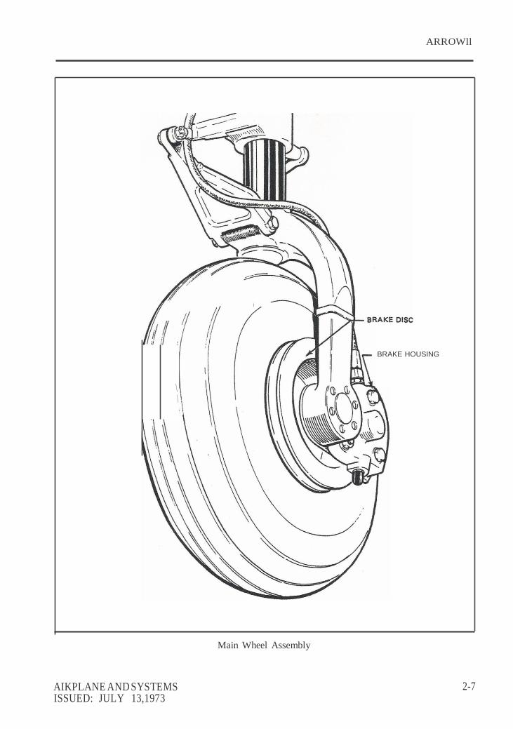
A single disc, single puck brake is mounted on the main gears. A brake disc is mounted on the
inboard side of the wheels and the brake housing which incorporates the pucks is mounted to the inboard side of the wheel axle.
1·6
AIRPLANE AND SYSTEMS REVISED: JANl,JARY 31, 1987
ARROWll
BRAKE HOUSING
\ \
Main Wheel Assembly
AIKPLANE AND SYSTEMS ISSUED: JULY 13,1973
2-7

ARROW II
FLIGHT CONTROLS
Dual flight controls are provided as standard equipment. A cable system provides actuation of the control surfaces when the flight controls are moved in their respective directions.
The horizontal surface (stabilator) is of the flying tail design with a trim tab/servo mounted
on the trailing edge. This tab serves the dual function of providing trim control and pitch control forces. The trim function is controlled by a trim control wheel located on the control console between the two front seats. Rotating the wheel forward gives nose down trim and rotation aft gives nose up trim. The stabilator provides extra stability and controllability with less area, drag and weight than conventional tail surfaces.
The rudder is conventional in design and incorporates a rudder trim. The trim mechanism
is a spring-loaded recentering device. The trim control islocated on the right side of the pedestal below the throttle quadrant. Turning the trim control clockwise gives nose right trim and counterclockwise rotation gives nose left trim.
Ailerons are provided with differential deflection. This feature reduces adverse yaw in
turning maneuvers and thus reducing the amount of coordination required.
Manually controlled flaps are provided. They are extended by a control cable and are spring-loaded to the retracted (up) position. The control is located between the two front seats on the control console. To extend the flaps pull the handle up to the desired flap setting of 10, 25 or 40 degrees. To retract, depress the button on the end of the handle and lower the control. A balanced control system is used for light operating forces.
When extending or retracting flaps, there is a pitch change in the aircraft. This pitch change
can be corrected either by stabilator trim or increased control wheel force. When the flaps are in the retracted position the right flap, provided with a over-center lock mechanism, acts as a step.
NOTE
The right flap will support a load only in the fully retracted (up) position. When loading and unloading passengers make sure the flaps are in the retracted (up) position.
2-8
AIRPLANE AND SYSTEMS ISSUED: JULY 13, 1973
ARROW II
.:-:-.::·
FUEL SYSTEM
The fuel system was designed with simplicity in mind . It incorporates two fuel tanks, one in each wing containing twenty-five (25) U.S. gallons , giving a total of 48 usable gallons. The tanks are attached to the leading edge of the wing with screws and are an integral part of the wing structure. This allows for easy removal for service. An auxiliary electric fuel pump is provided in case of a failure of the engine driven pump. A rocker type switch for controlling the electric pump is located on the switch panel above the throttle quadrant. The electric pump should be on for take-off, switching tanks and during landing.
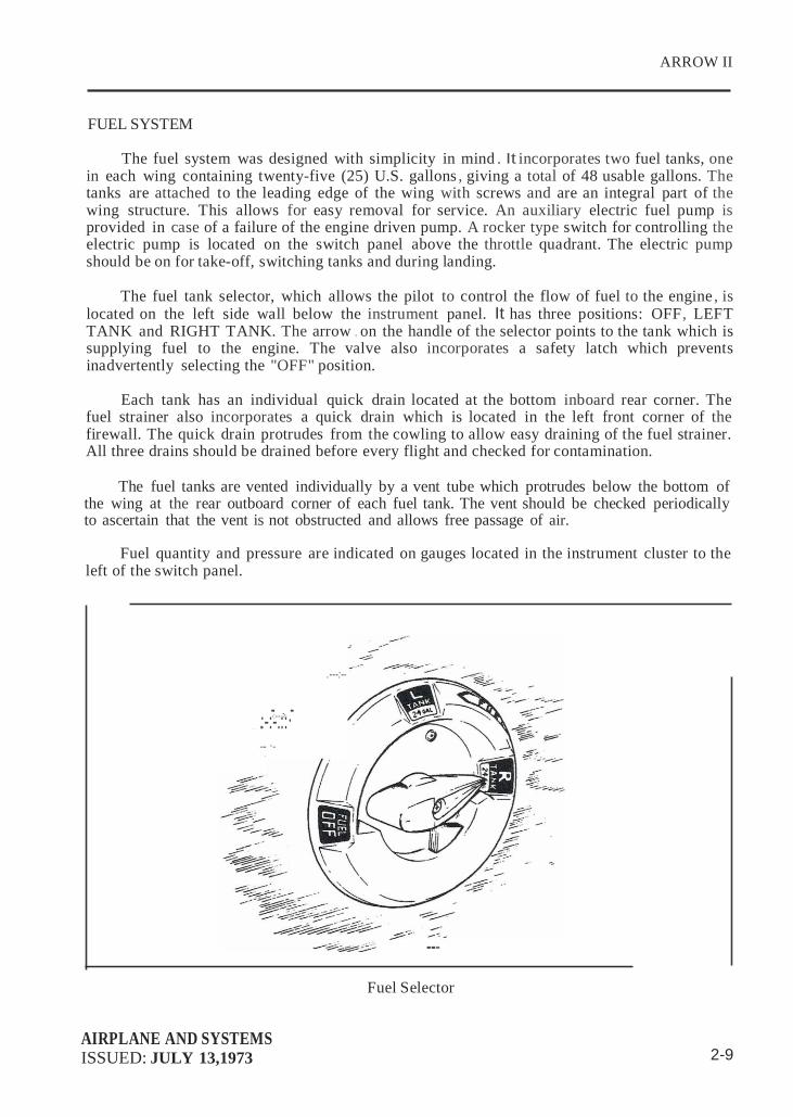
The fuel tank selector, which allows the pilot to control the flow of fuel to the engine , is
located on the left side wall below the instrument panel. It has three positions: OFF, LEFT TANK and RIGHT TANK. The arrow . on the handle of the selector points to the tank which is supplying fuel to the engine. The valve also incorporates a safety latch which prevents inadvertently selecting the "OFF" position.
Each tank has an individual quick drain located at the bottom inboard rear corner. The
fuel strainer also incorporates a quick drain which is located in the left front corner of the firewall. The quick drain protrudes from the cowling to allow easy draining of the fuel strainer. All three drains should be drained before every flight and checked for contamination.
The fuel tanks are vented individually by a vent tube which protrudes below the bottom of
the wing at the rear outboard corner of each fuel tank. The vent should be checked periodically to ascertain that the vent is not obstructed and allows free passage of air.
Fuel quantity and pressure are indicated on gauges located in the instrument cluster to the
left of the switch panel.
--:--------- - _ _
-- ·- -
.---:--
---
Fuel Selector AIRPLANE AND SYSTEMS ISSUED: JULY 13,1973 2-9

ARROW II
fUEl QUANTITY GAUGE
FUEl PRESSURE GAUGE
DRAIN
RIGHT TANK
FUEL SELECTOR
LEn TANK
DRAIN
GASCOUTOR
VENT
FUEl FLOW
GAUGE
VENT
ELECTRIC FUEL PUMP
ENGINE DRIVEN fUEL PUMP
SERVO REGULATOR
Fuel Schematic
2-10
AIRPLANE AND SYSTEMS JSSUED: JULY 13, 1973

ARROW II
ELECTRICAL SYSTEM
The electrical system is very simple and functional. All switches are grouped in a switch panel above the power quadrant. On the lower right side of the instrument panel is the circuit breaker paneL with each breaker clearly marked to show what circuit it protects. Also , circuit provisions are made to handle a complete complement of communication and navigationa l equipment.
Standard electrical accessories include alternator , starter, electric fuel pump, stall warning
indicator, ammeter, and annunciator panel* .
The annunciator panel includes alternator and low oil pressure indicator lights. When the optional gyro system is installed, the annunciator panel also includes a low vacuum indicator light. The annunciator panel lights are provided only as a warning to the pilot that a system may not be operating properly, and that he should check and monitor the applicable system gauge to determine when or if any necessary action is required.
Optional electrical accessories include navigation, anti-collision, landing, instrument and
cabin dome lights. Navigation and radio lights are controlled by a rheostat switch on the left side of the switch panel. The instrument panel lights are controlled by a rheostat switch on the right side of the panel.
WARNING
When optional panel lights are installed, rheostat switch must be off to obtain gear lights full intensity during daytime flying. When aircraft is operated at night and panel light rheostat switch is turned on, gear lights will automatically dim.
The anti-collision and landing lights are controlled by rocker switches on the switch panel.
Circuits will handle a full complement of communications and navigational equipment.
WARNING
Strobe lights should not be operating when flying through overcast and clouds since reflected light can produce spacial disorientation. Do not operate strobe lights in close proximity to ground, during takeoff and landing.
The master switch, also located in the switch panel, is a split rocker switch. One side of the
switch is the battery side ("BAT") and the other is the alternator side {"ALT"). Henceforth, "master switch," used in this manual, shall mean both "BAT" and "ALT" switches. The "ALT" . switch is provided for an emergency and its function is covered under "Alternator Failure" in the Emergency section of the handbook.
The primary electrical power source is a 14-volt, 6G-amp alternator, which is protected by
a voltage regulator and an ov"ervoltage relay. The alternator provides full electrical power output even at low engine RPM. This provides improved radio and electrical equipment operation and increases battery life by reducing battery load.
*Serial nos. 7535001 and up
AIRPLANE AND SYSTEMS REVISED: APRIL 13, 1979 2-11

I I I
J..ll
ARROWll
STARTER 8 ACCESSORIES
ALTERNATOR FIELD
r--,
'I]:I
I
L_.J CIGAR
- LIGHTER
STARTER SOLENOID
MASTER SOLENOID
S RTER
I
EXTERNAL POWER I RECEPTACLE I
I --
-------+4------------------l
L------- L _j
· ALTERNATOR OUTPUT
J C/P
- SOURCE-POWER
. ,RELAY ENERGIZING CIRCUIT
AMMETER MASTER
SWITCH
1
RADIO INTERFERENCE CAMCITOR
Alternator and Starter Schematic (Ser. Nos, 7435001 through 7435331}
AIRPLANE AND SYSTEMS REVISED: JUNE 18, £974

ARROWll
- ' 0
STARTER 8 ACCESSOR IES ALTERNATOR FIELD
A (IN LIN£) STARTER
SOLENOID
r --,
'I } :I 1
WARN
STARTER
1 _[ CIGAR
:- LIGHTER
CABIN
LIGHT LAMP TEST
..r:::=J..
l
' LIGHT
--------------- , EXTERNAL POWER SOLENOID
EXTERNAL POWER RECEPTACLE
Q.!'T.!Q L- _ _j
I I
.1:\ R;A
7SOURCE-POWER-
RELAY ENERGIZING CIRCUIT
AMMETER
VOLTAGE REGULATOR
l !
RADIO INTERFERENCE
CAPACITOR
MASTER
SWITCH
1
Alternator and Starter Schematic (Ser. Nos. 7535001 and up)
AIRPLANE AND SYSTEMS ISSUED: JUNE 18, 1974 2-12a

ARROW II
THIS PAGE INTENTIONALLY LEFT BLANK
AIRPLANE AND SYSTEMS
\ ISSUED: JUNE 18, 1974

ARROW II
W
<0
..len
zW.w.l
a.C a::::i W> !lc:,.J <a: a:w<
=z !:o :la:> uo ... !:oz CJCO
\ \
\
\
\-. ..
\\·,·
Circuit Breaker Panel
AIRPLANE AND SYSTEMS REVISED: JUNE 27, 1975 2-13

ARROW II
Secondary power is provided by a 12-volt, 25-ampere hour battery.
The ammeter as installed does not show battery discharge; rather it shows the electrical load placed on the system. With all the electrical equipment off, and the master switch on, the ammeter will indicate the charging rate of the battery. As each electrical unit is switched on, the ammeter will indicate the total ampere draw of all the units including the battery. For example , the maximum continuous load for night flying with radios on is about 30 amperes. The 30 ampere value plus 2 amperes for charging the battery will then show on the ammeter, indicating the alternator is functioning properly.
Solenoids, provided in the battery and starter circuits, are used to control high current
drain functions remotely from the cabin.
VACUUM SYSTEM
The vacuum system is designed to operate the air driven gyro instruments. This includes the directional and attitude gyros when installed. The system consists of an engine driven vacuum pump, a vacuum regulator, a filter and the necessary plumbing.
The vacuum pump is a dry type pump which eliminates the need for an air/oil separator
and its plumbing. A shear drive protects the pump from damage. If the drive shears the gyros will become inoperative. ·
The vacuum puge, mounted on the right instrument panel to the right of the radios,
provides valuable information to the pilot ab ut the operation of the vacuum system. A decrease in pressure in a system that has remained constant over an extended period, may indicate a dirty filter, dirty screens, possibly a [sticking vacuum regulator or leak in system (a low vacuum indicator light is provided in the arutunciator panel*). Zero pressure would indicate a sheared pump drive, defective pump, possibly [ a defective gauge or collapsed line. In the event of any gauge variation from the norm, the pil9t should have a mechanic check the system to prevent possible damage to the system componers or eventual failure of the system.
A vacuum regulator is provided in the systfm to protect the gyros. The valve is set so the
normal vacuum reads 5.0 ± .1 inches of mercury, a setting which provides sufficient vacuum to operate all the gyros at their rated RPM. Highet settings will damage the gyros and with a low setting the gyros will be unreliable. The regulatot is located behind the instrument panel.
*Serial nos. 7535001 and up
2-14
AIRPLANE AND SYSTEMS REVISED: JUNE 18, 1974

ARROW II
INSTRUMENT PANEL
The instrument panel is designed to be functiona l and professional, accommodat ing
complete instruments and avionics equipment for VFR an d IFR flights. A wide range of optional instruments and avionics permits an equipment selection uniquely suited to individual
needs.
Flight instruments are grouped in a standard "T" directly in front of the pilot. Radio
navigational indicators are to the right of the flight instruments and are located to correspond to
the respective radio control heads. Fuel gauges are located to the right of the pilo t control wheel
and engine instruments are located to the left of the control wheel. The tachometer and
manifold pressure instruments are located to the left of the power quadrant and are positioned
respective of the throttle and propeller controls.
The circuit breakers are protected by a cover door.
The climatic controls, when the air conditioning system is installed, are located in the right
instrument panel above the circuit breakers.
An annunciator panel* is mounted in the upper instrument panel to warn the pilot of a
possible malfunction in the alternator, oil pressure or vacuum systems.
PITOT-STATIC SYSTEM
The system supplies both pitot and static ·pressure for the airspeed indicator, altimeter and
vertical speed indicator (when installed).
Pitot and static pressure are picked up by the pitot head on the bottom of the left wing.
An optional heated pitot head, which alleviates problems with icing or heavy rain, is available. The switch for pitot heat is located on the lower left instrument panel.
To prevent bugs and water from entering the pitot and static pressure holes, a cover should
be placed over the pitot head. A partially or completely blocked pitot head will give erratic or zero readings on the instruments.
NOTE
During the preflight, check to make sure the pitot cover is
removed.
*Serial nos. 7535001 and up
AIRPLANE AND SYSTEMS REVISED: JUNE 18, 1974
2-15

-=.., c:: 3
=.c
.-
.
1. STALL WARNING INDICATOR
2. ADF INDICATOR
3. CLOCK
4. TURN INDICATOR
5. AIRSPEED INDICATOR
6. DIRECTIONAL GYRO
7. ATTITUDE GYRO
8. GEAR "UP" WARNING LIGHT
9. GEAR "IN TRANSIT " LIGHT 10. VERnCAL SPEED INDICATOR
11. ALnMETER
12. AUDIO SELECTOR 13. COMPASS
14. OMNI & GLIDESLOPE INDICATOR
15. AIR CONO. INDICATOR LIGHT
16. TRANSCEIVERS
17. TRANSPONDER
ll
18. ADF
19. DME
20. SUCTION GAUGE
21. . CIGAR LIGHTER
22. HEATER/DEFROSTER CONTROLS
23 . MIKE JACK
24. . PHONE JACK
25. AUTOPILOT
26. ENGINE INSTRUMENT CLUSTER
27. OMNI - COUPLER 28. NAV SELECTOR
29. PITCH CONTROL
30. MAGNETO 8t STARTER SWITCH 31. FUEL GAUGES
32. . MANIFOLD PRESSURE GAUGE
33. . TACHOMETER
34. GEAR SELECTOR
-
35. GEAR OVERRIDE LIGHT UF AIRCRAFT
EQUIPPED WITH BACKUP GEAR EXTENDER)
36. GEAR POSITION LIGHTS
37. MICROPHONE
38. FRICTION LOCK 39. THROTILE QUADRANT
40 . ALTERNATE AIR CONTROL
41 . EGT GAUGE
42. INSTRUMENT PANEL LIGHTS
43. CIRCUIT BREAKER PANEL
44. CIRCUIT BREAKER COVER {EARLY
MODELS ONLY)
45. MIXTURE CONTROL LOCK (SEA.
NOS. 7535001 AND UP)
46. ANNUNCIATOR PANEL {SER. NOS.
7535001 AND UP
47. ENGINE HOUR METER {SEA. NOS.
28 A· 7635001 AND UP)

ARROWll
/
'. '\ -r _/ / \ \,
...
\ \ \
Pitot - Static System
AIRPLANE AND SYSTEMS
ISSUED: JULY 13, 1973 2-17

ARROWll
HEATING, VENTILATING AND DEFROSTING SYSTEM
The heating system is designed to provide maximum comfort for the occupants during winter and cool weather flights. The system includes a heat shroud , heat ducts, defroster outlets, heat and defroster controls.
An opening in the front of the lower cowl admits ram air to the heater shroud and then the
air is ducted to the heater shut-offs on the right and left side of the firewall. When the shut-offs are opened the heated air then enters the heat ducts located along each side of the center console. Outlets in the heat duct are located at each seat location. Air flow to the rear seats can be regulated by controls in the heat ducts located between the front seats. The temperature of the cabin is regulated by the heater control located on the right side of the instrument panel.
CAUTION
When cabin heat is operated, heat duct surface becomes hot. This could result in burns if arms or legs are placed too close to heat duct outlets or surface.
Defrosting is accomplished. by heat outlets located on the right and left side of the cowl cover. Heated air is ducted directly to defroster shut-off valves at the firewall, then to the defroster outlets. The air flow is regulated by a defroster control located below the heat control.
To aid air distribution, the cabin air is exhausted overboard by an outlet located on the
bottom of the fuselage. Cabin exhaust outlets are located below and outboard of the rear seats. The above features are removed when air conditioning is installed.
Optional individual overhead fresh air outlets supply fresh air from an air inlet located on
the tip of the vertical fin. The air is directed to a plenum chamber at the base of the fm, then ducted to the individual outlets. For individual comfort, the amount and direction of air can be regulated to control the amount of air and direction of desired airflow. An optional blower is available which forces outside air through the overhead vents for ground use. The blower is operated by a "FAN" switch with 4 positions- "OFF," "LOW," "MED," or "HIGH."
2-18
AIRPLANE AND SYSTEMS REVISED: APRIL 13, 1979

9: 12.
• KHEAD
, L
0
FRESH AIR INLET
: DRAIN T :;LOWER 3
FRESH A ASSEMBLY 4 . BU H AIR DUCT OUTLET
5 • F:BIN EXHAUST
· ABIN VE TCH PANEL I• BLOWER S R CONTROL
DEFROST NTROL N CONTROL 10. HEATER EAT DIVERSIO
CABIN H IR CONTROL FRESHA
(/ - ' "-.. / I
(..,-; ;
.. '""1'; _,.- · ------ ----------
/ --
2
• FRESH AI R
/ CABIN HEAT ;
/
(f),' - /.

ARROW IT
CABIN FEATURES
The interior has been designed for passenger comfort and safety. All seat backs have three positions : normal, intermediate and recline. The adjustment lever is located at the base of the seat back on the outboard side of the seat. The front seats adjust fore and aft for ease of entry and occupant comfort. An armrest is located on the side panels adjacent·to the front seat. The rear seats are easily removed to provide room for bulky items. Some rear seat installations incorporate leg retainers with latching mechanisms which must be released before the rear seats can be removed. Releasing the retainers is accomplished on earlier models by turning the latching mechanisms 90° with a coin or screwdriver. Releasing the retainers is accomplished on later models by depressing the plunger behind each rear leg. Optional headrests are available.
A single strap shoulder harness controlled by an inertia reel, located above the side
window, protects each front seat occupant. Optional shoulder straps for the rear occupants are available. The shoulder strap is routed over the shoulder adjacent to the window and attached to the lap belt in the general area of the occupant's inboard hip. A check of the inertia reel mechanism can be made by pulling sharply on the strap and checking that the reel will lock in place under sudden stress; this locking feature prevents the strap from extending and holds the occupant in place. Under normal movement the strap will extend and retract as required. Shoulder harnesses should be routinely worn during take-off, landing and whenever an inflight emergency situation occurs.
Additional features include pilot storm window, two sun visors, ashtrays for each
occupant, two map pockets located on. the side panels below the instrument panel, miscellaneous pockets on the rear of the front seat backs, armrests for the front occupants, cabin or baggage door locks and ignition lock.
2-20 AIRPLANE AND SYSTEMS
REVISED: FEBRUARY 28, 1977

ARROW II
BAGGAGE AREA
A large baggage area, located behind the rear seats, is accessible either from the cabin or through a large outside baggage door on the right side of the aircraft. Maximum capacity is 200 lbs. Tie-down straps are provided and should be used at all times.
NOTE
It is the pilot's responsibility to be sure when the baggage is loaded that the aircraft C.G. falls within the allowable C.G. Range. (See Weight and Balance Section.)
STALL WARNING
An approaching stall is indicated by a stall warning indicator which is activated between
five and ten miles per hour above stall speed. Mild airframe buffeting and gentle pitching may also precede the stall. Stall speeds are shown on graphs in the Performance Charts Section. The stall warning indicator is a red warning light on the left side of the instrument panel on earlier models and a .continuous sounding horn located behind the instrument panel on later models. The landing gear horn is different in that it emits a 90 cycles per minute beeping sound on later models. The stall warning indicator is activated by a lift detector installed on the leading edge of the left wing. During preflight, the stall warning system should be checked by turning the master switch "ON," lifting the detector and checking to determine if the indicator is actuated.
FINISH
The exterior of the aircraft is finished with a durable acrylic lacquer in a variety of tasteful colors to suit individual owners.
AIR CONDITIONING*
The air conditioning system is a recirculating air system. The major items include; evaporator, condenser, compressor, blower, switches and temperature controls.
The evaporator is located behind the left rear side of the baggage compartment. This cools
the air that is used for air conditioning.
The condenser is mounted on a retractable scoop located on the bottom of the fuselage and to the rear of the baggage compartment area . The scoop extends when the air conditioner is "ON" and retracts to a flush position when the system is "OFF."
The compressor is mounted on the forward right underside of the engine. It has an electric
clutch which ·automatically engages or disengages the compressor to the belt drive system of the com pressor.
*Optional Equipment
AIRPLANE AND SYSTEMS
REVISED: FEBRUARY 29, 1984 2-21

ARROW II
TIDS PAGE INTENTIONALLY LEFT BLANK
2-22 AIRPLANE ANI? SYSTEMS REVISED: JUNE 27, 1975
ARROW II
An electrical blower is mounted on the aft side of the rear cabin panel. Air from the baggage area is drawn through the evaporator by the blower and distributed through an overhead duct to individual outlets located adjacent to each occupant.
The switches and temperature control are located on the lower right side of the instrument
panel in the climate control center panel. The temperature control regulates the desired temperature of the cabin. Turn the control clockwise for increased cooling, counterclockwise for decreased cooling.
Located inboard of the temperature control is the fan speed switch and the air
conditioning "ON-OFF" switch. The fan can be operated independently of the air conditioning. However, it must be on for air conditioner operation. Turning either switch off will disengage the compressor clutch and retract the condenser door. Cooling air should be felt within one minute after the air conditioner is turned on.
NOTE
If the system is not operating in S minutes tum the system "OFF," until the fault is corrected.
The "FAN" switch allows operation of the fan with the air conditioner turned "OFF" to
aid cabin air circulation if desired. A "LOW," "MED" or "HIGH" flow of air can be selected to the air conditioner outlets located in the overhead duct. The outlets can be adjusted or turned off by each occupant to obtain individ,ua! cooling effect. ·
The condenser door light is located to the left of the radio stack in front of the pilot. The
door light illuminates and remains on when the door is open or extended. The light is off when . the door is retracted.
A circuit breaker located on the circuit breaker panel protects the air conditioning
electrical system.
Whenever the throttle is in the full thrpttle position, it actuates a micro switch which disengages the compressor and retracts the scoop. This is done to obtain maximum power and maximum rate of climb. The fan continues to operate and the air will remain cool for approximately one minute. When the ·throttle is retarded approximately 1/4 inch, the clutch will engage and the scoop will extend, again supplying cool, dry air.
PIPER EXTERNAL POWER*
An optional starting installation known as Piper External Power (PEP) iS accessible through
a receptacle located on the right side of the fuselage aft of the wing. An external battery can be connected to the socket, thus allowing the operator to crank the engine without having to gain _ access to the airplane's battery.
*Optional Equipment
AIRPLANE AND SYSTEMS REVISED: JUNE 27,1975 2-23
Related Documents