Description of Functions 02/2005 Edition sinumerik SINUMERIK 840D/840Di/810D ShopMill

Welcome message from author
This document is posted to help you gain knowledge. Please leave a comment to let me know what you think about it! Share it to your friends and learn new things together.
Transcript

Description of Functions 02/2005 Edition
sinumerik SINUMERIK 840D/840Di/810D ShopMill

Valid for
Control Software versionSINUMERIK 840D powerline 7SINUMERIK 840DE powerline 7SINUMERIK 840Di 3SINUMERIK 840DiE (export version) 3SINUMERIK 810D powerline 7SINUMERIK 810DE powerline 7
02/05 Edition
ShopMill
SINUMERIK 840D/840Di/810D
Description of Functions
Hardware 1
Supplementary Conditions 2
Reserved Functions 3
Start-Up 4
PLC Program 5
Signal Description 6
Machine Data 7
Tool Management 8
Additional Functions 9
Customer-SpecificOperator Interface 10
Miscellaneous 11
Abbreviations A
References B
Index C
SINUMERIK Documentation
Printing history
Brief details of this edition and previous editions are listed below.
The status of each edition is shown by the code in the “Remarks” column.
Status code in the “Remarks” column:
A New documentation.. . . . . B Unrevised reprint with new Order No.. . . . . C Revised edition with new status. . . . . .
Edition Order No. Remarks10/97 6FC5 297-2AD80-0BP0 A11/98 6FC5 297-2AD80-0BP1 C03/99 6FC5 297-5AD80-0BP0 C08/00 6FC5 297-5AD80-0BP1 C12/01 6FC5 297-6AD80-0BP0 C08/03 6FC5 297-6AD80-0BP1 C11/03 6FC5 297-6AD80-0BP2 C02/05 6FC5 297-6AD80-0BP3 C
Additional information can be found at:http://www.siemens.com/motioncontrol
This publication was produced with Interleaf V 7
Siemens AG, 1997 – 2005. All rights reserved
Other functions not described in this documentation might beexecutable in the control. However, no claim can be made regardingthe availability of these functions when the equipment is first suppliedor in the event of servicing.
We have checked that the contents of this document correspond tothe hardware and software described. Nevertheless, differencesmight exist and therefore we cannot guarantee that they arecompletely identical. The information given in this publication isreviewed at regular intervals and any corrections that might benecessary are made in the subsequent printings. Suggestions forimprovement are also welcome.
Subject to change without prior notice.
Siemens AktiengesellschaftOrder No. 6FC5 297-6AD80-0BP3Printed in Germany
v Siemens AG, 2005. All rights reservedSINUMERIK 840D/840Di/810D Description of Functions ShopMill (FBSP) – 02/05 Edition
Preface
The SINUMERIK documentation is subdivided into 3 parts:
� General documentation
� User documentation
� Manufacturer/Service documentation
This documentation is intended for use by manufacturers of vertical machiningcenters or universal milling machines controlled by the SINUMERIK 840D/840Di/810D system.
This Description of Functions provides the information you require to configureand start up the ShopMill system.
Note
This Description of Functions is valid for ShopMill SW 6.4.
If you have any questions, please contact the following hotline:A&D Technical Support Phone: +49 (0) 180 5050–222
Fax: +49 (0) 180 5050–223Email: [email protected]/automation/support-request
If you have any queries (suggestions, corrections) in relation to this documenta-tion, please fax or e-mail us:Fax: +49 (0) 9131 98–2176You will find a fax form on the response sheet at the end of the documentE-mail: [email protected]
http://www.siemens.com/motioncontrol
Improved-performance variants SINUMERIK 840D powerline and SINUMERIK840DE powerline have been available since 09/2001. The hardware descriptionbelow contains a list of the available powerline modules: References: /PHD/, Configuring Manual SINUMERIK 840D
Improved-performance variants SINUMERIK 810D powerline and SINUMERIK810DE powerline have been available since 12/2001. The hardware descriptionbelow contains a list of the available powerline modules:References: /PHC/ SINUMERIK 810D Configuration Manual
Structure of the documentation
Audience
Objective
Hotline
Internet address
SINUMERIK 840Dpowerline
SINUMERIK 810Dpowerline
02/05
vi Siemens AG, 2005. All rights reserved
SINUMERIK 840D/840Di/810D Description of Functions ShopMill (FBSP) – 02/05 Edition
This document provides information about the control system design and theinterfaces of the individual components. It also describes the start-up andinstallation procedure for ShopMill with SINUMERIK 840D/840Di/810D.
For detailed information about individual functions, function assignment andperformance data of individual components, please refer to the approporiatedocument for the subject concerned (e.g. manuals, description of functionsetc.).
User-oriented activities such as the creation of parts programs and controloperating procedures are described in details in separate documents.
Further descriptions of tasks to be performed by the machine tool manuacturerare also available for the standard SINUMERIK 840D/840Di/810D. We mayrefer to them in this documentation if appropriate.
In addition to the table of contents, we have provided the following informationin the appendix for your assistance:
1. Abbreviations
2. List of References
3. Index
For a complete list and description of the ShopMill alarms, please refer to
References: /BAS/, ShopMill Operation/Programming
The SINUMERIK 840D/840Di/810D alarms are also listed in
References: /DA/, Diagnostics Guide
For further useful information on start-up and troubleshooting, please refer to
References: /FB/, D1, “Diagnostics Tools”
The following symbols with special significance are used in the documentation:
Note
This symbol always appears in this documentation where further, explanatoryinformation is provided.
The following warnings with varying levels of severity are used in this document:
!Danger
Indicates an imminently hazardous situation which, if not avoided, will result indeath or serious injury or in substantial property damage.
Standard scope
Findinginformation
Notes
Warnings
Preface
02/05
vii Siemens AG, 2005. All rights reservedSINUMERIK 840D/840Di/810D Description of Functions ShopMill (FBSP) – 02/05 Edition
!Warning
Indicates a potentially hazardous situation which, if not avoided, could result indeath or serious injury or in substantial property damage.
!Caution
Used with the safety alert symbol indicates a potentially hazardous situationwhich, if not avoided, may result in minor or moderate injury or in propertydamage.
Caution
Used without safety alert symbol indicates a potentially hazardous situationwhich, if not avoided, may result in property damage.
Notice
Used without the safety alert symbol indicates a potential situation which, if notavoided, may result in an undesirable result or state.
In this manual, the units of the parameters are always indicated as metric va-lues. The equivalent imperial units are shown in the table below.
Metric Inch
mm in
mm/tooth in/tooth
mm/min in/min
mm/rev in/rev
m/min ft/min
Unit ofmeasurement
Preface

02/05
viii Siemens AG, 2005. All rights reserved
SINUMERIK 840D/840Di/810D Description of Functions ShopMill (FBSP) – 02/05 Edition
Preface
Notes
ix Siemens AG, 2005. All rights reservedSINUMERIK 840D/840Di/810D Description of Functions ShopMill (FBSP) – 02/05 Edition
Contents
1 Hardware 1-13. . . . . . . . . . . . . . . . . . . . . . . . . . . . . . . . . . . . . . . . . . . . . . . . . . . . . . . . . . .
2 Supplementary Conditions 2-15. . . . . . . . . . . . . . . . . . . . . . . . . . . . . . . . . . . . . . . . . . .
3 Reserved Functions 3-17. . . . . . . . . . . . . . . . . . . . . . . . . . . . . . . . . . . . . . . . . . . . . . . . .
4 Start-Up 4-19. . . . . . . . . . . . . . . . . . . . . . . . . . . . . . . . . . . . . . . . . . . . . . . . . . . . . . . . . . . . .
4.1 Preconditions 4-19. . . . . . . . . . . . . . . . . . . . . . . . . . . . . . . . . . . . . . . . . . . . . . .
4.2 Initial start-up 4-21. . . . . . . . . . . . . . . . . . . . . . . . . . . . . . . . . . . . . . . . . . . . . . . 4.2.1 Sequence 4-21. . . . . . . . . . . . . . . . . . . . . . . . . . . . . . . . . . . . . . . . . . . . . . . . . . 4.2.2 Installing ShopMill on PCU 20 4-22. . . . . . . . . . . . . . . . . . . . . . . . . . . . . . . . . 4.2.3 Installing ShopMill on PCU 50 4-24. . . . . . . . . . . . . . . . . . . . . . . . . . . . . . . . . 4.2.4 NC start-up 4-30. . . . . . . . . . . . . . . . . . . . . . . . . . . . . . . . . . . . . . . . . . . . . . . . . 4.2.5 PLC Start-up 4-36. . . . . . . . . . . . . . . . . . . . . . . . . . . . . . . . . . . . . . . . . . . . . . . . 4.2.6 Display machine data 4-37. . . . . . . . . . . . . . . . . . . . . . . . . . . . . . . . . . . . . . . . 4.2.7 Acceptance report 4-38. . . . . . . . . . . . . . . . . . . . . . . . . . . . . . . . . . . . . . . . . . .
4.3 Series start-up 4-39. . . . . . . . . . . . . . . . . . . . . . . . . . . . . . . . . . . . . . . . . . . . . .
4.4 Upgrade 4-39. . . . . . . . . . . . . . . . . . . . . . . . . . . . . . . . . . . . . . . . . . . . . . . . . . . .
5 PLC Program 5-41. . . . . . . . . . . . . . . . . . . . . . . . . . . . . . . . . . . . . . . . . . . . . . . . . . . . . . .
5.1 Structure of the PLC program 5-41. . . . . . . . . . . . . . . . . . . . . . . . . . . . . . . . .
5.2 Overview of blocks 5-42. . . . . . . . . . . . . . . . . . . . . . . . . . . . . . . . . . . . . . . . . . .
5.3 ShopMill PLC program 5-43. . . . . . . . . . . . . . . . . . . . . . . . . . . . . . . . . . . . . . .
5.4 ShopMill interface DB82 5-44. . . . . . . . . . . . . . . . . . . . . . . . . . . . . . . . . . . . . .
5.5 Standard interface signals for/from ShopMill 5-46. . . . . . . . . . . . . . . . . . . . .
5.6 OB1 and OB100 5-48. . . . . . . . . . . . . . . . . . . . . . . . . . . . . . . . . . . . . . . . . . . . .
5.7 Machine control panel 5-51. . . . . . . . . . . . . . . . . . . . . . . . . . . . . . . . . . . . . . . .
5.8 Diagnostics function for start-up purposes 5-54. . . . . . . . . . . . . . . . . . . . . . .
6 Signal Description 6-55. . . . . . . . . . . . . . . . . . . . . . . . . . . . . . . . . . . . . . . . . . . . . . . . . . .
6.1 HMI interface DB19 6-55. . . . . . . . . . . . . . . . . . . . . . . . . . . . . . . . . . . . . . . . . .
6.2 Overview of ShopMill interface DB82 6-56. . . . . . . . . . . . . . . . . . . . . . . . . . . 6.2.1 Signals to ShopMill (input signals) 6-56. . . . . . . . . . . . . . . . . . . . . . . . . . . . . . 6.2.2 Signals from ShopMill (output signals) 6-57. . . . . . . . . . . . . . . . . . . . . . . . . . 6.2.3 Diagnostics buffer signals 6-58. . . . . . . . . . . . . . . . . . . . . . . . . . . . . . . . . . . . .
6.3 Description of ShopMill interface DB82 6-60. . . . . . . . . . . . . . . . . . . . . . . . . 6.3.1 Signals to ShopMill (input signals) 6-60. . . . . . . . . . . . . . . . . . . . . . . . . . . . . . 6.3.2 Signals from ShopMill (output signals) 6-68. . . . . . . . . . . . . . . . . . . . . . . . . . 6.3.3 Description of diagnostics buffer signals 6-76. . . . . . . . . . . . . . . . . . . . . . . .
02/05
x Siemens AG, 2005. All rights reserved
SINUMERIK 840D/840Di/810D Description of Functions ShopMill (FBSP) – 02/05 Edition
7 Machine Data 7-79. . . . . . . . . . . . . . . . . . . . . . . . . . . . . . . . . . . . . . . . . . . . . . . . . . . . . . . .
7.1 NC machine data for ShopMill 7-79. . . . . . . . . . . . . . . . . . . . . . . . . . . . . . . . .
7.2 Display machine data for ShopMill 7-81. . . . . . . . . . . . . . . . . . . . . . . . . . . . . 7.2.1 Overview of machine data display 7-81. . . . . . . . . . . . . . . . . . . . . . . . . . . . . . 7.2.2 Description of display machine data 7-84. . . . . . . . . . . . . . . . . . . . . . . . . . . .
8 Tool Management 8-105. . . . . . . . . . . . . . . . . . . . . . . . . . . . . . . . . . . . . . . . . . . . . . . . . . .
8.1 Overview of functions 8-105. . . . . . . . . . . . . . . . . . . . . . . . . . . . . . . . . . . . . . . .
8.2 Start-up sequence 8-108. . . . . . . . . . . . . . . . . . . . . . . . . . . . . . . . . . . . . . . . . . .
8.3 Start-up in the NC 8-109. . . . . . . . . . . . . . . . . . . . . . . . . . . . . . . . . . . . . . . . . . . 8.3.1 Enter the NC machine data 8-109. . . . . . . . . . . . . . . . . . . . . . . . . . . . . . . . . . . 8.3.2 Description of NC machine data 8-111. . . . . . . . . . . . . . . . . . . . . . . . . . . . . . . 8.3.3 Creating and loading the configuration file 8-117. . . . . . . . . . . . . . . . . . . . . . .
8.4 Start-up in the PLC 8-123. . . . . . . . . . . . . . . . . . . . . . . . . . . . . . . . . . . . . . . . . . 8.4.1 Example for FC 100 and FB 110 8-125. . . . . . . . . . . . . . . . . . . . . . . . . . . . . . . 8.4.2 Signal description 8-127. . . . . . . . . . . . . . . . . . . . . . . . . . . . . . . . . . . . . . . . . . . .
8.5 Display machine data 8-134. . . . . . . . . . . . . . . . . . . . . . . . . . . . . . . . . . . . . . . .
8.6 Tool change cycle 8-135. . . . . . . . . . . . . . . . . . . . . . . . . . . . . . . . . . . . . . . . . . . .
8.7 Manual tools 8-138. . . . . . . . . . . . . . . . . . . . . . . . . . . . . . . . . . . . . . . . . . . . . . . .
8.8 Activating the spindle, coolant, and tool-specific functions 8-139. . . . . . . . .
8.9 Modifying texts for tool-specific functions 8-141. . . . . . . . . . . . . . . . . . . . . . . . 8.9.1 PCU 20 8-141. . . . . . . . . . . . . . . . . . . . . . . . . . . . . . . . . . . . . . . . . . . . . . . . . . . . 8.9.2 PCU 50 8-143. . . . . . . . . . . . . . . . . . . . . . . . . . . . . . . . . . . . . . . . . . . . . . . . . . . .
8.10 Configuring the operator interface 8-145. . . . . . . . . . . . . . . . . . . . . . . . . . . . . . 8.10.1 Procedure 8-145. . . . . . . . . . . . . . . . . . . . . . . . . . . . . . . . . . . . . . . . . . . . . . . . . . 8.10.2 Creating configuration file 8-147. . . . . . . . . . . . . . . . . . . . . . . . . . . . . . . . . . . . . 8.10.3 Define texts 8-151. . . . . . . . . . . . . . . . . . . . . . . . . . . . . . . . . . . . . . . . . . . . . . . . .
8.11 Importing tool data 8-153. . . . . . . . . . . . . . . . . . . . . . . . . . . . . . . . . . . . . . . . . . .
9 Additional Functions 9-157. . . . . . . . . . . . . . . . . . . . . . . . . . . . . . . . . . . . . . . . . . . . . . . .
9.1 Measuring Cycles 9-157. . . . . . . . . . . . . . . . . . . . . . . . . . . . . . . . . . . . . . . . . . . . 9.1.1 Brief Description 9-157. . . . . . . . . . . . . . . . . . . . . . . . . . . . . . . . . . . . . . . . . . . . . 9.1.2 Probe connection 9-158. . . . . . . . . . . . . . . . . . . . . . . . . . . . . . . . . . . . . . . . . . . . 9.1.3 Function test 9-160. . . . . . . . . . . . . . . . . . . . . . . . . . . . . . . . . . . . . . . . . . . . . . . . 9.1.4 Start-up of probe 9-162. . . . . . . . . . . . . . . . . . . . . . . . . . . . . . . . . . . . . . . . . . . . 9.1.5 Machine data measuring cycles 9-165. . . . . . . . . . . . . . . . . . . . . . . . . . . . . . . . 9.1.6 Display machine data measuring cycles 9-166. . . . . . . . . . . . . . . . . . . . . . . . .
9.2 Network connection 9-173. . . . . . . . . . . . . . . . . . . . . . . . . . . . . . . . . . . . . . . . . . 9.2.1 General description 9-173. . . . . . . . . . . . . . . . . . . . . . . . . . . . . . . . . . . . . . . . . . 9.2.2 Integrating Windows network drives in ShopMill (PCU 20) 9-174. . . . . . . . . 9.2.3 Integrating Windows network drives in ShopMill (PCU 50) 9-175. . . . . . . . .
9.3 Cylinder surface transformation 9-177. . . . . . . . . . . . . . . . . . . . . . . . . . . . . . . . 9.3.1 Function 9-177. . . . . . . . . . . . . . . . . . . . . . . . . . . . . . . . . . . . . . . . . . . . . . . . . . . . 9.3.2 Example of how to set an axis configuration 9-178. . . . . . . . . . . . . . . . . . . . .
9.4 Swivel heads and tables 9-181. . . . . . . . . . . . . . . . . . . . . . . . . . . . . . . . . . . . . .
Contents
02/05
xi Siemens AG, 2005. All rights reservedSINUMERIK 840D/840Di/810D Description of Functions ShopMill (FBSP) – 02/05 Edition
9.5 Multiple clamping 9-182. . . . . . . . . . . . . . . . . . . . . . . . . . . . . . . . . . . . . . . . . . . .
9.6 Measuring cycle support in the G code editor 9-184. . . . . . . . . . . . . . . . . . . .
10 Customer-Specific Operator Interface 10-187. . . . . . . . . . . . . . . . . . . . . . . . . . . . . . . . .
10.1 Configuring the customized boot screen 10-187. . . . . . . . . . . . . . . . . . . . . . . . 10.1.1 PCU 20 10-187. . . . . . . . . . . . . . . . . . . . . . . . . . . . . . . . . . . . . . . . . . . . . . . . . . . . 10.1.2 PCU 50 10-188. . . . . . . . . . . . . . . . . . . . . . . . . . . . . . . . . . . . . . . . . . . . . . . . . . . .
10.2 Configuring the custom screen form 10-189. . . . . . . . . . . . . . . . . . . . . . . . . . . . 10.2.1 Transferring cycles to the machining plan 10-193. . . . . . . . . . . . . . . . . . . . . . . 10.2.2 Linking cycles into the machining plan 10-194. . . . . . . . . . . . . . . . . . . . . . . . . . 10.2.3 Integrating measuring cycles 10-195. . . . . . . . . . . . . . . . . . . . . . . . . . . . . . . . . .
10.3 ShopMill Open (PCU 50) 10-196. . . . . . . . . . . . . . . . . . . . . . . . . . . . . . . . . . . . . . 10.3.1 Basic menu bar 10-196. . . . . . . . . . . . . . . . . . . . . . . . . . . . . . . . . . . . . . . . . . . . . .
10.4 User status display (PCU 50) 10-197. . . . . . . . . . . . . . . . . . . . . . . . . . . . . . . . . .
10.5 OP hotkeys, PLC keys 10-199. . . . . . . . . . . . . . . . . . . . . . . . . . . . . . . . . . . . . . .
11 Miscellaneous 11-201. . . . . . . . . . . . . . . . . . . . . . . . . . . . . . . . . . . . . . . . . . . . . . . . . . . . . . .
11.1 Access protection via password and keyswitch 11-201. . . . . . . . . . . . . . . . . . 11.1.1 General 11-201. . . . . . . . . . . . . . . . . . . . . . . . . . . . . . . . . . . . . . . . . . . . . . . . . . . . 11.1.2 Password 11-203. . . . . . . . . . . . . . . . . . . . . . . . . . . . . . . . . . . . . . . . . . . . . . . . . . . 11.1.3 Keyswitch settings 11-204. . . . . . . . . . . . . . . . . . . . . . . . . . . . . . . . . . . . . . . . . . . 11.1.4 Machine data for protection levels 11-205. . . . . . . . . . . . . . . . . . . . . . . . . . . . . .
11.2 ISO dialects 11-207. . . . . . . . . . . . . . . . . . . . . . . . . . . . . . . . . . . . . . . . . . . . . . . . .
11.3 Spindle control 11-208. . . . . . . . . . . . . . . . . . . . . . . . . . . . . . . . . . . . . . . . . . . . . .
11.4 Analog spindles 11-209. . . . . . . . . . . . . . . . . . . . . . . . . . . . . . . . . . . . . . . . . . . . .
11.5 Automatically generated programs 11-210. . . . . . . . . . . . . . . . . . . . . . . . . . . . .
11.6 Version display 11-211. . . . . . . . . . . . . . . . . . . . . . . . . . . . . . . . . . . . . . . . . . . . . .
11.7 Action log 11-212. . . . . . . . . . . . . . . . . . . . . . . . . . . . . . . . . . . . . . . . . . . . . . . . . . .
11.8 Mold making 11-213. . . . . . . . . . . . . . . . . . . . . . . . . . . . . . . . . . . . . . . . . . . . . . . . 11.8.1 Start-up 11-213. . . . . . . . . . . . . . . . . . . . . . . . . . . . . . . . . . . . . . . . . . . . . . . . . . . . 11.8.2 Data storage, data transfer 11-216. . . . . . . . . . . . . . . . . . . . . . . . . . . . . . . . . . . .
A Abbreviations A-217. . . . . . . . . . . . . . . . . . . . . . . . . . . . . . . . . . . . . . . . . . . . . . . . . . . . . . .
B References B-221. . . . . . . . . . . . . . . . . . . . . . . . . . . . . . . . . . . . . . . . . . . . . . . . . . . . . . . . . .
C Index C-223. . . . . . . . . . . . . . . . . . . . . . . . . . . . . . . . . . . . . . . . . . . . . . . . . . . . . . . . . . . . . . .
Contents

02/05
xii Siemens AG, 2005. All rights reserved
SINUMERIK 840D/840Di/810D Description of Functions ShopMill (FBSP) – 02/05 Edition
Contents
Notes
1-13 Siemens AG, 2005. All rights reservedSINUMERIK 840D/840Di/810D Description of Functions ShopMill (FBSP) – 02/05 Edition
Hardware
The hardware configuration for ShopMill is as standard for SINUMERIK810D/840D/840Di.
References: /PHC/, SINUMERIK 810D, Configuration Manual/IAC/, SINUMERIK 810D, Installation and Start-Up Guide/PHD/, SINUMERIK 840D, Configuration Manual
NCU 561.2-573.3/IAD/, SINUMERIK 840D/SIMODRIVE 611D,
Installation and Start-Up Guide/HBI/, SINUMERIK 840Di, Manual
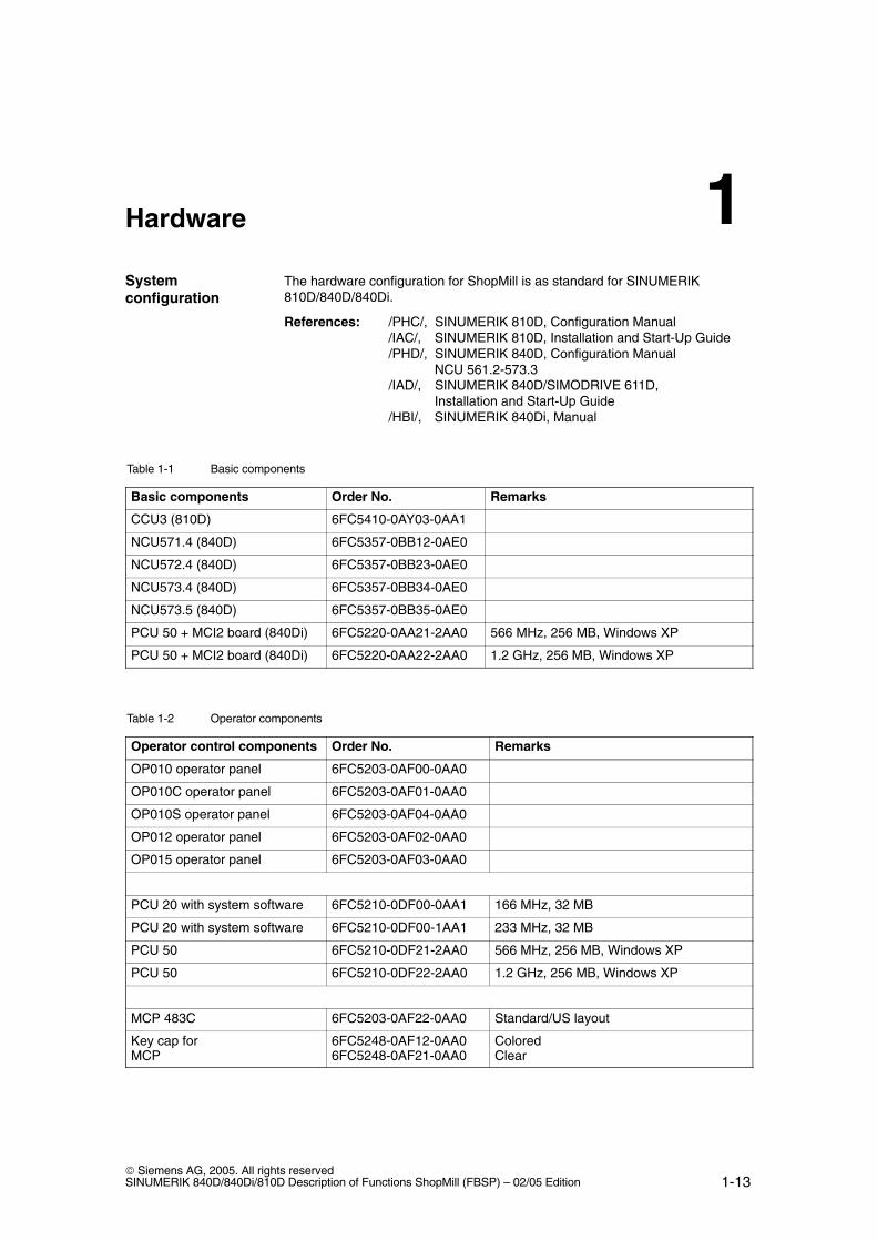
Table 1-1 Basic components
Basic components Order No. Remarks
CCU3 (810D) 6FC5410-0AY03-0AA1
NCU571.4 (840D) 6FC5357-0BB12-0AE0
NCU572.4 (840D) 6FC5357-0BB23-0AE0
NCU573.4 (840D) 6FC5357-0BB34-0AE0
NCU573.5 (840D) 6FC5357-0BB35-0AE0
PCU 50 + MCI2 board (840Di) 6FC5220-0AA21-2AA0 566 MHz, 256 MB, Windows XP
PCU 50 + MCI2 board (840Di) 6FC5220-0AA22-2AA0 1.2 GHz, 256 MB, Windows XP
Table 1-2 Operator components
Operator control components Order No. Remarks
OP010 operator panel 6FC5203-0AF00-0AA0
OP010C operator panel 6FC5203-0AF01-0AA0
OP010S operator panel 6FC5203-0AF04-0AA0
OP012 operator panel 6FC5203-0AF02-0AA0
OP015 operator panel 6FC5203-0AF03-0AA0
PCU 20 with system software 6FC5210-0DF00-0AA1 166 MHz, 32 MB
PCU 20 with system software 6FC5210-0DF00-1AA1 233 MHz, 32 MB
PCU 50 6FC5210-0DF21-2AA0 566 MHz, 256 MB, Windows XP
PCU 50 6FC5210-0DF22-2AA0 1.2 GHz, 256 MB, Windows XP
MCP 483C 6FC5203-0AF22-0AA0 Standard/US layout
Key cap forMCP
6FC5248-0AF12-0AA06FC5248-0AF21-0AA0
ColoredClear
Systemconfiguration
1
02/05
1-14 Siemens AG, 2005. All rights reserved
SINUMERIK 840D/840Di/810D Description of Functions ShopMill (FBSP) – 02/05 Edition
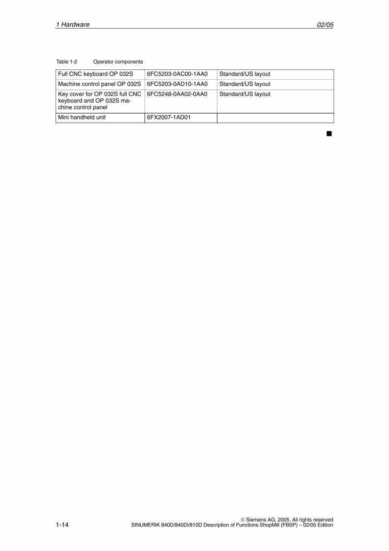
Table 1-2 Operator components
Full CNC keyboard OP 032S 6FC5203-0AC00-1AA0 Standard/US layout
Machine control panel OP 032S 6FC5203-0AD10-1AA0 Standard/US layout
Key cover for OP 032S full CNCkeyboard and OP 032S ma-chine control panel
6FC5248-0AA02-0AA0 Standard/US layout
Mini handheld unit 6FX2007-1AD01
�
1 Hardware
2-15 Siemens AG, 2005. All rights reservedSINUMERIK 840D/840Di/810D Description of Functions ShopMill (FBSP) – 02/05 Edition
Supplementary Conditions
Please observe the following supplementary conditions when using ShopMill:
� ShopMill is only executed in channel 1, mode group 1.
� The standard MPI bus addresses for the PCU 20, PCU 50, NC and PLCmust not be changed.
� Up to 5 axes plus a spindle are displayed on the ShopMill operator interface.
� The machine axes are assigned to fixed numbers (1=X, 2=Y, 3=Z).
� The spindle can be assigned to axis numbers 4, 5 or 6.
� ShopMill permits geometry axis exchange under the following conditions.There must always be three geometry axes.The names of the channel axes (MD 20080) and the geometry axes (MD 20060) must be different.Exchange of geometry axes can only be programmed for linear axes.Exchange of geometry axes is no possible for spindles.Only special axes known to ShopMill can be exchanged with geometryaxes.
� ShopMill only runs with tool management.The change point must always be spindle 1 (see configuration file). The loadpoint can be 1 or 2 (see MD 9673 $MM_CMM_TOOL_LOAD_STATION).
� With ShopMill Open you are not allowed to change the position of the follow-ing softkeys. This means that a specific task must always be assigned tothese functions in the REGIE.INI file.Task 0 (horizontal softkey 1): Machine operating areaTask 1 (horizontal softkey 2): Program Manager operating areaTask 2 (horizontal softkey 3): Program operating area Task 4 (horizontal softkey 5): Tools/Zero Offsets operating area
� You can use only one operator panel with ShopMill.
� Handheld programming unit (HHU) in addition to ShopMill on PCU50 onrequest only.
2

02/05
2-16 Siemens AG, 2005. All rights reserved
SINUMERIK 840D/840Di/810D Description of Functions ShopMill (FBSP) – 02/05 Edition
� It is not possible to use the HMI and the Windows screensaver at the sametime.References: /IAM/, IM2 Startup HMI Embedded
IM4 Startup HMI Advanced
2 Supplementary Conditions
3-17 Siemens AG, 2005. All rights reservedSINUMERIK 840D/840Di/810D Description of Functions ShopMill (FBSP) – 02/05 Edition
Reserved Functions
The following functions are utilized by ShopMill and must not be assigned forother purposes.
M functions with extended address:M[value]=100M[value]=101
M100 and M101 are defaults and must be changed where required.
1. Extended M address:DB82.DBB12 ext_m_cmd_1, standard value=100Display MD 9684 CMM_M_CODE_TOOL_BITS_1, standard value=100
2. Extended M address:DB82.DBB13 ext_m_cmd_2, standard value=101Display MD 9685 CMM_M_CODE_TOOL_BITS_2, standard value=101
The system cycle PROG_EVENT.SPF is used by the standard cycles and byShopMill.If you want to use the cycle PROG_EVENT.SPF for user functions too, it is ne-cessary to implement these user functions in the cycle CYCPE_US.SPF. Storecycle CYCPE_US.SPF in the user cycles or manufacturer cycles directory.
�
ExtendedM functions
PROG_EVENT
3

02/05
3-18 Siemens AG, 2005. All rights reserved
SINUMERIK 840D/840Di/810D Description of Functions ShopMill (FBSP) – 02/05 Edition
3 Reserved Functions
Notes
4-19 Siemens AG, 2005. All rights reservedSINUMERIK 840D/840Di/810D Description of Functions ShopMill (FBSP) – 02/05 Edition
Start-Up
4.1 Preconditions
For data transfer, you require:
� Hardware
– Programming device, e.g. a PG 740 or a PC with MPI module
– Cable for RS-232 PG/PC-NC (Order No.: 6FX2 002-1AA01-0BF0)
– Cable for MPI bus (Order No.: 6ES7 901-0BF00-0AA0)
– PCMCIA cardThis PCMCIA card can be used for the NCU/CCU or for the PCU 20.The PCMIA card is referred to by the following terms for easier distinc-tion in the start-up sections:
– for the NCU/CCU “NC card”
– for the PCU “PC card”
� Software
– SIMATIC Step 7, SW 4 and later (see SIMATIC catalog for order number)
– PCIN (See NC Z catalog for order number)
– SINUCOPY-FFS for NC card
The ShopMill software package to be installed comprises the following:
� ShopMill for PCU 20
� ShopMill for PCU 50
� Toolbox
� PLC Toolbox
The floppy disks are available on the ShopMill CD-ROM. The files must be cop-ied to the hard disk of a PC/PG. The procedure for further installation of the soft-ware on PCU and NC/PC is described in the following sections on installationand start-up.
The ShopMill CD-ROM also includes the NC standard software releases forSINUMERIK 810D/840D. These can be loaded onto a PCMIA card via SINU-COPY-FFS.
Note
The contents of the ShopMill CD ROM are listed in the file UPDATE_D.RTF (German) and UPDATE_E.RTF (English). A compatibility list is provided in file COMPAT.XLS.
Data transfer
ShopMillsoftware package
4
02/054.1 Preconditions
4-20 Siemens AG, 2005. All rights reserved
SINUMERIK 840D/840Di/810D Description of Functions ShopMill (FBSP) – 02/05 Edition
The CD contains directories with software that generates a 16-MB flash imagefor upgrading a PCU 20 / 16 MB. The software is provided in 6 languages (Ger-man, English, French, Italian, Spanish and Chinese).
The “Installation-disk” directory contains a “SETUP.EXE”. This starts the pro-gram with which you can create a flash image and modify the following parame-ters of the application:
– Select further languages,
– Change the MPI parameters (NETNAMES.INI),
– Adapt parameters for several operator panel fronts / NCUs,
– Set defaults for display machine data,
– Adapt and expand alarm text files,
– Transfer user-defined screens for PLC status,
– Add additional user screens.
The diskettes contain the software in 6 languages (German, English, French,Italian, Spanish, and Chinese).
The Toolbox contains the following ShopMill data:
– ShopMill machine data sets
– Cycles, definitions (macros, GUD) and examples
– Configuration files for the tool management function
The PLC Toolbox contains:
– ShopMill PLC program for 8x0D
– SINUMERIK add-on for STEP 7
– NCVar selector
In addition to the ShopMill PLC blocks, the ShopMill PLC program contains theblocks for the basic PLC program.Installation is menu-guided via an install shield.
NotePlease read the information in file SIEMENSD.WRI (German) or SIEMENSE.WRI (English) for the PLC toolbox.
ShopMill for PCU 20
ShopMill for PCU 50
Toolbox
PLC Toolbox
4 Start-Up
02/054.2 Initial start-up
4-21 Siemens AG, 2005. All rights reservedSINUMERIK 840D/840Di/810D Description of Functions ShopMill (FBSP) – 02/05 Edition
4.2 Initial start-up
4.2.1 Sequence
Before you begin with start-up please read about the supplementary conditionsand reserved functions.
Proceed as follows for installation and start-up:
1. Installation of ShopMill on PCU
2. NC start-up
3. PLC installation and start-up
4. Adapt display machine data
5. Install additional functions (optional)
6. Customize the operator interface (optional)
7. Run a test using the acceptance certificate
You can perform tool management start-up either together with NC and PLCstart-up or afterwards. If tool management has already been installed on themachine you only have to adapt the display machine data for the tool manage-ment (see Section 8.2 “Start-up sequence”).
4 Start-Up
02/054.2 Initial start-up
4-22 Siemens AG, 2005. All rights reserved
SINUMERIK 840D/840Di/810D Description of Functions ShopMill (FBSP) – 02/05 Edition
4.2.2 Installing ShopMill on PCU 20
When you install ShopMill on the PCU 20 the HMI Embedded software is auto-matically installed with it, that means, you do not have to install the HMI Em-bedded software on the PCU 20 separately.
ShopMill is installed on the PCU 20 by means of PC card. PC/PG with WindowsNT/2000/XP is required. To store the data on the installation CD and create a flash image for the PCcard, at least 30 to 40 MB of free memory must be available on the PC or PG.(And much more memory is required for logographic languages such as Chi-nese etc.!)
Proceed as follows to replace the software:
1. software replacement with standard configuration or Software replacement with changed configuration2. Generate image3. Transfer image to PC card4. Import image from PC card to PCU: – import complete new flash image – replace all files except for the configuration data – keep all all user files within one software version
Note
ShopMill uses the alarm texts and PLC messages of the CNC ISO operator interface. For more detailed information please refer to:References: /IAM/, Installation and Start-up Guide HMI 840D/840Di/810D
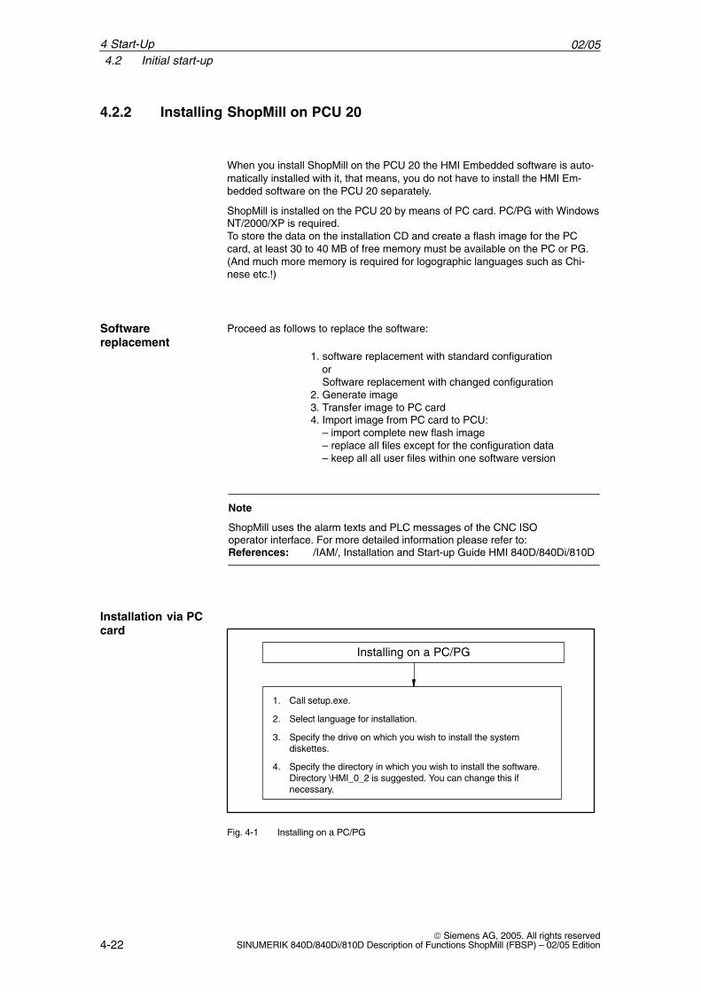
Installing on a PC/PG
1. Call setup.exe.
2. Select language for installation.
3. Specify the drive on which you wish to install the systemdiskettes.
4. Specify the directory in which you wish to install the software.Directory \HMI_0_2 is suggested. You can change this ifnecessary.
Fig. 4-1 Installing on a PC/PG
Softwarereplacement
Installation via PCcard
4 Start-Up
02/054.2 Initial start-up
4-23 Siemens AG, 2005. All rights reservedSINUMERIK 840D/840Di/810D Description of Functions ShopMill (FBSP) – 02/05 Edition
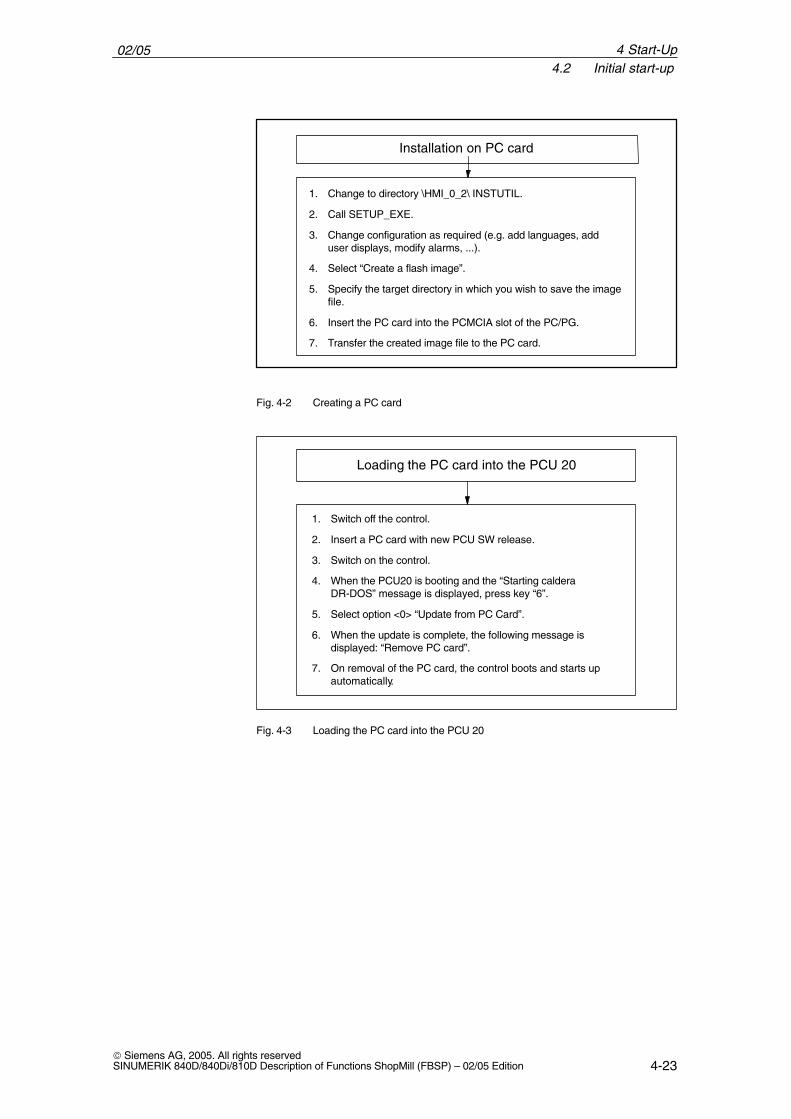
1. Change to directory \HMI_0_2\ INSTUTIL.
2. Call SETUP_EXE.
3. Change configuration as required (e.g. add languages, adduser displays, modify alarms, ...).
4. Select “Create a flash image”.
5. Specify the target directory in which you wish to save the imagefile.
6. Insert the PC card into the PCMCIA slot of the PC/PG.
7. Transfer the created image file to the PC card.
Installation on PC card
Fig. 4-2 Creating a PC card
1. Switch off the control.
2. Insert a PC card with new PCU SW release.
3. Switch on the control.
4. When the PCU20 is booting and the “Starting calderaDR-DOS” message is displayed, press key “6”.
5. Select option <0> “Update from PC Card”.
6. When the update is complete, the following message isdisplayed: “Remove PC card”.
7. On removal of the PC card, the control boots and starts upautomatically.
Loading the PC card into the PCU 20
Fig. 4-3 Loading the PC card into the PCU 20
4 Start-Up
02/054.2 Initial start-up
4-24 Siemens AG, 2005. All rights reserved
SINUMERIK 840D/840Di/810D Description of Functions ShopMill (FBSP) – 02/05 Edition
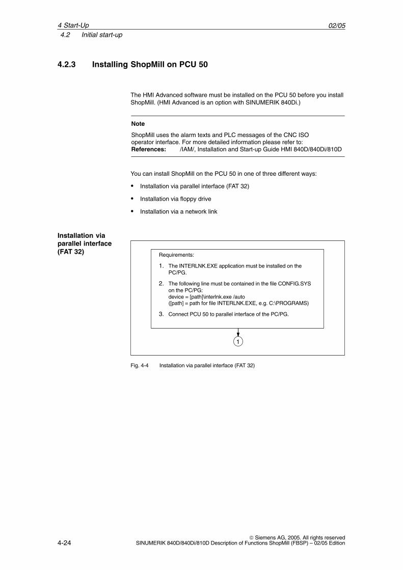
4.2.3 Installing ShopMill on PCU 50
The HMI Advanced software must be installed on the PCU 50 before you installShopMill. (HMI Advanced is an option with SINUMERIK 840Di.)
Note
ShopMill uses the alarm texts and PLC messages of the CNC ISO operator interface. For more detailed information please refer to:References: /IAM/, Installation and Start-up Guide HMI 840D/840Di/810D
You can install ShopMill on the PCU 50 in one of three different ways:
� Installation via parallel interface (FAT 32)
� Installation via floppy drive
� Installation via a network link
Requirements:
1. The INTERLNK.EXE application must be installed on thePC/PG.
2. The following line must be contained in the file CONFIG.SYSon the PC/PG:device = [path]\interlnk.exe /auto([path] = path for file INTERLNK.EXE, e.g. C:\PROGRAMS)
3. Connect PCU 50 to parallel interface of the PC/PG.
1
Fig. 4-4 Installation via parallel interface (FAT 32)
Installation viaparallel interface(FAT 32)
4 Start-Up
02/054.2 Initial start-up
4-25 Siemens AG, 2005. All rights reservedSINUMERIK 840D/840Di/810D Description of Functions ShopMill (FBSP) – 02/05 Edition
1
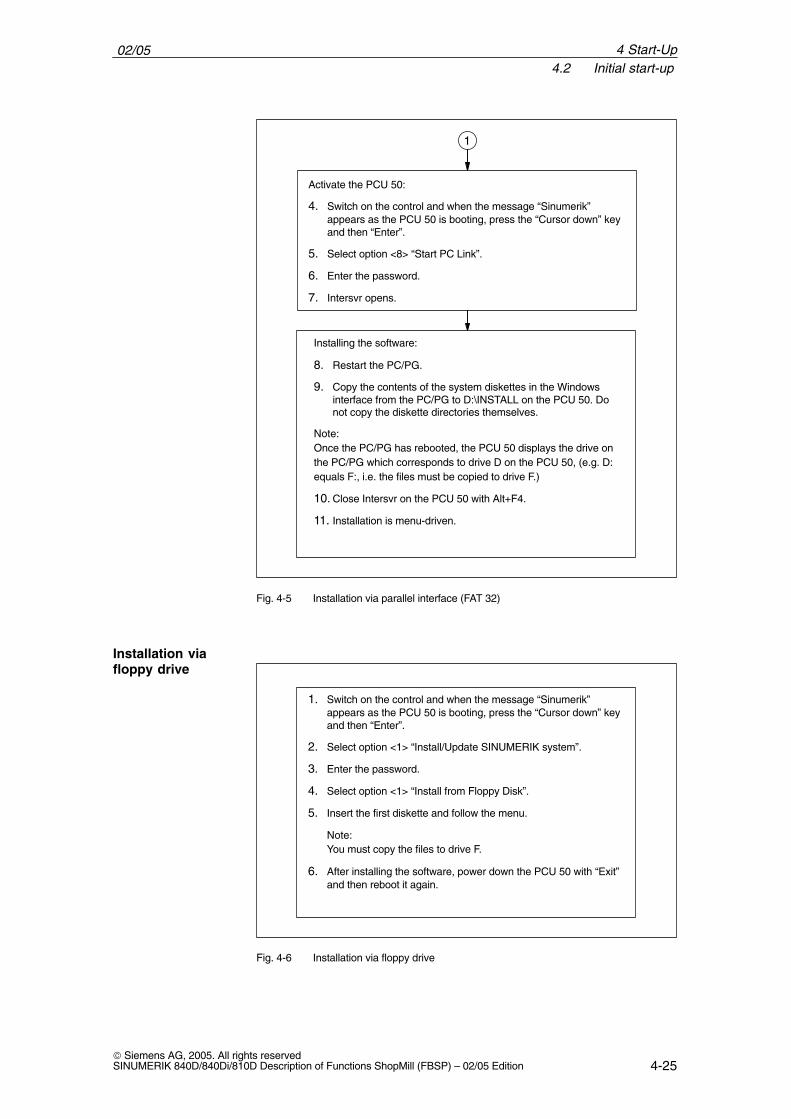
Activate the PCU 50:
4. Switch on the control and when the message “Sinumerik”appears as the PCU 50 is booting, press the “Cursor down” keyand then “Enter”.
5. Select option <8> “Start PC Link”.
6. Enter the password.
7. Intersvr opens.
Installing the software:
8. Restart the PC/PG.
9. Copy the contents of the system diskettes in the Windowsinterface from the PC/PG to D:\INSTALL on the PCU 50. Donot copy the diskette directories themselves.
Note:Once the PC/PG has rebooted, the PCU 50 displays the drive onthe PC/PG which corresponds to drive D on the PCU 50, (e.g. D:equals F:, i.e. the files must be copied to drive F.)
10. Close Intersvr on the PCU 50 with Alt+F4.
11. Installation is menu-driven.
Fig. 4-5 Installation via parallel interface (FAT 32)
1. Switch on the control and when the message “Sinumerik”appears as the PCU 50 is booting, press the “Cursor down” keyand then “Enter”.
2. Select option <1> “Install/Update SINUMERIK system”.
3. Enter the password.
4. Select option <1> “Install from Floppy Disk”.
5. Insert the first diskette and follow the menu.
Note:You must copy the files to drive F.
6. After installing the software, power down the PCU 50 with “Exit”and then reboot it again.
Fig. 4-6 Installation via floppy drive
Installation viafloppy drive
4 Start-Up
02/054.2 Initial start-up
4-26 Siemens AG, 2005. All rights reserved
SINUMERIK 840D/840Di/810D Description of Functions ShopMill (FBSP) – 02/05 Edition
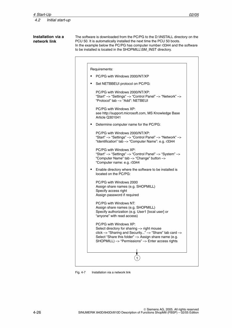
The software is downloaded from the PC/PG to the D:\INSTALL directory on thePCU 50. It is automatically installed the next time the PCU 50 boots.In the example below the PC/PG has computer number r3344 and the softwareto be installed is located in the SHOPMILL\SM_INST directory.
1
Requirements:
� PC/PG with Windows 2000/NT/XP
� Set NETBBEUI protocol on PC/PG:
PC/PG with Windows 2000/NT/XP:“Start” –> “Settings” –> “Control Panel” –> “Network” –>“Protocol” tab –> “Add”: NETBEUI
PC/PG with Windows XP:see http://support.microsoft.com, MS Knowledge BaseArticle Q301041
� Determine computer name for the PC/PG:
PC/PG with Windows 2000/NT/XP:“Start” –> “Settings” –> “Control Panel” –> “Network” –>“Identification” tab –> “Computer Name”: e.g. r3344
PC/PG with Windows XP:“Start” –> “Settings” –> “Control Panel” –> “System” –>“Computer Name” tab –> “Change” button –>“Computer name: e.g. r3344
� Enable directory where the software to be installed islocated on the PC/PG:
PC/PG with Windows 2000Assign share names (e.g. SHOPMILL)Specify access rightAssign password if required
PC/PG with Windows NT:Assign share names (e.g. SHOPMILL)Specify authorization (e.g. User1 [local user] or“anyone” with read access)
PC/PG with Windows XP:Select directory for sharing –> right mouse click –> “Sharing and Security...” –> “Share” tab card –>Select “Share this folder” –> Assign share name (e.g.SHOPMILL) –> “Permissions” –> Enter access rights
Fig. 4-7 Installation via a network link
Installation via anetwork link
4 Start-Up
02/054.2 Initial start-up
4-27 Siemens AG, 2005. All rights reservedSINUMERIK 840D/840Di/810D Description of Functions ShopMill (FBSP) – 02/05 Edition
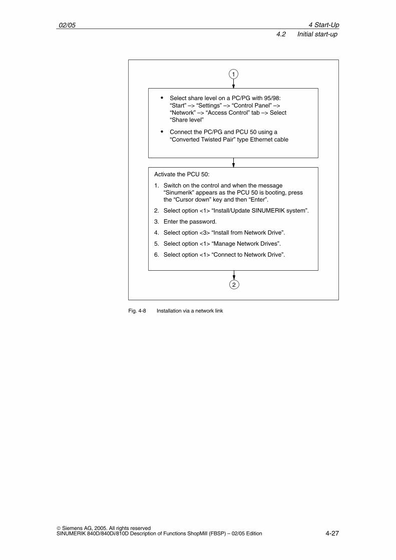
Activate the PCU 50:
1. Switch on the control and when the message“Sinumerik” appears as the PCU 50 is booting, pressthe “Cursor down” key and then “Enter”.
2. Select option <1> “Install/Update SINUMERIK system”.
3. Enter the password.
4. Select option <3> “Install from Network Drive”.
5. Select option <1> “Manage Network Drives”.
6. Select option <1> “Connect to Network Drive”.
2
� Select share level on a PC/PG with 95/98: “Start” –> “Settings” –> “Control Panel” –>“Network” –> “Access Control” tab –> Select“Share level”
� Connect the PC/PG and PCU 50 using a“Converted Twisted Pair” type Ethernet cable
1
Fig. 4-8 Installation via a network link
4 Start-Up
02/054.2 Initial start-up
4-28 Siemens AG, 2005. All rights reserved
SINUMERIK 840D/840Di/810D Description of Functions ShopMill (FBSP) – 02/05 Edition
2
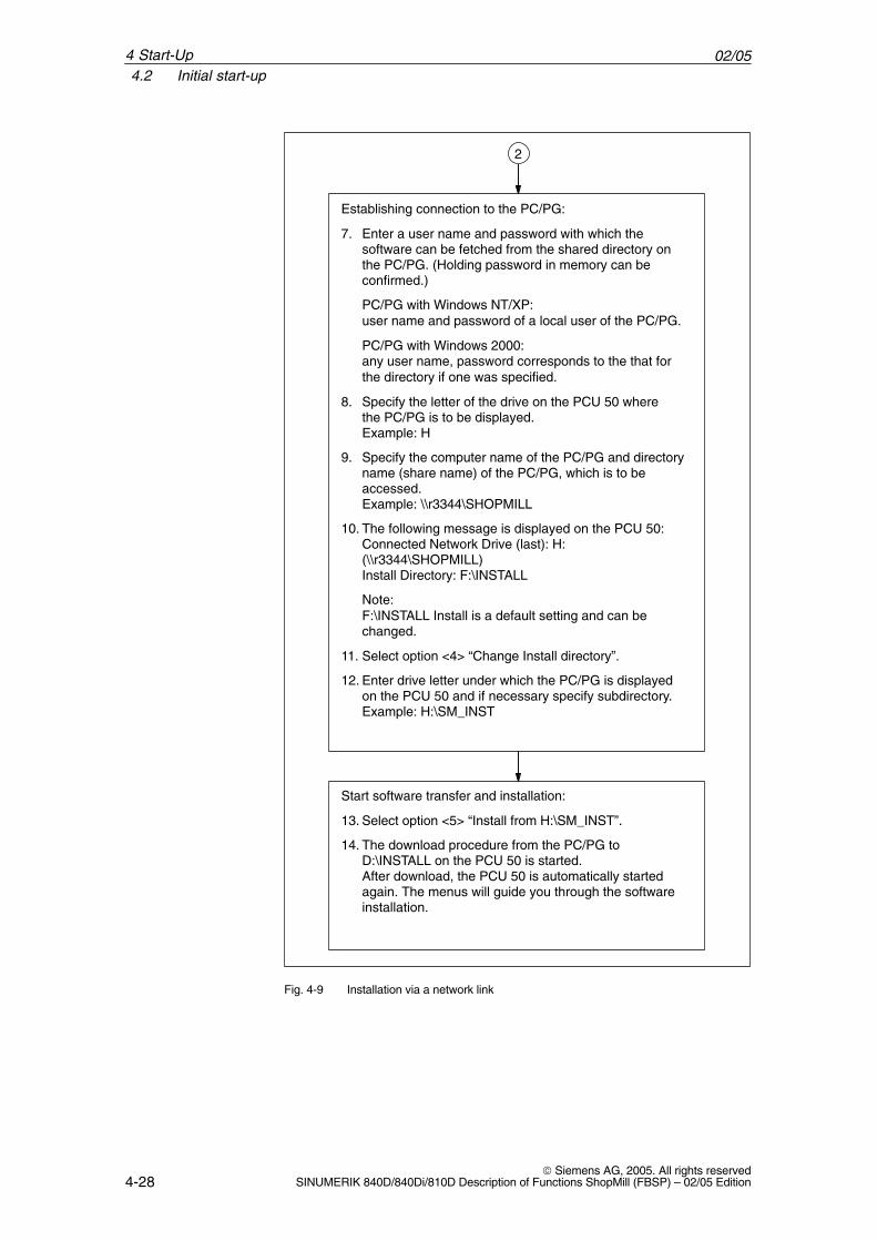
Establishing connection to the PC/PG:
7. Enter a user name and password with which thesoftware can be fetched from the shared directory onthe PC/PG. (Holding password in memory can beconfirmed.)
PC/PG with Windows NT/XP:user name and password of a local user of the PC/PG.
PC/PG with Windows 2000:any user name, password corresponds to the that forthe directory if one was specified.
8. Specify the letter of the drive on the PCU 50 where the PC/PG is to be displayed.Example: H
9. Specify the computer name of the PC/PG and directoryname (share name) of the PC/PG, which is to beaccessed.Example: \\r3344\SHOPMILL
10. The following message is displayed on the PCU 50:Connected Network Drive (last): H:(\\r3344\SHOPMILL)Install Directory: F:\INSTALL
Note:F:\INSTALL Install is a default setting and can bechanged.
11. Select option <4> “Change Install directory”.
12. Enter drive letter under which the PC/PG is displayedon the PCU 50 and if necessary specify subdirectory.Example: H:\SM_INST
Start software transfer and installation:
13. Select option <5> “Install from H:\SM_INST”.
14. The download procedure from the PC/PG toD:\INSTALL on the PCU 50 is started.After download, the PCU 50 is automatically startedagain. The menus will guide you through the softwareinstallation.
Fig. 4-9 Installation via a network link
4 Start-Up
02/054.2 Initial start-up
4-29 Siemens AG, 2005. All rights reservedSINUMERIK 840D/840Di/810D Description of Functions ShopMill (FBSP) – 02/05 Edition
The ShopMill software package includes 6 languages (German, English,French, Italian, Spanish and Chinese). The foreground language is always German. To select the background language, press the softkeys “MMC” and “Languages”in succession in the “Start-up” operating area on the CNC ISO operator inter-face and mark the desired language. Use the “Change Language” softkey to toggle between the foreground andbackground language in the “Start-up” area of the CNC ISO operator interface.
Languages
4 Start-Up
02/054.2 Initial start-up
4-30 Siemens AG, 2005. All rights reserved
SINUMERIK 840D/840Di/810D Description of Functions ShopMill (FBSP) – 02/05 Edition
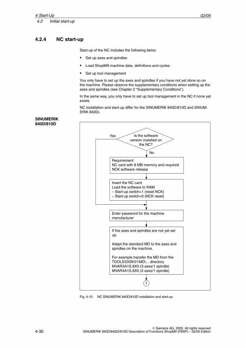
4.2.4 NC start-up
Start-up of the NC includes the following items:
� Set up axes and spindles
� Load ShopMill machine data, definitions and cycles
� Set up tool management
You only have to set up the axes and spindles if you have not yet done so onthe machine. Please observe the supplementary conditions when setting up theaxes and spindles (see Chapter 2 “Supplementary Conditions”).
In the same way, you only have to set up tool management in the NC if none yetexists.
NC installation and start-up differ for the SINUMERIK 840D/810D and SINUM-ERIK 840Di.
Requirement:NC card with 8 MB memory and requiredNCK software release
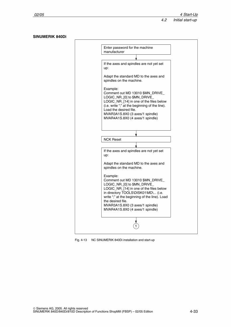
Enter password for the machine manufacturer
If the axes and spindles are not yet setup:
Adapt the standard MD to the axes andspindles on the machine.
For example transfer the MD from theTOOLS\DISK01\MD\... directoryMVAR3A1S.8X0 (3 axes/1 spindle)MVAR4A1S.8X0 (4 axes/1 spindle)
Is the softwareversion installed on
the NC?
Yes
No
Insert the NC cardLoad the software to RAM– Start-up switch=1 (reset NCK)– Start-up switch=0 (NCK reset)
1
Fig. 4-10 NC SINUMERIK 840D/810D installation and start-up
SINUMERIK840D/810D
4 Start-Up
02/054.2 Initial start-up
4-31 Siemens AG, 2005. All rights reservedSINUMERIK 840D/840Di/810D Description of Functions ShopMill (FBSP) – 02/05 Edition
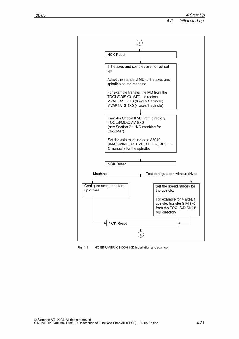
Transfer ShopMill MD from directoryTOOLS\MD\CMM.8X0(see Section 7.1 “NC machine forShopMill”)
Set the axis machine data 35040$MA_SPIND_ACTIVE_AFTER_RESET=2 manually for the spindle.
1
Set the speed ranges forthe spindle.
For example for 4 axes/1spindle, transfer SIM.8x0from the TOOLS\DISK01\MD directory.
Configure axes and startup drives
NCK Reset
Test configuration without drivesMachine
NCK Reset
If the axes and spindles are not yet setup:
Adapt the standard MD to the axes andspindles on the machine.
For example transfer the MD from theTOOLS\DISK01\MD\... directoryMVAR3A1S.8X0 (3 axes/1 spindle)MVAR4A1S.8X0 (4 axes/1 spindle)
2
NCK Reset
Fig. 4-11 NC SINUMERIK 840D/810D installation and start-up
4 Start-Up
02/054.2 Initial start-up
4-32 Siemens AG, 2005. All rights reserved
SINUMERIK 840D/840Di/810D Description of Functions ShopMill (FBSP) – 02/05 Edition
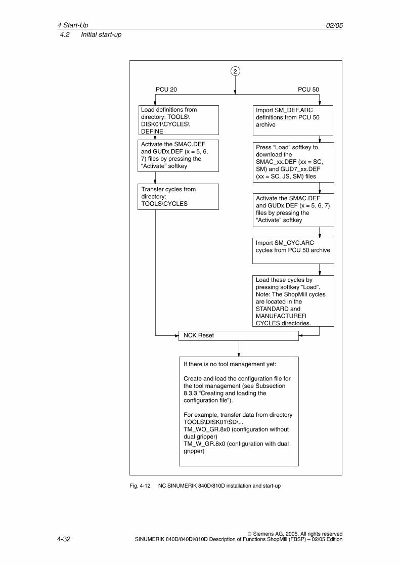
NCK Reset
If there is no tool management yet:
Create and load the configuration file forthe tool management (see Subsection8.3.3 “Creating and loading theconfiguration file”).
For example, transfer data from directoryTOOLS\DISK01\SD\...TM_WO_GR.8x0 (configuration withoutdual gripper)TM_W_GR.8x0 (configuration with dualgripper)
Import SM_DEF.ARCdefinitions from PCU 50archive
Load definitions fromdirectory: TOOLS\DISK01\CYCLES\DEFINE
PCU 50PCU 20
Transfer cycles fromdirectory:TOOLS\CYCLES
Import SM_CYC.ARCcycles from PCU 50 archive
Press “Load” softkey todownload theSMAC_xx.DEF (xx = SC,SM) and GUD7_xx.DEF(xx = SC, JS, SM) files
Activate the SMAC.DEFand GUDx.DEF (x = 5, 6,7) files by pressing the“Activate” softkey
2
Activate the SMAC.DEFand GUDx.DEF (x = 5, 6, 7)files by pressing the“Activate” softkey
Load these cycles bypressing softkey “Load”.Note: The ShopMill cyclesare located in theSTANDARD andMANUFACTURERCYCLES directories.
Fig. 4-12 NC SINUMERIK 840D/810D installation and start-up
4 Start-Up
02/054.2 Initial start-up
4-33 Siemens AG, 2005. All rights reservedSINUMERIK 840D/840Di/810D Description of Functions ShopMill (FBSP) – 02/05 Edition
NCK Reset
Enter password for the machine manufacturer
If the axes and spindles are not yet setup:
Adapt the standard MD to the axes andspindles on the machine.
Example:Comment out MD 13010 $MN_DRIVE_LOGIC_NR_[0] to $MN_DRIVE_LOGIC_NR_[14] in one of the files below(i.e. write “;” at the beginning of the line).Load the desired file. MVAR3A1S.8X0 (3 axes/1 spindle)MVAR4A1S.8X0 (4 axes/1 spindle)
1
If the axes and spindles are not yet setup:
Adapt the standard MD to the axes andspindles on the machine.
Example:Comment out MD 13010 $MN_DRIVE_LOGIC_NR_[0] to $MN_DRIVE_LOGIC_NR_[14] in one of the files belowin directory TOOLS\DISK01\MD\... (i.e.write “;” at the beginning of the line). Loadthe desired file. MVAR3A1S.8X0 (3 axes/1 spindle)MVAR4A1S.8X0 (4 axes/1 spindle)
Fig. 4-13 NC SINUMERIK 840Di installation and start-up
SINUMERIK 840Di
4 Start-Up
02/054.2 Initial start-up
4-34 Siemens AG, 2005. All rights reserved
SINUMERIK 840D/840Di/810D Description of Functions ShopMill (FBSP) – 02/05 Edition
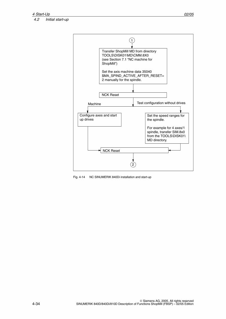
Transfer ShopMill MD from directoryTOOLS\DISK01\MD\CMM.8X0(see Section 7.1 “NC machine forShopMill”)
Set the axis machine data 35040$MA_SPIND_ACTIVE_AFTER_RESET=2 manually for the spindle.
1
Set the speed ranges forthe spindle.
For example for 4 axes/1spindle, transfer SIM.8x0from the TOOLS\DISK01\MD directory.
Configure axes and startup drives
NCK Reset
Test configuration without drivesMachine
NCK Reset
2
Fig. 4-14 NC SINUMERIK 840Di installation and start-up
4 Start-Up
02/054.2 Initial start-up
4-35 Siemens AG, 2005. All rights reservedSINUMERIK 840D/840Di/810D Description of Functions ShopMill (FBSP) – 02/05 Edition
NCK Reset
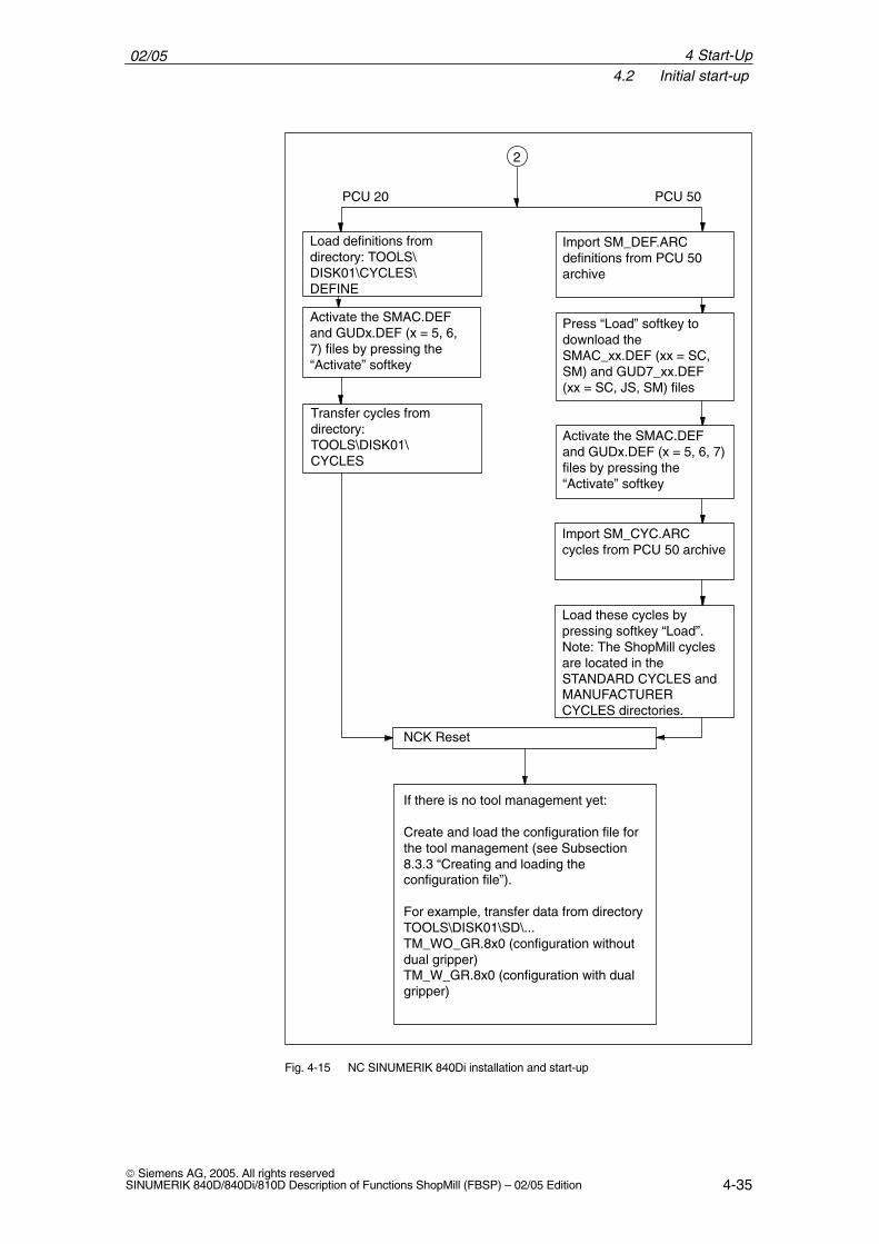
If there is no tool management yet:
Create and load the configuration file forthe tool management (see Subsection8.3.3 “Creating and loading theconfiguration file”).
For example, transfer data from directoryTOOLS\DISK01\SD\...TM_WO_GR.8x0 (configuration withoutdual gripper)TM_W_GR.8x0 (configuration with dualgripper)
Import SM_DEF.ARCdefinitions from PCU 50archive
Load definitions fromdirectory: TOOLS\DISK01\CYCLES\DEFINE
PCU 50PCU 20
Transfer cycles fromdirectory: TOOLS\DISK01\CYCLES
Import SM_CYC.ARCcycles from PCU 50 archive
Press “Load” softkey todownload theSMAC_xx.DEF (xx = SC,SM) and GUD7_xx.DEF(xx = SC, JS, SM) files
Activate the SMAC.DEFand GUDx.DEF (x = 5, 6,7) files by pressing the“Activate” softkey
2
Activate the SMAC.DEFand GUDx.DEF (x = 5, 6, 7)files by pressing the“Activate” softkey
Load these cycles bypressing softkey “Load”.Note: The ShopMill cyclesare located in theSTANDARD CYCLES andMANUFACTURERCYCLES directories.
Fig. 4-15 NC SINUMERIK 840Di installation and start-up
4 Start-Up
02/054.2 Initial start-up
4-36 Siemens AG, 2005. All rights reserved
SINUMERIK 840D/840Di/810D Description of Functions ShopMill (FBSP) – 02/05 Edition
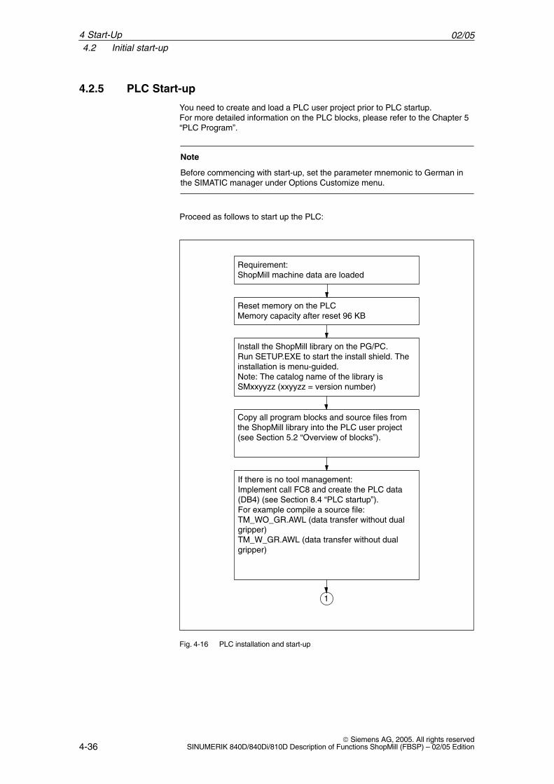
4.2.5 PLC Start-up
You need to create and load a PLC user project prior to PLC startup.For more detailed information on the PLC blocks, please refer to the Chapter 5“PLC Program”.
Note
Before commencing with start-up, set the parameter mnemonic to German inthe SIMATIC manager under Options Customize menu.
Proceed as follows to start up the PLC:
Reset memory on the PLCMemory capacity after reset 96 KB
Copy all program blocks and source files fromthe ShopMill library into the PLC user project(see Section 5.2 “Overview of blocks”).
Install the ShopMill library on the PG/PC. Run SETUP.EXE to start the install shield. Theinstallation is menu-guided.Note: The catalog name of the library isSMxxyyzz (xxyyzz = version number)
Requirement:ShopMill machine data are loaded
If there is no tool management:Implement call FC8 and create the PLC data(DB4) (see Section 8.4 “PLC startup”). For example compile a source file:TM_WO_GR.AWL (data transfer without dualgripper)TM_W_GR.AWL (data transfer without dualgripper)
1
Fig. 4-16 PLC installation and start-up
4 Start-Up

02/054.2 Initial start-up
4-37 Siemens AG, 2005. All rights reservedSINUMERIK 840D/840Di/810D Description of Functions ShopMill (FBSP) – 02/05 Edition
Download PLC user project to PLC
Call ShopMill PLC program in OB1 and OB100(see Section 5.6 “OB1 and OB100”).
For example compile a source file:� GPOB810D.AWL (SINUMERIK 810D)� GPOB840D.AWL (SINUMERIK 840D/840Di)
1
Assign parameters to ShopMill interface DB82in the PLC user program (see Section 5.4“ShopMill interface DB82”).
For example, compile a source file:
� FC90_OP32S.AWL� FC90_MSTT19.AWL
Note: The generated blocks are stored in theuser area and must be adapted to match themachine.
Fig. 4-17 PLC installation and start-up
4.2.6 Display machine data
Once you have completed installation of ShopMill on the PCU and start-up ofthe NC and the PLC you must adapt the display machine data. The display machine data are listed in Section 7.2 “Display Machine Data forShopMill”.
Note
You can copy your adapted display machine data from a PCU20 to a PCU50.For more detailed information please refer to:References: /IAM/, IM4 Installation and Start-up Guide HMI Advanced
4 Start-Up

02/054.2 Initial start-up
4-38 Siemens AG, 2005. All rights reserved
SINUMERIK 840D/840Di/810D Description of Functions ShopMill (FBSP) – 02/05 Edition
4.2.7 Acceptance report
The acceptance certificate can be used to test the installed ShopMill functionsonce the ShopMill installation and startup have been completed.The acceptance certificate is included on the ShopMill CD-ROM.
4 Start-Up
02/054.4 Upgrade
4-39 Siemens AG, 2005. All rights reservedSINUMERIK 840D/840Di/810D Description of Functions ShopMill (FBSP) – 02/05 Edition
4.3 Series start-up
Series startup is used to install the software on multiple machines.When setting up multiple machines, a standard software installation is per-formed on the first one (see Section 4.2 “First start-up”) and then an NC andPLC archive are created and read into the other machines.
When reading in these series start-up archives, you can choose between fourdifferent storage media:
� PGThe start-up archives are saved on a programming device connected via theRS-232 interface. Please also observe the instructions for series startup inthe manual:References: /IAD/, Installation and Start-Up Guide SINUMERIK 840D
/IAC/, Installation and Start-Up Guide SINUMERIK 810D /HBI/, SINUMERIK 840Di Manual
� NC cardThe free memory (approx. 2 MB) on the NC card (PCMCIA card) can beused to save the start-up archive it contains.
� Hard disk (PCU 50 only)The start-up archives are saved to hard disk.
� Diskette (PCU 50 only)The start-up archives are saved to diskette.
The exact operating sequence is described in:References: /BEM/, Operator’s Guide HMI Embedded or
/BAD/, Operator’s Guide HMI Advanced
Note
When you create an archive, you can save the NC and PLC separately ortogether.
When reading in the archive files, the NC archive must be read in first, then it isnecessary to perform an NCK reset and, if necessary, a general PLC reset.Then the PLC archive is read in. Ensure that all the data in the NC or PLC isdeleted and replaced with the data from the archive.
4.4 Upgrade
You will find information about upgrading ShopMill in file UPDATE_x.RTF.
�
4 Start-Up
02/054.4 Upgrade
4-40 Siemens AG, 2005. All rights reserved
SINUMERIK 840D/840Di/810D Description of Functions ShopMill (FBSP) – 02/05 Edition
4 Start-Up
Notes
5-41 Siemens AG, 2005. All rights reservedSINUMERIK 840D/840Di/810D Description of Functions ShopMill (FBSP) – 02/05 Edition
PLC Program
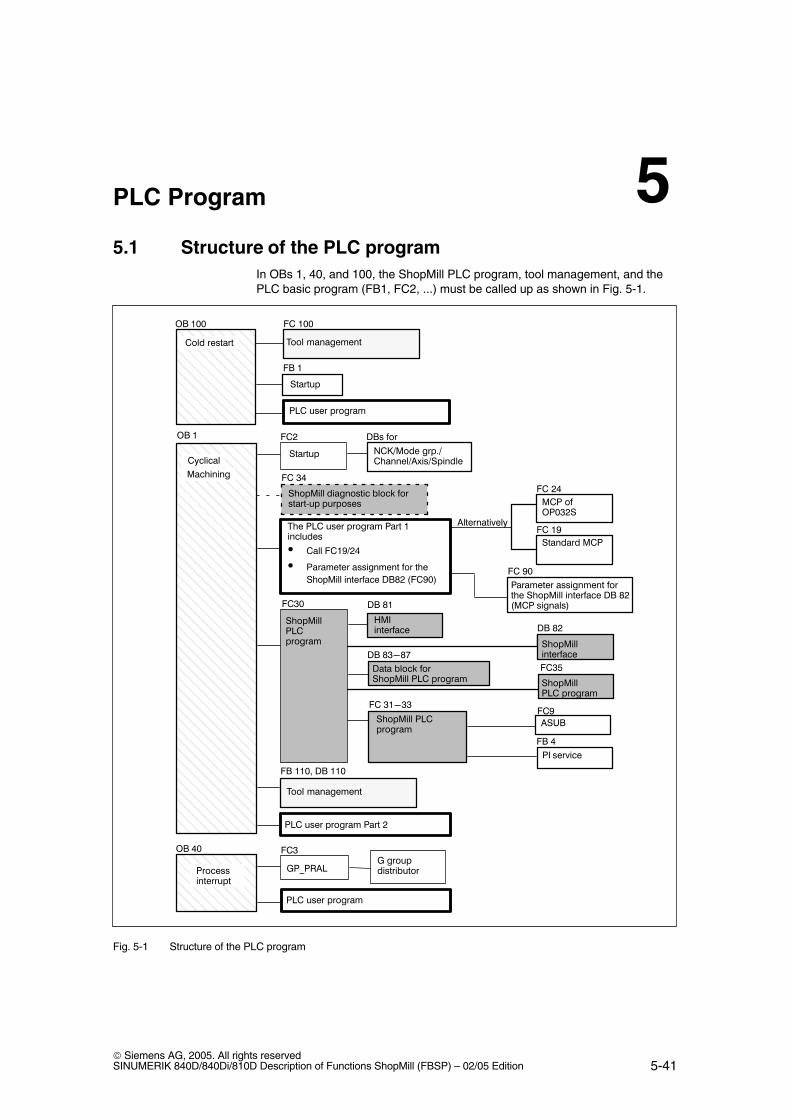
5.1 Structure of the PLC programIn OBs 1, 40, and 100, the ShopMill PLC program, tool management, and thePLC basic program (FB1, FC2, ...) must be called up as shown in Fig. 5-1.
ÇÇÇÇÇÇÇÇÇÇÇÇÇÇÇÇÇÇÇÇÇÇÇÇÇÇÇÇÇÇÇÇÇÇÇÇÇÇÇÇÇÇÇÇÇÇÇÇÇÇÇÇÇÇÇÇÇÇÇÇÇÇÇÇÇÇÇÇÇÇÇÇÇÇÇÇÇÇÇÇÇÇÇÇÇÇÇÇÇÇÇÇÇÇÇÇÇÇÇÇÇÇÇÇÇÇÇÇÇÇÇÇÇÇÇÇÇÇÇÇ
ÎÎÎÎÎÎ
������� ������
ÎÎÎ� ������ÎÎÎÎÎÎÎÎ
���������
����
�������
�����
�������� �������������������������
��� ��� ������!
ÇÇÇÇÇÇÇÇÇÇÇÇÇÇÇÇÇÇÇÇÇÇÇÇÇ
��� ��� ������! ��� "
��� ��� ������!
#$ %&
#$ '
#$ '&&
($ '
(�)
(�"
(�)&
�����������������!
��*����+���
,$ -'
,$ -"
,�� .���/ +�� �������� ��� ������!
,$ -)0-1
�������� ��� ������!
(�)2
�������� ��� ������!
(� )'0))
ÎÎÎÎÎÎÎÎ
���� �����
�������� ����+���
,$� +��
��3$
(�4
5�� ��� ��� ������! ��� '�������
� Call FC19/24
� Parameter assignment for theShopMill interface DB82 (FC90)
������� ���
(� '4
��� �+#�&)"�
(� "%
�������6��
�* ���6���
($ %
5��� !�����!��
($ ''&7 ,$ ''&
(� '&&
5��� !�����!��
����
�������� ��������� .���/ +�����8� �������
(� )%
� ���������.��
����!��� ������!�� +���� �������� ����+��� ,$ -"9��� �������:
(� 4&
Fig. 5-1 Structure of the PLC program
5

02/055.2 Overview of blocks
5-42 Siemens AG, 2005. All rights reserved
SINUMERIK 840D/840Di/810D Description of Functions ShopMill (FBSP) – 02/05 Edition
5.2 Overview of blocks
The blocks used by ShopMill are listed below. These blocks must not bechanged and must be used. A precise description of the blocks is given in thefollowing sections.
Table 5-1 ShopMill blocks
Block Comment
FC30 ShopMill PLC programBlock called in OB 1.
FC 31–33 ShopTurn PLC programBlocks only loaded.
FC 34 Diagnostics block for monitoring the standard interface sig-nals that are written by the ShopMill PLC program. Blockcan be called in OB1 for diagnostic purposes.
FC 35 ShopMill PLC programBlocks only loaded.
FB 20 HiGraphErrEmitterFB block for errors and monitoring time.Block only loaded.
DB 81 HMI interface
DB 82 ShopMill interface
DB 83–87 Data blocks for ShopMill PLC program
ShopMill also includes several source files for blocks as examples. You canadapt and compile these source files.Alternatively you can also use your own blocks.
Table 5-2 Example source files
Source Block Comment
GPOB810D.AWLGPOB840D.AWL
OB1,OB40,OB100
Example blocks for the OB
FC90_MSTT19.AWLFC90_OP032S.AWL
FC 90 Sample block for supplying ShopMill interface DB82Block can be called with OB1.
TM_W_GR.AWLTM_WO_GR.AWL
FC 100,
FB 110,
DB 110
Sample block for configuring tool management.Block is called in OB100.Sample block for data transfer of the tool manage-ment. Block is called in OB1.Instance data block for FB 110
A precise description of the example blocks is given in the following chapters.The example blocks for tool management are described in Chapter 9 “Tool Ma-nagement”.
5 PLC Program
02/055.3 ShopMill PLC program
5-43 Siemens AG, 2005. All rights reservedSINUMERIK 840D/840Di/810D Description of Functions ShopMill (FBSP) – 02/05 Edition
5.3 ShopMill PLC program
The ShopMill PLC program contains the following blocks:
The function blocks FC 30–35 control the machine control panel functionality inDB 82 and HMI functionality in DB 81.
You must not change the numbers of function blocks FC 30 to 35. This meansthat you have to change any blocks that were assigned these numbers by thePLC user program.
ShopMill is much more than just an operator interface consisting of screenforms and images; in addition, it offers a complete operator system providing theuser with the necessary functions for each control state. For example, the Shop-Mill operating mode “Manual” is not identical to the NCK operating mode “JOG”.
For example, in order to execute the functions “Zero workpiece”, “Measure tool”,“Position”, etc. in “Manual” mode, ShopMill switches automatically to NC operat-ing mode “Automatic” at NC start and back again to “JOG” mode at the end ofthe function. Thus from the operator’s point of view, the manual functions areindependent of the control operating modes of the NC.
This functionality, which is continued in the ShopMill “Automatic” mode, is imple-mented in the PCU (ShopMill operator interface) and in the PLC (ShopMill PLCprogram FC 30).
Function block FB 20 collects alarms issued by ShopMill FC 30–33 and dis-plays them.
Function block FB 20 is loaded only. It must be available in the automation sy-stem (AS) during operation. A block call is not required.
Data blocks DB 81 and DB 82 form the HMI/ShopMill interface; data blocks83–87 supply the ShopMill PLC program.
You must not change the numbers of function blocks FC 81 to 87. This meansthat you have to change any blocks that were assigned these numbers by thePLC user program.
FC 30...35
FB 20
DB 81...87
5 PLC Program
02/055.4 ShopMill interface DB82
5-44 Siemens AG, 2005. All rights reserved
SINUMERIK 840D/840Di/810D Description of Functions ShopMill (FBSP) – 02/05 Edition
5.4 ShopMill interface DB82
The ShopMill PLC program requires an interface to the PLC user program inaddition to the internal interfaces to the user interface or to the NC interface.This is implemented in ShopMill interface DB82.
The machine control panel’s signals (ShopMill operating modes Reset, Start,Stop, Spindle clockwise/counterclockwise/off, etc.) must be input into this inter-face by PLC user program part 1. The ShopMill PLC program then carries outthe relevant actions and returns the current status to DB82. This can then beassessed by PLC user program part 2.
Please refer to Chapter 6 “Signal Description” for a detailed description of all thesignals of ShopMill interface DB82.
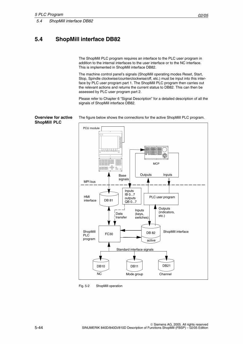
The figure below shows the connections for the active ShopMill PLC program.
InputsOutputs
PLC user programDB 81
HMIinterface
ShopMillPLCprogram
DB 82FC30
DB10 DB11 DB21
NC Mode group Channel
ShopMill interface
Inputs(keys,switches)
Outputs(indicators,etc.)
MPI bus
Standard interface signals
active
��3 !����
MCP
InputsIB 0...7outputsQB 0...7
Basesignals
Datatransfer
Fig. 5-2 ShopMill operation
Overview for activeShopMill PLC
5 PLC Program
02/055.4 ShopMill interface DB82
5-45 Siemens AG, 2005. All rights reservedSINUMERIK 840D/840Di/810D Description of Functions ShopMill (FBSP) – 02/05 Edition
A list of the standard interface signals that are affected by ShopMill PLC pro-gram FC 30 is given in Section 5.5 “Standard Interface Signals for/from Shop-Mill”.
Note
When the ShopMill operator interface is active, the ShopMill PLC program isalso activated. This is displayed by the output signal DB82 DBX36.0“cmm_plc_activ”=1. The ShopMill interface DB82 must be assignedparameters by the PLC user program. The data transfer of the base signalsfrom IB0...7/QB0...7 is set via the DB82 DBB0 signal “transfer_base_sig”. Thedefault interface signals allocated by the ShopMill PLC program must not beoverwritten by the user.
5 PLC Program
02/055.5 Standard interface signals for/from ShopMill
5-46 Siemens AG, 2005. All rights reserved
SINUMERIK 840D/840Di/810D Description of Functions ShopMill (FBSP) – 02/05 Edition
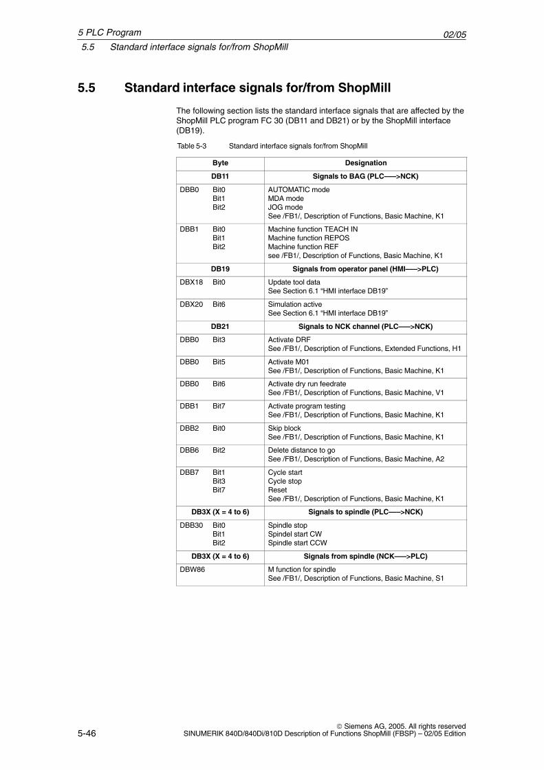
5.5 Standard interface signals for/from ShopMill
The following section lists the standard interface signals that are affected by theShopMill PLC program FC 30 (DB11 and DB21) or by the ShopMill interface(DB19).
Table 5-3 Standard interface signals for/from ShopMill
Byte Designation
DB11 Signals to BAG (PLC–––>NCK)
DBB0 Bit0Bit1Bit2
AUTOMATIC modeMDA modeJOG modeSee /FB1/, Description of Functions, Basic Machine, K1
DBB1 Bit0Bit1Bit2
Machine function TEACH INMachine function REPOSMachine function REFsee /FB1/, Description of Functions, Basic Machine, K1
DB19 Signals from operator panel (HMI–––>PLC)
DBX18 Bit0 Update tool dataSee Section 6.1 “HMI interface DB19”
DBX20 Bit6 Simulation activeSee Section 6.1 “HMI interface DB19”
DB21 Signals to NCK channel (PLC–––>NCK)
DBB0 Bit3 Activate DRFSee /FB1/, Description of Functions, Extended Functions, H1
DBB0 Bit5 Activate M01See /FB1/, Description of Functions, Basic Machine, K1
DBB0 Bit6 Activate dry run feedrateSee /FB1/, Description of Functions, Basic Machine, V1
DBB1 Bit7 Activate program testingSee /FB1/, Description of Functions, Basic Machine, K1
DBB2 Bit0 Skip block See /FB1/, Description of Functions, Basic Machine, K1
DBB6 Bit2 Delete distance to goSee /FB1/, Description of Functions, Basic Machine, A2
DBB7 Bit1Bit3Bit7
Cycle startCycle stopReset See /FB1/, Description of Functions, Basic Machine, K1
DB3X (X = 4 to 6) Signals to spindle (PLC–––>NCK)
DBB30 Bit0Bit1Bit2
Spindle stopSpindel start CWSpindle start CCW
DB3X (X = 4 to 6) Signals from spindle (NCK–––>PLC)
DBW86 M function for spindleSee /FB1/, Description of Functions, Basic Machine, S1
5 PLC Program
02/055.5 Standard interface signals for/from ShopMill
5-47 Siemens AG, 2005. All rights reservedSINUMERIK 840D/840Di/810D Description of Functions ShopMill (FBSP) – 02/05 Edition
Note
� If a mode group reset is used by the PLC user program, it must be ensuredthat DB82 DBX4.0, “base_sig.reset” is set simultaneously in the userprogram.
� If feed disable for a stationary spindle (DB3X.DBX61.4) has beenimplemented in the PLC user program it must not be activated with “rigidtapping” (DB3X.DBX84.3), because with “hole circle thread cutting withpositioning to circle” the axes are positioned with feedrate.
The “Simulation active” signal is enabled by ShopMill as well as by the CNCISO operator interface. This signal can be used, for example, in the user PLC tosuppress inhibition of operating mode changes to allow the simulation routine torun under ShopMill. (An operating mode changeover takes place in the ShopMillPLC when the simulation run starts.)
Sampleapplication“Simulationactive”
5 PLC Program
02/055.6 OB1 and OB100
5-48 Siemens AG, 2005. All rights reserved
SINUMERIK 840D/840Di/810D Description of Functions ShopMill (FBSP) – 02/05 Edition
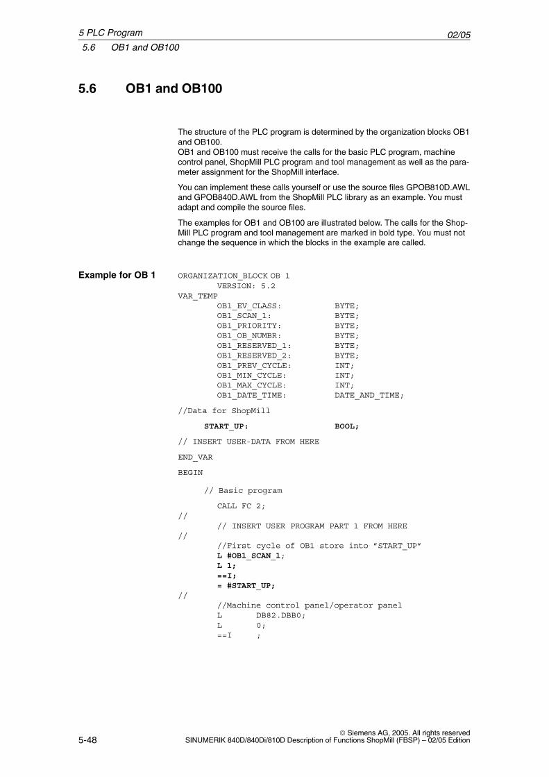
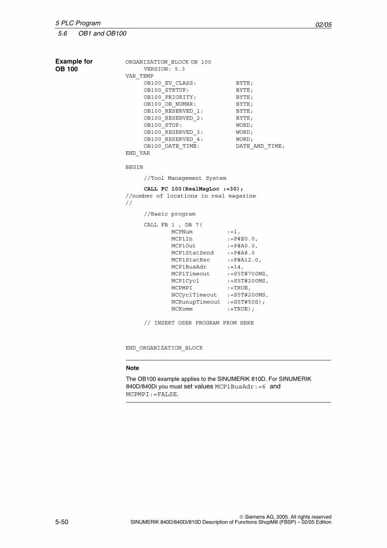
5.6 OB1 and OB100
The structure of the PLC program is determined by the organization blocks OB1and OB100.OB1 and OB100 must receive the calls for the basic PLC program, machinecontrol panel, ShopMill PLC program and tool management as well as the para-meter assignment for the ShopMill interface.
You can implement these calls yourself or use the source files GPOB810D.AWLand GPOB840D.AWL from the ShopMill PLC library as an example. You mustadapt and compile the source files.
The examples for OB1 and OB100 are illustrated below. The calls for the Shop-Mill PLC program and tool management are marked in bold type. You must notchange the sequence in which the blocks in the example are called.
ORGANIZATION_BLOCK OB 1VERSION: 5.2
VAR_TEMPOB1_EV_CLASS: BYTE;OB1_SCAN_1: BYTE;OB1_PRIORITY: BYTE;OB1_OB_NUMBR: BYTE;OB1_RESERVED_1: BYTE;OB1_RESERVED_2: BYTE;OB1_PREV_CYCLE: INT;OB1_MIN_CYCLE: INT;OB1_MAX_CYCLE: INT;OB1_DATE_TIME: DATE_AND_TIME;
//Data for ShopMill
START_UP: BOOL;
// INSERT USER-DATA FROM HERE
END_VAR
BEGIN
// Basic program
CALL FC 2;//
// INSERT USER PROGRAM PART 1 FROM HERE//
//First cycle of OB1 store into ”START_UP”L #OB1_SCAN_1;L 1;==I;= #START_UP;
////Machine control panel/operator panelL DB82.DBB0;L 0;==I ;
Example for OB 1
5 PLC Program
02/055.6 OB1 and OB100
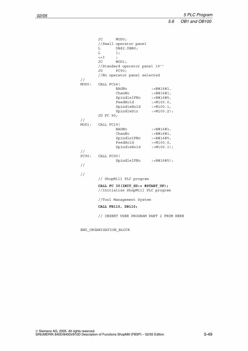
5-49 Siemens AG, 2005. All rights reservedSINUMERIK 840D/840Di/810D Description of Functions ShopMill (FBSP) – 02/05 Edition
JC MOD0;//Small operator panelL DB82.DBB0;L 1;==I ;JC MOD1;//Standard operator panel 19’’JU FC90;//No operator panel selected
//MOD0: CALL FC24(
BAGNo :=B#16#1,ChanNo :=B#16#1,SpindleIFNo :=B#16#5,FeedHold :=M100.0,SpindleHold :=M100.1,SpindleDir :=M100.2);
JU FC 90;//MOD1: CALL FC19(
BAGNo :=B#16#1,ChanNo :=B#16#1,SpindleIFNo :=B#16#5,FeedHold :=M100.0,SpindleHold :=M100.1);
//FC90: CALL FC90(
SpindleIFNo :=B#16#5);//
//// ShopMill PLC program
CALL FC 30(INIT_SD:= #START_UP);//Initialize ShopMill PLC program
//Tool Management System
CALL FB110, DB110;
// INSERT USER PROGRAM PART 2 FROM HERE
END_ORGANIZATION_BLOCK
5 PLC Program
02/055.6 OB1 and OB100
5-50 Siemens AG, 2005. All rights reserved
SINUMERIK 840D/840Di/810D Description of Functions ShopMill (FBSP) – 02/05 Edition
ORGANIZATION_BLOCK OB 100VERSION: 5.3
VAR_TEMPOB100_EV_CLASS: BYTE;OB100_STRTUP: BYTE;OB100_PRIORITY: BYTE;OB100_OB_NUMBR: BYTE;OB100_RESERVED_1: BYTE;OB100_RESERVED_2: BYTE;OB100_STOP: WORD;OB100_RESERVED_3: WORD;OB100_RESERVED_4: WORD;OB100_DATE_TIME: DATE_AND_TIME;
END_VAR
BEGIN
//Tool Management System
CALL FC 100(RealMagLoc :=30);//number of locations in real magazine//
//Basic program
CALL FB 1 , DB 7(MCPNum :=1,MCP1In :=P#E0.0,MCP1Out :=P#A0.0,MCP1StatSend :=P#A8.0MCP1StatRec :=P#A12.0,MCP1BusAdr :=14,MCP1Timeout :=S5T#700MS,MCP1Cycl :=S5T#200MS,MCPMPI :=TRUE,NCCyclTimeout :=S5T#200MS,NCRunupTimeout :=S5T#50S);NCKomm :=TRUE);
// INSERT USER PROGRAM FROM HERE
END_ORGANIZATION_BLOCK
Note
The OB100 example applies to the SINUMERIK 810D. For SINUMERIK840D/840Di you must set values MCP1BusAdr:=6 andMCPMPI:=FALSE.
Example for OB 100
5 PLC Program
02/055.7 Machine control panel
5-51 Siemens AG, 2005. All rights reservedSINUMERIK 840D/840Di/810D Description of Functions ShopMill (FBSP) – 02/05 Edition
5.7 Machine control panel
The signals from the machine control panel must be passed on to the ShopMillinterface DB 82.
You need to initialize the following signals in DB 82 as a minimum:
� DB82 DBB0 (transmission mode for MCP signals)
� DB82 DBB8 (assignment: Spindle axis data block)
Either use your own blocks or adapt the examples to block FC 90.
The following sample source files are available in the ShopMill library for para-meter assignment to ShopMill interface DB 82:
� FC90_MSTT19.AWL (key assignment for MCP19”)
� FC90_OP32S.AWL (key assignment for MCP of the OP032S)
By compiling one of the above STL sources, block FC 90 is generated whichautomatically initializes the two above mentioned signals of DB 82.
With fixed transmission mode (DB82 DBB0), the ShopMill PLC transfers thesignals from the input/output area of the machine control panel to the ShopMillinterface DB82 (DBX2.0, DBX2.1, DBX4.0, DBX4.1, DBX4.2, DBX6.7,DBX30.0, DBX30.1, DBX32.1, DBX32.2, DBX34.7).
FC 90 must be called in OB1 in Part 1 of the PLC user program.
The key assignment for the examples is as follows:keys which are assigned from ShopMill via DB 82 have a gray background.For keys � to � symbols are provided in the substitute key set (see Chapter 1“Hardware”).
Example FC 90
5 PLC Program
02/055.7 Machine control panel
5-52 Siemens AG, 2005. All rights reserved
SINUMERIK 840D/840Di/810D Description of Functions ShopMill (FBSP) – 02/05 Edition
5
% %8
Y
4 6
7
Z
1
10010
100001000
[.]
X
9
– +
�
�� ����
�
�
�
� � ��
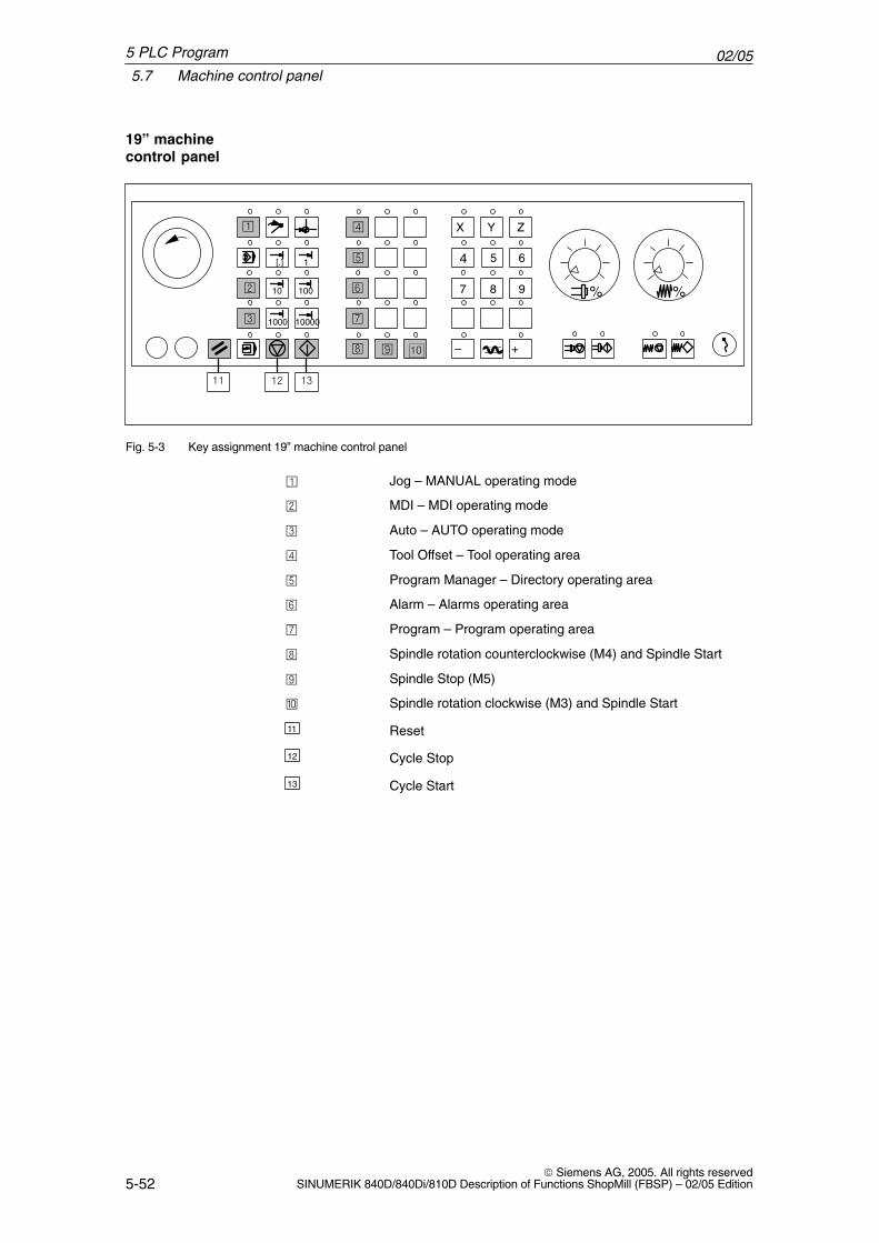
Fig. 5-3 Key assignment 19” machine control panel
� Jog – MANUAL operating mode
� MDI – MDI operating mode
Auto – AUTO operating mode
Tool Offset – Tool operating area
� Program Manager – Directory operating area
� Alarm – Alarms operating area
Program – Program operating area
� Spindle rotation counterclockwise (M4) and Spindle Start
� Spindle Stop (M5)
� Spindle rotation clockwise (M3) and Spindle Start
11 Reset
12 Cycle Stop
13 Cycle Start
19” machinecontrol panel
5 PLC Program
02/055.7 Machine control panel
5-53 Siemens AG, 2005. All rights reservedSINUMERIK 840D/840Di/810D Description of Functions ShopMill (FBSP) – 02/05 Edition
1
3
8 9 10
1312
2
11
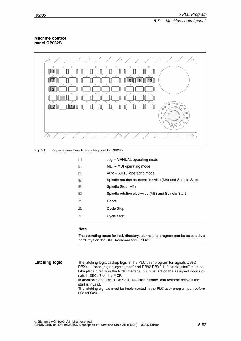
Fig. 5-4 Key assignment machine control panel for OP032S
� Jog – MANUAL operating mode
� MDI – MDI operating mode
Auto – AUTO operating mode
� Spindle rotation counterclockwise (M4) and Spindle Start
� Spindle Stop (M5)
� Spindle rotation clockwise (M3) and Spindle Start
11 Reset
12 Cycle Stop
13 Cycle Start
Note
The operating areas for tool, directory, alarms and program can be selected viahard keys on the CNC keyboard for OP032S.
The latching logic/backup logic in the PLC user program for signals DB82DBX4.1, “base_sig.nc_cycle_start” and DB82 DBX9.1, “spindle_start” must nottake place directly in the NCK interface, but must act on the assigned input sig-nals in EB0...7 on the MCP.In addition signal DB21 DBX7.0, “NC start disable” can become active if thestart is invalid.The latching signals must be implemented in the PLC user program part beforeFC19/FC24.
Machine controlpanel OP032S
Latching logic
5 PLC Program
02/055.8 Diagnostics function for start-up purposes
5-54 Siemens AG, 2005. All rights reserved
SINUMERIK 840D/840Di/810D Description of Functions ShopMill (FBSP) – 02/05 Edition
5.8 Diagnostics function for start-up purposes
If you would like to monitor the standard interface signals influenced duringShopMill startup, (see Section 5.5 “Standard interface signals for/from Shop-Mill”), use the diagnostic block FC 34. The standard interface signals must not be modified by the PLC user program.If changes in the signals take place, the diagnostics block indicates this error inits circular buffer for error messages (20 entries possible). If a signal is cyclicallychanged, a new entry is conducted in the error message buffer in each PLCcycle. This function is activated via the data block DB82 DBX60.0.
Initialize diagnostics function:DBX60.0 = 1 (monitor_on)DBX60.1 = 1 (monitor_initialize)
Activate diagnostics function;DBX60.0 = 1 (monitor_on)DBX60.1 = 0 (monitor_initialize)
Feedback from diagnostic function:Error message1 (e.g. for DB11DBX0.1)DBW62 current_number # 0 (error event count) 1. . . . . . . . . DBB64 db_number (output decimal) 11. . . . . . . . . . . . . . . . . . DBB65 byte_number (output decimal) 0. . . . . . . . . . . . . . . . . DBB66 bit_number (output decimal) 1. . . . . . . . . . . . . . . . . . error message 2 (e.g. for DB21DBX7.1)DBW68 current_number # 0 (error event count) 2. . . . . . . . . DBB70 db_number (output decimal) 21. . . . . . . . . . . . . . . . . . DBB71 byte_number (output decimal) 7. . . . . . . . . . . . . . . . . DBB72 bit_number (output decimal) 1. . . . . . . . . . . . . . . . . . etc. ...
The function block in OB1 must be called in the following sequence:
FC2 Basic program block
FC34 Diagnostics block
PLC user program Part 1(Interlocking logic, FC19/24 machine control panel block)
FC30 ShopMill PLC program
FB110 Data transfer block for ShopMill tool managementin standard mode
PLC user program part 2
Note
The tool box (PLC library) contains the example VAT82 for the variable table.
�
Description
Example
Call-up
5 PLC Program
6-55 Siemens AG, 2005. All rights reservedSINUMERIK 840D/840Di/810D Description of Functions ShopMill (FBSP) – 02/05 Edition
Signal Description
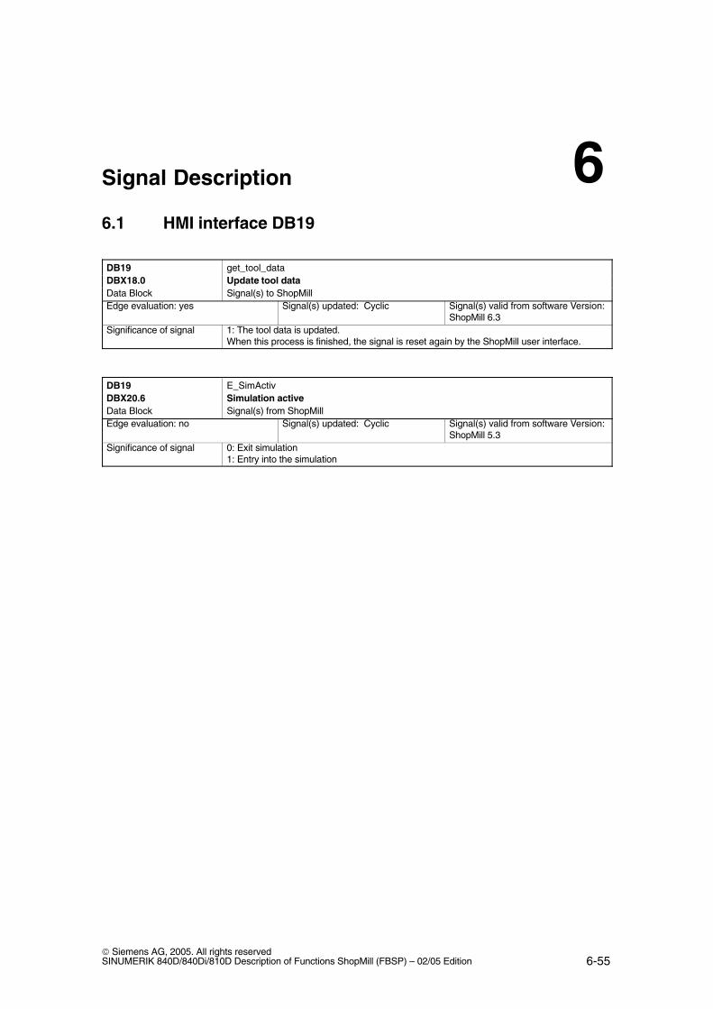
6.1 HMI interface DB19
DB19 get_tool_dataDBX18.0 Update tool dataData Block Signal(s) to ShopMillEdge evaluation: yes Signal(s) updated: Cyclic Signal(s) valid from software Version:
ShopMill 6.3Significance of signal 1: The tool data is updated.
When this process is finished, the signal is reset again by the ShopMill user interface.
DB19 E_SimActivDBX20.6 Simulation activeData Block Signal(s) from ShopMillEdge evaluation: no Signal(s) updated: Cyclic Signal(s) valid from software Version:
ShopMill 5.3Significance of signal 0: Exit simulation
1: Entry into the simulation
6
02/056.2 Overview of ShopMill interface DB82
6-56 Siemens AG, 2005. All rights reserved
SINUMERIK 840D/840Di/810D Description of Functions ShopMill (FBSP) – 02/05 Edition
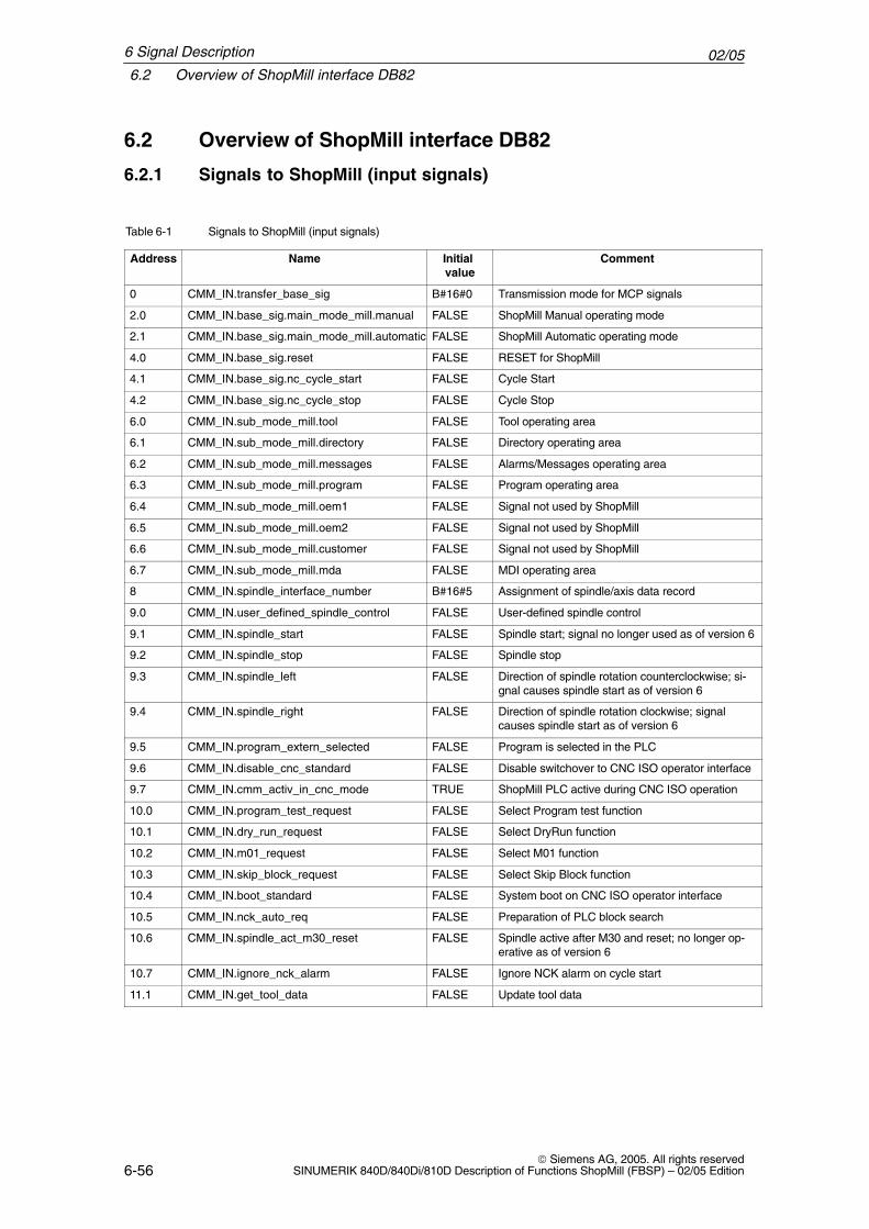
6.2 Overview of ShopMill interface DB82
6.2.1 Signals to ShopMill (input signals)
Table 6-1 Signals to ShopMill (input signals)
Address Name Initial value
Comment
0 CMM_IN.transfer_base_sig B#16#0 Transmission mode for MCP signals
2.0 CMM_IN.base_sig.main_mode_mill.manual FALSE ShopMill Manual operating mode
2.1 CMM_IN.base_sig.main_mode_mill.automatic FALSE ShopMill Automatic operating mode
4.0 CMM_IN.base_sig.reset FALSE RESET for ShopMill
4.1 CMM_IN.base_sig.nc_cycle_start FALSE Cycle Start
4.2 CMM_IN.base_sig.nc_cycle_stop FALSE Cycle Stop
6.0 CMM_IN.sub_mode_mill.tool FALSE Tool operating area
6.1 CMM_IN.sub_mode_mill.directory FALSE Directory operating area
6.2 CMM_IN.sub_mode_mill.messages FALSE Alarms/Messages operating area
6.3 CMM_IN.sub_mode_mill.program FALSE Program operating area
6.4 CMM_IN.sub_mode_mill.oem1 FALSE Signal not used by ShopMill
6.5 CMM_IN.sub_mode_mill.oem2 FALSE Signal not used by ShopMill
6.6 CMM_IN.sub_mode_mill.customer FALSE Signal not used by ShopMill
6.7 CMM_IN.sub_mode_mill.mda FALSE MDI operating area
8 CMM_IN.spindle_interface_number B#16#5 Assignment of spindle/axis data record
9.0 CMM_IN.user_defined_spindle_control FALSE User-defined spindle control
9.1 CMM_IN.spindle_start FALSE Spindle start; signal no longer used as of version 6
9.2 CMM_IN.spindle_stop FALSE Spindle stop
9.3 CMM_IN.spindle_left FALSE Direction of spindle rotation counterclockwise; si-gnal causes spindle start as of version 6
9.4 CMM_IN.spindle_right FALSE Direction of spindle rotation clockwise; signalcauses spindle start as of version 6
9.5 CMM_IN.program_extern_selected FALSE Program is selected in the PLC
9.6 CMM_IN.disable_cnc_standard FALSE Disable switchover to CNC ISO operator interface
9.7 CMM_IN.cmm_activ_in_cnc_mode TRUE ShopMill PLC active during CNC ISO operation
10.0 CMM_IN.program_test_request FALSE Select Program test function
10.1 CMM_IN.dry_run_request FALSE Select DryRun function
10.2 CMM_IN.m01_request FALSE Select M01 function
10.3 CMM_IN.skip_block_request FALSE Select Skip Block function
10.4 CMM_IN.boot_standard FALSE System boot on CNC ISO operator interface
10.5 CMM_IN.nck_auto_req FALSE Preparation of PLC block search
10.6 CMM_IN.spindle_act_m30_reset FALSE Spindle active after M30 and reset; no longer op-erative as of version 6
10.7 CMM_IN.ignore_nck_alarm FALSE Ignore NCK alarm on cycle start
11.1 CMM_IN.get_tool_data FALSE Update tool data
6 Signal Description
02/056.2 Overview of ShopMill interface DB82
6-57 Siemens AG, 2005. All rights reservedSINUMERIK 840D/840Di/810D Description of Functions ShopMill (FBSP) – 02/05 Edition
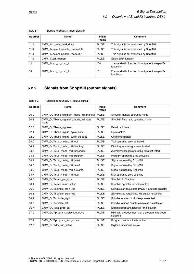
Table 6-1 Signals to ShopMill (input signals)
Address CommentInitial value
Name
11.2 CMM_IN.c_axis_feed_drive FALSE This signal is not evaluated by ShopMill
11.3 CMM_IN.select_spindle_readout_0 FALSE This signal is not evaluated by ShopMill
11.4 CMM_IN.select_spindle_readout_1 FALSE This signal is not evaluated by ShopMill
11.5 CMM_IN.drf_request FALSE Select DRF function
12 CMM_IN.ext_m_cmd_1 100 1. extended M function for output of tool-specificfunctions
13 CMM_IN.ext_m_cmd_2 101 2. extended M function for output of tool-specificfunctions
6.2.2 Signals from ShopMill (output signals)
Table 6-2 Signals from ShopMill (output signals)
Address Name Initial value
Comment
30.0 CMM_OUT.base_sig.main_mode_mill.manual FALSE ShopMill Manual operating mode
30.1 CMM_OUT.base_sig.main_mode_mill.auto-matic
FALSE ShopMill Automatic operating mode
32.0 CMM_OUT.base_sig.reset FALSE Reset performed
32.1 CMM_OUT.base_sig.nc_cycle_activ FALSE Cycle active
32.2 CMM_OUT.base_sig.nc_cycle_stopped FALSE Cycle interrupted
34.0 CMM_OUT.sub_mode_mill.tool FALSE Tool operating area activated
34.1 CMM_OUT.sub_mode_mill.directory FALSE Directory operating area activated
34.2 CMM_OUT.sub_mode_mill.messages FALSE Alarms/messages operating area activated
34.3 CMM_OUT.sub_mode_mill.program FALSE Program operating area activated
34.4 CMM_OUT.sub_mode_mill.oem1 FALSE Signal not used by ShopMill
34.5 CMM_OUT.sub_mode_mill.oem2 FALSE Signal not used by ShopMill
34.6 CMM_OUT.sub_mode_mill.customer FALSE Signal not used by ShopMill
34.7 CMM_OUT.sub_mode_mill.mda FALSE MDI operating area selected
36.0 CMM_OUT.cmm_plc_activ FALSE ShopMill PLC active
36.1 CMM_OUT.cmm_mmc_active FALSE ShopMill operator interface active
36.2 CMM_OUT.spindle_start_req FALSE Spindle start requested (M3/M4 output to spindle)
36.3 CMM_OUT.spindle_stop_req FALSE Spindle stop requested, M5 output to spindle
36.4 CMM_OUT.spindle_right FALSE Spindle rotation clockwise preselected
36.5 CMM_OUT.spindle_left FALSE Spindle rotation counterclockwise preselected
36.7 CMM_OUT.ext_prog_sel FALSE External program selected for execution
37.0 CMM_OUT.program_selection_done FALSE HMI acknowledgement that a program has beenselected
37.1 CMM_OUT.program_test_active FALSE Program test function is active
37.2 CMM_OUT.dry_run_active FALSE DryRun function is active
6 Signal Description
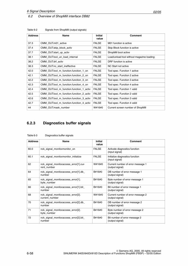
02/056.2 Overview of ShopMill interface DB82
6-58 Siemens AG, 2005. All rights reserved
SINUMERIK 840D/840Di/810D Description of Functions ShopMill (FBSP) – 02/05 Edition
Table 6-2 Signals from ShopMill (output signals)
Address CommentInitial value
Name
37.3 CMM_OUT.m01_active FALSE M01 function is active
37.4 CMM_OUT.skip_block_activ FALSE Skip Block function is active
37.7 CMM_OUT.start_up_activ FALSE ShopMill boot active
38.1 CMM_OUT.tool_un_load_internal FALSE Load/unload tool without magazine loading:
38.2 CMM_OUT.drf_activ FALSE DRF function is active
38.3 CMM_OUT.nc_start_ineffective FALSE NC Start not active
42.0 CMM_OUT.tool_m_function.function_1_on FALSE Tool spec. Function 1 active
42.1 CMM_OUT.tool_m_function.function_2_on FALSE Tool spec. Function 2 active
42.2 CMM_OUT.tool_m_function.function_3_on FALSE Tool spec. Function 3 active
42.3 CMM_OUT.tool_m_function.function_4_on FALSE Tool spec. Function 4 active
42.4 CMM_OUT.tool_m_function.function_1_activ FALSE Tool spec. Function 1 valid
42.5 CMM_OUT.tool_m_function.function_2_activ FALSE Tool spec. Function 2 valid
42.6 CMM_OUT.tool_m_function.function_3_activ FALSE Tool spec. Function 3 valid
42.7 CMM_OUT.tool_m_function.function_4_activ FALSE Tool spec. Function 4 valid
44 CMM_OUT.mask_number W#16#0 Current screen number of ShopMill
6.2.3 Diagnostics buffer signals
Table 6-3 Diagnostics buffer signals
Address Name Initial value
Comment
60.0 nck_signal_monitor.monitor_on FALSE Activate diagnostics function (input signal)
60.1 nck_signal_monitor.monitor_initialize FALSE Initialize diagnostics function (input signal)
62 nck_signal_monitor.access_error[1].cur-rent_number
W#16#0 Current number of error message 1 (output signal)
64 nck_signal_monitor.access_error[1].db_number
B#16#0 DB number of error message 1 (output signal)
65 nck_signal_monitor.access_error[1].byte_number
B#16#0 Byte number of error message 1 (output signal)
66 nck_signal_monitor.access_error[1].bit_number
B#16#0 Bit number of error message 1 (output signal)
68 nck_signal_monitor.access_error[2].current_number
W#16#0 Current number of error message 2 (output signal)
70 nck_signal_monitor.access_error[2].db_number
B#16#0 DB number of error message 2 (output signal)
71 nck_signal_monitor.access_error[2].byte_number
B#16#0 Byte number of error message 2 (output signal)
72 nck_signal_monitor.access_error[2].bit_number
B#16#0 Bit number of error message 2 (output signal)
6 Signal Description
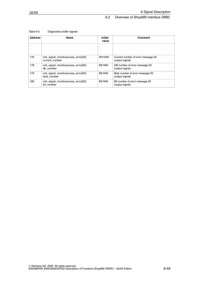
02/056.2 Overview of ShopMill interface DB82
6-59 Siemens AG, 2005. All rights reservedSINUMERIK 840D/840Di/810D Description of Functions ShopMill (FBSP) – 02/05 Edition
Table 6-3 Diagnostics buffer signals
Address CommentInitial value
Name
.
.
.
.
.
.
176 nck_signal_monitor.access_error[20].current_number
W#16#0 Current number of error message 20 (output signal)
178 nck_signal_monitor.access_error[20].db_number
B#16#0 DB number of error message 20 (output signal)
179 nck_signal_monitor.access_error[20].byte_number
B#16#0 Byte number of error message 20 (output signal)
180 nck_signal_monitor.access_error[20].bit_number
B#16#0 Bit number of error message 20 (output signal)
6 Signal Description
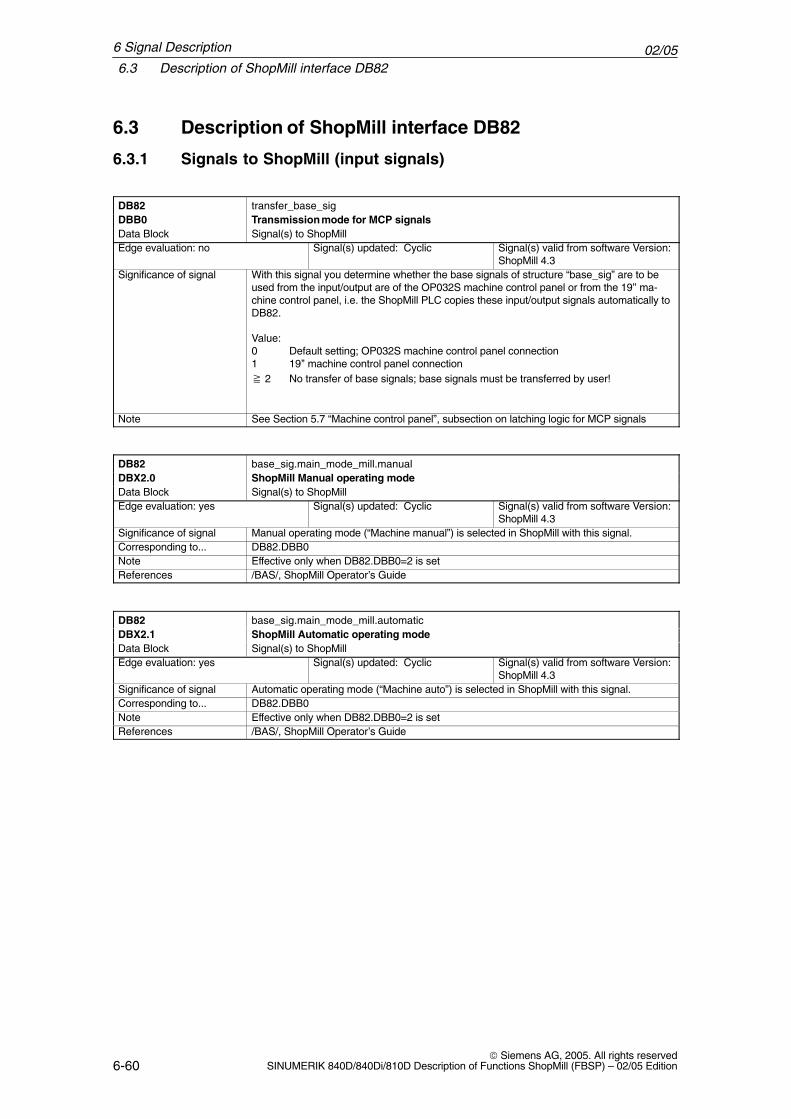
02/056.3 Description of ShopMill interface DB82
6-60 Siemens AG, 2005. All rights reserved
SINUMERIK 840D/840Di/810D Description of Functions ShopMill (FBSP) – 02/05 Edition
6.3 Description of ShopMill interface DB82
6.3.1 Signals to ShopMill (input signals)
DB82 transfer_base_sigDBB0 Transmission mode for MCP signalsData Block Signal(s) to ShopMillEdge evaluation: no Signal(s) updated: Cyclic Signal(s) valid from software Version:
ShopMill 4.3Significance of signal With this signal you determine whether the base signals of structure “base_sig” are to be
used from the input/output are of the OP032S machine control panel or from the 19’’ ma-chine control panel, i.e. the ShopMill PLC copies these input/output signals automatically toDB82.
Value:0 Default setting; OP032S machine control panel connection1 19’’ machine control panel connection� 2 No transfer of base signals; base signals must be transferred by user!
Note See Section 5.7 “Machine control panel”, subsection on latching logic for MCP signals
DB82 base_sig.main_mode_mill.manualDBX2.0 ShopMill Manual operating modeData Block Signal(s) to ShopMillEdge evaluation: yes Signal(s) updated: Cyclic Signal(s) valid from software Version:
ShopMill 4.3Significance of signal Manual operating mode (“Machine manual”) is selected in ShopMill with this signal.Corresponding to... DB82.DBB0Note Effective only when DB82.DBB0=2 is setReferences /BAS/, ShopMill Operator’s Guide
DB82 base_sig.main_mode_mill.automaticDBX2.1 ShopMill Automatic operating modeData Block Signal(s) to ShopMillEdge evaluation: yes Signal(s) updated: Cyclic Signal(s) valid from software Version:
ShopMill 4.3Significance of signal Automatic operating mode (“Machine auto”) is selected in ShopMill with this signal.Corresponding to... DB82.DBB0Note Effective only when DB82.DBB0=2 is setReferences /BAS/, ShopMill Operator’s Guide
6 Signal Description
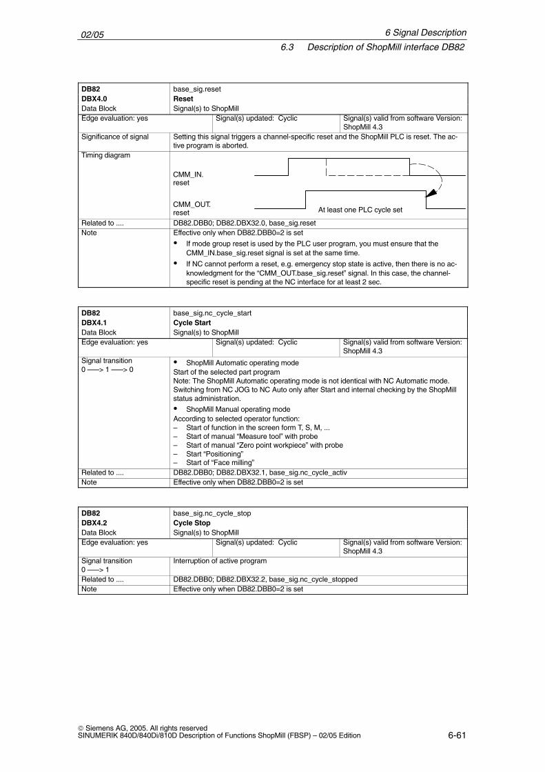
02/056.3 Description of ShopMill interface DB82
6-61 Siemens AG, 2005. All rights reservedSINUMERIK 840D/840Di/810D Description of Functions ShopMill (FBSP) – 02/05 Edition
DB82 base_sig.resetDBX4.0 ResetData Block Signal(s) to ShopMillEdge evaluation: yes Signal(s) updated: Cyclic Signal(s) valid from software Version:
ShopMill 4.3Significance of signal Setting this signal triggers a channel-specific reset and the ShopMill PLC is reset. The ac-
tive program is aborted.Timing diagram
CMM_IN. reset
CMM_OUT. reset At least one PLC cycle set
Related to .... DB82.DBB0; DB82.DBX32.0, base_sig.resetNote Effective only when DB82.DBB0=2 is set
� If mode group reset is used by the PLC user program, you must ensure that theCMM_IN.base_sig.reset signal is set at the same time.
� If NC cannot perform a reset, e.g. emergency stop state is active, then there is no ac-knowledgment for the “CMM_OUT.base_sig.reset” signal. In this case, the channel-specific reset is pending at the NC interface for at least 2 sec.
DB82 base_sig.nc_cycle_startDBX4.1 Cycle StartData Block Signal(s) to ShopMillEdge evaluation: yes Signal(s) updated: Cyclic Signal(s) valid from software Version:
ShopMill 4.3Signal transition0 –––> 1 –––> 0
� ShopMill Automatic operating modeStart of the selected part programNote: The ShopMill Automatic operating mode is not identical with NC Automatic mode.Switching from NC JOG to NC Auto only after Start and internal checking by the ShopMillstatus administration.
� ShopMill Manual operating modeAccording to selected operator function:– Start of function in the screen form T, S, M, ...– Start of manual “Measure tool” with probe– Start of manual “Zero point workpiece” with probe– Start “Positioning”– Start of “Face milling”
Related to .... DB82.DBB0; DB82.DBX32.1, base_sig.nc_cycle_activNote Effective only when DB82.DBB0=2 is set
DB82 base_sig.nc_cycle_stopDBX4.2 Cycle StopData Block Signal(s) to ShopMillEdge evaluation: yes Signal(s) updated: Cyclic Signal(s) valid from software Version:
ShopMill 4.3Signal transition0 –––> 1
Interruption of active program
Related to .... DB82.DBB0; DB82.DBX32.2, base_sig.nc_cycle_stoppedNote Effective only when DB82.DBB0=2 is set
6 Signal Description
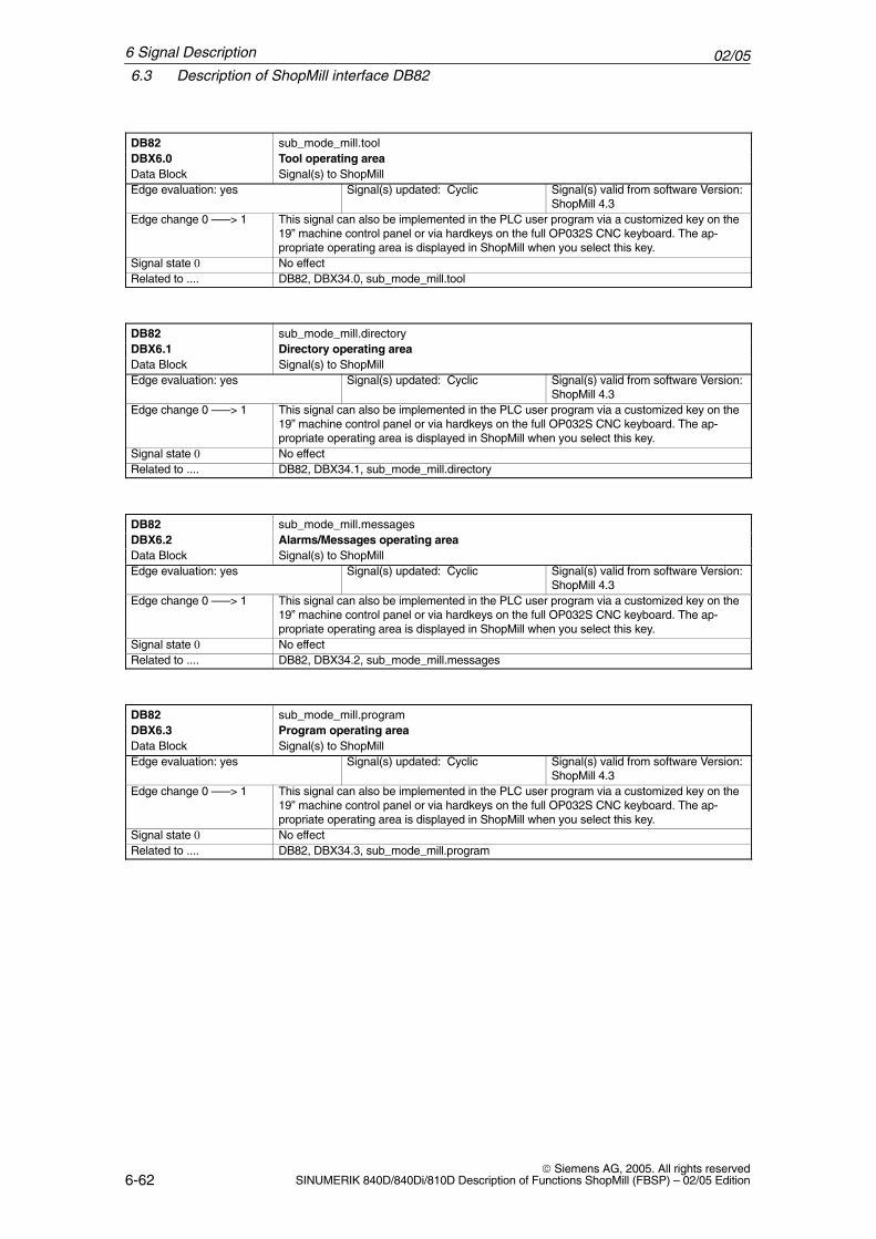
02/056.3 Description of ShopMill interface DB82
6-62 Siemens AG, 2005. All rights reserved
SINUMERIK 840D/840Di/810D Description of Functions ShopMill (FBSP) – 02/05 Edition
DB82 sub_mode_mill.toolDBX6.0 Tool operating areaData Block Signal(s) to ShopMillEdge evaluation: yes Signal(s) updated: Cyclic Signal(s) valid from software Version:
ShopMill 4.3Edge change 0 –––> 1 This signal can also be implemented in the PLC user program via a customized key on the
19” machine control panel or via hardkeys on the full OP032S CNC keyboard. The ap-propriate operating area is displayed in ShopMill when you select this key.
Signal state 0 No effectRelated to .... DB82, DBX34.0, sub_mode_mill.tool
DB82 sub_mode_mill.directoryDBX6.1 Directory operating areaData Block Signal(s) to ShopMillEdge evaluation: yes Signal(s) updated: Cyclic Signal(s) valid from software Version:
ShopMill 4.3Edge change 0 –––> 1 This signal can also be implemented in the PLC user program via a customized key on the
19” machine control panel or via hardkeys on the full OP032S CNC keyboard. The ap-propriate operating area is displayed in ShopMill when you select this key.
Signal state 0 No effectRelated to .... DB82, DBX34.1, sub_mode_mill.directory
DB82 sub_mode_mill.messagesDBX6.2 Alarms/Messages operating areaData Block Signal(s) to ShopMillEdge evaluation: yes Signal(s) updated: Cyclic Signal(s) valid from software Version:
ShopMill 4.3Edge change 0 –––> 1 This signal can also be implemented in the PLC user program via a customized key on the
19” machine control panel or via hardkeys on the full OP032S CNC keyboard. The ap-propriate operating area is displayed in ShopMill when you select this key.
Signal state 0 No effectRelated to .... DB82, DBX34.2, sub_mode_mill.messages
DB82 sub_mode_mill.programDBX6.3 Program operating areaData Block Signal(s) to ShopMillEdge evaluation: yes Signal(s) updated: Cyclic Signal(s) valid from software Version:
ShopMill 4.3Edge change 0 –––> 1 This signal can also be implemented in the PLC user program via a customized key on the
19” machine control panel or via hardkeys on the full OP032S CNC keyboard. The ap-propriate operating area is displayed in ShopMill when you select this key.
Signal state 0 No effectRelated to .... DB82, DBX34.3, sub_mode_mill.program
6 Signal Description
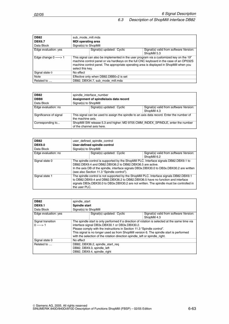
02/056.3 Description of ShopMill interface DB82
6-63 Siemens AG, 2005. All rights reservedSINUMERIK 840D/840Di/810D Description of Functions ShopMill (FBSP) – 02/05 Edition
DB82 sub_mode_mill.mdaDBX6.7 MDI operating areaData Block Signal(s) to ShopMillEdge evaluation: yes Signal(s) updated: Cyclic Signal(s) valid from software Version:
ShopMill 5.3Edge change 0 –––> 1 This signal can also be implemented in the user program via a customized key on the 19”
machine control panel or via hardkeys on the full CNC keyboard in the case of an OP032Smachine control panel. The appropriate operating area is displayed in ShopMill when youselect this key.
Signal state 0 No effectNote Effective only when DB82.DBB0=2 is setRelated to .... DB82, DBX34.7, sub_mode_mill.mda
DB82 spindle_interface_numberDBB8 Assignment of spindle/axis data recordData Block Signal(s) to ShopMillEdge evaluation: no Signal(s) updated: Cyclic Signal(s) valid from software Version:
ShopMill 4.3Significance of signal This signal can be used to assign the spindle to an axis data record. Enter the number of
the machine axis.Corresponding to... ShopMill SW release 5.3 and higher: MD 9705 CMM_INDEX_SPINDLE, enter the number
of the channel axis here.
DB82 user_defined_spindle_controlDBX9.0 User-defined spindle controlData Block Signal(s) to ShopMillEdge evaluation: no Signal(s) updated: Cyclic Signal(s) valid from software Version:
ShopMill 6.2Signal state 0 The spindle control is supported by the ShopMill PLC. Interface signals DB82.DBX9.1 to
DB82.DBX9.4 and DB82.DBX36.2 to DB82.DBX36.5 are active.In the axis DB of the spindle, interface signals DB3x.DBX30.0 to DB3x.DBX30.2 are written(see also Section 11.3 “Spindle control”).
Signal state 1 The spindle control is not supported by the ShopMill PLC. Interface signals DB82.DBX9.1to DB82.DBX9.4 and DB82.DBX36.2 to DB82.DBX36.5 have no function and interfacesignals DB3x.DBX30.0 to DB3x.DBX30.2 are not written. The spindle must be controlled inthe user PLC.
DB82 spindle_startDBX9.1 Spindle startData Block Signal(s) to ShopMillEdge evaluation: yes Signal(s) updated: Cyclic Signal(s) valid from software Version:
ShopMill 4.3Signal transition0 –––> 1
The spindle start is only performed if a direction of rotation is selected at the same time viainterface signal DB3x.DBX30.1 or DB3x.DBX30.2.Please comply with the instructions in Section 11.3 “Spindle control”.This signal is no longer used as from ShopMill version 6. The spindle start is performedwith the selection of the rotation direction spindle_left or spindle_right.
Signal state 0 No effectRelated to .... DB82, DBX36.2, spindle_start_req
DB82, DBX9.3, spindle_leftDB82, DBX9.4, spindle_right
6 Signal Description
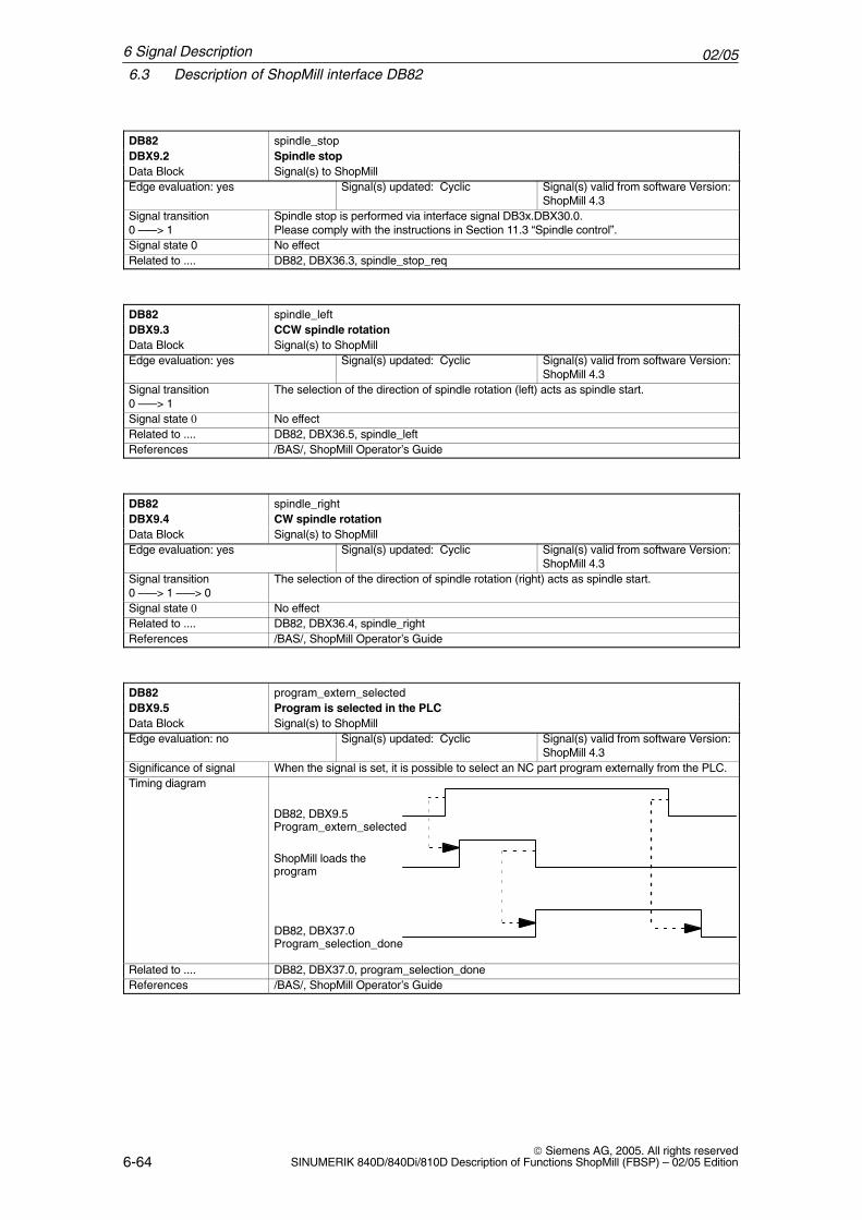
02/056.3 Description of ShopMill interface DB82
6-64 Siemens AG, 2005. All rights reserved
SINUMERIK 840D/840Di/810D Description of Functions ShopMill (FBSP) – 02/05 Edition
DB82 spindle_stopDBX9.2 Spindle stopData Block Signal(s) to ShopMillEdge evaluation: yes Signal(s) updated: Cyclic Signal(s) valid from software Version:
ShopMill 4.3Signal transition0 –––> 1
Spindle stop is performed via interface signal DB3x.DBX30.0.Please comply with the instructions in Section 11.3 “Spindle control”.
Signal state 0 No effectRelated to .... DB82, DBX36.3, spindle_stop_req
DB82 spindle_leftDBX9.3 CCW spindle rotationData Block Signal(s) to ShopMillEdge evaluation: yes Signal(s) updated: Cyclic Signal(s) valid from software Version:
ShopMill 4.3Signal transition0 –––> 1
The selection of the direction of spindle rotation (left) acts as spindle start.
Signal state 0 No effectRelated to .... DB82, DBX36.5, spindle_leftReferences /BAS/, ShopMill Operator’s Guide
DB82 spindle_rightDBX9.4 CW spindle rotationData Block Signal(s) to ShopMillEdge evaluation: yes Signal(s) updated: Cyclic Signal(s) valid from software Version:
ShopMill 4.3Signal transition0 –––> 1 –––> 0
The selection of the direction of spindle rotation (right) acts as spindle start.
Signal state 0 No effectRelated to .... DB82, DBX36.4, spindle_rightReferences /BAS/, ShopMill Operator’s Guide
DB82 program_extern_selectedDBX9.5 Program is selected in the PLCData Block Signal(s) to ShopMillEdge evaluation: no Signal(s) updated: Cyclic Signal(s) valid from software Version:
ShopMill 4.3Significance of signal When the signal is set, it is possible to select an NC part program externally from the PLC.Timing diagram
DB82, DBX9.5Program_extern_selected
ShopMill loads theprogram
DB82, DBX37.0Program_selection_done
Related to .... DB82, DBX37.0, program_selection_doneReferences /BAS/, ShopMill Operator’s Guide
6 Signal Description
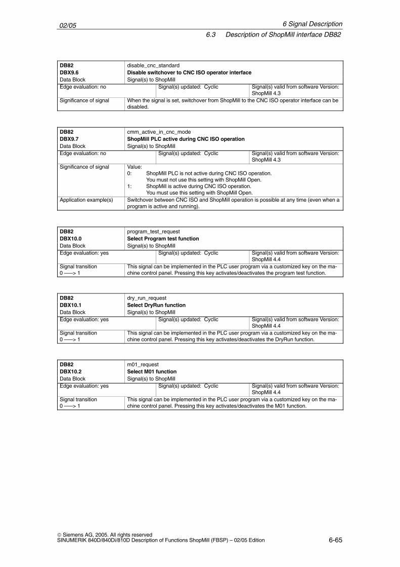
02/056.3 Description of ShopMill interface DB82
6-65 Siemens AG, 2005. All rights reservedSINUMERIK 840D/840Di/810D Description of Functions ShopMill (FBSP) – 02/05 Edition
DB82 disable_cnc_standardDBX9.6 Disable switchover to CNC ISO operator interfaceData Block Signal(s) to ShopMillEdge evaluation: no Signal(s) updated: Cyclic Signal(s) valid from software Version:
ShopMill 4.3Significance of signal When the signal is set, switchover from ShopMill to the CNC ISO operator interface can be
disabled.
DB82 cmm_active_in_cnc_modeDBX9.7 ShopMill PLC active during CNC ISO operationData Block Signal(s) to ShopMillEdge evaluation: no Signal(s) updated: Cyclic Signal(s) valid from software Version:
ShopMill 4.3Significance of signal Value:
0: ShopMill PLC is not active during CNC ISO operation.You must not use this setting with ShopMill Open.
1: ShopMill is active during CNC ISO operation.You must use this setting with ShopMill Open.
Application example(s) Switchover between CNC ISO and ShopMill operation is possible at any time (even when aprogram is active and running).
DB82 program_test_requestDBX10.0 Select Program test functionData Block Signal(s) to ShopMillEdge evaluation: yes Signal(s) updated: Cyclic Signal(s) valid from software Version:
ShopMill 4.4Signal transition0 –––> 1
This signal can be implemented in the PLC user program via a customized key on the ma-chine control panel. Pressing this key activates/deactivates the program test function.
DB82 dry_run_requestDBX10.1 Select DryRun functionData Block Signal(s) to ShopMillEdge evaluation: yes Signal(s) updated: Cyclic Signal(s) valid from software Version:
ShopMill 4.4Signal transition0 –––> 1
This signal can be implemented in the PLC user program via a customized key on the ma-chine control panel. Pressing this key activates/deactivates the DryRun function.
DB82 m01_requestDBX10.2 Select M01 functionData Block Signal(s) to ShopMillEdge evaluation: yes Signal(s) updated: Cyclic Signal(s) valid from software Version:
ShopMill 4.4Signal transition0 –––> 1
This signal can be implemented in the PLC user program via a customized key on the ma-chine control panel. Pressing this key activates/deactivates the M01 function.
6 Signal Description
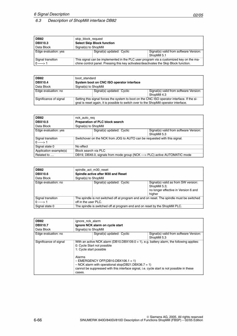
02/056.3 Description of ShopMill interface DB82
6-66 Siemens AG, 2005. All rights reserved
SINUMERIK 840D/840Di/810D Description of Functions ShopMill (FBSP) – 02/05 Edition
DB82 skip_block_requestDBX10.3 Select Skip Block functionData Block Signal(s) to ShopMillEdge evaluation: yes Signal(s) updated: Cyclic Signal(s) valid from software Version:
ShopMill 5.1Signal transition0 –––> 1
This signal can be implemented in the PLC user program via a customized key on the ma-chine control panel. Pressing this key activates/deactivates the Skip Block function.
DB82 boot_standardDBX10.4 System boot on CNC ISO operator interfaceData Block Signal(s) to ShopMillEdge evaluation: no Signal(s) updated: Cyclic Signal(s) valid from software Version:
ShopMill 4.3Significance of signal Setting this signal forces the system to boot on the CNC ISO operator interface. If the si-
gnal is reset again, it is possible to switch over to the ShopMill operator interface.
DB82 nck_auto_reqDBX10.5 Preparation of PLC block searchData Block Signal(s) to ShopMillEdge evaluation: yes Signal(s) updated: Cyclic Signal(s) valid from software Version:
ShopMill 5.3Signal transition0 –––> 1
Switchover on the NCK from JOG to AUTO can be requested with this signal.
Signal state 0 No effectApplication example(s) Block search via PLCRelated to .... DB19, DBX6.0, signals from mode group (NCK ––> PLC) active AUTOMATIC mode
DB82 spindle_act_m30_resetDBX10.6 Spindle active after M30 and ResetData Block Signal(s) to ShopMillEdge evaluation: no Signal(s) updated: Cyclic Signal(s) valid as from SW version:
ShopMill 5.3; no longer effective in Version 6 andhigher
Signal transition0 –––> 1
The spindle is not switched off at program end and on reset. The spindle must be switchedoff in the user PLC.
Signal state 0 The spindle is switched off at program end and on reset by the ShopMill PLC.
DB82 ignore_nck_alarmDBX10.7 Ignore NCK alarm on cycle startData Block Signal(s) to ShopMillEdge evaluation: no Signal(s) updated: Cyclic Signal(s) valid from software Version:
ShopMill 5.3Significance of signal With an active NCK alarm (DB10.DBX109.0 = 1), e.g. battery alarm, the following applies:
0: Cycle Start not possible1: Cycle start possible
Alarms– EMERGENCY OFF(DB10.DBX106.1 = 1)– NCK alarm with operational stop(DB21.DBX36.7 = 1)cannot be suppressed with this interface signal, i.e. cycle start is not possible in thesecases.
6 Signal Description
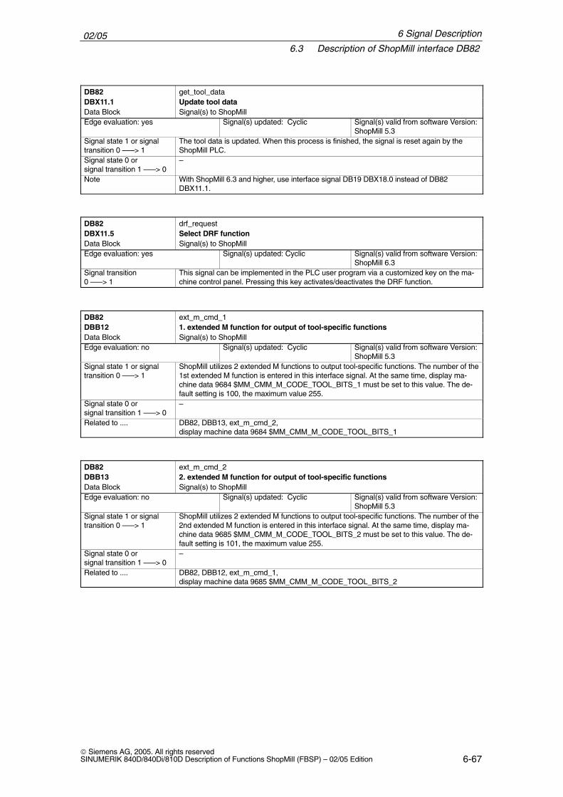
02/056.3 Description of ShopMill interface DB82
6-67 Siemens AG, 2005. All rights reservedSINUMERIK 840D/840Di/810D Description of Functions ShopMill (FBSP) – 02/05 Edition
DB82 get_tool_dataDBX11.1 Update tool dataData Block Signal(s) to ShopMillEdge evaluation: yes Signal(s) updated: Cyclic Signal(s) valid from software Version:
ShopMill 5.3Signal state 1 or signaltransition 0 –––> 1
The tool data is updated. When this process is finished, the signal is reset again by theShopMill PLC.
Signal state 0 or signal transition 1 –––> 0
–
Note With ShopMill 6.3 and higher, use interface signal DB19 DBX18.0 instead of DB82DBX11.1.
DB82 drf_requestDBX11.5 Select DRF functionData Block Signal(s) to ShopMillEdge evaluation: yes Signal(s) updated: Cyclic Signal(s) valid from software Version:
ShopMill 6.3Signal transition0 –––> 1
This signal can be implemented in the PLC user program via a customized key on the ma-chine control panel. Pressing this key activates/deactivates the DRF function.
DB82 ext_m_cmd_1DBB12 1. extended M function for output of tool-specific functionsData Block Signal(s) to ShopMillEdge evaluation: no Signal(s) updated: Cyclic Signal(s) valid from software Version:
ShopMill 5.3Signal state 1 or signaltransition 0 –––> 1
ShopMill utilizes 2 extended M functions to output tool-specific functions. The number of the1st extended M function is entered in this interface signal. At the same time, display ma-chine data 9684 $MM_CMM_M_CODE_TOOL_BITS_1 must be set to this value. The de-fault setting is 100, the maximum value 255.
Signal state 0 or signal transition 1 –––> 0
–
Related to .... DB82, DBB13, ext_m_cmd_2,display machine data 9684 $MM_CMM_M_CODE_TOOL_BITS_1
DB82 ext_m_cmd_2DBB13 2. extended M function for output of tool-specific functionsData Block Signal(s) to ShopMillEdge evaluation: no Signal(s) updated: Cyclic Signal(s) valid from software Version:
ShopMill 5.3Signal state 1 or signaltransition 0 –––> 1
ShopMill utilizes 2 extended M functions to output tool-specific functions. The number of the2nd extended M function is entered in this interface signal. At the same time, display ma-chine data 9685 $MM_CMM_M_CODE_TOOL_BITS_2 must be set to this value. The de-fault setting is 101, the maximum value 255.
Signal state 0 or signal transition 1 –––> 0
–
Related to .... DB82, DBB12, ext_m_cmd_1,display machine data 9685 $MM_CMM_M_CODE_TOOL_BITS_2
6 Signal Description
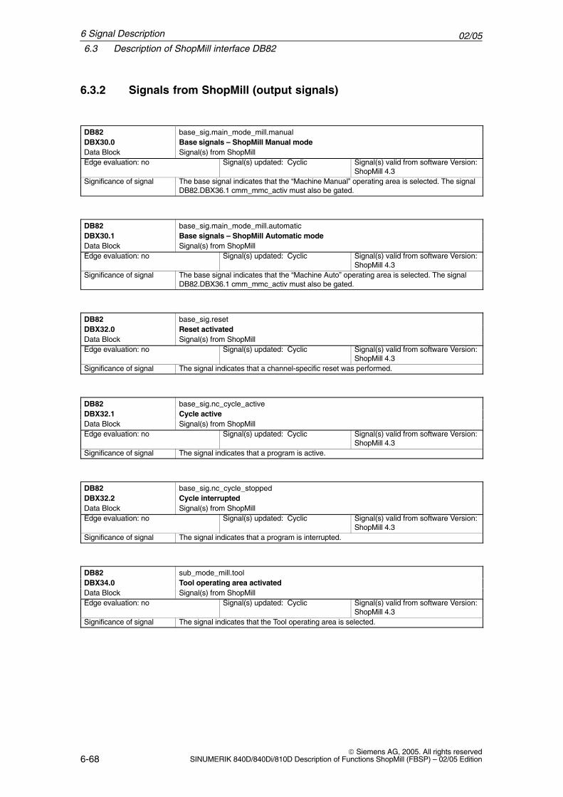
02/056.3 Description of ShopMill interface DB82
6-68 Siemens AG, 2005. All rights reserved
SINUMERIK 840D/840Di/810D Description of Functions ShopMill (FBSP) – 02/05 Edition
6.3.2 Signals from ShopMill (output signals)
DB82 base_sig.main_mode_mill.manualDBX30.0 Base signals – ShopMill Manual modeData Block Signal(s) from ShopMillEdge evaluation: no Signal(s) updated: Cyclic Signal(s) valid from software Version:
ShopMill 4.3Significance of signal The base signal indicates that the “Machine Manual” operating area is selected. The signal
DB82.DBX36.1 cmm_mmc_activ must also be gated.
DB82 base_sig.main_mode_mill.automaticDBX30.1 Base signals – ShopMill Automatic modeData Block Signal(s) from ShopMillEdge evaluation: no Signal(s) updated: Cyclic Signal(s) valid from software Version:
ShopMill 4.3Significance of signal The base signal indicates that the “Machine Auto” operating area is selected. The signal
DB82.DBX36.1 cmm_mmc_activ must also be gated.
DB82 base_sig.resetDBX32.0 Reset activatedData Block Signal(s) from ShopMillEdge evaluation: no Signal(s) updated: Cyclic Signal(s) valid from software Version:
ShopMill 4.3Significance of signal The signal indicates that a channel-specific reset was performed.
DB82 base_sig.nc_cycle_activeDBX32.1 Cycle activeData Block Signal(s) from ShopMillEdge evaluation: no Signal(s) updated: Cyclic Signal(s) valid from software Version:
ShopMill 4.3Significance of signal The signal indicates that a program is active.
DB82 base_sig.nc_cycle_stoppedDBX32.2 Cycle interruptedData Block Signal(s) from ShopMillEdge evaluation: no Signal(s) updated: Cyclic Signal(s) valid from software Version:
ShopMill 4.3Significance of signal The signal indicates that a program is interrupted.
DB82 sub_mode_mill.toolDBX34.0 Tool operating area activatedData Block Signal(s) from ShopMillEdge evaluation: no Signal(s) updated: Cyclic Signal(s) valid from software Version:
ShopMill 4.3Significance of signal The signal indicates that the Tool operating area is selected.
6 Signal Description
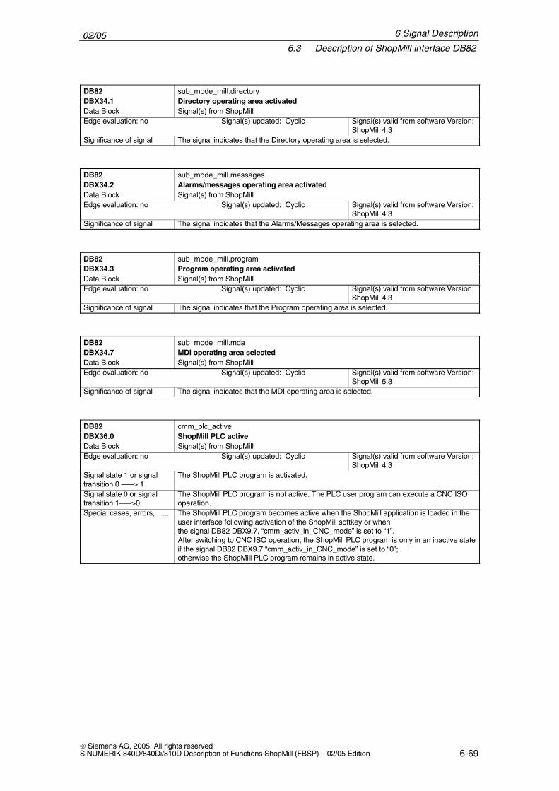
02/056.3 Description of ShopMill interface DB82
6-69 Siemens AG, 2005. All rights reservedSINUMERIK 840D/840Di/810D Description of Functions ShopMill (FBSP) – 02/05 Edition
DB82 sub_mode_mill.directoryDBX34.1 Directory operating area activatedData Block Signal(s) from ShopMillEdge evaluation: no Signal(s) updated: Cyclic Signal(s) valid from software Version:
ShopMill 4.3Significance of signal The signal indicates that the Directory operating area is selected.
DB82 sub_mode_mill.messagesDBX34.2 Alarms/messages operating area activatedData Block Signal(s) from ShopMillEdge evaluation: no Signal(s) updated: Cyclic Signal(s) valid from software Version:
ShopMill 4.3Significance of signal The signal indicates that the Alarms/Messages operating area is selected.
DB82 sub_mode_mill.programDBX34.3 Program operating area activatedData Block Signal(s) from ShopMillEdge evaluation: no Signal(s) updated: Cyclic Signal(s) valid from software Version:
ShopMill 4.3Significance of signal The signal indicates that the Program operating area is selected.
DB82 sub_mode_mill.mdaDBX34.7 MDI operating area selectedData Block Signal(s) from ShopMillEdge evaluation: no Signal(s) updated: Cyclic Signal(s) valid from software Version:
ShopMill 5.3Significance of signal The signal indicates that the MDI operating area is selected.
DB82 cmm_plc_activeDBX36.0 ShopMill PLC activeData Block Signal(s) from ShopMillEdge evaluation: no Signal(s) updated: Cyclic Signal(s) valid from software Version:
ShopMill 4.3Signal state 1 or signaltransition 0 –––> 1
The ShopMill PLC program is activated.
Signal state 0 or signaltransition 1–––>0
The ShopMill PLC program is not active. The PLC user program can execute a CNC ISOoperation.
Special cases, errors, ...... The ShopMill PLC program becomes active when the ShopMill application is loaded in theuser interface following activation of the ShopMill softkey or when the signal DB82 DBX9.7, “cmm_activ_in_CNC_mode” is set to “1”.After switching to CNC ISO operation, the ShopMill PLC program is only in an inactive stateif the signal DB82 DBX9.7,“cmm_activ_in_CNC_mode” is set to “0”; otherwise the ShopMill PLC program remains in active state.
6 Signal Description
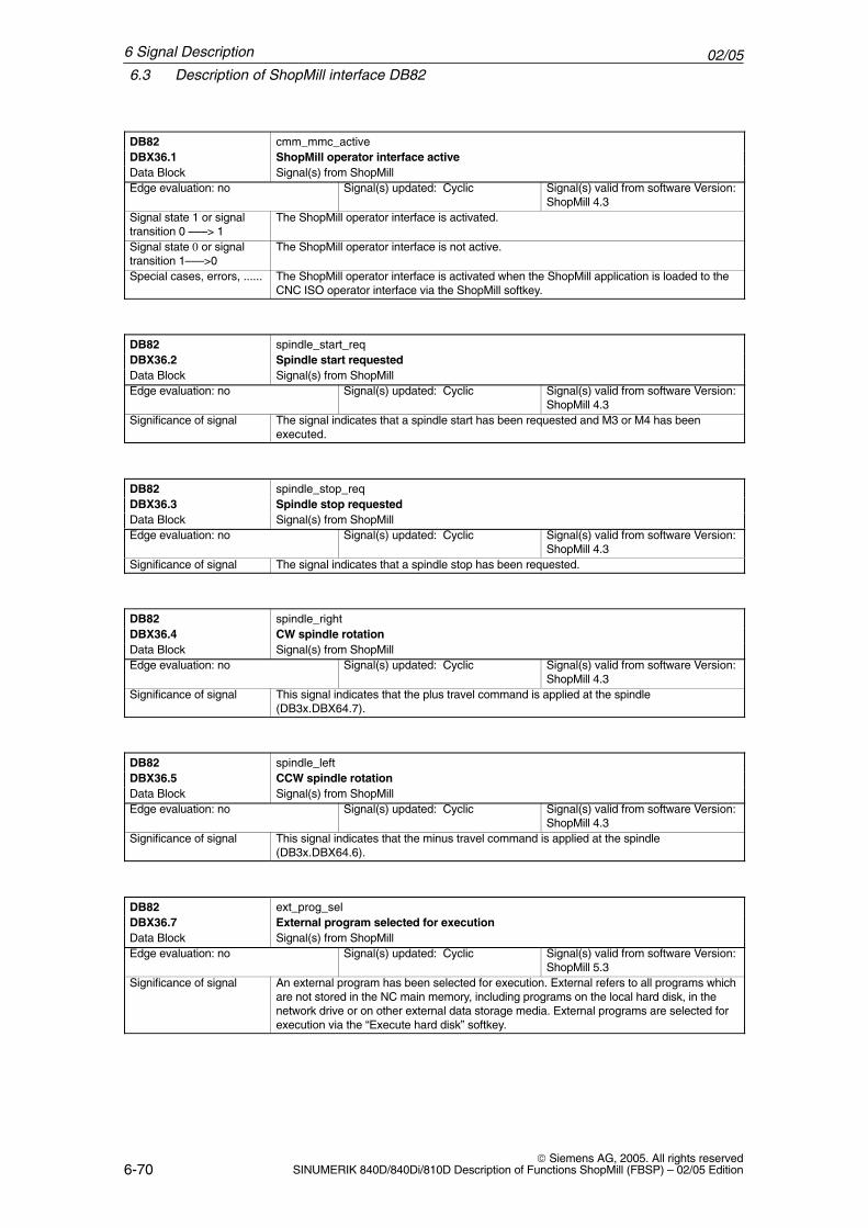
02/056.3 Description of ShopMill interface DB82
6-70 Siemens AG, 2005. All rights reserved
SINUMERIK 840D/840Di/810D Description of Functions ShopMill (FBSP) – 02/05 Edition
DB82 cmm_mmc_activeDBX36.1 ShopMill operator interface activeData Block Signal(s) from ShopMillEdge evaluation: no Signal(s) updated: Cyclic Signal(s) valid from software Version:
ShopMill 4.3Signal state 1 or signaltransition 0 –––> 1
The ShopMill operator interface is activated.
Signal state 0 or signaltransition 1–––>0
The ShopMill operator interface is not active.
Special cases, errors, ...... The ShopMill operator interface is activated when the ShopMill application is loaded to theCNC ISO operator interface via the ShopMill softkey.
DB82 spindle_start_reqDBX36.2 Spindle start requested Data Block Signal(s) from ShopMillEdge evaluation: no Signal(s) updated: Cyclic Signal(s) valid from software Version:
ShopMill 4.3Significance of signal The signal indicates that a spindle start has been requested and M3 or M4 has been
executed.
DB82 spindle_stop_reqDBX36.3 Spindle stop requestedData Block Signal(s) from ShopMillEdge evaluation: no Signal(s) updated: Cyclic Signal(s) valid from software Version:
ShopMill 4.3Significance of signal The signal indicates that a spindle stop has been requested.
DB82 spindle_rightDBX36.4 CW spindle rotationData Block Signal(s) from ShopMillEdge evaluation: no Signal(s) updated: Cyclic Signal(s) valid from software Version:
ShopMill 4.3Significance of signal This signal indicates that the plus travel command is applied at the spindle
(DB3x.DBX64.7).
DB82 spindle_leftDBX36.5 CCW spindle rotationData Block Signal(s) from ShopMillEdge evaluation: no Signal(s) updated: Cyclic Signal(s) valid from software Version:
ShopMill 4.3Significance of signal This signal indicates that the minus travel command is applied at the spindle
(DB3x.DBX64.6).
DB82 ext_prog_selDBX36.7 External program selected for executionData Block Signal(s) from ShopMillEdge evaluation: no Signal(s) updated: Cyclic Signal(s) valid from software Version:
ShopMill 5.3Significance of signal An external program has been selected for execution. External refers to all programs which
are not stored in the NC main memory, including programs on the local hard disk, in thenetwork drive or on other external data storage media. External programs are selected forexecution via the “Execute hard disk” softkey.
6 Signal Description
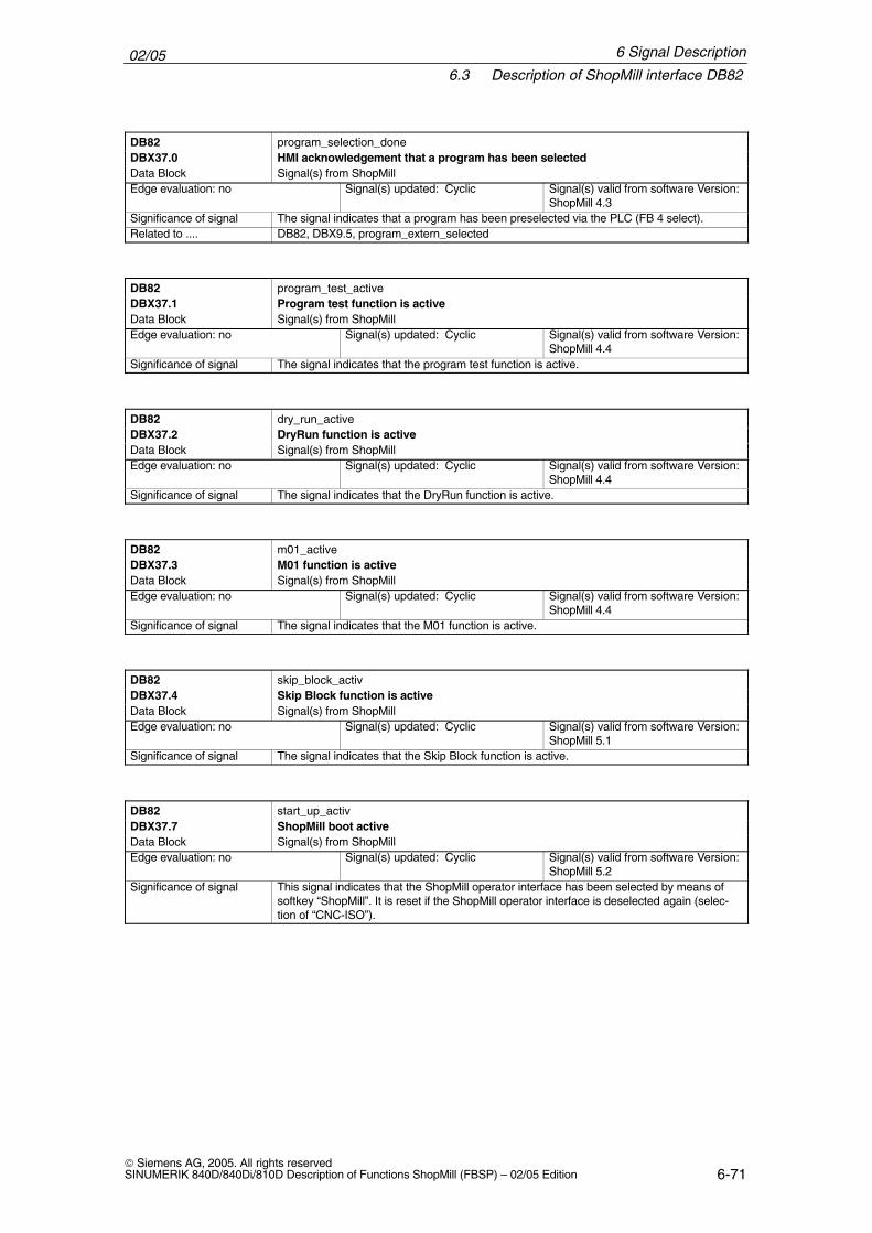
02/056.3 Description of ShopMill interface DB82
6-71 Siemens AG, 2005. All rights reservedSINUMERIK 840D/840Di/810D Description of Functions ShopMill (FBSP) – 02/05 Edition
DB82 program_selection_doneDBX37.0 HMI acknowledgement that a program has been selectedData Block Signal(s) from ShopMillEdge evaluation: no Signal(s) updated: Cyclic Signal(s) valid from software Version:
ShopMill 4.3Significance of signal The signal indicates that a program has been preselected via the PLC (FB 4 select).Related to .... DB82, DBX9.5, program_extern_selected
DB82 program_test_activeDBX37.1 Program test function is activeData Block Signal(s) from ShopMillEdge evaluation: no Signal(s) updated: Cyclic Signal(s) valid from software Version:
ShopMill 4.4Significance of signal The signal indicates that the program test function is active.
DB82 dry_run_activeDBX37.2 DryRun function is activeData Block Signal(s) from ShopMillEdge evaluation: no Signal(s) updated: Cyclic Signal(s) valid from software Version:
ShopMill 4.4Significance of signal The signal indicates that the DryRun function is active.
DB82 m01_activeDBX37.3 M01 function is activeData Block Signal(s) from ShopMillEdge evaluation: no Signal(s) updated: Cyclic Signal(s) valid from software Version:
ShopMill 4.4Significance of signal The signal indicates that the M01 function is active.
DB82 skip_block_activDBX37.4 Skip Block function is activeData Block Signal(s) from ShopMillEdge evaluation: no Signal(s) updated: Cyclic Signal(s) valid from software Version:
ShopMill 5.1Significance of signal The signal indicates that the Skip Block function is active.
DB82 start_up_activDBX37.7 ShopMill boot activeData Block Signal(s) from ShopMillEdge evaluation: no Signal(s) updated: Cyclic Signal(s) valid from software Version:
ShopMill 5.2Significance of signal This signal indicates that the ShopMill operator interface has been selected by means of
softkey “ShopMill”. It is reset if the ShopMill operator interface is deselected again (selec-tion of “CNC-ISO”).
6 Signal Description
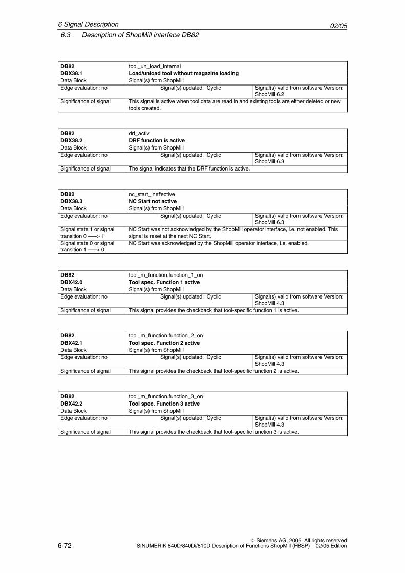
02/056.3 Description of ShopMill interface DB82
6-72 Siemens AG, 2005. All rights reserved
SINUMERIK 840D/840Di/810D Description of Functions ShopMill (FBSP) – 02/05 Edition
DB82 tool_un_load_internalDBX38.1 Load/unload tool without magazine loadingData Block Signal(s) from ShopMillEdge evaluation: no Signal(s) updated: Cyclic Signal(s) valid from software Version:
ShopMill 6.2Significance of signal This signal is active when tool data are read in and existing tools are either deleted or new
tools created.
DB82 drf_activDBX38.2 DRF function is activeData Block Signal(s) from ShopMillEdge evaluation: no Signal(s) updated: Cyclic Signal(s) valid from software Version:
ShopMill 6.3Significance of signal The signal indicates that the DRF function is active.
DB82 nc_start_ineffectiveDBX38.3 NC Start not activeData Block Signal(s) from ShopMillEdge evaluation: no Signal(s) updated: Cyclic Signal(s) valid from software Version:
ShopMill 6.3Signal state 1 or signaltransition 0 –––> 1
NC Start was not acknowledged by the ShopMill operator interface, i.e. not enabled. Thissignal is reset at the next NC Start.
Signal state 0 or signaltransition 1 –––> 0
NC Start was acknowledged by the ShopMill operator interface, i.e. enabled.
DB82 tool_m_function.function_1_onDBX42.0 Tool spec. Function 1 activeData Block Signal(s) from ShopMillEdge evaluation: no Signal(s) updated: Cyclic Signal(s) valid from software Version:
ShopMill 4.3Significance of signal This signal provides the checkback that tool-specific function 1 is active.
DB82 tool_m_function.function_2_onDBX42.1 Tool spec. Function 2 activeData Block Signal(s) from ShopMillEdge evaluation: no Signal(s) updated: Cyclic Signal(s) valid from software Version:
ShopMill 4.3Significance of signal This signal provides the checkback that tool-specific function 2 is active.
DB82 tool_m_function.function_3_onDBX42.2 Tool spec. Function 3 activeData Block Signal(s) from ShopMillEdge evaluation: no Signal(s) updated: Cyclic Signal(s) valid from software Version:
ShopMill 4.3Significance of signal This signal provides the checkback that tool-specific function 3 is active.
6 Signal Description
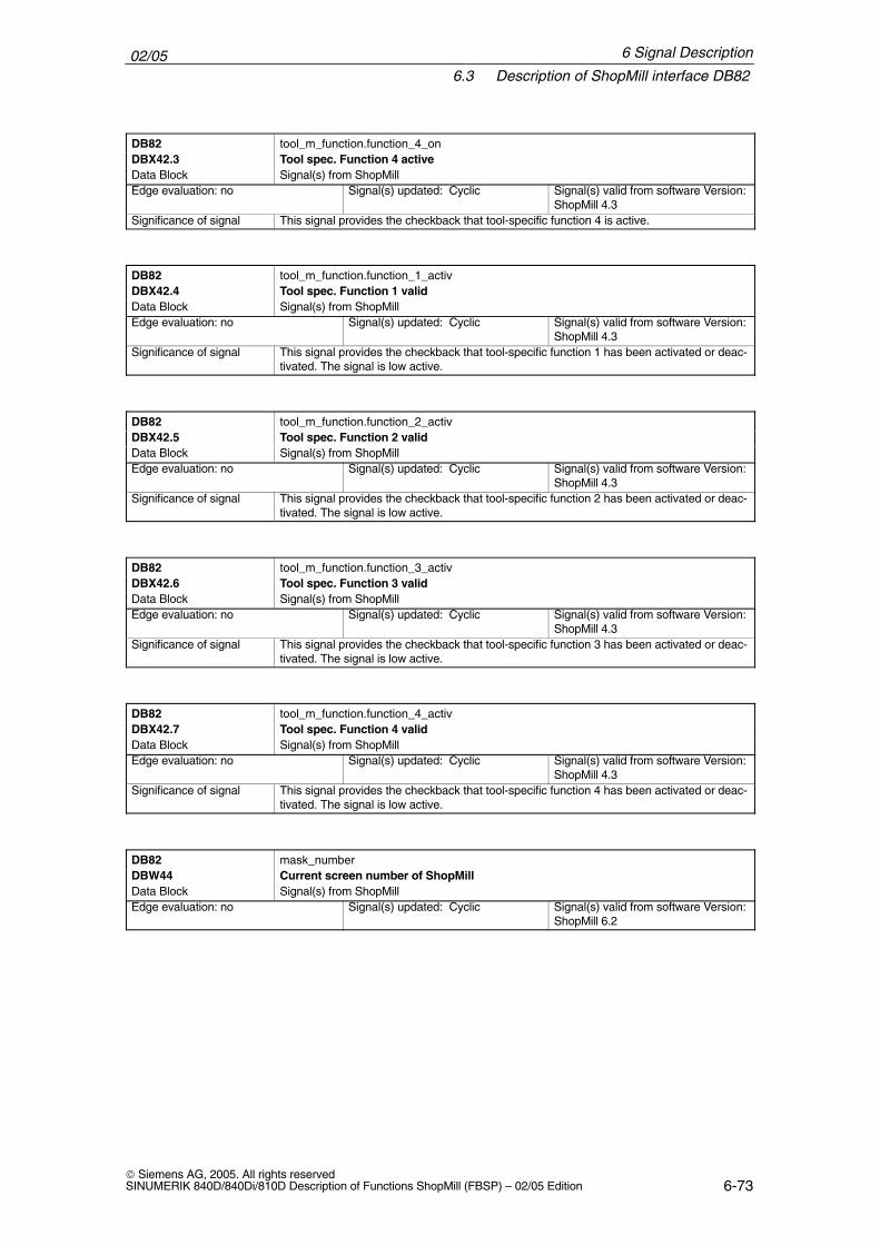
02/056.3 Description of ShopMill interface DB82
6-73 Siemens AG, 2005. All rights reservedSINUMERIK 840D/840Di/810D Description of Functions ShopMill (FBSP) – 02/05 Edition
DB82 tool_m_function.function_4_onDBX42.3 Tool spec. Function 4 activeData Block Signal(s) from ShopMillEdge evaluation: no Signal(s) updated: Cyclic Signal(s) valid from software Version:
ShopMill 4.3Significance of signal This signal provides the checkback that tool-specific function 4 is active.
DB82 tool_m_function.function_1_activDBX42.4 Tool spec. Function 1 validData Block Signal(s) from ShopMillEdge evaluation: no Signal(s) updated: Cyclic Signal(s) valid from software Version:
ShopMill 4.3Significance of signal This signal provides the checkback that tool-specific function 1 has been activated or deac-
tivated. The signal is low active.
DB82 tool_m_function.function_2_activDBX42.5 Tool spec. Function 2 validData Block Signal(s) from ShopMillEdge evaluation: no Signal(s) updated: Cyclic Signal(s) valid from software Version:
ShopMill 4.3Significance of signal This signal provides the checkback that tool-specific function 2 has been activated or deac-
tivated. The signal is low active.
DB82 tool_m_function.function_3_activDBX42.6 Tool spec. Function 3 validData Block Signal(s) from ShopMillEdge evaluation: no Signal(s) updated: Cyclic Signal(s) valid from software Version:
ShopMill 4.3Significance of signal This signal provides the checkback that tool-specific function 3 has been activated or deac-
tivated. The signal is low active.
DB82 tool_m_function.function_4_activDBX42.7 Tool spec. Function 4 validData Block Signal(s) from ShopMillEdge evaluation: no Signal(s) updated: Cyclic Signal(s) valid from software Version:
ShopMill 4.3Significance of signal This signal provides the checkback that tool-specific function 4 has been activated or deac-
tivated. The signal is low active.
DB82 mask_numberDBW44 Current screen number of ShopMillData Block Signal(s) from ShopMillEdge evaluation: no Signal(s) updated: Cyclic Signal(s) valid from software Version:
ShopMill 6.2
6 Signal Description
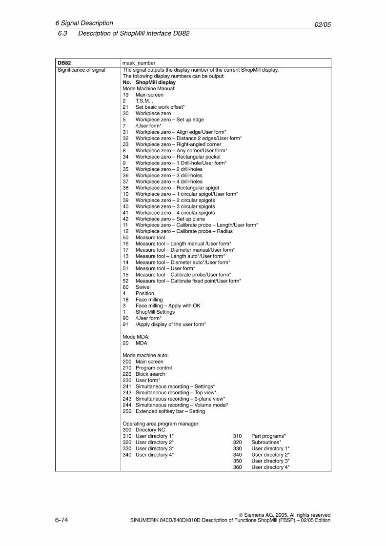
02/056.3 Description of ShopMill interface DB82
6-74 Siemens AG, 2005. All rights reserved
SINUMERIK 840D/840Di/810D Description of Functions ShopMill (FBSP) – 02/05 Edition
DB82 mask_numberSignificance of signal The signal outputs the display number of the current ShopMill display.
The following display numbers can be output:No. ShopMill displayMode Machine Manual:19 Main screen2 T,S,M...21 Set basic work offset*30 Workpiece zero5 Workpiece zero – Set up edge7 /User form*31 Workpiece zero – Align edge/User form*32 Workpiece zero – Distance 2 edges/User form*33 Workpiece zero – Right-angled corner8 Workpiece zero – Any corner/User form*34 Workpiece zero – Rectangular pocket9 Workpiece zero – 1 Drill-hole/User form*35 Workpiece zero – 2 drill-holes36 Workpiece zero – 3 drill-holes37 Workpiece zero – 4 drill-holes38 Workpiece zero – Rectangular spigot10 Workpiece zero – 1 circular spigot/User form*39 Workpiece zero – 2 circular spigots40 Workpiece zero – 3 circular spigots41 Workpiece zero – 4 circular spigots42 Workpiece zero – Set up plane11 Workpiece zero – Calibrate probe – Length/User form*12 Workpiece zero – Calibrate probe – Radius50 Measure tool16 Measure tool – Length manual /User form*17 Measure tool – Diameter manual/User form*13 Measure tool – Length auto*/User form*14 Measure tool – Diameter auto*/User form*51 Measure tool – User form*15 Measure tool – Calibrate probe/User form*52 Measure tool – Calibrate fixed point/User form*60 Swivel4 Position18 Face milling3 Face milling – Apply with OK1 ShopMill Settings90 /User form*91 /Apply display of the user form*
Mode MDA:20 MDA
Mode machine auto:200 Main screen210 Program control220 Block search230 User form*241 Simultaneous recording – Settings*242 Simultaneous recording – Top view*243 Simultaneous recording – 3-plane view*244 Simultaneous recording – Volume model*250 Extended softkey bar – Setting
Operating area program manager:300 Directory NC310 User directory 1* 310 Part programs*320 User directory 2* 320 Subroutines*330 User directory 3* 330 User directory 1*340 User directory 4* 340 User directory 2*
350 User directory 3*360 User directory 4*
6 Signal Description
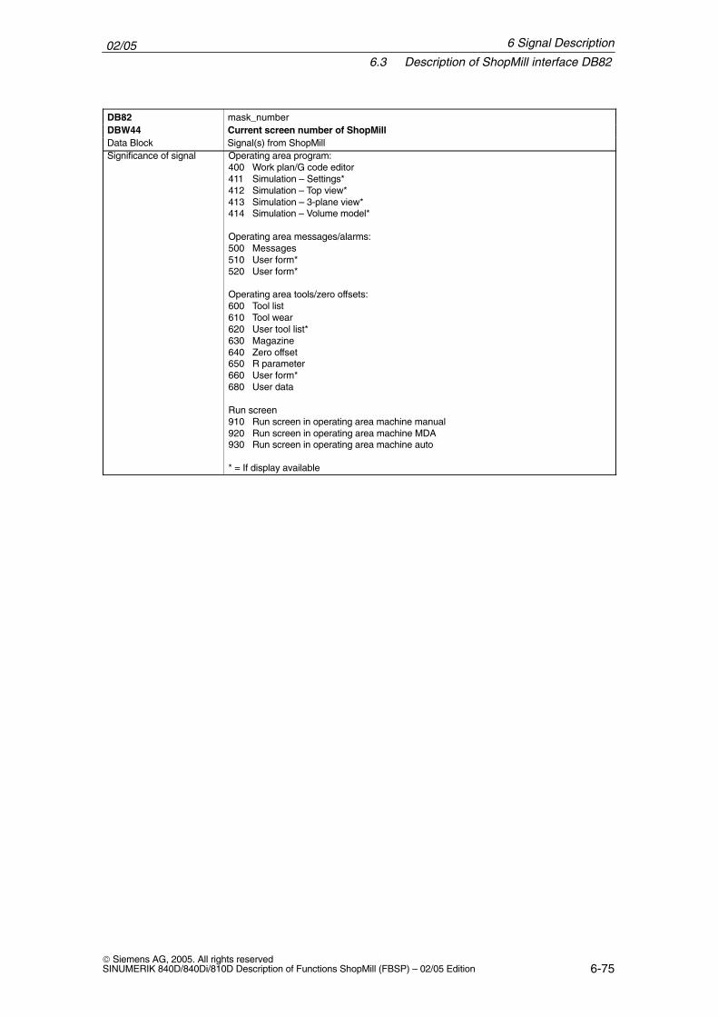
02/056.3 Description of ShopMill interface DB82
6-75 Siemens AG, 2005. All rights reservedSINUMERIK 840D/840Di/810D Description of Functions ShopMill (FBSP) – 02/05 Edition
DB82 mask_numberDBW44 Current screen number of ShopMillData Block Signal(s) from ShopMillSignificance of signal Operating area program:
400 Work plan/G code editor411 Simulation – Settings*412 Simulation – Top view*413 Simulation – 3-plane view*414 Simulation – Volume model*
Operating area messages/alarms:500 Messages510 User form*520 User form*
Operating area tools/zero offsets:600 Tool list610 Tool wear620 User tool list*630 Magazine640 Zero offset650 R parameter660 User form*680 User data
Run screen910 Run screen in operating area machine manual920 Run screen in operating area machine MDA930 Run screen in operating area machine auto
* = If display available
6 Signal Description
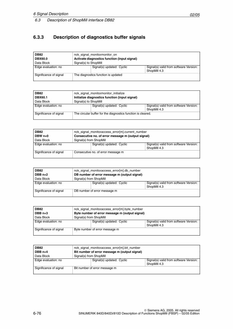
02/056.3 Description of ShopMill interface DB82
6-76 Siemens AG, 2005. All rights reserved
SINUMERIK 840D/840Di/810D Description of Functions ShopMill (FBSP) – 02/05 Edition
6.3.3 Description of diagnostics buffer signals
DB82 nck_signal_monitor.monitor_onDBX60.0 Activate diagnostics function (input signal)Data Block Signal(s) to ShopMillEdge evaluation: no Signal(s) updated: Cyclic Signal(s) valid from software Version:
ShopMill 4.3Significance of signal The diagnostics function is updated
DB82 nck_signal_monitor.monitor_initializeDBX60.1 Initialize diagnostics function (input signal)Data Block Signal(s) to ShopMillEdge evaluation: no Signal(s) updated: Cyclic Signal(s) valid from software Version:
ShopMill 4.3Significance of signal The circular buffer for the diagnostics function is cleared.
DB82 nck_signal_monitor.access_error[m].current_numberDBW n+0 Consecutive no. of error message m (output signal)Data Block Signal(s) from ShopMillEdge evaluation: no Signal(s) updated: Cyclic Signal(s) valid from software Version:
ShopMill 4.3Significance of signal Consecutive no. of error message m
DB82 nck_signal_monitor.access_error[m].db_numberDBB n+2 DB number of error message m (output signal)Data Block Signal(s) from ShopMillEdge evaluation: no Signal(s) updated: Cyclic Signal(s) valid from software Version:
ShopMill 4.3Significance of signal DB number of error message m
DB82 nck_signal_monitor.access_error[m].byte_numberDBB n+3 Byte number of error message m (output signal)Data Block Signal(s) from ShopMillEdge evaluation: no Signal(s) updated: Cyclic Signal(s) valid from software Version:
ShopMill 4.3Significance of signal Byte number of error message m
DB82 nck_signal_monitor.access_error[m].bit_numberDBB n+4 Bit number of error message m (output signal)Data Block Signal(s) from ShopMillEdge evaluation: no Signal(s) updated: Cyclic Signal(s) valid from software Version:
ShopMill 4.3Significance of signal Bit number of error message m
6 Signal Description
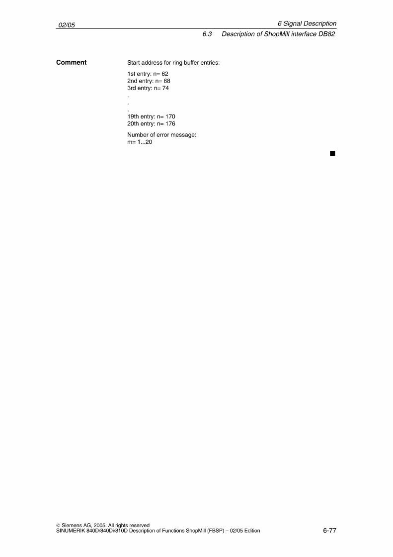
02/056.3 Description of ShopMill interface DB82
6-77 Siemens AG, 2005. All rights reservedSINUMERIK 840D/840Di/810D Description of Functions ShopMill (FBSP) – 02/05 Edition
Start address for ring buffer entries:
1st entry: n= 622nd entry: n= 683rd entry: n= 74...19th entry: n= 17020th entry: n= 176
Number of error message:m= 1...20
�
Comment
6 Signal Description
02/056.3 Description of ShopMill interface DB82
6-78 Siemens AG, 2005. All rights reserved
SINUMERIK 840D/840Di/810D Description of Functions ShopMill (FBSP) – 02/05 Edition
6 Signal Description
Notes
7-79 Siemens AG, 2005. All rights reservedSINUMERIK 840D/840Di/810D Description of Functions ShopMill (FBSP) – 02/05 Edition
Machine Data
7.1 NC machine data for ShopMill
For installation and startup of the NC (see Subsection 4.2.4 “NC Installation andStart-Up”) a machine data record CMM.8x0 is provided containing all relevantNC machine data (including tool management) together with the values to beset. You will find the machine data record on the software CD in the tools\mddirectory.
You must set NC machine data with exact values as specified. You can adaptNC machine data with minimum and variable values to the specific features ofyour machine.
Note
Remember that the machine data record also contains machine data forconfiguring the memory.
The machine data for calibrating the probe (measuring cycles) can be found inSubsection 9.1.5 “Machine data measuring cycles”.
A more detailed description of all NC machine data can be found in:References: /LIS/, Lists
/IAC/, Installation and Start-Up Guide 810D/IAD/, Installation and Start-Up Guide 840D/FB/, Description of Functions/HBI/, 840Di Manual
The load placed on the NCU by the position controller and the interpolator mustnot exceed a maximum value of 70%. You can set the load in the NC machinedata. To do that, proceed as follows:
� Change to the CNC-ISO operator interface and select the “Diagnosis” →“Service display” → “System resources” menu.
� Press “Start” softkey. The maximum value for “NCU load by position controller and interpolator” iscleared.
� Change to the ShopMill operator interface and in automatic operating modeselect the “Simultaneous recording” function.
NCU load
7
02/057.1 NC machine data for ShopMill
7-80 Siemens AG, 2005. All rights reserved
SINUMERIK 840D/840Di/810D Description of Functions ShopMill (FBSP) – 02/05 Edition
� Start the following test program:G0 G91LABEL:X1Y1Z1X-1Y-1Z-1GOTOB LABELM30
� Change back to the CNC-ISO operator interface and select the “Diagnosis”→ “Service display” → “System resources” menu.
� If the maximum value for “NCU load by position controller and interpolator” isgreater than 70%, adapt the interpolator cycle in MD 10070 $MN_IPO_SYSCLOCK_TIME_RATIO or the position controller cycle in MD10050 $MN_SYSCLOCK_CYCLE_TIME. Adapting the interpolator cyclehas the advantage that axis optimization is not modified.With the SINUMERIK 810D you can also set the interpolation task to com-munication task ratio via MD 10072 $MN_COM_IPO_TIME_RATIO. Thisvalue should be ≤ 0.5.
� Repeat the steps described.
7 Machine Data
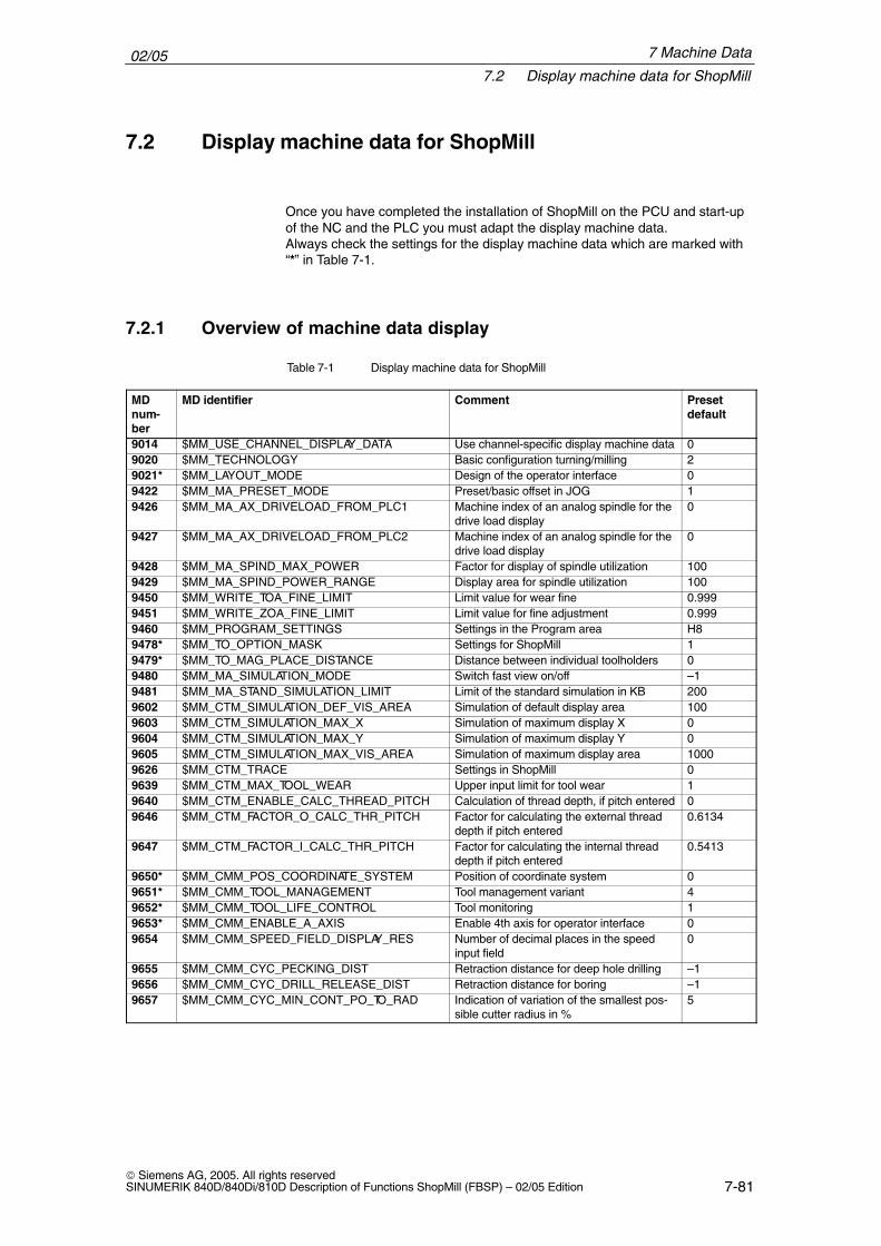
02/057.2 Display machine data for ShopMill
7-81 Siemens AG, 2005. All rights reservedSINUMERIK 840D/840Di/810D Description of Functions ShopMill (FBSP) – 02/05 Edition
7.2 Display machine data for ShopMill
Once you have completed the installation of ShopMill on the PCU and start-upof the NC and the PLC you must adapt the display machine data.Always check the settings for the display machine data which are marked with“*” in Table 7-1.
7.2.1 Overview of machine data display
Table 7-1 Display machine data for ShopMill
MDnum-ber
MD identifier Comment Preset default
9014 $MM_USE_CHANNEL_DISPLAY_DATA Use channel-specific display machine data 09020 $MM_TECHNOLOGY Basic configuration turning/milling 29021* $MM_LAYOUT_MODE Design of the operator interface 09422 $MM_MA_PRESET_MODE Preset/basic offset in JOG 19426 $MM_MA_AX_DRIVELOAD_FROM_PLC1 Machine index of an analog spindle for the
drive load display0
9427 $MM_MA_AX_DRIVELOAD_FROM_PLC2 Machine index of an analog spindle for thedrive load display
0
9428 $MM_MA_SPIND_MAX_POWER Factor for display of spindle utilization 1009429 $MM_MA_SPIND_POWER_RANGE Display area for spindle utilization 1009450 $MM_WRITE_TOA_FINE_LIMIT Limit value for wear fine 0.9999451 $MM_WRITE_ZOA_FINE_LIMIT Limit value for fine adjustment 0.9999460 $MM_PROGRAM_SETTINGS Settings in the Program area H89478* $MM_TO_OPTION_MASK Settings for ShopMill 19479* $MM_TO_MAG_PLACE_DISTANCE Distance between individual toolholders 09480 $MM_MA_SIMULATION_MODE Switch fast view on/off –19481 $MM_MA_STAND_SIMULATION_LIMIT Limit of the standard simulation in KB 2009602 $MM_CTM_SIMULATION_DEF_VIS_AREA Simulation of default display area 1009603 $MM_CTM_SIMULATION_MAX_X Simulation of maximum display X 09604 $MM_CTM_SIMULATION_MAX_Y Simulation of maximum display Y 09605 $MM_CTM_SIMULATION_MAX_VIS_AREA Simulation of maximum display area 10009626 $MM_CTM_TRACE Settings in ShopMill 09639 $MM_CTM_MAX_TOOL_WEAR Upper input limit for tool wear 19640 $MM_CTM_ENABLE_CALC_THREAD_PITCH Calculation of thread depth, if pitch entered 09646 $MM_CTM_FACTOR_O_CALC_THR_PITCH Factor for calculating the external thread
depth if pitch entered0.6134
9647 $MM_CTM_FACTOR_I_CALC_THR_PITCH Factor for calculating the internal threaddepth if pitch entered
0.5413
9650* $MM_CMM_POS_COORDINATE_SYSTEM Position of coordinate system 09651* $MM_CMM_TOOL_MANAGEMENT Tool management variant 49652* $MM_CMM_TOOL_LIFE_CONTROL Tool monitoring 19653* $MM_CMM_ENABLE_A_AXIS Enable 4th axis for operator interface 09654 $MM_CMM_SPEED_FIELD_DISPLAY_RES Number of decimal places in the speed
input field0
9655 $MM_CMM_CYC_PECKING_DIST Retraction distance for deep hole drilling –19656 $MM_CMM_CYC_DRILL_RELEASE_DIST Retraction distance for boring –19657 $MM_CMM_CYC_MIN_CONT_PO_TO_RAD Indication of variation of the smallest pos-
sible cutter radius in %5
7 Machine Data
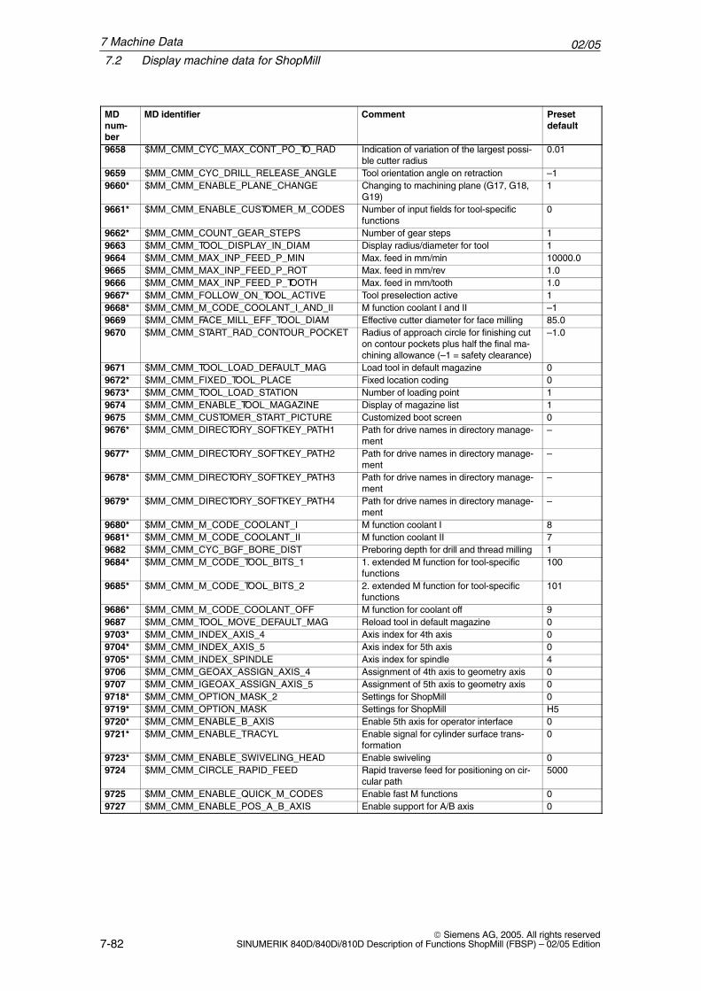
02/057.2 Display machine data for ShopMill
7-82 Siemens AG, 2005. All rights reserved
SINUMERIK 840D/840Di/810D Description of Functions ShopMill (FBSP) – 02/05 Edition
MDnum-ber
Preset default
CommentMD identifier
9658 $MM_CMM_CYC_MAX_CONT_PO_TO_RAD Indication of variation of the largest possi-ble cutter radius
0.01
9659 $MM_CMM_CYC_DRILL_RELEASE_ANGLE Tool orientation angle on retraction –19660* $MM_CMM_ENABLE_PLANE_CHANGE Changing to machining plane (G17, G18,
G19)1
9661* $MM_CMM_ENABLE_CUSTOMER_M_CODES Number of input fields for tool-specificfunctions
0
9662* $MM_CMM_COUNT_GEAR_STEPS Number of gear steps 19663 $MM_CMM_TOOL_DISPLAY_IN_DIAM Display radius/diameter for tool 19664 $MM_CMM_MAX_INP_FEED_P_MIN Max. feed in mm/min 10000.09665 $MM_CMM_MAX_INP_FEED_P_ROT Max. feed in mm/rev 1.09666 $MM_CMM_MAX_INP_FEED_P_TOOTH Max. feed in mm/tooth 1.09667* $MM_CMM_FOLLOW_ON_TOOL_ACTIVE Tool preselection active 19668* $MM_CMM_M_CODE_COOLANT_I_AND_II M function coolant I and II –19669 $MM_CMM_FACE_MILL_EFF_TOOL_DIAM Effective cutter diameter for face milling 85.09670 $MM_CMM_START_RAD_CONTOUR_POCKET Radius of approach circle for finishing cut
on contour pockets plus half the final ma-chining allowance (–1 = safety clearance)
–1.0
9671 $MM_CMM_TOOL_LOAD_DEFAULT_MAG Load tool in default magazine 09672* $MM_CMM_FIXED_TOOL_PLACE Fixed location coding 09673* $MM_CMM_TOOL_LOAD_STATION Number of loading point 19674 $MM_CMM_ENABLE_TOOL_MAGAZINE Display of magazine list 19675 $MM_CMM_CUSTOMER_START_PICTURE Customized boot screen 09676* $MM_CMM_DIRECTORY_SOFTKEY_PATH1 Path for drive names in directory manage-
ment–
9677* $MM_CMM_DIRECTORY_SOFTKEY_PATH2 Path for drive names in directory manage-ment
–
9678* $MM_CMM_DIRECTORY_SOFTKEY_PATH3 Path for drive names in directory manage-ment
–
9679* $MM_CMM_DIRECTORY_SOFTKEY_PATH4 Path for drive names in directory manage-ment
–
9680* $MM_CMM_M_CODE_COOLANT_I M function coolant I 89681* $MM_CMM_M_CODE_COOLANT_II M function coolant II 79682 $MM_CMM_CYC_BGF_BORE_DIST Preboring depth for drill and thread milling 19684* $MM_CMM_M_CODE_TOOL_BITS_1 1. extended M function for tool-specific
functions100
9685* $MM_CMM_M_CODE_TOOL_BITS_2 2. extended M function for tool-specificfunctions
101
9686* $MM_CMM_M_CODE_COOLANT_OFF M function for coolant off 99687 $MM_CMM_TOOL_MOVE_DEFAULT_MAG Reload tool in default magazine 09703* $MM_CMM_INDEX_AXIS_4 Axis index for 4th axis 09704* $MM_CMM_INDEX_AXIS_5 Axis index for 5th axis 09705* $MM_CMM_INDEX_SPINDLE Axis index for spindle 49706 $MM_CMM_GEOAX_ASSIGN_AXIS_4 Assignment of 4th axis to geometry axis 09707 $MM_CMM_IGEOAX_ASSIGN_AXIS_5 Assignment of 5th axis to geometry axis 09718* $MM_CMM_OPTION_MASK_2 Settings for ShopMill 09719* $MM_CMM_OPTION_MASK Settings for ShopMill H59720* $MM_CMM_ENABLE_B_AXIS Enable 5th axis for operator interface 09721* $MM_CMM_ENABLE_TRACYL Enable signal for cylinder surface trans-
formation0
9723* $MM_CMM_ENABLE_SWIVELING_HEAD Enable swiveling 09724 $MM_CMM_CIRCLE_RAPID_FEED Rapid traverse feed for positioning on cir-
cular path5000
9725 $MM_CMM_ENABLE_QUICK_M_CODES Enable fast M functions 09727 $MM_CMM_ENABLE_POS_A_B_AXIS Enable support for A/B axis 0
7 Machine Data
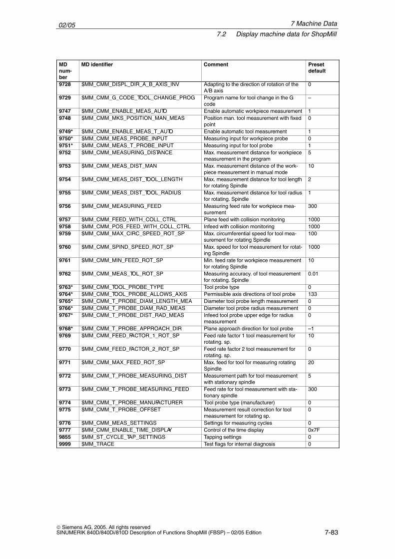
02/057.2 Display machine data for ShopMill
7-83 Siemens AG, 2005. All rights reservedSINUMERIK 840D/840Di/810D Description of Functions ShopMill (FBSP) – 02/05 Edition
MDnum-ber
Preset default
CommentMD identifier
9728 $MM_CMM_DISPL_DIR_A_B_AXIS_INV Adapting to the direction of rotation of theA/B axis
0
9729 $MM_CMM_G_CODE_TOOL_CHANGE_PROG Program name for tool change in the Gcode
–
9747 $MM_CMM_ENABLE_MEAS_AUTO Enable automatic workpiece measurement 19748 $MM_CMM_MKS_POSITION_MAN_MEAS Position man. tool measurement with fixed
point0
9749* $MM_CMM_ENABLE_MEAS_T_AUTO Enable automatic tool measurement 19750* $MM_CMM_MEAS_PROBE_INPUT Measuring input for workpiece probe 09751* $MM_CMM_MEAS_T_PROBE_INPUT Measuring input for tool probe 19752 $MM_CMM_MEASURING_DISTANCE Max. measurement distance for workpiece
measurement in the program5
9753 $MM_CMM_MEAS_DIST_MAN Max. measurement distance of the work-piece measurement in manual mode
10
9754 $MM_CMM_MEAS_DIST_TOOL_LENGTH Max. measurement distance for tool lengthfor rotating Spindle
2
9755 $MM_CMM_MEAS_DIST_TOOL_RADIUS Max. measurement distance for tool radiusfor rotating. Spindle
1
9756 $MM_CMM_MEASURING_FEED Measuring feed rate for workpiece mea-surement
300
9757 $MM_CMM_FEED_WITH_COLL_CTRL Plane feed with collision monitoring 10009758 $MM_CMM_POS_FEED_WITH_COLL_CTRL Infeed with collision monitoring 10009759 $MM_CMM_MAX_CIRC_SPEED_ROT_SP Max. circumferential speed for tool mea-
surement for rotating Spindle100
9760 $MM_CMM_SPIND_SPEED_ROT_SP Max. speed for tool measurement for rotat-ing Spindle
1000
9761 $MM_CMM_MIN_FEED_ROT_SP Min. feed rate for workpiece measurementfor rotating Spindle
10
9762 $MM_CMM_MEAS_TOL_ROT_SP Measuring accuracy. of tool measurementfor rotating. Spindle
0.01
9763* $MM_CMM_TOOL_PROBE_TYPE Tool probe type 09764* $MM_CMM_TOOL_PROBE_ALLOWS_AXIS Permissible axis directions of tool probe 1339765* $MM_CMM_T_PROBE_DIAM_LENGTH_MEA Diameter tool probe length measurement 09766* $MM_CMM_T_PROBE_DIAM_RAD_MEAS Diameter tool probe radius measurement 09767* $MM_CMM_T_PROBE_DIST_RAD_MEAS Infeed tool probe upper edge for radius
measurement0
9768* $MM_CMM_T_PROBE_APPROACH_DIR Plane approach direction for tool probe –19769 $MM_CMM_FEED_FACTOR_1_ROT_SP Feed rate factor 1 tool measurement for
rotating. sp.10
9770 $MM_CMM_FEED_FACTOR_2_ROT_SP Feed rate factor 2 tool measurement forrotating. sp.
0
9771 $MM_CMM_MAX_FEED_ROT_SP Max. feed for tool for measuring rotatingSpindle
20
9772 $MM_CMM_T_PROBE_MEASURING_DIST Measurement path for tool measurementwith stationary spindle
5
9773 $MM_CMM_T_PROBE_MEASURING_FEED Feed rate for tool measurement with sta-tionary spindle
300
9774 $MM_CMM_T_PROBE_MANUFACTURER Tool probe type (manufacturer) 09775 $MM_CMM_T_PROBE_OFFSET Measurement result correction for tool
measurement for rotating sp.0
9776 $MM_CMM_MEAS_SETTINGS Settings for measuring cycles 09777 $MM_CMM_ENABLE_TIME_DISPLAY Control of the time display 0x7F9855 $MM_ST_CYCLE_TAP_SETTINGS Tapping settings 09999 $MM_TRACE Test flags for internal diagnosis 0
7 Machine Data
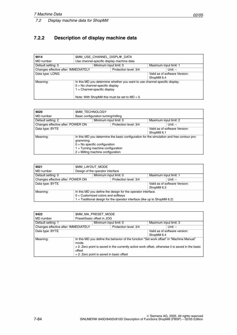
02/057.2 Display machine data for ShopMill
7-84 Siemens AG, 2005. All rights reserved
SINUMERIK 840D/840Di/810D Description of Functions ShopMill (FBSP) – 02/05 Edition
7.2.2 Description of display machine data
9014 $MM_USE_CHANNEL_DISPLAY_DATAMD number Use channel-specific display machine dataDefault setting: 0 Minimum input limit: 0 Maximum input limit: 1Changes effective after: IMMEDIATELY Protection level: 3/4 Unit: –Data type: LONG Valid as of software Version:
ShopMill 6.4Meaning: In this MD you determine whether you want to use channel-specific display.
0 = No channel-specific display1 = Channel-specific display
Note: With ShopMill this must be set to MD = 0.
9020 $MM_TECHNOLOGYMD number Basic configuration turning/millingDefault setting: 2 Minimum input limit: 0 Maximum input limit: 2Changes effective after: POWER ON Protection level: 3/4 Unit: –Data type: BYTE Valid as of software Version:
ShopMill 6.1Meaning: In this MD you determine the basic configuration for the simulation and free contour pro-
gramming.0 = No specific configuration1 = Turning machine configuration2 = Milling machine configuration
9021 $MM_LAYOUT_MODEMD number Design of the operator interfaceDefault setting: 0 Minimum input limit: 0 Maximum input limit: 1Changes effective after: POWER ON Protection level: 3/4 Unit: –Data type: BYTE Valid as of software Version:
ShopMill 6.3Meaning: In this MD you define the design for the operator interface.
0 = Customized colors and softkeys1 = Traditional design for the operator interface (like up to ShopMill 6.2)
9422 $MM_MA_PRESET_MODEMD number Preset/basic offset in JOGDefault setting: 1 Minimum input limit: 0 Maximum input limit: 3Changes effective after: IMMEDIATELY Protection level: 3/4 Unit: –Data type: BYTE Valid as of software version:
ShopMill 6.4Meaning: In this MD you define the behavior of the function “Set work offset” in “Machine Manual”
mode.≠ 2: Zero point is saved in the currently active work offset, otherwise it is saved in the basicoffset= 2: Zero point is saved in basic offset
7 Machine Data
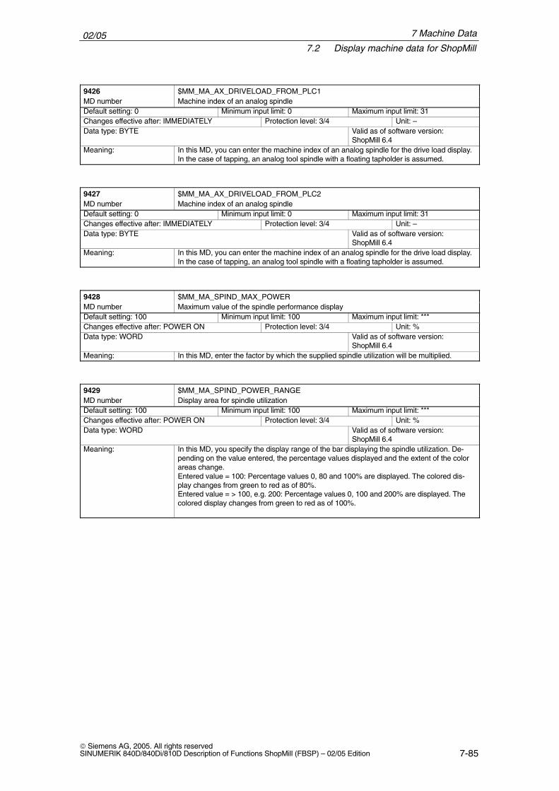
02/057.2 Display machine data for ShopMill
7-85 Siemens AG, 2005. All rights reservedSINUMERIK 840D/840Di/810D Description of Functions ShopMill (FBSP) – 02/05 Edition
9426 $MM_MA_AX_DRIVELOAD_FROM_PLC1MD number Machine index of an analog spindleDefault setting: 0 Minimum input limit: 0 Maximum input limit: 31Changes effective after: IMMEDIATELY Protection level: 3/4 Unit: –Data type: BYTE Valid as of software version:
ShopMill 6.4Meaning: In this MD, you can enter the machine index of an analog spindle for the drive load display.
In the case of tapping, an analog tool spindle with a floating tapholder is assumed.
9427 $MM_MA_AX_DRIVELOAD_FROM_PLC2MD number Machine index of an analog spindleDefault setting: 0 Minimum input limit: 0 Maximum input limit: 31Changes effective after: IMMEDIATELY Protection level: 3/4 Unit: –Data type: BYTE Valid as of software version:
ShopMill 6.4Meaning: In this MD, you can enter the machine index of an analog spindle for the drive load display.
In the case of tapping, an analog tool spindle with a floating tapholder is assumed.
9428 $MM_MA_SPIND_MAX_POWERMD number Maximum value of the spindle performance displayDefault setting: 100 Minimum input limit: 100 Maximum input limit: ***Changes effective after: POWER ON Protection level: 3/4 Unit: %Data type: WORD Valid as of software version:
ShopMill 6.4Meaning: In this MD, enter the factor by which the supplied spindle utilization will be multiplied.
9429 $MM_MA_SPIND_POWER_RANGEMD number Display area for spindle utilizationDefault setting: 100 Minimum input limit: 100 Maximum input limit: ***Changes effective after: POWER ON Protection level: 3/4 Unit: %Data type: WORD Valid as of software version:
ShopMill 6.4Meaning: In this MD, you specify the display range of the bar displaying the spindle utilization. De-
pending on the value entered, the percentage values displayed and the extent of the colorareas change.Entered value = 100: Percentage values 0, 80 and 100% are displayed. The colored dis-play changes from green to red as of 80%.Entered value = > 100, e.g. 200: Percentage values 0, 100 and 200% are displayed. Thecolored display changes from green to red as of 100%.
7 Machine Data
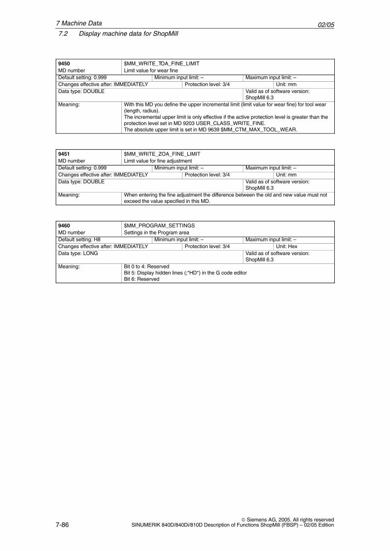
02/057.2 Display machine data for ShopMill
7-86 Siemens AG, 2005. All rights reserved
SINUMERIK 840D/840Di/810D Description of Functions ShopMill (FBSP) – 02/05 Edition
9450 $MM_WRITE_TOA_FINE_LIMITMD number Limit value for wear fineDefault setting: 0.999 Minimum input limit: – Maximum input limit: –Changes effective after: IMMEDIATELY Protection level: 3/4 Unit: mmData type: DOUBLE Valid as of software version:
ShopMill 6.3Meaning: With this MD you define the upper incremental limit (limit value for wear fine) for tool wear
(length, radius).The incremental upper limit is only effective if the active protection level is greater than theprotection level set in MD 9203 USER_CLASS_WRITE_FINE.The absolute upper limit is set in MD 9639 $MM_CTM_MAX_TOOL_WEAR.
9451 $MM_WRITE_ZOA_FINE_LIMITMD number Limit value for fine adjustmentDefault setting: 0.999 Minimum input limit: – Maximum input limit: –Changes effective after: IMMEDIATELY Protection level: 3/4 Unit: mmData type: DOUBLE Valid as of software version:
ShopMill 6.3Meaning: When entering the fine adjustment the difference between the old and new value must not
exceed the value specified in this MD.
9460 $MM_PROGRAM_SETTINGSMD number Settings in the Program areaDefault setting: H8 Minimum input limit: – Maximum input limit: –Changes effective after: IMMEDIATELY Protection level: 3/4 Unit: HexData type: LONG Valid as of software version:
ShopMill 6.3Meaning: Bit 0 to 4: Reserved
Bit 5: Display hidden lines (;*HD*) in the G code editorBit 6: Reserved
7 Machine Data
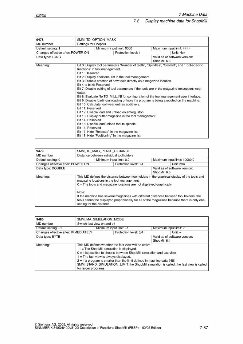
02/057.2 Display machine data for ShopMill
7-87 Siemens AG, 2005. All rights reservedSINUMERIK 840D/840Di/810D Description of Functions ShopMill (FBSP) – 02/05 Edition
9478 $MM_TO_OPTION_MASKMD number Settings for ShopMillDefault setting: 1 Minimum input limit: 0000 Maximum input limit: FFFFChanges effective after: POWER ON Protection level: 1 Unit: HexData type: LONG Valid as of software version:
ShopMill 6.3Meaning: Bit 0: Display tool parameters “Number of teeth”, “Spindles”, “Coolant”, and “Tool-specific
functions” in tool management.Bit 1: ReservedBit 2: Display additional list in the tool managementBit 3: Disable creation of new tools directly on a magazine location.Bit 4 to bit 6: ReservedBit 7: Disable editing of tool parameters if the tools are in the magazine (exception: weardata).Bit 8: Evaluate file TO_MILL.INI for configuration of the tool management user interface.Bit 9: Disable loading/unloading of tools if a program is being executed on the machine.Bit 10: Calculate tool wear entries additively.Bit 11: ReservedBit 12: Disable load and unload on emerg. stop.Bit 13: Display buffer magazine in the tool management.Bit 14: ReservedBit 15: Disable load/unload tool to spindle.Bit 16: ReservedBit 17: Hide “Relocate” in the magazine list.Bit 18: Hide “Positioning” in the magazine list.
9479 $MM_TO_MAG_PLACE_DISTANCEMD number Distance between individual toolholdersDefault setting: 0 Minimum input limit: 0.0 Maximum input limit: 10000.0Changes effective after: POWER ON Protection level: 3/4 Unit: mmData type: DOUBLE Valid as of software version:
ShopMill 6.3Meaning: This MD defines the distance between toolholders in the graphical display of the tools and
magazine locations in the tool management.0 = The tools and magazine locations are not displayed graphically.
Note:If the machine has several magazines with different distances between tool holders, thetools cannot be displayed proportionally for all of the magazines because there is only onesetting for the distance.
9480 $MM_MA_SIMULATION_MODEMD number Switch fast view on and offDefault setting: –1 Minimum input limit: –1 Maximum input limit: 2Changes effective after: IMMEDIATELY Protection level: 3/4 Unit: –Data type: BYTE Valid as of software version:
ShopMill 6.4Meaning: This MD defines whether the fast view will be active.
–1 = The ShopMill simulation is displayed.0 = It is possible to choose between ShopMill simulation and fast view.1 = The fast view is always displayed.2 = If a program is smaller than the limit defined in machine data 9481 $MM_STAND_SIMULATION_LIMIT, the ShopMill simulation is called; the fast view is calledfor larger programs.
7 Machine Data
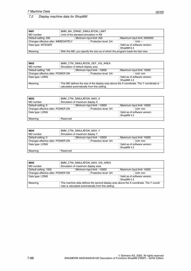
02/057.2 Display machine data for ShopMill
7-88 Siemens AG, 2005. All rights reserved
SINUMERIK 840D/840Di/810D Description of Functions ShopMill (FBSP) – 02/05 Edition
9481 $MM_MA_STAND_SIMULATION_LIMITMD number Limit of the standard simulation in KBDefault setting: 200 Minimum input limit: 200 Maximum input limit: 2000000Changes effective after: IMMEDIATELY Protection level: 3/4 Unit: –Data type: INTEGER Valid as of software version:
ShopMill 6.4Meaning: With this MD, you specify the size as of which the program loads the fast view.
9602 $MM_CTM_SIMULATION_DEF_VIS_AREAMD number Simulation of default display areaDefault setting: 100 Minimum input limit: –10000 Maximum input limit: 10000Changes effective after: POWER ON Protection level: 3/4 Unit: mmData type: LONG Valid as of software version:
ShopMill 4.3Meaning: This MD defines the size of the display area above the X coordinate. The Y coordinate is
calculated automatically from this setting.
9603 $MM_CTM_SIMULATION_MAX_XMD number Simulation of maximum display XDefault setting: 0 Minimum input limit: –10000 Maximum input limit: 10000Changes effective after: POWER ON Protection level: 3/4 Unit: mmData type: LONG Valid as of software version:
ShopMill 4.3Meaning: Reserved
9604 $MM_CTM_SIMULATION_MAX_YMD number Simulation of maximum display YDefault setting: 0 Minimum input limit: –10000 Maximum input limit: 10000Changes effective after: POWER ON Protection level: 3/4 Unit: mmData type: LONG Valid as of software version:
ShopMill 4.3Meaning: Reserved
9605 $MM_CTM_SIMULATION_MAX_VIS_AREAMD number Simulation of maximum display areaDefault setting: 1000 Minimum input limit: –10000 Maximum input limit: 10000Changes effective after: POWER ON Protection level: 3/4 Unit: mmData type: LONG Valid as of software version:
ShopMill 4.3Meaning: This machine data defines the second display area above the X coordinate. The Y coordi-
nate is calculated automatically from this setting.
7 Machine Data
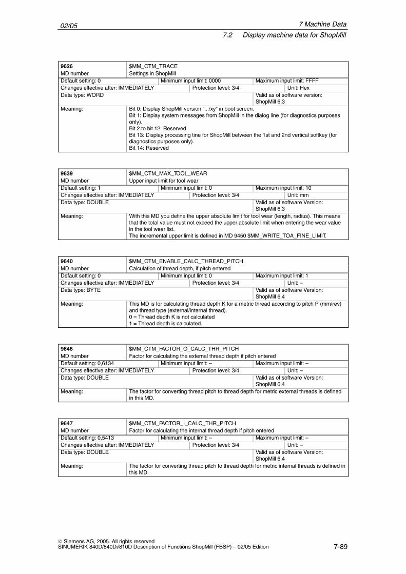
02/057.2 Display machine data for ShopMill
7-89 Siemens AG, 2005. All rights reservedSINUMERIK 840D/840Di/810D Description of Functions ShopMill (FBSP) – 02/05 Edition
9626 $MM_CTM_TRACEMD number Settings in ShopMillDefault setting: 0 Minimum input limit: 0000 Maximum input limit: FFFFChanges effective after: IMMEDIATELY Protection level: 3/4 Unit: HexData type: WORD Valid as of software version:
ShopMill 6.3Meaning: Bit 0: Display ShopMill version “.../xy” in boot screen.
Bit 1: Display system messages from ShopMill in the dialog line (for diagnostics purposesonly).Bit 2 to bit 12: ReservedBit 13: Display processing tine for ShopMill between the 1st and 2nd vertical softkey (fordiagnostics purposes only).Bit 14: Reserved
9639 $MM_CTM_MAX_TOOL_WEARMD number Upper input limit for tool wearDefault setting: 1 Minimum input limit: 0 Maximum input limit: 10Changes effective after: IMMEDIATELY Protection level: 3/4 Unit: mmData type: DOUBLE Valid as of software Version:
ShopMill 6.3Meaning: With this MD you define the upper absolute limit for tool wear (length, radius). This means
that the total value must not exceed the upper absolute limit when entering the wear valuein the tool wear list.The incremental upper limit is defined in MD 9450 $MM_WRITE_TOA_FINE_LIMIT.
9640 $MM_CTM_ENABLE_CALC_THREAD_PITCHMD number Calculation of thread depth, if pitch enteredDefault setting: 0 Minimum input limit: 0 Maximum input limit: 1Changes effective after: IMMEDIATELY Protection level: 3/4 Unit: –Data type: BYTE Valid as of software Version:
ShopMill 6.4Meaning: This MD is for calculating thread depth K for a metric thread according to pitch P (mm/rev)
and thread type (external/internal thread).0 = Thread depth K is not calculated1 = Thread depth is calculated.
9646 $MM_CTM_FACTOR_O_CALC_THR_PITCHMD number Factor for calculating the external thread depth if pitch enteredDefault setting: 0,6134 Minimum input limit: – Maximum input limit: –Changes effective after: IMMEDIATELY Protection level: 3/4 Unit: –Data type: DOUBLE Valid as of software Version:
ShopMill 6.4Meaning: The factor for converting thread pitch to thread depth for metric external threads is defined
in this MD.
9647 $MM_CTM_FACTOR_I_CALC_THR_PITCHMD number Factor for calculating the internal thread depth if pitch enteredDefault setting: 0,5413 Minimum input limit: – Maximum input limit: –Changes effective after: IMMEDIATELY Protection level: 3/4 Unit: –Data type: DOUBLE Valid as of software Version:
ShopMill 6.4Meaning: The factor for converting thread pitch to thread depth for metric internal threads is defined in
this MD.
7 Machine Data
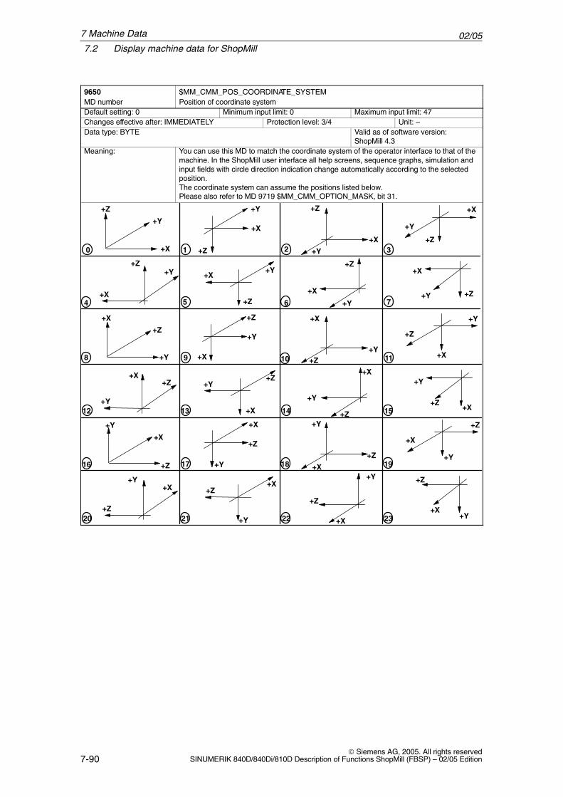
02/057.2 Display machine data for ShopMill
7-90 Siemens AG, 2005. All rights reserved
SINUMERIK 840D/840Di/810D Description of Functions ShopMill (FBSP) – 02/05 Edition
9650 $MM_CMM_POS_COORDINATE_SYSTEMMD number Position of coordinate systemDefault setting: 0 Minimum input limit: 0 Maximum input limit: 47Changes effective after: IMMEDIATELY Protection level: 3/4 Unit: –Data type: BYTE Valid as of software version:
ShopMill 4.3Meaning: You can use this MD to match the coordinate system of the operator interface to that of the
machine. In the ShopMill user interface all help screens, sequence graphs, simulation andinput fields with circle direction indication change automatically according to the selectedposition.The coordinate system can assume the positions listed below.Please also refer to MD 9719 $MM_CMM_OPTION_MASK, bit 31.
+Y
+X
+Z
0 1 2 3
4 5 6 7
8 9 10 11
12 13 14 15
16 17 18 19
20 21 22 23
+Y
+Y
+X
+Z+X
+Y
+Z
+Y
+X
+Z
+X
+Z+Y +Y
+Z
+X
+X
+Z
+Y+Y
+Z
+X
+X
+Z
+Y
+Y
+X
+Z +X
+Y+Z
+Y
+X
+Z
+X+Z +Y
+Z
+X
+X
+Z
+Y
+Y+Z
+X
+Y
+Z
+Y
+Y
+X
+Z
+X
+Y
+Z +Y
+X
+Z
+X
+Z
+Y
+Z+X
+X
+Z
+Y
+Y +Z
+X
+X
7 Machine Data
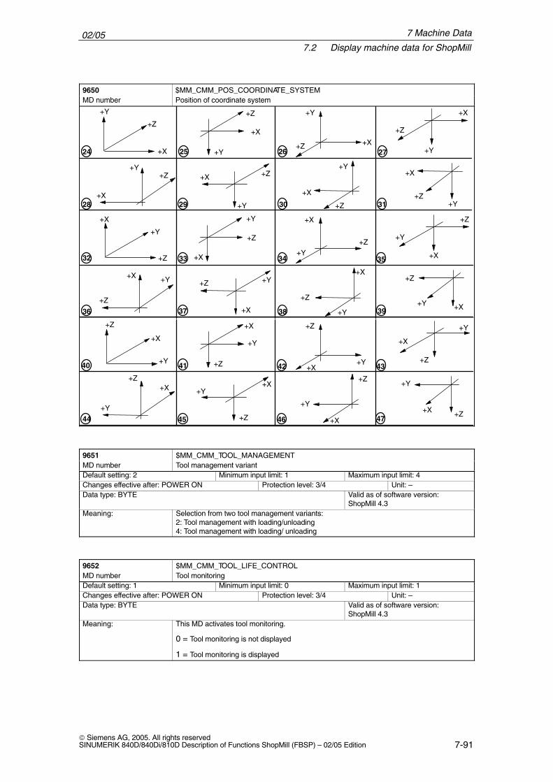
02/057.2 Display machine data for ShopMill
7-91 Siemens AG, 2005. All rights reservedSINUMERIK 840D/840Di/810D Description of Functions ShopMill (FBSP) – 02/05 Edition
9650 $MM_CMM_POS_COORDINATE_SYSTEMMD number Position of coordinate system
+Y
+X
+Z
24 25 26 27
28 29 30 31
32 33 34 35
36 37 38 39
+Y
+Y
+X
+Z
+X
+Y
+Z +Y
+X
+Z
+X
+Z+Y
+Y
+Z+X
+X
+Z +Y
+Y
+Z
+X
+X
+Z
+Y
+Y
+X
+Z
+X
+Y+Z
+Y
+X
+Z
+X
+Z
+Y+Z
+X
+X
+Z+Y
+Y
+Z
+X
40 41 42 43
44 45 46 47+Y
+Z
+Y
+Y
+X
+Z +X+Y
+Z +Y
+X
+Z
+X+Z
+Y
+Z
+X
+X
+Z+Y
+Y+Z+X
+X
9651 $MM_CMM_TOOL_MANAGEMENTMD number Tool management variantDefault setting: 2 Minimum input limit: 1 Maximum input limit: 4Changes effective after: POWER ON Protection level: 3/4 Unit: –Data type: BYTE Valid as of software version:
ShopMill 4.3Meaning: Selection from two tool management variants:
2: Tool management with loading/unloading4: Tool management with loading/ unloading
9652 $MM_CMM_TOOL_LIFE_CONTROLMD number Tool monitoringDefault setting: 1 Minimum input limit: 0 Maximum input limit: 1Changes effective after: POWER ON Protection level: 3/4 Unit: –Data type: BYTE Valid as of software version:
ShopMill 4.3Meaning: This MD activates tool monitoring.
0 = Tool monitoring is not displayed
1 = Tool monitoring is displayed
7 Machine Data
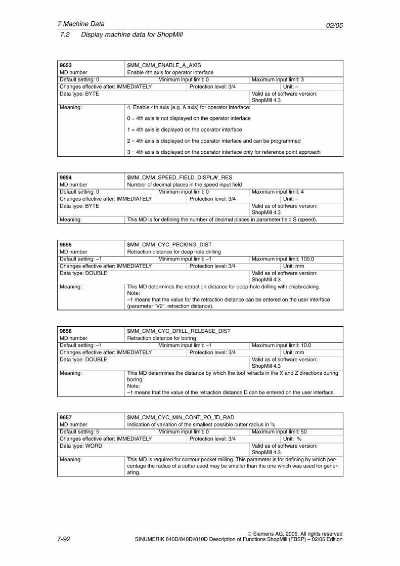
02/057.2 Display machine data for ShopMill
7-92 Siemens AG, 2005. All rights reserved
SINUMERIK 840D/840Di/810D Description of Functions ShopMill (FBSP) – 02/05 Edition
9653 $MM_CMM_ENABLE_A_AXISMD number Enable 4th axis for operator interfaceDefault setting: 0 Minimum input limit: 0 Maximum input limit: 3Changes effective after: IMMEDIATELY Protection level: 3/4 Unit: –Data type: BYTE Valid as of software version:
ShopMill 4.3Meaning: 4. Enable 4th axis (e.g. A axis) for operator interface:
0 = 4th axis is not displayed on the operator interface
1 = 4th axis is displayed on the operator interface
2 = 4th axis is displayed on the operator interface and can be programmed
3 = 4th axis is displayed on the operator interface only for reference point approach
9654 $MM_CMM_SPEED_FIELD_DISPLAY_RESMD number Number of decimal places in the speed input fieldDefault setting: 0 Minimum input limit: 0 Maximum input limit: 4Changes effective after: IMMEDIATELY Protection level: 3/4 Unit: –Data type: BYTE Valid as of software version:
ShopMill 4.3Meaning: This MD is for defining the number of decimal places in parameter field S (speed).
9655 $MM_CMM_CYC_PECKING_DISTMD number Retraction distance for deep hole drillingDefault setting: –1 Minimum input limit: –1 Maximum input limit: 100.0Changes effective after: IMMEDIATELY Protection level: 3/4 Unit: mmData type: DOUBLE Valid as of software version:
ShopMill 4.3Meaning: This MD determines the retraction distance for deep-hole drilling with chipbreaking.
Note:–1 means that the value for the retraction distance can be entered on the user interface(parameter “V2”, retraction distance).
9656 $MM_CMM_CYC_DRILL_RELEASE_DISTMD number Retraction distance for boringDefault setting: –1 Minimum input limit: –1 Maximum input limit: 10.0Changes effective after: IMMEDIATELY Protection level: 3/4 Unit: mmData type: DOUBLE Valid as of software version:
ShopMill 4.3Meaning: This MD determines the distance by which the tool retracts in the X and Z directions during
boring.Note:–1 means that the value of the retraction distance D can be entered on the user interface.
9657 $MM_CMM_CYC_MIN_CONT_PO_TO_RADMD number Indication of variation of the smallest possible cutter radius in %Default setting: 5 Minimum input limit: 0 Maximum input limit: 50Changes effective after: IMMEDIATELY Protection level: 3/4 Unit: %Data type: WORD Valid as of software version:
ShopMill 4.3Meaning: This MD is required for contour pocket milling. This parameter is for defining by which per-
centage the radius of a cutter used may be smaller than the one which was used for gener-ating.
7 Machine Data
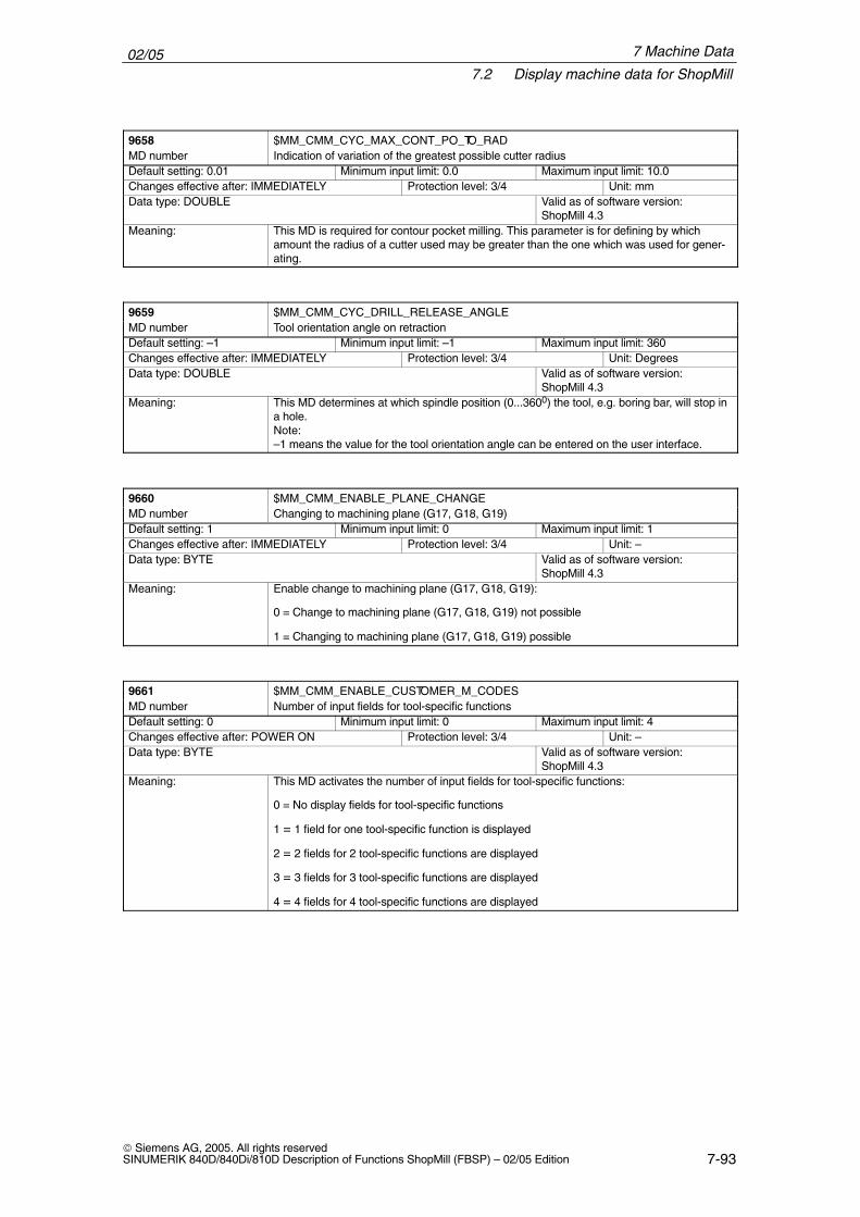
02/057.2 Display machine data for ShopMill
7-93 Siemens AG, 2005. All rights reservedSINUMERIK 840D/840Di/810D Description of Functions ShopMill (FBSP) – 02/05 Edition
9658 $MM_CMM_CYC_MAX_CONT_PO_TO_RADMD number Indication of variation of the greatest possible cutter radiusDefault setting: 0.01 Minimum input limit: 0.0 Maximum input limit: 10.0Changes effective after: IMMEDIATELY Protection level: 3/4 Unit: mmData type: DOUBLE Valid as of software version:
ShopMill 4.3Meaning: This MD is required for contour pocket milling. This parameter is for defining by which
amount the radius of a cutter used may be greater than the one which was used for gener-ating.
9659 $MM_CMM_CYC_DRILL_RELEASE_ANGLEMD number Tool orientation angle on retractionDefault setting: –1 Minimum input limit: –1 Maximum input limit: 360Changes effective after: IMMEDIATELY Protection level: 3/4 Unit: DegreesData type: DOUBLE Valid as of software version:
ShopMill 4.3Meaning: This MD determines at which spindle position (0...3600) the tool, e.g. boring bar, will stop in
a hole.Note:–1 means the value for the tool orientation angle can be entered on the user interface.
9660 $MM_CMM_ENABLE_PLANE_CHANGEMD number Changing to machining plane (G17, G18, G19)Default setting: 1 Minimum input limit: 0 Maximum input limit: 1Changes effective after: IMMEDIATELY Protection level: 3/4 Unit: –Data type: BYTE Valid as of software version:
ShopMill 4.3Meaning: Enable change to machining plane (G17, G18, G19):
0 = Change to machining plane (G17, G18, G19) not possible
1 = Changing to machining plane (G17, G18, G19) possible
9661 $MM_CMM_ENABLE_CUSTOMER_M_CODESMD number Number of input fields for tool-specific functionsDefault setting: 0 Minimum input limit: 0 Maximum input limit: 4Changes effective after: POWER ON Protection level: 3/4 Unit: –Data type: BYTE Valid as of software version:
ShopMill 4.3Meaning: This MD activates the number of input fields for tool-specific functions:
0 = No display fields for tool-specific functions
1 = 1 field for one tool-specific function is displayed
2 = 2 fields for 2 tool-specific functions are displayed
3 = 3 fields for 3 tool-specific functions are displayed
4 = 4 fields for 4 tool-specific functions are displayed
7 Machine Data
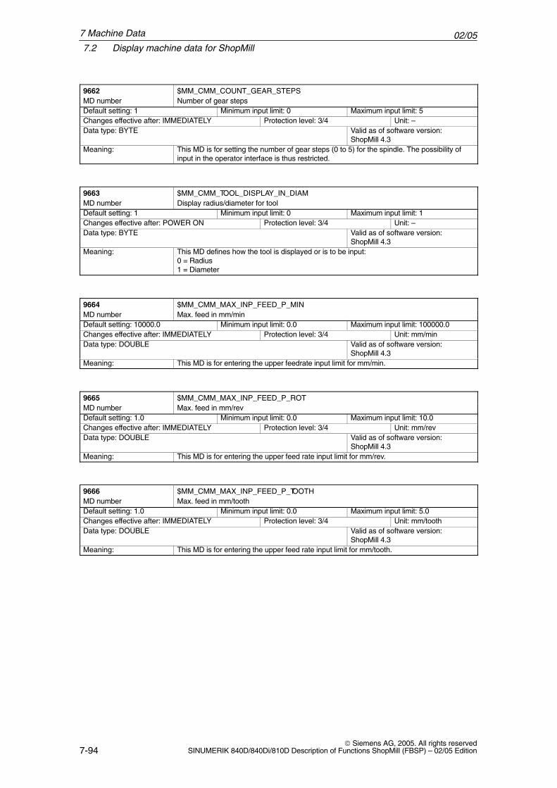
02/057.2 Display machine data for ShopMill
7-94 Siemens AG, 2005. All rights reserved
SINUMERIK 840D/840Di/810D Description of Functions ShopMill (FBSP) – 02/05 Edition
9662 $MM_CMM_COUNT_GEAR_STEPSMD number Number of gear stepsDefault setting: 1 Minimum input limit: 0 Maximum input limit: 5Changes effective after: IMMEDIATELY Protection level: 3/4 Unit: –Data type: BYTE Valid as of software version:
ShopMill 4.3Meaning: This MD is for setting the number of gear steps (0 to 5) for the spindle. The possibility of
input in the operator interface is thus restricted.
9663 $MM_CMM_TOOL_DISPLAY_IN_DIAMMD number Display radius/diameter for toolDefault setting: 1 Minimum input limit: 0 Maximum input limit: 1Changes effective after: POWER ON Protection level: 3/4 Unit: –Data type: BYTE Valid as of software version:
ShopMill 4.3Meaning: This MD defines how the tool is displayed or is to be input:
0 = Radius1 = Diameter
9664 $MM_CMM_MAX_INP_FEED_P_MINMD number Max. feed in mm/minDefault setting: 10000.0 Minimum input limit: 0.0 Maximum input limit: 100000.0Changes effective after: IMMEDIATELY Protection level: 3/4 Unit: mm/minData type: DOUBLE Valid as of software version:
ShopMill 4.3Meaning: This MD is for entering the upper feedrate input limit for mm/min.
9665 $MM_CMM_MAX_INP_FEED_P_ROTMD number Max. feed in mm/revDefault setting: 1.0 Minimum input limit: 0.0 Maximum input limit: 10.0Changes effective after: IMMEDIATELY Protection level: 3/4 Unit: mm/revData type: DOUBLE Valid as of software version:
ShopMill 4.3Meaning: This MD is for entering the upper feed rate input limit for mm/rev.
9666 $MM_CMM_MAX_INP_FEED_P_TOOTHMD number Max. feed in mm/toothDefault setting: 1.0 Minimum input limit: 0.0 Maximum input limit: 5.0Changes effective after: IMMEDIATELY Protection level: 3/4 Unit: mm/toothData type: DOUBLE Valid as of software version:
ShopMill 4.3Meaning: This MD is for entering the upper feed rate input limit for mm/tooth.
7 Machine Data
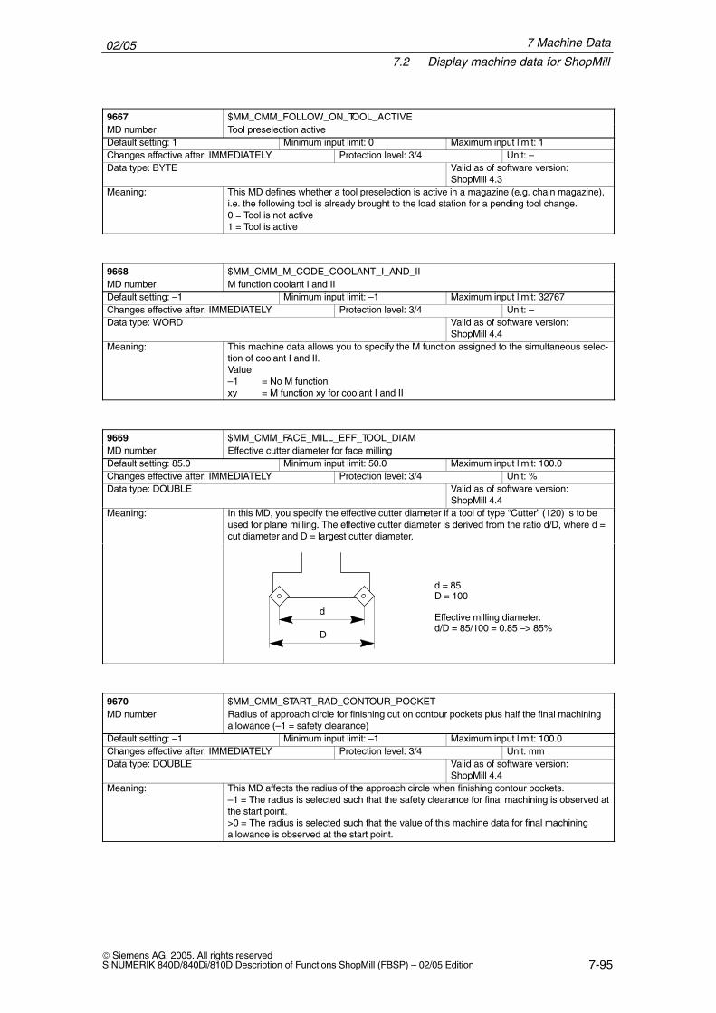
02/057.2 Display machine data for ShopMill
7-95 Siemens AG, 2005. All rights reservedSINUMERIK 840D/840Di/810D Description of Functions ShopMill (FBSP) – 02/05 Edition
9667 $MM_CMM_FOLLOW_ON_TOOL_ACTIVEMD number Tool preselection activeDefault setting: 1 Minimum input limit: 0 Maximum input limit: 1Changes effective after: IMMEDIATELY Protection level: 3/4 Unit: –Data type: BYTE Valid as of software version:
ShopMill 4.3Meaning: This MD defines whether a tool preselection is active in a magazine (e.g. chain magazine),
i.e. the following tool is already brought to the load station for a pending tool change.0 = Tool is not active1 = Tool is active
9668 $MM_CMM_M_CODE_COOLANT_I_AND_IIMD number M function coolant I and IIDefault setting: –1 Minimum input limit: –1 Maximum input limit: 32767Changes effective after: IMMEDIATELY Protection level: 3/4 Unit: –Data type: WORD Valid as of software version:
ShopMill 4.4Meaning: This machine data allows you to specify the M function assigned to the simultaneous selec-
tion of coolant I and II.Value:–1 = No M functionxy = M function xy for coolant I and II
9669 $MM_CMM_FACE_MILL_EFF_TOOL_DIAMMD number Effective cutter diameter for face millingDefault setting: 85.0 Minimum input limit: 50.0 Maximum input limit: 100.0Changes effective after: IMMEDIATELY Protection level: 3/4 Unit: %Data type: DOUBLE Valid as of software version:
ShopMill 4.4Meaning: In this MD, you specify the effective cutter diameter if a tool of type “Cutter” (120) is to be
used for plane milling. The effective cutter diameter is derived from the ratio d/D, where d =cut diameter and D = largest cutter diameter.
d = 85D = 100
Effective milling diameter: d/D = 85/100 = 0.85 –> 85%
d
D
9670 $MM_CMM_START_RAD_CONTOUR_POCKETMD number Radius of approach circle for finishing cut on contour pockets plus half the final machining
allowance (–1 = safety clearance)Default setting: –1 Minimum input limit: –1 Maximum input limit: 100.0Changes effective after: IMMEDIATELY Protection level: 3/4 Unit: mmData type: DOUBLE Valid as of software version:
ShopMill 4.4Meaning: This MD affects the radius of the approach circle when finishing contour pockets.
–1 = The radius is selected such that the safety clearance for final machining is observed atthe start point.>0 = The radius is selected such that the value of this machine data for final machiningallowance is observed at the start point.
7 Machine Data
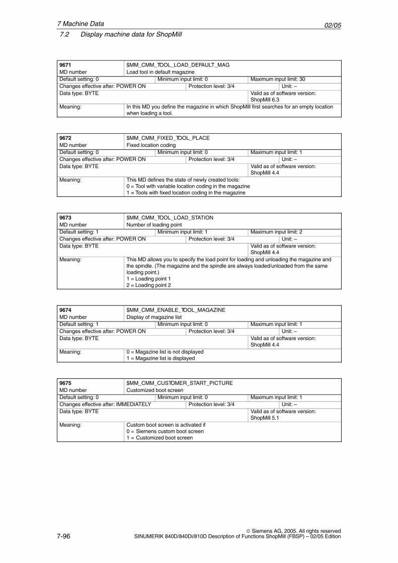
02/057.2 Display machine data for ShopMill
7-96 Siemens AG, 2005. All rights reserved
SINUMERIK 840D/840Di/810D Description of Functions ShopMill (FBSP) – 02/05 Edition
9671 $MM_CMM_TOOL_LOAD_DEFAULT_MAGMD number Load tool in default magazineDefault setting: 0 Minimum input limit: 0 Maximum input limit: 30Changes effective after: POWER ON Protection level: 3/4 Unit: –Data type: BYTE Valid as of software version:
ShopMill 6.3Meaning: In this MD you define the magazine in which ShopMill first searches for an empty location
when loading a tool.
9672 $MM_CMM_FIXED_TOOL_PLACEMD number Fixed location codingDefault setting: 0 Minimum input limit: 0 Maximum input limit: 1Changes effective after: POWER ON Protection level: 3/4 Unit: –Data type: BYTE Valid as of software version:
ShopMill 4.4Meaning: This MD defines the state of newly created tools:
0 = Tool with variable location coding in the magazine 1 = Tools with fixed location coding in the magazine
9673 $MM_CMM_TOOL_LOAD_STATIONMD number Number of loading pointDefault setting: 1 Minimum input limit: 1 Maximum input limit: 2Changes effective after: POWER ON Protection level: 3/4 Unit: –Data type: BYTE Valid as of software version:
ShopMill 4.4Meaning: This MD allows you to specify the load point for loading and unloading the magazine and
the spindle. (The magazine and the spindle are always loaded/unloaded from the sameloading point.)1 = Loading point 12 = Loading point 2
9674 $MM_CMM_ENABLE_TOOL_MAGAZINEMD number Display of magazine listDefault setting: 1 Minimum input limit: 0 Maximum input limit: 1Changes effective after: POWER ON Protection level: 3/4 Unit: –Data type: BYTE Valid as of software version:
ShopMill 4.4Meaning: 0 = Magazine list is not displayed
1 = Magazine list is displayed
9675 $MM_CMM_CUSTOMER_START_PICTUREMD number Customized boot screenDefault setting: 0 Minimum input limit: 0 Maximum input limit: 1Changes effective after: IMMEDIATELY Protection level: 3/4 Unit: –Data type: BYTE Valid as of software version:
ShopMill 5.1Meaning: Custom boot screen is activated if
0 = Siemens custom boot screen1 = Customized boot screen
7 Machine Data
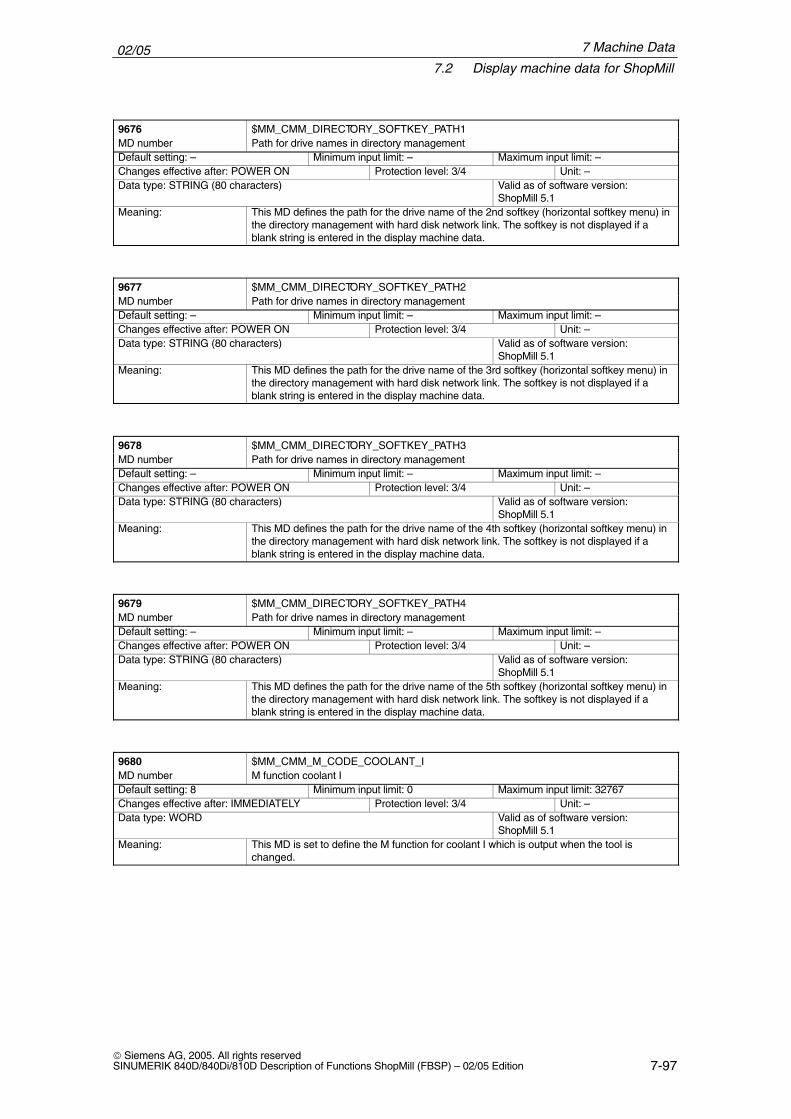
02/057.2 Display machine data for ShopMill
7-97 Siemens AG, 2005. All rights reservedSINUMERIK 840D/840Di/810D Description of Functions ShopMill (FBSP) – 02/05 Edition
9676 $MM_CMM_DIRECTORY_SOFTKEY_PATH1MD number Path for drive names in directory managementDefault setting: – Minimum input limit: – Maximum input limit: –Changes effective after: POWER ON Protection level: 3/4 Unit: –Data type: STRING (80 characters) Valid as of software version:
ShopMill 5.1Meaning: This MD defines the path for the drive name of the 2nd softkey (horizontal softkey menu) in
the directory management with hard disk network link. The softkey is not displayed if ablank string is entered in the display machine data.
9677 $MM_CMM_DIRECTORY_SOFTKEY_PATH2MD number Path for drive names in directory managementDefault setting: – Minimum input limit: – Maximum input limit: –Changes effective after: POWER ON Protection level: 3/4 Unit: –Data type: STRING (80 characters) Valid as of software version:
ShopMill 5.1Meaning: This MD defines the path for the drive name of the 3rd softkey (horizontal softkey menu) in
the directory management with hard disk network link. The softkey is not displayed if ablank string is entered in the display machine data.
9678 $MM_CMM_DIRECTORY_SOFTKEY_PATH3MD number Path for drive names in directory managementDefault setting: – Minimum input limit: – Maximum input limit: –Changes effective after: POWER ON Protection level: 3/4 Unit: –Data type: STRING (80 characters) Valid as of software version:
ShopMill 5.1Meaning: This MD defines the path for the drive name of the 4th softkey (horizontal softkey menu) in
the directory management with hard disk network link. The softkey is not displayed if ablank string is entered in the display machine data.
9679 $MM_CMM_DIRECTORY_SOFTKEY_PATH4MD number Path for drive names in directory managementDefault setting: – Minimum input limit: – Maximum input limit: –Changes effective after: POWER ON Protection level: 3/4 Unit: –Data type: STRING (80 characters) Valid as of software version:
ShopMill 5.1Meaning: This MD defines the path for the drive name of the 5th softkey (horizontal softkey menu) in
the directory management with hard disk network link. The softkey is not displayed if ablank string is entered in the display machine data.
9680 $MM_CMM_M_CODE_COOLANT_IMD number M function coolant IDefault setting: 8 Minimum input limit: 0 Maximum input limit: 32767Changes effective after: IMMEDIATELY Protection level: 3/4 Unit: –Data type: WORD Valid as of software version:
ShopMill 5.1Meaning: This MD is set to define the M function for coolant I which is output when the tool is
changed.
7 Machine Data
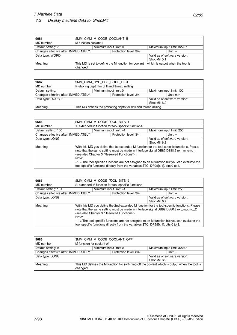
02/057.2 Display machine data for ShopMill
7-98 Siemens AG, 2005. All rights reserved
SINUMERIK 840D/840Di/810D Description of Functions ShopMill (FBSP) – 02/05 Edition
9681 $MM_CMM_M_CODE_COOLANT_IIMD number M function coolant IIDefault setting: 7 Minimum input limit: 0 Maximum input limit: 32767Changes effective after: IMMEDIATELY Protection level: 3/4 Unit: –Data type: WORD Valid as of software version:
ShopMill 5.1Meaning: This MD is set to define the M function for coolant II which is output when the tool is
changed.
9682 $MM_CMM_CYC_BGF_BORE_DISTMD number Preboring depth for drill and thread millingDefault setting: 1 Minimum input limit: 0 Maximum input limit: 100Changes effective after: IMMEDIATELY Protection level: 3/4 Unit: mmData type: DOUBLE Valid as of software version:
ShopMill 6.2Meaning: This MD defines the preboring depth for drill and thread milling.
9684 $MM_CMM_M_CODE_TOOL_BITS_1MD number 1. extended M function for tool-specific functionsDefault setting: 100 Minimum input limit: –1 Maximum input limit: 255Changes effective after: IMMEDIATELY Protection level: 3/4 Unit: –Data type: LONG Valid as of software version:
ShopMill 6.2Meaning: With this MD you define the 1st extended M function for the tool-specific functions. Please
note that the same setting must be made in interface signal DB82.DBB12 ext_m_cmd_1(see also Chapter 3 “Reserved Functions”).Note:–1 = The tool-specific functions are not assigned to an M function but you can evaluate thetool-specific functions directly from the variables $TC_DP25[x,1], bits 0 to 3.
9685 $MM_CMM_M_CODE_TOOL_BITS_2MD number 2. extended M function for tool-specific functionsDefault setting: 101 Minimum input limit: –1 Maximum input limit: 255Changes effective after: IMMEDIATELY Protection level: 3/4 Unit: –Data type: LONG Valid as of software version:
ShopMill 6.2Meaning: With this MD you define the 2nd extended M function for the tool-specific functions. Please
note that the same setting must be made in interface signal DB82.DBB13 ext_m_cmd_2(see also Chapter 3 “Reserved Functions”).Note:–1 = The tool-specific functions are not assigned to an M function but you can evaluate thetool-specific functions directly from the variables $TC_DP25[x,1], bits 0 to 3.
9686 $MM_CMM_M_CODE_COOLANT_OFFMD number M function for coolant offDefault setting: 9 Minimum input limit: 0 Maximum input limit: 32767Changes effective after: IMMEDIATELY Protection level: 3/4 Unit: –Data type: LONG Valid as of software version:
ShopMill 6.2Meaning: This MD defines the M function for switching off the coolant which is output when the tool is
changed.
7 Machine Data
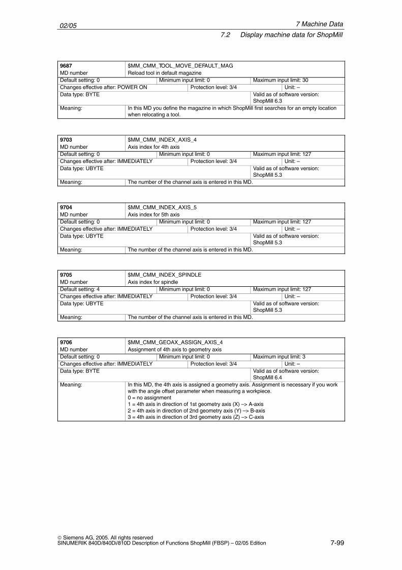
02/057.2 Display machine data for ShopMill
7-99 Siemens AG, 2005. All rights reservedSINUMERIK 840D/840Di/810D Description of Functions ShopMill (FBSP) – 02/05 Edition
9687 $MM_CMM_TOOL_MOVE_DEFAULT_MAGMD number Reload tool in default magazineDefault setting: 0 Minimum input limit: 0 Maximum input limit: 30Changes effective after: POWER ON Protection level: 3/4 Unit: –Data type: BYTE Valid as of software version:
ShopMill 6.3Meaning: In this MD you define the magazine in which ShopMill first searches for an empty location
when relocating a tool.
9703 $MM_CMM_INDEX_AXIS_4MD number Axis index for 4th axisDefault setting: 0 Minimum input limit: 0 Maximum input limit: 127Changes effective after: IMMEDIATELY Protection level: 3/4 Unit: –Data type: UBYTE Valid as of software version:
ShopMill 5.3Meaning: The number of the channel axis is entered in this MD.
9704 $MM_CMM_INDEX_AXIS_5MD number Axis index for 5th axisDefault setting: 0 Minimum input limit: 0 Maximum input limit: 127Changes effective after: IMMEDIATELY Protection level: 3/4 Unit: –Data type: UBYTE Valid as of software version:
ShopMill 5.3Meaning: The number of the channel axis is entered in this MD.
9705 $MM_CMM_INDEX_SPINDLEMD number Axis index for spindleDefault setting: 4 Minimum input limit: 0 Maximum input limit: 127Changes effective after: IMMEDIATELY Protection level: 3/4 Unit: –Data type: UBYTE Valid as of software version:
ShopMill 5.3Meaning: The number of the channel axis is entered in this MD.
9706 $MM_CMM_GEOAX_ASSIGN_AXIS_4MD number Assignment of 4th axis to geometry axisDefault setting: 0 Minimum input limit: 0 Maximum input limit: 3Changes effective after: IMMEDIATELY Protection level: 3/4 Unit: –Data type: BYTE Valid as of software version:
ShopMill 6.4Meaning: In this MD, the 4th axis is assigned a geometry axis. Assignment is necessary if you work
with the angle offset parameter when measuring a workpiece.0 = no assignment1 = 4th axis in direction of 1st geometry axis (X) –> A-axis2 = 4th axis in direction of 2nd geometry axis (Y) –> B-axis3 = 4th axis in direction of 3rd geometry axis (Z) –> C-axis
7 Machine Data
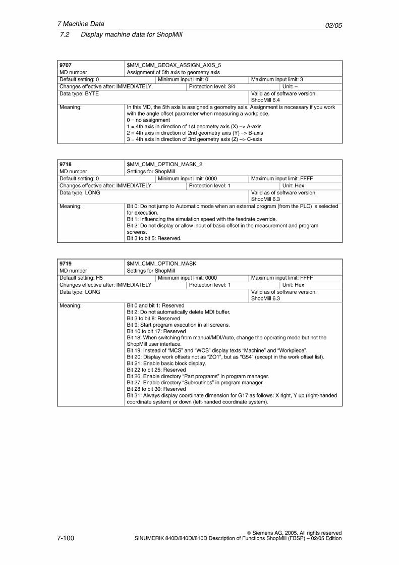
02/057.2 Display machine data for ShopMill
7-100 Siemens AG, 2005. All rights reserved
SINUMERIK 840D/840Di/810D Description of Functions ShopMill (FBSP) – 02/05 Edition
9707 $MM_CMM_GEOAX_ASSIGN_AXIS_5MD number Assignment of 5th axis to geometry axisDefault setting: 0 Minimum input limit: 0 Maximum input limit: 3Changes effective after: IMMEDIATELY Protection level: 3/4 Unit: –Data type: BYTE Valid as of software version:
ShopMill 6.4Meaning: In this MD, the 5th axis is assigned a geometry axis. Assignment is necessary if you work
with the angle offset parameter when measuring a workpiece.0 = no assignment1 = 4th axis in direction of 1st geometry axis (X) –> A-axis2 = 4th axis in direction of 2nd geometry axis (Y) –> B-axis3 = 4th axis in direction of 3rd geometry axis (Z) –> C-axis
9718 $MM_CMM_OPTION_MASK_2MD number Settings for ShopMillDefault setting: 0 Minimum input limit: 0000 Maximum input limit: FFFFChanges effective after: IMMEDIATELY Protection level: 1 Unit: HexData type: LONG Valid as of software version:
ShopMill 6.3Meaning: Bit 0: Do not jump to Automatic mode when an external program (from the PLC) is selected
for execution.Bit 1: Influencing the simulation speed with the feedrate override.Bit 2: Do not display or allow input of basic offset in the measurement and programscreens.Bit 3 to bit 5: Reserved.
9719 $MM_CMM_OPTION_MASKMD number Settings for ShopMillDefault setting: H5 Minimum input limit: 0000 Maximum input limit: FFFFChanges effective after: IMMEDIATELY Protection level: 1 Unit: HexData type: LONG Valid as of software version:
ShopMill 6.3Meaning: Bit 0 and bit 1: Reserved
Bit 2: Do not automatically delete MDI buffer.Bit 3 to bit 8: ReservedBit 9: Start program execution in all screens.Bit 10 to bit 17: ReservedBit 18: When switching from manual/MDI/Auto, change the operating mode but not theShopMill user interface.Bit 19: Instead of “MCS” and “WCS” display texts “Machine” and “Workpiece”.Bit 20: Display work offsets not as “ZO1”, but as “G54” (except in the work offset list).Bit 21: Enable basic block display.Bit 22 to bit 25: ReservedBit 26: Enable directory “Part programs” in program manager.Bit 27: Enable directory “Subroutines” in program manager.Bit 28 to bit 30: ReservedBit 31: Always display coordinate dimension for G17 as follows: X right, Y up (right-handedcoordinate system) or down (left-handed coordinate system).
7 Machine Data
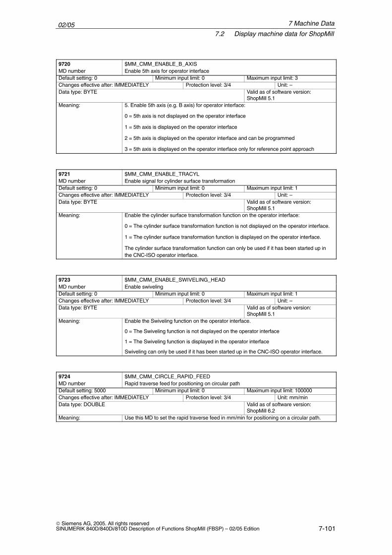
02/057.2 Display machine data for ShopMill
7-101 Siemens AG, 2005. All rights reservedSINUMERIK 840D/840Di/810D Description of Functions ShopMill (FBSP) – 02/05 Edition
9720 $MM_CMM_ENABLE_B_AXISMD number Enable 5th axis for operator interfaceDefault setting: 0 Minimum input limit: 0 Maximum input limit: 3Changes effective after: IMMEDIATELY Protection level: 3/4 Unit: –Data type: BYTE Valid as of software version:
ShopMill 5.1Meaning: 5. Enable 5th axis (e.g. B axis) for operator interface:
0 = 5th axis is not displayed on the operator interface
1 = 5th axis is displayed on the operator interface
2 = 5th axis is displayed on the operator interface and can be programmed
3 = 5th axis is displayed on the operator interface only for reference point approach
9721 $MM_CMM_ENABLE_TRACYLMD number Enable signal for cylinder surface transformationDefault setting: 0 Minimum input limit: 0 Maximum input limit: 1Changes effective after: IMMEDIATELY Protection level: 3/4 Unit: –Data type: BYTE Valid as of software version:
ShopMill 5.1Meaning: Enable the cylinder surface transformation function on the operator interface:
0 = The cylinder surface transformation function is not displayed on the operator interface.
1 = The cylinder surface transformation function is displayed on the operator interface.
The cylinder surface transformation function can only be used if it has been started up inthe CNC-ISO operator interface.
9723 $MM_CMM_ENABLE_SWIVELING_HEADMD number Enable swivelingDefault setting: 0 Minimum input limit: 0 Maximum input limit: 1Changes effective after: IMMEDIATELY Protection level: 3/4 Unit: –Data type: BYTE Valid as of software version:
ShopMill 5.1Meaning: Enable the Swiveling function on the operator interface.
0 = The Swiveling function is not displayed on the operator interface
1 = The Swiveling function is displayed in the operator interface
Swiveling can only be used if it has been started up in the CNC-ISO operator interface.
9724 $MM_CMM_CIRCLE_RAPID_FEEDMD number Rapid traverse feed for positioning on circular pathDefault setting: 5000 Minimum input limit: 0 Maximum input limit: 100000Changes effective after: IMMEDIATELY Protection level: 3/4 Unit: mm/minData type: DOUBLE Valid as of software version:
ShopMill 6.2Meaning: Use this MD to set the rapid traverse feed in mm/min for positioning on a circular path.
7 Machine Data
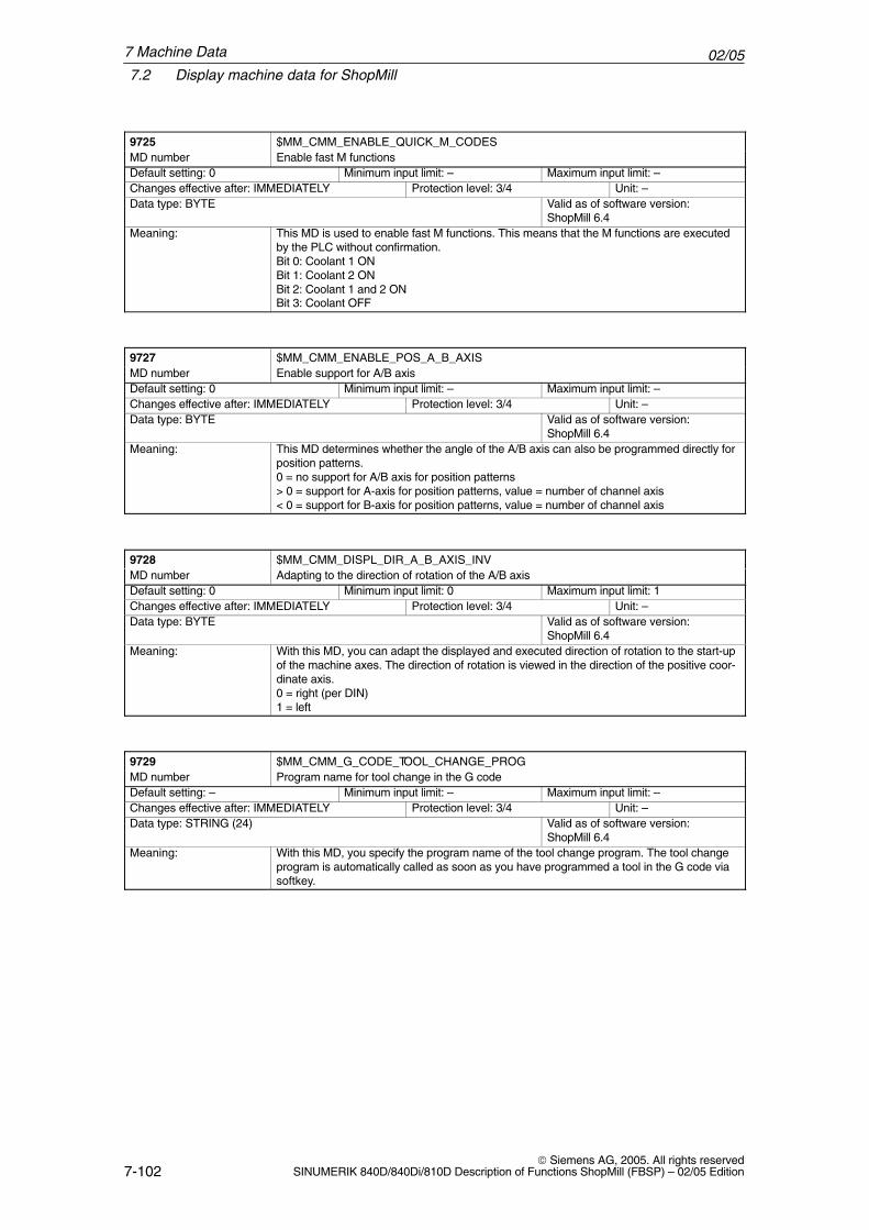
02/057.2 Display machine data for ShopMill
7-102 Siemens AG, 2005. All rights reserved
SINUMERIK 840D/840Di/810D Description of Functions ShopMill (FBSP) – 02/05 Edition
9725 $MM_CMM_ENABLE_QUICK_M_CODESMD number Enable fast M functionsDefault setting: 0 Minimum input limit: – Maximum input limit: –Changes effective after: IMMEDIATELY Protection level: 3/4 Unit: –Data type: BYTE Valid as of software version:
ShopMill 6.4Meaning: This MD is used to enable fast M functions. This means that the M functions are executed
by the PLC without confirmation.Bit 0: Coolant 1 ONBit 1: Coolant 2 ONBit 2: Coolant 1 and 2 ONBit 3: Coolant OFF
9727 $MM_CMM_ENABLE_POS_A_B_AXISMD number Enable support for A/B axisDefault setting: 0 Minimum input limit: – Maximum input limit: –Changes effective after: IMMEDIATELY Protection level: 3/4 Unit: –Data type: BYTE Valid as of software version:
ShopMill 6.4Meaning: This MD determines whether the angle of the A/B axis can also be programmed directly for
position patterns.0 = no support for A/B axis for position patterns> 0 = support for A-axis for position patterns, value = number of channel axis< 0 = support for B-axis for position patterns, value = number of channel axis
9728 $MM_CMM_DISPL_DIR_A_B_AXIS_INVMD number Adapting to the direction of rotation of the A/B axisDefault setting: 0 Minimum input limit: 0 Maximum input limit: 1Changes effective after: IMMEDIATELY Protection level: 3/4 Unit: –Data type: BYTE Valid as of software version:
ShopMill 6.4Meaning: With this MD, you can adapt the displayed and executed direction of rotation to the start-up
of the machine axes. The direction of rotation is viewed in the direction of the positive coor-dinate axis.0 = right (per DIN)1 = left
9729 $MM_CMM_G_CODE_TOOL_CHANGE_PROGMD number Program name for tool change in the G codeDefault setting: – Minimum input limit: – Maximum input limit: –Changes effective after: IMMEDIATELY Protection level: 3/4 Unit: –Data type: STRING (24) Valid as of software version:
ShopMill 6.4Meaning: With this MD, you specify the program name of the tool change program. The tool change
program is automatically called as soon as you have programmed a tool in the G code viasoftkey.
7 Machine Data
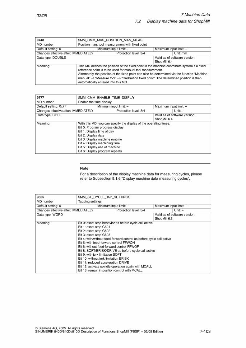
02/057.2 Display machine data for ShopMill
7-103 Siemens AG, 2005. All rights reservedSINUMERIK 840D/840Di/810D Description of Functions ShopMill (FBSP) – 02/05 Edition
9748 $MM_CMM_MKS_POSITION_MAN_MEASMD number Position man. tool measurement with fixed pointDefault setting: 0 Minimum input limit: – Maximum input limit: –Changes effective after: IMMEDIATELY Protection level: 3/4 Unit: mmData type: DOUBLE Valid as of software version:
ShopMill 6.4Meaning: This MD defines the position of the fixed point in the machine coordinate system if a fixed
reference point is to be used for manual tool measurement.Alternately, the position of the fixed point can also be determined via the function “Machinemanual” → “Measure tool” → “Calibration fixed point”. The determined position is thenautomatically entered into this MD.
9777 $MM_CMM_ENABLE_TIME_DISPLAYMD number Enable the time displayDefault setting: 0x7F Minimum input limit: – Maximum input limit: –Changes effective after: IMMEDIATELY Protection level: 3/4 Unit: –Data type: BYTE Valid as of software version:
ShopMill 6.4Meaning: With this MD, you can specify the display of the operating times.
Bit 0: Program progress displayBit 1: Display time of dayBit 2: Display dateBit 3: Display machine runtimeBit 4: Display machining timeBit 5: Display use of machineBit 6: Display program repeats
Note
For a description of the display machine data for measuring cycles, pleaserefer to Subsection 9.1.6 “Display machine data measuring cycles”.
9855 $MM_ST_CYCLE_TAP_SETTINGSMD number Tapping settingsDefault setting: 0 Minimum input limit: – Maximum input limit: –Changes effective after: IMMEDIATELY Protection level: 3/4 Unit: –Data type: WORD Valid as of software version:
ShopMill 6.3Meaning: Bit 0: exact stop behavior as before cycle call active
Bit 1: exact stop G601Bit 2: exact stop G602Bit 3: exact stop G603Bit 4: with/without feed-forward control as before cycle call activeBit 5: with feed-forward control FFWONBit 6: without feed-forward control FFWOFBit 8: SOFT/BRISK/DRIVE as before cycle call activeBit 9: with jerk limitation SOFTBit 10: without jerk limitation BRISKBit 11: reduced acceleration DRIVEBit 12: activate spindle operation again with MCALLBit 13: remain in position control with MCALL
7 Machine Data
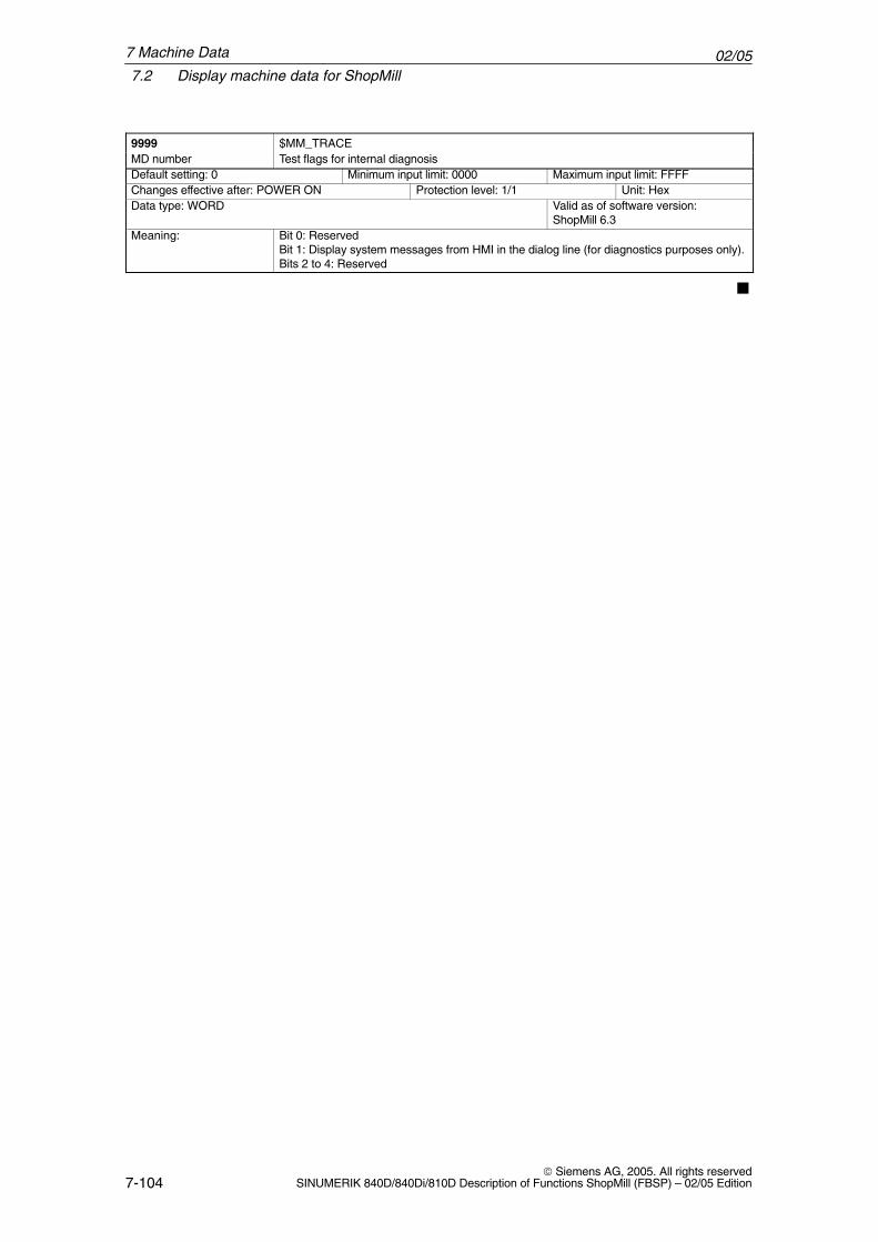
02/057.2 Display machine data for ShopMill
7-104 Siemens AG, 2005. All rights reserved
SINUMERIK 840D/840Di/810D Description of Functions ShopMill (FBSP) – 02/05 Edition
9999 $MM_TRACEMD number Test flags for internal diagnosisDefault setting: 0 Minimum input limit: 0000 Maximum input limit: FFFFChanges effective after: POWER ON Protection level: 1/1 Unit: HexData type: WORD Valid as of software version:
ShopMill 6.3Meaning: Bit 0: Reserved
Bit 1: Display system messages from HMI in the dialog line (for diagnostics purposes only).Bits 2 to 4: Reserved
�
7 Machine Data
8-105 Siemens AG, 2005. All rights reservedSINUMERIK 840D/840Di/810D Description of Functions ShopMill (FBSP) – 02/05 Edition
Tool Management
8.1 Overview of functions
ShopMill only runs when the tool management option is set. This is containedwithin the Shop Mill package. The option is contained in the machine data blockfor ShopMill.
References: /FBW/, Description of Tool Management Functions
Data storage and management is carried out in the NC. All data can be readand written manually, via initialization program or by data transfer.
Operation is performed via system screens.
When using tool management it is possible to call the tool with another name,e.g. “Milling cutter 120mm”.It is still possible to call the tool via a T No. (tool number). The T No. is then thename of the tool.
Separate PLC blocks are available for tool management to handle communica-tion between NC and PLC.
A maximum of 250 tools can be set up on the PCU 20; on the PCU 50, the ma-ximum number of tools is limited by MD 18082 $MN_MM_NUM_TOOL.Up to 9 cutting edges can be defined per tool.
A total of 98 replacement tools can be set up for each tool.
Chain and disk-type magazines can be managed. The maximum number ofmagazines is set in the NC. Display MD 9674 $MM_CMM_ENABLE_TOOL_MAGAZINE can be set to con-ceal the magazine list.
Option
Data
Operation
Programming
PLC
Tools
Replacement tools
Magazine
8
02/058.1 Overview of functions
8-106 Siemens AG, 2005. All rights reserved
SINUMERIK 840D/840Di/810D Description of Functions ShopMill (FBSP) – 02/05 Edition
Display MD 9672 $MM_CMM_FIXED_TOOL_PLACE determines whether alltools have a fixed or variable location coding.
� Fixed location coding (MD 9672, value 1) means that the tool is permanentlyassigned to a magazine location. This concept can be used for machineswith disk-type magazine.
� For variable location coding (MD 9672, value 0), a tool with a tool number ortool name can be returned to a different magazine location from its originalone. This concept can be used for machines with chain magazine.Individual tools can be set to fixed-location coded on the user interface (toolwear).
Magazine locations can be blocked, e.g. for oversized tools occupying adjacentmagazine locations.
The tool management system includes a tool monitoring function that monitorsbased on cutting edges either by tool life, tool loading operations or wear. Re-placement tools (sister tools) are distinguished by their Duplo No. (DP). Tool monitoring can be deactivated via the display MD 9652$MM_CMM_TOOL_LIFE_CONTROL.You can activate wear monitoring via display MD 18080, bit 5.
Setting 2 of display MD 9651 $MM_CMM_TOOL_MANAGEMENT can be se-lected to set the tool management function without a Load/Unload softkey.
Setting 4 of display MD 9651 $MM_CMM_TOOL_MANAGEMENT can be se-lected to set the tool management function with the Load/Unload softkey.
Loading brings the tool to its magazine location.
Unloading removes the tool from the magazine.
Tools can be sorted in the tool and tool wear lists according to magazine location, name and type.
Manual tools are tools that are stored in the tool list but not in the magazine.These tools must be attached/detached manually to/from the spindle.
Location coding
Magazine locationblocking
Monitoringfunctions
Tool managementwithout loading/unloading
Tool managementwith loading/unloading
Load
Unload
Sorting
Manual tools
8 Tool Management
02/058.1 Overview of functions
8-107 Siemens AG, 2005. All rights reservedSINUMERIK 840D/840Di/810D Description of Functions ShopMill (FBSP) – 02/05 Edition
� Load/unload point for tools by means of display MD 9673$MM_CMM_TOOL_LOAD_STATION
� Number of input fields for tool-specific functions by means of displayMD 9661 $MM_CMM_ENABLE_CUSTOMER_M_CODES
� Display tools as diameter or radius via display MD 9663$MM_CMM_TOOL_DISPLAY_IN_DIAM
Note
Modifications to the tool and cutting edge data via system variables in the partprogram are displayed in the tool list on the ShopMill operator interface only ifthey refer to the tool currently loaded in the spindle.
Other functions
Changing data
8 Tool Management
02/058.2 Start-up sequence
8-108 Siemens AG, 2005. All rights reserved
SINUMERIK 840D/840Di/810D Description of Functions ShopMill (FBSP) – 02/05 Edition
8.2 Start-up sequence
You can either start up tool management together with ShopMill start-up (seeSection 4.2 “Initial Start-up Sequence”) or subsequently.
Proceed as follows to start up tool management:
1. NC start-up
2. PLC installation and start-up
3. Adapt display machine data
4. Create tool-changing cycle
If tool management already exists on your machine it is not necessary to installone especially for ShopMill, i.e. NC, PLC and tool-changing cycles start-up isnot necessary, you only need to adapt the display machine data.
A precise description of tool management start-up is provided in: References /FBIW/, Description of Functions Tool Management
Note
In the case of the PCU 50 you can also perform tool management start-up(generate configuration file and PLC data) on the CNC-ISO operator interface.
References: /FBW/, Description of Tool Management Functions
8 Tool Management
02/058.3 Start-up in the NC
8-109 Siemens AG, 2005. All rights reservedSINUMERIK 840D/840Di/810D Description of Functions ShopMill (FBSP) – 02/05 Edition
8.3 Start-up in the NC
� PCU start-up is performed and the connection to the NC established.
� NC start-up is carried out with the default machine data.
� Enter the NC machine data for tool management.
� Create a new configuration file for tool management or use and adapt theexamples from the NC Toolbox.
� Load the configuration file in the control.
8.3.1 Enter the NC machine data
For tool management, machine data for memory setting and activation of themanagement function must be set.
Memory space must be made available in the battery-backed RAM for tool ma-nagement.
The following machine data must be set:
MD 18080 Activate the memory for the tool managementMD 18082 Number of tools to be managed by the NCKMD 18084 Number of magazines that the NCK can manage (min. 3);
include intermediate memory and loading magazine in the count!
MD 18086 Number of magazine locations that the NCK can manage;include 3 intermediate memory locations (2 gripper and 1 spindle) and 2 load locations in the count!
MD 18100 Number of cutting edges in the NCK
Note
ShopMill can manage 9 cutting edges per tool. Define the total number of all available cutting edges in MD 18105MM_MAX_CUTTING_EDGE_NO. It is not necessary to enter the number of tools multiplied by 9 cutting edges.Instead, specify approximately how many cutting edges you will need in total.
Requirements
Execution
Machine data formemory setting
8 Tool Management
02/058.3 Start-up in the NC
8-110 Siemens AG, 2005. All rights reserved
SINUMERIK 840D/840Di/810D Description of Functions ShopMill (FBSP) – 02/05 Edition
Assignment of machine data if a dual gripper is used to enable use of manualtools when the magazine is full (30 locations):18082=40; 40 tools (30 tools for the magazine + 10 tools as manual
tools)18084=3; 1 magazine + 1 buffer magazine + 1 loading magazine18086=35; 30 magazine locations + 3 buffers + 2 loading locations18100=80; 80 cutting edges
Note
The machine data settings serve only to reserve memory; locations are notassigned to the magazine, etc. until the configuration file is set up and loaded(see Subsection 8.3.3 “Creating and Loading the Configuration File”).
Modifying the “memory-influencing” machine data reformats the battery-backedRAM. The data must therefore be backed up beforehand.
In addition, the following machine data must be set for activation of the tool ma-nagement:
MD 20310 Channel-specific activation of tool managementMD 20320 Activation of tool life monitoring for the spindle specified hereMD 22550 New tool offset for M functionMD 22560 M function for tool changeMD 22562 Error handling with programmed tool change
Note
Bits 0–3 of MD 20310 $MC_TOOL_MANAGEMENT_MASK and MD 18080$MN_MM_TOOL_MANAGEMENT_MASK must always be set identically.
The NC machine data for tool management are in machine data recordCMM.8X0.
A detailed description of the NC machine data for tool management is given inthe next Subsection 8.3.2 “Description of the NC Machine Data for Tool Mana-gement”.
Example
Machine data foractivating toolmanagement
Default
8 Tool Management
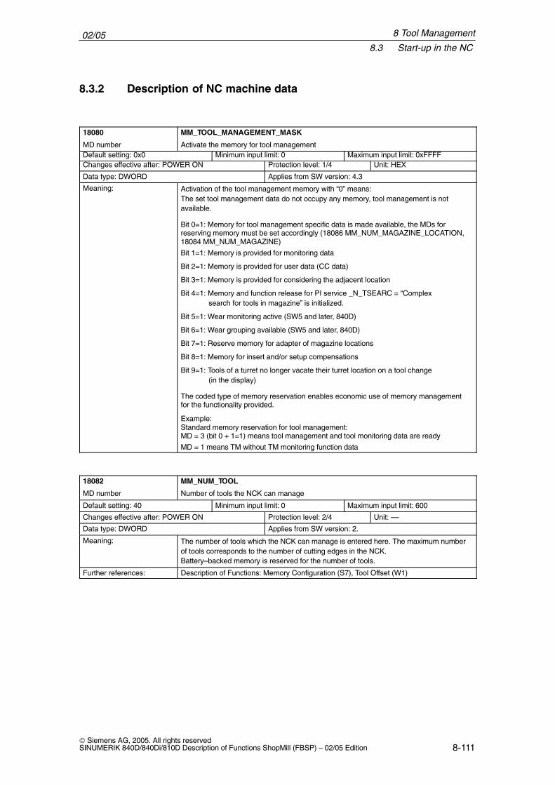
02/058.3 Start-up in the NC
8-111 Siemens AG, 2005. All rights reservedSINUMERIK 840D/840Di/810D Description of Functions ShopMill (FBSP) – 02/05 Edition
8.3.2 Description of NC machine data
ÁÁÁÁÁÁÁÁÁÁÁÁÁÁÁÁÁÁÁÁÁÁÁÁ
18080
MD number
ÁÁÁÁÁÁÁÁÁÁÁÁÁÁÁÁÁÁÁÁÁÁÁÁÁÁÁÁÁÁÁÁÁÁÁÁÁÁÁÁÁÁÁÁÁÁÁÁÁÁÁÁÁÁÁÁÁÁÁÁÁÁÁÁÁÁ
MM_TOOL_MANAGEMENT_MASK
Activate the memory for tool managementÁÁÁÁÁÁÁÁÁÁÁÁÁÁÁÁÁÁÁÁ
Default setting: 0x0 ÁÁÁÁÁÁÁÁÁÁÁÁÁÁÁÁÁÁÁÁ
Minimum input limit: 0 ÁÁÁÁÁÁÁÁÁÁÁÁÁÁÁÁÁÁÁÁÁÁ
Maximum input limit: 0xFFFF
ÁÁÁÁÁÁÁÁÁÁÁÁÁÁChanges effective after: POWER ON ÁÁÁÁÁÁÁÁProtection level: 1/4 ÁÁÁÁÁÁÁÁÁUnit: HEXÁÁÁÁÁÁÁÁÁÁÁÁÁÁÁÁÁÁÁÁÁÁÁÁÁÁÁÁData type: DWORD
ÁÁÁÁÁÁÁÁÁÁÁÁÁÁÁÁÁÁÁÁÁÁÁÁÁÁÁÁÁÁÁÁApplies from SW version: 4.3ÁÁÁÁÁÁÁÁ
ÁÁÁÁÁÁÁÁÁÁÁÁÁÁÁÁÁÁÁÁÁÁÁÁÁÁÁÁÁÁÁÁÁÁÁÁÁÁÁÁÁÁÁÁÁÁÁÁÁÁÁÁÁÁÁÁÁÁÁÁÁÁÁÁÁÁÁÁÁÁÁÁÁÁÁÁÁÁÁÁÁÁÁÁÁÁÁÁÁÁÁÁÁÁÁÁÁÁÁÁÁÁÁÁÁÁÁÁÁÁÁÁÁÁÁÁÁÁÁÁÁÁÁÁÁÁÁÁÁÁÁÁÁÁÁÁÁÁÁÁÁÁÁÁÁÁÁÁÁÁÁÁ
Meaning:ÁÁÁÁÁÁÁÁÁÁÁÁÁÁÁÁÁÁÁÁÁÁÁÁÁÁÁÁÁÁÁÁÁÁÁÁÁÁÁÁÁÁÁÁÁÁÁÁÁÁÁÁÁÁÁÁÁÁÁÁÁÁÁÁÁÁÁÁÁÁÁÁÁÁÁÁÁÁÁÁÁÁÁÁÁÁÁÁÁÁÁÁÁÁÁÁÁÁÁÁÁÁÁÁÁÁÁÁÁÁÁÁÁÁÁÁÁÁÁÁÁÁÁÁÁÁÁÁÁÁÁÁÁÁÁÁÁÁÁÁÁÁÁÁÁÁÁÁÁÁÁÁÁÁÁÁÁÁÁÁÁÁÁÁÁÁÁÁÁÁÁÁÁÁÁÁÁÁÁÁÁÁÁÁÁÁÁÁÁÁÁÁÁÁÁÁÁÁÁÁÁÁÁÁÁÁÁÁÁÁÁÁÁÁÁÁÁÁÁÁÁÁÁÁÁÁÁÁÁÁÁÁÁÁÁÁÁÁÁÁÁÁÁÁÁÁÁÁÁÁÁÁÁÁÁÁÁÁÁÁÁÁÁÁÁÁÁÁÁÁÁÁÁÁÁÁÁÁÁÁÁÁÁÁÁÁÁÁÁÁÁÁÁÁÁÁÁÁÁÁÁÁÁÁÁÁÁÁÁÁÁÁÁÁÁÁÁÁÁÁÁÁÁÁÁÁÁÁÁÁÁÁÁÁÁÁÁÁÁÁÁÁÁÁÁÁÁÁÁÁÁÁÁÁÁÁÁÁÁÁÁÁÁÁÁÁÁÁÁÁÁÁÁÁÁÁÁÁÁÁÁÁÁÁÁÁÁÁÁÁÁÁÁÁÁÁÁÁÁÁÁÁÁÁÁÁÁÁÁÁÁÁÁÁÁÁÁÁÁÁÁÁÁÁÁÁÁÁÁÁÁÁÁÁÁÁÁÁÁÁ
Activation of the tool management memory with “0” means: The set tool management data do not occupy any memory, tool management is notavailable.
Bit 0=1: Memory for tool management specific data is made available, the MDs forreserving memory must be set accordingly (18086 MM_NUM_MAGAZINE_LOCATION,18084 MM_NUM_MAGAZINE)
Bit 1=1: Memory is provided for monitoring data
Bit 2=1: Memory is provided for user data (CC data)
Bit 3=1: Memory is provided for considering the adjacent location
Bit 4=1: Memory and function release for PI service _N_TSEARC = “Complexsearch for tools in magazine” is initialized.
Bit 5=1: Wear monitoring active (SW5 and later, 840D)
Bit 6=1: Wear grouping available (SW5 and later, 840D)
Bit 7=1: Reserve memory for adapter of magazine locations
Bit 8=1: Memory for insert and/or setup compensations
Bit 9=1: Tools of a turret no longer vacate their turret location on a tool change(in the display)
The coded type of memory reservation enables economic use of memory managementfor the functionality provided.
Example:Standard memory reservation for tool management:MD = 3 (bit 0 + 1=1) means tool management and tool monitoring data are ready
MD = 1 means TM without TM monitoring function data
ÁÁÁÁÁÁÁÁÁÁÁÁÁÁÁÁ
18082
MD numberÁÁÁÁÁÁÁÁÁÁÁÁÁÁÁÁÁÁÁÁÁÁÁÁÁÁÁÁÁÁÁÁÁÁÁÁÁÁÁÁÁÁÁÁ
MM_NUM_TOOL
Number of tools the NCK can manageÁÁÁÁÁÁÁÁÁÁÁÁÁÁÁÁÁÁÁÁ
Default setting: 40ÁÁÁÁÁÁÁÁÁÁÁÁÁÁÁÁÁÁÁÁ
Minimum input limit: 0ÁÁÁÁÁÁÁÁÁÁÁÁÁÁÁÁÁÁÁÁÁÁ
Maximum input limit: 600ÁÁÁÁÁÁÁÁÁÁÁÁÁÁÁÁÁÁÁÁÁÁÁÁÁÁÁÁ
Changes effective after: POWER ON ÁÁÁÁÁÁÁÁÁÁÁÁÁÁÁÁ
Protection level: 2/4 ÁÁÁÁÁÁÁÁÁÁÁÁÁÁÁÁÁÁ
Unit: ––ÁÁÁÁÁÁÁÁÁÁÁÁÁÁÁÁÁÁÁÁÁÁÁÁÁÁÁÁ
Data type: DWORD ÁÁÁÁÁÁÁÁÁÁÁÁÁÁÁÁÁÁÁÁÁÁÁÁÁÁÁÁÁÁÁÁ
Applies from SW version: 2.
ÁÁÁÁÁÁÁÁÁÁÁÁÁÁÁÁÁÁÁÁÁÁÁÁ
Meaning: ÁÁÁÁÁÁÁÁÁÁÁÁÁÁÁÁÁÁÁÁÁÁÁÁÁÁÁÁÁÁÁÁÁÁÁÁÁÁÁÁÁÁÁÁÁÁÁÁÁÁÁÁÁÁÁÁÁÁÁÁÁÁÁÁÁÁ
The number of tools which the NCK can manage is entered here. The maximum numberof tools corresponds to the number of cutting edges in the NCK.Battery–backed memory is reserved for the number of tools.
ÁÁÁÁÁÁÁÁÁÁÁÁÁÁÁÁ
Further references: ÁÁÁÁÁÁÁÁÁÁÁÁÁÁÁÁÁÁÁÁÁÁÁÁÁÁÁÁÁÁÁÁÁÁÁÁÁÁÁÁÁÁÁÁ
Description of Functions: Memory Configuration (S7), Tool Offset (W1)
8 Tool Management
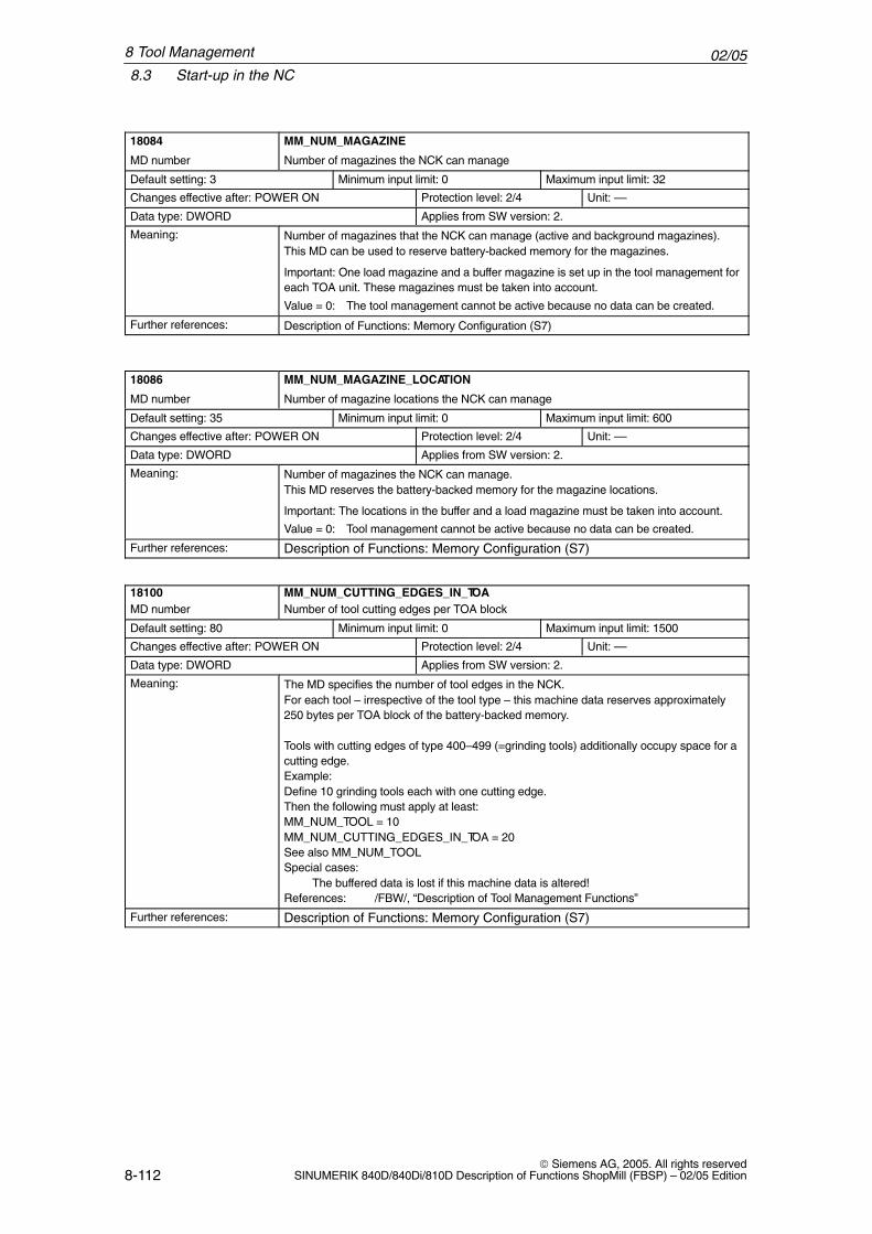
02/058.3 Start-up in the NC
8-112 Siemens AG, 2005. All rights reserved
SINUMERIK 840D/840Di/810D Description of Functions ShopMill (FBSP) – 02/05 Edition
ÁÁÁÁÁÁÁÁÁÁÁÁÁÁÁÁÁÁÁÁÁÁÁÁ
18084
MD number
ÁÁÁÁÁÁÁÁÁÁÁÁÁÁÁÁÁÁÁÁÁÁÁÁÁÁÁÁÁÁÁÁÁÁÁÁÁÁÁÁÁÁÁÁÁÁÁÁÁÁÁÁÁÁÁÁÁÁÁÁÁÁÁÁÁÁ
MM_NUM_MAGAZINE
Number of magazines the NCK can manageÁÁÁÁÁÁÁÁÁÁÁÁÁÁÁÁÁÁÁÁ
Default setting: 3 ÁÁÁÁÁÁÁÁÁÁÁÁÁÁÁÁÁÁÁÁ
Minimum input limit: 0 ÁÁÁÁÁÁÁÁÁÁÁÁÁÁÁÁÁÁÁÁÁÁ
Maximum input limit: 32
ÁÁÁÁÁÁÁÁÁÁÁÁÁÁÁÁÁÁÁÁÁÁÁÁÁÁÁÁ
Changes effective after: POWER ON ÁÁÁÁÁÁÁÁÁÁÁÁÁÁÁÁ
Protection level: 2/4 ÁÁÁÁÁÁÁÁÁÁÁÁÁÁÁÁÁÁ
Unit: ––
ÁÁÁÁÁÁÁÁÁÁÁÁÁÁÁÁÁÁÁÁÁÁÁÁÁÁÁÁ
Data type: DWORD ÁÁÁÁÁÁÁÁÁÁÁÁÁÁÁÁÁÁÁÁÁÁÁÁÁÁÁÁÁÁÁÁ
Applies from SW version: 2.
ÁÁÁÁÁÁÁÁÁÁÁÁÁÁÁÁÁÁÁÁÁÁÁÁÁÁÁÁÁÁÁÁÁÁÁÁÁÁÁÁ
Meaning: ÁÁÁÁÁÁÁÁÁÁÁÁÁÁÁÁÁÁÁÁÁÁÁÁÁÁÁÁÁÁÁÁÁÁÁÁÁÁÁÁÁÁÁÁÁÁÁÁÁÁÁÁÁÁÁÁÁÁÁÁÁÁÁÁÁÁÁÁÁÁÁÁÁÁÁÁÁÁÁÁÁÁÁÁÁÁÁÁÁÁÁÁÁÁÁÁÁÁÁÁÁÁÁÁÁÁÁÁÁÁ
Number of magazines that the NCK can manage (active and background magazines).This MD can be used to reserve battery-backed memory for the magazines.
Important: One load magazine and a buffer magazine is set up in the tool management foreach TOA unit. These magazines must be taken into account.
Value = 0: The tool management cannot be active because no data can be created.
ÁÁÁÁÁÁÁÁFurther references: ÁÁÁÁÁÁÁÁÁÁÁÁÁÁÁÁÁÁÁÁÁÁDescription of Functions: Memory Configuration (S7)
ÁÁÁÁÁÁÁÁÁÁÁÁÁÁÁÁÁÁÁÁÁÁÁÁ
18086
MD number
ÁÁÁÁÁÁÁÁÁÁÁÁÁÁÁÁÁÁÁÁÁÁÁÁÁÁÁÁÁÁÁÁÁÁÁÁÁÁÁÁÁÁÁÁÁÁÁÁÁÁÁÁÁÁÁÁÁÁÁÁÁÁÁÁÁÁ
MM_NUM_MAGAZINE_LOCATION
Number of magazine locations the NCK can manage
ÁÁÁÁÁÁÁÁÁÁDefault setting: 35 ÁÁÁÁÁÁÁÁÁÁMinimum input limit: 0 ÁÁÁÁÁÁÁÁÁÁÁMaximum input limit: 600ÁÁÁÁÁÁÁÁÁÁÁÁÁÁÁÁÁÁÁÁÁÁÁÁÁÁÁÁChanges effective after: POWER ON
ÁÁÁÁÁÁÁÁÁÁÁÁÁÁÁÁProtection level: 2/4
ÁÁÁÁÁÁÁÁÁÁÁÁÁÁÁÁÁÁUnit: ––ÁÁÁÁÁÁÁÁÁÁÁÁÁÁ
ÁÁÁÁÁÁÁÁÁÁÁÁÁÁData type: DWORD
ÁÁÁÁÁÁÁÁÁÁÁÁÁÁÁÁÁÁÁÁÁÁÁÁÁÁÁÁÁÁÁÁ
Applies from SW version: 2.ÁÁÁÁÁÁÁÁÁÁÁÁÁÁÁÁÁÁÁÁÁÁÁÁÁÁÁÁÁÁÁÁ
Meaning: ÁÁÁÁÁÁÁÁÁÁÁÁÁÁÁÁÁÁÁÁÁÁÁÁÁÁÁÁÁÁÁÁÁÁÁÁÁÁÁÁÁÁÁÁÁÁÁÁÁÁÁÁÁÁÁÁÁÁÁÁÁÁÁÁÁÁÁÁÁÁÁÁÁÁÁÁÁÁÁÁÁÁÁÁÁÁÁÁ
Number of magazines the NCK can manage.This MD reserves the battery-backed memory for the magazine locations.
Important: The locations in the buffer and a load magazine must be taken into account.
Value = 0: Tool management cannot be active because no data can be created.ÁÁÁÁÁÁÁÁÁÁÁÁÁÁÁÁFurther references:
ÁÁÁÁÁÁÁÁÁÁÁÁÁÁÁÁÁÁÁÁÁÁÁÁÁÁÁÁÁÁÁÁÁÁÁÁÁÁÁÁÁÁÁÁDescription of Functions: Memory Configuration (S7)
ÁÁÁÁÁÁÁÁÁÁÁÁÁÁÁÁÁÁÁÁÁÁÁÁ
18100MD number
ÁÁÁÁÁÁÁÁÁÁÁÁÁÁÁÁÁÁÁÁÁÁÁÁÁÁÁÁÁÁÁÁÁÁÁÁÁÁÁÁÁÁÁÁÁÁÁÁÁÁÁÁÁÁÁÁÁÁÁÁÁÁÁÁÁÁ
MM_NUM_CUTTING_EDGES_IN_TOANumber of tool cutting edges per TOA block
ÁÁÁÁÁÁÁÁÁÁÁÁÁÁÁÁÁÁÁÁ
Default setting: 80 ÁÁÁÁÁÁÁÁÁÁÁÁÁÁÁÁÁÁÁÁ
Minimum input limit: 0 ÁÁÁÁÁÁÁÁÁÁÁÁÁÁÁÁÁÁÁÁÁÁ
Maximum input limit: 1500
ÁÁÁÁÁÁÁÁÁÁÁÁÁÁÁÁÁÁÁÁÁÁÁÁÁÁÁÁ
Changes effective after: POWER ON ÁÁÁÁÁÁÁÁÁÁÁÁÁÁÁÁ
Protection level: 2/4 ÁÁÁÁÁÁÁÁÁÁÁÁÁÁÁÁÁÁ
Unit: ––
ÁÁÁÁÁÁÁÁÁÁÁÁÁÁData type: DWORD ÁÁÁÁÁÁÁÁÁÁÁÁÁÁÁÁApplies from SW version: 2.ÁÁÁÁÁÁÁÁÁÁÁÁÁÁÁÁÁÁÁÁÁÁÁÁÁÁÁÁÁÁÁÁÁÁÁÁÁÁÁÁÁÁÁÁÁÁÁÁÁÁÁÁÁÁÁÁÁÁÁÁÁÁÁÁÁÁÁÁÁÁÁÁÁÁÁÁÁÁÁÁÁÁÁÁÁÁÁÁÁÁÁÁÁÁÁÁ
Meaning:ÁÁÁÁÁÁÁÁÁÁÁÁÁÁÁÁÁÁÁÁÁÁÁÁÁÁÁÁÁÁÁÁÁÁÁÁÁÁÁÁÁÁÁÁÁÁÁÁÁÁÁÁÁÁÁÁÁÁÁÁÁÁÁÁÁÁÁÁÁÁÁÁÁÁÁÁÁÁÁÁÁÁÁÁÁÁÁÁÁÁÁÁÁÁÁÁÁÁÁÁÁÁÁÁÁÁÁÁÁÁÁÁÁÁÁÁÁÁÁÁÁÁÁÁÁÁÁÁÁÁÁÁÁÁÁÁÁÁÁÁÁÁÁÁÁÁÁÁÁÁÁÁÁÁÁÁÁÁÁÁÁÁÁÁÁÁÁÁÁÁÁÁÁÁÁÁÁÁÁÁÁÁÁÁÁÁÁÁÁÁÁÁÁÁÁÁÁÁÁÁÁÁÁÁÁÁÁÁÁÁÁÁÁÁÁÁÁÁÁÁÁÁÁÁÁÁÁÁÁÁÁÁÁÁÁÁÁÁÁÁÁÁÁÁÁÁÁÁÁÁÁÁÁÁÁÁÁÁÁÁÁÁÁÁ
The MD specifies the number of tool edges in the NCK. For each tool – irrespective of the tool type – this machine data reserves approximately250 bytes per TOA block of the battery-backed memory.
Tools with cutting edges of type 400–499 (=grinding tools) additionally occupy space for acutting edge.Example: Define 10 grinding tools each with one cutting edge. Then the following must apply at least:MM_NUM_TOOL = 10MM_NUM_CUTTING_EDGES_IN_TOA = 20See also MM_NUM_TOOLSpecial cases: The buffered data is lost if this machine data is altered! References: /FBW/, “Description of Tool Management Functions”
ÁÁÁÁÁÁÁÁÁÁÁÁÁÁÁÁ
Further references: ÁÁÁÁÁÁÁÁÁÁÁÁÁÁÁÁÁÁÁÁÁÁÁÁÁÁÁÁÁÁÁÁÁÁÁÁÁÁÁÁÁÁÁÁ
Description of Functions: Memory Configuration (S7)
8 Tool Management
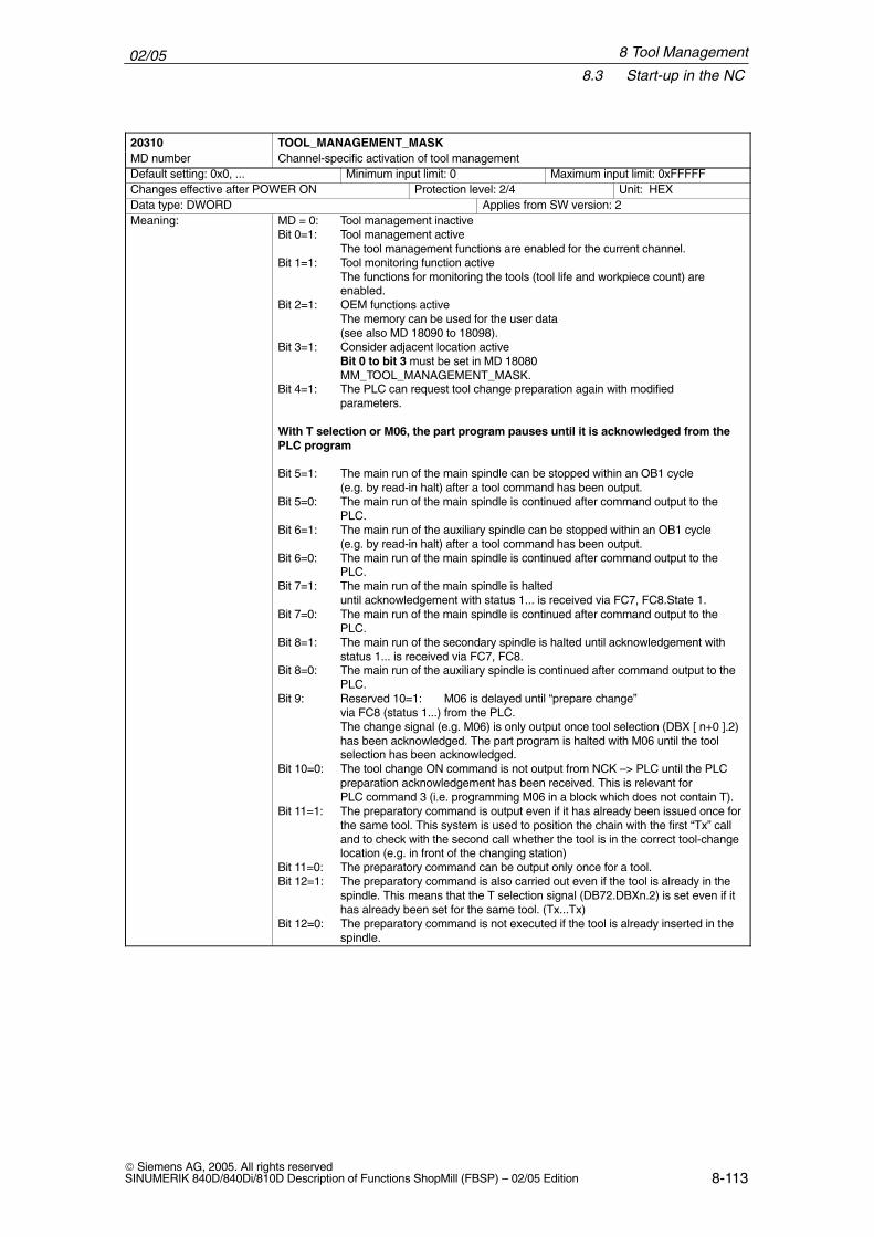
02/058.3 Start-up in the NC
8-113 Siemens AG, 2005. All rights reservedSINUMERIK 840D/840Di/810D Description of Functions ShopMill (FBSP) – 02/05 Edition
20310 TOOL_MANAGEMENT_MASKMD number Channel-specific activation of tool managementDefault setting: 0x0, ... Minimum input limit: 0 Maximum input limit: 0xFFFFFChanges effective after POWER ON Protection level: 2/4 Unit: HEXData type: DWORD Applies from SW version: 2Meaning: MD = 0: Tool management inactive
Bit 0=1: Tool management active The tool management functions are enabled for the current channel.Bit 1=1: Tool monitoring function active
The functions for monitoring the tools (tool life and workpiece count) are enabled.
Bit 2=1: OEM functions activeThe memory can be used for the user data(see also MD 18090 to 18098).
Bit 3=1: Consider adjacent location activeBit 0 to bit 3 must be set in MD 18080 MM_TOOL_MANAGEMENT_MASK.
Bit 4=1: The PLC can request tool change preparation again with modifiedparameters.
With T selection or M06, the part program pauses until it is acknowledged from thePLC program
Bit 5=1: The main run of the main spindle can be stopped within an OB1 cycle (e.g. by read-in halt) after a tool command has been output.
Bit 5=0: The main run of the main spindle is continued after command output to the PLC.
Bit 6=1: The main run of the auxiliary spindle can be stopped within an OB1 cycle (e.g. by read-in halt) after a tool command has been output.
Bit 6=0: The main run of the main spindle is continued after command output to the PLC.
Bit 7=1: The main run of the main spindle is halted until acknowledgement with status 1... is received via FC7, FC8.State 1.
Bit 7=0: The main run of the main spindle is continued after command output to the PLC.
Bit 8=1: The main run of the secondary spindle is halted until acknowledgement withstatus 1... is received via FC7, FC8.
Bit 8=0: The main run of the auxiliary spindle is continued after command output to the PLC.
Bit 9: Reserved 10=1: M06 is delayed until “prepare change” via FC8 (status 1...) from the PLC. The change signal (e.g. M06) is only output once tool selection (DBX [ n+0 ].2)has been acknowledged. The part program is halted with M06 until the toolselection has been acknowledged.
Bit 10=0: The tool change ON command is not output from NCK –> PLC until the PLC preparation acknowledgement has been received. This is relevant for PLC command 3 (i.e. programming M06 in a block which does not contain T).
Bit 11=1: The preparatory command is output even if it has already been issued once forthe same tool. This system is used to position the chain with the first “Tx” calland to check with the second call whether the tool is in the correct tool-changelocation (e.g. in front of the changing station)
Bit 11=0: The preparatory command can be output only once for a tool.Bit 12=1: The preparatory command is also carried out even if the tool is already in the
spindle. This means that the T selection signal (DB72.DBXn.2) is set even if it has already been set for the same tool. (Tx...Tx)
Bit 12=0: The preparatory command is not executed if the tool is already inserted in the spindle.
8 Tool Management
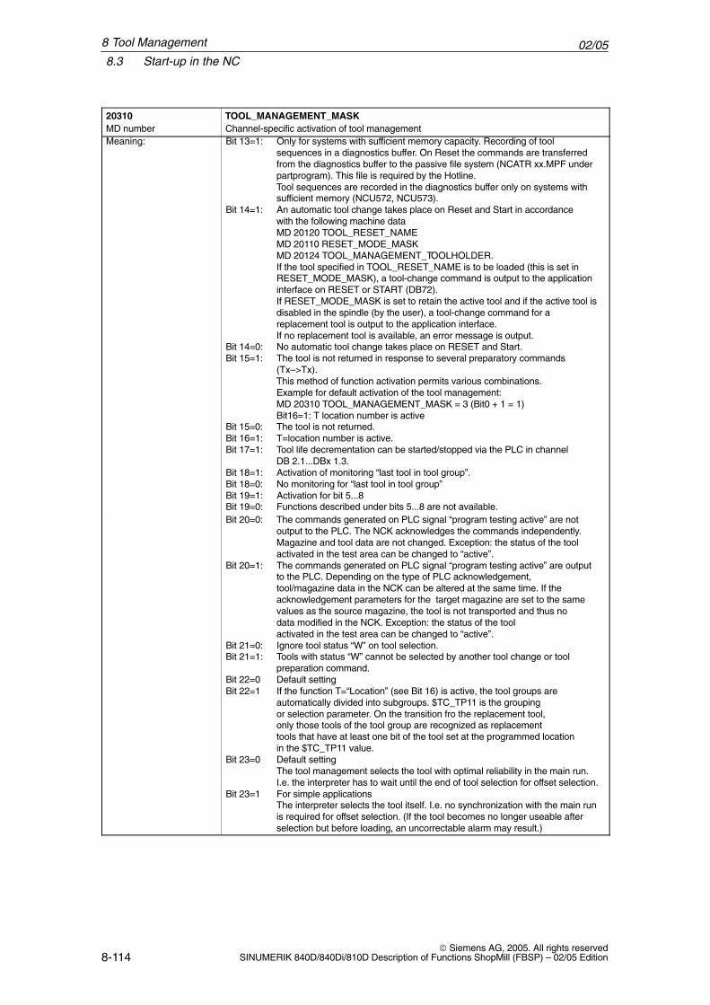
02/058.3 Start-up in the NC
8-114 Siemens AG, 2005. All rights reserved
SINUMERIK 840D/840Di/810D Description of Functions ShopMill (FBSP) – 02/05 Edition
20310 TOOL_MANAGEMENT_MASKMD number Channel-specific activation of tool managementMeaning: Bit 13=1: Only for systems with sufficient memory capacity. Recording of tool
sequences in a diagnostics buffer. On Reset the commands are transferred from the diagnostics buffer to the passive file system (NCATR xx.MPF under
partprogram). This file is required by the Hotline. Tool sequences are recorded in the diagnostics buffer only on systems withsufficient memory (NCU572, NCU573).
Bit 14=1: An automatic tool change takes place on Reset and Start in accordancewith the following machine dataMD 20120 TOOL_RESET_NAMEMD 20110 RESET_MODE_MASKMD 20124 TOOL_MANAGEMENT_TOOLHOLDER.If the tool specified in TOOL_RESET_NAME is to be loaded (this is set inRESET_MODE_MASK), a tool-change command is output to the applicationinterface on RESET or START (DB72).If RESET_MODE_MASK is set to retain the active tool and if the active tool isdisabled in the spindle (by the user), a tool-change command for areplacement tool is output to the application interface. If no replacement tool is available, an error message is output.
Bit 14=0: No automatic tool change takes place on RESET and Start.Bit 15=1: The tool is not returned in response to several preparatory commands
(Tx–>Tx).This method of function activation permits various combinations. Example for default activation of the tool management: MD 20310 TOOL_MANAGEMENT_MASK = 3 (Bit0 + 1 = 1) Bit16=1: T location number is active
Bit 15=0: The tool is not returned.Bit 16=1: T=location number is active.Bit 17=1: Tool life decrementation can be started/stopped via the PLC in channel
DB 2.1...DBx 1.3.Bit 18=1: Activation of monitoring “last tool in tool group”.Bit 18=0: No monitoring for “last tool in tool group”Bit 19=1: Activation for bit 5...8Bit 19=0: Functions described under bits 5...8 are not available.Bit 20=0: The commands generated on PLC signal “program testing active” are not
output to the PLC. The NCK acknowledges the commands independently. Magazine and tool data are not changed. Exception: the status of the toolactivated in the test area can be changed to “active”.
Bit 20=1: The commands generated on PLC signal “program testing active” are outputto the PLC. Depending on the type of PLC acknowledgement,tool/magazine data in the NCK can be altered at the same time. If the acknowledgement parameters for the target magazine are set to the same values as the source magazine, the tool is not transported and thus no data modified in the NCK. Exception: the status of the toolactivated in the test area can be changed to “active”.
Bit 21=0: Ignore tool status “W” on tool selection.Bit 21=1: Tools with status “W” cannot be selected by another tool change or tool
preparation command.Bit 22=0 Default settingBit 22=1 If the function T=“Location” (see Bit 16) is active, the tool groups are
automatically divided into subgroups. $TC_TP11 is the grouping or selection parameter. On the transition fro the replacement tool,only those tools of the tool group are recognized as replacementtools that have at least one bit of the tool set at the programmed location in the $TC_TP11 value.
Bit 23=0 Default settingThe tool management selects the tool with optimal reliability in the main run. I.e. the interpreter has to wait until the end of tool selection for offset selection.
Bit 23=1 For simple applicationsThe interpreter selects the tool itself. I.e. no synchronization with the main run is required for offset selection. (If the tool becomes no longer useable after selection but before loading, an uncorrectable alarm may result.)
8 Tool Management
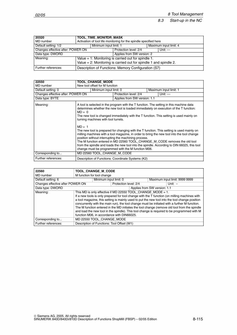
02/058.3 Start-up in the NC
8-115 Siemens AG, 2005. All rights reservedSINUMERIK 840D/840Di/810D Description of Functions ShopMill (FBSP) – 02/05 Edition
ÁÁÁÁÁÁÁÁÁÁÁÁÁÁÁÁÁÁÁÁÁÁÁÁ
20320MD number
ÁÁÁÁÁÁÁÁÁÁÁÁÁÁÁÁÁÁÁÁÁÁÁÁÁÁÁÁÁÁÁÁÁÁÁÁÁÁÁÁÁÁÁÁÁÁÁÁÁÁÁÁÁÁÁÁÁÁÁÁÁÁÁÁÁÁ
TOOL_TIME_MONITOR_MASKActivation of tool life monitoring for the spindle specified here
ÁÁÁÁÁÁÁÁÁÁDefault setting: 1/2 ÁÁÁÁÁÁÁÁÁÁMinimum input limit: 1 ÁÁÁÁÁÁÁÁÁÁÁMaximum input limit: 4ÁÁÁÁÁÁÁÁÁÁÁÁÁÁÁÁÁÁÁÁÁÁÁÁÁÁÁÁ
Changes effective after: POWER ONÁÁÁÁÁÁÁÁÁÁÁÁÁÁÁÁ
Protection level: 2/4ÁÁÁÁÁÁÁÁÁÁÁÁÁÁÁÁÁÁ
Unit: ––ÁÁÁÁÁÁÁÁÁÁÁÁÁÁÁÁÁÁÁÁÁÁÁÁÁÁÁÁ
Data type: DWORD ÁÁÁÁÁÁÁÁÁÁÁÁÁÁÁÁÁÁÁÁÁÁÁÁÁÁÁÁÁÁÁÁ
Applies from SW version: 2
ÁÁÁÁÁÁÁÁÁÁÁÁÁÁÁÁ
Meaning: ÁÁÁÁÁÁÁÁÁÁÁÁÁÁÁÁÁÁÁÁÁÁÁÁÁÁÁÁÁÁÁÁÁÁÁÁÁÁÁÁÁÁÁÁ
Value = 1: Monitoring is carried out for spindle 1.Value = 2: Monitoring is carried out for spindle 1 and spindle 2.
ÁÁÁÁÁÁÁÁÁÁÁÁÁÁÁÁ
Further references: ÁÁÁÁÁÁÁÁÁÁÁÁÁÁÁÁÁÁÁÁÁÁÁÁÁÁÁÁÁÁÁÁÁÁÁÁÁÁÁÁÁÁÁÁ
Description of Functions: Memory Configuration (S7)
ÁÁÁÁÁÁÁÁÁÁÁÁÁÁÁÁ
22550MD number ÁÁÁÁÁÁÁÁÁÁÁÁÁÁÁÁÁÁÁÁÁÁ
ÁÁÁÁÁÁÁÁÁÁÁÁÁÁÁÁÁÁÁÁÁÁ
TOOL_CHANGE_MODENew tool offset for M function
ÁÁÁÁÁÁÁÁÁÁÁÁÁÁÁÁÁÁÁÁ
Default setting: 0 ÁÁÁÁÁÁÁÁÁÁÁÁÁÁÁÁÁÁÁÁ
Minimum input limit: 0 ÁÁÁÁÁÁÁÁÁÁÁÁÁÁÁÁÁÁÁÁÁÁ
Maximum input limit: 1
ÁÁÁÁÁÁÁÁÁÁÁÁÁÁChanges effective after: POWER ON ÁÁÁÁÁÁÁÁProtection level: 2/4 ÁÁÁÁÁÁÁÁÁUnit: ––ÁÁÁÁÁÁÁÁÁÁÁÁÁÁÁÁÁÁÁÁÁÁÁÁÁÁÁÁ
Data type: BYTE ÁÁÁÁÁÁÁÁÁÁÁÁÁÁÁÁÁÁÁÁÁÁÁÁÁÁÁÁÁÁÁÁ
Applies from SW version: 1.1ÁÁÁÁÁÁÁÁÁÁÁÁÁÁÁÁÁÁÁÁÁÁÁÁÁÁÁÁÁÁÁÁÁÁÁÁÁÁÁÁÁÁÁÁÁÁÁÁÁÁÁÁÁÁÁÁÁÁÁÁÁÁÁÁÁÁÁÁÁÁÁÁ
Meaning: ÁÁÁÁÁÁÁÁÁÁÁÁÁÁÁÁÁÁÁÁÁÁÁÁÁÁÁÁÁÁÁÁÁÁÁÁÁÁÁÁÁÁÁÁÁÁÁÁÁÁÁÁÁÁÁÁÁÁÁÁÁÁÁÁÁÁÁÁÁÁÁÁÁÁÁÁÁÁÁÁÁÁÁÁÁÁÁÁÁÁÁÁÁÁÁÁÁÁÁÁÁÁÁÁÁÁÁÁÁÁÁÁÁÁÁÁÁÁÁÁÁÁÁÁÁÁÁÁÁÁÁÁÁÁÁÁÁÁÁÁÁÁÁÁÁÁÁÁÁÁÁÁÁÁÁÁÁÁÁÁÁÁÁÁÁÁÁÁÁÁÁÁÁÁÁÁÁÁÁÁÁÁÁÁÁÁÁÁÁÁÁÁÁÁÁÁÁÁ
A tool is selected in the program with the T function. The setting in this machine datadetermines whether the new tool is loaded immediately on execution of the T function:MD = 0The new tool is changed immediately with the T function. This setting is used mainly onturning machines with tool turrets.
MD = 1The new tool is prepared for changing with the T function. This setting is used mainly onmilling machines with a tool magazine, in order to bring the new tool into the tool changeposition without interrupting the machining process. The M function entered in MD 22560 TOOL_CHANGE_M_CODE removes the old toolfrom the spindle and loads the new tool into the spindle. According to DIN 66025, this toolchange must be programmed with the M function M06.ÁÁÁÁÁÁÁÁ
ÁÁÁÁÁÁÁÁCorresponding to... ÁÁÁÁÁÁÁÁÁÁÁÁÁÁÁÁÁÁÁÁÁÁ
ÁÁÁÁÁÁÁÁÁÁÁÁÁÁÁÁÁÁÁÁÁÁMD 22560 TOOL_CHANGE_M_CODE
ÁÁÁÁÁÁÁÁÁÁÁÁÁÁÁÁ
Further references: ÁÁÁÁÁÁÁÁÁÁÁÁÁÁÁÁÁÁÁÁÁÁÁÁÁÁÁÁÁÁÁÁÁÁÁÁÁÁÁÁÁÁÁÁ
Description of Functions: Coordinate Systems (K2)
22560 TOOL_CHANGE_M_CODEMD number M function for tool changeDefault setting: 6 Minimum input limit: 0 Maximum input limit: 9999 9999Changes effective after POWER ON Protection level: 2/4 Unit: –Data type: DWORD Applies from SW version: 1.1Meaning: This MD is only effective if MD 22550 TOOL_CHANGE_MODE = 1.
If a new tools is only prepared for tool change with the T function (on milling machines witha tool magazine, this setting is mainly used to put the new tool into the tool change positionconcurrently with the main run), the tool change must be initiated with a further M function.The M function entered in the MD initiates the tool change (remove old tool from the spindleand load the new tool in the spindle). This tool change is required to be programmed with Mfunction M06, in accordance with DIN66025.
Corresponding to... MD 22550 TOOL_CHANGE_MODEFurther references: Description of Functions: Tool Offset (W1)
8 Tool Management
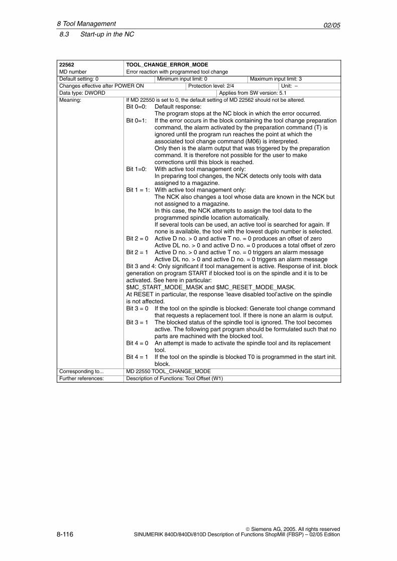
02/058.3 Start-up in the NC
8-116 Siemens AG, 2005. All rights reserved
SINUMERIK 840D/840Di/810D Description of Functions ShopMill (FBSP) – 02/05 Edition
22562 TOOL_CHANGE_ERROR_MODEMD number Error reaction with programmed tool changeDefault setting: 0 Minimum input limit: 0 Maximum input limit: 3Changes effective after POWER ON Protection level: 2/4 Unit: –Data type: DWORD Applies from SW version: 5.1Meaning: If MD 22550 is set to 0, the default setting of MD 22562 should not be altered.
Bit 0=0: Default response:The program stops at the NC block in which the error occurred.
Bit 0=1: If the error occurs in the block containing the tool change preparationcommand, the alarm activated by the preparation command (T) isignored until the program run reaches the point at which theassociated tool change command (M06) is interpreted.Only then is the alarm output that was triggered by the preparationcommand. It is therefore not possible for the user to makecorrections until this block is reached.
Bit 1=0: With active tool management only: In preparing tool changes, the NCK detects only tools with dataassigned to a magazine.
Bit 1 = 1: With active tool management only:The NCK also changes a tool whose data are known in the NCK butnot assigned to a magazine.In this case, the NCK attempts to assign the tool data to theprogrammed spindle location automatically.If several tools can be used, an active tool is searched for again. Ifnone is available, the tool with the lowest duplo number is selected.
Bit 2 = 0 Active D no. > 0 and active T no. = 0 produces an offset of zeroActive DL no. > 0 and active D no. = 0 produces a total offset of zero
Bit 2 = 1 Active D no. > 0 and active T no. = 0 triggers an alarm messageActive DL no. > 0 and active D no. = 0 triggers an alarm message
Bit 3 and 4: Only significant if tool management is active. Response of init. blockgeneration on program START if blocked tool is on the spindle and it is to beactivated. See here in particular:$MC_START_MODE_MASK and $MC_RESET_MODE_MASK.At RESET in particular, the response ’leave disabled tool’active on the spindleis not affected.Bit 3 = 0 If the tool on the spindle is blocked: Generate tool change command
that requests a replacement tool. If there is none an alarm is output.Bit 3 = 1 The blocked status of the spindle tool is ignored. The tool becomes
active. The following part program should be formulated such that noparts are machined with the blocked tool.
Bit 4 = 0 An attempt is made to activate the spindle tool and its replacementtool.
Bit 4 = 1 If the tool on the spindle is blocked T0 is programmed in the start init.block.
Corresponding to... MD 22550 TOOL_CHANGE_MODEFurther references: Description of Functions: Tool Offset (W1)
8 Tool Management
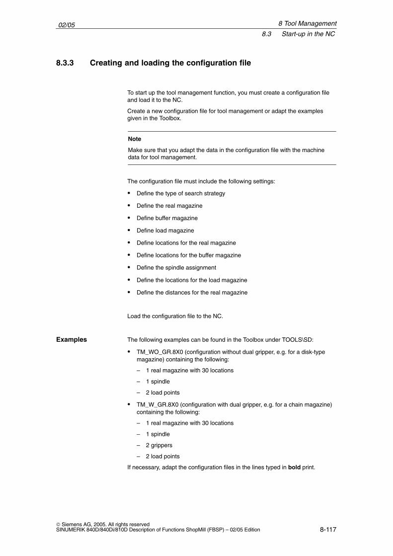
02/058.3 Start-up in the NC
8-117 Siemens AG, 2005. All rights reservedSINUMERIK 840D/840Di/810D Description of Functions ShopMill (FBSP) – 02/05 Edition
8.3.3 Creating and loading the configuration file
To start up the tool management function, you must create a configuration fileand load it to the NC.
Create a new configuration file for tool management or adapt the examplesgiven in the Toolbox.
Note
Make sure that you adapt the data in the configuration file with the machinedata for tool management.
The configuration file must include the following settings:
� Define the type of search strategy
� Define the real magazine
� Define buffer magazine
� Define load magazine
� Define locations for the real magazine
� Define locations for the buffer magazine
� Define the spindle assignment
� Define the locations for the load magazine
� Define the distances for the real magazine
Load the configuration file to the NC.
The following examples can be found in the Toolbox under TOOLS\SD:
� TM_WO_GR.8X0 (configuration without dual gripper, e.g. for a disk-typemagazine) containing the following:
– 1 real magazine with 30 locations
– 1 spindle
– 2 load points
� TM_W_GR.8X0 (configuration with dual gripper, e.g. for a chain magazine)containing the following:
– 1 real magazine with 30 locations
– 1 spindle
– 2 grippers
– 2 load points
If necessary, adapt the configuration files in the lines typed in bold print.
Examples
8 Tool Management
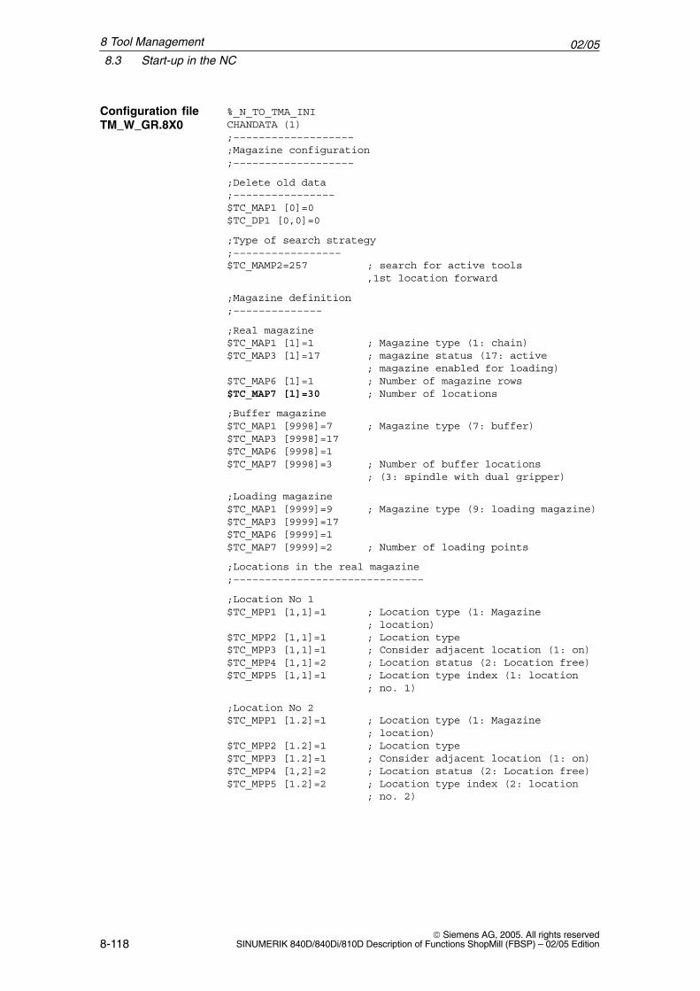
02/058.3 Start-up in the NC
8-118 Siemens AG, 2005. All rights reserved
SINUMERIK 840D/840Di/810D Description of Functions ShopMill (FBSP) – 02/05 Edition
%_N_TO_TMA_INICHANDATA (1);–––––––––––––––––––;Magazine configuration;–––––––––––––––––––
;Delete old data;––––––––––––––––$TC_MAP1 [0]=0$TC_DP1 [0,0]=0
;Type of search strategy;–––––––––––––––––$TC_MAMP2=257 ; search for active tools
,1st location forward
;Magazine definition;––––––––––––––
;Real magazine$TC_MAP1 [1]=1 ; Magazine type (1: chain)$TC_MAP3 [1]=17 ; magazine status (17: active
; magazine enabled for loading)$TC_MAP6 [1]=1 ; Number of magazine rows$TC_MAP7 [1]=30 ; Number of locations
;Buffer magazine$TC_MAP1 [9998]=7 ; Magazine type (7: buffer)$TC_MAP3 [9998]=17$TC_MAP6 [9998]=1$TC_MAP7 [9998]=3 ; Number of buffer locations
; (3: spindle with dual gripper)
;Loading magazine$TC_MAP1 [9999]=9 ; Magazine type (9: loading magazine)$TC_MAP3 [9999]=17$TC_MAP6 [9999]=1$TC_MAP7 [9999]=2 ; Number of loading points
;Locations in the real magazine;––––––––––––––––––––––––––––––
;Location No 1$TC_MPP1 [1,1]=1 ; Location type (1: Magazine
; location)$TC_MPP2 [1,1]=1 ; Location type$TC_MPP3 [1,1]=1 ; Consider adjacent location (1: on)$TC_MPP4 [1,1]=2 ; Location status (2: Location free)$TC_MPP5 [1,1]=1 ; Location type index (1: location
; no. 1)
;Location No 2$TC_MPP1 [1.2]=1 ; Location type (1: Magazine
; location)$TC_MPP2 [1.2]=1 ; Location type$TC_MPP3 [1.2]=1 ; Consider adjacent location (1: on)$TC_MPP4 [1,2]=2 ; Location status (2: Location free)$TC_MPP5 [1.2]=2 ; Location type index (2: location
; no. 2)
Configuration fileTM_W_GR.8X0
8 Tool Management
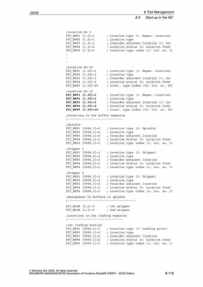
02/058.3 Start-up in the NC
8-119 Siemens AG, 2005. All rights reservedSINUMERIK 840D/840Di/810D Description of Functions ShopMill (FBSP) – 02/05 Edition
;Location No 3$TC_MPP1 [1.3]=1 ; Location type (1: Magaz. location)$TC_MPP2 [1.3]=1 ; Location type$TC_MPP3 [1.3]=1 ; Consider adjacent location (1: on)$TC_MPP4 [1,3]=2 ; Location status (2: Location free)$TC_MPP5 [1.3]=3 ; Location type index (3: loc. no. 3)...
;Location No 29$TC_MPP1 [1.29]=1 ; Location type (1: Magaz. location)$TC_MPP2 [1.29]=1 ; Location type$TC_MPP3 [1.29]=1 ; Consider adjacent location (1: on)$TC_MPP4 [1,29]=2 ; Location status (2: Location free)$TC_MPP5 [1.29]=29 ; Locat. type index (29: loc. no. 29)
;Location No 30$TC_MPP1 [1.30]=1 ; Location type (1: Magaz. location)$TC_MPP2 [1.30]=1 ; Location type$TC_MPP3 [1.30]=1 ; Consider adjacent location (1: on)$TC_MPP4 [1,30]=2 ; Location status (2: Location free)$TC_MPP5 [1.30]=30 ; Locat. type index (30: loc. no. 30)
;Locations in the buffer magazine;––––––––––––––––––––––––––––––
;Spindle$TC_MPP1 [9998,1]=2 ; Location type (2: Spindle)$TC_MPP2 [9998,1]=0 ; Location type$TC_MPP3 [9998,1]=0 ; Consider adjacent location $TC_MPP4 [9998,1]=2 ; Location status (2: Location free)$TC_MPP5 [9998,1]=1 ; Location type index (1: loc. no. 1)
;Gripper 1$TC_MPP1 [9998,2]=3 ; Location type (3: Gripper)$TC_MPP2 [9998,2]=0 ; Location type$TC_MPP3 [9998,2]=0 ; Consider adjacent location $TC_MPP4 [9998,2]=2 ; Location status (2: Location free)$TC_MPP5 [9998,2]=1 ; Location type index (1: loc. no. 1)
;Gripper 2$TC_MPP1 [9998,3]=3 ; Location type (3: Gripper)$TC_MPP2 [9998,3]=0 ; Location type$TC_MPP3 [9998,3]=0 ; Consider adjacent location $TC_MPP4 [9998,3]=2 ; Location status (2: Location free)$TC_MPP5 [9998,3]=2 ; Location type index (2: loc. no. 2)
;Assignment of buffers to spindle;–––––––––––––––––––––––––––––––––––––
$TC_MLSR [2,1]=0 ; 1st gripper$TC_MLSR [3,1]=0 ; 2nd gripper
;Locations in the loading magazine;––––––––––––––––––––––––––––––
;1st loading station$TC_MPP1 [9999,1]=7 ; Location type (7: Loading point)$TC_MPP2 [9999.1]=0 ; Location type$TC_MPP3 [9999.1]=0 ; Consider adjacent location $TC_MPP4 [9999.1]=2 ; Location status (2: Location free)$TC_MPP5 [9999.1]=1 ; Location type index (1: loc. no. 1)
8 Tool Management
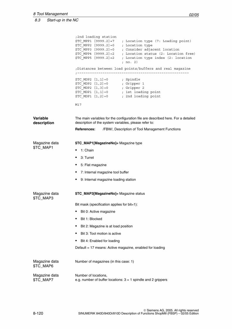
02/058.3 Start-up in the NC
8-120 Siemens AG, 2005. All rights reserved
SINUMERIK 840D/840Di/810D Description of Functions ShopMill (FBSP) – 02/05 Edition
;2nd loading station$TC_MPP1 [9999.2]=7 ; Location type (7: Loading point)$TC_MPP2 [9999.2]=0 ; Location type$TC_MPP3 [9999.2]=0 ; Consider adjacent location $TC_MPP4 [9999.2]=2 ; Location status (2: Location free)$TC_MPP5 [9999.2]=2 ; Location type index (2: location
; no. 2)
;Distances between load points/buffers and real magazine;–––––––––––––––––––––––––––––––––––––––––––––––––––––
$TC_MDP2 [1,1]=0 ; Spindle$TC_MDP2 [1,2]=0 ; Gripper 1$TC_MDP2 [1,3]=0 ; Gripper 2$TC_MDP1 [1,1]=0 ; 1st loading point$TC_MDP1 [1,2]=0 ; 2nd loading point
M17
The main variables for the configuration file are described here. For a detaileddescription of the system variables, please refer to:
References: /FBW/, Description of Tool Management Functions
$TC_MAP1[MagazineNo]= Magazine type
� 1: Chain
� 3: Turret
� 5: Flat magazine
� 7: Internal magazine tool buffer
� 9: Internal magazine loading station
$TC_MAP3[MagazineNo]= Magazine status
Bit mask (specification applies for bit=1):
� Bit 0: Active magazine
� Bit 1: Blocked
� Bit 2: Magazine is at load position
� Bit 3: Tool motion is active
� Bit 4: Enabled for loading
Default = 17 means: Active magazine, enabled for loading
Number of magazines (in this case: 1)
Number of locations,e.g. number of buffer locations: 3 = 1 spindle and 2 grippers
Variabledescription
Magazine data$TC_MAP1
Magazine data$TC_MAP3
Magazine data$TC_MAP6
Magazine data$TC_MAP7
8 Tool Management
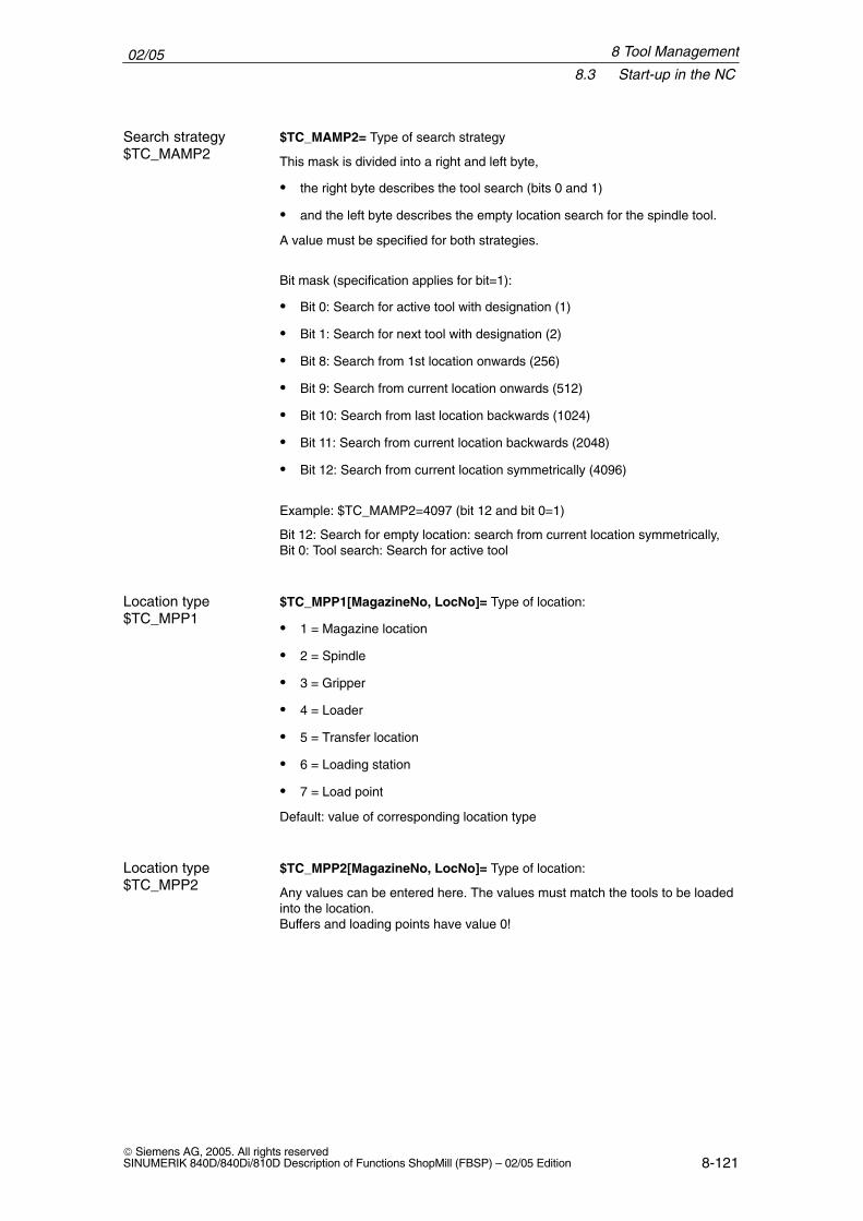
02/058.3 Start-up in the NC
8-121 Siemens AG, 2005. All rights reservedSINUMERIK 840D/840Di/810D Description of Functions ShopMill (FBSP) – 02/05 Edition
$TC_MAMP2= Type of search strategy
This mask is divided into a right and left byte,
� the right byte describes the tool search (bits 0 and 1)
� and the left byte describes the empty location search for the spindle tool.
A value must be specified for both strategies.
Bit mask (specification applies for bit=1):
� Bit 0: Search for active tool with designation (1)
� Bit 1: Search for next tool with designation (2)
� Bit 8: Search from 1st location onwards (256)
� Bit 9: Search from current location onwards (512)
� Bit 10: Search from last location backwards (1024)
� Bit 11: Search from current location backwards (2048)
� Bit 12: Search from current location symmetrically (4096)
Example: $TC_MAMP2=4097 (bit 12 and bit 0=1)
Bit 12: Search for empty location: search from current location symmetrically,Bit 0: Tool search: Search for active tool
$TC_MPP1[MagazineNo, LocNo]= Type of location:
� 1 = Magazine location
� 2 = Spindle
� 3 = Gripper
� 4 = Loader
� 5 = Transfer location
� 6 = Loading station
� 7 = Load point
Default: value of corresponding location type
$TC_MPP2[MagazineNo, LocNo]= Type of location:
Any values can be entered here. The values must match the tools to be loadedinto the location.Buffers and loading points have value 0!
Search strategy$TC_MAMP2
Location type $TC_MPP1
Location type $TC_MPP2
8 Tool Management
02/058.3 Start-up in the NC
8-122 Siemens AG, 2005. All rights reserved
SINUMERIK 840D/840Di/810D Description of Functions ShopMill (FBSP) – 02/05 Edition
$TC_MPP3[MagazineNo, LocNo]= Consider adjacent location ON = 1
� Value = 1: An adjacent location is considered for the location
� Value = 0: No adjacent location is considered for the location
� Value = 0: Must be entered for buffer and load locations!
$TC_MPP4[MagazineNo, LocNo]= Location status (bit mask)
� Bit 0: Blocked
� Bit 1: Free/allocated
Default: 2 = Location free
$TC_MPP5[MagazineNo, LocNo]= Location type index
For $TC_MPP1[Magazine No., Location No.]=1 (location type is the magazinelocation), the location number is entered here. For other location types, the typeindex is incremented:
Example with 2 grippers with location type 3
� the first gripper has location index 1
� the second gripper has location index 2
Distances to magazine
$TC_MDP2[MagazineNo, BufferNo.]= Distances between buffer and maga-zine
A value must be entered for each buffer, at least a zero. The value is not inter-preted here but is used only for assignment.
$TC_MDP1[MagazineNo, BufferNo.]= Distances between load points andmagazine
One value must be entered for each load location here. It is interpreted whencalculating the location before the load point. Only for “Load point for spindle”(location 1) is the value not interpreted but used “only” for magazine assign-ment.
$TC_MLSR[LocationNo of BUFF, LocationNo of spindle]= Assignment be-tween buffer and spindle. This enables determination of which buffer, e.g. gripper, may carry out toolchange to the spindle.
In ShopMill the tool change is initiated by a tool-changing cycle. This cycle iscalled from the ShopMill cycles where a tool can be programmed.
Consider adjacentlocation $TC_MPP3
Location status$TC_MPP4
Location type index$TC_MPP5
Distances tomagazine
Spindle assignment
8 Tool Management
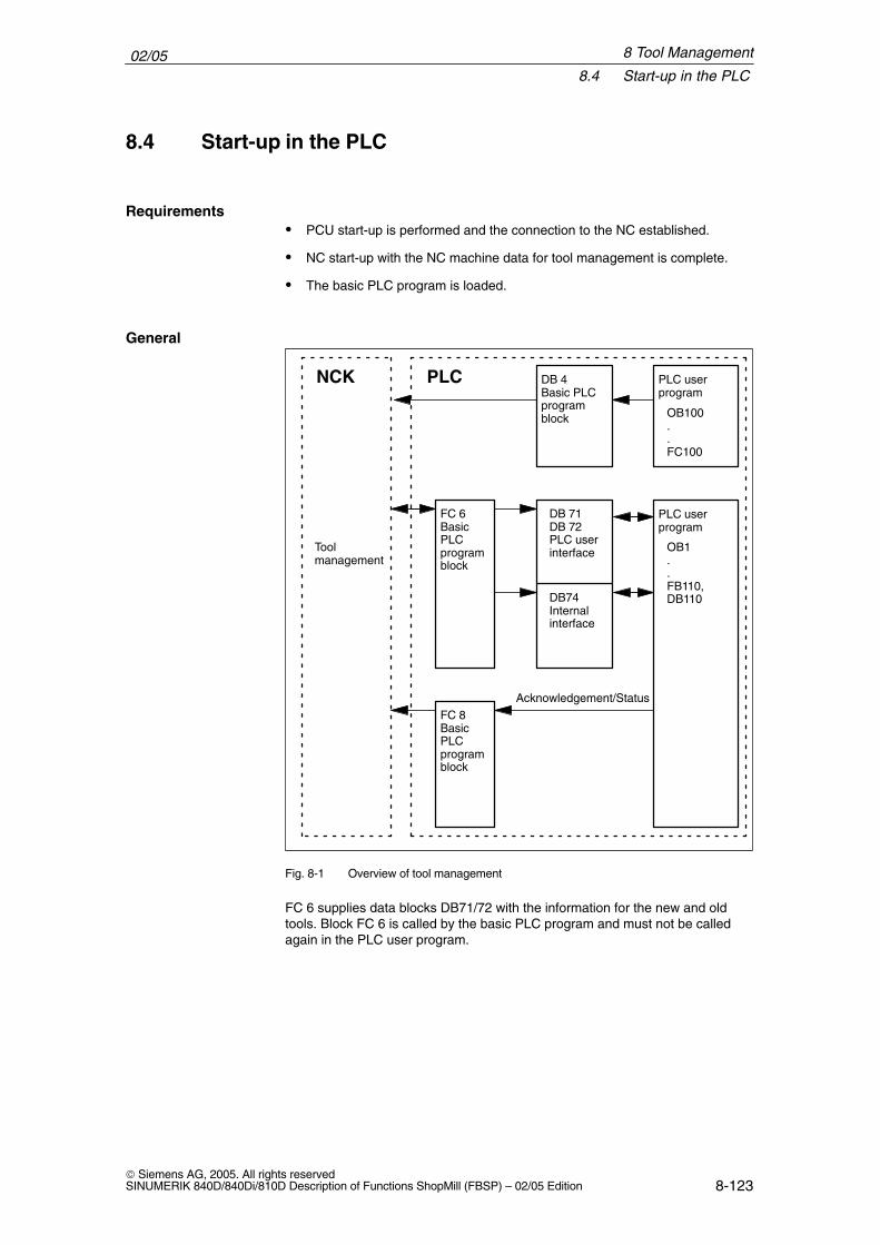
02/058.4 Start-up in the PLC
8-123 Siemens AG, 2005. All rights reservedSINUMERIK 840D/840Di/810D Description of Functions ShopMill (FBSP) – 02/05 Edition
8.4 Start-up in the PLC
� PCU start-up is performed and the connection to the NC established.
� NC start-up with the NC machine data for tool management is complete.
� The basic PLC program is loaded.
NCK
PLC userprogram
PLC userprogram
OB100..FC100
OB1..FB110,DB110
Toolmanagement
PLC DB 4Basic PLCprogramblock
DB 71DB 72PLC userinterface
DB74Internalinterface
FC 6Basic PLCprogramblock
FC 8Basic PLCprogramblock
Acknowledgement/Status
Fig. 8-1 Overview of tool management
FC 6 supplies data blocks DB71/72 with the information for the new and oldtools. Block FC 6 is called by the basic PLC program and must not be calledagain in the PLC user program.
Requirements
General
8 Tool Management
02/058.4 Start-up in the PLC
8-124 Siemens AG, 2005. All rights reserved
SINUMERIK 840D/840Di/810D Description of Functions ShopMill (FBSP) – 02/05 Edition
So that the tool management always knows where the current tool is located,each location change must be notified to the tool management via FC8 (transferblock). The FC 8 (transfer block) is called by the user program.FB110 is provided as an example.
The data blocks DB71/72 and 74 are set up automatically. The lengths of thedata blocks are determined by the parameters for the tool management in DB4.DB4 is written to by the PLC user program.FC100 is provided as an example.
Implement call FC 8 and create PLC data (DB4).Either adapt the examples for blocks FC 8 and DB4 from the ShopMill library oruse your own blocks.
Execution
8 Tool Management
02/058.4 Start-up in the PLC
8-125 Siemens AG, 2005. All rights reservedSINUMERIK 840D/840Di/810D Description of Functions ShopMill (FBSP) – 02/05 Edition
8.4.1 Example for FC 100 and FB 110
The ShopMill library contains two sources as examples of tool management.
� Adapt one of the following source files and compile it:
– TM_WO_GR.AWL (data transfer without dual gripper, e.g. for a disk-typemagazine)
– TM_W_GR.AWL (data transfer with dual gripper, e.g. for a chain maga-zine)
Source files TM_WO_GR.AWL and TM_W_GR.AWL contain the followingblocks
– FC 100 (block for the PLC data of tool management)
– FB 110, DB 110 (blocks for data transfer in tool management)
The blocks for transferring tool management data (FB110, DB110) must beadapted to suit the individual machine.
� Load the generated blocks to the PLC
� Call the blocks in OB 1 and OB 100:
– Call FC 100 in OB 100 (before FB 1)
– Call FB 110 in OB 1 (after FC 30)
The specified call sequence for these blocks is mandatory.
Block FC 100 transfers the tool management PLC data to DB4.
The PLC data is set up for 2 loading points (DB71), one toolholder (DB72) andthe tool turret (DB73).The signals for DB71, DB72 and DB73 are found in Subsection 8.4.2 “SignalDescription”.
The “Real MagLoc” parameter of FC 100 (number of locations of the real maga-zine) must be assigned values when FC 100 is called.
Block FB 110 controls the data transfer for tool management.
The block includes the following functions:
� Acknowledge load/unload/relocate for 1st load point
� Acknowledge load/unload for 2nd load point
� Acknowledge prepare/change for 1st spindle
� Abort, i.e. negative acknowledgment for the above-mentioned functions
Procedure
FC 100
FB 110
8 Tool Management
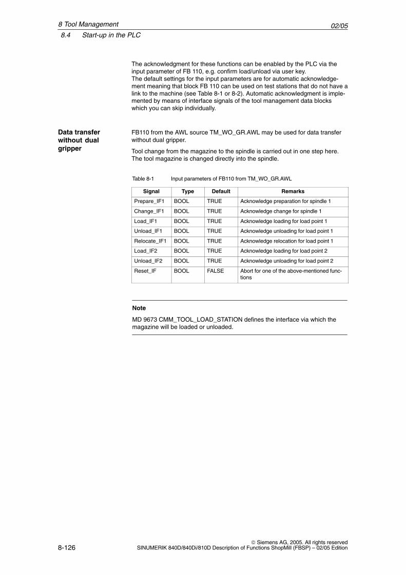
02/058.4 Start-up in the PLC
8-126 Siemens AG, 2005. All rights reserved
SINUMERIK 840D/840Di/810D Description of Functions ShopMill (FBSP) – 02/05 Edition
The acknowledgment for these functions can be enabled by the PLC via theinput parameter of FB 110, e.g. confirm load/unload via user key.The default settings for the input parameters are for automatic acknowledge-ment meaning that block FB 110 can be used on test stations that do not have alink to the machine (see Table 8-1 or 8-2). Automatic acknowledgment is imple-mented by means of interface signals of the tool management data blockswhich you can skip individually.
FB110 from the AWL source TM_WO_GR.AWL may be used for data transferwithout dual gripper.
Tool change from the magazine to the spindle is carried out in one step here.The tool magazine is changed directly into the spindle.
Table 8-1 Input parameters of FB110 from TM_WO_GR.AWL
Signal Type Default Remarks
Prepare_IF1 BOOL TRUE Acknowledge preparation for spindle 1
Change_IF1 BOOL TRUE Acknowledge change for spindle 1
Load_IF1 BOOL TRUE Acknowledge loading for load point 1
Unload_IF1 BOOL TRUE Acknowledge unloading for load point 1
Relocate_IF1 BOOL TRUE Acknowledge relocation for load point 1
Load_IF2 BOOL TRUE Acknowledge loading for load point 2
Unload_IF2 BOOL TRUE Acknowledge unloading for load point 2
Reset_IF BOOL FALSE Abort for one of the above-mentioned func-tions
Note
MD 9673 CMM_TOOL_LOAD_STATION defines the interface via which themagazine will be loaded or unloaded.
Data transferwithout dualgripper
8 Tool Management
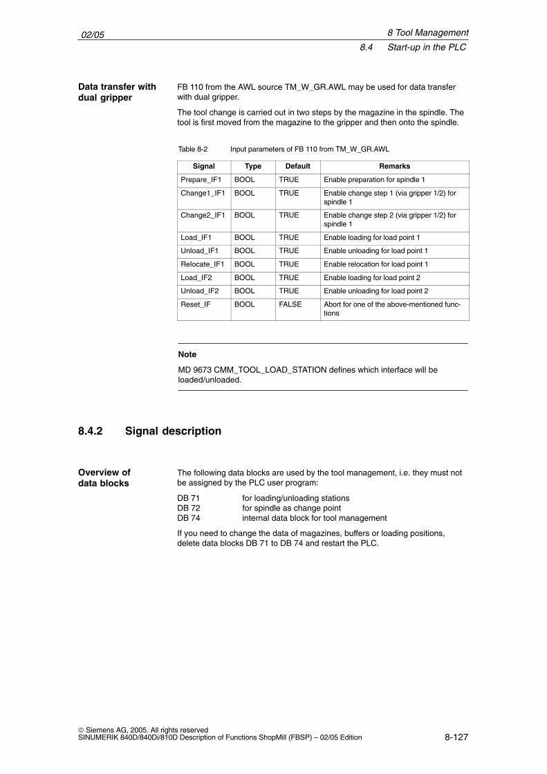
02/058.4 Start-up in the PLC
8-127 Siemens AG, 2005. All rights reservedSINUMERIK 840D/840Di/810D Description of Functions ShopMill (FBSP) – 02/05 Edition
FB 110 from the AWL source TM_W_GR.AWL may be used for data transferwith dual gripper.
The tool change is carried out in two steps by the magazine in the spindle. Thetool is first moved from the magazine to the gripper and then onto the spindle.
Table 8-2 Input parameters of FB 110 from TM_W_GR.AWL
Signal Type Default Remarks
Prepare_IF1 BOOL TRUE Enable preparation for spindle 1
Change1_IF1 BOOL TRUE Enable change step 1 (via gripper 1/2) forspindle 1
Change2_IF1 BOOL TRUE Enable change step 2 (via gripper 1/2) forspindle 1
Load_IF1 BOOL TRUE Enable loading for load point 1
Unload_IF1 BOOL TRUE Enable unloading for load point 1
Relocate_IF1 BOOL TRUE Enable relocation for load point 1
Load_IF2 BOOL TRUE Enable loading for load point 2
Unload_IF2 BOOL TRUE Enable unloading for load point 2
Reset_IF BOOL FALSE Abort for one of the above-mentioned func-tions
Note
MD 9673 CMM_TOOL_LOAD_STATION defines which interface will beloaded/unloaded.
8.4.2 Signal description
The following data blocks are used by the tool management, i.e. they must notbe assigned by the PLC user program:
DB 71 for loading/unloading stationsDB 72 for spindle as change pointDB 74 internal data block for tool management
If you need to change the data of magazines, buffers or loading positions,delete data blocks DB 71 to DB 74 and restart the PLC.
Data transfer withdual gripper
Overview of data blocks
8 Tool Management
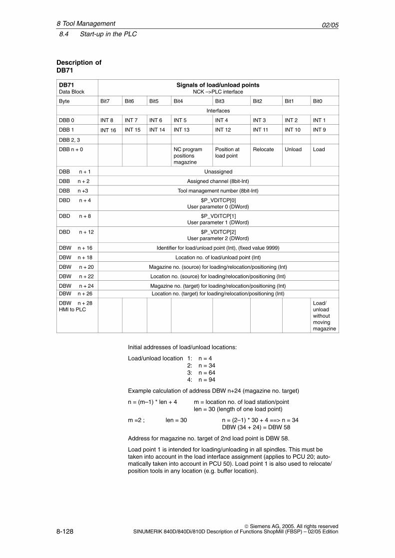
02/058.4 Start-up in the PLC
8-128 Siemens AG, 2005. All rights reserved
SINUMERIK 840D/840Di/810D Description of Functions ShopMill (FBSP) – 02/05 Edition
DB71Data Block
Signals of load/unload pointsNCK –>PLC interface
Byte Bit7 Bit6 Bit5 Bit4 Bit3 Bit2 Bit1 Bit0
Interfaces
DBB 0 INT 8 INT 7 INT 6 INT 5 INT 4 INT 3 INT 2 INT 1
DBB 1 INT 16 INT 15 INT 14 INT 13 INT 12 INT 11 INT 10 INT 9
DBB 2, 3
DBB n + 0 NC programpositions magazine
Position atload point
Relocate Unload Load
DBB n + 1 Unassigned
DBB n + 2 Assigned channel (8bit-Int)
DBB n +3 Tool management number (8bit-Int)
DBD n + 4 $P_VDITCP[0]User parameter 0 (DWord)
DBD n + 8 $P_VDITCP[1]User parameter 1 (DWord)
DBD n + 12 $P_VDITCP[2]User parameter 2 (DWord)
DBW n + 16 Identifier for load/unload point (Int), (fixed value 9999)
DBW n + 18 Location no. of load/unload point (Int)
DBW n + 20 Magazine no. (source) for loading/relocation/positioning (Int)
DBW n + 22 Location no. (source) for loading/relocation/positioning (Int)
DBW n + 24 Magazine no. (target) for loading/relocation/positioning (Int)DBW n + 26 Location no. (target) for loading/relocation/positioning (Int)
DBW n + 28HMI to PLC
Load/unloadwithoutmovingmagazine
Initial addresses of load/unload locations:
Load/unload location 1: n = 42: n = 343: n = 644: n = 94
Example calculation of address DBW n+24 (magazine no. target)
n = (m–1) * len + 4 m = location no. of load station/pointlen = 30 (length of one load point)
m =2 ; len = 30 n = (2–1) * 30 + 4 ==> n = 34DBW (34 + 24) = DBW 58
Address for magazine no. target of 2nd load point is DBW 58.
Load point 1 is intended for loading/unloading in all spindles. This must betaken into account in the load interface assignment (applies to PCU 20; auto-matically taken into account in PCU 50). Load point 1 is also used to relocate/position tools in any location (e.g. buffer location).
Description ofDB71
8 Tool Management
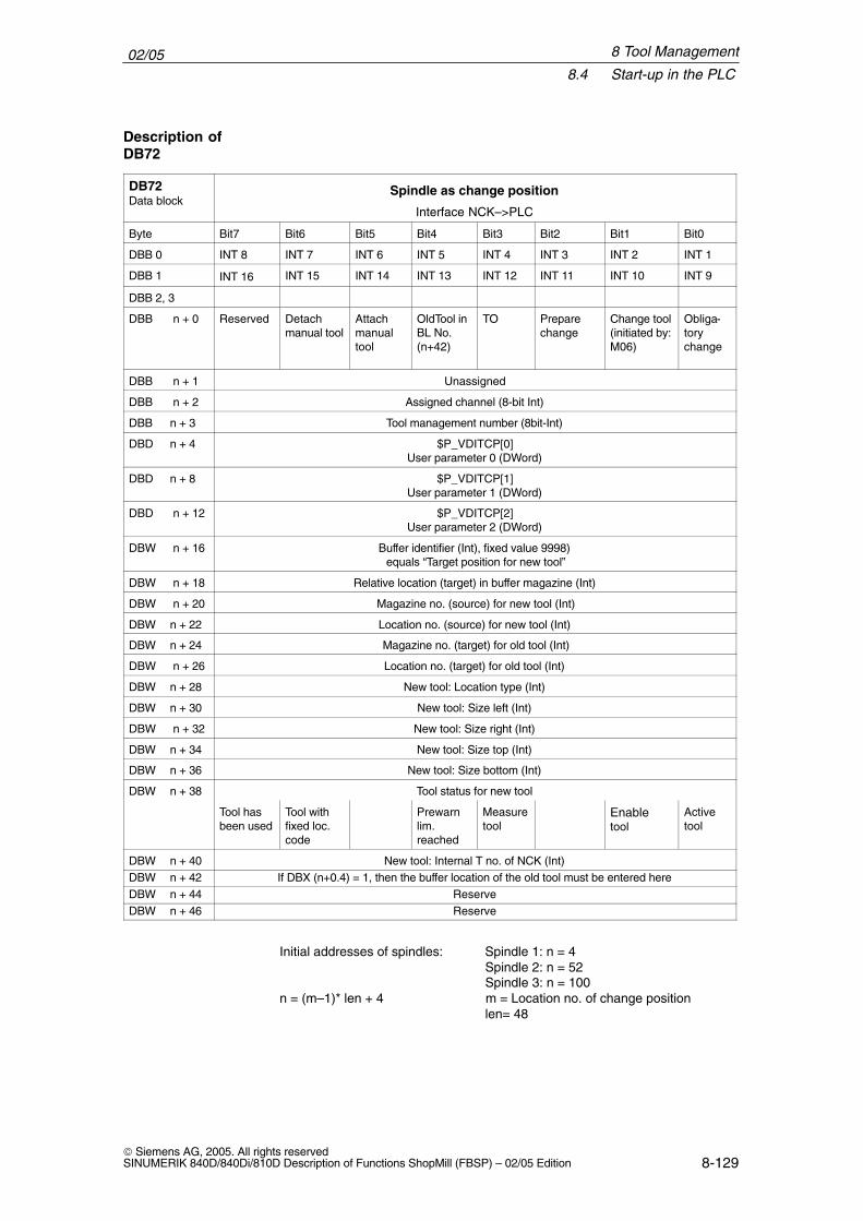
02/058.4 Start-up in the PLC
8-129 Siemens AG, 2005. All rights reservedSINUMERIK 840D/840Di/810D Description of Functions ShopMill (FBSP) – 02/05 Edition
DB72Data block
Spindle as change position
Interface NCK–>PLC
Byte Bit7 Bit6 Bit5 Bit4 Bit3 Bit2 Bit1 Bit0
DBB 0 INT 8 INT 7 INT 6 INT 5 INT 4 INT 3 INT 2 INT 1
DBB 1 INT 16 INT 15 INT 14 INT 13 INT 12 INT 11 INT 10 INT 9
DBB 2, 3
DBB n + 0 Reserved Detachmanual tool
Attachmanualtool
OldTool inBL No.(n+42)
TO Prepare change
Change tool(initiated by:M06)
Obliga-torychange
DBB n + 1 Unassigned
DBB n + 2 Assigned channel (8-bit Int)
DBB n + 3 Tool management number (8bit-Int)
DBD n + 4 $P_VDITCP[0]User parameter 0 (DWord)
DBD n + 8 $P_VDITCP[1]User parameter 1 (DWord)
DBD n + 12 $P_VDITCP[2]User parameter 2 (DWord)
DBW n + 16 Buffer identifier (Int), fixed value 9998) equals “Target position for new tool”
DBW n + 18 Relative location (target) in buffer magazine (Int)
DBW n + 20 Magazine no. (source) for new tool (Int)
DBW n + 22 Location no. (source) for new tool (Int)
DBW n + 24 Magazine no. (target) for old tool (Int)
DBW n + 26 Location no. (target) for old tool (Int)
DBW n + 28 New tool: Location type (Int)
DBW n + 30 New tool: Size left (Int)
DBW n + 32 New tool: Size right (Int)
DBW n + 34 New tool: Size top (Int)
DBW n + 36 New tool: Size bottom (Int)
DBW n + 38 Tool status for new tool
Tool hasbeen used
Tool withfixed loc.code
Prewarnlim.reached
Measuretool
Enabletool
Activetool
DBW n + 40 New tool: Internal T no. of NCK (Int)DBW n + 42 If DBX (n+0.4) = 1, then the buffer location of the old tool must be entered hereDBW n + 44 ReserveDBW n + 46 Reserve
Initial addresses of spindles: Spindle 1: n = 4Spindle 2: n = 52Spindle 3: n = 100
n = (m–1)* len + 4 m = Location no. of change positionlen= 48
Description ofDB72
8 Tool Management
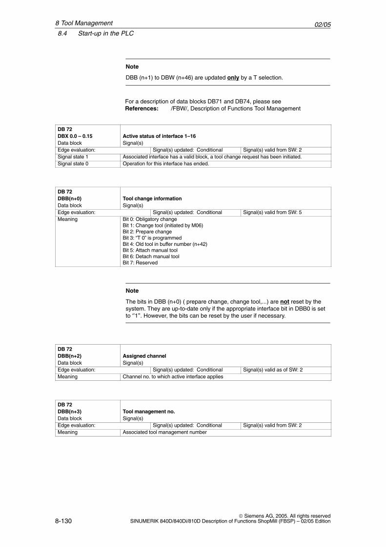
02/058.4 Start-up in the PLC
8-130 Siemens AG, 2005. All rights reserved
SINUMERIK 840D/840Di/810D Description of Functions ShopMill (FBSP) – 02/05 Edition
Note
DBB (n+1) to DBW (n+46) are updated only by a T selection.
For a description of data blocks DB71 and DB74, please seeReferences: /FBW/, Description of Functions Tool Management
DB 72DBX 0.0 – 0.15 Active status of interface 1–16Data block Signal(s)Edge evaluation: Signal(s) updated: Conditional Signal(s) valid from SW: 2Signal state 1 Associated interface has a valid block, a tool change request has been initiated.Signal state 0 Operation for this interface has ended.
DB 72DBB(n+0) Tool change informationData block Signal(s)Edge evaluation: Signal(s) updated: Conditional Signal(s) valid from SW: 5Meaning Bit 0: Obligatory change
Bit 1: Change tool (initiated by M06)Bit 2: Prepare changeBit 3: “T 0” is programmedBit 4: Old tool in buffer number (n+42)Bit 5: Attach manual toolBit 6: Detach manual toolBit 7: Reserved
Note
The bits in DBB (n+0) ( prepare change, change tool,...) are not reset by thesystem. They are up-to-date only if the appropriate interface bit in DBB0 is setto ‘’1’’. However, the bits can be reset by the user if necessary.
DB 72DBB(n+2) Assigned channelData block Signal(s)Edge evaluation: Signal(s) updated: Conditional Signal(s) valid as of SW: 2Meaning Channel no. to which active interface applies
DB 72DBB(n+3) Tool management no.Data block Signal(s)Edge evaluation: Signal(s) updated: Conditional Signal(s) valid from SW: 2Meaning Associated tool management number
8 Tool Management
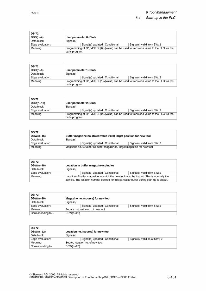
02/058.4 Start-up in the PLC
8-131 Siemens AG, 2005. All rights reservedSINUMERIK 840D/840Di/810D Description of Functions ShopMill (FBSP) – 02/05 Edition
DB 72DBD(n+4) User parameter 0 (DInt)Data block Signal(s)Edge evaluation: Signal(s) updated: Conditional Signal(s) valid from SW: 2Meaning Programming of $P_VDITCP[0]=(value) can be used to transfer a value to the PLC via the
parts program.
DB 72DBD(n+8) User parameter 1 (DInt)Data block Signal(s)Edge evaluation: Signal(s) updated: Conditional Signal(s) valid from SW: 2Meaning Programming of $P_VDITCP[1]=(value) can be used to transfer a value to the PLC via the
parts program.
DB 72DBD(n+12) User parameter 2 (DInt)Data block Signal(s)Edge evaluation: Signal(s) updated: Conditional Signal(s) valid from SW: 2Meaning Programming of $P_VDITCP[2]=(value) can be used to transfer a value to the PLC via the
parts program.
DB 72DBW(n+16) Buffer magazine no. (fixed value 9998) target position for new toolData block Signal(s)Edge evaluation: Signal(s) updated: Conditional Signal(s) valid from SW: 2Meaning Magazine no. 9998 for all buffer magazines, target magazine for new tool
DB 72DBW(n+18) Location in buffer magazine (spindle)Data block Signal(s)Edge evaluation: Signal(s) updated: Conditional Signal(s) valid from SW: 2Meaning Location of buffer magazine to which the new tool must be loaded. This is normally the
spindle. The location number defined for this particular buffer during start-up is output.
DB 72DBW(n+20) Magazine no. (source) for new toolData block Signal(s)Edge evaluation: Signal(s) updated: Conditional Signal(s) valid from SW: 2Meaning Source magazine no. of new toolCorresponding to... DBW(n+22)
DB 72DBW(n+22) Location no. (source) for new toolData block Signal(s)Edge evaluation: Signal(s) updated: Conditional Signal(s) valid as of SW:: 2Meaning Source location no. of new toolCorresponding to... DBW(n+20)
8 Tool Management
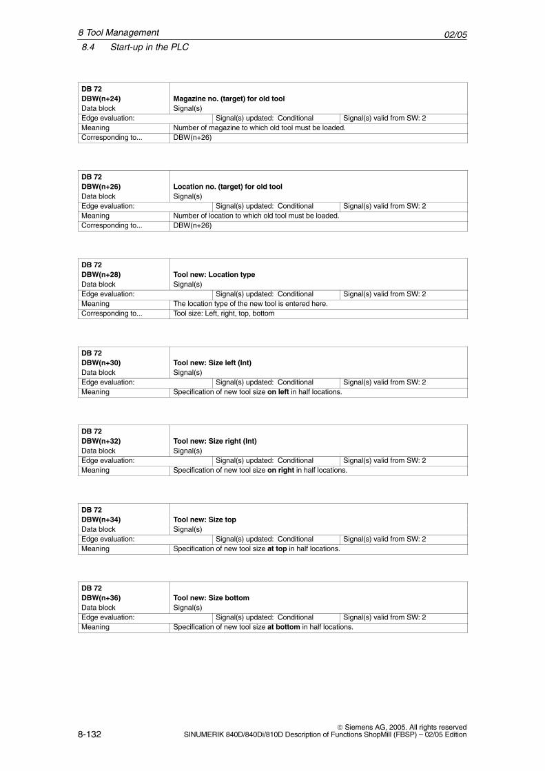
02/058.4 Start-up in the PLC
8-132 Siemens AG, 2005. All rights reserved
SINUMERIK 840D/840Di/810D Description of Functions ShopMill (FBSP) – 02/05 Edition
DB 72DBW(n+24) Magazine no. (target) for old toolData block Signal(s)Edge evaluation: Signal(s) updated: Conditional Signal(s) valid from SW: 2Meaning Number of magazine to which old tool must be loaded.Corresponding to... DBW(n+26)
DB 72DBW(n+26) Location no. (target) for old toolData block Signal(s)Edge evaluation: Signal(s) updated: Conditional Signal(s) valid from SW: 2Meaning Number of location to which old tool must be loaded.Corresponding to... DBW(n+26)
DB 72DBW(n+28) Tool new: Location typeData block Signal(s)Edge evaluation: Signal(s) updated: Conditional Signal(s) valid from SW: 2Meaning The location type of the new tool is entered here.Corresponding to... Tool size: Left, right, top, bottom
DB 72DBW(n+30) Tool new: Size left (Int)Data block Signal(s)Edge evaluation: Signal(s) updated: Conditional Signal(s) valid from SW: 2Meaning Specification of new tool size on left in half locations.
DB 72DBW(n+32) Tool new: Size right (Int)Data block Signal(s)Edge evaluation: Signal(s) updated: Conditional Signal(s) valid from SW: 2Meaning Specification of new tool size on right in half locations.
DB 72DBW(n+34) Tool new: Size topData block Signal(s)Edge evaluation: Signal(s) updated: Conditional Signal(s) valid from SW: 2Meaning Specification of new tool size at top in half locations.
DB 72DBW(n+36) Tool new: Size bottomData block Signal(s)Edge evaluation: Signal(s) updated: Conditional Signal(s) valid from SW: 2Meaning Specification of new tool size at bottom in half locations.
8 Tool Management
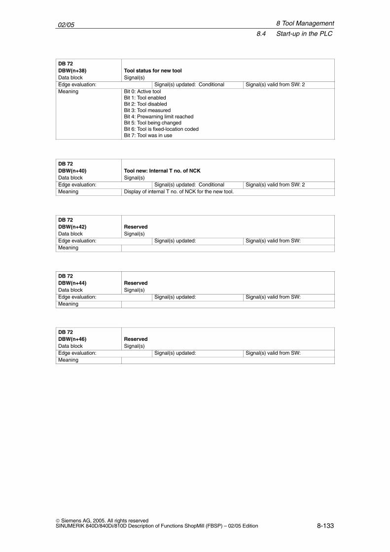
02/058.4 Start-up in the PLC
8-133 Siemens AG, 2005. All rights reservedSINUMERIK 840D/840Di/810D Description of Functions ShopMill (FBSP) – 02/05 Edition
DB 72DBW(n+38) Tool status for new toolData block Signal(s)Edge evaluation: Signal(s) updated: Conditional Signal(s) valid from SW: 2Meaning Bit 0: Active tool
Bit 1: Tool enabledBit 2: Tool disabledBit 3: Tool measuredBit 4: Prewarning limit reachedBit 5: Tool being changedBit 6: Tool is fixed-location codedBit 7: Tool was in use
DB 72DBW(n+40) Tool new: Internal T no. of NCKData block Signal(s)Edge evaluation: Signal(s) updated: Conditional Signal(s) valid from SW: 2Meaning Display of internal T no. of NCK for the new tool.
DB 72DBW(n+42) ReservedData block Signal(s)Edge evaluation: Signal(s) updated: Signal(s) valid from SW:Meaning
DB 72DBW(n+44) ReservedData block Signal(s)Edge evaluation: Signal(s) updated: Signal(s) valid from SW:Meaning
DB 72DBW(n+46) ReservedData block Signal(s)Edge evaluation: Signal(s) updated: Signal(s) valid from SW:Meaning
8 Tool Management
02/058.5 Display machine data
8-134 Siemens AG, 2005. All rights reserved
SINUMERIK 840D/840Di/810D Description of Functions ShopMill (FBSP) – 02/05 Edition
8.5 Display machine data
Via Display machine data you can activate certain functions and settings at theoperator interface.
MD 9450 $MM_WRITE_TOA_FINE_LIMITLimit value for wear fine
MD 9478 $MM_TO_OPTION_MASK Settings for ShopMill
MD 9639 $MM_CTM_MAX_TOOL_WEAR Upper input limit for tool wear
MD 9651 $MM_CMM_TOOL_MANAGEMENT Tool management variant
MD 9652 $MM_CMM_TOOL_LIFE_CONTROL Tool monitoring
MD 9661 $MM_CMM_ENABLE_CUSTOMER_M_CODES Number of input fields for tool-specific functions
MD 9663 $MM_CMM_TOOL_DISPLAY_IN_DIAM Radius/diameter display for tool
MD 9667 $MM_CMM_FOLLOW_ON_TOOL_ACTIVE Tool preselection active
MD 9671 $MM_CMM_TOOL_LOAD_DEFAULT_MAG Load tool in default magazine
MD 9672 $MM_CMM_FIXED_TOOL_PLACE Fixed location coding
MD 9673 $MM_CMM_TOOL_LOAD_STATION Number of loading station
MD 9674 $MM_CMM_ENABLE_TOOL_MAGAZINE Display of magazine list
MD 9687 $MM_CMM_TOOL_MOVE_DEFAULT_MAGMove tool to default magazine
The default setting and machine data description can be found in Section 7.2“Display Machine Data for ShopMill”.
8 Tool Management
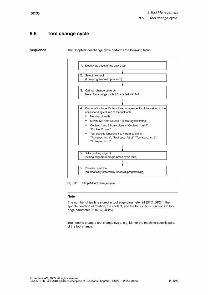
02/058.6 Tool change cycle
8-135 Siemens AG, 2005. All rights reservedSINUMERIK 840D/840Di/810D Description of Functions ShopMill (FBSP) – 02/05 Edition
8.6 Tool change cycle
The ShopMill tool change cycle performs the following tasks:
1. Deactivate offset of the active tool
2. Select new tool(from programmed cycle form)
3. Call tool change cycle L6Note: Tool change cycle L6 is called with M6.
4. Output of tool-specific functions, independently of the setting in thecorresponding column of the tool table
� Number of teeth
� M3/M4/M5 from column “Spindle right/left/stop”
� Coolant 1 and 2 from columns “Coolant 1 on/off”, “Coolant 2 on/off”
� Tool-specific functions 1 to 4 from columns
“Tool-spec. fct. 1”, “Tool-spec. fct. 2”, “Tool-spec. fct. 3”, “Tool-spec. fct. 4”
5. Select cutting edge D(cutting edge from programmed cycle form)
6. Preselect next tool(automatically entered by ShopMill programming)
Fig. 8-2 ShopMill tool change cycle
Note
The number of teeth is stored in tool edge parameter 24 ($TC_DP24), thespindle direction of rotation, the coolant, and the tool-specific functions in tooledge parameter 25 ($TC_DP25).
You need to create a tool change cycle, e.g. L6, for the machine-specific partsof the tool change.
Sequence
8 Tool Management
02/058.6 Tool change cycle
8-136 Siemens AG, 2005. All rights reserved
SINUMERIK 840D/840Di/810D Description of Functions ShopMill (FBSP) – 02/05 Edition
Example L6.SPF in the Toolbox shows how to do this. This example requires:
� MD 22550 $MC_TOOL_CHANGE_MODE=1Tool change via M function.
� MD 10715 $MN_M_NO_FCT_CYCLE[0]=6M function (M6) used to call the tool change, i.e. the subroutine assigned viaMD 10716 $MN_M_NO_FCT_CYCLE_NAME[0].
� MD 10716 $MN_M_NO_FCT_CYCLE_NAME[0]=“L6”Name of the subroutine (L6) to be executed after the M function defined inMD 10715.If the subroutine name is to be entered via program or MDA, the name mustbe placed between quotation marks. This does not apply to manual inputs.
� MD 22560 $MC_TOOL_CHANGE_M_CODE=206M function (M206) with which the tool change is defined for the tool manage-ment.
The machine data specified above can be found in the tool box in machine dataset CMM.8X0.
PROC L6 SAVE;______________________________________________________;Example of tool change cycle for machine manufacturer;_______________________________________________________DEF INT _WZ_IN_SP,_WZ_VORDEF REAL _WWP=... ; Tool change position
; MKSDEF REAL _SPP=... ; Spindle position;IF (NOT $P_SEARCH) ; If no block search _WZ_IN_SP=$TC_MPP6[9998,1] ; Tool on spindle GETSELT(_WZ_VOR) ; Preselected tool ; IF (_WZ_IN_SP<>_WZ_VOR) ; If other tool ; Position spindle: SPOS=_SPP ; Approach tool change position: SUPA D0 G0 G90 G40 G60 Z=_WWP ENDIFELSE IF (E_SIM_ACTIVE) ; If simulation active ; Approach tool change position: SUPA D0 G0 G90 G40 G60 Z=_WWP ENDIFENDIF;;Load tool: Tool management and PLCM206M17
Note
In the example of tool change cycle L6 you must replace “...” with values inlines “DEF REAL _WWP=...” and “DEF REAL _SPP=...”.
Example
8 Tool Management
02/058.6 Tool change cycle
8-137 Siemens AG, 2005. All rights reservedSINUMERIK 840D/840Di/810D Description of Functions ShopMill (FBSP) – 02/05 Edition
Tool change cycle L6 contains the following steps:
1. Position spindle (not when simulation is active)
2. Approach tool change positions in the machine coordinate system
3. Execute tool change (M206)
The tool must be at a safe height after tool change so that all motions in theplane are permissible.
8 Tool Management
02/058.7 Manual tools
8-138 Siemens AG, 2005. All rights reserved
SINUMERIK 840D/840Di/810D Description of Functions ShopMill (FBSP) – 02/05 Edition
8.7 Manual tools
Manual tools are tools which are required during machining, but are only avail-able in the tool list but not in the tool-holding magazine. These tools must beattached/detached manually to/from the spindle.
Via MD 22562 $MC_TOOL_CHANGE_ERROR_MODE, Bit 1=1, tools without magazine location assignment can additionally be selec-ted on a tool change.
An alarm is output every time the manual tool is loaded, unloaded or replaced. (e.g.: “Channel 1, manual tool cutter20, duplo no. 1 load to toolholder 1.” I.e. thatmanual tool cutter20 should be loaded into the spindle.)
Manual tools are identified by magazine location 1 in magazine 9999 in the in-terface to the PLC. Bit 5 in DB72 DBB (n+0) is set to load the tool and bit 6 tounload it.
8 Tool Management
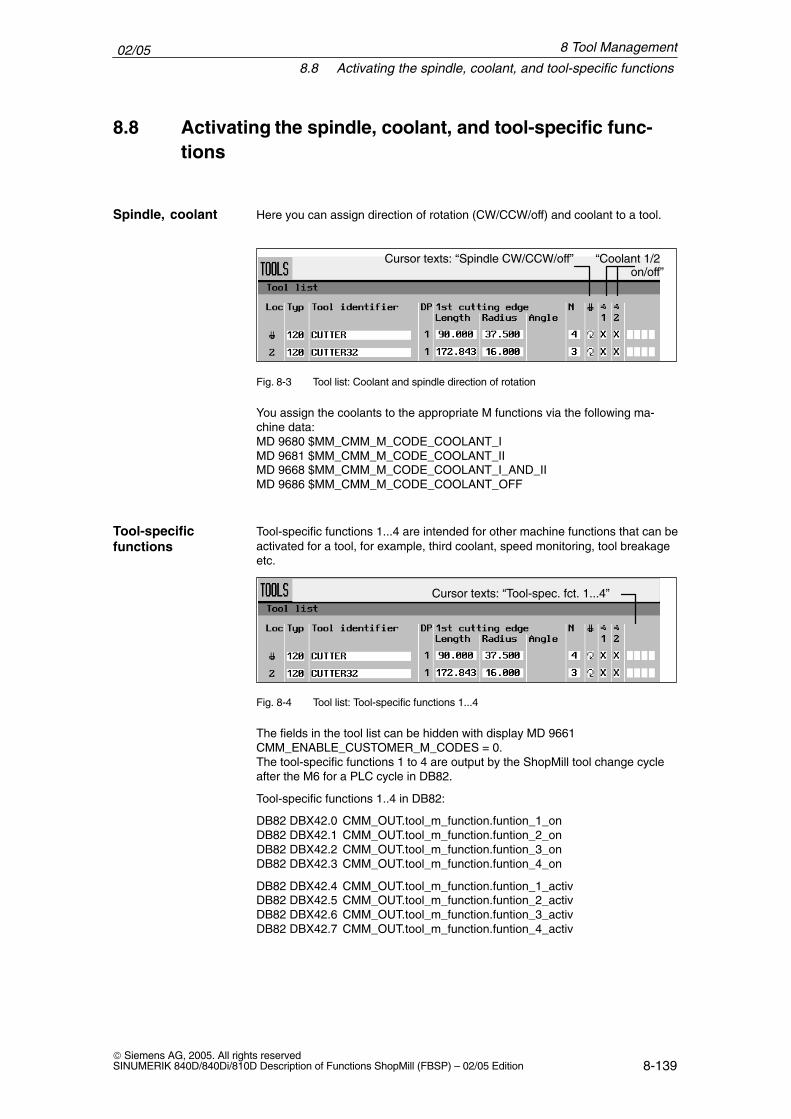
02/058.8 Activating the spindle, coolant, and tool-specific functions
8-139 Siemens AG, 2005. All rights reservedSINUMERIK 840D/840Di/810D Description of Functions ShopMill (FBSP) – 02/05 Edition
8.8 Activating the spindle, coolant, and tool-specific func-tions
Here you can assign direction of rotation (CW/CCW/off) and coolant to a tool.
Cursor texts: “Spindle CW/CCW/off” “Coolant 1/2 on/off”
Fig. 8-3 Tool list: Coolant and spindle direction of rotation
You assign the coolants to the appropriate M functions via the following ma-chine data:MD 9680 $MM_CMM_M_CODE_COOLANT_IMD 9681 $MM_CMM_M_CODE_COOLANT_IIMD 9668 $MM_CMM_M_CODE_COOLANT_I_AND_IIMD 9686 $MM_CMM_M_CODE_COOLANT_OFF
Tool-specific functions 1...4 are intended for other machine functions that can beactivated for a tool, for example, third coolant, speed monitoring, tool breakageetc.
Cursor texts: “Tool-spec. fct. 1...4”
Fig. 8-4 Tool list: Tool-specific functions 1...4
The fields in the tool list can be hidden with display MD 9661 CMM_ENABLE_CUSTOMER_M_CODES = 0.The tool-specific functions 1 to 4 are output by the ShopMill tool change cycleafter the M6 for a PLC cycle in DB82.
Tool-specific functions 1..4 in DB82:
DB82 DBX42.0 CMM_OUT.tool_m_function.funtion_1_onDB82 DBX42.1 CMM_OUT.tool_m_function.funtion_2_onDB82 DBX42.2 CMM_OUT.tool_m_function.funtion_3_onDB82 DBX42.3 CMM_OUT.tool_m_function.funtion_4_on
DB82 DBX42.4 CMM_OUT.tool_m_function.funtion_1_activDB82 DBX42.5 CMM_OUT.tool_m_function.funtion_2_activDB82 DBX42.6 CMM_OUT.tool_m_function.funtion_3_activDB82 DBX42.7 CMM_OUT.tool_m_function.funtion_4_activ
Spindle, coolant
Tool-specificfunctions
8 Tool Management
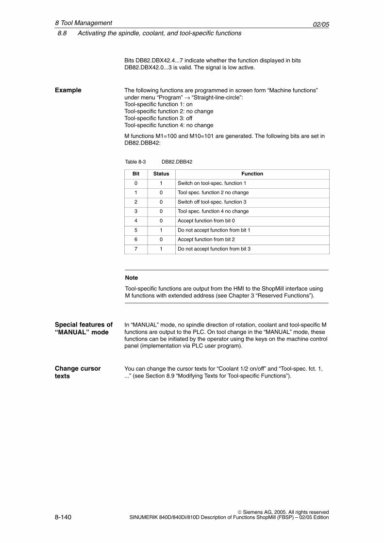
02/058.8 Activating the spindle, coolant, and tool-specific functions
8-140 Siemens AG, 2005. All rights reserved
SINUMERIK 840D/840Di/810D Description of Functions ShopMill (FBSP) – 02/05 Edition
Bits DB82.DBX42.4...7 indicate whether the function displayed in bitsDB82.DBX42.0...3 is valid. The signal is low active.
The following functions are programmed in screen form “Machine functions”under menu “Program” → “Straight-line-circle”:Tool-specific function 1: onTool-specific function 2: no changeTool-specific function 3: offTool-specific function 4: no change
M functions M1=100 and M10=101 are generated. The following bits are set inDB82.DBB42:
Table 8-3 DB82.DBB42
Bit Status Function
0 1 Switch on tool-spec. function 1
1 0 Tool spec. function 2 no change
2 0 Switch off tool-spec. function 3
3 0 Tool spec. function 4 no change
4 0 Accept function from bit 0
5 1 Do not accept function from bit 1
6 0 Accept function from bit 2
7 1 Do not accept function from bit 3
Note
Tool-specific functions are output from the HMI to the ShopMill interface usingM functions with extended address (see Chapter 3 “Reserved Functions”).
In “MANUAL” mode, no spindle direction of rotation, coolant and tool-specific Mfunctions are output to the PLC. On tool change in the “MANUAL” mode, thesefunctions can be initiated by the operator using the keys on the machine controlpanel (implementation via PLC user program).
You can change the cursor texts for “Coolant 1/2 on/off” and “Tool-spec. fct. 1,...” (see Section 8.9 “Modifying Texts for Tool-specific Functions”).
Example
Special features of“MANUAL” mode
Change cursortexts
8 Tool Management
02/058.9 Modifying texts for tool-specific functions
8-141 Siemens AG, 2005. All rights reservedSINUMERIK 840D/840Di/810D Description of Functions ShopMill (FBSP) – 02/05 Edition
8.9 Modifying texts for tool-specific functions
8.9.1 PCU 20
For tool-specific functions, you can modify the parameter texts in the “Prog. edit”→ “Linear Circular” → “Machine Function” menu and the cursor texts in the toollist. Cursor texts are texts, shown in the message line when the cursor is posi-tioned on the relevant input field.
You can use the ALUC.TXT text file on the application diskette to modify thetexts of the tool-specific functions.
The texts are assigned to the following text numbers in the file ALUC.TXT:
Table 8-4 Text assignment
Cursor texts in the “Tool list” menu Text number
Tool-specific function 1 (tool-spec. fct. 1) 89911
Tool-specific function 2 (tool-spec. fct. 2) 89912
Tool-specific function 3 (tool-spec. fct. 3) 89913
Tool-specific function 4 (tool-spec. fct. 4) 89914
Coolant 1 89921
Coolant 2 89922
Parameter texts in the menu “Program linear/circular machine functions”
Tool-specific function 1 (tool-spec. fct. 1) 89915
Tool-specific function 2 (tool-spec. fct. 2) 89916
Tool-specific function 3 (tool-spec. fct. 3) 89917
Tool-specific function 4 (tool-spec. fct. 4) 89918
Coolant 1 89919
Coolant 2 89920
This means that text numbers 89911 and 89915 etc. refer to the same func-tions.
Note
The maximum number of character is 23 for the cursor texts and 14 for theparameter texts.
Each language directory contains a file named ALUC.TXT.
Text numbers
Languageassignment
8 Tool Management
02/058.9 Modifying texts for tool-specific functions
8-142 Siemens AG, 2005. All rights reserved
SINUMERIK 840D/840Di/810D Description of Functions ShopMill (FBSP) – 02/05 Edition
To select ALUC.TXT file, proceed as follows:
� Switch to the subdirectory ...\INSTUTIL in the application environment.
� Call the APP_INST program.
� Select <2> “Modify configuration”.
� Specify whether the texts for the 1st or 2nd language are to be edited:
<4> “Edit text files for first language” or
<5> “Edit text files for second language”
� Scroll through the menu until the option “Alarm texts for user cycles”
appears and then enter the corresponding number.
This opens the ALUC.TXT text file with the DOS editor “edit”.
� Enter the texts of your choice.
� Save the file and close the editor.
� Press the “ESC” key twice.
The text modifications become operative when you take the following steps:
� Select <1> “Install all modules on hardware”.
� Confirm your language selection with “F4 Accept”.
� Select <2> “Create Flash Memory Card image”.
� Specify the source drive for the system diskettes.
� Specify the target path for the system diskettes.
� Enter the target drive to which the file must be saved.
� Specify the target path for the file.
� Use SINUCOPY to create a PC card (see Subsection 4.2.2 “Start-up on aPCU 20”).
� Load the PC card contents to the control (see Subsection 4.2.2 “Start-up ona PCU 20”).
The cursor text “Tool-spec. function 1” in the tool list should be changed to “Aircooling”.
You must make the following entry in text file ALUC.TXT:89911 0 0 ”Air cooling”
The two parameters 2 and 3 separated by blanks are control characters for textoutput and must always be set to 0.
Procedure
Example
8 Tool Management
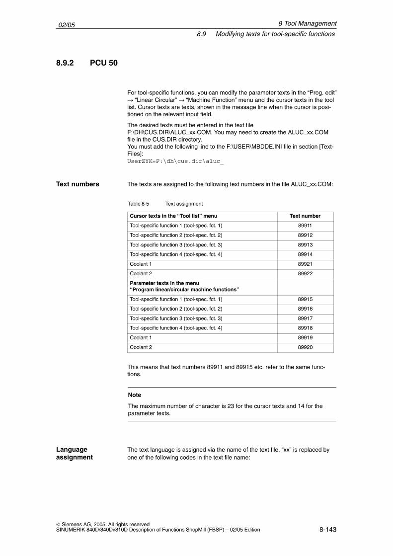
02/058.9 Modifying texts for tool-specific functions
8-143 Siemens AG, 2005. All rights reservedSINUMERIK 840D/840Di/810D Description of Functions ShopMill (FBSP) – 02/05 Edition
8.9.2 PCU 50
For tool-specific functions, you can modify the parameter texts in the “Prog. edit”→ “Linear Circular” → “Machine Function” menu and the cursor texts in the toollist. Cursor texts are texts, shown in the message line when the cursor is posi-tioned on the relevant input field.
The desired texts must be entered in the text fileF:\DH\CUS.DIR\ALUC_xx.COM. You may need to create the ALUC_xx.COMfile in the CUS.DIR directory.You must add the following line to the F:\USER\MBDDE.INI file in section [Text-Files]:UserZYK=F:\dh\cus.dir\aluc_
The texts are assigned to the following text numbers in the file ALUC_xx.COM:
Table 8-5 Text assignment
Cursor texts in the “Tool list” menu Text number
Tool-specific function 1 (tool-spec. fct. 1) 89911
Tool-specific function 2 (tool-spec. fct. 2) 89912
Tool-specific function 3 (tool-spec. fct. 3) 89913
Tool-specific function 4 (tool-spec. fct. 4) 89914
Coolant 1 89921
Coolant 2 89922
Parameter texts in the menu “Program linear/circular machine functions”
Tool-specific function 1 (tool-spec. fct. 1) 89915
Tool-specific function 2 (tool-spec. fct. 2) 89916
Tool-specific function 3 (tool-spec. fct. 3) 89917
Tool-specific function 4 (tool-spec. fct. 4) 89918
Coolant 1 89919
Coolant 2 89920
This means that text numbers 89911 and 89915 etc. refer to the same func-tions.
Note
The maximum number of character is 23 for the cursor texts and 14 for theparameter texts.
The text language is assigned via the name of the text file. “xx” is replaced byone of the following codes in the text file name:
Text numbers
Languageassignment
8 Tool Management
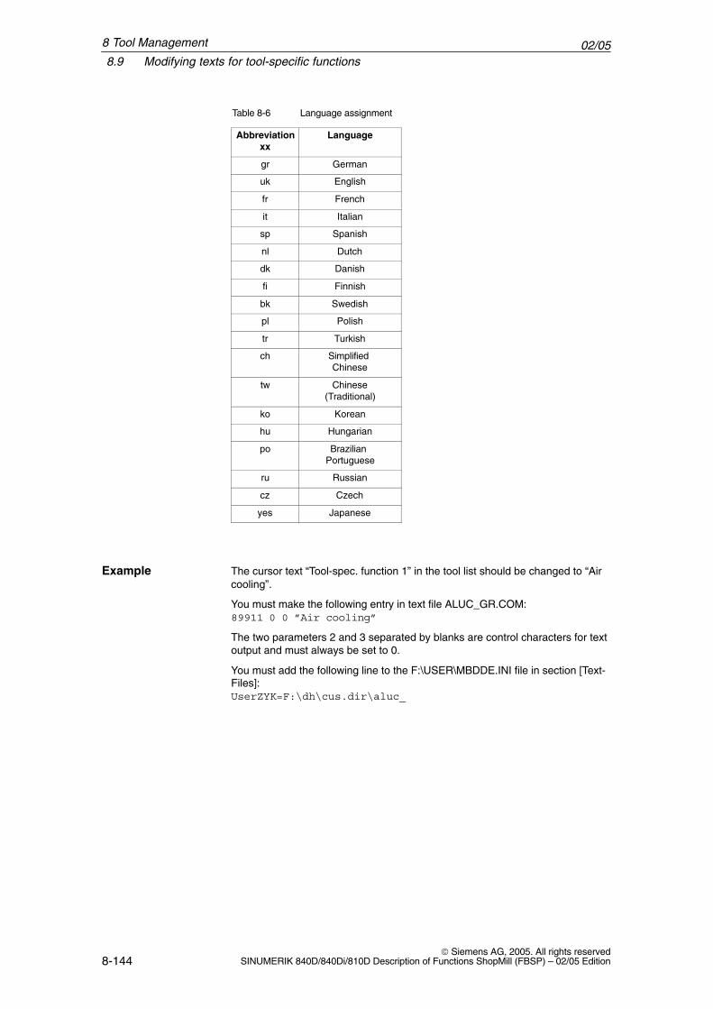
02/058.9 Modifying texts for tool-specific functions
8-144 Siemens AG, 2005. All rights reserved
SINUMERIK 840D/840Di/810D Description of Functions ShopMill (FBSP) – 02/05 Edition
Table 8-6 Language assignment
Abbreviationxx
Language
gr German
uk English
fr French
it Italian
sp Spanish
nl Dutch
dk Danish
fi Finnish
bk Swedish
pl Polish
tr Turkish
ch Simplified Chinese
tw Chinese(Traditional)
ko Korean
hu Hungarian
po Brazilian Portuguese
ru Russian
cz Czech
yes Japanese
The cursor text “Tool-spec. function 1” in the tool list should be changed to “Aircooling”.
You must make the following entry in text file ALUC_GR.COM:89911 0 0 ”Air cooling”
The two parameters 2 and 3 separated by blanks are control characters for textoutput and must always be set to 0.
You must add the following line to the F:\USER\MBDDE.INI file in section [Text-Files]:UserZYK=F:\dh\cus.dir\aluc_
Example
8 Tool Management
02/058.10 Configuring the operator interface
8-145 Siemens AG, 2005. All rights reservedSINUMERIK 840D/840Di/810D Description of Functions ShopMill (FBSP) – 02/05 Edition
8.10 Configuring the operator interface
There are two ways you can modify the existing operator interface for the toolmanagement system:
� In addition to the existing lists, you can activate a custom list on the 3rd hori-zontal softkey in the tool management.
� You can configure existing parameters as well as user-defined parametersin the existing lists (including the custom list). The options available mayvary according to the tool.
8.10.1 Procedure
Proceed as outlined below to activate a custom list or modify the existing lists.For more detailed information on the configuration file and for creating the textsplease refer to the following sections.
� Define texts for the custom list (optional)You need to define new texts if you want to modify the default texts for thesoftkey labeling and the list header for your the custom list.
� Set machine data9478 $MM_TO_OPTION_MASK, Bit 2Activate custom list
Press the 3rd horizontal softkey in the tool management to display a list tem-plate with parameters “LROU” and “Location Type”.
Activate customlist
8 Tool Management
02/058.10 Configuring the operator interface
8-146 Siemens AG, 2005. All rights reserved
SINUMERIK 840D/840Di/810D Description of Functions ShopMill (FBSP) – 02/05 Edition
� Create configuration fileYou must store all the changes you have made to the lists from the defaultsetting in the configuration file TO_MILL.INI.
� Define texts for customized parameters (optional)If you are using customized parameters, you need to define column headersand cursor texts for these parameters.
� Set machine dataMD 9478 $MM_TO_OPTION_MASK, Bit 8Evaluate TO_MILL.INI file
� Set machine data for customized parameters (optional)If you are using customized parameters, you need the set the following ma-chine data:MD 18080 $MN_MM_TOOL_MANAGEMENT_MASK, Bit 2Provide memory for user dataMD 18094 $MN_MM_NUM_CC_TDA_PARAMNumber of customized parametersMD 18095 $MN_MM_TYPE_CC_TDA_PARAM[n]=4Data type (DOUBLE) of the customized parametersMD 20310 $MC_TOOL_MANAGEMENT_MASK, Bit 2Activate user functions
Modifying lists
8 Tool Management
02/058.10 Configuring the operator interface
8-147 Siemens AG, 2005. All rights reservedSINUMERIK 840D/840Di/810D Description of Functions ShopMill (FBSP) – 02/05 Edition
8.10.2 Creating configuration file
You must store all the changes you have made to the lists from the default set-ting in the TO_MILL.INI configuration file.
Please note the following:
� You can define up to 13 columns after the “DP number” column.
� Define the tool edge parameters in consecutive columns.
� Define either edge parameters or tool parameters, but not both, in one col-umn.
A sample configuration file is located in the TOOLS\SD directory. You can adaptthis file if required. With the PCU 20 you must put this configuration file on the application disketteand then install it together with the ShopMill software. With the PCU 50, copythe file to the OEM directory.
The following syntax rules apply to entries in the configuration file (see also ex-ample at end of this chapter):
First specify in which tool management list you would like to make changes.[DISPLAY_IDENTIFIER]
DISPLAY_IDENTIFIER: Tool management list
Next, define the changes themselves:
� Modify a specific column for all tools:COLUMNx=CONTENTS_IDENTIFIER
COLUMN: Column commandx: Column number, max. 13 CONTENTS_IDENTIFIER: Parameter or property of tool
� Modify a specific column for a specific tool:TOOL_IDENTIFIER = x=CONTENTS_IDENTIFIER
TOOL_IDENTIFIER: Tool type
� Define different columns for each tool:TOOL_IDENTIFIER = CONTENTS_IDENTIFIER / CONTENTS_IDENTIFIER / ...TOOL_IDENTIFIER = CONTENTS_IDENTIFIER / CONTENTS_IDENTIFIER / ......
The parameters or properties of a tool are listed one after the other bymeans of a CONTENTS_IDENTIFIER and are separated from one anotherby a slash “/”. If the default setting is to be used for individual columns, youstill need to insert a slash.
If, for example, you only want to modify the last two columns, specify thenumber (x) of the first column you would like to modify and list the respectiveCONTENTS_IDENTIFIERs for the subsequent columns.TOOL_IDENTIFIER = x=CONTENTS_IDENTIFIER / CONTENTS_IDEN-TIFIER / ..
Syntax
8 Tool Management
02/058.10 Configuring the operator interface
8-148 Siemens AG, 2005. All rights reserved
SINUMERIK 840D/840Di/810D Description of Functions ShopMill (FBSP) – 02/05 Edition
Note
Using the COLUMN command, you can first define one column identically forall tools and then adapt it specifically for individual tools.
You can identify comments by a semicolon (;) symbol.
If errors occur during evaluation of the configuration file, refer to theTO_INI_F.LOG file for a description of the error. With the PCU 20 this file is lo-cated on drive I; with PCU 50 it is located in the F:\MMC0W32\TMP directory.
The following tables provide a list of the SCREEN_, TOOL_ and CONTENTS_identifiers available for defining the columns.
Table 8-7 SCREEN_IDENTIFIER
SCREEN_IDENTIFIER Tool management list
TOOL_LIST Tool list
TOOL_LIST_2ND_EDGE Tool list, further cutting edges
TOOL_WEAR Tool wear list
TOOL_WEAR_2ND_EDGE Tool wear list, further cutting edges
TOOL_MAGA Magazine list
TOOL_LIST_OEM Additional list
Table 8-8 TOOL_IDENTIFIER
TOOL_IDENTIFIER Tools
SHANK_END_CUTTER (End) mill
POINTED_DRILL (Twist) drill
TO_SCREW_TAP Screw tap
END_MILL_CUTTER Facing tool
ANGLE_HEAD_CUTTER Angle head cutter
LOCATOR Centering tool
EDGE_TRACER Edge probe
3DTRACER 3D probe
3DCUTTER_110 Cylindrical die mill
3DCUTTER_111 Ball end mill
3DCUTTER_121 End mill with corner rounding
3DCUTTER_155 Truncated cone mill
3DCUTTER_156 Bevel cutter with corner rounding
3DCUTTER_157 Tapered die mill
Identifier
8 Tool Management
02/058.10 Configuring the operator interface
8-149 Siemens AG, 2005. All rights reservedSINUMERIK 840D/840Di/810D Description of Functions ShopMill (FBSP) – 02/05 Edition
Table 8-9 CONTENT_ID
CONTENT_ID Parameter or property
EMPTY Empty field
NOT_USED Empty column
LENGTH length
RADIUS Radius
RADIUS_DIAM Radius with possible diameter calculation
ANGLE Angle
N Number of teeth
SPINDLE Spindle direction
COOL1 Cooling water 1
COOL2 Cooling water 2
MFCT1 Tool-specific function 1
MFCT2 Tool-specific function 2
MFCT3 Tool-specific function 3
MFCT4 Tool-specific function 4
DLENGTH Wear length
DRADIUS Wear radius
DRADIUS_DIAM Wear radius with possible diameter calculation
T_OR_C Method of wear monitoring
P_TIME Tool life
PW_TIME Prewarning limit for tool life
P_COUNT Count
PW_COUNT Pre-warning limit for count
P_WEAR Wear
PW_WEAR Prewarning limit for wear
T_LOCKED Tool blocked
T_SIZE Oversized tool, see also CONTENT_ID T_SIZE_LONG
T_FIXED Tool in fixed location
P_LOCKED Magazine location disabled
MAG_T_LOCKED Display only: Tool blocked
MAG_T_SIZE Display only: Oversized tool
MAG_T_FIXED Display only: Tool in fixed location
H_NBR H number of an ISO dialect program
TPC1 Parameter 1
TPC2 Parameter 2
TPC3 Parameter 3
TPC4 Parameter 4
TPC5 Parameter 5
TPC6 Parameter 6
TPC7 Parameter 7
TPC8 Parameter 8
TPC9 Parameter 9
8 Tool Management
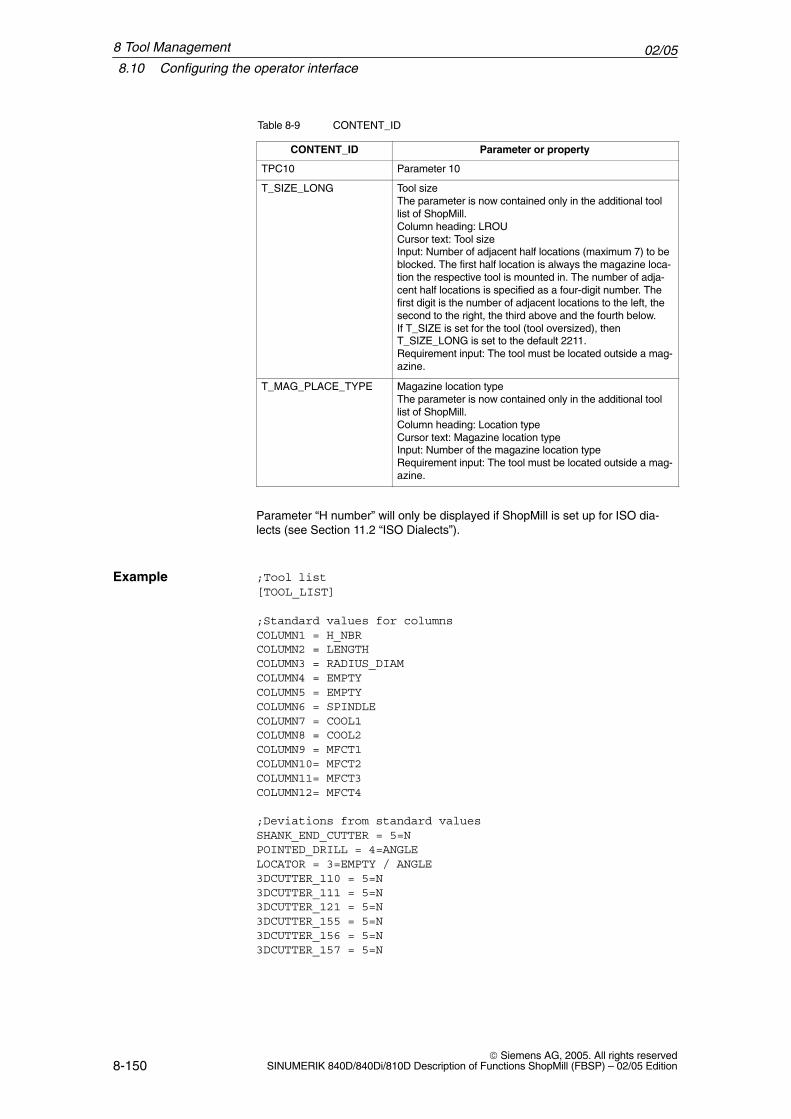
02/058.10 Configuring the operator interface
8-150 Siemens AG, 2005. All rights reserved
SINUMERIK 840D/840Di/810D Description of Functions ShopMill (FBSP) – 02/05 Edition
Table 8-9 CONTENT_ID
CONTENT_ID Parameter or property
TPC10 Parameter 10
T_SIZE_LONG Tool sizeThe parameter is now contained only in the additional toollist of ShopMill.Column heading: LROUCursor text: Tool sizeInput: Number of adjacent half locations (maximum 7) to beblocked. The first half location is always the magazine loca-tion the respective tool is mounted in. The number of adja-cent half locations is specified as a four-digit number. Thefirst digit is the number of adjacent locations to the left, thesecond to the right, the third above and the fourth below. If T_SIZE is set for the tool (tool oversized), thenT_SIZE_LONG is set to the default 2211.Requirement input: The tool must be located outside a mag-azine.
T_MAG_PLACE_TYPE Magazine location typeThe parameter is now contained only in the additional toollist of ShopMill.Column heading: Location typeCursor text: Magazine location typeInput: Number of the magazine location typeRequirement input: The tool must be located outside a mag-azine.
Parameter “H number” will only be displayed if ShopMill is set up for ISO dia-lects (see Section 11.2 “ISO Dialects”).
;Tool list[TOOL_LIST]
;Standard values for columnsCOLUMN1 = H_NBRCOLUMN2 = LENGTHCOLUMN3 = RADIUS_DIAMCOLUMN4 = EMPTYCOLUMN5 = EMPTYCOLUMN6 = SPINDLECOLUMN7 = COOL1COLUMN8 = COOL2COLUMN9 = MFCT1COLUMN10= MFCT2COLUMN11= MFCT3COLUMN12= MFCT4
;Deviations from standard valuesSHANK_END_CUTTER = 5=NPOINTED_DRILL = 4=ANGLELOCATOR = 3=EMPTY / ANGLE3DCUTTER_110 = 5=N3DCUTTER_111 = 5=N3DCUTTER_121 = 5=N3DCUTTER_155 = 5=N3DCUTTER_156 = 5=N3DCUTTER_157 = 5=N
Example
8 Tool Management
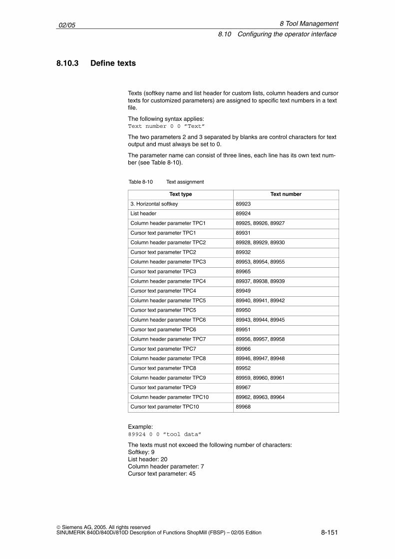
02/058.10 Configuring the operator interface
8-151 Siemens AG, 2005. All rights reservedSINUMERIK 840D/840Di/810D Description of Functions ShopMill (FBSP) – 02/05 Edition
8.10.3 Define texts
Texts (softkey name and list header for custom lists, column headers and cursortexts for customized parameters) are assigned to specific text numbers in a textfile.
The following syntax applies:Text number 0 0 ”Text”
The two parameters 2 and 3 separated by blanks are control characters for textoutput and must always be set to 0.
The parameter name can consist of three lines, each line has its own text num-ber (see Table 8-10).
Table 8-10 Text assignment
Text type Text number
3. Horizontal softkey 89923
List header 89924
Column header parameter TPC1 89925, 89926, 89927
Cursor text parameter TPC1 89931
Column header parameter TPC2 89928, 89929, 89930
Cursor text parameter TPC2 89932
Column header parameter TPC3 89953, 89954, 89955
Cursor text parameter TPC3 89965
Column header parameter TPC4 89937, 89938, 89939
Cursor text parameter TPC4 89949
Column header parameter TPC5 89940, 89941, 89942
Cursor text parameter TPC5 89950
Column header parameter TPC6 89943, 89944, 89945
Cursor text parameter TPC6 89951
Column header parameter TPC7 89956, 89957, 89958
Cursor text parameter TPC7 89966
Column header parameter TPC8 89946, 89947, 89948
Cursor text parameter TPC8 89952
Column header parameter TPC9 89959, 89960, 89961
Cursor text parameter TPC9 89967
Column header parameter TPC10 89962, 89963, 89964
Cursor text parameter TPC10 89968
Example:89924 0 0 ”tool data”
The texts must not exceed the following number of characters:Softkey: 9List header: 20Column header parameter: 7Cursor text parameter: 45
8 Tool Management
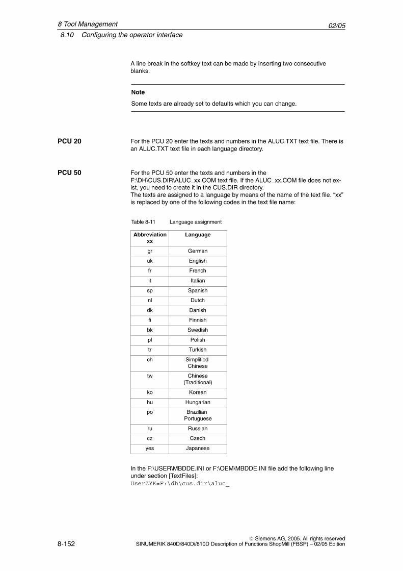
02/058.10 Configuring the operator interface
8-152 Siemens AG, 2005. All rights reserved
SINUMERIK 840D/840Di/810D Description of Functions ShopMill (FBSP) – 02/05 Edition
A line break in the softkey text can be made by inserting two consecutiveblanks.
Note
Some texts are already set to defaults which you can change.
For the PCU 20 enter the texts and numbers in the ALUC.TXT text file. There isan ALUC.TXT text file in each language directory.
For the PCU 50 enter the texts and numbers in theF:\DH\CUS.DIR\ALUC_xx.COM text file. If the ALUC_xx.COM file does not ex-ist, you need to create it in the CUS.DIR directory.The texts are assigned to a language by means of the name of the text file. “xx”is replaced by one of the following codes in the text file name:
Table 8-11 Language assignment
Abbreviationxx
Language
gr German
uk English
fr French
it Italian
sp Spanish
nl Dutch
dk Danish
fi Finnish
bk Swedish
pl Polish
tr Turkish
ch Simplified Chinese
tw Chinese(Traditional)
ko Korean
hu Hungarian
po Brazilian Portuguese
ru Russian
cz Czech
yes Japanese
In the F:\USER\MBDDE.INI or F:\OEM\MBDDE.INI file add the following lineunder section [TextFiles]:UserZYK=F:\dh\cus.dir\aluc_
PCU 20
PCU 50
8 Tool Management
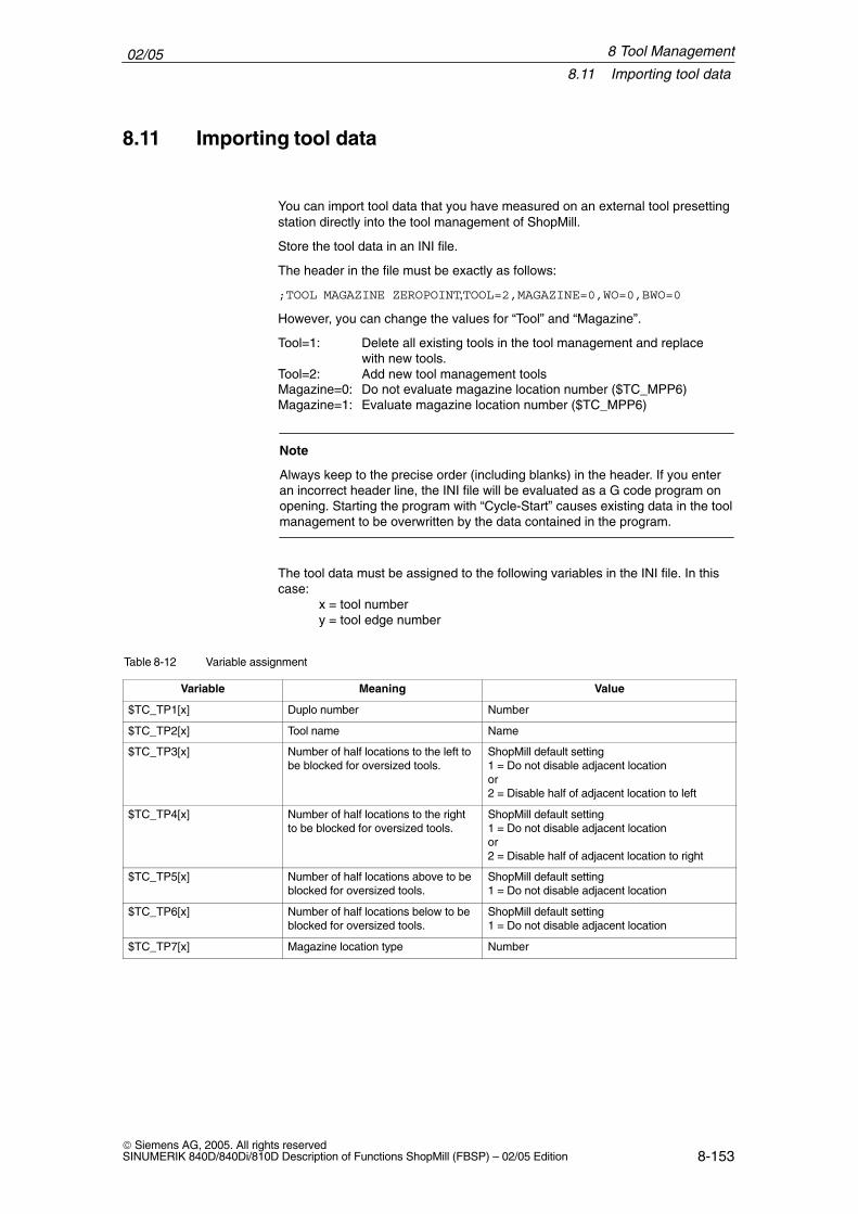
02/058.11 Importing tool data
8-153 Siemens AG, 2005. All rights reservedSINUMERIK 840D/840Di/810D Description of Functions ShopMill (FBSP) – 02/05 Edition
8.11 Importing tool data
You can import tool data that you have measured on an external tool presettingstation directly into the tool management of ShopMill.
Store the tool data in an INI file.
The header in the file must be exactly as follows:
;TOOL MAGAZINE ZEROPOINT,TOOL=2,MAGAZINE=0,WO=0,BWO=0
However, you can change the values for “Tool” and “Magazine”.
Tool=1: Delete all existing tools in the tool management and replacewith new tools.
Tool=2: Add new tool management toolsMagazine=0: Do not evaluate magazine location number ($TC_MPP6)Magazine=1: Evaluate magazine location number ($TC_MPP6)
Note
Always keep to the precise order (including blanks) in the header. If you enteran incorrect header line, the INI file will be evaluated as a G code program onopening. Starting the program with “Cycle-Start” causes existing data in the toolmanagement to be overwritten by the data contained in the program.
The tool data must be assigned to the following variables in the INI file. In thiscase:
x = tool numbery = tool edge number
Table 8-12 Variable assignment
Variable Meaning Value
$TC_TP1[x] Duplo number Number
$TC_TP2[x] Tool name Name
$TC_TP3[x] Number of half locations to the left tobe blocked for oversized tools.
ShopMill default setting 1 = Do not disable adjacent locationor2 = Disable half of adjacent location to left
$TC_TP4[x] Number of half locations to the rightto be blocked for oversized tools.
ShopMill default setting 1 = Do not disable adjacent locationor2 = Disable half of adjacent location to right
$TC_TP5[x] Number of half locations above to beblocked for oversized tools.
ShopMill default setting 1 = Do not disable adjacent location
$TC_TP6[x] Number of half locations below to beblocked for oversized tools.
ShopMill default setting 1 = Do not disable adjacent location
$TC_TP7[x] Magazine location type Number
8 Tool Management
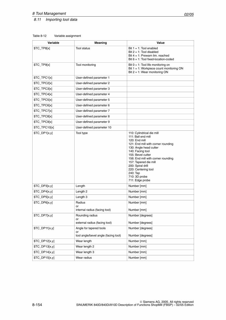
02/058.11 Importing tool data
8-154 Siemens AG, 2005. All rights reserved
SINUMERIK 840D/840Di/810D Description of Functions ShopMill (FBSP) – 02/05 Edition
Table 8-12 Variable assignment
Variable ValueMeaning
$TC_TP8[x] Tool status Bit 1 = 1: Tool enabledBit 2 = 1: Tool disabledBit 4 = 1: Prewarn lim. reachedBit 6 = 1: Tool fixed-location-coded
$TC_TP9[x] Tool monitoring Bit 0 = 1: Tool life monitoring onBit 1 = 1: Workpiece count monitoring ONBit 2 = 1: Wear monitoring ON
$TC_TPC1[x] User-defined parameter 1
$TC_TPC2[x] User-defined parameter 2
$TC_TPC3[x] User-defined parameter 3
$TC_TPC4[x] User-defined parameter 4
$TC_TPC5[x] User-defined parameter 5
$TC_TPC6[x] User-defined parameter 6
$TC_TPC7[x] User-defined parameter 7
$TC_TPC8[x] User-defined parameter 8
$TC_TPC9[x] User-defined parameter 9
$TC_TPC10[x] User-defined parameter 10
$TC_DP1[x,y] Tool type 110: Cylindrical die mill111: Ball end mill120: End mill121: End mill with corner rounding130: Angle head cutter140: Facing tool155: Bevel cutter156: End mill with corner rounding157: Tapered die mill200: Spiral drill220: Centering tool240: Tap710: 3D probe711: Edge probe
$TC_DP3[x,y] Length Number [mm]
$TC_DP4[x,y] Length 2 Number [mm]
$TC_DP5[x,y] Length 3 Number [mm]
$TC_DP6[x,y] Radiusorinternal radius (facing tool)
Number [mm]
Number [mm]
$TC_DP7[x,y] Rounding radiusorexternal radius (facing tool)
Number [degrees]
Number [degrees]
$TC_DP11[x,y] Angle for tapered toolsortool angle/bevel angle (facing tool)
Number [degrees]
Number [degrees]
$TC_DP12[x,y] Wear length Number [mm]
$TC_DP13[x,y] Wear length 2 Number [mm]
$TC_DP14[x,y] Wear length 3 Number [mm]
$TC_DP15[x,y] Wear radius Number [mm]
8 Tool Management
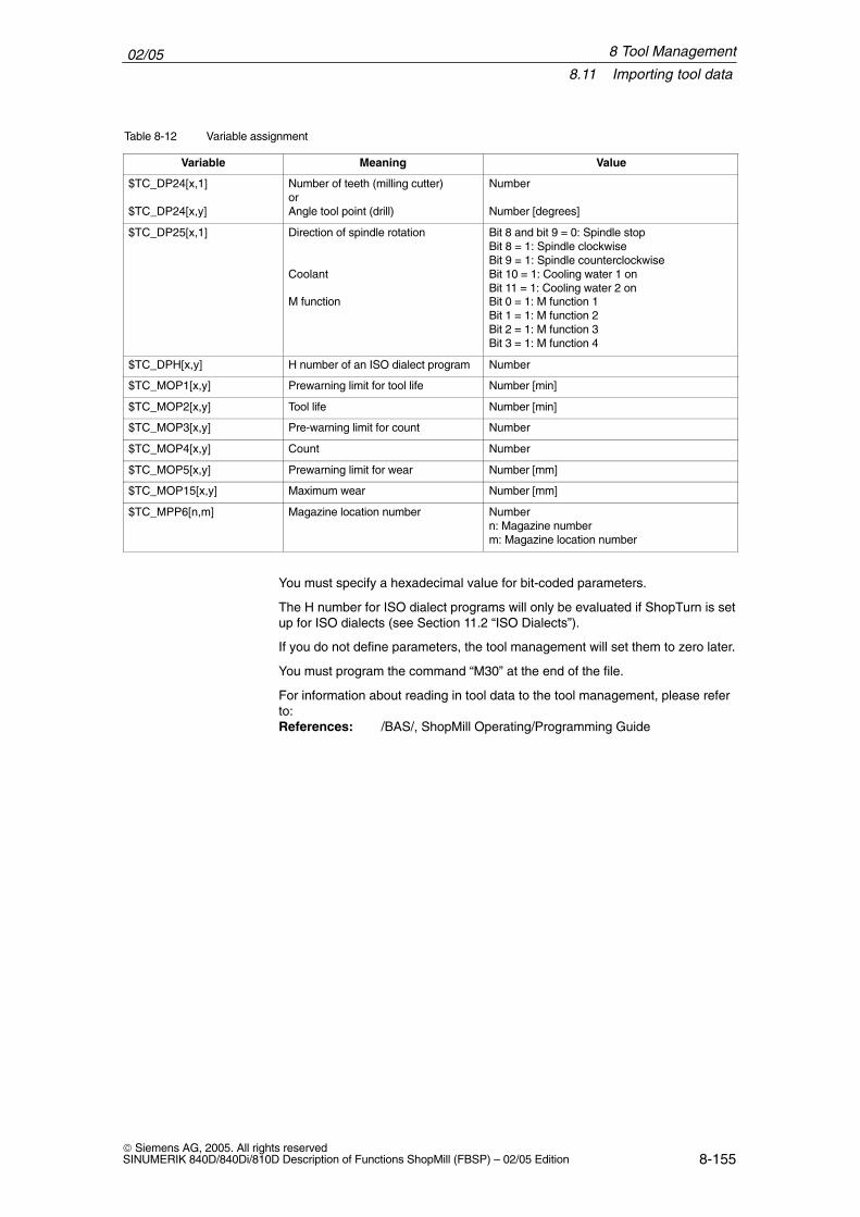
02/058.11 Importing tool data
8-155 Siemens AG, 2005. All rights reservedSINUMERIK 840D/840Di/810D Description of Functions ShopMill (FBSP) – 02/05 Edition
Table 8-12 Variable assignment
Variable ValueMeaning
$TC_DP24[x,1]
$TC_DP24[x,y]
Number of teeth (milling cutter)or Angle tool point (drill)
Number
Number [degrees]
$TC_DP25[x,1] Direction of spindle rotation
Coolant
M function
Bit 8 and bit 9 = 0: Spindle stopBit 8 = 1: Spindle clockwiseBit 9 = 1: Spindle counterclockwiseBit 10 = 1: Cooling water 1 onBit 11 = 1: Cooling water 2 onBit 0 = 1: M function 1Bit 1 = 1: M function 2Bit 2 = 1: M function 3Bit 3 = 1: M function 4
$TC_DPH[x,y] H number of an ISO dialect program Number
$TC_MOP1[x,y] Prewarning limit for tool life Number [min]
$TC_MOP2[x,y] Tool life Number [min]
$TC_MOP3[x,y] Pre-warning limit for count Number
$TC_MOP4[x,y] Count Number
$TC_MOP5[x,y] Prewarning limit for wear Number [mm]
$TC_MOP15[x,y] Maximum wear Number [mm]
$TC_MPP6[n,m] Magazine location number Numbern: Magazine numberm: Magazine location number
You must specify a hexadecimal value for bit-coded parameters.
The H number for ISO dialect programs will only be evaluated if ShopTurn is setup for ISO dialects (see Section 11.2 “ISO Dialects”).
If you do not define parameters, the tool management will set them to zero later.
You must program the command “M30” at the end of the file.
For information about reading in tool data to the tool management, please referto:References: /BAS/, ShopMill Operating/Programming Guide
8 Tool Management
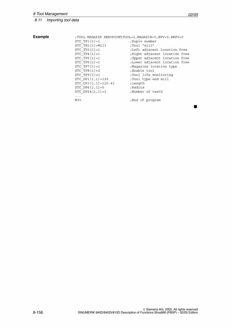
02/058.11 Importing tool data
8-156 Siemens AG, 2005. All rights reserved
SINUMERIK 840D/840Di/810D Description of Functions ShopMill (FBSP) – 02/05 Edition
;TOOL MAGAZIN ZEROPOINT,TOOL=2,MAGAZIN=0,NPV=0,BNPV=0$TC_TP1[1]=1 ;Duplo number$TC_TP2[1]=Mill ;Tool ”mill”$TC_TP3[1]=1 ;Left adjacent location free$TC_TP4[1]=1 ;Right adjacent location free$TC_TP5[1]=1 ;Upper adjacent location free$TC_TP6[1]=1 ;Lower adjacent location free$TC_TP7[1]=1 ;Magazine location type$TC_TP8[1]=2 ;Enable tool$TC_TP9[1]=1 ;Tool life monitoring$TC_DP1[1,1]=120 ;Tool type end mill$TC_DP3[1,1]=120.41 ;Length$TC_DP6[1,1]=5 ;Radius$TC_DP24[1,1]=3 ;Number of teeth...M30 ;End of program
�
Example
8 Tool Management
9-157 Siemens AG, 2005. All rights reservedSINUMERIK 840D/840Di/810D Description of Functions ShopMill (FBSP) – 02/05 Edition
Additional Functions
9.1 Measuring Cycles
9.1.1 Brief Description
Overview You can use measuring cycles for automatic measuring on vertical machiningcenters and universal milling machines with ShopMill.
This is achieved simply by connecting a touch trigger probe to the control.
The measuring cycles are shipped with ShopMill and contained in the ShopMillToolbox.
You have to adapt the measuring cycle data to the specific characteristics of themachine.
Measuring Cycles
9
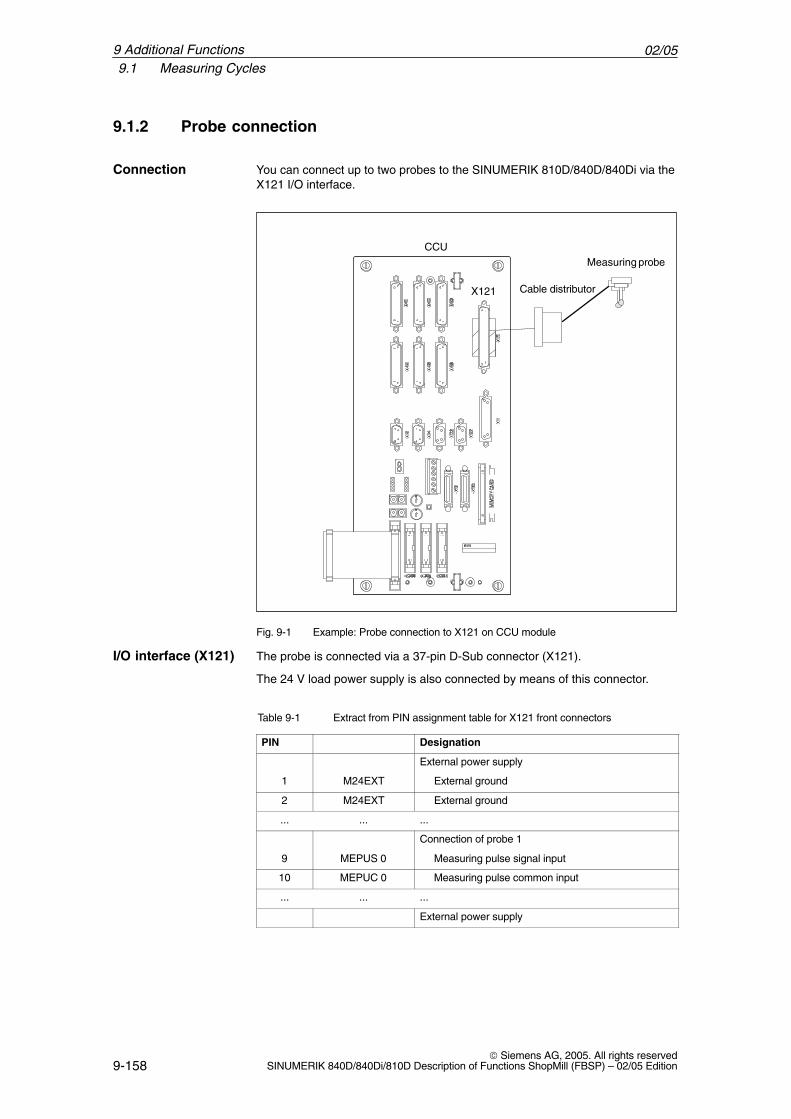
02/059.1 Measuring Cycles
9-158 Siemens AG, 2005. All rights reserved
SINUMERIK 840D/840Di/810D Description of Functions ShopMill (FBSP) – 02/05 Edition
9.1.2 Probe connection
You can connect up to two probes to the SINUMERIK 810D/840D/840Di via theX121 I/O interface.
Cable distributor
CCUMeasuring probe
X121
Fig. 9-1 Example: Probe connection to X121 on CCU module
The probe is connected via a 37-pin D-Sub connector (X121).
The 24 V load power supply is also connected by means of this connector.
Table 9-1 Extract from PIN assignment table for X121 front connectors
PIN Designation
External power supply
1 M24EXT External ground
2 M24EXT External ground
... ... ...
Connection of probe 1
9 MEPUS 0 Measuring pulse signal input
10 MEPUC 0 Measuring pulse common input
... ... ...
External power supply
Connection
I/O interface (X121)
9 Additional Functions
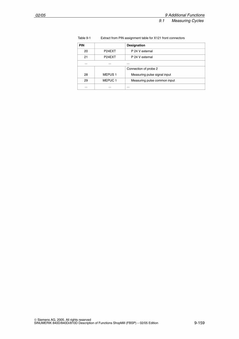
02/059.1 Measuring Cycles
9-159 Siemens AG, 2005. All rights reservedSINUMERIK 840D/840Di/810D Description of Functions ShopMill (FBSP) – 02/05 Edition
Table 9-1 Extract from PIN assignment table for X121 front connectors
PIN Designation
20 P24EXT P 24 V external
21 P24EXT P 24 V external
... ... ...
Connection of probe 2
28 MEPUS 1 Measuring pulse signal input
29 MEPUC 1 Measuring pulse common input
... ... ...
9 Additional Functions
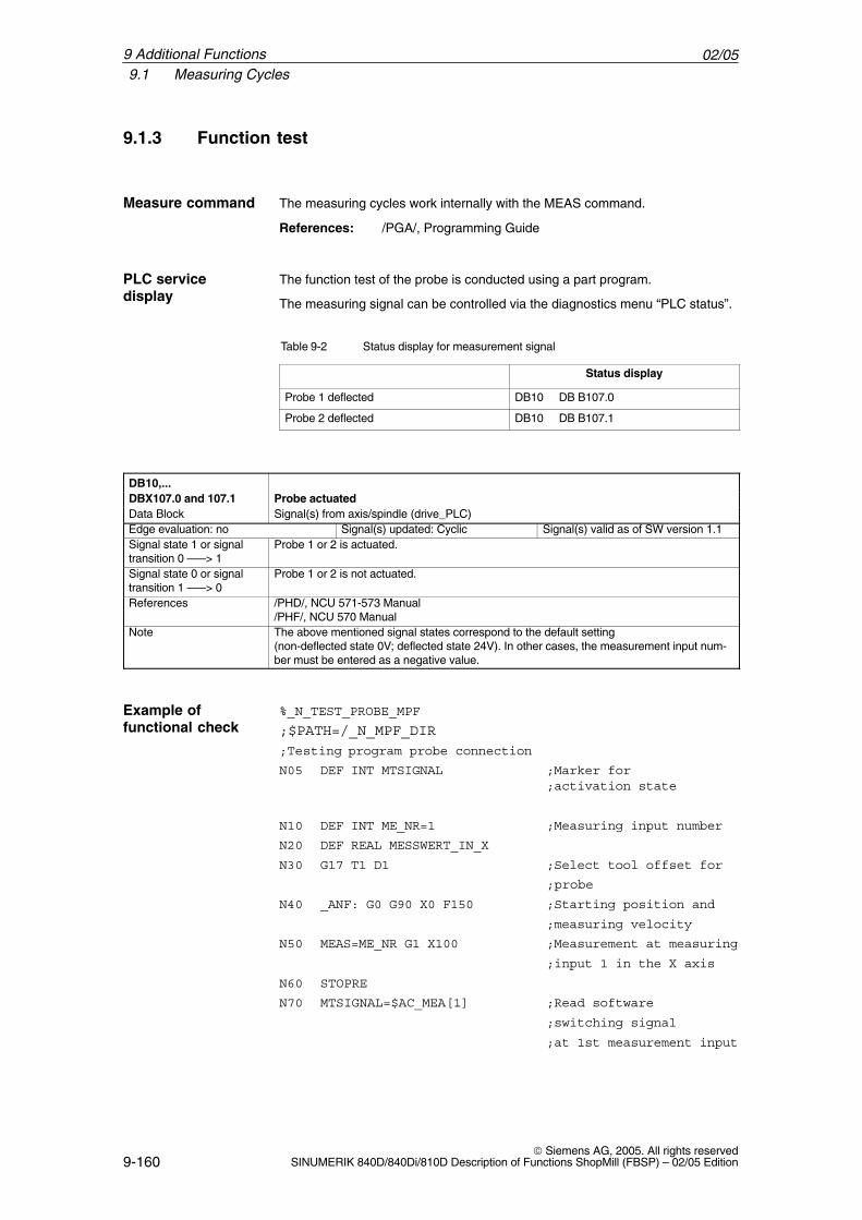
02/059.1 Measuring Cycles
9-160 Siemens AG, 2005. All rights reserved
SINUMERIK 840D/840Di/810D Description of Functions ShopMill (FBSP) – 02/05 Edition
9.1.3 Function test
Measure command The measuring cycles work internally with the MEAS command.
References: /PGA/, Programming Guide
The function test of the probe is conducted using a part program.
The measuring signal can be controlled via the diagnostics menu “PLC status”.
Table 9-2 Status display for measurement signal
Status display
Probe 1 deflected DB10 DB B107.0
Probe 2 deflected DB10 DB B107.1
DB10,...DBX107.0 and 107.1 Probe actuatedData Block Signal(s) from axis/spindle (drive_PLC)Edge evaluation: no Signal(s) updated: Cyclic Signal(s) valid as of SW version 1.1Signal state 1 or signaltransition 0 –––> 1
Probe 1 or 2 is actuated.
Signal state 0 or signaltransition 1 –––> 0
Probe 1 or 2 is not actuated.
References /PHD/, NCU 571-573 Manual/PHF/, NCU 570 Manual
Note The above mentioned signal states correspond to the default setting (non-deflected state 0V; deflected state 24V). In other cases, the measurement input num-ber must be entered as a negative value.
%_N_TEST_PROBE_MPF
;$PATH=/_N_MPF_DIR
;Testing program probe connection
N05 DEF INT MTSIGNAL ;Marker for;activation state
N10 DEF INT ME_NR=1 ;Measuring input number
N20 DEF REAL MESSWERT_IN_X
N30 G17 T1 D1 ;Select tool offset for
;probe
N40 _ANF: G0 G90 X0 F150 ;Starting position and
;measuring velocity
N50 MEAS=ME_NR G1 X100 ;Measurement at measuring
;input 1 in the X axis
N60 STOPRE
N70 MTSIGNAL=$AC_MEA[1] ;Read software
;switching signal
;at 1st measurement input
PLC servicedisplay
Example offunctional check
9 Additional Functions
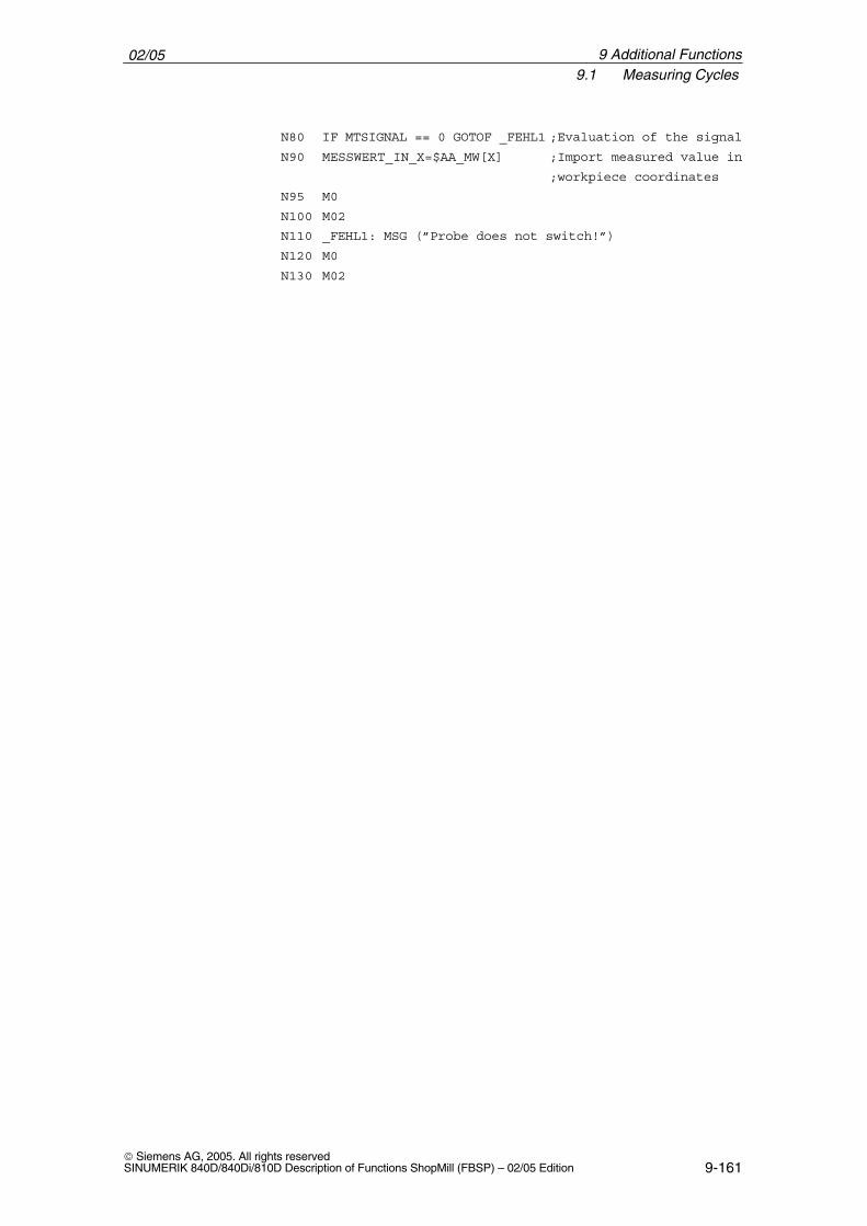
02/059.1 Measuring Cycles
9-161 Siemens AG, 2005. All rights reservedSINUMERIK 840D/840Di/810D Description of Functions ShopMill (FBSP) – 02/05 Edition
N80 IF MTSIGNAL == 0 GOTOF _FEHL1 ;Evaluation of the signal
N90 MESSWERT_IN_X=$AA_MW[X] ;Import measured value in
;workpiece coordinates
N95 M0
N100 M02
N110 _FEHL1: MSG (”Probe does not switch!”)
N120 M0
N130 M02
9 Additional Functions
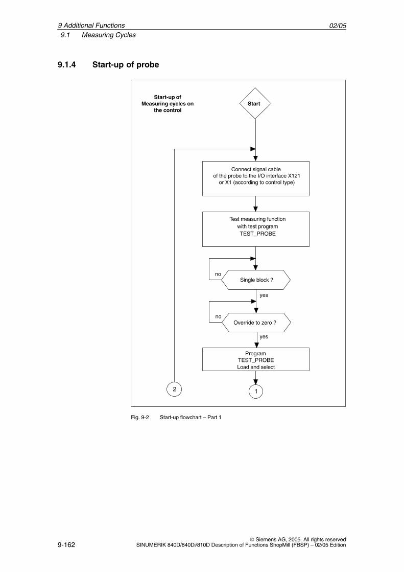
02/059.1 Measuring Cycles
9-162 Siemens AG, 2005. All rights reserved
SINUMERIK 840D/840Di/810D Description of Functions ShopMill (FBSP) – 02/05 Edition
9.1.4 Start-up of probe
Start-up ofMeasuring cycles on
the controlStart
Connect signal cable of the probe to the I/O interface X121
or X1 (according to control type)
Test measuring functionwith test programTEST_PROBE
Single block ?no
12
yes
yes
Override to zero ?no
ProgramTEST_PROBELoad and select
Fig. 9-2 Start-up flowchart – Part 1
9 Additional Functions
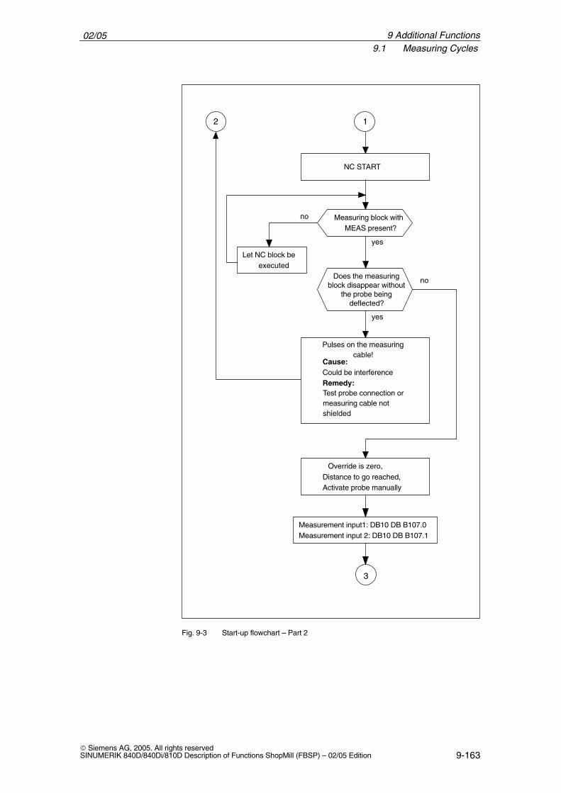
02/059.1 Measuring Cycles
9-163 Siemens AG, 2005. All rights reservedSINUMERIK 840D/840Di/810D Description of Functions ShopMill (FBSP) – 02/05 Edition
no
1
NC START
Measuring block withMEAS present?
Let NC block beexecuted
2
Does the measuringblock disappear without
the probe beingdeflected?
yes
Pulses on the measuringcable!
Cause:Could be interferenceRemedy:Test probe connection ormeasuring cable notshielded
yes
no
Override is zero,Distance to go reached,Activate probe manually
3
Measurement input1: DB10 DB B107.0Measurement input 2: DB10 DB B107.1
Fig. 9-3 Start-up flowchart – Part 2
9 Additional Functions
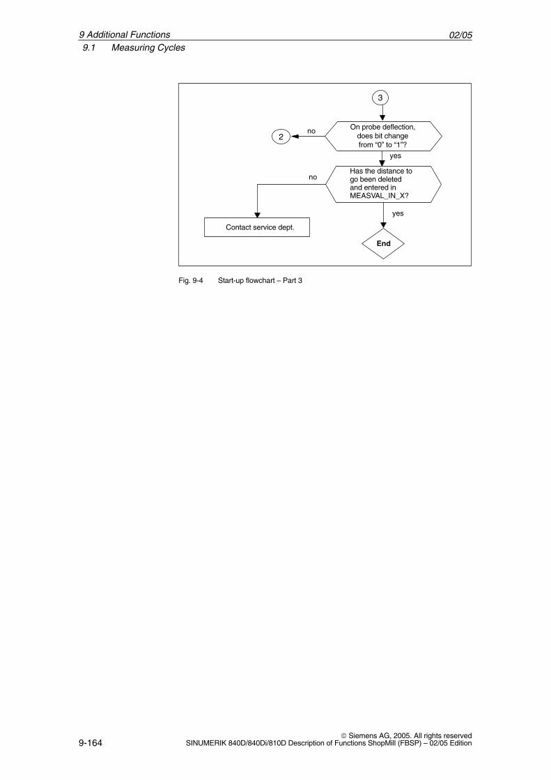
02/059.1 Measuring Cycles
9-164 Siemens AG, 2005. All rights reserved
SINUMERIK 840D/840Di/810D Description of Functions ShopMill (FBSP) – 02/05 Edition
3
yes
no
no On probe deflection,does bit changefrom “0” to “1”?
yes
Contact service dept.
2
End
Has the distance togo been deletedand entered in MEASVAL_IN_X?
Fig. 9-4 Start-up flowchart – Part 3
9 Additional Functions
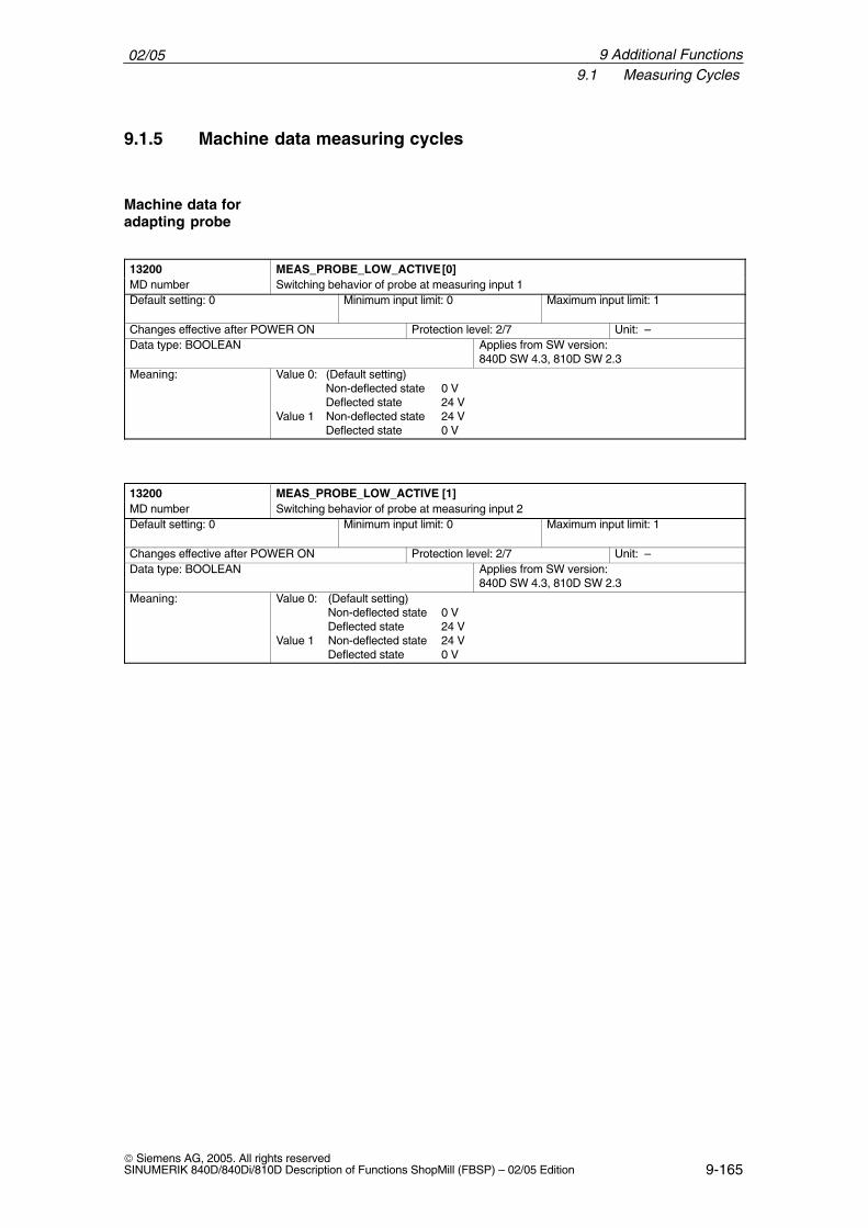
02/059.1 Measuring Cycles
9-165 Siemens AG, 2005. All rights reservedSINUMERIK 840D/840Di/810D Description of Functions ShopMill (FBSP) – 02/05 Edition
9.1.5 Machine data measuring cycles
13200 MEAS_PROBE_LOW_ACTIVE [0]MD number Switching behavior of probe at measuring input 1Default setting: 0 Minimum input limit: 0 Maximum input limit: 1
Changes effective after POWER ON Protection level: 2/7 Unit: –Data type: BOOLEAN Applies from SW version:
840D SW 4.3, 810D SW 2.3Meaning: Value 0: (Default setting)
Non-deflected state 0 VDeflected state 24 V
Value 1 Non-deflected state 24 VDeflected state 0 V
13200 MEAS_PROBE_LOW_ACTIVE [1]MD number Switching behavior of probe at measuring input 2Default setting: 0 Minimum input limit: 0 Maximum input limit: 1
Changes effective after POWER ON Protection level: 2/7 Unit: –Data type: BOOLEAN Applies from SW version:
840D SW 4.3, 810D SW 2.3Meaning: Value 0: (Default setting)
Non-deflected state 0 VDeflected state 24 V
Value 1 Non-deflected state 24 VDeflected state 0 V
Machine data foradapting probe
9 Additional Functions
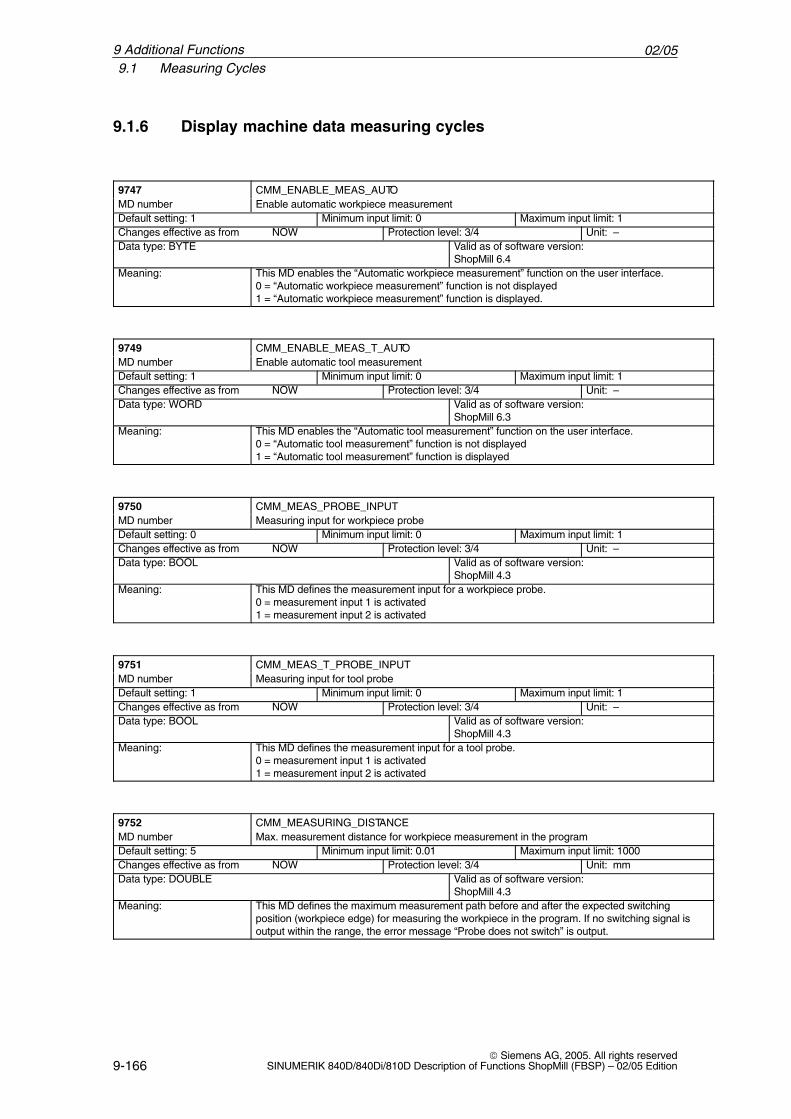
02/059.1 Measuring Cycles
9-166 Siemens AG, 2005. All rights reserved
SINUMERIK 840D/840Di/810D Description of Functions ShopMill (FBSP) – 02/05 Edition
9.1.6 Display machine data measuring cycles
ÁÁÁÁÁÁÁÁÁÁÁÁÁÁÁÁ
9747ÁÁÁÁÁÁÁÁÁÁÁÁÁÁÁÁÁÁÁÁÁÁÁÁÁÁÁÁÁÁÁÁÁÁÁÁÁÁÁÁÁÁÁÁÁÁ
CMM_ENABLE_MEAS_AUTOÁÁÁÁÁÁÁÁÁÁÁÁÁÁÁÁ
MD number ÁÁÁÁÁÁÁÁÁÁÁÁÁÁÁÁÁÁÁÁÁÁÁÁÁÁÁÁÁÁÁÁÁÁÁÁÁÁÁÁÁÁÁÁÁÁ
Enable automatic workpiece measurement
ÁÁÁÁÁÁÁÁÁÁÁÁÁÁÁÁÁÁÁÁÁÁ
Default setting: 1 ÁÁÁÁÁÁÁÁÁÁÁÁÁÁÁÁÁÁÁÁÁÁ
Minimum input limit: 0 ÁÁÁÁÁÁÁÁÁÁÁÁÁÁÁÁÁÁÁÁ
Maximum input limit: 1
ÁÁÁÁÁÁÁÁÁÁÁÁÁÁChanges effective as from NOW ÁÁÁÁÁÁÁÁÁÁÁProtection level: 3/4 ÁÁÁÁÁÁÁUnit: –ÁÁÁÁÁÁÁÁÁÁÁÁÁÁÁÁÁÁÁÁÁÁÁÁÁÁÁÁÁÁÁÁÁÁÁÁÁÁÁÁÁÁÁÁÁÁÁÁÁÁÁ
Data type: BYTE ÁÁÁÁÁÁÁÁÁÁÁÁÁÁÁÁÁÁÁÁÁÁÁÁÁÁÁÁÁÁÁÁÁÁÁÁÁÁÁÁÁÁ
Valid as of software version:ShopMill 6.4
ÁÁÁÁÁÁÁÁÁÁÁÁÁÁÁÁÁÁÁÁÁÁÁÁ
Meaning: ÁÁÁÁÁÁÁÁÁÁÁÁÁÁÁÁÁÁÁÁÁÁÁÁÁÁÁÁÁÁÁÁÁÁÁÁÁÁÁÁÁÁÁÁÁÁÁÁÁÁÁÁÁÁÁÁÁÁÁÁÁÁÁÁÁÁÁÁÁ
This MD enables the “Automatic workpiece measurement” function on the user interface.0 = “Automatic workpiece measurement” function is not displayed1 = “Automatic workpiece measurement” function is displayed.
ÁÁÁÁÁÁÁÁÁÁÁÁÁÁÁÁ
9749 ÁÁÁÁÁÁÁÁÁÁÁÁÁÁÁÁÁÁÁÁÁÁÁÁÁÁÁÁÁÁÁÁÁÁÁÁÁÁÁÁÁÁÁÁÁÁ
CMM_ENABLE_MEAS_T_AUTO
ÁÁÁÁÁÁÁÁÁÁÁÁÁÁÁÁ
MD number ÁÁÁÁÁÁÁÁÁÁÁÁÁÁÁÁÁÁÁÁÁÁÁÁÁÁÁÁÁÁÁÁÁÁÁÁÁÁÁÁÁÁÁÁÁÁ
Enable automatic tool measurement
ÁÁÁÁÁÁÁÁÁÁÁDefault setting: 1 ÁÁÁÁÁÁÁÁÁÁÁMinimum input limit: 0 ÁÁÁÁÁÁÁÁÁÁMaximum input limit: 1ÁÁÁÁÁÁÁÁÁÁÁÁÁÁÁÁÁÁÁÁÁÁÁÁÁÁÁÁ
Changes effective as from NOW ÁÁÁÁÁÁÁÁÁÁÁÁÁÁÁÁÁÁÁÁÁÁ
Protection level: 3/4 ÁÁÁÁÁÁÁÁÁÁÁÁÁÁ
Unit: –ÁÁÁÁÁÁÁÁÁÁÁÁÁÁÁÁÁÁÁÁÁÁÁÁÁÁÁÁÁÁÁÁÁÁ
Data type: WORD ÁÁÁÁÁÁÁÁÁÁÁÁÁÁÁÁÁÁÁÁÁÁÁÁÁÁÁÁ
Valid as of software version:ShopMill 6.3ÁÁÁÁÁÁÁÁ
ÁÁÁÁÁÁÁÁÁÁÁÁÁÁÁÁ
Meaning: ÁÁÁÁÁÁÁÁÁÁÁÁÁÁÁÁÁÁÁÁÁÁÁÁÁÁÁÁÁÁÁÁÁÁÁÁÁÁÁÁÁÁÁÁÁÁÁÁÁÁÁÁÁÁÁÁÁÁÁÁÁÁÁÁÁÁÁÁÁ
This MD enables the “Automatic tool measurement” function on the user interface.0 = “Automatic tool measurement” function is not displayed1 = “Automatic tool measurement” function is displayed
ÁÁÁÁÁÁÁÁÁÁÁÁÁÁÁÁ
9750 ÁÁÁÁÁÁÁÁÁÁÁÁÁÁÁÁÁÁÁÁÁÁÁÁÁÁÁÁÁÁÁÁÁÁÁÁÁÁÁÁÁÁÁÁÁÁ
CMM_MEAS_PROBE_INPUT
ÁÁÁÁÁÁÁÁMD number ÁÁÁÁÁÁÁÁÁÁÁÁÁÁÁÁÁÁÁÁÁÁÁMeasuring input for workpiece probeÁÁÁÁÁÁÁÁÁÁÁÁÁÁÁÁÁÁÁÁÁÁ
Default setting: 0ÁÁÁÁÁÁÁÁÁÁÁÁÁÁÁÁÁÁÁÁÁÁ
Minimum input limit: 0ÁÁÁÁÁÁÁÁÁÁÁÁÁÁÁÁÁÁÁÁ
Maximum input limit: 1ÁÁÁÁÁÁÁÁÁÁÁÁÁÁÁÁÁÁÁÁÁÁÁÁÁÁÁÁ
Changes effective as from NOW ÁÁÁÁÁÁÁÁÁÁÁÁÁÁÁÁÁÁÁÁÁÁ
Protection level: 3/4 ÁÁÁÁÁÁÁÁÁÁÁÁÁÁ
Unit: –
ÁÁÁÁÁÁÁÁÁÁÁÁÁÁÁÁÁÁÁÁÁÁÁÁÁÁÁÁÁÁÁÁÁÁ
Data type: BOOL ÁÁÁÁÁÁÁÁÁÁÁÁÁÁÁÁÁÁÁÁÁÁÁÁÁÁÁÁ
Valid as of software version:ShopMill 4.3
ÁÁÁÁÁÁÁÁÁÁÁÁÁÁÁÁÁÁÁÁÁÁÁÁ
Meaning: ÁÁÁÁÁÁÁÁÁÁÁÁÁÁÁÁÁÁÁÁÁÁÁÁÁÁÁÁÁÁÁÁÁÁÁÁÁÁÁÁÁÁÁÁÁÁÁÁÁÁÁÁÁÁÁÁÁÁÁÁÁÁÁÁÁÁÁÁÁ
This MD defines the measurement input for a workpiece probe.0 = measurement input 1 is activated1 = measurement input 2 is activated
ÁÁÁÁÁÁÁÁ9751 ÁÁÁÁÁÁÁÁÁÁÁÁÁÁÁÁÁÁÁÁÁÁÁCMM_MEAS_T_PROBE_INPUTÁÁÁÁÁÁÁÁÁÁÁÁÁÁÁÁ
MD numberÁÁÁÁÁÁÁÁÁÁÁÁÁÁÁÁÁÁÁÁÁÁÁÁÁÁÁÁÁÁÁÁÁÁÁÁÁÁÁÁÁÁÁÁÁÁ
Measuring input for tool probeÁÁÁÁÁÁÁÁÁÁÁÁÁÁÁÁÁÁÁÁÁÁ
Default setting: 1 ÁÁÁÁÁÁÁÁÁÁÁÁÁÁÁÁÁÁÁÁÁÁ
Minimum input limit: 0 ÁÁÁÁÁÁÁÁÁÁÁÁÁÁÁÁÁÁÁÁ
Maximum input limit: 1
ÁÁÁÁÁÁÁÁÁÁÁÁÁÁChanges effective as from NOW ÁÁÁÁÁÁÁÁÁÁÁProtection level: 3/4 ÁÁÁÁÁÁÁUnit: –
ÁÁÁÁÁÁÁÁÁÁÁÁÁÁÁÁÁÁÁÁÁÁÁÁÁÁÁÁÁÁÁÁÁÁ
Data type: BOOLÁÁÁÁÁÁÁÁÁÁÁÁÁÁÁÁÁÁÁÁÁÁÁÁÁÁÁÁ
Valid as of software version:ShopMill 4.3
ÁÁÁÁÁÁÁÁÁÁÁÁÁÁÁÁÁÁÁÁÁÁÁÁ
Meaning: ÁÁÁÁÁÁÁÁÁÁÁÁÁÁÁÁÁÁÁÁÁÁÁÁÁÁÁÁÁÁÁÁÁÁÁÁÁÁÁÁÁÁÁÁÁÁÁÁÁÁÁÁÁÁÁÁÁÁÁÁÁÁÁÁÁÁÁÁÁ
This MD defines the measurement input for a tool probe.0 = measurement input 1 is activated1 = measurement input 2 is activated
ÁÁÁÁÁÁÁÁÁÁÁÁÁÁÁÁ
9752ÁÁÁÁÁÁÁÁÁÁÁÁÁÁÁÁÁÁÁÁÁÁÁÁÁÁÁÁÁÁÁÁÁÁÁÁÁÁÁÁÁÁÁÁÁÁ
CMM_MEASURING_DISTANCEÁÁÁÁÁÁÁÁÁÁÁÁÁÁÁÁ
MD number ÁÁÁÁÁÁÁÁÁÁÁÁÁÁÁÁÁÁÁÁÁÁÁÁÁÁÁÁÁÁÁÁÁÁÁÁÁÁÁÁÁÁÁÁÁÁ
Max. measurement distance for workpiece measurement in the program
ÁÁÁÁÁÁÁÁÁÁÁÁÁÁÁÁÁÁÁÁÁÁ
Default setting: 5 ÁÁÁÁÁÁÁÁÁÁÁÁÁÁÁÁÁÁÁÁÁÁ
Minimum input limit: 0.01 ÁÁÁÁÁÁÁÁÁÁÁÁÁÁÁÁÁÁÁÁ
Maximum input limit: 1000
ÁÁÁÁÁÁÁÁÁÁÁÁÁÁChanges effective as from NOW ÁÁÁÁÁÁÁÁÁÁÁProtection level: 3/4 ÁÁÁÁÁÁÁUnit: mmÁÁÁÁÁÁÁÁÁÁÁÁÁÁÁÁÁÁÁÁÁÁÁÁÁÁÁÁÁÁÁÁÁÁÁÁÁÁÁÁÁÁÁÁÁÁÁÁÁÁÁ
Data type: DOUBLE ÁÁÁÁÁÁÁÁÁÁÁÁÁÁÁÁÁÁÁÁÁÁÁÁÁÁÁÁÁÁÁÁÁÁÁÁÁÁÁÁÁÁ
Valid as of software version:ShopMill 4.3
ÁÁÁÁÁÁÁÁÁÁÁÁÁÁÁÁ
Meaning: ÁÁÁÁÁÁÁÁÁÁÁÁÁÁÁÁÁÁÁÁÁÁÁÁÁÁÁÁÁÁÁÁÁÁÁÁÁÁÁÁÁÁÁÁÁÁ
This MD defines the maximum measurement path before and after the expected switchingposition (workpiece edge) for measuring the workpiece in the program. If no switching signal isoutput within the range, the error message “Probe does not switch” is output.
9 Additional Functions
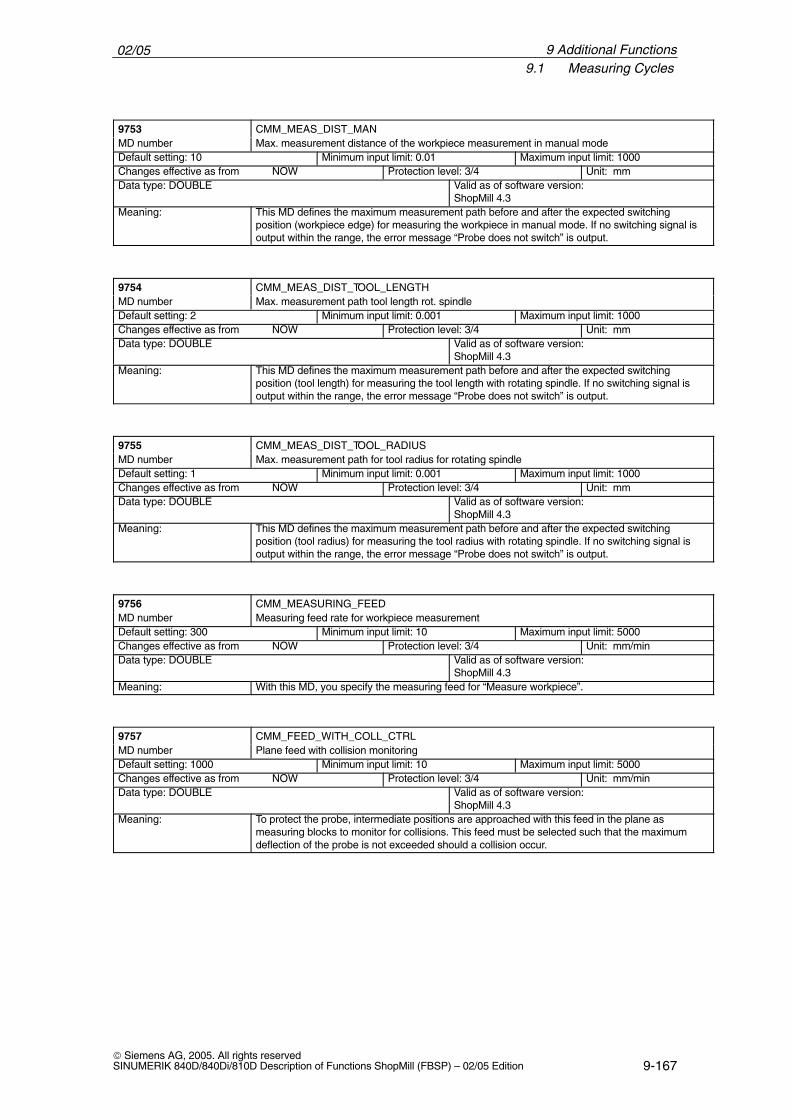
02/059.1 Measuring Cycles
9-167 Siemens AG, 2005. All rights reservedSINUMERIK 840D/840Di/810D Description of Functions ShopMill (FBSP) – 02/05 Edition
ÁÁÁÁÁÁÁÁÁÁÁÁÁÁÁÁ9753
ÁÁÁÁÁÁÁÁÁÁÁÁÁÁÁÁÁÁÁÁÁÁÁÁÁÁÁÁÁÁÁÁÁÁÁÁÁÁÁÁÁÁÁÁÁÁCMM_MEAS_DIST_MANÁÁÁÁÁÁÁÁ
ÁÁÁÁÁÁÁÁMD number ÁÁÁÁÁÁÁÁÁÁÁÁÁÁÁÁÁÁÁÁÁÁÁ
ÁÁÁÁÁÁÁÁÁÁÁÁÁÁÁÁÁÁÁÁÁÁÁMax. measurement distance of the workpiece measurement in manual mode
ÁÁÁÁÁÁÁÁÁÁÁÁÁÁÁÁÁÁÁÁÁÁ
Default setting: 10 ÁÁÁÁÁÁÁÁÁÁÁÁÁÁÁÁÁÁÁÁÁÁ
Minimum input limit: 0.01 ÁÁÁÁÁÁÁÁÁÁÁÁÁÁÁÁÁÁÁÁ
Maximum input limit: 1000
ÁÁÁÁÁÁÁÁÁÁÁÁÁÁChanges effective as from NOW ÁÁÁÁÁÁÁÁÁÁÁProtection level: 3/4 ÁÁÁÁÁÁÁUnit: mmÁÁÁÁÁÁÁÁÁÁÁÁÁÁÁÁÁÁÁÁÁÁÁÁÁÁÁÁÁÁÁÁÁÁÁÁÁÁÁÁÁÁÁÁÁÁÁÁÁÁÁ
Data type: DOUBLE ÁÁÁÁÁÁÁÁÁÁÁÁÁÁÁÁÁÁÁÁÁÁÁÁÁÁÁÁÁÁÁÁÁÁÁÁÁÁÁÁÁÁ
Valid as of software version:ShopMill 4.3
ÁÁÁÁÁÁÁÁÁÁÁÁÁÁÁÁÁÁÁÁÁÁÁÁ
Meaning: ÁÁÁÁÁÁÁÁÁÁÁÁÁÁÁÁÁÁÁÁÁÁÁÁÁÁÁÁÁÁÁÁÁÁÁÁÁÁÁÁÁÁÁÁÁÁÁÁÁÁÁÁÁÁÁÁÁÁÁÁÁÁÁÁÁÁÁÁÁ
This MD defines the maximum measurement path before and after the expected switchingposition (workpiece edge) for measuring the workpiece in manual mode. If no switching signal isoutput within the range, the error message “Probe does not switch” is output.
ÁÁÁÁÁÁÁÁÁÁÁÁÁÁÁÁ
9754 ÁÁÁÁÁÁÁÁÁÁÁÁÁÁÁÁÁÁÁÁÁÁÁÁÁÁÁÁÁÁÁÁÁÁÁÁÁÁÁÁÁÁÁÁÁÁ
CMM_MEAS_DIST_TOOL_LENGTHÁÁÁÁÁÁÁÁÁÁÁÁÁÁÁÁ
MD number ÁÁÁÁÁÁÁÁÁÁÁÁÁÁÁÁÁÁÁÁÁÁÁÁÁÁÁÁÁÁÁÁÁÁÁÁÁÁÁÁÁÁÁÁÁÁ
Max. measurement path tool length rot. spindle
ÁÁÁÁÁÁÁÁÁÁÁDefault setting: 2 ÁÁÁÁÁÁÁÁÁÁÁMinimum input limit: 0.001 ÁÁÁÁÁÁÁÁÁÁMaximum input limit: 1000ÁÁÁÁÁÁÁÁÁÁÁÁÁÁÁÁÁÁÁÁÁÁÁÁÁÁÁÁ
Changes effective as from NOWÁÁÁÁÁÁÁÁÁÁÁÁÁÁÁÁÁÁÁÁÁÁ
Protection level: 3/4ÁÁÁÁÁÁÁÁÁÁÁÁÁÁ
Unit: mmÁÁÁÁÁÁÁÁÁÁÁÁÁÁÁÁÁÁÁÁÁÁÁÁÁÁÁÁÁÁÁÁÁÁ
Data type: DOUBLE ÁÁÁÁÁÁÁÁÁÁÁÁÁÁÁÁÁÁÁÁÁÁÁÁÁÁÁÁ
Valid as of software version:ShopMill 4.3ÁÁÁÁÁÁÁÁ
ÁÁÁÁÁÁÁÁÁÁÁÁÁÁÁÁ
Meaning:ÁÁÁÁÁÁÁÁÁÁÁÁÁÁÁÁÁÁÁÁÁÁÁÁÁÁÁÁÁÁÁÁÁÁÁÁÁÁÁÁÁÁÁÁÁÁÁÁÁÁÁÁÁÁÁÁÁÁÁÁÁÁÁÁÁÁÁÁÁ
This MD defines the maximum measurement path before and after the expected switchingposition (tool length) for measuring the tool length with rotating spindle. If no switching signal isoutput within the range, the error message “Probe does not switch” is output.
ÁÁÁÁÁÁÁÁÁÁÁÁÁÁÁÁ
9755 ÁÁÁÁÁÁÁÁÁÁÁÁÁÁÁÁÁÁÁÁÁÁÁÁÁÁÁÁÁÁÁÁÁÁÁÁÁÁÁÁÁÁÁÁÁÁ
CMM_MEAS_DIST_TOOL_RADIUS
ÁÁÁÁÁÁÁÁMD number ÁÁÁÁÁÁÁÁÁÁÁÁÁÁÁÁÁÁÁÁÁÁÁMax. measurement path for tool radius for rotating spindleÁÁÁÁÁÁÁÁÁÁÁÁÁÁÁÁÁÁÁÁÁÁ
Default setting: 1ÁÁÁÁÁÁÁÁÁÁÁÁÁÁÁÁÁÁÁÁÁÁ
Minimum input limit: 0.001ÁÁÁÁÁÁÁÁÁÁÁÁÁÁÁÁÁÁÁÁ
Maximum input limit: 1000ÁÁÁÁÁÁÁÁÁÁÁÁÁÁÁÁÁÁÁÁÁÁÁÁÁÁÁÁ
Changes effective as from NOW ÁÁÁÁÁÁÁÁÁÁÁÁÁÁÁÁÁÁÁÁÁÁ
Protection level: 3/4 ÁÁÁÁÁÁÁÁÁÁÁÁÁÁ
Unit: mm
ÁÁÁÁÁÁÁÁÁÁÁÁÁÁÁÁÁÁÁÁÁÁÁÁÁÁÁÁÁÁÁÁÁÁ
Data type: DOUBLE ÁÁÁÁÁÁÁÁÁÁÁÁÁÁÁÁÁÁÁÁÁÁÁÁÁÁÁÁ
Valid as of software version:ShopMill 4.3
ÁÁÁÁÁÁÁÁÁÁÁÁÁÁÁÁÁÁÁÁÁÁÁÁ
Meaning: ÁÁÁÁÁÁÁÁÁÁÁÁÁÁÁÁÁÁÁÁÁÁÁÁÁÁÁÁÁÁÁÁÁÁÁÁÁÁÁÁÁÁÁÁÁÁÁÁÁÁÁÁÁÁÁÁÁÁÁÁÁÁÁÁÁÁÁÁÁ
This MD defines the maximum measurement path before and after the expected switchingposition (tool radius) for measuring the tool radius with rotating spindle. If no switching signal isoutput within the range, the error message “Probe does not switch” is output.
ÁÁÁÁÁÁÁÁ9756 ÁÁÁÁÁÁÁÁÁÁÁÁÁÁÁÁÁÁÁÁÁÁÁCMM_MEASURING_FEEDÁÁÁÁÁÁÁÁÁÁÁÁÁÁÁÁ
MD numberÁÁÁÁÁÁÁÁÁÁÁÁÁÁÁÁÁÁÁÁÁÁÁÁÁÁÁÁÁÁÁÁÁÁÁÁÁÁÁÁÁÁÁÁÁÁ
Measuring feed rate for workpiece measurementÁÁÁÁÁÁÁÁÁÁÁÁÁÁÁÁÁÁÁÁÁÁ
Default setting: 300 ÁÁÁÁÁÁÁÁÁÁÁÁÁÁÁÁÁÁÁÁÁÁ
Minimum input limit: 10 ÁÁÁÁÁÁÁÁÁÁÁÁÁÁÁÁÁÁÁÁ
Maximum input limit: 5000
ÁÁÁÁÁÁÁÁÁÁÁÁÁÁÁÁÁÁÁÁÁÁÁÁÁÁÁÁ
Changes effective as from NOW ÁÁÁÁÁÁÁÁÁÁÁÁÁÁÁÁÁÁÁÁÁÁ
Protection level: 3/4 ÁÁÁÁÁÁÁÁÁÁÁÁÁÁ
Unit: mm/min
ÁÁÁÁÁÁÁÁÁÁÁÁÁÁÁÁÁÁÁÁÁÁÁÁÁÁÁÁÁÁÁÁÁÁ
Data type: DOUBLEÁÁÁÁÁÁÁÁÁÁÁÁÁÁÁÁÁÁÁÁÁÁÁÁÁÁÁÁ
Valid as of software version:ShopMill 4.3
ÁÁÁÁÁÁÁÁÁÁÁÁÁÁÁÁ
Meaning: ÁÁÁÁÁÁÁÁÁÁÁÁÁÁÁÁÁÁÁÁÁÁÁÁÁÁÁÁÁÁÁÁÁÁÁÁÁÁÁÁÁÁÁÁÁÁ
With this MD, you specify the measuring feed for “Measure workpiece”.
ÁÁÁÁÁÁÁÁÁÁÁÁÁÁÁÁ
9757 ÁÁÁÁÁÁÁÁÁÁÁÁÁÁÁÁÁÁÁÁÁÁÁÁÁÁÁÁÁÁÁÁÁÁÁÁÁÁÁÁÁÁÁÁÁÁ
CMM_FEED_WITH_COLL_CTRL
ÁÁÁÁÁÁÁÁÁÁÁÁÁÁÁÁ
MD number ÁÁÁÁÁÁÁÁÁÁÁÁÁÁÁÁÁÁÁÁÁÁÁÁÁÁÁÁÁÁÁÁÁÁÁÁÁÁÁÁÁÁÁÁÁÁ
Plane feed with collision monitoring
ÁÁÁÁÁÁÁÁÁÁÁDefault setting: 1000 ÁÁÁÁÁÁÁÁÁÁÁMinimum input limit: 10 ÁÁÁÁÁÁÁÁÁÁMaximum input limit: 5000ÁÁÁÁÁÁÁÁÁÁÁÁÁÁÁÁÁÁÁÁÁÁÁÁÁÁÁÁ
Changes effective as from NOW ÁÁÁÁÁÁÁÁÁÁÁÁÁÁÁÁÁÁÁÁÁÁ
Protection level: 3/4 ÁÁÁÁÁÁÁÁÁÁÁÁÁÁ
Unit: mm/minÁÁÁÁÁÁÁÁÁÁÁÁÁÁÁÁÁÁÁÁÁÁÁÁÁÁÁÁÁÁÁÁÁÁ
Data type: DOUBLE ÁÁÁÁÁÁÁÁÁÁÁÁÁÁÁÁÁÁÁÁÁÁÁÁÁÁÁÁ
Valid as of software version:ShopMill 4.3ÁÁÁÁÁÁÁÁ
ÁÁÁÁÁÁÁÁÁÁÁÁÁÁÁÁ
Meaning: ÁÁÁÁÁÁÁÁÁÁÁÁÁÁÁÁÁÁÁÁÁÁÁÁÁÁÁÁÁÁÁÁÁÁÁÁÁÁÁÁÁÁÁÁÁÁÁÁÁÁÁÁÁÁÁÁÁÁÁÁÁÁÁÁÁÁÁÁÁ
To protect the probe, intermediate positions are approached with this feed in the plane asmeasuring blocks to monitor for collisions. This feed must be selected such that the maximumdeflection of the probe is not exceeded should a collision occur.
9 Additional Functions
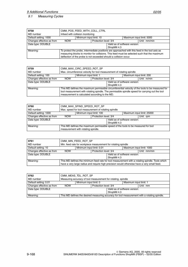
02/059.1 Measuring Cycles
9-168 Siemens AG, 2005. All rights reserved
SINUMERIK 840D/840Di/810D Description of Functions ShopMill (FBSP) – 02/05 Edition
ÁÁÁÁÁÁÁÁÁÁÁÁÁÁÁÁ9758
ÁÁÁÁÁÁÁÁÁÁÁÁÁÁÁÁÁÁÁÁÁÁÁÁÁÁÁÁÁÁÁÁÁÁÁÁÁÁÁÁÁÁÁÁÁÁCMM_POS_FEED_WITH_COLL_CTRLÁÁÁÁÁÁÁÁ
ÁÁÁÁÁÁÁÁMD number ÁÁÁÁÁÁÁÁÁÁÁÁÁÁÁÁÁÁÁÁÁÁÁ
ÁÁÁÁÁÁÁÁÁÁÁÁÁÁÁÁÁÁÁÁÁÁÁInfeed with collision monitoring
ÁÁÁÁÁÁÁÁÁÁÁÁÁÁÁÁÁÁÁÁÁÁ
Default setting: 1000 ÁÁÁÁÁÁÁÁÁÁÁÁÁÁÁÁÁÁÁÁÁÁ
Minimum input limit: 10 ÁÁÁÁÁÁÁÁÁÁÁÁÁÁÁÁÁÁÁÁ
Maximum input limit: 5000
ÁÁÁÁÁÁÁÁÁÁÁÁÁÁChanges effective as from NOW ÁÁÁÁÁÁÁÁÁÁÁProtection level: 3/4 ÁÁÁÁÁÁÁUnit: mm/minÁÁÁÁÁÁÁÁÁÁÁÁÁÁÁÁÁÁÁÁÁÁÁÁÁÁÁÁÁÁÁÁÁÁÁÁÁÁÁÁÁÁÁÁÁÁÁÁÁÁÁ
Data type: DOUBLE ÁÁÁÁÁÁÁÁÁÁÁÁÁÁÁÁÁÁÁÁÁÁÁÁÁÁÁÁÁÁÁÁÁÁÁÁÁÁÁÁÁÁ
Valid as of software version:ShopMill 4.3
ÁÁÁÁÁÁÁÁÁÁÁÁÁÁÁÁÁÁÁÁÁÁÁÁ
Meaning: ÁÁÁÁÁÁÁÁÁÁÁÁÁÁÁÁÁÁÁÁÁÁÁÁÁÁÁÁÁÁÁÁÁÁÁÁÁÁÁÁÁÁÁÁÁÁÁÁÁÁÁÁÁÁÁÁÁÁÁÁÁÁÁÁÁÁÁÁÁ
To protect the probe, intermediate positions are approached with this feed in the tool axis asmeasuring blocks to monitor for collisions. This feed must be selected such that the maximumdeflection of the probe is not exceeded should a collision occur.
ÁÁÁÁÁÁÁÁÁÁÁÁÁÁÁÁ
9759 ÁÁÁÁÁÁÁÁÁÁÁÁÁÁÁÁÁÁÁÁÁÁÁÁÁÁÁÁÁÁÁÁÁÁÁÁÁÁÁÁÁÁÁÁÁÁ
CMM_MAX_CIRC_SPEED_ROT_SPÁÁÁÁÁÁÁÁÁÁÁÁÁÁÁÁ
MD number ÁÁÁÁÁÁÁÁÁÁÁÁÁÁÁÁÁÁÁÁÁÁÁÁÁÁÁÁÁÁÁÁÁÁÁÁÁÁÁÁÁÁÁÁÁÁ
Max. circumference velocity for tool measurement of rotating spindle
ÁÁÁÁÁÁÁÁÁÁÁDefault setting: 100 ÁÁÁÁÁÁÁÁÁÁÁMinimum input limit: 1 ÁÁÁÁÁÁÁÁÁÁMaximum input limit: 200ÁÁÁÁÁÁÁÁÁÁÁÁÁÁÁÁÁÁÁÁÁÁÁÁÁÁÁÁ
Changes effective as from NOWÁÁÁÁÁÁÁÁÁÁÁÁÁÁÁÁÁÁÁÁÁÁ
Protection level: 3/4ÁÁÁÁÁÁÁÁÁÁÁÁÁÁ
Unit: m/minÁÁÁÁÁÁÁÁÁÁÁÁÁÁÁÁÁÁÁÁÁÁÁÁÁÁÁÁÁÁÁÁÁÁ
Data type: DOUBLE ÁÁÁÁÁÁÁÁÁÁÁÁÁÁÁÁÁÁÁÁÁÁÁÁÁÁÁÁ
Valid as of software version:ShopMill 4.3ÁÁÁÁÁÁÁÁ
ÁÁÁÁÁÁÁÁÁÁÁÁÁÁÁÁ
Meaning:ÁÁÁÁÁÁÁÁÁÁÁÁÁÁÁÁÁÁÁÁÁÁÁÁÁÁÁÁÁÁÁÁÁÁÁÁÁÁÁÁÁÁÁÁÁÁÁÁÁÁÁÁÁÁÁÁÁÁÁÁÁÁÁÁÁÁÁÁÁ
This MD defines the maximum permissible circumferential velocity of the tools to be measured fortool measurement with rotating spindle. The permissible spindle speed for carrying out the toolmeasurement is calculated according to the MD.
ÁÁÁÁÁÁÁÁÁÁÁÁÁÁÁÁ
9760 ÁÁÁÁÁÁÁÁÁÁÁÁÁÁÁÁÁÁÁÁÁÁÁÁÁÁÁÁÁÁÁÁÁÁÁÁÁÁÁÁÁÁÁÁÁÁ
CMM_MAX_SPIND_SPEED_ROT_SP
ÁÁÁÁÁÁÁÁMD number ÁÁÁÁÁÁÁÁÁÁÁÁÁÁÁÁÁÁÁÁÁÁÁMax. speed for tool measurement of rotating spindleÁÁÁÁÁÁÁÁÁÁÁÁÁÁÁÁÁÁÁÁÁÁ
Default setting: 1000ÁÁÁÁÁÁÁÁÁÁÁÁÁÁÁÁÁÁÁÁÁÁ
Minimum input limit: 100ÁÁÁÁÁÁÁÁÁÁÁÁÁÁÁÁÁÁÁÁ
Maximum input limit: 25000ÁÁÁÁÁÁÁÁÁÁÁÁÁÁÁÁÁÁÁÁÁÁÁÁÁÁÁÁ
Changes effective as from NOW ÁÁÁÁÁÁÁÁÁÁÁÁÁÁÁÁÁÁÁÁÁÁ
Protection level: 3/4 ÁÁÁÁÁÁÁÁÁÁÁÁÁÁ
Unit: rpm
ÁÁÁÁÁÁÁÁÁÁÁÁÁÁÁÁÁÁÁÁÁÁÁÁÁÁÁÁÁÁÁÁÁÁ
Data type: DOUBLE ÁÁÁÁÁÁÁÁÁÁÁÁÁÁÁÁÁÁÁÁÁÁÁÁÁÁÁÁ
Valid as of software version:ShopMill 4.3
ÁÁÁÁÁÁÁÁÁÁÁÁÁÁÁÁ
Meaning: ÁÁÁÁÁÁÁÁÁÁÁÁÁÁÁÁÁÁÁÁÁÁÁÁÁÁÁÁÁÁÁÁÁÁÁÁÁÁÁÁÁÁÁÁÁÁ
This MD defines the maximum permissible speed of the tools to be measured for toolmeasurement with rotating spindle.
ÁÁÁÁÁÁÁÁÁÁÁÁÁÁÁÁ
9761 ÁÁÁÁÁÁÁÁÁÁÁÁÁÁÁÁÁÁÁÁÁÁÁÁÁÁÁÁÁÁÁÁÁÁÁÁÁÁÁÁÁÁÁÁÁÁ
CMM_MIN_FEED_ROT_SP
ÁÁÁÁÁÁÁÁÁÁÁÁÁÁÁÁ
MD number ÁÁÁÁÁÁÁÁÁÁÁÁÁÁÁÁÁÁÁÁÁÁÁÁÁÁÁÁÁÁÁÁÁÁÁÁÁÁÁÁÁÁÁÁÁÁ
Min. feed rate for workpiece measurement for rotating spindle
ÁÁÁÁÁÁÁÁÁÁÁDefault setting: 10
ÁÁÁÁÁÁÁÁÁÁÁMinimum input limit: 0.01
ÁÁÁÁÁÁÁÁÁÁMaximum input limit: 1000
ÁÁÁÁÁÁÁÁÁÁÁÁÁÁÁÁÁÁÁÁÁÁÁÁÁÁÁÁ
Changes effective as from NOW ÁÁÁÁÁÁÁÁÁÁÁÁÁÁÁÁÁÁÁÁÁÁ
Protection level: 3/4 ÁÁÁÁÁÁÁÁÁÁÁÁÁÁ
Unit: mm/min
ÁÁÁÁÁÁÁÁÁÁÁÁÁÁÁÁÁÁÁÁÁÁÁÁÁÁÁÁÁÁÁÁÁÁ
Data type: DOUBLE ÁÁÁÁÁÁÁÁÁÁÁÁÁÁÁÁÁÁÁÁÁÁÁÁÁÁÁÁ
Valid as of software version:ShopMill 4.3
ÁÁÁÁÁÁÁÁÁÁÁÁÁÁÁÁÁÁÁÁÁÁÁÁ
Meaning: ÁÁÁÁÁÁÁÁÁÁÁÁÁÁÁÁÁÁÁÁÁÁÁÁÁÁÁÁÁÁÁÁÁÁÁÁÁÁÁÁÁÁÁÁÁÁÁÁÁÁÁÁÁÁÁÁÁÁÁÁÁÁÁÁÁÁÁÁÁ
This MD defines the minimum feed rate for tool measurement with a rotating spindle. Tools whichhave a very large radius and require high precision would otherwise have a very small feed.
ÁÁÁÁÁÁÁÁÁÁÁÁÁÁÁÁ
9762 ÁÁÁÁÁÁÁÁÁÁÁÁÁÁÁÁÁÁÁÁÁÁÁÁÁÁÁÁÁÁÁÁÁÁÁÁÁÁÁÁÁÁÁÁÁÁ
CMM_MEAS_TOL_ROT_SP
ÁÁÁÁÁÁÁÁÁÁÁÁÁÁÁÁ
MD number ÁÁÁÁÁÁÁÁÁÁÁÁÁÁÁÁÁÁÁÁÁÁÁÁÁÁÁÁÁÁÁÁÁÁÁÁÁÁÁÁÁÁÁÁÁÁ
Measuring accuracy of tool measurement for rotating. spindle
ÁÁÁÁÁÁÁÁÁÁÁDefault setting: 0.01 ÁÁÁÁÁÁÁÁÁÁÁMinimum input limit: 0 ÁÁÁÁÁÁÁÁÁÁMaximum input limit: 1ÁÁÁÁÁÁÁÁÁÁÁÁÁÁÁÁÁÁÁÁÁÁÁÁÁÁÁÁ
Changes effective as from NOW ÁÁÁÁÁÁÁÁÁÁÁÁÁÁÁÁÁÁÁÁÁÁ
Protection level: 3/4 ÁÁÁÁÁÁÁÁÁÁÁÁÁÁ
Unit: mmÁÁÁÁÁÁÁÁÁÁÁÁÁÁÁÁÁÁÁÁÁÁÁÁÁÁÁÁÁÁÁÁÁÁ
Data type: DOUBLE ÁÁÁÁÁÁÁÁÁÁÁÁÁÁÁÁÁÁÁÁÁÁÁÁÁÁÁÁ
Valid as of software version:ShopMill 4.3ÁÁÁÁÁÁÁÁ
ÁÁÁÁÁÁÁÁMeaning: ÁÁÁÁÁÁÁÁÁÁÁÁÁÁÁÁÁÁÁÁÁÁÁ
ÁÁÁÁÁÁÁÁÁÁÁÁÁÁÁÁÁÁÁÁÁÁÁThis MD defines the desired measuring accuracy for tool measurement with a rotating spindle.
9 Additional Functions
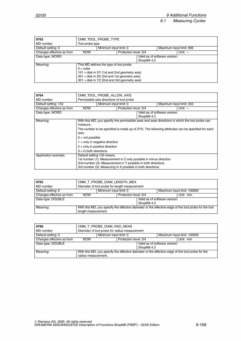
02/059.1 Measuring Cycles
9-169 Siemens AG, 2005. All rights reservedSINUMERIK 840D/840Di/810D Description of Functions ShopMill (FBSP) – 02/05 Edition
ÁÁÁÁÁÁÁÁÁÁÁÁÁÁÁÁ9763
ÁÁÁÁÁÁÁÁÁÁÁÁÁÁÁÁÁÁÁÁÁÁÁÁÁÁÁÁÁÁÁÁÁÁÁÁÁÁÁÁÁÁÁÁÁÁCMM_TOOL_PROBE_TYPEÁÁÁÁÁÁÁÁ
ÁÁÁÁÁÁÁÁMD number ÁÁÁÁÁÁÁÁÁÁÁÁÁÁÁÁÁÁÁÁÁÁÁ
ÁÁÁÁÁÁÁÁÁÁÁÁÁÁÁÁÁÁÁÁÁÁÁTool probe type
ÁÁÁÁÁÁÁÁÁÁÁÁÁÁÁÁÁÁÁÁÁÁ
Default setting: 0 ÁÁÁÁÁÁÁÁÁÁÁÁÁÁÁÁÁÁÁÁÁÁ
Minimum input limit: 0 ÁÁÁÁÁÁÁÁÁÁÁÁÁÁÁÁÁÁÁÁ
Maximum input limit: 999
ÁÁÁÁÁÁÁÁÁÁÁÁÁÁChanges effective as from NOW ÁÁÁÁÁÁÁÁÁÁÁProtection level: 3/4 ÁÁÁÁÁÁÁUnit: –ÁÁÁÁÁÁÁÁÁÁÁÁÁÁÁÁÁÁÁÁÁÁÁÁÁÁÁÁÁÁÁÁÁÁÁÁÁÁÁÁÁÁÁÁÁÁÁÁÁÁÁ
Data type: WORD ÁÁÁÁÁÁÁÁÁÁÁÁÁÁÁÁÁÁÁÁÁÁÁÁÁÁÁÁÁÁÁÁÁÁÁÁÁÁÁÁÁÁ
Valid as of software version:ShopMill 4.3
ÁÁÁÁÁÁÁÁÁÁÁÁÁÁÁÁÁÁÁÁÁÁÁÁÁÁÁÁÁÁÁÁ
Meaning: ÁÁÁÁÁÁÁÁÁÁÁÁÁÁÁÁÁÁÁÁÁÁÁÁÁÁÁÁÁÁÁÁÁÁÁÁÁÁÁÁÁÁÁÁÁÁÁÁÁÁÁÁÁÁÁÁÁÁÁÁÁÁÁÁÁÁÁÁÁÁÁÁÁÁÁÁÁÁÁÁÁÁÁÁÁÁÁÁÁÁÁÁ
This MD defines the type of tool probe.0 = cube101 = disk in XY (1st and 2nd geometry axis)201 = disk in ZX (3rd and 1st geometry axis)301 = disk in YZ (2nd and 3rd geometry axis)
ÁÁÁÁÁÁÁÁÁÁÁÁÁÁÁÁ9764
ÁÁÁÁÁÁÁÁÁÁÁÁÁÁÁÁÁÁÁÁÁÁÁÁÁÁÁÁÁÁÁÁÁÁÁÁÁÁÁÁÁÁÁÁÁÁCMM_TOOL_PROBE_ALLOW_AXISÁÁÁÁÁÁÁÁ
ÁÁÁÁÁÁÁÁMD number ÁÁÁÁÁÁÁÁÁÁÁÁÁÁÁÁÁÁÁÁÁÁÁ
ÁÁÁÁÁÁÁÁÁÁÁÁÁÁÁÁÁÁÁÁÁÁÁPermissible axis directions of tool probe
ÁÁÁÁÁÁÁÁÁÁÁÁÁÁÁÁÁÁÁÁÁÁ
Default setting: 133 ÁÁÁÁÁÁÁÁÁÁÁÁÁÁÁÁÁÁÁÁÁÁ
Minimum input limit: 0 ÁÁÁÁÁÁÁÁÁÁÁÁÁÁÁÁÁÁÁÁ
Maximum input limit: 333
ÁÁÁÁÁÁÁÁÁÁÁÁÁÁChanges effective as from NOW ÁÁÁÁÁÁÁÁÁÁÁProtection level: 3/4 ÁÁÁÁÁÁÁUnit: –ÁÁÁÁÁÁÁÁÁÁÁÁÁÁÁÁÁÁÁÁÁÁÁÁÁÁÁÁÁÁÁÁÁÁÁÁÁÁÁÁÁÁÁÁÁÁÁÁÁÁÁ
Data type: WORD ÁÁÁÁÁÁÁÁÁÁÁÁÁÁÁÁÁÁÁÁÁÁÁÁÁÁÁÁÁÁÁÁÁÁÁÁÁÁÁÁÁÁ
Valid as of software version:ShopMill 4.3
ÁÁÁÁÁÁÁÁÁÁÁÁÁÁÁÁÁÁÁÁÁÁÁÁÁÁÁÁÁÁÁÁÁÁÁÁÁÁÁÁÁÁÁÁÁÁÁÁ
Meaning: ÁÁÁÁÁÁÁÁÁÁÁÁÁÁÁÁÁÁÁÁÁÁÁÁÁÁÁÁÁÁÁÁÁÁÁÁÁÁÁÁÁÁÁÁÁÁÁÁÁÁÁÁÁÁÁÁÁÁÁÁÁÁÁÁÁÁÁÁÁÁÁÁÁÁÁÁÁÁÁÁÁÁÁÁÁÁÁÁÁÁÁÁÁÁÁÁÁÁÁÁÁÁÁÁÁÁÁÁÁÁÁÁÁÁÁÁÁÁÁÁÁÁÁÁÁÁÁÁÁÁÁÁÁÁÁÁÁÁ
With this MD, you specify the permissible axes and axes directions in which the tool probe canmeasure.The number to be specified is made up of ZYX. The following attributes can be specified for eachaxis:0 = not possible1 = only in negative direction2 = only in positive direction3 = in both directions
ÁÁÁÁÁÁÁÁÁÁÁÁÁÁÁÁÁÁÁÁÁÁÁÁÁÁÁÁÁÁÁÁ
Application example: ÁÁÁÁÁÁÁÁÁÁÁÁÁÁÁÁÁÁÁÁÁÁÁÁÁÁÁÁÁÁÁÁÁÁÁÁÁÁÁÁÁÁÁÁÁÁÁÁÁÁÁÁÁÁÁÁÁÁÁÁÁÁÁÁÁÁÁÁÁÁÁÁÁÁÁÁÁÁÁÁÁÁÁÁÁÁÁÁÁÁÁÁ
Default setting 133 means,1st number (1): Measurement in Z only possible in minus direction2nd number (3): Measurement in Y possible in both directions3rd number (3): Measuring in X possible in both directions
ÁÁÁÁÁÁÁÁÁÁÁÁÁÁÁÁ
9765ÁÁÁÁÁÁÁÁÁÁÁÁÁÁÁÁÁÁÁÁÁÁÁÁÁÁÁÁÁÁÁÁÁÁÁÁÁÁÁÁÁÁÁÁÁÁ
CMM_T_PROBE_DIAM_LENGTH_MEAÁÁÁÁÁÁÁÁÁÁÁÁÁÁÁÁ
MD number ÁÁÁÁÁÁÁÁÁÁÁÁÁÁÁÁÁÁÁÁÁÁÁÁÁÁÁÁÁÁÁÁÁÁÁÁÁÁÁÁÁÁÁÁÁÁ
Diameter of tool probe for length measurement
ÁÁÁÁÁÁÁÁÁÁÁÁÁÁÁÁÁÁÁÁÁÁ
Default setting: 0 ÁÁÁÁÁÁÁÁÁÁÁÁÁÁÁÁÁÁÁÁÁÁ
Minimum input limit: 0 ÁÁÁÁÁÁÁÁÁÁÁÁÁÁÁÁÁÁÁÁ
Maximum input limit: 100000
ÁÁÁÁÁÁÁÁÁÁÁÁÁÁChanges effective as from NOW
ÁÁÁÁÁÁÁÁÁÁÁProtection level: 3/4
ÁÁÁÁÁÁÁUnit: mm
ÁÁÁÁÁÁÁÁÁÁÁÁÁÁÁÁÁÁÁÁÁÁÁÁÁÁÁÁÁÁÁÁÁÁÁÁÁÁÁÁÁÁÁÁÁÁÁÁÁÁÁ
Data type: DOUBLE ÁÁÁÁÁÁÁÁÁÁÁÁÁÁÁÁÁÁÁÁÁÁÁÁÁÁÁÁÁÁÁÁÁÁÁÁÁÁÁÁÁÁ
Valid as of software version:ShopMill 4.3
ÁÁÁÁÁÁÁÁÁÁÁÁÁÁÁÁ
Meaning:ÁÁÁÁÁÁÁÁÁÁÁÁÁÁÁÁÁÁÁÁÁÁÁÁÁÁÁÁÁÁÁÁÁÁÁÁÁÁÁÁÁÁÁÁÁÁ
With this MD, you specify the effective diameter or the effective edge of the tool probe for the toollength measurement.
ÁÁÁÁÁÁÁÁÁÁÁÁÁÁÁÁ9766
ÁÁÁÁÁÁÁÁÁÁÁÁÁÁÁÁÁÁÁÁÁÁÁÁÁÁÁÁÁÁÁÁÁÁÁÁÁÁÁÁÁÁÁÁÁÁCMM_T_PROBE_DIAM_RAD_MEASÁÁÁÁÁÁÁÁ
ÁÁÁÁÁÁÁÁMD number ÁÁÁÁÁÁÁÁÁÁÁÁÁÁÁÁÁÁÁÁÁÁÁ
ÁÁÁÁÁÁÁÁÁÁÁÁÁÁÁÁÁÁÁÁÁÁÁDiameter of tool probe for radius measurement
ÁÁÁÁÁÁÁÁÁÁÁÁÁÁÁÁÁÁÁÁÁÁ
Default setting: 0 ÁÁÁÁÁÁÁÁÁÁÁÁÁÁÁÁÁÁÁÁÁÁ
Minimum input limit: 0 ÁÁÁÁÁÁÁÁÁÁÁÁÁÁÁÁÁÁÁÁ
Maximum input limit: 100000
ÁÁÁÁÁÁÁÁÁÁÁÁÁÁChanges effective as from NOW ÁÁÁÁÁÁÁÁÁÁÁProtection level: 3/4 ÁÁÁÁÁÁÁUnit: mmÁÁÁÁÁÁÁÁÁÁÁÁÁÁÁÁÁÁÁÁÁÁÁÁÁÁÁÁÁÁÁÁÁÁÁÁÁÁÁÁÁÁÁÁÁÁÁÁÁÁÁ
Data type: DOUBLE ÁÁÁÁÁÁÁÁÁÁÁÁÁÁÁÁÁÁÁÁÁÁÁÁÁÁÁÁÁÁÁÁÁÁÁÁÁÁÁÁÁÁ
Valid as of software version:ShopMill 4.3
ÁÁÁÁÁÁÁÁÁÁÁÁÁÁÁÁ
Meaning: ÁÁÁÁÁÁÁÁÁÁÁÁÁÁÁÁÁÁÁÁÁÁÁÁÁÁÁÁÁÁÁÁÁÁÁÁÁÁÁÁÁÁÁÁÁÁ
With this MD, you specify the effective diameter or the effective edge of the tool probe for theradius measurement.
9 Additional Functions
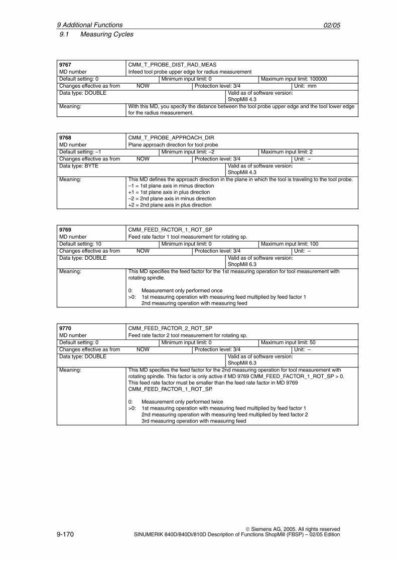
02/059.1 Measuring Cycles
9-170 Siemens AG, 2005. All rights reserved
SINUMERIK 840D/840Di/810D Description of Functions ShopMill (FBSP) – 02/05 Edition
ÁÁÁÁÁÁÁÁÁÁÁÁÁÁÁÁ9767
ÁÁÁÁÁÁÁÁÁÁÁÁÁÁÁÁÁÁÁÁÁÁÁÁÁÁÁÁÁÁÁÁÁÁÁÁÁÁÁÁÁÁÁÁÁÁCMM_T_PROBE_DIST_RAD_MEASÁÁÁÁÁÁÁÁ
ÁÁÁÁÁÁÁÁMD number ÁÁÁÁÁÁÁÁÁÁÁÁÁÁÁÁÁÁÁÁÁÁÁ
ÁÁÁÁÁÁÁÁÁÁÁÁÁÁÁÁÁÁÁÁÁÁÁInfeed tool probe upper edge for radius measurement
ÁÁÁÁÁÁÁÁÁÁÁÁÁÁÁÁÁÁÁÁÁÁ
Default setting: 0 ÁÁÁÁÁÁÁÁÁÁÁÁÁÁÁÁÁÁÁÁÁÁ
Minimum input limit: 0 ÁÁÁÁÁÁÁÁÁÁÁÁÁÁÁÁÁÁÁÁ
Maximum input limit: 100000
ÁÁÁÁÁÁÁÁÁÁÁÁÁÁChanges effective as from NOW ÁÁÁÁÁÁÁÁÁÁÁProtection level: 3/4 ÁÁÁÁÁÁÁUnit: mmÁÁÁÁÁÁÁÁÁÁÁÁÁÁÁÁÁÁÁÁÁÁÁÁÁÁÁÁÁÁÁÁÁÁÁÁÁÁÁÁÁÁÁÁÁÁÁÁÁÁÁ
Data type: DOUBLE ÁÁÁÁÁÁÁÁÁÁÁÁÁÁÁÁÁÁÁÁÁÁÁÁÁÁÁÁÁÁÁÁÁÁÁÁÁÁÁÁÁÁ
Valid as of software version:ShopMill 4.3
ÁÁÁÁÁÁÁÁÁÁÁÁÁÁÁÁ
Meaning: ÁÁÁÁÁÁÁÁÁÁÁÁÁÁÁÁÁÁÁÁÁÁÁÁÁÁÁÁÁÁÁÁÁÁÁÁÁÁÁÁÁÁÁÁÁÁ
With this MD, you specify the distance between the tool probe upper edge and the tool lower edgefor the radius measurement.
ÁÁÁÁÁÁÁÁÁÁÁÁÁÁÁÁ9768
ÁÁÁÁÁÁÁÁÁÁÁÁÁÁÁÁÁÁÁÁÁÁÁÁÁÁÁÁÁÁÁÁÁÁÁÁÁÁÁÁÁÁÁÁÁÁCMM_T_PROBE_APPROACH_DIRÁÁÁÁÁÁÁÁ
ÁÁÁÁÁÁÁÁMD number
ÁÁÁÁÁÁÁÁÁÁÁÁÁÁÁÁÁÁÁÁÁÁÁÁÁÁÁÁÁÁÁÁÁÁÁÁÁÁÁÁÁÁÁÁÁÁ
Plane approach direction for tool probeÁÁÁÁÁÁÁÁÁÁÁÁÁÁÁÁÁÁÁÁÁÁ
Default setting: –1 ÁÁÁÁÁÁÁÁÁÁÁÁÁÁÁÁÁÁÁÁÁÁ
Minimum input limit: –2 ÁÁÁÁÁÁÁÁÁÁÁÁÁÁÁÁÁÁÁÁ
Maximum input limit: 2
ÁÁÁÁÁÁÁÁÁÁÁÁÁÁChanges effective as from NOW ÁÁÁÁÁÁÁÁÁÁÁProtection level: 3/4 ÁÁÁÁÁÁÁUnit: –ÁÁÁÁÁÁÁÁÁÁÁÁÁÁÁÁÁÁÁÁÁÁÁÁÁÁÁÁÁÁÁÁÁÁÁÁÁÁÁÁÁÁÁÁÁÁÁÁÁÁÁ
Data type: BYTEÁÁÁÁÁÁÁÁÁÁÁÁÁÁÁÁÁÁÁÁÁÁÁÁÁÁÁÁÁÁÁÁÁÁÁÁÁÁÁÁÁÁ
Valid as of software version:ShopMill 4.3
ÁÁÁÁÁÁÁÁÁÁÁÁÁÁÁÁÁÁÁÁÁÁÁÁÁÁÁÁÁÁÁÁ
Meaning: ÁÁÁÁÁÁÁÁÁÁÁÁÁÁÁÁÁÁÁÁÁÁÁÁÁÁÁÁÁÁÁÁÁÁÁÁÁÁÁÁÁÁÁÁÁÁÁÁÁÁÁÁÁÁÁÁÁÁÁÁÁÁÁÁÁÁÁÁÁÁÁÁÁÁÁÁÁÁÁÁÁÁÁÁÁÁÁÁÁÁÁÁ
This MD defines the approach direction in the plane in which the tool is traveling to the tool probe.–1 = 1st plane axis in minus direction+1 = 1st plane axis in plus direction–2 = 2nd plane axis in minus direction+2 = 2nd plane axis in plus direction
ÁÁÁÁÁÁÁÁÁÁÁÁÁÁÁÁ9769
ÁÁÁÁÁÁÁÁÁÁÁÁÁÁÁÁÁÁÁÁÁÁÁÁÁÁÁÁÁÁÁÁÁÁÁÁÁÁÁÁÁÁÁÁÁÁCMM_FEED_FACTOR_1_ROT_SPÁÁÁÁÁÁÁÁ
ÁÁÁÁÁÁÁÁMD number ÁÁÁÁÁÁÁÁÁÁÁÁÁÁÁÁÁÁÁÁÁÁÁ
ÁÁÁÁÁÁÁÁÁÁÁÁÁÁÁÁÁÁÁÁÁÁÁFeed rate factor 1 tool measurement for rotating sp.
ÁÁÁÁÁÁÁÁÁÁÁÁÁÁÁÁÁÁÁÁÁÁ
Default setting: 10 ÁÁÁÁÁÁÁÁÁÁÁÁÁÁÁÁÁÁÁÁÁÁ
Minimum input limit: 0 ÁÁÁÁÁÁÁÁÁÁÁÁÁÁÁÁÁÁÁÁ
Maximum input limit: 100
ÁÁÁÁÁÁÁÁÁÁÁÁÁÁChanges effective as from NOW ÁÁÁÁÁÁÁÁÁÁÁProtection level: 3/4 ÁÁÁÁÁÁÁUnit: –ÁÁÁÁÁÁÁÁÁÁÁÁÁÁÁÁÁÁÁÁÁÁÁÁÁÁÁÁÁÁÁÁÁÁÁÁÁÁÁÁÁÁÁÁÁÁÁÁÁÁÁ
Data type: DOUBLEÁÁÁÁÁÁÁÁÁÁÁÁÁÁÁÁÁÁÁÁÁÁÁÁÁÁÁÁÁÁÁÁÁÁÁÁÁÁÁÁÁÁ
Valid as of software version:ShopMill 6.3
ÁÁÁÁÁÁÁÁÁÁÁÁÁÁÁÁÁÁÁÁÁÁÁÁÁÁÁÁÁÁÁÁÁÁÁÁÁÁÁÁ
Meaning: ÁÁÁÁÁÁÁÁÁÁÁÁÁÁÁÁÁÁÁÁÁÁÁÁÁÁÁÁÁÁÁÁÁÁÁÁÁÁÁÁÁÁÁÁÁÁÁÁÁÁÁÁÁÁÁÁÁÁÁÁÁÁÁÁÁÁÁÁÁÁÁÁÁÁÁÁÁÁÁÁÁÁÁÁÁÁÁÁÁÁÁÁÁÁÁÁÁÁÁÁÁÁÁÁÁÁÁÁÁÁÁÁÁÁÁ
This MD specifies the feed factor for the 1st measuring operation for tool measurement withrotating spindle.
0: Measurement only performed once>0: 1st measuring operation with measuring feed multiplied by feed factor 1
2nd measuring operation with measuring feed
ÁÁÁÁÁÁÁÁÁÁÁÁÁÁÁÁ
9770 ÁÁÁÁÁÁÁÁÁÁÁÁÁÁÁÁÁÁÁÁÁÁÁÁÁÁÁÁÁÁÁÁÁÁÁÁÁÁÁÁÁÁÁÁÁÁ
CMM_FEED_FACTOR_2_ROT_SP
ÁÁÁÁÁÁÁÁÁÁÁÁÁÁÁÁ
MD number ÁÁÁÁÁÁÁÁÁÁÁÁÁÁÁÁÁÁÁÁÁÁÁÁÁÁÁÁÁÁÁÁÁÁÁÁÁÁÁÁÁÁÁÁÁÁ
Feed rate factor 2 tool measurement for rotating sp.
ÁÁÁÁÁÁÁÁÁÁÁDefault setting: 0 ÁÁÁÁÁÁÁÁÁÁÁMinimum input limit: 0 ÁÁÁÁÁÁÁÁÁÁMaximum input limit: 50ÁÁÁÁÁÁÁÁÁÁÁÁÁÁÁÁÁÁÁÁÁÁÁÁÁÁÁÁ
Changes effective as from NOW ÁÁÁÁÁÁÁÁÁÁÁÁÁÁÁÁÁÁÁÁÁÁ
Protection level: 3/4 ÁÁÁÁÁÁÁÁÁÁÁÁÁÁ
Unit: –ÁÁÁÁÁÁÁÁÁÁÁÁÁÁÁÁÁÁÁÁÁÁÁÁÁÁÁÁÁÁÁÁÁÁ
Data type: DOUBLE ÁÁÁÁÁÁÁÁÁÁÁÁÁÁÁÁÁÁÁÁÁÁÁÁÁÁÁÁ
Valid as of software version:ShopMill 6.3ÁÁÁÁÁÁÁÁ
ÁÁÁÁÁÁÁÁÁÁÁÁÁÁÁÁÁÁÁÁÁÁÁÁÁÁÁÁÁÁÁÁÁÁÁÁÁÁÁÁÁÁÁÁÁÁÁÁ
Meaning: ÁÁÁÁÁÁÁÁÁÁÁÁÁÁÁÁÁÁÁÁÁÁÁÁÁÁÁÁÁÁÁÁÁÁÁÁÁÁÁÁÁÁÁÁÁÁÁÁÁÁÁÁÁÁÁÁÁÁÁÁÁÁÁÁÁÁÁÁÁÁÁÁÁÁÁÁÁÁÁÁÁÁÁÁÁÁÁÁÁÁÁÁÁÁÁÁÁÁÁÁÁÁÁÁÁÁÁÁÁÁÁÁÁÁÁÁÁÁÁÁÁÁÁÁÁÁÁÁÁÁÁÁÁÁÁÁÁÁÁÁÁÁÁÁÁÁÁÁÁÁÁÁÁÁÁÁÁÁÁÁÁ
This MD specifies the feed factor for the 2nd measuring operation for tool measurement withrotating spindle. This factor is only active if MD 9769 CMM_FEED_FACTOR_1_ROT_SP > 0. This feed rate factor must be smaller than the feed rate factor in MD 9769CMM_FEED_FACTOR_1_ROT_SP.
0: Measurement only performed twice>0: 1st measuring operation with measuring feed multiplied by feed factor 1
2nd measuring operation with measuring feed multiplied by feed factor 23rd measuring operation with measuring feed
9 Additional Functions
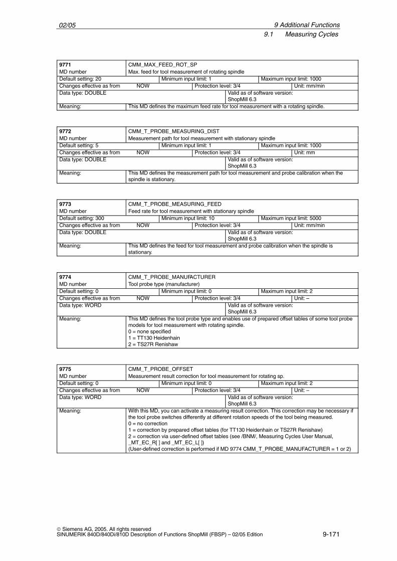
02/059.1 Measuring Cycles
9-171 Siemens AG, 2005. All rights reservedSINUMERIK 840D/840Di/810D Description of Functions ShopMill (FBSP) – 02/05 Edition
ÁÁÁÁÁÁÁÁÁÁÁÁÁÁÁÁ9771
ÁÁÁÁÁÁÁÁÁÁÁÁÁÁÁÁÁÁÁÁÁÁÁÁÁÁÁÁÁÁÁÁÁÁÁÁÁÁÁÁÁÁÁÁÁÁCMM_MAX_FEED_ROT_SPÁÁÁÁÁÁÁÁ
ÁÁÁÁÁÁÁÁMD number ÁÁÁÁÁÁÁÁÁÁÁÁÁÁÁÁÁÁÁÁÁÁÁ
ÁÁÁÁÁÁÁÁÁÁÁÁÁÁÁÁÁÁÁÁÁÁÁMax. feed for tool measurement of rotating spindle
ÁÁÁÁÁÁÁÁÁÁÁÁÁÁÁÁÁÁÁÁÁÁ
Default setting: 20 ÁÁÁÁÁÁÁÁÁÁÁÁÁÁÁÁÁÁÁÁÁÁ
Minimum input limit: 1 ÁÁÁÁÁÁÁÁÁÁÁÁÁÁÁÁÁÁÁÁ
Maximum input limit: 1000
ÁÁÁÁÁÁÁÁÁÁÁÁÁÁChanges effective as from NOW ÁÁÁÁÁÁÁÁÁÁÁProtection level: 3/4 ÁÁÁÁÁÁÁUnit: mm/minÁÁÁÁÁÁÁÁÁÁÁÁÁÁÁÁÁÁÁÁÁÁÁÁÁÁÁÁÁÁÁÁÁÁÁÁÁÁÁÁÁÁÁÁÁÁÁÁÁÁÁ
Data type: DOUBLE ÁÁÁÁÁÁÁÁÁÁÁÁÁÁÁÁÁÁÁÁÁÁÁÁÁÁÁÁÁÁÁÁÁÁÁÁÁÁÁÁÁÁ
Valid as of software version:ShopMill 6.3
ÁÁÁÁÁÁÁÁMeaning: ÁÁÁÁÁÁÁÁÁÁÁÁÁÁÁÁÁÁÁÁÁÁÁThis MD defines the maximum feed rate for tool measurement with a rotating spindle.
ÁÁÁÁÁÁÁÁÁÁÁÁÁÁÁÁ
9772 ÁÁÁÁÁÁÁÁÁÁÁÁÁÁÁÁÁÁÁÁÁÁÁÁÁÁÁÁÁÁÁÁÁÁÁÁÁÁÁÁÁÁÁÁÁÁ
CMM_T_PROBE_MEASURING_DIST
ÁÁÁÁÁÁÁÁMD number ÁÁÁÁÁÁÁÁÁÁÁÁÁÁÁÁÁÁÁÁÁÁÁMeasurement path for tool measurement with stationary spindleÁÁÁÁÁÁÁÁÁÁÁÁÁÁÁÁÁÁÁÁÁÁ
Default setting: 5ÁÁÁÁÁÁÁÁÁÁÁÁÁÁÁÁÁÁÁÁÁÁ
Minimum input limit: 1ÁÁÁÁÁÁÁÁÁÁÁÁÁÁÁÁÁÁÁÁ
Maximum input limit: 1000ÁÁÁÁÁÁÁÁÁÁÁÁÁÁÁÁÁÁÁÁÁÁÁÁÁÁÁÁ
Changes effective as from NOW ÁÁÁÁÁÁÁÁÁÁÁÁÁÁÁÁÁÁÁÁÁÁ
Protection level: 3/4 ÁÁÁÁÁÁÁÁÁÁÁÁÁÁ
Unit: mm
ÁÁÁÁÁÁÁÁÁÁÁÁÁÁÁÁÁÁÁÁÁÁÁÁÁÁÁÁÁÁÁÁÁÁ
Data type: DOUBLE ÁÁÁÁÁÁÁÁÁÁÁÁÁÁÁÁÁÁÁÁÁÁÁÁÁÁÁÁ
Valid as of software version:ShopMill 6.3
ÁÁÁÁÁÁÁÁÁÁÁÁÁÁÁÁ
Meaning: ÁÁÁÁÁÁÁÁÁÁÁÁÁÁÁÁÁÁÁÁÁÁÁÁÁÁÁÁÁÁÁÁÁÁÁÁÁÁÁÁÁÁÁÁÁÁ
This MD defines the measurement path for tool measurement and probe calibration when thespindle is stationary.
ÁÁÁÁÁÁÁÁÁÁÁÁÁÁÁÁ
9773 ÁÁÁÁÁÁÁÁÁÁÁÁÁÁÁÁÁÁÁÁÁÁÁÁÁÁÁÁÁÁÁÁÁÁÁÁÁÁÁÁÁÁÁÁÁÁ
CMM_T_PROBE_MEASURING_FEED
ÁÁÁÁÁÁÁÁÁÁÁÁÁÁÁÁ
MD number ÁÁÁÁÁÁÁÁÁÁÁÁÁÁÁÁÁÁÁÁÁÁÁÁÁÁÁÁÁÁÁÁÁÁÁÁÁÁÁÁÁÁÁÁÁÁ
Feed rate for tool measurement with stationary spindle
ÁÁÁÁÁÁÁÁÁÁÁDefault setting: 300
ÁÁÁÁÁÁÁÁÁÁÁMinimum input limit: 10
ÁÁÁÁÁÁÁÁÁÁMaximum input limit: 5000
ÁÁÁÁÁÁÁÁÁÁÁÁÁÁÁÁÁÁÁÁÁÁÁÁÁÁÁÁ
Changes effective as from NOW ÁÁÁÁÁÁÁÁÁÁÁÁÁÁÁÁÁÁÁÁÁÁ
Protection level: 3/4 ÁÁÁÁÁÁÁÁÁÁÁÁÁÁ
Unit: mm/min
ÁÁÁÁÁÁÁÁÁÁÁÁÁÁÁÁÁÁÁÁÁÁÁÁÁÁÁÁÁÁÁÁÁÁ
Data type: DOUBLE ÁÁÁÁÁÁÁÁÁÁÁÁÁÁÁÁÁÁÁÁÁÁÁÁÁÁÁÁ
Valid as of software version:ShopMill 6.3
ÁÁÁÁÁÁÁÁÁÁÁÁÁÁÁÁÁÁÁÁÁÁÁÁ
Meaning: ÁÁÁÁÁÁÁÁÁÁÁÁÁÁÁÁÁÁÁÁÁÁÁÁÁÁÁÁÁÁÁÁÁÁÁÁÁÁÁÁÁÁÁÁÁÁÁÁÁÁÁÁÁÁÁÁÁÁÁÁÁÁÁÁÁÁÁÁÁ
This MD defines the feed for tool measurement and probe calibration when the spindle isstationary.
ÁÁÁÁÁÁÁÁÁÁÁÁÁÁÁÁ
9774 ÁÁÁÁÁÁÁÁÁÁÁÁÁÁÁÁÁÁÁÁÁÁÁÁÁÁÁÁÁÁÁÁÁÁÁÁÁÁÁÁÁÁÁÁÁÁ
CMM_T_PROBE_MANUFACTURER
ÁÁÁÁÁÁÁÁÁÁÁÁÁÁÁÁ
MD number ÁÁÁÁÁÁÁÁÁÁÁÁÁÁÁÁÁÁÁÁÁÁÁÁÁÁÁÁÁÁÁÁÁÁÁÁÁÁÁÁÁÁÁÁÁÁ
Tool probe type (manufacturer)
ÁÁÁÁÁÁÁÁÁÁÁDefault setting: 0 ÁÁÁÁÁÁÁÁÁÁÁMinimum input limit: 0 ÁÁÁÁÁÁÁÁÁÁMaximum input limit: 2ÁÁÁÁÁÁÁÁÁÁÁÁÁÁÁÁÁÁÁÁÁÁÁÁÁÁÁÁ
Changes effective as from NOW ÁÁÁÁÁÁÁÁÁÁÁÁÁÁÁÁÁÁÁÁÁÁ
Protection level: 3/4 ÁÁÁÁÁÁÁÁÁÁÁÁÁÁ
Unit: –ÁÁÁÁÁÁÁÁÁÁÁÁÁÁÁÁÁÁÁÁÁÁÁÁÁÁÁÁÁÁÁÁÁÁ
Data type: WORD ÁÁÁÁÁÁÁÁÁÁÁÁÁÁÁÁÁÁÁÁÁÁÁÁÁÁÁÁ
Valid as of software version:ShopMill 6.3ÁÁÁÁÁÁÁÁ
ÁÁÁÁÁÁÁÁÁÁÁÁÁÁÁÁÁÁÁÁÁÁÁÁÁÁÁÁÁÁÁÁ
Meaning: ÁÁÁÁÁÁÁÁÁÁÁÁÁÁÁÁÁÁÁÁÁÁÁÁÁÁÁÁÁÁÁÁÁÁÁÁÁÁÁÁÁÁÁÁÁÁÁÁÁÁÁÁÁÁÁÁÁÁÁÁÁÁÁÁÁÁÁÁÁÁÁÁÁÁÁÁÁÁÁÁÁÁÁÁÁÁÁÁÁÁÁÁÁÁÁÁÁÁÁÁÁÁÁÁÁÁÁÁÁÁÁÁÁÁÁ
This MD defines the tool probe type and enables use of prepared offset tables of some tool probemodels for tool measurement with rotating spindle.0 = none specified1 = TT130 Heidenhain2 = TS27R Renishaw
ÁÁÁÁÁÁÁÁÁÁÁÁÁÁÁÁ
9775 ÁÁÁÁÁÁÁÁÁÁÁÁÁÁÁÁÁÁÁÁÁÁÁÁÁÁÁÁÁÁÁÁÁÁÁÁÁÁÁÁÁÁÁÁÁÁ
CMM_T_PROBE_OFFSET
ÁÁÁÁÁÁÁÁÁÁÁÁÁÁÁÁ
MD number ÁÁÁÁÁÁÁÁÁÁÁÁÁÁÁÁÁÁÁÁÁÁÁÁÁÁÁÁÁÁÁÁÁÁÁÁÁÁÁÁÁÁÁÁÁÁ
Measurement result correction for tool measurement for rotating sp.
ÁÁÁÁÁÁÁÁÁÁÁDefault setting: 0 ÁÁÁÁÁÁÁÁÁÁÁMinimum input limit: 0 ÁÁÁÁÁÁÁÁÁÁMaximum input limit: 2ÁÁÁÁÁÁÁÁÁÁÁÁÁÁÁÁÁÁÁÁÁÁÁÁÁÁÁÁ
Changes effective as from NOW ÁÁÁÁÁÁÁÁÁÁÁÁÁÁÁÁÁÁÁÁÁÁ
Protection level: 3/4 ÁÁÁÁÁÁÁÁÁÁÁÁÁÁ
Unit: –ÁÁÁÁÁÁÁÁÁÁÁÁÁÁÁÁÁÁÁÁÁÁÁÁÁÁÁÁÁÁÁÁÁÁ
Data type: WORD ÁÁÁÁÁÁÁÁÁÁÁÁÁÁÁÁÁÁÁÁÁÁÁÁÁÁÁÁ
Valid as of software version:ShopMill 6.3ÁÁÁÁÁÁÁÁ
ÁÁÁÁÁÁÁÁÁÁÁÁÁÁÁÁÁÁÁÁÁÁÁÁÁÁÁÁÁÁÁÁÁÁÁÁÁÁÁÁ
Meaning: ÁÁÁÁÁÁÁÁÁÁÁÁÁÁÁÁÁÁÁÁÁÁÁÁÁÁÁÁÁÁÁÁÁÁÁÁÁÁÁÁÁÁÁÁÁÁÁÁÁÁÁÁÁÁÁÁÁÁÁÁÁÁÁÁÁÁÁÁÁÁÁÁÁÁÁÁÁÁÁÁÁÁÁÁÁÁÁÁÁÁÁÁÁÁÁÁÁÁÁÁÁÁÁÁÁÁÁÁÁÁÁÁÁÁÁÁÁÁÁÁÁÁÁÁÁÁÁÁÁÁÁÁÁÁÁÁÁÁ
With this MD, you can activate a measuring result correction. This correction may be necessary ifthe tool probe switches differently at different rotation speeds of the tool being measured.0 = no correction1 = correction by prepared offset tables (for TT130 Heidenhain or TS27R Renishaw)2 = correction via user-defined offset tables (see /BNM/, Measuring Cycles User Manual,_MT_EC_R[ ] and _MT_EC_L[ ]) (User-defined correction is performed if MD 9774 CMM_T_PROBE_MANUFACTURER = 1 or 2)
9 Additional Functions
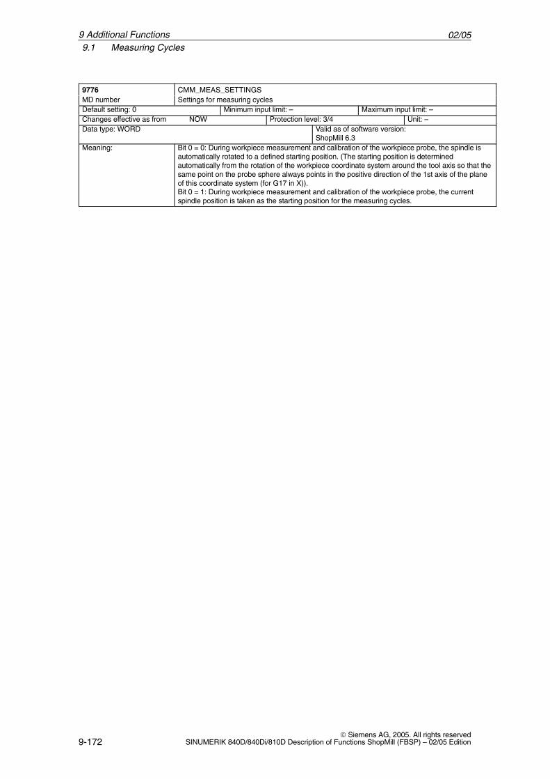
02/059.1 Measuring Cycles
9-172 Siemens AG, 2005. All rights reserved
SINUMERIK 840D/840Di/810D Description of Functions ShopMill (FBSP) – 02/05 Edition
ÁÁÁÁÁÁÁÁÁÁÁÁÁÁÁÁ9776
ÁÁÁÁÁÁÁÁÁÁÁÁÁÁÁÁÁÁÁÁÁÁÁÁÁÁÁÁÁÁÁÁÁÁÁÁÁÁÁÁÁÁÁÁÁÁCMM_MEAS_SETTINGSÁÁÁÁÁÁÁÁ
ÁÁÁÁÁÁÁÁMD number ÁÁÁÁÁÁÁÁÁÁÁÁÁÁÁÁÁÁÁÁÁÁÁ
ÁÁÁÁÁÁÁÁÁÁÁÁÁÁÁÁÁÁÁÁÁÁÁSettings for measuring cycles
ÁÁÁÁÁÁÁÁÁÁÁÁÁÁÁÁÁÁÁÁÁÁ
Default setting: 0 ÁÁÁÁÁÁÁÁÁÁÁÁÁÁÁÁÁÁÁÁÁÁ
Minimum input limit: – ÁÁÁÁÁÁÁÁÁÁÁÁÁÁÁÁÁÁÁÁ
Maximum input limit: –
ÁÁÁÁÁÁÁÁÁÁÁÁÁÁChanges effective as from NOW ÁÁÁÁÁÁÁÁÁÁÁProtection level: 3/4 ÁÁÁÁÁÁÁUnit: –ÁÁÁÁÁÁÁÁÁÁÁÁÁÁÁÁÁÁÁÁÁÁÁÁÁÁÁÁÁÁÁÁÁÁÁÁÁÁÁÁÁÁÁÁÁÁÁÁÁÁÁ
Data type: WORD ÁÁÁÁÁÁÁÁÁÁÁÁÁÁÁÁÁÁÁÁÁÁÁÁÁÁÁÁÁÁÁÁÁÁÁÁÁÁÁÁÁÁ
Valid as of software version:ShopMill 6.3
ÁÁÁÁÁÁÁÁÁÁÁÁÁÁÁÁÁÁÁÁÁÁÁÁÁÁÁÁÁÁÁÁÁÁÁÁÁÁÁÁ
Meaning: ÁÁÁÁÁÁÁÁÁÁÁÁÁÁÁÁÁÁÁÁÁÁÁÁÁÁÁÁÁÁÁÁÁÁÁÁÁÁÁÁÁÁÁÁÁÁÁÁÁÁÁÁÁÁÁÁÁÁÁÁÁÁÁÁÁÁÁÁÁÁÁÁÁÁÁÁÁÁÁÁÁÁÁÁÁÁÁÁÁÁÁÁÁÁÁÁÁÁÁÁÁÁÁÁÁÁÁÁÁÁÁÁÁÁÁ
Bit 0 = 0: During workpiece measurement and calibration of the workpiece probe, the spindle isautomatically rotated to a defined starting position. (The starting position is determinedautomatically from the rotation of the workpiece coordinate system around the tool axis so that thesame point on the probe sphere always points in the positive direction of the 1st axis of the planeof this coordinate system (for G17 in X)).Bit 0 = 1: During workpiece measurement and calibration of the workpiece probe, the currentspindle position is taken as the starting position for the measuring cycles.
9 Additional Functions
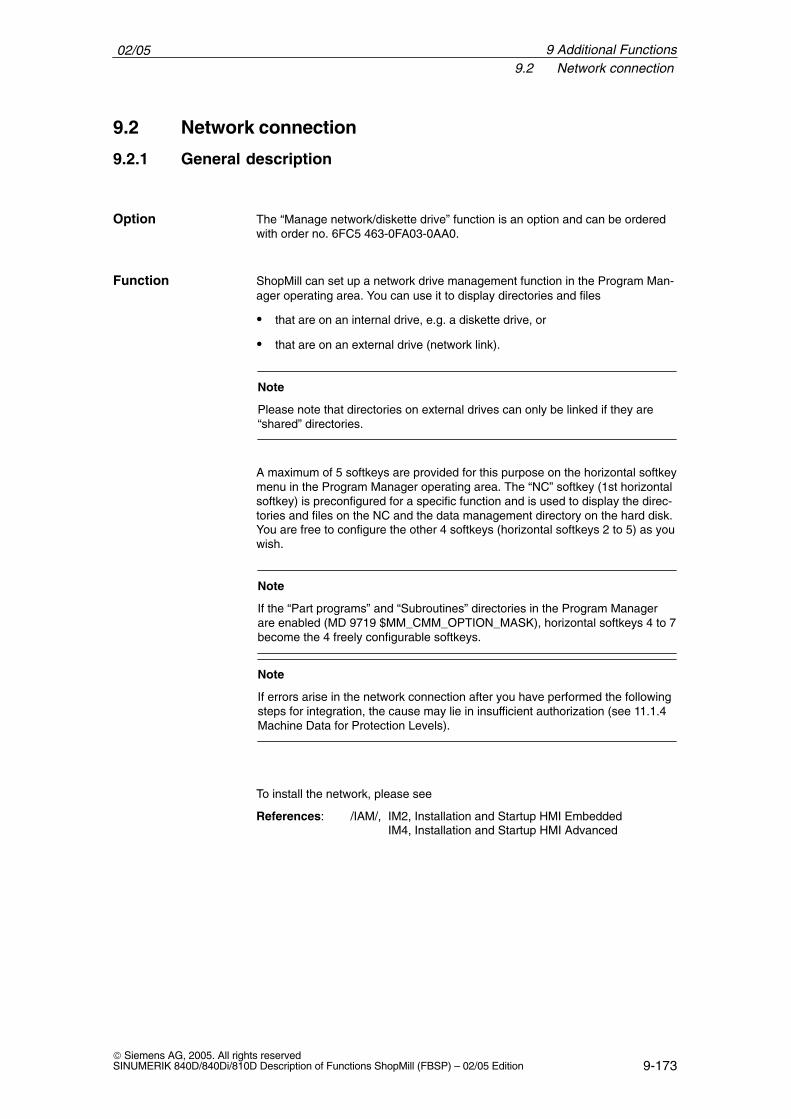
02/059.2 Network connection
9-173 Siemens AG, 2005. All rights reservedSINUMERIK 840D/840Di/810D Description of Functions ShopMill (FBSP) – 02/05 Edition
9.2 Network connection
9.2.1 General description
The “Manage network/diskette drive” function is an option and can be orderedwith order no. 6FC5 463-0FA03-0AA0.
ShopMill can set up a network drive management function in the Program Man-ager operating area. You can use it to display directories and files
� that are on an internal drive, e.g. a diskette drive, or
� that are on an external drive (network link).
Note
Please note that directories on external drives can only be linked if they are“shared” directories.
A maximum of 5 softkeys are provided for this purpose on the horizontal softkeymenu in the Program Manager operating area. The “NC” softkey (1st horizontalsoftkey) is preconfigured for a specific function and is used to display the direc-tories and files on the NC and the data management directory on the hard disk.You are free to configure the other 4 softkeys (horizontal softkeys 2 to 5) as youwish.
Note
If the “Part programs” and “Subroutines” directories in the Program Managerare enabled (MD 9719 $MM_CMM_OPTION_MASK), horizontal softkeys 4 to 7become the 4 freely configurable softkeys.
Note
If errors arise in the network connection after you have performed the followingsteps for integration, the cause may lie in insufficient authorization (see 11.1.4Machine Data for Protection Levels).
To install the network, please see
References: /IAM/, IM2, Installation and Startup HMI EmbeddedIM4, Installation and Startup HMI Advanced
Option
Function
9 Additional Functions
02/059.2 Network connection
9-174 Siemens AG, 2005. All rights reserved
SINUMERIK 840D/840Di/810D Description of Functions ShopMill (FBSP) – 02/05 Edition
9.2.2 Integrating Windows network drives in ShopMill (PCU 20)
To integrate the Windows network drives, proceed as follows:
Switch to the CNC-ISO operator interface and select the “Startup” → “Logicaldrives” → “Connections” menu options.
In the first line of the “Network connections” window, enter the drive path andsoftkey text for the 2nd horizontal softkey in the ShopMill Program Manager.The entries for the remaining softkeys are made in the lower lines.
Enter the drive path in the left-hand input field.
For internal drives, you will have to enter the drive letter and, if required, thepath.Example: A:\SM
You must specify the complete network path (\\Computer Name\Share-Name\PathName) for external drives (the path name is optional).Example: \\R4711\WORKPIECES\TEMPLATEThe directories (workpieces and templates) must be stored on the network com-puter (R4711).
Enter the softkey label on the right of the “Network connections” window. Thereis a separate input field for each line of the softkey. You can enter up to 6 char-acters per line (softkey with pictogram) or 9 characters (softkey without picto-gram).
Note
With the PCU 20 you can also integrate the Compact Flash Card as networkdrive. Drive letter “C:” is assigned to the Compact Flash Card.
Enter drive paths
Define softkeytexts
9 Additional Functions
02/059.2 Network connection
9-175 Siemens AG, 2005. All rights reservedSINUMERIK 840D/840Di/810D Description of Functions ShopMill (FBSP) – 02/05 Edition
9.2.3 Integrating Windows network drives in ShopMill (PCU 50)
To integrate the Windows network drives, proceed as follows:
In the F:\DH\CUS.DIR\ALUC_xx.COM text file, enter the drive name for the 2ndto 5th softkey in the horizontal softkey bar. You may need to create theALUC_xx.COM file in the CUS.DIR directory.
The following syntax applies:Text number 0 0 ”Softkey text”
The softkeys are assigned to the following text numbers in file ALUC_xx.COM:Softkey2: 89901Softkey3: 89902Softkey4: 89903Softkey5: 89904
The two parameters 2 and 3 separated by blanks are control characters for textoutput and must always be set to 0.
Note
A line break in the softkey text can be made by inserting two consecutiveblanks. You can enter up to 6 characters per line (softkey with pictogram) or9 characters (softkey without pictogram).
The text language is assigned on the basis of the text file name. “xx” is replacedby one of the following codes in the text file name:
Table 9-3 Language assignment
Abbreviationxx
Language
gr German
uk English
fr French
it Italian
sp Spanish
nl Dutch
dk Danish
fi Finnish
bk Swedish
pl Polish
tr Turkish
ch Simplified Chinese
tw Chinese(Traditional)
ko Korean
Define softkeytexts
9 Additional Functions
02/059.2 Network connection
9-176 Siemens AG, 2005. All rights reserved
SINUMERIK 840D/840Di/810D Description of Functions ShopMill (FBSP) – 02/05 Edition
Table 9-3 Language assignment
Abbreviationxx
Language
hu Hungarian
po Brazilian Portuguese
ru Russian
cz Czech
yes Japanese
In the F:\USER\MBDDE.INI or F:\OEM\MBDDE.INI file add the following lineunder section [TextFiles]:UserZYK=F:\dh\cus.dir\aluc_
If file MBDDE.INI does not exist in the specified directory, you will have to createit first.
In the Program Manager of ShopMill, the 2nd horizontal softkey must be as-signed the name “NETZ1” in German.
You must make the following entry in text file ALUC_GR.COM:89901 0 0 ”NETZ1“
Enter the drive path of the relevant softkey in display MD 9676 to 9679.
The following display machine data are available:Softkey2: MD 9676 $MM_CMM_DIRECTORY_SOFTKEY_PATH1Softkey3: MD 9677 $MM_CMM_DIRECTORY_SOFTKEY_PATH2Softkey4: MD 9678 $MM_CMM_DIRECTORY_SOFTKEY_PATH3Softkey5: MD 9679 $MM_CMM_DIRECTORY_SOFTKEY_PATH4
The display machine data are described in Chapter 6 “Machine Data”.
You must enter the drive letter and the path (if desired) for internal drives. You must specify the complete network path (\\COMPUTER NAME\SHARE-NAME\PATHNAME) for external drives (the path name is optional).
You want to display directory Workpieces\Templates, which is stored on com-puter R4711, via the 2nd horizontal softkey named “NET1”.
The following must be entered in MD 9676: \\R4711\WERKSTUECKE\MUSTER
You want to display the SM directory on the disk drive via the 3rd horizontal soft-key.
The following must be entered in MD 9677: A:\SM
Example
Enter drive paths
Example
9 Additional Functions
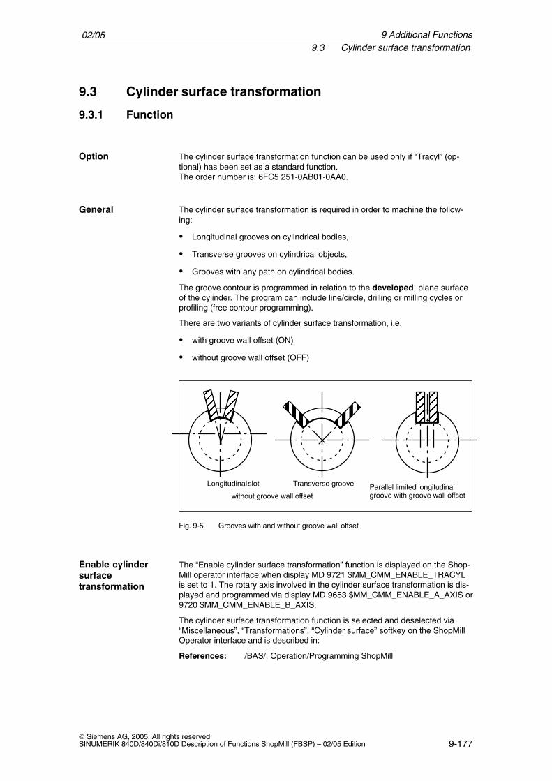
02/059.3 Cylinder surface transformation
9-177 Siemens AG, 2005. All rights reservedSINUMERIK 840D/840Di/810D Description of Functions ShopMill (FBSP) – 02/05 Edition
9.3 Cylinder surface transformation
9.3.1 Function
The cylinder surface transformation function can be used only if “Tracyl” (op-tional) has been set as a standard function.The order number is: 6FC5 251-0AB01-0AA0.
The cylinder surface transformation is required in order to machine the follow-ing:
� Longitudinal grooves on cylindrical bodies,
� Transverse grooves on cylindrical objects,
� Grooves with any path on cylindrical bodies.
The groove contour is programmed in relation to the developed, plane surfaceof the cylinder. The program can include line/circle, drilling or milling cycles orprofiling (free contour programming).
There are two variants of cylinder surface transformation, i.e.
� with groove wall offset (ON)
� without groove wall offset (OFF)
ÉÉÉÉÉÉ
ÉÉÉÉÉÉ
Longitudinal slot
ËËËËËËËËË
ËËËËËË
Transverse groove
ÉÉÉ
ÉÉÉ
Parallel limited longitudinal groove with groove wall offsetwithout groove wall offset
Fig. 9-5 Grooves with and without groove wall offset
The “Enable cylinder surface transformation” function is displayed on the Shop-Mill operator interface when display MD 9721 $MM_CMM_ENABLE_TRACYLis set to 1. The rotary axis involved in the cylinder surface transformation is dis-played and programmed via display MD 9653 $MM_CMM_ENABLE_A_AXIS or9720 $MM_CMM_ENABLE_B_AXIS.
The cylinder surface transformation function is selected and deselected via“Miscellaneous”, “Transformations”, “Cylinder surface” softkey on the ShopMillOperator interface and is described in:
References: /BAS/, Operation/Programming ShopMill
Option
General
Enable cylindersurfacetransformation
9 Additional Functions
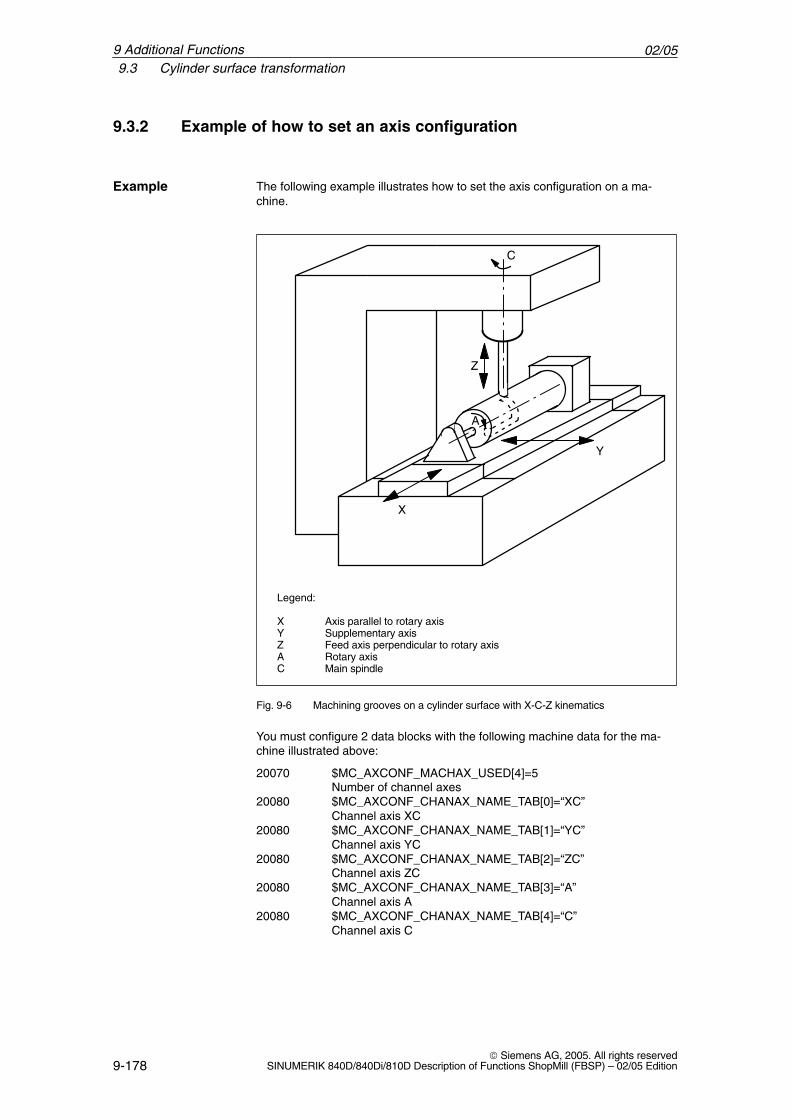
02/059.3 Cylinder surface transformation
9-178 Siemens AG, 2005. All rights reserved
SINUMERIK 840D/840Di/810D Description of Functions ShopMill (FBSP) – 02/05 Edition
9.3.2 Example of how to set an axis configuration
The following example illustrates how to set the axis configuration on a ma-chine.
Legend:
X Axis parallel to rotary axisY Supplementary axisZ Feed axis perpendicular to rotary axisA Rotary axisC Main spindle
Y
AÈ
X
Z
C
Fig. 9-6 Machining grooves on a cylinder surface with X-C-Z kinematics
You must configure 2 data blocks with the following machine data for the ma-chine illustrated above:
20070 $MC_AXCONF_MACHAX_USED[4]=5Number of channel axes
20080 $MC_AXCONF_CHANAX_NAME_TAB[0]=“XC”Channel axis XC
20080 $MC_AXCONF_CHANAX_NAME_TAB[1]=“YC”Channel axis YC
20080 $MC_AXCONF_CHANAX_NAME_TAB[2]=“ZC”Channel axis ZC
20080 $MC_AXCONF_CHANAX_NAME_TAB[3]=“A”Channel axis A
20080 $MC_AXCONF_CHANAX_NAME_TAB[4]=“C”Channel axis C
Example
9 Additional Functions
02/059.3 Cylinder surface transformation
9-179 Siemens AG, 2005. All rights reservedSINUMERIK 840D/840Di/810D Description of Functions ShopMill (FBSP) – 02/05 Edition
General settings for the transformations:10602 $MN_FRAME_GEOAX_CHANGE_MODE=1
1. Data set for cylinder surface transformation without groove wall offset:24100 $MC_TRAFO_TYPE_1=512
Definition of the 1st transformation in the channel cylinder surface24110 $MC_TRAFO_AXES_IN_1[0]=3
Channel axis radial rotary axis (Z) for 1st transformation24110 $MC_TRAFO_AXES_IN_1[1]=4
Channel axis der rotary axis for 1st transformation24110 $MC_TRAFO_AXES_IN_1[2]=1
Channel axis parallel rotary axis (X) for 1st transformation24110 $MC_TRAFO_AXES_IN_1[3]=2
Channel axis special axis Index [0] for 1st transformation24120 $MC_TRAFO_GEOAX_ASSIGN_TAB_1[0]=1
1st channel axis (X) for 1st transformation24120 $MC_TRAFO_GEOAX_ASSIGN_TAB_1[1]=4
2nd channel axis (Y) for 1st transformation24120 $MC_TRAFO_GEOAX_ASSIGN_TAB_1[2]=3
3rd channel axis (Z) for 1st transformation24800 $MC_TRACYL_ROT_AX_OFFSET_1=0
Offset der rotary axis for the 1st TRACYL transformation24805 $MC_TRACYL_ROT_AX_FRAME_1=1
Axial offset of the rotary axis is considered during TRACYL
24810 $MC_TRACYL_ROT_SIGN_IS_PLUS_1=1Sign of the rotary axis for the 1st TRACYL transformation
24820 $MC_TRACYL_BASE_TOOL_1[n]=0Vector of the basic tool for the 1st TRACYL transformation
2. Data set for cylinder surface transformation without groove wall offset:24200 $MC_TRAFO_TYPE_2=513
Definition of the 2nd transformation in the channel cylinder surface with groove wall offset
24210 $MC_TRAFO_AXES_IN_2[0]=3Channel axis radial rotary axis (Z) for 2nd transformation
24210 $MC_TRAFO_AXES_IN_2[1]=4Channel axis der rotary axis for 2nd transformation
24210 $MC_TRAFO_AXES_IN_2[2]=1Channel axis parallel rotary axis (X) for 2nd transformation
24210 $MC_TRAFO_AXES_IN_2[3]=2Channel axis special axis Index [0] for 2nd transformation
24220 $MC_TRAFO_GEOAX_ASSIGN_TAB_2[0]=11st channel axis (X) for 2nd transformation
24220 $MC_TRAFO_GEOAX_ASSIGN_TAB_2[1]=42nd channel axis (Y) for 2nd transformation
24220 $MC_TRAFO_GEOAX_ASSIGN_TAB_2[2]=33rd channel axis (Z) for 2nd transformation
24850 $MC_TRACYL_ROT_AX_OFFSET_2=0Offset der rotary axis for the 2nd TRACYL transformation
24855 $MC_TRACYL_ROT_AX_FRAME_2=1Axial offset of the rotary axis is considered during TRACYL
24860 $MC_TRACYL_ROT_SIGN_IS_PLUS_2=1Sign of the rotary axis for the 2nd TRACYL transformation
24870 $MC_TRACYL_BASE_TOOL[n]=0Vector of the basic tool for the 2nd TRACYL transformation
9 Additional Functions
02/059.3 Cylinder surface transformation
9-180 Siemens AG, 2005. All rights reserved
SINUMERIK 840D/840Di/810D Description of Functions ShopMill (FBSP) – 02/05 Edition
Note
For both data blocks, you can use any transformations from all availabletransformations (24100 $MC_TRAFO_TYPE_1, 24200 $MC_TRAFO_TYPE_2etc.). The two data blocks need not be directly next to each other. However, the1st data block must always be used for “Cylinder surface transformation withoutgroove side offset” (= 512) and the 2nd data block for “Cylinder surfacetransformation with groove side offset” (=513).
9 Additional Functions
02/059.4 Swivel heads and tables
9-181 Siemens AG, 2005. All rights reservedSINUMERIK 840D/840Di/810D Description of Functions ShopMill (FBSP) – 02/05 Edition
9.4 Swivel heads and tables
Swivel heads and tables are employed to create or machine oblique surfaces.
Display MD 9723 $MM_CMM_ENABLE_SWIVELLING_HEAD is set to enablethe swiveling function.
You must set up a swivel data set for every swivel head, swivel table or com-bination of both.
You can define swivel data sets using the “Swivel cycle” softkey in the “Start-up”operating area on the CNC-ISO operator interface.
User-specific customizations of the swivel function can be performed in theTOOLCARR swivel cycle.
A detailed description of the start-up (defining swivel data blocks and adaptingthe TOOLCARR swivel cycle) can be found in:References: /PGZ/, Programming Guide Cycles
When the swivel head/table is set manually, alarms displaying the requiredangle are output:62180 set both axes manually62181 set one axis manually
With a Hirth tooth system, the corresponding rotary axes can only assume cer-tain positions (angle grid > 0). If the programming requires a position deviationfrom the angle grid, the machine automatically sets the nearest position anddisplays an alarm.112328 Angle adapted to angle gridIn the TOOLCARR swivel cycle, it is possible to set how the alarm must be ac-knowledged.
If an angle of the swivel head/table is required to machine the workpiece that isoutside the permissible angle range, an alarm is output:61184 No solution possible with the current angle valuesThe programmed machining sequence cannot be performed with the existingswivel head/table.
In the case of manual loading/unloading or changing of swivel heads, ShopMilloutputs the following alarms:112323 Unload swivel head112324 Load swivel head112325 Replace swivel headOtherwise, the TOOLCARR swivel cycle is called on loading/unloading swivelheads.
Alarms
9 Additional Functions
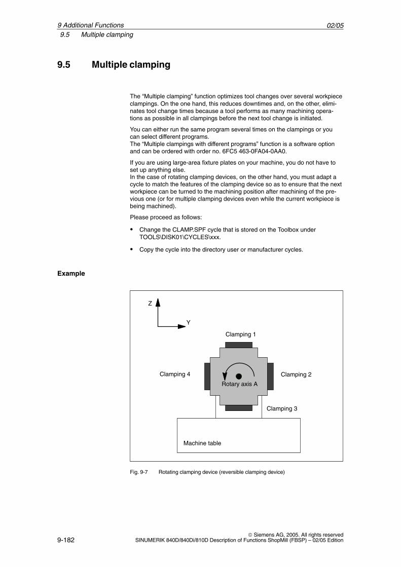
02/059.5 Multiple clamping
9-182 Siemens AG, 2005. All rights reserved
SINUMERIK 840D/840Di/810D Description of Functions ShopMill (FBSP) – 02/05 Edition
9.5 Multiple clamping
The “Multiple clamping” function optimizes tool changes over several workpiececlampings. On the one hand, this reduces downtimes and, on the other, elimi-nates tool change times because a tool performs as many machining opera-tions as possible in all clampings before the next tool change is initiated.
You can either run the same program several times on the clampings or youcan select different programs.The “Multiple clampings with different programs” function is a software optionand can be ordered with order no. 6FC5 463-0FA04-0AA0.
If you are using large-area fixture plates on your machine, you do not have toset up anything else.In the case of rotating clamping devices, on the other hand, you must adapt acycle to match the features of the clamping device so as to ensure that the nextworkpiece can be turned to the machining position after machining of the pre-vious one (or for multiple clamping devices even while the current workpiece isbeing machined).
Please proceed as follows:
� Change the CLAMP.SPF cycle that is stored on the Toolbox under TOOLS\DISK01\CYCLES\xxx.
� Copy the cycle into the directory user or manufacturer cycles.
Machine table
Clamping 1
Clamping 2
Clamping 3
Clamping 4
Rotary axis A
Z
Y
Fig. 9-7 Rotating clamping device (reversible clamping device)
Example
9 Additional Functions
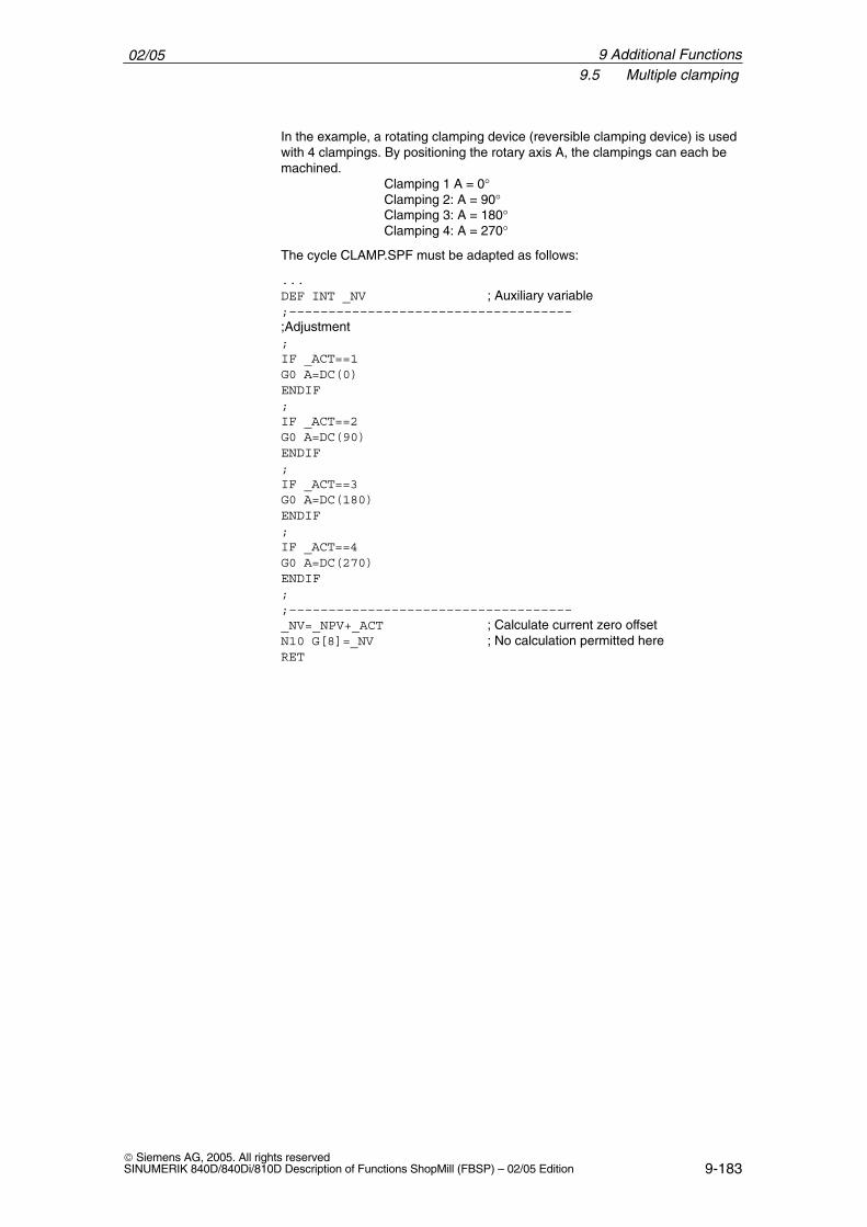
02/059.5 Multiple clamping
9-183 Siemens AG, 2005. All rights reservedSINUMERIK 840D/840Di/810D Description of Functions ShopMill (FBSP) – 02/05 Edition
In the example, a rotating clamping device (reversible clamping device) is usedwith 4 clampings. By positioning the rotary axis A, the clampings can each bemachined.
Clamping 1 A = 0°Clamping 2: A = 90°Clamping 3: A = 180°Clamping 4: A = 270°
The cycle CLAMP.SPF must be adapted as follows:
...DEF INT _NV ; Auxiliary variable;––––––––––––––––––––––––––––––––––––;Adjustment;IF _ACT==1G0 A=DC(0)ENDIF;IF _ACT==2G0 A=DC(90)ENDIF;IF _ACT==3G0 A=DC(180)ENDIF;IF _ACT==4G0 A=DC(270)ENDIF;;––––––––––––––––––––––––––––––––––––_NV=_NPV+_ACT ; Calculate current zero offsetN10 G[8]=_NV ; No calculation permitted hereRET
9 Additional Functions
02/059.6 Measuring cycle support in the G code editor
9-184 Siemens AG, 2005. All rights reserved
SINUMERIK 840D/840Di/810D Description of Functions ShopMill (FBSP) – 02/05 Edition
9.6 Measuring cycle support in the G code editor
In ShopMill you can integrate screen forms which provide support for program-ming measuring cycles into the G code editor. These cycles can then be recom-piled automatically.
The “measuring cycles” function is a software option with order no.6FC5 250-0BX00-0AB0.
For more information on measuring cycle support please refer to:References: /BNM/, Measuring Cycles User Manual
Proceed as follows for start-up:
� Transfer the file TOOLS\DISK01\CYCLES\COMMON.COM to the NC. Thefile is automatically stored in the STANDARD_CYCLES directory.
� Remove the semicolon “;” in front of the following line in file STANDARD-ZYKLEN\COMMON.COM:;sc8407=aeditor.com ;Measuring cycles milling (horizontal softkey 7
;On the extended softkey bar in the ;G code editor)
This makes the link between the softkey with which you call the measuringcycle support and the configuration file of this support screenform.
� Remove the semicolon “;” in front of the following line in file STANDARD-ZYKLEN\COMMON.COM:;sc617=startup.com ;Start-up operating area (horizontal
;softkey 7 on the extended softkey bar)This can change the properties of the measuring cycle support in thestart-up operating area.
� Restart the PCU 20.
� If required, modify the characteristics for the measuring cycle support in the“Start-up” → “>” → “Measuring Cycles” menu.
PCU 20
9 Additional Functions
02/059.6 Measuring cycle support in the G code editor
9-185 Siemens AG, 2005. All rights reservedSINUMERIK 840D/840Di/810D Description of Functions ShopMill (FBSP) – 02/05 Edition
Requirements:At HMI Advanced start-up the files AEDITOR.COM and STARTUP.COM arestored in the STANDARD CYCLES (CST.DIR) directory.The archive ST_CYC.ARC was transferred from the PCU 50 to the NC atstart-up of ShopMill. The COMMON.COM file was automatically copied to theSTANDARD_CYCLES directory (CST.DIR).
� Copy the archive MCSUPP from the ARCHIVES\CYCLES-ARCHIVE\MCYC.
� If you want to use the measurement result displays, you need to copy theMCRESULT archive from the ARCHIVES\CYCLE_ARCHIVES\MCYC direc-tory.
� If the versions of the standard measuring cycles supplied with ShopMill (seeUPDATE_x.RTF file on the software CD) differ from the HMI Advanced mea-suring cycles (see ARCHIVES\CYCLE_ARCHIVES\MCYC\VERSION.ARC)in the first 4 digits (e.g. 06.02), you need to copy the MCYCMILL archivefrom the ARCHIVES\CYCLE_ARCHIVES\MCYC directory.
� Remove the semicolon “;” in front of the following line in file STANDARD-ZYKLEN\COMMON.COM:;sc8407=aeditor.com ;Measuring cycles milling (horizontal softkey 7
;On the extended softkey bar in the ;G code editor)
Remove the semicolon “;” in front of the following line in file STANDARD-ZYKLEN\AEDITOR.COM:;HS15=($83531,,se1);PRESS(HS15); LS(”F_mess“,”MZ_SKL.COM“,1);END_PRESS
This makes the link between the softkey with which you call the measuringcycle support and the configuration file of this support screenform.
� In the file STANDARD_CYCLES\STARTUP.COM remove the semicolon “;”preceding the following lines:;HS15=($83070,,se1);PRESS(HS15); LS(”Messz“);END_PRESSThis allows you to modify the characteristics of the measuring cycle supportin the Start-up operating area.
� Restart the PCU 50.
� If required, modify the characteristics for the measuring cycle support in the“Start-up” → “>” → “Measuring Cycles” menu.
�
PCU 50
9 Additional Functions
02/059.6 Measuring cycle support in the G code editor
9-186 Siemens AG, 2005. All rights reserved
SINUMERIK 840D/840Di/810D Description of Functions ShopMill (FBSP) – 02/05 Edition
9 Additional Functions
Notes
10-187 Siemens AG, 2005. All rights reservedSINUMERIK 840D/840Di/810D Description of Functions ShopMill (FBSP) – 02/05 Edition
Customer-Specific Operator Interface
10.1 Configuring the customized boot screen
10.1.1 PCU 20
You can create your own customized boot screen (company logo, etc.) whichwill be displayed when the control system is booted.
Please proceed as follows to configure the customized boot screen:
1. Create your own boot screen in 16-color mode. The maximum screen size is224x224 pixels for the OP010/OP010C/OP010S/OP012 and 352x352 pixelsfor the OP015.
2. Save the boot screen in bitmap format under the name CUSTOM.BMP.
3. Start the APP_INST.EXE file (see Subsection 4.2.2 “Installing ShopMill onPCU 20”).
4. Select <2> “Modify configuration”.
5. Select <6> “Add user specific files to the application”.
6. Enter the path for file CUSTOM.BMP.The custom boot screen is added to the application software.
7. Return to the main menu with Esc.
8. Finish installing the software on the PC card (see Subsection 4.2.2 “Instal-ling ShopMill on PCU 20”).
9. Load the PC card to the PCU 20 (see Subsection 4.2.2 “Installing ShopMillon PCU 20”).
10. Set MD 9675 $MM_CMM_CUSTOMER_START_PICTURE to the value 1.
10
02/0510.1 Configuring the customized boot screen
10-188 Siemens AG, 2005. All rights reserved
SINUMERIK 840D/840Di/810D Description of Functions ShopMill (FBSP) – 02/05 Edition
10.1.2 PCU 50
You can create your own customized boot screen (company logo, etc.) whichwill be displayed when the control system is booted.
Please proceed as follows to configure the customized boot screen:
1. Create your own boot screen in 16-color mode. The maximum screen size is224x224 pixels for the OP010/OP010C/OP010S/OP012 and 352x352 pixelsfor the OP015.
2. Save the boot screen in bitmap format under the name CUSTOM.BMP.
3. Copy the CUSTOM.BMP file to the F:\DH\CUS.DIR\HLP.DIR directory.
4. Set MD 9675 $MM_CMM_CUSTOMER_START_PICTURE to the value 1.
10 Customer-Specific Operator Interface
02/0510.2 Configuring the custom screen form
10-189 Siemens AG, 2005. All rights reservedSINUMERIK 840D/840Di/810D Description of Functions ShopMill (FBSP) – 02/05 Edition
10.2 Configuring the custom screen form
You can use the “operator interface expansion” software to build your own cus-tom screen forms with specific functional expansions (e.g. custom cycles andmeasuring cycles) or just create your own screen form layout (static screenforms).
References: /IAM/, Installation and Start-Up Guide HMI, BE1 User Interface Extension
In ShopMill, you cannot specify any dimensions for configuration of the mainpart of the screen form. The position and size of the various form main parts arespecified depending on the operating area and mode. This only applies forforms that can be accessed via entry softkeys.
Table 10-1 Specified dimensions of the forms in ShopMill
Exit screen form Softkey Size Dimensions
Manual operatingmode – Zero pointworkpiece / Measureworkpiece
Vertical softkey 1...Vertical softkey 7
X-pos. = 0Y-pos. = 272height = 158 pixelswidth = 556 pixels
Manual operatingmode
Horizontal softkey 8 large X-pos. = 0Y-pos. = 34height = 396 pixelswidth = 556 pixels
Manual operatingmode
Horizontal softkey 8 medium X-pos. = 0Y-pos. = 78height = 352 pixelswidth = 556 pixels
Manual operatingmode
Horizontal softkey 8 small X-pos. = 0Y-pos. = 254height = 176 pixelswidth = 556 pixels
Automatic mode Horizontal softkey 6 large X-pos. = 0Y-pos. = 34height = 396 pixelswidth = 556 pixels
Automatic mode Horizontal softkey 6 medium X-pos. = 0Y-pos. = 78height = 352 pixelswidth = 556 pixels
Automatic mode Horizontal softkey 6 small X-pos. = 0Y-pos. = 254height = 176 pixelswidth = 556 pixels
Program operatingarea –Drilling / milling
Vertical softkey 6 X-pos. = 33Y-pos. = 52height = 378 pixelswidth = 523 pixels
Program operatingarea – Miscellaneous
Vertical softkey 4 X-pos. = 33Y-pos. = 52height = 378 pixelswidth = 523 pixels
Screen formproperties
10 Customer-Specific Operator Interface
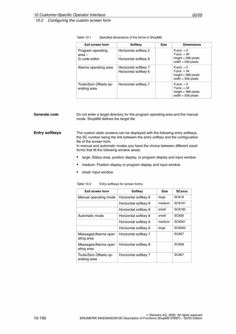
02/0510.2 Configuring the custom screen form
10-190 Siemens AG, 2005. All rights reserved
SINUMERIK 840D/840Di/810D Description of Functions ShopMill (FBSP) – 02/05 Edition
Table 10-1 Specified dimensions of the forms in ShopMill
Exit screen form DimensionsSizeSoftkey
Program operatingarea –G code editor
Horizontal softkey 2...Horizontal softkey 6
X-pos. = 0Y-pos. = 34height = 396 pixelswidth = 556 pixels
Alarms operating area Horizontal softkey 7Horizontal softkey 6
X-pos. = 0Y-pos. = 34height = 396 pixelswidth = 556 pixels
Tools/Zero Offsets op-erating area
Horizontal softkey 7 X-pos. = 0Y-pos. = 34height = 396 pixelswidth = 556 pixels
Generate code Do not enter a target directory for the program operating area and the manualmode. ShopMill defines the target file.
The custom static screens can be displayed with the following entry softkeys,the SC number being the link between the entry softkey and the configurationfile of the screen form. In manual and automatic modes you have the choice between different sizedforms that fill the following window areas:
� large: Status area, position display, or program display and input window
� medium: Position display or program display and input window
� small: Input window
Table 10-2 Entry softkeys for screen forms
Exit screen form Softkey Size SCxxxx
Manual operating mode Horizontal softkey 8 large SC818
Horizontal softkey 8 medium SC8181
Horizontal softkey 8 small SC8182
Automatic mode Horizontal softkey 6 small SC826
Horizontal softkey 6 medium SC8261
Horizontal softkey 6 large SC8262
Messages/Alarms oper-ating area
Horizontal softkey 7 SC857
Messages/Alarms oper-ating area
Horizontal softkey 8 SC858
Tools/Zero Offsets op-erating area
Horizontal softkey 7 SC867
Entry softkeys
10 Customer-Specific Operator Interface
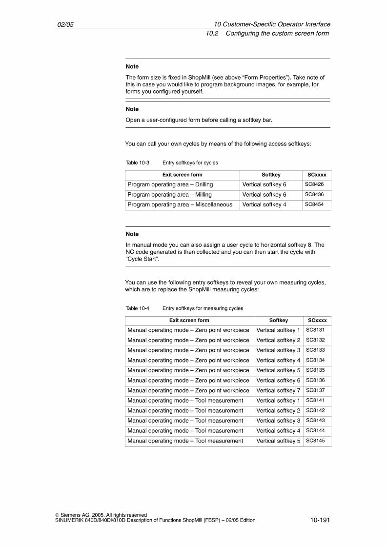
02/0510.2 Configuring the custom screen form
10-191 Siemens AG, 2005. All rights reservedSINUMERIK 840D/840Di/810D Description of Functions ShopMill (FBSP) – 02/05 Edition
Note
The form size is fixed in ShopMill (see above “Form Properties”). Take note ofthis in case you would like to program background images, for example, forforms you configured yourself.
Note
Open a user-configured form before calling a softkey bar.
You can call your own cycles by means of the following access softkeys:
Table 10-3 Entry softkeys for cycles
Exit screen form Softkey SCxxxx
Program operating area – Drilling Vertical softkey 6 SC8426
Program operating area – Milling Vertical softkey 6 SC8436
Program operating area – Miscellaneous Vertical softkey 4 SC8454
Note
In manual mode you can also assign a user cycle to horizontal softkey 8. TheNC code generated is then collected and you can then start the cycle with“Cycle Start”.
You can use the following entry softkeys to reveal your own measuring cycles,which are to replace the ShopMill measuring cycles:
Table 10-4 Entry softkeys for measuring cycles
Exit screen form Softkey SCxxxx
Manual operating mode – Zero point workpiece Vertical softkey 1 SC8131
Manual operating mode – Zero point workpiece Vertical softkey 2 SC8132
Manual operating mode – Zero point workpiece Vertical softkey 3 SC8133
Manual operating mode – Zero point workpiece Vertical softkey 4 SC8134
Manual operating mode – Zero point workpiece Vertical softkey 5 SC8135
Manual operating mode – Zero point workpiece Vertical softkey 6 SC8136
Manual operating mode – Zero point workpiece Vertical softkey 7 SC8137
Manual operating mode – Tool measurement Vertical softkey 1 SC8141
Manual operating mode – Tool measurement Vertical softkey 2 SC8142
Manual operating mode – Tool measurement Vertical softkey 3 SC8143
Manual operating mode – Tool measurement Vertical softkey 4 SC8144
Manual operating mode – Tool measurement Vertical softkey 5 SC8145
10 Customer-Specific Operator Interface
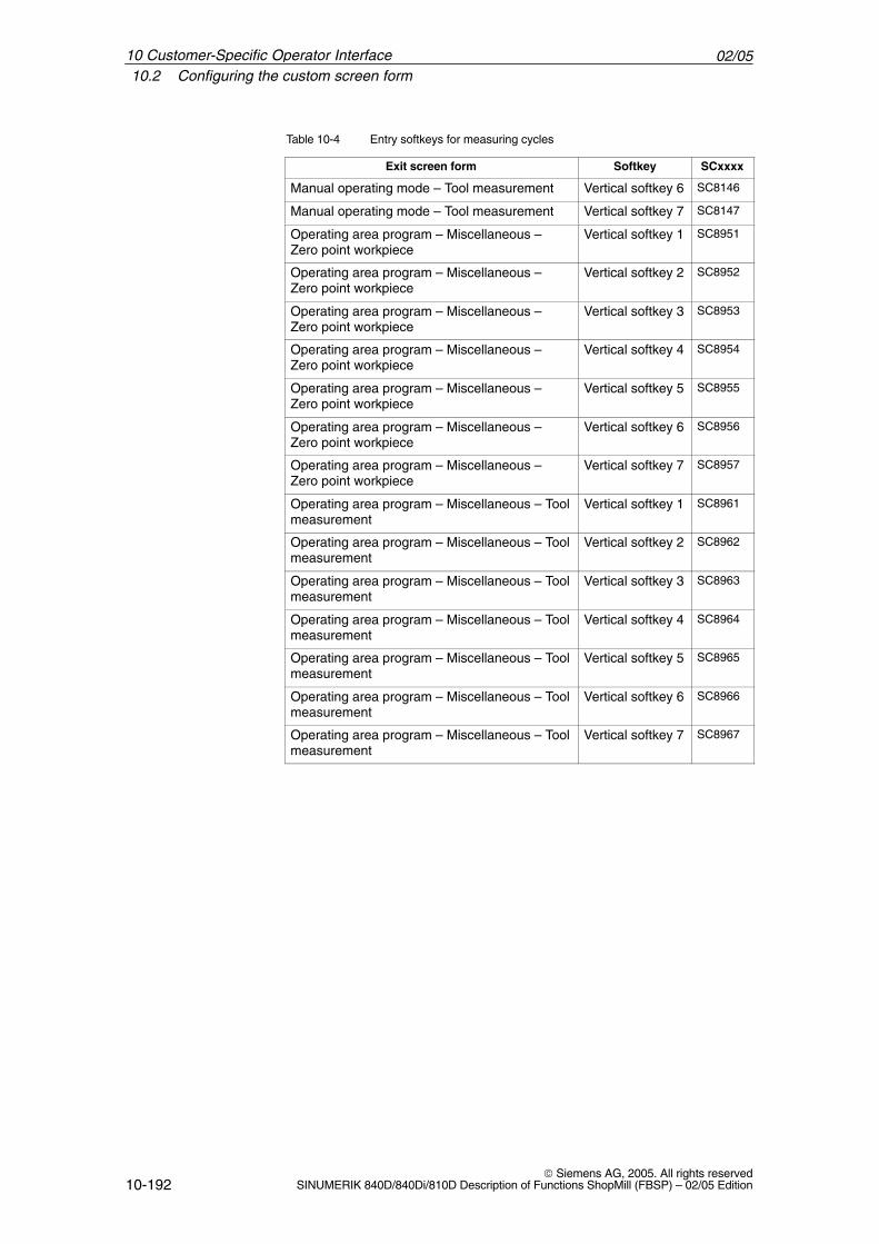
02/0510.2 Configuring the custom screen form
10-192 Siemens AG, 2005. All rights reserved
SINUMERIK 840D/840Di/810D Description of Functions ShopMill (FBSP) – 02/05 Edition
Table 10-4 Entry softkeys for measuring cycles
Exit screen form SCxxxxSoftkey
Manual operating mode – Tool measurement Vertical softkey 6 SC8146
Manual operating mode – Tool measurement Vertical softkey 7 SC8147
Operating area program – Miscellaneous –Zero point workpiece
Vertical softkey 1 SC8951
Operating area program – Miscellaneous –Zero point workpiece
Vertical softkey 2 SC8952
Operating area program – Miscellaneous –Zero point workpiece
Vertical softkey 3 SC8953
Operating area program – Miscellaneous –Zero point workpiece
Vertical softkey 4 SC8954
Operating area program – Miscellaneous –Zero point workpiece
Vertical softkey 5 SC8955
Operating area program – Miscellaneous –Zero point workpiece
Vertical softkey 6 SC8956
Operating area program – Miscellaneous –Zero point workpiece
Vertical softkey 7 SC8957
Operating area program – Miscellaneous – Toolmeasurement
Vertical softkey 1 SC8961
Operating area program – Miscellaneous – Toolmeasurement
Vertical softkey 2 SC8962
Operating area program – Miscellaneous – Toolmeasurement
Vertical softkey 3 SC8963
Operating area program – Miscellaneous – Toolmeasurement
Vertical softkey 4 SC8964
Operating area program – Miscellaneous – Toolmeasurement
Vertical softkey 5 SC8965
Operating area program – Miscellaneous – Toolmeasurement
Vertical softkey 6 SC8966
Operating area program – Miscellaneous – Toolmeasurement
Vertical softkey 7 SC8967
10 Customer-Specific Operator Interface
02/0510.2 Configuring the custom screen form
10-193 Siemens AG, 2005. All rights reservedSINUMERIK 840D/840Di/810D Description of Functions ShopMill (FBSP) – 02/05 Edition
10.2.1 Transferring cycles to the machining plan
You can transfer all user cycles that you have inserted in the operating areaprogram (including measuring cycles) to the machining plan and edit themthere. However, the cycles will not be displayed as programming graphics.
Use the “operator interface extension” software to define the cycle. Please notethat the cycle must contain the Generate Code (GC) function and an OUTPUTmethod for NC code to be generated and sent to the NC for execution.
If you call up and take over the cycle on the ShopMill operator interface, thecycle will automatically appear in the machining plan. The screen form name ofthe cycle will appear in the machining plan as plain text.
10 Customer-Specific Operator Interface
02/0510.2 Configuring the custom screen form
10-194 Siemens AG, 2005. All rights reserved
SINUMERIK 840D/840Di/810D Description of Functions ShopMill (FBSP) – 02/05 Edition
10.2.2 Linking cycles into the machining plan
You can link user cycles into the machining plan with the ShopMill “Positions”cycles.
The name of the cycles to be linked in the work plan is mandatory and must notbe changed:E_DR_Ox with x = 1 to 9
The following variables must be configured within the cycles:
You must first define three variables which are not assigned until the programstep is inserted in the machining plan, i.e. the attribute must be assigned invisi-bly (wr0) to the input field of each variable. The variable sequence is as follows:
1. Variable for the next tool, data type String (S)
2. Variable for the position identifier in objects, data type Integer
3. Variable for the sequencer text that is to be displayed in the ShopMill workschedule, data type character string (S)The easiest way to assign a value to this variable is in a LOAD method.
Two variables for cycles processing must also be defined as well as one vari-able for each toggle field which has a different display content on the interface(e.g. mm/rev) than the internally transferred quantity (e.g. 1). You need to assign the attribute invisible (wr0) to these variables too as they donot have their own input field. You can place the variables in any order.
Note
When an OUTPUT method is used, all variables described above must beconfigured within this method so that they can all be interpreted onrecompilation.
Directory TOOLS\DISK01\CYCLES\xxx\OEM_1 in the tool box contains a sam-ple cycle E_DR_O1.SPF. The associated operator interface is configured in theE_DR_O1.COM file. The German and English texts are stored in theE_DR_TXD.COM and E_DR_TXE.COM files respectively. A number of helpdisplays are also included with the sample cycle.Please see the README.TXT file for information on how to install the cycle.
Name
Variables
Example
10 Customer-Specific Operator Interface
02/0510.2 Configuring the custom screen form
10-195 Siemens AG, 2005. All rights reservedSINUMERIK 840D/840Di/810D Description of Functions ShopMill (FBSP) – 02/05 Edition
10.2.3 Integrating measuring cycles
If you wish to integrate your own measuring cycles in Manual mode, verticalsoftkey 8 (VS8) in the new cycles screen acquires a special meaning. All ac-tions that the new measuring cycle is supposed to perform after the “cycle start”key has been pressed must be defined in a PRESS method for VSK8. If youpress the “cycle start” button, NC code is generated that is written and executedin a program, i.e. the Generate Code (GC) function must be programmed in thePRESS method for VSK8. This in turn means that an OUTPUT method must bedefined.
Note
The user does not have to press VSK8; it is triggered internally when the “cyclestart” key is pressed. It should therefore not be labeled.
In the toolbox you will find the archive file E_MS_O1.ARC in directoryTOOLS\DISK01\CYCLES\xxx\OEM_MEAS. This contains the example measur-ing cycle E_MS_O1.SPF. The associated operator interface is configured in theE_DR_O1.COM file. In Files E_MS_TXD.COM and E_MS_TXE.COM containthe German and English texts, and file EDGE_Z.BMP contains a help display.Please see the README.TXT file for information on how to install the cycle.
If you want to link user measuring cycles into the operating area program, pro-ceed as described in Subsection 10.2.1 “Transferring Cycles to the MachiningPlan”. A vertical softkey menu will then be created behind the entry softkey “Miscella-neous” → “Zero point workpiece”, via which you can call up your measuringcycles. Such a vertical softkey menu already exists behind the “Miscellaneous”→ “Measure tool” entry softkey.
Manual operatingmode
Example
Program operatingarea
10 Customer-Specific Operator Interface
02/0510.3 ShopMill Open (PCU 50)
10-196 Siemens AG, 2005. All rights reserved
SINUMERIK 840D/840Di/810D Description of Functions ShopMill (FBSP) – 02/05 Edition
10.3 ShopMill Open (PCU 50)
ShopMill Open has an extended basic menu bar. In ShopMill Open, the HMIAdvanced operating areas “Parameter” (without tool management and zerooffsets), “Services”, “Diagnosis” and “Startup” on the extended horizontal soft-key bar.
The extended horizontal softkey bar also includes the “Machine Service” and“Exit” softkeys for start-up/diagnosis. These two softkeys are visible only whenprotection level 1 is selected.
In addition, in ShopMill Open you can integrate Windows applications in thestandard menu bar via softkeys.You must also install the Windows applications in the OEM directory and definethem in the REGIE.INI file. This does not apply to Siemens additional products.You must install those in the ADD_ON directory. See the ShopMill CD-ROM:
References: User’s Guide HMI Programming Package Part 1 (BN)
10.3.1 Basic menu bar
There are various methods by which you can integrate Windows applicationsinto the basic menu bar:
� Horizontal softkey 4, i.e. the Messages/Alarms operating area is replaced
� User-assignable softkeys 7 and 8
� User-assignable softkeys 1 to 8 in the extended horizontal softkey menu
There are 3 methods by which you can jump from the Windows application toanother operating area:
� Using the “Menu Select” key on the operator panel, you can return to thebasic menu bar and then select another operating area via a softkey.
� You can configure the keys “Position”, “Program”, “Offset”, “Program Man-ager”, “Alarm” and “Custom” on the operator panel to branch directly intoanother operating area or sub-menu.
� You can configure so-called “PLC keys” to branch into another operatingarea or sub-menu.
References: /IAM/, Installation and Start-Up Guide HMI, User Interface Extension (BE1)Section on “OP Hotkeys and PLC Keys”
Jump intoapplication
Return
10 Customer-Specific Operator Interface
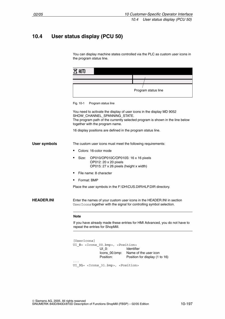
02/0510.4 User status display (PCU 50)
10-197 Siemens AG, 2005. All rights reservedSINUMERIK 840D/840Di/810D Description of Functions ShopMill (FBSP) – 02/05 Edition
10.4 User status display (PCU 50)
You can display machine states controlled via the PLC as custom user icons inthe program status line.
Program status line
Fig. 10-1 Program status line
You need to activate the display of user icons in the display MD 9052SHOW_CHANNEL_SPANNING_STATE.The program path of the currently selected program is shown in the line belowtogether with the program name.
16 display positions are defined in the program status line.
The custom user icons must meet the following requirements:
� Colors: 16-color mode
� Size: OP010/OP010C/OP010S: 16 x 16 pixelsOP012: 20 x 20 pixelsOP015: 27 x 26 pixels (height x width)
� File name: 8 character
� Format: BMP
Place the user symbols in the F:\DH\CUS.DIR\HLP.DIR directory.
Enter the names of your custom user icons in the HEADER.INI in section UserIcons together with the signal for controlling symbol selection.
Note
If you have already made these entries for HMI Advanced, you do not have torepeat the entries for ShopMill.
[UserIcons]UI_0= <Icons_00.bmp>, <Position>
UI_0: IdentifierIcons_00.bmp: Name of the user iconPosition: Position for display (1 to 16)
...UI_31= <Icons_31.bmp>, <Position>
User symbols
HEADER.INI
10 Customer-Specific Operator Interface
02/0510.4 User status display (PCU 50)
10-198 Siemens AG, 2005. All rights reserved
SINUMERIK 840D/840Di/810D Description of Functions ShopMill (FBSP) – 02/05 Edition
USER_ICON_BASE = DBx.DBByDBx.DBBy: Signal defined by user for controlling icon
selection
You will find the HEADER.INI file in the F:\HMI_ADV directory and must copythem either to the F:\OEM or the F:\USER directory.
The user icons are addressed bit by bit, i.e. if bit n is set in signal DBx.DBBy,then the user icon with identifier UI_n is displayed.If the bit is reset by the PLC, the associated user icon is deleted in the programstatus display.
If several user symbols are assigned to the same position, the user symbol withthe highest identifier number is displayed.You do not need to specify blank positions.
10 Customer-Specific Operator Interface
02/0510.5 OP hotkeys, PLC keys
10-199 Siemens AG, 2005. All rights reservedSINUMERIK 840D/840Di/810D Description of Functions ShopMill (FBSP) – 02/05 Edition
10.5 OP hotkeys, PLC keys
You can configure the keys “Position”, “Program”, “Offset”, “Program Manager”,“Alarm” and “Custom” on the operator panel to branch to an operating area ofyour choice.
You can configure so-called “PLC keys” to branch to particular operating areas.
You can switch to the following operating areas with the OP hotkeys or PLCkeys:
� PCU 20From ShopMill to any operating area of ShopMill.
� PCU 50From ShopMill to any other operating area in ShopTurn.From ShopMill to any other operating area in HMI Advanced and vice versa.
For information about how to configure the keys, please refer to:References: /IAM/, Installation and Start-Up Guide HMI, User Interface
Extension (BE1)keyword “OP Hotkeys” and “PLC Keys”
Note
In ShopMill, the “PLC keys” are configured in file KEYS.INI, not via interface DB 19.File KEYS.INI must contain the following entry in section [HMI_INI_FILES]:Task6 = shopmill.ini
�
OP hotkeys
PLC keys
Configuring
10 Customer-Specific Operator Interface

02/0510.5 OP hotkeys, PLC keys
10-200 Siemens AG, 2005. All rights reserved
SINUMERIK 840D/840Di/810D Description of Functions ShopMill (FBSP) – 02/05 Edition
10 Customer-Specific Operator Interface
Notes
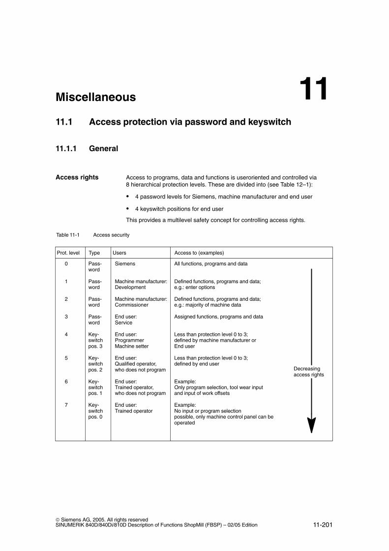
11-201 Siemens AG, 2005. All rights reservedSINUMERIK 840D/840Di/810D Description of Functions ShopMill (FBSP) – 02/05 Edition
Miscellaneous
11.1 Access protection via password and keyswitch
11.1.1 General
Access to programs, data and functions is useroriented and controlled via8 hierarchical protection levels. These are divided into (see Table 12–1):
� 4 password levels for Siemens, machine manufacturer and end user
� 4 keyswitch positions for end user
This provides a multilevel safety concept for controlling access rights.
Table 11-1 Access security
Prot. level Type Users Access to (examples)
0 Pass- Siemens All functions, programs and dataword
1 Pass- Machine manufacturer: Defined functions, programs and data;word Development e.g.: enter options
2 Pass- Machine manufacturer: Defined functions, programs and data;word Commissioner e.g.: majority of machine data
3 Pass- End user: Assigned functions, programs and dataword Service
4 Key- End user: Less than protection level 0 to 3;switch Programmer defined by machine manufacturer orpos. 3 Machine setter End user
5 Key- End user: Less than protection level 0 to 3;switch Qualified operator, defined by end userpos. 2 who does not program
6 Key- End user: Example:switch Trained operator, Only program selection, tool wear inputpos. 1 who does not program and input of work offsets
7 Key- End user: Example:switch Trained operator No input or program selectionpos. 0 possible, only machine control panel can be
operated
Decreasingaccess rights
Access rights
11
02/0511.1 Access protection via password and keyswitch
11-202 Siemens AG, 2005. All rights reserved
SINUMERIK 840D/840Di/810D Description of Functions ShopMill (FBSP) – 02/05 Edition
� Protection level 0 provides the greatest number of access rights, protectionlevel 7 the least.
� If certain access rights are granted to a protection level, these protectionrights automatically apply to any higher protection levels.
� Conversely, protection rights for a certain protection level can only be alteredfrom a higher protection level.
� Access rights for protection levels 0 to 3 are permanently assigned by Siemens and cannot be altered (default).
� Access authorization is set through scanning of the current keyswitchposition and a comparison of password entries. When a password is en-tered it overwrites the access rights of the keyswitch position.
� Options can be protected on each protection level. However, option datacan only be entered in protection levels 0 and 1.
� Access rights for protection levels 4 to 7 are merely suggested settings andcan be altered by the machine tool manufacturer or end user.
Access protectionsystem
11 Miscellaneous
02/0511.1 Access protection via password and keyswitch
11-203 Siemens AG, 2005. All rights reservedSINUMERIK 840D/840Di/810D Description of Functions ShopMill (FBSP) – 02/05 Edition
11.1.2 Password
The passwords for the 4 available password levels with their respectiveaccess authorization can be entered in the DIAGNOSTICS operating areathrough selection of softkey SET PASSWORD.References: /BEM/, Operator’s Guide HMI Embedded or
/BAD/, Operator’s Guide HMI Advanced
Please note that a password remains valid until the accessauthorization is directly reset with the “Delete password” softkey. Access authorization is therefore not automatically deleted during PowerON!
Up to 8 characters can be used in the password. We recommend that you re-strict yourself to the character set of the operator panel in selecting a password.Where a password consists of less than eight characters, the additional charac-ters are interpreted as blanks.
The following default passwords are defined for protection levels 1 to 3:Protection level 1 SUNRISEProtection level 2 EVENINGProtection level 3 CUSTOMER
Note
These passwords are entered as the defaults on system power-up in start-upmode (NCK start-up switch in position 1).
The default passwords should be changed in order to guarantee reliableaccess protection.
Set password
Reset password
Possiblecharacters
Default passwords
11 Miscellaneous
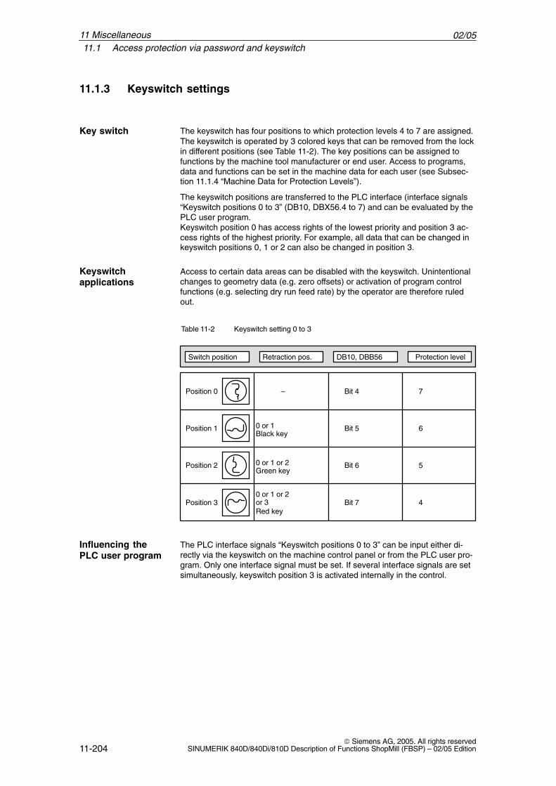
02/0511.1 Access protection via password and keyswitch
11-204 Siemens AG, 2005. All rights reserved
SINUMERIK 840D/840Di/810D Description of Functions ShopMill (FBSP) – 02/05 Edition
11.1.3 Keyswitch settings
The keyswitch has four positions to which protection levels 4 to 7 are assigned.The keyswitch is operated by 3 colored keys that can be removed from the lockin different positions (see Table 11-2). The key positions can be assigned tofunctions by the machine tool manufacturer or end user. Access to programs,data and functions can be set in the machine data for each user (see Subsec-tion 11.1.4 “Machine Data for Protection Levels”).
The keyswitch positions are transferred to the PLC interface (interface signals“Keyswitch positions 0 to 3” (DB10, DBX56.4 to 7) and can be evaluated by thePLC user program.Keyswitch position 0 has access rights of the lowest priority and position 3 ac-cess rights of the highest priority. For example, all data that can be changed inkeyswitch positions 0, 1 or 2 can also be changed in position 3.
Access to certain data areas can be disabled with the keyswitch. Unintentionalchanges to geometry data (e.g. zero offsets) or activation of program controlfunctions (e.g. selecting dry run feed rate) by the operator are therefore ruledout.
Table 11-2 Keyswitch setting 0 to 3
Switch position Retraction pos. DB10, DBB56 Protection level
Position 0 – Bit 4 7
Position 1 0 or 1 Bit 5 6
Position 2 0 or 1 or 2 Bit 6 5
Position 30 or 1 or 2
Bit 7 4
Black key
Green key
Red keyor 3
The PLC interface signals “Keyswitch positions 0 to 3” can be input either di-rectly via the keyswitch on the machine control panel or from the PLC user pro-gram. Only one interface signal must be set. If several interface signals are setsimultaneously, keyswitch position 3 is activated internally in the control.
Key switch
Keyswitchapplications
Influencing thePLC user program
11 Miscellaneous
02/0511.1 Access protection via password and keyswitch
11-205 Siemens AG, 2005. All rights reservedSINUMERIK 840D/840Di/810D Description of Functions ShopMill (FBSP) – 02/05 Edition
11.1.4 Machine data for protection levels
The machine manufacturer or end user can set operator panel machine data toassign the appropriate protection levels for individual functions and data areasFor a number of data types, it is possible to input different protection levels forread and write access authority.The machine data which can be “locked” by means of protection levels inShopMill are listed below:
Operator panel machine data Access to
9182 USER_CLASS_INCH_METRIC Inch/metric switchover
9200 USER_CLASS_READ_TOA Read tool offsets
9201 USER_CLASS_WRITE_TOA_GEO Write tool geometry (including type andcutting edge)
9202 USER_CLASS_WRITE_TOA_WEAR Write tool wear (withoutlimit value)
9203 USER_CLASS_WRITE_FINE Write tool wear fine andfine offsets
9210 USER_CLASS_WRITE_ZOA Write coarse offsets
9215 USER_CLASS_WRITE_SEA Write setting data
9216 USER_CLASS_READ_PROGRAMM Read program (protection level must be ≤ 6)
9217 USER_CLASS_WRITE_PROGRAM Write/edit program(protection level must be ≤ 5)
9218 USER_CLASS_SELECT_PROGRAM Enable program selection(protection level must be ≤ 7)
9222 USER_CLASS_WRITE_RPA Write R parameters
9252 USER_CLASS_TM_SKTOOLLOAD Enable loading of a tool
9253 USER_CLASS_TM_SKTOOLUNLOAD Enable unloading of a tool
9258 USER_CLASS_TM_SKNCNEWTOOL Enable setting up of a new tool
9259 USER_CLASS_TM_SKNCDELTOOL Enable deleting of a tool
9272 USER_CLASS_APPLICATION1 Enable machine operating area (only for PCU 20; protection level should be 1)
9272 USER_CLASS_APPLICATION1 Enable machine operating area (only for PCU 20; protection level should be 1)
9272 USER_CLASS_APPLICATION3 Enable program operating area(only for PCU 20; protection level should be 1)
9510 USER_CLASS_DIRECTORY1_P Enable network drive 1
9511 USER_CLASS_DIRECTORY2_P Enable network drive 2
Lockabledata areas
11 Miscellaneous

02/0511.1 Access protection via password and keyswitch
11-206 Siemens AG, 2005. All rights reserved
SINUMERIK 840D/840Di/810D Description of Functions ShopMill (FBSP) – 02/05 Edition
9512 USER_CLASS_DIRECTORY3_P Enable network drive 3
9513 USER_CLASS_DIRECTORY4_P Enable network drive 4
These machine data are assigned protection level 7 by default during the stan-dard start-up procedure. All these data areas and functions can thus beaccessed and altered in keyswitch position 0.The protection level defaults may need to be changed by the machine manufac-turer or end user. Protection levels 0 to 3 can also be entered.
Defaultsetting
11 Miscellaneous
02/0511.2 ISO dialects
11-207 Siemens AG, 2005. All rights reservedSINUMERIK 840D/840Di/810D Description of Functions ShopMill (FBSP) – 02/05 Edition
11.2 ISO dialects
You can also create and run ISO dialect programs under ShopMill. For moreinformation on how to set up ISO dialects please refer to the following documen-tation:References: /FBFA/, Description of Functions ISO Dialects
The “ISO dialects” function is a software option with order no. 6FC5 253-0AE00-0AA0.
11 Miscellaneous
02/0511.3 Spindle control
11-208 Siemens AG, 2005. All rights reserved
SINUMERIK 840D/840Di/810D Description of Functions ShopMill (FBSP) – 02/05 Edition
11.3 Spindle control
The ShopMill spindle control has the following special features:
ShopMill distinguishes between M2/M30 (end of a ShopMill program) and the Mfunction set in MD 10714 $MN_M_NO_FCT_EOP (end of a program created in“Manual” or “MDI” mode).Setting MD 35040 $MA_SPIND_ACTIVE_AFTER_RESET=2 causes the NCKto switch off the spindle in response to M2/M30, but not in response to the Mfunction programmed in MD 10714 $MN_M_NO_FCT_EOP.The ShopMill PLC also stops in response to M30 or RESET, but not in responseto the set M function.One of the purposes of this functionality is to allow continuous starting of thespindle in manual mode (e.g. for scratching).
ShopMill uses the following M functions for end of program:
� M function from MD 10714 $MN_M_NO_FCT_EOP: End of main program,spindle continues
� M2, M30: End of main program and return jump to beginning of program,spindle stops
� M17: End of subprogram and return jump to main program, spindle contin-ues operating
The keys “Spindle right”, “Spindle left” and “Spindle stop” triggers the ShopMill-PLC input signals DB82 DBX9.1 “spindle_start”, DB82 DBX9.4 “spindle_right”,DB82 DBX9.3 “spindle_left” and DB82 DBX9.2 “spindle_stop”. The ShopMill PLC program writes to the following interface signals in the datablock of the spindle:DB3x.DBX30.0 spindle stopDB3x.DBX30.1 spindle start CWDB3x.DBX30.2 spindle start CCWThe spindle can be started and stopped if the channel is in the reset state(DB21.DBX35.7=1) or the channel state is “interrupted” (DB21.DBX35.6=1) andthe program state is “interrupted” (DB21.DBX35.3=1).
Note
If the spindle must be stopped when the program is running, then the “FeedStop/Spindle Stop” interface signal must be set in the user PLC(DB3x.DBX4.3).
The spindle control can be deactivated via the DB82.DBX9.0 interface signal.
End of program
Keys
11 Miscellaneous

02/0511.4 Analog spindles
11-209 Siemens AG, 2005. All rights reservedSINUMERIK 840D/840Di/810D Description of Functions ShopMill (FBSP) – 02/05 Edition
11.4 Analog spindles
ShopMill supports analog spindles with encoder for tapping.The axis index of the analog spindle must be entered in MD 9426$MM_MA_AX_DRIVELOAD_FROM_PLC1 or MD 9427 $MM_MA_AX_DRIVELOAD_FROM_PLC2. The system detects thespindle as an analog spindle if one of these display machine data valuesmatches MD 9705 $MM_CMM_INDEX_SPINDLE.
11 Miscellaneous
02/0511.5 Automatically generated programs
11-210 Siemens AG, 2005. All rights reserved
SINUMERIK 840D/840Di/810D Description of Functions ShopMill (FBSP) – 02/05 Edition
11.5 Automatically generated programs
ShopMill creates several programs automatically during operation.
Directory of part programs:
The program is created when a function is executed in “Manual” mode. TheShopMill PLC switches internally to the “Automatic” operating mode, processesthe CMM_SINGLE program and returns to the “Jog” operating mode.
The G code records programmed under “MDI” are saved in this program.
The last parameter values entered in a screen are saved in these programs,depending on the unit of measurement. (INPUT_DATA_MM = values with theunit “mm”; INPUT_DATA_IN = values with the unit “Inch”)
Directory start-up:
Data which need to remain stored when the machine is next switched off (e.g.the last selected program) are saved in this program.
CMM_SINGLE
CMM_MDI
INPUT_DATA_MMINPUT_DATA_IN
REM_DATA.TRC
11 Miscellaneous
02/0511.6 Version display
11-211 Siemens AG, 2005. All rights reservedSINUMERIK 840D/840Di/810D Description of Functions ShopMill (FBSP) – 02/05 Edition
11.6 Version display
The version of ShopMill PLC is shown in the ShopMill boot display.The ShopMill and NCU version are shown on the CNC ISO user interface.
� Switch to the CNC ISO operator interface.
� Select menu options “Diagnostics” → “Service Displays” → “Version” →“NCU Version”.The NCU version is displayed at the top of the NCU version screen:xx.yy.zz 810D or 840D
� Select menu option “MMC Version”.You can view the ShopMill version in the displayed list.PCU 50: ShopMill............ V xx.yy.zz/nnPCU 20: cmm.dll.............. V xx.yy.zz/nn
11 Miscellaneous
02/0511.7 Action log
11-212 Siemens AG, 2005. All rights reserved
SINUMERIK 840D/840Di/810D Description of Functions ShopMill (FBSP) – 02/05 Edition
11.7 Action log
You can log sequences of operations in ShopMill in the action log to obtain ahistory of events for later examination.
For further information about the action log, please see:References: /IAM/, Installation and Start-Up Guide HMI,
IM2 Installation and HMI Embedded
Please refer to the DOCUMENTATION\WINDOWLISTS directory on the Shop-Mill CD ROM for the assignment between ID numbers listed in the log and thecorresponding ShopMill windows.
Note
If you use a PCU 50 with HMI Advanced and would like to log the ShopMilloperating processes, you must configure the settings for the trip recorderdirectly in MD 9012 $MM_ACTION_LOG_MODE. The log is stored in theF:\MMCOW32\TMP\_AC_LOG.BIN file. No support for display or readout of thisfile is provided.
11 Miscellaneous
02/0511.8 Mold making
11-213 Siemens AG, 2005. All rights reservedSINUMERIK 840D/840Di/810D Description of Functions ShopMill (FBSP) – 02/05 Edition
11.8 Mold making
ShopMill can also process mold making programs in addition to programs forthe 2 1/2D machining. The mold making programs are executable not only onspecial mold making machines but also on conventional milling machines for 21/2D machining.However, the milling machines must be optimized for execution mold makingprograms to achieve the best possible velocity control.
11.8.1 Start-up
You must perform the following steps to achieve the best possible velocity con-trol:
� Set NC machine data
� Optimizing the drive
� Preconfiguring and, if necessary, adapting the cycle “High Speed Settings”
The NC machine data values that you must set are found in the CMM.8x0 file inthe section “additional settings for mold and die”. In other words, these machinedata values are automatically set upon NC start-up.
Note
Please note that the settings of some machine data values depend on the CNCcontrol or are axis-specific; i.e. you must set these machine data valuesyourself.
To adapt the drive for processing of mold making programs, you must optimizeall controllers (current controller, speed controller, position controller), the jerkvalues and the feedforward control using machine-specific machine data, thencheck these settings based on a circular mold test and contour precision (cor-ners, radii).
You should perform optimization of the controller, jerk values, and feedforwardcontrol with the compressor function active to permit the compressor function tobe activated without additional re-optimization.The machine data settings described in file CMM.8x0 already take the compres-sor function into account.The compressor function is integrated into the option “Spline interpolation for3-axis machining” (Order No. 6FC5251-0AF14-0AA0) or “Spline interpolation for5-axis machining” (Order No. 6FC5251-0AA14-0AA0).
The most important machine-specific machine data items are listed below. Thislist is not necessarily complete.
NC machine data
Drive optimization
11 Miscellaneous
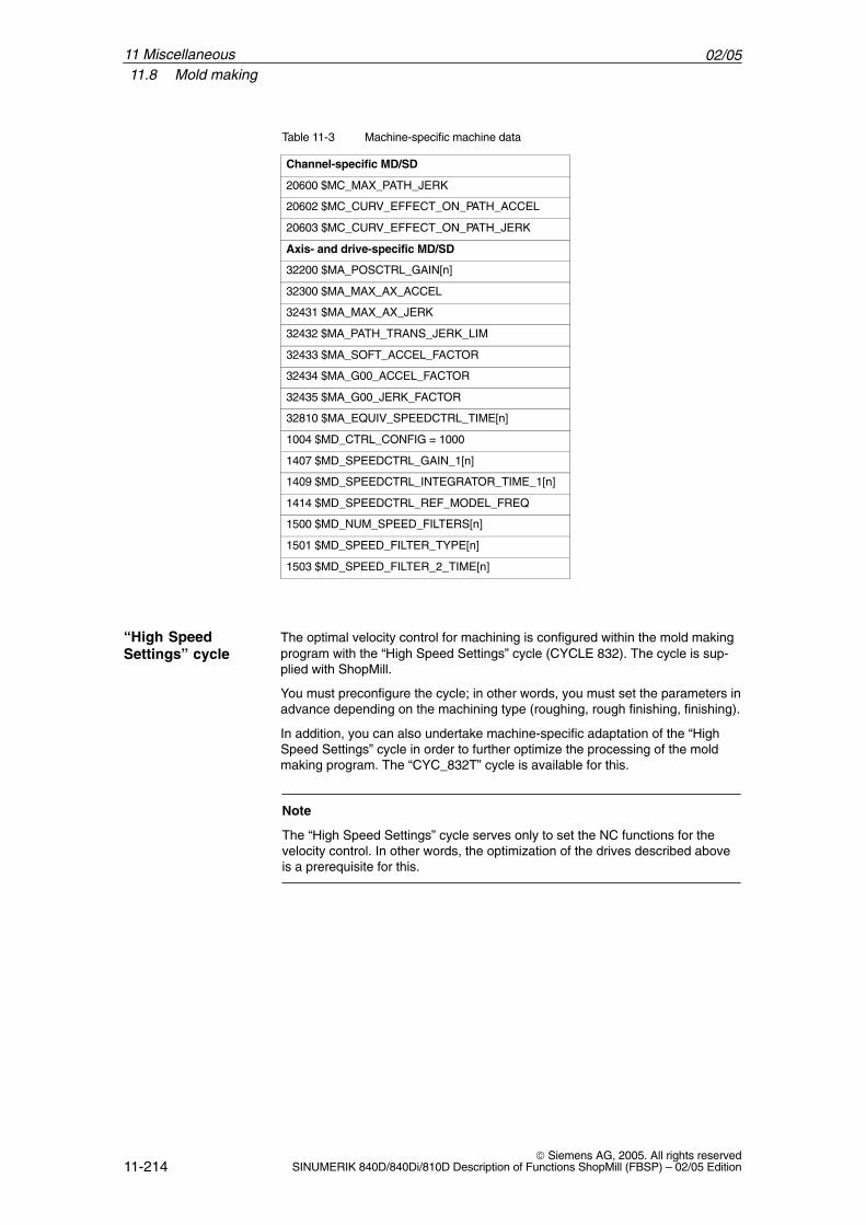
02/0511.8 Mold making
11-214 Siemens AG, 2005. All rights reserved
SINUMERIK 840D/840Di/810D Description of Functions ShopMill (FBSP) – 02/05 Edition
Table 11-3 Machine-specific machine data
Channel-specific MD/SD
20600 $MC_MAX_PATH_JERK
20602 $MC_CURV_EFFECT_ON_PATH_ACCEL
20603 $MC_CURV_EFFECT_ON_PATH_JERK
Axis- and drive-specific MD/SD
32200 $MA_POSCTRL_GAIN[n]
32300 $MA_MAX_AX_ACCEL
32431 $MA_MAX_AX_JERK
32432 $MA_PATH_TRANS_JERK_LIM
32433 $MA_SOFT_ACCEL_FACTOR
32434 $MA_G00_ACCEL_FACTOR
32435 $MA_G00_JERK_FACTOR
32810 $MA_EQUIV_SPEEDCTRL_TIME[n]
1004 $MD_CTRL_CONFIG = 1000
1407 $MD_SPEEDCTRL_GAIN_1[n]
1409 $MD_SPEEDCTRL_INTEGRATOR_TIME_1[n]
1414 $MD_SPEEDCTRL_REF_MODEL_FREQ
1500 $MD_NUM_SPEED_FILTERS[n]
1501 $MD_SPEED_FILTER_TYPE[n]
1503 $MD_SPEED_FILTER_2_TIME[n]
The optimal velocity control for machining is configured within the mold makingprogram with the “High Speed Settings” cycle (CYCLE 832). The cycle is sup-plied with ShopMill.
You must preconfigure the cycle; in other words, you must set the parameters inadvance depending on the machining type (roughing, rough finishing, finishing).
In addition, you can also undertake machine-specific adaptation of the “HighSpeed Settings” cycle in order to further optimize the processing of the moldmaking program. The “CYC_832T” cycle is available for this.
Note
The “High Speed Settings” cycle serves only to set the NC functions for thevelocity control. In other words, the optimization of the drives described aboveis a prerequisite for this.
“High SpeedSettings” cycle
11 Miscellaneous

02/0511.8 Mold making
11-215 Siemens AG, 2005. All rights reservedSINUMERIK 840D/840Di/810D Description of Functions ShopMill (FBSP) – 02/05 Edition
You can call the “high-speed settings” cycle via the cycle support in the Shop-Mill G code editor.You will find more precise information on the “high-speed settings” and“CYC_832T” cycles in:References: /PGZ/, Programming Guide Cycles
SINUMERIK 840D/840Di/810D
11 Miscellaneous
02/0511.8 Mold making
11-216 Siemens AG, 2005. All rights reserved
SINUMERIK 840D/840Di/810D Description of Functions ShopMill (FBSP) – 02/05 Edition
11.8.2 Data storage, data transfer
To make the optimization of the velocity control with the “High Speed Settings”cycle effective, mold making programs must be divided into a technology pro-gram and a geometry program. The technology program contains basic set-tings, such as zero offset, tool, feed, spindle speed, etc.; the geometry programonly contains geometric values of the free-form surface to be machined.Depending on the application, geometry programs may be anywhere between500 KB and 100 MB in size. Programs of this size can no longer be processeddirectly in the NC RAM. This means that the geometry programs must be savedeither on the hard drive of the PCU 50 or on a Compact Flash card in the PCU 20.The compact flash card is not part of the PCU 20, but has to be ordered sepa-rately (32 MB: order number 6FC5313-1AG00-0AA0, 64 MB: order number6FC5313-2AG00-0AA0). The Compact Flash card can be integrated into theprogram manager as a network drive.
Note
Due to the slower access speeds of the Compact Flash Card, a PCU 50 isrecommended for geometry programs larger than 2 MB.
To copy a mold making program from a network drive to the control, an Ethernetconnection must be used. The data transfer rate of the serial interface (RS232,V.24) is too low for the transfer of very large part programs.
To execute a mold making program from a network drive, a point-to-point linkbetween the control and the network drive is advisable because only then iscontinuous data transmission certain.Execution via the V.24 (RS 232) interface of the PCU 20 is not recommendedbecause of the low transmission rate.
�
Data storage
Data transfer
11 Miscellaneous
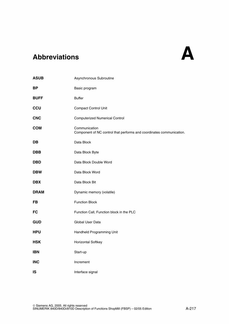
A-217 Siemens AG, 2005. All rights reservedSINUMERIK 840D/840Di/810D Description of Functions ShopMill (FBSP) – 02/05 Edition
Abbreviations
Asynchronous Subroutine
Basic program
Buffer
Compact Control Unit
Computerized Numerical Control
CommunicationComponent of NC control that performs and coordinates communication.
Data Block
Data Block Byte
Data Block Double Word
Data Block Word
Data Block Bit
Dynamic memory (volatile)
Function Block
Function Call, Function block in the PLC
Global User Data
Handheld Programming Unit
Horizontal Softkey
Start-up
Increment
Interface signal
ASUB
BP
BUFF
CCU
CNC
COM
DB
DBB
DBD
DBW
DBX
DRAM
FB
FC
GUD
HPU
HSK
IBN
INC
IS
A
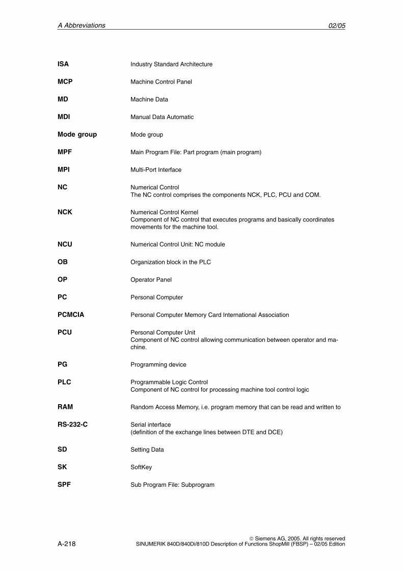
02/05
A-218 Siemens AG, 2005. All rights reserved
SINUMERIK 840D/840Di/810D Description of Functions ShopMill (FBSP) – 02/05 Edition
Industry Standard Architecture
Machine Control Panel
Machine Data
Manual Data Automatic
Mode group
Main Program File: Part program (main program)
Multi-Port Interface
Numerical ControlThe NC control comprises the components NCK, PLC, PCU and COM.
Numerical Control KernelComponent of NC control that executes programs and basically coordinatesmovements for the machine tool.
Numerical Control Unit: NC module
Organization block in the PLC
Operator Panel
Personal Computer
Personal Computer Memory Card International Association
Personal Computer UnitComponent of NC control allowing communication between operator and ma-chine.
Programming device
Programmable Logic ControlComponent of NC control for processing machine tool control logic
Random Access Memory, i.e. program memory that can be read and written to
Serial interface (definition of the exchange lines between DTE and DCE)
Setting Data
SoftKey
Sub Program File: Subprogram
ISA
MCP
MD
MDI
Mode group
MPF
MPI
NC
NCK
NCU
OB
OP
PC
PCMCIA
PCU
PG
PLC
RAM
RS-232-C
SD
SK
SPF
A Abbreviations
02/05
A-219 Siemens AG, 2005. All rights reservedSINUMERIK 840D/840Di/810D Description of Functions ShopMill (FBSP) – 02/05 Edition
Static RAM (non-volatile)
Statement List
SoftWare
Tool management
Tool number
Tool Offset Active Identifier for tool offsets
Vertical Softkey
Tool
�
SRAM
STL
SW
TM
T No.
TOA
VSK
WZ
A Abbreviations

02/05
A-220 Siemens AG, 2005. All rights reserved
SINUMERIK 840D/840Di/810D Description of Functions ShopMill (FBSP) – 02/05 Edition
A Abbreviations
Notes
B-221 Siemens AG, 2005. All rights reservedSINUMERIK 840D/840Di/810D Description of Functions ShopMill (FBSP) – 02/05 Edition
References
Documentation
You will find a list that is updated monthly of the documentation available ineach language in the Internet at:
http://www.siemens.com/motioncontrol
Follow the menu items ––> “Support” ––> “Technical documentation” ––> “Over-view of publications” or “DOCon WEB”.
B

02/05
B-222 Siemens AG, 2005. All rights reserved
SINUMERIK 840D/840Di/810D Description of Functions ShopMill (FBSP) – 02/05 Edition
B References
Notes
C-223 Siemens AG, 2005. All rights reservedSINUMERIK 840D/840Di/810D Description of Functions ShopMill (FBSP) – 02/05 Edition
Index
AAbbreviations, A-217Acceptance report, 4-38Access authorization, 11-201Access features, 11-202Access security, 11-201Action log, 11-212Additional Functions, 9-157
BBasic components, 1-13Boot screen, 10-187
CCLAMP.SPF, 9-182Configuration file, 8-117
Examples, 8-117Variables, 8-120
Constraints, 2-15Coolant, 8-139Custom screen form, 10-189Customer-Specific Operator Interface, 10-187Customized boot screen, 10-187Cycles, user-configured, 10-189Cylinder surface transformation, 9-177
Axis configuration, 9-178Slot side compensation, 9-177
DDB71, 8-128DB72, 8-129Default passwords, 11-203Diagnostic function for NC signals, 5-54
Diagnostics buffer signals, 6-58, 6-76Direction of spindle rotation, 8-139Display machine data, 7-81
EEnd of program, 11-208Example source files, 5-42
FFB 110, 8-125FC 100, 8-125FC 90, 5-51FC30...35, 5-43
HHardware, 1-13
Basic components, 1-13Operator control components, 1-13System configuration, 1-13
HEADER.INI, 10-197
IInput signals, 6-56Interface DB 19, 6-55Interface signals, 6-55Interface signals for ShopMill, 5-46Interpolator, 7-79ISO dialects, 11-207
KKey switch, 11-204
LLatching logic, 5-53Lockable data areas, 11-205
C
02/05
C-224 Siemens AG, 2005. All rights reserved
SINUMERIK 840D/840Di/810D Description of Functions ShopMill (FBSP) – 02/05 Edition
MMachine control panel, 5-51
19’’, 5-52OP032S, 5-53
Machine data, 7-79Display, 7-81Measuring Cycles, 9-165NC, 7-79
Manual tools, 8-138Measuring cycle support, 9-184Measuring Cycles
Display machine data, 9-166Function test, 9-160I/O interface, 9-158Machine data for probe, 9-165
Multiple clamping, 9-182
NNC machine data, 7-79NCU load, 7-79Network drive, Linking, 9-174, 9-175
OOB 1, 5-48OB 100, 5-50OP hotkeys, 10-199Operator control components, 1-13Output signals, 6-57
PPassword, 11-203
Resetting, 11-203Setting, 11-203
PC cardCreating, 4-23Load, 4-23
PLCDiagnostics buffer signals, 6-58Interface signals, 6-55Program, 5-41Program structure, 5-41ShopMill interface DB 82, 6-56
PLC keys, 10-199PLC Toolbox, 4-20Probe connection, 9-158Programs, generated automatically, 11-210Protection levels, 11-205
RReferences, B-221Reserved Functions, 3-17
SScreen form, user-configured, 10-189Series start-up, 4-39ShopMill blocks, 5-42ShopMill interface, 5-44ShopMill interface DB 82, 6-60ShopMill Open, 10-196ShopMill operation, 5-44ShopMill PLC program, 5-43Software
Installing on PC card, 4-23Installing on PC/PG, 4-22
Software start-upData transfer, 4-19ShopMill, 4-19
Spindle control, 11-208Spindles, analog, 11-209Start softkey, 10-189, 10-190Start-up
Initial, 4-21Measuring Cycles, 9-162NC, 4-30PCU 20, 4-22PCU 50, 4-24PLC, 4-36Requirements, 4-19Sequence, 4-21Series, 4-39
Start-up requirements, 4-19Status display, 10-197Support, Measuring Cycles, 9-184Swivel heads, 9-181Swivel tables, 9-181
TTexts, tool-specific, 8-141to_mill.ini, 8-147Tool change cycle, 8-135Tool management, 8-105
Configuring the operator interface, 8-145Display machine data, 8-134Function overview, 8-105NC machine data, 8-109NC start-up, 8-109PLC installation and start-up, 8-123Startup, 8-108
Tool-specific functions, 8-139Toolbox, 4-20TRACYL, 9-177
UUpgrading, 4-39User status display, 10-197
C Index

02/05
C-225 Siemens AG, 2005. All rights reservedSINUMERIK 840D/840Di/810D Description of Functions ShopMill (FBSP) – 02/05 Edition
VVersion display, 11-211
WWindow ID, 11-212
C Index

02/05
C-226 Siemens AG, 2005. All rights reserved
SINUMERIK 840D/840Di/810D Description of Functions ShopMill (FBSP) – 02/05 Edition
C Index
Notes
From
Name
Company/Dept.
Address
Zip code: City:
Phone: /
Suggestions
Corrections
For Publication/Manual:
SINUMERIK 840D/840Di/810D
ShopMill
Manufacturer/Service Documentation
Description of Functions
Order No.: 6FC5297-6AD80-0BP3Edition: 02/05
Should you come across any printing errors when reading this publication,please notify us on this sheet.Suggestions for improvement are alsowelcome.
To SIEMENS AGA&D MC BMSPostfach 3180
91050 ERLANGEN, GERMANYPhone: +49 (0) 180 / 5050-222 [Hotline]Fax: +49 (0) 9131 / 98-2176 [Documentation]E-mail: [email protected]
Fax: /
Suggestions and/or corrections

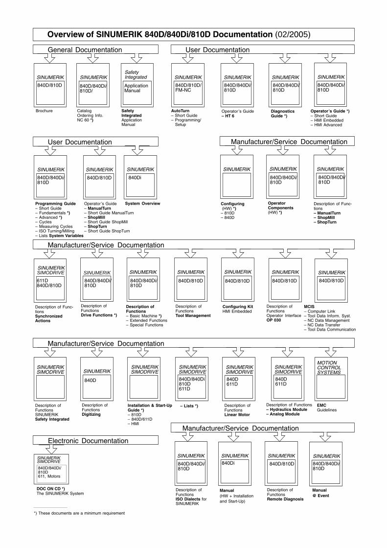
User Documentation
SINUMERIK
840D/810D
SINUMERIK
Overview of SINUMERIK 840D/840Di/810D Documentation (02/2005)
Brochure Catalog Ordering Info.NC 60 *)
Description of Functions Drive Functions *)
Description of Functions– Basic Machine *) – Extended Functions– Special Functions
840D/840Di/810D
SINUMERIK
840D/840Di/810D
ApplicationManual
Safety Integrated Application Manual
SafetyIntegrated
840D/840Di810D
– Lists *)Installation & Start-UpGuide *)– 810D– 840D/611D– HMI
SINUMERIK
840D
Description of FunctionsDigitizing
611D
SINUMERIK
SINUMERIK
840D/810D
Configuring Kit HMI Embedded
SINUMERIK
840D/840Di/810D
SIMODRIVE
611D840D/810D
Description of FunctionsSINUMERIKSafety Integrated
SINUMERIKSIMODRIVE
SINUMERIK
840D/840Di/810D611, Motors
SIMODRIVE
DOC ON CD *)The SINUMERIK System
General Documentation
Electronic Documentation
Manufacturer/Service Documentation
Manufacturer/Service Documentation
SINUMERIK
840D/810D/FM-NC
SINUMERIK
840D/840Di/810D
User Documentation
Diagnostics Guide *)
Operator ’s Guide – HT 6
AutoTurn– Short Guide– Programming/ Setup
SINUMERIK
840D/840Di/810D
Programming Guide– Short Guide– Fundamentals *)– Advanced *)– Cycles– Measuring Cycles– ISO Turning/Milling– Lists System Variables
Operator Components(HW) *)
Description of Func-tionsSynchronized Actions
840D/840Di/810D
SINUMERIK
Operator ’s Guide– ManualTurn– Short Guide ManualTurn– ShopMill– Short Guide ShopMill– ShopTurn– Short Guide ShopTurn
840D/810D
Manufacturer/Service Documentation
*) These documents are a minimum requirement
Operator’s Guide *)– Short Guide– HMI Embedded– HMI Advanced
SINUMERIK
840D/840Di/810D
Configuring (HW) *)– 810D– 840D
SINUMERIK
SINUMERIK
840D/810D
SINUMERIK
840D/810D
Description of FunctionsOperator InterfaceOP 030
Description ofFunctionsTool Management
SINUMERIKSIMODRIVE
SINUMERIKSIMODRIVE
SINUMERIKSINUMERIK
SINUMERIKSIMODRIVE
SINUMERIKSIMODRIVE
840D611D
840D611D
Description ofFunctionsLinear Motor
Description of Functions– Hydraulics Module– Analog Module
MOTIONCONTROLSYSTEMS
EMCGuidelines
Manufacturer/Service Documentation
SINUMERIK
Description of FunctionsISO Dialects for SINUMERIK
840D/840Di/810D
SINUMERIK
Manual(HW + Installationand Start-Up)
840Di
SINUMERIK
System Overview
840Di
840D/840Di/810D/
SINUMERIK
Description of FunctionsRemote Diagnosis
840D/810D
SINUMERIK
840D/810D
MCIS– Computer Link– Tool Data Inform. Syst.– NC Data Management– NC Data Transfer– Tool Data Communication
SINUMERIK
Description of Func-tions– ManualTurn– ShopMill– ShopTurn
840D/840Di/810D
SINUMERIK
840D/840Di/810D
Manual@ Event


© Siemens AG, 2005Subject to change without prior notice
Order No.: 6FC5297-6AD80-0BP3
Printed in Germany
Siemens AG Automation and Drives Motion Control Systems Postfach 3180 91050 ERLANGEN GERMANY www.siemens.com/motioncontrol
Related Documents


