Desarrollo de una celda electroquímica en gel para la evaluación in situ del patrimonio cultural metálico Blanca Ramírez Barat Tesis depositada en cumplimiento parcial de los requisitos para el grado de Doctor en Ciencia e Ingeniería de Materiales Universidad Carlos III de Madrid Director: Emilio Cano Díaz Tutora: María Asunción Bautista Arija Julio 2019

Welcome message from author
This document is posted to help you gain knowledge. Please leave a comment to let me know what you think about it! Share it to your friends and learn new things together.
Transcript

Desarrollo de una celda electroquímica en gel para la evaluación in situ del patrimonio cultural metálico
Blanca Ramírez Barat
Tesis depositada en cumplimiento parcial de los requisitos para el grado de Doctor en
Ciencia e Ingeniería de Materiales
Universidad Carlos III de Madrid
Director:
Emilio Cano Díaz
Tutora:
María Asunción Bautista Arija
Julio 2019

Esta tesis se distribuye bajo licencia “Creative Commons Reconocimiento – No Comercial –
Sin Obra Derivada”.

A mi madre.

AGRADECIMIENTOS
Como ocurre en todas las tesis, este es un capítulo con mucho contenido. Especialmente en mi caso, en el que es el capítulo final de un largo recorrido personal y profesional y son muchas las personas que me han acompañado en el camino. También es cierto que este es un capítulo muy personal, y por ese motivo he considerado seriamente escribir “A todos. Ellos ya saben quiénes son”, pero al final he claudicado, así que, aunque sin extenderme todo lo que debiera, allá va.
A Emilio Cano, que ha sido director, compañero y amigo, cada cosa en el momento oportuno y en quien he encontrado - con el permiso de Bea- mi media naranja profesional. A mi tutora, Asunción Bautista, por todo lo que me ha enseñado y por su confianza y apoyo en los momentos más difíciles, y por lo mismo, a Fran. A mis compañeros de la S.G.P.I. y en especial a Aníbal, porque siempre creyó en mí, y me animó cuando yo ya había renunciado a seguir por este camino. A los compañeros del metal, que me han hecho sentir como en casa desde el día que llegué al CENIM, por todos esos ratos compartiendo conocimientos, ideas, recursos, preocupaciones, buenos momentos y muchas risas y muchos cafés: Dani, Belén, Cristina, María, JC, Fede, Santi, Violeta, Gleydis, Jenny, Cris, Alejandro... Y entre ellos mis compañeros del grupo COPAC, los que están, Ana, Ivan, Irene, Conchi y los que se fueron, pero de algún modo siguen formando parte, Diana, Teresa, Marc, David. Al resto de personal del CENIM, a Paco, del taller, por hacerme las celdas, a Antonio, por su ayuda en el SEM, y al resto de compañeros de los servicios y administración, porque gracias a todos esto funciona. A todas las personas de la UC3M que, en algún momento, de una manera o de otra, me han echado una mano para que esto fuera posible: Susana, Berna, Mª Eugenia, Raquel, Delia, etc. A Emma y Sole, del IPCE por tantos ratos, y a María y a Miriam por tantos otros. A Marian y a Joaquina, del MUNCYT, por muchos años mezclando ciencia y conservación. A Antonio y Mª Teresa Domenech, por acogerme en Valencia, y por mucho más. A Rosa, del Museo de Escultura de Leganés, por su enorme amabilidad y su ayuda. A Marisa y Miguel Angel Codina, por compartir su tiempo y su conocimiento. Al gran Martín Chirino, por abrirnos las puertas de su casa, y a Alfredo Delgado. A Paola, por su generosidad. A Edith, Mónica, Pierluigi, por compartir trabajo y pasión por los metales. A mi familia, por el tiempo robado.

CONTENIDOS PUBLICADOS Y PRESENTADOS
Los siguientes trabajos publicados forman parte de la tesis doctoral y como tales se incluyen en la misma con los correspondientes permisos del propietario de los derechos. El papel de la doctoranda en todos estos trabajos incluye el diseño y realización de la parte experimental, interpretación de los resultados y redacción del manuscrito.
• B. Ramírez Barat, E. Cano, ‘Advances for in-situ EIS measurements and their interpretation for the diagnostic of metallic cultural heritage: a review’, ChemElectroChem, (2018), 5, pp 2698–2716. DOI: 10.1002/celc.201800844.
Papel: revisión de todos los artículos y redacción del manuscrito. Incluido en el capítulo 1 apartado 1.2.2. La aplicación de la EIS en patrimonio
cultural. Estado de la cuestión. Todo material de esta fuente incluido en la tesis está señalado por medios
tipográficos y una referencia explícita. • B. Ramírez Barat, E. Cano, ‘The use of agar gelled electrolyte for in situ electrochemical
measurements on metallic cultural heritage’, Electrochimica Acta, 182(2015) 751-62. DOI: 10.1016/j.electacta.2015.09.116
Papel: realización de la parte experimental, co-interpretación de los resultados y co-redacción del manuscrito.
Incluido en el capítulo 4. apartado 4.1 Todo material de esta fuente incluido en la tesis está señalado por medios
tipográficos y una referencia explícita.
• B. Ramírez Barat, E. Cano, P. Letardi, ‘Advances in the design of a gel-cell electrochemical sensor for corrosion measurements on metallic cultural heritage’, Sensors & Actuators: B Chemical 261(2018) 572-80. DOI: 10.1016/j.snb.2018.01.180
Papel: co-diseño y realización de la parte experimental, interpretación de los resultados y redacción del manuscrito.
Incluido en el capítulo 4 apartado 4.2.1. Construcción de la celda y optimización de los parámetros de diseño.
Todo material de esta fuente incluido en la tesis está señalado por medios tipográficos y una referencia explícita.
• P. Letardi, B. Ramírez Barat, E. Cano, ‘Analysis of the influence of the electrochemical
cell setup for corrosion measurements on metallic cultural heritage’, European Corrosion Congress - EUROCORR, Prague, 2017.
Papel: co-diseño y realización de la parte experimental, co-interpretación de los resultados y revisión del manuscrito.
Parte de los resultados de este trabajo se han incluido en el capítulo 4 apartado 4.2.2. Comparación con otros sistemas.
El material de esta fuente incluido en la tesis no está señalado por medios tipográficos ni referencias.

• B. Ramírez Barat, E. Cano: “Agar vs agarose gelled electrolyte for in situ corrosion studies on metallic cultural heritage”, ChemElectroChem, (2019), 6 (9), pp. 2553-2559. DOI: 10.1002/celc.201900344
Papel: diseño y realización de la parte experimental, interpretación de los resultados y redacción del manuscrito.
Incluido en el capítulo 4 apartado 4.2.2. Modificación del electrólito. Todo material de esta fuente incluido en la tesis está señalado por medios
tipográficos y una referencia explícita.
• P. Letardi, B. Ramírez Barat, M. Albini, P. Traverso, E. Cano, E. Joseph, ‘Copper Alloys and Weathering Steel Used in Outdoor Monuments: Weathering in an Urban-Marine Environment’, en: R. Menon, C. Chemello, A. Pandya (Eds.), METAL2016, 9th interim meeting of the ICOM-CC Metals Working Group, New Delhi, India, 2016, pp. 320-8.
Papel: realización de la parte experimental, interpretación de los resultados y co-redacción del manuscrito en los apartados de metalografía, microscopía electrónica e impedancia.
Incluido en el capítulo 4 apartado 4.3.1.1. Evaluación de pátinas Todo material de esta fuente incluido en la tesis está señalado por medios
tipográficos y una referencia explícita.
• B. Ramírez Barat, T. Palomar, B. Garcia, D. De la Fuente, E. Cano, ‘Composition and Protective Properties of Weathering Steel Artificial Patinas for the Conservation of Contemporary Outdoor Sculpture’, en: R. Menon, C. Chemello, A. Pandya (Eds.), METAL 2016 9th interim meeting of the ICOM-CC Metals Working Group New Delhi, India, 2016, pp. 314-9
Papel: diseño y realización de la parte experimental, interpretación de los resultados y redacción del manuscrito.
Incluido en el capítulo 4 apartado 4.3.1.1. Evaluación de pátinas Todo material de esta fuente incluido en la tesis está señalado por medios
tipográficos y una referencia explícita.
• B. Ramírez Barat, E. Cano, ‘Evaluación in situ de recubrimientos protectores para patrimonio cultural metálico mediante espectroscopía de impedancia electroquímica’, Ge-conservación, 8(2015) 6-13. https://ge-iic.com/ojs/index.php/revista/article/view/278
Papel: diseño y realización de la parte experimental, interpretación de los resultados y redacción del manuscrito.
Incluido en el capítulo 4 apartado 4.3.1.2. Evaluación de recubrimientos Todo material de esta fuente incluido en la tesis está señalado por medios
tipográficos y una referencia explícita.

• B. Ramírez Barat, A. Crespo, E. García, S. Díaz, E. Cano, ‘An EIS study of the conservation treatment of the bronze sphinxes at the Museo Arqueológico Nacional (Madrid)’, Journal of Cultural Heritage, 24(2017) 93-9. DOI: 10.1016/j.culher.2016.10.010
Papel: realización de la parte experimental, co-interpretación de los resultados y co-redacción del manuscrito.
Incluido en el capítulo 4 apartado 4.3.2.1 Estudio de las esfinges del Museo Arqueológico Nacional
Todo material de esta fuente incluido en la tesis está señalado por medios tipográficos y una referencia explícita.
• B. Ramírez Barat, A. Crespo, E. Cano, ‘In situ evaluation of outdoor sculpture with a gel
polymer electrolyte cell’, en: M.J. Mosquera, A. Gil (Eds.), TechnoHeritage 2017. 3rd International Congress Science and Technology for the Conservation of Cultural Heritage, Cádiz, 2017. CRC Press, pp. 83-85.
Papel: realización de la parte experimental, interpretación de los resultados y redacción del manuscrito.
Preprint incluido en el capítulo 4 apartado 4.3.2.3 Obras en el Museo de Escultura de Leganés.
Todo material de esta fuente incluido en la tesis está señalado por medios tipográficos y una referencia explícita.

OTROS MÉRITOS DE INVESTIGACIÓN Además de los resultados incluidos en la tesis, existen otros resultados relacionados con contenido y desarrollo de la misma, que se relacionan a continuación, y que incluyen congresos, cursos, capítulos de libro y artículos de colaboración:
Publicaciones:
• G. Monrrabal, B. Ramírez-Barat, A. Bautista, F. Velasco, E. Cano, ‘Non-destructive electrochemical testing for stainless-steel components with complex geometry using innovative gel electrolytes’, Metals, 8 (2018).
• J. Redondo-Marugán, J. Piquero-Cilla, M.T. Doménech-Carbó, B. Ramírez-Barat, W.A. Sekhaneh, S. Capelo, et al., ‘Characterizing archaeological bronze corrosion products intersecting electrochemical impedance measurements with voltammetry of immobilized particles’, Electrochimica Acta, 246(2017) 269-79.
• E. Cano, B. Ramírez, T. Palomar, "Ciencia y tecnología aplicada al estudio y la restauración del patrimonio metálico: técnicas electroquímicas", ICOM CE Digital 10 (2015) 96-103.
• E. Cano, A. Crespo, D. Lafuente, B. Ramírez Barat, "A novel gel polymer electrolyte cell for in-situ application of corrosion electrochemical techniques", Electrochemistry Communications, 41 (2014) 16-19.
Capítulos de libro
• E. Cano, B. Ramírez Barat, ‘Electrochemical techniques for in-situ corrosion evaluation of Cultural Heritage’, in: D.M. Bastidas, E. Cano (Eds.) Advanced Characterization, Diagnostics, and Evaluation in Heritage Science, Springer, 2018, pp. 21-32.
• B. Ramírez Barat, A. Crespo, E. Cano, ‘In situ evaluation of outdoor sculpture with a gel polymer electrolyte cell’, in: M.J. Mosquera, A. Gil (Eds.) TechnoHeritage 2017. 3rd International Congress Science and Technology for the Conservation of Cultural Heritage, CRC Press, Cádiz, 2017, pp. 83-85.
Otros trabajos presentados en workshops y congresos.
• B. Ramírez Barat, P. Letardi, E. Cano, ‘An overview on the use of EIS measurements for the assessment of patinas and coatings for conservation of metallic cultural heritage.’, in: Metal 2019. 9th interim meeting of the ICOM-CC Metals Working Group., Neuchâtel, Switzerland, 2-6 septiembre, 2019.
• Crespo, B. Ramírez Barat, E. Cano, ‘Electrochemical evaluation of the patina of a weathering steel sculpture: “Once Módulos”’, in: TechnoHeritage 2019. 4th International Congress Science and Technology for the Conservation of Cultural Heritage, Sevilla, 26-29 marzo 2019.

• E. Cano, B. Ramírez Barat, ‘Assessment of protective properties of metal coatings by Electrochemical Impedance Spectroscopy (EIS)’, en: IPERION CH, New strategies for diagnostics of conservation treatments, Amsterdam, 7-8 febrero, 2019, pp. 13.
• E. Cano, B. Ramírez Barat, ‘A gel electrochemical cell for in situ assessment of patinas and protective coatings for metals’, in: 4th International Conference on Science and Engineering in Arts, Heritage and Archaeology (SEAHA), University College London, 6-8 junio 2018.
• Crespo, B. Ramírez Barat, I. Diaz Ocaña, E. Cano Díaz, ‘Efecto del patinado artificial del acero Cor-Ten en la conservación de Templo, de Adriana Veyrat’, in: Conservación de Arte Contemporáneo 18ª Jornada, Museo Reina Sofía, Madrid, 2017, pp. 193-201.
• B. Ramírez Barat, A. Crespo, E. Cano, ‘A gel electrolyte cell for the electrochemical evaluation of conservation treatments on cultural heritage’, in: Workshop on New strategies for the conservation of metallic cultural heritage, Institut National du Patrimoine, Paris, 2016, pp. 16.
• Crespo, B. Ramírez Barat, E. Cano, ‘Artificial patinas in contemporary weathering steel sculpture", in: 5th INTERNATIONAL CONFERENCE YOuth in COnservation of CUltural Heritage- YOCOCU 2016, Madrid, 2016, pp. 230-233.
• Ramírez Barat, S. Díaz Martínez, E. García Alonso, E. Cano Díaz, ‘Aplicación de la EIS a la evaluación in situ de la resistencia a la corrosión de una escultura en bronce’, in: MetalEspaña 2015, Segovia, 2015, pp. 102-109.
• B. Ramírez Barat, E. Cano, ‘Diseño de una celda electroquímica en gel para evaluación in situ del patrimonio cultural metálico’, Jornadas de Investigación Emergente en Conservación y Restauración de Patrimonio Emerge 2014, Valencia, 2014, pp. 635-41.
Actividades de formación y difusión
• “Evaluación del estado de conservación del patrimonio cultural metálico mediante técnicas electroquímicas in-situ” (1h). Nuevos retos en la caracterización y conservación de los bienes del Patrimonio. UIMP. Santander, 2-5 julio de 2019.
• Cultural “Avances en protección y diagnóstico del patrimonio cultural metálico. Aplicación de técnicas electroquímicas” (1.5h). Innovaciones en conservación–restauración del patrimonio metálico arqueológico. Escuela de Patrimonio Histórico de Nájera. 23-25 de mayo de 2018.
• "La ciencia al servicio de la conservación y restauración del patrimonio metálico" (1.5h) VII Encontro de Conservación e Restauración: Conservación e restauración de metais arqueolóxicos. Museo Provincial de Pontevedra 15-17 de noviembre de 2017.
• Prácticas con equipos portátiles in situ (4h) en el Encuentro Metodologías avanzadas no destructivas: análisis de patrimonio (MetAnD). Universidad Internacional Menéndez Pelayo. 2017.
• ‘In situ electrochemical impedance spectroscopy (EIS) for conservation assessment’, 1st IPERION-CH Training Camp "HERITAGE SCIENCE IN PRACTICE", Nájera 14th-18th November 2016 (6h).

Desarrollo de una celda electroquímica en gel para la evaluación in situ del patrimonio cultural metálico
Blanca Ramírez Barat
Director: Emilio Cano Díaz
CONSEJO SUPERIOR DE INVESTIGACIONES CIENTÍFICAS (CSIC)
CENTRO NACIONAL DE INVESTIGACIONES METALÚRGICAS (CENIM)
Departamento de Ingeniería de Superficies, Corrosión y Durabilidad
Tutora: María Asunción Bautista Arija
UNIVERSIDAD CARLOS III DE MADRID
Instituto Tecnológico de Química y Materiales "Alvaro Alonso Barba"
Departamento de Ciencia e Ingeniería de Materiales

"Bástame solo suplicaros acojáis con benevolencia este insignificante trabajo en el
que, como dije al principio, se contendrán grandes defectos debido sin duda a mi
natural insuficiencia."
Final del discurso para la obtención del grado de doctor de Santiago Ramón y Cajal

i
RESUMEN
A lo largo de toda la historia, la humanidad ha tratado de preservar ciertos
objetos que por diversos motivos han adquirido un valor y un significado para la
sociedad que los ha poseído, constituyendo su patrimonio cultural. En ese esfuerzo por
preservar el pasado para las generaciones presentes y futuras, la investigación
científica ha ido adquiriendo una relevancia progresiva. La ciencia de la conservación
trata de comprender los problemas y aportar soluciones para la conservación del
patrimonio, tanto desde el punto de vista tecnológico como estratégico o de
sostenibilidad. El adecuado diseño y planificación de las estrategias de conservación de
los objetos y colecciones del patrimonio cultural son fundamentales, y deben tener en
cuenta las limitaciones tecnológicas y de recursos.
El fin de esta tesis ha sido contribuir desde la Ciencia e Ingeniería de Materiales a este
objetivo, concretamente en el ámbito del patrimonio cultural metálico, desarrollando
una herramienta de diagnóstico del estado de conservación y de los sistemas de
protección para este tipo de bienes culturales.
El principal problema para la conservación del patrimonio metálico es la corrosión,
que tiene lugar por interacción entre el objeto metálico y el medio que lo rodea. Para
enfrentarse a este problema, los conservadores de patrimonio metálico cuentan con
dos estrategias: el control de las condiciones ambientales –lo que no siempre es
posible- o el empleo de recubrimientos protectores, que lo aíslen del medio, que es el
método más habitual en la práctica de la conservación. Sin embargo, cualquier método
presenta limitaciones, por lo que resulta de gran relevancia el poder evaluar la eficacia
y la duración de los sistemas empleados, antes de que aparezcan efectos negativos en
el objeto. Así, los recubrimientos habituales en conservación –principalmente ceras y
barnices acrílicos- tienen una capacidad protectora bastante limitada y deben ser
renovados cada cierto tiempo. Esto conlleva la necesidad de conocer y evaluar el
comportamiento de los sistemas aplicados, con especial hincapié en su durabilidad.
La espectroscopía de impedancia electroquímica (EIS) es una técnica electroquímica
que permite estudiar los procesos de corrosión en los metales en diferentes medios y
evaluar la capacidad protectora de los recubrimientos, por lo que a priori resulta una

RESUMEN
ii
técnica idónea para este propósito. Sin embargo, la aplicación de la EIS a la
conservación del patrimonio cultural metálico no es una práctica generalizada, por las
dificultades particulares que presenta su aplicación en este campo. Las características
propias de los bienes culturales, hacen que en muchos casos los estudios de
laboratorio no sean suficientes, y que el objeto no se pueda trasladar, por lo que
resulta imprescindible la realización de medidas in situ, directamente sobre la
superficie del objeto a conservar.
La aplicación de técnicas electroquímicas requiere montar una celda electroquímica,
en la que poner en contacto la superficie del material que se va a estudiar con un
electrólito líquido y los electrodos auxiliares (electrodo de referencia y
contraelectrodo). Esta tarea resulta compleja en el caso de superficies irregulares y no
horizontales como las de una escultura. Para dar una solución a este problema, el
objetivo de esta tesis ha sido el desarrollo de una celda electroquímica con un
electrólito en gel, específicamente diseñada para la realización de medidas in situ
sobre patrimonio cultural.
Para el diseño se han tenido en cuenta diversos factores relacionados con este tipo de
medidas, tales como la forma y tamaño de la celda para facilitar su colocación en la
superficie de la obra, la naturaleza, geometría y posición de los electrodos para
obtener una señal de calidad, o el tipo de soporte adecuado para lograr una buena
estabilidad mecánica.
El trabajo se ha estructurado en varios apartados, si bien no recorrido su no ha sido
lineal, ya que los avances y dificultades en cada uno de los aspectos o subapartados
han contribuido al desarrollo de los demás.
El primer paso ha sido comprobar la posibilidad de realizar medidas de impedancia
utilizando un electrólito gelificado con agar, abordando cuestiones como la validez,
reproducibilidad o repetividad de los resultados. Una vez verificada la obtención de
medidas de calidad y comparables a las de un electrólito tradicional, se ha estudiado
en mayor detalle la contribución del agar en las medidas, para establecer la
concentración más adecuada tanto desde el punto de vista electroquímico como
mecánico. En esta misma línea, se ha comparado el comportamiento del agar y de la
agarosa, uno de los dos polisacáridos que componen este material, y que es el
responsable de las propiedades gelificantes.

RESUMEN
iii
El siguiente paso ha sido analizar en detalle el comportamiento del sistema completo,
incluyendo los electrodos (de referencia y contraelectrodo) para optimizar el diseño.
Así, se han estudiado diferentes configuraciones de celda con electrodos de distinta
naturaleza y geometría, un factor que ha demostrado su relevancia para minimizar la
aparición de artefactos en las medidas al emplearse electrólitos de baja conductividad.
En paralelo al desarrollo y estudio de la celda, se han realizado medidas sobre
diferentes sustratos para evaluar la aplicabilidad del sistema desarrollado a la
resolución de problemas de conservación. Por un lado, se han realizado ensayos de
laboratorio sobre probetas de bronce y acero patinable con diversas pátinas y
recubrimientos, simulando cuestiones que se abordan habitualmente en la
conservación del patrimonio metálico; por otro lado, se han realizado estudios in situ,
sobre obra real (principalmente escultura moderna y contemporánea del Museo
Arqueológico Nacional, Museo de Escultura de Leganés y colección de escultura del
campus de la Universidad Politécnica de Valencia), para comprobar y validar el diseño
de la celda en su modo de aplicación final, e ir introduciendo las modificaciones
necesarias para solventar las dificultades prácticas que se iban encontrando en
diferentes situaciones.
Todo ello ha permitido concluir con éxito con el diseño de una celda electroquímica con
electrólito en gel, adecuada para la realización de medidas electroquímicas in situ
sobre el patrimonio cultural metálico, aportando una nueva herramienta para avanzar
en la conservación de este tipo de patrimonio.

iv
ABSTRACT
Along history, mankind has sought to preserve certain objects which, for
multiple reasons, have acquired a special value and a meaning for the society that
owned them, constituting their cultural heritage. In this effort to preserve the past for
the present and future generations, scientific research has gained an increasing
relevance. Conservation science aims at understanding problems and provide
solutions for the conservation of heritage, both from the technological and sustainable
point of view. The proper design and planning of strategies for the conservation of
cultural heritage objects and collections is essential, and should take into account both
technological and resources limitations.
The purpose of this thesis is to contribute through Materials Science and Engineering
to this objective, in particular in the field of metallic cultural heritage, developing a tool
of diagnosis of the state of conservation and evaluation of protection systems for this
type of heritage.
The main challenge for the conservation of the heritage metal is corrosion, which takes
place because of the interaction between the metal object and its environment. To deal
with this problem, metal conservators have two strategies: control of environmental
conditions - which is not always possible - or the use of protective coatings to isolate
the metal object from the environment, which is the most frequent solution in
conservation practice. Nonetheless, any method has certain limitations. For this
reason, it is of great importance being able to evaluate the effectiveness and lifespan of
protective systems before damage occurs.
Common coatings in heritage conservation –mainly waxes and acrylic varnishes- have
a quite limited protective ability, and have to be renewed periodically. This entails the
need of knowing and evaluating the behavior of applied protective coatings, with
particular focus on durability.
Electrochemical impedance spectroscopy (EIS) is an electrochemical technique that
allows to investigate corrosion mechanisms of metals in different environments and to

ÍNDICE
v
evaluate the protective properties of coatings. This makes EIS the ideal technique for
this purpose.
Unfortunately, the use of EIS in metal cultural heritage is not a widespread practice,
due to the particular difficulties in applying this technique in heritage objects. The
special characteristics of cultural heritage assets make it necessary to carry out on
site measurements, directly on the surface of the object to preserve.
The use of electrochemical techniques requires mounting an electrochemical cell, in
which the surface of the material under study is placed in contact with a liquid
electrolyte and the auxiliary electrodes (reference and counter electrode). This is not
an easy task for irregular and non-horizontal surfaces as in a sculpture. To overcome
this challenge, the objective of this thesis is to develop an electrochemical cell with a
gelled electrolyte, specifically designed for conducting in situ electrochemical
measurements on cultural heritage.
The design has taken into account various factors related to this type of measures,
such as the shape and size of the cell to be placed on the surface of the object, the
nature, geometry and position of the electrodes to obtain a quality signal, or the fixing
system to ensure a good mechanical stability.
This work has been structured into several sections, although its progress has not
been linear in time, since the advances and difficulties in each of the aspects or
subsections have contributed to improve and develop the others.
The first step has been checking the possibility of performing impedance measures
using an agar gelled electrolyte, addressing issues such as validity, reproducibility, or
repeatability of the results. Once verified the quality of measurements, comparable to a
traditional electrolyte, detail the contribution of the agar been studied in greater detail,
to establish the most appropriate concentration both from the electrochemical and
mechanical point of view. With the same purpose the behavior of agar and agarose has
been compared.
The next step was to analyze in detail the behavior of the entire system, including
electrodes (reference and counter electrode) to optimize the design. Thus, we have
studied different configurations of cell with electrodes of different nature and

ÍNDICE
vi
geometry, a factor that has shown its relevance to minimize the appearance of artifacts
in the measurements when using low-conductivity electrolytes.
In parallel to the development and study of the cell, measurements on different
substrates have been performed to assess the applicability of the developed system to
solve conservation problems. On the one hand, laboratory tests on bronze and
weathering steel coupons, with different patinas and coatings were performed,
simulating issues usually addressed in metallic heritage conservation; on the other
hand, studies have been conducted in situ on real work (mainly modern and
contemporary sculpture of the National Archaeological Museum, Museum of Sculpture
in Leganes and the sculpture collection at the Polytechnic University of Valencia
campus), to check and validate the design of the cell in its final application mode, and
to introduce the modifications necessary to solve the practical difficulties that were
found in different situations.
This has allowed concluding successfully with the design of an electrochemical cell
with a gel electrolyte, suitable for carrying out on-site electrochemical measures on
metallic cultural heritage, providing a new tool for a better conservation of this kind of
heritage.

vii
ÍNDICE
RESUMEN ............................................................................................................................. i
ABSTRACT .......................................................................................................................... iv
ÍNDICE ................................................................................................................................ vii
1. INTRODUCCIÓN ............................................................................................................... 1
1.1. La conservación del patrimonio cultural metálico. .................................................... 1
1.1.1. Los metales como patrimonio. .............................................................................. 1
1.1.2. Degradación del patrimonio metálico. .................................................................. 1
1.1.3. Conservación de metales. Criterios y metodología. ............................................. 3
1.2. La EIS como herramienta de diagnóstico del estado de conservación del
patrimonio cultural metálico. Fundamentos y Estado de la cuestión. .............................. 7
1.2.1. Fundamentos de la técnica. .................................................................................. 7
1.2.2. La aplicación de la EIS en patrimonio cultural. Estado de la cuestión. ............. 13
2. OBJETIVOS ..................................................................................................................... 35
3. MATERIALES Y MÉTODOS ............................................................................................. 37
3.1. Selección y preparación de materiales metálicos. ................................................... 37
3.1.1. Probetas metálicas. ............................................................................................. 37
3.1.3. Recubrimientos orgánicos. ................................................................................. 41
3.2. Técnicas electroquímicas........................................................................................... 45
3.2.1. Electrodos. ........................................................................................................... 45
3.2.2. Electrólitos. .......................................................................................................... 47
3.2.1. Técnicas electroquímicas. ................................................................................... 48
3.3. Otras técnicas. ............................................................................................................ 52
3.2.1. Colorimetría. ........................................................................................................ 52
3.2.2. Medidas de espesor. ............................................................................................ 52

ÍNDICE
viii
4. RESULTADOS Y DISCUSIÓN .......................................................................................... 54
4.1. Prueba de concepto: diseño de un prototipo y validación de la idea. ....................... 54
4.2. Optimización del diseño. ............................................................................................ 70
4.2.1. Construcción de la celda y optimización de los parámetros de diseño. ............ 71
4.2.2. Comparación con otros sistemas. ....................................................................... 90
4.2.2. Modificación del electrólito. ................................................................................ 95
4.3. Validación y aplicación (casos prácticos). ................................................................ 103
4.3.1. Ensayos de laboratorio: patinas y recubrimientos. .......................................... 103
4.3.2. Medidas de campo y casos reales. .................................................................... 141
4.4. Discusión general. .................................................................................................... 178
5. CONCLUSIONES .......................................................................................................... 184
6. OTROS DESARROLLOS Y FUTURAS LÍNEAS DE TRABAJO. ...................................... 186
7. BIBLIOGRAFÍA ............................................................................................................. 189
8. ÍNDICE DE TABLAS Y FIGURAS ................................................................................... 206
8.1. Índice de tablas. ........................................................................................................ 206
8.2. Índice de figuras. ...................................................................................................... 207

1
1. INTRODUCCIÓN
1.1. La conservación del patrimonio cultural metálico.
1.1.1. Los metales como patrimonio.
Desde tiempos remotos, los metales han desempeñado un papel fundamental
en la historia de la humanidad, estando su empleo estrechamente ligado al desarrollo
de las sociedades, tanto a nivel tecnológico, como económico, social y cultural. La
versatilidad de los metales gracias a sus propiedades mecánicas, durabilidad,
conformabilidad y aspecto, ha permitido al hombre disponer de armas y herramientas,
pero también de monedas, joyas, esculturas, etc. Por ello, el patrimonio metálico
forma una parte importante del legado histórico y cultural que el hombre ha tratado
siempre de conservar para sí y transmitir a generaciones futuras.
Como ocurre con todos los materiales, los objetos metálicos tienden a degradarse con
el tiempo, y para luchar contra la pérdida de nuestro patrimonio la ciencia de la
conservación trata de desarrollar herramientas adecuadas para su diagnóstico y
conservación.
1.1.2. Degradación del patrimonio metálico.
Aunque los objetos metálicos también pueden sufrir daños mecánicos, el
principal problema de conservación en el patrimonio cultural en metal es la corrosión.
De hecho, la corrosión es la principal causa de deterioro de todos los materiales
metálicos, formen o no parte de nuestro patrimonio, constituyendo un problema de
dimensión global.
La degradación de los materiales metálicos por corrosión supone considerables
pérdidas económicas; un conocido estudio de la NACE1 realizado entre 1999 -2001
situaba las pérdidas anuales por corrosión en EE.UU. en 276 mil millones de dólares,
aproximadamente el 3.1% del PIB [1]. En el caso del patrimonio cultural metálico, las
1 National Association of Corrosion Engineers.

INTRODUCCIÓN
2
pérdidas van mucho más allá de la dimensión económica ya que generalmente se trata
de piezas únicas e irremplazables. Dada la magnitud del problema, la lucha contra la
corrosión es un campo de estudio muy amplio y en constante desarrollo, que se aborda
desde diferentes estrategias.
Tal y como se define en la norma ISO 8044:2015 [2] , la corrosión es una consecuencia
de la interacción entre el objeto y el medio en el que se encuentra. En base a esto,
podemos afirmar que existen tres estrategias de lucha contra la corrosión: modificar
el medio, modificar el objeto, o evitar la interacción.
ISO 8044:2015, ' Corrosión de metales y aleaciones. Términos principales y definiciones
"La interacción fisicoquímica entre un metal y su entorno que da como resultado
cambios en las propiedades del metal, y que puede conducir a un deterioro
significativo de la función del metal, el medio ambiente o el sistema técnico, del que
forman parte".
La modificación del objeto, mediante el diseño y selección de materiales, es una
posible solución a nivel industrial, e incluso se podría aplicar en creación de nueva
obra contemporánea, pero obviamente no es aplicable cuando hablamos de metales
históricos o arqueológicos.
La modificación del medio ambiente supone actuar sobre los factores responsables de
la corrosión, que en el caso del patrimonio cultural son básicamente la humedad y los
contaminantes. Esta es –al menos teóricamente- una posibilidad en espacios
interiores, pero constituye una opción muy limitada para actuar en obras concretas en
el caso de espacios exteriores, más allá de los avances en la reducción de ciertos
contaminantes en los últimos años.
Cuando no es posible actuar sobre el objeto ni sobre el medio, la única solución es
tratar de evitar la interacción entre ambos. Por ello, el uso de recubrimientos
protectores e inhibidores de la corrosión es probablemente uno de los campos más
desarrollados a nivel industrial. Lamentablemente, la mayor parte de los avances en
este sector no son trasladables al patrimonio cultural que, por sus características
particulares, requiere abordar el problema de una forma diferente. Para entenderlo es

INTRODUCCIÓN
3
necesario introducir algunos conceptos sobre la conservación y restauración del
patrimonio.
1.1.3. Conservación de metales. Criterios y metodología.
El concepto de conservación de los objetos del patrimonio cultural va más allá
de la conservación material; lo que hace que un objeto forme parte de nuestro
patrimonio incluye aspectos inmateriales como el significado, el valor para la sociedad
que lo posee o su historia. Esta concepción es uno de los motivos por el que tanto los
conceptos de conservación y restauración en si como los métodos y los criterios nunca
han sido uniformes, y han ido evolucionando a lo largo de la historia.
En el año 2008 el Comité de Conservación del Consejo Internacional de Museos (ICOM-
CC) adoptó una resolución sobre la terminología de conservación para facilitar la
comunicación ya que tradicionalmente los mismos términos se empleaban con
diferentes significados en distintos lugares. De acuerdo con esta resolución [3],
debemos hablar de:
Conservación – Todas aquellas medidas o acciones que tengan como objetivo la salvaguarda del patrimonio cultural tangible, asegurando su accesibilidad a generaciones presentes y futuras. La conservación comprende la conservación preventiva, la conservación curativa y la restauración. Todas estas medidas y acciones deberán respetar el significado y las propiedades físicas del bien cultural en cuestión.
Conservación preventiva – Todas aquellas medidas y acciones que tengan como objetito evitar o minimizar futuros deterioros o pérdidas. Se realizan sobre el contexto o el área circundante al bien, o más frecuentemente un grupo de bienes, sin tener en cuenta su edad o condición. Estas medidas y acciones son indirectas – no interfieren con los materiales y las estructuras de los bienes. No modifican su apariencia.
Conservación curativa – Todas aquellas acciones aplicadas de manera directa sobre un bien o un grupo de bienes culturales que tengan como objetivo detener los procesos dañinos presentes o reforzar su estructura. Estas acciones sólo se realizan cuando los bienes se encuentran en un estado de fragilidad notable o se están deteriorando a un ritmo elevado, por lo que podrían perderse en un tiempo relativamente breve. Estas acciones a veces modifican el aspecto de los bienes.

INTRODUCCIÓN
4
Restauración – Todas aquellas acciones aplicadas de manera directa a un bien individual y estable, que tengan como objetivo facilitar su apreciación, comprensión y uso. Estas acciones sólo se realizan cuando el bien ha perdido una parte de su significado o función a través de una alteración o un deterioro pasados. Se basan en el respeto del material original. En la mayoría de los casos, estas acciones modifican el aspecto del bien.
En base a estas definiciones, podemos entender que los criterios actuales de
conservación se basan en la regla de mínima intervención: “tan poco como sea posible,
tanto como sea necesario”. Es necesario actuar para frenar el deterioro del objeto,
pero esa actuación se debe limitar para respetar sus valores materiales, estéticos,
históricos y conceptuales. Esto implica que cualquier intervención debe ser mínima y
no alterar el objeto original. Unida a esta idea de no alterar el original, se plantea la
además la necesidad de que cualquier tratamiento debe ser reversible.
Para cumplir con estos criterios y considerando las dos posibles vías de lucha contra
la corrosión, las estrategias en el campo de la conservación del patrimonio cultural
metálico incluirán la actuación sobre el medio –conservación preventiva- y los
recubrimientos protectores –conservación curativa-.
1.1.3.1. Modificación del medio ambiente: Conservación preventiva.
La conservación preventiva resulta siempre, desde el punto de vista teórico al
menos, la opción más adecuada. Eliminando los factores de riesgo se elimina el daño
sin intervenir sobre el objeto. Sin embargo, la conservación preventiva de los bienes
metálicos presenta dos limitaciones. Por un lado, una gran parte del patrimonio
metálico se encuentra expuesto en el exterior u otros ambientes sobre los que no se
puede intervenir fácilmente. Por otro, el control de las condiciones ambientales en el
interior de museos no resulta trivial: limitaciones en los recursos técnicos,
económicos y humanos, o el equilibrio entre la conservación, la exposición y el
discurso museístico, incompatibilidad de materiales en la misma vitrina o en el mismo
objeto, etc. hacen que frecuentemente sea necesario recurrir a sistemas de protección
adicionales, tales como recubrimientos e inhibidores.

INTRODUCCIÓN
5
1.1.3.2. Aislar del medio ambiente: Conservación curativa.
El empleo de recubrimientos para evitar el acceso o la actuación de los agentes
de degradación –humedad y contaminantes- a la superficie metálica es el
procedimiento más habitual como estrategia de conservación de patrimonio metálico.
El procedimiento estándar de protección de una superficie metálica mediante un
sistema de recubrimiento implica una limpieza exhaustiva de la superficie metálica –
eliminando cualquier resto de contaminación o productos de corrosión- seguida de la
aplicación de varias capas, imprimación, capa intermedia y acabado, constituidas por
diferentes pigmentos y polímeros orgánicos. Este tipo de sistemas no son aplicables
en patrimonio metálico, donde los recubrimientos deben cumplir una serie de
exigencias basadas en los criterios generales de conservación:
Requisitos que deben cumplir los recubrimientos
• Deben respetar el original. Los tratamientos aplicados no deben alterar el
material original. En muchos casos esto incluye también a la historia del objeto,
de modo que en el caso de los metales deben conservarse las pátinas o capas
de corrosión siempre que sea posible.
• No deben modificar el aspecto de la superficie. Por tanto, deben ser
transparentes y con un brillo similar al del objeto.
• Deben ser estables. No deben modificar su aspecto ni descomponerse con el
tiempo de modo que puedan comprometer el aspecto o la integridad del objeto
sobre el que se han aplicado.
• Deben ser reversibles. Cualquier tratamiento aplicado a un objeto del
patrimonio debe poder eliminarse para devolver a dicho objeto a su estado
original. Esto, en algunos casos esto no es posible, pero entonces se exige que
al menos permita la re-tratabilidad del mismo. Para el caso de recubrimientos,
esto se traduce en que deben emplearse materiales que no creen películas
insolubles o que impidan la adherencia de futuras aplicaciones.
De manera general, los recubrimientos habitualmente utilizados en la protección de
metales son resinas acrílicas y ceras (ceras microcristalinas y ceras de polietileno),

INTRODUCCIÓN
6
aunque en los últimos años se está investigando en el desarrollo de nuevos
recubrimientos alternativos, especialmente recubrimientos naturales y respetuosos
con el medio ambiente como carboxilatos [4-7], sistemas sol-gel [8-10], biopátinas [11-
14], etc.
Estos recubrimientos son transparentes, su color apenas se modifica por efecto de la
radiación UV y son reversibles. Como contrapartida, tanto su capacidad protectora
como su duración son bastante limitadas (entre 3 y 10 años, dependiendo de
recubrimiento y las condiciones ambientales) y deben ser renovados cada cierto
tiempo [15-17] . Las tareas de conservación y mantenimiento requieren del empleo de
recursos humanos y materiales, que son limitados y deben ser empleados de la
manera más eficiente posible. Por ello, resulta fundamental disponer de herramientas
de evaluación y diagnóstico que nos permitan decidir sobre la necesidad y la prioridad
de intervención sobre un objeto u otro, comparar distintos sistemas de aplicación y
materiales a disposición del restaurador, y servir para evaluar la eficacia de nuevos
recubrimientos.
Las técnicas analíticas habitualmente utilizadas para el estudio de recubrimientos
orgánicos como las técnicas espectroscópicas (UV-Vis, FTIR) o cromatográficas (SEC)
pueden proporcionar información sobre cambios físicos o modificaciones
estructurales que tienen relación con la degradación de los materiales, pérdidas de
solubilidad, amarilleamiento, etc. [18-20] Sin embargo, ninguna de estas técnicas nos
informa directamente de la relación entre estos cambios y la capacidad de seguir o no
protegiendo el metal.
Ante la necesidad de disponer de técnicas de diagnóstico adecuadas, en los años 90
comienzan a introducirse las técnicas electroquímicas para el estudio de los
problemas de corrosión y los sistemas de protección en el patrimonio cultural
metálico. Dentro de las técnicas electroquímicas la espectroscopía de impedancia
electroquímica (EIS) constituye una herramienta de gran utilidad en los estudios de
corrosión y la evaluación de recubrimientos e inhibidores, cuya aplicación en el campo
industrial está ampliamente consolidada. Su aplicación y adaptación a la problemática
particular del patrimonio cultural metálico es el objeto de este trabajo.

INTRODUCCIÓN
7
1.2. La EIS como herramienta de diagnóstico del estado de conservación del patrimonio cultural metálico. Fundamentos y Estado de la cuestión.
1.2.1. Fundamentos de la técnica.
i.Concepto de impedancia
D.R.A.E.: impedancia
Del fr. impédance.
1. f. Electr. Relación entre la tensión alterna aplicada a un circuito y la intensidad de la
corriente producida, y que se mide en ohmios.
2. f. Fís. Relación entre la magnitud de una acción periódica y la de la respuesta
producida en un sistema físico.
Como en el caso de otras técnicas espectroscópicas, la EIS se basa en aplicar
una señal sobre un sistema y analizar su respuesta a lo largo de un cierto intervalo de
frecuencias, pero a diferencia de otras técnicas, basadas en la radiación, la señal es
una señal eléctrica. De manera habitual, se aplica una señal sinusoidal de potencial y
la respuesta de sistema se produce en forma de corriente alterna. Matemáticamente,
la impedancia viene definida por:
𝑍(𝜔) = E(𝜔) 𝐼(𝜔)
De acuerdo con la expresión anterior, podemos ver que la impedancia es una magnitud
análoga a la resistencia eléctrica, según la define la ley de Ohm: R = E/I. Esta relación
sin embargo sólo es aplicable en corriente continua; para el caso más general, la
relación entre el potencial y la intensidad viene dada por la impedancia. La impedancia
(Z) se puede definir como la oposición que presenta un circuito al flujo de corriente
alterna, expresada en ohmios.

INTRODUCCIÓN
8
ii. Medidas de impedancia
La impedancia de un sistema se mide aplicando una pequeña señal de potencial
sinusoidal (típicamente de unos 10mV) en un cierto intervalo de frecuencia. Esta señal
desplaza al sistema de su equilibrio, que seguidamente experimenta un proceso de
relajación produciendo una corriente sinusoidal de la misma frecuencia, pero diferente
amplitud y ángulo de fase.
Figura 1 Esquema y representación matemática de la impedancia.
Realizando un barrido de frecuencias, habitualmente entre 100 kHz- 10 mHz se obtiene
la impedancia del sistema como una función de la frecuencia, caracterizada por el
módulo, |Z| o Z0, y el desplazamiento del ángulo de fase ϕ. Aplicando la relación de
Euler (eix = cosx + isenx), la impedancia también se puede expresar como una magnitud
compleja:
𝑍 = = ( ) ( ( )) = 𝑍 𝑒𝑥𝑝(𝑗𝜑) = 𝑍 (𝑐𝑜𝑠𝜑 𝑗𝑠𝑒𝑛𝜑) = 𝑍 𝑗𝑍′′
Donde j representa √−1 (en electroquímica se usa la letra j en lugar de i para evitar su
confusión con la intensidad de corriente)
ii. Representación gráfica del espectro de impedancia:
A partir de las dos expresiones matemáticas de la impedancia se obtienen dos
formas típicas de representar gráficamente el espectro de impedancia, el diagrama de
Bode y el diagrama de Nyquist (figura 2). En el diagrama de Bode se representan el
módulo de la impedancia (|Z| o Z0) y el desplazamiento del ángulo de fase (ϕ) frente a la
𝑍(𝜔) = 𝐸(𝜔)𝐼(𝜔) = 𝐸 𝑠𝑒𝑛 (𝜔𝑡)𝐼 𝑠𝑒𝑛 (𝜔𝑡 𝜑)= 𝑍 𝑠𝑒𝑛 (𝜔𝑡)𝑠𝑒𝑛 (𝜔𝑡 𝜑)
IMPEDANCIA: SEÑAL/RESPUESTA

INTRODUCCIÓN
9
frecuencia en escala logarítmica. Si tomamos la expresión vectorial y representamos
la parte real (Zre o Z’) en el eje de abscisas frente a la parte imaginaria (-Zimag o -Z’’) en
el eje de ordenadas, tendremos lo que se conoce como diagrama de Nyquist. El
diagrama de Nyquist representa la curva formada por los extremos del vector
impedancia a cada frecuencia, en coordenadas polares.
Ambas representaciones son equivalentes y la elección de una u otra es arbitraria, si
bien en general el diagrama de Bode suele ser más adecuado para representar
grandes variaciones en el valor de la impedancia, mientras que el diagrama de Nyquist
facilita la visualización de ciertos elementos como la difusión.
Figura 2. (a) Diagrama de Bode. Representación de la variación del módulo de la impedancia y el ángulo de fase frente a la frecuencia. (b) Diagrama de Nyquist. Representación de la
componente imaginaria frente a la componente real del vector impedancia[21].
iv. Interpretación del espectro de impedancia. Circuitos equivalentes.
Los espectros de impedancia proporcionan una gran cantidad de información
sobre el sistema y permiten distinguir las contribuciones de distintos elementos que
intervienen en el proceso de corrosión. Con ello es posible obtener información sobre
los mecanismos involucrados en el proceso, las diferencias entre unos sistemas y
otros o evolución con el tiempo, de forma cualitativa y cuantitativa. Sin embargo, estos
espectros son complejos de interpretar en profundidad, por lo que a menudo se
recurre a ciertas herramientas o simplificaciones.
Una herramienta habitualmente utilizada para calcular e interpretar los valores de los
distintos elementos del sistema es el uso de circuitos equivalentes que reproducen las

INTRODUCCIÓN
10
propiedades eléctricas del sistema y proporcionan la misma respuesta de impedancia
que sistema bajo estudio. Los diferentes elementos (resistencias, condensadores,
inductores) que conforman el circuito, en serie o en paralelo, se relacionan con
diferentes elementos o fenómenos físicos del sistema estudiado. Además, existen
otros elementos que modelan situaciones específicas que se dan en sistemas
electroquímicos, como la impedancia de Warburg, que modela la impedancia asociada
a procesos de difusión; o los elementos de fase constante, CPE, que modelan
comportamientos no ideales debidos a irregularidades del sistema (falta de
uniformidad del recubrimiento, rugosidad, distribuciones no homogéneas de la
corriente, etc.). En la tabla 1 se recogen los elementos más habituales, sus
expresiones matemáticas correspondientes y los fenómenos físicos con los que se
relaciona.
Tabla 1. Elementos que pueden aparecer en un circuito.
Elemento Expresión matemática general Fenómenos con los que se relaciona
Resistencia (R)
ZR = R
Resistencia del electrólito (Re), resistencia de los recubrimientos, resistencia a la transferencia de carga (Rtc)
Condensador (C)
Z = −1j ω C Capacidad de la doble capa (Cdc), capacidad de un recubrimiento.
Inductancia (L)
Z = j ω L Procesos de adsorción-desorción de especies. Artefactos del sistema de medida.
Elemento de fase
constante (CPE)
Z = 1Y (jω) Condensadores imperfectos. Situaciones producidas por distribuciones no homogéneas de la corriente.
Impedancia de Warburg
generalizada (W)
Z = R(Tjω)
Z = R(Tjω) tanh(𝑇𝑗𝜔)
Fenómenos de difusión (semi-infinita o en un espesor finito).
R = resistencia (ohm); C = capacidad (faradio); L = inducción (henrio); Y0 = constante del CPE; α es parámetro empírico comprendido entre 0 y 1. En un CPE cuando α=1 éste describe el comportamiento de un condensador ideal y para α=0, equivale a una resistencia. El exponente toma un valor de α=0.5, en la impedancia de Warburg.

INTRODUCCIÓN
11
Matemáticamente existen múltiples circuitos equivalentes que proporcionan la misma
respuesta en impedancia. Por ello es fundamental tener en cuenta las características
de nuestro sistema a la hora de seleccionar los elementos y componer un circuito
equivalente, de modo que todos los elementos tengan un significado físico. Para los
sistemas habituales, como un metal limpio o un metal con un recubrimiento ideal en
contacto con un electrólito, existen algunos circuitos más o menos establecidos que
generalmente son aplicables a sistemas sencillos. En otros casos habrá que recurrir a
modelos más complejos, adaptados a las particularidades del sistema estudiado. En la
figura 3 se muestran algunos ejemplos de circuitos elementales junto con los perfiles
característicos de los espectros que representan. Por ejemplo, para un sistema metal-
recubrimiento ideal (figura 3a), Re representa la resistencia del electrolito, mientras
que un condensador (Crec) en paralelo con una resistencia (Rrec) modelan la
capacitancia y resistencia de la capa protectora. Si el recubrimiento está dañado o no
es totalmente protector (figura 3b) entonces el circuito cambia; cuando el electrolito
alcanza la superficie del metal a través de los poros y a la corrosión tiene lugar,
aparece un nuevo par R-C. El proceso de corrosión puede ser representado entonces
por un condensador para la capacitancia de doble capa (Cdc) en paralelo con la
resistencia de transferencia de carga (Rtc). En este caso, Crec representa la capacidad
del recubrimiento y Rpo la resistencia a la conducción iónica a través de los poros o
defectos de éste. Cada par R-C suele manifestarse en el espectro de impedancia por
un tramo inclinado en el diagrama de Bode o un semicírculo (completo o no) en el
diagrama de Nyquist. En sistemas no ideales estos perfiles se presentan achatados, y
es necesario recurrir a CPE en lugar de condensadores (figura 3c). Finalmente, en los
sistemas en los que el proceso de corrosión está controlado por la difusión, suele
emplearse un circuito como el representado en la figura 3d; la presencia de este
fenómeno se manifiesta en el espectro como una recta a 45º en el diagrama de
Nyquist.
En la práctica, los diagramas de impedancia obtenidos en pátinas y recubrimientos
sobre metales históricos son muy complejos debido a la heterogeneidad de los
sistemas estudiados: recubrimientos aplicados a mano sobre superficies irregulares,
con productos de corrosión, etc., de modo que para su representación recurriremos
siempre a CPE.

INTRODUCCIÓN
12
Figura 3. Diagrama de Bode y diagrama de Nyquist para algunos circuitos equivalentes habituales [21].
a)
b)
c)
d)

INTRODUCCIÓN
13
1.2.2. La aplicación de la EIS en patrimonio cultural. Estado de la
cuestión.
Como ocurre con muchas otras técnicas o metodologías, la ciencia del
patrimonio recurre frecuentemente a la adaptación de herramientas y métodos de
otras disciplinas. Sin embargo, en la mayor parte de los casos no es posible una
transposición directa de la técnica, sino que es necesario un desarrollo posterior
adaptado a las particularidades de los objetos y estudios en patrimonio cultural.
Las técnicas electroquímicas y en particular la EIS empiezan a aplicarse en la
conservación2 del patrimonio cultural metálico en los años 90 del siglo pasado. La
primera publicación aparece en el año 93 y hace referencia a la aplicación de la
resistencia de polarización lineal (Rp) y la EIS para la evaluación de tratamientos de
estabilización en hierros arqueológicos [22]. Poco después comienzan a aparecer
estudios sobre recubrimientos protectores para el patrimonio metálico. En el 95, Price
et al. evalúan el comportamiento de diversas recubrimientos a base de ceras para la
protección del bronce mediante ensayos de inmersión, determinando el tiempo de fallo
del recubrimiento cuando la impedancia en el diagrama de Bode se aproxima a la del
metal desnudo [23, 24]. En las mismas fechas Letardi, otra de las pioneras en la
aplicación de la EIS al patrimonio cultural, comienza el estudio sistemático de probetas
de bronce desnudas y con distintos recubrimientos expuestas en atmósfera marina y
propone el primer diseño de una celda portátil específicamente adaptada para la
realización de medidas in situ en patrimonio cultural [25, 26].
En la siguiente década los trabajos en este campo aumentan notablemente. Bierwagen
et al. ensayan diversos recubrimientos sobre probetas metálicas, que son sometidos a
sucesivos ciclos de envejecimiento artificial según norma ASTM D5894, tratando de
establecer un modelo para predecir su durabilidad a partir de la variación del módulo
de la impedancia a bajas frecuencias con el tiempo [27, 28]. Letardi evalúa además la
influencia de las pátinas en diversos tipos de recubrimientos (ceras microcristalinas,
acrílicos y organosilanos) aplicados sobre probetas de bronce desnudo y patinado,
2 Debe quedar claro aquí que se habla expresamente de conservación, y no de tratamientos de restauración como las reducciones electroquímicas que se utilizan desde finales del siglo XIX.

INTRODUCCIÓN
14
sometidas a envejecimiento natural y artificial, observando que el comportamiento de
dichos recubrimientos varía significativamente en función del sustrato [29].
En los últimos 10 años varios grupos han trabajado en esta técnica, centrándose
principalmente en la evaluación de recubrimientos para diferentes metales, incluyendo
la aplicación de nuevos sistemas de protección [30-33]. Otros autores, como C.
Chiavari han trabajado en el examen de las pátinas y la corrosión bronce en ambientes
contaminados y en especial en cómo la acidificación del pH del agua de lluvia afecta a
estabilidad de las pátinas históricas [34].
Como ya hemos mencionado, la obtención e interpretación de los espectros de
impedancia en objetos del patrimonio cultural no es sencilla. Muy frecuentemente los
objetos de estudio se hayan cubiertos de pátinas o productos de corrosión de diversa
naturaleza. En muchos casos estas pátinas forman parte de la historia y valor estético
de estos objetos; en otros casos el estado de conservación del metal base no permite
la eliminación de los productos de corrosión, por lo que los sistemas de protección se
aplican directamente sobre ellos. Además, la aplicación se realiza a mano, por lo que
el grosor nunca resulta uniforme. La irregularidad en estos sistemas hace que las
medidas de impedancia den lugar a diagramas complicados, con pendientes variables
en los diagramas de Bode y semicírculos solapados y achatados en los diagramas de
Nyquist, que no se ajustan bien a los modelos teóricos. Por ello, la mayor parte de los
estudios se basan simplemente en la evaluación del módulo de la impedancia |Z| a
bajas frecuencias (10–50 mHz) y en su evolución con el tiempo de inmersión en
diversos electrólitos o de exposición en tests de envejecimiento acelerado.[35]
En resumen, la aplicación de la EIS al estudio del patrimonio metálico presenta dos
problemas fundamentales, uno de aplicación y otro de interpretación. Para tratar de
analizar cada uno de ellos se ha realizado una revisión sobre los sistemas propuestos
por otros autores y sobre los posibles modelos de aplicación para la interpretación de
los resultados. Todo ello constituye el artículo de revisión sobre la aplicación de la
espectroscopía de impedancia a la evaluación del patrimonio cultural que se presenta
a continuación:

INTRODUCCIÓN
15
• B. Ramírez Barat, E. Cano, "Advances for in-situ EIS measurements and their interpretation for the diagnostic of metallic cultural heritage: a review", ChemElectroChem, (2018), 5, pp 2698–27163.
En este trabajo se realiza un repaso de los diferentes sistemas basados en el uso de
electrolitos líquidos o sólidos para mediciones in situ, desde la primera celda
propuesta por Letardi hasta la celda en gel objeto de esta tesis. En una segunda parte,
se proponen algunos circuitos equivalentes generales como base para interpretar los
resultados en diferentes superficies metálicas después de discutir diferentes modelos
propuestos en la literatura. Con ello se pretende resumir y aclarar los puntos clave la
aplicación de la EIS en la conservación del patrimonio cultural metálico, sirviendo de
base y de resumen del estado del arte para el trabajo que se presenta en esta tesis.
3 Las referencias bibliográficas de esta publicación se corresponden con las referencias [23, 26, 27, 29, 32, 34-156] de la bibliografía general.

123456789
101112131415161718192021222324252627282930313233343536373839404142434445464748495051525354555657
In Situ Electrochemical Impedance SpectroscopyMeasurements and their Interpretation for the Diagnosticof Metallic Cultural Heritage: A ReviewBlanca Ramırez Barat*[a] and Emilio Cano[a]
2698ChemElectroChem 2018, 5, 2698 – 2716 2018 Wiley-VCH Verlag GmbH & Co. KGaA, Weinheim
ReviewsDOI: 10.1002/celc.201800844
Wiley VCH Dienstag, 25.09.20181819 / 118192 [S. 2698/2716] 1
__________________________________________________________________________
__________________________________________________________________________ 16
INTRODUCCIÓN

123456789
101112131415161718192021222324252627282930313233343536373839404142434445464748495051525354555657
Protecting metallic cultural heritage from corrosion is a major
challenge for metal conservators. Electrochemical techniques
offer a great potential for monitoring the conservation con-
dition of this type of heritage, providing a powerful tool for
designing conservation strategies. For this reason, the applica-
tion of techniques such as electrochemical impedance spectro-
scopy (EIS) has aroused increasing interest in recent years,
although some difficulties in application and interpretation of
the results still keep it from being routine practice. This Review
aims to picture the state-of-the-art of using electrochemical
impedance spectroscopy (EIS) for the in situ monitoring of
metallic cultural heritage, focusing on spectra interpretation
and different approaches that have been proposed to perform
field measurements since the 1990’s. In the first part of the
Review, different cell designs based on the use of liquid or solid
electrolytes for in situ measurements are reviewed. In the
second part, a few general equivalent circuits are proposed as a
basis for interpreting results on different metal surfaces after
discussing different models proposed in literature. This overview
intends to summarize and clarify the key points in the use of
EIS, and encourage the use of this and other electrochemical
techniques in the field of conservation science, for a better
preservation of our cultural heritage.
1. Introduction
Scientific analytical methods have become an essential tool in
the study and conservation of cultural heritage.[1] Most
conservation interventions are based in a previous scientific
examination of the object to gather information on its
composition and structure, aimed at a better understanding of
its conservation problems and helping to plan out conservation
treatments and strategies.
In the field of metal conservation, techniques such as x-ray
fluorescence and metallography are used to characterize the
metal alloy composition and microstructure respectively, while
patinas and corrosion products are generally studied by x-ray
diffraction or spectroscopic techniques such as FTIR or Raman.
Additionally, microscopy techniques allow studying the mor-
phology and structure of corrosion layers, either in surface or in
cross-section, being scanning electron microscopy the most
used. Other techniques such as radiography and tomography
are very valuable tools to determine their internal structure and
conservation, being almost indispensable in the case of
archaeological metals.[2]
The study of corrosion products helps to understand
corrosion mechanisms; their composition, structure (cohesion)
and proportion is related to corrosion behavior. For instance,
the presence of chlorides in corrosion layers always suggests
active corrosion processes in iron and bronze, and for weath-
ering steels (WS), the composition of the rust layer has been
correlated to the corrosion rate through the Protective Ability
Ratio, calculated as the relationship between the mass fraction
of goethite and lepidocrocite.[3] Nevertheless, the study of
corrosion products has some limitations for conservation
purposes, as they are the result of past events or past
situations, and although they give a clue on the stability of the
object, they cannot provide an unequivocal diagnostic of the
present situation. Also they require the analysis of a representa-
tive number of samples, from the surface to the metal core. On
the other hand, analytical techniques give little information on
the effectiveness and duration of treatments. Of course,
spectroscopy can tell if an organic coating has experimented
chemical changes, but not how these changes have affected
the corrosion protection properties of the coating.
As an alternative or as a complement to those methods
mainly based on compositional analyses, electrochemical
methods such as electrochemical impedance spectroscopy (EIS)
give information on corrosion behavior. Thus, these methods
have largely been used in the study of corrosion mechanisms
and in the evaluation of protective systems (coatings and
inhibitors). In the field of cultural heritage they started to be
applied as a diagnostic tool in the 90’s[4] and their interest has
risen in the last decades. Other electrochemical techniques can
be used for studying the corrosion behavior of metals. Polar-
ization curves provide information on anodic and cathodic
reactions and have been used to evaluate patinas stability on
laboratory coupons[5] but they cannot be directly applied on
cultural heritage objects, as they are destructive techniques.
Techniques such as polarization resistance (Rp) or corrosion
potential monitoring have been also been applied to cultural
heritage studies;[6] these are nondestructive techniques, but the
information provided is much limited. The application of EIS to
the diagnostic of cultural heritage provides a very powerful
technique that can help conservators to know which object
requires an intervention, to evaluate the effect of a treatment,[7]
to choose the most adequate coating[4a,8] or to know when a
coating has to be renewed,[9] optimizing time, resources and
results. Despite its potential utility, EIS is still far away from
being standardly or routinely applied. Difficulties both in
applying this technique on heritage objects-requiring in situ
measurements- and in the interpretation of results are the main
constraints.
Heritage assets are unique in nature, composition and
history. While we can reproduce the composition of the ancient
metals, the manufacturing processes and, above all, the
changes in their surface resulting from centuries of exposure to
very different conditions cannot be recreated. Different con-
servation treatments are nowadays applied onto these unique
surfaces, such as cleaning, and protecting with different
inhibitors (benzotriazole derivatives, carboxilates, etc.), waxes
(microcrystalline or ethylene waxes) and/or organic coatings
[a] B. Ramrez Barat, Dr. E. CanoNational Center for Metallurgical Research (CENIM)Spanish National Research Council (CSIC)Avda. Gregorio del Amo 8, 28040 MadridE-mail: [email protected]
2699ChemElectroChem 2018, 5, 2698 – 2716 www.chemelectrochem.org 2018 Wiley-VCH Verlag GmbH & Co. KGaA, Weinheim
Reviews
Wiley VCH Dienstag, 25.09.20181819 / 118192 [S. 2699/2716] 1
__________________________________________________________________________
__________________________________________________________________________ 17
INTRODUCCIÓN

123456789
101112131415161718192021222324252627282930313233343536373839404142434445464748495051525354555657
(acrylics, etc.). Thus, in most cases, different analyses need to be
carried out in-situ on the real artifacts to select and evaluate
the efficiency of the conservation treatments. Mounting an
electrochemical cell on these rough, curved, irregular and non-
horizontal surfaces in not a trivial task, being this one of the
main reasons that have precluded the widespread adoption of
electrochemical techniques for the study of cultural heritage.
The second relevant limitation to the development of EIS as
a routine procedure for metal cultural heritage assessment is
related to difficulties in analyzing results, especially those
obtained in field measurements on heritage objects. Although
basics of EIS fundamentals are outlined in a few works,[10] a
comprehensive discussion on different models for interpreta-
tion of results from metallic heritage objects has not been yet
accomplished. This may help to clarify some issues and
contribute to a better understanding of the application of EIS
to metallic cultural heritage conservation.
Thus, the aim of this paper is to carry out a comprehensive
and critical review the use of EIS as a diagnostic tool for cultural
heritage, focusing on the different experimental approaches for
in situ applications and on the understanding of the results
from heritage metal objects, to bring this technique closer to
metal conservators and conservation scientist. Fundamentals of
the technique will not be discussed here, as they are described
in several papers and reviews,[10a,11] technical notes,[12] and
advanced text books or dedicated monographies.[13]
2. Instrumentation Developments for In SituEIS Measurement in Cultural Heritage
Although laboratory studies of artificial patina and coatings are
of interest, the complex nature of real systems and the need of
monitoring outdoor sculptures and monuments to assess their
conservation condition make in situ measurements necessary.
Though, since the introduction of EIS in the field of cultural
heritage, researchers began to develop portable devices.
The complete setup for in situ electrochemical measure-
ments comprises a potentiostat, an electrochemical cell and a
support fix the cell on the object. Although some researchers
have designed their own instrument, commercial portable
potentiostats such as Gamry Reference 6000 or different Ivium
technologies models, capable of measuring with floating
ground, are of common use.
Experimental conditions are quite similar in most cases.
Typically, a small potential signal is applied, between 5–10 mV
and up to 50 mV or even higher for highly resistive coatings,
and the spectra is registered between 100 kHz and 10 mHz, at
10 points per decade. EIS measurements are usually performed
at open circuit potential (OCP) after a conditioning/stabilization
time which variates from few minutes to one hour, to avoid any
alteration of the system under study. Nonetheless, for the
analysis of certain electrochemical processes, a bias potential
can be applied.[7c]
So the main difficulty at this point is how to place a
traditional cell with a liquid electrolyte in contact with the
irregular, non-flat and lean surface of a sculpture. Two main
approaches have been considered by researchers to overcome
this challenge. On one side, different systems for holding the
liquid electrolyte in contact with the sculpture’s surface have
been designed. The second approach is based on the use of
solid electrodes.
Liquid electrolytes are supposed to reproduce the corroding
conditions the analyzed object is exposed to, so their
composition is normally close to rainwater with different
pollutants. Different electrolytes have been used such as
mineral water,[4c] artificial rainwater,[14] diluted Na2SO4 or Na2SO4/
NaHCO3 solutions[15] dilute Harrison electrolyte.[11b,16] Other
electrolytes such as neutral or acidic NaCl solutions are used to
evaluate more aggressive conditions on laboratory coupons,
but these should not be used on real objects. Solid electrolytes
may have a composition related to the environment as it is the
case of agar gelled electrolytes[14b,17] or a complete different
one.[18]
Blanca Ramırez Barat is a member of the“Corrosion and Protection of metals in culturalheritage and construction” (COPAC) researchgroup at the National Center for MetallurgicalResearch (CENIM-CSIC) in Madrid, Spain. Shehas a BSc in Chemistry and a BA in Fine Arts,both from the Complutense University ofMadrid, and a MSc in Materials Science andEngineering from Carlos III University. Afterseveral years in R&D management, she joinedthe COPAC research group. Her research isfocused in the application of electrochemicaltechniques for conservation assessment anddiagnosis in cultural heritage.
Emilio Cano is Tenured Scientist at the Na-tional Center for Metallurgical Research (CEN-IM) of the Spanish National Research Council(CSIC) in Madrid. PI of the “Corrosion andProtection of metals in cultural heritage andconstruction” (COPAC) research group. PhDfrom the Complutense University of Madrid(2001). His research interests include corrosionand protection of metallic heritage, indoorcorrosion and electrochemical techniques.Assistant Coordinator of the ICOM-CC MetalWorking Group; coordinator of the SpanishNetwork on Science and Technology for theConservation of Cultural Heritage (TechnoHer-itage) and the Spanish Node of the EuropeanResearch Infrastructure on Heritage Science (E-RIHS).
2700ChemElectroChem 2018, 5, 2698 – 2716 www.chemelectrochem.org 2018 Wiley-VCH Verlag GmbH & Co. KGaA, Weinheim
Reviews
Wiley VCH Dienstag, 25.09.20181819 / 118192 [S. 2700/2716] 1
__________________________________________________________________________
__________________________________________________________________________ 18
INTRODUCCIÓN

123456789
101112131415161718192021222324252627282930313233343536373839404142434445464748495051525354555657
2.1. Portable Devices with Liquid Electrolytes
2.1.1. The Contact Probe
The first innovative solution was devised by Paola Letardi, who
developed a “contact probe” in which liquid electrolyte is
supported by a cloth. The idea is to place a thin layer of
electrolyte between the working electrode and counter elec-
trode, that allows the electrochemical measurement while
emulating the liquid layer in natural outdoor wetting con-
ditions. This is not only a solution for of holding the electrolyte,
but also this configuration is closer to the real situation and
reduces the ohmic drop due to the electrolyte‘s low conducti-
vity.[4c]
Different cells differing in size, construction materials and
assemblage were assayed resulting in a final design as the one
shown in Figure 1.[10a,19] A pseudo-reference electrode (RE) and a
counter electrode (CE) formed by two cylinders of AISI 316
stainless steel are embedded in a plastic cylinder (PTFE) in a
compact design, with a measuring surface area of 1.77 cm2. A
soft cloth soaked with the electrolyte (mineral water) is placed
between the working electrode and the cylinder, keeping a
cloth tail immersed in a small water reservoir, to avoid drying
out during measurement. Stainless steel was chosen as
electrode material as it is an inexpensive material with good
conductivity, stability and corrosion resistance, with comparable
performance to other electrode materials. EIS spectra registered
with this contact-probe show the same overall shape as those
acquired with a standard cell.[4c]
This cell has been successfully used in the evaluation of
different coatings and treatments on bronze coupons[4c,10a,19–20]
as well as on outdoor sculpture[20b,c] through comparison of the
impedance modulus (jZ j) at the minimum frequency (10 mHz).
Measurements in naturally exposed coupons and outdoor
monuments have shown some limitations, certain scattering of
data or some noise in the spectra, since many factors – difficult
to control in field conditions – may influence data.[21]
Although coating’s evaluation is the most common applica-
tion, this cell has also proved its utility for assessing
conservation treatments such as the effect of laser cleaning.[7a,b]
Figure 2 illustrates an example of this EIS study on the effects
laser cleaning with different conditions (a, b, c), on three types
of surfaces (A, B, C) from a nineteen century outdoor bronze
statue of Napoleon located in Milan, Italy. The values of jZ j 10mHz
show the differences in the corrosion susceptibility of the
different areas, and how treatment c) leads to a lower
impedance value, even lower than the initial situation for areas
A and B. This is an interesting example of how EIS can help to
choose the most appropriate cleaning method, beyond the
visual appearance.
2.1.2. Traditional Cell Designs
In parallel to different innovative solutions, researchers keep
working in the adaptation of the traditional liquid cell to the
monument surface, and different traditional-like cells have been
used for in situ electrochemical measures.
Researchers from the Politecnico di Torino have designed
several liquid cells together with a low-cost EIS system for
in situ measurements, always using mineral water as electrolyte,
as proposed by Letardi.[4c] The first cell consisted of a plastic
vessel containing the electrolyte and electrodes, closed by a
piston at the top and with a porous membrane at the bottom.
The contact of the cell with the metal surface is sealed by a
rubber ring.[22] Further development of the first prototype
incorporated the cell to a compact hand-held measuring
device.[23] It consisted of gun-shaped potentiostat including the
electrochemical cell assembled to its body. Nevertheless, the
focus of this work has been in the design of a low-cost portable
instrument rather than in a cell design for in-situ measure-
ments, and only a couple of laboratory examples have been
shown which do not allow evaluating the applicability of the
system for in-situ measurements. In any case, a rigid flat cell is
not the most appropriate design for monument surfaces.
To overcome the limitation of this system for measuring in
flat surfaces these authors have also worked on solid electrodes
– which will be described in next section – and flexible cells.
Thus, the second cell design for liquid electrolytes comprises a
nylon cylinder with a central hole and a soft foam disk on the
bottom, which adapts to the surface being measured. The cell
is held onto the surface through a double-side adhesive tape. A
Pt wire acts as counter electrode and no separate reference
Figure 1. Contact probe designed by Paola Letardi. Cell construction (left)and complete measurement setup (right).
Figure 2. Low-frequency impedance modulus as a function of laser cleaningconditions on three tested areas of an outdoor bronze statue measured withthe contact probe designed by Paola Letardi. Reproduced from Ref. [7a],using the original data provided by the author. Copyright (2015) TheAuthors.
2701ChemElectroChem 2018, 5, 2698 – 2716 www.chemelectrochem.org 2018 Wiley-VCH Verlag GmbH & Co. KGaA, Weinheim
Reviews
Wiley VCH Dienstag, 25.09.20181819 / 118192 [S. 2701/2716] 1
__________________________________________________________________________
__________________________________________________________________________ 19
INTRODUCCIÓN

123456789
101112131415161718192021222324252627282930313233343536373839404142434445464748495051525354555657
electrode is used, measuring in a two-electrode configuration.
This configuration has been used to study corrosion of
medieval wrought iron bar chains in the Amiens Cathedral.[24]
Nevertheless this system does not solve the main limitations of
handling a liquid electrolyte, not being appropriate for vertical
or curved surfaces. This has led to the latest design, a rigid
plastic cell, made of ABS, with a polyurethane disk in the
contact side to provide adaptability to “non-perfectly flat and/
or rough surfaces” (Figure 3). The cell has an inner chamber
with a platinum CE, and is filled with the electrolyte through an
inlet tube.[15c]
As in the previous design, the cell is fixed to the monument
surface by a double-side adhesive disk. The use of an adhesive
to fix the cell to the surface is an important issue, as it has to be
strong enough to avoid the leaking of the electrolyte but not
too strong to avoid leaving residues or damaging the surface
when removed. Thus, this method may not be appropriate for
delicate or loose surfaces.
This system has been tested in the weathering steel
monument “Reditus ad origines” in Ferrara, that has also been
measured with ECG electrodes (see next section). Results
obtained with the different setups show notable dissimilarities
in the spectra profile. This can be appreciated in Figure 4,
where data from EIS spectra recorded with both setups have
been extracted from figures and plotted together for compar-
ison using WebPlotDigitizer.[25]
2.1.3. Other Cell Designs
With a similar idea to Letardi’s contact probe, Elsener and co-
workers have recently proposed a sensor to monitor corrosion
in the inside of historical brass instruments.[6e,f] This sensor uses
an Ag/AgCl solid-state reference electrode and a platinum grid
counter electrode embedded in a thin sponge. The sensor can
be built in different shapes, as a flat electrode for flat surfaces
as was done in the first prototype, or in a cylindrical shape to fit
the inside of brass instrument; in this case, a balloon is used to
press the sponge to the metal surface (Figure 5). This sensor
has only been used for Rp studies, so its performance for EIS
cannot be compared with other cells. Nevertheless, it is a very
interesting design, which has proven to give good results,
compared to a traditional setup.
A contemporary study by Jamali et al. has proposed the use
of a cell setup in which the electrolyte is absorbed in a piece of
filter paper. In this design, electrodes are made by a piece of
Figure 3. Scheme of the ABS plastic cell designed by Grassini et al.Illustration adapted from Ref [15c].
Figure 4. EIS results from a weathering steel sculpture obtained with ECGelectrodes (symbols) and the ABS plastic cell (lines) in different areas. NE andSWE stand for North-East and South-West, red-orange (1) and red-brownoxide areas; TL refers to a thin oxide layer while RL is a rough oxide layer(measures 1 and 2).
Figure 5. Scheme of the cell design showing the reference electrode (RE)and counter electrode (CE) embedded in a thin sponge pressed with a smallballoon against the inside of the tuning slide (a) and photograph of thecomplete measuring system (b) by Elsener et al. Reprinted with permissionfrom Ref. [6e]. Copyright (2016) Elsevier.
2702ChemElectroChem 2018, 5, 2698 – 2716 www.chemelectrochem.org 2018 Wiley-VCH Verlag GmbH & Co. KGaA, Weinheim
Reviews
Wiley VCH Dienstag, 25.09.20181819 / 118192 [S. 2702/2716] 1
__________________________________________________________________________
__________________________________________________________________________ 20
INTRODUCCIÓN

123456789
101112131415161718192021222324252627282930313233343536373839404142434445464748495051525354555657
copper sheet coated with platinum and the set is fixed to the
surface by an adhesive tape (Figure 6).[26] The main difference is
in the cell configuration, placing two parallel electrodes on the
surface of the object without direct electrical contact with the
metal, as proposed by Mills to evaluate industrial coatings by
electrochemical noise technique.[27]
This setup has been tested in a painted steel sculpture, but
only the impedance modulus of the measures is presented,
making difficult to evaluate the quality of results. On the other
side, this system suffers from several of the drawbacks already
discussed for other systems: it is only suitable for flat surfaces
and uses an adhesive tape. This cell layout was firstly applied to
cultural heritage by Clare and coworkers[18] and will be further
discussed on section 2.2.1.
2.2. Portable Devices with Solid Electrolytes
The most obvious way to avoid the inconveniences of a liquid
electrolyte is not using a liquid electrolyte. For this reason the
use of solid electrolytes for in-situ electrochemical studies on
metallic heritage has been explored by several groups.
2.2.1. Gel Electrodes
2.2.1.1. ECG Gel Electrodes
The first attempt to find an alternative solution to liquid
electrolytes was the use of commercial electrodes such as those
employed in medicine for electrocardiograms, explored by
Angelini and col.[28] These electrodes are made of an Ag/AgCl
RE, a conductive gel and an adhesive. This solution avoids the
difficulties in handling a liquid electrolyte, and the flexibility of
the electrodes favors the adaptability to the surface.
From aforementioned studies, ECG electrodes apparently
adapt well to flat surfaces, including weathering steel, but they
did not gave good results on thick corrosion layers found on
materials such as heavily corroded wrought iron. ECG electro-
des have shown a series of limitations, both from the practical
application and from the electrochemical results. Despite the
flexibility of the gel, it cannot penetrate the pores of the
corrosion layer, thus it gives much higher impedance than a
traditional cell. To overcome this problem, it is necessary a pre-
conditioning of the surface by wetting the corrosion layer
about one hour prior to the measurement.[28b] This also reduces
the adhesiveness of the electrode preventing the detachment
of corrosion products when removing the electrode, which is
other of the drawbacks of the EGC electrodes, but enlarges the
time needed for field measurements. On the other hand, the
thickness of the gel is not homogenous as the RE occupies part
of the thickness in the central area. This introduces distortions
in the measurement because of inhomogeneous distribution of
current as a function of the coating resistivity.[28b,c] The fact is
that, as can be seen in Figure 10 of reference,[28c] results from
ECG and dry electrodes (see section 2.2.2) are quite different
from traditional cells, and the use of these electrodes has been
discarded in subsequent studies by the same authors.
2.2.1.2. Hydrogel Cells
To overcome some of the limitations of commercial ECG, Clare
and col. have worked on the design of hydrogels based on
formulations found in gel electrodes for medical applications,
to optimize their use in cultural heritage. These are anionic gels
are made of poly (acrylic acid-co-2-acrylamido-2-methyl-1-
propane sulfonic acid), poly (AA-AMPS), and equilibrated with
different aqueous solutions to a better control of the proper-
ties.[18,29] The gels are cut into 1 cm2 squares and a piece of
silver foil is placed on the top of the gel to provide electric
contact to the potentiostat.
Two key points are considered in this approach. First, the
gel properties for being used as an electrolyte in corrosion
measurements; and secondly, the cell setup. For a certain
hydrogel, equilibrating solution is responsible for the degree of
swelling –which is also related to the gel strength- and the
conductivity. The better compromise between conductivity and
swelling without involving aggressive ions (such as chlorides)
was found for dipotassium 1,4-piperazinediethanesulfonic acid
(K2PIPES). This is the first limitation of this system, as the
selection of the electrolytes is constrained by the equilibrium of
the gel, so its use for the evaluation of a coating in an
environment-like electrolyte is limited, and cannot be selected
by its convenience for the corrosion study.
In combination with the use of hydrogels, Clare et al. have
proposed the use of a two-cell EIS (TCEIS) configuration
(Figure 7), based on the design suggested by Qi and col.[30] As it
has already been presented, this layout was later used by Jamali
Figure 6. Scheme of the cell configuration proposed by Jamali et al.[26]
Figure 7. Scheme of the hydrogel two-cell EIS design, showing thetheoretical current path proposed by authors in Refs. [18, 29b] (blackdiscontinuous arrow) and the other possible current paths (red discontin-uous arrows).
2703ChemElectroChem 2018, 5, 2698 – 2716 www.chemelectrochem.org 2018 Wiley-VCH Verlag GmbH & Co. KGaA, Weinheim
Reviews
Wiley VCH Dienstag, 25.09.20181819 / 118192 [S. 2703/2716] 1
__________________________________________________________________________
__________________________________________________________________________ 21
INTRODUCCIÓN

123456789
101112131415161718192021222324252627282930313233343536373839404142434445464748495051525354555657
et al.[27] This is indeed a very interesting methodological
approach for non-invasive measurements in cultural heritage, in
which the use of two gel electrodes as CE and WE circumvents
the need to make direct electrical contact with the metal
substrate.
In order to measure the whole coating/metal system, the
current is supposed to flow though the black path depicted in
Figure 7, which equals two parallel cells. Thus, an area normal-
ization factor is used to obtain the impedance, Kcell, area = 1/
A1 + 1/A2. Nevertheless, there is more than one possible path
for the current flow, depending on the properties of the
coating, thus there is a degree of uncertainty of what is really
being measured in the system, which explains the differences
when compared to a traditional setup.
The comparison between the hydrogel and a traditional
liquid cell was done by measuring EIS spectra on a brass
coupon coated with Paraloid B44. Although the jZ j is quite
similar in both spectra, differences appear in the phase angle,
and also different EC were required to fit the experimental
results. While the spectrum from the liquid cell shows the
electrolyte resistance in series to the coating capacitance, the
spectra from the hydrogel cell is represented by the coating
capacitance in parallel with the pore resistance. This indicates
that different processes or effects are measured with each cell
(Figure 8).
This setup was tested in-situ on coated bronze sculptures[31]
but results exhibited a significant amount of noise below
10 kHz. As signals derived from coatings response and faradaic
processes usually appear at lower frequencies, the applicability
of this configuration for in-situ measurements seems quite
limited.
The fact that different processes are being measured with
the traditional and TCEIS setups is considered in a more recent
work,[32] in which authors compare the traditional cell and the
TCEIS (Figure 9) on painted coupons and in situ on a painted
steel sculpture. In this work, the changes in EIS spectra over
time are attributed to the changes in the “sheet resistance”, i. e.,
changes in the impedance of the current paths though the
coating (red lines in Figure 7). While this might be useful for
assessing the superficial degradation of the coating, it
disregards, the metal/coating interface, including faradaic
process. This implies that the actual protective properties of the
coating cannot be directly measured using this setup.
2.2.1.3. Agar G-PE Cell
As an alternative to these previous systems, Cano and col. have
proposed a cell based on a liquid electrolyte gelled with agar.[33]
This cell follows the general design of a typical flat cell, but
with a flexible solid electrolyte, that adapts to surface rough-
ness. Different electrolytes can be chosen to fit the specific
requirements of each research. A detailed study of the effect of
the agar addition has shown that using a low concentration,
results are similar to a traditional liquid electrolyte,[14b] showing
only a slight enhancing effect of the corrosion process, which is
not a relevant issue for comparison studies, i. e., between
different coatings or different exposure times.
Figure 10 shows the construction of the cell, in which a
counter electrode and a (pseudo) reference electrode (made of
AgCl coated Ag or AISI 316 stainless steel) are placed in a
plastic container. The aqueous electrolyte (artificial rain) is
jellified by addition of 3 % agar, poured in the container and
allowed to cool down. The cap of the container is then
removed, exposing a protruding gel cylinder, which is placed
on the surface of the object to be studied. A complete
description of the system and different variants can be found in
reference.[34] The main advantages of this design are the
possibility of choosing the electrolyte, the ease of preparation –
involving no chemical synthesis-, the low cost of materials, and
the good contact with the surface due to the combination of
syneresis and flexibility of the gel.
This design has been successfully applied in the evaluation
of bronze and weathering steel, both in laboratory and field
studies, allowing to carry out comparison of different coatings
and patinas and their evolution over time.[9,35] An example of
results obtained with the G-PE cell on one of the bronze
Sphinxes from the Museo Arqueologico Nacional (Madrid,
Spain) and on a bronze coupon of similar composition,
measured both with the G-PE cell and a traditional liquid cell
are shown in Figure 11.
Other researchers have followed this work developing other
applications of the agar G-PE cell. Di Turo and col.[17] have
recently applied a similar design, using and agar cell with
screen printed electrodes, for the characterization of patinas in
archaeological bronzes. Also, Monrrabal and col.[36] have further
worked in this idea developing an agar-glycerol cell as an
alternative to the saline aqueous solutions for evaluation of
pitting corrosion behavior of metals. Although this research is
focused in the inspection of irregular surfaces and hard-to-
access areas of complex geometry, such as welded joints and
Figure 8. Differences in the EC proposed for measurements with thehydrogel cell and a traditional setup. Bode (jZ j and phase angle) andNyquist plots for the liquid cell (gray/empty) and from hydrogel electrodes(gray/ filled). Reprinted from with permission from Ref. [29b]. Copyright(2014) John Wiley & Sons.
2704ChemElectroChem 2018, 5, 2698 – 2716 www.chemelectrochem.org 2018 Wiley-VCH Verlag GmbH & Co. KGaA, Weinheim
Reviews
Wiley VCH Dienstag, 25.09.20181819 / 118192 [S. 2704/2716] 1
__________________________________________________________________________
__________________________________________________________________________ 22
INTRODUCCIÓN

123456789
101112131415161718192021222324252627282930313233343536373839404142434445464748495051525354555657
angles, it is of potential interest in our field, and the addition of
plasticizers to the G-PE has to be explored.
3. Understanding EIS in Cultural Heritage
Besides practical difficulties in measuring discussed in last
section, specific challenges have to be faced in the interpreta-
tion of results when applying EIS to study historic metals. The
frequently complex and irregular nature of the metal substrate,
together with external interferences, and limitations in number
and time of measurements, can turn data analysis and
interpretation of results into a challenging task.
Different levels of information can be extracted from EIS
data, according to the quality of data and aim of the measure-
ments. The simplest analysis, commonly used in metallic
heritage studies, is to take the value of jZ j at the low frequency
limit as a global measure of corrosion resistance. Many
examples of the use of the jZ j at the low frequency limit as
comparative measure of corrosion can be found in the
conservation science literature.[4b,11b,16,20a,c,21,37] This approach is
substantiated in the fact that this value represents the
contribution of all the impedances of the different processes
occurring in the corrosion mechanism, thus, the larger the
impedance value, the more hindered the corrosion is. This
simplification is useful for comparative studies, when we only
want to know whether a system is working better than another
or how corrosion rate is evolving with time. It can also be an
Figure 9. Bode plot for a primer (upper graphs) and a primer and coating system (lower graphs) with the TCEIS hydrogel cell (red and green traces) and atraditional setup (black and grey traces). Spectra of the fresh (A), naturally aged (B) and artificially aged (C) are presented. As coating ages, EIS spectra from theTCEIS setup show differences with the traditional setup due different paths followed by current in the system. Reprinted from with permission from Ref. [32].Copyright (2017) John Wiley & Sons.
Figure 10. G-PE cell design: exploded view (a), mounted cell (b), and support(c). The complete measuring setup on the surface of an outdoor sculpture(d). Reprinted with permission from Ref. [34]. Copyright (2018) Elsevier.
Figure 11. Example of EIS spectra obtained with the G-PE cell for in situmeasurements on a bronze Sphinx and laboratory measurements with theG-PE cell and a liquid electrolyte cell on a bronze coupon.
2705ChemElectroChem 2018, 5, 2698 – 2716 www.chemelectrochem.org 2018 Wiley-VCH Verlag GmbH & Co. KGaA, Weinheim
Reviews
Wiley VCH Dienstag, 25.09.20181819 / 118192 [S. 2705/2716] 1
__________________________________________________________________________
__________________________________________________________________________ 23
INTRODUCCIÓN

123456789
101112131415161718192021222324252627282930313233343536373839404142434445464748495051525354555657
option when the spectra are too noisy or different phenomena
overlap making quite difficult a reliable fitting. However, this
approach does not fully exploit the potential of EIS to inform
about different processes taking place in the surface, and is
prone to misinterpretation of the data in complex scenarios.
In other cases, the interest is just focused on the protective
properties of the patina or corrosion layer, which can be
calculated from the diameter of the high/medium frequency
semicircle in the Nyquist plot[35c] In the same way, charge
transfer resistance (Rct) can sometimes be obtained from the
low frequency semicircle.[38] The main drawback of this
approach is that it is not always easy a precise definition of the
semicircle, as semicircles obtained in these objects are usually
quite flattened, and overlapped, which can lead to wrong
estimations. Similarly, the slope of the jZ j at mid frequencies
(between 0.1 Hz and 1 MHz) has been proposed as a quick
method to assess the quality of a coating, as defined by a pure
capacitive behavior, thus showing a value closest to 1.[39]
More and better information on the system properties and
corrosion mechanisms can be obtained from spectra analysis
by equivalent circuits (EC), in which passive electric elements
such as resistors (R), capacitors (C), etc. are used to reproduce
the electric behavior of the system. Although each element or
combination of elements – in series or parallel – gives a
characteristic response, the irregularity of cultural heritage
surfaces deviates the experimental results from the ideal
behavior, showing a dispersion of the time constants.1 This has
been related to low conductivity electrolytes, such as rain
water, and uneven and porous nature of patinas.[40] However it
has been demonstrated that it is related rather to the electro-
chemical/potential inhomogeneity than to the geometric
irregularities of the patina surface.[41] Fitting these results to an
EC require the use of constant phase elements (CPE) instead of
pure capacitors. While the impedance of a capacitor is ZC = 1/
jwC, the impedance of a CPE is given by ZCPE = 1/Y0(jw)a. When
using CPE, it is important to notice than only when a= 1, a CPE
equals a capacitor and the value of Y0 is equivalent to the
capacitance. Nevertheless, is a common mistake to take Y0 as
an equivalent for the capacitance of the corroding system for
a<1, and express Y0 units as F (s/W). The correct Y0 units are
S·s a or ·sa /W, thus Y0 cannot be used as a direct equivalent to
capacitance, especially to quantitatively determine other sys-
tem parameters.[42] Different mathematical formulas have been
proposed to obtain capacitance value from Y0,[42–43] which may
be used for different time-constant distributions.[44] EIS spectra
of these non-ideal systems yield depressed semicircles in the
Nyquist plot. Being this a relevant graphical feature, is it
important to represent these plots using isometric axes, which
is not always the case in the reviewed articles. Otherwise, the
depression of the semicircles (and other features such as the
angle of diffusion tails) will be distorted depending of the scale
of the axes.
In addition to the complex response from the system,
environmental interferences and measuring artifacts may
appear when using a low conductivity electrolyte.[45] As the use
of a mild electrolyte is mandatory in order not to compromise
the conservation of the measured surface, it is important to
understand the behavior and limitations of measuring systems
under this requirement.[34,46] Artifacts from the cell, cables or
electronics of the measuring system can produce generally
pseudo inductive effects or stray capacitances. Also, interfer-
ences from the environment, which is usually not controlled
when making in-situ measurements on heritage objects, such
as parasitic currents or electromagnetic noise, influence of light
and temperature, especially the metal surface heating under
sunlight, etc. may affect the quality of the measurement or the
results.
All these possible constraints should be taken into account
when interpreting experimental data. In most cases, these
effects may not be present, may appear in a frequency range
out of the measurement region, or may be modelled and
isolated with some additional circuit element, but it is necessary
to be aware of them. Regarding possible environmental
contributions, it is also important to contemplate them
specially when comparing measurements.
To be able to distinguish data from interferences or artifacts
it is critical to consider the nature and characteristics in our
system. From a mathematical point of view, different equivalent
circuits may fit an EIS spectrum, thus it is important being able
to stablish coherent correspondence between the proposed
element circuits and possible physical and chemical phenom-
ena in our system. Sometimes, extremely complicated circuits
are proposed with no other basis that the quality of the fitting,
which is, by itself, not an indication of a valid model.
After these previous considerations, the first step for a
proper interpretation of EIS results in cultural heritage is to
Figure 12. Classical Randles circuit with diffusion proposed for bronze inartificial rain (a). EC proposed by Feng et al. to describe corrosion of copperin simulated tap water (b). EC circuit proposed by Vera et al. for copper 0.1 MNa2SO4 (c)
1 Although in a strict sense it is not correct, the term “time constant” iscommonly used in corrosion science as an equivalent for an electrochemicalprocess involving the parallel association of a resistance and a capacitor, andwill be used in this paper in that sense. For a precise definition of timeconstant see reference,[11d] pp. 24–25.
2706ChemElectroChem 2018, 5, 2698 – 2716 www.chemelectrochem.org 2018 Wiley-VCH Verlag GmbH & Co. KGaA, Weinheim
Reviews
Wiley VCH Dienstag, 25.09.20181819 / 118192 [S. 2706/2716] 1
__________________________________________________________________________
__________________________________________________________________________ 24
INTRODUCCIÓN

123456789
101112131415161718192021222324252627282930313233343536373839404142434445464748495051525354555657
consider the variability of situations that will give a different
electrochemical response, which can typically be grouped in:
a) “Clean” metal objects, i. e. well preserved polished or bare
metal objects from historical, artistic or scientific collections
(armors, weapons, silverware, instruments, scientific objects,
etc.). Although non-visible for the eye, these objects are
usually covered by a thin oxide layer. These objects are
usually stored in museums under controlled conditions (low
RH and no pollutants) to avoid their degradation.
b) Metals with natural or artificial patinas or corrosion crusts.
Typical examples are outdoor sculptures, archaeological
objects. Metallic surface is covered by different layers of
corrosion products, presenting a huge variability in compo-
sition (oxides, sulfides, sulfates, nitrates, chlorides…), thick-
ness, compactness, adhesion, porosity, conductivity and
reactivity. Frequently, these patinas present a double layer
structure, with a thinner and compact inner layer and a
thicker, porous, heterogeneous outer layer.
c) Coated metal objects, i. e. metals protected from the
environment by an isolating layer, either applied during
their manufacture or applied by conservators-restorers to
protect them and restrain their degradation. In this group
we can find transparent organic coatings of different nature
(oils, waxes, synthetic polymers) and paintings (polymer +
pigments). These coatings can be applied over a clean metal
or – the common situation when they are applied by
conservators-restorers- over an existing patina or corrosion
crust.
Despite particular situations, most systems should respond
to a few representative circuits. A general overview of the
equivalent circuits proposed to analyze EIS results in cultural
heritage is reviewed in next sections for the three situations
already exposed. CPE instead of capacitors will be used in all EC
despite the element used in the original paper from which each
model is discussed.
3.1. Clean Metals
The simplest situation is also the less likely in cultural heritage
objects, as it is not common to find uncoated and unprotected
metals in museum collections. Moreover, there is a certain risk
of damaging the surface of a metal that has been kept indoors
in a low-humidity environment by placing an electrolyte in
contact with it. For these reasons, no EIS studies on clean-
surface metallic heritage artifacts are found in literature.
Notwithstanding this, the understanding of the electrochemical
behavior of the bare metal is of interest for conservation of
metallic heritage, as the equivalent circuit describing the
corrosion processes on the metal surface will be part of larger
circuits such as those for metal-patina or metal-coating systems
and will appear when using clean metal coupons as a reference
in laboratory tests. Many laboratory studies concerning the
electrochemistry of copper and its alloys (and patinas) on acidic
media or in chloride solution have been published, mostly
related to inhibitors development.[5a,47] However, those aggres-
sive electrolytes cannot be used for studies on real artifacts, so
its interest in this case is limited. Focusing in mild electrolytes,
which are a requirement to avoid damaging heritage objects,
studies on copper corrosion in tap water can be an interesting
model for understanding EIS spectra from historical objects on
copper and its alloys. A few publications can be found in this
subject, proposing similar interpretation, with small variations
that could be explained from differences in experimental
conditions.
According to Feng et al.[48] the corrosion mechanism of
copper in slightly mineralized neutral aqueous solutions (such
as tap water) seems to be controlled by diffusion of copper
ions in the surface oxide layer. This mechanism can be
represented by the typical Randles circuit in Figure 12(a), where
Re is the electrolyte resistance; CPEdl is the double layer
capacitance at the electrode interface in parallel with the
charge transfer resistance, Rct, and W is the Warburg impedance
for copper ions diffusion through the oxide film. Warburg
impedance is a specific element used to model semi-infinite
linear diffusion processes, and is mathematically equivalent to a
CPE with a= 0.5.
Feng et al.[48a] propose a variation of the Randles circuit in
which charge transfer resistances of cathodic (reduction of
dissolved oxygen) and anodic (copper dissolution) processes
appear in parallel in different branches of the circuit as shown
in Figure 12(b). This model has been used by other researchers
to explain the EIS spectra of artistic bronze coupons in artificial
rain[14b,49] (Figure 13) .Other authors have used a simple two
nested (R-CPE) couple circuit, but fitting results showing the
exponent of the second CPE close to 0.5, thus suggesting a
Figure 13. Nyquist plots (in the 102 to 103 frequency interval) and fittingresults (from EC in Figure 12b) for bronze alloys in artificial rain at differentimmersion times. The parameters in the Warburg element fit the followingexpression: Zw = [R/(Tjw)a]·tanh (Tjw)a. Reprinted with permission from Ref.[49]. Copyright (2006) Elsevier.
2707ChemElectroChem 2018, 5, 2698 – 2716 www.chemelectrochem.org 2018 Wiley-VCH Verlag GmbH & Co. KGaA, Weinheim
Reviews
Wiley VCH Dienstag, 25.09.20181819 / 118192 [S. 2707/2716] 1
__________________________________________________________________________
__________________________________________________________________________ 25
INTRODUCCIÓN

123456789
101112131415161718192021222324252627282930313233343536373839404142434445464748495051525354555657
diffusion impedance, both in copper and brass.[50] More
recently, Vera et al. have studied copper corrosion in 0.1 M
Na2SO4; unexposed copper coupons spectra fitted the classical
Randles circuit, without the diffusion element,[51] as shown in
Figure 12(c), whether as only numerical data without error
estimation is presented, it is difficult to ascertain the quality of
the fitting.
Occasionally, EIS spectra from copper shows three time
constants; this seems to be the case when the Cu2O layer has a
certain thickness (and also in patinas). E.g. Shim and Kim found
that for copper continuously immersed in drinking water the
spectra changed from two time constants to three after about
a month.[50a] While two time constant spectra are easy to
understand and link to a generally accepted corrosion mecha-
nism for copper, the process related to the third constant is not
so clear. Shim and Kim propose that the third constant arises
from an additional electrochemical response from the oxide
layer. Although this could be a reasonable explanation, the
oxide layer composition and structure presented is unusual and
the experimental data presented are not enough to support
their explanation. The oxide layer structure and composition
cannot be derived from the XPS results presented, as it is not
possible to distinguish between copper products using only
the photoemission peak, being necessary to resort to the Auger
peaks, which not included in their work.[52] Rios et al.[53]
observed three time constants in much shorter immersion
times and assigned the additional time constant, at higher
frequencies, to the oxide layer on the surface, being the
medium and low frequency time constants related to the
copper corrosion mechanism already described.
Regarding historical steel, electrochemical studies on herit-
age artifacts made of this material are still harder to find, but
again we can use some examples of steel in water,[54] to support
the proposed model. For historic steel objects, the EIS spectra
can be explained by a simple Randles circuit if the surface is
clean. When some corrosion products are present on the
surface, even only on localized areas, a second RC pair will
appear, and the circuit will change to the classical EC for metal
covered by an oxide layer discussed in next section.[8]
3.2. Metals with Patina
Most outdoor metal sculptures and monuments are made of
bronze or weathering steel, which are naturally or artificially
covered by patinas. Metallic archaeological objects covered by
a layer of corrosion products, can also be considered in this
group. Although very different in nature and behavior, those
patinas are generally constituted by two different layers, which
can give an independent or overlapped response. Different
circuits have been proposed to describe them, though in most
cases, a general common model gives the best explanation.
3.2.1. Copper and Alloys
Very few examples of EC analysis of EIS measurements on
ancient naturally developed patinas can be found in literature,
while there are a few more papers dealing with artificially
produced – chemically or electrochemically – ones. This is also
the case for archaeological bronzes, where part of the very few
studies are focused on the corrosion process of the metal in
different media[55] and not in the study of the patina.
Outdoor copper and bronze patinas generally show a
double layer structure with an inner layer of cuprous oxide and
an outer, more porous, layer of cupric compounds: basic copper
sulfates, chlorides, carbonates or other compounds depending
on the environment to which the object has been exposed. The
EIS spectra from these kind of patinas usually present two
(sometimes three) time constants, frequently not clearly
resolved. Different EC have been proposed to explain the EIS
spectra of this patina structure. Figure 14 shows the different
EC that have been used in the literature to model the behavior
of outdoor copper or bronze patinas. Figures 14(a) and 14(b)
have been proposed for different samples of copper from
churches roofs in urban environments in Scandinavia using
simulated rain water (conductivity~30 mS/cm),[40,56] while the EC
in Figure 14(c) was used to analyze the behavior of different
patinas from Mexican Baroque bronze bells by Arceo-Gomez
et al.[57] These examples, perfectly match the case of a typical
bronze outdoor sculpture.
The first EC approach for explaining the double layer patina
structure is based on the models proposed for the study of
anodized layers in aluminum, which consist of a thin barrier
Figure 14. EC for a thin barrier layer covered by a porous outer layer (a), twonested R-CPE model for a double layer patina structure or a patina-metalsurface response (b), and three-time-constant EC (c).
2708ChemElectroChem 2018, 5, 2698 – 2716 www.chemelectrochem.org 2018 Wiley-VCH Verlag GmbH & Co. KGaA, Weinheim
Reviews
Wiley VCH Dienstag, 25.09.20181819 / 118192 [S. 2708/2716] 1
__________________________________________________________________________
__________________________________________________________________________ 26
INTRODUCCIÓN

123456789
101112131415161718192021222324252627282930313233343536373839404142434445464748495051525354555657
layer covered by a porous outer layer.[58] However, this model,
which implies no signal coming from the faradaic process at
the metal surface (the pair CPEdlRct is not present) is valid for a
very compact and adherent layer as alumina, but does not
seem suitable for an irregular and porous corrosion layer. In
fact, from the SEM image of the patina in Figure 4 of
reference,[40] the electrolyte surely reaches the metal surface
through the pores and cracks (Figure 15). In a subsequent study
by same authors, this interpretation is replaced by the EC in
Figure 12(b), with two nested (RCPE), representing the
impedance of the inner and outer patina layer.[56] Considering
the values from fitting the EIS spectrum, the exponent value
close to 0.5 from the CPE in the inner layer, suggests that this
CPE can be replaced with a Warburg impedance, related to the
diffusion of copper ions within the inner oxide layer. The same
EC although considering CPE1 related to the patina response
and CPE2 with copper oxidation was used to study the response
of bronze roman coins[17] and natural copper patinas formed
during 1–3 years in Chile in different environments, with
different thickness and porosity depending on the location.[51]
This second interpretation of circuit elements is in a better
accordance to the copper corrosion mechanism previously
described.
Patinas showing a three-time-constant EIS spectra, have
been explained by the EC in Figure 14(c), showing three nested
(RCPE) pairs. This EC was proposed by Marusic et al. in several
papers to explain the electrochemical response of different
artificial patinas in Na2SO4NaHCO3 electrolyte,[59] and has also
been used in the study of different archaeological bronzes.[15a,60]
According to Marusic et al., the first (RCPE) pair represents the
resistance and capacitance of the patina, the second (RCPE), at
intermediate frequencies, represents the corrosion process on
the metal surface, while third (RCPE) couple that corresponds
to the low frequency loop is explained as a result of oxidation-
reduction processes of the corrosion products taking place at
the electrode surface. These processes involving different
copper species Cu(0),Cu(I) or Cu(I),Cu(II) and dissolved
oxygen, will result in a Faradaic resistance and Faradaic
capacitance. The extent of these processes could explain the
reason why sometimes only two time constants show in the EIS
spectra.
Some examples of EIS spectra fitting an EC with three
nested (R-CPE) pairs is shown in Figure 16. The first example
corresponds to an in situ EIS measurement on the aforemen-
tioned Mexican Baroque bronze bells by Arceo-Gomez et al,
while the other three are from laboratory studies of different
artificial patinas by Marusic et al. It can be appreciated that all
Nyquist plots show more or less depressed semicircles, which
can be relatively well defined, as in Figure 16(c), or completely
overlapped, as in Figure 16(a).
A few additional studies on archaeological objects have
been published, giving different interpretations on the EIS
response. Equivalent circuits and some examples of EIS spectra
are presented in Figures 17 to 20. First example is the EIS
spectrum of a fragment from a brass object excavated from the
archaeological site of Tharros, in 0.1 M NaCl. Though the
spectrum showed, apparently, only two time constants, it fitted
the EC in Figure 17(a).[61] This EC was also used by Souissi et al.
to study patina formation under different conditions on
archaeological bronze.[55] Although using a genuine archaeo-
logical fragment, patinas were artificially produced by immer-
sion in different electrolytes of the polished metal surface, thus
cannot represent archaeological patinas. The EIS spectra
showed three time constants regardless the chosen electrolyte,
which are related to the response of the corrosion products
formed upon immersion, and the charge transfer process and
mass transfer processes in a mixed activation-diffusion control
of the reactions, respectively (Figure 17(a)). More recently, two
EIS studies on archaeological bronze coins have been published
by Di Turo et al., using NaCl 0.3 M–5 % agar electrolyte[17] and in
mineral water.[62] In the first study, the EIS spectrum from the
roman coins was explained by the EC in Figure 17(b). In the
original publication, this EC is depicted in a different order
(Re[(RctCPEdl)(RplCPEpl)]); although it is mathematically equiv-
alent-as EC are only circuits that give the same EIS response as
a system- we consider that the order presented here is more
recommendable, as it is closer to the physical disposition of the
represented process. The second set of archaeological coins
showed two different behaviors. Coins presenting moderate
corrosion, fitted the EC in Figure 17(c), while in the case of
severe corrosion, i. e. a gross outer corrosion layer, the EC
included a second parallel combination of resistance and CPE
attributed by the authors to the ohmic resistance and charge
separation in the porous external patina (Figure 17(d)). Never-
theless, these EC would imply that the redox process (RctCPEdl)
is taking place at the surface of the patina instead of at the
metal-electrolyte interface, which is in discordance with all
previous models.
Figure 15. EIS spectrum (*) and fitting curve (&) in rainwater and cross-sectional image from a natural copper patina. Reprinted with permissionfrom Ref. [40]. Copyright (2002) Elsevier.
2709ChemElectroChem 2018, 5, 2698 – 2716 www.chemelectrochem.org 2018 Wiley-VCH Verlag GmbH & Co. KGaA, Weinheim
Reviews
Wiley VCH Dienstag, 25.09.20181819 / 118192 [S. 2709/2716] 1
__________________________________________________________________________
__________________________________________________________________________ 27
INTRODUCCIÓN

123456789
101112131415161718192021222324252627282930313233343536373839404142434445464748495051525354555657
3.2.2. Iron and Steel
Two kinds of iron materials can be found in outdoor sculpture
and monuments: iron or carbon steels that are commonly
present as part of built heritage as well as in archaeological
objects; and weathering steel, which is widely used in
contemporary art and architecture. The rust presents again a
two-layer structure, with a thinner inner layer and an outer
thick and heterogeneous corrosion crust. For iron and carbon
steel this layer is not protective and tends to delaminate,
Figure 16. Nyquist plot and three-time-constant equivalent circuit for “in situ” impedance obtained from a brown patina on a Historic Bell (a). Reprinted withpermission from Ref. [57]. Copyright (2016) The Authors. Nyquist plots of different artificial patinas immersed in artificial acid rain (0.2 g L1 Na2SO4 + 0.2 g L1
NaHCO3 at pH 5) for different times: sulfate patina (b), chloride patina (c) and electrochemical patina (d). Reprinted with permission from Ref. [59b]. Copyright(2007) Elsevier.
2710ChemElectroChem 2018, 5, 2698 – 2716 www.chemelectrochem.org 2018 Wiley-VCH Verlag GmbH & Co. KGaA, Weinheim
Reviews
Wiley VCH Dienstag, 25.09.20181819 / 118192 [S. 2710/2716] 1
__________________________________________________________________________
__________________________________________________________________________ 28
INTRODUCCIÓN

123456789
101112131415161718192021222324252627282930313233343536373839404142434445464748495051525354555657
causing material loss; weathering steels, on the other side, form
a much more compact and stable rust layer that slows down
the corrosion rate, and is considered as a protective patina.
Despite some similarities in the structure, the behavior of iron
corrosion layers is quite different from copper patinas. The
corrosion mechanism of iron – although still being discussed in
detail – involves a cyclic process of reduction and oxidation of
iron phases.[63] This means that depending on the step, different
redox reactions can take place. While the atmospheric corrosion
mechanism of iron is quite complex, fortunately, in most cases,
EIS spectra can be explained by simple circuits, and in general,
there is more consensus among different studies.
Fortunately in this case, in addition to the very few
examples of EIS studies on historic iron and weathering steel
sculptures, as weathering steel is also a common material in
architecture and civil engineering, there is an extensive
literature on this material, including some examples on
naturally weathered steel. Several years ago Wang et al. carried
out a series of studies on weathering and carbon steel in
different natural and artificial conditions.[64] The main purpose
of it was to find a reliable accelerated test to simulate natural
exposure, thus they compared several-year-old natural patinas
with corrosion layers grown through several accelerated test
under cyclic wet/dry conditions. EIS spectra of natural patinas
and artificial patinas after a certain number of cycles was
characterized in the Nyquist plot by two depressed semicircles
and a diffusion tail in the low-frequency region, which can be
represented by the EC already presented in Figure 14(a). In this
circuit, Rpl and CPEpl would represent the resistance and
capacitance of the rust layer, Rct the charge transfer resistance
(associated with both the anodic and/or cathodic reactions),
and CPEdl, the double layer capacitance. The Warburg element
Figure 17. Different EC proposed for archaeological copper alloys.
Figure 18. Nyquist plots (Zim vs ZRe in W cm2) from patinas grown byimmersion of archaeological bronze in 0.1 M NaCl solution, fitting EC inFigure 17a. Reprinted with permission from Ref. [55b]. Copyright (2006) JohnWiley & Sons.
Figure 19. Nyquist and Bode plots from different archaeological coins withan agar cell fitting EC in Figure 17b). Reprinted with permission from Ref.[17]. Copyright (2017) Elsevier.
Figure 20. Nyquist plots from different archaeological coins with mineralwater showing apparently two more or less overlapping capacitive loops,fitting EC in Figures 17c and 17d. The representation of the Nyquist plot,nevertheless, does not use isometric axes, so the shape of the spectra isdistorted. Reprinted with permission from Ref. [62]. Copyright (2017) Elsevier.
2711ChemElectroChem 2018, 5, 2698 – 2716 www.chemelectrochem.org 2018 Wiley-VCH Verlag GmbH & Co. KGaA, Weinheim
Reviews
Wiley VCH Dienstag, 25.09.20181819 / 118192 [S. 2711/2716] 1
__________________________________________________________________________
__________________________________________________________________________ 29
INTRODUCCIÓN

123456789
101112131415161718192021222324252627282930313233343536373839404142434445464748495051525354555657
is associated with diffusion of oxygen to the steel surface
through the pores in the rust layer, which acts as a diffusion
barrier. Subsequent studies with a similar experimental ap-
proach support the same model for carbon and weathering
steel.[65] Thus, EIS spectra on WS can be explained with the
same EC than bronze, only differing in the origin of the
Warburg impedance.
Regarding electrochemical studies on weathering steel
sculptures, although several papers have been publish-
ed[15c,28b,35b,c,66] and some of them comment on EC, there has
been only one attempt to fit the spectra to a EC.[15c] In this
paper, the spectra have been fitted using a two-cell EC like the
one in Figure 17(b), to describe the impedance of the two
interfaces: metal/rust layer and rust layer/electrolyte, respec-
tively. However, a third time constant seems to appear at low
frequencies, visible in the phase angle in Figure 6 of referen-
ce[15c] (Figure 21), which is neglected by authors and would
require additional elements in the EC. This 3-time constants
spectra have also been reported in other works,[35b,c] for which
the aforementioned R(RC(C[RW])) model still seems the best
match. To check this model, previous measurements carried out
with the G-PE cell, on a weathering steel sculpture from Adriana
Veyrat[35d] and on a weathering steel coupon after five years of
natural outdoor exposure[35a] have now been fitted to the
proposed R(RC(C[RW])) equivalent circuit. EIS spectra of both
measurements are presented on Figure 22, together with the
fitting results, supporting the proposed EC.
Besides weathering steel, researchers from the Politecnico
di Torino have also carried out EIS measurements on historic
iron bar chains from the Notre-Dame Cathedral of Amiens and
the Metz Cathedral, in France[24,66–67] (Figure 23). Several EC have
been discussed for this type of objects in different papers, while
the latest model proposed[66b] is the same as the general EC in
Figure 17(a) for weathering steel. This suggests that although
more complex models can be used to explain the full complex-
ity of the iron rust layers structure and behavior, this model is
Figure 21. EIS spectra for the sculpture Reditus ad origines, with the setupdescribed in Figure 3. At the lower frequencies the phase angle changesfrom 0 to lower values (as the value represented in the Figure is q),suggesting an additional process. Reprinted with permission from Ref. [15c].Copyright (2018) Elsevier.
Figure 22. Bode and Nyquist plots for a weathering steel coupon after fiveyears of natural outdoor exposure and in situ measurements of a sculpture“Templo” from Adriana Veyrat in Madrid.
Figure 23. EIS spectra from different areas of the wrought iron bars chains ofthe Amiens Cathedral, measured with the nylon cylinder liquid cellpreviously described in different campaigns. Reprinted with permission fromRef. [24] (top). Copyright (2013) Springer. Reprinted with permission fromRef. [66b] (bottom). Copyright (2014) NAUN.
2712ChemElectroChem 2018, 5, 2698 – 2716 www.chemelectrochem.org 2018 Wiley-VCH Verlag GmbH & Co. KGaA, Weinheim
Reviews
Wiley VCH Dienstag, 25.09.20181819 / 118192 [S. 2712/2716] 1
__________________________________________________________________________
__________________________________________________________________________ 30
INTRODUCCIÓN

123456789
101112131415161718192021222324252627282930313233343536373839404142434445464748495051525354555657
enough to explain the general behavior and evaluate the
conservation state of an iron object.
3.3. Evaluation of Coatings and Inhibitors
Protective coatings consist of a more or less isolating layer
which yields mainly a capacitive response in the EIS spectra. An
ideal intact coating acts as a dielectric and can be represented
by a capacitor in the EC. When defects are present, a resistive
component representing the ionic conductivity through the
coating appears in the circuit. The classical equivalent circuits
for describing the behavior of protective coatings on metal
substrates are depicted in Figure 24. A metal-coating system
can be represented as capacitor and a resistance in parallel for
the capacitance (Ccoat) and resistance (Rcoat) of the coating in
series with the resistance of the electrolyte, Re. In highly
protective coatings Rcoat is very high, which reduces the system
to a Ccoat in series with Re (as no current goes through the
resistance). When the coating deteriorates allowing the electro-
lyte to penetrate and reach the metal surface starting corrosion,
the circuit changes to the one in Figure 24(b), where Cdl is the
double layer capacitance and Rct the charge transfer resistance
of the corrosion process at the metal-electrolyte interface. This
circuit, generally substituting capacitances for CPE to adjust the
non-ideal behavior, has been applied to the study of organic
coatings – including varnishes and waxes- for bronze and
historic steel artifacts.[8,14a,35e,68] Although other more complex
circuits can be used – which may be needed to explain complex
multilayered coatings- the simple RC circuit and the porous
layer model may be used for most situations. In all examples
cited above, which included clean metal and pre-corroded
metal surfaces, liquid and gelled electrolytes, the standard
equivalent circuits were able to explain EIS results. This
indicates that the electrochemical response is dominated by
the contribution of the coating, and response from the patina
or corrosion layers is either concealed under the coating’s
response or appearing out of the frequency range of the
measurement.
Fitting parameters of EC on coatings allow extracting a lot
of information related to coating behavior and degradation
such as water uptake, coating porosity, extent of delamina-
tion… For further reading there are several excellent reviews
that give a clear insight of all the information that can be
extracted from spectra analysis, as those by Mansfeld or
Amirudin and Thierry.[69]
Inhibitors reduce corrosion by adsorption of the molecules
onto the metallic surface, hindering anodic, cathodic or both
reactions. This reduction of the effective area of the metal
exposed to the electrolyte is reflected in the EIS spectra in the
increase of the Rp and/or reduction of the Cdl. Although
adsorption/desorption of these molecules can also produce
pseudo-inductive responses on the low frequency region of the
EIS spectra, a literature review shows that for cultural heritage
materials, EIS spectra of metals and patinas in the presence of
an inhibitor show the same features as the spectra form the
clean surface, only differing in the values of different parameter-
s.[15a,47c,59a,b,70] An example is presented in Figure 25 from a study
on the inhibitor effect of imidazole and thiadiazol derivatives
on patinated bronze, by Muresan et al.[15a] EIS spectra show the
increase in the diameter of the semicircles in the Nyquist plot
with the immersion time in the inhibitor solution, while the
profile and EC remains the same.
4. Summary and Outlook
As it has been shown in this review, the increasing interest in
the use of EIS in cultural heritage has been noticeable in the
present decade. In the first years of the decade a couple of
papers and book chapters describing use of electrochemical
techniques for the conservation of metals were published;
some give a broad overview on electrochemical techni-
ques,[10b,71] while others are focused in certain uses of
impedance, such as coatings evaluation.[11a] This latter review
on use of EIS for the evaluation of the protective properties of
coatings for metallic cultural heritage by Cano et al. has had a
relevant impact in the field, approaching to 100 citations in
Scopus at this moment. One of the main issues highlighted in
this paper was the need of performing studies on real objects,
underlining the interest of in situ measurements, and conclud-
ing that ”Its application in this specific field will probably increase
in the next years, and it is desirable that the new developments in
the technique and the interpretation of the results made by
corrosion and coatings scientists and electrochemists would be
Figure 24. EC describing an ideal metal-coating system (a) and a non-idealor damaged coating (b).
Figure 25. Variation of EIS spectra of patinated bronze without inhibitor(black and red plots) and in presence of an inhibitor (blue, green and brown).Reprinted with permission from Ref. [15a]. Copyright (2007) Elsevier.
2713ChemElectroChem 2018, 5, 2698 – 2716 www.chemelectrochem.org 2018 Wiley-VCH Verlag GmbH & Co. KGaA, Weinheim
Reviews
Wiley VCH Dienstag, 25.09.20181819 / 118192 [S. 2713/2716] 1
__________________________________________________________________________
__________________________________________________________________________ 31
INTRODUCCIÓN

123456789
101112131415161718192021222324252627282930313233343536373839404142434445464748495051525354555657
applied to this specific field through an interdisciplinary collabo-
ration with the conservationrestoration professionals.”
As predicted in this paper, in recent years the number of
research groups using EIS for cultural heritage studies has
increased; since 2010 more than 60 new references related to
this topic have been published, about half of them dealing with
in situ measurements. Although it may seem not a high
number, the fact is that more references have been published
on the subject in the latest seven-eight years, than in the
previous sixteen.
As it has been presented in section 2 of this review, several
research groups have been working in the development of
electrochemical cells specifically tailored for the needs of
cultural heritage. Developments have followed two strands:
devices to keep a liquid electrolyte in contact with the heritage
assets; and cells based on different solid electrolytes. From the
different systems proposed, some of them seem to have been
soon abandoned, while others seem to have a longer trajectory
of application. Amongst the liquid electrolyte cells, the contact
cell developed by Letardi (or variations of it) is the one with a
longest and more consolidated use. Solid electrolytes are more
recent, but results with the agar G-PE cell are promising and
the system has been adopted and further developed by other
groups.[17,36a] The use of a two surface-mounted parallel cell
configuration is an interesting approach to circumvent the
problem of making electrical contact with the base metal, but
the quality of the results published using this setup is still too
poor to make this a real alternative.
Summarizing, none of the systems has been widely
adopted, and further developments of these systems and/or
newer proposals are to be expected in the near future. For
these future developments, special attention needs to be paid
to fully understand the limits and influences of the measuring
systems in the results. Comparative studies, both with tradi-
tional electrochemical cells and between different in-situ cells
need to be carried out. Aspects such as the use of two or three
electrode configurations, artefacts arising from the geometry of
the cell and low-conductivity electrolytes need to be fully
understood to be able to interpret correctly the results
obtained in the complex surfaces of a sculpture or monument.
Regarding the interpretation of the results, many papers
still adopt a simplistic approach of evaluating a single
parameter of EIS (typically, jZ j at low frequencies). While it
might be a first approximation, a deepest interpretation of EIS
results is necessary to fully exploit the potential of EIS for the
diagnostic of metallic cultural heritage. Works that have been
reviewed in section 3 demonstrate that the use of EC for the
analysis of EIS spectra can provide very valuable information for
the understanding of the different processes and elements of
the complex metal-patina-coating system. For weathering steel
and coated metals general EC are commonly accepted, but in
the case of copper and bronze patinas there is less consensus
on the interpretation of the EIS spectra. Sometimes, this lack of
agreement is shown even in similar studies or by same authors.
More studies and a comparative and critical approach are
needed.
Considering the number of papers published in last years
and research groups working in this topic, along with the rising
interest in the development and application of in-situ non-
destructive analytical techniques for the study and diagnostic
of cultural heritage, relevant developments are to be expected
in the near future in the application of in-situ electrochemical
techniques, especially EIS. Advances in this field will allow
developing more efficient conservation strategies and treat-
ments for metallic heritage, resulting in a better preservation of
this legacy for the future.
Acknowledgements
This work was supported by the Spanish Ministerio de Economıa y
Competividad (projects HAR2011-22402 and HAR2014-54893-R,
and grant BES-2012-052716), and GEOMATERIALES 2-CM Program
Ref. S2013/MIT-2914 (Comunidad de Madrid). Authors acknowl-
edge Paola Letardi for the “contact probe” in Figure 1 and the raw
data to draw Figure 2. Thanks are due also to Elsevier, ESG, IIC,
North Atlantic University Union, Springer and Wiley and Sons for
reprint permission of figures from reviewed articles. COPAC group
is a member of the Spanish Network on Science and Technology
for the Conservation of Cultural Heritage (TechnoHeritage).
Conflict of Interest
The authors declare no conflict of interest.
Keywords: electrochemical impedance spectroscopy · cultural
heritage · in situ analysis · diagnostics · conservation
[1] J. M. Madariaga, Anal. Methods 2015, 7, 4848–4876.[2] a) R. Mazzeo, S. Prati, M. Quaranta, G. Sciutto, Mediterranean Archae-
ology and Archaeometry 2012, 12, 261–271; b) D. A. Scott, G. Eggert,Iron and Steel in Art: Corrosion, Colorants, Conservation, Archetype,2009.
[3] a) M. Yamashita, H. Miyuki, Y. Matsuda, H. Nagano, T. Misawa, Corros. Sci.1994, 36, 283–299; b) T. Kamimura, S. Hara, H. Miyuki, M. Yamashita, H.Uchida, Corros. Sci. 2006, 48, 2799–2812.
[4] a) C. Price, D. Hallam, G. Heath, D. Creagh, J. Ashton, in Metal 95.International Conference on Metal Conservation (Eds.: I. D. MacLeod, S. L.Pennec, L. Robbiola), James & James, Semur-en-Auxois (France), 1995,pp. 233–241; b) V. Otieno-Alego, D. Hallam, A. Viduka, G. Heath, D.Creagh, in Metal 98. International Conference on Metal Conservation(Eds.: J. Ashton, D. Hallam), James & James, Draguignan-Figanires(France), 1998, pp. 315–319 ; c) P. Letardi, A. Beccaria, M. Marabelli, G.D’Ercoli, in Metal 98. International Conference on Metal Conservation(Eds.: J. Ashton, D. Hallam), James & James, Draguignan-Figanires(France), 1998, pp. 303–308.
[5] a) R. D. P. Bendezffl H, R. P. Goncalves, A. C. Neiva, H. G. De Melo, J. Braz.Chem. Soc. 2007, 18, 54–64; b) E. Rocca, F. Mirambet, J. Solid StateElectrochem. 2010, 14, 415–423; c) J. D. Sabau Chelaru, L. M. Muresan,V. F. Soporan, O. Nemes, T. Kolozsi, Int. J. Conserv. Sci. 2011, 2, 109–116.
[6] a) C. Degrigny, J. Crawford, R. Debattista, in Metal 07. Interim meeting ofthe ICOM-CC Metal WG, Vol. 3 (Eds.: C. Degrigny, R. Van Lang, I. Joosten,B. Ankersmith), Rijksmuseum Amsterdam, Amsterdam (The Neather-lands), 2007, p. 71; b) E. S. Fabjan, T. Kosec, V. Kuhar, A. Legat, Mater.Tehnol. 2011, 45, 585–591; c) C. Chiavari, E. Bernardi, C. Martini, F.Passarini, A. Motori, M. C. Bignozzi, Mater. Chem. Phys. 2012, 136, 477–486; d) N. De Cristofaro, F. Gallese, G. Laguzzi, L. Luvidi, Mater. Chem.Phys. 2012, 132, 458–465; e) B. Elsener, M. Alter, T. Lombardo, M.
2714ChemElectroChem 2018, 5, 2698 – 2716 www.chemelectrochem.org 2018 Wiley-VCH Verlag GmbH & Co. KGaA, Weinheim
Reviews
Wiley VCH Dienstag, 25.09.20181819 / 118192 [S. 2714/2716] 1
__________________________________________________________________________
__________________________________________________________________________ 32
INTRODUCCIÓN

123456789
101112131415161718192021222324252627282930313233343536373839404142434445464748495051525354555657
Ledergerber, M. Wçrle, F. Cocco, M. Fantauzzi, S. Palomba, A. Rossi,Microchem. J. 2016, 124, 757–764; f) B. Elsener, F. Cocco, M. Fantauzzi, S.Palomba, A. Rossi, Mater. Corros. 2016, 67, 1336–1343.
[7] a) A. Sansonetti, M. Colella, P. Letardi, B. Salvadori, J. Striova, Stud.Conserv. 2015, 60, S28-S33; b) P. Letardi, B. Salvadori, M. Galeotti, A.Cagnini, S. Porcinai, A. Santagostino Barbone, A. Sansonetti, Microchem.J. 2016, 125, 151–158; c) A. Domnech-Carb, M. Lastras, F. Rodrguez,E. Cano, J. Piquero-Cilla, L. Osete-Cortina, J. Solid State Electrochem.2014, 18, 399–409; d) M. Hernandez-Escampa, J. Gonzalez, J. Uruchurtu-Chavarin, J. Appl. Electrochem. 2010, 40, 345–356.
[8] E. Cano, D. M. Bastidas, V. Argyropoulos, S. Fajardo, A. Siatou, J. M.Bastidas, C. Degrigny, J. Solid State Electrochem. 2010, 14, 453–463.
[9] B. Ramrez Barat, A. Crespo, E. Garca, S. Daz, E. Cano, J. Cult. Herit.2017, 24, 93–99.
[10] a) P. Letardi, in Radiation in Art and Archeometry (Eds.: D. C. Creagh,O. A. Bradley), Elsevier Science B.V, Amsterdam, 2000, pp. 15–39; b) P.Letardi, in Corrosion and Conservation of Cultural Heritage MetallicArtefacts (Eds.: P. Dillmann, D. Watkinson, E. Angelini, A. Adriaens),European Federation of Corrosion, 2013, pp. 126–148.
[11] a) E. Cano, D. Lafuente, D. M. Bastidas, J. Solid State Electrochem. 2010,14, 381–391; b) L. A. Ellingson, T. J. Shedlosky, G. P. Bierwagen, E. R.De la Rie, L. B. Brostoff, Stud. Conserv. 2004, 49, 53–62.
[12] Basics of Electrochemical Impedance Spectroscopy, Gamry Instruments,2010.
[13] a) E. Barsoukov, J. R. Macdonald, Impedance Spectroscopy: Theory, Experi-ment, and Applications, 2005; b) M. E. Orazem, B. Tribollet, Electro-chemical Impedance Spectroscopy, 2008; c) A. Lasia, Electrochemicalimpedance spectroscopy and its applications, Vol. 9781461489337, 2014;d) V. F. Lvovich, Impedance Spectroscopy: Applications to Electrochemicaland Dielectric Phenomena, 2012.
[14] a) G. Brunoro, A. Frignani, A. Colledan, C. Chiavari, Corros. Sci. 2003, 45,2219–2231; b) B. Ramrez Barat, E. Cano, Electrochim. Acta 2015, 182,751–762.
[15] a) L. Muresan, S. Varvara, E. Stupnisek-Lisac, H. Otmacic, K. Marusic, S.Horvat-Kurbegovic, L. Robbiola, K. Rahmouni, H. Takenouti, Electrochim.Acta 2007, 52, 7770–7779; b) C. Chiavari, K. Rahmouni, H. Takenouti, S.Joiret, P. Vermaut, L. Robbiola, Electrochim. Acta 2007, 52, 7760–7769;c) S. Grassini, S. Corbellini, M. Parvis, E. Angelini, F. Zucchi, Measurement:Journal of the International Measurement Confederation 2018, 114, 508–514.
[16] G. Bierwagen, T. J. Shedlosky, L. A. Ellingson, in Metal 01. InternationalConference on Metal Conservation (Eds.: I. MacLeod, J. M. Theile, C.Degrigny), Western Australian Museum, Santiago (Chile), 2001, pp.291–296.
[17] F. Di Turo, C. De Vito, F. Coletti, F. Mazzei, R. Antiochia, G. Favero,Microchem. J. 2017, 134, 154–163.
[18] T. L. Clare, A. England, N. Swartz, K. Hosbein, in METAL 2013. InterimMeeting of the ICOM-CC Metal Working Group Conference Proceedings(Ed.: V. G. Ewan Hyslop, Lore Troalen, Lyn Wilson), Edinburgh, 2013, pp.89–94.
[19] P. Letardi, A. Beccaria, M. Marabelli, G. D’Ercoli, in 2nd InternationalCongress on Science and Tecnology for the Safeguard of Cultural Heritagein the Mediterranean Basin, Elsevier, Paris (France), 2000, pp. 407–411.
[20] a) P. Letardi, R. Spiniello, in Metal 01. International Conference on MetalConservation (Eds.: I. MacLeod, J. M. Theile, C. Degrigny), WesternAustralian Museum, Santiago (Chile), 2001, pp. 316–319; b) P. Letardi, inMetal 04: Proceedings of the International Conference on MetalsConservation (Eds.: J. Ashton, D. Hallam), National Museum of Australia,Canberra, Australia, 2004, pp. 379–387; c) E. Joseph, P. Letardi, R.Mazzeo, S. Prati, M. Vandini, in Metal 07. Interim meeting of the ICOM-CCMetal WG, Vol. 5 (Eds.: C. Degrigny, R. Van Lang, I. Joosten, B.Ankersmith), Rijksmuseum Amsterdam, Amsterdam (The Neatherlands),2007, pp. 71–77; d) R. Mazzeo, S. Bittner, D. Job, G. Farron, R. Fontinha,E. Joseph, P. Letardi, M. Mach, S. Prati, M. Salta, A. Simon, inConservation Science 2007 (Eds.: J. Townsend, L. Toniolo, F. Cappitelli),Archetype publications, 2007, pp. 40–48.
[21] P. Letardi, in Metal 04: Proceedings of the International Conference onMetals Conservation (Eds.: J. Ashton, D. Hallam), National Museum ofAustralia, Canberra, Australia, 2004.
[22] A. Carullo, F. Ferraris, M. Parvis, A. Vallan, E. Angelini, P. Spinelli,Transactions on Instrumentation and Measurement 2000, 49, 371–375.
[23] E. Angelini, A. Carullo, S. Corbellini, F. Ferraris, V. Gallone, S. Grassini, M.Parvis, A. Vallan, IEEE Trans. Instrum. Meas. 2006, 55, 436–441.
[24] S. Grassini, E. Angelini, M. Parvis, M. Bouchar, P. Dillmann, D. Neff, Appl.Phys. A. 2013, 113, 971–979.
[25] WebPlot Digitizer: https://automeris.io/WebPlotDigitizer/index.html, ac-cesed July 17th 2018
[26] S. S. Jamali, Y. Zhao, Z. Gao, H. Li, A. C. Hee, J. Ind. Eng. Chem. 2016, 43,36–43.
[27] D. J. Mills, M. Broster, I. Razaq, Prog. Org. Coat. 2008, 63, 267–271.[28] a) E. Angelini, S. Grassini, S. Corbellini, G. M. Ingo, T. De Caro, P. Plescia,
C. Riccucci, A. Bianco, S. Agostini, Appl. Phys. A. 2006, 83, 643–649; b) E.Angelini, S. Grassini, M. Parvis, F. Zucchi, Surf. Interface Anal. 2012, 44,942–946; c) S. Corbellini, M. Parvis, S. Grassini, IEEE Trans. Instrum. Meas.2012, 61, 1193–1200.
[29] a) T. L. Clare, A. England, N. Swartz, K. Hosbein, in METAL 2013 (Ed.: V. G.Ewan Hyslop, Lore Troalen, Lyn Wilson), EDINBURGH, 2013; b) A. H.England, T. L. Clare, Electroanalysis 2014, 26, 1059–1067.
[30] X. Qi, B. Hinderliter, V. J. Gelling, in 17th International Corrosion Congress2008: Corrosion Control in the Service of Society, Vol. 2, 2008, pp. 981–994.
[31] H. A. England, N. K. Hosbein, A. C. Price, K. M. Wylder, S. K. Miller, L. T.Clare, Coating 2016, 6.
[32] K. N. Hosbein, A. H. England, C. A. Price, T. L. Clare, Electroanalysis 2017,29, 1377–1387.
[33] E. Cano, A. Crespo, D. Lafuente, B. Ramrez Barat, Electrochem. Commun.2014, 41, 16–19.
[34] B. Ramrez Barat, E. Cano, P. Letardi, Sens. Actuators B 2018, 261, 572–580.
[35] a) B. Ramrez Barat, T. Palomar, B. Garcia, D. De la Fuente, E. Cano, inMETAL 2016. 9th interim meeting of the ICOM-CC Metals Working Group.(Eds.: R. Menon, C. Chemello, A. Pandya), New Delhi, India, 2016, pp.314–319; b) A. Crespo, B. Ramrez Barat, E. Cano, in 5th INTERNATIONALCONFERENCE YOuth in COnservation of CUltural Heritage- YOCOCU 2016,Madrid, 2016; c) A. Crespo, B. Ramrez Barat, I. Diaz, E. Cano Daz, inICOM-CC 18th Triennial Conference Preprints ed. (Ed.: J. Bridgland),Copenhagen„ 2017; d) A. Crespo, B. Ramrez Barat, I. Diaz OcaÇa, E.Cano Daz, in Conservacin de Arte Contemporneo 18a Jornada (Ed.: M.Departamento de Conservacin-Restauracin), 2017, pp. 193–201; e) B.Ramrez Barat, E. Cano Daz, Ge-Conservacion 2015, 2015, 6–13.
[36] a) G. Monrrabal, S. Guzmn, I. E. Hamilton, A. Bautista, F. Velasco,Electrochim. Acta 2016, 220, 20–28; b) G. Monrrabal, B. Ramrez Barat, A.Bautista, F. Velasco, E. Cano, Metals 2018, in press.
[37] a) T. L. Clare, P. A. Lins, in Metal 07. Interim meeting of the ICOM-CC MetalWG, Vol. 5 (Eds.: C. Degrigny, R. Van Lang, I. Joosten, B. Ankersmith),Rijksmuseum Amsterdam, Amsterdam (The Neatherlands), 2007, p.8387; b) D. Hallam, A. Thurrowgood, V. Otieno-Alego, D. Creagh, A.Viduka, G. Heath, in Metal 01. International Conference on MetalConservation (Eds.: I. MacLeod, J. M. Theile, C. Degrigny), WesternAustralian Museum, Santiago (Chile), 2001, pp. 297–303.
[38] F. Rodrguez-AcuÇa, J. Genesc, J. Uruchurtu, J. Appl. Electrochem. 2010,40, 311–320.
[39] K. N. Hosbein, N. A. Swartz, T. L. Clare, Electroanalysis 2014, 26, 1935–1944.
[40] X. Zhang, W. He, I. Odnevall Wallinder, J. Pan, C. Leygraf, Corros. Sci.2002, 44, 2131–2151.
[41] a) C. L. Alexander, B. Tribollet, M. E. Orazem, Electrochim. Acta 2015, 173,416–424; b) P. Crdoba-Torres, T. J. Mesquita, R. P. Nogueira, J. Phys.Chem. C 2015, 119, 4136–4147.
[42] C. H. Hsu, F. Mansfeld, Corrosion 2001, 57, 747–748.[43] G. J. Brug, A. L. G. van den Eeden, M. Sluyters-Rehbach, J. H. Sluyters, J.
Electroanal. Chem. 1984, 176, 275–295.[44] B. Hirschorn, M. E. Orazem, B. Tribollet, V. Vivier, I. Frateur, M. Musiani,
Electrochim. Acta 2010, 55, 6218–6227.[45] S. Chechirlian, P. Eichner, M. Keddam, H. Takenouti, H. Mazille, Electro-
chim. Acta 1990, 35, 1125–1131.[46] P. Letardi, B. Ramirez Barat, E. Cano, in European Corrosion Congress,
EUROCORR 2017, Prague, Czech Republic, 2017.[47] a) K. Rahmouni, M. Keddam, A. Srhiri, H. Takenouti, Corros. Sci. 2005, 47,
3249–3266; b) E. M. Sherif, S. M. Park, Corros. Sci. 2006, 48, 4065–4079;c) K. M. Ismail, Electrochim. Acta 2007, 52, 7811–7819; d) F. J. R. deOliveira, D. C. B. Lago, L. F. Senna, L. R. M. de Miranda, E. D’Elia, Mater.Chem. Phys. 2009, 115, 761–770; e) X. Liao, F. Cao, L. Zheng, W. Liu, A.Chen, J. Zhang, C. Cao, Corros. Sci. 2011, 53, 3289–3298.
[48] a) Y. Feng, W. K. Teo, K. S. Siow, K. L. Tan, A. K. Hsieh, Corros. Sci. 1996,38, 369–385; b) Y. Feng, W. K. Teo, K. S. Siow, A. K. Hsieh, Corros. Sci.1996, 38, 387–395.
[49] C. Chiavari, A. Colledan, A. Frignani, G. Brunoro, Mater. Chem. Phys.2006, 95, 252–259.
2715ChemElectroChem 2018, 5, 2698 – 2716 www.chemelectrochem.org 2018 Wiley-VCH Verlag GmbH & Co. KGaA, Weinheim
Reviews
Wiley VCH Dienstag, 25.09.20181819 / 118192 [S. 2715/2716] 1
__________________________________________________________________________
__________________________________________________________________________ 33
INTRODUCCIÓN

123456789
101112131415161718192021222324252627282930313233343536373839404142434445464748495051525354555657
[50] a) J. J. Shim, J. G. Kim, Mater. Lett. 2004, 58, 2002–2006; b) M. B. Valcarce,S. R. De Snchez, M. Vzquez, J. Mater. Sci. 2006, 41, 1999–2007; c) L.Yohai, M. Vzquez, M. B. Valcarce, Corros. Sci. 2011, 53, 1130–1136.
[51] R. Vera, R. Araya, M. Bagnara, A. Daz-Gmez, S. Ossandn, Mater. Corros.2017, 68, 316–328.
[52] E. Cano, C. L. Torres, J. M. Bastidas, Werkst. Korros. 2001, 52, 667–676.[53] J. F. Rios, J. A. Caldern, R. P. Nogueira, J. Braz. Chem. Soc. 2011, 22,
1362–1370.[54] a) Y.-S. Choi, J.-J. Shim, J.-G. Kim, Mater. Sci. Eng. A 2004, 385, 148–156;
b) Y.-S. Choi, J.-J. Shim, J.-G. Kim, J. Alloys Compd. 2005, 391, 162–169.[55] a) N. Souissi, L. Bousselmi, S. Khosrof, E. Triki, Mater. Corros. 2003, 54,
318–325; b) N. Souissi, L. Bousselmi, S. Khosrof, E. Triki, Mater. Corros.2006, 57, 794–799.
[56] J. Sandberg, I. Odnevall Wallinder, C. Leygraf, N. Le Bozec, Corros. Sci.2006, 48, 4316–4338.
[57] D. E. Arceo-Gmez, J. Reyes-Trujeque, G. E. Zambrano-Rengel, T. Prez-Lpez, R. Orozco-Cruz, Int. J. Electrochem. Sci. 2016, 11, 9379–9393.
[58] F. Mansfeld, in Solartron analytical Technical Report N826, 1999.[59] a) H. Otmacic Curkovic, T. Kosec, K. Marusic, A. Legat, Electrochim. Acta
2012, 83, 28–39; b) K. Marusic, H. Otmacic-Curkovic, S. Horvat-Kurbegovic, H. Takenouti, E. Stupnisek-Lisac, Electrochim. Acta 2009, 54,7106–7113; c) K. Marusic, H. Otmacic-Curkovic, H. Takenouti, A. D.Mance, E. Stupnisek-Lisac, Chem. Biochem. Eng. Q. 2007, 21, 71–76.
[60] K. Rahmouni, H. Takenouti, N. Hajjaji, A. Srhiri, L. Robbiola, Electrochim.Acta 2009, 54, 5206–5215.
[61] O. Papadopoulou, M. Delagrammatikas, P. Vassiliou, E. Angelini, S.Grassini, G. M. Ingo, V. Gouda, Degradation phenomena of bronzeartefacts in coastal archaeological environments of the Mediterraneanbasin, 2015.
[62] F. Di Turo, N. Montoya, J. Piquero-Cilla, C. De Vito, F. Coletti, G. Favero,A. Domnech-Carb, Anal. Chim. Acta 2017, 955, 36–47.
[63] a) U. R. Evans, C. A. J. Taylor, Corros. Sci. 1972, 12, 227–246; b) M.Stratmann, K. Bohnenkamp, H. J. Engell, Corros. Sci. 1983, 23, 969–985.
[64] a) J. H. Wang, F. I. Wei, H. C. Shih, Corrosion 1996, 52, 900–909; b) J. H.Wang, F. I. Wei, H. C. Shin, Corrosion 1996, 52, 600–608; c) J. H. Wang,F. I. Wei, Y. S. Chang, H. C. Shih, Mater. Chem. Phys. 1997, 47, 1–8;
d) Q. X. Li, Z. Y. Wang, W. Han, E. H. Han, Corros. Sci. 2008, 50, 365–371;e) J. Wang, Z. Y. Wang, W. Ke, Mater. Chem. Phys. 2010, 124, 952–958.
[65] a) L. Hao, S. Zhang, J. Dong, W. Ke, Corros. Sci. 2012, 59, 270–276; b) L.Hao, S. Zhang, J. Dong, W. Ke, Metall. Mater. Trans. A 2012, 43, 1724–1730; c) P. Dhaiveegan, N. Elangovan, T. Nishimura, N. Rajendran,Electroanalysis 2014, 26, 2419–2428; d) X. Zhang, S. Yang, W. Zhang, H.Guo, X. He, Corros. Sci. 2014, 82, 165–172.
[66] a) E. Angelini, D. Assante, S. Grassini, M. Parvis, in Recent Researches inApplied Economics and Management Economic Aspects of Environment,Development, Tourism and Cultural Heritage. Proceedings of the 5thInternational Conference on Applied Economics, Business and Develop-ment (AEBD ’13), Vol. 2 (Eds.: P. Lorca, C. Popescu), Chania, Crete Island,Greece, 2013, pp. 223–227; b) E. Angelini, D. Assante, S. Grassini, M.Parvis, International Journal of Circuits, Systems and Signal Processing2014, 8, 240–245.
[67] S. Grassini, M. Parvis, M. Bouchar, P. Dillmann, D. Neff, in ConferenceRecord – IEEE Instrumentation and Measurement Technology Conference,2013, pp. 990–995.
[68] a) N. Swartz, T. L. Clare, J. Am. Inst. Conserv. 2015, 54, 181–201; b) J.Svadlena, J. Stoulil, Koroze a Ochrana Materialu 2017, 61, 25–31; c) D. A.Juregui-Gnzalez, F. J. Rodrguez-Gmez, J. Contreras-Vargas, P. Ronca-gliolo-Barrera, M. Lpez-Arriaga, in METAL 2016. 9th interim meeting ofthe ICOM-CC Metals Working Group. (Eds.: R. Menon, C. Chemello, A.Pandya), New Delhi, India, 2016, pp. 170–177.
[69] a) F. Mansfeld, J. Appl. Electrochem. 1995, 25, 187–202; b) A. Amirudin,D. Thierry, Prog. Org. Coat. 1995, 26, 1–28.
[70] a) H. O. Curkovic, T. Kosec, A. Legat, E. Stupnisek-Lisac, Corros. Eng., Sci.Technol. 2010, 45, 327–333; b) S. Varvara, R. Bostan, L. G«in«, L. M.Muresan, Mater. Corros. 2014, 65, 1202–1214.
[71] C. Degrigny, J. Solid State Electrochem. 2010, 14, 353–361.
Manuscript received: June 22, 2018Accepted Article published: July 26, 2018Version of record online: August 13, 2018
2716ChemElectroChem 2018, 5, 2698 – 2716 www.chemelectrochem.org 2018 Wiley-VCH Verlag GmbH & Co. KGaA, Weinheim
Reviews
Wiley VCH Dienstag, 25.09.20181819 / 118192 [S. 2716/2716] 1
__________________________________________________________________________
__________________________________________________________________________ 34
INTRODUCCIÓN

35
2. OBJETIVOS
Tal y como se acaba de presentar, la principal motivación de esta tesis es dar
respuesta a una necesidad en el sector de la conservación del patrimonio cultural
metálico: dotar a los conservadores, restauradores y científicos del patrimonio de una
herramienta de evaluación y diagnóstico que permita el estudio del estado de
conservación de un objeto metálico y los sistemas de protección presentes, y la toma
de decisiones respecto al mismo. Para ello, y como indica su título, el objetivo general
de este trabajo es:
Diseño, desarrollo y validación de una celda electroquímica con electrólito en gel para
la realización de medidas electroquímicas in situ sobre el patrimonio cultural
metálico.
Para alcanzar este objetivo general es necesario abordar de forma progresiva una
serie de objetivos parciales que darán respuesta a diferentes cuestiones:
• Evaluación de la viabilidad del empleo de un electrólito gelificado para la
realización de medidas de espectroscopía de impedancia electroquímica.
El abordaje de este primer objetivo pretende dar respuesta a algunas
cuestiones elementales pero imprescindibles ¿Es posible hacer medidas
electroquímicas con un electrólito gelificado? ¿El resultado obtenido es comparable al
del electrólito líquido? ¿Cuánto y cómo influye el empleo de un gel?
• Conocimiento del sistema y optimización de la geometría y diseño de la celda
Una vez validado el empleo de un electrólito gelificado es necesario conocer y
analizar los diferentes aspectos que condicionan la obtención de los resultados para
una correcta interpretación. Al mismo tiempo hay que tener en cuenta el diseño del
sistema completo de cara a su utilización en medidas de campo, con las dificultades de
carácter técnico o práctico que ello conlleva.

OBJETIVOS
36
• Validación de la celda para la evaluación de pátinas y recubrimientos.
El siguiente objetivo es validar el uso de la celda en condiciones de laboratorio sobre
diferentes pátinas y recubrimientos, similares a los que nos encontraríamos en casos
reales, para comprobar que el diseño es adecuado para medir este tipo de sistemas y
se obtienen medidas de buena calidad.
• Aplicación a casos reales
Finalmente se tratará de aplicar la celda al estudio de diversos problemas o
situaciones reales, en esculturas expuestas en el exterior y en distintos estados de
conservación, para confirmar la aplicabilidad de este diseño a la problemática del
patrimonio cultural.
Los diferentes objetivos y su desarrollo constituyen los tres principales
apartados del capítulo 4, aunque en la práctica el abordaje no de estos objetivos no es
lineal, sino que en muchos casos transcurre en paralelo: de forma simultánea se ha
ido aplicando el prototipo desarrollado a diversos problemas o casos prácticos. Con
ello se ha podido evaluar su comportamiento en diferentes situaciones y al mismo
tiempo ver qué dificultades o particularidades presentaban las diferentes aplicaciones
en la práctica, para así mejorar el diseño.
Por ello, aunque la presentación de los resultados se realiza siguiendo la estructura de
los objetivos propuestos, las publicaciones que recogen estos resultados no siguen
una secuencia temporal.
Con la consecución de estos objetivos se pretende contribuir al desarrollo de una
metodología para la aplicación de las técnicas electroquímicas y en especial de la EIS
al diagnóstico y evaluación de los tratamientos de conservación y con ello contribuir a
una mejor conservación de nuestro patrimonio.

37
3. MATERIALES Y MÉTODOS
Prácticamente la totalidad del desarrollo experimental se ha basado en la
realización de medidas de espectroscopía de impedancia electroquímica con diferentes
modelos de celda y sobre diferentes materiales metálicos. De forma ocasional se han
realizado otro tipo de medidas electroquímicas como resistencia de polarización, para
comparar con los resultados de EIS, o curvas de polarización, para estudiar por
separado los procesos anódico y catódico, o se han empleado otro tipo de técnicas para
obtener algunos datos complementarios, como el espesor de las capas estudiadas o
variaciones de color. Los métodos, detalles experimentales y condiciones de trabajo
empleados en cada caso se recogen específicamente en los artículos publicados. En
este apartado describen las condiciones generales de trabajo y la relación de
materiales utilizados.
3.1. Selección y preparación de materiales metálicos.
3.1.1. Probetas metálicas.
3.1.1.1. Selección de materiales.
Para selección de materiales para la preparación de probetas se aplicaron dos
criterios según el tipo de ensayos a realizar. Para los ensayos de caracterización y
optimización del funcionamiento de la celda y el electrólito era necesario disponer de
muestras simples y estables, para poder distinguir entre las variaciones o efectos
debidos a las diferentes configuraciones de la celda y los debidos a las características
o comportamiento del material de la probeta. Para ello se eligieron acero inoxidable y
bronce binario. Por otra parte, para evaluar el funcionamiento de la celda en la
práctica era necesario disponer de materiales lo más parecidos posible a los objetos
sobre los que luego se iba a aplicar; así, se utilizaron probetas de bronce de fundición
con pátinas tradicionales y acero patinable con pátinas naturales y artificiales, como
los materiales más representativos de la escultura metálica. Así mismo, se prepararon
algunas probetas con recubrimientos utilizados habitualmente en conservación y
restauración.

MATERIALES Y MÉTODOS
38
3.1.1.2. Composición y preparación de las probetas.
• Acero inoxidable
Se utilizaron probetas de acero inoxidable AISI 316 (composición expresada
como porcentaje en peso Fe 69, Cr 18, Ni 10, Mo 3), de dimensiones 5 x 5 cm y 1.2 mm
de espesor, sin lijar, para preservar la capa pasiva original y disponer de una superficie
estable.
• Bronce binario
Se utilizó bronce laminado EN 1652 de 5x5 cm y 1.5 mm de espesor y
composición expresada como porcentaje en peso: 94.07 Cu, 5.85 Sn, 0.055 P, 0.002 Ni,
0.008 Zn, 0.005 Pb y 0.005 Fe.
Inicialmente se emplearon probetas lijadas manualmente con lija de grano 360, 600 y
1200 sucesivamente, realizando 3 pasadas en cada sentido, de manera alterna y
lavando con agua destilada. Una vez lijadas se desengrasaron con acetona. Los
primeros ensayos demostraron que la superficie recién lijada era muy activa e iba
cambiando durante los ensayos, produciendo una distorsión de los resultados. Por
este motivo y después de realizar pruebas con diferentes acabados superficiales, se
optó por emplear dos tipos de superficies:
• Probetas en estado de recepción. Se comprobó que la superficie no lijada,
cubierta de una fina capa de óxido formado de manera natural, resultaba
bastante estable. El inconveniente de emplear este tipo de acabado es la
limitación en la cantidad de muestras disponibles con un estado superficial
adecuado, es decir, libre de manchas, arañazos, etc.
• Probetas lijadas y expuestas al aire durante 6-8 semanas antes de su
utilización. Con este sistema se consigue la formación de una fina capa de óxido
natural que reduce la reactividad de la superficie, aumentando la estabilidad de
las medidas. Se comprobó que de este modo se obtenían resultados
equivalentes.

MATERIALES Y MÉTODOS
39
• Bronce de fundición
Para trabajar con un material lo más parecido al que posteriormente se iba a
encontrar en la realidad se contactó con una fundición tradicional, la fundición Codina,
y se encargaron probetas de bronce realizadas con las técnicas y materiales de la
escultura tradicional. Se prepararon dos series de probetas de bronce fundido EN 1982
CC491K, de composición nominal como porcentaje en peso: 85 Cu, 5 Sn, 5 Pb, 5 Zn, de
7 x3.5 cm y 7 mm de grosor. El material se fundió y coló en moldes por técnicos de la
Fundición Codina simulando el proceso utilizado para la fundición de esculturas.
Figura 4. Proceso de patinado de las muestras en la fundición (izda) y pátinas resultantes: pátina tostada a base de sulfuro potásico (inferior) y pátina verde de cloruro amónico sobre
base de sulfuro (superior).
Las probetas fueron granalladas y posteriormente patinadas, siguiendo los
procedimientos habituales utilizados en la función: la primera serie con sulfuro
potásico al 10% (potasio sulfuro QP, Manuel Riesgo) en agua aplicado en caliente con
brocha (pátina tostada) y la segunda serie aplicando sobre la misma pátina de sulfuro
potásico un segundo tratamiento con una disolución de cloruro amónico (cloruro
amónico técnico RWN, Manuel Riesgo), también al 10% en agua, aplicado en frío con
spray (pátina verde). En la figura 4 se muestra una imagen del proceso de patinado y el
aspecto final de las muestras. Estas probetas se han utilizado como referencia para
comprobar el comportamiento de la celda con materiales próximos a los de la
escultura tradicional y también para comparar medidas de laboratorio con medidas de
campo en materiales semejantes.

MATERIALES Y MÉTODOS
40
• Acero patinable
Se utilizaron probetas de acero patinable Arcelor S355J2W, EN 10025–5-2004,
de composición expresada como porcentaje en peso: 0.057 C, ‹ 0.05 Si, 0.35 Mn, 0.017
P, ‹ 0.010 S, 0.57 Cr, 0.30 Ni, 0.35 Cu, 0.025 Al, ‹ 0.010 Nb, resto Fe. Las dimensiones de
las probetas eran 10 x 5 cm y 2 mm de espesor, Las probetas fueron tratadas por
granallado con corindón para eliminar los óxidos de la superficie.
Una primera serie de probetas había sido expuesta a la intemperie en una estación de
corrosión atmosférica en el CENIM según norma ISO 8565:1992 [157] durante 1, 3 y 5
años para la obtención de una pátina natural. Estas probetas formaban parte de otro
estudio del grupo CAPA y fueron cedidas para estos ensayos.
Una segunda serie de probetas fue patinada de forma artificial mediante tratamiento
con diferentes oxidantes (HCl, H2O2, NaHSO3 y un producto comercial, “Rust Activator”,
fabricado por Modern Masters) para simular los tratamientos de patinado artificial
realizados por los artistas contemporáneos. Posteriormente estar probetas también
fueron expuestas para permitir su evolución natural con el tiempo. Los tratamientos se
detallan en el trabajo correspondiente [144].
Figura 5. Probetas de acero patinable oxidadas artificialmente y expuestas a la intemperie (izquierda). Probeta con capa de óxido formada por exposición natural durante 5 años (derecha).

MATERIALES Y MÉTODOS
41
3.1.3. Recubrimientos orgánicos.
Para evaluar la respuesta de la celda sobre recubrimientos protectores se
prepararon algunas series de probetas con recubrimientos orgánicos, eligiéndose una
muestra representativa de los principales productos utilizados por los profesionales de
la conservación-restauración del patrimonio metálico: barnices acrílicos y ceras.
Siguiendo el mismo criterio que en el caso anterior, los recubrimientos se aplicaron
sobre bronce binario lijado para tener un modelo sencillo que facilitase la
interpretación, y sobre bronce patinado para disponer de ejemplos comparables a las
esculturas en este material.
También se estudió la adecuación de la celda en la evaluación de la capacidad
protectora de los diferentes recubrimientos frente al envejecimiento. Para ello se
realizaron algunos test de envejecimiento natural y artificial en dos grupos de probetas
de bronce recubiertas (ver apartado 4.3.1.2).
3.1.3.1. Recubrimientos aplicados.
Los recubrimientos orgánicos se prepararon a base de resinas acrílicas y cera
microcristalina, todos ellos suministrados por Kremer Pigmente GmbH & Co
(Alemania). Los productos seleccionados fueron los siguientes:
• Paraloid B-72: copolímero de etil metacrilato y metil metacrilato.
• Paraloid B-67: metacrilato de isobutilo.
• Paraloid B-44: copolimero de metil metacrilato y etil acrilato.
• Paraloid B-48N: copolímero de metil metacrilato y butil acrilato.
• Incralac®: producto comercial preparado a partir de Paraloid B-44 disuelto en
tolueno, con benzotriazol y otros aditivos.
• Cosmolloid 80 H: cera microcristalina.
Los barnices se prepararon disolviendo la resina al 15% en xileno, excepto el B-67 que
se disolvió en White Spirit y el Incralac que viene ya preparado y se usó sin diluir. De
cada uno se aplicaron dos capas, y se dejaron secar 24 h entre capa y capa.
La aplicación de los recubrimientos se ha realizado de dos formas diferentes, según en
el enfoque del estudio a realizar:

MATERIALES Y MÉTODOS
42
• Aplicación por inmersión, para lograr una superficie lo más lisa y homogénea
posible.
• Aplicación con brocha, para reproducir con mayor fidelidad las condiciones
reales, ya que es el método utilizado habitualmente en restauración. En este
caso es habitual la aplicación de dos capas sucesivas, en dirección
perpendicular.
Los recubrimientos se dejaron secar durante un tiempo mínimo de 4 semanas antes
de su medida, para asegurar un buen curado y una completa evaporación del
disolvente [158].
Además de estos recubrimientos se realizaron medidas sobre otras probetas de
bronce con diferentes combinaciones de Paraloid B44 y/o dos tipos de ceras
microcristalinas, Cosmolloid H80 y Soter (un preparado comercial a base de cera y
benzotriazol) que fueron suministradas ya preparadas por restauradores del Opificio
delle Pietre Dure (OPD) de Florencia, en el marco de un proyecto europeo (IPERION-
CH 4).
3.1.3.2. Tratamientos de envejecimiento.
Tanto para el envejecimiento de los recubrimientos aplicados como para
permitir el desarrollo o evolución de pátinas naturales y artificiales se emplearon
sistemas de envejecimiento natural y artificial, disponibles en el CENIM.
• Envejecimiento natural
El envejecimiento natural de las probetas se realizó por exposición a la
intemperie en una estación de corrosión atmosférica, según norma ISO
8565:1992[157], en la azotea del Centro Nacional de Investigaciones Metalúrgicas en
Madrid (figura 6 y figura 7). Según la norma, las probetas se expusieron sujetas en
soportes inertes, con una inclinación de 45º y orientadas al sur. Las muestras no están
cubiertas ni protegidas de ningún modo, quedando expuestas a la radiación solar y
4 Proyecto “Integrated Platform for the European Research Infrastructure ON Cultural Heritage” (IPERION-CH) Comisión Europea. H2020-INFRAIA-2014-2015 Grant agreement nº 654028. Mayo 2015-octubre 2019.
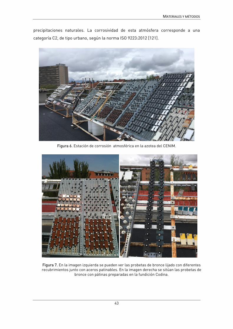
MATERIALES Y MÉTODOS
43
precipitaciones naturales. La corrosividad de esta atmósfera corresponde a una
categoría C2, de tipo urbano, según la norma ISO 9223:2012 [121].
Figura 6. Estación de corrosión atmosférica en la azotea del CENIM.
Figura 7. En la imagen izquierda se pueden ver las probetas de bronce lijado con diferentes recubrimientos junto con aceros patinables. En la imagen derecha se sitúan las probetas de
bronce con pátinas preparadas en la fundición Codina.

MATERIALES Y MÉTODOS
44
• Envejecimiento artificial
Para obtener recubrimientos envejecidos en un periodo de tiempo corto,
también se realizó un envejecimiento artificial, de acuerdo a la norma UNE-EN ISO
11507:2007 [159]. El tratamiento se llevó a cabo en una cámara QUV del fabricante Q-
Lab, alternando ciclos de radiación ultravioleta (lámpara UVB-313) y humedad
(condensación) de 4 h de duración (figura 8). Las probetas se sujetaron a los
correspondientes soportes con una cinta adhesiva de doble cara.
El tratamiento realizado se resume en la siguiente tabla:
Tabla 2. Condiciones de envejecimiento artificial para las probetas de bronce con recubrimientos.
Ciclo Radiación Temperatura
4h UV 0.63 W/(m2·nm) 60 ± 2.5 ºC
4h Condensación Oscuridad 50 ± 2.5 ºC
Figura 8.Cámara de envejecimiento acelerado de ultravioleta-condensación.

MATERIALES Y MÉTODOS
45
3.2. Técnicas electroquímicas.
Todas las medidas electroquímicas se realizaron con la celda desarrollada en
este trabajo, cuya construcción forma parte de los resultados y por tanto se describe
en el apartado 4.1. En este apartado se detallan los diferentes tipos de electrodos y
electrólitos utilizados, así como las condiciones experimentales generales.
3.2.1. Electrodos.
Como parte de la optimización de la celda se ensayaron tres tipos de electrodos
de referencia y dos contraelectrodos diferentes. En el caso de los electrodos de
referencia se compararon electrodos de pseudo-referencia con un electrodo de
referencia real, mientras que para el caso de los contraelectrodos se probaron dos
geometrías diferentes, del mismo material (figura 9). Los electrodos ensayados fueron
los siguientes:
Electrodos de referencia (RE)
• Pseudo-referencia de alambre de plata 99.9% (Goodfellow). 5.5mm de
diámetro, recubierto de cloruro de plata depositado electroquímicamente a
partir de una disolución de KCl 0.05M, aplicando una diferencia de potencial de
3V [160].
• Pseudo-referencia de alambre de acero inoxidable AISI316, diámetro 1.4 mm-.
• Electrodo de referencia Ag/AgCl (KCl 1M), CH Instruments (ref CHI111P).
Contraelectrodo (CE)
• Contraelectrodo de alambre de acero inoxidable AISI316, diámetro 1.4 mm,
enrollado en espiral.
• Contraelectrodo de malla de acero inoxidable AISI316, dispuesta de manera
paralela a la superficie a medir y sujeta a un anillo del mismo material
fabricado con alambre de 1.4 mm de diámetro.

MATERIALES Y MÉTODOS
46
Figura 9. Electrodos de referencia (plata y acero) y contra electrodos (malla y espiral).
Electrodo de trabajo (WE)
El electrodo de trabajo lo constituye la probeta o el bien cultural a estudiar, con
el que se hace contacto eléctrico de diversos modos dependiendo del objeto a medir.
En los estudios sobre probetas metálicas (ver apartado 3.1.2) el contacto se ha hecho
directamente con el cocodrilo del cable del potenciostato. Para los estudios sobre obra
real, el contacto se ha hecho a través de un tornillo de latón con una punta de acero,
presionada sobre la superficie metálica, y conectando el cocodrilo al tornillo. El giro
del tornillo, insertado en una pieza de metacrilato, permite ejercer la presión
necesaria para ello.
Figura 10. Detalle del sistema de contacto con el electrodo de trabajo.

MATERIALES Y MÉTODOS
47
3.2.2. Electrólitos.
Uno de los requisitos fundamentales de aplicación de la técnica es no alterar la
superficie de medida. Aunque la EIS es en sí una técnica no destructiva, el empleo de
un electrólito agresivo puede provocar por sí mismo daños sobre las pátinas. De hecho
autores como P. Letardi emplean agua mineral para evitar introducir elementos
extraños en la obra [25]. El inconveniente de utilizar agua mineral es la disponibilidad
geográfica de una marca concreta y el riesgo de que deje de producirse y se carezca
del electrólito de referencia.
Electrólito líquido:
En la primera fase del desarrollo de la celda de agar se empleó como
electrólito una disolución de NaCl al 0.3% en peso, como electrólito sencillo y bien
conocido en estudios de corrosión. Sin embargo, se comprobó que podía dejar marca
en algunas pátinas, por lo que ha sido necesario buscar una alternativa. Tras
considerar las distintas posibilidades se ha optado por utilizar agua de lluvia artificial,
[161] concentrada 10 veces para obtener una disolución suficientemente conductora.
La disolución, cuya composición se recoge en la tabla 3, se ha ajustado a pH 6.5 con
HNO3.
Tabla 3. Composición del electrólito
Composición Conc. mg/l
CaSO4·2H2O 14.43
(NH4)2SO4 15.04
(NH4)Cl 19.15
NaNO3 15.13
CH3COONa 3.19
Gelificante:
Para gelificar el electrólito se han empleado dos tipos de gelificantes añadidos
al electrólito líquido.
• Agar técnico Cultimed (Panreac 401792.1210).
• Agarosa Basic (Panreac A8963)

MATERIALES Y MÉTODOS
48
El agar o agarosa se dispersan en frio en el electrólito previamente preparado, y se
calientan a ebullición durante el tiempo necesario para la completa disolución. A
continuación, se vierten en el molde y se deja enfriar a temperatura ambiente hasta
solidificación.
Para realizar una comparación precisa entre el electrólito líquido y el
electrólito gelificado se ha empleado la misma celda y geometrías. Cuando ésta se
emplea con el electrólito líquido, la superficie a medir se delimita con un aro de
silicona y la celda se coloca en un soporte de tal modo que queda presionada contra la
silicona y se evita la salida del líquido (figura 11).
Figura 11. Detalle del montaje con la celda líquida.
3.2.1. Técnicas electroquímicas.
Las medidas electroquímicas se realizaron utilizando un potenciostato Gamry
Reference 600, con tierra flotante y un cable de 60 cm de longitud. En algunas medidas
de campo se utilizó un cable de 1.5 m.
Se realizaron tres tipos de medidas: EIS, resistencia de polarización (Rp) y curvas de
polarización. En cada uno de los artículos publicados se detallan las medidas
realizadas y el objetivo de cada una de ellas.
El tiempo de estabilización de las muestras a circuito abierto ha sido de 1800 s, aunque
se han realizado algunos ensayos con tiempos mayores para comprobar la
estabilización de las muestras. Tras 1800 s la estabilización no es completa pero si

MATERIALES Y MÉTODOS
49
permite obtener medidas reproducibles, por lo que teniendo en cuenta que se trata de
establecer un método para medidas de campo, se considera suficiente.
3.2.1.1. Espectroscopía de impedancia electroquímica (EIS).
Descrita en la introducción, la EIS es la técnica principal para la que se ha
desarrollado este trabajo y la más adecuada para estudiar recubrimientos orgánicos
sobre metales y/o capas gruesas de productos de corrosión.
Los espectros de impedancia se han obtenido con un barrido logarítmico de frecuencia
de 100 kHz a 10 mHz, con una amplitud de 10 mV RMS y 10 puntos/decada, excepto en
las medidas de recubrimientos que la amplitud ha sido de 20 mV para tratar de
mejorar la relación señal/ruido. Todas las medidas se normalizan a un área expuesta
de 3.14 cm2.
Para la interpretación de los resultados, en algunos casos se ha recurrido al valor del
módulo de la impedancia en el límite de bajas frecuencias. En otros casos se ha
ajustado el espectro obtenido al circuito equivalente correspondiente mediante el
software Zview® (Scribner Associates) o mediante el programa Echem Analyst®
(Gamry). Ambos programas son equivalentes y utilizan la misma fórmula para definir
la impedancia de los elementos del circuito a excepción de la difusión de Warbug:
mientras que el Zview® utiliza las expresiones de la tabla 1, el Echem Analyst® utiliza
las siguientes fórmulas:
Difusión semi-infinita: Z = / (1 − j)
Difusión finita: Z = / (1 − j) tanh 𝛿 /
Donde σW = coeficiente de difusión de Warburg; δ= espesor de la capa de difusión; D=
coeficiente de difusión. En cualquier caso las expresiones son matemáticamente
equivalentes en ambos programas.

MATERIALES Y MÉTODOS
50
El circuito equivalente empleado principalmente en este trabajo para la interpretación
de los resultados, salvo ejemplos en los que se detalla otro circuito, es el que se
muestra en la figura 12. Este circuito equivalente, al que nos referiremos como
“circuito general” permite explicar en la mayoría de los casos los espectros obtenidos
tanto en bronces como en aceros patinados, aunque con diferente interpretación. En
este circuito Rs representa la no compensada (principalmente la resistencia del
electrólito), el primer par (CPE1 R1) la capacidad de la pátina y/o recubrimiento y
resistencia del electrólito en los poros y defectos de los mismos; y el subcircuito
(CPE2[R2W]) los procesos que ocurren en la superficie del metal: la reacción de
transferencia de carga, caracterizada por Rtc y la capacidad de la doble capa
electroquímica, representada por CPE2 o CPEdl, y los fenómenos de difusión, W. En el
caso de pátinas en aleaciones de cobre estos fenómenos de difusión están
relacionados con el transporte de iones cobre en la capa de óxido superficial [45],
mientras que para el acero se relacionan con la difusión del oxígeno a través de la
capa de óxido [108, 109]. En algunos casos, y en especial en medidas de campo, es
necesario introducir una pseudoinductancia, L, que modela interferencias producidas
por acoplamientos entre los electrodos y posiblemente otras interferencias para
mejorar el ajuste en la zona de altas frecuencias. Estos artefactos, que se discutirán
más adelante, no interfieren en la región de interés y no se comentarán en la
interpretación de los resultados de medidas de campo, aunque su valor se reflejará en
las tablas para denotar su presencia.
Figura 12. Circuito equivalente general empleado en los ajustes.
L1 Rs CPE1
R1 CPE2
R2 Ws1

MATERIALES Y MÉTODOS
51
3.2.1.2. Resistencia de polarización (Rp).
La resistencia de polarización lineal se ha utilizado en algunos casos para tener
una segunda medida electroquímica del sistema y comprobar la obtención de los
mismos resultados con dos técnicas complementarias.
La polarización lineal se basa en aplicar una pequeña polarización en el entorno del
potencial de corrosión y medir la intensidad de corriente producida; en esta región, las
curvas de polarización presentan un tramo recto, cuya pendiente es la resistencia de
polarización.
Los ensayos de resistencia de polarización se han registrado realizando un barrido
lineal en un intervalo de -10 a +10 mV frente al OCP a una velocidad de barrido 0.1667
mV/s.
3.2.1.3. Curvas de polarización.
Para la caracterización del comportamiento del gel sobre probetas metálicas
se han utilizado curvas de polarización de forma puntual, si bien esta no es una técnica
aplicable para los estudios de patrimonio por ser una técnica destructiva. Las curvas
de polarización se obtienen realizando un barrido de potencial amplio (del orden de los
centenares de milivoltios) en dos tramos. En primer tramo se recorre un intervalo de
potencial catódico desde un valor arbitrario hasta el potencial de corrosión, en el que
únicamente está teniendo lugar la reacción catódica (generalmente la reducción del
oxígeno); seguidamente se invierte el signo del potencial y se comienza un barrido
anódico en el que se produce la oxidación del metal. Las características de los dos
tramos de las curvas, nos dan información separada sobre los procesos anódico y
catódico.
En este caso las curvas de polarización se han registrado para un intervalo de ± 150
mV frente al potencial de circuito abierto (OCP) a una velocidad de barrido de 0.1667
mV/s.

MATERIALES Y MÉTODOS
52
3.3. Otras técnicas.
De manera complementaria se han utilizado otras técnicas para caracterizar la
morfología, composición o cualidades cromáticas de las superficies estudiadas. En el
caso de empleo de técnicas de caracterización habituales en el estudio de materiales,
los detalles experimentales se han incluido en las publicaciones correspondientes;
únicamente se hará mención aquí a dos técnicas con una aplicación más específica
para el estudio de las pátinas y recubrimientos sobre los metales.
3.2.1. Colorimetría.
El análisis colorimétrico permite relacionar la evolución en la composición o el
comportamiento de pátinas o recubrimientos con el tiempo con sus valores cromáticos
y de luminosidad. Estos parámetros son importantes en el caso de los objetos de
patrimonio, en los que las características visuales y/o estéticas son de suma
importancia.
Las medidas de color se han realizado mediante un espectrofotómetro Kónica Minolta
CM 700D utilizando un iluminante estándar D65 y un ángulo de observador de 10°. La
presentación de los datos se realiza conforme al sistema CIE L*a*b*, que permite
representar los parámetros de color (tono, saturación y luminosidad) en un espacio
tridimensional. El color se representa en este modelo en función de tres variables: la
luminosidad L*(0-100, desde negro hasta blanco puros), y las coordenadas cromáticas
a* y b*. La variable a* representa un eje que va desde el rojo (+60) al verde (-60), y la
variable b* corresponde al eje que va desde el amarillo (+60) a azul (-60).
3.2.2. Medidas de espesor.
La determinación del espesor de las pátinas y/o capas de recubrimiento nos
permite relacionar este parámetro con el comportamiento más o menos protector de
las mismas. La capacidad protectora de una capa depende, entre otros factores, de su
grosor, por efecto barrera, y de su compacidad, de modo que el conocimiento del
espesor en relación con los valores de los parámetros electroquímicos nos
proporciona información sobre las características de dicha capa.

MATERIALES Y MÉTODOS
53
Las medidas de espesor se han realizado con un Elcometer 456, con sonda para
metales férricos y para metales no férricos, de acuerdo a la norma UNE-EN 13523-
1:2017 [162]. La sonda para metales férricos se basa en el principio de inducción
magnética, midiendo la variación del campo magnético generado por la sonda causada
por el sustrato magnético. La sonda para metales no férricos se basa en la generación
de corrientes inducidas sobre el substrato metálico, y midiendo el cambio de la
impedancia de la sonda causado por las mismas.

54
4. RESULTADOS Y DISCUSIÓN
4.1. Prueba de concepto: diseño de un prototipo y validación de la idea.
El desarrollo de una celda electroquímica específicamente diseñada para la
realización de medidas de impedancia in situ se enmarca dentro de los proyectos
CREMEL5 y CREMEL II6. En el momento de inicio del primero de estos proyectos, los
únicos intentos de utilizar electrólitos gelificados para medidas en patrimonio cultural
habían sido los trabajos de Angelini y col. con electrodos de electrocardiograma [68],
aunque pronto aparecieron los primeros trabajos de Clare y col.[163]. Sí existían
antecedentes de la utilización de electrólitos sólidos en otras aplicaciones (como
baterías, dispositivos electrocrómicos, etc. [164-167]) pero excesivamente alejadas de
nuestro campo y aunque otros autores habían sugerido el empleo de geles de agar o
agarosa para la realización de ensayos electroquímicos [168-170] o estudios de
corrosión [171], el número de estudios era muy limitado y no se había realizado un
trabajo sistemático para la validación de esta aplicación en concreto. Por ello, el
primer paso antes de abordar otras cuestiones era comprobar la posibilidad de
realizar medidas de impedancia utilizando un electrólito gelificado con agar y diseñar
una celda adecuada para la realización de dichas medidas. La posibilidad de utilizar un
electrólito gelificado suponía responder a una serie de cuestiones:
• ¿Es posible obtener un espectro coherente utilizando un electrólito gelificado?
• ¿Son reproducibles los resultados?
• ¿El resultado es comparable al de un electrólito tradicional?
• ¿En qué medida afecta el gel a los resultados?
• ¿Qué consistencia debe tener el gel para que sea adecuado para medir?
5 “Conservación-restauración del Patrimonio Cultural metálico por técnicas electroquímicas: desarrollo de una metodología específica adaptada al diagnóstico y tratamiento” (CREMEL) MICINN- Proyectos Investigación Fundamental no Orientada-Convocatoria 2011. HAR2011-22402. Enero 2012 – septiembre 2015. 6 “Conservación-restauración del patrimonio cultural metálico por técnicas electroquímicas: investigación y aplicación” (CREMEL II) MINECO, Programa Estatal de I+D+i Orientada a los Retos de la Sociedad 2014. HAR2014-54893-R. Enero 2015 – junio 2018.

RESULTADOS Y DISCUSIÓN
55
Para dar respuesta a estas cuestiones, incluidas el objetivo 1, se diseñaron una serie
de ensayos, primero para comprobar la posibilidad de medir –tanto en laboratorio
como en campo- y luego para abordar el resto de las cuestiones en mayor detalle:
determinar en qué grado el agar influye en el comportamiento del electrólito y cuál es
la concentración más adecuada, tanto desde el punto de vista de los resultados
electroquímicos como de la realización práctica de los ensayos.
Respecto a las características de la celda en sí, se partió de una serie de premisas
para la construcción del primer prototipo (figura 13), para adecuarlo a las
particularidades de las medidas en campo:
Forma y tamaño
Para utilizar la celda en campo era necesario que fuera fácil de transportar y de
adaptar a geometrías complejas y huecos difíciles. Por otra parte, el tamaño debía
poder medir una superficie representativa, dentro de la natural heterogeneidad de las
superficies de bienes metálicos expuestos al exterior, y ser suficiente para
proporcionar una adecuada relación señal-ruido. Aunque un tamaño pequeño
facilitaría su colocación, podría no responder a las premisas de proporcionar una
respuesta adecuada. La solución adoptada fue fabricar una celda cilíndrica, de 3.2 cm
de diámetro externo y 2.2 cm de altura, con un área de medida de 5.72 cm2.
Elección de los electrodos
Para la elección de los electrodos se consideró la necesidad de tener un
sistema robusto y resistente. Así, se decidió como primera opción utilizar un electrodo
de pseudo-referencia formado por un hilo de plata recubierto de cloruro de plata, que
evitaría manejar electrodos de referencia de vidrio más frágiles y delicados, y un
contraelectrodo fabricado con una malla de acero inoxidable, con un orificio circular a
través del cual se podía colocar el electrodo de referencia para aproximarlo lo más
posible a la superficie a medir. Así, los electrodos quedarían paralelos a la superficie
para evitar distribuciones no homogéneas de la corriente, que en trabajos previos con
electrodos sólidos se habían demostrado que podían causar distorsiones de los
resultados e incertidumbres sobre el área efectiva que estaba siendo medida [106].
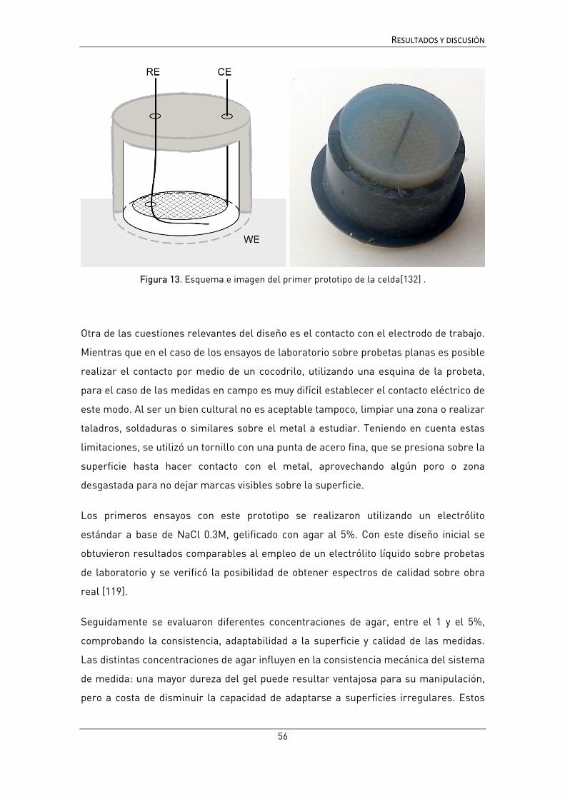
RESULTADOS Y DISCUSIÓN
56
Figura 13. Esquema e imagen del primer prototipo de la celda[132] .
Otra de las cuestiones relevantes del diseño es el contacto con el electrodo de trabajo.
Mientras que en el caso de los ensayos de laboratorio sobre probetas planas es posible
realizar el contacto por medio de un cocodrilo, utilizando una esquina de la probeta,
para el caso de las medidas en campo es muy difícil establecer el contacto eléctrico de
este modo. Al ser un bien cultural no es aceptable tampoco, limpiar una zona o realizar
taladros, soldaduras o similares sobre el metal a estudiar. Teniendo en cuenta estas
limitaciones, se utilizó un tornillo con una punta de acero fina, que se presiona sobre la
superficie hasta hacer contacto con el metal, aprovechando algún poro o zona
desgastada para no dejar marcas visibles sobre la superficie.
Los primeros ensayos con este prototipo se realizaron utilizando un electrólito
estándar a base de NaCl 0.3M, gelificado con agar al 5%. Con este diseño inicial se
obtuvieron resultados comparables al empleo de un electrólito líquido sobre probetas
de laboratorio y se verificó la posibilidad de obtener espectros de calidad sobre obra
real [119].
Seguidamente se evaluaron diferentes concentraciones de agar, entre el 1 y el 5%,
comprobando la consistencia, adaptabilidad a la superficie y calidad de las medidas.
Las distintas concentraciones de agar influyen en la consistencia mecánica del sistema
de medida: una mayor dureza del gel puede resultar ventajosa para su manipulación,
pero a costa de disminuir la capacidad de adaptarse a superficies irregulares. Estos

RESULTADOS Y DISCUSIÓN
57
ensayos, en los que el NaCl 0.3M se sustituyó por agua de lluvia artificial, más acorde
al medio en que se encuentran habitualmente las esculturas y menos agresiva,
pusieron de manifiesto una cierta influencia del agar en la medida, especialmente a
altas concentraciones. A partir de estos resultados se consideró que la concentración
más adecuada para este tipo de medidas se encontraba en torno al 3%. Todo esto se
presenta en detalle y se discute en la siguiente publicación:
• B. Ramírez Barat, E. Cano, “The use of agar gelled electrolyte for in situ electrochemical measurements on metallic cultural heritage”, Electrochimica Acta, 182(2015) 751-627.
7 Referencias bibliográficas [25, 26, 34, 35, 45, 53, 68, 104, 106, 112, 119, 122, 127, 128, 160, 161, 167, 172-186] de la bibliografía general.

The use of agar gelled electrolyte for in situ electrochemicalmeasurements on metallic cultural heritage
Blanca [7_TD$DIFF]Ramírez Barat*, Emilio CanoCentro Nacional de Investigaciones Metalúrgicas (CENIM), Consejo Superior de Investigaciones Científicas (CSIC), Av. Gregorio del Amo 8, 28040 Madrid, Spain
A R T I C L E I N F O
Article history:Received 19 May 2015Received in revised form 10 September 2015Accepted 20 September 2015Available online 28 September 2015
Keywords:agarpolymer electrolytecultural heritageEISbronze
A B S T R A C T
Electrochemical techniques, such as electrochemical impedance spectroscopy (EIS), are widely used forcorrosion studies. However, their applicability to studies on metallic cultural heritage has been lessspread due to the practical difficulties of performingmeasurements in-situ on sculptures or monuments.One interesting approach to this application is the use of gel polymer electrolytes (GP-E) to overcome thedifficulties of handling liquid electrolytes on irregular leaning surfaces. In this paper, the behavior of anagar gelled electrolyte with a portable cell is evaluated for EIS measurements over three types of bronzecoupons, and compared with a traditional liquid cell. The influence of the addition of agar in thereproducibility and repeatability of measurements is assessed, as well as the possible interaction of agarwith the corrosion process. Results show that, although agar slightly accelerates the anodic process, itdoes not significantly affect the cathodic reaction and does not introduce new reactions in the corrosionmechanism. It is demonstrated that the GP-E allows obtaining reproducible and good quality EIS spectra,comparable to the liquid cell. Hence, it can be used for comparative in-situ measurements, being a veryvaluable tool for the evaluation of patina and coatings on metal cultural heritage.
ã 2015 Elsevier Ltd. All rights reserved.
1. Introduction
Electrochemical Impedance Spectroscopy (EIS) is a widely usedtechnique for corrosion studies, as it gives qualitative andquantitative information on corrosion processes and corrosionresistance. In the field of metallic cultural heritage it can be a veryuseful tool as it can be used to evaluate the actual situation of anobject, i.e., if there is an active corrosion process or it has a stablepatina, how much a protective coating has increased its corrosionresistance, which coating offers the better corrosion protection orwhen a protection treatment is beginning to fail [1]. The answer tothese questions can help to take conservation decisions andstablish priorities when time and resources are limited. For thisreason, EIS constitutes a very valuable complement to classicalanalytical methods widely used in conservation science (XRF,Raman, XRD, FTIR, etc.), which give information on compositionand structure, but cannot give quantitative information on theircorrosion behavior.
However, the application of this technique for corrosion studiesin the field of cultural heritage poses some particular difficulties
[1]. Some studies have been carried out using artificial couponsthat try to mimic the original composition of metallic artifacts[2–5], or patinas scrapped from the monuments [6], usingtraditional laboratory techniques. Nevertheless, this kind oflaboratory studies provide limited information, due to theimpossibility to reproduce the composition and characteristicsof patinas that have formed over several hundred years. On theother hand, it is always desirable to evaluate conservationconditions on the real objects to undertake conservation decisions.At this point, the main issue is how to perform electrochemicalmeasurements using a conventional three electrode cell with aliquid electrolyte on a non-flat, irregular and leaning surface as isusually the one of metallic sculptures and monuments.
Since the beginning of application of electrochemical techni-ques to cultural heritage, mainly electrochemical impedancespectroscopy,[8_TD$DIFF] researchers have worked on portable devices withdifferent approaches. On one side, methods for retaining the liquidelectrode in contact with the object have been developed, as theLetardi’s contact probe [7,8]. This method has been successfullyapplied to the evaluation of cultural heritage, but still has dedisadvantage of handling a liquid electrolyte. On the other side,commercial gel electrodes or prepared gel electrodes based onsame type of gels have also been proposed [9,10]. This systemavoids the liquid electrolyte, so it is convenient for field use.Nevertheless, the conductivity of these gels is poor, so irregular
* Corresponding author. Tel.: +34 91 5538900 ext 309.E-mail addresses: [email protected] (B. [7_TD$DIFF]Ramírez Barat),
[email protected] (E. Cano).
http://dx.doi.org/10.1016/j.electacta.2015.09.1160013-4686/ã 2015 Elsevier Ltd. All rights reserved.
Electrochimica Acta 182 (2015) 751–762
Contents lists available at ScienceDirect
Electrochimica Acta
journa l homepage: www.e lsevier .com/ locate /e lectacta
__________________________________________________________________________
__________________________________________________________________________ 58
RESULTADOS Y DISCUSIÓN

distribution of currents might mislead the results [11]. Addition-ally, the composition of the electrolyte cannot be selected to testthe resistance of the metal to specific environments in commercialelectrodes, or it is limited by the swelling equilibrium ofsynthetized (anionic) gels [12]. This is a major drawback of thisapproach, since for corrosion studies the composition and pH ofthe electrolyte play a key role in the process. So although the ideaof gel electrolytes seems to be a good choice, solutions that allowthe selection of the adequate electrolyte have to be furtherinvestigated.
The use of solid electrolytes has been explored in the lastdecades for [9_TD$DIFF]applications where liquid electrolytes present incon-veniences such as handling difficulties or risk of leaking orevaporation of the liquid [13]. The development of new andimproved solid electrolytes has mainly focused in the fields ofenergy storage (lithium batteries, solar and fuel cells . . . ) andelectrochromic devices. Different kinds of polymers have beenassayed as solid electrolytes, from polyethylene oxide (PEO) sincethe [10_TD$DIFF]70’s of the last century to polymer mixtures, composites orhybrid inorganic–organic polymer electrolytes. In last years,natural polymers have been considered as a cheap and greenalternative, including gelatin, chitosan, agar, etc. Among these, agaroffers interesting properties making it a good candidate for theseapplications.
Agar is a natural polysaccharide extracted from certain speciesof red seaweeds. It is composed of two fractions, agarose andagaropectin, both made up of repeating units of agarobiose. Whileagarose is a neutral linear polymer, agaropectin is partiallymodified by different hydrophobic (methoxyl) and polar (sulfate,pyruvate) side groups [11_TD$DIFF][14].
Since its discovery agar has been using as a gelling agent formany different uses. In this case it has been the choice as it is
inexpensive, easy and quick to prepare and can support a widerange of aqueous electrolytes, forming translucent gels. Further-more, agar has a very interesting property, syneresis, which is theability of weeping or expelling liquid from a gel [15].This helpswetting the surface and favors contact between the electrolyte andthe working electrode (i.e., the metal under study) in fieldcorrosion tests.
Previous studies have been carried out on agar based electro-lytes, but these studies have focused on its preparation withdifferent salts or acids in order to achieve the maximumconductivity, with good optical and mechanical properties[16–18]. For its use as electrolyte in electrochemical corrosion
[(Fig._1)TD$FIG]
Fig.1. Cell design scheme (a), picture of the cell with the gelled electrolyte from theside in contact with the WE (b) and picture of the cell/sample connection setup (c).
Table 1Composition of the 10x concentrated synthetic rain used as electrolyte.
Composition Conc. mg/l
CaSO42H2O 14.43(NH4)2SO4 15.04(NH4)Cl 19.15NaNO3 15.13CH3COONa 3.19
pH adjusted to 6.5 with HNO3.
[(Fig._2)TD$FIG]
Fig. 2. Bronze coupons used for the electrochemical tests: clean bronze A (top), andartificially patinated bronze B, with a dark potassium sulfide patina (bottom right)and a green ammonium chloride patina (bottom left).
752 B. Ramírez Barat, E. Cano / Electrochimica Acta 182 (2015) 751–762
__________________________________________________________________________
__________________________________________________________________________ 59
RESULTADOS Y DISCUSIÓN

measurements, our interest is focused on its use with classicalaqueous electrolytes usually employed to evaluate the behavior ofone metal in different weathering conditions. In the case ofevaluation of cultural heritage objects, several electrolytes havebeen proposed to simulate marine, urban or rural atmospheres.Nevertheless, the use of these electrolytesmaydamage the originalsurface of the object so authors working in this field have proposedmild electrolytes, included slightly mineralized water to avoidintroducing aggressive ions on the patinas [7].
Taking this into account, and as an alternative to previouslymentioned approaches, authors have recently developed aportable cell based on the use of agar as a gelling agent to supportthe liquid electrolyte [19]. While initial results have beenpromising, yielding results that are comparable to a conventionalliquid cell, a deeper study of the effect of agar on the results isneeded: changes in the electrolyte conductivity were observedwith the addition of agar, but have not been studied; and thepossible effect of agar in the corrosion process needs to be wellunderstood before the extensive application of this cell for in-situcorrosion measurements.
Therefore, the aim of this work is to evaluate the behavior of anagar-gelled electrolyte for its use in a portable cell for in situelectrochemical corrosion measurements on cultural heritage, inorder to assess the stability and reproducibility of the measure-ments and the possible effect of agar in the results.
2. Experimental
The design of the gel polymer electrolyte (GP-E) cell is describedin a previous paper in detail [19], based on a traditional threeelectrode cell as shown in Fig. 1, were WE is the working electrodeor the object under study, CE is the counter made with a AISI 316Lstainless steel mesh and RE is a 99.9% silver wire (Goodfellow)electrochemically coated with AgCl, used as (pseudo) referenceelectrode [20].
The electrolyte has been prepared by gelling artificial rain withagar (technical grade). To minimize the introduction of aggressiveions and to mimic the conditions outdoor sculptures are exposedto, the selected liquid electrolyte has been artificial rain adaptedfrom [21]. Since the conductivity of this solution is too low, it hasbeen used ten times concentrated. The composition of theelectrolyte is presented in Table 1. The chloride concentration inthis solution is 3.58104M. This gives a potential of 0,462V vs. SHEfor the Ag/AgCl coated silver wire used as reference electrode,calculated from Nernst equation.
After the preparation of the liquid electrolyte, 1 to 5% w/v ofagar powder has been dispersed in the solution, heated untildissolution, allowed to cool down for a fewminutes and casted onthe electrochemical cell containing the RE and CE. For comparison,the same electrochemical cell and electrode arrangement has alsobeen used with the liquid electrolyte without agar (agar 0%). Theaddition of agar slightly increased the pH of the electrolyte, from a
[(Fig._3)TD$FIG]
Fig. 3. Nyquist (top) and Bode (bottom) plots showing three consecutive measurements on a bronze A coupon. GP-E cell with 3% agar electrolyte. Black lines represent theKramers-Kronig fitting of data.
B. Ramírez Barat, E. Cano / Electrochimica Acta 182 (2015) 751–762 753
__________________________________________________________________________
__________________________________________________________________________ 60
RESULTADOS Y DISCUSIÓN

value of 6.6 measured in the liquid solution to a 7.0 value in the 5%agar electrolyte.
Electrochemical measurements have been carried out on twotypes of samples: 50501.5mm laminated EN 1652CuSn5bronze coupons (95 [12_TD$DIFF]Cu, 5 Sn %w), hereafter bronze A; and70357mm EN 1982CC491K (DIN 1705-RG5) cast bronzecoupons (85 [13_TD$DIFF]Cu, 5 Sn, 5 Pb, 5 Zn %w), hereafter bronze B. BronzeAwas selected as a simplemodel tominimize other variables in thestudy of the agar behavior, while bronze B was selected to have asystem as close as possible to real cast bronze sculptures.
Bronze Awas used as received to have a long-termnatural oxidelayer. Bronze Bwas prepared tomimic bronze sculptures by CodinaEscultura, a traditional Spanish artistic foundry according totraditional materials and techniques: Bronze was casted in ingots,cut into coupons of the desired size and sandblasted. Then, twodifferent artificial patinas have been applied to bronze B, a darkpotassium sulfide patina and a green ammonium chloride patina,following traditional patination procedures for artistic sculpture.For the dark patina, a 10% w/v aqueous solution of potassiumsulfide was applied by brush and then heated with a blowtorch.Green patina was obtained with a 10% w/v ammonium chlorideaqueous solution applied with brush over the dark one. Fig. 2shows the aspect of the coupons.
EIS spectra have been acquired using a Gamry 600 Potentiostat,using a frequency swept from 100kHz to 10 mHz, 10mV RMSamplitude (at the open circuit potential, OCP) and 10 points/decade. The area exposed to the electrolyte was 3 cm2. Analysis of
the data has been carried out using ZView software. Polarizationcurves have been obtained starting from -150mV vs. OCP andpolarizing at 0.16mV/s in the anodic direction.
The system was left to stabilize at OCP for 30minutes beforemeasurements. As it has been observed and confirmed by otherauthors [22], the most remarkable variations show in the first30minutes and stay small after that time. Between differentmeasurements 5-10minutes delay has shown to be enough for thestabilization of the OCP.
Conductivity and pH of the electrolytes has beenmeasuredwitha Crison MM40 conductimeter/pHmeter.
3. Results and discussion
In order to validate the system and verify its stability threeconsecutive EIS measurements were performed on the samesample. Although the system takes some time to stabilizeundergoing small changes with time, the general repeatabilityof the measurements is quite good. Fig. 3 shows an example ofthree consecutivemeasurements on a bronze A coupon. Only smalldifferences in the mid frequency appear, being related to slightmodifications of surface oxide layers in contact with theelectrolyte. Kramers-Kronig analysis was applied to all curvesdemonstrating the linearity, stability, causality and finite value ofallmeasurements. Results for the patina-covered bronze B sampleswere even more stable. The small changes in the spectra alsodemonstrate that the measurements do not alter the surface of the
[(Fig._4)TD$FIG]
Fig. 4. Nyquist (top) and Bode (bottom) plots of two different areas from a bronze B coupon with dark patina. GP-E cell with 3% agar electrolyte. Black line represents theKramers-Kronig fitting of data.
754 B. Ramírez Barat, E. Cano / Electrochimica Acta 182 (2015) 751–762
__________________________________________________________________________
__________________________________________________________________________ 61
RESULTADOS Y DISCUSIÓN

bronze, i.e., the tests are non-destructive and can be safely appliedto cultural heritage objects.
Repeatability was also checked in different areas of the samesample. In Fig. 4 two independent measurements on a bronze Bcoupon covered with dark patina show that measurements onsimilar surfaces give almost identical responses.
The possible effects of agar [14_TD$DIFF]were evaluated comparing spectraregistered with the same cell filled with liquid electrolyte andgelled electrolyte (3% agar) on different samples. Results are shownin [33_TD$DIFF]Figs. 5 (bronze A), 6 (bronze B, dark patina) and [34_TD$DIFF]7 (bronze B,green patina). The outline from both curves is comparable, thesame features being present, although the addition of agar resultsin a decrease of Z module and a shift of time constants to higherfrequencies. As |Z| at high frequencies is related with electrolyteresistance, this indicates that agar addition increases the electro-lyte conductivity. The decrease of |Z| at low frequencies and thefrequency shift of time constants suggest a direct effect of agar inthe corrosion process.
In order to obtain a better understanding of agar influence inour system, different agar concentrations, from 0 to 5% wereassayed, using bronze A as a simplemodel to eliminate the effect ofpossible inhomogeneities of the different patinas. Agar additionmight influence two processes: the resistance of the electrolyteand the corrosion reaction on the metal/electrolyte interface. Forour system to be valid to carry out in situ measurements onmetallic heritage, corrosion mechanisms should not be
significantly altered by the addition of agar. The electrolyteconductivity, on the other hand, is a parameter that can besubstracted from experimental EIS data, so it does not interfere onthe interpretation of the results.
To see how resistance of the electrolyte changes with agar,conductivity of electrolyte with different agar concentrations(0-5%) was measured (Fig. 8). It can be observed that electrolyteconductivity increases proportionally to agar concentration, beinga linear function of the concentration of agar plus the conductivityof the electrolyte, according to:
K ¼ 76þ 221 %agar½ R2 ¼ 0:99 ð1Þ
An additional measurement was done with 3% agar in deionizedwater to separate the contribution of the liquid electrolyte(artificial rain), giving a value of 72010mS. So, gelled electrolyte'sconductivity is the sum of two contributions: agar’s conductivityand artificial rain's conductivity, being agar themain responsible ofthe electrolyte's conductivity. This may represent an advantage forits application in cultural heritage, as it gives higher conductivity tothe electrolyte without introducing other ions that may leavedangerous residues on the surface of the object.
Aiming to understand the corrosion processes, several electro-chemical measurements including EIS and polarization curveshave been done for 0 to 5% agar. Polarization curves have beenregistered to elucidate the effect of the agar on the anodic andcathodic reactions. Fig. 9 show the polarization curves obtained in
[(Fig._5)TD$FIG]
Fig. 5. Nyquist (top) and Bode (bottom) plots of a bronze A coupon. GP-E cell with 3% agar electrolyte (squares) and same cell with liquid electrolyte (circles). Black linerepresents the Kramers-Kronig fitting of data.
B. Ramírez Barat, E. Cano / Electrochimica Acta 182 (2015) 751–762 755
__________________________________________________________________________
__________________________________________________________________________ 62
RESULTADOS Y DISCUSIÓN

bronze A. Under our experimental conditions (aerated neutral pHelectrolyte), the expected main anodic and cathodic reactions are:
Anodic reaction : Cu0$Cuþ þ 1e ð2Þ
Cathodic reaction : 2H2Oþ O2 þ 4e$4OH ð3Þ
The cathodic branch seems to follow a Tafel behavior with nosignificant changes in the slopes with the increasing concentrationof agar. This indicates that the cathodic process (eq. (3)) is undercharge transfer control and that the addition of agar up to 5% doesnot substantially change the kinetics of this reaction. On the otherhand, agar clearly affects the anodic branch, increasing the anodicslopes as the concentration of agar increases, and suggests a directinteraction between agar and copper ions which shifts the anodicreaction towards the oxidation of copper (eq. (2)).
Experimental EIS data for 0-5% agar electrolytes are presentedin Fig. 10. The general shape of the spectra shows two timeconstants. The increase of electrolyte conductivity [17_TD$DIFF]with agarconcentration is clearly appreciated in the impedance at highfrequencies. Also, a decrease in the size of the capacitive loops inNyquist plots is observed with increase in agar concentration.
The large changes in the electrolyte resistance (R0) obscure theanalysis of the effect of agar in the corrosion reactions on themetal-electrolyte interface. To avoid this effect, electrolyteresistance (obtained from intersection of the extrapolation of
high frequency loop with the real axis in Nyquist plots) has beensubstracted from the EIS data. This representation eliminates thedistortion induced by this resistance and allows [18_TD$DIFF]better compara-tion of spectra [23]. Additionally, data above 104 Hz showedartifacts attributable to instrumental effects, and therefore havebeen eliminated for analysis. Corrected (Z-R0) impedancemodulus [19_TD$DIFF]and phase angle versus frequency data are presented in Fig. 11. Thefeatures of the curves for all concentrations of agar are similar,indicating that the addition of agar does not alter significantly theelectrode reactions, thus supporting the use of this gelledelectrolyte for EIS measurements.
Two different slopes can be clearly observed in Fig.11. The slopeof the high frequency part of the data (above 10Hz) gives a value of-0.8 for all measurements, and the low frequency part (below1Hz) has a slope between 0.3 and 0.35. These slopes depart fromthe ideal capacitive behavior (slope of -1), indicating a distributionof the time constants. This distribution of the time constants iscommonly modeled by a constant phase element (CPE):
ZCPE ¼1
Y jvð Það4Þ
whose actual physical meaning could be very different dependingon the system: this response has been attributed to surfaceroughness and heterogeneities, to electrode porosity, to variation ofcoating composition, to slow adsorption reactions, and to non-uniform potential or current distributions [24]. [20_TD$DIFF]As a first approach
[(Fig._6)TD$FIG]
Fig. 6. Nyquist (top) and Bode (bottom) plots of a bronze B couponwith dark patina. GP-E cell with 3% agar electrolyte (squares) and same cell with liquid electrolyte (circles).Black line represents the Kramers-Kronig fitting of data.
756 B. Ramírez Barat, E. Cano / Electrochimica Acta 182 (2015) 751–762
__________________________________________________________________________
__________________________________________________________________________ 63
RESULTADOS Y DISCUSIÓN

[(Fig._7)TD$FIG]
Fig. 7. Nyquist (top) and Bode (bottom) plots of a bronze B couponwith greenpatina. GP-E cell with 3% agar electrolyte (squares) and same cell with liquid electrolyte (circles).Black line represents the Kramers-Kronig fitting of data.
[(Fig._8)TD$FIG]
Fig. 8. Conductivity increase of the electrolyte with agar concentration.[5_TD$DIFF]
B. Ramírez Barat, E. Cano / Electrochimica Acta 182 (2015) 751–762 757
__________________________________________________________________________
__________________________________________________________________________ 64
RESULTADOS Y DISCUSIÓN

experimental datawere fitted to an equivalent circuit with 2 nestedCPE-R pairs, as shown in Fig. 12a. To give a physical meaning to themathematical analysis several possibilities may be evaluated.
One approach [21_TD$DIFF]is to interpret the results according to the classicalequivalent circuit for modeling an imperfect metal-coating system,inwhichelements of circuit 12a are interpretedas:R0 represents theelectrolyte resistance, CPE1 represents the pseudo-capacitance ofthepatinaoroxide layeron themetal surfaceandR1 the resistanceofthe electrolyte though the pores; and CPE2 in parallel with R2
represent the pseudo-capacitance of the double layer at the metal-electrolyte interface and the charge transfer resistance of thecorrosion reaction respectively. In this hypothesis the distributionoftime constants of CPE2 would be related to inhomogeneous currentdistributions due to both irregularities in themetal surface [20] andto the presence of agarmolecules at the interface. As agarmoleculesinteract with the metal surface and favor the corrosion process, anincrease of agar would explain the decrease of impedancecontribution associated to CPE2.
Nevertheless, the values of [22_TD$DIFF]a2 with this model are about 0.5 forall conditions. This value is too low to be attributed toinhomogeneities or roughness of the surface, especially consider-ing the smooth and apparently regular surface of bronze A (seeFig. 2), that is was not altered by the measurements. Recent workshave also demonstrated that pure geometric aspects (surfaceroughness) can not explain a CPE behavior [25,26].
A second tentative interpretation of the distribution of the timeconstant at low frequencies is to assign it to the impedance of aporous electrode. Under de Levie's assumptions (equal cylindricalpores uniformly distributed in the electrode surface), the imped-ance of a porous electrode is given by:
ZdeLevie ¼ RcZ0ð Þ0:5coth lcl
ð5Þ
being Rc the electrolyte resistance within the pore, Z0 theimpedance of the flat electrode developed in the cylindrical pore,lc the pore depth and l=(Z0/Rc)0.5 the penetration depth of the AC
signal in the pore [3,27]. Hern[23_TD$DIFF]ández et al. [3] found this kind ofresponse on rough copper electrodes when exposed to NaCl. In ourcase, the short exposure times and the low aggressiveness of theelectrolyte (the chloride concentration of our electrolyte is muchlower) did not change the original smooth surfaces of the sample.Since according to eq. (5), when the pores are shallow the responseof the electrode is similar to that of a flat electrode, it is not likelythat the dispersion of the time constant can be attributed toporosity.
For copper corrosion in milder electrolytes, with compositionand pH much similar to the one used in our study, theaforementioned article by Hern [23_TD$DIFF]ández et al. (using synthetic rainof Sao Paulo, pH5) [3] and a previous one by Feng et al. [28] (usingsynthetic tap water, pH 7.6) found that the dispersion of the timeconstants was attributable to diffusion of copper ions within theoxide layer and the electrolyte. The equivalent circuit modelingthis behavior is presented in Fig. 12b in which the second CPE hasbeen replaced by a generalized finite length Warburg impedance:
ZGFLW ¼R
Tjvð Þatanh Tjvð Þa ð6Þ
This expression is the solution to the one-dimensional anomalousdiffusion equation subject to the absorbing boundary.Whena=0.5,this equation corresponds to the finite lengthWarburg impedance.The numerical data for the different parameters obtained by fittingto this equivalent circuit are presented in Table 2. It should bementioned that for 4 and 5% agar, a third time constant seems toappear at the lowest frequencies. While it is not clearly defined asto propose an additional element in the circuit, it distorts thefitting at the last points, causing inaccuracies in the estimation ofthe parameters of the diffusional impedance for these conditions(values marked with asterisk in the table).
The values of [24_TD$DIFF]aGFLW are about 0.35 (corresponding to the slopeof the low frequencies part of data in Fig. 11), therefore thediffusional impedance in our system does not follow the pure finiteWarburg diffusion. The reason for this behavior is not clear, and
[(Fig._9)TD$FIG]
Fig. 9. Polarization curves obtained in bronze A with different agar concentration.
758 B. Ramírez Barat, E. Cano / Electrochimica Acta 182 (2015) 751–762
__________________________________________________________________________
__________________________________________________________________________ 65
RESULTADOS Y DISCUSIÓN

might be related with complex diffusion phenomena or to theoverlapping of other processes, such as the impedance of the thinoxide layer on the metal surface. In any case, this behavior appearsboth in the liquid electrolyte and the gelified electrolyte, so it is nota consequence of the addition of agar.
From the analysis of these results, it can be inferred that theaddition of agar slightly decreases Rct, thus increasing the anodicdissolution of copper. An increase in Cdl is also observed,attributable to the interaction of charged moieties of agarmolecules with the electrode surface. However, this increase isnegligible until 3% agar. The affinity of agar and other biomolecules
for metallic ions is not unknown. There are many studies on metaluptake by different biomaterials for environmental applications[29] and agar and algae Gelidium (which is the raw material foragar extraction) have been studied as biosorbents for copperremoval in wastewater [30,31]. These biomaterials containfunctional groups which may act [25_TD$DIFF]as binding sites for metal ions,therefore acting as anodic depolarizers when used in corrosionstudies. A more detailed study on binding equilibrium betweenagar and copper would be of interest although it is out of the scopeof this work.
[(Fig._10)TD$FIG]
Fig. 10. Nyquist (top) and Bode (bottom) plots of EIS data for bronze A with different concentrations of agar 0-5%.
B. Ramírez Barat, E. Cano / Electrochimica Acta 182 (2015) 751–762 759
__________________________________________________________________________
__________________________________________________________________________ 66
RESULTADOS Y DISCUSIÓN

Our results show that the addition of agar to the artificial rainelectrolyte in concentrations up to 3% [26_TD$DIFF]does not alter the corrosionmechanisms, although it increases the corrosion rate by decreasingfaradaic impedance. Themost evident effect of the addition of agar,the decrease in the resistance of the electrolyte, can be easilysubstracted from experimental data, and can be even favorable forfield measurements as it increases the range of measurableimpedances. When using the gelled electrolyte for the assessmentof protective properties of patinas or coatings on metallic culturalheritage these effects can be disregarded provided the results arereproducible and allow obtaining data comparing the protective
properties of different coatings or following their evolution withtime. Although corrosion rate in a determinate electrolyte will beoverestimated with the addition of agar, quantitative absolutevalues of corrosion rates are not usually of interest whenevaluating patinas or coatings for atmospheric exposure, as inthese atmospheric conditions the metal is not continuouslyimmersed in the electrolyte. These comparative results permitchoosing between different coatings or monitoring changes incorrosion resistance of a surface, thus being a powerful tool forestablishing conservation strategies for metallic cultural heritage.This application of gelled electrolyte cell for the comparison of
[(Fig._11)TD$FIG]
Fig. 11. Modulus (top) and phase angle (bottom) of corrected impedance (Z-R0) as function of frequency for bronze A with different concentrations of agar 0-5%.
[(Fig._12)TD$FIG]
Fig. 12. Equivalent electrical circuits used to analyze EIS data.
760 B. Ramírez Barat, E. Cano / Electrochimica Acta 182 (2015) 751–762
__________________________________________________________________________
__________________________________________________________________________ 67
RESULTADOS Y DISCUSIÓN

different patinas and coating systems is currently being tested inreal conservation applications. Preliminary results have shown theapplicability of the agar G-PE cell as a non-destructive diagnostictool [32,33].
4. Conclusions
The agar gelled electrolyte allows to obtain repetitive and goodquality EIS spectra. Some differences between the spectra of theliquid and gelled electrolyte have been observed, due to an increasein conductivity and a slight depolarization effect of the agar. Forapplication on cultural heritage studies, these effects can usuallybe disregarded since the results are reproducible and allowobtaining comparative data of different substrates, patinas andcoatings, and follow their evolution with time. In consequence,agar gel polymer electrolyte (GP-E) cell has proved to be aninteresting alternative to carry out in-situ EIS tests on metalliccultural heritage, solving some of the difficulties of the experi-mental setups used by other authors. The information obtained bythis technique can provide conservators-restorers quantitativedata about the corrosion protection properties of patinas andcoatings.
Acknowledgements
This work has been funded by project HAR2011-22402 and FPIgrant BES-2012-052716 within the Plan Nacional de I+D+i 2008-2011 of Spanish Ministerio de Ciencia e Innovación. The authorsalso want to thank Marisa and Miguel Angel Codina for theirinvaluable help with the preparation of bronze coupons.
References
[1] E. Cano, D. Lafuente, D.M. Bastidas, Use of EIS for the evaluation of theprotective properties of coatings for metallic cultural heritage: A review,Journal of Solid State Electrochemistry 14 (2010) 381–391.
[2] E. Cano, D.M. Bastidas, V. Argyropoulos, S. Fajardo, A. Siatou, J.M. Bastidas, C.Degrigny, Electrochemical characterization of organic coatings for protectionof historic steel artefacts, Journal of Solid State Electrochemistry 14 (2010)453–463.
[3] R.d.P.B. Hernández, I.V., Aoki, B., Tribollet, H.G. de Melo, Electrochemicalimpedance spectroscopy investigation of the electrochemical behaviour ofcopper coatedwith artificial patina layers and submitted towet and dry cycles,Electrochimica Acta, 56 (2011) 2801–2814.
[4] H. Otmacic Curkovic, T. Kosec, K. Marušic, A. Legat, An electrochemicalimpedance study of the corrosion protection of artificially formed patinas onrecent bronze, Electrochimica Acta 83 (2012) 28–39.
[5] T. Kosec, H.O. Curkovic, A. Legat, Investigation of the corrosion protection ofchemically and electrochemically formed patinas on recent bronze,Electrochimica Acta 56 (2010) 722–731.
[6] C. Chiavari, K. Rahmouni, H. Takenouti, S. Joiret, P. Vermaut, L. Robbiola,Composition and electrochemical properties of natural patinas of outdoorbronze monuments, Electrochimica Acta 52 (2007) 7760–7769.
[7] P. Letardi, A., Beccaria, M. Marabelli, G. D’Ercoli, Application of electrochemicalimpedance mesurements as a tool for the characterization of the conservationand protection state of bronzeworks of art, in: J. Ashton, D. Hallam (Eds.)Metal98. International Conference on Metal Conservation James & James,Draguignan-Figanières (France), 1998, pp. 303–308.
[8] P. Letardi, R. Spiniello, Characterisation of bronze corrosion and protection bycontact-probe electrochemical impedancemeasurements, in: I. MacLeod, J.M.,Theile, C. Degrigny (Eds.) Metal 01. International Conference on MetalConservation Western Australian Museum, Santiago (Chile), 2001, pp. 316–319.
[9] E. Angelini, S. Grassini, S. Corbellini, G.M. Ingo, T. De Caro, P. Plescia, C. Riccucci,A. Bianco, S. Agostini, Potentialities of XRF and EIS portable instruments for thecharacterisation of ancient artefacts, Applied Physics A: Materials Science andProcessing 83 (2006) 643–649.
[10] E. Angelini, S. Grassini, M. Parvis, F. Zucchi, An in situ investigation of thecorrosion behaviour of a weathering steel work of art, Surface and InterfaceAnalysis 44 (2012) 942–946.
[11] S. Corbellini, M. Parvis, S. Grassini, Noninvasive solution for electrochemicalimpedance spectroscopy on metallic works of art, IEEE Transactions onInstrumentation and Measurement 61 (2012) 1193–1200.
[12] A.H. England, T.L. Clare, Synthesis and characterization of flexible hydrogelelectrodes for electrochemical impedance measurements of protectivecoatings on metal sculptures, Electroanalysis 26 (2014) 1059–1067.
[13] V. Di Noto, S. Lavina, G.A. Giffin, E. Negro, B. Scrosati, Polymer electrolytes:Present, past and future, Electrochimica Acta 57 (2011) 4–13.
[14] M. Lahaye, C. Rochas, Chemical structure and physico-chemical properties ofagar, Hydrobiologia 221 (1991) 137–148.
[15] S. Arnott, A. Fulmer, W.E. Scott, I.C.M. Dea, R. Moorhouse, D.A. Rees, Theagarose double helix and its function in agarose gel structure, Journal ofMolecular Biology 90 (1974) 269–284.
[16] E. Raphael, C.O. Avellaneda, B. Manzolli, A. Pawlicka, Agar-based films forapplication as polymer electrolytes, Electrochimica Acta 55 (2010) 1455–1459.
[17] R. Leones, F. Sentanin, L.C. Rodrigues, I.M. Marrucho, J.M.S.S. Esperança, A.Pawlicka, M.M. Silva, Investigation of polymer electrolytes based on agar andionic liquids, Express Polymer Letters 6 (2012) 1007–1016.
[18] A.C. Nwanya, C.I. Amaechi, A.E. Udounwa, R.U. Osuji, M. Maaza, F.I. Ezema,Complex impedance and conductivity of agar-based ion-conducting polymerelectrolytes, Applied Physics A: Materials Science and Processing 119 (2015)387–396.
[19] E. Cano, A. Crespo, D. Lafuente, B. Ramírez Barat, A novel gel polymerelectrolyte cell for in-situ application of corrosion electrochemical techniques,Electrochemistry Communications 41 (2014) 16–19.
[20] S.N. Inamdar, M.A. Bhat, S.K. Haram, Construction of Ag/AgCl ReferenceElectrode from Used Felt-Tipped Pen Barrel for Undergraduate Laboratory,Journal of Chemical Education 86 (2009) 355–356.
[21] E. Bernardi, C. Chiavari, C. Martini, L. Morselli, The atmospheric corrosion ofquaternary bronzes: An evaluation of the dissolution rate of the alloyingelements, Applied Physics A: Materials Science and Processing 92 (2008) 83–89.
[22] P. Letardi, Electrochemical impedance measurements in the conservation ofmetals, in: D.C. Creagh, O.A. Bradley (Eds.), Radiation in Art and Archeometry,Elsevier Science B.V, Amsterdam, 2000, pp. 15–39.
[23] M.E. Orazem, N. Pébère, B. Tribollet, Enhanced graphical representation ofelectrochemical impedance data, Journal of the Electrochemical Society 153(2006) B129–B136.
[24] M.E. Jorcin, N. Pébère, B. Tribollet, CPE analysis by local electrochemicalimpedance spectroscopy, Electrochemical Impedance Spectroscopy Selectionof Papers from the 6th International Symposium (EIS 2004) 51 (2006) 1473–1479.
[25] C.L. Alexander, B. Tribollet, M.E. Orazem, Contribution of Surface Distributionsto Constant-Phase-Element (CPE) Behavior: 1. Influence of Roughness,Electrochimica Acta 173 (2015) 416–424.
[26] P. C[27_TD$DIFF]órdoba-Torres, T.J. Mesquita, R.P. Nogueira, Relationship between the originof constant-phase element behavior in electrochemical impedancespectroscopy and electrode surface structure, Journal of Physical Chemistry C119 (2015) 4136–4147.
[27] R. De Levie, Electrochemical response of porous and rough electrodes, in: P.Delahay (Ed.), Advances in Electrochemistry and Electrochemical Engineering,Interscience Publishers, Inc, New York, 1967.
[28] Y. Feng, W.K. Teo, K.S. Siow, K.L. Tan, A.K. Hsieh, The corrosion behaviour ofcopper in neutral tap water. Part I: Corrosion mechanisms, Corrosion Science38 (1996) 369–385.
Table 2Electrochemical parameters obtained fromfitting to equivalent circuit in Fig.12b of EISmeasurements on bronze Awith liquid electrolyte and gelled electrolytewith agar 1 to5%.
Agar % CPEdl Rct (kV cm2) ZGFLW
Ydl
(mS sa1 cm2)adl R (kV cm2) T (s) a
[6_TD$DIFF]GFLW
0% 6.42 0.7990.004 82 785 266 0.320.021% 8.80.2 0.8460.002 3.40.1 451 403 0.3970.0052% 8.60.1 0.8370.001 4.00.1 33.00.8 575 0.3110.0043% 10.30.2 0.8450.002 2.50.2 312 9020 0.2940.0074% 391 0.7560.04 0.80.1 4.9*0.3 1.9*0.3 0.38*0.025% 33.080.8 0.7850.02 0.90.1 3.9*0.2 1.5*0.3 0.37*0.01
B. Ramírez Barat, E. Cano / Electrochimica Acta 182 (2015) 751–762 761
__________________________________________________________________________
__________________________________________________________________________ 68
RESULTADOS Y DISCUSIÓN

[29] S.O. Lesmana, N. Febriana, F.E. Soetaredjo, J. Sunarso, S. Ismadji, Studies onpotential applications of biomass for the separation of heavy metals fromwater and wastewater, Biochemical Engineering Journal 44 (2009) 19–41.
[30] V.J.P. Vilar, C.M.S. Botelho, R.A.R. Boaventura, Modeling equilibrium andkinetics ofmetal uptake by algal biomass in continuous stirred and packed bedadsorbers, Adsorption 13 (2007) 587–601.
[31] V.J.P. Vilar, C.M.S. Botelho, R.A.R. Boaventura, Copper removal by algaeGelidium, agar extraction algal waste and granulated algal waste: Kinetics andequilibrium, Bioresource Technology 99 (2008) 750–762.
[32] A. Crespo, B. Ramírez Barat, D. [28_TD$DIFF]Lafuente, S. Diaz, E. García, E. Cano, Non-destructive electrochemical evaluation of the patinas on the bronze sphinxesof the Museo Arqueológico Nacional in Madrid, ArtZ14. 11 th InternationalConference on non-destructive investigations and microanalysis for thediagnostics and conservation of cultural and environmental heritage. Madrid,2014.
[33] B. Ramírez Barat, E. Cano, Evaluación in situ de recubrimientos protectorespara patrimonio cultural metálico mediante espectroscopía de impedanciaelectroquímica, Ge-Conservacion 2015 (8) (2015) 6–13.
762 B. Ramírez Barat, E. Cano / Electrochimica Acta 182 (2015) 751–762
__________________________________________________________________________
__________________________________________________________________________ 69
RESULTADOS Y DISCUSIÓN

RESULTADOS Y DISCUSIÓN
70
4.2. Optimización del diseño.
Una vez validada la posibilidad de utilizar el agar como electrólito se planteó la
mejora del diseño a partir de los resultados obtenidos. En este caso se abordaron dos
cuestiones, en primer lugar, la evaluación y optimización de los parámetros de diseño,
y en segundo lugar, posibles modificaciones del electrólito.
En cuanto al diseño de la celda, se ha trabajado en el estudio y mejora de dos aspectos:
la construcción de la celda en sí y su soporte para adecuarla a la aplicación para la que
ha sido diseñada, la realización de medidas de campo sobre objetos del patrimonio
cultural; y la selección del tipo y posición de los electrodos para la obtención de las
medidas electroquímicas.
Estas adaptaciones del diseño pretenden dar respuesta a las dos principales
dificultades identificadas a la hora de realizar las medidas en los primeros ensayos, el
reto de posicionar una celda electroquímica sobre la superficie irregular –y
generalmente inclinada y con cierta rugosidad- de una escultura o monumento, y la
dificultad en la interpretación de los resultados. En este sentido, además de la propia
irregularidad de la superficie a estudiar, el empleo de electrólitos de baja
conductividad aumenta la importancia de posibles efectos o contribuciones del sistema
de medida al espectro de impedancia obtenido. Algunos estudios han demostrado que,
dependiendo de la geometría de la celda y la conductividad del electrodo pueden
aparecer artefactos en las medidas, motivados por acoplamientos entre los electrodos,
y que en ciertos casos pueden interferir en la región del espectro de interés para los
estudios de corrosión (típicamente 100 kHz - 1 mHz) [187-189]. Por este motivo se ha
realizado un trabajo para estudiar la posible influencia del tipo y posición de los
electrodos en la celda en la señal obtenida. Parte de estos estudios se realizaron en
colaboración con la investigadora italiana Paola Letardi, del Istituto di Scienze Marine
(ISMAR)- Consiglio Nazionale delle Ricerche, con la idea de comparar resultados entre
diferentes sistemas de medida.

RESULTADOS Y DISCUSIÓN
71
4.2.1. Construcción de la celda y optimización de los parámetros de
diseño.
La construcción de la celda y especialmente el diseño de un sistema de
sujeción adecuado para posicionarla durante las medidas no resulta una cuestión
trivial, como se fue comprobando desde las primeras medidas de campo realizadas
con el prototipo inicial. A lo largo de todo el desarrollo de este trabajo se fueron
introduciendo modificaciones en la celda para ir solventando las dificultades que se
iban encontrando en cada paso. Los principales aspectos considerados fueron:
• El diseño del molde que contiene el agar de tal modo que facilite la colocación
de la celda y la obtención de una buena superficie de contacto entre el gel y la
escultura.
• La construcción de un soporte adecuado que asegure la correcta sujeción de la
celda, un buen contacto con la superficie de la obra y evite la tensión de los
cables de conexión con el potenciostato.
Teniendo en cuenta estas cuestiones, el diseño de la celda fue evolucionando desde el
primer prototipo, en la figura 14, hasta el diseño utilizado en la actualidad, que se
puede comparar en la figura 15 .
Diseño del molde:
El molde que contiene el gel se modificó en material, construcción y
dimensiones. El PVC inicial se sustituyó por metacrilato transparente, para poder
visualizar el interior de la celda y verificar tanto la correcta disposición de los
electrodos (electrodo de referencia y contraelectrodo), como la ausencia de defectos
en el gel. Para fijar la posición de los electrodos, que inicialmente se sujetaban por
presión, se han colocado con unos tornillos de nylon. La construcción del molde se
realiza en dos piezas, un cuerpo cilíndrico y un contra-molde ciego en la parte inferior;
el agar se vierte por la zona superior, obteniéndose así una superficie de contacto
perfectamente plana. Las nuevas dimensiones utilizadas para la celda han sido 2.5 cm
de diámetro y 5 cm de altura, con un diámetro interno de 2cm, que proporciona un
área de medida de 3.14 cm2. La mayor longitud y menor diámetro de la celda facilitan
su colocación en la superficie a medir y la visualización de la zona de contacto entre la

RESULTADOS Y DISCUSIÓN
72
superficie de la celda y la superficie de estudio. Así, es posible conseguir una buena
adaptación del gel a la forma y a la textura de la superficie estudiada (figura 16).
Figura 14. Diseño inicial del molde, con dos piezas de PVC gris y el soporte de metacrilato para sujetar la celda. En los primeros ensayos el vertido del agar se realizaba por la base, con la celda invertida. Posteriormente realizaron unos orificios en la parte superior para verter el
electrólito a través de ellos con la celda apoyada sobre una placa de plástico. De este modo se obtenía una superficie más plana.

RESULTADOS Y DISCUSIÓN
73
Figura 15. En las dos imágenes superiores se muestra el diseño final del molde de metracrilato, de dos piezas; en la parte superior se han realizado dos taladros para la
colocación de los electrodos, que se sujetan a la altura deseada con dos tornillos de nylon.En las imágenes inferiores se puede ver la celda rellena con agar y el detalle de la colocación de la celda en contacto con una probeta metálica en una superficie plana (centro) y curva (derecha).

RESULTADOS Y DISCUSIÓN
74
Figura 16. Capacidad de adaptación del gel a la textura y forma de la superficie medida.

RESULTADOS Y DISCUSIÓN
75
Diseño del soporte:
Además de la celda con los electrodos y el electrólito ha sido necesario idear un
sistema para situar y fijar la celda en contacto con la superficie a medir. Los aspectos
clave a tener en cuenta en este caso son de tipo geométrico y de estabilidad: el soporte
debe facilitar el acceso y el posicionamiento de la celda en la superficie a medir y tener
la firmeza suficiente para mantener el contacto adecuado.
Las principales dificultades encontradas están relacionadas con mantener un buen
contacto entre la superficie del gel y la superficie metálica. Por un lado, el
potenciostato debe situarse a una distancia que está limitada por la longitud de los
cables, cuya tensión puede tirar de la celda y separarla de la superficie. Por otra parte,
el soporte debe ser firme para permitir la presión de la punta metálica en el electrodo
de trabajo garantizando el contacto eléctrico. Como se ha comentado en el apartado
anterior, el contacto eléctrico con el electrodo de trabajo, necesario para la realización
de las medidas se realiza con una punta metálica. Para que este contacto sea efectivo
la punta debe estar en contacto firme con la superficie metálica, lo que requiere una
cierta presión, que se consigue enroscando el tornillo en la pieza que lo sostiene. En el
primer diseño la punta metálica se insertaba en el mismo soporte de metacrilato que
la celda (figura 17) sin embargo esto hacía que en ocasiones el gel se separase de la
superficie de la escultura al presionar para hacer contacto, lo que se corrigió más
adelante, separando el tornillo de contacto del resto de la celda (figura 18).
El soporte para la sujeción de la celda durante la realización de las medidas también
se fue modificando, desde el primer sistema empleado en los ensayos iniciales, que se
limitó a un pie de laboratorio (figura 19), hasta el sistema final. Como primer paso se
introdujo un brazo extensible – (figura 20)- que posteriormente fue sustituido por un
brazo articulado de fotografía, sujeto a una barra de aluminio. Este último sistema
aportaba la gran ventaja de contar con una rosca que bloquea simultáneamente las
diferentes articulaciones del brazo en la posición deseada.

RESULTADOS Y DISCUSIÓN
76
Figura 17. Primer diseño de la celda posicionado sobre una escultura.
Figura 18. Separación del contacto del electrodo de trabajo y el resto de la celda.

RESULTADOS Y DISCUSIÓN
77
Para facilitar el acceso a las diferentes zonas y orientaciones de las obras a medir, se
preparó un juego de barras de aluminio de cuatro ranuras con diferentes piezas de
unión (figura 21). A este soporte se unían dos brazos articulados, uno para la celda y
otro para el contacto; ambos brazos podían sujetarse en cualquiera de las cuatro caras
de la barra de aluminio a la altura deseada. La separación de la celda y el contacto con
el electrodo de trabajo supone una gran ventaja, tanto para facilitar la colocación del
contacto en el punto más adecuado como para evitar la separación de la celda al
presionarlo sobre la superficie.
Aunque este sistema era muy versátil, en ocasiones no ofrecía la estabilidad suficiente
para evitar el desplazamiento de la celda, por lo que finalmente se optó por sustituirlo
por un trípode de fotografía Manfrotto 475B Pro con un brazo 131DB (figura 22). En
ambos sistemas se ha colocado un soporte para elevar el potenciostato y aproximar
los cables al área de medida, evitando tensiones y la necesidad de emplear un cable
largo.
Figura 19. Primer sistema de sujección de la celda.

RESULTADOS Y DISCUSIÓN
78
Figura 20. Brazo extensible (izquierda) y brazo articulado con bloqueo (derecha) para la sujecion de la celda y el electrodo de trabajo.
Figura 21. Sistema debarras de aluminio para la colocación de la celda y el potenciostato

RESULTADOS Y DISCUSIÓN
79
Figura 22. Montaje final de la celda sobre un trípode de fotografía. Para facilitar el transporte de los materiales y las baterías utilizadas para garantizar la autonomía del equipo se utiliza un
caja de herramientas con ruedas.

RESULTADOS Y DISCUSIÓN
80
Optimización de los parámetros de diseño
Además de los trabajos mencionados al comienzo del apartado 4.2. sobre
posibles efectos relacionados con los electrodos, la revisión de los diferentes sistemas
de medida propuestos (ver apartado 1.2.2.) permitió comprobar diferencias en los
resultados obtenidos por los diferentes diseños sobre sistemas metal-pátina o metal-
recubrimiento similares, cuando no claros efectos del sistema de medida en sí, como
distribuciones no homogéneas de corriente en el caso de los electrodos comerciales
para electrocardiograma o el sistema de dos celdas paralelas que supone la existencia
de diferentes caminos posibles para la conducción eléctrica [106, 190].
Por ello, se consideró relevante estudiar la posible influencia de la naturaleza de los
electrodos y la geometría de la celda diseñada en los resultados, mediante una serie
de medidas sistemáticas variando el tipo y posición de los electrodos. Así, se han
estudiado el efecto de la geometría del contraelectrodo (malla paralela a la superficie
o espiral), el empleo de un electrodo de referencia de Ag/AgCl frente a un electrodo de
pseudo-referencia, o la influencia de la distancia al electrodo de trabajo. Los
resultados han demostrado que la posición de los electrodos es un factor importante
cuando se trabaja con electrólitos de baja conductividad, ya que puede producir
artefactos en la medida, y que estos efectos son menos acusados cuando se emplea un
electrodo de pseudo-referencia que usando un electrodo de referencia real. Los
posibles efectos o diferencias relativos a la naturaleza, geometría y distancia entre los
electrodos en la celda en gel se analizan en el siguiente trabajo:
• B. Ramírez Barat, E. Cano, P. Letardi, “Advances in the design of a gel-cell electrochemical sensor for corrosion measurements on metallic cultural heritage”, Sensors & Actuators: B Chemical 261(2018) 572-808.
8 Referencias [26, 27, 30, 35, 40, 45, 50, 53, 68, 78, 91, 104, 117, 121, 132, 134, 150, 160, 161, 163, 184, 187-189, 191-203] de la bibliografía general.

Sensors and Actuators B 261 (2018) 572–580
Contents lists available at ScienceDirect
Sensors and Actuators B: Chemical
jo u r nal homep age: www.elsev ier .com/ locate /snb
Advances in the design of a gel-cell electrochemical sensor forcorrosion measurements on metallic cultural heritage
Blanca Ramírez Barata,∗, Emilio Canoa, Paola Letardib
a Centro Nacional de Investigaciones Metalúrgicas (CENIM), Consejo Superior de Investigaciones Científicas (CSIC), Av. Gregorio del Amo 8, 28040 Madrid,Spainb Institute of Marine Sciences (ISMAR), Consiglio Nazionale delle Ricerche (CNR), Via de Marini 6, Genoa, Italy
a r t i c l e i n f o
Article history:Received 18 October 2017Received in revised form 16 January 2018Accepted 23 January 2018
Keywords:Electrochemical sensorElectrochemical impedance spectroscopyGel electrolytesCultural heritageCorrosion
a b s t r a c t
Electrochemical impedance spectroscopy (EIS) is widely used in corrosion studies and coatings evaluationfor metals. However, its applicability to conservation problems in the field cultural heritage is limitedby the practical difficulties of performing in-situ measurements on sculptures and monuments. Authorshave proposed use of a gel polymer electrolyte (GP-E) cell as an electrochemical sensor to overcome thedifficulties of handling liquid electrolytes on irregular surfaces. The aim of this paper is to optimize thedesign of the G-PE cell for in-situ EIS measurements on metallic cultural heritage, and to characterize indetail the possible effects of the configuration of the cell on the EIS spectra. Parasitic impedances fromthe reference electrodes have been analyzed to discriminate the response of the working electrode fromthat arising from artifacts from the cell setup, in order to be able to make an accurate interpretationof the results. This has allowed optimizing the different parameters and designing an effective tool forconservation assessment in metallic cultural heritage.
© 2018 Elsevier B.V. All rights reserved.
1. Introduction
The use of electrochemical impedance spectroscopy (EIS) for theevaluation of patinas and coatings in the field of cultural heritagehas raised some interest in the latest decades. Traditional coatingsusually applied by conservators such as acrylic resins and waxeshave been evaluated using this technique, which has also been usedfor testing in the development of new coatings and inhibitors [1–8].Besides these studies, researchers have also worked in the devel-opment of portable systems to carry out EIS measurements directlyon sculptures and monuments [9–12]. As in other applications, tomeasure in-situ corrosion, specific sensors need to be developedwhich are specially adapted to the characteristics of the systemunder study [13–15]. These field studies are of great importance forcultural heritage conservation, as they provide a proof of coatingsperformance in real conditions and allow evaluating the conser-vation condition of the object under study and, in consequence,helping to assess conservation treatments and decisions [16].
∗ Corresponding author at: Centro Nacional de Investigaciones Metalúrgicas(CENIM), Consejo Superior de Investigaciones Científicas (CSIC), Av. Gregorio delAmo 8, Madrid, 28040, Spain.
E-mail address: [email protected] (B. Ramírez Barat).
The difficulties in applying this technique in the field of metalliccultural heritage can be summarized in two aspects. From a practi-cal point of view, mounting an electrochemical cell on the irregularand non-flat surface of a monument is not an easy task. The secondchallenge is in interpreting results obtained from complex surfaceswith low conductivity electrolytes. Practical difficulties and the dif-ferent approaches that have been proposed to tackle them havealready been discussed in previous papers [17–19]. Among the pos-sible solutions to use EIS for in situ measurements, authors haveproposed an agar gelled electrolyte (G-PE) cell which has givenpromising results [18,20]. The gelled electrolyte has shown to pro-vide good quality and reproducible results without damaging thesurface of the sculpture or monument [18]. Another advantage ofthe G-PE cell over other alternatives is the fact that it is not limitedto a pseudo-reference electrode, and a real reference electrode canbe incorporated in the cell. For convenience, the initial setup of theG-PE cell used a pseudo-reference electrode, but the use of a realreference electrode would allow measuring the real electrochemi-cal potential of working electrode.
A rough comparative approach based on the low frequencyimpedance modulus may sometimes be used. Nonetheless a fullexploitation of the information content in the EIS spectra, besidesthe complexity of the surface, requires taking into considerationthe possible contribution of the measuring setup also. Authors havealready drawn attention on the fact that the use of low conductiv-
https://doi.org/10.1016/j.snb.2018.01.1800925-4005/© 2018 Elsevier B.V. All rights reserved.
________________________________________________________________________
________________________________________________________________________ 81
RESULTADOS Y DISCUSIÓN

B. Ramírez Barat et al. / Sensors and Actuators B 261 (2018) 572–580 573
ity electrolytes needed to avoid alteration of the metallic culturalheritage surface can make the cell impedance not negligible [21].It has been demonstrated too that, on a 3-electrode measurementconfiguration, artifacts can appear on EIS measurements due to thecoupling of the working, reference and counter electrodes [22,23].Depending on the geometry of the cell and the conductivity ofthe electrolyte, these artifacts can distort the EIS in the frequen-cies of interest for corrosion studies (typically 100 kHz to 1 mHz)[24–26], and therefore an accurate interpretation of the workingelectrode impedance requires special attention to these issues.Another source of distortion of the EIS spectra is the impedanceof the reference electrode, which is usually neglected. However, ithas been demonstrated that a high-impedance reference electrodecan be responsible for parasitic elements in the fitting equivalentcircuit [27].
The aim of this paper is to optimize the design of the G-PE cellfor in-situ EIS measurements on metallic cultural heritage, and tocharacterize in detail the effects on the results of the configurationof the cell, including composition of the electrolyte, type of refer-ence and counter electrodes used, and geometric arrangement ofthe different elements. A deep understanding of these effects is nec-essary to be able to make an accurate interpretation of the resultobtained on real heritage objects using this cell.
2. Experimental
2.1. Cell construction
From the initial prototype [20] several changes have been intro-duced in the cell design to improve its performance and handling.The cell design is based on a traditional three electrode cell, inwhich the electrolyte is introduced into a cylinder container withthe reference (RE) and counter-electrode (CE) and then placed overthe object under study, i.e., the working electrode (WE). The con-tainer is made of two hard plastic pieces which act as a mold for thegel. One cylindrical piece supports the electrolyte and electrodes;a second piece acts as a cap and it is removed after the electrolytesolidifies, leaving the first millimeters of the gel cylinder exposedto allow good contact with the WE (Fig. 1).
In the first prototype the cell was constructed with a 2.7 cmdiameter grey PVC tube. In this second design the overall shapeof the cell has been modified. The base cylinder is now longerand thinner, 2 cm diameter, and has been made with transparentmethacrylate. This shape facilitates positioning of the cell in fieldstudies. However, the exact size of the cell can be modified accord-ing to the needs of the precise surface to be measured: larger areasmight improve the signal, resulting in cleaner spectra; and smaller
areas can be used to measure in narrow spaces or complex geome-tries. The transparency of the material allows seeing if any bubbleshave been trapped in the gel and also the contact between the elec-trolyte and the metal surface. Electrodes are fastened with a coupleof nylon screws to a fixed distance (Fig. 1a and b).
The cell is fixed on a square plastic support (Fig. 1c) which isattached to a double articulated arm, that can be locked in any posi-tion with a single central locking knob. This arm is fixed on a tripodwith an extensible arm, which allows positioning the cell in thedesired place (Fig. 1d). A light pressure is applied, making the flexi-ble gel to adapt to the irregular surface and causing an expulsion of asmall amount of electrolyte from the gel (syneresis) which ensuresa proper wetting of the surface and assures the ionic conductivity.
The same base cylinder may be used as a standard cell setupif filled with liquid electrolyte; this design allow for a morestraightforward comparison between the setup usually adopted forlaboratory measurements and the G-PE cell setup to be used on fieldmeasurements.
2.2. Electrodes
Pseudo reference electrodes made of stainless steel wire (AISI316L) and 99.9% silver electrochemically coated with AgCl havebeen compared to an Ag/AgCl (KCl 1M) reference electrode by CHInstruments. The electrochemically AgCl coated silver wire wasprepared as follows: the silver wire was polished with 2000 grainemery paper and then introduced in a 0.05 M KCl solution and ananodic 3.0 V potential vs Ag/AgCl reference electrode was appliedfor 10–20 min until the surface was coated with a grayish-whitelayer of silver chloride [28]. A stainless steel mesh or a stainlesssteel spiral (AISI 316L) have been used as a counter electrode.
Shape and position of electrodes has been designed to minimizeohmic drops and current distribution inhomogeneity, taking intoaccount that measurements will be done always in low conductiv-ity electrolytes. Pseudo reference electrodes are L shaped, with thelower part close to the WE, to minimize the ohmic drop, and paral-lel to the surface the WE. The non-measuring part of the electrodeis covered with a heat shrink sleeve. The CE was also placed paral-lel to the WE surface and above the RE, covering an area as equalas possible to the WE. This configuration was chosen to ensure auniform and parallel distribution of the current lines, and havingthe sensing part of the RE in an equipotential line [25,29].
Results obtained with different electrodes are shown in the fig-ures with the following labels: <StdRE>, <SRE> and <AgRE> for“standard”, “stainless steel” and “AgCl coated Ag wire” referenceelectrodes respectively, while the suffix <−e> or <−m> stands forspiral or mesh CE.
Fig. 1. Cell design: exploded view (a) mounted cell (b) and support (c). The picture in the right (d) shows the complete measuring setup on the surface of an outdoor sculpture.
________________________________________________________________________
________________________________________________________________________ 82
RESULTADOS Y DISCUSIÓN

574 B. Ramírez Barat et al. / Sensors and Actuators B 261 (2018) 572–580
Fig. 2. EIS spectra with stainless steel and AgCl coated Ag pseudo-reference electrodes on stainless steel (a), laminated bronze (b) and cast bronze (c).
2.3. Electrolyte
The electrolyte has been prepared by gelling a liquid elec-trolyte with agar (technical grade). As liquid electrolyte, artificialrain (CaSO4·2H2O 14.43 mg/L, (NH4)2SO4 15.04 mg/L, (NH4)Cl19.15 mg/L, NaNO3 15.13 mg/L and CH3COONa mg/L) has beenused, adapted from [30]. The solution is prepared 1000 fold con-centrated and pH adjusted to 5 with HNO3 and stored at roomtemperature. This solution has then been diluted to a 10-fold con-centration, with a final pH value of 6.5. This solution has beenchosen because it has a similar composition to the natural elec-trolyte to which outdoor monuments are exposed and at the sametime it is a mild electrolyte which prevents any damage to the sur-face. To prepare the electrolyte 3% w-v agar powder is added to theelectrolyte in a beaker and gently heated in a microwave at lowpower until dissolution. The electrolyte is left to cool for a shorttime before pouring it on the mold, and then left to cool until solid-ification. After each use the gel electrolyte is removed from the celland renewed. The measured conductivity was 72 S/cm for the liq-uid electrolyte (LIQ) and 716 S/cm for the agar gelled electrolyte(AA).
2.4. Coupons
Electrochemical measurements have been carried out on differ-ent metal coupons. Laminated AISI 316 stainless steel (SS), has beenused as received as bare reference testing material for differentcell configurations. Stainless steel provides a passive, very repro-ducible, uniform and smooth surface, to reduce possible variationsin the measurements attributable to changes in the working elec-trode and allowing a better discrimination of cell contribution fromWE behavior. In addition, some measurements have been done inbronze coupons. As bronze is one of the most representative mate-rials in metallic cultural heritage, this has been done to compare andvalidate with results obtained in the stainless steel reference sys-tem. Two different bronze coupons have been used. Laminated EN1652 CuSn5 bronze (95 Cu, 5 Sn%w) was selected as a simple bronzemodel (BL). Bronze coupons were grit with 1200 emery paper toobtain a clean homogeneous surface, and left to the air for severalweeks to allow a thin oxide layer to grow reducing the high reactiv-
ity of a freshly polished surface. EN 1982 CC491K (DIN 1705-RG5)cast bronze (85 Cu, 5 Sn, 5 Pb, 5 Zn%w) was selected as a simileto real cast bronze sculptures (BF). Casted bronze was prepared byCodina Escultura, a traditional Spanish artistic foundry according totraditional materials and techniques. These coupons were used asreceived, i.e. with a rough surface (sandblasted) covered by a nativeoxide layer.
Finally, to test the cell’s performance for in situ measurementson real cultural heritage assets in comparison to laboratory tests,measurements have been done on two sculptures: The sculpture‘Mediterranea III’, by the Spanish sculptor Martin Chirino, made outof stainless steel in 1971, and exposed in the Museo de Escultura deLeganés; and the right sphinx of the fac ade of the National Archae-ological Museum in Madrid, made in 1894, by Felipe Moratilla yParreto.
2.5. Electrochemical measurements
EIS spectra have been acquired using a Gamry 600 Potentio-stat, using a frequency swept from 100 kHz to 10 mHz, 10 mV RMSamplitude (at the open circuit potential, OCP) and 10 points/decade.The system was left to stabilize at OCP for 30 min before measure-ments.
The area exposed to the electrolyte was 3.14 cm2 for the G-PEcell and 2.84 cm2 for the liquid cell. Analysis of the normalizedspectra has been carried out using ZView software.
3. Results and discussion
Different series of measurements with different setups wereperformed to identify which design factors had a significant influ-ence in the results and which ones where of minor relevance.
3.1. The nature of the pseudo-reference electrode
The AgCl coated silver wire from the first prototype [20] wascompared to a stainless steel wire pseudo-reference electrode. Theuse of a pseudo-reference stainless steel electrode has been testedinstead of the AgCl coated silver since it is cheaper, convenient andsimplifies the experimental procedure, as does not require prepar-
________________________________________________________________________
________________________________________________________________________ 83
RESULTADOS Y DISCUSIÓN
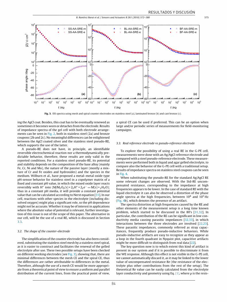
B. Ramírez Barat et al. / Sensors and Actuators B 261 (2018) 572–580 575
Fig. 3. EIS spectra using mesh and spiral counter electrodes on stainless steel (a), laminated bronze (b) and cast bronze (c).
ing the AgCl coat. Besides, this coat has to be eventually renewed assometimes it becomes worn or detaches from the electrode. Resultsof impedance spectra of the gel cell with both electrode arrange-ments can be seen in Fig. 2, both in stainless steel (2a) and bronzecoupons (2b and 2c). No meaningful differences can be enlightenedbetween the AgCl coated silver and the stainless steel pseudo-RE,which supports the use of the latter.
A pseudo-RE does not have, in principle, an identifiablereversible electrochemical reaction nor a thermodynamically pre-dictable behavior, therefore, these results are only valid in thereported conditions. For a stainless steel pseudo-RE, its potentialand stability depends on the composition of the base alloy (mainlyFe, Cr, Ni and Mo), the nature of the passive layer (mostly a mix-ture of Cr and Fe oxides and hydroxides) and the species in themedium. Wilburn et al., have proposed a metal–metal oxide typepH-sensor behavior for stainless steel in a copolymer matrix of afixed and constant pH value, in which the mixed oxide layer reactsreversibly with H+ ions (M/MxOy(s) + 2yH+ + 2ye− ↔ M(s) + yH2O);thus in a constant pH media, it will provide a constant potentialvalue that can be calculated according to Nerst equation [31]. In ourcell, reactions with other species in the electrolyte (including dis-solved oxygen) might play a significant role, so the pH dependencemight not be accurate. Whether it may be of interest in applicationswhere the absolute value of potential is relevant, further investiga-tion of this issue is out of the scope of this paper. The alternative inour cell, will be the use of a real RE, which is discussed in Section3.3.
3.2. The shape of the counter-electrode
The simplification of the counter electrode has also been consid-ered, substituting the stainless steel mesh by a stainless steel spiral,as it is easier to construct and facilitates the renewal of the gelledelectrolyte after use. These two possible setups have been checkedon different working electrodes (see Fig. 3), showing that, there areminimal differences between the mesh CE and the spiral CE, thusthe differences are rather attributable to differences in the metal.Therefore, although the use of a mesh CE would be more appropri-ate from a theoretical point of view to ensure a uniform and paralleldistribution of the current lines, from the practical point of view,
a spiral CE can be used if preferred. This can be an option whenlarge and/or periodic series of measurements for field-monitoringcampaigns.
3.3. Real reference electrode vs pseudo-reference electrode
To explore the possibility of using a real RE in the G-PE cell,measurements were done with an Ag/AgCl reference electrode andcompared with a steel pseudo-reference electrode. These measure-ments were performed both in liquid and agar gelled electrolyte, tocompare also the behavior of the G-PE cell with a traditional setup.Results of impedance spectra on stainless steel coupons can be seenin Fig. 4.
When substituting the pseudo-RE for the standard Ag/AgCl REsome relevant changes are observed. With the Std-RE uncom-pensated resistance, corresponding to the impedance at highfrequencies appears to be lower. In the case of standard RE with theliquid electrolyte it can also be observed a distortion of the phaseangle spectra at the high frequencies, between 104 and 105 Hz(Fig. 4b), which denotes the presence of an artifact.
The spectra distortion at high frequencies caused by the RE andother elements of the measurement setup is a long time knownproblem, which started to be discussed in the 80’s [31,32]. Inparticular, the contribution of the RE can be significant in low con-ductivity media causing parasitic impedances [32,33], in whichinteractions between the three electrodes are involved [22,23].These parasitic impedances, commonly referred as stray capac-itances, frequently produce pseudo-inductive behaviors. Whilepseudo-inductive artifacts are easy to recognize as they appear asa loop in the fourth quadrant in Nyquist plot, capacitive artifactsmight be more difficult to distinguish from real data [22].
The key question now is to which extent this kind of artifact ispresent in our system and if it is possible to discriminate it fromthe WE response. Although this effect is not visible in the G-PE cell,we cannot automatically discard it, as it may be linked to the lowervalue of uncompensated resistance Re (the resistance of the elec-trolyte plus other contributions from the rest of the setup). Thetheoretical Re value can be easily calculated from the electrolytelayer conductivity and geometry using Eq. (1), where is the resis-
________________________________________________________________________
________________________________________________________________________ 84
RESULTADOS Y DISCUSIÓN

576 B. Ramírez Barat et al. / Sensors and Actuators B 261 (2018) 572–580
Fig. 4. EIS spectra comparing a real reference and a pseudo reference electrode on stainless steel coupons with gelled (a) and liquid electrolyte (b).
Table 1Fitting results for the real and pseudo reference electrodes with agar gelled and liquid electrolyte.
L (H cm2) Re ( cm2) CPE Chi-Sqr
Y (S s˛ cm−2)
AA-SRE −8.8 ± 0.9 418 ± 2 13.65 ± 0.08 0.828 ± 0.001 4.00E − 03AA-StdRE −3.8 ± 0.3 126 ± 1 14.05 ± 0.08 0.827 ± 0.001 2.81E − 03LIQ-SRE −49 ± 6 1384 ± 6 17.84 ± 0.09 0.805 ± 0.002 6.85E − 03LIQ-StdRE 280 ± 10 750 ± 2 15.90 ± 0.05 0.792 ± 0.001 1.53E − 03
tivity in ·cm (the inverse of the conductivity), d is the distancebetween the RE and WE in cm and A the contact area in cm2.
Re = d
A(1)
For a 3.2 mm distance between the RE and WE used in these experi-ments, Re should be around 1556 for the liquid cell and 142 forthe G-PE one. Thus, we can compare these calculated values withthe experimental ones obtained by fitting the EIS spectra.
EIS spectra of agar and liquid cells with both real and pseudoRE have been fitted to the equivalent circuit in Fig. 4, where Re isthe uncompensated resistance, the passive layer of stainless steel isrepresented by a constant phase element (CPE), and an inductor, L,has been used to model the artifacts from the measuring system. Asit has been demonstrated by other authors, this inductive elementarises from the reduction to a 2-pole electrical equivalent circuitof the 3-pole (WE, RE and CE) circuit that constitutes the electro-chemical cell; and the choice of an inductive or capacitive elementis a matter of convenience and in no way does it suggest the induc-tive or capacitive behavior of the electrode [22,23], and it can evenhave negative values [29].
Fit results are presented in Table 1. Comparing experimentaland calculated Re values, it can be observed that, for the pseudoRE, the experimental value with agar is much higher and about 10%lower for the liquid electrolyte. With the real RE, the experimentalvalue is about 10% lower for the agar, and half the value for the
liquid. A higher experimental value can be attributed to the contri-bution of other elements (such as interfacial impedances betweenthe electrolyte and the RE), but a lower experimental value has nophysical explanation, thus it is clearly caused by an artifact in thishigh frequency region [23]. Considering that in corrosion measure-ments a 10% deviation from the theoretical value can be consideredreasonable, we can derive two practical consequences. In very lowconductivity electrolyte as the artificial rain, the use of the real REcauses the presence of an artifact that, at least, affects the region ofthe electrolyte response, while the pseudo RE gives a more reliableresult. With the agar gelled electrolyte (with low but higher con-ductivity than the liquid), it may be possible to use a real RE withno overlapping of parasitic responses, while the use of a pseudo-RE adds additional resistance to the high-frequency part of the EISspectrum. In any case, this contribution can be separated from thecontributions of the other elements of the corrosion system, andthe results obtained for the region of interest −corresponding tofaradaic processes and passive layers or coatings- are the same withboth pseudo and real reference electrodes.
3.4. The influence of the WE-RE distance
The distance and relative position between electrodes is anotherrelevant parameter affecting the cell response [29,33], since it willinfluence the values of the capacitances and resistances between
________________________________________________________________________
________________________________________________________________________ 85
RESULTADOS Y DISCUSIÓN

B. Ramírez Barat et al. / Sensors and Actuators B 261 (2018) 572–580 577
Fig. 5. Effect of the distance between the reference and the working electrode for a real reference electrode (a) and a pseudo reference electrode (b).
Table 2Fitting results at different distances for the real and pseudo reference electrodes. Rcal is the value estimated for Re from Eq. (1).
L(H cm2) Re ( cm2) CPE Rcal ( cm2) Chi-Sqr
Y (S s cm−2)
AA-StdRE 2.0 mm 82 ± 2 52 ± 1 19.1 ± 0.1 0.808 ± 0.001 98 3.10E − 03AA-StdRE 3.2 mm −3.8 ± 0.3 124 ± 1 14.05 ± 0.04 0.827 ± 0.001 142 1.20E − 03AA-StdRE 4.4 mm −6 ± 4 243 ± 1 12.78 ± 0.03 0.834 ± 0.001 196 9.89E − 04AA-SRE 2.0 mm −33 ± 9 342 ± 1 14.99 ± 0.06 0.814 ± 0.001 98 2.60E − 03AA-SRE 3.2 mm −1.8 ± 0.9 421 ± 2 13.65 ± 0.08 0.828 ± 0.001 142 3.35E − 03AA-SRE 4.4 mm 21 ± 2 587 ± 1 13.50 ± 0.1 0.808 ± 0.001 196 2.50E − 03
Table 3Fitting results at different distances for the real and pseudo reference electrodes on bronze coupons.
L (H cm2) Re ( cm2) CPE1 R1 ( cm2) W Chi-Sqr
Y (S s cm−2) RW (k cm2) TW(s) W
BL-StdRE 3.2 mm 1.95 ± 0.06 124.6 ± 0.3 9.5 ± 0.2 0.915 ± 0.003 1430 ± 50 20.7 ± 0.2 22.0 ± 0.7 0.396 ± 0.003 4.42E − 04BL-StdRE 4.4 mm −4 ± 3 203.9 ± 0.5 10.7 ± 0.4 0.911 ± 0.005 1390 ± 60 19.2 ± 0.2 19.8 ± 0.7 0.409 ± 0.003 7.01E − 04BL-SRE 3.2 mm −15 ± 7 431 ± 1 13.2 ± 0.6 0.834 ± 0.007 2000 ± 100 20.3 ± 0.4 24 ± 1 0.394 ± 0.005 8.64E − 04BL-SRE 4.4 mm −18 ± 9 517 ± 2 12.9 ± 0.7 0.885 ± 0.009 1510 ± 90 18.1 ± 0.3 22 ± 1 0.406 ± 0.005 1.25E − 03
the electrodes in the 3-pole cell. To analyze the influence of thisparameter in our cell and optimize the RE-WE distance, a seriesof measurements at different distances with both Std-RE andpseudo-RE electrodes were carried out. Fig. 5 shows the EIS spectrawith both RE at three different RE-WE distances: 2.0 mm, 3.2 mmand 4.4 mm, which may give around 98, 142 and 196 for theelectrolyte resistance between them. Results from fitting the exper-imental data to the equivalent circuit are presented in Table 2.
Pseudo-inductive responses are clearly present when using thereal RE in the closest position (2.0 mm) while their value decreasesas RE-WE distance increases. For 3.2 mm distance the spectra doesnot appear to be distorted but there is still a slight inductivecontribution in the equivalent circuit. For the pseudo-RE pseudo-
inductive effects are negligible (in fact, fitting the spectra withoutthe pseudo-inductive element yield the same results for other ele-ments in the circuit) although the electrode contributes to theuncompensated resistance.
The values of CPE are all very close and can be considered equalfor all setup but the 2.0 mm with a standard RE suggesting thatthe RE parasitic contribution (either inductive or resistive) doesnot affect the results from the stainless steel WE. This means thatas long as the uncompensated resistance (Re) can be separatedfrom the WE response, both RE electrodes are valid. To minimizeinterferences of artifacts in the frequency ranges of interest for thecorrosion studies, the lower distance is more convenient when apseudo RE is used not to increase the Re value. On the contrary,
________________________________________________________________________
________________________________________________________________________ 86
RESULTADOS Y DISCUSIÓN

578 B. Ramírez Barat et al. / Sensors and Actuators B 261 (2018) 572–580
Fig. 6. EIS spectra comparing a real reference and a pseudo reference electrode atdifferent distances on bronze coupons.
when using a standard RE a higher distance allows avoiding induc-tive artifact. The CPE values obtained with the pseudo RE are a littleless sensitive to the different WE-RE distances tested. It has to beconsidered that, especially in field measurements on irregular sur-faces, the real WE-RE may be slightly different (lower) from thedesign distance, due to the pressure applied to adapt the gel to theWE surface.
3.5. Bronze working electrode
As artifacts are the result of interactions between the three elec-trodes [22,23] the change in the nature of the WE may increase its
effects or overlap with the region of interest when measuring othersurfaces. For this reason, once the contribution/behavior or the cellis clear enough it is necessary to verify this is also valid for bronze,which is probably the most relevant material for this application.
Thus, EIS spectra with the real and pseudo RE have been acquiredon laminated bronze coupons at the two selected distances, 3.2 mmand 4.4 mm. Graphical and numerical results are presented in Fig. 6and Table 3 respectively. EIS spectra have been fitted to the equiv-alent circuit in Fig. 6, where Re is the uncompensated resistance,CPE1 and R1 represent the double layer and the charge transferresistance while W in associated to diffusion of copper ions withinthe oxide layer and the electrolyte. This equivalent circuit hasbeen previously used to explain the behavior of copper and bronzein mild neutral electrolytes [18,34]. Results from bronze couponsare coherent with those obtained for stainless steel, Re values arealmost identical for the same setup, while the rest of parametersare reasonably similar for the different setups. Pseudo-inductiveartifacts are only appreciable for the lower RE-WE distance withthe real reference, thus same considerations on RE and distancescan be made for bronze.
3.6. In situ measurements
The final step is to test if the cell allows obtaining good qual-ity data out of the ideal situation of model samples and laboratoryconditions. So, along with the development of the cell design, ithas been assayed in different materials and case studies [35,36].These examples have allowed to validate the cell performanceand to improve the design according to different difficulties beingobserved. In this section an example of EIS spectra recorded ona twentieth century stainless steel sculpture with the G-PE cell(stainless steel pseudo RE) is compared to laboratory measure-ments (Fig. 7). The sculpture is Mediterránea III, made by theSpanish sculptor Martín Chirino in 1971, which is owned by theMuseo Nacional Centro de Arte Reina Sofía and exposed at theMuseo de Escultura de Leganés. Although the spectra of the sculp-ture shows a couple of small discontinuities in the phase angle,it can be considered a good quality field measurement, showing
Fig. 7. Comparison between laboratory measures on stainless steel coupons and field measurements on the stainless steel sculpture, Mediterránea III, by Martín Chirino.
________________________________________________________________________
________________________________________________________________________ 87
RESULTADOS Y DISCUSIÓN

B. Ramírez Barat et al. / Sensors and Actuators B 261 (2018) 572–580 579
Fig. 8. Comparison between EIS spectra on an aged cast bronze coupon with a sulfide patina and Incralac coating with field measurements on right bronze sphinx from theMuseo Arqueológico Nacional, restored and protected with Incralac.
an identical profile to those obtained on coupons under laboratoryconditions. Slight differences at intermediate and high frequencies– higher impedance for the sculpture – can be attributed to theageing of the passive layer of the metal exposed outdoors.
As an example of a bronze outdoor sculpture measurements on abronze sphinx at the main fac ade of the Spanish National Archaeo-logical Museum (MAN) in Madrid are compared with a cast bronzecoupon (Fig. 8). The two bronze sphinxes from the MAN fac adewere restored a few years ago and protected with an acrylic coating(Incralac), commonly used for conservation treatments of copper-alloy sculptures [16]. The EIS spectra of the right sphinx two yearsafter the treatment is compared to a bronze coupon with a darksulfide patina prepared in the traditional way that has been alsocoated with Incralac and exposed to the atmosphere in Madrid forthe same period. Again, results obtained in field measurements arecomparable to laboratory results, considering the differences in thematerials, validating the performance of the G-PE cell for in situconservation assessment.
4. Conclusions
Results support the suitability of the G-PE cell as an electro-chemical sensor for corrosion measurements on metallic culturalheritage.
The analysis of different design parameters has allowed toimprove the cell and to understand the influence of the nature andgeometry of the electrodes in the EIS response. This has allowedalso separating possible parasitic contributions from the responseof the working electrode. As it has been demonstrated, the cell canbe used either with a real reference electrode or with a pseudo-reference electrode, as a matter of convenience. When using a realreference electrode attention has to be paid not to place it too closeto the working electrode surface to avoid pseudo-inductive effects.When using a pseudo-reference electrode it is more convenientusing a closer distance to reduce the uncompensated resistance.
The G-PE cell has demonstrated to be a versatile and useful toolfor conservation assessment, giving good results both in laboratorysamples and field measurements.
Acknowledgements
This work was supported by the Spanish Ministry of Economyand Competitiveness (projects HAR2011-22402 and HAR2014-54893-R, and grant BES-2012-052716); by the CNR-STM grant“In situ electrochemical techniques for metal artworks conserva-tion” and the Comunidad de Madrid (project GEOMATERIALES2S2013/MIT-2914). Authors want to thank Rosa Ma Izquierdo andIsrael, from the Museo de Escultura de Leganés, Teresa Espinosafrom the Museo Arqueológico Nacional, Codina Escultura, and Fran-cisco García from the CENIM.
References
[1] V. Otieno-Alego, D. Hallam, A. Viduka, G. Heath, D. Creagh, Electrochemicalimpedance studies of the corrosion resistance of wax coatings on artificiallypatinated bronze, in: J. Ashton, D. Hallam (Eds.), Metal 98 InternationalConference on Metal Conservation, James & James, Draguignan-Figanières(France), 1998, pp. 315–319.
[2] G. Bierwagen, T.J. Shedlosky, L.A. Ellingson, Electrochemical studies of theprotection of bronzes from corrosion by organic coatings, in: I. MacLeod, J.M.Theile, C. Degrigny (Eds.), Metal 01 International Conference on MetalConservation, Western Australian Museum, Santiago (Chile), 2001, pp.291–296.
[3] G. Bierwagen, T.J. Shedlosky, K. Stanek, Developing and testing a newgeneration of protective coatings for outdoor bronze sculpture, Prog. Org.Coat. 48 (2003) 289–296.
[4] L.A.B. Ellingson, L.B. Shedlosky, T.J. Bierwagen, G.P. De la Rie, E. René, The useof electrochemical impedance spectroscopy in the evaluation of coatings foroutdoor bronze, Stud. Conserv. 49 (2004) 53–62.
[5] E. Joseph, P. Letardi, R. Mazzeo, S. Prati, M. Vandini, Innovative treatments forthe protection of outdoor bronze monuments, in: C. Degrigny, R. Van Lang, I.Joosten, B. Ankersmith (Eds.), Metal 07 Interim Meeting of the ICOM-CC MetalWG, Rijksmuseum Amsterdam, Amsterdam (The Neatherlands), 2007, pp.71–77.
[6] E. Cano, D.M. Bastidas, V. Argyropoulos, S. Fajardo, A. Siatou, J.M. Bastidas,et al., Electrochemical characterization of organic coatings for protection ofhistoric steel artefacts, J. Solid State Electrochem. 14 (2010) 453–463.
________________________________________________________________________
________________________________________________________________________ 88
RESULTADOS Y DISCUSIÓN

580 B. Ramírez Barat et al. / Sensors and Actuators B 261 (2018) 572–580
[7] N. Swartz, T.L. Clare, On the protective nature of wax coatings for culturallysignificant outdoor metalworks: microstructural flaws, oxidative changes,and barrier properties, J. Am. Inst. Conserv. 54 (2015) 181–201.
[8] P. Letardi, Electrochemical impedance measurements in the conservation ofmetals, in: D.C. Creagh, O.A. Bradley (Eds.), Radiation in Art and Archeometry,Elsevier Science B.V, Amsterdam, 2000, pp. 15–39.
[9] P. Letardi, R. Spiniello, Characterisation of bronze corrosion and protection bycontact-probe electrochemical impedance measurements, in: I. MacLeod, J.M.Theile, C. Degrigny (Eds.), Metal 01 International Conference on MetalConservation, Western Australian Museum, Santiago (Chile), 2001, pp.316–319.
[10] E. Angelini, S. Grassini, S. Corbellini, G.M. Ingo, T. De Caro, P. Plescia, et al.,Potentialities of XRF and EIS portable instruments for the characterisation ofancient artefacts, Appl. Phys. A: Mater. Sci. Process. 83 (2006) 643–649.
[11] E. Angelini, S. Grassini, M. Parvis, F. Zucchi, An in situ investigation of thecorrosion behaviour of a weathering steel work of art, Surf. Interface Anal. 44(2012) 942–946.
[12] T.L. Clare, A. England, N. Swartz, K. Hosbein, 2013. Onsite electrochemicalmonitoring method for early detection of coating failure, In: E. Hyslop, V.Gonzalez, L. Troalen, L. Wilson, (Eds.), Metal 2013 Interim Meeting of theICOM-CC Metal Working Group, Edinburgh.
[13] S. Li, Y.G. Kim, S. Jung, H.S. Song, S.M. Lee, Application of steel thin filmelectrical resistance sensor for in situ corrosion monitoring, Sens. Actuators B:Chem. 120 (2007) 368–377.
[14] S. Muralidharan, T.H. Ha, J.H. Bae, Y.C. Ha, H.G. Lee, K.W. Park, et al.,Electrochemical studies on the performance characteristics of solidmetal-metal oxide reference sensor for concrete environments, Sens.Actuators B: Chem. 113 (2006) 187–193.
[15] P.G. Venancio, R.A. Cottis, R. Narayanaswamy, J.C.S. Fernandes, Optical sensorsfor corrosion detection in airframes, Sens. Actuators B: Chem. 182 (2013)774–781.
[16] B. Ramírez Barat, A. Crespo, E. García, S. Díaz, E. Cano, An EIS study of theconservation treatment of the bronze sphinxes at the Museo ArqueológicoNacional (Madrid), J. Cult. Heritage 24 (2017) 93–99.
[17] E. Cano, D. Lafuente, D.M. Bastidas, Use of EIS for the evaluation of theprotective properties of coatings for metallic cultural heritage: a review, J.Solid State Electrochem. 14 (2010) 381–391.
[18] B. Ramírez Barat, E. Cano, The use of agar gelled electrolyte for in situelectrochemical measurements on metallic cultural heritage, Electrochim.Acta 182 (2015) 751–762.
[19] P. Letardi, 2013. Electrochemical measurements in the conservation ofmetallic heritage artefacts: an overview In: P. Dillmann, D. Watkinson, E.Angelini, A. Adriaens (Eds.), Corrosion and Conservation of Cultural HeritageMetallic Artefacts, Woodhead Publishing Ltd.,126–148.
[20] E. Cano, A. Crespo, D. Lafuente, B. Ramírez Barat, A novel gel polymerelectrolyte cell for in-situ application of corrosion electrochemicaltechniques, Electrochem. Commun. 41 (2014) 16–19.
[21] P. Letardi, B. Ramirez Barat, E. Cano, Analysis of the Influence of theElectrochemical Cell Setup for Corrosion Measurements on Metallic CulturalHeritage, European Corrosion Congress, EUROCORR, Prague, Czech Republic,2017.
[22] S. Fletcher, The two-terminal equivalent network of a three-terminalelectrochemical cell, Electrochem. Commun. 3 (2001) 692–696.
[23] A. Sadkowski, J.P. Diard, On the Fletcher’s two-terminal equivalent network ofa three-terminal electrochemical cell, Electrochim. Acta 55 (2010) 1907–1911.
[24] G. Hsieh, S.J. Ford, T.O. Mason, L.R. Pederson, Experimental limitations inimpedance spectroscopy: part I—simulation of reference electrode artifacts inthree-point measurements, Solid State Ion. 91 (1996) 191–201.
[25] G. Hsieh, T.O. Mason, E.J. Garboczi, L.R. Pederson, Experimental limitations inimpedance spectroscopy: part III. Effect of reference electrodegeometry/position, Solid State Ion. 96 (1997) 153–172.
[26] G. Hsieh, T.O. Mason, L.R. Pederson, Experimental limitations in impedancespectroscopy: part II—electrode artifacts in three-point measurements onPt/YSZ, Solid State Ion. 91 (1996) 203–212.
[27] P. Vanysek, H. Tavassol, K.L. Pilson, Electrochemistry in the electrochemicalcells: there is more than just the working electrode, ECS Trans. 63 (2014)145–155.
[28] S.N. Inamdar, M.A. Bhat, S.K. Haram, Construction of Ag/AgCl referenceelectrode from used felt-tipped pen barrel for undergraduate laboratory, J.Chem. Educ. 86 (2009) 355–356.
[29] M. Balabajew, B. Roling, Minimizing artifacts in three-electrode double layercapacitance measurements caused by stray capacitances, Electrochim. Acta176 (2015) 907–918.
[30] E. Bernardi, C. Chiavari, C. Martini, L. Morselli, The atmospheric corrosion ofquaternary bronzes: an evaluation of the dissolution rate of the alloyingelements, Appl. Phys. A: Mater. Sci. Process. 92 (2008) 83–89.
[31] H. Göhr, M. Mirnik, C.A. Schiller, Distortions of high frequency electrodeimpedance. Their causes and how to avoid them, J. Electroanal. Chem. 180(1984) 273–285.
[32] F. Mansfeld, S. Lin, Y.C. Chen, H. Shih, Minimization of high-frequency phaseshifts in impedance measurements, J. Electrochem. Soc. 135 (1988) 906–907.
[33] S. Chechirlian, P. Eichner, M. Keddam, H. Takenouti, H. Mazille, A specificaspect of impedance measurements in low conductivity media. Artefacts andtheir interpretations, Electrochim. Acta 35 (1990) 1125–1131.
[34] Y. Feng, W.K. Teo, K.S. Siow, K. l. Tan, A.K. Hsieh, The corrosion behaviour ofcopper in neutral tap water. Part I: corrosion mechanisms, Corros. Sci. 38(1996) 369–385.
[35] A. Crespo, D. Ramírez Barat, S. Lafuente, E. García, E. Cano, Non-destructiveelectrochemical evaluation of the patinas on the bronze sphinxes of theMuseo Arqueológico Nacional in Madrid, in: Art‘14 11th InternationalConference on Non-destructive Investigations and Microanalysis for theDiagnostics and Conservation of Cultural and Environmental Heritage,Madrid, 2014.
[36] B. Ramírez Barat, E. Cano, Evaluación in situ de recubrimientos protectorespara patrimonio cultural metálico mediante espectroscopía de impedanciaelectroquímica, Ge-conservación 8 (2015) 6–13.
Biographies
Blanca Ramírez-Barat has a degree in Chemistry and in Fine Arts, both from theComplutense University of Madrid, and a MSc in Materials Science and Engineeringfrom Carlos III University. After several years in R&D management, she is currentlyworking at the National Center for Metallurgical Research (CENIM-CSIC) in Madrid,Spain in the research group “Corrosion and protection of metals in cultural heritageand construction” at the CENIM-CSIC. Her research is focused in the application ofelectrochemical techniques for conservation assessment and diagnosis in culturalheritage.
Emilio Cano is Tenured Scientist at the Centro Nacional de Investigaciones Met-alúrgicas (CENIM-CSIC) in Madrid, Spain. He obtained his PhD in Fine Arts from theComplutense University of Madrid in 2001. His fields of expertise include corro-sion and protection of metallic cultural heritage, indoor corrosion, electrochemicaltechniques applied to conservation science, XPS and corrosion inhibitors. He haspublished more than 100 research papers in international scientific journals and pre-sented communications to about 60 scientific conferences, both in corrosion scienceand conservation science.
Paola Letardi has a degree in Physics and worked in the field of Material Science andSurface Spectroscopy, with particular interest in the development of methodologiesand instrumentation. She has been active in national and international projects ondiagnostics and monitoring for the Conservation of Cultural Heritage. Her researchis focused on the study of corrosion of metals in the marine environment and onspecific applications of electrochemical and spectroscopic techniques in the field ofartifacts of historical interest.
________________________________________________________________________
________________________________________________________________________ 89
RESULTADOS Y DISCUSIÓN

RESULTADOS Y DISCUSIÓN
90
4.2.2. Comparación con otros sistemas.
Como continuación del análisis de la posible influencia del sistema de medida
en los resultados obtenidos y para profundizar en el conocimiento del propio sistema,
se está trabajando con P. Letardi en el estudio y comparación de la celda G-PE y la
celda de contacto (CP) desarrollada por esta investigadora. Estos sistemas son, hasta
la fecha, los que han demostrado un mayor desarrollo y trayectoria en su aplicación
estudio del patrimonio cultural metálico. Al mismo tiempo, se trata de dos ejemplos de
los dos tipos de soluciones propuestas para resolver el problema de la medida in situ.
La CP desarrollada por Letardi[49, 204] consiste en un cilindro de teflón que contiene
embebidos dos cilindros concéntricos de acero inoxidable AISI316, que actúan como
electrodo de pseudo-referencia y contraelectrodo. Sobre este cilindro se sujeta un
paño impregnado en el electrólito que se mantiene húmedo por capilaridad, mediante
un extremo sumergido en un pequeño recipiente que contiene el electrólito (figura 23).
El área nominal de contacto de la celda es de 1.77cm2.
Figura 23. Celda de contacto desarrollada por Letardi (izquierda) y montaje completo para la realización de las medida (derecha).
Además del análisis independiente de cada uno de estos sistemas, resulta interesante
comparar medidas realizadas con las diferentes celdas en las mismas condiciones. De
este modo, las diferencias obtenidas pueden atribuirse a la influencia del sistema
empleado [205]. Por ello, caracterizar estas diferencias es de gran utilidad tanto para
poder comparar medidas realizadas con diferentes sistemas como para comprender
mejor los resultados de las medidas de impedancia e identificar las posibles fuentes
de interferencias.

RESULTADOS Y DISCUSIÓN
91
Los primeros estudios comparativos se han realizado sobre acero inoxidable AISI316
como sustrato estable, reproducible y de resultados fácilmente interpretables.
Además, todas las medidas se han realizado conjuntamente en el mismo laboratorio y
con el mismo electrólito para minimizar cualquier otro factor externo, durante una
estancia en Madrid de P. Letardi y otra de la autora en Génova. Desde el punto de vista
cualitativo, las principales diferencias se observan a frecuencias más altas, en especial
en la resistencia no compensada y en la posición de las constantes de tiempo, a
frecuencias más altas en la celda de contacto. En la región de frecuencias más bajas
las diferencias son reducidas. Esto se puede apreciar en la figura 24, en la que se
presenta un ejemplo de las medidas realizadas con los dos sistemas en una probeta de
acero inoxidable con dos concentraciones diferentes del electrólito, y sobre una
escultura de acero inoxidable, Mediterránea III, de Martín Chirino (Museo de Escultura
de Leganés) en comparación con las medidas realizadas sobre la probeta (figura 25).
Figura 24. Ejemplo de medidas comparativas entre la celda G-PE y la CP sobre acero inoxidable con agua de lluvia artificial 10x y 1000x (izquierda). Comparación de los resultados obtenidos en
probetas y en obra real Mediterránea III de Martín Chirino (dcha).

RESULTADOS Y DISCUSIÓN
92
La menor resistencia del electrólito en la CP es coherente con el diseño de la misma
ya que la distancia RE-WE es mucho menor que en el caso de la celda G-PE. De hecho,
el espectro obtenido con la celda G-PE empleando un electrólito concentrado (agua de
lluvia artificial 1000x) sobre una probeta de acero inoxidable resulta prácticamente
idéntico al obtenido con la celda CP en la concentración habitual (agua de lluvia
artificial 10x). En el caso de las medidas de campo sobre obra real, ambas celdas
ofrecen resultados de la misma calidad, con las mismas diferencias en la región de
altas frecuencias que en las medidas de laboratorio.
Figura 25. Realización de medidas de campo sobre la obra Mediterránea III con la CP y la celda G-PE.

RESULTADOS Y DISCUSIÓN
93
Además de las medidas sobre acero inoxidable, se han realizado medidas en probetas
de bronce, pertenecientes a la serie de probetas de bronce de fundición con pátina
tostada a base de sulfuro potásico tras 16 meses de exposición atmosférica en el
CENIM. En la figura 26 se presentan los resultados obtenidos para tres probetas
distintas.
Figura 26. Comparación de los espectros obtenidos con la celda CP y G-PE sobre tres probetas de bronce patinado (T01-T03).
Los espectros obtenidos en este caso presentan mayores diferencias, aunque
el valor máximo del módulo de la impedancia es muy similar en ambos casos. Los
resultados de los ajustes de los espectros al circuito general (figura 12) pueden
compararse en las tablas 4 y 5. Se puede comprobar que las diferencias en los
parámetros calculados no son excesivamente grandes, aproximándose los valores en
los elementos que aparecen a frecuencias más bajas (R2-CPE2, difusión). Por otra
parte, el ajuste de los espectros realizados con la CP requiere la introducción de una
inductancia antes de la resistencia del electrólito y el grado de ajuste es peor que en el

RESULTADOS Y DISCUSIÓN
94
caso de la celda G-PE. Esto sugiere la presencia de algún artefacto en la medida con la
celda CP, que pudiera estar relacionado con la reducida distancia entre el electrodo de
trabajo y el electrodo de referencia, como se ha demostrado en el estudio realizado
para la celda G-PE [206].
Tabla 4. Ajuste de los espectros obtenidos con la celda G-PE sobre tres probetas de bronce patinado.
Celda G-PE T01 T02 T03
Re (Ω·cm2) 642±1 651±1 592±2
CPE1 Y1 (S sα1 cm-2) 2.83±0.09E-05 2.6±0.1E-05 2.00±0.09E-05
α1 0.59±0.01 0.63±0.01 0.65±0.01
R1(kΩ· cm2) 3.2±0.1 3.5±0.2 3.5±0.2
CPE2 Y2(S sα2 cm-2) 6.8±0.1E-05 9.3±0.1E-05 6.4±0.1E-05
α2 0.66±0.01 0.54±0.02 0.56±0.01
R2 (kΩ cm2) 26.9±0.7 25±2 30±2
W
R (kΩ· cm2) 52±1 46±2 52±3
T (s) 82±4 82±7 90±10
αw 0.73±0.02 0.73±0.03 0.70±0.04
Tabla 5. Ajuste de los espectros obtenidos con la celda CP sobre tres probetas de bronce patinado.
Celda CP T01 T02 T03
L -6.12E-05 -9.27E-05 -5.59E-05
Re (Ω·cm2) 75±1 142±1 77±2
CPE1 Y1 (S sα1 cm-2) 1.18±0.09E-05 1.29±0.5E-05 1.37±0.04E-05
α1 0.83±0.01 0.81±0.01 0.70±0.01
R1(kΩ· cm2) 9.7±0.8 16±1 24±1
CPE2 Y2(S sα2 cm-2) 6.6±0.6E-05 7±1E-05 9±2E-05
α2 0.67±0.08 0.8±0.1 1±0.2
R2 (kΩ cm2) 21±4 16±4 13±4
W
R (kΩ· cm2) 52±6 48±5 58±8
T (s) 70±10 60±7 70±15
αw 0.77±0.06 0.80±0.04 0.75±0.7

RESULTADOS Y DISCUSIÓN
95
4.2.2. Modificación del electrólito.
Los ensayos realizados con el gel de agar pusieron de manifiesto que el agar
parece tener un cierto efecto de despolarización catódica en el bronce, aumentando
levemente la velocidad de corrosión medida frente a un electrólito tradicional [132].
Este efecto puede ser minimizado utilizando bajas concentraciones de agar, y no
supone un problema práctico para la aplicación pretendida en patrimonio cultural,
puesto que para comparar la eficacia de distintos sistemas de protección o seguir su
degradación con el tiempo siempre se recurrirá a medidas comparativas. A pesar de
ello, se consideró de interés explorar la posibilidad de modificar el electrólito, con el
fin de lograr una mayor aproximación a un electrólito líquido tradicional y profundizar
en la comprensión del efecto del gelificante sobre las medidas
Al tratarse el agar de una mezcla de dos polisacáridos, agarosa y agaropectina, una
mejor opción la ofrecería el empleo de agarosa pura, ya que teóricamente, por ser la
fracción neutra del gel, presentaría las ventajas del agar sin sus inconvenientes.
Partiendo de esta hipótesis se estudió el comportamiento de la agarosa tanto sobre
probetas de laboratorio como en medidas de campo, en comparación con el agar y con
el electrólito líquido. Los resultados de esta comparativa demostraron que
efectivamente, la agarosa presenta un comportamiento más próximo al electrólito
líquido, sin embargo, estas diferencias sólo se producen en superficies reactivas, como
puede resultar una probeta de metal limpio y lijado. En el caso de probetas
recubiertas, o de las medidas realizadas en campo sobre superficies expuestas largo
tiempo a la acción de los agentes atmosféricos, no se aprecian diferencias
significativas en el empleo de ambos gelificantes. Este estudio se recoge en la
siguiente publicación:
• B. Ramírez Barat, E. Cano: “Agar vs agarose gelled electrolyte for in situ corrosion studies on metallic cultural heritage”, ChemElectroChem, (2019) 6 (9), 2553–25599.
9 Referencias bibliográficas [35, 45-47, 68, 91, 119, 122, 132, 143, 146, 147, 151, 155, 161, 168-170, 206-209] de la bibliografía general

123456789101112131415161718192021222324252627282930313233343536373839404142434445464748495051525354555657
Agar versus Agarose Gelled Electrolyte for In Situ CorrosionStudies on Metallic Cultural HeritageBlanca Ramírez Barat* and Emilio Cano[a]
The use of gelled electrolytes has revealed an interestingsolution for in situ electrochemical measures on culturalheritage, where liquid electrolytes cannot be easily handled.After developing an agar gelled electrolyte cell, other gellingagents such as agarose are being considered to improve it. Inthis work, the performance of agarose gels in different
concentrations has been studied and compared to agar and aliquid electrolyte. Measurements have been done on patinatedquaternary bronze and weathering steel, as representativematerials of outdoor monuments. Agarose gels have beenvalidated for in situ corrosion studies on bronze and weatheringsteel sculptures.
1. Introduction
Development of new and improved diagnostic tools is arelevant subject in conservation science, and the application ofelectrochemical techniques has become an outstanding topic inrecent years for the assessment of patinas and protectivecoatings for metallic heritage.[1] The unique nature of theobjects, their irreplaceable value, the long-term evolution ofpatinas and corrosion products (which cannot be reproduced inthe laboratory) and the requirement of conservators-restorersto have scientific evidence to support decisions on conservationtreatments make necessary to carry out in-situ scientific analysison the real heritage artefacts. The practical difficulties of doingin-situ electrochemical measurements has restrained the use ofthese techniques for conservation science.[2]
In this particular area, different authors have worked in thedesign of a solid electrolyte cell for in situ electrochemicalmeasurements, where handling liquid electrolytes offers severaldifficulties. Commercial electrocardiogram electrodes,[3] synthe-tized anionic gels,[4] agar gelled electrolytes[5] or PVA[6] havebeen proposed for this purpose. The properties of the electro-lyte together with the geometric design are the design keyfeatures, particularly for in situ studies.
The use of agar gelled electrolytes has recently beenevaluated by different authors[7] showing that agar cells offergood performance and interesting properties for this purpose.Agar is a translucent, cheap, non-toxic, and quick and easy toprepare material, which admits a wide range of aqueouselectrolytes and also contributes to conductivity. It's flexibilityallows adaptation to irregular surfaces and can be improved bythe addition of plasticizers,[7d,e] and its syneresis helps wettingthe surface and allowing good contact. Other proposedmaterials, have shown other limitations: Commercial or synthe-tized anionic gels are very limited by the electrolyte choice, and
the use of PVA has to be more deeply studied, as preliminaryresults showed appreciable differences when compared to atraditional cell design. In previous studies agar showed a certaindecrease in impedance values if compared to the liquidelectrolyte, which was attributed to some anodic depolarizingeffect in bronze, slightly increasing the measured corrosion rateif compared to a traditional liquid electrolyte. Though this effectcan be minimized using low agar concentrations and it is not aproblem for comparative studies,[7b,c] further improvements ofthe measuring system were considered.
Agar is a mixture of two polysaccharides: agarose, which isthe neutral fraction, and agaropectin, modified by side groups.As this later seems to be the responsible for the interactionwith copper ions, which accelerates the anodic reaction, themost intuitive approach to avoid this effect is the use of pureagarose instead of agar. Agarose may have same advantages asagar, while its neutral chemical nature will reduce the risk ofundesired interactions with metal ions, effects that may beattributed to the agaropectin fraction. Another potentialadvantage of agarose is that being a purer and homogeneoussubstance, it is foreseeable to obtain consistent results betweendifferent commercial products, while agar may show differencesaccording to its provenance.
A review of literature shows that other researchers havealready suggested the use of agarose as a solid medium forconventional electrochemical measurements although very fewarticles have been published. Kaneko and co-workers studiedthe use of agarose gels as an electrolyte for electrochemicalmeasurements, such as Electrochemical Impedance Spectro-scopy or Voltammetry, providing similar results to liquidelectrolytes.[8] These authors evaluated transport and electro-chemical properties of agarose gels, finding out that were veryclose to aqueous systems. Despite the interest of this work, toour best knowledge, no application of agarose to corrosionstudies has been done. For this reason, the aim of this work isto evaluate the behavior and applicability of agarose gelledelectrolytes for corrosion studies in cultural heritage, incomparison with both a liquid electrolyte and with agar-basedelectrolyte, which has demonstrated its utility for in-situmeasurements. Measurements have been done with the gel
[a] B. Ramírez Barat, Dr. E. CanoNational Center for Metallurgical Research (CENIM)Spanish National Research Council (CSIC)Avda. Gregorio del Amo 8, 28040 MadridE-mail: [email protected]
ArticlesDOI: 10.1002/celc.201900344
2553ChemElectroChem 2019, 6, 2553–2559 © 2019 Wiley-VCH Verlag GmbH & Co. KGaA, Weinheim
Wiley VCH Mittwoch, 08.05.2019
1909 / 136507 [S. 2553/2559] 1
________________________________________________________________________
________________________________________________________________________ 96
RESULTADOS Y DISCUSIÓN

123456789101112131415161718192021222324252627282930313233343536373839404142434445464748495051525354555657
polymer electrolyte (G-PE) cell described in previous papers,[5,7c,9] under the experimental conditions presented in “ExperimentalSection”. As base electrolyte, an artificial rain (AR) solution hasbeen used, both as liquid and gelled with agar and agarose.
2. Results and Discussion
2.1. Agarose as a Gelling Agent
The behavior of the agarose gelled electrolyte has been studiedover different substrates and compared with the liquid electro-lyte and agar-gelled electrolyte. These include bare metalsurfaces, artificially and naturally patinated metals and coatedmetals: AISI316 stainless steel has been chosen as referencematerial, and patinated cast bronze and weathering steel, asrepresentative materials of outdoor sculptures.
Figure 1 shows EIS spectra for the liquid, agarose-gelled andagar-gelled electrolyte obtained on stainless steel coupons. Thehigh stability and uniformity of the passive layer formed on thestainless steel allows a precise comparison of the contributionof the different experimental setups[9] For this system, agaroseand liquid results are almost identical, and differences appearonly for agar and in the high frequency region. This difference
can explained by the lower electrolyte resistance, due to theagar’s increase of conductivity.[5]
In the case of weathering steel (Figure 2) a decrease in theimpedance of intermediate frequencies is also observable foragar, while results from liquid and agarose electrolyte can beconsiderate almost equivalent. Due to the inhomogeneity ofnatural patinas in weathering steels, it is difficult to ascertain towhich extent this effect is attributable to differences in thesamples or to the effect of the composition of the electrolyte.
When measures are done on bronze (Figure 3), there is alsoa drop in impedance's value at low frequencies, together with aphase angle shift. This effect, which is slightly present in theagarose gel too, has been related to the interaction betweencopper ions and the gel matrix.[7c] When bronze is covered by aprotective coating as Incralac® (Figures 4) this effect is mini-mized, and results obtained with the three electrolytes arecomparable, taking into account that the measured surfaces arenot identical (as have been individually prepared by hand,following the common practice of conservators-restorers inconservation treatments for real objects).
In general, it can be appreciated that EIS spectra obtainedwith agarose are quite similar to those acquired with the liquidelectrolyte, while measurements with agar show lower impe-dances, especially at high frequencies. These differences aremore or less pronounced depending on the working electrodematerial.
Figure 1. EIS spectra (Bode plot) obtained with liquid electrolyte, agaroseand agar gels on AISI316 stainless steel.
Figure 2. EIS spectra (Bode plot) obtained with liquid electrolyte, agaroseand agar gels on weathering steel (three year natural patina).
Figure 3. EIS spectra (Bode plot) obtained with liquid electrolyte, agaroseand agar gels on cast bronze with dark (top) and green (bottom) patina.
Articles
2554ChemElectroChem 2019, 6, 2553–2559 www.chemelectrochem.org © 2019 Wiley-VCH Verlag GmbH & Co. KGaA, Weinheim
Wiley VCH Mittwoch, 08.05.2019
1909 / 136507 [S. 2554/2559] 1
________________________________________________________________________
________________________________________________________________________ 97
RESULTADOS Y DISCUSIÓN

123456789101112131415161718192021222324252627282930313233343536373839404142434445464748495051525354555657
2.2. Agar vs. Agarose in Field Measurements
Since the final aim of the G-PE cell is the in-situ electrochemicalmeasurements on metallic heritage, the comparison of agarand agarose gelled electrolyte was done by field measurementson five different bronze and weathering steel sculptures, atdifferent locations. The five sculptures where a bronze Sphinxat the National Archaeological Museum in Madrid, with anIncralac® coating; a bronze angel figure by Enrico Astorri fromthe Staglieno monumental cemetery in Genoa; a modernbronze sculpture, Unidad Yunta (Pablo Serrano, 1970) at thePolytechnic University of Valencia and two weathering steelsculptures located at the Museo de Escultura de Leganés(Madrid): Templo (2003) by Adriana Veyrat and Zenon (1980) byJosé Luis Sánchez (owned by Museo Reina Sofía).
In all cases, apart from the higher conductivity of agar, EISspectra are very similar for agar and agarose in all examples, ascan be appreciated in Figures 6–8. Measures on the Angel figure,with a thick highly washed patina, and Zenon, with a well-
developed and smooth patina, are almost identical for the twogelled electrolytes. Comparing the values of the low frequencylimit of the impedance modulus (Table 1), it can be appreciatedthat values are very close for every couple of measurements(agar-agarose) on the same sculpture. The fact that in somecases agarose yield lower impedance and in other highersuggest that differences may be attributed to small patinainhomogeneity and/or differences in the wetted area, which inthis in-situ measurements are higher than the differences dueto the electrolyte that have been demonstrated in previoussection. The largest differences seem to appear in one of theweathering steel sculptures, Templo, the one with the youngerand presumably thinner patina, but numerical differences are infact very little, though visual differences seem higher due to thescale of the graph. The higher difference when comparingvalues is in the coated bronze surface from the bronze Sphinx.
From these results, it can be considered that differencesbetween both electrolytes in field measurements are not quiterelevant. This difference with laboratory measurements can beexplained by the fact that laboratory coupons are morehomogeneous and uniform, and are more reactive than patinasof outdoor sculptures which have been exposed and washedthrough many years.
2.3. Agarose Concentration
As previously noted, the choice of 2% agarose was based onthe fact that this would be the equivalent to 3% agar, so thisconcentration could be compared with previous results ob-tained with the agar cell. As shown in previous sections, 2%agarose gave spectra closer to liquid electrolyte than agar,though still showed a slightly lower impedance values in themore reactive bronze surfaces. Considering that results may beimproved using a different agarose concentration, a series ofEIS measurements at different agarose percentages were doneon the two reference materials, patinated bronze (Figure 9) andweathering steel (Figure 10), and compared to the liquidelectrolyte
Though the lower is the agarose concentration more closeis the EIS spectra to the liquid electrolyte, differences betweenagarose concentrations are relatively small. Table 2 shows thedifferent electrolyte concentrations, pH and conductivity. Theaddition of agarose to the liquid electrolyte slightly increasesthe conductivity and does not modify the pH value, while agarproduced more basic pH and significantly enhances conductiv-ity, as previously described.[7c] As with agar, this increase inconductivity explains the lower jZ j values at high frequencieswith the increasing concentration of agarose, but this effect isquite small, especially when compared with agar, so it can
Figure 4. EIS spectra (Bode plot) obtained with liquid electrolyte, agaroseand agar gels on Incralac coated bronze with dark (top) and green (bottom)patina.
Table 1. Comparison of the impedance modulus at the low frequency limit with agar and agarose gelled electrolyte for different sculptures.
jZ jmax [Ohm cm2]Angel (green area) Angel (black area) Sphinx Unidad Yunta Templo Zenon
agar 1.50E+05 6.83E+04 3.89E+05 3.45E+05 9.44E+03 1.57E+06agarose 1.26E+05 8.12E+04 6.02E+05 2.78E+05 9.81E+03 1.93E+06
Articles
2555ChemElectroChem 2019, 6, 2553–2559 www.chemelectrochem.org © 2019 Wiley-VCH Verlag GmbH & Co. KGaA, Weinheim
Wiley VCH Mittwoch, 08.05.2019
1909 / 136507 [S. 2555/2559] 1
________________________________________________________________________
________________________________________________________________________ 98
RESULTADOS Y DISCUSIÓN

123456789101112131415161718192021222324252627282930313233343536373839404142434445464748495051525354555657
usually be disregarded. Considering these small variations,other effects, such as geometrical factors can be responsible forslight variations in high frequencies jZ j values in Figures 9 and10: as Rs depends on the area and WE-RE distance, smallvariations due to the deformation of the gel when pressured tothe working electrode surface, can explain this behavior. This isspecially the case of the lower concentrations (1%), whichproduce a very soft gel, with low mechanical resistance.
Figure 5. Bode plots from a bronze angel (pictured left), by Enrico Astorri (1859–1921) at the Staglieno cemetery in Genoa. Spectra from green (top right) andblack (bottom right) areas on the left arm.
Figure 6. Bode plot (right) of the sphinx at the main façade of the National Archaeological Museum in Madrid (pictured left). The Sphinxes, casted in 1894,were restored and protected with Incralac® and wax a couple of years before.[7b,10]
Table 2. Different electrolyte concentrations, pH and conductivity.
Electrolyte pH Conductivity [mS])
AR 6.67 94.0AR-agarose 1% 6.70.2 1202AR-agarose 1.5% 6.50.2 1266AR-agarose 2% 6.60.2 1326AR-agar 3% 7.420.03 152415
Articles
2556ChemElectroChem 2019, 6, 2553–2559 www.chemelectrochem.org © 2019 Wiley-VCH Verlag GmbH & Co. KGaA, Weinheim
Wiley VCH Mittwoch, 08.05.2019
1909 / 136507 [S. 2556/2559] 1
________________________________________________________________________
________________________________________________________________________ 99
RESULTADOS Y DISCUSIÓN

123456789101112131415161718192021222324252627282930313233343536373839404142434445464748495051525354555657
In order to elucidate the contribution of agarose to the EISspectra at other frequencies, results were fitted to the generalequivalent circuit presented in Figure 11. The use of this circuithas been discussed in a previous paper.[1] Rs is the resistance ofthe electrolyte, CPE1-R1 represent the resistance and capaci-tance of the patina or rust layer, CPE2-R2 the capacitance of thedouble layer at the metal-electrolyte interface and chargetransfer resistance of the redox reactions and W representsdiffusive effects related to copper ions diffusion in the patina
for bronze[12] and to oxygen diffusion through the pores in therust layer, in the case of steel.[13] The values obtained for thedifferent elements (Table 3) are also very close, moreover takinginto account the irregularities of the patina surfaces and theunavoidable uncertainty in the measured area, in particular forthe highly porous and absorbing rust layer in weathering steel.The values of R2 seem to decrease slightly with the increasingconcentration of agarose, both for bronze and weathering steel.This indicates that agarose slightly increases the measured
Figure 7. Bode plot (right) of a modern bronze sculpture (pictured left), Unidad Yunta (1970) by Pablo Serrano, on the brown polished area.
Figure 8. EIS spectra (Bode plots; right) on weathering steel sculptures at the Museo de Escultura de Leganés. Zenon (1980), by José Luis Sánchez (top left),and a weathering steel sculpture with a waxed and polished surface and Templo (2003), by Adriana Veyrat (bottom left), with a thin lepidocrocite patina.[11]
Articles
2557ChemElectroChem 2019, 6, 2553–2559 www.chemelectrochem.org © 2019 Wiley-VCH Verlag GmbH & Co. KGaA, Weinheim
Wiley VCH Mittwoch, 08.05.2019
1909 / 136507 [S. 2557/2559] 1
________________________________________________________________________
________________________________________________________________________ 100
RESULTADOS Y DISCUSIÓN

123456789101112131415161718192021222324252627282930313233343536373839404142434445464748495051525354555657
corrosion rate, although this effect is much less relevant thanfor agar.[7c] Diffusion does not seem to be affected by the use ofthe gel in the case of bronze, in agreement with a previouswork,[7c] but for weathering steel the diffusive impedance isincreased, what might be explained by the lower oxygencontent of gelled electrolytes.[7d] In any case, as it has beenshown in the results of previous section (Figures 5–8), theuncertainties of field measurements are higher than these
effects. For this reason, the use and concentration of agarosedoes not present a critical issue for in situ corrosion studies incultural heritage. As a compromise between mechanical andelectrochemical properties, 1.5–2% agarose would be a goodoption.
3. Conclusions
Agarose has shown to be a good option for electrochemicalmeasurements on cultural heritage objects, where a conven-tional cell cannot be used and the use of gel electrolytes canoffer many advantages.
Results show that agarose gives a response quite close tothe liquid electrolyte, thus it is a good option to carry outcorrosion studies, where agar may have a higher effect onresults. This would be the case of reactive surfaces as non-agedcoupons or fresh patinas.
Field measurements on long-term weathered surfaces ofmonuments or in coated metals do not show significantdifferences between the two gelled electrolytes, so the use ofagar is still valid if necessary. The natural conductivity of agarmay offer an additional advantage in field measurements,especially for low impedance patinas such as those of weath-ering steels.
Experimental SectionAs mentioned in the introduction, measurements have been donewith the gel polymer electrolyte (G-PE) cell designed by authorsand described in detail in references.[5,7c, 9]
The electrolyte has been prepared by gelling a liquid electrolytewith agar (technical grade) or agarose (basic, Panreac). As liquid
Figure 9. EIS spectra of brown patinated bronze coupons with differentagarose concentrations.
Figure 10. EIS spectra of 5-years-aged weathering steel with differentagarose concentrations.
Figure 11. Equivalent circuit used for modelling EIS spectra of patinatedmetal coupons.
Table 3. Fit results of EIS spectra on bronze and weathering steel coupons for different agarose concentrations compared to the liquid electrolyte.
Rs[kΩ · cm2]
CPE 1 R1[kΩ · cm2]
CPE 2 R2[kΩcm2]
WY1[Ssα1 cm 2]
α1 Y2[S sα2 cm 2]
α2 R[kΩ · cm2]
T [s] αw
Bronze
Liq 2.6 7.5E-06 0.64 1.8 5.1 E-05 0.58 7.4 17.1 123 0.721% 2.0 3.7E-06 0.69 1.7 4.2E-05 0.55 6.6 13.4 140 0.671.5% 2.5 4.7E-06 0.69 2.0 4.7E-05 0.58 5.4 11.6 117 0.722% 1.8 5.1E-06 0.66 1.9 4.7E-05 0.57 4.5 13.8 159 0.84
W. Steel
Liq 2.3 1.35E-06 0.51 4.0 5.5E-05 0.48 10.4 138 80 0.541% 2.3 3.3E-06 0.44 3.7 6.0E-05 0.40 16.9 152 120 0.751.5% 1.9 2.8E-06 0.46 3.6 5.1E-05 0.47 13.1 154 150 0.702% 1.7 2.1E-06 0.46 2.5 4.2E-05 0.44 10.6 107 146 0.70
Articles
2558ChemElectroChem 2019, 6, 2553–2559 www.chemelectrochem.org © 2019 Wiley-VCH Verlag GmbH & Co. KGaA, Weinheim
Wiley VCH Mittwoch, 08.05.2019
1909 / 136507 [S. 2558/2559] 1
________________________________________________________________________
________________________________________________________________________ 101
RESULTADOS Y DISCUSIÓN

123456789101112131415161718192021222324252627282930313233343536373839404142434445464748495051525354555657
electrolyte concentrated artificial rain (CaSO4 ·2H2O 14.43 mg/mL,(NH4)2SO4 15.04 mg/mL, (NH4)Cl 19.15 mg/mL, NaNO3 15.13 mg/mLand CH3COONa 3.19 mg/mL) has been used, adapted from.[14] Thesolution is prepared 1000 fold concentrated and pH adjusted to 5with HNO3 and stored at room temperature. For the measurements,this solution is then diluted to a 10-fold concentration, with a finalpH value of 6.5. This solution has been chosen because it has asimilar composition to the natural electrolyte to which outdoormonuments are exposed and at the same time it is a mildelectrolyte which prevents any damage to the surface. To preparethe electrolyte 3% w-v agar or 1–2% w-v agarose powder is addedto the electrolyte in a beaker and gently heated in a microwaveoven at low power until dissolution. The solution is poured into themold and left to cool at room temperature. For comparisonbetween agar and agarose gels, 2% agarose was used. As agaroserepresents two thirds of agar composition, 2% agarose would bethe equivalent to the 3% agar gel used in previous work. Astainless-steel wire (AISI 316 L) has been used as pseudo-referenceelectrode and a spiral made of the same material has beenemployed for the counter electrode (CE). In all cases, the geometryof the cell and electrode positions have been kept constant.
The behavior of the different electrolyte compositions has beentested on AISI316 stainless steel coupons and on patinated castbronze and weathering steel, as representative materials of outdoorsculptures. Different sets of reference coupons were used, preparedas:& Quaternary (85 Cu, 5 Sn, 5 Pb, 5 Zn %w) EN 1982CC491K (DIN1705-RG5) cast bronze coupons were prepared by a traditionalSpanish foundry according to traditional methods for artisticsculpture. Samples were cast, sand blasted and artificiallypatinated with a dark patina (using a potassium sulfide solution)and a green patina (using an ammonium chloride solution).Patination solutions were applied by alternatingly brushing thesolution on the metallic surface and heating with a torch. Onelayer of Incralac®, an acrylic coating used in conservation treat-ments of bronze sculptures, was applied by brush on somecoupons.
& Weathering steel (Arcelor S355J2W, EN 10025-5-2004) with anatural patina developed by exposing the steel coupons to amild urban atmosphere (Madrid, Spain) for 3 and 5 years in anatmospheric corrosion station (according to standard ISO8565 :1992).
& AISI 316 stainless steel has been used as a highly stable referencematerial, to minimize the effects of inhomogeneity in patinalayers. Stainless steel coupons have been polished for homoge-nization of the surface and left to the air for several days to allowthe formation of its natural passivation layer.
EIS spectra have been acquired using a Gamry 600 Potentiostat,using a frequency swept from 100 kHz to 10 mHz, 10 mV RMSamplitude (at the open circuit potential, OCP) and 10 points/decade. The area exposed to the electrolyte was 3.14 cm2. Analysisof the data has been carried out using ZView software. The systemwas left to stabilize at OCP for 30 minutes before measurements.Conductivity and pH of the electrolytes has been measured with aCrison MM40 conductimeter/pH meter.
Acknowledgements
This work was supported by the Spanish Ministerio de Economía yCompetividad (projects HAR2011-22402 and HAR2014-54893-R,and grant BES-2012-052716), Comunidad de Madrid and Euro-pean Union (Programa TOP Heritage-CM, P2018/NMT-4372).Authors want to acknowledge Museo de Escultura de Leganés,Museo Nacional Centro de Arte Reina Sofía, Museo ArqueológicoNacional, Universidad Politécnica de Valencia, Paola Letardi andCimitero di Staglieno (Genoa) and the Spanish Network Techno-Heritage.
Conflict of Interest
The authors declare no conflict of interest.
Keywords: agarose · corrosion · cultural heritage · gelelectrolyte · impedance
[1] B. Ramírez Barat, E. Cano, ChemElectroChem 2018, 5, 2698–2716.[2] a) E. Cano, D. Lafuente, D. M. Bastidas, J. Solid State Electrochem. 2010,
14, 381–391; b) E. Cano, D. M. Bastidas, V. Argyropoulos, S. Fajardo, A.Siatou, J. M. Bastidas, C. Degrigny, J. Solid State Electrochem. 2010, 14,453–463.
[3] E. Angelini, S. Grassini, S. Corbellini, G. M. Ingo, T. De Caro, P. Plescia, C.Riccucci, A. Bianco, S. Agostini, Appl. Phys. A 2006, 83, 643–649.
[4] A. H. England, T. L. Clare, Electroanalysis 2014, 26, 1059–1067.[5] E. Cano, A. Crespo, D. Lafuente, B. Ramírez Barat, Electrochem. Commun.
2014, 41, 16–19.[6] F. Di Turo, P. Matricardi, C. Di Meo, F. Mazzei, G. Favero, D. Zane, J. Cult.
Herit. 2018.[7] a) B. Ramírez Barat, E. Cano, P. Letardi, Sens. Actuators B 2018, 261, 572–
580; b) B. Ramírez Barat, A. Crespo, E. García, S. Díaz, E. Cano, J. Cult.Herit. 2017, 24, 93–99; c) B. Ramírez Barat, E. Cano, Electrochim. Acta2015, 182, 751–762; d) G. Monrrabal, B. Ramírez-Barat, A. Bautista, F.Velasco, E. Cano, Metals 2018, 8; e) G. Monrrabal, S. Guzmán, I. E.Hamilton, A. Bautista, F. Velasco, Electrochim. Acta 2016, 220, 20–28; f) F.Di Turo, C. De Vito, F. Coletti, F. Mazzei, R. Antiochia, G. Favero,Microchem. J. 2017, 134, 154–163.
[8] a) H. Ueno, Y. Endo, Y. Kaburagi, M. Kaneko, J. Electroanal. Chem. 2004,570, 95–100; b) N. Mochizuki, H. Ueno, M. Kaneko, Electrochim. Acta2004, 49, 4143–4148; c) H. Ueno, M. Kaneko, J. Electroanal. Chem. 2004,568, 87–92.
[9] B. Ramírez Barat, E. Cano, P. Letardi, Sens. Actuators B 2018, 261, 572–580.
[10] S. Díaz Martínez, Boletín del Museo Arqueológico Nacional 2015, 33, 267–283.
[11] A. Crespo, B. Ramírez Barat, I. Diaz Ocaña, E. Cano Díaz, in Conservaciónde Arte Contemporáneo 18ª Jornada (Ed.: M. Departamento deConservación-Restauración), 2017, pp. 193–201.
[12] Y. Feng, W. K. Teo, K. S. Siow, K. l. Tan, A. K. Hsieh, Corros. Sci. 1996, 38,369–385.
[13] a) J. H. Wang, F. I. Wei, H. C. Shih, Corrosion 1996, 52(12), 900–909;b) J. H. Wang, F. I. Wei, H. C. Shin, Corrosion 1996, 52(8), 600–608.
[14] E. Bernardi, C. Chiavari, C. Martini, L. Morselli, Appl. Phys. A 2008, 92, 83–89.
Manuscript received: February 28, 2019Revised manuscript received: April 11, 2019Accepted manuscript online: April 15, 2019
Articles
2559ChemElectroChem 2019, 6, 2553–2559 www.chemelectrochem.org © 2019 Wiley-VCH Verlag GmbH & Co. KGaA, Weinheim
Wiley VCH Mittwoch, 08.05.2019
1909 / 136507 [S. 2559/2559] 1
________________________________________________________________________
________________________________________________________________________ 102
RESULTADOS Y DISCUSIÓN

RESULTADOS Y DISCUSIÓN
103
4.3. Validación y aplicación (casos prácticos).
Además de los ensayos realizados con diferentes probetas para el diseño y
evaluación de la celda, de manera paralela se han hecho estudios puntuales sobre
diferentes sustratos para estudiar las posibilidades de aplicación a la resolución de
problemas de conservación. Por un lado, se han realizado estudios de laboratorio
sobre probetas con diversas pátinas y recubrimientos que simulaban las diversas
circunstancias y cuestiones que se abordan habitualmente en la conservación del
patrimonio metálico; por otro lado, se han realizado estudios in situ, sobre obra real,
para comprobar y validar el diseño de la celda en su modo de aplicación final, e ir
introduciendo las modificaciones necesarias para solventar las dificultades prácticas
que se iban encontrando en diferentes situaciones.
4.3.1. Ensayos de laboratorio: patinas y recubrimientos.
El estudio de pátinas y recubrimientos tiene gran interés para la ciencia de la
conservación. El estudio de la composición y características de las pátinas permite,
entre otros objetivos, comprender mejor los mecanismos de corrosión y los factores
que intervienen o determinar la estabilidad de un objeto en un determinado ambiente
para anticipar problemas de conservación. Por ejemplo, poder predecir la evolución de
las pátinas teniendo en cuenta el cambio climático, las variaciones en los niveles de
contaminación, el traslado de lugar del objeto, etc. En patrimonio cultural, estos daños
no tienen por qué ser necesariamente físicos o químicos, pueden ser también
estéticos, tales como la alteración del color de la pátina. Por otra parte, estudio de la
efectividad y la evolución de los recubrimientos protectores es sin duda una cuestión
de gran relevancia para la conservación del patrimonio metálico. Los recubrimientos
utilizados en conservación han de cumplir una serie de requisitos específicos
impuestos por los criterios actuales de conservación, y se aplican en condiciones que
no son las idóneas desde un punto de vista de optimizar su capacidad protectora. Por
estas razones, resulta importante realizar estudios de estos productos para conocer
sus prestaciones y evolución con el tiempo [35]
Las técnicas analíticas habitualmente utilizadas en este campo, como FTIR, DRX o
Raman, permiten ver la evolución en la composición y estructura de una pátina o
recubrimiento, pero no proporcionan una relación cuantitativa con la capacidad

RESULTADOS Y DISCUSIÓN
104
protectora. Por ello, la posibilidad de aplicación de técnicas electroquímicas a estos
estudios supone una valiosa contribución. En este capítulo, se presentan varios
estudios realizados para demostrar las posibilidades reales de aplicación del sistema
desarrollado a casos reales.
4.3.1.1. Evaluación de pátinas.
Dentro de las posibilidades de utilización de la celda al estudio de pátinas se
presentan dos ejemplos de aplicación. El primer caso es un trabajo sobre la
caracterización de pátinas formadas sobre probetas metálicas para su utilización
posterior como sustratos para la evaluación de tratamientos, en colaboración con el
grupo del ISMAR-CNR y el grupo de la Dra. Joseph de la Universidad de Neuchâtel.
Este trabajo se presentó en el noveno congreso del Grupo de Metales del Comité de
Conservación del ICOM:
• P. Letardi, B. Ramírez Barat, M. Albini, P. Traverso, E. Cano, E. Joseph, “Copper Alloys and Weathering Steel Used in Outdoor Monuments: Weathering in an Urban-Marine Environment”, en: R. Menon, C. Chemello, A. Pandya (Eds.), METAL2016, 9th interim meeting of the ICOM-CC Metals Working Group, New Delhi, India, 2016, pp. 320-8.
En este trabajo se estudiaron las patinas formadas sobre probetas de cuatro metales
representativos del patrimonio, cobre, bronce terciario, bronce cuaternario y acero
patinable, por exposición durante 18 meses a una atmósfera urbano-marina en Génova
(Italia). Los resultados mostraron que las patinas desarrolladas sobre las probetas a
lo largo de este periodo presentaban características similares a las pátinas formadas
en los monumentos. Concretamente para las medidas de impedancia en las probetas
de cobre y sus aleaciones los valores de |Z|10mHz eran próximos a los medidos sobre
obra real. Estos resultados avalan la posibilidad de obtener muestras adecuadas para
la evaluación de tratamientos de conservación y restauración, mediante exposición de
probetas a periodos de tiempo relativamente razonables.
El segundo ejemplo es el estudio de la evolución de pátinas artificiales sobre
aceros patinables. Los aceros patinables, más conocidos en el campo del arte y la
arquitectura por la denominación comercial de acero corten (o COR-TEN, que es la
denominación original utilizada por el fabricante US Steel, que lo desarrolló), se
caracterizan por desarrollar una pátina protectora bajo determinadas condiciones.

RESULTADOS Y DISCUSIÓN
105
Además de ese cierto carácter protector, la pátina formada presenta un rango de
tonalidades entre naranja y marrón que le confieren un valor estético, motivo por el
cual son muy utilizados en las artes plásticas. En este caso, se ha aplicado la celda G-
PE para la evaluación de la capacidad protectora de pátinas artificiales desarrolladas
sobre aceros patinables. La utilización de la celda en este estudio permitiría evaluar el
estado de conservación de esculturas tratadas de esta manera.
Los primeros resultados de la aplicación de la celda en el estudio de probetas de acero
patinadas artificialmente muestran diferencias de comportamiento entre las pátinas
aplicadas. El empleo de la celda ha permitido medir estas diferencias y compararlas
con pátinas naturales y pátinas sobre obra real [146, 210-212], demostrando que es
una herramienta adecuada para medir en este tipo de superficies que presentan una
textura irregular y de elevada porosidad, adaptándose a la superficie y reteniendo
adecuadamente el electrólito líquido. Los estudios iniciados en este tema, han sido el
origen de otra tesis doctoral que se está realizando actualmente en el CENIM.
Los primeros resultados en la aplicación de la celda en el estudio de probetas de acero
patinadas artificialmente también se presentaron en el congreso METAL 2016:
• B. Ramírez Barat, T. Palomar, B. Garcia, D. De la Fuente, E. Cano, “Composition and Protective Properties of Weathering Steel Artificial Patinas for the Conservation of Contemporary Outdoor Sculpture”, en: R. Menon, C. Chemello, A. Pandya (Eds.), METAL 2016 9th interim meeting of the ICOM-CC Metals Working Group New Delhi, India, 2016, pp. 314-9.
Ambas publicaciones se presentan a continuación.

Copper Alloys and Weathering Steel Used in Outdoor Monuments: Weathering in an Urban-marine Environment
Paola Letardi*CNR, Institute of Marine SciencesVia de Marini 616149 Genova, [email protected]
Blanca Ramírez-BaratCentro Nacional de Investigaciones Metalúrgicas (CENIM)-CSICAvda. Gregorio del Amo 828040 Madrid, [email protected]
* Author for correspondence
Monica AlbiniLaboratory of Microbiology, University of NeuchâtelRue Emile-Argand 112000 Neuchâtel, [email protected]
Pierluigi TraversoCNR, Institute of Marine SciencesVia de Marini 616149 Genova, [email protected]
Emilio CanoCentro Nacional de Investigaciones Metalúrgicas (CENIM)-CSICAvda. Gregorio del Amo 828040 Madrid, [email protected]
Edith JosephLaboratory of Microbiology, University of NeuchâtelRue Emile-Argand 112000 Neuchâtel, Switzerland
Haute Ecole Arc Conservation-restaurationUniversity of Applied Sciences Western SwitzerlandEspace de l’Europe 112000 Neuchâtel, [email protected]
Introduction and research aims
We present the experimental design and first results of an inter-laboratory research activity aimed at a deeper understanding of the properties of natural patinas, further development of in situ characterisation of metal monuments and ornamentations and an improvement of metal conservation-restoration treatments based on clear scientific and ethical criteria. This initial charac-terization aims to establish the best understanding of the composition and corrosion behaviour of coupons to be used for testing corrosion protection treatments.
Extensive analytical studies on conservation strategies (e.g. cleaning and protective treatments) can be performed only on artificial coupons, due to the wide homogeneous
surface required to compare many different parameters (Pilz 1997, Joseph 2013). Nonetheless, to recreate speci-mens representing the surface structure that is the result of past technologies and of complex interactions with the changing environments for many years may be quite difficult. However, copper, bronze and steel coupons with patinas as similar as possible to the ones commonly found in outdoor monuments (Selwyn 2004) are necessary in order to evaluate the efficiency of novel treatments, which depend also on the interaction with the patina (Otieno-Alego 1998, Chiavari 2010). Despite extensive studies on atmospheric corrosion, knowledge of many relevant parts is still lacking (Odnevall 2014). To elucidate this topic, experiments on weathering of coupons in standard
AbstractWe exposed metal coupons to natural weathering for 18 months at the Experimental Marine Station (SMS) inside Genoa Harbour. Four different compositions related to metals used in outdoor monuments were selected: copper (CU), ternary bronze (TB), quaternary bronze (QB), and weathering steel (WS). For each alloy, subsets of samples were monitored in situ for colour variation at regular intervals. To fully characterise the natural urban-marine patina growth and its chemical-physical properties, several analytical techniques have been used. For a more effective comparison with patinas on metal monuments and ornamentations, both portable Non-destructive Techniques (NdT) and classical laboratory methods were adopted. First results showed a generally slower growth rate and evolution of the properties of patinas after 12-14 months. The patina on bronzes and pure copper showed the early formation of cuprite
followed by Cu2Cl(OH)3 polymorphs and copper sulfates, mainly brochantite on CU. On WS a thicker corrosion layer than on copper alloys had grown, mainly composed of iron oxyhydroxides lepidocrocite and akaganeite, with a higher corrosion rate in respect of copper alloys. The patina composition on 18 months weathered coupons corresponds to the main composition generally reported for outdoor artworks. These coupons would thus be useful to test the performance of treatments on complex patina layers.
Keywords corrosion, natural ageing, bronze, copper, weathering steel, X-Ray Diffraction (XRD), Electrochemical Impedance Spectroscopy (EIS), Fourier Transform Infrared Spectroscopy (FTIR)
________________________________________________________________________
________________________________________________________________________ 106
RESULTADOS Y DISCUSIÓN

COPPER ALLOYS AND WEATHERING STEEL USED IN OUTDOOR MONUMENTS: WEATHERING IN AN URBAN-MARINE ENVIRONMENT 321
conditions are widely used (Tidblad 2012). Their surface characterisation by in-situ Non destructive Techniques (NdT) is not a standard practice, even though it could provide a valuable tool in the field of cultural heritage. In fact, it would allow a straightforward comparison between the measurements performed on coupons and those on monuments in terms of patina characterization and performance of tested treatments (Letardi 2016).
Among others, electrochemical techniques have raised a growing interest in the field of metal conservation and EIS has proved to be an effective tool to non-destructively characterise the corrosion behaviour of patinas and the efficiency of conservation treatments (Cano 2010, Letardi 2013, Albini 2015, Sansonetti 2015). A full exploitation of EIS data in metal conservation is not yet well established, especially for patina characterisation (Letardi 2007), and a deeper multi-analytical investigation will help in reaching that goal.
We focused our attention to the patina development on coupons exposed outdoor in a marine-urban envi-ronment, also considering the role of composition on corrosion. We applied NdT characterisation techniques to coupons, preferentially using in situ methods usually applied on artworks. Moreover, we wanted to take advan-tage of laboratory techniques to gain a better insight on both the effectiveness of NdT measurements on metal artworks and the analysis of electrochemical properties of the patinas. Finally, we addressed the use of these weathered coupons for the testing of treatments on outdoor monuments.
This paper presents the natural weathering exposure program of metal coupons and the first results on their characterisation over 18 months.
Materials and methods
Coupons and weathering conditions
Four different metal/alloy compositions were chosen:
• Cast copper (CU).
• Cast ternary bronze (TB) with nominal composition Cu90/Sn8/Pb2.
• Cast quaternary bronze (QB) with nominal compo-sition Cu85/Sn5/Zn5/Pb5.
• Weathering steel (WS) Arcelor S355J2W, EN 10025–5-2004 similar to CorTen steel.
The surface was polished with SiC grinding paper up to 1200 grit size, rinsed in deionised water and air-dried immediately before exposure. Two unexposed samples (3 × 3 cm) of each alloy were stored in the laboratory as reference. Two sets composed of 16 (6 × 6 cm-de-signed as large) and 12 (3 × 3 cm-designed as small) coupons for each alloy were exposed at the ISMAR-SMS site inside Genoa harbour, classified in corrosivity category C3 according to standard (ISO 9223:1992), with a chloride deposition rate of about 30 mg/(m2d) (ISO 9225:2012). The samples faced south and were positioned 45 degrees from the horizontal level (ISO 8565:1992) (Figure 1).
Figure 1. Exposure rack at the beginning (top) and after 14 months exposure (bottom)
The large samples were intended for future treat-ments testing and comparison; therefore, they were characterised only with NdT. The small samples were intended for monitoring patina growth and a wider use of analytical techniques. They were removed in pairs at regular intervals (1-3-6-12-18 months) in order to characterize the corrosion layer, both with portable NdT and laboratory measurements. The large coupons showed an almost even overall appearance after 18 months weathering, with a perceivable uneven texture at smaller scale (Figure 2a). The same appearance more or less characterised the small coupons at all weathering times (Figure 2b) with more relevant border effects, which is the reason why the larger coupons should be adopted for treatment testing.
________________________________________________________________________
________________________________________________________________________ 107
RESULTADOS Y DISCUSIÓN

322 ICOM-CC | METAL 2016 | NEW DELHI, INDIA SCULPTURE
Figure 2. Typical coupons appearance after weathering: a) large samples after 18 months; b) small samples at different exposure times
Characterisation techniques
For each alloy, subsets of 3 large samples and 3 small samples were monitored in situ for colour variation at regular intervals with a portable spectrophotometer Minolta d2600 [8 mm diameter measurement area, 360-750nm, illuminant D65, 10° observer, UV 100%]. Measurements were done using a positioning mask to repeat the measurement on the same points, in order to minimise scatter of data due to small-scale lack of homogeneity. The results are expressed according to the CIE 1976 L*a*b* colour reference space: the variable L* represents lightness, while a* (red-green) and b* (yellow-blue) are the chromatic coordinates.
A PHYNIX Surfix PRO FN Thickness Gauge was used to measure the patina’s thickness at the end of the exposure time. The instrument was zeroed and calibrated with 12 µm and 51 µm thickness standard, using a freshly polished unexposed sample as bare reference for each alloy. On each sample an average of 9 readings (5 mm diameter measurement area) evenly distributed over the whole area was acquired.
Patina composition was characterised on small samples by XRD and FTIR measurements on the coupons surface, without any sampling performed. FTIR spectra in Atten-
uated Total Reflectance (ATR) mode were recorded in the range 4000-550 cm-1 with a resolution of 4 cm-1 on Perkin Elmer Spectrum Two™ IR spectrometers as the average of 32 scans with Spectrum software. Thermo Scientific Omnic software was used for post-run processing. XRD spectra were recorded on a Rigaku Geigerflex D/max-B series diffractometer with Cu Kα radiation in the range of 7°-75° 2θ.
Corrosion behaviour was characterised by Polarisation Resistance (Rp) and EIS measurements with a Gamry Ref600 potentiostat with two different electrochemical cells designed for in situ measurements (Letardi 2004, Cano 2014, Ramírez Barat 2015). A ten-fold concentrated artificial rain solution (Bernardi 2008, Agnoletti 2011) was used as electrolyte; the composition is reported in Table 1. Polarization resistance measurements were obtained from -20 to +20 mV vs. open circuit potential (OCP) at a scan rate of 0.167 mV/s. EIS spectra were acquired in potentiostatic mode at OCP in the frequency range 100KHz-10mHz with10mV applied potential.
Table 1. Composition of synthetic rain used.A solution at 1000x concentration was prepared in deionised water and then diluted at 10x to be used as electrolyte in electrochemical measurements. Analytical grade salts were used
Salt Concentration mg/L
CaSO4.2H20 1.443
(NH4)2SO4 1.504
NH4Cl 1.915
NaNO3 1.513
CH3COONa 0.319
HNO3 65% Some drops of 50% solution diluted in water to adjust pH to 5
The small samples were analysed also with metallo-graphic techniques to fully characterise the natural urban-marine patina growth morphology on the different metal substrates. Metal samples were embedded in epoxy resin and ground with SiC grinding paper up to 2000 grit size followed by polishing with 3 and 1 µm diamond paste. For bare alloys characterisation, the weathering steel was etched with 2% nital solution and the copper alloys with ferric chloride in alcohol solution.
Weathered sample surface was examined by scanning electron microscopy (SEM). The SEM micrographs were obtained using the secondary electrons detector of a Hitachi S-4800 microscope, equipped with a cold-cathode field emission electron gun.
a)
b)
________________________________________________________________________
________________________________________________________________________ 108
RESULTADOS Y DISCUSIÓN

COPPER ALLOYS AND WEATHERING STEEL USED IN OUTDOOR MONUMENTS: WEATHERING IN AN URBAN-MARINE ENVIRONMENT 323
Results and discussion
Copper and bronze show the characteristic casting micro-structure (Figure 3). Copper has small and regular polyg-onal phase-α grains about 25 µm in size; no cast shrinkage porosity is observed. Both ternary and quaternary bronze show as-cast microstructure with large irregular grains of α-phase and solidification defects such as pores and shrink cavities. Dark spots appear due to segregation of tin surrounded by δ-phase. Small grey segregates can be observed in QB alloy, probably lead, due to its limited solubility in copper. WS is a hypoeutectoid steel with very fine and equiaxial grains. Microstructure consists of a ferrite matrix with small perlitic colonies.
Figure 3. Metallographic examination of CU (a), WS (b), TB (c) and QB (d)
Bronze coupons TB and QB are characterised by fairly similar colour values (Figure 4); they show almost the same colour variation upon weathering, with slightly higher b* (tendency to yellow) for TB. Copper samples are darker (lower L*) and more reddish (higher a* values). A bigger colour variation than for the bronzes is measured for CU in the first months of exposure, while after one year the general trends of pure copper and its alloys are quite similar. WS samples undergo a larger chromatic variation, with the major colour changes in the first 3-6 months. For all alloys, the colour became more stable after about 14 months of exposure.
The patina thickness of WS samples increased rapidly in the first months (Figure 5), with a slower growth rate after 6 months which led to about 60 µm after 18months. On CU, TB and QB samples, the patina seemed to develop slower and patina thickness started increasing only after 6 months, with a slower growth rate after 1 year; on bronzes the patina thickness after 18 months reached about 5 µm while on copper it was just about 3 µm.
Figure 4. CIELab color values as function of exposure time
Figure 5. Patina thickness as function of exposure time; ( top) all the four alloys considered; (bottom) detail for copper and copper alloys
________________________________________________________________________
________________________________________________________________________ 109
RESULTADOS Y DISCUSIÓN

324 ICOM-CC | METAL 2016 | NEW DELHI, INDIA SCULPTURE
ATR-FTIR measurements for CU samples (Figure 6a) reveal the gradual formation of copper hydroxychlorides Cu2Cl(OH)3 with characteristic vibrational bands in the 3450-3320 cm-1 and 990-820 cm-1 regions. Also, copper phosphates (cornetite, libethenite, and pseudomalachite) were observed at 637, 613 cm-1 after 1 month of exposure but their presence decreased thereafter. On the contrary, the presence of some copper hydroxysulfates, in particular brochantite, was ascertained and slightly increased with time (3589, 3567, 1121, 1113, 1101, 872, 782, 739, 642, 625, 600 cm-1). Traces of Nantokite (804, 787 and 703 cm-1) could also be present along the exposure time. TB and QB samples were characterized by a similar patina composi-tion with the formation of copper hydroxychlorides and copper phosphates (as for CU samples). Nantokite was slightly visible on QB samples but not on TB samples (maybe due to a concentration lower than the detection limit of the FTIR spectrometer). Moreover, we observed mixed basic lead carbonate/sulfate minerals leadhillite and hydrocerusite (1392, 1097, 1046, 840, 684 cm-1) that gradually disappeared in favour of the formation of copper hydroxysulfates, such as brochantite. (Figures 6-b and 6-c). On WS samples, the presence of iron oxyhydrox-ides, such as lepidocrocite (L) and possibly goethite (G) and akaganeite (A), was observed (1148 (L), 1092 (A), 1021 (L), 903 (G), 891 (L), 806 (G), 788 (L/A), 744 (L) and 690-670 (G/A) cm-1), as mentioned in the literature (Raman et al 1991, Thickett 2004), (data not shown).
XRD spectra on CU, TB and QB are dominated by metal peaks for 2θ greater than 41, while corrosion products peaks ranges mainly at lower 2θ; all measurements show the early formation of cuprite and its continued growth during weathering. As already mentioned for FTIR results, several Cu2Cl(OH)3 polymorphs (ataca-mite, botallackite, clinoatacamite) can be identified; the monoclinic form(s) (Jambor 1996) can be recognised from the first months, while atacamite is clearly visible from 6-12 months onward on CU, TB - QB; a small peak from nantokite is generally present. Copper sulfates are much better identified on CU, where brochantite peaks are clearly visible at 18 months (Figure 7) along with posnjakite in the first months of exposure, while antlerite (A) may be recognised on TB and QB. Copper phosphates cannot be clearly identified on CU, while libethenite may be identified on alloys along with cornetite on TB and pseudomalachite on QB at longer exposure times. On QB lead carbonate hydrocerussite is clearly identified after 1 month exposure with intensity of peaks not very
dependent on exposure time. On WS coupons, which are characterised by a thicker rust layer, peaks from the underlying metal disappeared after 1 month (Figure 8); the rust layer is known to be composed of a large amount of X-ray amorphous substances (Yamashita 1998) which, along with a wide distribution of particle sizes, give rise to non-intense and well-defined Bragg peaks; lepidocrocite is clearly identified in all XRD spectra on WS coupons, with traces of akaganeite; identification of goethite is not
Figure 6. ATR-FTIR spectra recorded after 1, 3, 6, 12 and 18 months of exposure on a) copper, b) ternary bronze and c) quaternary bronze coupons. Upward arrows: peaks from copper hydroxychlorides; downward arrows: peaks from copper phosphates, and (b,c only) lead mixed carbonate-sulfate minerals
________________________________________________________________________
________________________________________________________________________ 110
RESULTADOS Y DISCUSIÓN

COPPER ALLOYS AND WEATHERING STEEL USED IN OUTDOOR MONUMENTS: WEATHERING IN AN URBAN-MARINE ENVIRONMENT 325
obvious for any of the samples; however, magnetite and/or maghemite (Yamashita 1998) may be present.
Although the main compounds identified by ATR-FTIR and back-reflection XRD are the same, some differences may be seen, such as the identification of lead carbonate on QB samples for different exposure times. We suggest this can be linked to the different penetration depth of ATR-FTIR (0.3-3 µm) compared to XRD (2-120 µm) with respect to the patina growth. This issue is of rele-vance for in situ characterisation of monuments. Further investigations are in progress.
The mixed composition of cuprite with copper hydrox-ychlorides (atacamite, clinoatacamite) and hydrox-ysulfates (brochantite, antlerite) on copper alloys coupons and the mixed iron oxyhydroxides, including akaganeite, on WS coupons after 18 months exposure corresponds to the main components of the patina generally reported for outdoor monuments (Selwyn 2004, Aramendia 2011), when chloride pollution is present. The large coupons weathered for 18 months would thus be useful to test treatment performance on complex patina layers.
Figure 9. (a) Low frequency Impedance module and (b) Polarisation Resistance Rp as function of exposure time
Preliminary values of |Z|10mHz and Rp obtained (Figure 9) show a similar behaviour, especially for copper alloys. Some discrepancies are clearly visible, mainly for WS. As is well known, especially in the case of bare metals, a lower frequency may be required for |Z| to approximately equal the Polarisation Resistance. A deeper analysis of electrochemical measurements is in progress for better exploitation of the results. Nonetheless, we can gener-ally observe a higher corrosion rate for WS than copper alloys in the marine environment selected. As expected, data also show a lowering trend of corrosion rate with increased weathering time, which is more marked for copper alloys than for WS and in the first 9-12 months. For longer weathering time, copper alloys are charac-terised by |Z|10mHz of the order of 100KΩcm2 as the one measured on outdoor bronze monuments (Sansonetti 2015, Letardi 2016).
SEM (Figure 10) on the surface of CU samples show a thin layer of fine grained corrosion products at 1 month which can be associated to the early formation of cuprite. After 6 months, this layer grows in an irregular pattern. At 18 months, the corrosion products layer seems thicker without clearly defined crystals. TB and QB show similar
Figure 7. XRD spectra on CU, TB, QB after 18 months exposure Copper oxide cuprite: black arrows; copper chlorides: clinoatacamite (CA), atacamite (AT), nantokite (NT), botallakite (BT); copper sulfates: brochantite (BR), antlerite (AN), posnjakite (PN); copper phosphates: libethenite (LT), cornetite (CN), pseudomalachite (PM); lead carbonate: hydrocerussite (HC)
Figure 8. XRD spectra on WS at different weathering time
________________________________________________________________________
________________________________________________________________________ 111
RESULTADOS Y DISCUSIÓN

326 ICOM-CC | METAL 2016 | NEW DELHI, INDIA SCULPTURE
features, with thin irregular crusts of corrosion prod-ucts visible from the first month. These crusts thicken and form coarser aggregates with time. Thin cracks are visible in this crust on QB from month 6. Finally, WS corrosion products present two morphologies: after 3 months, globular shaped aggregates (bottom-left) and flake shaped crystals that seem to grow over them; at 6 and 18 months the entire surface is uniformly covered by these small-size flakes, but large cracks appear, breaking this surface. According to literature (Díaz 2012) the outer layer is mainly formed by lepidocrocite. Further analyses are in progress.
Conclusions
Weathering of copper, ternary bronze, quaternary bronze and weathering steel coupons for 18 months by exposure in the mildly aggressive urban-marine SMS site in Genoa allowed comparison of the patina growth for different metals and alloys of interest for outdoor metallic cultural heritage. The wide characterisation program includes both the measurements with the same setup directly applicable for in situ measurements on artworks as well as Lab techniques.
Preliminary results enlightened the following features of interest for outdoor metal conservation:
– the patinas grown at SMS after 18 months show inter-esting similarities with those on outdoor monuments which would be suitable for treatment testing;
– the non-destructive characterisation of patina thick-ness and composition without scraping from surfaces along with laboratory measurements on metallo-graphic sections can provide relevant information for in-situ diagnostic measurements.
Through the completion of planned measurements, the overall analysis of experimental data and an informed dialogue between conservators and scientists, we can glimpse an improvement in metal conservation-res-toration methodologies based on clear scientific and ethical criteria.
Acknowledgements
This work was partially supported by the European Union Seventh Framework Programme (FP7/2007-2013) under grant agreement n° 262584 JERICO-TNA (end user agreement n° 13/1210589/BF, 2013-2015), CREMEL project (HAR2011-22402) and the pre-doctoral FPI grant BES-2012-052716 funded by the Spanish Ministry of Science and Innovation.
References
ISO 9223:1992. Corrosion of metals and alloys - Corro-sivity of atmospheres - Classification.
ISO 8565:1992. Metals and alloys – Atmospheric corro-sion testing - General requirements for field test.
ISO 9225:2012. Corrosion of metals and alloys – Corro-sivity of atmospheres – Measurement of environmental parameters affecting corrosivity of atmospheres.
Aramendia, J., L. Gomez-Nubla, D. Vega, A. Sanz Lòpez de Heredia, A. García Ibáñez de Opakua, and J.M. Madariaga. 2011. The conservation of weathering steel sculpture - A comparative study of Chillida’s sculptures exposed in Bilbao. In Art’11 10th International Conference on non-destructive investigations and microanalysis for the diagnostics and conservation of cultural and environmental heritage Firenze
Agnoletti, S., L. Brambilla, A. Brini, A. Cagnini, M. Camaiti, C. Celi, L. Cetarini, R. De Lapi, G. Monica, S. Goidanich, S. Porcinai, B. Salvadori, and L. Toniolo. 2011. Formulati e metodologie per la pulitura e la protezione di superfici metalliche. Arkos 28: 34-37.
Albini, M., L. Comensoli, L. Brambilla, E. Domon Beuret, W. Kooli, L. Mathys, P. Letardi, and E. Joseph. 2015. Innovative biological approaches for metal conservation. Materials and Corrosion 67: 200-206.
Figure 10. SEM microphotographs at 1000x magnification on the surface of 1, 6 and 18 months exposure (from left to right) of CU, TB, QB and WS (top to bottom) samples
________________________________________________________________________
________________________________________________________________________ 112
RESULTADOS Y DISCUSIÓN

COPPER ALLOYS AND WEATHERING STEEL USED IN OUTDOOR MONUMENTS: WEATHERING IN AN URBAN-MARINE ENVIRONMENT 327
Bernardi, E., C. Chiavari, C. Martini, and L. Morselli. 2008. The atmospheric corrosion of quaternary bronzes: An evaluation of the dissolution rate of alloying elements. Applied Physics A 92: 83-89.
Cano, E., D. Lafuente, and D.M. Bastidas. 2010. Use of EIS for the evaluation of the protective properties of coatings for metallic cultural heritage: A review. Journal of Solid State Electrochemistry 14: 381-391.
Cano, E., A. Crespo, D. Lafuente, and B. Ramirez Barat. 2014. A novel gel polymer electrolyte cell for in-situ application of corrosion electrochemical techniques. Electrochemistry Communications 41: 16-19.
Chiavari, C., E. Bernardi, C. Martini, L. Morselli, F. Ospitali, L. Robbiola, and A. Texier. 2010. Predicting the corrosion behaviour of outdoor bronzes: assess-ment of artificially exposed and real outdoor samples. In Metal2010, 11-15 October 2010, ed. P. Mardikian, C. Chemello, C. Watters, and P. Hull, 218-224. Charleston, USA: Clemson University, South Carolina.
Díaz, I., H. Cano, B. Chico, D. De la Fuente and M. Morcillo. 2012. Some clarifications regarding literature on Atmospheric Corrosion of Weathering Steels. Inter-national Journal of Corrosion 2012: Article ID 812192, 9 pages
Jambor, J.L., J.E. Dutrizac, A.C. Roberts, J.D. Grice, J. T. Szymansky. 1996. Clinoatacamite, a new polymorph of Cu2(OH)3Cl, and its relationship to Paratacamite and “Anarakite”. The Canadian Mineralogist 34: 61-72.
Joseph, E., P. Letardi, L. Comensoli, A. Simon, P. Junier, D. Job, and M. Wörle. 2013. Assessment of a biological approach for the protection of copper alloys artefacts. In Metal2013, ed. E. Hyslop, V. Gonzalez, L. Troalen, and L. Wilson, 203-207. Edinburgh: Historic Scotland and International Council of Museums.
Letardi, P. 2004. Laboratory and field test on patinas and protective coating systems for outdoor bronze monuments. In Metal2004, ed. J. Ashton and D. Hallam, 379-387. Canberra: National Museum of Australia.
Letardi, P. and G. Luciano. 2007. Survey of EIS measure-ments on copper and bronze patinas. In Metal 07, ed. Degrigny, R. van Langh, I. Joosten, and B. Ankersmit, Vol.3 44-50. Amsterdam.
Letardi, P .2013. Electrochemical measurements in the conservation of metallic heritage artefacts: an overview. In Corrosion and conservation of cultural heritage metallic
artefacts, ed. P.Dillmann, D.Watkinson, E. Angelini, and A. Adriaens, 126-148. Cambridge: Woodhead Publishing Limited.
Letardi, P., B. Salvadori , M. Galeotti, A. Cagnini, S. Porcinai, A. Santagostino Barbone and A. Sansonetti. 2016. An in-situ multi-analytical approach in the resto-ration of bronze artifacts. Microchemical Journal 125: 151-158.
Otieno-Alego, V., D. Hallam, A. Viduka, G. Heath, and D. Creagh. 1998. Electrochemical impedance studies of the corrosion resistance of wax coatings on artificially patinated bronze. In Metal98, 26-29 may 1998, ed. W. Mourey and L. Robbiola, 315-319. Draguignan (France): James&James.
Odnevall Wallinder, I., X. Zhang, S. Goidanich, N. Le Bozec, G. Herting, and C. Leygraf. 2014. Corrosion and runoff rates of Cu and three Cu-alloys in marine environments with increasing chloride deposition rate. Science of the Total Environment 472: 681-694.
Pilz, M. and H. Roemich. 1997. Sol-Gel Derived Coatings for Outdoor Bronze Conservation. Journal of Sol-Gel Science and Technology 8: 1071-1075.
Raman A., B. Kuban and A. Razvan., 1991. The appli-cation of infrared spectroscopy to the study of atmos-pheric rust systems—I. Standard spectra and illustrative applications to identify rust phases in natural atmos-pheric corrosion products. Corrosion Science, 32(12), 1295-1306.
Ramírez Barat, B. and E. Cano. 2015. The use of agar gelled electrolyte for in situ electrochemical measure-ments on metallic cultural heritage. Electrochimica Acta 182: 751-762.
Sansonetti, A., M. Colella, P. Letardi, B. Salvadori, and J. Striova. 2015. Laser cleaning of a nineteenth-century bronze sculpture: In situ multi-analytical evaluation. Studies in Conservation 60: S28-S33.
Selwyn,L. 2004. Metals and corrosion. A handbook for the conservation professional. CCI, Canada.
Thickett D., 2005.The use of Infra-red and Raman Spec-troscopies for Iron Corrosion Products. In Postprints of Sixth Infra-Red Users Group, Florence, 29 March – 1 April 2004, ed. M.Picollo, 86-93. Padua: Il Prato.
Tidblad, J. 2012. Atmospheric corrosion of metals in 2010–2039 and 2070–2099. Atmospheric Environment 55: 1-6.
________________________________________________________________________
________________________________________________________________________ 113
RESULTADOS Y DISCUSIÓN

328 ICOM-CC | METAL 2016 | NEW DELHI, INDIA SCULPTURE
Yamashita, M., H. Nagano, T. Misawa and H.E. Townsend. 1998. Structure of Protective Rust Layers Formed on Weathering Steels by Long-term Exposure in the Indus-trial Atmospheres of Japan and North America. ISIJ International 38: 285-290.
Authors
Paola Letardi has a degree in Physics and worked in the field of Material Science and Surface Spectroscopy, with particular interest in the development of methodologies and instrumentation. She has been active in national and international projects on diagnostics and monitoring for the Conservation of Cultural Heritage. Her research is focused on the study of corrosion of metals in the marine environment and on specific applications of electrochem-ical and spectroscopic techniques in the field of artifacts of historical interest.
Blanca Ramírez-Barat has a degree in Chemistry and in Fine Arts, both from the Complutense Univer-sity of Madrid, and an MSc in Materials Science and Engineering from Carlos III University. After several years in R&D management, she has joined the research group “Corrosion and protection of metal in cultural heritage” at the CENIM-CSIC. She is currently working in the development of an electrochemical cell for in-situ diagnose of metallic cultural heritage.
Monica Albini received an MSc degree in Science applied to Cultural Heritage from the University of Rome “Sapienza” (Italy) in 2010. After collaborations with Italian institutions and museums in the field of archaeometry and diagnostic of metallic artefacts, she has joined the Laboratory of Microbiology of the Univer-sity of Neuchâtel (Switzerland) as PhD student. Her research is currently focused on biotechnology applied to the development of new conservation treatments for copper-based alloys.
Pierluigi Traverso graduated in Industrial Chemistry from the University of Genoa (Italy) in 1989. Since 2001, he was a researcher at CNR-ISMAR. His research is focused on the study of corrosion and protection of metals in various natural and anthropogenic aggres-sive environments. He gained experience in research and service analysis with industrial partners that have promoted the development of technologically advanced products. His expertise in experimental measurements is related to electrochemistry, microscopy, analytical chemistry and different spectroscopy.
Emilio Cano is Tenured Scientist at the Centro Nacional de Investigaciones Metalúrgicas (CENIM)-CSIC in Madrid, Spain. He obtained his PhD in Fine Arts from the Complutense University of Madrid in 2001. His fields of expertise include corrosion and protection of metallic cultural heritage, indoor corrosion, electro-chemical techniques applied to conservation science, XPS and corrosion inhibitors. He has published more than 100 research papers in international scientific journals and presented communications to about 60 scientific conferences, both in corrosion science and conservation science. He is Assistant Coordinator of the ICOM-CC Metals Working Group.
Edith Joseph is a project leader at the University of Neuchâtel and the University of Applied Sciences ARC Conservation-restoration (Neuchâtel, CH). In 2009, she obtained a PhD degree in chemistry from the University of Bologna (Italy). Her main research activities are the application of spectroscopic techniques for the char-acterization of artistic and archaeological objects. The characterization of heterogeneous matrixes and the interaction between organic substances and inorganic compounds, in particular microorganism-metals, are some of her research interests. She is author of more than 40 papers published in international journals and books, related to analytical chemistry and conservation science.
________________________________________________________________________
________________________________________________________________________ 114
RESULTADOS Y DISCUSIÓN

Composition and Protective Properties of Weathering Steel Artificial Patinas for the Conservation of Contemporary Outdoor Sculpture
B. Ramírez [email protected]
B. Garcí[email protected]
* Author for correspondence
D. de la [email protected]
E. Cano*[email protected]
Centro Nacional de Investigaciones Metalúrgicas (CENIM)Consejo Superior de Investigaciones Científicas (CSIC)Avda. Gregorio del Amo 8 28040 Madrid, Spain
Introduction
Weathering steels (such as Cor-Ten®) are types of steel alloys capable of acquiring a natural protective oxide layer when exposed to a mild urban atmosphere with wetting and drying cycles for a certain amount of time. It is known that the formation of a good quality patina on these steels takes some years under specific conditions (Morcillo 2013). Besides its protective properties, this patina has an attractive range of orange to purple colors, making it widely used in art and architecture in the last century. When used for artistic purposes, the quick acquisition of a rusty appearance is demanded, so artificial patinas are created by treatment with different oxidants such as hydrogen peroxide, hydrochloric acid, or commercial products specifically developed for this purpose. This acceleration of the process may produce a different composition and/or microstructure of the patinas, rendering them less protective and posing a problem
for the conservation of these works. If these patinas lack the protective properties expected for this material, the corrosion rate will increase and may compromise their conservation. In that case, additional protection strategies might need to be considered, such as the employment of corrosion inhibitors or protective coatings. The purpose of this paper is to evaluate the protective properties and the composition of artificial patinas produced on weath-ering steels with different accelerated treatments, and to compare them with natural patina, in order to propose recommendations for contemporary art conservation.
Materials and methods
Weathering steel (Arcelor S355J2W, EN 10025–5-2004) coupons were prepared by sandblasting, the usual procedure in modern sculpture. The composition of
AbstractWeathering steels (such as Cor-Ten®) are known for their ability to produce beautiful and protective oxide layers when exposed to a mild urban atmosphere. For this reason, they have been extensively used in contemporary art and architecture. Nevertheless, the natural patina formation is a slow process, requiring many years and specific environmental conditions. For aesthetic purposes, artificial patinas are created by treatment with different oxidants. The composition, structure and properties of these patinas have not been yet investigated, so it is not known how future conservation will deal with this type of patination. The aim of this work is to evaluate the characteristics and properties of these artificial patinas compared to natural patina and follow their evolution over time, in order to make recommendations for contemporary art conservation.Four artificial patinas obtained by treatment with different
oxidants (hydrogen peroxide, sodium bisulfite, hydrochloric acid), as well as a commercial product (Metal Effects Rust Activator Solution) and a well-formed five year natural patina have been studied by colorimetry, optical microscopy, scanning electron microscopy (SEM) and X-ray diffraction (XRD). Corrosion behavior has been evaluated by Electrochemical Impedance Spectroscopy (EIS) with a gel polymer electrolyte (G-PE) cell specifically developed for in-situ measurements of cultural heritage.Results show that artificial treatments produce thin irregular patinas, mainly composed of lepidocrocite, with non-protective properties, that show less corrosion resistance than the bare metal.
Keywords patina, corrosion, weathering steel, contemporary sculpture, Electrochemical Impedance Spectroscopy
________________________________________________________________________
________________________________________________________________________ 115
RESULTADOS Y DISCUSIÓN

COMPOSITION AND PROTECTIVE PROPERTIES OF WEATHERING STEEL ARTIFICIAL PATINAS FOR THE CONSERVATION OF CONTEMPORARY OUTDOOR SCULPTURE 315
the alloy is shown in Table 1. Natural patina (patina N) was produced by exposing the steel coupons to a mild urban atmosphere for five years, in an atmos-pheric corrosion station (Madrid, Spain). Artificial patinas were produced by brushing a 1M aqueous solution of different oxidants: hydrogen peroxide (H2O2, patina A1), sodium bisulfite (NaHSO3, patina A2) and hydrochloric acid (HCl, patina A3), and a commercial product called “Metal Effects Rust Activator Solution” (PA904) by Modern Masters (patina A4), which is an acidic aqueous solution of copper salts. Loose oxide was removed with a soft brush and wetting and drying cycles were applied for a week, spraying the coupons twice a day with demineralized water to avoid intro-ducing additional ions.
Table 1. Weathering steel composition (% weight)
C Si Mn P S Cr Ni Cu Al Nb
0.057 <0.05 0.35 0.017 <0.010 0.57 0.30 0.35 0.025 <0.010
After one week, all samples presented a non-uniform thin rust layer covering the whole surface of the sample (Figure 1).
Figure 1. Visual aspect of artificial patinas formed after one week of treatment for artificial patina formation, with H2O2 (A1), NaHSO3 (A2), HCl (A3) and commercial product “Metal Effects Rust Activator Solution” (A4)
The color of the patinas was measured by a Konica Minolta CM700D spectrophotometer, using an 8 mm diameter mask, D65 standard illuminant and 10º observer. The colorimetric results were reported in CIE L*a*b* color space. The surface morphology was characterized by SEM using a Hitachi S4800 scanning electron microscope equipped with a cold-cathode field emission electron gun, using the secondary electron detector. Metallographic cross sections were prepared by embedding in a cold-curing resin, dry-cutting and polishing with SiC grinding paper up to 2000 grit size, followed by polishing with 3 and 1 µm diamond paste, to measure the thickness and observe the structure of the rust layer. Samples were observed by optical microscopy using polarized light. Protective properties of the patinas
were measured by electrochemical impedance spectros-copy (EIS), with a Gamry Reference 600 potentiostat using a gel-polymer electrolyte (G-PE) cell specifically developed for in-situ measurements of cultural heritage. This G-PE cell uses a classical 3 electrode configuration, using as electrolyte a 10x concentrated artificial rain solution gelified with 3% agar (Cano 2014, Ramírez Barat 2015).
Results and discussion
Visual appearance
All the treatments produced a rusty surface with similarity in appearance. Colorimetric measurements (Figure 2) placed the patinas in positive values of both a* and b*, which correspond to red and yellow hues respectively, and a luminosity, L* (10°/D65) around 40 in a scale from 0 to 100. Compared with the natural patina, this is darker and tends to have cooler hues, and the three color parameters are 15-25% lower than in the artificial patinas. However, the differences between the 4 different artificial patination procedures are smaller, all of them showing a similar color.
Figure 2. CIELAB color values of artificial and natural patina where L* represents lightness (from 0 to 100), while a* (red-green) and b* (yellow-blue) are the chromatic coordinates (in a scale from +60 to -60)
________________________________________________________________________
________________________________________________________________________ 116
RESULTADOS Y DISCUSIÓN

316 ICOM-CC | METAL 2016 | NEW DELHI, INDIA SCULPTURE
Structure
Macro photographs of the surface taken under a stere-omicroscope show the differences in texture (Figure 3). A1 is clearly non-homogenous in thickness, showing the underlying metal in some areas. A2 is also irregular but less transparent, although the metal surface is revealed in some spots. A3 and A4 seem thicker and more homo-geneous, although A3 presents some dark spots and A4 a coarser texture.
Figure 3. Macro photographs of the patina surface under a stereomicroscope
The surface of the patina has also been examined by SEM, showing large differences in patina texture depending on the patination procedure; 200x (Figure 4) and 5000x (Figure 5) magnifications compare the general texture and crystal morphologies. NaHSO3 and HCl provide more regular patinas (A2 and A3), the A2 patina being the one with the smoothest surface. The patinas made with H2O2 (A1) and the commercial product (A3) are more irregular, in particular A3 which has quite a rough surface. When surfaces are examined through higher magnifications, greater differences are observed. A1 consists of a cracked crust of corrosion products without a clear crystalline structure, under which poorly defined flake-like crystals seem to grow. A2 shows irregular aggregates of small flakes, while A3 creates a more regular network of larger and well defined crystals with some cracks. Finally, the commer-cial product (A4) forms a crust of small flakes with different compactness and crystal size. Comparing these patinas with the reference 5 years’ natural patina (Figure 6), the A3 patina is the one that presents more similarities, although the natural crystals are much smaller and regular.
Figure 4. SEM photographs of artificial patina surfaces at 200x magnifications, patinated with H2O2 (A1), NaHSO3 (A2), HCl (A3) and commercial product “Metal Effects Rust Activator Solution” (A4)
Figure 5. SEM photographs of artificial patina surfaces at 5000x magnifications, patinated with H2O2 (A1), NaHSO3 (A2), HCl (A3) and commercial product “Metal Effects Rust Activator Solution” (A4)
Figure 6. Five years natural patina: Macro photograph under stereomicroscope (a), cross-section under polarization microscope (b) and SEM images at 200x (c) and 5000x (d) magnifications
________________________________________________________________________
________________________________________________________________________ 117
RESULTADOS Y DISCUSIÓN

COMPOSITION AND PROTECTIVE PROPERTIES OF WEATHERING STEEL ARTIFICIAL PATINAS FOR THE CONSERVATION OF CONTEMPORARY OUTDOOR SCULPTURE 317
Cross-sections under a polarization microscope show a thin irregular layer of rust (Figure 7). A1 and A2 are thinner (less than 10 micrometers) than A3 and A4. In A1 and A2, the rust layer does not completely cover the surface of the metal, as was already observed in Figure 3. In A4, while the rust layer is thicker, it shows inclusions of particles (composed of different corrosion products or particles of the base metal), appearing in a dusty pink color under polarized light. The reddish color of the rust under polarized light is associated with lepidocrocite-rich rust layers. On the contrary, the rust layer formed upon natural patination is considerably thicker and shows a greyish aspect (Figure 6) associated with the goethite content (Diaz 2012).
Figure 7. Cross-section of artificial patinas under polarization microscope, patinated with H2O2 (A1), NaHSO3 (A2), HCl (A3) and commercial product “Metal Effects Rust Activator Solution” (A4)
Composition
The patina composition was analyzed by XRD. The analysis mainly detected the underlying metal and lepi-docrocite (γ-FeOOH) in all patinas. Two small peaks in the HCl patina suggest the presence of akaganeite (β-FeOOH). However, the patina thickness and the low crystallinity of corrosion products make the iron peaks predominant and make it difficult to distinguish the iron compounds. The 5-year patina clearly shows the presence of goethite (α-FeOOH) in addition to lepido-crocite (Figure 8). Lepidocrocite is more abundant in the surface of the rust, which explains its prevalence in the XRD spectra obtained on the surface of the sample, while goethite is abundant in the deeper parts of the rust layer, as shown in optical microscopy (Figure 7).
Corrosion behavior
Corrosion resistance of different patina has been studied by EIS with a gel polymer cell (G-PE). The G-PE cell
performed well in the electrochemical measurements of these rough surfaces, usually difficult to measure using a traditional liquid cell.
Figure 9 shows Nyquist plots of EIS results obtained on the artificial patinas and on the natural patina. Addition-ally, for comparison purposes, EIS was acquired from a bare weathering steel sample with the same material and surface preparation but without patina.
The Nyquist plot at the bottom is a detail of the spectra for good visualization of the response of patinated samples. The highest impedance is shown, as expected, by the natural patina. Two inductive loops followed by a diffusion tail can be observed, which can be attributed to the rust layer (loop at high frequencies), double layer capacitance in parallel with charge transfer resistance (loop at inter-mediate frequencies) and diffusion of ions in the rust layer (Bousselmi 1999). For the artificial patinas, no significant differences can be observed between them, all showing very similar EIS response. Two similar loops are observed in all cases, with similar attribution to the natural patina and the start of a third process at low impedances. The diameter of the high frequencies loop is similar to that of the bare steel, indicating that the patina does not have a significant protective character. It is remarkable, however, that the diameter of the low frequencies loop, associated with the faradaic processes on the surface, is higher in the bare metal than in the artificially patinated samples. This indicates that the corrosion process is faster in the artifi-cially patinated samples than in the bare metal, and that the artificial patina accelerates the dissolution of the steel instead of protecting the base metal as in the case of the natural patina. The fact that no significant differences are observed between the different artificial patinas suggests that this acceleration could not be attributed to the pres-ence of aggressive ions (chlorides or sulfates) remaining after the chemical treatment.
This paradoxical behavior should be attributed to the composition and structure of the artificial patinas. Lepi-docrocite, which is the prevalent phase in these patinas, is not a protective phase. The Protective Ability Ratio, defined as a ratio between protective/non-reactive and non-protective/reactive phases in the rust layer, has been proposed as an index to assess the protective properties of rust layers (Díaz 2012). Different formulas have been proposed, but in all of them the goethite (considered the most stable and protective iron oxyhydroxide) is in the numerator and lepidocrocite (and akaganeite, if present)
________________________________________________________________________
________________________________________________________________________ 118
RESULTADOS Y DISCUSIÓN

318 ICOM-CC | METAL 2016 | NEW DELHI, INDIA SCULPTURE
in the denominator (Yamashita 1994, Kamimura 2006). According to this relationship, expressed in equation [1], a higher mass fraction of α-FeOOH and a low mass frac-tion of γ and β-FeOOH will result in a higher protective ability of the rust layer.
Protective Ability Ratio = mass fraction α-FeOOH /mass fraction γ, β-FeOOH [1]
It has been shown that reduction of lepidocrocite is the main cathodic reaction in some stages of the steel corro-sion process, dominating over the reduction of oxygen (Evans 1972) and being the rate-controlling step of the whole corrosion process. Therefore, the large amount of lepidocrocite formed by the chemical treatment of the steel in artificial patination can explain the acceleration of the corrosion process when compared to the bare steel, and the eventual barrier properties of the rust layer (which in this case is very low, since the layers are thin and porous) are considerably exceeded by the increase of the cathodic reaction.
The evolution of these rust layers with time is currently being studied to determine the effects of the oxidation treatments in the long-term development of the rust layer and its protective properties. The final aim is to elucidate how these artificial patination procedures can endanger the conservation of contemporary outdoor sculpture.
Conclusions
The accelerated oxidation of weathering steels by direct treatment with an oxidant produces a rapid corrosion of the surface, yielding the desired rust layer. However, these layers are irregular and non-protective. The compo-sition of these layers is mainly lepidocrocite, regardless of the chemical treatment employed, and probably other amorphous iron compounds.
These layers do not offer corrosion protection, their resistance being not only lower than a natural patina but even lower than the bare metal. These artificially prepared patinas are less stable and lack the excellent protective properties of natural patina. This means that at these initial stages a metal sculpture/artwork with an artificially applied patina is likely to corrode much faster. These patinas will evolve with time, and their protective properties can change, so our work will continue to assess whether this faster corrosion remains or not. This work has provided the foundation for the future development of this investigation that will be continued with the follow-up of
Figure 8. XRD spectra of natural and artificial patinas
Figure 9. Nyquist plots for natural and artificial patinas, and bare metal
________________________________________________________________________
________________________________________________________________________ 119
RESULTADOS Y DISCUSIÓN

COMPOSITION AND PROTECTIVE PROPERTIES OF WEATHERING STEEL ARTIFICIAL PATINAS FOR THE CONSERVATION OF CONTEMPORARY OUTDOOR SCULPTURE 319
the evolution of artificial patinas, and with the evaluation of weathering steel sculptures exposed outdoors. This will help to determine if additional protection, such as corrosion inhibitors or protective coatings is needed for weathering steel artworks with artificial patina, and the degree of corrosion advance without protection.
Acknowledgements
This work was supported by CREMEL and CREMEL II projects (refs. HAR2011-22402 and HAR2014-54893-R) and FPI Grant BES-2012-052716 funded by the Spanish Ministry Economy and Competitiveness.
References
Bousselmi, L., C. Fiaud, B. Tribollet, and E. Triki. 1999. Impedance spectroscopic study of a steel electrode in condition of scaling and corrosion: Interphase model. Electrochimica Acta 44: 4357-4363Cano, E., A. Crespo, D. Lafuente, and B. Ramírez Barat. 2014. A novel gel polymer electrolyte cell for in-situ application of corrosion electrochemical techniques. Electrochemistry Communications 41: 16-19.Diaz, I. 2012 Corrosión atmosférica de aceros patinables de nueva generación. Ph.D. Thesis. UCM, Madrid.Evans, U.R. and C.A.J. Taylor. 1972. Mechanism of atmos-pheric rusting. Corrosion Science 12: 227-246.Kamimura, T., S. Hara, H. Miyuki, M. Yamashita, and H. Uchida. 2006. Composition and protective ability of rust layer formed on weathering steel exposed to various environments. Corrosion Science 48: 2799-2812.Morcillo, M., B. Chico, I. Díaz, H. Cano, and D. de la Fuente. 2013. Atmospheric corrosion data of weathering steels. A review. Corrosion Science 77: 6-24.Ramírez Barat, B. and E. Cano. 2015. The use of agar gelled electrolyte for in situ electrochemical measure-ments on metallic cultural heritage. Electrochimica Acta 182: 751-762.Yamashita, M., H. Nagano, T. Misawa and H.E. Townsend. 1998. Structure of Protective Rust Layers Formed on Weathering Steels by Long-term Exposure in the Indus-trial Atmospheres of Japan and North America. ISIJ International 38: 285-290.
Authors
Blanca Ramírez-Barat has a degree in Chemistry and Fine Arts both from the Complutense University of
Madrid, and a MSc in Materials Science and Engineering from Carlos III University. After several years in R&D management she has joined the research group “Corro-sion and protection of metal in cultural heritage” at the CENIM-CSIC. She is currently working in the develop-ment of an electrochemical cell for in-situ diagnose of metallic cultural heritage.
Teresa Palomar has a PhD in Chemistry from the Autonoma University of Madrid, and she has focused her research on the corrosion and conservation of inorganic materials from cultural heritage, especially on glass and metal. Currently, she is working in the National Center for Metallurgical Research of the Spanish National Research Council (CENIM-CSIC) and is manager of the Spanish Observatory of Research in Conservation (www.investigacionenconservacion.es).
Bárbara García is currently doing the last semester of the Materials Science and Engineering degree in the Technical University of Madrid. After a three-month internship at the CENIM-CSIC, she is focused on her final degree project based on the study of controlled release of corrosion inhibitor microcapsules for the protection of reinforced concrete structures.
Daniel de la Fuente is Tenured Scientist at the Centro Nacional de Investigaciones Metalúrgicas (CENIM)-CSIC in Madrid, Spain. He obtained his PhD in Chem-istry from the Autonoma University of Madrid in 2004. His fields of expertise include atmospheric corrosion and protection by coatings. He has published more than 75 research papers in international scientific journals and presented similar number of communications to national and international congresses in the scientific fields of materials, metallurgy, corrosion and protection of metals.
Emilio Cano is Tenured Scientist at the Centro Nacional de Investigaciones Metalúrgicas (CENIM)-CSIC in Madrid, Spain. He obtained his PhD in Fine Arts from the Complutense University of Madrid in 2001. His fields of expertise include corrosion and protection of metallic cultural heritage, indoor corrosion, electro-chemical techniques applied to conservation science, XPS and corrosion inhibitors. He has published more than 100 research papers in international scientific journals and presented communications to about 60 scientific conferences, both in corrosion science and conservation science. He is Assistant Coordinator of the ICOM-CC Metals Working Group.
________________________________________________________________________
________________________________________________________________________ 120
RESULTADOS Y DISCUSIÓN

RESULTADOS Y DISCUSIÓN
121
4.3.1.2. Evaluación de recubrimientos.
La evaluación de recubrimientos es una de las principales aplicaciones de la
EIS en investigación de sistemas de protección de aplicación industrial. Dentro del
campo de la conservación del patrimonio esta técnica resulta especialmente útil,
dadas las características particulares de los sistemas de protección aplicados al
patrimonio metálico. En primer lugar, los recubrimientos se aplican a superficies que
en la mayor parte de los casos están recubiertas de productos de corrosión, resultan
bastante heterogéneas y no siempre se conocen en detalle. La aplicación de la EIS,
permite seleccionar el sistema de protección más adecuado en cada caso, ya que como
se ha demostrado, la eficacia de un recubrimiento depende en parte del sustrato sobre
el que se ha aplicado [29]. Por otra parte, la duración de los recubrimientos es
limitada. La realización de series temporales de medidas, permite llevar a cabo un
seguimiento de la evolución de la capacidad protectora del recubrimiento y detectar la
pérdida de propiedades antes de que ello suponga un riesgo para la conservación del
objeto.
Con este fin, al tiempo que se fue desarrollando la celda se realizaron algunos ensayos
con el fin de comprobar su aplicabilidad en la evaluación de recubrimientos para
protección de patrimonio cultural metálico. Para los trabajos iniciales se eligieron
unas probetas de bronce binario, con una selección de recubrimientos acrílicos y una
cera, preparados como se ha descrito en la sección 3.1.3., para obtener una superficie
simple que facilitara interpretar la respuesta del recubrimiento, y se expusieron en el
exterior durante unas pocas semanas. Los resultados obtenidos reflejan claramente
las diferencias de comportamiento inicial y frente a la exposición atmosférica de los
diferentes sistemas y permiten ver la aparición de defectos en un recubrimiento
mediante cambios en su espectro de impedancia. Esto demuestra la capacidad de la
celda de medir este tipo de recubrimientos y de detectar los cambios producidos en
poco tiempo. Estos primeros ensayos se recogen en el artículo:
• B. Ramírez Barat, E. Cano, Evaluación in situ de recubrimientos protectores para patrimonio cultural metálico mediante espectroscopía de impedancia electroquímica, Ge-conservación, 8, (2015) 6-1310.
10 Referencias bibliográficas [26, 29, 35, 49, 68, 104, 119, 160, 161] de la bibliografía general

Evaluación in situ de recubrimientos protectores para patrimonio cultural metálico mediante espectroscopía de
impedancia electroquímica
Blanca Ramírez Barat y Emilio Cano Díaz
Resumen: Los métodos electroquímicos como la espectroscopía de impedancia electroquímica (EIS) son herramientas ampliamente utilizadas para estudios de corrosión y evaluación de recubrimientos. En el campo de la conservación del patrimonio cultural metálico, sin embargo, su uso se encuentra menos extendido por la dificultad para la realización de medidas in situ sobre esculturas y monumentos. En este trabajo se presentan las posibilidades de aplicación de esta técnica al estudio de recubrimientos protectores para el bronce con una novedosa celda portátil con un electrólito gelificado con agar.
Palabras clave: agar, electrólitos sólidos, espectroscopía de impedancia electroquímica, patrimonio cultural metálico, recubrimientos
In situ assessment of protective coatings for metallic cultural heritage using electrochemical impedance spectroscopyAbstract: Electrochemical methods such as electrochemical impedance spectroscopy (EIS) are widely used for corrosion studies and coatings evaluation. Nevertheless, their use in the field of metallic cultural heritage conservation is less widespread because of the difficulty to perform in situ measurements on sculptures and monuments. In this paper the possibilities of applying this technique to the study of protective coatings for bronze with an innovative portable cell with an electrolyte gelled with agar are presented.
Key words: agar, coatings, electrochemical impedance spectroscopy, metal cultural heritage, solid electrolytes
Introducción
Todos los objetos metálicos en contacto con el medio ambiente sufren un proceso más o menos lento de deterioro por corrosión. La corrosión es un proceso inevitable; sin embargo, lo que determina en la práctica sus efectos, es la velocidad a la que se produce. Para reducir o retardar la corrosión es frecuente el empleo de recubrimientos e
inhibidores que ofrecen protecciones más o menos eficaces y duraderas según el producto, el sustrato y las condiciones ambientales. Conocer la eficacia de un recubrimiento aplicado sobre un objeto, así como su evolución o degradación con el tiempo, resulta fundamental a la hora de diseñar estrategias para la conservación del patrimonio cultural metálico y para ello es necesario disponer de técnicas de diagnóstico adecuadas.
Ge-conservación Conservação | Conservation
________________________________________________________________________
________________________________________________________________________ 122
RESULTADOS Y DISCUSIÓN

Ge-conservación nº 8/ 2015. ISSN: 1989-8568
7
La espectroscopía de impedancia electroquímica (EIS) es una técnica ampliamente utilizada en la evaluación de pinturas y recubrimientos industriales y que en los últimos años ha comenzado a utilizarse también en el campo del patrimonio cultural. Sin embargo, la aplicación de esta técnica en la conservación del patrimonio cultural metálico presenta una serie de particularidades que hace que su aplicación no se encuentre al mismo nivel de desarrollo que en otros campos. Por un lado la irregularidad de las superficies de medida se traduce en una distorsión en los espectros, que son difíciles de interpretar. Esto hace que la mayoría de los estudios se limiten a evaluar el módulo de la impedancia a altas frecuencias relacionándolo con la resistencia de la pátina o el recubrimiento (Cano et al., 2010). Por otra parte esta irregularidad junto con la falta de horizontalidad supone otra importante dificultad en las medidas, teniendo en cuenta que las celdas clásicas para la realización de ensayos electroquímicos están formadas por un recipiente rígido relleno de un electrólito líquido, que debe estar en contacto con la superficie a estudiar y abierto a la atmósfera. Para solventar estas dificultades diversos autores han propuesto sistemas portátiles basados en absorber el electrólito líquido en un soporte poroso como un paño o una esponja o en el empleo de electrodos comerciales como los utilizados para electrocardiogramas (Letardi, 2004, Letardi et al., 1998, Letardi y Spiniello, 2001, Angelini et al., 2006, Angelini et al., 2012). Algunos de estos sistemas proporcionan buenos resultados de medida pero tienen ciertas dificultades de manejo, mientras que en otros los resultados de las medidas son bastante irregulares.
Con la idea de buscar alternativas mejoradas a estos sistemas y explorar las posibilidades de aplicación de las técnicas electroquímicas a la conservación del patrimonio cultural metálico hemos desarrollado una celda electroquímica con electrólito polimérico en gel (G-PE por sus siglas en inglés) (Cano et al.,2014, Ramírez Barat y Cano, 2014). Esta celda permite la evaluación in situ y no destructiva de pátinas y recubrimientos, lo que supone una herramienta muy útil a la hora de abordar tratamientos de conservación/restauración. La gran sensibilidad de la técnica permite además detectar cambios en las propiedades del recubrimiento en cortos intervalos de tiempo, mucho antes de que sean apreciables visualmente y de que el deterioro del objeto sea irreversible. Así, tienen interés para decidir la necesidad de intervención sobre un objeto, para elegir el recubrimiento protector más adecuado evaluando su comportamiento directamente sobre el objeto en su entorno y para realizar un seguimiento en el tiempo de los tratamientos aplicados.
Espectroscopía de Impedancia Electroquímica. Fundamentos de la técnica
La impedancia es una magnitud equivalente a la resistencia: la impedancia de un sistema representa su oposición al paso de corriente alterna. Del mismo modo que la ley de Ohm nos
da el valor de la resistencia de un sistema como la relación de proporcionalidad entre la intensidad de corriente (I) que circula por un conductor y la diferencia de potencial (E) entre sus extremos, R = E/I, la impedancia Z viene dada por la relación entre un potencial y una intensidad de corriente variables. Así, mientras que la resistencia es una magnitud escalar, es decir, un número, la impedancia es una magnitud vectorial, es decir, una función que depende de la frecuencia.
La impedancia de un sistema se mide aplicando una pequeña señal de potencial sinusoidal (10-20mV), suficientemente pequeña para no producir alteración de la superficie estudiada, y midiendo la respuesta de sistema en forma de una intensidad de corriente sinusoidal de la misma frecuencia, pero diferente amplitud y ángulo de fase.
(1)
Realizando un barrido de frecuencias, típicamente entre 100 kHz- 10 mHz, se obtiene la impedancia del sistema como una función de la frecuencia, caracterizada por el módulo Z0 o |Z| y el desplazamiento del ángulo de fase φ
(2)
La representación gráfica de esta función proporciona el espectro de impedancia y su análisis permite separar las contribuciones de distintos elementos que intervienen en el proceso de corrosión de modo que se obtiene información tanto a nivel cuantitativo (capacidad de protección) como cualitativo (información sobre los mecanismos implicados). Existen diversas formas de representar los espectros o diagramas de impedancia; representando el valor del módulo y el ángulo de fase frente a la frecuencia se obtiene un diagrama de Bode, que es la representación que se va a utilizar en este trabajo.
Para la interpretación de los espectros de impedancia suele recurrirse al ajuste de los datos experimentales por medio de circuitos equivalentes, que reproducen las propiedades eléctricas del sistema estudiado y proporcionan la misma respuesta en impedancia. Estos circuitos se componen de una serie de elementos, principalmente resistencias y condensadores, en serie o en paralelo, que se relacionan con los diferentes elementos o fenómenos físicos del sistema estudiado. Además, existen otros elementos que modelan situaciones específicas que se dan en sistemas electroquímicos, como la impedancia de Warburg, que modela la impedancia asociada a procesos de difusión; o los elementos de fase constante, CPE, que modelan comportamientos no ideales debidos a irregularidades del sistema (falta de uniformidad del recubrimiento, rugosidad, distribuciones no homogéneas de la corriente, etc.).
Un sistema metal-recubrimiento puede representarse
________________________________________________________________________
________________________________________________________________________ 123
RESULTADOS Y DISCUSIÓN

Blanca Ramírez Barat y Emilio Cano DíazEvaluación in situ de recubrimientos protectores para patrimonio cultural metálico... pp. 06-13
8
El grosor de las capas se midió con un medidor de espesor de recubrimientos Elcometer 300 utilizando la sonda para metales no férricos. Los espesores mostrados en la Tabla 1 son la media de 20 medidas realizadas sobre cada probeta. El espesor de la muestra R006 estaba por debajo del límite de medida del aparato (~5 μm) y no pudo determinarse.
mediante un circuito formado por un condensador (Cp) y una resistencia (Rpo) en paralelo que representan la capacidad y la resistencia del recubrimiento respectivamente, en serie con una resistencia Re, correspondiente al electrolito (figura 1a). En recubrimientos muy protectores la Rpo suele ser muy elevada, con lo que en la práctica el circuito queda reducido a Re en serie con Cp. Cuando el recubrimiento se deteriora y el electrolito penetra a través del recubrimiento y entra en contacto con el metal, iniciándose el proceso de corrosión, aparecen tres nuevos elemento en el sistema (figura 1b): una resistencia Rpo que modela la resistencia al paso de corriente a través de los poros del recubrimiento, un condensador Cdl que representa la doble capa electroquímica en la interfase metal-electrólito y una resistencia Rtc que representa la resistencia de transferencia de carga en el proceso de corrosión en la interfase metal-electrolito (Cano et al., 2010).
Materiales y métodos:
Se utilizó bronce laminado EN 1652 de 5x5 cm y 1,5 mm de espesor (de composición expresada como porcentaje en peso: 94,07 Cu; 5,85 Sn; 0,055 P; 0,002 Ni; 0,008 Zn; 0,005 Pb y 0,005 Fe). Las probetas se lijaron con lija de grano 360, 600 y 1200 sucesivamente, realizando 3 pasadas en cada sentido, de manera alterna y lavando con agua destilada. Una vez lijadas se desengrasaron con acetona.
Sobre estas probetas aplicaron varios recubrimientos a base de resinas acrílicas y cera microcristalina, todos ellos suministrados por Kremer Pigmente GmbH & Co (Alemania). Se eligió una muestra representativa de los principales productos utilizados por los profesionales de la restauración-conservación del patrimonio metálico. Los productos seleccionados fueron los siguientes: Paraloid B-72 (copolímero de etil metacrilato y metil metacrilato), Paraloid B-67 (metacrilato de isobutilo), Paraloid B-44 (copolimero de metil metacrilato y etil acrilato), Paraloid B-48N (copolímero de metil metacrilato y butil acrilato), Incralac (producto comercial preparado a partir de Paraloid B-44 disuelta en tolueno, benzotriazol y otros aditivos), cera microcristalina Cosmolloid H80. Cada muestra se preparó por triplicado.
Los barnices se prepararon disolviendo la resina al 15% en xileno, excepto el B-67 y la cera Cosmolloid H80 que se disolvieron en White Spirit y el Incralac que viene ya disuelto y se usó en estado de recepción. De cada uno se aplicaron dos capas por inmersión dejando secar horizontalmente 24h entre capa y capa.
Recubrimiento Muestra espesor (µm)
Paraloid B72
R001a 23 ± 6
R001b 18 ± 5
R001b 30 ± 4
Paraloid B67
R002a 20 ± 3
R002b 22 ± 8
R002c 28 ± 8
Paraloid B44
R003a 18 ± 6
R003b 18 ± 6
R003c 22 ± 6
Los ensayos de EIS se realizaron sobre las probetas tras la aplicación y secado de los recubrimientos, y tras 6 semanas de exposición a la intemperie en una estación de corrosión atmosférica (según norma ISO 8565:1992) en la azotea del Centro Nacional de Investigaciones Metalúrgicas en Madrid. Según la norma, las probetas se expusieron sujetas en soportes inertes, con una inclinación de 45º y orientadas al sur. Las muestras no están cubiertas ni protegidas de ningún modo, quedando expuestas a la radiación solar y precipitaciones naturales. La corrosividad de esta atmósfera corresponde a una categoría C2, de tipo urbano, según la norma ISO 9223:2012.
Para la realización de las medidas se utilizó la celda G-PE (Figura. 2) previamente diseñada (Cano et al.,2014, Ramírez Barat y Cano, 2014). Esta celda consiste en un cilindro de metacrilato transparente en el cual se sitúan un alambre de plata pura (99,9%) recubierto electroquímicamente de cloruro de plata (Inamdar et al., 2009) que actúa como electrodo de referencia y un anillo con una malla de acero inoxidable AISI316 como contraelectrodo. El interior de la celda se rellena con el
Recubrimiento Muestra espesor (µm)
Paraloid B48N
R004a 15 ± 4
R004b 26 ± 5
R004c 19 ± 5
Incralac
R005a 18 ± 5
R005b 18 ± 5
R005c 24 ± 4
Cosmolloid H80
R006a -
R006b -
R006c -
Tabla 1: Espesores medios de los recubrimientos aplicados en las probetas de Bronce
Figura 1: Circuito equivalente de un sistema metal-recubrimien-to perfecto (a) y un sistema deteriorado o imperfecto (b).
________________________________________________________________________
________________________________________________________________________ 124
RESULTADOS Y DISCUSIÓN

Ge-conservación nº 8/ 2015. ISSN: 1989-8568
9
electrólito que consiste en una disolución acuosa (electrólito líquido) gelificada con agar (agar técnico Cultimed /Panreac 401792.1210). Como electrólito líquido se ha empleado en este caso una disolución de composición similar al agua de lluvia (Bernardi et al., 2008) concentrada 10 veces para obtener una conductividad suficiente para las medidas. La disolución, cuya composición se recoge en la Tabla 2, se ha ajustado a pH 6,5 con HNO3.
Composición Conc. mg/l
CaSO4•2H2O 14,43
(NH4)2SO4 15,04
(NH4)Cl 19,15
NaNO3 15,13
CH3COONa 3,19
Tabla 2: Composición del electrólito
La conexión con el electrodo de trabajo se realiza directamente con cable del equipo a través del cocodrilo correspondiente en el caso de muestras delgadas o un tornillo de latón con una punta de acero para objetos de mayor volumen.
El equipo utilizado fue un potenciostato Gamry Reference 600, con un software de adquisición de datos Gamry Framework Software. Los espectros de impedancia se han obtenido con un barrido logarítmico de frecuencia de 100 kHz a 10 mHz, con una amplitud de 20 mV RMS y 10 puntos/década. El tratamiento de los datos experimentales se realizó mediante el ajuste a circuitos eléctricos equivalentes con el programa Gamry Echem Analyst.
Figura 2: Diseño del molde (izquierda). Celda rellena con agar (centro) y detalle del contacto de la colocación de la celda en contacto con una probeta metálica.
Resultados y discusión
Las probetas se midieron antes y después de ser expuestas en el exterior durante un periodo de seis semanas con el objeto de verificar si era posible apreciar cambios en las propiedades de los recubrimientos desde esta fase temprana de exposición a la intemperie. En fases posteriores del esta investigación, estos recubrimientos serán evaluado tras exposiciones de meses o años para comprender el deterioro que se produce y poder establecer parámetros que nos permitan identificar de forma prematura fallos de los mismos. En las figuras 3 y 4 se representa el módulo de la impedancia para las diferentes frecuencias antes y después de su envejecimiento. Recordemos que el valor del módulo de la impedancia a bajas frecuencias se utiliza como una medida sencilla de la resistencia del recubrimiento y por tanto de su capacidad protectora.
Lo primero que se observa es que todos los recubrimientos acrílicos presentan unos valores del módulo de impedancia muy elevados bajas frecuencias, siendo el Incralac el más protector con diferencia, mientras que la cera Cosmolloid proporciona valores muy inferiores a los de los recubrimientos acrílicos. Tras 6 semanas de envejecimiento, a primera vista los recubrimientos no resultaban alterados frente a la muestra sin proteger que presentaba manchas irregulares de óxido, sin embargo las medidas de impedancia muestran que los recubrimientos experimentan diferentes comportamientos: algunos disminuyen su resistencia en mayor o menor proporción, mientras que otros la aumentan. En el primer caso encontramos en Incralac, el Paraloid B72, Paraloid B48N y la cera Cosmolloid H80; en el segundo el Paraloid B44 y B67.
El Incralac disminuye su resistencia, pero sigue presentando un elevado valor de Z y por tanto ofrece una buena protección, el Paraloid B72 sufre una leve
________________________________________________________________________
________________________________________________________________________ 125
RESULTADOS Y DISCUSIÓN
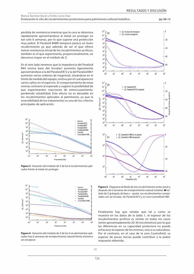
Blanca Ramírez Barat y Emilio Cano DíazEvaluación in situ de recubrimientos protectores para patrimonio cultural metálico... pp. 06-13
10
Finalmente hay que señalar que tal y como se muestra en los datos de la tabla 1, el espesor de los recubrimientos acrílicos es similar en todos los casos (entre aproximadamente 20-30 micrómetros) por lo que las diferencias en su capacidad protectora no puede achacarse al espesor de los mismos, sino a su naturaleza. Por el contrario, en el caso de la cera Cosmolloid, su espesor de pocas micras puede contribuir a la pobre respuesta obtenida.
pérdida de resistencia mientras que la cera se deteriora rápidamente aproximándose al metal sin proteger en tan solo 6 semanas, por lo que supone una protección muy pobre. El Paraloid B48N tampoco parece un buen recubrimiento ya que además de ser el que ofrece menor resistencia inicial de los recubrimientos acrílicos, también es el que experimenta, proporcionalmente, un descenso mayor en el módulo de Z.
En el otro lado tenemos que la impedancia del Paraloid B44 (resina base del Incralac) aumenta ligeramente aproximándose a la del Paraloid B72 y la del Paraloid B67 aumenta varios ordenes de magnitud, situándose en el límite de medida del equipo, motivo por el cual aparecen varios saltos en el espectro. El comportamiento de estas resinas contrario al esperado y sugiere la posibilidad de que experimenten reacciones de entrecruzamiento, perdiendo solubilidad. Este efecto no es deseable en los recubrimientos aplicados al patrimonio, ya que la reversibilidad de los tratamientos es uno de los criterios principales de aplicación.
Figura 3: Variación del módulo de Z de los 6 recubrimientos apli-cados frente al metal sin proteger
Figura 4: Variación del módulo de Z de los 6 recubrimientos apli-cados tras 6 semanas de envejecimiento natural frente al bronce sin envejecer
Figura 5: Diagrama de Bode de tres recubrimientos antes (azul) y después de 6 semanas de envejecimiento natural (violeta): mó-dulo de Z, ángulo de fase y – ajuste. Los recubrimientos compa-rados son (a) Incralac. (b) Paraloid B72 y (c) cera Cosmolloid H80
________________________________________________________________________
________________________________________________________________________ 126
RESULTADOS Y DISCUSIÓN

Ge-conservación nº 8/ 2015. ISSN: 1989-8568
11
Es interesante comparar los espectros de cada una de las resinas antes y después del envejecimiento para analizar su comportamiento. En la figura 5 se muestran tres ejemplos representativos, el Incralac, el Paraloid B72 y la cera Cosmolloid H80, sobre los que se ha realizado un ajuste por medio de circuitos equivalentes para poder cuantificar la evolución de los elementos que intervienen en el proceso de corrosión. En la gráfica se pueden comparar los diagramas de Bode de los tres recubrimientos comparados antes (azul) y después de 6 semanas de envejecimiento natural (violeta). Los valores obtenidos de los ajustes a los circuitos equivalentes correspondientes a cada caso (figura 6) se recogen en la tabla 3.
El diagrama de Bode del Incralac (figura 5a) es un buen ejemplo de un comportamiento casi puramente capacitivo. Para todo el intervalo de frecuencias el módulo de Z aumenta con una pendiente constante y el ángulo de fase se mantiene próximo a 90º. Tras el envejecimiento se observa como en la zona de bajas frecuencias aparece un componente resistivo que se manifiesta por la aparición de un pequeño tramo horizontal al tiempo que el ángulo de fase cae rápidamente. Este comportamiento se relaciona con la resistencia a través de los defectos del recubrimiento.
El Incralac es un claro ejemplo del comportamiento descrito en la introducción El recubrimiento sin envejecer se puede representar mediante un sistema de 1 CPE (figura 6a), análogo al circuito de la figura 1 en el que además de la resistencia del electrólito, Re, estarían representadas la capacidad y resistencia –muy elevada– del recubrimiento. Al iniciarse el deterioro de la resina aparecería una segunda constante de tiempo, formada por un CPE y una resistencia en paralelo,
Figura 6: Circuitos equivalentes propuestos para el ajuste de los espectros de los recubrimientos estudiados. El modelo de la iz-quierda se corresponde al Incralac sin envejecer, mientras para que explicar el espectro del Incralac envejecido, el Paraloid B72 y la cera Cosmolloid H80 se recurre al circuito de la derecha
representando la reacción de corrosión que aparecería en los poros y defectos del recubrimiento, como se muestra en la figura 6b.
El diagrama de impedancia del Paraloid B72 (figura 5b) presenta un primer tramo dominado por la componente capacitiva con un módulo creciente y un ángulo de fase elevado pero para una frecuencia entre 1 y 10Hz hay un cambio de pendiente y una disminución de ángulo de fase que indican que su comportamiento se aleja del de un recubrimiento perfecto. El envejecimiento hace que el tramo capacitivo disminuya ligeramente, indicando una mayor contribución del resto de los procesos (paso del electrólito a través de los poros y procesos de transferencia de carga). Al no tratase ya de un recubrimiento perfecto, es necesario recurrir a un circuito equivalente de 2 CPE (figura 6b) en ambos casos. Si nos fijamos en los datos del ajuste (tabla 3) podemos comprobar como la resistencia de transferencia de carga disminuye mientras que la capacidad de la doble
Tabla 3: Parámetros electroquímicos del ajuste de los recubrimientos estudiados sin envejecer y tras 6 semanas de envejecimiento natural
________________________________________________________________________
________________________________________________________________________ 127
RESULTADOS Y DISCUSIÓN
Blanca Ramírez Barat y Emilio Cano DíazEvaluación in situ de recubrimientos protectores para patrimonio cultural metálico... pp. 06-13
12
ANGELINI, E., GRASSINI, S., PARVIS, M. Y ZUCCHI, F. (2012). An in situ investigation of the corrosion behaviour of a weathering steel work of art. Surface and Interface Analysis, 44, 942-946.
BERNARDI, E., CHIAVARI, C., MARTINI, C. Y MORSELLI, L. (2008). The atmospheric corrosion of quaternary bronzes: An evaluation of the dissolution rate of the alloying elements. Applied Physics A: Materials Science and Processing, 92, 83-89.
CANO, E., LAFUENTE, D. Y BASTIDAS, D. M. (2010). Use of EIS for the evaluation of the protective properties of coatings for metallic cultural heritage: A review. Journal of Solid State Electrochemistry, 14, 381-391.
CANO, E., CRESPO, A., LAFUENTE, D. Y RAMÍREZ BARAT, B. (2014). A novel gel polymer electrolyte cell for in-situ application of corrosion electrochemical techniques. Electrochemistry Communications, 41, 16-19.
INAMDAR, S. N., BHAT, M. A. Y HARAM, S. K. (2009). Construction of Ag/AgCl Reference Electrode from Used Felt-Tipped Pen Barrel for Undergraduate Laboratory. Journal of Chemical Education, 86, 355-356.
LETARDI, P. (2004). Laboratory and field tests on patinas and protective coating systems for outdoor bronze monuments. In: ASHTON, J. & HALLAM, D., eds. Metal 04. International Conference on Metal Conservation 2004 Canberra (Australia). National Museum of Australia, 379-387.
LETARDI, P., BECCARIA, A., MARABELLI, M. Y D’ERCOLI, G. (2001). Application of electrochemical impedance mesurements as a tool for the characterization of the conservation and protection state of bronze works of art. In: ASHTON, J. & HALLAM, D., eds. Metal 98. International Conference on Metal Conservation 1998 Draguignan-Figanières (France). London: James & James, 303-308.
LETARDI, P. Y SPINIELLO, R. (2004). Characterisation of bronze corrosion and protection by contact-probe electrochemical impedance measurements. In: MACLEOD, I., THEILE, J. M. & DEGRIGNY, C., eds. Metal 01. International Conference on Metal Conservation 2001 Santiago (Chile). Welshpool: Western Australian Museum, 316-319.
RAMÍREZ BARAT, B. Y CANO, E. (2014). Diseño de una celda electroquímica en gel para evaluación in situ del patrimonio cultural metálico. Jornadas de Investigación Emergente en Conservación y Restauración de Patrimonio. Emerge 2014. Valencia.
capa aumenta con el envejecimiento, lo que se explica por el aumento de la fracción de metal que se ve expuesta al contacto con el medio corrosivo.
En el último ejemplo, el de la cera Cosmolloid H80 (figura 5c), podemos ver que su comportamiento como recubrimiento es muy pobre. A altas frecuencias la impedancia del recubrimiento es tan baja que predomina claramente la resistencia del electrólito no empezando a ser apreciable la componente capacitiva hasta cerca de 1MHz en la cera recién aplicada y hasta unos 100Hz en la cera envejecida. Además, con el envejecimiento su resistencia decae rápidamente siendo de un orden de magnitud menor en sólo 6 semanas.
Conclusiones:
La celda portátil con un electrólito gelificado con agar diseñada por el equipo de investigación permite obtener espectros de impedancia de calidad sobre objetos metálicos in situ sin los inconvenientes de las celdas líquidas convencionales. Los resultados obtenidos han permitido comparar las propiedades protectoras de varios recubrimientos acrílicos y una cera microcristalina y los cambios sufridos en un corto periodo de tiempo, confirmando el buen comportamiento del Incralac como recubrimiento protector y la limitada resistencia de la cera.
Estos resultados avalan la aplicabilidad de la celda en gel y su utilidad para el estudio del comportamiento y la evolución de pátinas y recubrimientos sobre el patrimonio cultural metálico. La capacidad de la espectroscopía de impedancia electroquímica de detectar cambios a corto plazo, mucho antes de que sean perceptibles a simple vista, junto con la posibilidad de aplicación in situ la convierten en una herramienta de gran interés para la selección del tratamiento protector más indicado en cada caso o para la evaluación de la necesidad de sustituir o renovar un recubrimiento.
Agradecimientos:
Este trabajo ha sido financiado por el proyecto HAR2011-22402 y por la ayuda de Formación de Personal Investigador BES-2012-052716 concedidos por el Ministerio de Ciencia e Innovación dentro del Plan Nacional de I+D+i 2008-2011.
Bibliografía:
ANGELINI, E., GRASSINI, S., CORBELLINI, S., INGO, G. M., DE CARO, T., PLESCIA, P., RICCUCCI, C., BIANCO, A. Y AGOSTINI, S. (2006). Potentialities of XRF and EIS portable instruments for the characterisation of ancient artefacts. Applied Physics A: Materials Science and Processing, 83, 643-649.
________________________________________________________________________
________________________________________________________________________ 128
RESULTADOS Y DISCUSIÓN

Ge-conservación nº 8/ 2015. ISSN: 1989-8568
13
Blanca Ramírez Barat Centro Nacional de Investigaciones Metalúrgicas (CENIM). Consejo Superior de Investigacio-nes Científicas. (CSIC)[email protected]
Blanca Ramírez Barat es licenciada en Bellas Artes (especialidad Restauración), grado en Química por la UCM y Máster en Ciencia e Ingeniería de Materiales por la UC3M. Ha dedicado la mayor parte de su trayectoria profesional a la gestión de la I+D en los que ha participado en el proyectos como Net-Heritage, la Joint Programming Initiative “Cultural Heritage and Global Change: a Challenge for Europe”o en la elaboración del Plan Nacional de Investigación en Conservación (PNIC) y la puesta en marcha del Observatorio para la investigación en conservación. Desde el año 2013 se ha incorporado al grupo “Corrosión y Protección de Metales en Patrimonio Cultural y Construcción” (COPAC) en el Centro Nacional de Investigaciones Metalúrgicas (CENIM) para realizar la tesis doctoral sobre diagnóstico y protección frente a la corrosión del patrimonio cultural metálico mediante técnicas electroquímicas.
Emilio Cano Díaz Centro Nacional de Investigaciones Metalúrgicas (CENIM). Consejo Superior de Investigaciones Científicas. (CSIC)[email protected]
El Dr. Emilio Cano es Científico Titular de OPI, en el Dpto. de Ingeniería de Superficies, Corrosión y Durabilidad del Centro Nacional de Investigaciones Metalúrgicas (CENIM), del Consejo Superior de Investigaciones Científicas. Es licenciado en Bellas Artes (especialidad Restauración), por la UCM. Obtuvo su doctorado en el año 2001 en la misma universidad, habiendo realizado una estancia en el Canadian Conservation Institute. Sus líneas de investigación se enfocan al estudio de la corrosión y sistemas de protección del Patrimonio Cultural metálico, corrosión atmosférica en interiores, técnicas electroquímicas e inhibidores de corrosión, actividades desarrolladas en el grupo de investigación “Corrosión y Protección de Metales en Patrimonio Cultural y Construcción” (COPAC) que lidera. Su actividad científica se ha visto plasmada en más de 100 publicaciones científicas (de las cuales, 65 son artículos en revistas científicas incluidas en el SCI), ha presentado más de 70 comunicaciones a congresos, ha participado en 22 proyectos de investigación nacionales e internacionales y numerosos contratos de investigación y apoyo tecnológico con empresas e instituciones. Es el Assistant Coordinator del Grupo de Metal del ICOM-CC. Vice coordinador de Grupos del CSIC de la “Red de Ciencia y Tecnología para la Conservación del Patrimonio Cultural (TechnoHeritage). Así mismo, es miembro del International Institute of Conservation (IIC) y del Grupo Español del IIC. Es Colaborador de la Dir. Gral. de Investigación Científica y Técnica del Ministerio de Ciencia e Innovación para la Joint Programming Initiative “Cultural Heritage and Global Change: a Challenge for Europe”, siendo miembro del Comité Ejecutivo de ésta en representación de España.
Artículo enviado el 13/03/2015Artículo aceptado el 16/07/2015
________________________________________________________________________
________________________________________________________________________ 129
RESULTADOS Y DISCUSIÓN

RESULTADOS Y DISCUSIÓN
130
Tras estos primeros ensayos se han evaluado otros recubrimientos sobre
probetas de bronce, plata y hierro en el marco del proyecto europeo IPERION-CH. En
este caso, el objetivo era demostrar la capacidad del sistema desarrollado para
evaluar diferentes recubrimientos orgánicos utilizados sobre distintos metales en
patrimonio cultural, como parte de un trabajo más amplio de evaluación y comparación
de técnicas de análisis para materiales del patrimonio.
A continuación se exponen como ejemplo los principales resultados obtenidos en el
estudio de recubrimientos orgánicos sobre probetas de bronce y su envejecimiento
artificial. Los resultados sobre plata y hierro no se incluyen, ya que no aportan
información adicional sobre el empleo de la celda. Conjuntamente, estos trabajos han
permitido validar el empleo de la celda para la evaluación de recubrimientos
protectores en patrimonio metálico.
Evaluación de recubrimientos sobre bronce sometidos a envejecimiento
artificial
Las muestras de bronce fueron preparadas por restauradores del Opificio delle
Pietre Dure (Florencia) y enviadas al CENIM, para estudiar las diferencias en la
capacidad protectora de los recubrimientos con la celda G-PE. Se trata de un conjunto
de 14 probetas de bronce de fundición (ca. 95 mm x 50 mm), sobre las que se han
aplicado diversas combinaciones de recubrimientos tradicionales, tal y como se
recogen en la tabla 6. Junto a la descripción de las probetas también se incluyen los
datos de espesor de los recubrimientos medidos con el medidor de espesores
Elcometer 456. El dato reflejado corresponde al promedio de 20 medidas distribuidas
por toda la zona plana recubierta de la probeta, con la correspondiente desviación
estándar entre paréntesis. Los datos del espesor del recubriendo son un dato
importante en especial a la hora de comparar entre diferentes formulaciones, ya que
puede influir en la capacidad protectora, por efecto barrera.

RESULTADOS Y DISCUSIÓN
131
Tabla 6. Probetas de bronce. Relación de recubrimientos medidos y espesor
NÚM. DESCRIPCIÓN Espesor, μm (σ)
Elcometer 456 (N=20)
16 Sin tratar -
17 Cera Soter concentración 1 2.3 (1.4)
18 Cera Soter concentración 2 (mayor) 1.8 (3.6)
19 Cera Soter concentración 1; dos capas cruzadas 1.6 (1.4)
20 Cera Soter concentración 2; dos capas cruzadas 3.0 (2.3)
21 Cera Cosmolloid 3.1 (1.2)
22 Cera Cosmolloid dos capas cruzadas 3.0 (2.8)
23 Paraloid B44 2.4 (3.3)
24 Paraloid B44 dos capas cruzadas 10.0 (3.3)
25 Dos capas: Paraloid B44 + Soter conc.1 4.6 (2.4)
27 Dos capas: Paraloid B44 + Soter conc.2 6.7 (2.4)
28 Dos capas: Paraloid B44 + Cosmolloid 7.7 (2.9)
29 Tres capas: Soter conc.1 + Paraloid B44 + Soter conc.1
3.6 (2.1)
30 Tres capas: Cosmolloid + Paraloid B44 + Cosmolloid
6.0 (2.1)

RESULTADOS Y DISCUSIÓN
132
Figura 27. Colección de muestras de bronce estudiadas
Las muestras se midieron inicialmente en las condiciones descritas en el apartado
3.2.1. A continuación, se sometieron a envejecimiento artificial en la cámara QUV,
comprobándose que, al cabo de una semana de tratamiento, ya podían apreciarse
cambios de color a simple vista (figura 28). A la vista de estas alteraciones se
consideró que los recubrimientos ya habían sufrido modificaciones suficientes como
para poder mostrar diferencias en los espectros de impedancia. Por otra parte, los
cambios visuales en los recubrimientos aplicados permitieron apreciar la irregularidad
en la aplicación del recubrimiento.

RESULTADOS Y DISCUSIÓN
133
Figura 28. Probetas tras el envejecimiento artificial. (16: Sin recubrimiento; 17: Soter concentration 1; 18: Soter concentración 2; 19: Soter concentración 1, dos capas; 20: Soter concentración 2, dos capas; 21: Cosmolloid; 22: Cosmolloid, dos capas; 23: Paraloid B44; 24: Paraloid B44, dos capas; 25: Dos capas: Paraloid B44+Soter conc.1; 27: Dos capas: Paraloid B44+Soter conc.2; 28: Dos capas: Paraloid B44+Cosmolloid; 29: Tres capas: Soter conc.1+Paraloid B44+Soter conc.1; 30: Tres capas: Cosmolloid +Paraloid B44+Cosmolloid)
16 17 18 20 19
21 22 23 25 24
27 28 29 30

RESULTADOS Y DISCUSIÓN
134
Los espectros de impedancia obtenidos para cada uno de los recubrimientos se
han agrupado en función de sus composiciones para compararlos entre sí, antes y
después del tratamiento de envejecimiento artificial:
• Bronce sin recubrimiento como material de referencia
• Ceras
• Barniz acrílico (Paraloid B44)
• Sistemas de doble capa: barniz acrílico (Paraloid B44) y cera
• Sistemas de triple capa: cera, barniz acrílico (Paraloid B44) y cera
Bronce sin recubrimiento
Figura 29. Bronce sin recubrimiento. Espectro de impedancia antes (azul) y después (rojo) del envejecimiento artificial.
Aunque el valor de |Z|10mHz prácticamente no varía con el envejecimiento, el
módulo de impedancia de la probeta envejecida es ligeramente inferior en la región de
medias frecuencias, asociada con las características de la pátina. Este resultado puede
atribuirse al hecho de que la muestra no tratada está recubierta por una capa estable
de óxido natural, que puede haberse desestabilizado ligeramente al exponerse a
condiciones agresivas.

RESULTADOS Y DISCUSIÓN
135
Recubrimientos de cera: Soter y Cosmolloid
Figura 30. Recubrimientos a base de ceras . Espectro de impedancia antes (azul) y después (rojo) del envejecimiento artificial.

RESULTADOS Y DISCUSIÓN
136
Figura 31. Recubrimientos a base de ceras . Espectro de impedancia antes (azul) y después (rojo) del envejecimiento artificial.
Recubrimiento acrílico (Paraloid B44)
Figura 32. Recubrimientos de Paraloid B44 . Espectro de impedancia antes (azul) y después (rojo) del envejecimiento artificial.

RESULTADOS Y DISCUSIÓN
137
Recubrimientos de doble capa: Paraloid B44 + cera
Figura 33. Recubrimientos de doble capa a base de acrílico y cera. Espectro de impedancia antes (azul) y después (rojo) del envejecimiento artificial.

RESULTADOS Y DISCUSIÓN
138
Recubrimientos de triple capa cera +Paraloid B44 + cera
Figura 34. Recubrimientos de triple capa a base de acrílico y cera. Espectro de impedancia antes (azul) y después (rojo) del envejecimiento artificial.
La comparación de los resultados de los diferentes recubrimientos se ha
realizado a partir de los valores módulo de la impedancia en el límite de bajas
frecuencias, |Z|10mHz, que se representan gráficamente en la figura 35.
Los resultados indican que la aplicación de una cera más concentrada no aumenta la
protección del bronce. La aplicación de dos capas puede aumentar ligeramente la
impedancia por efecto barrera, pero no proporciona un mejor resultado con el
envejecimiento. En el caso de la cera Cosmolloid, la aplicación de dos capas ha
resultado incluso menos eficaz; esto podría deberse al arrastre de la primera capa con
la brocha, al aplicar la segunda. Los resultados de espesores medidos (tabla 6)
demuestran que el espesor total medio no aumenta, aunque si la desviación estándar
del espesor en distintas zonas, indicando que la capa resultante es más irregular.
Respecto a la comparación entre ambos productos, la cera Soter proporciona
resultados ligeramente superiores a la Cosmolloid, posiblemente debido al contenido

RESULTADOS Y DISCUSIÓN
139
en benzotriazol (BTA) de la primera, que es un conocido inhibidor de corrosión del
cobre y sus aleaciones.
El comportamiento con el envejecimiento resulta opuesto en ambas ceras. La
impedancia disminuye tras el envejecimiento en la cera Soter, pero aumenta en el caso
de la Cosmolloid. Esto sugiere la posibilidad de reacciones de entrecruzamiento en el
recubrimiento, que si bien pueden ser positivas desde el punto de vista de protección
frente a la corrosión, podrían no ser deseables desde el punto de vista de la
reversibilidad, al disminuir la solubilidad.
El Paraloid B44 ofrece una protección que podría considerarse relativamente buena.
La aplicación de una segunda capa incrementa el máximo de |Z| en dos órdenes de
magnitud, aunque los resultados son más desiguales por zonas. Sin embargo, este
producto sufre un importante oscurecimiento tras el envejecimiento artificial, que
además de poner de manifiesto la irregularidad en la aplicación, no cumpliría los
criterios de los recubrimientos para conservación de patrimonio. Hay que tener en
cuenta, no obstante, que los tratamientos de envejecimiento artificial resultan muy
agresivos, y no implican necesariamente que este tipo de alteración se vayan a
producir de la misma forma o magnitud en condiciones de envejecimiento natural.
Sería necesario realizar un estudio detallado de este fenómeno que está fuera de los
objetivos de este trabajo.
La aplicación de una capa de cera sobre el Paraloid B44 no produce una diferencia
significativa inicialmente, aunque si mejora la respuesta al envejecimiento.
Nuevamente, las probetas envejecidas han sufrido un notable oscurecimiento y
muestran una aplicación muy irregular de los recubrimientos.
Las combinaciones cera + Paraloid B44 + cera no proporcionan una mayor protección
en comparación con el sistema más simple Paraloid B44 + cera, sin embargo, parece
tener un efecto positivo sobre el oscurecimiento, lo cual es de gran relevancia. En
relación a las dos combinaciones ensayadas, con Soter o con Cosmolloid, esta última
experimentó (como en el caso de las capas simples de cera) un aumento en el valor de
la impedancia tras el envejecimiento.
Más allá de la valoración individual del rendimiento de cada recubrimiento y de su
comportamiento con el envejecimiento, cuyo estudio detallado requeriría un estudio

RESULTADOS Y DISCUSIÓN
140
sistemático con condiciones de aplicación más controladas, el estudio realizado bajo el
proyecto IPERION CH demostró la aplicabilidad de la celda G-PE para la evaluación de
recubrimientos en probetas que simulan bienes culturales. Los resultados de EIS
obtenidos han servido como referencia para la interpretación de los resultados de
otras técnicas empleadas en el proyecto.
Figura 35. Comparación del máximo del módulo de impedancia a bajas frecuencias para los diferentes recubrimientos antes (azul claro) y después del envejecimiento artificial (azul
oscuro). Valor promedio de dos medidas.
1,0E+03
1,0E+04
1,0E+05
1,0E+06
1,0E+07
1,0E+08
|Z|
10 m
Hz, Ω

RESULTADOS Y DISCUSIÓN
141
4.3.2. Medidas de campo y casos reales.
Dada la finalidad práctica de este trabajo, el objetivo principal implica el
traslado de los resultados obtenidos en laboratorio, que se han presentado en el
apartado anterior, a casos reales, algo que se ha tratado de llevar a cabo desde el
primer momento. En paralelo al diseño y a los ensayos en laboratorio se han realizado
diversas medidas sobre esculturas en bronce y acero, que han servido para comprobar
el funcionamiento de la celda in situ sobre obra real.
La mayor parte de estos resultados no han sido publicados como estudios
independientes, sino que se han incluido para ilustrar los trabajos dedicados al diseño
de la celda. Hay que tener en cuenta que la realización de medidas de campo no
resulta sencilla, por motivos administrativos, meteorológicos, etc. y que, por otra
parte, la realización de medidas aisladas sobre obras individuales tampoco
proporciona resultados de especial relevancia para la conservación de las mismas, si
bien nos han permitido conocer el comportamiento de la celda in situ, y por tanto
resultan de gran importancia en su desarrollo. Algunos de ellos se han presentado en
congresos de Patrimonio con el objetivo de dar difusión entre los potenciales usuarios
finales; dado el enfoque práctico de este trabajo, el traslado de los resultados a los
posibles usuarios se ha considerado un aspecto importante desde el principio.
Afortunadamente, los inicios del desarrollo de la celda coincidieron con la restauración
de las esfinges que decoran la fachada principal del Museo Arqueológico Nacional, lo
que sí ha permitido realizar un estudio de caso completo. En colaboración con las
restauradoras responsables de la intervención, Soledad Díaz y Emma García, del
Instituto del Patrimonio Cultural de España, se realizaron medidas antes y después de
los tratamientos y se hizo un seguimiento de la evolución del sistema de protección
aplicado durante dos años, demostrando el potencial de la celda como herramienta de
diagnóstico para la conservación del patrimonio metálico. El estudio realizado sobre la
restauración de las esfinges se publicó en la revista Journal of Cultural Heritage (ver
apartado 4.3.2.1.).
Además de este estudio de caso, se incluyen a continuación otros ejemplos de medidas
realizadas en diversas esculturas, que, aunque no forman parte de ningún estudio
concreto o estudio en profundidad sirven para ilustrar las posibilidades del sistema y
como referencia para futuros estudios, ya que actualmente existen pocos espectros de

RESULTADOS Y DISCUSIÓN
142
impedancia obtenidos en objetos reales. En estos ejemplos, la calidad de los
espectros obtenidos es variable, ya que se han ido realizando en paralelo al desarrollo
y perfeccionamiento de la celda, por lo que en algunos casos la interpretación o el
ajuste que se puede hacer de ellos es limitada. Sin embargo, los resultados muestran
en todo momento una coherencia con las características de la superficie medida.
Las obras sobre las que se han realizado medidas de impedancia con la celda
G-PE, junto con las referencias de los artículos o congresos en los que han sido
publicadas se resumen en la tabla 7. Seguidamente se recogen algunos ejemplos de
los resultados obtenidos, organizados en tres apartados:
• Estudio de las esfinges del Museo Arqueológico Nacional, en Madrid.
• Esculturas de la Universidad de Valencia
• Esculturas del Museo de Escultura de Leganés
El primer apartado corresponde al único estudio completo realizado, enfocado
específicamente a un caso de restauración, los dos siguientes apartados recogen
colecciones de medidas realizadas en diferentes tipos de esculturas y acabados en
Valencia y en Madrid para evaluar el funcionamiento de la celda en diferentes
materiales y superficies. El resto de las medidas realizadas se encuentran en las
publicaciones referidas en la tabla a modo de diferentes ejemplos, y no se incluyen
aquí de nuevo.

RESULTADOS Y DISCUSIÓN
143
Tabla 7. Resumen de las obras medidas in situ con la celda G-PE.
Obra: Esfinges
Localización: Fachada del Museo Arqueológico Nacional
Técnica: Bronce
Fecha: 1894
Autor: Felipe de Moratilla y Parreto
Referencias:
• A.Crespo, B. Ramírez Barat, D. Lafuente, S. Diaz, E. García, E. Cano, "Non-destructive electrochemical evaluation of the patinas on the bronze sphinxes of the Museo Arqueológico Nacional in Madrid", en: Art`14. 11 th Int. Conference on non-destructive investigations and microanalysis for the diagnostics and conservation of cultural and environmental heritage, Madrid, 2014.
• B. Ramírez Barat, A. Crespo, E. García, S. Díaz, E. Cano, “An EIS study of the conservation treatment of the bronze sphinxes at the Museo Arqueológico Nacional (Madrid)”, Journal of Cultural Heritage, 24(2017) 93-9.
• B. Ramírez Barat, E. Cano, "Agar vs agarose gelled electrolyte for in situ corrosion studies on metallic cultural heritage", ChemElectroChem 2019, 6(9) 2553-2559.
Obra: Francesco
Localización: Instituto del Patrimonio Cultural de España
Técnica: bronce fundido con pátina de sulfuro
Fecha:
Autor: Francisco López Hernández
Referencias:
• B. Ramírez Barat, S. Díaz Martínez, E. García Alonso, E. Cano Díaz, “Aplicación de la EIS a la evaluación in situ de la resistencia a la corrosión de una escultura en bronce”, en: E. Cano, J. Barrio (Eds.), MetalEspaña 2015, Segovia, 2015, pp. 102-9.
Obra: Unidad Yunta
Localización: Campus de la Universidad Politécnica de Valencia
Técnica: Bronce patinado
Fecha: 1970
Autor: Pablo Serrano
Referencias:
• Redondo-Marugán, J., et al. (2016), “Electrochemical study of a contemporary outdoor bronze sculpture (Poster)”, en 5th INTERNATIONAL CONFERENCE YOuth in COnservation of CUltural Heritage-YOCOCU 2016, Madrid, 21-23 September, 2016, 204.

RESULTADOS Y DISCUSIÓN
144
Obra: Crónica del viento
Localización: Campus de la Universidad Politécnica de Valencia
Técnica: Bronce
Fecha: 1991
Autor: Martín Chirino
Referencias: no publicado
Obra: Angel
Localización: Cementerio de Staglieno (Génova, Italia)
Técnica: Bronce
Fecha: s. XIX
Autor: Enrico Astorri (1859-1921)
Referencias:
• B. Ramírez Barat, E. Cano, "Agar vs agarose gelled electrolyte for in situ corrosion studies on metallic cultural heritage", ChemElectroChem 2019, 6(9) 2553-2559.
Obra: Hachero
Localización: Museo de Escultura de Leganés
Técnica: bronce patinado.
Fecha: 1926
Autor: Luis Marco Pérez
Referencias: no publicado
Obra: El Segador
Localización: Museo de Escultura de Leganés
Técnica: bronce patinado.
Fecha: 1970
Autor: Venancio Blanco
Referencias: no publicado

RESULTADOS Y DISCUSIÓN
145
Obra: Zenon
Localización: Museo de Escultura de Leganés
Técnica: acero corten, cera
Fecha: 1980
Autor: José Luis Sánchez
Referencias:
• B. Ramírez Barat, A. Crespo, E. Cano, “In situ evaluation of outdoor sculpture with a gel polymer electrolyte cell”, TechnoHeritage 2017. 3rd International Congress Science and Technology for the Conservation of Cultural Heritage, Cádiz, 2017.
• B. Ramirez Barat, E. Cano, "Agar vs agarose gelled electrolyte for in situ corrosion studies on metallic cultural heritage", ChemElectroChem 2019, 6(9) 2553-2559.
Obra: Templo
Localización: Museo de Escultura de Leganés
Técnica: acero corten
Fecha: 2003
Autor: Adriana Veyrat
Referencias:
• A. Crespo, B. Ramírez Barat, I. Diaz Ocaña, E. Cano Díaz, "Efecto del patinado artificial del acero Cor-Ten en la conservación de Templo, de Adriana Veyrat", en: Conservación de Arte Contemporáneo 18ª Jornada, MNCARS, Madrid, 2017, pp. 193-201.
• A. Crespo, B. Ramírez Barat, I. Diaz, E. Cano Díaz, "Assessment of the protective properties of patinas on contemporary sculpture made out of weathering steel", en: ICOM-CC 18th Triennial Conference, Copenhagen, 2017.
• B. Ramírez Barat, E. Cano, "Agar vs agarose gelled electrolyte for in situ corrosion studies on metallic cultural heritage", ChemElectroChem 2019, 6(9) 2553-2559.
Obra: Once Módulos
Localización: Museo de Escultura de Leganés
Técnica: acero corten, Paraloid B72
Fecha: 1971
Autor: Amador Rodríguez
Referencias:
• A. Crespo, B. Ramírez Barat, E. Cano, “Electrochemical evaluation of the patina of a weathering steel sculpture: Once Módulos”, TechnoHeritage 2019. 4th International Congress Science and Technology for the Conservation of Cultural Heritage, Seville, March 26-30, 2019.
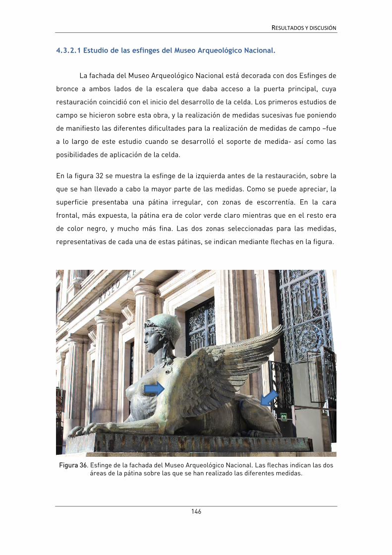
RESULTADOS Y DISCUSIÓN
146
4.3.2.1 Estudio de las esfinges del Museo Arqueológico Nacional.
La fachada del Museo Arqueológico Nacional está decorada con dos Esfinges de
bronce a ambos lados de la escalera que daba acceso a la puerta principal, cuya
restauración coincidió con el inicio del desarrollo de la celda. Los primeros estudios de
campo se hicieron sobre esta obra, y la realización de medidas sucesivas fue poniendo
de manifiesto las diferentes dificultades para la realización de medidas de campo –fue
a lo largo de este estudio cuando se desarrolló el soporte de medida- así como las
posibilidades de aplicación de la celda.
En la figura 32 se muestra la esfinge de la izquierda antes de la restauración, sobre la
que se han llevado a cabo la mayor parte de las medidas. Como se puede apreciar, la
superficie presentaba una pátina irregular, con zonas de escorrentía. En la cara
frontal, más expuesta, la pátina era de color verde claro mientras que en el resto era
de color negro, y mucho más fina. Las dos zonas seleccionadas para las medidas,
representativas de cada una de estas pátinas, se indican mediante flechas en la figura.
Figura 36. Esfinge de la fachada del Museo Arqueológico Nacional. Las flechas indican las dos áreas de la pátina sobre las que se han realizado las diferentes medidas.

RESULTADOS Y DISCUSIÓN
147
En este primer estudio de la pátina se empleó el primer prototipo de la celda y con
agar al 4%, ya que aún no se había realizado la optimización del diseño ni la evaluación
de la concentración del gel. A pesar de ello y de la limitada calidad de los espectros
obtenidos, con bastante ruido en la zona de frecuencias más bajas, estas primeras
medidas permitieron confirmar la aplicabilidad de la celda. La comparación de
medidas de EIS mostró las diferencias de la capacidad protectora de la pátina en las
dos zonas de la escultura, mucho mayor en la región frontal (pátina verde)
comprobándose la coherencia de los resultados proporcionados por la celda [184]
Figura 37. Espectros de impedancia obtenidos sobre la pátina verde y la pátina oscura de la esfinge izquierda del Museo Arqueológico Nacional, con el primer prototipo de la celda G-PE.
Tras estas medidas iniciales las esfinges fueron restauradas y se realizó el
seguimiento de la evolución del recubrimiento de protección aplicado, incluyendo una
estimación de la posible duración del mismo que, aunque no ha podido comprobarse
por motivos técnicos – se ha vuelto a colocar un andamio sobre la escultura resultando
inaccesible- concuerda con los valores referidos en la literatura para el tipo de
recubrimiento aplicado. Los resultados de este estudio se presentan seguidamente en
la publicación:
• B. Ramírez Barat, A. Crespo, E. García, S. Díaz, E. Cano, An EIS study of the conservation treatment of the bronze sphinxes at the Museo Arqueológico Nacional (Madrid), Journal of Cultural Heritage, 24(2017) 93-9.11
11 Referencias bibliográficas [15-17, 23, 26, 27, 29, 30, 32, 35, 43, 49, 50, 67, 68, 78, 91, 95, 104, 117, 119, 121, 122, 132, 134, 160, 163, 183, 184, 194, 202, 207, 213-221] de la bibliografía general).

Journal of Cultural Heritage 24 (2017) 93–99
Available online at
ScienceDirectwww.sciencedirect.com
Original article
An EIS study of the conservation treatment of the bronze sphinxes atthe Museo Arqueológico Nacional (Madrid)
Blanca Ramírez Barata,∗, Ana Crespoa, Emma Garcíab, Soledad Díazb, Emilio Canoa
a Centro Nacional de Investigaciones Metalúrgicas (CENIM), Consejo Superior de Investigaciones Científicas (CSIC), Av. Gregorio del Amo 8, 28040 Madrid,Spainb Instituto del Patrimonio Cultural de Espana (IPCE), Ministerio de Educación, Cultura y Deporte (MECD), Pintor el Greco 4, Ciudad Universitaria, 28040Madrid, Spain
a r t i c l e i n f o
Article history:Received 19 July 2016Accepted 13 October 2016Available online 18 November 2016
Keywords:ConservationOutdoor sculptureBronzeElectrochemical impedance spectroscopyProtective coatingsDiagnostic tools
a b s t r a c t
In any conservation project, conservators have to address several questions to design the appropriateintervention strategy. Among them, the effectiveness and duration of protective treatments is an impor-tant issue, not easy to evaluate. In the field of metallic cultural heritage, electrochemical techniques suchas electrochemical impedance spectroscopy (EIS) can be used to evaluate patinas and protective coatingsperformance. Widely used in industrial applications, the use of these techniques in conservation scienceis much more recent and limited.
During the restauration process of the bronze sphinxes at the main fac ade of the National ArchaeologicalMuseum in Madrid, collaboration with conservators has been established to test the performance ofa recently developed gel-electrolyte cell for the electrochemical evaluation of metal cultural heritage.Electrochemical measurements (EIS and Rp) of the patinas have been carried out before, during and afterthe conservation treatments, on two different areas of the sculpture. This has provided information onhow the protective coatings have improved corrosion resistance by 3 orders of magnitude, and how thisprotection is starting to decrease with time; periodic measurements will allow verifying the performanceof the treatment over time and detecting the failure of the protection treatment before its effects arevisible on the surface.
© 2016 Elsevier Masson SAS. All rights reserved.
Research aims
The objective of this work is to test and validate on a real sit-uation a recently developed agar gel-polymer electrolyte (G-PE)cell specifically designed for in situ electrochemical measurementson metallic cultural heritage. These measurements allow quanti-fying the corrosion resistance of the patina in different areas andto assess the increase in the corrosion resistance of the metal pro-vided by the coatings and other conservation treatments. With thisdevelopment we would like to provide metal conservators witha useful diagnostic tool that allows corrosion resistance evalua-tion of patinas and coatings, its evolution over time and to predictthe failure of the protective coatings before active corrosion startsagain.
∗ Corresponding author. Tel.: +34 91 5538900.E-mail address: [email protected] (B. Ramírez Barat).
1. Introduction
The main fac ade of the National Archaeological Museum inMadrid is decorated by two bronze sphinxes, half woman, and halflioness, placed at both sides of the main staircase over a stonebase. The sphinxes were designed inspired by the classical cannonsby the Spanish sculptor Felipe Moratilla y Parreto, and lost-waxcasted in the Madrilenian foundry Arias, in 1894. Due to theirlarge dimensions (1.91 m high, 3.52 m depth and 1.06 m width,and around 3000 kg) they were done in several pieces and joinedtogether.
The sphinxes have remained in the same place – with a small dis-placement in 1970 due to the extension of the staircase – since theinauguration of the museum on July the 5th, 1895. During 2014, fol-lowing the complete refurbishment of the Museum, all sculpturesin the main fac ade, including the sphinxes have been restored underthe supervision of the Instituto del Patrimonio Cultural de Espana(IPCE) [1].
In any conservation project, conservators have to addressseveral questions to design the appropriate intervention strat-egy. Among them, the effectiveness and duration of protective
http://dx.doi.org/10.1016/j.culher.2016.10.0101296-2074/© 2016 Elsevier Masson SAS. All rights reserved.
________________________________________________________________________
________________________________________________________________________ 148
RESULTADOS Y DISCUSIÓN

94 B. Ramírez Barat et al. / Journal of Cultural Heritage 24 (2017) 93–99
treatments is an important issue, not easy to assess. Fortunately,for metallic objects, electrochemical techniques can provide someanswers to this problem. Among these techniques, electrochemicalimpedance spectroscopy (EIS) is a very well-established methodto assess the anti-corrosive efficiency of protective coatings andinhibitors. However, EIS is less widespread for the study of patinasand coatings in the field of cultural heritage [2–6]. EIS is based onthe application of a low-amplitude (usually 10 mV) alternating cur-rent (AC) voltage signal to the metallic sample using a conventionalthree electrode (working, i.e. the metal under study, reference andcounter electrode) electrochemical cell. Measuring the AC currentresponse of the system, the impedance is calculated at differentfrequencies. The impedance spectra profile provides informationon the corrosion and other electroactive processes taking placeon a metal surface. EIS can be used to quantify the effective-ness of a conservation treatment in terms of corrosion resistancegain and repetitive measurements over time allow monitoring thedecrease in protection ability of these treatments, detecting fail-ure before it is too late. Unfortunately, application of this and otherelectrochemical techniques in the field of cultural heritage is notalways easy, especially for in situ measurements as they usuallyimply the use of a liquid electrolyte in contact with the surfaceunder study – which is not easy to handle. On the other hand,the interpretation of results is usually hard work, as the irregu-larity and complexity of the surfaces and interferences from theenvironment do not always allow obtaining good quality spec-tra.
Since the mid 90s conservation scientists have started to usethis technique in the evaluation of protective coatings for metal-lic cultural heritage [7–11], and in the last three decades severalresearchers have been working in the development of specificmethodologies and portable devices to its application in thein situ evaluation of patina and coatings on outdoor sculptureand monuments [12–18]. Concurrently with the restoration pro-cess of the sphinxes and within the framework of CREMEL project(Conservation-REstoration of Metal cultural heritage with ELec-trochemical techniques) authors have been working in an agargel-polymer electrolyte (G-PE) cell specifically designed for in situmeasurements on cultural heritage overcoming some of the lim-itations of previous designs [19,20]. This cell had already beensuccessfully tested in the evaluation of protective coatings onbronze coupons [21], but it has not yet been applied in a sys-tematic way on a real conservation problem. Now it was a goodopportunity both to test the performance of the cell on a real sit-uation and to evaluate the effectiveness of the applied treatmentson the sphinxes. The complete treatment has been published inthe museum’s technical bulletin [1]: The internal structure hasbeen reinforced, and after a cleaning process, 2% benzotriazole ina water–alcohol mixture was applied, followed by three layers ofIncralac. In the first layer the product was used in a 15% solutionin xylene, in the second layer concentration was increased to 20%in same solvent. Then, a third layer of 30% Incralac in acetone wasapplied followed by 10% microcrystalline wax (Cosmolloid 80 H) inwhite spirit.
Electrochemical measurements were performed using the G-PE cell on the left sphinx before, during and after the restaurationprocess. Fig. 1 shows the left sphinx during measurements beforeand after restoration. Measurements before restauration allowedevaluating the corrosion resistance of different areas of the sphinx.During the restoration process they gave information of the addi-tional resistance provided by protective coatings and supportedthe decision on the number of layers to apply. Finally, after therestoration, periodical measurements are being done to follow theevolution of coatings over time. The objective is to detect the coat-ing failure, i.e. the drop of resistance to initial levels, before thesculpture can be affected.
2. Materials and methods
Several electrochemical impedance spectroscopy (EIS) andpolarization resistance (Rp) measurements were carried out on twodifferent areas of the southern sphinx: a greenish patina (GP) on theleft arm of the sphinx and a dark patina (DP) on the left thigh of thesphinx (Fig. 1). These areas have been selected as representativesof two extreme conditions of the surface: GP is a thick, matt patinaformed in areas exposed to atmospheric corrosion; and DP is athin, semi-transparent patina remaining from the original artificialpatination treatment.
Measurements have been performed with the gel polymer elec-trolyte (G-PE) cell previously developed by the authors [19,20]. Itconsists of a plastic mold in which the counter electrode (CE) anda pseudo-reference electrode (RE) are attached. The CE is madewith a stainless steel mesh to maximize its surface, and the RE is a99.9% silver wire electrochemically coated with AgCl [22]. The moldis then filled with a traditional aqueous electrolyte that has beengelled by addition of 4% (w/v) of agar powder.
The liquid electrolyte in which agar is dissolved to obtain thegel electrolyte is synthetic rain adapted from Bernardi [23]. It con-tains 14.43 mg/L CaSO4·2H2O, 15.04 mg/L (NH4)2SO4, 19.15 mg/L(NH4)Cl, 15.13 NaNO3 and 3.19 mg/L CH3COONa, prepared in dis-tilled water. Synthetic rain has been chosen to mimic the corrosiveenvironment which the sculptures are exposed to, so the interac-tion of the electrolyte with the metal, patina and coating is similarto actual degradation process, and the object is not exposed to otherions [24]. This solution has been used 10× concentrated with a finalpH adjusted to 6.5 with HNO3, to provide a mild electrolyte whichprevents any damage to the patina, but with enough conductivityto measure. The agar powder has been dispersed in the electrolyteand heated until dissolution. After a few minutes, the liquid hasbeen poured into the mold and left to cool until solidification. Thecell is then mounted on a support with an articulated arm whichallows positioning on the surface to be measured; the measure-ment area 5.72 cm2. A more detailed description of the cell hasbeen provided in references [19,20]. Fig. 2 illustrates the realiza-tion of measurements on the sculptures. A closer view of the cellplaced on the surface of the sculpture during measurements can beseen in Fig. 2(a), while Fig. 2(b) shows the RE and CE inside the cell,and the imprint of the surface texture on the gel. Measured areaswere photographed in detail to ensure that no marks were left onthe surface and that subsequent measurements were done on thesame point (Fig. 3).
First data were taken in March 2014, before restoration; a sec-ond set of measurements was done in July during restorationtreatment (after cleaning and first coating layer), then after restora-tion, in early January, May and November 2015 and in June 2016(approximately 5, 10, 16 and 23 months later). EIS and Rp mea-surements were performed consecutively each patina. EIS spectrahave been acquired with a Gamry 600 Potentiostat, using a fre-quency swept from 100 kHz to 10 mHz, 10 mV RMS amplitude and10 points/decade. Polarization resistance (Rp) has been measuredusing the same setup, performing a 0.16 mV/s swept from −10 to+10 mV vs. open circuit potential. All results have been normalizedto the measurement area. Due to the limited access to the sphinxes,single measurements were made at each time. However, the repro-ducibility and repeatability of measurements using this system hasbeen validated in a previous work by the authors [20].
3. Results and discussion
G-PE cell has shown to fulfill the requirements for in situ mea-surements, on rough, leaning and slightly curved surfaces. In Fig. 2,the flexibility and adaptability of the cell to the surface under study,
________________________________________________________________________
________________________________________________________________________ 149
RESULTADOS Y DISCUSIÓN

B. Ramírez Barat et al. / Journal of Cultural Heritage 24 (2017) 93–99 95
Fig. 1. Left sphinx during measurements before restoration (a) and after restoration (b). Arrows indicate the green patina (GP) and dark patina (DP) test areas.
Fig. 2. Detail of the cell during measurements. It can be seen how the gel adapts to the surface of the sculpture (left) and the deformation of the cell surface after measurement(right).
following the roughness of the patina, can be appreciated. The non-destructive character of the measurements has also been verifiedin the worst case scenario, i.e., before protection treatment. Fig. 3shows the visual appearance of the patinas just after removal ofthe gel-cell (left) and a few seconds later (right). It can be observedhow the wetted area dries out immediately leaving no traces onthe surface proving the non-destructive character of the technique[25]. On the long term, no visible effects have been observed afterthe series of measurements.
The evolution of the impedance’s modulus for DP and GP is pre-sented in Fig. 4. EIS spectra are rather noisy at the high frequencyregion. As the museum is located in the city center, surroundedby traffic, subway and train tunnels, the quality of EIS spectra maybe affected by environmental interferences. Similar noisy spectraat high frequencies have also been observed by other authors inon-site EIS measurements in sculptures [17]. This effect is moreimportant after the restoration process, as the application of a thicklayer of Incralac highly reduces the intensity of the electric sig-nal decreasing the signal to noise ratio. The noise of the EIS datadoes not allow an in-depth analysis of the corrosion and protec-tion mechanisms from the electrochemical results. Despite this, theresults clearly show some general features and trends that allow
comparing the result in different areas and study the evolution ofimpedance over time.
Impedance data are generally analyzed using equivalent cir-cuits, in which passive electric elements such as resistors,capacitors, etc. are used to reproduce the electric characteristics ofthe system [3,24]. Thus, to interpret the results we need to considerthe nature of our system, a bronze sculpture covered with a patina,to which an organic coating has been applied. The corrosion of thesculpture takes place when the rain (electrolyte), containing dis-solved oxygen and atmospheric pollutants, reaches the base metaland the corrosion reactions take place. The anodic process involvesthe dissolution of the metal (copper and alloying elements) whilethe cathodic reaction is the reduction of dissolved oxygen. For thecorrosion reaction to take place, several resistances (or impedances)have to be overcome. The charged species have to travel acrossthe electrolyte, against the electrolyte resistance, and reach thecoating. Conductivity through the coating has two contributions,the charge of the capacitor at both sides of the coating and theresistance through its pores, thus the impedance of a coating isusually represented by a capacitor and a resistance in parallel. Thesame behavior is to be expected for the patina. Finally, when theelectrolyte reaches the metal surface, the corrosion process can be
________________________________________________________________________
________________________________________________________________________ 150
RESULTADOS Y DISCUSIÓN

96 B. Ramírez Barat et al. / Journal of Cultural Heritage 24 (2017) 93–99
Fig. 3. Detail of the surface after measurement showing that no marks are left after it (before conservation treatment).
Fig. 4. Evolution of impedance modulus with time for dark patina (DP) and green patina (GP).
________________________________________________________________________
________________________________________________________________________ 151
RESULTADOS Y DISCUSIÓN

B. Ramírez Barat et al. / Journal of Cultural Heritage 24 (2017) 93–99 97
Fig. 5. |Z| limit and Rp before and after restoration treatments for dark patina (DP)and green patina (GP).
assimilated to another pair capacitor-resistance in parallel, repre-senting the capacity of the electrochemical double layer and thecharge transfer resistance. This is probably the simplest approach,in which the equivalent circuit could be represented by one resis-tance in series with two or three nested capacitor-resistance pairs[2,11,26,27]. In practice, circuits can get much more complicatedwhen other physicochemical phenomena get involved and sev-eral processes overlap [28]. In the first place, these systems do notfollow the ideal capacitive behavior, and constant phase elements(CPE) have to be used instead of capacitors [3] adding new calcu-lations to obtain capacity values from CPE parameters [29]. Also,diffusion effects may appear, requiring the introduction of otherelements such as Warburg impedance and in some cases, reac-tivity of the patina itself require the employment of transmissionlines [20,30,31]. There are several good reviews about EIS of coatedmetals which can be consulted for further information [4,32–34].
Difficulties in the interpretation of EIS spectra from cultural her-itage objects are not an unknown fact. Surface inhomogeneitiestogether with environmental interferences in field measure-ments lead frequently to evaluate EIS data in terms of simplifiedapproaches [3]. Thus the value of |Z| at the low frequency limit hasbeen used as a measure of the protective effectiveness of the sur-face layers or the corrosion resistance and applied to comparativestudies [5,8,10,13,35–37]. This value is the sum of the impedance ofthe coating plus all the other aforementioned elements (electrolyteresistance, charge transfer resistance, diffusion impedances, etc.).In the case of organic coatings, the contribution of these other ele-ments is usually much smaller than the coating impedance, so thefilm resistance dominates the spectra at low frequencies. Althougha deeper interpretation would be desirable, information given bythis simplified approach has proven to be effective to assess theprotective properties of coating systems for outdoor bronze monu-ments and its evolution over time [5,37].
The variation of the impedance module, |Z|, at the lower fre-quencies for DP and GP on successive measurements, together withthe Rp values are represented in Fig. 5. Although the EIS spectrawere acquired from 100 kHz to 10 mHz, 15.8 mHz has been usedas lowest frequency limit as some points are missing at the low-est frequency value. From this figure, several facts can be pointedout, supported both by |Z|15.8mHz and Rp results. Before restoration(March 2014) GP was about 5 times more protective than DP, whileafter treatments, both areas showed similar behavior. From data ofJuly 2014 it is clearly appreciated that the first protective coatingwith 2% benzotriazole and 15% Incralac does not give an apprecia-ble protection, as |Z| has barely increased from its initial value, thus
Fig. 6. Lifetime prediction of coatings from EIS data, based on a first order kineticapproach.
justifying the need of additional varnish layers. After the whole pro-tection treatment has been applied, |Z| has increased three orders ofmagnitude as can be observed in the measurement done in January2016. Differences between DP and GP are now insignificant, indicat-ing that the coating is the main responsible for protective propertiesof the system, thus being the patina contribution negligible. Fromthis moment, the resistance of the coating begins a slow decay,although two years after application it is still offering a good pro-tection when compared with the initial results before restoration. Italso appears to be a seasonal effect that may increase resistance val-ues in cooler months (comparing Jan. and Nov. 2015 vs. May 2015and Jun. 2016); higher temperatures may induce higher conduc-tivity of the aqueous solutions that penetrate into the coating andcause a progressive reduction of the impedance, as well as increasethe anodic and/or cathodic corrosion reaction rates. This effect oftemperature on measurements is currently under study.
Overall, there is a good agreement between Rp and |Z| values,showing similar results and the same evolution with time, validat-ing the approach of using |Z| at low frequencies as measure of thecorrosion resistance of the system. In the case of GP after the wholeprotection treatment, some discrepancy between these parame-ters seems to appear. This might be related with diffusion or otherphenomena that are disregarded by the simplification of taking thevalues of |Z| at low frequencies, or with inaccuracy of the estima-tion of this value in the noisy spectra. In any case, the evolutionof both parameters shows the same pattern, leading to the sameconclusions.
Although we have not enough experimental data for inferring akinetic model for coating’s resistance decay, we can try to obtain arough estimate on the duration of our coating. Some attempts havebeen done to develop models or equations to predict service lifefor industrial coatings. Studies from Bierwagen et al. have foundthat the evolution of |Z| values in the low frequency portion of thespectrum that can be fit by a simple exponential decay function intime [38,39]. Fitting the values of |Z| to a simple first order equation:Ln|Z| = Ln|Z|o − kt (where |Z| is the variation of |Z|15.8mHz, |Z|o thevalue before treatment in kOhm, k is the rate constant and t thetime in months) and calculating the time for |Z| decay to its initialvalue, i.e. before restoration, the sphinx’s coating will fail in about4 years (Fig. 6).
This result is in agreement with previously reported durationof this kind of coatings, as long-term protection coatings for cul-tural heritage are estimated for 5–10 year service [40]. Accordingto Brostoff, Incralac coatings are expected to last 3–5 years inoutdoor environments [41] while some authors report up to 9years with topcoats of wax and regular maintenance [42]. It isclear that the duration of the coating depends on too many factorssuch as substrate characteristics, thickness, regularity, defects and
________________________________________________________________________
________________________________________________________________________ 152
RESULTADOS Y DISCUSIÓN

98 B. Ramírez Barat et al. / Journal of Cultural Heritage 24 (2017) 93–99
environment, so a regular monitoring of the performance of thecoating would be necessary for each individual artifact.
4. Conclusions
This study has validated the utility and applicability of the agargel polymer electrolyte (G-PE) cell for protective treatments eval-uation on outdoor bronze sculpture. It has proven to be convenientfor field measurements and has allowed carrying out electrochem-ical measurements on different positions and orientations of thesurface of the monument.
On-site EIS and Rp results obtained using the G-PE cell havedemonstrated to be a useful tool for conservation treatmentsassessment. Experimental data have shown the effectiveness of theprotection layers and allowed to follow its evolution. Assuming anexponential decay of coating resistance, a rough estimation of thecoating’s duration can be extrapolated to about 4 years.
The systematic application of the G-PE cell in future work to awider collection of outdoor sculpture will allow refining the modeland obtaining more accurate predictions. This will help to stablisha calendar for periodic inspections and design an efficient mainte-nance plan for these collections.
Acknowledgments
This research has been funded by the Spanish Ministry ofEconomy (MINECO) with the research projects HAR2011-22402and HAR2014-54893-R and FPI Grants BES-2012-052716 and BES-2015-071472; and by Comunidad de Madrid and European SocialFund under Geomateriales 2 Programme (S2013/MIT 2914).
Authors want to acknowledge the Museo Arqueológico Nacionalof Madrid, especially to Teresa Gómez Espinosa, for giving theopportunity of carrying out this research. Thanks are due too toFernando Guerra-Librero, from Artyco, for detailed information onthe conservation treatments on the sphinxes.
References
[1] S. Díaz Martínez, Acciones de conservación y tratamiento de restauración apli-cado a las esfinges del Museo Arqueológico Nacional de Madrid. Esculturasexpuestas en atmósfera urbana, Bol. Museo Arqueol. Nac. 33 (2015) 267–283.
[2] E. Cano, D.M. Bastidas, V. Argyropoulos, S. Fajardo, A. Siatou, J.M. Bastidas, C.Degrigny, Electrochemical characterization of organic coatings for protectionof historic steel artefacts, J. Solid State Electrochem. 14 (2010) 453–463.
[3] E. Cano, D. Lafuente, D.M. Bastidas, Use of EIS for the evaluation of the protectiveproperties of coatings for metallic cultural heritage: a review, J. Solid StateElectrochem. 14 (2010) 381–391.
[4] U. Rammelt, G. Reinhard, Application of electrochemical impedance spec-troscopy (EIS) for characterizing the corrosion-protective performance oforganic coatings on metals, Prog. Org. Coat. 21 (1992) 205–226.
[5] P. Letardi, Laboratory and field tests on patinas and protective coating sys-tems for outdoor bronze monuments, in: J. Ashton, D. Hallam (Eds.), Metal 04:Proceedings of the International Conference on Metals Conservation, NationalMuseum of Australia, Canberra, Australia, 2004, pp. 379–387.
[6] P. Letardi, G. Luciano, Survey of EIS measurements on copper and bronze pati-nas, in: C. Degrigny, R. Van Lang, I. Joosten, B. Ankersmith (Eds.), Metal 07.Interim Meeting of the ICOM-CC Metal WG, Amsterdam (Netherland), Book 3,2007, pp. 44–50.
[7] C. Price, D. Hallam, G. Heath, D. Creagh, J. Ashton, An electrochemical study ofwaxes for bronze sculpture, in: I.D. MacLeod, S.L. Pennec, L. Robbiola (Eds.),Metal 95. International Conference on Metal Conservation James & James,Semur-en-Auxois (France), 1995, pp. 233–241.
[8] V. Otieno-Alego, D. Hallam, A. Viduka, G. Heath, D. Creagh, Electrochemicalimpedance studies of the corrosion resistance of wax coatings on artificiallypatinated bronze, in: J. Ashton, D. Hallam (Eds.), Metal 98. International Con-ference on Metal Conservation James & James, Draguignan-Figanières (France),1998, pp. 315–319.
[9] G. Bierwagen, T.J. Shedlosky, K. Stanek, Developing and testing a new gener-ation of protective coatings for outdoor bronze sculpture, Prog. Org. Coat. 48(2003) 289–296.
[10] L.A. Ellingson, T.J. Shedlosky, G.P. Bierwagen, E. De la Rie, L.B. René Brostoff, Theuse of electrochemical impedance spectroscopy in the evaluation of coatingsfor outdoor bronze, Stud. Conserv. 49 (2004) 53–62.
[11] C.J. McNamara, M. Breuker, M. Helms, T.D. Perry, R. Mitchell, Biodeteriorationof Incralac used for the protection of bronze monuments, J. Cult. Herit. 5 (2004)361–364.
[12] P. Letardi, A. Beccaria, M. Marabelli, G. D’Ercoli, Application of electrochemicalimpedance measurements as a tool for the characterization of the conserva-tion and protection state of bronze works of art, in: J. Ashton, D. Hallam (Eds.),Metal 98. International Conference on Metal Conservation James & James,Draguignan-Figanières (France), 1998, pp. 303–308.
[13] P. Letardi, R. Spiniello, Characterisation of bronze corrosion and protection bycontact-probe electrochemical impedance measurements, in: I. MacLeod, J.M.Theile, C. Degrigny (Eds.), Metal 01. International Conference on Metal Conser-vation Western Australian Museum, Santiago (Chile), 2001, pp. 316–319.
[14] E. Angelini, A. Carullo, S. Corbellini, F. Ferraris, V. Gallone, S. Grassini, M.Parvis, A. Vallan, Handheld-impedance-measurement system with seven-decade capability and potentiostatic function, IEEE Trans. Instrument. Meas.55 (2006) 436–441.
[15] E. Angelini, S. Grassini, S. Corbellini, G.M. Ingo, T. De Caro, P. Plescia, C. Riccucci,A. Bianco, S. Agostini, Potentialities of XRF and EIS portable instruments forthe characterisation of ancient artefacts, Appl. Phys. A: Mater. Sci. Process. 83(2006) 643–649.
[16] E. Angelini, S. Grassini, M. Parvis, F. Zucchi, An in situ investigation of the corro-sion behaviour of a weathering steel work of art, Surf. Interface Anal. 44 (2012)942–946.
[17] T.L. Clare, A. England, N. Swartz, K. Hosbein, Onsite electrochemical monitoringmethod for early detection of coating failure, in: V.G. Ewan Hyslop, Lore Troalen,Lyn Wilson (Eds.), Metal 2013, Edinburgh, 2013, pp. 89–94.
[18] A.H. England, T.L. Clare, Synthesis and characterization of flexible hydrogel elec-trodes for electrochemical impedance measurements of protective coatings onmetal sculptures, Electroanalysis 26 (2014) 1059–1067.
[19] E. Cano, A. Crespo, D. Lafuente, B. Ramírez Barat, A novel gel polymer elec-trolyte cell for in-situ application of corrosion electrochemical techniques,Electrochem. Commun. 41 (2014) 16–19.
[20] B. Ramírez Barat, E. Cano, The use of agar gelled electrolyte for in situ electro-chemical measurements on metallic cultural heritage, Electrochim. Acta 182(2015) 751–762.
[21] B. Ramírez Barat, E. Cano, Evaluación in situ de recubrimientos protectores parapatrimonio cultural metálico mediante espectroscopía de impedancia electro-química, Ge-Conservacion 8 (2015) 6–13.
[22] S.N. Inamdar, M.A. Bhat, S.K. Haram, Construction of Ag/AgCl reference elec-trode from used felt-tipped pen barrel for undergraduate laboratory, J. Chem.Educ. 86 (2009) 355–356.
[23] E. Bernardi, C. Chiavari, B. Lenza, C. Martini, L. Morselli, F. Ospitali, L. Robbiola,The atmospheric corrosion of quaternary bronzes: the leaching action of acidrain, Corros. Sci. 51 (2009) 159–170.
[24] P. Letardi, Electrochemical measurements in the conservation of metallic her-itage artefacts: an overview, in: Corrosion, Conservation of Cultural HeritageMetallic Artefacts, 2013, pp. 126–148.
[25] A. Crespo, B. Ramírez Barat, D. Lafuente, S. Diaz, E. García, E. Cano, Non-destructive electrochemical evaluation of the patinas on the bronze sphinxesof the Museo Arqueológico Nacional in Madrid, in: Art’14. 11th InternationalConference on Non-Destructive Investigations and Microanalysis for the Diag-nostics and Conservation of Cultural and Environmental Heritage, Madrid,2014.
[26] N. Swartz, T.L. Clare, On the protective nature of wax coatings for culturallysignificant outdoor metalworks: microstructural flaws, oxidative changes, andbarrier properties, J. Am. Inst. Conserv. 54 (2015) 181–201.
[27] L. Beaunier, I. Epelboin, J.C. Lestrade, H. Takenouti, Etude electrochimique, etpar microscopie electronique a balayage, du fer recouvert de peinture, Surf.Technol. 4 (1976) 237–254.
[28] A. Doménech-Carbó, M. Lastras, F. Rodríguez, E. Cano, J. Piquero-Cilla, L.Osete-Cortina, Monitoring stabilizing procedures of archaeological iron usingelectrochemical impedance spectroscopy, J. Solid State Electrochem. 18 (2014)399–409.
[29] B. Hirschorn, M.E. Orazem, B. Tribollet, V. Vivier, I. Frateur, M. Musiani,Determination of effective capacitance and film thickness from constant-phase-element parameters, Electrochim. Acta 55 (2010) 6218–6227.
[30] P.B.R. del Hernández, I.V. Aoki, B. Tribollet, H.G. De Melo, Electrochemicalimpedance spectroscopy investigation of the electrochemical behaviour of cop-per coated with artificial patina layers and submitted to wet and dry cycles,Electrochim. Acta 56 (2011) 2801–2814.
[31] D.M. Bastidas, Interpretation of impedance data for porous electrodes and dif-fusion processes, Corrosion 63 (2007) 515–521.
[32] F. Mansfeld, Use of electrochemical impedance spectroscopy for the studyof corrosion protection by polymer coatings, J. Appl. Electrochem. 25 (1995)187–202.
[33] M. Kendig, J. Scully, Basic aspects of electrochemical impedance application forthe life prediction of organic coatings on metals, Corrosion 46 (1990) 22–29.
[34] J.N. Murray, Electrochemical test methods for evaluating organic coatings onmetals: an update. Part III: Multiple test parameter measurements, Prog. Org.Coat. 31 (1997) 375–391.
[35] G. Bierwagen, T.J. Shedlosky, L.A. Ellingson, Electrochemical studies of the pro-tection of bronzes from corrosion by organic coatings, in: I. MacLeod, J.M. Theile,C. Degrigny (Eds.), Metal 01. International Conference on Metal ConservationWestern Australian Museum, Santiago (Chile), 2001, pp. 291–296.
[36] T.L. Clare, P.A. Lins, Evaluation of fluorinated protective coatings for outdoormetals, in: C. Degrigny, R. Van Lang, I. Joosten, B. Ankersmith (Eds.), Metal 07.
________________________________________________________________________
________________________________________________________________________ 153
RESULTADOS Y DISCUSIÓN

B. Ramírez Barat et al. / Journal of Cultural Heritage 24 (2017) 93–99 99
Interim Meeting of the ICOM-CC Metal WG, Rijksmuseum Amsterdam, Amster-dam (The Neatherlands), Book 5, 2007, pp. 83–87.
[37] E. Joseph, P. Letardi, R. Mazzeo, S. Prati, M. Vandini, Innovative treatments forthe protection of outdoor bronze monuments, in: C. Degrigny, R. Van Lang, I.Joosten, B. Ankersmith (Eds.), Metal 07. Interim Meeting of the ICOM-CC MetalWG, Rijksmuseum Amsterdam, Amsterdam (The Neatherlands), Book 5, 2007,pp. 71–77.
[38] G. Bierwagen, J. Li, L. He, D. Tallman, Fundamentals of the measurement ofcorrosion protection and the prediction of its lifetime in organic coatings, in:Service Life Prediction, American Chemical Society, 2001, pp. 316–350.
[39] B.R. Hinderliter, S.G. Croll, D.E. Tallman, Q. Su, G. Bierwagen, Interpretationof EIS data from accelerated exposure of coated metals based on modeling ofcoating physical properties, Electrochim. Acta 51 (2006) 4505–4515.
[40] C. Degrigny, The search for new and safe materials for protecting metal objects,in: V. Argyropoulos (Ed.), Metals and Museums in the Mediterranean. Protec-ting, Preserving and Interpreting, TEI of Athens-PROMET Project, Athens, 2008,pp. 179–235.
[41] L.B. Brostoff, Coating Strategies for the Protection of Outdoor Bronze Art andOrnamentation, Faculteit der Natuurwetenschappen, Wiskunde en Informat-ica, Amsterdam, 2003.
[42] C. Craine, K. Severson, S. Merritt, Prospects for the long term maintenance ofoutdoor bronze sculpture: the Shaw memorial nine years after cleaning andcoating, in: AIC 2th Annual Meeting, Buffalo, New York, 1992.
________________________________________________________________________
________________________________________________________________________ 154
RESULTADOS Y DISCUSIÓN

RESULTADOS Y DISCUSIÓN
155
4.3.2.2 Las esculturas de la Universidad Politécnica de Valencia.
La Universidad Politécnica de Valencia cuenta con una importante colección de
escultura contemporánea que se localiza en el campus de Vera. Dentro de esta
colección se realizaron medidas de dos esculturas en bronce diferentes: Unidad Yunta
(1970), de Pablo Serrano, y Crónica del Viento (1991), de Martin Chirino. Las dos
esculturas se sitúan en los jardines del campus, que se encuentra a aproximadamente
1.9 km de la playa de la Malvarrosa.
Por su situación, las esculturas están expuestas tanto al agua de riego, como al
aerosol marino. Estudios realizados por investigadores de la UPV y la UV [222, 223] han
puesto de manifiesto que los productos principales de corrosión en estas obras son la
cuprita, acompañada de carbonatos básicos de cobre y trihidroxicloruros de cobre.
Los primeros aparecen en las muestras tomadas cerca del suelo y por tanto expuestas
al agua de riego (con alto contenido en carbonatos en la región de Valencia), mientras
que en zonas más elevadas predominan los cloruros, por influencia del aerosol
marino. En algunas obras como es el caso también se han encontrado zonas en las que
predominan trihidroxicloruros de cobre acompañados de abundantes agregados de
anglesita (PbSO4) y otros compuestos de plomo. Esto se explica por la segregación del
plomo, uno de los componentes característicos del bronce de la escultura tradicional,
que es insoluble en el cobre a temperatura ambiente
Unidad Yunta
Figura 38. Unidad Yunta (1970), Pablo Serrano.

RESULTADOS Y DISCUSIÓN
156
La escultura Unidad Yunta está formada por dos piezas redondeadas, enfrentadas
entre sí, situadas sobre una gran losa rectangular. Cada una de ellas consta de dos
partes diferenciadas, una cara interna, con una pátina lisa de color marrón, y una cara
externa, con una pátina rugosa con zonas diferenciadas de tonalidades negruzcas y
blanquecinas.
La pátina de la cara interna es fina, uniforme y de aspecto pulido, mientras que la
pátina de la cara externa es muy irregular y presenta zonas de aspecto muy diferente.
Debido a las grandes diferencias en el aspecto de las pátinas se consideró interesante
realizar una medida en cada una de las tres zonas con textura diferente y comparar los
resultados. Además, se midió el espesor de cada una de las zonas utilizando el
medidor de espesores Elcometer 456. Como se puede ver según los resultados
recogidos en la tabla 8 (valores para 20 medidas), la pátina de la cara interna es fina y
de espesor uniforme, mientras las pátinas negra y blanquecina de la cara externa
tienen mayores grosores y son más irregulares. Esto es apreciable a simple vista,
especialmente en la pátina blanquecina.
Tabla 8. Medidas de espesor en las tres zonas de la pátina.
Grosor (μm)
Patina marrón
Patina negra
Patina blanquecina
Promedio 13.4 42.5 81.3
Desviación 2.9 11.5 24.0
Max. 19.1 69.9 122
Min. 8.6 23.1 44.7
En la figura 39 se pueden ver en detalle las diferentes texturas de la pátina y la
realización de cada una de las medidas. Los espectros de impedancia se pueden
comparar en la figura 40. Las medidas obtenidas sobre la pátina marrón y la pátina
negra y la pátina blanquecina pueden ajustarse equivalente general (tabla 9), aunque
la para medida sobre la pátina blanquecina el ajuste es aproximado.

RESULTADOS Y DISCUSIÓN
157
Figura 39. Detalle de las tres diferentes texturas de la pátina de la obra Unidad Yunta medidas por EIS. De abajo a arriba: pátina marrón, pátina negra y pátina blanquecina.

RESULTADOS Y DISCUSIÓN
158
Figura 40. Diagrama de Bode obtenido de los espectros de impedancia de las tres pátinas de la obra Unidad Yunta.
Tabla 9. Valores del maximo del módulo de la impedancia y resultados del ajuste al circuito equivalente Rs(R1CPE1(CPE2[R2W])) de los espectros de las pátinas.
Pátina marrón Pátina negra Pátina blanquecina
|Z|10mHz ohm·cm2 3.80E+05 9.92E+03 9.21E+05
Re (Ω·cm2) 340 ± 40 610 ± 10 4000 ± 1000
CPE1 Y1 (S sα1 cm-2) 2.5 ± 0.1 E-08 9 ± 1E-05 1.1 ± 0.6 E-10
α1 0.77 ± 0.01 0.41 ±0.02 1.00 ± 004
R1(kΩ· cm2) 36.5 ±0.8 1.8 ±0.6 26 ± 2
CPE2 Y2(S sα2 cm-2) 3.3 ± 0.1 E-06 3 ± 3 E-06 1.7 ± 0.1 E-06
α2 0.57 ±0.02 0.9 ±0.2 0.39 ±0.01
R2 (kΩ cm2) 310 ± 20 6.2 ±0.8 800 ± 100
σW (S*s^(1/2)/cm2) 2.7 ± 0.3 E-05 6.3 ± 0.4 E-04 2. 3 ± 0.4 E-06

RESULTADOS Y DISCUSIÓN
159
Las tres zonas medidas presentan diferentes valores de impedancia, lo que resulta
coherente con las diferencias observadas entre las pátinas. La zona con menor
impedancia, corresponde a la pátina negra irregular, mientras que las dos áreas con
aspecto más regular y compacto, ofrecen una impedancia superior en un par de
órdenes de magnitud. Es razonable que las pátinas compactas y homogéneas ofrezcan
una protección superior a la zona de la pátina negra, de textura irregular y porosa.
Por otro lado, y aunque no se tiene un análisis de la zona de medida correspondiente a
la pátina negra, esta es una de las esculturas en las que el estudio realizado por la
UPV-UV detectó zonas con elevada concentración de plomo, lo que podría haber
contribuido a este resultado.

RESULTADOS Y DISCUSIÓN
160
Crónica del viento
La segunda obra, Crónica del Viento, está formada por una espiral de bronce,
situada a nivel de suelo y apoyada sobre un conjunto de losetas de piedra. Por los
restos que se observan en algunas zonas, se piensa que la escultura pudo tener un
recubrimiento en algún momento
Figura 41. Escultura Crónica del Viento (1991), Martin Chirino.
En esta obra también se han realizado tres medidas, una en la parte superior frontal
de la espiral, otra en la cara posterior, y otra en la zona abierta de la espiral, donde
aparecen restos del posible recubrimiento. Se trata de una capa porosa, compuesta
por carbonato de calcio y arcillas [222].En las otras dos zonas de medida el metal se
encuentra recubierto únicamente por una pátina oscura, bastante fina y desgastada,
especialmente en la parte frontal, aunque en algunas zonas menos expuestas también
se observan restos de color blanquecino. Las medidas de espesor realizadas
confirman la delgadez de la pátina oscura, a diferencia de la zona recubierta.
Tabla 10. Medidas de espesor en las tres zonas de la pátina.
Grosor (μm) Zona superior Zona posterior Recubrimiento
Promedio 17.0 23.0 75.8
Desviación 4.9 6.1 27.5
Max. 26.3 34.4 154
Min. 7.9 8 43.1

RESULTADOS Y DISCUSIÓN
161
En la figura 42 se muestra el detalle de las tres medidas realizadas y a continuación
los espectros de impedancia obtenidos (figura 43). Las medidas realizadas en la parte
cerrada de la espiral, en el anverso y reverso son bastante similares, siendo mayor la
impedancia en el reverso, que se encuentra más resguardado. El ajuste de los
espectros al circuito equivalente general (tabla 11) da algunos valores muy próximos,
a pesar de las diferencias importantes en los espesores medidos. La falta de capacidad
protectora de la zona con recubrimiento se puede explicar por la alta porosidad y
deterioro de la misma, que hace que no tenga un efecto protector significativo.
Figura 42. Detalle de las medidas realizadas en la obra Crónica del viento: zona superior de la espiral, zona posterior y zona con restos de recubrimiento.

RESULTADOS Y DISCUSIÓN
162
Figura 43. Espectros de impedancia obtenidos en tres zonas de la obra Crónica del viento.
Tabla 11. Valores del maximo del módulo de la impedancia y resultados del ajuste mediante el circuito equivalente general de los espectros de las pátinas de la obra Crónica del Viento.
Zona superior Zona posterior Recubrimiento
|Z|10mHz ohm·cm2 9.52E+04 1.10E+05 1.70E+05
Re (Ω·cm2) 276 ± 7 370 ± 30 900 ± 30
CPE1 Y1 (S sα1 cm-2) 1.7 ± 0.3 E-06 8 ± 3 1E-08 5 ± 2 E-06
α1 0.67 ± 0.02 0.76 ± 0.03 0.54 ± 0.03
R1(kΩ· cm2) 4.0 ± 0.6 4 ± 3 2.5 ± 0.5
CPE2 Y2(S sα2 cm-2) 2.5 ± 0.3 E-05 1.6 ± 0.2E-05 4 ± 1 E-06
α2 0.47 ± 0.04 0.23 ± 0.02 0.72 ± 0.04
R2 (kΩ cm2) 33 ± 9 160 ± 60 140 ± 20
σW (S*s^(1/2)/cm2) 2.26E-05 2.24E-05 6.02E-06

RESULTADOS Y DISCUSIÓN
163
4.3.2.3 Obras en el Museo de Escultura de Leganés.
El Museo de Escultura de Leganés es un museo de escultura al aire libre, que
nace en el año 1984, y cuenta con una colección de escultura española desde finales
del siglo XIX hasta nuestros días. Parte de las obras que alberga proceden del
desaparecido Museo Español de Arte Contemporáneo, en Madrid, habiendo sido
depositadas en el museo gracias a un convenio entre el Ayuntamiento y el Museo
Nacional Centro de Arte Reina Sofía, titular de las mismas [224]. Dentro del museo se
realizaron medidas sobre dos esculturas de bronce y tres esculturas en acero
patinable.
Esculturas en bronce: Hachero y El Segador
Se trata de dos esculturas de bronce patinado en negro de diferentes autores y
realizadas en momentos diferentes. Hachero, obra de Luis Marco Pérez (1926) y El
Segador, realizada por Venancio Blanco (1970).
Figura 44. Hachero (izquierda) y El Segador (derecha) en el Museo de Escultura de Leganés.

RESULTADOS Y DISCUSIÓN
164
El interés de realizar medidas en estas dos
esculturas radicaba en poder comparar los
resultados obtenidos en dos obras de bronce que,
si bien habían sido realizadas en momentos muy
distintos, sí que llevaban expuestas en un mismo
entorno durante varias décadas. Por otra parte, a
pesar de ser obras de autores diferentes es
probable que ambas fueran realizadas en la
misma fundición. La obra Hachero fue realizada
en la Fundición Codina, en Madrid, apareciendo la
firma de la fundición en la escultura; y aunque en la escultura El Segador no hay una
firma visible, sabemos que Venancio Blanco trabajó con esta misma fundición. En
cualquier caso, es razonable suponer que la técnica y materiales de ambas esculturas
es la misma, un bronce cuaternario con una pátina realizada a base de sulfuro
potásico.
Figura 46. Iluminación irregular sobre la escultura Hachero (izquierda) y realización de la medida protegiendo la zona de la luz.
Figura 45 Firma de la fundición en la obra Hachero

RESULTADOS Y DISCUSIÓN
165
Estas esculturas no han sido aún estudiadas en profundidad, y únicamente ha sido
posible obtener un par de espectros. Las medidas en estas obras, en especial en el
caso de El Segador, no han resultado sencillas. Al estar situadas en un jardín, con
mucha vegetación, la brisa modifica la posición de las hojas de los árboles que dan
sombra sobre el bronce. Se ha podido observar que las variaciones de luz sobre las
superficies de bronce provocan oscilaciones en el potencial, lo que a su vez puede
relacionarse con la inestabilidad de las medidas; este efecto estaría relacionado con
propiedades semiconductoras y fotoquímicas de la cuprita [225-227]. Para minimizar
este efecto se ha empleado un parasol para mantener una sombra constante en la
zona de medida (figura 46).
A pesar de estas limitaciones, podemos ver la coincidencia los dos espectros de
impedancia tomados en cada una de las obras (figura 47). Este ejemplo permite
ilustrar la capacidad de la celda diseñada para medir la respuesta característica de
una escultura en bronce tradicional, y comprobar como a pesar de la diferencia de
tiempo en su fabricación, la exposición a un medio similar durante varias décadas ha
desarrollado sobre las obras una pátina con una capacidad protectora prácticamente
idéntica.

RESULTADOS Y DISCUSIÓN
166
Figura 47. Espectros de impedancia obtenidos en las obras Hachero (Luis Marco Pérez, 1926) y El Segador (Venancio Blanco, 1970).
El ajuste de los espectros de impedancia en este caso al circuito equivalente general
no es muy bueno, ajustándose mejor a un circuito equivalente formado por tres
subcircuitos R-CPE anidados (figura 48), aunque para la figura El Segador no se puede
calcular el valor de la resistencia del electrólito. Este modelo, propuesto por Marušić
et al. [79, 81, 87, 112] es uno de los modelos aceptados para la descripción del
comportamiento de bronces patinados [190]. En este caso el primer par R-CPE
representa capacidad y resistencia la pátina, el segundo par R-CPE la doble capa
eléctrica y la resistencia de transferencia de carga y el tercer par R-CPE está asociado
a procesos redox en la superficie del electrodo.
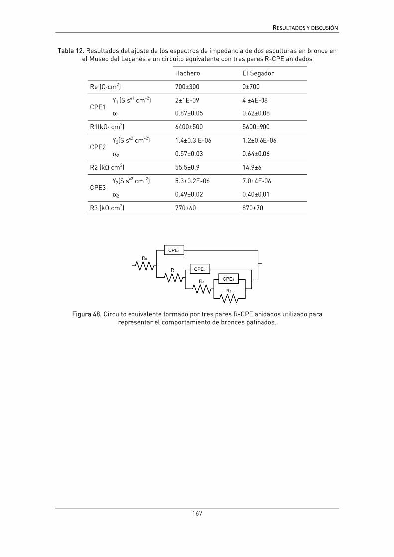
RESULTADOS Y DISCUSIÓN
167
Tabla 12. Resultados del ajuste de los espectros de impedancia de dos esculturas en bronce en el Museo del Leganés a un circuito equivalente con tres pares R-CPE anidados
Hachero El Segador
Re (Ω·cm2) 700±300 0±700
CPE1 Y1 (S sα1 cm-2) 2±1E-09 4 ±4E-08
α1 0.87±0.05 0.62±0.08
R1(kΩ· cm2) 6400±500 5600±900
CPE2 Y2(S sα2 cm-2) 1.4±0.3 E-06 1.2±0.6E-06
α2 0.57±0.03 0.64±0.06
R2 (kΩ cm2) 55.5±0.9 14.9±6
CPE3 Y2(S sα2 cm-2) 5.3±0.2E-06 7.0±4E-06
α2 0.49±0.02 0.40±0.01
R3 (kΩ cm2) 770±60 870±70
Figura 48. Circuito equivalente formado por tres pares R-CPE anidados utilizado para representar el comportamiento de bronces patinados.

RESULTADOS Y DISCUSIÓN
168
Esculturas en acero patinable:
La mayor parte de las medidas realizadas en el Museo de Escultura de Leganés
se han centrado en esculturas de acero patinable, con el objetivo de ensayar la celda
en este tipo de material. El acero patinable es un metal muy apreciado en escultura
contemporánea por las cualidades plásticas y por la capacidad protectora de la pátina
que se forma sobre él, en comparación con el hierro o el acero al carbono. Sin
embargo, como ya se ha comentado, la formación de una pátina protectora es un
proceso lento, y que requiere unas condiciones determinadas; la ubicación, geometría
u otros factores pueden afectar a la formación y propiedades de la pátina. Así, el
objetivo de esta serie de medidas ha sido ensayar la celda en este tipo de material y
comprobar su capacidad para determinar diferencias de comportamiento de las
pátinas de una misma obra en función de su posición o geometría. Las obras sobre las
que se han realizado las medidas han sido:
• Zenon, José Luis Sánchez (1980)
• Templo, Adriana Veyrat (2003)
• Once Módulos, Amador Rodríguez (1971)
La realización de las medidas sobre obras de acero patinable presenta ventajas y
desventajas sobre las medidas realizadas en bronce. Por un lado, la adaptación del gel
a la superficie es mucho más sencilla. Aunque la herrumbre sobre los aceros tiene
una textura irregular, al tratarse de obras realizadas a base de uniones de planchas de
metal, la superficie suele ser plana o suavemente curvada, sin el relieve de una obra
fundida, lo que facilita mucho el posicionamiento y adaptación de la celda. La principal
dificultad que se ha encontrado a la hora realizar medidas de campo sobre esculturas
de acero patinable ha sido en establecer un buen contacto eléctrico con la superficie
metálica. La menor conductividad del material junto con la continuidad de las capas –
no existiendo zonas de desgaste pulidas como en el bronce- o el grosor en algunos
casos de las capas de óxido, dificulta el contacto y la realización de las medidas. Esto
fue especialmente complejo en el caso de la primera obra estudiada, Zenon, que
además presenta la particularidad de ser una pátina tratada con cera. Aunque debido a
la calidad de los espectros y a la particular composición y estructura de la pátina no ha
sido posible realizar un ajuste y una interpretación en profundidad, estos resultados sí
han servido para ilustrar las posibilidades de la celda para medir sobre este tipo de
superficies.
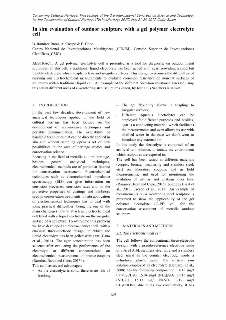
Conserving Cultural Heritage: Proceedings of the 3rd International Congress on Science and Technology for the Conservation of Cultural Heritage (TechnoHeritage 2017), May 21-24, 2017, Cadiz, Spain
169
In situ evaluation of outdoor sculpture with a gel polymer electrolyte cell
B. Ramírez Barat, A. Crespo & E. Cano Centro Nacional de Investigaciones Metalúrgicas (CENIM). Consejo Superior de Investigaciones Científicas (CSIC).
ABSTRACT: A gel polymer electrolyte cell is presented as a tool for diagnostic on outdoor metal sculptures. In this cell, a traditional liquid electrolyte has been gelled with agar, providing a solid but flexible electrolyte which adapts to lean and irregular surfaces. This design overcomes the difficulties of carrying out electrochemical measurements to evaluate corrosion resistance on non-flat surfaces of sculptures with a traditional liquid cell. An example of the different corrosion resistance assessed using this cell in different areas of a weathering steel sculpture (Zenon, by Jose Luis Sánchez) is shown.
1. INTRODUCTION
In the past few decades, development of new analytical techniques applied in the field of cultural heritage has been focused on the development of non-invasive techniques and portable instrumentation. The availability of handheld techniques that can be directly applied in situ and without sampling opens a lot of new possibilities in the area of heritage studies and conservation science. Focusing in the field of metallic cultural heritage, besides general analytical techniques, electrochemical methods are of particular interest for conservation assessment. Electrochemical techniques such as electrochemical impedance spectroscopy (EIS) can give information on corrosion processes, corrosion rates and on the protective properties of coatings and inhibitors used in conservation treatments. In situ application of electrochemical techniques has to deal with some practical difficulties, being the one of the main challenges how to attach an electrochemical cell filled with a liquid electrolyte on the irregular surface of a sculpture. To overcome this problem we have developed an electrochemical cell, with a classical three-electrode design, in which the liquid electrolyte has been gelled with agar (Cano et al., 2014). The agar concentration has been selected after evaluating the performance of the electrolyte at different concentrations on electrochemical measurements on bronze coupons (Ramírez Barat and Cano, 2015b). This cell has several advantages: As the electrolyte is solid, there is no risk of
leaching,
The gel flexibility allows it adapting to irregular surfaces.
Different aqueous electrolytes can be employed for different purposes and besides, agar is a conducting material, which facilitates the measurements and even allows its use with distilled water in the case we don´t want to introduce any external ion.
In this study the electrolyte is composed of an artificial rain solution, to imitate the environment which sculptures are exposed to. The cell has been tested in different materials (copper, bronze, weathering and stainless steel, etc.) on laboratory coupons and in field measurements, and used for monitoring the evolution of patinas and coatings over time (Ramírez Barat and Cano, 2015a, Ramírez Barat et al., 2017, Crespo et al., 2017). An example of measurements on a weathering steel sculpture is presented to show the applicability of the gel polymer electrolyte (G-PE) cell for the conservation assessment of metallic outdoor sculpture.
2. MATERIALS AND METHODS
2.1. The electrochemical cell
The cell follows the conventional three-electrode de-sign, with a pseudo-reference electrode made of a AISI 316L stainless steel wire and a stainless steel spiral as the counter electrode, inside a cylindrical plastic mold. The artificial rain solution employed as electrolyte (Bernardi et al., 2008) has the following composition: 14.43 mg/l CaSO4ꞏ2H2O, 15.04 mg/l (NH4)2SO4, 19.15 mg/l (NH4)Cl, 15.13 mg/l NaNO3, 3.19 mg/l CH3COONa; due to its low conductivity, it has

Conserving Cultural Heritage: Proceedings of the 3rd International Congress on Science and Technology for the Conservation of Cultural Heritage (TechnoHeritage 2017), May 21-24, 2017, Cadiz, Spain
170
been used 10-fold concentrated. A small amount of agar (3% w/v) is added to the liquid electrolyte and heated until complete dissolution, then poured inside the mold and left to cool. When the agar solidifies the outer part of the mold is removed leaving a gel cylinder which is placed in contact with the surface under study.
2.2. Electrochemical measurements
EIS measurements have been carried out with a Gamry Reference 600 potentiostat using a fre-quency swept from 100 kHz to 10 mHz, with a perturbation of 10 mV RMS amplitude at the open circuit potential and 10 points/decade. Measurements were done after 30 minutes of stabilization time. All results have been normalized to the measurement area, which is 3.14 cm2.
2.3. Zenon
Zenon (figure 1) is a weathering steel sculpture made by the Spanish sculptor José Luis Sánchez in 1980. The sculpture is owned by the Museo Nacional Centro de Arte Reina Sofía and since 2001 located outdoors in the Museo de Escultura de Leganés. According to the information from the museum, the author used to apply wax finishing to his works.
Figure 1. General view of the Zenon sculpture.
3. RESULTS
The sculpture has a nice smooth dark brown patina, which is apparently in good condition,
although some areas present a more irregular surface. In order to assess the differences in the protective properties of the patina in these areas, EIS measurements were carried out in three areas with different orientations: Zenon 1 was measured on a vertical smooth area (fig 2a), with south-west orientation. Zenon 2 (fig 2b) corresponds to on a sheltered area, in the south-east face. Zenon 3 on a vertical rough area (fig 1c) faced north-west. As shown in figure 1d, the flexibility of the gel cell allows it to adapt to the irregular texture of the patina.
Figure 2. Different measuring areas on the weathering steel sculpture (a-c) and aspect of the gel surface after removal (d).
Results from the EIS measurements are presented in figure 3. Phase angle results are rather noisy at about 1 kHz, but notwithstanding this, the spectra show a good quality and allow comparing the different patinas. The three patinas show an impedance modulus value at the lowest frequencies of above 2 KOhmꞏcm2. This is a empirical value generally accepted to classify a weathering steel patina as protective (Kihira et al., 1989), although strictly speaking, this criterion is only valid for natural patinas, without coatings and in relation to a given thickness. The most relevant feature of the spectra is that the results greatly differ from one area to the other. Differences are especially relevant in the mid-frequencies area of the spectra (1-100 Hz), which correspond to the protective properties of the patina and/or coating, with more than one order of magnitude of difference between the lowest resistance (Zenon 3) and the highest (Zenon 1). This different behavior can be related

Conserving Cultural Heritage: Proceedings of the 3rd International Congress on Science and Technology for the Conservation of Cultural Heritage (TechnoHeritage 2017), May 21-24, 2017, Cadiz, Spain
171
with the appearance of the patina: Zenon 1 is smooth and homogeneous in color and texture, while Zenon 3 is rough and heterogeneous. Also, this seems to have a certain relation with the orientation. Zenon 1 is faced to the south-west, receiving direct sunlight most part of the time, while Zenon 3, in a shadier face, may remain humid for longer periods after raining or morning dew. Zenon 2, presenting an intermediate impedance value, was done in a face-down plane, thus, less exposed to the rain. It should be reminded that the development of a protective patina requires specific conditions, including dry and wet cycles. Therefore, the different behavior of the different surfaces can be explained by different local conditions, such as the different wetting-drying cycles dynamics.
Figure 3. Bode plot of EIS measurements in three different areas of the sculpture.
4. CONCLUSIONS
Agar cell has proved to be a suitable tool to carry out in-situ EIS tests on metallic cultural heritage, where the use of traditional cells is not possible. The use of a gelled electrolyte allows measuring in vertical or face down areas. It also adapts to surface texture. In this example the G-PE cell has allowed to assess the protective properties of different areas of the Zenon sculpture. EIS results have shown
that different areas of the same sculpture present important differences in their corrosion resistance, which can be related to differences in surface and position.
5. AKNOWLEDGEMENTS
This work has been funded by MINECO, Projects HAR2011-22402 and HAR2014-54893-R, and doctoral grants BES-2012-052716 and BES-2015-071472. Thanks are due to Museo de Escultura de Leganés, MNCARS, and the Spanish Network on Science and Technology for the Conservation of Cultural Heritage (TechnoHeritage).
6. REFERENCES
CANO, E., CRESPO, A., LAFUENTE, D. & RAMIREZ BARAT, B. (2014) A novel gel polymer electrolyte cell for in-situ application of corrosion electrochemical techniques. Electrochemistry Communications, 41, 16-19.
CRESPO, A., RAMÍREZ BARAT, B., DIAZ, I. & CANO DÍAZ, E. (2017) Assessment of the protective properties of patinas on contemporary sculpture made out of weathering steel. IN BRIDGLAND, J. (Ed. ICOM-CC 18th Triennial Conference Preprints ed. Copenhagen,.
KIHIRA, H., ITO, S. & MURATA, T. (1989) Quantitative classification of patina conditions for weathering steel using a recently developed instrument. Corrosion, 45, 347-352.
RAMÍREZ BARAT, B. & CANO, E. (2015a) In situ assessment of protective coatings for metallic cultural heritage using electrochemical impedance spectroscopy. Ge-Conservacion, 2015, 6-13.
RAMÍREZ BARAT, B. & CANO, E. (2015b) The use of agar gelled electrolyte for in situ electrochemical measurements on metallic cultural heritage. Electrochimica Acta, 182, 751-762.
RAMÍREZ BARAT, B., CRESPO, A., GARCÍA, E., DÍAZ, S. & CANO, E. (2017) An EIS study of the conservation treatment of the bronze sphinxes at the Museo Arqueológico Nacional (Madrid). Journal of Cultural Heritage, 24, 93-99.

RESULTADOS Y DISCUSIÓN
172
Sobre las otras dos obras mencionadas se han realizado diferentes series de medidas.
Algunos de estos estudios preliminares, en colaboración con Ana Crespo, han tenido
un desarrollo posterior y se han presentado en diversos congresos nacionales e
internacionales [146, 210-212], pero se encuentran ya fuera del objetivo de esta tesis y
no se incluyen aquí. A continuación se presentan únicamente algunos ejemplos de las
primeras series realizadas para poner a prueba el funcionamiento de la celda.
Templo
Se trata de una obra geométrica, de pequeñas dimensiones y realizada con
planchas de acero patinable. Las medidas tomadas en esta obra se realizaron para
evaluar las diferencias en las características de la pátina en diferentes orientaciones.
Se eligieron 3 zonas de medida, una en un plano lateral (Templo 01), una en el plano
superior (Templo 02) y otra en la cara interior (Templo 03). En la figura 49 se puede ver
la obra junto con dos de las medidas realizadas.
Figura 49. Escultura Templo (a) y detalle de dos de las zonas medidas en el plano superior (b,
Templo 02) y lateral (c, Templo 01).
c)
a) b)
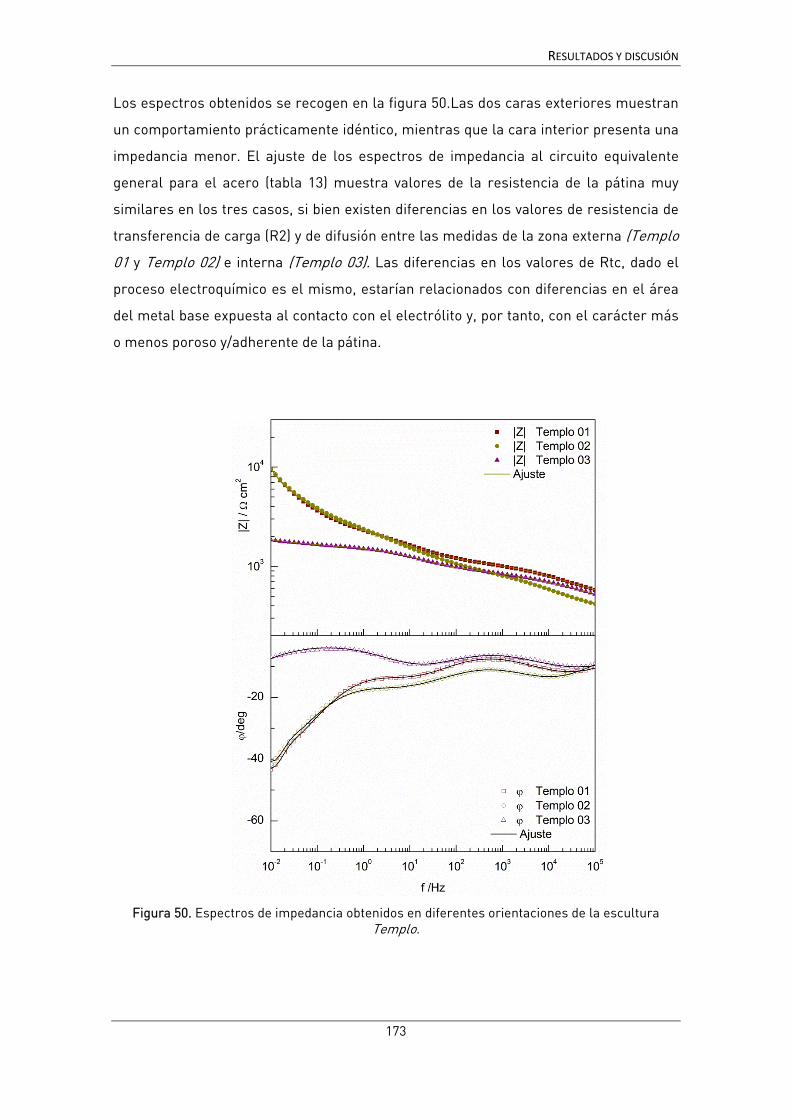
RESULTADOS Y DISCUSIÓN
173
Los espectros obtenidos se recogen en la figura 50.Las dos caras exteriores muestran
un comportamiento prácticamente idéntico, mientras que la cara interior presenta una
impedancia menor. El ajuste de los espectros de impedancia al circuito equivalente
general para el acero (tabla 13) muestra valores de la resistencia de la pátina muy
similares en los tres casos, si bien existen diferencias en los valores de resistencia de
transferencia de carga (R2) y de difusión entre las medidas de la zona externa (Templo
01 y Templo 02) e interna (Templo 03). Las diferencias en los valores de Rtc, dado el
proceso electroquímico es el mismo, estarían relacionados con diferencias en el área
del metal base expuesta al contacto con el electrólito y, por tanto, con el carácter más
o menos poroso y/adherente de la pátina.
Figura 50. Espectros de impedancia obtenidos en diferentes orientaciones de la escultura Templo.

RESULTADOS Y DISCUSIÓN
174
Tabla 13. Resultados del ajuste de los espectros de impedancia y medidas de espesor [146] de la obra Templo.
Templo 01 Templo 02 Templo 03
Espesor (μm) 27.3 21.2 27.8
Re (Ω·cm2) 418 ± 8 340 ± 4 369 ± 9
CPE1 Y1 (S sα1 cm-2) 5.1 ± 0.7 E-06 5.3 ± 0.8 E-06 7.8 ± 0.1 E-06
α1 0.50 ± 0.01 0.55 ± 0.01 0.47 ± 0.01
R1(kΩ· cm2) 700 ±20 550 ±20 550 ±20
CPE2 Y2(S sα2 cm-2) 8.0 ± 0.4 E-05 1.30 ± 0.07 E-04 1.16 ± 0.04E-04
α2 0.60 ± 0.01 0.48 ± 0.01 0.60 ± 0.01
R2 (kΩ cm2) 1.3 ± 0.4 2.5 ± 0.1 0.69 ±0.2
W
R (kΩ· cm2) 18.6 ± 0.3 21.2 ± 0.7 1.3 ± 0.7
T (s) 65±1 58±2 300±300
αw 0.56 ± 0.01 0.58 ± 0.01 0.46 ± 0.02

RESULTADOS Y DISCUSIÓN
175
Once módulos
Once módulos es una escultura realizada en 1971, obra de Amador Rodríguez.
La escultura está formada por diversas piezas y tiene una geometría compleja.
Figura 51. Imagen de la obra Once módulos y de las dos zonas de medida. Detalle de la medida en la zona interior curva.

RESULTADOS Y DISCUSIÓN
176
Como se puede apreciar en los espectros de impedancia (figura 52) y su ajuste al
mismo circuito equivalente que en el caso anterior, en este caso es la zona interior la
que muestra un mejor comportamiento a la corrosión (resultados del ajuste en la tabla
13). Este comportamiento, aunque en principio no sería el esperado, coincide con las
características visuales de la pátina, mucho más uniforme en la zona 02.
Figura 52. Espectros de impedancia obtenidos en la zona frontal (Zona 01) y la zona curvada (Zona 02) de Once Módulos

RESULTADOS Y DISCUSIÓN
177
Tabla 14. Resultados del ajuste de los espectros de impedancia y medidas de espesor [212] de la obra Once Modulos.
Zona 01 Zona 02
Espesor (μm) 56.7 43.1
Re (Ω·cm2) 830±7 800±15
CPE1 Y1 (S sα1 cm-2) 2.40± 0.8E-07 6.8± 0.2E-08
α1 0.65±0.01 0.67±0.01
R1(kΩ· cm2) 3.15±0.03 9.92±0.08
CPE2 Y2(S sα2 cm-2) 1.48± 0.04E-04 5.68± 0.05E-05
α2 0.308±0.007 0.232±0.002
R2 (kΩ cm2) 10.4±0.8 108±7
W
R (kΩ· cm2) 70 ±6 830 ±80
T (s) 150 ±20 65±4
αw 0.63 ±0.2 0.75±0.2

RESULTADOS Y DISCUSIÓN
178
4.4. Discusión general.
El objeto de este trabajo ha estado centrado en el desarrollo de una celda
electroquímica en gel para su empleo en la resolución de cuestiones de conservación
del patrimonio cultural metálico. Como se ha planteado inicialmente, una técnica como
la EIS, que ha demostrado ampliamente su utilidad en el estudio de la corrosión y de
los sistemas de protección en otros campos, no ha tenido su reflejo en una aplicación
al mismo nivel en el ámbito del patrimonio. Los obstáculos para la generalización de
su empleo esta área se encuentran, como se ha explicado en el apartado 1.2.2. de la
introducción, en las dificultades prácticas para la realización de las medidas y en las
dificultades para su interpretación. A lo largo del desarrollo de la celda con electrólito
en gel con la que se pretendía dar solución a esta primera dificultad, se ha podido
comprobar que algunos aspectos del diseño y de la realización de las medidas también
están relacionados con la segunda cuestión, ya que de ellos depende la calidad de las
medidas y la posible aparición de ruido, inestabilidad o artefactos en los espectros
obtenidos, que afectan a la interpretación de los resultados.
La primera condición que impone el tipo de objeto de estudio es que la técnica sea no
destructiva. Aunque la EIS en principio cumple este requisito, el electrólito elegido
puede resultar agresivo para las superficies que se quiere medir. Por este motivo, tras
la prueba de concepto (apartado 4.1) en la que se utilizó NaCl por ser un electrólito
bien conocido, la solución ha sido emplear una disolución de agua de lluvia artificial
con un pH próximo a la neutralidad. El empleo de agua de lluvia artificial resulta
adecuado además porque es similar al electrólito al que se encuentra principalmente
expuesto el patrimonio metálico en el exterior, aunque en algunos ambientes se trate
de lluvia ácida o aerosoles marinos. Con esto se evita aportar a la superficie del bien
cultural otros iones cuyos residuos pudieran dar lugar en el futuro a un deterioro
acelerado de la zona estudiada. El principal inconveniente del agua de lluvia es su baja
conductividad que acorta el intervalo entre el valor mínimo y máximo del módulo de la
impedancia, disminuye la relación señal-ruido y favorece la aparición de artefactos de
la medida dentro del rango de frecuencias de interés. Por eso es fundamental tener en
cuenta todos los factores que pueden introducir ruido o distorsiones de otro tipo en las
medidas, para evitarlos, minimizarlos o considerarlos adecuadamente al analizar los

RESULTADOS Y DISCUSIÓN
179
resultados. Este aspecto, que resulta fundamental para poder interpretar
adecuadamente los resultados, no siempre recibe la atención suficiente.
Podemos considerar los factores que afectan a las medidas en dos grupos. Aquellos
relacionados con el sistema de medida y aquellos propios de la realización de medidas
de campo.
El sistema de medida
Al emplear un electrólito de baja conductividad uno de los problemas posibles es la
aparición de artefactos debidos a acoplamientos entre los electrodos de referencia,
trabajo y contraelectrodo [193, 198]. Estos acoplamientos pueden dar lugar a efectos
de tipo (pseudo)inductivo o (pseudo)capacitivo de diferente alcance, que es
fundamental determinar ya que pueden interferir con la zona del espectro de interés
[187-189]. Con las configuraciones de celdas y electrólitos habituales utilizados en
estudios de corrosión, estos artefactos aparecen fuera del rango de frecuencias
estudiadas (típicamente entre 100 kHz y 1-10 mHz). Para el caso de la celda G-PE el
estudio sistemático del efecto de la naturaleza y posición de los electrodos, discutido
en el apartado 4.2.1., ha permitido determinar en qué casos pueden darse estos
efectos y cuál es la posición óptima de los electrodos para evitarlos. Este tipo de
efectos pueden explicar las diferencias obtenidas con diferentes sistemas de medida
sobre sustratos similares [190] y es uno de los aspectos que está en proceso de
desarrollo futuro con la investigadora italiana P. Letardi [150].
El siguiente aspecto relativo al sistema de medida es la retención del electrólito. Ya se
ha discutido ampliamente la existencia de dos enfoques para enfrentarse a esta
cuestión: el diseño de sistemas para la retención del líquido frente al empleo de
electrólitos gelificados. Aunque algunos de los sistemas con retención de líquido como
el propuesto por Letardi [25] o más recientemente el sistema de Elsener [137, 138] han
proporcionado buenos resultados, para las medidas sobre superficies muy porosas se
ha comprobado que el gel retiene mejor el electrólito (figura 53), evitando la excesiva
absorción del mismo por la pátina porosa. En este sentido, la celda G-PE desarrollada
en este trabajo sería preferible para este tipo de sustratos, al facilitar la delimitación
de la zona de medida, y evitar que la misma pueda ir cambiando a lo largo de la
realización del ensayo de EIS, distorsionando los resultados.

RESULTADOS Y DISCUSIÓN
180
Figura 53. Comparación de la realización de medidas con la celda de contacto (electrólito líquido), a la izquierda, y la celda G-PE, a la derecha, sobre una superficie muy porosa. En la
imagen central se puede ver el tamaño de la huella del líquido en ambos casos.
Otra de las ventajas de la utilización del gel, como ya se ha visto, es su adaptación a la
textura de la superficie, según se ha mostrado en las figuras 13 y 14. Es posible,
además, modificar la concentración de agar para obtener geles con mayor o menor
rigidez, permitiendo con ello modular la facilidad de manejo y la capacidad de
adaptación a superficies complejas. La caracterización realizada del efecto de distintas
concentraciones de agar (apartado 4.1) nos ha permitido conocer en detalle cómo
afecta dicha concentración a las medidas.
Como ventaja añadida en el caso del agar, su conductividad natural contrarresta la
baja conductividad del electrólito líquido. El principal inconveniente observado en el
agar es el aparente efecto despolarizante anódico observado en las medidas en
algunas superficies de bronce [132]; sin embargo, como ya se ha demostrado, este
efecto puede minimizarse utilizando bajas concentraciones de agar, y únicamente es
observable en el caso de superficies reactivas. Se ha podido comprobar que en obra
real, cuya superficie se ha estabilizado por exposición a la intemperie durante largos
periodos de tiempo, no hay diferencias significativas entre el agar y la agarosa, la
fracción neutra de este producto natural, que en laboratorio sí presenta un
comportamiento muy próximo al del electrólito líquido [228].

RESULTADOS Y DISCUSIÓN
181
Las medidas de campo:
La realización de medidas de campo conlleva una serie de dificultades añadidas
a los estudios de laboratorio. La principal es la posible interferencia de factores
externos que produce ruido en las medidas, a lo que se une la necesidad de medir con
tierra flotante, lo que produce medidas de peor calidad. Algunas interferencias de tipo
electromagnético son difíciles de detectar y más aún de evitar; en ocasiones los
propios cables y alargadores pueden ser fuente de interferencias, habiéndose obtenido
medidas de mejor calidad en ocasiones empleando baterías que cables alargadores
para enchufar el equipo a una toma de corriente. Así, el uso de baterías sería ventajoso
para evitar esta posible fuente de interferencias y para poder medir en localizaciones
alejadas de una toma de corriente eléctrica. Como desventaja, la capacidad de las
mismas puede limitar el tiempo disponible para realizar las medidas.
La longitud de los cables del propio potenciostato también añade una dificultad para el
acceso a ciertas zonas de la obra a medir; y aunque existen cables de 1.5 y 3 m, éstos
también pueden constituir una fuente de incertidumbre. Para evitar la necesidad de
utilizar cables de gran longitud, se puede utilizar un soporte para el potenciostato que
lo sitúe próximo a la superficie.
Otro aspecto importante en las medidas de campo son los posibles efectos de la luz y
la temperatura. La temperatura influye en cualquier proceso químico, por lo que
necesariamente medidas de la misma superficie con temperaturas ambiente
diferentes, presentarán algunas diferencias, como ya se apuntó en el estudio de las
esfinges del Museo Arqueológico [151]. La luz, como se ha comentado, produce
cambios en el potencial medido de las superficies de cobre, que hacen las medidas
inestables. Por ello, es recomendable, siempre que sea posible, medir en condiciones
de sombra. De este modo se evita también el calentamiento excesivo de la superficie
del metal por efecto del sol, que produce además la evaporación del electrólito y añade
una nueva dificultad.
Finalmente, el último aspecto crítico en la realización de medidas de campo es la
dificultad de realizar el contacto eléctrico con el metal. Aunque algunos autores han
propuesto el empleo de un sistema de dos celdas paralelas para evitarlo, ya se ha
discutido en el apartado 1.2.2 que esta no es una opción adecuada [190]. Otra
posibilidad sería realizar un pequeño taladro en una zona no visible, sin embargo, esta

RESULTADOS Y DISCUSIÓN
182
opción limita mucho las posibilidades, por lo que la alternativa de utilizar una punta
metálica resulta adecuada y más respetuosa con la superficie. Esta solución funciona
bastante bien para esculturas de bronce, en las que además es frecuente encontrar
algún punto con desgastes o arañazos que exponen el metal facilitando el contacto
(figura 54). En el caso de esculturas en acero patinable es más difícil y cuando se
observen anomalías en los valores o el desarrollo del espectro de impedancia durante
el proceso de medida, debe considerarse la posibilidad de que exista un mal contacto
con la superficie metálica. También se ha comprobado que la calidad del contacto
mejora cuando se dispone de un soporte suficientemente robusto para la sujeción del
sistema de medida, por lo que es un detalle importante a tener en cuenta en el diseño.
Aunque aún hay algunos aspectos que pueden mejorarse o desarrollarse en un futuro,
esta investigación ha permitido diseñar un sistema que posibilita obtener medidas de
calidad, al tiempo que ha proporcionado un conocimiento suficiente de los factores
limitantes en las medidas de campo. Esto ha aportado una herramienta de utilidad
para resolver problemas de conservación del patrimonio metálico, como se ha podido
comprobar a través de los diferentes ejemplos y trabajos de colaboración a lo largo de
este trabajo, que se han presentado en los apartados anteriores, tales como el
seguimiento de procesos de restauración o la comparación entre diferentes sistemas
de protección.
Además, abre la posibilidad de comenzar a realizar colecciones sistemáticas de
medidas en campo, inexistentes en la actualidad, y en diferentes modelos de
Figura 54. Detalle del contacto eléctrico con una punta metálica sobre una zona desgastada (izquierda) y en un hueco de la superficie (derecha).

RESULTADOS Y DISCUSIÓN
183
laboratorio para entender mejor el comportamiento electroquímico de las pátinas y
recubrimientos en escultura. Este debe ser el siguiente paso para seguir avanzando en
la aplicación de esta técnica a la resolución de problemas de conservación del
patrimonio cultural metálico.

184
5. CONCLUSIONES
El trabajo desarrollado a lo largo de esta tesis ha permitido diseñar, desarrollar
y validar una celda electroquímica con electrólito en gel para la realización de medidas
electroquímicas in situ sobre el patrimonio cultural metálico.
Atendiendo a los objetivos parciales que se planteaban inicialmente, se pueden
establecer las siguientes conclusiones:
• El empleo de un electrólito gelificado con agar o agarosa permite obtener medidas
electroquímicas reproducibles y de buena calidad sobre superficies metálicas. Los
resultados obtenidos son comparables a los de un electrólito líquido; la presencia
del gel no introduce ningún artefacto o proceso adicional en el sistema, que
responde al mismo circuito equivalente. En el caso de superficies reactivas, el uso
de agar puede acelerar las velocidades de corrosión medidas, siendo posible en
estos casos el empleo de agarosa, que tiene un comportamiento más neutro. En
cualquier caso, este no resulta un efecto importante para la realización de
medidas comparativas.
• El análisis de los diferentes elementos del diseño, como la naturaleza de los
electrodos, geometría de la celda o sistemas de fijación ha permitido la
optimización del diseño de la celda, garantizando la calidad y fiabilidad de los
resultados obtenidos. Este diseño, junto con el sistema de soporte y colocación
adoptado para su utilización en medidas de campo ha permitido solventar las
dificultades prácticas de la realización de este tipo de medidas.
• El uso de la celda es adecuado para la evaluación de pátinas y recubrimientos. La
evaluación del sistema sobre diferentes pátinas y recubrimientos en laboratorio ha
demostrado la capacidad del sistema para poner de manifiesto las diferencias y la
evolución de diferentes sistemas metal/pátina o metal recubrimiento. Esto
permite utilizar la celda para realizar estudios sobre la idoneidad, el
comportamiento o la evolución de tratamientos de conservación en laboratorio,
que posteriormente puedan ser trasladados a obra real y monitorizados utilizando
la misma metodología.

CONCLUSIONES
185
• Se ha demostrado la aplicabilidad de la celda a situaciones reales relacionadas
con la conservación del patrimonio metálico, realizando el seguimiento de un
trabajo de restauración. Asimismo, las medidas puntuales realizadas sobre
diversos tipos de obras en diferentes ubicaciones han permitido apreciar
diferencias relacionadas con la posición o geometría de las esculturas, que
constituyen una información de interés para poder llevar a cabo tratamientos o
estrategias de conservación.
La celda electroquímica en gel desarrollada en esta tesis proporciona a los
conservadores e investigadores un sistema para la realización de medidas de campo
sencillo y eficaz. Esto permitirá generalizar su empleo, recopilar medidas y estudios de
caso, lo que a su vez contribuirá a un mayor conocimiento y comprensión del
comportamiento y respuesta de las superficies metálicas en los objetos del patrimonio
y con ello a su conservación.

186
6. OTROS DESARROLLOS Y FUTURAS LÍNEAS DE TRABAJO.
En paralelo al desarrollo de la celda, las posibilidades de aplicación han dado
lugar a otros trabajos y colaboraciones con otros investigadores. Además de los
estudios sobre el comportamiento de las pátinas artificiales en escultura de aceros
patinables que ya se ha comentado, otros autores han realizado nuevos avances o
aplicaciones a partir de la celda inicialmente desarrollada en este trabajo. El más
destacado, fuera del campo del patrimonio cultural, es la Tesis Doctoral de G.
Monrrabal [229], que ha trabajado en la modificación del electrólito con plastificantes
para poder aplicar la celda al estudio de la corrosión del acero inoxidable geometrías
complejas [143, 155]. A su vez, los ensayos sobre el empleo de geles modificados con
plastificantes para patrimonio cultural se han iniciado en nuestro grupo de
investigación del CENIM en el marco de una beca JAE-Intro y es uno de los futuros
estudios previstos para la celda. Esto podría tener aplicaciones especialmente en el
campo de la arqueología, dadas las características morfológicas y superficiales de
algunos objetos (objetos o superficies pequeñas o con capas de corrosión muy
texturizadas). El interés de este campo de aplicación ya ha sido apuntado por F. di
Turo, quien ha utilizado la celda para la evaluación de monedas de bronce de
procedencia arqueológica[147], y ha sugerido el empleo de otros electrólitos
poliméricos [208].
Para avanzar el estudio de esculturas al aire libre, la cuestión más importante a
abordar a partir de ahora son los posibles efectos de la luz y la temperatura. El estudio
de hasta qué punto influye la temperatura en los resultados es un tema pendiente;
aunque se han diseñado algunos ensayos para su estudio éstos no han sido llevados a
cabo todavía. Lo mismo ocurre con el problema de la luz, como se ha comentado en el
apartado 4.3.2.3., se ha observado que las variaciones de luz provocan oscilaciones
bruscas en el potencial, lo que produce la inestabilidad de las medidas. Estas
cuestiones se abordarán mediante un conjunto de medidas sistemáticas a diferentes
temperaturas dentro de un rango que abarque los valores a los que se puede
encontrar la superficie de una escultura, y con diferentes intensidades de iluminación
con una fuente regulable de luz día. El objetivo es establecer un modelo o unos

FUTURAS LÍNEAS
187
parámetros que permitan normalizar los resultados obtenidos en campo en función de
estos valores, que son difícilmente controlables.
Además de las nuevas aplicaciones, la evaluación de la influencia del medio y de
explorar posibles modificaciones del electrólito para aplicaciones concretas, otro
objetivo relevante a partir de este momento, es realizar series sistemáticas de
medidas sobre diferentes obras y materiales metálicos de patrimonio cultural para
seguir avanzando en su comprensión. Una de las líneas de trabajo estaría orientada al
estudio de recubrimientos, en patrimonio metálico; de hecho, la revisión y análisis de
las aportaciones de la EIS al estudio de pátinas y recubrimientos es un tema que se ha
abordado brevemente en el trabajo presentado al congreso METAL2019 [230]. La
evaluación de nuevos recubrimientos se plantea en el marco de un proyecto vigente
del grupo de investigación, COMPACT, aplicado a la conservación del patrimonio
científico-técnico. En el proyecto COMPACT,” La Conservación de los Metales en el
Patrimonio Científico-Técnico” (HAR2017-89911-R) se abordará, entre otras
cuestiones, el empleo de recubrimientos e inhibidores innovadores y su adecuación al
patrimonio científico-técnico, cuyo comportamiento in situ podrá ser estudiado con la
celda G-PE. La aplicación de electrólitos gelificados con agar para el estudio de
pátinas, y concretamente para el “análisis del proceso electroquímico de degradación
de pátinas formadas artificialmente sobre bronce cuaternario y su relación directa con
las condiciones atmosféricas” ha sido el objeto de un reciente TFM dirigido por el Dr.
Ricardo Orozco, de la Universidad Veracruzana (México). Este TFM se enmarca en el
proyecto “Escenarios de riesgo para el patrimonio en México: causas ambientales
involucradas en su deterioro y estrategias de conservación”, de la “Red de estudios
interdisciplinarios sobre medio ambiente y conservación del patrimonio mexicano” con
la que nuestro grupo está participando como colaborador externo.
Finalmente, como se ha mencionado en el apartado 4.3.1.2, parte de los resultados se
han obtenido dentro del proyecto IPERION-CH. Este proyecto es último de una serie de
proyectos –iniciados con la red LabsTech en el V Programa Marco- que han venido
dando acceso a investigadores en patrimonio cultural a un conjunto de tecnologías de
análisis y archivos de datos científicos en los últimos 15 años y que han constituido el

FUTURAS LÍNEAS
188
origen de la infraestructura E-RIHS12. E-RIHS (“European Research Infrastructure for
Heritage Science”) es una infraestructura de investigación distribuida cuyo objetivo es
dar soporte a la investigación en patrimonio cultural y natural, proporcionando acceso
a herramientas tecnologías de análisis más avanzadas y a archivos científicos a través
de las cuatro plataformas: FIXLAB, para acceso a grandes instalaciones fijas; MOLAB,
una flota de laboratorios e instrumentos portátiles que se trasladan para estudios in-
situ; ARCHLAB, formado por colecciones de materiales y archivos de archivos de
datos científicos, de carácter único y DIGILAB , que dará acceso online a datos y
herramientas digitales.
El sistema portátil para la evaluación de pátinas y recubrimientos en metales basado
en los desarrollos de esta tesis ha sido incluido como uno de los servicios del nodo
español de esta infraestructura, dentro del MOLAB “METAL.es. In-situ metal
electrochemical studies for heritage science”. Metal.es estará orientado al estudio in
situ de las características y comportamiento de las superficies metálicas y evaluación
de recubrimientos protectores mediante técnicas electroquímicas.
12 http://www.e-rihs.eu

189
7. BIBLIOGRAFÍA
[1] G.H. Koch, M.P.H. Brongers, N.G. Thompson, Y.P. Virmani, J.H. Payer, Corrosion costs and preventive strategies in the United States, NACE, 2002.
[2] ISO 8044:2015. Corrosion of metals and alloys — Basic terms and definitions.
[3] Terminología para definir la conservación del patrimonio cultural tangible, en: ICOM-CC (Ed.), 2008.
[4] F. Mirambet, E. Rocca, J. Steinmetz, "Protection of iron artefacts of the cultural heritage: Use of the sodium carboxylates as corrosion inhibitors", en, EUROCORR 2004 - European Corrosion Conference: Long Term Prediction and Modelling of Corrosion, 2004.
[5] A. Elia, M. Dowsett, A. Adriaens, "On the use of alcoholic carboxylic acid solutons for the deposition of protective coatings on copper", en: P. Mardikian, C. Chemello, C. Watters, P. Hull (Eds.), METAL 2010. 6th Interim Meeting of the ICOM-CC Metal Working Group Conference Proceedings, Charleston, South Carolina, USA, 2010, pp. 193-200.
[6] S. Hollner, F. Mirambet, E. Rocca, S. Reguer, "Evaluation of new non-toxic corrosion inhibitors for conservation of iron artefacts", Corrosion Engineering Science and Technology, 45 (2010) 362-366.
[7] L.M. Abrantes, A.I. Melato, "Coatings including carboxylates for the preservation of metallic heritage artefacts", en: Corrosion and Conservation of Cultural Heritage Metallic Artefacts, 2013, pp. 518-539.
[8] M. Pilz, H. Römich, "Sol-Gel Derived Coatings for Outdoor Bronze Conservation", Journal of Sol-Gel Science and Technology, 8 (1997) 1071-1075.
[9] C. Chiavari, A. Balbo, E. Bernardi, C. Martini, M.C. Bignozzi, M. Abbottoni, C. Monticelli, "Protective silane treatment for patinated bronze exposed to simulated natural environments", Materials Chemistry and Physics, 141 (2013) 502-511.
[10] E. Kiele, J. Senvaitiene, A. Griguceviciene, R. Ramanauskas, R. Raudonis, A. Kareiva, "Application of sol–gel method for the conservation of copper alloys", Microchemical Journal, 124 (2016) 623-628.
[11] E. Joseph, P. Letardi, R. Mazzeo, S. Prati, M. Vandini, "Innovative treatments for the protection of outdoor bronze monuments", en: C. Degrigny, R. Van Lang, I. Joosten, B. Ankersmith (Eds.), Metal 07. 5th Interim Meeting of the ICOM-CC Metal Working Group Conference Proceedings, Amsterdam (The Neatherlands), 2007, pp. 71-77.
[12] E. Joseph, P. Letardi, L. Comensoli, A. Simon, P. Junier, D. Job, M. Wörle, "Assesment of a biological approach for the protection of copper alloys artefacts", en: V.G. Ewan Hyslop, Lore Troalen, Lyn Wilson (Ed.), METAL 2013. 7th Interim Meeting of the ICOM-CC Metal Working Group Conference Proceedings, Edinburgh, 2013, pp. 203-207.

BIBLIOGRAFÍA
190
[13] M. Albini, L. Comensoli, L. Brambilla, E. Domon Beuret, W. Kooli, L. Mathys, P. Letardi, E. Joseph, "Innovative biological approaches for metal conservation", Materials and Corrosion, 67 (2016) 200-206.
[14] M. Albini, Fungal biogenic patina : optimization of an innovative conservation treatment for copper-based artefacts. , Tesis Doctoral, Université de Neuchâtel 2017.
[15] L.B. Brostoff, Coating strategies for the protection of outdoor bronze art and ornamentation, Tesis Doctoral, Faculteit der Natuurwetenschappen, Wiskunde en Informatica, Amsterdam, 2003.
[16] C. Craine, K. Severson, S. Merritt, "Prospects for the Long Term Maintenance of Outdoor Bronze Sculpture: The Shaw Memorial Nine Years After Cleaning and Coating," en, AIC 2th Annual Meeting, Buffalo, New York, 1992.
[17] C. Degrigny, "The search for new and safe materials for protecting metal objects", en: V. Argyropoulos (Ed.) Metals and Museums in the Mediterranean. Protecting, Preserving and Interpreting, TEI of Athens-PROMET project, Athens, 2008, pp. 179-235.
[18] O. Chiantore, M. Lazzari, "Photo-oxidative stability of paraloid acrylic protective polymers", Polymer, 42 (2001) 17-27.
[19] C. Chiavari, A. Balbo, E. Bernardi, C. Martini, F. Zanotto, I. Vassura, M.C. Bignozzi, C. Monticelli, "Organosilane coatings applied on bronze: Influence of UV radiation and thermal cycles on the protectiveness", Progress in Organic Coatings, 82 (2015) 91-100.
[20] M.T. Doménech-Carbó, D.J. Yusá-Marco, G. Bitossi, M.F. Silva, X. Mas-Barberá, L. Osete-Cortina, "Study of ageing of ketone resins used as picture varnishes by FTIR spectroscopy, UV–Vis spectrophotometry, atomic force microscopy and scanning electron microscopy X-ray microanalysis", Analytical and Bioanalytical Chemistry, 391 (2008) 1351-1359.
[21] E. Cano, B. Ramírez Barat, "Electrochemical techniques for in-situ corrosion evaluation of Cultural Heritage", en: D.M. Bastidas, E. Cano (Eds.) Advanced Characterization, Diagnostics, and Evaluation in Heritage Science, Springer, 2018, pp. 21-32.
[22] N. Hjelm-Hansen, J. van Lanschot, C.D. Szalkay, S. Turgoose, "Electrochemical assessment and monitoring of stabilisation of heavily corroded archaeological iron artefacts", Corrosion Science, 35 (1993) 767-774.
[23] C. Price, D. Hallam, G. Heath, D. Creagh, J. Ashton, "An electrochemical study of waxes for bronze sculpture", en: I.D. MacLeod, S.L. Pennec, L. Robbiola (Eds.), Metal 95. International Conference on Metal Conservation Semur-en-Auxois (France), 1995, pp. 233-241.
[24] V. Otieno-Alego, G. Heath, D. Hallam, D. Creagh, "Electrochemical evaluation of the anti-corrosion performance of waxy coatings for outdoor bronze conservation", en: J. Ashton, D. Hallam (Eds.), Metal 98. International Conference on Metal Conservation Draguignan-Figanières (France), 1998, pp. 315-319

BIBLIOGRAFÍA
191
[25] P. Letardi, A. Beccaria, M. Marabelli, G. D'Ercoli, "Application of electrochemical impedance mesurements as a tool for the characterization of the conservation and protection state of bronze works of art", en: J. Ashton, D. Hallam (Eds.), Metal 98. International Conference on Metal Conservation Draguignan-Figanières (France), 1998, pp. 303-308.
[26] P. Letardi, R. Spiniello, "Characterisation of bronze corrosion and protection by contact-probe electrochemical impedance measurements", en: I. MacLeod, J.M. Theile, C. Degrigny (Eds.), Metal 01. International Conference on Metal Conservation Santiago (Chile), 2001, pp. 316-319.
[27] G. Bierwagen, T.J. Shedlosky, L.A. Ellingson, "Electrochemical studies of the protection of bronzes from corrosion by organic coatings", en: I. MacLeod, J.M. Theile, C. Degrigny (Eds.), Metal 01. International Conference on Metal Conservation Santiago (Chile), 2001, pp. 291-296.
[28] G. Bierwagen, D. Tallman, J. Li, L. He, C. Jeffcoate, "EIS studies of coated metals in accelerated exposure", Progress in Organic Coatings, 46 (2003) 148-157.
[29] P. Letardi, "Laboratory and field tests on patinas and protective coating systems for outdoor bronze monuments", en: J. Ashton, D. Hallam (Eds.), Metal 04: Proceedings of the International Conference on Metals Conservation, Canberra, Australia, 2004, pp. 379-387.
[30] G. Bierwagen, T.J. Shedlosky, K. Stanek, "Developing and testing a new generation of protective coatings for outdoor bronze sculpture", Progress in Organic Coatings, 48 (2003) 289-296.
[31] H. Hammouch, A. Dermaj, D. Chebabe, P. Decaro, N. Hajjaji, N. Bettach, H. Takenouti, A. Srhiri, "Opuntia ficus indica seed oil: Characterization and application in corrosion inhibition of carbon steel in acid medium", Analytical and Bioanalytical Electrochemistry, 5 (2013) 236-254.
[32] T.L. Clare, P.A. Lins, "Evaluation of fluorinated protective coatings for outdoor metals", en: C. Degrigny, R. Van Lang, I. Joosten, B. Ankersmith (Eds.), Metal 07. Interim meeting of the ICOM-CC Metal WG, Amsterdam (The Neatherlands), 2007, pp. 8387.
[33] A. Balbo, C. Chiavari, C. Martini, C. Monticelli, "Effectiveness of corrosion inhibitor films for the conservation of bronzes and gilded bronzes", Corrosion Science, 59 (2012) 204-212.
[34] C. Chiavari, K. Rahmouni, H. Takenouti, S. Joiret, P. Vermaut, L. Robbiola, "Composition and electrochemical properties of natural patinas of outdoor bronze monuments", Electrochimica Acta, 52 (2007) 7760-7769.
[35] E. Cano, D. Lafuente, D.M. Bastidas, "Use of EIS for the evaluation of the protective properties of coatings for metallic cultural heritage: A review", Journal of Solid State Electrochemistry, 14 (2010) 381-391.
[36] WebPlot Digitizer: https://automeris.io/WebPlotDigitizer/index.html, consultado 17-7-2018.
[37] U.R. Evans, C.A.J. Taylor, "Mechanism of atmospheric rusting", Corrosion Science, 12 (1972) 227-246.
[38] M. Stratmann, K. Bohnenkamp, H.J. Engell, "An electrochemical study of phase-transitions in rust layers", Corrosion Science, 23 (1983) 969-985.

BIBLIOGRAFÍA
192
[39] G.J. Brug, A.L.G. van den Eeden, M. Sluyters-Rehbach, J.H. Sluyters, "The analysis of electrode impedances complicated by the presence of a constant phase element", Journal of Electroanalytical Chemistry, 176 (1984) 275-295.
[40] S. Chechirlian, P. Eichner, M. Keddam, H. Takenouti, H. Mazille, "A specific aspect of impedance measurements in low conductivity media. Artefacts and their interpretations", Electrochimica Acta, 35 (1990) 1125-1131.
[41] M. Yamashita, H. Miyuki, Y. Matsuda, H. Nagano, T. Misawa, "The long term growth of the protective rust layer formed on weathering steel by atmospheric corrosion during a quarter of a century", Corrosion Science, 36 (1994) 283-299.
[42] A. Amirudin, D. Thierry, "Application of electrochemical impedance spectroscopy to study the degradation of polymer-coated metals", Progress in Organic Coatings, 26 (1995) 1-28.
[43] F. Mansfeld, "Use of electrochemical impedance spectroscopy for the study of corrosion protection by polymer coatings", Journal of Applied Electrochemistry, 25 (1995) 187-202.
[44] Y. Feng, W.K. Teo, K.S. Siow, A.K. Hsieh, "The corrosion behaviour of copper in neutral tap water. Part II: Determination of corrosion rates", Corrosion Science, 38 (1996) 387-395.
[45] Y. Feng, W.K. Teo, K.S. Siow, K.l. Tan, A.K. Hsieh, "The corrosion behaviour of copper in neutral tap water. Part I: Corrosion mechanisms", Corrosion Science, 38 (1996) 369-385.
[46] J.H. Wang, F.I. Wei, H.C. Shih, "Modeling of atmospheric corrosion behavior of weathering steel in sulfur dioxide-polluted atmospheres", Corrosion, 52 (1996) 900-909.
[47] J.H. Wang, F.I. Wei, H.C. Shin, "Electrochemical Studies of the Corrosion Behavior of Carbon and Weathering Steels in Alternating Wet/Dry Environments with Sulfur Dioxide Gas", CORROSION, 52 (1996) 600-608.
[48] J.H. Wang, F.I. Wei, Y.S. Chang, H.C. Shih, "The corrosion mechanisms of carbon steel and weathering steel in SO2 polluted atmospheres", Materials Chemistry and Physics, 47 (1997) 1-8.
[49] P. Letardi, A. Beccaria, M. Marabelli, G. D'Ercoli, "Application of electrochemical impedance measurements as a tool for the characterization of the conservation and protection state of bronze works of art", en: J. Ashton, D. Hallam (Eds.), Metal 98. International Conference on Metal Conservation Draguignan-Figanières (France), 1998, pp. 303-308.
[50] V. Otieno-Alego, D. Hallam, A. Viduka, G. Heath, D. Creagh, "Electrochemical impedance studies of the corrosion resistance of wax coatings on artificially patinated bronze", en: J. Ashton, D. Hallam (Eds.), Metal 98. International Conference on Metal Conservation Draguignan-Figanières (France), 1998, pp. 315-319
[51] F. Mansfeld, Analysis and Interpretation of EIS data for metals and alloys, en: Solartron analytical Technical Report Nº26, 1999.

BIBLIOGRAFÍA
193
[52] A. Carullo, F. Ferraris, M. Parvis, A. Vallan, E. Angelini, P. Spinelli, "Low-cost electrochemical impedance spectroscopy system for corrosion monitoring of metallic antiquities and works of art", Transactions On Instrumentation And Measurement, 49 (2000) 371-375.
[53] P. Letardi, "Electrochemical impedance measurements in the conservation of metals", en: D.C. Creagh, O.A. Bradley (Eds.) Radiation in Art and Archeometry, Elsevier Science B.V, Amsterdam, 2000, pp. 15-39.
[54] P. Letardi, A. Beccaria, M. Marabelli, G. D'Ercoli, "Developments of Electrochemical Impedance Spectroscopy as a tool for outdoors bronze corrosion characterization.", en, 2nd International Congress on Science and Tecnology for the Safeguard of Cultural Heritage in the Mediterranean Basin, Paris (France), 2000, pp. 407-411.
[55] E. Cano, C.L. Torres, J.M. Bastidas, "An XPS study of copper corrosion originated by formic acid vapour at 40% and 80% relative humidity", Werkstoffe und Korrosion, 52 (2001) 667-676.
[56] D. Hallam, A. Thurrowgood, V. Otieno-Alego, D. Creagh, A. Viduka, G. Heath, "Studies of commercial protective petrochemical coatings on ferrous surfaces of historical and museum objects", en: I. MacLeod, J.M. Theile, C. Degrigny (Eds.), Metal 01. International Conference on Metal Conservation Santiago (Chile), 2001, pp. 297-303.
[57] C.H. Hsu, F. Mansfeld, "Technical Note: Concerning the Conversion of the Constant Phase Element Parameter Y0 into a Capacitance", CORROSION, 57 (2001) 747-748.
[58] X. Zhang, W. He, I. Odnevall Wallinder, J. Pan, C. Leygraf, "Determination of instantaneous corrosion rates and runoff rates of copper from naturally patinated copper during continuous rain events", Corrosion Science, 44 (2002) 2131-2151.
[59] G. Brunoro, A. Frignani, A. Colledan, C. Chiavari, "Organic films for protection of copper and bronze against acid rain corrosion", Corrosion Science, 45 (2003) 2219-2231.
[60] N. Souissi, L. Bousselmi, S. Khosrof, E. Triki, "Electrochemical behaviour of an archaeological bronze alloy in various aqueous media: New method for understanding artifacts preservation", Materials and Corrosion, 54 (2003) 318-325.
[61] Y.-S. Choi, J.-J. Shim, J.-G. Kim, "Corrosion behavior of low alloy steels containing Cr, Co and W in synthetic potable water", Materials Science and Engineering A, 385 (2004) 148-156.
[62] L.A. Ellingson, T.J. Shedlosky, G.P. Bierwagen, E.R. De la Rie, L.B. Brostoff, "The use of electrochemical impedance spectroscopy in the evaluation of coatings for outdoor bronze", Studies in Conservation, 49 (2004) 53-62.
[63] J.J. Shim, J.G. Kim, "Copper corrosion in potable water distribution systems: Influence of copper products on the corrosion behavior", Materials Letters, 58 (2004) 2002-2006.
[64] E. Barsoukov, J.R. Macdonald, Impedance Spectroscopy: Theory, Experiment, and Applications, 2005.

BIBLIOGRAFÍA
194
[65] Y.-S. Choi, J.-J. Shim, J.-G. Kim, "Effects of Cr, Cu, Ni and Ca on the corrosion behavior of low carbon steel in synthetic tap water", Journal of Alloys and Compounds, 391 (2005) 162-169.
[66] K. Rahmouni, M. Keddam, A. Srhiri, H. Takenouti, "Corrosion of copper in 3% NaCl solution polluted by sulphide ions", Corrosion Science, 47 (2005) 3249-3266.
[67] E. Angelini, A. Carullo, S. Corbellini, F. Ferraris, V. Gallone, S. Grassini, M. Parvis, A. Vallan, "Handheld-impedance-measurement system with seven-decade capability and potentiostatic function", IEEE Transactions on Instrumentation and Measurement, 55 (2006) 436-441.
[68] E. Angelini, S. Grassini, S. Corbellini, G.M. Ingo, T. De Caro, P. Plescia, C. Riccucci, A. Bianco, S. Agostini, "Potentialities of XRF and EIS portable instruments for the characterisation of ancient artefacts", Applied Physics A: Materials Science and Processing, 83 (2006) 643-649.
[69] C. Chiavari, A. Colledan, A. Frignani, G. Brunoro, "Corrosion evaluation of traditional and new bronzes for artistic castings", Materials Chemistry and Physics, 95 (2006) 252-259.
[70] T. Kamimura, S. Hara, H. Miyuki, M. Yamashita, H. Uchida, "Composition and protective ability of rust layer formed on weathering steel exposed to various environments", Corrosion Science, 48 (2006) 2799-2812.
[71] J. Sandberg, I. Odnevall Wallinder, C. Leygraf, N. Le Bozec, "Corrosion-induced copper runoff from naturally and pre-patinated copper in a marine environment", Corrosion Science, 48 (2006) 4316-4338.
[72] E.M. Sherif, S.M. Park, "2-Amino-5-ethyl-1,3,4-thiadiazole as a corrosion inhibitor for copper in 3.0% NaCl solutions", Corrosion Science, 48 (2006) 4065-4079.
[73] N. Souissi, L. Bousselmi, S. Khosrof, E. Triki, "Comparaison between archaeological and artificially aged bronze interfaces", Materials and Corrosion, 57 (2006) 794-799.
[74] M.B. Valcarce, S.R. De Sánchez, M. Vázquez, "A comparative analysis of copper and brass surface films in contact with tap water", Journal of Materials Science, 41 (2006) 1999-2007.
[75] R.D.P. Bendezú H, R.P. Gonçalves, A.C. Neiva, H.G. De Melo, "EIS and microstructural characterization of artificial nitrate patina layers produced at room temperature on copper and bronze", Journal of the Brazilian Chemical Society, 18 (2007) 54-64.
[76] C. Degrigny, J. Crawford, R. Debattista, "The ‘Drop’ Ecorr vs time monitoring technique: a possible spot test for metal artefacts?", en: C. Degrigny, R. Van Lang, I. Joosten, B. Ankersmith (Eds.), Metal 07. Interim meeting of the ICOM-CC Metal WG, Amsterdam (The Neatherlands), 2007, pp. 71.
[77] K.M. Ismail, "Evaluation of cysteine as environmentally friendly corrosion inhibitor for copper in neutral and acidic chloride solutions", Electrochimica Acta, 52 (2007) 7811-7819.

BIBLIOGRAFÍA
195
[78] E. Joseph, P. Letardi, R. Mazzeo, S. Prati, M. Vandini, "Innovative treatments for the protection of outdoor bronze monuments", en: C. Degrigny, R. Van Lang, I. Joosten, B. Ankersmith (Eds.), Metal 07. Interim meeting of the ICOM-CC Metal WG, Amsterdam (The Neatherlands), 2007, pp. 71-77.
[79] K. Marušić, H. Otmačić-Ćurković, H. Takenouti, A.D. Mance, E. Stupnišek-Lisac, "Corrosion protection of synthetic bronze patina", Chemical and Biochemical Engineering Quarterly, 21 (2007) 71-76.
[80] R. Mazzeo, S. Bittner, D. Job, G. Farron, R. Fontinha, E. Joseph, P. Letardi, M. Mach, S. Prati, M. Salta, A. Simon, "Development and Evaluation of New Treatments for Outdoor Bronze Monuments ", en: J. Townsend, L. Toniolo, F. Cappitelli (Eds.) Conservation Science 2007, Archetype publications, 2007, pp. 40-48.
[81] L. Muresan, S. Varvara, E. Stupnišek-Lisac, H. Otmačić, K. Marušić, S. Horvat-Kurbegović, L. Robbiola, K. Rahmouni, H. Takenouti, "Protection of bronze covered with patina by innoxious organic substances", Electrochimica Acta, 52 (2007) 7770-7779.
[82] Q.X. Li, Z.Y. Wang, W. Han, E.H. Han, "Characterization of the rust formed on weathering steel exposed to Qinghai salt lake atmosphere", Corrosion Science, 50 (2008) 365-371.
[83] D.J. Mills, M. Broster, I. Razaq, "Continuing work to enable electrochemical methods to be used to monitor the performance of organic coatings in the field", Progress in Organic Coatings, 63 (2008) 267-271.
[84] M.E. Orazem, B. Tribollet, Electrochemical Impedance Spectroscopy, John Wiley & Sons, Inc., Hoboken, New Jersey, 2008.
[85] X. Qi, B. Hinderliter, V.J. Gelling, "A novel two electrode surface impedance sensor", en, 17th International Corrosion Congress 2008: Corrosion Control in the Service of Society, 2008, pp. 981-994.
[86] F.J.R. de Oliveira, D.C.B. Lago, L.F. Senna, L.R.M. de Miranda, E. D’Elia, "Study of patina formation on bronze specimens", Materials Chemistry and Physics, 115 (2009) 761-770.
[87] K. Marušić, H. Otmačić-Ćurković, S. Horvat-Kurbegović, H. Takenouti, E. Stupnišek-Lisac, "Comparative studies of chemical and electrochemical preparation of artificial bronze patinas and their protection by corrosion inhibitor", Electrochimica Acta, 54 (2009) 7106-7113.
[88] K. Rahmouni, H. Takenouti, N. Hajjaji, A. Srhiri, L. Robbiola, "Protection of ancient and historic bronzes by triazole derivatives", Electrochimica Acta, 54 (2009) 5206-5215.
[89] D.A. Scott, G. Eggert, Iron and Steel in Art: Corrosion, Colorants, Conservation, Archetype, 2009.
[90] Basics of Electrochemical Impedance Spectroscopy, Gamry Instruments, 2010.
[91] E. Cano, D.M. Bastidas, V. Argyropoulos, S. Fajardo, A. Siatou, J.M. Bastidas, C. Degrigny, "Electrochemical characterization of organic coatings for protection of historic steel artefacts", Journal of Solid State Electrochemistry, 14 (2010) 453-463.

BIBLIOGRAFÍA
196
[92] H.O. Ćurković, T. Kosec, A. Legat, E. Stupnišek-Lisac, "Improvement of corrosion stability of patinated bronze", Corrosion Engineering, Science & Technology, 45 (2010) 327-333.
[93] C. Degrigny, "Use of electrochemical techniques for the conservation of metal artefacts: A review", Journal of Solid State Electrochemistry, 14 (2010) 353-361.
[94] M. Hernandez-Escampa, J. Gonzalez, J. Uruchurtu-Chavarin, "Electrochemical assessment of the restoration and conservation of a heavily corroded archaeological iron artifact", Journal of Applied Electrochemistry, 40 (2010) 345-356.
[95] B. Hirschorn, M.E. Orazem, B. Tribollet, V. Vivier, I. Frateur, M. Musiani, "Determination of effective capacitance and film thickness from constant-phase-element parameters", Electrochimica Acta, 55 (2010) 6218-6227.
[96] E. Rocca, F. Mirambet, "The electrochemical techniques for the diagnosis and restoration treatments of technical and industrial heritage: three examples of metallic artefacts", Journal of Solid State of Electrochemistry, 14 (2010) 415-423.
[97] F. Rodríguez-Acuña, J. Genescá, J. Uruchurtu, "Electrochemical evaluation of patinas formed on nineteenth century bronze bells", Journal of Applied Electrochemistry, 40 (2010) 311-320.
[98] J. Wang, Z.Y. Wang, W. Ke, "Corrosion behaviour of weathering steel in diluted Qinghai salt lake water in a laboratory accelerated test that involved cyclic wet/dry conditions", Materials Chemistry and Physics, 124 (2010) 952-958.
[99] E.Š. Fabjan, T. Kosec, V. Kuhar, A. Legat, "Corrosion stability of different bronzes in simulated Urban rain", Materiali in Tehnologije, 45 (2011) 585-591.
[100] X. Liao, F. Cao, L. Zheng, W. Liu, A. Chen, J. Zhang, C. Cao, "Corrosion behaviour of copper under chloride-containing thin electrolyte layer", Corrosion Science, 53 (2011) 3289-3298.
[101] J.F. Rios, J.A. Calderón, R.P. Nogueira, "Electrochemical behavior of copper in drinking water: Evaluation of dissolution process at low anodic overpotential", Journal of the Brazilian Chemical Society, 22 (2011) 1362-1370.
[102] J.D. Sabǎu Chelaru, L.M. Mureşan, V.F. Soporan, O. Nemeş, T. Kolozsi, "A study on the corrosion resistance of bronzes covered with artificial patina", International Journal of Conservation Science, 2 (2011) 109-116.
[103] L. Yohai, M. Vázquez, M.B. Valcarce, "Brass corrosion in tap water distribution systems inhibited by phosphate ions", Corrosion Science, 53 (2011) 1130-1136.
[104] E. Angelini, S. Grassini, M. Parvis, F. Zucchi, "An in situ investigation of the corrosion behaviour of a weathering steel work of art", Surface and Interface Analysis, 44 (2012) 942-946.
[105] C. Chiavari, E. Bernardi, C. Martini, F. Passarini, A. Motori, M.C. Bignozzi, "Atmospheric corrosion of Cor-Ten steel with different surface finish: Accelerated ageing and metal release", Materials Chemistry and Physics, 136 (2012) 477-486.
[106] S. Corbellini, M. Parvis, S. Grassini, "Noninvasive solution for electrochemical impedance spectroscopy on metallic works of art", IEEE Transactions on Instrumentation and Measurement, 61 (2012) 1193-1200.

BIBLIOGRAFÍA
197
[107] N. De Cristofaro, F. Gallese, G. Laguzzi, L. Luvidi, "Selection of bronze alloys with reduced lead content suitable for outdoor sculptures production", Materials Chemistry and Physics, 132 (2012) 458-465.
[108] L. Hao, S. Zhang, J. Dong, W. Ke, "Evolution of atmospheric corrosion of MnCuP weathering steel in a simulated coastal-industrial atmosphere", Corrosion Science, 59 (2012) 270-276.
[109] L. Hao, S. Zhang, J. Dong, W. Ke, "Rusting Evolution of MnCuP Weathering Steel Submitted to Simulated Industrial Atmospheric Corrosion", Metallurgical and Materials Transactions A, 43 (2012) 1724-1730.
[110] V.F. Lvovich, Impedance Spectroscopy: Applications to Electrochemical and Dielectric Phenomena, John Wiley & Sons, Inc., Hoboken, New Jersey, 2012.
[111] R. Mazzeo, S. Prati, M. Quaranta, G. Sciutto, "An overview of analytical techniques and methods for the study and preservation of artistic and archaeological bronzes", Mediterranean Archaeology and Archaeometry, 12 (2012) 261-271.
[112] H. Otmacic Curkovic, T. Kosec, K. Marušić, A. Legat, "An electrochemical impedance study of the corrosion protection of artificially formed patinas on recent bronze", Electrochimica Acta, 83 (2012) 28-39.
[113] E. Angelini, D. Assante, S. Grassini, M. Parvis, "In-situ Electrochemical Impedance Spectroscopy measurements on immovable cultural heritage", en: P. Lorca, C. Popescu (Eds.), Recent Researches in Applied Economics and Management Economic Aspects of Environment, Development, Tourism and Cultural Heritage. Proceedings of the 5th International Conference on Applied Economics, Business and Development (AEBD '13), Chania, Crete Island, Greece, 2013, pp. 223-227.
[114] T.L. Clare, A. England, N. Swartz, K. Hosbein, "Onsite electrochemical monitoring method for early detection of coating failure", en: V.G. Ewan Hyslop, Lore Troalen, Lyn Wilson (Ed.), METAL 2013. Interim Meeting of the ICOM-CC Metal Working Group Conference Proceedings, Edinburgh, 2013, pp. 89-94.
[115] S. Grassini, E. Angelini, M. Parvis, M. Bouchar, P. Dillmann, D. Neff, "An in situ corrosion study of Middle Ages wrought iron bar chains in the Amiens Cathedral", Applied Physics A: Materials Science and Processing, 113 (2013) 971-979.
[116] S. Grassini, M. Parvis, M. Bouchar, P. Dillmann, D. Neff, "Integrated measuring approach for the study of corrosion mechanisms", en, Conference Record - IEEE Instrumentation and Measurement Technology Conference, 2013, pp. 990-995.
[117] P. Letardi, "Electrochemical measurements in the conservation of metallic heritage artefacts: An overview", en: P. Dillmann, D. Watkinson, E. Angelini, A. Adriaens (Eds.) Corrosion and Conservation of Cultural Heritage Metallic Artefacts, European Federation of Corrosion, 2013, pp. 126-148.
[118] E. Angelini, D. Assante, S. Grassini, M. Parvis, "EIS measurements for the assessment of the conservation state of metallic works of art", International Journal of Circuits, Systems and Signal Processing, 8 (2014) 240-245.
[119] E. Cano, A. Crespo, D. Lafuente, B. Ramírez Barat, "A novel gel polymer electrolyte cell for in-situ application of corrosion electrochemical techniques", Electrochemistry Communications, 41 (2014) 16-19.

BIBLIOGRAFÍA
198
[120] P. Dhaiveegan, N. Elangovan, T. Nishimura, N. Rajendran, "Electrochemical Characterization of Carbon and Weathering Steels Corrosion Products to Determine the Protective Ability Using Carbon Paste Electrode (CPE)", Electroanalysis, 26 (2014) 2419-2428.
[121] A. Doménech-Carbó, M. Lastras, F. Rodríguez, E. Cano, J. Piquero-Cilla, L. Osete-Cortina, "Monitoring stabilizing procedures of archaeological iron using electrochemical impedance spectroscopy", Journal of Solid State Electrochemistry, 18 (2014) 399-409.
[122] A.H. England, T.L. Clare, "Synthesis and characterization of flexible hydrogel electrodes for electrochemical impedance measurements of protective coatings on metal sculptures", Electroanalysis, 26 (2014) 1059-1067.
[123] K.N. Hosbein, N.A. Swartz, T.L. Clare, "Electrochemical identification and categorization of the protective quality of intact and damaged coatings", Electroanalysis, 26 (2014) 1935-1944.
[124] A. Lasia, Electrochemical impedance spectroscopy and its applications, Springer, New York, NY, 2014.
[125] S. Varvara, R. Bostan, L. Gəinə, L.M. Muresan, "Thiadiazole derivatives as inhibitors for acidic media corrosion of artificially patinated bronze", Materials and Corrosion, 65 (2014) 1202-1214.
[126] X. Zhang, S. Yang, W. Zhang, H. Guo, X. He, "Influence of outer rust layers on corrosion of carbon steel and weathering steel during wet-dry cycles", Corrosion Science, 82 (2014) 165-172.
[127] C.L. Alexander, B. Tribollet, M.E. Orazem, "Contribution of Surface Distributions to Constant-Phase-Element (CPE) Behavior: 1. Influence of Roughness", Electrochimica Acta, 173 (2015) 416-424.
[128] P. Córdoba-Torres, T.J. Mesquita, R.P. Nogueira, "Relationship between the origin of constant-phase element behavior in electrochemical impedance spectroscopy and electrode surface structure", Journal of Physical Chemistry C, 119 (2015) 4136-4147.
[129] J.M. Madariaga, "Analytical chemistry in the field of cultural heritage", Analytical Methods, 7 (2015) 4848-4876.
[130] O. Papadopoulou, M. Delagrammatikas, P. Vassiliou, E. Angelini, S. Grassini, G.M. Ingo, V. Gouda, "Degradation phenomena of bronze artefacts in coastal archaeological environments of the Mediterranean basin", en, EUROCORR 2015 - The European Corrosion Congress, Graz, Austria, 2015.
[131] B. Ramírez Barat, E. Cano Díaz, "Evaluación in situ de recubrimientos protectores para patrimonio cultural metálico mediante espectroscopía de impedancia electroquímica", Ge-Conservacion, 2015 (2015) 6-13.
[132] B. Ramírez Barat, E. Cano, "The use of agar gelled electrolyte for in situ electrochemical measurements on metallic cultural heritage", Electrochimica Acta, 182 (2015) 751-762.
[133] A. Sansonetti, M. Colella, P. Letardi, B. Salvadori, J. Striova, "Laser cleaning of a nineteenth-century bronze sculpture: In situ multi-analytical evaluation", Studies in Conservation, 60 (2015) S28-S33.

BIBLIOGRAFÍA
199
[134] N. Swartz, T.L. Clare, "On the protective nature of wax coatings for culturally significant outdoor metalworks: Microstructural flaws, oxidative changes, and barrier properties", Journal of the American Institute for Conservation, 54 (2015) 181-201.
[135] D.E. Arceo-Gómez, J. Reyes-Trujeque, G.E. Zambrano-Rengel, T. Pérez-López, R. Orozco-Cruz, "Electrochemical characterization of patinas formed on a historic bell from the Cathedral Museum of Campeche-México, world heritage site", International Journal of Electrochemical Science, 11 (2016) 9379-9393.
[136] A. Crespo, B. Ramírez Barat, E. Cano, "Artificial patinas in contemporary weathering steel sculpture", en, 5th INTERNATIONAL CONFERENCE YOuth in COnservation of CUltural Heritage- YOCOCU 2016, Madrid, 2016.
[137] B. Elsener, M. Alter, T. Lombardo, M. Ledergerber, M. Wörle, F. Cocco, M. Fantauzzi, S. Palomba, A. Rossi, "A non-destructive in-situ approach to monitor corrosion inside historical brass wind instruments", Microchemical Journal, 124 (2016) 757-764.
[138] B. Elsener, F. Cocco, M. Fantauzzi, S. Palomba, A. Rossi, "Determination of the corrosion rate inside historical brass wind instruments - Proof of concept", Materials and Corrosion, 67 (2016) 1336-1343.
[139] H.A. England, N.K. Hosbein, A.C. Price, K.M. Wylder, S.K. Miller, L.T. Clare, "Assessing the Protective Quality of Wax Coatings on Bronze Sculptures Using Hydrogel Patches in Impedance Measurements", Coatings, 6 (2016).
[140] S.S. Jamali, Y. Zhao, Z. Gao, H. Li, A.C. Hee, "In situ evaluation of corrosion damage using non-destructive electrochemical measurements—A case study", Journal of Industrial and Engineering Chemistry, 43 (2016) 36-43.
[141] D.A. Jáuregui-Gónzalez, F.J. Rodríguez-Gómez, J. Contreras-Vargas, P. Roncagliolo-Barrera, M. López-Arriaga, "Influence of the Application and Preparation of Wax Coatings on Artificially Patinated Bronze Surfaces", en: R. Menon, C. Chemello, A. Pandya (Eds.), METAL 2016. 9th interim meeting of the ICOM-CC Metals Working Group. , New Delhi, India, 2016, pp. 170-177.
[142] P. Letardi, B. Salvadori, M. Galeotti, A. Cagnini, S. Porcinai, A. Santagostino Barbone, A. Sansonetti, "An in situ multi-analytical approach in the restoration of bronze artefacts", Microchemical Journal, 125 (2016) 151-158.
[143] G. Monrrabal, S. Guzmán, I.E. Hamilton, A. Bautista, F. Velasco, "Design of gel electrolytes for electrochemical studies on metal surfaces with complex geometry", Electrochimica Acta, 220 (2016) 20-28.
[144] B. Ramírez Barat, T. Palomar, B. Garcia, D. De la Fuente, E. Cano, "Composition and Protective Properties of Weathering Steel Artificial Patinas for the Conservation of Contemporary Outdoor Sculpture", en: R. Menon, C. Chemello, A. Pandya (Eds.), METAL 2016. 9th interim meeting of the ICOM-CC Metals Working Group. , New Delhi, India, 2016, pp. 314-319.
[145] A. Crespo, B. Ramírez Barat, I. Diaz, E. Cano Díaz, "Assessment of the protective properties of patinas on contemporary sculpture made out of weathering steel", en: J. Bridgland (Ed.), ICOM-CC 18th Triennial Conference Copenhagen,, 2017.

BIBLIOGRAFÍA
200
[146] A. Crespo, B. Ramírez Barat, I. Diaz Ocaña, E. Cano Díaz, "Efecto del patinado artificial del acero Cor-Ten en la conservación de Templo, de Adriana Veyrat", en: M. Departamento de Conservación-Restauración (Ed.), Conservación de Arte Contemporáneo 18ª Jornada, 2017, pp. 193-201.
[147] F. Di Turo, C. De Vito, F. Coletti, F. Mazzei, R. Antiochia, G. Favero, "A multi-analytical approach for the validation of a jellified electrolyte: Application to the study of ancient bronze patina", Microchemical Journal, 134 (2017) 154-163.
[148] F. Di Turo, N. Montoya, J. Piquero-Cilla, C. De Vito, F. Coletti, G. Favero, A. Doménech-Carbó, "Archaeometric analysis of Roman bronze coins from the Magna Mater temple using solid-state voltammetry and electrochemical impedance spectroscopy", Analytica Chimica Acta, 955 (2017) 36-47.
[149] K.N. Hosbein, A.H. England, C.A. Price, T.L. Clare, "Measuring Sheet Resistances of Dielectrics Using Co-Planar Hydrogel Electrochemical Cells with Practical Applications to Characterize the Protective Quality of Paints on Sculptures", Electroanalysis, 29 (2017) 1377-1387.
[150] P. Letardi, B. Ramirez Barat, E. Cano, "Analysis of the influence of the electrochemical cell setup for corrosion measurements on metallic cultural heritage", en, European Corrosion Congress, EUROCORR 2017, Prague, Czech Republic, 2017.
[151] B. Ramírez Barat, A. Crespo, E. García, S. Díaz, E. Cano, "An EIS study of the conservation treatment of the bronze sphinxes at the Museo Arqueológico Nacional (Madrid)", Journal of Cultural Heritage, 24 (2017) 93-99.
[152] J. Švadlena, J. Stoulil, "Evaluation of protective properties of acrylate varnishes used for conservation of historical metal artefacts", Koroze a Ochrana Materialu, 61 (2017) 25-31.
[153] R. Vera, R. Araya, M. Bagnara, A. Díaz-Gómez, S. Ossandón, "Atmospheric corrosion of copper exposed to different environments in the region of Valparaiso, Chile", Materials and Corrosion, 68 (2017) 316-328.
[154] S. Grassini, S. Corbellini, M. Parvis, E. Angelini, F. Zucchi, "A simple Arduino-based EIS system for in situ corrosion monitoring of metallic works of art", Measurement: Journal of the International Measurement Confederation, 114 (2018) 508-514.
[155] G. Monrrabal, B. Ramírez-Barat, A. Bautista, F. Velasco, E. Cano, "Non-Destructive Electrochemical Testing for Stainless-Steel Components with Complex Geometry Using Innovative Gel Electrolytes", Metals, 8 (2018).
[156] B. Ramírez Barat, E. Cano, P. Letardi, "Advances in the design of a gel-cell electrochemical sensor for corrosion measurements on metallic cultural heritage", Sensors and Actuators, B: Chemical, 261 (2018) 572-580.
[157] ISO 8565:1992. Atmospheric corrosion testing — General requirements for field tests.
[158] J. Tetreault, "Sustainable use of coatings in museums and archives – some critical observations", e-Preservation Science, 8 (2011) 39-48.
[159] UNE-EN ISO 11507:2007. Pinturas y barnices. Exposición de los recubrimientos a envejecimiento artificial. Exposición a lámparas de UV fluorescente y al agua.

BIBLIOGRAFÍA
201
[160] S.N. Inamdar, M.A. Bhat, S.K. Haram, "Construction of Ag/AgCl Reference Electrode from Used Felt-Tipped Pen Barrel for Undergraduate Laboratory", Journal of Chemical Education, 86 (2009) 355-356.
[161] E. Bernardi, C. Chiavari, C. Martini, L. Morselli, "The atmospheric corrosion of quaternary bronzes: An evaluation of the dissolution rate of the alloying elements", Applied Physics A: Materials Science and Processing, 92 (2008) 83-89.
[162] UNE-EN 13523-1:2017. Metales pintados en banda continua. Métodos de ensayo. Parte 1: Espesor de película.
[163] T.L. Clare, A. England, N. Swartz, K. Hosbein, "Onsite electrochemical monitoring method for early detection of coating failure", en: V.G. Ewan Hyslop, Lore Troalen, Lyn Wilson (Ed.), METAL 2013. International Conference on Metal Conservation, Edinburgh, 2013.
[164] C.L. Cheng, C.C. Wan, Y.Y. Wang, "Microporous PVdF-HFP based gel polymer electrolytes reinforced by PEGDMA network", Electrochemistry Communications, 6 (2004) 531-535.
[165] J.J. Xu, H. Ye, "Polymer gel electrolytes based on oligomeric polyether/cross-linked PMMA blends prepared via in situ polymerization", Electrochemistry Communications, 7 (2005) 829-835.
[166] E. Lima, E. Raphael, F. Sentanin, L.C. Rodrigues, R.A.S. Ferreira, L.D. Carlos, M.M. Silva, A. Pawlicka, "Photoluminescent polymer electrolyte based on agar and containing europium picrate for electrochemical devices", Materials Science and Engineering: B, 177 (2012) 488-493.
[167] R. Leones, F. Sentanin, L.C. Rodrigues, I.M. Marrucho, J.M.S.S. Esperança, A. Pawlicka, M.M. Silva, "Investigation of polymer electrolytes based on agar and ionic liquids", Express Polymer Letters, 6 (2012) 1007-1016.
[168] H. Ueno, Y. Endo, Y. Kaburagi, M. Kaneko, "New ionically conductive solids of polysaccharides containing excess water", Journal of Electroanalytical Chemistry, 570 (2004) 95-100.
[169] N. Mochizuki, H. Ueno, M. Kaneko, "Solid medium for conventional electrochemical measurements", Electrochimica Acta, 49 (2004) 4143-4148.
[170] H. Ueno, M. Kaneko, "Investigation of a nanostructured polysaccharide solid medium for electrochemistry", Journal of Electroanalytical Chemistry, 568 (2004) 87-92.
[171] C.J. Newton, J.M. Sykes, "A galvanostatic pulse technique for investigation of steel corrosion in concrete", Corrosion Science, 28 (1988) 1051-1074.
[172] R. De Levie, "Electrochemical response of porous and rough electrodes", en: P. Delahay (Ed.) Advances in Electrochemistry and Electrochemical Engineering, Interscience Publishers, Inc, New York, 1967.
[173] S. Arnott, A. Fulmer, W.E. Scott, I.C.M. Dea, R. Moorhouse, D.A. Rees, "The agarose double helix and its function in agarose gel structure", Journal of Molecular Biology, 90 (1974) 269-284.
[174] M. Lahaye, C. Rochas, "Chemical structure and physico-chemical properties of agar", Hydrobiologia, 221 (1991) 137-148.

BIBLIOGRAFÍA
202
[175] J.B. Jorcin, M.E. Orazem, N. Pébère, B. Tribollet, "CPE analysis by local electrochemical impedance spectroscopy", Electrochim Acta, 51 (2006) 1473-1479.
[176] M.E. Orazem, N. Pébère, B. Tribollet, "Enhanced graphical representation of electrochemical impedance data", J Electrochem Soc, 153 (2006) B129-B136.
[177] V.J.P. Vilar, C.M.S. Botelho, R.A.R. Boaventura, "Modeling equilibrium and kinetics of metal uptake by algal biomass in continuous stirred and packed bed adsorbers", Adsorption, 13 (2007) 587-601.
[178] V.J.P. Vilar, C.M.S. Botelho, R.A.R. Boaventura, "Copper removal by algae Gelidium, agar extraction algal waste and granulated algal waste: Kinetics and equilibrium", Bioresource Technology, 99 (2008) 750-762.
[179] S.O. Lesmana, N. Febriana, F.E. Soetaredjo, J. Sunarso, S. Ismadji, "Studies on potential applications of biomass for the separation of heavy metals from water and wastewater", Biochemical Engineering Journal, 44 (2009) 19-41.
[180] T. Kosec, H.O. Ćurković, A. Legat, "Investigation of the corrosion protection of chemically and electrochemically formed patinas on recent bronze", Electrochimica Acta, 56 (2010) 722-731.
[181] E. Raphael, C.O. Avellaneda, B. Manzolli, A. Pawlicka, "Agar-based films for application as polymer electrolytes", Electrochimica Acta, 55 (2010) 1455-1459.
[182] V. Di Noto, S. Lavina, G.A. Giffin, E. Negro, B. Scrosati, "Polymer electrolytes: Present, past and future", Electrochimica Acta, 57 (2011) 4-13.
[183] R.D.P.B. Hernández, I.V. Aoki, B. Tribollet, H.G. De Melo, "Electrochemical impedance spectroscopy investigation of the electrochemical behaviour of copper coated with artificial patina layers and submitted to wet and dry cycles", Electrochimica Acta, 56 (2011) 2801-2814.
[184] A. Crespo, B. Ramírez Barat, D. Lafuente, S. Diaz, E. García, E. Cano, "Non-destructive electrochemical evaluation of the patinas on the bronze sphinxes of the Museo Arqueológico Nacional in Madrid", en, Art`14. 11 th International Conference on non-destructive investigations and microanalysis for the diagnostics and conservation of cultural and environmental heritage., Madrid, 2014.
[185] A.C. Nwanya, C.I. Amaechi, A.E. Udounwa, R.U. Osuji, M. Maaza, F.I. Ezema, "Complex impedance and conductivity of agar-based ion-conducting polymer electrolytes", Applied Physics A: Materials Science and Processing, 119 (2015) 387-396.
[186] B. Ramírez Barat, E. Cano Díaz, "Evaluación in situ de recubrimientos protectores para patrimonio cultural metálico mediante espectroscopía de impedancia electroquímica", GE-Conservación, 8 (2015).
[187] G. Hsieh, S.J. Ford, T.O. Mason, L.R. Pederson, "Experimental limitations in impedance spectroscopy: Part I — simulation of reference electrode artifacts in three-point measurements", Solid State Ionics, 91 (1996) 191-201.
[188] G. Hsieh, T.O. Mason, L.R. Pederson, "Experimental limitations in impedance spectroscopy: Part II — electrode artifacts in three-point measurements on Pt/YSZ", Solid State Ionics, 91 (1996) 203-212.

BIBLIOGRAFÍA
203
[189] G. Hsieh, T.O. Mason, E.J. Garboczi, L.R. Pederson, "Experimental limitations in impedance spectroscopy: Part III. Effect of reference electrode geometry/position", Solid State Ionics, 96 (1997) 153-172.
[190] B. Ramírez Barat, E. Cano, "In-situ EIS measurements and their interpretation for the diagnostic of metallic cultural heritage: a review", ChemElectroChem, 15 (2018) 2698-2716.
[191] H. Göhr, M. Mirnik, C.A. Schiller, "Distortions of high frequency electrode impedance. Their causes and how to avoid them", Journal of Electroanalytical Chemistry, 180 (1984) 273-285.
[192] F. Mansfeld, S. Lin, Y.C. Chen, H. Shih, "Minimization of High-Frequency Phase Shifts in Impedance Measurements", J Electrochem Soc, 135 (1988) 906-907.
[193] S. Fletcher, "The two-terminal equivalent network of a three-terminal electrochemical cell", Electrochemistry Communications, 3 (2001) 692-696.
[194] L.A.B. Ellingson, L.B.; Shedlosky, T. J.; Bierwagen, G. P.; De la Rie, E. René, "The use of electrochemical impedance spectroscopy in the evaluation of coatings for outdoor bronze", Studies in Conservation, 49 (2004) 53-62.
[195] J.P. Wilburn, M. Ciobanu, N.I. Buss, D.R. Franceschetti, D.A. Lowy, "Miniaturized reference electrodes with stainless steel internal reference elements", Analytica Chimica Acta, 511 (2004) 83-89.
[196] S. Muralidharan, T.H. Ha, J.H. Bae, Y.C. Ha, H.G. Lee, K.W. Park, D.K. Kim, "Electrochemical studies on the performance characteristics of solid metal-metal oxide reference sensor for concrete environments", Sensors and Actuators, B: Chemical, 113 (2006) 187-193.
[197] S. Li, Y.G. Kim, S. Jung, H.S. Song, S.M. Lee, "Application of steel thin film electrical resistance sensor for in situ corrosion monitoring", Sensors and Actuators, B: Chemical, 120 (2007) 368-377.
[198] A. Sadkowski, J.P. Diard, "On the Fletcher's two-terminal equivalent network of a three-terminal electrochemical cell", Electrochimica Acta, 55 (2010) 1907-1911.
[199] P.G. Venancio, R.A. Cottis, R. Narayanaswamy, J.C.S. Fernandes, "Optical sensors for corrosion detection in airframes", Sensors and Actuators, B: Chemical, 182 (2013) 774-781.
[200] P. Vanýsek, H. Tavassol, K.L. Pilson, "Electrochemistry in the electrochemical cells: There is more than just the working electrode", ECS Transactions, 63 (2014) 145-155.
[201] M. Balabajew, B. Roling, "Minimizing Artifacts in Three-electrode Double Layer Capacitance Measurements Caused by Stray Capacitances", Electrochimica Acta, 176 (2015) 907-918.
[202] B. Ramírez Barat, E. Cano, "Evaluación in situ de recubrimientos protectores para patrimonio cultural metálico mediante espectroscopía de impedancia electroquímica", Ge-conservación, 8 (2015) 6-13.
[203] B. Ramírez Barat, A. Crespo, E. García, S. Díaz, E. Cano, "An EIS study of the conservation treatment of the bronze sphinxes at the Museo Arqueológico Nacional (Madrid)", Journal of Cultural Heritage, 24 (2017) 93-99.

BIBLIOGRAFÍA
204
[204] P. Letardi, "Outdoor bronze protective coatings: characterisation by a new contact-probe electrochemical impedance measurement technique", en: P.A. Vigato (Ed.) The Science of Art, Edizioni Libreria Progetto Padova, Bressanone (Italy), 2001.
[205] P. Letardi, B. Ramírez Barat, E. Cano, "Analysis of the influence of the electrochemical cell setup for corrosion measurements on metallic cultural heritage", en, European Corrosion Congress - EUROCORR, Prague, 2017.
[206] B. Ramírez Barat, E. Cano, P. Letardi, "Advances in the design of a gel-cell electrochemical sensor for corrosion measurements on metallic cultural heritage", Sensors & Actuators: B. Chemical 261 (2018) 572-580.
[207] S. Díaz Martínez, "Acciones de conservación y tratamiento de restauración aplicado a las esfinges del Museo Arqueológico Nacional de Madrid. Esculturas expuestas en atmósfera urbana", Boletín del Museo Arqueológico Nacional, 33 (2015) 267-283.
[208] F. Di Turo, P. Matricardi, C. Di Meo, F. Mazzei, G. Favero, D. Zane, "PVA hydrogel as polymer electrolyte for electrochemical impedance analysis on archaeological metals", Journal of Cultural Heritage, (2018).
[209] B. Ramírez Barat, E. Cano, "In Situ Electrochemical Impedance Spectroscopy Measurements and their Interpretation for the Diagnostic of Metallic Cultural Heritage: A Review", ChemElectroChem, 5 (2018) 2698-2716.
[210] A. Crespo, B. Ramírez Barat, E. Cano, "Artificial patinas in contemporary weathering steel sculpture", en: M. Álvarez de Buergo, N. Pérez-Ema, J. García Gómez-Tejedor (Eds.), 5th INTERNATIONAL CONFERENCE YOuth in COnservation of CUltural Heritage- YOCOCU 2016, Madrid, 2016, pp. 230-233.
[211] A. Crespo, B. Ramírez Barat, I. Diaz, E. Cano Díaz, "Assessment of the protective properties of patinas on contemporary sculpture made out of weathering steel", en: J. Bridgland (Ed.), ICOM-CC 18th Triennial Conference Copenhagen, 2017.
[212] A. Crespo, B. Ramírez Barat, E. Cano, "Electrochemical evaluation of the patina of a weathering steel sculpture: “Once Módulo”", en, TechnoHeritage 2019. 4th International Congress Science and Technology for the Conservation of Cultural Heritage, Seville, 2019.
[213] L. Beaunier, I. Epelboin, J.C. Lestrade, H. Takenouti, "Etude electrochimique, et par microscopie electronique a balayage, du fer recouvert de peinture", Surface Technology, 4 (1976) 237-254.
[214] M. Kendig, J. Scully, "Basic Aspects of Electrochemical Impedance Application for the Life Prediction of Organic Coatings on Metals", Corrosion, 46 (1990) 22-29.
[215] U. Rammelt, G. Reinhard, "Application of electrochemical impedance spectroscopy (EIS) for characterizing the corrosion-protective performance of organic coatings on metals", Progress in Organic Coatings, 21 (1992) 205-226.
[216] J.N. Murray, "Electrochemical test methods for evaluating organic coatings on metals: An update. Part III: Multiple test parameter measurements", Progress in Organic Coatings, 31 (1997) 375-391.
[217] C.J. McNamara, M. Breuker, M. Helms, T.D. Perry, R. Mitchell, "Biodeterioration of Incralac used for the protection of bronze monuments", Journal of Cultural Heritage, 5 (2004) 361-364.

BIBLIOGRAFÍA
205
[218] B.R. Hinderliter, S.G. Croll, D.E. Tallman, Q. Su, G. Bierwagen, "Interpretation of EIS data from accelerated exposure of coated metals based on modeling of coating physical properties", Electrochimica Acta, 51 (2006) 4505-4515.
[219] D.M. Bastidas, "Interpretation of impedance data for porous electrodes and diffusion processes", Corrosion, 63 (2007) 515-521.
[220] P. Letardi, G. Luciano, "Survey of EIS measurements on copper and bronze patinas", en: C. Degrigny, R. Van Lang, I. Joosten, B. Ankersmith (Eds.), Metal 07. Interim meeting of the ICOM-CC Metal WG, Amsterdam (Netherland), 2007, pp. 44-50.
[221] E. Bernardi, C. Chiavari, B. Lenza, C. Martini, L. Morselli, F. Ospitali, L. Robbiola, "The atmospheric corrosion of quaternary bronzes: The leaching action of acid rain", Corrosion Science, 51 (2009) 159-170.
[222] J. Redondo-Marugán, Estudio electroquímico de bronce escultórico: diagnóstico conservativo y autentificación y datación de muestras arqueológicas, Tesis Doctoral, Departamento de Química Analítica, Universidad Politécnica de Valencia, 2017.
[223] A. Doménech-Carbó, M.T. Doménech-Carbó, J. Redondo-Marugán, L. Osete-Cortina, M.V. Vivancos-Ramón, "Electrochemical Characterization of Corrosion Products in Leaded Bronze Sculptures Considering Ohmic Drop Effects on Tafel Analysis", Electroanalysis, 28 (2016) 833-845.
[224] Museo de Escultura de Leganés, http://www.leganes.org/MuseoEsculturas/museo.html, consultado 5-5-2019.
[225] E. Fortin, M. Zouaghi, J.P. Zielinger, "High temperature photoconductivity in Cu2O", Physics Letters A, 24 (1967) 180-182.
[226] U. Bertocci, "Photopotentials on Copper and Copper Alloy Electrodes", J Electrochem Soc, 125 (1978) 1598-1602.
[227] S.M. Wilhelm, Y. Tanizawa, C.Y. Liu, N. Hackerman, "A photo-electrochemical investigation of semiconducting oxide films on copper", Corrosion Science, 22 (1982) 791-805.
[228] B. Ramirez Barat, E. Cano, "Agar vs agarose gelled electrolyte for in situ corrosion studies on metallic cultural heritage", ChemElectroChem, 6 (2019) 2553-2559.
[229] G. Monrrabal Márquez, Diseño y utilización de electrolitos gel para estudios electroquímicos de corrosión en superficies metálicas de geometría compleja, Tesis Doctoral, Departamento de Ciencia e Ingeniería de Materiales e Ingeniería Química, Universidad Carlos III de Madrid, 2018.
[230] B. Ramírez Barat, P. Letardi, E. Cano, "An overview on the use of EIS measurements for the assessment of patinas and coatings for conservation of metallic cultural heritage.", en, METAL 2019. 10th interim meeting of the ICOM-CC Metals Working Group. , Neuchatel, 2019.

206
8. ÍNDICE DE TABLAS Y FIGURAS
8.1. Índice de tablas.
Tabla 1. Elementos que pueden aparecer en un circuito. .......................................... 10
Tabla 2. Condiciones de envejecimiento artificial para las probetas de bronce
con recubrimientos. .......................................................................................................... 44
Tabla 3. Composición del electrólito ........................................................................... 47
Tabla 4. Ajuste de los espectros obtenidos con la celda G-PE sobre tres
probetas de bronce patinado. ........................................................................................... 94
Tabla 5. Ajuste de los espectros obtenidos con la celda CP sobre tres probetas
de bronce patinado. ........................................................................................................... 94
Tabla 6. Probetas de bronce. Relación de recubrimientos medidos y espesor ...... 131
Tabla 7. Resumen de las obras medidas in situ con la celda G-PE. ........................ 143
Tabla 8. Medidas de espesor en las tres zonas de la pátina (Unidad Yunta). .......... 156
Tabla 9. Valores del máximo del módulo de la impedancia y resultados del
ajuste al circuito equivalente Rs(R1CPE1(CPE2[R2W])) de los espectros de las
pátinas (Unidad Yunta). ................................................................................................... 158
Tabla 10. Medidas de espesor en las tres zonas de la pátina (Crónica del
Viento). ...................................................................................................................... 160
Tabla 11. Valores del máximo del módulo de la impedancia y resultados del
ajuste mediante el circuito equivalente general de los espectros de las pátinas de
la obra Crónica del Viento. .............................................................................................. 162
Tabla 12. Resultados del ajuste de los espectros de impedancia de dos
esculturas en bronce en el Museo del Leganés a un circuito equivalente con tres
pares R-CPE anidados .................................................................................................... 165
Tabla 13. Resultados del ajuste de los espectros de impedancia y medidas de
espesor de la obra Templo ............................................................................................. 174
Tabla 14. Resultados del ajuste de los espectros de impedancia y medidas de
espesor de la obra Once módulos .................................................................................. 177

TABLAS Y FIGURAS
207
8.2. Índice de figuras.
Figura 1. Esquema y representación matemática de la impedancia. ........................... 8
Figura 2. (a) Diagrama de Bode. Representación de la variación del módulo de
la impedancia y el ángulo de fase frente a la frecuencia. (b) Diagrama de Nyquist.
Representación de la componente imaginaria frente a la componente real del
vector impedancia. .............................................................................................................. 9
Figura 3. Diagrama de Bode y diagrama de Nyquist para algunos circuitos
equivalentes habituales . .................................................................................................. 12
Figura 4. Proceso de patinado de las muestras en la fundición y pátinas
resultantes: pátina tostada a base de sulfuro potásico y pátina verde de cloruro
amónico sobre base de sulfuro......................................................................................... 39
Figura 5. Probetas de acero patinable oxidadas artificialmente y expuestas a la
intemperie. Probeta con capa de óxido formada por exposición natural durante 5
años. ........................................................................................................................ 40
Figura 6. Estación de corrosión atmosférica en la azotea del CENIM. ...................... 43
Figura 7. Probetas de bronce lijado con diferentes recubrimientos junto con
aceros patinables. Probetas de bronce con pátinas preparadas en la fundición
Codina. Exposición atmosférica ........................................................................................ 43
Figura 8. Cámara de envejecimiento acelerado de ultravioleta-condensación ............. 44
Figura 9. Electrodos de referencia (plata y acero) y contra electrodos (malla y
espiral). ........................................................................................................................ 46
Figura 10. Detalle del sistema de contacto con el electrodo de trabajo. ...................... 46
Figura 11. Detalle del montaje con la celda líquida. ...................................................... 48
Figura 12. Circuito equivalente general empleado en los ajustes. ............................... 50
Figura 13. Esquema e imagen del primer prototipo de la celda ................................... 56
Figura 14. Diseño inicial del molde y el soporte de metacrilato para sujetar la
celda. ........................................................................................................................ 72
Figura 15. Diseño final del molde de metracrilato, y el detalle de la colocación
de la celda en contacto con una probeta metálica. .......................................................... 73
Figura 16. Capacidad de adaptación del gel a la textura y forma de la superficie
medida. ........................................................................................................................ 74
Figura 17. Primer diseño de la celda posicionado sobre una escultura. ...................... 76

TABLAS Y FIGURAS
208
Figura 18. Separación del contacto del electrodo de trabajo y el resto de la
celda. ........................................................................................................................ 76
Figura 19. Primer sistema de sujeción de la celda. ....................................................... 77
Figura 20. Brazo extensible (izquierda) y brazo articulado con bloqueo (derecha)
para la sujeción de la celda y el electrodo de trabajo. ..................................................... 78
Figura 21. Sistema de barras de aluminio para la colocación de la celda y el
potenciostato ..................................................................................................................... 78
Figura 22. Montaje final de la celda sobre un trípode de fotografía. Para facilitar
el transporte de los materiales y las baterías utilizadas para garantizar la
autonomía del equipo se utiliza una caja de herramientas con ruedas. ......................... 79
Figura 23. Celda de contacto desarrollada por Letardi) y montaje completo para
la realización de las medidas. ........................................................................................... 90
Figura 24. Ejemplo de medidas comparativas entre la celda G-PE y la CP sobre
acero inoxidable con agua de lluvia artificial 10x y 1000x. Comparación de los
resultados obtenidos en probetas y en obra real Mediterránea III de Martín
Chirino. ........................................................................................................................ 91
Figura 25. Realización de medidas de campo sobre la obra Mediterránea III con
la CP y la celda G-PE. ........................................................................................................ 92
Figura 26. Comparación de los espectros obtenidos con la celda CP y G-PE
sobre tres probetas de bronce patinado (T01-T03). ......................................................... 93
Figura 27. Colección de muestras de bronce estudiadas ............................................ 132
Figura 28. Probetas de bronce con recubrimientos tras el envejecimiento
artificial. ...................................................................................................................... 133
Figura 29. Bronce sin recubrimiento. Espectro de impedancia antes y después
del envejecimiento artificial. ........................................................................................... 134
Figura 30. Recubrimientos a base de ceras. Espectro de impedancia antes y
después del envejecimiento artificial. ............................................................................ 135
Figura 31. Recubrimientos a base de ceras. Espectro de impedancia antes y
después del envejecimiento artificial. ............................................................................ 136
Figura 32. Recubrimientos de Paraloid B44. Espectro de impedancia antes y
después del envejecimiento artificial. ............................................................................ 136
Figura 33. Recubrimientos de doble capa a base de acrílico y cera. Espectro de
impedancia antes y después del envejecimiento artificial. .......................................... 137

TABLAS Y FIGURAS
209
Figura 34. Recubrimientos de triple capa a base de acrílico y cera. Espectro de
impedancia antes y después del envejecimiento artificial. .......................................... 138
Figura 35. Comparación del máximo del módulo de impedancia a bajas
frecuencias para los diferentes recubrimientos antes y después del
envejecimiento artificial. Valor promedio de dos medidas. ........................................... 140
Figura 36. Esfinge de la fachada del Museo Arqueológico Nacional. Las flechas
indican las dos áreas de la pátina sobre las que se han realizado las diferentes
medidas. ...................................................................................................................... 146
Figura 37. Espectros de impedancia obtenidos sobre la pátina verde y la pátina
oscura de la esfinge izquierda del Museo Arqueológico Nacional, con el primer
prototipo de la celda G-PE. ............................................................................................. 147
Figura 38. Unidad Yunta (1970), Pablo Serrano. ........................................................... 155
Figura 39. Detalle de las tres diferentes texturas de la pátina de la obra Unidad
Yunta medidas por EIS. De abajo a arriba: pátina marrón, pátina negra y pátina
blanquecina. .................................................................................................................... 157
Figura 40. Diagrama de Bode obtenido de los espectros de impedancia de las
tres pátinas de la obra Unidad Yunta. ............................................................................. 158
Figura 41. Escultura Crónica del Viento (1991), Martin Chirino. ................................. 160
Figura 42. Detalle de las medidas realizadas en la obra Crónica del viento: zona
superior de la espiral, zona posterior y zona con restos de recubrimiento. ................ 161
Figura 43. Espectros de impedancia obtenidos en tres zonas de la obra Crónica
del viento. ...................................................................................................................... 162
Figura 44. Hachero y El Segador en el Museo de Escultura de Leganés. ................... 163
Figura 45. Firma de la fundición en la obra Hachero .................................................. 164
Figura 46. Iluminación irregular sobre la escultura Hachero y realización de la
medida protegiendo la zona de la luz. ............................................................................ 164
Figura 47. Espectros de impedancia obtenidos en las obras Hachero (Luis Marco
Pérez, 1926) y El Segador (Venancio Blanco, 1970). ...................................................... 166
Figura 48. Circuito equivalente formado por tres pares R-CPE anidados utilizado
para representar el comportamiento de bronces patinados. ....................................... 167
Figura 49. Escultura Templo y detalle de dos de las zonas medidas en el plano
superior y lateral. ............................................................................................................ 172
Figura 50. Espectros de impedancia obtenidos en diferentes orientaciones de la
escultura Templo. ........................................................................................................... 173

TABLAS Y FIGURAS
210
Figura 51. Imagen de la obra Once módulos y de las dos zonas de medida.
Detalle de la medida en la zona interior curva. ............................................................. 175
Figura 52. Espectros de impedancia obtenidos en la zona frontal y la zona
curvada de Once Módulos ............................................................................................... 176
Figura 53. Comparación de la realización de medidas con la celda de contacto
(electrólito líquido), y la celda G-PE, a la derecha, sobre una superficie muy
porosa. ...................................................................................................................... 180
Figura 54. Detalle del contacto eléctrico con una punta metálica sobre una zona
desgastada y en un hueco de la superficie. .................................................................... 182

211
El trabajo que aquí se presenta ha sido financiado por la beca FPI BES-2012-052716 y
el proyecto HAR2011-22402 del Plan Nacional de I+D+i 2008-2011 del Ministerio de
Ciencia e Innovación, el proyecto HAR2014-54893-R, HAR2014-54893-R, la Comunidad
de Madrid y el fondo Social Europeo en el marco del Programa Geomateriales 2
(S2013/MIT 2914), y el proyecto IPERION-CH (European Union H2020, G.A. 654028).
Related Documents