This manual has been prepared by DERBI Nacional Motor, S.A. Sociedad Unipersonal for use by concessionaires and DERBI sub-agency workshops. It is assumed that persons using this work for the maintenance and repair of DERBI vehicles will have a basic grounding in the principles of mechanics and the necessary technical methods used in the repair of such vehicles. Major variations in the technical specifications of the vehicles or in specific repair operations will be communicated by means of updates to this manual. Nevertheless, completely satisfactory work cannot be performed without the necessary installations and tools: for this reason we strongly recommend that you consult the pages in this manual which refer to specific tools and equip- ment. Information in this manual which is of particular importance is indicated by the following notes: N.B. This indicates a note which gives key information for performing the procedure more easily and clearly. This indicates specific procedures which should be followed to avoid causing damage to the vehicle. This indicates procedures which should be followed to avoid possible injury to the person carrying out the repairs to the vehicle. Caution! Warning !!! All data may be changed without prior notice. Derbi declines all responsibility for the use of non-original parts and accessories which have not been tested and approved. 1 DERBI - NACIONAL MOTOR Sociedad Unipersonal / 2002 • Dep. Leg. GI-1302-2000 • N.º 80881158407 fourth edition - May 2002

Welcome message from author
This document is posted to help you gain knowledge. Please leave a comment to let me know what you think about it! Share it to your friends and learn new things together.
Transcript
This manual has been prepared by DERBI Nacional Motor, S.A. Sociedad
Unipersonal for use by concessionaires and DERBI sub-agency workshops. It isassumed that persons using this work for the maintenance and repair ofDERBI vehicles will have a basic grounding in the principles of mechanicsand the necessary technical methods used in the repair of such vehicles.Major variations in the technical specifications of the vehicles or in specificrepair operations will be communicated by means of updates to this manual.
Nevertheless, completely satisfactory work cannot be performed without thenecessary installations and tools: for this reason we strongly recommend thatyou consult the pages in this manual which refer to specific tools and equip-ment.
Information in this manual which is of particular importance is indicated bythe following notes:
N.B. This indicates a note which gives key information for performing theprocedure more easily and clearly.
This indicates specific procedures which should be followed toavoid causing damage to the vehicle.
This indicates procedures which should be followed to avoidpossible injury to the person carrying out the repairs to the vehicle.
Caution!
Warning !!!
All data may be changed without prior notice.
Derbi declines all responsibility for the use of non-original parts and accessorieswhich have not been tested and approved.
1
DERBI - NACIONAL MOTOR Sociedad Unipersonal / 2002 • Dep. Leg. GI-1302-2000 • N.º 80881158407
fourth edition - May 2002

2
3
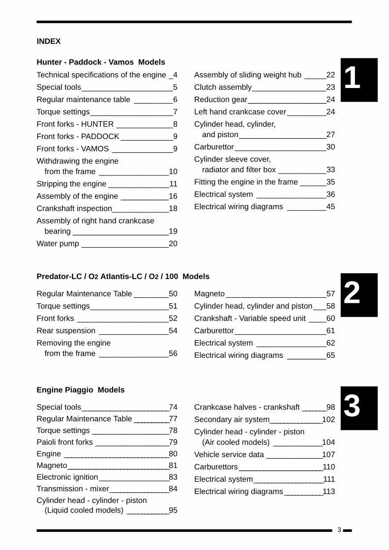
INDEX
Predator-LC / O2 Atlantis-LC / O2 / 100 Models
Hunter - Paddock - Vamos Models
Technical specifications of the engine _4
Special tools_____________________5
Regular maintenance table _________6
Torque settings___________________7
Front forks - HUNTER _____________8
Front forks - PADDOCK ____________9
Front forks - VAMOS ______________9
Withdrawing the engine from the frame ________________10
Stripping the engine ______________11
Assembly of the engine ___________16
Crankshaft inspection_____________18
Assembly of right hand crankcasebearing ______________________19
Water pump ____________________20
Assembly of sliding weight hub _____22
Clutch assembly_________________23
Reduction gear__________________24
Left hand crankcase cover_________24
Cylinder head, cylinder, and piston____________________27
Carburettor_____________________30
Cylinder sleeve cover, radiator and filter box ___________33
Fitting the engine in the frame ______35
Electrical system ________________36
Electrical wiring diagrams _________45
Regular Maintenance Table ________50
Torque settings__________________51
Front forks _____________________52
Rear suspension ________________54
Removing the engine from the frame ________________56
Magneto _______________________57
Cylinder head, cylinder and piston___58
Crankshaft - Variable speed unit ____60
Carburettor_____________________61
Electrical system ________________62
Electrical wiring diagrams _________65
Engine Piaggio Models
Special tools_________________________74
Regular Maintenance Table __________77
Torque settings ______________________78
Paioli front forks _____________________79
Engine ______________________________80
Magneto_____________________________81
Electronic ignition____________________83
Transmission - mixer_________________84
Cylinder head - cylinder - piston(Liquid cooled models) ____________95
Crankcase halves - crankshaft _______98
Secondary air system_______________102
Cylinder head - cylinder - piston(Air cooled models) ______________104
Vehicle service data ________________107
Carburettors________________________110
Electrical system____________________111
Electrical wiring diagrams___________113
1
2
3
4
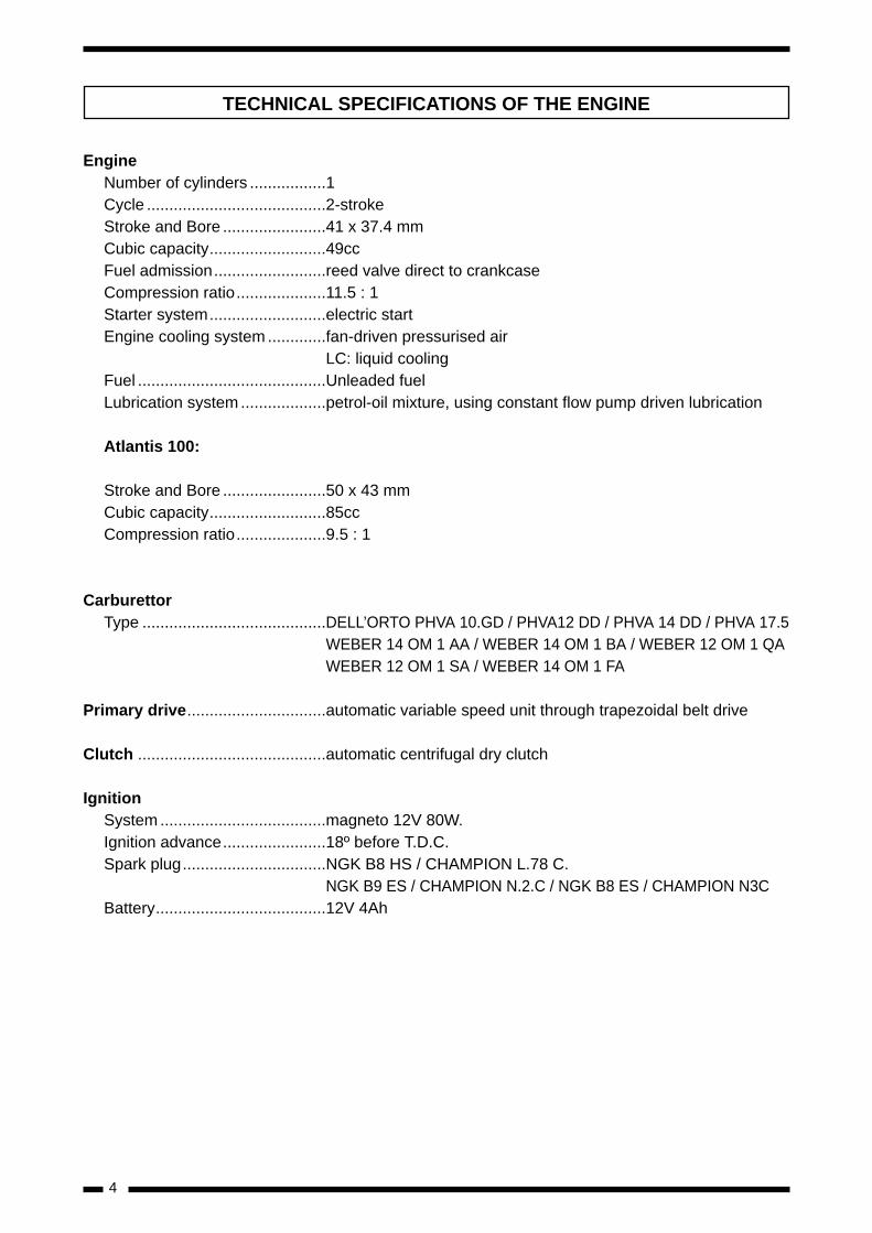
EngineNumber of cylinders .................1Cycle ........................................2-strokeStroke and Bore .......................41 x 37.4 mmCubic capacity..........................49ccFuel admission.........................reed valve direct to crankcaseCompression ratio....................11.5 : 1Starter system..........................electric startEngine cooling system .............fan-driven pressurised air
LC: liquid coolingFuel ..........................................Unleaded fuelLubrication system ...................petrol-oil mixture, using constant flow pump driven lubrication
Atlantis 100:
Stroke and Bore .......................50 x 43 mmCubic capacity..........................85ccCompression ratio....................9.5 : 1
CarburettorType .........................................DELL’ORTO PHVA 10.GD / PHVA12 DD / PHVA 14 DD / PHVA 17.5
WEBER 14 OM 1 AA / WEBER 14 OM 1 BA / WEBER 12 OM 1 QA WEBER 12 OM 1 SA / WEBER 14 OM 1 FA
Primary drive...............................automatic variable speed unit through trapezoidal belt drive
Clutch ..........................................automatic centrifugal dry clutch
IgnitionSystem .....................................magneto 12V 80W.Ignition advance.......................18º before T.D.C.Spark plug................................NGK B8 HS / CHAMPION L.78 C.
NGK B9 ES / CHAMPION N.2.C / NGK B8 ES / CHAMPION N3CBattery......................................12V 4Ah
TECHNICAL SPECIFICATIONS OF THE ENGINE
5
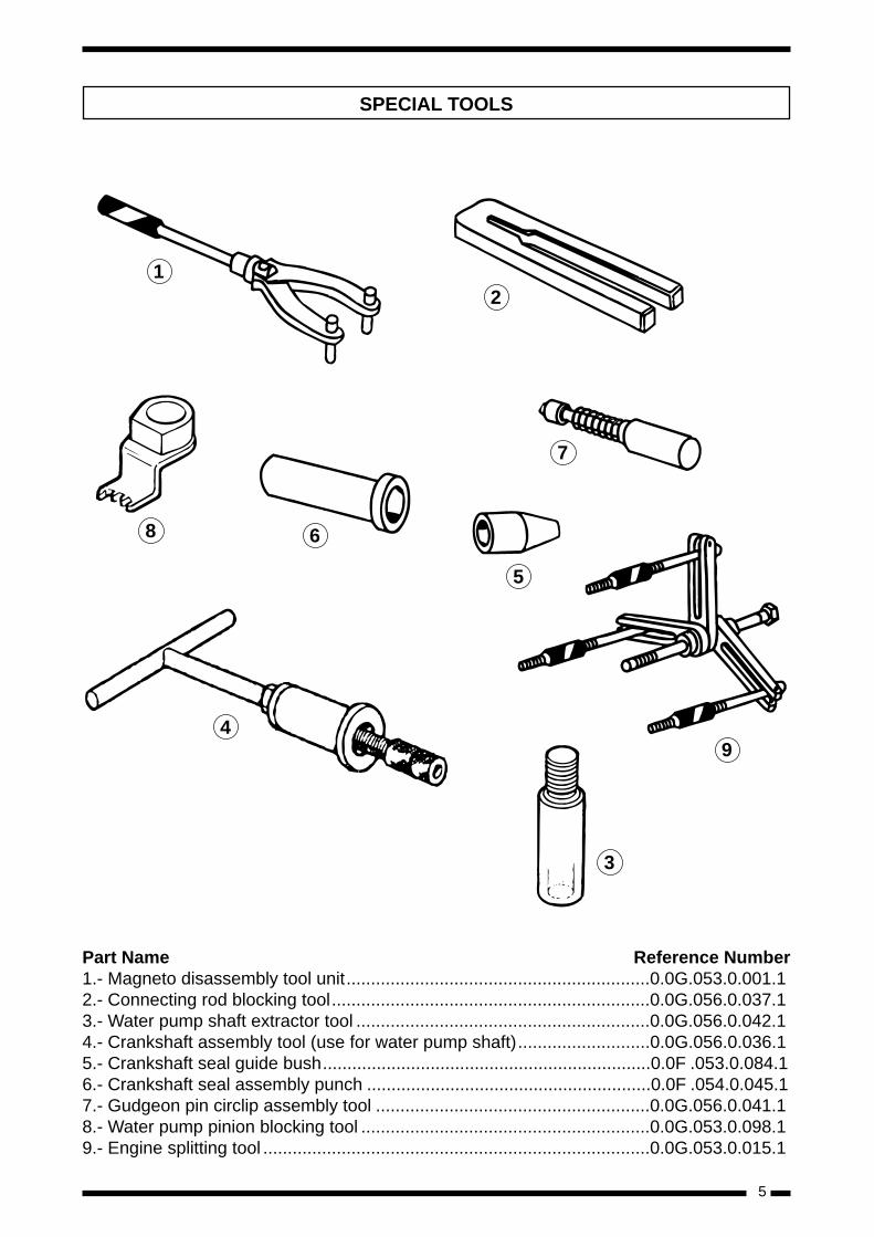
Part Name Reference Number1.- Magneto disassembly tool unit..............................................................0.0G.053.0.001.12.- Connecting rod blocking tool.................................................................0.0G.056.0.037.13.- Water pump shaft extractor tool ............................................................0.0G.056.0.042.14.- Crankshaft assembly tool (use for water pump shaft)...........................0.0G.056.0.036.15.- Crankshaft seal guide bush...................................................................0.0F .053.0.084.16.- Crankshaft seal assembly punch ..........................................................0.0F .054.0.045.17.- Gudgeon pin circlip assembly tool ........................................................0.0G.056.0.041.18.- Water pump pinion blocking tool ...........................................................0.0G.053.0.098.19.- Engine splitting tool ...............................................................................0.0G.053.0.015.1
SPECIAL TOOLS
1
8 6
4
5
3
9
7
2
6
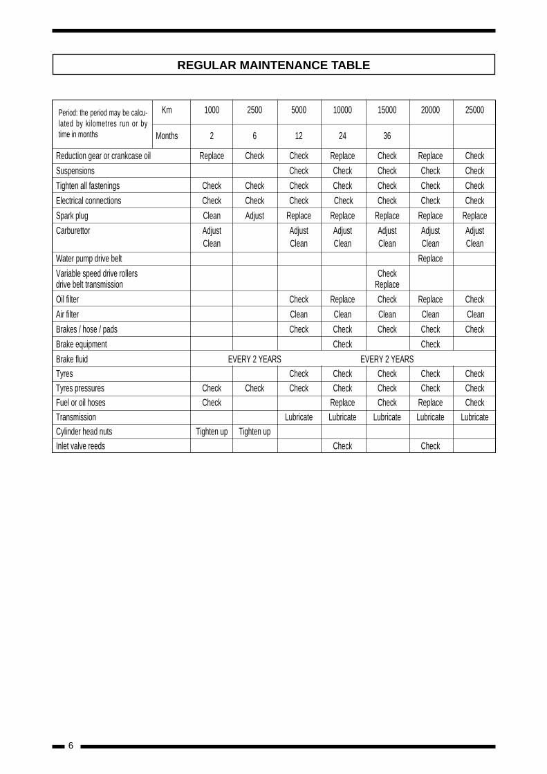
REGULAR MAINTENANCE TABLE
Período: este período puede Km 1000 2500 5000 10000 15000 20000 25000valorarse según los kilómetros
Months 2 6 12 24 36recorridos o el tiempo en meses
Reduction gear or crankcase oil Replace Check Check Replace Check Replace Check
Suspensions Check Check Check Check Check
Tighten all fastenings Check Check Check Check Check Check Check
Electrical connections Check Check Check Check Check Check Check
Spark plug Clean Adjust Replace Replace Replace Replace Replace
Carburettor Adjust Adjust Adjust Adjust Adjust AdjustClean Clean Clean Clean Clean Clean
Water pump drive belt Replace
Variable speed drive rollers Checkdrive belt transmission Replace
Oil filter Check Replace Check Replace Check
Air filter Clean Clean Clean Clean Clean
Brakes / hose / pads Check Check Check Check Check
Brake equipment Check Check
Brake fluid EVERY 2 YEARS EVERY 2 YEARS
Tyres Check Check Check Check Check
Tyres pressures Check Check Check Check Check Check Check
Fuel or oil hoses Check Replace Check Replace Check
Transmission Lubricate Lubricate Lubricate Lubricate Lubricate
Cylinder head nuts Tighten up Tighten up
Inlet valve reeds Check Check
Period: the period may be calcu-lated by kilometres run or bytime in months
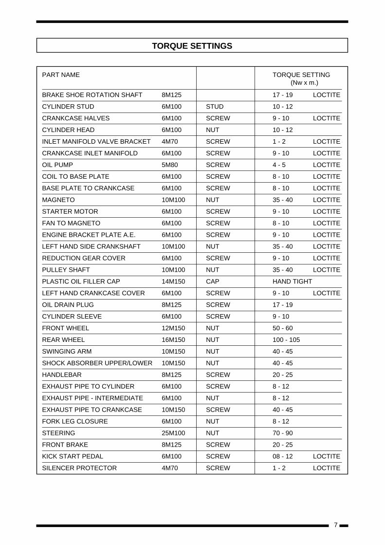
7
PART NAME TORQUE SETTING(Nw x m.)
BRAKE SHOE ROTATION SHAFT 8M125 17 - 19 LOCTITE
CYLINDER STUD 6M100 STUD 10 - 12
CRANKCASE HALVES 6M100 SCREW 9 - 10 LOCTITE
CYLINDER HEAD 6M100 NUT 10 - 12
INLET MANIFOLD VALVE BRACKET 4M70 SCREW 1 - 2 LOCTITE
CRANKCASE INLET MANIFOLD 6M100 SCREW 9 - 10 LOCTITE
OIL PUMP 5M80 SCREW 4 - 5 LOCTITE
COIL TO BASE PLATE 6M100 SCREW 8 - 10 LOCTITE
BASE PLATE TO CRANKCASE 6M100 SCREW 8 - 10 LOCTITE
MAGNETO 10M100 NUT 35 - 40 LOCTITE
STARTER MOTOR 6M100 SCREW 9 - 10 LOCTITE
FAN TO MAGNETO 6M100 SCREW 8 - 10 LOCTITE
ENGINE BRACKET PLATE A.E. 6M100 SCREW 9 - 10 LOCTITE
LEFT HAND SIDE CRANKSHAFT 10M100 NUT 35 - 40 LOCTITE
REDUCTION GEAR COVER 6M100 SCREW 9 - 10 LOCTITE
PULLEY SHAFT 10M100 NUT 35 - 40 LOCTITE
PLASTIC OIL FILLER CAP 14M150 CAP HAND TIGHT
LEFT HAND CRANKCASE COVER 6M100 SCREW 9 - 10 LOCTITE
OIL DRAIN PLUG 8M125 SCREW 17 - 19
CYLINDER SLEEVE 6M100 SCREW 9 - 10
FRONT WHEEL 12M150 NUT 50 - 60
REAR WHEEL 16M150 NUT 100 - 105
SWINGING ARM 10M150 NUT 40 - 45
SHOCK ABSORBER UPPER/LOWER 10M150 NUT 40 - 45
HANDLEBAR 8M125 SCREW 20 - 25
EXHAUST PIPE TO CYLINDER 6M100 SCREW 8 - 12
EXHAUST PIPE - INTERMEDIATE 6M100 NUT 8 - 12
EXHAUST PIPE TO CRANKCASE 10M150 SCREW 40 - 45
FORK LEG CLOSURE 6M100 NUT 8 - 12
STEERING 25M100 NUT 70 - 90
FRONT BRAKE 8M125 SCREW 20 - 25
KICK START PEDAL 6M100 SCREW 08 - 12 LOCTITE
SILENCER PROTECTOR 4M70 SCREW 1 - 2 LOCTITE
TORQUE SETTINGS
8
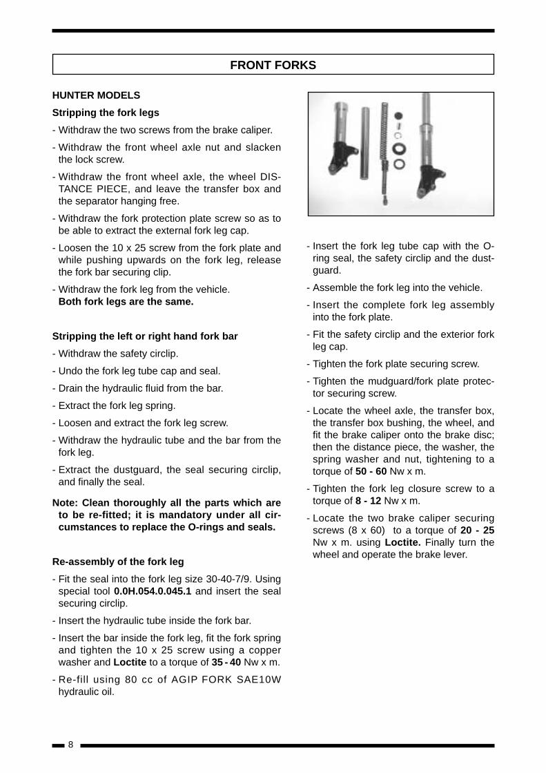
HUNTER MODELS
Stripping the fork legs
- Withdraw the two screws from the brake caliper.
- Withdraw the front wheel axle nut and slackenthe lock screw.
- Withdraw the front wheel axle, the wheel DIS-TANCE PIECE, and leave the transfer box andthe separator hanging free.
- Withdraw the fork protection plate screw so as tobe able to extract the external fork leg cap.
- Loosen the 10 x 25 screw from the fork plate andwhile pushing upwards on the fork leg, releasethe fork bar securing clip.
- Withdraw the fork leg from the vehicle.Both fork legs are the same.
Stripping the left or right hand fork bar
- Withdraw the safety circlip.
- Undo the fork leg tube cap and seal.
- Drain the hydraulic fluid from the bar.
- Extract the fork leg spring.
- Loosen and extract the fork leg screw.
- Withdraw the hydraulic tube and the bar from thefork leg.
- Extract the dustguard, the seal securing circlip,and finally the seal.
Note: Clean thoroughly all the parts which areto be re-fitted; it is mandatory under all cir-cumstances to replace the O-rings and seals.
Re-assembly of the fork leg
- Fit the seal into the fork leg size 30-40-7/9. Usingspecial tool 0.0H.054.0.045.1 and insert the sealsecuring circlip.
- Insert the hydraulic tube inside the fork bar.
- Insert the bar inside the fork leg, fit the fork springand tighten the 10 x 25 screw using a copperwasher and Loctite to a torque of 35 - 40 Nw x m.
- Re-fill using 80 cc of AGIP FORK SAE10Whydraulic oil.
FRONT FORKS
- Insert the fork leg tube cap with the O-ring seal, the safety circlip and the dust-guard.
- Assemble the fork leg into the vehicle.
- Insert the complete fork leg assemblyinto the fork plate.
- Fit the safety circlip and the exterior forkleg cap.
- Tighten the fork plate securing screw.
- Tighten the mudguard/fork plate protec-tor securing screw.
- Locate the wheel axle, the transfer box,the transfer box bushing, the wheel, andfit the brake caliper onto the brake disc;then the distance piece, the washer, thespring washer and nut, tightening to atorque of 50 - 60 Nw x m.
- Tighten the fork leg closure screw to atorque of 8 - 12 Nw x m.
- Locate the two brake caliper securingscrews (8 x 60) to a torque of 20 - 25Nw x m. using Loctite. Finally turn thewheel and operate the brake lever.
9
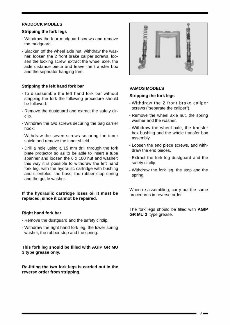
PADDOCK MODELS
Stripping the fork legs
- Withdraw the four mudguard screws and removethe mudguard.
- Slacken off the wheel axle nut, withdraw the was-her, loosen the 2 front brake caliper screws, loo-sen the locking screw, extract the wheel axle, theaxle distance piece and leave the transfer boxand the separator hanging free.
Stripping the left hand fork bar
- To disassemble the left hand fork bar withoutstripping the fork the following procedure shouldbe followed:
- Remove the dustguard and extract the safety cir-clip.
- Withdraw the two screws securing the bag carrierhook.
- Withdraw the seven screws securing the innershield and remove the inner shield.
- Drill a hole using a 15 mm drill through the forkplate protector so as to be able to insert a tubespanner and loosen the 6 x 100 nut and washer;this way it is possible to withdraw the left handfork leg, with the hydraulic cartridge with bushingand silentbloc, the boss, the rubber stop springand the guide washer.
If the hydraulic cartridge loses oil it must bereplaced, since it cannot be repaired.
Right hand fork bar
- Remove the dustguard and the safety circlip.
- Withdraw the right hand fork leg, the lower springwasher, the rubber stop and the spring.
This fork leg should be filled with AGIP GR MU3 type grease only.
Re-fitting the two fork legs is carried out in thereverse order from stripping.
VAMOS MODELS
Stripping the fork legs
- Withdraw the 2 front brake caliperscrews (“separate the caliper”).
- Remove the wheel axle nut, the springwasher and the washer.
- Withdraw the wheel axle, the transferbox bushing and the whole transfer boxassembly.
- Loosen the end piece screws, and with-draw the end pieces.
- Extract the fork leg dustguard and thesafety circlip.
- Withdraw the fork leg, the stop and thespring.
When re-assembling, carry out the sameprocedures in reverse order.
The fork legs should be filled with AGIPGR MU 3 type grease.
10
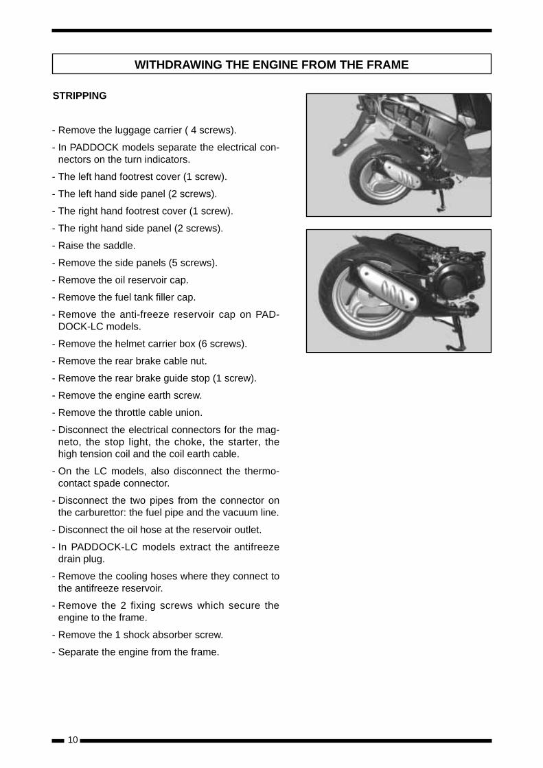
STRIPPING
- Remove the luggage carrier ( 4 screws).
- In PADDOCK models separate the electrical con-nectors on the turn indicators.
- The left hand footrest cover (1 screw).
- The left hand side panel (2 screws).
- The right hand footrest cover (1 screw).
- The right hand side panel (2 screws).
- Raise the saddle.
- Remove the side panels (5 screws).
- Remove the oil reservoir cap.
- Remove the fuel tank filler cap.
- Remove the anti-freeze reservoir cap on PAD-DOCK-LC models.
- Remove the helmet carrier box (6 screws).
- Remove the rear brake cable nut.
- Remove the rear brake guide stop (1 screw).
- Remove the engine earth screw.
- Remove the throttle cable union.
- Disconnect the electrical connectors for the mag-neto, the stop light, the choke, the starter, thehigh tension coil and the coil earth cable.
- On the LC models, also disconnect the thermo-contact spade connector.
- Disconnect the two pipes from the connector onthe carburettor: the fuel pipe and the vacuum line.
- Disconnect the oil hose at the reservoir outlet.
- In PADDOCK-LC models extract the antifreezedrain plug.
- Remove the cooling hoses where they connect tothe antifreeze reservoir.
- Remove the 2 fixing screws which secure theengine to the frame.
- Remove the 1 shock absorber screw.
- Separate the engine from the frame.
WITHDRAWING THE ENGINE FROM THE FRAME
11
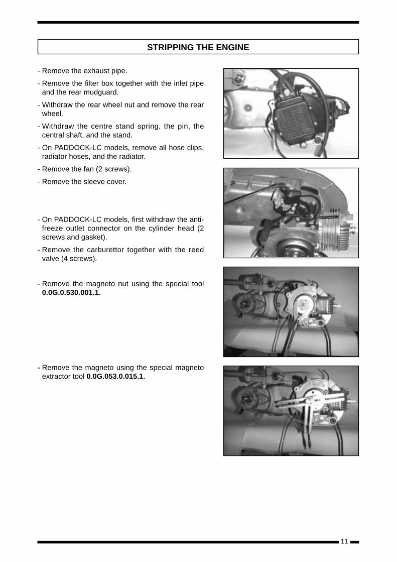
- Remove the exhaust pipe.
- Remove the filter box together with the inlet pipeand the rear mudguard.
- Withdraw the rear wheel nut and remove the rearwheel.
- Withdraw the centre stand spring, the pin, thecentral shaft, and the stand.
- On PADDOCK-LC models, remove all hose clips,radiator hoses, and the radiator.
- Remove the fan (2 screws).
- Remove the sleeve cover.
- On PADDOCK-LC models, first withdraw the anti-freeze outlet connector on the cylinder head (2screws and gasket).
- Remove the carburettor together with the reedvalve (4 screws).
- Remove the magneto nut using the special tool0.0G.0.530.001.1.
- Remove the magneto using the special magnetoextractor tool 0.0G.053.0.015.1.
STRIPPING THE ENGINE
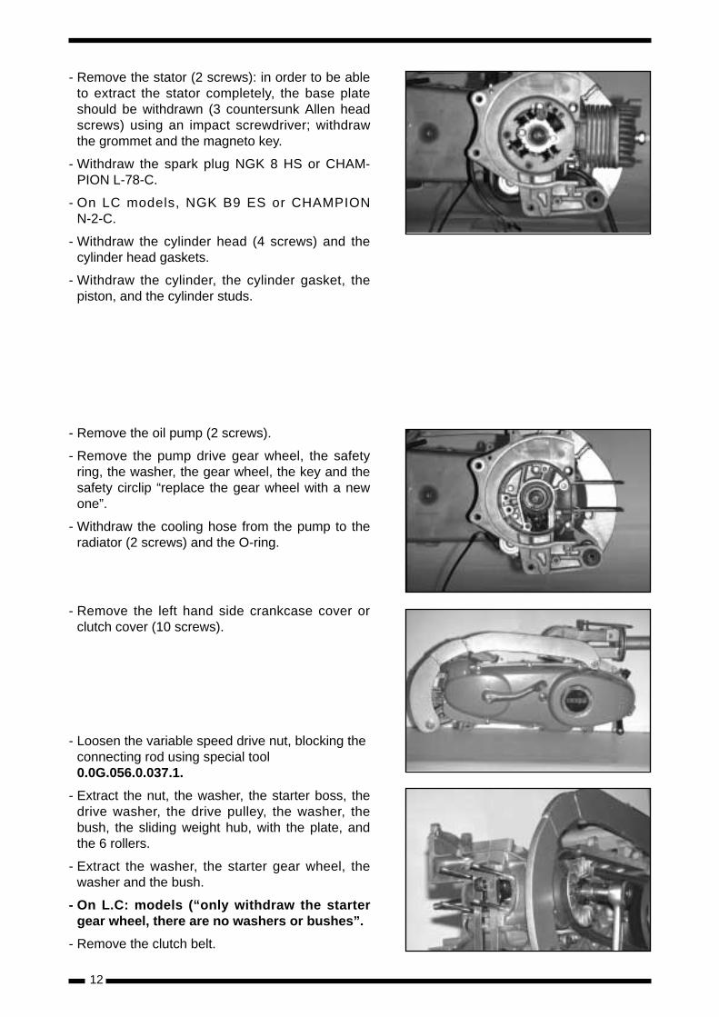
- Remove the stator (2 screws): in order to be ableto extract the stator completely, the base plateshould be withdrawn (3 countersunk Allen headscrews) using an impact screwdriver; withdrawthe grommet and the magneto key.
- Withdraw the spark plug NGK 8 HS or CHAM-PION L-78-C.
- On LC models, NGK B9 ES or CHAMPIONN-2-C.
- Withdraw the cylinder head (4 screws) and thecylinder head gaskets.
- Withdraw the cylinder, the cylinder gasket, thepiston, and the cylinder studs.
- Remove the oil pump (2 screws).
- Remove the pump drive gear wheel, the safetyring, the washer, the gear wheel, the key and thesafety circlip “replace the gear wheel with a newone”.
- Withdraw the cooling hose from the pump to theradiator (2 screws) and the O-ring.
- Remove the left hand side crankcase cover orclutch cover (10 screws).
- Loosen the variable speed drive nut, blocking theconnecting rod using special tool0.0G.056.0.037.1.
- Extract the nut, the washer, the starter boss, thedrive washer, the drive pulley, the washer, thebush, the sliding weight hub, with the plate, andthe 6 rollers.
- Extract the washer, the starter gear wheel, thewasher and the bush.
- On L.C: models (“only withdraw the startergear wheel, there are no washers or bushes”.
- Remove the clutch belt.
12
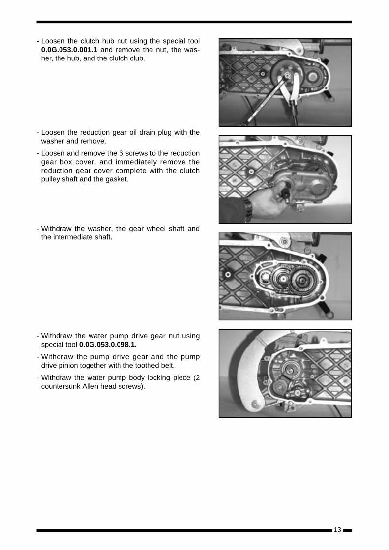
- Loosen the clutch hub nut using the special tool0.0G.053.0.001.1 and remove the nut, the was-her, the hub, and the clutch club.
- Loosen the reduction gear oil drain plug with thewasher and remove.
- Loosen and remove the 6 screws to the reductiongear box cover, and immediately remove thereduction gear cover complete with the clutchpulley shaft and the gasket.
- Withdraw the washer, the gear wheel shaft andthe intermediate shaft.
- Withdraw the water pump drive gear nut usingspecial tool 0.0G.053.0.098.1.
- Withdraw the pump drive gear and the pumpdrive pinion together with the toothed belt.
- Withdraw the water pump body locking piece (2countersunk Allen head screws).
13
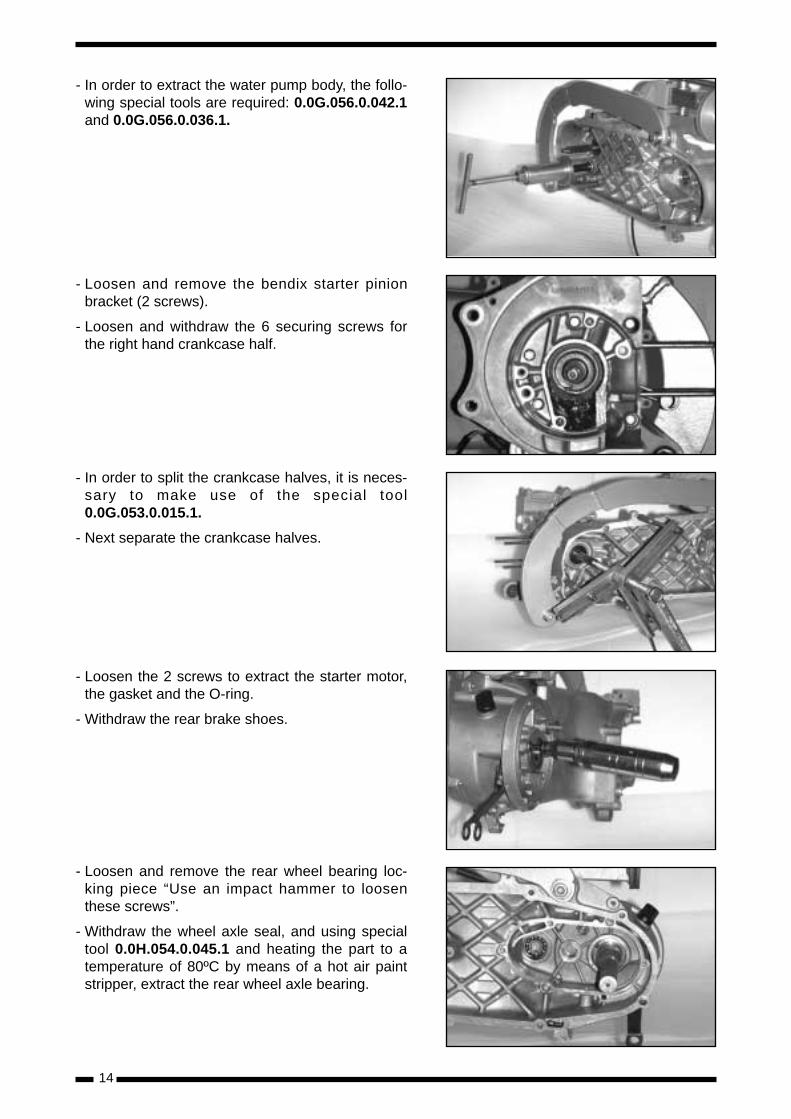
- In order to extract the water pump body, the follo-wing special tools are required: 0.0G.056.0.042.1and 0.0G.056.0.036.1.
- Loosen and remove the bendix starter pinionbracket (2 screws).
- Loosen and withdraw the 6 securing screws forthe right hand crankcase half.
- In order to split the crankcase halves, it is neces-sary to make use of the special tool0.0G.053.0.015.1.
- Next separate the crankcase halves.
- Loosen the 2 screws to extract the starter motor,the gasket and the O-ring.
- Withdraw the rear brake shoes.
- Loosen and remove the rear wheel bearing loc-king piece “Use an impact hammer to loosenthese screws”.
- Withdraw the wheel axle seal, and using specialtool 0.0H.054.0.045.1 and heating the part to atemperature of 80ºC by means of a hot air paintstripper, extract the rear wheel axle bearing.
14
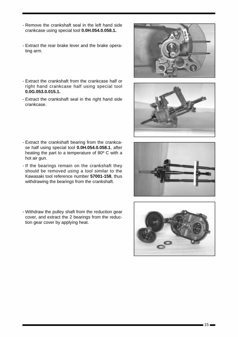
- Remove the crankshaft seal in the left hand sidecrankcase using special tool 0.0H.054.0.058.1.
- Extract the rear brake lever and the brake opera-ting arm.
- Extract the crankshaft from the crankcase half orright hand crankcase half using special tool0.0G.053.0.015.1.
- Extract the crankshaft seal in the right hand sidecrankcase.
- Extract the crankshaft bearing from the crankca-se half using special tool 0.0H.054.0.058.1, afterheating the part to a temperature of 80º C with ahot air gun.
- If the bearings remain on the crankshaft theyshould be removed using a tool similar to theKawasaki tool reference number 57001-158, thuswithdrawing the bearings from the crankshaft.
- Withdraw the pulley shaft from the reduction gearcover, and extract the 2 bearings from the reduc-tion gear cover by applying heat.
15
16
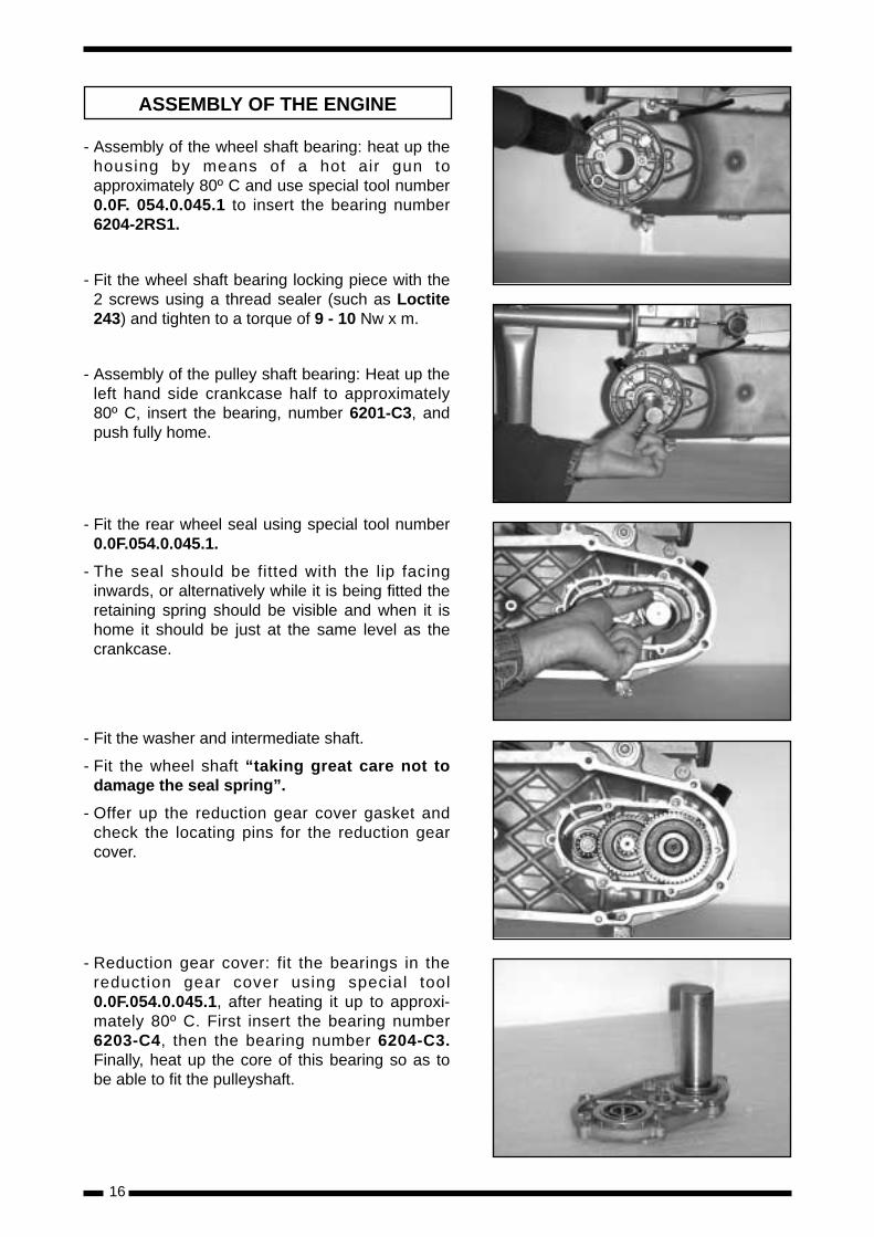
- Assembly of the wheel shaft bearing: heat up thehousing by means of a hot air gun toapproximately 80º C and use special tool number0.0F. 054.0.045.1 to insert the bearing number6204-2RS1.
- Fit the wheel shaft bearing locking piece with the2 screws using a thread sealer (such as Loctite243) and tighten to a torque of 9 - 10 Nw x m.
- Assembly of the pulley shaft bearing: Heat up theleft hand side crankcase half to approximately80º C, insert the bearing, number 6201-C3, andpush fully home.
- Fit the rear wheel seal using special tool number0.0F.054.0.045.1.
- The seal should be fitted with the lip facinginwards, or alternatively while it is being fitted theretaining spring should be visible and when it ishome it should be just at the same level as thecrankcase.
- Fit the washer and intermediate shaft.
- Fit the wheel shaft “taking great care not todamage the seal spring”.
- Offer up the reduction gear cover gasket andcheck the locating pins for the reduction gearcover.
- Reduction gear cover: fit the bearings in thereduction gear cover using special tool0.0F.054.0.045.1, after heating it up to approxi-mately 80º C. First insert the bearing number6203-C4, then the bearing number 6204-C3.Finally, heat up the core of this bearing so as tobe able to fit the pulleyshaft.
ASSEMBLY OF THE ENGINE
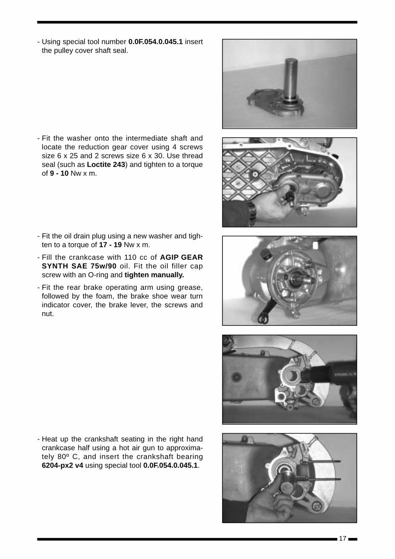
- Using special tool number 0.0F.054.0.045.1 insertthe pulley cover shaft seal.
- Fit the washer onto the intermediate shaft andlocate the reduction gear cover using 4 screwssize 6 x 25 and 2 screws size 6 x 30. Use threadseal (such as Loctite 243) and tighten to a torqueof 9 - 10 Nw x m.
- Fit the oil drain plug using a new washer and tigh-ten to a torque of 17 - 19 Nw x m.
- Fill the crankcase with 110 cc of AGIP GEARSYNTH SAE 75w/90 oil. Fit the oil filler capscrew with an O-ring and tighten manually.
- Fit the rear brake operating arm using grease,followed by the foam, the brake shoe wear turnindicator cover, the brake lever, the screws andnut.
- Heat up the crankshaft seating in the right handcrankcase half using a hot air gun to approxima-tely 80º C, and insert the crankshaft bearing6204-px2 v4 using special tool 0.0F.054.0.045.1.
17
18
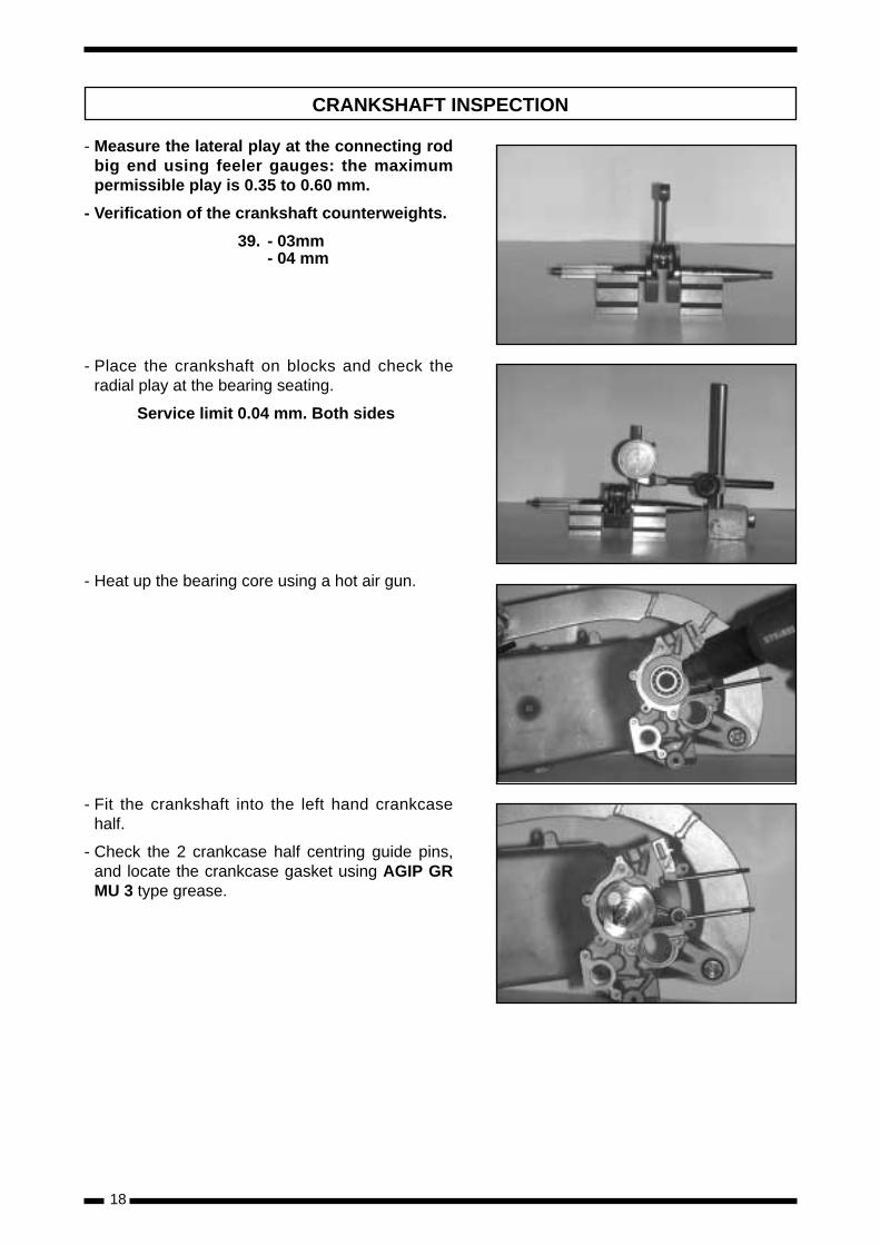
- Measure the lateral play at the connecting rodbig end using feeler gauges: the maximumpermissible play is 0.35 to 0.60 mm.
- Verification of the crankshaft counterweights.
39. - 03mm- 04 mm
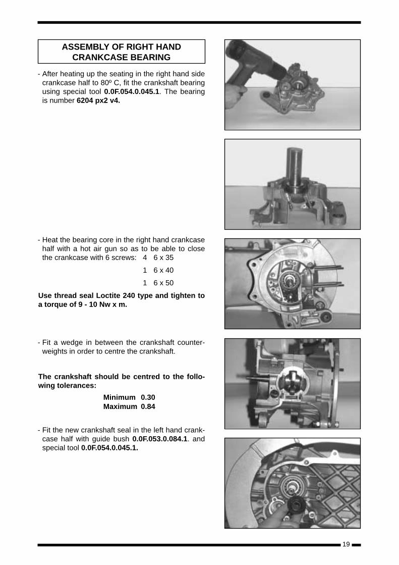
- Place the crankshaft on blocks and check theradial play at the bearing seating.
Service limit 0.04 mm. Both sides
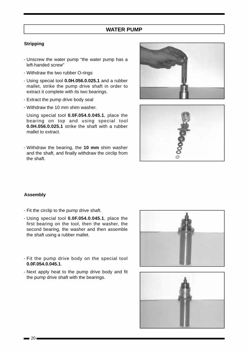
- Heat up the bearing core using a hot air gun.
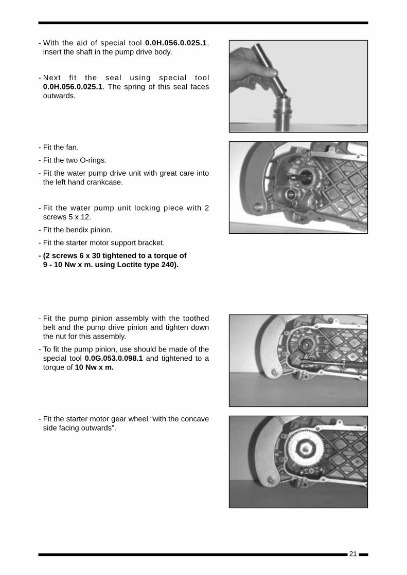
- Fit the crankshaft into the left hand crankcasehalf.
- Check the 2 crankcase half centring guide pins,and locate the crankcase gasket using AGIP GRMU 3 type grease.
CRANKSHAFT INSPECTION
19
- After heating up the seating in the right hand sidecrankcase half to 80º C, fit the crankshaft bearingusing special tool 0.0F.054.0.045.1. The bearingis number 6204 px2 v4.
- Heat the bearing core in the right hand crankcasehalf with a hot air gun so as to be able to closethe crankcase with 6 screws: 4 6 x 35
1 6 x 40
1 6 x 50
Use thread seal Loctite 240 type and tighten toa torque of 9 - 10 Nw x m.
- Fit a wedge in between the crankshaft counter-weights in order to centre the crankshaft.
The crankshaft should be centred to the follo-wing tolerances:
Minimum 0.30Maximum 0.84
- Fit the new crankshaft seal in the left hand crank-case half with guide bush 0.0F.053.0.084.1. andspecial tool 0.0F.054.0.045.1.
ASSEMBLY OF RIGHT HANDCRANKCASE BEARING
20
Stripping
- Unscrew the water pump “the water pump has aleft-handed screw”
- Withdraw the two rubber O-rings
- Using special tool 0.0H.056.0.025.1 and a rubbermallet, strike the pump drive shaft in order toextract it complete with its two bearings.
- Extract the pump drive body seal
- Withdraw the 10 mm shim washer.
Using special tool 0.0F.054.0.045.1, place thebearing on top and using special tool0.0H.056.0.025.1 strike the shaft with a rubbermallet to extract.
- Withdraw the bearing, the 10 mm shim washerand the shaft, and finally withdraw the circlip fromthe shaft.
Assembly
- Fit the circlip to the pump drive shaft.
- Using special tool 0.0F.054.0.045.1, place thefirst bearing on the tool, then the washer, thesecond bearing, the washer and then assemblethe shaft using a rubber mallet.
- Fit the pump drive body on the special tool0.0F.054.0.045.1.
- Next apply heat to the pump drive body and fitthe pump drive shaft with the bearings.
WATER PUMP
- With the aid of special tool 0.0H.056.0.025.1,insert the shaft in the pump drive body.
- Next f i t the seal using special tool0.0H.056.0.025.1. The spring of this seal facesoutwards.
- Fit the fan.
- Fit the two O-rings.
- Fit the water pump drive unit with great care intothe left hand crankcase.
- Fit the water pump unit locking piece with 2screws 5 x 12.
- Fit the bendix pinion.
- Fit the starter motor support bracket.
- (2 screws 6 x 30 tightened to a torque of 9 - 10 Nw x m. using Loctite type 240).
- Fit the pump pinion assembly with the toothedbelt and the pump drive pinion and tighten downthe nut for this assembly.
- To fit the pump pinion, use should be made of thespecial tool 0.0G.053.0.098.1 and tightened to atorque of 10 Nw x m.
- Fit the starter motor gear wheel “with the concaveside facing outwards”.
21
22
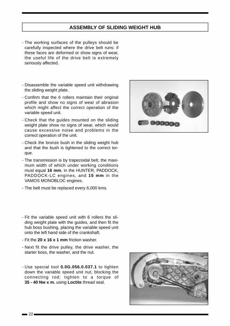
- The working surfaces of the pulleys should becarefully inspected where the drive belt runs: ifthese faces are deformed or show signs of wear,the useful life of the drive belt is extremelyseriously affected.
- Disassemble the variable speed unit withdrawingthe sliding weight plate.
- Confirm that the 6 rollers maintain their originalprofile and show no signs of wear of abrasionwhich might affect the correct operation of thevariable speed unit.
- Check that the guides mounted on the slidingweight plate show no signs of wear, which wouldcause excessive noise and problems in thecorrect operation of the unit.
- Check the bronze bush in the sliding weight huband that the bush is tightened to the correct tor-que.
- The transmission is by trapezoidal belt, the maxi-mum width of which under working conditionsmust equal 16 mm, in the HUNTER, PADDOCK,PADDOCK-LC engines, and 15 mm in theVAMOS MONOBLOC engines.
- The belt must be replaced every 6,000 kms.
- Fit the variable speed unit with 6 rollers the sli-ding weight plate with the guides, and then fit thehub boss bushing, placing the variable speed unitonto the left hand side of the crankshaft.
- Fit the 20 x 16 x 1 mm friction washer.
- Next fit the drive pulley, the drive washer, thestarter boss, the washer, and the nut.
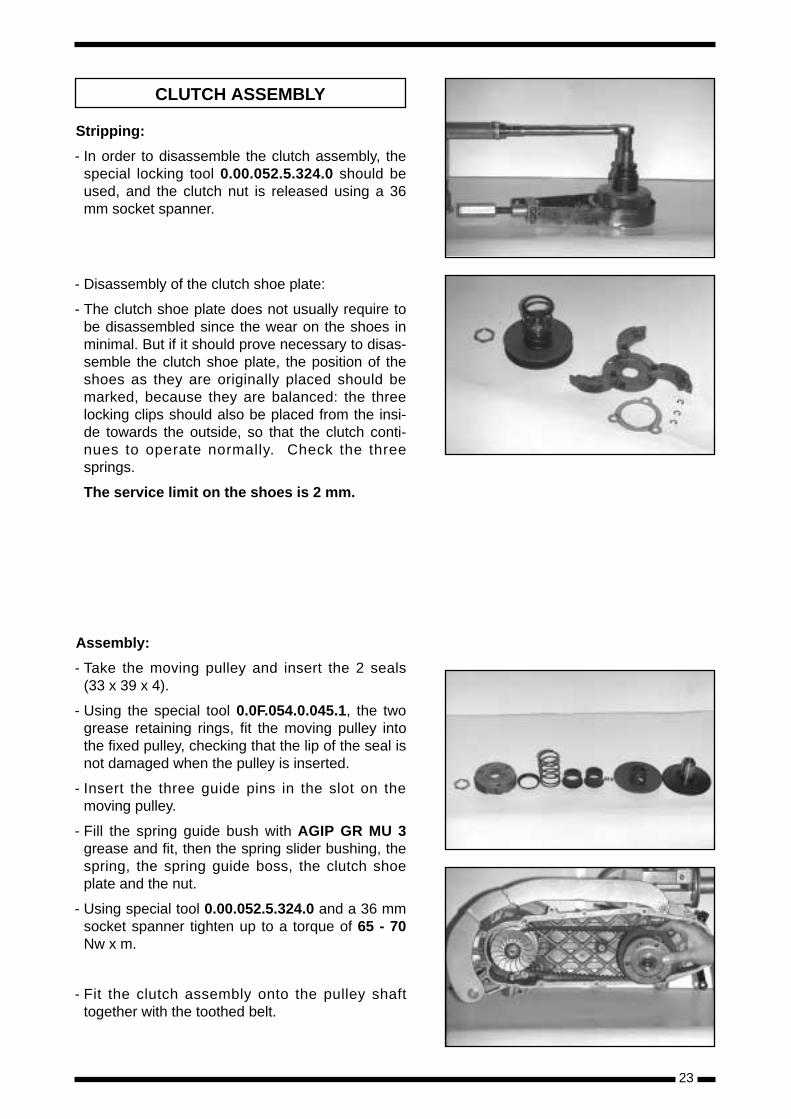
- Use special tool 0.0G.056.0.037.1 to tightendown the variable speed unit nut, blocking theconnecting rod; t ighten to a torque of35 - 40 Nw x m. using Loctite thread seal.
ASSEMBLY OF SLIDING WEIGHT HUB
23
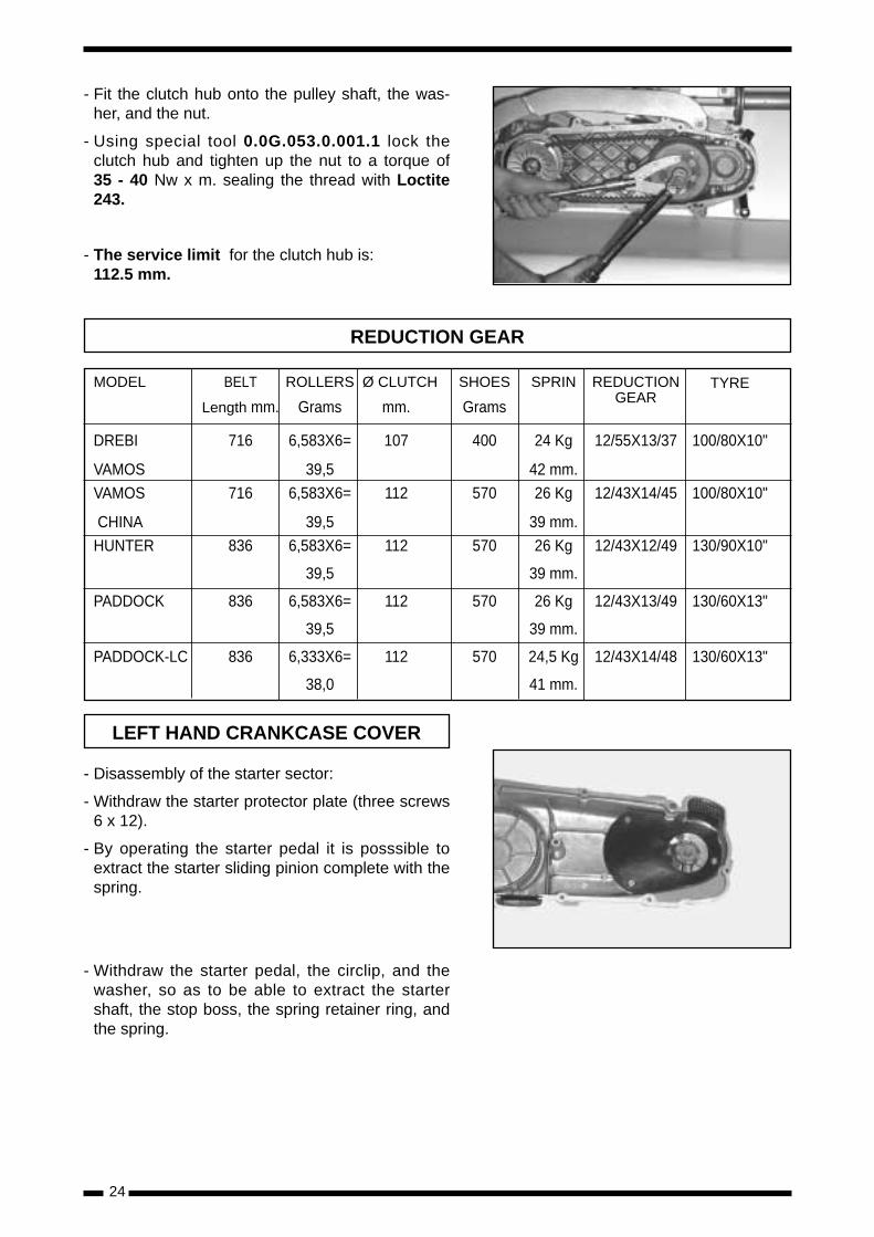
Stripping:
- In order to disassemble the clutch assembly, thespecial locking tool 0.00.052.5.324.0 should beused, and the clutch nut is released using a 36mm socket spanner.
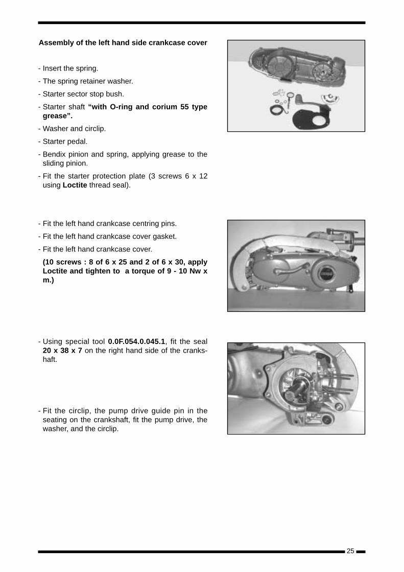
- Disassembly of the clutch shoe plate:
- The clutch shoe plate does not usually require tobe disassembled since the wear on the shoes inminimal. But if it should prove necessary to disas-semble the clutch shoe plate, the position of theshoes as they are originally placed should bemarked, because they are balanced: the threelocking clips should also be placed from the insi-de towards the outside, so that the clutch conti-nues to operate normally. Check the threesprings.
The service limit on the shoes is 2 mm.
Assembly:
- Take the moving pulley and insert the 2 seals(33 x 39 x 4).
- Using the special tool 0.0F.054.0.045.1, the twogrease retaining rings, fit the moving pulley intothe fixed pulley, checking that the lip of the seal isnot damaged when the pulley is inserted.
- Insert the three guide pins in the slot on themoving pulley.
- Fill the spring guide bush with AGIP GR MU 3grease and fit, then the spring slider bushing, thespring, the spring guide boss, the clutch shoeplate and the nut.
- Using special tool 0.00.052.5.324.0 and a 36 mmsocket spanner tighten up to a torque of 65 - 70Nw x m.
- Fit the clutch assembly onto the pulley shafttogether with the toothed belt.
CLUTCH ASSEMBLY
- Fit the clutch hub onto the pulley shaft, the was-her, and the nut.
- Using special tool 0.0G.053.0.001.1 lock theclutch hub and tighten up the nut to a torque of35 - 40 Nw x m. sealing the thread with Loctite243.
- The service limit for the clutch hub is: 112.5 mm.
- Disassembly of the starter sector:
- Withdraw the starter protector plate (three screws6 x 12).
- By operating the starter pedal it is posssible toextract the starter sliding pinion complete with thespring.
- Withdraw the starter pedal, the circlip, and thewasher, so as to be able to extract the startershaft, the stop boss, the spring retainer ring, andthe spring.
24
MODEL BELT ROLLERS Ø CLUTCH SHOES SPRIN REDUCTION GEAR
TYRE
Length mm. Grams mm. Grams
DREBI 716 6,583X6= 107 400 24 Kg 12/55X13/37 100/80X10"
VAMOS 39,5 42 mm.
VAMOS 716 6,583X6= 112 570 26 Kg 12/43X14/45 100/80X10"
CHINA 39,5 39 mm.
HUNTER 836 6,583X6= 112 570 26 Kg 12/43X12/49 130/90X10"
39,5 39 mm.
PADDOCK 836 6,583X6= 112 570 26 Kg 12/43X13/49 130/60X13"
39,5 39 mm.
PADDOCK-LC 836 6,333X6= 112 570 24,5 Kg 12/43X14/48 130/60X13"
38,0 41 mm.
REDUCTION GEAR
LEFT HAND CRANKCASE COVER
Assembly of the left hand side crankcase cover
- Insert the spring.
- The spring retainer washer.
- Starter sector stop bush.
- Starter shaft “with O-ring and corium 55 typegrease”.
- Washer and circlip.
- Starter pedal.
- Bendix pinion and spring, applying grease to thesliding pinion.
- Fit the starter protection plate (3 screws 6 x 12using Loctite thread seal).
- Fit the left hand crankcase centring pins.
- Fit the left hand crankcase cover gasket.
- Fit the left hand crankcase cover.
(10 screws : 8 of 6 x 25 and 2 of 6 x 30, applyLoctite and tighten to a torque of 9 - 10 Nw xm.)
- Using special tool 0.0F.054.0.045.1, fit the seal20 x 38 x 7 on the right hand side of the cranks-haft.
- Fit the circlip, the pump drive guide pin in theseating on the crankshaft, fit the pump drive, thewasher, and the circlip.
25
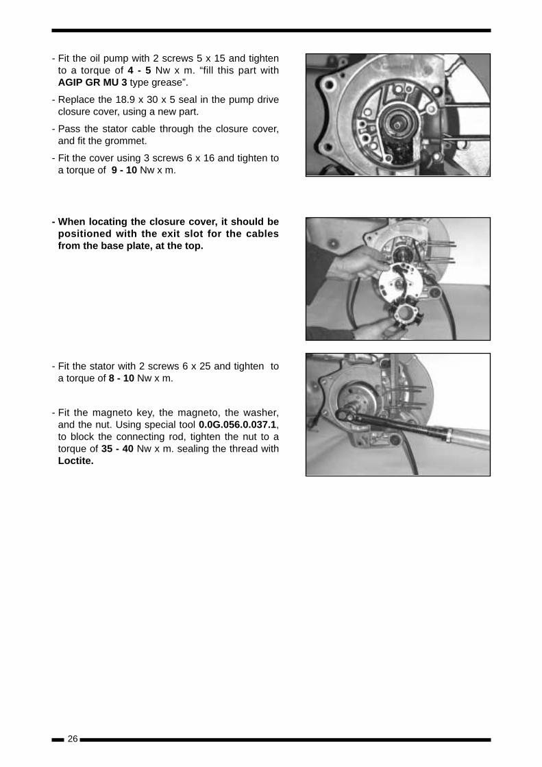
- Fit the oil pump with 2 screws 5 x 15 and tightento a torque of 4 - 5 Nw x m. “fill this part withAGIP GR MU 3 type grease”.
- Replace the 18.9 x 30 x 5 seal in the pump driveclosure cover, using a new part.
- Pass the stator cable through the closure cover,and fit the grommet.
- Fit the cover using 3 screws 6 x 16 and tighten toa torque of 9 - 10 Nw x m.
- When locating the closure cover, it should bepositioned with the exit slot for the cablesfrom the base plate, at the top.
- Fit the stator with 2 screws 6 x 25 and tighten toa torque of 8 - 10 Nw x m.
- Fit the magneto key, the magneto, the washer,and the nut. Using special tool 0.0G.056.0.037.1,to block the connecting rod, tighten the nut to atorque of 35 - 40 Nw x m. sealing the thread withLoctite.
26
27
- Fit a new cylinder gasket.
- Fit the cage bearing to the connecting rod littleend.
PISTON RINGS
- Fit the piston rings into the cylinder and use thepiston to push them a little way in, until they areperpendicular to the longitudinal axis of the cylin-der.
- Measure the gap between the ends of the pistonrings using feeler gauges.
The maximum permissible value is 0.5 mm.
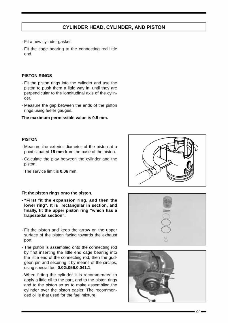
PISTON
- Measure the exterior diameter of the piston at apoint situated 15 mm from the base of the piston.
- Calculate the play between the cylinder and thepiston.
The service limit is 0.06 mm.
Fit the piston rings onto the piston.
- “First fit the expansion ring, and then thelower ring”. It is rectangular in section, andfinally, fit the upper piston ring “which has atrapezoidal section”.
- Fit the piston and keep the arrow on the uppersurface of the piston facing towards the exhaustport.
- The piston is assembled onto the connecting rodby first inserting the little end cage bearing intothe little end of the connecting rod, then the gud-geon pin and securing it by means of the circlips,using special tool 0.0G.056.0.041.1.
- When fitting the cylinder it is recommended toapply a little oil to the part, and to the piston ringsand to the piston so as to make assembling thecylinder over the piston easier. The recommen-ded oil is that used for the fuel mixture.
CYLINDER HEAD, CYLINDER, AND PISTON
- The cylinders of the monobloc models cannot berectified, and there are no oversizes. There areonly families of cylinders and pistons, which go insteps of 0.005 mm.
- When replacing the piston, the family identifica-tion stamped on the cylinder should be identified,and a piston of the same letter as on the cylindershould be used.
Table of tolerances for cylinder and piston
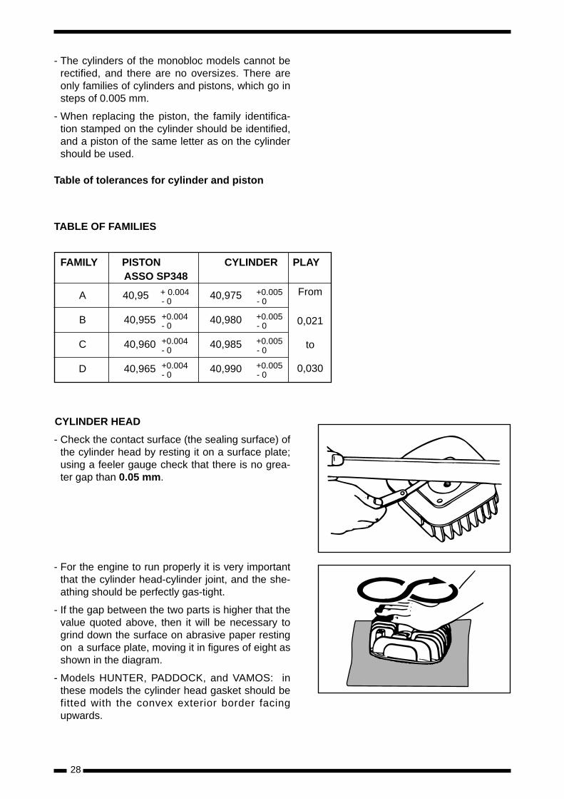
CYLINDER HEAD
- Check the contact surface (the sealing surface) ofthe cylinder head by resting it on a surface plate;using a feeler gauge check that there is no grea-ter gap than 0.05 mm.
- For the engine to run properly it is very importantthat the cylinder head-cylinder joint, and the she-athing should be perfectly gas-tight.
- If the gap between the two parts is higher that thevalue quoted above, then it will be necessary togrind down the surface on abrasive paper restingon a surface plate, moving it in figures of eight asshown in the diagram.
- Models HUNTER, PADDOCK, and VAMOS: inthese models the cylinder head gasket should befitted with the convex exterior border facingupwards.
28
TABLE OF FAMILIES
FAMILY PISTON CYLINDER PLAYASSO SP348
A 40,95 + 0.004 40,975 +0.005- 0 - 0
B 40,955 +0.004 40,980 +0.005- 0 - 0
C 40,960 +0.004 40,985 +0.005- 0 - 0
D 40,965 +0.004 40,990 +0.005- 0 - 0
From
0,021
to
0,030
- In the case of the PADDOCK-LC model the gas-kets must be changed every time the cylinderhead is removed.
- Fit the cylinder head gaskets.
- Fit the cylinder head and tighten up the four 6mm nuts to a torque of 10 - 12 Nw x m. using atorque spanner.
- Fit the copper gasket and the thermocontact to atorque of 18 - 20 Nw x m.
- Fit the spark plug and tighten to a torque of18 - 20 Nw x m.
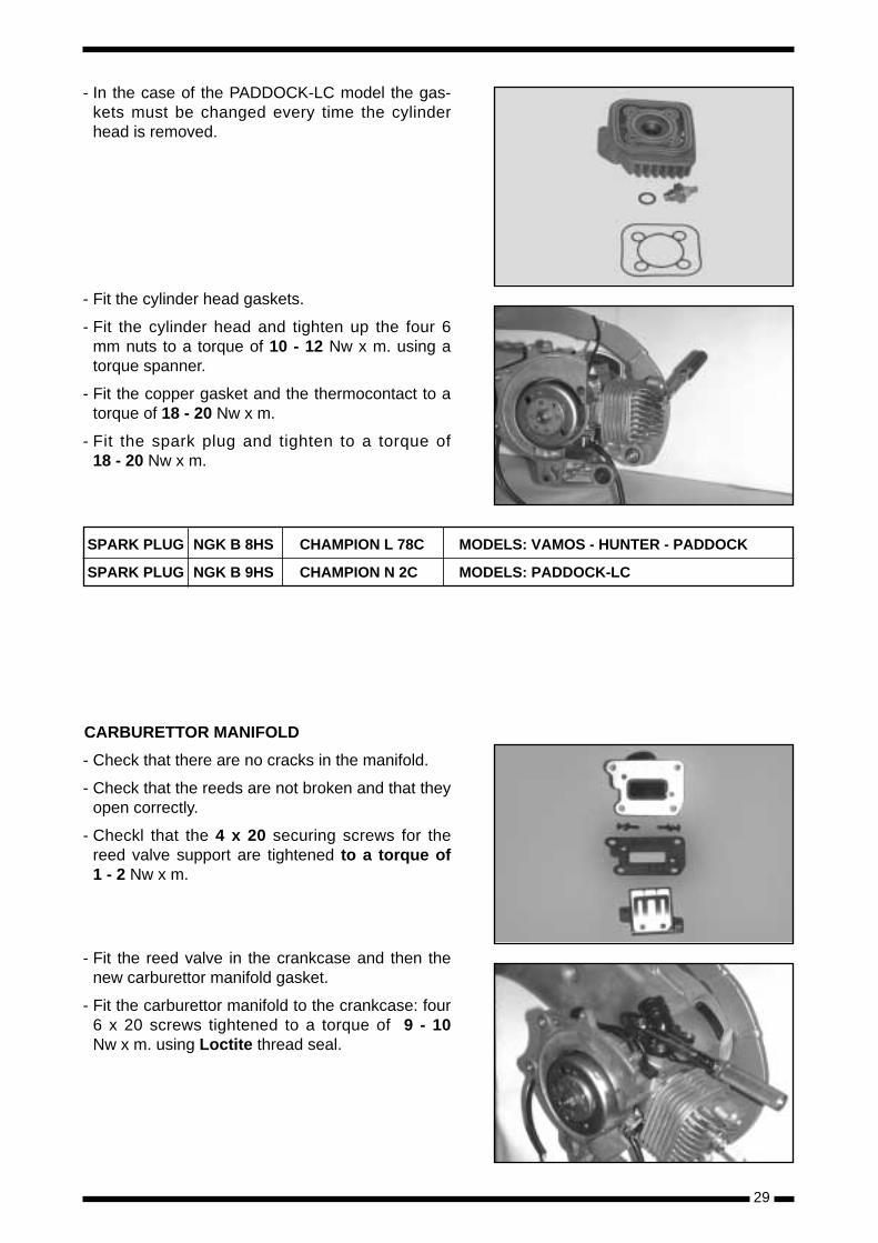
CARBURETTOR MANIFOLD
- Check that there are no cracks in the manifold.
- Check that the reeds are not broken and that theyopen correctly.
- Checkl that the 4 x 20 securing screws for thereed valve support are tightened to a torque of1 - 2 Nw x m.
- Fit the reed valve in the crankcase and then thenew carburettor manifold gasket.
- Fit the carburettor manifold to the crankcase: four6 x 20 screws tightened to a torque of 9 - 10Nw x m. using Loctite thread seal.
29
SPARK PLUG NGK B 8HS CHAMPION L 78C MODELS: VAMOS - HUNTER - PADDOCK
SPARK PLUG NGK B 9HS CHAMPION N 2C MODELS: PADDOCK-LC
30
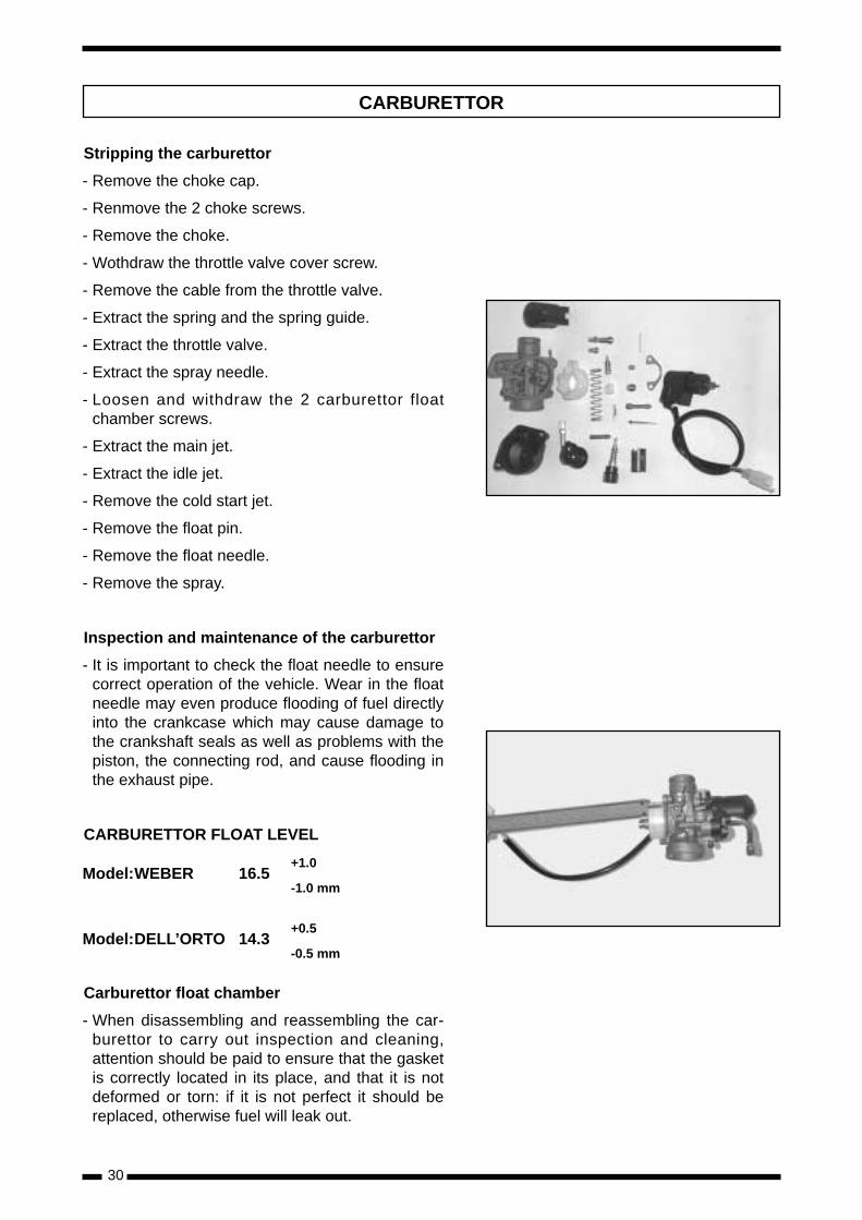
Stripping the carburettor
- Remove the choke cap.
- Renmove the 2 choke screws.
- Remove the choke.
- Wothdraw the throttle valve cover screw.
- Remove the cable from the throttle valve.
- Extract the spring and the spring guide.
- Extract the throttle valve.
- Extract the spray needle.
- Loosen and withdraw the 2 carburettor floatchamber screws.
- Extract the main jet.
- Extract the idle jet.
- Remove the cold start jet.
- Remove the float pin.
- Remove the float needle.
- Remove the spray.
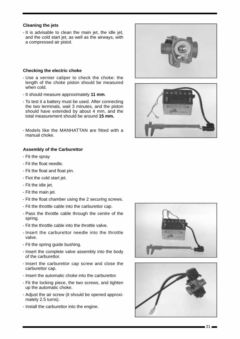
Inspection and maintenance of the carburettor
- It is important to check the float needle to ensurecorrect operation of the vehicle. Wear in the floatneedle may even produce flooding of fuel directlyinto the crankcase which may cause damage tothe crankshaft seals as well as problems with thepiston, the connecting rod, and cause flooding inthe exhaust pipe.
CARBURETTOR FLOAT LEVEL
Model:WEBER 16.5+1.0
-1.0 mm
Model:DELL’ORTO 14.3+0.5
-0.5 mm
Carburettor float chamber
- When disassembling and reassembling the car-burettor to carry out inspection and cleaning,attention should be paid to ensure that the gasketis correctly located in its place, and that it is notdeformed or torn: if it is not perfect it should bereplaced, otherwise fuel will leak out.
CARBURETTOR
Cleaning the jets
- It is advisable to clean the main jet, the idle jet,and the cold start jet, as well as the airways, witha compressed air pistol.
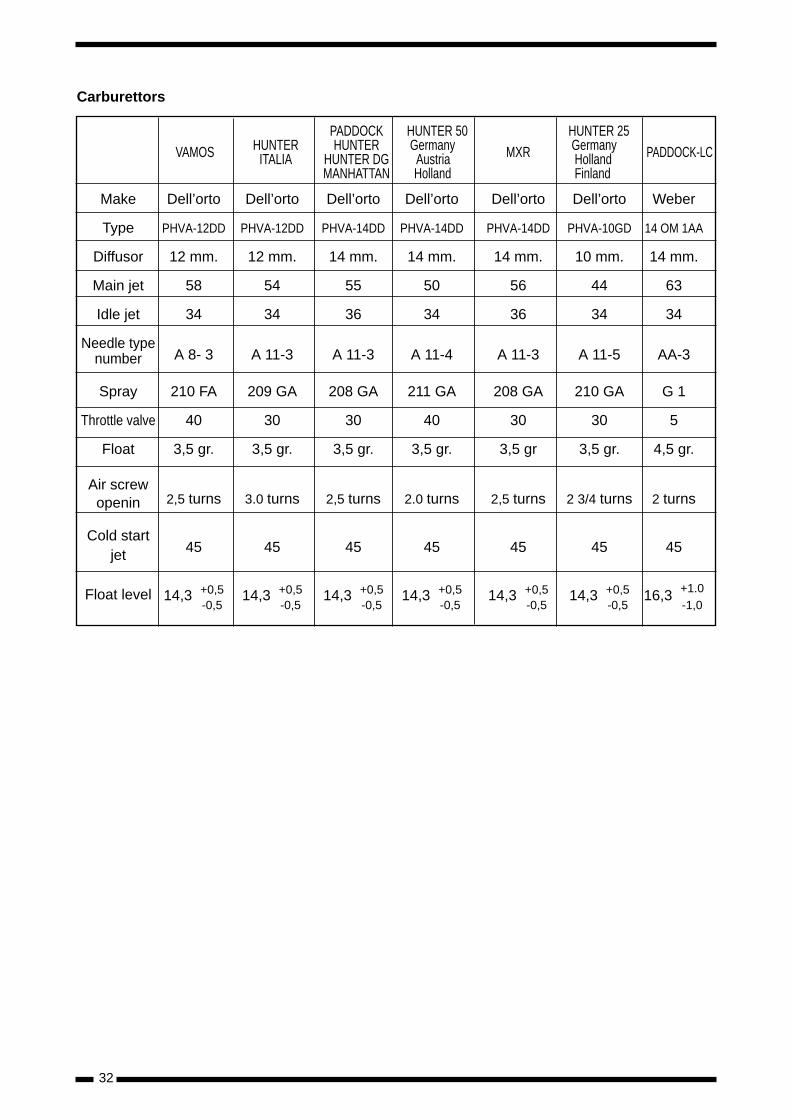
Checking the electric choke
- Use a vernier caliper to check the choke: thelength of the choke piston should be measuredwhen cold.
- It should measure approximately 11 mm.
- To test it a battery must be used. After connectingthe two terminals, wait 3 minutes, and the pistonshould have extended by about 4 mm, and thetotal measurement should be around 15 mm.
- Models like the MANHATTAN are fitted with amanual choke.
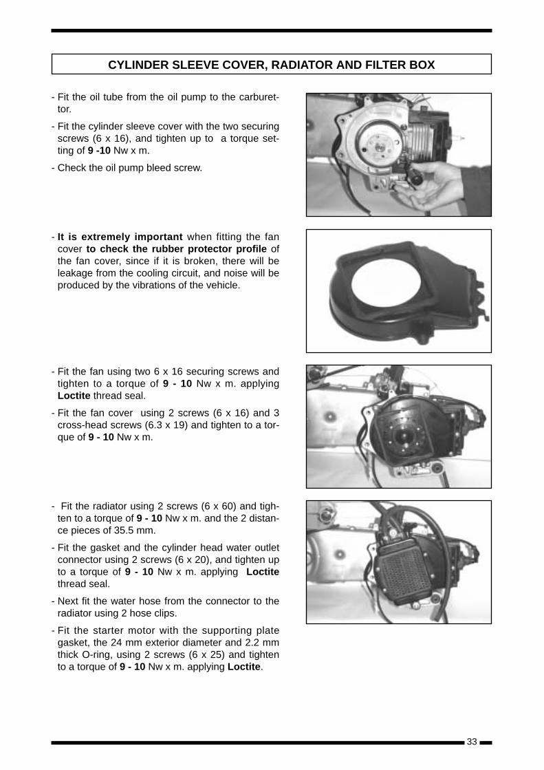
Assembly of the Carburettor
- Fit the spray
- Fit the float needle.
- Fit the float and float pin.
- Fiot the cold start jet.
- Fit the idle jet.
- Fit the main jet.
- Fit the float chamber using the 2 securing screws.
- Fit the throttle cable into the carburettor cap.
- Pass the throttle cable through the centre of thespring.
- Fit the throttle cable into the throttle valve.
- Insert the carburettor needle into the throttlevalve.
- Fit the spring guide bushing.
- Insert the complete valve assembly into the bodyof the carburettor.
- Insert the carburettor cap screw and close thecarburettor cap.
- Insert the automatic choke into the carburettor.
- Fit the locking piece, the two screws, and tightenup the automatic choke.
- Adjust the air screw (it should be opened approxi-mately 2.5 turns).
- Install the carburettor into the engine.
31
32
Make Dell’orto Dell’orto Dell’orto Dell’orto Dell’orto Dell’orto Weber
Type PHVA-12DD PHVA-12DD PHVA-14DD PHVA-14DD PHVA-14DD PHVA-10GD 14 OM 1AA
Diffusor 12 mm. 12 mm. 14 mm. 14 mm. 14 mm. 10 mm. 14 mm.
Main jet 58 54 55 50 56 44 63
Idle jet 34 34 36 34 36 34 34
Needle type number A 8- 3 A 11-3 A 11-3 A 11-4 A 11-3 A 11-5 AA-3
Spray 210 FA 209 GA 208 GA 211 GA 208 GA 210 GA G 1
Throttle valve 40 30 30 40 30 30 5
Float 3,5 gr. 3,5 gr. 3,5 gr. 3,5 gr. 3,5 gr 3,5 gr. 4,5 gr.
Air screw openin 2,5 turns 3.0 turns 2,5 turns 2.0 turns 2,5 turns 2 3/4 turns 2 turns
Cold start jet 45 45 45 45 45 45 45
Float level 14,3 +0,5 14,3 +0,5 14,3 +0,5 14,3 +0,5 14,3 +0,5 14,3 +0,5 16,3 +1.0-0,5 -0,5 -0,5 -0,5 -0,5 -0,5 -1,0
VAMOS HUNTERITALIA
PADDOCKHUNTER
HUNTER DGMANHATTAN
HUNTER 50Germany
AustriaHolland
MXR
HUNTER 25GermanyHollandFinland
PADDOCK-LC
Carburettors
33
- Fit the oil tube from the oil pump to the carburet-tor.
- Fit the cylinder sleeve cover with the two securingscrews (6 x 16), and tighten up to a torque set-ting of 9 -10 Nw x m.
- Check the oil pump bleed screw.
- It is extremely important when fitting the fancover to check the rubber protector profile ofthe fan cover, since if it is broken, there will beleakage from the cooling circuit, and noise will beproduced by the vibrations of the vehicle.
- Fit the fan using two 6 x 16 securing screws andtighten to a torque of 9 - 10 Nw x m. applyingLoctite thread seal.
- Fit the fan cover using 2 screws (6 x 16) and 3cross-head screws (6.3 x 19) and tighten to a tor-que of 9 - 10 Nw x m.
- Fit the radiator using 2 screws (6 x 60) and tigh-ten to a torque of 9 - 10 Nw x m. and the 2 distan-ce pieces of 35.5 mm.
- Fit the gasket and the cylinder head water outletconnector using 2 screws (6 x 20), and tighten upto a torque of 9 - 10 Nw x m. applying Loctitethread seal.
- Next fit the water hose from the connector to theradiator using 2 hose clips.
- Fit the starter motor with the supporting plategasket, the 24 mm exterior diameter and 2.2 mmthick O-ring, using 2 screws (6 x 25) and tightento a torque of 9 - 10 Nw x m. applying Loctite.
CYLINDER SLEEVE COVER, RADIATOR AND FILTER BOX
- Fit the cooling hose from the water pump to theradiator with an O-ring (using 1 screw 6 x 16) andtighten to a torque of 9 - 10 Nw x m. applyingLoctite.
- Then also fit 1 screw (6 x 10) to a torque of9 - 10 Nw x m. which is secured to the crankcase,applying Loctite.
- At the lowest part of the cooling hose the coolingliquid drain screw and washer are to be found.The washer must be replaced every time thescrew is touched.
- Fit the oil drain plug (8 x 16 screw) with a newwasher and tighten to a torque of 17 - 19 Nw x m.
- Fil l the reduction gearbox with 110 cc ofAGIP GEAR SYNTH SAE 75w/90 oil.
- Next fit the filler cap and tighten to hand tightonly.
- Fit the rear brake shoes, where the assembledposition of the shoes must be with the bevellededges facing outwards.
- Fit the centre stand inserting the shaft from left toright, complete with washer, pin and stand spring.
- Fit the rear wheel on its shaft, with washer andnut and tighten to a torque of 100 - 105 Nw x m.
- Fit the filter box using 2 screws (6 x 35) and tigh-ten to a torque of 9 - 10 Nw x m.
- Tighten up the drainage tank securing screw.
- Fit the inlet tube “with the spring to the carburet-tor”.
- Fit the rear mudguard using 2 screws (5.1 x 18).
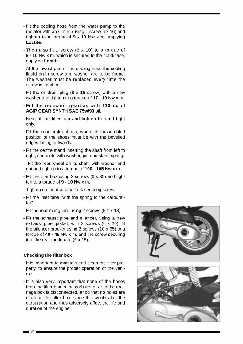
- Fit the exhaust pipe and silencer, using a newexhaust pipe gasket, with 2 screws (6 x 20); fitthe silencer bracket using 2 screws (10 x 65) to atorque of 40 - 45 Nw x m. and the screw securingit to the rear mudguard (5 x 15).
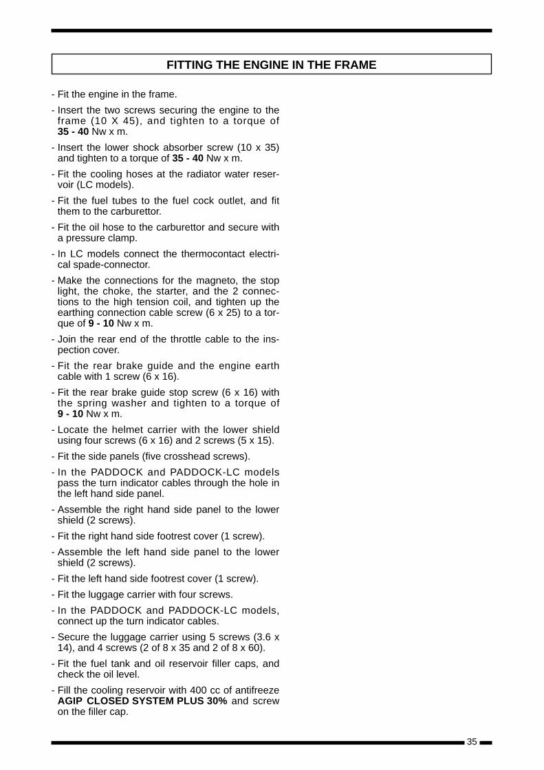
Checking the filter box
- It is important to maintain and clean the filter pro-perly, to ensure the proper operation of the vehi-cle.
- It is also very important that none of the hosesfrom the filter box to the carburettor or to the drai-nage box is disconnected, anbd that no holes aremade in the filter box, since this would alter thecarburation and thus adversely affect the life andduration of the engine.
34
35
- Fit the engine in the frame.
- Insert the two screws securing the engine to theframe (10 X 45), and tighten to a torque of35 - 40 Nw x m.
- Insert the lower shock absorber screw (10 x 35)and tighten to a torque of 35 - 40 Nw x m.
- Fit the cooling hoses at the radiator water reser-voir (LC models).
- Fit the fuel tubes to the fuel cock outlet, and fitthem to the carburettor.
- Fit the oil hose to the carburettor and secure witha pressure clamp.
- In LC models connect the thermocontact electri-cal spade-connector.
- Make the connections for the magneto, the stoplight, the choke, the starter, and the 2 connec-tions to the high tension coil, and tighten up theearthing connection cable screw (6 x 25) to a tor-que of 9 - 10 Nw x m.
- Join the rear end of the throttle cable to the ins-pection cover.
- Fit the rear brake guide and the engine earthcable with 1 screw (6 x 16).
- Fit the rear brake guide stop screw (6 x 16) withthe spring washer and tighten to a torque of9 - 10 Nw x m.
- Locate the helmet carrier with the lower shieldusing four screws (6 x 16) and 2 screws (5 x 15).
- Fit the side panels (five crosshead screws).
- In the PADDOCK and PADDOCK-LC modelspass the turn indicator cables through the hole inthe left hand side panel.
- Assemble the right hand side panel to the lowershield (2 screws).
- Fit the right hand side footrest cover (1 screw).
- Assemble the left hand side panel to the lowershield (2 screws).
- Fit the left hand side footrest cover (1 screw).
- Fit the luggage carrier with four screws.
- In the PADDOCK and PADDOCK-LC models,connect up the turn indicator cables.
- Secure the luggage carrier using 5 screws (3.6 x14), and 4 screws (2 of 8 x 35 and 2 of 8 x 60).
- Fit the fuel tank and oil reservoir filler caps, andcheck the oil level.
- Fill the cooling reservoir with 400 cc of antifreezeAGIP CLOSED SYSTEM PLUS 30% and screwon the filler cap.
FITTING THE ENGINE IN THE FRAME
36
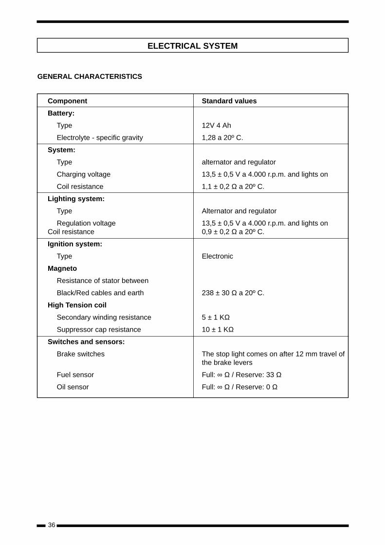
GENERAL CHARACTERISTICS
Component Standard values
Battery:
Type 12V 4 Ah
Electrolyte - specific gravity 1,28 a 20º C.
System:
Type alternator and regulator
Charging voltage 13,5 ± 0,5 V a 4.000 r.p.m. and lights on
Coil resistance 1,1 ± 0,2 Ω a 20º C.
Lighting system:
Type Alternator and regulator
Regulation voltage 13,5 ± 0,5 V a 4.000 r.p.m. and lights onCoil resistance 0,9 ± 0,2 Ω a 20º C.
Ignition system:
Type Electronic
Magneto
Resistance of stator between
Black/Red cables and earth 238 ± 30 Ω a 20º C.
High Tension coil
Secondary winding resistance 5 ± 1 KΩ
Suppressor cap resistance 10 ± 1 KΩ
Switches and sensors:
Brake switches The stop light comes on after 12 mm travel of the brake levers
Fuel sensor Full: ∞ Ω / Reserve: 33 Ω
Oil sensor Full: ∞ Ω / Reserve: 0 Ω
ELECTRICAL SYSTEM
BATTERY
Warnings:
- Never reverse the polarity of the battery. Thiscould cause damage to certain electronic compo-nents.
- The battery produces explosive gases. Do notmake sparks or flames near the battery, and parti-cularly when the battery is charging.
- The electrolyte in the battery contains sulphuricacid. If this acid comes into contact with the skinit causes burns. Wash the affected area withplentiful water and consult a doctor.
- In order to avoid mechanical failures do not dis-connect the battery terminals or other connec-tions unless the ignition switch is in the “OFF”position.
- Always use a slow charge whenever possible. Arapid charge should only be used in cases ofemergency and then only for a short time, since itmay damage the battery.
- It is advisable to remove the battery fropm thevehicle in order to charge it.
- Keep the breather tube clear of obstructions, par-ticularly during charging.
IMPORTANT
Batteries lose charge when they are not used. Donot leave the battery for more than a month wit-hout recharging, and reduce the recharging inter-val to a fortnight after the first month.
37
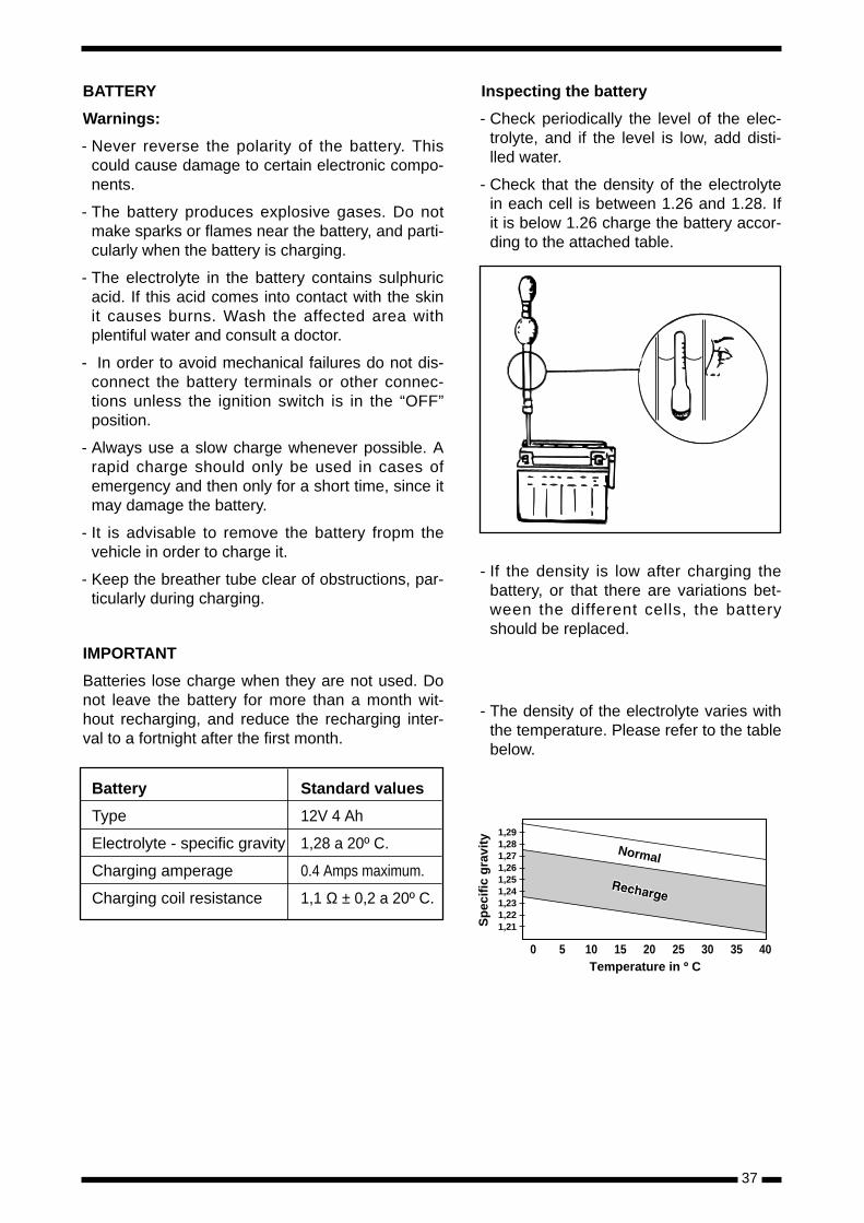
Inspecting the battery
- Check periodically the level of the elec-trolyte, and if the level is low, add disti-lled water.
- Check that the density of the electrolytein each cell is between 1.26 and 1.28. Ifit is below 1.26 charge the battery accor-ding to the attached table.
- If the density is low after charging thebattery, or that there are variations bet-ween the different cells, the batteryshould be replaced.
- The density of the electrolyte varies withthe temperature. Please refer to the tablebelow.
0 5 10 15 20 25 30 35
1,211,221,231,241,251,261,271,281,29
Temperature in º C
Sp
ecif
ic g
ravi
ty
Normal
40
Battery Standard values
Type 12V 4 Ah
Electrolyte - specific gravity 1,28 a 20º C.
Charging amperage 0.4 Amps maximum.
Charging coil resistance 1,1 Ω ± 0,2 a 20º C.
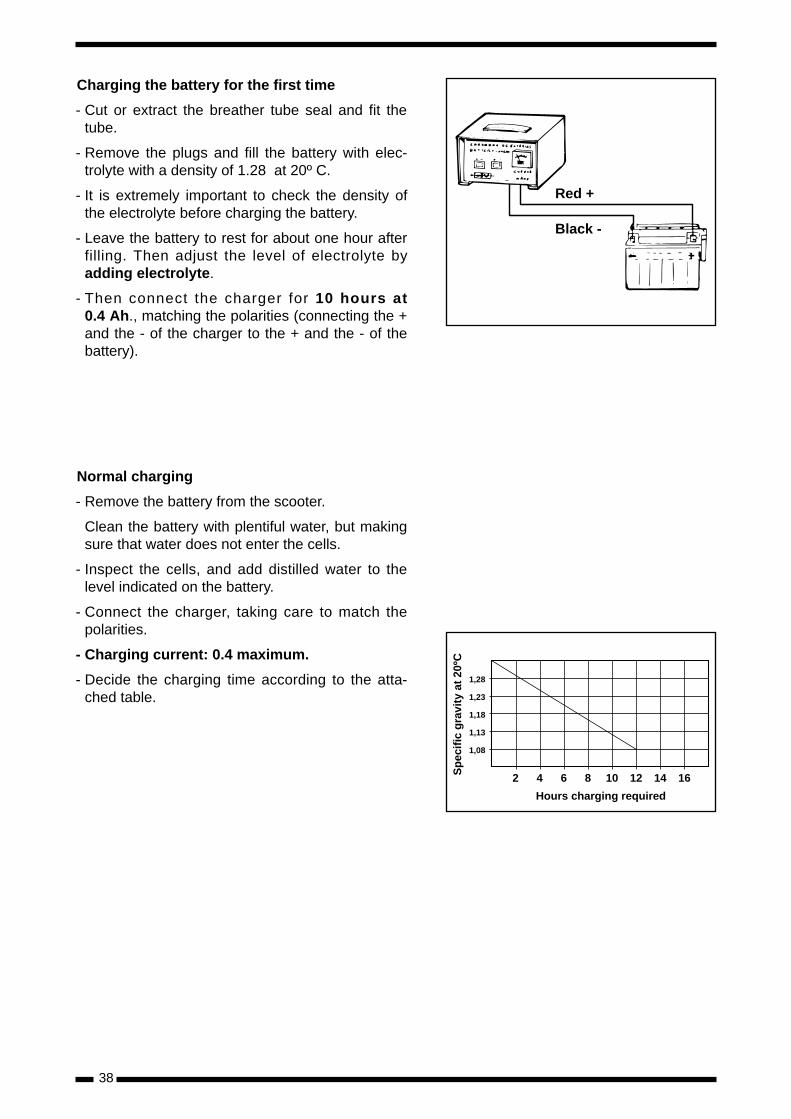
Charging the battery for the first time
- Cut or extract the breather tube seal and fit thetube.
- Remove the plugs and fill the battery with elec-trolyte with a density of 1.28 at 20º C.
- It is extremely important to check the density ofthe electrolyte before charging the battery.
- Leave the battery to rest for about one hour afterfilling. Then adjust the level of electrolyte byadding electrolyte.
- Then connect the charger for 10 hours at0.4 Ah., matching the polarities (connecting the +and the - of the charger to the + and the - of thebattery).
Normal charging
- Remove the battery from the scooter.
Clean the battery with plentiful water, but makingsure that water does not enter the cells.
- Inspect the cells, and add distilled water to thelevel indicated on the battery.
- Connect the charger, taking care to match thepolarities.
- Charging current: 0.4 maximum.
- Decide the charging time according to the atta-ched table.
38
Red +
Black -
2 4 6 8 10 12 14 16
1,08
1,13
1,18
1,23
1,28
Hours charging required
Sp
ecif
ic g
ravi
ty a
t 20
ºC
39
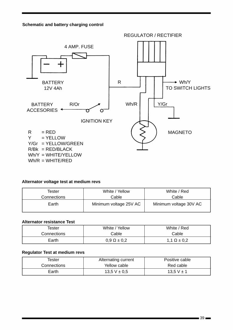
Schematic and battery charging control
4 AMP. FUSE
BATTERY12V 4Ah
BATTERYACCESORIES
R/Or
R
IGNITION KEY
Wh/R
REGULATOR / RECTIFIER
Wh/YTO SWITCH LIGHTS
Y/Gr
MAGNETORYY/GrR/BkWh/YWh/R
= RED= YELLOW= YELLOW/GREEN= RED/BLACK= WHITE/YELLOW= WHITE/RED
Alternator voltage test at medium revs
Tester White / Yellow White / RedConnections Cable Cable
Earth Minimum voltage 25V AC Minimum voltage 30V AC
Alternator resistance TestTester White / Yellow White / Red
Connections Cable Cable
Earth 0,9 Ω ± 0,2 1,1 Ω ± 0,2
Regulator Test at medium revs
Tester Alternating current Positive cableConnections Yellow cable Red cable
Earth 13,5 V ± 0,5 13,5 V ± 1
40
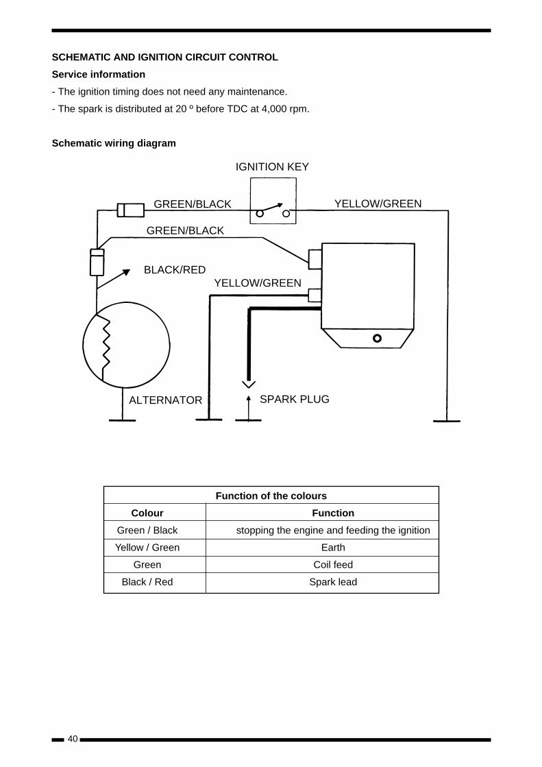
Function of the colours
Colour Function
Green / Black stopping the engine and feeding the ignition
Yellow / Green Earth
Green Coil feed
Black / Red Spark lead
IGNITION KEY
GREEN/BLACK
GREEN/BLACK
BLACK/REDYELLOW/GREEN
YELLOW/GREEN
SPARK PLUGALTERNATOR
SCHEMATIC AND IGNITION CIRCUIT CONTROL
Service information
- The ignition timing does not need any maintenance.
- The spark is distributed at 20 º before TDC at 4,000 rpm.
Schematic wiring diagram
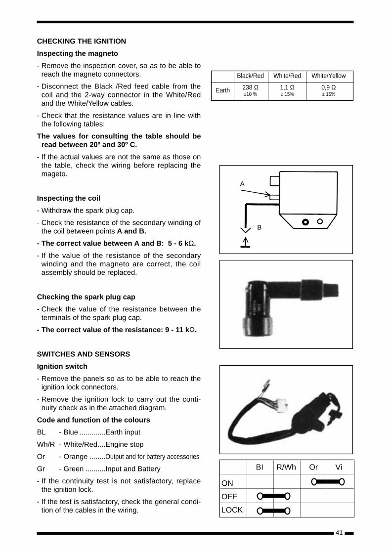
CHECKING THE IGNITION
Inspecting the magneto
- Remove the inspection cover, so as to be able toreach the magneto connectors.
- Disconnect the Black /Red feed cable from thecoil and the 2-way connector in the White/Redand the White/Yellow cables.
- Check that the resistance values are in line withthe following tables:
The values for consulting the table should beread between 20º and 30º C.
- If the actual values are not the same as those onthe table, check the wiring before replacing themageto.
Inspecting the coil
- Withdraw the spark plug cap.
- Check the resistance of the secondary winding ofthe coil between points A and B.
- The correct value between A and B: 5 - 6 kΩ.
- If the value of the resistance of the secondarywinding and the magneto are correct, the coilassembly should be replaced.
Checking the spark plug cap
- Check the value of the resistance between theterminals of the spark plug cap.
- The correct value of the resistance: 9 - 11 kΩ.
SWITCHES AND SENSORS
Ignition switch
- Remove the panels so as to be able to reach theignition lock connectors.
- Remove the ignition lock to carry out the conti-nuity check as in the attached diagram.
Code and function of the colours
BL - Blue .............Earth input
Wh/R - White/Red....Engine stop
Or - Orange ........Output and for battery accessories
Gr - Green ..........Input and Battery
- If the continuity test is not satisfactory, replacethe ignition lock.
- If the test is satisfactory, check the general condi-tion of the cables in the wiring.
41
BI R/Wh Or Vi
ON
OFF
LOCK
Black/Red White/Red White/Yellow
Earth 238 Ω 1,1 Ω 0,9 Ω±10 % ± 15% ± 15%
A
B
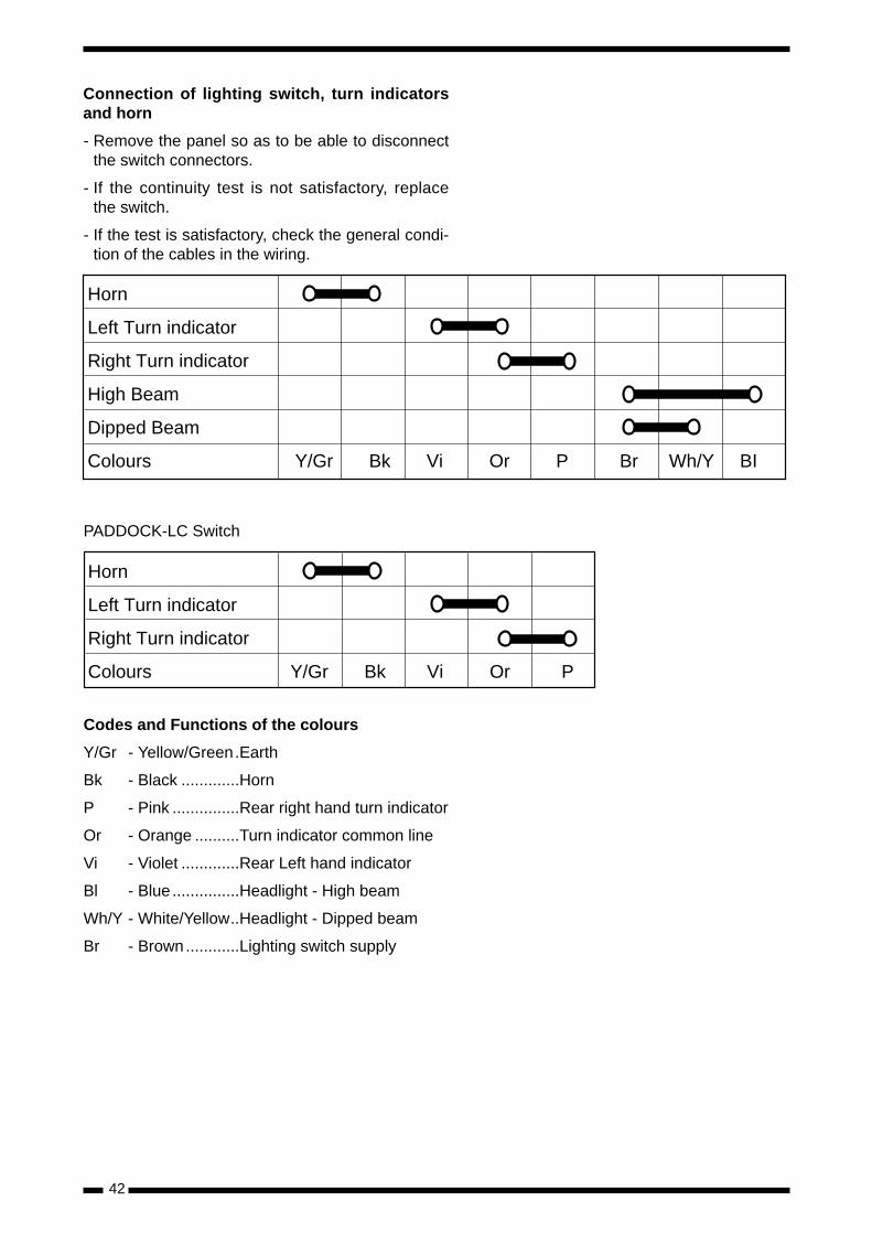
Connection of lighting switch, turn indicatorsand horn
- Remove the panel so as to be able to disconnectthe switch connectors.
- If the continuity test is not satisfactory, replacethe switch.
- If the test is satisfactory, check the general condi-tion of the cables in the wiring.
PADDOCK-LC Switch
Codes and Functions of the colours
Y/Gr - Yellow/Green.Earth
Bk - Black .............Horn
P - Pink ...............Rear right hand turn indicator
Or - Orange ..........Turn indicator common line
Vi - Violet .............Rear Left hand indicator
Bl - Blue ...............Headlight - High beam
Wh/Y - White/Yellow..Headlight - Dipped beam
Br - Brown............Lighting switch supply
42
Horn
Left Turn indicator
Right Turn indicator
High Beam
Dipped Beam
Colours Y/Gr Bk Vi Or P Br Wh/Y BI
Horn
Left Turn indicator
Right Turn indicator
Colours Y/Gr Bk Vi Or P
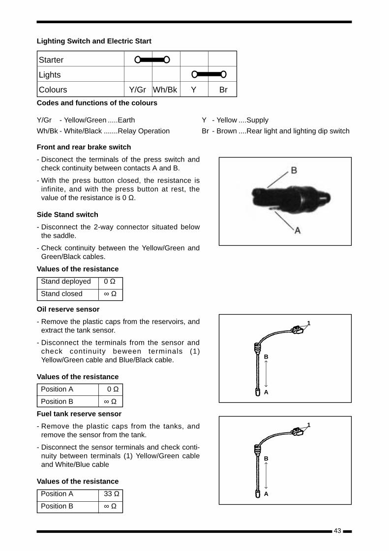
Lighting Switch and Electric Start
Codes and functions of the colours
Front and rear brake switch
- Disconect the terminals of the press switch andcheck continuity between contacts A and B.
- With the press button closed, the resistance isinfinite, and with the press button at rest, thevalue of the resistance is 0 Ω.
Side Stand switch
- Disconnect the 2-way connector situated belowthe saddle.
- Check continuity between the Yellow/Green andGreen/Black cables.
Values of the resistance
Stand deployed 0 Ω
Stand closed ∞ Ω
Oil reserve sensor
- Remove the plastic caps from the reservoirs, andextract the tank sensor.
- Disconnect the terminals from the sensor andcheck continuity beween terminals (1)Yellow/Green cable and Blue/Black cable.
Values of the resistance
Position A 0 Ω
Position B ∞ Ω
Fuel tank reserve sensor
- Remove the plastic caps from the tanks, andremove the sensor from the tank.
- Disconnect the sensor terminals and check conti-nuity between terminals (1) Yellow/Green cableand White/Blue cable
Values of the resistance
Position A 33 Ω
Position B ∞ Ω
43
Starter
Lights
Colours Y/Gr Wh/Bk Y Br
Y/Gr - Yellow/Green .....Earth
Wh/Bk - White/Black .......Relay Operation
Y - Yellow ....Supply
Br - Brown ....Rear light and lighting dip switch
1
B
A
1
B
A
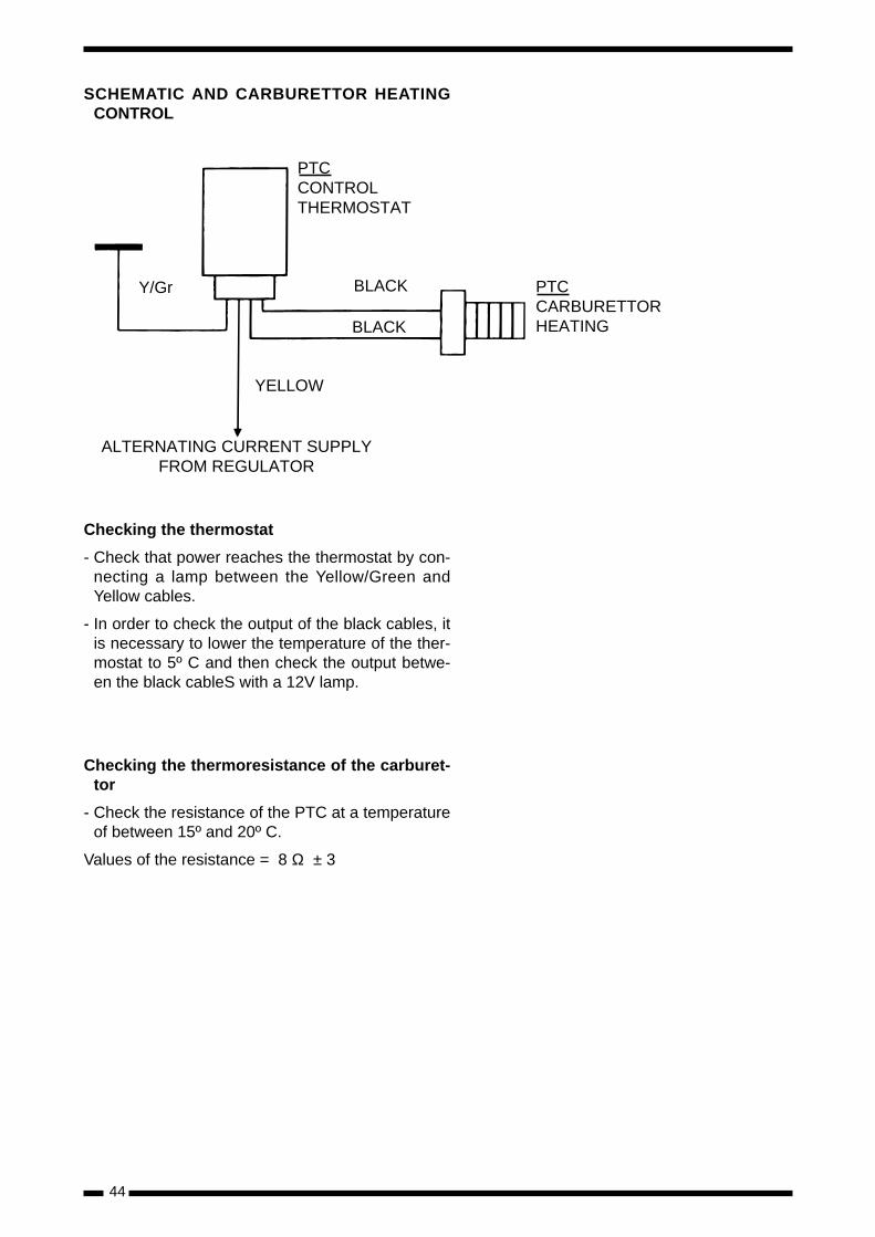
SCHEMATIC AND CARBURETTOR HEATINGCONTROL
Checking the thermostat
- Check that power reaches the thermostat by con-necting a lamp between the Yellow/Green andYellow cables.
- In order to check the output of the black cables, itis necessary to lower the temperature of the ther-mostat to 5º C and then check the output betwe-en the black cableS with a 12V lamp.
Checking the thermoresistance of the carburet-tor
- Check the resistance of the PTC at a temperatureof between 15º and 20º C.
Values of the resistance = 8 Ω ± 3
44
PTCCONTROLTHERMOSTAT
Y/Gr BLACK
BLACK
YELLOW
ALTERNATING CURRENT SUPPLYFROM REGULATOR
PTCCARBURETTORHEATING
45
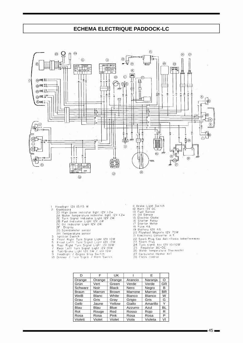
ECHEMA ELECTRIQUE PADDOCK-LC
OrangeGrünSchwarzBraunWeiBGrauGelbBlauRotRosaViolett
OrangeVertNoirMarronBlancGrisJauneBlauRougeRosaViolet
OrangeGreenBlackBrownWhiteGrayYellowBlueRedPinkViolet
ArancioVerdeNeroMarroneBiancoGrigioGialloAzzurroRossoRosaViola
NaranjaVerdeNegroMarronBlancoGrisAmarilloAzulRojoRosaVioleta
OGRB
BRWGYBLRPVI
D F UK I E
46
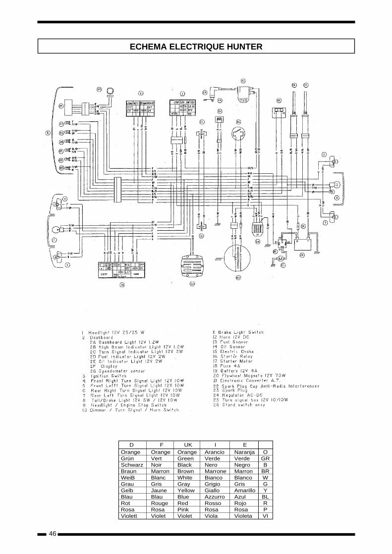
ECHEMA ELECTRIQUE HUNTER
OrangeGrünSchwarzBraunWeiBGrauGelbBlauRotRosaViolett
OrangeVertNoirMarronBlancGrisJauneBlauRougeRosaViolet
OrangeGreenBlackBrownWhiteGrayYellowBlueRedPinkViolet
ArancioVerdeNeroMarroneBiancoGrigioGialloAzzurroRossoRosaViola
NaranjaVerdeNegroMarronBlancoGrisAmarilloAzulRojoRosaVioleta
OGRB
BRWGYBLRPVI
D F UK I E
47
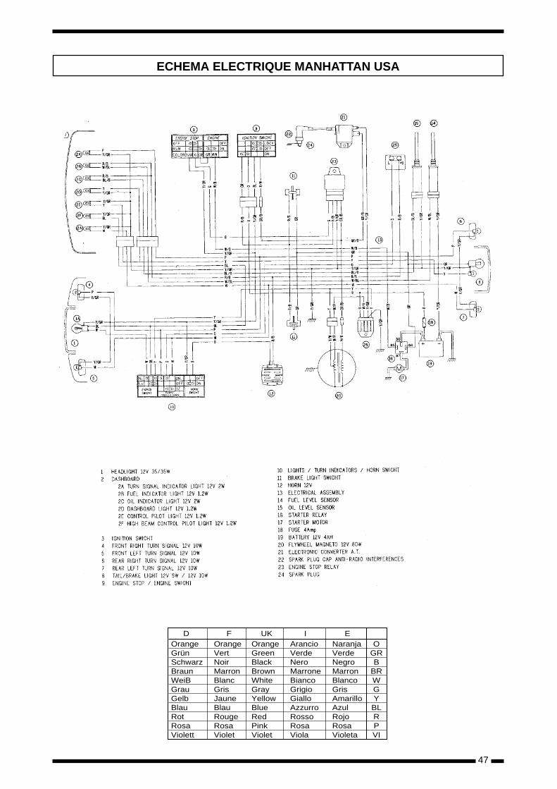
ECHEMA ELECTRIQUE MANHATTAN USA
OrangeGrünSchwarzBraunWeiBGrauGelbBlauRotRosaViolett
OrangeVertNoirMarronBlancGrisJauneBlauRougeRosaViolet
OrangeGreenBlackBrownWhiteGrayYellowBlueRedPinkViolet
ArancioVerdeNeroMarroneBiancoGrigioGialloAzzurroRossoRosaViola
NaranjaVerdeNegroMarronBlancoGrisAmarilloAzulRojoRosaVioleta
OGRB
BRWGYBLRPVI
D F UK I E

49
ANNEXE
PREDATOR-LC - CAT - WVTA Models PREDATOR O2 - CAT - WVTA Models ATLANTIS - CAT - WVTA Models ATLANTIS-LC - CAT - WVTA Models ATLANTIS 100 Models
2
50
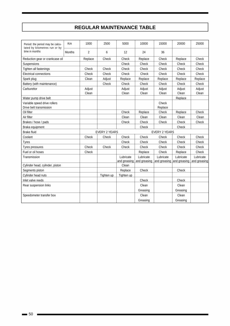
REGULAR MAINTENANCE TABLE
Período: este período puede Km 1000 2500 5000 10000 15000 20000 25000valorarse según los kilómetros
Months 2 6 12 24 36recorridos o el tiempo en meses
Reduction gear or crankcase oil Replace Check Check Replace Check Replace Check
Suspensions Check Check Check Check Check
Tighten all fastenings Check Check Check Check Check Check Check
Electrical connections Check Check Check Check Check Check Check
Spark plug Clean Adjust Replace Replace Replace Replace Replace
Battery (with maintenance) Check Check Check Check Check Check
Carburettor Adjust Adjust Adjust Adjust Adjust AdjustClean Clean Clean Clean Clean Clean
Water pump drive belt Replace
Variable speed drive rollers CheckDrive belt transmission Replace Oil filter Check Replace Check Replace Check
Air filter Clean Clean Clean Clean Clean
Brakes / hose / pads Check Check Check Check Check
Braka equipment Check Check
Brake fluid EVERY 2 YEARS EVERY 2 YEARS
Coolant Check Check Check Check Check Check Check
Tyres Check Check Check Check Check
Tyres pressures Check Check Check Check Check Check Check
Fuel or oil hoses Check Replace Check Replace Check
Transmission Lubricate Lubricate Lubricate Lubricate Lubricateand greasing and greasing and greasing and greasing and greasing
Cylinder head, cylinder, piston Clean
Segments piston Replace Check Check
Cylinder head nuts Tighten up Tighten up
Inlet valve reeds Check Check
Rear suspension links Clean Clean
Greasing Greasing
Speedometer transfer box Clean Clean
Greasing Greasing
Period: the period may be calcu-lated by kilometres run or bytime in months
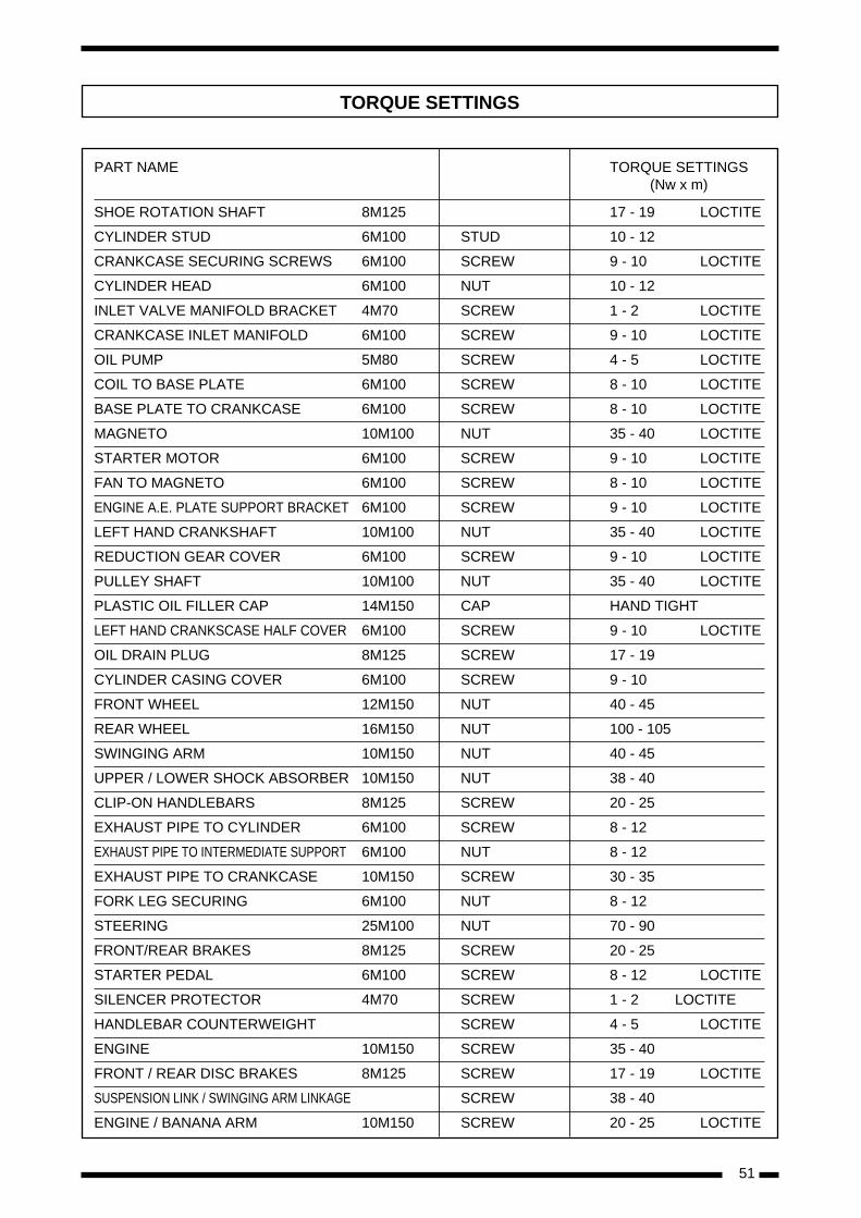
51
PART NAME TORQUE SETTINGS(Nw x m)
SHOE ROTATION SHAFT 8M125 17 - 19 LOCTITE
CYLINDER STUD 6M100 STUD 10 - 12
CRANKCASE SECURING SCREWS 6M100 SCREW 9 - 10 LOCTITE
CYLINDER HEAD 6M100 NUT 10 - 12
INLET VALVE MANIFOLD BRACKET 4M70 SCREW 1 - 2 LOCTITE
CRANKCASE INLET MANIFOLD 6M100 SCREW 9 - 10 LOCTITE
OIL PUMP 5M80 SCREW 4 - 5 LOCTITE
COIL TO BASE PLATE 6M100 SCREW 8 - 10 LOCTITE
BASE PLATE TO CRANKCASE 6M100 SCREW 8 - 10 LOCTITE
MAGNETO 10M100 NUT 35 - 40 LOCTITE
STARTER MOTOR 6M100 SCREW 9 - 10 LOCTITE
FAN TO MAGNETO 6M100 SCREW 8 - 10 LOCTITE
ENGINE A.E. PLATE SUPPORT BRACKET 6M100 SCREW 9 - 10 LOCTITE
LEFT HAND CRANKSHAFT 10M100 NUT 35 - 40 LOCTITE
REDUCTION GEAR COVER 6M100 SCREW 9 - 10 LOCTITE
PULLEY SHAFT 10M100 NUT 35 - 40 LOCTITE
PLASTIC OIL FILLER CAP 14M150 CAP HAND TIGHT
LEFT HAND CRANKSCASE HALF COVER 6M100 SCREW 9 - 10 LOCTITE
OIL DRAIN PLUG 8M125 SCREW 17 - 19
CYLINDER CASING COVER 6M100 SCREW 9 - 10
FRONT WHEEL 12M150 NUT 40 - 45
REAR WHEEL 16M150 NUT 100 - 105
SWINGING ARM 10M150 NUT 40 - 45
UPPER / LOWER SHOCK ABSORBER 10M150 NUT 38 - 40
CLIP-ON HANDLEBARS 8M125 SCREW 20 - 25
EXHAUST PIPE TO CYLINDER 6M100 SCREW 8 - 12
EXHAUST PIPE TO INTERMEDIATE SUPPORT 6M100 NUT 8 - 12
EXHAUST PIPE TO CRANKCASE 10M150 SCREW 30 - 35
FORK LEG SECURING 6M100 NUT 8 - 12
STEERING 25M100 NUT 70 - 90
FRONT/REAR BRAKES 8M125 SCREW 20 - 25
STARTER PEDAL 6M100 SCREW 8 - 12 LOCTITE
SILENCER PROTECTOR 4M70 SCREW 1 - 2 LOCTITE
HANDLEBAR COUNTERWEIGHT SCREW 4 - 5 LOCTITE
ENGINE 10M150 SCREW 35 - 40
FRONT / REAR DISC BRAKES 8M125 SCREW 17 - 19 LOCTITE
SUSPENSION LINK / SWINGING ARM LINKAGE SCREW 38 - 40
ENGINE / BANANA ARM 10M150 SCREW 20 - 25 LOCTITE
TORQUE SETTINGS
52
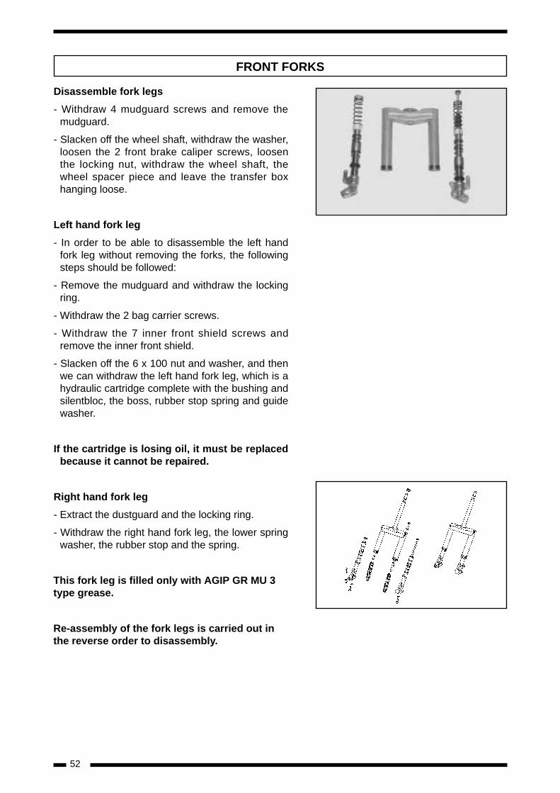
Disassemble fork legs
- Withdraw 4 mudguard screws and remove themudguard.
- Slacken off the wheel shaft, withdraw the washer,loosen the 2 front brake caliper screws, loosenthe locking nut, withdraw the wheel shaft, thewheel spacer piece and leave the transfer boxhanging loose.
Left hand fork leg
- In order to be able to disassemble the left handfork leg without removing the forks, the followingsteps should be followed:
- Remove the mudguard and withdraw the lockingring.
- Withdraw the 2 bag carrier screws.
- Withdraw the 7 inner front shield screws andremove the inner front shield.
- Slacken off the 6 x 100 nut and washer, and thenwe can withdraw the left hand fork leg, which is ahydraulic cartridge complete with the bushing andsilentbloc, the boss, rubber stop spring and guidewasher.
If the cartridge is losing oil, it must be replacedbecause it cannot be repaired.
Right hand fork leg
- Extract the dustguard and the locking ring.
- Withdraw the right hand fork leg, the lower springwasher, the rubber stop and the spring.
This fork leg is filled only with AGIP GR MU 3type grease.
Re-assembly of the fork legs is carried out inthe reverse order to disassembly.
FRONT FORKS
53
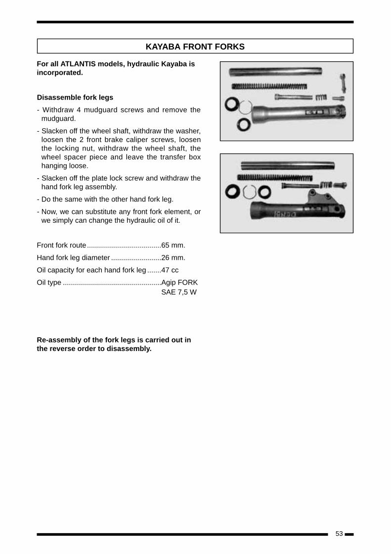
For all ATLANTIS models, hydraulic Kayaba isincorporated.
Disassemble fork legs
- Withdraw 4 mudguard screws and remove themudguard.
- Slacken off the wheel shaft, withdraw the washer,loosen the 2 front brake caliper screws, loosenthe locking nut, withdraw the wheel shaft, thewheel spacer piece and leave the transfer boxhanging loose.
- Slacken off the plate lock screw and withdraw thehand fork leg assembly.
- Do the same with the other hand fork leg.
- Now, we can substitute any front fork element, orwe simply can change the hydraulic oil of it.
Front fork route.....................................65 mm.
Hand fork leg diameter .........................26 mm.
Oil capacity for each hand fork leg .......47 cc
Oil type .................................................Agip FORK SAE 7,5 W
Re-assembly of the fork legs is carried out inthe reverse order to disassembly.
KAYABA FRONT FORKS
54
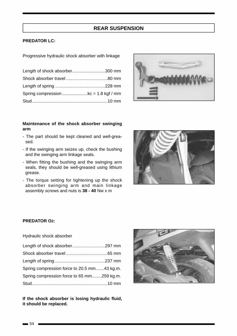
PREDATOR LC:
Progressive hydraulic shock absorber with linkage
Length of shock absorber...........................300 mm
Shock absorber travel ..................................80 mm
Length of spring .........................................228 mm
Spring compression .....................kc = 1.8 kgf / mm
Stud..............................................................10 mm
Maintenance of the shock absorber swingingarm
- The part should be kept cleaned and well-grea-sed.
- If the swinging arm seizes up, check the bushingand the swinging arm linkage seals.
- When fitting the bushing and the swinging armseals, they should be well-greased using lithiumgrease.
- The torque setting for tightening up the shockabsorber swinging arm and main l inkageassembly screws and nuts is 38 - 40 Nw x m
PREDATOR O2:
Hydraulic shock absorber
Length of shock absorber...........................297 mm
Shock absorber travel ..................................65 mm
Length of spring .........................................237 mm
Spring compression force to 20.5 mm.......43 kg.m.
Spring compression force to 65 mm........259 kg.m.
Stud..............................................................10 mm
If the shock absorber is losing hydraulic fluid,it should be replaced.
REAR SUSPENSION
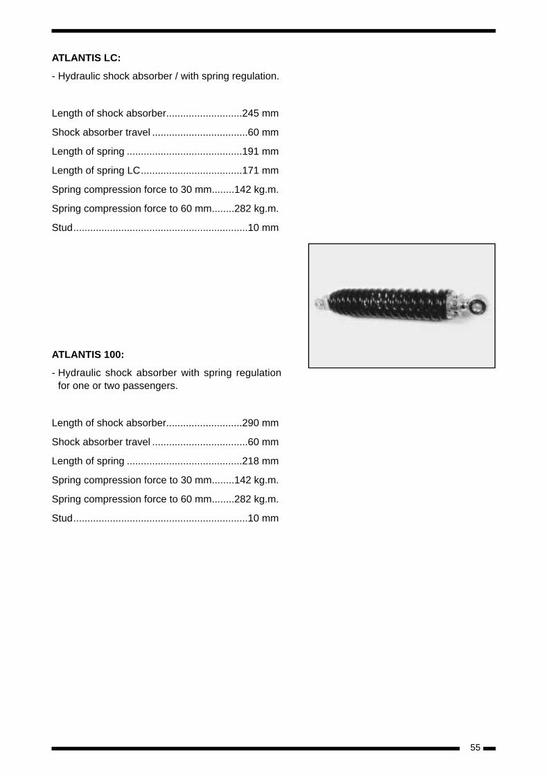
ATLANTIS LC:
- Hydraulic shock absorber / with spring regulation.
Length of shock absorber...........................245 mm
Shock absorber travel ..................................60 mm
Length of spring .........................................191 mm
Length of spring LC....................................171 mm
Spring compression force to 30 mm........142 kg.m.
Spring compression force to 60 mm........282 kg.m.
Stud..............................................................10 mm
ATLANTIS 100:
- Hydraulic shock absorber with spring regulationfor one or two passengers.
Length of shock absorber...........................290 mm
Shock absorber travel ..................................60 mm
Length of spring .........................................218 mm
Spring compression force to 30 mm........142 kg.m.
Spring compression force to 60 mm........282 kg.m.
Stud..............................................................10 mm
55
56
PREDATOR LC
- Remove the antifreeze liquid drain plug.
- Withdraw the engine inspection cover secu-ring screw.
- Disconnect the thermo-contact.
- Withdraw the cylinder-head water outlet hoseconnector and clip.
- Disconnect the throttle cable at the connec-tor.
- Disconnect the crankcase coolant hose andclip at the connection to the crankscase.
- Withdraw the high tension coil securing screwand coil earth.
- Disconnect the oil hose at the connector.
- Withdraw the 2 (fuel and vacuum) hoses fromthe fuel cock.
- Extract the 2 rear brake caliper screws andleave the caliper lying on the engine.
- Remove the engine earth cable screw.
- Disconnect the electrical connectors to themagneto, cut-off, starter and automaticchoke.
- Withdraw the 2 engine frame anchoragesecuring screws.
- Withdraw the suspension link screw.
- Remove the engine from the frame.
PREDATOR O2 / ATLANTIS O2ATLANTIS LC / ATLANTIS 100
- Remove the throttle cable from the connector.
- Withdraw the screw and the low seat body(Atlantis).
- Withdraw the screw and the engine recordcover (Predator).
- Withdraw the high tension coil securing screwand coil earth.
- Disconnect the oil hose at the connector.
- Withdraw the 2 (fuel and vacuum) hoses fromthe fuel cock.
- Withdraw the rear brake cable guide screw.
- Withdraw the rear brake nut.
- Remove the engine earth cable screw.
- Remove the carburettor access cover andwithdraw the manual choke cable.
- Disconnect the electrical connectors to themagneto, cut-off, and starter.
- Withdraw the 2 engine frame anchoragesecuring screws.
- Withdraw the lower rear shock absorberscrew.
- Remove the engine from the frame.
- Remove the antifreeze liquid drain plug(Atlantis LC).
- Disconnect the thermo-contact (Atlantis LC).
- Withdraw the cylinder-head water outlet hoseconnector and clip (Atlantis LC).
- Withdraw the coolant hose at the connectionto the radiator (Atlantis LC).
REMOVING THE ENGINE FROM THE FRAME
57
CHECKING THE IGNITION
Inspecting the magneto
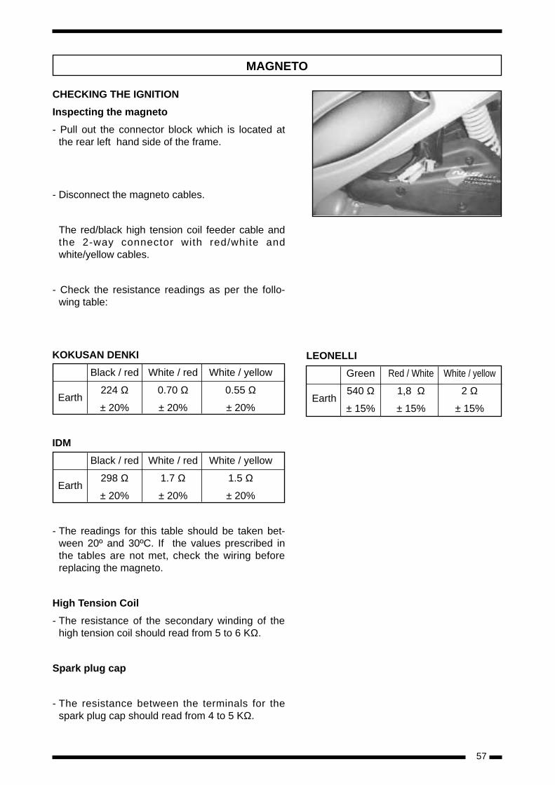
- Pull out the connector block which is located atthe rear left hand side of the frame.
- Disconnect the magneto cables.
The red/black high tension coil feeder cable andthe 2-way connector with red/white andwhite/yellow cables.
- Check the resistance readings as per the follo-wing table:
KOKUSAN DENKI
Black / red White / red White / yellow
Earth224 Ω 0.70 Ω 0.55 Ω
± 20% ± 20% ± 20%
IDM
Black / red White / red White / yellow
Earth298 Ω 1.7 Ω 1.5 Ω
± 20% ± 20% ± 20%
- The readings for this table should be taken bet-ween 20º and 30ºC. If the values prescribed inthe tables are not met, check the wiring beforereplacing the magneto.
High Tension Coil
- The resistance of the secondary winding of thehigh tension coil should read from 5 to 6 KΩ.
Spark plug cap
- The resistance between the terminals for thespark plug cap should read from 4 to 5 KΩ.
MAGNETO
LEONELLI
Green Red / White White / yellow
Earth540 Ω 1,8 Ω 2 Ω
± 15% ± 15% ± 15%
58
Table of Cylinder and Piston tolerances
PREDATOR - ATLANTIS ATLANTIS 100LC – O2 – CAT – WVTA O2 – WVTA
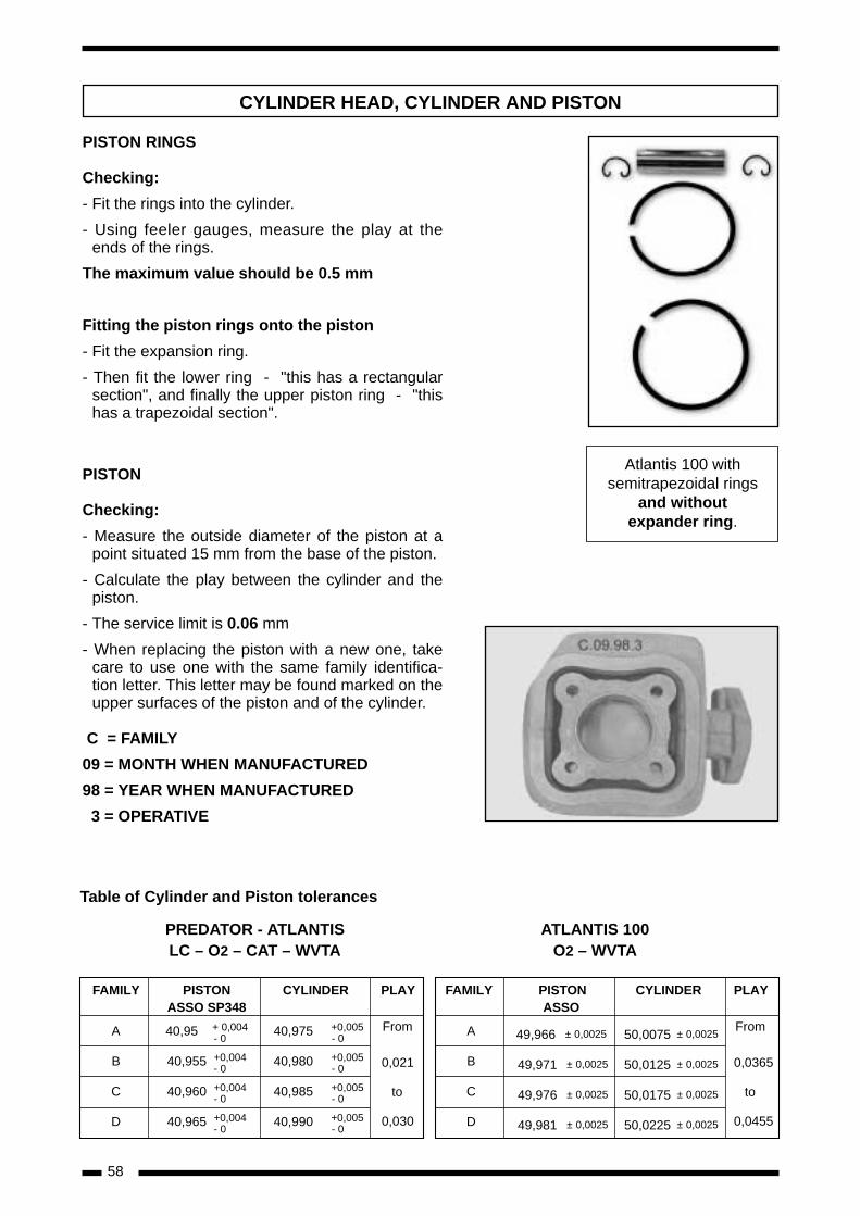
PISTON RINGS
Checking:
- Fit the rings into the cylinder.
- Using feeler gauges, measure the play at theends of the rings.
The maximum value should be 0.5 mm
Fitting the piston rings onto the piston
- Fit the expansion ring.
- Then fit the lower ring - "this has a rectangularsection", and finally the upper piston ring - "thishas a trapezoidal section".
PISTON
Checking:
- Measure the outside diameter of the piston at apoint situated 15 mm from the base of the piston.
- Calculate the play between the cylinder and thepiston.
- The service limit is 0.06 mm
- When replacing the piston with a new one, takecare to use one with the same family identifica-tion letter. This letter may be found marked on theupper surfaces of the piston and of the cylinder.
C = FAMILY
09 = MONTH WHEN MANUFACTURED
98 = YEAR WHEN MANUFACTURED
3 = OPERATIVE
CYLINDER HEAD, CYLINDER AND PISTON
FAMILY PISTON CYLINDER PLAYASSO SP348
A 40,95 + 0,004 40,975 +0,005- 0 - 0
B 40,955 +0,004 40,980 +0,005- 0 - 0
C 40,960 +0,004 40,985 +0,005- 0 - 0
D 40,965 +0,004 40,990 +0,005- 0 - 0
From
0,021
to
0,030
FAMILY CYLINDER PLAY
From
to
PISTONASSO
A 49,966 ± 0,0025 50,0075 ± 0,0025
B 49,971 ± 0,0025 50,0125 ± 0,0025
C 49,976 ± 0,0025 50,0175 ± 0,0025
D 49,981 ± 0,0025 50,0225 ± 0,0025
0,0365
0,0455
Atlantis 100 withsemitrapezoidal rings
and withoutexpander ring.
59
CYLINDER HEAD
Compression Ratio: 11.5:1
Compression Ratio ATLANTIS 100: 9.5:1
PREDATOR LC / O2
- The gaskets should be replaced every time thecylinder head is removed.- Check that the cylin-der head is gas-tight. There should be no morethan 0.05 mm gap.
Cylinder head torque settings: 10 - 12 Nw x m.
Cylinder head torque settingsATLANTIS 100: 18 - 20 Nw x m.
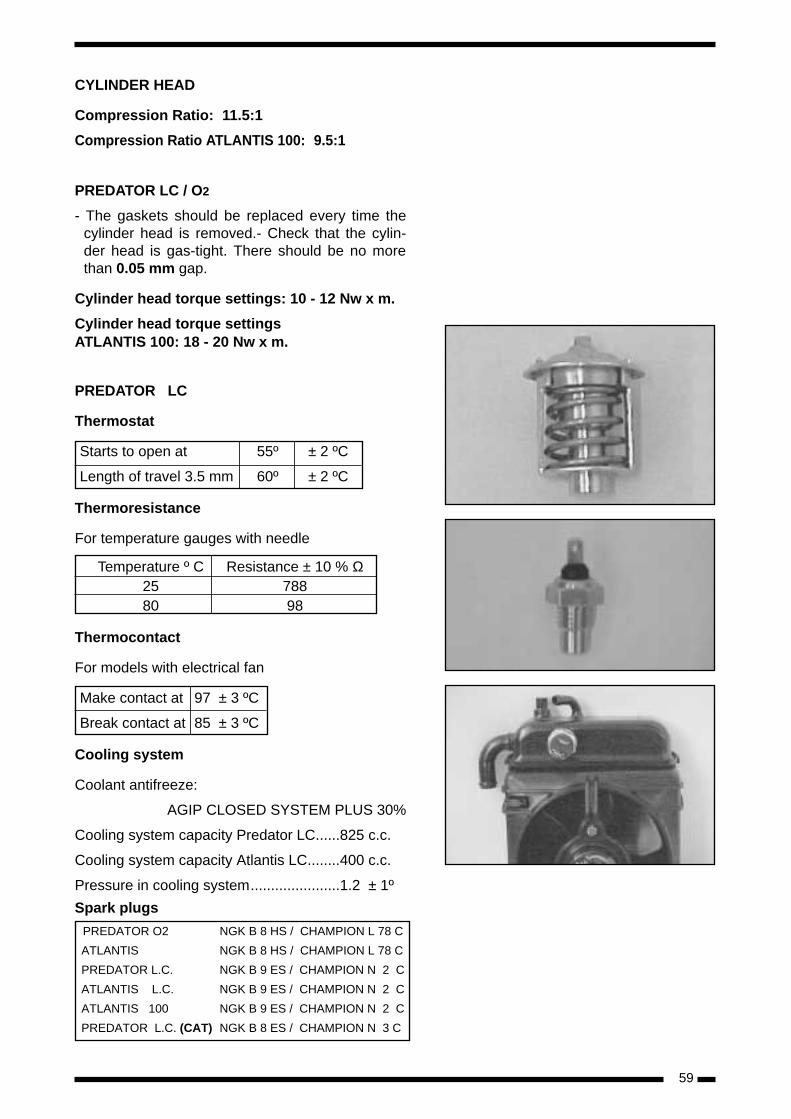
PREDATOR LC
Thermostat
Starts to open at 55º ± 2 ºC
Length of travel 3.5 mm 60º ± 2 ºC
Thermoresistance
For temperature gauges with needle
Temperature º C Resistance ± 10 % Ω25 78880 98
Thermocontact
For models with electrical fan
Make contact at 97 ± 3 ºC
Break contact at 85 ± 3 ºC
Cooling system
Coolant antifreeze:
AGIP CLOSED SYSTEM PLUS 30%
Cooling system capacity Predator LC......825 c.c.
Cooling system capacity Atlantis LC........400 c.c.
Pressure in cooling system......................1.2 ± 1º
Spark plugs
PREDATOR O2 NGK B 8 HS / CHAMPION L 78 C
ATLANTIS NGK B 8 HS / CHAMPION L 78 C
PREDATOR L.C. NGK B 9 ES / CHAMPION N 2 C
ATLANTIS L.C. NGK B 9 ES / CHAMPION N 2 C
ATLANTIS 100 NGK B 9 ES / CHAMPION N 2 C
PREDATOR L.C. (CAT) NGK B 8 ES / CHAMPION N 3 C
60
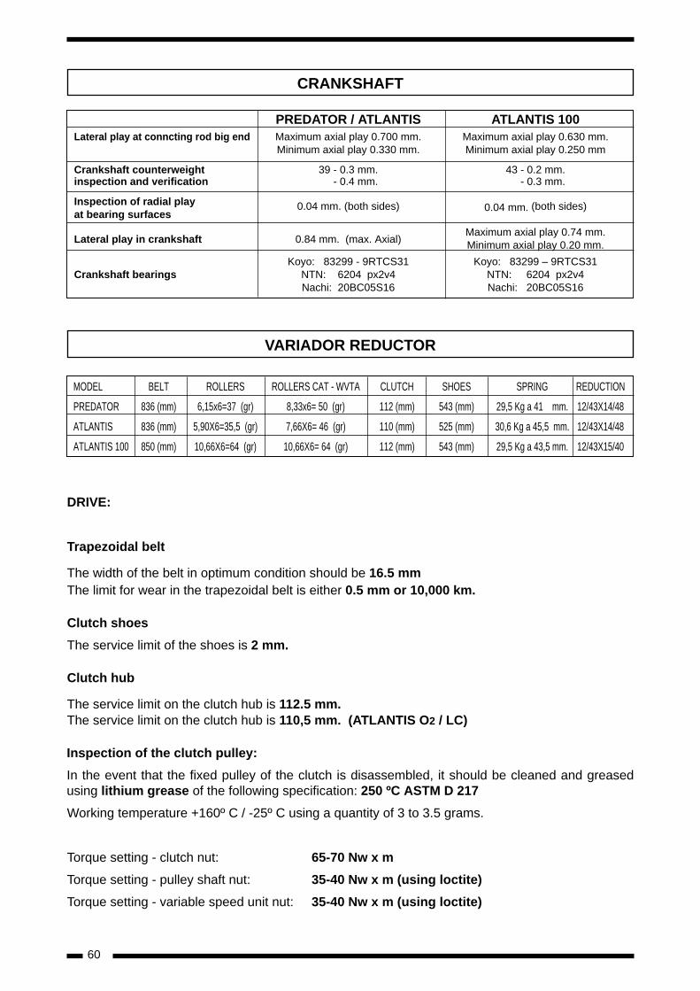
DRIVE:
Trapezoidal belt
The width of the belt in optimum condition should be 16.5 mmThe limit for wear in the trapezoidal belt is either 0.5 mm or 10,000 km.
Clutch shoes
The service limit of the shoes is 2 mm.
Clutch hub
The service limit on the clutch hub is 112.5 mm.The service limit on the clutch hub is 110,5 mm. (ATLANTIS O2 / LC)
Inspection of the clutch pulley:
In the event that the fixed pulley of the clutch is disassembled, it should be cleaned and greasedusing lithium grease of the following specification: 250 ºC ASTM D 217
Working temperature +160º C / -25º C using a quantity of 3 to 3.5 grams.
Torque setting - clutch nut: 65-70 Nw x m
Torque setting - pulley shaft nut: 35-40 Nw x m (using loctite)
Torque setting - variable speed unit nut: 35-40 Nw x m (using loctite)
CRANKSHAFT
PREDATOR / ATLANTIS ATLANTIS 100Lateral play at conncting rod big end Maximum axial play 0.700 mm. Maximum axial play 0.630 mm.
Minimum axial play 0.330 mm. Minimum axial play 0.250 mm
Crankshaft counterweight 39 - 0.3 mm. 43 - 0.2 mm.inspection and verification - 0.4 mm. - 0.3 mm.
Inspection of radial play at bearing surfaces
0.04 mm. (both sides) 0.04 mm. (both sides)
Lateral play in crankshaft 0.84 mm. (max. Axial)Maximum axial play 0.74 mm.Minimum axial play 0.20 mm.
Koyo: 83299 - 9RTCS31 Koyo: 83299 – 9RTCS31Crankshaft bearings NTN: 6204 px2v4 NTN: 6204 px2v4
Nachi: 20BC05S16 Nachi: 20BC05S16
MODEL BELT ROLLERS ROLLERS CAT - WVTA CLUTCH SHOES SPRING REDUCTION
PREDATOR 836 (mm) 6,15x6=37 (gr) 8,33x6= 50 (gr) 112 (mm) 543 (mm) 29,5 Kg a 41 mm. 12/43X14/48
ATLANTIS 836 (mm) 5,90X6=35,5 (gr) 7,66X6= 46 (gr) 110 (mm) 525 (mm) 30,6 Kg a 45,5 mm. 12/43X14/48
ATLANTIS 100 850 (mm) 10,66X6=64 (gr) 10,66X6= 64 (gr) 112 (mm) 543 (mm) 29,5 Kg a 43,5 mm. 12/43X15/40
VARIADOR REDUCTOR
61
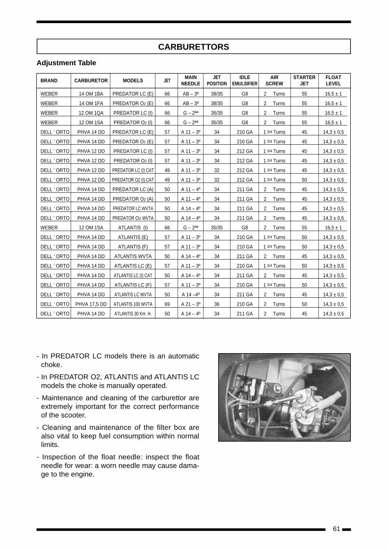
CARBURETTORS
- In PREDATOR LC models there is an automaticchoke.
- In PREDATOR O2, ATLANTIS and ATLANTIS LCmodels the choke is manually operated.
- Maintenance and cleaning of the carburettor areextremely important for the correct performanceof the scooter.
- Cleaning and maintenance of the filter box arealso vital to keep fuel consumption within normallimits.
- Inspection of the float needle: inspect the floatneedle for wear: a worn needle may cause dama-ge to the engine.
BRAND CARBURETOR MODELS JETMAIN JET IDLE AIR STARTER FLOAT
NEEDLE POSITION EMULSIFIER SCREW JET LEVEL
WEBER 14 OM 1BA PREDATOR LC (E) 66 AB – 3ª 38/35 G8 2 Turns 55 16,5 ± 1
WEBER 14 OM 1FA PREDATOR O2 (E) 66 AB – 3ª 38/35 G8 2 Turns 55 16,5 ± 1
WEBER 12 OM 1QA PREDATOR LC (I) 66 G – 2ªª 35/35 G8 2 Turns 55 16,5 ± 1
WEBER 12 OM 1SA PREDATOR O2 (I) 66 G – 2ªª 35/35 G8 2 Turns 55 16,5 ± 1
DELL ’ ORTO PHVA 14 DD PREDATOR LC (E) 57 A 11 – 3º 34 210 GA 1 3/4 Turns 45 14,3 ± 0,5
DELL ’ ORTO PHVA 14 DD PREDATOR O2 (E) 57 A 11 – 3º 34 210 GA 1 3/4 Turns 45 14,3 ± 0,5
DELL ’ ORTO PHVA 12 DD PREDATOR LC (I) 57 A 11 – 3º 34 212 GA 1 3/4 Turns 45 14,3 ± 0,5
DELL ’ ORTO PHVA 12 DD PREDATOR O2 (I) 57 A 11 – 3º 34 212 GA 1 3/4 Turns 45 14,3 ± 0,5
DELL ’ ORTO PHVA 12 DD PREDATOR LC (I) CAT 49 A 11 – 3º 32 212 GA 1 3/4 Turns 45 14,3 ± 0,5
DELL ’ ORTO PHVA 12 DD PREDATOR O2 (I) CAT 49 A 11 – 3º 32 212 GA 1 3/4 Turns 50 14,3 ± 0,5
DELL ’ ORTO PHVA 14 DD PREDATOR LC (A) 50 A 11 – 4º 34 211 GA 2 Turns 45 14,3 ± 0,5
DELL ’ ORTO PHVA 14 DD PREDATOR O2 (A) 50 A 11 – 4º 34 211 GA 2 Turns 45 14,3 ± 0,5
DELL ’ ORTO PHVA 14 DD PREDATOR LC WVTA 50 A 14 – 4º 34 211 GA 2 Turns 45 14,3 ± 0,5
DELL ’ ORTO PHVA 14 DD PREDATOR O2 WVTA 50 A 14 – 4º 34 211 GA 2 Turns 45 14,3 ± 0,5
WEBER 12 OM 1SA ATLANTIS (I) 66 G – 2ªª 35/35 G8 2 Turns 55 16,5 ± 1
DELL ’ ORTO PHVA 14 DD ATLANTIS (E) 57 A 11 – 3º 34 210 GA 1 3/4 Turns 50 14,3 ± 0,5
DELL ’ ORTO PHVA 14 DD ATLANTIS (F) 57 A 11 – 3º 34 210 GA 1 3/4 Turns 50 14,3 ± 0,5
DELL ’ ORTO PHVA 14 DD ATLANTIS WVTA 50 A 14 – 4º 34 211 GA 2 Turns 45 14,3 ± 0,5
DELL ’ ORTO PHVA 14 DD ATLANTIS LC (E) 57 A 11 – 3º 34 210 GA 1 3/4 Turns 50 14,3 ± 0,5
DELL ’ ORTO PHVA 14 DD ATLANTIS LC (I) CAT 50 A 14 – 4º 34 211 GA 2 Turns 45 14,3 ± 0,5
DELL ’ ORTO PHVA 14 DD ATLANTIS LC (F) 57 A 11 – 3º 34 210 GA 1 3/4 Turns 50 14,3 ± 0,5
DELL ’ ORTO PHVA 14 DD ATLANTIS LC WVTA 50 A 14 –4º 34 211 GA 2 Turns 45 14,3 ± 0,5
DELL ’ ORTO PHVA 17,5 DD ATLANTIS 100 WVTA 69 A 21 – 3º 36 210 GA 2 Turns 50 14,3 ± 0,5
DELL ’ ORTO PHVA 14 DD ATLANTIS 30 Km H. 50 A 14 – 4º 34 211 GA 2 Turns 45 14,3 ± 0,5
Adjustment Table
62
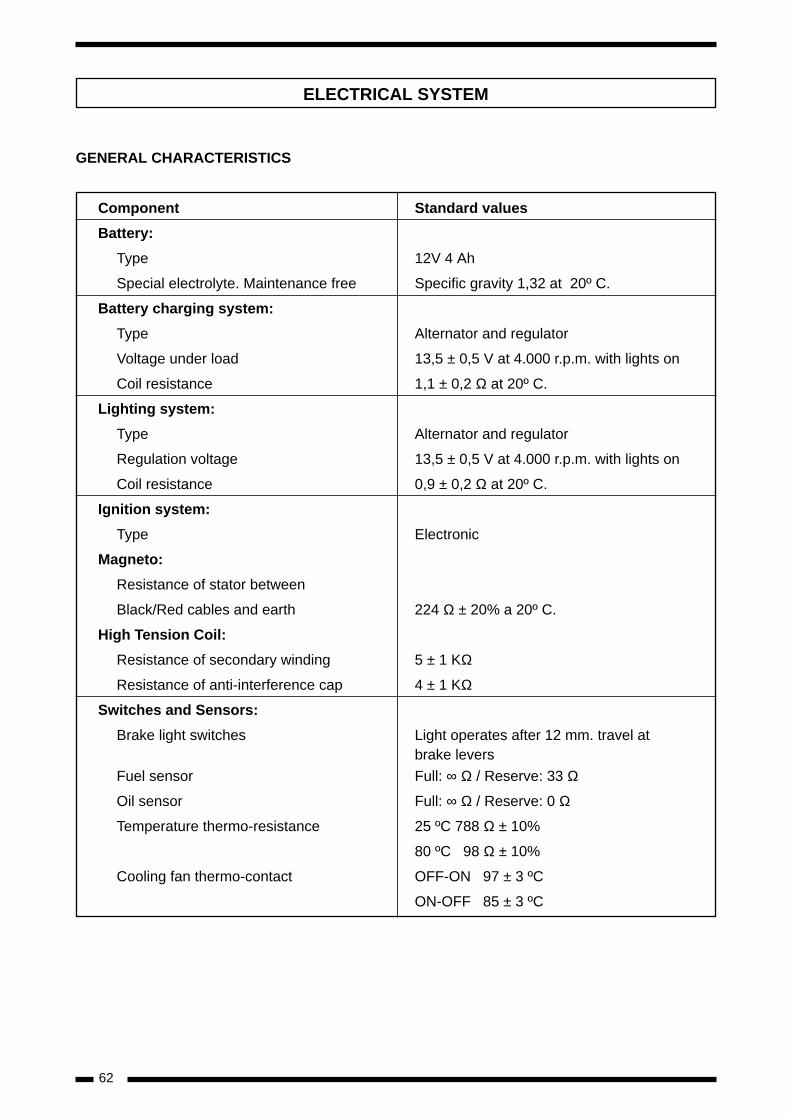
GENERAL CHARACTERISTICS
Component Standard values
Battery:
Type 12V 4 Ah
Special electrolyte. Maintenance free Specific gravity 1,32 at 20º C.
Battery charging system:
Type Alternator and regulator
Voltage under load 13,5 ± 0,5 V at 4.000 r.p.m. with lights on
Coil resistance 1,1 ± 0,2 Ω at 20º C.
Lighting system:
Type Alternator and regulator
Regulation voltage 13,5 ± 0,5 V at 4.000 r.p.m. with lights on
Coil resistance 0,9 ± 0,2 Ω at 20º C.
Ignition system:
Type Electronic
Magneto:
Resistance of stator between
Black/Red cables and earth 224 Ω ± 20% a 20º C.
High Tension Coil:
Resistance of secondary winding 5 ± 1 KΩ
Resistance of anti-interference cap 4 ± 1 KΩ
Switches and Sensors:
Brake light switches Light operates after 12 mm. travel at brake levers
Fuel sensor Full: ∞ Ω / Reserve: 33 Ω
Oil sensor Full: ∞ Ω / Reserve: 0 Ω
Temperature thermo-resistance 25 ºC 788 Ω ± 10%
80 ºC 98 Ω ± 10%
Cooling fan thermo-contact OFF-ON 97 ± 3 ºC
ON-OFF 85 ± 3 ºC
ELECTRICAL SYSTEM

63
BATTERY
- When the battery is used for the first time, it isnecessary to fill with the acid which comes toget-her with the battery.
- First remove the sealing strip.
- Next place the container of electrolyte upsidedown with the six sealed parts aligned with thesix filler holes on the battery. Push the containerfirmly down to break the seals.
- Check that all the electrolyte has gone into thebattery.
Sealing up the battery:
- Push the sealing strip firmly into each of the fillerholes.
- Never remove the sealing strip, and never addwater to the electrolyte.
- The battery is a 12V 4 Ah type. When installingthe battery it is important not to reverse the pola-rity of the terminals, since this could cause dama-ge to some sensitive electronic components.
Using the battery for the first time:
- This battery is a sealed type and the cellcovers should never be removed, and watermust never be added.
- After 30 minutes test the voltage at the terminals.
Standard voltage 12.5 volts minimum
Under normal circumstances it is not necessary tocharge the battery. Once charged it is normally at75% capacity.
Special conditions under which the batteryshould be charged:
- When the temperature falls below 0 ºC.
- After a long period in storage.
- When the original seal has been broken.
- In general the battery should be charged whene-ver the voltage after charging remains below thestandard reading of 12.5 V.
CHECKING THE ELECTRICAL SYSTEM IN THE SCOOTER
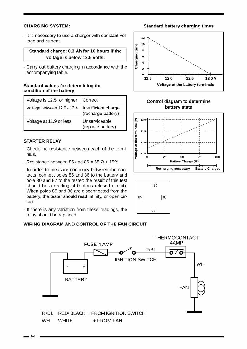
64
STARTER RELAY
- Check the resistance between each of the termi-nals.
- Resistance between 85 and 86 = 55 Ω ± 15%.
- In order to measure continuity between the con-tacts, connect poles 85 and 86 to the battery andpole 30 and 87 to the tester: the result of this testshould be a reading of 0 ohms (closed circuit).When poles 85 and 86 are disconnected from thebattery, the tester should read infinity, or open cir-cuit.
- If there is any variation from these readings, therelay should be replaced.
THERMOCONTACTFUSE 4 AMP 4AMP
R/BL
IGNITION SWITCH
BATTERY
R/BL RED/ BLACK + FROM IGNITION SWITCH
WH WHITE + FROM FAN
- + WH
FAN
CHARGING SYSTEM:
- It is necessary to use a charger with constant vol-tage and current.
Standard charge: 0.3 Ah for 10 hours if thevoltage is below 12.5 volts.
- Carry out battery charging in accordance with theaccompanying table.
11,5 12,0 12,5 13,0 V
2
4
6
8
10
Voltage at the battery terminals
Ch
arg
ing
tim
e
12
0
0 25 50 75
12,0
12,5
13,0
Battery Charge (%)
Vo
ltag
e at
th
e te
rmin
als
(V)
11,5
100
Recharging necessary Battery Charged
Standard values for determining thecondition of the battery
Voltage is 12.5 or higher Correct
Voltage between 12.0 - 12.4 Insufficient charge(recharge battery)
Voltage at 11.9 or less Unserviceable(replace battery)
Control diagram to determinebattery state
Standard battery charging times
30
87
85 86
WIRING DIAGRAM AND CONTROL OF THE FAN CIRCUIT
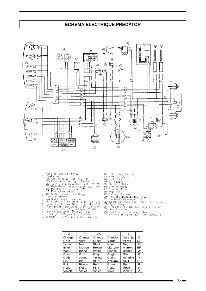
65
ECHEMA ELECTRIQUE PREDATOR
OrangeGrünSchwarzBraunWeiBGrauGelbBlauRotRosaViolett
OrangeVertNoirMarronBlancGrisJauneBlauRougeRosaViolet
OrangeGreenBlackBrownWhiteGrayYellowBlueRedPinkViolet
ArancioVerdeNeroMarroneBiancoGrigioGialloAzzurroRossoRosaViola
NaranjaVerdeNegroMarronBlancoGrisAmarilloAzulRojoRosaVioleta
OGRB
BRWGYBLRPVI
D F UK I E
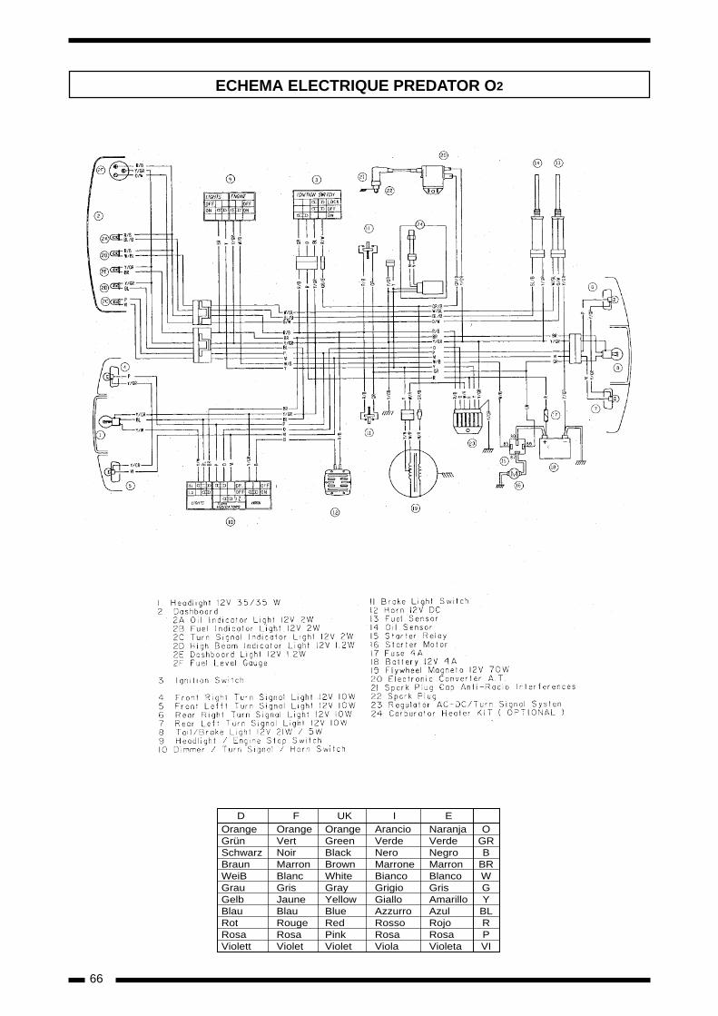
66
ECHEMA ELECTRIQUE PREDATOR O2
OrangeGrünSchwarzBraunWeiBGrauGelbBlauRotRosaViolett
OrangeVertNoirMarronBlancGrisJauneBlauRougeRosaViolet
OrangeGreenBlackBrownWhiteGrayYellowBlueRedPinkViolet
ArancioVerdeNeroMarroneBiancoGrigioGialloAzzurroRossoRosaViola
NaranjaVerdeNegroMarronBlancoGrisAmarilloAzulRojoRosaVioleta
OGRB
BRWGYBLRPVI
D F UK I E
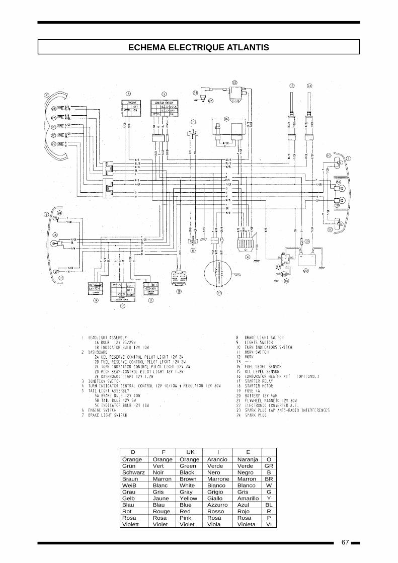
67
ECHEMA ELECTRIQUE ATLANTIS
OrangeGrünSchwarzBraunWeiBGrauGelbBlauRotRosaViolett
OrangeVertNoirMarronBlancGrisJauneBlauRougeRosaViolet
OrangeGreenBlackBrownWhiteGrayYellowBlueRedPinkViolet
ArancioVerdeNeroMarroneBiancoGrigioGialloAzzurroRossoRosaViola
NaranjaVerdeNegroMarronBlancoGrisAmarilloAzulRojoRosaVioleta
OGRB
BRWGYBLRPVI
D F UK I E
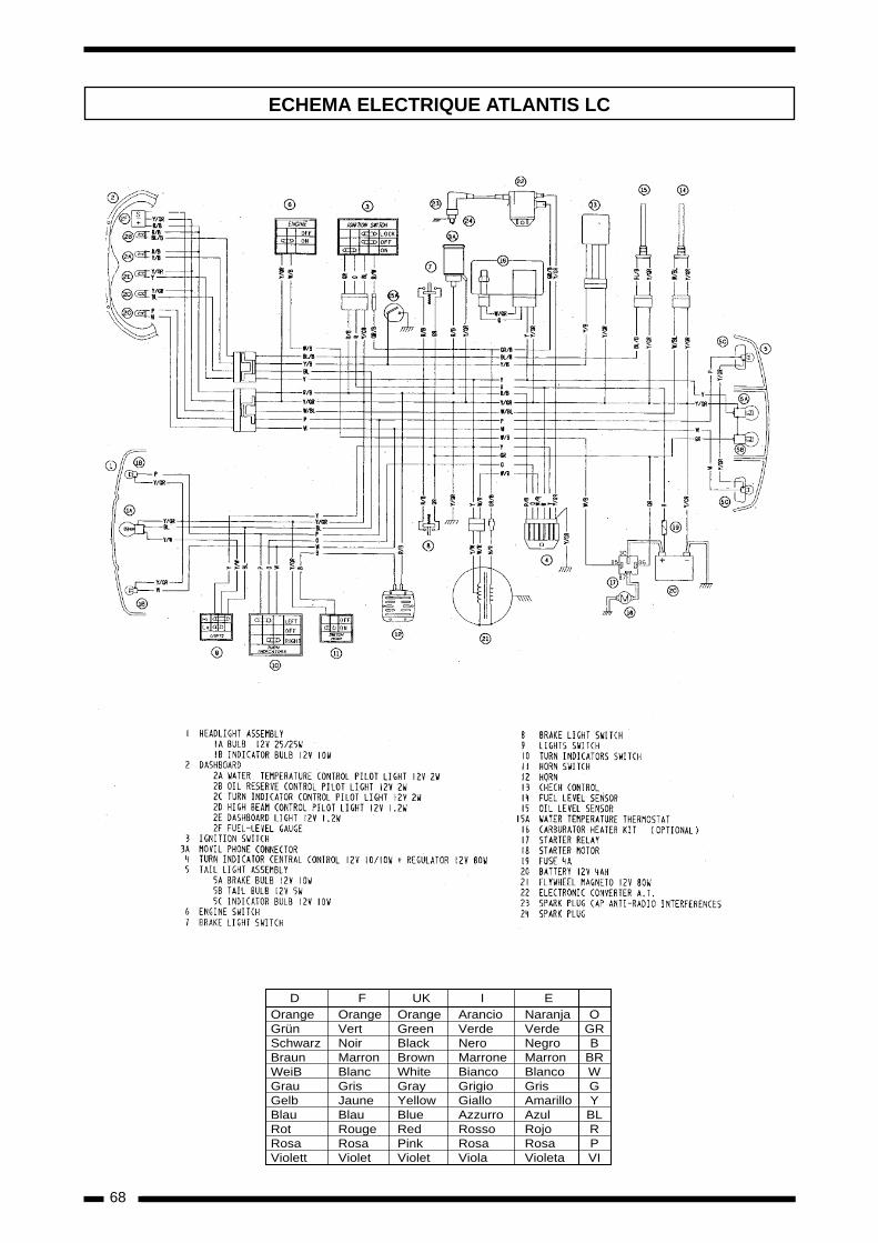
68
ECHEMA ELECTRIQUE ATLANTIS LC
OrangeGrünSchwarzBraunWeiBGrauGelbBlauRotRosaViolett
OrangeVertNoirMarronBlancGrisJauneBlauRougeRosaViolet
OrangeGreenBlackBrownWhiteGrayYellowBlueRedPinkViolet
ArancioVerdeNeroMarroneBiancoGrigioGialloAzzurroRossoRosaViola
NaranjaVerdeNegroMarronBlancoGrisAmarilloAzulRojoRosaVioleta
OGRB
BRWGYBLRPVI
D F UK I E
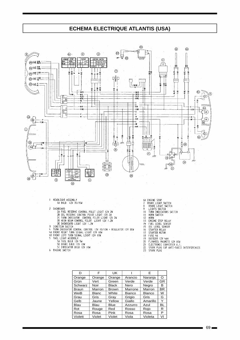
69
ECHEMA ELECTRIQUE ATLANTIS (USA)
OrangeGrünSchwarzBraunWeiBGrauGelbBlauRotRosaViolett
OrangeVertNoirMarronBlancGrisJauneBlauRougeRosaViolet
OrangeGreenBlackBrownWhiteGrayYellowBlueRedPinkViolet
ArancioVerdeNeroMarroneBiancoGrigioGialloAzzurroRossoRosaViola
NaranjaVerdeNegroMarronBlancoGrisAmarilloAzulRojoRosaVioleta
OGRB
BRWGYBLRPVI
D F UK I E

70
ECHEMA ELECTRIQUE PREDATOR (USA)
OrangeGrünSchwarzBraunWeiBGrauGelbBlauRotRosaViolett
OrangeVertNoirMarronBlancGrisJauneBlauRougeRosaViolet
OrangeGreenBlackBrownWhiteGrayYellowBlueRedPinkViolet
ArancioVerdeNeroMarroneBiancoGrigioGialloAzzurroRossoRosaViola
NaranjaVerdeNegroMarronBlancoGrisAmarilloAzulRojoRosaVioleta
OGRB
BRWGYBLRPVI
D F UK I E
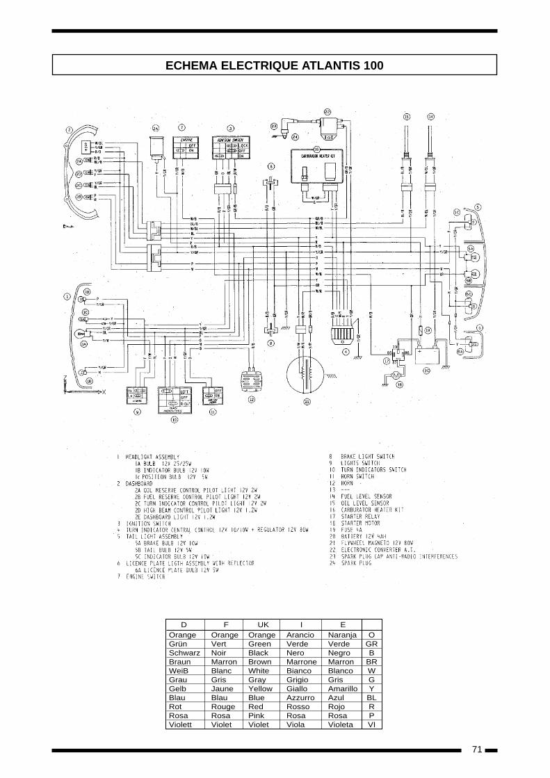
71
ECHEMA ELECTRIQUE ATLANTIS 100
OrangeGrünSchwarzBraunWeiBGrauGelbBlauRotRosaViolett
OrangeVertNoirMarronBlancGrisJauneBlauRougeRosaViolet
OrangeGreenBlackBrownWhiteGrayYellowBlueRedPinkViolet
ArancioVerdeNeroMarroneBiancoGrigioGialloAzzurroRossoRosaViola
NaranjaVerdeNegroMarronBlancoGrisAmarilloAzulRojoRosaVioleta
OGRB
BRWGYBLRPVI
D F UK I E

73
WORKSHOP MANUAL
GP 1GP SERIESATLANTIS
* 50 C.C. ENGINE PIAGGIO
3
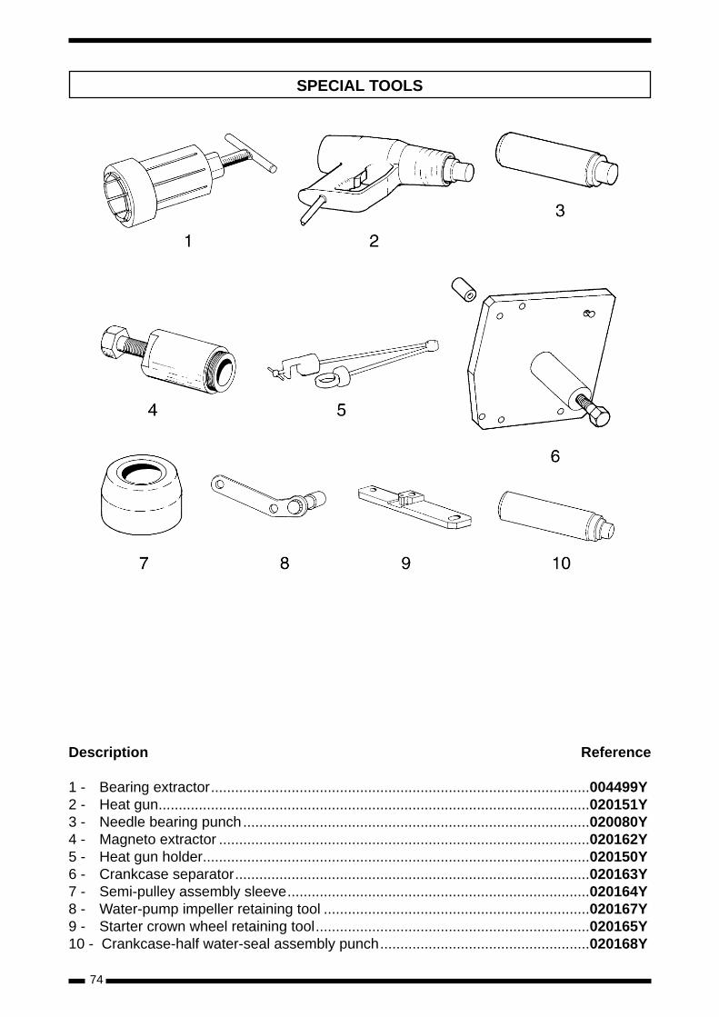
74
SPECIAL TOOLS
Description Reference
1 - Bearing extractor..............................................................................................004499Y2 - Heat gun...........................................................................................................020151Y3 - Needle bearing punch......................................................................................020080Y4 - Magneto extractor ............................................................................................020162Y5 - Heat gun holder................................................................................................020150Y 6 - Crankcase separator........................................................................................020163Y7 - Semi-pulley assembly sleeve...........................................................................020164Y8 - Water-pump impeller retaining tool ..................................................................020167Y 9 - Starter crown wheel retaining tool....................................................................020165Y10 - Crankcase-half water-seal assembly punch....................................................020168Y
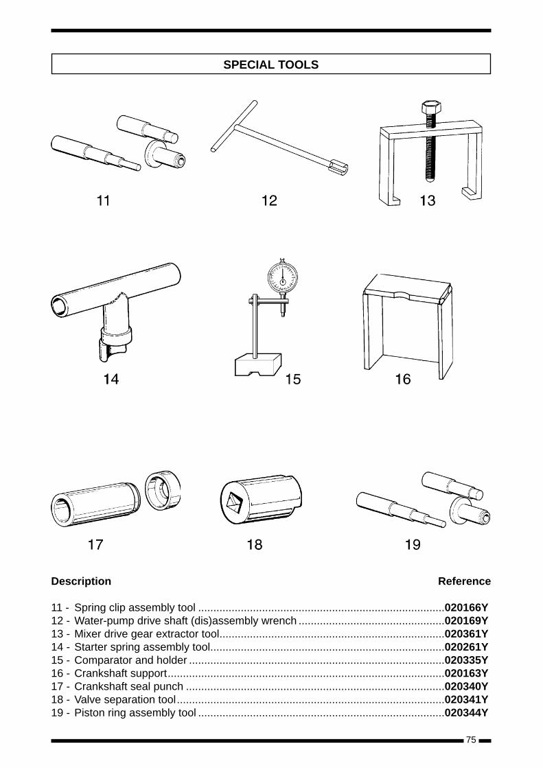
75
SPECIAL TOOLS
Description Reference
11 - Spring clip assembly tool .................................................................................020166Y12 - Water-pump drive shaft (dis)assembly wrench ................................................020169Y13 - Mixer drive gear extractor tool..........................................................................020361Y14 - Starter spring assembly tool.............................................................................020261Y15 - Comparator and holder ....................................................................................020335Y 16 - Crankshaft support...........................................................................................020163Y17 - Crankshaft seal punch .....................................................................................020340Y18 - Valve separation tool........................................................................................020341Y 19 - Piston ring assembly tool .................................................................................020344Y
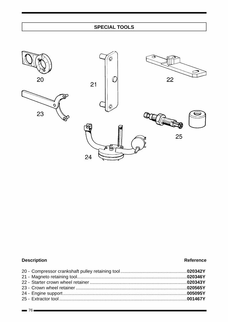
76
SPECIAL TOOLS
Description Reference
20 - Compressor crankshaft pulley retaining tool ....................................................020342Y21 - Magneto retaining tool......................................................................................020346Y22 - Starter crown wheel retainer ............................................................................020343Y23 - Crown wheel retainer .......................................................................................020565Y24 - Engine support .................................................................................................005095Y 25 - Extractor tool ....................................................................................................001467Y
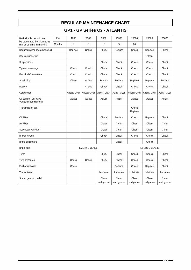
77
Km 1000 2500 5000 10000 15000 20000 25000
Months 2 6 12 24 36
Reduction gear or crankcase oil Replace Check Check Replace Check Replace Check
Check cylinder air Clean
Suspensions Check Check Check Check Check
Tighten fastenings Check Check Check Check Check Check Check
Electrical Connections Check Check Check Check Check Check Check
Spark plug Clean Adjust Replace Replace Replace Replace Replace
Battery Check Check Check Check Check Check
Carburettor Adjust / Clean Adjust / Clean Adjust / Clean Adjust / Clean Adjust / Clean Adjust / Clean Adjust / Clean
Oil pump / Fuel valve Adjust Adjust Adjust Adjust Adjust Adjust AdjustVariable speed rollers /
Transmission belt Check Replace
Oil Filter Check Replace Check Replace Check
Air Filter Clean Clean Clean Clean Clean
Secondary Air Filter Clean Clean Clean Clean Clean
Brakes / Pads Check Check Check Check Check
Brake equipment Check Check
Brake fluid EVERY 2 YEARS EVERY 2 YEARS
Tyres Check Check Check Check Check
Tyre pressures Check Check Check Check Check Check Check
Fuel or oil hoses Check Replace Check Replace Check
Transmission Lubricate Lubricate Lubricate Lubricate Lubricate
Starter gears to pedal Clean Clean Clean Clean Clean
and grease and grease and grease and grease and grease
REGULAR MAINTENANCE CHART
GP1 - GP Series O2 - ATLANTIS
Period: this period canbe calculated by kilometresrun or by time in months
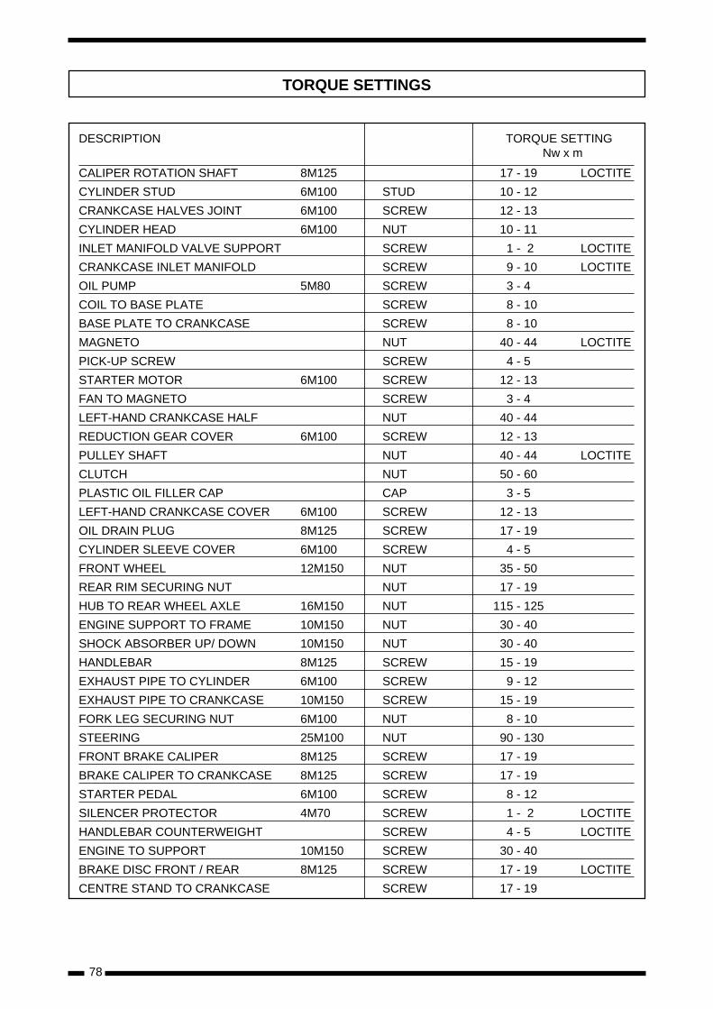
78
DESCRIPTION TORQUE SETTINGNw x m
CALIPER ROTATION SHAFT 8M125 17 - 19 LOCTITE
CYLINDER STUD 6M100 STUD 10 - 12
CRANKCASE HALVES JOINT 6M100 SCREW 12 - 13
CYLINDER HEAD 6M100 NUT 10 - 11
INLET MANIFOLD VALVE SUPPORT SCREW 1 - 2 LOCTITE
CRANKCASE INLET MANIFOLD SCREW 9 - 10 LOCTITE
OIL PUMP 5M80 SCREW 3 - 4
COIL TO BASE PLATE SCREW 8 - 10
BASE PLATE TO CRANKCASE SCREW 8 - 10
MAGNETO NUT 40 - 44 LOCTITE
PICK-UP SCREW SCREW 4 - 5
STARTER MOTOR 6M100 SCREW 12 - 13
FAN TO MAGNETO SCREW 3 - 4
LEFT-HAND CRANKCASE HALF NUT 40 - 44
REDUCTION GEAR COVER 6M100 SCREW 12 - 13
PULLEY SHAFT NUT 40 - 44 LOCTITE
CLUTCH NUT 50 - 60
PLASTIC OIL FILLER CAP CAP 3 - 5
LEFT-HAND CRANKCASE COVER 6M100 SCREW 12 - 13
OIL DRAIN PLUG 8M125 SCREW 17 - 19
CYLINDER SLEEVE COVER 6M100 SCREW 4 - 5
FRONT WHEEL 12M150 NUT 35 - 50
REAR RIM SECURING NUT NUT 17 - 19
HUB TO REAR WHEEL AXLE 16M150 NUT 115 - 125
ENGINE SUPPORT TO FRAME 10M150 NUT 30 - 40
SHOCK ABSORBER UP/ DOWN 10M150 NUT 30 - 40
HANDLEBAR 8M125 SCREW 15 - 19
EXHAUST PIPE TO CYLINDER 6M100 SCREW 9 - 12
EXHAUST PIPE TO CRANKCASE 10M150 SCREW 15 - 19
FORK LEG SECURING NUT 6M100 NUT 8 - 10
STEERING 25M100 NUT 90 - 130
FRONT BRAKE CALIPER 8M125 SCREW 17 - 19
BRAKE CALIPER TO CRANKCASE 8M125 SCREW 17 - 19
STARTER PEDAL 6M100 SCREW 8 - 12
SILENCER PROTECTOR 4M70 SCREW 1 - 2 LOCTITE
HANDLEBAR COUNTERWEIGHT SCREW 4 - 5 LOCTITE
ENGINE TO SUPPORT 10M150 SCREW 30 - 40
BRAKE DISC FRONT / REAR 8M125 SCREW 17 - 19 LOCTITE
CENTRE STAND TO CRANKCASE SCREW 17 - 19
TORQUE SETTINGS
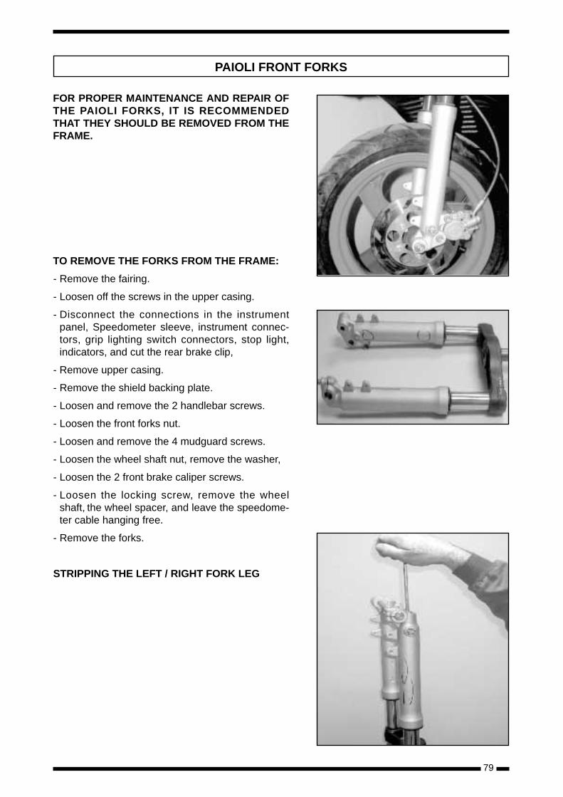
79
FOR PROPER MAINTENANCE AND REPAIR OFTHE PAIOLI FORKS, IT IS RECOMMENDEDTHAT THEY SHOULD BE REMOVED FROM THEFRAME.
TO REMOVE THE FORKS FROM THE FRAME:
- Remove the fairing.
- Loosen off the screws in the upper casing.
- Disconnect the connections in the instrumentpanel, Speedometer sleeve, instrument connec-tors, grip lighting switch connectors, stop light,indicators, and cut the rear brake clip,
- Remove upper casing.
- Remove the shield backing plate.
- Loosen and remove the 2 handlebar screws.
- Loosen the front forks nut.
- Loosen and remove the 4 mudguard screws.
- Loosen the wheel shaft nut, remove the washer,
- Loosen the 2 front brake caliper screws.
- Loosen the locking screw, remove the wheelshaft, the wheel spacer, and leave the speedome-ter cable hanging free.
- Remove the forks.
STRIPPING THE LEFT / RIGHT FORK LEG
PAIOLI FRONT FORKS
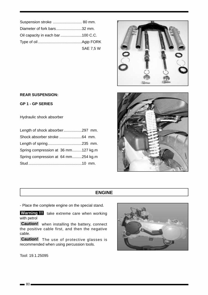
80
Suspension stroke ........................... 80 mm.
Diameter of fork bars........................32 mm.
Oil capacity in each bar ....................100 C.C.
Type of oil .........................................Agip FORK
SAE 7,5 W
REAR SUSPENSION:
GP 1 - GP SERIES
Hydraulic shock absorber
Length of shock absorber.................297 mm.
Shock absorber stroke .....................64 mm.
Length of spring................................235 mm.
Spring compression at 36 mm.........127 kg.m
Spring compression at 64 mm.........254 kg.m
Stud ..................................................10 mm.
ENGINE
- Place the complete engine on the special stand.
take extreme care when workingwith petrol
when installing the battery, connectthe positive cable first, and then the negativecable.
The use of protective glasses isrecommended when using percussion tools.
Tool: 19.1.25095
Warning !!!
Caution!
Caution!
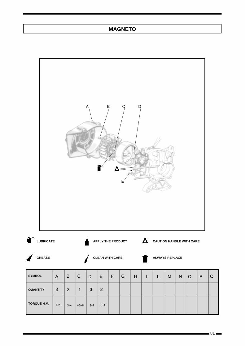
81
÷ ÷ ÷ ÷ ÷
LUBRICATE
GREASE
APPLY THE PRODUCT
CLEAN WITH CARE
CAUTION HANDLE WITH CARE
ALWAYS REPLACE
SYMBOL
QUANTITY
TORQUE N.M.
MAGNETO
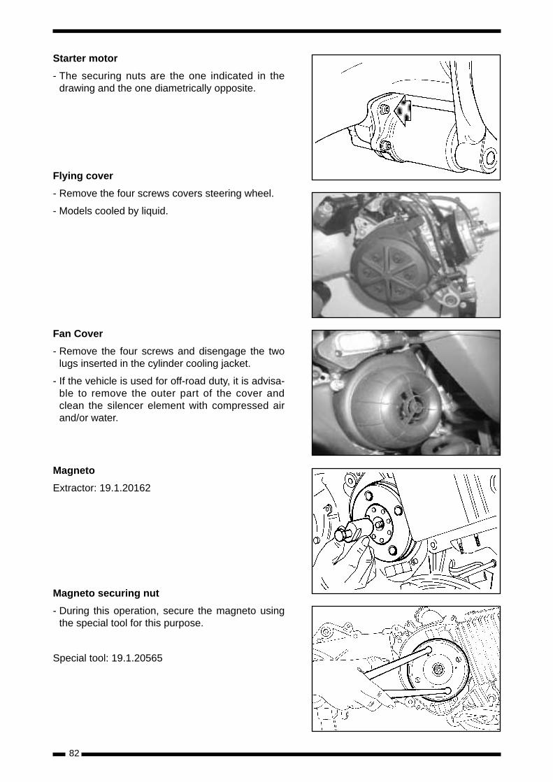
82
Starter motor
- The securing nuts are the one indicated in thedrawing and the one diametrically opposite.
Flying cover
- Remove the four screws covers steering wheel.
- Models cooled by liquid.
Fan Cover
- Remove the four screws and disengage the twolugs inserted in the cylinder cooling jacket.
- If the vehicle is used for off-road duty, it is advisa-ble to remove the outer part of the cover andclean the silencer element with compressed airand/or water.
Magneto
Extractor: 19.1.20162
Magneto securing nut
- During this operation, secure the magneto usingthe special tool for this purpose.
Special tool: 19.1.20565
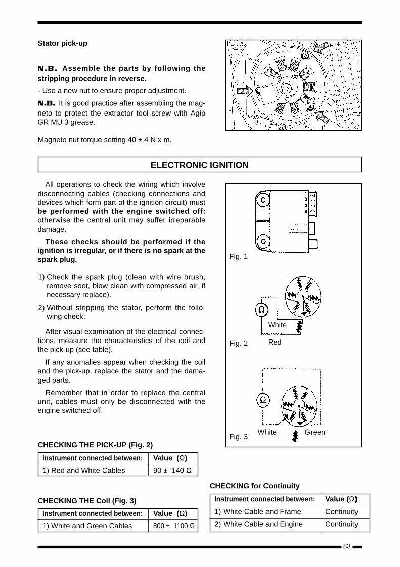
83
Stator pick-up
N.B. Assemble the parts by following thestripping procedure in reverse.
- Use a new nut to ensure proper adjustment.
N.B. It is good practice after assembling the mag-neto to protect the extractor tool screw with AgipGR MU 3 grease.
Magneto nut torque setting 40 ± 4 N x m.
All operations to check the wiring which involvedisconnecting cables (checking connections anddevices which form part of the ignition circuit) mustbe performed with the engine switched off:otherwise the central unit may suffer irreparabledamage.
These checks should be performed if theignition is irregular, or if there is no spark at thespark plug.
1) Check the spark plug (clean with wire brush,remove soot, blow clean with compressed air, ifnecessary replace).
2) Without stripping the stator, perform the follo-wing check:
After visual examination of the electrical connec-tions, measure the characteristics of the coil andthe pick-up (see table).
If any anomalies appear when checking the coiland the pick-up, replace the stator and the dama-ged parts.
Remember that in order to replace the centralunit, cables must only be disconnected with theengine switched off.
ELECTRONIC IGNITION
White
Fig. 2
Fig. 3
Fig. 1
Red
White Green
CHECKING THE PICK-UP (Fig. 2)
Instrument connected between: Value (Ω)
1) Red and White Cables 90 ± 140 Ω
CHECKING THE Coil (Fig. 3)
Instrument connected between: Value (Ω)
1) White and Green Cables 800 ± 1100 Ω
CHECKING for Continuity
Instrument connected between: Value (Ω)
1) White Cable and Frame Continuity
2) White Cable and Engine Continuity
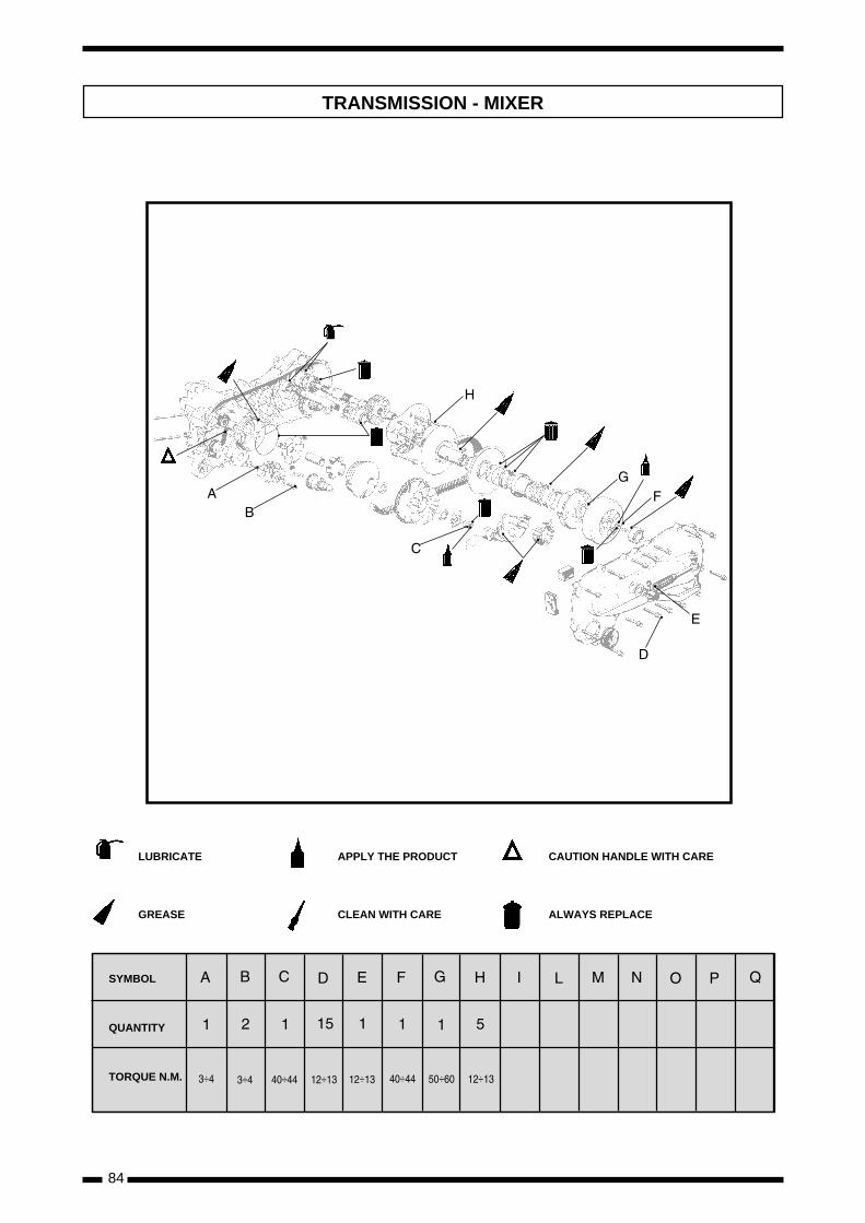
84
TRANSMISSION - MIXER
÷ ÷ ÷ ÷ ÷ ÷ ÷÷
LUBRICATE
GREASE
APPLY THE PRODUCT
CLEAN WITH CARE
CAUTION HANDLE WITH CARE
ALWAYS REPLACE
SYMBOL
QUANTITY
TORQUE N.M.
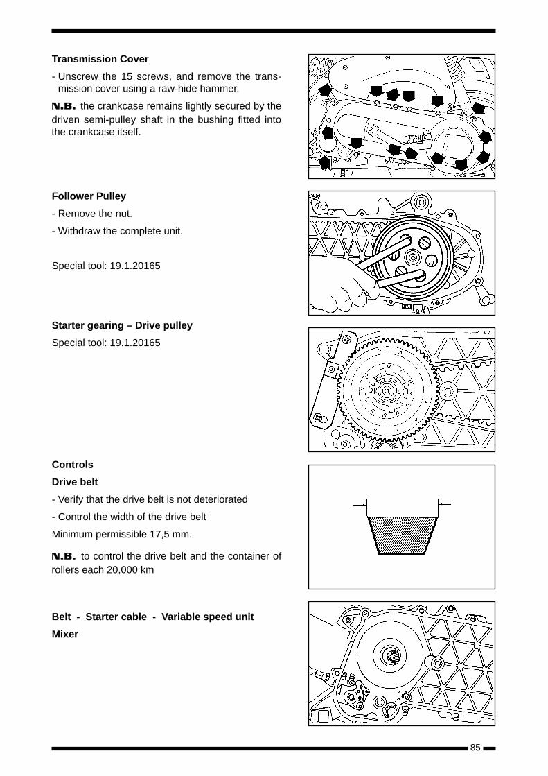
85
Transmission Cover
- Unscrew the 15 screws, and remove the trans-mission cover using a raw-hide hammer.
N.B. the crankcase remains lightly secured by thedriven semi-pulley shaft in the bushing fitted intothe crankcase itself.
Follower Pulley
- Remove the nut.
- Withdraw the complete unit.
Special tool: 19.1.20165
Starter gearing – Drive pulley
Special tool: 19.1.20165
Controls
Drive belt
- Verify that the drive belt is not deteriorated
- Control the width of the drive belt
Minimum permissible 17,5 mm.
N.B. to control the drive belt and the container ofrollers each 20,000 km
Belt - Starter cable - Variable speed unit
Mixer
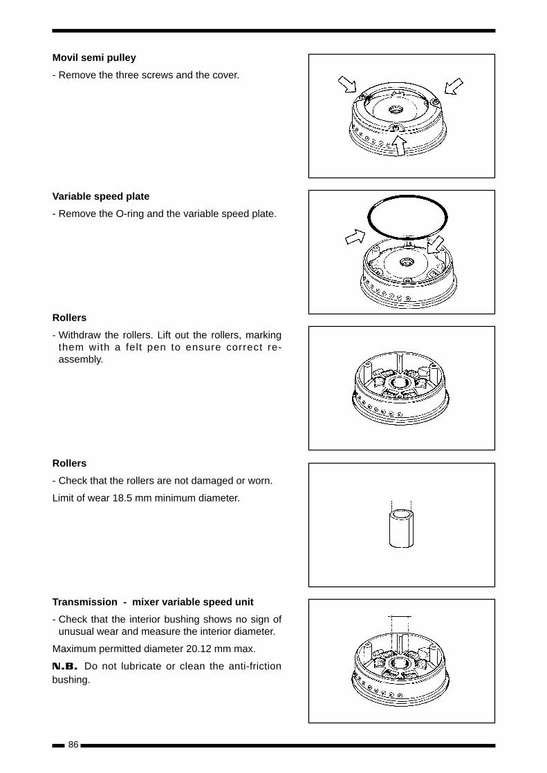
86
Movil semi pulley
- Remove the three screws and the cover.
Variable speed plate
- Remove the O-ring and the variable speed plate.
Rollers
- Withdraw the rollers. Lift out the rollers, markingthem with a felt pen to ensure correct re-assembly.
Rollers
- Check that the rollers are not damaged or worn.
Limit of wear 18.5 mm minimum diameter.
Transmission - mixer variable speed unit
- Check that the interior bushing shows no sign ofunusual wear and measure the interior diameter.
Maximum permitted diameter 20.12 mm max.
N.B. Do not lubricate or clean the anti-frictionbushing.
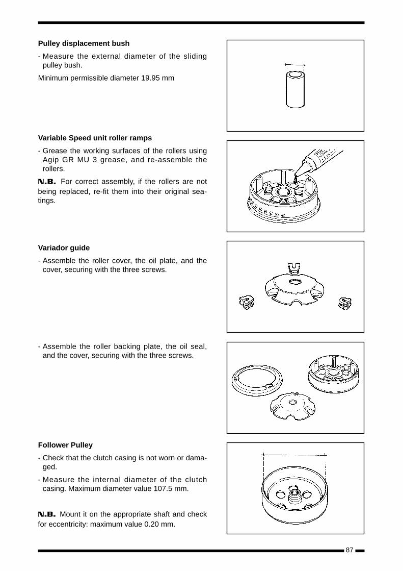
87
Pulley displacement bush
- Measure the external diameter of the slidingpulley bush.
Minimum permissible diameter 19.95 mm
Variable Speed unit roller ramps
- Grease the working surfaces of the rollers usingAgip GR MU 3 grease, and re-assemble therollers.
N.B. For correct assembly, if the rollers are notbeing replaced, re-fit them into their original sea-tings.
Variador guide
- Assemble the roller cover, the oil plate, and thecover, securing with the three screws.
- Assemble the roller backing plate, the oil seal,and the cover, securing with the three screws.
Follower Pulley
- Check that the clutch casing is not worn or dama-ged.
- Measure the internal diameter of the clutchcasing. Maximum diameter value 107.5 mm.
N.B. Mount it on the appropriate shaft and checkfor eccentricity: maximum value 0.20 mm.
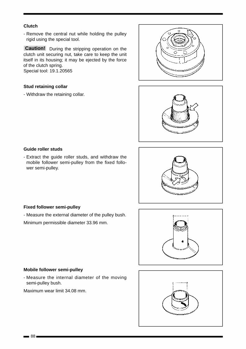
88
Clutch
- Remove the central nut while holding the pulleyrigid using the special tool.
During the stripping operation on theclutch unit securing nut, take care to keep the unititself in its housing; it may be ejected by the forceof the clutch spring.Special tool: 19.1.20565
Stud retaining collar
- Withdraw the retaining collar.
Guide roller studs
- Extract the guide roller studs, and withdraw themobile follower semi-pulley from the fixed follo-wer semi-pulley.
Fixed follower semi-pulley
- Measure the external diameter of the pulley bush.
Minimum permissible diameter 33.96 mm.
Mobile follower semi-pulley
- Measure the internal diameter of the movingsemi-pulley bush.
Maximum wear limit 34.08 mm.
Caution!
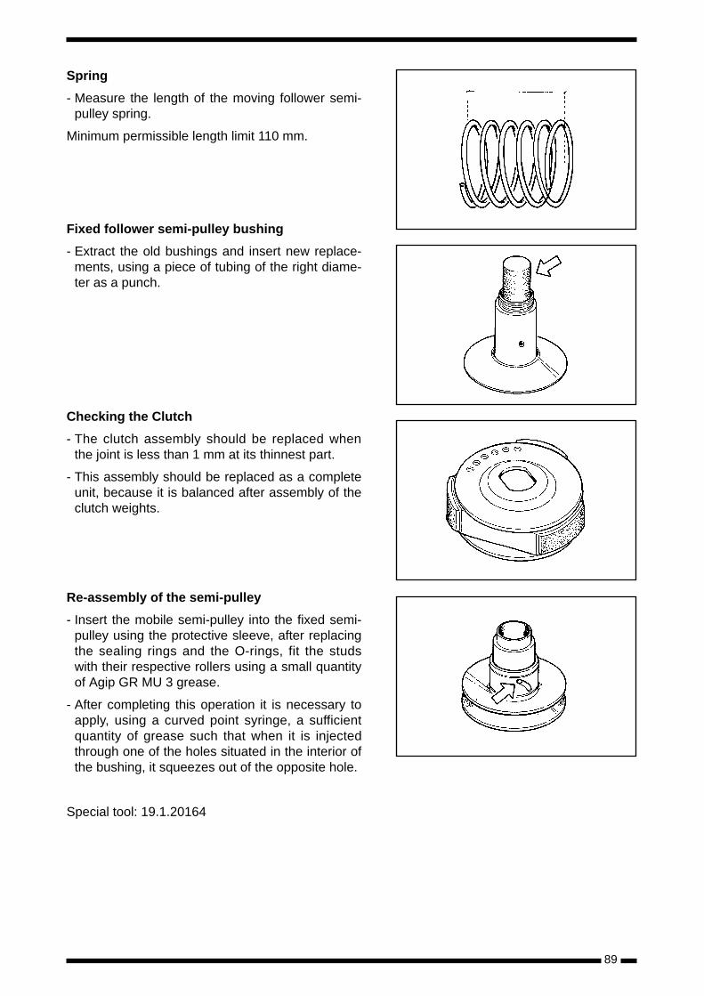
89
Spring
- Measure the length of the moving follower semi-pulley spring.
Minimum permissible length limit 110 mm.
Fixed follower semi-pulley bushing
- Extract the old bushings and insert new replace-ments, using a piece of tubing of the right diame-ter as a punch.
Checking the Clutch
- The clutch assembly should be replaced whenthe joint is less than 1 mm at its thinnest part.
- This assembly should be replaced as a completeunit, because it is balanced after assembly of theclutch weights.
Re-assembly of the semi-pulley
- Insert the mobile semi-pulley into the fixed semi-pulley using the protective sleeve, after replacingthe sealing rings and the O-rings, fit the studswith their respective rollers using a small quantityof Agip GR MU 3 grease.
- After completing this operation it is necessary toapply, using a curved point syringe, a sufficientquantity of grease such that when it is injectedthrough one of the holes situated in the interior ofthe bushing, it squeezes out of the opposite hole.
Special tool: 19.1.20164
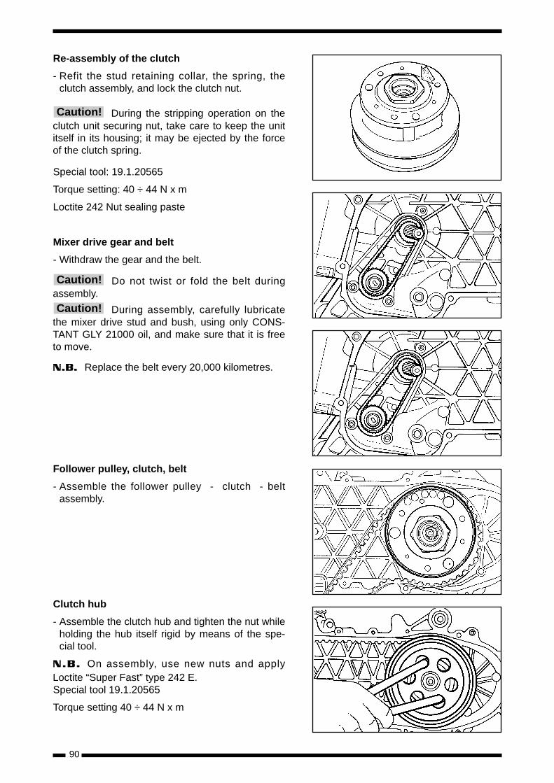
90
Re-assembly of the clutch
- Refit the stud retaining collar, the spring, theclutch assembly, and lock the clutch nut.
During the stripping operation on theclutch unit securing nut, take care to keep the unititself in its housing; it may be ejected by the forceof the clutch spring.
Special tool: 19.1.20565
Torque setting: 40 ÷ 44 N x m
Loctite 242 Nut sealing paste
Mixer drive gear and belt
- Withdraw the gear and the belt.
Do not twist or fold the belt duringassembly.
During assembly, carefully lubricatethe mixer drive stud and bush, using only CONS-TANT GLY 21000 oil, and make sure that it is freeto move.
N.B. Replace the belt every 20,000 kilometres.
Follower pulley, clutch, belt
- Assemble the follower pulley - clutch - beltassembly.
Clutch hub
- Assemble the clutch hub and tighten the nut whileholding the hub itself rigid by means of the spe-cial tool.
N.B. On assembly, use new nuts and applyLoctite “Super Fast” type 242 E.Special tool 19.1.20565
Torque setting 40 ÷ 44 N x m
Caution!
Caution!
Caution!
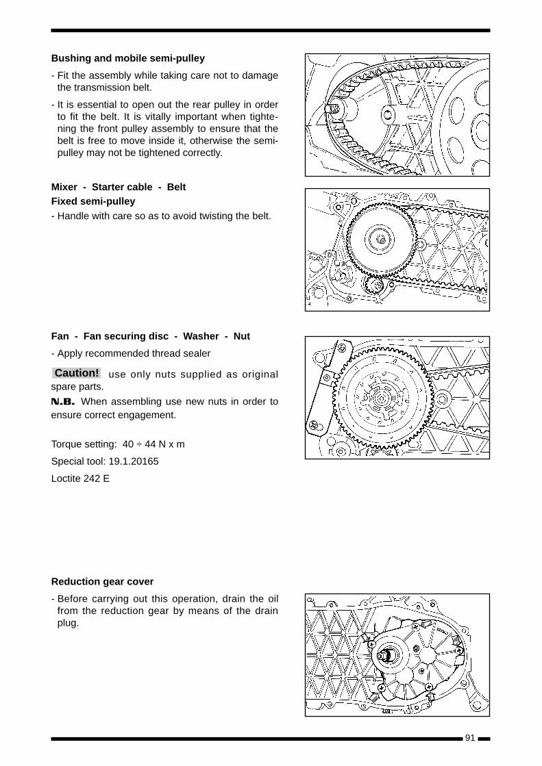
91
Bushing and mobile semi-pulley
- Fit the assembly while taking care not to damagethe transmission belt.
- It is essential to open out the rear pulley in orderto fit the belt. It is vitally important when tighte-ning the front pulley assembly to ensure that thebelt is free to move inside it, otherwise the semi-pulley may not be tightened correctly.
Mixer - Starter cable - Belt Fixed semi-pulley- Handle with care so as to avoid twisting the belt.
Fan - Fan securing disc - Washer - Nut
- Apply recommended thread sealer
use only nuts supplied as originalspare parts.
N.B. When assembling use new nuts in order toensure correct engagement.
Torque setting: 40 ÷ 44 N x m
Special tool: 19.1.20165
Loctite 242 E
Reduction gear cover
- Before carrying out this operation, drain the oilfrom the reduction gear by means of the drainplug.
Caution!
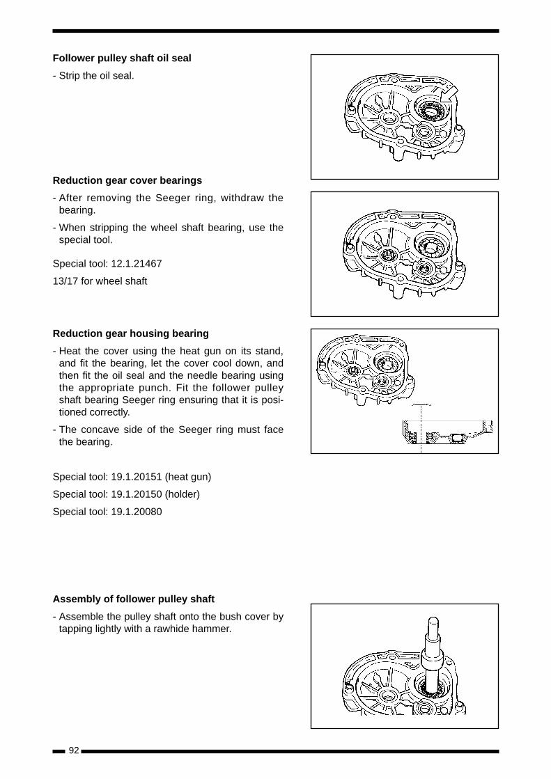
92
Follower pulley shaft oil seal
- Strip the oil seal.
Reduction gear cover bearings
- After removing the Seeger ring, withdraw thebearing.
- When stripping the wheel shaft bearing, use thespecial tool.
Special tool: 12.1.21467
13/17 for wheel shaft
Reduction gear housing bearing
- Heat the cover using the heat gun on its stand,and fit the bearing, let the cover cool down, andthen fit the oil seal and the needle bearing usingthe appropriate punch. Fit the follower pulleyshaft bearing Seeger ring ensuring that it is posi-tioned correctly.
- The concave side of the Seeger ring must facethe bearing.
Special tool: 19.1.20151 (heat gun)
Special tool: 19.1.20150 (holder)
Special tool: 19.1.20080
Assembly of follower pulley shaft
- Assemble the pulley shaft onto the bush cover bytapping lightly with a rawhide hammer.
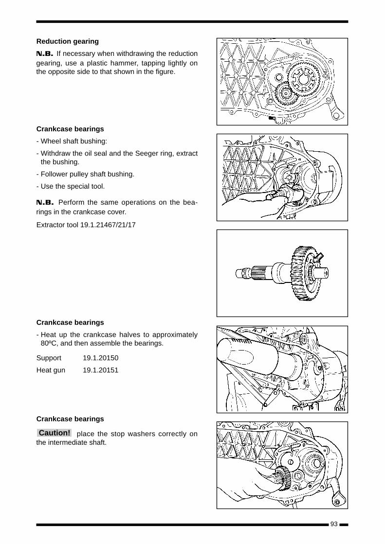
93
Reduction gearing
N.B. If necessary when withdrawing the reductiongearing, use a plastic hammer, tapping lightly onthe opposite side to that shown in the figure.
Crankcase bearings
- Wheel shaft bushing:
- Withdraw the oil seal and the Seeger ring, extractthe bushing.
- Follower pulley shaft bushing.
- Use the special tool.
N.B. Perform the same operations on the bea-rings in the crankcase cover.
Extractor tool 19.1.21467/21/17
Crankcase bearings
- Heat up the crankcase halves to approximately80ºC, and then assemble the bearings.
Support 19.1.20150
Heat gun 19.1.20151
Crankcase bearings
place the stop washers correctly onthe intermediate shaft.Caution!
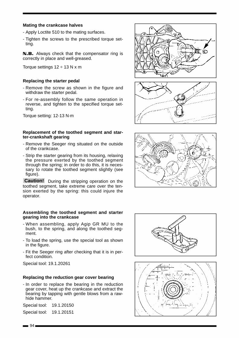
94
Mating the crankcase halves
- Apply Loctite 510 to the mating surfaces.
- Tighten the screws to the prescribed torque set-ting.
N.B. Always check that the compensator ring iscorrectly in place and well-greased.
Torque settings 12 ÷ 13 N x m
Replacing the starter pedal
- Remove the screw as shown in the figure andwithdraw the starter pedal.
- For re-assembly follow the same operation inreverse, and tighten to the specified torque set-ting.
Torque setting: 12-13 N·m
Replacement of the toothed segment and star-ter-crankshaft gearing
- Remove the Seeger ring situated on the outsideof the crankcase.
- Strip the starter gearing from its housing, relaxingthe pressure exerted by the toothed segmentthrough the spring; in order to do this, it is neces-sary to rotate the toothed segment slightly (seefigure).
During the stripping operation on thetoothed segment, take extreme care over the ten-sion exerted by the spring: this could injure theoperator.
Assembling the toothed segment and startergearing into the crankcase
- When assembling, apply Agip GR MU to thebush, to the spring, and along the toothed seg-ment.
- To load the spring, use the special tool as shownin the figure.
- Fit the Seeger ring after checking that it is in per-fect condition.
Special tool: 19.1.20261
Replacing the reduction gear cover bearing
- In order to replace the bearing in the reductiongear cover, heat up the crankcase and extract thebearing by tapping with gentle blows from a raw-hide hammer.
Special tool: 19.1.20150
Special tool: 19.1.20151
Caution!
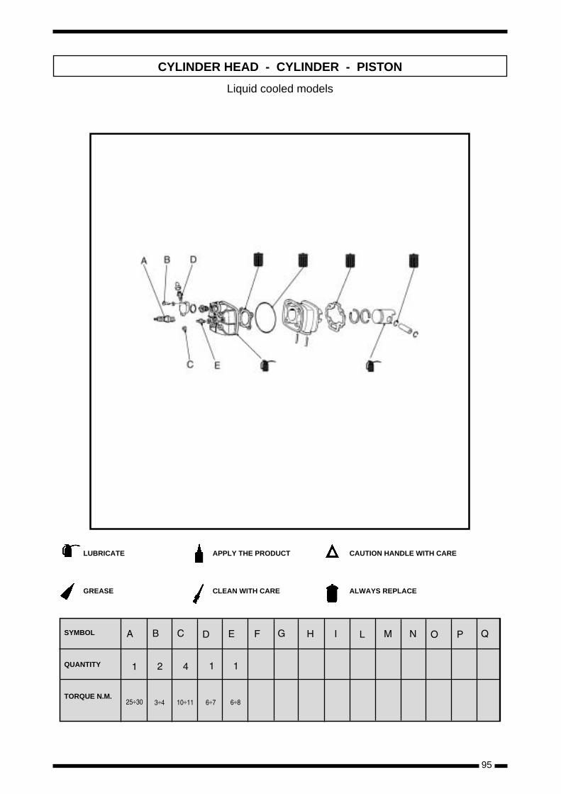
95
CYLINDER HEAD - CYLINDER - PISTON
LUBRICATE
GREASE
APPLY THE PRODUCT
CLEAN WITH CARE
CAUTION HANDLE WITH CARE
ALWAYS REPLACE
SYMBOL
QUANTITY
TORQUE N.M.÷ ÷ ÷ ÷ ÷
Liquid cooled models
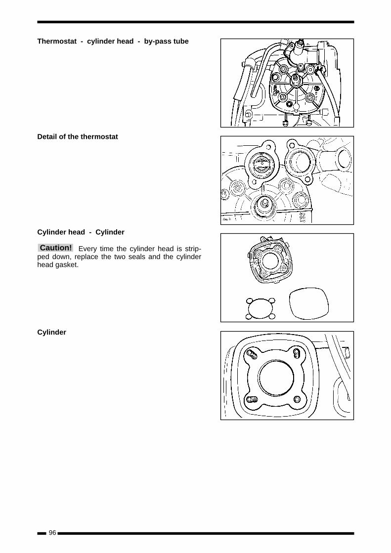
96
Thermostat - cylinder head - by-pass tube
Detail of the thermostat
Cylinder head - Cylinder
Every time the cylinder head is strip-ped down, replace the two seals and the cylinderhead gasket.
Cylinder
Caution!
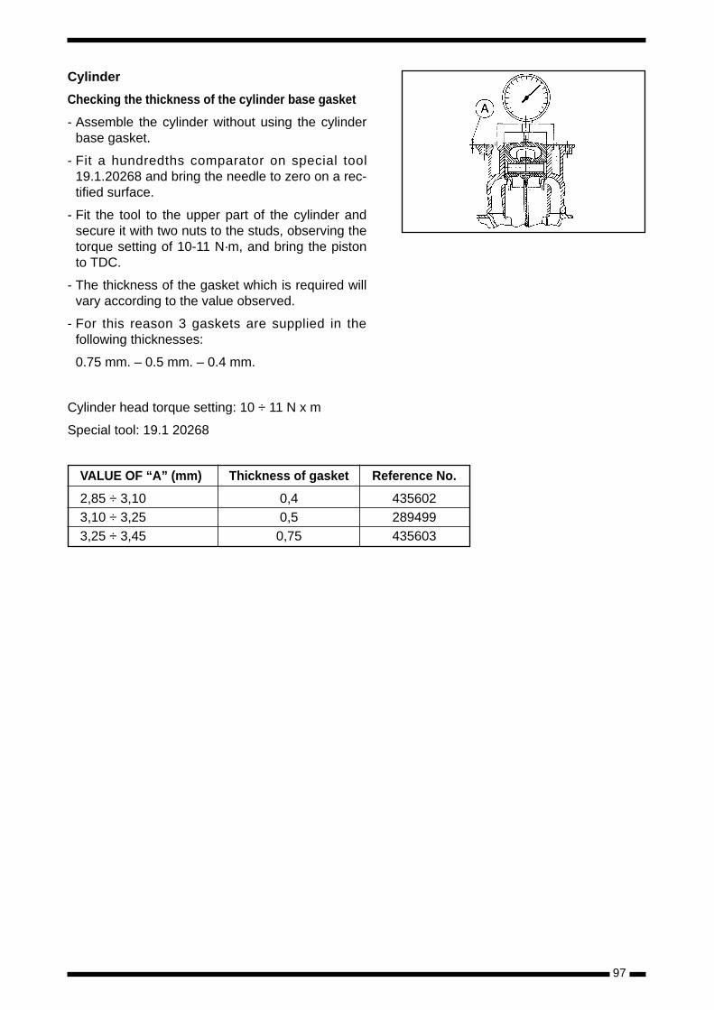
97
Cylinder
Checking the thickness of the cylinder base gasket
- Assemble the cylinder without using the cylinderbase gasket.
- Fit a hundredths comparator on special tool19.1.20268 and bring the needle to zero on a rec-tified surface.
- Fit the tool to the upper part of the cylinder andsecure it with two nuts to the studs, observing thetorque setting of 10-11 N·m, and bring the pistonto TDC.
- The thickness of the gasket which is required willvary according to the value observed.
- For this reason 3 gaskets are supplied in thefollowing thicknesses:
0.75 mm. – 0.5 mm. – 0.4 mm.
Cylinder head torque setting: 10 ÷ 11 N x m
Special tool: 19.1 20268
VALUE OF “A” (mm) Thickness of gasket Reference No.
2,85 ÷ 3,10 0,4 4356023,10 ÷ 3,25 0,5 2894993,25 ÷ 3,45 0,75 435603
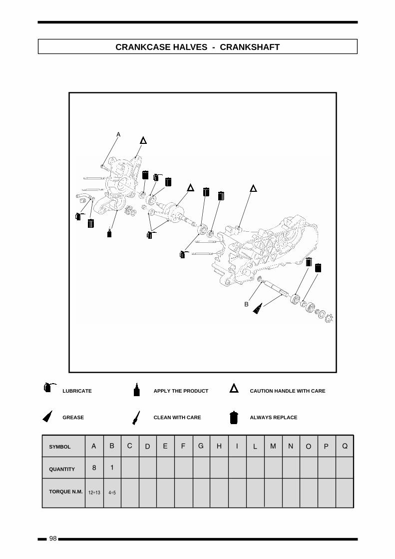
98
CRANKCASE HALVES - CRANKSHAFT
÷ ÷
LUBRICATE
GREASE
APPLY THE PRODUCT
CLEAN WITH CARE
CAUTION HANDLE WITH CARE
ALWAYS REPLACE
SYMBOL
QUANTITY
TORQUE N.M.
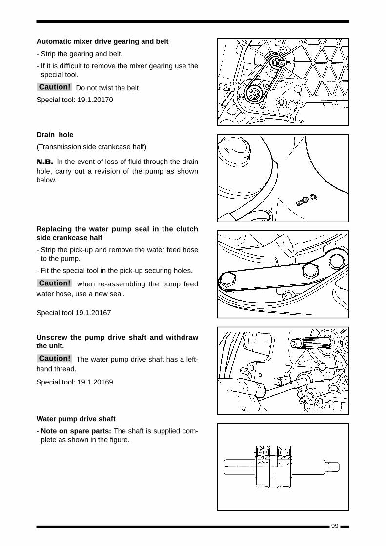
99
Automatic mixer drive gearing and belt
- Strip the gearing and belt.
- If it is difficult to remove the mixer gearing use thespecial tool.
Do not twist the belt
Special tool: 19.1.20170
Drain hole
(Transmission side crankcase half)
N.B. In the event of loss of fluid through the drainhole, carry out a revision of the pump as shownbelow.
Replacing the water pump seal in the clutchside crankcase half
- Strip the pick-up and remove the water feed hoseto the pump.
- Fit the special tool in the pick-up securing holes.
when re-assembling the pump feedwater hose, use a new seal.
Special tool 19.1.20167
Unscrew the pump drive shaft and withdrawthe unit.
The water pump drive shaft has a left-hand thread.
Special tool: 19.1.20169
Water pump drive shaft
- Note on spare parts: The shaft is supplied com-plete as shown in the figure.
Caution!
Caution!
Caution!
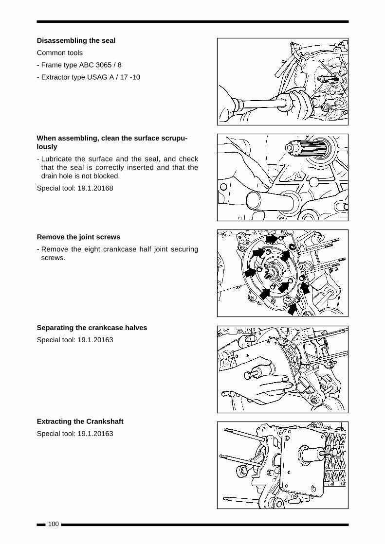
100
Disassembling the seal
Common tools
- Frame type ABC 3065 / 8
- Extractor type USAG A / 17 -10
When assembling, clean the surface scrupu-lously
- Lubricate the surface and the seal, and checkthat the seal is correctly inserted and that thedrain hole is not blocked.
Special tool: 19.1.20168
Remove the joint screws
- Remove the eight crankcase half joint securingscrews.
Separating the crankcase halves
Special tool: 19.1.20163
Extracting the Crankshaft
Special tool: 19.1.20163
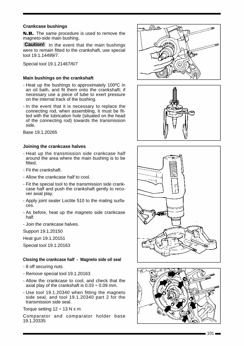
101
Crankcase bushings
N.B. The same procedure is used to remove themagneto-side main bushing.
In the event that the main bushingswere to remain fitted to the crankshaft, use specialtool 19.1.14499/7.
Special tool 19.1.21467/6/7
Main bushings on the crankshaft
- Heat up the bushings to approximately 100ºC inan oil bath, and fit them onto the crankshaft; ifnecessary use a piece of tube to exert pressureon the internal track of the bushing.
- In the event that it is necessary to replace theconnecting rod, when assembling, it must be fit-ted with the lubrication hole (situated on the headof the connecting rod) towards the transmissionside.
Base 19.1.20265
Joining the crankcase halves
- Heat up the transmission side crankcase halfaround the area where the main bushing is to befitted.
- Fit the crankshaft.
- Allow the crankcase half to cool.
- Fit the special tool to the transmission side crank-case half and push the crankshaft gently to reco-ver axial play.
- Apply joint sealer Loctite 510 to the mating surfa-ces.
- As before, heat up the magneto side crankcasehalf.
- Join the crankcase halves.
Support 19.1.20150
Heat gun 19.1.20151
Special tool 19.1.20163
Closing the crankcase half - Magneto side oil seal
- 8 off securing nuts
- Remove special tool 19.1.20163
- Allow the crankcase to cool, and check that theaxial play of the crankshaft is 0.03 ÷ 0.09 mm.
- Use tool 19.1.20340 when fitting the magnetoside seal, and tool 19.1.20340 part 2 for thetransmission side seal.
Torque setting 12 ÷ 13 N x m
Comparator and comparator holder base19.1.20335
Caution!
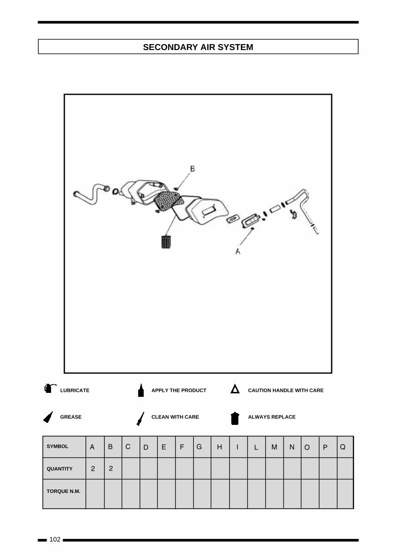
102
SECONDARY AIR SYSTEM
LUBRICATE
GREASE
APPLY THE PRODUCT
CLEAN WITH CARE
CAUTION HANDLE WITH CARE
ALWAYS REPLACE
SYMBOL
QUANTITY
TORQUE N.M.
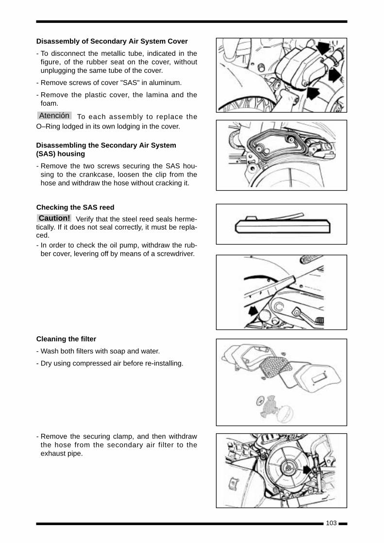
103
Disassembly of Secondary Air System Cover
- To disconnect the metallic tube, indicated in thefigure, of the rubber seat on the cover, withoutunplugging the same tube of the cover.
- Remove screws of cover "SAS" in aluminum.
- Remove the plastic cover, the lamina and thefoam.
To each assembly to replace theO–Ring lodged in its own lodging in the cover.
Disassembling the Secondary Air System(SAS) housing
- Remove the two screws securing the SAS hou-sing to the crankcase, loosen the clip from thehose and withdraw the hose without cracking it.
Checking the SAS reed
Verify that the steel reed seals herme-tically. If it does not seal correctly, it must be repla-ced. - In order to check the oil pump, withdraw the rub-
ber cover, levering off by means of a screwdriver.
Cleaning the filter
- Wash both filters with soap and water.
- Dry using compressed air before re-installing.
- Remove the securing clamp, and then withdrawthe hose from the secondary air filter to theexhaust pipe.
Atención
Caution!
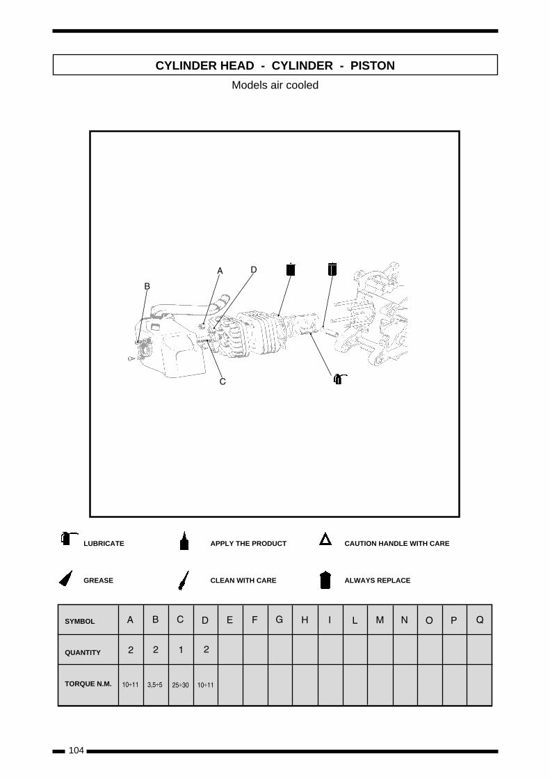
104
CYLINDER HEAD - CYLINDER - PISTON
÷ ÷÷ ÷
LUBRICATE
GREASE
APPLY THE PRODUCT
CLEAN WITH CARE
CAUTION HANDLE WITH CARE
ALWAYS REPLACE
SYMBOL
QUANTITY
TORQUE N.M.
Models air cooled
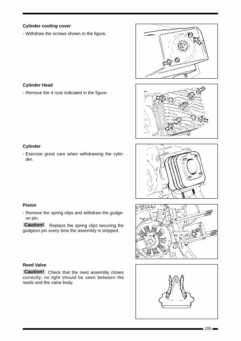
105
Cylinder cooling cover
- Withdraw the screws shown in the figure.
Cylinder Head
- Remove the 4 nuts indicated in the figure.
Cylinder
- Exercise great care when withdrawing the cylin-der.
Piston
- Remove the spring clips and withdraw the gudge-on pin.
Replace the spring clips securing thegudgeon pin every time the assembly is stripped.
Reed Valve
Check that the reed assembly closescorrectly; no light should be seen between thereeds and the valve body.
Caution!
Caution!
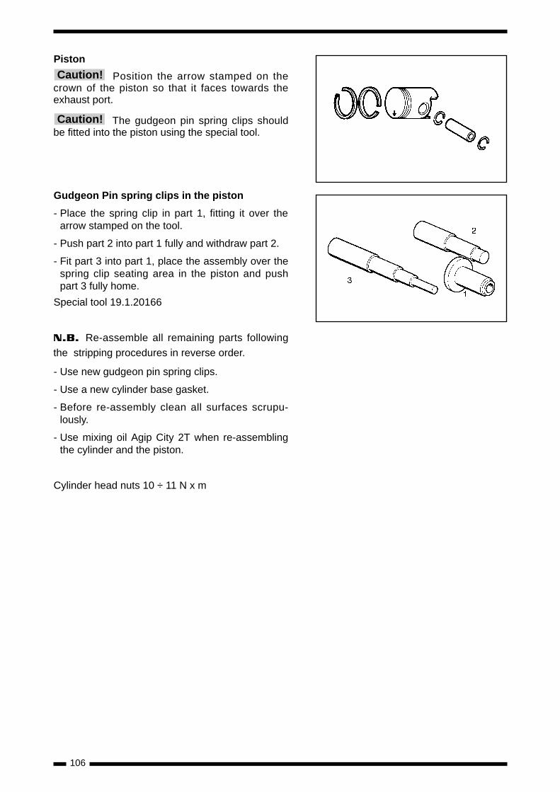
106
Piston
Position the arrow stamped on thecrown of the piston so that it faces towards theexhaust port.
The gudgeon pin spring clips shouldbe fitted into the piston using the special tool.
Gudgeon Pin spring clips in the piston
- Place the spring clip in part 1, fitting it over thearrow stamped on the tool.
- Push part 2 into part 1 fully and withdraw part 2.
- Fit part 3 into part 1, place the assembly over thespring clip seating area in the piston and pushpart 3 fully home.
Special tool 19.1.20166
N.B. Re-assemble all remaining parts following
the stripping procedures in reverse order.
- Use new gudgeon pin spring clips.
- Use a new cylinder base gasket.
- Before re-assembly clean all surfaces scrupu-lously.
- Use mixing oil Agip City 2T when re-assemblingthe cylinder and the piston.
Cylinder head nuts 10 ÷ 11 N x m
Caution!
Caution!
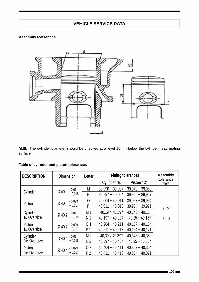
107
DESCRIPTION Dimension Letter Fitting tolerances
Cylinder Ø 40 - 0,01 MN+ 0,018
0,040
0,054
Assemblytolerance
"A"Cylinder "E" Piston "C"39,990 ÷ 39,997 39,943 ÷ 39,95039,997 ÷ 40,004 39,950 ÷ 39,957
Piston Ø 40 - 0,029 OP+ 0,057
40,004 ÷ 40,011 39,957 ÷ 39,96440,011 ÷ 40,018 39,964 ÷ 39,971
Cylinder1st Oversize Ø 40,2 - 0,01 M 1
N 1+ 0,01840,19 ÷ 40,197 40,143 ÷ 40,15
40,197 ÷ 40,204 40,15 ÷ 40,157Pistón1st Oversize Ø 40,2 - 0,029 O 1
P 1+ 0,05740,204 ÷ 40,211 40,157 ÷ 40,16440,211 ÷ 40,218 40,164 ÷ 40,171
Cylinder2nd Oversize Ø 40,4 - 0,01 M 2
N 2+ 0,01840,39 ÷ 40,397 40,343 ÷ 40,35
40,397 ÷ 40,404 40,35 ÷ 40,357Pistón2nd Oversize Ø 40,4 - 0,029 O 2
P 2+ 0,05740,404 ÷ 40,411 40,357 ÷ 40,36440,411 ÷ 40,418 40,364 ÷ 40,371
VEHICLE SERVICE DATA
Assembly tolerances
N.B. The cylinder diameter should be checked at a level 15mm below the cylinder head matingsurface.
Table of cylinder and piston tolerances
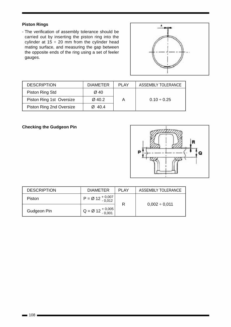
108
Piston Rings
- The verification of assembly tolerance should becarried out by inserting the piston ring into thecylinder at 15 ÷ 20 mm from the cylinder headmating surface, and measuring the gap betweenthe opposite ends of the ring using a set of feelergauges.
DESCRIPTION DIAMETER PLAY ASSEMBLY TOLERANCE
Piston Ring Std Ø 40
Piston Ring 1st Oversize Ø 40.2 A 0.10 ÷ 0.25
Piston Ring 2nd Oversize Ø 40.4
DESCRIPTION DIAMETER PLAY ASSEMBLY TOLERANCE
Piston P = Ø 12 + 0,007- 0,012
R 0,002 ÷ 0,011
Gudgeon Pin Q = Ø 12 + 0,005- 0,001
Checking the Gudgeon Pin
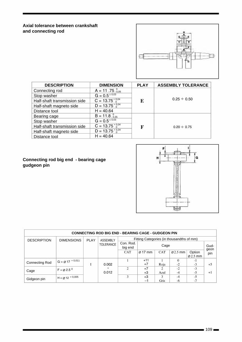
109
Connecting rod big end - bearing cagegudgeon pin
÷
÷
0- 0,05
± 0,03
+ 0,04 0
0- 0,35
± 0,03
+ 0,04 0+ 0,04 0
+ 0,04 0
DESCRIPTION DIMENSION PLAY ASSEMBLY TOLERANCEConnecting rodStop washerHalf-shaft transmission sideHalf-shaft magneto sideDistance toolBearing cageStop washerHalf-shaft transmission sideHalf-shaft magneto sideDistance tool
Ø
Ø
Ø
+ 0,011
0
+ 0,005
÷
ØØ
Ø
CONNECTING ROD BIG END - BEARING CAGE - GUDGEON PIN
DESCRIPTION DIMENSIONS PLAY ASSEMBLYTOLERANCE
Connecting Rod
Cage
Gidgeon pin
Fitting Categories (in thousandths of mm)
CageCon. Rod.
big end Gud-geonpinOption
Axial tolerance between crankshaftand connecting rod
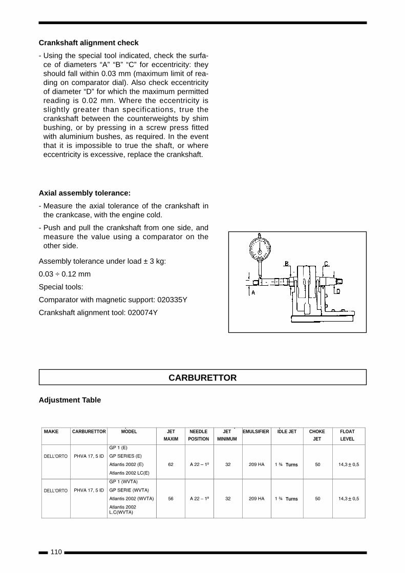
110
Crankshaft alignment check
- Using the special tool indicated, check the surfa-ce of diameters “A” “B” “C” for eccentricity: theyshould fall within 0.03 mm (maximum limit of rea-ding on comparator dial). Also check eccentricityof diameter “D” for which the maximum permittedreading is 0.02 mm. Where the eccentricity isslightly greater than specifications, true thecrankshaft between the counterweights by shimbushing, or by pressing in a screw press fittedwith aluminium bushes, as required. In the eventthat it is impossible to true the shaft, or whereeccentricity is excessive, replace the crankshaft.
Axial assembly tolerance:
- Measure the axial tolerance of the crankshaft inthe crankcase, with the engine cold.
- Push and pull the crankshaft from one side, andmeasure the value using a comparator on theother side.
Assembly tolerance under load ± 3 kg:
0.03 ÷ 0.12 mm
Special tools:
Comparator with magnetic support: 020335Y
Crankshaft alignment tool: 020074Y
Adjustment Table
MAKE CARBURETTOR
DELL'ORTO
DELL'ORTO
±
±
MODEL JET
MAXIM
NEEDLE
POSITION
JET
MINIMUM
EMULSIFIER IDLE JET CHOKE
JET
FLOAT
LEVEL
Turns
Turns
CARBURETTOR
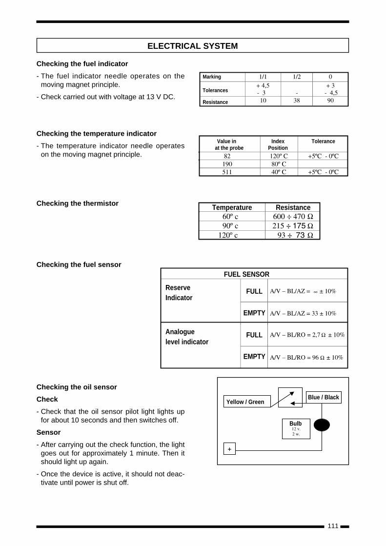
111
Yellow / GreenBlue / Black
Bulb
Checking the fuel indicator
- The fuel indicator needle operates on themoving magnet principle.
- Check carried out with voltage at 13 V DC.
Checking the temperature indicator
- The temperature indicator needle operateson the moving magnet principle.
Checking the thermistor
Checking the fuel sensor
Checking the oil sensor
Check
- Check that the oil sensor pilot light lights upfor about 10 seconds and then switches off.
Sensor
- After carrying out the check function, the lightgoes out for approximately 1 minute. Then itshould light up again.
- Once the device is active, it should not deac-tivate until power is shut off.
Marking
Tolerances
Resistance
Value in at the probe
IndexPosition
Tolerance
Temperature Resistance
FUEL SENSOR
ReserveIndicator
Analoguelevel indicator
FULL
EMPTY
FULL
EMPTY
ELECTRICAL SYSTEM
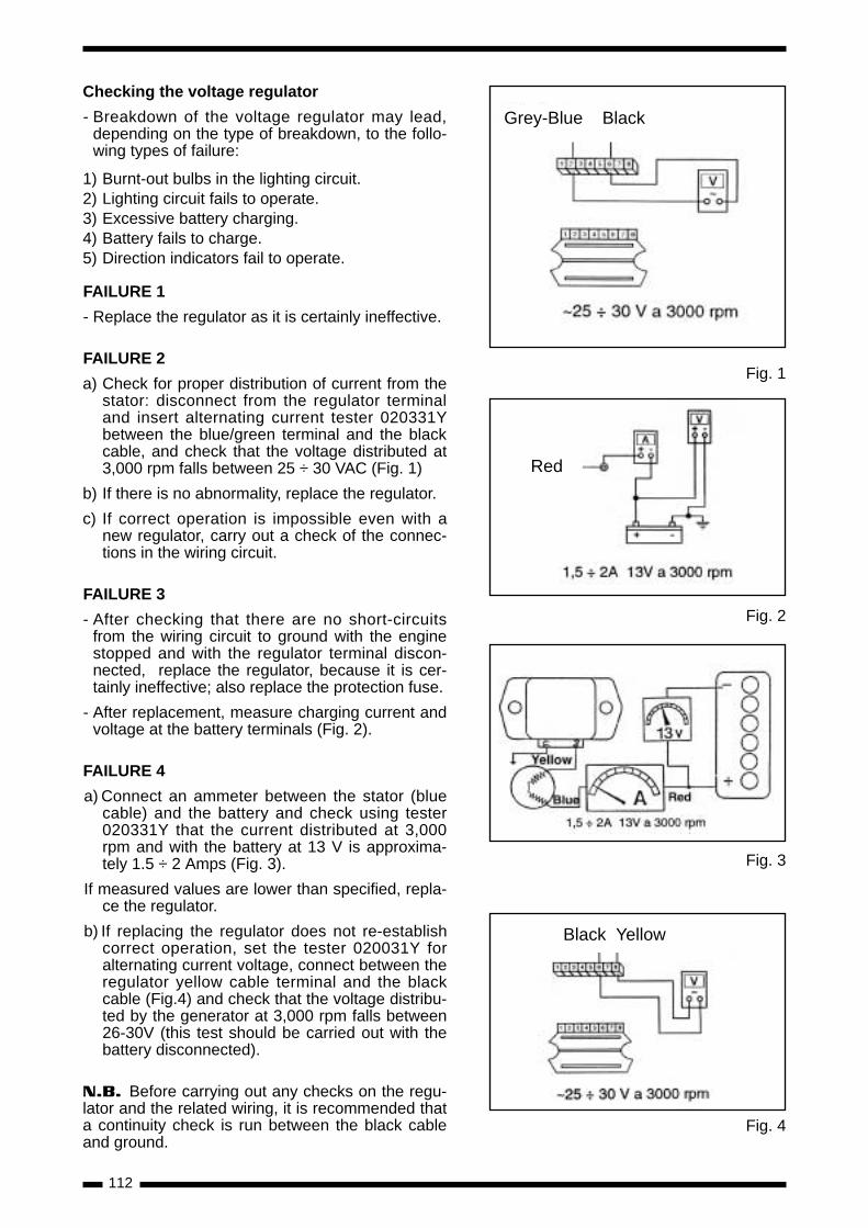
112
Fig. 4
Fig. 3
Checking the voltage regulator
- Breakdown of the voltage regulator may lead,depending on the type of breakdown, to the follo-wing types of failure:
1) Burnt-out bulbs in the lighting circuit.2) Lighting circuit fails to operate.3) Excessive battery charging.4) Battery fails to charge.5) Direction indicators fail to operate.
FAILURE 1
- Replace the regulator as it is certainly ineffective.
FAILURE 2
a) Check for proper distribution of current from thestator: disconnect from the regulator terminaland insert alternating current tester 020331Ybetween the blue/green terminal and the blackcable, and check that the voltage distributed at3,000 rpm falls between 25 ÷ 30 VAC (Fig. 1)
b) If there is no abnormality, replace the regulator.
c) If correct operation is impossible even with anew regulator, carry out a check of the connec-tions in the wiring circuit.
FAILURE 3
- After checking that there are no short-circuitsfrom the wiring circuit to ground with the enginestopped and with the regulator terminal discon-nected, replace the regulator, because it is cer-tainly ineffective; also replace the protection fuse.
- After replacement, measure charging current andvoltage at the battery terminals (Fig. 2).
FAILURE 4
a) Connect an ammeter between the stator (bluecable) and the battery and check using tester020331Y that the current distributed at 3,000rpm and with the battery at 13 V is approxima-tely 1.5 ÷ 2 Amps (Fig. 3).
If measured values are lower than specified, repla-ce the regulator.
b) If replacing the regulator does not re-establishcorrect operation, set the tester 020031Y foralternating current voltage, connect between theregulator yellow cable terminal and the blackcable (Fig.4) and check that the voltage distribu-ted by the generator at 3,000 rpm falls between26-30V (this test should be carried out with thebattery disconnected).
N.B. Before carrying out any checks on the regu-lator and the related wiring, it is recommended thata continuity check is run between the black cableand ground.
Fig. 1
Fig. 2
Grey-Blue Black
Black Yellow
Red

113
ECHEMA ELECTRIQUE ATLANTIS
OrangeGrünSchwarzBraunWeiBGrauGelbBlauRotRosaViolett
OrangeVertNoirMarronBlancGrisJauneBlauRougeRosaViolet
OrangeGreenBlackBrownWhiteGrayYellowBlueRedPinkViolet
ArancioVerdeNeroMarroneBiancoGrigioGialloAzzurroRossoRosaViola
NaranjaVerdeNegroMarronBlancoGrisAmarilloAzulRojoRosaVioleta
OGRB
BRWGYBLRPVI
D F UK I E

114
ECHEMA ELECTRIQUE GP1
OrangeGrünSchwarzBraunWeiBGrauGelbBlauRotRosaViolett
OrangeVertNoirMarronBlancGrisJauneBlauRougeRosaViolet
OrangeGreenBlackBrownWhiteGrayYellowBlueRedPinkViolet
ArancioVerdeNeroMarroneBiancoGrigioGialloAzzurroRossoRosaViola
NaranjaVerdeNegroMarronBlancoGrisAmarilloAzulRojoRosaVioleta
OGRB
BRWGYBLRPVI
D F UK I E

115
OrangeGrünSchwarzBraunWeiBGrauGelbBlauRotRosaViolett
OrangeVertNoirMarronBlancGrisJauneBlauRougeRosaViolet
OrangeGreenBlackBrownWhiteGrayYellowBlueRedPinkViolet
ArancioVerdeNeroMarroneBiancoGrigioGialloAzzurroRossoRosaViola
NaranjaVerdeNegroMarronBlancoGrisAmarilloAzulRojoRosaVioleta
OGRB
BRWGYBLRPVI
D F UK I E
ECHEMA ELECTRIQUE GP1 (USA)

116
OrangeGrünSchwarzBraunWeiBGrauGelbBlauRotRosaViolett
OrangeVertNoirMarronBlancGrisJauneBlauRougeRosaViolet
OrangeGreenBlackBrownWhiteGrayYellowBlueRedPinkViolet
ArancioVerdeNeroMarroneBiancoGrigioGialloAzzurroRossoRosaViola
NaranjaVerdeNegroMarronBlancoGrisAmarilloAzulRojoRosaVioleta
OGRB
BRWGYBLRPVI
D F UK I E
ECHEMA ELECTRIQUE GP Series
Related Documents