Deployment of the Geosynthetic Reinforced Soil Integrated Bridge System from 2011 to 2017 Synthesis Report September 2017 Sponsored by Federal Highway Administration Office of Infrastructure FHWA-HIF-17-043

Welcome message from author
This document is posted to help you gain knowledge. Please leave a comment to let me know what you think about it! Share it to your friends and learn new things together.
Transcript
Deployment of the Geosynthetic Reinforced Soil Integrated Bridge System from 2011 to 2017 Synthesis Report
September 2017
Sponsored by Federal Highway Administration Office of Infrastructure FHWA-HIF-17-043

{cover back blank}

Technical Report Documentation Page 1. Report No.
2. Government Accession No.
3. Recipient’s Catalog No.
FHWA-HIF-17-043
4. Title and Subtitle 5. Report DateDeployment of the Geosynthetic Reinforced Soil Integrated Bridge September 2017 System From 2011 to 2017
6. Performing Organization Code
7. Principal Investigator(s): See Acknowledgments for Authors and 8. Performing Organization ReportContributors No.
Akmal Daniyarov Brian Zelenko Alexandra Derian 9. Performing Organization Name and Address 10. Work Unit No. (TRAIS) WSP USA, Inc. 1015 Half Street, SE, Suite 650 11. Contract or Grant No.Washington, DC 20003
DTFH6114D00047
12. Sponsoring Agency Name and Address 13. Type of Report and PeriodFederal Highway Administration
HIBT-20 Office of Bridge Technology 14. Sponsoring Agency Code1200 New Jersey Avenue, SE
Washington, DC 20005 15. Supplementary Notes
16. Abstract
This report provides a brief background on Geosynthetic Reinforced Soil Integrated Bridge System (GRS-IBS) which is a method of bridge support. The purpose of the report is to highlight the range of the structure types, sites and materials that have been used in deployment of GRS-IBS from 2011 to 2017.
17. Key Words 18. Distribution StatementGeosynthetic Reinforced Soil Integrated Bridge System (GRS-IBS), Deployment, Advantages, Design considerations, No restrictions. Lessons learned, Construction, Versatility 19. Security Classif. (of this
20. Security Classif. (of this 21. No. of Pages 22. Price
UNCLASSIFIED UNCLASSIFIED 26
Form DOT F 1700.7(8-72) Reproduction of completed page authorized

FOREWORD
Geosynthetic Reinforced Soil (GRS) technology consists of closely spaced layers of geosynthetic reinforcement and compacted granular fill material. Since its first use by the U.S. Forest Service for building walls for roads in steep mountain terrain in the 1970s, GRS has been used for a variety of earthwork applications. Ultimately, GRS has evolved into the GRS Integrated Bridge System (IBS), a cost-effective, rapid-construction, and high-quality method of bridge support that blends the roadway into the superstructure. GRS-IBS can be built in various weather conditions with simple and readily available labor, materials and equipment and can be easily modified in the field.
Because of its benefits, the GRS-IBS was selected for deployment through the Federal Highway Administration’s (FHWA’s) Every Day Counts (EDC) initiative in 2010. During this implementation, over 200 bridges have been successfully built in a variety of environments, demonstrating its applicability for more widespread use and development. The purpose of this report is to summarize deployment of GRS-IBS from 2011 to 2017.
Unless otherwise noted, images were provided by FHWA.
Notice This document is disseminated under the sponsorship of the U.S. Department of Transportation in the interest of information exchange. The U.S. Government assumes no liability for the use of the information contained in this document. This report does not constitute a standard, specification, or regulation.
The U.S. Government does not endorse products or manufacturers. Trademarks or manufacturers’ names appear in this report only because they are considered essential to the objective of the document.
Quality Assurance Statement The Federal Highway Administration (FHWA) provides high-quality information to serve Government, industry, and the public in a manner that promotes public understanding. Standards and policies are used to ensure and maximize the quality, objectivity, utility, and integrity of its information. FHWA periodically reviews quality issues and adjusts its programs and processes to ensure continuous quality improvement.
ii

iii
TABLE OF CONTENTS 1 Introduction ............................................................................................................................. 1
1.1 History .............................................................................................................................. 1
1.2 Advantages and Limitations ............................................................................................. 2
1.3 Increase in Usage ............................................................................................................. 5
2 GRS-IBS Applications ............................................................................................................ 7
2.1 GRS-IBS Versatility ......................................................................................................... 7
2.1.1 Superstructure Types ................................................................................................ 7
2.1.2 GRS Abutment Materials ........................................................................................ 10
2.2 GRS-IBS Over Streams .................................................................................................. 12
2.3 GRS-IBS Over Roadways .............................................................................................. 14
2.4 GRS-IBS Over Railroads ............................................................................................... 15
2.5 GRS-IBS in Seismically Active Zones .......................................................................... 16
3 GRS-IBS Case Histories ........................................................................................................ 18
3.1 Summary ........................................................................................................................ 18
3.2 Project Costs ................................................................................................................... 18
3.3 Project Performance ....................................................................................................... 19
3.4 Lessons Learned ............................................................................................................. 20
4 Supplemental Material ........................................................................................................... 22
5 Acknowledgements ............................................................................................................... 24
6 References ............................................................................................................................. 25

iv
FIGURES
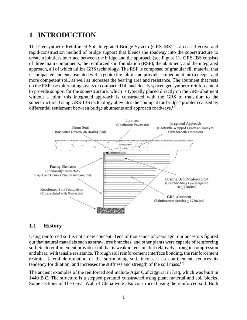
Figure 1. Typical GRS-IBS cross section. ...................................................................................... 1 Figure 2. Typical MSE wall constructed with geosynthetic reinforcement. ................................... 2 Figure 3. Construction of U.S. 301 Trail Bridge with multi-span GRS-IBS in Zephyrhills, Florida. ............................................................................................................................................ 5 Figure 4. Completed two-span GRS-IBS bridge in Knox County Beach, Maine. ......................... 5 Figure 5. Placement of concrete girders on abutments at one of the Sand Creek Road Bridges in Crook County, Wyoming. ............................................................................................................... 8 Figure 6. Timber piles from previous structure repurposed to provide temporary support for cast-in-place superstructure at State Highway 40 over Hay Creek Bridge. .................................... 9 Figure 7. Completed Stever Road Bridge over Tiffin River. .......................................................... 9 Figure 8. Precast concrete panels and the interface between precast concrete panels and steel girders. Source: St. Lawrence County .......................................................................................... 10 Figure 9. GRS abutment with split-face CMU block (a) and SRW block (b) facing. .................. 11 Figure 10. Coffer-dam for a project in Dodge County, Wisconsin. ............................................. 13 Figure 11. Dewatering area of excavation using culverts and pumps - Sand Creek Bridges Project in Crook County, Wyoming. ......................................................................................................... 14 Figure 12. Completed westbound Echo bridge. ............................................................................ 15 Figure 13. Completed County Route 55 over MN Southern Railway Bridge. ............................. 15 Figure 14. Completed State Road 7A over Housatonic Railroad Bridge. .................................... 16 Figure 15. Completed Daniel K. Inouye Highway Underpass. .................................................... 17 Figure 16. Surveying points installed on GRS wall facing. .......................................................... 20 Figure 17. GRS abutments with rounded corners in Hamilton County, Indiana. ......................... 21

v
TABLES Table 1. Project Case Histories. .................................................................................................... 22 Table 2. List of Informative Videos for GRS-IBS technology. .................................................... 23
1
1 INTRODUCTION The Geosynthetic Reinforced Soil Integrated Bridge System (GRS-IBS) is a cost-effective and rapid-construction method of bridge support that blends the roadway into the superstructure to create a jointless interface between the bridge and the approach (see Figure 1). GRS-IBS consists of three main components, the reinforced soil foundation (RSF), the abutment, and the integrated approach, all of which utilize GRS technology. The RSF is composed of granular fill material that is compacted and encapsulated with a geotextile fabric and provides embedment into a deeper and more competent soil, as well as increases the bearing area and resistance. The abutment that rests on the RSF uses alternating layers of compacted fill and closely spaced geosynthetic reinforcement to provide support for the superstructure, which is typically placed directly on the GRS abutment without a joint; this integrated approach is constructed with the GRS to transition to the superstructure. Using GRS-IBS technology alleviates the “bump at the bridge” problem caused by differential settlement between bridge abutments and approach roadways.(1)
1.1 History
Using reinforced soil is not a new concept. Tens of thousands of years ago, our ancestors figured out that natural materials such as straw, tree branches, and other plants were capable of reinforcing soil. Such reinforcement provides soil that is weak in tension, but relatively strong in compression and shear, with tensile resistance. Through soil reinforcement interface bonding, the reinforcement restrains lateral deformation of the surrounding soil, increases its confinement, reduces its tendency for dilation, and increases the stiffness and strength of the soil mass.(2)
The ancient examples of the reinforced soil include Aqar Quf ziggurat in Iraq, which was built in 1440 B.C. The structure is a stepped pyramid constructed using plant material and soil blocks. Some sections of The Great Wall of China were also constructed using the reinforced soil. Both
2
structures are still standing today, demonstrating the durability of this technology. Modern technology utilizes stronger and more durable geosynthetic materials for reinforcement purposes instead of plant materials.(2)
Mechanically Stabilized Earth (MSE), established and patented by Henri Vidal in the early 1960s, originally incorporated discrete steel strips embedded within a soil mass. Other reinforcement methods have been developed since then, and include steel mats and geosynthetics. MSE walls built with geosynthetics were used by the U.S. Forest service starting in the 1970's for reinforced slopes, walls, and slope repairs. Today, MSE walls are built with various facings, reinforcements and connection details. The vertical spacing of the reinforcement is typically 18 to 30 inches and is based on the selected facing element geometry and connection locations.(2)
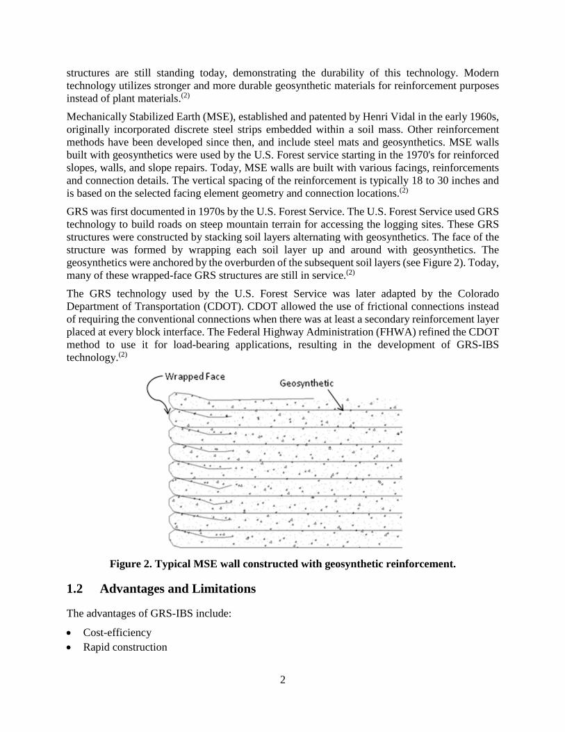
GRS was first documented in 1970s by the U.S. Forest Service. The U.S. Forest Service used GRS technology to build roads on steep mountain terrain for accessing the logging sites. These GRS structures were constructed by stacking soil layers alternating with geosynthetics. The face of the structure was formed by wrapping each soil layer up and around with geosynthetics. The geosynthetics were anchored by the overburden of the subsequent soil layers (see Figure 2). Today, many of these wrapped-face GRS structures are still in service.(2)
The GRS technology used by the U.S. Forest Service was later adapted by the Colorado Department of Transportation (CDOT). CDOT allowed the use of frictional connections instead of requiring the conventional connections when there was at least a secondary reinforcement layer placed at every block interface. The Federal Highway Administration (FHWA) refined the CDOT method to use it for load-bearing applications, resulting in the development of GRS-IBS technology.(2)
Figure 2. Typical MSE wall constructed with geosynthetic reinforcement.
1.2 Advantages and Limitations
The advantages of GRS-IBS include:
• Cost-efficiency • Rapid construction
3
• Construction that does not require specialized labor, materials, or equipment • Can support a variety of superstructure types • Flexible design • Smooth transition (no bump)
With GRS-IBS technology, construction time can be reduced from months to weeks. The design simplicity, rapid construction, and the fact that GRS-IBS technology does not require specialized materials, equipment, or labor make it a highly cost-effective construction method. Construction costs are typically 25 to 60 percent lower for GRS-IBS than for conventional bridges (spill-through slope bridges and concrete box culverts). GRS-IBS is also less expensive than conventional bridges when it comes to maintenance due the fact that the GRS-IBS bridge has fewer parts and is easier to maintain. This cost-effectiveness is one the main reasons why GRS-IBS is promoted by FHWA.(3)
GRS-IBS can be constructed in adverse weather conditions because of the free draining nature of the fill typically used in GRS abutments. The lack of cast-in-place (CIP) concrete in GRS-IBS design makes the method more flexible. Final changes to the design of GRS abutments are frequently made in the field and it is simple to reorient or cut some of the facing blocks. In fact, all other materials used in GRS-IBS are considered modular and alterable on site. The geosynthetic can be cut to fit and backfill can be placed at any location. These features further enhance the flexibility of GRS-IBS.(3)
GRS-IBS is unique in that it does not require expansion joints at the ends of the bridge. Instead, the road approaches are blended into the superstructure and paved over in a continuous manner to create a bump-less surface. This creates a positive riding experience for drivers and helps improve safety for the traveling public and reduces impact to the structure as well as the vehicles.(3)
GRS-IBS implementation has several design considerations with respect to site selection. One of the main design considerations involves scour. FHWA has developed design guidance that contains the process for evaluating GRS-IBS feasibility. Hydraulic modeling and evaluation of scour is one of the most important parts of the process. Design guidance documents developed on the state level often limit the use of GRS-IBS to certain foundation soil types and flow velocities due to the risk of scour. It is worth mentioning, however, that scour is a site-specific design consideration that is not strictly dependent on velocity. It also depends on the calculated scour depth, type of soils, and groundwater elevation.(3) Compressible soils also need to be considered during the design of GRS-IBS bridges. Foundation compressibility limits are dictated by the acceptable deformations for the selected superstructure type. GRS abutments are designed as shallow foundations and require competent soil to support the abutment without excessive settlements. It should be mentioned, however, that GRS-IBS is more forgiving when it comes to settlement than conventional bridge systems. GRS-IBS settlement tends to be more uniform because the abutments and the superstructure bear on the same foundation soil. Bridges supported on deep foundations tend to have less settlement than the approach fill creating differential deformation at the interface between the bridge and the approach or the "bump" at the end of the bridge. The compressible soils can also be improved to minimize settlement. For example, Great Western Trail over Grace St was built using GRS-IBS in 2011 and utilized stone columns to improve foundation soils under the bridge and approach fill.(4)

4
Other design considerations include flooded excavations. Building within flooded excavation can be facilitated with the use of coffer-dams and dewatering pumps or by quickly compacting the structural backfill to create a stable working platform. The dewatering system will depend on the type of foundation soil and water influx.(1)
GRS-IBS has been used for a wide range of average daily traffic (ADT) from under 100 to over 20,000. Since all bridges are designed for the same live loading criteria as that of an interstate bridge, ADT is not a design consideration. Some state departments of transportation (DOTs) and other bridge owners have placed certain limitations on ADT as an attempt to minimize the potential risks and to gradually deploy GRS-IBS technology. As these owners, have gained experience and evaluated their performance they have reconsidered these limitations for future revisions to their practice. One example is Pennsylvania Department of Transportation (PennDOT). PennDOT’s success with low-ADT bridges caused it to consider GRS-IBS for higher ADT roads. PennDOT is now collecting information on existing GRS-IBS bridges serving high-ADT roads in other states (e.g. Echo Bridges in Echo, Utah) and identifying potential candidates in Pennsylvania.
GRS-IBS deployment has been previously limited to certain bridge dimensions. The maximum recorded span length of a GRS-IBS bridge is 140 feet. However, the design of GRS abutments is largely unaffected by the length or width of the bridge. The main design limitation for the GRS abutments is the load transferred to RSF, which is currently capped at under 4,000 psf. The length of the bridge is limited by the lengths of the steel girders that become impractical to produce passed a certain length threshold at which point, constructing a multi-span bridge must be considered. Designing GRS-IBS with multi-span bridges is challenging but possible. It can be difficult to account for settlement at each support structure for the design of the superstructure.
Even with the challenges, multi-span GRS-IBS bridges have been built. The U.S. 301 Trail Bridge in Zephyrhills, Florida is one example; it was built with GRS abutments and GRS piers (see Figure 3). GRS piers were chosen for this project because the environmentally sensitive nature of the crossing did not allow entry to heavy equipment. Because GRS-IBS bridges can be built without heavy equipment, this method of construction was preferred. Multi-span GRS-IBS bridges can also be used with conventional piers if differential settlement is taken into account. One of the few bridges that was constructed with a traditional pier and GRS-IBS, is the Knox County Beach Bridge in Maine that was replaced in 2013 (see Figure 4). This was a two-span bridge that reused the existing pier to save the costs associated with demolishing the existing pier and using a larger superstructure.(5) While multi-span GRS-IBS bridges have been previously constructed, it is recommended that the use of the technology be limited to single span bridges.
Despite the original limitations in span length that have since been removed as result of increased usage and the excellent performance of the GRS-IBS bridges demonstrated throughout various monitoring programs, GRS-IBS has the potential to be a primary bridge construction method in the U.S. Since most of the bridges in the U.S. National Bridge Inventory System (NBIS) are single span bridges less than 140 feet in length, there is a significant population of the bridges that could be replaced using GRS-IBS. The maximum abutment height is currently 30 feet based on the GRS abutments constructed to date. However, there are no technical reasons why higher GRS walls could not be constructed.

5
Figure 3. Construction of U.S. 301 Trail Bridge with multi-span GRS-IBS in Zephyrhills, Florida.
Figure 4. Completed two-span GRS-IBS bridge in Knox County Beach, Maine.
1.3 Increase in Usage
FHWA has actively been promoting GRS-IBS technology through several programs. These programs include Highways for LIFE (HfL), Innovative Bridge Research and Deployment (IBRD), and Every Day Counts (EDC).
EDC is a program launched by FHWA in cooperation with American Association of State Highway and Transportation Officials (AASHTO) to speed up adoption of proven market ready technologies by the transportation industry. Every two years, FHWA works closely with state and local transportation agencies to identify innovations for deployment in the following round of EDC. GRS-IBS has been featured in the first, second, and third rounds of EDC. Over 200 bridges in 44 states, including Puerto Rico and the District of Columbia, were selected for construction

6
using GRS-IBS since the innovation was first championed in 2010.(6) One of the very successful examples of a state deploying GRS-IBS technology is in Pennsylvania. PennDOT has developed its own GRS-IBS design guidance documents and has helped construct 25 bridges between 2011 and 2017.(7) Another great success story features Defiance County in Ohio, the pioneer of the GRS-IBS technology. Defiance County has the most GRS-IBS bridge in the nation and has mostly used its own workers and local funds to replace its bridges. As of this writing, Defiance County has replaced 34 deficient bridges; this constitutes 10 percent of all county’s bridges.(8) These examples, drawn from FHWA’s EDC program, demonstrate that GRS-IBS can be practical solution to replacing the nation’s aging infrastructure.
FHWA has been assisting with GRS-IBS projects by providing funding and technical guidance through EDC program. The projects resulting from the programs generated necessary awareness about GRS-IBS through showcases, presentations, video materials, and reports. These programs have been highly effective in promoting GRS-IBS technology and increasing number of GRS-IBS projects deployed.

7
2 GRS-IBS APPLICATIONS Since the first GRS-IBS bridge was constructed in Defiance County, Ohio in 2005, the technology has been applied to varying geometries, materials, and site conditions. This section describes the different applications of the GRS-IBS.
2.1 GRS-IBS Versatility
The first GRS-IBS bridge was the Bowman Road Bridge in Defiance County, Ohio. Built in 2005, this water crossing structure had a span of 79 feet, wall height of 17 feet, 0.5 percent grade, 24-degree skew, wall facing made of concrete masonry unit (CMU) blocks, and adjacent precast concrete boxes for the superstructure.(8) Since then, GRS-IBS bridges have been constructed to cross roadways, railroads, and trails. Additionally, various geometries have been used with GRS-IBS to constantly push the limits of the technology. GRS-IBS bridges have been constructed with greater skews, grades, spans, and wall heights. In addition to flexibility with regards to site conditions and geometry, GRS-IBS has been proven to accommodate various combinations of materials and bridge elements. This flexibility increases the possibility of using locally available materials and reduces cost.
2.1.1 Superstructure Types
Since the inception of GRS-IBS, this technology was used in combination with the following spans:
• Concrete girders • CIP structure • Composite girders • Steel stringers with precast deck panels or CIP deck • Timber deck • Steel grade deck materials • Steel trusses • Folded plate girders
Prestressed concrete box girders is the most common superstructure for GRS-IBS. This type of superstructure typically bears directly upon the GRS abutment. Figure 5 shows the placement of concrete girders on abutments at one of the Sand Creek Road Bridges in Crook County, Wyoming.

8
Figure 5. Placement of concrete girders on abutments at one of the Sand Creek Road Bridges in Crook County, Wyoming.
While it is generally more time-consuming to construct a CIP superstructure, there were cases where this method was preferred. Daniel K. Inouye Highway underpass, located on the Big Island of Hawaii, was constructed using GRS-IBS with a CIP superstructure. The CIP superstructure proved to be a cost-effective solution since precast concrete bridge elements were not available on the Big Island.(9) This project utilized a soffit fill to support the falsework for the superstructure casting. The soffit fill consisted of a granular backfill placed and compacted between the bridge abutment facing blocks during the erection of the abutments. The fill was then excavated upon curing of the concrete deck. Successful implementation of this unconventional bridge construction approach demonstrated the versatility of GRS-IBS technology. Another example of providing temporary support for a CIP deck involved the use of the existing piles of the structure being replaced. One example of this was the Wisconsin project on State Highway 40 constructed over Hay Creek in 2012. The contractor used timber piles from previous bridge as temporary support for the CIP concrete superstructure falsework.(10)
Another type of superstructure combines steel girders and concrete deck, which act as a composite superstructure. GRS-IBS bridges with composite girders have been constructed to provide spans up to 140 feet, the longest span recorded as of this writing. The GRS-IBS bridge with the longest span (140 feet) is Stever Road Bridge over Tiffin River constructed in 2009 in Defiance County, Ohio (see Figure 7). This bridge also has the highest recorded GRS abutment wall at nearly 30 feet.

9
Figure 6. Timber piles from previous structure repurposed to provide temporary support for cast-in-place superstructure at State Highway 40 over Hay Creek Bridge.
Source: Wisconsin Department of Transportation.
Figure 7. Completed Stever Road Bridge over Tiffin River.
Another example of a GRS-IBS bridge with composite superstructure can be found in St. Lawrence County, New York. The County Route 47 over Trout Brook Bridge spans 98 feet and has a superstructure composed of steel girders and precast concrete panels. Precast concrete panels were chosen as a superstructure element to reduce construction time. The panels covered the whole width of the bridge and had exposed reinforcement at the joint sections (see Figure 8); ultra-high performance concrete (UHPC) was used for the panel joints. The interface between the steel girders and concrete panels was composed of two steel angles welded onto girders to form a “channel” with the free ends of the angles topped with foam to provide a better seal. Within the “channel,” three rows of shear connector studs were welded into the girders. These studs ensured that the superstructure, composed of steel and concrete, acted as a composite material. As a final step, the “channel” was filled with cement grout to combine the concrete panels with the girders to form a complete superstructure system(11). The superstructure system and the interface between

10
the steel and concrete materials are shown in . Per FHWA’s design guidance manual, at the abutments the steel girders needed to be placed on a precast or CIP concrete footing to transfer a uniform bearing pressure. Steel girders also had to be tied together and fastened to the bridge seat. In addition, a back wall and cheek walls needed to be designed to create a solid form against which the integrated approach can be built.
The other superstructure types mentioned in the beginning of this section are far less common than concrete girders and CIP structures. It is worth mentioning that GRS-IBS technology is independent of the superstructure types and is capable of accommodating virtually any superstructure. This feature adds to the versatility of the GRS-IBS technology.
Figure 8
(a) Precast concrete panel lowered on top of steel girders
(b) Steel girder and precast concrete panel interface
Figure 8. Precast concrete panels and the interface between precast concrete panels and steel girders. Source: St. Lawrence County
2.1.2 GRS Abutment Materials
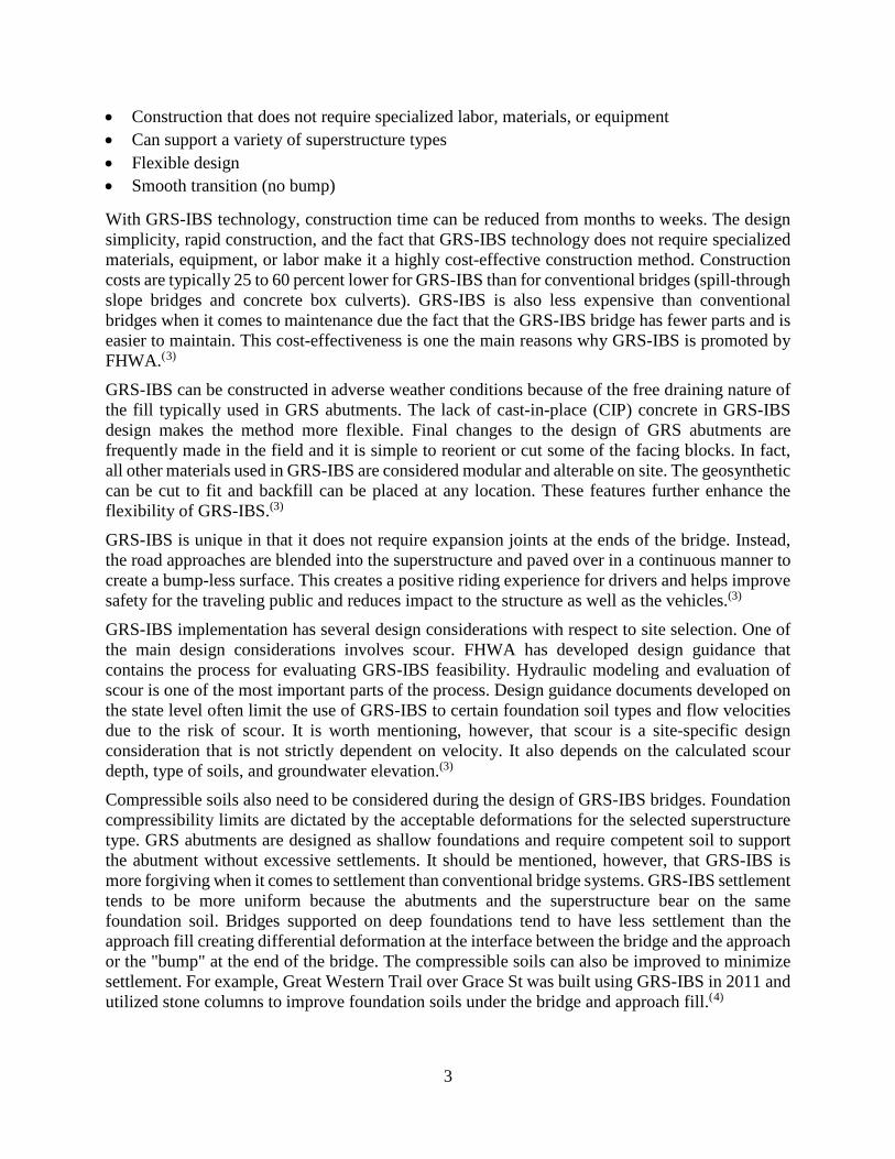
GRS-IBS proved to be flexible when it comes to GRS abutment materials. Wall facing, for example, can be constructed using CMU, Segmental Retaining Wall (SRW) units, precast panels, or sheet piles (see Figure 9). Although, CMU is conventionally used, SRW units and the locally produced variations of the product have been previously approved. Both block types feature smooth or split-face surfaces. Split-face surface has been popular among GRS-IBS builders and designers for its aesthetics and ability to disguise minor joint misalignments. The most common facing element for GRS abutments are split-face CMU blocks that have a height of about eight
11
inches and weight of 42 pounds which makes them easy to place. Another common facing element are SRW blocks of varying shapes and sizes. Although the facing is not a structural component, it is important to construct the walls with a product meeting durability requirements consistent for the site conditions as well as meeting any aesthetic requirement for the site. Concrete Masonry Units (CMU) have been the most common facing type used to construct GRS-IBS structures. SRW units have been increasingly used for GRS-IBS. SRW units are typically manufactured to meet durability requirements for the local environment.
(a) (b)
Figure 9. GRS abutment with split-face CMU block (a) and SRW block (b) facing.
GRS abutment backfill types also vary based on the requirements listed in FHWA’s GRS-IBS design guidance manual. Factors affecting backfill selection include drainage, workability, strength requirements, and availability. The general requirement for backfill is that it should consist of crushed, hard, durable particles, or fragments of stone or gravel. These materials should be free from organic matter or deleterious material such as shale or other soft particles that have poor durability. The backfill should follow the size and quality requirements for crushed aggregate normally used locally in the construction and maintenance of highways by Federal or State agencies. Abutment backfill typically consists of either well-graded or open-graded aggregates. Most of the GRS-IBS projects have used open graded material because of the ease of construction, lower weight, and favorable drainage characteristics. FHWA recommends that abutments that will be submerged at any point in time use open-graded aggregates because they are free-draining and will not build up hydrostatic pressures. Well-graded backfills have different advantages including their stiffness characteristics, availability, and compaction control techniques that are familiar. Regardless of the selected gradation, the friction angle of the backfill should be greater than or equal to 40 degrees.(1)
Various geosynthetic materials have been used for GRS-IBS. Any geosynthetic type satisfying the requirements described in FHWA’s GRS-IBS design guidance manual can be used for the technology. Woven polypropylene geotextiles have been traditionally used to build GRS abutments. A geotextile is usually selected for several reasons, including cost and ease of placement. Geogrids have also been successfully used for GRS abutments as well. It is important

12
to note that a geotextile must be used for the RSF and the integrated approach to fully encapsulate the material.(1)
Depending on site conditions, GRS-IBS can employ the elements and materials mentioned above to satisfy the project design criteria. The application of GRS-IBS in various site conditions are described the following subsections.(1)
2.2 GRS-IBS Over Streams
Most the GRS-IBS bridges are stream crossings of various geometries. GRS-IBS was found to be a cost-effective alternative to concrete open bottom box culverts and long-span bridges supported by spill-through slopes. These GRS-IBS bridges vary in span lengths from under 20 feet to 140 feet. GRS-IBS bridges spanning water tend to be challenging due to surface and groundwater conditions. The need for groundwater or surface water cutoff using a coffer-dam, increased embedment depth due to greater scour depth, riprap placement, and additional permits need to be considered when evaluating the use of GRS-IBS with regards to cost and constructability for a specific site. The Knox County Beach Bridge, mentioned previously, crossed a stream with tidal fluctuations of 12 feet. Construction on the project site was limited to three hours a day during low tides. More time was made available for construction as more courses were laid down, raising the abutment further away from the water level.(5) GRS-IBS, known for its rapid construction, helped to complete this project in efficient manner.
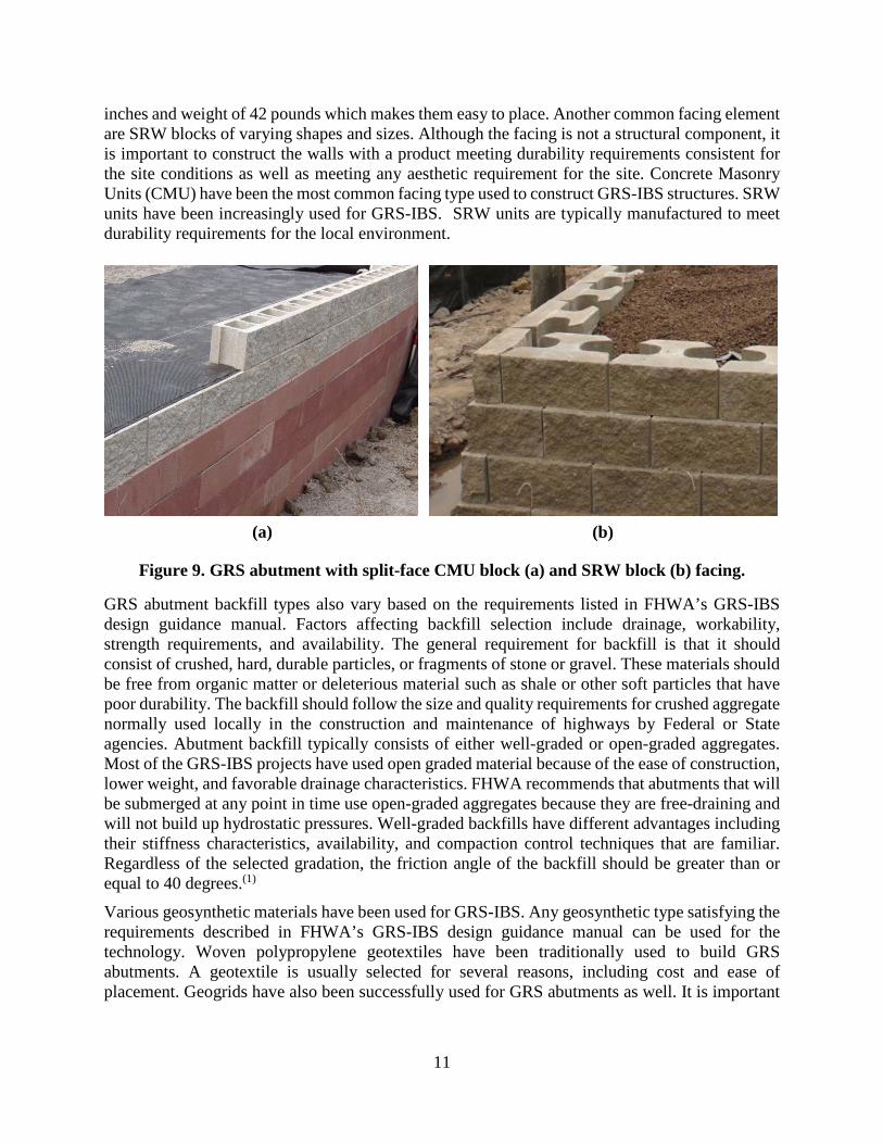
The County Route 47 over Trout Brook Bridge in St. Lawrence, New York required a coffer-dam due to the need to excavate near a stream. Throughout construction, the excavation area was flooded several times with stream water flowing over the coffer-dams. The excavation-flooding was a result of unusually intense rainfall events that occurred during construction. Despite the flooding, the partially constructed GRS abutments remained intact.(11) A similar challenge was faced by the project in Dodge County, Wisconsin involving two bridges: County Trunk Highway S over Shaw Brook and County Trunk Highway KW over Pratt Creek. As in the case of the County Route 47 over Trout Brook Bridge, a flood caused full immersion of the half-complete GRS abutment. Upon dewatering the coffer-dam enclosed area, no damage to the wall was found.(12) Figure 10 shows a coffer-dam at one of the two construction sites.
13
Figure 10. Coffer-dam for a project in Dodge County, Wisconsin.
While GRS-IBS performs well at water crossings, there are design and construction considerations that need to be considered and addressed. The Sand Creek Bridges in Crook County, Wyoming provide a good example of the limitations of GRS-IBS. Four of the six Sand Creek bridges were constructed using GRS-IBS. The GRS-IBS technology was chosen because of the competent bearing material available at relatively low depth with favorable scour and hydraulic conditions. Given these site conditions, GRS-IBS was decided to be the most cost-effective system for four of the six bridges. The rapid construction associated with GRS-IBS was another reason why the technology was the best fit for these bridges. Even though the sites of the remaining two bridges were also underlain by low-depth, competent, bearing soils, their design involved cast-in-place abutments supported on deep foundations (micropiles) due to great scour depths (5.5 and 8.7 feet respectively) and the need for micropiles to address the scour concerns.
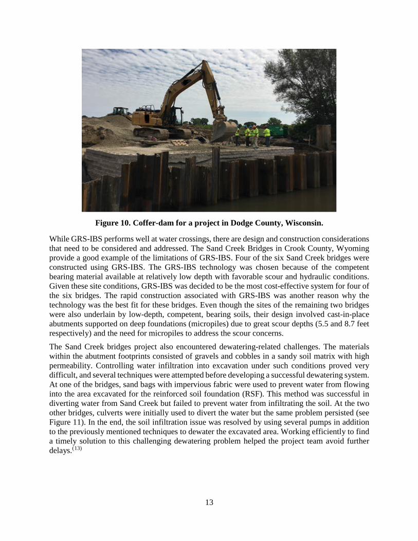
The Sand Creek bridges project also encountered dewatering-related challenges. The materials within the abutment footprints consisted of gravels and cobbles in a sandy soil matrix with high permeability. Controlling water infiltration into excavation under such conditions proved very difficult, and several techniques were attempted before developing a successful dewatering system. At one of the bridges, sand bags with impervious fabric were used to prevent water from flowing into the area excavated for the reinforced soil foundation (RSF). This method was successful in diverting water from Sand Creek but failed to prevent water from infiltrating the soil. At the two other bridges, culverts were initially used to divert the water but the same problem persisted (see Figure 11). In the end, the soil infiltration issue was resolved by using several pumps in addition to the previously mentioned techniques to dewater the excavated area. Working efficiently to find a timely solution to this challenging dewatering problem helped the project team avoid further delays.(13)
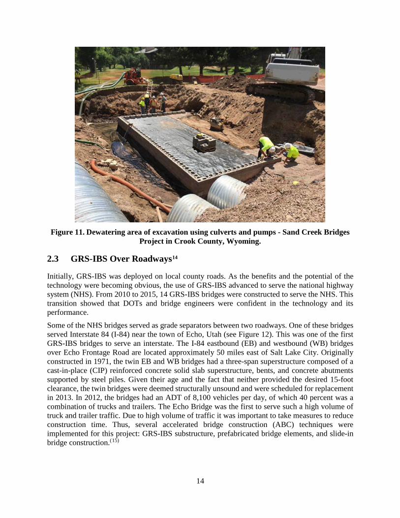
14
Figure 11. Dewatering area of excavation using culverts and pumps - Sand Creek Bridges Project in Crook County, Wyoming.
2.3 GRS-IBS Over Roadways14
Initially, GRS-IBS was deployed on local county roads. As the benefits and the potential of the technology were becoming obvious, the use of GRS-IBS advanced to serve the national highway system (NHS). From 2010 to 2015, 14 GRS-IBS bridges were constructed to serve the NHS. This transition showed that DOTs and bridge engineers were confident in the technology and its performance.
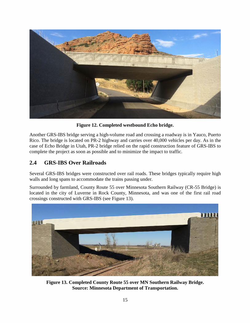
Some of the NHS bridges served as grade separators between two roadways. One of these bridges served Interstate 84 (I-84) near the town of Echo, Utah (see Figure 12). This was one of the first GRS-IBS bridges to serve an interstate. The I-84 eastbound (EB) and westbound (WB) bridges over Echo Frontage Road are located approximately 50 miles east of Salt Lake City. Originally constructed in 1971, the twin EB and WB bridges had a three-span superstructure composed of a cast-in-place (CIP) reinforced concrete solid slab superstructure, bents, and concrete abutments supported by steel piles. Given their age and the fact that neither provided the desired 15-foot clearance, the twin bridges were deemed structurally unsound and were scheduled for replacement in 2013. In 2012, the bridges had an ADT of 8,100 vehicles per day, of which 40 percent was a combination of trucks and trailers. The Echo Bridge was the first to serve such a high volume of truck and trailer traffic. Due to high volume of traffic it was important to take measures to reduce construction time. Thus, several accelerated bridge construction (ABC) techniques were implemented for this project: GRS-IBS substructure, prefabricated bridge elements, and slide-in bridge construction.(15)
15
Figure 12. Completed westbound Echo bridge.
Another GRS-IBS bridge serving a high-volume road and crossing a roadway is in Yauco, Puerto Rico. The bridge is located on PR-2 highway and carries over 40,000 vehicles per day. As in the case of Echo Bridge in Utah, PR-2 bridge relied on the rapid construction feature of GRS-IBS to complete the project as soon as possible and to minimize the impact to traffic.
2.4 GRS-IBS Over Railroads
Several GRS-IBS bridges were constructed over rail roads. These bridges typically require high walls and long spans to accommodate the trains passing under.
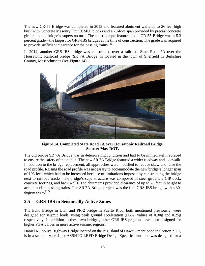
Surrounded by farmland, County Route 55 over Minnesota Southern Railway (CR-55 Bridge) is located in the city of Luverne in Rock County, Minnesota, and was one of the first rail road crossings constructed with GRS-IBS (see Figure 13).
Figure 13. Completed County Route 55 over MN Southern Railway Bridge.
Source: Minnesota Department of Transportation.
16
The new CR-55 Bridge was completed in 2013 and featured abutment walls up to 26 feet high built with Concrete Masonry Unit (CMU) blocks and a 78-foot span provided by precast concrete girders as the bridge’s superstructure. The most unique feature of the CR-55 Bridge was a 5.3 percent grade – the largest for GRS-IBS bridges at the time of construction. The grade was required to provide sufficient clearance for the passing trains.(16)
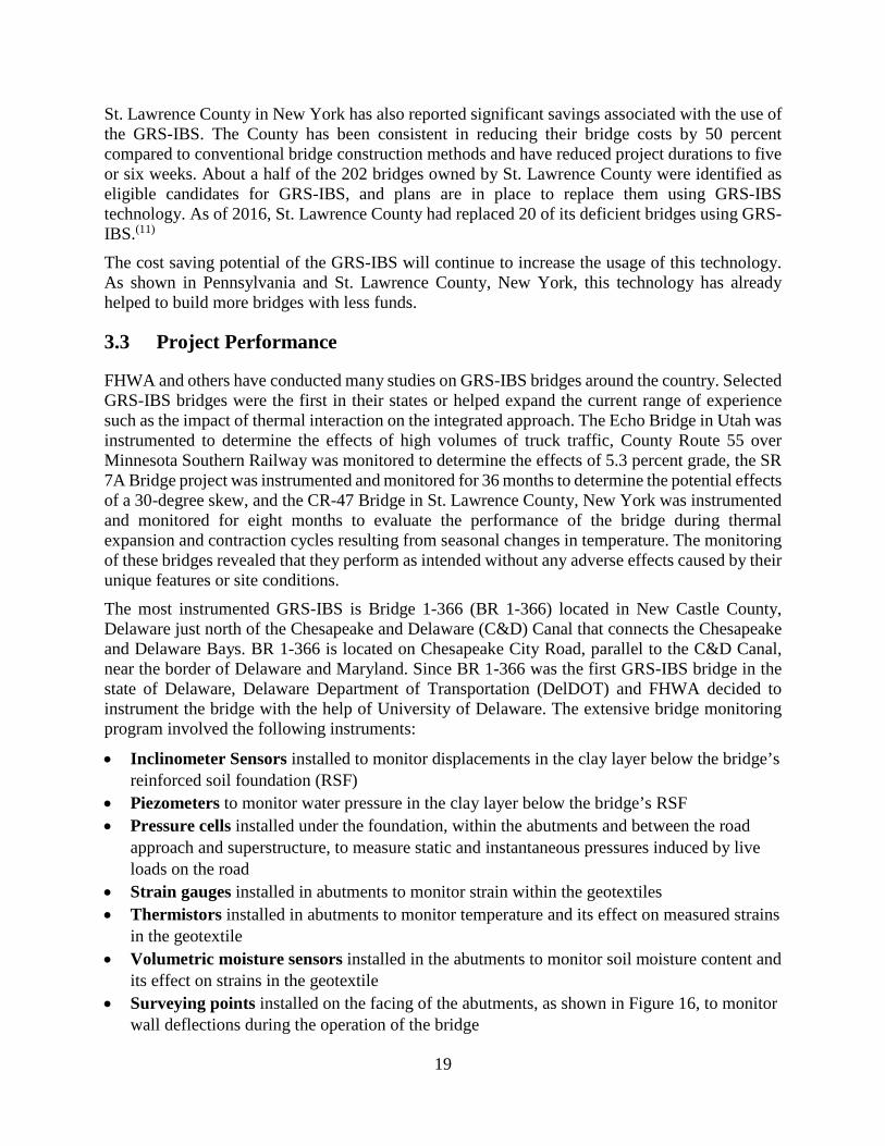
In 2014, another GRS-IBS bridge was constructed over a railroad. State Road 7A over the Housatonic Railroad bridge (SR 7A Bridge) is located in the town of Sheffield in Berkshire County, Massachusetts (see Figure 14).
Figure 14. Completed State Road 7A over Housatonic Railroad Bridge.
Source: MassDOT. The old bridge SR 7A Bridge was in deteriorating condition and had to be immediately replaced to ensure the safety of the public. The new SR 7A Bridge featured a wider roadway and sidewalk. In addition to the bridge replacement, all approaches were modified to reduce skew and raise the road profile. Raising the road profile was necessary to accommodate the new bridge’s longer span of 105 feet, which had to be increased because of limitations imposed by constructing the bridge next to railroad tracks. The bridge’s superstructure was composed of steel girders, a CIP deck, concrete footings, and back walls. The abutments provided clearance of up to 28 feet in height to accommodate passing trains. The SR 7A Bridge project was the first GRS-IBS bridge with a 30-degree skew.(17)
2.5 GRS-IBS in Seismically Active Zones
The Echo Bridge in Utah and PR-2 bridge in Puerto Rico, both mentioned previously, were designed for seismic loads, using peak ground acceleration (PGA) values of 0.30g and 0.25g respectively. In addition to these two bridges, other GRS-IBS projects have been designed for higher PGA values in more active seismic regions.
Daniel K. Inouye Highway Bridge located on the Big Island of Hawaii, mentioned in Section 2.1.1, is in a seismic zone 4 per ASSHTO LRFD Bridge Design Specifications and was designed for a

17
PGA of 0.58g. Neither AASHTO nor the “Design and Construction Guidelines for GRS-IBS” provided specific guidance for seismic design of the GRS abutments subjected to Extreme Even I. Thus, these procedures had to be developed by the design team. The GRS abutments were designed for axial and lateral loads in addition to the seismic loads imposed by Extreme Event I. The GRS-IBS concept was selected by the contractor to construct the bridge because of its geometry, accelerated construction, and reduced cost in comparison to other alternatives. Additionally, a nearby rock quarry of high-strength basalt aggregate appropriate for use as the reinforced fill composite within the GRS abutments was available to the contractor. The Daniel K. Inouye Highway Bridge was a 42-foot long, 55-foot wide bridge bearing on 20-foot high GRS abutment, and served as an underpass for traffic separation.(9) The completed Daniel K. Inouye Highway underpass is show in Figure 15.
Figure 15. Completed Daniel K. Inouye Highway Underpass.
Other seismically active areas where GRS-IBS was deployed include California. In 2012, Disney Bridge was constructed in Sequoia National Park located in the state’s southern Sierra Nevada mountains. Later, in 2015, Beckwourth Genesee Road over Crocker Creek was constructed in Plumas National Forest located in northern California.

18
3 GRS-IBS CASE HISTORIES As noted in previous sections, GRS-IBS has been deployed in various site conditions, geometries, and material combinations. This section summarizes the GRS-IBS projects completed since 2011 and describes some of the unique GRS-IBS projects. The GRS-IBS implementation experiences of various agencies and the lessons learned are also included in this section.
3.1 Summary
GRS-IBS projects constructed since 2011 spanned 10 to 110 feet and were approximately 50 feet on average. The GRS wall heights ranged from four feet to 27 feet and were about 11 feet on average. Most the bridges constructed since 2011 crossed a stream.
Since 2011, GRS-IBS technology has been included in various applications. As discussed in Section 2.5, the Daniel K. Inouye Highway Bridge on the Big Island, Hawaii helped improve guidance for seismic design of GRS-IBS. The GRS-IBS limits have been pushed in other ways as well. Deployment of the GRS-IBS technology has been expanded from low volume local roads to interstates. Other milestones involved bridge geometries and challenging site conditions. Increases in the usage and diversity of GRS-IBS bridges can be attributed to the previous successes of counties, state DOTs, and other agencies with the technology. Additionally, efforts made by FHWA to promote this technology through project showcases, presentations, and various publications are responsible for the national success of GRS-IBS. For example, in 2011, PennDOT and Huston Township successfully constructed its first GRS-IBS bridge on Mount Pleasant Road. PennDOT and Huston Township learned about GRS-IBS through FHWA. Since the construction of Mount Pleasant Road Bridge, 24 additional GRS-IBS bridges have been constructed on low-ADT roads in Pennsylvania. To help municipalities, PennDOT developed straightforward design guidance documents for GRS-IBS that were instrumental in Pennsylvania’s success deploying the technology. Success with low volume bridges has led PennDOT to consider revised design guidance for GRS-IBS bridges serving higher levels of traffic. This progression in the use of GRS-IBS technology is a testament to PennDOT’s confidence in GRS-IBS technology and will result in more bridges built using this method.(7)
GRS-IBS bridges in Hamilton County, Indiana are another example of how the success of one agency can inspire others to build using GRS-IBS. Hamilton County engineers found out about GRS-IBS through a presentation by the Defiance County, Ohio engineers – the pioneers of the technology. The success of Defiance County prompted Hamilton County to replace four of their bridges using GRS-IBS.(18)
3.2 Project Costs
Cost savings is one of the main reasons why GRS-IBS is a successful bridge construction method. On many occasions, GRS-IBS was selected for a project due to lack of funds. Using GRS-IBS technology has been reported to save 25 to 60 percent, allowing for more bridges to be replaced using the same amount funds.
PennDOT has been collecting and analyzing its GRS-IBS bridge costs and comparing them to conventional bridge projects of similar geometry and site conditions. The results of the comparisons revealed that GRS-IBS generates an average savings of 50 percent.(19)
19
St. Lawrence County in New York has also reported significant savings associated with the use of the GRS-IBS. The County has been consistent in reducing their bridge costs by 50 percent compared to conventional bridge construction methods and have reduced project durations to five or six weeks. About a half of the 202 bridges owned by St. Lawrence County were identified as eligible candidates for GRS-IBS, and plans are in place to replace them using GRS-IBS technology. As of 2016, St. Lawrence County had replaced 20 of its deficient bridges using GRS-IBS.(11)
The cost saving potential of the GRS-IBS will continue to increase the usage of this technology. As shown in Pennsylvania and St. Lawrence County, New York, this technology has already helped to build more bridges with less funds.
3.3 Project Performance
FHWA and others have conducted many studies on GRS-IBS bridges around the country. Selected GRS-IBS bridges were the first in their states or helped expand the current range of experience such as the impact of thermal interaction on the integrated approach. The Echo Bridge in Utah was instrumented to determine the effects of high volumes of truck traffic, County Route 55 over Minnesota Southern Railway was monitored to determine the effects of 5.3 percent grade, the SR 7A Bridge project was instrumented and monitored for 36 months to determine the potential effects of a 30-degree skew, and the CR-47 Bridge in St. Lawrence County, New York was instrumented and monitored for eight months to evaluate the performance of the bridge during thermal expansion and contraction cycles resulting from seasonal changes in temperature. The monitoring of these bridges revealed that they perform as intended without any adverse effects caused by their unique features or site conditions.
The most instrumented GRS-IBS is Bridge 1-366 (BR 1-366) located in New Castle County, Delaware just north of the Chesapeake and Delaware (C&D) Canal that connects the Chesapeake and Delaware Bays. BR 1-366 is located on Chesapeake City Road, parallel to the C&D Canal, near the border of Delaware and Maryland. Since BR 1-366 was the first GRS-IBS bridge in the state of Delaware, Delaware Department of Transportation (DelDOT) and FHWA decided to instrument the bridge with the help of University of Delaware. The extensive bridge monitoring program involved the following instruments:
• Inclinometer Sensors installed to monitor displacements in the clay layer below the bridge’s reinforced soil foundation (RSF)
• Piezometers to monitor water pressure in the clay layer below the bridge’s RSF • Pressure cells installed under the foundation, within the abutments and between the road
approach and superstructure, to measure static and instantaneous pressures induced by live loads on the road
• Strain gauges installed in abutments to monitor strain within the geotextiles • Thermistors installed in abutments to monitor temperature and its effect on measured strains
in the geotextile • Volumetric moisture sensors installed in the abutments to monitor soil moisture content and
its effect on strains in the geotextile • Surveying points installed on the facing of the abutments, as shown in Figure 16, to monitor
wall deflections during the operation of the bridge

20
Some of the instrumentation on BR 1-366 is still actively collecting data. All the data indicate that the bridge is performing very well.(20)
These are just a few examples of instrumented GRS-IBS bridges. Many more GRS-IBS bridges were instrumented and monitored to further evaluate this new technology.
Figure 16. Surveying points installed on GRS wall facing.
3.4 Lessons Learned
It is clear GRS-IBS is a cost-efficient and high performance technology. Nevertheless, being new technology, GRS-IBS construction and design processes can be improved by continuously sharing knowledge from various projects. Given this consideration, a list of the lessons learned from some of the projects described herein is presented below.
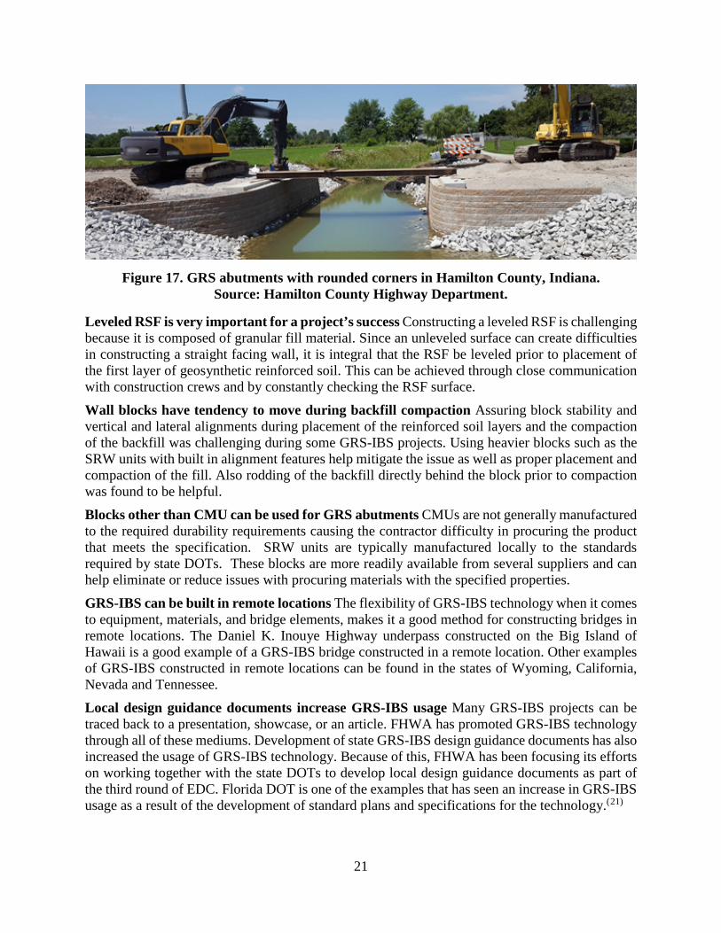
Cutting blocks increases construction time This observation was made during several GRS-IBS projects. For example, two GRS-IBS bridges in Hamilton County, Indiana were built using GRS abutment walls with 90-degree corners. The SRW split face units used for both bridges had generic corner blocks that had to be cut to fit properly. Cutting blocks was time consuming and resulted in wasted block material. To avoid cutting the blocks, GRS abutment walls for the other Hamilton County bridges were constructed with rounded corners (see Figure 17). Using rounded corners meant that the blocks did not have to be cut, which significantly minimized construction time.
21
Figure 17. GRS abutments with rounded corners in Hamilton County, Indiana. Source: Hamilton County Highway Department.
Leveled RSF is very important for a project’s success Constructing a leveled RSF is challenging because it is composed of granular fill material. Since an unleveled surface can create difficulties in constructing a straight facing wall, it is integral that the RSF be leveled prior to placement of the first layer of geosynthetic reinforced soil. This can be achieved through close communication with construction crews and by constantly checking the RSF surface.
Wall blocks have tendency to move during backfill compaction Assuring block stability and vertical and lateral alignments during placement of the reinforced soil layers and the compaction of the backfill was challenging during some GRS-IBS projects. Using heavier blocks such as the SRW units with built in alignment features help mitigate the issue as well as proper placement and compaction of the fill. Also rodding of the backfill directly behind the block prior to compaction was found to be helpful.
Blocks other than CMU can be used for GRS abutments CMUs are not generally manufactured to the required durability requirements causing the contractor difficulty in procuring the product that meets the specification. SRW units are typically manufactured locally to the standards required by state DOTs. These blocks are more readily available from several suppliers and can help eliminate or reduce issues with procuring materials with the specified properties.
GRS-IBS can be built in remote locations The flexibility of GRS-IBS technology when it comes to equipment, materials, and bridge elements, makes it a good method for constructing bridges in remote locations. The Daniel K. Inouye Highway underpass constructed on the Big Island of Hawaii is a good example of a GRS-IBS bridge constructed in a remote location. Other examples of GRS-IBS constructed in remote locations can be found in the states of Wyoming, California, Nevada and Tennessee.
Local design guidance documents increase GRS-IBS usage Many GRS-IBS projects can be traced back to a presentation, showcase, or an article. FHWA has promoted GRS-IBS technology through all of these mediums. Development of state GRS-IBS design guidance documents has also increased the usage of GRS-IBS technology. Because of this, FHWA has been focusing its efforts on working together with the state DOTs to develop local design guidance documents as part of the third round of EDC. Florida DOT is one of the examples that has seen an increase in GRS-IBS usage as a result of the development of standard plans and specifications for the technology.(21)
22
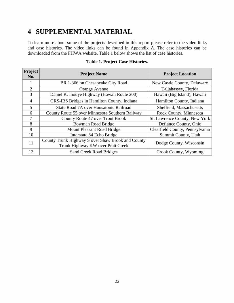
4 SUPPLEMENTAL MATERIAL To learn more about some of the projects described in this report please refer to the video links and case histories. The video links can be found in Appendix A. The case histories can be downloaded from the FHWA website. Table 1 below shows the list of case histories.
Table 1. Project Case Histories.
Project No. Project Name Project Location
1 BR 1-366 on Chesapeake City Road New Castle County, Delaware 2 Orange Avenue Tallahassee, Florida 3 Daniel K. Inouye Highway (Hawaii Route 200) Hawaii (Big Island), Hawaii 4 GRS-IBS Bridges in Hamilton County, Indiana Hamilton County, Indiana 5 State Road 7A over Housatonic Railroad Sheffield, Massachusetts 6 County Route 55 over Minnesota Southern Railway Rock County, Minnesota 7 County Route 47 over Trout Brook St. Lawrence County, New York 8 Bowman Road Bridge Defiance County, Ohio 9 Mount Pleasant Road Bridge Clearfield County, Pennsylvania 10 Interstate 84 Echo Bridge Summit County, Utah
11 County Trunk Highway S over Shaw Brook and County Trunk Highway KW over Pratt Creek Dodge County, Wisconsin
12 Sand Creek Road Bridges Crook County, Wyoming

23
APPENDIX A. GRS-IBS VIDEO LINKS
Table 2. List of Informative Videos for GRS-IBS technology.
Title Description Link
Geosynthetic Reinforced Soil-Integrated Bridge System (GRS-IBS) 2011.
The video includes the following: explanation of GRS and its history of development; interviews with designers, owners and construction personnel; information on construction; and time lapse photography to show the speed of construction.
5WFoAdoUw&index=10&t=7s&list=FL4nHoYd-wfOVY1zUKSioWTA&spfreload=10
I-84 Echo Bridge Move and Geosynthetic Reinforced Soil.
The following video provides details about I-84 Echo Bridge project that used accelerated bridge technologies (GRS-IBS and lateral bridge slide) to reduce construction time and cost.
https://www.youtube.com/watch?v=atGicyyj6D8&index=3&list=FL4nHoYd-wfOVY1zUKSioWTA
I-84 Echo Bridge – Time Lapse. Time lapse of the project construction. https://www.youtube.com/watch?v=g2o1fN2-qzA
PA DOT - Geosynthetic Reinforced Soil Bridge Technique.
This video provides general information about GRS-IBS. https://www.youtube.com/watch?v=Tqlu9vVlRQ4&index=4&list=FL4nHoYd-wfOVY1zUKSioWTA
FHWA EDC Showcase: GRS-IBS Demonstration, Luverne, Minnesota.
This video provides information on GRS-IBS project in Luverne, Minnesota.
https://www.youtube.com/watch?v=QWkREPlQXZ0&index=5&list=FL4nHoYd-wfOVY1zUKSioWTA&spfreload=10
GRS Bridge System Pilot Project, Chippewa County, Wisconsin.
This video describes the first GRS-IBS project in Wisconsin. https://www.youtube.com/watch?v=frxx9J7qiWU&index=7&list=FL4nHoYd-wfOVY1zUKSioWTA&spfreload=10
GRS-IBS Bridge Replacement in Dodge County, Wisconsin.
This video describes the GRS-IBS projects in Dodge County, Wisconsin.
https://www.youtube.com/watch?v=oqSrYzrNkh8&index=1&list=FL4nHoYd-wfOVY1zUKSioWTA
GRS-IBS Hamilton County, Indiana Bridge 301 East Abutment.
Construction Time-lapse Video. https://www.youtube.com/watch?v=H8sK5jGERkI
https://www.youtube.com/watch?v=w_5WFoAdoUw&index=10&t=7s&list=FL4nHoYd-wfOVY1zUKSioWTA&spfreload=10
24
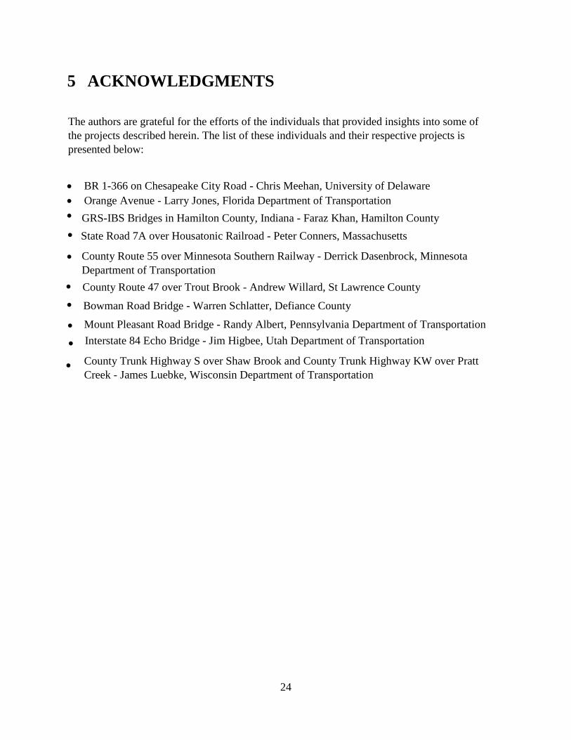
5 ACKNOWLEDGMENTS
The authors are grateful for the efforts of the individuals that provided insights into some of the projects described herein. The list of these individuals and their respective projects is presented below:
• BR 1-366 on Chesapeake City Road - Chris Meehan, University of Delaware• Orange Avenue - Larry Jones, Florida Department of Transportation•
•GRS-IBS Bridges in Hamilton County, Indiana - Faraz Khan, Hamilton County
•
State Road 7A over Housatonic Railroad - Peter Conners, Massachusetts
County Route 55 over Minnesota Southern Railway - Derrick Dasenbrock, Minnesota Department of Transportation
•
County Route 47 over Trout Brook - Andrew Willard, St Lawrence County•
Bowman Road Bridge - Warren Schlatter, Defiance County
• Mount Pleasant Road Bridge - Randy Albert, Pennsylvania Department of Transportation
• Interstate 84 Echo Bridge - Jim Higbee, Utah Department of Transportation
County Trunk Highway S over Shaw Brook and County Trunk Highway KW over PrattCreek - James Luebke, Wisconsin Department of Transportation
•

25
6 REFERENCES
1. Adams, M. and Nicks, J. E., “Design and Construction Guidelines for GeosyntheticReinforced Soil Abutments and Integrated Bridge Systems DRAFT”, Federal Highway Administration, McLean, VA, 2017.
2. Adams, M.T., Nicks, J.E., Stabile, T., Wu, J.T.H., Schlatter, W., and Hartmann, J. 2011.Geosynthetic Reinforced Soil Integrated Bridge System—Synthesis Report, Report No. FHWA-HRT-11-027, Federal Highway Administration, McLean, VA.
3. “Geosynthetic Reinforced Soil Integrated Bridge System (GRS-IBS). TechnologyOverview.” Every Day Counts. (presentation, Federal Highway Administration).
4. “Geosynthetic Reinforced Soil-Integrated Bridge System (GRS-IBS)”, YouTube, 2015.Retrieved from: https://www.youtube.com/watch?v=1NOLcVtAln0 (49:39). Accessed April 24, 2017.
5. “Geosynthetic Reinforced Soil-Integrated Bridge System (GRS-IBS)”, YouTube, 2015.Retrieved from: https://www.youtube.com/watch?v=1NOLcVtAln0 (57:48). Accessed April 24, 2017.
6. EDC-3: GRS-IBS. Center for Accelerating Innovation. Federal Highway Administration.Retrieved from: https://www.fhwa.dot.gov/innovation/everydaycounts/edc-3/grs-ibs.cfm. Accessed July 7, 2017.
7. Mount Pleasant Road Bridge – Project Case History.
8. Bowman Road Bridge – Project Case History.
9. Daniel K. Inouye Highway (Hawaii Route 200) – Project Case History.
10. Bob Arndorfer “GRS-IBS Showcase: Design, Materials, Specifications and Construction.STH 40, Chippewa County”, Every Day Counts. (presentation, Wisconsin Department of Transportation).
11. County Route 47 over Trout Brook – Project Case History.
12. County Trunk Highway S over Shaw Brook and County Trunk Highway KW over PrattCreek – Project Case History.
13. Sand Creek Road Bridges – Project Case History.
14. Alzamora, D. and Nicks, J. E., “National Usage of Geosynthetic-Reinforced Soil to SupportBridges”, Geostrata. Pg. 34-40. March/April 2015. Retrieved from: http://geostrata.geoinstitute.org/wp-content/uploads/sites/2/2015/06/Geo-mar_april2.pdf.
15. Interstate 84 Echo Bridge – Project Case History.
16. County Route 55 over Minnesota Southern Railway – Project Case History.

26
17. State Road 7A over Housatonic Railroad – Project Case History.
18. GRS-IBS Bridges in Hamilton County, Indiana – Project Case History.
19. Randy Albert, “GRS-IBS PA Project Examples Cost Comparisons” (presentation,Pennsylvania Department of Transportation, 2017).
20. BR 1-366 on Chesapeake City Road – Project Case History.
21. Orange Avenue Bridge – Project Case History.
Related Documents