IMPLEMENTATION GUIDE Copyright © 2010, Juniper Networks, Inc. 1 DEPLOYING JUNIPER NETWORKS EX SERIES ETHERNET SWITCHES IN BRANCH OFFICES Although Juniper Networks has attempted to provide accurate information in this guide, Juniper Networks does not warrant or guarantee the accuracy of the information provided herein. Third party product descriptions and related technical details provided in this document are for information purposes only and such products are not supported by Juniper Networks. All information provided in this guide is provided “as is”, with all faults, and without warranty of any kind, either expressed or implied or statutory. Juniper Networks and its suppliers hereby disclaim all warranties related to this guide and the information contained herein, whether expressed or implied of statutory including, without limitation, those of merchantability, fitness for a particular purpose and noninfringement, or arising from a course of dealing, usage, or trade practice.

Welcome message from author
This document is posted to help you gain knowledge. Please leave a comment to let me know what you think about it! Share it to your friends and learn new things together.
Transcript
IMPLEMENTATION GUIDE
Copyright © 2010, Juniper Networks, Inc. 1
DEPLOYING JUNIPER NETWORKS EX SERIES ETHERNET SWITCHES IN BRANCH OFFICES
Although Juniper Networks has attempted to provide accurate information in this guide, Juniper Networks does not warrant or guarantee the accuracy of the information provided herein. Third party product descriptions and related technical details provided in this document are for information purposes only and such products are not supported by Juniper Networks. All information provided in this guide is provided “as is”, with all faults, and without warranty of any kind, either expressed or implied or statutory. Juniper Networks and its suppliers hereby disclaim all warranties related to this guide and the information contained herein, whether expressed or implied of statutory including, without limitation, those of merchantability, fitness for a particular purpose and noninfringement, or arising from a course of dealing, usage, or trade practice.
2 Copyright © 2010, Juniper Networks, Inc.
IMPLEMENTATION GUIDE - Deploying Juniper Networks EX Series Ethernet Switches in Branch Offices
Table of Contents
Introduction . . . . . . . . . . . . . . . . . . . . . . . . . . . . . . . . . . . . . . . . . . . . . . . . . . . . . . . . . . . . . . . . . . . . . . . . . . . . . . . . . . . . . . . . . . . . . . . . . . . . . 5
Hardware . . . . . . . . . . . . . . . . . . . . . . . . . . . . . . . . . . . . . . . . . . . . . . . . . . . . . . . . . . . . . . . . . . . . . . . . . . . . . . . . . . . . . . . . . . . . . . . . . . . . . 5
Software . . . . . . . . . . . . . . . . . . . . . . . . . . . . . . . . . . . . . . . . . . . . . . . . . . . . . . . . . . . . . . . . . . . . . . . . . . . . . . . . . . . . . . . . . . . . . . . . . . . . . 5
EX Series Ethernet Switches in the Branch . . . . . . . . . . . . . . . . . . . . . . . . . . . . . . . . . . . . . . . . . . . . . . . . . . . . . . . . . . . . . . . . . . . . . . . . 6
Section 1: Routing and Switching at the Core . . . . . . . . . . . . . . . . . . . . . . . . . . . . . . . . . . . . . . . . . . . . . . . . . . . . . . . . . . . . . . . . . . . .7
Section 1: Physical Connectivity and Layer 2 Features . . . . . . . . . . . . . . . . . . . . . . . . . . . . . . . . . . . . . . . . . . . . . . . . . . . . . . . . . 8
Section 2: High Availability . . . . . . . . . . . . . . . . . . . . . . . . . . . . . . . . . . . . . . . . . . . . . . . . . . . . . . . . . . . . . . . . . . . . . . . . . . . . . . . . . . 8
Section 3: Switching and Routing . . . . . . . . . . . . . . . . . . . . . . . . . . . . . . . . . . . . . . . . . . . . . . . . . . . . . . . . . . . . . . . . . . . . . . . . . . . . 8
Section 4: Switch Services . . . . . . . . . . . . . . . . . . . . . . . . . . . . . . . . . . . . . . . . . . . . . . . . . . . . . . . . . . . . . . . . . . . . . . . . . . . . . . . . . . 8
Section 5: Port Security and Network Management . . . . . . . . . . . . . . . . . . . . . . . . . . . . . . . . . . . . . . . . . . . . . . . . . . . . . . . . . . . 8
Section 1.1: Physical Connectivity and Layer 2 Features . . . . . . . . . . . . . . . . . . . . . . . . . . . . . . . . . . . . . . . . . . . . . . . . . . . . . . . . . . 9
Port Connection . . . . . . . . . . . . . . . . . . . . . . . . . . . . . . . . . . . . . . . . . . . . . . . . . . . . . . . . . . . . . . . . . . . . . . . . . . . . . . . . . . . . . . . . . . . . 9
VLAN . . . . . . . . . . . . . . . . . . . . . . . . . . . . . . . . . . . . . . . . . . . . . . . . . . . . . . . . . . . . . . . . . . . . . . . . . . . . . . . . . . . . . . . . . . . . . . . . . . . . . . .10
VLAN Membership . . . . . . . . . . . . . . . . . . . . . . . . . . . . . . . . . . . . . . . . . . . . . . . . . . . . . . . . . . . . . . . . . . . . . . . . . . . . . . . . . . . . . . . . . . 11
Option 1: VLAN Centric . . . . . . . . . . . . . . . . . . . . . . . . . . . . . . . . . . . . . . . . . . . . . . . . . . . . . . . . . . . . . . . . . . . . . . . . . . . . . . . . . . . . . . 11
Option 2: Port Centric . . . . . . . . . . . . . . . . . . . . . . . . . . . . . . . . . . . . . . . . . . . . . . . . . . . . . . . . . . . . . . . . . . . . . . . . . . . . . . . . . . . . . . . 11
RVI . . . . . . . . . . . . . . . . . . . . . . . . . . . . . . . . . . . . . . . . . . . . . . . . . . . . . . . . . . . . . . . . . . . . . . . . . . . . . . . . . . . . . . . . . . . . . . . . . . . . . . . . . 11
Management Interface . . . . . . . . . . . . . . . . . . . . . . . . . . . . . . . . . . . . . . . . . . . . . . . . . . . . . . . . . . . . . . . . . . . . . . . . . . . . . . . . . . . . . . 12
IPT Deployment . . . . . . . . . . . . . . . . . . . . . . . . . . . . . . . . . . . . . . . . . . . . . . . . . . . . . . . . . . . . . . . . . . . . . . . . . . . . . . . . . . . . . . . . . . . . 12
Option 1: PC and IP Phone on Separate Ports . . . . . . . . . . . . . . . . . . . . . . . . . . . . . . . . . . . . . . . . . . . . . . . . . . . . . . . . . . . . . . . . . 12
Option 2: PC and IP Phone on the Same Port . . . . . . . . . . . . . . . . . . . . . . . . . . . . . . . . . . . . . . . . . . . . . . . . . . . . . . . . . . . . . . . . . 13
Section 1.2: High Availability . . . . . . . . . . . . . . . . . . . . . . . . . . . . . . . . . . . . . . . . . . . . . . . . . . . . . . . . . . . . . . . . . . . . . . . . . . . . . . . . . . . 14
LAG . . . . . . . . . . . . . . . . . . . . . . . . . . . . . . . . . . . . . . . . . . . . . . . . . . . . . . . . . . . . . . . . . . . . . . . . . . . . . . . . . . . . . . . . . . . . . . . . . . . . . . . . . . 14
Virtual Chassis Technology . . . . . . . . . . . . . . . . . . . . . . . . . . . . . . . . . . . . . . . . . . . . . . . . . . . . . . . . . . . . . . . . . . . . . . . . . . . . . . . . . . . . 15
Mastership Priority . . . . . . . . . . . . . . . . . . . . . . . . . . . . . . . . . . . . . . . . . . . . . . . . . . . . . . . . . . . . . . . . . . . . . . . . . . . . . . . . . . . . . . . . . .16
Preprovisioning . . . . . . . . . . . . . . . . . . . . . . . . . . . . . . . . . . . . . . . . . . . . . . . . . . . . . . . . . . . . . . . . . . . . . . . . . . . . . . . . . . . . . . . . . . . . . . .16
GRES . . . . . . . . . . . . . . . . . . . . . . . . . . . . . . . . . . . . . . . . . . . . . . . . . . . . . . . . . . . . . . . . . . . . . . . . . . . . . . . . . . . . . . . . . . . . . . . . . . . . . . . . . 17
VRRP . . . . . . . . . . . . . . . . . . . . . . . . . . . . . . . . . . . . . . . . . . . . . . . . . . . . . . . . . . . . . . . . . . . . . . . . . . . . . . . . . . . . . . . . . . . . . . . . . . . . . . . . . 17
Section 1.3: Routing and Switching . . . . . . . . . . . . . . . . . . . . . . . . . . . . . . . . . . . . . . . . . . . . . . . . . . . . . . . . . . . . . . . . . . . . . . . . . . . . .18
Routing . . . . . . . . . . . . . . . . . . . . . . . . . . . . . . . . . . . . . . . . . . . . . . . . . . . . . . . . . . . . . . . . . . . . . . . . . . . . . . . . . . . . . . . . . . . . . . . . . . . . .18
Inter-VLAN Routing . . . . . . . . . . . . . . . . . . . . . . . . . . . . . . . . . . . . . . . . . . . . . . . . . . . . . . . . . . . . . . . . . . . . . . . . . . . . . . . . . . . . . . . . .18
Unicast Routing . . . . . . . . . . . . . . . . . . . . . . . . . . . . . . . . . . . . . . . . . . . . . . . . . . . . . . . . . . . . . . . . . . . . . . . . . . . . . . . . . . . . . . . . . . . . .18
Static Routes (Small and Medium Branch Offices) . . . . . . . . . . . . . . . . . . . . . . . . . . . . . . . . . . . . . . . . . . . . . . . . . . . . . . . . . . . .19
OSPF (Large Branch Office) . . . . . . . . . . . . . . . . . . . . . . . . . . . . . . . . . . . . . . . . . . . . . . . . . . . . . . . . . . . . . . . . . . . . . . . . . . . . . . . . .19
ECMP . . . . . . . . . . . . . . . . . . . . . . . . . . . . . . . . . . . . . . . . . . . . . . . . . . . . . . . . . . . . . . . . . . . . . . . . . . . . . . . . . . . . . . . . . . . . . . . . . . . . . . . 20
Multicast Routing . . . . . . . . . . . . . . . . . . . . . . . . . . . . . . . . . . . . . . . . . . . . . . . . . . . . . . . . . . . . . . . . . . . . . . . . . . . . . . . . . . . . . . . . . . 20
Spanning Tree Protocol. . . . . . . . . . . . . . . . . . . . . . . . . . . . . . . . . . . . . . . . . . . . . . . . . . . . . . . . . . . . . . . . . . . . . . . . . . . . . . . . . . . . . . 21
RSTP (Ideal for Small/Medium Branch Offices) . . . . . . . . . . . . . . . . . . . . . . . . . . . . . . . . . . . . . . . . . . . . . . . . . . . . . . . . . . . . . . . . 22
MSTP (Ideal for Large Branch Office) . . . . . . . . . . . . . . . . . . . . . . . . . . . . . . . . . . . . . . . . . . . . . . . . . . . . . . . . . . . . . . . . . . . . . . . . . . 22
Copyright © 2010, Juniper Networks, Inc. 3
IMPLEMENTATION GUIDE - Deploying Juniper Networks EX Series Ethernet Switches in Branch Offices
BPDU Protection . . . . . . . . . . . . . . . . . . . . . . . . . . . . . . . . . . . . . . . . . . . . . . . . . . . . . . . . . . . . . . . . . . . . . . . . . . . . . . . . . . . . . . . . . . . . . 24
Redundant Trunk Group (RTG) . . . . . . . . . . . . . . . . . . . . . . . . . . . . . . . . . . . . . . . . . . . . . . . . . . . . . . . . . . . . . . . . . . . . . . . . . . . . . . . . 24
IGMP Snooping . . . . . . . . . . . . . . . . . . . . . . . . . . . . . . . . . . . . . . . . . . . . . . . . . . . . . . . . . . . . . . . . . . . . . . . . . . . . . . . . . . . . . . . . . . . . . . 25
Section 1.4: Services . . . . . . . . . . . . . . . . . . . . . . . . . . . . . . . . . . . . . . . . . . . . . . . . . . . . . . . . . . . . . . . . . . . . . . . . . . . . . . . . . . . . . . . . . 25
DHCP/BOOTP Relay . . . . . . . . . . . . . . . . . . . . . . . . . . . . . . . . . . . . . . . . . . . . . . . . . . . . . . . . . . . . . . . . . . . . . . . . . . . . . . . . . . . . . . . 26
LLDP/LLDP-MED . . . . . . . . . . . . . . . . . . . . . . . . . . . . . . . . . . . . . . . . . . . . . . . . . . . . . . . . . . . . . . . . . . . . . . . . . . . . . . . . . . . . . . . . . . . 26
GVRP . . . . . . . . . . . . . . . . . . . . . . . . . . . . . . . . . . . . . . . . . . . . . . . . . . . . . . . . . . . . . . . . . . . . . . . . . . . . . . . . . . . . . . . . . . . . . . . . . . . . . 26
CoS . . . . . . . . . . . . . . . . . . . . . . . . . . . . . . . . . . . . . . . . . . . . . . . . . . . . . . . . . . . . . . . . . . . . . . . . . . . . . . . . . . . . . . . . . . . . . . . . . . . . . . . 27
Forwarding Classes (Queuing) . . . . . . . . . . . . . . . . . . . . . . . . . . . . . . . . . . . . . . . . . . . . . . . . . . . . . . . . . . . . . . . . . . . . . . . . . . . . . . 27
Classification . . . . . . . . . . . . . . . . . . . . . . . . . . . . . . . . . . . . . . . . . . . . . . . . . . . . . . . . . . . . . . . . . . . . . . . . . . . . . . . . . . . . . . . . . . . . . . 28
Scheduling . . . . . . . . . . . . . . . . . . . . . . . . . . . . . . . . . . . . . . . . . . . . . . . . . . . . . . . . . . . . . . . . . . . . . . . . . . . . . . . . . . . . . . . . . . . . . . . . 29
Section 1.5: Security and Switch Management . . . . . . . . . . . . . . . . . . . . . . . . . . . . . . . . . . . . . . . . . . . . . . . . . . . . . . . . . . . . . . . . . . 31
SSH . . . . . . . . . . . . . . . . . . . . . . . . . . . . . . . . . . . . . . . . . . . . . . . . . . . . . . . . . . . . . . . . . . . . . . . . . . . . . . . . . . . . . . . . . . . . . . . . . . . . . . . . 31
Firewall Filter . . . . . . . . . . . . . . . . . . . . . . . . . . . . . . . . . . . . . . . . . . . . . . . . . . . . . . . . . . . . . . . . . . . . . . . . . . . . . . . . . . . . . . . . . . . . . . . 31
Port-Level Access . . . . . . . . . . . . . . . . . . . . . . . . . . . . . . . . . . . . . . . . . . . . . . . . . . . . . . . . . . . . . . . . . . . . . . . . . . . . . . . . . . . . . . . . . . 32
Access-Security . . . . . . . . . . . . . . . . . . . . . . . . . . . . . . . . . . . . . . . . . . . . . . . . . . . . . . . . . . . . . . . . . . . . . . . . . . . . . . . . . . . . . . . . . . . . 33
DHCP Snooping . . . . . . . . . . . . . . . . . . . . . . . . . . . . . . . . . . . . . . . . . . . . . . . . . . . . . . . . . . . . . . . . . . . . . . . . . . . . . . . . . . . . . . . . . . . . 33
Dynamic Arp Inspection (DAI) . . . . . . . . . . . . . . . . . . . . . . . . . . . . . . . . . . . . . . . . . . . . . . . . . . . . . . . . . . . . . . . . . . . . . . . . . . . . . . 34
IP Source Guard . . . . . . . . . . . . . . . . . . . . . . . . . . . . . . . . . . . . . . . . . . . . . . . . . . . . . . . . . . . . . . . . . . . . . . . . . . . . . . . . . . . . . . . . . . . 34
Switch Management . . . . . . . . . . . . . . . . . . . . . . . . . . . . . . . . . . . . . . . . . . . . . . . . . . . . . . . . . . . . . . . . . . . . . . . . . . . . . . . . . . . . . . . 34
Section 2: Routing to the Edge . . . . . . . . . . . . . . . . . . . . . . . . . . . . . . . . . . . . . . . . . . . . . . . . . . . . . . . . . . . . . . . . . . . . . . . . . . . . . . . . . . 35
Section 2.1: Physical Connectivity and Layer 2 Features . . . . . . . . . . . . . . . . . . . . . . . . . . . . . . . . . . . . . . . . . . . . . . . . . . . . . . . . 36
Section 2.2: High Availability. . . . . . . . . . . . . . . . . . . . . . . . . . . . . . . . . . . . . . . . . . . . . . . . . . . . . . . . . . . . . . . . . . . . . . . . . . . . . . . . . . 36
Section 2.3: Routing and Switching . . . . . . . . . . . . . . . . . . . . . . . . . . . . . . . . . . . . . . . . . . . . . . . . . . . . . . . . . . . . . . . . . . . . . . . . . . . 37
Routing . . . . . . . . . . . . . . . . . . . . . . . . . . . . . . . . . . . . . . . . . . . . . . . . . . . . . . . . . . . . . . . . . . . . . . . . . . . . . . . . . . . . . . . . . . . . . . . . . . . . 37
RIP (for Small and Medium Branch Offices) . . . . . . . . . . . . . . . . . . . . . . . . . . . . . . . . . . . . . . . . . . . . . . . . . . . . . . . . . . . . . . . . . 37
OSPF (for Large Branch Offices) . . . . . . . . . . . . . . . . . . . . . . . . . . . . . . . . . . . . . . . . . . . . . . . . . . . . . . . . . . . . . . . . . . . . . . . . . . . . 38
ECMP . . . . . . . . . . . . . . . . . . . . . . . . . . . . . . . . . . . . . . . . . . . . . . . . . . . . . . . . . . . . . . . . . . . . . . . . . . . . . . . . . . . . . . . . . . . . . . . . . . . . . 38
Multicast Routing . . . . . . . . . . . . . . . . . . . . . . . . . . . . . . . . . . . . . . . . . . . . . . . . . . . . . . . . . . . . . . . . . . . . . . . . . . . . . . . . . . . . . . . . . . 38
Switching . . . . . . . . . . . . . . . . . . . . . . . . . . . . . . . . . . . . . . . . . . . . . . . . . . . . . . . . . . . . . . . . . . . . . . . . . . . . . . . . . . . . . . . . . . . . . . . . . . 38
Section 2.4: Services . . . . . . . . . . . . . . . . . . . . . . . . . . . . . . . . . . . . . . . . . . . . . . . . . . . . . . . . . . . . . . . . . . . . . . . . . . . . . . . . . . . . . . . . . 39
DHCP Services DHCP Server . . . . . . . . . . . . . . . . . . . . . . . . . . . . . . . . . . . . . . . . . . . . . . . . . . . . . . . . . . . . . . . . . . . . . . . . . . . . . . . . . . 39
Section 2.5: Security and Switch Management . . . . . . . . . . . . . . . . . . . . . . . . . . . . . . . . . . . . . . . . . . . . . . . . . . . . . . . . . . . . . . . . 40
Summary . . . . . . . . . . . . . . . . . . . . . . . . . . . . . . . . . . . . . . . . . . . . . . . . . . . . . . . . . . . . . . . . . . . . . . . . . . . . . . . . . . . . . . . . . . . . . . . . . . . . . . 40
References . . . . . . . . . . . . . . . . . . . . . . . . . . . . . . . . . . . . . . . . . . . . . . . . . . . . . . . . . . . . . . . . . . . . . . . . . . . . . . . . . . . . . . . . . . . . . . . . . . . . . 40
Appendix A: Acronyms . . . . . . . . . . . . . . . . . . . . . . . . . . . . . . . . . . . . . . . . . . . . . . . . . . . . . . . . . . . . . . . . . . . . . . . . . . . . . . . . . . . . . . . . . .41
About Juniper Networks . . . . . . . . . . . . . . . . . . . . . . . . . . . . . . . . . . . . . . . . . . . . . . . . . . . . . . . . . . . . . . . . . . . . . . . . . . . . . . . . . . . . . . . . . 42
4 Copyright © 2010, Juniper Networks, Inc.
IMPLEMENTATION GUIDE - Deploying Juniper Networks EX Series Ethernet Switches in Branch Offices
Table of Figures
Figure 1: Highly available branch office topology . . . . . . . . . . . . . . . . . . . . . . . . . . . . . . . . . . . . . . . . . . . . . . . . . . . . . . . . . . . . . . . . . . 6
Figure 2: Mixed L2 and L3 environment for routing at the core deployment . . . . . . . . . . . . . . . . . . . . . . . . . . . . . . . . . . . . . . . . . . .7
Figure 3: Physical and basic layer 2 configurations for routing at the core deployment . . . . . . . . . . . . . . . . . . . . . . . . . . . . . . . 9
Figure 4: Switch divided into separate VLANs . . . . . . . . . . . . . . . . . . . . . . . . . . . . . . . . . . . . . . . . . . . . . . . . . . . . . . . . . . . . . . . . . . . . .10
Figure 5: Separate physical connection for PC and IP phone . . . . . . . . . . . . . . . . . . . . . . . . . . . . . . . . . . . . . . . . . . . . . . . . . . . . . . . 12
Figure 6: Independent LAN connections for PC and IP phone . . . . . . . . . . . . . . . . . . . . . . . . . . . . . . . . . . . . . . . . . . . . . . . . . . . . . . 13
Figure 7: High availability scenarios for routing at the core deployment . . . . . . . . . . . . . . . . . . . . . . . . . . . . . . . . . . . . . . . . . . . . . 14
Figure 8: LAG can be formed between any devices that have the LAG capability . . . . . . . . . . . . . . . . . . . . . . . . . . . . . . . . . . . . 14
Figure 9: Logical representation of VRRP between L3 switches . . . . . . . . . . . . . . . . . . . . . . . . . . . . . . . . . . . . . . . . . . . . . . . . . . . . 17
Figure 10: Implementation of routing and switching for routing at the core deployment . . . . . . . . . . . . . . . . . . . . . . . . . . . .18
Figure 11: Spanning-tree layer 2 forwarding topology for MSTI 1 and MSTI 2 . . . . . . . . . . . . . . . . . . . . . . . . . . . . . . . . . . . . . . . . 23
Figure 12: Switch features implementation for routing at the core . . . . . . . . . . . . . . . . . . . . . . . . . . . . . . . . . . . . . . . . . . . . . . . . . 25
Figure 13: EX Series switches CoS model for classification, queuing, and scheduling . . . . . . . . . . . . . . . . . . . . . . . . . . . . . . . . 27
Figure 14: Security features for routing in the core deployment . . . . . . . . . . . . . . . . . . . . . . . . . . . . . . . . . . . . . . . . . . . . . . . . . . . . . 31
Figure 15: Hacker posing as the end device . . . . . . . . . . . . . . . . . . . . . . . . . . . . . . . . . . . . . . . . . . . . . . . . . . . . . . . . . . . . . . . . . . . . . . . 33
Figure 16: Diagram of routing to the edge (access) . . . . . . . . . . . . . . . . . . . . . . . . . . . . . . . . . . . . . . . . . . . . . . . . . . . . . . . . . . . . . . . 35
Figure 17: Physical connectivity and basic L2 features in routing to the access deployment. . . . . . . . . . . . . . . . . . . . . . . . . . 36
Figure 18: HA deployment for routing to the edge method . . . . . . . . . . . . . . . . . . . . . . . . . . . . . . . . . . . . . . . . . . . . . . . . . . . . . . . . 36
Figure 19: Routing and switching implantation for routing to the access deployment . . . . . . . . . . . . . . . . . . . . . . . . . . . . . . . 37
Figure 20: OSPF areas for the large branch office in routing to the access deployment . . . . . . . . . . . . . . . . . . . . . . . . . . . . . 38
Figure 21: Services implementation for routing to the edge deployment . . . . . . . . . . . . . . . . . . . . . . . . . . . . . . . . . . . . . . . . . . . . 39
Figure 22: Security and switch management implementation for routing to the access deployment . . . . . . . . . . . . . . . . . 40
Copyright © 2010, Juniper Networks, Inc. 5
IMPLEMENTATION GUIDE - Deploying Juniper Networks EX Series Ethernet Switches in Branch Offices
Introduction
This Implementation Guide is targeted at the SE community and other technical audiences to describe how to deploy
Juniper Networks® EX Series Ethernet Switches in a branch environment. This document covers implementation and
configuration for the following EX Series switch features:
• VLAN
• Spanning Tree Protocol (STP)
• Routing
• Class of service (CoS)
• DHCP services
• High Availability (HA)
• Security
• Management
Since the focus of this document is on EX Series in highly available branch offices, configuration of Juniper Networks J
Series Services Routers is not covered. Application Notes on J Series routers can be found under the Literature tab on
the J Series Web page at www.juniper.net.
Hardware
This document will cover the EX Series, including the Juniper Networks EX3200 Ethernet Switch and the Juniper
Networks EX4200 Ethernet Switch with Virtual Chassis technology.
Software
All features described in this document are available in Juniper Networks Junos® Software 9.2 or later for the
EX Series switches.
6 Copyright © 2010, Juniper Networks, Inc.
IMPLEMENTATION GUIDE - Deploying Juniper Networks EX Series Ethernet Switches in Branch Offices
EX Series Ethernet Switches in the Branch
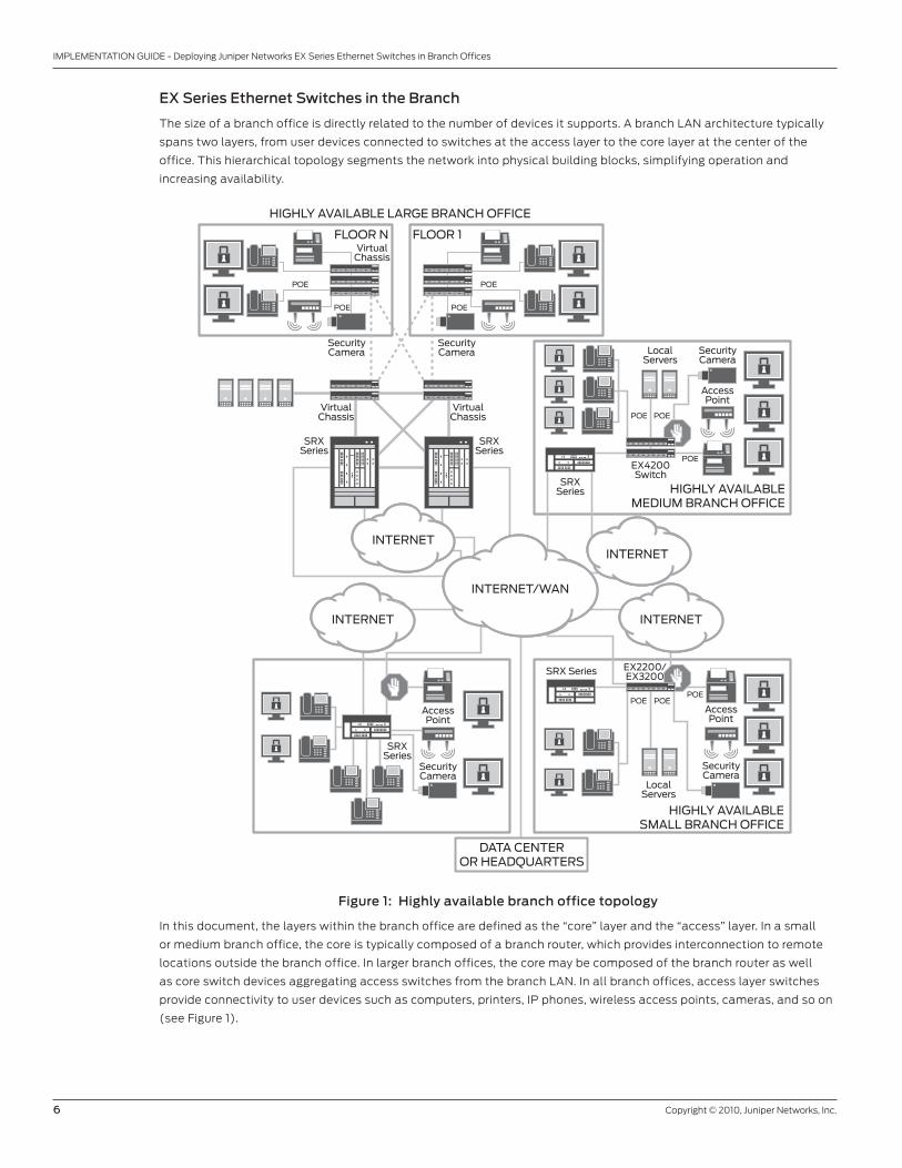
The size of a branch office is directly related to the number of devices it supports. A branch LAN architecture typically
spans two layers, from user devices connected to switches at the access layer to the core layer at the center of the
office. This hierarchical topology segments the network into physical building blocks, simplifying operation and
increasing availability.
Figure 1: Highly available branch office topology
In this document, the layers within the branch office are defined as the “core” layer and the “access” layer. In a small
or medium branch office, the core is typically composed of a branch router, which provides interconnection to remote
locations outside the branch office. In larger branch offices, the core may be composed of the branch router as well
as core switch devices aggregating access switches from the branch LAN. In all branch offices, access layer switches
provide connectivity to user devices such as computers, printers, IP phones, wireless access points, cameras, and so on
(see Figure 1).
HIGHLY AVAILABLE LARGE BRANCH OFFICE
FLOOR N
HIGHLY AVAILABLEMEDIUM BRANCH OFFICE
SecurityCamera
SecurityCamera Security
Camera
AccessPoint
LocalServers
EX4200Switch
VirtualChassis
VirtualChassis
VirtualChassis
SRXSeries
SRXSeries
DATA CENTEROR HEADQUARTERS
SRXSeries
FLOOR 1
INTERNETINTERNET
POE POE
POE POE
POE POE
POE
HIGHLY AVAILABLESMALL BRANCH OFFICE
SecurityCamera
AccessPoint
LocalServers
EX2200/EX3200SRX Series
POE POEPOE
SecurityCamera
AccessPoint
SRXSeries
INTERNETINTERNET
INTERNET/WAN
Copyright © 2010, Juniper Networks, Inc. 7
IMPLEMENTATION GUIDE - Deploying Juniper Networks EX Series Ethernet Switches in Branch Offices
In branch offices with a small number of users (typically less than 20 and referred to as a micro-branch), the access
switch and branch router functions may be consolidated within a single device, merging the access and core layers.
This document provides implementation guidelines and configuration examples for EX Series Ethernet Switches in
small, medium, and large branch offices. Configuration of Layer 2 and Layer 3 protocols within the access and core
layers of the branch office is discussed, as well as implementation details on connectivity, HA, security, and services.
The configuration of branch routers, such as J Series routers, is not covered in detail.
This document is broken into two main sections, which represent two different deployment methods: Routing and
Switching at the Core, and Routing to the Edge.
Section 1: Routing and Switching at the Core: A traditional branch-office deployment is a mixture of Layer 3 (core)
and Layer 2 (between the core and access). Network engineers are faced with complex designs involving routing and
Spanning Tree. And because of the complexity, network management and visibility can be a challenge.
Section 2: Routing to the Edge: Creating a Layer 3 network by extending routing to the edge (or access layer) is the
optimal branch-office deployment since it creates a deterministic network, maximizes redundant links (ECMP) without
the worry of a Layer 2 loop, and has superior convergence characteristics. A Layer 3 network also reduces the number
of protocols required to run the network (such as Spanning Tree and VRRP) implemented between the core and edge/
access, which means less time managing and more time to innovating the network.
Each of the previous sections is further divided into five subsections:
• Subsection 1: Physical Connectivity and Basic Switch Configuration
• Subsection 2: High Availability
• Subsection 3: Routing and Switching
• Subsection 4: Switch Services
• Subsection 5: Security and Network Management
Section 1: Routing and Switching at the Core
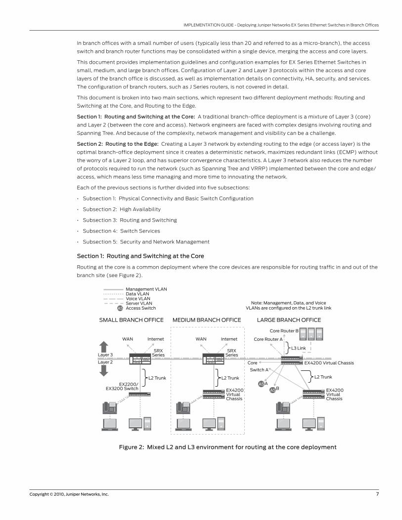
Routing at the core is a common deployment where the core devices are responsible for routing traffic in and out of the
branch site (see Figure 2).
Figure 2: Mixed L2 and L3 environment for routing at the core deployment
L2 Trunk
EX4200 Virtual Chassis
Core Router A
Core
Core Router B
L3 Link
AAS
AS
AS
B
MEDIUM BRANCH OFFICESMALL BRANCH OFFICE LARGE BRANCH OFFICE
Layer 3
Layer 2
Note: Management, Data, and VoiceVLANs are configured on the L2 trunk link
Management VLANData VLANVoice VLANServer VLANAccess Switch
L2 Trunk L2 Trunk
EX4200VirtualChassis
EX4200VirtualChassis
Switch A
EX2200/EX3200 Switch
WAN Internet
SRXSeries
WAN Internet
SRXSeries

8 Copyright © 2010, Juniper Networks, Inc.
IMPLEMENTATION GUIDE - Deploying Juniper Networks EX Series Ethernet Switches in Branch Offices
The following features are covered in this section:
Section 1: Physical Connectivity and Layer 2 Features
• L2/L3
• VLAN
• RVI
• IPT
• Management interface
Section 2: High Availability
• LAG
• GRES
• VRRP
Section 3: Switching and Routing
• RSTP/MSTP
• BPDU Protection
• IGMP Snooping
• Inter-VLAN Routing
• Unicast Routing
• Multicast Routing
Section 4: Switch Services
• DHCP/BOOTP Relay
• LLDP/LLDP-MED
• GVRP
• CoS
Section 5: Port Security and Network Management
• 802.1X
• DHCP Snooping
• DAI
• IP Source Guard
• Firewall Filter on management interface
• SSH
• Juniper Networks J-Web Software/Juniper Networks Network and Security Manager (NSM)

Copyright © 2010, Juniper Networks, Inc. 9
IMPLEMENTATION GUIDE - Deploying Juniper Networks EX Series Ethernet Switches in Branch Offices
Section 1.1: Physical Connectivity and Layer 2 Features
Figure 3 depicts the same three branches shown in Figure 2 with features pertaining to the physical layer and Layer 2.
Features such as port modes, VLAN, RVI, and management interface are covered in this section.
Figure 3: Physical and basic layer 2 configurations for routing at the core deployment
Port Connection
On the EX Series, port interfaces are configured as Layer 2 Access, Layer 2 Trunk, or Layer 3 interface.
Access (Layer 2): An access port is a member of a single VLAN, which is common for a host port. The packet on the
wire is unaltered (no VLAN identifier) with the exception of the voice over IP (VoIP) feature, which will be discussed in
further detail later in the “IPT Deployment” section.
AS
MEDIUM BRANCH OFFICESMALL BRANCH OFFICE LARGE BRANCH OFFICE
Note: Management, Data, and VoiceVLANs are configured on the L2 trunk link
Management VLANData VLANVoice VLANServer VLANAccess Switch
1GbEAccess PortAccess Port with VoiceVLANRVIManagement Interface
123456
L2 Trunk
EX4200 Virtual Chassis
Core Router A
Core
Core Router B
L3 Link
AAS
ASB
Layer 3
Layer 2
L2 Trunk L2 Trunk
EX4200VirtualChassis
EX4200VirtualChassis
Switch A
EX2200/EX3200 Switch
1
1
2
1
4 63
1
1
2
1
4 63
1
1
11
1
1
11
2
2
1
1
4 63
WAN Internet
SRXSeries
WAN Internet
SRXSeries
root# set interfaces ge-0/0/0.0 family ethernet-switching port-mode access
Trunk (Layer 2): A trunk port is a member of multiple VLANs. This is common for links that need to extend multiple
VLANs over a single link. When traffic traverses a trunk port, the traffic is tagged with a VLAN identifier (per IEEE 802.1Q).
root# set interfaces ge-0/1/0.0 family ethernet-switching port-mode trunk
Layer 3: Configuring an IP address to the interface itself creates a distinct Layer 3 network for the interface. This is
usually configured between two routed nodes (that is, between core router and switch in the large branch office).
root# set interfaces ge-0/1/1.0 family inet address 10.1.3.1/30
10 Copyright © 2010, Juniper Networks, Inc.
IMPLEMENTATION GUIDE - Deploying Juniper Networks EX Series Ethernet Switches in Branch Offices
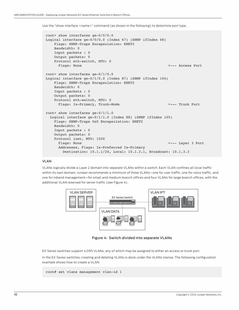
Use the “show interface <name>” command (as shown in the following) to determine port type.
root> show interfaces ge-0/0/0.0 Logical interface ge-0/0/0.0 (Index 67) (SNMP ifIndex 48) Flags: SNMP-Traps Encapsulation: ENET2 Bandwidth: 0 Input packets : 0 Output packets: 0 Protocol eth-switch, MTU: 0 Flags: None <--- Access Port
root> show interfaces ge-0/1/0.0 Logical interface ge-0/1/0.0 (Index 87) (SNMP ifIndex 104) Flags: SNMP-Traps Encapsulation: ENET2 Bandwidth: 0 Input packets : 0 Output packets: 0 Protocol eth-switch, MTU: 0 Flags: Is-Primary, Trunk-Mode <--- Trunk Port
root> show interfaces ge-0/1/1.0 Logical interface ge-0/1/1.0 (Index 88) (SNMP ifIndex 105) Flags: SNMP-Traps 0x0 Encapsulation: ENET2 Bandwidth: 0 Input packets : 0 Output packets: 0 Protocol inet, MTU: 1500 Flags: None <--- Layer 3 Port Addresses, Flags: Is-Preferred Is-Primary Destination: 10.1.1/24, Local: 10.1.3.1, Broadcast: 10.1.3.3
VLAN
VLANs logically divide a Layer 2 domain into separate VLANs within a switch. Each VLAN confines all local traffic
within its own domain. Juniper recommends a minimum of three VLANs—one for user traffic, one for voice traffic, and
one for inband management—for small and medium branch offices and four VLANs for large branch offices, with the
additional VLAN reserved for server traffic (see Figure 4).
Figure 4: Switch divided into separate VLANs
EX Series switches support 4,095 VLANs, any of which may be assigned to either an access or trunk port.
In the EX Series switches, creating and deleting VLANs is done under the VLANs stanza. The following configuration
example shows how to create a VLAN.
EX Series Switch
VLAN DATA
VLAN SERVER VLAN IPT
root# set vlans management vlan-id 1
Copyright © 2010, Juniper Networks, Inc. 11
IMPLEMENTATION GUIDE - Deploying Juniper Networks EX Series Ethernet Switches in Branch Offices
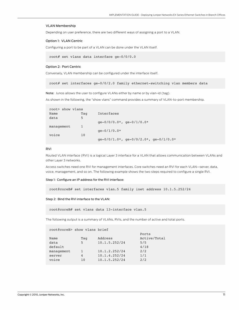
VLAN Membership
Depending on user preference, there are two different ways of assigning a port to a VLAN.
Option 1: VLAN Centric
Configuring a port to be part of a VLAN can be done under the VLAN itself.
root# set vlans data interface ge-0/0/0.0
Option 2: Port Centric
Conversely, VLAN membership can be configured under the interface itself.
root# set interfaces ge-0/0/2.0 family ethernet-switching vlan members data
Note: Junos allows the user to configure VLANs either by name or by vlan-id (tag).
As shown in the following, the “show vlans” command provides a summary of VLAN-to-port membership.
root> show vlans Name Tag Interfacesdata 5 ge-0/0/0.0*, ge-0/1/0.0*management 1 ge-0/1/0.0*voice 10 ge-0/0/1.0*, ge-0/0/2.0*, ge-0/1/0.0*
RVI
Routed VLAN interface (RVI) is a logical Layer 3 interface for a VLAN that allows communication between VLANs and
other Layer 3 networks.
Access switches need one RVI for management interfaces. Core switches need an RVI for each VLAN—server, data,
voice, management, and so on. The following example shows the two steps required to configure a single RVI.
Step 1: Configure an IP address for the RVI interface:
root@coreB# set interfaces vlan.5 family inet address 10.1.5.252/24
Step 2: Bind the RVI interface to the VLAN:
root@coreB# set vlans data l3-interface vlan.5
The following output is a summary of VLANs, RVIs, and the number of active and total ports.
root@coreB> show vlans brief PortsName Tag Address Active/Totaldata 5 10.1.5.252/24 5/5default 4/18management 1 10.1.2.252/24 2/2server 4 10.1.4.252/24 1/1voice 10 10.1.5.252/24 2/2
12 Copyright © 2010, Juniper Networks, Inc.
IMPLEMENTATION GUIDE - Deploying Juniper Networks EX Series Ethernet Switches in Branch Offices
Management Interface
EX Series switches have an out-of-band Ethernet interface (me0) and serial port (console 0) for management.
For secure management, it is good practice to manage the switch out-of-band, but that can require a separate
infrastructure. For branch offices, the cost does not justify a separate management infrastructure. Instead, in-band
management interface (on the same network as the data) is more cost-effective.
Any Layer 3 interfaces such as, lo0, RVI, or L3 interface can be an in-band management interface. Loopback 0
is commonly used as the in-band management interface. However there is certain deployment where in-band
management interface is other than lo0 such as access switches as in this type of deployment. In cases where the
access switch is strictly a Layer 2 device, configuring a RVI on the management VLAN will eliminate the need to
configure a lo0.
Since routing protocols are enabled at the core layer, lo0 should be configured as follows:
root@coreB# set interfaces lo0.0 family inet address 10.1.2.1/32
The following is an output of the “show interfaces” command for lo0.
root@coreB> show interfaces lo0.0 Logical interface lo0.0 (Index 88) (SNMP ifIndex 16) Flags: SNMP-Traps Encapsulation: Unspecified Input packets : 6 Output packets: 6 Protocol inet, MTU: Unlimited Flags: None Addresses, Flags: Is-Default Is-Primary Local: 10.1.2.1
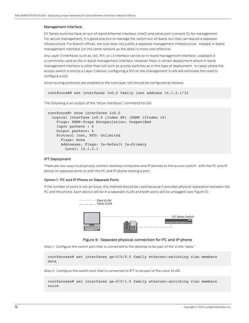
IPT Deployment
There are two ways to physically connect desktop computers and IP phones to the access switch: with the PC and IP
phone on separate ports or with the PC and IP phone sharing a port.
Option 1: PC and IP Phone on Separate Ports
If the number of ports is not an issue, this method should be used because it provides physical separation between the
PC and the phone. Each device will be in a separate VLAN and both ports will be untagged (see Figure 5):
Figure 5: Separate physical connection for PC and IP phone
Step 1: Configure the switch port that is connected to the desktop to be part of the VLAN “data.”
Data VLANVoice VLAN
EX Series Switch
root@access# set interfaces ge-0/0/0.0 family ethernet-switching vlan members data
Step 2: Configure the switch port that is connected to IPT to be part of the voice VLAN.
root@access# set interfaces ge-0/0/1.0 family ethernet-switching vlan members voice

Copyright © 2010, Juniper Networks, Inc. 13
IMPLEMENTATION GUIDE - Deploying Juniper Networks EX Series Ethernet Switches in Branch Offices
Option 2: PC and IP Phone on the Same Port
This is a common deployment because it preserves ports by allowing two devices to be connected on a single port
while keeping the voice and data traffic in separate VLANs (see Figure 6). This can be done either by configuring the
port as trunk port or using the “voip vlan” feature. Juniper recommends enabling the “voip vlan” feature. The “voip vlan”
feature allows tagged packets on access ports. Packets that are tagged will be mapped into the voice VLAN while
untagged packets will be mapped to the data VLAN.
Figure 6: Independent LAN connections for PC and IP phone
Step 1: Configure the access port to be a member of VLAN “data.”
Note: By default, all ports are access ports. Therefore, it is not necessary to configure the “access” keyword.
Data VLANVoice VLAN
Access PortEX Series Switch
root@access# set interfaces ge-0/0/2.0 family ethernet-switching vlan members data
Step 2: Configure voice VLAN. Even though interface ge-0/0/0.0 is an access port, it is configured to accept both
tagged packets for voice traffic and untagged packets for data traffic.
root@access# set ethernet-switching-options voip interface ge-0/0/2.0 vlan voice
The following command is useful to validate VLANs on a given interface.
root@access> show ethernet-switching interfaces ge-0/0/2.0 detail Interface: ge-0/0/2.0 Index: 66 State: up VLANs: data untagged unblocked voice tagged unblocked
Note: For full IPT implementation, please refer to the IP telephony (IPT) Application Note.
14 Copyright © 2010, Juniper Networks, Inc.
IMPLEMENTATION GUIDE - Deploying Juniper Networks EX Series Ethernet Switches in Branch Offices
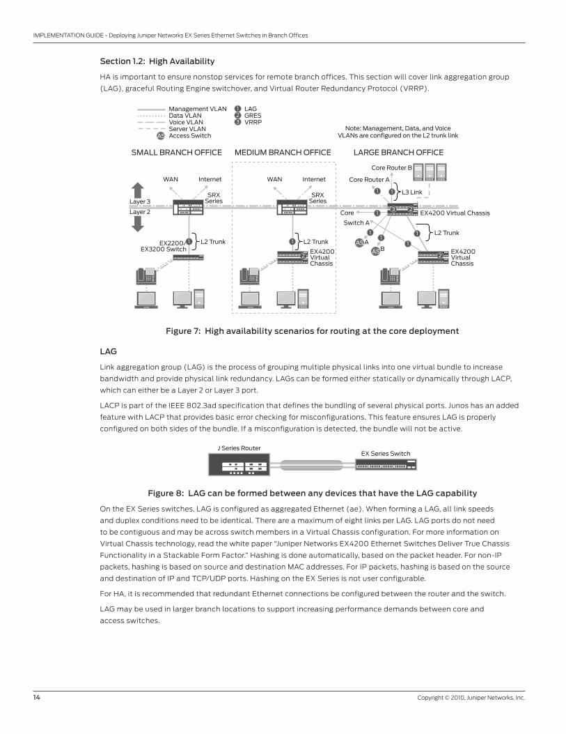
Section 1.2: High Availability
HA is important to ensure nonstop services for remote branch offices. This section will cover link aggregation group
(LAG), graceful Routing Engine switchover, and Virtual Router Redundancy Protocol (VRRP).
Figure 7: High availability scenarios for routing at the core deployment
LAG
Link aggregation group (LAG) is the process of grouping multiple physical links into one virtual bundle to increase
bandwidth and provide physical link redundancy. LAGs can be formed either statically or dynamically through LACP,
which can either be a Layer 2 or Layer 3 port.
LACP is part of the IEEE 802.3ad specification that defines the bundling of several physical ports. Junos has an added
feature with LACP that provides basic error checking for misconfigurations. This feature ensures LAG is properly
configured on both sides of the bundle. If a misconfiguration is detected, the bundle will not be active.
Figure 8: LAG can be formed between any devices that have the LAG capability
On the EX Series switches, LAG is configured as aggregated Ethernet (ae). When forming a LAG, all link speeds
and duplex conditions need to be identical. There are a maximum of eight links per LAG. LAG ports do not need
to be contiguous and may be across switch members in a Virtual Chassis configuration. For more information on
Virtual Chassis technology, read the white paper “Juniper Networks EX4200 Ethernet Switches Deliver True Chassis
Functionality in a Stackable Form Factor.” Hashing is done automatically, based on the packet header. For non-IP
packets, hashing is based on source and destination MAC addresses. For IP packets, hashing is based on the source
and destination of IP and TCP/UDP ports. Hashing on the EX Series is not user configurable.
For HA, it is recommended that redundant Ethernet connections be configured between the router and the switch.
LAG may be used in larger branch locations to support increasing performance demands between core and
access switches.
LAGGRESVRRP
123
L2 Trunk
EX4200 Virtual Chassis
Core Router A
Core
Core Router B
L3 Link
AAS
AS
AS
B
MEDIUM BRANCH OFFICESMALL BRANCH OFFICE LARGE BRANCH OFFICE
Layer 3
Layer 2
Note: Management, Data, and VoiceVLANs are configured on the L2 trunk link
Management VLANData VLANVoice VLANServer VLANAccess Switch
L2 Trunk L2 Trunk
EX4200VirtualChassis
EX4200VirtualChassis
Switch A
EX2200/EX3200 Switch
1 1
2
1
11
1
1
1 1
2
3 2
WAN Internet
SRXSeries
WAN Internet
SRXSeries
J Series RouterEX Series Switch
Copyright © 2010, Juniper Networks, Inc. 15
IMPLEMENTATION GUIDE - Deploying Juniper Networks EX Series Ethernet Switches in Branch Offices
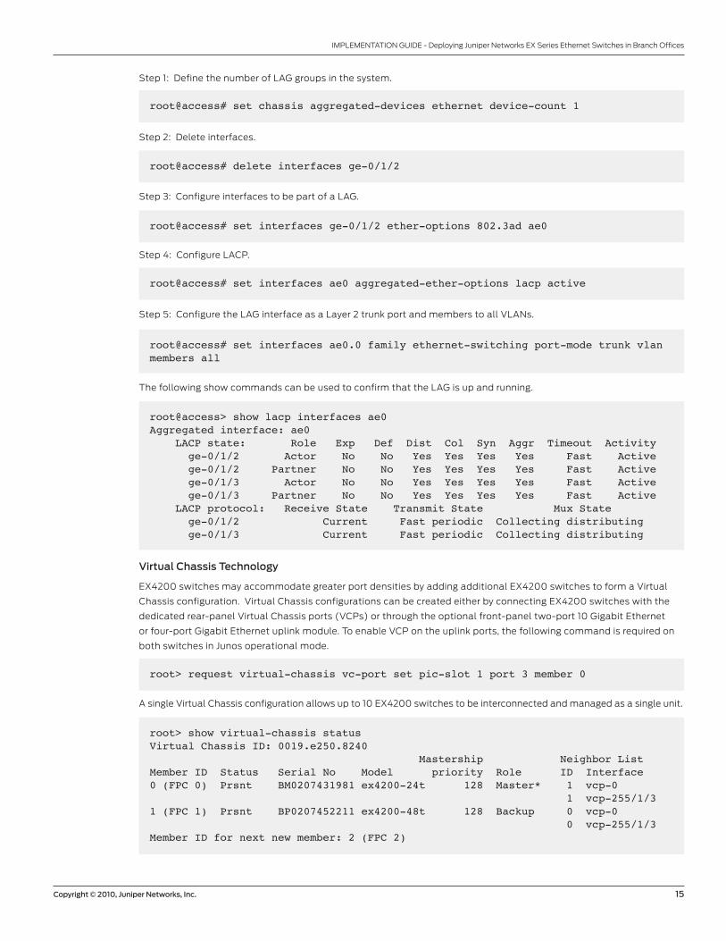
Step 1: Define the number of LAG groups in the system.
root@access# set chassis aggregated-devices ethernet device-count 1
Step 2: Delete interfaces.
root@access# delete interfaces ge-0/1/2
Step 3: Configure interfaces to be part of a LAG.
root@access# set interfaces ge-0/1/2 ether-options 802.3ad ae0
Step 4: Configure LACP.
root@access# set interfaces ae0 aggregated-ether-options lacp active
Step 5: Configure the LAG interface as a Layer 2 trunk port and members to all VLANs.
root@access# set interfaces ae0.0 family ethernet-switching port-mode trunk vlan members all
The following show commands can be used to confirm that the LAG is up and running.
root@access> show lacp interfaces ae0 Aggregated interface: ae0 LACP state: Role Exp Def Dist Col Syn Aggr Timeout Activity ge-0/1/2 Actor No No Yes Yes Yes Yes Fast Active ge-0/1/2 Partner No No Yes Yes Yes Yes Fast Active ge-0/1/3 Actor No No Yes Yes Yes Yes Fast Active ge-0/1/3 Partner No No Yes Yes Yes Yes Fast Active LACP protocol: Receive State Transmit State Mux State ge-0/1/2 Current Fast periodic Collecting distributing ge-0/1/3 Current Fast periodic Collecting distributing
Virtual Chassis Technology
EX4200 switches may accommodate greater port densities by adding additional EX4200 switches to form a Virtual
Chassis configuration. Virtual Chassis configurations can be created either by connecting EX4200 switches with the
dedicated rear-panel Virtual Chassis ports (VCPs) or through the optional front-panel two-port 10 Gigabit Ethernet
or four-port Gigabit Ethernet uplink module. To enable VCP on the uplink ports, the following command is required on
both switches in Junos operational mode.
root> request virtual-chassis vc-port set pic-slot 1 port 3 member 0
A single Virtual Chassis configuration allows up to 10 EX4200 switches to be interconnected and managed as a single unit.
root> show virtual-chassis status Virtual Chassis ID: 0019.e250.8240 Mastership Neighbor List Member ID Status Serial No Model priority Role ID Interface0 (FPC 0) Prsnt BM0207431981 ex4200-24t 128 Master* 1 vcp-0 1 vcp-255/1/31 (FPC 1) Prsnt BP0207452211 ex4200-48t 128 Backup 0 vcp-0 0 vcp-255/1/3Member ID for next new member: 2 (FPC 2)
16 Copyright © 2010, Juniper Networks, Inc.
IMPLEMENTATION GUIDE - Deploying Juniper Networks EX Series Ethernet Switches in Branch Offices
In the previous command, a Virtual Chassis configuration is formed through the dedicated Virtual Chassis ports (vcp-
0) and the front-panel uplink module (vcp-255/1/3).
When EX4200 switches are deployed in a Virtual Chassis configuration, the member switches automatically elect
a master and backup Routing Engine. The master Routing Engine is responsible for managing the Virtual Chassis
configuration, while the backup is available to take over in the event a master failure. All other switches in a Virtual
Chassis configuration take on the role of a line card, and are eligible as a master or backup Routing Engine if the
original master or backup were to fail.
Mastership Priority
There is a specific master election process when a Virtual Chassis configuration is formed. Upon bootup, all members
are considered eligible candidates and participate in the election.
The Master Election Decision Tree determines which switch becomes the master. The master and backup Routing
Engines are assigned based on the following criteria:
1. Highest Mastership priority (default 128, user configurable 1 thru 255)
2. Master in previous boot among eligible switches
3. Uptime of the eligible masters (if uptime difference is more than 1 minute)
4. Lowest switch-based MAC address
root# set virtual-chassis member 0 mastership-priority 250
Preprovisioning
The preprovisioning feature is a deterministic way of predefining a switch member role (Routing Engine or line card)
prior to joining the Virtual Chassis configuration. The entire configuration is done under the master RE. Any member
that is not pre-provisioned will not be part of the Virtual Chassis configuration upon connection.
Step 1: Enable preprovisioning on the master Routing Engine.
root# set virtual-chassis preprovisioned
Step 2: Configure members’ roles on the master Routing Engine (all members need to be defined, including the master
Routing Engine).
root# set virtual-chassis preprovisioned member 0 serial-number xxxxxxxxxxxx role routing-engineroot# set virtual-chassis preprovisioned member 0 serial-number xxxxxxxxxxxx role routing-engineroot# set virtual-chassis preprovisioned member 0 serial-number xxxxxxxxxxxx role line-cardStep 3: Connect the members.
Copyright © 2010, Juniper Networks, Inc. 17
IMPLEMENTATION GUIDE - Deploying Juniper Networks EX Series Ethernet Switches in Branch Offices
GRES
Graceful Routing Engine switchover is a Junos feature that facilitates seamless failover between the master and
backup Routing Engines. When graceful Routing Engine switchover is enabled, the kernel and certain tables (MAC
address, route tables, port states, and so on) are synchronized between the master and the backup Routing Engine,
eliminating the need for the backup Routing Engine to relearn states and routes should the master Routing Engine fail.
Minimal packet loss should be expected during master failover when graceful Routing Engine switchover is configured.
root@coreB# set chassis redundancy graceful-switchover
VRRP
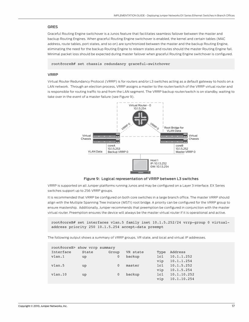
Virtual Router Redundancy Protocol (VRRP) is for routers and/or L3 switches acting as a default gateway to hosts on a
LAN network. Through an election process, VRRP assigns a master to the router/switch of the VRRP virtual router and
is responsible for routing traffic to and from the LAN segment. The VRRP backup router/switch is on standby, waiting to
take over in the event of a master failure (see Figure 9).
Figure 9: Logical representation of VRRP between L3 switches
VRRP is supported on all Juniper platforms running Junos and may be configured on a Layer 3 interface. EX Series
switches support up to 256 VRRP groups.
It is recommended that VRRP be configured on both core switches in a large branch office. The master VRRP should
align with the Multiple Spanning Tree Instance (MSTI) root bridge. A priority can be configured for the VRRP group to
ensure mastership. Additionally, Juniper recommends that preemption be configured in conjunction with the master
virtual router. Preemption ensures the device will always be the master virtual router if it is operational and active.
VirtualChassis
Root Bridge forVLAN Data
Virtual Router - 010.1.5.254
VRRP 0VRRP 0
VirtualChassis
Host 1IP: 10.1.5.252GW: 10.1.5.254
VLAN Data
coreA10.1.5.253Backup VRRP 0
coreB10.1.5.252Master VRRP 0
root@coreB# set interfaces vlan.5 family inet 10.1.5.252/24 vrrp-group 0 virtual-address priority 250 10.1.5.254 accept-data preempt
The following output shows a summary of VRRP groups, VR state, and local and virtual IP addresses.
root@coreB> show vrrp summary Interface State Group VR state Type Addressvlan.1 up 0 backup lcl 10.1.1.252 vip 10.1.1.254 vlan.5 up 0 master lcl 10.1.5.252 vip 10.1.5.254 vlan.10 up 0 backup lcl 10.1.10.252 vip 10.1.10.254
18 Copyright © 2010, Juniper Networks, Inc.
IMPLEMENTATION GUIDE - Deploying Juniper Networks EX Series Ethernet Switches in Branch Offices
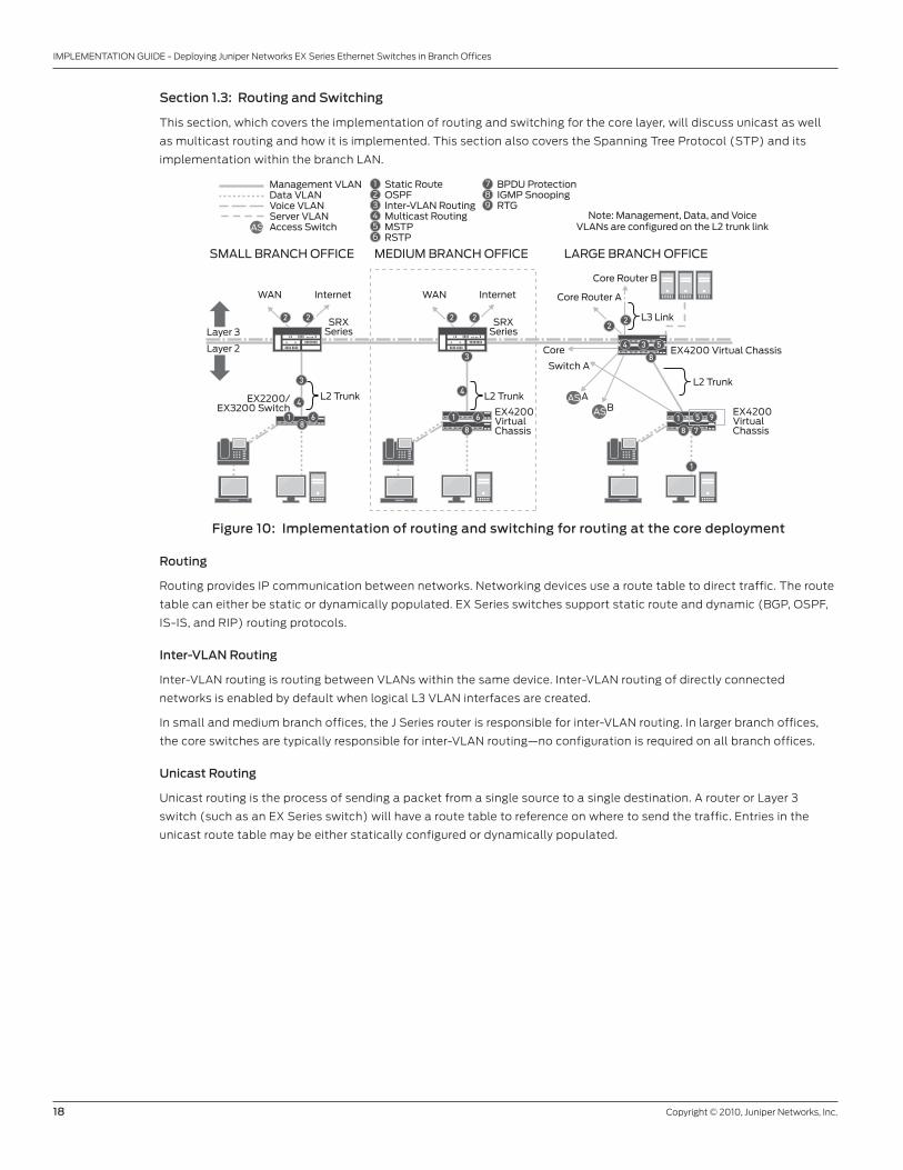
Section 1.3: Routing and Switching
This section, which covers the implementation of routing and switching for the core layer, will discuss unicast as well
as multicast routing and how it is implemented. This section also covers the Spanning Tree Protocol (STP) and its
implementation within the branch LAN.
Figure 10: Implementation of routing and switching for routing at the core deployment
Routing
Routing provides IP communication between networks. Networking devices use a route table to direct traffic. The route
table can either be static or dynamically populated. EX Series switches support static route and dynamic (BGP, OSPF,
IS-IS, and RIP) routing protocols.
Inter-VLAN Routing
Inter-VLAN routing is routing between VLANs within the same device. Inter-VLAN routing of directly connected
networks is enabled by default when logical L3 VLAN interfaces are created.
In small and medium branch offices, the J Series router is responsible for inter-VLAN routing. In larger branch offices,
the core switches are typically responsible for inter-VLAN routing—no configuration is required on all branch offices.
Unicast Routing
Unicast routing is the process of sending a packet from a single source to a single destination. A router or Layer 3
switch (such as an EX Series switch) will have a route table to reference on where to send the traffic. Entries in the
unicast route table may be either statically configured or dynamically populated.
Static RouteOSPFInter-VLAN RoutingMulticast RoutingMSTPRSTP
123
BPDU ProtectionIGMP SnoopingRTG
789
456
L2 Trunk
EX4200 Virtual Chassis
Core Router A
Core
Core Router B
L3 Link
AAS
AS
AS
B
MEDIUM BRANCH OFFICESMALL BRANCH OFFICE LARGE BRANCH OFFICE
Layer 3
Layer 2
Note: Management, Data, and VoiceVLANs are configured on the L2 trunk link
Management VLANData VLANVoice VLANServer VLANAccess Switch
L2 Trunk L2 Trunk
EX4200VirtualChassis
EX4200VirtualChassis
Switch A
EX2200/EX3200 Switch
3
81 6
3
81 6
8
22
8 7
1
1 5 9
4 53
44
WAN Internet
SRXSeries
WAN Internet
SRXSeries
2 22 2

Copyright © 2010, Juniper Networks, Inc. 19
IMPLEMENTATION GUIDE - Deploying Juniper Networks EX Series Ethernet Switches in Branch Offices
Static Routes (Small and Medium Branch Offices)
In the small and medium branch office, the access switch typically will not be routing data traffic. Routing functionality
will be provided by the SRX Series. However, a static route is needed for management protocols—FTP, SSH, SNMP, and
so on. Although not covered here, the SRX Series will need to do some route distribution for the management traffic.
root@access# set routing-options static route 0.0.0.0/0 next-hop 10.1.1.254The “show route” command will display all the active routes.root@access> show route
inet.0: 4 destinations, 4 routes (4 active, 0 holddown, 0 hidden)+ = Active Route, - = Last Active, * = Both
0.0.0.0/0 *[Static/5] 00:00:05 > to 10.1.1.254 via vlan.110.1.1.0/24 *[Direct/0] 00:00:05 > via vlan.110.1.1.1/32 *[Local/0] 00:02:44 Local via vlan.1
OSPF (Large Branch Office)
OSPF is a two-tier hierarchical link state routing protocol. The backbone area (area 0.0.0.0) must border every area in
its autonomous system. The backbone distributes routing information between areas. The routing table is based on the
shortest path tree in each area.
The core switches in the large branch office are responsible for routing data traffic to and from users to other locations
via the WAN. Therefore, OSPF will be enabled on the core devices (both core routers and switches). The following
configuration shows the commands for area 0.0.0.0. Customer-specific requirements may differ.
Step 1: Enable OSPF on the interface connecting to the J Series routers, assign the interface to an area 0.0.0.0, and
configure for authentication.
root@coreB# set protocols ospf area 0.0.0.0 interface ae0.0 authentication md5 1 key peerless
If the authentication fails, then the interface will not establish adjacency with the neighboring OSPF router.
Step 2: Advertise the VLAN networks (data, voice, server, and management) to corporate without enabling OSPF on
the RVI.
root@coreB# set protocols ospf area 0.0.0.0 interface vlan.1 passive
The following output can be used to confirm that OSPF has established a full adjacency with its neighbor.
root> show ospf neighbor Address Interface State ID Pri Dead10.1.3.2 ae0.0 Full 10.1.2.1 1 3010.1.3.6 ae1.0 Full 10.1.2.1 1 30
20 Copyright © 2010, Juniper Networks, Inc.
IMPLEMENTATION GUIDE - Deploying Juniper Networks EX Series Ethernet Switches in Branch Offices
ECMP
OSPF supports equal-cost multipath (ECMP). When building the shortest path tree, OSPF calculates the shortest path
to a given destination. If equal-cost paths exist, OSPF inserts the next hops for all equal-cost paths to a destination in
the routing table.
In the large branch office, ECMP should be configured on all core enabled routing devices.
root@coreB# set policy-options policy-statement ECMP then load-balance per-packet root@coreB# set routing-options forwarding-table export ECMP
In a mixed L2/L3 environment where EMCP is combined with different ARP and MAC aging timers, unknown unicast
flooding will occur due to asymmetrical routing—a condition in which the sending (host to server) and receiving (server
to host) paths are different. On one of the core switches (usually the switch that is the backup VRRP), the host’s MAC
address ages out because the MAC aging timer never gets reset.
There are two different ways to mitigate this problem. The first requires a lot of route manipulation on the core routers.
The second—and easier—option is to match the ARP timer and MAC aging timer on the core switches to be the
same for all VLANs. The MAC aging timer is configurable in seconds and defaults to 300 seconds. The ARP timer is
configurable in minutes and defaults to 20 minutes.
root@coreB# set system arp aging-timer 20 root@coreB# set vlans data mac-table-aging-time 1200
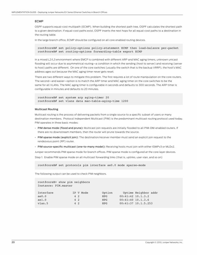
Multicast Routing
Multicast routing is the process of delivering packets from a single source to a specific subset of users or many
destination members. Protocol Independent Multicast (PIM) is the predominant multicast routing protocol used today.
PIM operates in three basic modes:
• PIM dense mode (flood and prune): Multicast join requests are initially flooded to all PIM-DM-enabled routers. If
there are no downstream members, then the router will prune towards the source.
• PIM sparse mode (explicit join): The destination/receiver member must send an explicit join request to the
rendezvous point (RP) router.
• PIM source-specific multicast (one-to-many model): Receiving hosts must join with either IGMPv3 or MLDv2.
Juniper recommends PIM sparse mode for branch offices. PIM sparse mode is configured at the core layer devices.
Step 1: Enable PIM sparse mode on all multicast forwarding links (that is, uplinks, user vlan, and so on)
root@coreB# set protocols pim interface ae0.0 mode sparse-mode
The following output can be used to check PIM neighbors.
root@coreB> show pim neighbors Instance: PIM.master
Interface IP V Mode Option Uptime Neighbor addrae0.0 4 2 HPG 00:41:42 10.1.3.2ae1.0 4 2 HPG 00:41:40 10.1.3.6vlan.5 4 2 HPG 00:41:37 10.1.5.253
Copyright © 2010, Juniper Networks, Inc. 21
IMPLEMENTATION GUIDE - Deploying Juniper Networks EX Series Ethernet Switches in Branch Offices
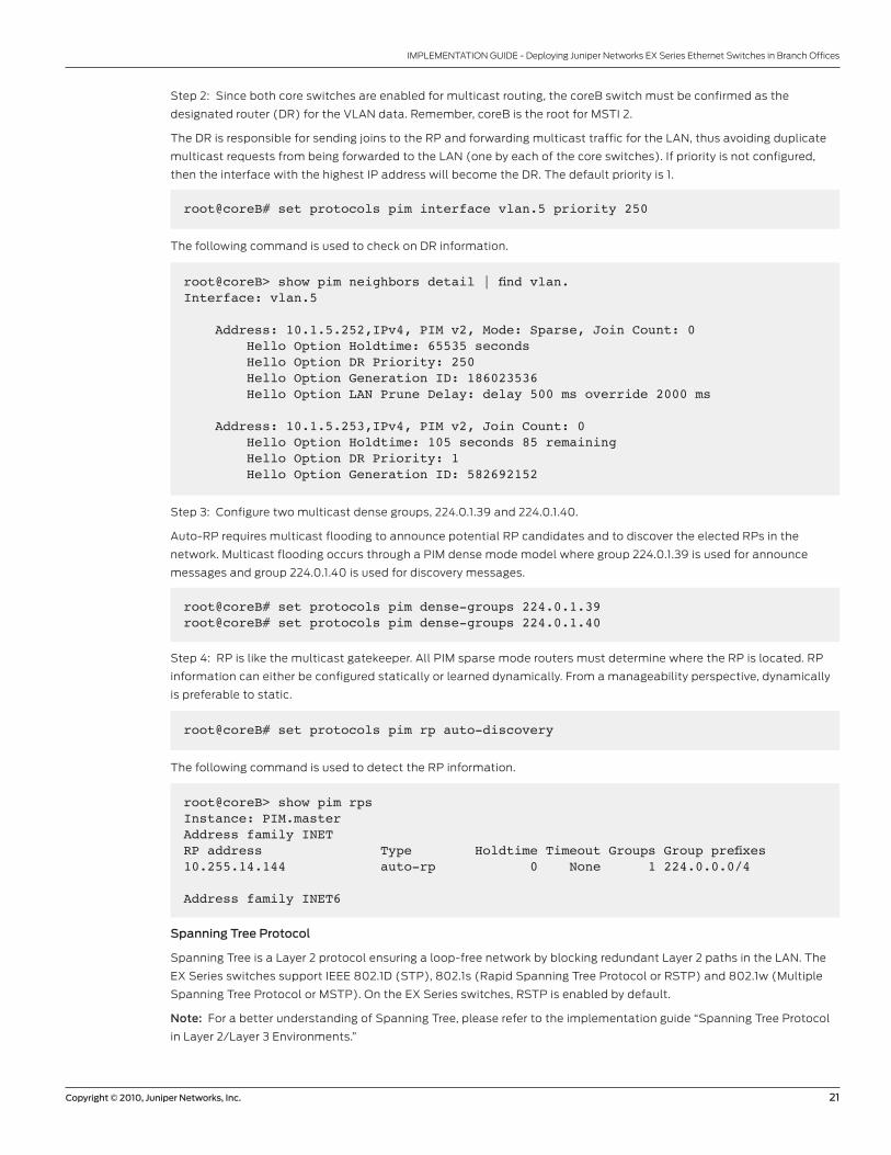
Step 2: Since both core switches are enabled for multicast routing, the coreB switch must be confirmed as the
designated router (DR) for the VLAN data. Remember, coreB is the root for MSTI 2.
The DR is responsible for sending joins to the RP and forwarding multicast traffic for the LAN, thus avoiding duplicate
multicast requests from being forwarded to the LAN (one by each of the core switches). If priority is not configured,
then the interface with the highest IP address will become the DR. The default priority is 1.
root@coreB# set protocols pim interface vlan.5 priority 250
The following command is used to check on DR information.
root@coreB> show pim neighbors detail | find vlan.Interface: vlan.5
Address: 10.1.5.252,IPv4, PIM v2, Mode: Sparse, Join Count: 0 Hello Option Holdtime: 65535 seconds Hello Option DR Priority: 250 Hello Option Generation ID: 186023536 Hello Option LAN Prune Delay: delay 500 ms override 2000 ms
Address: 10.1.5.253,IPv4, PIM v2, Join Count: 0 Hello Option Holdtime: 105 seconds 85 remaining Hello Option DR Priority: 1 Hello Option Generation ID: 582692152
Step 3: Configure two multicast dense groups, 224.0.1.39 and 224.0.1.40.
Auto-RP requires multicast flooding to announce potential RP candidates and to discover the elected RPs in the
network. Multicast flooding occurs through a PIM dense mode model where group 224.0.1.39 is used for announce
messages and group 224.0.1.40 is used for discovery messages.
root@coreB# set protocols pim dense-groups 224.0.1.39root@coreB# set protocols pim dense-groups 224.0.1.40
Step 4: RP is like the multicast gatekeeper. All PIM sparse mode routers must determine where the RP is located. RP
information can either be configured statically or learned dynamically. From a manageability perspective, dynamically
is preferable to static.
root@coreB# set protocols pim rp auto-discovery
The following command is used to detect the RP information.
root@coreB> show pim rpsInstance: PIM.masterAddress family INETRP address Type Holdtime Timeout Groups Group prefixes10.255.14.144 auto-rp 0 None 1 224.0.0.0/4
Address family INET6
Spanning Tree Protocol
Spanning Tree is a Layer 2 protocol ensuring a loop-free network by blocking redundant Layer 2 paths in the LAN. The
EX Series switches support IEEE 802.1D (STP), 802.1s (Rapid Spanning Tree Protocol or RSTP) and 802.1w (Multiple
Spanning Tree Protocol or MSTP). On the EX Series switches, RSTP is enabled by default.
Note: For a better understanding of Spanning Tree, please refer to the implementation guide “Spanning Tree Protocol
in Layer 2/Layer 3 Environments.”
22 Copyright © 2010, Juniper Networks, Inc.
IMPLEMENTATION GUIDE - Deploying Juniper Networks EX Series Ethernet Switches in Branch Offices
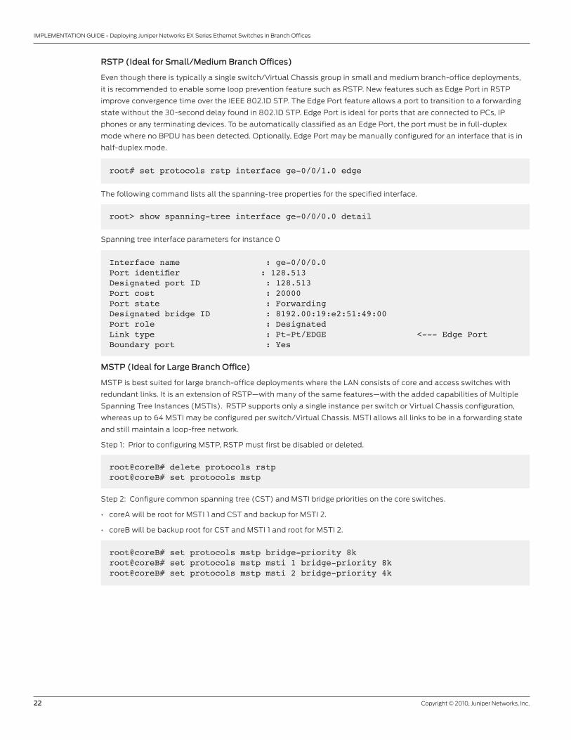
RSTP (Ideal for Small/Medium Branch Offices)
Even though there is typically a single switch/Virtual Chassis group in small and medium branch-office deployments,
it is recommended to enable some loop prevention feature such as RSTP. New features such as Edge Port in RSTP
improve convergence time over the IEEE 802.1D STP. The Edge Port feature allows a port to transition to a forwarding
state without the 30-second delay found in 802.1D STP. Edge Port is ideal for ports that are connected to PCs, IP
phones or any terminating devices. To be automatically classified as an Edge Port, the port must be in full-duplex
mode where no BPDU has been detected. Optionally, Edge Port may be manually configured for an interface that is in
half-duplex mode.
root# set protocols rstp interface ge-0/0/1.0 edge
The following command lists all the spanning-tree properties for the specified interface.
root> show spanning-tree interface ge-0/0/0.0 detail
Spanning tree interface parameters for instance 0
Interface name : ge-0/0/0.0Port identifier : 128.513Designated port ID : 128.513Port cost : 20000Port state : ForwardingDesignated bridge ID : 8192.00:19:e2:51:49:00Port role : DesignatedLink type : Pt-Pt/EDGE <--- Edge PortBoundary port : Yes
MSTP (Ideal for Large Branch Office)
MSTP is best suited for large branch-office deployments where the LAN consists of core and access switches with
redundant links. It is an extension of RSTP—with many of the same features—with the added capabilities of Multiple
Spanning Tree Instances (MSTIs). RSTP supports only a single instance per switch or Virtual Chassis configuration,
whereas up to 64 MSTI may be configured per switch/Virtual Chassis. MSTI allows all links to be in a forwarding state
and still maintain a loop-free network.
Step 1: Prior to configuring MSTP, RSTP must first be disabled or deleted.
root@coreB# delete protocols rstproot@coreB# set protocols mstp
Step 2: Configure common spanning tree (CST) and MSTI bridge priorities on the core switches.
• coreA will be root for MSTI 1 and CST and backup for MSTI 2.
• coreB will be backup root for CST and MSTI 1 and root for MSTI 2.
root@coreB# set protocols mstp bridge-priority 8kroot@coreB# set protocols mstp msti 1 bridge-priority 8kroot@coreB# set protocols mstp msti 2 bridge-priority 4k
Copyright © 2010, Juniper Networks, Inc. 23
IMPLEMENTATION GUIDE - Deploying Juniper Networks EX Series Ethernet Switches in Branch Offices
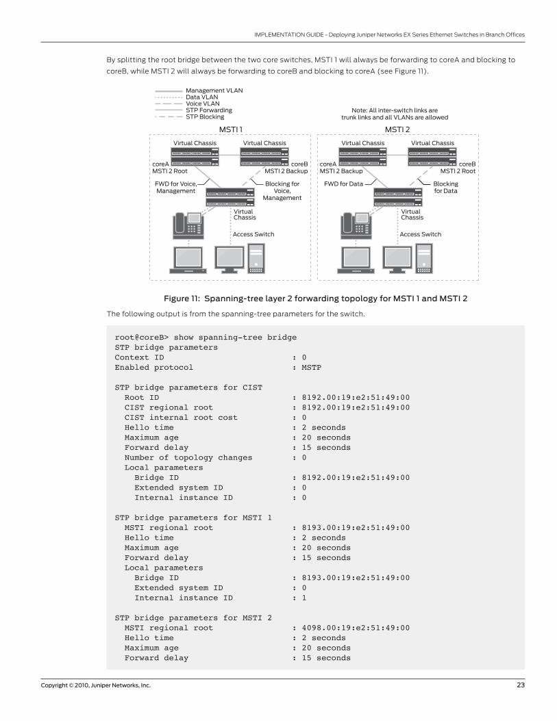
By splitting the root bridge between the two core switches, MSTI 1 will always be forwarding to coreA and blocking to
coreB, while MSTI 2 will always be forwarding to coreB and blocking to coreA (see Figure 11).
Figure 11: Spanning-tree layer 2 forwarding topology for MSTI 1 and MSTI 2
The following output is from the spanning-tree parameters for the switch.
VirtualChassis
Virtual Chassis Virtual Chassis
MSTI 1
VirtualChassis
Virtual Chassis Virtual Chassis
MSTI 2
Note: All inter-switch links aretrunk links and all VLANs are allowed
Management VLANData VLANVoice VLANSTP ForwardingSTP Blocking
coreAMSTI 2 Root
FWD for Voice,Management
Blocking forVoice,
Management
coreBMSTI 2 Backup
Access Switch Access Switch
coreAMSTI 2 Backup
FWD for Data Blockingfor Data
coreBMSTI 2 Root
root@coreB> show spanning-tree bridge STP bridge parameters Context ID : 0Enabled protocol : MSTP
STP bridge parameters for CIST Root ID : 8192.00:19:e2:51:49:00 CIST regional root : 8192.00:19:e2:51:49:00 CIST internal root cost : 0 Hello time : 2 seconds Maximum age : 20 seconds Forward delay : 15 seconds Number of topology changes : 0 Local parameters Bridge ID : 8192.00:19:e2:51:49:00 Extended system ID : 0 Internal instance ID : 0
STP bridge parameters for MSTI 1 MSTI regional root : 8193.00:19:e2:51:49:00 Hello time : 2 seconds Maximum age : 20 seconds Forward delay : 15 seconds Local parameters Bridge ID : 8193.00:19:e2:51:49:00 Extended system ID : 0 Internal instance ID : 1
STP bridge parameters for MSTI 2 MSTI regional root : 4098.00:19:e2:51:49:00 Hello time : 2 seconds Maximum age : 20 seconds Forward delay : 15 seconds
24 Copyright © 2010, Juniper Networks, Inc.
IMPLEMENTATION GUIDE - Deploying Juniper Networks EX Series Ethernet Switches in Branch Offices
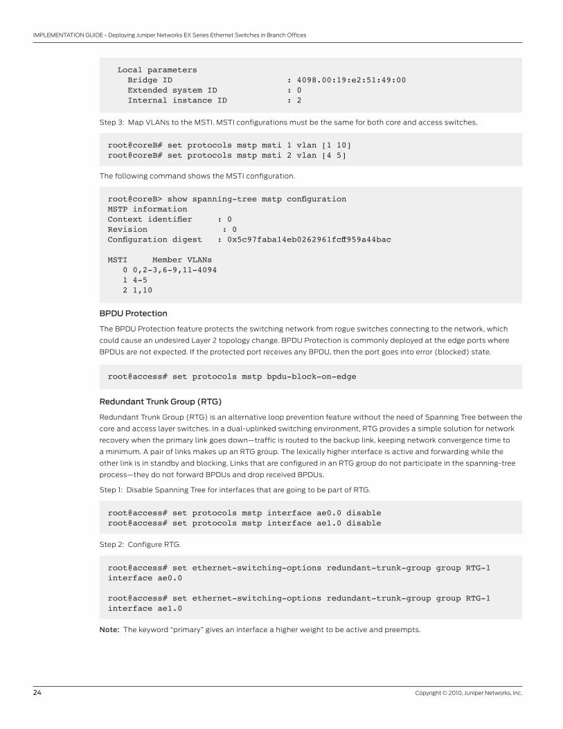
Local parameters Bridge ID : 4098.00:19:e2:51:49:00 Extended system ID : 0 Internal instance ID : 2
Step 3: Map VLANs to the MSTI. MSTI configurations must be the same for both core and access switches.
root@coreB# set protocols mstp msti 1 vlan [1 10]root@coreB# set protocols mstp msti 2 vlan [4 5]
The following command shows the MSTI configuration.
root@coreB> show spanning-tree mstp configuration MSTP information Context identifier : 0Revision : 0Configuration digest : 0x5c97faba14eb0262961fcff959a44bac
MSTI Member VLANs 0 0,2-3,6-9,11-4094 1 4-5 2 1,10
BPDU Protection
The BPDU Protection feature protects the switching network from rogue switches connecting to the network, which
could cause an undesired Layer 2 topology change. BPDU Protection is commonly deployed at the edge ports where
BPDUs are not expected. If the protected port receives any BPDU, then the port goes into error (blocked) state.
root@access# set protocols mstp bpdu-block-on-edge
Redundant Trunk Group (RTG)
Redundant Trunk Group (RTG) is an alternative loop prevention feature without the need of Spanning Tree between the
core and access layer switches. In a dual-uplinked switching environment, RTG provides a simple solution for network
recovery when the primary link goes down—traffic is routed to the backup link, keeping network convergence time to
a minimum. A pair of links makes up an RTG group. The lexically higher interface is active and forwarding while the
other link is in standby and blocking. Links that are configured in an RTG group do not participate in the spanning-tree
process—they do not forward BPDUs and drop received BPDUs.
Step 1: Disable Spanning Tree for interfaces that are going to be part of RTG.
root@access# set protocols mstp interface ae0.0 disableroot@access# set protocols mstp interface ae1.0 disable
Step 2: Configure RTG.
root@access# set ethernet-switching-options redundant-trunk-group group RTG-1 interface ae0.0
root@access# set ethernet-switching-options redundant-trunk-group group RTG-1 interface ae1.0
Note: The keyword “primary” gives an interface a higher weight to be active and preempts.
Copyright © 2010, Juniper Networks, Inc. 25
IMPLEMENTATION GUIDE - Deploying Juniper Networks EX Series Ethernet Switches in Branch Offices
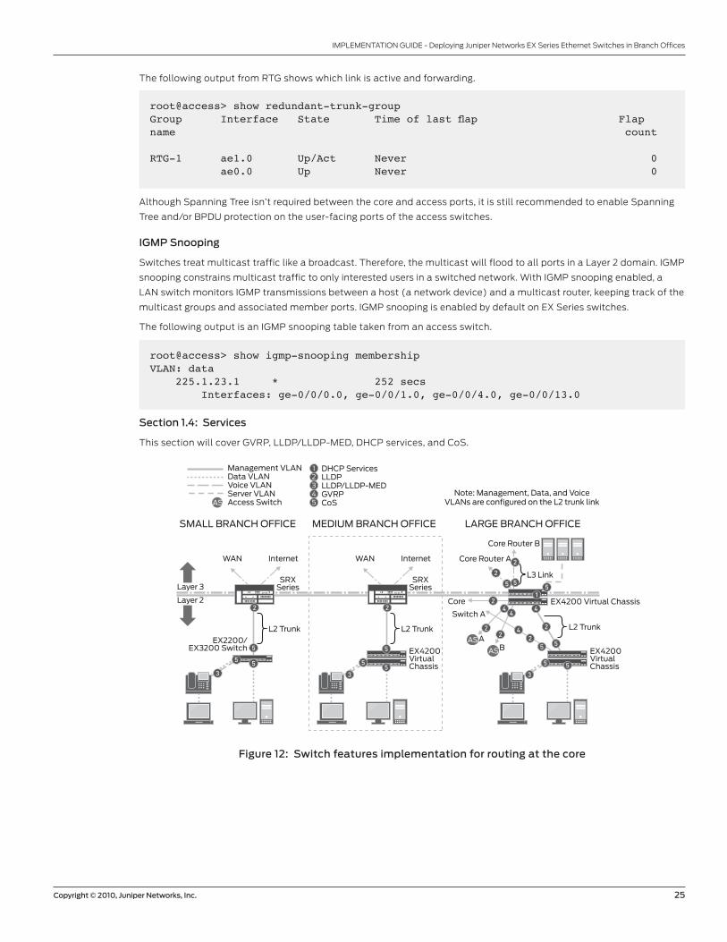
The following output from RTG shows which link is active and forwarding.
root@access> show redundant-trunk-group Group Interface State Time of last flap Flap name count
RTG-1 ae1.0 Up/Act Never 0 ae0.0 Up Never 0
Although Spanning Tree isn’t required between the core and access ports, it is still recommended to enable Spanning
Tree and/or BPDU protection on the user-facing ports of the access switches.
IGMP Snooping
Switches treat multicast traffic like a broadcast. Therefore, the multicast will flood to all ports in a Layer 2 domain. IGMP
snooping constrains multicast traffic to only interested users in a switched network. With IGMP snooping enabled, a
LAN switch monitors IGMP transmissions between a host (a network device) and a multicast router, keeping track of the
multicast groups and associated member ports. IGMP snooping is enabled by default on EX Series switches.
The following output is an IGMP snooping table taken from an access switch.
root@access> show igmp-snooping membership VLAN: data 225.1.23.1 * 252 secs Interfaces: ge-0/0/0.0, ge-0/0/1.0, ge-0/0/4.0, ge-0/0/13.0
Section 1.4: Services
This section will cover GVRP, LLDP/LLDP-MED, DHCP services, and CoS.
Figure 12: Switch features implementation for routing at the core
DHCP ServicesLLDPLLDP/LLDP-MEDGVRPCoS
12345
L2 Trunk
EX4200 Virtual Chassis
Core Router A
Core
Core Router B
L3 Link
AAS
AS
AS
B
MEDIUM BRANCH OFFICESMALL BRANCH OFFICE LARGE BRANCH OFFICE
Layer 3
Layer 2
Note: Management, Data, and VoiceVLANs are configured on the L2 trunk link
Management VLANData VLANVoice VLANServer VLANAccess Switch
L2 Trunk L2 Trunk
EX4200VirtualChassis
EX4200VirtualChassis
Switch A
EX2200/EX3200 Switch 5
55
3
5
55
3
4
5
25
2
5
35
5
2
244
22
42
5
51
WAN Internet
SRXSeries
WAN Internet
SRXSeries
2 2
26 Copyright © 2010, Juniper Networks, Inc.
IMPLEMENTATION GUIDE - Deploying Juniper Networks EX Series Ethernet Switches in Branch Offices
DHCP/BOOTP Relay
DHCP is utilized by client devices to obtain parameters necessary for operating in an IP network from a centralized
server. Typically the DHCP server is located on a different subnet. Since DHCP discovery is a Layer 2 broadcast packet
and is not forwarded beyond the Layer 2 broadcast domain, DHCP relay (BOOTP relay) is required to forward the
request from a client to a DHCP server to obtain the necessary IP parameters. The DHCP/BOOTP relay feature is
typically configured on the routed interface for the VLAN—in this case the core devices: routers for small and medium
branch offices and core switches for large branch offices.
root@coreB# set forwarding-options helpers bootp server 10.1.4.12
LLDP/LLDP-MED
LLDP is a link-layer protocol that allows end devices to advertise their information to each other. LLDP-MED, an
extension of LLDP, is used to communicate with PoE-capable devices and will advertise the VLAN and 802.1p value to
the IP phone based of the VoIP configuration in the Ethernet switching options. LLDP should be enabled on all inter-
switch links and LLDP-MED should be enabled on access switch ports connected with PoE-capable devices.
LLDP and LLDP-MED are enabled by default on EX Series switches. The following output shows the neighboring
devices learned through LLDP.
root@access> show lldp neighbors LocalInterface Chassis Id Port info System Nameae0.0 00:19:e2:50:87:a0 ae0.0 coreAae1.0 00:19:e2:50:ac:40 ae1.0 coreB
GVRP
GVRP is a standard Layer 2 protocol for creating, deleting, and pruning VLANs. If a host is a member of a VLAN that
the switch is not part of, then the switch will dynamically create the VLAN and forward the VLAN requirement to all
802.1q trunks enabled for GVRP. GVRP also manages VLANs on trunk links. If a downstream switch does not have any
members for a given VLAN, then the switch will not “join” the VLAN. The upstream switch will not need to forward any
broadcast, multicast, or unknown unicast on the trunk link for that given VLAN. GVRP is recommended on all switch
trunk links.
root# set protocols gvrp interface ae0.0
Note: There are plans for VLAN prorogation (adding/deleting) to be supported in a later software release.
Copyright © 2010, Juniper Networks, Inc. 27
IMPLEMENTATION GUIDE - Deploying Juniper Networks EX Series Ethernet Switches in Branch Offices
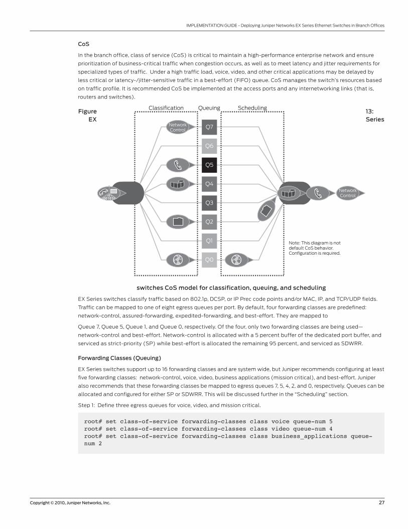
CoS
In the branch office, class of service (CoS) is critical to maintain a high-performance enterprise network and ensure
prioritization of business-critical traffic when congestion occurs, as well as to meet latency and jitter requirements for
specialized types of traffic. Under a high traffic load, voice, video, and other critical applications may be delayed by
less critical or latency-/jitter-sensitive traffic in a best-effort (FIFO) queue. CoS manages the switch’s resources based
on traffic profile. It is recommended CoS be implemented at the access ports and any internetworking links (that is,
routers and switches).
Figure 13: EX Series
switches CoS model for classification, queuing, and scheduling
EX Series switches classify traffic based on 802.1p, DCSP, or IP Prec code points and/or MAC, IP, and TCP/UDP fields.
Traffic can be mapped to one of eight egress queues per port. By default, four forwarding classes are predefined:
network-control, assured-forwarding, expedited-forwarding, and best-effort. They are mapped to
Queue 7, Queue 5, Queue 1, and Queue 0, respectively. Of the four, only two forwarding classes are being used—
network-control and best-effort. Network-control is allocated with a 5 percent buffer of the dedicated port buffer, and
serviced as strict-priority (SP) while best-effort is allocated the remaining 95 percent, and serviced as SDWRR.
Forwarding Classes (Queuing)
EX Series switches support up to 16 forwarding classes and are system wide, but Juniper recommends configuring at least
five forwarding classes: network-control, voice, video, business applications (mission critical), and best-effort. Juniper
also recommends that these forwarding classes be mapped to egress queues 7, 5, 4, 2, and 0, respectively. Queues can be
allocated and configured for either SP or SDWRR. This will be discussed further in the “Scheduling” section.
Step 1: Define three egress queues for voice, video, and mission critical.
Classification SchedulingQueuing
NetworkControl
NetworkControl
Note: This diagram is notdefault CoS behavior.Configuration is required.
Q7
Q6
Q5
Q4
Q3
Q2
Q1
Q0
root# set class-of-service forwarding-classes class voice queue-num 5root# set class-of-service forwarding-classes class video queue-num 4root# set class-of-service forwarding-classes class business_applications queue-num 2
28 Copyright © 2010, Juniper Networks, Inc.
IMPLEMENTATION GUIDE - Deploying Juniper Networks EX Series Ethernet Switches in Branch Offices
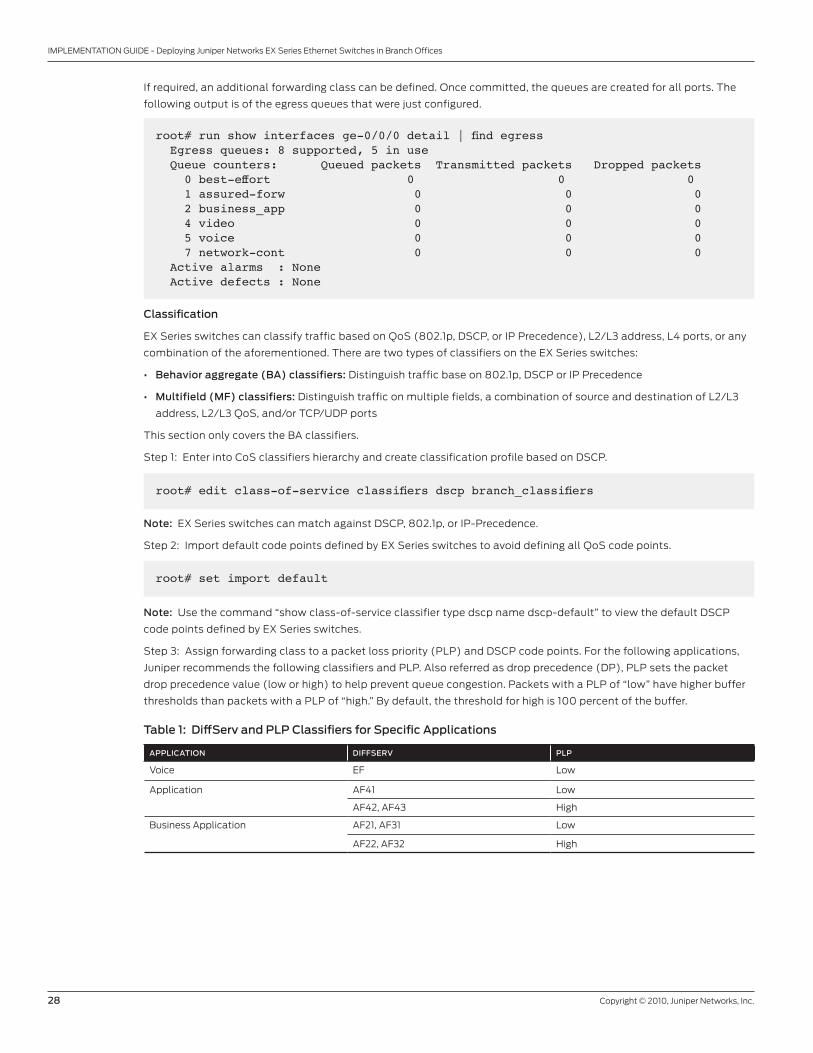
If required, an additional forwarding class can be defined. Once committed, the queues are created for all ports. The
following output is of the egress queues that were just configured.
root# run show interfaces ge-0/0/0 detail | find egress Egress queues: 8 supported, 5 in use Queue counters: Queued packets Transmitted packets Dropped packets 0 best-effort 0 0 0 1 assured-forw 0 0 0 2 business_app 0 0 0 4 video 0 0 0 5 voice 0 0 0 7 network-cont 0 0 0 Active alarms : None Active defects : None
Classification
EX Series switches can classify traffic based on QoS (802.1p, DSCP, or IP Precedence), L2/L3 address, L4 ports, or any
combination of the aforementioned. There are two types of classifiers on the EX Series switches:
• Behavior aggregate (BA) classifiers: Distinguish traffic base on 802.1p, DSCP or IP Precedence
• Multifield (MF) classifiers: Distinguish traffic on multiple fields, a combination of source and destination of L2/L3
address, L2/L3 QoS, and/or TCP/UDP ports
This section only covers the BA classifiers.
Step 1: Enter into CoS classifiers hierarchy and create classification profile based on DSCP.
root# edit class-of-service classifiers dscp branch_classifiers
Note: EX Series switches can match against DSCP, 802.1p, or IP-Precedence.
Step 2: Import default code points defined by EX Series switches to avoid defining all QoS code points.
root# set import default
Note: Use the command “show class-of-service classifier type dscp name dscp-default” to view the default DSCP
code points defined by EX Series switches.
Step 3: Assign forwarding class to a packet loss priority (PLP) and DSCP code points. For the following applications,
Juniper recommends the following classifiers and PLP. Also referred as drop precedence (DP), PLP sets the packet
drop precedence value (low or high) to help prevent queue congestion. Packets with a PLP of “low” have higher buffer
thresholds than packets with a PLP of “high.” By default, the threshold for high is 100 percent of the buffer.
Table 1: DiffServ and PLP Classifiers for Specific Applications
APPLICATION DIFFSERV PLP
Voice EF Low
Application AF41 Low
AF42, AF43 High
Business Application AF21, AF31 Low
AF22, AF32 High
Copyright © 2010, Juniper Networks, Inc. 29
IMPLEMENTATION GUIDE - Deploying Juniper Networks EX Series Ethernet Switches in Branch Offices
root# set forwarding-class voice loss-priority low code-points 101110root# set forwarding-class video loss-priority low code-points 100110root# set forwarding-class video loss-priority high code-points [100100 100010]root# set forwarding-class business_applications loss-priority low code-points [010010 011010]root# set forwarding-class business_applications loss-priority high code-points [010100 011100]
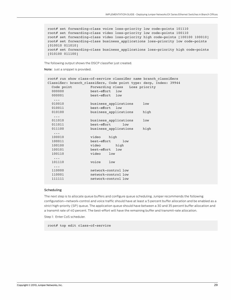
The following output shows the DSCP classifier just created.
Note: Just a snippet is provided.
root# run show class-of-service classifier name branch_classifiersClassifier: branch_classifiers, Code point type: dscp, Index: 39944 Code point Forwarding class Loss priority 000000 best-effort low 000001 best-effort low ... 010010 business_applications low 010011 best-effort low 010100 business_applications high ... 011010 business_applications low 011011 best-effort low 011100 business_applications high ... 100010 video high 100011 best-effort low 100100 video high 100101 best-effort low 100110 video low ... 101110 voice low ... 110000 network-control low 110001 network-control low 111111 network-control low
Scheduling
The next step is to allocate queue buffers and configure queue scheduling. Juniper recommends the following
configuration—network-control and voice traffic should have at least a 5 percent buffer allocation and be enabled as a
strict high-priority (SP) queue. The application queue should have between a 30 and 35 percent buffer allocation and
a transmit rate of 40 percent. The best-effort will have the remaining buffer and transmit-rate allocation.
Step 1: Enter CoS scheduler.
root# top edit class-of-service
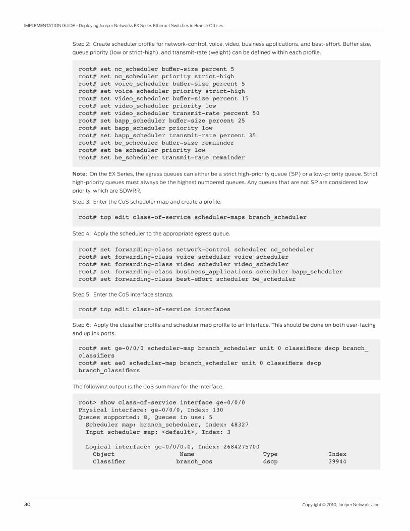
30 Copyright © 2010, Juniper Networks, Inc.
IMPLEMENTATION GUIDE - Deploying Juniper Networks EX Series Ethernet Switches in Branch Offices
Step 2: Create scheduler profile for network-control, voice, video, business applications, and best-effort. Buffer size,
queue priority (low or strict-high), and transmit-rate (weight) can be defined within each profile.
root# set nc_scheduler buffer-size percent 5root# set nc_scheduler priority strict-highroot# set voice_scheduler buffer-size percent 5root# set voice_scheduler priority strict-highroot# set video_scheduler buffer-size percent 15root# set video_scheduler priority lowroot# set video_scheduler transmit-rate percent 50 root# set bapp_scheduler buffer-size percent 25root# set bapp_scheduler priority lowroot# set bapp_scheduler transmit-rate percent 35root# set be_scheduler buffer-size remainderroot# set be_scheduler priority lowroot# set be_scheduler transmit-rate remainder
Note: On the EX Series, the egress queues can either be a strict high-priority queue (SP) or a low-priority queue. Strict
high-priority queues must always be the highest numbered queues. Any queues that are not SP are considered low
priority, which are SDWRR.
Step 3: Enter the CoS scheduler map and create a profile.
root# top edit class-of-service scheduler-maps branch_scheduler
Step 4: Apply the scheduler to the appropriate egress queue.
root# set forwarding-class network-control scheduler nc_schedulerroot# set forwarding-class voice scheduler voice_schedulerroot# set forwarding-class video scheduler video_schedulerroot# set forwarding-class business_applications scheduler bapp_schedulerroot# set forwarding-class best-effort scheduler be_scheduler
Step 5: Enter the CoS interface stanza.
root# top edit class-of-service interfaces
Step 6: Apply the classifier profile and scheduler map profile to an interface. This should be done on both user-facing
and uplink ports.
root# set ge-0/0/0 scheduler-map branch_scheduler unit 0 classifiers dscp branch_classifiersroot# set ae0 scheduler-map branch_scheduler unit 0 classifiers dscp branch_classifiers
The following output is the CoS summary for the interface.
root> show class-of-service interface ge-0/0/0 Physical interface: ge-0/0/0, Index: 130Queues supported: 8, Queues in use: 5 Scheduler map: branch_scheduler, Index: 48327 Input scheduler map: <default>, Index: 3
Logical interface: ge-0/0/0.0, Index: 2684275700 Object Name Type Index Classifier branch_cos dscp 39944
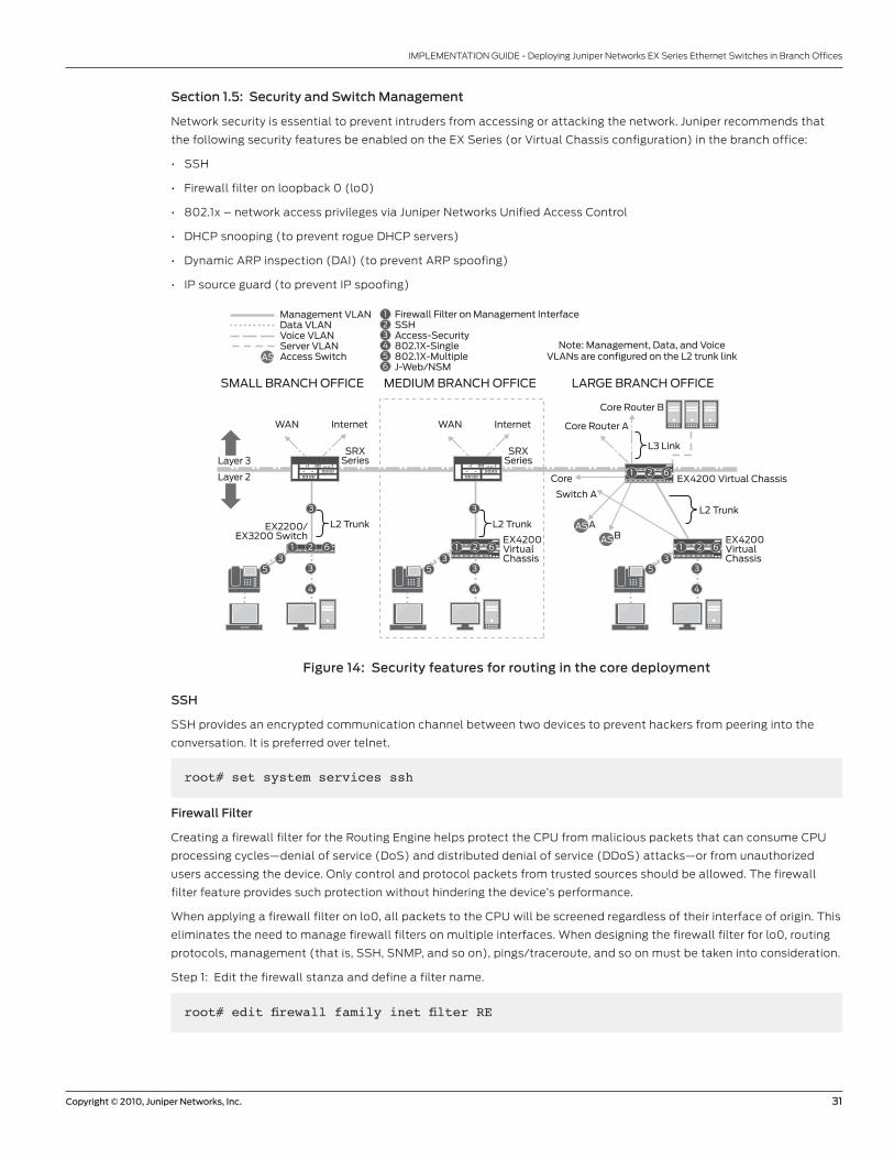
Copyright © 2010, Juniper Networks, Inc. 31
IMPLEMENTATION GUIDE - Deploying Juniper Networks EX Series Ethernet Switches in Branch Offices
Section 1.5: Security and Switch Management
Network security is essential to prevent intruders from accessing or attacking the network. Juniper recommends that
the following security features be enabled on the EX Series (or Virtual Chassis configuration) in the branch office:
• SSH
• Firewall filter on loopback 0 (lo0)
• 802.1x – network access privileges via Juniper Networks Unified Access Control
• DHCP snooping (to prevent rogue DHCP servers)
• Dynamic ARP inspection (DAI) (to prevent ARP spoofing)
• IP source guard (to prevent IP spoofing)
Figure 14: Security features for routing in the core deployment
SSH
SSH provides an encrypted communication channel between two devices to prevent hackers from peering into the
conversation. It is preferred over telnet.
Firewall Filter on Management InterfaceSSHAccess-Security802.1X-Single802.1X-MultipleJ-Web/NSM
123456
L2 Trunk
EX4200 Virtual Chassis
Core Router A
Core
Core Router B
L3 Link
AAS
AS
AS
B
MEDIUM BRANCH OFFICESMALL BRANCH OFFICE LARGE BRANCH OFFICE
Layer 3
Layer 2
Note: Management, Data, and VoiceVLANs are configured on the L2 trunk link
Management VLANData VLANVoice VLANServer VLANAccess Switch
L2 Trunk L2 Trunk
EX4200VirtualChassis
EX4200VirtualChassis
Switch A
EX2200/EX3200 Switch
3 3
444
3333
53
53
5
1 62
1 621 621 62
WAN Internet
SRXSeries
WAN Internet
SRXSeries
root# set system services ssh
Firewall Filter
Creating a firewall filter for the Routing Engine helps protect the CPU from malicious packets that can consume CPU
processing cycles—denial of service (DoS) and distributed denial of service (DDoS) attacks—or from unauthorized
users accessing the device. Only control and protocol packets from trusted sources should be allowed. The firewall
filter feature provides such protection without hindering the device’s performance.
When applying a firewall filter on lo0, all packets to the CPU will be screened regardless of their interface of origin. This
eliminates the need to manage firewall filters on multiple interfaces. When designing the firewall filter for lo0, routing
protocols, management (that is, SSH, SNMP, and so on), pings/traceroute, and so on must be taken into consideration.
Step 1: Edit the firewall stanza and define a filter name.
root# edit firewall family inet filter RE
32 Copyright © 2010, Juniper Networks, Inc.
IMPLEMENTATION GUIDE - Deploying Juniper Networks EX Series Ethernet Switches in Branch Offices
Step 2: Define the firewall filter to accept access connections from trusted sources. The following is an example for
SSH. Additional terms are needed for NSM for all branch sites and OSPF and multicast (PIM) for large branch offices.
root# set term ssh from source-address 10.255.1.0/24root# set term ssh from protocol tcp source-port sshroot# set term ssh then accept
Step 3: Apply the filter on lo0. In the case of small and medium branch offices, apply it to the RVI (vlan.1). The
following sample configuration was performed on lo0.
root@coreB# set interfaces lo0.0 family inet filter input management
Note: On EX Series switches, policing action is not supported within the lo0 firewall filter. However, the PFE has a
built-in CPU rate limiter that protects it from DDoS attacks. Firewall filter on me0 is not supported. This is expected to
be supported in later software releases.
Port-Level Access
802.1X is an IEEE standard that permits port-level access to end users. Teaming 802.1X with Juniper Networks UAC
allows administrators to define access privileges such as assigning VLANs and pushing policies (that is, CoS, firewall
filters, and so on) down to the port level.
Based on physical connectivity, there are three 802.1X modes used to authenticate users when accessing the network.
These three authentication modes are:
• Single: This requires one supplicant to authenticate to an authenticator port. All other supplicants connecting to the
authenticator port after the first has connected successfully, whether they are 802.1X enabled or not, are permitted
to access the port without further authentication. If the first authenticated supplicant logs out, all other supplicants
are locked out until a new supplicant successfully authenticates to the port.
• Single-secure: This allows only one supplicant to authenticate to an authenticator port. No other supplicant can
connect to the authenticator port until the first supplicant logs out.
• Multiple: This authenticates multiple supplicants individually on one authenticator port. There is no limit to the
number of supplicants that can be configured by a port. This should be used when the port is connected to a wireless
access point or in a daisy-chained IPT deployment.
It is highly recommended that 802.1X be implemented on all access switches.
Step 1: Configure UAC or radius server information, IP address, and password.
root@access# set access radius-server 10.255.1.100 secret juniper
Step 2: Configure a radius profile.
root@access# set access profile corp_radius authentication-order radius radiusauthentication-server 10.255.1.100
Step 3: Enable 802.1X on the interface and determine which radius profile to authenticate against. For a single device
connected to the switch interface, use single-secure. For multiple devices connected to a single switch interface (that
is, access point or daisy-chained IPT deployment), then use multiple.
root@access# set protocols dot1x authenticator authentication-profile-namecorp_radius interface ge-0/0/0.0 supplicant multiple
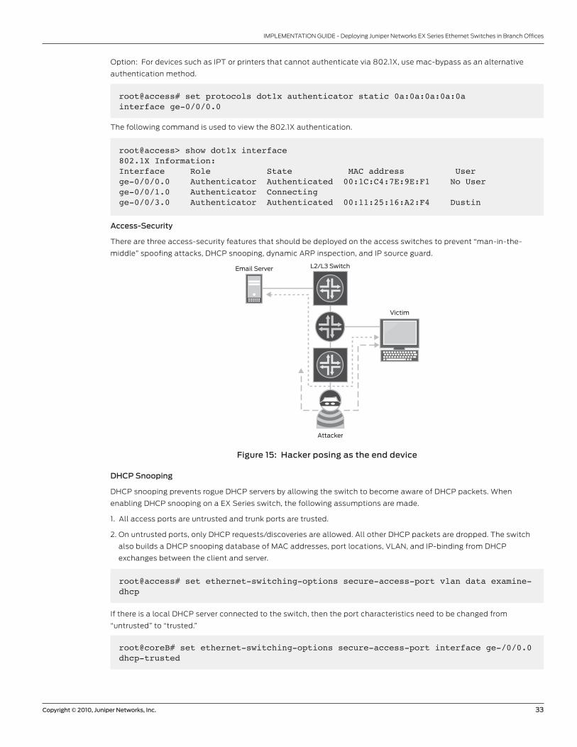
Copyright © 2010, Juniper Networks, Inc. 33
IMPLEMENTATION GUIDE - Deploying Juniper Networks EX Series Ethernet Switches in Branch Offices
Option: For devices such as IPT or printers that cannot authenticate via 802.1X, use mac-bypass as an alternative
authentication method.
root@access# set protocols dot1x authenticator static 0a:0a:0a:0a:0a interface ge-0/0/0.0
The following command is used to view the 802.1X authentication.
root@access> show dot1x interface 802.1X Information:Interface Role State MAC address Userge-0/0/0.0 Authenticator Authenticated 00:1C:C4:7E:9E:F1 No User ge-0/0/1.0 Authenticator Connecting ge-0/0/3.0 Authenticator Authenticated 00:11:25:16:A2:F4 Dustin
Access-Security
There are three access-security features that should be deployed on the access switches to prevent “man-in-the-
middle” spoofing attacks, DHCP snooping, dynamic ARP inspection, and IP source guard.
Figure 15: Hacker posing as the end device
DHCP Snooping
DHCP snooping prevents rogue DHCP servers by allowing the switch to become aware of DHCP packets. When
enabling DHCP snooping on a EX Series switch, the following assumptions are made.
1. All access ports are untrusted and trunk ports are trusted.
2. On untrusted ports, only DHCP requests/discoveries are allowed. All other DHCP packets are dropped. The switch
also builds a DHCP snooping database of MAC addresses, port locations, VLAN, and IP-binding from DHCP
exchanges between the client and server.
Email Server L2/L3 Switch
Victim
Attacker
root@access# set ethernet-switching-options secure-access-port vlan data examine-dhcp
If there is a local DHCP server connected to the switch, then the port characteristics need to be changed from
“untrusted” to “trusted.”
root@coreB# set ethernet-switching-options secure-access-port interface ge-/0/0.0 dhcp-trusted
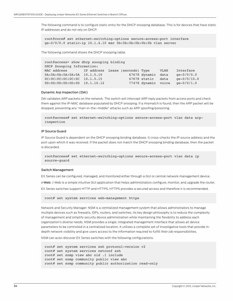
34 Copyright © 2010, Juniper Networks, Inc.
IMPLEMENTATION GUIDE - Deploying Juniper Networks EX Series Ethernet Switches in Branch Offices
The following command is to configure static entry for the DHCP snooping database. This is for devices that have static
IP addresses and do not rely on DHCP.
root@core# set ethernet-switching-options secure-access-port interface ge-0/0/0.0 static-ip 10.1.4.10 mac 0b:0b:0b:0b:0b:0b vlan server
The following command shows the DHCP snooping table.
root@access> show dhcp snooping binding DHCP Snooping Information:MAC address IP address Lease (seconds) Type VLAN Interface0A:0A:0A:0A:0A:0A 10.1.5.10 67678 dynamic data ge-0/0/0.00C:0C:0C:0C:0C:0C 10.1.5.15 67678 static data ge-0/0/10.00D:0D:0D:0D:0D:0D 10.1.10.12 77478 dynamic voice ge-0/0/1.0
Dynamic Arp Inspection (DAI)
DAI validates ARP packets on the network. The switch will intercept ARP reply packets from access ports and check
them against the IP-MAC database populated by DHCP snooping. If a mismatch is found, then the ARP packet will be
dropped, preventing any “man-in-the–middle” attacks such as ARP spoofing/poisoning.
root@access# set ethernet-switching-options secure-access-port vlan data arp-inspection
IP Source Guard
IP Source Guard is dependent on the DHCP snooping binding database. It cross-checks the IP source address and the
port upon which it was received. If the packet does not match the DHCP snooping binding database, then the packet
is discarded.
root@access# set ethernet-switching-options secure-access-port vlan data ip source-guard
Switch Management
EX Series can be configured, managed, and monitored either through a GUI or central network management device.
J-Web: J-Web is a simple intuitive GUI application that helps administrators configure, monitor, and upgrade the router.
EX Series switches support HTTP and HTTPS. HTTPS provides a secured access and therefore it is recommended.
root# set system services web-management https
Network and Security Manager: NSM is a centralized management system that allows administrators to manage
multiple devices such as firewalls, IDPs, routers, and switches. Its key design philosophy is to reduce the complexity
of management and simplify security device administration while maintaining the flexibility to address each
organization’s diverse needs. NSM provides a single, integrated management interface that allows all device
parameters to be controlled in a centralized location. It utilizes a complete set of investigative tools that provide in-
depth network visibility and give users access to the information required to fulfill their job responsibilities.
NSM can auto-discover EX Series switches with the following configurations.
root# set system services ssh protocol-version v2root# set system services netconf sshroot# set snmp view abc oid .1 includeroot# set snmp community public view abcroot# set snmp community public authorization read-only
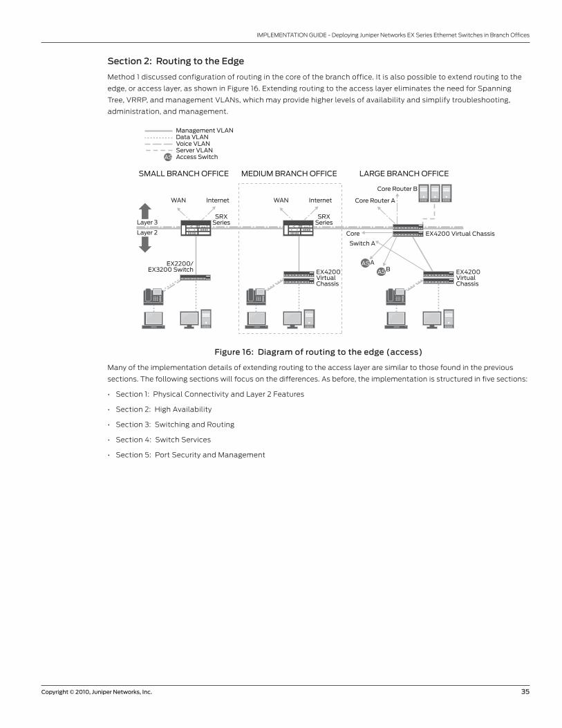
Copyright © 2010, Juniper Networks, Inc. 35
IMPLEMENTATION GUIDE - Deploying Juniper Networks EX Series Ethernet Switches in Branch Offices
Section 2: Routing to the Edge
Method 1 discussed configuration of routing in the core of the branch office. It is also possible to extend routing to the
edge, or access layer, as shown in Figure 16. Extending routing to the access layer eliminates the need for Spanning
Tree, VRRP, and management VLANs, which may provide higher levels of availability and simplify troubleshooting,
administration, and management.
Figure 16: Diagram of routing to the edge (access)
Many of the implementation details of extending routing to the access layer are similar to those found in the previous
sections. The following sections will focus on the differences. As before, the implementation is structured in five sections:
• Section 1: Physical Connectivity and Layer 2 Features
• Section 2: High Availability
• Section 3: Switching and Routing
• Section 4: Switch Services
• Section 5: Port Security and Management
EX4200 Virtual Chassis
Core Router A
Core
Core Router B
AAS
AS
AS
B
MEDIUM BRANCH OFFICESMALL BRANCH OFFICE LARGE BRANCH OFFICE
Layer 3
Layer 2
Management VLANData VLANVoice VLANServer VLANAccess Switch
EX4200VirtualChassis
EX4200VirtualChassis
Switch A
EX2200/EX3200 Switch
WAN Internet
SRXSeries
WAN Internet
SRXSeries
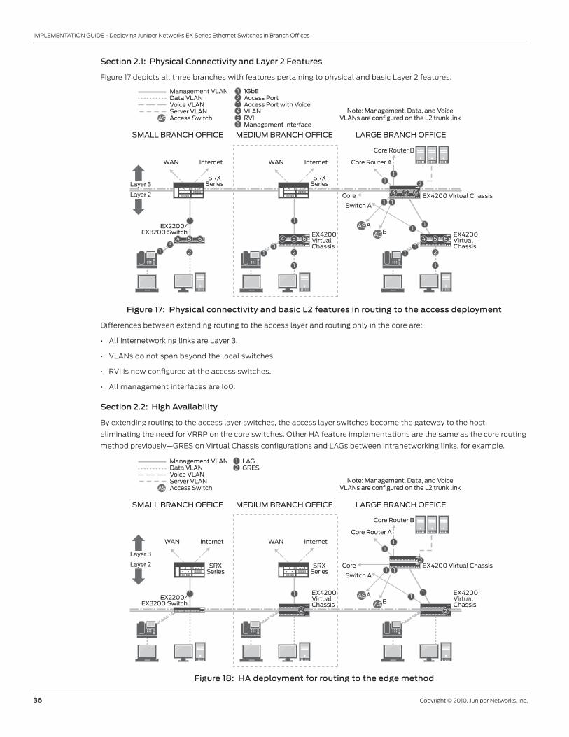
36 Copyright © 2010, Juniper Networks, Inc.
IMPLEMENTATION GUIDE - Deploying Juniper Networks EX Series Ethernet Switches in Branch Offices
Section 2.1: Physical Connectivity and Layer 2 Features
Figure 17 depicts all three branches with features pertaining to physical and basic Layer 2 features.
Figure 17: Physical connectivity and basic L2 features in routing to the access deployment
Differences between extending routing to the access layer and routing only in the core are:
• All internetworking links are Layer 3.
• VLANs do not span beyond the local switches.
• RVI is now configured at the access switches.
• All management interfaces are lo0.
Section 2.2: High Availability
By extending routing to the access layer switches, the access layer switches become the gateway to the host,
eliminating the need for VRRP on the core switches. Other HA feature implementations are the same as the core routing
method previously—GRES on Virtual Chassis configurations and LAGs between intranetworking links, for example.
Figure 18: HA deployment for routing to the edge method
1GbEAccess PortAccess Port with VoiceVLANRVIManagement Interface
123456
EX4200 Virtual Chassis
Core Router A
Core
Core Router B
AAS
AS
AS
B
MEDIUM BRANCH OFFICESMALL BRANCH OFFICE LARGE BRANCH OFFICE
Layer 3
Layer 2
Note: Management, Data, and VoiceVLANs are configured on the L2 trunk link
Management VLANData VLANVoice VLANServer VLANAccess Switch
EX4200VirtualChassis
EX4200VirtualChassis
Switch A
EX2200/EX3200 Switch
1
2
31
4 65
1
1
23
1
4 65
1 1
11 2
11
1
23
1
4 65
4 65
WAN Internet
SRXSeries
WAN Internet
SRXSeries
LAGGRES
12
EX4200 Virtual Chassis
Core Router A
Core
Core Router B
AAS
AS
AS
B
MEDIUM BRANCH OFFICESMALL BRANCH OFFICE LARGE BRANCH OFFICE
Layer 3
Layer 2
Note: Management, Data, and VoiceVLANs are configured on the L2 trunk link
Management VLANData VLANVoice VLANServer VLANAccess Switch
EX4200VirtualChassis
EX4200VirtualChassis
Switch A
EX2200/EX3200 Switch
1 1
2
1
11
11
2
2
1
WAN Internet
SRXSeries
WAN Internet
SRXSeries
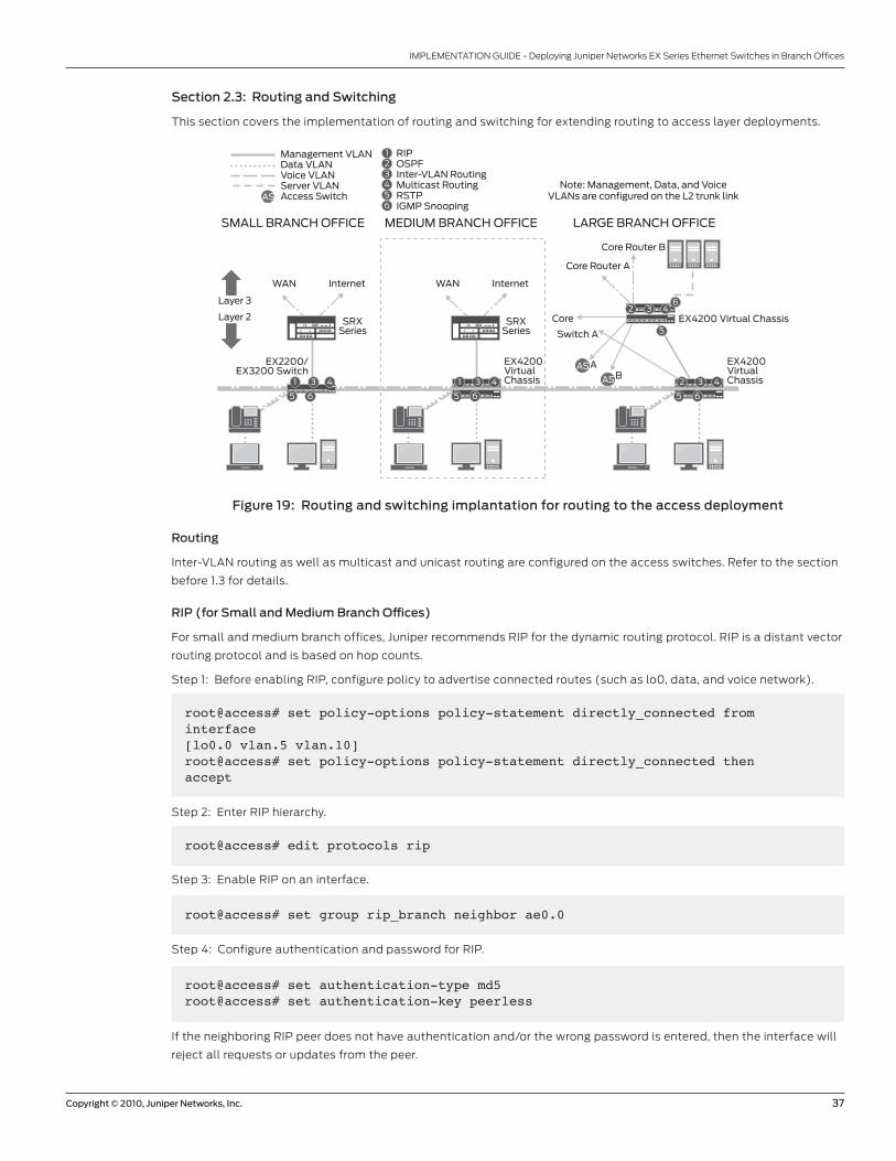
Copyright © 2010, Juniper Networks, Inc. 37
IMPLEMENTATION GUIDE - Deploying Juniper Networks EX Series Ethernet Switches in Branch Offices
Section 2.3: Routing and Switching
This section covers the implementation of routing and switching for extending routing to access layer deployments.
Figure 19: Routing and switching implantation for routing to the access deployment
Routing
Inter-VLAN routing as well as multicast and unicast routing are configured on the access switches. Refer to the section
before 1.3 for details.
RIP (for Small and Medium Branch Offices)
For small and medium branch offices, Juniper recommends RIP for the dynamic routing protocol. RIP is a distant vector
routing protocol and is based on hop counts.
Step 1: Before enabling RIP, configure policy to advertise connected routes (such as lo0, data, and voice network).
RIPOSPFInter-VLAN RoutingMulticast RoutingRSTPIGMP Snooping
123456
EX4200 Virtual Chassis
Core Router A
Core
Core Router B
AAS
AS
AS
B
MEDIUM BRANCH OFFICESMALL BRANCH OFFICE LARGE BRANCH OFFICE
Layer 3
Layer 2
Note: Management, Data, and VoiceVLANs are configured on the L2 trunk link
Management VLANData VLANVoice VLANServer VLANAccess Switch
EX4200VirtualChassis
EX4200VirtualChassis
Switch A
EX2200/EX3200 Switch
1 43
5 6
1 43
5 6
6
5
2 43
5 6
2 43
WAN Internet
SRXSeries
WAN Internet
SRXSeries
root@access# set policy-options policy-statement directly_connected from interface [lo0.0 vlan.5 vlan.10]root@access# set policy-options policy-statement directly_connected then accept
Step 2: Enter RIP hierarchy.
root@access# edit protocols rip
Step 3: Enable RIP on an interface.
root@access# set group rip_branch neighbor ae0.0
Step 4: Configure authentication and password for RIP.
root@access# set authentication-type md5root@access# set authentication-key peerless
If the neighboring RIP peer does not have authentication and/or the wrong password is entered, then the interface will
reject all requests or updates from the peer.
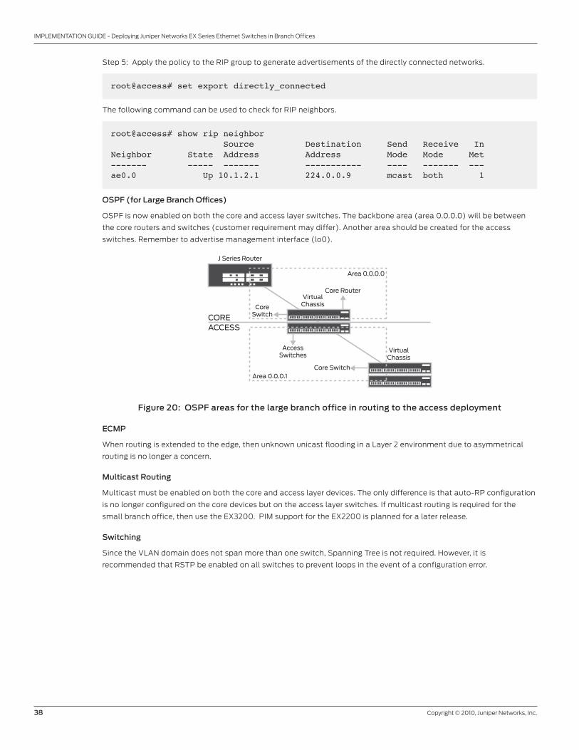
38 Copyright © 2010, Juniper Networks, Inc.
IMPLEMENTATION GUIDE - Deploying Juniper Networks EX Series Ethernet Switches in Branch Offices
Step 5: Apply the policy to the RIP group to generate advertisements of the directly connected networks.
root@access# set export directly_connected
The following command can be used to check for RIP neighbors.
root@access# show rip neighbor Source Destination Send Receive InNeighbor State Address Address Mode Mode Met ------- ----- ------- ----------- ---- ------- --- ae0.0 Up 10.1.2.1 224.0.0.9 mcast both 1
OSPF (for Large Branch Offices)
OSPF is now enabled on both the core and access layer switches. The backbone area (area 0.0.0.0) will be between
the core routers and switches (customer requirement may differ). Another area should be created for the access
switches. Remember to advertise management interface (lo0).
Figure 20: OSPF areas for the large branch office in routing to the access deployment
ECMP
When routing is extended to the edge, then unknown unicast flooding in a Layer 2 environment due to asymmetrical
routing is no longer a concern.
Multicast Routing
Multicast must be enabled on both the core and access layer devices. The only difference is that auto-RP configuration
is no longer configured on the core devices but on the access layer switches. If multicast routing is required for the
small branch office, then use the EX3200. PIM support for the EX2200 is planned for a later release.
Switching
Since the VLAN domain does not span more than one switch, Spanning Tree is not required. However, it is
recommended that RSTP be enabled on all switches to prevent loops in the event of a configuration error.
Core Router
Area 0.0.0.0
Area 0.0.0.1
COREACCESS
J Series Router
VirtualChassis
AccessSwitches
Core Switch
CoreSwitch
VirtualChassis
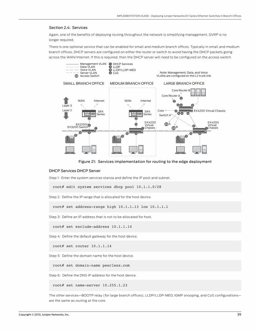
Copyright © 2010, Juniper Networks, Inc. 39
IMPLEMENTATION GUIDE - Deploying Juniper Networks EX Series Ethernet Switches in Branch Offices
Section 2.4: Services
Again, one of the benefits of deploying routing throughout the network is simplifying management. GVRP is no
longer required.
There is one optional service that can be enabled for small and medium branch offices. Typically in small and medium
branch offices, DHCP servers are configured on either the router or switch to avoid having the DHCP packets going
across the WAN/Internet. If this is required, then the DHCP server will need to be configured on the access switch.
Figure 21: Services implementation for routing to the edge deployment
DHCP Services DHCP Server
Step 1: Enter the system services stanza and define the IP pool and subnet.
DHCP ServicesLLDPLLDP/LLDP-MEDCoS
1234
EX4200 Virtual Chassis
Core Router A
Core
Core Router B
AAS
AS
AS
B
MEDIUM BRANCH OFFICESMALL BRANCH OFFICE LARGE BRANCH OFFICE
Layer 3
Layer 2
Note: Management, Data, and VoiceVLANs are configured on the L2 trunk link
Management VLANData VLANVoice VLANServer VLANAccess Switch
EX4200VirtualChassis
EX4200VirtualChassis
Switch A
EX2200/EX3200 Switch
2
4
43
4
1
2
4
43
4
14
44
4 4 4
2
42
2
43
4
1
WAN Internet
SRXSeries
WAN Internet
SRXSeries
root# edit system services dhcp pool 10.1.1.0/28
Step 2: Define the IP range that is allocated for the host device.
root# set address-range high 10.1.1.13 low 10.1.1.1
Step 3: Define an IP address that is not to be allocated for host.
root# set exclude-address 10.1.1.14
Step 4: Define the default gateway for the host device.
root# set router 10.1.1.14
Step 5: Define the domain name for the host device.
root# set domain-name peerless.com
Step 6: Define the DNS IP address for the host device.
root# set name-server 10.255.1.23
The other services—BOOTP relay (for large branch offices), LLDP/LLDP-MED, IGMP snooping, and CoS configurations—
are the same as routing at the core.
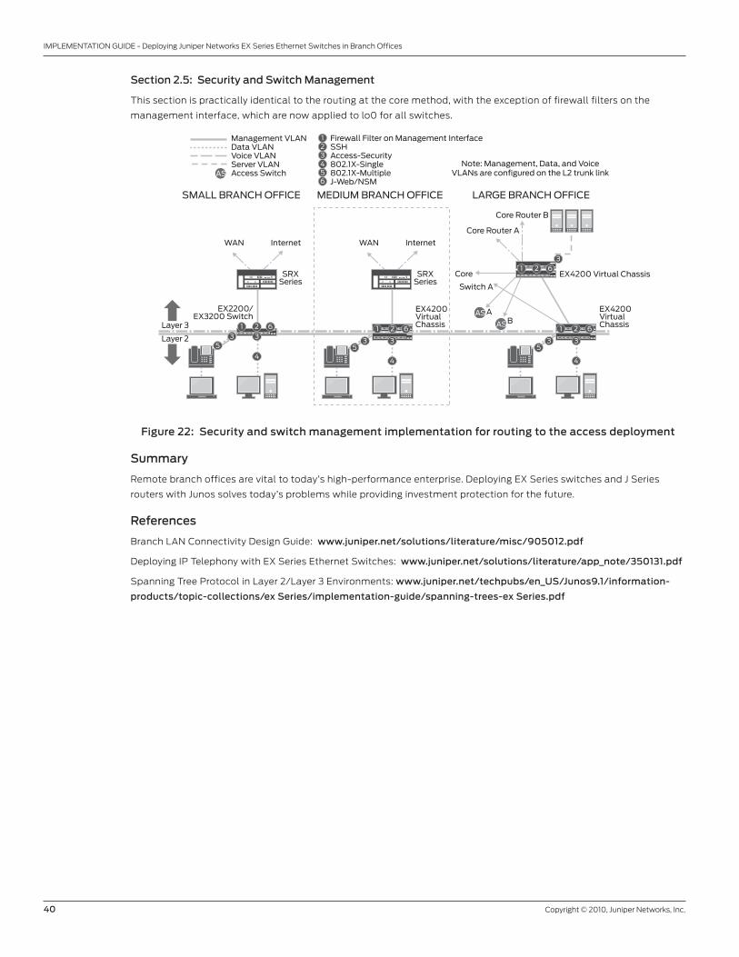
40 Copyright © 2010, Juniper Networks, Inc.
IMPLEMENTATION GUIDE - Deploying Juniper Networks EX Series Ethernet Switches in Branch Offices
Section 2.5: Security and Switch Management
This section is practically identical to the routing at the core method, with the exception of firewall filters on the
management interface, which are now applied to lo0 for all switches.
Figure 22: Security and switch management implementation for routing to the access deployment
Summary
Remote branch offices are vital to today’s high-performance enterprise. Deploying EX Series switches and J Series
routers with Junos solves today’s problems while providing investment protection for the future.
References
Branch LAN Connectivity Design Guide: www.juniper.net/solutions/literature/misc/905012.pdf
Deploying IP Telephony with EX Series Ethernet Switches: www.juniper.net/solutions/literature/app_note/350131.pdf
Spanning Tree Protocol in Layer 2/Layer 3 Environments: www.juniper.net/techpubs/en_US/Junos9.1/information-
products/topic-collections/ex Series/implementation-guide/spanning-trees-ex Series.pdf
Firewall Filter on Management InterfaceSSHAccess-Security802.1X-Single802.1X-MultipleJ-Web/NSM
123456
EX4200 Virtual Chassis
WAN Internet
Core Router A
Core
Core Router B
AAS
AS
AS
B
MEDIUM BRANCH OFFICESMALL BRANCH OFFICE LARGE BRANCH OFFICE
Layer 3
Layer 2
Note: Management, Data, and VoiceVLANs are configured on the L2 trunk link
Management VLANData VLANVoice VLANServer VLANAccess Switch
EX4200VirtualChassis
EX4200VirtualChassis
Switch A
EX2200/EX3200 Switch
SRXSeries
1 623
53
1 62
35
3
44
35
3
4
3
1 62
1 62
WAN Internet
SRXSeries

Copyright © 2010, Juniper Networks, Inc. 41
IMPLEMENTATION GUIDE - Deploying Juniper Networks EX Series Ethernet Switches in Branch Offices
Appendix A: Acronyms
ARP Address Resolution Protocol
BPDU Bridge Protocol Data Unit
CoS Class of Service
DAI Dynamic ARP Inspection
DHCP Dynamic Host Configuration Protocol
DDoS Distributed Denial of Service
DoS Denial of Service
DP Drop Precedence
GRES Graceful Routing Engine Switchover
GVRP Generic Attribute Resolution Protocol VLAN Registration Protocol
HA High Availability
IPT Internet Protocol Telephony
LACP Link Aggregation Control Protocol
LAG Link Aggregation Group
LLDP Link Layer Discovery Protocol
LLDP-MED Link Layer Discovery Protocol-Media Endpoint Discovery
lo0 Loopback 0
MSTI Multiple Spanning Tree Instance
MSTP Multiple Spanning Tree Protocol
NSM Network and Security Manager
OSPF Open Shortest Path First
PIM Protocol Independent Multicast
PIM DM PIM Dense Mode
PIM SM PIM Sparse Mode
QoS Quality of Service
RIP Routing Information Protocol
RP Rendezvous Point
RSTP Rapid Spanning Tree Protocol
RVI Routed VLAN Interface
SP Strict Priority
SSH Secure Shell
STP Spanning Tree Protocol
VLAN Virtual LAN
VRRP Virtual Router Redundancy Protocol
UAC Unified Access Control
WAN Wide Area Network
42 Copyright © 2010, Juniper Networks, Inc.
IMPLEMENTATION GUIDE - Deploying Juniper Networks EX Series Ethernet Switches in Branch Offices
8010010-002-EN Mar 2010
Copyright 2010 Juniper Networks, Inc. All rights reserved. Juniper Networks, the Juniper Networks logo, Junos, NetScreen, and ScreenOS are registered trademarks of Juniper Networks, Inc. in the United States and other countries. All other trademarks, service marks, registered marks, or registered service marks are the property of their respective owners. Juniper Networks assumes no responsibility for any inaccuracies in this document. Juniper Networks reserves the right to change, modify, transfer, or otherwise revise this publication without notice.
EMEA Headquarters
Juniper Networks Ireland
Airside Business Park
Swords, County Dublin, Ireland
Phone: 35.31.8903.600
EMEA Sales: 00800.4586.4737
Fax: 35.31.8903.601
APAC Headquarters
Juniper Networks (Hong Kong)
26/F, Cityplaza One
1111 King’s Road
Taikoo Shing, Hong Kong
Phone: 852.2332.3636
Fax: 852.2574.7803
Corporate and Sales Headquarters
Juniper Networks, Inc.
1194 North Mathilda Avenue
Sunnyvale, CA 94089 USA
Phone: 888.JUNIPER (888.586.4737)
or 408.745.2000
Fax: 408.745.2100
www.juniper.net
To purchase Juniper Networks solutions,
please contact your Juniper Networks
representative at 1-866-298-6428 or
authorized reseller.
Printed on recycled paper
About Juniper Networks
Juniper Networks, Inc. is the leader in high-performance networking. Juniper offers a high-performance network
infrastructure that creates a responsive and trusted environment for accelerating the deployment of services and
applications over a single network. This fuels high-performance businesses. Additional information can be found at
www.juniper.net.
Related Documents


