Deploying a Resilient Converged Plantwide Ethernet Architecture Design and Implementation Guide September 2020 Document Reference Number: ENET-TD010C-EN-P

Welcome message from author
This document is posted to help you gain knowledge. Please leave a comment to let me know what you think about it! Share it to your friends and learn new things together.
Transcript

Deploying a Resilient Converged Plantwide Ethernet ArchitectureDesign and Implementation Guide
September 2020
Document Reference Number: ENET-TD010C-EN-P
Preface
Converged Plantwide Ethernet (CPwE) is a collection of architected, tested, and validated designs. The testing and validation follow the Cisco Validated Design (CVD) and Cisco Reference Design (CRD) methodologies. The content of CPwE, which is relevant to both operational technology (OT) and informational technology (IT) disciplines, consists of documented architectures, best practices, guidance, and configuration settings to help industrial operations and OEMs achieve the design and deployment of a scalable, reliable, secure, and future-ready plant-wide or site-wide industrial network infrastructure. CPwE can also help industrial operations and OEMs achieve cost reduction benefits using proven designs that can facilitate quicker deployment while helping to minimize risk in deploying new technology. CPwE is brought to market through a CPwE ecosystem consisting of Cisco, Panduit, and Rockwell Automation emergent from the strategic alliance between Cisco Systems and Rockwell Automation.
Resilient plant-wide or site-wide network architectures play a pivotal role in helping to confirm overall plant/site uptime and productivity. Industrial Automation and Control System (IACS) application requirements such as availability and performance drive the choice of resiliency technology. A holistic resilient plant-wide or site-wide network architecture is composed of multiple technologies (logical and physical) deployed at different levels within plant-wide or site-wide architectures. When selecting resiliency technology, various IACS application factors should be evaluated, including physical layout of IACS devices (geographic dispersion), recovery time performance, uplink media type, tolerance to data latency and jitter and future-ready requirements.
Deploying a Resilient Converged Plantwide Ethernet Architecture CVD (CPwE Resiliency), which is documented in this Design and Implementation Guide (DIG), outlines several use cases for designing and deploying resilient plant-wide or site-wide architectures for Industrial Automation and Control System (IACS) applications. CPwE Resiliency highlights the key IACS application requirements, technology, and supporting design considerations to help with the successful design and deployment of these specific use cases within the CPwE framework. CPwE Resiliency was architected, tested, and validated by Cisco Systems, Panduit, and Rockwell Automation.
Release NotesThis section summarizes the extensions to CPwE Resiliency in this September 2020 release:
• Test Hardware, Software, test results and reference architecture for Catalyst 9300 as distribution/aggregation switch
• Test Hardware, Software, test results and reference architecture for Catalyst 9500 as distribution/aggregation switch
iiDeploying a Resilient Converged Plantwide Ethernet Architecture
ENET-TD010C-EN-P

PrefaceDocument Organization
• References to Deploying Parallel Redundancy Protocol within a Converged Plantwide Ethernet Architecture
This section summarizes the extensions that were added to the CPwE Resiliency February 2018 release:
• Test Hardware, Software, test results and reference architecture for Catalyst 3850 as distribution/aggregation switch
• Removal of Catalyst 3750X as distribution/aggregation switch
• References to Deploying Device Level Ring within a Converged Plantwide Ethernet Architecture
Document OrganizationThis document is composed of the following chapters and appendices:
For More InformationMore information on CPwE Design and Implementation Guides can be found at the following URLs:
• Rockwell Automation site:
– https://www.rockwellautomation.com/en-us/capabilities/industrial-networks/network-architectures.html
• Cisco site:
– http://www.cisco.com/c/en/us/solutions/enterprise/design-zone-manufacturing/landing_ettf.html
Note This release of the CPwE architecture focuses on EtherNet/IP™, which uses the ODVA, Inc. Common Industrial Protocol (CIP™) and is ready for the Industrial Internet of Things (IIoT). For more information on EtherNet/IP, CIP Sync™, and DLR, see odva.org at the following URL:
• http://www.odva.org/Technology-Standards/EtherNet-IP/Overview
Chapter/Appendix Description
CPwE Resiliency Overview Provides an overview of CPwE Resiliency and the uses cases used in this release.
CPwE Resiliency Design Considerations
Provides an overview of design considerations for integrating resiliency into an Industrial Automation and Control System (IACS) network based on the CPwE architecture.
CPwE Resiliency Configuration Describes how to configure resiliency for the Industrial and Cell/Area Zone switches in the CPwE architecture based on the design considerations and recommendations of the previous chapters.
CPwE Resiliency Troubleshooting Describes how to assess and verify the status of the resiliency protocols running on the Industrial and Cell/Area Zone switches.
References Links to documents and websites that are relevant to Deploying a Resilient Converged Plantwide Ethernet Architecture Design and Implementation Guide.
Acronyms and Initialisms List of acronyms and initialisms used in this document.
About Cisco Validated Design (CVD) Program
Describes the Cisco Validated Design (CVD) process and the distinction between CVDs and Cisco Reference Designs (CRDs).
iiiDeploying a Resilient Converged Plantwide Ethernet Architecture
ENET-TD010C-EN-P
https://www.rockwellautomation.com/en-us/capabilities/industrial-networks/network-architectures.html
Deploying a Resilient ConENET-TD010C-EN-P
C H A P T E R 1
CPwE Resiliency OverviewThis chapter includes the following major topics:
• CPwE Resilient IACS Architectures Overview, page 1-3
• CPwE Resiliency Solution Use Cases, page 1-5
The prevailing trend in Industrial Automation and Control System (IACS) networking is the convergence of technology, specifically IACS operational technology (OT) with information technology (IT). Converged Plantwide Ethernet (CPwE) helps to enable IACS network and security technology convergence, including OT-IT persona convergence, by using standard Ethernet, Internet Protocol (IP), network services, security services, and EtherNet/IP. A reliable and secure converged plant-wide or site-wide IACS architecture helps to enable the Industrial Internet of Things (IIoT).
Business practices, corporate standards, policies, industry standards, and tolerance to risk are key factors in determining the degree of resiliency and application availability required within an IACS plant-wide or site-wide architecture, such as non-resilient LAN, resilient LAN, or redundant LANs. A resilient network architecture within an IACS application plays a pivotal role in helping to minimize the risk of IACS application shutdowns while helping to maximize overall plant/site uptime.
A holistic resilient plant-wide or site-wide network architecture is composed of multiple technologies (logical and physical) deployed at different levels within the plant/site. When selecting a resiliency technology, various plant/site application factors should be evaluated, including the physical layout of IACS devices (geographic dispersion), recovery time performance, uplink media type, tolerance to data latency and jitter, and future-ready requirements:
• Robust physical infrastructure
• Topologies and protocols
• Switching and routing
• Wireless LAN Controllers (WLC)
• Firewalls
• Network and device management
Deploying a Resilient Converged Plantwide Ethernet Architecture Design and Implementation Guide (DIG), outlines several use cases for designing and deploying resilient plant-wide or site-wide LAN architectures for IACS applications. CPwE Resiliency was architected, tested, and validated by Cisco Systems, Panduit and Rockwell Automation.
1-1verged Plantwide Ethernet Architecture
Chapter 1 CPwE Resiliency OverviewCPwE Overview
CPwE OverviewCPwE is the underlying architecture that provides standard network and security services for control and information disciplines, devices, and equipment found in modern IACS applications. The CPwE architectures (Figure 1-1) were architected, tested, and validated to provide design and implementation guidance, test results, and documented configuration settings. This can help to achieve the real-time communication, reliability, scalability, security, and resiliency requirements of modern IACS applications. The content and key tenets of CPwE are relevant to both OT and IT disciplines. CPwE key tenets include:
• Smart IIoT devices—Controllers, I/O, drives, instrumentation, actuators, analytics, and a single IIoT network technology (EtherNet/IP) , facilitating both technology coexistence and IACS device interoperability, which helps to enable the choice of best-in-class IACS devices.
• Zoning (segmentation)—Smaller connected LANs, functional areas, and security groups.
• Managed infrastructure—Managed Allen-Bradley® Stratix® industrial Ethernet switches (IES), Cisco Catalyst® distribution/core switches, FactoryTalk® Network Manager™ software, and Stratix industrial firewalls.
• Resiliency—Robust physical layer and resilient or redundant topologies with resiliency protocols.
• Time-critical data—Data prioritization and time synchronization via CIP Sync and IEEE-1588 Precision Time Protocol (PTP).
• Wireless—Unified wireless LAN (WLAN) to enable mobility for personnel and equipment.
• Holistic defense-in-depth security—Multiple layers of diverse technologies for threat detection and prevention, implemented by different persona (for example, OT and IT) and applied at different levels of the plant-wide or site-wide IACS architecture.
• Convergence-ready—Seamless plant-wide or site-wide integration by trusted partner applications.
1-2Deploying a Resilient Converged Plantwide Ethernet Architecture
ENET-TD010C-EN-P

Chapter 1 CPwE Resiliency OverviewCPwE Resilient IACS Architectures Overview
Figure 1-1 CPwE Architectures
CPwE Resilient IACS Architectures OverviewAn IACS is deployed in a wide variety of industries such as automotive, pharmaceuticals, consumer packaged goods, pulp and paper, oil and gas, mining, and energy. IACS applications are composed of multiple control and information disciplines such as continuous process, batch, discrete, and hybrid combinations. One of the challenges facing industrial operations is the industrial hardening of standard Ethernet and IP-converged IACS networking technologies to take advantage of the business benefits associated with IIoT. A resilient LAN architecture can help to increase the overall equipment effectiveness (OEE) of the IACS by helping to reduce the impact of a failure and speed recovery from an outage, which lowers Mean-Time-to-Repair (MTTR).
Protecting availability for IACS assets requires a scalable defense-in-depth approach where different solutions are needed to address various network resiliency requirements for OEM, plant-wide or site-wide architectures. This section summarizes the Cisco, Panduit and Rockwell Automation CPwE validated designs that address different aspects of availability for IIoT IACS applications.
• Deploying Device Level Ring within a Converged Plantwide Ethernet Architecture Design and Implementation Guide outlines several use cases for designing and deploying DLR technology with IACS device-level, switch-level, and mixed device/switch-level single and multiple ring topologies across OEM and plant-wide or site-wide resilient LAN IACS applications.
1-3Deploying a Resilient Converged Plantwide Ethernet Architecture
ENET-TD010C-EN-P

Chapter 1 CPwE Resiliency OverviewCPwE Resilient IACS Architectures Overview
– Rockwell Automation site:https://literature.rockwellautomation.com/idc/groups/literature/documents/td/enet-td015_-en-p.pdf
– Cisco site:https://www.cisco.com/c/en/us/td/docs/solutions/Verticals/CPwE/5-1/DLR/DIG/CPwE-5-1-DLR-DIG.html
• Deploying Parallel Redundancy Protocol within a Converged Plantwide Ethernet Architecture Design and Implementation Guide outlines several use cases for designing and deploying Parallel Redundancy Protocol (PRP) technology with redundant LANs across plant-wide or site-wide IACS applications.
– Rockwell Automation site:https://literature.rockwellautomation.com/idc/groups/literature/documents/td/enet-td021_-en-p.pdf
– Cisco site:https://www.cisco.com/c/en/us/td/docs/solutions/Verticals/CPwE/5-1/PRP/DIG/CPwE-5-1-PRP-DIG.html
• Deploying a Fiber Optic Physical Infrastructure within a Converged Plantwide Ethernet Architecture Application Guide helps designers and installers select and deploy fiber optic media in plant/site environments. It details fiber optic network infrastructure solutions that provide high-performance connectivity options that help increase the integrity and availability of a CPwE architecture at each level of the OEM, plant-wide or site-wide network.
– Rockwell Automation site:https://literature.rockwellautomation.com/idc/groups/literature/documents/td/enet-td003_-en-p.pdf
– Cisco site:https://www.cisco.com/c/en/us/td/docs/solutions/Verticals/CPwE/5-1/FOI/CPwE-5-1-FOI-AG.html
• Physical Infrastructure for the Converged Plantwide Ethernet Architecture Application Guide which helps customers address the physical deployment associated with converged plant-wide or site-wide EtherNet/IP architectures. As a result, users can achieve resilient, scalable EtherNet/IP networks that can support proven and flexible CPwE logical architectures designed to help optimize OEM, plant-wide or site-wide IACS network performance.
– Rockwell Automation site:https://literature.rockwellautomation.com/idc/groups/literature/documents/td/enet-td020_-en-p.pdf
– Cisco site:https://www.cisco.com/c/en/us/td/docs/solutions/Verticals/CPwE/5-1/Phy_Arch/CPwE_PhyArch_AppGuide.html
• Deploying A Resilient Converged Plantwide Ethernet Architecture Design and Implementation Guide outlines several use cases for designing and deploying resilient plant-wide or site-wide architectures for IACS applications, utilizing a robust physical layer and resilient LAN topologies with resiliency protocols.
– Industrial Zone:
– Core Switching
– Aggregation/Distribution Switching
– Robust Physical Infrastructure
– Cell/Area Zone:
– Redundant Path Topology with Resiliency Protocol
– Industrial Ethernet Switching
– Robust Physical Infrastructure
1-4Deploying a Resilient Converged Plantwide Ethernet Architecture
ENET-TD010C-EN-P
Chapter 1 CPwE Resiliency OverviewCPwE Resiliency Solution Use Cases
– Rockwell Automation site:https://literature.rockwellautomation.com/idc/groups/literature/documents/td/enet-td010_-en-p.pdf
– Cisco site:https://www.cisco.com/c/en/us/td/docs/solutions/Verticals/CPwE/4-0/Resiliency/DIG/CPwE_resil_CVD.html
CPwE Resiliency Solution Use CasesThe CPwE Resiliency architecture supports scalability, which includes the degree of resiliency applied to a plant-wide or site-wide architecture. Scalable resiliency comes in many forms, such as technology choices in topology and distribution switches. This Deploying a Resilient Converged Plantwide Ethernet Architecture Design and Implementation Guide represents a portion of the use cases that were architected, tested, validated, and documented by Cisco Systems, Panduit, and Rockwell Automation. For more details, see CPwE Resiliency Design Considerations.
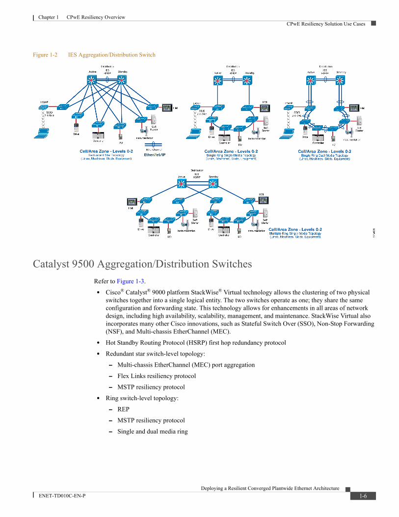
Allen-Bradley Stratix and Cisco Industrial Ethernet Switches (IES) Refer to Figure 1-2.
• Form factor:
– DIN rail/panel mount
– 19” rack mount - 1 RU (rack unit)
• Hot Standby Routing Protocol (HSRP) first hop redundancy protocol
• Redundant star switch-level topology:
– Flex Links resiliency protocol
– MSTP resiliency protocol
• Ring switch-level topology:
– Resilient Ethernet Protocol (REP)
– Device Level Ring Protocol (see CPwE DLR)
– Multiple Spanning Tree Protocol (MSTP) resiliency protocol
– Single and dual media ring
– EtherChannel for dual media ring only
1-5Deploying a Resilient Converged Plantwide Ethernet Architecture
ENET-TD010C-EN-P
Chapter 1 CPwE Resiliency OverviewCPwE Resiliency Solution Use Cases
Figure 1-2 IES Aggregation/Distribution Switch
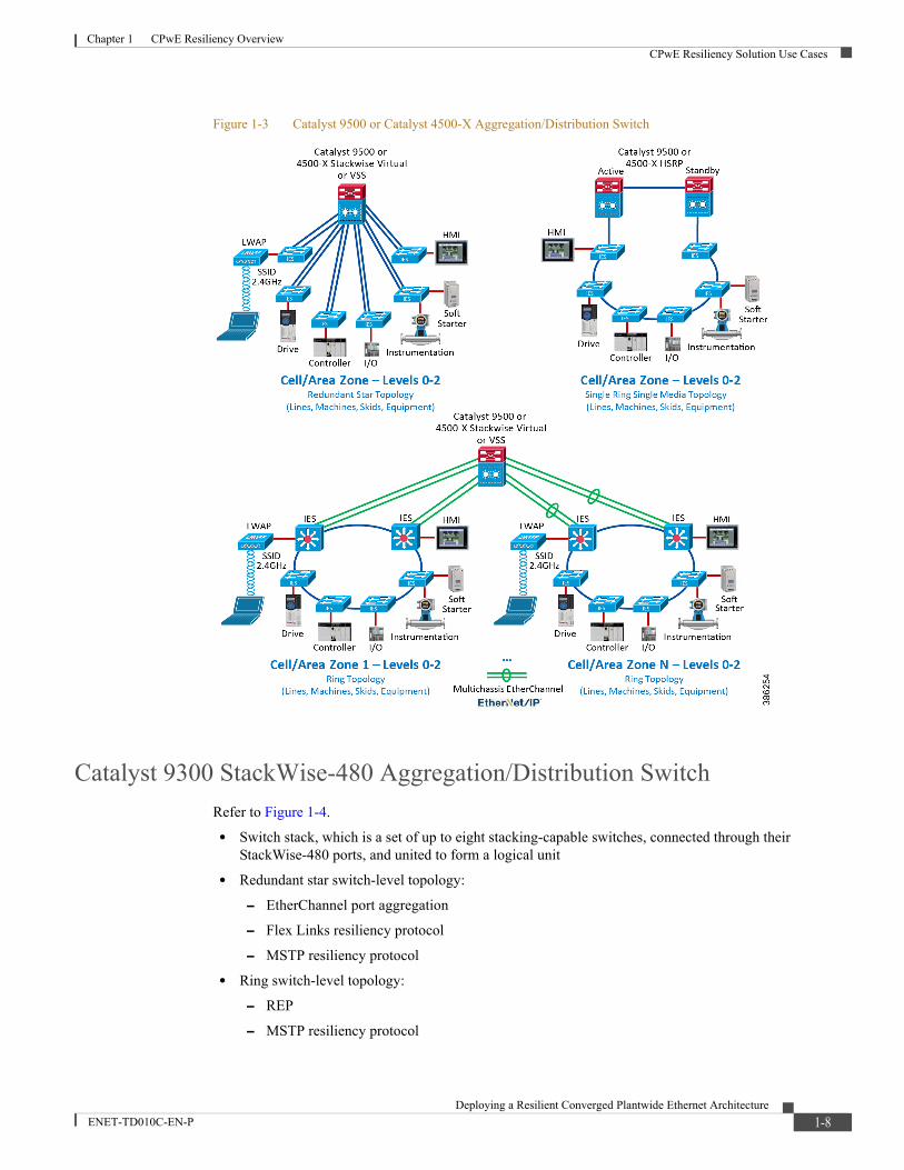
Catalyst 9500 Aggregation/Distribution SwitchesRefer to Figure 1-3.
• Cisco® Catalyst® 9000 platform StackWise® Virtual technology allows the clustering of two physical switches together into a single logical entity. The two switches operate as one; they share the same configuration and forwarding state. This technology allows for enhancements in all areas of network design, including high availability, scalability, management, and maintenance. StackWise Virtual also incorporates many other Cisco innovations, such as Stateful Switch Over (SSO), Non-Stop Forwarding (NSF), and Multi-chassis EtherChannel (MEC).
• Hot Standby Routing Protocol (HSRP) first hop redundancy protocol
• Redundant star switch-level topology:
– Multi-chassis EtherChannel (MEC) port aggregation
– Flex Links resiliency protocol
– MSTP resiliency protocol
• Ring switch-level topology:
– REP
– MSTP resiliency protocol
– Single and dual media ring
1-6Deploying a Resilient Converged Plantwide Ethernet Architecture
ENET-TD010C-EN-P
Chapter 1 CPwE Resiliency OverviewCPwE Resiliency Solution Use Cases
Catalyst 4500-X Aggregation/Distribution SwitchesRefer to Figure 1-3.
• Virtual Switching System (VSS) virtualization technology that combines two physical switch chassis into one virtual switch, with Stateful Switch Over (SSO) and Non-stop forwarding (NSF)
• Hot Standby Routing Protocol (HSRP) first hop redundancy protocol
• Redundant star switch-level topology:
– Multi-chassis EtherChannel (MEC) port aggregation
– Flex Links resiliency protocol
– MSTP resiliency protocol
• Ring switch-level topology:
– REP
– MSTP resiliency protocol
– Single and dual media ring
Note Cisco, Panduit, and Rockwell Automation recommend migrating from Catalyst 4500-X to Catalyst 9500 series as the aggregation/distribution switch platform.
1-7Deploying a Resilient Converged Plantwide Ethernet Architecture
ENET-TD010C-EN-P
Chapter 1 CPwE Resiliency OverviewCPwE Resiliency Solution Use Cases
Figure 1-3 Catalyst 9500 or Catalyst 4500-X Aggregation/Distribution Switch
Catalyst 9300 StackWise-480 Aggregation/Distribution SwitchRefer to Figure 1-4.
• Switch stack, which is a set of up to eight stacking-capable switches, connected through their StackWise-480 ports, and united to form a logical unit
• Redundant star switch-level topology:
– EtherChannel port aggregation
– Flex Links resiliency protocol
– MSTP resiliency protocol
• Ring switch-level topology:
– REP
– MSTP resiliency protocol
1-8Deploying a Resilient Converged Plantwide Ethernet Architecture
ENET-TD010C-EN-P
Chapter 1 CPwE Resiliency OverviewCPwE Resiliency Solution Use Cases
– Single and dual media ring
Catalyst 3850 StackWise-480 Aggregation/Distribution SwitchRefer to Figure 1-4.
• Switch stack, which is a set of up to nine stacking-capable switches, connected through their StackWise-480 ports, and united to form a logical unit
• Redundant star switch-level topology:
– EtherChannel port aggregation
– Flex Links resiliency protocol
– MSTP resiliency protocol
• Ring switch-level topology:
– REP
– MSTP resiliency protocol
– Single and dual media ring
Note Cisco, Panduit, and Rockwell Automation recommend migrating from Catalyst 3850 to Catalyst 9300 series as the aggregation/distribution switch platform.
1-9Deploying a Resilient Converged Plantwide Ethernet Architecture
ENET-TD010C-EN-P

Chapter 1 CPwE Resiliency OverviewCPwE Resiliency Solution Use Cases
Figure 1-4 Catalyst 9300 or Catalyst 3850 Aggregation/Distribution Switch
1-10Deploying a Resilient Converged Plantwide Ethernet Architecture
ENET-TD010C-EN-P
Chapter 1 CPwE Resiliency OverviewCPwE Resiliency Solution Use Cases
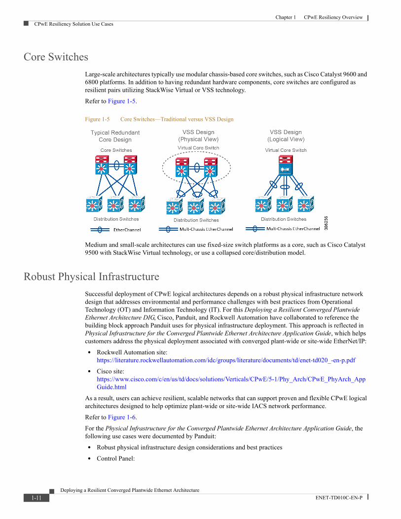
Core SwitchesLarge-scale architectures typically use modular chassis-based core switches, such as Cisco Catalyst 9600 and 6800 platforms. In addition to having redundant hardware components, core switches are configured as resilient pairs utilizing StackWise Virtual or VSS technology.
Refer to Figure 1-5.
Figure 1-5 Core Switches—Traditional versus VSS Design
Medium and small-scale architectures can use fixed-size switch platforms as a core, such as Cisco Catalyst 9500 with StackWise Virtual technology, or use a collapsed core/distribution model.
Robust Physical InfrastructureSuccessful deployment of CPwE logical architectures depends on a robust physical infrastructure network design that addresses environmental and performance challenges with best practices from Operational Technology (OT) and Information Technology (IT). For this Deploying a Resilient Converged Plantwide Ethernet Architecture DIG, Cisco, Panduit, and Rockwell Automation have collaborated to reference the building block approach Panduit uses for physical infrastructure deployment. This approach is reflected in Physical Infrastructure for the Converged Plantwide Ethernet Architecture Application Guide, which helps customers address the physical deployment associated with converged plant-wide or site-wide EtherNet/IP:
• Rockwell Automation site:https://literature.rockwellautomation.com/idc/groups/literature/documents/td/enet-td020_-en-p.pdf
• Cisco site:https://www.cisco.com/c/en/us/td/docs/solutions/Verticals/CPwE/5-1/Phy_Arch/CPwE_PhyArch_AppGuide.html
As a result, users can achieve resilient, scalable networks that can support proven and flexible CPwE logical architectures designed to help optimize plant-wide or site-wide IACS network performance.
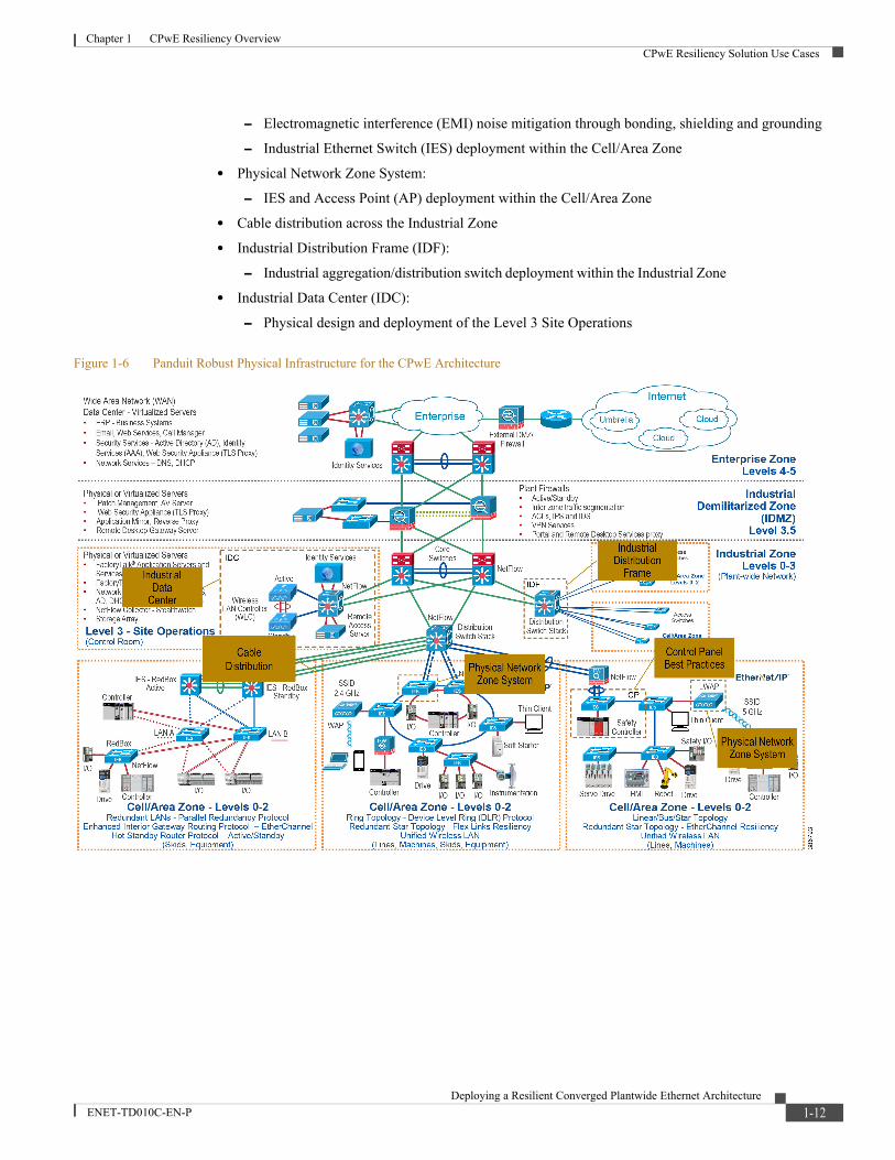
Refer to Figure 1-6.
For the Physical Infrastructure for the Converged Plantwide Ethernet Architecture Application Guide, the following use cases were documented by Panduit:
• Robust physical infrastructure design considerations and best practices
• Control Panel:
1-11Deploying a Resilient Converged Plantwide Ethernet Architecture
ENET-TD010C-EN-P
Chapter 1 CPwE Resiliency OverviewCPwE Resiliency Solution Use Cases
– Electromagnetic interference (EMI) noise mitigation through bonding, shielding and grounding
– Industrial Ethernet Switch (IES) deployment within the Cell/Area Zone
• Physical Network Zone System:
– IES and Access Point (AP) deployment within the Cell/Area Zone
• Cable distribution across the Industrial Zone
• Industrial Distribution Frame (IDF):
– Industrial aggregation/distribution switch deployment within the Industrial Zone
• Industrial Data Center (IDC):
– Physical design and deployment of the Level 3 Site Operations
Figure 1-6 Panduit Robust Physical Infrastructure for the CPwE Architecture
1-12Deploying a Resilient Converged Plantwide Ethernet Architecture
ENET-TD010C-EN-P

Deploying a Resilient ConENET-TD010C-EN-P
C H A P T E R 2
CPwE Resiliency Design ConsiderationsThis chapter provides an overview of design considerations for integrating resiliency into an Industrial Automation and Control System (IACS) network based on the CPwE architecture and includes:
• Test Hardware and Software
• Resiliency Architectural Framework, page 2-2
Test Hardware and SoftwareTable 2-1 Network Hardware and Software
Role Product Software Version Notes
2015 DIG Release 2018 DIG Release 2020 DIG Release
Access switch Cisco Industrial Ethernet 2000 Series Switch/Allen-Bradley Stratix 5700
15.2(3)EA 15.2(6)E1 15.2(7)E (Cisco)
15.2(6)E1 (RA)
Access switch Cisco Industrial Ethernet 3000 Series Switch/Allen-Bradley Stratix 8000
15.2(3)EA Not tested Not tested
Access switch Cisco Industrial Ethernet 4000 Series Switch/Allen-Bradley Stratix 5400
15.2(2)EA (Cisco),
15.2(2)EA1 (RA)
15.2(6)E1 15.2(7)E (Cisco)
15.2(6)E1 (RA)
Distribution switch Cisco Industrial Ethernet 5000 Series Switch/Allen-Bradley Stratix 5410
15.2(2)EB 15.2(6)E1 Not tested Hot Standby Routing Protocol (HSRP)
Distribution switch Catalyst 3850 Not tested 03.03.05.SE Not tested StackWise-480
Distribution switch Catalyst 9300 Not tested Not tested 16.12.1 (see note 1)
1. 16.12 is a Long-Term Maintenance version of code. 16.12.1 and 16.9.3 were the versions available for the 9300 and 9500 platforms when the testing for this release was initiated. Cisco, Panduit, and Rockwell Automation recommend using the most recent CCO versions of Long-Term maintenance code for their deployments and to check the release notes for fixes and updates that are included in each release, especially regarding key features and functions upon which they may be relying.
StackWise-480
Distribution switch Catalyst 9500 Not tested Not tested 16.9.3 (see note 1) StackWise Virtual and HSRP
Distribution switch Catalyst 4500-X Not tested 03.08.00.E Not tested Virtual Switching System (VSS) and HSRP
Distribution switch Cisco Industrial Ethernet 4000 Series Switch/Allen-Bradley Stratix 5400
15.2(2)EA (Cisco),
15.2(2)EA1 (RA)
15.2(6)E1 15.2(7)E (Cisco)
15.2(6)E1 (RA)
HSRP)
2-1verged Plantwide Ethernet Architecture
Chapter 2 CPwE Resiliency Design ConsiderationsResiliency Architectural Framework
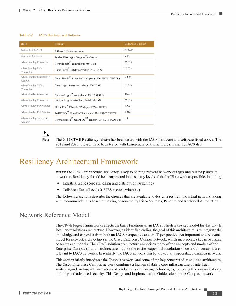
Note The 2015 CPwE Resiliency release has been tested with the IACS hardware and software listed above. The 2018 and 2020 releases have been tested with Ixia-generated traffic representing the IACS data.
Resiliency Architectural FrameworkWithin the CPwE architecture, resiliency is key to helping prevent network outages and related plant/site downtime. Resiliency should be incorporated into as many levels of the IACS network as possible, including:
• Industrial Zone (core switching and distribution switching)
• Cell/Area Zone (Levels 0-2 IES access switching)
The following sections describe the choices that are available to design a resilient industrial network, along with recommendations based on testing conducted by Cisco Systems, Panduit, and Rockwell Automation.
Network Reference ModelThe CPwE logical framework reflects the basic functions of an IACS, which is the key model for this CPwE Resiliency solution architecture. However, as identified earlier, the goal of this architecture is to integrate the knowledge and expertise from both an IACS perspective and an IT perspective. An important and relevant model for network architectures is the Cisco Enterprise Campus network, which incorporates key networking concepts and models. The CPwE solution architecture comprises many of the concepts and models of the Enterprise Campus solution architecture, but not the entire scope of that solution since not all concepts are relevant to IACS networks. Essentially, the IACS network can be viewed as a specialized Campus network.
This section briefly introduces the Campus network and some of the key concepts of its solution architecture. The Cisco Enterprise Campus network combines a high-availability core infrastructure of intelligent switching and routing with an overlay of productivity-enhancing technologies, including IP communications, mobility and advanced security. This Design and Implementation Guide refers to the Campus network
Table 2-2 IACS Hardware and Software
Role Product Software Version
Rockwell Software RSLinx® Classic software 3.73.00
Rockwell Software Studio 5000 Logix Designer®software V26
Allen-Bradley Controller ControlLogix® controller (1756-L75) 26.013
Allen-Bradley Safety Controller
GuardLogix® Safety controller(1576-L73S) 26.013
Allen-Bradley EtherNet/IP Adapter
ControlLogix® EtherNet/IP adapter (1756-ENT2T/EN2TR) 5.0.28
Allen-Bradley Safety Controller
GuardLogix Safety controller (1756-L7SP) 26.013
Allen-Bradley Controller CompactLogix™ controller (1769-L36ERM) 26.013
Allen-Bradley Controller CompactLogix controller (1769-L18ERM) 26.013
Allen-Bradley I/O Adapter FLEX I/O™ EtherNet/IP adapter (1794-AENT) 4.003
Allen-Bradley I/O Adapter POINT I/O™ EtherNet/IP adapter (1734-AENT/AENTR) 3.012
Allen-Bradley Safety I/O Adapter
CompactBlock™ Guard I/O™ adapter 1791ES-IB8XOBV4) 1.9
2-2Deploying a Resilient Converged Plantwide Ethernet Architecture
ENET-TD010C-EN-P

Chapter 2 CPwE Resiliency Design ConsiderationsResiliency Architectural Framework
documentation and the concept of access, distribution and core. Figure 2-1 shows a hierarchical design model that has proven to be effective in a Campus environment consisting of three main layers: access, distribution and core.
Figure 2-1 Campus Network Hierarchical Model
• The access layer provides the first layer of access to the IACS network. Layer 2 (OSI model) switching, security and QoS reside at this layer. Access layer switches aggregate IACS devices.
• The distribution layer aggregates the access layer switches and provides security and access level network policy enforcement. Layer 3 protocols are used at this layer to provide load balancing, fast convergence and scalability.
• The core is the backbone of the network. This layer is designed to be fast converging, highly reliable and stable. This layer aggregates the distribution switches and often integrates connectivity to the IDMZ in this CPwE solution architecture. Designed with Layer 3 protocols, the core helps provide load balancing, fast convergence and scalability. Often, in small-to-medium topologies, the core and distribution layers are consolidated into a single collapsed core/distribution layer. For large topologies, the core is required for scalability, throughput and to interconnect multiple distribution switches to other services (such as security firewalls).
This three-layer design provides high availability with redundant hardware, redundant software features, redundant network connections/paths and automatic procedures for reconfiguring network paths when failures occur.
2-3Deploying a Resilient Converged Plantwide Ethernet Architecture
ENET-TD010C-EN-P

Chapter 2 CPwE Resiliency Design ConsiderationsResiliency Architectural Framework
Note For more information on the Enterprise Campus network, see the following URLs:
• Enterprise Campus Architecture: Overview and Framework: http://www.cisco.com/en/US/docs/solutions/Enterprise/Campus/campover.html
• Campus Network for High Availability Design Guide: http://www.cisco.com/en/US/docs/solutions/Enterprise/Campus/HA_campus_DG/hacampusdg.html
Note For more information on the Industrial Zone design and topology options, see the "Solution Design-- Manufacturing and Demilitarized Zones" chapter of the Converged Plantwide Ethernet (CPwE) Design and Implementation Guide at the following URLs:
Rockwell Automation site:
• http://literature.rockwellautomation.com/idc/groups/literature/documents/td/enet-td001_-en-p.pdf
Cisco site:
• http://www.cisco.com/en/US/docs/solutions/Verticals/CPwE/CPwE_DIG.html
This release of the CPwE Resiliency DIG introduces the following new distribution layer switches: Catalyst 9500 and Catalyst 9300. The following sections describe the resiliency options available for the distribution layer.
Industrial Zone
Resiliency ProtocolsThe following section describes the resiliency protocol available for the distribution layer:
• StackWise Virtual, page 2-4
• StackWise-480, page 2-7
• Hot Standby Redundancy Protocol, page 2-8
StackWise Virtual
StackWise Virtual OverviewCisco Catalyst 9000 platform StackWise Virtual technology allows the clustering of two physical switches together into a single logical entity. The two switches operate as one; they share the same configuration and forwarding state. This technology allows for enhancements in all areas of network design, including high availability, scalability, management, and maintenance. Figure 2-2 graphically represents the StackWise Virtual feature, which allows you to manage two Cisco Catalyst 9000 Switches as a single switch.
Note For more information on StackWise Virtual design and implementation, see the “Configuring Cisco StackWise Virtual” chapter of the Catalyst 9500 Switches High Availability Guide IOS XE at the following URL:
2-4Deploying a Resilient Converged Plantwide Ethernet Architecture
ENET-TD010C-EN-P
Chapter 2 CPwE Resiliency Design ConsiderationsResiliency Architectural Framework
• https://www.cisco.com/c/en/us/td/docs/switches/lan/catalyst9500/software/release/16-9/configuration_guide/ha/b_169_ha_9500_cg/configuring_cisco_stackwise_virtual.html
Note The Catalyst 9500 with StackWise Virtual can also be used in the core layer, depending on plant/site size.
The virtualization of two physical chassis into a single logical switch with StackWise Virtual fundamentally alters the design of the campus topology. One of the most significant changes is that StackWise Virtual enables the creation of a loop-free topology. In addition, the StackWise Virtual incorporates many other Cisco innovations such as SSO and MEC, which substantially enhance application response time. Key business benefits of StackWise Virtual include the following:
• Reduced risk associated with a looped topology
• Non-stop business communication by using a redundant chassis with SSO
• Better return on existing investments via increased bandwidth from the access layer
• Reduced configuration errors and elimination of First Hop Redundancy Protocols (FHRP), such as Hot Standby Routing Protocol (HSRP), GLBP, and VRRP
• Simplified management of a single configuration and fewer operational failure points
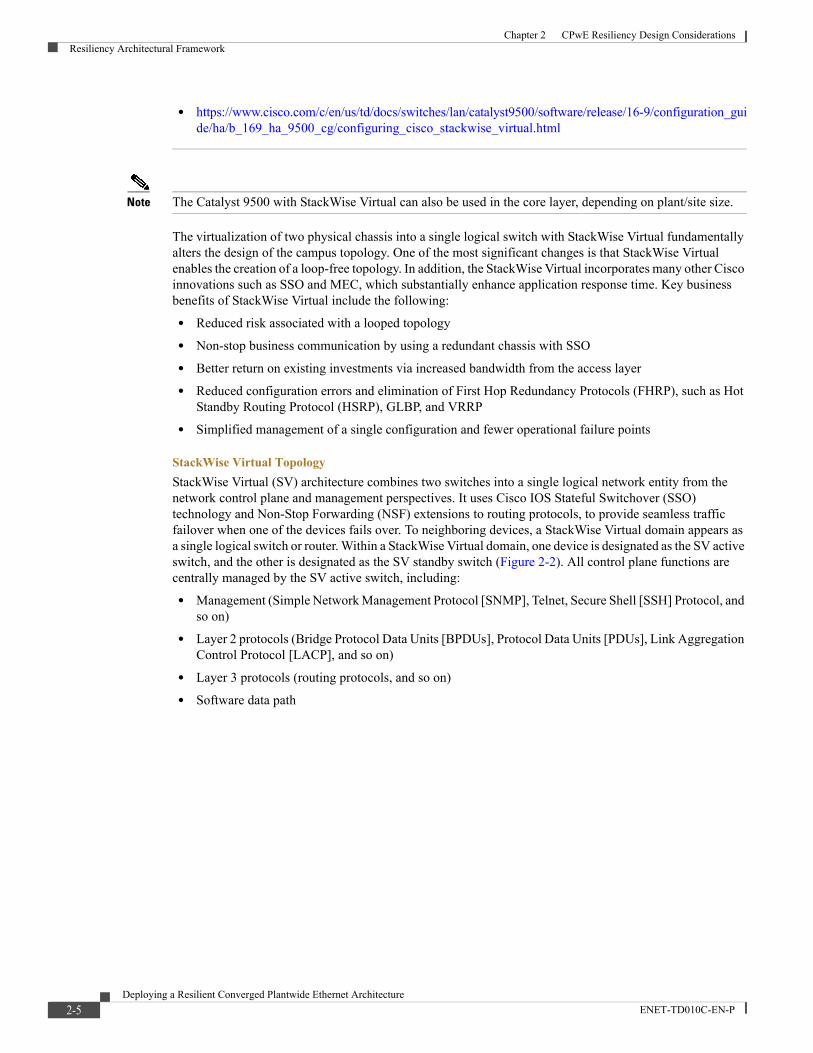
StackWise Virtual TopologyStackWise Virtual (SV) architecture combines two switches into a single logical network entity from the network control plane and management perspectives. It uses Cisco IOS Stateful Switchover (SSO) technology and Non-Stop Forwarding (NSF) extensions to routing protocols, to provide seamless traffic failover when one of the devices fails over. To neighboring devices, a StackWise Virtual domain appears as a single logical switch or router. Within a StackWise Virtual domain, one device is designated as the SV active switch, and the other is designated as the SV standby switch (Figure 2-2). All control plane functions are centrally managed by the SV active switch, including:
• Management (Simple Network Management Protocol [SNMP], Telnet, Secure Shell [SSH] Protocol, and so on)
• Layer 2 protocols (Bridge Protocol Data Units [BPDUs], Protocol Data Units [PDUs], Link Aggregation Control Protocol [LACP], and so on)
• Layer 3 protocols (routing protocols, and so on)
• Software data path
2-5Deploying a Resilient Converged Plantwide Ethernet Architecture
ENET-TD010C-EN-P

Chapter 2 CPwE Resiliency Design ConsiderationsResiliency Architectural Framework
Figure 2-2 StackWise Virtual in the Distribution Network
StackWise Virtual LinkA StackWise Virtual domain consists of two Cisco Catalyst 9000 Switches. In order to bond the two switches together into a single logical node, special signaling and control information must be exchanged between the two switches in a timely manner. To facilitate this information exchange, a dedicated link is used to transfer both data and control traffic between the peer switches. This link is referred to as the StackWise Virtual link
Centralized ManagementThe fundamental design of a StackWise Virtual domain allows the centralized management of all network and device resources. This includes Layer 3 protocols such as Open Shortest Path First (OSPF), Enhanced Interior Gateway Routing Protocol (EIGRP), and Border Gateway Protocol (BGP) and Layer 2 protocols such as Spanning Tree Protocol (STP), Unidirectional Link Detection Protocol (UDLD), Flow Control, and LACP. A single switch in the StackWise Virtual domain is elected as the central management point for the entire system when accessed via management IP or console. The switch acting as the single management point is referred to as the SV active switch. The peer chassis is referred to as the SV standby switch. The SV standby switch is also considered a hot-standby switch since it is ready to become the active switch and take over all functions if something happens to the active switch.
StackWise Virtual Link InitializationThe initialization process must determine which switch will become the active switch for the StackWise Virtual domain. To determine the active and standby roles, the StackWise Virtual link must be initialized and brought online for control plane communication. Because this determination affects the behavior of each switch, the roles must be negotiated early during the switch bootup cycle. As a result, the system must bring the StackWise Virtual link and its associated ports online before initializing the rest of the system. Communication between the two switches is facilitated with internal messaging that is sent across the StackWise Virtual link. Because the link is implemented as an EtherChannel interface, it is resilient to single-link failures. The system must bring the StackWise Virtual link online before activating the StackWise Virtual domain.
StackWise Virtual Link RedundancyStackWise Virtual provides the signaling path used for synchronizing the two switch control planes, and the data path for any user data traffic needing to pass between the two switches. Therefore, the StackWise Virtual link is bundled as an EtherChannel interface, allowing for redundant interfaces and higher bandwidth capacity.
2-6Deploying a Resilient Converged Plantwide Ethernet Architecture
ENET-TD010C-EN-P
Chapter 2 CPwE Resiliency Design ConsiderationsResiliency Architectural Framework
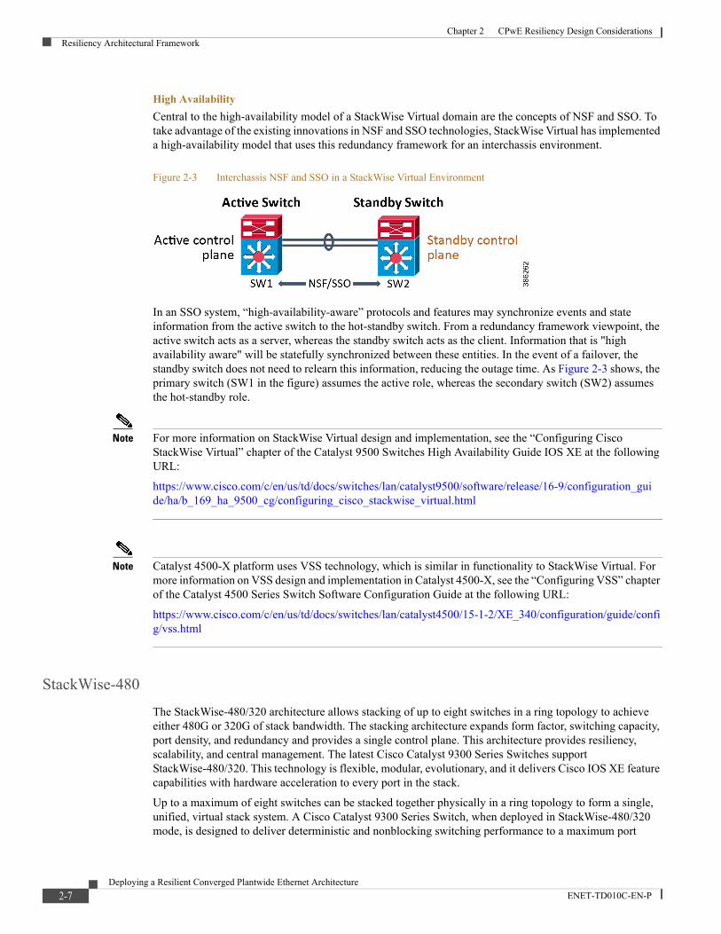
High AvailabilityCentral to the high-availability model of a StackWise Virtual domain are the concepts of NSF and SSO. To take advantage of the existing innovations in NSF and SSO technologies, StackWise Virtual has implemented a high-availability model that uses this redundancy framework for an interchassis environment.
Figure 2-3 Interchassis NSF and SSO in a StackWise Virtual Environment
In an SSO system, “high-availability-aware” protocols and features may synchronize events and state information from the active switch to the hot-standby switch. From a redundancy framework viewpoint, the active switch acts as a server, whereas the standby switch acts as the client. Information that is "high availability aware" will be statefully synchronized between these entities. In the event of a failover, the standby switch does not need to relearn this information, reducing the outage time. As Figure 2-3 shows, the primary switch (SW1 in the figure) assumes the active role, whereas the secondary switch (SW2) assumes the hot-standby role.
Note For more information on StackWise Virtual design and implementation, see the “Configuring Cisco StackWise Virtual” chapter of the Catalyst 9500 Switches High Availability Guide IOS XE at the following URL:
https://www.cisco.com/c/en/us/td/docs/switches/lan/catalyst9500/software/release/16-9/configuration_gui de/ha/b_169_ha_9500_cg/configuring_cisco_stackwise_virtual.html
Note Catalyst 4500-X platform uses VSS technology, which is similar in functionality to StackWise Virtual. For more information on VSS design and implementation in Catalyst 4500-X, see the “Configuring VSS” chapter of the Catalyst 4500 Series Switch Software Configuration Guide at the following URL:
https://www.cisco.com/c/en/us/td/docs/switches/lan/catalyst4500/15-1-2/XE_340/configuration/guide/config/vss.html
StackWise-480The StackWise-480/320 architecture allows stacking of up to eight switches in a ring topology to achieve either 480G or 320G of stack bandwidth. The stacking architecture expands form factor, switching capacity, port density, and redundancy and provides a single control plane. This architecture provides resiliency, scalability, and central management. The latest Cisco Catalyst 9300 Series Switches support StackWise-480/320. This technology is flexible, modular, evolutionary, and it delivers Cisco IOS XE feature capabilities with hardware acceleration to every port in the stack.
Up to a maximum of eight switches can be stacked together physically in a ring topology to form a single, unified, virtual stack system. A Cisco Catalyst 9300 Series Switch, when deployed in StackWise-480/320 mode, is designed to deliver deterministic and nonblocking switching performance to a maximum port
2-7Deploying a Resilient Converged Plantwide Ethernet Architecture
ENET-TD010C-EN-P
Chapter 2 CPwE Resiliency Design ConsiderationsResiliency Architectural Framework
density of 448 ports with a distributed data plane, single control plane, and management plane. The switching performance delivers hardware-accelerated, integrated borderless network services such as PoE, PoE+, Cisco UPOE, Quality of Service (QoS), Access Control Lists (ACLs), Flexible NetFlow, Cisco Encrypted Traffic Analytics (ETA), streaming telemetry, and many more services on every port.
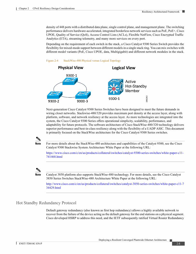
Depending on the requirement of each switch in the stack, a Cisco Catalyst 9300 Series Switch provides the flexibility for mixed-mode support between different models in a single stack ring. You can mix switches with different model variants (PoE, Cisco UPOE, data, Multigigabit) and different network modules in the stack.
Figure 2-4 StackWise-480 Physical versus Logical Topology
Next-generation Cisco Catalyst 9300 Series Switches have been designed to meet the future demands in wiring closet networks. Stackwise-480/320 provides maximum port density at the access layer, along with platform, software, and network resiliency at the access layer. As more technologies are integrated into the system, the Cisco Catalyst 9300 Series offers operational simplicity, scalability, performance, and adaptability for future protocols. The software architecture of Cisco StackWise-480/320 technology delivers superior performance and best-in-class resiliency along with the flexibility of a UADP ASIC. This document is primarily focused on the StackWise architecture for the Cisco Catalyst 9300 Series switches.
Note For more details about the StackWise-480 architecture and capabilities of the Catalyst 9300, see the Cisco Catalyst 9300 Stackwise System Architecture White Paper at the following URL:
https://www.cisco.com/c/en/us/products/collateral/switches/catalyst-9300-series-switches/white-paper-c11-741468.html
Note Catalyst 3850 platform also supports StackWise-480 technology. For more details, see the Cisco Catalyst 3850 Series Switches StackWise-480 Architecture White Paper at the following URL:
http://www.cisco.com/c/en/us/products/collateral/switches/catalyst-3850-series-switches/white-paper-c11-734429.html
Hot Standby Redundancy ProtocolDefault gateway redundancy (also known as first hop redundancy) allows a highly available network to recover from the failure of the device acting as the default gateway for the end stations on a physical segment. Cisco developed HSRP to address this need, and the IETF subsequently ratified Virtual Router Redundancy
2-8Deploying a Resilient Converged Plantwide Ethernet Architecture
ENET-TD010C-EN-P
Chapter 2 CPwE Resiliency Design ConsiderationsResiliency Architectural Framework
Protocol (VRRP) as the standards-based method of providing default gateway redundancy. HSRP is supported on various platforms, including the Catalyst 4500-X, IE 5000/Stratix 5410, IE 4000/Stratix 5400, Catalyst 3850, and Catalyst 9300/9500.
In the recommended hierarchical model, the distribution switches are the Layer 2/Layer 3 boundary and act as the default gateway for the entire Layer 2 domain that they support. Some form of redundancy is required because this environment can be large, and a considerable outage could occur if the device acting as the default gateway failed.
HSRP, which provides a robust method of backing up the default gateway, can provide sub-second failover to the redundant distribution switch when tuned properly. HSRP is the recommended protocol because it is a Cisco-owned standard that allows for the rapid development of new features and functionality for HSRP before VRRP.
Note Cisco, Panduit, and Rockwell Automation recommend that the Spanning Tree Protocol (STP) root be configured to be the same as the primary HSRP peer. Therefore, if the STP root and primary HSRP peer are not synchronized due to a switch disruption, a manual switchover to restore the original peer as primary should be initiated during the next maintenance window.
Cell/Area Zone
Common Industrial Protocol MessagingBefore discussing resiliency and design recommendations in the Cell/Area Zone, a clear understanding of the different types of Common Industrial Protocol (CIP) traffic that may traverse this area of the IACS network is required, since each of these has its own unique convergence requirements:
• Class 1 (Implicit)—Class 1 connections do not use a reliable transport method so they are less tolerant of excessive latency and disruptions in the IACs network. Examples include I/O and produced/consumed connections. Another name for a Class 1 message is implicit messaging. Once the Class 1 connection is established the producer sends an "implicit" message every requested packet interval (RPI).
Note Recommendations given in this document focus on Class 1 (implicit) traffic since this type of traffic is more sensitive to IACS network disruptions.
• Class 3 (Explicit)—Class 3 connections use a reliable transport method so they are more tolerant of excessive latency and disruptions in the IACS network. Examples include MSG instructions and going online with a Programmable Automation Controller (PAC). Another name for a Class 3 message is explicit messaging. Explicit messages are triggered on demand or in other terms the data is explicitly requested.
Note For more information on convergence requirements for different types of CIP messaging, see the "CPwE Solution - Design Cell/Area Zone" chapter of the Converged Plantwide Ethernet (CPwE) Design and Implementation Guide at the following URLs:
Rockwell Automation site:
• http://literature.rockwellautomation.com/idc/groups/literature/documents/td/enet-td001_-en-p.pdf
Cisco site:
2-9Deploying a Resilient Converged Plantwide Ethernet Architecture
ENET-TD010C-EN-P
Chapter 2 CPwE Resiliency Design ConsiderationsResiliency Architectural Framework
• http://www.cisco.com/en/US/docs/solutions/Verticals/CPwE/CPwE_Design and Implementation Guide.html
Access Layer SwitchingThe access layer is the first tier or edge of the CPwE architecture. It is the place where IACS network devices (such as PCs, servers, controllers, I/O devices, and drives) attach to the wired portion of the IACS network. The wide variety of possible types of connectable devices and the various necessary services and dynamic configuration mechanisms, make the access layer one of the IACS feature-rich parts of the CPwE architecture.
The access layer provides the intelligent demarcation between the network infrastructure and the devices that leverage that infrastructure. As such, it provides a security, QoS, and policy trust boundary. When reviewing the overall IACS network design, the access switch provides most of these access layer services and is a key element in enabling multiple IACS network services. The Cell/Area Zone can be considered an access layer network specialized and optimized for IACS networks.
CPwE Resiliency uses the IE 4000/Stratix 5400 and IE 2000/Stratix 5700 access layer industrial Ethernet switches (IES). The IE 4000/Stratix 5400 is available as an all Gigabit Ethernet switch to support advanced applications. In addition, all IE 4000/Stratix 5400 variants support four gigabit uplink ports, which allow it to be used in both single and dual media rings (see Ring Topology, page 2-26 for more details on these designs). The IE 4000/Stratix 5400 can also be used as a distribution switch for smaller scale deployments.
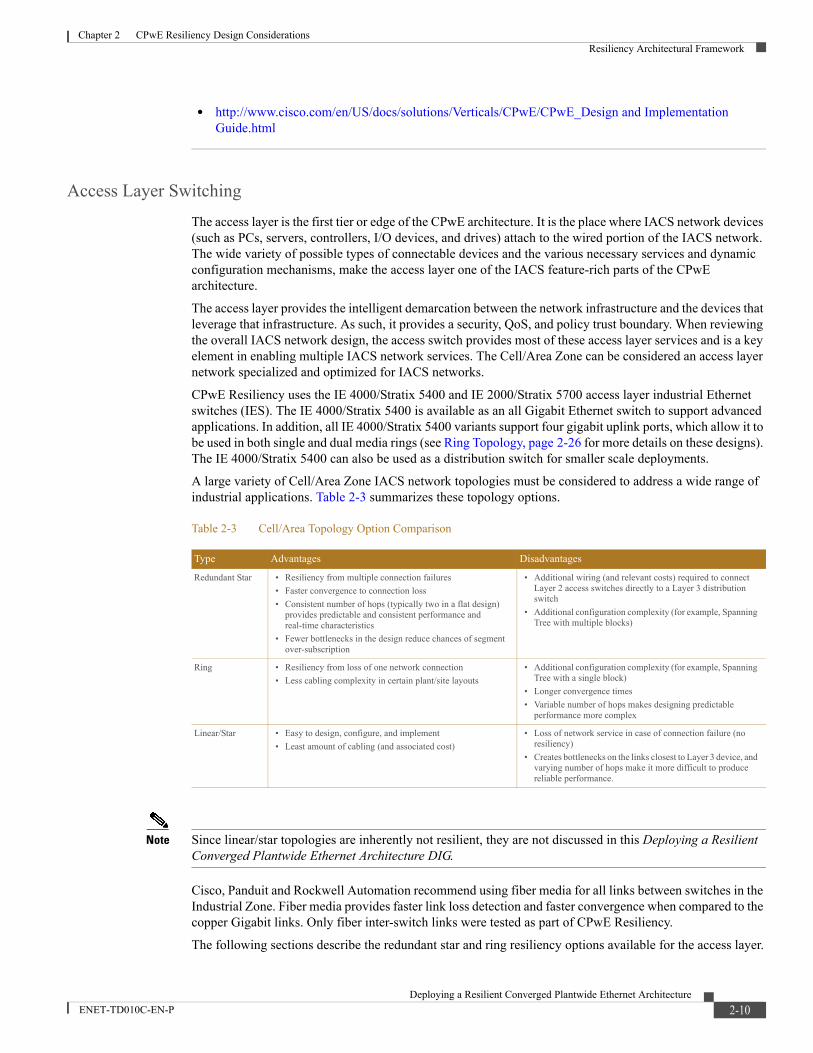
A large variety of Cell/Area Zone IACS network topologies must be considered to address a wide range of industrial applications. Table 2-3 summarizes these topology options.
Note Since linear/star topologies are inherently not resilient, they are not discussed in this Deploying a Resilient Converged Plantwide Ethernet Architecture DIG.
Cisco, Panduit and Rockwell Automation recommend using fiber media for all links between switches in the Industrial Zone. Fiber media provides faster link loss detection and faster convergence when compared to the copper Gigabit links. Only fiber inter-switch links were tested as part of CPwE Resiliency.
The following sections describe the redundant star and ring resiliency options available for the access layer.
Table 2-3 Cell/Area Topology Option Comparison
Type Advantages Disadvantages
Redundant Star • Resiliency from multiple connection failures• Faster convergence to connection loss• Consistent number of hops (typically two in a flat design)
provides predictable and consistent performance and real-time characteristics
• Fewer bottlenecks in the design reduce chances of segment over-subscription
• Additional wiring (and relevant costs) required to connect Layer 2 access switches directly to a Layer 3 distribution switch
• Additional configuration complexity (for example, Spanning Tree with multiple blocks)
Ring • Resiliency from loss of one network connection• Less cabling complexity in certain plant/site layouts
• Additional configuration complexity (for example, Spanning Tree with a single block)
• Longer convergence times• Variable number of hops makes designing predictable
performance more complex
Linear/Star • Easy to design, configure, and implement• Least amount of cabling (and associated cost)
• Loss of network service in case of connection failure (no resiliency)
• Creates bottlenecks on the links closest to Layer 3 device, and varying number of hops make it more difficult to produce reliable performance.
2-10Deploying a Resilient Converged Plantwide Ethernet Architecture
ENET-TD010C-EN-P
Chapter 2 CPwE Resiliency Design ConsiderationsResiliency Architectural Framework
Redundant Star Topology
Resiliency Protocols
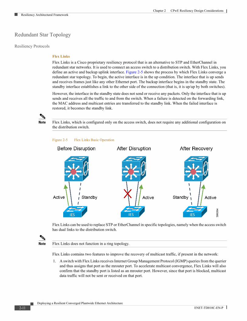
Flex LinksFlex Links is a Cisco proprietary resiliency protocol that is an alternative to STP and EtherChannel in redundant star networks. It is used to connect an access switch to a distribution switch. With Flex Links, you define an active and backup uplink interface. Figure 2-5 shows the process by which Flex Links converge a redundant star topology. To begin, the active interface is in the up condition. The interface that is up sends and receives frames just like any other Ethernet port. The backup interface begins in the standby state. The standby interface establishes a link to the other side of the connection (that is, it is up/up by both switches).
However, the interface in the standby state does not send or receive any packets. Only the interface that is up sends and receives all the traffic to and from the switch. When a failure is detected on the forwarding link, the MAC address and multicast entries are transferred to the standby link. When the failed interface is restored, it becomes the standby link.
Note Flex Links, which is configured only on the access switch, does not require any additional configuration on the distribution switch.
Figure 2-5 Flex Links Basic Operation
Flex Links can be used to replace STP or EtherChannel in specific topologies, namely when the access switch has dual links to the distribution switch.
Note Flex Links does not function in a ring topology.
Flex Links contains two features to improve the recovery of multicast traffic, if present in the network:
1. A switch with Flex Links receives Internet Group Management Protocol (IGMP) queries from the querier and thus assigns that port as the mrouter port. To accelerate multicast convergence, Flex Links will also confirm that the standby port is listed as an mrouter port. However, since that port is blocked, multicast data traffic will not be sent or received on that port.
2-11Deploying a Resilient Converged Plantwide Ethernet Architecture
ENET-TD010C-EN-P

Chapter 2 CPwE Resiliency Design ConsiderationsResiliency Architectural Framework
2. “Leaking” IGMP reports out of the blocked port improves multicast convergence. When the upstream or distribution switch receives these reports on this port, the port is added to the snooping table and multicast traffic is sent in that direction. The Flex Links protocol on the access switch blocks the incoming traffic on the standby port. When a failure occurs and the standby link is unblocked, the port is already an mrouter port and the upstream switch is already forwarding multicast traffic on that interface.
Flex Links has the following key advantages:
• Ease of use—Simple protocol to manage resilient uplinks between two switches
• Performance—Fast convergence of unicast and multicast traffic, with built-in features to improve multicast convergence
• Compatibility with STP—As Flex Links blocks one port, STP does not identify a loop and inappropriately block any ports
• Interoperability—Although Flex Links is proprietary, the fact that it does not communicate or negotiate with other switches means that the protocol can be used in mixed vendor environments
Flex Links has the following key disadvantages:
• Not standards-based—Protocol is Cisco proprietary, so it can only be configured on devices operating Cisco IOS
• Bandwidth—Does not take advantage of the available bandwidth (only one link forwarding traffic)
• Not configurable via Device Manager web interface on IES (must be configured via CLI)
Note For more information about Flex Links, see Configuring Flex Links at the following URL:
• http://www.cisco.com/c/en/us/td/docs/switches/lan/cisco_ie2000/software/release/15_2_2_e/configuration/guide/scg-ie2000/swflink.html
EtherChannelStrictly speaking, EtherChannel and Link Aggregation Control Protocol (LACP) are not resiliency protocols. They are designed to provide additional bandwidth between two devices by aggregating multiple Ethernet connections into a higher bandwidth virtual connection. However, these protocols must quickly recover from the loss of one or more channel members. This fast recovery from a failure of an individual channel member can be used to provide link redundancy between two devices.
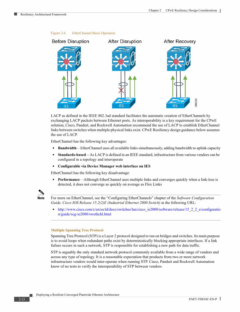
EtherChannel bundles multiple Ethernet links between two switches into a single logical link and balances the traffic load across the physical links. As shown in Figure 2-6, when a physical link is lost, the EtherChannel load-balancing algorithm stops using the lost link and uses the other available links. When the link is restored, EtherChannel resumes balancing the load across the available link. In this way, EtherChannel can be used as a resiliency protocol when multiple links exist between two switches. To be used as a resiliency protocol, the switches must have redundant links between each other, such as in the redundant star topology.
2-12Deploying a Resilient Converged Plantwide Ethernet Architecture
ENET-TD010C-EN-P
Chapter 2 CPwE Resiliency Design ConsiderationsResiliency Architectural Framework
Figure 2-6 EtherChannel Basic Operation
LACP as defined in the IEEE 802.3ad standard facilitates the automatic creation of EtherChannels by exchanging LACP packets between Ethernet ports. As interoperability is a key requirement for the CPwE solution, Cisco, Panduit, and Rockwell Automation recommend the use of LACP to establish EtherChannel links between switches when multiple physical links exist. CPwE Resiliency design guidance below assumes the use of LACP.
EtherChannel has the following key advantages:
• Bandwidth—EtherChannel uses all available links simultaneously, adding bandwidth to uplink capacity
• Standards-based—As LACP is defined in an IEEE standard, infrastructure from various vendors can be configured in a topology and interoperate
• Configurable via Device Manager web interface on IESEtherChannel has the following key disadvantage:
• Performance—Although EtherChannel uses multiple links and converges quickly when a link-loss is detected, it does not converge as quickly on average as Flex Links
Note For more on EtherChannel, see the “Configuring EtherChannels” chapter of the Software Configuration Guide, Cisco IOS Release 15.2(2)E (Industrial Ethernet 2000 Switch) at the following URL:
• http://www.cisco.com/c/en/us/td/docs/switches/lan/cisco_ie2000/software/release/15_2_2_e/configuration/guide/scg-ie2000/swethchl.html
Multiple Spanning Tree ProtocolSpanning Tree Protocol (STP) is a Layer 2 protocol designed to run on bridges and switches. Its main purpose is to avoid loops when redundant paths exist by deterministically blocking appropriate interfaces. If a link failure occurs in such a network, STP is responsible for establishing a new path for data traffic.
STP is arguably the only standard network protocol commonly available from a wide range of vendors and across any type of topology. It is a reasonable expectation that products from two or more network infrastructure vendors would inter-operate when running STP. Cisco, Panduit and Rockwell Automation know of no tests to verify the interoperability of STP between vendors.
2-13Deploying a Resilient Converged Plantwide Ethernet Architecture
ENET-TD010C-EN-P

Chapter 2 CPwE Resiliency Design ConsiderationsResiliency Architectural Framework
STP is an IEEE standard that has gone through several revisions since its conception. These revisions are summarized as follows:
1. Original Spanning Tree Protocol is incorporated into IEEE 802.1D. STP will recover from a topology change in less than 60 seconds. STP is too slow to use in IACS networks.
2. Rapid Spanning Tree Protocol (RSTP) known as IEEE 802.1w is now incorporated into IEEE 802.1D-2004, which helps reduce the convergence time.
3. Multiple Spanning Tree Protocol (MSTP) known as IEEE 802.1s now incorporated into IEEE 802.1Q-2003, which extends the RSTP to work with multiple VLANs.
The standards are backward compatible with each other but may lose some of the performance advantages. For example, a ring of switches operating with both STP and RSTP, will default to using STP and thereby lose the performance advantages of RSTP. We recommend that when using STP, the switches in a topology are all operating the same STP protocol.
Cisco, Panduit and Rockwell Automation used MSTP for validation, since it is enabled by default by standard IES and Stratix macros. Using MSTP, multiple VLANs can be mapped to the same Spanning Tree instance, which reduces the number of Spanning Tree instances required to support many Virtual LANs (VLANs). MSTP runs on top of RSTP, which provides for rapid convergence by eliminating the forward delay and quickly transitioning root ports and designated ports to the forwarding state.
The key advantages of STP include the following:
• Plug-and-Play—STP sends packets to determine whether loops exist in the topology. If a loop is inadvertently created and STP has not been disabled, it will detect the loop and block a port to "close" the loop. For this feature, Cisco, Panduit and Rockwell Automation recommend that STP be enabled in a topology unless specific conflicts exist.
• Consistency—In the same topology, STP will always choose the same link to block.
• Adaptability—STP will function on any redundant topology.
• Standards-based—Since STP is defined in various IEEE standards, infrastructure from various vendors can be configured in a topology and inter-operate.
Key disadvantages of STP in general include the following:
• Performance—All variants of STP converge more slowly than other protocols. Cisco, Panduit and Rockwell Automation did not find that MSTP converges fast enough to avoid application outages on a consistent basis to recommend it for anything other than information/process applications.
• Fallback issues—STP is the lowest common denominator of the STP variants. It is supported by most hardware vendors and serves as the fallback if two devices are using incompatible STP implementations. If this situation occurs, STP may be unknowingly in effect due to incompatibility between the other STP variants, causing long network recovery when failures occur.
Note For more information on MSTP and related technologies, see Understanding Multiple Spanning Tree Protocol (802.1s) at the following URL:
• http://www.cisco.com/c/en/us/support/docs/lan-switching/spanning-tree-protocol/24248-147.html
The following section describes the redundant star options available for the access layer with their results.
2-14Deploying a Resilient Converged Plantwide Ethernet Architecture
ENET-TD010C-EN-P
Chapter 2 CPwE Resiliency Design ConsiderationsResiliency Architectural Framework
Catalyst 9500 and Catalyst 4500-X with StackWise Virtual or VSS
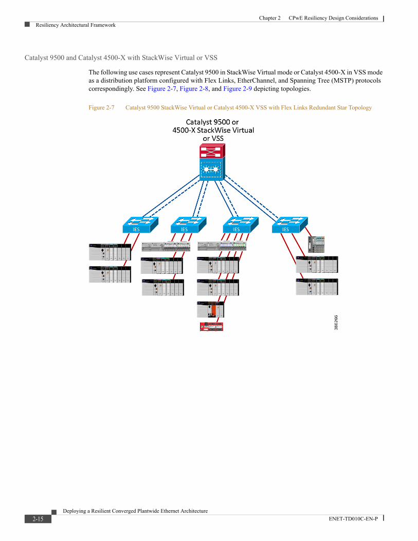
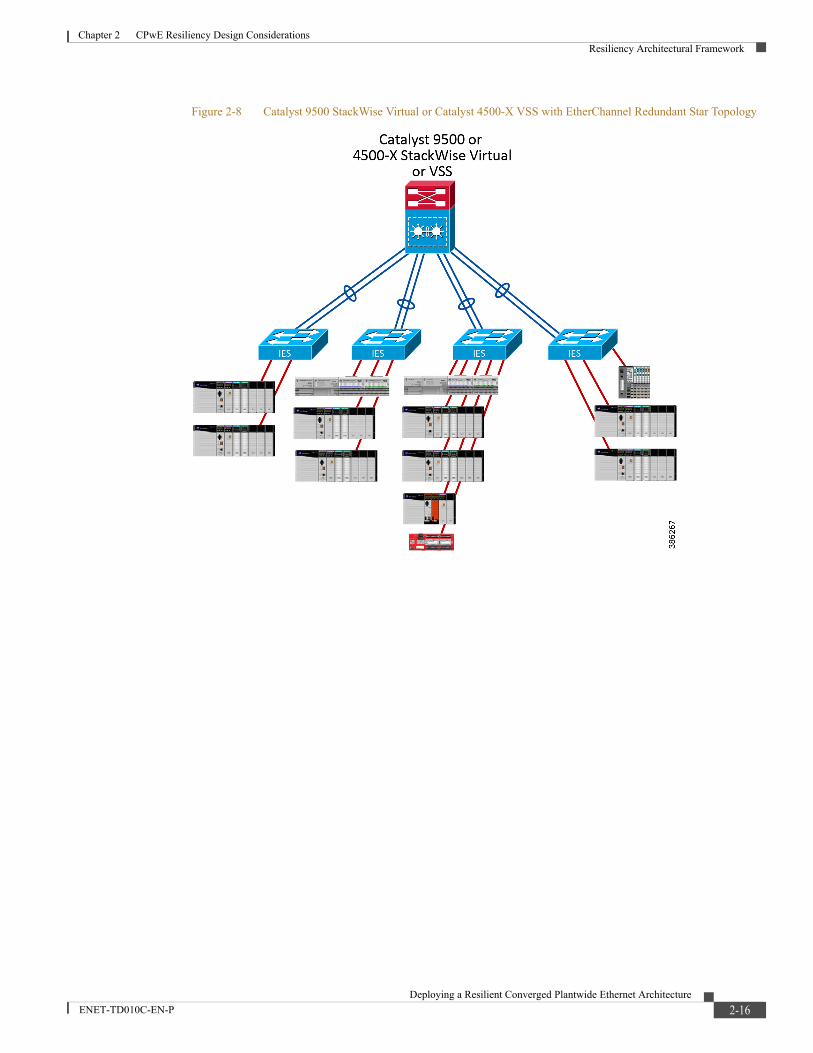
The following use cases represent Catalyst 9500 in StackWise Virtual mode or Catalyst 4500-X in VSS mode as a distribution platform configured with Flex Links, EtherChannel, and Spanning Tree (MSTP) protocols correspondingly. See Figure 2-7, Figure 2-8, and Figure 2-9 depicting topologies.
Figure 2-7 Catalyst 9500 StackWise Virtual or Catalyst 4500-X VSS with Flex Links Redundant Star Topology
2-15Deploying a Resilient Converged Plantwide Ethernet Architecture
ENET-TD010C-EN-P
Chapter 2 CPwE Resiliency Design ConsiderationsResiliency Architectural Framework
Figure 2-8 Catalyst 9500 StackWise Virtual or Catalyst 4500-X VSS with EtherChannel Redundant Star Topology
2-16Deploying a Resilient Converged Plantwide Ethernet Architecture
ENET-TD010C-EN-P

Chapter 2 CPwE Resiliency Design ConsiderationsResiliency Architectural Framework
Figure 2-9 Catalyst 9500 StackWise Virtual or Catalyst 4500-X VSS with MSTP Redundant Star Topology
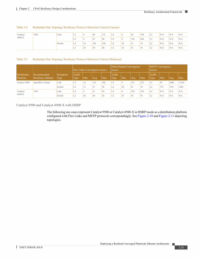
Table 2-4 and Table 2-5 summarize the convergence values observed during validation efforts and can be used to select the appropriate resiliency protocols based on application requirements. The results are based on CIP Class 1 (implicit) traffic flows (both unicast and multicast), and the unicast results are further divided into traffic that remains within the VLAN (Layer 2) and traffic that travels across VLANs (Layer 3).
Note Link disruptions in Table 2-4 and Table 2-5 refer to links within the Cell/Area Zone. Switch disruptions refer to the distribution switches only. To help prevent such events from occurring within your IACS network, refer to “Physical Infrastructure Design for the Cell/Area Zone” in Physical Infrastructure for the Converged Plantwide Ethernet Architecture Application Guide (https://www.cisco.com/c/en/us/td/docs/solutions/Verticals/CPwE/5-1/Phy_Arch/CPwE_PhyArch_AppGuide.html).
Table 2-4 Redundant Star Topology Resiliency Protocol Selection Criteria (Unicast)
Distribution Platform
Recommended Resiliency Method
Disruption Type
Flex Links Convergence (msec)EtherChannel Convergence (msec)
MSTP Convergence(msec)
Traffic Type Min Avg Max
Traffic Type Min Avg Max
Traffic Type Min Avg Max
Catalyst 9500 StackWise Virtual Link L2 14 142 386 L2 4 140 322 L2 44 188 362
L3 12 142 386 L3 4 142 322 L3 12 188 352
Switch L2 52 212 704 L2 20 41 76 L2 62 135 200
L3 54 212 700 L3 20 41 76 L3 62 135 196
2-17Deploying a Resilient Converged Plantwide Ethernet Architecture
ENET-TD010C-EN-P
Chapter 2 CPwE Resiliency Design ConsiderationsResiliency Architectural Framework
Catalyst 9500 and Catalyst 4500-X with HSRP
The following use cases represent Catalyst 9500 or Catalyst 4500-X in HSRP mode as a distribution platform configured with Flex Links and MSTP protocols correspondingly. See Figure 2-10 and Figure 2-11 depicting topologies.
Catalyst 4500-X
VSS Link L2 4 68 272 L2 4 84 180 L2 N/A N/A N/A
L3 4 21 80 L3 4 138 266 L3 N/A N/A N/A
Switch L2 18 126 230 L2 34 53 76 L2 N/A N/A N/A
L3 20 30 40 L3 34 53 76 L3 N/A N/A N/A
Table 2-5 Redundant Star Topology Resiliency Protocol Selection Criteria (Multicast)
Distribution Platform
Recommended Resiliency Method
Disruption Type
Flex Links Convergence (msec)EtherChannel Convergence (msec)
MSTP Convergence(msec)
Traffic Type Min Avg Max
Traffic Type Min Avg Max
Traffic Type Min Avg Max
Catalyst 9500 StackWise Virtual Link L2 14 141 386 L2 4 141 322 L2 56 3040 11516
Switch L2 12 31 58 L2 20 41 76 L2 372 1911 3448
Catalyst 4500-X
VSS Link L2 4 21 82 L2 4 102 210 L2 N/A N/A N/A
Switch L2 20 30 42 L2 35 45 76 L2 N/A N/A N/A
Table 2-4 Redundant Star Topology Resiliency Protocol Selection Criteria (Unicast)
2-18Deploying a Resilient Converged Plantwide Ethernet Architecture
ENET-TD010C-EN-P

Chapter 2 CPwE Resiliency Design ConsiderationsResiliency Architectural Framework
Figure 2-10 Catalyst 9500 or Catalyst 4500-X HSRP with Flex Links Redundant Star Topology
2-19Deploying a Resilient Converged Plantwide Ethernet Architecture
ENET-TD010C-EN-P
Chapter 2 CPwE Resiliency Design ConsiderationsResiliency Architectural Framework
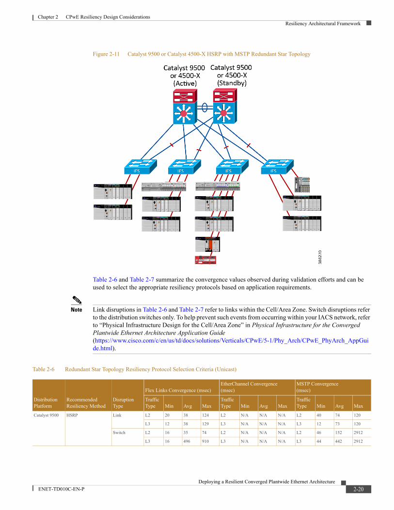
Figure 2-11 Catalyst 9500 or Catalyst 4500-X HSRP with MSTP Redundant Star Topology
Table 2-6 and Table 2-7 summarize the convergence values observed during validation efforts and can be used to select the appropriate resiliency protocols based on application requirements.
Note Link disruptions in Table 2-6 and Table 2-7 refer to links within the Cell/Area Zone. Switch disruptions refer to the distribution switches only. To help prevent such events from occurring within your IACS network, refer to “Physical Infrastructure Design for the Cell/Area Zone” in Physical Infrastructure for the Converged Plantwide Ethernet Architecture Application Guide (https://www.cisco.com/c/en/us/td/docs/solutions/Verticals/CPwE/5-1/Phy_Arch/CPwE_PhyArch_AppGuide.html).
Table 2-6 Redundant Star Topology Resiliency Protocol Selection Criteria (Unicast)
Distribution Platform
Recommended Resiliency Method
Disruption Type
Flex Links Convergence (msec)EtherChannel Convergence (msec)
MSTP Convergence(msec)
Traffic Type Min Avg Max
Traffic Type Min Avg Max
Traffic Type Min Avg Max
Catalyst 9500 HSRP Link L2 20 38 124 L2 N/A N/A N/A L2 40 74 120
L3 12 38 129 L3 N/A N/A N/A L3 12 73 120
Switch L2 16 35 74 L2 N/A N/A N/A L2 46 152 2912
L3 16 496 910 L3 N/A N/A N/A L3 44 442 2912
2-20Deploying a Resilient Converged Plantwide Ethernet Architecture
ENET-TD010C-EN-P
Chapter 2 CPwE Resiliency Design ConsiderationsResiliency Architectural Framework
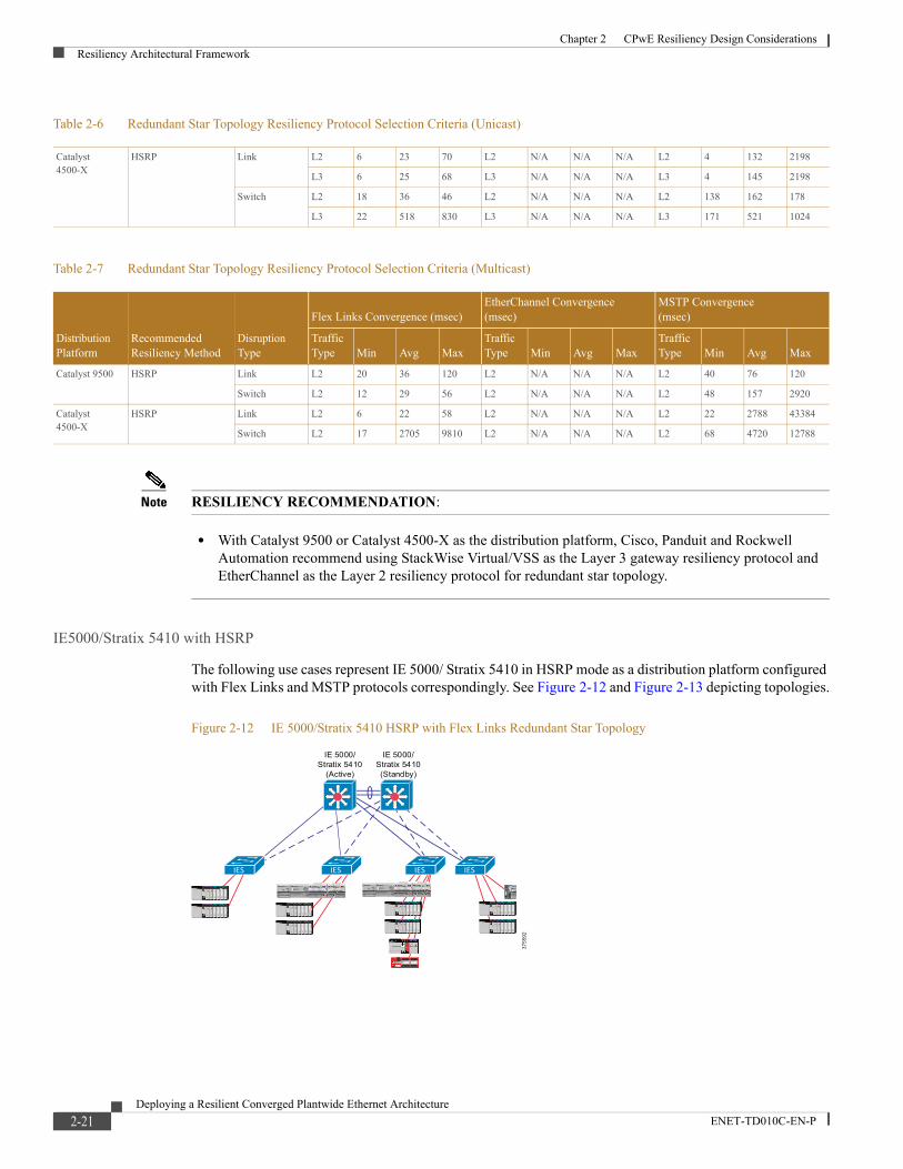
Note RESILIENCY RECOMMENDATION:
• With Catalyst 9500 or Catalyst 4500-X as the distribution platform, Cisco, Panduit and Rockwell Automation recommend using StackWise Virtual/VSS as the Layer 3 gateway resiliency protocol and EtherChannel as the Layer 2 resiliency protocol for redundant star topology.
IE5000/Stratix 5410 with HSRP
The following use cases represent IE 5000/ Stratix 5410 in HSRP mode as a distribution platform configured with Flex Links and MSTP protocols correspondingly. See Figure 2-12 and Figure 2-13 depicting topologies.
Figure 2-12 IE 5000/Stratix 5410 HSRP with Flex Links Redundant Star Topology
Catalyst 4500-X
HSRP Link L2 6 23 70 L2 N/A N/A N/A L2 4 132 2198
L3 6 25 68 L3 N/A N/A N/A L3 4 145 2198
Switch L2 18 36 46 L2 N/A N/A N/A L2 138 162 178
L3 22 518 830 L3 N/A N/A N/A L3 171 521 1024
Table 2-7 Redundant Star Topology Resiliency Protocol Selection Criteria (Multicast)
Distribution Platform
Recommended Resiliency Method
Disruption Type
Flex Links Convergence (msec)EtherChannel Convergence (msec)
MSTP Convergence(msec)
Traffic Type Min Avg Max
Traffic Type Min Avg Max
Traffic Type Min Avg Max
Catalyst 9500 HSRP Link L2 20 36 120 L2 N/A N/A N/A L2 40 76 120
Switch L2 12 29 56 L2 N/A N/A N/A L2 48 157 2920
Catalyst 4500-X
HSRP Link L2 6 22 58 L2 N/A N/A N/A L2 22 2788 43384
Switch L2 17 2705 9810 L2 N/A N/A N/A L2 68 4720 12788
Table 2-6 Redundant Star Topology Resiliency Protocol Selection Criteria (Unicast)
3755
92
IESIES
IE 5000/Stratix 5410
(Active)
IE 5000/Stratix 5410(Standby)
IESIES
2-21Deploying a Resilient Converged Plantwide Ethernet Architecture
ENET-TD010C-EN-P
Chapter 2 CPwE Resiliency Design ConsiderationsResiliency Architectural Framework
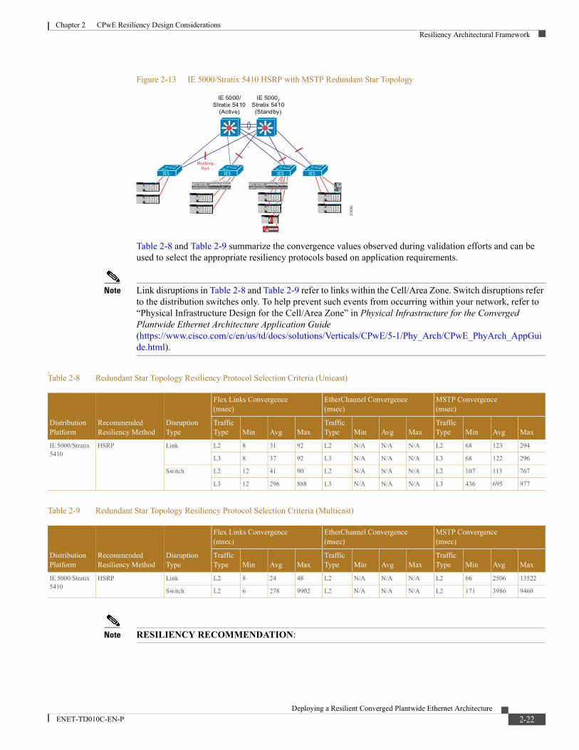
Figure 2-13 IE 5000/Stratix 5410 HSRP with MSTP Redundant Star Topology
Table 2-8 and Table 2-9 summarize the convergence values observed during validation efforts and can be used to select the appropriate resiliency protocols based on application requirements.
Note Link disruptions in Table 2-8 and Table 2-9 refer to links within the Cell/Area Zone. Switch disruptions refer to the distribution switches only. To help prevent such events from occurring within your network, refer to “Physical Infrastructure Design for the Cell/Area Zone” in Physical Infrastructure for the Converged Plantwide Ethernet Architecture Application Guide (https://www.cisco.com/c/en/us/td/docs/solutions/Verticals/CPwE/5-1/Phy_Arch/CPwE_PhyArch_AppGuide.html).
.
Note RESILIENCY RECOMMENDATION:
3755
93
BlockingPort
IESIES
IE 5000/Stratix 5410
(Active)
IE 5000/Stratix 5410(Standby)
IES IES
Table 2-8 Redundant Star Topology Resiliency Protocol Selection Criteria (Unicast)
Distribution Platform
Recommended Resiliency Method
Disruption Type
Flex Links Convergence (msec)
EtherChannel Convergence(msec)
MSTP Convergence (msec)
Traffic Type Min Avg Max
Traffic Type Min Avg Max
Traffic Type Min Avg Max
IE 5000/Stratix 5410
HSRP Link L2 8 31 92 L2 N/A N/A N/A L2 68 123 294
L3 8 37 92 L3 N/A N/A N/A L3 68 122 296
Switch L2 12 41 90 L2 N/A N/A N/A L2 107 113 767
L3 12 296 888 L3 N/A N/A N/A L3 436 695 977
Table 2-9 Redundant Star Topology Resiliency Protocol Selection Criteria (Multicast)
Distribution Platform
Recommended Resiliency Method
Disruption Type
Flex Links Convergence (msec)
EtherChannel Convergence(msec)
MSTP Convergence (msec)
Traffic Type Min Avg Max
Traffic Type Min Avg Max
Traffic Type Min Avg Max
IE 5000/Stratix 5410
HSRP Link L2 8 24 48 L2 N/A N/A N/A L2 66 2506 13522
Switch L2 6 278 9902 L2 N/A N/A N/A L2 171 3986 9460
2-22Deploying a Resilient Converged Plantwide Ethernet Architecture
ENET-TD010C-EN-P

Chapter 2 CPwE Resiliency Design ConsiderationsResiliency Architectural Framework
• With IE 5000/Stratix 5410 as the distribution platform, Cisco, Panduit and Rockwell Automation recommend using HSRP as the Layer 3 gateway resiliency protocol and Flex Links as the Layer 2 resiliency protocol.
• In this configuration, the distribution switch failure may cause high convergence time for multicast traffic and connection timeouts for IACS applications that use multicast.
Catalyst 9300 or Catalyst 3850 with StackWise-480
The following use cases represent Catalyst 9300 or Catalyst 3850 with StackWise-480 as a distribution platform configured with Flex Links, EtherChannels and MSTP protocols correspondingly. See Figure 2-14, Figure 2-15 and Figure 2-16 depicting topologies.
Figure 2-14 Catalyst 9300 or Catalyst 3850 StackWise-480 with Flex Links Redundant Star Topology
2-23Deploying a Resilient Converged Plantwide Ethernet Architecture
ENET-TD010C-EN-P
Chapter 2 CPwE Resiliency Design ConsiderationsResiliency Architectural Framework
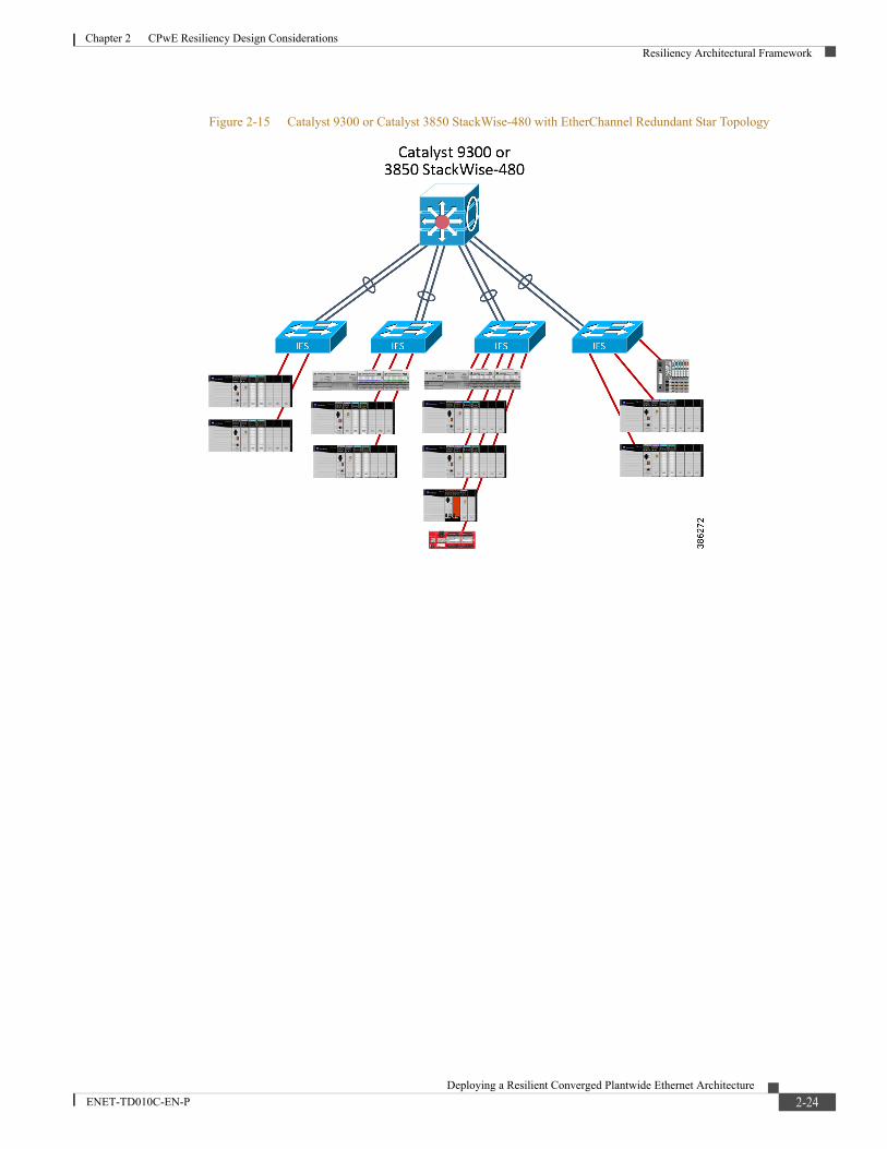
Figure 2-15 Catalyst 9300 or Catalyst 3850 StackWise-480 with EtherChannel Redundant Star Topology
2-24Deploying a Resilient Converged Plantwide Ethernet Architecture
ENET-TD010C-EN-P

Chapter 2 CPwE Resiliency Design ConsiderationsResiliency Architectural Framework
Figure 2-16 Catalyst 9300 or Catalyst 3850 StackWise-480 with MSTP Redundant Star Topology
Table 2-10 and Table 2-11 summarize the convergence values observed during validation efforts and can be used to select the appropriate resiliency protocols based on application requirements.
Note Link and switch disruption locations are defined in Table 2-10 and Table 2-11. To help prevent such events from occurring within your network, refer to “Physical Infrastructure Design for the Cell/Area Zone” in Physical Infrastructure for the Converged Plantwide Ethernet Architecture Application Guide (https://www.cisco.com/c/en/us/td/docs/solutions/Verticals/CPwE/5-1/Phy_Arch/CPwE_PhyArch_AppGuide.html).
Table 2-10 Redundant Star Topology Resiliency Protocol Selection Criteria (Unicast)
Distribution Platform
Recommended Resiliency Method
Disruption Type
Flex Links Convergence (msec)EtherChannel Convergence (msec)
MSTP Convergence(msec)
Traffic Type Min Avg Max
Traffic Type Min Avg Max
Traffic Type Min Avg Max
Catalyst 9300 StackWise-480 Link L2 10 35 92 L2 4 56 104 L2 4 414 2858
L3 10 35 94 L3 4 56 106 L3 4 427 11634
Switch L2 66 136 276 L2 18 372 1036 L2 52 140 316
L3 66 140 282 L3 18 376 1036 L3 54 141 317
Catalyst 3850 StackWise-480 Link L2 14 49 124 L2 4 62 112 L2 52 203 526
L3 14 49 124 L3 4 62 112 L3 52 205 526
Switch L2 12 48 172 L2 4 1871 7448 L2 62 2990 6382
L3 10 47 172 L3 4 1870 7449 L3 60 2989 6382
2-25Deploying a Resilient Converged Plantwide Ethernet Architecture
ENET-TD010C-EN-P

Chapter 2 CPwE Resiliency Design ConsiderationsResiliency Architectural Framework
Note RESILIENCY RECOMMENDATION:
• With Catalyst 9300 or Catalyst 3850 as the distribution platform, Cisco, Panduit, and Rockwell Automation recommend using StackWise-480 as the Layer 3 gateway resiliency protocol and Flex Links as the Layer 2 resiliency protocol.
• If EtherChannel is used as a Layer 2 resiliency protocol, distribution switch failures in the stack may cause high convergence times. The impact on IACS applications should be evaluated.
Ring Topology
Resiliency Protocols and Topology Design Options
This section describes resiliency protocol and topology options for an access ring design. Several options are available when implementing a ring topology in the access layer (see Figure 2-17):
• Single ring with single media is the simplest choice in terms of implementation. All access switches are connected in a linear fashion, with each end of the line connected to the distribution switch. Multiple VLANs can exist in the ring segment. This design can sustain a single disruption within the ring and still maintain connectivity between all switches. It is supported with all IES platforms.
• Single ring with dual media uses the same design as the previous ring, but connects each switch with an EtherChannel, rather than a single link. Therefore, a single link disruption within the ring is converged by EtherChannel, and only a disruption of both links between two switches or a switch failure triggers the underlying resiliency protocol for recovery. This design can sustain multiple disruptions throughout the ring and still maintain connectivity between all switches, if at least one link is still active in each EtherChannel connection. Since dual links between each access switch are required, and Gigabit fiber media is recommended, only access switches with four or more Gigabit fiber ports support this design; such as the IE 4000/Stratix 5400 switches.
• For multiple rings (with single or dual media), two design options exist:
– In the Layer 3 Access design, each of the rings contains two Layer 3 access switches that provide redundant gateways for routed traffic and handle Layer 2 resiliency. Routed traffic is then aggregated by the distribution switches, which provide routed connectivity to the core and handle Layer 3 resiliency. Multiple VLANs can exist in each ring segment; however, VLANs cannot be spanned across multiple rings because of the routed links in between.
Table 2-11 Redundant Star Topology Resiliency Protocol Selection Criteria (Multicast)
Distribution Platform
Recommended Resiliency Method
Disruption Type
Flex Links Convergence (msec)EtherChannel Convergence (msec)
MSTP Convergence(msec)
Traffic Type Min Avg Max
Traffic Type Min Avg Max
Traffic Type Min Avg Max
Catalyst 9300 StackWise-480 Link L2 10 34 92 L2 4 56 104 L2 4 1429 26506
Switch L2 12 31 58 L2 4 372 1036 L2 1000 5646 19658
Catalyst 3850 StackWise-480 Link
Switch
L2 14 47 112 L2 4 62 112 L2 58 3433 11460
L2 12 30 58 L2 4 1871 7448 L2 1526 25283 48124
2-26Deploying a Resilient Converged Plantwide Ethernet Architecture
ENET-TD010C-EN-P

Chapter 2 CPwE Resiliency Design ConsiderationsResiliency Architectural Framework
– In the Layer 2 Access design, each of the rings attaches to the same pair of distribution switches that participate in a Layer 2 resiliency protocol, provide routed connectivity to the core, and handle Layer 3 resiliency. Multiple VLANs can exist in each ring segment and can span across segments.
2-27Deploying a Resilient Converged Plantwide Ethernet Architecture
ENET-TD010C-EN-P

Chapter 2 CPwE Resiliency Design ConsiderationsResiliency Architectural Framework
Figure 2-17 Ring Topology Options
2-28Deploying a Resilient Converged Plantwide Ethernet Architecture
ENET-TD010C-EN-P

Chapter 2 CPwE Resiliency Design ConsiderationsResiliency Architectural Framework
Resilient Ethernet ProtocolResilient Ethernet Protocol (REP) is a technology implemented on Cisco distribution switches, Cisco IE, and Rockwell Automation Stratix IES. REP is designed to provide fast network and application convergence in a media or network failure, without a negative impact on most network applications.
REP is a segment protocol that integrates easily into existing CPwE Cell/Area Zone LANs. Although REP disables STP on interfaces where REP is enabled, it can coexist with STP as part of the same Cell/Area Zone LAN. Since REP can also notify STP about potential topology changes, it allows for interoperability between the two.
REP is a distributed and secure control plane protocol that does not rely on a primary switch controlling the status of the ring. Therefore, failures can be detected locally, either through loss of signal (LOS) or loss of connectivity to a neighboring switch. By default, REP automatically elects an alternate port (the switch port being blocked). Any REP port within the REP topology can initiate a switchover to unblock the alternate port.
REP OperationA REP segment, as shown in Figure 2-18, is a chain of switch ports connected to each other and configured with the same segment ID. Each end of a segment terminates on what is called the "edge port" of an edge switch. Each switch in a segment has exactly two REP-enabled ports.
Figure 2-18 REP Segment
With REP, to help prevent a loop in the network, one switch port (the alternate port) is always blocked in any given segment. The blocked port helps achieve loop-free traffic within the segment by requiring traffic flow to exit only one of the edge ports. Therefore, when a failure occurs in the segment, REP opens the alternate port so traffic can reach the edge of the segment. Figure 2-19 shows the basic operation of REP to converge the network when a disruption occurs.
Figure 2-19 REP Basic Operation
2-29Deploying a Resilient Converged Plantwide Ethernet Architecture
ENET-TD010C-EN-P
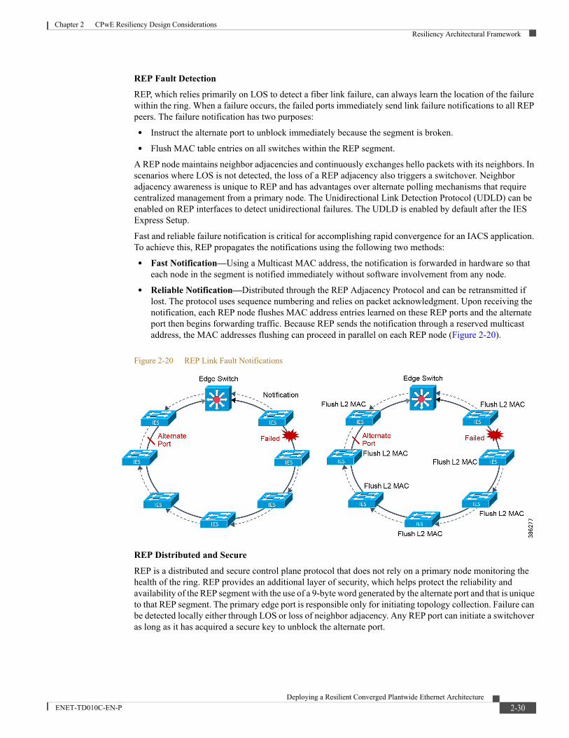
Chapter 2 CPwE Resiliency Design ConsiderationsResiliency Architectural Framework
REP Fault DetectionREP, which relies primarily on LOS to detect a fiber link failure, can always learn the location of the failure within the ring. When a failure occurs, the failed ports immediately send link failure notifications to all REP peers. The failure notification has two purposes:
• Instruct the alternate port to unblock immediately because the segment is broken.
• Flush MAC table entries on all switches within the REP segment.
A REP node maintains neighbor adjacencies and continuously exchanges hello packets with its neighbors. In scenarios where LOS is not detected, the loss of a REP adjacency also triggers a switchover. Neighbor adjacency awareness is unique to REP and has advantages over alternate polling mechanisms that require centralized management from a primary node. The Unidirectional Link Detection Protocol (UDLD) can be enabled on REP interfaces to detect unidirectional failures. The UDLD is enabled by default after the IES Express Setup.
Fast and reliable failure notification is critical for accomplishing rapid convergence for an IACS application. To achieve this, REP propagates the notifications using the following two methods:
• Fast Notification—Using a Multicast MAC address, the notification is forwarded in hardware so that each node in the segment is notified immediately without software involvement from any node.
• Reliable Notification—Distributed through the REP Adjacency Protocol and can be retransmitted if lost. The protocol uses sequence numbering and relies on packet acknowledgment. Upon receiving the notification, each REP node flushes MAC address entries learned on these REP ports and the alternate port then begins forwarding traffic. Because REP sends the notification through a reserved multicast address, the MAC addresses flushing can proceed in parallel on each REP node (Figure 2-20).
Figure 2-20 REP Link Fault Notifications
REP Distributed and SecureREP is a distributed and secure control plane protocol that does not rely on a primary node monitoring the health of the ring. REP provides an additional layer of security, which helps protect the reliability and availability of the REP segment with the use of a 9-byte word generated by the alternate port and that is unique to that REP segment. The primary edge port is responsible only for initiating topology collection. Failure can be detected locally either through LOS or loss of neighbor adjacency. Any REP port can initiate a switchover as long as it has acquired a secure key to unblock the alternate port.
2-30Deploying a Resilient Converged Plantwide Ethernet Architecture
ENET-TD010C-EN-P
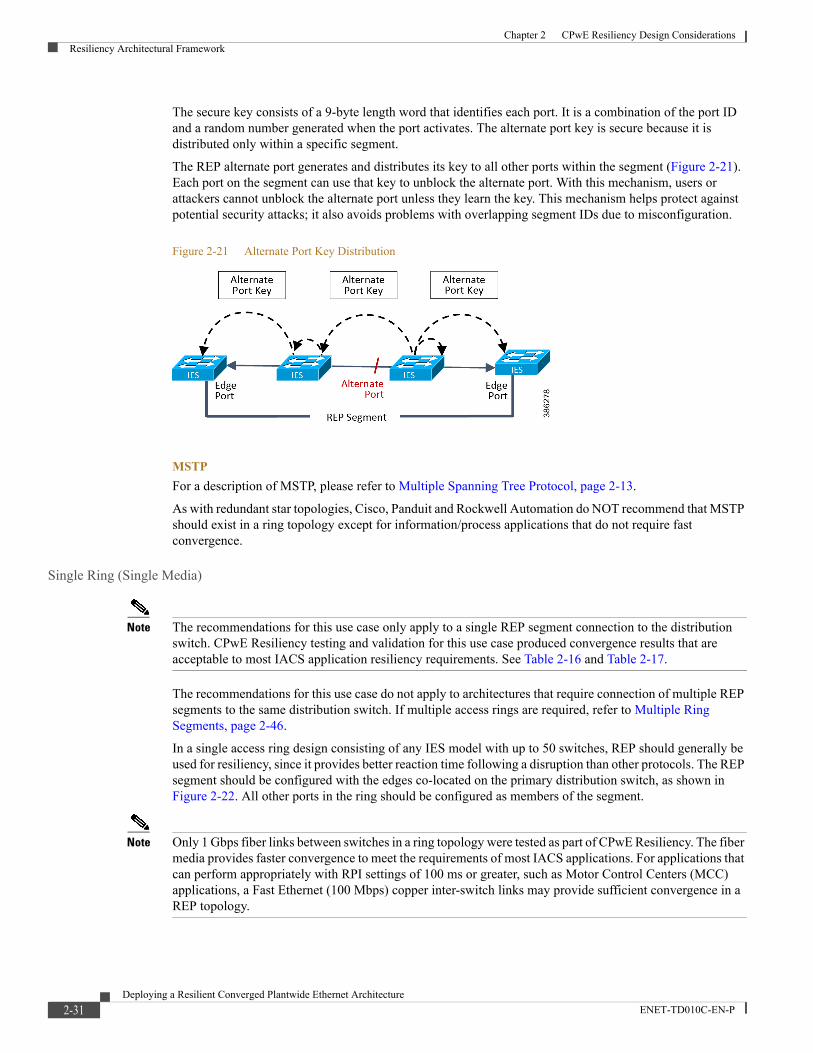
Chapter 2 CPwE Resiliency Design ConsiderationsResiliency Architectural Framework
The secure key consists of a 9-byte length word that identifies each port. It is a combination of the port ID and a random number generated when the port activates. The alternate port key is secure because it is distributed only within a specific segment.
The REP alternate port generates and distributes its key to all other ports within the segment (Figure 2-21). Each port on the segment can use that key to unblock the alternate port. With this mechanism, users or attackers cannot unblock the alternate port unless they learn the key. This mechanism helps protect against potential security attacks; it also avoids problems with overlapping segment IDs due to misconfiguration.
Figure 2-21 Alternate Port Key Distribution
MSTPFor a description of MSTP, please refer to Multiple Spanning Tree Protocol, page 2-13.
As with redundant star topologies, Cisco, Panduit and Rockwell Automation do NOT recommend that MSTP should exist in a ring topology except for information/process applications that do not require fast convergence.
Single Ring (Single Media)
Note The recommendations for this use case only apply to a single REP segment connection to the distribution switch. CPwE Resiliency testing and validation for this use case produced convergence results that are acceptable to most IACS application resiliency requirements. See Table 2-16 and Table 2-17.
The recommendations for this use case do not apply to architectures that require connection of multiple REP segments to the same distribution switch. If multiple access rings are required, refer to Multiple Ring Segments, page 2-46.
In a single access ring design consisting of any IES model with up to 50 switches, REP should generally be used for resiliency, since it provides better reaction time following a disruption than other protocols. The REP segment should be configured with the edges co-located on the primary distribution switch, as shown in Figure 2-22. All other ports in the ring should be configured as members of the segment.
Note Only 1 Gbps fiber links between switches in a ring topology were tested as part of CPwE Resiliency. The fiber media provides faster convergence to meet the requirements of most IACS applications. For applications that can perform appropriately with RPI settings of 100 ms or greater, such as Motor Control Centers (MCC) applications, a Fast Ethernet (100 Mbps) copper inter-switch links may provide sufficient convergence in a REP topology.
2-31Deploying a Resilient Converged Plantwide Ethernet Architecture
ENET-TD010C-EN-P

Chapter 2 CPwE Resiliency Design ConsiderationsResiliency Architectural Framework
• The first use case represents Catalyst 9500, Catalyst 4500-X, IE 5000/Stratix 5410, or IE 4000/Stratix 5400 as a distribution platform configured in HSRP mode with REP (Figure 2-22).
• A second use case represents Catalyst 9300 or Catalyst 3850 switches configured with StackWise-480 technology acting as the distribution switch in a REP ring topology (Figure 2-23).
Note Multiple VLANs can exist in a ring topology. Use cases have been validated for Layer 2 traffic within a VLAN and for Layer 3 traffic between VLANs in the same ring.
Figure 2-22 Catalyst 9500, Catalyst 4500-X, IE 5000/Stratix 5410, or IE 4000/Stratix 5400 HSRP with REP Ring Topology
3755
52
IES
IES
IES
IES IES
IES
IES
IES
BlockingPort
REPSegment
EdgePort
EdgePort
Distribution Switch A (Active)
Distribution Switch B
(Standby)
2-32Deploying a Resilient Converged Plantwide Ethernet Architecture
ENET-TD010C-EN-P

Chapter 2 CPwE Resiliency Design ConsiderationsResiliency Architectural Framework
Figure 2-23 Catalyst 9300 or Catalyst 3850 StackWise-480 with REP Ring Topology
Table 2-12 and Table 2-13 summarize the convergence values observed during validation efforts and can be used to select the appropriate resiliency protocols based on application requirements.
REP configuration for a single ring is as follows:
• For HSRP use cases, both primary and secondary REP edges are on the HSRP active gateway
• For StackWise-480 use cases, the primary REP edge and the secondary REP edge are on different switches in the stack
Note Link disruptions in Table 2-12 and Table 2-13 refer to links within the Cell/Area Zone. Switch disruptions refer to the distribution switches only. To help prevent such events from occurring within your network, refer to “Physical Infrastructure Design for the Cell/Area Zone” in Physical Infrastructure for the Converged Plantwide Ethernet Architecture Application Guide (https://www.cisco.com/c/en/us/td/docs/solutions/Verticals/CPwE/5-1/Phy_Arch/CPwE_PhyArch_AppGuide.html).
3779
38
Edge PortPrimary
Edge PortSecondary
BlockingPort
BlockingPort
BlockingPort
IES2
IES3
IES4IES5
IES6
IES7
IES8 IES1
3850 Stackwise
2-33Deploying a Resilient Converged Plantwide Ethernet Architecture
ENET-TD010C-EN-P

Chapter 2 CPwE Resiliency Design ConsiderationsResiliency Architectural Framework
Note Resiliency Recommendation:
Table 2-12 Single Ring (Single Media) Topology Resiliency Protocol Selection Criteria (Unicast)
Distribution Platform
Recommended Resiliency Method Disruption Type
REP Convergence (msec)Traffic Type Min Avg Max
Catalyst 9500 HSRP Link L2 L3 4 34
L3 4 34 82
Switch L2 29 194 238
L3 20 44 864
Catalyst 4500-X HSRP Link L2 4 45 112
L3 4 56 186
Switch L2 16 56 90
L3 16 461 1064
IE 5000/Stratix 5410 HSRP Link L2 8 31 68
L3 8 31 68
Switch L2 18 31 50
L3 18 430 896
IE 4000/Stratix 5400 HSRP Link L2 4 33 78
L3 4 33 78
Switch L2 16 32 40
L3 4 154 516
Catalyst 9300 StackWise-480 Link L2 18 116 314
L3 4 92 486
Switch L2 18 119 378
L3 4 154 516
Table 2-13 Single Ring (Single Media) Topology Resiliency Protocol Selection Criteria (Multicast)
Distribution Platform
Recommended Resiliency Method Disruption Type
REP Convergence (msec)Traffic Type Min Avg Max
Catalyst 9500 HSRP Link
Switch
L2 12 13 290
L2 40 185 348
Catalyst 4500-X HSRP Link
Switch
L2 8 51 220
L2 4 31 74
IE 5000/Stratix 5410 HSRP Link
Switch
L2 6 27 66
L2 14 29 48
IE 4000/Stratix 5400 HSRP Link
Switch
L2 18 29 40
L2 14 31 38
Catalyst 9300 StackWise-480 Link
Switch
L2 6 104 298
L2 16 109 350
2-34Deploying a Resilient Converged Plantwide Ethernet Architecture
ENET-TD010C-EN-P
Chapter 2 CPwE Resiliency Design ConsiderationsResiliency Architectural Framework
• With Catalyst 9500, Catalyst 4500-X, IE 5000/Stratix 5410, or IE 4000/Stratix 5400 as the distribution platform, Cisco, Panduit, and Rockwell Automation recommend using HSRP as the Layer 3 gateway resiliency protocol and REP as the Layer 2 resiliency protocol. This allows for fast convergence of the traffic within the Cell/Area Zone and failover for traffic leaving the Cell/Area Zone.
• With Catalyst 9300 in StackWise-480 mode as the distribution platform, Cisco, Panduit, and Rockwell Automation recommend using this platform in ring topologies only for applications that can tolerate maximum times as shown in the Table 2-12 and Table 2-13.
• At the time of this publication, REP is not supported with the Catalyst 9500 configured with StackWise Virtual mode.
Note For detailed results on link and switch disruptions in ring topologies with MSTP, see the “Complete Test Data” appendix of the Converged Plantwide Ethernet (CPwE) Design and Implementation Guide at the following URLs:
Rockwell Automation site:
• http://literature.rockwellautomation.com/idc/groups/literature/documents/td/enet-td001_-en-p.pdf
Cisco site:
• http://www.cisco.com/en/US/docs/solutions/Verticals/CPwE/CPwE_DIG.html
Single Ring (Dual Media)
Note These recommendations only apply to a single ring design with dual media links between switches. If multiple access rings are required, refer to the following Multiple Ring Segments section for recommendations.
If the access ring is constructed entirely from IE 4000/Stratix 5400, which has four SFP gigabit uplinks available, then an alternative to the previous design is a dual media ring. In this design, the access switches have two links between each switch that are grouped into an EtherChannel, as shown in Figure 2-24. REP is still recommended for resiliency and is configured as in the single media case. Multiple network disruption scenarios are accommodated by this design:
• Single Link Disruption—The EtherChannel itself provides the resiliency for a single link disruption, migrating traffic from the disrupted link to the remaining link automatically (see description of EtherChannel in Redundant Star Topology, page 2-11). Because each connection between switches is a separate EtherChannel, the ring is also resilient to multiple link disruptions if the two links within each EtherChannel are not both disrupted simultaneously.
• EtherChannel Disruption—While unlikely, if both links within one of the EtherChannels fail simultaneously, causing the entire EtherChannel to go down, REP (or MSTP) is responsible for recovering the network in the same way as the single media ring, providing a backup mechanism for the EtherChannel resiliency.
• Switch Disruption—Since a switch disruption (access or distribution switch) causes all links within its connected EtherChannels to be disrupted as well, REP (or MSTP) is responsible for recovering the network in the same way as the single media ring.
The following use cases have been tested with dual-media ring topology:
2-35Deploying a Resilient Converged Plantwide Ethernet Architecture
ENET-TD010C-EN-P
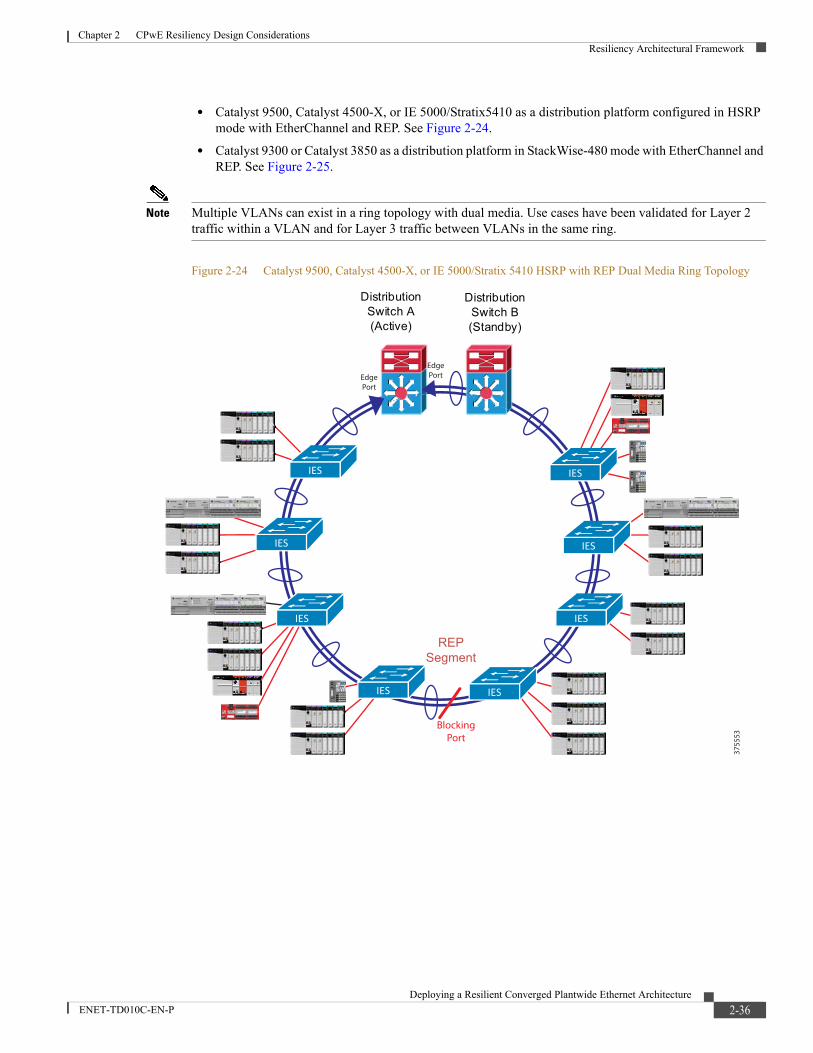
Chapter 2 CPwE Resiliency Design ConsiderationsResiliency Architectural Framework
• Catalyst 9500, Catalyst 4500-X, or IE 5000/Stratix5410 as a distribution platform configured in HSRP mode with EtherChannel and REP. See Figure 2-24.
• Catalyst 9300 or Catalyst 3850 as a distribution platform in StackWise-480 mode with EtherChannel and REP. See Figure 2-25.
Note Multiple VLANs can exist in a ring topology with dual media. Use cases have been validated for Layer 2 traffic within a VLAN and for Layer 3 traffic between VLANs in the same ring.
Figure 2-24 Catalyst 9500, Catalyst 4500-X, or IE 5000/Stratix 5410 HSRP with REP Dual Media Ring Topology
3755
53
REPSegment
IES
IES
IES
IES IES
IES
IES
IES
EdgePort
EdgePort
BlockingPort
Distribution Switch A (Active)
Distribution Switch B (Standby)
2-36Deploying a Resilient Converged Plantwide Ethernet Architecture
ENET-TD010C-EN-P
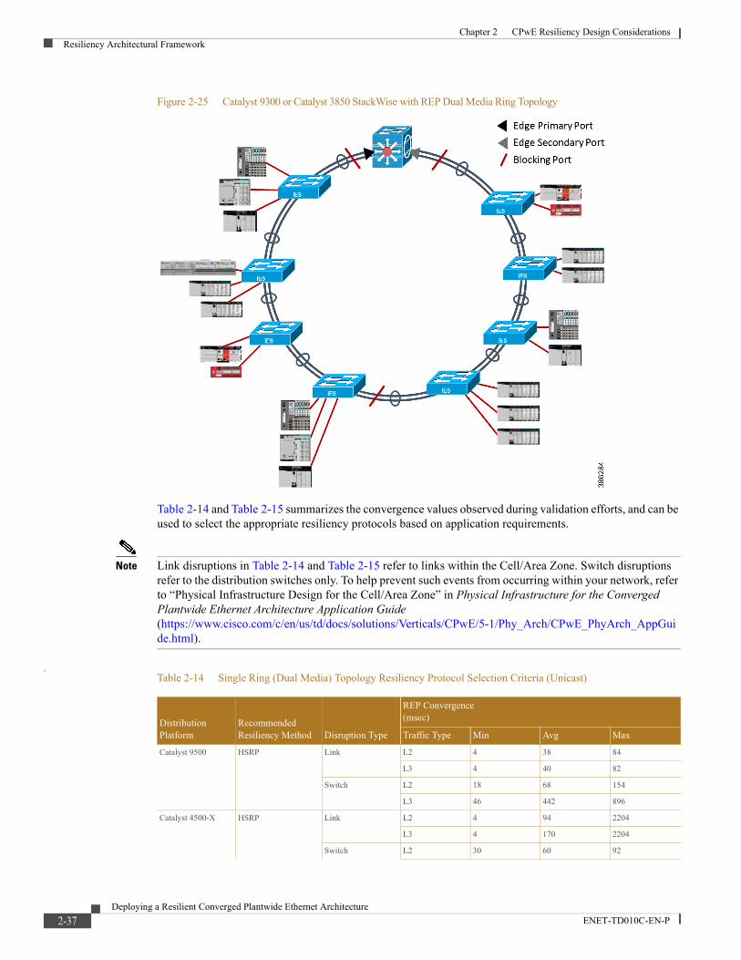
Chapter 2 CPwE Resiliency Design ConsiderationsResiliency Architectural Framework
Figure 2-25 Catalyst 9300 or Catalyst 3850 StackWise with REP Dual Media Ring Topology
Table 2-14 and Table 2-15 summarizes the convergence values observed during validation efforts, and can be used to select the appropriate resiliency protocols based on application requirements.
Note Link disruptions in Table 2-14 and Table 2-15 refer to links within the Cell/Area Zone. Switch disruptions refer to the distribution switches only. To help prevent such events from occurring within your network, refer to “Physical Infrastructure Design for the Cell/Area Zone” in Physical Infrastructure for the Converged Plantwide Ethernet Architecture Application Guide (https://www.cisco.com/c/en/us/td/docs/solutions/Verticals/CPwE/5-1/Phy_Arch/CPwE_PhyArch_AppGuide.html).
.Table 2-14 Single Ring (Dual Media) Topology Resiliency Protocol Selection Criteria (Unicast)
Distribution Platform
Recommended Resiliency Method Disruption Type
REP Convergence (msec)
Traffic Type Min Avg Max
Catalyst 9500 HSRP Link L2 4 38 84
L3 4 40 82
Switch L2 18 68 154
L3 46 442 896
Catalyst 4500-X HSRP Link L2 4 94 2204
L3 4 170 2204
Switch L2 30 60 92
2-37Deploying a Resilient Converged Plantwide Ethernet Architecture
ENET-TD010C-EN-P
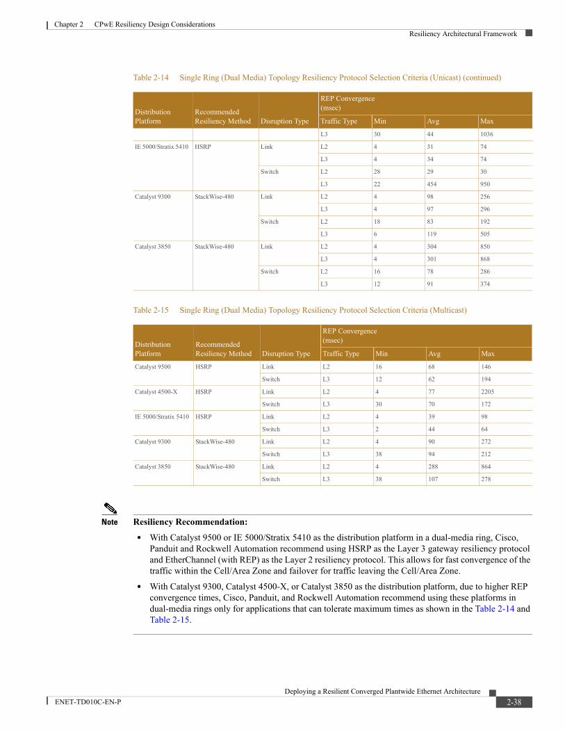
Chapter 2 CPwE Resiliency Design ConsiderationsResiliency Architectural Framework
Note Resiliency Recommendation:• With Catalyst 9500 or IE 5000/Stratix 5410 as the distribution platform in a dual-media ring, Cisco,
Panduit and Rockwell Automation recommend using HSRP as the Layer 3 gateway resiliency protocol and EtherChannel (with REP) as the Layer 2 resiliency protocol. This allows for fast convergence of the traffic within the Cell/Area Zone and failover for traffic leaving the Cell/Area Zone.
• With Catalyst 9300, Catalyst 4500-X, or Catalyst 3850 as the distribution platform, due to higher REP convergence times, Cisco, Panduit, and Rockwell Automation recommend using these platforms in dual-media rings only for applications that can tolerate maximum times as shown in the Table 2-14 and Table 2-15.
L3 30 44 1036
IE 5000/Stratix 5410 HSRP Link L2 4 31 74
L3 4 34 74
Switch L2 28 29 30
L3 22 454 950
Catalyst 9300 StackWise-480 Link L2 4 98 256
L3 4 97 296
Switch L2 18 83 192
L3 6 119 505
Catalyst 3850 StackWise-480 Link L2 4 304 850
L3 4 301 868
Switch L2 16 78 286
L3 12 91 374
Table 2-15 Single Ring (Dual Media) Topology Resiliency Protocol Selection Criteria (Multicast)
Distribution Platform
Recommended Resiliency Method Disruption Type
REP Convergence (msec)
Traffic Type Min Avg Max
Catalyst 9500 HSRP Link L2 16 68 146
Switch L3 12 62 194
Catalyst 4500-X HSRP Link L2 4 77 2205
Switch L3 30 70 172
IE 5000/Stratix 5410 HSRP Link L2 4 39 98
Switch L3 2 44 64
Catalyst 9300 StackWise-480 Link L2 4 90 272
Switch L3 38 94 212
Catalyst 3850 StackWise-480 Link L2 4 288 864
Switch L3 38 107 278
Table 2-14 Single Ring (Dual Media) Topology Resiliency Protocol Selection Criteria (Unicast) (continued)
Distribution Platform
Recommended Resiliency Method Disruption Type
REP Convergence (msec)
Traffic Type Min Avg Max
2-38Deploying a Resilient Converged Plantwide Ethernet Architecture
ENET-TD010C-EN-P
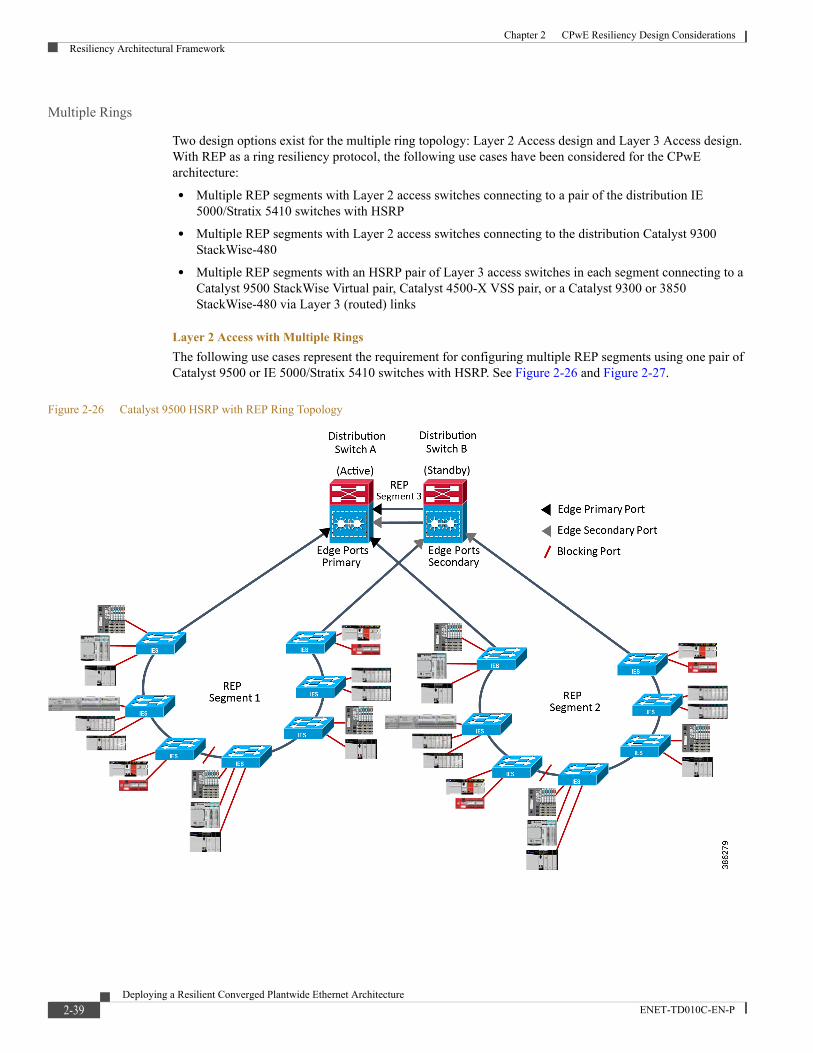
Chapter 2 CPwE Resiliency Design ConsiderationsResiliency Architectural Framework
Multiple Rings
Two design options exist for the multiple ring topology: Layer 2 Access design and Layer 3 Access design. With REP as a ring resiliency protocol, the following use cases have been considered for the CPwE architecture:
• Multiple REP segments with Layer 2 access switches connecting to a pair of the distribution IE 5000/Stratix 5410 switches with HSRP
• Multiple REP segments with Layer 2 access switches connecting to the distribution Catalyst 9300 StackWise-480
• Multiple REP segments with an HSRP pair of Layer 3 access switches in each segment connecting to a Catalyst 9500 StackWise Virtual pair, Catalyst 4500-X VSS pair, or a Catalyst 9300 or 3850 StackWise-480 via Layer 3 (routed) links
Layer 2 Access with Multiple RingsThe following use cases represent the requirement for configuring multiple REP segments using one pair of Catalyst 9500 or IE 5000/Stratix 5410 switches with HSRP. See Figure 2-26 and Figure 2-27.
Figure 2-26 Catalyst 9500 HSRP with REP Ring Topology
2-39Deploying a Resilient Converged Plantwide Ethernet Architecture
ENET-TD010C-EN-P
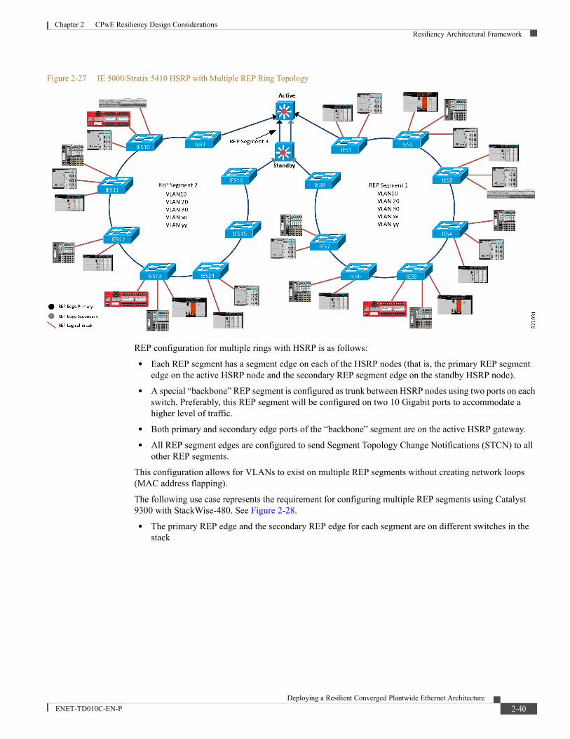
Chapter 2 CPwE Resiliency Design ConsiderationsResiliency Architectural Framework
Figure 2-27 IE 5000/Stratix 5410 HSRP with Multiple REP Ring Topology
REP configuration for multiple rings with HSRP is as follows:
• Each REP segment has a segment edge on each of the HSRP nodes (that is, the primary REP segment edge on the active HSRP node and the secondary REP segment edge on the standby HSRP node).
• A special “backbone” REP segment is configured as trunk between HSRP nodes using two ports on each switch. Preferably, this REP segment will be configured on two 10 Gigabit ports to accommodate a higher level of traffic.
• Both primary and secondary edge ports of the “backbone” segment are on the active HSRP gateway.
• All REP segment edges are configured to send Segment Topology Change Notifications (STCN) to all other REP segments.
This configuration allows for VLANs to exist on multiple REP segments without creating network loops (MAC address flapping).
The following use case represents the requirement for configuring multiple REP segments using Catalyst 9300 with StackWise-480. See Figure 2-28.
• The primary REP edge and the secondary REP edge for each segment are on different switches in the stack
2-40Deploying a Resilient Converged Plantwide Ethernet Architecture
ENET-TD010C-EN-P
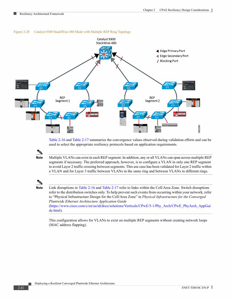
Chapter 2 CPwE Resiliency Design ConsiderationsResiliency Architectural Framework
Figure 2-28 Catalyst 9300 StackWise-480 Mode with Multiple REP Ring Topology
Table 2-16 and Table 2-17 summarize the convergence values observed during validation efforts and can be used to select the appropriate resiliency protocols based on application requirements.
Note Multiple VLANs can exist in each REP segment. In addition, any or all VLANs can span across multiple REP segments if necessary. The preferred approach, however, is to configure a VLAN in only one REP segment to avoid Layer 2 traffic crossing between segments. This use case has been validated for Layer 2 traffic within a VLAN and for Layer 3 traffic between VLANs in the same ring and between VLANs in different rings.
Note Link disruptions in Table 2-16 and Table 2-17 refer to links within the Cell/Area Zone. Switch disruptions refer to the distribution switches only. To help prevent such events from occurring within your network, refer to “Physical Infrastructure Design for the Cell/Area Zone” in Physical Infrastructure for the Converged Plantwide Ethernet Architecture Application Guide (https://www.cisco.com/c/en/us/td/docs/solutions/Verticals/CPwE/5-1/Phy_Arch/CPwE_PhyArch_AppGuide.html).
This configuration allows for VLANs to exist on multiple REP segments without creating network loops (MAC address flapping).
2-41Deploying a Resilient Converged Plantwide Ethernet Architecture
ENET-TD010C-EN-P
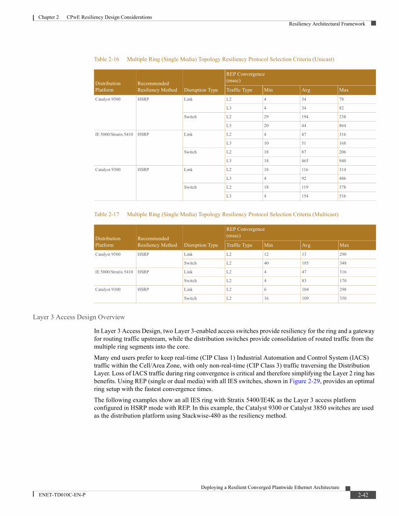
Chapter 2 CPwE Resiliency Design ConsiderationsResiliency Architectural Framework
Layer 3 Access Design Overview
In Layer 3 Access Design, two Layer 3-enabled access switches provide resiliency for the ring and a gateway for routing traffic upstream, while the distribution switches provide consolidation of routed traffic from the multiple ring segments into the core.
Many end users prefer to keep real-time (CIP Class 1) Industrial Automation and Control System (IACS) traffic within the Cell/Area Zone, with only non-real-time (CIP Class 3) traffic traversing the Distribution Layer. Loss of IACS traffic during ring convergence is critical and therefore simplifying the Layer 2 ring has benefits. Using REP (single or dual media) with all IES switches, shown in Figure 2-29, provides an optimal ring setup with the fastest convergence times.
The following examples show an all IES ring with Stratix 5400/IE4K as the Layer 3 access platform configured in HSRP mode with REP. In this example, the Catalyst 9300 or Catalyst 3850 switches are used as the distribution platform using Stackwise-480 as the resiliency method.
Table 2-16 Multiple Ring (Single Media) Topology Resiliency Protocol Selection Criteria (Unicast)
Distribution Platform
Recommended Resiliency Method Disruption Type
REP Convergence (msec)
Traffic Type Min Avg Max
Catalyst 9500 HSRP Link L2 4 34 78
L3 4 34 82
Switch L2 29 194 238
L3 20 44 864
IE 5000/Stratix 5410 HSRP Link L2 4 47 316
L3 10 51 168
Switch L2 18 87 206
L3 18 465 940
Catalyst 9300 HSRP Link L2 18 116 314
L3 4 92 486
Switch L2 18 119 378
L3 4 154 516
Table 2-17 Multiple Ring (Single Media) Topology Resiliency Protocol Selection Criteria (Multicast)
Distribution Platform
Recommended Resiliency Method Disruption Type
REP Convergence(msec)
Traffic Type Min Avg Max
Catalyst 9500 HSRP Link L2 12 13 290
Switch L2 40 185 348
IE 5000/Stratix 5410 HSRP Link L2 4 47 316
Switch L2 4 83 170
Catalyst 9300 HSRP Link L2 6 104 298
Switch L2 16 109 350
2-42Deploying a Resilient Converged Plantwide Ethernet Architecture
ENET-TD010C-EN-P
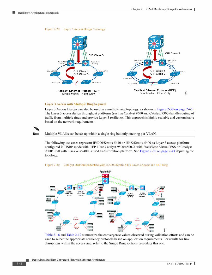
Chapter 2 CPwE Resiliency Design ConsiderationsResiliency Architectural Framework
Figure 2-29 Layer 3 Access Design Topology
Layer 3 Access with Multiple Ring SegmentLayer 3 Access Design can also be used in a multiple ring topology, as shown in Figure 2-30 on page 2-45. The Layer 3 access design throughput platforms (such as Catalyst 9500 and Catalyst 9300) handle routing of traffic from multiple rings and provide Layer 3 resiliency. This approach is highly scalable and customizable based on the network requirements.
Note Multiple VLANs can be set up within a single ring but only one ring per VLAN.
The following use cases represent IE5000/Stratix 5410 or IE4K/Stratix 5400 as Layer 3 access platform configured in HSRP mode with REP. Here Catalyst 9500/4500-X with StackWise Virtual/VSS or Catalyst 9300/3850 with StackWise-480 is used as distribution platform. See Figure 2-30 on page 2-43 depicting the topology.
Figure 2-30 Catalyst Distribution Switches with IE 5000/Stratix 5410 Layer 3 Access and REP Ring
Table 2-18 and Table 2-19 summarize the convergence values observed during validation efforts and can be used to select the appropriate resiliency protocols based on application requirements. For results for link disruptions within the access ring, refer to the Single Ring sections preceding this one.
2-43Deploying a Resilient Converged Plantwide Ethernet Architecture
ENET-TD010C-EN-P
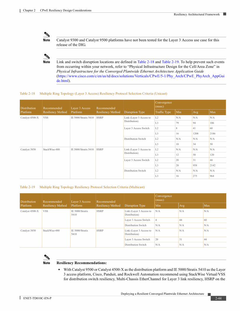
Chapter 2 CPwE Resiliency Design ConsiderationsResiliency Architectural Framework
Note Catalyst 9300 and Catalyst 9500 platforms have not been tested for the Layer 3 Access use case for this release of the DIG.
Note Link and switch disruption locations are defined in Table 2-18 and Table 2-19. To help prevent such events from occurring within your network, refer to “Physical Infrastructure Design for the Cell/Area Zone” in Physical Infrastructure for the Converged Plantwide Ethernet Architecture Application Guide (https://www.cisco.com/c/en/us/td/docs/solutions/Verticals/CPwE/5-1/Phy_Arch/CPwE_PhyArch_AppGuide.html).
Note Resiliency Recommendations:• With Catalyst 9500 or Catalyst 4500-X as the distribution platform and IE 5000/Stratix 5410 as the Layer
3 access platform, Cisco, Panduit, and Rockwell Automation recommend using StackWise Virtual/VSS for distribution switch resiliency, Multi-Chassis EtherChannel for Layer 3 link resiliency, HSRP on the
Table 2-18 Multiple Ring Topology (Layer 3 Access) Resiliency Protocol Selection Criteria (Unicast)
Distribution Platform
Recommended Resiliency Method
Layer 3 Access Platform
Recommended Resiliency Method Disruption Type
Convergence (msec)
Traffic Type Min Avg Max
Catalyst 4500-X VSS IE 5000/Stratix 5410 HSRP Link (Layer 3 Access to Distribution)
L2 N/A N/A N/A
L3 79 94 106
Layer 3 Access Switch L2 8 41 60
L3 16 1208 2186
Distribution Switch L2 N/A N/A N/A
L3 18 34 50
Catalyst 3850 StackWise-480 IE 5000/Stratix 5410 HSRP Link (Layer 3 Access to Distribution)
L2 N/A N/A N/A
L3 12 50 120
Layer 3 Access Switch L2 20 31 44
L3 20 958 2142
Distribution Switch L2 N/A N/A N/A
L3 16 275 964
Table 2-19 Multiple Ring Topology Resiliency Protocol Selection Criteria (Multicast)
Distribution Platform
Recommended Resiliency Method
Layer 3 Access Platform
Recommended Resiliency Method Disruption Type
Convergence (msec)
Min Avg Max
Catalyst 4500-X VSS IE 5000/Stratix 5410
HSRP Link (Layer 3 Access to Distribution)
N/A N/A N/A
Layer 3 Access Switch 4 44 60
Distribution Switch N/A N/A N/A
Catalyst 3850 StackWise-480 IE 5000/Stratix 5410
HSRP Link (Layer 3 Access to Distribution)
N/A N/A N/A
Layer 3 Access Switch 20 31 44
Distribution Switch N/A N/A N/A
2-44Deploying a Resilient Converged Plantwide Ethernet Architecture
ENET-TD010C-EN-P
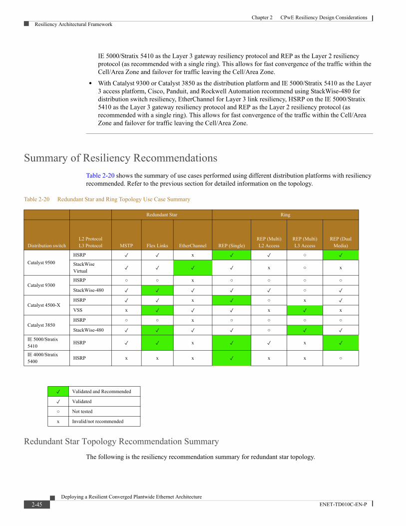
Chapter 2 CPwE Resiliency Design ConsiderationsResiliency Architectural Framework
IE 5000/Stratix 5410 as the Layer 3 gateway resiliency protocol and REP as the Layer 2 resiliency protocol (as recommended with a single ring). This allows for fast convergence of the traffic within the Cell/Area Zone and failover for traffic leaving the Cell/Area Zone.
• With Catalyst 9300 or Catalyst 3850 as the distribution platform and IE 5000/Stratix 5410 as the Layer 3 access platform, Cisco, Panduit, and Rockwell Automation recommend using StackWise-480 for distribution switch resiliency, EtherChannel for Layer 3 link resiliency, HSRP on the IE 5000/Stratix 5410 as the Layer 3 gateway resiliency protocol and REP as the Layer 2 resiliency protocol (as recommended with a single ring). This allows for fast convergence of the traffic within the Cell/Area Zone and failover for traffic leaving the Cell/Area Zone.
Summary of Resiliency RecommendationsTable 2-20 shows the summary of use cases performed using different distribution platforms with resiliency recommended. Refer to the previous section for detailed information on the topology.
Redundant Star Topology Recommendation SummaryThe following is the resiliency recommendation summary for redundant star topology.
Table 2-20 Redundant Star and Ring Topology Use Case Summary
Redundant Star Ring
Distribution switchL2 ProtocolL3 Protocol MSTP Flex Links EtherChannel REP (Single)
REP (Multi) L2 Access
REP (Multi) L3 Access
REP (Dual Media)
Catalyst 9500HSRP ✓ ✓ x ✓ ✓ ○ ✓StackWise Virtual ✓ ✓ ✓ ✓ x ○ x
Catalyst 9300HSRP ○ ○ x ○ ○ ○ ○
StackWise-480 ✓ ✓ ✓ ✓ ✓ ○ ✓
Catalyst 4500-XHSRP ✓ ✓ x ✓ ○ x ✓VSS x ✓ ✓ ✓ x ✓ x
Catalyst 3850HSRP ○ ○ x ○ ○ ○ ○
StackWise-480 ✓ ✓ ✓ ✓ ○ ✓ ✓IE 5000/Stratix 5410
HSRP ✓ ✓ x ✓ ✓ x ✓IE 4000/Stratix 5400
HSRP x x x ✓ x x ○
✓ Validated and Recommended
✓ Validated
○ Not tested
x Invalid/not recommended
2-45Deploying a Resilient Converged Plantwide Ethernet Architecture
ENET-TD010C-EN-P

Chapter 2 CPwE Resiliency Design ConsiderationsResiliency Architectural Framework
Catalyst 9500 with StackWise-Virtual
With Catalyst 9500 as the distribution platform, Cisco, Panduit, and Rockwell Automation recommend using StackWise Virtual as the Layer 3 gateway resiliency protocol and EtherChannel as the Layer 2 resiliency protocol for redundant star topology. See Figure 2-8.
IE 5000/Stratix 5410 with HSRP
With IE 5000/Stratix 5410 as the distribution platform, Cisco, Panduit, and Rockwell Automation recommend using HSRP as the Layer 3 gateway resiliency protocol and Flex Links as the Layer 2 resiliency protocol. See Figure 2-12.
Catalyst 9300 with StackWise-480
With Catalyst 9300 as the distribution platform, Cisco, Panduit, and Rockwell Automation recommend using StackWise-480 as the Layer 3 gateway resiliency protocol and Flex Links as the Layer 2 resiliency protocol. See Figure 2-14.
Ring Topology Recommendation SummaryThe following is the resiliency recommendation summary for ring topology.
Single Ring (Single Media)
With Catalyst 9500, IE 5000/Stratix 5410, or IE 4000/Stratix 5400 as the distribution platform, Cisco, Panduit, and Rockwell Automation recommend using HSRP as the Layer 3 gateway resiliency protocol and REP as the Layer 2 resiliency protocol. See Figure 2-22.
Single Ring (Dual Media)
With Catalyst 9500, IE 5000/Stratix 5410, or IE 4000/Stratix 5400 as the distribution platform, Cisco, Panduit, and Rockwell Automation recommend using HSRP as the Layer 3 gateway resiliency protocol and EtherChannel (with REP) as the Layer 2 resiliency protocol. See Figure 2-23.
Multiple Ring Segments
With Catalyst 9500 as the distribution platform and IE 5000/Stratix 5410 or IE4000/Stratix 5400 as the Layer 3 access platform, Cisco, Panduit and Rockwell Automation recommend using StackWise Virtual on the Catalyst 9500 for distribution switch resiliency, Multi-Chassis EtherChannel for Layer 3 link resiliency, HSRP on the IE 5000/Stratix 5410 as the Layer 3 gateway resiliency protocol and REP as the Layer 2 resiliency protocol (as recommended with a single ring). See Figure 2-30.
With Catalyst 9300 as the distribution platform and IE 5000/Stratix 5410 or IE4000/Stratix 5400 as the Layer 3 access platform, Cisco, Panduit and Rockwell Automation recommend using StackWise-480 on the Catalyst 9300 for distribution switch resiliency, EtherChannel for Layer 3 link resiliency, HSRP on the IE 5000/Stratix 5410 as the Layer 3 gateway resiliency protocol and REP as the Layer 2 resiliency protocol (as recommended with a single ring). See Figure 2-30.
2-46Deploying a Resilient Converged Plantwide Ethernet Architecture
ENET-TD010C-EN-P
Deploying a Resilient ConENET-TD010C-EN-P
C H A P T E R 3
CPwE Resiliency ConfigurationThis chapter describes how to configure resiliency in the CPwE architecture based on the design considerations and recommendations of the previous chapters. It covers the configuration of the Industrial and Cell/Area Zone switches. The included configurations have been validated during the testing effort.
This chapter includes the following major topics:
• Industrial Zone, page 3-1
• Cell/Area Zone, page 3-5
Industrial Zone
Distribution Switching
Catalyst 9500 StackWise Virtual ConfigurationBy default, the Catalyst 9500 switch is configured to operate in standalone mode (the switch works independently). StackWise Virtual combines two standalone switches into one virtual switch, operating in virtual switch mode.
Note The LAN Base license does not support StackWise Virtual. You must upgrade to IP Base or higher to support this feature.
StackWise Virtual is configured and activated as shown in the following sections.
Note For more information on StackWise Virtual configuration, see the High Availability Configuration Guide, Cisco IOS XE Fuji 16.9.x (Catalyst 9500 Switches) at the following URL:https://www.cisco.com/c/en/us/td/docs/switches/lan/catalyst9500/software/release/16-9/configuration_guide/ha/b_169_ha_9500_cg/configuring_cisco_stackwise_virtual.html
3-1verged Plantwide Ethernet Architecture

Chapter 3 CPwE Resiliency ConfigurationIndustrial Zone
Prerequisites for Cisco StackWise Virtual• All switches in a Cisco StackWise Virtual solution must be of the same switch model.
• All switches in a Cisco StackWise Virtual solution must be running the same license level.
• All switches in a Cisco StackWise Virtual solution must be running the same software version.
Assigning Virtual Switch Domain and Switch Numbers
The same virtual switch domain number must be configured on both switches of the StackWise Virtual stack. The virtual switch domain is a number between 1 and 255. The following is the virtual switch domain configuration for each switch:
Enter the commands for both switches (9500-A and 9500-B).
Define the Domain:9500-A#conf t9500-A(config)#stackwise-virtual9500-A(config-stackwise-virtual)#domain 10 9500-A(config-stackwise-virtual)#exit
Define the Virtual link:9500-A(config)#int HundredGigE1/0/499500-A(config-if)#stackwise-virtual link 19500-A(config)#int HundredGigE1/0/519500-A(config-if)#stackwise-virtual link 19500-A(config-if)#exit9500-A(config)#reload
Define the Dual-active-detection link:
Configuring StackWise Virtual Fast Hello Dual-Active-Detection Link9500-A(config)#int TwentyFiveGigE1/0/489500-A(config-if)#stackwise-virtual dual-active-detection9500-A(config-if)#exit9500A(config)#reload
Dual-Active DetectionIf the standby switch detects a complete loss of the StackWise Virtual link, it assumes that the active switch has failed and will take over as the active switch. However, if the original Cisco StackWise Virtual active switch is still operational, both the switches will now be Cisco StackWise Virtual active switches. This situation is called a dual-active scenario. This scenario can have adverse effects on network stability because both the switches use the same IP addresses, SSH keys, and STP bridge IDs. Cisco StackWise Virtual detects a dual-active scenario and takes recovery action. The dual-active-detection link is the dedicated link used to mitigate this.
If a StackWise Virtual link fails, the Cisco StackWise Virtual standby switch cannot determine the state of the Cisco StackWise Virtual active switch. To confirm that switchover occurs without delay, the Cisco StackWise Virtual standby switch assumes that the Cisco StackWise Virtual active switch has failed and initiates switchover to take over the Cisco StackWise Virtual active role. The original Cisco StackWise Virtual active switch enters recovery mode and brings down all the interfaces except the StackWise Virtual link and the management interfaces.
3-2Deploying a Resilient Converged Plantwide Ethernet Architecture
ENET-TD010C-EN-P
Chapter 3 CPwE Resiliency ConfigurationIndustrial Zone
Dual-Active-Detection Link with Fast Hello
To use the dual-active fast hello packet detection method, you must provision a direct Ethernet connection between the two Cisco StackWise Virtual switches. You can dedicate up to four links for this purpose.
The two switches periodically exchange special dual-active hello messages containing information about the switch state. If all SVLs fail and a dual-active scenario occurs, each switch recognizes that there is a dual-active scenario from the peer's messages. This initiates recovery actions as described in the Recovery Actions section. If a switch does not receive an expected dual-active fast hello message from the peer before the timer expires, the switch assumes that the link is no longer capable of dual-active detection.
Dual-Active Detection with enhanced PAgP
Port aggregation protocol (PAgP) is a Cisco proprietary protocol used for managing EtherChannels. If a StackWise Virtual MEC terminates on a Cisco switch, you can run PAgP protocol on the MEC. If PAgP is running on the MECs between the StackWise Virtual switch and an upstream or downstream switch, StackWise Virtual can use PAgP to detect a dual-active scenario. The MEC must have at least one port on each switch of the StackWise Virtual setup.
Enhanced PAgP is an extension of the PAgP protocol. In virtual switch mode, ePAgP messages include a new type length value (TLV) which contains the ID of the StackWise Virtual active switch. Only switches in virtual switch mode send the new TLV.
When the StackWise Virtual standby switch detects SVL failure, it initiates SSO and becomes StackWise Virtual active. Subsequent ePAgP messages sent to the connected switch from the newly StackWise Virtual active switch contain the new StackWise Virtual active ID. The connected switch sends ePAgP messages with the new StackWise Virtual active ID to both StackWise Virtual switches.
If the formerly StackWise Virtual active switch is still operational, it detects the dual-active scenario because the StackWise Virtual active ID in the ePAgP messages changes.
Catalyst 9300 StackWise-480 ConfigurationThe active switch has the saved and running configuration file for the switch stack. The standby switch automatically receives the synchronized running configuration file. Stack members receive synchronized copies when the running configuration file is saved into the startup configuration file. If the active switch becomes unavailable, the standby switch takes over with the current running configuration.
Once a stacked switch configuration comes up and elects active and standby switches within the stack, some additional configuration is required to assure stability if there are disruptions within the stack.
Stack Member Priority
By default, all switches within the stack have a priority of 1 (configurable up to 15). The desired active switch should be configured with a higher priority than other switches in the stack to help prevent changes whenever a re-election occurs.
Note The re-election process only occurs following a reset of the entire switch stack. If Switch 1 (active) is disrupted and Switch 2 (standby) becomes active, Switch 1 will rejoin the stack as the standby and will not preempt Switch 2 from being active.
Switch priority is set using the following command (in EXEC mode):switch 1 priority 15
3-3Deploying a Resilient Converged Plantwide Ethernet Architecture
ENET-TD010C-EN-P

Chapter 3 CPwE Resiliency ConfigurationIndustrial Zone
Stack MAC Address PersistenceA stacked switch configuration uses a single MAC address for its bridge ID and router MAC. By default, if the active switch in a stack is disrupted, the MAC address of the standby switch replaces the old one once it becomes active. This can result in traffic disruptions since a new MAC address must be learned within the network. To avoid this situation, use the following command to help prevent the stack MAC address from changing when new switches become active:
stack-mac persistent timer 0
Stack Member RenumberingThe stack member number (1 to 9) identifies each member in the switch stack. The member number also determines the interface-level configuration that a stack member uses. A new, out-of-the-box switch (one that has not joined a switch stack or has not been manually assigned a stack member number) ships with a default stack member number of 1. When it joins a switch stack, its default stack member number changes to the lowest available member number in the stack.
Stack members in the same switch stack cannot have the same stack member number. Every stack member, including a standalone switch, retains its member number until you manually change the number or unless the number is already being used by another member in the stack.
Switches that are removed from one stack and put into another might have non-contiguous numbering because of the preceding behavior mentioned. If desired, the following command manually configures a stack member with a new number (the change will only take effect once that switch is reloaded):
switch <CURRENT VALUE> renumber <NEW VALUE>
Note For more information on the Catalyst 9300 StackWise-480 configuration, see Stack Manager and High Availability Configuration Guide, Cisco IOS XE Fuji 16.9.x (Catalyst 9300 Switches) at the following URL:https://www.cisco.com/c/en/us/td/docs/switches/lan/catalyst9300/software/release/16-9/configuration_guide/stck_mgr_ha/b_169_stck_mgr_ha_9300_cg/managing_switch_stacks.html
Hot Standby Routing Protocol ConfigurationHot Standby Routing Protocol (HSRP) is enabled and configured on the SVI of each distribution switch. The following sections describe how to configure HSRP features.
Note HSRP may be configured on Catalyst 9500, Catalyst 4500-X, IE 5000/Stratix 5410, and IE 4000/Stratix 5400. HSRP can only be configured via the switch CLI, not via the Device Manager web interface.
Virtual IP AddressHSRP is enabled by configuring an instance, specified by an ID value, and the virtual IP that will be shared between the HSRP peers. Generally, the primary HSRP peer should be configured with the lower physical IP address so that it will win elections for protocols that do not rely on the virtual IP, such as IGMP. In addition, the primary HSRP peer should also be the STP root switch (for reasons discussed earlier in this document). The following is a typical configuration for the HSRP primary peer, though different IP addresses may be used if desired:
interface Vlan10 ip address 10.17.10.2 255.255.255.0 standby 1 ip 10.17.10.1
The following is a typical configuration for the HSRP standby peer:interface Vlan10
3-4Deploying a Resilient Converged Plantwide Ethernet Architecture
ENET-TD010C-EN-P
Chapter 3 CPwE Resiliency ConfigurationCell/Area Zone
ip address 10.17.10.3 255.255.255.0 standby 1 ip 10.17.10.1
PriorityPriority is used to determine which HSRP peer should be active during initial setup (and if preemption is enabled). By default, HSRP peers have a priority of 100. The desired active peer should be configured with a higher priority (max 254) so that it consistently wins the election. HSRP priority is configured as follows:
standby 1 priority 254
HSRP TimersHSRP relies on two timers: hello interval refers to the frequency that hello packets are sent to the other peer, and hold time refers to the amount of time to wait before declaring the other peer down. The hold time should be configured to be greater than or equal to three times the hello interval to help prevent unnecessary flapping between the peers. Cisco, Panduit and Rockwell Automation recommend configuring the following timer values on both HSRP peers to balance network stability with sub-second convergence:
standby 1 timers msec 200 msec 750
Startup DelayThe HSRP process itself must be delayed on startup to help prevent a new HSRP peer from assuming too quickly that it is the only peer in the network and taking on the active role. The following command specifies the minimum delay after HSRP is enabled before it attempts to establish a peer relationship and a longer delay following a reload:
standby delay minimum 30 reload 60
Cell/Area Zone
Access Layer Switching
Redundant Star Topology
Flex Links
Flex Links are simple to configure. On the active interface, the backup interface is specified using a single command, with multicast fast convergence enabled to allow consistent convergence results for all types of network traffic. The feature is enabled using the following command on the access switch (CLI only):
interface GigabitEthernet1/1 switchport backup interface Gi1/2 multicast fast-convergence
Note If STP is enabled on the distribution switches connected to the access switch running Flex Links, a switch disruption could cause STP to converge, resulting in traffic loss for up to 30 seconds to transition the port through the listening and learning states before forwarding traffic. To help prevent this loss and allow the port to immediately forward traffic after a convergence event, enable the following command on the downlinks facing the access switch: spanning-tree portfast edge trunk.
3-5Deploying a Resilient Converged Plantwide Ethernet Architecture
ENET-TD010C-EN-P

Chapter 3 CPwE Resiliency ConfigurationCell/Area Zone
EtherChannel
To configure an EtherChannel using LACP in active mode between the access and distribution switches, configure a port-channel interface on each switch, and then configure the links as members of the port-channel. This configuration is performed using the following commands:
interface Port-channel2!interface GigabitEthernet1/0/3 channel-group 2 mode activeinterface GigabitEthernet2/0/3 channel-group 2 mode active
Ring Topology
Resilient Ethernet Protocol
This section describes the basic configurations necessary to implement REP in a single or multiple ring topology in a Cell/Area Zone. It is assumed that Express Setup and other Smart Port macro configurations for IES have already been applied, so the details of those configurations are not covered in this document (refer to the IES user manuals for these details). This section covers the following topics:
• General REP recommendations
• Native VLAN implementation for REP control messages.
• REP administrative VLAN implementation for fast failure notifications.
• REP segment and edge configuration.
The general considerations for configuring REP are:
• First configure the edge port in the REP segment, and then configure the contiguous ports in the segment.
• REP and STP or REP and Flex Links cannot be enabled on the same IES port.
• All trunk ports in the segment must be configured with the same set of allowed VLANs.
• Be careful when configuring REP through a switch management connection (for example, SSH or webpage). Because REP blocks all VLANs until another REP interface sends a message to unblock it, you might lose connectivity to the switch if you enable REP in a management session that accesses the switch through the same interface. As an alternative, you may use a direct Ethernet connection to IES or a serial console connection.
• REP is supported on EtherChannels, but not on an individual port that belongs to an EtherChannel. In a dual-media ring topology, REP must be configured on a logical EtherChannel interface (PortChannel).
Native VLAN ImplementationREP uses the native VLAN configured on the trunk interfaces of a network segment to establish and maintain connectivity across the segment, as well as reliably informing all nodes of any topology changes using Link Status Layer (LSL) frames. This behavior is like other Layer 2 control plane protocols such as Cisco Discovery Protocol (CDP) and VLAN Trunking Protocol (VTP).
Best practices for configuring the native VLAN on the trunk interfaces include the following:
• The native VLAN on a trunk is 1 by default. For security purposes, select another VLAN as the native VLAN.
• When selecting the native VLAN, use a VLAN that is separate from the one carrying IACS traffic as the best practice.
3-6Deploying a Resilient Converged Plantwide Ethernet Architecture
ENET-TD010C-EN-P
Chapter 3 CPwE Resiliency ConfigurationCell/Area Zone
• When pruning unused VLANs from the trunk, be sure to include the native VLAN (along with the IACS VLAN) as allowed.
If the native VLAN has not already been configured on the uplink ports using a Smart Port macro (Device Manager or CLI), it can be configured using the following command in interface configuration mode:
switchport trunk native vlan <VALUE>
In addition, confirm that the VLAN has been added to the global database using the following commands in global configuration mode:
vlan <VALUE>name Native_VLAN
Admin VLAN for REPIn addition to the reliable notifications sent on the native VLAN after a topology change, REP also uses Hardware Flood Layer (HFL) notifications that are immediately sent out as multicast frames by the switch hardware. Because these frames are hardware switched by each device in the path, rather than relayed hop-by-hop, they can be received across the segment quickly. This behavior allows REP to converge quickly following a failure and limit IACS device timeouts for many applications.
A REP administrative VLAN is configured globally on each switch within a segment to control the VLAN onto which the HFL frames are forwarded. In addition, since HFL frames are flooded as data traffic only on ports belonging to that VLAN, the scope of this traffic can be confined to the Cell/Area Zone LAN. Best practices for configuring the REP administrative VLAN include the following:
• As with the native VLAN, for security purposes change the REP administrative VLAN (via CLI or Device Manager) to another value from its default of 1. Similarly, do not choose the VLAN carrying IACS traffic.
• Be sure to include the administrative VLAN as allowed when pruning unused VLANs from the trunk.
Note If the administrative VLAN is not allowed across the entire REP ring, both within and outside the segment, the HFL frames will be dropped and network convergence will be dependent on the slower LSL mechanism. While LSL frames are considered control traffic and are therefore relayed across the trunk regardless of pruning, HFL frames are considered data traffic and must be explicitly allowed across the trunk.
• Since the administrative VLAN has similar constraints to the native VLAN, it makes sense to assign the two as the same VLAN. In addition, most Cell/Area Zones will be separated by Layer 3 (distribution switch) domains, so constraining the HFL flooding does not need to be a significant consideration.
To configure the REP administrative VLAN, use the following command in global configuration mode:rep admin vlan <VALUE>
In addition, confirm that the VLAN has been added to the global database using the following commands in global configuration mode:
vlan <VALUE>name REP_Admin_VLAN
REP Edge ConfigurationREP is configured on both IES and distribution switches simply by enabling it on each interface that will be part of the segment and including a segment ID to identify to which segment the port belongs. Primary and secondary edge ports are configured at each end of the segment. The purpose of the primary edge port is to initiate topology discovery and communicate special configurations for the segment. The secondary edge port has no special function beyond terminating the segment.
3-7Deploying a Resilient Converged Plantwide Ethernet Architecture
ENET-TD010C-EN-P
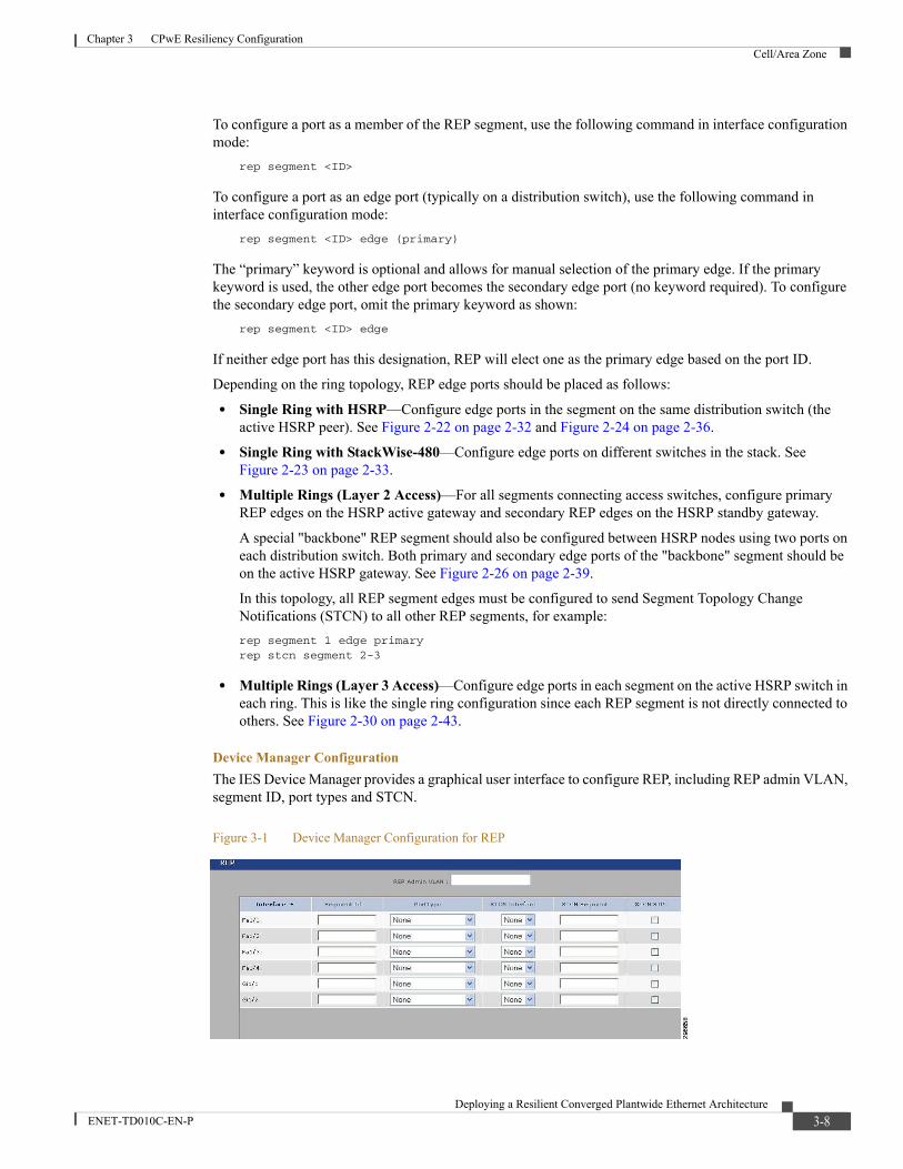
Chapter 3 CPwE Resiliency ConfigurationCell/Area Zone
To configure a port as a member of the REP segment, use the following command in interface configuration mode:
rep segment <ID>
To configure a port as an edge port (typically on a distribution switch), use the following command in interface configuration mode:
rep segment <ID> edge (primary)
The “primary” keyword is optional and allows for manual selection of the primary edge. If the primary keyword is used, the other edge port becomes the secondary edge port (no keyword required). To configure the secondary edge port, omit the primary keyword as shown:
rep segment <ID> edge
If neither edge port has this designation, REP will elect one as the primary edge based on the port ID.
Depending on the ring topology, REP edge ports should be placed as follows:
• Single Ring with HSRP—Configure edge ports in the segment on the same distribution switch (the active HSRP peer). See Figure 2-22 on page 2-32 and Figure 2-24 on page 2-36.
• Single Ring with StackWise-480—Configure edge ports on different switches in the stack. See Figure 2-23 on page 2-33.
• Multiple Rings (Layer 2 Access)—For all segments connecting access switches, configure primary REP edges on the HSRP active gateway and secondary REP edges on the HSRP standby gateway.
A special "backbone" REP segment should also be configured between HSRP nodes using two ports on each distribution switch. Both primary and secondary edge ports of the "backbone" segment should be on the active HSRP gateway. See Figure 2-26 on page 2-39.
In this topology, all REP segment edges must be configured to send Segment Topology Change Notifications (STCN) to all other REP segments, for example:rep segment 1 edge primaryrep stcn segment 2-3
• Multiple Rings (Layer 3 Access)—Configure edge ports in each segment on the active HSRP switch in each ring. This is like the single ring configuration since each REP segment is not directly connected to others. See Figure 2-30 on page 2-43.
Device Manager ConfigurationThe IES Device Manager provides a graphical user interface to configure REP, including REP admin VLAN, segment ID, port types and STCN.
Figure 3-1 Device Manager Configuration for REP
3-8Deploying a Resilient Converged Plantwide Ethernet Architecture
ENET-TD010C-EN-P

Chapter 3 CPwE Resiliency ConfigurationCell/Area Zone
For detailed description of the REP parameters in the Device Manager, see the Stratix Managed Switches User Manual at the following URL:
• http://literature.rockwellautomation.com/idc/groups/literature/documents/um/1783-um007_-en-p.pdf
3-9Deploying a Resilient Converged Plantwide Ethernet Architecture
ENET-TD010C-EN-P
Deploying a Resilient ConENET-TD010C-EN-P
C H A P T E R 4
CPwE Resiliency TroubleshootingThis chapter, which describes how to assess and verify the status of the resiliency protocols running on the Industrial and Cell/Area Zone switches, includes the following major topics:
• StackWise Virtual Troubleshooting, page 4-1
• StackWise-480 Troubleshooting, page 4-2
• HSRP Troubleshooting, page 4-2
• Flex Links Troubleshooting, page 4-3
• EtherChannel Troubleshooting, page 4-4
• REP Troubleshooting, page 4-4
StackWise Virtual TroubleshootingTo investigate problems with StackWise Virtual, the commands for confirming the configuration are shown below.
To verify your StackWise Virtual configuration, use the show commands in Table 4-1.
Table 4-1 Commands for Verifying StackWise Virtual Configuration
Command Description
show stackwise-virtual switch number <1-2> Displays information of a particular switch in the stack.
show stackwise-virtual link Displays StackWise Virtual link information.show stackwise-virtual bandwidth Displays the bandwidth available for the
Cisco StackWise Virtual.show stackwise-virtual neighbors Displays the Cisco StackWise Virtual
neighbors.show stackwise-virtual dual-active-detection Displays StackWise Virtual
dual-active-detection information.show stackwise-virtual dual-active-detection pagp Displays ePAgP dual-active-detection
information.
4-1verged Plantwide Ethernet Architecture
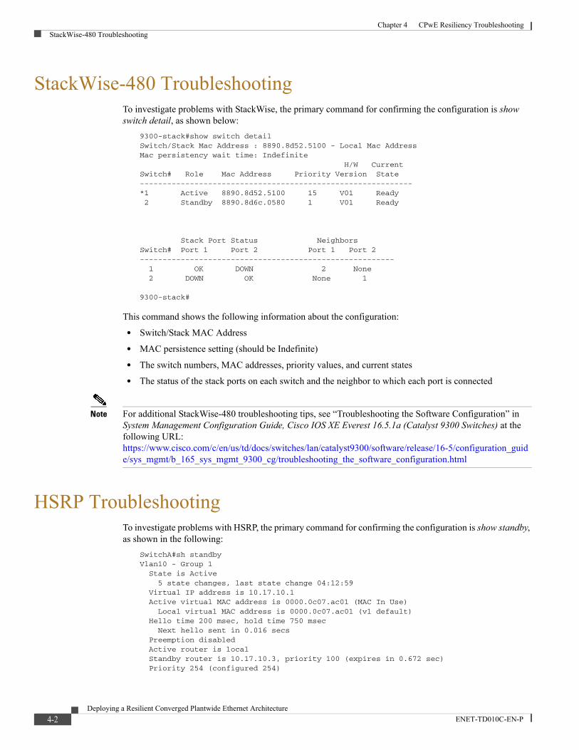
Chapter 4 CPwE Resiliency TroubleshootingStackWise-480 Troubleshooting
StackWise-480 TroubleshootingTo investigate problems with StackWise, the primary command for confirming the configuration is show switch detail, as shown below:
9300-stack#show switch detailSwitch/Stack Mac Address : 8890.8d52.5100 - Local Mac AddressMac persistency wait time: Indefinite H/W CurrentSwitch# Role Mac Address Priority Version State------------------------------------------------------------*1 Active 8890.8d52.5100 15 V01 Ready 2 Standby 8890.8d6c.0580 1 V01 Ready
Stack Port Status NeighborsSwitch# Port 1 Port 2 Port 1 Port 2-------------------------------------------------------- 1 OK DOWN 2 None 2 DOWN OK None 1
9300-stack#
This command shows the following information about the configuration:
• Switch/Stack MAC Address
• MAC persistence setting (should be Indefinite)
• The switch numbers, MAC addresses, priority values, and current states
• The status of the stack ports on each switch and the neighbor to which each port is connected
Note For additional StackWise-480 troubleshooting tips, see “Troubleshooting the Software Configuration” in System Management Configuration Guide, Cisco IOS XE Everest 16.5.1a (Catalyst 9300 Switches) at the following URL:https://www.cisco.com/c/en/us/td/docs/switches/lan/catalyst9300/software/release/16-5/configuration_guide/sys_mgmt/b_165_sys_mgmt_9300_cg/troubleshooting_the_software_configuration.html
HSRP TroubleshootingTo investigate problems with HSRP, the primary command for confirming the configuration is show standby, as shown in the following:
SwitchA#sh standbyVlan10 - Group 1 State is Active 5 state changes, last state change 04:12:59 Virtual IP address is 10.17.10.1 Active virtual MAC address is 0000.0c07.ac01 (MAC In Use) Local virtual MAC address is 0000.0c07.ac01 (v1 default) Hello time 200 msec, hold time 750 msec Next hello sent in 0.016 secs Preemption disabled Active router is local Standby router is 10.17.10.3, priority 100 (expires in 0.672 sec) Priority 254 (configured 254)
4-2Deploying a Resilient Converged Plantwide Ethernet Architecture
ENET-TD010C-EN-P
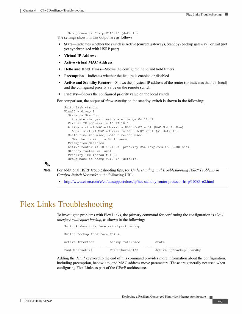
Chapter 4 CPwE Resiliency TroubleshootingFlex Links Troubleshooting
Group name is "hsrp-Vl10-1" (default)
The settings shown in this output are as follows:
• State—Indicates whether the switch is Active (current gateway), Standby (backup gateway), or Init (not yet synchronized with HSRP peer)
• Virtual IP Address• Active virtual MAC Address• Hello and Hold Times—Shows the configured hello and hold timers
• Preemption—Indicates whether the feature is enabled or disabled
• Active and Standby Routers—Shows the physical IP address of the router (or indicates that it is local) and the configured priority value on the remote switch
• Priority—Shows the configured priority value on the local switch
For comparison, the output of show standby on the standby switch is shown in the following:SwitchB#sh standbyVlan10 - Group 1 State is Standby 9 state changes, last state change 04:11:31 Virtual IP address is 10.17.10.1 Active virtual MAC address is 0000.0c07.ac01 (MAC Not In Use) Local virtual MAC address is 0000.0c07.ac01 (v1 default) Hello time 200 msec, hold time 750 msec Next hello sent in 0.016 secs Preemption disabled Active router is 10.17.10.2, priority 254 (expires in 0.608 sec) Standby router is local Priority 100 (default 100) Group name is "hsrp-Vl10-1" (default)
Note For additional HSRP troubleshooting tips, see Understanding and Troubleshooting HSRP Problems in Catalyst Switch Networks at the following URL:
• http://www.cisco.com/c/en/us/support/docs/ip/hot-standby-router-protocol-hsrp/10583-62.html
Flex Links TroubleshootingTo investigate problems with Flex Links, the primary command for confirming the configuration is show interface switchport backup, as shown in the following:
Switch# show interface switchport backup
Switch Backup Interface Pairs:
Active Interface Backup Interface State------------------------------------------------------------------------FastEthernet1/1 FastEthernet1/2 Active Up/Backup Standby
Adding the detail keyword to the end of this command provides more information about the configuration, including preemption, bandwidth, and MAC address move parameters. These are generally not used when configuring Flex Links as part of the CPwE architecture.
4-3Deploying a Resilient Converged Plantwide Ethernet Architecture
ENET-TD010C-EN-P
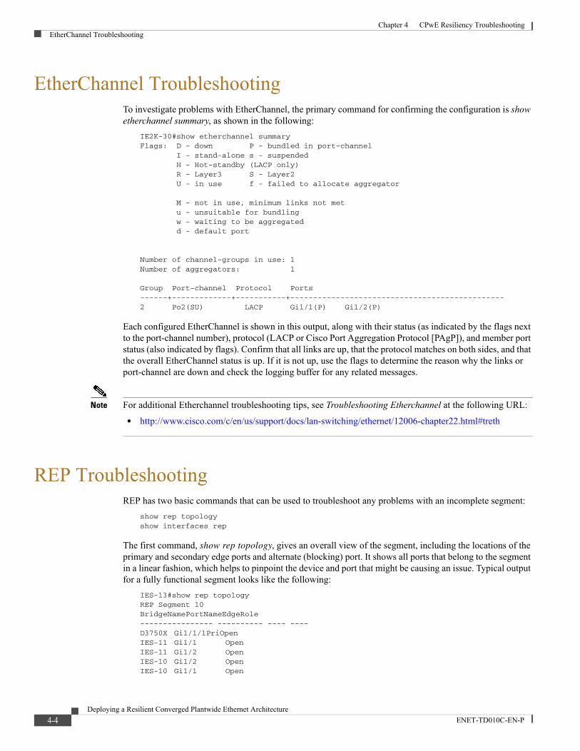
Chapter 4 CPwE Resiliency TroubleshootingEtherChannel Troubleshooting
EtherChannel TroubleshootingTo investigate problems with EtherChannel, the primary command for confirming the configuration is show etherchannel summary, as shown in the following:
IE2K-30#show etherchannel summaryFlags: D - down P - bundled in port-channel I - stand-alone s - suspended H - Hot-standby (LACP only) R - Layer3 S - Layer2 U - in use f - failed to allocate aggregator
M - not in use, minimum links not met u - unsuitable for bundling w - waiting to be aggregated d - default port
Number of channel-groups in use: 1Number of aggregators: 1
Group Port-channel Protocol Ports------+-------------+-----------+-----------------------------------------------2 Po2(SU) LACP Gi1/1(P) Gi1/2(P)
Each configured EtherChannel is shown in this output, along with their status (as indicated by the flags next to the port-channel number), protocol (LACP or Cisco Port Aggregation Protocol [PAgP]), and member port status (also indicated by flags). Confirm that all links are up, that the protocol matches on both sides, and that the overall EtherChannel status is up. If it is not up, use the flags to determine the reason why the links or port-channel are down and check the logging buffer for any related messages.
Note For additional Etherchannel troubleshooting tips, see Troubleshooting Etherchannel at the following URL:
• http://www.cisco.com/c/en/us/support/docs/lan-switching/ethernet/12006-chapter22.html#treth
REP TroubleshootingREP has two basic commands that can be used to troubleshoot any problems with an incomplete segment:
show rep topology show interfaces rep
The first command, show rep topology, gives an overall view of the segment, including the locations of the primary and secondary edge ports and alternate (blocking) port. It shows all ports that belong to the segment in a linear fashion, which helps to pinpoint the device and port that might be causing an issue. Typical output for a fully functional segment looks like the following:
IES-13#show rep topologyREP Segment 10BridgeNamePortNameEdgeRole---------------- ---------- ---- ----D3750X Gi1/1/1PriOpenIES-11 Gi1/1 OpenIES-11 Gi1/2 OpenIES-10 Gi1/2 OpenIES-10 Gi1/1 Open
4-4Deploying a Resilient Converged Plantwide Ethernet Architecture
ENET-TD010C-EN-P
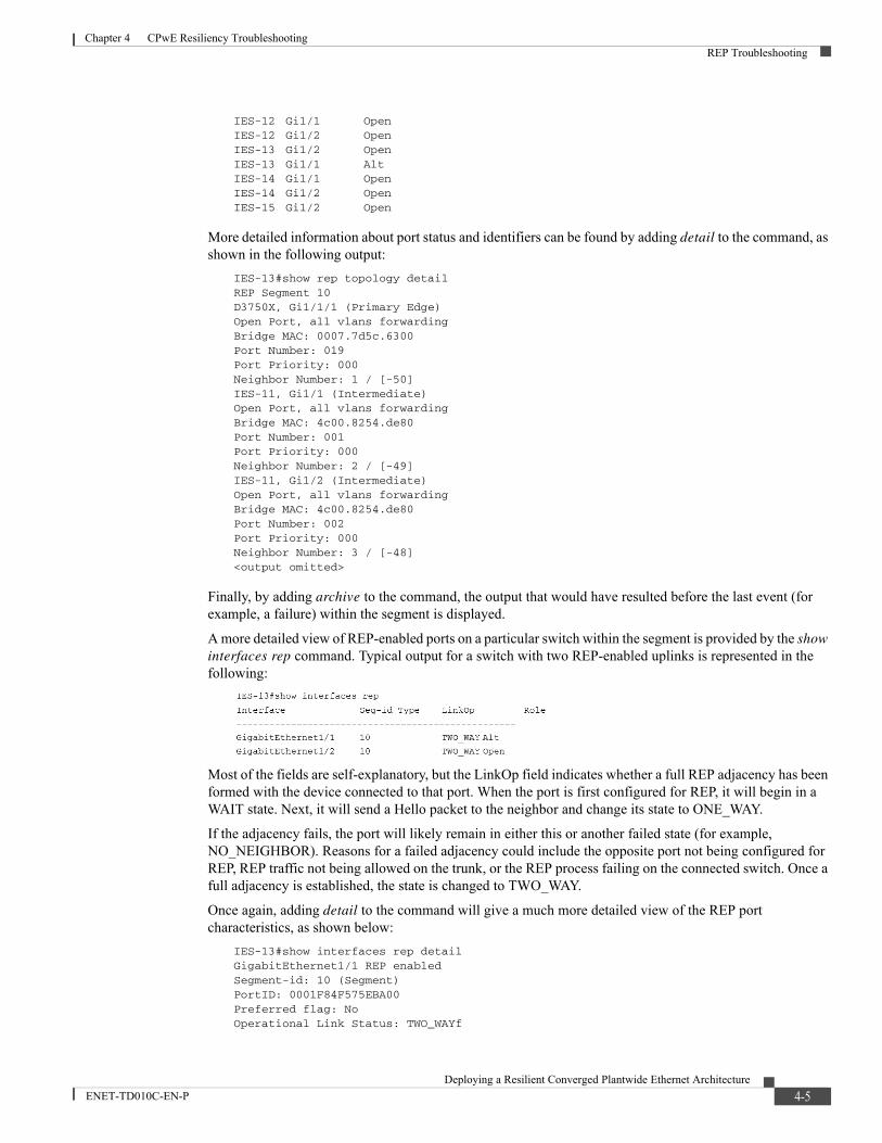
Chapter 4 CPwE Resiliency TroubleshootingREP Troubleshooting
IES-12 Gi1/1 OpenIES-12 Gi1/2 OpenIES-13 Gi1/2 OpenIES-13 Gi1/1 AltIES-14 Gi1/1 OpenIES-14 Gi1/2 OpenIES-15 Gi1/2 Open
More detailed information about port status and identifiers can be found by adding detail to the command, as shown in the following output:
IES-13#show rep topology detailREP Segment 10D3750X, Gi1/1/1 (Primary Edge)Open Port, all vlans forwardingBridge MAC: 0007.7d5c.6300Port Number: 019Port Priority: 000Neighbor Number: 1 / [-50]IES-11, Gi1/1 (Intermediate)Open Port, all vlans forwardingBridge MAC: 4c00.8254.de80Port Number: 001Port Priority: 000Neighbor Number: 2 / [-49]IES-11, Gi1/2 (Intermediate)Open Port, all vlans forwardingBridge MAC: 4c00.8254.de80Port Number: 002Port Priority: 000Neighbor Number: 3 / [-48]<output omitted>
Finally, by adding archive to the command, the output that would have resulted before the last event (for example, a failure) within the segment is displayed.
A more detailed view of REP-enabled ports on a particular switch within the segment is provided by the show interfaces rep command. Typical output for a switch with two REP-enabled uplinks is represented in the following:
Most of the fields are self-explanatory, but the LinkOp field indicates whether a full REP adjacency has been formed with the device connected to that port. When the port is first configured for REP, it will begin in a WAIT state. Next, it will send a Hello packet to the neighbor and change its state to ONE_WAY.
If the adjacency fails, the port will likely remain in either this or another failed state (for example, NO_NEIGHBOR). Reasons for a failed adjacency could include the opposite port not being configured for REP, REP traffic not being allowed on the trunk, or the REP process failing on the connected switch. Once a full adjacency is established, the state is changed to TWO_WAY.
Once again, adding detail to the command will give a much more detailed view of the REP port characteristics, as shown below:
IES-13#show interfaces rep detailGigabitEthernet1/1 REP enabledSegment-id: 10 (Segment)PortID: 0001F84F575EBA00Preferred flag: NoOperational Link Status: TWO_WAYf
4-5Deploying a Resilient Converged Plantwide Ethernet Architecture
ENET-TD010C-EN-P

Chapter 4 CPwE Resiliency TroubleshootingREP Troubleshooting
Current Key: 0001F84F575EBA0011DDPort Role: AlternateBlocked VLAN: 1-4094Admin-vlan: 900Preempt Delay Timer: disabledLSL Ageout Timer: 5000 msConfigured Load-balancing Block Port: noneConfigured Load-balancing Block VLAN: noneSTCN Propagate to: noneLSL PDU rx: 1563198, tx: 1830473HFL PDU rx: 1139, tx: 948BPA TLV rx: 551026, tx: 1078849BPA (STCN, LSL) TLV rx: 0, tx: 0BPA (STCN, HFL) TLV rx: 0, tx: 0EPA-ELECTION TLV rx: 22649, tx: 25342EPA-COMMAND TLV rx: 0, tx: 0EPA-INFO TLV rx: 422937, tx: 422832
GigabitEthernet1/2 REP enabledSegment-id: 10 (Segment)PortID: 0002F84F575EBA00Preferred flag: NoOperational Link Status: TWO_WAYCurrent Key: 0001F84F575EBA0011DDPort Role: OpenBlocked VLAN: <empty>Admin-vlan: 900Preempt Delay Timer: disabledLSL Ageout Timer: 5000 msConfigured Load-balancing Block Port: noneConfigured Load-balancing Block VLAN: noneSTCN Propagate to: noneLSL PDU rx: 1330531, tx: 2110526HFL PDU rx: 1087, tx: 0BPA TLV rx: 28423, tx: 1601021BPA (STCN, LSL) TLV rx: 0, tx: 0BPA (STCN, HFL) TLV rx: 0, tx: 0EPA-ELECTION TLV rx: 32022, tx: 22649EPA-COMMAND TLV rx: 0, tx: 0EPA-INFO TLV rx: 429606, tx: 429756
Significant fields from this output include:
• PortID—The full REP port identifier, formed by appending the port priority and port number to the bridge MAC address (these values can be seen in the output of show rep topology detail).
• Current Key—Indicates the key for the current alternate port in the segment. All segment ports should have synchronized keys.
• Blocked VLAN—Any VLANs blocked by this port for load balancing purposes.
• Admin—VLAN-configured REP administrative VLAN.
• Statistics for LSL and HFL packets and other REP-related messaging.
This debug command shows failure detection and HFL/LSL packets sent to inform the segment of the failure:debug rep failure-recovery
4-6Deploying a Resilient Converged Plantwide Ethernet Architecture
ENET-TD010C-EN-P
Deploying a Resilient CoENET-TD010C-EN-P
A P P E N D I X A
ReferencesThis appendix includes the following major topics:
• Converged Plantwide Ethernet (CPwE), page A-1
• Core Switch Architecture, page A-3
• Distribution Switches, page A-3
• Access Layer Switches, page A-4
• Routing Between Zones, page A-4
• Network Time Protocol, page A-4
• Network Infrastructure Hardening, page A-5
Converged Plantwide Ethernet (CPwE)• Design Zone for Manufacturing-Converged Plantwide Ethernet
http://www.cisco.com/c/en/us/solutions/enterprise/design-zone-manufacturing/landing_ettf.html
• Industrial Network Architectures-Converged Plantwide Ethernethttp://www.rockwellautomation.com/global/products-technologies/network-technology/architectures.page
• Converged Plantwide Ethernet (CPwE) Design and Implementation Guide:
– Rockwell Automation site: http://literature.rockwellautomation.com/idc/groups/literature/documents/td/enet-td001_-en-p.pdf
– Cisco site:http://www.cisco.com/c/en/us/td/docs/solutions/Verticals/CPwE/CPwE_DIG.html
• Deploying 802.11 Wireless LAN Technology within a Converged Plantwide Ethernet Architecture:
– Rockwell Automation site:http://literature.rockwellautomation.com/idc/groups/literature/documents/td/enet-td006_-en-p.pdf
– Cisco site:http://www.cisco.com/c/en/us/td/docs/solutions/Verticals/CPwE/NovCVD/CPwE_WLAN_CVD.html
• Deploying Network Address Translation within a Converged Plantwide Ethernet Architecture:
A-1nverged Plantwide Ethernet Architecture
Appendix A ReferencesConverged Plantwide Ethernet (CPwE)
– Rockwell Automation site:http://literature.rockwellautomation.com/idc/groups/literature/documents/td/enet-td007_-en-p.pdf
– Cisco site: http://www.cisco.com/c/en/us/td/docs/solutions/Verticals/CPwE/3-5-1/NAT/DIG/CPwE_NAT_CVD.html
• OEM Networking within a Converged Plantwide Ethernet Architecture:
– Rockwell Automation site:http://literature.rockwellautomation.com/idc/groups/literature/documents/td/enet-td018_-en-p.pdf
– Cisco site:https://www.cisco.com/c/en/us/td/docs/solutions/Verticals/CPwE/5-1/OEM/WP/CPwE-5-1-OEM- WP/CPwE-5-1-OEM-WP.html
• Deploying Identity Services within a Converged Plantwide Ethernet Architecture:
– Rockwell Automation site:http://literature.rockwellautomation.com/idc/groups/literature/documents/td/enet-td008_-en-p.pdf
– Cisco site:http://www.cisco.com/c/en/us/td/docs/solutions/Verticals/CPwE/3-5-1/ISE/DIG/CPwE_ISE_CVD.html
• Securely Traversing IACS Data Across the Industrial Demilitarized Zone:
– Rockwell Automation site:http://literature.rockwellautomation.com/idc/groups/literature/documents/td/enet-td009_-en-p.pdf
– Cisco site:http://www.cisco.com/c/en/us/td/docs/solutions/Verticals/CPwE/3-5-1/IDMZ/DIG/CPwE_IDMZ_CVD.html
• Deploying Industrial Firewalls within a Converged Plantwide Ethernet Architecture:
– Rockwell Automation site:http://literature.rockwellautomation.com/idc/groups/literature/documents/td/enet-td002_-en-p.pdf
– Cisco site:http://www.cisco.com/c/en/us/td/docs/solutions/Verticals/CPwE/5-0/Firewalls/DIG/CPwE-5-IFS-DIG.html
• Cloud Connectivity to a Converged Plantwide Ethernet Architecture:
– Rockwell Automation site:https://literature.rockwellautomation.com/idc/groups/literature/documents/td/enet-td017_-en-p.pdf
– Cisco site:https://www.cisco.com/c/en/us/td/docs/solutions/Verticals/CPwE/5-1/Cloud/DIG/CPwE_Cloud_C onnect_CVD.html
• Deploying Network Security within a Converged Plantwide Ethernet Architecture:
– Rockwell Automation site:https://literature.rockwellautomation.com/idc/groups/literature/documents/td/enet-td019_-en-p.pdf
– Cisco site:https://www.cisco.com/c/en/us/td/docs/solutions/Verticals/CPwE/5-1/Network_Security/DIG/CPw E-5-1-NetworkSecurity-DIG.html
• Deploying CIP Security within a Converged Plantwide Ethernet Architecture:
– Rockwell Automation site:https://literature.rockwellautomation.com/idc/groups/literature/documents/td/enet-td022_-en-p.pdf
A-2Deploying a Resilient Converged Plantwide Ethernet Architecture
ENET-TD010C-EN-P

Appendix A ReferencesCore Switch Architecture
– Cisco site:https://www.cisco.com/c/en/us/td/docs/solutions/Verticals/CPwE/5-1/CIP_Security/DIG/CPwE_CIPSec_CVD.html
• Deploying Scalable Time Distribution within a Converged Plantwide Ethernet Architecture:
– Rockwell Automation site:https://literature.rockwellautomation.com/idc/groups/literature/documents/td/enet-td016_-en-p.pdf
– Cisco site:https://www.cisco.com/c/en/us/td/docs/solutions/Verticals/CPwE/5-1/STD/DIG/CPwE-5-1-STD-D IG.html
• Deploying Parallel Redundancy Protocol within a Converged Plantwide Ethernet Architecture:
– Rockwell Automation site:https://literature.rockwellautomation.com/idc/groups/literature/documents/td/enet-td021_-en-p.pdf
– Cisco site:https://www.cisco.com/c/en/us/td/docs/solutions/Verticals/CPwE/5-1/PRP/DIG/CPwE-5-1-PRP-D IG.html
• Deploying Device Level Ring within a Converged Plantwide Ethernet Architecture:
– Rockwell Automation site:https://literature.rockwellautomation.com/idc/groups/literature/documents/td/enet-td015_-en-p.pdf
– Cisco site:https://www.cisco.com/c/en/us/td/docs/solutions/Verticals/CPwE/5-1/DLR/DIG/CPwE-5-1-DLR-DIG.html
• Physical Infrastructure for the Converged Plantwide Ethernet Architecture Application Guide:
– Rockwell Automation site:https://literature.rockwellautomation.com/idc/groups/literature/documents/td/enet-td020_-en-p.pdf
– Cisco site:https://www.cisco.com/c/en/us/td/docs/solutions/Verticals/CPwE/5-1/Phy_Arch/CPwE_PhyArch_AppGuide.html
Core Switch Architecture• Virtual Switching Systems Release 15.1SY Supervisor Engine 2T Software Configuration Guide:
– http://www.cisco.com/c/en/us/td/docs/switches/lan/catalyst6500/ios/15-1SY/config_guide/sup2T/15_1_sy_swcg_2T/virtual_switching_systems.html
• Virtual Switching Systems (Supervisor Engine 6T Software Configuration Guide, Release 15.3SY):
– http://www.cisco.com/c/en/us/td/docs/switches/lan/catalyst6500/ios/15-3SY/config_guide/sup6T/15_3_sy_swcg_6T/virtual_switching_systems.pdf
Distribution Switches• Catalyst 4500 Series Switch Software Configuration Guide:
– http://www.cisco.com/c/en/us/td/docs/switches/lan/catalyst4500/15-1-2/XE_340/configuration/guide/config.html
• Cisco Catalyst 9300 Switch Guides:
A-3Deploying a Resilient Converged Plantwide Ethernet Architecture
ENET-TD010C-EN-P
Appendix A ReferencesAccess Layer Switches
– https://www.cisco.com/c/en/us/products/switches/catalyst-9300-series-switches/index.html
– https://www.cisco.com/c/en/us/support/switches/catalyst-9300-series-switches/products-installation-and-configuration-guides-list.html
• Cisco Catalyst 9500 Switch Guides:
– https://www.cisco.com/c/en/us/products/switches/catalyst-9500-series-switches/index.html
– https://www.cisco.com/c/en/us/support/switches/catalyst-9500-series-switches/products-installation-and-configuration-guides-list.html
• Cisco Catalyst 3850 Switch Deployment Guide:
– http://www.cisco.com/c/en/us/products/collateral/switches/catalyst-3850-series-switches/deployment_guide_c07-727067.html
• Industrial Ethernet 5000 Software Configuration Guide:
– http://www.cisco.com/c/en/us/td/docs/switches/lan/cisco_ie5000/software/release/15-2_2_eb/configuration/guide/scg-ie5000.html
• Stratix Managed Switches User Manual:
– http://literature.rockwellautomation.com/idc/groups/literature/documents/um/1783-um007_-en-p.pdf
Access Layer Switches• Industrial Ethernet 4000 Software Configuration Guide:
– http://www.cisco.com/c/en/us/td/docs/switches/lan/cisco_ie4000/software/release/15-2_2_ea/configuration/guide/scg-ie4000.html
• Industrial Ethernet 2000 Software Configuration Guide:
– http://www.cisco.com/c/en/us/td/docs/switches/lan/cisco_ie2000/software/release/15_2_2_e/configuration/guide/scg-ie2000.html
• Stratix Managed Switches User Manual:
– http://literature.rockwellautomation.com/idc/groups/literature/documents/um/1783-um007_-en-p.pdf
Routing Between Zones• Enhanced Interior Gateway Routing Protocol White Paper:
– http://www.cisco.com/c/en/us/support/docs/ip/enhanced-interior-gateway-routing-protocol-eigrp/16406-eigrp-toc.html
• OSPF Design Guide:
– http://www.cisco.com/c/en/us/support/docs/ip/open-shortest-path-first-ospf/7039-1.html
Network Time Protocol• Network Time Protocol: Best Practices White Paper:
– http://www.cisco.com/c/en/us/support/docs/availability/high-availability/19643-ntpm.html
A-4Deploying a Resilient Converged Plantwide Ethernet Architecture
ENET-TD010C-EN-P

Appendix A ReferencesNetwork Infrastructure Hardening
Network Infrastructure Hardening• Cisco Guide to Harden Cisco IOS Devices:
– http://www.cisco.com/c/en/us/support/docs/ip/access-lists/13608-21.html
A-5Deploying a Resilient Converged Plantwide Ethernet Architecture
ENET-TD010C-EN-P
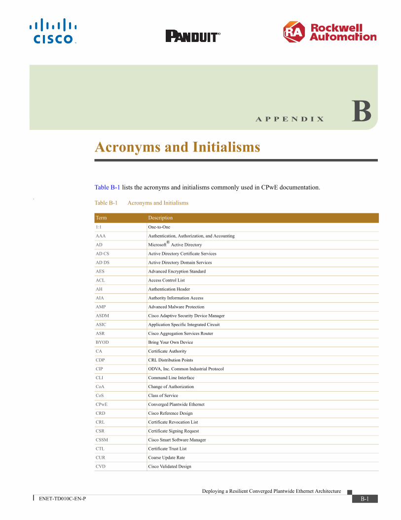
Deploying a Resilient CoENET-TD010C-EN-P
A P P E N D I X B
Acronyms and InitialismsTable B-1 lists the acronyms and initialisms commonly used in CPwE documentation..
Table B-1 Acronyms and Initialisms
Term Description
1:1 One-to-One
AAA Authentication, Authorization, and Accounting
AD Microsoft® Active Directory
AD CS Active Directory Certificate Services
AD DS Active Directory Domain Services
AES Advanced Encryption Standard
ACL Access Control List
AH Authentication Header
AIA Authority Information Access
AMP Advanced Malware Protection
ASDM Cisco Adaptive Security Device Manager
ASIC Application Specific Integrated Circuit
ASR Cisco Aggregation Services Router
BYOD Bring Your Own Device
CA Certificate Authority
CDP CRL Distribution Points
CIP ODVA, Inc. Common Industrial Protocol
CLI Command Line Interface
CoA Change of Authorization
CoS Class of Service
CPwE Converged Plantwide Ethernet
CRD Cisco Reference Design
CRL Certificate Revocation List
CSR Certificate Signing Request
CSSM Cisco Smart Software Manager
CTL Certificate Trust List
CUR Coarse Update Rate
CVD Cisco Validated Design
B-1nverged Plantwide Ethernet Architecture

Appendix B Acronyms and Initialisms
DACL Downloadable Access Control List
DAN Double Attached Node
DC Domain Controller
DHCP Dynamic Host Configuration Protocol
DIG Design and Implementation Guide
DLR Device Level Ring
DMVPN Dynamic Multipoint Virtual Private Network
DNS Domain Name System
DPI Deep Packet Inspection
DSRM Directory Services Restoration Mode
EAP Extensible Authentication Protocol
EAP-TLS Extensible Authentication Protocol-Transport Layer Security
EIGRP Enhanced Interior Gateway Routing Protocol
EMI Enterprise Manufacturing Intelligence
EoIP Ethernet over IP
ERP Enterprise Resource Planning
ESP Encapsulating Security Protocol
ESR Embedded Services Router
FIB Forwarding Information Base
FIFO First-In First-Out
FPGA Field-Programmable Gate Array
FQDN Fully Qualified Domain Name
FVRF Front-door Virtual Route Forwarding
GNSS Global Navigation Satellite Systems
GRE Generic Routing Encapsulation
HMAC Hash Message Authentication Code
HMI Human-Machine Interface
HSRP Hot Standby Router Protocol
IACS Industrial Automation and Control System
ICS Industrial Control System
IDMZ Industrial Demilitarized Zones
IES Industrial Ethernet Switch (Allen-Bradley Stratix, Cisco IE)
IGMP Internet Group Management Protocol
IIoT Industrial Internet of Things
IKE Internet Key Exchange
I/O Input/Output
IoT Internet of Things
IP Internet Protocol
IPDT IP Device Tracking
ISAKMP Internet Security Association and Key Management Protocol
ISP Internet Service Provider
ISE Cisco Identity Services Engine
ISR Integrated Service Router
IT Information Technology
Table B-1 Acronyms and Initialisms (continued)
Term Description
B-2Deploying a Resilient Converged Plantwide Ethernet Architecture
ENET-TD010C-EN-P

Appendix B Acronyms and Initialisms
LBS Location Based Services
LWAP Lightweight Access Point
MAB MAC Authentication Bypass
MAC Media Access Control
MDM Mobile Device Management
ME FactoryTalk View Machine Edition
mGRE Multipoint Generic Routing Encapsulation
MLS Multilayer Switching QoS
MMC Microsoft Management Console
MnT Monitoring Node
MPLS Multiprotocol Label Switching
MQC Modular QoS CLI
MSE Mobile Service Engine
MSS Maximum Segment Size
MTTR Mean Time to Repair
MTU Maximum Transmission Unit
NAC Network Access Control
NAT Network Address Translation
NDES Network Device Enrollment Service
NHRP Next Hop Routing Protocol
NOC Network Operation Center
NPS Microsoft Network Policy Server
NSP Native Supplicant Profile
NTP Network Time Protocol
OCSP Online Certificate Status Protocol
OEE Overall Equipment Effectiveness
OEM Original Equipment Manufacturer
OT Operational Technology
OTA Over-the-Air
OU Organizational Unit
PAC Programmable Automation Controller
PAN Policy Administration Node
PAT Port Address Translation
PCS Process Control System
PEAP Protected Extensible Authentication Protocol
PKI Public Key Infrastructure
pps Packet per second
PRP Parallel Redundancy Protocol
PSK Pre-Shared Key
PSN Policy Service Node
PTP Precision Time Protocol
QoS Quality of Service
RA Registration Authority
RADIUS Remote Authentication Dial-In User Service
Table B-1 Acronyms and Initialisms (continued)
Term Description
B-3Deploying a Resilient Converged Plantwide Ethernet Architecture
ENET-TD010C-EN-P
Appendix B Acronyms and Initialisms
RAS Remote Access Server
RD Route Descriptor
RDG Remote Desktop Gateway
RDP Remote Desktop Protocol
RDS Remote Desktop Services
RedBox PRP redundancy box
REP Resilient Ethernet Protocol
RPI Request Packet Interval
RTT Round Trip Time
SA Security Association
SaaS Software-as-a-Service
SAN Single Attached Node
SCEP Simple Certificate Enrollment Protocol
SE FactoryTalk View Site Edition
SHA Secure Hash Standard
SIG Secure Internet Gateway
SPW Software Provisioning Wizard
SSID Service Set Identifier
STP Spanning Tree Protocol
SYN Synchronization
TAI International Atomic Time
TCN Topology Change Notification
TCP Transmission Control Protocol
TLS Transport Layer Security
UDP User Datagram Protocol
UTC Coordinated Universal Time
VDAN Virtual Double Attached Node
VLAN Virtual Local Area Network
VM Virtual Machine
VNC Virtual Network Computing
VPN Virtual Private Network
VRF Virtual Route Forwarding
VSS Virtual Switching System
WAN Wide Area Network
wIPS wireless Intrusion Prevention Service
WLAN Wireless LAN
WLC Cisco Wireless LAN Controller
WSA Cisco Web Security Appliance
ZFW Zone-Based Policy Firewall
Table B-1 Acronyms and Initialisms (continued)
Term Description
B-4Deploying a Resilient Converged Plantwide Ethernet Architecture
ENET-TD010C-EN-P
Deploying a Resilient CoENET-TD010C-EN-P
A P P E N D I X C
About Cisco Validated Design (CVD) ProgramConverged Plantwide Ethernet (CPwE) is a collection of architected, tested, and validated designs developed by subject matter authorities at Cisco and Rockwell Automation with assistance by Panduit, which follows the Cisco Validated Design (CVD) program.
CVDs provide the foundation for systems design based on common use cases or current engineering system priorities. They incorporate a broad set of technologies, features, and applications to address customer needs. Each one has been comprehensively tested and documented by engineers to ensure faster, more reliable, and fully predictable deployment.
The CVD process is comprehensive and focuses on solving business problems for customers and documenting these solutions. The process consists of the following steps:
1. Requirements are gathered from a broad base of customers to devise a set of use cases that will fulfill these business needs.
2. Network architectures are designed or extended to provide the functionality necessary to enable these use cases, and any missing functionality is relayed back to the appropriate product development team(s).
3. Detailed test plans are developed based on the architecture designs to validate the proposed solution, with an emphasis on feature and platform interaction across the system. These tests generally consist of functionality, resiliency, scale, and performance characterization.
4. All parties contribute to the development of the CVD guide, which covers both design recommendations and implementation of the solution based on the testing outcomes.
Within the CVD program, CPwE also provides Cisco Reference Designs (CRDs) that follow the CVD process, but that focus on reference designs developed around specific set of priority use cases. The scope of CRD testing typically focuses on solution functional verification with limited scale.
For more information about the CVD program, please see Cisco Validated Designs:
http://www.cisco.com/c/dam/en/us/td/docs/solutions/CVD/overview/cvd_overview.pdf
C-1nverged Plantwide Ethernet Architecture

Appendix C About Cisco Validated Design (CVD) Program
.
Panduit Corp. is a world-class provider of engineered, flexible, end-to-end electrical and network connectivity infrastructure solutions that provides businesses with the ability to keep pace with a connected world. Our robust partner ecosystem, global staff, and unmatched service and support make Panduit a valuable and trusted partner.
www.panduit.comUS and Canada:Panduit Corp.World Headquarters18900 Panduit DriveTinley Park, IL [email protected]. 708.532.1800
Asia Pacific:One Temasek Avenue #09-01 Millenia Tower 039192 SingaporeTel. 65 6305 7555
Europe/Middle East/Africa:Panduit Corp.West World Westgate London W5 1XP Q United KingdomTel. +44 (0) 20 8601 7219
Latin America:Panduit Corp.Periférico Pte Manuel Gómez Morin #7225 - A Guadalajara Jalisco 45010 MEXICOTel. (33) 3777 6000
Cisco is the worldwide leader in networking that transforms how people connect, communicate and collaborate. Information about Cisco can be found at www.cisco.com. For ongoing news, please go to http://newsroom.cisco.com. Cisco equipment in Europe is supplied by Cisco Systems International BV, a wholly owned subsidiary of Cisco Systems, Inc.
www.cisco.comAmericas HeadquartersCisco Systems, Inc.San Jose, CA
Asia Pacific HeadquartersCisco Systems (USA) Pte. Ltd.Singapore
Europe HeadquartersCisco Systems International BVAmsterdam, The Netherlands
Cisco has more than 200 offices worldwide. Addresses, phone numbers, and fax numbers are listed on the Cisco Website at www.cisco.com/go/offices.
Cisco and the Cisco logo are trademarks or registered trademarks of Cisco and/or its affiliates in the U.S. and other countries. To view a list of Cisco trademarks, go to this URL:www.cisco.com/go/trademarks. Third-party trademarks mentioned are the property of their respective owners. The use of the word partner does not imply a partnership relationship betweenCisco and any other company. (1721R)
Rockwell Automation is a leading provider of power, control and information solutions that enable customers to be more productive and the world more sustainable. In support of smart manufacturing concepts, Rockwell Automation helps customers maximize value and prepare for their future by building a Connected Enterprise.
www.rockwellautomation.comAmericas:Rockwell Automation1201 South Second Street Milwaukee, WI 53204-2496 USA Tel: (1) 414.382.2000Fax: (1) 414.382.4444
Asia Pacific:Rockwell AutomationLevel 14, Core F, Cyberport 3 100 Cyberport Road, Hong Kong Tel: (852) 2887 4788Fax: (852) 2508 1846
Europe/Middle East/Africa: Rockwell AutomationNV, Pegasus Park, De Kleetlaan 12a 1831 Diegem, Belgium Tel: (32) 2 663 0600Fax: (32) 2 663 0640
Allen-Bradley, CompactBlock Guard I/O, CompactLogix, ControlLogix, FactoryTalk, FactoryTalk Network Manager, FLEX I/O, Guard I/O, GuardLogix, Point I/O, Rockwell Automation, Rockwell Software, RSLinx, Stratix, and Studio 5000 Logix Designer are trademarks of Rockwell Automation, Inc. Trademarks not belonging to Rockwell Automation are property of their respective companies.
CIP, CIP Security, CIP Sync, and EtherNet/IP are trademarks of ODVA, Inc.Microsoft is a trademark of Microsoft Corporation.
© 2020 Cisco Systems, Inc., Panduit Corp. and Rockwell Automation, Inc. and all rights reserved. Publication ENET-TD010C-EN-P September 2020
C-2Deploying a Resilient Converged Plantwide Ethernet Architecture
ENET-TD010C-EN-P
Related Documents