STATE OF CALIFORNIA-BUSINESS, TRANSPORTATION AND HOUSING AGENCY ARNOLD SCHWARZENEGGER, Governor DEPARTMENT OF TRANSPORTATION DES-OE MS #43 1727 30TH Street, 2ND Floor Sacramento, CA 95816 ** WARNING ** WARNING ** WARNING ** WARNING ** This document is intended for informational purposes only. Users are cautioned that California Department of Transportation (Department) does not assume any liability or responsibility based on these electronic files or for any defective or incomplete copying, exerpting, scanning, faxing or downloading of the contract documents. As always, for the official paper versions of the bidders packages and non-bidder packages, including addenda write to the California Department of Transportation, Plans and Bid Documents, Room 0200, P.O. Box 942874, Sacramento, CA 94272-0001, telephone (916) 654-4490 or fax (916) 654-7028. Office hours are 7:30 a.m. to 4:15 p.m. When ordering bidder or non-bidder packages it is important that you include a telephone number and fax number, P.O. Box and street address so that you can receive addenda. January 12, 2004 04-SF-80-13.4,13.8 04-0120E4 ACBRIM-080-1(094)N Addendum No. 6 Dear Contractor: This addendum is being issued to the contract for construction on State highway in THE CITY AND COUNTY OF SAN FRANCISCO AT YERBA BUENA ISLAND. Submit bids for this work with the understanding and full consideration of this addendum. The revisions declared in this addendum are an essential part of the contract. Bids for this work will be opened on January 21, 2004. This addendum is being issued to revise the Project Plans, the Notice to Contractors and Special Provisions and the Proposal and Contract. Project Plan Sheets 21, 34, 52, 54, 68, 70 and 71 are revised. Half-sized copies of the revised sheets are attached for substitution for the like-numbered sheets. Project Plan Sheet 5A is added. A half-sized copy of the added sheet is attached for addition to the project plans. In the Special Provisions, "AMENDMENTS TO JULY 1999 STANDARD SPECIFICATIONS," Section 52, "REINFORCEMENT," is revised as attached. In the Special Provisions, Section 5-1.0105, "INTERGRATED SHOP DRAWINGS," is revised as attached. In the Special Provisions, Section 5-1.12, "PROJECT INFORMATION," subsection "INFORMATION HANDOUT," subsection "District Materials Information," Item "H" in the second paragraph is revised as follows: "H. Underground Classification No. C151-075-04T, December 10, 2003, and No. C151-075-04T Amendment #1, December 18, 2003, by the Division of Occupational Safety and Health, Mining and Tunneling Unit." In the Special Provisions, Section 5-1.19, "AREAS FOR CONTRACTOR'S USE," the following paragraph is added after the third paragraph: "The Area CE as shown on the plans shall be available for the Contractor's use from January 1, 2005 to December 31, 2006. Access shall be made available to the Pier W2 area for work to be performed by the adjacent contract 04-0120F4." In the Special Provisions, Section 5-1.25, "PAYMENTS," is revised as attached. In the Special Provisions, Section 10-1.115, "WORKING DRAWING COORDINATION," replaced with Section 10- 1.115, "WORKING DRAWING CAMPUS" as attached.

Welcome message from author
This document is posted to help you gain knowledge. Please leave a comment to let me know what you think about it! Share it to your friends and learn new things together.
Transcript
STATE OF CALIFORNIA-BUSINESS, TRANSPORTATION AND HOUSING AGENCY ARNOLD SCHWARZENEGGER, Governor
DEPARTMENT OF TRANSPORTATIONDES-OE MS #431727 30TH Street, 2ND FloorSacramento, CA 95816
** WARNING ** WARNING ** WARNING ** WARNING **This document is intended for informational purposes only.
Users are cautioned that California Department of Transportation (Department) does not assume any liability or responsibility basedon these electronic files or for any defective or incomplete copying, exerpting, scanning, faxing or downloading of the contract documents.As always, for the official paper versions of the bidders packages and non-bidder packages, including addenda write to the CaliforniaDepartment of Transportation, Plans and Bid Documents, Room 0200, P.O. Box 942874, Sacramento, CA 94272-0001, telephone (916)654-4490 or fax (916) 654-7028. Office hours are 7:30 a.m. to 4:15 p.m. When ordering bidder or non-bidder packages it is important thatyou include a telephone number and fax number, P.O. Box and street address so that you can receive addenda.
January 12, 2004
04-SF-80-13.4,13.804-0120E4ACBRIM-080-1(094)N
Addendum No. 6
Dear Contractor:
This addendum is being issued to the contract for construction on State highway in THE CITY AND COUNTY OF SANFRANCISCO AT YERBA BUENA ISLAND.
Submit bids for this work with the understanding and full consideration of this addendum. The revisions declared in thisaddendum are an essential part of the contract.
Bids for this work will be opened on January 21, 2004.
This addendum is being issued to revise the Project Plans, the Notice to Contractors and Special Provisions and theProposal and Contract.
Project Plan Sheets 21, 34, 52, 54, 68, 70 and 71 are revised. Half-sized copies of the revised sheets are attached forsubstitution for the like-numbered sheets.
Project Plan Sheet 5A is added. A half-sized copy of the added sheet is attached for addition to the project plans.
In the Special Provisions, "AMENDMENTS TO JULY 1999 STANDARD SPECIFICATIONS," Section 52,"REINFORCEMENT," is revised as attached.
In the Special Provisions, Section 5-1.0105, "INTERGRATED SHOP DRAWINGS," is revised as attached.
In the Special Provisions, Section 5-1.12, "PROJECT INFORMATION," subsection "INFORMATION HANDOUT,"subsection "District Materials Information," Item "H" in the second paragraph is revised as follows:
"H. Underground Classification No. C151-075-04T, December 10, 2003, and No. C151-075-04TAmendment #1, December 18, 2003, by the Division of Occupational Safety and Health, Mining andTunneling Unit."
In the Special Provisions, Section 5-1.19, "AREAS FOR CONTRACTOR'S USE," the following paragraph is addedafter the third paragraph:
"The Area CE as shown on the plans shall be available for the Contractor's use from January 1, 2005 toDecember 31, 2006. Access shall be made available to the Pier W2 area for work to be performed by theadjacent contract 04-0120F4."
In the Special Provisions, Section 5-1.25, "PAYMENTS," is revised as attached.
In the Special Provisions, Section 10-1.115, "WORKING DRAWING COORDINATION," replaced with Section 10-1.115, "WORKING DRAWING CAMPUS" as attached.
Addendum No. 6Page 2January 12, 2004
04-SF-80-13.4,13.804-0120E4ACBRIM-080-1(094)N
In the Special Provisions, Section 10-1.24, "PILING," subsection "CAST-IN-DRILLED-HOLE CONCRETE PILES,"the following paragraph is added after the fourth paragraph:
"Should the Contractor elect to use a temporary casing for constructing cast-in-drilled-hole concretepiling, driving of temporary casings will not be permitted. The Contractor may use an impact hammer toseat the temporary casing provided the impact hammer energy does not exceed 200 kJ. Use of a marinepile driving energy attenuator will not be required."
In the Special Provisions, Section 10-1.26, "CONCRETE STRUCTURES," subsection "MASS CONCRETE,"subsection "Thermal Control Plan," the eleventh and twelfth paragraphs are revised as follows:
"After the completion of the mass concrete element, the Contractor shall remove all formwork,equipment and materials from the mass concrete element and clean the surface for the Engineer to measurethe crack intensity. Surface crack intensity will be determined after monitoring shows the maximuminternal temperature has dropped to within 5oC of the outer concrete temperature. Cracking shall beconsidered excessive if a surface crack intensity on any face of a concrete surface where cracks greater than0.15 mm in width measure more than 1.0 m in cumulative length within any 2 m square area or whereindividual cracks greater than 0.15 mm in width measure more than 300 mm in length.
In case of excessive cracking, the Contractor shall suspend work on subsequent mass concreteplacements, submit a written explanation of the thermal cracking and additional steps to be taken in thefuture to eliminate excessive cracking, and submit proposed modifications in writing to the Engineer forreview. Concrete placement may not resume until the Engineer approves the proposed modifications."
In the Special Provisions, Section 10-1.29, "REINFORCEMENT," is revised as attached.
In the Special Provisions, Section 10-1.31, "STEEL STRUCTURES," subsection "TEMPLATE," the third paragraph isrevised as follows:
"Twelve months prior to the completion of the number of days bid, the Contractor shall furnish to theEngineer a steel template with holes that correspond to the as-fabricated location of the tower anchorageanchor bolt pipe sleeves and dowels. The steel template shall be sufficiently rigid to locate holes for toweranchorage anchor bolt pipe sleeves and dowels within 5% of the tolerance required after shipping anderection. The steel template shall be comprised of four (4) match-marked quadrants or as otherwiseapproved by the Engineer. The Contractor shall submit steel template working drawings to the Engineer 30working days prior to fabrication of the steel template. The Contractor shall allow the Engineer 10 workingdays to review and approve steel template working drawings."
In the Special Provisions, Section 10-3.05, "PILE CORROSION MORNITORING SYSTEM," subsection"SUBMITTALS," subsection "Ultrasonic Thickness Probe," the first paragraph is revised as follows:
"The ultrasonic thickness transducers to be installed on the interior surface of the steel pile on Piershall be an Accuscan, Lemo Connector Type, Transducer Part Number D790 manufactured by RTtransducers distributed by Panametrics, or approved equal. Cable shall be as supplied by manufacturer forthe intended use. The probes are to be installed permanently inside the pile shell and set in epoxy after thereinforcing cage is installed and before the tremie concrete is placed. Wiring shall be set in epoxy on theshell wall, or installed in a small conduit and sealed in silicone gel."
In the Proposal and Contract, the Engineer’s Estimate, Alternate 1 and Alternate 2, Item 30 is revised, Item 40 and 41 areadded and Item 39 is deleted as attached.
Addendum No. 6Page 3January 12, 2004
04-SF-80-13.4,13.804-0120E4ACBRIM-080-1(094)N
To Proposal and Contract book holders:
Replace the entire Engineer's Estimate in the Proposal with the attached revised Engineer's Estimate. Therevised Engineer's Estimate is to be used in the bid.
Indicate receipt of this addendum by filling in the number of this addendum in the space provided on thesignature page of the proposal.
Submit bids in the Proposal and Contract book you now possess. Holders who have already mailed theirbook will be contacted to arrange for the return of their book.
Inform subcontractors and suppliers as necessary.
This office is sending this addendum by UPS overnight mail to Proposal and Contract book holders to ensure that eachreceives it. A copy of this addendum and the modified wage rates are available for the contractor's use on the Internet Site:
http://www.dot.ca.gov/hq/esc/oe/weekly_ads/addendum_page.html
If you are not a Proposal and Contract book holder, but request a book to bid on this project, you must comply with therequirements of this letter before submitting your bid.
Sincerely,
ORIGINAL SIGNED BY
REBECCA D. HARNAGEL, ChiefOffice of Plans, Specifications & EstimatesOffice Engineer
Attachments

SECTION 52: REINFORCEMENT
Issue Date: November 06, 2003
The third paragraph in Section 52-1.04, "Inspection," of the Standard Specifications is amended to read:
• A Certificate of Compliance conforming to the provisions in Section 6-1.07, "Certificates of Compliance," shall alsobe furnished for each shipment of epoxy-coated bar reinforcement or wire reinforcement certifying that the coatedreinforcement conforms to the requirements in ASTM Designation: A 775/A 775M or A 884/A 884M, respectively, and theprovisions in Section 52-1.02B, "Epoxy-coated Reinforcement." The Certificate of Compliance shall include all of thecertifications specified in ASTM Designation: A 775/A 775M or A 884/A 884M respectively, and a statement that thecoating material has been prequalified by acceptance testing performed by the Valley Forge Laboratories, Inc., Devon,Pennsylvania.
Section 52-1.07 "Placing," of the Standard Specifications is amended to read by deleting item C of the third paragraph.
Section 52-1.08 "Splicing," of the Standard Specifications is amended to read:
52-1.08 SPLICING• Splices of reinforcing bars shall consist of lap splices, service splices, or ultimate butt splices.• Splicing of reinforcing bars will not be permitted at a location designated on the plans as a "No-Splice Zone." At
the option of the Contractor, reinforcing bars may be continuous at locations where splices are shown on the plans. Thelocation of splices, except where shown on the plans, shall be determined by the Contractor using available commerciallengths where practicable.
• Unless otherwise shown on the plans, splices in adjacent reinforcing bars at any particular section shall be staggered.The minimum distance between staggered lap splices or mechanical lap splices shall be the same as the length required for alap splice in the largest bar. The minimum distance between staggered butt splices shall be 600 mm, measured between themidpoints of the splices along a line which is centered between the axes of the adjacent bars.
52-1.08A Lap Splicing Requirements• Splices made by lapping shall consist of placing reinforcing bars in contact and wiring them together, maintaining
the alignment of the bars and the minimum clearances. Should the Contractor elect to use a butt welded or mechanical spliceat a location not designated on the plans as requiring a service or ultimate butt splice, this splice shall conform to the testingrequirements for service splice.
• Reinforcing bars shall not be spliced by lapping at locations where the concrete section is not sufficient to provide aminimum clear distance of 50 mm between the splice and the nearest adjacent bar. The clearance to the surface of theconcrete specified in Section 52-1.07, "Placing," shall not be reduced.
• Reinforcing bars Nos. 43 and 57 shall not be spliced by lapping.• Where ASTM Designations: A 615/A 615M, Grade 420 or A 706/A 706M reinforcing bars are required, the length
of lap splices shall be as follows: Reinforcing bars No. 25 or smaller shall be lapped at least 45 diameters of the smaller barjoined; and reinforcing bars Nos. 29, 32, and 36 shall be lapped at least 60 diameters of the smaller bar joined, except whenotherwise shown on the plans.
• Where ASTM Designation: A 615/A 615M, Grade 280 reinforcing bars are permitted, the length of lap splices shallbe as follows: Reinforcing bars No. 25 or smaller shall be lapped at least 30 diameters of the smaller bar joined; andreinforcing bars Nos. 29, 32, and 36 shall be lapped at least 45 diameters of the smaller bar joined, except when otherwiseshown on the plans.
• Splices in bundled bars shall conform to the following:
A In bundles of 2 bars, the length of the lap splice shall be the same as the length of a single bar lap splice.B. In bundles of 3 bars, the length of the lap splice shall be 1.2 times the length of a single bar lap splice.
CONTRACT NO. 04-0120E4REVISED PER ADDENDUM NO. 6 DATED JANUARY 12, 2004
• Welded wire fabric shall be lapped such that the overlap between the outermost cross wires is not less than the largerof:
A. 150 mm,B. The spacing of the cross wires plus 50 mm, orC. The numerical value of the longitudinal wire size (MW-Size Number) times 370 divided by the spacing of the
longitudinal wires in millimeters.
52-1.08B Service Splicing and Ultimate Butt Splicing Requirements• Service splices and ultimate butt splices shall be either butt welded or mechanical splices, shall be used at the
locations shown on the plans, and shall conform to the requirements of these specifications and the special provisions.
52-1.08B(1) Mechanical Splices• Mechanical splices to be used in the work shall be on the Department's current prequalified list before use. The
prequalified list can be obtained from the Department's internet site listed in the special provisions or by contacting theTransportation Laboratory directly.
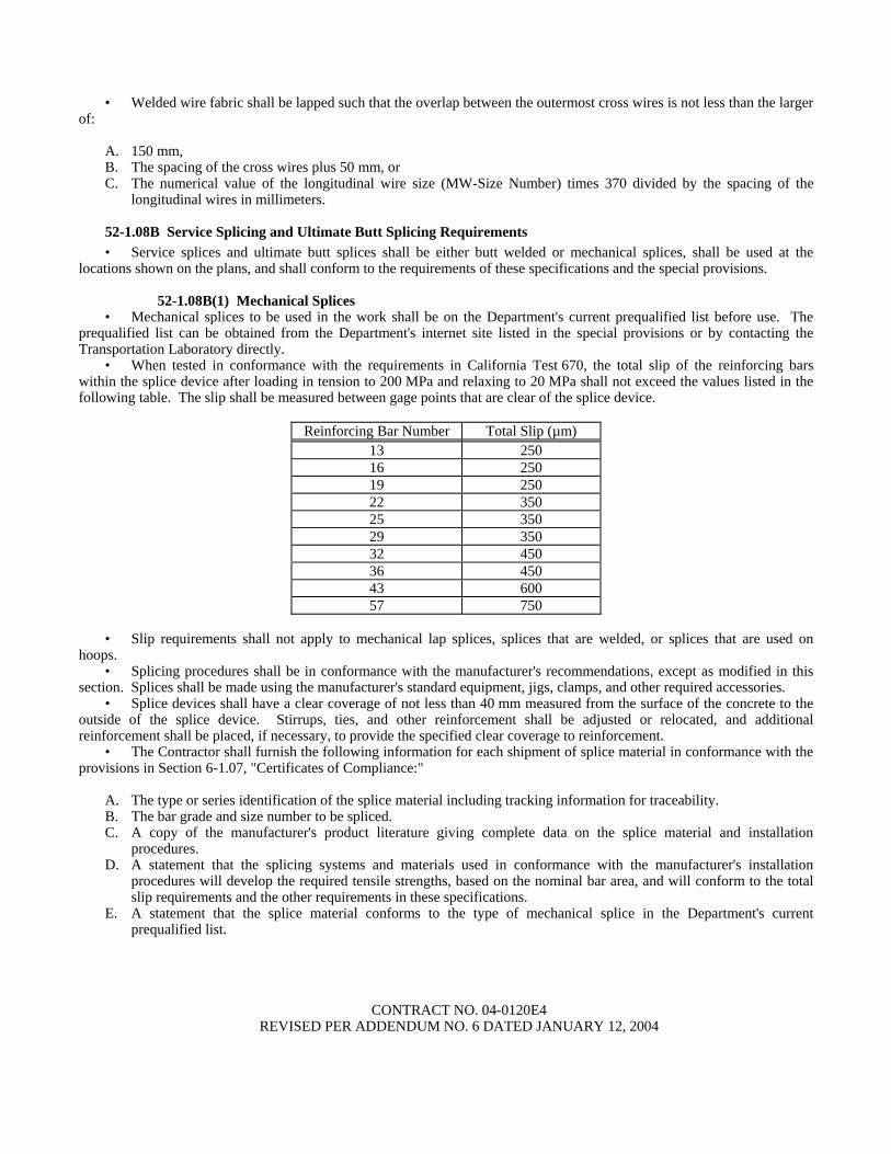
• When tested in conformance with the requirements in California Test 670, the total slip of the reinforcing barswithin the splice device after loading in tension to 200 MPa and relaxing to 20 MPa shall not exceed the values listed in thefollowing table. The slip shall be measured between gage points that are clear of the splice device.
Reinforcing Bar Number Total Slip (µm)13 25016 25019 25022 35025 35029 35032 45036 45043 60057 750
• Slip requirements shall not apply to mechanical lap splices, splices that are welded, or splices that are used onhoops.
• Splicing procedures shall be in conformance with the manufacturer's recommendations, except as modified in thissection. Splices shall be made using the manufacturer's standard equipment, jigs, clamps, and other required accessories.
• Splice devices shall have a clear coverage of not less than 40 mm measured from the surface of the concrete to theoutside of the splice device. Stirrups, ties, and other reinforcement shall be adjusted or relocated, and additionalreinforcement shall be placed, if necessary, to provide the specified clear coverage to reinforcement.
• The Contractor shall furnish the following information for each shipment of splice material in conformance with theprovisions in Section 6-1.07, "Certificates of Compliance:"
A. The type or series identification of the splice material including tracking information for traceability.B. The bar grade and size number to be spliced.C. A copy of the manufacturer's product literature giving complete data on the splice material and installation
procedures.D. A statement that the splicing systems and materials used in conformance with the manufacturer's installation
procedures will develop the required tensile strengths, based on the nominal bar area, and will conform to the totalslip requirements and the other requirements in these specifications.
E. A statement that the splice material conforms to the type of mechanical splice in the Department's currentprequalified list.
CONTRACT NO. 04-0120E4REVISED PER ADDENDUM NO. 6 DATED JANUARY 12, 2004

52-1.08B(2) Butt Welded Splices• Except for resistance butt welds, butt welded splices of reinforcing bars shall be complete joint penetration butt
welds conforming to the requirements in AWS D 1.4, and these specifications.• Welders and welding procedures shall be qualified in conformance with the requirements in AWS D 1.4.• Only the joint details and dimensions as shown in Figure 3.2, "Direct Butt Joints," of AWS D 1.4, shall be used for
making complete joint penetration butt welds of bar reinforcement. Split pipe backing shall not be used.• Butt welds shall be made with multiple weld passes using a stringer bead without an appreciable weaving motion.
The maximum stringer bead width shall be 2.5 times the diameter of the electrode and slagging shall be performed betweeneach weld pass. Weld reinforcement shall not exceed 4 mm in convexity.
• Electrodes used for welding shall meet the minimum Charpy V-notch impact requirement of 27°J at –20°C.• For welding of bars conforming to the requirements of ASTM Designation: A 615/A 615M, Grade 280 or
Grade 420, the requirements of Table 5.2, "Minimum Preheat and Interpass Temperatures," of AWS D 1.4 are superseded bythe following:
The minimum preheat and interpass temperatures shall be 200°C for Grade 280 bars and 300°C for Grade 420 bars.Immediately after completing the welding, at least 150 mm of the bar on each side of the splice shall be covered byan insulated wrapping to control the rate of cooling. The insulated wrapping shall remain in place until the bar hascooled below 90°C.
• When welding different grades of reinforcing bars, the electrode shall conform to Grade 280 bar requirements andthe preheat shall conform to the Grade 420 bar requirements.
• In the event that any of the specified preheat, interpass, and post weld cooling temperatures are not met, all weld andheat affected zone metal shall be removed and the splice rewelded.
• Welding shall be protected from air currents, drafts, and precipitation to prevent loss of heat or loss of arc shielding.The method of protecting the welding area from loss of heat or loss of arc shielding shall be subject to approval by theEngineer.
• Reinforcing bars shall not be direct butt spliced by thermite welding.• Procedures to be used in making welded splices in reinforcing bars, and welders employed to make splices in
reinforcing bars, shall be qualified by tests performed by the Contractor on sample splices of the type to be used, beforemaking splices to be used in the work.
52-1.08B(3) Resistance Butt Welds• Shop produced resistance butt welds shall be produced by a fabricator who is approved by the Transportation
Laboratory. The list of approved fabricators can be obtained from the Department’s internet site or by contacting theTransportation Laboratory directly.
• Before manufacturing hoops using resistance butt welding, the Contractor shall submit to the Engineer themanufacturer's Quality Control (QC) manual for the fabrication of hoops. As a minimum, the QC manual shall include thefollowing:
A. The pre-production procedures for the qualification of material and equipment.B. The methods and frequencies for performing QC procedures during production.C. The calibration procedures and calibration frequency for all equipment.D. The welding procedure specification (WPS) for resistance welding.E. The method for identifying and tracking lots.
52-1.08C Service Splice and Ultimate Butt Splice Testing Requirements• The Contractor shall designate in writing a splicing Quality Control Manager (QCM). The QCM shall be
responsible directly to the Contractor for 1) the quality of all service and ultimate butt splicing including the inspection ofmaterials and workmanship performed by the Contractor and all subcontractors; and 2) submitting, receiving, and approvingall correspondence, required submittals, and reports regarding service and ultimate splicing to and from the Engineer.
• The QCM shall not be employed or compensated by any subcontractor, or by other persons or entities hired bysubcontractors, who will provide other services or materials for the project. The QCM may be an employee of theContractor.
CONTRACT NO. 04-0120E4REVISED PER ADDENDUM NO. 6 DATED JANUARY 12, 2004

• Testing on prequalification and production sample splices shall be performed at the Contractor's expense, at anindependent qualified testing laboratory. The laboratory shall not be employed or compensated by any subcontractor, or byother persons or entities hired by subcontractors who will provide other services or materials for the project, and shall havethe following:
A. Proper facilities, including a tensile testing machine capable of breaking the largest size of reinforcing bar to betested with minimum lengths as shown in this section.
B. A device for measuring the total slip of the reinforcing bars across the splice to the nearest 25 µm, that, when placedparallel to the longitudinal axis of the bar is able to simultaneously measure movement across the splice, at2 locations, 180 degrees apart.
C. Operators who have received formal training for performing the testing requirements of ASTM Designation: A 370and California Test 670.
D. A record of annual calibration of testing equipment performed by an independent third party that has 1) standardsthat are traceable to the National Institute of Standards and Technology, and 2) a formal reporting procedure,including published test forms.
• The Contractor shall provide samples for quality assurance testing in conformance with the provisions in thesespecifications and the special provisions.
• Prequalification and production sample splices shall be 1) a minimum length of 1.5 meters for reinforcing barsNo. 25 or smaller, and 2 meters for reinforcing bars No. 29 or larger, with the splice located at mid-point; and 2) suitablyidentified before shipment with weatherproof markings that do not interfere with the Engineer's tamper-proof markings orseals. Splices that shows signs of tampering will be rejected.
• Each set or sample splice, as defined herein, shall be identified as representing either a prequalification orproduction test sample splice.
• For the purpose of production testing, a lot of either service splices or ultimate butt splices is defined as 1) 150, orfraction thereof, of the same type of mechanical splices used for each bar size and each bar deformation pattern that is used inthe work, or 2) 150, or fraction thereof, of complete joint penetration butt welded splices, or resistance butt welded splices foreach bar size used in the work. If different diameters of hoop reinforcement are shown on the plans, separate lots shall beused for each different hoop diameter.
• Whenever a lot of splices is rejected, the rejected lot and subsequent lots of splices shall not be used in the workuntil 1) the QCM performs a complete review of the Contractor's quality control process for these splices, 2) a written reportis submitted to the Engineer describing the cause of failure for the splices in this lot and provisions for preventing similarfailures in future lots, and 3) the Engineer has provided the Contractor with written notification that the report is acceptable.The Engineer shall have 3 working days after receipt of the report to provide notification to the Contractor. In the event theEngineer fails to provide notification within the time allowed, and if, in the opinion of the Engineer, completion of the workis delayed or interfered with by reason of the Engineer's delay in providing notification, the Contractor will be compensatedfor any resulting loss, and an extension of time will be granted in the same manner as provided for in Section 8-1.09, "Rightof Way Delays."
52-1.08C(1) Splice Prequalification Report• Before using any service splices or ultimate butt splices in the work, the Contractor shall submit a Splice
Prequalification Report. The report shall include splice material information, names of the operators who will be performingthe splicing, and descriptions of the positions, locations, equipment, and procedures that will be used in the work.
• The Splice Prequalification Report shall also include certifications from the fabricator for prequalifications ofoperators and procedures based on sample tests performed no more than 2 years before submitting the report. Each operatorshall be certified by performing 2 sample splices for each bar size of each splice type that the operator will be performing inthe work. For deformation-dependent types of splice devices, each operator shall be certified by performing 2 additionalsamples for each bar size and deformation pattern that will be used in the work.
• Prequalification sample splices shall be tested by an independent qualified testing laboratory and shall conform tothe appropriate production test criteria and slip requirements specified herein. When epoxy-coated reinforcement is required,resistance butt welded sample splices shall have the weld flash removed by the same procedure as will be used in the work,before coating and testing. The Splice Prequalification Report shall include the certified test results for all prequalificationsample splices.
CONTRACT NO. 04-0120E4REVISED PER ADDENDUM NO. 6 DATED JANUARY 12, 2004

• The QCM shall review and approve the Splice Prequalification Report before submitting it to the Engineer forapproval. The Contractor shall allow 2 weeks for the review and approval of a complete report before performing any servicesplicing or ultimate butt splicing in the work. In the event the Engineer fails to complete the review within the time allowed,and in the opinion of the Engineer, completion of the work is delayed or interfered with by reason of the Engineer's delay incompleting the review, the Contractor will be compensated for any resulting loss, and an extension of time will be granted, inthe same manner as provided for in Section 8-1.09, "Right of Way Delays."
52-1.08C(2) Service Splice Test Criteria• Service production and quality assurance sample splices shall be tensile tested in conformance with the requirements
in ASTM Designation: A 370 and California Test 670 and shall develop a minimum tensile strength of not less than550 MPa.
52-1.08C(2)(a) Production Test Requirements for Service Splices• Production tests shall be performed by the Contractor's independent laboratory for all service splices used in the
work. A production test shall consist of testing 4 sample splices prepared for each lot of completed splices. The samplesshall be prepared by the Contractor using the same splice material, position, operators, location, and equipment, andfollowing the same procedure as used in the work.
• At least one week before testing, the Contractor shall notify the Engineer in writing of the date when and thelocation where the testing of the samples will be performed.
• The 4 samples from each production test shall be securely bundled together and identified with a completed sampleidentification card before shipment to the independent laboratory. The card will be furnished by the Engineer. Bundles ofsamples containing fewer than 4 samples of splices shall not be tested.
• Before performing any tensile tests on production test sample splices, one of the 4 samples shall be tested for, andshall conform to, the requirements for total slip. Should this sample not meet the total slip requirements, one retest, in whichthe 3 remaining samples are tested for total slip, will be allowed. Should any of the 3 remaining samples not conform to thetotal slip requirements, all splices in the lot represented by this production test will be rejected.
• If 3 or more sample splices from a production test conform to the provisions in this Section 52-1.08C(2), "ServiceSplice Test Criteria," all splices in the lot represented by this production test will be considered acceptable, provided each ofthe 4 samples develop a minimum tensile strength of not less than 420 MPa.
• Should only 2 sample splices from a production test conform to the provisions in this Section 52-1.08C(2), "ServiceSplice Test Criteria," one additional production test shall be performed on the same lot of splices. This additional productiontest shall consist of testing 4 samples splices that have been randomly selected by the Engineer and removed by theContractor from the actual completed lot of splices. Should any of the 4 splices from this additional test fail to conform tothese provisions, all splices in the lot represented by these production tests will be rejected.
• If only one sample splice from a production test conforms to the provisions in this Section 52-1.08C(2), "ServiceSplice Test Criteria," all splices in the lot represented by this production test will be rejected.
• If a production test for a lot fails, the Contractor shall repair or replace all reinforcing bars from which samplesplices were removed before the Engineer selects additional splices from this lot for further testing.
52-1.08C(2)(b) Quality Assurance Test Requirements for Service Splices• For the first production test performed, and for at least one, randomly selected by the Engineer, of every
5 subsequent production tests, or portion thereof, the Contractor shall concurrently prepare 4 additional service qualityassurance sample splices. These service quality assurance sample splices shall be prepared in the same manner as specifiedherein for service production sample splices.
• These 4 additional quality assurance sample splices shall be shipped to the Transportation Laboratory for qualityassurance testing. The 4 sample splices shall be securely bundled together and identified by location and contract numberwith weatherproof markings before shipment. Bundles containing fewer than 4 samples of splices will not be tested. Samplesplices not accompanied by the supporting documentation required in Section 52-1.08B(1), for mechanical splices, or inSection 52-1.08B(3), for resistance butt welds, will not be tested.
• Quality assurance testing will be performed in conformance with the requirements for service production samplesplices in Section 52-1.08C(2)(a), "Production Test Requirements for Service Splices."
CONTRACT NO. 04-0120E4REVISED PER ADDENDUM NO. 6 DATED JANUARY 12, 2004
52-1.08C(3) Ultimate Butt Splice Test Criteria• Ultimate production and quality assurance sample splices shall be tensile tested in conformance with the
requirements described in ASTM Designation: A 370 and California Test 670.• A minimum of one control bar shall be removed from the same bar as, and adjacent to, all ultimate production, and
quality assurance sample splices. Control bars shall be 1) a minimum length of one meter for reinforcing bars No. 25 orsmaller and 1.5 meters for reinforcing bars No. 29 or larger, and 2) suitably identified before shipment with weatherproofmarkings that do not interfere with the Engineer's tamper-proof markings or seals. The portion of adjacent bar remaining inthe work shall also be identified with weatherproof markings that correspond to its adjacent control bar.
• Each sample splice and its associated control bar shall be identified and marked as a set. Each set shall be identifiedas representing a prequalification, production, or quality assurance sample splice.
• The portion of hoop reinforcing bar, removed to obtain a sample splice and control bar, shall be replaced using aprequalified ultimate mechanical butt splice, or the hoop shall be replaced in kind.
• Reinforcing bars, other than hoops, from which sample splices are removed, shall be repaired using ultimatemechanical butt splices conforming to the provisions in Section 52-1.08C(1), "Splice Prequalification Report," or the barsshall be replaced in kind. These bars shall be repaired or replaced such that no splices are located in any "No Splice Zone"shown on the plans.
• Ultimate production and quality assurance sample splices shall rupture in the reinforcing bar either: 1) outside ofthe affected zone or 2) within the affected zone, provided that the sample splice has achieved at least 95 percent of theultimate tensile strength of the control bar associated with the sample splice. In addition, necking of the bar shall be visiblyevident at rupture regardless of whether the bar breaks inside or outside the affected zone.
• The affected zone is the portion of the reinforcing bar where any properties of the bar, including the physical,metallurgical, or material characteristics, have been altered by fabrication or installation of the splice.
• The ultimate tensile strength shall be determined for all control bars by tensile testing the bars to rupture, regardlessof where each sample splice ruptures. If 2 control bars are tested for one sample splice, the bar with the lower ultimatetensile strength shall be considered the control bar.
52-1.08C(3)(a) Production Test Requirements for Ultimate Butt Splices• Production tests shall be performed for all ultimate butt splices used in the work. A production test shall consist of
testing 4 sets of sample splices and control bars removed from each lot of completed splices, except when quality assurancetests are performed.
• After the splices in a lot have been completed, and the bars have been epoxy-coated when required, the QCM shallnotify the Engineer in writing that the splices in this lot conform to the specifications and are ready for testing. Except forhoops, sample splices will be selected by the Engineer at the job site. Sample splices for hoops will be selected by theEngineer either at the job site or a fabrication facility.
• After notification has been received, the Engineer will randomly select the 4 sample splices to be removed from thelot and place tamper-proof markings or seals on them. The Contractor shall select the adjacent control bar for each samplesplice bar, and the Engineer will place tamper-proof markings or seals on them. These ultimate production sample splicesand control bars shall be removed by the Contractor, and tested by an independent qualified testing laboratory.
• At least one week before testing, the Contractor shall notify the Engineer in writing of the date when and thelocation where the testing of the samples will be performed.
• A sample splice or control bar from any set will be rejected if a tamper-proof marking or seal is disturbed beforetesting.
• The 4 sets from each production test shall be securely bundled together and identified with a completed sampleidentification card before shipment to the independent laboratory. The card will be furnished by the Engineer. Bundles ofsamples containing fewer than 4 sets of splices shall not be tested.
• Before performing any tensile tests on production test sample splices, one of the 4 sample splices shall be tested for,and shall conform to, the requirements for total slip. Should this sample splice not meet these requirements, one retest, inwhich the 3 remaining sample splices are tested for total slip, will be allowed. Should any of the 3 remaining sample splicesnot conform to these requirements, all splices in the lot represented by this production test will be rejected.
• If 3 or more sample splices from a production test conform to the provisions in Section 52-1.08C(3), "Ultimate ButtSplice Test Criteria," all splices in the lot represented by this production test will be considered acceptable.
CONTRACT NO. 04-0120E4REVISED PER ADDENDUM NO. 6 DATED JANUARY 12, 2004

• Should only 2 sample splices from a production test conform to the provisions in Section 52-1.08C(3), "UltimateButt Splice Test Criteria," one additional production test shall be performed on the same lot of splices. Should any of the4 sample splices from this additional test fail to conform to these provisions, all splices in the lot represented by theseproduction tests will be rejected.
• If only one sample splice from a production test conforms to the provisions in Section 52-1.08C(3), "Ultimate ButtSplice Test Criteria," all splices in the lot represented by this production test will be rejected.
• If a production test for a lot fails, the Contractor shall repair or replace all reinforcing bars from which samplesplices were removed, complete in place, before the Engineer selects additional splices from this lot for further testing.
• Production tests will not be required on repaired splices from a lot, regardless of the type of prequalified ultimatemechanical butt splice used to make the repair. However, should an additional production test be required, the Engineer mayselect any repaired splice for the additional production test.
52-1.08C(3)(b) Quality Assurance Test Requirements for Ultimate Butt Splices• For the first production test performed, and for at least one, randomly selected by the Engineer, of every
5 subsequent production tests, or portion thereof, the Contractor shall concurrently prepare 4 additional ultimate qualityassurance sample splices along with associated control bars.
• Each time 4 additional ultimate quality assurance sample splices are prepared, 2 of these quality assurance samplesplice and associated control bar sets and 2 of the production sample splice and associated control bar sets, together, shallconform to the requirements for ultimate production sample splices in Section 52-1.08C(3)(a), "Production TestRequirements for Ultimate Butt Splices."
• The 2 remaining quality assurance sample splice and associated control bar sets, along with the 2 remainingproduction sample splice and associated control bar sets shall be shipped to the Transportation Laboratory for qualityassurance testing. The 4 sets shall be securely bundled together and identified by location and contract number withweatherproof markings before shipment. Bundles containing fewer than 4 sets will not be tested.
• Quality assurance testing will be performed in conformance with the requirements for ultimate production samplesplices in Section 52-1.08C(3)(a), "Production Test Requirements for Ultimate Butt Splices."
52-1.08C(3)(c) Nondestructive Splice Tests• When the specifications allow for welded sample splices to be taken from other than the completed lot of splices, the
Contractor shall meet the following additional requirements.• Except for resistance butt welded splices, radiographic examinations shall be performed on 25 percent of all
complete joint penetration butt welded splices from a production lot. The size of a production lot will be a maximum of150 splices. The Engineer will select the splices which will compose the production lot and also the splices within eachproduction lot to be radiographically examined.
• All required radiographic examinations of complete joint penetration butt welded splices shall be performed by theContractor in conformance with the requirements in AWS D 1.4 and these specifications.
• Before radiographic examination, welds shall conform to the requirements in Section 4.4, "Quality of Welds," ofAWS D 1.4.
• Should more than 12 percent of the splices which have been radiographically examined in any production lot bedefective, an additional 25 percent of the splices, selected by the Engineer from the same production lot, shall beradiographically examined. Should more than 12 percent of the cumulative total of splices tested from the same productionlot be defective, all remaining splices in the lot shall be radiographically examined.
• Additional radiographic examinations performed due to the identification of defective splices shall be at theContractor's expense.
• All defects shall be repaired in conformance with the requirements in AWS D 1.4.• The Contractor shall notify the Engineer in writing 48 hours before performing any radiographic examinations.• The radiographic procedure used shall conform to the requirements in AWS D1.1, AWS D1.4, and the following:
Two exposures shall be made for each complete joint penetration butt welded splice. For each of the 2 exposures,the radiation source shall be centered on each bar to be radiographed. The first exposure shall be made with the radiationsource placed at zero degrees from the top of the weld and perpendicular to the weld root and identified with a stationmark of "0." The second exposure shall be at 90 degrees to the "0" station mark and shall be identified with a stationmark of "90." When obstructions prevent a 90 degree placement of the radiation source for the second exposure, andwhen approved in writing by the Engineer, the source may be rotated, around the centerline of the reinforcing bar, amaximum of 25 degrees.
CONTRACT NO. 04-0120E4REVISED PER ADDENDUM NO. 6 DATED JANUARY 12, 2004

For field produced complete joint penetration butt welds, no more than one weld shall be radiographed during oneexposure. For shop produced complete joint penetration butt welds, if more than one weld is to be radiographed duringone exposure, the angle between the root line of each weld and the direction to the radiation source shall be not less than65 degrees.
Radiographs shall be made by either X-ray or gamma ray. Radiographs made by X-ray or gamma rays shall havedensities of not less than 2.3 nor more than 3.5 in the area of interest. A tolerance of 0.05 in density is allowed fordensitometer variations. Gamma rays shall be from the iridium 192 isotope and the emitting specimen shall not exceed4.45 mm in the greatest diagonal dimension.
The radiographic film shall be placed perpendicular to the radiation source at all times; parallel to the root line of theweld unless source placement determines that the film must be turned; and as close to the root of the weld as possible.
The minimum source to film distance shall be maintained so as to ensure that all radiographs maintain a maximumgeometric unsharpness of 0.020 at all times, regardless of the size of the reinforcing bars.
Penetrameters shall be placed on the source side of the bar and perpendicular to the radiation source at all times.One penetrameter shall be placed in the center of each bar to be radiographed, perpendicular to the weld root, andadjacent to the weld. Penetrameter images shall not appear in the weld area.
When radiography of more than one weld is being performed per exposure, each exposure shall have a minimum ofone penetrameter per bar, or 3 penetrameters per exposure. When 3 penetrameters per exposure are used, onepenetrameter shall be placed on each of the 2 outermost bars of the exposure, and the remaining penetrameter shall beplaced on a centrally located bar.
An allowable weld buildup of 4 mm may be added to the total material thickness when determining the properpenetrameter selection. No image quality indicator equivalency will be accepted. Wire penetrameters or penetrameterblocks shall not be used.
Penetrameters shall be sufficiently shimmed using a radiographically identical material. Penetrameter imagedensities shall be a minimum of 2.0 and a maximum of 3.6.
Radiographic film shall be Class 1, regardless of the size of reinforcing bars.Radiographs shall be free of film artifacts and processing defects, including, but not limited to, streaks, scratches,
pressure marks or marks made for the purpose of identifying film or welding indications.Each splice shall be clearly identified on each radiograph and the radiograph identification and marking system shall
be established between the Contractor and the Engineer before radiographic inspection begins. Film shall be identifiedby lead numbers only; etching, flashing or writing in identifications of any type will not be permitted. Each piece of filmidentification information shall be legible and shall include, as a minimum, the following information: Contractor'sname, date, name of nondestructive testing firm, initials of radiographer, contract number, part number and weld number.The letter "R" and repair number shall be placed directly after the weld number to designate a radiograph of a repairedweld.
Radiographic film shall be developed within a time range of one minute less to one minute more than the filmmanufacturer's recommended maximum development time. Sight development will not be allowed.
Processing chemistry shall be done with a consistent mixture and quality, and processing rinses and tanks shall beclean to ensure proper results. Records of all developing processes and any chemical changes to the developingprocesses shall be kept and furnished to the Engineer upon request. The Engineer may request, at any time, that a sheetof unexposed film be processed in the presence of the Engineer to verify processing chemical and rinse quality.
The results of all radiographic interpretations shall be recorded on a signed certification and a copy kept with thefilm packet.
Technique sheets prepared in conformance with the requirements in ASME Boiler and Pressure Vessels Code,Section V, Article 2 Section T-291 shall also contain the developer temperature, developing time, fixing duration and allrinse times.
52-1.08D Reporting Test Results• A Production Test Report for all testing performed on each lot shall be prepared by the independent testing
laboratory performing the testing and submitted to the QCM for review and approval. The report shall be signed by anengineer who represents the laboratory and is registered as a Civil Engineer in the State of California. The report shallinclude, as a minimum, the following information for each test: contract number, bridge number, lot number and location,bar size, type of splice, length of mechanical splice, length of test specimen, physical condition of test sample splice and anyassociated control bar, any notable defects, total measured slip, ultimate tensile strength of each splice, and for ultimate buttsplices, limits of affected zone, location of visible necking area, ultimate tensile strength and 95 percent of this ultimatetensile strength for each control bar, and a comparison between 95 percent of the ultimate tensile strength of each control barand the ultimate tensile strength of its associated splice.
CONTRACT NO. 04-0120E4REVISED PER ADDENDUM NO. 6 DATED JANUARY 12, 2004

• The QCM must review, approve, and forward each Production Test Report to the Engineer for review before thesplices represented by the report are encased in concrete. The Engineer will have 3 working days to review each ProductionTest Report and respond in writing after a complete report has been received. Should the Contractor elect to encase anysplices before receiving notification from the Engineer, it is expressly understood that the Contractor will not be relieved ofthe responsibility for incorporating material in the work that conforms to the requirements of the plans and specifications.Material not conforming to these requirements will be subject to rejection. Should the Contractor elect to wait to encasesplices pending notification by the Engineer, and in the event the Engineer fails to complete the review and providenotification within the time allowed, and if, in the opinion of the Engineer, the work is delayed or interfered with by reason ofthe Engineer's delay in completing the review, the Contractor will be compensated for any resulting loss, and an extension oftime will be granted, in the same manner as provided for in Section 8-1.09, "Right of Way Delays."
• Quality assurance test results for each bundle of 4 sets or 4 samples of splices will be reported in writing to theContractor within 3 working days after receipt of the bundle by the Transportation Laboratory. In the event that more thanone bundle is received on the same day, 2 additional working days shall be allowed for providing test results for eachadditional bundle received. A test report will be made for each bundle received. Should the Contractor elect to encasesplices before receiving notification from the Engineer, it is expressly understood that the Contractor will not be relieved ofthe responsibility for incorporating material in the work that conforms to the requirements of the plans and specifications.Material not conforming to these requirements will be subject to rejection. Should the Contractor elect to wait to encasesplices pending notification by the Engineer, and in the event the Engineer fails to complete the review within the timeallowed, and in the opinion of the Engineer, completion of the work is delayed or interfered with by reason of the Engineer'sdelay in completing the review, the Contractor will be compensated for any resulting loss, and an extension of time will begranted, in the same manner as provided for in Section 8-1.09, "Right of Way Delays."
Section 52-1.08F, "Nondestructive Splice Tests," of the Standard Specifications is amended by deleting the seventhparagraph.
CONTRACT NO. 04-0120E4REVISED PER ADDENDUM NO. 6 DATED JANUARY 12, 2004

5-1.0105 INTEGRATED SHOP DRAWINGSDifficult construction is anticipated at the Tower footing, and the Pier E2 footing and columns that are highly congested
with steel plates, stiffeners, studs, dowels, pile sleeves, reinforcing steel, headed reinforcing steel, anchor bolts, pipe sleeves,drain pipes, and other concrete embedded items as shown on the plans. The Contractor shall develop three-dimensionalintegrated shop drawings (ISD) for the Tower and Pier E2 including columns and footings, in accordance with the detailsshown on the plans and the requirements of this section. The ISD shall conform to Section “Working Drawings,” of thesespecial provisions. The ISD shall be of sufficient detail to demonstrate compatibility of the embedded items within theconcrete.
Prior to commencing work on the ISD, the Contractor (including any subconsultants hired to work on the ISD) shallattend a meeting with the Engineer to discuss the ISD work.
The Contractor shall utilize commercially available software that checks for interference in three dimensions. Prior toacquiring the software, the Contractor shall submit to the Engineer the product name and application features of the softwarefor review and approval. The software shall be compatible with the computer-aided drafting (CAD) software used to developthe ISD. Bar reinforcement shall be shown with deformed diameters. The Contractor shall develop CAD files usingdifferent layers for each type of embedded item such that the sequence of construction of the member or area being detailedcan be shown. Attention is directed to "Working Drawing Campus" elsewhere in these special provisions for otherequipment and software requirements.
Embedded items that are to be shown on the ISD shall include, but are not limited to, the following:
A. Bar reinforcing steel and splices including lap, welded, and mechanical splicesB. Casings and pipesC. Anchor boltsD. Drainage pipesE. Corrosion protection system itemsF. Inserts, bolt sleeves, dowels and studsG. Other items, as shown on the plans
The Contractor shall use the ISD to identify and eliminate interference between the planned positions of embedded itemsand to satisfy the concrete cover shown on the plans.
If a conflict is identified, the Contractor shall document the conflict and propose changes to the embedded items in theISD to resolve the conflict. Proposed changes to the embedded items shall be made by a licensed engineer practicing civilengineering with extensive previous experience developing ISD.
The Contractor's proposed changes in the ISD shall comply with the following sequence of item adjustments:
A. Non structural embedded items.B. Bar reinforcing steel.
The Contractor shall use the following measures in the order prescribed to resolve interference issues during thepreparation of the ISD:
A. Adjust reinforcement spacing.B. Bundle bars.C. Relocate splices.D. Change reinforcement size and number. Reduction of the total reinforcement area will not be permitted, unless
otherwise approved by the Engineer.E. Change reinforcement shape.F. Move embedded inserts.
The ISD to be submitted to the Engineer shall include the following:
A. Three sets of the ISD corresponding to the details as shown on the plans without any modifications. These ISD shallindicate all conflicts including locations of the conflicts and items involved in the conflicts.
B. Three complete lists of conflicts with descriptions and the Contractor's proposed modifications for each conflict.
CONTRACT NO. 04-0120E4REVISED PER ADDENDUM NO. 6 DATED JANUARY 12, 2004

C. Three sets of the ISD corresponding to the details as shown on the plans with incorporation of the Contractor'sproposed modifications. These ISD shall indicate that all previous identified conflicts have been resolved andconcrete cover requirements as shown on the plans are met.
D. ISD shall be 559 mm x 864 mm in size and shall use colored ink to differentiate each type of embedded items. Foreach portion of the structure, ISD shall include a minimum of six isometric views. Any two isometric views shall be90 degrees apart.
E. Three copies of the ISD in electronic form on compact discs or tape for use by the Engineer.
An ISD submittal that complies with all of the above requirements, in the opinion of the Engineer, will be defined as acomplete ISD submittal. Submittal of isometric drawings made from ISD shall in no way relieve the Contractor from anyother working drawing submittal required by these special provisions or the Standard Specifications.
CAD files of the contract drawings will not be made available to the Contractor.After an ISD submittal is received by the Engineer, the Contractor shall allow the Engineer 7 days to review the ISD
submittal for completeness. If determined to be complete, the Engineer shall have 28 working days from the day of receipt toreview and approve the ISD submittal. For proposed modifications that are not approved by the Engineer, the Engineer willpropose alternative modifications to the Contractor. The Contractor shall submit revised ISD incorporating the Engineer’salternative modifications as specified in this section.
Assembly of the mock-up represented by the ISD and construction of the Tower footing and the Pier E2 footings andcolumns shall not begin until the Engineer reviews and approves the complete ISD submittal with all conflicts resolved.
No extension of time will be permitted for the Contractor’s failure to complete the ISD as required by these specialprovisions.
Full compensation for preparing ISD, including all revisions necessary due to conflict resolution measures taken by theContractor, shall be considered as included in the contract prices paid for the various items of work and no additionalcompensation will be allowed therefore.
CONTRACT NO. 04-0120E4REVISED PER ADDENDUM NO. 6 DATED JANUARY 12, 2004

5-1.25 PAYMENTSAttention is directed to Sections 9-1.06, "Partial Payments," and 9-1.07, "Payment After Acceptance," of the Standard
Specifications and these special provisions.Partial Payments shall conform to Section 9-1.06, "Partial Payments," of the Standard Specifications and these special
provisions.In conformance with 49 CFR, Part 26, Subpart A, Section 26.29 (b)(1), the retention of proceeds required by Public
Contract Code Section 10261 shall not apply. In conformance with Public Contract Code 7200 (b), in subcontracts betweenthe Contractor and a subcontractor and in subcontracts between a subcontractor and any subcontractor thereunder, retentionproceeds shall not be withheld, and the exceptions provided in Public Contract Code 7200 (c) shall not apply. At the optionof the Contractor, subcontractors shall be required to furnish payment and performance bonds issued by an admitted suretyinsurer.
The third and fourth paragraphs of Section 9-1.06, "Partial Payments," of the Standard Specifications, andSection 9-1.065, "Payment of Withheld Funds," of the Standard Specifications shall not apply.
The Department shall pay monthly to the Contractor, while carrying on the work, the balance, after deducting therefromall previous payments and all sums to be kept or withheld under the provisions of the contract. No monthly estimate orpayment shall be required to be made when, in the judgement of the Engineer, the work is not proceeding in accordance withthe provisions of the contract.
For the purpose of making partial payments pursuant to Section 9-1.06, "Partial Payments," of the StandardSpecifications, the amount set forth for the contract items of work hereinafter listed shall be deemed to be the maximumvalue of the contract item of work which will be recognized for progress payment purposes:
A. Electronic Mobile Daily Diary Computer System Data Delivery $ 7,500B. Progress Schedule (critical Path) $40,000C. Establish Marine Access $5,000,000D. Working Drawing Campus $4,000,000
After acceptance of the contract pursuant to the provisions in Section 7-1.17, "Acceptance of Contract," of the StandardSpecifications, the amount, if any, payable for a contract item of work in excess of the maximum value for progress paymentpurposes hereinabove listed for the item, will be included for payment in the first estimate made after acceptance of thecontract.
In determining the partial payments to be made to the Contractor, only the following listed materials will be consideredfor inclusion in the payment as materials furnished but not incorporated in the work:
A. Steel shells for cast-in-steel shell pilingB. Permanent steel casingsC. Bar reinforcing steelD. Bar reinforcing steel (epoxy coated)E. Headed bar reinforcementF. Structural steelG. Miscellaneous metal
Plate steel for fabrication of structural steel and fabricated elements for structural steel, fabricated and stored in fencedareas with locked gates or in locked warehouses stored within will be eligible for partial payment if the Contractor furnishesevidence satisfactory to the Engineer that its storage is subject to or under the control of the Department and that it has beendesignated or fabricated specifically for this project and is of such character that is not adaptable to any other use.
CONTRACT NO. 04-0120E4REVISED PER ADDENDUM NO. 6 DATED JANUARY 12, 2004

Attention is directed to Section 2-1.104, "Alternative Bids," and Section 3, "Award and Execution of the Contract," ofthese special provisions. If the contract is awarded based upon a bid pursuant to “Engineer’s Estimate, Alternative 1, ForeignSteel and Iron Alternative,” the following shall apply: For the purpose of making partial payments for plate steel andfabricated elements for structural steel fabricated and stored outside the United States pursuant to these special provisions andSection 9-1.06, "Partial Payments," of the Standard Specifications, the amount of $30,000,000 for each monthly pay estimateshall be deemed to be the maximum value which will be recognized for progress payment purposes, until such material isbrought into the United States.
If the contract is awarded based upon a bid pursuant to "Engineer’s Estimate, Alternative 1, Foreign Steel and IronAlternative," the successful bidder shall furnish a bond or first demand bank guarantee to secure the value of potential partialpayments for plate steel and fabricated elements for structural steel fabricated and stored outside the United States pursuant tothese special provisions and Section 9-1.06, "Partial Payments," of the Standard Specifications.” The bond form will befurnished to the successful bidder by the Department. The bond shall be in a sum equal to at least $30,000,000. Allalterations, extensions of time, extra and additional work, and other changes authorized by these special provisions or anypart of the contract may be made without securing the consent of the surety of the bond.
CONTRACT NO. 04-0120E4REVISED PER ADDENDUM NO. 6 DATED JANUARY 12, 2004

10-1.115 WORKING DRAWING CAMPUSThe objective of the working drawing campus is to prepare, submit, review and process working drawings in the shortest
and most efficient manner possible. After the bid, the Department will make its Design engineers available for consultationon site with the contractor’s engineers and detailers who are preparing working drawings. The effort will focus on the mostcritical and time dependent working drawings first to prevent delay to the project schedule. It is the Contractor’sresponsibility to submit working drawings sufficiently in advance of the start of the affected work, in accordance with“Working Drawings” of these special provisions.
The Contractor shall provide the following within 60 days of contract award to facilitate early resolution of constructionworking drawings:
1. Suitable office facilities within 10 km of the San Francisco-Oakland Bay Bridge Toll Plaza for a minimum of oneyear. The facilities shall include workspace for the Contractor’s staff as determined by the Contractor plus aminimum of 4 vacant, separate office cubicles or rooms intended for the use by the Department or its representatives,and a common meeting room with meeting table to seat a minimum of 6 people. The facilities shall also includeaccess to a copier, and a fax machine. Each workspace shall include a minimum of a desk, office chair, bookshelf,phone, and T1 computer cabling. The Contractor is responsible for providing local phone service, internet accessand building utility services.
2. On-site Coordination Engineer. The Coordination Engineer shall be a full time, on-site, registered Civil Engineer inthe State of California, and available to coordinate, manage, and process shop/working drawings for the project.
3. Full time, on-site staff authorized by the Contractor to be capable of producing and revising working drawings, andin conjunction with such work generating and assisting in resolution of requests for information and potentiallyresultant change orders. It is not required that all the Contractor’s design staff be located on-site.
4. Regularly scheduled submittal status meetings (daily if required) to discuss the status and resolve shop/workingdrawing issues, attended by representatives of the Engineer and the Contractor’s coordinator and staff asappropriate.
5. Regular updates of the working drawing submittal schedule specified in “Working Drawing Submittal Schedule,” ofthese special provisions.
The Contractor shall provide a submittal for the Working Drawing Campus within the first 10 calendar days of award ofcontract. The submittal shall show the location of the office, layout of the office space and meeting room, and list of thefurnishing, including office computer, telephone, desk and chairs to be supplied. The Department will review within 10working days.
Conformance with these special provisions does not relieve the Contractor of the responsibility for furnishing completeshop/working drawings or producing finished work of the quality specified in the Standard Specifications, these specialprovisions and as shown on the plans.
The Contractor shall submit, for approval by the Engineer, a schedule of costs detailing the breakdown of the contractlump sum item. The schedule of costs shall be proportionate to the work involved and shall detail the costs and paymentschedule for each cost item associated with the process entailed in obtaining approval on all approved working drawing asspecified hereunder. When requested by the Engineer, the Contractor shall furnish any cost data, which might assist theEngineer in verifying one-time partial payments and establishing a suitable schedule of costs. The schedule of costs will beused to determine progress payments for "Working Drawing Campus" during the progress of the work. The schedule of costsshall be submitted to the Engineer for approval within 10 days of contract award. The Engineer shall be allowed 10 days forapproval or return for correction of the submittal.
EQUIPMENT AND SOFTWAREAttention is directed to "Integrated Shop Drawings" elsewhere in these special provisions.The Contractor shall provide for the State's exclusive possession and use a complete computer system specifically
capable of creating, storing, and updating ISD utilizing the latest hardware and software technology. Before delivery andsetup of the computer system, the Contractor shall submit to the Engineer for approval a detailed list of all computerhardware and software the Contractor proposes to furnish. The minimum computer system to be furnished shall include thefollowing:
A. Complete computer system, including keyboard, mouse with scroll, video card with one hundred twenty eight (128)megabyte onboard memory and dual ports, two 530-mm color SVGA monitors (1,024x768 pixels), current IntelPentium IV micro processor chip, or equivalent or later;
CONTRACT NO. 04-0120E4REPLACED PER ADDENDUM NO. 6 DATED JANUARY 12, 2004

B. Computer operating system software, compatible with the selected processing unit and CADD software, forWindows 2000, equivalent;
C. Minimum one (1) gigabytes of random access memory (RAM);D. A 100 gigabyte minimum hard disk drive, a 1.44 megabyte 90-mm floppy disk drive, 32x speed minimum CD-RW
drive, 10/100 Ethernet card, two UBCUSB ports;E. CADD software identical to the CADD software used by the Contractor to generate ISD;F. Microsoft Office software, the latest version for Windows NT/Windows 2000, or later, and McAfee Virus software
or equivalent.G. A color laser-jet printer with a minimum of eight (8) megabytes of RAM, capable of 600 dots per inch color, 600
dots per inch monochrome or equivalent. Capable of printing fully legible plots in color with a minimum size of279-mm by 432-mm. LaserJet toner and paper to be provided throughout the contract. HP LaserJet 5500,equivalent or later.
The computer hardware and software furnished shall be compatible with that used by the Contractor for the productionof the ISD by the Contract, and shall include original instruction manuals and other documentation normally provided withthe software.
The Contractor shall furnish, install, set up, maintain and repair the computer hardware and software ready for use at alocation determined by the Engineer. The hardware and software shall be installed and ready for use at least 30 days prior tosubmittal of the first ISD. The Contractor shall provide 16 hours of formal training for the Engineer, and three other agentsof the department designated by the Engineer, in the use of the hardware and software to include generating 3-D drawings,merging files, and manipulating drawing elements. An authorized vendor of CADD software shall perform the training.
All computer hardware and software furnished shall remain the property of the Contractor and shall be removed by theContractor upon acceptance of the contract.
MEASUREMENT AND PAYMENTAttention is directed to “Payments,” of these special provisions.The contract lump sum price paid for working drawing campus shall include full compensation for furnishing all labor,
materials, tools, equipment, and incidentals, and for doing all the work involved in facilitating early resolution ofconstruction working drawings, including but not limited to utility connection costs, maintenance costs, purchasing of officeequipment and furniture, and set up and removal of the office facility.
CONTRACT NO. 04-0120E4REPLACED PER ADDENDUM NO. 6 DATED JANUARY 12, 2004
10-1.29 REINFORCEMENTReinforcement shall conform to the provisions in Section 52, "Reinforcement," of the Standard Specifications and these
special provisions.Attention is directed to the section "Headed Bar Reinforcement," of these special provisions.Exposed portion of reinforcement at the top of columns shall be cleaned and painted. Dirt, loose rust and mill scale shall
be removed in conformance with the requirements in Surface Preparation Specification No. 2, "Hand Tool Cleaning," of the"SSPC: The Society for Protective Coatings." One application of a zinc-rich primer shall be applied to the exposed surfaceof the reinforcement in conformance with the provisions in Section 59-2.13, "Application of Zinc-Rich Primer," of theStandard Specifications.
The Department's mechanical splices prequalified list can be found at the following internet site:
http://www.dot.ca.gov/hq/esc/approved_products_list/
The provisions of "Welding Quality Control" of these special provisions shall not apply to resistance butt welding.At the option of the Contractor, sample splices shall be either 1) removed from the completed lot, or 2) prepared in the
same manner as specified in Section 52-1.08 "Splicing," of the Standard Specifications for ultimate prequalification samplesplices and control bars.
EPOXY-COATED PREFABRICATED REINFORCEMENTBar reinforcement to be epoxy-coated shall conform to the ASTM Designation and grade required or permitted by
Section 52-1.02A, "Bar Reinforcement," of the Standard Specifications, for the location or type of structure involved. Thecoated bar reinforcement shall conform to the requirements in ASTM Designation: A 934/A 934M except as providedherein.
Welded wire fabric and wire reinforcement to be epoxy-coated shall conform to the ASTM Designation and graderequired or permitted by Section 52-1.02C, "Welded Wire Fabric," and Section 52-1.02D, "Reinforcing Wire," of theStandard Specifications, respectively, for the location or type of structure involved. The coated wire reinforcement shallconform to the requirements for Class A, Type 2 coating of ASTM Designation: A 884/A 884M except as provided herein.
Appendices X1 and X2, "Guidelines For Job-Site Practices," of ASTM Designation: A 884/A 884M andA 934/A 934M, respectively, shall apply except as provided herein. The term "shall" shall replace the term "should" in theseappendices. Section X1.2 of Appendix X1 and Section X2.2 of Appendix X2 shall not apply.
All coatings shall be purple or gray in color.Except for field welding of butt splices, all welding of reinforcement shall be complete prior to epoxy coating the
reinforcement.Prior to epoxy coating, all resistance butt welds shall have the weld flash removed to produce a smooth profile free of
any sharp edges that would prevent proper coating of the bar. The flash shall be removed such that the ultimate tensilestrength and elongation properties of the bar are not reduced, and the outside radius of the flash, at any point along thecircumference of the bar, is 1) not less than the nominal radius of the bar, nor 2) greater than 5 mm beyond the nominalradius of the bar.
Mechanical couplers used in fenders shall be epoxy-coated to the requirements of this section. Prior to epoxy coating,surfaces of couplers shall be prepared to produce a smooth profile free of any sharp edges that would prevent proper coating.Surface preparation shall be such that the mechanical properties of the coupler are not reduced.
Couplers shall be properly connected to bar reinforcement and the entire unit epoxy-coated in accordance with thissection. The Contractor shall provide a temporary plug or other means to protect the exposed end of the coupler threadsduring the epoxy coating process. After the epoxy coating process, the exposed threads of finished units shall be filled with acommercial quality corrosion inhibiting grease. Finish units shall be covered with plastic caps, as shown on the plans.
A proposed weld flash removal process shall be submitted to and approved by the Engineer in writing, prior toperforming any removal work. The submittal shall demonstrate that the proposed flash removal process produces a smoothprofile that can be successfully epoxy-coated in conformance with the requirements specified herein.
Bending of epoxy-coated reinforcement after the coating has been applied will not be allowed.When any portion of a reinforcing bar or wire requires epoxy coating, the entire bar or wire shall be coated, except, when
the bar or wire is spliced outside of the limits of epoxy coating shown on the plans, epoxy coating will not be required on theportion of bar or wire beyond the splice.
CONTRACT NO. 04-0120E4REVISED PER ADDENDUM NO. 6 DATED JANUARY 12, 2004

Within areas where epoxy-coated reinforcement is required, tie wire and bar chairs or other metallic devices used tosecure or support the reinforcement shall be plastic-coated or epoxy-coated to prevent corrosion of the devices or damage tothe coated reinforcement.
Prior to coating, the Contractor shall furnish to the Transportation Laboratory a representative 110 g sample from eachbatch of epoxy coating material to be used. Each sample shall be packaged in an airtight container identified with themanufacturer's name and batch number.
Two 700-mm long samples of coated bar or wire reinforcement from each size and from each load shipped to the jobsiteshall be furnished to the Transportation Laboratory for testing. These samples shall be representative of the materialfurnished. These samples, as well as any additional random samples taken by the Engineer, may be tested for specificationcompliance. Additional sampling, and all tests performed by the Engineer, may be performed at any location deemedappropriate by the Engineer. Failure of any sample to meet the requirements of the specifications will be cause for rejection.
If any bar tested for coating thickness or for adhesion of coating fails to meet the requirements for coated bars in Section9 of ASTM Designation: A 934/A 934M, 2 retests on random samples taken from bars represented by the failed test will beconducted for each failed test. If the results of both retests meet the specified requirements, the coated bars represented bythe samples may be certified as meeting the test requirements.
If any wire reinforcement tested for coating thickness or for flexibility fails to meet the requirements for coated wire inSection 8 of ASTM Designation: A 884/A 884M, 2 retests on random samples taken from wire represented by the failed testwill be conducted for each failed test. If the results of both retests meet the specified requirements, the coated wirerepresented by the samples may be certified as meeting the test requirements.
Epoxy-coated reinforcement shall be covered with an opaque polyethylene sheeting or other suitable protective materialto protect the reinforcement from exposure to sunlight, salt spray, and weather. For stacked bundles, the protective coveringshall be draped around the perimeter of the stack. The covering shall be adequately secured; however, it should allow for aircirculation around the reinforcement to prevent condensation under the covering. Epoxy-coated reinforcement shall not bestored within 300 m of ocean or tidal water for more than 2 months.
All visible damage to coatings caused by shipping, handling, or installation shall be repaired as required for repairingcoating damaged prior to shipment conforming to the requirements in ASTM Designation: A 934/A 934M for barreinforcement or ASTM Designation: A 884/A 884M for wire reinforcement. When the extent of coating damage prior torepair exceeds 2 percent of the bar or wire surface area in any 300-mm length, repair of the bar or wire will not be allowed,and the coated bar or wire will be rejected.
The patching material and process shall be suitable for field application. The patching material shall be prequalified asrequired for the coating material and shall be either identified on the container as a material compatible with thereinforcement coating, or shall be accompanied by a Certificate of Compliance certifying that the material is compatible withthe reinforcement coating. Damaged areas shall be patched in conformance with the patching material manufacturer'srecommendations.
Except for lap splices, all splices for epoxy-coated reinforcement shall be coated with a corrosion protection coveringthat is on the Department's list of approved products. The covering shall be installed in conformance with the manufacturer'srecommendations and as directed by the Engineer. The list is available from the Transportation Laboratory.
A Certificate of Compliance conforming to the provisions in Section 6-1.07, "Certificates of Compliance," of theStandard Specifications, shall be furnished for each shipment of epoxy-coated bar, welded wire fabric, or wire reinforcementcertifying that the coated bars, fabric, or wire conform to the requirements in ASTM Designation: A 934/A 934M for bars orA 884/A 884M for welded wire fabric and wire and Section 52-1.02B, "Epoxy-coated Reinforcement," of the StandardSpecifications. This Certificate of Compliance shall include all the certifications specified in ASTM Designation:A 934/A 934M for bars or ASTM Designation: A 884/A 884M for welded wire fabric and wire and a statement that thecoating material has been prequalified by acceptance testing performed by the Valley Forge Laboratories, Inc., Devon,Pennsylvania.
Any portion of bar or wire reinforcement extending beyond the limits for epoxy-coated reinforcement shown on theplans will be measured and paid for as bar reinforcing steel (bridge) of the types listed in the Engineer's Estimate.
MEASUREMENT AND PAYMENTMeasurement and payment for reinforcement in structures shall conform to the provisions in Section 52-1.10,
"Measurement," and Section 52-1.11, "Payment," of the Standard Specifications and these special provisions.Full compensation for preparing and epoxy-coating mechanical couplers, filling mechanical couplers with corrosion
inhibiting grease, and furnishing and placing plastic caps and plugs shall be considered as included in the contract prices paidfor the various contract items of work involved and no additional compensation will be allowed therefor.
CONTRACT NO. 04-0120E4REVISED PER ADDENDUM NO. 6 DATED JANUARY 12, 2004

ENGINEER'S ESTIMATE04-0120E4
ALTERNATIVE 1 FOREIGN STEEL AND IRON ALTERNATIVEItem Item
CodeItem Unit of
MeasureEstimatedQuantity
Unit Price Item Total
1 030627 ELECTRONIC MOBILE DAILY DIARYCOMPUTER SYSTEM DATADELIVERY
LS LUMP SUM LUMP SUM
2 030628 TRANSPORTATION FOR THEENGINEER
LS LUMP SUM LUMP SUM
3 030629 CONSTRUCTION SURVEYING LS LUMP SUM LUMP SUM
4 030630 PILE CORROSION MONITORINGSYSTEM
LS LUMP SUM LUMP SUM
5 070012 PROGRESS SCHEDULE (CRITICALPATH METHOD)
LS LUMP SUM LUMP SUM
6 070018 TIME-RELATED OVERHEAD WDAY 1130
7 074019 PREPARE STORM WATERPOLLUTION PREVENTION PLAN
LS LUMP SUM LUMP SUM
8 074020 WATER POLLUTION CONTROL LS LUMP SUM LUMP SUM
9 030631 NON-STORM WATER DISCHARGES LS LUMP SUM LUMP SUM
10 030632 TURBIDITY CONTROL LS LUMP SUM LUMP SUM
11 074032 TEMPORARY CONCRETE WASHOUTFACILITY
LS LUMP SUM LUMP SUM
12(S)
490672 2.5 M CAST-IN-DRILLED-HOLECONCRETE PILING
M 423
13(S)
049245 2.2 M CAST-IN-DRILLED-HOLECONCRETE PILING (ROCK SOCKET)
M 390
14(S)
049246 FURNISH 2.5 M CAST-IN-STEELSHELL CONCRETE PILING
M 1694
15(S)
049247 DRIVE 2.5 M CAST-IN-STEEL SHELLCONCRETE PILE
EA 16
16(S)
049248 2.5 M PERMANENT STEEL CASING M 423
17(S-F)
049249 MARINE PILE DRIVING ENERGYATTENUATOR
LS LUMP SUM LUMP SUM
18(F)
510051 STRUCTURAL CONCRETE, BRIDGEFOOTING
M3 7030
19(F)
049250 STRUCTURAL CONCRETE, BRIDGEFOOTING (LIGHTWEIGHT)
M3 2300
20(F)
510053 STRUCTURAL CONCRETE, BRIDGE M3 1640
3REVISED PER ADDENDUM NO. 6 DATED JANUARY 12, 2004

ENGINEER'S ESTIMATE04-0120E4
ALTERNATIVE 1Item Item
CodeItem Unit of
MeasureEstimatedQuantity
Unit Price Item Total
21 049251 NONSHRINK GROUT LS LUMP SUM LUMP SUM
22 049252 NONSHRINK FIBER-REINFORCEDGROUT
LS LUMP SUM LUMP SUM
23(S-F)
520102 BAR REINFORCING STEEL (BRIDGE) KG 2 495 000
24(S-F)
520110 BAR REINFORCING STEEL (EPOXYCOATED) (BRIDGE)
KG 801 000
25(S-F)
520120 HEADED BAR REINFORCEMENT EA 3020
26(F)
550203 FURNISH STRUCTURAL STEEL(BRIDGE)
KG 3 960 000
27(F)
550204 ERECT STRUCTURAL STEEL(BRIDGE)
KG 3 960 000
28(S)
590115 CLEAN AND PAINT STRUCTURALSTEEL
LS LUMP SUM LUMP SUM
29(S)
049253 FURNISH AND INSTALL STEELDOWNHOLE CASING E
LS LUMP SUM LUMP SUM
30(S-F)
750501 MISCELLANEOUS METAL (BRIDGE) KG 420
31 800391 CHAIN LINK FENCE (TYPE CL-1.8) M 150
32 833080 CONCRETE BARRIER (TYPE K) M 72
33 030633 GROUNDING FOR PIERS E2 AND T1FOUNDATIONS
LS LUMP SUM LUMP SUM
34 030634 NAVIGATION LIGHTING SYSTEM LS LUMP SUM LUMP SUM
35 030635 STRONG MOTION DETECTIONDOWNHOLE
LS LUMP SUM LUMP SUM
36(S-F)
030965 PLASTIC LUMBER M3 145
37(S-F)
030966 UHMW POLYETHYLENE PANEL (50MM)
M2 930
38 049400 ESTABLISH MARINE ACCESS LS LUMP SUM LUMP SUM
39 BLANK
40 032252 WORKING DRAWING CAMPUS LS LUMP SUM LUMP SUM
4REVISED PER ADDENDUM NO. 6 DATED JANUARY 12, 2004
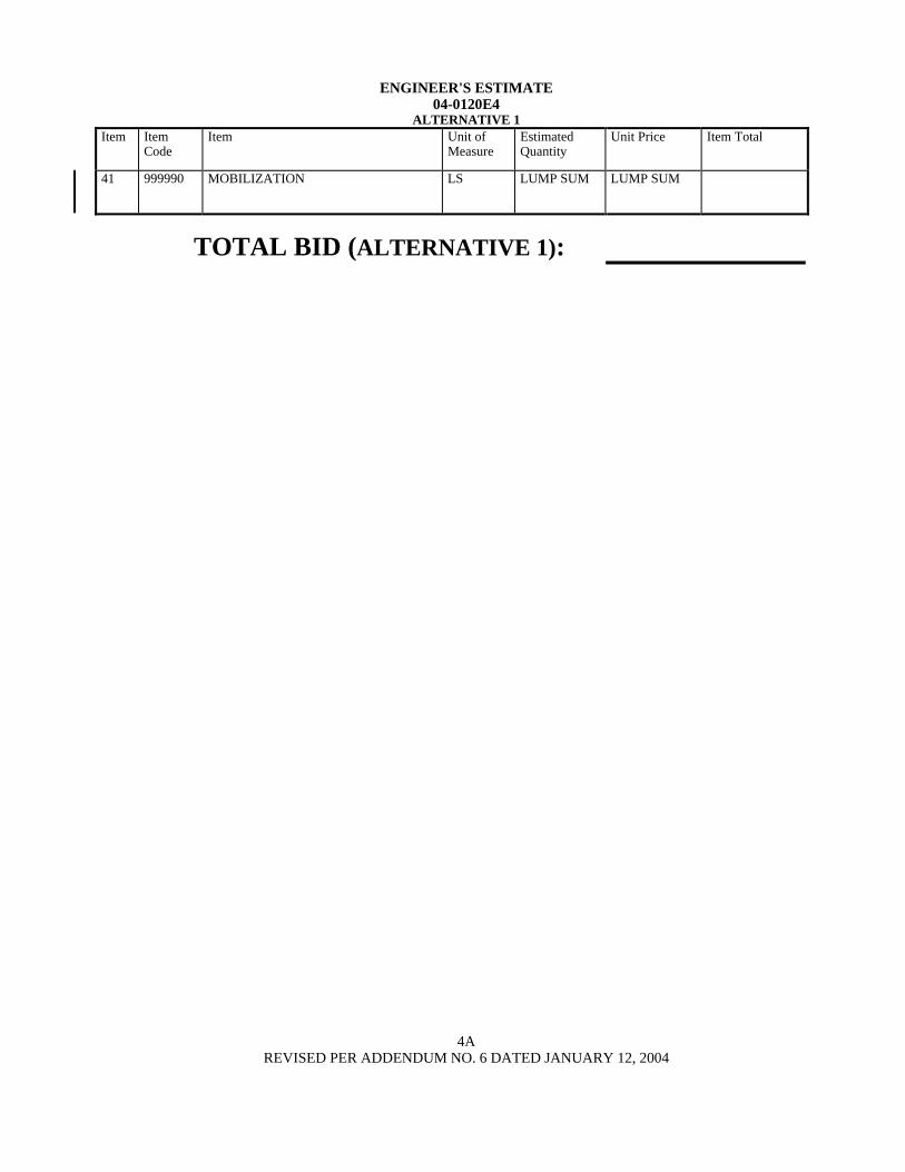
ENGINEER'S ESTIMATE04-0120E4
ALTERNATIVE 1Item Item
CodeItem Unit of
MeasureEstimatedQuantity
Unit Price Item Total
41 999990 MOBILIZATION LS LUMP SUM LUMP SUM
TOTAL BID (ALTERNATIVE 1):
4AREVISED PER ADDENDUM NO. 6 DATED JANUARY 12, 2004

ENGINEER'S ESTIMATE04-0120E4
Alternative 2 DOMESTIC Steel and Iron AlternativeItem Item
CodeItem Unit of
MeasureEstimatedQuantity
Unit Price Item Total
1 030627 ELECTRONIC MOBILE DAILY DIARYCOMPUTER SYSTEM DATADELIVERY
LS LUMP SUM LUMP SUM
2 030628 TRANSPORTATION FOR THEENGINEER
LS LUMP SUM LUMP SUM
3 030629 CONSTRUCTION SURVEYING LS LUMP SUM LUMP SUM
4 030630 PILE CORROSION MONITORINGSYSTEM
LS LUMP SUM LUMP SUM
5 070012 PROGRESS SCHEDULE (CRITICALPATH METHOD)
LS LUMP SUM LUMP SUM
6 070018 TIME-RELATED OVERHEAD WDAY 1130
7 074019 PREPARE STORM WATERPOLLUTION PREVENTION PLAN
LS LUMP SUM LUMP SUM
8 074020 WATER POLLUTION CONTROL LS LUMP SUM LUMP SUM
9 030631 NON-STORM WATER DISCHARGES LS LUMP SUM LUMP SUM
10 030632 TURBIDITY CONTROL LS LUMP SUM LUMP SUM
11 074032 TEMPORARY CONCRETE WASHOUTFACILITY
LS LUMP SUM LUMP SUM
12(S)
490672 2.5 M CAST-IN-DRILLED-HOLECONCRETE PILING
M 423
13(S)
049245 2.2 M CAST-IN-DRILLED-HOLECONCRETE PILING (ROCK SOCKET)
M 390
14(S)
049246 FURNISH 2.5 M CAST-IN-STEELSHELL CONCRETE PILING
M 1694
15(S)
049247 DRIVE 2.5 M CAST-IN-STEEL SHELLCONCRETE PILE
EA 16
16(S)
049248 2.5 M PERMANENT STEEL CASING M 423
17(S-F)
049249 MARINE PILE DRIVING ENERGYATTENUATOR
LS LUMP SUM LUMP SUM
18(F)
510051 STRUCTURAL CONCRETE, BRIDGEFOOTING
M3 7030
19(F)
049250 STRUCTURAL CONCRETE, BRIDGEFOOTING (LIGHTWEIGHT)
M3 2300
20(F)
510053 STRUCTURAL CONCRETE, BRIDGE M3 1640
5REVISED PER ADDENDUM NO. 6 DATED JANUARY 12, 2004

ENGINEER'S ESTIMATE04-0120E4
ALTERNATIVE 2Item Item
CodeItem Unit of
MeasureEstimatedQuantity
Unit Price Item Total
21 049251 NONSHRINK GROUT LS LUMP SUM LUMP SUM
22 049252 NONSHRINK FIBER-REINFORCEDGROUT
LS LUMP SUM LUMP SUM
23(S-F)
520102 BAR REINFORCING STEEL (BRIDGE) KG 2 495 000
24(S-F)
520110 BAR REINFORCING STEEL (EPOXYCOATED) (BRIDGE)
KG 801 000
25(S-F)
520120 HEADED BAR REINFORCEMENT EA 3020
26(F)
550203 FURNISH STRUCTURAL STEEL(BRIDGE)
KG 3 960 000
27(F)
550204 ERECT STRUCTURAL STEEL(BRIDGE)
KG 3 960 000
28(S)
590115 CLEAN AND PAINT STRUCTURALSTEEL
LS LUMP SUM LUMP SUM
29(S)
049253 FURNISH AND INSTALL STEELDOWNHOLE CASING E
LS LUMP SUM LUMP SUM
30(S-F)
750501 MISCELLANEOUS METAL (BRIDGE) KG 420
31 800391 CHAIN LINK FENCE (TYPE CL-1.8) M 150
32 833080 CONCRETE BARRIER (TYPE K) M 72
33 030633 GROUNDING FOR PIERS E2 AND T1FOUNDATIONS
LS LUMP SUM LUMP SUM
34 030634 NAVIGATION LIGHTING SYSTEM LS LUMP SUM LUMP SUM
35 030635 STRONG MOTION DETECTIONDOWNHOLE
LS LUMP SUM LUMP SUM
36(S-F)
030965 PLASTIC LUMBER M3 145
37(S-F)
030966 UHMW POLYETHYLENE PANEL (50MM)
M2 930
38 049400 ESTABLISH MARINE ACCESS LS LUMP SUM LUMP SUM
39 BLANK
40 032252 WORKING DRAWING CAMPUS LS LUMP SUM LUMP SUM
6REVISED PER ADDENDUM NO. 6 DATED JANUARY 12, 2004

ENGINEER'S ESTIMATE04-0120E4
ALTERNATIVE 2Item Item
CodeItem Unit of
MeasureEstimatedQuantity
Unit Price Item Total
41 999990 MOBILIZATION LS LUMP SUM LUMP SUM
TOTAL BID (ALTERNATIVE 2):
6AREVISED PER ADDENDUM NO. 6 DATED JANUARY 12, 2004
Related Documents