AI> 0 00, DEPARTMENT OF THE NAVY NAVAL SHIP RESEARCH AND DEVELOPMENT CENTER Washington, D.C. 20034 A METHOD FOR 'PREDICTING THE STATIC AERODYNAMIC CHARACTERISTICS OF TYPICAL MISSILE CONFIGURATIONS FOR ANGLES OF ATTACK TO 180 DEGREES Bernard F. Millard L. Howard and EugeneN. Brooks, Jr. Approved for public release; distribution unlimited AVIATION AND SURFACE EFFECTS Research and Development Report March 1971 Report 3645 --- Aero Report PROPERLY OF U.S. r\IR AEDe. TECI-ll<ITCAL UBRi<RY Jilll\lOLD TN 373B9

Welcome message from author
This document is posted to help you gain knowledge. Please leave a comment to let me know what you think about it! Share it to your friends and learn new things together.
Transcript

AI> 0 00,
DEPARTMENT OF THE NAVY
NAVAL SHIP RESEARCH AND DEVELOPMENT CENTER
Washington, D.C. 20034
A METHOD FOR 'PREDICTING THE STATIC AERODYNAMIC CHARACTERISTICS OF TYPICAL
MISSILE CONFIGURATIONS FOR ANGLES OF ATTACK TO 180 DEGREES
Bernard F. Saffel~. ~r.
Millard L. Howard
and
EugeneN. Brooks, Jr.
Approved for public release; distribution unlimited
AVIATION AND SURFACE EFFECTS DEPAR~lliNT
Research and Development Report
March 1971 Report 3645 --Aero Report ~168
PROPERLY OF U.S. r\IR FO:P-~C'E AEDe. TECI-ll<ITCAL UBRi<RY
Jilll\lOLD TN 373B9

...
SUMMARY
A method for predicting the static, longitudinal aerodynamic
characteristics of typical missile configurations at zero roll angle
(i.e., in a plus configuration) has been developed and programmed for
use on the IBM 7090 digital computer. It can be applied throughout
the subsonic, transonic, and supersonic speed regimes to slender bodies
of revolution or to nose-cylinder body combinations with low aspect
ratio lifting ,surfaces. The aerodynamic character'istics can be com
puted for missile configurations operating at angles of attack up to
180 degrees. The effect of control surface deflections for all modes
of aerodynamic control are taken into account by this method. The
method is based on well-known linear, nonlinear crossflow and slender
body theories with empirical modifications to provide the high angle
of attack capability. Comparisons of the theory with experimental data
are presented to demonstrate the accuracy of the method.

TABLE OF CONTENTS
INTRODUCTION .......... , ........................................ . LIFT CHARACTERISTICS
DRAG CHARACTERISTICS
.......................................... ,. ••• , lit • , ••••••••••••••••••••••• - ••••••••••••••
Page
1
2
8
PITCHING MOMENT CHARACTERISTICS ••••••••••••••••••••••••••••••••• 17
COMPUTER PROGRAH DESCRIPTION ••••••••••••••••••••.•••••••••••••••• 21
CO~PARISON OF THEORY WITH F~PERIMENTAL DATA •••••••••••••••.••••• 22
CONCLUSIONS •••• c ••••••••••••••••••••• t •••••••••••••••••••••••• , • 23
REFERENCES ........................... , .......................... . LIST OF FIGURES
Figure 1 Typical Missile Configurations ••••••••••••••••••••• :~ "
F'igurp 2 General Geometric Characteristics ................... Figure 3 Parameters Used to Compute Body Normal Force
and Pitching Moment (from Reference 3) ••••••••••••••
Figur~ 4 - Crossflow Drag Coefficient as a Function of Mach
24
26
27
28
Number (from Reference 3) ••••••••••••••••••••••••••• 29
Figure 5 - Linear Lift Interference Factors (from Reference 7) •••••••.• "................................ 30
~F'igure 6 - Lift Curve Slope for Wings and Tails (from Reference 8) ................................ • ~. . . . . .. . . . • 33
Figure T Crossflow Drag Coefficient for Wings and Ta.ils as a Function of Aspect Ratio and Taper Ratio •••••••••• 35
Figurp 8 - Vortex Model Used to Determine the Lift Loss Due to Downwash (from Reference 1) ••..•.•.•..•.•........ 36
FigurE' 9 - Inc~mpre8sible Skin Friction Coefficient (from Reference 9) , ......................................... t 37
FigurF.· 10 - Compressibili toy Effect on Turbulent Skin Friction (from Reference 9) •••••••••••••••••••••••••••••••••• 38
Figl.lrp 11 Transonic Wave Drag for Ogival and Blunted Conical Forebodi.es ............... t" •• f •• tf ••••••• , ••••••• eo •••• ~ 39
External Wave Drag 0f Blunt Forebodies (from Refer€'nce 11) •.•.. , .. " •.•••••••.•...••.••.•••• ~ _ ... 40
Fit1, l .rrl'> 13 - Transonic Zero-Lift Wing Wave Dra.g for Unswept Wings (from Referen~e 9) •••••••••••••••••••••••••••• 41
Fi.gll"'~ l}-J - Ratio of Wave Ratios to the
Figure 15 - Wa.ve Dl'np; of Reference 6)
Drag for Noses of Various Fineness Wave.Dra.g for a Hemispherical Nose
a Pointed Conical Nose (from' , . ,
t- .. ,. ..
................................ I"'.~.' .....
iii
42
43
Figure 16 - Drag Coefficient for a Flat Plate Normal to the Flow .......... ~ • • . . . . . . . . • . • • . • • • • • • • • • • • • • • • • • • • ~4
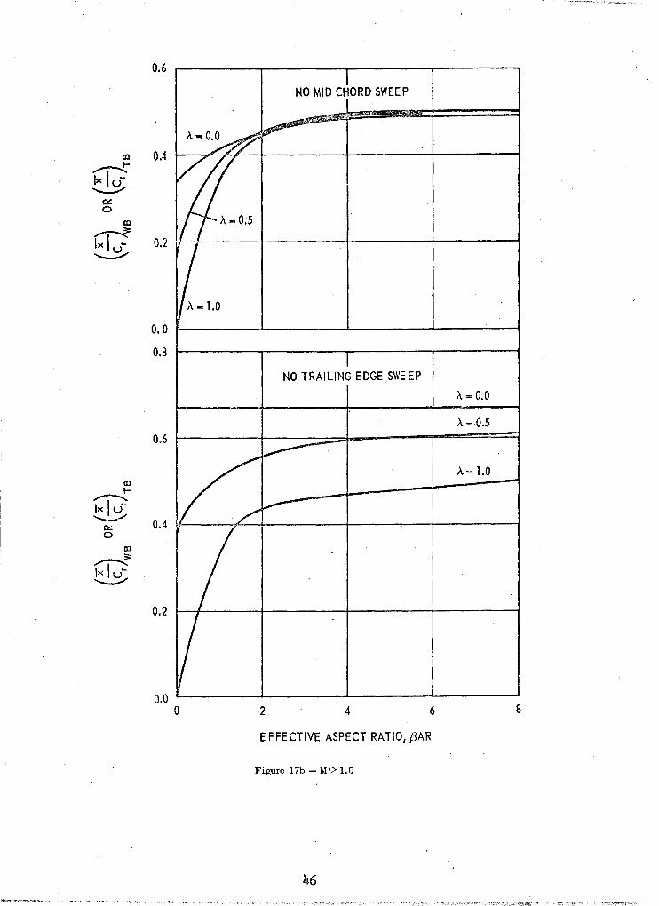
Figure 11 Lifting Surface Center of-Pressure as a Function of Effective Aspect RAtio (from Reference 1) ••••••••
Figure 18 - Subsonic Center of Pressure Location of Li~ on the Body in the Pressure of Wings Of Tails (from . Reference 1) •.••... It .............. , •• 0 ••••••••••••••••
Figure 19 - Supersonic Center of Pressure Location of L~ft on the Body in the Pressure of Wings or Tails for BAR (1 + A') (1 + L\! 4.0. (from, Reference I) ••
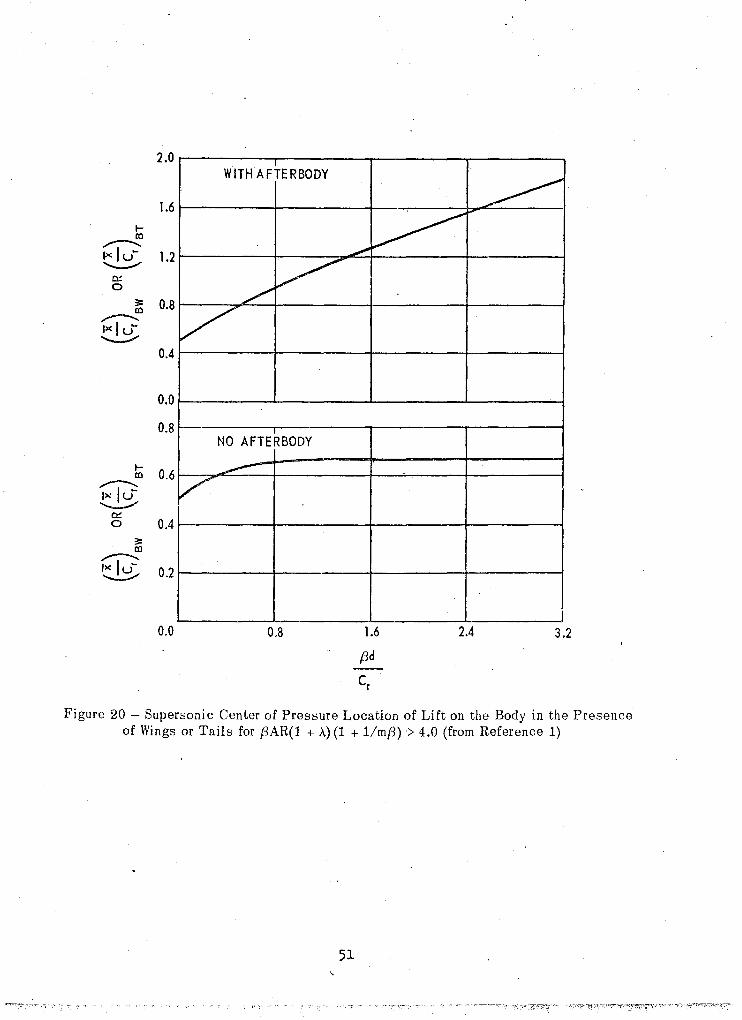
\ mB) . Figure 20 - Supersonic Center of Pressure Location of Lift
on the Body in the Presence of Wings or Tails for BAR (~+ A) (1 +~) > 4.0. (from Reference
Figure 21 Nissile Axis Systems ••••••••••••••••••••••••••••••••
Figure 22 - Configurations'Used ~o Compare Theory with
47
49
51
52
Experiment •.••. , .•.•..•.....•..• " ..• " ••••• 1.1 • • • ••• •• 53
Figure 23 Comparison of Experimental Data with Theoretical Results for Configuration 1 .......................... 54
Figure 24 - Comparison o£ Experimental Data with Theoretical Results for Configuration 2 ••••••••••••••••••••••••• 58
Figure 25 Comparison of Experimental Data with Theoretical Results for Configuration 3 ••••••••••••••••••••••••• 62
Figure 26 - Comparison of Experimental Data with Theoretical Results for Configuration 4 ••••••..•••.•••••.•••.••• 64
LIST OF TABLES
Table 1 - Computer Program Listing •••••••••••••••••••••••••••••• 65
Table 2 ,- Input Nomenclature •••••••• ~ • • • • • • • • • • • • • • • • • • • • • • • • • • • 84
Table 3
Table 4
Program Input Format ••••••••••••••••••••••••••••••••••
Output Nomenclature •••••••••••••••••••••••••••••••••••
iv
87 88

AR
b
CD
CD b
CD c
CD f
CD. 1
CD o
CD P
CD V
Cf
Cf
c C DFP CL
CL
C m
f
i
a
NOMENCLATURE
exposed aspect ratio
semispan of an aerodynamic surface including the body radius, feet
total drag coefficient
base drag coefficient
crossflow drag coefficient
frict"ibn drag coefficient
induced drag coefficient
total zero-lift drag coefficient
pressure drag coefficient
wave drag coefficient
incompressible skin-friction coefficient,
compressible skin-friction coefficient
drag of a flat plate normal to the flow
total lift coefficient
lift curve slope, per radian
total longitudinal pitching moment coefficient .
root~chord of an aerodynamic surface, feet
tip-chord of an aerodynamic surface, feet
diameter of the body at any station, feet
base diameter of the body,fe~t
diameter of the nose at the nose-body juncture, feet
span"lise location of the vortex which emanates from the forwar~.surface, feet
height of the trailing vortex above the body centerline at the aft surface center of pressure, feet
downwash interference constant v
, K
lREF
M
m
r
Re
NOMENCLATURE
(continued)
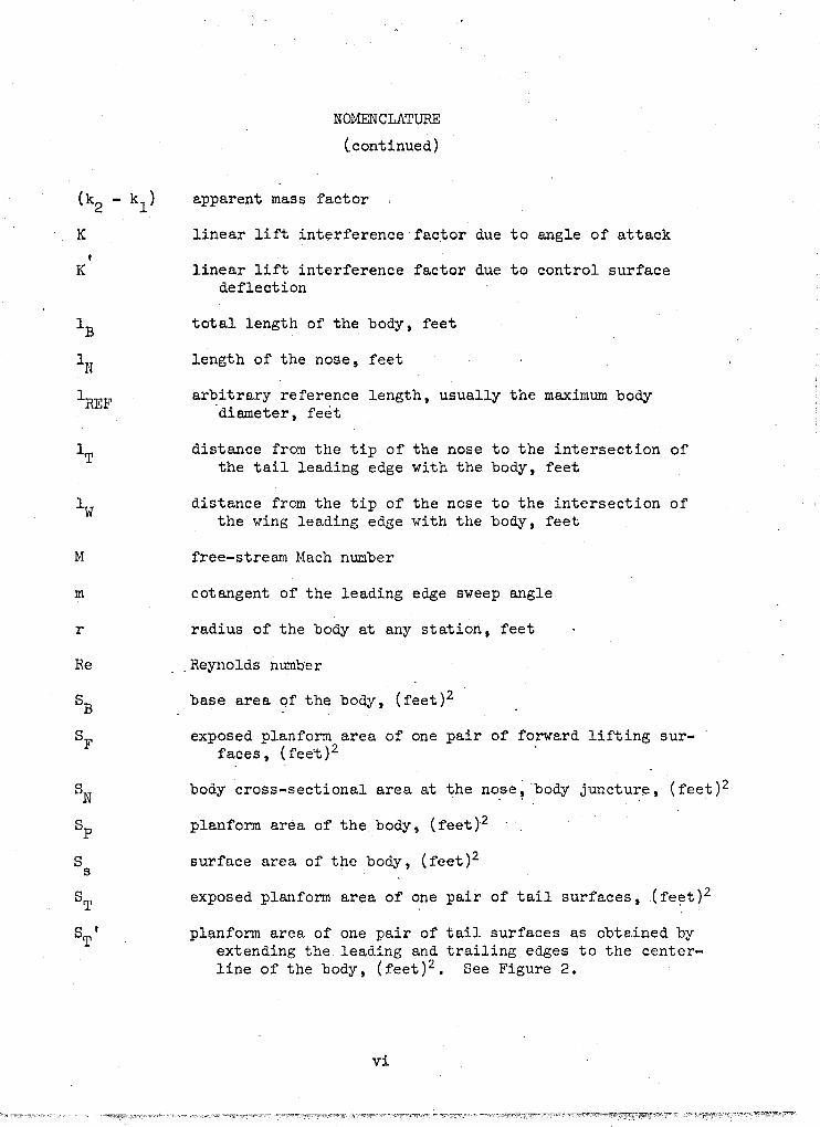
apparent mass factor
linear lift interference factor due to angle of attack
linear lift interference factor due to control surface deflection
total length of the body, feet
length of the nose, feet
arbitrary reference length, usually the maximum body "diameter, feet
distance from the tip of the nose to the intersection of the tail leading edge with the body, feet
distance from the tip of the nose to the intersection of the wing leading edge with the body, feet
free-stream Mach number
cotangent of the leading edge sweep angle
radius of the body at any station, feet
__ Reynolds number
base area of the body, (feet)2
exposed plan form area of one pair of forward lifting surfaces, (fee't)2
body cross-sectional area at ~he no~e? "body juncture, (feet)2
planform area of the body, (feet)2
surface area of the body, (feet)2
exposed plan form area of one pair of tail surfaces, (feet)2
plan form area of one pair of tail surfaces as obtained by extending the leading and trailing edges to the centerline of the body, (feet)2. See Figure 2.
vi
S f W
x p
a
e 15
eN 'Xc
A
\/4
NOMENCLATURE
(continued)
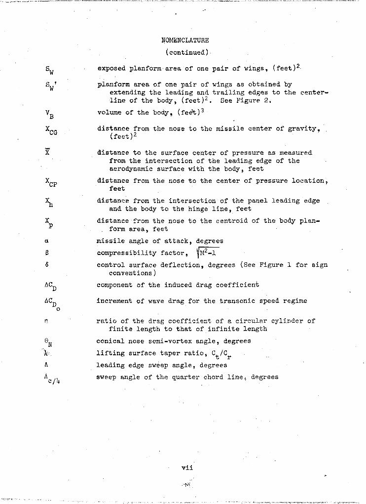
exposed planform area of one pair of wings, (feet)2
planform area of one pair of wings as obtained by extending the leading and trailing edges to the centerline of the body, (feet)2. See Figure 2.
volume of the bodYt (fee~)3
distance from the nose to the missile center of gravity, (feet)2
distance to the surface center of pressure as measured from the intersection of the leading edge of the aerodynamic surface with the body, feet
distance from the nose to the center of pressure location, feet
distance from the intersection of the panel leading edge and the body to the hinge lipe, feet
distance from the nose to the centroid of the body plan-form area, feet
missile angle of attack, degrees
compressibility factor, ~M2_1 control surface deflection, degrees (See Figure 1 for sign
conventions)
COmponent of the induced drag coefficient
increment of wave drag for the transonic speed regime
ratio of the dreg coefficient of a circular cylinder of finite length to that of infinite length
conical nose semi-vortex angle, degrees
lifting surface taper ratio, Ct/Cr leading edge sweep angle, degrees
sweep angle of the quarter chord line~ degrees
vii

A
B
BT
BT - a
BT - <5
BW
BW - a
F
FB
N
T
T - a
T - <5
TB
TB - a
TB <5
TV
W
\olE
WE - a
WV
NOMENCLATURE
(continued)
SUBSCRIPTS
aft lifting surface, alone
body alone
body in the presence of the tail
body in the presence of the ta.il
body in the presence of the tail deflection
body in the presence of the wing
body in the presence of the wing
forward surface alone
due to angle of attack
due.to control surface
due to angle of attack
forward surface in the presence of the body
nose
tail alone
tail alone due to angle of attack
tail alone due to control surface deflection
tail in the presence of the body
tail in the presence of the body due to angle of attack
tail in the presence of the body due to control surface deflection
tail, nonlinear component
wing alone
wing in the presence of the body
wing in the presence of the body due to angle of attack
wing, nonlinear component
The control surface is defined as the tail regardless of the mode of control; the fixed surface is defined as the wing (see Figure 1).
viii
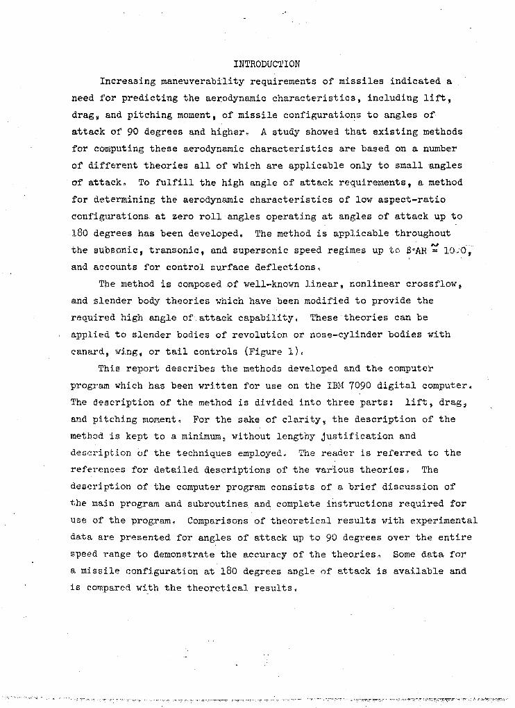
INTRODUCTION
Increasing maneuverability requirements of missiles indicated a
need for predicting the aerodynamic characteristics, including lift,
drag~ and pitching moment, of missile configurations to angles of
attack of 90 degrees and higher. A study showed that existing methods
for computing these aerodynamic characteristics are based on a number
of different theories all of which are applicable only to small angles
of attack. To fulfill the high angle of attack requirements, a method
for determining the aerodynamic characteristics of low aspect-ratio
configurations at zero roll angles operating at angles of attack up to
180 degrees has been developed. The method is applicable throughout I>J . "".
the subsonic, transonic, and supersonic speed regimes up to 8~AR = 10,0,
and accounts for control surface deflections.
The method is composed of well-known linear, nonlinear crossflow,
and slender body theories which have been modified to provide the
required high angle of attack capability. These theories can be
applied to slender bodies of revolution or nose-cylinder bodies with
canard* wing, or tail controls (Figure 1).
This report describes the methods developed and the computer
program which has been written for use on the IBM 7090 digital computer.
The description of the method is divided into three parts: lift, drag,
and pitching moment. For the sake of clarity~ the description of the
method is kept to a minimum, without lengthy justification and
descript.ion of the techniques employed. The reader is referred to the
references for detailed descriptions of the varIous theories. The
description of the computer program consists of a brief discussion of
the main program and subroutines. and complete instructions required for
use of the program. Compa.risons of theoretica.l results with experimental
data are presented for angles of attack up to 90 degrees over the entire
speed range to demonstrate the accuracy of the theorieso Some data for
a missile configuration at 180 degrees angle of attack is available and
is compared with the theoretical results.

LIFT CHARACTERISTICS
The tot~l lift on the missile is the sum of the body lift, the lift
due to the aerodynamic surfaces, and the interference lift between the
forward and aft surfaces, The lift on the body and aerodynamic surfaces
is composed of two components: linear lift including the effects of t~
body-lifting surface interaction and nonlinear crossflow lift. In
general, the croasflow lift component is caused by flow separation ",hie»
occurs at angle of attack, while the interference component is the lift
loss on the aft lifting surface due to dOIDlwash from the forward surface
(Reference 1).
Allen. References 2 and 3, developed a method for predicting the
total lift on bodies of revolution at angles "of attack. This method
includes the linear or potential flow component and two nonlinear -,'"
components: the viscous crossflow force and the viscous axial force.
Because the contribution of the axial force component to the body lift ,~.:;~ is small, it is usually neglected. Allen's expression for the body
lift is
nCd (SSp ) sin2a c REF'
cos a- CD cos 2a sin a
°B
where the first term is the linear contribution and the second term is the
nonlinear contribution. The apparent mass factor, k2 - kIf and the drag
ratio, n, can be- obtained from Figure 3, while the crossflow drag
coefficient, Cdc' is obt~ined from Figure 4. Comparisons of theory with
experimental data for numerous bodies of revolution over a wide range
of Mach numbers and angles of attack are presented in Reference 3. It
should be noted that although this expression for the lift is independent
of the nose shape, good agreement with experiment is indicated in
Reference 4 for a body with an unus~~ shape.
The linear lift characteristics o~ low aspect-ratio lifting surf~ces
whose cross-sections are thin and symmetrical are generally a function of
speed, planform area, and aspect-ratio. When the diameter of the
missile body is of the same order of magnitude as the span of the
2
(1)

lifting surfaces, the effects of body-wing and body-tail interactions are
significant. Hence, the linear lift of the aerodynamic surfaces is composed
of two components: the lift on the surface in the presence of the body,
and the added lift on the body due to the presence of a surfaceo Most low
aspect-ratio missile configurations exhibit a nonlinear dependence of lift
on angle of attack, especially at the higher angleso One primary cause of
this is the crossflovT lift component which is due to lateral flow separa
tion and the formation of free vortices on the upper surfaceo This non
linear dependence is analyzed in References 1 and 5 and summarized by Eaton
in Reference 60 The exp'ression for the total wing lift based on an arpitrary
reference area is
ClL = CL.._ + CL + CL.....:._ -W -WE-a . BW-a -WV
In order to provide high angle of attack capability, it is necessary to
modify both the linear and nonlinear theories 0 The lift on the wing in
(2)
the presence of the body, as presented in Reference 2, is a linear function
of angle of attack and can be expressed as
C = ~-a
Since the lift force does not vary linearly with angle of attack at high
angles, Equation (3) is modified such that the linear lift becomes a
function of sin a as shown below
(4)
3

This C'cmponent of the linear lift is modified further to satisfy the end
condition of' zero lift at .90 degrees angle of attack. The resulting
expression for the linear wing lift in the pressure of a body is
sin a cos a
It, is important to note that i'or sma.ll angles of attack the modi fied
.theory should be very close to the method of Reference 1 since sin
~(), a.nd cos a.~l. Similarly~ the additional lift on the body due to
th~ presence of the wing is
(::E~) sin a cos a
The parameters 0; ~B and KB\<l' are determined from Figure 5. CL o.w
is
obtained from Figure 6 by m1Altiplying by the aspect-ratio
AR
if' AR < 1.0. When the asp~ct ratio is greater than one~ the lift-curve
slope is obtained from the following equation
= AR
(6)
(_CARL~,\ where ,1) i;; r,ttaj nt?d from Figure 6. The first term of Equation (7)
is an emptric:al modification of the lift curve slope for a lifting
surfa.ce with aspect-rat.io greater than 1.
4
The nonlinear wing lift from Reference 6 is
Crw = Cdc . 2
s~n ex (8)
This expression is modified to satisfy the aforementioned end condition
with the result being
where Cdc is obtained from Figure 1. It should be noted that the cross
flow dr~ coefficient is not appreciably affected by Mach number,
(References 6 and 1); hence, Cd is presented independent of Mach numbero c . The total tail lift is computed basically the same as the wing lift
except for the lift due to deflection of the control surfaces. The tail
lift is expressed as
(10)
where CL and CL are obtained by applying Equations (5) and (6) TB-ex BT-ex
to the tail surface. The other three components are:
CLex sin 0 ~ \ cos(~ + 0)
T ~REF) (11)
C - Ie ~T-o - -13T. (12)
0) (~ \ cos(ex + 0)
SREF)
(13)
5

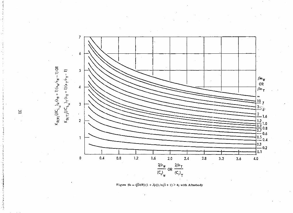
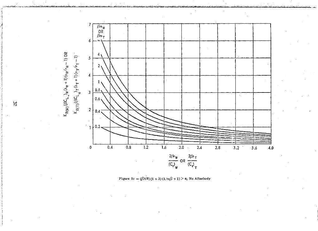
The parameters, KBT' and KTB' , are obtained from Fig~re 5, while Cdc and
CL
are obtained as specified for the wing. Notice that the nonlinear aT
lift is based on the local angle of attack, (a + o)~ of the control
surface.
The lift-loss on the aft surface due to downwash from the forward
surface is obt'ained from the method presented in Reference 1 and discussed
in Reference 7. Since the method for computing this component of the
total lift on the missile is both complex and lengthy, only the equations
necessary to compute the lift-loss are presented. The reader is referred
to Reference 1 for a detailed discussion of the assumptions and tec'hnique
used in deriving the method. It is noted that the nomenclature used to
describe the lifting surfaces is changed from wing and tail to forward and
aft surfaces. This is necessary because the control surface, whether it
be wing, canard, or tail type of control, is designated the tail and
because the aft surface, regardless of the mode of control, is the one
which is affected by downwash.
This method is valid for the entire speed range. The lift-loss due
to downwash is
=
This equation is obtained from line-vortex theory assuming only one
trailing vortex per forward panel exists (see Figure 8). The lateral
location, ~F~ and the vertical location, hA
, of the vortex are required
for use in Equation (14) and to compute the interference factor, i.
The lateral location of the vortex on the~orward surface expressed as
a fraction of the exposed semispan of this surface is
"\
[1 +(r/b)~ 2 . -1 [1 -(r/b)~ ] 7T - 7T(r/b)2 - (r/b)F +
sJ.n ~ 1 +(~/b);··· 4 4' F 2[1 -{rib ~J
(t~) = ~"!!M!f 9: tr
b - r [1 -{r~b)FJ F 2
6
(14)
(15)

For convenience, the right hand side of this equation is defined as A'.
Isolating fF results in the following expression
where fF is the spanwise location of the vortex at the forward
surface.. Since the lateral location of the vortex with respect to
the body axis is unchanged, the subscript may be dropped and Equation
(16) may be written as
The vertical location of the vortex, hA, is measured normal
to the body axis at the center of pressure of the aft surface.
The expression for hA is
(16)
hA = ,,(Cr d l),)F sin OF + rIA + (Xcp ) A - IF - (Cr)F] sin a (18)
Note that the vertical location of the vortex is a function of both
angle of attack and the deflection angle of the forward surface.
The interference factor, it is given by
i = (rlr)G(A'f'a) - L(A'~'-f'~) where
Inlh2+(f- bl:\"{L: . .l\ ~b - r) + \~)Z ) \b-r1L
-lff ... r\ -l(t - r_~} htan ," h ,-htan '\ h i'J
and
,
7

Hence! once the location of the vortex is determined and the position of
the image vortices, f. and h., is determined from Equation (21), the J. J.
interfe~ence factor can be computed from Equations (19) and (20). The
lift-loss due to interference can then be calculated.
The total lift based on an arbitrary reference area is obtained
by adding the components
where CL ., a lift-loss, will be a negative quantity, The other three J. . ' _
components include both linear and nonli;l-ep..r~cQn~.;-i1?:ut ions.
DRAG CHARACTERISTICS
The total aerodynamic drag acting on a missile is the sum of the
zero-lift drag, the induced drag due to angle of attack and/or control
surface deflection, and the base pressure drag. It is well-known that
the selection of the proper technique for computing the zero-lift drag
is determined by the operating speed of the missile. Hence, the
(22)
methods employed to compute the zero-lift drag of a missile are described
for three speed regimes. These speed regimes and their associated
limits are defined as follows:
1. Subsonic -- M < 0.8
2. Transonic -- 0.8 s M ~ 1.2
3. Supersonic -- M > 1.2
The description of CD calculations for these speed regimes is followed o
by a description of the methodused,tacompu:te the induced drag due to
angle of attack and/or tail deflection. The last section presents
the total drag.
8

1. Subsonic Region
The zero-lift drag for subsonic speeds can be expressed as
where each of the components is composed of skin-friction drag and pressure
drag 0 The pressure drag at subsonic speeds is usually small compared-to the
drag due to skin frictiono Since the flow around high speed missiles of the
type being considered here is primarily turbulent, the methods employed are
developed assuming the existence of fully turbulent boundary layers.
The zero-lift drag of the body based on an arbitrary reference area is
obtained from Section 4020301 of Refer~nce 9 and can be expressed as
(24)
where Cf , the skin-friction coefficient, is determined using Figure 9.
is
The wing zero-lift drag as presented in Section 4010501 of Reference 9
+ 2(t/c) + 100(t/C)4] Sw' SREF
The factor of 8.0 is included to account for the total wetted area of
the surfaces and for the existence of four wingso The tail zero-lift C
drag , Do can be obtained by using the tail thickness-to-chord ratio and T' ,
the total tail area, ST ' in Equation (25).
These three components, based on the same arbitrary reference area,
are added as indicated by Equation (23) to give the total subsonic zero
lift drag 0
9

2& Transonic Region
The body drag in the transonic speed regime is composed of compressible
skin-friction drag, subsonic pressure drag, and transonic wave drag, and is
obtained using the techniques presented in Section 4.2.3.1 of Reference 9.
The compressible skin-friction drag is obtained using the following
equation:
= 1.02 Cf Sa c
SREF-(26)
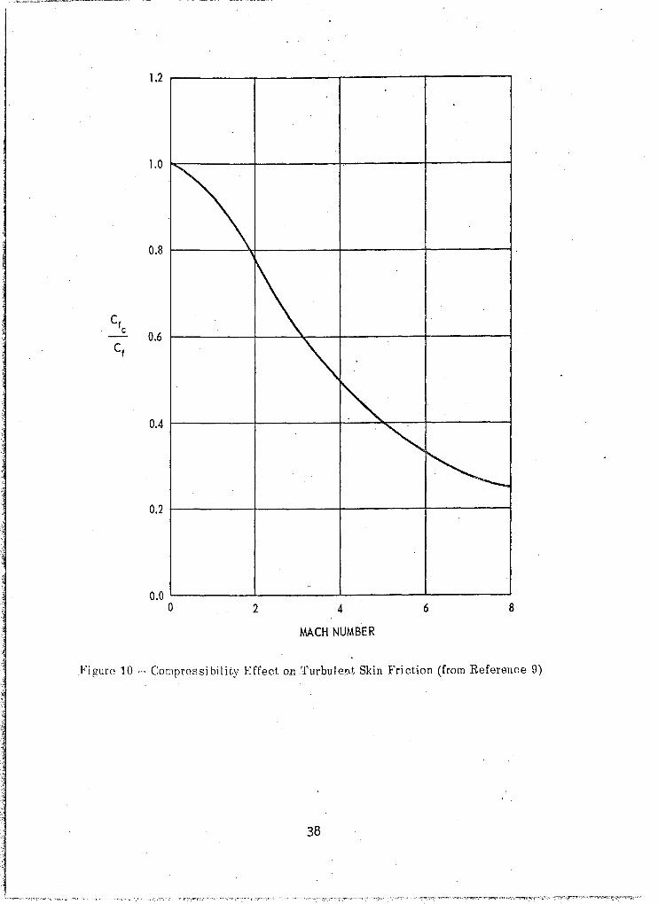
where Cf is a function of both Reynolds number and Mach number and can
be deteriiined from Figures 9 and 10. The subsonic pressure drag as ex
tracted from Equation (24) is
The transonic pressure drag is computed using Equation (27) up to a
Mach number of 1.0 and then it is decreased linearly from its value at 100
to zero at M=1.2.
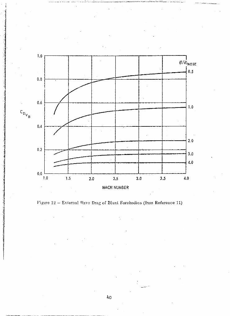
The transonic wave drag of the body is obtained from Figure 11 which
presents the wave drag as a function of the nose fineness ratio and Mach
number 0 This figure was constructed \from experimental data presented in
Reference 10 and by using the curves of wave drag for bodies of revolution
as shown in Reference 11 and reproduced here in Figure 12.
The total transonic body zero-lift drag is obtained form the following
expression:
(28)
t. ~ ,
10

Experimental results show little increase in the viscous drag of the
aerodynamic surfaces from the subsonic to the transenic regime and there
fore, the skin-frictien drag for the subsonic regien is a1se used in the
transenic regimeo It may be expressed as fe11ews;
= (29)
Te this wing transenic skin-frictien drag is added a drag increment, ~CD 'OW
which is the transonic wave drag 'Of the wing surfaces o Figure. 13 expresses
this cemponent as a functien 'Of thickness-to-cherd ratio, ! , aspect-ratio, c
and Mach number fer rectangular surfaces. Fer surfaces havlng swept
leading edges, llCD
is obtained as fer rectangular surfaces and then ad'oW
justed to acceunt for the sweep angle using the following equationg
(30)
I
The Mach number ..used in_Figure 13 to obtain A CD fer swept lifting
surfaces is Ow
( 31)
This compenent of the dragdu€'to' the ae-rodynamic surfaces must be com
puted for both the wings and tai1so The tail contributien is determlned
in the same manner as the wing contribution above using tail parameterso
11

The total transonic zero-lift drag is the sum of these,. components as
shown below:
3. Supersonic Region
S I W
SR~-;
A simple empirical method for computing the zero-lift drag for the
supersonic speed regime has been developed by ass~~ing a parabolic
variation of CD with Mach number. between 1.2 and 3.0. The resulting o
equation which is used to compute the zero-lift drag of a missile for
Mach numbers greater than 1.2 is
~. tDo" C 'J C " . C ' D .. D
CD = ?2 'jM+ ~ {37f~.J + CD ,
0 .p- o
where CD ' and CD " are the values of the total zero-lift drag at o 0
Mach numbers 1.2 and 3.0 respectively. It should be noted that
although CD for Mach numbers greater than 3.0 can be determined from o
Equation (33), existing hypersonic flow theories would probably provide
a more accurate estimate of the zero lift drag.
In order to utilize Equation (33) for determining the variation
of CD with Mach number~ CD ' and CD " must be specified. CD' is 000 0
determined by using the techniques described in the previous section
for the transonic flow regime. Since the magnitude of the supersonic
wave drag is heavily dependent o"':L,the nDS.e shape of the missile, CD "
is determined using one of two methods; the selection of the propero
method depends on the missile forebody shape.
12
(33)

In the first method, which is for blunted ogives, pointed ogives,
and blunted cones, the supersonic zero-lift drag is a function of Mach
" number and nose fineness ratio o Since CD is the zero-lift drag at M=300,
it remains to define its variation with °nose fineness ratio o Hoerner,
Reference 12, .indicates the zero-lift drag for body-fin configurations with
slender (high fineness ratio) nose shapes generally peaks at a Mach number
of 100 to 102 and then decreases to approximately its subsonic value plus
the transonic wave drag of the lifting surfaces at M=3.00 Similar con
figurations with blunted nose shapes of low fineness ratio reach a peak at
about ,the same Mach number, but decrease very little as the Mach number is
increasedo Using these trends as an indication of the effect of fineness
ratio on the variation of zero-lift drag 'with Mach number for the supersonic
speed regime" CD o follows:
a} For (l!d)N
"
< -b) For (l!d)N >
for the aforementioned nose shapes is specified as
" 005, CD ' - CD , t 0
C o~ + tc ~ + S ) " 800, CD - t:,C ...L.-DDS DOT SREF 0 o M=O. 8~. Ow REF
where CD I. o M=Oo8
is determined utilizing subsonic flow theory and t:,~D Ow
and t:,CD
are the transonic wing and tail wave drag. The variation of the
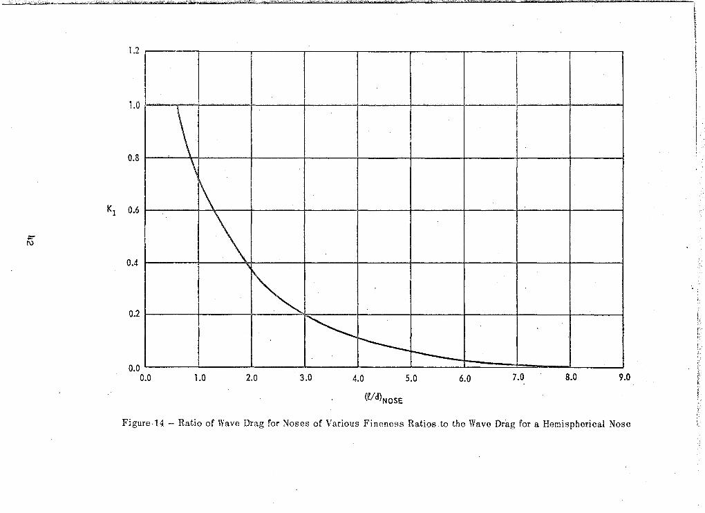
0'1' forebody wave drag as a function of Mach number is presented in Figure 12 and
was used to construct Figure 14 which is. utilized with the following equation:
" to compute CD for nose fineness ratios between 0.5 and 8.0. o
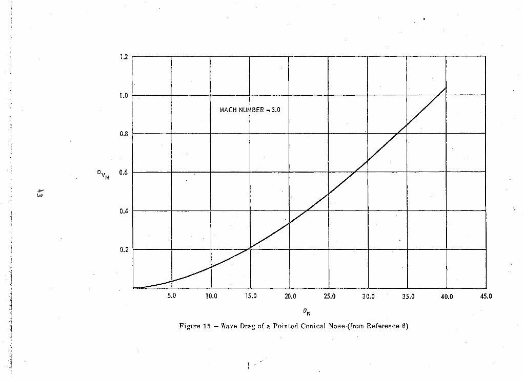
.. In the second method, which is for pointed conical noses, CD is
o determined from the following equation:
(35)
where the first two terms are obtained in the same manner described above.
The forebody wave drag, which for this type of nose is a function of Mach
number and the cone semivertex angle, is obtained from Figure 15. " Once CD is determined, Equation (30) can be,used to compute the o
zero-lift drag at any Mach number between 1.2 and 3.0. The complete zero-
lift drag curve of a missile can now be determined.
4. Induced Drag
The induced drag due to angle of attack and/or tail surface de
flection is composed of four drag increments as shown below:
( 36)
The drag increment for the bodY·· is obtained using a metnod'presented in
Reference 3, while the induced drag due to the wing and tail is obtained
from the drag of an equivalent flat plate normal to the flow. The in
duced drag on a body of revolution at angle of attack can be expressed
as follows:
sin3a
l" . '1;4
The wing induced drag based on an arbitrary reference area is obtained
from
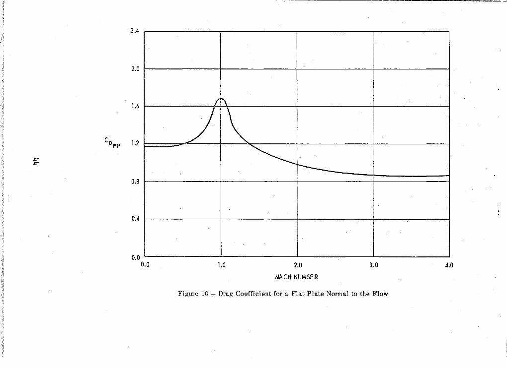
llC = CD ~w sin n) (38)
Dw-a FP SREF
where CD is the drag of a flat plate normal to'the flow field, and is FP
determined from Figure 16 0 The drag curve shown in Figure 16 has been
constructed using the three-dimensional subsonic drag coefficient for a
flat plate normal to the flow (Reference 13) and the variation of the drag
coefficient ,dth Mach number for the two~dimensional flat plate (Refer
ence 12)0 The equivalent flat plate area of the wing is taken as the pro
jection of the wing area on the normal ,planet Sw sin a o Similarly, the
drag increment of the tail surface at angle of attack is
n)
The drag increment due to deflection of the tail surface cannot be
obtained directly since the drag increment is not a linear function of
local angle of attack o The total drag increment for the tail surface can
be expressed as
\
, (40)
where (a + 8) is the local tail, angle of' attacko It now becomes a
simple matter to obtain the drag 'increment due to the deflection of the
control surface by taking the difference between Equations (39) and (40)0
Thus
(41)
15
6. Total Drag
The total drag can be expressed as follows:
CD = CD + CD (42) o i
where CD. is, determined using Equation (36) and CD is obtained 1~rom 1 0
.- Equation (23) ~ (32)! or (33) depending on the speed of the missile,
Base pressure drag is not included in Equation (42)~
16
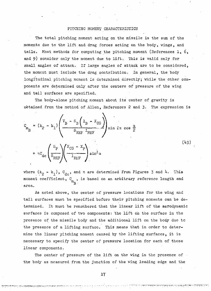
PITCHING MOMENT CHARACTERISTICS
The total pitching moment acting on the missile is the sum of the
moments due to the lift and drag forces acting on the body, wings, and
tailso Most methods for computing the pitching moment (References 1, 6,
and 9) consider only the moment due to lifto This is valid only for
small angles of attacko If large angles of attack are to be considered,
the moment must include the drag contribution 0 In general, the body
longitudinal pitching moment is determined directly; while the other com
ponents are de~ermined only after the centers of pressure of the wing
and tail surfaces are specifiedo
The body-alone pitching moment about its center of gravity is
obtained from the method of Allen, References 2 and 30 The expression is
+ nC (.2.-)(XCG - Xp) sin2C4
dc SREF lREF
1.
C4 sin 2ct cos
2
(43)
where (,k2 - kl ) 9 Cdc' and n are determined from Figu.res 3 and 40 This
moment coefficient, C ~ is based on an arbitrary reference length and mB ·
areao
As noted above~ the center of pressure locations for the wing and
tail surfaces must be specified before their pitching moments can be de
termined o It must be remembered that the linear lift of the aerodynamic
surfaces is composed of two components g 'the lift on the surface in the
presence of the missile body and the additional lift on the body due to
the presence of a lifting surface o This means that in order to deter
mine the linear pitching moment caused by the lifting surfaces, it is
necessary to specify the center of pressure location for each of these
linear componentso
The center of pressure of the lift on the wing in the presence of
the body as measured from the junction of the wing leading edge and the
17

body is obtained using Figure 17. The reference point is transferred to
the nose by using the following equation
where(~) is obtained from Figure l7a for subsonic speeds and from r WB
Figure l7b for supersonic speeds.
(44)
The center of pressure of the additional lift on the body in the
presence of the wing is obtai~ed using Figure 18 if the flow is subsonic,
and either Figure 19 or 20 if the flow is supersonic. For the case of
supersonic flow, Figure 19 is used if
SAR (1 + A) ( 1 + ; e ) ~ 11. 0
and Figure 20 is used if the above quantity is greater than 4.0. The cen
ter of pressure, XBW ' as obtained from the aforementioned figures, is
referred to the nose by using the following equation.
location of both centers of pressure for the tails, (XCP) 'l'B and
can also be obtained from the above procedure.
centers of pressure for c 13. given lilting surface are combined to
obtain a single average center of pressure location for each set of aero
dynamic surfaces. For example, the average center of pressure of the
wings ,is obtained by computing t,~e total pitching moment due to the wings
and dividing by the wing normal force. ~~he pitching moment about the ""1
18

nose of the body due to the wing is
C"" = [( Crw + C~v + CLi ) cos a t IICDw_a Bin a ]
+ [ C~w cos a ] [( XCP)B/1REF ]
(46)
where all of the above terms have been previously defined. The average
wing center of pressure as measured from the nose of the body can now be
defined as
Similarly, the tail pitching moment and center of pressure including the
effect of surface deflection can be expressed as
= [( CL + CL + CL.) c as a + CL + ~B-a TV 1 TB-o
where
and
19

The total longitudinal pitching moment of the missile about the
missile's center of gravity may be expressed as
20
(50)
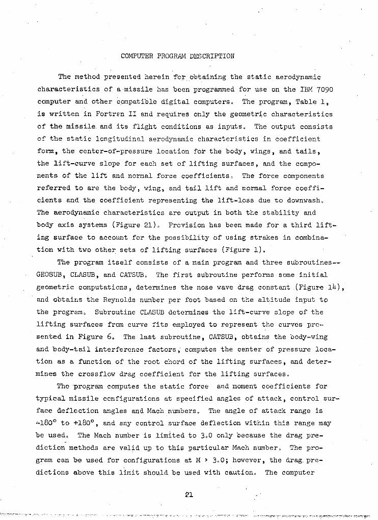
COMPUTER PROGRAM DESCRIPTION
The method presented herein ~o~obtaining the static aerodynamic
characteristics of a missile has been programmed for use on the IBM 7090
computer and other compatible digital computers 0 The program, Table l~
is written in Fortren II and requires only the geometric characteristics
of the missile and its flight conditions as inputs 0 The output consists
of the static longitudinal aerodynrunic characteristics in coefficient
form, the center-of-pressure location for the body, wings, and tails,
the lift-curve slope for each set of lifting surfaces, and the compo
nents of the lift and normal force coefficients 0 The force components
referred to are the body, wing i and tail lift and normal force coeffi
cients and the coefficient representing the lift-loss due to downwash o
The aerodynamic characteristics are output in both the stability and
body axis systems (Figure 21)0 Provision has been made for a third lift
ing surface to account for the possibility of using strakes in combina
tion with two other sets of lifting surfaces (Figure 1)0 The program itself consists of a main program and three subroutines-
GEOSUB, CLASUB, and CATSUB o The first subroutine performs some initial
geometric computations, determines the nose wave drag constant (Figure 14),
and obtains the Reynolds number per foot based on the altitude input to
the program 0 Subroutine CLASUB determines the lift-curve slope of the
lifting surfaces from curve fits employed to represent the curves pre
sented in Figure 6. The last subroutine, CATSUB, obtains the body-wing
and body-tail interference factors, computes the center of pressure loca
tion as a function of the root chord of the lifting surfaces, and deter
mines the crossflow drag coefficient for the lifting surfaceso
The program computes the static force and moment coefficients for
typical missile configurations at specified angles of attack~ control sur
face deflection angles and Mach nUmbers o The angle of attack range is
~18oo to +180°, and any control surface deflection within this range may
be used o The Mach number is limited to 300 only because the drag pre
diction methods are valid up to this particular Mach number o The pro
gram can be used for configurations at M > 300; however, the drag. pre
dictions above this limit should be used with caution o The computer
~l

program can be used to obtain build-up information; that is, the aero
dynamic characteristics of the missile body 'alone, the body-wing configu
ration. an'd the body-tail configuration. This information may be ob
tained by simply setting the appropriate parameters to zero.
The inputs to the computer program with their FORTRAN symbols are
presented in Table 2. The format for preparing the input cards is pre
sented in Table 3. It should be noted that if a configuration does not
have a control surface, e.g. a body alone configuration, the number of
control surface deflection angles should be set at one and the deflec
tion angle, itself, would be 0.0 degrees. Cards 11 and 12 are used
only when the number of angles of attack require their use. The output
variables are defined in Table 4. There is no limit to the number of
data decks vhich may be stacked together and run at the same time.
COMPARISON OF T,HEORY WITH EXPERIMENTAL DATA
Numerous comparisons of theory with experiment have been made in
order to establish and verify the accuracy of the method. Figure 22
presents the configurations used for comparison. Configuration 1 is a
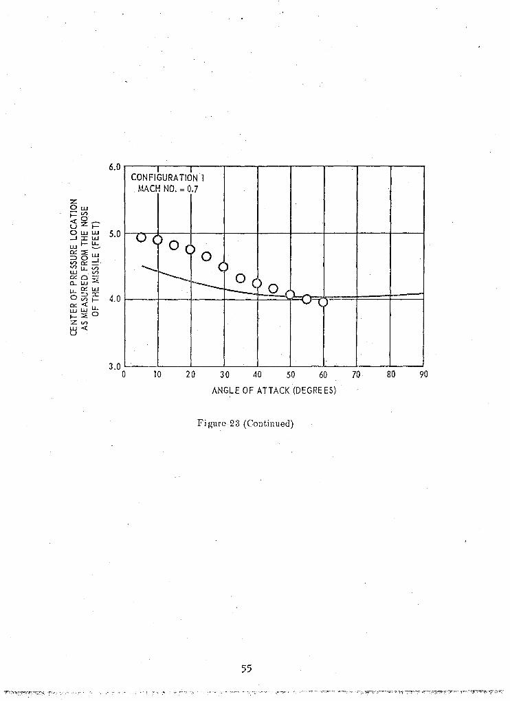
strake-tail configuration. Figure 23 presents the comparison between
the experimental data and the theoretical results obtained from the
method described herein. The theoretical lift and drag are within
15 percent of the experimental data for M = 0.7. The deviation for
M = l~l does increase to about 25 percent. However, it should be noted
that the accuracy of the method to 30 degrees is good. The method also
predicts the center of pressure location very satisfactorily.
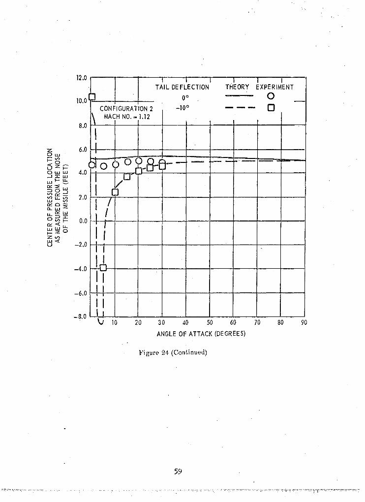
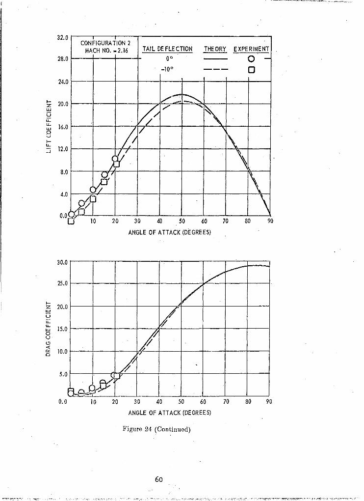
Configua·ation 2 is a wing-controlled vehicle. Comparisons are
presented in Figure 24 for Mach numbers of 1.12 and 2.16 and for wing
deflection angles of 0 and -10 degrees. Although high angle of attack
data 15 not available for this configuration, it appears that the com
paratively high theoretical lift shown by Configuration 1 may be more
pronounced for Configuration 2. This trend is seen by the decrease in
the slope of the experimental lift data at 25 to 30 degrees angle of
attack, Figure 21~. The comparison with the wing deflected down 10 de
grees appeared to be good.
22

Data for Configuration 3 is presented ,in Figure 250 Configuration
4 was tested by the Cornell Aeronautical Laboratory to 180 degrees angle
of attack, Reference 140 Comparison of theory with experimental'data
is presented in Figure 26 0
CONCLUSIONS
A method for predicting the static~ ,longitudinal aerodynamic
characteristics of low aspect-ratio missiles operating at angles of
attack to 180 degrees has been developed o The method is valid for
a wide speed range and considers control surface deflectionsc A com
puter program~ written to facilitate use of the method, has been
described o Results obtained using the method have been compared with
wind tunnel data and acceptable agreement has been demonstrated o
23
REFERENCES
1. Pitts, William C' l Jack N. Nielsen and George Eo Kaattari.
Lift and Center of Pressure of Wing-Body-Tail Combinations
at Subsonic, Transonic and Supersonic Speeds •. Wash" 1957~
70 p. incl o illus, (National Advisory Committee for
Aeronautics 0 Rpt, 1307)
2. Allen, H. Julian. Estimation of the Forces and Moments Of
Acting on Inclined Bodies of Revolution of High Fineness
Ratio. Wash. t D, C. Nov 1949, 27 p. ,incl. ill us. (National
Advisory Committee for Aeronautics" lli~ A9126)
3~ Allen, He Julian and Edward W. Perkins, Characteristics of
Flow Over Inclined Bodies of Revolution 0 Wash" D.C.,
Mar 1951. 47 po incL i11us", (National Advisory Committee.
for Aeronautics" m~ A50L07)
4. Jorgensen, Leland Ho and Stuart Lo Treon, Measured and
Estimated Aerodynamic Characteristics for a Model of a
Rocket Booster at Mach Numbers From 0.6 to 4.0 and at Angles
of Attack From 0° to l80 c e' Wash" DoCo. Sep 1961.
76 p. incl. i1lus, (National Aeronautics and Space
Administration. Tech. Memo, X-580).
5. Flax, At H. and H. P. Lawrence, The Aerodynamics of Low
Aspect-Ratio Wings and Wing~Body Combinations" Buffalo,
Sep 1951. [66] L inc!. illus t (Cornell Aeronautical
Lab., Inc. Rpt, CAL-37) (Also in Proceedings of Third Anglo
American Aeronautical Conference t Brighton, Eng., 3-14 Sep 1951.
London, Royal Aeronautical Society, 1952)
6. Eaton, Peter T. A Method for Predicting the Static Aerodynamic
Characteristics of Low-Aspect Ratio Configurations. Wash., D.C e
Jun 1966. 90 p" inc!. illus G (Naval Ship Research and Develop
ment Center. Rpto 2216. Aero,Rpt. 1112) (AD 647234)
7~ Gersten, K. Calculation of Non-Linear Aerodynamic Stability
Derivatives of Aeroplanes. Paris [1962] 20 p. incl.
illu·s. (Advi'sory Group for Aerospace Research and Development. ·11
Rpt. 342) (Deutsche Forschungsanstalt fur Luft • und Raumfahrt.
Bericht 143)
24

8~ Frantz, Gerald Eo Lift Curve Slopes of Low Aspect Ratio Wings
at Transonic Speeds. Columbus, Ohio, Jun 1963. 32 1. incl a
illus 0 (North American Aviation, Inc'. Applied Mechanics Tech.
Note AM-TN-2-63)
9~ Douglas Aircraft Co., Inc o USAF Stability and Control DATCOMo
Revo W-P AFB, Jul 1963. 2vo (loose-leaf)
10. Stoney, William Eo, Jr. Collection of Zero-Lift Drag Data on
Bodies of Revolution From Free-Flight Investigations. Wash.,
19618 188 p" incL illuso (National Aeronautics & Space
Administration. Tech. Rpt. R-IOO~ . Formerly NACA TN 4201)
110 Royal Aeronautical Society. Data Sheets: Aerodynamics 0 VoL 4.
London, Aug. 1964.
12. Hoerner, Sighard Fa Fluid Dynamic Drago (2do ed~] Midland Park,
No Jot 19650
13. Dommasch, David 0., Sydney So Sherby and Thomas Fa Connolly 0
Airplane Aerodynamics. 3rd edo New York, Pitman [1961]
600 po
14. Beil, W. J. and others. Major Developments for the Jet Vane
Controlled Bomber Defense Nissile. Buffalo, Mar 1955.
226 10 incl~ illus. (Cornell Aeronautical Lab., Inc. Rpt.
BE-753-S-24 a Contract AF33(038)22346)
25
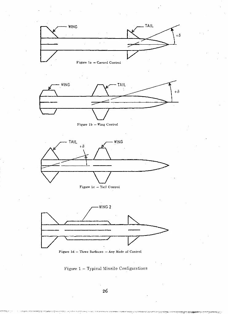
WING
Figure la - Canard Control
WING
:;::::>" .c: _________ ~~-I--
Figure lb - Wing Control
WING
Figure lc - Tail Control
jWING2
Figure ld - Three Surfaces - Any Mode of Control
Figure 1 - Typical Missile Configurations
26

'I 1
1 1
",~
i ;1
" ,I
I\) -4
$'/2
b
POINTED CONICAL NOSE
~ XCG ~I~------
" , /
'1 ,., /
, dN
- ------., ~~I
---~ 711--
___ J______ 14.iN
.. I l I l , TRAILING VORTEX t w l . IT ~
LB
Figure 2 - General Geometric Characteristics

tl .'~ ~
i 'i "
I\) Q)
m'M)1'WMM '1'$ h'tW w;ct J rt Htd' dk'lH " , 'if,>' - Pl.' ".
1.0
,0.8
0.6
0.4
0.2
0.0 5 10 15 20 25 30
BODY FINENESS RATIO
Figure 3 - Parameters Used to Compute Body Normal Force and Pitching Moment (from Reference.3)

2.0
1.6
1.2 Cd
c
0.8
ro 0.4 \0
0.0 0,2 0,4 0.6 0.8 1.0 ].2 1.4 1.6 1.8 2.0 2.2 2.4 2.6 2.8 3.0
CROSSFLOW MACH NUMB,ER, M(SIN a)
Figure 4 - Crossflow Drag Coefficient as a Function of Mach Number (from Reference 3)
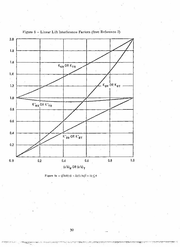
Figure 5 - Linear Lift Interference Factors (from Reference·7)
2.0
1.8
1.6
1.4
1.2
1.0 1==::===+====t==~=====t=====:/1 K'WB OR K'TB
0.8 ~-----I------+-----:~--+--~-~:::----~
0.6
0.4
0.2
0.0 0.2 0.4 0.6 0.8 1.0
Figure Sa - C(3AR) (1 +,\) (l/m{3 + 1) ~ 4
30
~4 , :~I .\ i
7
1 1 J .J.
0.4 0.8 1.2 1.6 -L- .1
2.0
2f3rw 2{3rT -OR--(C,) (C,)
w T
2.4
f3m w OR
{3m T
~ ~~~, :: -- --l ~ 1.6
~.1.2 1.0 0.9 0.8
_ 0.70.6
- 0.5 0.4 --j3 1~0.2 - 0.1
-----' .J. 4.0 2.8 3.2 3.6
Figure Sb - (j3AR)(1 + A)(I/m{3 + 1) > 4; with Afterbody
A 1 A
J 1 1
1.
',·t, ! i liiwf""t,j,"$"46aRfuc **'" !}).""m-..jX'k'e ".tiM· "m-"';iY&c"'j'"i >u\. '.'> d C ~ W' :"'t! M"' 'l',;:ilj"iH' ,'i,lc .. YV .1tl:C~ WT¥~"I-·;,.,ij';G- '417&&+2#\% ).4 \:fnil'£i¥'. W ¥¥U 4Y'k',9iw.; IMAC ,'\&i' b"h-mk 1* :",,' i1W¥'w 46Y±w #:'1'1' ! 'I'M Y 'it 'Vl'zh8-':."YtM'o&!lI.;'/ !l-{' '1' 5'~>' at' ,:",-:;':''S'" ';-l -t'·,
w I\)
0:: 0
( :;:: ....
"-:;:: ~
+ :;::
.$ :;::
---t ..J
U S ~ co ~
(
I-
~ '" . ~
+ I-
6-f-
---(j
..J u S
i=-ill
.~
6 oc
I 4 5
2
4
3 I 0.8
I 0.6
TA 1 0.2
o 0.4 0.8 1.2 1.6 2.0
2{3rw -OR (Cr)w
2{3rT
(Cr)T
2.4
Figure Sc - (j3AR) (1 + A) (1/m{3 + 1) > 4; No Afterbody
:::::'l~S?:~"",._~,,,"
2.8 3.2 3 .6 .4.0

w w
A
Figure 6 - Lift Curve Slope for Wings and Tails (from Reference 8)
2.0. _.tI.
CL a A
o ! .
,~ I I 0.2 /I 0.4
,-..- 2P ~ I 1.2 t-I ----t.-----jr-
~-------~--------+------O"8~ ~
I
f-----~+ o 41---'--+-----+-----I-----!-----1
~ ~UBSONIC I SUPER,SONlf ~
3 2 o 2 3 4 5
AR {l::M2 AR 1M2 -1
Figure 6a - Unswept Trailing Edge

·'",J"bi"bihvtrfii "#yftebNOf! ' , "¢'"'j ";S"Wh'15-1I'o'Y-l'aI"@ yr.%4tiJ;! 'f~%- Q ,'.!"vNxY e' ';"M:}"' ~W '3dmijr tLt%h'lWtlb} tf4wtt' ~H&fN'&"!II.'b'o',¥i&'wrsj;i;W\·\' C,11.:w>wllcwdtftitnlJ6(b,:sWrt#ft!liiftiHntJ:Ci ri'II¥*''¥·t''t-''p'i"t'. 'tHer"1i¥4fJMe,'Wttrlr -taett.lifl ')'* #»z"tHY'"'1e+\'!):{rFreJliidw'[ tf&M"MtrtWiSit-'a:'tV·€WII'Hs5-""qWIr'Wg I r'b-Yc' 'IHs#- ~.
W .!='" I ........ ~~J L-___ +-___ +-__ 0.81 """-- ....... --..
~---+-----r----O.4~!----;--------~----~+_------~------~
SUBSONIC SUPERSONIC
3 2 o 2 3 . 4 5
AR~2 AR JM2_1
Figure 6b - Unswept Mid Chord
:j f ,~
.'.~ , 1
'''i
1 "
J cs

w VI
8.0
6.0~k------~--------~------~r-------~------~--------~
Cd 4.0 k c ................
2.0 f --=:::::::::: ==---r----=:::::::::= I ==r== :::j ,\ = 1.0
1------t----L-=~,\"'0.5 ~-.lA ... O.O
0.0 0.5 1.0 1.5 2.0 2.5 3.0
ASPE CT RA TlO
Figure 7 - Crossflow Drag Coefficient for Wings and Tails as a Function of Aspect Ratio and Taper Ratio
~; , I ! i
I ~ Ii I
t e ~ ,
f ,

VORTICES FROM FORWARD LIFTING
.. '
/ ' SURFACE ~ H):r-Hr
h
! ~ AFT SURFACE
,--........j---ll r ~-~-~ I I I I I I I I I 'c
I I I I
t TRA1LiNG VORTEX ~ FROM FORWARD I LIFTING SURFACE
I I
f-~
I I
Figure 8 - Vortex \Iodel Used to Determine the Lift Loss due to DowI1wash (from Reference 1)
/
36 '

"/
30
20
10 8.0
M C>
x 6.0 u I-
4.0 Z UJ
U u.... 2.0 u.... UJ 0 U z
1.0 0 W
I-~
u 0.8 a:::: u.... 0.6 , z ~ V) 0.4
0.2
--- ____ TURBULENT FLOW LINE FOR AERODYNAMICALLY SMOOTH SURFACES ---r-.
~ ~
~ ----.. i
105
~ ~URELY LAMINAR FLO~
...... ""
106
.........
107
REYNOLDS NUMBER
108
Figure 9 - Incompressible Skin Friction Coefficient (from Reference 9)
-
10 9
1.2
1.0
0.8 -..;
~ ~ .~
"----
0.6
0.4
0.2
0.0 o 2 4 6 8
MACH NUMBER
Figure 10 - Compressibility Effect on Turbule.nt Skin Friction (from Reference 9)
38

1.4
1.2
1.0
\
\\ \\ \\ ~-1.2 \:~ ~ M 0.8 :::::-
0.8
0.6
0.4
0,2
0.0 o 2 3 4 5 6 7
Figure 11 - Transonic Wave,Drag for Ogival and Blunted Conical Forebodies
, i
39
1.0
0.8
0.6
0.4
0,2
0.0 1.0
V ..--
/ I
V- ----L
/ ~
~
~ --1.5 2.0 2.5
MACH NUMBER
3.0 3.5
(Ud~ NOSE
0.5
1.0
2.0
3.0
4.0
4.0
Figure 12 - External Wave Drag of Blunt Forebodies (from Reference 11)
----40

~ 4 .~ i ~ .,
~
J ., ,] I;
'i .~ ;i
.. ~ ~
j ';1 ,j ,I .;~
flC o 0
(tic) 5/3
.::-r-
4 .
3 I IJL. -' .,. ar 7'
1 II 11/ 2
0 1 ~
1.2 0.8 SUBSONIC ~i----
, AR{t/c)l;3
4.0 3.0 2.0
L ........ 1.5
~ 1.0
0.5
0.4 o
IfM2_1 I (tic) 1;3
0.4 0.8 1.2
--~ SUPE RSONIC
Figure 13;- Transonic Zero-Lift Wing Wave Drag for Unswept Wings (frolll Reference 9)
'.,,'" ...... ·,w·, .% ,-" .'~ H ."",.,- ,""",,,,,,,,., "'~"""''''"'''''''''' , ... , "." '-, ~-.,-.,. ""_.,,., ,", I
I I
~ I\)
1.2
1.0
0.8
Kl 0.6
0.4
0.2
0.0 0.0
-" ~--
\ \
\ \ ,
~ ~
I------1.0 2.0 3.0 4.0 5.0
(Ud)NOSE
I i
6.0 7.0 8.0 9.0
Figure-14 - Ratio of Wave Drag for Noses of Various Fineness Ratios to the Wave Drag for a Hemispherical Nose
I I I -, I i f
i-:
j
~ w
1.2
I
1.0
0.8
DV 0.6 N
0.4
0.2
/
MACH NUMBER - 3.0 VI /
/ i
L !
,
/ "/
/ /
~ /
------~--- ~--- -------- .~- .. - --------- - -
5.0 10.0 15.0 20.0 25.0 30.0 35.0 40.0 45.0
eN Figure 15 - Wave Drag of a Pointed Conical Nose (from Reference.6)
,1 n
I
~ ~
2.4
2.0
1.6
Co 1.2 FP
0.8
0.4
0.0 0.0
,
1.0 2.0
NACH NUMBER
bY> p*",,*'lMT'b'n't::M lIHit "'9W"8fI ZXS *"'"-'1.e4"J.r!HW 0\'1 M" ""ra
3.0 4.0
Figure 16 - Drag Coefficient for a Flat Plate Normal to the Flow
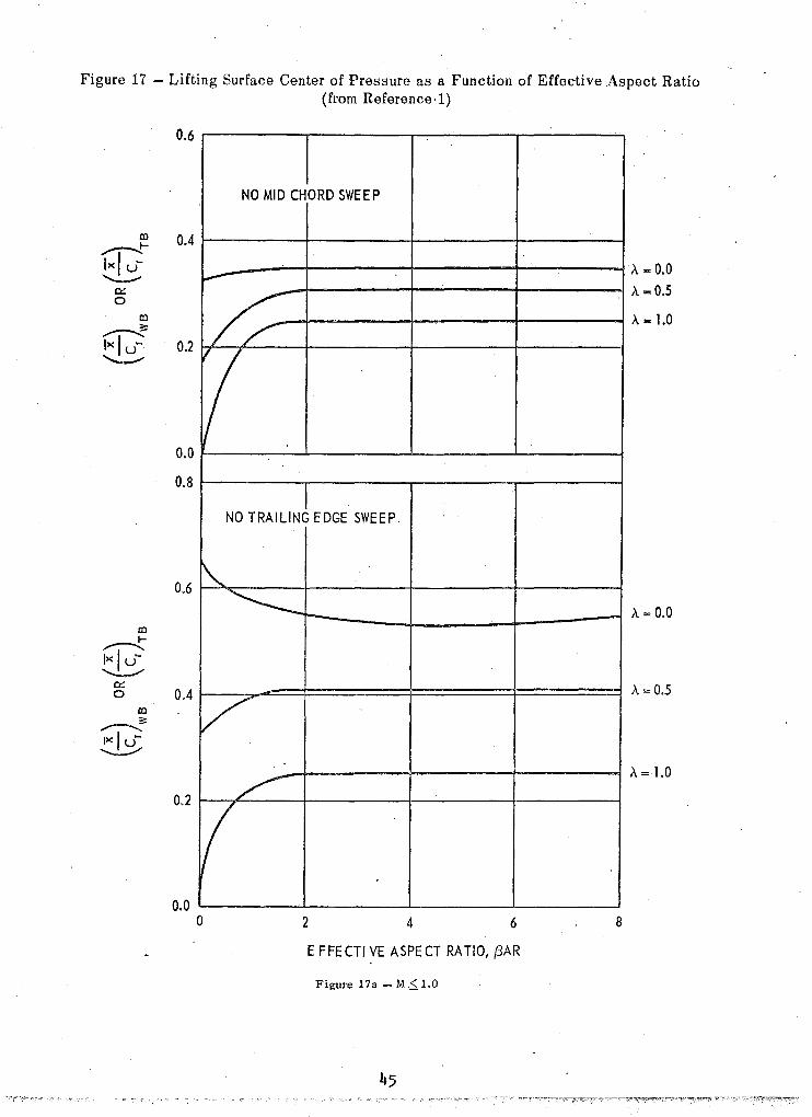
Figure 17 - Lifting Surface Center of Pressure as a Function of Effective Aspect Ratio (from Reference ,1)
ro ~ 1><1 u--.....:.--
a::: 0
ro ~ 1>< I u-~
ro -----t Ixl u-~
a::: 0
ro ~ Ixl -~
0.6
0.4
0.2
0.0
0.8
0.6
0.4
0.2
0.0
NO MID CHORD SWEEP
~
U V
NO TRAILINJ EDGE SWEEP
~ ~ l-
V ..
/
if o 2 4 6
E F FE CTI VE ASPE CT RA TIO, {JAR
Figure 17a - M,S;.1.0
8
,\ .. 0.0 ,\ == 0.5
,\ -1.0
,\ = 0.0
,\ = 0.5
,\ = 1.0
co ~ Ix I -~
0:: 0
co ~ Ix I -~
co ~ .......-:--...
Ix Iu-~
0.: 0
co ~ Ix lu---.;:/
0.6
0.4
0.2
0.0
0.8
0.6
0.4
0.2
0.0
NO MID C~ORD SWEEP
A-O~ "..
/,
A ... 0;5
I NO TRAILING EDGE SWE EP
A = 0.0
A=0.5
/: ~
A= 1.0
.....--
..
o 2 4 6 8
E FFE CTIVE ASPECT RATIO, {3AR
Figure 17b - M ,> 1.0
46

Figure 18 - Subsonic Center of Pressure Location of the Lift on the Body in the Presence of Wings or Tails (from Reference' 1)
0.4
I-0.3
~ Ix lu-'---'" 0,2
0:: 0
::: ~fD 0.1 Ix I -~
0.0
OA
I- 0.3 ~ Ix I u--........--
0:: 0.2 0 ::: fD ~
Ixl u -........-- 0.1
0.0
PA
I- 0.3 fD ~ Ix lu---=---0:: 0.2 0
::: ~ Ix I ---3- 0.1
0.0
A =0.0
~ ,
~ ~
A= 0.5
~ ~ I
r-- I ~
A = 1.0
./ V-
/ V j
o 2 4 6
E FFECTIYE ASPECT RATIO, (:3AR
Figure 18a - No Mid Chord Sweep
47
8
rib = 0.6 rib = 0.4 rib = 0.2
rib = 0.0
rib = 0.6 rib = 0.2 rib", 0.0

0.6
0.5
~ 0.4 00 ~
1>< I u-..:..........!.
a::: 0.3 0
3: ~oo
Ix lu- 0.2 ~
0.1
0.0
0.4
~ 0.3 ~r:t:J
t.8 a::: 0.2 0
3: /,,"--:--...00
Ix I - 0.1 .....3
0.0
0.3 ~ co
l:j~ ~ 0.2
a::: 0
3: 0.1 ".,--.......co
Ix lu--.........:...-
0.0
)" .. 0.0
~ r--
" ~ --
,\ = 0.5 ~
~ i-I'"'"
V~
,\ .. 1.0
.... v---
/ V o 2 4 6
EFFECTIVE ASPECT RATIO, {JAR
Figure ISb - No Trailing Edge Sweep
8
rib - 0.6 rib -0.4
rib - 0.2
rib - 0.0
rib = 0.6 rib", 0.4 rib ... 0.2
r/b:o: 0.0

Figure 19 - Supersonic Center of Pressure Location of Lift on the Body in the Presence of Wings or Tails for I3AR (1 + A) (1 + 1/m(3) .:; 4.0 (from Reference 1)
1.6 ,..------r-----~-----~----__, A= 0.0
rib = 0.4
~ 12~------~---------~c-------~------~~ ~
~Iu: /b ~ L-~L~J~==--_=J....",~======f====:J r = 0.2 g 0.8
;;
~ rtJ rib", 0.0 1>< I -~
0.0 !--____ -L-____ -'--____ --'-____ -j
1.6 ~-----_.__ __ rib = 0.6 --,-----::7" rib = 0.4 -------I .\ = 0.5
I- 1.2 I---_i--l--_t::...---+-----+-------::l. rib = 0.2 rtJ ~
~ ~ 0.8~_L-~~~--~~~--+_------_+-----~ o
~
~rtJ rib = 0.0 ~ O.4hf,~~~--~----------+_------t------~
0.0 l---___ -L-____ -1-____ --'-____ -;
2.0 ~--------t---.. rib = 0.6 --.---'-_ rib = 0.4 -------1
.\ = 1.0
L6l------~+_----?L-~-~--_+-----l
IrtJ ....---..... ~ 1.2~-_.~--~L-------+_----~_+~=-----~
0::: o
0.0 2 4 6 8
E FFE CTIVE ASPE CT RATIO, I3AR
Figure 19a - No Mid Chord Sweep
rib"" 0.2

1.6 rib = 0.6 rib = 0.4 ,\ ,",0.0
t- 1.2 al ....---1>< I u ~ r/b".0.2
0::: 0.8 0
;:: al
rib - 0.0 ....---1>< I u~ 0.4 -.:.--'
0.0
1.6 ,\ "" 0.5
1- 1.2 rib = 0.2 D3 ....--Ixlu---/
0::: 0.8 0
;:: D3
rib =: 0.0 .-----..... Ixl u- 0.4
---------0.0
2.0 rib .. 0.6 rib ",,0.4 ,\ = 1.5
1.6
,- rib .. 0.2 m ...---....
1.2 1>< I u-~
0::: 0
;:: 0.8 m ....--
1>< I u-~ rib = 0.0
0.4
0.0 6
EFFECTIVE ASPECT RATIO, (iAR
Figure 19b - No Trailing Edge Sweep
50
2.0
1.6 I-m ,--....
IX lu- 1.2 ""--""
eY-e
3: 0.8 m ..--:---.
~
WITH AFTERBODY
~
.". ~ ~ ~
V 0.4
0.0
0.8 NO AFTERBODY
I- 0.6 m ,,--... Ix lu---.:..--'
~
V 0:: e 0.4
3: m ~ Ix I - 0.2 ~
0.0 0.8 2.4 3.2
Figure 20 - Supersonic Center of Pressure Location of Lift on the Body in the Presence of Wings or Tails for ,BAR(l + A) (1 + l/m,B) ,> 4.0 (from Reference 1)
51
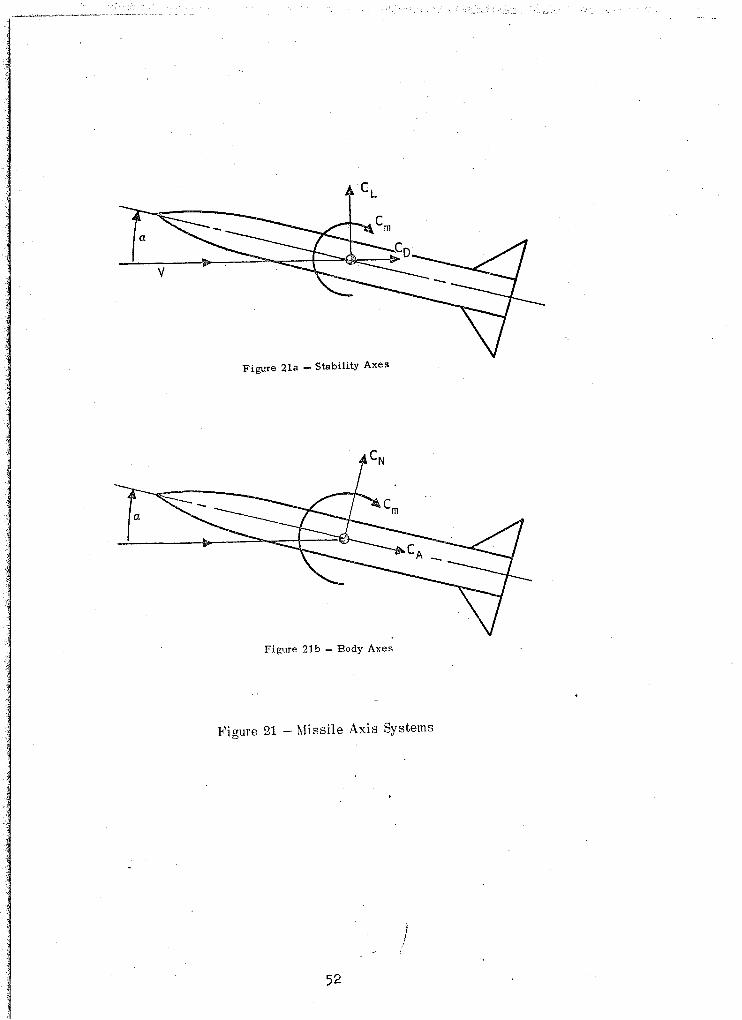
Figure 21a - Stability Axes
Figure 21b - Body Axes
Figure 21 - Missile' Axis Systems
,; 52

: d c 0
.1 4.0' J 8.0'
CONFIGURA TION 1
i'III---4.26'D 14----------9.6'---------
CONFIGURATION 2
~
E 2.81 ' =5'3~' CONFIGURATION 3
t«1------- 5.29 '--------iI>f
I-tf----------- 9.21 ,---
CONFIGURA nON 4
~
----__ -J
Figure 22 -- Configurations Used to Compare Theory with Experiment
53
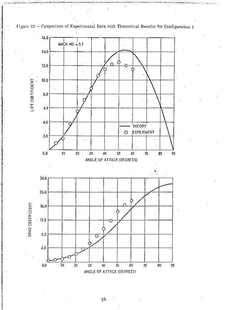
Figure 23 - Comparison of Experimental Data with Theoretical Results for Configuration 1
16.0
14.0
12.0
I- 10.0 z UJ
0 u:: LI- 8.0 UJ 0 U l-ll .. 6.0 ....J
4.0
2.0
0.0
24.0
20.0
I-16.0 z
UJ
0 ll.. ll..
12.0 UJ 0 U C-' -< oe: 8.0 a
4.0
0.0
I I MACH NO. - 0.7
-V;:) 1\
I' ~
\ ~
} ( \
f 't
I
V VI
10
10
20
- THEORY
0 EXPE RIMENT
30 40 50 60 70
ANGLE OF ATTACK (DEGREES)
(
()
/
20 30 40 50 60 70
ANGLE OF ATTACK (DEGREES)
\
1\ \ \
80 90
80 90
6.0
3.0 o
CONFlbuRA TION 1 MACH NO. = 0.7
UO O )0 "-I---
) --- 0 -- o r'l - ,-(J
10 20 30 40 50 60
ANGLE OF ATTACK (DEGREES)
Figure 23 (Continued)
55
70 80 90

II
1 1
I-z W
U u... u... l!..! 0 U I-u... ::i
18.0
16.0
14.0
CONFIGURA TlON 1
/ ~ MACH NO. - 1.1
" V .\ 12.0 ! o( 0
~ ()
10.0
8.0
6.0
4.0
2.0
Vo \ j \
II ~ )
- THEORY ~ (! o EXPERIMENT \
V \ 0.0 10 20 30 40 50· 60 70 80 90
ANGLE OF ATTACK (DEGREES)
28.0 .----,----.----..----.----.---r---/-r
V---=-----.
24.0 1----+--+---+--4--I---+
sV-<-+---I---i
20.0 1----+---+--+--f---
c
-+
l--...,..-+f----+---+---1
16.01----+---+--+--f---"""d---+---+--1-----i
oj 12.0 1----+---+--+--+-(-+-+--+---+---+---;
/ 8.0 f----+---+--,..,/-+-V-LJiL+---I--f----+---+---1
4.0 1---+-1
- ----c-+r-{ (~l
0.0 10 20 30 40 50 60 70 80 90
ANGLE OF AHACK (DEGREES)
Figure 23 (Continued)
/

6.0 I I CONFIGURA TION 1
MACH NO. = 1.1
\.1 .
!".~ ~ ) ) . -
10 20 30 40 50 60 70 80 90
ANGLE OF ATTACK (DEGREES)
Figure 23 (Continued)
57

·l~ "
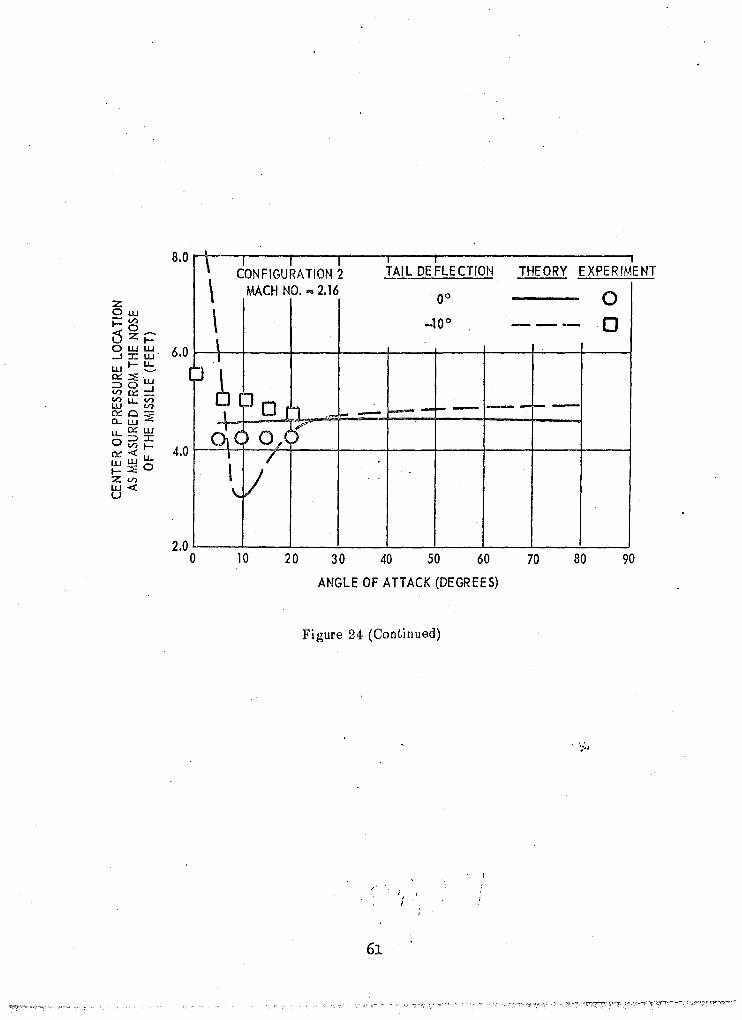
Figure 24 - Comparison of Experimental Data with Theoretical Results for Configuration 2
32.0 I---r----r--r---~..=--'T""C":"-T"""_-.,....-__r-___, CONFIGURATION 2
MACH NO. -1.12 28.0 I---+---+--l--~-+-:,-L--+--~--!-----+---f
24.0 I---+---+--+-I-+--+---+--l--~H-----+----i
~ 20.0 ~--+----1--+7"'r---+---+--i---~k---+----i w U u.. ~ 16.0 i----+---±t'-f ~-!---+--I-'---!---+--\-l---"
8 ~ :J 12.0 I---+--'-J~'-----'-l---+---+--!----t---'t-----i
8.0 r----I..J--+--+--l----+---+--!----t---+-;----i
TAl L DE FLE CTION THEORY
4.0 /--'o~:rt-- rr
10 20 30 40 50 60 70
ANGLE OF ATTACK (DEGREES)
40.0
35.0 :/
30.0
~ 25.0 w U u::: u.. w a u <!)
< O!: o
20.0
15.0
10.0
;f ~
j 'I
"/1 'I
I ~I
5.0
jJl f).k/
l~/ 0.0 10 20 30 40 50 60
ANGLE OF ATTACK (DE GRE ES)
58 .
70
80 90
....... --- -
80 90
12.0 I I I I .1 J I
TAIL DE FLECTION THEORY EXPERIMENT
10.0 0 00 0 -CONFIGURATION 2 -10 0 --- 0
1\ MACH NO ... 1.12 8.0 ,
z 6.0 I Ow I
- V>
o g~B-1-0 ~~ 0 ( - - :.- - I- - -l)zt=' oww 4.0 ...J :c w I (~D wl-~ cx:::;:w I ~~= 2.0 V>u..V')
I I w V') 0::0-'-a..w::!O
I u..o:: w I 0::J:C
V> I- 0,0 O::«u.. I I wWo I , I-::E Zen w«
-2.0 I u I I
-4.0 ~ II
-6.0 I I I
I I -8.0
, I
\; 10 20 30 40 50 60 70 80 90
ANGLE OF ATTACK (DEGREES)
Figure 24 (Continued)
59
32.0 T CONFIGURA TION 2
MACH NO. -2.16 TAl L DE FLE CTION THEORY EXPERIMENT
28.0 00 0 -_10 0 --- 0
24.0
I- 20.0 z UJ
Ci u:: Ll.. 16.0 UJ
/: ~ ~
./ ........
" " 0 U l-Ll..
12.0 /; / \
....J
8.0
4.0
0.0
J!/ \ ~
J}' \ r~ \ tr 10 20 30 40 50 60 70 80 90
ANGLE OF ATTACK (DEGREES)
30.0
/ ....--
25.0
IZ 20.0 UJ
Ci Ll..
~ 15.0 o u t!)
<: g; 10.0
/
/i /
/ r"
.
5.0 ~ fl~
0.0 10 20 30 40 50 60 70
ANGLE OF ATTACK (DEGREES)
Figure 24 (Continued)
60
80 90
8.0
1
2.0 o
• \ tONFIGUkATION ~
, , -, TAIL DEFLECTION THEORY EXPERIMENT
\ MACH NO. sa 2.16 '00 0 \ _100 --- 0 \ I
61 Or 11 --I----i-- -, - I- -
0;( )O/J I 1// ,
..
\.
10 20 30 40 50 60 70 80 90
ANGLE OF ATTACK (DEGREES)
Figure 24 (Continued)
61
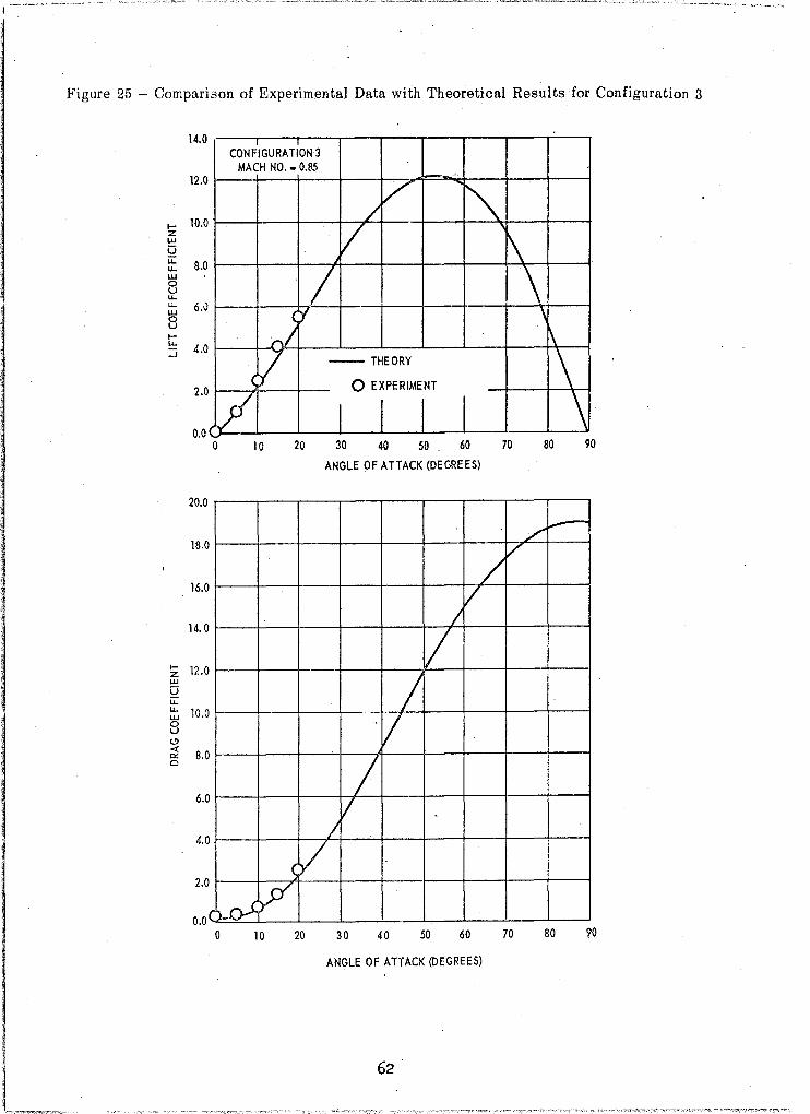
Figure 25 - Comparison of Experimental Data with Theoretical Results for Configuration 3
14.0 CONFIGURATION 3
MACH NO ... 0.85 12.0
I- 10.0
.
/ V '" z
w U u:: 8.0
V r\ u. w 0 U u. u... w 0 U l-ll ..
..J
IZ w Q u. u. ~ U Cl
/ 6.0
4.0 i'/Y
2.0 <V V 0.0 o 10
20.0
18,0
16.0
14.0
12.0
10.0
-- THEORY
o EXPERIMENT
I I I I H ~ ~ ~"~ ro
ANGLE OF ATTACK (DW~EES)
/
/ /
I
/ /
'V i?2 8.0 -/ o
6. 0 V
0 /
~V (~
4.
2.0
0.0 o 10 20 30 40 50 60 70
ANGLE OF ATTACK (DEGREES)
\ \
~
\ \
80 90
/" ... -
80 ~o

45.0 CON~IGURAT\ON 3
MACH NO. "" 0.85 40.0
Z Ow i=V)_ LS°V) ZUJ
35.0 oUJ:X:: -.J:c u w~~ O::::::E w ::>0-.J 30.0 ~O:::_
wu..~ 0:::0-O-w:::E
0
~ ~
2 ?;'
u..~w 25.0 0::>:C
V)~
~~u.. ~:::EO
.n
ZV) w« 20.0 u
15.0 o 10 20 30 40 50 60 70 80 90
ANGLE OF ATTACK (DE GR EES)
Figure 25 (Continued)
/
63
/ 40
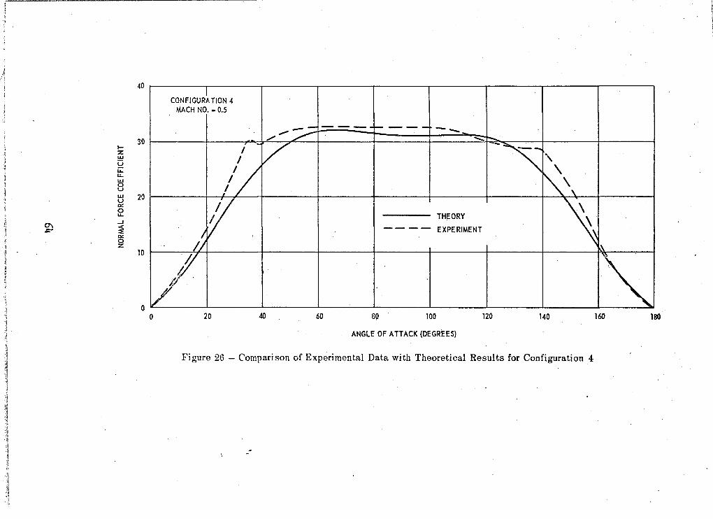
CONFIGURATION 4 MACH NO. - 0.5
--- --30 --...;:
I-z: W U u.. u.. w 0 U w 20 u ~
~ THEORY --' 0\ ~ ,;::- - - - - EXPERIMENT ~ 0 z:
10
o --------
o 20 40 60 89 100 120 140 160 180
ANGLE OF A HACK (DEGREES)
Figure 26 - Comparison of Experimental Data with Theoretical Results for Configuration 4

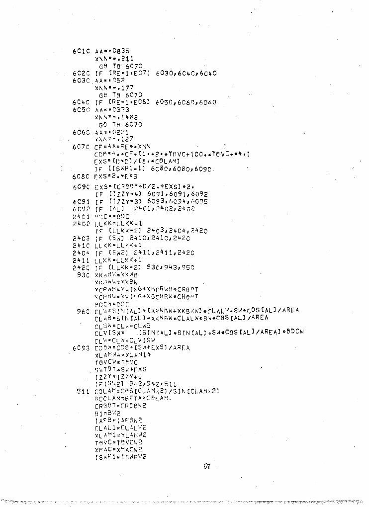
Table 1
COMPUTER PROGRAM LISTING
DI~E~Sle~ XVXMC16"XDTC16J,XALC_8) ceM~8N XVXM,XDT,XAL ce~M9~ CN/CA)C~8JCNWICNT,CNW2/CCW/CLT,CLW2,CLI,CLWB,CLVISW/CL ITI
1 CLIW,CNTD,CAB/XCP2/~CG2/XCPB/XCPT,XCPW'XCPW2'XCG,XCPTV, 2 XLAMT4
ceMMbN LLKKJIS~PW'ISWPT,IS~PW2/iAFBW/IAFBT/IAF8W2,IL/LLLL/IJ,J, 1 II,N8BOY/IZZY,ICSc,iNOSE,NM,NMLK,JDT,IM,IAL,ISW P 1/ IAF9
ceMM(lN XLAMw I Xl.A~T I XLA!'IW2, yMAC\'~' xMACT, XMACW 2, CLA"1W I CLA~T I CLAMW 2, 1 8W,BT,Bh2/CReeTw,CR~ATT/CReBw2,Bw,ST,SW21XWrNG,XTAIL,XWING2 2 ,XL/D/Dl,XLN,ARrA,XREF,SSUBS,XLBB,ZF,ART,ARW,ARW2,XLNBBE ceM~e~ CBLAM,BC BLAM,CROBT,Rl,CLAL1,xLA M1A8AR,RATre,XKTB,XKST,
1 XKWG,XKeW/X8CR8G"XK~BW'XKW8r,XKWBW2/XKBwW,XKBWT/XK8WW2, 2 XCPBW,XCP8T,XCP2W2,vCPWR,XCPTB,XCPWB2,XKWBI,BCC,BDCW,BDCT, 3 eDCW2/CLALW,CLALT/C~AlW2,REFT~8ETA,AL,TeNST/HeNST/HT,XKT81, 4 VX~,VXMR1JDELTA/XKCPWBJXBCRWB'XMAC/XLAMW4/XLAM24,XLAM2, 5 XLAM4/T~VC'TeVCT,TevCW2'Tevcw/EXS/STTBT/SWTeTJS~2TAT,RE, 6 cCB,c~e~'CDeTlcreBlrOA~2,CL8WICLWB2,CLBW2ICLTR,CLBT,CLTDI 7 CLrDB,CLBDT,CLVIST,rLVI W2,CMB/COBWBT
reMMfN DCDfSW,~CDBSTJDCC3S?,nCDBW/DCDBT,CCDBW2 ce~MeN CDALZ
IL. "' C 3C4C ~eRMAT(215J7FlC·5J 3C5C r:e r-<r-',AT(615J 2C2C FBR~ATC7Fl0.3J 3e1e FBRMAT(lCAAl 311C FeR~AT(lhl,lOA6) 312C ~eR~AT[6X/2HHT, 9X,2HD ,RXJ2HXl,6X,6HXLNeSE,5X,3HXCG,6X,4HAREA,6X,
14f-iXREFJ 3C21 r:eRMAT[//,5X/5~TSVCW,5X,hHTeVCW2,5X/5HTBVCTJ 314C FeR~AT ( 3XJ 15, 5X, 15, 4XI 7F15.6A//J 315C rBRMAT[4X,I5/5X'I5,5x,r5,5~,r5J6X,I5/5X/I5J 324C FeRMAT (6X,5,-dswpw, 5X1kHIAFew, lOX .. 5HXLAMW, lOX, 5HCLAMW,
1 lCX/5~ 8~ 19kI6HCRe3T~'1~XJ5H sw ,10X/5HX~ACW,10XI5HXWINGJIJ 3244 FSR~AT ( 6X/6~IswPW21 4X,~HIAFBW21 9x, bHXLAMW2, 9X, 6HCLAMW2,
1 1 ex J 5 H B w 2 I 9 X J 6 H C R A f) I~ 21 lOX I 5 H S W 2 ,9 X I 6 H X MAC W 2 I 9 X I 6 H X wIN G 2 J I J 3248 FBRMAT [6X,5HISWPT, ~X,5~IAr8T' loX, 5HXLAMT, lOX, 5~CLAuT'
1 10Xl5H 8T 19X}6HCReBTT'1~X/5H Sl 110X/5HX~ACT/lOX,5HXTArL}/] 3241 FORMAT[/1/6X,5HIcSC ,5X,5HiNBSE,5XJ5 HND ELT,5X,5HNMACH/5X,5HNALPH,
15XJ~HNr.eDyJ . 3333 p E AD 301 0 I T r T ll, TIT L 2,1 I T J~3 ,'T I T L 4 I TIT L 5 I TIT L 6 , T TTL 7 I TIT L 8, TIT L 9 ,
lTpLC READ 305C, ICSC,INOSE,IDT,iM,IAL,NBeDY "(AD 3C4C, ISWPW) IAFr'''';}XLA'''tI,CLAMW,8w,CReen';/sw,XMACW,XviI~G READ 3040, ISWPW2/IAFB~2IXCA~W2,CLAMW2'BW2/CReAW?,SW2,XMACW2JXWIN
lG2 RFAD 3Q4C, IswrT,IAFBT,XLAYT,CLAMT,BT,CReBTT,ST,XMACT,XTAIL R~AC 3020, HT,C/XL,XLN?SE,yCG,AREA,xREF READ 3020, rBvc W,TeVCw2,TBVCT

PRINT 3110 1 TIT~1'TITL2ITiTL3,TiTL4,TtTL5,TITL6/TrTL7,TITL8,TITL9, 1 T ITL C
PRINT 3241 PRINT 31501 ICSC,!NBSE,IDr,IM,IAL,NBBDV PRINT 1240 PRINT 31 401 ISkPW'IAFB~IXL~MW,CCAMW/BW/CReeTW/SW/XMACW/XWING PRINT 324lj. PRINT 31401 lS~PW2,IAFr~2/~LAMW~,CLAMW2/BW2,CReOW2,SW2,XMACW2,
lx .... ING2 PRINT 3248 PRI~T 31401 lS~PTIIAFBT,XCj~T,CCAMT/eT,CRee~T/ST,XMACT/XTAt~ PRINT 312C PR I NT 3C2CI HT, D, XL, xL~;eSEI XCGI AREA,XREF' PRINT 3021 PR!~T 3C201 TeVCW,TeVC~2IT~VCT
IL "1 + IL LLKK=O LLLL"o
XCG2 "' XcG IZlY :: C
CALL GreSuB READ 4noo , [XDTCMj/~alIIDTJ READ 40CO, (XVXM(~)/t\B1/IMj
READ 4000, CXALCNAJ,t\A-l,YALJ ~E=REFT*VXM V X M :: X V X 1" ( 1J C'S 6002 IJ=l/II" r:ELTAl'''xDr(lJ ~B 6eo1 Ip:l,y~T ALPHA"''<AI.. (1)
4CCC ~eR~AT[16F5.1) 5CCC F9~MAT[lHl'4HVX~~IF5.2,2XJ~HDELTAR'F6.21/J . 5CCl F~RMAT[2XJ2HAL,3xI5HCLTeT,~X)5HCDT~T,2XI4HCLWT,3X,4HCLTT J 3x l 3HCLB,
14X,3WCLIJ4XJ3HCNWJ4X/3HCNT,4X/4HCNTDI3X/3HCNB,5X,2HC~,5X,2HCA,4X, 24~XCP~J3X}4HXCPTJ3X,4HXCP6/3Y/4HXCP214X/2HCMII)
82ec rRI~T secOl VX~IDELTAl FRINT 5CCl 2ELTA=DELTAl/57.29578+.000000ooi r,e 6C;C:J Jlll/IAL' AL=ALP~A/57~29578 •• 0Coooooi
1 vx""Rl::VxM IZZY=!ZZY+l
IF tIZZY" 4) 6666166t.6,lil1 6666 vx~r;'6
1111 CALL CLASU3 IF[LLLL-1J 900 , 942,980
gee IF [l ZlY- 4) 6JC9J 60C9i 925 . 92~ CALL CATSUB
6CC9 XLAM14~ATAN([.5.[Bl.CJ.l./tBLAM~.25*XLAM1*cReeT-.25.CReeT)/ 1(.5*(Bl~D)JJ
RE=REFT*VXM*XMAC IF (RE."1. (06) 6010 , 6020,6020
66
6C1C AAIII",C835 )(1\1'10 11 .,,211
Ge T6 6070 6C2C IF eRE"l'EOl) 6030,6C4C,6040 6C3C AA .. ·tJ52
XJ\""".177 G8 Te 6070
6C4C ! F eRE'"l' E08) 6 0 50,6060, 60t.O 6cse h.A"'tC333
Xf\" ..... 1488 Ge Te 6070
606e AA ... 0221 "Xi\i\:l: Q d 27
6C7e CF"AA*RE**XNN ~, cc~"4.·cF*[1·+2·*TeVC+l00.4T~VC*44.J [XS"(D~C)/(8·*CeLAM) IF CI s\;.;p 1 .. 1 J 6e 8 0,6080,609C
608e [X5l!l2.*ExS
609C EXS=(CQeBT*D/2.+EXS)*2. IF nZZY"4J 6091,6091,6092
6091 IF CIZZY"3) 6093,6094,h095 6C92 IF (ALJ 2401/2 402,2402 2401 pcc:..eDC 2402 LLKK=U.KK+l
IF CLLI(K-2J 24C3,21+C4,2420 2 4 03 IF (S\.;) 2410/2410,2420 241C LLKKcLLKK+l 2404 IF (S',..2) 2 4 11,21+11,2 4 2C 2411 LLKK"LLKK+l 242C IF (LLKK"2J 93CJ 9431 950
93 C X K ,~ 8i:i :: X K 1,) 8 XI(i:3~W",Xl(ew
xcP~8cY~ING+XBcRwB*cRe~T ~cPBW::x~I~G+X8cRRW*CRaRT ecC'~ =eDC
96C CL0=SI~j(ALJ*(XKWBW+XKBWWJ*rLALW*SW*CeS[ALJ/AREA CL~BBS!~[AL)*XKW8W*CLALw~s~*ceS[ALJ/AREA CLG ' .... "CL'" "CLI.;3 CLVISw= (SINrALJ*srNCA~J4sw*ceS[AL)/AREAJ*eDCw C L \oJ " C L ',II + C L V I S W
6C93 cCS~=CDe*(SW+ExSl/AR[A XLAI"!\~4=XLA~14 TSVCWItTeVc SI;;T5r"S\\+EXS IZZY:IZZY+l TF[SW2] 94219421511
511 C SL At-' = CAS [CLAM'..;2) IS I f\ [CLAM~'2) eccLAM"~ETA.CBLAM. CRsBT:::rRee W2 gpB\>12 1 AFS" I "t,F~\~2 CLAL1"CLAL w2 XLA N l =xLAr'1~/2 T'J V C '" 1'= V C\.i 2 Xt-AC"X"'ACw2 I S\~p 1 .. T SWpW2
67

8AR-8ETA*ARW2 ~ATI~.CReeT/CBETA*DJ IFCIZZV.4] 6009J~009/925
943 XK\'. t3W 2=XKwB XKB .... I-J2=X KeW XC Pw8 2=XWING2+XBCRWS*CReeT XCP~~2·XWING2+XBCROW*CReeT ~CCw2=~DC _ '
944 CL~2ESIN[AL)*(XKW8~2.XKBWW?)*CLALW2*SW2*ceSCAL)/AREA. CL~82=SINCAL)*XKWBW2*CLALW2~SW2*CeSCALJ/AREA CLB~2=CLW2·CLW~2 CLVIW2=[SIN(ALJ~SI~(AL]*SW?CBSCALJ/AREA,*eDCW2 CL~2=CL~2+CLVI~2
6C9~ rC~~2=CCe*(SW2+EXSJ/AREA XLA~24"'XL.At-'!14 )(LA~2&XLAM14 S w2T AT:: S\>l2+E XS
942 IllY" IlZY + 1 LLKK=LLKK+2
IF rST) 980,980/940 94C (BLA~",CeS(CLAMTJ/SI~CCLAMT'
,H(T'" (Br .. D) u2/ST . 8CeLA~=BETA.CeLAM CRtlST",CRBeTT B1=8T flAR=~ETA*ART CLAL1=(LALT IAFB=IAFBT Xf"AC=X"'ACT TBVC=T'lVCT r s ;.; p 1 :: I S 10/ P T XLAt-'l=XL At0T ~ATI~=CKr5T/CBETA*D) IF CIZlY w 4J 60C9,60C9J925
95 C X K lv 8 T .. X K \\ 8 XKt:i\\T.,XKPW xCPBT::XTAIl+X8cRG~*CRe~T ':~CT;:G'::C
951 ClT=[(XKWeT+XK2WTJ.SIN(ALJ).CLACT~ST*CeSCA~)/AQEA CL 18=S I~, (AU *X><W8T *CLAl. T*Sf*ces (A.LJ /AREA ClfjT=ClT"CLT8 CLTD9:XkTG·CLALT.SI~[DELTA].ST*CAStAL+DELTAJ/AREA CLTD"[XKTB+XKBTJ*CLALT*SI~rDELTAJ*ST*cesrAL+DE~TAJ/AREA CL8DT:CLTD-CLTr,8 . CLVIST=[[SIN(AL+DELTAJ.SINrAL+DELTAJ~.ST*ceSCAl+DELTAJ/AREAJ*AOCT CLT=CLT~CLV!ST
6C9~ cc~T=C~B*tST+EXS)/AREA STTBT::ST+[XS XL,H'T4=XLAIv114 I~ CtZlY·4J 1610/161C/6098
6C98 XCPTR:XTAIL+[(xKWBT.Sr~[Al]*XBCRWB+xKT8*SIN(DELTA).XBCRWBJI lrXK~~T*sr~CALJ+XKT8*sr\[D[CTAJJJ.CRBeTT
98C IF-~IZZY - 4) 16101 1~10J 1710 171C xLeg ~ ~L/D
ZX~"VX~.A8S(SI~[ALJJ
IF CZX"''''8J 1310~135CJ135C 13 1C CCC=2.4.SQRT(1.5129~1.5129*ZXM~ZXMJ
se Ttl 1391 68
137C 136C
1:?81 1391
! F (ZX~·l .15) 138011 37011370 CCC·1.6+SCRT(.C344·CZX~·'975)··2J. 3~ TB 1391 . r F t z X ., .. 3 • J 1 3 6 O} 1 3 8 11 1 3 8 1 CCC=1.9-SGqT(.361·.09*(ZX~.3.J·*2J se TP 139 1 . CCCJ:l.1 ETA~[C.0000475.(XL08**3]J.CO.00173*CXLeB**2]J+[0.0298*XLB8J+O.S146 1F (VX~'- ·5) 1395} 1395 J t 332 IF (VX"-1.4J 1393J13g4J13q4 ETAarTA+(1·-ETA)*[VX~".5];i'1111111111111 G'J iF 1395
1~?-~ Li,~r,1t
13'9:: IF (XL"B-10.J 13 20 / 133('.,1340 . 13~r XK2~1~-r'OC54*(XL~J**2J+O.1C4*X~eB+C,437
GO T ... 1600 133C ',(\(2K1=0.939
G~~ i[l 1600 134: YK2Kl=r.938+(O.OS1525*(XLe~.10'O)J
·160C ALP=AL FCALJ 16 C2116C1d6Cl
1622 CCC"-C~C lcCl C~~~= rXK21(1*SI~ C2 .*ALP] *CSSrALP/2.]) .3.14159*D*D/C4.*ARF.A)
1 + ETA. C C' C ... ( (X L * r; J I ARE A J 10 ( C S l ~ CAL p) ) • * 2) 'ir;",xCG/8 C~31w(X~2Kl*XQ.SlN(2.*ALP).CeS(ALP/2,JJ*3'14159*D.D*DI
1 r 4 • -\I .<\ R ~A " X P f:T ) ~~~2~trTA"CCC*([XL*C]/ARE~'.[[XCG.(X~/2.]J/D]*[[SI~[ALp)**2]J]
l"C/X~Er. C .... d"C~:: 1 +C'-:E2
161e; R[:::'"'EFT .. \,x~1*XL IF [~E·l·EJ6J 1611,1612,1612
1611 AA"'"C83t:;" "".:," ... 211 ';S T0 1617
1612 'F (r.E-l.t.C7) 16 13df14d61 4
1fl:? t,.~:.C5:?
GS TA 1617 1614 IF (Q["1·£:08J 16 15,1611'11616 lel:'- Ab,:.C3'3
:.0,\: ... 14R8 ~'1 T~ 1617 AA,,·C221 YI\~,;::"o127 (r.~~r=AA*Qr*·X·~ ~C~B :1.C2*CF5CD4(lt+l.s/(xLOS*.1,S)+7./[XLBB**3,JJ*SSU8S/AREA
162:: 1621
IF [1ZZY·4) 1618J161F,:~19 v X ". :I 1 • 1 9 9 9 9 ~l C)
I F ( S 1'1 1 1 6 2 0 I 1& 2 0 J 1 6 2 1 '":~(.',..:: o· iF (S>'l2) 1622,1 6 ?2}1621
162 C -C C ~ /' 2:; c. 1(-2:; iF" CST) 1€:2'+llf: 2 4J1625 H:24 CC'jT><O' 1625 ~e~ST:CDeW+CDe~2+CDeT+CDAB
69
rie T~ 1639 1619 rr [VX u ·1.2l 1631/1~31,163~ 1631 IF CVX"1"'8J 16381163RI1639 1638 CCALZ=CCOB
CC~~~T=COe8+CDeW.cceT+CDeW2 r,e TA 1663 .
l 6 3 ,:; I F [ S II.' ) 1 700 J 17 0 0 I 1 '70 1 17CC ccDes~: 0.0
s·~Te T: C' C ccet~ : ·0.0 G~ TO 1702
1 7 C 1 X XV " V X i'l * S ;~ R T (C e s (X L At'. '1'/ 4' ) SG~ITC&SGRT(A8S[CXXM*XXM]~i,o]]/[levCw**o.~3333) ATC=ARW·(r8VCW.*.333333J - - -J ZT=l
164,= rr= (ATe,,1.5) 1641/1642d61j.? 164;:: IF- (Vx"-l.J 1643,1643,\644 1643 FL~CT=3.3081~1,88779.S1MITr+l1'o916*SQMITC.~QM'TC.18.6087.
lSG~1TC*·3+7.4633*SG~·qTC**4 - -' - < - - - -
GO T0 1650 -1644 rl\CT:3. Lf
Ge T'3 1(:::5C 16 lq !~ CATC"'5J 1645 / 1645J1646 164( IF (Vx'-'-l.J 1647d647J16~8 1647 rl~CT:?47917·1'42798~SQMITC •• 3244C5.SQMITC*SQ~ITC
r;e T'" 1650 164~ FC\CT m2.S*ATC
GEl Te 1650
1645 TF CVx"-l.J 16491164911651 1649 rU~CTz.5325 •• 47202.SQM!TC.~0863i*SQMITC*SQ~ITC
GB Tr 165C . 16~1 Fl~CT:.55917+.33~33*SQurTC_'071429*sQMITC.S~MITC 16 5C IF CIzT~2J 1652J1653J1A54 . 1652 GCD~SW:FUNCT*[TeVC~**1.66667J.[CCeS[XLAMW4]J**2.5]
rcc?~=rcresw .. . -17C2 IF (S~'J2) 1703,1703117C4 17C3 CCC~S2 = 0.0
S\ 2T OT :: o.c CDF;1\1,2= C. 0 Gil Te 17C5
17C4 IlT:: 2 xx~:VXu*SQRTCCrS[XLA~24]J
SG~ITC=S~RTCABS[[XX~*XX~J~1~~]/(reVcW2*.C~~3~33J ATcaARW2·[TeVC~2*·.33333J . - . CiA TI11h 4C
1652 rc~GS2=rUNCT*[TAVC~2**1.66~~7J_.E(CBS[XL~~24J]**2.5J C C C e '.~ 2 " ceo f) s 2 . -' - - - _. -
170:; IF (ST ) 1706} 17061 1707 17Cf DC C9 ST:: C.O .
sTTeT::C.o CDtlT '" C.O G·'] Te 1 7 Cfi.
17C7 IZl:: 3 XX··"':Vx·'.sQrn CCf'S (XLAi"T4)) SGMITC=SGRT(ABsC[X~~*XV~J.l.)J/crevcT·*O,33333) t,TC-ART* CrBVCTIf*.33333J . . - ... ~e re 1640 .
1'0

1654 DCDeSr·rUNCT*CTeVCT**1.6666?'*CCCeSCX~A~T4JJ**2.5J DCDElT.DCOeST
1708 eeve u 1.31213.0.36633*VXM+.06638*vXM**2~.00601*VXM**3+tC00275* 1VXM**4 '
CDFPTR=lt02*CFe BD*ceVC*SSU8S/AREA CC PPTRaCDBB-1.02*CFBBD*Ss0eS/AREA
rF[VXM-l'CJ 17c 911709,1711 1711 (CPPTRZ[CDPPTR/O.2J*C1.2·vx~J 17C9 FR=XLNeSE/D
CDhN1 a O.OQ0407.CFR**8)_O,01C2*CFR**7)+Oel0 8 *[FR*.6J-O.A16*[F~·.5] 1.2.074.CFR**4J~4.183.Cr.R**1)+4'891*(FR**2).3.017.FR+O.7795 CCkN2Qa.OC0172*(FR.*8].o.or453*[FR**7J+O,050*CFR**6J~O.3C4*[F~ •• 5)
1+1tC96*CFR**4).2.4C6*CFR**3J+3'160*CFR**2)-2t391*CFRl+1.000 CC~N3=t000125*[FR**8J •• 003iO*CFR**7)+.0447*(FR**6)-t288*(FR**5~ 1+1.076*(FR**4).2.385*C~R**3J+3'141*(FR**2J.2.529*FR+1.30C
IF (V X M .. 0 • 8 J 1 6 6 4 I 1 6 611 166 2 1661 cC PTQ .. CC'tiNl
Ge T9 1658 1662 IFCVXM-l'OJ 1655,1665,1666 1e6~ CCPTR"CD\~N2
Ge TA 1658 165~ ccPTR=crCDWN2-CDWN1J/o.2J*rVXM-Oi8).CDWNl
Gf) Tf! 1658 1666 IF[VX~·1'2] 1667,1668,1664 166>3 CC PTR .. Cr,\'if\3
Ge Te 1658 1667 CCPTR .. [[CDWN3·cDWN2)/O.2J*~VXM·i,OJ+CDWN2
GB T~ 1658 1664 C[;PTRs:C.C 1658 cceB"CDFPTR+CDPPTR+eDPTR*VXM~3'14159*D·D/C4.*AREAJ
CCALZ.,CQeB CD~T"1.1·cDCDeST.rSTTeT/AR~A].CDeT) ccew:l'l·(DCDBsW.CS~TeT/ARFAJ+coeW) CDe~2z: 1. h CCDe~~2+DcceS2* (S',:Tf.1TI AREAJ J Cce~8T"1'1*[CDeW+DCCfs~*rSvTBT/AREAJ.cDew2+CCD~S2*[SW2T~T/AREAJ
l+cDeT.rCDOST*(STTBT/ARFAJ+iDBS) IF (lZZY"4) 1659,1659,1663'·
1659 T~~ST=CDe~8T ~ef\STs:HB~ST+ZF*[TBNST"HBNST~ vX~=VXvhl
IlZY :; IllY + 1 GEl TF) 1
1632 CCB~eT=([HBNST.TBNST)/CSQRT[3,J.SQRT[1.2]~].SQRTrVXMJ+TeNST 1.(~e~ST.TBNSTJ/[1.·SGRT[3~J/SQRT[1.2JJ ' CCOT=1.1·(~CDeT *(STTBT/ARrAl+CDBTl CDew=l'l*(DCDe~ *[SWTBT/AREAJ+CCBWl c c e \.'i 2,. 1 • ill- (CC! e : . .,2+DCCel-i (' *£5,,1 Tfl T I AREA) J crH8=c~O~8T·CD~T·CCBW-CDeW?-CDAL7=CDAE .
1~63 CCb=XK2Kl*SI~(2'.ALj*SINrAL/2.j*3'14159.D*D/(4.*AREA)+ETA.cDc-xL l'D·[rsr~[ALJJ.*3]/AREA CL8gXK2Kl*(SrN(2.*ALJJ*C~SCAL/2.)*3.14159*D*DIC4.*ARrA)+ET~.CDC*XL 1.c*trsI~(ALJ).*2).ceSCAL]/AREA.CDALZ*ceSCAL)*C~SCAL]*SIN[ALJ CA5"CD~v;BT IFCALJ 1603J16c411603
71

1604 '<CPBIIO.O G9 Hl 1605
1603 XCP8I1CCXCG/XRErj·tC~B/CNBJj*XREp 160~ IF (S\\J 1607, It,0711606 i6e6 tF CST) 2973/297311608 1607 IF CST) 1990/199012974 1608 R:D/2.
IF qcsc .. 1J 1970,1970,11:)71 1971 XGluew/2.
XB2=BT/2' TT=D/6 T ~Wlc.O.5*cReeTT.ABSCSI~[DErTA)J;[XCpW8~XTAIL.CReeTT)*ABS(SIN[A~~) xLA~:l "XLA~1W Ge Te 1969
197C )(Bll1~T/2' )(82=81-,/2' TT =0/8'.': ~kl=[XCPTB~XWING~CReeT~]*~9SCSI~rAL)J xLA~l .. XLAYT
1965 FTRT=((X82.RJ/(2.*(1."TTJ),.rt3.14159/4'J~[C3'14159*TT.*2J/4-)-TT+ 1 [ ( [1 • -I- T T * .. 2] lHt 2) I r 2 • ~ [1 .... rr "Hi 2:) )j .. A R SIN C C1 ... T T ... 2:) I C 1 _ + T T .. It 2] J ~ ~~=FrRT+R . FI1"'[FW*R*.2]/[[FW.*2]+(~W1*.2J] ~Il=[HW1*R.*2J/(rF~*"2J+[H~1 •• 2J) ZC=F\\ z G =H\~ 1 ZLPO.O no 1800 t,dl4 Z Ll " ( (X81 ft (XL M' hR] J .. [Z c* ri ... XL A 1-11) ) , I (2, .. ( X81 .. R) ] lL2vAL8G([[ZD •• 2J+t(ZC~XB1J*.2JJ/(Cl~.*2J+((lC.Rj*421)J ZL3~(Cl.-xLAM1J/(X81~R))* (rX81·RJ+rzD*(ATA~(CZC.XB1J/ZDJ-ATANCCZC.
lPJ/ZCJJJJ 7.L=(ZL1*ZL2J~ZL3 rrcl w 2) 1810,182 0,1820
lSle zc·"Zc 3S T"l 185 0
182C TFn"3J 1830J18 40/1850 183C lL"'''ZL
ZC=Fll ZD"HIl Gel Tn 1850
184C n="n ZC:;-rll
185C ?Li=ZLT+ZL. 180C C,)!\TINUE
I r ( I esc - 1 J 2 9 7 C J 2' 9 7 C .. 2::: 71 297C AQ1:[BT.D)**2/ST
XBT=8T/2. [LI=rCLAL~.CLALT*XKWB!*sr~rAL'*SW*2.*ZLT*(XBT.RJ]/[2.*3,1 4 159*ART* l~TRT.AqEA*(l·+xLAHT)J
CU=CL r .CeS (AU CLT=CL Hell CLIT=cL.I rUI,o,=o· ycPTVaXcPrB GO Te 2972
72
2971
2974
ARW-CBW.D)**2/SW xBvjll' 8W/2. CLI.CClAlW*C~ALT*CXKWBI*si~I[AL~+XKrBI*SrNrDE~TAJl*ST*2.*ZLT*(XBW.
lRlJ/C2t*3.14159*ARW*FTRT*APEA*Cl·+XLAMWJJ . CL I-eLI .. ces CAL] CLvJ-CLW+CLI CLI W·CL I ClIl"o. xcPTV.xcPw B GS Te 2972 ClT-O, CLALTaC. ClTD·O. CCTD·O, ClBTeo. CLBDT.O. CLTB=O· CLTDS.O. CLvISTaO. CLIT-O' CLn·,·O· CLlee, GB Te 2972 CLW-C, ClALW",o. Clt3~=O' CLW8=O' CLvlSw=o· CLIl-.xO' CLIT-OCLIEC.
2972 I r CSW2) 70017eOl7cl 70C CLW2=0.
7el
1976 1977
CLA~W2GC' CL8 w2,.O. CLw82"O. CLv!W2=OALPHA .. AL IF(VXM u O'5) 1975,197611976 xK a l'17 Ge Te 1973 lrCVXMM1') 197711~78,1978 XK=2 t O-SQRTCO'764·CVXM wO,126J**2) GS Hl 1973
1978 IF[VXM fi 2 t ol 1979,1979/1980 1975}:K~2 .. ei"'·SQRT 0.298'" eVXM .. 2 .13 ] **2]
GO TB 19 73 . 198C 1973
"'K=C'87 CCT=XK*A8S(SrNrAL~J*ST/AREA CCW"XK*ABS(SINCAL))*SW/AREi ccW2DX~*ABS[SI~[AL]].SW2/AQEA CCDmXK*ABsCSINCAL+DELTA]]*ST/AREA CC1D=C~D~CDT . CATDmCDTD*ceS(ALJ.CLTD*SINrALJ C~TDuCLTD*ceS(ALJ+CDTD*SIN(AL) C~T·CLT*ceSCALpHAJ.CDT~SINCALPHA' CATaCDT*CeStALPHA)pCLT~SlNrA~PHA) CAW2~CD~2.ceS(ALJ.CLW2·SIN~AL)
73

CA~-CDW*Ces CALP~AJ.CLW*si~ CALp~Al C~W·CLW*CeS rAlP~AJ+CDW*Sr~' (ALPHA' C~~2·CLw2*CeS[ALl+CDW2.SINrALJ CAJ·CD9*CeSCALJ·CLB*SI~[AL' rA5 a CAT+CAW+CAk2+CATD+CAB r:e T':l 1991
199C (1\.=0'''8 XC P2=XCPB CAz:C A5 CLTBTz:CLB • CCTeTz:Ct8+CA*C~SCALJ*CAS(AL) C'L AL T::. O. ClALW:C. COT-a. CCD=C,I) rCh:l!C, CATD=O' C~TD=O. C1\T=O, (AT:C. CA~i·C. C1\w=C. Cl iJ" C, CLT"'C. elI-Of CLTT=O. rL iti T "0. ClAUJ2"O' CP!Ac=o. rAhc"o. Ct\TT=O' CI\. '., T:: 0 •
:\ \, T 2 = C. CI\~o,!2=O • CL ,~2 = C. CLA2T=O. XCPl,.oJ?"C. XCPT:rO. XCPi-.':rO· Ge T~ 1992
1991 CI\.=CNB+CI\~+CNT+C~TD+CN~2 _ CL TT=CL8 T +CL T8+CLBDT+CL TD8;CL IT ';'CLVIST CL~T.CLRW+CLWB+CLIW+CLV!SW~CLBW2.CLW82.CLVrW2 CI\TT=[CLIT+CLT~+[LqT+CLV!STJ*ceSCALJ.CDT*Sl~CALJ.ClTDB+C~BDT CI\~T=(CLIW+CLwP+CL9W+(LV!S~l*CBSCALJ+CDW.SrI\CALl C\~T?=[ CL~B2+CLrW2+CLVIW2J4CeSCALJ+CDW2*SI~CALJ rLTUT=CLTT+CL~T+CL8 rCTjT=(DB+CDW+CD~+CD~2+CDe~BT CACC~TqT~C~S(AL)~(LTBT*SIN[ALJ
IF CST) 9901/S9(;1~9902 9C.C2 XCPT=[(CLTR*CeS(ALJ+CD~*SI~(AL))*XCPT8+CL8T.C6SrALJ*XCPBT+CLTDB*
lXCPT~+(L~DT*XCr8T+CLIT~C~S[ALJ*XCPTa+CLVIST*CeSCALJ*XCPT8J/CNTT g9::)1 IF CSit-J 0903.19S031'19C4
9ge 4 '<CP'" [ [CL \\ R if ce~; (AU +(D',;*$ I'" C AU J * XCpwB+CL Bw*Ct1S C AU oI;XCP8 1>1+ CL! W. lC~S[AL).XCPWB+CLVISw*CBSCAL1.XCPW8J/CNWT
IF C S ','" 2 J 9903.1 9903 I 1993
74

1993 XCPW2.rCCLWB2.ceSCALJ+CDW2.SINCiLJl.XCPWB2+CLBW2*CeSCALJ*XCPBW2 1+CLV!w2-CeSCAL)·XCPWB2'/CNWT2 .
99C3 IF' (SW2) 1994'19~4J 1995 1994 xC pw 2.0.
Ct\WT2.0. T F (S W) 1997, 1997, 1 99·5
1995 XCP~=CCXCFW )*CN~T.CXCPW2 '*CN~T2J/[CN~T+CNWT2] c~,;I.~ T,. (t'JWT .CNfq 2 IF (SW)· 1997,1997/1998
1997 XCPWIIQ. 1998 IF CST) 19991199g1l996 1999 XCPTIIO' 1996 XCP2·(C~8*XCPB+XCPT*CNTT+XCPW*CNWT)/(CNB.CNTT.CNWT) 1992 C~:Ct\*[xCG2.XCP2)/XREF 7CCl AL1 BA L*57.29578 a7ec PRINT 50021 AL1/CLTBT / CDTBT,CLWT,CLTT,CLS,CLY,CNWT,CNTT,CNTC,CNB,
lC~/CA,XCPw/XCPT'XCPB/XCP2,r~ 5002 F~R~AT (lx/F4'C,17C1X,F6.2)J
nPHA.XAL (J+1J 60ac ce\T!i\UE
PRl~T 94001 CLALT/CLALW/CL~LW2' 94CC FeRMAT(I/,2XJ6~CLALT./r6.315x,6HCLALW.JF6.3,5X/7HCLALW2=,F6.3)
~ELTA1=XDTrII+iJ 6001 (st'-.;T H;UE
VXt"'cxvxr C I J+ 1)
6002 cs"TINUE IF(N~eOY~ILJ 3334/333413333
3234 cet\TIl\;UE STep ft\D
75

S~BReUTINE GEeSUB OIKENSIBN XVXM(16),xDTC16J,XALt_8l ceMMeN XVXM,XDT,XAL .. reMM9N CN,CA,C~B,CNW/C~T,C~W2,CCW/C~T/CLw2,CLI,CLW8,CLVISW,CL ITI
1 CLt W,CNTD,CAS,XCP2,XCG2/XCPB,XCPT,XCPW,XCPW2,XCG,XCPTV I
2 XLAMT4 CB~M~N LLKK,IS~PW,ISWPT,IS~pw2IiAFBWIIAF8T/IAFBW2,IL,LLLL,lJ, J,
1 II,N8eDY'!ZZYJICSC,!NeSEJNM,~MLKIIDT,IM/IAL,ISWP1/IAFB ce~~BN XLAMW'XLAMT/XLAuW2,XMACW/XMACT,XMACW2,CLAMW,CLAMT,CLA~W2,
1 BW,8T'B~2,CReeTw,CRABTT'CRe~w2,SW/ST/SW2'XWING/XTAIL/XWlNG2 2 ,XL,D,D1JXLNJAREA/XQEF,SSUBS,XLBB,ZF,ART,ARW,ARW2,XLN8SE ceM~eN CBLAM / BC BLAM,CReeT,S1,CLAL1,xL AM 1,SAR,RATle,XKTB,XKBTI
1 XKwB,XK~W,XGCRBW,XKV8W/XKWBT1XKWBw2,XKBWWIXKBWTJXKBWW2I 2 XCPBW/XCPBT/XCP~~2/vCPWB,XCPTe,XCPWB2/XKWRI/eDC,eDCW,BOCT, 3 e DC It! 2, C L A L W .. C LA L T,C t. A L W 2, REF T J BET A, A l., TeN S T , H R N S T , H T , X K T B I , ~ VXM/VXMR1JDELTA,XKC~WB/XBCRWB,XMAC/XLAMW4/XLAM24,XLAM2' 5 Xl.AM4,TBVC,TBVCT,TBVCW2/TBVcw,EXS,STTBT,SWTBT1SW2TBT,RE, 6 CDe/CDeW/CDAT,C~BB,rDAW2/CLBW,CLWB2/CLBW2ICLTnICLBT,CLTDI 7 CLTDB,CL80T,CLVIST,ClVI W21CMB,CD6wBT ce~M~N DCDeSW/~C8eST,DrDBS2,DcDew,DcDBT/DCDeW2 cef'A M9N CDALZ
CRAT I!! XLNBSE/D C1=C Xl,.Be c XL/D IFrCLAv~·5') 1C/l0,20
Ie CLA~W:x5. 2C IF rCLA""v.:2 .. 5.) 30,30,40 3C ClAt' w2=5. 4C !F(CLA~T"5') 5C/50,60 5C CLAt-'T .. 5. 6e ceNTI~uE
CLAMW;CL AMW /57,29578 CLAMT=CLAMT/57.29578 CLAKW2=CLA~W2/57.29578 IF [!N~SE .. 1) 1571'1~721157i
1572 SS1:8.·3.*CDRAT-2.SJ t;C TP 1~79
It.371 ff UNeSE-2J 1573/1574/1571 1574 SSl: 4 .+8-*CDRAT Q 1.5J/3.
GO Te 1::;,79' 1573 IF (!t\eSE"3) 157911576,1579 1576 SSl=4.+2·*(DRAT-1.S7) 1579 ssU8S=sSl*(3.14159*r*D/4.J.3.14i59*~*CXL~XLNeSEJ
IF COR/·,T ... b) 1580'158011581 1!58C ZI='=1.
G6 Hl 1594 15~1 ZF~1.522·EXP[ •• 7.D~ATJ 1594 Z=HT*O.OCl
TFC HT .35332.0J 1595115g5/is96 1595 Tc519. p HT/28a,
pS·(1·91.0.01315*lJ**5.25~ GEl Tf) 1597
1596 T::393. B_lto9"'OtC478*Z ps-6'49*ExPC8J

1591 C;~9'1*SQ~TCTl PSllllPS*70'9 ~~e·PSI 0715 .*T) x~U~2.2'O*(T**1'5l/CCT.198~6)*rio •• *8)J ~EFT.(C*RHeJ/X~U RETURN E't\D
"~. '
':-" ...
77

I
s~aR~uTINE C~ASU8 r!~E~STe~ XVXM(16)JXDTr16),XALC~8J C~r~ON xVXMIXDT/XAL reM~PN C~JCA,C~BJCNW/C~T,C~W2,CLWJCLT,CLW2,CLIICLWB/CLVISW,CLIT,
1 ClIW,CNTD,CAB,XCP2,YCG21XCPB,XCPT,XCPW,XCPW2,XCO,XCPTV, 2 XLA!'1T4 (e~~8N LLKKJIS~pW,rSWPT,IS~PW2,iAF8W,IAFBT/IAFBW2,IL'LLLL'IJ,J,
1 II,NBBDY,IZZV,ICSC,jNBSE,NM,NMLK,IDT,IM,IAL,ISWP1,IAFB re~~~N XLAM~/XLAMT/XLA~W2JyMACW,XMACT,XMACW2,C~AMWtCLAMT/CLAMWZ,
1 8W/Br,8~2,C~eeT~/CR"eTTICReBW2/SW,ST,SW2/XWING/XTAIL,XWINGZ 2 ,XL/D,DlIXLN,AREA,XREF,SSUBS,XLBS,ZF,ART,ARW,ARW2,XLNBSE ce~~~~ CrLA~,BCALA~ICReeT/nl,CL~ll/XLA~lABAR,RATIe/XKT8,XKAT'
1 XK~B,XKeWJX~(R8W,XK~BW,XKW8T,XKWBW2,XKBWW/XK8WT/XK8WW2, 2 X(peW,XCPBT,XCP8W2,XCPWB,XCPTB,XCPW82,XKWBI,BCC,BDCW,eOCT, 3 eD(W2/ClALW,CLA1.T/CLALW2,REFT,SETAIAL,rBNSTIHeNST,HTIXKTBI, 4 VX~JVXMR1/DrLTA,XKCRWB,X8CRW8JXMACIXLAMW4IXLA~24,XLAM2 I 5 ~LAM4/TeVCITBVCT/TeV(W2'reVCw'EXS,STTeT,SWTeT/SW2TBT,RE, 6 CJe,C~e~ICDBT,C~eB/CDRW2,CLBWICLWP2ICLBW2,CLTRICLBT,~LTDI 7 CLTDB,CLBDT,CLVIST,rLvI W2,C Ma,CDBWBT CO~~qN CCDeS~,tCDeSTIDCDrS2,DCDe~,DCDeT'DCDeW2 (eHM~N CDALZ !FtVXr--'''1·)2,?',3
c 3ETA=S~PT (1'-VXM**2) GS T~ 4
• eE1AeS~RT CVX~4*2-1.J 4 TFCIZZY.4J9C2,SO?/1111
1111 IF(VXM~1·)41/42'41 4c PETA:O.CC00001 41 KFlN=O
KFlN=K~I~i-+-l I F ( S \.: ) 5 C 4 I f) C 4 I 1+ 11
41l AR'.~ z [ttl'; • DJ 4*~/SW PAR"'E:(TA*ARw ! S \~ P '" 1 S \;. p V. XLAM=XLAMI-i AhuARW
::C~ tF USl>;p .. n 5,,:;1200 ,~ IF (XLA~ ... 25J (,0.,10110
1C IF(VXM"l'OJ 20,20130 2C rLAR=-·1833.8A~+1'6
rB TEl ~70 3C rF(8AR~1') 50,,40,40 4C CLAR=1.5C8*C1.2 6 J**C2.-BAR)
GB T9 370 SC CLA~=.348AP.l.6
c;e T'3 370 be TFtVX,.. .. l.] 70,70,80 72 CL.AR=·.1667*SAR+\.575
CIA. T'3 37C 8(, IF(6Ar~"'1.) 9C,SlOdCC 9C CLAR=.1667*8 AR+l.575
:3C TA 170 lcc 1~(8AF"2'J 110,110,120 l1C CLAR'"1 0 74 17
'31:1 HI 37C
I "
78

l2C CLAR~1,~28*Cl.22'**C2.~eAR~ GEl T~ 370
20C IF tXV,~.,.lJ 210,260/260 e1C IF(VXM-l') 220,220,230 22C CLAR~ •• 2077*BAR+l'5i5
GEl TEl 370 23C ! F' CBAR-. 25) 2401240,250 24C CLARa.2077*BAR+l.575
G8 TA 370 25C IFtBAR .. 4'J 251,251,252 251 CLAR",,·1 668*BAR+1·667
Gel T8 370 252 CLAR=1.5 87*C1.2 6J**(2,.SARJ
GS TB 37C 26C IF CXLAM-.3) 270,320,320 27(, IFtVXM"l-) 280,2RO,290 28C CLAR~-·2065*BAR+1·6
Ge T8 370 29:; IF (B·~R"O·75) 300,300,310 30e CLAR".2065*BAR+1.6
GS T8 370 31C YFCBAR .. 2.5J 311/311 .. 312 311 CLAR:·.217*BAR+2.293
GS T8 370 312 CLAR"1·5 43*Cl t 26l.*r2.-SARl
G9 T9 370 32C IF[VXM"ltJ 330,330,340 33C CLA~:·.225*BAR+l.675
Ge TO 370 34C IFCBAR"loJ 350,350,360 35C CLAR~.225.BAR+l·675
Ge TA 370 36C CLAR=1·508*Cl.2 6 J·*C2 •• BARJ 37C IF'-CAR-l.O) 800,800,810 Boe ARR"l.Q
Ge Te R20 81C ARR=l.I[AR**(CAR~l.J/Aq)J 82C CLAL=cLAR.ARR*~R
-IF (KFIN .. 2J 500 , 501,502 5CC CLALw"CV,L
GB TEl 503 5C1 CLALw2::CLAL
GEl TA 5C3 50;:; CLALT=CLAL 503 IF (KFIt,"2J 5041507,90C 5C4 LlFIN=KFTN+l
IF' (SW2J 507, 5c7, 5'06 506 AR=CBw2.DJ**2/sW2
8AR"eETA*AR I SWP= I SINf'lw2 ,I Ii' ,1 -T n I if
ARW2"AR XLAM-xLAM\o,'2 G8 TIj 5C5
79
1
=C7 KrI N.Krp>I+1 1 F CSTJ 509 .. 509" !SOB
5C~ AR8(eT~CJ**2/ST 13AR 8 eETA*AR ART8AR
509 5l0e 5HC
98C
9CC 9C2
CJel
I S \'1 P • I S w P T XLAMaXLAr-'T GB T8 505 IF [SW) 510015100,900 IF CSW2 J 5110,,5110,900 IF. CST) 980, 98C" 900 LLLL 8 2 PETUqN LLKK!110
IllY = IllY ... 1 IF (SW) 510,510J901 CeLA~: CBs[C~A~W]/[SINCC~AMWlJ A R \~ I: [B \.; .. D J * * 2 / S W ec~LAMaAETA*CBLAM (Re 8T.CRee TW e 1 :8\-4 lAFS-IAFBW Xt-'AC=X~ACW TSVC=TOVCW ClAL 1 a(LAL\.J XL AM 1. YLM1 1,oJ
! S \', P 1 .. r 5 ~J P W ? AR aBET A * AR\.J RATIB.CRBBT/CBETA*Cl LLLL=O RETURN
51C IZlY:= IZlY + 1 I F ( S \·1 2 J 94 2.1 9 4 2 J 5 11
942 LLLL=l r.;:ETU~N
511 ceLA~.CeS[CLA~w2)/[SINtCLA~W2JJ ~ceLAM"8ETA*CeLAM CRS9T:CRE1SW2 ~1119\o;2 lAFS"IAFBW2 CLAL1::CLALW2 )(L!\M 1 a XLAMW2 )(tvAC=X M ACW2 TBVCIITf'VCw2 I S \~ P 1 .. 1 s W p ',.; 2 AR~2=(sw2.n)**2/SW2 8ARSB[TA*ARw2 RATI~.CReeT/C8ETA*DJ LLLL=O 1 qETl.IRN I EI\D
80
, { , \l\J \J~-.

S~BR~UTINE CATSUS rlME~sIeN XVX~(16)/XCTt16JIXALt48) CA~~9N XVXM,XDT/XAL CB~~AN CN/CAIC~B/C~WIC':T,C~W2,CLW/CLTJCLW2,CLIJCLWB/CLVISW/CLITI
1 CLIW,CNTD,CAB,XCP2,yCG2JXCPB,XCPT,XCPW,XCPW2,XCG,XCPTV, 2 XLAr--1T4
Cf:W"'At\ LLKK, IS'",P',~, IS~JPTI IS,/p''''21 IAFBw, IAF8T, IAFBW2, IL,LLLLI TJ/J, 1 II/NBeDYJIlZY/ICSC,TNeSE}~MI~HLK/!DT,IM,IALJISWP1JIAFB ceM~5N XLAMWIXLA~T/XLAuW2,~MACW}XMACT,X~ACW?}CLA~W/eLA~T,CLAMW2,
1 e~,8TIBh2/CReeTw'CR~eTT/CRe9w2,sw,STISW2/XWING/XTAILJXWING2 2 JXL,D,Dl/xL~/AREA/XPEF/SSUBS,XLABJlFJART,ARW/AR~2,XLNeSE CBMM9~ CBLAM,BCBLAM,CRABTJ81,CLAL1,xLA M1,BAR,RATIB,XKTB,XKBT,
1 XKwS/XKewJX8CRB~/XK~8~/XK~8TJXKW8W2/XK8~~,X~BWT/XK8~W2 I 2 XCPBWIX(P8T/XCPQ~2/YCPWB/XCPTB,XCPW82/XKW~I/BDClBCCWJBOCT, 3 e Del>I 2 J C l A L W J C LA L TIC LA L I,<J 2 IRE!=' TI BET A J A L .. TAN S T , H A ~ S T I H T I X K T B I I 'I V X ~'II V X M R 1, D F L T A J X K C~' W 8 J X B C R \,161 X"" A C, X L A'1 \.J 4 I X LAM 2 4 I X L A ~'2 I 5 XLAM4,TeVCJTeVCTITeVCW2JTAVC~/EXSJSTTeTJSWTAr,SW2TeT,R(, 6 CDB/c~e~/CDBTJCGBR/rOeW2,CL~WICLW82ICLBW2/CLT3,CLeT/cLTD, 7 CLrD8,Cl9nT,CLVIST,rLvI W2,CYB/coewBT CPM~rN CCDeSWJCCDeSTJDCOeS?JGCD~~/OcDeT,CCDeW2 Cs~M9N (OALZ . XK~B.(2./3.141~9).[[1.+D**4/Bl*.4J*[.5*ATA~[.5*[Bl/D.D 181))+3.1 4 15 19/4.J.(C**2/81**2j*[(Bl/C~~/P.1)+2'*ATANCO/B1)J)/(1 •• DIqll**2
92t x~TE1=((3.1415~l**2.D**2*[Rl/D+1.J**2]/[4'*81**2)+(3.14159*D·*2*(B 11**2/D**2+1.)**2/[01**2*[5~/n-l.1*.2]]*A~SI~((91**2/D**2-1.)/[31*· 22/0"'2+1.)) XK182=2.*3'14159.D*[B1/C+i~]/(81*[gl/Dwl,]J.([Rl**2/D**2+1.)**2/((
1~1 •• 2/C**2].[81/D.l.J**2)).(ARSIN[(Bl**2/D*.2-1.)/[81**2/0**2+1,]] 2)*112 ~KT33:(4.*~*CG1/D+l.)/(Bl*~81/D~1.J)J*ARSI~((81.*2/D.*2-1·)/(81**2
1/D**2+1.)).(8./[Bl/D.l.]*.?J.ALBGC[Bl*.2/D •• 2+1.~/[2, *Ol/D)]
(~. XKTH:Cl,/(3114159.J**2J*CXKTBlqXKTB2_XKTB3]
IF (IeS(-l) 97C / 970J971 97( J F (Ll.KKJ 972J s721 973
\ 97~ XK~EI:C/81+1. '. QJ.<KT 2 I:: XKTB .
.. '-... GJB Te <:73 9]-}/1;:' (LL:{k-l) 97?J973J97? 973 ~A~lF:AAR*Cl.+xLAM1)*[[1./rBETA.ceLA~]J+l·J
IF (PAPEFa4,J c:2~J92~Ja29 928 XK~wn(l.+D/Bl)*·?·XK~B
GO T:I 1 COO 92S IF CtAFS) 9291,9292,92 g 1
9 2 9 1 ! F ( [l C '.' L M' ... 1 • J 9 3 2 J 9 3 1 J 9 '3 1 . 931 ¥KSW1:(ECeLA~/[1.+BceLA~J]*[t[[~CeLA~+1'J.(1./RATI9J+BceLA~]/BceLA
1 ~'J *"? J ~ A q C e s [ ( 1 • + t1 11 + 1" ~;e L A ~,) .., H ... I RAT I e J ) I [5 C f) L ,\ M... (8 C ") LA" + 1 • ) * C1 • / 2~AT1fJ))J . XKGw2=[SQRT(OCeLA~ •• 2-1.]ir8ceLA~+1.J).(SQRT(1.+2.*BETA*D/CReSTJ. 11.).(SGRT[aceLA~ •• 2-1.]/3CPLA~)*(aETA*D/cReeTJ**2*ALnGC(l.+eR BST/( 2~ETA.DJJ+SJRT((1.+CRO~T/(BrTA.~J)-1.JJ~(RCeLA~/(1.+B(OlAM))*ARCeS 3 (l.!PC5L Ar"J -XK~W~(9'.BCOlA~/[3.14159*S~RT(Gc~LAM.*2.1.]*[1.+XLAM1]-(BETA*D/ lC~eeTJ·cal/D"1.].(H.ETA*CLAL1)J]*(XK8~1+XKBW2j
GS T~ lOOe
81
'132 XK3 Wl n C CSC6LA~. Cl .... ec6LAMJ .B£TA.O/CR!!n IBC6I,.AMl •• l.S+C CBCBLAMo6oU. 1+eCeLA~)~BETA*O/CReerJ/8CeLAMJ**,5g2' . XKaW2a([[1·+BCOLAMJ*BETA.D/CReB~]/8ceL.AM'*'2*O.5*CALeGCl.+SQRT(BCe
lLA~/(BCeLAM+Cl.+8C6LAM)*BETA*D/CRe~T'Jl.ALeGC1 •• SQRTCeCel,.AM/CBCBI,.A 2~+(1.+8CeLAMJ·eETA*D/CRe~T")J XK8~.(16.*CBCeLAMIC1.+8ceCiM'J.*2Ir301'15'.Cl'.XLAM13*CBETA*OI
lCReBT]*C81/ D"1.l*CBETA*CLA[lJJ).CXKB W1-XKBW2) oe H 1000
9292 rF(eCeLA~p1') 92951929 4 19294 9294 IFC RA TIe·l·] 929319311J93i1 5293 PATlSrd •.
c.C RA eT/8ETA 3311 x~~ls(1.+CeLAM*BETA*RATleJ**2*ARceSC(8CBLAM+RATleJ/(1 •• CeLAM*BETA
ll1RA rr eJJ XKG2=8ceLAM**2*RATle*.2*ARLBStl./BceLA~J~BCeLAM*RATle**2*SQRTCBC6L lA~**2.1.J*ARSI~Cl./RATre)
XK33=SGRT(BCALAM**2 9 1.J*ALPGCRATye+sQRTCRATI6**2.1.)) XKa~~r(8./(3.14159.SGRTCBcqLA~*.2.1.J*SETA*C~A~1*(XLAM 1+1.]*(81/D1 lql·J))·(1./RATIS)J*CXKOlqXKB2~XKB3)
GA TB 1000 929~ IFC RATle-l'] 9?9bI9312,931~ 929c KATI~=l. .
r:CRAeT;EETA 9312 XK31=(l.+c9LAM*B[TA.RATIB)*SQRT[tRATle·l.J.cceLA~*BETA.RATtS·1.])
xKe2=RATle**2*[BCBLA~J**1,~.BCeLAM*RATle •• 2.[BCeLAM+l.J.CATANCSQRT· 1[1.;8CeLA~J].ATA~[SQRT[(~ArIA.l.]/CCeLAH.8ETA*qATle+l,ll)J XKB3=([BCBLA~+1'J/SQRT[BCeCAMJ].O.5*[ALeG(1 •• S~RT[8CeLAM-CRATlS.1. 1)/[CeLA~.BETA.pATIB+l.JJJ~ALeG[1,pSQRTC8Ce~AM~rRATIe~1.)/CCBLAM* 2eETA*RATIe+l.JJJ) XKa~U[[16 •• S~RT[BCeLAM1*[i./RATieJ/CeETA.CLAL1.(XLAM1+l.l*CB1/D1 1~1·J*3·14159·(eC~LA~+1.JJJJ*CXKB1~XKB2vXK83~
1eee YKBT:x~~8.XKTB O=D1 TFCVXMwltOJ 20cO,200C,?01C
2CCC IFCI SWP1-1 ] 2020,2C20,2030 2C2c IF [eAR"2tCJ 2040,2:::50 ... 2050 2C4C xeCR~B=O.35.XLAM1*[O.35+17~885~SQRTC328'8782·CBAR.3.,*_2))
roe TB i'ogo 2C5C X8CR~BuO.35-0~1*xLAMl
GB T8 2080 2C3C I F [~.AR"2. 0) 2060,2070/2070 2C6G xCR1=sJ~T[2029.5+[8AR.3.J**2J
XBCRW8=([.44.5+XCR1J-XLAMi*c.44.S+XcR1+17.S8S.SQRTC328.8782- CBAR 1 .. 3·JII42))J
r::e T[l 2110 2C7r X2CRWB£CtE5·0'3*xLA~1
Gfl T':2110 2C8C rF(8AR~4'CJ 2090_2100,2100 . 2C5C x~CR8W=O'25.XLAM1*[32.125.sQRT[1032.02.(BAR.4'] •• 2J)+[l··XLA~lJ*
lALBG[1,04+0.1*C/B1).(-7.5~SQRTr72.25·C8AR.4,OJ.*2JJ GIJ T~ 2400
218C xRCRPwRO'25+([lt-XLA~1'*ALBGrl.04+0.1~D/B1)J Ge T~ 2400
82

o
211e IrC BA R-4.0J 2120,2130,2130 212e X8CRBW.0'25.t1 •• 2.*XLAM1'*e32.12~·SQRTC1032.02.rAAR~4.).*2)J~
lCl'.~LA~1)*ALeG(1.12+0.3*D/B1)*c.1,5+SQRT(72.25-C8AR.4.J**2)) Gi'::l T8 2400
213C YBCR8W-O.25+Cl.-XLAMlJ*ALenCl.12.0.3*D/81) G8 Te 2400
2CIC IF(ISW P1'''l J 2140,2l40,2iso 2l4C IFCBAR"3'0J 2160,217c,2170 21te XBCRW8~.C9.235+25'*(1'.XLA~lJ)+SQRTt(9.71+25.*rl'~XLAM1))**2-
1 CBAR"3.J **2) GB Te 2200
217C XBCRWB-0·005*BAR.O.46 OB TB 2200
215e IFCBAR-3tJ 218Cl2190,2190 2l8e XBCRWB.O.675.XLA~1*(0.675~~.235~SQRTC94tl-CBAR·3.J*.2]J
GB T8 2300 219C xecRw8=c.005*BAR+0.46+~.2*c1.~XLAM1)
GB T8 2300 eARI..A~~= BAR* el ... XLM11J * t1 H r 1./Bc"'LAr~) J I~CBARLAM-4.0) 2210,2210/2220 ,FCBAR·?·CJ 2230J224C,?240 xB~IDl - AL8Gc 1.32 - C.32.XLA M1)
223~ XB~IC2=4t+(X8~ID1**2J~((O.~+Ot5139*(D/Bl)*(1.17+XLAM1J.(1-/CO.331 1**(D/BUJJJ**2J xe~IC322.*((X8~IDIJ.[O.5+0~5139*[C/Bl]*Cl.17+XLA~ll*Cl ,/[0.331
lu (DiS 1) JJ J J XB~ID.X8MID2/XeMID3 xC~lC.4.+[X8MIC1.XBMIDJ**2 ' xeCRRw=SQRTCXC~ID~r[BAR.2.]**2]]+XBMID GA Tf. 2400
224C xgCR8W=Ct5+0.25695*[C/81J*rl./(o.331**CD/B1)J)*8AR*C\.17+XLA~lJ GI) Te 2400
2222 IF (I AFB) 2250/2250J 226C 225C IFCRAT!eal.CJ 2280/228C,2270 228C XBCRPW:O'67
Ge TEl 2400 227C XBCR8W=p2.32+SGRTC8.94Cl·(rl./RATleJ·l.)~*2J
Ge TO 2/fCC 226C XSC R8W c (C.429/RATIBJ+O.5
G8 TB 2400 23CC QARLAM=HAR*[1,-XLAM1J*[1.~[1./8ceLAM])
IF(BAR~AM~4.OJ 2310,2310,2220 231C fF(BAR-2'0) 2320,2240,2240 232C x~~ID1=ALeG(1.65.0,65*XLAMl)
Ge re 2235 240C r=D1
ARAT"'BARISETA IF(ARAT.3.0) 2C120/21
21 ARAT-310 2C ACC"'2.*[1.+XLA~1]**1.6*rxrr·.~*ARAT]
IF[ARAT.1.0) 22'23/23 23 rDC:ADC.O.25*CAR~T~1.0) 22 C!)i\,TINUE
RETURt\ END
83

AREA
BT
BW
CLAMT
CLAMi'l
CROOTT
CROOTW
CROOTH;::?
D
HT
IAFBT
IAFBW
IAFEW2
TABLE 2
INPUT NOMENCLATURE*
arbitrary reference area,ft2
total tip-to-tip tail span including the missile body**
total tip-to-tip wing span including the missile body
total tip-to-tip wing two span including the missile body
leading edge sweep angle-of the tail***
leading edge sweep angle of the wing
leading edge sweep angle of wing two
tail root chord
wing root chordc
wing two root chord
body dia'1leter
altitude in feet
after-l:)dy constant for the tail o - no afterooCiy following the tail 1 - afterbody following the tail
afterbody constant for the wing o - no afterbody following the wing l' - afterbody following the wing
afterbody constant for wing two o no afterbody following wing two 1 - afterbody following wing two
number of angles of attack
control surface constant 1 - tail control 2 - wing control 3 - canard control cl
number of control surface deflection angles (must beat least one; if there is no control surface, IDT = 1, DELTA = 000)
number of Mach numbers
84
•
INOSE
ISV1PT
ISHPW
ISHPW2
I-iBODY
ST
SI{
SW2
TOVCT
TOVCiV
ToveW2
XAL
XCG
XDT
XL
XLA!1T
XLAMW
XLAMI{2
XLNOSE
nose constant 1 blunted 2 pointed 3 - pointed
sweep constant 1 - unswept 2 - unswept
TABLE 2
(continued)
ogive or cone ogive Gone
of tail mid-chord trailing edge
sweep constant of wing 1 - unswept mid-chord 2 - unswept trailing edge
sweep constant of wing two 1 - unswept mid-chord 2 - unswept trailing edge
number of confieurations being run (a confieuration is one complete data deck)
exposed plan form area of one pair of tail panels
exposed planforrn area of one pa.ir of wing panels
exposed planform area of one pa.ir of wing two panels
thickness-to-chord ratio of the tail
thickness-to-chord ratio of the wing
thickness-to-chord ratio of wing two
missile angle of attack (degrees)
missile center of gravity location as measured from the nose
control surface defJ.ection angle (degrees)
missile length
tip-to-root-chord ratio of the tail
tip-to-root-chord ratio of the wing
tip-to-root-chord ratio of wing two
length of the nose
85
XMACT
Xlv1ACI'l
XMACW2
XREF
XTAIt
XVXM
XWING
XHING2
TABLE 2
(continued)
mean geometric chord of the tail
mean geometric chord of the wing
mean geometric chord of wing two
arbitrary reference length
distance from the nose to the leading edge of the tail root chord
missile flight Mach number
distance from the nose to the leading edge of the wing root chord
distance from the nose to the leading edge of wing two root chord
* The control surface is defined as th~ tail regar~ess of the mode of control, and the fixed surface(s) is (are) always defined as the wing(s)o See Figure 10
** All linear dimensions are in feeto
***All angular dimensions are in degrees.
86

·,
J
,~ j 1
j "
,i ,j o
~ J 1 1
,I
00 -...J
I
2
3
4
5
6
7
8
9
10
11
12
Run Identifica.tion
. -Control
Constants
Wing Inputs
Wing 2 lnputs
Tail Inputs
Miscellaneous Data
Miscellaneous Data.
Control Surface Deflection Angles
Missile Flight Mach Numbers
Missile Angles of Attack
Missile Angles of Attack
Missile Angles of Attack
TABLE 3
PROGRAM INPUT FORMAT ~ .. - . .. -
Configuration TitJ..:~ and/or Nnmb~r (1st 60 coltunns)
lCSe INOSE IDT 1M rAL (15) (15) (15 ) (15 ) (15)
IS'HPW IAFBW XLAMW CLAlv1W BW (15) (15) (FIO.5) (FIO.5) (FIO.5)
ISWPVl2 IAFBW2 XLAMTtl2 CLAMW2 BW2 (15) (15) (FIO.5) (FIO.5) (FIO.5)
ISVlPWT IAFBT XL<\..MT CLA.lI,1T BT -(15) (15) (FIO.5) (FIO.·5 ) (FIO.S)
HT D 'XL XLNOSE XCG (FI0.3) (FlO.3) (FIO.3) (FIO.3) (FlO.3)
'l'OVCW TOVCvl2 TOVCT ~FIO.3) (FIO.3) (:nO.3)
NBODY (15)
CROOTW SW (FIO.5) (FIO.5)
CROOW2 SW2 (FIO.5) (FIO.5)
CROO'I'T ST (FIO.5) (FIO.5)
AREA XREF (FIO.3) (FIO.3)
XDT Any number of deflection angles up to 16 may be input. (F5.l)
XVXM Any number of Mach numbers up to 16 may be input. (F5.l)
XAL Any number of angles of attack up to 48 may be input. (F5.l)
If this card is not required!! leave out of data deck.'
If this card is not. required, lea.ve out of da.ta. deck.
XMACW XWING (FIO.5) (FIO.5)
XMACW2 XWING2 (FlO.5) (FlO.5)
XMACT XTAIL (FIO.5) (FIO.5)
------ --

AL
CA
CDTOT
CLALT
CLALW
CLALW2
CLB
CLI
CLTOT
CLTT
CLWT
CM
CN
CNB
CNT
CNTD
CNW
DELTA
VXM
XCPB
XCPT
TABLE 4
OUTPUT NOMENCLATURE
missile angle of attack, degrees
total axial force coefficient
total missile drag coefficient
CL ,of the tail a
CL of the wing a
CL of wing two a
body lift coefficient
lift loss due to downwash
total missile lift coefficient
tail lift coefficient
wing lift coefficient
total pitching moment coefficient about the missile center of gravity
total normal force coefficient
body normal force coefficient
tail normal force coefficient
tail normal force coefficient due to control surface deflection
wing normal force coefficie~t
control surface deflection angle, degrees
missile flight Mach number
body center of pressure location as measured from the nose, feet
tail center of pressure location as measured from the nose, feet
88

XCPW
XCP2
c
TABLE 4
(contin'ued)
wing center of pressure location as measured from the nose, feet
total missile center of pressure location as measured from the nose, feet
INITIAL DISTRIBUTION
Copy
1 AIR 3033
1 AIR 320
1 AIR 360
1 AIR 5301
4 AIR 604
1 NWC 3013
1 N\W 30101
1 NWC 406
1 NWC 4063
1 NWC 4506
12 DDC
1 William Millard Division 9324 Sandia Laboratories Albuquerque, New Mexico 87115
1 Alvin Spector Naval Air Development Center Code AMFC-2 Warminster, Pennsylvania 18974
1 John Fiddler Martin-Marietta Corp. Orlando Division Sand Lake Rd. Mail Pt. 326 Orlando, Florida 32801
1 David N. Bixler Missile Dynamics Division Code 323 Naval Ordnance Laboratory Whi te Oak. Maryland 20910
90
1 R. A. Deep U.S. Army Missile Command Redstone Arsenal, Alabama 35809
1 Girard Rapp Raytheon Company Box 550 Bedford, Massachussettes 01730
1 Glen L.· Martin % Hr. Charles J. Dragowitz Grumman Aerospace Corp. South Oyster Bay Road Bethpage, New York 11714
1 Terry Martin NAVAIR 530142B
1 Frank J. Krenz Hughes Aircraft Missile Systems Division Mail Station x-16 Canoga Park, California 91304
1 John G. Gebhard Fluid Mechanics Department Aerospace Corporation P.O. Box 1308 San Bernadino, California 92402
1 Barry Clark GBJ Naval Weapons Laboratory Dahlgren, Virginia
1 We,llace Sawyer Mail Stop ln3 Langley Research Center Hampton, Virginia 23365
91

!
1 'I
~
i 1 ~
~ i
I , 1 1 I
I I !
I. ,
UNCLASSIFIED t CI f t SPl"Urt yo assl lea IOn
'1 DOCUMENT CONTROL DATA· R&D (Sl'CtJrity classification of tit/c. hody of nhstrnct lind indcxirlf.! annotnlion OIUN' 1){, ~ntered when the oVf)rall rf"port J.~ r/nssilied) K
~ 1 ORICINATING ACTIVITY (Corporate author) 2a. REPORT SECURITY CLASSIFICATION
Aviation Department UNCLASSIFIED Naval Ship Research and Development Cen:ter 2b. GROUP
Washington, D.C. 20034
I ) REPORT TITLE
A METHOD FOR PREDICTING THE STATIC AERODYNAMIC CHARACTERISTICS OF TYPICAL MISSILE , CONFIGURATIONS FOR ANGLES OF ATTACK TO 180 DEGREES
.4. DESCRIPTIVE NOTES (Type of report and inclusive dates)
Research and Development Report 5. AUTHOR(S) (Fir.st name, middle initial, lest name) " ~
Bernard F. Saffe·ll t Jr., Millard L. Hovard, and Eugene N. Brooks, Jr. i ~ I:
6. REPORT OATE 7B~ TOTAL NO, OF PAGES \7b. NO. OF REFS
~ Barch 1971 99 l4 ~ ~"lTRACT OR GRANT NO. 9a, ORIGINATOR"S REPORT NUMBER(S)
b. PROJECT NO, WW 16-25 Aero Report 1168 t
c. 'l'ask 10501 9b. OTHER REPORT NO(S) (Any other numbers that may be assigned i this report)
3645 1-651-106-01
Eeport d. NSRDC
10. DISTRIBUTION STATEMENT
Approved for public release; distribution unlimited
11. SUPPLEMENTARY NOTES 12~ SPONSORING MILITARY ACTIVITY
• Commander, Naval Air Systems Comma.nd . Navy Department Washington t D. c. 20360
13. ABSTRACT
A method for predicting the static, longitUdinal aerodynamic characteristics of typical missile configurations at zero roll angle (i.e., in a plus configuration) . has been developed and programmed for use on the IBM 7090 digital computer. It can be applied throughout the subsonic, transonic, and supersonic speed regimes to slender bodies of revolution or to nose-cylinder body combinations ",ith low aspect-r"J.tio lifting surfaces. The aerodynamic characteristics can be computed for missile confi gurat ions operating at angles of attack up to 180 degrees. The effect of control surface deflections for all modes of aerodynamic control are taken into account by this method. The method is based on well-knovn linear, nonlinear crossflow and slender body theories with empirical modifications to provide the high angle of attack capability. Comparisons of the theory '1i th experimental data are presented to demonstrate the accuracy of the method.
- __ A" m~JR>!:l ..... :mI!5 ........ N >'!iliJU IiIUIiWIr=ilI'llll~
(PAGE 1) UNCLASSI=-FI~ED~~ ______ __
------=S-e-c-u-r"'"i t-y-C=la 55i fi ca tion SIN 0101.807.6801
'···'>"'·'·'~~C'·'-""~~'-7"'--· ~

I
:f
Security Classification
Pitching Moment Stability and Control Static Aerodynamics
DD /N°::an1473 (BACK)
(PAGE' 2)
93 Security Classification
Related Documents