QMP 7.1 D/F Channabasaveshwara Institute of Technology (Affiliated to VTU, Belgaum & Approved by AICTE, New Delhi) (NAAC Accredited & ISO 9001:2015 Certified Institution) Department of Mechanical Engineering Machine Shop Lab Manual (17MEL38B/48B) ( 2018–2019 ) III / IV Semester, B.E., (Mechanical Engineering) Name : _________________________________________________ U S N : _________________________________________________ Sem & Sec : ________________ Batch : ____________________

Welcome message from author
This document is posted to help you gain knowledge. Please leave a comment to let me know what you think about it! Share it to your friends and learn new things together.
Transcript

QMP 7.1 D/F
Channabasaveshwara Institute of Technology
(Affiliated to VTU, Belgaum & Approved by AICTE, New Delhi)
(NAAC Accredited & ISO 9001:2015 Certified Institution)
Department of Mechanical Engineering
Machine Shop Lab Manual (17MEL38B/48B)
( 2018–2019 )
III / IV Semester, B.E., (Mechanical Engineering)
Name : _________________________________________________
U S N : _________________________________________________
Sem & Sec : ________________ Batch : ____________________
Channabasaveshwara Institute of Technology
(Affiliated to VTU, Belgaum & Approved by AICTE, New Delhi)
(NAAC Accredited & ISO 9001:2015 Certified Institution)
Department of Mechanical Engineering
CERTIFICATE
This is to certify that Mr. / Ms. …………………………………………………………
has satisfactorily completed the course of Machine Shop Laboratory prescribed by
Vishvesvaraya Technological University for the III / IV semester B.E. in the year
……………………
Mr. / Ms.: ________________________________________________
U S N.: ___________________________________________________
Semester & Section: ________________ Batch No.: ______________
Signature of Staff in-charge Signature of HOD
IA Marks
Max. Min. Obtained
40 20

Channabasaveshwara Institute of Technology
(Affiliated to VTU, Belgaum & Approved by AICTE, New Delhi)
(NAAC Accredited & ISO 9001:2015 Certified Institution)
College Vision
To create centres of excellence in education and to serve the society by enhancing the quality of life
through value based professional leadership.
College Mission
To provide high quality technical and professionally relevant education in a diverse learning
environment.
To provide the values that prepare students to lead their lives with personal integrity,
professional ethics and civic responsibility in a global society.
To prepare the next generation of skilled professionals to successfully compete in the diverse
global market.
To promote a campus environment that welcomes and honors women and men of all races,
creeds and cultures, values and intellectual curiosity, pursuit of knowledge and academic
integrity and freedom.
To offer a wide variety of off-campus education and training programmes to individuals and
groups.
To stimulate collaborative efforts with industry, universities, government and professional
societies.
To facilitate public understanding of technical issues and achieve excellence in the operations
of the institute.
Department Vision
To create state of the art learning environment to nurture the learning, blending human values,
academic professionalism and research process in the field of mechanical engineering for the
betterment of society.
Department Mission
The mission of the department is to
Provide requisite foundation to our students in Mechanical Engineering
Provide cutting edge laboratory resources to bridge the gap between theoretical and practical
concepts
Provide exposure to various mechanical industries through periodic industrial visits
Enhance our students skill set and to make them industry ready by systematic skill
development program
II
III

QMP 7.1 D/D
Channabasaveshwara Institute of Technology (Affiliated to VTU, Belgaum & Approved by AICTE, New Delhi)
(NAAC Accredited & ISO 9001:2015 Certified Institution)
DEPARTMENT OF MECHANICAL ENGINEERING
MACHINE SHOP - Syllabus [AS PER CHOICE BASED CREDIT SYSTEM (CBCS) SCHEME]
SEMESTER – III/IV
Subject Code: 17MEL38B/48B IA Marks: 40
Number of Lecture Hrs / Week: 01 Exam Marks: 60
No of Practical Hours / Week: 02 Exam Hours: 03
CREDITS – 02
COURSE OBJECTIVES
• To provide an insight to different machine tools, accessories and attachments
• To train students into machining operations to enrich their practical skills
• To inculcate team qualities and expose students to shop floor activities
• To educate students about ethical, environmental and safety standards
COURSE OUTCOMES
At the end of the course, the students will be able to
COs Description CL POs
CO1
Perform turning , facing , knurling , thread cutting, tapering ,
eccentric, turning and allied operations, keyways / slots , grooves etc
using shaper
A PO1, PO6, PO9
CO2 Perform gear tooth cutting using milling machine A PO1, PO6, PO9
CO3
Understand the formation of cutting tool parameters of single point
cutting tool using bench grinder / tool and cutter grinder, Surface
Milling/Slot Milling
U PO1, PO6
CO4 Demonstrate precautions and safety norms followed in Machine
Shop U PO8
CO5 Exhibit interpersonal skills towards working in a team U PO9
PART – A
Preparation of three models on lathe involving Plain turning, Taper turning, Step turning, Thread
cutting, Facing, Knurling, Drilling, Boring, Internal Thread cutting and Eccentric turning.
PART – B
Cutting of V Groove/ dovetail / Rectangular groove using a shaper.
Cutting of Gear Teeth using Milling Machine
PART –C
For demonstration
Demonstration of formation of cutting parameters of single point cutting tool using bench grinder /
tool & cutter grinder.
Demonstration of surface milling /slot milling
One Model from Part – A 50 Marks
One Model from Part – B 30 Marks
Viva – Voce 20 Marks
Total 100 Marks
IV

QMP 7.5 R/A Rev.2
Channabasaveshwara Institute of Technology (Affiliated to VTU, Belgaum & Approved by AICTE, New Delhi)
(NAAC Accredited & ISO 9001:2015 Certified Institution)
DEPARTMENT OF MECHANICAL ENGINEERING
LECTURE PLAN Sem. & Sec.: III & A Sub.: Machine Shop Lab Lab. Code: 17MEL38B
Sl.
No. Date
Lesson
Plan No. Topic Remarks
1
LP.1
Introduction of Lathe
Practical application
Specification, Main Parts, Basic
controlling parts, Accessories to
mount on main spindle, tools held
in tail stock spindle lubrication
points.
To draw the sketch of model no.1
Tools required & operations
2 LP.2
Safety precaution to perform on a
lathe
Demonstration to perform facing
& turning
Vernier caliper measurements
Practice on facing & turning by
students
3 LP.3
Sequence of operation to perform
Model No1
Continue to practice of model No1.
4 LP.4 Continue to practice of model No1.
Introduction a shaper.
5 LP.5 Continue to practice of model No1.
Introduction on Milling.
6 LP.6
Introduction of model No.2 with
demonstration.
Continue to practice of model No.2
Batch for shaping and Milling
Demonstration of shaping &
milling operations

7 LP.7
Continue to practice of model
No.2
Continue to practice of shaping
and milling
8 LP.8
Test
Introduction & demonstration of
model no.3
Practice on preparing model no.3
Continue to practice of shaping &
milling
9 LP.9
Continue to practice of model
No.3
Practice on shaping and milling
10 LP.10
Introduction & demonstration of
model no.4
11 LP.11 Practice on preparing model no.4
12
IA – 2
LP.12
Test
Continue to practice on shaping
& milling
13 LP.13
Continue to practice on lathe,
Internal thread cutting, shaping,
milling and in-completed models
14
IA - 3
LP.14
Test
Continue to practice on lathe,
shaping milling & of in
completed models
Staff In-charge HOD, Dept. of Mech. Engg
Channabasaveshwara Institute of Technology (Affiliated to VTU, Belgaum & Approved by AICTE, New Delhi)
(NAAC Accredited & ISO 9001:2015 Certified Institution)
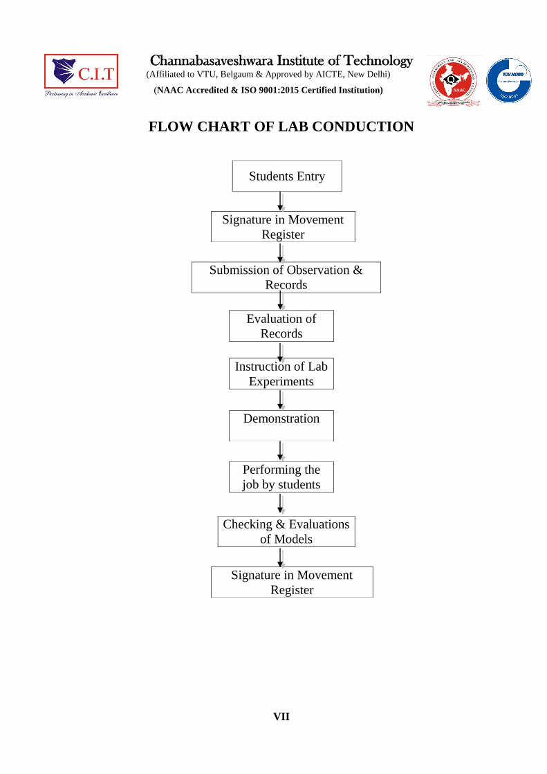
FLOW CHART OF LAB CONDUCTION
VII
Students Entry
Signature in Movement
Register
Submission of Observation &
Records
Evaluation of
Records
Instruction of Lab
Experiments
Demonstration
Performing the
job by students
Checking & Evaluations
of Models
Signature in Movement
Register

CONTENTS
TITLE PAGE NO.
Certificate I
College Vision and Mission II
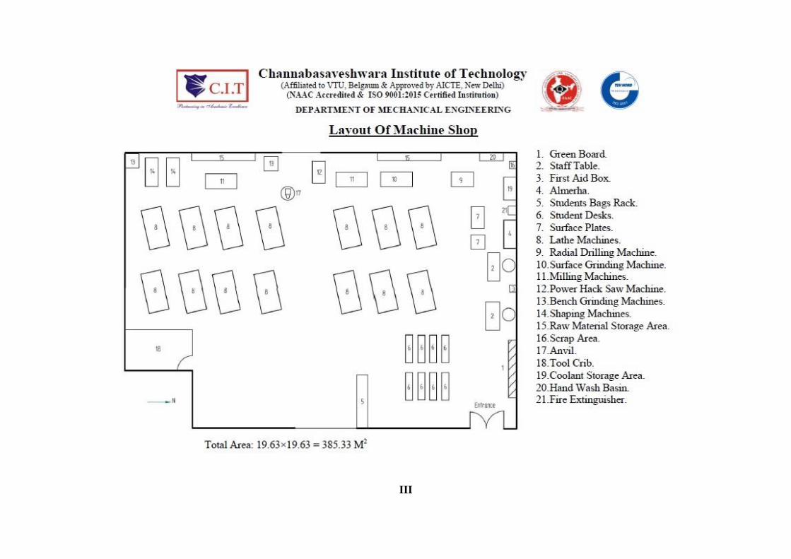
Layout plan III
Syllabus IV
Lecture plan V
Flow chart of lab conduction VII
Chapter 1 LATHE
1.1 Lathe and their practical applications
1.2 Main parts of lathe and description
1.3 Basic controlling parts
1.4 Lathe operations
1.5 Safety precautions (Personal safety and Machine safety)
1.6 Turning models and its working procedure
1.7 Lathe specifications
1.8 Use of measuring instruments
1.9 Work holding devices
1.10 Machining parameters
1.11 Lubrication of cutting fluids
1.12 Maintenance
1.13 Nomenclature of single point cutting tool
1.14 Norton thread chart
1.15 Demonstration of eccentric turning
Chapter 2 SHAPER
2.1 Shaping model and its working procedure
Chapter 3 MILLING
3.1 Milling of a spur gear by the indexing method
Chapter 4 ADDITIONAL MODELS
4.1 Crank shaft
4.2 Shoulder forming
4.3 Converting circular job into hexagonal shape
Chapter 5 GRINDING
5.1 Bench Grinding

5.2 Surface grinding
Chapter 6 DRILLING
6.1 Sensitive drilling machine
6.2 Radial drilling machine
Chapter 7 VIVA VOICE
REFERENCES
Production technology – R K Jain
Workshop Technology – Hazra chowdray

MACHINE SHOP / 17MEL38/48B III /IVSEM
Dept. of ME, C.I.T. Gubbi, Tumakuru Page 1
Chapter 1:
LATHE Machine tool:
A machine tool is a device in which energy is utilized for shaping the material into a product by
removing the excess material in the form of chips.
Machining:
Machining is process of shaping the metal product from various machine tools.
1.1 Lathe :
The main function of a lathe is to remove metal from a work piece to give the required
shape and size by holding the work securely and rigidly on the machine and then turning it
against cutting tool which will remove metal from the work in the form of chips. The most
common and widely used is the center lathe for preparing of various turning operation.
A lathe basically consists of a bed to provide support a Headstock, a cross slide to traverse
the tool, a tool post mounted on the cross slide. The spindle is drive by a electric motor
through a gear box to obtain a range of speeds, The carriage moves on the bed guide ways
parallel to the work piece and the cross slide provides the transverse motion. A feed shaft
and lead screw are also provided to power the carriage for auto movement and for cutting
the thread respectively.
Practical applications to make use of a lathe:
Cylindrical shaft, stepped shaft, eccentric shaft, crankshaft, multiple splined shaft.
Bolt and nuts, bushes, machine handles, knobs and pulleys etc.

MACHINE SHOP / 17MEL38/48B III /IVSEM
Dept. of ME, C.I.T. Gubbi, Tumakuru Page 2
1.2 Main parts of lathe and description :
3D Model of Lathe
2D Model of Lathe

MACHINE SHOP / 17MEL38/48B III /IVSEM
Dept. of ME, C.I.T. Gubbi, Tumakuru Page 3
Sl. No.
Parts
Description
1.
Head stock
Head stock is one type of gear box & it is the heart of the
machine. Which gives various speed by means of gear
arrangement. The gear change lever is given in the head stock
body to change the speed.
2. Chuck Plate Chuck plate is provided to mount the chuck on it.
3.
Tool Post
Tool post is mounted on the compound slide, which is used
to hold the tools.
4. Compound
Slide
Compound slide is used to give angular & small longitudinal
motion to the tool.
5. Saddle &
Cross Slide
Cross slide is mounted on the saddle. Cross slide give
transverse motion whereas saddle gives longitudinal motion.
6. Tail Stock Tail stock is used to hold the job for between centre turning.
7.
Lead Screw
Lead screw is used for threading operation. Which is also
known as thread shaft.
8. Apron
Apron is a gear box which gives automatic feed to the
carriage.
9. Feed Shaft Feed shaft is used for auto feeding.
10. Norton gear
box
Norton gear box is used to obtained metric as well as BSW
thread in various pitch for threading operation.
11.
Tray
Tray is provided to collect the cutting fluid & chip when
machine is in running condition.
12.
Side Cover
Side cover is provided in the back side of the machine for
protection of gear train & for safety purpose.
MACHINE SHOP / 17MEL38/48B III /IVSEM
Dept. of ME, C.I.T. Gubbi, Tumakuru Page 4
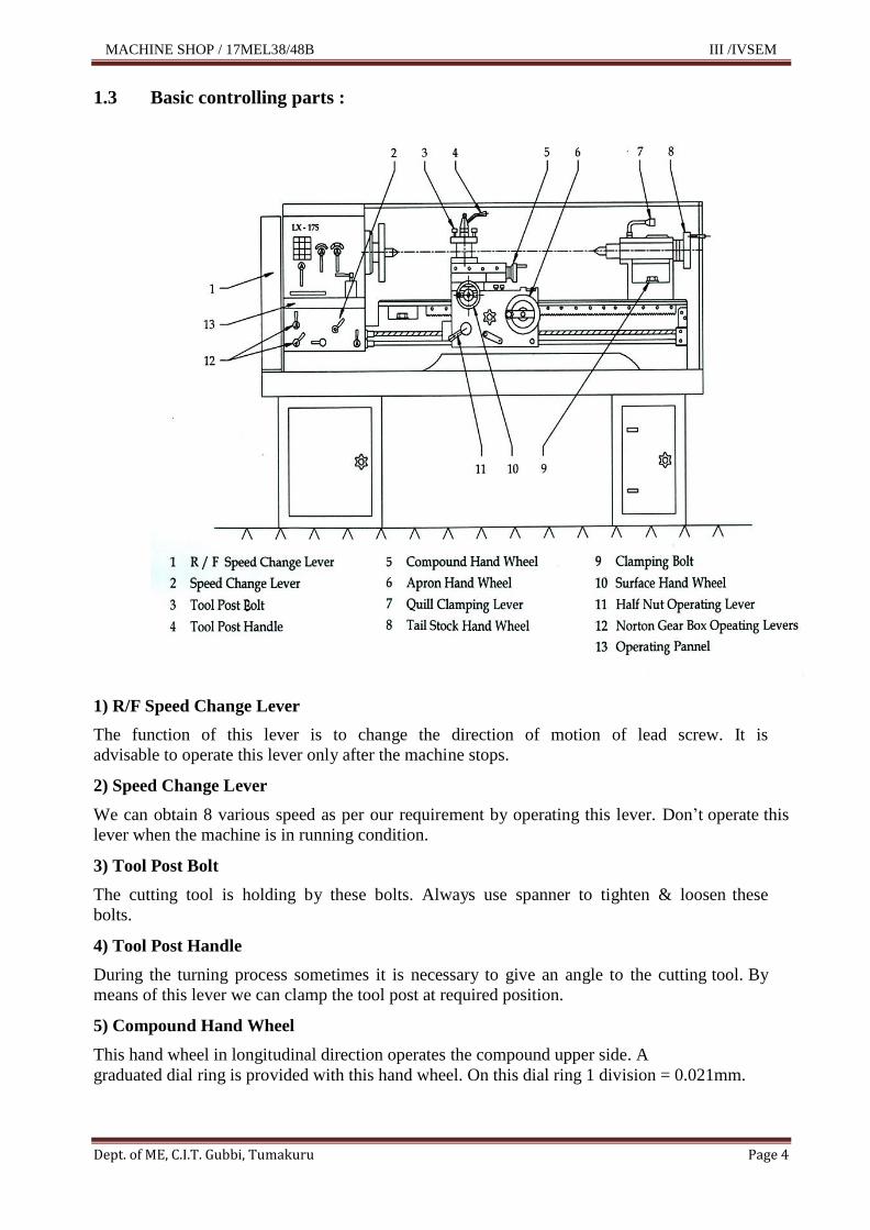
1.3 Basic controlling parts :
1) R/F Speed Change Lever
The function of this lever is to change the direction of motion of lead screw. It is
advisable to operate this lever only after the machine stops.
2) Speed Change Lever
We can obtain 8 various speed as per our requirement by operating this lever. Don‟t operate this
lever when the machine is in running condition.
3) Tool Post Bolt
The cutting tool is holding by these bolts. Always use spanner to tighten & loosen these
bolts.
4) Tool Post Handle
During the turning process sometimes it is necessary to give an angle to the cutting tool. By
means of this lever we can clamp the tool post at required position.
5) Compound Hand Wheel
This hand wheel in longitudinal direction operates the compound upper side. A
graduated dial ring is provided with this hand wheel. On this dial ring 1 division = 0.021mm.

MACHINE SHOP / 17MEL38/48B III /IVSEM
Dept. of ME, C.I.T. Gubbi, Tumakuru Page 5
6) Apron Hand Wheel
This hand wheel is used to give longitudinal travel to the carriage with surface and
compound slide on the bed guide ways. On apron hand wheel 1 division = 0.200 mm.
7) Quill Clamping Lever
By means of this lever, tailstock quill can be clamped in required position.
8) Tail Stock Hand Wheel
This hand wheel operates the tailstock quill. The graduated dial ring is provided on this
hand wheel. On this dial ring 1 division = 0.050 mm.
9) Clamping Bolt
The function of this bolt is to locate the tail stock body at required position on the bed guide
ways.
10) Surface Hand Wheel
This handle operates the surface in transverse direction. A graduated dial ring is provided
on this hand wheel. On this dial ring 1 division = 0.10 mm.
11) Half Nut Operating Lever
This lever is used to engage or disengage the lead screw while threading operation is
performed.
12) Norton Operating Levers
Norton gear box is operated by means of this lever so that various pitch of thread can be selected.
MACHINE SHOP / 17MEL38/48B III /IVSEM
Dept. of ME, C.I.T. Gubbi, Tumakuru Page 6
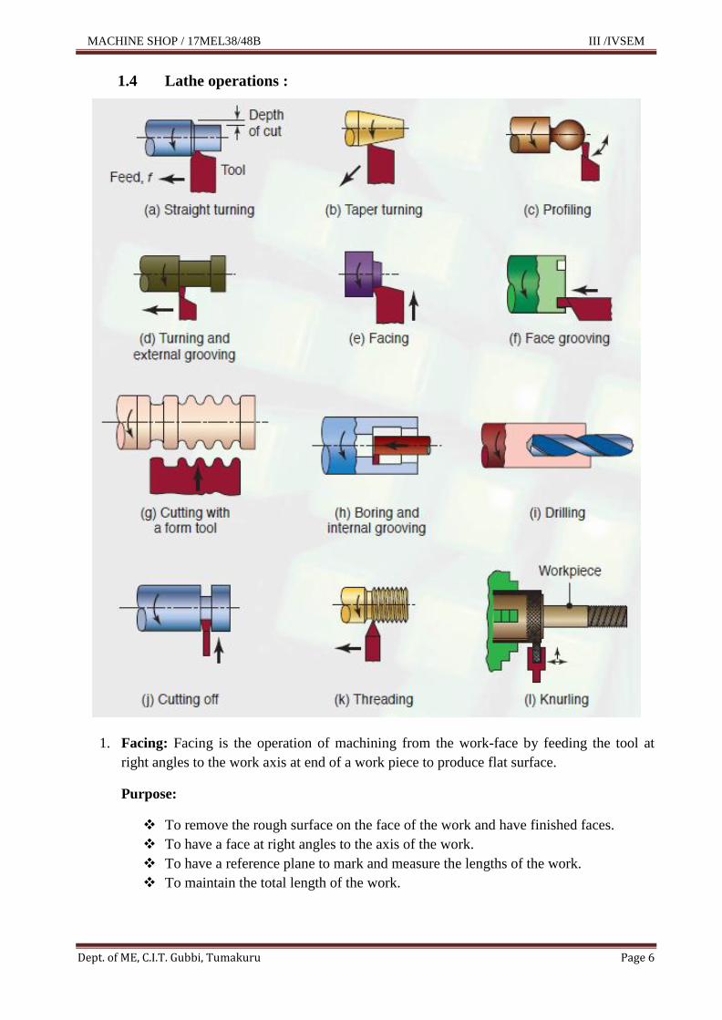
1.4 Lathe operations :
1. Facing: Facing is the operation of machining from the work-face by feeding the tool at
right angles to the work axis at end of a work piece to produce flat surface.
Purpose:
To remove the rough surface on the face of the work and have finished faces.
To have a face at right angles to the axis of the work.
To have a reference plane to mark and measure the lengths of the work.
To maintain the total length of the work.

MACHINE SHOP / 17MEL38/48B III /IVSEM
Dept. of ME, C.I.T. Gubbi, Tumakuru Page 7
2. Center drilling:
Centering is the operation of producing conical holes in work pieces at the ends to
provide bearing surface for lathe centers.
The axis of the work coincides with the lathe axis.
3. Plain turning: The plain turning operation involves removal of metal diametrically from
the raw material by feeding the tool parallel to the axis of the work to bring the work to
required size.
4. Taper turning: Taper is a gradual increase or decrease in diameter along the length of the
job.
Uses:
Easy assembly and disassembly of parts.
Giving self-alignments in assembled parts.
Transmission of power.(Clutch plates.)
5. Step turning: Wherever more than one diameter is machined on a shaft, the section
joining each diameter is called step or shoulder.
6. Thread cutting on lathe by using single point cutting tool: The principle of thread
cutting is to produce helical groove on a cylindrical or conical surface by rotating the job at
a constant speed and moving the tool longitudinally at the rate equal to pitch of the thread
per revolution of the job.
Uses of thread:
Transmission of motion (Half nut with lead screw)
Fastening purpose (Nut and Bolt)
Precision measuring instruments. (Micrometer)
Lifting of load (Screw Jack)
Elevating arm of drilling, milling and shaping machines.
7. Knurling: Knurling is the operation of producing straight lined diamond shaped or cross
lined pattern on a cylindrical external surface by pressing a tool called knurling tool.
Knurling is not cutting operation, but it is a forming operation.
Purpose of knurling:
A good grip and make positive handling
Good appearance
For raising the diameter to a small range
8. Drilling: Drilling is the production of cylindrical holes of definite diameter in a work piece
by using multipoint cutting tool called drill. It is the first operation done internally for any
further operations.
MACHINE SHOP / 17MEL38/48B III /IVSEM
Dept. of ME, C.I.T. Gubbi, Tumakuru Page 8
9. Boring: Boring is the process of enlarging and turning an existing drilled or core hole with
a single point cutting tool.
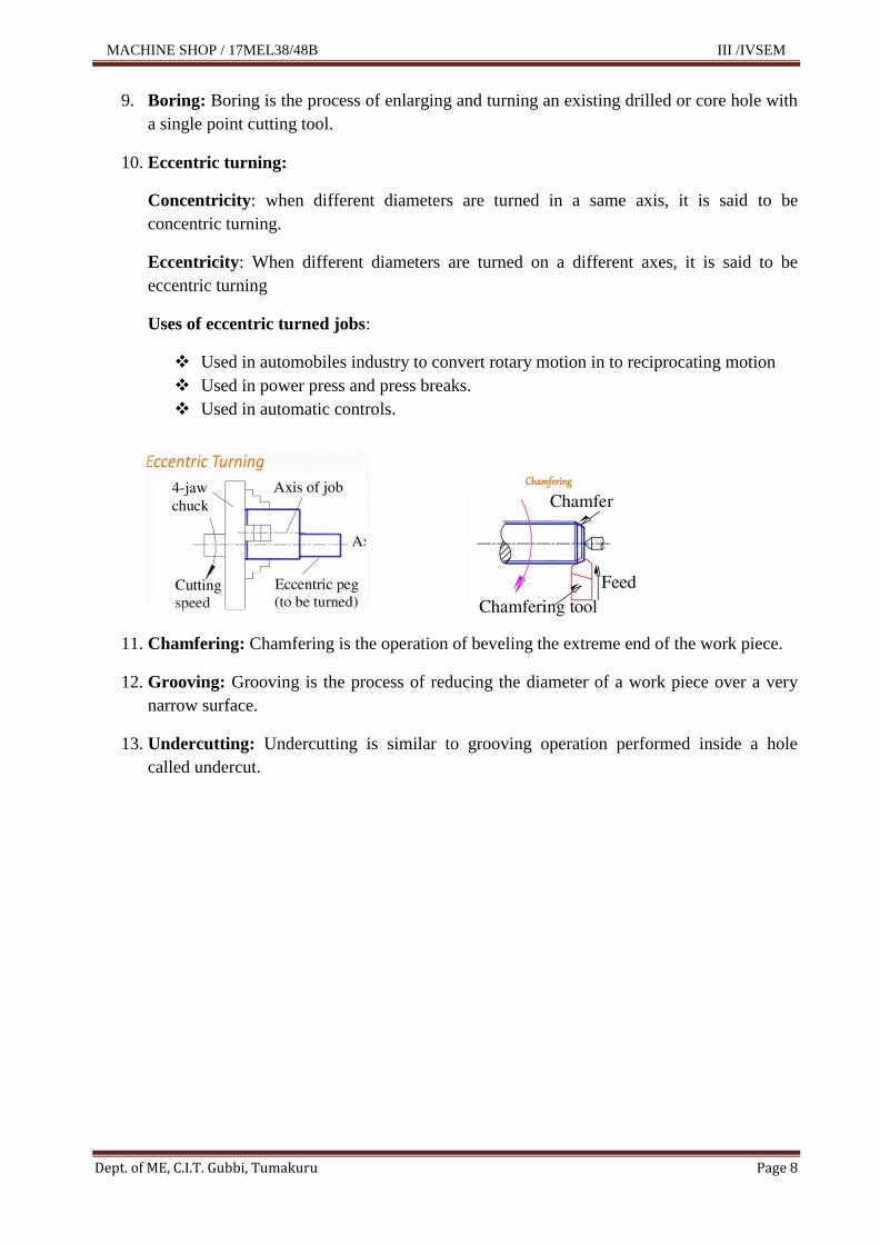
10. Eccentric turning:
Concentricity: when different diameters are turned in a same axis, it is said to be
concentric turning.
Eccentricity: When different diameters are turned on a different axes, it is said to be
eccentric turning
Uses of eccentric turned jobs:
Used in automobiles industry to convert rotary motion in to reciprocating motion
Used in power press and press breaks.
Used in automatic controls.
11. Chamfering: Chamfering is the operation of beveling the extreme end of the work piece.
12. Grooving: Grooving is the process of reducing the diameter of a work piece over a very
narrow surface.
13. Undercutting: Undercutting is similar to grooving operation performed inside a hole
called undercut.
MACHINE SHOP / 17MEL38/48B III /IVSEM
Dept. of ME, C.I.T. Gubbi, Tumakuru Page 9
1.5 Safety precautions (Personal safety and Machine safety) :
Operator should follow various precautions to ensure of safe working conditions.
Sleeves should be rolled up, rings, wrist watches, jewellery and neck tie removed.
Wearing of uniform with shoes are very important.
Tools should never be placed over lathe bedways.
The tailstock should be moved to the extreme right on the bed ways.
Do not attempt to operate the machine before receiving the instructions from the
instructor.
Never leave safe guards of lathe machine.
Before starting any operation, always see the work and cutting tools secured first.
Dis engages all the operating levers and places them in neutral position before
starting the motor.
Never leave the machine when it is running.
Never mount or remove the work when machine is in running position.
While machining such metal, which produces fine flying chip always wear goggle
or use guard screen.
Never wear loose clothing. Tie your sleeves up at wrist. Never handle chips with
you bare hands; you should use special hook brushes or scrubbers to pull them
away from the machine.
Do not take measurement of the works while the machine is running.
Do not try to stop the chuck with your hands.
Keep the work place clean and tidy. Never allow the work pieces or other objects
to line on the floor around the machine.
During mounting the work piece on the lathe be sure to see the Centre hole are
correct. (in sufficient depth of center hole is likely to result in the work breaking
away while it is revolving).
See that the chuck key is removed after the work has been clamped in the chuck.
The machine should be always earthed, if electric motor, lightning appliances or
the wires insulation get out of order report it to the instructor on duty.

MACHINE SHOP / 17MEL38/48B III /IVSEM
Dept. of ME, C.I.T. Gubbi, Tumakuru Page 10
1.6 Turning models and its working procedure
Model No. 01
Note: All dimensions are in mm only
Material: M S bright rod
Size: Ø25 x 105 Length
Tolerance: ±0.50
Taper Turning Calculation
Tan (D d ) / 2l
tan-1(D d ) / 2l
tan-1 (24 19) / 2l
tan-1 (24 19) / 2(25)
MACHINE SHOP / 17MEL38/48B III /IVSEM
Dept. of ME, C.I.T. Gubbi, Tumakuru Page 11
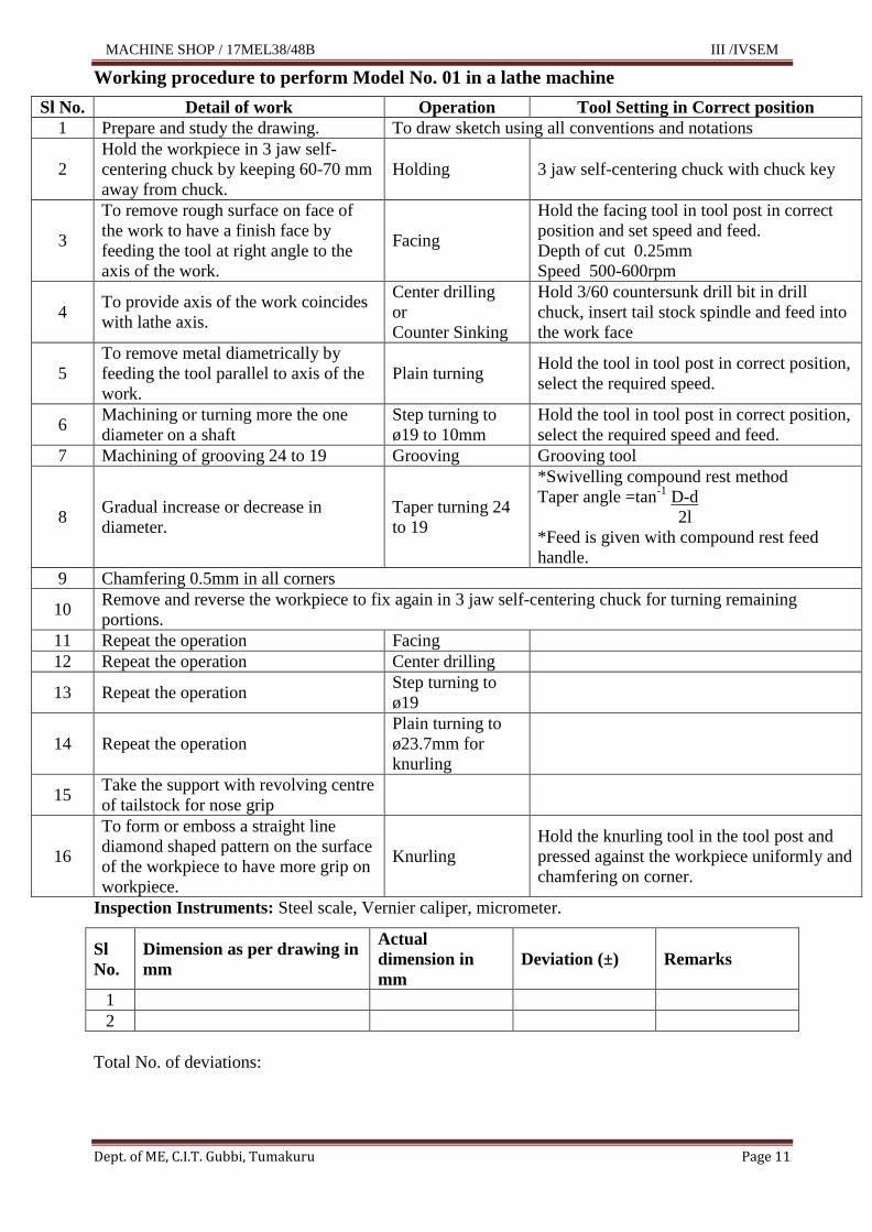
Working procedure to perform Model No. 01 in a lathe machine
Sl No. Detail of work Operation Tool Setting in Correct position
1 Prepare and study the drawing. To draw sketch using all conventions and notations
2
Hold the workpiece in 3 jaw self-
centering chuck by keeping 60-70 mm
away from chuck.
Holding 3 jaw self-centering chuck with chuck key
3
To remove rough surface on face of
the work to have a finish face by
feeding the tool at right angle to the
axis of the work.
Facing
Hold the facing tool in tool post in correct
position and set speed and feed.
Depth of cut 0.25mm
Speed 500-600rpm
4 To provide axis of the work coincides
with lathe axis.
Center drilling
or
Counter Sinking
Hold 3/60 countersunk drill bit in drill
chuck, insert tail stock spindle and feed into
the work face
5
To remove metal diametrically by
feeding the tool parallel to axis of the
work.
Plain turning Hold the tool in tool post in correct position,
select the required speed.
6 Machining or turning more the one
diameter on a shaft
Step turning to
ø19 to 10mm
Hold the tool in tool post in correct position,
select the required speed and feed.
7 Machining of grooving 24 to 19 Grooving Grooving tool
8 Gradual increase or decrease in
diameter.
Taper turning 24
to 19
*Swivelling compound rest method
Taper angle =tan-1
D-d
2l
*Feed is given with compound rest feed
handle.
9 Chamfering 0.5mm in all corners
10 Remove and reverse the workpiece to fix again in 3 jaw self-centering chuck for turning remaining
portions.
11 Repeat the operation Facing
12 Repeat the operation Center drilling
13 Repeat the operation Step turning to
ø19
14 Repeat the operation
Plain turning to
ø23.7mm for
knurling
15 Take the support with revolving centre
of tailstock for nose grip
16
To form or emboss a straight line
diamond shaped pattern on the surface
of the workpiece to have more grip on
workpiece.
Knurling
Hold the knurling tool in the tool post and
pressed against the workpiece uniformly and
chamfering on corner.
Inspection Instruments: Steel scale, Vernier caliper, micrometer.
Sl
No.
Dimension as per drawing in
mm
Actual
dimension in
mm
Deviation (±) Remarks
1
2
Total No. of deviations:

MACHINE SHOP / 17MEL38/48B III /IVSEM
Dept. of ME, C.I.T. Gubbi, Tumakuru Page 12
Model No. 02
Note: All dimensions are in mm only
Material: M S bright rod
Size: Ø25 x 105 Length
Tolerance: ±0.50
Blank size for thread cutting
Blank size = Major diameter – Blank size = Major diameter –
= 24 - = 24 –
= 24 – 0.2
= 23.8 mm
=24 – 0.25
= 23.75 m

MACHINE SHOP / 17MEL38/48B III /IVSEM
Dept. of ME, C.I.T. Gubbi, Tumakuru Page 13
Working procedure to perform Model No. 02 in a lathe machine
Sl No. Detail of work Operation Tool Setting in Correct position
1 Prepare and study the drawing. To draw sketch using all conventions and notations
2
Hold the workpiece in 3 jaw self-
centering chuck by keeping 60-70 mm
away from chuck.
Holding 3 jaw self-centering chuck with chuck
key
3
To remove rough surface on face of the
work to have a finish face by feeding
the tool at right angle to the axis of the
work.
Facing
Hold the tool in tool post in correct
position and set speed
Depth of cut 0.25mm
Speed 500-600rpm
4 To provide axis of the work coincides
with lathe axis.
Center drilling
or
Counter Sinking
Hold 3/60 countersunk drill bit in drill
chuck, insert tail stock spindle and feed
into the work face
5
To remove metal diametrically by
feeding the tool parallel to axis of the
work.
Plain turning Hold the tool in tool post in correct
position, select the required speed.
6 Machining or turning more the one
diameter on a shaft Step turning
Hold the tool in tool post in correct
position, select the required speed.
7 Machining of grooving 24 to 19 Grooving Grooving tool
8 Thread cutting on ø 23.8mm for a
length of 20mm. Thread cutting
* Hold the threading tool in tool post in
correct position.
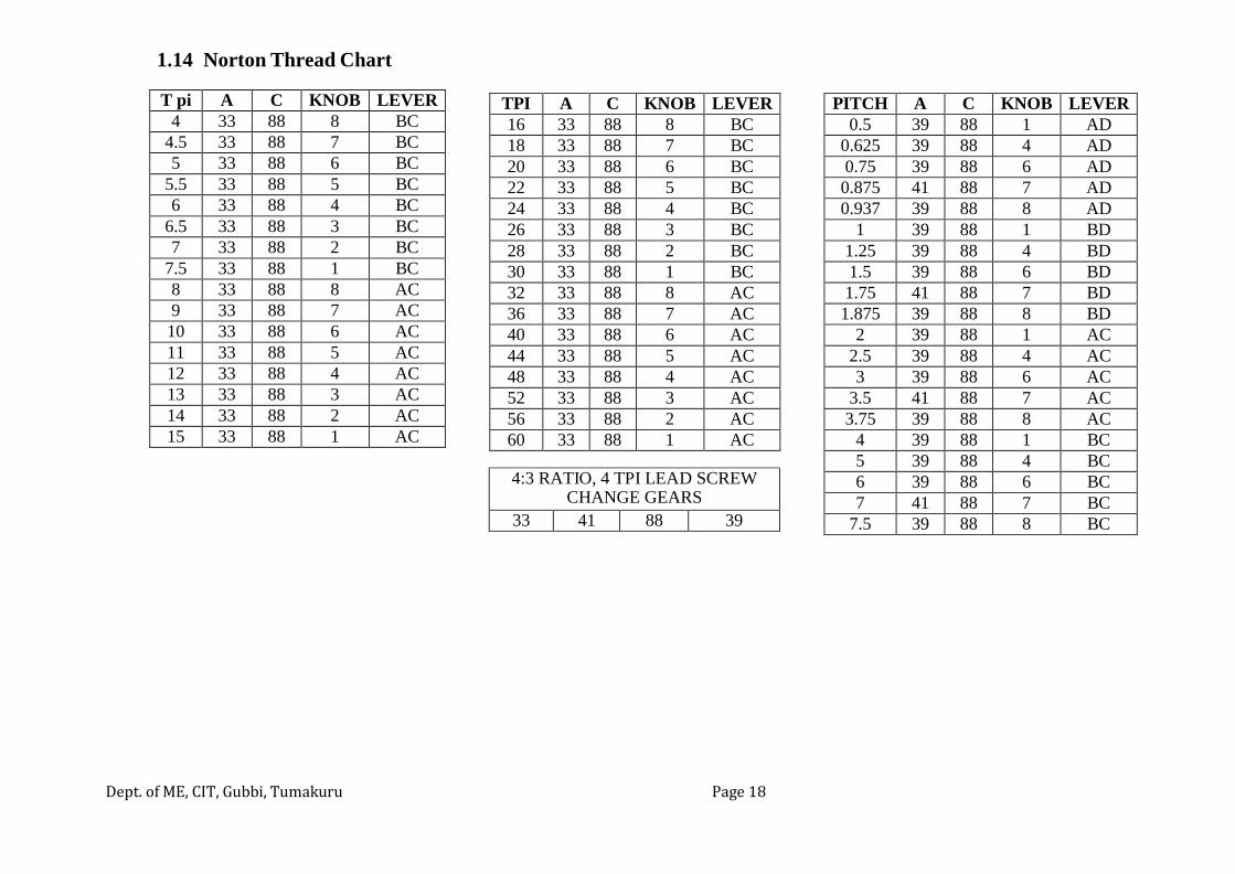
* Ref Norton thread chart for selection of
knob and lever for 2mm pitch RH thread.
* Spindle speed 90rpm
9 Chamfering 0.5mm in all corners take the support with revolving centre of tailstock for nose grip.
10 Remove and reverse the workpiece to fix again in 3 jaw self-centering chuck for turning remaining
portions.
11 Repeat the operation Facing
12 Repeat the operation Center drilling
13 Repeat the operation
Step turning to
ø17mm and
length 20mm
14 Plain turning to ø23.80mm for thread cutting to length of 20mm
15 Thread cutting on ø 23.8mm for a
length of 20mm. Thread cutting
* Hold the threading tool in tool post in
correct position.
* Ref Norton thread chart for selection of
knob and lever for 2mm pitch RH thread.
* Spindle speed 90rpm
Inspection Instruments: Steel scale, Vernier caliper, micrometer.
Sl
No.
Dimension as per drawing in
mm
Actual
dimension in
mm
Deviation (±) Remarks
1
2
Total No. of deviations:

MACHINE SHOP / 17MEL38/48B III /IVSEM
Dept. of ME, C.I.T. Gubbi, Tumakuru Page 14
Ø 1
7
Ø 2
4
Ø 1
8
Ø 1
8
Model No. 03
2
3
Note: All dimensions are in mm only
Material: M S bright rod
Size: Ø25 x 105 Length
Tolerance: ±0.50
Concave forming dia on 24 M24 × 3P RH V-Thread
10
12
6 15 17 20 20
MACHINE SHOP / 17MEL38/48B III /IVSEM
Dept. of ME, C.I.T. Gubbi, Tumakuru Page 15
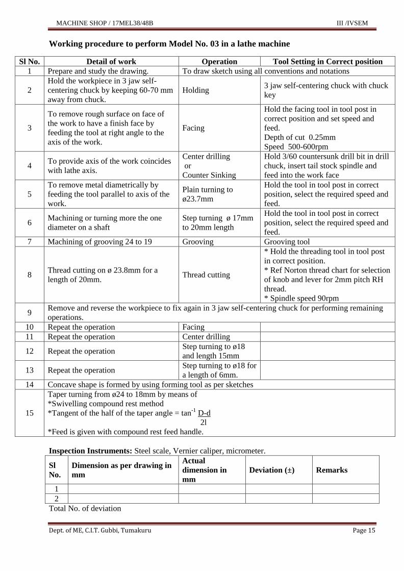
Working procedure to perform Model No. 03 in a lathe machine
Sl No. Detail of work Operation Tool Setting in Correct position
1 Prepare and study the drawing. To draw sketch using all conventions and notations
2
Hold the workpiece in 3 jaw self-
centering chuck by keeping 60-70 mm
away from chuck.
Holding 3 jaw self-centering chuck with chuck
key
3
To remove rough surface on face of
the work to have a finish face by
feeding the tool at right angle to the
axis of the work.
Facing
Hold the facing tool in tool post in
correct position and set speed and
feed.
Depth of cut 0.25mm
Speed 500-600rpm
4 To provide axis of the work coincides
with lathe axis.
Center drilling
or
Counter Sinking
Hold 3/60 countersunk drill bit in drill
chuck, insert tail stock spindle and
feed into the work face
5
To remove metal diametrically by
feeding the tool parallel to axis of the
work.
Plain turning to
ø23.7mm
Hold the tool in tool post in correct
position, select the required speed and
feed.
6 Machining or turning more the one
diameter on a shaft
Step turning ø 17mm
to 20mm length
Hold the tool in tool post in correct
position, select the required speed and
feed.
7 Machining of grooving 24 to 19 Grooving Grooving tool
8 Thread cutting on ø 23.8mm for a
length of 20mm. Thread cutting
* Hold the threading tool in tool post
in correct position.
* Ref Norton thread chart for selection
of knob and lever for 2mm pitch RH
thread.
* Spindle speed 90rpm
9 Remove and reverse the workpiece to fix again in 3 jaw self-centering chuck for performing remaining
operations.
10 Repeat the operation Facing
11 Repeat the operation Center drilling
12 Repeat the operation Step turning to ø18
and length 15mm
13 Repeat the operation Step turning to ø18 for
a length of 6mm.
14 Concave shape is formed by using forming tool as per sketches
15
Taper turning from ø24 to 18mm by means of
*Swivelling compound rest method
*Tangent of the half of the taper angle = tan-1
D-d
2l
*Feed is given with compound rest feed handle.
Inspection Instruments: Steel scale, Vernier caliper, micrometer.
Sl
No.
Dimension as per drawing in
mm
Actual
dimension in
mm
Deviation (±) Remarks
1
2
Total No. of deviation
MACHINE SHOP / 17MEL38/48B III /IVSEM
Dept. of ME, C.I.T. Gubbi, Tumakuru Page 16
1.7 Lathe specifications
The maximum diameter of a work that is held between centres.
The swing over the bed (this is the perpendicular distance from the lathe axis to top
of the bed).
The length of the bed.
The length of the bed ways & type.
The maximum length of work that can be turned b/n centers.
The range of threads that can be cut.
The capacity of lathe (Motor).
Range of spindle speed.
Range of feed.
Size of the spindle nose
1.8 Use of measuring instruments:
MACHINE SHOP / 17MEL38/48B III /IVSEM
Dept. of ME, C.I.T. Gubbi, Tumakuru Page 17
1.9 Work holding and supporting devices in machining process:
Chucks
Three jaw self-centering chuck – Used for holding round and other symmetrical works.
Four jaw independent chuck – used for irregular shapes (Ex: Square etc)
Centers
Used for support work pieces and take up the thrust due to metal cutting.
Carriers
Used to drive the work pieces when it is held between the two centers.
Face plates
Used for machining of flat plates.
Follower and Steady rests
Used to hold long work piece is machined.
Mandrels
Used to hold rotating a hollow piece of work.
Drill chuck
Used to hold in a tail stock center.

MACHINE SHOP / 17MEL38/48B III /IVSEM
Dept. of ME, C.I.T. Gubbi, Tumakuru Page 18
1.10 Machining parameters :
Cutting Speed :
Cutting speed means the number of meters measured on the circumference of the job
that passes the cutting tool edge in one minute. It is denoted by a letter „V‟.
Unit: Meter per minute
Cutting Speed = V = π x D x N
1000
Where,
V = Cutting speed, m/min
D = Diameter of the work piece in mm,
N = Number of revolutions per minute.
For thread cutting, V will be about half of the cutting speed for longitudinal turning.
Speed: Speed is the number of circular motion of the spindle /work piece in one minute of
time. Unit in RPM
Feed :
It is the amount of tool advancement of the job parallel to the surface being machined.
Feed is generally expressed in mm/rev
Depth of Cut :
It is the advancement of the tool in the job in a direction perpendicular to the surface
being machined.
Depth of cut is generally expressed in mm
In a lathe, depth of cut is expressed as,
Depth of cut = D1 – D2 (mm)
2
Where, D1 – Diameter of the work piece before machining, (mm)
D2 – Diameter of the machined work piece. (mm)
Machining Time: The machining time in a lathe work can be calculated for a particular
operation, speed of the work piece and feed length of the work piece is known.
Machine time is generally expressed in minutes
Machining Time = Length of cut (l) , minutes
Feed (f) x Speed(N)
l = Length of cut, mm
f = Feed, mm/rev
N=Speed, rpm

MACHINE SHOP / 17MEL38/48B III /IVSEM
Dept. of ME, C.I.T. Gubbi, Tumakuru Page 19
Example: A brass pin has a length of 500mm and of 40mm dia. Find the turning to reduce
the pin to 38.8mm in one pass, when cutting speed is 60m/min and feed is 0.8mm/min.
Cutting Speed = π x D x N
1000
60 = π x 40 x N
1000
N = 478 rpm
Machine Time = Length of cut
Feed x RPM
= 500
0.8 x 478
= 1.31 min

MACHINE SHOP / 17MEL38/48B III /IVSEM
Dept. of ME, C.I.T. Gubbi, Tumakuru Page 20
1.11 Lubrication of cutting fluids :
Lubrication chart
Lubrication:
Proper lubrication is very important. The accuracy of the lathe depends on the proper and
regular lubrication. Lubrication instructions are displayed in a lubrication chart.
If the lubrication is neglected then the bearing surfaces may damage, impairing the
accuracy and shortening the life of the machine.
Before putting the machine in operation, all the Oil cups, Apron, Norton Gear Box &
Head stock should be checked and filled with oil until the oil reaches the “Red Line” in the oil
sight glass.
MACHINE SHOP / 17MEL38/48B III /IVSEM
Dept. of ME, C.I.T. Gubbi, Tumakuru Page 21
Assembly Wise Lubrication Instruction
1) Head Stock
Threads on the spindle nose should be always cleaned and oiled before mounting the
chuck plate or faceplate.
Head stock body should be filled with oil. The level of the oil should be always
maintained. The oil used for head stock is EP – 90 Gear Oil.
Oil nipple, on the various parts like brackets. etc. must be properly filled with oil.
2) Tailstock
There are two oil holes plunged by oil cup and by oil nipple. Oil cup carry oil to the
housing and tailstock quill.
3) Apron
A hole is provided in the front face of apron to pour oil in apron. Pour the oil till level
comes up to the “Red Mark” on the oil sight glass of the apron. The oil used for apron
is EP–140 Gear Oil.
All the rotating parts and bearings of the apron are splash lubricated. An oil-drain
plug is provided at the bottom to change the oil.
4) Saddle
Two oil cups are provided on the top face of the saddle. Fill these cups with oil daily.
Oil flows and reaches to the Flat and V- guide ways of the bed.
Surfaces Screw should be lubricated by the nipple, which is given on the screw boss.
Two oil nipples are provided on the top face of the surface slide, which carry oil in both
the guide ways of the saddle.
5) Compound Slide
Two oil nipples are provided on the front face of the compound slide, which carry the oil
for both the guide ways of the slide.
To oil the housing of the compound slide oil nipple is provided on the compound
boss.
6) Lead Shaft & Feed Shaft
Clean the lead shaft, feed shaft & rack with the cotton waste daily & oil the same
properly.
Both lead screw brackets (Front and Rear) having an oil nipple on the tiny top face,
which supply oil to the bearing and housing.
7) Norton Gear Box
Norton gear box should be filled up by Gear EP–90 to get proper efficiency of the
gear box. An oil sight glass is provided on the Norton to check the oil level. Change the
oil when it is required.
8) Guide Ways
Before starting the lathe, operator should always clean both the guide ways of the bed
thoroughly and should oil properly

MACHINE SHOP / 17MEL38/48B III /IVSEM
Dept. of ME, C.I.T. Gubbi, Tumakuru Page 22
Advantages of using cutting fluids during machining
The advantages of cutting fluids in machining operations are:
i. Increase of tool life by cooling the cutting edge.
ii. Decrease tool chip friction.
iii. Provide better finish on the workpiece.
iv. Reduce forces on tool hence economic power consumption.
v. To maintain its dimensional accuracy
vi. Discourge corrosion of newly machined surface
vii. Lubricate machine movements.
1.12 Maintenance
1. Careful maintenance will increase the life and efficiency of the machine.
2. Any defect however small it should be immediately rectified otherwise this will lead
to a major breakdown of the machine resulting in loss of prevention and high cost of
repair.
Preventive maintenance and its advantages.
Preventive maintenance means planning and scheduling the maintenance in advance.
1. To avoid sudden break down of machine.
2. Damage of costly parts are avoided.
3. Shut down of production is avoided.
4. Longer life of the equipment is ensured.
5. Possibility of serial accidents is minimized.
6. Preventive maintenance is less cost than break down maintenance.

MACHINE SHOP / 17MEL38/48B III /IVSEM
Dept. of ME, C.I.T. Gubbi, Tumakuru Page 23
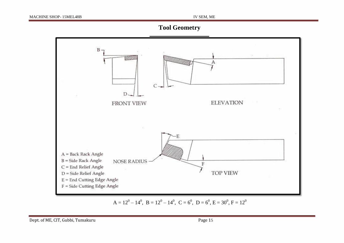
1.13 Nomenclature of single point cutting tool :
The signature is a sequence of numbers listing the various angles in degrees, and the size
of nose radius. The seven elements that comprise the signature of a single point cutting
tool stated in the following order:
8 – 14 – 6 – 6 – 6 – 15 – 4
has 80 back rake angle, 14
0 side rake, 6
0 end relief, 6
0 end or side relief, 6
0 end cutting
edge and 150
side cutting edge angles and 4 mm nose radius.
Pictorial View of Single point cutting tool
MACHINE SHOP- 15MEL48B IV SEM, ME
Dept. of ME, CIT, Gubbi, Tumakuru Page 15
Tool Geometry
A = 120
– 140, B = 12
0 – 14
0, C = 6
0, D = 6
0, E = 30
0, F = 12
0
MACHINE SHOP- 15MEL48B IV SEM, ME
Dept. of ME, CIT, Gubbi, Tumakuru Page 16
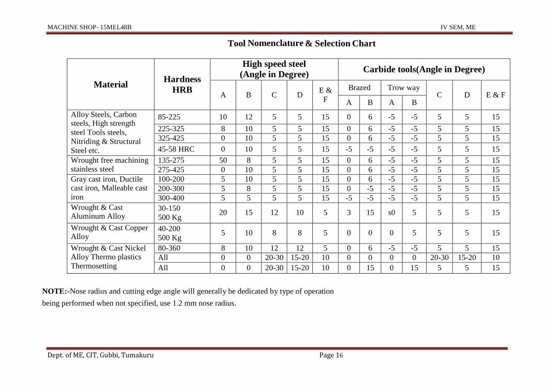
Tool Nomenclature & Selection Chart
Material
Hardness
HRB
High speed steel (Angle in Degree)
Carbide tools(Angle in Degree)
A
B
C
D
E &
F
Brazed Trow way
C
D
E & F A B A B
Alloy Steels, Carbon steels, High strength
steel Tools steels,
Nitriding & Structural
Steel etc.
85-225 10 12 5 5 15 0 6 -5 -5 5 5 15
225-325 8 10 5 5 15 0 6 -5 -5 5 5 15
325-425 0 10 5 5 15 0 6 -5 -5 5 5 15
45-58 HRC 0 10 5 5 15 -5 -5 -5 -5 5 5 15
Wrought free machining stainless steel
135-275 50 8 5 5 15 0 6 -5 -5 5 5 15
275-425 0 10 5 5 15 0 6 -5 -5 5 5 15
Gray cast iron, Ductile cast iron, Malleable cast
iron
100-200 5 10 5 5 15 0 6 -5 -5 5 5 15
200-300 5 8 5 5 15 0 -5 -5 -5 5 5 15
300-400 5 5 5 5 15 -5 -5 -5 -5 5 5 15
Wrought & Cast Aluminum Alloy
30-150
500 Kg
20
15
12
10
5
3
15
s0
5
5
5
15
Wrought & Cast Copper Alloy
40-200
500 Kg
5
10
8
8
5
0
0
0
5
5
5
15
Wrought & Cast Nickel Alloy Thermo plastics
Thermosetting
80-360 8 10 12 12 5 0 6 -5 -5 5 5 15
All 0 0 20-30 15-20 10 0 0 0 0 20-30 15-20 10
All 0 0 20-30 15-20 10 0 15 0 15 5 5 15
NOTE:-Nose radius and cutting edge angle will generally be dedicated by type of operation
being performed when not specified, use 1.2 mm nose radius.
Dept. of ME, CIT, Gubbi, Tumakuru Page 18
TPI A C KNOB LEVER
16 33 88 8 BC
18 33 88 7 BC
20 33 88 6 BC
22 33 88 5 BC
24 33 88 4 BC
26 33 88 3 BC
28 33 88 2 BC
30 33 88 1 BC
32 33 88 8 AC
36 33 88 7 AC
40 33 88 6 AC
44 33 88 5 AC
48 33 88 4 AC
52 33 88 3 AC
56 33 88 2 AC
60 33 88 1 AC
PITCH A C KNOB LEVER
0.5 39 88 1 AD
0.625 39 88 4 AD
0.75 39 88 6 AD
0.875 41 88 7 AD
0.937 39 88 8 AD
1 39 88 1 BD
1.25 39 88 4 BD
1.5 39 88 6 BD
1.75 41 88 7 BD
1.875 39 88 8 BD
2 39 88 1 AC
2.5 39 88 4 AC
3 39 88 6 AC
3.5 41 88 7 AC
3.75 39 88 8 AC
4 39 88 1 BC
5 39 88 4 BC
6 39 88 6 BC
7 41 88 7 BC
7.5 39 88 8 BC
1.14 Norton Thread Chart
T pi A C KNOB LEVER
4 33 88 8 BC
4.5 33 88 7 BC
5 33 88 6 BC
5.5 33 88 5 BC
6 33 88 4 BC
6.5 33 88 3 BC
7 33 88 2 BC
7.5 33 88 1 BC
8 33 88 8 AC
9 33 88 7 AC
10 33 88 6 AC
11 33 88 5 AC
12 33 88 4 AC
13 33 88 3 AC
14 33 88 2 AC
15 33 88 1 AC
4:3 RATIO, 4 TPI LEAD SCREW
CHANGE GEARS
33 41 88 39

MACHINE SHOP / 17MEL38/48B III /IVSEM
Dept. of ME, C.I.T. Gubbi, Tumakuru Page 14
1.15 Demonstration of eccentric turning :
Note: All dimensions are in mm only
Material: M S bright rod
Size: Ø50 x 35 Length
Tolerance: ±0.5

MACHINE SHOP / 17MEL38/48B III /IVSEM
Dept. of ME, C.I.T. Gubbi, Tumakuru Page 15
Tools required Operations
1.Facing tool 1.Facing
2.Turning tool 2.Turning
3. Vernier height gauge 3. Eccentric turning
4. Try square 4. Drilling
5. Centre punch 5. Boring
6. Granite surface plate 6. Threading
7. V-Block
Procedure:
1. Study the drawing.
2. Set the cutting tool for centre height.
3. Prepare the work piece for the Ø 48mm and to a length of 30 mm.
4. Mark the work piece center with the help of Vernier height gauge and V block
with „C‟ clamp and try square.
5. Mark the 5 mm offset from centre of Ø48 mm by using Vernier height gauge
and V block.
6. Punch the eccentric centre point with the help of centre punch.
7. Hold the job in four jaw chuck and true the job to eccentric centre point with
the help of dead centre.
8. Do eccentric turning to a Ø30 mm to a length of 15 mm ( use slow speed)
9. With the help of centre bit and drill bit drill the hole to the eccentric point
Ø18 mm hole and bore it up to Ø23.8 mm.
10. Do internal threading by using internal threading tool.
Hole size (Minor Dia) = Major Dia – pitch x depth of thread
= 25 – 2 x 0.61
= 25 – 1.22
= 23.78 = 23.8 mm
11. Finally check the dimensions as per given drawing

MACHINE SHOP / 17MEL38/48B III /IVSEM
Dept. of ME, C.I.T. Gubbi, Tumakuru Page 16
Chapter 2:
SHAPER
Shaping is a process of removing metal from surfaces in horizontal by the use of
single point cutting tool held in a ram that reciprocates the tool in a linear direction
across the work pieces.
Application of shaping machine
To manufacture rectangular grooves, dovetail and V grooves etc….
Shaping machine (Shaper)
Principle parts of Shaping machine (Shaper)
MACHINE SHOP / 17MEL38/48B III /IVSEM
Dept. of ME, C.I.T. Gubbi, Tumakuru Page 17
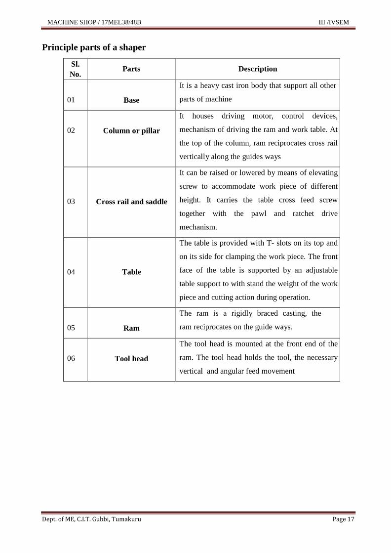
Principle parts of a shaper
Sl.
No.
Parts
Description
01
Base
It is a heavy cast iron body that support all other
parts of machine
02
Column or pillar
It houses driving motor, control devices,
mechanism of driving the ram and work table. At
the top of the column, ram reciprocates cross rail
vertically along the guides ways
03
Cross rail and saddle
It can be raised or lowered by means of elevating
screw to accommodate work piece of different
height. It carries the table cross feed screw
together with the pawl and ratchet drive
mechanism.
04
Table
The table is provided with T- slots on its top and
on its side for clamping the work piece. The front
face of the table is supported by an adjustable
table support to with stand the weight of the work
piece and cutting action during operation.
05
Ram
The ram is a rigidly braced casting, the
ram reciprocates on the guide ways.
06
Tool head
The tool head is mounted at the front end of the
ram. The tool head holds the tool, the necessary
vertical and angular feed movement

MACHINE SHOP / 17MEL38/48B III /IVSEM
Dept. of ME, C.I.T. Gubbi, Tumakuru Page 18
Operating controls of a shaping machine
Sl.
No.
Controls
Function
01
Main switch Power supply to shaper in main
electrical panel.
02
Starter ON & OFF switch control to run or
stop the shaper.
03 Ram locking handle Stroke adjustment
04 Ram and gear movement hand wheel To adjust the stroke length and
change of speed gear box
05 Speed changing levers (2 nos) For variation of stroke feed movement
06 Spindle for elevating screw For vertical movement of the table
07
Spindle for cross feed Cross feed movement of the table
both by hand and pawl and ratchet
drive mechanism (Auto feed
movement).
08 Spindle for ram stroke adjustment To set stroke length
09 Hand wheel for tool head movement To give depth of cut to work piece
10 Clapper box -------------
11 Oil flashing unit -------------
12 Tool locking bolt -------------
Work holding devices:
V- block with T-bolt and clamp
Shaper vice
T-bolts and clamp
MACHINE SHOP / 17MEL38/48B III /IVSEM
Dept. of ME, C.I.T. Gubbi, Tumakuru Page 19
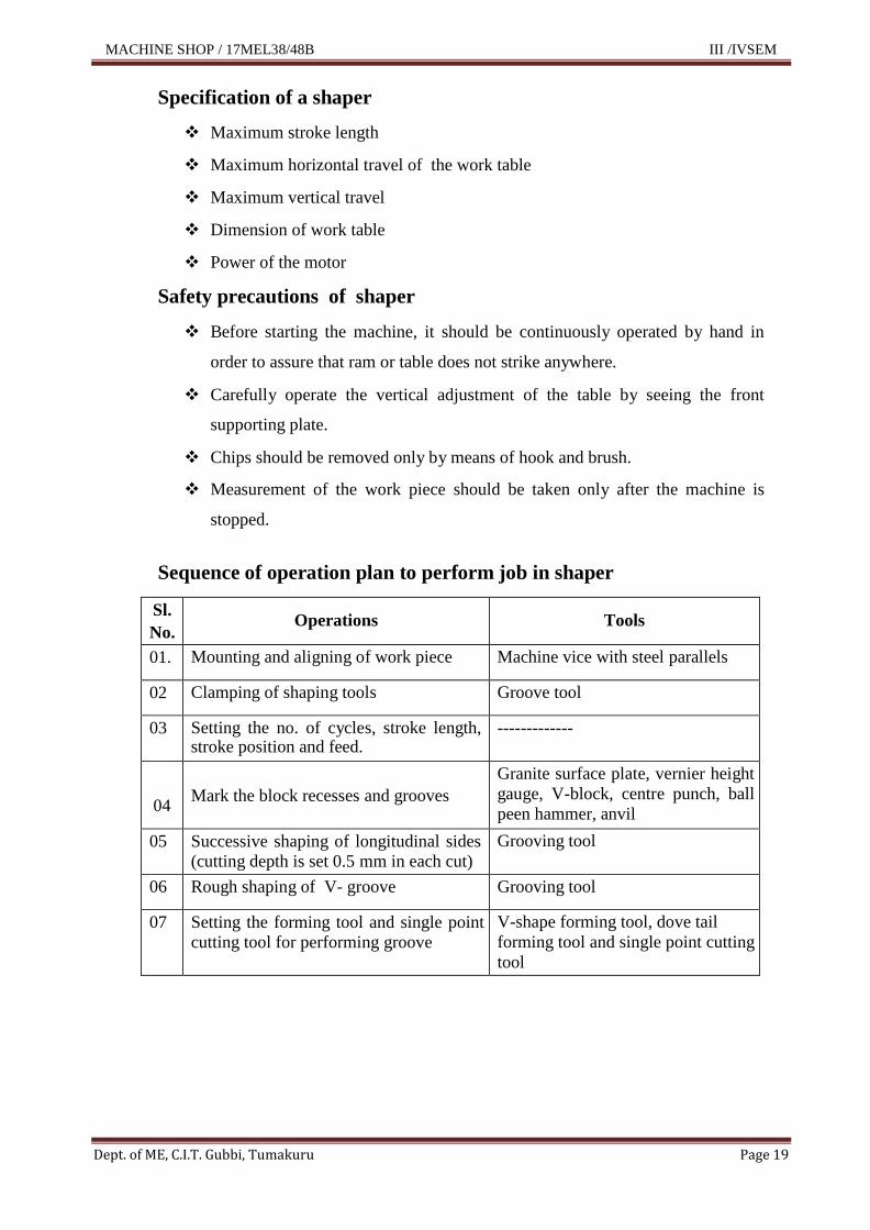
Specification of a shaper
Maximum stroke length
Maximum horizontal travel of the work table
Maximum vertical travel
Dimension of work table
Power of the motor
Safety precautions of shaper
Before starting the machine, it should be continuously operated by hand in
order to assure that ram or table does not strike anywhere.
Carefully operate the vertical adjustment of the table by seeing the front
supporting plate.
Chips should be removed only by means of hook and brush.
Measurement of the work piece should be taken only after the machine is
stopped.
Sequence of operation plan to perform job in shaper
Sl.
No.
Operations
Tools
01. Mounting and aligning of work piece Machine vice with steel parallels
02 Clamping of shaping tools Groove tool
03 Setting the no. of cycles, stroke length, stroke position and feed.
-------------
04
Mark the block recesses and grooves
Granite surface plate, vernier height
gauge, V-block, centre punch, ball
peen hammer, anvil
05 Successive shaping of longitudinal sides
(cutting depth is set 0.5 mm in each cut)
Grooving tool
06 Rough shaping of V- groove Grooving tool
07 Setting the forming tool and single point
cutting tool for performing groove
V-shape forming tool, dove tail
forming tool and single point cutting
tool
MACHINE SHOP / 17MEL38/48B III /IVSEM
Dept. of ME, C.I.T. Gubbi, Tumakuru Page 20
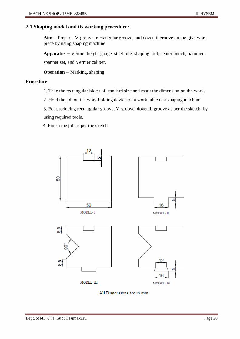
2.1 Shaping model and its working procedure:
Aim – Prepare V-groove, rectangular groove, and dovetail groove on the give work
piece by using shaping machine
Apparatus – Vernier height gauge, steel rule, shaping tool, center punch, hammer,
spanner set, and Vernier caliper.
Operation – Marking, shaping
Procedure
1. Take the rectangular block of standard size and mark the dimension on the work.
2. Hold the job on the work holding device on a work table of a shaping machine.
3. For producing rectangular groove, V-groove, dovetail groove as per the sketch by
using required tools.
4. Finish the job as per the sketch.

MACHINE SHOP / 17MEL38/48B III /IVSEM
Dept. of ME, C.I.T. Gubbi, Tumakuru Page 21
CHAPTER 3: MILLING
Milling is the machining process in which the metal removal takes place due to the
cutting action of a revolving cutter when the work piece is fed past it.
Practical applications
Machining of plane, curved surface, slots, grooves, gears, teethes, guide gibs,
bolt, splined shaft and ring nut are few example parts of milling operations.
Principle parts of milling machine
Principle parts of milling machine
1. Base
2. Column
3. Spindle with supporting arm
4. Over arm, supporting bracket
5. Knee
6. Saddle
7. Work table
8. Main drive
9. Feed drive
10. Vertical head spindle

MACHINE SHOP / 17MEL38/48B III /IVSEM
Dept. of ME, C.I.T. Gubbi, Tumakuru Page 22
Operating controls of milling machine:
Sl. No. Controls
Functions
1 Main switch Power supply to milling machine
2 Push button starter Starting and stopping of main motor
3
Levers for selecting spindle
speed
Selection of suitable speeds
4 Levers for selecting feed drive Selection of suitable speeds
5
Hand wheel for longitudinal feed
or movement
Hand movement of table ( longitudinal)
6 Hand crank for cross feed Hand movement of table ( cross)
7 Hand crank for vertical feed Hand movement of the table (vertical)
8 Lever for auto feed movement Auto movement both to and fro
Specification of Milling Machine
1. Length and width of the table
2. Longitudinal traverse of the table hand/power
3. Cross travel of the table hand/power
4. Vertical travel of the table hand
6. No. of spindle speeds
7. HP of the motor
8. Net Weight of machine
9. Floor space Work Holding devices
Plain Vice
Swivel Vice
Dividing head attachment
Attachments used for Milling

MACHINE SHOP / 17MEL38/48B III /IVSEM
Dept. of ME, C.I.T. Gubbi, Tumakuru Page 23
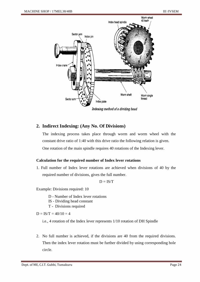
Universal Dividing Head attachment
Universal dividing head is an important work holding and indexing device used on milling
machine. With the help of the dividing head, the round or gear blank work piece can be
accurately divided into any number of equal divisions. Universal dividing heads find wide
use in the production of spur gears, splines, helical gears, and other indexing requirements
on a milling machine In this method marking is not necessary.
Methods of Indexing
1. Direct Indexing
2. Indirect Indexing (Simple indexing)
3. Compound Indexing
4. Differential Indexing
5. Angular Indexing
1. Direct Indexing: Small no. of divisions
The Indexing takes place by rotating the dividing head spindle, where by the required
divisions can be achieved through the relevant Index plate and indexing pin.
Operation Sequence
Worm and worm wheel must be disengaged by means of the disengaging lever., Loosen
clamping lever, Release Index pin., Rotate the main spindle with the direct Index plate
through the desired indexing holes. Engage Index pin., Clamp lever tightened firmly,
commence the milling process.
Divisions of direct indexing
1. Face with 24 Notches 2 3 4 6 8 12 24
2. Face with 5 and 7 Notches 5 7
The reversing of notch plate can be done by losing the knurled nut.
MACHINE SHOP / 17MEL38/48B III /IVSEM
Dept. of ME, C.I.T. Gubbi, Tumakuru Page 24
2. Indirect Indexing: (Any No. Of Divisions)
The indexing process takes place through worm and worm wheel with the
constant drive ratio of 1:40 with this drive ratio the following relation is given.
One rotation of the main spindle requires 40 rotations of the Indexing lever.
Calculation for the required number of Index lever rotations
1. Full number of Index lever rotations are achieved when divisions of 40 by the
required number of divisions, gives the full number.
D = IS/T
Example: Divisions required: 10
D - Number of Index lever rotations
IS - Dividing head constant
T - Divisions required
D = IS/T = 40/10 = 4
i.e., 4 rotation of the Index lever represents 1/10 rotation of DH Spindle
2. No full number is achieved, if the divisions are 40 from the required divisions.
Then the index lever rotation must be further divided by using corresponding hole
circle.

MACHINE SHOP / 17MEL38/48B III /IVSEM
Dept. of ME, C.I.T. Gubbi, Tumakuru Page 25
The hole circles of the double-sided index plate are as follows:
15-17-19-21-27-37-41-47
16-18-20-23-29-33-39-49
Example 1: Required number of division t = 29
Constant ratio = 1:40, Dividing head is Constant = 40
No. of Index lever rotations = D = IS/t = 40/29 = 1 11
i.e. 29
To achieve the desired no. of 29 division on the dividing head spindle, the Index lever
must be rotated by 1 full rotation and 11 holes extra on the 29 hole circle.
Example 2: Required Number of Divisions t = 132
D IS
40
40 10 4
132
i.e.T 132 4
33
To achieve the desired number of 132 divisions on the dividing head spindle, the
Index lever must be rotated by 10 holes on the 33-hole circle.
Example 3: Required number of divisions t = 9
D IS
40
40(3)
120 4.44 i.e.
t 9 9(3) 27
To achieve the desired number of divisions 9 on the dividing head spindle, the Index
lever must be rotated by 4 rotation + 12 holes extra on the 27 holes circle.

MACHINE SHOP / 17MEL38/48B III /IVSEM
Dept. of ME, C.I.T. Gubbi, Tumakuru Page 26
Sequence of Operation
Engage Worm and Worm wheel by means of the swing provided,. Set Index
lever on the corresponding hole circle.
Release Index into the marked hole on the selected.
hole circle.
Set the first indicator to touch the index pin.
Set the second indicator by rotating it over the number of holes and
clamp the indicator by means of the clamping screws.
Loosen clamping lever; rotate the index lever by the number of rotations and
also by the no. holes and release the Index pin in last hole before the second
indicator rotate the indicator set further until the first indicator rests on the
Index pin tighten clamping lever and start the milling practice.
Dimensions of Spur Gear
The tooth form is limited by the tip and root circle
On the pitch circle tooth are spaced. The distance between the two teeth measured on
the pitch circle is called the PITCH
The pitch is the product of constant and fig π.
The number with which π is multiplied is the MODULE (m)

MACHINE SHOP / 17MEL38/48B III /IVSEM
Dept. of ME, C.I.T. Gubbi, Tumakuru Page 27
Modules are standardized to a selected series. The Module is an absolute fig and the
product in pitch is specified in mm.
Pitch = Module × π
P = m × π in mm
Module =
Circular Pitch =
Module is a standardized quantity, whose purpose is to enable calculations with
numbers, it is measured in mm.
Example: Calculate the pitch in mm for a module 2 = 2 × 3.14 = 6.28 mm
Since the pitch is a multiple of π simple figures are obtained for the pitch circle
diameter.
Pitch circle diameter = module × no. of teeth
d = m × z
Note: m = module
Z = no. of teeth
Teeth depth h = 13/6 m = 2.166 m = 0.7 p
Addendum ha = 6/6 mm = 1 m = 0.3 p
Addendum hf = 7/6 m = 1.166 m = 0.4 p
Tip diameter = da = d + 2ha
(or) da = d + 2m
(or) da = m × z + 2 x m (or) da = m (z + 2) (mm) (or) Outside diameter: OD = m (z + 2) (mm) of the blank
MACHINE SHOP / 17MEL38/48B III /IVSEM
Dept. of ME, C.I.T. Gubbi, Tumakuru Page 28
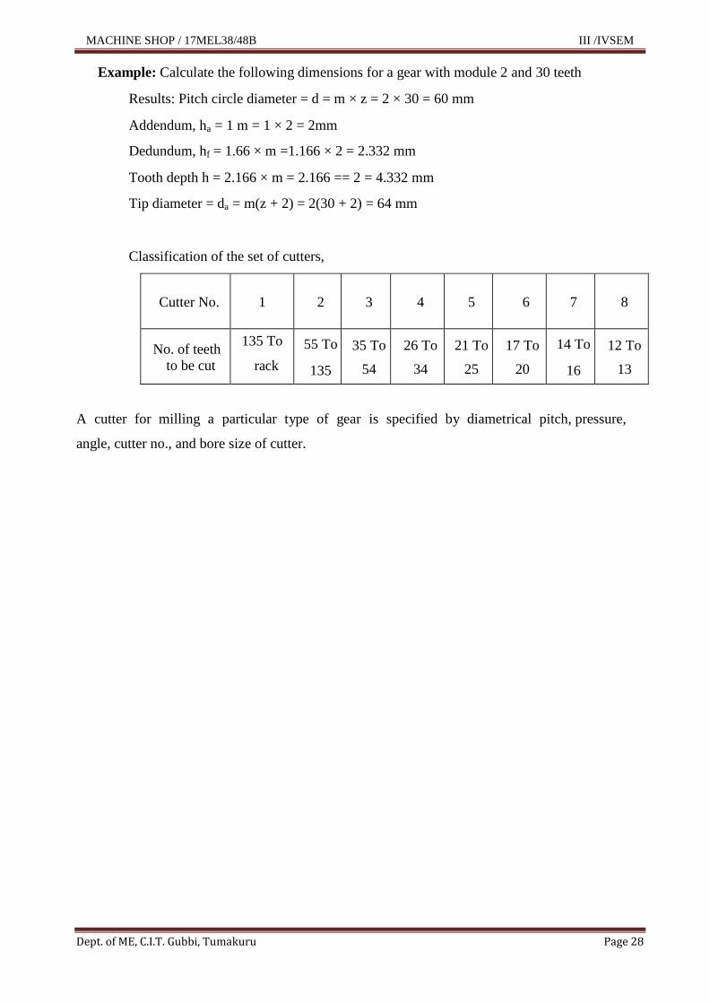
Example: Calculate the following dimensions for a gear with module 2 and 30 teeth
Results: Pitch circle diameter = d = m × z = 2 × 30 = 60 mm
Addendum, ha = 1 m = 1 × 2 = 2mm
Dedundum, hf = 1.66 × m =1.166 × 2 = 2.332 mm
Tooth depth h = 2.166 × m = 2.166 == 2 = 4.332 mm
Tip diameter = da = m(z + 2) = 2(30 + 2) = 64 mm
Classification of the set of cutters,
Cutter No. 1 2 3 4 5 6 7 8
No. of teeth
to be cut
135 To
rack
55 To
135
35 To
54
26 To
34
21 To
25
17 To
20
14 To
16
12 To
13
A cutter for milling a particular type of gear is specified by diametrical pitch, pressure,
angle, cutter no., and bore size of cutter.
MACHINE SHOP / 17MEL38/48B III /IVSEM
Dept. of ME, C.I.T. Gubbi, Tumakuru Page 29
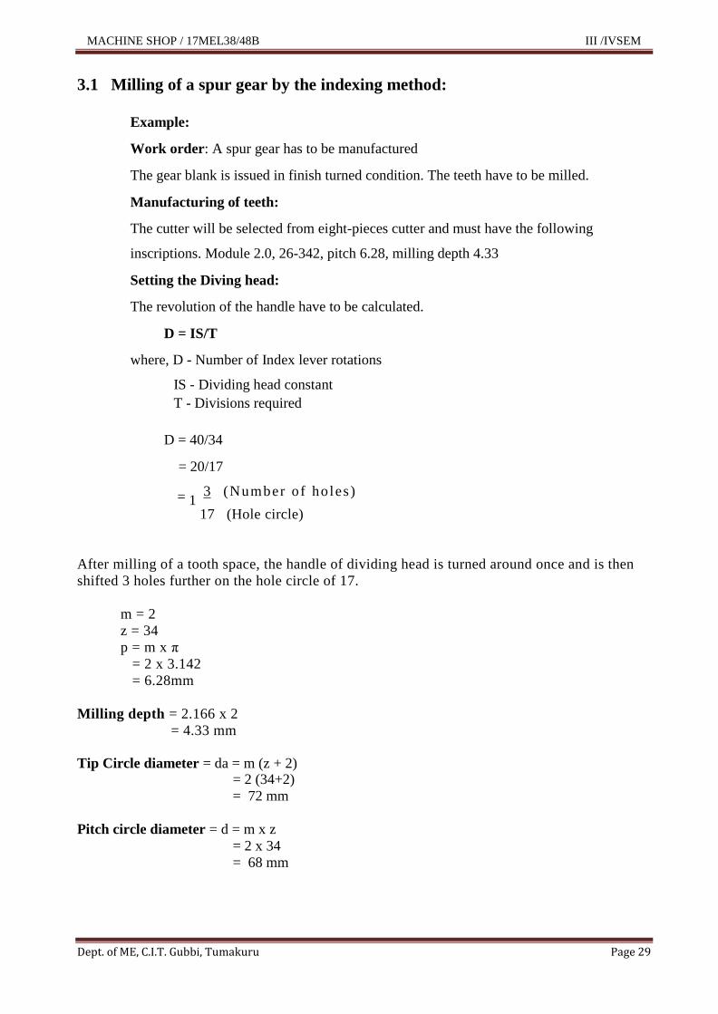
3.1 Milling of a spur gear by the indexing method:
Example:
Work order: A spur gear has to be manufactured
The gear blank is issued in finish turned condition. The teeth have to be milled.
Manufacturing of teeth:
The cutter will be selected from eight-pieces cutter and must have the following
inscriptions. Module 2.0, 26-342, pitch 6.28, milling depth 4.33
Setting the Diving head:
The revolution of the handle have to be calculated.
D = IS/T
where, D - Number of Index lever rotations
IS - Dividing head constant
T - Divisions required
D = 40/34
= 20/17
= 1 3 (Number of holes )
17 (Hole circle)
After milling of a tooth space, the handle of dividing head is turned around once and is then
shifted 3 holes further on the hole circle of 17.
m = 2
z = 34
p = m x π
= 2 x 3.142
= 6.28mm
Milling depth = 2.166 x 2
= 4.33 mm
Tip Circle diameter = da = m (z + 2)
= 2 (34+2)
= 72 mm
Pitch circle diameter = d = m x z
= 2 x 34
= 68 mm

MACHINE SHOP / 17MEL38/48B III /IVSEM
Dept. of ME, C.I.T. Gubbi, Tumakuru Page 30
CHAPTER 4:
ADDITIONAL MODELS
4.1 Crankshaft Turning
Note: All dimensions are in mm only
Material: M S bright rod
Size: Ø25 x 105 Length
Tolerance: ±0.50
Procedure:
01. Facing both the sides of work piece and maintain the total length.
02. Marking the offsets on both the faces of the work piece by using vernier height
gauge, C-clamp and V block on surface plate.
03. Center punch the offset points.
04. Hold the work piece firmly in four jaw independent chuck by truing the
marking center by using centre at tailstock.
05. Turn the diameter 12 mm as per the sketch.
06. Reverse hold the job and repeat all the operations.

MACHINE SHOP / 17MEL38/48B III /IVSEM
Dept. of ME, C.I.T. Gubbi, Tumakuru Page 31
4.2 Shoulder Forming
Shoulder:
Whenever more than one diameter is machined on a shaft, the section joining each diameter
is called shoulder or step.
Purpose of shoulder forming:
For mating parts to fit at right angles against the face of the step.
To eliminate sharp corners.
To give additional strength at the junction of steps.
To give a good appearance.
Filleted shoulders are generally used on parts which require additional strength at the shoulder.
The rounded corner is pleasing in appearance and also strengthens the shaft at this point without
any increase in the diameter of the part.

MACHINE SHOP / 17MEL38/48B III /IVSEM
Dept. of ME, C.I.T. Gubbi, Tumakuru Page 32
4.3 Converting Circular Job In to Hexagonal Shape
Note: All dimensions are in mm only
Material: M S bright rod
Size: Ø50x 55 Length
Tolerance: ±0.50

MACHINE SHOP / 17MEL38/48B III /IVSEM
Dept. of ME, C.I.T. Gubbi, Tumakuru Page 33
Details:
Side of the hexagon = 25 mm
Across corners of the hexagon = 50 mm
Across flats = side × √3 =25×√3=43.30
Thickness = 25 mm
Procedure:
01. Facing both the sides of work piece and maintain the total length.
02. Marking to be done on the face of the work piece as per the sketch.
03. Aligning the across flats lines in the four jaw chuck; facing to be done to
achieve the flat surface.
04. Repeat the procedure for all the sides

MACHINE SHOP / 17MEL38/48B III /IVSEM
Dept. of ME, C.I.T. Gubbi, Tumakuru Page 34
CHAPTER 5:
GRINDING
Grinding is the most common form of abrasive machining. It is a material cutting
process that engages an abrasive tool whose cutting elements are grains of abrasive
material known as grit. These grits are characterized by sharp cutting points, high hot
hardness, chemical stability and wear resistance. The grits are held together by a
suitable bonding material to give shape of an abrasive tool.
Practical applications
Surface finishing, slitting and parting, descaling, deburring, stock removal (abrasive
milling) finishing of flat as well as cylindrical surface and grinding of tools and cutters
and re sharpening of the same.
5.1 Bench Grinding Machine
A bench grinder is manually operated and normally has two wheels of different grain
sizes that are fixed on a floor stand or work bench; to perform roughing and finishing
operations. It is mainly used to shape tool bits; and repair or make various tools.

MACHINE SHOP / 17MEL38/48B III /IVSEM
Dept. of ME, C.I.T. Gubbi, Tumakuru Page 35
Principle parts of a Bench Grinder
Specifications of Bench grinder
Power rating of the electric motor
Speed of the motor
Abrasive grain size
Size of the wheel
Procedure for Grinding
1. Examine the grinder to see that the tool rest is set at the required height, is within
1/8 of an inch to the face of the wheel.
2. Adjust safety glass shields on the grinder to permit clear vision of the part to be
ground and still protect the operator from flying particles.
3. Start the grinder.
4. Hold the work in one hand, and steady it with the other. Place the work on the tool
rest; then guide it against the face of the revolving wheel and apply enough
pressure to grind.
5. Cool work in a water pot as it becomes heated from grinding, especially the small
hardened tools that would lose their temper if overheated.
6. Check work with a gauge or other measuring tool.
7. Stop grinder.
Sl.
No. Parts Description
01 On/off switch Starting and stopping of main motor
02 Coarse grain wheel It is generally used for roughing purposes
03 Fine grain wheel It is generally used for finishing purposes
04
Wheel guards
The operator is protected against flying abrasive
particles and ground material by the wheel guards
05 Eye shield Safety glass shields are provided for additional
protection against glares and flying particles.
06 Tool rest A tool rest is provided for each wheel so that tools
may be held or steadied while being ground

MACHINE SHOP / 17MEL38/48B III /IVSEM
Dept. of ME, C.I.T. Gubbi, Tumakuru Page 36
5.2 Surface Grinding
Surface grinding operation

MACHINE SHOP / 17MEL38/48B III /IVSEM
Dept. of ME, C.I.T. Gubbi, Tumakuru Page 37
CHAPTER 6:
DRILLING
Drilling is an operation through which cylindrical holes are in a solid material by using revolving
tool.
Sensitive drilling machine
Radial drilling machine
Sensitive drilling machine:
This type of drilling machine is designed for drilling small holes at high speed in light work piece.
It is small machine having simple construction and operations. Fig no. shows principle parts of a
sensitive drilling machine
Fig no. Sensitive Drilling Machine
MACHINE SHOP / 17MEL38/48B III /IVSEM
Dept. of ME, C.I.T. Gubbi, Tumakuru Page 38
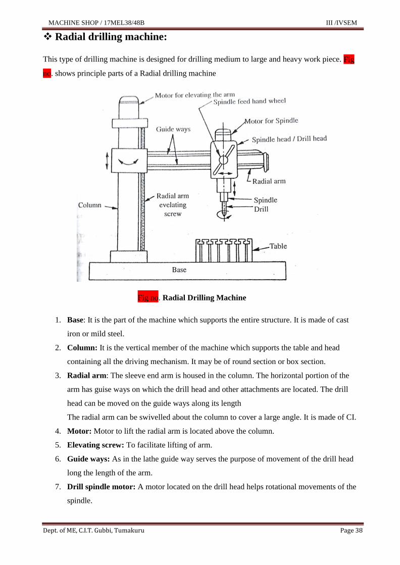
Radial drilling machine:
This type of drilling machine is designed for drilling medium to large and heavy work piece. Fig
no. shows principle parts of a Radial drilling machine
Fig no. Radial Drilling Machine
1. Base: It is the part of the machine which supports the entire structure. It is made of cast
iron or mild steel.
2. Column: It is the vertical member of the machine which supports the table and head
containing all the driving mechanism. It may be of round section or box section.
3. Radial arm: The sleeve end arm is housed in the column. The horizontal portion of the
arm has guise ways on which the drill head and other attachments are located. The drill
head can be moved on the guide ways along its length
The radial arm can be swivelled about the column to cover a large angle. It is made of CI.
4. Motor: Motor to lift the radial arm is located above the column.
5. Elevating screw: To facilitate lifting of arm.
6. Guide ways: As in the lathe guide way serves the purpose of movement of the drill head
long the length of the arm.
7. Drill spindle motor: A motor located on the drill head helps rotational movements of the
spindle.

MACHINE SHOP / 17MEL38/48B III /IVSEM
Dept. of ME, C.I.T. Gubbi, Tumakuru Page 39
CHAPTER 7:
VIVA -VOCE
1. What is a machine tool?
Machine is a mechanical device which having a provisions for holding the work and
tool with on a facilities rotation of work and different feed of the tool.
2. What is a machining?
Machining is process of shaping the metal product from various machine tools.
3. Define the term turning?
Turning is a machining process to bring the raw material to the required shape and
size by metal removal. This is done by feeding a single point cutting tool against the
direction of rotation of the work.
The machine tool on which turning is carried out is known as lathe.
4. What are the different types of lathes?
Centre lathe, Bench lathe, Capstan lathe, Combination lathe, Turret lathe, CNC
lathes.
5. What are the differences between the Center Lathe and Capstan Lathe?
Centre Lathe - It is a manually operated lathe, It has only one tool post tool
changing time is more, It has tail stock, Only one tool can be fitted in the tail stock,
Number of speeds is less, Tool changing time is more, The machine should be
stopped for changing tool, It is not suitable for mass production, The tool is centered
manually after changing the tool,
Capstan / Turret Lathe - It is a semi-automatic lathe, Front and rear tool posts are
available. Tool changing time is less, It has turret head instead of tail stock, Six
different tools can be fitted in the turret head. Number of speeds is more, Tool
changing time is less, Tool can be changed without stopping the machine, It is
suitable for mass production , The tool is centered automatically,
6. How the Center Lathe can be specified?
The maximum diameter of a work that can be held.
The length of the bed.
Distance of the between centers.
The range of threads can be cut.
Capacity of the lathe.
Range of spindle speed.

MACHINE SHOP / 17MEL38/48B III /IVSEM
Dept. of ME, C.I.T. Gubbi, Tumakuru Page 40
7. What are the functions of lead screw and feed rod?
Lead Screw – Lead Screw for thread cutting purpose.
Feed Rod – Feed Rod to provide automatic feeding either for facing or turning.
8. What are the different methods of Taper turning?
1) Compound slide method
2) Tailstock offset method
3) Form tool method
4) Taper turning attachment method
9. What is meant by eccentric turning?
When different diameters are turned on different axis, it is said to be eccentric turning.
10. What is the difference between L.H. thread cutting R.H. thread cutting?
a) A right hand bolt thread screws into the nut when it is rotated clockwise.
b) A right hand bolt thread screws into the nut when it is rotated anticlockwise.
11. Why the knurling operations are necessary for the given models in m/c shop?
a) A good grip and make for positive handling
b) Good appearance
c) For raising the diameter to a small range for assembly to get a desired fit.
12. What are the differences between 3-jaw chuck and 4-jaw chuck?
3– Jaw chuck
Only cylindrical or hexagonal work center, internal and external jaws are available,
setting of work is easy, less gripping power, work pieces can‟t be set for eccentric
turning, concentric circles are not provided on the face.
4– Jaw chuck.
A wide range of regular and irregular shaped jobs can be held, jaws are reversible for
external and internal holdings, setting of work is difficult, more gripping power, work
pieces can be set for eccentric turning, concentric circles are provided.
13. What are the differences between lathe accessories and lathe attachments? Give
examples.
a) The lathe accessories are machined, independent units supplied with the lathe,
which are essential for the full utilization of the lathe,
Example,
1) Work holding accessories – 4 – jaw chuck, 3 – jaw chuck, face plates,
lathe mandrels.
2) Work supporting accessories – catch plate, driving plate, lathe centers,
lathe carriers, fixed and travelling steady rests.
b) Attachment is an optional extra attachments to produce tapers, contours, thread
forming, grinding, etc…

MACHINE SHOP / 17MEL38/48B III /IVSEM
Dept. of ME, C.I.T. Gubbi, Tumakuru Page 41
Example;
1) Taper turning attachment
2) Forming attachment
3) Cylindrical, grinding, thread, grinding attachment
14. What is meant by single point cutting tool?
Single point cutting tools having two cutting edges (major & minor cutting edges)
joining at a point called single point cutting tool. And these tools are used on lathe
shaper & planner
15. What is meant by multi point cutting tool? Give examples.
These tools have more than one cutting edge and they remove metal from the work
piece simultaneously by the action of all the cutting edges,
Ex. Files, hacksaw blade, twist drills, reamers, milling cutters, hand taps, and spilt
dies, grinding wheels.
16. What are the properties of cutting tool material?
The most important basic properties of only cutting tool is,
- Cold hardness
- Red hardness
- Toughness
17. What is meant by H.S.S. tool? What are the elements present in that?
HSS (High Speed Steel) is an alloy of high carbon steel with an alloying elements like
Tungsten 18%, Chromium 4% and Vanadium of 1%.
18. What is meant by carbide tipped tool?
These tools are made of two different metals, the cutting portions of these tools are
tungsten carbide which are brazed to ordinary metal blank which are tough (low cost).
19. Define cutting speed. Feed and depth of cut?
a) Cutting speed – “The speed at which the cutting edge passes over material” which
is expressed in meters per minute is called the cutting speed.
V = ΠDN/1000 meter/min. (OR) V = ΠDN/12 feet/min.
Where – V = cutting speed in meters/min
Π = 3.14
D = diameter of work piece in mm
N = rpm
b) Feed – The feed of the tool is the distance it moves along the work for each
revolution of the work. and it is expressed in mm/revolution.
c) Depth of cut – It is the advancement of the tool at the beginning of the feed which
is perpendicular to the type of feed.
20. What is the spindle speed during thread cutting operations?
Set the spindle speed to about 1/4th
of the normal turning speed.

MACHINE SHOP / 17MEL38/48B III /IVSEM
Dept. of ME, C.I.T. Gubbi, Tumakuru Page 42
21. What is difference between orthogonal cutting and oblique cutting?
Orthogonal cutting – Is a process of cutting operation where only two forces
i.e. tangential and axial forces are acting on the tool while turning
Oblique cutting - Is a process of cutting operation where three forces
i.e. Tangential, axial and radial forces are acting on the cutting tool while turning.
22. Why steady rest and follower rest are used?
A steady rest and follower rest are the lathe accessories used to give extra
support for a long slender work piece in addition to the centre support during
turning.
23. Why the mandrels are used?
Lathe mandrels are devices used to hold the job for machining on lathes. They are
mainly used for machining outside diameters with reference to bores which have
been duly finished by either reaming or boring on a lathe.
24. What are the measuring (limit) gauges used while doing/machining components
on lathe?
Internal features check External features check
Cylindrical plug gauge Plain ring gauge
Taper plug gauge Taper ring gauge
Screw threaded plug gauge Screw pitch gauge
Fillet gauge Radius gauge
25. What is the formula for calculating the machining time on lathe?
Time to turn = length of cut x no. of cuts / feed x r p m minutes
(OR)
T = L x n/ f xN min.
Extra Questions
26. What is meant by taper turning?
27. List the work holding devices used on shaper?
28. What is meant by indexing? List the methods of indexing?
29. What is the formula for simple indexing method?
30. Name the milling cutter used for gear cutting operation?
31. Name the milling cutter used in vertical milling machine?
32. Why cutting fluids are used in machining operations?
33. What are the differences between shaper and planner?
34. What do you mean grinding operation?
35. What is meant by Surface grinding and Cylindrical grinding?

MACHINE SHOP / 17MEL38/48B III /IVSEM
Dept. of ME, C.I.T. Gubbi, Tumakuru Page 43
REFERENCES
01. Workshop Technology, (Volume II) by Hazra chaudhary Serope Kalpakjian, Steuen.
R. Sechmid, Pearson Education Asia, 5th
Ed. 2006
02. Production Technology, R K Jain Khanna Publications, 2003
03. Production Technology, HMT, Tata Mc Graw Hill, 2001
04. Fundaments in Metal Machining and Machine Tools, G Boothroyed, Mc Graw
Hill, 2001
05. Manufacturing Science, Amitabha Ghosh and Mallik, affiliated East West
Press, 2003
Related Documents