Department of Information Technology and Media Electronic Simulation Group [email protected] 1 Devices • Couplers • Isolators and Circulators • Multiplexers and Filters • Lasers and LEDs • Detectors • Amplifiers • Switches

Department of Information Technology and Media Electronic Simulation Group [email protected] 1 Devices Couplers Isolators and Circulators Multiplexers.
Dec 19, 2015
Welcome message from author
This document is posted to help you gain knowledge. Please leave a comment to let me know what you think about it! Share it to your friends and learn new things together.
Transcript
Department of Information Technology and Media
Electronic Simulation Group [email protected]
1
Devices• Couplers• Isolators and Circulators • Multiplexers and Filters• Lasers and LEDs• Detectors• Amplifiers• Switches

Department of Information Technology and Media
Electronic Simulation Group [email protected]
2
Couplers
• When two fibers are placed in proximity to each other, the signal are coupled from one fiber to another.
• The coupler are treated mathematically in exactly the same manner as a electrical RF-coupler with scattering parameters.
• Bild s84

Department of Information Technology and Media
Electronic Simulation Group [email protected]
3
Isolators and Circulators
• Isolators couples the signals in one direction and block the transmission in the other direction
• A circulator couples the signal to another port in a circular manner
– Insertion loss is the power loss in the coupled direction (As low as possible)
– Isolation is the loss in the blocked direction (As high as possible)

Department of Information Technology and Media
Electronic Simulation Group [email protected]
4
Isolator
• A isolator is using a combination of polarization filters and polarization rotators.– A single polarization
isolator is simple.– A polarization
independent isolator are using polarization splitters, a rotator and a /2-plate.
• Bild s88• Bild s 89:1

Department of Information Technology and Media
Electronic Simulation Group [email protected]
5
Circulator
• A circulator have similar operation as an isolator with more than two ports.
• The signal are coupled from port 1 to 2, 2 to 3 and so on.
Bild s 89:2

Department of Information Technology and Media
Electronic Simulation Group [email protected]
6
Multiplexers and Filters
• In the optical domain there exist– Filters– Multiplexers and
Demultiplexers– Wavelength Routers
Bild s 91
Department of Information Technology and Media
Electronic Simulation Group [email protected]
7
Filters
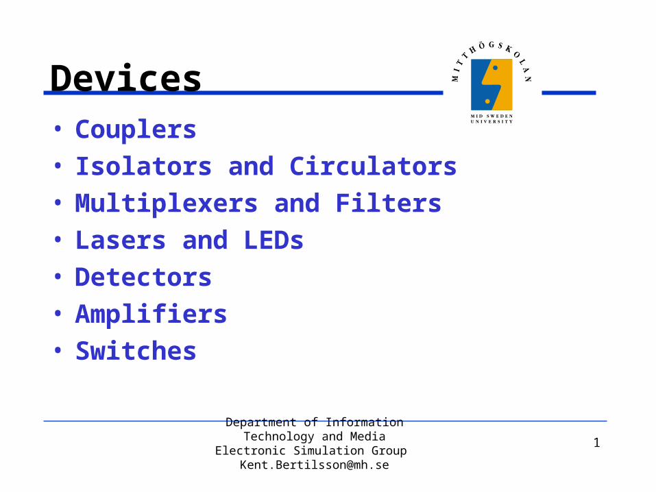
• Filters are usually designed with Bragg grating
• Any periodic perturbation in the propagating medium serve as a Bragg grating (Usually refractive index).– The wavelength corresponding to the
Bragg grating frequency are reflected while all other are transmitted.
– The side lobes can be reduced by having smaller refractive index changes near the edges of the filter.
Bild s 98

Department of Information Technology and Media
Electronic Simulation Group [email protected]
8
Fabry-Perot Filters• Fabry-Perot Filter (Etalon) is
fabricated by a cavity surrounded by two mirrors
• The transfer function of an etalon filter is periodical due to the multiple of standing waves in the cavity.
• Etalon is very simple and cheap.
Bild s 103,105

Department of Information Technology and Media
Electronic Simulation Group [email protected]
9
Multi Layer Filters
• A single Etalon filter is very narrow banded.
• The bandwidth can be increased by using multiple cavities.
Bild s 106,107:1

Department of Information Technology and Media
Electronic Simulation Group [email protected]
10
Add/Drop elements• Add/Drop elements can
be realized by a fiber gratings (isolator), a circulator and a coupler. Bild s 100

Department of Information Technology and Media
Electronic Simulation Group [email protected]
11
Multiplexers and Demultiplexers
• Static multiplexers can be realized using one multi-layer filters for each wavelength.
• The same device can be used as a multiplexer as well.
Bild s 107:2

Department of Information Technology and Media
Electronic Simulation Group [email protected]
12
Wavelength Routers
• A Static wave-length router can be realized by using a few multiplexers and demultiplexers Bild s 92
Department of Information Technology and Media
Electronic Simulation Group [email protected]
13
Planar Lasers
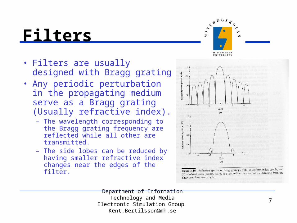
• An amplifying medium is surrounded by two mirrors (one semi-transparent)
• The amplifying medium is mostly a quantum well
Bild Agrawal s 96, 98
Department of Information Technology and Media
Electronic Simulation Group [email protected]
14
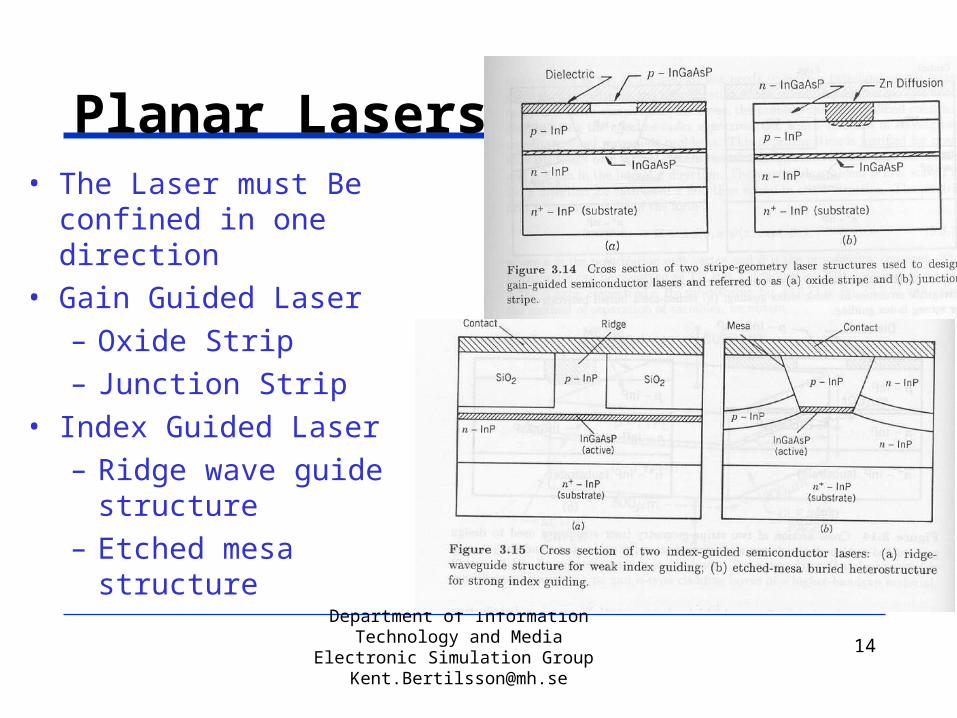
Planar Lasers• The Laser must Be
confined in one direction• Gain Guided Laser
– Oxide Strip– Junction Strip
• Index Guided Laser– Ridge wave guide
structure– Etched mesa
structure
Bild Agrawal s 99,100

Department of Information Technology and Media
Electronic Simulation Group [email protected]
15
Lasers
• The semiconductor amplifier is wide-banded
• The monochromatic lasing wavelength is determined by the cavity surrounding the amplifier
• For low power, high reflectivity is required for lasing operation.– Cavity Laser (Fabry Perot Cavity)– Distributed Feedback Reflector
(DFR)– Distributed Bragg Reflector (DBR)
Bild Agrawal s 105, 107

Department of Information Technology and Media
Electronic Simulation Group [email protected]
16
Vertical Cavity Surface Emitting Lasers (VCSEL)
• The cavity is made of epitaxial layers.
• Possible to make very small devices
• Devices can be tested before assembly
Bild Pessa 22:2
Department of Information Technology and Media
Electronic Simulation Group [email protected]
17
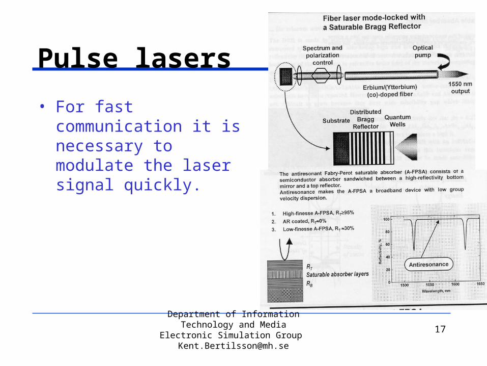
Pulse lasers
• For fast communication it is necessary to modulate the laser signal quickly.
Bild Oleg 1-2
Department of Information Technology and Media
Electronic Simulation Group [email protected]
18
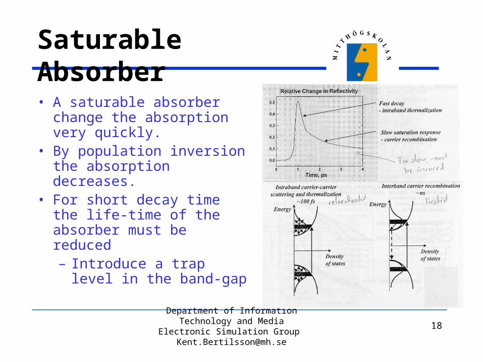
Saturable Absorber• A saturable absorber
change the absorption very quickly.
• By population inversion the absorption decreases.
• For short decay time the life-time of the absorber must be reduced– Introduce a trap level in
the band-gap
Bild Oleg 3-4
Department of Information Technology and Media
Electronic Simulation Group [email protected]
19
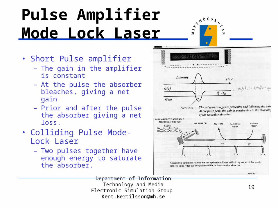
Pulse AmplifierMode Lock Laser• Short Pulse amplifier
– The gain in the amplifier is constant
– At the pulse the absorber bleaches, giving a net gain
– Prior and after the pulse the absorber giving a net loss.
• Colliding Pulse Mode-Lock Laser– Two pulses together have
enough energy to saturate the absorber.
Bild Oleg 5-6
Department of Information Technology and Media
Electronic Simulation Group [email protected]
20
Light Emitting Diodes (LEDs)
• Much Simpler and cheaper compared with lasers
• For many applications with short distances and low data rates LEDs are sufficient.
• A LED is a forward biased pn-junction, where the injected minority carriers recombine by spontaneous emission of light

Department of Information Technology and Media
Electronic Simulation Group [email protected]
21
LEDs
Telecommunication LEDs can either be surface or edge emitting.
Department of Information Technology and Media
Electronic Simulation Group [email protected]
22
Detectors
• Telecommunication detectors are traditional pn-detectors
• PIN diodes are used to increase the efficiency• Avalanche photodiodes are also used to increase the
signal– To high amplification reduces noise performance

Department of Information Technology and Media
Electronic Simulation Group [email protected]
23
Semiconductor Optical Amplifiers (SOAs)
• A semiconductor amplifiers is realized as a semiconductor laser without mirrors
• Very short compared with fiber amplifiers
Bild Reale

Department of Information Technology and Media
Electronic Simulation Group [email protected]
24
SOAs
• For high amplification and large bandwidth a very good antireflective coatings are necessary.– Difficult to achieve.
• The antireflectivity can be improved by:– Tilted stripe structure– Window faced structure
Bild s 370, 369

Department of Information Technology and Media
Electronic Simulation Group [email protected]
25
SOAs
• SOAs are polarization dependent
• Multiple SOAs can be used to realize a polarization independent amplifier.
Bild s 372

Department of Information Technology and Media
Electronic Simulation Group [email protected]
26
Electro-Optic Switch
• Electro-optic directional coupler switch
• Semiconductor Optical Amplifier switch– An optical amplifier
where the amplifier bias switches the signal
Bild s 155

Department of Information Technology and Media
Electronic Simulation Group [email protected]
27
All-Optical Regeneration• Nonlinear Loop Mirror
– Without control pulse: Reshaping
– With control pulse: Retiming and reshaping
• A saturable absorber can be used as an optical gate for retiming and reshaping.
Bild Oleg 7-8

Department of Information Technology and Media
Electronic Simulation Group [email protected]
28
All Optic SwitchLoop Mirror
– If the two signals are equal the signal are coupled to the input.
– If the two signals experiences different absorption or index the signal are fully coupled to the output.
• The control signal saturates the SOA for a short moment.
• The two pulses reaches the SOA with a time difference, one where the amplified is saturated.
• The control pulse are filtered awayThe two other are based on Mach-
Zehnder Interferometers.
Bild Toliver

Department of Information Technology and Media
Electronic Simulation Group [email protected]
29
All Optic Switch
• Each data-pulse induces an non-linear refractive index change in the SOAs.
• Each clock pulse is split in two parts and passing the SOAs.
• The two pulses are interfering either destructively or constructively depending on the clock pulse arrival.
Bild Nakamura, 2xUeno,

Department of Information Technology and Media
Electronic Simulation Group [email protected]
30
All-Optical Pulse Regeneration
• Electro optical timing and reshaping– All Optical signal path– Electrical signal for timing signal.
• For all Optical Pulse Regeneration only the clock recovery is missing
Bild Oleg 5-6

Department of Information Technology and Media
Electronic Simulation Group [email protected]
31
Optical Clock Recovery
• For Optical Clock recovery a lasers which are able to create short pulses are required– Self Pulsating Laser
– Mode Lock Laser • Optical Clock recovery
up to 40 Gbit/s have
been achieved
Department of Information Technology and Media
Electronic Simulation Group [email protected]
32
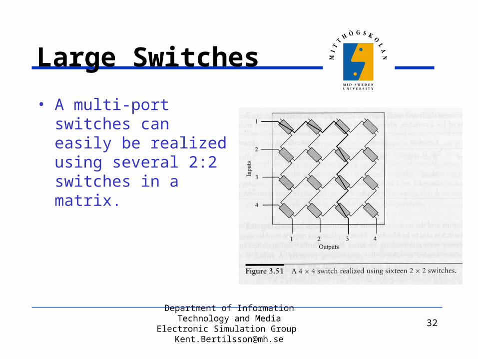
Large Switches
• A multi-port switches can easily be realized using several 2:2 switches in a matrix. Bild s158

Department of Information Technology and Media
Electronic Simulation Group [email protected]
33
Wavelength converters
• Opto-electric approach• Cross Gain Modulation in
a SOABild s162, 164
Department of Information Technology and Media
Electronic Simulation Group [email protected]
34
Solitons
• Introduction
• Robustness
• Sliding-Frequency Filter
• Tapered Fibers
• Dispersion Managed Fibers
• Pulse-to-Pulse Interaction

Department of Information Technology and Media
Electronic Simulation Group [email protected]
35
Introduction
• Narrow pulses with high peak power and special shape.
• A soliton is not affected by dispersion.– The dispersion is exactly compensated by
nonlinear effects in the fiber.

Department of Information Technology and Media
Electronic Simulation Group [email protected]
36
Robustness
• A soliton is, when once created very robust.• A pulse where nonlinear effects not exactly
compensate the dispersion is shifted towards this case.
• Solitons ”feels” only average parameters (fiber dispersion, fiber mode area, pulse energy) as long as the variations are faster than the soliton dispersion length. – Stable in systems with lumped amplifiers (Lamp< zdisp).– Slow variation can be used for pulse reshaping
(compression and broadening)

Department of Information Technology and Media
Electronic Simulation Group [email protected]
37
Sliding-Frequency Filter
• Etalon Filter can be used due to the narrow bandwidth of the soliton– Cheap and simple,
compared with Gaussian filters
– Same filter can be used for multiple channels
• Bild 17:1
Department of Information Technology and Media
Electronic Simulation Group [email protected]
38
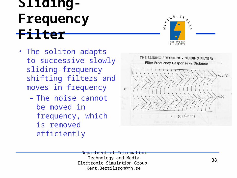
Sliding-Frequency Filter
• The soliton adapts to successive slowly sliding-frequency shifting filters and moves in frequency– The noise cannot be
moved in frequency, which is removed efficiently
• Bild 19:2

Department of Information Technology and Media
Electronic Simulation Group [email protected]
39
Sliding-Frequency FilterNoise Reduction
• Bild 20:2 • Bild 21:1
Department of Information Technology and Media
Electronic Simulation Group [email protected]
40
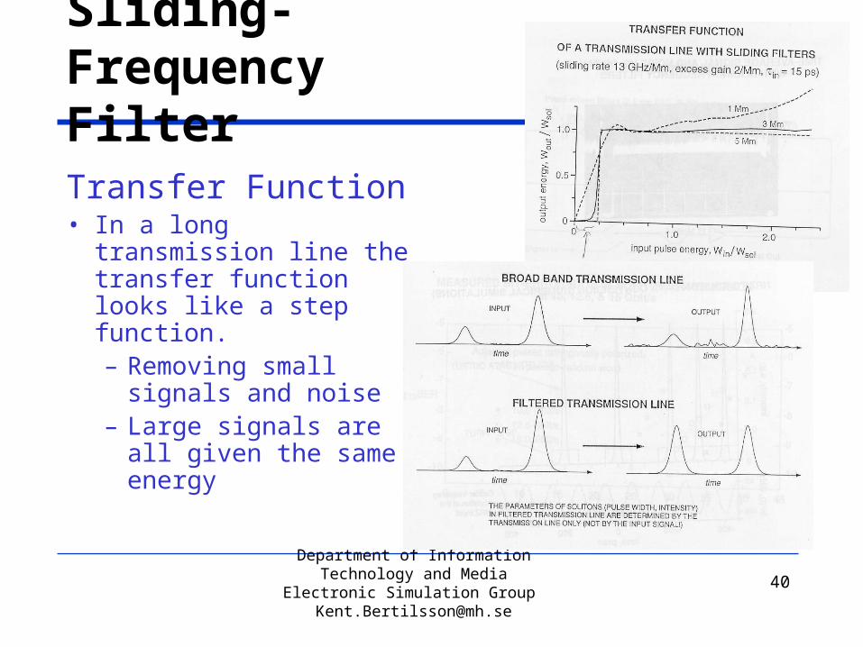
Sliding-Frequency Filter
Transfer Function• In a long transmission
line the transfer function looks like a step function.– Removing small
signals and noise– Large signals are all
given the same energy
24:2
25:1

Department of Information Technology and Media
Electronic Simulation Group [email protected]
41
Wavelength Division Multiplexing (WDM)
In WDM, Solitons of different channels overtake and pass thought (Collide with) each other, which results in.
Department of Information Technology and Media
Electronic Simulation Group [email protected]
42
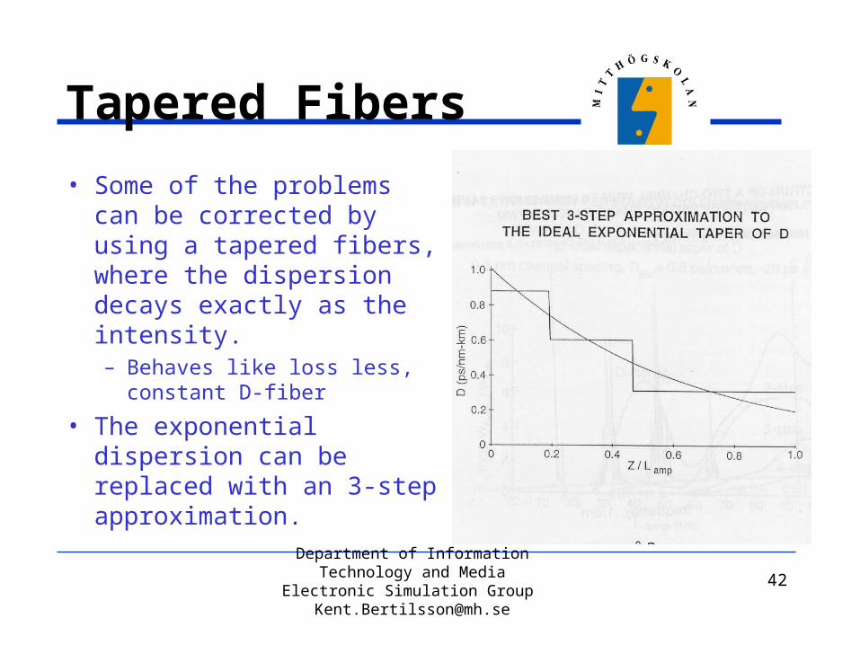
Tapered Fibers
• Some of the problems can be corrected by using a tapered fibers, where the dispersion decays exactly as the intensity.– Behaves like loss less,
constant D-fiber
• The exponential dispersion can be replaced with an 3-step approximation.
• Bild 35:2

Department of Information Technology and Media
Electronic Simulation Group [email protected]
43
Gain Flatness• Optical amplifiers have not
a flat gain over several channels.
• After multiple amplifiers the signal power differs very much between channels.
• In Soliton transmission with filters the amplitude can be kept relative constant between the different channels.
• Bild 39:1

Department of Information Technology and Media
Electronic Simulation Group [email protected]
44
Gain Flatness
• Bild 40:2• Bild 39:2

Department of Information Technology and Media
Electronic Simulation Group [email protected]
45
Dispersion Managed Fibers
• Fibers with alternating dispersion where the pulses are true solitons only in a few points along the fiber.
– All advantages of ’classical solitons’– Power enhancement– Inexpensive and flexible design– High stability range– WDM

Department of Information Technology and Media
Electronic Simulation Group [email protected]
46
Pulse-to-Pulse Interaction
• The pulse-to-pulse interaction depends on the pulse width-spacing ratio.• The interaction increases
as the pulses starts overlap
• At large overlap the interaction vanishes
• Bild 60:1
Department of Information Technology and Media
Electronic Simulation Group [email protected]
47
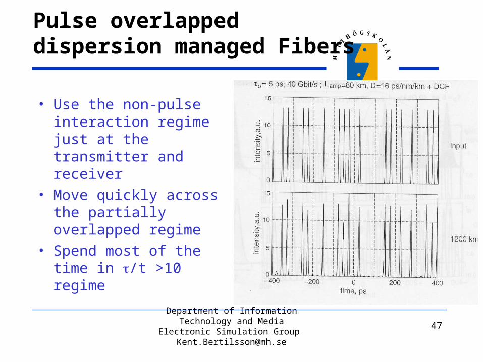
Pulse overlapped dispersion managed Fibers
• Use the non-pulse interaction regime just at the transmitter and receiver
• Move quickly across the partially overlapped regime
• Spend most of the time in /t >10 regime
• Bild 61:2
Department of Information Technology and Media
Electronic Simulation Group [email protected]
48
State of The Art
• 320 Gbit/s Transmission over 200 km.• 10 GHz Clock Recovery from a 160 Gbit/s stream.• 168 Gbit/s Demultiplexing• 84 Gbit/s All Optical 3R Regeneration (No clock
recovery)• 40 Gbit/s All Optical Clock Recovery
Related Documents