DEPARTMENT OF ELECTRONICS AND COMMUNICATION ENGINEERING III SEMESTER EE6352-ELECTRICAL ENGINEERING AND INSTRUMENTATION UNIT I - D.C. MACHINES PART A 1. Define electric motor. The electric motor is a machine that converts electrical energy into mechanical energy or motion. 2. Define electric generator. What is a prime mover? (May 2016) The electric generator is machine that converts mechanical energy into electrical energy. The basic source of mechanical power which drives the armature of the generator is called prime mover. 3. What do you mean by residual flux in D.C. Generator? The magnetic flux retained in the poles of the machine even without field supply is called the residual flux. 4. State the principle of working of D.C. motor. (Nov 2016) An electric motor is a machine which converts electrical energy into mechanical energy. Its action is based on principle that when a current carrying conductor is placed in a magnetic field it experiences a mechanical force whose direction is given by Fleming’s left hand rule. 5. How are DC Machines classified? (Nov/Dec 2015) D.C Generators 1. Separately excited machine.2. Self excited machine. 1.shunt generator 2.series generator 3.compond generator D.C Motors 1.Shunt 2.Series 3.compond 6. What are the losses of a shunt machine assumed as constant? Core losses, mechanical losses and shunt field copper loss assumed as constant in shunt machine. 7. What is the condition for maximum efficiency of a D.C. machine? Efficiency of a D.C. machine will be maximum when variable losses are equal to constant losses. 8. What are the applications of D.C Series generator? These are used for series arc lighting, series incandescent lighting and as a series booster for increasing the voltage in D.C. transmission lines. 9. What is the use of shunt generator? Shunt wound generator with field regulations are used for light and power supply purposes. These are also used for charging of batteries on account of its constant terminal voltage. 10. What causes sparking at the brushes? It is either due to self-induction of the coil undergoing commutation or due to improper pressing of brush over the commutator surface. 11. Explain how you would reverse the direction of rotation of a D.C shunt motor. The direction of rotation of a D.C. shunt motor can be reversed either by changing the direction of field current or armature current. 12. How can the speed of a D.C shunt motor be controlled? By varying the field current as well as armature voltage speed can controlled.

Welcome message from author
This document is posted to help you gain knowledge. Please leave a comment to let me know what you think about it! Share it to your friends and learn new things together.
Transcript
DEPARTMENT OF ELECTRONICS AND COMMUNICATION
ENGINEERING
III SEMESTER
EE6352-ELECTRICAL ENGINEERING AND INSTRUMENTATION
UNIT I - D.C. MACHINES PART A
1. Define electric motor.
The electric motor is a machine that converts electrical energy into mechanical energy or motion.
2. Define electric generator. What is a prime mover? (May 2016)
The electric generator is machine that converts mechanical energy into electrical energy.
The basic source of mechanical power which drives the armature of the generator is called prime
mover.
3. What do you mean by residual flux in D.C. Generator?
The magnetic flux retained in the poles of the machine even without field supply is called the
residual flux.
4. State the principle of working of D.C. motor. (Nov 2016)
An electric motor is a machine which converts electrical energy into mechanical energy. Its action
is based on principle that when a current carrying conductor is placed in a magnetic field it
experiences a mechanical force whose direction is given by Fleming’s left hand rule.
5. How are DC Machines classified? (Nov/Dec 2015)
D.C Generators
1. Separately excited machine.2. Self excited machine.
1.shunt generator 2.series generator 3.compond generator
D.C Motors
1.Shunt 2.Series 3.compond
6. What are the losses of a shunt machine assumed as constant?
Core losses, mechanical losses and shunt field copper loss assumed as constant in shunt machine.
7. What is the condition for maximum efficiency of a D.C. machine?
Efficiency of a D.C. machine will be maximum when variable losses are equal to constant losses.
8. What are the applications of D.C Series generator?
These are used for series arc lighting, series incandescent lighting and as a series booster for
increasing the voltage in D.C. transmission lines.
9. What is the use of shunt generator?
Shunt wound generator with field regulations are used for light and power supply purposes. These
are also used for charging of batteries on account of its constant terminal voltage.
10. What causes sparking at the brushes?
It is either due to self-induction of the coil undergoing commutation or due to improper pressing of
brush over the commutator surface.
11. Explain how you would reverse the direction of rotation of a D.C shunt motor.
The direction of rotation of a D.C. shunt motor can be reversed either by changing the
direction of field current or armature current.
12. How can the speed of a D.C shunt motor be controlled?
By varying the field current as well as armature voltage speed can controlled.
13. What will be the effect of adding resistance in the field circuit of a D.C shunt motor?
When the motor is running on no-load, the speed will increase, if additional resistance is connected
in the field circuit. But the speed will decrease if it runs with load as torque produced decreases.
14. What do you mean by “commutation’ and commutation period?
The process by which current in the short circuited coil is reversed while it crosses the magnetic
neutral axis is called “commutation”. The brief period during which coil remains short circuited is
known as commutation period.
15. What happens when a D.C. Shunt motor is directly connected to the supply mains?
When the motor is at rest, there is no back EMF developed in the armature. If now full supply
voltage is applied across the stationary armature, it will draw a very large current because armature
resistance
is very small ( I = V/R ) this excessive current will blow out the fuses and prior to that, it will
damage the commutator, brushes etc.,
16. What is the function of carbon brushes used in DC generator?
The function of carbon brushes is to collect current from the commutator and supply to external
load circuit and to load.
17. A 200 V DC Motor has an =0.06Ω and =0.04Ω.If the motor input is 20KW find the
back emf of the motor and power developed in the armature.(Apr/May 2015)
I= =100 A ; V= + +
Back emf=190 V; Power developed= * =19KW
18. Define Back emf of DC motor and expression for speed ? (Nov/Dec 2015)
The emf induced in the armature of motor usually opposes the applied voltage. This induced emf
is called as back emf or counter emf. (Lenz’s law) - It acts as a governor (ie., self regulating).
N= = V=Voltage ; = Armature Current ; = Armature Resistance
19.An 8 pole wave connected armature has 600 conductors and is driven at 625 rev/min. If the
flux
per pole is 20 mWb, Determine the generated emf. (Nov/Dec 2013)
Here A=2
Eg = (0.02*600*625*8)/120 Eg= 500V
20. A DC motor operates from a 240V supply. The armature resistance is 0.2Ω. Determine the
back emf when the armature current is 50A. ( Nov/Dec 2013)
V= Eb+ IaRa
Eb = 240- (50*0.2)
Eb = 230 V
21. What is the significance of back emf? (Apr/May 2013)
If the back emf is zero, a high armature current flow which damages the windings. So in order to
limit the armature current back emf is necessary for the machine.
22. Write down the application of D.C series motor. (Apr/May 2013)
Electric Trains, Cranes, hoists, elevators and conveyors, Fans and air compressors hair
driers,Vacuum cleaners, Sewing machines, Traction drives, Trolley
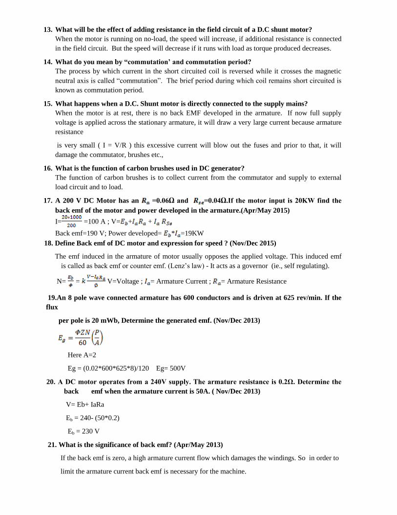
23. Draw the open circuit characteristics of D.C. Generators. (Nov/Dec 2014)
24. List the types of D.C. motors. Give any one difference between them. (Nov/Dec 2014)
The various types of DC motors are shunt motor, series motor and compound motor. The
compound motor are further classified as short shunt compound motor and long shunt
compound motor. In Shunt motor, the field winding is connected parallel to the armature winding
whereas in case of series motor, the field winding is connected in series to the armature winding.
In Long shunt compound motor, the shunt field winding is connected across the combination of
armature and series field winding and in case of short shunt compound motor, the shunt field is
connected purely in parallel with armature and the series field is connected in series with the
combination of armature and shunt field winding.
25.Mention the advantage of star and delta systems.(Apr/May 2015)
Star connected alternator requires less no of turns.
For the same line voltage star connected system requires less insulation.
In star the neutral can be earthed which permits the use of protective devices. Delta offers the
flexibility to add or remove the loads.
26. Why is the starting current very high in a dc motor? (May 2016)
A rotating d.c. motor generates a back-emf which opposes the supply voltage and reduces the
current drawn by the motor. When the motor is stationary, it cannot generate this back emf and, so,
the only opposition to current is the resistance as the machine starts to run, the resulting back emf,
acts to reduce the current. The starting current is high because when the motor is not rotating no
back-emf is generated, leaving the starting current to be determined by the armature resistance
should be low.

Part-B
1. With a neat diagram explain the construction of a D.CMachine.
The major parts can be identified as,
• Magnetic Frame orYoke
• Pole core and Poleshoe
• Pole coil/fieldcoil
• Armaturecore
• Armaturewindings/conductor
• Commutator
• Brushes andbearings
Yoke:
• Purpose
Figure : Overview
– Provides mechanical support for thepoles
– Acts as a protective covering for the wholemachine
– Carries magnetic flux produced bypoles
• Made of
– Cast iron in smallgenerators
– Cast steel/rolled steel in largegenerators
Pole Core & Pole shoe
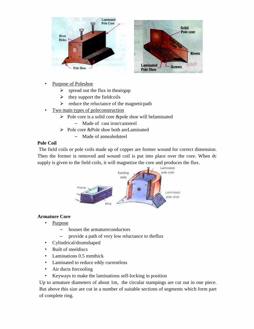
• Purpose of Poleshoe
spread out the flux in theairgap
they support the fieldcoils
reduce the reluctance of the magneticpath
• Two main types of poleconstruction
Pole core is a solid core &pole shoe will belaminated
– Made of cast iron/caststeel
Pole core &Pole shoe both areLaminated
– Made of annealedsteel
Pole Coil
The field coils or pole coils made up of copper are former wound for correct dimension.
Then the former is removed and wound coil is put into place over the core. When dc
supply is given to the field coils, it will magnetize the core and produces the flux.
Armature Core
• Purpose
– houses the armatureconductors
– provide a path of very low reluctance to theflux
• Cylindrical/drumshaped
• Built of steeldiscs
• Laminations 0.5 mmthick
• Laminated to reduce eddy currentloss
• Air ducts forcooling
• Keyways to make the laminations self-locking in position
Up to armature diameters of about 1m, the circular stampings are cut out in one piece.
But above this size are cut in a number of suitable sections of segments which form part
of complete ring.
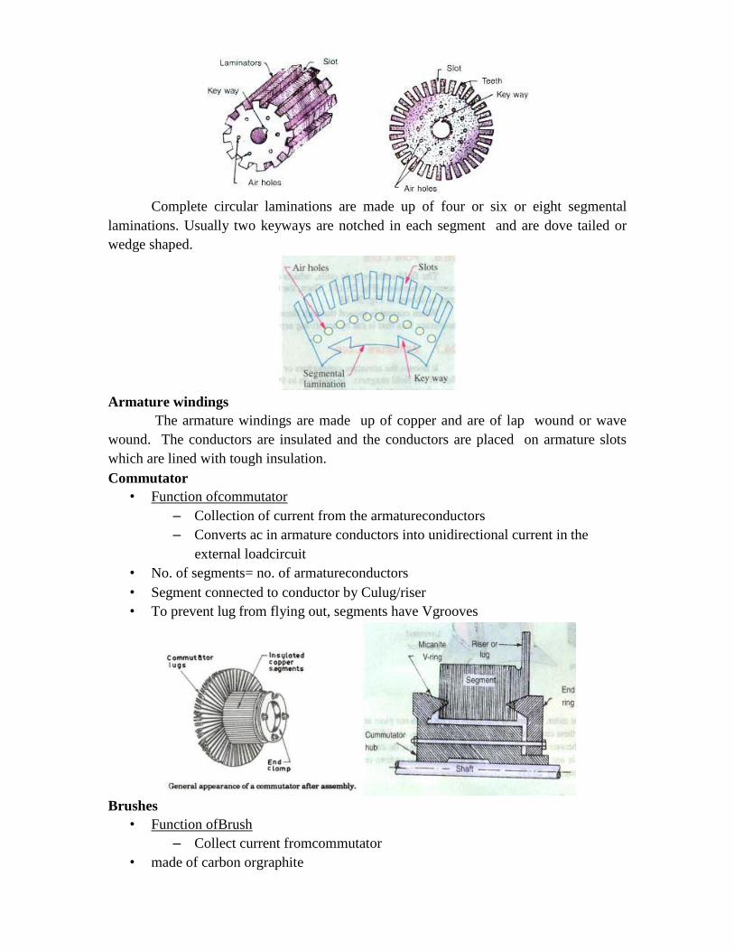
Complete circular laminations are made up of four or six or eight segmental
laminations. Usually two keyways are notched in each segment and are dove tailed or
wedge shaped.
Armature windings
The armature windings are made up of copper and are of lap wound or wave
wound. The conductors are insulated and the conductors are placed on armature slots
which are lined with tough insulation.
Commutator
• Function ofcommutator
– Collection of current from the armatureconductors
– Converts ac in armature conductors into unidirectional current in the
external loadcircuit
• No. of segments= no. of armatureconductors
• Segment connected to conductor by Culug/riser
• To prevent lug from flying out, segments have Vgrooves
Brushes
• Function ofBrush
– Collect current fromcommutator
• made of carbon orgraphite
• Rectangularshape
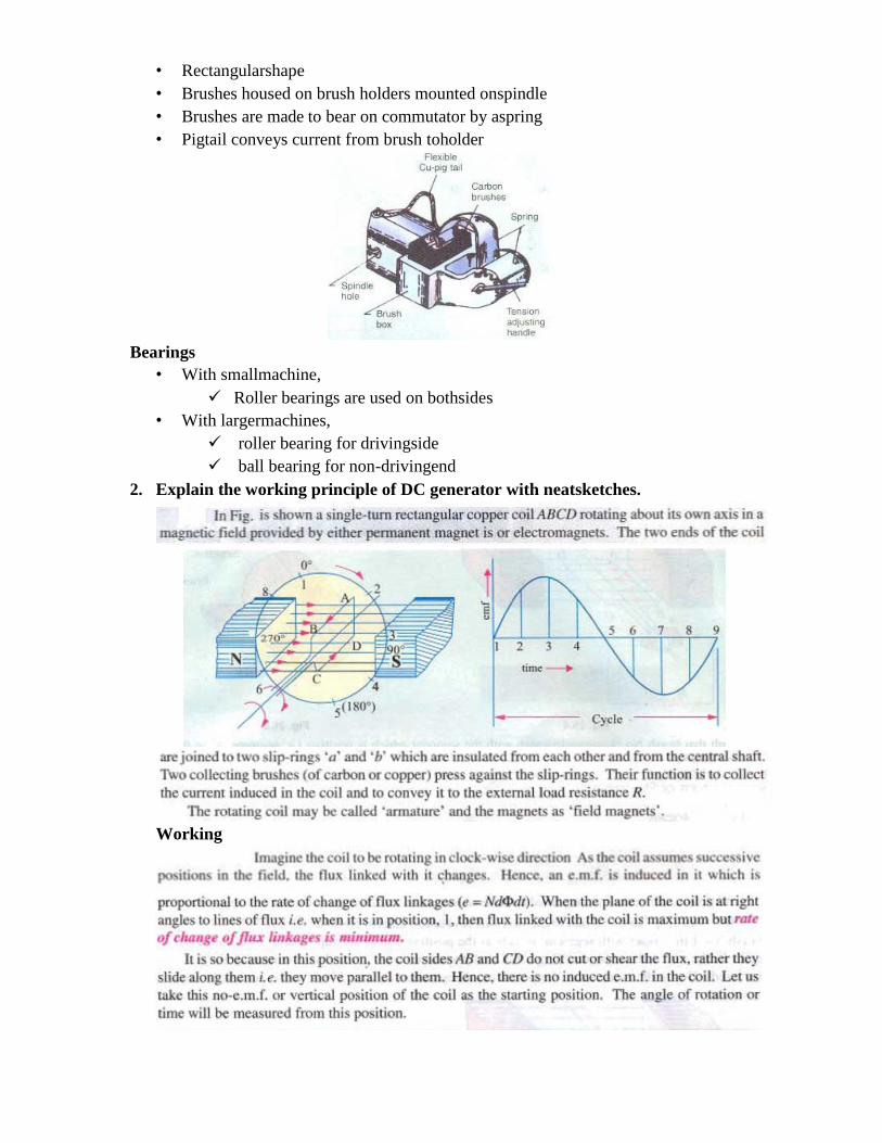
• Brushes housed on brush holders mounted onspindle
• Brushes are made to bear on commutator by aspring
• Pigtail conveys current from brush toholder
Bearings
• With smallmachine,
Roller bearings are used on bothsides
• With largermachines,
roller bearing for drivingside
ball bearing for non-drivingend
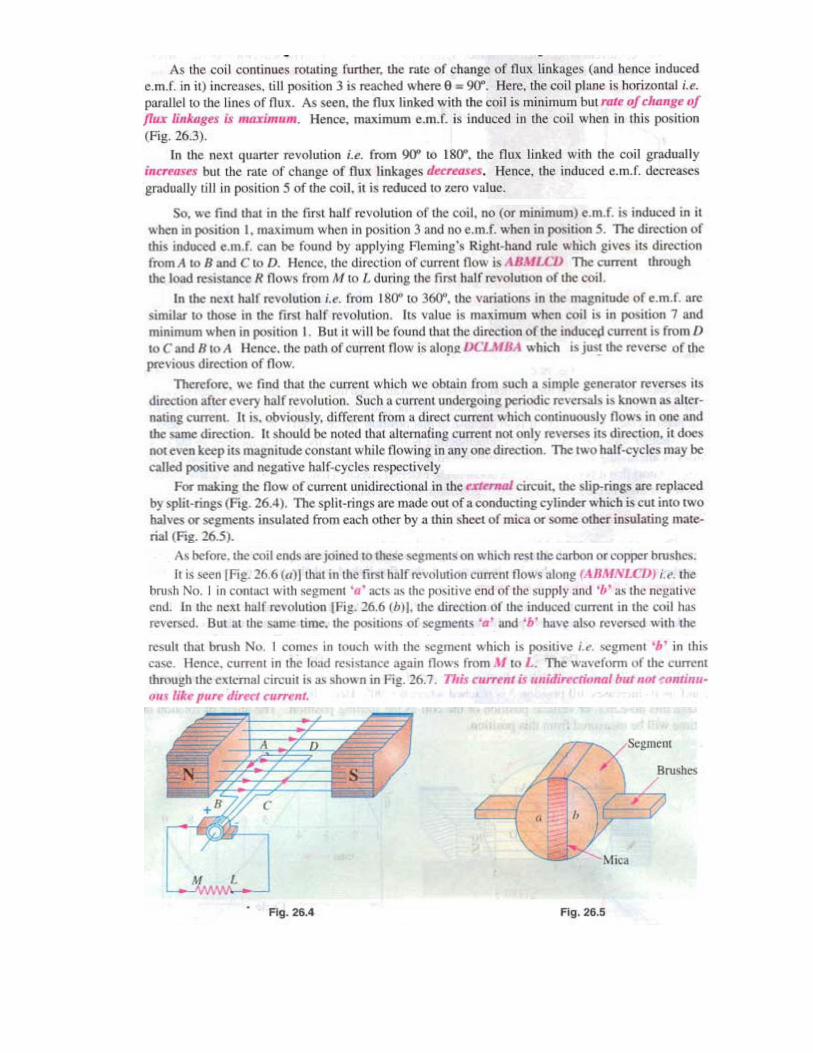
2. Explain the working principle of DC generator with neatsketches.
Working
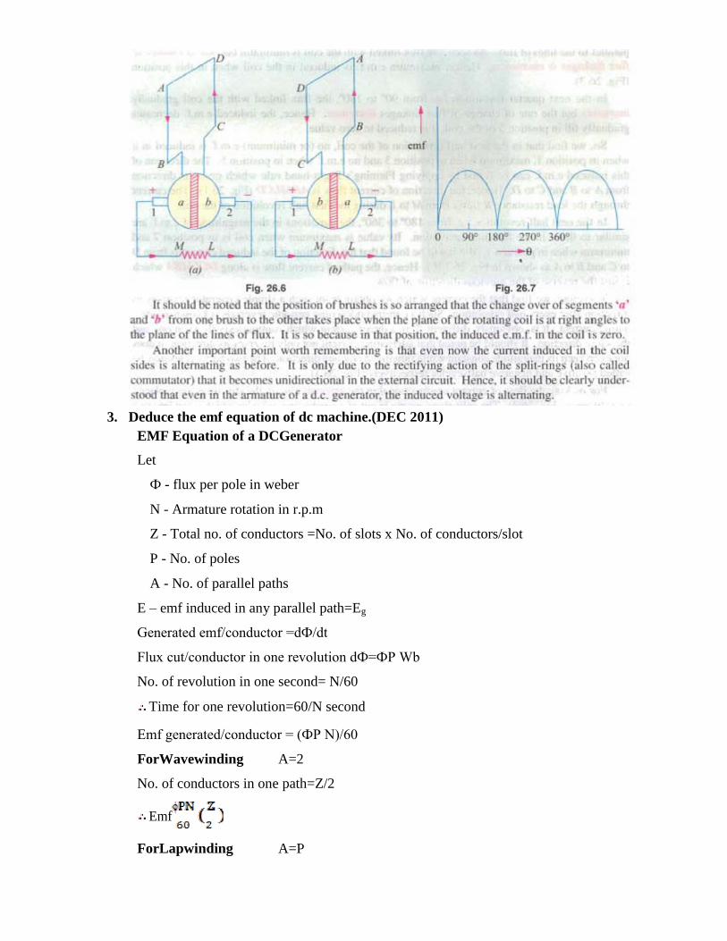
3. Deduce the emf equation of dc machine.(DEC 2011)
EMF Equation of a DCGenerator
Let
Ф - flux per pole in weber
N - Armature rotation in r.p.m
Z - Total no. of conductors =No. of slots x No. of conductors/slot
P - No. of poles
A - No. of parallel paths
E – emf induced in any parallel path=Eg
Generated emf/conductor =dФ/dt
Flux cut/conductor in one revolution dФ=ФP Wb
No. of revolution in one second= N/60
Time for one revolution=60/N second
Emf generated/conductor = (ФP N)/60
ForWavewinding A=2
No. of conductors in one path=Z/2
Emf
ForLapwinding A=P
No. of conductors in one path=Z/P
Emfgenerated/p
ath= Ing
eneral,
4. Explain the various characteristics of self-excited dcgenerators.
CHARACTERISTICS OF DCGENERATORS
• Open Circuit Characteristics(OCC)/No-load / magnetization characteristics [E0 /
If]
• Internal Characteristics [Ea /Ia]
• External Characteristics [V / I]
Characteristics of self-excited dcgenerator:
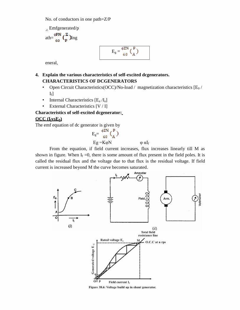
OCC (IfvsE0)
The emf equation of dc generator is given by
Eg=
Eg =KφN φ αIf
From the equation, if field current increases, flux increases linearly till M as
shown in figure. When If =0, there is some amount of flux present in the field poles. It is
called the residual flux and the voltage due to that flux is the residual voltage. If field
current is increased beyond M the curve becomes saturated.
Eg =
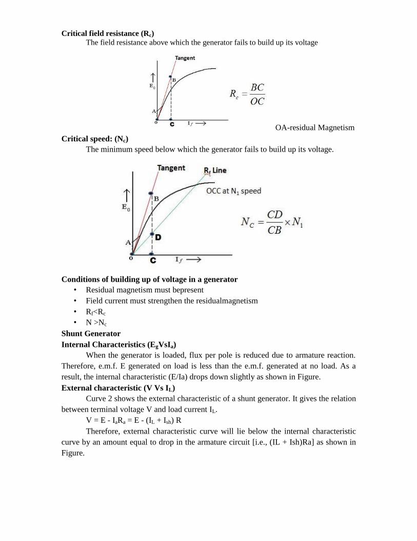
Critical field resistance (Rc)
The field resistance above which the generator fails to build up its voltage
OA-residual Magnetism
Critical speed: (Nc)
The minimum speed below which the generator fails to build up its voltage.
Conditions of building up of voltage in a generator
• Residual magnetism must bepresent
• Field current must strengthen the residualmagnetism
• Rf<Rc
• N >Nc
Shunt Generator
Internal Characteristics (EgVsIa)
When the generator is loaded, flux per pole is reduced due to armature reaction.
Therefore, e.m.f. E generated on load is less than the e.m.f. generated at no load. As a
result, the internal characteristic (E/Ia) drops down slightly as shown in Figure.
External characteristic (V Vs IL)
Curve 2 shows the external characteristic of a shunt generator. It gives the relation
between terminal voltage V and load current IL.
V = E - IaRa = E - (IL + Ish) R
Therefore, external characteristic curve will lie below the internal characteristic
curve by an amount equal to drop in the armature circuit [i.e., (IL + Ish)Ra] as shown in
Figure.

Series Generator
Figure shows the connections of a series wound generator. Since there is only one
current (that which flows through the whole machine), the load current is the same as the
exciting current.
Internal characteristics
Curve 2 shows the total or internal characteristic of a series generator. It gives the
relation between the generated e.m.f. E. on load and armature current. Due to armature
reaction, the flux in the machine will be less than the flux at no load. Hence, e.m.f. E
generated under load conditions will be less than the e.m.f. E0 generated under no load
conditions. Consequently, internal characteristic curve. Internal characteristics lies below
the O.C.C. curve; the difference between them representing the effect of armature
reaction.
External characteristic
Curve 3 shows the external characteristic of a series generator. It gives the
relation between terminal voltage and load current IL.
V E IaRaRse
Therefore, external characteristic curve will lie below internal characteristic curve by an amount equal to ohmic drop [i.e., Ia(Ra + Rse)] in the machine as shown in Figure.
Compound Generator
In a compound generator, both series and shunt excitation are combined as shown
in Figure The shunt winding can be connected either across the armature only (short-
shunt connection S) or across armature plus series field (long-shunt connection G). The
compound generator can be cumulatively compounded or differentially compounded
generator. The latter is rarely used in practice. Therefore, we shall discuss the
characteristics of cumulatively compounded generator. It may be noted that external
characteristics of long and short shunt compound generators are almost identical.
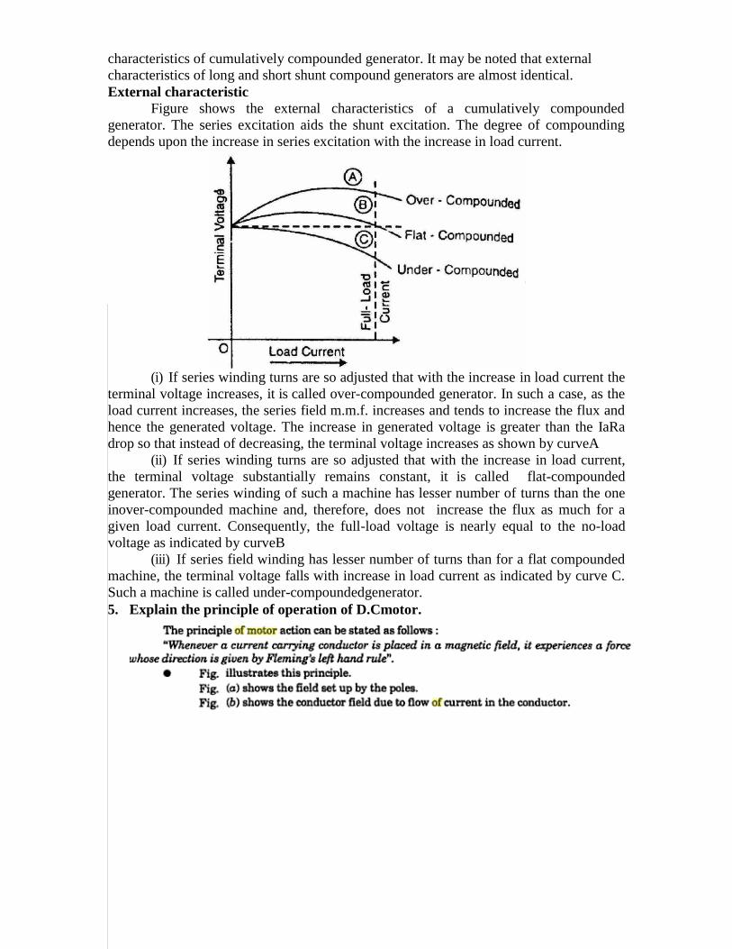
External characteristic
Figure shows the external characteristics of a cumulatively compounded
generator. The series excitation aids the shunt excitation. The degree of compounding
depends upon the increase in series excitation with the increase in load current.
(i) If series winding turns are so adjusted that with the increase in load current the
terminal voltage increases, it is called over-compounded generator. In such a case, as the
load current increases, the series field m.m.f. increases and tends to increase the flux and
hence the generated voltage. The increase in generated voltage is greater than the IaRa
drop so that instead of decreasing, the terminal voltage increases as shown by curveA
(ii) If series winding turns are so adjusted that with the increase in load current,
the terminal voltage substantially remains constant, it is called flat-compounded
generator. The series winding of such a machine has lesser number of turns than the one
inover-compounded machine and, therefore, does not increase the flux as much for a
given load current. Consequently, the full-load voltage is nearly equal to the no-load
voltage as indicated by curveB
(iii) If series field winding has lesser number of turns than for a flat compounded
machine, the terminal voltage falls with increase in load current as indicated by curve C.
Such a machine is called under-compoundedgenerator.
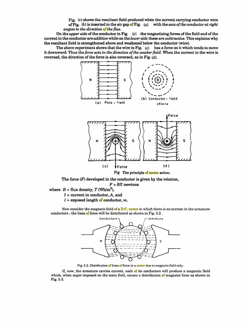
5. Explain the principle of operation of D.Cmotor.
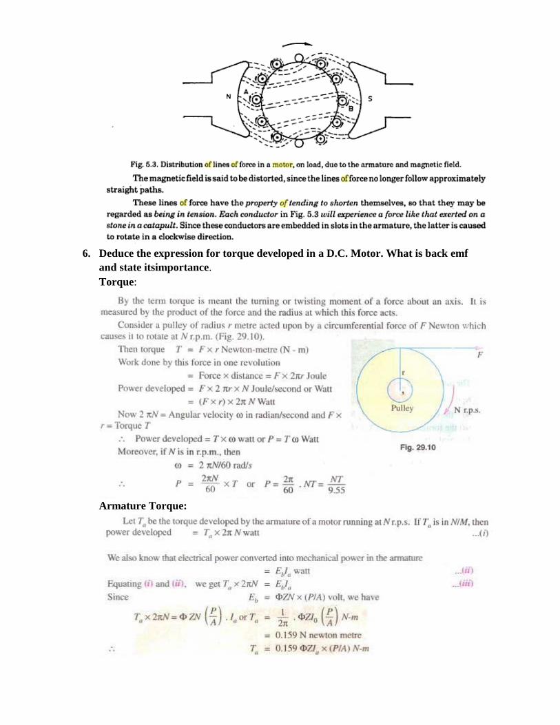
6. Deduce the expression for torque developed in a D.C. Motor. What is back emf
and state itsimportance.
Torque:
Armature Torque:
Shaft Torque:
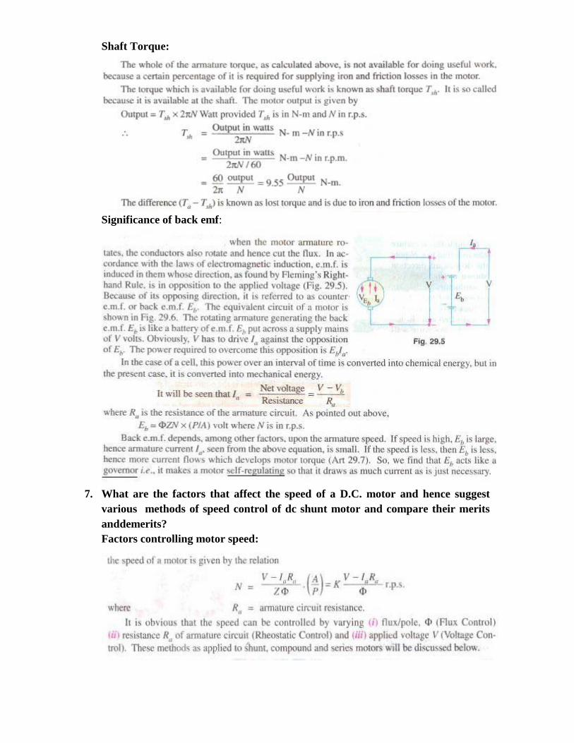
Significance of back emf:
7. What are the factors that affect the speed of a D.C. motor and hence suggest
various methods of speed control of dc shunt motor and compare their merits
anddemerits?
Factors controlling motor speed:
Methods of speed control:
1. Variation of flux controlmethod
2. Armature ControlMethod
3. Voltage Control Method
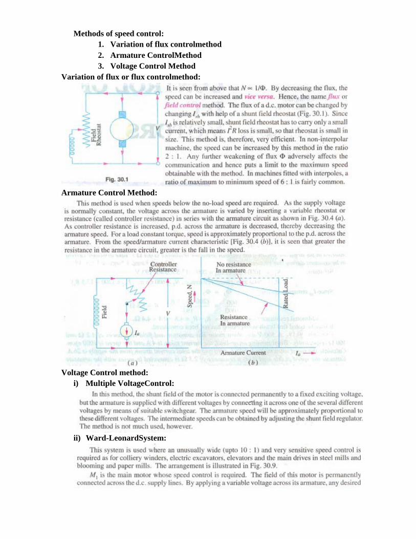
Variation of flux or flux controlmethod:
Armature Control Method:
Voltage Control method:
i) Multiple VoltageControl:
ii) Ward-LeonardSystem:

8. Explain the characteristics of DC shunt motor and from the nature of the curve
explain the applications of DC shuntmotor.
Characteristics of DC shunt motor:

Applications:
9. Explain the characteristics of DC series motor and from the nature of the curve
explain the application DC series motor. (DEC2011)
Characteristics of DC series motor:
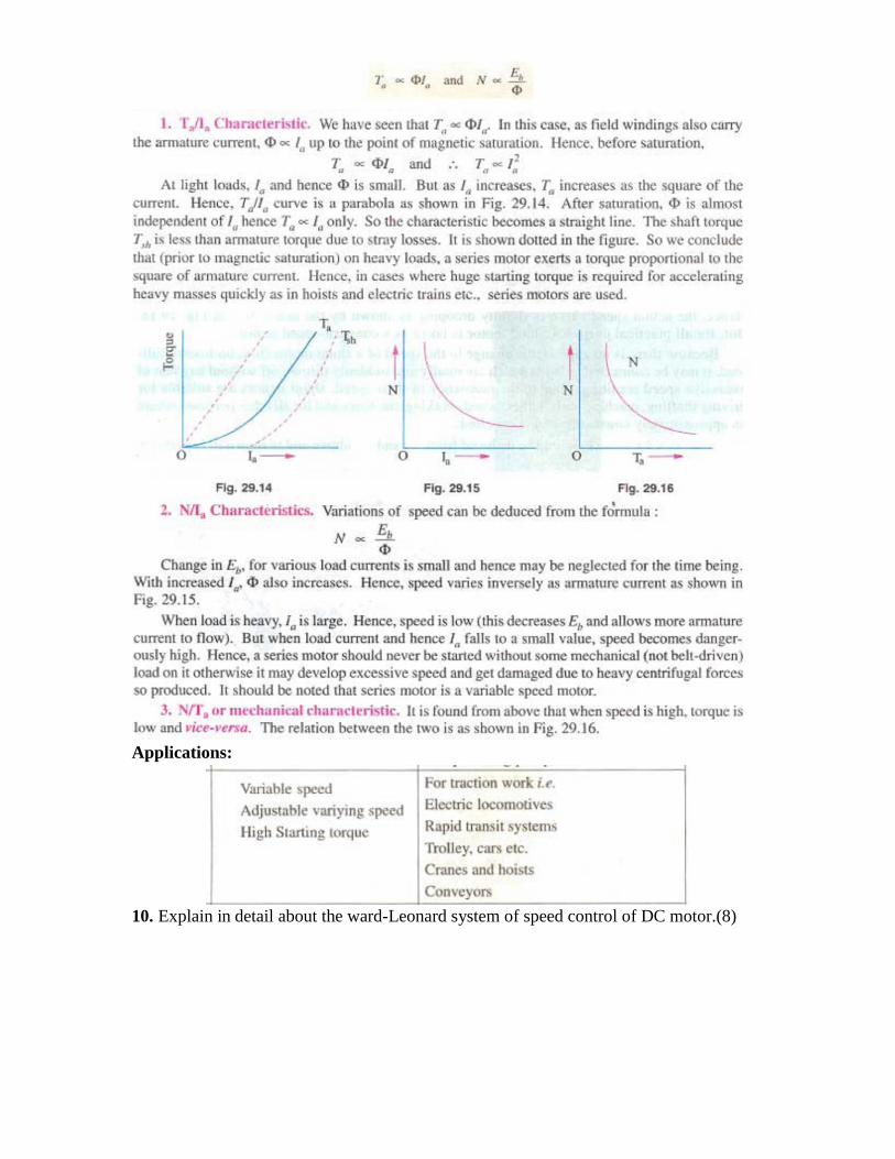
Applications:
10. Explain in detail about the ward-Leonard system of speed control of DC motor.(8)

Related Documents


