i UNIVERSITY OF NAIROBI DEPARTMENT OF ELECTRICAL AND INFORMATION ENGINEERING DESIGN OF A PWM BASED DC MOTOR CONTROL FOR ELECTRIC VEHICLE USING A MICROCONTROLLER PROJECT INDEX: PRJ 82 BY TOWETT FESTUS KIPNGENO REGISTRATION NO. : F17/30740/2010 SUPERVISOR: MR. OMBURA EXAMINER: PROF. MANGOLI Project report submitted in partial fulfillment of the requirement for the award of the degree of: Bachelor of Science in Electrical and Electronic Engineering of the University of Nairobi. Submitted on: 24th day of April, 2015

Welcome message from author
This document is posted to help you gain knowledge. Please leave a comment to let me know what you think about it! Share it to your friends and learn new things together.
Transcript
i
UNIVERSITY OF NAIROBI
DEPARTMENT OF ELECTRICAL AND INFORMATION
ENGINEERING
DESIGN OF A PWM BASED DC MOTOR CONTROL FOR ELECTRIC
VEHICLE USING A MICROCONTROLLER
PROJECT INDEX: PRJ 82
BY
TOWETT FESTUS KIPNGENO
REGISTRATION NO. : F17/30740/2010
SUPERVISOR: MR. OMBURA
EXAMINER: PROF. MANGOLI
Project report submitted in partial fulfillment of the requirement for the award of the degree of:
Bachelor of Science in Electrical and Electronic Engineering of the University of Nairobi.
Submitted on: 24th day of April, 2015

ii
DEDICATION To my family, for believing in me.

iii
DECLARATION OF ORIGINALITY
FACULTY/ SCHOOL/ INSTITUTE: Engineering
DEPARTMENT: Electrical and Information Engineering
COURSE NAME: Bachelor of Science in Electrical & Electronic Engineering
TITLE OF NAME OF STUDENT: Towett Festus Kipngeno
REGISTRATION NUMBER: F17/30740/2010
COLLEGE: Architecture and Engineering
WORK: DESIGN OF A PWM BASED DC MOTOR CONTROL FOR ELECTRIC VEHICLE
USING A MICROCONTROLLER
1) I understand what plagiarism is and I am aware of the university policy in this regard.
2) I declare that this final year project report is my original work and has not been
submitted elsewhere for examination, award of a degree or publication. Where other
people’s work or my own work has been used, this has properly been acknowledged
and referenced in accordance with the University of Nairobi’s requirements.
3) I have not sought or used the services of any professional agencies to produce this work.
4) I have not allowed, and shall not allow anyone to copy my work with the intention of
passing it off as his/her own work.
5) I understand that any false claim in respect of this work shall result in disciplinary
action, in accordance with University anti-plagiarism policy.
Signature: ………………………………………………………………………………………
Date: ……………………………………………………………………………………………

iv
ACKNOWLEDGEMENT
This is an honor for me to thank those who have helped to make this report possible.
First of all I would like to pay my deepest gratitude to my supervisor, Mr. Ombura for
giving me the opportunity to work on this project under his supervision. His support,
guidance and encouragement from the initial stage to the end has enabled me to
understand the concept behind this thesis work. I also express my gratitude to all the
faculty members and lab technologist for their guidance and support. Finally, all the
thanks to Almighty GOD that I have come to this far.
v
Table of Contents
DEDICATION ......................................................................................................................................................... ii
DECLARATION OF ORIGINALITY .............................................................................................................. iii
ACKNOWLEDGEMENT ....................................................................................................................................iv
TABLE OF FIGURES ......................................................................................................................................... vii
ABSTRACT .............................................................................................................................................................. 1
1 INTRODUCTION.......................................................................................................................................... 2
1.1 APPLICATION OF ELECTRIC TRACTION ................................................................................. 3
1.1.1 ELECTRIC TRAIN ........................................................................................................................ 3
1.1.2 ELECTRIC MOTORCYCLES ..................................................................................................... 3
1.1.3 ELECTRIC ELEVATOR .............................................................................................................. 4
1.2 PROBLEM STATEMENT .................................................................................................................. 4
1.3 ADVANTAGES OF ELECTRIC TRACTION ................................................................................. 5
1.4 DISADVANTAGES OF ELECTRIC VEHICLES ........................................................................... 6
1.5 OBJECTIVE ............................................................................................................................................. 7
2 LITERATURE REVIEW ............................................................................................................................. 8
2.1 CLASSIFICATION OF ELECTRIC VEHICLE ............................................................................... 8
2.1.1 Hybrid drive ................................................................................................................................. 8
2.1.2 ELECTRIC DRIVE (EV) .......................................................................................................... 12
2.2 DIRECT CURRENT MOTOR ......................................................................................................... 15
2.2.1 CLASSIFICATION OF A DC MOTORS ............................................................................... 16
2.2.2 CLASSIFICATION ON BASIS OF EXCITATION WINDING ....................................... 16
3 DESIGN ........................................................................................................................................................ 24
3.1 HARDWARE DEVELOPMENT .................................................................................................... 24
3.1.1 H-BRIDGE ................................................................................................................................... 25
3.1.2 CONTROL SYSTEM ................................................................................................................. 32
3.1.3 MICROCONTROLLER ............................................................................................................. 35
3.1.4 LCD DISPLAY UNIT ................................................................................................................. 36
3.1.5 INPUT UNIT ............................................................................................................................... 37

vi
3.1.6 DC MOTOR.................................................................................................................................. 37
3.1.7 POWER SUPPLY ....................................................................................................................... 38
3.1.8 CIRCUIT PROTECTION ......................................................................................................... 39
3.2 SOFTWARE DESIGN ....................................................................................................................... 40
4 RESULTS ..................................................................................................................................................... 44
4.1 SIMULATION ..................................................................................................................................... 44
4.1.1 CIRCUIT DIAGRAM ................................................................................................................. 44
4.1.2 CIRCUIT DESCRIPTION ........................................................................................................ 45
4.2 SIMULATION RESULTS ................................................................................................................. 46
4.2.1 POWER SUPPLY OUTPUT.................................................................................................... 46
4.2.2 MICROCONTROLLER OUTPUTS ....................................................................................... 46
4.2.3 LCD DISPLAY ............................................................................................................................. 47
4.2.4 H-BRIDGE OUTPUTS.............................................................................................................. 48
4.3 EXPERIMENTAL RESULT ............................................................................................................ 50
4.3.1 MICROCONTROLLER OUTPUT WHEN IN FORWARD MODE .............................. 51
4.3.2 OUTPUT WHEN THE CAR IS MOVING FORWARD ................................................... 52
4.3.3 OUTPUT WHEN REVERSE DRIVING ............................................................................... 53
5 CONCLUSION ............................................................................................................................................ 54
REFERENCES ..................................................................................................................................................... 55
APPENDIX ............................................................................................................................................................ 57
vii
TABLE OF FIGURES Figure 2.1 classification of hybrid electric vehicles .............................................................................................. 10
Figure 2.2primary electric vehicle power train ..................................................................................................... 12
Figure 2.3 conceptual illustration of general ev configuration ...................................................................... 13
Figure 2.4 possible ev configurations ......................................................................................................................... 15
Figure 2.5 types of dc motors ......................................................................................................................................... 17
Figure 2.6 permanent magnet dc motor and curves ............................................................................................ 18
Figure 2.7 shunt wound dc motor and curve ........................................................................................................... 19
Figure 2.8 series dc motor ............................................................................................................................................... 21
Figure 3.1 block diagram ................................................................................................................................................. 25
Figure 3.2 h-bridge ............................................................................................................................................................. 25
Figure 3.3 h-bridge switch configuration ................................................................................................................. 26
Figure 3.4 regenerative braking ................................................................................................................................... 27
Figure 3.5 ir2110 connection ......................................................................................................................................... 30
Figure 3.6 series gate resistance vs. Amplitude of negative voltage spike and turn-off time ............. 32
Figure 3.7 pwm signal ....................................................................................................................................................... 34
Figure 3.8 examples of pwm signal.............................................................................................................................. 35
Figure 3.9 16x2 lcd display .............................................................................................................................................. 37
Figure 3.10 voltage regulator circuit ........................................................................................................................ 39
Figure 3.11 flow chart ....................................................................................................................................................... 42
Figure 4.1 circuit diagram .............................................................................................................................................. 44
Figure 4.2 voltage regulator output ........................................................................................................................... 46
Figure 4.3 forward drive microcontroller output ................................................................................................. 46
Figure 4.4 forward driving lcd display ....................................................................................................................... 47
Figure 4.5 reverse driving lcd display ......................................................................................................................... 47
Figure 4.6 regenerative braking lcd display ............................................................................................................ 48
Figure 4.7 h-bridge output forward mode................................................................................................................ 48
Figure 4.8 h-bridge output reverse mode ................................................................................................................. 49
Figure 4.9 breadboard constructed circuit .............................................................................................................. 50
Figure 4.10 pwm signal generated by microcontroller ...................................................................................... 51
Figure 4.11 h-bridge output using oscilloscope ..................................................................................................... 52
Figure 4.12 lcd and leds output ..................................................................................................................................... 52
Figure 4.13 h-bridge output reverse driving ........................................................................................................... 53
Figure 4.14 lcd and led output ....................................................................................................................................... 53

1
ABSTRACT
The aim of this project is to design and implement a power controller based on a
microcontroller to be used in controlling a DC motor driving an electric vehicle. The
ease of control and excellent performance of the DC motors will ensure that it is widely
used in many applications. This project is mainly concerned on DC motor speed control
system by using microcontroller PIC 16F877A. Pulse Width Modulation (PWM)
technique is used where its signal is generated in microcontroller. The program for
PWM generation is written in C Language using MIKROC software. It is programmed
into the microcontroller using Pickit 2. Then the microcontroller is installed into the
motor control circuit. The Microcontroller acts as the motor speed controller in this
project. Based on the result, the readings are quite reliable. Through the project, it can
be concluded that microcontroller PIC 16F877A can control motor speed at desired
speed efficiently by using Pulse Width Modulation signal.
Keywords: DC motor, Microcontroller, Pulse Width Modulation.

2
1 INTRODUCTION Electro mobility has always been an issue that has helped drive the development of
vehicles. It did become less important for a while because the oil fields did not appear
to be drying up, but now electro mobility is becoming increasingly significant as people
become aware of the depletion of oil reserves and the need for of global environmental
and climate protection.
The present discussion on the CO2 emissions of passenger cars gives a new stimulus to
electric traction drives. At least for city travel the fuel consumption and consequently
the CO2 emissions can be reduced by applying a concept containing electric traction. By
electric traction is meant locomotion in which the driving (or tractive) force is obtained
from electric motors. It is used in electric trains, tramcars, trolley buses and diesel-
electric vehicles etc. [1]
The development of internal combustion engine vehicles, especially automobiles, is one
of the greatest achievements of modern technology. Automobiles have made great
contributions to the growth of modern society by satisfying many of its needs for
mobility in everyday life. The rapid development of the automotive industry, unlike that
of any other industry, has prompted the progress of human society from a primitive one
to a highly developed industrial society. However, the large number of automobiles in
use around the world has caused and continues to cause serious problems for the
environment and human life. Air pollution, global warming, and the rapid depletion of
the Earth’s petroleum resources are now problems of paramount concern.
At present, all vehicles rely on the combustion of hydrocarbon fuels to derive the
energy necessary for their propulsion. Combustion is a reaction between the fuel and
the air that releases heat and combustion products. The heat is converted to mechanical
power by an engine and the combustion products are released into the atmosphere [2].
A hydrocarbon is a chemical compound with molecules made up of carbon and
hydrogen atoms. Ideally, the combustion of a hydrocarbon yields only carbon dioxide
and water, which do not harm the environment. But the combustion of hydrocarbon
fuel in combustion engines is never ideal. Besides carbon dioxide and water, the
combustion products contain a certain amount of nitrogen oxides (NO), carbon
monoxides (CO), and unburned hydrocarbons (HC), all of which are toxic to human
health.

3
1.1 APPLICATION OF ELECTRIC TRACTION
Over the years study and research of electric traction have intensified and its
application be used in many different ways such as electric vehicle, electric train,
electric motorcycles and electric traction elevators.
1.1.1 ELECTRIC TRAIN
The railway as a means of transport is a very old idea. At its beginnings, it was mainly
utilized in the central European mines with different means of traction being applied.
But it did not come into general use until the invention of the steam engine. Since the
18th century it has developed faster and faster until in the 21st century it has become
the most efficient means of transport for medium distances thanks to the development
of High Speed. Railway electrification as a means of traction emerged at the end of the
nineteenth century, although experiments in electric rail have been traced back to the
mid-nineteenth century [3].
An electric locomotive is a locomotive powered by electricity from overhead lines, a
third rail or an on-board energy storage device (such as a chemical battery or fuel cell).
Electrically propelled locomotives with on-board fuelled prime movers, such as diesel
engines or gas turbines, are classed as diesel-electric or gas turbine electric locomotives
because the electric generator/motor combination only serves as a power transmission
system. Electricity is used to eliminate smoke and take advantage of the high efficiency
of electric motors; however, the cost of railway electrification means that usually only
heavily-used lines can be electrified.
Electric locomotives benefit from the high efficiency of electric motors, often above
90% [4]. Additional efficiency can be gained from regenerative braking, which allows
kinetic energy to be recovered during braking to put some power back on the line.
Newer electric locomotives use AC motor-inverter drive systems that provide for
regenerative braking.
1.1.2 ELECTRIC MOTORCYCLES
Electric motorcycles, though still in their infancy, are starting to gain a foothold in the
marketplace. Most electric motorcycles and scooters today are powered by
rechargeable lithium ion batteries, though some early models used nickel-metal
hydride batteries. As technology improves and costs of battery starts to come down it is
most likely that more and more of electric motorcycle will be manufactured.

4
As it stands now, the biggest hurdle for electric motorcycles is range. Since batteries
cannot store as much energy as a tank of gas. Anything over 130 miles (210 km) on a
single charge is considered an exceptionally long range [5]. As a result, while electric
machines excel as daily commuters traveling a fixed distance round trip, on the open
road riders experience inhibiting range anxiety. Also electric power trades off range
against speed. For instance the current longest range electric scooter, the ZEV 10 LRC,
travels 220 km (140 mi) at 89 km/h (55 mph), but according to the manufacturer the
range drops to about 129 km (80 mi) at 112 km/h (70 mph) [6].
However, Electric scooters and motorcycles need virtually no maintenance and therefor
charge up and maintenance costs should also be lower.
1.1.3 ELECTRIC ELEVATOR
An elevator is essentially a platform that is either pulled or pushed up by a mechanical
means to efficiently move people or goods between floors of a building or other
structure. Elevators are generally powered by electric motors that either drive traction
cables or counterweight systems like a hoist, or pump hydraulic fluid to raise a
cylindrical piston like a jack [7].
In the past, elevator drive mechanisms were powered by steam and water hydraulic
pistons or by hand. In a "traction" elevator, cars are pulled up by means of rolling steel
ropes over a deeply grooved pulley, commonly called a sheave in the industry. The
weight of the car is balanced by a counterweight. Sometimes two elevators are built so
that their cars always move synchronously in opposite directions, and are each other's
counterweight [7].
The technology used in new installations depends on a variety of factors. Hydraulic
elevators are cheaper, but installing cylinders greater than a certain length becomes
impractical for very-high lift hoist ways. For buildings of much over seven stories,
traction elevators must be employed instead. Hydraulic elevators are usually slower
than traction elevators.
1.2 PROBLEM STATEMENT
Electric vehicles are significantly more expensive than conventional internal
combustion engine vehicles and hybrid electric vehicles due to the additional cost of
their lithium-ion battery pack [8]. However, battery prices are coming down with mass
production and are expected to drop further. Another challenge of internal combustion
engines vehicles is the level they produce air pollution emissions, due to incomplete

5
combustion of carbonaceous fuel. The main derivatives of the process are carbon
dioxide CO2, water and some soot — also called particulate matter (PM). The effects of
inhaling particulate matter have been studied in humans and animals and include
asthma, lung cancer, cardiovascular issues, and premature death [9]. There are,
however, some additional products of the combustion process that include nitrogen
oxides and sulfur and some un-combusted hydrocarbons, depending on the operating
conditions and the fuel-air ratio.
Electric vehicles provide for less dependence on foreign oil, which for our country
Kenya and other emerging countries is cause for concern about vulnerability to oil price
volatility and supply disruption [10]. Also for many developing countries, and
particularly those in Africa, high oil prices have an adverse impact on their balance of
payments, hindering their economic growth.
An important goal for electric vehicles is overcoming the disparity between their costs
of development, production, and operation, with respect to those of equivalent internal
combustion engine vehicles. The up-front purchase price of electric cars is significantly
higher than conventional internal combustion engine cars, even after
considering government incentives for plug-in electric vehicles available in several
countries. The primary reason is the high cost of car batteries. The high purchase price
is hindering the mass transition from gasoline vehicle to electric vehicle [10].
While there is some technical superiority of electric propulsion compared with
conventional technology, one should be aware that, in many countries, the effect of
electrification of vehicles' fleet emissions will predominantly be due to regulation
rather than technology. Several governments have established policies and economic
incentives to overcome existing barriers, promote the sales of electric Vehicle, and fund
further development of electric vehicles, batteries and components. Several national
and local governments have established tax credits, subsidies, and other incentives to
reduce the net purchase price of electric cars.
1.3 ADVANTAGES OF ELECTRIC TRACTION
Electric drive motors run quieter than internal-combustion engines. The noise
emissions from electric vehicles is very low. At high speeds, the rolling noise
from the tires is the loudest sound.
Electric vehicles produce no harmful emissions of greenhouse gases while
driving. If the high-voltage battery is charged from renewable energy sources, an
electric vehicle can be run CO2-free.
6
In the near future, if particularly badly congested town centers are turned into
zero-emissions zones, we will only be able to drive through them with high-
voltage vehicles.
The electric drive motor is very robust and requires little maintenance. It is only
subject to minor mechanical wear.
Electric drive motors have a high degree of efficiency of up to 96% compared
with internal-combustion engines that have an efficiency of 35–40%.
Electric drive motors have excellent torque and output characteristics. They
develop maximum torque from standstill. This allows an electric vehicle to
accelerate considerably faster than a vehicle with an internal combustion engine
producing the same output.
The drive train design is simpler because vehicle components like the
transmission, clutch, mufflers, particulate filters, fuel tank, starter, alternator and
spark plugs are not required.
When the vehicle is braked, the motor can also be used as an alternator that
produces electricity and charges the battery (regenerative braking).
The high-voltage battery can be charged at home, in a car park and by using any
accessible sockets. The blue charging connector on the vehicle and on public
charging stations has been standardized across Germany and is used by all
manufacturers.
The energy is only supplied when the user needs it. Compared with conventional
vehicles, the electric drive motor never runs when the vehicle stops at a red light.
The electric drive motor is highly efficient particularly in lines and bumper-to-
bumper traffic.
Apart from the reduction gearbox on the electric drive motor, the electric vehicle
does not require any lubricating oil.
1.4 DISADVANTAGES OF ELECTRIC VEHICLES
Electric vehicles have a limited range due to battery size and construction.
Charging a high voltage battery can take a long time, depending on the battery
charge and power source.
The network of electric charging stations is sparse.
If the destination is beyond the range of the electric vehicle, the driver will need
to plan the journey. “Where he/ she can charge the electric vehicle on the road?”

7
1.5 OBJECTIVE
The Objectives of this project is to design and implement a PWM based DC motor
control for electric vehicle that has the following properties;
Operates using 12V 7ah battery.
Can be used to drive an electric vehicle while minimizing the overall cost of
production.
Reduction of circuit’s complexity by using microcontroller to PWM signal.

8
2 LITERATURE REVIEW
The topic of “electro-mobility” basically refers to all vehicles that are driven by means
of electrical energy. This includes both battery-powered vehicles and hybrid vehicles
(full hybrid vehicles) or vehicles with a fuel cell.
2.1 CLASSIFICATION OF ELECTRIC VEHICLE
Electric vehicles are categorized primarily according to concept and their names
indicate how the electrical energy is supplied.
Hybrid drive
Electric drive
2.1.1 Hybrid drive
Basically, any vehicle power train is required to;
1. Develop sufficient power to meet the demands of vehicle performance.
2. Carry sufficient energy onboard to support vehicle driving in the given range.
3. Demonstrate high efficiency.
4. Emit few environmental pollutants.
Broadly, a vehicle may have more than one energy source and energy converter (power
source), such as a gasoline (or diesel) heat engine system, hydrogen–fuel cell–electric
motor system, chemical battery–electric motor system, etc. A vehicle that has two or
more energy sources and energy converters is called a hybrid vehicle [2].
Hybrids share an overlapping set of technologies to make their systems work. Their
basic goal is to maximize the use of the electric portion of the drivetrain because
electric motors are more efficient and produce no emissions. Hybrids have been called a
“bridge” toward pure electric vehicles. In other words, they are a compromise, so
another qualifier is they can be considered good, better, and best compromises.
All gas-electric hybrids utilize some size of battery pack and electric motor. Engineers
have come up with various ways to keep the battery charged short of plugging the car
in. An exception is the plug-in hybrid which can partially recharge on the road, but
needs to be plugged in because its battery is too large for the car to efficiently recharge
it on the go [11].

9
The smaller batteries in regular “full” or “mild” hybrids – or even “micro hybrids” – are
replenished through a couple of ways. One is by the motor/generator which alternately
helps propel the car, or upon deceleration, generates power back to the pack. This is
what “regenerative braking” involves. The motor essentially reverses and works to
create energy when the car is slowing down. It thus converts kinetic energy and is an
elegant solution [1]. Another way is by allowing the engine to turn the motor/generator
in certain portions of the drive cycle where it can most efficiently do so. Of course this
would be impossible without fairly advanced computer controls which monitor these
and a few other tricks. Other tricks include “stop-start” technology, also known as “idle-
off,” which shuts down the engine when the car comes to a stop, and these come in a
variety of types.
Another thing enabled by hybridization is reduction of the engine displacement and
often number of cylinders. Because the electric motor shares the load, a gasoline engine
can be optimally sized for fuel efficiency and clean burning. Most full hybrids also
incorporate the Atkinson Cycle. This shortens the intake and compression stroke of a
four-cycle engine to increase efficiency at the expense of some horsepower and torque.
Again, with the addition of electric motor to fill in the gaps, the driver does not perceive
an underpowered vehicle.
Hybrids also tend to use an efficient variation of the automatic transmission called a
continuously variable transmission (CVT). This changes the drive ratios more steadily
allowing the engine to run in its most fuel-efficient rpm range. Some hybrids however
may have a regular automatic transmission.
2.1.1.1 ARCHITECTURES OF HYBRID ELECTRIC DRIVE TRAINS
The architecture of a hybrid vehicle is loosely defined as the connection between the
components that define the energy flow routes and control ports. Traditionally, HEVs
were classified into two basic types: series and parallel. It is interesting to note that, in
2000, some newly introduced HEVs could not be classified into these kinds. Therefore,
HEVs are now classified into four kinds: series hybrid, parallel hybrid, series–parallel
hybrid, and complex hybrid, which are functionally shown in below [2].
2.1.1.1.1 Series Hybrid Electric Drive Trains
A series hybrid drive train is a drive train where two power sources feed a single
power-plant (electric motor) that propels the vehicle. Only the electric motor drives the
drivetrain, and a smaller internal combustion engine works as a generator to power the
electric motor or to recharge the batteries.

10
In other words, the gas engine never mechanically turns the drive wheels [2] [11]. They
also usually have a larger battery pack than parallel hybrids, making them more
expensive. Once the batteries are low, the small combustion engine can generate power
at its optimum settings at all times, making them more efficient in extensive city
driving.
2.1.1.1.2 Parallel Hybrid Electric Drive Trains
In parallel mode, both the gas engine and electric motor contribute to driving the
wheels. A parallel hybrid drive train is a drive train in which the engine supplies its
power mechanically to the wheels like in a conventional internal combustion engine-
powered vehicle. It is assisted by an electric motor that is mechanically coupled to the
transmission [2]. The internal combustion engine of many parallel hybrids can also act
as a generator for supplemental recharging. Currently, commercialized parallel hybrids
use a full size combustion engine with a single, small (<20 kW) electric motor and small
Figure 2.1 Classification of hybrid electric vehicles

11
battery pack as the electric motor is designed to supplement the main engine, not to be
the sole source of motive power from launch.
2.1.1.2 TYPES BY DEGREE OF HYBRIDIZATION
Hybrids can basically be divided into three main types depending on the degree of
hybridization. These are:
Full hybrids
Mild hybrids
Plug-in hybrids.
2.1.1.2.1 Full hybrids (HEV)
Sometimes also called a strong hybrid, is a vehicle that can run on just the engine, just
the batteries, or a combination of both. Ford's hybrid system, Toyota's Hybrid Synergy
Drive and General Motors/Chrysler's Two-Mode Hybrid technologies are full hybrid,
these cars can be moved forward on battery power alone. A large, high-capacity battery
pack is needed for battery-only operation. These vehicles have a split power path
allowing greater flexibility in the drivetrain by interconverting mechanical and
electrical power, at some cost in complexity [11] [12].
2.1.1.2.2 Mild hybrids
Mild hybrid, is a vehicle that cannot be driven solely on its electric motor, because the
electric motor does not have enough power to propel the vehicle on its own. Mild
hybrids only include some of the features found in hybrid technology, and usually
achieve limited fuel consumption savings. A mild hybrid is essentially a conventional
vehicle with oversize starter motor, allowing the engine to be turned off whenever the
car is coasting, braking, or stopped, yet restart quickly and cleanly. The motor is often
mounted between the engine and transmission, taking the place of the torque
converter, and is used to supply additional propulsion energy when accelerating.
Accessories can continue to run on electrical power while the gasoline engine is off, and
as in other hybrid designs, the motor is used for regenerative braking to recapture
energy. As compared to full hybrids, mild hybrids have smaller batteries and a smaller,
weaker motor/generator, which allows manufacturers to reduce cost and weight [11]
[12].

12
2.1.1.2.3 Plug-in hybrids
A plug-in hybrid electric vehicle (PHEV), also known as a plug-in hybrid, is a hybrid
electric vehicle with rechargeable batteries that can be restored to full charge by
connecting a plug to an external electric power source. A PHEV shares the
characteristics of both a conventional hybrid electric vehicle, having an electric motor
and an internal combustion engine; and of an all-electric vehicle, also having a plug to
connect to the electrical grid. PHEVs have a much larger all-electric range as compared
to conventional gasoline-electric hybrids, and also eliminate the "range anxiety"
associated with all-electric vehicles, because the combustion engine works as a backup
when the batteries are depleted [12] [11].
Since it is both an electric vehicle (EV) for short distance travel and a conventional
hybrid vehicle (HV) for longer distances, the plug-in hybrid vehicle (PHV) integrates the
merits of both an electric and a hybrid vehicle.
2.1.2 ELECTRIC DRIVE (EV)
Previously, the EV was mainly converted from the existing internal combustion engine
vehicle by replacing the internal combustion engine and fuel tank with an electric
motor drive and battery pack while retaining all the other components, as shown in
Figure 2.2 below.
Figure 2.2 Primary electric vehicle power train

13
Drawbacks such as its heavy weight, lower flexibility, and performance degradation
have caused the use of this type of EV to fade out. In its place, the modern EV is built
based on original body and frame designs. This satisfies the structure requirements
unique to EVs and makes use of the greater flexibility of electric propulsion. A modern
electric drive train is conceptually illustrated in Figure 2.3. The drive train consists of
three major subsystems: electric motor propulsion, energy source, and auxiliary. The
electric propulsion subsystem is comprised of a vehicle controller, power electronic
converter, electric motor, mechanical transmission, and driving wheels. The energy
source subsystem involves the energy source, the energy management unit, and the
energy refueling unit.
The auxiliary subsystem consists of the power steering unit, the hotel climate control
unit, and the auxiliary supply unit. Based on the control inputs from the accelerator and
brake pedals, the vehicle controller provides proper control signals to the electronic
power converter, which functions to regulate the power flow between the electric
motor and energy source. The backward power flow is due to the regenerative braking
of the EV and this regenerated energy can be restored to the energy source, provided
the energy source is receptive. Most EV batteries as well as ultra-capacitors and
Figure 2.3 Conceptual illustration of general EV configuration

14
flywheels readily possess the ability to accept regenerated energy. The energy
management unit cooperates with the vehicle controller to control the regenerative
braking and its energy recovery. It also works with the energy refueling unit to control
the refueling unit, and to monitor the usability of the energy source. The auxiliary
power supply provides the necessary power at different voltage levels for all the EV
auxiliaries, especially the hotel climate control and power steering units.
There are a variety of possible EV configurations due to the variations in electric
propulsion characteristics and energy sources, as shown in Figure 2.4.
a. Figure 2.4(a) shows the configuration of the first alternative, in which an electric
propulsion replaces the IC engine of a conventional vehicle drive train. It consists
of an electric motor, a clutch, a gearbox, and a differential. The clutch and
gearbox may be replaced by automatic transmission. The clutch is used to
connect or disconnect the power of the electric motor from the driven wheels.
The gearbox provides a set of gear ratios to modify the speed-power (torque)
profile to match the load requirement. The differential is a mechanical device
(usually a set of planetary gears), which enables the wheels of both sides to be
driven at different speeds when the vehicle runs along a curved path.
b. With an electric motor that has constant power in a long speed range, a fixed
gearing can replace the multispeed gearbox and reduce the need for a clutch. This
configuration not only reduces the size and weight of the mechanical
transmission, but also simplifies the drive train control because gear shifting is
not needed.
c. Similar to the drive train in (b), the electric motor, the fixed gearing, and the
differential can be further integrated into a single assembly while both axles
point at both driving wheels. The whole drive train is further simplified and
compacted.
d. In Figure 2.4(d), the mechanical differential is replaced by using two traction
motors. Each of them drives one side wheel and operates at a different speed
when the vehicle is running along a curved path.
e. In order to further simplify the drive train, the traction motor can be placed
inside a wheel. This arrangement is the so-called in-wheel drive. A thin planetary
gear set may be used to reduce the motor speed and enhance the motor torque.
The thin planetary gear set offers the advantage of a high-speed reduction ratio
as well as an inline arrangement of the input and output shaft.
f. By fully abandoning any mechanical gearing between the electric motor and the
driving wheel, the out-rotor of a low-speed electric motor in the in-wheel drive
can be directly connected to the driving wheel. The speed control of the electric

15
motor is equivalent to the control of the wheel speed and hence the vehicle
speed. However, this arrangement requires the electric motor to have a higher
torque to start and accelerate the vehicle.
2.2 DIRECT CURRENT MOTOR
Direct-current machines were the first electrical machines invented, a simple DC motor
drove an electric locomotive in Edinburgh in 1839, and although it took another 40
years before the DC motor became widespread. The ability to control the speed with
great accuracy is an attractive feature of the DC motor.
A DC motor relies on the fact that like magnet poles repel and unlike magnetic poles
attract each other. A coil of wire with a current running through it generates an
electromagnetic field aligned with the center of the coil. By switching the current on or
off in a coil its magnetic field can be switched on or off or by switching the direction of
the current in the coil the direction of the generated magnetic field can be switched
180°. A simple DC motor typically has a stationary set of magnets in the stator and an
Figure 2.4 Possible EV configurations

16
armature with a series of two or more windings of wire wrapped in insulated stack
slots around iron pole pieces (called stack teeth) with the ends of the wires terminating
on a commutator. The armature includes the mounting bearings that keep it in the
center of the motor and the power shaft of the motor and the commutator connections.
The winding in the armature continues to loop all the way around the armature and
uses either single or parallel conductors (wires), and can circle several times around
the stack teeth. The total amount of current sent to the coil, the coil's size and what it's
wrapped around dictate the strength of the electromagnetic field created. The sequence
of turning a particular coil on or off dictates what direction the effective
electromagnetic fields are pointed. By turning on and off coils in sequence a rotating
magnetic field can be created. These rotating magnetic fields interact with the magnetic
fields of the magnets (permanent or electromagnets) in the stationary part of the motor
(stator) to create a force on the armature which causes it to rotate. In some DC motor
designs the stator fields use electromagnets to create their magnetic fields which allow
greater control over the motor. At high power levels, DC motors are almost always
cooled using forced air [1].
2.2.1 CLASSIFICATION OF A DC MOTORS
DC motors can be divided into two general categories;
2.2.1.1 Brush-type DC Motors:
They have a mechanical brush pair on the motor frame and makes contact with a commutator ring assembly on the rotor in order to communicate current, i.e. to switch current from one winding to another, as a function of rotor position so that the magnetic fields of the rotor & stator are always at a 90 degrees angle relative to each other.
2.2.1.2 Brushless DC Motors:
They are an inside-out version of the brush-type DC motors, i.e. the rotor has the permanent magnets and the stator has the winding. Hence, magnetic fields of the rotor & stator must be perpendicular to each other at all rotor positions. Communication is done by solid-state power transistors based on a rotor position sensor, hence it is considered a servo motor.
2.2.2 CLASSIFICATION ON BASIS OF EXCITATION WINDING
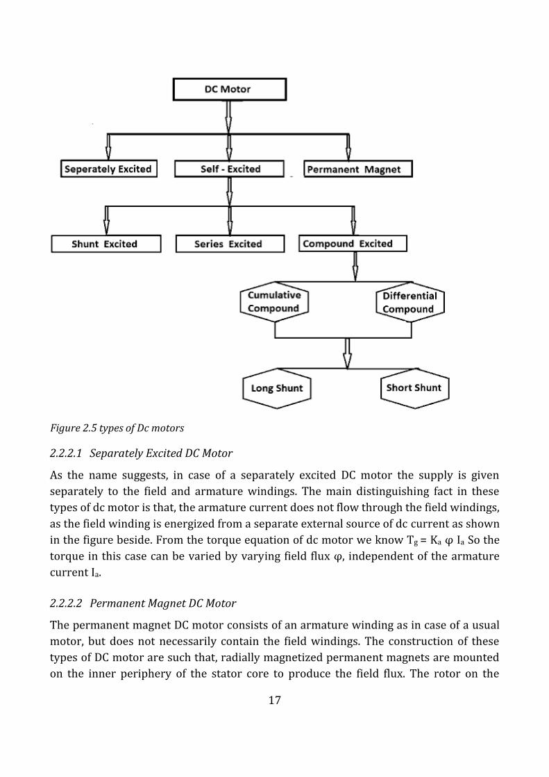
Further classification of dc motors is on the basis of their excitation winding. Field winding may be connected to armature winding (in series or parallel) or it may be separately excited [13]. Figure 2.5 below shows the various types available;
17
2.2.2.1 Separately Excited DC Motor
As the name suggests, in case of a separately excited DC motor the supply is given
separately to the field and armature windings. The main distinguishing fact in these
types of dc motor is that, the armature current does not flow through the field windings,
as the field winding is energized from a separate external source of dc current as shown
in the figure beside. From the torque equation of dc motor we know Tg = Ka φ Ia So the
torque in this case can be varied by varying field flux φ, independent of the armature
current Ia.
2.2.2.2 Permanent Magnet DC Motor
The permanent magnet DC motor consists of an armature winding as in case of a usual
motor, but does not necessarily contain the field windings. The construction of these
types of DC motor are such that, radially magnetized permanent magnets are mounted
on the inner periphery of the stator core to produce the field flux. The rotor on the
Figure 2.5 types of Dc motors

18
other hand has a conventional dc armature with commutator segments and brushes.
The diagrammatic representation of a permanent magnet dc motor is given below.
The torque equation of dc motor suggests Tg = Ka φ Ia. Here φ is always constant, as
permanent magnets of required flux density are chosen at the time of construction and
can’t be changed thereafter.
For a permanent magnet dc motor Tg = Ka1Ia
Where Ka1 = Ka.φ which is another constant. In this case the torque of DC Motor can
only be changed by controlling armature supply.
2.2.2.3 Self-Excited DC Motor
In case of self-excited dc motor, the field winding is connected either in series or in
parallel or partly in series, partly in parallel to the armature winding, and on this basis
its further classified as:-
1. Shunt wound DC motor.
2. Series wound DC motor.
3. Compound wound DC motor
2.2.2.3.1 Parallel (Shunt) Wound DC Motors
A shunt wound DC motor has the armature and field windings connected in parallel.
Figure 2.7 shows a shunt wound DC motor, with an associated speed/torque curve.
Figure 2.6 permanent magnet DC motor and Curves

19
This type of DC motor is probably the most widely used motor in industrial
applications. As indicated in the figure, this type of motor requires two power supplies-
one for the armature and one for the field winding. To understand the characteristic of
these types of DC motor, let's consider the basic voltage equation given by,
[Where E, Eb, Ia, Ra are the supply voltage, back emf, armature current and armature
resistance respectively]
[Since back emf increases with flux φ and angular speed ω]
Now substituting Eb from equation (2) to equation (1) we get,
The torque equation of a dc motor resembles,
This is similar to the equation of a straight line, and we can graphically representing the
torque speed characteristic of a shunt wound self-excited dc motor as
The shunt wound dc motor is a constant speed motor, as the speed does not vary here
with the variation of mechanical load on the output.
Figure 2.7 shunt wound DC motor and curve

20
With constant armature voltage and field winding excitation, this type of motor offers
relatively flat speed/torque characteristics. The starting torque developed can be 250-
300% of the full load torque rating for a short period of time. Speed regulation (speed
fluctuation due to load) is acceptable in many cases between 5-10% of maximum speed,
when operated from a DC drive. Regulation of this amount would be typical when
operated from a drive controller, open loop (no electronic feedback device connected to
the motor shaft).
Because of the need for two power sources, the shunt wound DC motor offers the use of
simplified control for reversing requirements. Direction of any shunt wound motor can
be changed by simply reversing the direction of current flow, in either the armature or
shunt field winding. The capability of armature or field reversal is standard on many DC
drive modules. (In many cases, the reversing of flux and direction is accomplished in the
field winding control. The field winding consumes less than one tenth of the current
compared with the armature circuit. Smaller components and less stress on circuitry is
the result when "field reversal" is used for DC motor control.)
2.2.2.3.2 Series Wound DC Motors
A series wound DC motor has the armature and field windings connected in a series
circuit. Figure below shows a series wound DC motor, with an associated speed/torque
curve.
Now to determine the torque speed characteristic of these types of DC motor, let's get
to the torque speed equation.
From the circuit diagram we can see that the voltage equation gets modified to
Whereas back emf remains Eb = kaφω
Neglecting saturation we get,
[Since field current = armature current]
From equation (5) & (6)

21
From this equation we obtain the torque speed characteristic as shown in Figure 2.8. In
a series wound dc motor, the speed varies with load. And operation wise this is its main
difference from a shunt wound dc motor. The starting torque developed can be as high
as 500% of the full load rating. The high starting torque is a result of the fact that the
field winding is operated below the saturation point. An increase in load will cause a
corresponding increase in both the armature and field winding current, which means
that both armature and field winding flux increase together. As you recall, the torque
developed in a DC motor is the result of the interaction of armature and field winding
fluxes. Torque in a DC motor increases as the square of the current value.
A series wound DC motor will generate a larger torque increase compared with a shunt
wound DC motor for given increase in current. Conversely, the speed regulation of a
series wound DC motor is poorer than that of a shunt wound motor. As stated above,
when the load increases, so does the armature and field winding current. When the load
is reduced, so is the current, which causes a corresponding decrease in flux density. As a
reminder of DC motor basics, when the field flux is reduced once the motor is running, a
decrease in "hold-back" electromotive force (EMF) occurs. Therefore, when the load is
reduced, speed increases. If the load were completely removed, the speed of the motor
would increase to infinity-basically until the motor destroys itself. As a safety
precaution, series wound DC motors should always be connected to a load.
2.2.2.3.3 Compound Wound DC Motors
A compound wound DC motor is basically a combination of shunt wound and series
wound configurations. This type of motor offers the high starting torque of a series
wound motor. In addition, it offers constant speed regulation (speed stability) under a
given load. This type of motor is used whenever speed regulation cannot be obtained
Figure 2.8 series DC motor

22
from either a series or shunt wound motor. The torque and speed characteristics are
the result of placing a portion of the field winding circuit in series with the armature
circuit. This additional armature winding circuit is not to be confused with the
commutating winding or inter-poles. The commutation windings also have a few turns,
but have the duty of neutralizing armature reaction.
When a load is applied, there is a corresponding increase in current through the series
winding, which also increases the field flux. This in turn increases the torque output of
the motor. The excitation of compound wound dc motor can be of two types depending
on the nature of compounding.
2.2.2.3.3.1 Cumulative Compound DC Motor
When the shunt field flux assists the main field flux, produced by the main field
connected in series to the armature winding then it’s called cumulative compound dc
motor.
2.2.2.3.3.2 Differential Compound DC Motor
In case of a differentially compounded self-excited dc motor i.e. differential compound
dc motor, the arrangement of shunt and series winding is such that the field flux
produced by the shunt field winding diminishes the effect of flux by the main series
field winding.
The net flux produced in this case is lesser than the original flux and hence does not find
much of a practical application. Both the cumulative compound and differential
compound dc motor can either be of short shunt or long shunt type depending on the
nature of arrangement.
2.2.2.3.3.3 Short Shunt DC Motor
If the shunt field winding is only parallel to the armature winding and not the series
field winding then it’s known as short shunt dc motor or more specifically short shunt
type compound wound dc motor.

23
2.2.2.3.3.4 Long Shunt DC Motor
If the shunt field winding is parallel to both the armature winding and the series field
winding then it’s known as long shunt type compounded wound dc motor or simply
long shunt dc motor.

24
3 DESIGN
In this paper we are concern majorly on controlling DC Motors for electric Vehicle. DC
motor is an electric motor that runs on direct current (DC) electricity. The DC motors
will be used to providing the motive power for the electric vehicles and operate directly
from rechargeable battery of 12V 7AH battery hence allow regenerative braking to be
implemented.
While designing a DC motor control for electric vehicle can be complex, it does become
easier when broken down into its component steps. The following sections detail each
component within the project, as well as how each section is constructed and interacts
with other blocks.
The two stages of this work are the hardware development and software development.
The first stage i.e. the hardware development, has the following sections;
1. H-bridge 2. Display Unit (LCD) 3. Input Unit 4. Motor controller circuit, this includes the circuit for the PIC16F877A
microcontroller and the H-bridge. 5. DC-motor and Mechanical Vehicle Parts (Wheels and Gears) 6. Dc Power Supply and charging unit
The second stage i.e. the software development, has two parts which are;
1) To develop embedded system software using the MikroC PRO for PIC16F877A
microcontroller.
2) Simulating the control system using Proteus software.
3.1 HARDWARE DEVELOPMENT
The block diagram of the system is shown in Figure 3.1

25
3.1.1 H-BRIDGE
An H-Bridge or full bridge converter is a switching configuration composed of four
switches in this case MOSFETs in an arrangement that resembles an H and enables a
voltage to be applied across a load in either direction [14]. These circuits are often used
in robotics and other applications to allow DC motors to run forwards and backwards.
Figure 3.2 h-bridge
Figure 3.1 block diagram
26
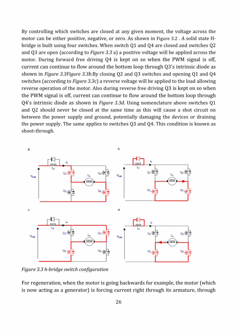
By controlling which switches are closed at any given moment, the voltage across the
motor can be either positive, negative, or zero. As shown in Figure 3.2 . A solid state H-
bridge is built using four switches. When switch Q1 and Q4 are closed and switches Q2
and Q3 are open (according to Figure 3.3 a) a positive voltage will be applied across the
motor. During forward free driving Q4 is kept on so when the PWM signal is off,
current can continue to flow around the bottom loop through Q3's intrinsic diode as
shown in Figure 3.3Figure 3.3b.By closing Q2 and Q3 switches and opening Q1 and Q4
switches (according to Figure 3.3c) a reverse voltage will be applied to the load allowing
reverse operation of the motor. Also during reverse free driving Q3 is kept on so when
the PWM signal is off, current can continue to flow around the bottom loop through
Q4's intrinsic diode as shown in Figure 3.3d. Using nomenclature above switches Q1
and Q2 should never be closed at the same time as this will cause a shot circuit on
between the power supply and ground, potentially damaging the devices or draining
the power supply. The same applies to switches Q3 and Q4. This condition is known as
shoot-through.
Figure 3.3 h-bridge switch configuration
For regeneration, when the motor is going backwards for example, the motor (which
is now acting as a generator) is forcing current right through its armature, through

27
Q2's diode, through the battery (thereby charging it up) and back through Q3's
diode. Regenerative braking is shown in Figure 3.4 below.
Figure 3.4 regenerative braking
TABLE 1 below outlines the positions. Note that shoot-through switch positions are
omitted. The switches used to implement an H-Bridge can be mechanical built from
solid state transistors. Selection of the proper switches varies greatly.
TABLE 1 H-BRIDGE SWITCHES CONFIGURATION
S1 S2 S3 S4 OPERATION PERFORMED
1 0 0 1 Forward Drive
0 1 1 0 Reverse Drive
0 0 0 0 Free Running
1 0 1 0 Brakes
0 1 0 1 Brakes
28
3.1.1.1 CHOICE OF SWITCHING TRANSISTOR
While designing this circuit, a choice had to be made between the two main types of
switches used in power electronics. One is the power MOSFET which is much like a
standard MOSFET but designed to handle relatively large voltages and currents. The
other is the insulated gate bipolar transistor (IGBT) [15]. Each has its advantages, and
there is a high degree of overlap in the specifications of the two. IGBTs tend to be used
in very high voltage applications, nearly always above 200V, and generally above 600W.
They do not have the high frequency switching capability of MOSFETs, and tend to be
used at frequencies lower than 29 kHz. They can handle high currents, are able to
output greater than 5kW, and have very good thermal operating ability, being able to
operate properly above 100 Celsius. One of the major disadvantages of IGBTs is their
unavoidable current tail when they turn off. Essentially, when the IGBT turns off, the
current of the gate transistor cannot dissipate immediately, which causes a loss of
power each time this occurs. This tail is due to the very design of the IGBT and cannot
be remedied. IGBTs also have no body diode, which can be good or bad depending on
the application.
Power MOSFETS have a much higher switching frequency capability than do IGBTs, and
can be switched at frequencies higher than 200 kHz. They do not have as much
capability for high voltage and high current applications, and tend to be used at voltages
lower than 250V and less than 500W [1]. MOSFETs do not have current tail power
losses, which makes them more efficient than IGBTs. Both MOSFETs and IGBTs have
power losses due to the ramp up and ramp down of the voltage when turning on and off
(dV/dt losses). Unlike IGBTs, MOSFETs have body diode. Generally, IGBTs are the sure
bet for high voltage, low frequency (>1000V, <20 kHz) uses and MOSFETs are ideal for
low voltage, high frequency applications (<250V, >200 kHz). In between these two
extremes is a large grey area. In this area, other considerations such as power, percent
duty cycle, availability and cost tend to be the deciding factors. Since this project is
about design of a 12V, DC motor control to be used in electric vehicle MOSFET is the
ideal choice. Also MOSFET being a voltage controlled device, it can be driven directly
from CMOS or TTL logic and the same gate signal can be applied to diagonally opposite
switches since the gate drive current required is very low.
3.1.1.2 ENHANCED N-CHANNEL VS ENHANCED P-CHANNEL MOSFETS
The use of P-Channel MOSFETs on the high side and N-Channel MOSFETs on the low
side is easier, but using all N-Channel MOSFETs and a FET driver, lower “on” resistance
can be obtained resulting in reduced power loss. This requires a more complex circuit

29
since the gate of the high side Mosfet must be driven positive with respect to Vs bus
voltage to turn on Mosfet [15].
3.1.1.3 MOSFETs CHARACTERISTIC
In this project enhanced n-channel Mosfet was chosen for both high side and low side
switches of the H-bridge. For the Mosfet to carry drain current Id (on state) a channel
between the drain and source must be created [1]. This occurs when drain to source
Vgs voltage exceeds the device threshold (Vgs>Vth). Once the channel is induced the
Mosfet can operate in either triode region (drain current proportional to channel
resistance) or the saturation region (constant drain current). The gate to drain voltage
Vgs determines whether the induced channel enters pitch-off or remains in triode
region. When used as a switching device only triode and cut-off region are utilized. The
device will operate at cut-off (off state) when gate to source voltage Vgs is less than
threshold voltage Vth (Vgs<Vth) [1].
a. Triode region; Vds<Vgs-Vth b. Saturation region; Vds>Vgs-Vth c. Cut-off region; Vgs<Vth
3.1.1.4 MOSFET DRIVER
As stated in the previous section, it is beneficial to use N-channel MOSFETs as the high
side switches as well as the low side switches because they have a lower ‘ON’ resistance
and therefore less power loss. However, to do so, the drain of the high side device is
connected to 12V DC power. This is a problem because the 12V is the highest voltage in
the system and in order for the switch to be turned on the voltage at the gate terminal
must be 10V higher than the drain terminal voltage [15]. Therefore, to drive MOSFETs
in the H-Bridge MOSFET driver IC is used with a bootstrap capacitor specifically
designed for driving a half-bridge. After considering various IC options, the ideal choice
was the IR2110, which is rated at 600V, with a gate driving current of 2A and a gate
driving voltage of 10-20V. The turn on and turn off times are 120ns and 94ns
respectively [16].
The MOSFET driver operates from a signal input given from the microcontroller and
takes its power from the battery voltage supply that the system uses. The driver is
capable of operating both the high side and low side devices, but in order to get the
extra 10V for the high side device, an external bootstrap capacitor is charged through a
diode from the 12V power supply when the device is off. Because the power for the

30
driver is supplied from the low voltage source, the power consumed to drive the gate is
small. When the driver is given the signal to turn on the high side device, the gate of the
MOSFET has an extra boost in charge from the bootstrap capacitor, surpassing the
needed 10V to activate the device and turning the switch on [17].
FIGURE 3.5 IR2110 CONNECTION
3.1.1.4.1 BOOTSTRAP CAPACITOR
As shown in FIGURE 3.5, the bootstrap diode and capacitor are the only external
components strictly required for operation in a standard PWM application. Local
decoupling capacitors on the VCC (and digital) supply are useful in practice to
compensate for the inductance of the supply lines. The voltage seen by the bootstrap
capacitor is the VCC supply only. Its capacitance is determined by the following
constraints:
(i) Gate voltage required to enhance MGT
(ii) IQBS - quiescent current for the high-side driver circuitry
(iii) Currents within the level shifter of the control IC
(iv) MGT gate-source forward leakage current
(v) Bootstrap capacitor leakage current
Factor 5 is only relevant if the bootstrap capacitor is an electrolytic capacitor, and can
be ignored if other types of capacitor are used. Therefore it was ignored since only

31
nonelectrolyte capacitors were used. The minimum bootstrap capacitor value was
calculated from the following equation [17]:
𝐶 ≥ 2[2𝑄𝑔+
𝐼𝑞𝑏𝑠
𝑓+𝑄𝑙𝑠+
𝐼𝑐𝑏𝑠(𝑙𝑒𝑎𝑘)
𝑓]
𝑉𝑐𝑐−𝑉𝑓−𝑉𝑙𝑠−𝑉𝑚𝑖𝑛
Where:
Qg = Gate charge of high-side FET=16nC f= frequency of operation=5000Hz ICbs (leak) = bootstrap capacitor leakage current=0A Iqbs (max) = Maximum VBS quiescent current=230µA VCC = Logic section voltage source=12V Vf = Forward voltage drop across the bootstrap diode=1.4V VLS = Voltage drop across the low-side FET or load=1.8V VMin = Minimum voltage between VB and VS=0V Qls = level shift charge required per cycle (typically 5nC for 500 V/600 V MGDs and 20nC for 1200 V MGDs)
The values substituted into this equation were found either in driver datasheet for
IR2110 IC or IRF540 MOSFET datasheet. Using these numbers minimum bootstrap
capacitance value was calculated in the equation below:
𝑐 ≥2[(2∗16∗10−9)+
230∗10−6
5000+(5∗10−9)]
12−1.4−1.8
𝑐 ≥ 18𝑛𝐹
The capacitor value obtained from the above equation is the absolute minimum
required, however due to nature the bootstrap circuit operation, a low value of
capacitor can lead to overcharging which could in turn damage the IC. Therefore to
minimize the risk of overcharging and further reduce ripple on the Vds voltage the
capacitor value obtained is multiplied by a factor of 5 to get a capacitor value of 90nF
where by 100nF is selected.
3.1.1.4.2 BOOTSTRAP DIODE
The bootstrap diode must be able to block the full voltage seen in the specific circuit
and is about equal to the voltage across the power rail. The current rating of the diode is
the product of gate charge times switching frequency. The high temperature reverse
leakage characteristic of this diode can be an important parameter in those applications
where the capacitor has to hold the charge for a prolonged period of time. For the same
reason it is important that this diode have an ultra-fast recovery to reduce the amount
of charge that is fed back from the bootstrap capacitor into the supply [17]. In order to

32
improve decoupling a decoupling capacitors has to be connected directly across the VCC
and COM pins as shown in FIGURE 3.5.
3.1.1.4.3 GATE RESISTOR
Driving MOS-gated power transistors directly from the driver can result in
unnecessarily high switching speeds. Increasing the value of the series gate resistor,
results in a rapid decrease of the amplitude of the negative spike, while the turn-off
time is a linear function of the series gate resistance. Selecting a resistor value just right
from the “knee” in Figure 3.6 provides a good trade-off between the spike amplitude
and the turn-off speed the di/dt losses may have to be reduced by reducing the
switching speed by means of the gate resistor [17]. A graph of the negative spike and
the turn-off time versus series gate resistance is shown in Figure 3.6. The layout should
also minimize the stray inductance in the charge/discharge loops of the gate drive to
reduce oscillations and to improve switching speed and noise immunity, particularly
the “dV/dt induced turn-on”. For this design resistor values of 20 ohms was chosen.
Figure 3.6 series gate resistance vs. Amplitude of negative voltage spike and turn-off time
3.1.2 CONTROL SYSTEM
Control theory is an interdisciplinary branch of engineering and mathematics that deals
with the behavior of dynamical systems .The desired output of a system is called the
reference. When one or more output variables of a system need to follow a certain

33
reference over time, a controller manipulates the inputs to a system to obtain the
desired effect on the output of the system [18].
If we consider an automobile cruise control, it is design to maintain the speed of the
vehicle at a constant speed set by the driver. In this case the system is the vehicle. The
vehicle speed is the output and the control is the vehicle throttle which influences the
engine torque output. One way to implement cruise control is by locking the throttle at
the desired speed but when encounter a hill the vehicle will slow down going up and
accelerate going down. In fact, any parameter different than what was assumed at
design time will translate into a proportional error in the output velocity, including
exact mass of the vehicle, wind resistance, and tire pressure [18] .This type of controller
is called an open-loop controller because there is no direct connection between the
output of the system (the engine torque) and the actual conditions encountered mean
the system does not and cannot compensate for unexpected forces. For the purpose of
keeping the cost of the project at minimum this is the type which is going to be
implemented in this design. Although, there is another type known as closed loop
control system.
For a closed-loop control system, a sensor will monitor the vehicle speed and feedback
the data to its computer and continuously adjusting its control input or the throttle as
desired to ensure the control error to a minimum therefore maintaining the desired
speed of the vehicle [18]. Feedback on how the system is actually performing allows the
controller (vehicle's on board computer) to dynamically compensate for disturbances
to the system, such as changes in slope of the ground or wind speed. An ideal feedback
control system cancels out all errors, effectively mitigating the effects of any forces that
may or may not arise during operation and producing a response in the system that
perfectly matches the user's wishes.
3.1.2.1 PULSE WIDTH MODULATION (PWM)
From research, I have found several ways to control the motor speed using electronic
devices. There is voltage speed control, field speed control (I field), resistance speed
control and PWM technique. These control method have their benefit and
disadvantages respectively which is more focus to efficiency element. In this project
only PWM technique will be consider and be implemented.
Pulse Width Modulation (PWM) uses digital signals to control power applications, as
well as being fairly easy to convert back to analog with a minimum of hardware. Analog
systems, such as linear power supplies, tend to generate a lot of heat since they are
34
basically variable resistors carrying a lot of current. Digital systems don't generally
generate as much heat. Almost all the heat generated by a switching device is during the
transition (which is done quickly), while the device is neither on nor off, but in between.
This is because power follows the following formula:
P = E I, or Watts = Voltage X Current
If either voltage or current is near zero then power will be near zero. PWM takes full
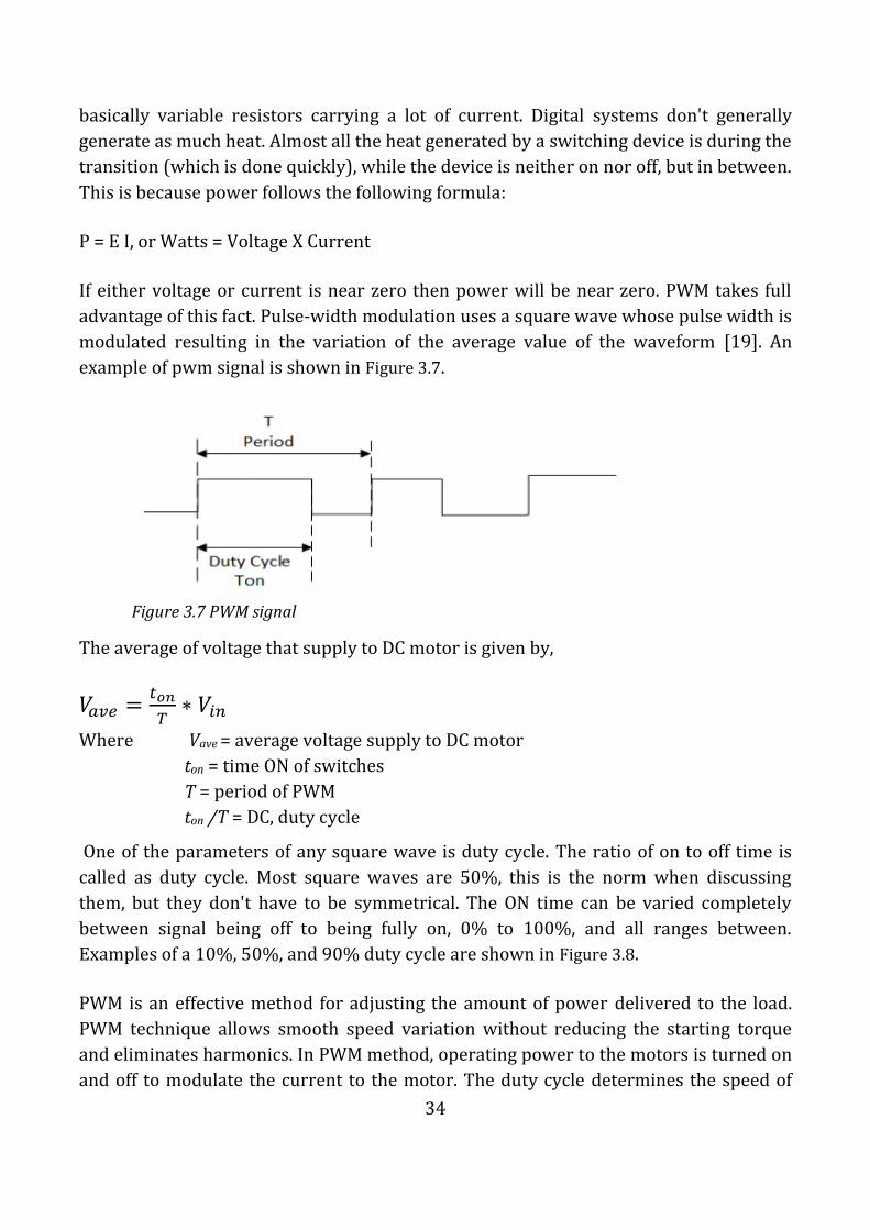
advantage of this fact. Pulse-width modulation uses a square wave whose pulse width is
modulated resulting in the variation of the average value of the waveform [19]. An
example of pwm signal is shown in Figure 3.7.
The average of voltage that supply to DC motor is given by,
𝑉𝑎𝑣𝑒 =𝑡𝑜𝑛
𝑇∗ 𝑉𝑖𝑛
Where Vave = average voltage supply to DC motor
ton = time ON of switches
T = period of PWM
ton /T = DC, duty cycle
One of the parameters of any square wave is duty cycle. The ratio of on to off time is
called as duty cycle. Most square waves are 50%, this is the norm when discussing
them, but they don't have to be symmetrical. The ON time can be varied completely
between signal being off to being fully on, 0% to 100%, and all ranges between.
Examples of a 10%, 50%, and 90% duty cycle are shown in Figure 3.8.
PWM is an effective method for adjusting the amount of power delivered to the load.
PWM technique allows smooth speed variation without reducing the starting torque
and eliminates harmonics. In PWM method, operating power to the motors is turned on
and off to modulate the current to the motor. The duty cycle determines the speed of
Figure 3.7 PWM signal

35
the motor. The desired speed can be obtained by changing the duty cycle. The Pulse-
Width Modulation (PWM) in microcontroller is used to control duty cycle of DC motor
drive. Since the frequency is held constant while the on-off time is varied, the duty cycle
of PWM is determined by the pulse width. Thus the power increases with increase of
duty cycle in PWM.
3.1.3 MICROCONTROLLER
A microcontroller (sometimes abbreviated µC, uC or MCU) is a small computer on a
single integrated circuit containing a processor core, memory, and programmable
input/output peripherals. Program memory in the form of NOR flash or OTP ROM is
also often included on chip, as well as a typically small amount of RAM. Microcontrollers
are designed for embedded applications. Microcontrollers are used in automatically
controlled products and devices, such as automobile engine control systems,
implantable medical devices, remote controls, office machines, appliances, power
tools, and other systems. The Microcontroller used in this design is PIC16F877A.
3.1.3.1 REASONS FOR CHOOSING PIC MICROCONTROLLER (PIC16F877A)
3.1.3.1.1 INTERNAL ARCHITECTURE
PIC16F877a has Harvard architecture. Harvard architecture is a newer concept than
von Neumann [20]. It rose out of the need to speed up the work of a microcontroller. In
Harvard architecture data bus and address bus are separate. Thus a greater flow of data
is possible through the central processing unit and of course a greater speed of work.
Separating a program from data memory makes it further possible for instructions not
to have to be 8-bits instructions which allows for all instructions to be one word
instructions.
Figure 3.8 examples of PWM signal

36
3.1.3.1.2 INSTRUCTION SET
It is also typical for Harvard architecture to have fewer instructions than von-
Neumann's, and to have instructions usually executed in one cycle. Microcontrollers
with Harvard architecture are also called "RISC microcontrollers" [21]. Stands for
Reduced Instruction Set Computer. Microcontrollers with von-Neumann's architecture
are called 'CISC microcontrollers', which stands for Complex Instruction Set Computer.
PIC16F877A is a RISC microcontroller that means it has a reduced set of instructions;
more precisely 35 instructions. Advantages of RISC is that the microcontroller is fast
and it’s easy to learn programming language needed to program it and the user only
sees the final results [22].
3.1.3.1.3 COST
PIC16F877A is an 8 bit microcontroller classified under medium range
microcontrollers which makes it very cost competitive with other similar products in
the market and hence its pocket friendly. Due to its low cost the overall cost of the
inverter ends up being low and market competitive given that the microcontroller is the
most expensive chip in the design.
3.1.3.1.4 AVAILABILITY IN THE MARKET
Since in our country we don’t have a plant to fabricate microchips it is very important
to choose a chip which readily available in the local market to avoid incurring extra cost
of shipping. PIC16F877A was available in the local stores hence the reason to using it.
PIC16F877a perfectly fits many uses, from automotive industries and controlling home
appliances to industrial instruments, remote sensors, electrical door locks and safety
devices. It is also ideal for smart cards as well as for battery-supplied devices because of
its low power consumption [22].
3.1.4 LCD DISPLAY UNIT
A suitable display unit is required to display the gear engaged which selects the mode of
operation of the driving motor and also show the speed at which the vehicle is moving.
A 16x2 Liquid Crystal Display is a low power, low cost, basic electronic display. A 16x2
LCD means it can display 16 characters per line and there are 2 such lines. In this LCD
each character is displayed in 5x7 pixel matrix. This LCD has two registers, namely,
Command and Data. The command register stores the command instructions given to
the LCD. A command is an instruction given to LCD to do a predefined task like
initializing it, clearing its screen, setting the cursor position, controlling display etc. The
data register stores the data to be displayed on the LCD. The data is the ASCII value of

37
the character (measured distance) to be displayed on the LCD [23]. The Figure 3.9
below shows LCD screen chosen for this project.
Figure 3.9 16X2 LCD display
3.1.5 INPUT UNIT
In order to be able to select different types of operation a suitable input was to be
selected capable of communicating with the microcontroller and relaying the command
from operator efficiently and fast. Several factors were considered such as the size,
weight and mode of interconnection either wireless or wired. An ideal and user friendly
would have been the wireless mode of connection but given the complicity of the circuit
needed and the cost of implementation 4 way DIP switch was selected instead. 2
switches was programmed to emulate function of gears in a vehicle while the third
switch be the brake paddle and the fourth accelerating paddle.
3.1.6 DC MOTOR
There are several types of DC motors that are available their advantages, disadvantages,
and other basic information are listed below in Table 2 [1]. In this design DC geared
motor operating at rated voltage 12V and no load speed of 200rpm was selected to be
used due to its low cost and small size and also availability in the market.

38
Table 2 Advantages and disadvantages of various types of DC motor
TYPE ADVANTAGES DISADVANTAGES
DC Geared Motor Very precise speed and position control. High Torque at low speed.
Low speed. Mechanical wear and require regular servicing
DC Motor w/field coil Wide range of speeds and torques. More powerful than permanent magnet motors
Require more current than permanent magnet motors, since field coil must be energized. Generally heavier than permanent magnet motors. More difficult to obtain.
DC permanent magnet motor
Small, compact, and easy to find. Very inexpensive
Generally small. Cannot vary magnetic field strength.
Gasoline (small two stroke) Very high power/weight ratio. Provide Extremely high torque. No batteries required.
Expensive, loud, difficult to mount, very high vibration.
3.1.7 POWER SUPPLY
Signal generation begins with the power supply for the microcontroller. As a battery’s
stored energy depletes, its voltage is reduced. Several of the amplifiers in the control
signal generation circuits rely on the rail voltages to charge and discharge capacitors
which cause a controlled oscillation Generally speaking, the correct voltage supply is of
utmost importance for the proper functioning of the microcontroller system.
For a proper function of this circuit design, it is necessary to provide 2 stable power
rails source of supply. One to power low voltage components of 5V and another 12V to
drive high voltage electronics such as IR2112 Mosfet driver and the DC motor.
According to technical specifications by the manufacturer of PIC microcontroller,
supply voltage should move between 2.0V to 5.0V in all versions [21]. The solution
comes in the form of a linear voltage regulator. There are other types of voltage
regulation, mainly switching regulators, but their benefits are of little use in powering

39
chips. Switching regulators are more efficient than linear regulators and they have the
ability to boost voltages, but the supply voltage is well-defined and the op-amps require
very little power relative to what a lead acid battery can provide. Thus, the simplest
solution to the source of supply is using the voltage stabilizer LM7805 which gives
stable +5V on its output [24]. Its connection as per datasheet is shown in Figure 3.10
below.
Figure 3.10 Voltage regulator circuit
3.1.8 CIRCUIT PROTECTION
MOSFETs turn OFF more slowly than they turn ON. If you attempt to turn on a high side
MOSFET at the same time you're turning OFF a low-side MOSFET (or vice versa), you
will wind up having both of them turned on at the same time, causing the dreaded
"shoot-through" condition, which will lead to damage of the components [17]. For this
reason one of the major factor in inverter device is its ability to protect itself from
surges that could damage the circuitry. The IR2110 used in this design does not have
built-in optoisolators hence it does not provide for "dead time" which is much needed
in order to avoid short circuiting of the rail voltage. Another protection of the circuit
needed is MOSFET gate protection, which employed a resistor between “gate” and
“source”. It prevents accidental turn on of the MOSFET by external noise usually at
startup when the gate is floating. The MOSFET may sometimes turn on with a floating
gate because of the internal drain to gate "Miller" capacitance. A gate to source resistor
acts as a pull-down to ensure a low level for the MOSFET.
The principle of operation is that when the parasitic capacitance of the circuit comes
into play. The resistor creates an RC circuit complete with its time constant. And this RC

40
delays the time the circuit switches ON just enough to allow the complementary part of
the bridge circuit to switch OFF. Typical values of this resistor a 1 kΩ, 10 kΩ, or 100 kΩ
depending on the rail voltage of the h bridge. Some of the factors which need to be
considered when selecting the value of resistor are;
1. The resistance needs to be low enough so that the gate is discharged in time, and
can be held in the low state despite capacitive coupling from startup transients.
The gate of a FET has very high resistance and mostly looks capacitive. Even a
large resistor can eventually discharge the gate capacitance. The limiting factor
there is how fast the device might be turned off and then back on again. Usually
this isn't the issue though. Keeping the gate low despite startup transients is
much harder to judge since it's almost impossible to know where these
transients may be coming from and how strongly they will couple onto the gate
node.
2. On the other end, pull-down resistor should not draw significant current that
would otherwise go to driving the gate high quickly or at all.
3.2 SOFTWARE DESIGN
The program design for this project was done in C language using MikroC compiler. It is
easy to develop and implement PIC microcontroller like the one used in this design PIC
16F877A program in C language due to its flexibility, easiness of Programming and
debugging. After writing the program code it was burned to the microcontroller using
the Pickit 2 programmer.
The flow chart of the program is shown in Figure 3.11 below. The code execution starts
by initializing ports, LCD module and setting all analogue channels off. Next, variables
used in codding are defined and interrupt function called. By using interrupt function to
monitor the input from the 4 channel DIP switch the microcontroller is able to respond
to user command without affecting the normal execution of the program.
Main function which defines the start of execution code is now called and pulse width
modulation modules of the microcontroller initialized. If input issued by the driver
changes the code executes a switch function where the command is compared among

41
YES NO
YES
NO
YES
NO
NO
YES
START
INITIALIZE LCD MODULE INITIALIZE MICROCONTROLLER PORTS INITIALIZE PWM1 & PWM2 MODULES
DEFINE VARIABLES
START EXECUTING INTERRUPT FUNCTION
IF INPUT ≠ OLD INPUT?
SWITCH INPUT = 48?
START PWM1 STOP PWM2 SET RC1 BIT TO HIGH SET RC2 BIT TO LOW PRINT MOTOR STATUS TO LCD
IF RBO BIT = 0?
INCREASE DUTY CYCLE PRINT SPEED
SWITCH INPUT = 80?
C1
C2
C3
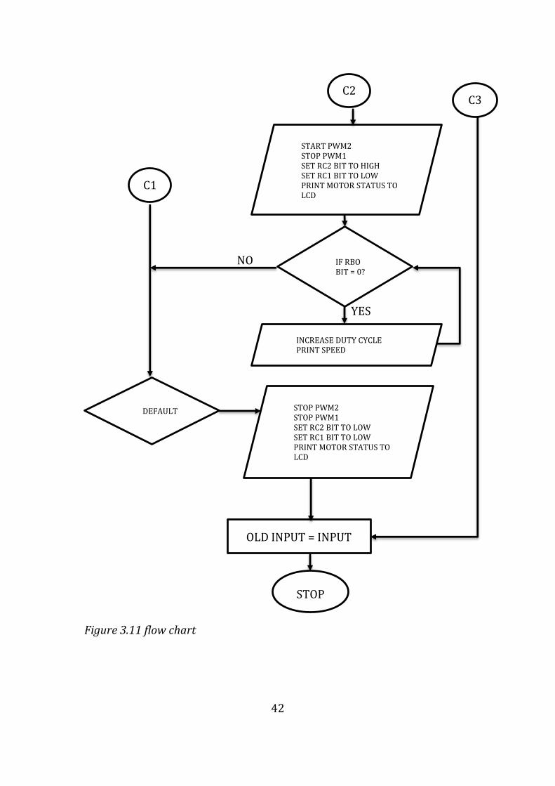
42
YES
YES
NO
START PWM2 STOP PWM1 SET RC2 BIT TO HIGH SET RC1 BIT TO LOW PRINT MOTOR STATUS TO LCD
IF RBO BIT = 0?
INCREASE DUTY CYCLE PRINT SPEED
C1
C2 C3
DEFAULT STOP PWM2 STOP PWM1 SET RC2 BIT TO LOW SET RC1 BIT TO LOW PRINT MOTOR STATUS TO LCD
STOP
OLD INPUT = INPUT
Figure 3.11 flow chart

43
different cases and if any one of them matches the input condition the code sequence in
it is executed hence driving the car either forward or reverse or regenerative braking.
The interrupt function takes advantage of provided RB0 external interrupt and port B
<4-7> pins interrupt capabilities. If the status of those pins change at any given time the
interrupt function will update the input variable therefor making the program able to
respond to the new command from the driver immediately. LEDs with different colors
are connected to port E which has three pins. These LEDs are used to indicate the status
of the car green when the car is engaged in forward drive, yellow when the car is
reversing and red when it’s braking.

44
4 RESULTS
4.1 SIMULATION
4.1.1 CIRCUIT DIAGRAM
Figure 4.1 circuit diagram

45
4.1.2 CIRCUIT DESCRIPTION
Simulation of the PWM DC motor control circuit was carried out using Proteus
simulation software version 8.1 .Various blocks of the circuit were interconnected and
virtual instruments of the simulator used to observe and analyze results. Compiled hex
file from mikroc pro was attached to the properties of the microcontroller.
Pins 13 and 14 of the microcontroller are connected to 8MHz quartz crystal. A stable 5
volts to power the microcontroller was provided from the output of 7805 IC voltage
regulator. The LEDs connected in pin 8, 9 and 10 color green, blue and red respectively
will light green to indicate that the car is moving forward, blue when the car is
reversing and red when braking. Also, another green led was connected to the power
supply to show when the power is switched on and go off when the power is
disconnected.
Pins 37, 38, 39 and 40 of microcontroller was programmed as input ports and 4 way dip
switch connected. When pin 40 is in logic low the car will be engaged in forward drive
and it can be accelerated by setting pin 37 low or decelerated by setting pin 38 low.
Likewise, reverse driving can be engaged by setting pin 39 to logic low. During forward
driving pin 16 and 18 will output low state which will in turn switch off transistor Q2
and Q4 pin 23 will be high to switch on transistor Q4 and pin 17 will output a pulse
width modulated signal at a frequency of 5 kHz to drive transistor Q1. To reverse the
car pin 23 and 17 will be off, pin 18 will be on and pin 16 will output a pulse width
modulated signal of 5 kHz this way current will flow in opposite direction.
During simulation IR2112 IC is used instead of IR2110 but there function are similar
and they do operate the same way. Pins 10 and pin 12 receive logic inputs from the
microcontroller to drive high side and low side Mosfet respectively. Signal from pin 12
is passed to pin 1 just as it is without being stepped up and from pin 1 is connected to
low side Mosfet gate through a gate resistor. That from pin 10 is used to charge and
discharge bootstrap capacitor which in turn provides the much needed high voltage to
drive high side Mosfet through gate resistor.
In order to observe regenerative braking led was connected between 12V power rail of
H-bridge and battery with its cathode connected to positive terminal of the battery. This
is made possible by use of relay which is controlled by pin 25 of the microcontroller to
bypass the led during motoring state and connect to led during regenerative state.
When the performance of the circuit was analyzed for different conditions. The circuit
was able to drive the car up to maximum speed.

46
4.2 SIMULATION RESULTS
The working model of the proposed PWM based DC motor control for electric vehicle
using a microcontroller was successfully designed, simulated and implemented on a
breadboard.
4.2.1 POWER SUPPLY OUTPUT
Using proteus virtual voltmeter the supply voltage which is very important for
successful implementation of this project was tested and analyzed. The circuit was
found to generate a stable 5V dc supply from input voltage of 12V from battery.
Figure 4.2 voltage regulator output
4.2.2 MICROCONTROLLER OUTPUTS
.
Figure 4.3 forward drive microcontroller output
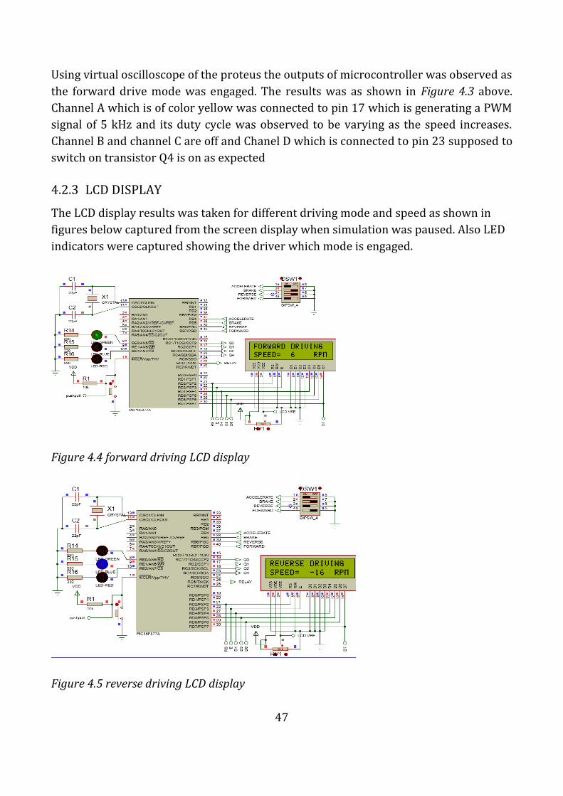
47
Using virtual oscilloscope of the proteus the outputs of microcontroller was observed as
the forward drive mode was engaged. The results was as shown in Figure 4.3 above.
Channel A which is of color yellow was connected to pin 17 which is generating a PWM
signal of 5 kHz and its duty cycle was observed to be varying as the speed increases.
Channel B and channel C are off and Chanel D which is connected to pin 23 supposed to
switch on transistor Q4 is on as expected
4.2.3 LCD DISPLAY
The LCD display results was taken for different driving mode and speed as shown in
figures below captured from the screen display when simulation was paused. Also LED
indicators were captured showing the driver which mode is engaged.
Figure 4.4 forward driving LCD display
Figure 4.5 reverse driving LCD display

48
Figure 4.6 regenerative braking LCD display
4.2.4 H-BRIDGE OUTPUTS
The output of the H-bridge was measured and captured for the different driving mode
using virtual digital oscilloscope as shown in figures below
4.2.4.1 FORWARD MODE
Figure 4.7 H-bridge output forward mode

49
4.2.4.2 REVERSE MODE
Figure 4.8 H-bridge output reverse mode

50
4.3 EXPERIMENTAL RESULT
After simulation and determination of specifications of the overall design, a prototype
was built of the final circuit as shown below Figure 4.9. First a preliminary prototype
was constructed on a breadboard to test the components before being soldered
permanent on a PCB. MOSFETs are attached to heat-sinks due to their nature of
generating heat especially at high switching frequency. When testing on breadboard the
motor had not been mounted on the car and hence regenerative braking could not be
observed since it had no momentum to keep it rotating when the supply is cut off
Figure 4.9 breadboard constructed circuit
After carefully wiring the circuit, checking component polarities and layout of the
various segments of the construction were separately tested for their workability. The
output of the microcontroller was observed using laboratory oscilloscope before
connecting the circuit to ensure that control signals were being generated as required.
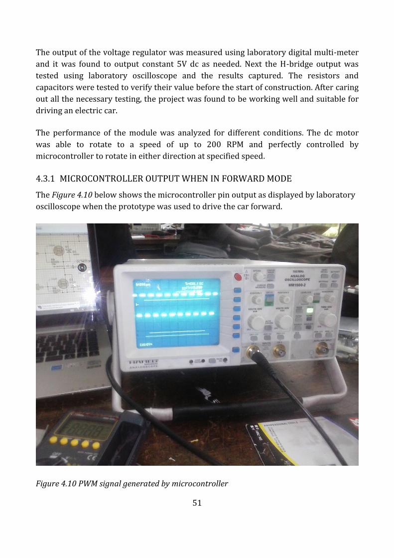
51
The output of the voltage regulator was measured using laboratory digital multi-meter
and it was found to output constant 5V dc as needed. Next the H-bridge output was
tested using laboratory oscilloscope and the results captured. The resistors and
capacitors were tested to verify their value before the start of construction. After caring
out all the necessary testing, the project was found to be working well and suitable for
driving an electric car.
The performance of the module was analyzed for different conditions. The dc motor
was able to rotate to a speed of up to 200 RPM and perfectly controlled by
microcontroller to rotate in either direction at specified speed.
4.3.1 MICROCONTROLLER OUTPUT WHEN IN FORWARD MODE
The Figure 4.10 below shows the microcontroller pin output as displayed by laboratory
oscilloscope when the prototype was used to drive the car forward.
Figure 4.10 PWM signal generated by microcontroller

52
4.3.2 OUTPUT WHEN THE CAR IS MOVING FORWARD
Figure 4.11 H-bridge output using oscilloscope
Figure 4.12 LCD and LEDs output
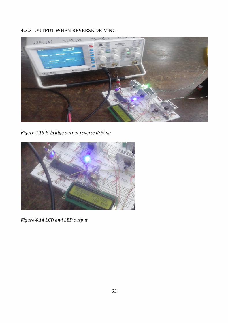
53
4.3.3 OUTPUT WHEN REVERSE DRIVING
Figure 4.13 H-bridge output reverse driving
Figure 4.14 LCD and LED output

54
5 CONCLUSION
Applications of high performance DC motor drives in area such as electric elevators,
electric vehicle, electric trains and electric motorcycles require direction and speed
control to perform tasks. DC motors have direction and a speed control capability,
which means that speed and direction of rotation can be changed at any time to meet
new condition.
The aim of this work which is to design a PWM based DC motor control for electric
vehicle using a microcontroller to control the direction and speed of a vehicle has been
achieved. By reversing the polarity of DC motor contacts, the direction of a DC motor
can be reversed. Also varying the PWM signal from microcontroller to the motor driver,
motor speed can be controlled.
In conclusion, the overall aim of this project was met, a fully functional electric vehicle
with regenerative braking was built. The vehicle was further made user friendly by in
cooperating LCD display which shows the driver the speed at which he or she is driving
at and also the gear engaged. Ultimately the limiting factor was time. Anyone continuing
this project in the future should think about reworking the circuitry so that available
power stored in the battery can be displayed and warnings can be issued to the driver
whenever this power is too law, by doing so the driver will be able to plan for his or her
journey in advance.

55
REFERENCES
[1] A. T. B.L Theraja, ELECTRICAL TECHNOLOGY, New Delhi: S. chand and company
Ltd, 2005.
[2] Mehrdad Ehsani,Yimin Gao,Sebastien E. Gay, Ali Emadi, Modern Electric,Hybrid
Electric and Fuel Cell Vehicles, United States of America: CRC Press LLC, 2005.
[3] wikipedia, "Railway_electric_traction," [Online]. Available:
http://en.wikipedia.org/wiki/Railway_electric_traction. [Accessed Feb 2015].
[4] s. freg, "Railway electrification system and engineering," White Word Publications,
2012.
[5] E. Schaal, "electric-motorcycles-with-over-130-miles-of-range," 2014. [Online].
Available: http://wallstcheatsheet.com/automobiles/5-electric-motorcycles-with-
over-130-miles-of-range.html/?a=viewall. [Accessed Feb 2015].
[6] ZEV, "ZEV LRC," [Online]. Available: http://zelectricvehicle.com/22.html.
[Accessed Feb 2015].
[7] wikipedia, "Elevator," [Online]. Available: http://en.wikipedia.org/wiki/Elevator.
[Accessed Feb 2015].
[8] N. R. Council, "Transitions to Alternative Transportation Technologies-Plug-in
Hybrid Electric Vehicles," The National Academies Press, 2010.
[9] wikipedia, "Internal_combustion_engine," [Online]. Available:
http://en.wikipedia.org/wiki/Internal_combustion_engine. [Accessed 9 Feb 2015].
[10] wikipedia, "Electric_car," [Online]. Available:
http://en.wikipedia.org/wiki/Electric_car. [Accessed Feb 2015].
[11] jeff cobb, "hybrid cars," [Online]. Available: http://www.hybridcars.com/the-
three-main-types-of-hybrids-explained/. [Accessed Feb 2015].
[12] wikipedia, "Hybrid electric vehicle," [Online]. Available:
http://en.wikipedia.org/wiki/Hybrid_electric_vehicle. [Accessed Feb 2015].
[13] "Electrical 4you," [Online]. Available: http://electrical4u.com/types-of-dc-motor-
separately-excited-shunt-series-compound-dc-motor/. [Accessed feb 2015].
[14] I. F. C. a. H. F. Leung, "PWM Techniques," A Pure Sine Wave Inverter.
[15] M. H. Rashid, Power Electronics Circuits, Devices and Applications, Prentice-Hall of
India.
[16] Texas instruments, "IR2110".datasheet.
[17] International rectifier, "Application note AN-978".HV Floating MOS-gate driver ICs.

56
[18] N. S. Nise, control system engineering, 2015.
[19] D. S. C. Hsiung, "The Use of PIC Microcontrollers in Multiple DC Motors Control
Applications," Journal of Industrial Technology, vol. 23, 2007.
[20] M. Verle, PIC Microcontrollers - Programming in C, mikroElektronika, 2009.
[21] microchip, "PIC16F87XA".datasheet.
[22] M. Verle, PIC Microcontrollers - Programming in C, mikroElektronika; 1st edition ,
2009.
[23] HITACHI, "LM016L," datasheet, 2015.
[24] Texas Instrument, "LM78XX".datasheet.

57
APPENDIX
PROGRAM CODE
// LCD module connections
sbit LCD_RS at RD2_bit;
sbit LCD_EN at RD3_bit;
sbit LCD_D4 at RD4_bit;
sbit LCD_D5 at RD5_bit;
sbit LCD_D6 at RD6_bit;
sbit LCD_D7 at RD7_bit;
sbit LCD_RS_Direction at TRISD2_bit;
sbit LCD_EN_Direction at TRISD3_bit;
sbit LCD_D4_Direction at TRISD4_bit;
sbit LCD_D5_Direction at TRISD5_bit;
sbit LCD_D6_Direction at TRISD6_bit;
sbit LCD_D7_Direction at TRISD7_bit;
// End LCD module connections
// VARIABLE DEFINITION
short int input, old_input;
signed int SPEED1=0, A;
unsigned int duty_cycle, B ;
char txt1[] = "FORWARD DRIVING";
char txt2[] = "REVERSE DRIVING";
char txt5[] = "BRAKE.SPEED=";
char txt6[] = "REGENERATIVE";
char txt8[] = "SPEED=";
char txt9[] = "RPM";
char SPEED[7];
char *txt10;
// INTERRUPT FUNCTION
void interrupt () {
if (INTCON.RBIF == 1) {
input = PORTB>>5 ; // read portB shifted left 5 bits
INTCON.RBIF = 0; // Clear interrupt flag
} //end intcon.RBIF if
} //end Interrupt

58
// MAIN FUNCTION
void main(){
ADCON1 = 0; // Configure AN pins as digital I/O
OPTION_REG.B7=0; // ENABLE WEAK PULL-UP RESISTOR OF PORT B
TRISB = 0b11110000; // CONFIGURE PORT B INPUT AND OUTPUT PINS
TRISC = 0; // CONFIGURE PORT C PINS AS OUTPUT
TRISD = 0; // CONFIGURE PORT D PINS AS OUTPUT
TRISE = 0; // CONFIGURE PORT E PINS AS OUTPUT
PORTB = 0; // INITIALIZE PORT B
PORTC = 0b01000000; // INITIALIZE PORT C & SWITCH OFF RELAY
PORTD = 0; // INITIALIZE PORT D
PORTE = 0; // INITIALIZE PORT E
INTCON.RBIF = 0; // Clear interrupt flag prior to enable
INTCON.RBIE = 1; // enable on change interrupts
INTCON.GIE = 1; // enable Global interrupts
PWM1_start(); //START PWM1
PWM2_start(); //START PWM2
PWM1_Init(5000); // Initialize PWM1 module at 5KHz
PWM2_Init(5000); // Initialize PWM2 module at 5KHz
Lcd_Init(); // Initialize LCD
Lcd_Cmd(_LCD_CURSOR_OFF); // Cursor off
duty_cycle = 0;
while (1) {
if ((input != old_input )||(RB4_bit == 0)){
switch (input) {
case 3:
RC6_BIT = 1; // SWITCH OFF RELAY
Lcd_Cmd(_LCD_CLEAR); // Clear display
Lcd_Out(1, 1, txt1); // Write message text on LCD
Lcd_Out(2, 1, txt8); // Write message text on LCD
RE1_bit = 0; // SWITCH OF REVERSE INDICATOR
RE2_bit = 0; // SWITCH OF BRAKE INDICATOR
RE0_bit = 1; // INDICATE THAT THE FORWARD GEAR IS ENGAGED
RC3_bit = 0; // SWITCH OFF Q2
PWM2_Stop(); // SWITCH OFF Q3
RC1_bit = 0; // FORCE Q3 TO 0
if (SPEED1 < 0) { // CHECK IF THE CAR IS MOVING FORWARD

59
SPEED1 = 0; // IF NOT RESET THE SPEED TO ZERO
duty_cycle = 0; // RESET DUTY CYCLE TOO
}
delay_us(100); // WAIT FOR THE TRANSISTORS TO RESPOND
RC4_bit = 1; // SWITCH ON Q4
PWM1_start(); //START PWM1 TO DRIVE Q1 PIN
if (RB4_bit == 0) { // CHECK FOR THE ACCELERATOR PADDLE
for ( B = duty_cycle ; B < 100; B += 1) {
duty_cycle += 1;
PWM1_Set_Duty( duty_cycle*2.55); // Set current duty for PWM1
SPEED1 += 2;
IntToStr(SPEED1, SPEED);
txt10 = Ltrim(SPEED);
Lcd_Out(2,9,txt10);
Lcd_Out(2,14,txt9);
delay_us(60);
if (SPEED1 == 200){
Lcd_Out(2,1,"MAXI SPEED 200 ");
while (RB4_BIT == 0){}
}
if ( RB4_bit == 1){
B = 101;
}
}
} else {
PWM1_Set_Duty( duty_cycle*2.55); // Set current duty for PWM1
IntToStr(SPEED1, SPEED);
txt10 = Ltrim(SPEED);
Lcd_Out(2,9,txt10);
Lcd_Out(2,14,txt9);
}
break;
case 5:
RC6_BIT = 1; // SWITCH OFF RELAY
Lcd_Cmd(_LCD_CLEAR); // Clear display
Lcd_Out(1, 1, txt2); // Write message text on LCD
Lcd_Out(2, 1, txt8); // Write message text on LCD
60
RE0_bit = 0; // SWITCH OFF FORWARD INDICATOR
RE2_bit = 0; // SWITCH OFF BRAKE INDICATOR
RE1_bit = 1; // SWITCH ON REVERSE INDICATOR
RC4_bit = 0;
PWM1_Stop();
RC2_bit = 0;
if (SPEED1 > 0) {
SPEED1 = 0;
duty_cycle = 0;
}
delay_us(100);
RC3_bit = 1;
PWM2_start(); //START PWM2
if (RB4_bit == 0) {
for ( B = duty_cycle ; B < 100; B += 1) {
duty_cycle += 1;
PWM2_Set_Duty( duty_cycle*2.55); // Set current duty for PWM1
SPEED1 -= 2;
IntToStr(SPEED1, SPEED);
txt10 = Ltrim(SPEED);
Lcd_Out(2,9,txt10);
Lcd_Out(2,14,txt9);
delay_us(60);
if (SPEED1 == -200){
Lcd_Out(2,1,"MAXI SPEED -200 ");
while (RB4_BIT == 0){}
}
if (RB4_bit == 1){
B = 101;
}
}
} else {
PWM2_Set_Duty( duty_cycle*2.55); // Set current duty for PWM1
IntToStr(SPEED1, SPEED);
txt10 = Ltrim(SPEED);
Lcd_Out(2,9,txt10);
Lcd_Out(2,14,txt9);
}

61
break;
default:
PWM1_Stop();
PWM2_Stop();
RC1_bit = 0;
RC2_bit = 0;
RC3_bit = 0;
RC4_bit = 0;
RE0_bit = 0; // SWITCH OFF FORWARD INDICATOR
RE1_bit = 0; // SWITCH 0FF REVERSE INDICATOR
RE2_bit = 1; // SWITCH ON BRAKE INDICATOR
if (SPEED1 > 0) {
RC6_BIT = 0; // SWITCH ON RELAY
Lcd_Cmd(_LCD_CLEAR); // Clear display
Lcd_Out(1, 1, txt6); // Write message text on LCD
Lcd_Out(2, 1, txt5); // Write message text on LCD
A = SPEED1;
while (A>0) {
SPEED1 -= 2;
duty_cycle -= 1;
A-= 2;
IntToStr(SPEED1, SPEED);
txt10 = Ltrim(SPEED);
Lcd_Out(2,13,txt10);
//delay_us(6);
if (RB5_bit == 1){
A = -10;
}
}
RC6_BIT = 1; // SWITCH OFF RELAY
}else if (SPEED1 < 0) {
RC6_BIT = 0; // SWITCH ON RELAY
Lcd_Cmd(_LCD_CLEAR); // Clear display
Lcd_Out(1, 1, txt6); // Write message text on LCD
Lcd_Out(2, 1, txt5); // Write message text on LCD
A = SPEED1;
while( A<=-2 ) {
SPEED1 += 2;

62
duty_cycle -= 1;
A+= 2;
if (A >= 0){
SPEED1 = 0;
}
IntToStr(SPEED1, SPEED);
txt10 = Ltrim(SPEED);
Lcd_Out(2,13,txt10);
//delay_us(6);
if (RB5_bit == 1){
A = 10;
}
}
RC6_BIT = 1; // SWITCH OFF RELAY
} else {
RC6_BIT = 1; // SWITCH OFF RELAY
Lcd_Cmd(_LCD_CLEAR); // Clear display
Lcd_Out(1, 1, txt6); // Write message text on LCD
Lcd_Out(2, 1, txt5); // Write message text on LCD
Lcd_Out(2,13,"0 ");
}
break;
}
old_input = input;
}
}
}

63
LIST OF MATERIALS
Design Title
Author
Revision
Design Created Sunday, March 22, 2015
Design Last Modified Wednesday, April 22, 2015
Total Parts In Design 57
Category Quantity References Value rating Unit Cost
Capacitors 2 C1,C2 22pF 50V 10.00
Capacitors 2 C3,C4 1uF 50V 10.00
Capacitors 2 C5,C6 100nF 50V 10.00
Capacitors 2 C7,C8 0.1uF 50V 10.00
Resistors 1 R1 10k 2-Jan 5.00
Resistors 4 R2,R3,R4,R5 100 2-Jan 5.00
Resistors 4 R6,R7,R8,R9 100k 2-Jan 5.00
Resistors 2 R10,R17 330 5.00
Resistors 3 R14,R15,R16 330 2-Jan 5.00
Resistors 1 R18 10k 5.00
Resistors 2 R19,R20 4.7k 5.00
Integrated Circuits 1 U1 PIC16F877A 600.00
Integrated Circuits 2 U2,U3 IR2112 200.00
Integrated Circuits 1 U4 7805 25.00
Transistors 4 Q1,Q2,Q3,Q4 IRF540 100V 100.00
Transistors 2 Q5,Q6 BC547 5.00
Diodes 6 D1,D2,D3,D4,D5,D61N4002 1A 40.00
Diodes 1 D7 LED-GREEN 20mA 10.00
Diodes 1 D8 LED-BLUE 20mA 10.00
Diodes 1 D9 LED-RED 20mA 10.00
Diodes 1 D10 1N4148 40.00
Diodes 1 D11 LED-yellow 10.00
Diodes 1 D12 LED-yello 10.00
Miscellaneous 3 BATT,MOTOR,SPEEDCONN-SIL3 10.00
Miscellaneous 1 BATTERY 12V 2000.00
Miscellaneous 1 DC MOTOR 12V 200RPM 1600.00
Miscellaneous 1 LCD1 LM016L 400.00
Miscellaneous 1 PUSH CONN-DIL8 10.00
Miscellaneous 1 RL1 G5CLE-1-DC5 5.00
Miscellaneous 1 RV1 1k 2-Jan 25.00
Miscellaneous 1 X1 CRYSTAL 50.00
electric vehicle
towett festus
Bill Of Materials
Related Documents