Department of Defense Joint Technical Architecture JOINT INTEROPERABILITY JOINT INTEROPERABILITY and and WARRIOR SUPPORT WARRIOR SUPPORT Version 2.0 26 May 1998 DISTRIBUTION STATEMENT A: Approved for public release; distribution unlimited

Welcome message from author
This document is posted to help you gain knowledge. Please leave a comment to let me know what you think about it! Share it to your friends and learn new things together.
Transcript
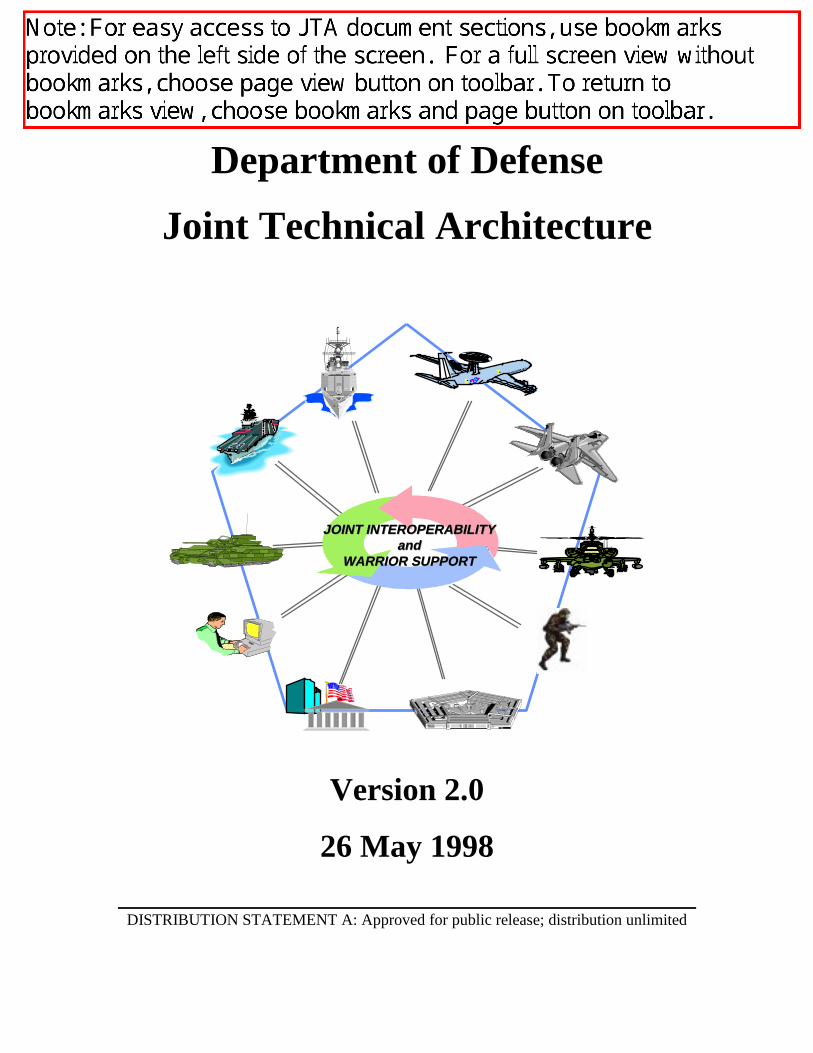
Department of Defense
Joint Technical Architecture
JOINT INTEROPERABILITYJOINT INTEROPERABILITYandand
WARRIOR SUPPORTWARRIOR SUPPORT
Version 2.0
26 May 1998
DISTRIBUTION STATEMENT A: Approved for public release; distribution unlimited

This page intentionally left blank.
iiiJTA Version 2.0
26 May 1998
EXECUTIVE SUMMARY
Effective military operations must respond with a mix of forces, anywhere in the world, at a moment’snotice. The ability for the information technology systems supporting these operations to interoperate –work together and exchange information – is critical to their success. The lessons learned from the recentconflicts of Desert Shield/Desert Storm have resulted in a new vision for the Department of Defense(DoD). Joint Vision 2010 (JV2010) is the conceptual template for how America’s Armed Forces willchannel the vitality and innovation of our people, and leverage technological opportunities to achieve newlevels of effectiveness in joint warfighting. The DoD Joint Technical Architecture (JTA) is crucial toachieving JV2010.
The JTA provides DoD systems with the basis for the needed seamless interoperability. The JTA definesthe service areas, interfaces, and standards (JTA elements) applicable to all DoD systems, and its adoptionis mandated for the management, development, and acquisition of new or improved systems throughoutDoD. The JTA is structured into service areas based on the DoD Technical Reference Model (TRM). TheDoD TRM originated from the Technical Architecture Framework for Information Management (TAFIM),and was developed to show which interfaces and content needed to be identified. These are depicted asmajor service areas in the DoD TRM.
Standards and guidelines in the JTA are stable, technically mature, and publicly available. Whereverpossible, they are commercially supported, and validated off-the-shelf commercial implementations frommultiple vendors are available. Standards and guidelines that do not yet meet these criteria, but areexpected to mature to meet them in the near-term, are cited as “emerging standards” in the expectation thatthey will be mandated in future versions of the JTA.
The JTA consists of two main parts: the JTA core, and the JTA Annexes. The JTA core contains theminimum set of JTA elements applicable to all DoD systems to support interoperability. The JTA Annexescontain additional JTA elements applicable to specific functional domains (families of systems). Theseelements are needed to ensure interoperability of systems within each domain, but may be inappropriate forsystems in other domains. The current version of the JTA, JTA Version 2.0, was extended to includeAnnexes for: the Command, Control, Communications, Computers, Intelligence, Surveillance, andReconnaissance (C4ISR) domain; the Combat Support domain; the Modeling and Simulation domain; andthe Weapon Systems domain. Where subsets of an application domain (subdomains) have specialinteroperability requirements, the JTA includes Subdomain Annexes containing JTA elements applicable tosystems within that subdomain. The intention is that a system within a specific subdomain shall adopt theJTA elements contained in the relevant Subdomain Annex, the JTA elements contained in the parentDomain Annex, and the JTA elements contained in the JTA core.
The JTA is complementary to and consistent with other DoD programs and initiatives aimed at thedevelopment and acquisition of effective, interoperable information systems. These include the DoD’sSpecification and Standards Reform; Implementation of the Information Technology Management ReformAct (ITMRA); Defense Modeling and Simulation Initiative; Evolution of the DoD TRM; DefenseInformation Infrastructure Common Operating Environment (DII COE); and Open Systems Initiative.
Development of the JTA is a collaborative effort, conducted by the JTA Development Group (JTADG),directed by the Technical Architecture Steering Group (TASG), and approved by the ArchitectureCoordination Council (ACC). Members represent the DoD Components (Office of the Secretary of Defense(OSD), the Military Departments, the Organization of the Joint Chiefs of Staff (OJCS), the Unified andSpecified Commands, and the Defense Agencies), and components of the Intelligence Community.
The JTA is a living document and will continue to evolve with the technologies, marketplace, andassociated standards upon which it is based.
ivJTA Version 2.026 May 1998
TABLE OF CONTENTS
EXECUTIVE SUMMARY ......................................................................................................................... iii
SECTION 1: JTA OVERVIEW ............................................................................................................... 1-1
1.1 INTRODUCTION TO THE JOINT TECHNICAL ARCHITECTURE......................................1-21.1.1 Purpose.....................................................................................................................................1-21.1.2 Scope........................................................................................................................................1-31.1.3 Applicability.............................................................................................................................1-31.1.4 Background ..............................................................................................................................1-31.1.5 Architectures Defined ..............................................................................................................1-4
1.1.5.1 Operational Architecture (OA) View...............................................................................1-51.1.5.2 Technical Architecture (TA) View...................................................................................1-51.1.5.3 Systems Architecture (SA) View .....................................................................................1-6
1.2 DOCUMENT ORGANIZATION................................................................................................1-61.2.1 General Organization ...............................................................................................................1-61.2.2 Information Technology Standards ..........................................................................................1-61.2.3 Domain and Subdomain Annexes ............................................................................................1-61.2.4 Appendices (Appendix A, B, C) ..............................................................................................1-8
1.3 KEY CONSIDERATIONS IN USING THE JTA.......................................................................1-81.4 ELEMENT NORMALIZATION RULES...................................................................................1-91.5 JTA RELATIONSHIP TO DOD STANDARDS REFORM.......................................................1-91.6 STANDARDS SELECTION CRITERIA....................................................................................1-91.7 CONFIGURATION MANAGEMENT.....................................................................................1-10
SECTION 2: INFORMATION TECHNOLOGY STANDARDS
2.1 GENERAL................................................................................................................................2.1-12.1.1 Background .......................................................................................................................2.1-12.1.2 Scope.................................................................................................................................2.1-12.1.3 DoD Technical Architecture Framework for Information Management...........................2.1-1
2.1.3.1 TAFIM DoD Technical Reference Model ....................................................................2.1-12.1.3.2 Emerging “Integrated” DoD Technical Reference Model ............................................2.1-3
2.1.4 Mandates ...........................................................................................................................2.1-52.1.4.1 Year 2000 (Y2K) Compliance ......................................................................................2.1-52.1.4.2 Defense Information Infrastructure Common Operating Environment (DII COE).......2.1-5
2.1.5 Organization of Section 2..................................................................................................2.1-6
2.2 INFORMATION PROCESSING STANDARDS ....................................................................2.2-12.2.1 Introduction.......................................................................................................................2.2-2
2.2.1.1 Purpose..........................................................................................................................2.2-22.2.1.2 Scope.............................................................................................................................2.2-22.2.1.3 Background ...................................................................................................................2.2-2
2.2.2 Mandates ...........................................................................................................................2.2-22.2.2.1 Application Software Entity..........................................................................................2.2-22.2.2.2 Application Platform Entity ..........................................................................................2.2-3
2.2.2.2.1 Service Areas ..........................................................................................................2.2-32.2.2.2.1.1 Software Engineering Services ........................................................................2.2-32.2.2.2.1.2 User Interface Services ....................................................................................2.2-32.2.2.2.1.3 Data Management Services..............................................................................2.2-42.2.2.2.1.4 Data Interchange Services................................................................................2.2-4
2.2.2.2.1.4.1 Document Interchange..............................................................................2.2-42.2.2.2.1.4.2 Graphics Data Interchange........................................................................2.2-52.2.2.2.1.4.3 Geospatial Data Interchange.....................................................................2.2-5
vJTA Version 2.0
26 May 1998
2.2.2.2.1.4.4 Still Imagery Data Interchange .................................................................2.2-62.2.2.2.1.4.5 Motion Imagery Data Interchange ............................................................2.2-7
2.2.2.2.1.4.5.1 Video Systems ...................................................................................2.2-72.2.2.2.1.4.5.1.1 Video Imagery ............................................................................2.2-72.2.2.2.1.4.5.1.2 Video Teleconference .................................................................2.2-82.2.2.2.1.4.5.1.3 Video Telemedicine....................................................................2.2-82.2.2.2.1.4.5.1.4 Video Support.............................................................................2.2-8
2.2.2.2.1.4.6 Audio Data Interchange ............................................................................2.2-92.2.2.2.1.4.6.1 Audio Associated with Video ............................................................2.2-9
2.2.2.2.1.4.6.1.1 Audio for Video Imagery............................................................2.2-92.2.2.2.1.4.6.1.2 Audio for Video Teleconference.................................................2.2-92.2.2.2.1.4.6.1.3 Audio for Video Telemedicine .................................................2.2-102.2.2.2.1.4.6.1.4 Audio for Video Support ..........................................................2.2-10
2.2.2.2.1.4.6.2 Audio Not Associated with Video Systems.....................................2.2-102.2.2.2.1.4.7 Multimedia Data Interchange .................................................................2.2-102.2.2.2.1.4.8 Product Data Interchange........................................................................2.2-102.2.2.2.1.4.9 Atmospheric Data Interchange ...............................................................2.2-102.2.2.2.1.4.10 Oceanographic Data Interchange ..........................................................2.2-112.2.2.2.1.4.11 Time of Day Data Interchange..............................................................2.2-11
2.2.2.2.1.5 Graphic Services ............................................................................................2.2-112.2.2.2.1.6 Communications Services..............................................................................2.2-112.2.2.2.1.7 Operating System Services ............................................................................2.2-11
2.2.2.2.2 Application Platform Cross-Area Services ...........................................................2.2-122.2.2.2.2.1 Internationalization Services..........................................................................2.2-122.2.2.2.2.2 Security Services............................................................................................2.2-122.2.2.2.2.3 System Management Services .......................................................................2.2-122.2.2.2.2.4 Distributed Computing Services ....................................................................2.2-13
2.2.2.2.2.4.1 Remote Procedure Computing................................................................2.2-132.2.2.2.2.4.2 Distributed Object Computing................................................................2.2-13
2.2.3 Emerging Standards ........................................................................................................2.2-142.2.3.1 User Interface..............................................................................................................2.2-142.2.3.2 Data Management .......................................................................................................2.2-142.2.3.3 Data Interchange .........................................................................................................2.2-14
2.2.3.3.1 Document Interchange ..........................................................................................2.2-142.2.3.3.2 Graphics Data Interchange....................................................................................2.2-142.2.3.3.3 Virtual Reality Modeling Language .....................................................................2.2-142.2.3.3.4 Geospatial Data Interchange .................................................................................2.2-142.2.3.3.5 Still Imagery Data Interchange .............................................................................2.2-152.2.3.3.6 Motion Imagery Data Interchange ........................................................................2.2-15
2.2.3.3.6.1 Video Systems ...............................................................................................2.2-152.2.3.3.6.1.1 Video Imagery ........................................................................................2.2-152.2.3.3.6.1.2 Video Teleconference .............................................................................2.2-15
2.2.3.3.7 Multimedia Data Interchange ...............................................................................2.2-152.2.3.4 Operating Systems ......................................................................................................2.2-16
2.2.3.4.1 POSIX...................................................................................................................2.2-162.2.3.4.2 UNIX ....................................................................................................................2.2-162.2.3.4.3 Virtual Machines...................................................................................................2.2-16
2.2.3.5 Distributed Computing................................................................................................2.2-16
2.3 INFORMATION TRANSFER STANDARDS ........................................................................2.3-12.3.1 Introduction...........................................................................................................................2.3-2
2.3.1.1 Purpose..........................................................................................................................2.3-22.3.1.2 Scope.............................................................................................................................2.3-22.3.1.3 Background ...................................................................................................................2.3-3
2.3.2 Mandates ...............................................................................................................................2.3-32.3.2.1 End-system Standards ...................................................................................................2.3-3
viJTA Version 2.026 May 1998
2.3.2.1.1 Host Standards..........................................................................................................2.3-32.3.2.1.1.1 Application Support Services ............................................................................2.3-3
2.3.2.1.1.1.1 Electronic Mail............................................................................................2.3-32.3.2.1.1.1.2 Directory Services .......................................................................................2.3-4
2.3.2.1.1.1.2.1 X.500 Directory Services......................................................................2.3-42.3.2.1.1.1.2.2 Lightweight Directory Access Protocol (LDAP)..................................2.3-42.3.2.1.1.1.2.3 Domain Name System (DNS)...............................................................2.3-4
2.3.2.1.1.1.3 File Transfer ................................................................................................2.3-42.3.2.1.1.1.4 Remote Terminal.........................................................................................2.3-42.3.2.1.1.1.5 Network Time Synchronization ..................................................................2.3-42.3.2.1.1.1.6 Bootstrap Protocol (BOOTP) ......................................................................2.3-52.3.2.1.1.1.7 Configuration Information Transfer ............................................................2.3-52.3.2.1.1.1.8 World Wide Web (WWW) Services ...........................................................2.3-5
2.3.2.1.1.1.8.1 Hypertext Transfer Protocol (HTTP)....................................................2.3-52.3.2.1.1.1.8.2 Uniform Resource Locator (URL)........................................................2.3-5
2.3.2.1.1.1.9 Connectionless Data Transfer .....................................................................2.3-52.3.2.1.1.2 Transport Services .............................................................................................2.3-5
2.3.2.1.1.2.1 Transmission Control Protocol (TCP)/User Datagram Protocol (UDP)Over Internet Protocol (IP)..........................................................................2.3-5
2.3.2.1.1.2.1.1 Transmission Control Protocol (TCP) ..................................................2.3-52.3.2.1.1.2.1.2 User Datagram Protocol (UDP)............................................................2.3-62.3.2.1.1.2.1.3 Internet Protocol (IP) ............................................................................2.3-6
2.3.2.1.1.2.2 Open Systems Interconnection (OSI) Transport Over IP-based Networks .2.3-62.3.2.1.2 Video Teleconferencing (VTC) Standards ...............................................................2.3-62.3.2.1.3 Facsimile Standards..................................................................................................2.3-7
2.3.2.1.3.1 Analog Facsimile Standards ..............................................................................2.3-72.3.2.1.3.2 Digital Facsimile Standards ...............................................................................2.3-7
2.3.2.1.4 Secondary Imagery Dissemination Communications Standards ..............................2.3-72.3.2.1.5 Global Positioning System (GPS) ............................................................................2.3-8
2.3.2.2 Network Standards........................................................................................................2.3-82.3.2.2.1 Internetworking (Router) Standards .........................................................................2.3-8
2.3.2.2.1.1 Internet Protocol (IP) .........................................................................................2.3-82.3.2.2.1.2 IP Routing..........................................................................................................2.3-8
2.3.2.2.1.2.1 Interior Routers ...........................................................................................2.3-92.3.2.2.1.2.2 Exterior Routers ..........................................................................................2.3-9
2.3.2.2.2 Subnetworks .............................................................................................................2.3-92.3.2.2.2.1 Local Area Network (LAN) Access...................................................................2.3-92.3.2.2.2.2 Point-to-Point Standards ....................................................................................2.3-92.3.2.2.2.3 Combat Net Radio (CNR) Networking............................................................2.3-102.3.2.2.2.4 Integrated Services Digital Network (ISDN)...................................................2.3-102.3.2.2.2.5 Asynchronous Transfer Mode (ATM) .............................................................2.3-11
2.3.2.3 Transmission Media ....................................................................................................2.3-122.3.2.3.1 Military Satellite Communications (MILSATCOM) .............................................2.3-12
2.3.2.3.1.1 Ultra High Frequency (UHF) Satellite Terminal Standards.............................2.3-122.3.2.3.1.1.1 5-kHz and 25-kHz Service ........................................................................2.3-122.3.2.3.1.1.2 5-kHz Demand Assigned Multiple Access (DAMA) Service ...................2.3-122.3.2.3.1.1.3 25-kHz Time Division Multiple Access (TDMA)/Demand Assigned
Multiple Access (DAMA) Service ............................................................2.3-122.3.2.3.1.1.4 Data Control Waveform............................................................................2.3-122.3.2.3.1.1.5 Demand Assigned Multiple Access (DAMA) Control System.................2.3-13
2.3.2.3.1.2 Super High Frequency (SHF) Satellite Terminal Standards ............................2.3-132.3.2.3.1.2.1 Earth Terminals .........................................................................................2.3-132.3.2.3.1.2.2 Phase Shift Keying (PSK) Modems ..........................................................2.3-13
2.3.2.3.1.2 Extremely High Frequency (EHF) Satellite Payload and TerminalStandards .........................................................................................................2.3-13
2.3.2.3.1.3.1 Low Data Rate (LDR) ...............................................................................2.3-13
viiJTA Version 2.0
26 May 1998
2.3.2.3.1.3.2 Medium Data Rate (MDR)........................................................................2.3-132.3.2.3.2 Radio Communications ..........................................................................................2.3-13
2.3.2.3.2.1 Low Frequency (LF) and Very Low Frequency (VLF) ...................................2.3-132.3.2.3.2.2 High Frequency (HF).......................................................................................2.3-14
2.3.2.3.2.2.1 HF and Automatic Link Establishment (ALE)..........................................2.3-142.3.2.3.2.2.2 Anti-jamming Capability...........................................................................2.3-142.3.2.3.2.2.3 Data Modems ............................................................................................2.3-14
2.3.2.3.2.3 Very High Frequency (VHF) ...........................................................................2.3-142.3.2.3.2.4 Ultra High Frequency (UHF)...........................................................................2.3-14
2.3.2.3.2.4.1 UHF Radio ................................................................................................2.3-142.3.2.3.2.4.2 Anti-jamming Capability...........................................................................2.3-14
2.3.2.3.2.5 Super High Frequency (SHF) ..........................................................................2.3-142.3.2.3.2.6 Link 16 Transmission Standards......................................................................2.3-14
2.3.2.3.3 Synchronous Optical Network (SONET) Transmission Facilities .........................2.3-152.3.2.4 Network and Systems Management ............................................................................2.3-15
2.3.2.4.1 Data Communications Management.......................................................................2.3-152.3.2.4.2 Telecommunications Management .........................................................................2.3-15
2.3.3 Emerging Information Transfer Standards..........................................................................2.3-162.3.3.1 End-system Standards .................................................................................................2.3-16
2.3.3.1.1 Internet Standards ...................................................................................................2.3-162.3.3.1.2 Video Teleconferencing (VTC) Standards .............................................................2.3-172.3.3.1.3 Space Communication Protocol Standards.............................................................2.3-17
2.3.3.2 Network Standards......................................................................................................2.3-182.3.3.3 Military Satellite Communications (MILSATCOM)..................................................2.3-192.3.3.4 Radio Communications...............................................................................................2.3-192.3.3.5 Network Management.................................................................................................2.3-19
2.4 INFORMATION MODELING, METADATA, AND INFORMATION EXCHANGESTANDARDS ..........................................................................................................................2.4-1
2.4.1 Introduction...........................................................................................................................2.4-12.4.1.1 Purpose..........................................................................................................................2.4-12.4.1.2 Scope.............................................................................................................................2.4-12.4.1.3 Background ...................................................................................................................2.4-1
2.4.2 Mandates ...............................................................................................................................2.4-22.4.2.1 Activity Model ..............................................................................................................2.4-22.4.2.2 Data Model....................................................................................................................2.4-32.4.2.3 DoD Data Definitions ...................................................................................................2.4-3
2.4.2.3.1 DoD Date Standards .................................................................................................2.4-32.4.2.4 Information Exchange Standards ..................................................................................2.4-4
2.4.2.4.1 Information Exchange Standards Applicability........................................................2.4-42.4.2.4.2 Tactical Information Exchange Standards ................................................................2.4-4
2.4.2.4.2.1 Bit-oriented Formatted Messages ......................................................................2.4-42.4.2.4.2.2 Character-based Formatted Messages................................................................2.4-5
2.4.3 Emerging Standards ..............................................................................................................2.4-52.4.3.1 Activity Modeling .........................................................................................................2.4-52.4.3.2 Data Modeling...............................................................................................................2.4-52.4.3.3 DoD Data Definitions ...................................................................................................2.4-62.4.3.4 Information Exchange Standards ..................................................................................2.4-6
2.5 HUMAN-COMPUTER INTERFACE STANDARDS.............................................................2.5-12.5.1 Introduction...........................................................................................................................2.5-1
2.5.1.1 Purpose..........................................................................................................................2.5-12.5.1.2 Scope.............................................................................................................................2.5-12.5.1.3 Background ...................................................................................................................2.5-1
2.5.2 Mandates ...............................................................................................................................2.5-22.5.2.1 General ..........................................................................................................................2.5-2

viiiJTA Version 2.026 May 1998
2.5.2.1.1 Character-based Interfaces........................................................................................2.5-22.5.2.1.2 Graphical User Interface...........................................................................................2.5-2
2.5.2.2 Style Guides ..................................................................................................................2.5-22.5.2.2.1 Commercial Style Guides .........................................................................................2.5-3
2.5.2.2.1.1 X-Window Style Guides....................................................................................2.5-32.5.2.2.1.2 Windows Style Guide ........................................................................................2.5-3
2.5.2.2.2 DoD Human-Computer Interface (HCI) Style Guide ...............................................2.5-32.5.2.2.3 Domain-level Style Guides.......................................................................................2.5-42.5.2.2.4 System-level Style Guides........................................................................................2.5-4
2.5.2.3 Symbology ....................................................................................................................2.5-42.5.3 Emerging Standards ..............................................................................................................2.5-4
2.6 INFORMATION SYSTEMS SECURITY STANDARDS ......................................................2.6-12.6.1 Introduction.............................................................................................................. .............2.6-2
2.6.1.1 Purpose..........................................................................................................................2.6-22.6.1.2 Scope.............................................................................................................................2.6-22.6.1.3 Background ...................................................................................................................2.6-2
2.6.2 Mandates ...............................................................................................................................2.6-32.6.2.1 Introduction...................................................................................................................2.6-32.6.2.2 Information Processing Security Standards ..................................................................2.6-3
2.6.2.2.1 Application Software Entity Security Standards ......................................................2.6-32.6.2.2.2 Application Platform Entity Security Standards.......................................................2.6-3
2.6.2.2.2.1 Data Management Services................................................................................2.6-32.6.2.2.2.2 Operating System Services Security..................................................................2.6-3
2.6.2.2.2.2.1 Security Auditing and Alarms Standards ....................................................2.6-32.6.2.2.2.2.2 Authentication Security Standards ..............................................................2.6-4
2.6.2.3 Information Transfer Security Standards ......................................................................2.6-42.6.2.3.1 End-system Security Standards ................................................................................2.6-4
2.6.2.3.1.1 Host Security Standards.....................................................................................2.6-42.6.2.3.1.1.1 Security Algorithms ....................................................................................2.6-42.6.2.3.1.1.2 Security Protocols .......................................................................................2.6-52.6.2.3.1.1.3 Evaluation Criteria Security Standards .......................................................2.6-5
2.6.2.3.2 Network Security Standards .....................................................................................2.6-52.6.2.3.3 Transmission Media Security Standards...................................................................2.6-5
2.6.2.4 Information Modeling, Metadata, and Information Security Standards........................2.6-62.6.2.5 Human-Computer Interface Security Standards............................................................2.6-6
2.6.3 Emerging Standards ..............................................................................................................2.6-62.6.3.1 Introduction...................................................................................................................2.6-62.6.3.2 Information Processing Security Standards ..................................................................2.6-6
2.6.3.2.1 Application Software Entity Security Standards ......................................................2.6-62.6.3.2.1.1 Evaluation Criteria Security Standards ..............................................................2.6-62.6.3.2.1.2 World Wide Web Security Standards ................................................................2.6-6
2.6.3.2.2 Application Platform Entity Security Standards.......................................................2.6-72.6.3.2.2.1 Software Engineering Services Security............................................................2.6-7
2.6.3.2.2.1.1 Generic Security Service (GSS)-Application Program Interface (API)Security .......................................................................................................2.6-7
2.6.3.2.2.1.2 POSIX Security Standards ..........................................................................2.6-72.6.3.2.2.2 Operating System Services Security..................................................................2.6-7
2.6.3.2.2.2.1 Evaluation Criteria Security Standards .......................................................2.6-72.6.3.2.2.2.2 Authentication Security Standards ..............................................................2.6-8
2.6.3.2.2.3 Distributed Computing Services Security Standards .........................................2.6-82.6.3.3 Information Transfer Security Standards ......................................................................2.6-8
2.6.3.3.1 End-system Security Standards ................................................................................2.6-82.6.3.3.1.1 Host Security Standards.....................................................................................2.6-8
2.6.3.3.1.1.1 Security Protocols .......................................................................................2.6-82.6.3.3.1.1.2 Public Key Infrastructure Security Standards .............................................2.6-9

ixJTA Version 2.0
26 May 1998
2.6.3.3.2 Network Security Standards .....................................................................................2.6-92.6.3.3.2.1 Internetworking Security Standards...................................................................2.6-9
2.6.3.4 Information Modeling, Metadata, and Information Security Standards......................2.6-102.6.3.5 Human-Computer Interface Security Standards..........................................................2.6-10
COMMAND, CONTROL, COMMUNICATIONS, COMPUTERS, INTELLIGENCE,SURVEILLANCE, AND RECONNAISSANCE (C4ISR) DOMAIN ANNEX
C4ISR.1 DOMAIN OVERVIEW ..................................................................................................C4ISR-1C4ISR.1.1 PURPOSE ...................................................................................................................C4ISR-1C4ISR.1.2 BACKGROUND.........................................................................................................C4ISR-1C4ISR.1.3 DOMAIN DESCRIPTION .........................................................................................C4ISR-1C4ISR.1.4 SCOPE AND APPLICABILITY................................................................................C4ISR-2C4ISR.1.5 TECHNICAL REFERENCE MODEL .......................................................................C4ISR-2C4ISR.1.6 ANNEX ORGANIZATION .......................................................................................C4ISR-2
C4ISR.2 ADDITIONS TO THE JTA CORE.................................................................................C4ISR-3C4ISR.2.1 INTRODUCTION ......................................................................................................C4ISR-3C4ISR.2.2 INFORMATION PROCESSING STANDARDS.......................................................C4ISR-3
C4ISR.2.2.1 Mandate Additions ..............................................................................................C4ISR-3C4ISR.2.2.2 Emerging Standards ............................................................................................C4ISR-3
C4ISR.2.3 INFORMATION TRANSFER STANDARDS...........................................................C4ISR-3C4ISR.2.3.1 Mandate Additions ..............................................................................................C4ISR-3
C4ISR.2.4 INFORMATION MODELING, METADATA, AND INFORMATIONEXCHANGE STANDARDS......................................................................................C4ISR-3
C4ISR.2.4.1 Mandate Additions ..............................................................................................C4ISR-3C4ISR.2.5 HUMAN-COMPUTER INTERFACE STANDARDS...............................................C4ISR-3
C4ISR.2.5.1 Mandate Additions ..............................................................................................C4ISR-3C4ISR.2.6 INFORMATION SYSTEMS SECURITY STANDARDS........................................C4ISR-4
C4ISR.2.6.1 Mandate Additions ..............................................................................................C4ISR-4C4ISR.3 DOMAIN SPECIFIC SERVICE AREAS.......................................................................C4ISR-4
AIRBORNE RECONNAISSANCE SUBDOMAIN ANNEX FOR THE C4ISR DOMAIN
C4ISR.AR.1 AR SUBDOMAIN ANNEX OVERVIEW...........................................................C4ISR.AR-2C4ISR.AR.1.1 PURPOSE.....................................................................................................C4ISR.AR-2C4ISR.AR.1.2 BACKGROUND ..........................................................................................C4ISR.AR-2C4ISR.AR.1.3 SUBDOMAIN DESCRIPTION....................................................................C4ISR.AR-3C4ISR.AR.1.4 SCOPE AND APPLICABILITY..................................................................C4ISR.AR-4C4ISR.AR.1.5 TECHNICAL REFERENCE MODEL .........................................................C4ISR.AR-5
C4ISR.AR.1.5.1 Background for the AR Functional Reference Model ..............................C4ISR.AR-6C4ISR.AR.1.5.2 AR FRM Traceability ...............................................................................C4ISR.AR-6C4ISR.AR.1.5.3 AR FRM Defined .....................................................................................C4ISR.AR-7
C4ISR.AR.1.6 ANNEX ORGANIZATION .........................................................................C4ISR.AR-7C4ISR.AR.2 ADDITIONS TO C4ISR DOMAIN SERVICE AREAS......................................C4ISR.AR-8
C4ISR.AR.2.1 INTRODUCTION ........................................................................................C4ISR.AR-8C4ISR.AR.2.2 INFORMATION PROCESSING STANDARDS.........................................C4ISR.AR-9
C4ISR.AR.2.2.1 Introduction...............................................................................................C4ISR.AR-9C4ISR.AR.2.2.2 AR Information Processing Mandates ......................................................C4ISR.AR-9
C4ISR.AR.2.2.2.1 Image Processing ...............................................................................C4ISR.AR-9C4ISR.AR.2.2.2.1.1 Imagery Archives.........................................................................C4ISR.AR-9C4ISR.AR.2.2.2.1.2 Common Imagery Ground/Surface System (CIGSS) ................C4ISR.AR-10
C4ISR.AR.2.2.2.2 SIGINT Information Processing ......................................................C4ISR.AR-10C4ISR.AR.2.2.2.3 MASINT Information Processing ....................................................C4ISR.AR-11C4ISR.AR.2.2.2.4 Data Management ............................................................................C4ISR.AR-11
C4ISR.AR.2.2.2.4.1 Target/Threat Data Management ...............................................C4ISR.AR-11C4ISR.AR.2.2.2.4.2 Data Management Services .......................................................C4ISR.AR-11

xJTA Version 2.026 May 1998
C4ISR.AR.2.2.3 Emerging Standards................................................................................C4ISR.AR-11C4ISR.AR.2.3 INFORMATION TRANSFER STANDARDS...........................................C4ISR.AR-11
C4ISR.AR.2.3.1 Introduction.............................................................................................C4ISR.AR-11C4ISR.AR.2.3.2 AR Information Transfer Mandates........................................................C4ISR.AR-12
C4ISR.AR.2.3.2.1 Dissemination Systems ....................................................................C4ISR.AR-12C4ISR.AR.2.3.2.2 Data Link Standards.........................................................................C4ISR.AR-12
C4ISR.AR.2.3.3 Emerging Standards................................................................................C4ISR.AR-13C4ISR.AR.2.4 INFORMATION MODELING, METADATA, AND INFORMATION
EXCHANGE STANDARDS......................................................................C4ISR.AR-13C4ISR.AR.2.4.1 Introduction.............................................................................................C4ISR.AR-13C4ISR.AR.2.4.2 AR Information Modeling and Information Mandates ...........................C4ISR.AR-13C4ISR.AR.2.4.3 Emerging Standards................................................................................C4ISR.AR-13
C4ISR.AR.2.5 HUMAN-COMPUTER INTERFACE STANDARDS...............................C4ISR.AR-13C4ISR.AR.2.5.1 Introduction.............................................................................................C4ISR.AR-13C4ISR.AR.2.5.2 AR Human-Computer Interface Mandates .............................................C4ISR.AR-13C4ISR.AR.2.5.3 Emerging Standards................................................................................C4ISR.AR-13
C4ISR.AR.2.6 INFORMATION SYSTEMS SECURITY STANDARDS.........................C4ISR.AR-14C4ISR.AR.2.6.1 Introduction.............................................................................................C4ISR.AR-14C4ISR.AR.2.6.2 AR Information Security Mandates ........................................................C4ISR.AR-14C4ISR.AR.2.6.3 Emerging Standards................................................................................C4ISR.AR-14
C4ISR.AR.3 SUBDOMAIN SPECIFIC SERVICE AREAS...................................................C4ISR.AR-14C4ISR.AR.3.1 SENSOR-TO-PLATFORM INTERFACE .................................................C4ISR.AR-14
C4ISR.AR.3.1.1 Introduction.............................................................................................C4ISR.AR-14C4ISR.AR.3.1.2 AR Sensor-to-Platform Mandates...........................................................C4ISR.AR-15
C4ISR.AR.3.1.2.1 Sensor Mandates ..............................................................................C4ISR.AR-15C4ISR.AR.3.1.2.1.1 IMINT .......................................................................................C4ISR.AR-15
C4ISR.AR.3.1.2.1.1.1 Video Cameras....................................................................C4ISR.AR-15C4ISR.AR.3.1.2.1.1.2 Image Quality Standards.....................................................C4ISR.AR-15C4ISR.AR.3.1.2.1.1.3 Synthetic Aperture Radar....................................................C4ISR.AR-15
C4ISR.AR.3.1.2.1.2 SIGINT......................................................................................C4ISR.AR-16C4ISR.AR.3.1.2.1.3 MASINT....................................................................................C4ISR.AR-16
C4ISR.AR.3.1.2.1.3.1 Unattended MASINT Sensors ............................................C4ISR.AR-16C4ISR.AR.3.1.2.2 Airborne Platform Mandates ............................................................C4ISR.AR-17
C4ISR.AR.3.1.2.2.1 Timing .......................................................................................C4ISR.AR-17C4ISR.AR.3.1.2.2.2 Navigation, Geospatial ..............................................................C4ISR.AR-17
C4ISR.AR.3.1.2.3 Airborne Platform-Internal Communications...................................C4ISR.AR-17C4ISR.AR.3.1.2.4 Air Vehicle/Sensor Telemetry Mandates .........................................C4ISR.AR-17C4ISR.AR.3.1.2.5 Mission Recorder Mandates.............................................................C4ISR.AR-18
C4ISR.AR.3.1.3 Emerging Standards................................................................................C4ISR.AR-18C4ISR.AR.3.2 COLLECTION MANAGEMENT, MISSION PLANNING, AND
CONTROL..................................................................................................C4ISR.AR-18C4ISR.AR.3.2.1 Introduction.............................................................................................C4ISR.AR-18C4ISR.AR.3.2.2 AR Collection Management, Mission Planning, and Control
Mandates.................................................................................................C4ISR.AR-18C4ISR.AR.3.2.2.1 Collection Management Mandates...................................................C4ISR.AR-18C4ISR.AR.3.2.2.2 Mission Planning Mandates .............................................................C4ISR.AR-19C4ISR.AR.3.2.2.3 Mission Control Mandates ...............................................................C4ISR.AR-20
C4ISR.AR.3.2.3 Emerging Standards................................................................................C4ISR.AR-21
COMBAT SUPPORT DOMAIN ANNEX
CS.1 DOMAIN OVERVIEW................................................................................................................CS-1CS.1.1 PURPOSE .............................................................................................................................CS-1CS.1.2 BACKGROUND...................................................................................................................CS-1CS.1.3 DOMAIN DESCRIPTION ...................................................................................................CS-1CS.1.4 SCOPE AND APPLICABILITY..........................................................................................CS-2
xiJTA Version 2.0
26 May 1998
CS.1.5 TECHNICAL REFERENCE MODEL .................................................................................CS-2CS.1.6 ANNEX ORGANIZATION .................................................................................................CS-2
CS.2 ADDITIONS TO JTA CORE.......................................................................................................CS-2CS.2.1 INTRODUCTION ................................................................................................................CS-2CS.2.2 INFORMATION PROCESSING STANDARDS.................................................................CS-3
CS.2.2.1 Document Interchange ..................................................................................................CS-3CS.2.2.2 Graphics Data Interchange ............................................................................................CS-3CS.2.2.3 Product Data Interchange..............................................................................................CS-3CS.2.2.4 Electronic Data Interchange ..........................................................................................CS-3
CS.2.3 INFORMATION TRANSFER STANDARDS.....................................................................CS-4CS.2.3.1 Additions.......................................................................................................................CS-4CS.2.3.2 Emerging Standards ......................................................................................................CS-4
CS.2.4 INFORMATION MODELING, METADATA, AND INFORMATION EXCHANGESTANDARDS.......................................................................................................................CS-4
CS.2.5 HUMAN-COMPUTER INTERFACE STANDARDS.........................................................CS-4CS.2.6 INFORMATION SYSTEMS SECURITY STANDARDS...................................................CS-5
CS.3 DOMAIN SPECIFIC SERVICE AREAS ....................................................................................CS-5
AUTOMATIC TEST SYSTEMS SUBDOMAIN ANNEX FOR THE COMBAT SUPPORTDOMAIN
CS.ATS.1 SUBDOMAIN OVERVIEW ................................................................................... CS.ATS-2CS.ATS.1.1 PURPOSE............................................................................................................ CS.ATS-2CS.ATS.1.2 BACKGROUND ................................................................................................. CS.ATS-2CS.ATS.1.3 SUBDOMAIN DESCRIPTION........................................................................... CS.ATS-3CS.ATS.1.4 SCOPE AND APPLICABILITY......................................................................... CS.ATS-4CS.ATS.1.5 TECHNICAL REFERENCE MODEL ................................................................ CS.ATS-5
CS.ATS.1.5.1 Hardware ....................................................................................................... CS.ATS-5CS.ATS.1.5.2 Software......................................................................................................... CS.ATS-6
CS.ATS.1.6 ANNEX ORGANIZATION ................................................................................ CS.ATS-8CS.ATS.1.7 CONFIGURATION MANAGEMENT ............................................................... CS.ATS-8
CS.ATS.2 ADDITIONS TO THE JTA CORE.......................................................................... CS.ATS-8CS.ATS.2.1 INTRODUCTION ............................................................................................... CS.ATS-8CS.ATS.2.2 INFORMATION PROCESSING STANDARDS................................................ CS.ATS-9
CS.ATS.2.2.1 Mandate Additions......................................................................................... CS.ATS-9CS.ATS.2.2.1.1 Instrument Driver API Standards ........................................................... CS.ATS-9CS.ATS.2.2.1.2 Digital Test Data Formats....................................................................... CS.ATS-9
CS.ATS.2.2.2 Emerging Standards....................................................................................... CS.ATS-9CS.ATS.2.2.2.1 Instrument Driver API Standards ........................................................... CS.ATS-9CS.ATS.2.2.2.2 Digital Test Data Formats....................................................................... CS.ATS-9CS.ATS.2.2.2.3 Generic Instrument Class Standards ....................................................... CS.ATS-9CS.ATS.2.2.2.4 Diagnostic Processing Standards .......................................................... CS.ATS-10CS.ATS.2.2.2.5 Adapter Function and Parametric Data Standards ................................ CS.ATS-10CS.ATS.2.2.2.6 ATS Instrument Function and Parametric Data Standards ................... CS.ATS-10CS.ATS.2.2.2.7 ATS Switching Function and Parametric Data Standards .................... CS.ATS-10CS.ATS.2.2.2.8 UUT Test Requirements Data Standards .............................................. CS.ATS-11CS.ATS.2.2.2.9 TPS Documentation Standards ............................................................. CS.ATS-11
CS.ATS.2.3 INFORMATION TRANSFER STANDARDS.................................................. CS.ATS-11CS.ATS.2.3.1 Mandate Additions....................................................................................... CS.ATS-11
CS.ATS.2.3.1.1 Data Networking Standards .................................................................. CS.ATS-11CS.ATS.2.3.1.2 Instrument Communication Manager Standards................................... CS.ATS-11
CS.ATS.2.3.2 Emerging Standards..................................................................................... CS.ATS-12CS.ATS.2.3.2.1 Data Networking Standards .................................................................. CS.ATS-12CS.ATS.2.3.2.2 Instrument Communication Manager Standards................................... CS.ATS-12
CS.ATS.2.4 INFORMATION MODELING, METADATA, AND INFORMATIONEXCHANGE STANDARDS............................................................................. CS.ATS-12
xiiJTA Version 2.026 May 1998
CS.ATS.2.4.1 Mandate Additions....................................................................................... CS.ATS-12CS.ATS.2.4.2 Emerging Standards..................................................................................... CS.ATS-12
CS.ATS.2.5 HUMAN-COMPUTER INTERFACE STANDARDS...................................... CS.ATS-12CS.ATS.2.5.1 Mandate Additions....................................................................................... CS.ATS-12CS.ATS.2.5.2 Emerging Standards..................................................................................... CS.ATS-13
CS.ATS.2.6 INFORMATION SYSTEMS SECURITY STANDARDS............................... CS.ATS-13CS.ATS.2.6.1 Mandate Additions....................................................................................... CS.ATS-13CS.ATS.2.6.2 Emerging Standards..................................................................................... CS.ATS-13
CS.ATS.3 SUBDOMAIN SPECIFIC SERVICE AREAS...................................................... CS.ATS-13CS.ATS.3.1 SOFTWARE ENGINEERING SERVICES ...................................................... CS.ATS-13
CS.ATS.3.1.1 Mandates...................................................................................................... CS.ATS-13CS.ATS.3.1.1.1 Test Program to Operating System Calls.............................................. CS.ATS-13
CS.ATS.3.1.2 Emerging Standards..................................................................................... CS.ATS-13CS.ATS.3.1.2.1 Test Program to Operating System Calls.............................................. CS.ATS-13
CS.ATS.3.2 DATA/INFORMATION SERVICES................................................................ CS.ATS-14CS.ATS.3.2.1 Mandates...................................................................................................... CS.ATS-14CS.ATS.3.2.2 Emerging Standards..................................................................................... CS.ATS-14
CS.ATS.3.2.2.1 Run Time Services................................................................................ CS.ATS-14CS.ATS.3.3 PLATFORM/ENVIRONMENT SERVICES .................................................... CS.ATS-14
CS.ATS.3.3.1 Mandates...................................................................................................... CS.ATS-14CS.ATS.3.3.1.1 Computer to External Environments .................................................... CS.ATS-14CS.ATS.3.3.1.2 System Framework Standards .............................................................. CS.ATS-14
CS.ATS.3.3.2 Emerging Standards..................................................................................... CS.ATS-15CS.ATS.3.3.2.1 System Framework Standards .............................................................. CS.ATS-15CS.ATS.3.3.2.2 Receiver/Fixture Interface .................................................................... CS.ATS-15CS.ATS.3.3.2.3 Switching Matrix Interface ................................................................... CS.ATS-15
CS.ATS.3.3.3 Other Standards ........................................................................................... CS.ATS-15CS.ATS.3.3.3.1 Computer Asset Controller Interface .................................................... CS.ATS-15CS.ATS.3.3.3.2 Host Computer Interface....................................................................... CS.ATS-15CS.ATS.3.3.3.3 Instrument Control Bus Interface.......................................................... CS.ATS-16CS.ATS.3.3.3.4 Instrument Command Language........................................................... CS.ATS-16CS.ATS.3.3.3.5 Application Development Environments.............................................. CS.ATS-16
MODELING AND SIMULATION DOMAIN ANNEX
M&S.1 DOMAIN OVERVIEW........................................................................................................M&S-1M&S.1.1 PURPOSE.....................................................................................................................M&S-1M&S.1.2 BACKGROUND ..........................................................................................................M&S-1M&S.1.3 DOMAIN DESCRIPTION ...........................................................................................M&S-2M&S.1.4 SCOPE AND APPLICABILITY..................................................................................M&S-3M&S.1.5 TECHNICAL REFERENCE MODEL .........................................................................M&S-3M&S.1.6 ANNEX ORGANIZATION .........................................................................................M&S-4
M&S.2 ADDITIONS TO THE JTA CORE ......................................................................................M&S-4M&S.2.1 INTRODUCTION ........................................................................................................M&S-4M&S.2.2 INFORMATION PROCESSING STANDARDS.........................................................M&S-4
M&S.2.2.1 Introduction.......................................................................................................... .M&S-4M&S.2.2.2 Mandates ...............................................................................................................M&S-4
M&S.2.2.2.1 HLA Rules.........................................................................................................M&S-4M&S.2.2.2.2 HLA Interface Specification..............................................................................M&S-4M&S.2.2.2.3 HLA Object Model Template Specification ......................................................M&S-4
M&S.2.3 INFORMATION TRANSFER STANDARDS.............................................................M&S-5M&S.2.4 INFORMATION MODELING, METADATA, AND INFORMATION
EXCHANGE STANDARDS........................................................................................M&S-5M&S.2.4.1 Introduction...........................................................................................................M&S-5M&S.2.4.2 Mandates ...............................................................................................................M&S-5
M&S.2.4.2.1 Federation Execution Details Data Interchange Format (FED DIF)..................M&S-5
xiiiJTA Version 2.0
26 May 1998
M&S.2.4.2.2 Object Model Template Data Interchange Format ............................................M&S-5M&S.2.4.2.3 Standard Simulator Database Interchange Format (SIF) ...................................M&S-5
M&S.2.4.3 Emerging Standards ..............................................................................................M&S-5M&S.2.4.3.1 Synthetic Environment Data Representation and Interchange Specification
(SEDRIS)...........................................................................................................M&S-5M&S.2.4.3.2 Object Model Data Dictionary...........................................................................M&S-6
M&S.2.5 HUMAN-COMPUTER INTERFACE STANDARDS.................................................M&S-6M&S.2.6 INFORMATION SYSTEMS SECURITY STANDARDS...........................................M&S-6
M&S.3 DOMAIN SPECIFIC SERVICE AREAS ............................................................................M&S-6
WEAPON SYSTEMS DOMAIN ANNEX
WS.1 DOMAIN OVERVIEW...........................................................................................................WS-1WS.1.1 PURPOSE ............................................................................................................................WS-1WS.1.2 BACKGROUND..................................................................................................................WS-1WS.1.3 DOMAIN DESCRIPTION ..................................................................................................WS-2WS.1.4 SCOPE AND APPLICABILITY.........................................................................................WS-2WS.1.5 TECHNICAL REFERENCE MODEL ................................................................................WS-3
WS.1.5.1 DoD TRM Views .........................................................................................................WS-3WS.1.5.1.1 Performance Environment.......................................................................................WS-4WS.1.5.1.2 Application Hardware Environment........................................................................WS-5
WS.1.5.2 Hierarchy of TRM Views.............................................................................................WS-5WS.1.6 ANNEX ORGANIZATION ................................................................................................WS-5
WS.2 ADDITIONS TO THE JTA CORE .........................................................................................WS-5WS.2.1 INTRODUCTION ...............................................................................................................WS-5WS.2.2 INFORMATION PROCESSING STANDARDS................................................................WS-5
WS.2.2.1 Mandate Additions .......................................................................................................WS-5WS.2.2.2 Emerging Standards .....................................................................................................WS-5
WS.2.2.2.1 Emerging General Standards...................................................................................WS-5WS.2.2.2.2 Emerging Service Area Standards...........................................................................WS-5
WS.2.2.2.2.1 Operating System Services ...............................................................................WS-5WS.2.2.2.2.2 Real-time Common Object Request Broker Architecture (CORBA) ...............WS-6
WS.2.3 INFORMATION TRANSFER STANDARDS....................................................................WS-6WS.2.4 INFORMATION MODELING, METADATA, AND INFORMATION EXCHANGE
STANDARDS......................................................................................................................WS-6WS.2.4.1 Emerging Standards .....................................................................................................WS-6
WS.2.5 HUMAN-COMPUTER INTERFACE STANDARDS........................................................WS-6WS.2.5.1 Additions......................................................................................................................WS-7WS.2.5.2 Emerging Standards .....................................................................................................WS-7
WS.2.6 INFORMATION SYSTEMS SECURITY STANDARDS..................................................WS-7WS.3 DOMAIN SPECIFIC SERVICE AREAS ...............................................................................WS-7
WS.3.1 APPLICATION SYSTEMS HARDWARE STANDARDS................................................WS-7WS.3.1.1 Additions.............................................................................................................. ........WS-7WS.3.1.2 Emerging Standards ..................................................................................................... WS-8
WS.3.2 EMERGING EMBEDDED COMPUTING STANDARDS ...............................................WS-8
AVIATION SUBDOMAIN ANNEX FOR THE WEAPON SYSTEMS DOMAIN
WS.AV.1 SUBDOMAIN OVERVIEW ........................................................................................ WS.AV-1WS.AV.1.1 PURPOSE............................................................................................................. WS.AV-1WS.AV.1.2 BACKGROUND .................................................................................................. WS.AV-1WS.AV.1.3 SUBDOMAIN DESCRIPTION............................................................................ WS.AV-2WS.AV.1.4 SCOPE AND APPLICABILITY.......................................................................... WS.AV-2WS.AV.1.5 TECHNICAL REFERENCE MODEL ................................................................. WS.AV-2WS.AV.1.6 ANNEX ORGANIZATION ................................................................................. WS.AV-2
WS.AV.2 ADDITIONS TO THE JTA CORE............................................................................... WS.AV-2
xivJTA Version 2.026 May 1998
WS.AV.2.1 INTRODUCTION ................................................................................................ WS.AV-2WS.AV.2.2 INFORMATION PROCESSING STANDARDS................................................. WS.AV-2
WS.AV.2.2.1 Additions .......................................................................................................... WS.AV-2WS.AV.2.2.2 Emerging Standards.......................................................................................... WS.AV-2
WS.AV.2.2.2.1 Emerging Service Area Standards.............................................................. WS.AV-2WS.AV.2.2.2.1.1 Operating System Services.................................................................. WS.AV-2
WS.AV.2.3 INFORMATION TRANSFER STANDARDS..................................................... WS.AV-2WS.AV.2.4 INFORMATION MODELING, METADATA, AND INFORMATION
EXCHANGE STANDARDS................................................................................ WS.AV-3WS.AV.2.5 HUMAN-COMPUTER INTERFACE STANDARDS......................................... WS.AV-3
WS.AV.2.5.1 Additions .......................................................................................................... WS.AV-3WS.AV.2.5.1.1 Symbology ................................................................................................. WS.AV-3
WS.AV.2.5.2 Emerging Standards.......................................................................................... WS.AV-3WS.AV.2.6 INFORMATION SYSTEMS SECURITY STANDARDS................................... WS.AV-3
WS.AV.3 SUBDOMAIN SPECIFIC SERVICE AREAS............................................................. WS.AV-3WS.AV.3.1 APPLICATION SYSTEMS HARDWARE STANDARDS................................. WS.AV-3
WS.AV.3.1.1 Additions .......................................................................................................... WS.AV-3WS.AV.3.1.1.1 Hardware Interface Standards .................................................................... WS.AV-3
WS.AV.3.1.1.1.1 Bus Interface Standards ....................................................................... WS.AV-3WS.AV.3.1.1.1.2 General Hardware Interface Standards ................................................ WS.AV-3
WS.AV.3.1.2 Emerging Standards.......................................................................................... WS.AV-3
GROUND VEHICLE SUBDOMAIN ANNEX FOR THE WEAPON SYSTEMS DOMAIN
WS.GV.1 SUBDOMAIN OVERVIEW ........................................................................................ WS.GV-1WS.GV.1.1 PURPOSE............................................................................................................. WS.GV-1WS.GV.1.2 BACKGROUND .................................................................................................. WS.GV-1WS.GV.1.3 SUBDOMAIN DESCRIPTION............................................................................ WS.GV-1WS.GV.1.4 SCOPE AND APPLICABILITY.......................................................................... WS.GV-1WS.GV.1.5 TECHNICAL REFERENCE MODEL ................................................................. WS.GV-2WS.GV.1.6 ANNEX ORGANIZATION ................................................................................. WS.GV-2
WS.GV.2 ADDITIONS TO THE JTA CORE............................................................................... WS.GV-2WS.GV.2.1 INTRODUCTION ................................................................................................ WS.GV-2WS.GV.2.2 INFORMATION PROCESSING STANDARDS................................................. WS.GV-2WS.GV.2.3 INFORMATION TRANSFER STANDARDS..................................................... WS.GV-2WS.GV.2.4 INFORMATION MODELING, METADATA, AND INFORMATION
EXCHANGE STANDARDS................................................................................ WS.GV-2WS.GV.2.5 HUMAN-COMPUTER INTERFACE STANDARDS......................................... WS.GV-2WS.GV.2.6 INFORMATION SYSTEMS SECURITY STANDARDS................................... WS.GV-2
WS.GV.3 SUBDOMAIN SPECIFIC SERVICE AREAS............................................................. WS.GV-3WS.GV.3.1 APPLICATION SYSTEMS HARDWARE STANDARDS................................. WS.GV-3
WS.GV.3.1.1 Additions........................................................................................................... WS.GV-3WS.GV.3.1.1.1 Hardware Interface Standards..................................................................... WS.GV-3
WS.GV.3.1.1.1.1 Bus Interface Standards........................................................................ WS.GV-3WS.GV.3.1.1.1.2 General Hardware Interface Standards................................................. WS.GV-3
WS.GV.3.1.2 Emerging Standards .......................................................................................... WS.GV-3
MISSILE DEFENSE SUBDOMAIN ANNEX FOR THE WEAPON SYSTEMS DOMAIN
WS.MD.1 SUBDOMAIN OVERVIEW ................................................................................... WS.MD-1WS.MD.1.1 PURPOSE............................................................................................................ WS.MD-1WS.MD.1.2 BACKGROUND ................................................................................................. WS.MD-1WS.MD.1.3 SUBDOMAIN DESCRIPTION........................................................................... WS.MD-2WS.MD.1.4 SCOPE AND APPLICABILITY......................................................................... WS.MD-2WS.MD.1.5 TECHNICAL REFERENCE MODEL ................................................................ WS.MD-2WS.MD.1.6 ANNEX ORGANIZATION ................................................................................ WS.MD-2
xvJTA Version 2.0
26 May 1998
WS.MD.2 ADDITIONS TO THE JTA CORE.......................................................................... WS.MD-3WS.MD.2.1 INTRODUCTION ............................................................................................... WS.MD-3WS.MD.2.2 INFORMATION PROCESSING STANDARDS................................................ WS.MD-3
WS.MD.2.2.1 Mandates......................................................................................................... WS.MD-3WS.MD.2.2.2 Emerging Standards........................................................................................ WS.MD-3
WS.MD.2.2.2.1 Navigation Standard................................................................................. WS.MD-3WS.MD.2.3 INFORMATION TRANSFER STANDARDS.................................................... WS.MD-3WS.MD.2.4 INFORMATION MODELING, METADATA, AND INFORMATION
EXCHANGE STANDARDS............................................................................... WS.MD-3WS.MD.2.4.1 Mandates......................................................................................................... WS.MD-3WS.MD.2.4.2 Emerging Standards........................................................................................ WS.MD-3
WS.MD.2.5 HUMAN-COMPUTER INTERFACE STANDARDS........................................ WS.MD-4WS.MD.2.6 INFORMATION SYSTEMS SECURITY STANDARDS.................................. WS.MD-4
WS.MD.3 SUBDOMAIN SPECIFIC SERVICE AREAS....................................................... WS.MD-4
APPENDIX A - ACRONYMS AND GLOSSARY
A.1 ACRONYMS..................................................................................................................................A-1A.2 GLOSSARY .................................................................................................................................A-13
APPENDIX B – LIST OF MANDATED STANDARDS AND SOURCES
B.1 INTRODUCTION .......................................................................................................................... B-1B.2 SUMMARY LIST OF JTA STANDARDS.................................................................................... B-3
Information Processing Standards .......................................................................................................... B-3Information Transfer Standards ............................................................................................................ B-23Information Modeling, Metadata, and Information Exchange Standards ............................................. B-58Human-Computer Interface Standards.................................................................................................. B-62Information Systems Security Standards .............................................................................................. B-64Airborne Reconnaissance Subdomain Annex Standards ...................................................................... B-78Combat Support Domain Annex Standards .......................................................................................... B-82Automatic Test System Subdomain Annex Standards.......................................................................... B-84Modeling and Simulation Domain Annex Standards............................................................................ B-87Weapons Systems Domain Annex Standards ....................................................................................... B-89Aviation Subdomain Annex Standards ................................................................................................. B-91Ground Vehicle Subdomain Annex Standards...................................................................................... B-93Missile Defense Subdomain Annex Standards ..................................................................................... B-95
B.3 DOCUMENT SOURCES............................................................................................................. B-97Commercial Documents ............................................................................................................. B-97Government Documents ............................................................................................................. B-99
APPENDIX C – JTA RELATIONSHIP TO DoD STANDARDS REFORM
C.1 DOD (SPECIFICATIONS AND) STANDARDS REFORM - BACKGROUND ......................... C-1C.2 THE JTA AND THE DOD STANDARDS REFORM................................................................... C-1C.3 REFORM WAIVER POLICY........................................................................................................ C-1C.4 NON-DODISS STANDARDS NOT SUBJECT TO THE REFORM WAIVER POLICY............ C-2C.5 INTERFACE STANDARDS ARE WAIVER-FREE..................................................................... C-2C.6 NON-GOVERNMENT STANDARDS VS. MILITARY/FEDERAL STANDARDIZATION
DOCUMENTS................................................................................................................................ C-2
xviJTA Version 2.026 May 1998
This page intentionally left blank.
1-1JTA Version 2.0
26 May 1998
SECTION 1: JTA OVERVIEW1.1 INTRODUCTION TO THE JOINT TECHNICAL ARCHITECTURE......................................1-2
1.1.1 Purpose.....................................................................................................................................1-21.1.2 Scope........................................................................................................................................1-31.1.3 Applicability.............................................................................................................................1-31.1.4 Background ..............................................................................................................................1-31.1.5 Architectures Defined ..............................................................................................................1-4
1.1.5.1 Operational Architecture (OA) View...............................................................................1-51.1.5.2 Technical Architecture (TA) View...................................................................................1-51.1.5.3 Systems Architecture (SA) View .....................................................................................1-6
1.2 DOCUMENT ORGANIZATION................................................................................................1-61.2.1 General Organization ...............................................................................................................1-61.2.2 Information Technology Standards ..........................................................................................1-61.2.3 Domain and Subdomain Annexes ............................................................................................1-61.2.4 Appendices (Appendix A, B, C) ..............................................................................................1-8
1.3 KEY CONSIDERATIONS IN USING THE JTA.......................................................................1-81.4 ELEMENT NORMALIZATION RULES...................................................................................1-91.5 JTA RELATIONSHIP TO DOD STANDARDS REFORM.......................................................1-91.6 STANDARDS SELECTION CRITERIA....................................................................................1-91.7 CONFIGURATION MANAGEMENT.....................................................................................1-10
The Department of Defense (DoD) Warfighter battlespace is complex and dynamic, requiring timely andclear decisions by all levels of military command. There is an unprecedented increase in the amount of dataand information necessary to conduct operational planning and combat decision making. Informationconcerning targets, movement of forces, condition of equipment, levels of supplies, and disposition ofassets, both friendly and unfriendly, must be provided to joint commanders and their forces. Therefore,information must flow quickly and seamlessly among all tactical, strategic, and supporting elements.
As shown in Figure 1-1, Warfighters must be able to work together within and across Services in ways nottotally defined in today’s operational concepts and/or architectures. They must be able to obtain and useintelligence from national and theater assets that may be geographically dispersed among national andinternational locations. Today’s split base/reach-back concept requires them to obtain their logistics andadministrative support from both home bases and deployed locations. All of this requires that informationflows quickly and seamlessly among DoD’s sensors, processing and command centers, and shooters toachieve dominant battlefield awareness, and move inside the enemy’s decision loop.

1-2JTA Version 2.026 May 1998
Figure 1-1 DoD Warfighter Information Technology Environment
The Joint Technical Architecture (JTA) provides the minimum set of standards that, when implemented,permits this flow of information in support of the Warfighter. As shown in Figure 1-1, there must be:
• A distributed information processing environment in which applications are integrated.
• Applications and data independent of hardware to achieve true integration.
• Information transfer assets to ensure seamless communications within and across diverse media.
• Information in a common format with a common meaning.
• Common human-computer interfaces for users, and effective means to protect the information.
The current JTA concept is focused on the interoperability and standardization of information technology(IT). However, the JTA concept lends itself to application in other technology areas, when required tosupport IT interoperability requirements.
1.1 INTRODUCTION TO THE JOINT TECHNICALARCHITECTURE
This section provides an overview of the JTA. It includes the JTA purpose, scope, background, andapplicability; introduces basic architecture concepts; and discusses the selection criteria for standardsincorporated in the document.
1.1.1 PurposeA foremost objective of the JTA is to improve and facilitate the ability of our systems to support joint andcombined operations in an overall investment strategy.
The DoD JTA:
• Provides the foundation for interoperability among all tactical, strategic, and combat support systems.

1-3JTA Version 2.0
26 May 1998
• Mandates interoperability standards and guidelines for system development and acquisition that willfacilitate joint and coalition force operations. These standards are to be applied in concert with DoDStandards Reform.
• Communicates to industry the DoD’s intent to consider open systems products and implementations.
• Acknowledges the direction of industry's standards-based development.
1.1.2 ScopeThe JTA is considered a living document and will be updated periodically, as a collaborative effort amongthe DoD Components (Commands, Services, and Agencies) to leverage technology advancements,standards maturity, and commercial product availability. The scope of JTA Version 2.0 includesinformation technology and information technology-related standards in the DoD systems that mayexchange information or services across a joint, functional, or organizational boundary. Informationtechnology (IT) means any equipment or system that is used in the automatic acquisition, storage,manipulation, management, movement, control, display, switching, interchange, transmission, or receptionof data or information. IT includes computers, communications systems, ancillary equipment, software,firmware, and their related procedures, services (including support services), and related resources.
The JTA is critical to achieving the envisioned objective of a cost-effective, seamless integrationenvironment; achieving and maintaining this vision requires interoperability:
• Within a Joint Task Force/Commander in Chief (CINC) Area of Responsibility (AOR).
• Across CINC AOR boundaries.
• Between strategic and tactical systems.
• Within and across Services and Agencies.
• From the battlefield to the sustaining base.
• Between US, Allied, and Coalition forces.
• Across current and future systems.
1.1.3 ApplicabilityThis version of the DoD JTA mandates the minimum set of standards and guidelines for the acquisition ofall DoD systems that produce, use, or exchange information. The JTA shall be used by anyone involved inthe management, development, or acquisition of new or improved systems within DoD. Specific guidancefor implementing this JTA is provided in the separate DoD Component JTA implementation plans.Operational requirements developers shall be cognizant of the JTA in developing requirements andfunctional descriptions. System developers shall use the JTA to facilitate the achievement ofinteroperability for new and upgraded systems (and the interfaces to such systems). System integrators shalluse it to foster the integration of existing and new systems.
The JTA will be updated periodically with continued DoD Component participation. Future versions of theJTA will extend the Version 2.0 scope in two dimensions: into other functional domains and into othertechnology areas. Version 2.0 begins the functional expansion by moving beyond the C4I domain toinclude other DoD domains.
1.1.4 BackgroundThe evolution of national military strategy in the post-Cold War era, and the lessons learned from therecent conflicts of Desert Shield/Desert Storm have resulted in a new vision for the DoD. Joint Vision 2010is the conceptual template for how America’s Armed Forces will channel the vitality and innovation of ourpeople and leverage technological opportunities to achieve new levels of effectiveness in joint warfighting.This template provides a common direction to our Services in developing their unique capabilities within ajoint framework of doctrine and programs as they prepare to meet an uncertain and challenging future. TheChairman of the Joint Chiefs of Staff said in Joint Vision 2010, “The nature of modern warfare demands

1-4JTA Version 2.026 May 1998
that we fight as a joint team. This was important yesterday, it is essential today, and it will be even moreimperative tomorrow.”
Joint Vision 2010 (JV 2010) creates a broad framework for understanding joint warfare in the future, andfor shaping Service programs and capabilities to fill our role within that framework. JV 2010 defines fouroperational concepts - Precision Engagement, Dominant Maneuver, Focused Logistics, and FullDimensional Protection. These concepts combine to ensure American forces can secure Full SpectrumDominance - the capability to dominate an opponent across the range of military operations and domains.Furthermore, Full Spectrum Dominance requires Information Superiority, the capability to collect, process,analyze, and disseminate information while denying an adversary the ability to do the same.Interoperability is crucial to Information Superiority.
Recognizing the need for joint operations in combat and the reality of a shrinking budget, the AssistantSecretary of Defense (ASD) Command, Control, Communications, and Intelligence (C3I) issued amemorandum on 14 November 1995 to Command, Service, and Agency principals involved in thedevelopment of Command, Control, Communications, Computers, and Intelligence (C4I) systems. Thisdirective tasked them to "reach a consensus of a working set of standards" and "establish a single, unifyingDoD technical architecture that will become binding on all future DoD C4I acquisitions" so that "newsystems can be born joint and interoperable, and existing systems will have a baseline to move towardsinteroperability."
A Joint Technical Architecture Working Group (JTAWG), chaired by ASD (C3I), C4I Integration SupportActivity (CISA), was formed and its members agreed to use the Army Technical Architecture (ATA) as thestarting point for the JTA. Version 1.0 of the JTA was released on 22 August 1996 and was immediatelymandated by Under Secretary of Defense, Acquisition Technology (USD A&T) and ASD (C3I) for all newand upgraded C4I systems in DoD.
JTA Version 2.0 development began in March 1997 under the direction of a Technical ArchitectureSteering Group (TASG), co-chaired by ASD (C3I)/CISA and USD (A&T) Open Systems Joint Task Force(OS-JTF). The applicability of Version 2.0 of the JTA is expanded to include the information technology inall DoD systems.
1.1.5 Architectures DefinedDoD has many efforts underway in support of the Warfighters’ environment, one of which is thedevelopment and maintenance of the Joint Technical Architecture. In addition, other efforts are definingand consolidating DoD Architecture guidance through work in the Command, Control, Communications,Computers, Intelligence, Surveillance, and Reconnaissance (C4ISR) Architecture Framework and theevolution of the Technical Architecture Framework for Information Management (TAFIM). Work iscurrently being done at the DoD level to consolidate the guidance currently contained in the C4ISRArchitecture Framework, the TAFIM, and other pertinent documents.
The C4ISR Architecture Framework provides information addressing the development and presentation ofarchitectures. The framework provides the rules, guidance, and product descriptions for developing andpresenting architectures to ensure a common denominator for understanding, comparing, and integratingarchitectures across and within DoD. As such, the development of the JTA aligns with the intendedproducts and presentation schemes depicted in the C4ISR Architecture Framework. The C4ISRArchitecture Framework document defines the process of developing systems within the construct of thethree architectures defined. The content and structure of the JTA takes its definition from the C4ISRFramework.
An architecture is defined by the Institute for Electrical and Electronics Engineers (IEEE) in IEEE610.12A-1990 as the structures or components, their relationships, and the principles and guidelinesgoverning their design and evolution over time. DoD has implemented this by defining an interrelated setof architectures: Operational, Systems, and Technical. Figure 1-2 shows the relationship among the three
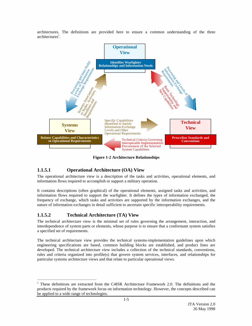
1-5JTA Version 2.0
26 May 1998
architectures. The definitions are provided here to ensure a common understanding of the threearchitectures1.
OperationalView
Identifies WarfighterRelationships and Information Needs
SystemsView
Relates Capabilities and Characteristicsto Operational Requirements
TechnicalView
Prescribes Standards andConventions
Specific CapabilitiesIdentified to SatisfyInformation-ExchangeLevels and OtherOperational Requirements
Technical Criteria GoverningInteroperable Implementation/Procurement of the SelectedSystem Capabilities
Processing and Levels of
Information Exchange
RequirementsB
asic Technology
Supportability and
New
Capabilities
Syst
ems
Ass
ocia
tions
to N
odes
, Act
iviti
es,
Nee
dlin
es a
nd
Req
uire
men
ts
Proc
essi
ng a
nd In
ter-
Nod
al
Leve
ls o
f Inf
orm
atio
n
Exch
ange
Req
uire
men
ts
Figure 1-2 Architecture Relationships
1.1.5.1 Operational Architecture (OA) ViewThe operational architecture view is a description of the tasks and activities, operational elements, andinformation flows required to accomplish or support a military operation.
It contains descriptions (often graphical) of the operational elements, assigned tasks and activities, andinformation flows required to support the warfighter. It defines the types of information exchanged, thefrequency of exchange, which tasks and activities are supported by the information exchanges, and thenature of information exchanges in detail sufficient to ascertain specific interoperability requirements.
1.1.5.2 Technical Architecture (TA) ViewThe technical architecture view is the minimal set of rules governing the arrangement, interaction, andinterdependence of system parts or elements, whose purpose is to ensure that a conformant system satisfiesa specified set of requirements.
The technical architecture view provides the technical systems-implementation guidelines upon whichengineering specifications are based, common building blocks are established, and product lines aredeveloped. The technical architecture view includes a collection of the technical standards, conventions,rules and criteria organized into profile(s) that govern system services, interfaces, and relationships forparticular systems architecture views and that relate to particular operational views.
1 These definitions are extracted from the C4ISR Architecture Framework 2.0. The definitions and theproducts required by the framework focus on information technology. However, the concepts described canbe applied to a wide range of technologies.
1-6JTA Version 2.026 May 1998
1.1.5.3 Systems Architecture (SA) ViewThe systems architecture view is a description, including graphics, of systems2 and interconnections3
providing for, or supporting, warfighting functions.
For a domain, the systems architecture view shows how multiple systems link and interoperate, and maydescribe the internal construction and operations of particular systems within the architecture. For theindividual system, the systems architecture view includes the physical connection, location, andidentification of key nodes (including materiel item nodes), circuits, networks, warfighting platforms, etc.,and specifies system and component performance parameters (e.g., mean time between failure,maintainability, availability). The systems architecture view associates physical resources and theirperformance attributes to the operational view and its requirements following standards defined in thetechnical architecture.
1.2 DOCUMENT ORGANIZATIONThe JTA is organized into a main body, followed by domain annexes, subdomain annexes, and a set ofappendices. This section describes the structure of the document.
1.2.1 General OrganizationThe main body identifies the “core” set of JTA elements consisting of service areas, interfaces, andstandards. Each section of the main body, except for the overview, is divided into three subsections asfollows:
• Introduction - This subsection is for information purposes only. It defines the purpose and scope of thesubsection and provides background descriptions and definitions that are unique to the section.
• Mandates - This subsection identifies mandatory standards or practices. Each mandated standard orpractice is clearly identified on a separate bulletized line and includes a formal reference citation that issuitable for inclusion within Requests for Proposals (RFP), Statements of Work (SOW) or Statementsof Objectives (SOO).
• Emerging Standards - This subsection provides an information-only description of standards which arecandidates for possible addition to the JTA mandate. The purpose of listing these candidates is to helpthe program manager determine those areas that are likely to change in the near term (within threeyears) and suggest those areas in which "upgradability" should be a concern. The expectation is thatemerging standards will be elevated to mandatory status when implementations of the standardsmature. Emerging standards may be implemented, but shall not be used in lieu of a mandated standard.
1.2.2 Information Technology StandardsSection 2, also called the JTA core or main body, addresses commercial and Government standardscommon to most DoD information technology, grouped into categories; Information Processing Standards;Information Transfer Standards; Information Modeling, Metadata, and Information Exchange Standards;Human-Computer Interface Standards; and Information Systems Security Standards. Each categoryaddresses a set of functions common to most DoD IT systems.
1.2.3 Domain and Subdomain AnnexesThe JTA core contains the common service areas, interfaces and standards (JTA elements) applicable to allDoD systems to support interoperability. Recognizing that there are additional JTA elements common
2 Systems: People, machines, and facilities organized to accomplish a set of specific functions, whichcannot be further subdivided while still performing required functions. Includes the radios, terminals,command, control, and support facilities, sensors and sensor platforms, automated information systems,etc., necessary for effective operations.3 Interconnections: The manual, electrical, electronic, or optical communications paths/linkages betweenthe systems. Includes the circuits, networks, relay platforms, switches, etc., necessary for effectivecommunications.

1-7JTA Version 2.0
26 May 1998
within families of related systems (i.e., domains), the JTA adopted the Domain and Subdomain annexnotion. A domain represents a grouping of systems sharing common functional, behavioral and operationalrequirements. JTA Domain and Subdomain annexes are intended to exploit the common service areas,interfaces and standards supporting interoperability across systems within the domain/subdomain.
The JTA Domain Annexes contain domain-specific JTA elements applicable within the specified family ofsystems, to further support interoperability within the systems represented in the domain - in addition tothose included in the JTA core. Domains may be composed of multiple subdomains. Subdomains representthe decomposition of a domain (referred to as the subdomain’s parent domain) into a subset of relatedsystems, exploiting additional commonalities and addressing variances within the domain. SubdomainAnnexes contain domain-specific JTA elements applicable within the specified family of systems, tofurther support interoperability within the systems represented in the subdomain - in addition to thoseincluded in the JTA core and in the parent Domain Annex. The relationships between the JTA core,Domain Annexes, and Subdomain Annexes currently included in the JTA are illustrated in Figure 1-3.
Subdomain Annexes
C4ISR WeaponSystems
Modeling &Simulation
CombatSupport
DomainElements
SubdomainElements
Domain Annexes
Aviation
Ground Vehicles
Soldier Systems
Surveillance/Reconnaissance
Space Vehicles
Ship Systems
Munitions
Missile
JTA MainBody
JTA CoreElements
Acquisition
Finance/Accounting
H R Management
Medical
Logistics Materiel
Legal
JTA Core
Command & Control
Communication
IntelligenceInfo Warfare
Automated Test Systems
Airborne Reconnaissance
*Boxed subdomain names indicate Subdomain Annexespresent in this version of the JTA. Italicized subdomainnames are candidates for Subdomain Annexes in futureversions.
Missile Defense
Figure 1-3 JTA Hierarchy Model
A program manager or engineer specifying or applying JTA standards for a specific system will first selectall appropriate JTA core elements, and then those included in the relevant Domain and Subdomain annex.
As shown in Figure 1-3, the following Domain and Subdomain annexes are currently populated:
Domain Annexes:
• Command, Control, Communications, Computers, Intelligence, Surveillance, and Reconnaissance(C4ISR).
• Combat Support (CS).
• Weapon Systems (WS).
• Modeling and Simulation (M&S).
1-8JTA Version 2.026 May 1998
Subdomain Annexes:
• Airborne Reconnaissance (AR). • Ground Vehicles (GV).
• Automated Test Systems (ATS). • Aviation (AV).
• Missile Defense (MD).
The goal is to build on these annexes by incorporating the requirements of additional domains andsubdomains. Each Annex includes an introduction clearly specifying the purpose, scope, description of thedomain, and background of the annex. As necessary, each annex provides a list of domain specificstandards and guidance in a format consistent with the JTA core. Annexes generally use the TAFIM DoDTechnical Reference Model (TRM) defined in Section 2.1.3.1, but may include a different or expandedmodel. Annex developers should define which standards apply to which system interfaces in their domain.They may address emerging standards that are of interest to the domain.
1.2.4 Appendices (Appendix A, B, C)The appendices provide supporting information (e.g., how to get a copy of mandated standards) andavailable links to standards organization’s home pages, which facilitate the use of the document, but are notmainline to its purpose.
Appendix A, “Acronyms and Glossary”, includes an acronym list and glossary of terms referenced in theJTA.
Appendix B, “List of Mandated Standards and Sources”, includes “retired,” “mandated,” and “emerging”standards for each JTA service area; and a list of organizations from whom documents cited in the JTAmay be obtained.
Appendix C, “JTA Relationship to DoD Standards Reform”, describes the relationship of the JTA to theDoD Standards Reform begun in June 1994 and addresses the relevance of the reform waiver policy to theJTA.
1.3 KEY CONSIDERATIONS IN USING THE JTAIn general, the JTA shall be used to determine the specific service areas and standards for implementationwithin new or upgraded systems. However, there are several key considerations in using the JTA.
The JTA service areas are based on the DoD TRM. For a more complete description of the DoD TRM andservice areas refer to Section 2.1.3.1.
The mandatory standards in the JTA must be implemented or used by systems that have a need for thecorresponding service areas. A standard is mandatory in the sense that if a service/interface is going to beimplemented, it shall be implemented in accordance with the associated standard. If a required service canbe obtained by implementing more than one standard (e.g., operating system standards), the appropriatestandard should be selected based on system requirements.
The JTA is a "forward-looking" document. It guides the acquisition and development of new and emergingfunctionality and provides a baseline towards which existing systems will move. It is a compendium ofstandards (for interfaces/services) that should be used now and in the future. It is NOT a catalog of allinformation technology standards used within today's DoD systems. If legacy standards are needed tointerface with existing systems, they can be implemented on a case-by-case basis in addition to themandated standard.
If cited, requirements documents not identified in the JTA should complement and not conflict with theJTA core, and applicable Domain and Subdomain Annexes.

1-9JTA Version 2.0
26 May 1998
1.4 ELEMENT NORMALIZATION RULESAs the JTA evolves, the JTA elements contained in the JTA core, Domain Annexes and SubdomainAnnexes will need to be periodically revisited and updated to ensure correctness. The JTA normalizationrules in this section address the movement of elements across the core or annexes following the definitionsand scope.
All standards are placed in the core unless they are justified as unacceptable to meet domain-specificrequirements. When core standards cannot meet the requirements of a specific domain, JTA elements areremoved from the JTA core and placed in the appropriate Domain Annex(es). Likewise, when domainstandards cannot meet subdomain-specific requirements, those will be removed from the Domain Annexand placed in the appropriate Subdomain Annex(es).
The intent of the above normalization rules is as follows. (1) The core applies to all DoD systems. (2) TheJTA core contains selected standards for as many JTA services as possible. (3) A service area provides theminimum number of alternative standards applicable to DoD.
Figure 1-3 also illustrates a notional hierarchy of JTA core, domains and subdomains – as defined by theCommittee on Open Electronic Standards (COES) [Committee on Open Electronic Standards (COES)Report, DoD Open Systems-Joint Task Force (OS-JTF), July 1996], and tailored by the Joint TechnicalArchitecture Development Group.
1.5 JTA RELATIONSHIP TO DOD STANDARDSREFORM
The DoD Standards Reform was begun in June 1994 when the Secretary of Defense issued a memorandumentitled "Specifications and Standards - A New Way of Doing Business." This memorandum directs thatperformance-based specifications and standards or nationally-recognized private sector standards be used infuture acquisitions. The intent of this initiative is to eliminate non-value added requirements, and thus toreduce the cost of weapon systems and materiel, remove impediments to getting commercial state-of-the-art technology into weapon systems, and integrate the commercial and military-industrial bases to thegreatest extent possible.
The JTA implements standards reform by selecting the minimum standards necessary to achieve jointinteroperability. The JTA mandates commercial standards and practices to the maximum extent possible.Use of JTA mandated standards or specifications in acquisition solicitations will not require a waiver fromstandards reform policies. All mandatory standards in the JTA are of the types that have been identified bythe DoD Standards Reform as waiver-free or for which an exemption has already been obtained. Additionalinformation on this topic can be found in Appendix C.
1.6 STANDARDS SELECTION CRITERIAThe standards selection criteria used throughout the JTA focus on mandating only those items critical tointeroperability that are based primarily on commercial open system technology, are implementable, andhave strong support in the commercial marketplace. Standards will only be mandated if they meet all of thefollowing criteria:
• INTEROPERABILITY: They enhance joint and potentially combined Service/Agency informationexchange and support joint activities.
• MATURITY: They are technically mature (strong support in the commercial marketplace) and stable.
• IMPLEMENTABILITY: They are technically implementable.
• PUBLIC: They are publicly available.
• CONSISTENT WITH AUTHORITATIVE SOURCES: They are consistent with law, regulation,policy, and guidance documents.

1-10JTA Version 2.026 May 1998
The following preferences were used to select standards:
• Standards that are commercially supported in the marketplace with validated implementationsavailable in multiple vendors’ mainstream commercial products took precedence.
• Publicly held standards were generally preferred.
• International or national industry standards were preferred over military or other governmentstandards.
Many standards have optional parts or parameters that can affect interoperability. In some cases, anindividual standard may be further defined by a separate, authoritative document called a ‘profile’ or a‘profile of a standard’ which further refines the implementation of the original standard to ensure properoperation and assist interoperability.
The word ‘standards’ as referred to in the JTA is a generic term for the collection of documents citedherein. An individual ‘standard’ is a document that establishes uniform engineering and technicalrequirements for processes, procedures, practices, and methods. A standard may also establish requirementsfor selection, application, and design criteria of material. The standards cited in the JTA may includecommercial, federal and military standards and specifications, and various other kinds of authoritativedocuments and publications.
1.7 CONFIGURATION MANAGEMENTThe JTA is configuration managed by the Joint Technical Architecture Development Group (JTADG),under the direction of the DoD Technical Architecture Steering Group (TASG), and approved by theArchitecture Coordination Council (ACC). These groups consist of members representing DoD andcomponents of the Intelligence Community. The following organizations have voting memberships in bothgroups:
The JTA Management Plan describes the process by which the JTA will be configuration managed. Thisdocument, as well as the charter for the JTADG, may be found on the Defense Information SystemsAgency (DISA) Center for Standards (CFS) JTA World Wide Web home page:
http://www-jta.itsi.disa.mil
JTA VOTING MEMBERSHIP LISTAssistant Secretary of Defense Command, Control, Communications and Intelligence/C4I IntegrationSupport Activity (ASD (C3I)/CISA)
Ballistic Missile Defense Organization (BMDO) Defense Airborne Reconnaissance Office (DARO) Defense Information Systems Agency (DISA)Defense Intelligence Agency/DoD Intelligence Information Systems (DIA/DoDIIS)
Defense Logistics Agency (DLA) Defense Modeling and Simulation Office (DMSO)Joint Staff/J6
National Imagery and Mapping Agency (NIMA) National Reconnaissance Office (NRO) National Security Agency (NSA)US. Air Force (USAF)US. Army (USA)US. Marine Corps (USMC)US. Navy (USN)Under Secretary of Defense for Acquisition and TechnologyOpen Joint Systems Task Force (USD (A&T) OS-JTF)

1-11JTA Version 2.0
26 May 1998
Suggested changes to and comments on the JTA originating from DoD Components (Office of theSecretary of Defense (OSD), the Military Departments, the Organization of the Joint Chiefs of Staff(OJCS), the Unified and Specified Commands, and the Defense Agencies) should be submitted via theappropriate official JTA Component representative listed on the JTA web home page. Theserepresentatives will integrate and coordinate received comments for submission as official DoDComponent-sponsored comments.
Industry and other non-DoD comments and suggested changes should be submitted through DISA CFS viaelectronic mail to [email protected]. All comments and suggested changes must be in thestandard comment format described on the JTA World Wide Web home page.
1-12JTA Version 2.026 May 1998
This page intentionally left blank.
2.1-1JTA Version 2.0
26 May 1998
SECTION 2: INFORMATION TECHNOLOGYSTANDARDS
2.1 GENERAL2.1.1 Background .......................................................................................................................2.1-12.1.2 Scope.................................................................................................................................2.1-12.1.3 DoD Technical Architecture Framework for Information Management...........................2.1-1
2.1.3.1 TAFIM DoD Technical Reference Model ....................................................................2.1-12.1.3.2 Emerging “Integrated” DoD Technical Reference Model ............................................2.1-3
2.1.4 Mandates ...........................................................................................................................2.1-52.1.4.1 Year 2000 (Y2K) Compliance ......................................................................................2.1-52.1.4.2 Defense Information Infrastructure Common Operating Environment (DII COE).......2.1-5
2.1.5 Organization of Section 2..................................................................................................2.1-6
2.1.1 BackgroundSection 2 of the JTA is essentially a technical refreshment of Version 1.0 of the JTA. This section isintended as the basis from which to develop the main body of the JTA (i.e., the JTA core). As the JTAevolves, the structure of this section will also evolve to be more reflective of the goal of the JTA structure.
2.1.2 ScopeThis section of the JTA establishes the minimum set of rules governing information technology within DoDsystems. The scope includes standards for information processing, information transfer, the structure ofinformation and data, human-computer interface standards for information entry and display, andinformation security standards. Information technology includes any equipment or interconnected systemor subsystem of equipment that is used in the automatic acquisition, storage, manipulation, management,movement, control, display, switching, interchange, transmission, or reception of data or information.
2.1.3 DoD Technical Architecture Framework for InformationManagement
The Technical Architecture Framework for Information Management (TAFIM) version 3.0 is a set of eightvolumes consisting of very specific guidance on building and maintaining DoD systems architectures. Itdescribes the process for defining a technical architecture. Volume 2, the Technical Reference Model, asdescribed below and referenced as the TAFIM DoD TRM, is the basis for the structure and standardsselected for Section 2 of the JTA.
For applicable systems, the specific guidance in the JTA replaces the general standards guidance in theTAFIM 3.0, Volume 7: Adopted Information Technology Standards (AITS).
2.1.3.1 TAFIM DoD Technical Reference ModelThe TAFIM DoD TRM (DoD TRM) and the core set of standards mandated in the JTA define the targettechnical environment for the acquisition, development, and support of DoD information technology. Thepurpose of the DoD TRM is to provide a common conceptual framework, and define a common vocabularyso that the diverse components within the DoD can better coordinate acquisition, development, and supportof DoD information technology. Interoperability is dependent on the establishment of a common set ofservices and interfaces that system developers can use to resolve technical architectures and related issues.The DoD TRM structure is intended to reflect the separation of data from applications, and applicationsfrom the computing platform – a key principle in achieving open systems. The model is to be used as aguideline for system planning, interoperability, and selecting appropriate standards. The DoD TRM isintended to ensure the use of consistent definitions between the services, domains, interfaces and other
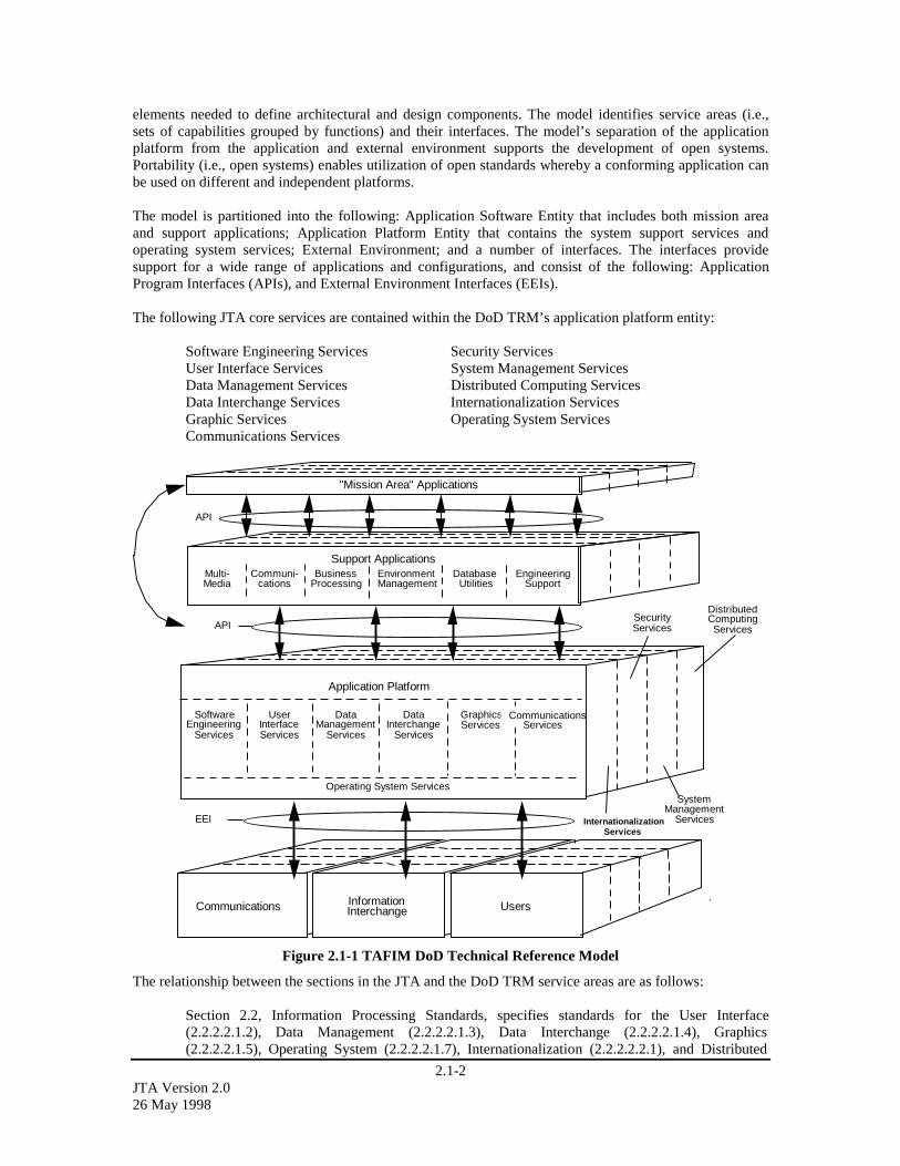
2.1-2JTA Version 2.026 May 1998
elements needed to define architectural and design components. The model identifies service areas (i.e.,sets of capabilities grouped by functions) and their interfaces. The model’s separation of the applicationplatform from the application and external environment supports the development of open systems.Portability (i.e., open systems) enables utilization of open standards whereby a conforming application canbe used on different and independent platforms.
The model is partitioned into the following: Application Software Entity that includes both mission areaand support applications; Application Platform Entity that contains the system support services andoperating system services; External Environment; and a number of interfaces. The interfaces providesupport for a wide range of applications and configurations, and consist of the following: ApplicationProgram Interfaces (APIs), and External Environment Interfaces (EEIs).
The following JTA core services are contained within the DoD TRM’s application platform entity:
Software Engineering Services Security ServicesUser Interface Services System Management ServicesData Management Services Distributed Computing ServicesData Interchange Services Internationalization ServicesGraphic Services Operating System ServicesCommunications Services
EEI
Support ApplicationsMulti-Media
InformationInterchangeCommunications Users
BusinessProcessing
Communi-cations
EnvironmentManagement
DatabaseUtilities
EngineeringSupport
Application Platform
SoftwareEngineering
Services
UserInterfaceServices
DataManagement
Services
DataInterchange
Services
GraphicsServices
CommunicationsServices
API
"Mission Area" Applications
API
InternationalizationServices
SecurityServices
DistributedComputingServices
SystemManagement
Services
Operating System Services
Figure 2.1-1 TAFIM DoD Technical Reference Model
The relationship between the sections in the JTA and the DoD TRM service areas are as follows:
Section 2.2, Information Processing Standards, specifies standards for the User Interface(2.2.2.2.1.2), Data Management (2.2.2.2.1.3), Data Interchange (2.2.2.2.1.4), Graphics(2.2.2.2.1.5), Operating System (2.2.2.2.1.7), Internationalization (2.2.2.2.2.1), and Distributed

2.1-3JTA Version 2.0
26 May 1998
Computing (2.2.2.2.2.4) service areas, and the latter’s two subordinate paragraphs become2.2.2.2.2.4.1 and 2.2.2.2.2.4.2 respectively. This section also references, but does not specify anystandards for the Software Engineering (2.2.2.2.1.1), Communications (2.2.2.2.1.6), Security(2.2.2.2.2.2), and System Management (2.2.2.2.2.3) service areas.
Section 2.3, Information Transfer Standards, specifies standards for the Communications (2.3.2.1through 2.3.2.3) and System Management (2.3.2.4) service areas applicable to both system andnetwork management.
Section 2.4, Information Modeling, Metadata, and Information Exchange Standards, addressesstandards for an area that is not currently elaborated, but is supported by engineering support, datamanagement, and software engineering services in the DoD TRM.
Section 2.5, Human-Computer Interface Standards, addresses standards for what is often referredto as TAFIM Volume 8, Version 3.0. The standards specified in Section 2.5 complement thosecited for User Interface Services in Section 2.2.2.2.1.2.
Section 2.6, Information Systems Security Standards, specifies security standards that are relevantto the service areas discussed in Sections 2.2, 2.3, and 2.5.
In this version of the JTA, the DoD TRM does not embrace all service areas within the weapon systemsdomain, and is applicable to the JTA core as described above. In cases where new services are identified,they should be presented to the Technical reference Model Working Group (TRMWG) for adjudication andpotential inclusion into the TRM.
2.1.3.2 Emerging “Integrated” DoD Technical Reference ModelTo support a more extensive, dynamic and complete set of JTA services, interfaces and platformconfigurations, an “integrated” DoD TRM (I-DoD TRM) has been developed (Figure 2.1-2). This TRMrepresents an enhancement to, and uses as a foundation, the TAFIM DoD TRM structure, service featuresand definitions (as defined in TAFIM Version 3.0, Volume 2, DoD Technical Reference Model). Themodel also derives interface features that have been identified as essential from the Society of AutomotiveEngineers (SAE) Generic Open Architecture (GOA) model and other derived models used by certainsegments of the Weapons community to support their real-time needs. Thus, the enhanced “integrated”model combines the best of service/interface capabilities and definitions from several existing models. Ithas the added advantage of providing greater detail in the Application Software and External EnvironmentEntity levels, and is tailorable to accommodate different DoD users and performance needs, both hardwareand real-time. Interfaces are defined in Table 2.1-1. The “integrated” model is defined in its entirety in theemerging document, DoD Technical Reference Model, Version 1.0 Draft, dated April 1998.
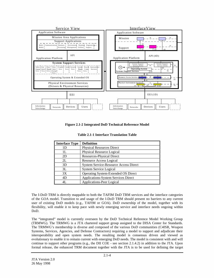
2.1-4JTA Version 2.026 May 1998
Service View
EEI EEI (1D)
InformationInterchange
Devices UsersNetworksInformationInterchange
Devices UsersNetworks
InterfaceView
M ission
Support
3L
API (4D)
Resource Access Services
3D
2L
2L2D
1L
1L1D 1D
Physical Environment Services
Application Platform
Application SoftwareApplication Software
1D
4L 4L
4L
4D4D 4D
Application Platform
System Support Services
Physical Environment Services(Drivers & Physical Resources)
API
4D
3LSystem SupportService (XOS)
Operating System3X
System SupportService (XOS)
3D
3D
Systems Support Services 3L
M ission Area Applications
Multi- Communications Business Environment Database Engineering…Media Processing Management Utilities Support
Support Applications
Softw. User Data Data Graphic Comm. Security System Distrib. In ternatlizn.…Engrg. Interf. Mgmt. Inter- Svcs Svcs. Svcs. Mgmt. Comp. ServicesSvcs. Svcs. Svcs. change Svcs. Svcs.
Svcs.
Operating System & Extended OS
Figure 2.1-2 Integrated DoD Technical Reference Model
Table 2.1-1 Interface Translation Table
Interface Type Definition 1D Physical Resources Direct 1L Physical Resource Logical 2D Resources-Physical Direct 2L Resource Access Logical 3D System Service-Resource Access Direct 3L System Service Logical 3X Operating System-Extended OS Direct 4D Applications-System Services Direct 4L Applications-Peer Logical
The I-DoD TRM is directly mappable to both the TAFIM DoD TRM services and the interface categoriesof the GOA model. Transition to and usage of the I-DoD TRM should present no barriers to any currentuser of existing DoD models (e.g., TAFIM or GOA). DoD ownership of the model, together with itsflexibility, will enable it to keep pace with newly emerging service and interface needs ongoing withinDoD.
The “integrated” model is currently overseen by the DoD Technical Reference Model Working Group(TRMWG). The TRMWG is a JTA chartered support group assigned to the DISA Center for Standards.The TRMWG’s membership is diverse and composed of the various DoD communities (C4ISR, WeaponSystems, Services, Agencies, and Defense Contractors) requiring a model to support and adjudicate theirinteroperability and open system needs. The resulting model is consensus driven and viewed asevolutionary to enable it to remain current with emerging DoD needs. The model is consistent with and willcontinue to support other programs (e.g., the DII COE - see section 2.1.4.2) in addition to the JTA. Uponformal release, the enhanced TRM document together with the JTA is to be used for defining the target
2.1-5JTA Version 2.0
26 May 1998
technical environment for DoD information technology needs. The I-DoD TRM document, when approved,will supersede the existing TAFIM Version 3.0, Volume 2, DoD TRM.
2.1.4 Mandates
2.1.4.1 Year 2000 (Y2K) ComplianceTo ensure proper data interchange beyond the year 2000, it is DoD policy that all new software and dataacquired by the DoD shall be Year 2000 (Y2K) compliant. “Year 2000 compliant” means informationtechnology that accurately processes date/time data (including, but not limited to, calculating, comparing,and sequencing) from, into, and between the twentieth and twenty-first centuries, and the years 1999 and2000 and leap year calculations. Furthermore, Year 2000 compliant information technology, when used incombination with other information technology, shall accurately process date/time data if the otherinformation technology properly exchanges date/time data with it.1. Refer to JTA Section 2.4 for guidanceon specific date data formats to be used.
DoD policy guidance on this matter can be found in the "DoD Year 2000 Management Plan." The plan isavailable on the World Wide Web at:
http://www.dtic.mil/c3i/
For procurement and acquisition purposes, the General Services Administration (GSA) has made availablethe following documents:
1. "Recommended Year 2000 Contract Language (1996-09-11)"
2. "Federal Acquisition Regulation Interim Rule on the Year 2000 (1997-01-02)"
These documents can be used by contracting officers to help ensure that acquired products and services areY2K compliant. They are available on the GSA World Wide Web site at:
http://www.itpolicy.gsa.gov/
2.1.4.2 Defense Information Infrastructure Common Operating Environment(DII COE)
The Common Operating Environment (COE) concept is described in the Integration and RuntimeSpecification (I&RTS), Version 3.0, 1 July 1997. The Defense Information Infrastructure COE (DII COE)is implemented with a set of modular software that provides generic functions or services, such as operatingsystem services. These services or functions are accessed by other software through standard APIs. The DIICOE may be adapted and tailored to meet the specific requirements of a domain. COE Implementationsprovide standard, modular software services that are consistent with the service areas identified in the DoDTechnical Reference Model. Application programmers then have access to these software services throughstandardized APIs.
The DII COE, as defined in the DII COE I&RTS Version 3.0, is fundamental to a Joint SystemArchitecture (JSA). In the absence of a JSA, the JTA mandates that all Command, Control,Communications, Computers, and Intelligence (C4I) systems shall use the DII COE. The strict definition ofC4I, as given in JTA 1.0, is expanding to cover information technology areas that cut across JTA Version2.0 domain boundaries. The DII COE mandate is therefore intended for all applicable systems. Allapplications of a system which must be integrated into the DII shall be at least DII COE I&RTS level 5compliant (software is segmented, uses DII COE Kernel, and is installed via COE tools) with a goal ofachieving level 8.
1 August 1, 1997 Interim FAR Rule on Year 2000 Compliance

2.1-6JTA Version 2.026 May 1998
The DII COE implements the appropriate JTA standards applicable to the COE functionality. The DII COEimplementation will continue to evolve in compliance with all applicable JTA specifications, standards, andsource references. Additional functionality not contained in the DII COE is subject to the JTA mandate.
2.1.5 Organization of Section 2The Information Technology section of the JTA consists of six sections. The first section is the overview.The next sections are: (2.2) Information Processing Standards; (2.3) Information Transfer Standards; (2.4)Information Modeling, Metadata, and Information Exchange Standards; (2.5) Human-Computer InterfaceStandards; and (2.6) Information Systems Security Standards.
Information Processing Standards - Section 2.2 describes government and commercial informationprocessing standards the DoD shall use to develop integrated, interoperable systems that meet theWarfighters’ information processing requirements.
Information Transfer Standards - Section 2.3 describes the information transfer standards and profilesthat are essential for information transfer interoperability and seamless communications. This sectionmandates the use of the open-systems standards used for the Internet and the Defense Information SystemNetwork (DISN).
Information Modeling, Metadata, and Information Exchange Standards - Section 2.4 describes the useof integrated information modeling and mandates applicable standards. Information modeling consists ofActivity and Data Modeling. This section explains the use of the DoD Command and Control (C2) CoreData Model (C2CDM) and the Defense Data Dictionary System (DDDS), formerly the Defense DataRepository System (DDRS). This section also mandates information standards including message formats.
Human-Computer Interface Standards - Section 2.5 provides a common framework for Human-Computer Interface (HCI) design and implementation in DoD systems. The objective is the standardizationof user interface implementation options, enabling DoD applications to appear and behave in a reasonablyconsistent manner. The section specifies HCI design guidance, mandates, and standards.
Information Systems Security Standards - Section 2.6 prescribes the standards and protocols to be usedto satisfy security requirements. This section provides the mandated and emerging security standards thatapply to JTA Sections 2.2 through 2.5. Section 2.6 is structured to mirror the overall organization of theJTA so that readers can easily link security topics with the related JTA subject areas.

2.2-1JTA Version 2.0
26 May 1998
2.2 INFORMATION PROCESSING STANDARDS2.2.1 Introduction.......................................................................................................................2.2-2
2.2.1.1 Purpose..........................................................................................................................2.2-22.2.1.2 Scope.............................................................................................................................2.2-22.2.1.3 Background ...................................................................................................................2.2-2
2.2.2 Mandates ...........................................................................................................................2.2-22.2.2.1 Application Software Entity..........................................................................................2.2-22.2.2.2 Application Platform Entity ..........................................................................................2.2-3
2.2.2.2.1 Service Areas ..........................................................................................................2.2-32.2.2.2.1.1 Software Engineering Services ........................................................................2.2-32.2.2.2.1.2 User Interface Services ....................................................................................2.2-32.2.2.2.1.3 Data Management Services..............................................................................2.2-42.2.2.2.1.4 Data Interchange Services................................................................................2.2-4
2.2.2.2.1.4.1 Document Interchange ..............................................................................2.2-42.2.2.2.1.4.2 Graphics Data Interchange........................................................................2.2-52.2.2.2.1.4.3 Geospatial Data Interchange .....................................................................2.2-52.2.2.2.1.4.4 Still Imagery Data Interchange .................................................................2.2-62.2.2.2.1.4.5 Motion Imagery Data Interchange ............................................................2.2-7
2.2.2.2.1.4.5.1 Video Systems ...................................................................................2.2-72.2.2.2.1.4.5.1.1 Video Imagery ............................................................................2.2-72.2.2.2.1.4.5.1.2 Video Teleconference .................................................................2.2-82.2.2.2.1.4.5.1.3 Video Telemedicine....................................................................2.2-82.2.2.2.1.4.5.1.4 Video Support.............................................................................2.2-8
2.2.2.2.1.4.6 Audio Data Interchange ............................................................................2.2-92.2.2.2.1.4.6.1 Audio Associated with Video ............................................................2.2-9
2.2.2.2.1.4.6.1.1 Audio for Video Imagery............................................................2.2-92.2.2.2.1.4.6.1.2 Audio for Video Teleconference.................................................2.2-92.2.2.2.1.4.6.1.3 Audio for Video Telemedicine .................................................2.2-102.2.2.2.1.4.6.1.4 Audio for Video Support ..........................................................2.2-10
2.2.2.2.1.4.6.2 Audio Not Associated with Video Systems.....................................2.2-102.2.2.2.1.4.7 Multimedia Data Interchange .................................................................2.2-102.2.2.2.1.4.8 Product Data Interchange........................................................................2.2-102.2.2.2.1.4.9 Atmospheric Data Interchange ...............................................................2.2-102.2.2.2.1.4.10 Oceanographic Data Interchange ..........................................................2.2-112.2.2.2.1.4.11 Time of Day Data Interchange..............................................................2.2-11
2.2.2.2.1.5 Graphic Services ............................................................................................2.2-112.2.2.2.1.6 Communications Services..............................................................................2.2-112.2.2.2.1.7 Operating System Services ............................................................................2.2-11
2.2.2.2.2 Application Platform Cross-Area Services ...........................................................2.2-122.2.2.2.2.1 Internationalization Services..........................................................................2.2-122.2.2.2.2.2 Security Services............................................................................................2.2-122.2.2.2.2.3 System Management Services .......................................................................2.2-122.2.2.2.2.4 Distributed Computing Services ....................................................................2.2-13
2.2.2.2.2.4.1 Remote Procedure Computing................................................................2.2-132.2.2.2.2.4.2 Distributed Object Computing................................................................2.2-13
2.2.3 Emerging Standards ........................................................................................................2.2-142.2.3.1 User Interface..............................................................................................................2.2-142.2.3.2 Data Management .......................................................................................................2.2-142.2.3.3 Data Interchange .........................................................................................................2.2-14
2.2.3.3.1 Document Interchange ..........................................................................................2.2-142.2.3.3.2 Graphics Data Interchange....................................................................................2.2-142.2.3.3.3 Virtual Reality Modeling Language .....................................................................2.2-142.2.3.3.4 Geospatial Data Interchange .................................................................................2.2-14
2.2-2JTA Version 2.026 May 1998
2.2.3.3.5 Still Imagery Data Interchange .............................................................................2.2-152.2.3.3.6 Motion Imagery Data Interchange ........................................................................2.2-15
2.2.3.3.6.1 Video Systems ...............................................................................................2.2-152.2.3.3.6.1.1 Video Imagery ........................................................................................2.2-152.2.3.3.6.1.2 Video Teleconference .............................................................................2.2-15
2.2.3.3.7 Multimedia Data Interchange ...............................................................................2.2-152.2.3.4 Operating Systems ......................................................................................................2.2-16
2.2.3.4.1 POSIX...................................................................................................................2.2-162.2.3.4.2 UNIX ....................................................................................................................2.2-162.2.3.4.3 Virtual Machines...................................................................................................2.2-16
2.2.3.5 Distributed Computing................................................................................................2.2-16
2.2.1 Introduction
2.2.1.1 PurposeThe purpose of this section is to specify the Joint Technical Architecture (JTA) government andcommercial information processing standards the DoD will use to develop integrated, interoperable systemsthat directly or indirectly support the Warfighter.
2.2.1.2 ScopeThis section applies to mission area, support application, and application platform service software. Thissection does not cover communications standards needed to transfer information between systems (definedin Section 2.3), nor standards relating to information modeling (process, data, and simulation), dataelements, or military unique message set formats (defined in Section 2.4).
2.2.1.3 BackgroundInformation Processing (IP) standards provide the data formats and instruction processing specificationsrequired to represent and manipulate data to meet information technology (IT) mission needs. Thestandards in this section are drawn from widely accepted commercial standards that meet DoDrequirements. Where necessary for interoperability, profiles of commercial standards are used. Militarystandards are mandated only when suitable commercial standards are not available.
2.2.2 MandatesThe following sections provide the applicable mandated standards that shall be used for the selection ofcommercial or government off-the-shelf (GOTS) software or in the development of government software.Appendix B contains a table that summarizes the mandated standards from this section, as well asproviding information on how to obtain the standards.
2.2.2.1 Application Software EntityThe Application Software Entity includes both mission area applications and support applications. Missionarea applications implement specific user’s requirements and needs (e.g., personnel, material, management).This application software may be commercial off-the-shelf (COTS), GOTS, custom-developed software, ora combination of these.
Common support applications are those (e.g., e-mail and word processing) that can be standardized acrossindividual or multiple mission areas. The services they provide can be used to develop mission-area-specific applications or can be made available to the user. The DoD Technical Reference Model (TRM)defines six support application categories: Multimedia, Communications, Business Processing,Environment Management, Database Utilities, and Engineering Support. The definitions of these categoriesare found in the TAFIM 3.0, Volume 2, DoD Technical Reference Model, 30 April 1996.

2.2-3JTA Version 2.0
26 May 1998
2.2.2.2 Application Platform EntityThe Application Platform Entity is the second layer of the DoD TRM, and includes the common, standardservices upon which the required functionality is built. The Application Platform Entity is composed ofservice areas and cross-area services. The corresponding mandates are provided in the followingsubsections.
2.2.2.2.1 Service AreasSeven primary service areas are defined within the Application Platform Entity: Software Engineering,User Interfaces, Data Management, Data Interchange, Graphics, Communications, and Operating SystemServices.
2.2.2.2.1.1 Software Engineering ServicesThe software engineering services provide system developers with the tools that are appropriate to thedevelopment and maintenance of applications. There are no mandated standards for this service area.
Language services provide the basic syntax and semantic definition for use by developers to describe thedesired software function.
“Programming language selections should be made in the context of the system and software engineeringfactors that influence overall life-cycle costs, risks, and potential for interoperability.”1
Computer languages should be used in such a way as to minimize changes when compilers, operatingsystems or hardware change. To maximize portability, the software should be structured where possible soit can be easily ported.
2.2.2.2.1.2 User Interface ServicesUser Interface Services control how a user interfaces with an information technology system. TheCommon Desktop Environment (CDE) provides a common set of desktop applications and managementcapabilities for environments similar to the Microsoft Windows desktop environment. CDE supports OpenSoftware Foundation (OSF) Motif based application execution. Both CDE and Motif applications use theunderlying X-Windows system. The Win32 Application Program Interface (API) set provides similarservices for Microsoft Windows applications. Applications that require user interaction shall use eitherMotif/X-Window APIs and be capable of executing in the CDE or the applicable native windowing Win32APIs. The following standards are mandated:
• C507, Window Management (X11R5): X-Window System Protocol, X/Open CAE Specification,April 1995.
• C508, Window Management (X11R5): Xlib - C Language Binding, X/Open CAE Specification, April1995.
• C509, Window Management (X11R5): X Toolkit Intrinsics, X/Open CAE Specification, April 1995.
• C510, Window Management (X11R5): File Formats & Application Conventions, X/Open CAESpecification, April 1995.
• C320, Motif Toolkit API, X/Open CAE Specification, April 1995.
• X/Open C323, Common Desktop Environment (CDE) Version 1.0, April 1995.
• Win32 APIs, Window Management and Graphics Device Interface, Volume 1 Microsoft Win32Programmers Reference Manual, 1993 or later, Microsoft Press.
Refer to Section 2.5 for Human-Computer Interface (HCI) style guidance and standards.
1 Additional guidance may be found in the memorandum "Use of the Ada Programming Language" byASD (C3I), April 29, 1997, DoD 5000.2-R, and DoDD 3405.1.
2.2-4JTA Version 2.026 May 1998
2.2.2.2.1.3 Data Management ServicesCentral to most systems is the sharing of data between applications. The data management services providefor the independent management of data shared by multiple applications.
These services support the definition, storage, and retrieval of data elements from Database ManagementSystems (DBMSs). Application code using Relational Database Management System (RDBMS) resourcesand COTS RDBMSs shall conform to the requirements of Entry Level Structured Query Language (SQL).The following standards are mandated for any system using an RDBMS:
• ISO/IEC 9075: 1992 Information Technology - Database Language - SQL, as modified by FIPS PUB127-2: 1993, Database Language for Relational DBMSs. (Entry Level SQL).
In addition, the SQL/Call Level Interface (CLI) addendum to the SQL standard provides a standard CLIbetween database application clients and database servers. The following API is mandated for bothdatabase application clients and database servers:
• Open Data-Base Connectivity, ODBC 2.0.
2.2.2.2.1.4 Data Interchange ServicesThe data interchange services provide specialized support for the exchange of data and informationbetween applications and to and from the external environment. These services include document, graphicsdata, geospatial data, still imagery data, motion imagery data, multimedia data, product data, atmosphericdata, oceanographic data, and time-of-day data.
2.2.2.2.1.4.1 Document InterchangeThe Standard Generalized Markup Language (SGML) format supports the production of documents whichare intended for long-term storage and electronic dissemination for viewing in multiple formats. SGMLformalizes document mark-up, making the document independent of the production and/or publishingsystem. SGML is an architecture-independent and application-independent language for managingdocument structures. SGML is a meta-language, providing the rules for designing and applying a system ofmarkup tags rather than the specific set of tags. The following standard is mandated:
• ISO 8879: 1986, Standard Generalized Markup Language (SGML) with Amendment 1, 1998.
The Hypertext Markup Language (HTML) is used for hyper-text formatted and navigational linkeddocuments. For hypertext documents intended to be interchanged via the World Wide Web (WWW) ormade available via organizational intra-nets, the following standard is mandated:
• REC-html-971218, Hypertext Markup Language (HTML), Internet Version 4.0, ReferenceSpecification, World Wide Web Consortium (W3C), 18 December 1997 - Interchange format used bythe WWW for hypertext format and embedded navigational links.
Table 2.2-1 identifies file formats for the interchange of common document types such as text documents,spreadsheets, and presentation graphics. Some of these formats are controlled by individual vendors, but allof these formats are supported by products from multiple companies. In support of the standards mandatedin this section, Table 2.2-1 identifies conventions for file name extensions for documents of various types.The following file formats are mandated, but not the specific products mentioned:
• All applications acquired or developed for the production of documents shall be capable of generatingat least one of the formats listed in Table 2.2-1 for the appropriate document type.
• All organizations shall at a minimum be capable of reading and printing all of the formats listed belowfor the appropriate document type.
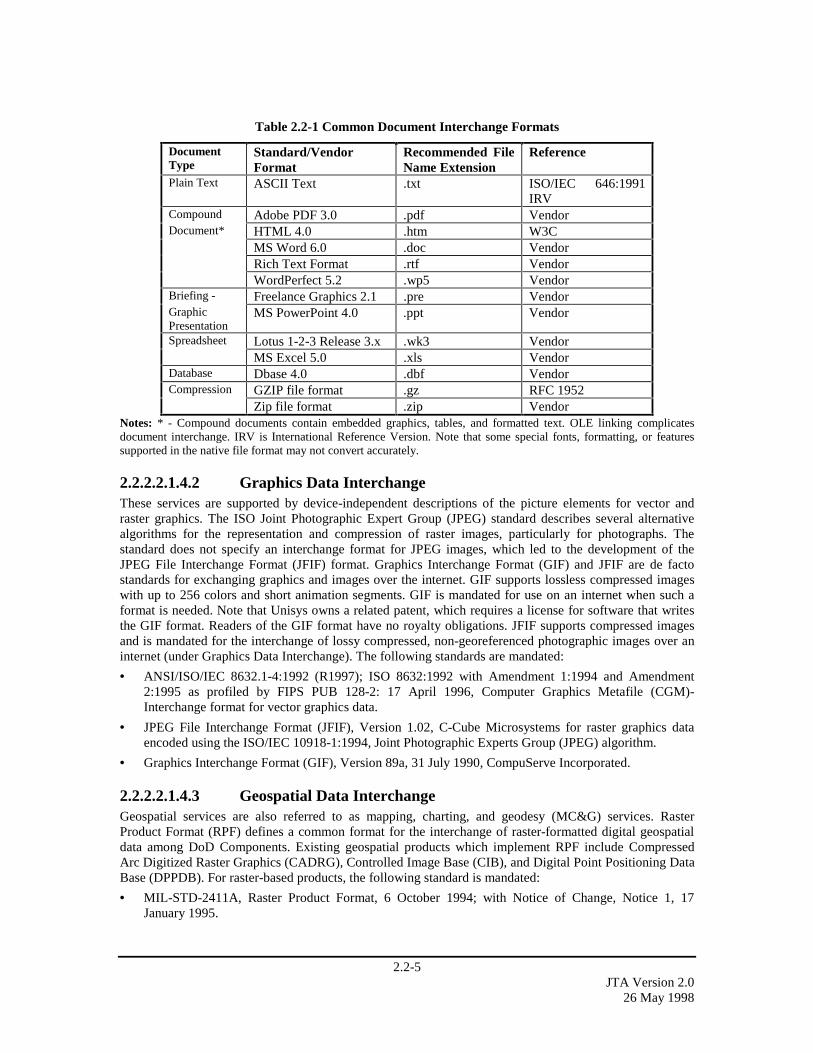
2.2-5JTA Version 2.0
26 May 1998
Table 2.2-1 Common Document Interchange Formats
DocumentType
Standard/VendorFormat
Recommended FileName Extension
Reference
Plain Text ASCII Text .txt ISO/IEC 646:1991IRV
Compound Adobe PDF 3.0 .pdf VendorDocument* HTML 4.0 .htm W3C
MS Word 6.0 .doc VendorRich Text Format .rtf VendorWordPerfect 5.2 .wp5 Vendor
Briefing - Freelance Graphics 2.1 .pre VendorGraphicPresentation
MS PowerPoint 4.0 .ppt Vendor
Spreadsheet Lotus 1-2-3 Release 3.x .wk3 VendorMS Excel 5.0 .xls Vendor
Database Dbase 4.0 .dbf VendorCompression GZIP file format .gz RFC 1952
Zip file format .zip VendorNotes: * - Compound documents contain embedded graphics, tables, and formatted text. OLE linking complicatesdocument interchange. IRV is International Reference Version. Note that some special fonts, formatting, or featuressupported in the native file format may not convert accurately.
2.2.2.2.1.4.2 Graphics Data InterchangeThese services are supported by device-independent descriptions of the picture elements for vector andraster graphics. The ISO Joint Photographic Expert Group (JPEG) standard describes several alternativealgorithms for the representation and compression of raster images, particularly for photographs. Thestandard does not specify an interchange format for JPEG images, which led to the development of theJPEG File Interchange Format (JFIF) format. Graphics Interchange Format (GIF) and JFIF are de factostandards for exchanging graphics and images over the internet. GIF supports lossless compressed imageswith up to 256 colors and short animation segments. GIF is mandated for use on an internet when such aformat is needed. Note that Unisys owns a related patent, which requires a license for software that writesthe GIF format. Readers of the GIF format have no royalty obligations. JFIF supports compressed imagesand is mandated for the interchange of lossy compressed, non-georeferenced photographic images over aninternet (under Graphics Data Interchange). The following standards are mandated:
• ANSI/ISO/IEC 8632.1-4:1992 (R1997); ISO 8632:1992 with Amendment 1:1994 and Amendment2:1995 as profiled by FIPS PUB 128-2: 17 April 1996, Computer Graphics Metafile (CGM)-Interchange format for vector graphics data.
• JPEG File Interchange Format (JFIF), Version 1.02, C-Cube Microsystems for raster graphics dataencoded using the ISO/IEC 10918-1:1994, Joint Photographic Experts Group (JPEG) algorithm.
• Graphics Interchange Format (GIF), Version 89a, 31 July 1990, CompuServe Incorporated.
2.2.2.2.1.4.3 Geospatial Data InterchangeGeospatial services are also referred to as mapping, charting, and geodesy (MC&G) services. RasterProduct Format (RPF) defines a common format for the interchange of raster-formatted digital geospatialdata among DoD Components. Existing geospatial products which implement RPF include CompressedArc Digitized Raster Graphics (CADRG), Controlled Image Base (CIB), and Digital Point Positioning DataBase (DPPDB). For raster-based products, the following standard is mandated:
• MIL-STD-2411A, Raster Product Format, 6 October 1994; with Notice of Change, Notice 1, 17January 1995.
2.2-6JTA Version 2.026 May 1998
Vector Product Format (VPF) defines a common format, structure, and organization for data objects inlarge geographic databases that are based on a georelational data model and intended for direct use.Existing geospatial products which implement VPF include Vector Map (VMap) Levels 0-2, Urban VectorMap (UVMap), Digital Nautical Chart (DNC), Vector Product Interim Terrain Data (VITD), DigitalTopographic Data (DTOP), and World Vector Shoreline Plus (WVS+). For vector-based products, thefollowing standard is mandated:
• MIL-STD-2407, Interface Standard for Vector Product Format (VPF), 28 June 1996.
WGS 84, a Conventional Terrestrial Reference System (CTRS), is mandated for representation of areference frame, reference ellipsoid, fundamental constants, and an Earth Gravitational Model with relatedgeoid. Included in the Reference System are parameters for transferring to/from other geodetic datums.WGS 84 will be used for all joint operations and is recommended for use in multinational and unilateraloperations after coordination with allied commands (CJCS). The following standard is mandated:
• MIL-STD-2401, Department of Defense World Geodetic System (WGS 84), 11 January 1994.
FIPS PUB 10-4 provides a list of the basic geopolitical entities in the world, together with the principaladministrative divisions that comprise each entity. For applications involving the interchange of geospatialinformation requiring the use of country codes, the following standard is mandated:
• FIPS PUB 10-4, Countries, Dependencies, Areas of Special Sovereignty, and Their PrincipalAdministrative Divisions, April 1995.
Additional information on other Geospatial services not identified in the mandated standards is available inNIMAL 805-IA, NIMA GGI&S List of Products and Services, January 1997.
2.2.2.2.1.4.4 Still Imagery Data InterchangeThe National Imagery Transmission Format Standard (NITFS) is a DoD and Federal IntelligenceCommunity suite of standards for the exchange, storage, and transmission of digital imagery products andimage related products. NITFS provides a package containing information about the image, the imageitself, and optional overlay graphics. The Standard provides a ‘package’ containing an image(s), subimages,symbols, labels, and text as well as other information related to the image(s). NITF supports thedissemination of secondary digital imagery from overhead collection platforms. Guidance on applying thesuite of standards composing NITFS can be found in MIL-HDBK-1300A. The following standards aremandated for imagery product dissemination:
• MIL-STD-2500A, National Imagery Transmission Format (Version 2.0) for the National ImageryTransmission Format Standard, 12 October 1994, Revised 7 February 1997.
• MIL-STD-188-196, Bi-Level Image Compression for the National Imagery Transmission FormatStandard, 18 June 1993.
• MIL-STD-188-199, Vector Quantization Decompression for the National Imagery TransmissionFormat Standard, 27 June 1994.
• MIL-STD-2301A, Computer Graphics Metafile (CGM) Implementation Standard for the NationalImagery Transmission Format Standard, 18 June 1993, with Notice of Change 1, 12 October 1994,profiled by ANSI/ISO 8632:1992 Computer Graphics Metafile (CGM) for the Storage and Transfer ofPicture Description Information.
• ISO/IEC 10918-1: 1994, Joint Photographic Experts Group (JPEG) as profiled byMIL-STD-188-198A, Joint Photographic Experts Group (JPEG) Image Compression for the NationalImagery Transmission Format Standard, 15 December 1993. Although the NITFS uses the same ISOJPEG algorithm as mandated in Section 2.2.2.2.1.4.2, the NITFS file format is not interchangeablewith the JFIF file format.
Communication protocols for transmission of imagery over point-to-point tactical data links in high BitError Rate (BER), disadvantaged communications environments are specified in Section 2.3.2.1.4.
2.2-7JTA Version 2.0
26 May 1998
2.2.2.2.1.4.5 Motion Imagery Data InterchangeMotion Imagery is sequential or continuous streaming images at specified temporal rates (normallyexpressed as frames per second) at frame rates of 1 Hz (1 frame per second) or higher.
2.2.2.2.1.4.5.1 Video SystemsVideo systems, defined as electro-optical motion imagery whose formats are governed by national andinternational standards, are divided into four categories:
1. Video Imagery Systems create, transmit, edit, store, archive or disseminate digital video for real-time,near-real time or for other end-user product distribution, usually in support of Intelligence,Reconnaissance, and Surveillance (ISR) activities.
2. Video Teleconference Systems provide real-time visual interchange between remote locations typicallyin support of meetings. When video teleconference systems are used for the display of Video Imagery,the standards in the Video Imagery section apply.
3. Video Telemedicine Systems provide real-time visual interchange between remote locations inbiomedical applications including fiber optic and video teleconferencing.
4. Video Support Systems enable end-user applications associated with video based training; newsgathering or other non-critical functions that do not directly support the warfighter. This includestraditional studio and field video productions which are not associated with DoD warfighter operations.
The standards and use directives for each class of video system are noted in the following sections:
2.2.2.2.1.4.5.1.1 Video ImageryThe “DoD/IC/USIGS Video Imagery Standards Profile (VISP),” Version 1.21, 7 January 1998, describesthe minimum set of standards and guidelines for the acquisition of systems that produce, use, or exchangeVideo Imagery information. The United States Imagery and Geospatial Information System (USIGS) is thefederation of organizations within U.S. government that collectively or individually acquire, produce, ordeliver imagery, imagery intelligence, and geospatial information and services. The VISP identifiescommercial standards that support interoperability for USIGS environments. Digital video standards (asdefined in the VISP) are for use in all new or upgraded DoD systems. Legacy video imagery systems thatcurrently use analog formats may continue to use their existing analog components. The followingstandards, as profiled in VISP 1.21, 7 January 1998, are mandated for video imagery:
• ITU-R BT.601-4, Encoding Parameters of Digital Television for Studios, Component (4:2:2) DigitalVideo, 1994, shall be used for baseband (uncompressed) video signal waveforms.
• ANSI/SMPTE 259M-1993, Television - 10 bit 4:2:2 Component (Serial Digital Interface), 1993, usingITU-R BT.601-4 Component (4:2:2) digital video waveforms, shall be the uncompressed basebandsignal transport and processing standard for digital video, audio and metadata origination, systeminterface, production/analysis center processing and manipulation.
• ISO/IEC 13818 - 1,2,4 “MPEG-2, 4:2:2 Profile @ Main Level” (4:2:2 P @ ML), 1996 shall be thecompression profile for initial link origination, transmission, production, manipulation, and computerbased archiving (disk based) where further image processing is anticipated.
• ISO/IEC 13818 – 1,2,4 “MPEG-2, 4:2:0 Main Profile @ Main Level” (MP @ ML), 1996 shall be theminimum quality compression profile for end-user video product distribution, including wide areatransmissions, where limited additional image processing is anticipated and where bandwidthlimitations preclude use of 4:2:2 P @ ML.
• ANSI/SMPTE 12M-1995, Television, Audio and Film - Time and Control Code, commonly known asSociety and Motion Picture and Television Engineers (SMPTE) time code, shall be the standard fortime annotation and embedded time references for video systems. Furthermore, within 12M, VerticalInterval Time Code (VITC), Drop Frame shall be used for 29.97 FPS systems, Non-Drop Frame TimeCode shall be used for 24, 25, 30, 50, and 60 FPS systems. Note: Analog NTSC systems are based on29.97 FPS.
2.2-8JTA Version 2.026 May 1998
The standards for Video Imagery section does not completely define an architecture for interoperability forlow bandwidth (below 1.5 Mbits/s) real-time streaming applications. Standards for such low bandwidthapplications are actively under development. Until such standards are available, users may use “MPEG-1”or “MPEG-2 4:2:0 MP@ML Adaptive Field Frame” standards for low bandwidth video applications. DoDusers that adopt proprietary video compression systems for very low bandwidth applications are cautionedthat such systems are generally not supported within DoD and that the interoperability of such systems isnot assured.
2.2.2.2.1.4.5.1.2 Video TeleconferenceVideo Teleconferencing (VTC) standards are specified in Section 2.3.2.1.2.
2.2.2.2.1.4.5.1.3 Video TelemedicineVideo Telemedicine System interchange standards will be addressed in a later version of the JTA.
2.2.2.2.1.4.5.1.4 Video SupportMPEG-1 is an open international standard for video compression that has been optimized for single anddouble-speed CD-ROM data transfer rates. The standard defines a bit-stream representation forsynchronized digital video and audio, compressed to fit into a bandwidth of 1.5 Mbits/s. This correspondsto the data retrieval speed from CD-ROM and Digital Audio Tape (DAT). With 30 frames per second videoat a display resolution of 352 x 240 pixels, the quality of compressed and decompressed video at this datarate is often described as similar to a VHS recording. A major application of MPEG is the storage ofaudiovisual information on CD-ROM and DAT. MPEG is also gaining ground on the Internet as aninterchange standard for video clips because the shell format is interoperable across platforms andconsidered to be platform-independent. The following standards are mandated:
• ISO/IEC 11172-1: 1993 Coding of moving pictures and associated audio for digital storage media atup to about 1.5 Mbits/s – Part 1: Systems, 1993.
• ISO/IEC 11172-1: 1993/Cor. 1:1995 Coding of moving pictures and associated audio for digitalstorage media at up to about 1.5 Mbits/s – Part 1: Systems Technical Corrigendum 1; 1993/1995.
• ISO/IEC 11172-2: 1993 Coding of moving pictures and associated audio for digital storage media atup to about 1.5 Mbits/s – Part 2 Video; 1993.
MPEG-2 Main Profile @ Main Level (MP@ML) 4:2:0 systems are fully backward compatible with theMPEG-1 standard. MPEG-2 MP@ML can be used with all video support systems (storage, broadcast,network) at bit rates from 3 to 10 Mbits/s, where limited additional processing is anticipated, operating ineither progressive or interlaced scan mode, optimally handling the resolution of the ITU-R 601recommendation (that is, 720 x 480 pixels for the luminance signal and 360 x 480 pixels for the colorspace). The following video support standards for compressed video are mandated:
• ISO/IEC 13818-1: 1996 - Generic Coding of Moving Pictures and Associated Audio Information - Part1: Systems (MPEG-2); 1996, with Amendment 1:1997. (The identical text is also published as ITU-TRec. H.222.0.).
• ISO/IEC 13818-2: 1996 - Generic Coding of Moving Pictures and Associated Audio Information - Part2: Video (MPEG-2); 1996, with Amendment 1:1997 and Amendment 2:1997. (The identical text isalso published as ITU-T Rec. H.262).
The following video support applications will be addressed in a later version of the JTA:
− Moving Target Indication (MTI)
− Synthetic Aperature Radar (SAR)
− Infrared (IR)

2.2-9JTA Version 2.0
26 May 1998
2.2.2.2.1.4.6 Audio Data InterchangeEffective compression of audio data depends not only upon data compression techniques but also upon theapplication of a psycho-acoustic model that predicts which sounds humans are likely to be able to hear ornot hear in given situations. The sounds selected for elimination depend on the bit rate available forstreaming the audio data when the file is decoded and played. Therefore, the best selection of a file formatdepends upon the bandwidth assumed to be available on the platform that will decode the file. For audiofiles intended to be decoded in an environment with a target bit rate of about 56 to 64 kilobits per second(Kbits/s) per audio channel, the following format is mandated.
• ISO/IEC 11172-3: 1993, Encoding of moving pictures and associated audio for digital storage media atup to about 1.5 Megabits per second (Mbits/s) – Part 3 (Audio Layer-3 only).
• ISO/IEC 11172-3/Cor. 1: 1996, Encoding of moving pictures and associated audio for digital storagemedia at up to about 1.5 Mbits/s – Part 3: Audio Technical Corrigendum (Audio Layer-3 only).
• ISO/IEC 11172-1: 1993 Coding of moving pictures and associated audio for digital storage media atup to about 1.5 Mbits/s – Part 1: Systems, 1993.
• ISO/IEC 11172-1: 1993/Cor. 1:1995 Coding of moving pictures and associated audio for digitalstorage media at up to about 1.5 Mbits/s – Part 1: Systems Technical Corrigendum 1, 1993/1995.
2.2.2.2.1.4.6.1 Audio Associated with VideoThe classes of audio in support of video have been subdivided into four categories:
1. Audio for Video Imagery Systems create, transmit, edit, store, archive or disseminate audio for real-time, near-real time and other end-user product distribution, usually in support of Intelligence,Reconnaissance, and Surveillance (ISR) activities.
2. Audio for Video Teleconference Systems provide real-time verbal interchange between remotelocations, typically in support of meetings. When video teleconference systems are used for the displayof Video Imagery, the standards in the Audio for Video Imagery section apply.
3. Audio for Video Telemedicine Systems provide real-time visual interchange between remote locationsin support of biomedical applications including fiber optic and video teleconferencing.
4. Audio for Video Support Systems enable end-user applications associated with video/audio basedtraining; news gathering; or other non-critical functions that do not directly support the warfighter.This includes traditional studio and field productions which are not associated with DoD warfightingoperations.
The standards and use directives for each category of audio application are given in the following sections.
2.2.2.2.1.4.6.1.1 Audio for Video ImageryFor audio systems associated with Video Imagery applications, the audio sub-sections of the “USIGSVideo Imagery Standards Profile (VISP),” Version 1.21, 7 January 1998 apply. The following standards aremandated:
• ANSI S4.40-1992/AES3-1992, AES (Audio Engineering Society) Recommended Practice for DigitalAudio Engineering - Serial transmission format for two-channel linearly represented digital audio data,1992 (reaffirmed and amended 1997). Used for digital audio signal interchange in uncompresseddigital video.
• ISO/IEC 13818-3:1995, Information technology - Generic coding of moving pictures and associatedaudio information, with Amendment 1:1996. Used for compressed digital audio systems, MPEG-2 Part3: Audio.
2.2.2.2.1.4.6.1.2 Audio for Video TeleconferenceVideo Teleconferencing (VTC) standards are specified in Section 2.3.2.1.2.

2.2-10JTA Version 2.026 May 1998
2.2.2.2.1.4.6.1.3 Audio for Video TelemedicineAudio for Video Telemedicine system interchange standards will be addressed in a later version of the JTA.
2.2.2.2.1.4.6.1.4 Audio for Video SupportEffective compression of audio data depends not only upon data compression techniques but also upon theapplication of a psycho-acoustic model that predicts which sounds humans are likely to be able to hear ornot hear in given situations. The sounds selected for elimination depend on the bit rate available forstreaming the audio data when the file is decoded and played. Therefore, the best selection of a file formatdepends upon the bandwidth assumed to be available on the platform that will decode the file. For audiofiles intended to be decoded in an environment with a target bit rate of about 56 to 64 kilobits per second(Kbits/s) per audio channel, the following format is mandated:
• ISO/IEC 11172-3: 1993, Encoding of moving pictures and associated audio for digital storage media atup to about 1.5 Mbits/s - Part 3 (Audio Layer-3 only).
• ISO/IEC 11172-3/Cor. 1: 1996, Encoding of moving pictures and associated audio for digital storagemedia at up to about 1.5 Mbits/s - Part 3: Audio Technical Corrigendum (Audio Layer-3 only).
2.2.2.2.1.4.6.2 Audio Not Associated with Video SystemsFormats for the exchange of stand-alone audio will be addressed in a later version of the JTA.
2.2.2.2.1.4.7 Multimedia Data InterchangeFormats for the exchange of multimedia data will be addressed in a later version of the JTA.
2.2.2.2.1.4.8 Product Data InterchangeFormats for the exchange of product data are not addressed in the main body of the JTA.
2.2.2.2.1.4.9 Atmospheric Data InterchangeThe following formats are established by the World Meteorological Organization (WMO) Commission forBasic Systems (CBS) for meteorological data. The WMO Format for the Storage of Weather ProductInformation and the Exchange of Weather Product Messages in Gridded Binary (GRIB) Form. GRIB wasdeveloped for the transfer of gridded data fields, including spectral model coefficients, and of satelliteimages. A GRIB record (message) contains values at grid points of an array, or a set of spectralcoefficients, for a parameter at a single level or layer as a continuous bit stream. It is an efficient vehicle fortransmitting large volumes of gridded data to automated centers over high speed telecommunication linesusing modern protocols. It can serve as a data storage format. While GRIB can use predefined grids,provisions have been made for a grid to be defined within the message. The following standard ismandated:
• FM 92-X Ext. GRIB WMO No. 306, Manual on Codes, International Codes, Volume I.2 (Annex II toWMO Technical Regulations) Parts B and C.
The WMO Binary Universal Format for Representation (BUFR) is used for interchange of meteorologicaldata. Besides being used for the transfer of data, BUFR is used as an on-line storage format and as a dataarchiving format. A BUFR record (message) containing observational data of any sort also contains acomplete description of what those data are: the description includes identifying the parameter in question,(height, temperature, pressure, latitude, date, and time), the units, any decimal scaling that may have beenemployed to change the precision from that of the original units, data compression that may have beenapplied for efficiency, and the number of binary bits used to contain the numeric value of the observation.BUFR is a purely binary or bit oriented form. The following standard is mandated:
• FM 94-X Ext. BUFR WMO No. 306, Manual on Codes, International Codes, Volume I.2 (Annex II toWMO Technical Regulations) Parts B and C.
2.2-11JTA Version 2.0
26 May 1998
2.2.2.2.1.4.10 Oceanographic Data InterchangeStandard transfer formats are required for the pre-distribution of oceanographic information. WMO GRIBand the BUFR file transfer formats are used for this purpose. The GRIB and BUFR formats include severalextensions, including provision for additional variables, additional originating models, a standard method toencode tables and line data; a method to encode grids (tables) with an array of data at each grid point (tableentry); and a method to encode multiple levels in one GRIB message. There is also a possible need toincorporate a method for vector product data. The following WMO CBS format for oceanographic data ismandated:
• FM 94-X Ext. BUFR WMO No. 306, Manual on Codes, International Codes, Volume I.2 (Annex II toWMO Technical Regulations) Parts B and C.
2.2.2.2.1.4.11 Time of Day Data InterchangeCoordinated Universal Time (UTC), traceable to UTC(USNO) maintained by the U.S. Naval Observatory(USNO), shall be used for time of day information exchanged among DoD systems. Time of dayinformation is exchanged for numerous purposes including time stamping events, determining ordering,and synchronizing clocks. Traceability to UTC(USNO) may be achieved by various means depending onsystem-specific accuracy requirements. These means may range from a direct reference via a GPS timecode receiver to a manual interface involving an operator, wristwatch, and telephone based time service.The UTC definition contained in the following standard, traceable to UTC(USNO), is mandated:
• ITU-R Recommendation TF.460-4, Standard-frequency and Time-signal Emissions, InternationalTelecommunications Union, July 1986.
Note that the Global Positioning System (GPS) provides time of day information that is traceable toUTC(USNO). Also, note that leap seconds are inserted or deleted when necessary in UTC to keep the timeof day system synchronized with the Earth’s rotation.
2.2.2.2.1.5 Graphic ServicesThese services support the creation and manipulation of graphics. The following standards are mandatedfor non-COTS graphics development:
• ANSI/ISO/IEC 9636-1,2,3,4,5,6:1991 (R1997), Information Technology Computer GraphicsInterfacing (CGI) Techniques for Dialogue with Graphics Devices.
• The OpenGL Graphics System: A Specification (Version 1.1) 25 June 1996 (for three-dimensionalgraphics).
2.2.2.2.1.6 Communications ServicesThese services support the distributed applications that require data access and applications interoperabilityin networked environments. The mandated standards are provided in Section 2.3.
2.2.2.2.1.7 Operating System ServicesThese core services are necessary to operate and administer a computer platform and to support theoperation of application software. They include kernel operations, shell, and utilities. The kernel controlsaccess to information and the underlying hardware. These services shall be accessed by applicationsthrough either the standard Portable Operating System Interface (POSIX) or WIN32 APIs. Not alloperating system services are required to be implemented, but those that are used shall comply with thestandards listed below.
The following standards are mandated:
Note: References to "C language" are part of the formal titles of some standards in this section, denotingthe language used to define the standard.
• ISO/IEC 9945-1:1996, Information Technology – Portable Operating System Interface (POSIX) – Part1: System Application Program Interface (API)[C language] (Mandated Services).

2.2-12JTA Version 2.026 May 1998
• ISO/IEC 9945-1:1996:(Real-time Extensions) to ISO/IEC 9945-1:1996, Information Technology -Portable Operating System Interface (POSIX) – Part 1: System Application Program Interface (API)[C language] (Real-time Optional Services).
• ISO/IEC 9945-1:1996:(Thread Extensions) to ISO/IEC 9945-1:1996, Information Technology -Portable Operating System Interface (POSIX) – Part 1: System Application Program Interface (API)[C language] (Thread Optional Services).
• ISO/IEC 9945-2: 1993, Information Technology - Portable Operating System Interface (POSIX) - Part2: Shell and Utilities, as profiled by FIPS PUB 189: 1994, Information Technology - PortableOperating System Interface (POSIX) – Recommendations (Section 12) and Implementation Guidance(Section 13).
• IEEE 1003.2d: 1994, POSIX – Part 2: Shell and Utilities – Amendment: Batch Environment.
• IEEE 1003.5: 1992, IEEE Standard for Information Technology – POSIX Ada Language Interfaces –Part 1: Binding for System Application Program Interface (API) with Interpretations, March 1994.
• IEEE 1003.5b: 1996, IEEE Standard for Information Technology – POSIX Ada Language Interfaces –Part 1: Binding for System Application Program Interface (API) – Amendment 1: Real-timeExtensions. (Incorporates IEEE 1003.5:1992).
• Win32 APIs, Window Management and Graphics Device Interface, Volume 1 Microsoft Win32Programmers Reference Manual, 1993 or later, Microsoft Press.
2.2.2.2.2 Application Platform Cross-Area ServicesThe DoD TRM defines four application platform cross-area services: Internationalization, Security, SystemManagement, and Distributed Computing Services.
2.2.2.2.2.1 Internationalization ServicesThe internationalization services provide a set of services and interfaces that allow a user to define, select,and change between different culturally related application environments supported by the particularimplementation. These services include character sets, data representation, cultural convention, and nativelanguage support.
In order to interchange text information between systems, it is fundamental that systems agree on thecharacter representation of textual data. The following character set coding standards, which build upon theASCII character set, are mandated for the interchange of 8-bit and 16-bit textual information respectively:
• ANSI/ISO 8859-1:1987, Information Processing – 8-Bit Single Byte Coded Character Sets, Part 1:Latin Alphabet No. 1.
• ISO/IEC 10646-1:1993, Information Technology - Universal Multiple-Octet Coded Character Set(UCS) – Part 1: Architecture and Basic Multilingual Plane with Technical Corrigendum 1:1996.
2.2.2.2.2.2 Security ServicesThese services assist in protecting information and computer platform resources. They must often becombined with security procedures, which are beyond the scope of the information technology serviceareas, to fully meet security requirements. Security services include security policy, accountability, andassurance. (Note: Security Service standards have been consolidated in Section 2.6.)
2.2.2.2.2.3 System Management ServicesThese services provide capabilities to manage an operating platform and its resources and users. Systemmanagement services include configuration management, fault management, and performancemanagement. Network Management mandated standards are provided in Section 2.3.2.4. There are nostandards currently mandated for systems management. Emerging Network Management Standards can befound in Section 2.3.3.5.

2.2-13JTA Version 2.0
26 May 1998
2.2.2.2.2.4 Distributed Computing ServicesThese services allow various tasks, operations, and information transfers to occur on multiple, physically-or logically-dispersed, computer platforms. These services include, but are not limited to: global time; data,file, and name services; thread services; and remote process services. There are two categories ofDistributed Computing Services: Remote Procedure Computing and Distributed Object Computing.
2.2.2.2.2.4.1 Remote Procedure ComputingThe mandated standards for remote procedure computing are identified in the Open Group DistributedComputing Environment (DCE) Version 1.1. The mandated standards are:
• C310, DCE 1.1: Time Services Specification, X/Open CAE Specification, November 1994.
• C311, DCE 1.1: Authentication and Security Services, Open Group CAE Specification, August 1997.
• C705, DCE 1.1: Directory Services, Open Group CAE Specification, August 1997.
• C706, DCE 1.1: Remote Procedure Call, Open Group CAE Specification, August 1997.
The C311 specification is included here to provide the complete definition of the DCE. Section 2.6,Information Systems Security Standards, specifies the other security requirements that must be met.
When used in conjunction with the POSIX Threads Extensions, the recommendations of the Open Group’sSingle UNIX Specification 1998 (UNIX 1998) is expected to integrate the DCE thread model with thePOSIX thread model.
2.2.2.2.2.4.2 Distributed Object ComputingThe mandate for distributed object computing is interworking with the Object Management Group (OMG)Object Management Architecture (OMA), composed of the Common Object Request Broker Architecture(CORBA), CORBAservices, and CORBAfacilities. The CORBA specification defines the interfaces andservices for Object Request Brokers, including an Interface Definition Language (IDL) and the InternetInter-ORB Protocol (IIOP). CORBAservices define interfaces and semantics for services required tosupport distributed objects, such as naming, security, transactions, and events. CORBAfacilities definesinterfaces and semantics for services required to support functions such as compound documentmanipulation. Interworking is the exchange of meaningful information between computing elements(semantic integration). Application Level Interworking, for CORBA, results in CORBA clients interactingwith non-CORBA servers and non-CORBA clients interacting with CORBA servers. For OLE/COM,Application Level Interworking results in COM/OLE clients interacting with non-COM/OLE servers andnon-COM/OLE clients interacting with COM/OLE servers.
The CORBA interoperability mandate does not preclude the use of other distributed object technologies,such as ActiveX/DCOM or Java, as long as the capability for interworking with CORBA applications andobjects is maintained by the non-CORBA system. Products are available that allow interworking amongdistributed object techniques. Interworking with the following specification is mandated:
• The Common Object Request Broker: Architecture and Specification, Version 2.1, OMG documentformal/1 September 1997.
When a CORBA Object Request Broker (ORB) is used, the following specifications are mandated:
• Naming Service, 7 December 1993, contained in CORBAservices: Common Object ServicesSpecification, OMG Document formal/4 July 1997.
• Event Notification Service, 7 December 1993, contained in CORBAservices: Common ObjectServices Specification, OMG Document formal/24 February 1997.
• Object Transaction Service, 6 December 1994, contained in CORBAservices: Common ObjectServices Specification, OMG Document formal/24 February 1997.
2.2-14JTA Version 2.026 May 1998
2.2.3 Emerging StandardsThe standards listed in this subsection are expected to be elevated to mandatory status whenimplementations of the standards mature.
2.2.3.1 User InterfaceThe Open Group released version 2.1 of the Common Desktop Environment (CDE) which integrates theMotif 2.1 graphical user interface, X Window System (X11R6), and CDE to standardize applicationpresentations in distributed multi-platform environments. This framework provides not only mechanismsfor graphical display of common objects, but also standard interprocess communication mechanisms and aset of commonly-used desktop tools (e.g., file manager and mail tool) that are relevant to many domains.
2.2.3.2 Data ManagementWithin Data Management Services, standards for both RDBMS and Object-Oriented DatabaseManagement Systems (OODBMSs) will continue to evolve and mature. In the RDBMS domain, SQL3 isbeing developed by the ANSI X3H2 committee. In the OODBMS domain, the Object DatabaseManagement Group (ODMG) is evolving from the ODMG-93 specification to the ODMG-9x standard.SQL3 and ODMG-9x are being developed in parallel to ensure as much commonality as possible.
2.2.3.3 Data Interchange
2.2.3.3.1 Document InterchangeThe eXtensible Markup Language (XML), REC-xml-19980210, Extensible Markup Language, W3CRecommendation, 10 February 1998, is being defined by the World Wide Web Consortium (W3C) and is ametalanguage, based on SGML, for describing languages based on name-attribute tuples. XML allowsdomain specific markup languages and customized, application-specific markup languages to be definedthrough the use of application profiles using application-specific tagged data items. The resulting XMLdocuments are conforming SGML documents that, while primarily intended for use in the exchange ofmetadata, support the embedding of URLs and style sheets. This allows XML tags to be used to representconcepts at multiple levels of abstraction, facilitate metadata searches, provide direct access to datadescribed by the metadata, and provide information as to how to obtain data that is not available directlyon-line. Finally, XML allows new capabilities to be defined and delivered dynamically.
2.2.3.3.2 Graphics Data InterchangeThe Portable Network Graphics (PNG) format (IETF RFC-2083 PNG Specification Version 1.0, 16January 1997) has been developed as a patent-free replacement for GIF. PNG is an extensible file formatfor the lossless, portable, well-compressed storage of raster images. Indexed-color, grayscale, and truecolorimages are supported, plus an optional alpha channel for transparency. The Internet Media Type image/pngwas approved on 14 October 1996. The PNG specification was issued as a W3C Recommendation on 1October 1996. Product support for PNG is growing, but is not yet sufficient to justify mandating the use ofthe format.
2.2.3.3.3 Virtual Reality Modeling LanguageThe Virtual Reality Modeling Language (VRML) is developing into a commercial standard withcapabilities for 3-D representation of data.
2.2.3.3.4 Geospatial Data InterchangeDIGEST (Digital Geographic Information Exchange Standard) 2.0, June 1997, has been developed by theDGI Working Group (DGIWG) to support the transfer of DGI between GISs in DoD, U.S., NATO, and co-producer countries. The DIGEST is evolving to supersede many of the MIL-STDs, such as MIL-STD-2411, Vector Product Format, that are currently maintained by the DoD.
2.2-15JTA Version 2.0
26 May 1998
Some Geospatial MIL-STDs are being reclassified as Interface Standards. Draft MIL-STD-2405, Datums,Coordinates, and Grids is being revised as an Interface Standard.
The NIMA Technical Report for the DoD World Geodetic System (WGS-84) 1984, NIMA TR8350.2,Third Edition, 4 July 1997, has been updated and approved. The report has been submitted for joint reviewand the development of an implementation plan. TR8350.2 is the technical implementation of MIL-STD-2401, DoD World Geodetic System (WGS84).
2.2.3.3.5 Still Imagery Data InterchangeMIL-STD-2500B, National Imagery Transmission Format (Version 2.1) for the National ImageryTransmission Format Standard has been approved, with an effective date of 1 October 1998. The NITFS isproposed for adoption as ISO standard (ISO 12087-5 BIIF).
Several NITFS (National Imagery Transmission Format Standard) Support Data Extensions (SDEs) havebeen developed to extend the functionality of the standard file format for imagery and imagery-relatedproducts. These SDEs provide support for using the NITFS with SAR, commercial satellite imagery andgeoreferenced imagery.
2.2.3.3.6 Motion Imagery Data Interchange
2.2.3.3.6.1 Video Systems
2.2.3.3.6.1.1 Video ImageryThe DoD/IC/USIGS Video Imagery Standards Profile (VISP), Version 1.21, 7 January 1998, Chapter 3outlines emerging Standards, Profiles, and Recommended Practices for Video Imagery applications. VISPChapter 3 emerging video imagery standards include profiles for High Definition Television Systems(HDTV); Advanced Television Systems (ATV); Video Metadata Systems, to include Intelligence VideoIndex, Content Description Metadata; Advanced Video Index; Ancillary Data; Advanced Video IndexEncoding; Ancillary Data, Encoding into MPEG-2 Private Data Streams; Ancillary Data, Encoding intoAES3 Data Streams; Time Code Embedding; Time Reference Synchronization; and completion of alllevels of the Video Systems (Spatial and Temporal) Matrix (VSM).
It is also anticipated that MPEG-4 and MPEG-7 may be used for very low data rate video disseminationapplications (such as VSM 1 and VSM 2).
ATSC A/52 (Audio), Dolby Digital AC3 is an emerging standard for advanced television applications.
2.2.3.3.6.1.2 Video TeleconferenceEmerging standards for video teleconferencing are covered in the Information Transfer section of the JTA,Section 2.3.3.1.2.
2.2.3.3.7 Multimedia Data InterchangeThe Draft “DoD Guide to Selecting Computer-Based Multimedia Standards, Technologies, Products, andPractices”, dated 15 February 1998, defines emerging standards for DoD systems employing Multimedia.In this context, interactivity is a key distinguishing characteristic, where “two or more media types (audio,video, imagery, text, and data) are electronically manipulated, integrated, and reconstructed in synchrony,where interactivity indicates an ability of a user to make decisions or selections which (can) alter the typeand sequence of information or communication.”
2.2-16JTA Version 2.026 May 1998
2.2.3.4 Operating Systems
2.2.3.4.1 POSIXThe following POSIX standards are emerging:
− P1003.1d Real-Time System API Extensions.
− P1003.1g Protocol Independent Interfaces.
− P1003.1h Services for Reliable, Available, Serviceable Systems.
− P1003.1j Advanced Real-time System API Extensions.
− P1003.1m Checkpoint Restart.
− P1003.1q System API: The Trace Amendment.
− P1003.13 Standardized Application Environment Profile - POSIX Real-time Application Support.
− P1003.21 Real-Time Distributed Systems Communication.
2.2.3.4.2 UNIXThe X/Open Single UNIX Specification (SUS) Version 2 (T912) (previously referred to as Specification1170, February 1997) has been updated to include POSIX real-time interfaces. Operating systems thatconform to this specification and have received the UNIX brand from X/Open are on the market. ForUNIX-based implementations, strong emphasis should be placed on acquiring systems that are SUSconformant over those that are not.
2.2.3.4.3 Virtual MachinesThe Java Virtual Machine (JVM) and supporting libraries are an emerging standard. The JVM may be usedto support applications executed through a web browser or to support development of portable applications.The Java Virtual Machine is defined in "The Java Virtual Machine Specification" by Tim Lindholm andFrank Yellin, Addison-Wesley, 1997. An overview of Java libraries and their status is available on theWorld Wide Web at:
http://java.sun.com/products/api-overview/index.html
2.2.3.5 Distributed Computing
− OSF-DCE Version 1.2.2 was issued to developers by the Open Group in November 1997.
Among the many emerging standards from the Object Management Group, there are three newly adoptedspecifications and one soon-to-be-adopted specification that bear particular consideration: the UnifiedModeling Language (UML), the Meta-Object Facility (MOF), the COM/CORBA interworkingspecification, and the Mobile Agent Facility specification. In addition, there are a wide variety ofspecifications in various stages of development, including, but not limited to: real-time CORBA; a CORBAScripting Language; a Messaging Service; a Negotiation Service and Electronic Payment Service forelectronic commerce applications; a Healthcare Claims Facility; and much more.
2.3-1JTA Version 2.0
26 May 1998
2.3 INFORMATION TRANSFER STANDARDS2.3.1 Introduction...........................................................................................................................2.3-2
2.3.1.1 Purpose..........................................................................................................................2.3-22.3.1.2 Scope.............................................................................................................................2.3-22.3.1.3 Background ...................................................................................................................2.3-3
2.3.2 Mandates ...............................................................................................................................2.3-32.3.2.1 End-system Standards ...................................................................................................2.3-3
2.3.2.1.1 Host Standards..........................................................................................................2.3-32.3.2.1.1.1 Application Support Services ............................................................................2.3-3
2.3.2.1.1.1.1 Electronic Mail............................................................................................2.3-32.3.2.1.1.1.2 Directory Services .......................................................................................2.3-4
2.3.2.1.1.1.2.1 X.500 Directory Services......................................................................2.3-42.3.2.1.1.1.2.2 Lightweight Directory Access Protocol (LDAP)..................................2.3-42.3.2.1.1.1.2.3 Domain Name System (DNS)...............................................................2.3-4
2.3.2.1.1.1.3 File Transfer ................................................................................................2.3-42.3.2.1.1.1.4 Remote Terminal.........................................................................................2.3-42.3.2.1.1.1.5 Network Time Synchronization ..................................................................2.3-42.3.2.1.1.1.6 Bootstrap Protocol (BOOTP) ......................................................................2.3-52.3.2.1.1.1.7 Configuration Information Transfer ............................................................2.3-52.3.2.1.1.1.8 World Wide Web (WWW) Services ...........................................................2.3-5
2.3.2.1.1.1.8.1 Hypertext Transfer Protocol (HTTP)....................................................2.3-52.3.2.1.1.1.8.2 Uniform Resource Locator (URL)........................................................2.3-5
2.3.2.1.1.1.9 Connectionless Data Transfer .....................................................................2.3-52.3.2.1.1.2 Transport Services .............................................................................................2.3-5
2.3.2.1.1.2.1 Transmission Control Protocol (TCP)/User Datagram Protocol (UDP)Over Internet Protocol (IP)..........................................................................2.3-5
2.3.2.1.1.2.1.1 Transmission Control Protocol (TCP) ..................................................2.3-52.3.2.1.1.2.1.2 User Datagram Protocol (UDP)............................................................2.3-62.3.2.1.1.2.1.3 Internet Protocol (IP) ............................................................................2.3-6
2.3.2.1.1.2.2 Open Systems Interconnection (OSI) Transport Over IP-based Networks .2.3-62.3.2.1.2 Video Teleconferencing (VTC) Standards ...............................................................2.3-62.3.2.1.3 Facsimile Standards..................................................................................................2.3-7
2.3.2.1.3.1 Analog Facsimile Standards ..............................................................................2.3-72.3.2.1.3.2 Digital Facsimile Standards ...............................................................................2.3-7
2.3.2.1.4 Secondary Imagery Dissemination Communications Standards ..............................2.3-72.3.2.1.5 Global Positioning System (GPS) ............................................................................2.3-8
2.3.2.2 Network Standards........................................................................................................2.3-82.3.2.2.1 Internetworking (Router) Standards .........................................................................2.3-8
2.3.2.2.1.1 Internet Protocol (IP) .........................................................................................2.3-82.3.2.2.1.2 IP Routing..........................................................................................................2.3-8
2.3.2.2.1.2.1 Interior Routers ...........................................................................................2.3-92.3.2.2.1.2.2 Exterior Routers ..........................................................................................2.3-9
2.3.2.2.2 Subnetworks .............................................................................................................2.3-92.3.2.2.2.1 Local Area Network (LAN) Access...................................................................2.3-92.3.2.2.2.2 Point-to-Point Standards ....................................................................................2.3-92.3.2.2.2.3 Combat Net Radio (CNR) Networking............................................................2.3-102.3.2.2.2.4 Integrated Services Digital Network (ISDN)...................................................2.3-102.3.2.2.2.5 Asynchronous Transfer Mode (ATM) .............................................................2.3-11
2.3.2.3 Transmission Media ....................................................................................................2.3-122.3.2.3.1 Military Satellite Communications (MILSATCOM) .............................................2.3-12
2.3.2.3.1.1 Ultra High Frequency (UHF) Satellite Terminal Standards.............................2.3-122.3.2.3.1.1.1 5-kHz and 25-kHz Service ........................................................................2.3-122.3.2.3.1.1.2 5-kHz Demand Assigned Multiple Access (DAMA) Service ...................2.3-12

2.3-2JTA Version 2.026 May 1998
2.3.2.3.1.1.3 25-kHz Time Division Multiple Access (TDMA)/Demand AssignedMultiple Access (DAMA) Service ............................................................2.3-12
2.3.2.3.1.1.4 Data Control Waveform............................................................................2.3-122.3.2.3.1.1.5 Demand Assigned Multiple Access (DAMA) Control System.................2.3-13
2.3.2.3.1.2 Super High Frequency (SHF) Satellite Terminal Standards ............................2.3-132.3.2.3.1.2.1 Earth Terminals .........................................................................................2.3-132.3.2.3.1.2.2 Phase Shift Keying (PSK) Modems ..........................................................2.3-13
2.3.2.3.1.2 Extremely High Frequency (EHF) Satellite Payload and TerminalStandards .........................................................................................................2.3-13
2.3.2.3.1.3.1 Low Data Rate (LDR) ...............................................................................2.3-132.3.2.3.1.3.2 Medium Data Rate (MDR)........................................................................2.3-13
2.3.2.3.2 Radio Communications ..........................................................................................2.3-132.3.2.3.2.1 Low Frequency (LF) and Very Low Frequency (VLF) ...................................2.3-132.3.2.3.2.2 High Frequency (HF).......................................................................................2.3-14
2.3.2.3.2.2.1 HF and Automatic Link Establishment (ALE)..........................................2.3-142.3.2.3.2.2.2 Anti-jamming Capability...........................................................................2.3-142.3.2.3.2.2.3 Data Modems ............................................................................................2.3-14
2.3.2.3.2.3 Very High Frequency (VHF) ...........................................................................2.3-142.3.2.3.2.4 Ultra High Frequency (UHF)...........................................................................2.3-14
2.3.2.3.2.4.1 UHF Radio ................................................................................................2.3-142.3.2.3.2.4.2 Anti-jamming Capability...........................................................................2.3-14
2.3.2.3.2.5 Super High Frequency (SHF) ..........................................................................2.3-142.3.2.3.2.6 Link 16 Transmission Standards......................................................................2.3-14
2.3.2.3.3 Synchronous Optical Network (SONET) Transmission Facilities .........................2.3-152.3.2.4 Network and Systems Management ............................................................................2.3-15
2.3.2.4.1 Data Communications Management.......................................................................2.3-152.3.2.4.2 Telecommunications Management .........................................................................2.3-15
2.3.3 Emerging Information Transfer Standards..........................................................................2.3-162.3.3.1 End-system Standards .................................................................................................2.3-16
2.3.3.1.1 Internet Standards ...................................................................................................2.3-162.3.3.1.2 Video Teleconferencing (VTC) Standards .............................................................2.3-172.3.3.1.3 Space Communication Protocol Standards.............................................................2.3-17
2.3.3.2 Network Standards......................................................................................................2.3-182.3.3.3 Military Satellite Communications (MILSATCOM)..................................................2.3-192.3.3.4 Radio Communications...............................................................................................2.3-192.3.3.5 Network Management.................................................................................................2.3-19
2.3.1 Introduction
2.3.1.1 PurposeInformation transfer standards and profiles are described in this section. These standards promote seamlesscommunications and information transfer interoperability for DoD systems.
2.3.1.2 ScopeThis section identifies the information transfer standards that are required for interoperability between DoDinformation technology systems. These standards support access for end-systems including host, VTC,facsimile, GPS, and secondary imagery dissemination. Networking and internetworking standards areidentified. Transmission media standards for MILSATCOM, Synchronous Optical Network (SONET) andradio links as well as network and systems management standards for data communications andtelecommunications are identified. Finally, emerging technologies that should be monitored for futureextension of information transfer capabilities are identified. This section includes the CommunicationsServices depicted in Figure 2.1-1, TAFIM DoD Technical Reference Model. Security standards areaddressed in Section 2.6.2.3.

2.3-3JTA Version 2.0
26 May 1998
2.3.1.3 BackgroundThe standards are drawn from widely accepted commercial standards that meet DoD requirements. Wherenecessary for interoperability, profiles of commercial standards are used. Military standards are mandatedonly when suitable commercial standards are not available. For example, the JTA makes use of the open-systems architecture used by the Internet and the Defense Information System Network (DISN). Systemcomponents are categorized here as end-systems, networks and transmission media. End-systems (e.g., hostcomputers, terminals) generally execute applications on behalf of users and share information with otherend-systems via networks. Networks may be relatively simple (e.g., point-to-point links or subnetworkswhich are homogenous in protocol stacks) or have complex internal structures of diverse subnetworks.Routers interconnect two or more subnetworks and forward packets across subnetwork boundaries. Routersare distinct from hosts in that they are normally not the destination of data traffic. End-systems andnetworks are connected by transmission media.
2.3.2 MandatesThis subsection identifies the mandatory standards, profiles, and practices for information transfer. Eachmandated standard or practice is clearly identified on a separate line, and includes a formal reference thatcan be included within Requests for Proposals (RFP) or Statements of Work (SOW). Appendix B containsa table that summarizes the mandated standards from this section, as well as providing information on howto obtain the standards.
2.3.2.1 End-system StandardsThis section addresses standards for the following types of end-systems: host, Video Teleconferencing(VTC), facsimile, secondary imagery dissemination, and GPS.
2.3.2.1.1 Host StandardsHosts are computers that generally execute application programs on behalf of users and share informationwith other hosts. Internet Engineering Task Force (IETF) Standard-3 is an umbrella standard thatreferences other documents and corrects errors in some of the referenced documents. Standard-3 also addsadditional discussion and guidance for implementers. The following standard is mandated:
• IETF Standard 3/RFC-1122/RFC-1123, Host Requirements, October 1989.
2.3.2.1.1.1 Application Support Services
2.3.2.1.1.1.1 Electronic MailThe standard for official organizational messaging traffic between DoD organizations is the DefenseMessage System’s (DMS) X.400-based suite of military messaging standards defined in AlliedCommunication Publication (ACP) 123. The ACP 123 annexes contain standards profiles for the definitionof the DMS "Business Class Messaging" (P772) capability and the Message Security Protocol (MSP).Organizational messaging is considered a high assurance messaging service that requires authentication,delivery confirmation, and encryption. See Section 2.6 for security standards. Since X.400 is not an internetstandard, see Section 2.3.2.1.1.2.2 for operation over Internet Protocol (IP) based networks. The followingstandards are mandated:
• ACP 123, Common Messaging Strategy and Procedures, November 1994.
• ACP 123, U.S. Supplement No. 1, Common Messaging Strategy and Procedures, November 1995.
DMS has expanded its baseline to include a medium assurance messaging service. The requirements formedium assurance messaging are less stringent than organizational messaging and can be met by existingIP-based mail standards. This allows the augmentation of DMS to include the use of the Simple MailTransfer Protocol (SMTP) for medium assurance messaging. For SMTP, the following standards aremandated:
2.3-4JTA Version 2.026 May 1998
• IETF Standard 10/RFC-821/RFC-1869/RFC-1870, Simple Mail Transfer Protocol (SMTP) ServiceExtensions, November 1995.
• IETF Standard 11/RFC-822/RFC-1049, Standard for the Format of ARPA Internet Text Messages,August 1982.
• IETF RFCs 2045-2049, Multipurpose Internet Mail Extensions (MIME) Parts 1-5, November 1996.
2.3.2.1.1.1.2 Directory Services
2.3.2.1.1.1.2.1 X.500 Directory ServicesInternational Telecommunications Union (ITU) X.500 provides directory services that may be used byusers or host applications to locate other users and resources on the network. While it is appropriate for allgrades of service, it must be used for high grade service where standards based access control, signedoperations, replication, paged results, and server to server communication are required. It provides thesecurity services used by DMS-compliant X.400 implementations and is mandated for use with DMS. SeeSection 2.6 for security standards. Since X.500 is not an internet standard, see Section 2.3.2.1.1.2.2 foroperation over IP based networks. The following standard is mandated:
• ITU-T X.500, The Directory - Overview of Concepts, Models, and Services - Data CommunicationNetworks Directory, 1993.
2.3.2.1.1.1.2.2 Lightweight Directory Access Protocol (LDAP)LDAP (Version 2) is an internet protocol for accessing online directory services. It runs directly over TCP.LDAP derives from the X.500 Directory Access Protocol (DAP). It is appropriate for systems which needto support a medium grade of service where security is not an issue and access is only needed to acentralized server. The following standard is mandated:
• IETF RFC-1777, LDAP, March 1995.
2.3.2.1.1.1.2.3 Domain Name System (DNS)DNS is a hierarchical host management system that has a distributed database. It provides the look-upservice of translating between host names and IP addresses. DNS uses Transmission Control Protocol(TCP)/User Datagram Protocol (UDP) as a transport service when used in conjunction with other services.The following standard is mandated:
• IETF Standard 13/RFC-1034/RFC-1035, Domain Name System, November 1987.
2.3.2.1.1.1.3 File TransferBasic file transfer shall be accomplished using File Transfer Protocol (FTP). FTP provides a reliable filetransfer service for text or binary files. FTP uses TCP as a transport service. The following standard ismandated:
• IETF Standard 9/RFC-959, File Transfer Protocol, October 1985, with the following FTP commandsmandated for reception: Store unique (STOU), Abort (ABOR), and Passive (PASV).
2.3.2.1.1.1.4 Remote TerminalBasic remote terminal services shall be accomplished using Telecommunications Network (TELNET).TELNET provides a virtual terminal capability that allows a user to "log on" to a remote system as thoughthe user’s terminal was directly connected to the remote system. The following standard is mandated:
• IETF Standard 8/RFC-854/RFC-855, TELNET Protocol, May 1983.
2.3.2.1.1.1.5 Network Time SynchronizationNetwork Time Protocol (NTP) provides the mechanisms to synchronize time and coordinate timedistribution in a large, diverse internet. The following standard is mandated:
• IETF RFC-1305, Network Time Protocol (V3), 9 April 1992.
2.3-5JTA Version 2.0
26 May 1998
2.3.2.1.1.1.6 Bootstrap Protocol (BOOTP)BOOTP is used to provide address determination and bootfile selection. It assigns an IP address toworkstations with no IP address. The following standards are mandated:
• IETF RFC-951, Bootstrap Protocol, 1 September 1985.
• IETF RFC-1533, DHCP Options and BOOTP Vendor Extensions, 8 October 1993.
• IETF RFC-1542, Clarifications and Extensions for the Bootstrap Protocol, 27 October 1993.
2.3.2.1.1.1.7 Configuration Information TransferThe Dynamic Host Configuration Protocol (DHCP) provides an extension of BOOTP to support thepassing of configuration information to Internet hosts. DHCP consists of two parts: a protocol fordelivering host-specific configuration parameters from a DHCP server to a host, and a mechanism forautomatically allocating IP addresses to hosts. The following standard is mandated:
• IETF RFC-1541, Dynamic Host Configuration Protocol, 27 October 1993.
2.3.2.1.1.1.8 World Wide Web (WWW) Services
2.3.2.1.1.1.8.1 Hypertext Transfer Protocol (HTTP)HTTP is used for search and retrieval within the WWW. HTTP uses TCP as a transport service. Thefollowing standard is mandated:
• IETF RFC-1945, Hypertext Transfer Protocol - HTTP/1.0, 17 May 1996.
2.3.2.1.1.1.8.2 Uniform Resource Locator (URL)A URL specifies the location of and access methods for resources on an internet. The following standardsare mandated:
• IETF RFC-1738, Uniform Resource Locator, 20 December 1994.
• IETF RFC-1808, Relative Uniform Resource Locators, 14 June 1995.
2.3.2.1.1.1.9 Connectionless Data TransferThe Connectionless Data Transfer Application Layer Standard allows Variable Message Format (VMF)messages to be used in connectionless applications. This standard uses TCP/UDP as a transport service.The following standard is mandated:
• MIL-STD-2045-47001B, Connectionless Data Transfer Application Layer Standard, 20 January 1998.
2.3.2.1.1.2 Transport ServicesThe transport services provide host-to-host communications capability for application support services. Thefollowing sections define the requirements for this service.
2.3.2.1.1.2.1 Transmission Control Protocol (TCP)/User Datagram Protocol(UDP) Over Internet Protocol (IP)
2.3.2.1.1.2.1.1 Transmission Control Protocol (TCP)TCP provides a reliable connection-oriented transport service. The following standards are mandated:
• IETF Standard 7/RFC-793, Transmission Control Protocol, September 1981. In addition, TCP shallimplement the PUSH flag and the Nagle Algorithm, as defined in IETF Standard 3, HostRequirements.
• IETF RFC-2001, TCP Slow Start, Congestion Avoidance, Fast Retransmit, and Fast RecoveryAlgorithms, 24 January 1997.

2.3-6JTA Version 2.026 May 1998
2.3.2.1.1.2.1.2 User Datagram Protocol (UDP)UDP provides an unacknowledged, connectionless, datagram transport service. The following standard ismandated:
• IETF Standard 6/RFC-768, User Datagram Protocol, August 1980.
2.3.2.1.1.2.1.3 Internet Protocol (IP)IP is a basic connectionless datagram service. All protocols within the IP suite use the IP datagram as thebasic data transport mechanism. Two other protocols are considered integral parts of IP: the InternetControl Message Protocol (ICMP) and the Internet Group Management Protocol (IGMP). ICMP is used toprovide error reporting, flow control, and route redirection. IGMP provides multicast extensions for hoststo report their group membership to multicast routers. The following standard is mandated:
• IETF Standard 5/RFC-791/RFC-950/RFC-919/RFC-922/RFC-792/RFC-1112, Internet Protocol,September 1981. In addition, all implementations of IP must pass the 8-bit Type-of-Service (TOS)byte transparently up and down through the transport layer as defined in IETF Standard 3, HostRequirements.
Furthermore, for hosts that transmit or receive multi-addressed datagrams over Combat Net Radio (CNR),the multi-addressed IP option field must be used. The following standard is mandated:
• IETF Informational RFC 1770, IPv4 Option for Sender Directed Multi-Destination Delivery, 28 March1995.
2.3.2.1.1.2.2 Open Systems Interconnection (OSI) Transport Over IP-basedNetworks
This protocol provides the interworking between Transport Protocol Class 0 (TP0) and TCP transportservice necessary for OSI applications to operate over IP-based networks. The following standard ismandated:
• IETF Standard 35/RFC 1006, ISO Transport Service on top of the TCP, May 1987.
2.3.2.1.2 Video Teleconferencing (VTC) StandardsVTC terminals and Multipoint Control Units operating at data rates of 56-1,920 kilobits per second(Kbits/s) shall comply with Appendix A of Federal Telecommunications Recommendation (FTR) 1080-97Profile for Video Teleconferencing. The purpose of the profile is to provide interoperability between VTCterminal equipment, both in point-to-point and multipoint configurations for telephony applications.Additional ITU-T ratified standards, which supplement and/or displace the standards in Appendix A ofFTR 1080-97, are mandated for those VTC systems implementing the multimedia applications. The keystandard included in FTR 1080-97 is ITU-T H.320, Narrowband Visual Telephone Systems and TerminalEquipment, an umbrella standard of recommendations addressing audio, video, signaling, and control.
The following standards are mandated for VTC terminals operating at data rates of 56-1,920 Kbits/s:
• FTR 1080-97, Profile for Video Teleconferencing, Appendix A, 30 October 1997.
• ITU-T G.728 Coding of Speech at 16 kbps Using Low-Delay Code Excited Linear Prediction (LD-CELP), September 1992.
The following standards are mandated for VTC terminals requiring far-end camera control and operating atdata rates of 56-1,920 Kbits/s:
• ITU-T H.224, A Real Time Control Protocol for Simplex Applications using H.221 LSD/HSD/MLPchannels, November 1994.
• ITU-T H.281, A Far-End Camera Protocol for Videoconferencing Using H.224, November 1994.
For VTC terminals operating at low bit rates (9.6-28.8 Kbits/s) the following standard is mandated:
• ITU-T H.324, Terminal for Low Bit Rate Multimedia Communications, March 1996.

2.3-7JTA Version 2.0
26 May 1998
For VTC applications implementing the features of audiographic conferencing, facsimile, still imagetransfer, annotation, pointing, shared whiteboard, file transfer, and audio-visual control, the followingstandards are mandated:
• ITU-T T.120, Transmission Protocols for Multimedia Data, July 1996.
• ITU-T T.122, Multipoint Communications Service for Audiographic and Audio Visual ConferencingService Definition, March 1993.
• ITU-T T.123, Protocol Stacks for Audiographic and Audiovisual Teleconferencing Applications,November 1994.
• ITU-T T.124, Generic Conference Control for Audiographic and Audiovisual Terminals andMultipoint Control Units, August 1995.
• ITU-T T.125, Multipoint Communications Service Protocol Specification, April 1994.
• ITU-T T.126, Multipoint Still Image and Annotation Conferencing Protocol Specification, August1995.
• ITU-T T.127, Multipoint Binary File Transfer Protocol, August 1995.
For inverse multiplexers connected to VTC terminals, and for VTC terminals with built-in inversemultiplexers, the following standard is mandated:
• ITU-T H.244, Synchronized Aggregation of Multiple 64 or 56 kbps channels, July 1995.
2.3.2.1.3 Facsimile Standards
2.3.2.1.3.1 Analog Facsimile StandardsFacsimile requirements for analog output shall comply with ITU-T Group 3 specifications. The followingstandards are mandated:
• TIA/EIA-465-A, Group 3 Facsimile Apparatus for Document Transmission, 21 March 1995.
• TIA/EIA-466-A, Procedures for Document Facsimile Transmission, 27 September 1996.
2.3.2.1.3.2 Digital Facsimile StandardsDigital facsimile terminals operating in tactical, high Bit Error Rate (BER) environments shall implementdigital facsimile equipment standards for Type I and/or Type II modes. Also, facsimile transmissionsrequiring encryption, or interoperability with NATO countries, shall use the digital facsimile standard. Thefollowing standard is mandated:
• MIL-STD 188-161D, Interoperability and Performance Standards for Digital Facsimile Equipment, 10January 1995.
2.3.2.1.4 Secondary Imagery Dissemination Communications StandardsThe Tactical Communications Protocol 2 (TACO2) is the communications component of the NationalImagery Transmission Format Standard (NITFS) suite of standards used to disseminate secondary imagery.TACO2 shall be used over point-to-point tactical data links in high BER disadvantaged communicationsenvironments. TACO2 is used to transfer secondary imagery and related products where JTA transferprotocols in Section 2.3.2.1.1.2 fail (e.g., TACO2 only applies to users having simplex and half duplexlinks as their only means of communications). MIL-HDBK-1300A, NITFS, provides guidance toimplement various Technical Interface Specifications (TIS) to connect the TACO2 host to specificcryptographic equipment. The following standard is mandated:
• MIL-STD-2045-44500, National Imagery Transmission Format Standard (NITFS) TacticalCommunications Protocol 2 (TACO2), 18 June 1993; with Notice of Change 1, 29 July 1994, andNotice of Change 2, 27 June 1996.
2.3-8JTA Version 2.026 May 1998
2.3.2.1.5 Global Positioning System (GPS)GPS user equipment must employ Precise Position Service (PPS) user equipment incorporating bothselective availability and anti-spoofing features to support combat operations. The GPS guidelines that aredocumented in ASD (C3I) Memorandum "Development, Procurement, and Employment of DoD GlobalPosition System, User Equipment," 30 April 1992 must be followed.
2.3.2.2 Network StandardsNetworks are made up of subnetworks, and the internetworking (router) elements needed for informationtransfer. This section identifies the standards needed to access certain subnetworks, and for routing andinteroperability between the subnetworks.
2.3.2.2.1 Internetworking (Router) StandardsRouters are used to interconnect various subnetworks and end-systems. Protocols necessary to provide thisservice are specified below. RFC-1812 is an umbrella standard that references other documents andcorrects errors in some of the referenced documents. In addition, some of the standards that were mandatedfor hosts in Section 2.3.2.1.1 also apply to routers. The following standards are mandated:
• IETF RFC-1812, Requirements for IP Version 4 Routers, 22 June 1995.
• IETF Standard 6/RFC-768, User Datagram Protocol, August 1980.
• IETF Standard 7/RFC-793, Transmission Control Protocol, September 1981.
• IETF Standard 8/RFC-854/RFC-855, TELNET Protocol, May 1983.
• IETF Standard 13/RFC-1034/RFC-1035, Domain Name System, November 1987.
• IETF RFC-951, Bootstrap Protocol, 1 September 1985.
• IETF RFC-1533, DHCP Options and BOOTP Vendor Extensions, 8 October 1993.
• IETF RFC-1541, DHCP, 27 October 1993.
• IETF RFC-1542, Clarifications and Extensions for the Bootstrap Protocol, 27 October 1993.
• IETF Standard 33/RFC-1350, Trivial FTP (TFTP), July 1992, to be used for initialization only.
Security requirements are addressed in Section 2.6.
2.3.2.2.1.1 Internet Protocol (IP)IP is a basic connectionless datagram service. All protocols within the IP suite use the IP datagram as thebasic data transport mechanism. IP was designed to interconnect heterogeneous networks and operates overa wide variety of networks. Two other protocols are considered integral parts of IP, the Internet ControlMessage Protocol (ICMP) and the Internet Group Management Protocol (IGMP). ICMP is used to provideerror reporting, flow control, and route redirection. IGMP provides multicast extensions for hosts to reporttheir group membership to multicast routers. The following standard is mandated:
• IETF Standard 5/RFC-791/RFC-950/RFC-919/RFC-922/RFC-792/RFC-1112, Internet Protocol,September 1981.
In addition, in all implementations of IP routers that transmit or receive multi-addressed datagrams overCombat Net Radio (CNR), the multi-addressed IP option field must be used. The following standard ismandated:
• IETF Informational RFC 1770, IPv4 Option for Sender Directed Multi-Destination Delivery, 28 March1995.
2.3.2.2.1.2 IP RoutingRouters exchange connectivity information with other routers to determine network connectivity and adaptto changes in the network. This enables routers to determine, on a dynamic basis, where to send IP packets.
2.3-9JTA Version 2.0
26 May 1998
2.3.2.2.1.2.1 Interior RoutersRoutes within an autonomous system are considered local routes that are administered and advertisedlocally by means of an interior gateway protocol. Routers shall use the Open Shortest Path First (OSPF) V2protocol for unicast interior gateway routing and Multicast OSPF (MOSPF) for multicast interior gatewayrouting. The following standards are mandated:
• IETF RFC-1583, Open Shortest Path First Routing Version 2, 23 March 1994, for unicast routing.
• IETF RFC-1584, Multicast Extensions to OSPF, 24 March 1994, for multicast routing.
2.3.2.2.1.2.2 Exterior RoutersExterior gateway protocols are used to specify routes between autonomous systems. Routers shall use theBorder Gateway Protocol 4 (BGP-4) for exterior gateway routing. BGP-4 uses TCP as a transport service.The following standards are mandated:
• IETF RFC-1771, Border Gateway Protocol 4, 21 March 1995.
• IETF RFC-1772, Application of BGP-4 In the Internet, 21 March 1995.
2.3.2.2.2 SubnetworksThis section identifies the standards needed to access subnetworks used in joint environments.
2.3.2.2.2.1 Local Area Network (LAN) AccessWhile no specific LAN technology is mandated, the following is required for interoperability in a jointenvironment. This requires provision for a LAN interconnection. Ethernet, the common implementation ofCarrier Sense Multiple Access with Collision Detection (CSMA/CD), is the most common LANtechnology in use with TCP/IP. The hosts use a CSMA/CD scheme to control access to the transmissionmedium. An extension to Ethernet, Fast Ethernet provides interoperable service at both 10 Mbits/s and 100Mbits/s. Platforms that must physically connect to a joint task force local area network shall support the10BASE-T connection for Ethernet. When a higher speed interconnection is required, 100BASE-TX (twopairs of Category 5 unshielded twisted pair) may be employed. The 100BASE-TX Auto-Negotiationfeatures are required when 100BASE-TX is deployed to permit interoperation with 10BASE-T. Thefollowing standards are mandated as the minimum LAN requirements for operation in a joint task force:
• ISO/IEC 8802-3:1996, Carrier Sense Multiple Access with Collision Detection (CSMA/CD) AccessMethod and Physical Layer Specifications, 10BASE-T Medium-Access Unit (MAU).
• IEEE 802.3u-1995, Supplement to ISO/IEC 8802-3:1993, Local and Metropolitan Area Networks:Media Access Control (MAC) Parameters, Physical Layer, Medium Attachment Units, and Repeaterfor 100 Mbps Operation, Type 100BASE-T (Clauses 21-30).
• IETF Standard 41/RFC-894, Standard for the Transmission of IP Datagrams Over Ethernet Networks,April 1984.
• IETF Standard 37/RFC-826, An Ethernet Address Resolution Protocol, November 1982.
2.3.2.2.2.2 Point-to-Point StandardsFor full duplex, synchronous or asynchronous, point-to-point communication, the following standards aremandated:
• IETF Standard 51/RFC-1661/RFC-1662, Point-to-Point Protocol (PPP), July 1994.
• IETF RFC-1332, PPP Internet Protocol Control Protocol (IPCP), 26 May 1992.
• IETF RFC-1989, PPP Link Quality Monitoring (LQM), 16 August 1996.
• IETF RFC-1994, PPP Challenge Handshake Authentication Protocol (CHAP), 30 August 1996.
• IETF RFC-1570, PPP Link Control Protocol (LCP) Extensions, 11 January 1994.
The serial line interface shall comply with one of the following mandated standards:
2.3-10JTA Version 2.026 May 1998
• EIA/TIA-232-E, Interface Between Data Terminal Equipment and Data Circuit TerminatingEquipment Employing Serial Binary Data Interchange, July 1991.
• EIA/TIA-530-A, High Speed 25-Position Interface for Data Terminal Equipment and Data CircuitTerminating Equipment, June 1992, Including Alternate 26-Position Connector, 1992. (This calls outEIA 422B and 423B).
2.3.2.2.2.3 Combat Net Radio (CNR) NetworkingCNRs are a family of radios that allow voice or data communications for mobile users. These radiosprovide a half-duplex, broadcast transmission media with potentially high BERs. The method by which IPpackets are encapsulated and transmitted is specified in MIL-STD-188-220B. With the exception of HighFrequency (HF) networks, MIL-STD-188-220B shall be used as the standard communications net accessprotocol for CNR networks. The following standard is mandated:
• MIL-STD-188-220B, Interoperability Standard for Digital Message Transfer Device (DMTD)Subsystems, 20 January 1998.
2.3.2.2.2.4 Integrated Services Digital Network (ISDN)ISDN is an international standard used to support integrated voice and data over standard twisted-pair wire.ISDN defines a Basic Rate Interface (BRI) and Primary Rate Interface (PRI) to provide digital access toISDN networks. These interfaces support both circuit-switched and packet-switched services. Note: Itshould be recognized that deployable systems might additionally be required to support other non-NorthAmerican ISDN standards when accessing region-specific international infrastructure for ISDN services.The JTA recognizes that this is a critical area affecting interoperability but does not recommend specificsolutions in this version. The following standards are mandated:
For BRI physical layer:
• ANSI T1.601, ISDN Basic Access Interface for Use on Metallic Loops for Application on the NetworkSide of the NT (Layer 1 Specification), 1992.
For PRI physical layer:
• ANSI T1.408, ISDN Primary Rate - Customer Installation Metallic Interfaces (Layer 1 Specification),1990.
For the data link layer:
• ANSI T1.602, ISDN Data Link Signaling Specification for Application at the User Network Interface,1996.
For signaling at the user-network interface:
• ANSI T1.607, Digital Subscriber Signaling System No. 1 (DSS1) - Layer 3 Signaling Specification forCircuit Switched Bearer Service, 1990.
• ANSI T1.607a, Supplement, 1996.
• ANSI T1.610, DSS1 - Generic Procedures for the Control of ISDN Supplementary Services, 1994.
• ANSI T1.619, Multi-Level Precedence and Preemption (MLPP) Service, ISDN Supplementary ServiceDescription, 1992.
• ANSI T1.619a, Supplement, 1994.
Signaling at the user-network interface ANSI mandates shall be as profiled by the following National ISDNdocuments as adopted by the North American ISDN Users’ Forum (NIUF):
• SR-3875, National ISDN 1995, 1996, and 1997, Bellcore.
• SR-3888, 1997 Version of National ISDN Basic Rate Interface Customer Premise Equipment GenericGuidelines, Bellcore.
2.3-11JTA Version 2.0
26 May 1998
• SR-3887, 1997 Version of National ISDN Primary Rate Interface Customer Premise EquipmentGeneric Guidelines, Bellcore.
For addressing:
• ITU-T E.164, Numbering Plan for the ISDN Era, May 1997.
• DISA Circular (DISAC) 310-225-1, Defense Switched Network (DSN) User Services Guide, 2 April1998.
For transmitting IP packets when using ISDN packet-switched services:
• IETF RFC-1356, Multiprotocol Interconnect on X.25 and ISDN in the Packet Mode, 6 August 1992.
For transmitting IP packets using Point-to-Point Protocol (PPP) over ISDN:
• IETF RFC-1618, PPP over ISDN, 13 May 1994.
2.3.2.2.2.5 Asynchronous Transfer Mode (ATM)ATM is a high speed switched data transport technology that takes advantage of primarily low bit error ratetransmission media to accommodate intelligent multiplexing of voice, data, video, imagery, and compositeinputs over high-speed trunks and dedicated user links. ATM is a layered type of transfer protocol with theindividual layers consisting of an ATM Adaptation Layer (AAL), the ATM layer, and the Physical Layer.The function of the AAL layer is to segment variable length data units into 48-octet cells, reassemble thedata units, and perform error checking. The ATM Layer adds the necessary header information to allow forrecovery of the data at the receiver end. The Physical Layer converts the cell information to the appropriateelectrical/optical signals for the given transmission medium. AAL5 shall be used to support variable rateservice. AAL1 shall be used to support constant bit rate service, which is sensitive to cell delay, but not cellloss. IP packets shall be transported over AAL5 in accordance with Lane 1.0. The ATM Forum’s User-Network Interface (UNI) Specification shall be used as the set of Network Access Protocols for ATMSwitches. The Private Network-Network Interface (PNNI) supports the distribution of topologyinformation between switches and clusters of switches to allow paths to be computed through the network.PNNI also defines the signaling to establish point-to-point and point-to-multipoint connections across theATM network. ATM Forum’s Local Area Network Emulation supports the emulation of Ethernet allowingATM Networks to be deployed without disruption of host network protocols and applications.
The following standards are mandated:
For Physical Layer:
• ATM Forum, af-phy-0040.000, Physical Interface Specification for 25.6 Mbp/s over twisted pair,November 1995.
• ATM Forum, af-uni-0010.002, ATM UNI Specification V 3.1, Section 2, September 1994.
• ATM Forum, af-phy-0016.000, DS1 Physical Layer Interface Specification, September 1994.
• ATM Forum, af-phy-0054.000, DS3 Physical Layer Interface Specification, January 1996.
• ATM Forum, af-phy-0046.000, 622.08 Mbp/s Physical Layer, January 1996.
For User to Network Interface (UNI):
• ATM Forum, af-uni-0010.002, ATM UNI Specification V 3.1, September 1994.
For ATM Adaptation Layer:
• ANSI T1.630, ATM Adaptation Layer for Constant Bit Rate (CBR) Services Functionality andSpecification, 1993.
• ANSI T1.635, ATM Adaptation Layer Type 5 Common Part Functions and Specifications, 1994,which adopts ITU-T I.363, section 6.
2.3-12JTA Version 2.026 May 1998
For Private Network to Network Interfaces:
• ATM Forum, af-pnni-0055.000, PNNI Specification, Version 1.0, March 1996.
• ATM Forum, af-pnni-0066.000, PNNI Version 1.0 Addendum, September 1996.
For Local Area Network Emulation (LANE):
• ATM Forum, af-lane-0021.000, LANE over ATM, Version 1.0, January 1995.
• ATM Forum, af-lane-0050.000, LANE Version 1.0 Addendum, December 1995.
• ATM Forum, af-lane-0038.000, LANE Client Management Specification, September 1995.
• ATM Forum, af-lane-0057.000, LANE Servers Management Specification, March 1996.
For ATM Addressing Format:
• ATM Addressing Format specified as Notice of Change 1, 20 October 1997, to MIL-STD-188-176,Standardized Profile for ATM, 21 May 1996.
2.3.2.3 Transmission Media
2.3.2.3.1 Military Satellite Communications (MILSATCOM)MILSATCOM systems include those systems owned or leased and operated by the DoD and thosecommercial SATCOM services used by the DoD. The basic elements of satellite communications are aspace segment, a control segment, and a terminal segment (air, ship, ground, etc.). An implementation of atypical satellite link will require the use of satellite terminals, a user communications extension, and ofmilitary or commercial satellite resources.
2.3.2.3.1.1 Ultra High Frequency (UHF) Satellite Terminal Standards
2.3.2.3.1.1.1 5-kHz and 25-kHz ServiceFor 5-kHz or 25-kHz single channel access service supporting the transmission of either voice or data, thefollowing standard is mandated:
• MIL-STD-188-181A, Interoperability Standard for Single Access 5-kHz and 25-kHz UHF SatelliteCommunications Channels, 31 March 1997.
2.3.2.3.1.1.2 5-kHz Demand Assigned Multiple Access (DAMA) ServiceFor 5-kHz Demand Assigned Multiple Access (DAMA) service, supporting the transmission of data at 75 -2400 bits/s and digitized voice at 2400 bits/s, the following standard is mandated:
• MIL-STD-188-182A, Interoperability Standard for 5-kHz UHF DAMA Terminal Waveform, 31March 1997.
2.3.2.3.1.1.3 25-kHz Time Division Multiple Access (TDMA)/Demand AssignedMultiple Access (DAMA) Service
For 25-kHz TDMA/DAMA service, supporting the transmission of voice at 2400, 4800, or 16,000 bits/sand data at rates of 75 - 16,000 bits/s, the following standard is mandated:
• MIL-STD-188-183, Interoperability Standard for 25-kHz UHF/TDMA/DAMA Terminal Waveform,18 September 1992; with Notice of Change 1, 2 December 1996.
2.3.2.3.1.1.4 Data Control WaveformFor interoperable waveform for data controllers used to operate over single access 5-kHz and 25-kHz UHFSATCOM channels, the following standard (a robust link protocol that can transfer error free dataefficiently and effectively over channels that have high error rates) is mandated:

2.3-13JTA Version 2.0
26 May 1998
• MIL-STD-188-184, Interoperability and Performance Standard for the Data Control Waveform, 20August 1993.
2.3.2.3.1.1.5 Demand Assigned Multiple Access (DAMA) Control SystemFor the minimum mandatory interface requirements for MILSATCOM equipment that control access toDAMA UHF 5-kHz and 25-kHz MILSATCOM channels, the following standard is mandated:
• MIL-STD-188-185, DoD Interface Standard, Interoperability of UHF MILSATCOM DAMA ControlSystem, 29 May 1996.
2.3.2.3.1.2 Super High Frequency (SHF) Satellite Terminal Standards
2.3.2.3.1.2.1 Earth TerminalsFor minimum mandatory Radio Frequency (RF) and Intermediate Frequency (IF) requirements to ensureinteroperability of SATCOM earth terminals operating over C, X, and Ku- band channels, the followingstandard is mandated:
• MIL-STD-188-164, Interoperability and Performance Standards for C-Band, X-Band, and Ku-BandSHF Satellite Communications Earth Terminals, 13 January 1995.
2.3.2.3.1.2.2 Phase Shift Keying (PSK) ModemsFor minimum mandatory requirements to ensure interoperability of PSK modems operating in FrequencyDivision Multiple Access mode, the following standard is mandated:
• MIL-STD-188-165, Interoperability and Performance Standards for SHF Satellite CommunicationsPSK Modems (Frequency Division Multiple Access (FDMA) Operations), 13 January 1995.
2.3.2.3.1.3 Extremely High Frequency (EHF) Satellite Payload and TerminalStandards
2.3.2.3.1.3.1 Low Data Rate (LDR)For waveform, signal processing, and protocol requirements for acquisition, access control, andcommunications for low data rate (75 - 2400 bits/s) EHF satellite data links, the following standard ismandated:
• MIL-STD-1582D, EHF LDR Uplinks and Downlinks, 30 September 1996; with Notice of Change 1,14 February 1997.
2.3.2.3.1.3.2 Medium Data Rate (MDR)For waveform, signal processing, and protocol requirements for acquisition, access control, andcommunications for medium data rate (4.8 Kbits/s- 1.544 Mbits/s) EHF satellite data links, the followingstandard is mandated:
• MIL-STD-188-136, EHF MDR Uplinks and Downlinks, 26 August 1995; with Notice of Change 1, 15August 1996, and Notice of Change 2, 14 February 1997.
2.3.2.3.2 Radio Communications
2.3.2.3.2.1 Low Frequency (LF) and Very Low Frequency (VLF)For radio subsystem requirements operating in the LF/VLF frequency bands, the following standard ismandated:
• MIL-STD-188-140A, Equipment Technical Design Standards for Common Long Haul/Tactical RadioCommunications in the LF Band and Lower Frequency Bands, 1 May 1990.
2.3-14JTA Version 2.026 May 1998
2.3.2.3.2.2 High Frequency (HF)
2.3.2.3.2.2.1 HF and Automatic Link Establishment (ALE)For both ALE and radio subsystem requirements operating in the HF bands, the following standard ismandated:
• MIL-STD-188-141A, Interoperability and Performance Standards for Medium and High FrequencyRadio Equipment Standard, 15 September 1988; with Notice of Change 1, 17 June 1992, and Notice ofChange 2, 10 September 1993.
2.3.2.3.2.2.2 Anti-jamming CapabilityFor anti-jamming capabilities for HF radio equipment, the following standard is mandated:
• MIL-STD-188-148A, Interoperability Standard for Anti-Jam Communications in the HF Band (2-30Mhz), 18 March 1992.
2.3.2.3.2.2.3 Data ModemsFor HF data modem interfaces, the following standard is mandated:
• MIL-STD-188-110A, Data Modems, Interoperability and Performance Standards, 30 September 1991.
2.3.2.3.2.3 Very High Frequency (VHF)For radio subsystem requirements operating in the VHF frequency bands, the following standard ismandated:
• MIL-STD-188-242, Tactical Single Channel (VHF) Radio Equipment, 20 June 1985.
2.3.2.3.2.4 Ultra High Frequency (UHF)
2.3.2.3.2.4.1 UHF RadioFor radio subsystem requirements operating in the UHF frequency bands, the following standard ismandated:
• MIL-STD-188-243, Tactical Single Channel (UHF) Radio Communications, 15 March 1989.
2.3.2.3.2.4.2 Anti-jamming CapabilityFor anti-jamming capabilities for UHF radio equipment, the following standard is mandated:
• STANAG 4246, Edition 2, HAVE QUICK UHF Secure and Jam-resistant CommunicationsEquipment, 17 June 1987; with Amendment 3, August 1991.
2.3.2.3.2.5 Super High Frequency (SHF)For radio subsystem requirements operating in the SHF frequency bands, the following standard ismandated:
• MIL-STD-188-145, Digital Line-of-Sight (LOS) Microwave Radio Equipment, 7 May 1987; withNotice of Change 1, 28 July 1992.
2.3.2.3.2.6 Link 16 Transmission StandardsFor communicating with the JTIDS/MIDS radios the following standard is mandated:
• STANAG 4175, Edition 1, Technical Characteristics of the Multifunctional Information DistributionSystem (MIDS), 29 August 1991.

2.3-15JTA Version 2.0
26 May 1998
2.3.2.3.3 Synchronous Optical Network (SONET) Transmission FacilitiesThe Synchronous Optical Network (SONET) is a telecommunications transmission standard for use overfiber-optic cable. SONET is the North American subset of the ITU standardized interfaces, and includes ahierarchical multiple structure, optical parameters, and service mapping. The following standards aremandated:
• ANSI T1.105, Telecommunications - Synchronous Optical Network (SONET) Basic DescriptionIncluding Multiplex Structure, Rates and Formats (ATIS) (Revision and Consolidation of ANSIT1.105-1991 and ANSI T1.105A-1991), 1995.
• ANSI T1.107 Digital Hierarchy - Formats Specifications, 1995.
• ANSI T1.117, Digital Hierarchy - Optical Interface Specifications (SONET) (Single Mode - ShortReach), 1991.
The citation of applicable ANSI standards for SONET does not assure C4I interoperability in regionsoutside North America where standards for these services differ. The JTA recognizes that this is a criticalarea affecting interoperability but does not recommend specific solutions in this version.
2.3.2.4 Network and Systems ManagementNetwork and Systems Management (NSM) provides the capability to manage designated networks,systems, and information services. This includes: controlling the network’s topology; dynamicallysegmenting the network into multiple logical domains; maintaining network routing tables; monitoring thenetwork load; and making routing adjustments to optimize throughput. NSM also provides the capability toreview and publish addresses of network and system objects; monitor the status of objects; start, restart,reconfigure, or terminate network or system services; and detect loss of network or system objects in orderto support automated fault recovery. A management system has four essential elements: managementstations; management agents; management information bases (MIBs); and management protocols, to whichthese standards apply.
2.3.2.4.1 Data Communications ManagementData communications management stations and management agents (in end-systems and networkedelements) shall support the Simple Network Management Protocol (SNMP). The following SNMP-relatedstandard is mandated:
• IETF Standard 15/RFC-1157, Simple Network Management Protocol (SNMP), May 1990.
To standardize the management scope and view of end-systems and networks, the following standards forMIB modules of the management information base are mandated:
• IETF Standard 16/RFC-1155/RFC-1212, Structure of Management Information, May 1990.
• IETF Standard 17/RFC-1213, Management Information Base, March 1991.
• IETF RFC-1514, Host Resources MIB, September 1993.
• IETF Standard 50/RFC-1643, Definitions of Managed Objects for the Ethernet-like Interface Types,July 1994.
• IETF RFC-1757, Remote Network Monitoring Management Information Base, (RMON Version 1),February 1995.
• IETF RFC-1850, Open Shortest Path First (OSPF) Version 2 Management Information Base,November 1995.
2.3.2.4.2 Telecommunications ManagementTelecommunications management systems for telecommunications switches will implement theTelecommunications Management Network (TMN) framework. To perform information exchange within atelecommunications network, the following TMN framework standards are mandated:

2.3-16JTA Version 2.026 May 1998
• ANSI T1.204, OAM&P - Lower Layer Protocols for TMN Interfaces Between Operations Systemsand Network Elements, 1993.
• ANSI T1.208, OAM&P - Upper Layer Protocols for TMN Interfaces Between Operations Systems andNetwork Elements, 1993.
• ITU-T M.3207.1, TMN management service: maintenance aspects of B-ISDN management, 1996.
• ITU-T M.3211.1, TMN management service: Fault and performance management of the ISDN access,1996.
• ITU-T M.3400, TMN Management Functions, 1992.
• ISO/IEC 9595 Information Technology - Open Systems Interconnection Common ManagementInformation Services (CMIS), December 1991.
• ISO/IEC 9596-1:1991 Information Technology - Open Systems Interconnection - CommonManagement Information Protocol (CMIP) - Part 1: Specification.
• ISO/IEC 9596-2:1993 Information Technology - Open Systems Interconnection - CommonManagement Information Protocol (CMIP): Protocol Implementation Conformance Statement (PICS)proforma.
2.3.3 Emerging Information Transfer StandardsCommercial communications standards and products will evolve over time. The JTA must also evolve, tobenefit from these standards and products. The purpose of this section is to provide notice of thosestandards that are expected to be elevated to mandatory status when implementations of the standardsmature.
2.3.3.1 End-system Standards
2.3.3.1.1 Internet StandardsIP Next Generation/Version 6 (IPv6). IPv6 is being designed to provide better internetworking capabilitiesthan are currently available within IP (Version 4). IPv6 will include support for the following: expandedaddressing and routing capabilities, authentication and privacy, autoconfiguration, and increased quality ofservice capabilities. IPv6 is described in the following proposed IETF standards: RFC-1883 (IPv6Specification), RFC-1884 (IPv6 Addressing Architecture), RFC-1885 (ICMPv6 for IPv6), and RFC-1886(DNS Extensions to Support IPv6).
Dynamic Domain Name System (DDNS). The DDNS protocol defines extensions to the DNS to enableDNS servers to accept requests to update the DNS database dynamically. DDNS is referenced in RFC2136.
Lightweight Directory Access Protocol 3 (LDAPv3). The proposed standard for LDAPv3, IETF RFC 2251,supports standard based authentication, referrals, and all protocol elements of LDAP (IETF RFC 1777).Other features still under development include standards based access control, signed operations,replication, knowledge references, and paged results.
Mobile Host Protocol (MHP). This protocol allows the transparent routing of IP datagrams to mobile nodesin the Internet. Each mobile node is always identified by its home address, regardless of its current point ofattachment to the Internet. A mobile IP protocol is currently available as an IETF proposed standard, RFC2002, entitled IP Mobility Support.
Integrated Services and Resource Reservation Protocol (RSVP). The IETF is currently developing anarchitecture for providing services over the internet beyond the current best-effort IP based service. Thiswork is described in the Integrated Services Architecture (RFC 1633) which provides an informationaloverview of this work. This effort is extending the capabilities of the current, "stateless" IP protocol toincorporate "soft state" information. Network elements, which include end-systems and routers, willexchange Quality of Service (QoS) information in order to reserve resources for a particular information
2.3-17JTA Version 2.0
26 May 1998
flow between a sender and receiver. Key components in the Integrated Services Architecture are: (1) PacketScheduler for controlling when packets are forwarded; (2) Packet Classifier for determining whether apacket received relates to a particular flow; (3) Admission Control for determining whether a particularflow requested can be supported or not and (4) Reservation Setup Protocol which defines how networkelements exchange flow information in order to set up a "soft state" which allows a particular QoS to beachieved. Currently the IETF is standardizing a Reservation Setup Protocol named ReSerVation Protocol(RSVP) and a number of protocols for running the Integrated Services over a variety of subnet types(including LANs, ATM, and low speed links). Two Integrated Services service types are being defined atthis time for data flows involving guaranteed (bandwidth and latency) and controlled load data flows.
2.3.3.1.2 Video Teleconferencing (VTC) StandardsFederal Telecommunications Recommendation (FTR) 1080-1997 will be updated by a revision to itsAppendix A. The updated document will include multimedia applications such as shared whiteboard andstill image annotation, and additional security specifications. ITU-T H.321 and ITU-T H.323 are twoemerging recommendations that support VTC over ATM and Ethernet networks, respectively. Also, ITU-TH.310, Broadband Audiovisual Communication Systems and Terminals, ratified November 1996, is anumbrella standard for VTC over high bandwidth (ATM) communication links. H.310 includes underlyingstandards for video (MPEG2), and audio (MPEG1, MPEG2). H.310 is used for high quality VTC requiring> 2 Mbits/s infrastructure. In the T.120 series of multimedia standards, T.128, Application Sharing, is adraft standard pending approval.
2.3.3.1.3 Space Communication Protocol StandardsThe DoD has joined a cooperative effort with the National Aeronautics and Space Administration (NASA)and the National Security Agency (NSA) to develop the Space Communication Protocol Standards (SCPS),September 1997. The cognizant DoD office is SMC/AXE. The SCPS protocol suite will increase thereliability of data transfer, increase interoperability with both DoD and non-DoD assets, and decrease thecost of operating our space systems. The suite consists of a set of four protocols that operate at the networklayer and above of the Open Systems Interconnect (OSI) model.
1. The File Handling Protocol (FP) is an application layer protocol (layer 7 in the OSI model) that wasderived from the Internet file transfer protocol (FTP). FP is more capable than FTP in that individualrecords within a file can be updated in addition to the entire file. Another important feature of FP isthat a file transfer can be automatically restarted after an interruption.
2. The Transport Protocol (TP) is a transport layer protocol (layer 4 in the OSI model) that was derivedfrom the Internet transmission control protocol (TCP). TP can provide better end-to-end throughput inthe space environment because it can respond to corruption in addition to congestion, it implements aTCP window scaling option, and it uses selective negative acknowledgments.
3. The Security Protocol (SP) is based on the security protocol at layer 3 (SP3) and the network layersecurity protocol (NLSP) with reduced overhead. SP does not have a corresponding layer in the OSIsense. It operates between the network and transport layers (layers 3 and 4).
4. The Network Protocol (NP) is a network layer protocol (layer 3 in the OSI model) that was developedto be a bit-efficient, scaleable protocol for a broad range of spacecraft environments. Among otherthings, NP provides for a selectable routing method, connectionless and managed connectionoperations, corruption and congestion signaling to TP, and handling of packet precedence.
Four MIL STDs have been developed and approved for the SCPS protocol suite. The MIL-STDs include:
1. MIL-STD-2045-44000: Department of Defense Interface Standard: Transport Protocol for High-Stress,Resource-Constrained Environments, 30 September 1997.
2. MIL-STD-2045-43000: Department of Defense Interface Standard: Network Protocol for High-Stress,Resource-Constrained Environments, 30 September 1997.
3. MIL-STD-2045-47000: Department of Defense Interface Standard: File and Record Transfer Protocolfor Resource-Constrained Environments, 30 September 1997.

2.3-18JTA Version 2.026 May 1998
4. MIL-STD-2045-43001: Department of Defense Interface Standard: Network Security Protocol forResource-Constrained Environments, 30 September 1997.
2.3.3.2 Network StandardsWireless LAN. The IEEE 802.11 Wireless LAN protocol was finalized in June 1997 as IEEE 802.11-1997Part II: Wireless LAN Medium Access Control (MAC) and Physical Layer (PHY) Specifications. Itprovides a common set of operational rules for airwave interoperability of wireless LAN products fromdifferent vendors. It specifies both direct-sequence spread-spectrum and frequency-hopping spread-spectrum physical layers for wireless radio based LANs. Also, it includes infrared connectivitytechnologies. An Inter Access Point protocol is being developed to provide a standardized method forcommunications between wireless LAN access points.
ATM-related Standards. The ATM Forum has developed new Version 4.0 standards for UNI signaling (af-sig-0061.000), signaling ABR addendum (af-sig-0076.000), integrated local management (af-ilmi-0065.000), traffic management (af-tm-0056.000) and traffic management ABR addendum (af-tm-0077.000). Since ATM is essentially a packet rather than circuit oriented transmission technology, it mustemulate circuit characteristics in order to provide support for CBR or "circuit" (voice and telephony) trafficover ATM. For voice and telephony, the following two ATM Forum standards were approved: CircuitEmulation Service Interoperability Specification, af-vtoa-0078.000, and ATM trunking using AAL1 forNarrowband Services Version 1.0, af-vtoa-0089.000.
LANE Version 2.0 LANE UNI (LUNI) specification and the MultiProtocol Over ATM (MPOA) Version1.0 specification were recently approved by the ATM Forum. The LANE Version 2.0 LUNI, af-lane-0084.000, standardizes the interface between the LANE client (the LEC) and the LANE Server (the LES,LECS, and BUS). MPOA Version 1.0, af-mpoa-0087.000, provides for the support of multiple networklayer protocols over ATM.
ATM Conformance Testing - ATM Forum’s conformance test suites, Protocol Information ConformanceStatement (PICS) pro forma and the Protocol Implementation Extra Information for Testing (Pixit) proforma, are available to demonstrate interoperability between vendor products.
Personal Communications Services (PCS) and Mobile Cellular. PCS will support both terminal mobilityand personal mobility. Terminal mobility is based on wireless access to the public switched telephonenetwork (PSTN). Personal mobility allows users of telecommunication services to gain access to theseservices from any convenient terminal (either wireline or wireless). Mobile cellular radio can be regardedas an early form of ‘personal communications service’ allowing subscribers to place and receive telephonecalls over the PSTN wherever cellular service is provided. The three predominant competing world-widemethods for digital PCS and Mobile Cellular access are: Code Division Multiple Access (CDMA), TimeDivision Multiple Access (TDMA), and Global System for Mobile Communications (GSM). Of thesethree, CDMA offers the best technical advantages for military applications based on its utilization of DirectSequence Spread Spectrum (DSSS) techniques for increased channel capacity, low probability of intercept(LPI), and protection against jamming. CDMA's low transmission power requirements should also reduceportable power consumption. The PCS standard for CDMA is J-STD-008. The Mobile Cellular standard forCDMA is IS-95-A. In North America, the standard signaling protocol for CDMA and TDMA mobilecellular is IS-41-C. It should be recognized that for Operations-Other-Than-War (OOTW), a user mayrequire support of multiple protocols to access region-specific international digital PCS/Mobile Cellularinfrastructures.
International Mobile Telecommunications - 2000 (IMT-2000). IMT-2000 defines third generation mobilesystems which are scheduled to start service around the year 2000, subject to market conditions. Alsoknown as Future Public Land Mobile Telecommunications Systems (FPLMTS), these systems will provideaccess by means of one or more radio links to a wide variety of telecommunication services supported bythe fixed and mobile telecommunications networks (e.g. PSTN/ISDN), and to other services which may beunique to IMT-2000. A range of mobile terminal types, designed for mobile and fixed use, is envisagedlinking to terrestrial and/or satellite-based networks. A goal for third generation mobile systems is to

2.3-19JTA Version 2.0
26 May 1998
provide global coverage and to enable terminals to be capable of seamless roaming between multiplenetworks. The ability to coexist and work with pre-IMT-2000 systems is required.
Point-to-Point Standards. IETF draft standard RFC 1990, PPP Multilink Protocol, allows for aggregationof bandwidth via multiple simultaneous dial-up connections. It proposes a method for splitting,recombining and sequencing datagrams across multiple PPP links connecting two systems.
2.3.3.3 Military Satellite Communications (MILSATCOM)SHF Satellite Terminal Standards. The following draft standards are under development: MIL-STD-188-166 (Interface Standard, Interoperability and Performance Standard for SHF SATCOM Link Control),MIL-STD-188-167 (Interface Standard, Message Format for SHF SATCOM Link Control), and MIL-STD-188-168 (Interface Standard, Interoperability and Performance Standards for SHF SatelliteCommunications Mulitplexers and Demultiplexers).
2.3.3.4 Radio CommunicationsLink 22 Transmission Standards. Link 22 Transmission media will be used to exchange Link 22 messages.Link 22 messages, composed of F-Series formats, will be used for the exchange of maritime operationaldata between tactical data systems using line of sight (UHF) and beyond line of sight (HF) bands. Thestandard for Link 22 waveform is under development.
VHF. MIL-STD-188-241, RF Interface Requirements for VHF Frequency Hopping Tactical RadioSystems, is a classified document that is currently under development. This standard identifies the anti-jamming capabilities for VHF radio systems.
2.3.3.5 Network ManagementNetwork Management Systems for Data Communications. The following SNMP MIB modules areidentified as emerging IETF standards for implementation within systems that manage datacommunications networks: (1) Asynchronous Transfer Mode (ATM) MIB, RFC 1695 - defines a set ofstandard objects for managing ATM switches. (2) Border Gateway Protocol version 4 (BGP-4) MIB, RFC1657 - defines a set of standard objects for managing this internetwork routing protocol. (3) Domain NameService (DNS) MIBs, RFCs 1611 and 1612 - define a set of standard objects for managing this name serverand name resolver services. (4) Internetwork Protocol (IP) MIBs, RFCs 2006 and 2011 - define a set ofstandard objects for managing this traditional static IP and emerging mobile IP services. (5) Point-to-PointProtocol (PPP) MIBs, RFCs 1471 through 1474 - define a set of standard objects for managing PPP links,security, IP network level, and bridge level services. (6) Remote Network Management Monitoring Version2 (RMON2) MIB, RFC 2021 - defines a set of standard objects for monitoring protocol communicationsservices across a subnetwork across all seven layers of the OSI model. (7) Transmission Control Protocol(TCP) MIB, RFC 2012 - defines a set of standard objects for managing a system’s TCP services. (8) UserDatagram Protocol (UDP) MIB, RFC 2013 - defines a set of standard objects for managing a system’s UDPservices. (9) Directory Services MIB, RFC 1567 - currently defines a set of standard objects for monitoringX.500 directory services. and is being updated to add support for LDAP. (10) Network Services MIB, RFC2248 – defines MIB that serves as a basis for application specific monitoring and management. (11) MailMonitoring MIB, RFC 2249 – allows for the monitoring of Message Transfer Agents (MTAs).

2.3-20JTA Version 2.026 May 1998
This page intentionally left blank.

2.4-1JTA Version 2.0
26 May 1998
2.4 INFORMATION MODELING, METADATA, ANDINFORMATION EXCHANGE STANDARDS
2.4.1 Introduction...........................................................................................................................2.4-12.4.1.1 Purpose..........................................................................................................................2.4-12.4.1.2 Scope.............................................................................................................................2.4-12.4.1.3 Background ...................................................................................................................2.4-1
2.4.2 Mandates ...............................................................................................................................2.4-22.4.2.1 Activity Model ..............................................................................................................2.4-22.4.2.2 Data Model....................................................................................................................2.4-32.4.2.3 DoD Data Definitions ...................................................................................................2.4-3
2.4.2.3.1 DoD Date Standards .................................................................................................2.4-32.4.2.4 Information Exchange Standards ..................................................................................2.4-4
2.4.2.4.1 Information Exchange Standards Applicability........................................................2.4-42.4.2.4.2 Tactical Information Exchange Standards ................................................................2.4-4
2.4.2.4.2.1 Bit-oriented Formatted Messages ......................................................................2.4-42.4.2.4.2.2 Character-based Formatted Messages................................................................2.4-5
2.4.3 Emerging Standards ..............................................................................................................2.4-52.4.3.1 Activity Modeling .........................................................................................................2.4-52.4.3.2 Data Modeling...............................................................................................................2.4-52.4.3.3 DoD Data Definitions ...................................................................................................2.4-62.4.3.4 Information Exchange Standards ..................................................................................2.4-6
2.4.1 Introduction
2.4.1.1 PurposeThis section specifies the minimum information modeling, metadata, and information exchange standardsthe DoD will use to develop or upgrade integrated, interoperable systems that directly or indirectly supportthe Warfighter.
2.4.1.2 ScopeThis section applies to activity models, data models, and data definitions used to define physical databases,and formatted messages used to exchange information among systems.
Security standards related to this section are in Section 2.6.2.4.
2.4.1.3 BackgroundAn information model is a representation at one or more levels of abstraction of a set of real-worldactivities, products, and/or interfaces. Within the Information System (IS) domain, there are two basic typesof models frequently created: activity and data.
Activity models are representations of mission area applications, composed of one or more relatedactivities. Information required to support the mission area function is the primary product of each activitymodel. An activity model is also referred to as a function or process model.
Data models, developed from the information requirements documented in the activity model, defineentities, their data elements and illustrate the interrelationships among the entities. The data modelidentifies the logical information requirements and metadata, which forms a basis for physical databaseschemata and standard data elements.
2.4-2JTA Version 2.026 May 1998
In order to provide an authoritative source for DoD data standards, the DoD created the Defense DataDictionary System (DDDS). The DDDS, managed by DISA, is a DoD-wide central database that includesstandard names and definitions for data entities and data elements (i.e., attributes). The DDDS server alsoprovides password-protected access to DoD standard data models. The DDDS is used to collect individualdata standards derived from the DoD data model (DDM) and to document content and format for dataelements. A classified version of the DDDS, known as the Secure Intelligence Data Repository (SIDR), hasbeen developed to support standardization of classified data elements and domains. System developers usethese repositories as a primary source of data element standards.
Information exchange is accomplished for the most part by sending formatted messages. The definition anddocumentation of these exchange mechanisms are provided by various messaging standards. Each messagestandard provides a means to define message form and functions (i.e., transfer syntax), which includes thedefinition of the message elements that are contained in each message. The message fields, which arecurrently defined in the various message standards, are not necessarily mutually consistent, nor are theyconsistently based on any activity or data models either within a message system or across messagesystems. Newer techniques provide more direct exchange of data without the user following a rigid format.A model-based structure will eventually provide definitions which will be data element-based and will becompliant with the DoD data element standards established in accordance with the DoD Directive (DoDD)8320.1, Data Administration, and associated DoD 8320.1 manuals.
Efficient execution of information exchange requirements (IERs) throughout the joint battlespace is key toevolving the DoD toward the ultimate goal of seamless information exchange. The primary component ofthis infrastructure is the Tactical Data Link (TDL), composed of message elements/messages and physicalmedia. However, due to the diversity of Warfighter requirements, no single data link is applicable to everyplatform and weapon system.
Tactical Digital Information Links (TADILs), structured on bit-oriented message standards, evolved tomeet critical real-time and near-real-time message requirements. The United States Message Text Format(USMTF), designed primarily for non-real-time exchange, is based on a character-oriented message formatand is the standard for human-readable and machine-processable information exchange. The goal of TDLs,character-oriented/human-readable (USMTF messages), imagery, voice, and video standards is to provide atimely, integrated, and coherent picture for joint commanders and their operational forces.
Disparate data link message formats and communications media have resulted in late delivery of crucialbattlefield information. This causes significant interoperability problems among the Commanders-in-Chief(CINCs), Services, Agencies (C/S/As), and allied nations. Currently, it is difficult to establish seamlessinformation flow among diverse data link units. Future joint operations, such as ballistic missile defenseand battlefield digitization, will place greater emphasis on the need for automated C4I functions.Tomorrow’s battlefields will vastly increase the burden on networks.
2.4.2 MandatesThis subsection identifies the mandatory standards, profiles, and practices for information modeling,metadata, and information exchange standards.
2.4.2.1 Activity ModelActivity models are used to document/model the activities, processes, and data flows supporting therequirements of process improvement and system development activities. Prior to system development ormajor system update, an activity model is prepared to depict the mission area function to a level of detailsufficient to identify each entity in the data model that is involved in an activity. The activity model formsthe basis for data model development or refinement. It is validated against the requirements and doctrine,and approved by the operational sponsor.
The mandated standard for activity modeling is:
• FIPS PUB 183, Integration Definition for Function Modeling (IDEF0), December 1993.
2.4-3JTA Version 2.0
26 May 1998
2.4.2.2 Data ModelRelational data models are used in software requirements analyses and design activities as a logical basisfor physical data exchange and shared data structures, including message formats and schema for shareddatabases. The DoD Data Model (DDM) is a department-wide logical data model which provides thestandard definition and use of specific data elements to the developers of all DoD systems. Command andcontrol systems will incorporate applicable Command and Control (C2) Core Data Model (C2CDM)requirements. The C2CDM is a subset of the DDM.
Implementation of the DDM and C2CDM will be interpreted to mean that the DDM and C2CDM willserve as the logical database schema defining the names, representations, and relations of data within DoDsystems. System developers comply by using this database schema as the basis of their own physicaldatabase schemas. Developers of new and existing systems will maintain traceability between theirphysical database schema and the DDM and C2CDM, as applicable, by registering the use of the datastandards in the DDDS. Information regarding access to the DDM and C2CDM can be obtained from theDoD Data Administration World Wide Web home page at:
http://www-datadmn.itsi.disa.mil/
Adherence to the DDM will aid DoD agencies in becoming data interoperable among all informationsystems. The information requirements of a new or major system upgrade will be documented within a datamodel based on the DDM. New information requirements are submitted by DoD Components andapproved by functional data stewards in accordance with DoD Manual 8320.1-M-1, DoD DataStandardization Procedures. These information requirements will be used to extend the DDM and C2CDM,as appropriate.
System engineering methodology internal to a system is unrestricted. The mandated standards for DataModeling are:
• DoD Manual 8320.1-M-1, DoD Data Standardization Procedures, April 1998 (which mandates the useof the DDM).
• FIPS PUB 184, Integration Definition For Information Modeling (IDEF1X), December 1993.
2.4.2.3 DoD Data DefinitionsThe Defense Data Dictionary System (DDDS) is a central database that includes standard data entities, dataelements, and provides access to DDM files from the DDDS server. The procedures for preparing andsubmitting data definitions and data models for standardization are covered in DoD Manual 8320.1-M-1. Aclassified version of the DDDS, Secure Intelligence Data Repository (SIDR), has been developed tosupport standardization of classified data elements and domains. System developers shall use theserepositories as a primary source of data element standards.
The mandated standards for DoD Data Definitions are:
• DoD Manual 8320.1-M-1, DoD Data Standardization Procedures, April 1998.
• Defense Data Dictionary System (DDDS).
• Secure Intelligence Data Repository (SIDR).
2.4.2.3.1 DoD Date StandardsIn order to ensure the unambiguous exchange of date data between systems before, during, and past theyear 2000, database design and data modeling shall adhere to DoD date data standards. For externalexchange of character dates between systems not using a standardized message or transaction format, themandated standards are:
• Calendar Date: DDDS Counter ID # 195 Format: YYYYMMDD (8-digit contiguous)

2.4-4JTA Version 2.026 May 1998
Where: YYYY = year; MM = month; DD = day (Also referenced in ISO 8601, ANSI X3.30, and FIPS 4-1)
• Ordinal Date: DDDS Counter ID # 165 Format: YYYYDDD (7-digit contiguous) Where: YYYY = year; DDD = ordinal day within year (Also referenced in ISO 8601)
• Year Date: DDDS Counter ID #166 Format: YYYY (4-digit contiguous) Where: YYYY = year (Also referenced in ISO 8601)
2.4.2.4 Information Exchange Standards
2.4.2.4.1 Information Exchange Standards ApplicabilityInformation Exchange Standards refer to the exchange of information among mission area applicationswithin the same system or among different systems. The scope of information exchange standards follows:
A. The exchange of information among applications shall be based on the logical data models developedfrom identifying information requirements through activity models, where appropriate. The data modelidentifies the logical information requirements, which shall be developed into physical databaseschemata and standard data elements.
B. The standard data elements shall be exchanged using the data management, data interchange, anddistributed computing services of application platforms. (Refer to Section 2.2 for further guidance onthese services.) The goal is to exchange information directly between information systems, subject tosecurity classification considerations.
For purposes of clarification, Information Exchange Standards refer to the system or application-independent ability of data to be shared, whereas Data Interchange is system or application-specific. Hence,this section discusses information exchange standards as the generic ability of a system or application toshare data. Interchange standards help form the DII Common Operating Environment (COE) ensuring theuse of system or application formats which can share data. Key references include Section 2.2.2.2.1.3, forSQL standards in Data Management Services and Section 2.2.2.2.1.4 for Data Interchange Services.
In distributed databases, other types of data messaging may be used as long as they remain DDDScompliant.
2.4.2.4.2 Tactical Information Exchange StandardsThe message standards below are joint/combined message standards that provide for the formatted transferof information between systems. Although it must be recognized that the J-Series Family of TDLs and theUSMTF Standards are not model-based and therefore do not meet the goals of standard informationexchange, they must be recognized as existing standards. As more systems are developed using logical datamodels and standard data elements, these message standards must evolve to be data model-based if they areto continue to support joint automated systems. In distributed databases, other types of data messaging maybe used as long as they remain DDDS compliant.
2.4.2.4.2.1 Bit-oriented Formatted MessagesThe J-Series Family of TADILs allow information exchange using common data element structures andmessage formats which support time-critical information. They include Air Operations/Defense Maritime,Fire Support, and Maneuver Operations. These are the primary data links for exchange of bit-orientedinformation. The family consists of LINK 16, LINK 22, and the Joint Variable Message Format (VMF) andinteroperability is achieved through use of J-Series family messages and data elements. The policy andmanagement of this family is described in the Joint Tactical Data Link Management Plan (JTDLMP), dated6 June 1996.
2.4-5JTA Version 2.0
26 May 1998
New message requirements shall use these messages and data elements or use the message constructionhierarchy described in the JTDLMP. The mandated standards for information exchange are:
• MIL-STD-6016, Tactical Digital Information Link (TADIL) J Message Standard, 7 February 1997.
• STANAG 5516, Edition 1, Tactical Data Exchange - LINK 16, Ratified 15 January 1997.
• Joint Interoperability of Tactical Command and Control Systems Variable Message Format (VMF)Technical Interface Design Plan (Test Edition) Reissue 2, August 1996.
2.4.2.4.2.2 Character-based Formatted MessagesUSMTF messages are jointly agreed, fixed-format, character-oriented messages that are human-readableand machine-processable. USMTFs are the mandatory standard for record messages when communicatingwith the Joint Staff, Combatant Commands, and Service Components. The mandated standard for USMTFMessages is:
• MIL-STD-6040, United States Message Text Format (USMTF), 1 January 1997.
Note: MIL-STD-6040 is published every January with an implementation in the following January.
2.4.3 Emerging StandardsThe standards listed in this subsection are expected to be elevated to mandatory status whenimplementations of the standards mature.
2.4.3.1 Activity ModelingThe emerging standard for activity modeling is IEEE P1320.1, IDEF0 Function Modeling, currently underdevelopment by a working group of the Software Engineering Standards Committee of the IEEE ComputerSociety. The standard extends FIPS PUB 183 by specifying detailed syntax and semantics for the IDEF0language. The IDEF0 language deals with the constructs, semantics and syntax of the function modeling.The IDEF0 language is used to produce a function model which is a structured representation of thefunctions of a system or environment, and the information and objects which interrelate those functions.The intent of the IEEE standard is not to significantly change the notation described in FIPS PUB 183 butrather to improve the definition of it.
2.4.3.2 Data ModelingThe emerging standards for data modeling are IDEF1X97, Conceptual Schema Modeling and the UnifiedModeling Language (UML). These standards accommodate object-oriented methods (OOM):
IDEF1X97. IDEF1X97 is being developed by the IEEE IDEF1X Standards Working Group of the IEEE1320.2 Standards Committee. The standard describes two styles of the IDEF1X model. The key-style isused to produce information models which represent the structure and semantics of data within anenterprise and is backward-compatible with the US Government’s Federal Standard for IDEF1X, FIPS 184.The identity-style is a wholly new language which provides system designers and developers a robust set ofmodeling capabilities covering all static and many dynamic aspects of the emerging object model. Thisidentity-style can, with suitable automation support, be used to develop a model which is an executableprototype of the target object-oriented system. The identity-style can be used in conjunction with emergingdynamic modeling techniques to produce full object-oriented models.
Unified Modeling Language (UML). UML (Rational Corp., Version 1.0, January 1997) is a language forspecifying, constructing, visualizing, and documenting the artifacts of a software-intensive system. In anelaborative approach, developers develop models and increasingly add details until the model becomes theactual system being developed. The UML is being submitted to the Object Management Group (OMG) foradoption as an industry standard. Information may be obtained from the World Wide Web at:
http://www.rational.com.
2.4-6JTA Version 2.026 May 1998
2.4.3.3 DoD Data DefinitionsDISA Joint Interoperability and Engineering Organization (JIEO), in coordination with the StandardsCoordinating Committee (SCC) and the Change Control Board (CCB), will develop the strategy/policy formigration from many tactical data link (bit-oriented) and character-oriented joint message standards to aminimal family of DoD 8320.1-compliant information exchange standards. A normalized unifieddata/message element dictionary will be developed based on normalized Data Model and associated dataelement standards. The dictionary will support both character and bit-oriented representation of thestandard data and their domain values. Message standards will then establish the syntax for standard datapackaging to support mission requirements (e.g., character or bit-oriented, fixed or variable format, etc.).The unified data dictionary will ensure that multiple representations are minimized and transformationalgorithms are standardized. The Data Model basis for the data elements will ensure the information isnormalized.
2.4.3.4 Information Exchange StandardsThe emerging standards for information exchange are:
Multi-functional Information Distribution System (MIDS). MIDS is a planned replacement for theJoint Tactical Information Distribution System (JTIDS). MIDS will provide secure jam-resistantcommunications, utilizing tactical digital data and voice. Message format standards for MIDS will notchange from those of the JTIDS.
STANAG 5522, Edition 1, Tactical Data Exchange - LINK 22 (Undated) is the Multinational Group(MG) agreed Configuration Management (CM) baseline document as of 15 September 1995. It isdistributed as ADSIA(DLWG)-RCU-C-74-95.
2.5-1JTA Version 2.0
26 May 1998
2.5 HUMAN-COMPUTER INTERFACESTANDARDS
2.5.1 Introduction...........................................................................................................................2.5-12.5.1.1 Purpose..........................................................................................................................2.5-12.5.1.2 Scope.............................................................................................................................2.5-12.5.1.3 Background ...................................................................................................................2.5-1
2.5.2 Mandates ...............................................................................................................................2.5-22.5.2.1 General ..........................................................................................................................2.5-2
2.5.2.1.1 Character-based Interfaces........................................................................................2.5-22.5.2.1.2 Graphical User Interface...........................................................................................2.5-2
2.5.2.2 Style Guides ..................................................................................................................2.5-22.5.2.2.1 Commercial Style Guides .........................................................................................2.5-3
2.5.2.2.1.1 X-Window Style Guides....................................................................................2.5-32.5.2.2.1.2 Windows Style Guide ........................................................................................2.5-3
2.5.2.2.2 DoD Human-Computer Interface (HCI) Style Guide ...............................................2.5-32.5.2.2.3 Domain-level Style Guides.......................................................................................2.5-42.5.2.2.4 System-level Style Guides........................................................................................2.5-4
2.5.2.3 Symbology ....................................................................................................................2.5-42.5.3 Emerging Standards ..............................................................................................................2.5-4
2.5.1 Introduction
2.5.1.1 PurposeThis section provides a common framework for Human-Computer Interface (HCI) design andimplementation in DoD automated systems. The objective is to standardize user interface design andimplementation options thus enabling DoD applications within a given domain to appear and behaveconsistently. The standardization of HCI appearance and behavior within the DoD will result in higherproductivity, shorter training time, and reduced development, operation, and support costs.
2.5.1.2 ScopeThis section addresses the presentation and dialogue levels of the Human-Computer Interface. Section 2.2addresses the application program interface (API) definitions and protocols. See Section 2.6.2.5 andAppendix A of the DoD HCI Style Guide, Security Presentation Guidelines, and other applicable portionsof the DoD HCI Style Guide for HCI Security.
2.5.1.3 BackgroundThe objective of system design is to ensure system reliability and effectiveness. To achieve this objectivethe human must be able to effectively interact with the system. Humans interact with automated systemsusing the HCI. The HCI includes the appearance and behavior of the interface, physical interaction devices,graphical interaction objects, and other human-computer interaction methods. A good HCI is both easy touse and appropriate to the operational environment. It exhibits a combination of user-orientedcharacteristics such as intuitive operation, ease and retention of learning, facilitation of user taskperformance, and consistency with user expectations.
The need to learn the appearance and behavior of different HCIs used by different applications and systemsincreases both the training burden and the probability of operator error. What is required are interfaces thatexhibit a consistent appearance and behavior both within and across applications and systems.

2.5-2JTA Version 2.026 May 1998
2.5.2 MandatesThis subsection identifies the mandatory standards, profiles, and practices for human-computer interfaces.Each mandated standard or practice is clearly identified on a separate line, and includes a formal referencethat can be included within Requests for Proposals (RFP) or Statements of Work (SOW). Appendix B contains a table that summarizes the mandated standards from this section, as well as providing informationon how to obtain the standards.
2.5.2.1 GeneralThe predominant types of HCIs include graphical user interfaces (GUIs) and character-based interfaces.For all DoD automated systems, the near-term goal is to convert character-based interfaces to GUIs.Although GUIs are the preferred user interface, some specialized devices may require use of character-based interfaces due to operational, technical, or physical constraints. These specialized interfaces shall bedefined by domain-level style guides and further detailed in system-level user interface specifications. Inorder to present a consistent interface to the user, application software shall not mix command line userinterfaces and GUIs.
2.5.2.1.1 Character-based InterfacesThe following is mandated for systems with an approved requirement for a character-based interface:
• DoD HCI Style Guide, TAFIM Version 3.0, Volume 8, 30 April 1996.
While not mandated, additional guidance for developing character-based interfaces can be found inESD-TR-86-278, Guidelines for Designing User Interface Software (Smith and Mosier 1986).
2.5.2.1.2 Graphical User InterfaceWhen developing DoD automated systems, the graphical user interface shall be based on one commercialuser interface style guide consistent with Section 2.5.2.2.1. Hybrid GUIs that mix user interface styles (e.g.,Motif with Microsoft Windows) shall not be created. A hybrid GUI is a GUI that is composed of toolkitcomponents from more than one user interface style. When selecting commercial off-the-shelf(COTS)/government off-the-shelf (GOTS) applications for integration with developed DoD automatedsystems, maintaining consistency in the user interface style is highly recommended.
See Section 2.2.2.2.1.2 for mandated GUI standards.
2.5.2.2 Style GuidesAn HCI style guide is a document that specifies design rules and guidelines for the look and behavior of theuser interaction with a software application or a family of software applications. The goal of a style guide isto improve human performance and reduce training requirements by ensuring consistent and usable designof the HCI across software modules, applications, and systems. The style guide represents "what" userinterfaces should do in terms of appearance and behavior, and can be used to derive HCI designspecifications which define "how" the rules are implemented in the HCI application code.
Figure 2.5-1 illustrates the hierarchy of style guides that shall be followed to maintain consistency and goodHCI design within the DoD. This hierarchy, when applied according to the process mandated in the DoDHCI Style Guide, provides a framework that supports iterative prototype-based HCI development. Theprocess starts with top-level general guidance and uses prototyping activities to develop system-specificdesign rules.
The interface developer shall use the selected commercial GUI style guide, refinements provided in theDoD HCI Style Guide, and the appropriate domain-level style guide for specific style decisions, along withinput of human factors specialists to create the system-specific HCI. The following paragraphs includespecific guidance regarding the style guide hierarchy levels.

2.5-3JTA Version 2.0
26 May 1998
DoD HCIStyle Guide
System-levelStyle Guides
CommercialStyle Guides
Domain-level StyleGuide/Specification
SpecificDesign Rules
GeneralGuidelines
System-level HCISpecifications
Iterative User HCI evaluationand development
HCIPrototyping
Process
Figure 2.5-1 HCI Development Guidance
2.5.2.2.1 Commercial Style GuidesA commercial GUI style shall be selected as the basis for user interface development. The GUI styleselected is usually driven by the mandates specified in Section 2.2 (User Interface Services and OperatingSystem Services).
2.5.2.2.1.1 X-Window Style GuidesIf an X-Windows based environment is selected, the style guide corresponding to the selected version ofMotif is mandated:
• Open Software Foundation (OSF)/Motif Style Guide, Revision 1.2 (OSF 1992).
For systems required to interface with the Defense Information Infrastructure (DII) Common OperatingEnvironment (COE), the following specification is mandated:
• TriTeal Enterprise Desktop (TED) 4.0 Style Guide and Certification Checklist, Carlsbad, CA: TriTealCorporation, 1995.
2.5.2.2.1.2 Windows Style GuideIf a Windows based environment is selected, the following is mandated:
• “The Windows Interface Guidelines for Software Design”, Microsoft Press, 1995.
2.5.2.2.2 DoD Human-Computer Interface (HCI) Style GuideThe DoD HCI Style Guide is a high level document which allows consistency across DoD systems withoutundue constraint on domain and system level implementation. The DoD HCI Style Guide (Volume 8 of theTAFIM Version 3.0) was developed as a guideline document presenting recommendations for goodHuman-Computer Interface design. This document focuses on Human-Computer behavior and concentrateson elements or functional areas that apply to DoD applications. These functional areas include such things
2.5-4JTA Version 2.026 May 1998
as security classification display, mapping display and manipulation, decision aids, and embedded training.This style guide, while emphasizing commercial GUIs, contains guidance that can be used for all types ofsystems including those which employ character-based interfaces. Although the DoD HCI Style Guide isnot intended to be strictly a compliance document, it does represent DoD policy.
The following guideline is mandated:
• DoD HCI Style Guide, TAFIM Version 3.0, Volume 8, 30 April 1996.
The general principles given in this document apply to all interfaces; some specialized areas, however,require separate consideration. Specialized interfaces, such as those used in hand-held devices, haveinterface requirements that are beyond the scope of the DoD HCI Style Guide. These systems shall complywith their domain-level style guide and follow the general principles and HCI design guidelines presentedin the DoD HCI Style Guide.
2.5.2.2.3 Domain-level Style GuidesThe JTA allows for the development of domain-level HCI style guides. These style guides will reflect theconsensus on HCI appearance and behavior for a particular domain within the DoD. The domain-level styleguide will be the compliance document and may be supplemented by a system-level style guide.
The following domain-level style guide is mandated for Motif-based systems.
• User Interface Specification for the Defense Information Infrastructure (DII), Version 2.0, June 1996.
2.5.2.2.4 System-level Style GuidesSystem-level style guides provide the special tailoring of commercial, DoD, and domain-level style guides.These documents include explicit design guidance and rules for the system, while maintaining theappearance and behavior provided in the domain-level style guide. If needed, the Motif-based system-levelstyle guide will be created in accordance with the User Interface Specification for the DII.
2.5.2.3 SymbologyThe following standard is mandated for the display of common warfighting symbology:
• MIL-STD-2525A, Common Warfighting Symbology, 15 December 1996.
2.5.3 Emerging StandardsThe standards listed in this subsection are expected to be elevated to mandatory status whenimplementations of the standards mature.
Motif 2.1 Style Guide is published as part of the CDE 2.1 documentation, and is expected to be mandated.
Most Web-based interfaces use Hypertext Markup Language (HTML) to describe the structure of theinformation they contain. The next version of the DoD HCI Style Guide and the User InterfaceSpecifications for the DII are expected to address HTML-based interfaces. The next version of the UserInterface Specification for the DII addresses Win32-based interfaces.
Currently, research is underway to investigate non-traditional user interfaces. Such interfaces may begesture-based and may involve processing multiple input sources, such as voice and spatial monitors.Ongoing research and investigation includes the use of virtual reality and interface agents. Interface agentsautonomously act on behalf of the user to perform various functions, thus allowing the user to focus on thecontrol of the task domain. The DoD will integrate standards for non-traditional user interfaces as researchmatures and commercial standards are developed
Work to standardize data labeling for classified electronic and hardcopy documents is in progress. Theresults of this effort will replace the labeling standards currently appearing in Appendix A of the DoD HCIStyle Guide, TAFIM, Version 3.0, Volume 8, 30 April 1996.
2.6-1JTA Version 2.0
26 May 1998
2.6 INFORMATION SYSTEMS SECURITYSTANDARDS
2.6.1 Introduction...........................................................................................................................2.6-22.6.1.1 Purpose..........................................................................................................................2.6-22.6.1.2 Scope.............................................................................................................................2.6-22.6.1.3 Background ...................................................................................................................2.6-2
2.6.2 Mandates ...............................................................................................................................2.6-32.6.2.1 Introduction...................................................................................................................2.6-32.6.2.2 Information Processing Security Standards ..................................................................2.6-3
2.6.2.2.1 Application Software Entity Security Standards ......................................................2.6-32.6.2.2.2 Application Platform Entity Security Standards.......................................................2.6-3
2.6.2.2.2.1 Data Management Services................................................................................2.6-32.6.2.2.2.2 Operating System Services Security..................................................................2.6-3
2.6.2.2.2.2.1 Security Auditing and Alarms Standards ....................................................2.6-32.6.2.2.2.2.2 Authentication Security Standards ..............................................................2.6-4
2.6.2.3 Information Transfer Security Standards ......................................................................2.6-42.6.2.3.1 End-system Security Standards ................................................................................2.6-4
2.6.2.3.1.1 Host Security Standards.....................................................................................2.6-42.6.2.3.1.1.1 Security Algorithms ....................................................................................2.6-42.6.2.3.1.1.2 Security Protocols .......................................................................................2.6-52.6.2.3.1.1.3 Evaluation Criteria Security Standards .......................................................2.6-5
2.6.2.3.2 Network Security Standards .....................................................................................2.6-52.6.2.3.3 Transmission Media Security Standards...................................................................2.6-5
2.6.2.4 Information Modeling, Metadata, and Information Security Standards........................2.6-62.6.2.5 Human-Computer Interface Security Standards............................................................2.6-6
2.6.3 Emerging Standards ..............................................................................................................2.6-62.6.3.1 Introduction...................................................................................................................2.6-62.6.3.2 Information Processing Security Standards ..................................................................2.6-6
2.6.3.2.1 Application Software Entity Security Standards ......................................................2.6-62.6.3.2.1.1 Evaluation Criteria Security Standards ..............................................................2.6-62.6.3.2.1.2 World Wide Web Security Standards ................................................................2.6-6
2.6.3.2.2 Application Platform Entity Security Standards.......................................................2.6-72.6.3.2.2.1 Software Engineering Services Security............................................................2.6-7
2.6.3.2.2.1.1 Generic Security Service (GSS)-Application Program Interface (API)Security .......................................................................................................2.6-7
2.6.3.2.2.1.2 POSIX Security Standards ..........................................................................2.6-72.6.3.2.2.2 Operating System Services Security..................................................................2.6-7
2.6.3.2.2.2.1 Evaluation Criteria Security Standards .......................................................2.6-72.6.3.2.2.2.2 Authentication Security Standards ..............................................................2.6-8
2.6.3.2.2.3 Distributed Computing Services Security Standards .........................................2.6-82.6.3.3 Information Transfer Security Standards ......................................................................2.6-8
2.6.3.3.1 End-system Security Standards ................................................................................2.6-82.6.3.3.1.1 Host Security Standards.....................................................................................2.6-8
2.6.3.3.1.1.1 Security Protocols .......................................................................................2.6-82.6.3.3.1.1.2 Public Key Infrastructure Security Standards .............................................2.6-9
2.6.3.3.2 Network Security Standards .....................................................................................2.6-92.6.3.3.2.1 Internetworking Security Standards...................................................................2.6-9
2.6.3.4 Information Modeling, Metadata, and Information Security Standards......................2.6-102.6.3.5 Human-Computer Interface Security Standards..........................................................2.6-10
2.6-2JTA Version 2.026 May 1998
2.6.1 Introduction
2.6.1.1 PurposeThis section provides the information system security standards necessary to implement security at therequired level of protection.
2.6.1.2 ScopeThe standards mandated in this section apply to all DoD information technology systems. This sectionprovides the security standards applicable to information processing, transfer, modeling and standards, andHuman-Computer Interfaces (HCI). This section also addresses standards for security audit and keymanagement mechanisms. Subsection 2.6.2 addresses mandated security standards, and subsection 2.6.3addresses emerging security standards.
2.6.1.3 BackgroundThe Technical Architecture Framework for Information Management (TAFIM) provides a blueprint for theDefense Information Infrastructure (DII), capturing the evolving vision of a common, multipurpose,standards-based technical infrastructure. The DoD Goal Security Architecture (DGSA), Volume 6 of theDoD TAFIM, dated 30 April 1996, provides a comprehensive view of the architecture from the securityperspective. The DGSA is a generic architectural framework for developing mission-specific securityarchitectures; it includes security services for information systems (authentication, access control, dataintegrity, data confidentiality, non-repudiation, and availability). Although advancements in security theoryand technology are needed to develop systems that are consistent with DGSA, the DGSA concepts andprinciples can be incorporated into current systems.
Interoperability requires seamless information flow at all levels of information classification withoutcompromising security. The goal is to protect information at multiple levels of security, recognizing thattoday’s DoD systems are "islands" of system-high solutions.
Systems that process sensitive data must be certified and accredited before use. Certification is thetechnical evaluation of security features and other safeguards, made in support of the accreditation.Accreditation is the authorization by the Designated Approving Authority (DAA) that an informationsystem may be placed into operation. By authorizing a system to be placed in operation, the DAA isdeclaring that the system is operating under an "acceptable level of risk." Therefore, system developersshould open dialog with the Certifier and DAA concurrently with their use of the Joint TechnicalArchitecture (JTA), as DAA decisions can affect the applicability of standards within specificenvironments.
DoD systems should have adequate safeguards to enforce DoD security policies and system securityprocedures. System safeguards should provide adequate protection from user attempts to circumventsystem access control, accountability, or procedures for the purpose of performing unauthorized systemoperations.
Security requirements and engineering should be determined in the initial phases of design. Thedetermination of security services to be used and the strength of the mechanisms providing the services areprimary aspects of developing the specific security architectures to support specific domains. Section 2.6 ofthe JTA is used after operational architectural decisions are made regarding the security services neededand the required strengths of protection of the mechanisms providing those services.
The proper selection of standards can also provide a basis for improved information protection. Althoughfew specific standards for the general topic of "information protection" exist within Defensive InformationWarfare, selecting standards with security-relevant content contributes to the overall improvement of thesecurity posture of information systems.

2.6-3JTA Version 2.0
26 May 1998
2.6.2 MandatesThis subsection identifies the mandatory standards, profiles, and practices for information systems securitystandards. Each mandated standard or practice is clearly identified on a separate line, and includes a formalreference that can be included within Requests for Proposals (RFP) or Statements of Work (SOW).Appendix B contains a table that summarizes the mandated standards from this section, as well asproviding information on how to obtain the standards.
2.6.2.1 IntroductionThis section contains the mandatory information systems security standards and protocols that shall beimplemented in systems that have a need for the corresponding interoperability-related services. If a serviceis to be implemented, then it shall be implemented at the required level of protection using the associatedsecurity standards in this section. If a service is specified by more than one standard, the appropriatestandard should be selected based on system requirements. Section 2.6.2 is structured to mirror the overallorganization of the JTA so that readers can easily link security topics with the related subject area in thesections of the JTA (information processing; information transfer; information modeling, metadata, andinformation exchange; and human-computer interface) and their subsections.
2.6.2.2 Information Processing Security StandardsTechnical evaluation criteria to support information system security policy, and evaluation and approval,disapproval, and accreditation responsibilities are promulgated by DoD Directive (DoDD) 5200.28. Basedon the required level of trust, the following information processing security standards are mandated.
2.6.2.2.1 Application Software Entity Security StandardsThe following standards are mandated for the development and acquisition of application softwareconsistent with the required level of trust:
• DoD 5200.28-STD, The DoD Trusted Computer System Evaluation Criteria, December 1985.
• NCSC-TG-021, Version 1, Trusted Database Management System Interpretation, April 1991.
If FORTEZZA services are used, the following are mandated:
• FORTEZZA Application Implementers’ Guide, MD4002101-1.52, 5 March 1996.
• FORTEZZA Cryptologic Interface Programmers’ Guide, MD4000501-1.52, 30 January 1996.
2.6.2.2.2 Application Platform Entity Security StandardsFor the application platform entity, security standards are mandated for data management services andoperating system services. Security is an important part of other application platform service areas, butthere are no standards for the other service areas.
2.6.2.2.2.1 Data Management ServicesThe following standard is mandated for data management services consistent with the required level oftrust:
• NCSC-TG-021, Version 1, Trusted Database Management System Interpretation, April 1991.
2.6.2.2.2.2 Operating System Services SecurityFor the application platform entity, the following standard is mandated for the acquisition of operatingsystems consistent with the required level of trust:
• DoD 5200.28-STD, The DoD Trusted Computer System Evaluation Criteria, December 1985.
2.6.2.2.2.2.1 Security Auditing and Alarms StandardsSecurity auditing is a review or examination of records and activities to test controls, ensure compliancewith policies and procedures, detect breaches in security, and indicate changes in operation. Security alarm

2.6-4JTA Version 2.026 May 1998
reporting is the capability to receive notifications of security-related events, alerts of any misoperations ofsecurity services and mechanisms, alerts of attacks on system security, and information as to the perceivedseverity of any misoperation, attack, or breach of security.
The following standard is mandated for security auditing or alarm reporting:
• DoD 5200.28-STD, The DoD Trusted Computer System Evaluation Criteria, December 1985.
2.6.2.2.2.2.2 Authentication Security StandardsAuthentication supports tracing security-relevant events to individual users. If Open Software FoundationDCE Version 1.1 is used, the following authentication standard is mandated:
• IETF RFC-1510, The Kerberos Network Authentication Service, Version 5, 10 September 1993.
If DCE Version 1.1 is not used, the following authentication standard is mandated:
• FIPS-PUBS 112, Password Usage, 30 May 1985.
Additional guidance documents: NCSC-TG-017 - A Guide to Understanding Identification andAuthentication in Trusted Systems; CSC-STD-002 - DoD Password Management Guidance.
2.6.2.3 Information Transfer Security StandardsThis section discusses the security standards that shall be used when implementing information transfersecurity services. Security standards are mandated for the following information transfer areas: end system(host standards), and network (internetworking standards).
2.6.2.3.1 End-system Security StandardsSecurity standards for host end-systems are included in the following subsections.
2.6.2.3.1.1 Host Security StandardsHost end system security standards include security algorithms, security protocols, and evaluation criteria.The first generation FORTEZZA Cryptographic Card is designed for protection of information inmessaging and other applications.
For systems required to interface with Defense Message System, the following standard is mandated:
• FORTEZZA Interface Control Document, Revision P1.5, 22 December 1994.
2.6.2.3.1.1.1 Security AlgorithmsTo achieve interoperability, products must support a common transport protocol. Transport protocols mustagree on a common cryptographic message syntax, cryptographic algorithms, and modes of operations(e.g., cipher block chaining). Transport protocols support negotiation mechanisms for selecting commonsyntax, algorithms, and modes of operation.
The following paragraphs identify security standards that shall be used for the identified types ofcryptographic algorithms.
Message digest or hash algorithms are one-way functions which create a "fingerprint" of a message. Theyprovide data integrity when used in conjunction with other cryptographic functions. If message digest orhash algorithms are required, Key Recovery will be implemented in the certificate management hierarchy.The NSA developed encryption algorithm SKIPJACK is mandated:
• SKIPJACK, NSA, R21-TECH-044, 21 May 1991.
Digital signatures provide strong identification and authentication. Related standards include public keycertificate standards (X.509) and directory service standards (X.500). If digital signature is required, thefollowing standard is mandated:

2.6-5JTA Version 2.0
26 May 1998
• FIPS PUB 186, Digital Signature Standard, May 1994.
Encryption prevents unauthorized disclosure of information during transmission. Systems processingclassified information must use a Type 1 NSA-approved encryption product, which can also be used toencrypt sensitive but unclassified information.
Key exchange algorithms allow two parties to exchange encryption keys without relying on out-of-bandcommunications. In FORTEZZA applications, the following NSA-developed Type II key exchangealgorithm is mandated:
• Key Exchange Algorithm, NSA, R21-TECH-23-94, 12 July 1994.
2.6.2.3.1.1.2 Security ProtocolsThe following standard is mandated for DoD systems that are required to exchange security attributes, forexample sensitivity labels:
• MIL-STD-2045-48501, Common Security Label, 25 January 1995.
Establishment of a certificate and key management infrastructure for digital signature is required for thesuccessful implementation of the security architecture. This infrastructure is responsible for the propercreation, distribution, and revocation of end users’ public key certificates. The following standard ismandated:
• ITU-T Rec. X.509 (ISO/IEC 9594-8.2), Version 3, The Directory: Authentication Framework, 1993.
The Message Security Protocol (MSP) Version 4.0 has been revised to accommodate, in part, Alliedrequirements. All of MSP 4.0 features have been incorporated into ACP-120, Allied CommunicationsPublication 120, Common Security Protocol. The following messaging security protocol is mandated forDoD message systems that are required to exchange sensitive but unclassified and classified information:
• ACP-120, Allied Communications Publication 120, Common Security Protocol, CSP, 1997.
The following key management protocol is mandated:
• SDN.903, revision 3.2, Secure Data Network System (SDNS) Key Management Protocol (KMP), 1August 1989.
2.6.2.3.1.1.3 Evaluation Criteria Security StandardsThe following standards are mandated consistent with the required level of trust:
• DoD 5200.28-STD, The DoD Trusted Computer System Evaluation Criteria, December 1985.
• NCSC-TG-005, Version 1, Trusted Network Interpretation, July 1987.
2.6.2.3.2 Network Security StandardsSystems processing classified information must use Type 1 NSA-approved encryption products to provideboth confidentiality and integrity security services within the network.
When network layer security is required, the following security protocol is mandated:
• SDN.301, Revision 1.5, Secure Data Network System (SDNS) Security Protocol 3 (SP3), 1989.
The following standard is mandated for DoD systems that are required to exchange security attributes, forexample sensitivity labels:
• MIL-STD-2045-48501, Common Security Label, 25 January 1995.
2.6.2.3.3 Transmission Media Security StandardsThere are currently no security standards mandated for transmission media.
2.6-6JTA Version 2.026 May 1998
2.6.2.4 Information Modeling, Metadata, and Information SecurityStandards
At this time, no information modeling, metadata, and information security standards are mandated. Processmodels and data models produced should be afforded the appropriate level of protection. (Ref: NCSC-TG-010, October 1992, A Guide to Understanding Security Modeling in Trusted Systems).
2.6.2.5 Human-Computer Interface Security StandardsDoD 5200.28-STD, DoD Trusted Computer System Evaluation Criteria (TCSEC), December 1985,specifies the minimal security requirements associated with a required level of protection for DoDautomated systems. HCI security-related requirements may include authentication, screen classificationdisplay, and management of access control workstation resources.
For systems employing graphical user interfaces, the following guideline is mandated:
• DoD Human-Computer Interface Style Guide, TAFIM Version 3.0, Volume 8, 30 April 1996.
2.6.3 Emerging StandardsThe standards listed in this subsection are expected to be elevated to mandatory status whenimplementations of the standards mature.
2.6.3.1 IntroductionThe emerging security standards described in this section are drawn from work being pursued by ISO,IEEE, IETF, Federal standards bodies, and consortia such as the Object Management Group (OMG).Section 2.6.3 is structured to mirror the overall organization of the JTA so that readers can easily linksecurity topics with the related subject area in the sections of the JTA (information processing; informationtransfer; information modeling, metadata, and information exchange; and human-computer interface) andtheir subsections.
2.6.3.2 Information Processing Security StandardsInformation processing security standards are emerging in applications software and application platformentity areas.
2.6.3.2.1 Application Software Entity Security StandardsEmerging application software entity standards include evaluation criteria and World Wide Web (WWW)security-related standards.
2.6.3.2.1.1 Evaluation Criteria Security StandardsThe Evaluation Criteria for Information Technology Security (Common Criteria) represents the outcome ofefforts to develop criteria for evaluation of IT security that are widely useful within the internationalcommunity. It is an alignment and development of a number of the existing European, US. and Canadiancriteria (ITSEC, TCSEC and CTCPEC respectively). The Common Criteria resolves the conceptual andtechnical differences between the source criteria. It is a contribution to the development of an internationalstandard, and opens the way to worldwide mutual recognition of evaluation results (ISO/IECJTC1/SC27/WG3 N304, 23 April 1996).
2.6.3.2.1.2 World Wide Web Security Standards"The Transport Layer Security (TLS) Protocol, Version 1.0," Tim Dierks (Consensus Development),Christopher Allen (Consensus Development), 21 May 1997, draft-ietf-tls-protocol-03.txt, whichincorporates the Secure Sockets Layer (SSL) Protocol Version 3.0, 18 November 1996, is an InternetEngineering Task Force (IETF) Draft document supporting WWW security, and is being considered forstandardization. The TLS protocol provides communications privacy over the Internet. The protocol allows
2.6-7JTA Version 2.0
26 May 1998
client/server applications to communicate in a way that is designed to prevent eavesdropping, tampering, ormessage forgery. TLS runs above the transport layer.
2.6.3.2.2 Application Platform Entity Security StandardsFor the application platform entity, security standards are emerging for software engineering, operatingsystems, and distributed computing services.
2.6.3.2.2.1 Software Engineering Services SecurityFor software engineering services, security standards are emerging for Generic Security Service (GSS)-Application Program Interface (API) and POSIX areas.
2.6.3.2.2.1.1 Generic Security Service (GSS)-Application Program Interface(API) Security
The GSS-API, as defined in RFC-1508, September 1993 (IETF), provides security services to callers in ageneric fashion, supportable with a range of underlying mechanisms and technologies and hence allowingsource-level portability of applications to different environments. RFC-1508 defines GSS-API services andprimitives at a level independent of underlying mechanism and programming language environment. RFC-2078, "GSS-API, Version 2.0," J. Linn, January 1997, revises RFC-1508, making specific, incrementalchanges in response to implementation experience and liaison requests.
The IETF Draft, "Independent Data Unit Protection Generic Security Service Application ProgramInterface (IDUP-GSS-API)," C. Adams, 25 March 1997, draft-ietf-cat-idup-gss-07.txt, extends the GSS-API (RFC-1508) for non-session protocols and applications requiring protection of a generic data unit(such as a file or message) in a way which is independent of the protection of any other data unit andindependent of any concurrent contact with designated "receivers" of the data unit. An example applicationis secure electronic mail where data needs to be protected without any on-line connection with the intendedrecipient(s) of that data. Subsequent to being protected, the data unit can be transferred to the recipient(s) –or to an archive - perhaps to be processed as unprotected days or years later.
2.6.3.2.2.1.2 POSIX Security StandardsThe following draft IEEE standards define a standard interface and environment for POSIX-basedcomputer operating systems that require a secure environment:
– IEEE P1003.1e, POSIX Part 1: System API - Protection, Audit, and Control Interfaces [C Language],Draft, 16 June 1997.
– IEEE P1003.2c, POSIX Part 2: Shell and Utilities - Protection and Control Interfaces, Draft, 16 June1997.
These draft standards define security interfaces to open systems for access control lists, audit, privilege,mandatory access control, and information label mechanisms and are stated in terms of their C bindings.
2.6.3.2.2.2 Operating System Services SecurityOperating system services security standards are emerging in the following areas: evaluation criteria andauthentication.
2.6.3.2.2.2.1 Evaluation Criteria Security StandardsSee Section 2.6.3.2.1.1 for a description of the emerging Common Criteria. It is expected that the evolvingCommon Criteria Protection Profiles will replace those references to the Orange Book (e.g., Orange BookClass C2 would equate to a specific Common Criteria Protection Profile). More information on CommonCriteria Protection Profiles is available on NIST's World Wide Web home page at:
http://csrc.nist.gov/nistpubs/cc

2.6-8JTA Version 2.026 May 1998
2.6.3.2.2.2.2 Authentication Security StandardsIETF RFC-1938, "A One-Time Password System," May 1996, provides authentication for system access(login), and other applications requiring authentication, that is secure against passive attacks based onreplaying captured reusable passwords. The One-Time Password System evolved from the S/KEY One-Time Password System that was released by Bellcore.
When Remote Dial In Authentication is required, the following standard may be used:
– IETF RFC 2138, “Remote Authentication Dial In User Service (RADIUS),” April 1997.
2.6.3.2.2.3 Distributed Computing Services Security StandardsDCE Authentication and Security Specification (P315) is a draft Open-Group Specification for DCE.
The Common Object Request Broker Architecture (CORBA) Security Services define a softwareinfrastructure that supports access control, authorization, authentication, auditing, delegation, non-repudiation, and security administration for distributed object-based systems. This infrastructure can bebased on existing security environments and can be used with existing permission mechanisms and loginfacilities. The key security functionality is confined to a trusted core that enforces the essential securitypolicy elements. Since the CORBA Security Services are intended to be flexible, two levels ofconformance may be provided. Level 1 provides support for a default system security policy coveringaccess control and auditing. Level 1 is intended to support applications that do not have a default policy.Level 2 provides the capability for applications to control the security provided at object invocation andalso for applications to control the administration of an application-specific security policy. Level 2 isintended to support multiple security policies and to provide the capability to select separate access controland audit policies.
2.6.3.3 Information Transfer Security StandardsSecurity standards are emerging for the following information transfer areas: end-systems (host standards)and network (internetworking standards).
2.6.3.3.1 End-system Security StandardsEmerging end-system security standards include host standards discussed in the following subsection.
2.6.3.3.1.1 Host Security StandardsSecurity standards are emerging for host end systems in the security protocols and public key infrastructureareas discussed in the following subsections.
2.6.3.3.1.1.1 Security ProtocolsIn mid-1996, some significant improvements were proposed to the Secure/Multipurpose Internet MailExtensions (S/MIME) messaging security protocol and the underlying encapsulation protocol, PKCS#7.With these improvements, S/MIME will provide a business quality security protocol for both the Internetand X.400 messaging environments. The improvements include: (1) algorithm independence; (2) supportfor digitally signed receipts; (3) support for mail lists; and (4) support for sensitivity labels in signed andunsigned/encrypted messages. This effectively merges S/MIME and Message Security Protocol (MSP)4.0/ACP-120. In November 1997, the IETF formed the S/MIME security protocol working group to createInternet standards based on S/MIME and these improvements.
It is expected that the Trusted Systems Interoperability Group (TSIG) Trusted Information for Exchangefor Restricted Environments (TSIX (RE) 1.1) will adopt MIL-STD-2045-48501 as a replacement for itsCommon Internet Protocol Security Options (CIPSO) labeling standard.
The following are emerging standards for Local Area Network (LAN) security: IEEE 802.10c/D13,Standard for Interoperable LAN Security-Part C: Key Management, and IEEE 802.10g/D7, Secure DataExchange Label, 1995.
2.6-9JTA Version 2.0
26 May 1998
2.6.3.3.1.1.2 Public Key Infrastructure Security StandardsFIPS PUB 196, Entity Authentication Using Public Key Cryptography, 18 February 1997, is based onISO/IEC 9798-3: 1993, Entity Authentication Using a Public Key System and will provide a standard forPublic Key Cryptographic Entity Authentication Mechanisms for use in public key-based challenge-response and authentication systems at the application layer within computer and digitaltelecommunications systems.
2.6.3.3.2 Network Security StandardsEmerging network standards are listed in Section 2.6.3.3.2.1.
2.6.3.3.2.1 Internetworking Security StandardsRFC-1825, "Security Architecture for the Internet Protocol," R. Atkinson, August 1995, describes thesecurity mechanisms for IP version 4 (IPv4) and IP version 6 (IPv6) and the services that they provide.Each security mechanism is specified in a separate document. RFC-1825 also describes key managementrequirements for systems implementing those security mechanisms. It is not an overall SecurityArchitecture for the Internet, but focuses on IP-layer security.
The Internet Draft "IP Authentication Header (AH)," Stephen Kent (BBN Corp.), Randall Atkinson(@Home Network), 30 May 1997, draft-ietf-ipsec-auth-05.txt, describes a mechanism for providingcryptographic authentication for IPv4 and IPv6 datagrams. An AH is normally inserted after an IP headerand before the other information being authenticated. The AH is a mechanism for providing strong integrityand authentication for IP datagrams. It might also provide non-repudiation, depending on whichcryptographic algorithm is used and how keying is performed.
The Internet Draft "IP Encapsulating Security Payload (ESP)," Stephen Kent (BBN Corp), RandallAtkinson (@Home Network), 30 May 1997, draft-ietf-ipsec-esp-04.txt, discusses a mechanism forproviding integrity and confidentiality to IP datagrams. In some circumstances, depending on theencryption algorithm and mode used, it can also provide authentication to IP datagrams. Otherwise, the IPAH may be used in conjunction with ESP to provide authentication. The mechanism works with both IPv4and IPv6.
RFC 2104, "HMAC: Keyed-Hashing for Message Authentication," February 1997, H. Krawczyk (IBM),M. Bellare (UCSD), R. Canetti (IBM). This document describes HMAC, a mechanism for messageauthentication using cryptographic hash functions. HMAC can be used with any iterative cryptographichash function, e.g., MD5, SHA-1, in combination with a secret shared key. The cryptographic strength ofHMAC depends on the properties of the underlying hash function.
RFC 1829, "The ESP DES-CBC Transform," P. Karn (Qualcomm), P. Metzger (Piermont), W. Simpson(Daydreamer), August 1995. The Encapsulating Security Payload (ESP) provides confidentiality for IPdatagrams by encrypting the payload data to be protected. This specification describes the ESP use of theCipher Block Chaining (CBC) mode of the US Data Encryption Standard (DES) algorithm (FIPS-46, FIPS-46-1, FIPS-74, FIPS-81). All implementations that claim conformance or compliance with the ESPspecification must implement this DES-CBC transform.
The Domain Name System (DNS) has become a critical operational part of the Internet infrastructure yet ithas no strong security mechanisms to assure data integrity or authentication. IETF RFC-2065, "DNSSecurity Extensions," D. Eastlake, C. Kaufman, January 1997, describes extensions to the DNS thatprovide these services to security aware resolvers or applications through the use of cryptographic digitalsignatures. These digital signatures are included in secured zones as resource records. Security can still beprovided even through non-security aware DNS servers in many cases. The extensions also provide for thestorage of authenticated public keys in the DNS. This storage of keys can support general public keydistribution service as well as DNS security.

2.6-10JTA Version 2.026 May 1998
The IETF Draft, "Internet Security Association and Key Management Protocol (ISAKMP)," DouglasMaughan, Mark Schertler, Mark Schneider, Jeff Turner, 21 February 1997, draft-ietf-ipsec-isakmp-07.txt,describes a protocol utilizing security concepts necessary for establishing Security Associations (SAs) andcryptographic keys in an Internet environment. It is expected that the IETF will adopt this protocol as theInternet standard for key and security association management for IPv6 security.
The IETF Draft, "The Resolution of ISAKMP with Oakley," D. Harkins, D. Carrel (Cisco Systems),February 1997, draft-ietf-ipsec-isakmp-oakley-03.txt, describes a proposal for using the Oakley KeyExchange Protocol in conjunction with ISAKMP to obtain authenticated keying material for use withISAKMP, and for other security associations such as AH and ESP for the IETF IPsec Domain ofInterpretation (DOI). ISAKMP provides a framework for authentication and key exchange but does notdefine them. ISAKMP is designed to be key exchange independent; that is, it is designed to support manydifferent key exchanges. Oakley describes a series of key exchanges – called "modes" – and details theservices provided by each (e.g., perfect forward secrecy for keys, identity protection, and authentication).
The Internet Draft, "The Internet IP Security Domain of Interpretation for ISAKMP," Derrell Piper (CiscoSystems), 28 February 1997, draft-ietf-ipsec-ipsec-doi-02.txt, details the Internet IP Security DOI, which isdefined to cover the IP security protocols that use ISAKMP to negotiate their security associations. TheISAKMP defines a framework for security association management and cryptographic key establishmentfor the Internet. This framework consists of defined exchanges and processing guidelines that occur withina given DOI.
Two IEEE LAN security standards are emerging: IEEE 802.10, IEEE Standards for Local andMetropolitan Area Networks (MANs): Interoperable LAN/MAN Security (SILS), 1992, discusses services,protocols, data formats and interfaces to allow IEEE 802 products to interoperate, and discussesauthentication, access control, data integrity, and confidentiality; IEEE 802.10a, Standard for InteroperableLAN Security – The Model, Draft January 1989, shows the relationship of SILS to OSI and describesrequired interfaces. IEEE 802.10b, Secure Data Exchange, 1992, is incorporated in IEEE 802-10, and dealswith secure data exchange at the data link layer.
2.6.3.4 Information Modeling, Metadata, and Information SecurityStandards
There are no emerging standards in this area at this time.
2.6.3.5 Human-Computer Interface Security StandardsRefer to Section 2.6.3.2.1.1 for information pertaining to the Common Criteria Protection Profilesemerging standard that is expected to replace DoD 5200.28-STD.
Refer to Section 2.6.3.3.1.1.2 for information pertaining to FIPS PUB 196, Entity Authentication UsingPublic Key Cryptography, 18 February 1997.
C4ISR-1JTA Version 2.0
26 May 1998
COMMAND, CONTROL, COMMUNICATIONS,COMPUTERS, INTELLIGENCE, SURVEILLANCE,AND RECONNAISSANCE (C4ISR) DOMAIN ANNEXC4ISR.1 DOMAIN OVERVIEW ..................................................................................................C4ISR-1
C4ISR.1.1 PURPOSE ...................................................................................................................C4ISR-1C4ISR.1.2 BACKGROUND.........................................................................................................C4ISR-1C4ISR.1.3 DOMAIN DESCRIPTION .........................................................................................C4ISR-1C4ISR.1.4 SCOPE AND APPLICABILITY................................................................................C4ISR-2C4ISR.1.5 TECHNICAL REFERENCE MODEL .......................................................................C4ISR-2C4ISR.1.6 ANNEX ORGANIZATION .......................................................................................C4ISR-2
C4ISR.2 ADDITIONS TO THE JTA CORE.................................................................................C4ISR-3C4ISR.2.1 INTRODUCTION ......................................................................................................C4ISR-3C4ISR.2.2 INFORMATION PROCESSING STANDARDS.......................................................C4ISR-3
C4ISR.2.2.1 Mandate Additions ..............................................................................................C4ISR-3C4ISR.2.2.2 Emerging Standards ............................................................................................C4ISR-3
C4ISR.2.3 INFORMATION TRANSFER STANDARDS...........................................................C4ISR-3C4ISR.2.3.1 Mandate Additions ..............................................................................................C4ISR-3
C4ISR.2.4 INFORMATION MODELING, METADATA, AND INFORMATIONEXCHANGE STANDARDS......................................................................................C4ISR-3
C4ISR.2.4.1 Mandate Additions ..............................................................................................C4ISR-3C4ISR.2.5 HUMAN-COMPUTER INTERFACE STANDARDS...............................................C4ISR-3
C4ISR.2.5.1 Mandate Additions ..............................................................................................C4ISR-3C4ISR.2.6 INFORMATION SYSTEMS SECURITY STANDARDS........................................C4ISR-4
C4ISR.2.6.1 Mandate Additions ..............................................................................................C4ISR-4C4ISR.3 DOMAIN SPECIFIC SERVICE AREAS.......................................................................C4ISR-4
C4ISR.1 DOMAIN OVERVIEW
C4ISR.1.1 PURPOSEThe C4ISR Domain Annex identifies elements (i.e., standards, interfaces, and service areas) specific to thefunctional areas of command, control, communications, computers, intelligence, surveillance, andreconnaissance that are additions to those standards listed in Section 2 of the JTA core. These additions arecommon to the majority of C4ISR systems and support the functional requirements of C4ISR systems.
C4ISR.1.2 BACKGROUNDThe scope and elements listed in JTA Version 1.0 focused on C4I. The JTA Version 2.0 has expanded thescope to include the areas of C4ISR, Modeling and Simulation, Weapon Systems, and Combat Support.The sections describing these areas are referred to as Domain Annexes.
C4ISR.1.3 DOMAIN DESCRIPTIONThe C4ISR domain consists of those integrated systems of doctrine, procedures, organizational structures,personnel, equipment, facilities, and communications whose primary function is to:
– Support properly designated commanders in the exercise of authority and direction over assigned andattached forces across the range of military operations;
– Collect, process, integrate, analyze, evaluate, or interpret available information concerning foreigncountries or areas;
– Systematically observe aerospace, surface or subsurface areas, places, persons, or things, by visual,aural, electronic, photographic, or other means; or
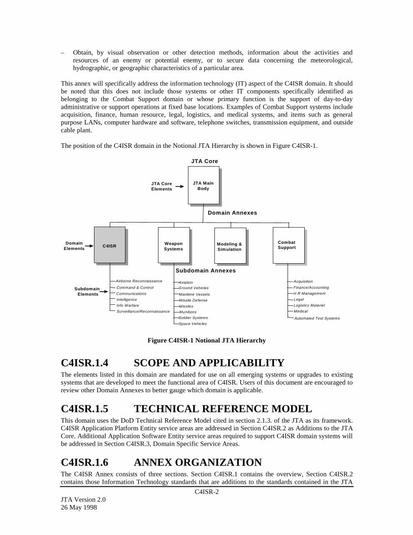
C4ISR-2JTA Version 2.026 May 1998
– Obtain, by visual observation or other detection methods, information about the activities andresources of an enemy or potential enemy, or to secure data concerning the meteorological,hydrographic, or geographic characteristics of a particular area.
This annex will specifically address the information technology (IT) aspect of the C4ISR domain. It shouldbe noted that this does not include those systems or other IT components specifically identified asbelonging to the Combat Support domain or whose primary function is the support of day-to-dayadministrative or support operations at fixed base locations. Examples of Combat Support systems includeacquisition, finance, human resource, legal, logistics, and medical systems, and items such as generalpurpose LANs, computer hardware and software, telephone switches, transmission equipment, and outsidecable plant.
The position of the C4ISR domain in the Notional JTA Hierarchy is shown in Figure C4ISR-1.
Subdomain Annexes
C4ISR WeaponSystems
Modeling &Simulation
CombatSupport
DomainElements
SubdomainElements
Domain Annexes
AviationGround Vehicles
Soldier Systems
Surveillance/Reconnaissance
Space Vehicles
Maritime Vessels
Automated Test Systems
Missile Defense
Munitions
Missiles
JTA MainBody
JTA CoreElements
Acquisition
Finance/Accounting
H R Management
Medical
Logistics Materiel
Legal
JTA Core
Command & Control
Communications
Intelligence
Info Warfare
Airborne Reconnaissance
Figure C4ISR-1 Notional JTA Hierarchy
C4ISR.1.4 SCOPE AND APPLICABILITYThe elements listed in this domain are mandated for use on all emerging systems or upgrades to existingsystems that are developed to meet the functional area of C4ISR. Users of this document are encouraged toreview other Domain Annexes to better gauge which domain is applicable.
C4ISR.1.5 TECHNICAL REFERENCE MODELThis domain uses the DoD Technical Reference Model cited in section 2.1.3. of the JTA as its framework.C4ISR Application Platform Entity service areas are addressed in Section C4ISR.2 as Additions to the JTACore. Additional Application Software Entity service areas required to support C4ISR domain systems willbe addressed in Section C4ISR.3, Domain Specific Service Areas.
C4ISR.1.6 ANNEX ORGANIZATIONThe C4ISR Annex consists of three sections. Section C4ISR.1 contains the overview, Section C4ISR.2contains those Information Technology standards that are additions to the standards contained in the JTA

C4ISR-3JTA Version 2.0
26 May 1998
core, and Section C4ISR.3 is reserved for those mandates for C4ISR that are domain specific because theydo not map directly to the JTA core service areas.
C4ISR.2 ADDITIONS TO THE JTA CORE
C4ISR.2.1 INTRODUCTIONThe C4ISR Domain Annex contains no additions to the elements mandated in the main body of the JTAunless otherwise cited in a specific C4ISR subdomain. The Airborne Reconnaissance (AR) SubdomainAnnex does list additions to the C4ISR elements.
C4ISR.2.2 INFORMATION PROCESSINGSTANDARDS
C4ISR.2.2.1 Mandate AdditionsThere are currently no additions applicable to C4ISR with respect to Information Processing Standards asspecified in Section 2.2 of the JTA. The Airborne Reconnaissance (AR) Subdomain Annex does listadditions to the C4ISR elements.
C4ISR.2.2.2 Emerging StandardsThere are currently no emerging standards identified in this section of the C4ISR domain.
C4ISR.2.3 INFORMATION TRANSFER STANDARDS
C4ISR.2.3.1 Mandate AdditionsThere are no additions applicable to C4ISR with respect to Information Transfer Standards as specified inSection 2.3 of the JTA. The Airborne Reconnaissance (AR) Subdomain Annex does list additions to theC4ISR elements.
C4ISR.2.4 INFORMATION MODELING, METADATA,AND INFORMATION EXCHANGESTANDARDS
C4ISR.2.4.1 Mandate AdditionsThere are no additions applicable to C4ISR with respect to Information Modeling, Metadata, andInformation Exchange Standards as specified in Section 2.4 of the JTA.
C4ISR.2.5 HUMAN-COMPUTER INTERFACESTANDARDS
C4ISR.2.5.1 Mandate AdditionsThere are no additions applicable to C4ISR with respect to Human-Computer Interface Standards asspecified in Section 2.5 of the JTA.

C4ISR-4JTA Version 2.026 May 1998
C4ISR.2.6 INFORMATION SYSTEMS SECURITYSTANDARDS
C4ISR.2.6.1 Mandate AdditionsThere are no additions applicable to C4ISR with respect to Information Systems Security Standards asspecified in Section 2.6 of the JTA.
C4ISR.3 DOMAIN SPECIFIC SERVICE AREASThere are no C4ISR domain specific service areas identified. The Airborne Reconnaissance (AR)Subdomain Annex does list additional service areas.

C4ISR.AR-1JTA Version 2.0
26 May 1998
AIRBORNE RECONNAISSANCE SUBDOMAINANNEX FOR THE C4ISR DOMAINC4ISR.AR.1 AR SUBDOMAIN ANNEX OVERVIEW...........................................................C4ISR.AR-2
C4ISR.AR.1.1 PURPOSE.....................................................................................................C4ISR.AR-2C4ISR.AR.1.2 BACKGROUND ..........................................................................................C4ISR.AR-2C4ISR.AR.1.3 SUBDOMAIN DESCRIPTION....................................................................C4ISR.AR-3C4ISR.AR.1.4 SCOPE AND APPLICABILITY..................................................................C4ISR.AR-4C4ISR.AR.1.5 TECHNICAL REFERENCE MODEL .........................................................C4ISR.AR-5
C4ISR.AR.1.5.1 Background for the AR Functional Reference Model ..............................C4ISR.AR-6C4ISR.AR.1.5.2 AR FRM Traceability ...............................................................................C4ISR.AR-6C4ISR.AR.1.5.3 AR FRM Defined .....................................................................................C4ISR.AR-7
C4ISR.AR.1.6 ANNEX ORGANIZATION .........................................................................C4ISR.AR-7C4ISR.AR.2 ADDITIONS TO C4ISR DOMAIN SERVICE AREAS......................................C4ISR.AR-8
C4ISR.AR.2.1 INTRODUCTION ........................................................................................C4ISR.AR-8C4ISR.AR.2.2 INFORMATION PROCESSING STANDARDS.........................................C4ISR.AR-9
C4ISR.AR.2.2.1 Introduction...............................................................................................C4ISR.AR-9C4ISR.AR.2.2.2 AR Information Processing Mandates ......................................................C4ISR.AR-9
C4ISR.AR.2.2.2.1 Image Processing ...............................................................................C4ISR.AR-9C4ISR.AR.2.2.2.1.1 Imagery Archives.........................................................................C4ISR.AR-9C4ISR.AR.2.2.2.1.2 Common Imagery Ground/Surface System (CIGSS) ................C4ISR.AR-10
C4ISR.AR.2.2.2.2 SIGINT Information Processing ......................................................C4ISR.AR-10C4ISR.AR.2.2.2.3 MASINT Information Processing ....................................................C4ISR.AR-11C4ISR.AR.2.2.2.4 Data Management ............................................................................C4ISR.AR-11
C4ISR.AR.2.2.2.4.1 Target/Threat Data Management ...............................................C4ISR.AR-11C4ISR.AR.2.2.2.4.2 Data Management Services .......................................................C4ISR.AR-11
C4ISR.AR.2.2.3 Emerging Standards................................................................................C4ISR.AR-11C4ISR.AR.2.3 INFORMATION TRANSFER STANDARDS...........................................C4ISR.AR-11
C4ISR.AR.2.3.1 Introduction.............................................................................................C4ISR.AR-11C4ISR.AR.2.3.2 AR Information Transfer Mandates........................................................C4ISR.AR-12
C4ISR.AR.2.3.2.1 Dissemination Systems ....................................................................C4ISR.AR-12C4ISR.AR.2.3.2.2 Data Link Standards.........................................................................C4ISR.AR-12
C4ISR.AR.2.3.3 Emerging Standards................................................................................C4ISR.AR-13C4ISR.AR.2.4 INFORMATION MODELING, METADATA, AND INFORMATION
EXCHANGE STANDARDS......................................................................C4ISR.AR-13C4ISR.AR.2.4.1 Introduction.............................................................................................C4ISR.AR-13C4ISR.AR.2.4.2 AR Information Modeling and Information Mandates ...........................C4ISR.AR-13C4ISR.AR.2.4.3 Emerging Standards................................................................................C4ISR.AR-13
C4ISR.AR.2.5 HUMAN-COMPUTER INTERFACE STANDARDS...............................C4ISR.AR-13C4ISR.AR.2.5.1 Introduction.............................................................................................C4ISR.AR-13C4ISR.AR.2.5.2 AR Human-Computer Interface Mandates .............................................C4ISR.AR-13C4ISR.AR.2.5.3 Emerging Standards................................................................................C4ISR.AR-13
C4ISR.AR.2.6 INFORMATION SYSTEMS SECURITY STANDARDS.........................C4ISR.AR-14C4ISR.AR.2.6.1 Introduction.............................................................................................C4ISR.AR-14C4ISR.AR.2.6.2 AR Information Security Mandates ........................................................C4ISR.AR-14C4ISR.AR.2.6.3 Emerging Standards................................................................................C4ISR.AR-14
C4ISR.AR.3 SUBDOMAIN SPECIFIC SERVICE AREAS...................................................C4ISR.AR-14C4ISR.AR.3.1 SENSOR-TO-PLATFORM INTERFACE .................................................C4ISR.AR-14
C4ISR.AR.3.1.1 Introduction.............................................................................................C4ISR.AR-14C4ISR.AR.3.1.2 AR Sensor-to-Platform Mandates...........................................................C4ISR.AR-15
C4ISR.AR.3.1.2.1 Sensor Mandates ..............................................................................C4ISR.AR-15C4ISR.AR.3.1.2.1.1 IMINT .......................................................................................C4ISR.AR-15
C4ISR.AR.3.1.2.1.1.1 Video Cameras....................................................................C4ISR.AR-15C4ISR.AR.3.1.2.1.1.2 Image Quality Standards.....................................................C4ISR.AR-15C4ISR.AR.3.1.2.1.1.3 Synthetic Aperture Radar....................................................C4ISR.AR-15
C4ISR.AR-2JTA Version 2.026 May 1998
C4ISR.AR.3.1.2.1.2 SIGINT......................................................................................C4ISR.AR-16C4ISR.AR.3.1.2.1.3 MASINT....................................................................................C4ISR.AR-16
C4ISR.AR.3.1.2.1.3.1 Unattended MASINT Sensors ............................................C4ISR.AR-16C4ISR.AR.3.1.2.2 Airborne Platform Mandates ............................................................C4ISR.AR-17
C4ISR.AR.3.1.2.2.1 Timing .......................................................................................C4ISR.AR-17C4ISR.AR.3.1.2.2.2 Navigation, Geospatial ..............................................................C4ISR.AR-17
C4ISR.AR.3.1.2.3 Airborne Platform-Internal Communications...................................C4ISR.AR-17C4ISR.AR.3.1.2.4 Air Vehicle/Sensor Telemetry Mandates .........................................C4ISR.AR-17C4ISR.AR.3.1.2.5 Mission Recorder Mandates.............................................................C4ISR.AR-18
C4ISR.AR.3.1.3 Emerging Standards................................................................................C4ISR.AR-18C4ISR.AR.3.2 COLLECTION MANAGEMENT, MISSION PLANNING, AND
CONTROL..................................................................................................C4ISR.AR-18C4ISR.AR.3.2.1 Introduction.............................................................................................C4ISR.AR-18C4ISR.AR.3.2.2 AR Collection Management, Mission Planning and Control Mandates .C4ISR.AR-18
C4ISR.AR.3.2.2.1 Collection Management Mandates...................................................C4ISR.AR-18C4ISR.AR.3.2.2.2 Mission Planning Mandates .............................................................C4ISR.AR-19C4ISR.AR.3.2.2.3 Mission Control Mandates ...............................................................C4ISR.AR-20
C4ISR.AR.3.2.3 Emerging Standards................................................................................C4ISR.AR-21
C4ISR.AR.1 AR SUBDOMAIN ANNEX OVERVIEW
C4ISR.AR.1.1 PURPOSEThe Airborne Reconnaissance (AR) Subdomain Annex supports four mutually supporting objectives thatprovide the framework for meeting warfighter requirements. First, the AR Subdomain Annex provides thefoundation for seamless flow of information and for interoperability among all airborne reconnaissancesystems and associated ground/surface systems that produce, use, or exchange electronic information.Second, it establishes the minimum set of standards and technical guidelines for development andacquisition of new, upgraded, and demonstration systems to achieve interoperability; with reductions incosts and fielding times that would be unachievable without a technical architecture. Third, it ensuresinteroperability within the Defense Airborne Reconnaissance Programs (DARP) and enables developmentof new or alternative connectivities and operational plans for specific mission scenarios for AR systems.Finally, through coordination with other sections of the JTA, the AR Subdomain Annex takes the first stepin ensuring interoperability between DARP and other DoD systems. Specifically, it provides the frameworkfor attaining interoperability with space-based and other intelligence, surveillance, and reconnaissancesystems.
C4ISR.AR.1.2 BACKGROUNDThis AR Subdomain Annex to the Joint Technical Architecture (JTA) has been developed to providestandards to the DARP. These standards are mandated in order to aid in the development of new ARsystems (or major upgrades of legacy systems). In addition, the standards are designed to facilitate theexchange and exploitation of AR data across the Department of Defense (DoD), and, in Operations OtherThan War (OOTW), to users outside of the DoD. These standards have been determined to be unique to theDARP acquisition, communications, data processing, and user workstation systems. Standards that are notunique to the DARP have been transferred into the C4ISR Domain Annex or the core of the JTA.
The Airborne Reconnaissance Information Technical Architecture (ARITA) was the first attempt toconsolidate all known airborne reconnaissance technical standards into a single document. The AirborneReconnaissance Technical Architecture Working Group (ARTAWG) had representatives from the sensor,platform, communications, ground stations, and collection management/mission domains planning toconsolidate AR standards. Based on the ARTAWG work, the Defense Airborne Reconnaissance Office(DARO) published the ARITA in September 1996. The DARO promoted the ARITA as a stand-alone
C4ISR.AR-3JTA Version 2.0
26 May 1998
reference that incorporated much of the work from the JTA, the Technical Architecture Framework forInformation Management (TAFIM), and others that applied to airborne reconnaissance. In addition theARITA contained many standards that were unique to AR. During this time, the proliferation of numerousarchitectures was addressed by both the Assistant Secretary of Defense for Command, Control,Communications and Intelligence (ASD(C3I)) and the Office of the Secretary of Defense for Acquisitionand Technology (OSD(A&T)). The ARITA was recognized as unique because it addressed both Command,Control, Communications, Computers, and Intelligence (C4I), and the acquisition aspects of airbornereconnaissance systems. Therefore, the ARITA was deemed as a “pathfinder” for the larger architectureconsolidation efforts within the DoD. As such, the Director of DARO elected to migrate the ARITA to theJTA and discontinue publication of the ARITA as a stand-alone document.
This version of the AR Subdomain Annex recognizes only standards that are mandated for AR systems inaddition to those found in corresponding sections of the C4ISR Domain Annex or the JTA core. DARO isin the process of examining all DARP standards. As a result of this effort, future versions of the ARSubdomain Annex will address standards for the DARP that are not yet mature (under the rule set of theJTA), but are expected to develop into AR Subdomain Annex mandated standards. These standards will beplaced in emerging standards sections of this annex.
C4ISR.AR.1.3 SUBDOMAIN DESCRIPTIONThe AR Subdomain Annex to the JTA mandates the minimum set of standards and guidelines forCommand, Control, Communications, Computers, Intelligence, Surveillance, and Reconnaissance (C4ISR)systems relating to manned and unmanned AR systems. The annex provides the technical foundation formigrating AR systems towards the objective architecture identified in the Integrated AirborneReconnaissance Strategy and in the various program plan documents of the DARO. Published DAROdocuments can be found on the World Wide Web at:
http://www.acq.osd.mil/daro
This AR Subdomain Annex adds the standards and guidance required for the airborne reconnaissancedomain and is meant to complement both the C4ISR Domain Annex and the Defense InformationInfrastructure Common Operating Environment (DII COE) as shown in Figure C4ISR.AR-1. The JTA(including the AR Subdomain Annex) and the DII COE supply the high level guidance to the two standardshandbooks governing AR systems: the Joint Airborne Signals Intelligence (SIGINT) Architecture (JASA)Standards Handbook, and the Common Imagery Ground/Surface System (CIGSS) Acquisition StandardsHandbook. These standards handbooks provide the most specific guidance for implementing the airborneefforts of the Imagery Intelligence (IMINT) and SIGINT communities and their corresponding umbrellaprograms. Airborne Measurement and Signature Intelligence (MASINT) standards will eventually bedocumented in the Joint Airborne MASINT Architecture (JAMA). An umbrella program, the DistributedCommon Ground Systems (DCGS), has been proposed to eliminate potential duplication of IMINT,SIGINT, and MASINT ground station development. DCGS was chartered to develop a single groundsystem for these three intelligence areas under a common reference model.
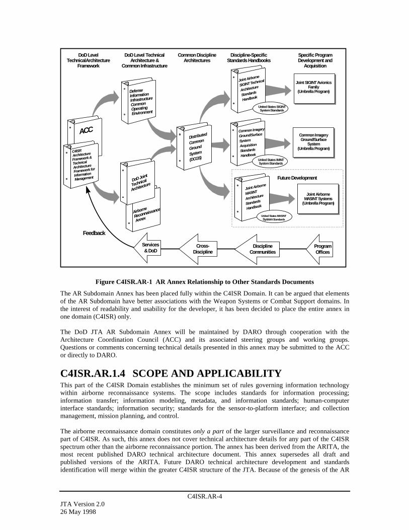
C4ISR.AR-4JTA Version 2.026 May 1998
DoD Level TechnicalArchitecture &
Common Infrastructure
Discipline-SpecificStandards Handbooks
Specific ProgramDevelopment and
Acquisition
DoD LevelTechnicalArchitecture
Framework
DoD Joint
Technical
Architecture
Airborne
Reconnaissance
Annex
Joint Airborne
SIGINT Technical
Architecture
Standards
Handbook
Joint SIGINT AvionicsFamily
(Umbrella Program)
United States SIGINTSystem Standards
Common Imagery
Ground/Surface
SystemAcquisition
Standards
Handbook
Common ImageryGround/Surface
System(Umbrella Program)
United States IMINTSystem Standards
ACC
C4ISR Architecture
Framework &
TechnicalArchitecture
Framework for
Information
Management
DefenseInformationInfrastructure
CommonOperatingEnvironment
Feedback
ProgramOffices
DisciplineCommunities
Services& DoD
Joint AirborneMASINT Systems
(Umbrella Program)
United States MASINTSystem Standards
Joint Airborne
MASINT
Architecture
Standards
Handbook
Future Development
Distributed
Common
Ground
System
(DCGS)
Common DisciplineArchitectures
Cross-Discipline
Figure C4ISR.AR-1 AR Annex Relationship to Other Standards Documents
The AR Subdomain Annex has been placed fully within the C4ISR Domain. It can be argued that elementsof the AR Subdomain have better associations with the Weapon Systems or Combat Support domains. Inthe interest of readability and usability for the developer, it has been decided to place the entire annex inone domain (C4ISR) only.
The DoD JTA AR Subdomain Annex will be maintained by DARO through cooperation with theArchitecture Coordination Council (ACC) and its associated steering groups and working groups.Questions or comments concerning technical details presented in this annex may be submitted to the ACCor directly to DARO.
C4ISR.AR.1.4 SCOPE AND APPLICABILITYThis part of the C4ISR Domain establishes the minimum set of rules governing information technologywithin airborne reconnaissance systems. The scope includes standards for information processing;information transfer; information modeling, metadata, and information standards; human-computerinterface standards; information security; standards for the sensor-to-platform interface; and collectionmanagement, mission planning, and control.
The airborne reconnaissance domain constitutes only a part of the larger surveillance and reconnaissancepart of C4ISR. As such, this annex does not cover technical architecture details for any part of the C4ISRspectrum other than the airborne reconnaissance portion. The annex has been derived from the ARITA, themost recent published DARO technical architecture document. This annex supersedes all draft andpublished versions of the ARITA. Future DARO technical architecture development and standardsidentification will merge within the greater C4ISR structure of the JTA. Because of the genesis of the AR

C4ISR.AR-5JTA Version 2.0
26 May 1998
Subdomain Annex (from the ARITA), this version does not include many emerging standards. An ongoingeffort by the DARO will identify emerging standards for future versions of the JTA.
The JTA mandates the minimum set of standards and guidelines for the acquisition of all DoD systems thatproduce, use, or exchange information. The main body of the JTA (the “core”) provides the standards thatare applicable across the entire DoD information technology spectrum. If a service area in the core appliesto an AR system being developed, and there is no corresponding service area in the C4ISR Annex, then thestandard(s) listed in a core service area apply. The mandates found in the C4ISR Annex are intended toaugment those found in the core. If additional service area standards are found in the C4ISR Annex, thedeveloper must select the service area standards from both the core and the C4ISR Annex. Similarly, theAR Subdomain Annex is intended to augment the C4ISR Annex. Applicable service area mandates foundin the AR Subdomain Annex must be used in addition to the service area mandates found in the C4ISRAnnex and the core. When multiple mandates are required in this process, the mandate selection whichoffers the best technical and business solution is the preferred decision.
Since airborne reconnaissance does cross domain boundaries, a certain degree of flexibility for citation ofstandards is necessary in order to meet the intent of the JTA. The AR Subdomain Annex references specificstandards using the same rule set as the remainder of the JTA except for the following situation. In a fewsections (e.g., Section C4ISR.AR.3.1.2.1.3.1 for Unattended MASINT Sensors), an Interface ControlDocument (ICD) has been mandated with a selected profile of Intelligence, Surveillance, andReconnaissance (ISR) standards and tailored standards. This is necessary to meet the intent of the JTA topromote interoperability by acknowledging the dual C4ISR and Weapon Systems aspects of airbornereconnaissance. The JTA rules (Section 1) do allow “guidance” for interpretation of specific standards. Thealternative, in this case, of specifying only a suite of standards instead of providing guidance through anICD obscures the common ISR interfaces so vital to fully integrated, open systems. The selectiveapplication of ICDs, with corresponding standards profiles, will promote interoperability by combiningstandards with stable, open interfaces.
The AR Subdomain Annex may list multiple standards for individual service areas. Similarly, the core andthe Annex may offer multiple solutions within a single service area. For these cases, it is not required thatthe developer implement all standards listed. A subset should be selected based on technical merit anddesign/cost constraints. Future versions of this annex will have detailed information on standardsimplementation and standards profiles. The intent, as previously stated, is to promote a minimum set ofstandards for interoperability among DoD AR systems.
C4ISR.AR.1.5 TECHNICAL REFERENCE MODELAs strictly defined by the C4ISR Integrated Architecture Panel, C4ISR Architecture Framework,“architectures” address multiple aspects crossing the boundaries of operational, technical, and system levelarchitectures. The AR Subdomain Annex focuses on the technical architecture level and specificallyidentifies only those standards that have a direct bearing on airborne reconnaissance systems.
In order to achieve the desired focus, the AR Subdomain Annex uses a different reference model than theJTA technical reference model (TAFIM DoD TRM). This model variant is the AR Functional ReferenceModel (FRM). The complementary FRM and DoD TRM frameworks (or perspectives) are used to presentand discuss the technology and information standards selected for virtually any C4ISR system. The DoDTRM, as derived from the TAFIM, is primarily a software-based model. It was originally developed forcovering information technology within the DoD. Domain-specific standards, such as those required tocover all of airborne reconnaissance, do not fit fully within a software-based model. The FRM has thereforebeen adopted by DARO to encompass the airborne reconnaissance standards. It is used as a standardstraceability matrix between the DARP architectures. The FRM depicts the generic, functional makeup ofairborne reconnaissance systems, and shows how the various functions are interrelated. It is particularlywell suited for showing which specific technology standards apply to each functional area.

C4ISR.AR-6JTA Version 2.026 May 1998
C4ISR.AR.1.5.1 Background for the AR Functional Reference ModelThe AR FRM provides a common framework for defining the scope and functional makeup of airbornereconnaissance systems. The FRM is critical for selecting standards and effectively depicting where theymust be applied in the overall framework. Based on the functional model developed by the JASA workinggroup and approved by the Defense Airborne Reconnaissance Steering Committee (DARSC), the FRMincorporates additional functions found in IMINT and MASINT systems, explicit mission planning andcontrol functions, and expanded communications functions for integrating airborne reconnaissance withwarfighter and other C4I systems (e.g., command and control systems, air tasking, and collectionmanagement). The AR FRM is shown in Figure C4ISR.AR-2.
Reach Back& ReachForward
Special Pre-Processing
FilmCameras
EOSensors
InfraredSensors
VideoCameras
SyntheticApertureRadar
SpectralSensors
MovingTarget
Indicator
Special Pre-Processing
CBWSensors
LWRSensors
UnattendedGroundSensors
AirSampling
SyntheticApertureRadar
SpectralSensors
SensorControls
RFSensors
Special Pre-Processing
Low BandTuners
IFDigitizers
Subtuners/Digitizers
RF Distribution
IFDistribution
MissionRecorders
Set-OnReceivers
High BandTuners
IFDistribution
Sensor/Platform Integration Mechanics
Navigation,Timing, and
Ancillary Data
EncryptedStorage
DirectReporting M
LG
Direct to ShootersDirect Intel Inputs
Syst. Planningand Control Databases Servers Product
Libraries
Warfighters &IntelligenceCommunity
ISR Community
Digital SignalProcessing
C2
Interface Warfighters & IntelCommunity Planningand Control Systems
Dat
a Li
nk
Multimedia Network
C2 Network
Multimedia Network
C2 Network
Front-End Processing High PerformanceProcessing
System Planning andControl
Functional Areas
High Speed Data Flow Network
SIGINT Front-End IMINT Front-End MASINT Front-End
SEN
SOR
TO
PL
AT
FO
RM
PL
AT
FO
RM
TO
CO
MM
S
CO
MM
S T
O G
RO
UN
D S
YST
EM
S
HU
MA
N/C
OM
PU
TE
R I
NT
ER
FA
CE
Navigation, Timing, &Ancillary Data Networking
SystemProcessingand Control
MLG
Reporting andConnectivity
Operator OrientedProcessing
OperatorWorkstations
OperatorWorkstations M
LGM
LG
OperatorReporting
Figure C4ISR.AR-2 Airborne Reconnaissance Functional Reference Model
C4ISR.AR.1.5.2 AR FRM TraceabilityIn addition to this technical architecture, the DARO uses both operational and systems architectures todefine and lead airborne reconnaissance systems. Both the operational and systems architectures willexamine airborne reconnaissance using a functional flow approach. In each of these evolving architectures,there must be traceability back to standards as defined in this AR Subdomain Annex FRM. Where theoperational functional flow or the system functional flow cannot be traced back to a set of standards (i.e., a“block” as shown in the FRM illustration), the FRM will require updating. Similarly, where the FRMblocks cannot be traced to both an operational component and a system component, the operational orsystem architecture model will require updating. Thus, the FRM model, as used in the airbornereconnaissance technical architecture described in this annex, will provide a cross-comparison capability
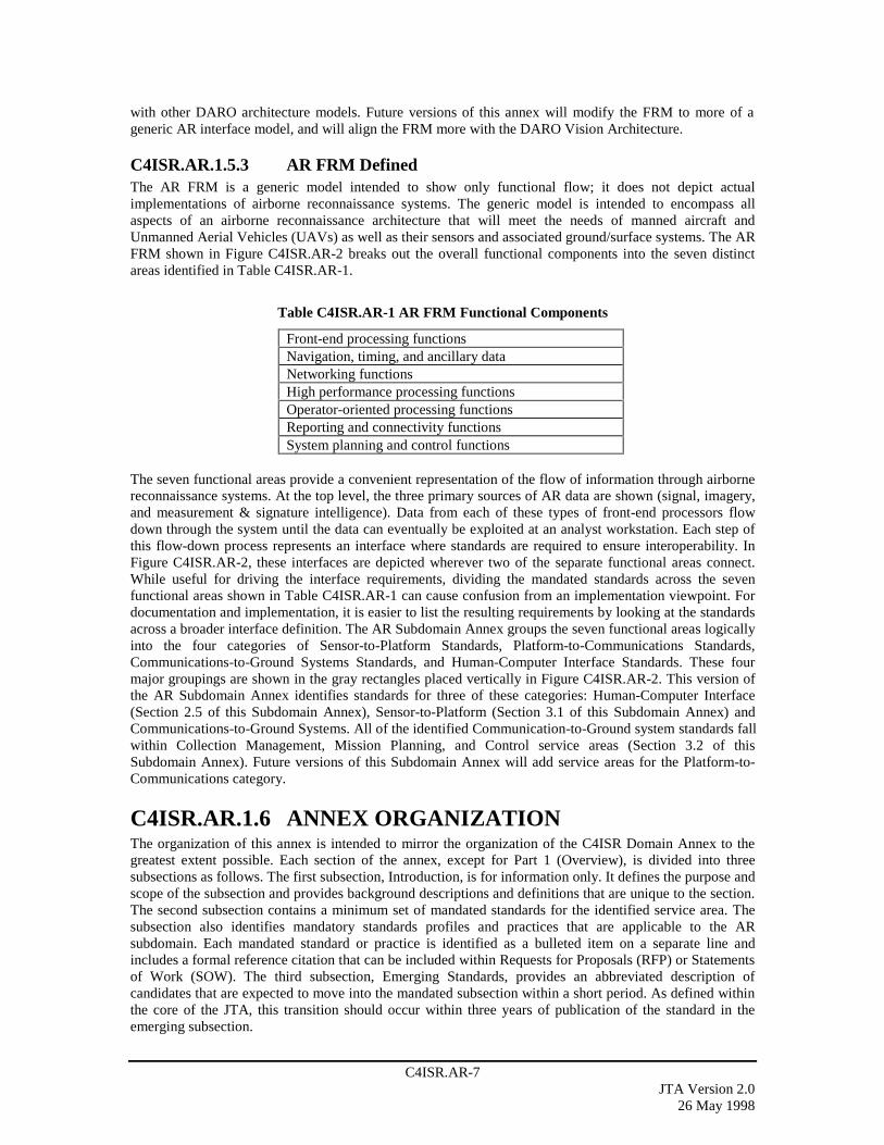
C4ISR.AR-7JTA Version 2.0
26 May 1998
with other DARO architecture models. Future versions of this annex will modify the FRM to more of ageneric AR interface model, and will align the FRM more with the DARO Vision Architecture.
C4ISR.AR.1.5.3 AR FRM DefinedThe AR FRM is a generic model intended to show only functional flow; it does not depict actualimplementations of airborne reconnaissance systems. The generic model is intended to encompass allaspects of an airborne reconnaissance architecture that will meet the needs of manned aircraft andUnmanned Aerial Vehicles (UAVs) as well as their sensors and associated ground/surface systems. The ARFRM shown in Figure C4ISR.AR-2 breaks out the overall functional components into the seven distinctareas identified in Table C4ISR.AR-1.
Table C4ISR.AR-1 AR FRM Functional Components
Front-end processing functionsNavigation, timing, and ancillary dataNetworking functionsHigh performance processing functionsOperator-oriented processing functionsReporting and connectivity functionsSystem planning and control functions
The seven functional areas provide a convenient representation of the flow of information through airbornereconnaissance systems. At the top level, the three primary sources of AR data are shown (signal, imagery,and measurement & signature intelligence). Data from each of these types of front-end processors flowdown through the system until the data can eventually be exploited at an analyst workstation. Each step ofthis flow-down process represents an interface where standards are required to ensure interoperability. InFigure C4ISR.AR-2, these interfaces are depicted wherever two of the separate functional areas connect.While useful for driving the interface requirements, dividing the mandated standards across the sevenfunctional areas shown in Table C4ISR.AR-1 can cause confusion from an implementation viewpoint. Fordocumentation and implementation, it is easier to list the resulting requirements by looking at the standardsacross a broader interface definition. The AR Subdomain Annex groups the seven functional areas logicallyinto the four categories of Sensor-to-Platform Standards, Platform-to-Communications Standards,Communications-to-Ground Systems Standards, and Human-Computer Interface Standards. These fourmajor groupings are shown in the gray rectangles placed vertically in Figure C4ISR.AR-2. This version ofthe AR Subdomain Annex identifies standards for three of these categories: Human-Computer Interface(Section 2.5 of this Subdomain Annex), Sensor-to-Platform (Section 3.1 of this Subdomain Annex) andCommunications-to-Ground Systems. All of the identified Communication-to-Ground system standards fallwithin Collection Management, Mission Planning, and Control service areas (Section 3.2 of thisSubdomain Annex). Future versions of this Subdomain Annex will add service areas for the Platform-to-Communications category.
C4ISR.AR.1.6 ANNEX ORGANIZATIONThe organization of this annex is intended to mirror the organization of the C4ISR Domain Annex to thegreatest extent possible. Each section of the annex, except for Part 1 (Overview), is divided into threesubsections as follows. The first subsection, Introduction, is for information only. It defines the purpose andscope of the subsection and provides background descriptions and definitions that are unique to the section.The second subsection contains a minimum set of mandated standards for the identified service area. Thesubsection also identifies mandatory standards profiles and practices that are applicable to the ARsubdomain. Each mandated standard or practice is identified as a bulleted item on a separate line andincludes a formal reference citation that can be included within Requests for Proposals (RFP) or Statementsof Work (SOW). The third subsection, Emerging Standards, provides an abbreviated description ofcandidates that are expected to move into the mandated subsection within a short period. As defined withinthe core of the JTA, this transition should occur within three years of publication of the standard in theemerging subsection.
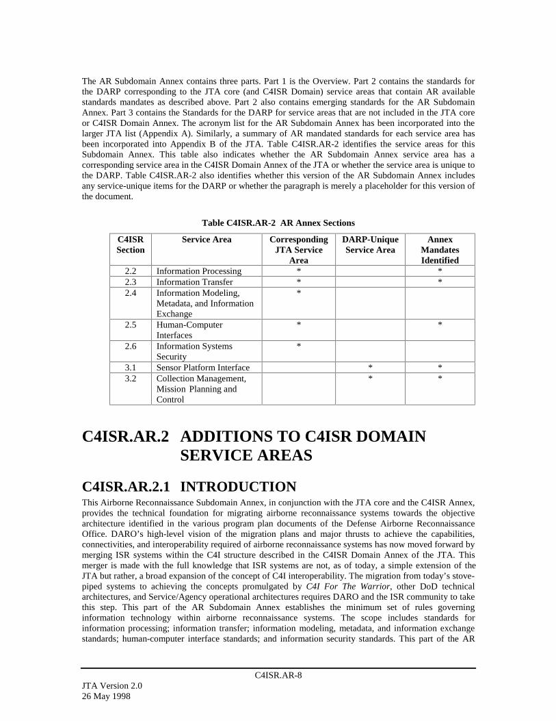
C4ISR.AR-8JTA Version 2.026 May 1998
The AR Subdomain Annex contains three parts. Part 1 is the Overview. Part 2 contains the standards forthe DARP corresponding to the JTA core (and C4ISR Domain) service areas that contain AR availablestandards mandates as described above. Part 2 also contains emerging standards for the AR SubdomainAnnex. Part 3 contains the Standards for the DARP for service areas that are not included in the JTA coreor C4ISR Domain Annex. The acronym list for the AR Subdomain Annex has been incorporated into thelarger JTA list (Appendix A). Similarly, a summary of AR mandated standards for each service area hasbeen incorporated into Appendix B of the JTA. Table C4ISR.AR-2 identifies the service areas for thisSubdomain Annex. This table also indicates whether the AR Subdomain Annex service area has acorresponding service area in the C4ISR Domain Annex of the JTA or whether the service area is unique tothe DARP. Table C4ISR.AR-2 also identifies whether this version of the AR Subdomain Annex includesany service-unique items for the DARP or whether the paragraph is merely a placeholder for this version ofthe document.
Table C4ISR.AR-2 AR Annex Sections
C4ISRSection
Service Area CorrespondingJTA Service
Area
DARP-UniqueService Area
AnnexMandatesIdentified
2.2 Information Processing * *2.3 Information Transfer * *2.4 Information Modeling,
Metadata, and InformationExchange
*
2.5 Human-ComputerInterfaces
* *
2.6 Information SystemsSecurity
*
3.1 Sensor Platform Interface * *3.2 Collection Management,
Mission Planning andControl
* *
C4ISR.AR.2 ADDITIONS TO C4ISR DOMAINSERVICE AREAS
C4ISR.AR.2.1 INTRODUCTIONThis Airborne Reconnaissance Subdomain Annex, in conjunction with the JTA core and the C4ISR Annex,provides the technical foundation for migrating airborne reconnaissance systems towards the objectivearchitecture identified in the various program plan documents of the Defense Airborne ReconnaissanceOffice. DARO’s high-level vision of the migration plans and major thrusts to achieve the capabilities,connectivities, and interoperability required of airborne reconnaissance systems has now moved forward bymerging ISR systems within the C4I structure described in the C4ISR Domain Annex of the JTA. Thismerger is made with the full knowledge that ISR systems are not, as of today, a simple extension of theJTA but rather, a broad expansion of the concept of C4I interoperability. The migration from today’s stove-piped systems to achieving the concepts promulgated by C4I For The Warrior, other DoD technicalarchitectures, and Service/Agency operational architectures requires DARO and the ISR community to takethis step. This part of the AR Subdomain Annex establishes the minimum set of rules governinginformation technology within airborne reconnaissance systems. The scope includes standards forinformation processing; information transfer; information modeling, metadata, and information exchangestandards; human-computer interface standards; and information security standards. This part of the AR
C4ISR.AR-9JTA Version 2.0
26 May 1998
Subdomain Annex does not contain rules for the physical, mechanical, or electrical components of systems,even when these are related to information technology.
C4ISR.AR.2.2 INFORMATION PROCESSINGSTANDARDS
C4ISR.AR.2.2.1 IntroductionThis annex expands the concept of information within a C4I system to include the information processingof ISR sensor systems. Much of this processing is embedded within the sensor systems themselves and theavionics on-board reconnaissance assets. It is important to note that ISR systems encompass both real-timeand non-real-time architectures. The sensor, platform, telemetry, and data link systems within ISR are allreal-time, embedded systems that require speeds at least three orders of magnitude higher than traditionalC4I systems. Real-time systems also require deterministic scheduling and robust fault tolerance. The DoDTRM, adopted for use by the JTA, does not accommodate real-time and embedded systems. On the otherhand, once raw data is delivered to the ground, non-real-time processing and dissemination systems followthe current JTA/TRM model.
It is not the intent of the AR Subdomain Annex to force DII COE compliance on those AR systems wherethe DII COE cannot presently provide a reasonable solution (e.g., real-time systems or multi-level securitysystems). These situations must be evaluated on a case-by-case basis. The JTA waiver process is designedto allow flexibility in implementation details when there are overriding technical or economic concerns.This annex does endorse compliance with the DII COE I&RTS (as defined in the JTA core) in the absenceof a submitted waiver.
As intelligence time lines continue to shrink to weapon systems (shooter) time lines, speed will becomeeven more critical for operational systems. Much of this architecture is based on real-time processing anddoes not follow the Technical Reference Model described in the JTA. Real time systems may be closer tothe Society of Automotive Engineers (SAE) Generic Open Architecture (GOA). The DII COE is alsoworking towards a DoD-wide real-time architecture model. Ongoing work by the TRM Working Groupwill resolve this disconnect in a manner that, if possible, accommodates both weapon systems and C4Isystems.
User requirements for specific ISR missions define information processing within the three intelligencedisciplines (IMINT, SIGINT and MASINT) as defined below. These standards encompass all software inassociated ground/surface systems as well as software embedded in airborne reconnaissance systems.
C4ISR.AR.2.2.2 AR Information Processing Mandates
C4ISR.AR.2.2.2.1 Image ProcessingThis AR Subdomain Annex defines image processing as the conversion of raw data into a product that canbe exploited. Imagery is defined as any Electro Optical (EO), Infrared (IR), or Synthetic Aperture Radar(SAR) data stream collected by an imaging sensor that can be visualized on an exploitation terminal. Thesequence of steps needed to extract information and prepare an exploitation product depends upon therequired external environment interface (EEI), the shapes of the objects in the scene, illumination andshadows, and military and physical contexts.
C4ISR.AR.2.2.2.1.1 Imagery ArchivesThe primary function for product libraries is to maintain a complete set of all reconnaissance productsproduced (in a given system) and make them available to all potential users on a query or browse basis.Although the products may include conventional formatted message reports, product libraries are mostuseful for disseminating newer “specialized” products such as video and audio clips, imagery, graphics,multi-media, and hypertext products like those available on the Internet. Dissemination of these products

C4ISR.AR-10JTA Version 2.026 May 1998
and access to the product libraries will be through the Internet protocol router networks such as NIPRNET,SIPRNET, and JWICS. Although there are no mandated standards for this area, compatibility with theNIMA Library Program (NLP) [formerly Image Product Archive (IPA) and Image Product Library (IPL)]is required. The NLP is described in the US Imagery and Geospatial Information System (USIGS)Architecture.
C4ISR.AR.2.2.2.1.2 Common Imagery Ground/Surface System (CIGSS)The Common Imagery Ground/Surface System (CIGSS) concept, which is now a segment of the DCGSdescribed in Part 1, has been approved by the Joint Requirements Oversight Council (JROC) and is fullysupported by the DoD Services. It is not a system in the traditional sense; instead, CIGSS is an umbrellaprogram that defines interoperability, performance, and commonality requirements and standards for DoDground/surface based imagery processing and exploitation systems. It consolidates the systems listed inTable C4ISR.AR-3 into a single DARP project.
Table C4ISR.AR-3 CIGSS Component Programs
Joint Service Image Processing System (JSIPS) program – including Navy, Air Force, and Marine CorpsArmy’s Enhanced Tactical Radar Correlator (ETRAC)Army’s Modernized Imagery Exploitation System (MIES)Imagery parts of the Air Force’s Contingency Airborne Reconnaissance System (CARS)Marine Corps’ Tactical Exploitation Group (TEG) programsKorean Combined Operational Intelligence Center (KCOIC) imagery systemsPacific Air Forces Interim National Exploitation System (PINES)Mobile Intelligence Processing Element (MIPE)Integrated Deployable Processing System (IPDS)Processing/exploitation capability for the U-2R SENIOR YEAR Electro-Optical (E/O) sensor (SENIORBLADE)
CIGSS-compliant (mandated) systems are designed to receive, process, exploit and disseminate imageryproducts derived from satellites, commercial or foreign satellite sensors, UAV, U-2 reconnaissance aircraftand tactical aircraft such as the F/A-18. CIGSS will be afforded increased flexibility and capability insatisfying multiple time-sensitive user needs. Once compliant with common community processing,storage, retrieval, and dissemination standards, CIGSS modularity will enable the theater, JTF andcomponents to employ interactive CIGSS elements for small regional contingencies and major regionalconflicts from a variety of sources to meet the anticipated intelligence demand. This annex mandates thestandards identified in the most current approved handbook for airborne IMINT:
• Common Imagery Ground/Surface System (CIGSS) Acquisition Standards Handbook, Version 1, 19July 1995.
C4ISR.AR.2.2.2.2 SIGINT Information ProcessingThe Joint Airborne SIGINT Architecture (JASA) is the DoD’s plan for meeting the warfighter’s 2010 andbeyond airborne SIGINT requirements. The fundamental philosophy behind JASA is to leveragecommercial digital signal processor technology to address the ever growing population of varied radiofrequency (RF) signals, modulation schemes and signal multiplexing structures. By digitizing the signalearly in the sensor system, common hardware processing can be used that is independent of signal type,reducing the need for signal specific specialized hardware. This approach to signal processing increases theflexibility and overall capacity of the SIGINT system, which must rapidly respond to the explosion ofdigital signals in the environment.
Version 2.0 of the JASA Standards Handbook, developed by the JASA Standards Working Group, waspublished in October 1997. This AR Subdomain Annex mandates the standards identified in the handbookfor airborne SIGINT systems:
• Joint Airborne SIGINT Architecture Standards Handbook, Version 2.0, 30 October 1997.

C4ISR.AR-11JTA Version 2.0
26 May 1998
C4ISR.AR.2.2.2.3 MASINT Information ProcessingThe Central MASINT Office (CMO) is currently developing a MASINT architecture under the umbrella ofthe US MASINT System (USMS) program. The airborne portion of the USMS is called the Joint AirborneMASINT Architecture (JAMA). As a part of JAMA, a MASINT Standards Handbook will be developed.Upon publication, it will be evaluated for incorporation into this AR Subdomain Annex. There arepresently no MASINT-specific information processing mandates identified.
C4ISR.AR.2.2.2.4 Data ManagementAirborne Reconnaissance data management supports the definition, storage, retrieval, and distribution ofdata elements (e.g., imagery and support data) derived from data collected by airborne sensors and sharedby multiple applications/systems.
C4ISR.AR.2.2.2.4.1 Target/Threat Data ManagementThe National Target/Threat Signature Data System (NTSDS) has been designated as a migration system, inaccordance with guidance from ASD(C3I) and by the Intelligence Systems Board (ISB). NTSDS providesthe DoD signature data community (ISR, MASINT, & Armament) signature data from multiple,geographically distributed sites via a unified national system. NTSDS Data Centers employ standard dataparameters and formats for stored target signatures for national and DoD customers. There are no ARAnnex mandates for target/threat data management. However, compatibility with the NationalTarget/Threat Signature Database System is required.
C4ISR.AR.2.2.2.4.2 Data Management ServicesThese services support the definition, storage, and retrieval of data elements from monolithic anddistributed relational Database Management Systems (DBMSs). These services also support platform-independent file management (e.g., the creation, access, and destruction of files and directories). Thisannex follows the JTA core that mandates conformance to entry level ANSI Structured Query Language(SQL) standards and adds Ada interfaces. There are presently no additional AR Annex Data ManagementService standards beyond those listed elsewhere in the JTA.
C4ISR.AR.2.2.3 Emerging StandardsThis version of the AR Annex does not identify any emerging standards for information processing. Anongoing effort by the DARO will identify emerging standards for future versions of the JTA.
C4ISR.AR.2.3 INFORMATION TRANSFER STANDARDS
C4ISR.AR.2.3.1 IntroductionNear-real-time dissemination of Joint Service tactical intelligence information hinges on informationtransfer standards. To ensure continued battlespace awareness and to satisfy the requirement for secure,high-speed, multi-media transmission services, an integration of several intelligence broadcasts into onestandard system is probable.
Information transfer standards and profiles described in this section cover dissemination and data linkmandates for ISR systems. This section identifies systems and the interface standards that are required forinteroperability between and among ISR systems and are in addition to the systems described in the JTAcore and the C4ISR Domain Annex. This section does not cover standards for platform internal informationtransfer. These standards will be covered in the Sensor-to-Platform service areas of this Subdomain Annex.
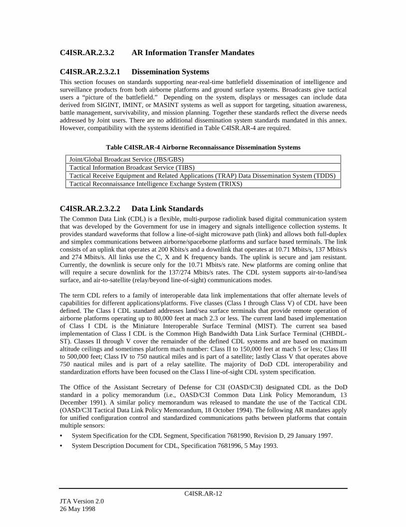
C4ISR.AR-12JTA Version 2.026 May 1998
C4ISR.AR.2.3.2 AR Information Transfer Mandates
C4ISR.AR.2.3.2.1 Dissemination SystemsThis section focuses on standards supporting near-real-time battlefield dissemination of intelligence andsurveillance products from both airborne platforms and ground surface systems. Broadcasts give tacticalusers a “picture of the battlefield.” Depending on the system, displays or messages can include dataderived from SIGINT, IMINT, or MASINT systems as well as support for targeting, situation awareness,battle management, survivability, and mission planning. Together these standards reflect the diverse needsaddressed by Joint users. There are no additional dissemination system standards mandated in this annex.However, compatibility with the systems identified in Table C4ISR.AR-4 are required.
Table C4ISR.AR-4 Airborne Reconnaissance Dissemination Systems
Joint/Global Broadcast Service (JBS/GBS)Tactical Information Broadcast Service (TIBS)Tactical Receive Equipment and Related Applications (TRAP) Data Dissemination System (TDDS)Tactical Reconnaissance Intelligence Exchange System (TRIXS)
C4ISR.AR.2.3.2.2 Data Link StandardsThe Common Data Link (CDL) is a flexible, multi-purpose radiolink based digital communication systemthat was developed by the Government for use in imagery and signals intelligence collection systems. Itprovides standard waveforms that follow a line-of-sight microwave path (link) and allows both full-duplexand simplex communications between airborne/spaceborne platforms and surface based terminals. The linkconsists of an uplink that operates at 200 Kbits/s and a downlink that operates at 10.71 Mbits/s, 137 Mbits/sand 274 Mbits/s. All links use the C, X and K frequency bands. The uplink is secure and jam resistant.Currently, the downlink is secure only for the 10.71 Mbits/s rate. New platforms are coming online thatwill require a secure downlink for the 137/274 Mbits/s rates. The CDL system supports air-to-land/seasurface, and air-to-satellite (relay/beyond line-of-sight) communications modes.
The term CDL refers to a family of interoperable data link implementations that offer alternate levels ofcapabilities for different applications/platforms. Five classes (Class I through Class V) of CDL have beendefined. The Class I CDL standard addresses land/sea surface terminals that provide remote operation ofairborne platforms operating up to 80,000 feet at mach 2.3 or less. The current land based implementationof Class I CDL is the Miniature Interoperable Surface Terminal (MIST). The current sea basedimplementation of Class I CDL is the Common High Bandwidth Data Link Surface Terminal (CHBDL-ST). Classes II through V cover the remainder of the defined CDL systems and are based on maximumaltitude ceilings and sometimes platform mach number: Class II to 150,000 feet at mach 5 or less; Class IIIto 500,000 feet; Class IV to 750 nautical miles and is part of a satellite; lastly Class V that operates above750 nautical miles and is part of a relay satellite. The majority of DoD CDL interoperability andstandardization efforts have been focused on the Class I line-of-sight CDL system specification.
The Office of the Assistant Secretary of Defense for C3I (OASD/C3I) designated CDL as the DoDstandard in a policy memorandum (i.e., OASD/C3I Common Data Link Policy Memorandum, 13December 1991). A similar policy memorandum was released to mandate the use of the Tactical CDL(OASD/C3I Tactical Data Link Policy Memorandum, 18 October 1994). The following AR mandates applyfor unified configuration control and standardized communications paths between platforms that containmultiple sensors:
• System Specification for the CDL Segment, Specification 7681990, Revision D, 29 January 1997.
• System Description Document for CDL, Specification 7681996, 5 May 1993.
C4ISR.AR-13JTA Version 2.0
26 May 1998
C4ISR.AR.2.3.3 Emerging StandardsThe airborne reconnaissance dissemination systems listed in Table C4ISR.AR-4 are to be replaced by theIntegrated Broadcast Service (IBS) over the next five years. The IBS IOC is expected in 2002.
C4ISR.AR.2.4 INFORMATION MODELING, METADATA,AND INFORMATION EXCHANGESTANDARDS
C4ISR.AR.2.4.1 IntroductionThis section identifies standards applicable to information modeling and exchange of information forairborne reconnaissance systems. Information Modeling, Metadata, and Information Exchange Standardspertain to activity models, data models, data definitions, and information exchange among systems.
C4ISR.AR.2.4.2 AR Information Modeling and Information MandatesThis version of the AR Subdomain Annex does not specify any additional standards for informationmodeling and information.
C4ISR.AR.2.4.3 Emerging StandardsThis version of the AR Subdomain Annex does not identify any emerging standards for informationmodeling, metadata and information exchange.
C4ISR.AR.2.5 HUMAN-COMPUTER INTERFACESTANDARDS
C4ISR.AR.2.5.1 IntroductionThis subsection identifies the mandatory standards, profiles, and practices for human-computer interfaces.The human-computer interface is an extremely important AR function. It is an area that is evolving quicklydue in large part to rapid advances in commercial video technologies. These commercial interfaces havebeen released to the public only to be replaced in a very short time by the next generation of products. Thisrapid pace has produced few standards. However, the speed of technology advance is expected to produceseveral breakthroughs for information/understanding transfer to reconnaissance operations.
C4ISR.AR.2.5.2 AR Human-Computer Interface MandatesCurrently, the ISR community has no additional standards, beyond those in the core of the JTA, forimagery display systems.
C4ISR.AR.2.5.3 Emerging StandardsThe Tactical Control System (TCS) is being designed and developed to provide a common set of Human-Computer Interfaces for interoperability with the family of Tactical UAVs. TCS HCI design requirementsare contained within the TCS Block 0 Software Requirements Specification, (TCS Document ControlNumber: TCS-103), and the TCS Human-Computer Interface Requirements Specification, (TCS DocumentControl Number: TCS-108). These documents will be adopted as formal emerging standards followingtheir official release.
C4ISR.AR-14JTA Version 2.026 May 1998
C4ISR.AR.2.6 INFORMATION SYSTEMS SECURITYSTANDARDS
C4ISR.AR.2.6.1 IntroductionInformation systems security standards protect information and the processing platform resources. Theymust often be combined with security procedures, which are beyond the scope of the informationtechnology service areas, to fully meet operational security requirements. Security services include securitypolicy, accountability, assurance, user authentication, access control, data integrity and confidentiality, non-repudiation, and system availability control. The mandated and emerging standards identified in Section 2.6of the JTA apply to the AR subdomain. ISR reporting includes dissemination of formatted message traffic,imagery, imagery products, database transaction updates, and graphical situation display data. In general,these products are widely disseminated through the DoD communications infrastructure.
C4ISR.AR.2.6.2 AR Information Security MandatesIntelligence information can be disseminated from Unclassified to TS/SCI. For the AR Subdomain, thereare presently no additions to the information security mandates listed in the JTA core.
C4ISR.AR.2.6.3 Emerging StandardsThis version of the AR Subdomain Annex does not identify any emerging standards for informationsecurity. An ongoing effort by the DARO will identify emerging standards for future versions of the JTA.
C4ISR.AR.3 SUBDOMAIN SPECIFIC SERVICEAREAS
C4ISR.AR.3.1 SENSOR-TO-PLATFORM INTERFACE
C4ISR.AR.3.1.1 IntroductionThis section identifies the minimum standards for airborne sensors and the interface to the airborne sensorplatforms. These interfaces allow sensor data, both raw and pre-processed, to transfer through airbornecommunications/telemetry systems and to mission recording equipment. Conversely, aircraft data such asnavigation, timing, or telemetry inputs to control on-board sensors (e.g., optics, SAR spot coverage) mustpass through this interface as well. Eventually, the interfaces will become more platform independent andsensor system independent as these standards evolve towards open systems.
Airborne reconnaissance sensors are the source of all ISR information. Their output, combined with on-board flight information such as position and altitude, produces a raw data set that is normally notconsidered useful information until it is processed and disseminated to the warfighter consumer. Much ofthis processing is done on board within real-time systems and these must interface seamlessly within thehost aircraft. This section lists standards that apply to that interface.
This section addresses the critical components of the interface between the sensor system and the hostaircraft. This interface includes: sensor to external environment; sensor control; data recording; aircraftpower; navigation/flight data information to the sensor system; timing; internal communications; avionicsbusses and back planes; telemetry; and sensor preprocessing. Sensor systems have been divided intoimagery, signals, and MASINT.
C4ISR.AR-15JTA Version 2.0
26 May 1998
C4ISR.AR.3.1.2 AR Sensor-to-Platform Mandates
C4ISR.AR.3.1.2.1 Sensor MandatesAll airborne reconnaissance systems begin with a platform-integrated SIGINT, IMINT, or MASINT sensor.The specific functions of the front-end sensors are completely different and are discussed separately withinthe following subsections.
C4ISR.AR.3.1.2.1.1 IMINTIMINT front-end functions are divided into ten major areas: seven image acquisition sensors, sensor controlfunctions, special pre-processing functions, and mission recorders. The following subsections describeIMINT sensors and the specific standards that apply.
C4ISR.AR.3.1.2.1.1.1 Video CamerasLegacy AR video systems currently use analog components. For analog systems, the base video standard isthe National Television Standards Committee (NTSC) signal provided in RS-170 format. Commercialindustry is currently migrating away from analog video components to all-digital systems. Airbornereconnaissance systems will leverage advances in commercial television technology that provide thestandards for interoperability for commercial broadcast and military video systems. AR systems shouldprovide a clear migration path toward an all-digital system, conforming to the mandated standards of theJTA core. There are no additional video camera standards mandated for the AR community.
C4ISR.AR.3.1.2.1.1.2 Image Quality StandardsImage quality is the single most critical factor determining the utility of the image for data exploitation.Image quality is dependent upon physical features of the collection system (e.g., focal length, lens quality,number and spread of multispectral sensors, and density of the sensor array), the geometric relationships atthe time of imaging (e.g., distance and angle between the sensor and the target), target and transmissionmedia features (e.g., acquisition angle and degree of illumination, image degradation from cloud cover andsmoke), and errors introduced in the processing stream (e.g., data dropouts and “noisy” communicationpaths). The user communities for panchromatic, multispectral and radar imagery have developed a series ofscales to rate the quality of the received imagery. These scales condense the many factors influencing theimage into a single rating that defines the overall usability of the image. Common rating scales include theNational Imagery Interpretability Rating Scale (NIIRS) for optical imagery, National Radar ImageryInterpretation Standard (NRIIS) for Synthetic Aperture Radar, and Multispectral Imagery InterpretabilityRating Scale (MSIIRS) for spectral imagery.
For video imagery systems, the Department of Defense/Intelligence Community/United States Imagery andGeospatial System (DoD/IC/USIGS) Video Working Group Video Imagery Standards Profile (VISP),Version 1.21, 7 January 1998, defines a "Video Systems (Spatial and Temporal) Matrix" (VSM). ThisRecommended Practice gives user communities an easy to use, common shorthand reference language todescribe the fundamental technical capabilities of DoD/IC video imagery systems. The "Video SystemsMatrix" includes tables of Technical Specifications and related Notes.
There are no AR community mandated standards for image quality beyond those referenced in the JTAcore.
C4ISR.AR.3.1.2.1.1.3 Synthetic Aperture RadarSynthetic Aperture Radar (SAR) is the most commonly used type of radar for imagery reconnaissanceapplications. The systems are called synthetic aperture because the combination of the individual radarreturns effectively creates one large antenna with an effective aperture size equivalent to the flight path-length traversed during the signal integration. The formation of this large synthetic aperture is what enablesthese radars to produce images with fine in-track (for azimuthal) resolution. The high bandwidth and pulserepetition interval enables the SAR’s fine cross track (or range) resolution. The image can be produced withground resolutions less than one foot, when operating in “spot” mode, and approach photographic

C4ISR.AR-16JTA Version 2.026 May 1998
appearance and interpretability. In search modes, ground sample distance (more correctly radar impulseresponse) is often ten feet or more. It is common practice to smooth the navigation and timing data for SARusing Kalman filtering techniques. The following standard practice is therefore mandated for the ARcommunity:
• Kalman filtering for navigation and timing, as originally defined in Kalman, R.E., A new approach tolinear filtering and prediction problems, Trans. ASME, Series D, J. Basic Eng., V. 82, March 1960.
C4ISR.AR.3.1.2.1.2 SIGINTSIGINT front-end standards are concerned primarily with on-board systems that receive and process radiofrequency (RF) from low frequency (LF), 30 KHz to 300 KHz, through extra high frequency (EHF),30 GHz to 300 GHz, received by the platform antenna/antenna arrays. These RF antenna/antenna arraytypes may be omni-directional, directional, beam-steered, steered dish, interferometric, or spinning dish. Inaddition, the SIGINT front-end functional elements include the RF distribution, low and high band tuners,set-on receivers, IF distribution IF digitizers, and sub-band tuners/digitizers, and channelizers. SIGINTsensor/platform interface standards are identified in the following reference:
• Joint Airborne SIGINT Architecture Standards Handbook, Version 2.0, 30 October 1997.
C4ISR.AR.3.1.2.1.3 MASINTTwo important distinctions between MASINT and other intelligence systems are the maturity and diversityof the component systems. MASINT technologies are both immature and diverse. The MASINT disciplineencompasses the seven technological areas of remote sensing identified in Table C4ISR.AR-5. Within eachof the seven areas there are numerous implementations, many of which are still in the research anddevelopment phase, which makes the creation of standards a much more difficult task. Where possible,standards for MASINT systems will be specified in this document. This version of the AR annex onlyidentifies a single standard for unattended MASINT sensors.
Table C4ISR.AR-5 MASINT Technology Areas
Chemical and Biological Weapons (CBW)LASINT/Laser Warning Receivers (LWR)Unattended Ground Sensors (UGS)Spectral (Non-literal)Air SamplingRadio Frequency (RF)Synthetic Aperture Radar Phase History (SAR PH)
The Joint Airborne MASINT Architecture (JAMA) is a much needed effort to define the overallarchitecture for airborne MASINT systems and the corresponding standards. The JAMA, when initiated,will be fully integrated with JASA where RF MASINT and SIGINT systems overlap. Similarly, the SARPH and spectral MASINT airborne areas will be fully coordinated with CIGSS to maximize intelligenceassets.
C4ISR.AR.3.1.2.1.3.1 Unattended MASINT SensorsUnattended MASINT Sensors (UMS) are small, autonomously powered, disposable systems that can beemplaced by airborne platforms or hand emplaced. UMS can contain one or more types of sensors (seismic,acoustic, IR, magnetic, chemical, or radiological) that transmit alarm messages or data when triggered byenemy activity. The SEIWG-005 standard specifies the frequencies, data formats, and protocols for thisclass of sensors in order to relay the data back via communication links and data relays, to a commonexploitation station. The following UMS standard is mandated for AR systems:
• Interface Specification, Radio Frequency Transmission Interfaces for DoD Physical Security Systems,SEIWG-005, 15 December 1981.
C4ISR.AR-17JTA Version 2.0
26 May 1998
C4ISR.AR.3.1.2.2 Airborne Platform MandatesThis AR Annex does not cover the technical architecture details for the airborne platform except for thosedetails that directly affect the on-board reconnaissance sensors and the processing of the collected datastream. Power, timing, and navigation standards are critical for the operation of the sensors, thetransmission of data, and the exploitation of the gathered information.
C4ISR.AR.3.1.2.2.1 TimingTiming is critical for airborne sensor systems and directly affects the overall quality of the finished airbornereconnaissance product. All processing and exploitation functions use timing data in some way whenprocessing the sensor data. The following timing standards are mandated for AR systems:
• Telemetry Group, Range Commanders Council, Telemetry Standards, IRIG 106-96, Secretariat, RangeCommanders Council, U.S. Army White Sands Missile Range, New Mexico, 21 March 1996, Chapter4, Pulse Coded Modulation Standards, Chapter 8 - MIL-STD-1553 Department of Defense InterfaceStandard for Digital Time Division Command/Response Multiplex Data Bus.
C4ISR.AR.3.1.2.2.2 Navigation, GeospatialNavigation service provides information about the position and attitude (roll, pitch and yaw) of thecollection platform. Navigation and geospatial data are parts of the metadata associated with sensor data,and are critical to sensor data exploitation. The following navigation and geospatial standards are mandatedfor AR systems:
• SNU-84-1, Revision D Specification for USAF Standard Form, Fit, and Function (F3) MediumAccuracy Inertial Navigation Unit (INS), 21 September 1992.
• ICD-GPS-200, Interface Control Document GPS (200), 1 July 1992.
C4ISR.AR.3.1.2.3 Airborne Platform-Internal CommunicationsInternal communications for on-board networks are used to apply real-time commands to control on-boardsensors, distribution of raw/pre-processed digital sensor data between processing components, andmetadata tagged to the sensor data. The numerous standards referenced below must be selected based onthe platform. Their selection depends on whether the end platform is an unmanned aerial vehicle or mannedvehicle. For example, most UAVs will not require a LAN capacity needed for a Rivet Joint or AWACS.Depending upon the application environment, one of more of the following mandated standards shall beselected for AR systems:
• MIL-STD-1553B, Notice 4, Department of Defense Interface Standard for Digital Time DivisionCommand/Response Multiplex Data Bus, 15 January 1996.
• ANSI X3.184, Information Systems - Fiber Distributed Data Interface (FDDI) Single-Mode FiberPhysical Layer Medium Dependent (SMF-PMD) (100 Mb/s dual counter rotating ring), 1 January1993.
• ANSI X3.230, Information Technology - Fiber Channel - Physical and Signaling Interface (FC-PH),(800 Mb/s), 1 January 1996.
C4ISR.AR.3.1.2.4 Air Vehicle/Sensor Telemetry MandatesCommands to various SIGINT, IMINT, and MASINT front-end equipment flow through airbornetelemetry systems to on-board LANs. Sensor commands and acknowledgments may include positionchanges, mode changes, fault isolation commands, and others. The mandated telemetry standard is:
• Telemetry Group, Range Commanders Council, Telemetry Standards, IRIG 106-96, Secretariat, RangeCommanders Council, U.S. Army White Sands Missile Range, New Mexico, Chapter 4, Pulse CodedModulation Standards, Chapter 8 - MIL-STD-1553 Department of Defense Interface Standard forDigital Time Division Command/Response Multiplex Data Bus, 21 March 1996.
C4ISR.AR-18JTA Version 2.026 May 1998
C4ISR.AR.3.1.2.5 Mission Recorder MandatesMission recorders are used to capture the raw, pre-processed sensor data together with associatednavigation, timing, and ancillary data. Additionally a computer controlled interface for basic recorderfunctions such as start, stop, shuttle, fast forward, and rewind is included.
In conjunction with recording the raw sensor data, timing data will be recorded (on a separate track) inaccordance with the standards defined below. The DCRsi 240 rack mount and modular ruggedized systemsare one inch, transverse scan, rotary digital recorders capable of recording and reproducing at any user datarate from 0 to 30 Mbytes/sec (0-240 Mbits/sec). The ANSI digital recording standard, providing datacompatibility and tape interchangeability, is provided by the X3.175 series. The Instrumentation GroupIRIG-B standard was written specifically for analog magnetic tape storage. In conjunction with themigration to all digital systems, mission recorder standards will be re-evaluated to emphasize digital andde-emphasize analog.
To support digital recording activities, the following mission recorder standards are mandated for use inAR systems:
• Compatibility with the published “AMPEX Digital Instrumentation Recorder DCRSi 240 UserManual.”
• ANSI X3.175, 19-mm Type ID-1 Recorded Instrumentation - Digital Cassette Tape Form, 1990, ID 1.
To support analog recording activities, the following mission recorder standard is mandated for use in ARsystems:
• Instrumentation Group (IRIG) B format as defined in IRIG Document 104-70, August 1970.
C4ISR.AR.3.1.3 Emerging StandardsThis version of the AR Annex does not identify any emerging standards for the sensor platform interface.An ongoing effort by the DARO will identify emerging standards for future versions of the JTA.
C4ISR.AR.3.2 COLLECTION MANAGEMENT, MISSIONPLANNING, AND CONTROL
C4ISR.AR.3.2.1 IntroductionThis annex defines standards for collection management, mission planning and mission control which areintegral parts of airborne reconnaissance systems. Collection management is a process that is performed bya Collection Management Authority (CMA) which uses a specific collection management system. Missionplanning is a process that may be performed within an airborne reconnaissance system or it may beperformed externally. Mission control is a process that deals with execution of specific reconnaissancemissions.
C4ISR.AR.3.2.2 AR Collection Management, Mission Planning, and ControlMandates
C4ISR.AR.3.2.2.1 Collection Management MandatesCollection requirements are generated by warfighters and then allocated to the Collection ManagementAuthority (CMA). The CMA uses the Joint Collection Management Tool (JCMT) to provide an overviewof the requirements database. JCMT assists the CMA in determining the appropriate collection platform ormix of assets required to perform the mission. The CMA’s collection management system provides thereconnaissance feedback to the warfighters who originated the requests for information. JCMT is themigration system designated by the DoD to be used for all-source management functions (i.e., legacysystems will be phased out as JCMT supersedes them). As such, it will combine IMINT, SIGINT,MASINT, and HUMINT tasking.
C4ISR.AR-19JTA Version 2.0
26 May 1998
On 28 October 1994, the Assistant Secretary of Defense for Command, Control, Communications andIntelligence (ASD(C3I)) approved the recommendations from the Intelligence Systems Board MigrationPanel that: 1) JCMT become the DoD Intelligence Information Systems (DODIIS) migration system forall-source collection management, and 2) the Army’s Collection Management Support Tools (CMST)become the initial baseline for JCMT. According to ASD (C3I) direction, migration systems are to replaceall legacy systems in FY97. Besides CMST, the legacy systems which JCMT will replace include DIA'sCollection Requirements Management Application (CRMA), USAF National Air Intelligence Center's(NAIC) Collection Requirements Management System (CRMS), Operational Support Office's (OSO)UNIX-based National Exercise Support Terminal (UNEST), and SOUTHCOM’s Intelligence SupportProcessing Tool (ISPT).
For the AR domain, compatibility with the Joint Collection Management Tool (JCMT) is a requirement. Inaddition, the following standard for country codes is mandated for collection management functions:
• FIPS PUB 10-4: April 1995, Countries, Dependencies, Areas of Special Sovereignty, MunicipalDivisions.
C4ISR.AR.3.2.2.2 Mission Planning MandatesA multitude of mission planning systems exist today. Many of these are special applications that weredesigned for specific aircraft and operate on specific hardware suites. There are formal, programmaticefforts underway to consolidate these into several generic systems. Two of these were picked asrepresentative systems for purposes of developing this annex: the U.S. Navy’s Tactical Aviation MissionPlanning System (TAMPS) and the USAF Air Force Mission Support System (AFMSS). Note that otherspecific mission planning systems have been consolidated into these two programs. TAMPS consists of acore and a number of mission planning modules for specific Navy, Marine Corps, and Coast Guard aircraftand weapons. AFMSS contains a core and a number of Avionics/Weapons/Electronics (AWE) modules forspecific Air Force, Army, and US Special Operations Command aircraft and weapons. Long-term plans callfor combining these into one DoD-wide mission planning system.
While both the TAMPS and AFMSS programs show plans to provide mission planning capabilities forreconnaissance platforms (such as the U-2, UAVs, RC-135, EP-3, F/A-18 and others), the plans aregenerally for platform and navigation planning only (e.g., flight path, threat avoidance, take-off and landingcalculations, or fuel consumption). Mission planning modules for the reconnaissance sensor systempayloads and communications system planning are currently not in the baseline.
The interfaces required for mission planning functions vary depending on specific system operationalrequirements and mission needs. For example, systems operated by the USAF will receive intelligence datafrom the unit-level Combat Information System (CIS), whereas the Army will generally rely on their AllSource Analysis System (ASAS). Regardless of the source of the data, it will generally be received inairborne reconnaissance systems through the command and control interfaces or via bulk digital mediasuch as magnetic tape and CD-ROM. There are no mandated mission planning standards for the ARdomain. However, depending upon the service supported by the reconnaissance asset, compatibility withthe Air Force Mission Support System (AFMSS), the Tactical Aviation Mission Planning System(TAMPS), the USAF Combat Intelligence System (CIS), the Joint Maritime Combat Intelligence System(JMCIS), or the USA All Source Analysis System (ASAS) is essential.
The Tactical Control System (TCS) Tactical UAV Route and Payload Planner (RPP) is being designed anddeveloped to provide a common route and payload planner for the family of Tactical UAVs. Air vehicleroute planning, modular mission payload planning, plan verification, plan uplink, plan monitoring, and plandisplay are provided by the TCS RPP. These two standards are mandated for tactical UAVs:
• TCS RPP design requirements are contained within the TCS RPP Software Requirements SpecificationVersion 1.0, 14 November 1997 (TCS Document Control Number: TCS-303).
• The Tactical Control System (TCS) Flight Route Plan to Tactical Control System, Version 1.0Interface Design Description (IDD), (TCS Document Control Number: TCS-244, 1 October 1997,
C4ISR.AR-20JTA Version 2.026 May 1998
provides the standard Flight Route and Payload Plan file format to be used for compatibility with theTCS RPP and TCS Core Software.
C4ISR.AR.3.2.2.3 Mission Control MandatesMission control functions provide for real-time and near-real-time control of the platform, sensor suite, andcommunications subsystems during the execution of reconnaissance missions. These control functions areimplemented in ground/surface subsystems and consist of three types: remote piloting functions andtelemetry data, remote sensor control functions, and dynamic retasking functions.
Currently, there are no standards in this annex for manned aircraft. However, for remotely piloted UAVs,telemetry data are transmitted to the ground/surface system and piloting commands are transmitted to thevehicle via the data link in real-time. For UAVs, the Mission Planning and Control Station (MPCS)consists of the equipment necessary to perform mission planning, mission control, communications anddata exploitation for one or more UAVs. Mission control includes the capability to hand over or takecontrol of another UAV to/from another MPCS and prepare or process all the data which must betransmitted to the air vehicle to conduct the mission. The telemetry data essentially provides the same datathat would otherwise be displayed to a cockpit pilot, but it is processed and displayed on ground-basedequipment. As an aid to the ground-based “pilot,” telemetry data also includes real-time video (e.g., in thevisible part of the spectrum). The remote piloting functions are also used to facilitate take-off and landingfor UAVs that may otherwise operate autonomously by executing programmed flight and sensor operationsplans.
Remote sensor control functions serve to extend real-time, direct control of the collection equipment tooperators stationed in ground/surface systems. Remote commands may include, for example, turningreceivers, aiming directional antenna, changing sensor modes, pointing cameras, adjusting focal length andexposure, setting on-board processing parameters, and a host of other operator-controlled functions. TheMPCS is capable of receiving, storing, displaying, and exploiting Modular Mission Payloads (MMP) datareceived from the Air Vehicle (AV), reformatting the data and transmitting that data to appropriate internaland external users. The MPCS manages the data link and controls the data link operating parameters.
Dynamic retasking functions enable reconnaissance operations to be changed in near-real-time bydesignated users/operators. Changes may affect the platform, such as navigating to a new track (flightpath), or they may affect the sensor suites, such as switching SAR modes or switching from SIGINT toimagery collection.
For all current and future Tactical UAVs, the Tactical Control System has been identified as the system thatwill provide for real-time and near-real time control of the platform, sensor suite, and communicationssubsystems, as well as payload product and tactical data dissemination to identified C4I systems during theexecution of Tactical UAV missions.
The Tactical Control System (TCS) provides an open architecture system that supports interoperability withall Tactical UAVs. The TCS architecture consists of real-time and non-real time core components and airvehicle specific components integrated using standardized interfaces, networking and data servertechnologies, and software applications that support distributive processing, functional scaleability,modularity, and portability across service standard computing platforms. The TCS software and hardwarearchitectures have been developed in compliance with the requirements of the JTA and the DII COE. TCSprovides the necessary physical components, human-computer interface, Tactical UAV route and payloadplanner, air vehicle monitoring and control applications, tactical message communications processing, andthe connectivity necessary to receive tasking, operate Tactical UAVs and sensors, and support payloadproduct and tactical data dissemination to identified C4I systems.
The following standards are mandated for use in AR systems for any mission planning and control systemthat is interoperable with Tactical UAVs:
• TCS SDD 117, Tactical Control System (TCS) Software Design Description (SDD), Version 1.0, 31March 1997 (TCS Document Control Number: TCS-117).
C4ISR.AR-21JTA Version 2.0
26 May 1998
• TCS JII 2, Tactical Control System Joint Interoperability Interface 2 (JII 2) - Tactical Control Systemto Service Command, Control, Communications, Computers and Intelligence (C4I) Systems, Version1.0, 9 May 1997 (TCS Document Control Number: TCS-233).
• TCS IDD 229, Tactical Control System Segment to Air Vehicle Standard Segment Interface (TCSAVSI) Interface Design Description (IDD), Version 1.2, 29 August 1997 (TCS Document ControlNumber: TCS-229).
C4ISR.AR.3.2.3 Emerging StandardsThis version of the AR Subdomain Annex does not identify any emerging standards for collectionmanagement, mission planning, and control. An ongoing effort by the DARO will identify emergingstandards for future versions of the JTA.
C4ISR.AR-22JTA Version 2.026 May 1998
This page intentionally left blank.
CS-1JTA Version 2.0
26 May 1998
COMBAT SUPPORT DOMAIN ANNEXCS.1 DOMAIN OVERVIEW................................................................................................................CS-1
CS.1.1 PURPOSE .............................................................................................................................CS-1CS.1.2 BACKGROUND...................................................................................................................CS-1CS.1.3 DOMAIN DESCRIPTION ...................................................................................................CS-1CS.1.4 SCOPE AND APPLICABILITY..........................................................................................CS-2CS.1.5 TECHNICAL REFERENCE MODEL .................................................................................CS-2CS.1.6 ANNEX ORGANIZATION .................................................................................................CS-2
CS.2 ADDITIONS TO JTA CORE.......................................................................................................CS-2CS.2.1 INTRODUCTION ................................................................................................................CS-2CS.2.2 INFORMATION PROCESSING STANDARDS.................................................................CS-3
CS.2.2.1 Document Interchange ..................................................................................................CS-3CS.2.2.2 Graphics Data Interchange ............................................................................................CS-3CS.2.2.3 Product Data Interchange..............................................................................................CS-3CS.2.2.4 Electronic Data Interchange ..........................................................................................CS-3
CS.2.3 INFORMATION TRANSFER STANDARDS.....................................................................CS-4CS.2.3.1 Additions.......................................................................................................................CS-4CS.2.3.2 Emerging Standards ......................................................................................................CS-4
CS.2.4 INFORMATION MODELING, METADATA, AND INFORMATION EXCHANGESTANDARDS.......................................................................................................................CS-4
CS.2.5 HUMAN-COMPUTER INTERFACE STANDARDS.........................................................CS-4CS.2.6 INFORMATION SYSTEMS SECURITY STANDARDS...................................................CS-5
CS.3 DOMAIN SPECIFIC SERVICE AREAS ....................................................................................CS-5
CS.1 DOMAIN OVERVIEW
CS.1.1 PURPOSEThe Combat Support Domain Annex was developed to help Combat Support Elements migrate toward acommon technical architecture. This technical architecture will enable the entire DoD community tounderstand the nuances of the Combat Support community. The goal is to have the rest of DoD communitycommunicate with the Combat Support Elements and either adopt their practices or work to eliminate thedifferences.
CS.1.2 BACKGROUNDThere are numerous information technology services that support Warfighter activities. These services needto be made interoperable with the rest of the DoD community.
CS.1.3 DOMAIN DESCRIPTIONThe Combat Support domain addresses those specific elements necessary for the production, use, orexchange of information within and among systems supporting personnel, logistics, and other functionsrequired to maintain operations or combat (see Figure CS-1). The Combat Support domain consists ofautomated systems that perform combat service support and administrative business functions, such asacquisition, finance, human resources management, legal, logistics, transportation and medical functions.
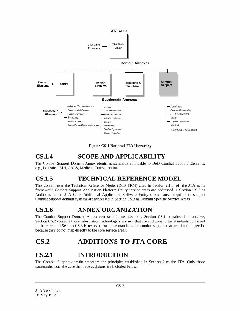
CS-2JTA Version 2.026 May 1998
Subdomain Annexes
C4ISR WeaponSystems
Modeling &Simulation
CombatSupport
DomainElements
SubdomainElements
Domain Annexes
Aviation
Ground Vehicles
Soldier Systems
Surveillance/Reconnaissance
Space Vehicles
Maritime Vessels
Automated Test Systems
Missile Defense
Munitions
Missiles
JTA MainBody
JTA CoreElements
Acquisition
Finance/Accounting
H R Management
Medical
Logistics Materiel
Legal
JTA Core
Command & Control
CommunicationsIntelligence
Info Warfare
Airborne Reconnaissance
Figure CS-1 Notional JTA Hierarchy
CS.1.4 SCOPE AND APPLICABILITYThe Combat Support Domain Annex identifies standards applicable to DoD Combat Support Elements,e.g., Logistics, EDI, CALS, Medical, Transportation.
CS.1.5 TECHNICAL REFERENCE MODELThis domain uses the Technical Reference Model (DoD TRM) cited in Section 2.1.3. of the JTA as itsframework. Combat Support Application Platform Entity service areas are addressed in Section CS.2 asAdditions to the JTA Core. Additional Application Software Entity service areas required to supportCombat Support domain systems are addressed in Section CS.3 as Domain Specific Service Areas.
CS.1.6 ANNEX ORGANIZATIONThe Combat Support Domain Annex consists of three sections. Section CS.1 contains the overview,Section CS.2 contains those information technology standards that are additions to the standards containedin the core, and Section CS.3 is reserved for those mandates for combat support that are domain specificbecause they do not map directly to the core service areas.
CS.2 ADDITIONS TO JTA CORE
CS.2.1 INTRODUCTIONThe Combat Support domain embraces the principles established in Section 2 of the JTA. Only thoseparagraphs from the core that have additions are included below.
CS-3JTA Version 2.0
26 May 1998
CS.2.2 INFORMATION PROCESSINGSTANDARDS
CS.2.2.1 Document InterchangeCALS has developed a set of standards that apply to this service area. CALS SGML profiles the ISOstandard (8879) by selecting a particular Document Type Definition (DTD) and other parameters that helpstandardize the development of technical manuals for DoD. CALS also developed a handbook for applyingCALS SGML (MIL-HDBK-28001, 30 June 1995). Although HTML is also a subset of SGML, it is notsufficiently robust enough for TM development. [XML may replace both CALS SGML and HTML in thefuture.] CALS also has a standard for archiving documents (1840C). The mandated standards for theCALS Document Interchange BSA are:
• MIL-PRF-28001C, Markup Requirements and Generic Style Specification for Electronic PrintedOutput and Exchange of Text. (CALS SGML), 2 May 1997.
• MIL-STD-1840C, Automated Interchange of Technical Information (AITI), 26 June 1997.
CS.2.2.2 Graphics Data InterchangeCALS has developed a metadata standard which profiles the ISO CGM standard (8632). The latest FIPS128-2 also profiles the CGM ISO standard and incorporates CALS CGM (see 2.2.2.2.1.4.2). There is also aCALS Raster Standard that puts raster graphics in a binary format. The mandated standards for the CALSGraphics Data Interchange BSA are:
• ISO 8632 as profiled by MIL-PRF-28003A.
• MIL-PRF-28002C, Requirements for Raster Graphics Representation in Binary Format, 30 September1997.
The Medical Community has developed a standard for digital image transfer. The following mandatorystandard applies to the Medical Imagery Data Interchange BSA:
• NEMA/ACR DICOM V3.0, parts 1-12, Digital Imaging and Communication in Medicine, 1993.
CS.2.2.3 Product Data InterchangeCALS has developed a standard that profiles the IGES standard for Engineering Drawings. IGES is usedfor CAD/CAM applications. The latest FIPS also profiles IGES and incorporates CALS IGES. CALSSTEP is an international standard, which depicts products in three dimensions. MIL-STD-2549 wasdeveloped to replace MIL-STD-973, Configuration Management. The AITI (MIL-STD-1840C) also hasformats for product data archiving. The Bar Code used by DoD is documented in AIM BC1 “UniformSymbology specification Code 39.” Users are cautioned to evaluate this document for their particularapplication before citing it as a replacement document of MIL-STD-1189B. The mandatory standards forthe Product Data Interchange BSA are:
• FIPS PUB 177-1, IGES, adopts CALS IGES and ANSI/US PRO-100-1993, V5.2, 23 April 1996.
• MIL-PRF-28000A w/AMD 1, Digital Representation for Communications of Product Data: IGESApplication Subsets and IGES Application Protocols, 14 December 1992.
• ISO/IEC 10303-1:1994 Standards for the Exchange of Product Model Data (STEP), Part 1: Overviewand Principles.
• MIL-STD-2549, Configuration Management Data Interface, 30 June 1997.
• MIL-STD-1840C, Automated Interchange of Technical Information, 26 June 1997.
CS.2.2.4 Electronic Data InterchangeElectronic Data Interchange (EDI) is a new Base Service Area specializing in the computer-to-computerexchange of business information using a public standard. EDI is a central part of Electronic Commerce(EC). EC is the paperless exchange of business information. The FIPS Pub (161-2) establishes the Federal
CS-4JTA Version 2.026 May 1998
EDI Standards Management Coordinating Committee (FESMCC) to harmonize the development of EDItransaction sets and message standards among Federal agencies, and the adoption of Government-wideimplementation conventions. The Federally approved Implementation Conventions may be viewed on theWorld Wide Web at:
http:// www.antd.nist.gov/fededi/l.
The DoD EDI Standards Management Committee (EDISMC) was established for the purpose ofcoordinating EDI standardization activities within the DoD. The EDISMC supports the development,adoption, publication, and configuration management of EDI implementation conventions for DoD. TheDoD EDISMC manages the efforts of several Functional Working Groups (FWGs). The DoD FWGs havebeen established in the following areas: Logistics, Finance, Healthcare, Transportation, Procurement,Communications, Command and Control. EDISMC approved implementation conventions are submitted tothe FESMCC for approval as Federal implementation conventions. DoD approved implementationconventions may be viewed on the World Wide Web at:
http://www-edi.itsi.disa.mil.
FIPS PUB 161-2, 22 May 1996, Electronic Data Interchange (EDI) adopts, with specific conditions, ANSIASC X12, UN/EDIFACT and ANSI HL7.
The following standards are mandated as profiled by FIPS PUB 161-2:
• ANSI ASC X12 Electronic Data Interchange (ASC X12S 97-372 is latest edition).
• ANSI HL7 Version 2.3 (is the latest edition).
• ISO UN/EDIFACT.
CS.2.3 INFORMATION TRANSFER STANDARDS
CS.2.3.1 AdditionsThere are no additions for the Information Transfer Standards section
CS.2.3.2 Emerging StandardsThe following standard is not mandated in this version of the JTA, but is an emerging standard for the nextversion of the JTA:
IEEE 1073, Protocol for Medical Device Communications, 1996.
CS.2.4 INFORMATION MODELING, METADATA,AND INFORMATION EXCHANGESTANDARDS
There are no additions or emerging standards for the Combat Support Information Modeling, Metadata, andInformation Exchange Standards section.
CS.2.5 HUMAN-COMPUTER INTERFACESTANDARDS
There are no additions or emerging standards for the Combat Support Human-Computer InterfaceStandards section.

CS-5JTA Version 2.0
26 May 1998
CS.2.6 INFORMATION SYSTEMS SECURITYSTANDARDS
EC/EDI have security services associated with ANSI ASC X12 transactions. ANSI ASC X12.58 is adescription of that security but is not mandated.
CS.3 DOMAIN SPECIFIC SERVICE AREASThere are no domain specific service areas for the Combat Support Domain.
CS-6JTA Version 2.026 May 1998
This page intentionally left blank.
CS.ATS-1JTA Version 2.0
26 May 1998
AUTOMATIC TEST SYSTEMS SUBDOMAINANNEX FOR THE COMBAT SUPPORT DOMAINCS.ATS.1 SUBDOMAIN OVERVIEW ................................................................................... CS.ATS-2
CS.ATS.1.1 PURPOSE............................................................................................................ CS.ATS-2CS.ATS.1.2 BACKGROUND ................................................................................................. CS.ATS-2CS.ATS.1.3 SUBDOMAIN DESCRIPTION........................................................................... CS.ATS-3CS.ATS.1.4 SCOPE AND APPLICABILITY......................................................................... CS.ATS-4CS.ATS.1.5 TECHNICAL REFERENCE MODEL ................................................................ CS.ATS-5
CS.ATS.1.5.1 Hardware ....................................................................................................... CS.ATS-5CS.ATS.1.5.2 Software......................................................................................................... CS.ATS-6
CS.ATS.1.6 ANNEX ORGANIZATION ................................................................................ CS.ATS-8CS.ATS.1.7 CONFIGURATION MANAGEMENT ............................................................... CS.ATS-8
CS.ATS.2 ADDITIONS TO THE JTA CORE.......................................................................... CS.ATS-8CS.ATS.2.1 INTRODUCTION ............................................................................................... CS.ATS-8CS.ATS.2.2 INFORMATION PROCESSING STANDARDS................................................ CS.ATS-9
CS.ATS.2.2.1 Mandate Additions......................................................................................... CS.ATS-9CS.ATS.2.2.1.1 Instrument Driver API Standards ........................................................... CS.ATS-9CS.ATS.2.2.1.2 Digital Test Data Formats....................................................................... CS.ATS-9
CS.ATS.2.2.2 Emerging Standards....................................................................................... CS.ATS-9CS.ATS.2.2.2.1 Instrument Driver API Standards ........................................................... CS.ATS-9CS.ATS.2.2.2.2 Digital Test Data Formats....................................................................... CS.ATS-9CS.ATS.2.2.2.3 Generic Instrument Class Standards ....................................................... CS.ATS-9CS.ATS.2.2.2.4 Diagnostic Processing Standards .......................................................... CS.ATS-10CS.ATS.2.2.2.5 Adapter Function and Parametric Data Standards ................................ CS.ATS-10CS.ATS.2.2.2.6 ATS Instrument Function and Parametric Data Standards ................... CS.ATS-10CS.ATS.2.2.2.7 ATS Switching Function and Parametric Data Standards .................... CS.ATS-10CS.ATS.2.2.2.8 UUT Test Requirements Data Standards .............................................. CS.ATS-11CS.ATS.2.2.2.9 TPS Documentation Standards ............................................................. CS.ATS-11
CS.ATS.2.3 INFORMATION TRANSFER STANDARDS.................................................. CS.ATS-11CS.ATS.2.3.1 Mandate Additions....................................................................................... CS.ATS-11
CS.ATS.2.3.1.1 Data Networking Standards .................................................................. CS.ATS-11CS.ATS.2.3.1.2 Instrument Communication Manager Standards................................... CS.ATS-11
CS.ATS.2.3.2 Emerging Standards..................................................................................... CS.ATS-12CS.ATS.2.3.2.1 Data Networking Standards .................................................................. CS.ATS-12CS.ATS.2.3.2.2 Instrument Communication Manager Standards................................... CS.ATS-12
CS.ATS.2.4 INFORMATION MODELING, METADATA, AND INFORMATIONEXCHANGE STANDARDS............................................................................. CS.ATS-12
CS.ATS.2.4.1 Mandate Additions....................................................................................... CS.ATS-12CS.ATS.2.4.2 Emerging Standards..................................................................................... CS.ATS-12
CS.ATS.2.5 HUMAN-COMPUTER INTERFACE STANDARDS...................................... CS.ATS-12CS.ATS.2.5.1 Mandate Additions....................................................................................... CS.ATS-12CS.ATS.2.5.2 Emerging Standards..................................................................................... CS.ATS-13
CS.ATS.2.6 INFORMATION SYSTEMS SECURITY STANDARDS............................... CS.ATS-13CS.ATS.2.6.1 Mandate Additions....................................................................................... CS.ATS-13CS.ATS.2.6.2 Emerging Standards..................................................................................... CS.ATS-13
CS.ATS.3 SUBDOMAIN SPECIFIC SERVICE AREAS...................................................... CS.ATS-13CS.ATS.3.1 SOFTWARE ENGINEERING SERVICES ...................................................... CS.ATS-13
CS.ATS.3.1.1 Mandates...................................................................................................... CS.ATS-13CS.ATS.3.1.1.1 Test Program to Operating System Calls.............................................. CS.ATS-13
CS.ATS.3.1.2 Emerging Standards..................................................................................... CS.ATS-13CS.ATS.3.1.2.1 Test Program to Operating System Calls.............................................. CS.ATS-13
CS.ATS.3.2 DATA/INFORMATION SERVICES................................................................ CS.ATS-14CS.ATS.3.2.1 Mandates...................................................................................................... CS.ATS-14CS.ATS.3.2.2 Emerging Standards..................................................................................... CS.ATS-14
CS.ATS-2JTA Version 2.026 May 1998
CS.ATS.3.2.2.1 Run Time Services................................................................................ CS.ATS-14CS.ATS.3.3 PLATFORM/ENVIRONMENT SERVICES .................................................... CS.ATS-14
CS.ATS.3.3.1 Mandates...................................................................................................... CS.ATS-14CS.ATS.3.3.1.1 Computer to External Environments .................................................... CS.ATS-14CS.ATS.3.3.1.2 System Framework Standards .............................................................. CS.ATS-14
CS.ATS.3.3.2 Emerging Standards..................................................................................... CS.ATS-15CS.ATS.3.3.2.1 System Framework Standards .............................................................. CS.ATS-15CS.ATS.3.3.2.2 Receiver/Fixture Interface .................................................................... CS.ATS-15CS.ATS.3.3.2.3 Switching Matrix Interface ................................................................... CS.ATS-15
CS.ATS.3.3.3 Other Standards ........................................................................................... CS.ATS-15CS.ATS.3.3.3.1 Computer Asset Controller Interface .................................................... CS.ATS-15CS.ATS.3.3.3.2 Host Computer Interface....................................................................... CS.ATS-15CS.ATS.3.3.3.3 Instrument Control Bus Interface.......................................................... CS.ATS-16CS.ATS.3.3.3.4 Instrument Command Language........................................................... CS.ATS-16CS.ATS.3.3.3.5 Application Development Environments.............................................. CS.ATS-16
CS.ATS.1 SUBDOMAIN OVERVIEW
CS.ATS.1.1 PURPOSEThe Automatic Test Systems (ATS) Subdomain Annex identifies additions to the Combat Support DomainAnnex core elements (i.e., standards, interfaces, and service areas) listed in Section 2 of this document.These additions are common to the majority of ATS and support the functional requirements of thesesystems.
The purpose of the ATS Subdomain Annex is:
– To provide the foundation for a seamless flow of information and interoperability among allDepartment of Defense (DoD) ATS.
– To mandate standards and guidelines for system development and acquisition which will significantlyreduce cost, development time, and fielding time for improved systems, while minimizing the impacton program performance wherever possible.
– To improve the test acquisition process by creating an ATS framework that can meet functional andtechnical needs, promote automation in software development, re-hostability and portability of TestProgram Sets (TPSs).
– To communicate to industry DoD’s intention to use open systems products and implementations. DoDwill buy commercial products and systems, which use open standards, to obtain the most value forlimited procurement dollars.
CS.ATS.1.2 BACKGROUNDFrom 1980 to 1992, the US DoD investment in depot and factory ATS exceeded $35 billion with anadditional $15 billion for associated support. Often, application specific test capability was procured byweapon systems acquisition offices with little coordination among DoD offices. This resulted in aproliferation of different custom equipment types with unique interfaces that made the DoD appear to be avariety of separate customers. To address this problem, the DoD enacted policy changes that require that“Automatic Test System capabilities be defined through critical hardware and software elements.” Inresponse, the joint service Automatic Test Systems (ATS) Research and Development (R&D) IntegratedProduct Team (IPT) (ARI) sponsored the Critical Interfaces (CI) Working Group, which recommendedinterfaces and standards that should be mandated for DoD ATS acquisitions. The CI report became thebasis for this document which is an annex to the Joint Technical Architecture (JTA). The ATS SubdomainAnnex will aid in satisfying the requirements of DoD Regulation 5000.2-R to migrate DoD designatedtester families towards a common architecture.
CS.ATS-3JTA Version 2.0
26 May 1998
The policy changes listed below require DoD offices to take a unified corporate approach to acquisition ofATS.
– DoD Regulation 5000.2-R, “Mandatory Procedures for Major Defense Acquisition Programs andMajor Automated Information System Acquisition Programs”, March 15, 19961, brings a cost-effectiveapproach to the acquisition of ATS. This policy requires hardware and software needs for depot andintermediate-level applications to be met using DoD designated families and commercial equipmentwith defined interfaces and requires the management of ATS as a separate commodity through a DoDExecutive Agent Office (EAO).
– Secretary of Defense Memorandum on Specifications and Standards - 29 June 1994, directs that DoDprocurements will be made first by performance definition, second by commercial standards, andfinally (and only with waiver) by military standards.
The use of open standards in ATS has been projected to provide the following five benefits.2
– Improve the test acquisition process by creating an ATS framework that can meet functional andtechnological needs, and promote automation in software development, re-hostability, and portabilityof Test Program Sets (TPSs).
– Decrease the use of custom hardware from approximately 70% today to 30%.
– Reduce engineering costs 70%.
– Reduce TPS integration time and cost 50-75%.
– Provide an iterative improvement in the quality of test by the reuse and refinement of libraries.
CS.ATS.1.3 SUBDOMAIN DESCRIPTIONA high level overview of a typical ATS is shown in Figure CS.ATS-1. An ATS has three majorcomponents: Automated Test Equipment (ATE), TPSs, and the Test Environment. The ATE consists of testand measurement instruments, a host computer, switching, communication busses, a receiver, and systemsoftware. The host computer controls the test and measurement equipment and execution of the TPS. Thesystem software controls the test station and allows TPSs to be developed and executed. Examples ofsystem software include operating systems, compilers, and test executives. The TPS consists of software todiagnose Units Under Test (UUTs), a hardware fixture that connects the UUT to the ATE, anddocumentation that instructs the station operator how to load and execute the TPS. The Test Environmentincludes a description of the ATS Architecture, programming and test specification languages, compilers,development tools, and a standard format for describing UUT design requirements and test strategyinformation that allows TPS software to be produced at a lower cost. The ATS architecture shown in FigureCS.ATS-1 is expanded into more detail in the hardware and software technical reference models introducedin Section CS.ATS.1.4. Each interface in the technical reference models is discussed in more detail inSections CS.ATS.2 and CS.ATS.3.
1 DoD Regulation 5000.2-R, paragraph 4.3.3.4, 15 March 1996. “DoD Automated Test System (ATS)families or COTS components that meet defined ATS capabilities shall be used to meet all acquisition needsfor automatic test equipment hardware and software. ATS capabilities shall be defined through criticalhardware and software elements. The introduction of unique types of ATS into the DoD field, depot, andmanufacturing operations shall be minimized.” 2Institute for Defense Analysis (IDA) Investment Strategy Study 1993
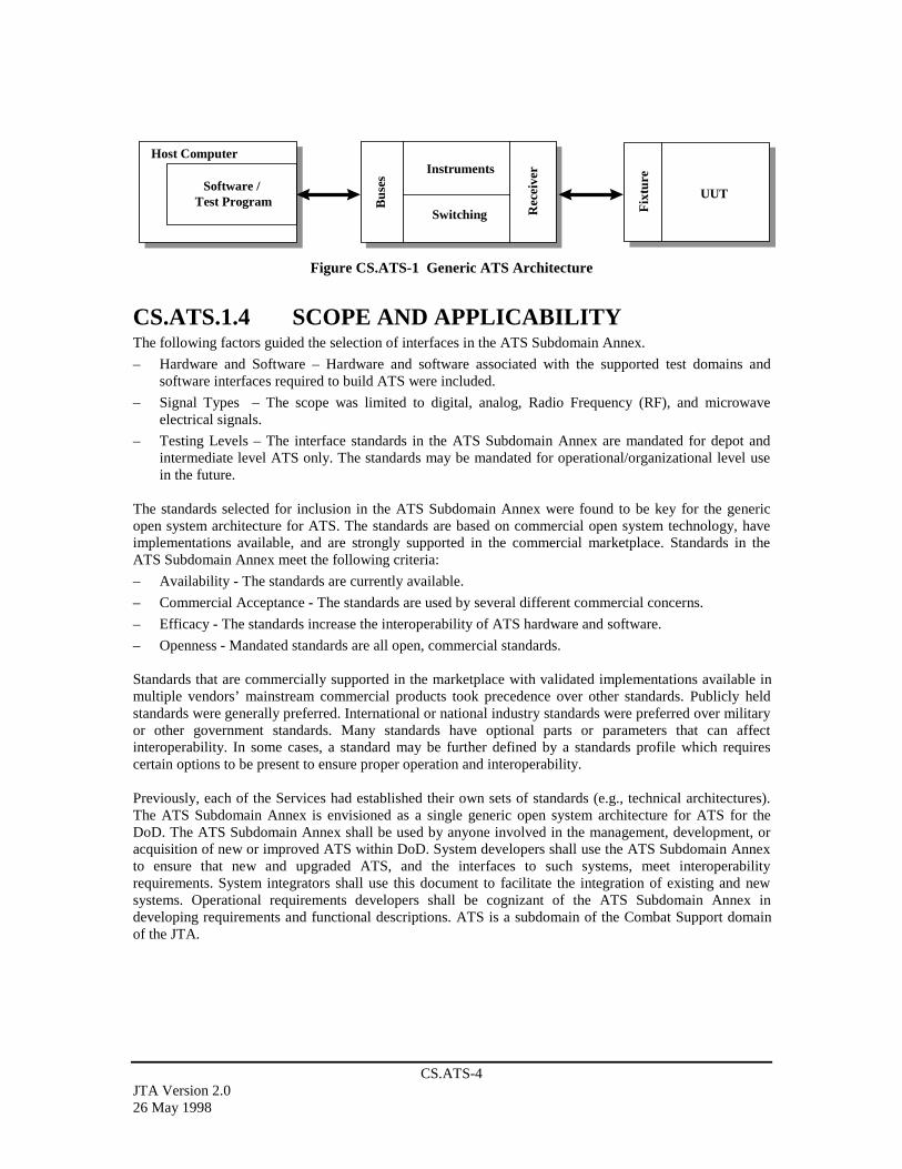
CS.ATS-4JTA Version 2.026 May 1998
Software / Test Program
Host Computer
Rec
eive
r
Bus
es
Switching
Instruments
UUT
Fix
ture
Figure CS.ATS-1 Generic ATS Architecture
CS.ATS.1.4 SCOPE AND APPLICABILITYThe following factors guided the selection of interfaces in the ATS Subdomain Annex.
– Hardware and Software – Hardware and software associated with the supported test domains andsoftware interfaces required to build ATS were included.
– Signal Types – The scope was limited to digital, analog, Radio Frequency (RF), and microwaveelectrical signals.
– Testing Levels – The interface standards in the ATS Subdomain Annex are mandated for depot andintermediate level ATS only. The standards may be mandated for operational/organizational level usein the future.
The standards selected for inclusion in the ATS Subdomain Annex were found to be key for the genericopen system architecture for ATS. The standards are based on commercial open system technology, haveimplementations available, and are strongly supported in the commercial marketplace. Standards in theATS Subdomain Annex meet the following criteria:
– Availability - The standards are currently available.
– Commercial Acceptance - The standards are used by several different commercial concerns.
– Efficacy - The standards increase the interoperability of ATS hardware and software.
– Openness - Mandated standards are all open, commercial standards.
Standards that are commercially supported in the marketplace with validated implementations available inmultiple vendors’ mainstream commercial products took precedence over other standards. Publicly heldstandards were generally preferred. International or national industry standards were preferred over militaryor other government standards. Many standards have optional parts or parameters that can affectinteroperability. In some cases, a standard may be further defined by a standards profile which requirescertain options to be present to ensure proper operation and interoperability.
Previously, each of the Services had established their own sets of standards (e.g., technical architectures).The ATS Subdomain Annex is envisioned as a single generic open system architecture for ATS for theDoD. The ATS Subdomain Annex shall be used by anyone involved in the management, development, oracquisition of new or improved ATS within DoD. System developers shall use the ATS Subdomain Annexto ensure that new and upgraded ATS, and the interfaces to such systems, meet interoperabilityrequirements. System integrators shall use this document to facilitate the integration of existing and newsystems. Operational requirements developers shall be cognizant of the ATS Subdomain Annex indeveloping requirements and functional descriptions. ATS is a subdomain of the Combat Support domainof the JTA.
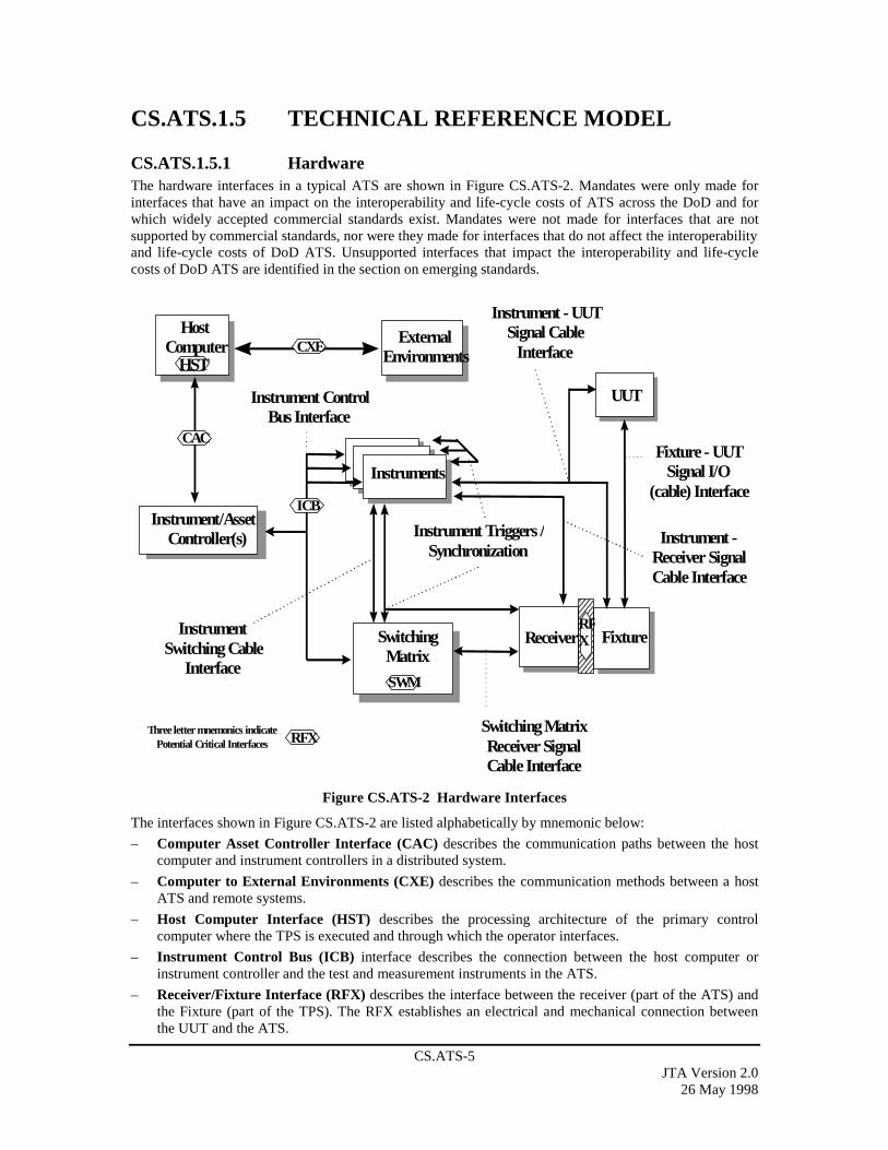
CS.ATS-5JTA Version 2.0
26 May 1998
CS.ATS.1.5 TECHNICAL REFERENCE MODEL
CS.ATS.1.5.1 HardwareThe hardware interfaces in a typical ATS are shown in Figure CS.ATS-2. Mandates were only made forinterfaces that have an impact on the interoperability and life-cycle costs of ATS across the DoD and forwhich widely accepted commercial standards exist. Mandates were not made for interfaces that are notsupported by commercial standards, nor were they made for interfaces that do not affect the interoperabilityand life-cycle costs of DoD ATS. Unsupported interfaces that impact the interoperability and life-cyclecosts of DoD ATS are identified in the section on emerging standards.
Receiver Fixture
Instruments
Switching MatrixReceiver SignalCable Interface
Instrument - UUTSignal Cable
Interface
Instrument Triggers /Synchronization
Instrument ControlBus Interface
Fixture - UUTSignal I/O
(cable) Interface
UUT
ExternalEnvironments
Instrument -Receiver SignalCable Interface
RFX
SWM
SwitchingMatrix
Instrument/AssetController(s)
HostComputer CXE
InstrumentSwitching Cable
Interface
CAC
HST
RFXThree letter mnemonics indicate
Potential Critical Interfaces
ICB
Figure CS.ATS-2 Hardware Interfaces
The interfaces shown in Figure CS.ATS-2 are listed alphabetically by mnemonic below:
– Computer Asset Controller Interface (CAC) describes the communication paths between the hostcomputer and instrument controllers in a distributed system.
– Computer to External Environments (CXE) describes the communication methods between a hostATS and remote systems.
– Host Computer Interface (HST) describes the processing architecture of the primary controlcomputer where the TPS is executed and through which the operator interfaces.
– Instrument Control Bus (ICB) interface describes the connection between the host computer orinstrument controller and the test and measurement instruments in the ATS.
– Receiver/Fixture Interface (RFX) describes the interface between the receiver (part of the ATS) andthe Fixture (part of the TPS). The RFX establishes an electrical and mechanical connection betweenthe UUT and the ATS.

CS.ATS-6JTA Version 2.026 May 1998
– Switching Matrix Interface (SWM) describes switch paths that connect ATS test and measurementinstruments to pins on the RFX.
CS.ATS.1.5.2 Software The software interfaces are introduced using two reference models, a run time view and a TPS developmentview. The interfaces applicable to the run time view are shown in Figure CS.ATS-3. These interfacesdescribe information processing flows as the TPS diagnoses a UUT. The TPS development interfaces areshown in Figure CS.ATS-4.
In these diagrams, Host Computer refers to computers that run the ATS and instrument asset controllersand computers that are subordinate to the host. The run time diagram presents a generic template for thefunctional organization of software processes. Subsets of this structure will appear on individual processorsin a distributed-processing architecture. On any processor, if components shown on this diagram arepresent and interact, their interactions must comply with the interface requirements identified in thisdocument.
A pplica tion E xecu tionE nviron m en t
Instrum en tC om m un ica tion S tack
Inst
rum
ent
Dri
vers
Com
mun
icat
ion
Man
ager
Bus
Dri
versT
est
Pro
cedu
re
R un T im e S erv ices
Dia
gnos
tic
Pro
cess
ing
Fra
mew
ork
O peratin g System (s)
C om pu ter(s)
MM
F
DIA
R T S
ICM
NE
T
F R M
T h ree let ter m n em o n ics in d ica teP o ten tia l C r itica l In terfaces
H ost C om p uterSoftw are /
T est P rogram Bus
esSw itch ing
Instru m ents
Rec
eive
r
Fix
ture
U U T
D R V
TO
S
Gen
eric
Inst
rum
ent
Cla
sses
GIC
DR
V
ICL
Figure CS.ATS-3 TPS Run Time Interfaces

CS.ATS-7JTA Version 2.0
26 May 1998
ApplicationDevelopmentEnvironment
Digital TestDevelopment
Tools
IFP UTRAFP
Host ComputerSoftware /
Test Program Bus
es
Switching
Instruments
Rec
eive
r
Fix
ture
UUT
Arrow symbols indicateinformation relationships
UTRThree letter mnemonics indicate
Potential Critical Interfaces
TPD
ADE
SFP
DTF
Figure CS.ATS-4 TPS Development Interfaces
The interfaces depicted in the run time view of Figure CS.ATS-3 are listed alphabetically by mnemonicbelow:
– Diagnostic Processing (DIA) is the interface protocol linking execution of a test with softwarediagnostic processes that analyze the significance of the test results and suggest conclusions oradditional actions required.
– Instrument Driver API (DRV) is the Application Programming Interface (API) through whichinstrument drivers accept commands from and return results to Generic Instrument Classes.
– Framework (FRM) is a collection of system requirements, software protocols, and business rules(e.g., software installation) affecting the operation of test software with its host computer andOperating System (OS).
– Generic Instrument Classes (GIC) is the interface through which instrument drivers acceptcommands from and return results to test procedures or run time services serving the Test Program.
– Instrument Command Language (ICL) is the language in which instrument commands and resultsare expressed as they enter or leave the instrument.
– Instrument Communication Manager (ICM) is the interface between the instrument drivers and theCommunication Manager that supports communication with instruments independent of the bus orother protocol used (e.g., VXI, IEEE-488.2, RS-232).
– Multimedia Formats (MMF) denotes the formats used to convey hyperlink text, audio, video andthree-dimensional physical model information from multimedia authoring tools to the ApplicationDevelopment Environment (ADE), Application Execution Environment, and host framework.
– Network Protocol (NET) is the protocol used to communicate with external environments, possiblyover a Local or Wide Area Network. The software protocol used on the CXE hardware interface isrepresented by the NET software interface.
CS.ATS-8JTA Version 2.026 May 1998
– Run Time Services (RTS) denotes the services needed by a TPS not handled by the services suppliedby the DRV, FRM, GIC, and NET, (e.g., error reporting, data logging).
– Test Program to Operating System (TOS) denotes system calls to the host OS made directly fromthe TPS.
The interfaces depicted in the development view of Figure CS.ATS-4 are listed alphabetically bymnemonic below:
– Application Development Environments (ADE) is the interface by which the test engineer createsand maintains a TPS, whether captured in the form of a text or graphical language.
– Adapter Function and Parametric Data (AFP) is the information and formats used to define to theADE the capabilities of the test fixture, how the capabilities are accessed, and the associatedperformance parameters.
– Instrument Function and Parametric Data (IFP) is the information and formats used to define tothe ADE the load, sense, and drive capabilities of the instruments, how these capabilities are accessed,and the associated performance parameters.
– Switch Function and Parametric Data (SFP) is the information and formats used to define to theADE the interconnect capabilities of the switch matrix, how these capabilities are accessed, andassociated performance parameters.
– Test Program Documentation (TPD) is human-understandable representations of information aboutthe TPS for use by the TPS maintainer.
– UUT Test Requirements (UTR) is the information and formats used to define to the ADE the load,sense, and drive capabilities that must be applied to the UUT to test it, including the minimumperformance required for a successful test.
CS.ATS.1.6 ANNEX ORGANIZATIONThe ATS Subdomain Annex consists of three main sections. Section one contains the overview, section twocontains the additions to the JTA core service areas for ATS, and section three contains the domain specificservice areas for ATS. A list of sources is provided in Appendix B. In cases where the ATS SubdomainAnnex does not address an interface to be used in an ATS, the JTA takes precedence. In cases where theJTA and ATS Subdomain Annex specify different standards for the same interface, the ATS SubdomainAnnex takes precedence.
CS.ATS.1.7 CONFIGURATION MANAGEMENTConfiguration management of the ATS Subdomain Annex will be the responsibility of the joint serviceARI. All changes will be approved by the ATS EAO with coordination from the ATS Management Board(AMB).
CS.ATS.2 ADDITIONS TO THE JTA CORE
CS.ATS.2.1 INTRODUCTIONThe standards in the ATS Subdomain Annex apply in addition to the standards in the Combat SupportDomain and the JTA core.

CS.ATS-9JTA Version 2.0
26 May 1998
CS.ATS.2.2 INFORMATION PROCESSINGSTANDARDS
CS.ATS.2.2.1 Mandate Additions
CS.ATS.2.2.1.1 Instrument Driver API StandardsThe DRV is the interface between the generic instrument class serving the test procedure and theinstrument driver. The calls made available at this interface include calls oriented to softwarehousekeeping, such as initializing the driver itself, and calls that cause the instrument to perform a function,such as arm and measure commands. The service requests crossing this interface are communicationsbetween generic ATS assets (e.g., digital multimeter) and specific ATS assets (e.g., vendor XYZ model 123digital multimeter). The instruments are ATS assets, but the calls to the driver are either direct or close-to-direct consequences of action requests in the Test Procedure which is a TPS asset. Some instrumentfunctions are available from a variety of instruments. However, the driver calls to access these functionsvary from instrument to instrument. This interferes with TPS portability. Historically, cross-platformincompatibilities in the way drivers for the same instrument implement the same function have been arecurring ATS integration problem. In common commercial practice, the driver is acquired with theinstrument from the instrument’s original equipment manufacturer. The DRV API interface allows softwaredeveloped by different organizations to work together. No standards are mandated in this version of theJTA, but an emerging standard is given in Section CS.ATS.2.2.2.1.
CS.ATS.2.2.1.2 Digital Test Data FormatsDigital Test Data Formats (DTF) describe the sequence of logic levels necessary to test a digital UUT.Digital test data is generally divided into four parts: patterns, timing, levels, and circuit models andcomponent models that are used for the fault dictionary. In addition, certain diagnostic data may exist thatare closely associated with the digital test data. This interface is intended to be used for capturing the outputof digital automatic test pattern generators. No standards are mandated in this version of the JTA, but anemerging standard is given in section CS.ATS.2.2.2.2.
CS.ATS.2.2.2 Emerging Standards
CS.ATS.2.2.2.1 Instrument Driver API StandardsThe following standard may be mandated in a future version of the JTA:
– VXI plug&play Systems Alliance Instrument Driver Functional Body Specification VPP-3.2, Revision4.0, 2 February 1996.
CS.ATS.2.2.2.2 Digital Test Data FormatsA standard for describing DTF, known as LSRTAP, has become a de facto industry standard. The LSRTAPstandard was submitted to the IEEE for formal standardization and is currently being voted on. Thefollowing standard may be mandated in a future version of the JTA:
– NAWCADLKE-MISC-05-PD-003, Navy Standard Digital Simulation Data Format (SDF), January1998.
Note: The Navy specification for LSRTAP will be replaced with the IEEE standard (IEEE P1445) uponfinal approval from the IEEE.
CS.ATS.2.2.2.3 Generic Instrument Class StandardsThe Generic Instrument Class (GIC) is the interface between the generic instrument classes serving the testprocedure or run time services and the instrument driver. The service requests crossing this interface arecommunications between the TPS requirements (e.g., measure voltage of a sine wave) and generic ATS
CS.ATS-10JTA Version 2.026 May 1998
assets (e.g., digital multimeters, waveform generators, and power supplies). Industry has indicated aninterest in pursuing a standard in this area. Some examples are the IEEE 1226 ABBET standard and theVXIplug&play Systems Alliance.
CS.ATS.2.2.2.4 Diagnostic Processing StandardsThe diagnostic processing interface resides between the test procedure or run time services supporting theTPS and a diagnostic reasoner, diagnostic controller, or other diagnostic process. Diagnostic tools are mostfrequently encountered in one of three forms: expert systems, decision-tree systems and model-basedreasoners. Other diagnostic tools are expert systems known as Fault Isolation System, and Expert MissileMaintenance Advisor; decision-tree systems including Weapon System Testability Analyzer, SystemTestability and Maintenance Program, System Testability Analysis Tool, and AUTOTEST; and model-based reasoners including Intelligent-Computer Aided Test, Portable Interactive Troubleshooter, ArtificialIntelligence-Test, and Adaptive Diagnostic System.
Standardization in this area would allow tools to be written that can translate test strategy information tovarious test programming languages. Additionally, the tools would be interchangeable since one could useany tool to obtain the same output source code. Industry has indicated an interest in pursuing a standard inthis area. One example is IEEE 1232.1: 1997, Artificial Intelligence Exchange and Services Tie to All TestEnvironments (AI-ESTATE).
CS.ATS.2.2.2.5 Adapter Function and Parametric Data StandardsThis information defines the electrical behavior of the fixture which connects the UUT to the ATS.Functional descriptions are included to allow for the case of active fixtures. Describing the function of thefixture begins with a statement of the wirelist association between receiver terminals and UUT terminals.Performance parameters are required to complete the characterization of the path between the instrumentand the UUT, so as to be able to construct a model of the effective instrument applied to the UUT signals(characterized with reference to the UUT interface). Industry has indicated an interest in pursuing astandard in this area. One example of this is the IEEE P1226.11 ABBET Test Resource Information Model(TRIM).
CS.ATS.2.2.2.6 ATS Instrument Function and Parametric Data StandardsThis interface defines the capabilities of the ATS stimulus and measurement devices, how they arecontrolled, and how they are connected within the ATS. It includes:
− Instrument Capabilities - This defines what the instrument can measure, stimulate, and/or load thecircuits to which it is attached. It includes identifying the function, such as measure volts, andquantitative performance characteristics including the range over which a voltage can be measured andthe resolution and accuracy (as a function of choice of range) to be expected from the measured value.
− Instrument Control - The command vocabulary by which the instrument can be controlled to applythese behaviors.
− Instrument Limits - Limits are associated both with the safety of the instrument and surety ofresolution performance. For example: “Do not expose this instrument to more than 1 KV across thesensing terminals” or “Accuracy of voltage stimulus guaranteed with the instrument sourcing up to100 mA.”
Industry has indicated an interest in pursuing a standard in this area. One example of this is the IEEEP1226.11 ABBET TRIM.
CS.ATS.2.2.2.7 ATS Switching Function and Parametric Data StandardsThis interface defines the capabilities of the ATS switching devices, how they are controlled, and how theyare interconnected with other ATS devices. It includes the possible states of the separately-setable switchelements, the connectivity through the switch in each such state, and electrical performance characteristicsof the paths connected as a result of the switch state. The parametric information includes as-installedelectrical path performance from the point to which the instrument characteristics are referenced out to the

CS.ATS-11JTA Version 2.0
26 May 1998
receiver/fixture disconnect surface. Industry has indicated an interest in pursuing a standard in this area.One example of this is the IEEE P1226.11 ABBET TRIM.
CS.ATS.2.2.2.8 UUT Test Requirements Data StandardsHigh re-host costs in the past have been associated with the failure to record or preserve the signal-orientedaction capabilities as required as opposed to as used. This problem is most visible in the allocation phase ofTPS development. When a TPS is transported or re-hosted, the resources requested by the TPS must beallocated to assets in the target ATS. This task would be simplified if UUT test requirements in the form ofload specifications, measurement requirements, and stimuli requirements that must appear at the UUTinterface were available. Industry has indicated an interest in pursuing a standard in this area. Someexamples of this are the IEEE P1029.3 Test Requirements Specification Language (TRSL) and theElectronics Industry Association’s Electronic Design Interchange Format (EDIF).
CS.ATS.2.2.2.9 TPS Documentation StandardsThe TPS Documentation interface consists of the supporting documentation, provided by the TPSdeveloper, whose purpose is to convey an understanding of the design philosophies incorporated into thevarious elements of the TPS hardware and software, along with detailed instructions for selected processessuch as how to regenerate the executable program from the source libraries provided. These documentsmay include the Test Strategy Report (TSR), Diagnostic Flow Charts (DFC), Test Requirements Document(TRD), Test Diagrams, Test Program Instruction (TPI), and Automatic Test Program Generator (ATPG)support data. These data are bundled together in the Test Program Documentation (TPD) interface. Thefollowing Data Item Descriptions are being considered for mandates:
– DI-ATTS-80284A, Test Program Set Document.
– DI-ATTS-80285A, Engineering Support Data.
CS.ATS.2.3 INFORMATION TRANSFER STANDARDS
CS.ATS.2.3.1 Mandate Additions
CS.ATS.2.3.1.1 Data Networking StandardsIn an ATS that has either internal (controller to controller) or external (controller to external host)networking, standardizing on a networking protocol should reduce the amount of time spent re-hosting aTPS between two organizations. This problem becomes more serious if the ADE that is controlling theATS has built-in applications that are network objects (either clients, servers, routers, or other). In theseinstances, porting the ADE between platforms becomes more difficult since it may support differentnetwork protocols and different operating environments. Also important is the transfer of test result data forlogistics and maintenance engineering purposes, i.e., tracking of UUT, failure modes, and test resultsanalysis. By defining a specific protocol as the choice for data communications, these problems will besignificantly reduced. Networking accelerates the distribution of updates for TPSs that are operational on alarge number of widely distributed ATSs. No data networking standards are mandated in this version of theJTA, but an emerging standard is given in section CS.ATS.2.3.2.1.
CS.ATS.2.3.1.2 Instrument Communication Manager StandardsThe ICM interface includes bus-specific options for communicating from the instrument driver to asupporting Input/Output (I/O) library. Until recently, vendors of IEEE-488 and VXI bus hardware providedsoftware drivers for their buses that were different according to the hardware bus protocol or OperatingSystem (OS) used. This situation interfered with the plug and play capabilities that users thought they weregoing to get from buying different instruments that all communicated by common hardware protocols. Thesame functions of the same instruments were not accessed through software in the same way across busesand host platforms. Different manufacturers of IEEE-488 cards had proprietary and unique software calls.Furthermore, Hewlett-Packard and National Instruments, the two leading vendors of VXI slot0 cards andembedded controllers, used different I/O calls to access instruments. This impeded the transporting of

CS.ATS-12JTA Version 2.026 May 1998
instrument drivers, ADEs, and test programs from one set of hardware to another. Without a standard ICMinterface, vendors cannot provide interoperable or portable instrument drivers because different vendorswould use different I/O drivers at the very lowest layer of the software. This forces instrument drivers to betailored to specific I/O calls for each test station and lowers the likelihood that instrument drivers will becommercially available for each configuration. In addition, standard I/O software allows one to placeparameters such as bus addresses and instrument addresses in the instrument driver instead of the testprogram. No instrument communication manager standards are mandated in this version of the JTA, but anemerging standard is given in Section CS.ATS.2.3.2.2.
CS.ATS.2.3.2 Emerging Standards
CS.ATS.2.3.2.1 Data Networking StandardsATS and development systems that are elements of ATS must maintain networking capabilities thatconform with current Internet standards. Current Internet standards are identified in the Internet OfficialProtocol Standards Index as released by the Internet Architecture Board (IAB), which may be mandated ina future version of the JTA:
– Any hardware that has support for the software protocol standards specified in JTA Section2.3.2.1.1.2.1.1, Transmission Control Protocol (TCP) and JTA Section 2.3.2.1.1.2.1.3, InternetProtocol (IP) may be used; however TCP and IP are mandated by the JTA core document.Unacknowledged, connectionless, datagram transport services will not be used in ATS.
CS.ATS.2.3.2.2 Instrument Communication Manager StandardsA standard ICM interface enables higher level software to be interoperable and portable between vendorsand across different platforms. This improves the interoperability of test software and the ability to re-hosttest software from one test system to another. The following specification may be mandated in a futureversion of the JTA:
– VXI plug&play (VPP) Systems Alliance Virtual Instrument Standard Architecture (VISA) Library,VPP-4.3, 22 January 1997.
CS.ATS.2.4 INFORMATION MODELING, METADATA,AND INFORMATION EXCHANGESTANDARDS
CS.ATS.2.4.1 Mandate AdditionsThere are currently no additions applicable to ATS with respect to Information Modeling, Metadata, andInformation Transfer Standards as specified in Section 2.4 of the JTA.
CS.ATS.2.4.2 Emerging StandardsThere are currently no emerging standards identified in this section of the ATS Subdomain Annex.
CS.ATS.2.5 HUMAN-COMPUTER INTERFACESTANDARDS
CS.ATS.2.5.1 Mandate AdditionsThere are currently no additions applicable to ATS with respect to Human-Computer Interface Standards asspecified in Section 2.5 of the JTA.
CS.ATS-13JTA Version 2.0
26 May 1998
CS.ATS.2.5.2 Emerging StandardsThere are currently no emerging standards identified in this section of the ATS Subdomain Annex.
CS.ATS.2.6 INFORMATION SYSTEMS SECURITYSTANDARDS
CS.ATS.2.6.1 Mandate AdditionsThere are currently no additions applicable to ATS with respect to Information Systems Security asspecified in Section 2.6 of the JTA.
CS.ATS.2.6.2 Emerging StandardsThere are currently no emerging standards identified in this section of the ATS Subdomain Annex.
CS.ATS.3 SUBDOMAIN SPECIFIC SERVICEAREAS
CS.ATS.3.1 SOFTWARE ENGINEERING SERVICES
CS.ATS.3.1.1 Mandates
CS.ATS.3.1.1.1 Test Program to Operating System CallsThe TOS interface defines calls to host OS functions from the TPS. Some TPSs are highly dependent uponsystem calls unique to the initial TPS development system OS. A common use of calls to the OS in a TPSis in the area of file I/O. At the time of re-host, the OS calls may not be supported on the target ATS. OScalls are a chronic cause of non-portability in software. The best measure that will alleviate thetransportability and re-hostability problems associated with OS calls is to ban them entirely. This alsoensures that the TPS is developed with an ADE that provides enough encapsulated run time services topreclude the need for direct calls to the OS. The problems associated with calling OS utilities from within aTPS can be generalized to problems that occur if the next interface in the process is bypassed. For example,interoperability will be reduced if an instrument driver bypasses the ICM interface and calls a functionoutside of the VISA (VPP-4.x) library or if functions that are supported by VISA are embedded in aninstrument driver and implemented in a non-standard manner. No test program to operating system callstandards are mandated in this version of the JTA, but a rule which may be mandated in a future version ofthe JTA is given in Section CS.ATS.3.1.2.1.
CS.ATS.3.1.2 Emerging Standards
CS.ATS.3.1.2.1 Test Program to Operating System CallsThe following rule may be mandated in a future version of the JTA.
– Any element of the technical architecture that is implemented shall not be bypassed by a directcommunication to another interface or layer further on in the process.

CS.ATS-14JTA Version 2.026 May 1998
CS.ATS.3.2 DATA/INFORMATION SERVICES
CS.ATS.3.2.1 MandatesThis version of the ATS Subdomain Annex does not contain any domain-specific mandated standards inthe area of data/information services.
CS.ATS.3.2.2 Emerging Standards
CS.ATS.3.2.2.1 Run Time ServicesThe RTS interface encompasses data logging services, operator I/O, timing and tasking control, andresource allocation performed at execution. This interface defines the means by which run time services arecalled during TPS execution. Although standards do not exist, various implementations do. Standardizationin this area would allow the use of various test executives with any language that they support. Proprietaryimplementations of the interface between the TPS and Test Executive exist. However, the means by whichvarious run time services are called depends upon the implementation. Direct transportability of a TPSacross platforms will be compromised if the TPS requires run time services that are not supported on bothsystems or if the calling method differs between the host and target platforms.
Industry has indicated an interest in pursuing a standard in this area. Some examples are IEEE P1226.10,Microsoft’s COM/OLE (Component Object Model/Object Linking and Embedding), and ObjectManagement Group’s CORBA (Common Object Request Broker Architecture).
CS.ATS.3.3 PLATFORM/ENVIRONMENT SERVICES
CS.ATS.3.3.1 Mandates
CS.ATS.3.3.1.1 Computer to External EnvironmentsThe Computer to External Environments (CXE) interface describes the communication methods between ahost ATS and remote systems. This includes paths between the target ATS host computer and other ATSsystems as well as TPS development stations which are part of the Test Environment. This interfacesupports transporting TPS software and supporting documentation between organizations. Examples of thisinterface include Ethernet, RS-232, and IEEE-488.
Any hardware that has support for the software protocol standards specified in JTA Sections 2.3.2.1.1.2.1.1and 2.3.2.1.1.2.1.3, Transmission Control Protocol (TCP) over Internet Protocol (IP), may be used.
CS.ATS.3.3.1.2 System Framework StandardsSystem frameworks provide a common interface for developers of software modules, ensuring that they areportable to other computers that conform to the specified framework. By defining system frameworks,suppliers can focus on developing programming tools and instrument drivers that can be used with anyADE that is compliant with the framework. System frameworks contain, but are not limited to, thefollowing components:
− Compatible ADEs
− Instrument Drivers
− Operating System
− Required Documentation and Installation Support
− Requirements for the Control Computer Hardware
− Soft Front Panel
− VISA Interface and I/O Software
CS.ATS-15JTA Version 2.0
26 May 1998
− VXI Instruments, VXI slot0, System Controller, VXI Mainframe
A system designed using a VXIplug&play system framework ensures that the ADE, DRV, GIC, ICM, andother FRM components are compatible and interoperable with each other. Following the system frameworkrequirements also ensures that all necessary system components have been included, resulting in a completeand operational system. System frameworks increase the likelihood that ADEs will be available on multipleplatforms, greatly enhancing the ability to move test software between platforms. While this does notensure total portability of TPSs, it does eliminate the need to translate or rewrite the source code when it isported. No system framework standards are mandated in this version of the JTA, but a standard which maybe mandated in a future version of the JTA is given in Section CS.ATS.3.3.2.1.
CS.ATS.3.3.2 Emerging Standards
CS.ATS.3.3.2.1 System Framework StandardsThe following standard may be mandated in a future version of the JTA.
– VXI plug&play System Alliance System Frameworks Specification, VPP-2, Revision 4.0, 29 January1996.
CS.ATS.3.3.2.2 Receiver/Fixture InterfaceThe Receiver/Fixture (RFX) and generic pin map interfaces represent a central element of the ATS throughwhich the majority of stimulus and measurement reach the UUT. Standardization of the RFX and pin mapallows the same fixture to be used on multiple ATS. A standard pin map restricts the types of signalspresent at different positions on the receiver. Standardization of this interface increases the interoperabilityof test program sets, resulting in lower re-host costs. Industry has indicated an interest in pursuing astandard in this area. One example of this is the Receiver Fixture Interface (RFI) Alliance.
CS.ATS.3.3.2.3 Switching Matrix InterfaceThe Switching Matrix (SWM) interface and ATS receiver/fixture pin map represent a central element of theATS for connecting ATS instrumentation to the UUT through a switch matrix. The SWM allows a varietyof instruments to be connected to multifunction terminals identified by a standard receiver/fixture pin map.The combination of standardizing the SWM interface and a common receiver/fixture pin map gives theATS the capability to accommodate any fixture that conforms to the pin map. Standardization of the SWMinterface and receiver/fixture pin map increase interoperability by ensuring that ATS instruments needed totest a UUT can be switched to pins required by the fixture.
CS.ATS.3.3.3 Other StandardsThe interfaces described in this section are provided for completeness of the ATS Subdomain Annex and tomake readers aware that these interfaces have been addressed. Standards for these interfaces are notmandated because they were not found to be key for the generic open system architecture for ATS.
CS.ATS.3.3.3.1 Computer Asset Controller InterfaceThe Computer Asset Controller (CAC) interface describes the communication paths between the hostcomputer and instrument controllers in a distributed system. These interfaces may be internal or external tothe host computer. Examples of internal interfaces are Industry Standard Architecture (ISA) and PeripheralComponent Interface (PCI). Examples of external interfaces are IEEE-488, RS-232, Ethernet, MultisystemExtension Interface, and Modular System Interface Bus.
CS.ATS.3.3.3.2 Host Computer InterfaceThe Host Computer (HST) interface describes the processing architecture of the primary control computerwhere the TPS is executed and through which the operator interfaces. Portions of the HST interface affectthe interoperability of ATS. These requirements are included in the Frameworks software interface.

CS.ATS-16JTA Version 2.026 May 1998
CS.ATS.3.3.3.3 Instrument Control Bus InterfaceThe Instrument Control Bus (ICB) interface describes the connection between the host computer orinstrument controller and the test and measurement instruments in the ATS. Examples of these interfacesare IEEE-488, VME, and VME Extensions for Instrumentation (VXI).
CS.ATS.3.3.3.4 Instrument Command LanguageThe Instrument Command Language (ICL) interface describes how instrument commands and results areexpressed as they enter or leave test and measurement instruments. The requirements for this interface aresatisfied by the DRV and GIC interfaces.
CS.ATS.3.3.3.5 Application Development EnvironmentsThe Application Development Environment (ADE) interface describes how the test engineer creates andmaintains a TPS, whether it is captured in the form of a text or graphical language. This interface was notmandated because the requirements for the ADE are restricted by the FRM interface.
M&S-1JTA Version 2.0
26 May 1998
MODELING AND SIMULATION DOMAIN ANNEXM&S.1 DOMAIN OVERVIEW........................................................................................................M&S-1
M&S.1.1 PURPOSE.....................................................................................................................M&S-1M&S.1.2 BACKGROUND ..........................................................................................................M&S-1M&S.1.3 DOMAIN DESCRIPTION ...........................................................................................M&S-2M&S.1.4 SCOPE AND APPLICABILITY..................................................................................M&S-3M&S.1.5 TECHNICAL REFERENCE MODEL .........................................................................M&S-3M&S.1.6 ANNEX ORGANIZATION .........................................................................................M&S-4
M&S.2 ADDITIONS TO THE JTA CORE ......................................................................................M&S-4M&S.2.1 INTRODUCTION ........................................................................................................M&S-4M&S.2.2 INFORMATION PROCESSING STANDARDS.........................................................M&S-4
M&S.2.2.1 Introduction.......................................................................................................... .M&S-4M&S.2.2.2 Mandates ...............................................................................................................M&S-4
M&S.2.2.2.1 HLA Rules.........................................................................................................M&S-4M&S.2.2.2.2 HLA Interface Specification..............................................................................M&S-4M&S.2.2.2.3 HLA Object Model Template Specification ......................................................M&S-4
M&S.2.3 INFORMATION TRANSFER STANDARDS.............................................................M&S-5M&S.2.4 INFORMATION MODELING, METADATA, AND INFORMATION
EXCHANGE STANDARDS........................................................................................M&S-5M&S.2.4.1 Introduction...........................................................................................................M&S-5M&S.2.4.2 Mandates ...............................................................................................................M&S-5
M&S.2.4.2.1 Federation Execution Details Data Interchange Format (FED DIF)..................M&S-5M&S.2.4.2.2 Object Model Template Data Interchange Format ............................................M&S-5M&S.2.4.2.3 Standard Simulator Database Interchange Format (SIF) ...................................M&S-5
M&S.2.4.3 Emerging Standards ..............................................................................................M&S-5M&S.2.4.3.1 Synthetic Environment Data Representation and Interchange Specification
(SEDRIS)...........................................................................................................M&S-5M&S.2.4.3.2 Object Model Data Dictionary...........................................................................M&S-6
M&S.2.5 HUMAN-COMPUTER INTERFACE STANDARDS.................................................M&S-6M&S.2.6 INFORMATION SYSTEMS SECURITY STANDARDS...........................................M&S-6
M&S.3 DOMAIN SPECIFIC SERVICE AREAS ............................................................................M&S-6
The Defense Modeling and Simulation Office (DMSO) manages this annex.
M&S.1 DOMAIN OVERVIEW
M&S.1.1 PURPOSEThe Modeling and Simulation (M&S) Domain Annex identifies additions to the JTA core elements(standards, interfaces, and service areas) listed in Section 2 of the JTA. These additional standards are keyto the interoperability of M&S within DoD among themselves and real-world systems.
M&S.1.2 BACKGROUNDIn 1992 DoD established a vision for modeling and simulation, as stated in the DoD M&S Master Plan.“Defense modeling and simulation will provide readily available, operationally valid environments for useby the DoD Components:
To train jointly, develop doctrine and tactics, formulate operational plans, and assess warfightingsituations.
To support technology assessment, system upgrade, prototype and full-scale development, and forcestructuring.

M&S-2JTA Version 2.026 May 1998
Common use of these environments will promote a closer interaction between the operations andacquisition communities in carrying out their respective responsibilities. To allow maximum utility andflexibility, these modeling and simulation environments will be constructed from affordable, reusablecomponents interoperating through an open systems architecture.” (Executive Council for Modeling &Simulation).
Department of Defense Directive 5000.59, DoD Modeling and Simulation (M&S) Management, January 4,1994, and DoD 5000.59-P, DoD Modeling and Simulation (M&S) Master Plan (MSMP), October 1995,outline DoD policies, organizational responsibilities and management procedures for M&S and provide acomprehensive strategic plan to achieve DoD’s vision of readily available, authoritative, interoperable andreusable simulations.
Objective 1 of the DoD MSMP states “Provide a common technical framework for M&S” and includes,under sub-objective 1-1, the establishment of “a common high level simulation architecture to facilitate theinteroperability of all types of simulations among themselves and with C4I systems, as well as to facilitatethe reuse of M&S components.” The efficient and effective use of models and simulations across theDepartment of Defense and supporting industries requires a common technical framework for M&S tofacilitate interoperability and reuse. This common technical framework consists of: (1) a high levelarchitecture (HLA) to which simulations must conform; (2) conceptual models of the mission space(CMMS) to provide a basis for the development of consistent and authoritative M&S representation; (3)data standards to support common understanding of data across models, simulations, and real worldsystems.
The HLA is a progression from the previous architectures and associated standards which have beendeveloped and used successfully for specific classes of simulation. These include Distributed InteractiveSimulation (DIS) protocol standards which support networked, real-time, platform-level virtual simulationand the Aggregate Level Simulation Protocol (ALSP) which is used to support distributed, logical-time,constructive simulations. The HLA provides a common architecture for all classes of simulation and,consequently, the HLA supersedes both the DIS and ALSP standards. Transition of simulations from use ofother standards is underway in accordance with DoD M&S policy.
M&S.1.3 DOMAIN DESCRIPTIONThis annex provides a set of standards affecting the definition, design, development, execution and testingof models and simulations. DoD modeling and simulation ranges from high-fidelity engineeringsimulations to highly aggregated, campaign-level simulations involving joint forces. Increasingly theDepartment and supporting industries are integrating and operating a mix of computer simulations, actualwarfighting systems, weapons simulators and instrumented ranges to support a diversity of applicationsincluding training, mission rehearsal, operational course of action analysis, investment analysis, and manyaspects of acquisition support throughout all phases of the system lifecycle. Figure M&S-1 shows theposition of the M&S domain in the Notional JTA Hierarchy.
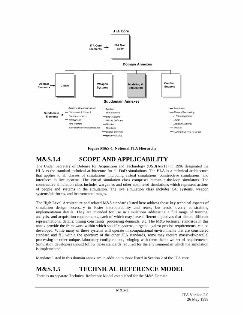
M&S-3JTA Version 2.0
26 May 1998
Subdomain Annexes
C4ISR WeaponSystems
Modeling &Simulation
CombatSupport
DomainElements
SubdomainElements
Domain Annexes
AviationShip Systems
Soldier Systems
Surveillance/Reconnaissance
Space Vehicles
Ship Systems
Automated Test Systems
Missile Defense
Munitions
Missiles
JTA MainBody
JTA CoreElements
Acquisition
Finance/Accounting
H R Management
Medical
Logistics Materiel
Legal
JTA Core
Command & Control
Communications
Intelligence
Info Warfare
Airborne Reconnaissance
Figure M&S-1 Notional JTA Hierarchy
M&S.1.4 SCOPE AND APPLICABILITYThe Under Secretary of Defense for Acquisition and Technology (USD(A&T)) in 1996 designated theHLA as the standard technical architecture for all DoD simulations. The HLA is a technical architecturethat applies to all classes of simulations, including virtual simulations, constructive simulations, andinterfaces to live systems. The virtual simulation class comprises human-in-the-loop simulators. Theconstructive simulation class includes wargames and other automated simulations which represent actionsof people and systems in the simulation. The live simulation class includes C4I systems, weaponsystems/platforms, and instrumented ranges.
The High Level Architecture and related M&S standards listed here address those key technical aspects ofsimulation design necessary to foster interoperability and reuse, but avoid overly constrainingimplementation details. They are intended for use in simulations addressing a full range of training,analysis, and acquisition requirements, each of which may have different objectives that dictate differentrepresentational details, timing constraints, processing demands, etc. The M&S technical standards in thisannex provide the framework within which specific systems, targeted against precise requirements, can bedeveloped. While many of these systems will operate in computational environments that are consideredstandard and fall within the spectrum of the other JTA standards, some may require massively-parallelprocessing or other unique, laboratory configurations, bringing with them their own set of requirements.Simulation developers should follow those standards required for the environment in which the simulationis implemented.
Mandates listed in this domain annex are in addition to those listed in Section 2 of the JTA core.
M&S.1.5 TECHNICAL REFERENCE MODELThere is no separate Technical Reference Model established for the M&S Domain.

M&S-4JTA Version 2.026 May 1998
M&S.1.6 ANNEX ORGANIZATIONThe Modeling and Simulation Domain Annex consists of three sections. Section M&S.1 contains theoverview, Section M&S.2 contains those Information Technology standards that are additions to thestandards contained in the core, and Section M&S.3 is reserved for those mandates for modeling andsimulation that are domain specific because they do not map directly to the core service areas.
M&S.2 ADDITIONS TO THE JTA CORE
M&S.2.1 INTRODUCTIONThe following standards apply in addition to those found in the core of the JTA. On September 10, 1996 theUnder Secretary of Defense for Acquisition and Technology (USD(A&T)) designated the High LevelArchitecture (HLA) as the standard technical architecture for all DoD simulations. The HLA, as mandated,is defined by the HLA Rules, the HLA Interface Specification and the HLA Object Model TemplateSpecification. Compliance criteria have been set forth in the compliance checklist, which was developed aspart of the HLA, along with the HLA test procedures. These form the technical basis for HLA compliance.The following additional standards are mandated, current versions of which are listed and available at theDefense Modeling and Simulation Office World Wide Web site at:
http://www.dmso.mil
M&S.2.2 INFORMATION PROCESSINGSTANDARDS
M&S.2.2.1 IntroductionIn addition to those mandates for Information Processing Standards described in Section 2.2 of the JTA,the following are unique mandates applicable to the Modeling and Simulation Domain.
M&S.2.2.2 Mandates
M&S.2.2.2.1 HLA RulesHLA Rules: These rules comprise a set of underlying technical principles for the HLA. For federations, therules address the requirement for a federation object model (FOM), object ownership and representation,and data exchange. For federates, the rules require a simulation object model (SOM), time management inaccordance with the HLA Runtime Infrastructure (RTI) time management services, and certain restrictionson attribute ownership and updates.
• High Level Architecture Rules, Version 1.3, February 1998.
M&S.2.2.2.2 HLA Interface SpecificationHLA Interface Specification: HLA federates interact with an RTI (analogous to a special-purposedistributed operating system) to establish and maintain a federation and to support efficient informationexchange among simulations and other federates. The HLA interface specification defines the nature ofthese interactions, which are arranged into sets of basic RTI services.
• High Level Architecture Interface Specification, Version 1.3, February 1998.
M&S.2.2.2.3 HLA Object Model Template SpecificationHLA Object Model Template: The HLA requires simulations (and other federates) and federations to eachhave an object model describing the entities represented in the simulations and the data to be exchangedacross the federation. The HLA Object Model Template prescribes the method for recording the

M&S-5JTA Version 2.0
26 May 1998
information in the object models, to include objects, attributes, interactions, and parameters, but it does notdefine the specific data (e.g., vehicles, unit types) that will appear in the object models.
• High Level Architecture Object Model Template, Version 1.3, February 1998.
M&S.2.3 INFORMATION TRANSFER STANDARDSThere are no additional Information Transfer Standards applicable to modeling and simulation beyondthose specified in Section 2.3 of the JTA.
M&S.2.4 INFORMATION MODELING, METADATA,AND INFORMATION EXCHANGESTANDARDS
M&S.2.4.1 IntroductionIn addition to those mandates for Information Modeling, Metadata, and Information Exchange Standardsdescribed in Section 2.4 of the JTA, the following mandates are applicable to the Modeling and SimulationDomain.
M&S.2.4.2 Mandates
M&S.2.4.2.1 Federation Execution Details Data Interchange Format (FEDDIF)
This DIF is the input/output vehicle for sharing HLA initialization data. It contains data from theFederation Object Model as well as additional initialization data needed by the HLA Runtime Infrastructure(RTI) and other HLA initialization tools. The content of the FED DIF is compliant with the HLA InterfaceSpecification referenced above.
• Federation Execution Details Data Interchange Format, Version 1.3, February 1998.
M&S.2.4.2.2 Object Model Template Data Interchange FormatA data interchange format has been adopted as an input/output vehicle for sharing HLA object modelspresented in the standard Object Model Template (OMT) among object model developers and users.
• Object Model Template Data Interchange Format (OMT DIF), Version 1.3, February 1998.
M&S.2.4.2.3 Standard Simulator Database Interchange Format (SIF)A DoD data exchange standard (MIL-STD-1821) has been adopted as an input/output vehicle for sharingexternally created visual terrain simulator databases among the operational system training and missionrehearsal communities.
• MIL-STD-1821, Standard Simulator Data Base (SSDB) Interchange Format (SIF) Design Standard, 17June 1993, with Notice of Change 1, 17 April 1994, and Notice of Change 2, 17 February 1996.
M&S.2.4.3 Emerging Standards
M&S.2.4.3.1 Synthetic Environment Data Representation and InterchangeSpecification (SEDRIS)
No standard currently exists for comprehensively describing and interchanging environmental data in alldomains (terrain, ocean, atmosphere, and space) among M&S applications supporting the broad range ofacquisition, analysis, and training requirements. SIF will be replaced by SEDRIS. SEDRIS establishes auniform and effective interchange specification for the pre-runtime distribution of source data andintegrated databases. The specification encompasses a robust data model, data dictionary, and interchange

M&S-6JTA Version 2.026 May 1998
format supported by read and write application program interfaces (APIs), data viewers, a data modelbrowser, and analytical verification and validation data model compliance tools. While designed to meetM&S community requirements, the interchange specification has the potential for also being used fornatural environment data in DoD operational systems.
M&S.2.4.3.2 Object Model Data DictionaryThe Object Model Data Dictionary is being developed to support the development and reuse of FederationObject Models (FOMs) and Simulation Object Models (SOMs). This will greatly reduce the time needed todevelop new HLA applications and transition legacy systems to the HLA. Initially, content standards arebeing developed based on the requirements of several programs, which are early adopters of the HLAstandards. The early adopter programs cover a broad range of simulation applications from engineering toanalysis and multiple levels of aggregation from platform-level (previously addressed by the IEEE 1278.1Protocol Data Unit standards) to aggregate unit simulations (previously addressed by the Aggregate LevelSimulation Protocol). The object model requirements of these programs are being consolidated into acommon set of data elements, specifying both semantics and syntax. Where existing DoD standards do notexist, they will be developed through the HLA Object Model Data Dictionary process.
M&S.2.5 HUMAN-COMPUTER INTERFACESTANDARDS
There are no additional Human-Computer Interface standards applicable to modeling and simulationbeyond those specified in Section 2.5 of the JTA.
M&S.2.6 INFORMATION SYSTEMS SECURITYSTANDARDS
There are no additional Information Systems Security standards applicable to modeling and simulationbeyond those specified in Section 2.6 of the JTA.
M&S.3 DOMAIN SPECIFIC SERVICE AREASThere are no domain specific service areas for the Modeling and Simulation Domain.
WS-1JTA Version 2.0
26 May 1998
WEAPON SYSTEMS DOMAIN ANNEXWS.1 DOMAIN OVERVIEW...........................................................................................................WS-1
WS.1.1 PURPOSE ............................................................................................................................WS-1WS.1.2 BACKGROUND..................................................................................................................WS-1WS.1.3 DOMAIN DESCRIPTION ..................................................................................................WS-2WS.1.4 SCOPE AND APPLICABILITY.........................................................................................WS-2WS.1.5 TECHNICAL REFERENCE MODEL ................................................................................WS-3
WS.1.5.1 DoD TRM Views .........................................................................................................WS-3WS.1.5.1.1 Performance Environment.......................................................................................WS-4WS.1.5.1.2 Application Hardware Environment........................................................................WS-5
WS.1.5.2 Hierarchy of TRM Views.............................................................................................WS-5WS.1.6 ANNEX ORGANIZATION ................................................................................................WS-5
WS.2 ADDITIONS TO THE JTA CORE .........................................................................................WS-5WS.2.1 INTRODUCTION ...............................................................................................................WS-5WS.2.2 INFORMATION PROCESSING STANDARDS................................................................WS-5
WS.2.2.1 Mandate Additions .......................................................................................................WS-5WS.2.2.2 Emerging Standards .....................................................................................................WS-5
WS.2.2.2.1 Emerging General Standards...................................................................................WS-5WS.2.2.2.2 Emerging Service Area Standards...........................................................................WS-5
WS.2.2.2.2.1 Operating System Services ...............................................................................WS-5WS.2.2.2.2.2 Real-time Common Object Request Broker Architecture (CORBA) ...............WS-6
WS.2.3 INFORMATION TRANSFER STANDARDS....................................................................WS-6WS.2.4 INFORMATION MODELING, METADATA, AND INFORMATION EXCHANGE
STANDARDS......................................................................................................................WS-6WS.2.4.1 Emerging Standards .....................................................................................................WS-6
WS.2.5 HUMAN-COMPUTER INTERFACE STANDARDS........................................................WS-6WS.2.5.1 Additions......................................................................................................................WS-7WS.2.5.2 Emerging Standards .....................................................................................................WS-7
WS.2.6 INFORMATION SYSTEMS SECURITY STANDARDS..................................................WS-7WS.3 DOMAIN SPECIFIC SERVICE AREAS ...............................................................................WS-7
WS.3.1 APPLICATION SYSTEMS HARDWARE STANDARDS................................................WS-7WS.3.1.1 Additions.............................................................................................................. ........WS-7WS.3.1.2 Emerging Standards ..................................................................................................... WS-8
WS.3.2 EMERGING EMBEDDED COMPUTING STANDARDS ................................................WS-8
WS.1 DOMAIN OVERVIEWA Weapon System is a combination of one or more weapons with all related equipment, materials, services,personnel, and means of delivery and deployment (if applicable) required for self-sufficiency (Joint Pub 1-02).
WS.1.1 PURPOSEThis annex identifies standards for the Weapon Systems domain to include information standards andanalogous standards applicable to weapon systems.
WS.1.2 BACKGROUNDThis Domain Annex follows the JTA core document structure to facilitate the identification and traceabilityof the Weapon Systems domain additions to the standards mandated in the main body of the JTA.Therefore, the Weapon Systems Domain Annex consists of three sections including: Domain Overview,Mandates, and Emerging Standards.
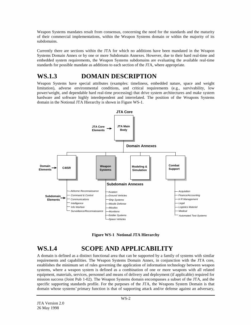
WS-2JTA Version 2.026 May 1998
Weapon Systems mandates result from consensus, concerning the need for the standards and the maturityof their commercial implementations, within the Weapon Systems domain or within the majority of itssubdomains.
Currently there are sections within the JTA for which no additions have been mandated in the WeaponSystems Domain Annex or by one or more Subdomain Annexes. However, due to their hard real-time andembedded system requirements, the Weapon Systems subdomains are evaluating the available real-timestandards for possible mandate as additions to each section of the JTA, where appropriate.
WS.1.3 DOMAIN DESCRIPTIONWeapon Systems have special attributes (examples: timeliness, embedded nature, space and weightlimitation), adverse environmental conditions, and critical requirements (e.g., survivability, lowpower/weight, and dependable hard real-time processing) that drive system architectures and make systemhardware and software highly interdependent and interrelated. The position of the Weapons Systemsdomain in the Notional JTA Hierarchy is shown in Figure WS-1.
Subdomain Annexes
C4ISR WeaponSystems
Modeling &Simulation
CombatSupport
DomainElements
SubdomainElements
Domain Annexes
AviationGround Vehicles
Soldier Systems
Surveillance/Reconnaissance
Space Vehicles
Ship Systems
Automated Test Systems
Missile Defense
Munitions
Missiles
JTA MainBody
JTA CoreElements
Acquisition
Finance/Accounting
H R Management
Medical
Logistics Materiel
Legal
JTA Core
Command & Control
Communications
Intelligence
Info Warfare
Airborne Reconnaissance
Figure WS-1 Notional JTA Hierarchy
WS.1.4 SCOPE AND APPLICABILITYA domain is defined as a distinct functional area that can be supported by a family of systems with similarrequirements and capabilities. The Weapon Systems Domain Annex, in conjunction with the JTA core,establishes the minimum set of rules governing the application of information technology between weaponsystems, where a weapon system is defined as a combination of one or more weapons with all relatedequipment, materials, services, personnel and means of delivery and deployment (if applicable) required formission success (Joint Pub 1-02). The Weapon Systems domain encompasses a subset of the JTA, and thespecific supporting standards profile. For the purposes of the JTA, the Weapons System Domain is thatdomain whose systems’ primary function is that of supporting attack and/or defense against an adversary,
WS-3JTA Version 2.0
26 May 1998
and that are intentionally designed to interoperate with other weapons systems and/or with systems externalto the Weapon Systems domain.
The Weapon Systems Domain annex is applicable to all weapons systems as defined in Joint Pub 1-02.
For the purposes of the JTA, the Weapon Systems domain is organized into subdomains to facilitate theidentification of interoperability standards for common areas while maintaining the systems’ primary designfunction of supporting attack and/or defense against an adversary.
The inclusion or exclusion of subdomains in the Weapons System Domain is based upon the Domainparticipants’ agreement to include or exclude a candidate. It is important to note that some weaponssystems incorporate features/functions associated with more than one subdomain and therefore mustconsider the applicable standards from the pertinent subdomains. The current weapon systems subdomainsare:
Ground Vehicle subdomainIncludes all DoD weapons systems on moving ground platforms, except missiles, both wheeled andtracked, manned and unmanned.
Aviation subdomainIncludes all DoD weapons systems on aeronautical platforms, except missiles, both manned and unmanned,fixed wing and rotorcraft.
Missile Defense subdomainIncludes any system or subsystem (including associated BM/C4I systems) with a mission to detect,classify, identify, intercept, and destroy or negate the effectiveness of enemy aircraft or missiles beforelaunch or while in flight so as to protect US and coalition forces, people, and geopolitical assets.
WS.1.5 TECHNICAL REFERENCE MODEL
WS.1.5.1 DoD TRM ViewsThe Weapon Systems domain and subdomains use both the DoD TRM Service View and the InterfaceView, as described in Section 2. The Interface View is more applicable to real-time systems. Services arebest described by the DoD TRM Services View. Interface standardization in weapon systems is a goal ofthe Open Systems Joint Task Force (OSJTF) of DoD. Both views are needed to capture all of the standardsrequired for the Weapon Systems domain and subdomains to operate within the DoD Enterprise.
Figure WS-2 depicts the DoD TRM Service View and Interface View. The Interface View is based on theGOA framework. Both views were developed using the POSIX model as a baseline. The POSIXApplications Software Layer is analogous to the Application Software Interface View, while the ServiceView extends the POSIX model by categorizing Application Software into mission area applications andseveral support application areas.

WS-4JTA Version 2.026 May 1998
Figure WS-2 DOD TRM Service View and Interface View
The Interface View expanded the Application Platform entity within the POSIX model to include the threeother layers: Systems Support Services, Resource Access Services, and Physical Environment Services.The Interface View includes the 4L, 3L, and 2L, for peer-to-peer logical interfaces, and the 3X, 3D, and 2Ddirect interfaces. The Application Programmers Interface (API) is synonymous with the 4D interface. TheExternal Environment Interface (EEI) is synonymous with the 1L and 1D interfaces treated as a pair. Thusthe Interface View extends the Service View by including language describing application-to-applicationlogical interfaces, expanding the Application Platform, and by including language to discuss ApplicationPlatform-to-Application Platform logical interface (3L and 2L interfaces).
The Service View, unlike the Interface View, categorizes services available in the Applications Platform.The Application Platform service areas defined by the Service View include both run-time and pre-run-time services. The Service View addresses only 4D API interfaces and 1D/1L EEI interfaces. The ServiceView does not address 2L, 3L, or 4L peer-to-peer logical interfaces, 3X, 3D, or 2D direct interfaces, nordoes it address Resource Access Services.
The Interface View contains two types of interfaces: logical and direct. A logical interface definesrequirements for peer-to-peer interchange of data. It identifies senders, receivers, data types, frequency ofexchange, and formats. A direct interface identifies the characteristics of the information transfer medium.Simply stated, logical interfaces define what information is transferred, the direct interfaces define how theinformation is transferred. Logical interfaces are implemented with direct interfaces.
Section WS.2 uses the Service View and identifies additions to the JTA core standards. WS.2 also includesemerging standards representing current standards work within the Weapon Systems domain.The DoD TRM Interface View is based on the SAE GOA framework, and provides a framework to identifyinterface classes for applying open system interface standards to the design of hardware/software systems.As a result, the following architecture standard is used to define the interfaces:
– SAE AS 4893. Generic Open Architecture (GOA) Framework, 1 January 1996.
WS.1.5.1.1 Performance EnvironmentOne of the most distinctive features of a weapon system is the importance of performance characteristics.Weapon systems are developed to meet stringent operational performance criteria in order to be accurate
Service View
Integrated DoD Technical Reference Model
EEI EEI (1D)
InformationInterchange
Devices UsersNetworksInformationInterchange
Devices UsersNetworks
Interface View
Mission
Support
3L
API (4D)
Resource Access Services
3D
2L
2L2D
1L
1L1D 1D
Physical Environment Services
Application Platform
Application SoftwareApplication Software
1D
4L 4L
4L
4D4D 4D
Application Platform
System Support Services
Physical Environment Services (Drivers & Physical Resources)
API
4D
3LSystem Support Service (XOS)
Operating System3X
System Support Service (XOS)
3D
3D
Systems Support Services3L
Mission Area Applications
Multi- Communications Business Environment Database Engineering …Media Processing Management Utilities Support
Support Applications
Softw. User Data Data Graphic Comm. Security System Distrib. Internatlizn. …Engrg. Interf. Mgmt. Inter- Svcs Svcs. Svcs. Mgmt. Comp. ServicesSvcs. Svcs. Svcs. change Svcs. Svcs.
Svcs.
Operating System
4D

WS-5JTA Version 2.0
26 May 1998
and lethal; and to survive. In order to emphasize this issue, performance is modeled as a separate externalenvironment entity. At the lower level of TRMs, performance will be an integral part of the services.
WS.1.5.1.2 Application Hardware EnvironmentWithin weapon systems, embedded computing hardware and software components are highlyinterdependent in order to satisfy very demanding requirements. The DoD TRM Service View often doesnot fit a general purpose computing model very well. Therefore the DoD TRM Interface View is used tocapture such features as interconnect and open systems hardware standards.
WS.1.5.2 Hierarchy of TRM ViewsIn order to capture the diversity found in weapon subsystem design, a hierarchical approach to TRM Viewsis being established. From the DoD TRM Service View in Figure WS-2, the DoD TRM Interface View inFigure 2.1-2 will extend downward into the Weapon Systems domain and subdomains to provide the basisfor standards identification and traceability.
WS.1.6 ANNEX ORGANIZATIONThis annex is divided into three sections: the Overview in Section WS.1, the Additions to the JTA CoreService Areas in Section WS.2, and the Domain Specific Services in Section WS.3. Section WS.2 followsthe JTA Section 2 service area structure. The structure of Section WS.3 will evolve as WS-specific serviceareas are identified and a common structure is coordinated amongst the other annexes.
WS.2 ADDITIONS TO THE JTA CORE
WS.2.1 INTRODUCTIONThe DoD TRM Interface View provides for sufficient fidelity to identify critical functions, interfaces, andtechnical issues.
WS.2.2 INFORMATION PROCESSINGSTANDARDS
This section applies to mission area, support application, and application platform service softwaredeveloped or procured to process information for weapon systems.
WS.2.2.1 Mandate AdditionsThere are no additions mandated for the Information Processing Standards section.
WS.2.2.2 Emerging Standards
WS.2.2.2.1 Emerging General StandardsThere are no emerging general standards for the Information Processing Standards section.
WS.2.2.2.2 Emerging Service Area Standards
WS.2.2.2.2.1 Operating System ServicesThe OSJTF is sponsoring and synchronizing Weapon Systems domain involvement in the IEEE POSIXworking groups. Many POSIX standards are at various stages of standardization and are expected to berevised shortly to accommodate real-time systems’ requirements and to provide for test methods. Thefollowing standards are emerging:

WS-6JTA Version 2.026 May 1998
– IEEE P1003.5c/D3 POSIX-Part 1: Binding for API - Amendment 2: Protocol Independent Interfaces,October 1997.
– IEEE P1003.5f POSIX: Ada binding to 1003.21, January 1997.
– IEEE P1003.1e/D15 POSIX: Protection Audit And Control Interface (C Language), December 1995.
– IEEE P1003.22/D6. POSIX-Open System Security Framework, August 95.
WS.2.2.2.2.2 Real-time Common Object Request Broker Architecture(CORBA)
Real-time Common Object Request Broker Architecture (CORBA) - The OMG Special Interest Group isevaluating the need for real-time object oriented standards and products to support real-time embeddedsystems. As more information becomes available from this group the Weapon Systems domain willconsider adopting the standards as additions to the JTA information processing standards.
WS.2.3 INFORMATION TRANSFER STANDARDSThere are no additions mandated for the Information Transfer Standards section.
WS.2.4 INFORMATION MODELING, METADATA,AND INFORMATION EXCHANGESTANDARDS
This section fosters information exchange among Weapon Systems during their development andmaintenance phases. During concept exploration and development a large number of information elements,objects, and artifacts are generated. If these elements, objects, and artifacts are shared across weaponsystem developments, considerable resources can be saved.
Real-time, embedded processing systems must be developed within a development support environment foran entire system. As such, they must integrate into a systems engineering process that culminates inprototype or production weapon systems that meet specific functional and performance requirements.
WS.2.4.1 Emerging StandardsThe following emerging standard is being considered for mandate by the Weapon Systems domain as anaddition to the JTA information modeling standards:
– IEEE 1076: 1993, Standard VHSIC Hardware Description Language (VHDL) Reference Manual,1993. (VHDL is a high level hardware language).
Additional emerging standards are:
– IEEE 1076.2: VHDL Mathematical Package, 1996.
– IEEE 1076.3: Standard VHDL Synthesis Packages, 1997.
– IEEE 1076.4: VITAL Application-Specific Integrated Circuit (ASIC) Modeling Specification, 1995.(Provides VITAL timing and primitives).
WS.2.5 HUMAN-COMPUTER INTERFACESTANDARDS
This section provides a common framework for Human-Computer Interfaces (HCI) design andimplementation in weapon systems. It complements and extends the DoD HCI Style Guide, Version 2.0,10 October, 1997. The objective is to standardize user interface design and implementation options acrossweapon systems, thus enabling applications within the Weapon Systems domain to appear and behaveconsistently, resulting in higher productivity, shorter training time, and reduced development, operation,

WS-7JTA Version 2.0
26 May 1998
and support costs besides influencing commercial HCI development. This version mandates the design ofgraphical and character-based displays and controls for weapon systems.
In order to identify appropriate systems to use for baseline characterization, the following workingdefinition for time criticality is used: "Systems where no perceptible delay exists between the time an eventoccurs and the time it is presented to the user; and where there is an operational requirement for the userto quickly recognize this presentation, comprehend its significance, and determine and execute appropriateaction(s)."
There are some aspects of HCI’s that can be common across the Weapon Systems domain, while others aresubdomain specific. Hence, an HCI style guide is required at the weapon systems level, and currently foreach subdomain.
WS.2.5.1 AdditionsThere are no additional mandates for the Human-Computer Interface Standards section.
WS.2.5.2 Emerging StandardsThe Weapon Systems Human-Computer Interface (WSHCI) Style Guide addresses guidelines that areapplicable across most or all of the Weapon Systems domain. It provides a starting point for thedevelopment of the subdomain-specific style guides that will further the goal of standardization. Also, theWSHCI Style Guide provides design guidance based on lessons learned and best practices from past HCIefforts. However, the WSHCI Style Guide does not provide the level of design guidance needed to attain acommon behavior and appearance. This is left to the subdomain-specific style guides. The following armydocument is proposed as the starting point to become the joint weapons system style guide:
– U.S. Army Weapon Systems Human-Computer Interface (WSHCI) Style Guide, Version 1.0, 30September 1996.
WS.2.6 INFORMATION SYSTEMS SECURITYSTANDARDS
There are no additions mandated for the Information Systems Security Standards section.
WS.3 DOMAIN SPECIFIC SERVICE AREAS
WS.3.1 APPLICATION SYSTEMS HARDWARESTANDARDS
The primary purpose of this section is to minimize the percentage of standalone and closed applicationmodules used in Weapon Systems. The secondary purpose is to foster the development of commercialhardware standards that can be used for Weapon Systems development.
Real-time embedded processing systems must control, sense, and integrate with an application hardwareenvironment. The application hardware is generally a custom built electronic or mechanical module. Theapplication hardware along with the processing system and application software must work together toperform unique mission requirements. The level of coupling of the processing system to the applicationhardware environment determines the possibility of modular partitioning.
WS.3.1.1 AdditionsThere are no additional standards mandated for the Application Hardware section.
WS-8JTA Version 2.026 May 1998
WS.3.1.2 Emerging StandardsThere are no emerging standards in this section.
WS.3.2 EMERGING EMBEDDED COMPUTINGSTANDARDS
There are no emerging embedded computing standards in this version of the Weapon Systems Annex.

WS.AV-1JTA Version 2.0
26 May 1998
AVIATION SUBDOMAIN ANNEX FOR THEWEAPON SYSTEMS DOMAINWS.AV.1 SUBDOMAIN OVERVIEW ........................................................................................ WS.AV-1
WS.AV.1.1 PURPOSE............................................................................................................. WS.AV-1WS.AV.1.2 BACKGROUND .................................................................................................. WS.AV-1WS.AV.1.3 SUBDOMAIN DESCRIPTION............................................................................ WS.AV-2WS.AV.1.4 SCOPE AND APPLICABILITY.......................................................................... WS.AV-2WS.AV.1.5 TECHNICAL REFERENCE MODEL ................................................................. WS.AV-2WS.AV.1.6 ANNEX ORGANIZATION ................................................................................. WS.AV-2
WS.AV.2 ADDITIONS TO THE JTA CORE............................................................................... WS.AV-2WS.AV.2.1 INTRODUCTION ................................................................................................ WS.AV-2WS.AV.2.2 INFORMATION PROCESSING STANDARDS................................................. WS.AV-2
WS.AV.2.2.1 Additions .......................................................................................................... WS.AV-2WS.AV.2.2.2 Emerging Standards.......................................................................................... WS.AV-2
WS.AV.2.2.2.1 Emerging Service Area Standards.............................................................. WS.AV-2WS.AV.2.2.2.1.1 Operating System Services.................................................................. WS.AV-2
WS.AV.2.3 INFORMATION TRANSFER STANDARDS..................................................... WS.AV-2WS.AV.2.4 INFORMATION MODELING, METADATA, AND INFORMATION
EXCHANGE STANDARDS................................................................................ WS.AV-3WS.AV.2.5 HUMAN-COMPUTER INTERFACE STANDARDS......................................... WS.AV-3
WS.AV.2.5.1 Additions .......................................................................................................... WS.AV-3WS.AV.2.5.1.1 Symbology ................................................................................................. WS.AV-3
WS.AV.2.5.2 Emerging Standards.......................................................................................... WS.AV-3WS.AV.2.6 INFORMATION SYSTEMS SECURITY STANDARDS................................... WS.AV-3
WS.AV.3 SUBDOMAIN SPECIFIC SERVICE AREAS............................................................. WS.AV-3WS.AV.3.1 APPLICATION SYSTEMS HARDWARE STANDARDS................................. WS.AV-3
WS.AV.3.1.1 Additions .......................................................................................................... WS.AV-3WS.AV.3.1.1.1 Hardware Interface Standards .................................................................... WS.AV-3
WS.AV.3.1.1.1.1 Bus Interface Standards ....................................................................... WS.AV-3WS.AV.3.1.1.1.2 General Hardware Interface Standards ................................................ WS.AV-3
WS.AV.3.1.2 Emerging Standards.......................................................................................... WS.AV-3
WS.AV.1 SUBDOMAIN OVERVIEWA weapon system is a combination of one or more weapons with all related equipment, materials, services,personnel and means of delivery and deployment (if applicable) required for self sufficiency.
Systems covered within the Aviation subdomain include all DoD weapon systems on aeronauticalplatforms, except missiles, both manned and unmanned, fixed wing and rotorcraft.
This subdomain has been designated as an “emerging subdomain” for JTA 2.0; all standards in thissubdomain are designated as emerging and are not mandated by JTA 2.0.
WS.AV.1.1 PURPOSEThis annex identifies standards for the Aviation subdomain of the Weapon Systems domain to includeinformation standards and analogous standards applicable to Aviation systems.
WS.AV.1.2 BACKGROUNDThe proposed and emerging standards in this subdomain are based on the work performed by the ArmyWeapon Systems Technical Architecture Working Group (WSTAWG).
WS.AV-2JTA Version 2.026 May 1998
WS.AV.1.3 SUBDOMAIN DESCRIPTIONThe subdomain description is given in Section WS.AV.1.
WS.AV.1.4 SCOPE AND APPLICABILITYThis subdomain annex does not include any mandates at this time. Emerging standards are identified.Mandates are expected to be added in the next version of the JTA. Some proposed standards are identified.
WS.AV.1.5 TECHNICAL REFERENCE MODELThe technical reference model adopted for use in this subdomain is the DoD TRM which is described in theWeapon Systems Domain Annex. The DoD TRM Service View and Interface View are used as applicable.
WS.AV.1.6 ANNEX ORGANIZATIONThis annex is divided into three sections: the Overview in Section WS.AV.1, the additions to the JTA corestandards in Section WS.AV.2, and the Subdomain Specific Services in Section WS.AV.3. SectionWS.AV.2 follows the JTA Section 2 service area structure. The structure of Section WS.AV.3 will evolveas aviation-specific service areas are identified and a common structure is coordinated amongst the otherannexes.
WS.AV.2 ADDITIONS TO THE JTA CORE
WS.AV.2.1 INTRODUCTIONThis section identifies the standards for the Aviation Subdomain that are additional to standards in the JTAcore.
WS.AV.2.2 INFORMATION PROCESSINGSTANDARDS
WS.AV.2.2.1 AdditionsThere are no additions mandated for the Information Processing Standards section.
WS.AV.2.2.2 Emerging Standards
WS.AV.2.2.2.1 Emerging Service Area Standards
WS.AV.2.2.2.1.1 Operating System ServicesThe Open Systems Joint Task Force (OSJTF) is sponsoring and synchronizing Weapon Systems domaininvolvement in the IEEE POSIX working groups. Many POSIX standards are at various stages ofstandardization and are expected to be revised shortly to accommodate real time systems’ requirements andto provide for test methods. Therefore, the following emerging standards are being considered for mandatein this subdomain as additions to the JTA operating system services standards:
– SAE xxx: Operating System API for Ada Run Time System.
WS.AV.2.3 INFORMATION TRANSFER STANDARDSThere are no additions or emerging standards for the Information Transfer Standards section.
WS.AV-3JTA Version 2.0
26 May 1998
WS.AV.2.4 INFORMATION MODELING, METADATA,AND INFORMATION EXCHANGESTANDARDS
There are no additions or emerging standards for the JTA Information Modeling, Metadata, andInformation Exchange Standards section.
WS.AV.2.5 HUMAN-COMPUTER INTERFACESTANDARDS
WS.AV.2.5.1 Additions
WS.AV.2.5.1.1 SymbologyThere are no mandated standards for the Human-Computer Interface Standards section.
WS.AV.2.5.2 Emerging StandardsThe following standard is not mandated in this version of the JTA, but is proposed for the next version ofthe JTA:
– MIL-STD-1787, Aircraft Display Symbology.
WS.AV.2.6 INFORMATION SYSTEMS SECURITYSTANDARDS
There are no additions or emerging standards for the Information Systems Security Standards section.
WS.AV.3 SUBDOMAIN SPECIFIC SERVICEAREAS
WS.AV.3.1 APPLICATION SYSTEMS HARDWARESTANDARDS
WS.AV.3.1.1 Additions
WS.AV.3.1.1.1 Hardware Interface StandardsThere are no mandated standards for the Hardware Interface Standards section.
WS.AV.3.1.1.1.1 Bus Interface StandardsThere are no mandated standards for the Bus Interface Standards section.
WS.AV.3.1.1.1.2 General Hardware Interface StandardsThere are no mandated standards for General Hardware Interface.
WS.AV.3.1.2 Emerging StandardsThe following Bus Interface standards are not mandated in this version of the JTA but are proposed for thenext version of the JTA:
WS.AV-4JTA Version 2.026 May 1998
– MIL-STD-1553B, Standard for Medium Speed System Network Bus, 21 September 1978, with Noticeof Change 1, 12 February 1980, Notice of Change 2, 8 September 1986, Notice of Change 3, 31January 1993, and Notice of Change 4, 15 January 1996.
– ANSI/VITA 1, VME64 Specification, 1994.
– MIL-STD-1773, Fiber Optics Mechanization of an Aircraft Internal Time DivisionCommand/Response Multiplex Data Bus, 20 May 1988 with Notice of Change 1, 2 October 1989.
The following General Hardware standard is not mandated in this version of the JTA but is proposed forthe next version of the JTA:
– MIL-STD-1389D, Design Requirements for Standard Electronic Module (SME), 30 March 1989.
WS.GV-1JTA Version 2.0
26 May 1998
GROUND VEHICLE SUBDOMAIN ANNEX FORTHE WEAPON SYSTEMS DOMAINWS.GV.1 SUBDOMAIN OVERVIEW ........................................................................................ WS.GV-1
WS.GV.1.1 PURPOSE............................................................................................................. WS.GV-1WS.GV.1.2 BACKGROUND .................................................................................................. WS.GV-1WS.GV.1.3 SUBDOMAIN DESCRIPTION............................................................................ WS.GV-1WS.GV.1.4 SCOPE AND APPLICABILITY.......................................................................... WS.GV-1WS.GV.1.5 TECHNICAL REFERENCE MODEL ................................................................. WS.GV-2WS.GV.1.6 ANNEX ORGANIZATION ................................................................................. WS.GV-2
WS.GV.2 ADDITIONS TO THE JTA CORE............................................................................... WS.GV-2WS.GV.2.1 INTRODUCTION ................................................................................................ WS.GV-2WS.GV.2.2 INFORMATION PROCESSING STANDARDS................................................. WS.GV-2WS.GV.2.3 INFORMATION TRANSFER STANDARDS..................................................... WS.GV-2WS.GV.2.4 INFORMATION MODELING, METADATA, AND INFORMATION
EXCHANGE STANDARDS................................................................................ WS.GV-2WS.GV.2.5 HUMAN-COMPUTER INTERFACE STANDARDS......................................... WS.GV-2WS.GV.2.6 INFORMATION SYSTEMS SECURITY STANDARDS................................... WS.GV-2
WS.GV.3 SUBDOMAIN SPECIFIC SERVICE AREAS............................................................. WS.GV-3WS.GV.3.1 APPLICATION SYSTEMS HARDWARE STANDARDS................................. WS.GV-3
WS.GV.3.1.1 Additions........................................................................................................... WS.GV-3WS.GV.3.1.1.1 Hardware Interface Standards..................................................................... WS.GV-3
WS.GV.3.1.1.1.1 Bus Interface Standards........................................................................ WS.GV-3WS.GV.3.1.1.1.2 General Hardware Interface Standards................................................. WS.GV-3
WS.GV.3.1.2 Emerging Standards .......................................................................................... WS.GV-3
WS.GV.1 SUBDOMAIN OVERVIEWA weapon system is a combination of one or more weapons with all related equipment, materials, services,personnel and means of delivery and deployment (if applicable) required for self-sufficiency.
Systems covered within the Ground Vehicle subdomain include all DoD weapon systems on movingground platforms, except missiles, both wheeled and tracked, manned and unmanned.
WS.GV.1.1 PURPOSEThis annex identifies standards for the Ground Vehicle subdomain of the Weapon Systems domain toinclude information standards and analogous standards applicable to Ground Vehicle systems.
WS.GV.1.2 BACKGROUNDThe standards in this subdomain are based on the work performed by the Army Weapon Systems TechnicalArchitecture Working Group (WSTAWG).
WS.GV.1.3 SUBDOMAIN DESCRIPTIONThe subdomain description is given in Section WS.GV.1.
WS.GV.1.4 SCOPE AND APPLICABILITYThe scope of this Subdomain Annex is the entire Ground Vehicle subdomain as defined in SectionWS.GV.1.
WS.GV-2JTA Version 2.026 May 1998
WS.GV.1.5 TECHNICAL REFERENCE MODELThe technical reference model used in this subdomain is the DoD TRM which is described in the WeaponSystems Domain Annex. The DoD TRM Service View and Interface View are used as applicable.
WS.GV.1.6 ANNEX ORGANIZATIONThis annex is divided into three sections: the Overview in Section WS.GV.1, the additions to the JTA corestandards in Section WS.GV.2, and the Subdomain Specific Services in Section WS.GV.3. SectionWS.GV.2 follows the JTA Section 2 service area structure. The structure of Section WS.GV.3 will evolveas ground vehicle-specific service areas are identified and a common structure is coordinated among theother annexes.
WS.GV.2 ADDITIONS TO THE JTA CORE
WS.GV.2.1 INTRODUCTIONThis section identifies standards for the Ground Vehicles subdomain additional to the standards in the JTAcore.
WS.GV.2.2 INFORMATION PROCESSINGSTANDARDS
There are no additions or emerging standards for the Information Processing Standards section.
WS.GV.2.3 INFORMATION TRANSFER STANDARDSThere are no additions or emerging standards for this section.
WS.GV.2.4 INFORMATION MODELING, METADATA,AND INFORMATION EXCHANGESTANDARDS
There are no additions or emerging standards for this section.
WS.GV.2.5 HUMAN-COMPUTER INTERFACESTANDARDS
There are no additions or emerging standards for this section.
WS.GV.2.6 INFORMATION SYSTEMS SECURITYSTANDARDS
There are no additions or emerging standards for this section.
WS.GV-3JTA Version 2.0
26 May 1998
WS.GV.3 SUBDOMAIN SPECIFIC SERVICEAREAS
WS.GV.3.1 APPLICATION SYSTEMS HARDWARESTANDARDS
WS.GV.3.1.1 Additions
WS.GV.3.1.1.1 Hardware Interface Standards
WS.GV.3.1.1.1.1 Bus Interface Standards
• MIL-STD-1553B, Standard for Medium Speed System Network Bus, 21 September 1978, with Noticeof Change 1, 12 February 1980, Notice of Change 2, 8 September 1986, Notice of Change 3, 31January 1993, and Notice of Change 4, 15 January 1996.
• ANSI/VITA 1, VME64 Specification, 1994.
• SAE J 1850, Class B Data Communication Network Interface, 1 July 1995.
• ANSI X3.131, Information Systems - Small Computer Systems Interface - 2 (SCSI-2), 1994.
WS.GV.3.1.1.1.2 General Hardware Interface Standards
• Personal Computer Memory Card International Association (PCMCIA), PC Card Standard, March1997.
• IEEE 1101.2, Standard for Mechanical Core Specifications for Conduction-Cooled Eurocards (ANSI),1992.
• EIA 170, Electrical Performance Standards - Monochrome Television Studio Facilities, November1957.
• EIA 330, Electrical Performance Standards for Closed Circuit Television Camera 525/60 Interlaced2:1 (ANSI/EIA 330-68), November 1966.
• EIA 343-A, Electrical Performance Standard for High Resolution Monochrome Closed CircuitTelevision Camera (November 1966), September 1969.
• SMPTE 170M, Television - Composite Analog Video Signal - NTSC for Studio Applications, 1994.
WS.GV.3.1.2 Emerging Standards
– PCI Industrial Computer Manufacturer’s Group (PICMG): Compact PCI Specification, R2.1,September 1997.

WS.GV-4JTA Version 2.026 May 1998
This page intentionally left blank.
WS.MD-1JTA Version 2.0
26 May 1998
MISSILE DEFENSE SUBDOMAIN ANNEX FORTHE WEAPON SYSTEMS DOMAINWS.MD.1 SUBDOMAIN OVERVIEW ................................................................................... WS.MD-1
WS.MD.1.1 PURPOSE............................................................................................................ WS.MD-1WS.MD.1.2 BACKGROUND ................................................................................................. WS.MD-1WS.MD.1.3 SUBDOMAIN DESCRIPTION........................................................................... WS.MD-2WS.MD.1.4 SCOPE AND APPLICABILITY......................................................................... WS.MD-2WS.MD.1.5 TECHNICAL REFERENCE MODEL ................................................................ WS.MD-2WS.MD.1.6 ANNEX ORGANIZATION ................................................................................ WS.MD-2
WS.MD.2 ADDITIONS TO THE JTA CORE.......................................................................... WS.MD-3WS.MD.2.1 INTRODUCTION ............................................................................................... WS.MD-3WS.MD.2.2 INFORMATION PROCESSING STANDARDS................................................ WS.MD-3
WS.MD.2.2.1 Mandates......................................................................................................... WS.MD-3WS.MD.2.2.2 Emerging Standards........................................................................................ WS.MD-3
WS.MD.2.2.2.1 Navigation Standard................................................................................. WS.MD-3WS.MD.2.3 INFORMATION TRANSFER STANDARDS.................................................... WS.MD-3WS.MD.2.4 INFORMATION MODELING, METADATA, AND INFORMATION
EXCHANGE STANDARDS............................................................................... WS.MD-3WS.MD.2.4.1 Mandates......................................................................................................... WS.MD-3WS.MD.2.4.2 Emerging Standards........................................................................................ WS.MD-3
WS.MD.2.5 HUMAN-COMPUTER INTERFACE STANDARDS........................................ WS.MD-4WS.MD.2.6 INFORMATION SYSTEMS SECURITY STANDARDS.................................. WS.MD-4
WS.MD.3 SUBDOMAIN SPECIFIC SERVICE AREAS........................................................ WS.MD-4
WS.MD.1 SUBDOMAIN OVERVIEWA weapon system is a combination of one or more weapons with all related equipment, materials, services,personnel and means of delivery and deployment (if applicable) required for self-sufficiency.
Systems covered within the Missile Defense subdomain include any system or subsystem (includingassociated BM/C4I systems) with a mission to detect, classify, identify, intercept, and destroy or negate theeffectiveness of enemy missiles before launch or while in flight so as to protect US and coalition forces,people, and geopolitical assets.
This subdomain has been designated as an “emerging subdomain” for JTA 2.0; all standards in thissubdomain are designated as emerging and are not mandated by JTA 2.0.
WS.MD.1.1 PURPOSEThis JTA Subdomain Annex identifies standards for missile defense systems. This version is focused solelyon active ballistic missile defense, with the intent of expanding this annex in the future.
WS.MD.1.2 BACKGROUNDThe following documents provide useful background information regarding missile defense (sorted bytitle), with particular emphasis on ballistic missile defense:
1. Ballistic Missile Defense (BMD) Command, Control, and Communications (C3) OperationalRequirements Document (ORD), Air Force Space Command, working draft, 19 May 1997, Secret (US.Only).
2. Battle Management Concept for Joint Theater Air and Missile Defense Operations, Joint Theater Airand Missile Defense Organization (JTAMDO), final draft, 11 September 1997. This document isdownloadable from the following World Wide Web address:
http://199.114.114.8/~dj9snops/samd_files_for_download
WS.MD-2JTA Version 2.026 May 1998
3. Capstone Theater Missile Defense (TMD) Cost and Operational Effectiveness Analysis (COEA),BMDO, 1996.
4. Doctrine for Joint Theater Missile Defense. Joint Pub 3-01.5. February 22, 1996.
5. FY96 Analysis Of The Ballistic Missile Defense Interoperability Standards, Fife et al., IDA-P-3277,Alexandria, VA: Institute For Defense Analyses.
6. JTAMD Mission Area Assessment, DoD J8, draft, October 30, 1997, Secret. (Note that this documentcombines the capstone TMD COEA, TAD, and information on land attack cruise missiles).
7. National Ballistic Missile Defense (NBMD) Capstone Requirements Document (CRD), U.S. SpaceCommand, August 24, 1996, Secret (Release Can-US).
8. NMD Capability 2 System Requirements Document, TRW Inc., April 4, 1997, BMC3 SE&I, Rosslyn,VA: TRW.
9. Operational Requirements Document (ORD) for National Ballistic Missile Defense (NBMD), USArmy Space and Strategic Defense Command, March 10, 1997, Secret.
10. Theater Air and Missile Defense Architecture for Joint Force Operations, Bean et al., June 1997, MP97W 105.
11. Theater Air and Missile Defense Master Plan, September 1997, JTAMDO. POET control numberMCNEIL 000396/97.
12. Theater Ballistic Missile Defense (TBMD) Capstone Requirements Document (CRD), U.S. SpaceCommand, draft, August 7, 1997, Secret.
13. Theater Missile Defense (TMD) Command and Control (C2) Plan, August 1996.
WS.MD.1.3 SUBDOMAIN DESCRIPTIONFor a description of this subdomain, see the background material in Section WS.MD.1.2.
WS.MD.1.4 SCOPE AND APPLICABILITYThe scope of this Subdomain Annex is the entire domain of missile defense (as defined in the overviewabove). However, the standards listed within this version of the annex solely address support for activedefense against theater and strategic ballistic missiles (BMs) in flight, as a first step in evolving acomprehensive and complete set of standards for all missile defense systems. It is acknowledged that thisevolution will require interaction with many communities to resolve standardization issues.
WS.MD.1.5 TECHNICAL REFERENCE MODELMissile defense systems typically include one or more sensors, one or more weapons systems, and acommunication infrastructure all coordinated by a BMC3 system (which also coordinates with externalsystems). Kinetic missile defense systems have a weapon system including one or more launchers with oneor more interceptors. Sensors, launchers, interceptors, and other weapon systems include informationtechnology (IT) components and other components. At this time no single document or view has beenofficially designated as the missile defense technical reference model. No reference models have yet beendeveloped for the non-IT parts of these systems.
WS.MD.1.6 ANNEX ORGANIZATIONThis annex is divided into three sections: the Overview in Section WS.MD.1, the missile defense mandatesand emerging standards additional to those in the JTA core in Section WS.MD.2, and the SubdomainSpecific Services in Section WS.MD.3. Section WS.MD.2 follows the JTA Section 2 service area structure.The structure of Section WS.MD.3 will evolve as missile defense-specific service areas are identified and acommon structure is coordinated amongst the other annexes.
WS.MD-3JTA Version 2.0
26 May 1998
WS.MD.2 ADDITIONS TO THE JTA CORE
WS.MD.2.1 INTRODUCTIONThis section identifies standards for the Missile Defense Subdomain that are additional to standards in theJTA core.
WS.MD.2.2 INFORMATION PROCESSINGSTANDARDS
WS.MD.2.2.1 MandatesThere are no mandates in this section.
WS.MD.2.2.2 Emerging Standards
WS.MD.2.2.2.1 Navigation StandardThe following standard may be mandated by the JTA for ballistic missile defense systems to ensure thatnavigation-related data (e.g. position, velocity, and time) can be shared and properly used between missiledefense systems. Note that this standard is consistent with and extends the mandates in the JTA core (e.g.,WGS-84):
– BMD-P-SD-92-000002-A, Ballistic Missile Defense (BMD) Navigation Standard, 23 June 1993,Ballistic Missile Defense Organization.
WS.MD.2.3 INFORMATION TRANSFER STANDARDSThere are no mandates or emerging standards for this section.
WS.MD.2.4 INFORMATION MODELING, METADATA,AND INFORMATION EXCHANGESTANDARDS
WS.MD.2.4.1 MandatesThere are no mandates in this section.
WS.MD.2.4.2 Emerging StandardsIt is anticipated that future versions of the JTA may mandate that missile defense systems which areidentified as part of the “Theater Missile Defense” system shall support MIL-STD-6016 (TADIL-J/link-16)as a mobile interoperable communication link.
It is also anticipated that future versions of the JTA may mandate that those missile defense systems whichsupport MIL-STD-6016 shall also support the following additional standard, which adds a message typeand conventions necessary to support ballistic missile defense:
– Interface Change Proposal (ICP) TJ93-096 Ch9, commonly called the “Space Track Message,”Ballistic Missile Defense Organization, 26 September 1997.
Note that there are ongoing efforts to include ICP TJ93-096 (listed above) as part of MIL-STD-6016.

WS.MD-4JTA Version 2.026 May 1998
Efforts are ongoing to merge the data element definitions (DEDs) developed for Theater Missile Defense(TMD), National Missile Defense (NMD), and the Joint Theater and Air Missile Defense Organization(JTAMDO).
The NMD program is in the process of selecting communication mechanisms. An IPT formed to study theissue has recommended that NMD use a VMF-based message set.
BMDO has formed the “Time and Geospatial Working Group” (TGWG) to identify additional time andgeospatial issues and to develop cross-system resolutions of those issues.
WS.MD.2.5 HUMAN-COMPUTER INTERFACESTANDARDS
There are no mandates or emerging standards for this section.
WS.MD.2.6 INFORMATION SYSTEMS SECURITYSTANDARDS
There are no mandates or emerging standards for this section.
WS.MD.3 SUBDOMAIN SPECIFIC SERVICEAREAS
There are no subdomain specific service areas identified at this time.
A-1JTA Version 2.0
26 May 1998
APPENDIX A: ACRONYMS AND GLOSSARYA.1 ACRONYMS..................................................................................................................................A-1A.2 GLOSSARY .................................................................................................................................A-13
A.1 ACRONYMSNote:Multiple acronyms are sometimes shown for the same term where the different acronyms are used in thedocument. For example, the text of the document consistently uses “Mbits/s” for “Megabits per second”,but the acronym “Mbps” is used in the titles of some standards.
AAC Advance Audio CodingAAL ATM Adaptation LayerABBET A Broad Based Environment for TestABOR AbortACC Architecture Coordination CouncilACP Allied Communication PublicationACR-NEMA American College of Radiology - National Electrical Manufacturers AssociationACTD Advanced Concept Technology DemonstrationADE Application Development EnvironmentAES Application Environment SpecificationAES3 Audio Engineering Society 3AF ATM ForumAFMSS Air Force Mission Support SystemAFP Adapter Function and Parametric Data InterfaceAH Authentication HeaderAITI Automated Interchange of Technical InformationALE Automated Link EstablishmentALSP Aggregate Level Simulation ProtocolANSI American National Standards InstituteAOR Area of ResponsibilityAPI Application Program InterfaceAR Airborne ReconnaissanceARI ATS Research and Development Integrated Product TeamARITA Airborne Reconnaissance Information Technical ArchitectureARL Airborne Reconnaissance LowARP Address Resolution ProtocolARTAWG Airborne Reconnaissance Technical Architecture Working GroupASAS All-Source Analysis SystemASD Assistant Secretary of DefenseASD C3I Assistant Secretary of Defense for Command, Control, Communications, and
IntelligenceATA Army Technical ArchitectureATARS Advanced Tactical Air Reconnaissance SystemATD Advanced Technology DemonstrationATE Automated Test EquipmentATIS Alliance for Telecommunication Industry SolutionsATLAS Abbreviated Test Language for All SystemsATM Asynchronous Transfer ModeATPG Automatic Test Program GeneratorATS Automatic Test SystemsATV Advanced Television SystemsAUTODIN Automatic Digital NetworkAV Air Vehicle
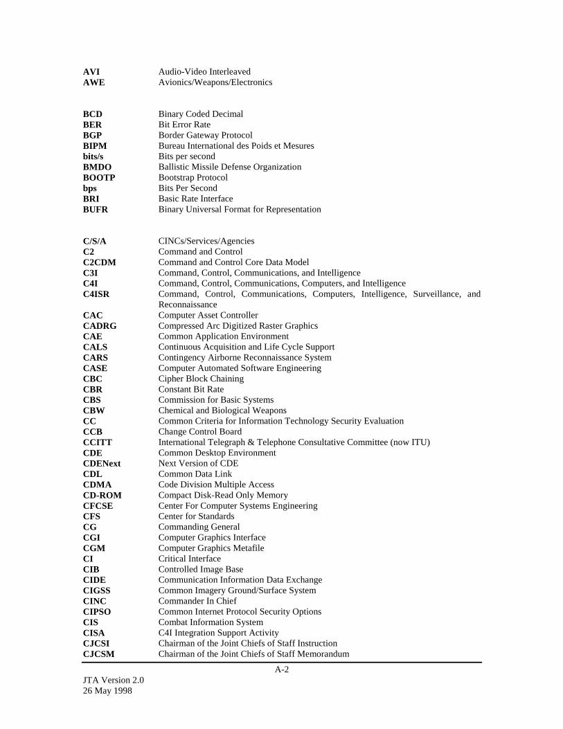
A-2JTA Version 2.026 May 1998
AVI Audio-Video InterleavedAWE Avionics/Weapons/Electronics
BCD Binary Coded DecimalBER Bit Error RateBGP Border Gateway ProtocolBIPM Bureau International des Poids et Mesuresbits/s Bits per secondBMDO Ballistic Missile Defense OrganizationBOOTP Bootstrap Protocolbps Bits Per SecondBRI Basic Rate InterfaceBUFR Binary Universal Format for Representation
C/S/A CINCs/Services/AgenciesC2 Command and ControlC2CDM Command and Control Core Data ModelC3I Command, Control, Communications, and IntelligenceC4I Command, Control, Communications, Computers, and IntelligenceC4ISR Command, Control, Communications, Computers, Intelligence, Surveillance, and
ReconnaissanceCAC Computer Asset ControllerCADRG Compressed Arc Digitized Raster GraphicsCAE Common Application EnvironmentCALS Continuous Acquisition and Life Cycle SupportCARS Contingency Airborne Reconnaissance SystemCASE Computer Automated Software EngineeringCBC Cipher Block ChainingCBR Constant Bit RateCBS Commission for Basic SystemsCBW Chemical and Biological WeaponsCC Common Criteria for Information Technology Security EvaluationCCB Change Control BoardCCITT International Telegraph & Telephone Consultative Committee (now ITU)CDE Common Desktop EnvironmentCDENext Next Version of CDECDL Common Data LinkCDMA Code Division Multiple AccessCD-ROM Compact Disk-Read Only MemoryCFCSE Center For Computer Systems EngineeringCFS Center for StandardsCG Commanding GeneralCGI Computer Graphics InterfaceCGM Computer Graphics MetafileCI Critical InterfaceCIB Controlled Image BaseCIDE Communication Information Data ExchangeCIGSS Common Imagery Ground/Surface SystemCINC Commander In ChiefCIPSO Common Internet Protocol Security OptionsCIS Combat Information SystemCISA C4I Integration Support ActivityCJCSI Chairman of the Joint Chiefs of Staff InstructionCJCSM Chairman of the Joint Chiefs of Staff Memorandum

A-3JTA Version 2.0
26 May 1998
CLI Call Level InterfaceCM Configuration ManagementCMA Collection Management AuthorityCMIP Common Management Information ProtocolCMMS Conceptual Models of the Mission SpaceCMST Collection Management Support ToolsCNR Combat Net RadioCOE Common Operating EnvironmentCOM Common Object ModelCONUS Continental United StatesCORBA Common Object Request Broker ArchitectureCOSE Common Open Software EnvironmentCOTS Commercial Off-the-ShelfCRM Computer Resources ManagementCRMA Collection Requirement Management ApplicationCRMS Collection Requirement Management SystemCSMA/CD Carrier Sense Multiple Access / Collision DetectionCSP Common Security ProtocolCTCPEC Canadian Trusted Computer Product Evaluation CriteriaCTRS Conventional Terrestrial Reference SystemCXE Computer to External Environments Interface
DAA Designated Approving AuthorityDAMA Demand Assigned Multiple AccessDAP Directory Access ProtocolDARO Defense Airborne Reconnaissance OfficeDARP Defense Airborne Reconnaissance ProgramDARSC Defense Airborne Reconnaissance Steering CommitteeDAT Digital Audio TapeDBDB Digital Bathymetric DatabaseDBMS Data Base Management SystemDCA Defense Communications Agency (now DISA)DCAC Defense Communications Agency (now DISA) CircularDCE Distributed Computing EnvironmentDCGS Distributed Common Ground SystemDCOM Distributed Component Object ModeDCRSi Digital Cassette Recording System - ImprovedDDDS Defense Data Dictionary SystemDDM DoD Data ModelDDNS Dynamic Domain Name SystemDDRS Defense Data Repository SystemDEF Data Exchange FormatDFC Diagnostic Flow ChartsDGSA DoD Goal Security ArchitectureDHCP Dynamic Host Configuration ProtocolDIA Defense Intelligence AgencyDIA Diagnostic processing interface protocol (ATS Sub-domain)DIGEST Digital Geographic Information Exchange StandardDII Defense Information InfrastructureDIS Distributed Interactive SimulationDIS Draft International StandardDISA Defense Information Systems Agency (formerly Defense Communication Agency
(DCA))DISN Defense Information System NetworkDLA Defense Logistics Agency
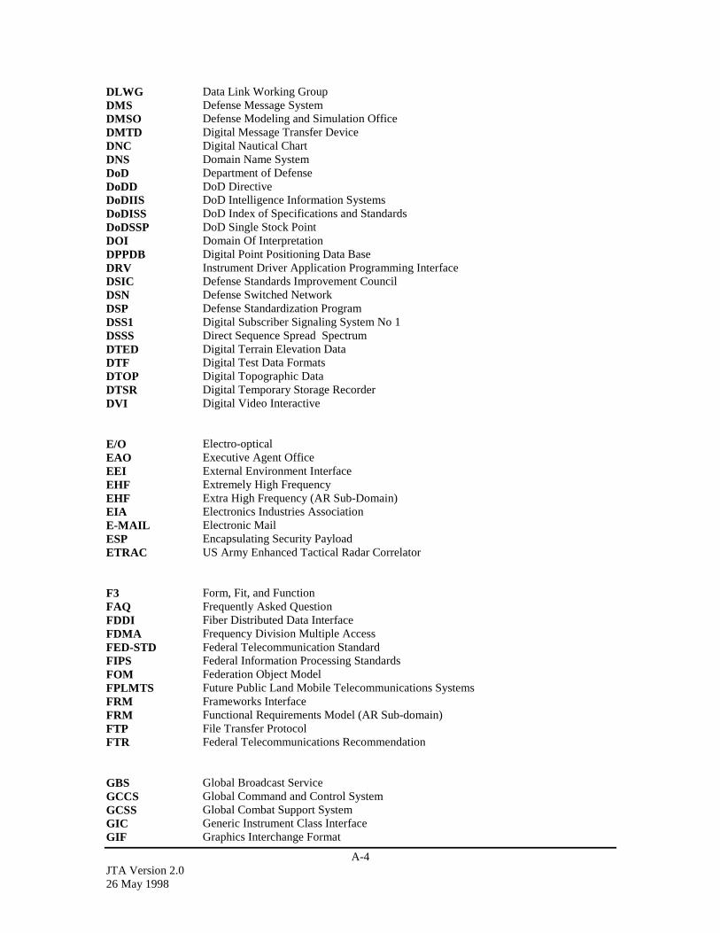
A-4JTA Version 2.026 May 1998
DLWG Data Link Working GroupDMS Defense Message SystemDMSO Defense Modeling and Simulation OfficeDMTD Digital Message Transfer DeviceDNC Digital Nautical ChartDNS Domain Name SystemDoD Department of DefenseDoDD DoD DirectiveDoDIIS DoD Intelligence Information SystemsDoDISS DoD Index of Specifications and StandardsDoDSSP DoD Single Stock PointDOI Domain Of InterpretationDPPDB Digital Point Positioning Data BaseDRV Instrument Driver Application Programming InterfaceDSIC Defense Standards Improvement CouncilDSN Defense Switched NetworkDSP Defense Standardization ProgramDSS1 Digital Subscriber Signaling System No 1DSSS Direct Sequence Spread SpectrumDTED Digital Terrain Elevation DataDTF Digital Test Data FormatsDTOP Digital Topographic DataDTSR Digital Temporary Storage RecorderDVI Digital Video Interactive
E/O Electro-opticalEAO Executive Agent OfficeEEI External Environment InterfaceEHF Extremely High FrequencyEHF Extra High Frequency (AR Sub-Domain)EIA Electronics Industries AssociationE-MAIL Electronic MailESP Encapsulating Security PayloadETRAC US Army Enhanced Tactical Radar Correlator
F3 Form, Fit, and FunctionFAQ Frequently Asked QuestionFDDI Fiber Distributed Data InterfaceFDMA Frequency Division Multiple AccessFED-STD Federal Telecommunication StandardFIPS Federal Information Processing StandardsFOM Federation Object ModelFPLMTS Future Public Land Mobile Telecommunications SystemsFRM Frameworks InterfaceFRM Functional Requirements Model (AR Sub-domain)FTP File Transfer ProtocolFTR Federal Telecommunications Recommendation
GBS Global Broadcast ServiceGCCS Global Command and Control SystemGCSS Global Combat Support SystemGIC Generic Instrument Class InterfaceGIF Graphics Interchange Format

A-5JTA Version 2.0
26 May 1998
GIS Geographic Information SystemGKS Graphical Kernel SystemGOA Generic Open ArchitectureGOTS Government Off-the-ShelfGPS Global Positioning SystemGRIB Gridded BinaryGSD Global Situation DisplayGSM Global System for Mobile CommunicationsGSS Generic Security ServiceGUI Graphical User Interface
HCI Human-Computer InterfaceHDBK HandbookHDTV High Definition TelevisionHF High FrequencyHITL Human-in-the-LoopHLA High Level ArchitectureHMAC keyed-Hashing for Message AuthenticationHST Host Computer InterfaceHTML Hypertext Markup LanguageHTTP Hypertext Transfer ProtocolHUMINT Human IntelligenceHyTime Hypermedia Time-based Structuring Language
I&RTS Integration and Runtime SpecificationI/O Input/OutputIAB Internet Architecture BoardICB Instrument Communication Bus InterfaceICCCM Inter-Client Communications Convention ManualICL Instrument Command Language InterfaceICM Instrument Communications Manager InterfaceICMP Internet Control Message ProtocolIDEF0 Integrated Definition for Function ModelingIDEF1X Integrated Definition for Information ModelingIDL Interface Definition LanguageIDUP Independent Data Unit ProtectionIEC International Electrotechnical CommissionIEEE Institute of Electrical and Electronic EngineersIER Information Exchange RequirementsIESG Internet Engineering Steering GroupIETF Internet Engineering Task ForceIF Intermediate FrequencyIFOG Interferometric Fiber Optic GyroIFP Instrument Function and Parametric Data InterfaceIGES Initial Graphics Exchange SpecificationIGMP Internet Group Management ProtocolIIOP Internet Inter-Orb ProtocolILMI Interim Local Management InterfaceIMA Interactive Multimedia AssociationIMETS Integrated Meteorological SystemIMINT Imagery IntelligenceINS Inertial Navigation SystemIP Internet ProtocolIPA Image Product Archive
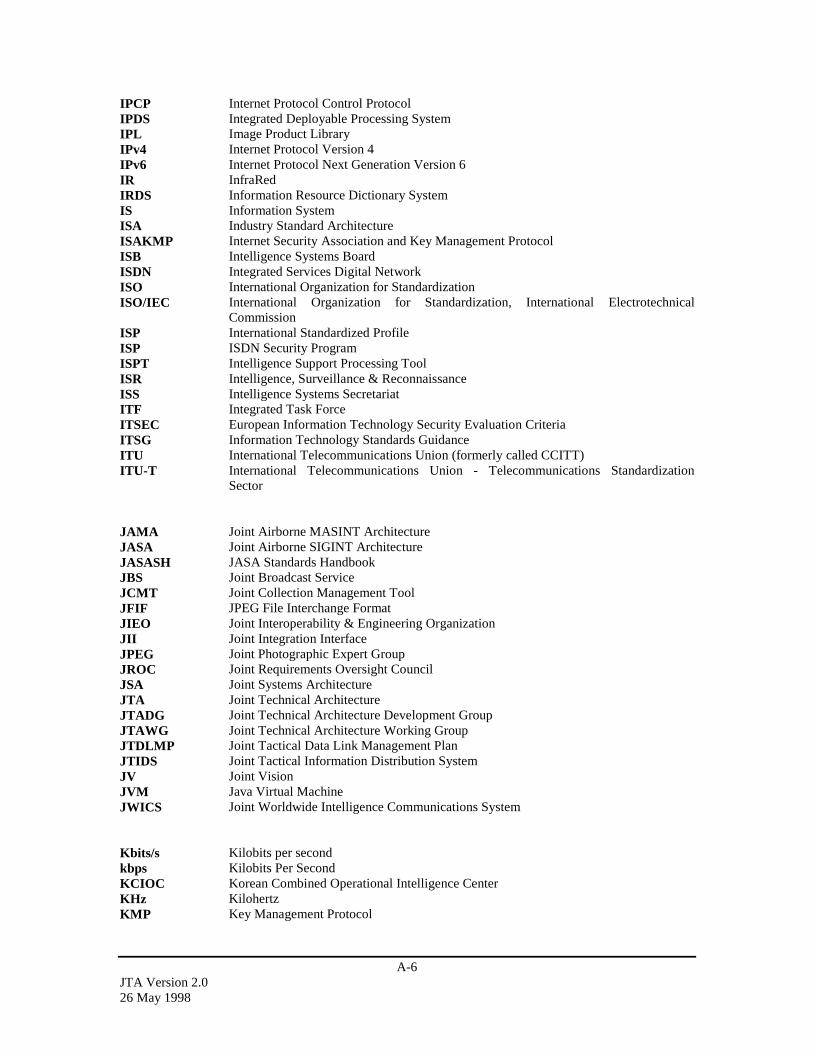
A-6JTA Version 2.026 May 1998
IPCP Internet Protocol Control ProtocolIPDS Integrated Deployable Processing SystemIPL Image Product LibraryIPv4 Internet Protocol Version 4IPv6 Internet Protocol Next Generation Version 6IR InfraRedIRDS Information Resource Dictionary SystemIS Information SystemISA Industry Standard ArchitectureISAKMP Internet Security Association and Key Management ProtocolISB Intelligence Systems BoardISDN Integrated Services Digital NetworkISO International Organization for StandardizationISO/IEC International Organization for Standardization, International Electrotechnical
CommissionISP International Standardized ProfileISP ISDN Security ProgramISPT Intelligence Support Processing ToolISR Intelligence, Surveillance & ReconnaissanceISS Intelligence Systems SecretariatITF Integrated Task ForceITSEC European Information Technology Security Evaluation CriteriaITSG Information Technology Standards GuidanceITU International Telecommunications Union (formerly called CCITT)ITU-T International Telecommunications Union - Telecommunications Standardization
Sector
JAMA Joint Airborne MASINT ArchitectureJASA Joint Airborne SIGINT ArchitectureJASASH JASA Standards HandbookJBS Joint Broadcast ServiceJCMT Joint Collection Management ToolJFIF JPEG File Interchange FormatJIEO Joint Interoperability & Engineering OrganizationJII Joint Integration InterfaceJPEG Joint Photographic Expert GroupJROC Joint Requirements Oversight CouncilJSA Joint Systems ArchitectureJTA Joint Technical ArchitectureJTADG Joint Technical Architecture Development GroupJTAWG Joint Technical Architecture Working GroupJTDLMP Joint Tactical Data Link Management PlanJTIDS Joint Tactical Information Distribution SystemJV Joint VisionJVM Java Virtual MachineJWICS Joint Worldwide Intelligence Communications System
Kbits/s Kilobits per secondkbps Kilobits Per SecondKCIOC Korean Combined Operational Intelligence CenterKHz KilohertzKMP Key Management Protocol
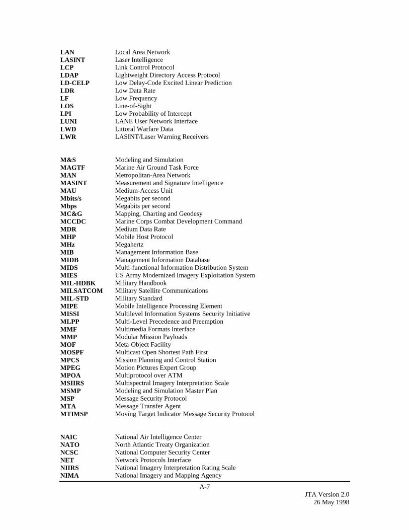
A-7JTA Version 2.0
26 May 1998
LAN Local Area NetworkLASINT Laser IntelligenceLCP Link Control ProtocolLDAP Lightweight Directory Access ProtocolLD-CELP Low Delay-Code Excited Linear PredictionLDR Low Data RateLF Low FrequencyLOS Line-of-SightLPI Low Probability of InterceptLUNI LANE User Network InterfaceLWD Littoral Warfare DataLWR LASINT/Laser Warning Receivers
M&S Modeling and SimulationMAGTF Marine Air Ground Task ForceMAN Metropolitan-Area NetworkMASINT Measurement and Signature IntelligenceMAU Medium-Access UnitMbits/s Megabits per secondMbps Megabits per secondMC&G Mapping, Charting and GeodesyMCCDC Marine Corps Combat Development CommandMDR Medium Data RateMHP Mobile Host ProtocolMHz MegahertzMIB Management Information BaseMIDB Management Information DatabaseMIDS Multi-functional Information Distribution SystemMIES US Army Modernized Imagery Exploitation SystemMIL-HDBK Military HandbookMILSATCOM Military Satellite CommunicationsMIL-STD Military StandardMIPE Mobile Intelligence Processing ElementMISSI Multilevel Information Systems Security InitiativeMLPP Multi-Level Precedence and PreemptionMMF Multimedia Formats InterfaceMMP Modular Mission PayloadsMOF Meta-Object FacilityMOSPF Multicast Open Shortest Path FirstMPCS Mission Planning and Control StationMPEG Motion Pictures Expert GroupMPOA Multiprotocol over ATMMSIIRS Multispectral Imagery Interpretation ScaleMSMP Modeling and Simulation Master PlanMSP Message Security ProtocolMTA Message Transfer AgentMTIMSP Moving Target Indicator Message Security Protocol
NAIC National Air Intelligence CenterNATO North Atlantic Treaty OrganizationNCSC National Computer Security CenterNET Network Protocols InterfaceNIIRS National Imagery Interpretation Rating ScaleNIMA National Imagery and Mapping Agency
A-8JTA Version 2.026 May 1998
NIPNET Non-secure IP Routing NetworkNIST National Institute of Standards and TechnologyNITF National Imagery Transmission FormatNITFS National Imagery Transmission Format StandardNIUF North American ISDN User’s ForumNLSP Network Layer Security ProtocolNRIIRS National Radar Imagery Interpretation ScaleNRO National Reconnaissance OfficeNSA National Security AgencyNSM Network and Systems ManagementNTIS National Technical Information ServiceNTP Network Time ProtocolNTSC National Television Standards CommitteeNTSDS National Target/Threat Signature Data System
ODBC Open Database ConnectivityODMG Object Data Management GroupOLE Object Linking and EmbeddingOMA Object Management ArchitectureOMG Object Management GroupOODBMS Object-Oriented Database Management SystemOOM Object-Oriented MethodsOOT Object Oriented TechnologyOOTW Operations Other Than WarOS Operating SystemOSD Office of the Secretary of DefenseOSD A&T Office of the Secretary of Defense for Acquisition and TechnologyOSF Open Software FoundationOSI Open Systems InterconnectionOSJTF Open Systems Joint Task ForceOSO Operational Support OfficeOSPF Open Shortest Path First
PASV PassivePCAT PC Access ToolPCI Peripheral Computer InterfacePCMCIA Personal Computer Memory Card International AssociationPCS Personal Communications ServicesPDF Portable Document FormatPDU Protocol Data UnitsPHIGS Programmers Hierarchical Interactive Graphics SystemsPICS Protocol Implementation Conformance StatementPINES Pacific Air Forces Interim National Exploitation SystemPM Program ManagerPNG Portable Network GraphicsPN-NI Private Network-Network InterfacePOC Point of ContactPOSIX Portable Operating System InterfacePPP Point-to-Point ProtocolPPS Precise Position ServicePPS Pulse Per Second (AR Sub-domain)PRI Primary Rate InterfacePSK Phase Shift KeyingPSM Persistent Stored Modules

A-9JTA Version 2.0
26 May 1998
PST Prestructured TechnologyPSTN Public Switched Telephone Networks
QoS Quality of Service
RDA Remote Data AccessRDBMS Relational Database Management SystemRF Radio FrequencyRFC Request for CommentsRFI Receiver Fixture Interface AllianceRFP Requests for ProposalsRFX Receiver/Fixture InterfaceRMON Remote MonitoringRPC Remote Procedure CallRPF Raster Product FormatRTI Run Time InfrastructureRTS Run Time Services Interface
SA Systems ArchitectureSAE Society of Automotive EngineersSAMP Security Association Management ProtocolSAR Synthetic Aperture RadarSAR PH SAR Phase HistorySATCOM Satellite CommunicationsSCC Standards Coordinating CommitteeSCPS Space Communications Protocol StandardsSDE Support Data ExtensionsSDF Simulation Data FormatSDN Secure Data NetworkSDNS Secure Data Network SystemSE Synthetic EnvironmentsSEDRIS Synthetic Environment Data Representation and Interchange SpecificationSFP Switch Function and Parametric Data InterfaceSGML Standard Generalized Markup LanguageSHF Super High FrequencySIDR Secure Intelligence Data RepositorySIF Standard Simulator Database Interchange FormatSIGINT Signal IntelligenceSILS Standard for Interoperable LAN SecuritySIPRNET Secure IP Routing NetworkS/MIME Secure/Multipurpose Internet Mail ExtensionsSMPTE Society of Motion Picture and Television EngineersSMTP Simple Mail Transfer ProtocolSNMP Simple Network Management ProtocolSOM Simulation Object ModelSONET Synchronous Optical NetworkSOO Statement Of ObjectiveSOW Statements of WorkSQL Structured Query LanguageSSL Secure Socket LayerSTANAG Standard NATO AgreementSTD StandardSTOU Store Unique
A-10JTA Version 2.026 May 1998
STS Synchronous Transport SignalSUS Single UNIX SpecificationSWM Switch Matrix Interface
TACO2 Tactical Communications Protocol 2TADIL Tactical Digital Information LinkTAFIM Technical Architecture Framework for Information ManagementTAMPS Tactical Aviation Mission Planning SystemTASG Technical Architecture Steering GroupTAWDS Tactical Automated Weather Distribution SystemTCP Transmission Control ProtocolTCSEC Trusted Computer Security Evaluation CriteriaTDDS TRAP Data Dissemination SystemTDL Tactical Data LinkTDMA Time Division Multiple AccessTEG Marine Corps’ Tactical Exploitation GroupTELNET Telecommunications NetworkTFTP Trivial File Transfer ProtocolTIA Telecommunications Industry AssociationTIBS Tactical Information Broadcast SystemTIDP Technical Interface Design PlanTIS Technical Interface SpecificationTMN Telecommunications Management NetworkTOS Type-of-ServiceTOS Test Program to Operating System Interface (ATS Sub-domain)TP Transport ProtocolTP0 Transport Protocol Class 0TPD Test Program Documentation InterfaceTPI Test Program InstructionsTPS Test Program SetTRAP Tactical Receive Equipment and Related ApplicationsTRC Technical Reference CodeTRD Test Requirements DocumentTRIXS Tactical Reconnaissance Intelligence Exchange SystemTRM Technical Reference ModelTRMWG Technical Reference Model Working GroupTSIG Trusted Systems Interoperability GroupTSIX(RE) Trusted Security Information Exchange for Restricted EnvironmentsTSR Test Strategy Report
UAV Unmanned Aerial VehicleUCS Universal Multiple-Octet Coded Character SetUDP User Datagram ProtocolUGS Unattended Ground SensorsUHF Ultra High FrequencyUI User InterfaceUML Unified Modeling LanguageUMS Unattended MASINT SensorsUNEST UNIX-based National Exercise Support TerminalUNI User-Network InterfaceURL Uniform Resource LocatorUSAF United States Air ForceUSD(A&T) Under Secretary of Defense for Acquisition and TechnologyUSIGS United States Imagery and Geospatial Information System
A-11JTA Version 2.0
26 May 1998
USIPS US. Joint Service Image Processing SystemUSMC US. Marine CorpsUSMTF United States Message Text FormatUSNO US. Naval ObservatoryUTC Coordinated Universal TimeUTC(USNO) UTC as maintained at the U.S. Naval ObservatoryUTR Unit Under Test Requirements InterfaceUUT Unit Under TestUVMap Urban Vector Map
VHF Very High FrequencyVHS Vertical Helical ScanVISA Virtual Instrument Standard ArchitectureVISP Video Imagery Standards ProfileVITC Vertical Interval Time CodeVITD Vector Product Interim Terrain DataVLF Very Low FrequencyVMap Vector MapVME Versa Modulo EuropaVMF Variable Message FormatVPF Vector Product FormatVPP VXIplug&playVRML Virtual Reality Modeling LanguageVSM Video Systems MatrixVTC Video TeleconferencingVXIVMap AD VME Extensions for InstrumentationVMap Aeronautical Data
W3C World Wide Web ConsortiumWGS World Geodetic SystemWMO World Meteorological OrganizationWNDP Worldwide Numbering and Dialing PlanWVS+ World Vector Shoreline PlusWWW World Wide Web
XML eXtensible Markup Language
Y2K Year 2000
A-12JTA Version 2.026 May 1998
This page intentionally left blank.
A-13JTA Version 2.0
26 May 1998
A.2 GLOSSARYNote:Where two textual variants of the same term, e.g., “real time” and “real-time” occur in the document, bothare shown.
Access ControlProcess of limiting access to the resources of an IT product only to authorized users, programs, processes,systems, or other IT products.
AccreditationThe managerial authorization and approval granted to an ADP system or network to process sensitive datain an operational environment, made on the basis of a certification by designated technical personnel of theextent to which design and implementation of the system meet pre-specified technical requirements, e.g.,TCSEC, for achieving adequate data security. Management can accredit a system to operate at ahigher/lower level than the risk level recommended (e.g., by the Requirements Guideline) for thecertification level of the system. If management accredits the system to operate at a higher level than isappropriate for the certification level, management is accepting the additional risk incurred.
Activity Model (IDEF0)A graphic description of a system or subject that is developed for a specific purpose and from a selectedviewpoint. A set of one or more IDEF0 diagrams that depict the functions of a system or subject area withgraphics, text and glossary. (FIPS Pub 183, Integration Definition For Function Modeling (IDEF0),December 1993).
Aggregate Level Simulation Protocol (ALSP)A family of simulation interface protocols and supporting infrastructure software that permit the integrationof distinct simulations and war games. Combined, the interface protocols and software enable large-scale,distributed simulations and war games of different domains to interact at the combat object and event level.The most widely known example of an ALSP confederation is the Joint/Service Training Confederation(CBS, AWSIM, JECEWSI, RESA, MTWS, TACSIM, CSSTSS) that has provided the backbone to manylarge, distributed, simulation-supported exercises. Other examples of ALSP confederations includeconfederations of analytical models that have been formed to support U.S. Air Force, U.S. Army, and U.S.TRANSCOM studies. (DoD 5000.59-P, “Modeling and Simulation Master Plan,” October 1995, authorizedby DoD Directive 5000.59, January 4, 1994).
American National Standards Institute (ANSI)The principal standards coordination body in the U.S. ANSI is a member of the ISO. (TAFIM, Version 3.0,Volume 4).
Application Platform1. The collection of hardware and software components that provide the services used by support and
mission-specific software applications. (TAFIM, Version 3.0, Volumes 1 and 3)
2. The application platform is defined as the set of resources that support the services on whichapplication software will execute. It provides services at its interfaces that, as much as possible, makethe implementation-specific characteristics of the platform transparent to the application software.(TAFIM, Version 3.0, Volume 2).
Application Platform EntityThe application platform is defined as the set of resources that support the services on which applicationsoftware will execute. It provides services at its interfaces that, as much as possible, make theimplementation-specific characteristics of the platform transparent to the application software. (TAFIM,Version 3.0, Volume 2).
A-14JTA Version 2.026 May 1998
Application Program Interface (API)1. The interface, or set of functions, between the application software and the application platform. (NIST
Special Publication 500-230; TAFIM, Version 3.0, Volumes 1 and 3)
2. The means by which an application designer enters and retrieves information. (TAFIM, Version 3.0,Volumes 1 and 3).
Application Software EntityMission-area and support applications. A common set of support applications forms the basis for thedevelopment of mission-area applications. Mission-area applications should be designed and developed toaccess this set of common support applications. Applications access the Application Platform via a standardset of APIs. (TAFIM, Version 3.0, Volume 2).
ArchitectureArchitecture has various meanings, depending upon its contextual usage. (1) The structure of components,their interrelationships, and the principles and guidelines governing their design and evolution over time.(2) Organizational structure of a system or component. (IEEE STD 610.12-1900; TAFIM, Version 3.0,Volumes 1 and 3).orAn architecture is a composition of (1) components (including humans) with their functionality defined(Technical), (2) requirements that have been configured to achieve a prescribed purpose or mission(Operational), and (3) their connectivity with the information flow defined. (OS-JTF).
Authentication1. To verify the identity of a user, device, or other entity in a computer system, often as a prerequisite to
allowing access to resources in a system.
2. To verify the integrity of data that have been stored, transmitted, or otherwise exposed to possibleunauthorized modification.
CBRCircuit (voice and telephony) traffic over ATM.
Character-based interfaceA non-bit mapped user interface in which the primary form of interaction between the user and system isthrough text.
Command and ControlThe exercise of authority and direction by a properly designated commander over assigned and attachedforces in the accomplishment of the mission. Command and control functions are performed through anarrangement of personnel, equipment, communications, facilities, and procedures employed by acommander in planning, directing, coordinating, and controlling forces and operations in theaccomplishment of the mission. (JP1-02).
Command, Control, Communications, and Computer SystemsIntegrated systems of doctrine, procedures, organizational structures, personnel, equipment, facilities, andcommunications designed to support a commander’s exercise of command and control across the range ofmilitary operations. (JP1-02).
Commercial Item1. Any item customarily used by the general public for other than governmental purposes, that has been
sold, leased, or licensed to the general public, or that has been offered for sale, lease or license to thegeneral public.

A-15JTA Version 2.0
26 May 1998
2. Any item that evolved from an item described in 1) above through advances in technology orperformance that is not yet available in the commercial market, but will be available in time to meetthe delivery requirements of the solicitation.
3. Any item that, but for modifications of a type customarily available in the commercial market or minormodifications made to meet DoD requirements, would satisfy the criteria in 1) or 2) above.
4. Any combination of items meeting the requirements of 1, 2, or 3 above or 5 below that are of a typecustomarily combined and sold in combination to the general public.
5. Installation services, maintenance services, repair services, training services, and other services if suchservices are procured for support of any item referred to paragraphs 1, 2, 3. or 4 above, if the sourcesof such services:
offers such services to the general public and the DoD simultaneously and under similar terms andconditions and
offers to use the same work force for providing the DoD with such services as the source used forproviding such services to the general public.
6. Services offered and sold competitively, in substantial quantities, in the commercial marketplace basedon established catalog prices of specific tasks performed and under standard commercial terms andconditions.
7. Any item, combination of items or service referred to in 1 through 6 above notwithstanding the factthat the item or service is transferred between or among separate divisions, subsidiaries, or affiliates ofa contractor.
8. A nondevelopmental item developed exclusively at private expense and sold in substantial quantities,on a competitive basis, to State and local governments.
(DRAFT 6/30/95 NDI HANDBOOK/ Federal Acquisition Streamlining Act of 1994 DoD 5000.37H.)
Commercial off-the-Shelf (COTS)1. See the definition of Commercial Item found above. (OS-JTF 1995).
2. Refers to an item of hardware or software that has been produced by a contractor and is available forgeneral purchase. Such items are at the unit level or higher. Such items must have been sold anddelivered to government or commercial customers, must have passed customer’s acceptance testing, beoperating under customer’s control, and within the user environment. Further, such items must havemeaningful reliability, maintainability, and logistics historical data. (TAFIM, Version 3.0, Volumes 1and 3)
ComplianceCompliance is enumerated in an implementation/migration plan. A system is compliant with the JTA if itmeets, or is implementing, an approved plan to meet all applicable JTA mandates.
Conceptual Model of the Mission Space (CMMS)One of the three components of the DoD Common Technical Framework (CTF). They are first abstractionsof the real world and serve as a frame of reference for simulation development by capturing the basicinformation about important entities involved in any mission and their key actions and interactions. Theyare simulation-neutral views of those entities, actions, and interactions occurring in the real world. (DoD5000.59-P, “Modeling and Simulation Master Plan,” October 1995, authorized by DoD Directive 5000.59,January 4, 1994).
Configuration ManagementA discipline applying technical and administrative direction and surveillance to: (1) identify and documentthe functional and physical characteristics of a configuration item, (2) control changes to thosecharacteristics, and (3) record and report changes to processing and implementation status. (TAFIM,Version 3.0, Volumes 1 and 3).
A-16JTA Version 2.026 May 1998
Coordinated Universal Time (UTC)Time scale, based on the second (SI), as defined and recommended by the CCIR and maintained by theBureau International des Poids et Mésures (BIPM).
Data DictionaryA specialized type of database containing metadata that is managed by a data dictionary system;arepository of information describing the characteristics of data used to design, monitor, document, protect,and control data in information systems and databases; an application of a data dictionary system. (DoD8320.1-M-1, “Data Element Standardization Procedures,” January 15, 1993, authorized by DoD Directive8320.1, September 26, 1991).
Data Integrity1. The state that exists when computerized data is the same as that in the source documents and has not
been exposed to accidental or malicious alteration or destruction.
2. The property that data has not been exposed to accidental or malicious alteration or destruction.
Data ModelIn a database, the user’s logical view of the data in contrast to the physically stored data, or storagestructure. A description of the organization of data in a manner that reflects the information structure of anenterprise. (DoD 8320.1-M-1, “Data Element Standardization Procedures,” January 15, 1993, authorized byDoD Directive 8320.1, September 26, 1991).
Designated Approving Authority (DAA)The official with the authority to formally assume responsibility for operating an AIS or network at anacceptable level of risk. (NSTISSI No. 4009).
Distributed Interactive Simulation (DIS)Program to electronically link organizations operating in the four domains: advanced concepts andrequirements; military operations; research, development, and acquisition; and training. (2) A syntheticenvironment within which humans may interact through simulation(s) at multiple sites networked usingcompliant architecture, modeling, protocols, standards, and data bases. (DoD 5000.59-P, “Modeling andSimulation Master Plan,” October 1995, authorized by DoD Directive 5000.59, January 4, 1994).
DomainA distinct functional area that can be supported by a family of systems with similar requirements andcapabilities. An area of common operational and functional requirements.
ElementA Service Area, Interface, or Standard within the JTA document. The definitions below are abbreviatedversions of those appearing elsewhere in the JTA Glossary.
Service Area – a set of system capabilities grouped by functional areas. Both the DoD TechnicalReference Model and the JTA define set(s) of Service Areas common to every system.
Interface – a boundary between two functional areas in a Reference Model.
Standard – a document that establishes uniform engineering and technical requirements. The mandatedstandards in the JTA are grouped by their applicable Service Areas.
External Environment Interface (EEI)The interface that supports information transfer between the application platform and the externalenvironment. (NIST Special Publication 500-230; TAFIM, Version 3.0, Volumes 1 and 3).
A-17JTA Version 2.0
26 May 1998
FederateA member of an HLA Federation. All applications participating in a Federation are called Federates. Inreality, this may include Federate Managers, data collectors, live entity surrogates, simulations, or passiveviewers. (HLA Glossary: http://www.dmso.mil/projects/hla/docslib/hlagloss.html).
FederationA named set of interacting federates, a common federation object model, and supporting RTI, that are usedas a whole to achieve some specific objective. (HLA Glossary: http://www.dmso.mil/projects/hla/docslib/hlagloss.html).
Federation Object Model (FOM)An identification of the essential classes of objects, object attributes, and object interactions that aresupported by an HLA federation. In addition, optional classes of additional information may also bespecified to achieve a more complete description of the federation structure and/or behavior. (HLAGlossary, http://www.dmso.mil/projects/hla/docslib/hlagloss.html).
Government off-the-Shelf (GOTS)See COTS.
Graphical User Interface (GUI)System design that allows the user to effect commands, enter into transaction sequences, and receivedisplayed information through graphical representations of objects (menus, screens, buttons, etc.).
High Level Architecture (HLA)Major functional elements, interfaces, and design rules, pertaining as feasible to all DoD simulationapplications, and providing a common framework within which specific system architectures can bedefined. (HLA Glossary: http://www.dmso.mil/projects/hla/docslib/hlagloss.html).
Human-Computer Interface (HCI)Hardware and software allowing information exchange between the user and the computer.
Hybrid Graphical User InterfaceA GUI that is composed of tool kit components from more than one user interface style.
ImageryCollectively, the representations of objects reproduced electronically or by optical means on film,electronic display devices, or other media. (JCS).
Information Technology (IT)A. The term "information technology", with respect to an executive agency means any equipment or
interconnected system or subsystem of equipment, that is used in the automatic acquisition, storage,manipulation, management, movement, control, display, switching, interchange, transmission, orreception of data or information by the executive agency. For purposes of the preceding sentence,equipment is used by an executive agency if the equipment is used by the executive agency directly oris used by a contractor under a contract with the executive agency which (i) requires the use of suchequipment, or (ii) requires the use, to a significant extent, of such equipment in the performance of aservice or the furnishing of a product.
B. The term "information technology" includes computers, ancillary equipment, software, firmware andsimilar procedures, services (including support services), and related resources.

A-18JTA Version 2.026 May 1998
C. Notwithstanding subparagraphs (A) and (B), the term "information technology" does not include anyequipment that is acquired by a Federal contractor incidental to a Federal contract. (InformationTechnology Management Reform Act of 1996. See:
http://www.dtic.mil/c3i/cio/references/itmra.Annot.html).
Institute of Electrical and Electronics Engineers (IEEE)An accredited standards body that has produced standards such as the network-oriented 802 protocols andPOSIX. Members represent an international cross section of users, vendors, and engineering professionals.(TAFIM, Version 3.0, Volume 4).
Intelligence1. The product resulting from the collection, processing, integration, analysis, evaluation, and
interpretation of available information concerning foreign countries or areas.
2. Information and knowledge about an adversary obtained through observation, investigation, analysis,or understanding. (JP1-02).
Interactive ModelA model that requires human participation. Syn: human-in-the-loop. (“A Glossary of Modeling andSimulation Terms for Distributed Interactive Simulation (DIS),” August, 1995).
InterfaceA shared boundary between two functional units. A functional unit is referred to as a entity whendiscussing the classification of items related to application portability.
International Electrotechnical Commission (IEC)An international standards body similar to ISO, but limited by its charter to standards in the electrical andelectrotechnical areas. In 1987, the ISO and IEC merged ISO Technical Committee 97 and IEC TechnicalCommittees 47B and 83 to form ISO/IEC Joint Technical Committee (JTC) 1, which is the onlyinternationally recognized committee dealing exclusively with information technology standards.
International Organization for Standardization (ISO)The International Organization for Standardization (ISO) is a worldwide federation of national standardsbodies from some 100 countries, one from each country.
ISO is a non-governmental organization, established to promote the development of standardization andrelated activities in the world with a view to facilitating the international exchange of goods and services,and to developing cooperation in the spheres of intellectual, scientific, technological and economic activity.ISO's work results in international agreements which are published as International Standards.
International Telecommunications Union - Telecommunications StandardizationSector (ITU-T)ITU-T, formerly called the Comité Consultatif International de Télégraphique et Téléphonique (CCITT), ispart of the International Telecommunications Union, a United Nations treaty organization. Membership andparticipation in ITU-T is open to private companies; scientific and trade associations; and postal, telephone,and telegraph administrations. Scientific and industrial organizations can participate as observers. The U.S.representative to ITU-T is provided by the Department of State. Since ITU-T does not have the authority ofa standards body nor the authority to prescribe implementation of the documents it produces, its documentsare called recommendations rather than standards.
Internet Engineering Task Force (IETF)The Internet Engineering Task Force (IETF) is a large open international community of network designers,operators, vendors, and researchers concerned with the evolution of the Internet architecture and thesmooth operation of the Internet. The actual technical work of the IETF is done in its working groups,
A-19JTA Version 2.0
26 May 1998
which are organized by topic into several areas (e.g., routing, transport, security, etc.). The IETF is asubdivision of the Internet Architecture Board (IAB) responsible for the development of protocols, theirimplementations and standardization.
Interoperability1. The ability of two or more systems or components to exchange data and use information. (IEEE STD
610.12).
2. The ability of two or more systems to exchange information and to mutually use the information thathas been exchanged. (Army Science Board).
InterworkingThe exchange of meaningful information between computing elements (semantic integration), as opposedto interoperability, which provides syntactic integration among computing elements..
Joint Technical Committee (JTC) 1JTC1 was formed in 1987 by merger of ISO Technical Committee 97 and IEC Technical Committees 47Band 83 to avoid development of possibly incompatible information technology standards by ISO and IEC.ANSI represents the U.S. government in ISO and JTC1.
Legacy EnvironmentsLegacy environments could be called legacy architectures or infrastructures and as a minimum consist of ahardware platform and an operating system. Legacy environments are identified for phase-out, upgrade, orreplacement. All data and applications software that operate in a legacy environment must be categorizedfor phase-out, upgrade, or replacement. (TAFIM 2.0, vol 1).
Legacy StandardA JTA standard that is a candidate for phase-out, upgrade, or replacement. A legacy standard may be anobsolete standard without an upgrade path, or an older version of a currently mandated JTA standard. Alegacy standard is generally associated with an existing or ‘legacy system’, although it may be necessary ina new or upgraded system when an interface to a legacy system is required. (JTADG).
Legacy SystemsSystems that are candidates for phase-out, upgrade, or replacement. Generally legacy systems are in thiscategory because they do not comply with data standards or other standards. Legacy system workloadsmust be converted, transitioned, or phased out (eliminated). Such systems may or may not operate in alegacy environment. (TAFIM 2.0, vol 1).
Live, Virtual, and Constructive SimulationThe categorization of simulation into live, virtual, and constructive is problematic, because there is no cleardivision between these categories. The degree of human participation in the simulation is infinitelyvariable, as is the degree of equipment realism. This categorization of simulations also suffers by excludinga category for simulated people working real equipment (e.g., smart vehicles). (DoD 5000.59-P, “Modelingand Simulation Master Plan,” October 1995, authorized by DoD Directive 5000.59, January 4, 1994).
A. Live Simulation. A simulation involving real people operating real systems.
B. Virtual Simulation. A simulation involving real people operating simulated systems. Virtualsimulations inject human-in-the-loop (HITL) in a central role by exercising motor control skills (e.g.,flying an airplane), decision skills (e.g., committing fire control resources to action), or communicationskills (e.g., as members of a C4I team).
C. Constructive Model or Simulation. Models and simulations that involve simulated people operatingsimulated systems. Real people stimulate (make inputs) to such simulations, but are not involved indetermining the outcomes.
A-20JTA Version 2.026 May 1998
Market AcceptanceMeans that an item has been accepted in the market as evidenced by annual sales, length of time availablefor sale, and after-sale support capability. (SD-2, April 1996).
MetadataInformation describing the characteristics of data; data or information about data; descriptive informationabout an organization’s data, data activities, systems, and holdings. (DoD 8320.1-M-1, DataStandardization Procedures, August 1997).
ModelA physical, mathematical, or otherwise logical representation of a system, entity, phenomenon, or process.(“A Glossary of Modeling and Simulation Terms for Distributed Interactive Simulation (DIS)”, August,(DoD Directive 5000.59, “DoD Modeling and Simulation (M&S) Management,” January 4, 1994); (DoD5000.59-P, “Modeling and Simulation Master Plan,” October 1995, authorized by DoD Directive 5000.59,January 4, 1994).
Modeling and Simulation (M&S)The use of models, including emulators, prototypes, simulators, and stimulators, either statically or overtime, to develop data as a basis for making managerial or technical decisions. The terms “modeling” and“simulation” are often used interchangeably. (“M&S Educational Training Tool (MSETT), Navy AirWeapons Center Training Systems Division Glossary,” April 28, 1994).
MotifUser interface design approach based upon the "look and feel" presented in the OSF/Motif style guide.Motif is marketed by the Open Software Foundation.
MultimediaThe presentation of information on a computer using sound, graphics, animation, and text; using variousinput and output devices.
National Institute of Standards and Technology (NIST)The division of the U.S. Department of Commerce that ensures standardization within Governmentagencies. NIST was formerly known as the National Bureau of Standards. NIST develops and maintainsFIPS PUBS, the standards the Federal Government uses in its procurement efforts. Federal agencies,including DoD, must use these standards where applicable.
National Security SystemA. The term "national security system" means any telecommunications or information system operated by
the United States Government, the function, operation, or use of which: (1) involves intelligenceactivities; (2) involves cryptologic activities related to national security; (3) involves command andcontrol of military forces; (4) involves equipment that is an integral part of a weapon or weaponssystem; or (5) subject to subsection (b), is critical to the direct fulfillment of military or intelligencemissions.
B. LIMITATION.-Subsection (a)(5) does not include a system that is to be used for routine administrativeand business applications (including payroll, finance, logistics, and personnel managementapplications). (Information Technology Management Reform Act of 1996. See:http://www.dtic.mil/c3i/cio/references/itmra.Annot.html).
Nondevelopmental Item (NDI)1. Any previously developed item used exclusively for governmental purposes by a US Federal, State or
Local government agency or a foreign government with which the US has a mutual defensecooperation agreement.

A-21JTA Version 2.0
26 May 1998
2. Any item described in subparagraph 1 above, that requires only minor modification in order to meetthe requirements of the procuring agency.
3. Any item currently being produced that does not meet the requirement of paragraphs 1 or 2 above,solely because the item is not yet in use.
(DRAFT 6/30/95 NDI HANDBOOK/ Federal Acquisition Streamlining Act of 1994 DoD 5000.37H).
Object ModelA specification of the objects intrinsic to a given system, including a description of the objectcharacteristics (attributes) and a description of the static and dynamic relationships that exist betweenobjects. (HLA Glossary: http://hla.dmso.mil/hla/general/hlagloss.html).
Open SystemA system that implements sufficient open specifications for interfaces, services, and supporting formats toenable properly engineered components to be utilized across a wide range of systems with minimalchanges, to interoperate with other components on local and remote systems, and to interact with users in astyle that facilitates portability. An open system is characterized by the following:
Well defined, widely used, non-proprietary interfaces/protocols, and
Use of standards which are developed/adopted by industrially recognized standards bodies, and
Definition of all aspects of system interfaces to facilitate new or additional systems capabilities for awide range of applications, and
Explicit provision for expansion or upgrading through the incorporation of additional or higherperformance elements with minimal impact on the system.
(IEEE POSIX 1003.0/D15 as modified by the Tri-Service Open Systems Architecture Working Group).
Open Systems ApproachAn open systems approach is a business approach that emphasizes commercially supported practices,products, specifications and standards. The approach defines, documents, and maintains a system technicalarchitecture that depicts the lowest level of system configuration control. This architecture clearly identifiesall the performance characteristics of the system including those that will be accomplished with animplementation that references open standards and specifications. (OS-JTF).
Operational Architecture (OA)An Operational Architecture is a description (often graphical) of the operational elements, assigned tasks,and information flows required to support the warfighter. It defines the type of information, the frequencyof the exchange, and what tasks are supported by these information exchanges. (JTA 1.0).
PortabilityThe ease with which a system, component, body of data, or user can be transferred from one hardware orsoftware environment to another. (TAFIM, Version 3.0, Volumes 1 and 3).
PracticeA recommended implementation or process that further clarifies the implementation of a standard or aprofile of a standard. (VISP (Video Imagery Standards Profile)).
Profile of a StandardAn extension to a existing, approved standard which further defines the implementation of that standard inorder to ensure interoperability. A profile is generally more restrictive than the base standard it wasextracted from. (VISP).
A-22JTA Version 2.026 May 1998
Protocol Data Unit (PDU)DIS terminology for a unit of data that is passed on a network between simulation applications. (DoD5000.59-P, “Modeling and Simulation Master Plan,” October 1995, authorized by DoD Directive 5000.59,January 4, 1994).
Real Time, Real-timeReal-time is a mode of operation. Real-time systems require events, data, and information to be available intime for the system to perform its required course of action. Real-time operation is characterized byscheduled event, data, and information meeting their acceptable arrival times. (OS-JTF).orAbsence of delay, except for the time required for transmission. (DoD HCI Style Guide).
Real-Time Control SystemSystems capable of responding to external events with negligible delays. (DoD HCI Style Guide).
Real-time SystemsSystems which provide a deterministic response to asynchronous inputs. (OS-JTF).
ReconnaissanceA mission undertaken to obtain, by visual observation or other detection methods, information about theactivities and resources of an enemy or potential enemy, or to secure data concerning the meteorological,hydrographic, or geographic characteristics of a particular area. (JP1-02).
Reference ModelA reference model is a generally accepted abstract representation that allows users to focus on establishingdefinitions, building common understandings and identifying issues for resolution. For Warfare andWarfare Support System (WWSS) acquisitions, a reference model is necessary to establish a context forunderstanding how the disparate technologies and standards required to implement WWSS relate to eachother. Reference models provide a mechanism for identifying key issues associated with portability,scalability, and interoperability. Most importantly, reference models will aid in the evaluation and analysisof domain specific architectures. (TRI-SERVICE Open Systems Architecture Working Group).
Runtime Infrastructure (RTI)The general purpose distributed operating system software which provides the common interface servicesduring the runtime of an HLA federation. (HLA Glossary: http://hla.dmso.mil/hla/general/hlagloss.html).
Scalability, Scaleability1. The capability to adapt hardware or software to accommodate changing work loads. (OS-JTF).
2. The ability to use the same application software on many different classes of hardware/softwareplatforms from personal computers to super computers (extends the portability concept). The ability togrow to accommodate increased work loads. (TAFIM, Version 3.0, Volumes 1 and 3).
Secondary Imagery Dissemination (SID)The process for the post-collection electronic transmission or receipt of C3I exploited non-original imageryand imagery-products in other than real or near-real time.
Security1. The combination of confidentiality, integrity, and availability.
2. The quality or state of being protected from uncontrolled losses or effects. Note: Absolute security mayin practice be impossible to reach; thus the security "quality" could be relative. Within state models ofsecurity systems, security is a specific "state" that is to be preserved under various operations.
A-23JTA Version 2.0
26 May 1998
Service AreaA set of capabilities grouped into categories by function. The JTA defines a set of services common to DoDinformation systems.
Simulation Object Model (SOM)A specification of the intrinsic capabilities that an individual simulation offers to federations. The standardformat in which SOMs are expressed provides a means for federation developers to quickly determine thesuitability of simulation systems to assume specific roles within a federation. (HLA Glossary:http://hla.dmso.mil/hla/general/hlagloss.html).
SpecificationA document prepared to support acquisition that describes the essential technical requirements forpurchased materiel and the criteria for determining whether those requirements are met. (DoD 4120.3-M).
StandardA document that establishes uniform engineering and technical requirements for processes, procedures,practices, and methods. Standards may also establish requirements for selection, application, and designcriteria of material. (DoD 4120.3-M).
Standards Based ArchitectureAn architecture based on an acceptable set of standards governing the arrangement, interaction, andinterdependence of the parts or elements that together may be used to form a weapons systems, and whosepurpose is to ensure that a conformant system satisfies a specified set of requirements. (OS-JTF).
Standards ProfileA set of one or more base standards, and, where applicable, the identification of those classes, subsets,options, and parameters of those base standards, necessary for accomplishing a particular function.(TAFIM, Version 3.0, Volumes 1 and 3).
Standard Simulator Database Interchange Format (SIF)A DoD data exchange standard (MIL-STD-1821) adopted as an input/output vehicle for sharing externallycreated simulator databases among the operational system training and mission rehearsal communities.
SurveillanceThe systematic observation of aerospace, surface or subsurface areas, places, persons, or things, by visual,aural, electronic, photographic, or other means. (JP1-02).
Synthetic Environment Data Representation and Interchange Specification(SEDRIS)The specification encompasses a robust data model, data dictionary, and interchange format supported byread and write application programmer’s interfaces (APIs), data viewers, a data model browser, andanalytical verification and validation data model compliance tools.
Synthetic Environments (SE)Interneted simulations that represent activities at a high level of realism from simulations of theaters of warto factories and manufacturing processes. These environments may be created within a single computer or avast distributed network connected by local and wide area networks and augmented by super-realisticspecial effects and accurate behavioral models. They allow visualization of and immersion into theenvironment being simulated. (DoD 5000.59-P, “Modeling and Simulation Master Plan,” October 1995,authorized by DoD Directive 5000.59, January 4, 1994); (CJCSI 8510.01, Chairman of the Joint Chiefs ofStaff Instruction 8510.01, “Joint Modeling and Simulation Management,” February 17, 1995).

A-24JTA Version 2.026 May 1998
System1. People, machines and methods organized to accomplish a set of specific functions. (FIPS 11-3).
2. An integrated composite of people, products, and processes that provides a capability or satisfies astated need or objective. (DoD 5000.2).
Systems Architecture (SA)A description, including graphics, of the systems and interconnections providing for or supporting awarfighting function. The SA defines the physical connection, location, and identification of the key nodes,circuits, networks, warfighting platforms, etc., and allocates system and component performanceparameters. It is constructed to satisfy Operational Architecture requirements in the standards defined in theTechnical Architecture. The SA shows how multiple systems within a domain or an operational scenariolink and interoperate, and may describe the internal construction or operations of particular systems in theSA.
Technical Architecture (TA)The minimal set of rules governing the arrangement, interaction, and interdependence of the parts orelements whose purpose is to ensure that a conformant system satisfies a specified set of requirements. Thetechnical architecture identifies the services, interfaces, standards, and their relationships. It provides thetechnical guidelines for implementation of systems upon which engineering specifications are based,common building blocks are built, and product lines are developed.
Technical Reference Model (TRM)A conceptual framework that provides the following:
A. Consistent set of service and interface categories and relationships used to address interoperability andopen system issues.
B. Conceptual entities that establish a common vocabulary to better describe, compare, and contrastsystems and components.
C. A basis (an aid) for the identification, comparison and selection of existing and emerging standards andtheir relationships.
The framework is not an architecture, is not a set of and does not contain standards.
VideoElectro-Optical imaging sensors and systems which generate sequential or continuous streaming imagery atspecified rates. Video standards are developed by recognized bodies such as ISO, ITU, SMPTE, EBU, etc.(VISP).
Weapon SystemsA combination of one or more weapons with all related equipment, materials, services, personnel andmeans of delivery and deployment (if applicable) required for self sufficiency. (JCS Pub 1-02) See alsoNational Security Systems.
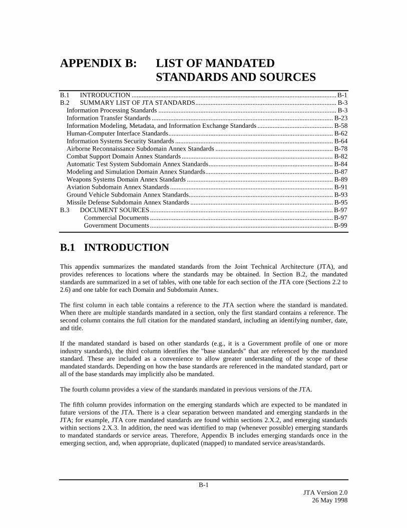
B-1JTA Version 2.0
26 May 1998
APPENDIX B: LIST OF MANDATEDSTANDARDS AND SOURCES
B.1 INTRODUCTION .......................................................................................................................... B-1B.2 SUMMARY LIST OF JTA STANDARDS.................................................................................... B-3
Information Processing Standards .......................................................................................................... B-3Information Transfer Standards ............................................................................................................ B-23Information Modeling, Metadata, and Information Exchange Standards ............................................. B-58Human-Computer Interface Standards.................................................................................................. B-62Information Systems Security Standards .............................................................................................. B-64Airborne Reconnaissance Subdomain Annex Standards ...................................................................... B-78Combat Support Domain Annex Standards .......................................................................................... B-82Automatic Test System Subdomain Annex Standards.......................................................................... B-84Modeling and Simulation Domain Annex Standards............................................................................ B-87Weapons Systems Domain Annex Standards ....................................................................................... B-89Aviation Subdomain Annex Standards ................................................................................................. B-91Ground Vehicle Subdomain Annex Standards...................................................................................... B-93Missile Defense Subdomain Annex Standards ..................................................................................... B-95
B.3 DOCUMENT SOURCES............................................................................................................. B-97Commercial Documents ............................................................................................................. B-97Government Documents ............................................................................................................. B-99
B.1 INTRODUCTION
This appendix summarizes the mandated standards from the Joint Technical Architecture (JTA), andprovides references to locations where the standards may be obtained. In Section B.2, the mandatedstandards are summarized in a set of tables, with one table for each section of the JTA core (Sections 2.2 to2.6) and one table for each Domain and Subdomain Annex.
The first column in each table contains a reference to the JTA section where the standard is mandated.When there are multiple standards mandated in a section, only the first standard contains a reference. Thesecond column contains the full citation for the mandated standard, including an identifying number, date,and title.
If the mandated standard is based on other standards (e.g., it is a Government profile of one or moreindustry standards), the third column identifies the "base standards" that are referenced by the mandatedstandard. These are included as a convenience to allow greater understanding of the scope of thesemandated standards. Depending on how the base standards are referenced in the mandated standard, part orall of the base standards may implicitly also be mandated.
The fourth column provides a view of the standards mandated in previous versions of the JTA.
The fifth column provides information on the emerging standards which are expected to be mandated infuture versions of the JTA. There is a clear separation between mandated and emerging standards in theJTA; for example, JTA core mandated standards are found within sections 2.X.2, and emerging standardswithin sections 2.X.3. In addition, the need was identified to map (whenever possible) emerging standardsto mandated standards or service areas. Therefore, Appendix B includes emerging standards once in theemerging section, and, when appropriate, duplicated (mapped) to mandated service areas/standards.
B-2JTA Version 2.026 May 1998
Section B.3 lists the organizations from which standards documents cited in the JTA may be obtained. Itcontains two tables: Commercial Documents, and Government Documents. Each entry gives the full nameof the relevant organization, and, where available, the organization’s postal address and telephone number.Where possible, each entry also includes a World Wide Web Uniform Resource Locator (URL) providingaccess to information about the cited documents. In many cases, the text of the documents can bedownloaded from the corresponding World Wide Web site.

B-3JTA Version 2.0
26 May 1998
B.2 SUMMARY LIST OF JTA STANDARDS
Information Processing StandardsJTASECTION &SERVICEAREA
CURRENTLY MANDATEDSTANDARD, TITLE, & DATE
BASE STANDARDSPROFILED
PREVIOUSLYMANDATEDSTANDARD
EMERGINGSTANDARD
COMMENTS
2.2.2.2.1.2User InterfaceServices
C507, Window Management (X11R5): XWindow System Protocol, X/Open CAESpecification, April 1995
FIPS PUB 158-1: 1993,User InterfaceComponent of theApplication PortabilityProfile, X-WindowsVersion 11, Release 5
2.2.3.1 CommonDesktop Environment(CDE), Version 2.1,which integrates Motif2.1 graphical userinterface, X WindowSystem (XIIR6), andCDE
FIPS cancelled. FIPSwas an adoption ofX11R5 (MIT XConsortium).
C508, Window Management (X11R5):Xlib - C Language Binding, X/Open CAESpecification, April 1995
FIPS PUB 158-1: 1993,User InterfaceComponent of theApplication PortabilityProfile, X-WindowsVersion 11, Release 5
2.2.3.1 CommonDesktop Environment(CDE), Version 2.1,which integrates Motif2.1 graphical userinterface, X WindowSystem (XIIR6), andCDE
C509, Window Management (X11R5): XToolkit Intrinsics, X/Open CAESpecification, April 1995
FIPS PUB 158-1: 1993,User InterfaceComponent of theApplication PortabilityProfile, X-WindowsVersion 11, Release 5
2.2.3.1 CommonDesktop Environment(CDE), Version 2.1,which integrates Motif2.1 graphical userinterface, X WindowSystem (XIIR6), andCDE

B-4JTA Version 2.026 May 1998
JTASECTION &SERVICEAREA
CURRENTLY MANDATEDSTANDARD, TITLE, & DATE
BASE STANDARDSPROFILED
PREVIOUSLYMANDATEDSTANDARD
EMERGINGSTANDARD
COMMENTS
C510, Window Management (X11R5):File Formats & Application Conventions,X/Open CAE Specification, April 1995
FIPS PUB 158-1: 1993,User InterfaceComponent of theApplication PortabilityProfile, X-WindowsVersion 11, Release 5
2.2.3.1 CommonDesktop Environment(CDE), Version 2.1,which integrates Motif2.1 graphical userinterface, X WindowSystem (XIIR6), andCDE
C320, Motif Toolkit API, X/Open CAESpecification, April 1995
OSF Motif ApplicationEnvironmentSpecification (AES)Release 1.2, 1992andOSF/Motif Motif InterClient CommunicationsConverntion Manual(ICCCM)
2.2.3.1 CommonDesktop Environment(CDE), Version 2.1,which integrates Motif2.1 graphical userinterface, X WindowSystem (XIIR6), andCDE
C320 replaced both,AES and ICCCM.
X/Open C323, Common DesktopEnvironment (CDE) Version 1.0, April1995
same 2.2.3.1 CommonDesktop Environment(CDE), Version 2.1,which integrates Motif2.1 graphical userinterface, X WindowSystem (XIIR6), andCDE
Win32 APIs, Window Management andGraphics Device Interface, Volume 1Microsoft Win32 Programmers ReferenceManual, 1993 or later, Microsoft Press
same (see Comment) Same reference aspreviously mandated;but defaults to latestversion (i.e., “.. 1993 orlater”)

B-5JTA Version 2.0
26 May 1998
JTASECTION &SERVICEAREA
CURRENTLY MANDATEDSTANDARD, TITLE, & DATE
BASE STANDARDSPROFILED
PREVIOUSLYMANDATEDSTANDARD
EMERGINGSTANDARD
COMMENTS
2.2.2.2.1.3DataManagementServices
ISO/IEC 9075:1992, InformationTechnology - Database Language - SQL,as modified by FIPS PUB 127-2:1993,Database Language for Relational DBMS
same Entry-level SQL
Open Data-Base Connectivity ODBC 2.0 same
2.2.2.2.1.4.1DocumentInterchange
ISO 8879:1986, Standard GeneralizedMarkup Language (SGML), withAmendment 1, 1988
same 2.2.3.3.1 eXtensibleMarkup Language(XML), REC-xml-19980210, ExtensibleMarkup Language,W3C Recommendation,10 February 1998
REC-html-971218-, Hypertext MarkupLanguage (HTML), Internet Version 4.0,Reference Specification, World WideWeb Consortium (W3C), 18 December1997.
RFC-1866:1995,Hypertext MarkupLanguage (HTML),Internet Version 2.0
2.2.3.3.1 eXtensibleMarkup Language(XML), REC-xml-19980210, ExtensibleMarkup Language,W3C Recommendation,10 February 1998
Interchange format usedby the World Wide Webfor hypertext format andembedded navigationallinks.
2.2.2.2.1.4.2Graphics DataInterchange
ANSI/ISO/IEC 8632-1,2,3,4:1992(R1997); ISO 8632:1992 withAmendment 1:1994 and Amendment2:1995; as profiled by FIPS PUB 128-2,Computer Graphics Metafile (CGM)Interchange format for vector graphicsdata, 17 April 1996
ISO 8632.1-4: 1992Computer GraphicsMetafile (CGM),profiled by FIPS PUB128-1: 1993, ComputerGraphics Metafile(CGM) - Interchangeformat for vectorgraphics data
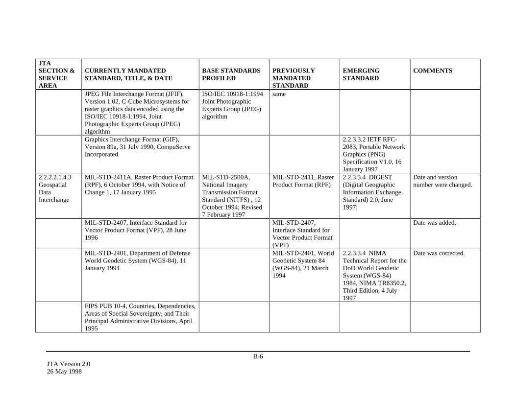
B-6JTA Version 2.026 May 1998
JTASECTION &SERVICEAREA
CURRENTLY MANDATEDSTANDARD, TITLE, & DATE
BASE STANDARDSPROFILED
PREVIOUSLYMANDATEDSTANDARD
EMERGINGSTANDARD
COMMENTS
JPEG File Interchange Format (JFIF),Version 1.02, C-Cube Microsystems forraster graphics data encoded using theISO/IEC 10918-1:1994, JointPhotographic Experts Group (JPEG)algorithm
ISO/IEC 10918-1:1994Joint PhotographicExperts Group (JPEG)algorithm
same
Graphics Interchange Format (GIF),Version 89a, 31 July 1990, CompuServeIncorporated
2.2.3.3.2 IETF RFC-2083, Portable NetworkGraphics (PNG)Specification V1.0, 16January 1997
2.2.2.2.1.4.3GeospatialDataInterchange
MIL-STD-2411A, Raster Product Format(RPF), 6 October 1994, with Notice ofChange 1, 17 January 1995
MIL-STD-2500A,National ImageryTransmission FormatStandard (NITFS) , 12October 1994; Revised7 February 1997
MIL-STD-2411, RasterProduct Format (RPF)
2.2.3.3.4 DIGEST(Digital GeographicInformation ExchangeStandard) 2.0, June1997;
Date and versionnumber were changed.
MIL-STD-2407, Interface Standard forVector Product Format (VPF), 28 June1996
MIL-STD-2407,Interface Standard forVector Product Format(VPF)
Date was added.
MIL-STD-2401, Department of DefenseWorld Geodetic System (WGS-84), 11January 1994
MIL-STD-2401, WorldGeodetic System 84(WGS-84), 21 March1994
2.2.3.3.4 NIMATechnical Report for theDoD World GeodeticSystem (WGS-84)1984, NIMA TR8350.2,Third Edition, 4 July1997
Date was corrected.
FIPS PUB 10-4, Countries, Dependencies,Areas of Special Sovereignty, and TheirPrincipal Administrative Divisions, April1995

B-7JTA Version 2.0
26 May 1998
JTASECTION &SERVICEAREA
CURRENTLY MANDATEDSTANDARD, TITLE, & DATE
BASE STANDARDSPROFILED
PREVIOUSLYMANDATEDSTANDARD
EMERGINGSTANDARD
COMMENTS
2.2.2.2.1.4.4Still ImageryDataInterchange
MIL-STD-2500A, National ImageryTransmission Format (Version 2.0) for theNational Imagery Transmission FormatStandard, 12 October 1994; Revised 7February 1997
same 2.2.3.3.5 MIL-STD-2500B, NationalImagery TransmissionFormat (Version 2.1),22 August 1997
MIL-STD-188-196, Bi-Level ImageCompression for the National ImageryTransmission Format Standard, 18 June1993
same
MIL-STD-188-199, Vector QuantizationDecompression for the National ImageryTransmission Format Standard, 27 June1994
same
MIL-STD-2301A, Computer GraphicsMetafile (CGM) Implementation Standardfor the National Imagery TransmissionFormat Standard, 18 June 1993 withNotice of Change 1, 12 October 1994
ANSI/ISO 8632-1,2,3,4:1992, ComputerGraphics Metafile(CGM) for the Storageand Transfer of PictureDescription Information
ANSI/ISO 8632:1992Computer GraphicsMetafile (CGM),profiled by MIL-STD-2301: 18 June 1993
MIL-STD-188-198A, Joint PhotographicExperts Group (JPEG) ImageCompression for the National ImageryTransmission Format Standard, 15December 1993
ISO/IEC 10918-1: 1994,Joint PhotographicExperts Groups (JPEG)
same
2.2.2.2.1.4.5.1.1Video Imagery
ITU-R BT.601-4, Encoding Parameters ofDigital Television for Studios,Component (4:2:2) Digital Video, 1994
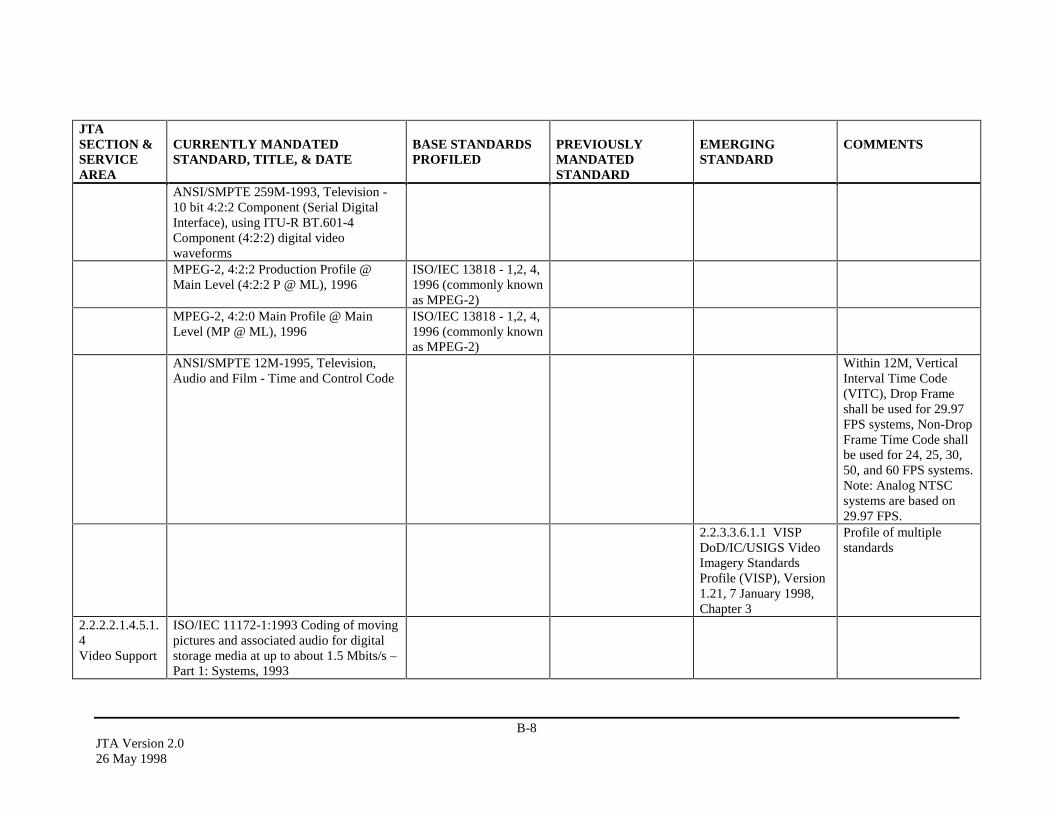
B-8JTA Version 2.026 May 1998
JTASECTION &SERVICEAREA
CURRENTLY MANDATEDSTANDARD, TITLE, & DATE
BASE STANDARDSPROFILED
PREVIOUSLYMANDATEDSTANDARD
EMERGINGSTANDARD
COMMENTS
ANSI/SMPTE 259M-1993, Television -10 bit 4:2:2 Component (Serial DigitalInterface), using ITU-R BT.601-4Component (4:2:2) digital videowaveformsMPEG-2, 4:2:2 Production Profile @Main Level (4:2:2 P @ ML), 1996
ISO/IEC 13818 - 1,2, 4,1996 (commonly knownas MPEG-2)
MPEG-2, 4:2:0 Main Profile @ MainLevel (MP @ ML), 1996
ISO/IEC 13818 - 1,2, 4,1996 (commonly knownas MPEG-2)
ANSI/SMPTE 12M-1995, Television,Audio and Film - Time and Control Code
Within 12M, VerticalInterval Time Code(VITC), Drop Frameshall be used for 29.97FPS systems, Non-DropFrame Time Code shallbe used for 24, 25, 30,50, and 60 FPS systems.Note: Analog NTSCsystems are based on29.97 FPS.
2.2.3.3.6.1.1 VISPDoD/IC/USIGS VideoImagery StandardsProfile (VISP), Version1.21, 7 January 1998,Chapter 3
Profile of multiplestandards
2.2.2.2.1.4.5.1.4Video Support
ISO/IEC 11172-1:1993 Coding of movingpictures and associated audio for digitalstorage media at up to about 1.5 Mbits/s –Part 1: Systems, 1993

B-9JTA Version 2.0
26 May 1998
JTASECTION &SERVICEAREA
CURRENTLY MANDATEDSTANDARD, TITLE, & DATE
BASE STANDARDSPROFILED
PREVIOUSLYMANDATEDSTANDARD
EMERGINGSTANDARD
COMMENTS
ISO/IEC 11172-1:1993/Cor. 1:1995Coding of moving pictures and associatedaudio for digital storage media at up toabout 1.5 Mbits/s - Part 1: SystemsTechnical Corrigendum 1, 1993/1995ISO/IEC 11172-2:1993 Coding of movingpictures and associated audio for digitalstorage media at up to about 1.5 Mbits/s -Part 2 Video, 1993ISO/IEC 13818-1:1996 with Amendment1:1997, Generic Coding of MovingPictures and Associated AudioInformation - Part 1: Systems (MPEG-2),1996ISO/IEC 13818-2:1996 with Amendment1:1997 and Amendment 2:1997, GenericCoding of Moving Pictures andAssociated Audio Information - Part 2:Video (MPEG-2), 1996
2.2.2.2.1.4.6Audio DataInterchange
ISO/IEC 11172-3:1993, Encoding ofmoving pictures and associated audio fordigital storage media at up to about 1.5Mbits/s - Part 3 (Audio Layer-3 only)
same
ISO/IEC 11172-3/Cor. 1:1996, Encodingof moving pictures and associated audiofor digital storage media at up to about 1.5Mbits/s -Part 3: Audio TechnicalCorrigendum (Audio Layer-3 only)
same
ISO/IEC 11172-1:1993, Coding ofmoving pictures and associated audio fordigital storage media at up to about 1.5Mbits/s - Part 1: Systems, 1993
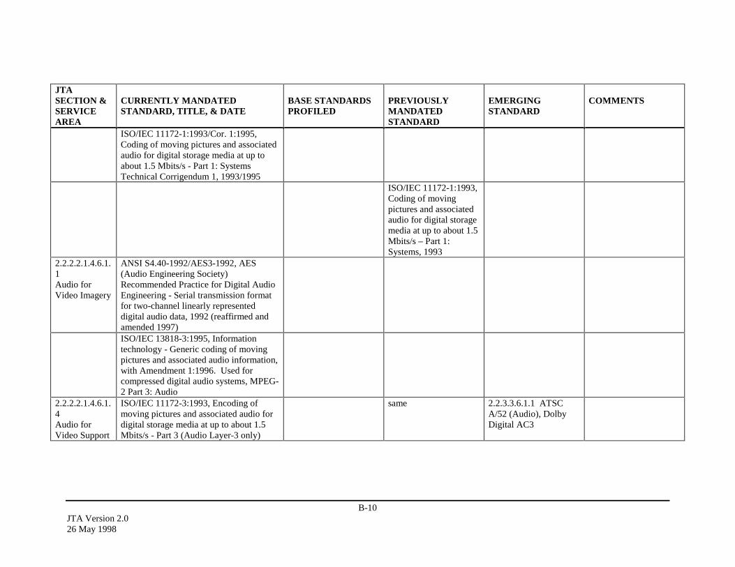
B-10JTA Version 2.026 May 1998
JTASECTION &SERVICEAREA
CURRENTLY MANDATEDSTANDARD, TITLE, & DATE
BASE STANDARDSPROFILED
PREVIOUSLYMANDATEDSTANDARD
EMERGINGSTANDARD
COMMENTS
ISO/IEC 11172-1:1993/Cor. 1:1995,Coding of moving pictures and associatedaudio for digital storage media at up toabout 1.5 Mbits/s - Part 1: SystemsTechnical Corrigendum 1, 1993/1995
ISO/IEC 11172-1:1993,Coding of movingpictures and associatedaudio for digital storagemedia at up to about 1.5Mbits/s – Part 1:Systems, 1993
2.2.2.2.1.4.6.1.1Audio forVideo Imagery
ANSI S4.40-1992/AES3-1992, AES(Audio Engineering Society)Recommended Practice for Digital AudioEngineering - Serial transmission formatfor two-channel linearly representeddigital audio data, 1992 (reaffirmed andamended 1997)ISO/IEC 13818-3:1995, Informationtechnology - Generic coding of movingpictures and associated audio information,with Amendment 1:1996. Used forcompressed digital audio systems, MPEG-2 Part 3: Audio
2.2.2.2.1.4.6.1.4Audio forVideo Support
ISO/IEC 11172-3:1993, Encoding ofmoving pictures and associated audio fordigital storage media at up to about 1.5Mbits/s - Part 3 (Audio Layer-3 only)
same 2.2.3.3.6.1.1 ATSCA/52 (Audio), DolbyDigital AC3
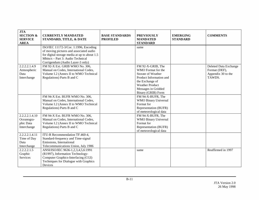
B-11JTA Version 2.0
26 May 1998
JTASECTION &SERVICEAREA
CURRENTLY MANDATEDSTANDARD, TITLE, & DATE
BASE STANDARDSPROFILED
PREVIOUSLYMANDATEDSTANDARD
EMERGINGSTANDARD
COMMENTS
ISO/IEC 11172-3/Cor. 1:1996, Encodingof moving pictures and associated audiofor digital storage media at up to about 1.5Mbits/s – Part 3: Audio TechnicalCorrigendum (Audio Layer-3 only)
same
2.2.2.2.1.4.9AtmosphericDataInterchange
FM 92-X Ext. GRIB WMO No. 306,Manual on Codes, International Codes,Volume I.2 (Annex II to WMO TechnicalRegulations) Parts B and C
FM 92-X-GRIB, TheWMO Format for theStorate of WeatherProduct Information andthe Exchange ofWeather ProductMessages in GriddedBinary (GRIB) Form
Deleted Data ExchangeFormat (DEF),Appendix 30 to theTAWDS.
FM 94-X Ext. BUFR WMO No. 306,Manual on Codes, International Codes,Volume I.2 (Annex II to WMO TechnicalRegulations) Parts B and C
FM 94-X-BUFR, TheWMO Binary UniversalFormat forRepresentation (BUFR)of meteorological data
2.2.2.2.1.4.10Oceanogra-phic DataInterchange
FM 94-X Ext. BUFR WMO No. 306,Manual on Codes, International Codes,Volume I.2 (Annex II to WMO TechnicalRegulations) Parts B and C
FM 94-X-BUFR, TheWMO Binary UniversalFormat forRepresentation (BUFR)of meteorological data
2.2.2.2.1.4.11Time of DayDataInterchange
ITU-R Recommendation TF.460-4,Standard-frequency and Time-signalEmissions, InternationalTelecommunications Union, July 1986
2.2.2.2.1.5GraphicServices
ANSI/ISO/IEC 9636-1,2,3,4,5,6:1991(R1997), Information Technology-Computer Graphics-Interfacing (CGI)Techniques for Dialogue with GraphicsDevices
same Reaffirmed in 1997
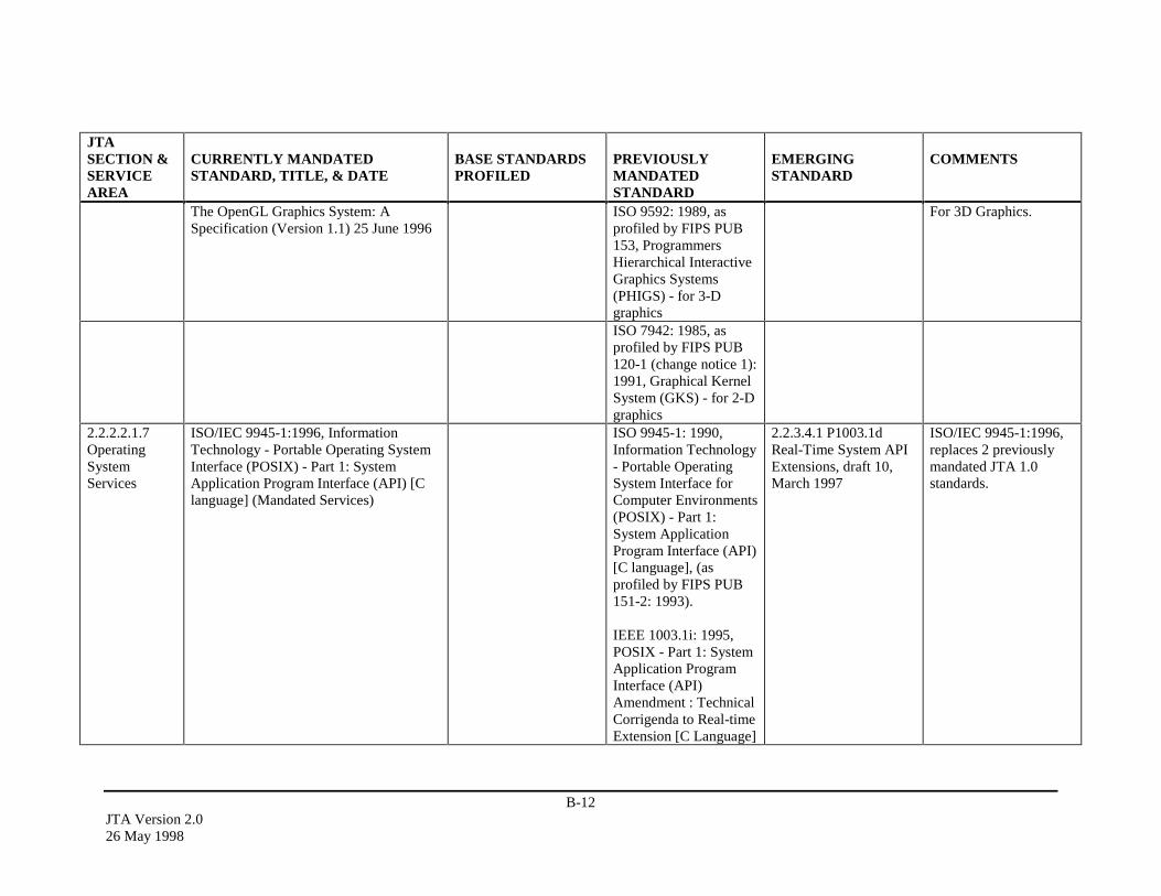
B-12JTA Version 2.026 May 1998
JTASECTION &SERVICEAREA
CURRENTLY MANDATEDSTANDARD, TITLE, & DATE
BASE STANDARDSPROFILED
PREVIOUSLYMANDATEDSTANDARD
EMERGINGSTANDARD
COMMENTS
The OpenGL Graphics System: ASpecification (Version 1.1) 25 June 1996
ISO 9592: 1989, asprofiled by FIPS PUB153, ProgrammersHierarchical InteractiveGraphics Systems(PHIGS) - for 3-Dgraphics
For 3D Graphics.
ISO 7942: 1985, asprofiled by FIPS PUB120-1 (change notice 1):1991, Graphical KernelSystem (GKS) - for 2-Dgraphics
2.2.2.2.1.7OperatingSystemServices
ISO/IEC 9945-1:1996, InformationTechnology - Portable Operating SystemInterface (POSIX) - Part 1: SystemApplication Program Interface (API) [Clanguage] (Mandated Services)
ISO 9945-1: 1990,Information Technology- Portable OperatingSystem Interface forComputer Environments(POSIX) - Part 1:System ApplicationProgram Interface (API)[C language], (asprofiled by FIPS PUB151-2: 1993).
IEEE 1003.1i: 1995,POSIX - Part 1: SystemApplication ProgramInterface (API)Amendment : TechnicalCorrigenda to Real-timeExtension [C Language]
2.2.3.4.1 P1003.1dReal-Time System APIExtensions, draft 10,March 1997
ISO/IEC 9945-1:1996,replaces 2 previouslymandated JTA 1.0standards.

B-13JTA Version 2.0
26 May 1998
JTASECTION &SERVICEAREA
CURRENTLY MANDATEDSTANDARD, TITLE, & DATE
BASE STANDARDSPROFILED
PREVIOUSLYMANDATEDSTANDARD
EMERGINGSTANDARD
COMMENTS
2.2.3.4.1 P1003.1g -Protocol IndependentInterfaces, draft 6.6,April 19972.2.3.4.1 P1003.1h -Services for Reliable,Available, ServiceableSystems, draft 3,January 19982.2.3.4.1 P1003.1j -Advanced Real-timeSystem API Extensions,draft 6, February 19982.2.3.4.1 P1003.1m -Checkpoint Restart,draft 1.3, October 19972.2.3.4.1 P1003.1q -System API: The TraceAmendment, draft 2.6,January 19982.2.3.4.1 P1003.13StandardizedApplicationEnvironmentProfile - POSIX Real-Time ApplicationSupport, draft 9,January 1998

B-14JTA Version 2.026 May 1998
JTASECTION &SERVICEAREA
CURRENTLY MANDATEDSTANDARD, TITLE, & DATE
BASE STANDARDSPROFILED
PREVIOUSLYMANDATEDSTANDARD
EMERGINGSTANDARD
COMMENTS
2.2.3.4.1 P1003.21Real-Time DistributedSystemsCommunication,Version 1.0, October1996
ISO/IEC 9945-1:1996:(Real-timeExtensions) to ISO/IEC 9945-1:1996,Information Technology - PortableOperating System Interface (POSIX)- Part1: System Application Program Interface(API) [C language] (Real-time OptionalServices)
IEEE 1003.1b: 1993,POSIX - Part 1: SystemApplication ProgramInterface (API)Amendment 1; RealTime Extension [CLanguage], (as profiledby FIPS PUB 151-2:1993)
ISO/IEC 9945-1:1996: (ThreadExtensions) to ISO/IEC 9945-1:1996,Information Technology - PortableOperating System Interface (POSIX)- Part1: System Application Program Interface(API) [C language] (Thread OptionalServices)
IEEE 1003.1c: 1995,POSIX - Part 1: SystemApplication ProgramInterface (API)Amendment 2: ThreadsExtension [C Language]
ISO/IEC 9945-2: 1993, InformationTechnology - Portable Operating SystemInterface (POSIX) - Part 2: Shell andUtilities, as profiled by FIPS PUB 189:1994, Information Technology - PortableOperating System Interface (POSIX) -Recommendations (Section 12) andImplementation Guidance (Section 13).
FIPS PUB 189:1994,Information Technology- Portable OperatingSystem Interface(POSIX) -Recommendations(section 12) andImplementationGuidance (section 13)
ISO/IEF 9945-2:1993,Information Technology- Portable OperatingSystem Interface(POSIX) - Part 2: Shelland Utilities as profiledby FIPS PUB 189:1994
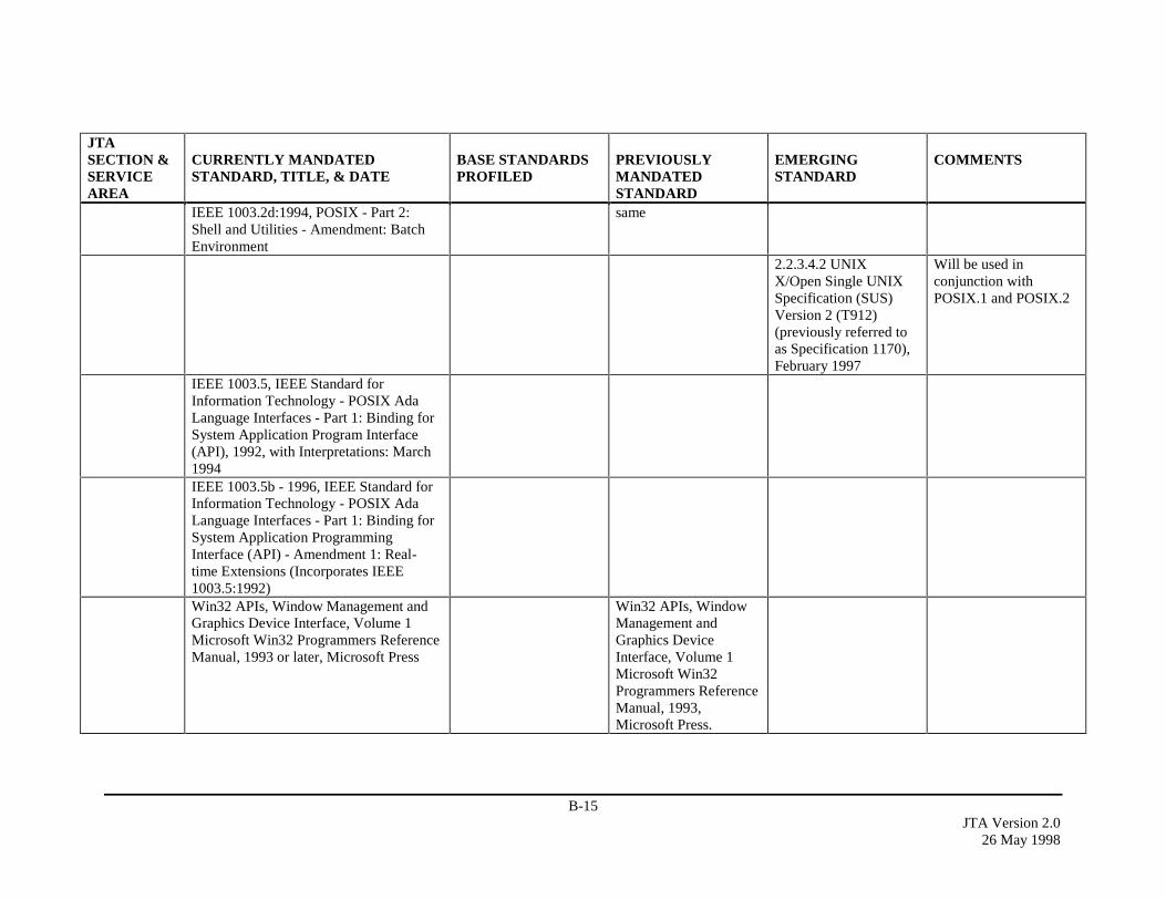
B-15JTA Version 2.0
26 May 1998
JTASECTION &SERVICEAREA
CURRENTLY MANDATEDSTANDARD, TITLE, & DATE
BASE STANDARDSPROFILED
PREVIOUSLYMANDATEDSTANDARD
EMERGINGSTANDARD
COMMENTS
IEEE 1003.2d:1994, POSIX - Part 2:Shell and Utilities - Amendment: BatchEnvironment
same
2.2.3.4.2 UNIXX/Open Single UNIXSpecification (SUS)Version 2 (T912)(previously referred toas Specification 1170),February 1997
Will be used inconjunction withPOSIX.1 and POSIX.2
IEEE 1003.5, IEEE Standard forInformation Technology - POSIX AdaLanguage Interfaces - Part 1: Binding forSystem Application Program Interface(API), 1992, with Interpretations: March1994IEEE 1003.5b - 1996, IEEE Standard forInformation Technology - POSIX AdaLanguage Interfaces - Part 1: Binding forSystem Application ProgrammingInterface (API) - Amendment 1: Real-time Extensions (Incorporates IEEE1003.5:1992)Win32 APIs, Window Management andGraphics Device Interface, Volume 1Microsoft Win32 Programmers ReferenceManual, 1993 or later, Microsoft Press
Win32 APIs, WindowManagement andGraphics DeviceInterface, Volume 1Microsoft Win32Programmers ReferenceManual, 1993,Microsoft Press.
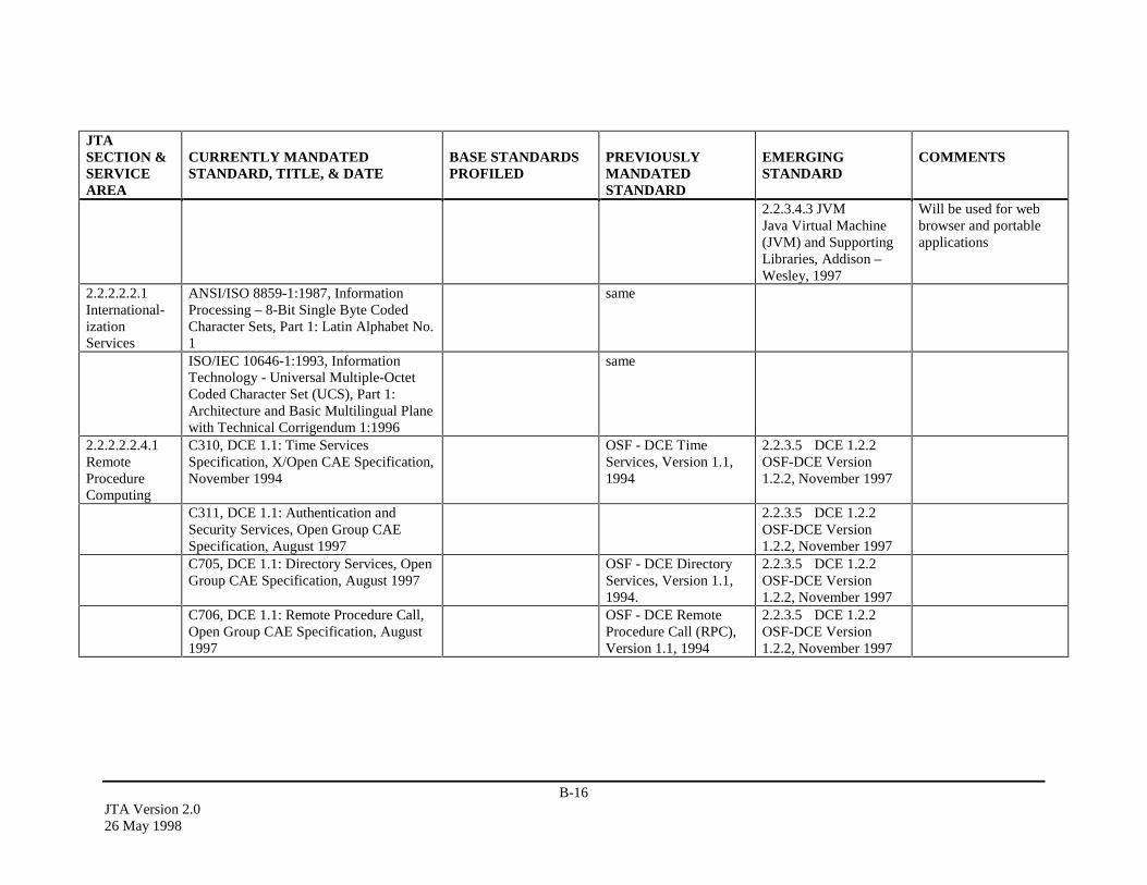
B-16JTA Version 2.026 May 1998
JTASECTION &SERVICEAREA
CURRENTLY MANDATEDSTANDARD, TITLE, & DATE
BASE STANDARDSPROFILED
PREVIOUSLYMANDATEDSTANDARD
EMERGINGSTANDARD
COMMENTS
2.2.3.4.3 JVMJava Virtual Machine(JVM) and SupportingLibraries, Addison –Wesley, 1997
Will be used for webbrowser and portableapplications
2.2.2.2.2.1International-izationServices
ANSI/ISO 8859-1:1987, InformationProcessing – 8-Bit Single Byte CodedCharacter Sets, Part 1: Latin Alphabet No.1
same
ISO/IEC 10646-1:1993, InformationTechnology - Universal Multiple-OctetCoded Character Set (UCS), Part 1:Architecture and Basic Multilingual Planewith Technical Corrigendum 1:1996
same
2.2.2.2.2.4.1RemoteProcedureComputing
C310, DCE 1.1: Time ServicesSpecification, X/Open CAE Specification,November 1994
OSF - DCE TimeServices, Version 1.1,1994
2.2.3.5 DCE 1.2.2OSF-DCE Version1.2.2, November 1997
C311, DCE 1.1: Authentication andSecurity Services, Open Group CAESpecification, August 1997
2.2.3.5 DCE 1.2.2OSF-DCE Version1.2.2, November 1997
C705, DCE 1.1: Directory Services, OpenGroup CAE Specification, August 1997
OSF - DCE DirectoryServices, Version 1.1,1994.
2.2.3.5 DCE 1.2.2OSF-DCE Version1.2.2, November 1997
C706, DCE 1.1: Remote Procedure Call,Open Group CAE Specification, August1997
OSF - DCE RemoteProcedure Call (RPC),Version 1.1, 1994
2.2.3.5 DCE 1.2.2OSF-DCE Version1.2.2, November 1997
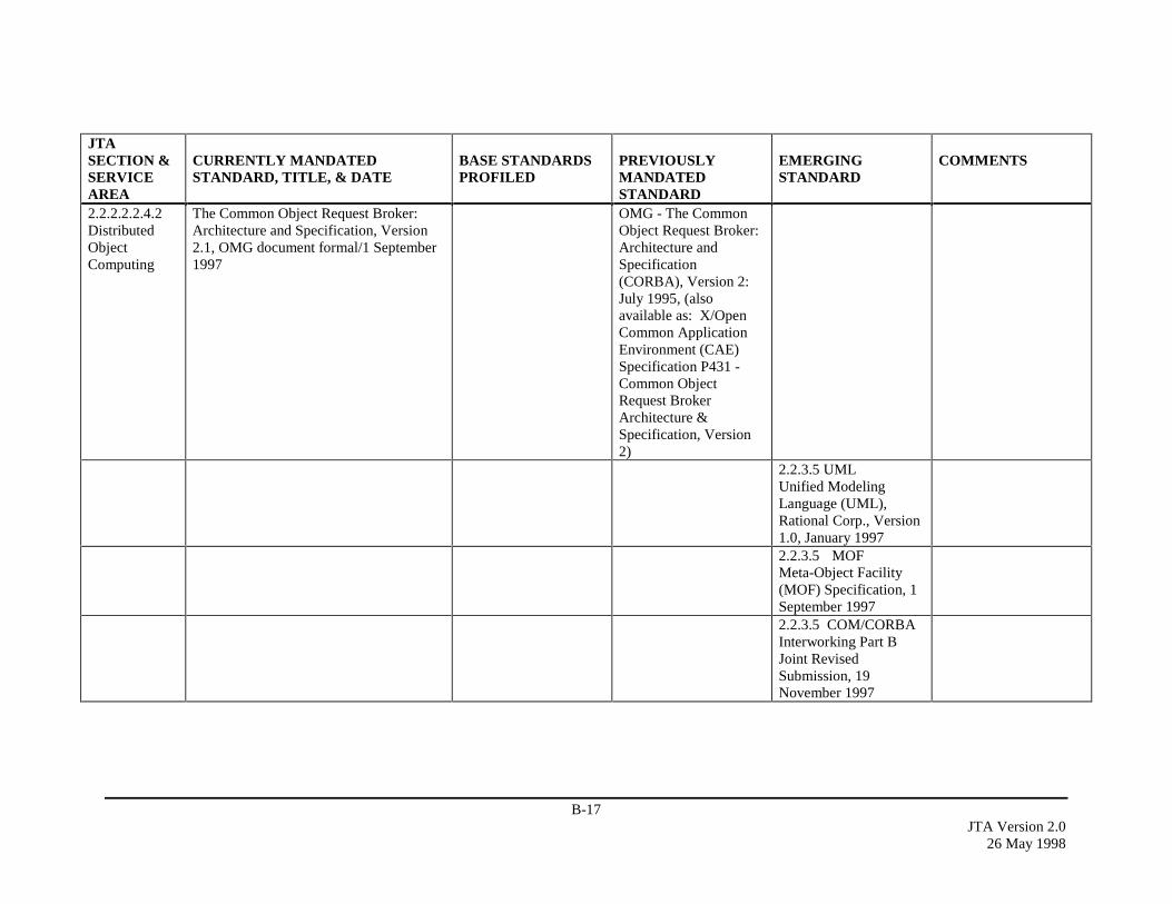
B-17JTA Version 2.0
26 May 1998
JTASECTION &SERVICEAREA
CURRENTLY MANDATEDSTANDARD, TITLE, & DATE
BASE STANDARDSPROFILED
PREVIOUSLYMANDATEDSTANDARD
EMERGINGSTANDARD
COMMENTS
2.2.2.2.2.4.2DistributedObjectComputing
The Common Object Request Broker:Architecture and Specification, Version2.1, OMG document formal/1 September1997
OMG - The CommonObject Request Broker:Architecture andSpecification(CORBA), Version 2:July 1995, (alsoavailable as: X/OpenCommon ApplicationEnvironment (CAE)Specification P431 -Common ObjectRequest BrokerArchitecture &Specification, Version2)
2.2.3.5 UMLUnified ModelingLanguage (UML),Rational Corp., Version1.0, January 19972.2.3.5 MOFMeta-Object Facility(MOF) Specification, 1September 19972.2.3.5 COM/CORBAInterworking Part BJoint RevisedSubmission, 19November 1997
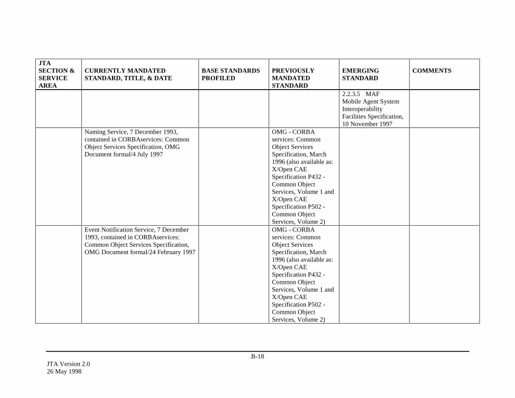
B-18JTA Version 2.026 May 1998
JTASECTION &SERVICEAREA
CURRENTLY MANDATEDSTANDARD, TITLE, & DATE
BASE STANDARDSPROFILED
PREVIOUSLYMANDATEDSTANDARD
EMERGINGSTANDARD
COMMENTS
2.2.3.5 MAFMobile Agent SystemInteroperabilityFacilities Specification,10 November 1997
Naming Service, 7 December 1993,contained in CORBAservices: CommonObject Services Specification, OMGDocument formal/4 July 1997
OMG - CORBAservices: CommonObject ServicesSpecification, March1996 (also available as:X/Open CAESpecification P432 -Common ObjectServices, Volume 1 andX/Open CAESpecification P502 -Common ObjectServices, Volume 2)
Event Notification Service, 7 December1993, contained in CORBAservices:Common Object Services Specification,OMG Document formal/24 February 1997
OMG - CORBAservices: CommonObject ServicesSpecification, March1996 (also available as:X/Open CAESpecification P432 -Common ObjectServices, Volume 1 andX/Open CAESpecification P502 -Common ObjectServices, Volume 2)
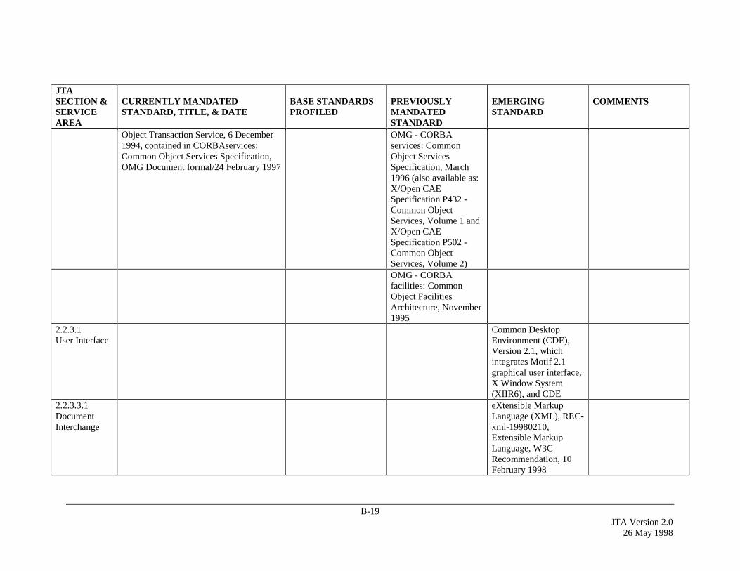
B-19JTA Version 2.0
26 May 1998
JTASECTION &SERVICEAREA
CURRENTLY MANDATEDSTANDARD, TITLE, & DATE
BASE STANDARDSPROFILED
PREVIOUSLYMANDATEDSTANDARD
EMERGINGSTANDARD
COMMENTS
Object Transaction Service, 6 December1994, contained in CORBAservices:Common Object Services Specification,OMG Document formal/24 February 1997
OMG - CORBAservices: CommonObject ServicesSpecification, March1996 (also available as:X/Open CAESpecification P432 -Common ObjectServices, Volume 1 andX/Open CAESpecification P502 -Common ObjectServices, Volume 2)OMG - CORBAfacilities: CommonObject FacilitiesArchitecture, November1995
2.2.3.1User Interface
Common DesktopEnvironment (CDE),Version 2.1, whichintegrates Motif 2.1graphical user interface,X Window System(XIIR6), and CDE
2.2.3.3.1DocumentInterchange
eXtensible MarkupLanguage (XML), REC-xml-19980210,Extensible MarkupLanguage, W3CRecommendation, 10February 1998
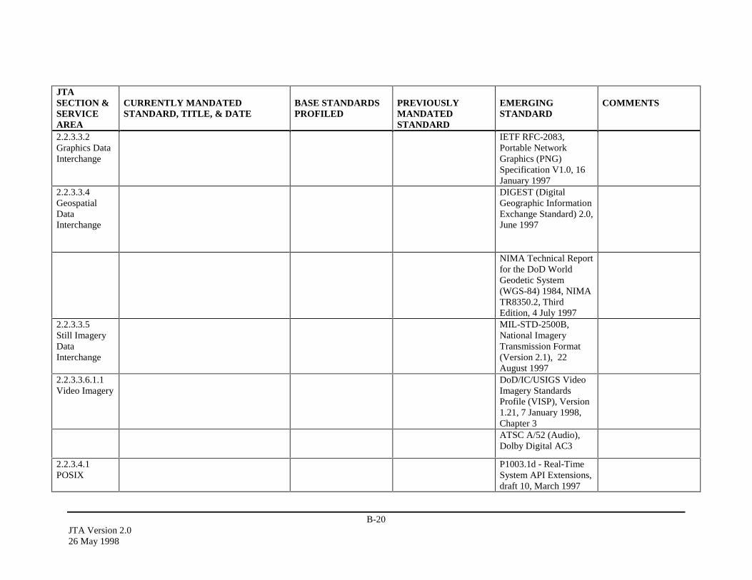
B-20JTA Version 2.026 May 1998
JTASECTION &SERVICEAREA
CURRENTLY MANDATEDSTANDARD, TITLE, & DATE
BASE STANDARDSPROFILED
PREVIOUSLYMANDATEDSTANDARD
EMERGINGSTANDARD
COMMENTS
2.2.3.3.2Graphics DataInterchange
IETF RFC-2083,Portable NetworkGraphics (PNG)Specification V1.0, 16January 1997
2.2.3.3.4GeospatialDataInterchange
DIGEST (DigitalGeographic InformationExchange Standard) 2.0,June 1997
NIMA Technical Reportfor the DoD WorldGeodetic System(WGS-84) 1984, NIMATR8350.2, ThirdEdition, 4 July 1997
2.2.3.3.5Still ImageryDataInterchange
MIL-STD-2500B,National ImageryTransmission Format(Version 2.1), 22August 1997
2.2.3.3.6.1.1Video Imagery
DoD/IC/USIGS VideoImagery StandardsProfile (VISP), Version1.21, 7 January 1998,Chapter 3ATSC A/52 (Audio),Dolby Digital AC3
2.2.3.4.1POSIX
P1003.1d - Real-TimeSystem API Extensions,draft 10, March 1997
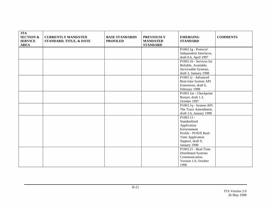
B-21JTA Version 2.0
26 May 1998
JTASECTION &SERVICEAREA
CURRENTLY MANDATEDSTANDARD, TITLE, & DATE
BASE STANDARDSPROFILED
PREVIOUSLYMANDATEDSTANDARD
EMERGINGSTANDARD
COMMENTS
P1003.1g - ProtocolIndependent Interfaces,draft 6.6, April 1997P1003.1h - Services forReliable, Available,Serviceable Systems,draft 3, January 1998P1003.1j - AdvancedReal-time System APIExtensions, draft 6,February 1998P1003.1m - CheckpointRestart, draft 1.3,October 1997P1003.1q - System API:The Trace Amendment,draft 2.6, January 1998P1003.13 -StandardizedApplicationEnvironmentProfile - POSIX Real-Time ApplicationSupport, draft 9,January 1998P1003.21 - Real-TimeDistributed SystemsCommunication,Version 1.0, October1996

B-22JTA Version 2.026 May 1998
JTASECTION &SERVICEAREA
CURRENTLY MANDATEDSTANDARD, TITLE, & DATE
BASE STANDARDSPROFILED
PREVIOUSLYMANDATEDSTANDARD
EMERGINGSTANDARD
COMMENTS
2.2.3.4.2UNIX
X/Open Single UNIXSpecification (SUS)Version 2 (T912)(previously referred toas Specification 1170),February 1997
2.2.3.4.3VirtualMachines
Java Virtual Machine(JVM) and SupportingLibraries, Addison –Wesley, 1997
2.2.3.5DistributedComputing
OSF-DCE Version1.2.2, November 1997
Unified ModelingLanguage (UML),Rational Corp., Version1.0, January 1997Meta-Object Facility(MOF) Specification, 1September 1997COM/CORBAInterworking Part BJoint RevisedSubmission , 19November 1997Mobile Agent SystemInteroperabilityFacilities Specification,10 November 1997
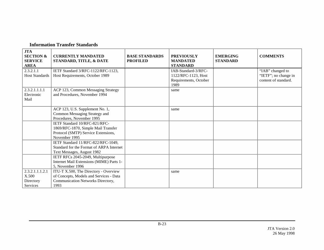
B-23JTA Version 2.0
26 May 1998
Information Transfer StandardsJTASECTION &SERVICEAREA
CURRENTLY MANDATEDSTANDARD, TITLE, & DATE
BASE STANDARDSPROFILED
PREVIOUSLYMANDATEDSTANDARD
EMERGINGSTANDARD
COMMENTS
2.3.2.1.1Host Standards
IETF Standard 3/RFC-1122/RFC-1123,Host Requirements, October 1989
IAB-Standard-3/RFC-1122/RFC-1123, HostRequirements, October1989
“IAB” changed to“IETF”; no change incontent of standard.
2.3.2.1.1.1.1ElectronicMail
ACP 123, Common Messaging Strategyand Procedures, November 1994
same
ACP 123, U.S. Supplement No. 1,Common Messaging Strategy andProcedures, November 1995
same
IETF Standard 10/RFC-821/RFC-1869/RFC-1870, Simple Mail TransferProtocol (SMTP) Service Extensions,November 1995IETF Standard 11/RFC-822/RFC-1049,Standard for the Format of ARPA InternetText Messages, August 1982IETF RFCs 2045-2049, MultipurposeInternet Mail Extensions (MIME) Parts 1-5, November 1996
2.3.2.1.1.1.2.1X.500DirectoryServices
ITU-T X.500, The Directory - Overviewof Concepts, Models and Services - DataCommunication Networks Directory,1993
same
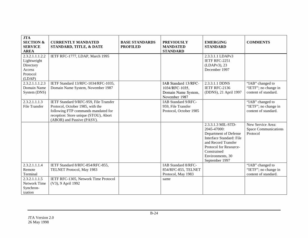
B-24JTA Version 2.026 May 1998
JTASECTION &SERVICEAREA
CURRENTLY MANDATEDSTANDARD, TITLE, & DATE
BASE STANDARDSPROFILED
PREVIOUSLYMANDATEDSTANDARD
EMERGINGSTANDARD
COMMENTS
2.3.2.1.1.1.2.2LightweightDirectoryAccessProtocol(LDAP)
IETF RFC-1777, LDAP, March 1995 2.3.3.1.1 LDAPv3IETF RFC-2251(LDAPv3), 23December 1997
2.3.2.1.1.1.2.3Domain NameSystem (DNS)
IETF Standard 13/RFC-1034/RFC-1035,Domain Name System, November 1987
,$%�6WDQGDUG����5)&������5)&������'RPDLQ�1DPH�6\VWHP�1RYHPEHU�����
2.3.3.1.1 DDNSIETF RFC-2136(DDNS), 21 April 1997
“IAB” changed to“IETF”; no change incontent of standard.
2.3.2.1.1.1.3File Transfer
IETF Standard 9/RFC-959, File TransferProtocol, October 1985, with thefollowing FTP commands mandated forreception: Store unique (STOU), Abort(ABOR) and Passive (PASV).
IAB Standard 9/RFC-959, File TransferProtocol, October 1985
“IAB” changed to“IETF”; no change incontent of standard.
2.3.3.1.3 MIL-STD-2045-47000:Department of DefenseInterface Standard: Fileand Record TransferProtocol for Resource-ConstrainedEnvironments, 30September 1997
New Service Area:Space CommunicationsProtocol
2.3.2.1.1.1.4RemoteTerminal
IETF Standard 8/RFC-854/RFC-855,TELNET Protocol, May 1983
IAB Standard 8/RFC-854/RFC-855, TELNETProtocol, May 1983
“IAB” changed to“IETF”; no change incontent of standard.
2.3.2.1.1.1.5Network TimeSynchron-ization
IETF RFC-1305, Network Time Protocol(V3), 9 April 1992
same
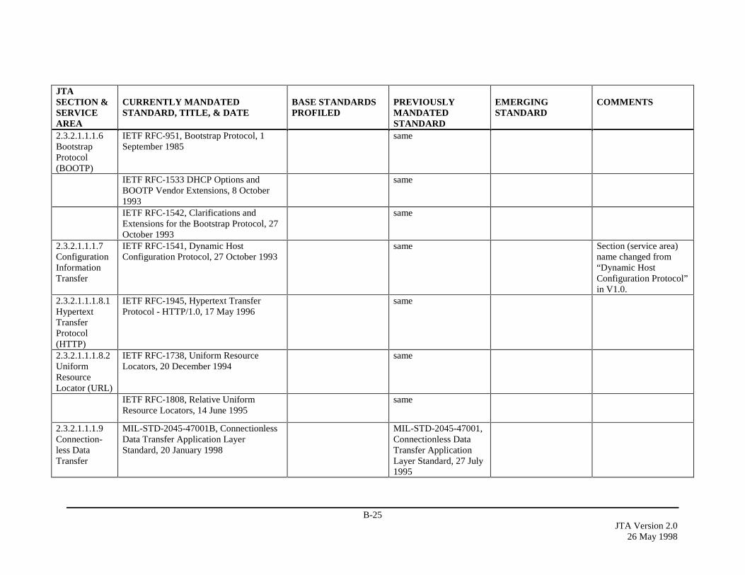
B-25JTA Version 2.0
26 May 1998
JTASECTION &SERVICEAREA
CURRENTLY MANDATEDSTANDARD, TITLE, & DATE
BASE STANDARDSPROFILED
PREVIOUSLYMANDATEDSTANDARD
EMERGINGSTANDARD
COMMENTS
2.3.2.1.1.1.6BootstrapProtocol(BOOTP)
IETF RFC-951, Bootstrap Protocol, 1September 1985
same
IETF RFC-1533 DHCP Options andBOOTP Vendor Extensions, 8 October1993
same
IETF RFC-1542, Clarifications andExtensions for the Bootstrap Protocol, 27October 1993
same
2.3.2.1.1.1.7ConfigurationInformationTransfer
IETF RFC-1541, Dynamic HostConfiguration Protocol, 27 October 1993
same Section (service area)name changed from“Dynamic HostConfiguration Protocol”in V1.0.
2.3.2.1.1.1.8.1HypertextTransferProtocol(HTTP)
IETF RFC-1945, Hypertext TransferProtocol - HTTP/1.0, 17 May 1996
same
2.3.2.1.1.1.8.2UniformResourceLocator (URL)
IETF RFC-1738, Uniform ResourceLocators, 20 December 1994
same
IETF RFC-1808, Relative UniformResource Locators, 14 June 1995
same
2.3.2.1.1.1.9Connection-less DataTransfer
MIL-STD-2045-47001B, ConnectionlessData Transfer Application LayerStandard, 20 January 1998
MIL-STD-2045-47001,Connectionless DataTransfer ApplicationLayer Standard, 27 July1995
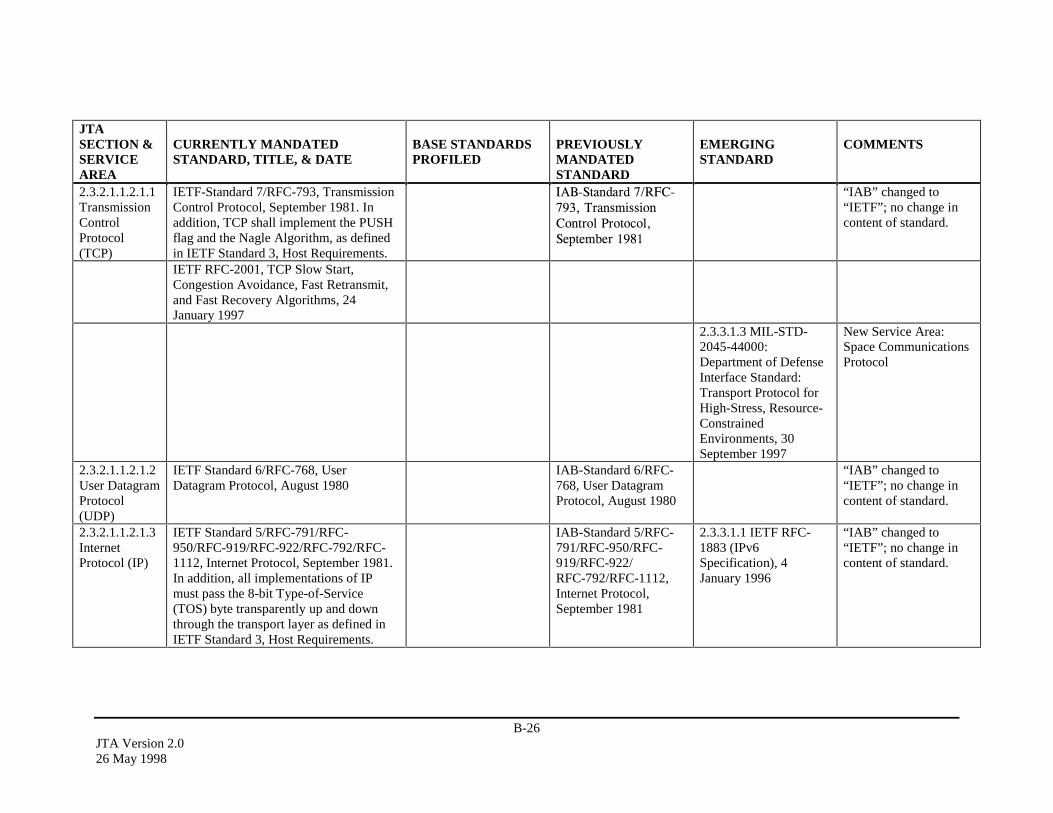
B-26JTA Version 2.026 May 1998
JTASECTION &SERVICEAREA
CURRENTLY MANDATEDSTANDARD, TITLE, & DATE
BASE STANDARDSPROFILED
PREVIOUSLYMANDATEDSTANDARD
EMERGINGSTANDARD
COMMENTS
2.3.2.1.1.2.1.1TransmissionControlProtocol(TCP)
IETF-Standard 7/RFC-793, TransmissionControl Protocol, September 1981. Inaddition, TCP shall implement the PUSHflag and the Nagle Algorithm, as definedin IETF Standard 3, Host Requirements.
,$%�6WDQGDUG���5)&������7UDQVPLVVLRQ&RQWURO�3URWRFRO�6HSWHPEHU�����
“IAB” changed to“IETF”; no change incontent of standard.
IETF RFC-2001, TCP Slow Start,Congestion Avoidance, Fast Retransmit,and Fast Recovery Algorithms, 24January 1997
2.3.3.1.3 MIL-STD-2045-44000:Department of DefenseInterface Standard:Transport Protocol forHigh-Stress, Resource-ConstrainedEnvironments, 30September 1997
New Service Area:Space CommunicationsProtocol
2.3.2.1.1.2.1.2User DatagramProtocol(UDP)
IETF Standard 6/RFC-768, UserDatagram Protocol, August 1980
IAB-Standard 6/RFC-768, User DatagramProtocol, August 1980
“IAB” changed to“IETF”; no change incontent of standard.
2.3.2.1.1.2.1.3InternetProtocol (IP)
IETF Standard 5/RFC-791/RFC-950/RFC-919/RFC-922/RFC-792/RFC-1112, Internet Protocol, September 1981.In addition, all implementations of IPmust pass the 8-bit Type-of-Service(TOS) byte transparently up and downthrough the transport layer as defined inIETF Standard 3, Host Requirements.
IAB-Standard 5/RFC-791/RFC-950/RFC-919/RFC-922/RFC-792/RFC-1112,Internet Protocol,September 1981
2.3.3.1.1 IETF RFC-1883 (IPv6Specification), 4January 1996
“IAB” changed to“IETF”; no change incontent of standard.

B-27JTA Version 2.0
26 May 1998
JTASECTION &SERVICEAREA
CURRENTLY MANDATEDSTANDARD, TITLE, & DATE
BASE STANDARDSPROFILED
PREVIOUSLYMANDATEDSTANDARD
EMERGINGSTANDARD
COMMENTS
IETF RFC-1770, IPv4 Option for SenderDirected Multi-Destination Delivery, 28March 1995
To be used only withCombat Net Radio(CNR) routers.
2.3.3.1.1 IETF RFC-1884 (IPv6 AddressingArchitecture), 4 January19962.3.3.1.1 IETF RFC-1885 (ICMPv6 forIPv6), 4 January 19962.3.3.1.1 IETF RFC-1886 (DNS Extensionsto Support IPv6), 4January 19962.3.3.1.1 IntegratedServices and RSVPIETF RFC-1633(Integrated Services andRSVP), 9 June 19942.3.3.1.1 MHPIETF RFC-2002 (IPMobility Support), 22October 19962.3.3.1.3 MIL-STD-2045-43000:Department of DefenseInterface Standard:Network Protocol forHigh-Stress, Resource-ConstrainedEnvironments, 30September 1997
New Service Area:Space CommunicationsProtocol
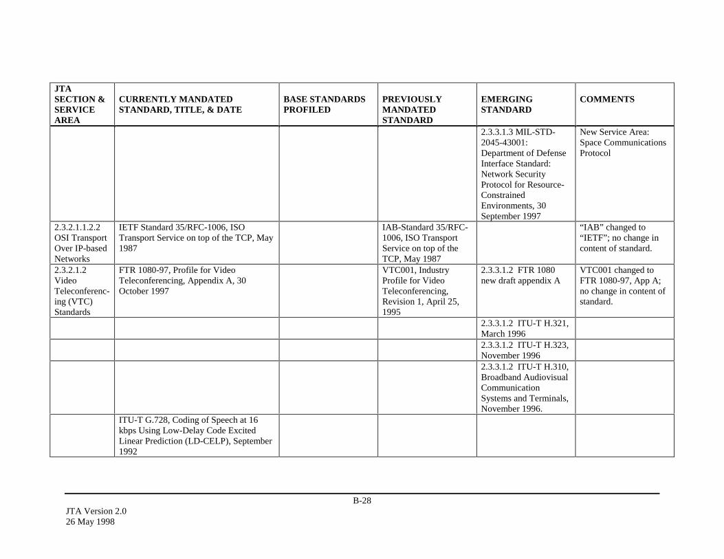
B-28JTA Version 2.026 May 1998
JTASECTION &SERVICEAREA
CURRENTLY MANDATEDSTANDARD, TITLE, & DATE
BASE STANDARDSPROFILED
PREVIOUSLYMANDATEDSTANDARD
EMERGINGSTANDARD
COMMENTS
2.3.3.1.3 MIL-STD-2045-43001:Department of DefenseInterface Standard:Network SecurityProtocol for Resource-ConstrainedEnvironments, 30September 1997
New Service Area:Space CommunicationsProtocol
2.3.2.1.1.2.2OSI TransportOver IP-basedNetworks
IETF Standard 35/RFC-1006, ISOTransport Service on top of the TCP, May1987
IAB-Standard 35/RFC-1006, ISO TransportService on top of theTCP, May 1987
“IAB” changed to“IETF”; no change incontent of standard.
2.3.2.1.2VideoTeleconferenc-ing (VTC)Standards
FTR 1080-97, Profile for VideoTeleconferencing, Appendix A, 30October 1997
VTC001, IndustryProfile for VideoTeleconferencing,Revision 1, April 25,1995
2.3.3.1.2 FTR 1080new draft appendix A
VTC001 changed toFTR 1080-97, App A;no change in content ofstandard.
2.3.3.1.2 ITU-T H.321,March 19962.3.3.1.2 ITU-T H.323,November 19962.3.3.1.2 ITU-T H.310,Broadband AudiovisualCommunicationSystems and Terminals,November 1996.
ITU-T G.728, Coding of Speech at 16kbps Using Low-Delay Code ExcitedLinear Prediction (LD-CELP), September1992
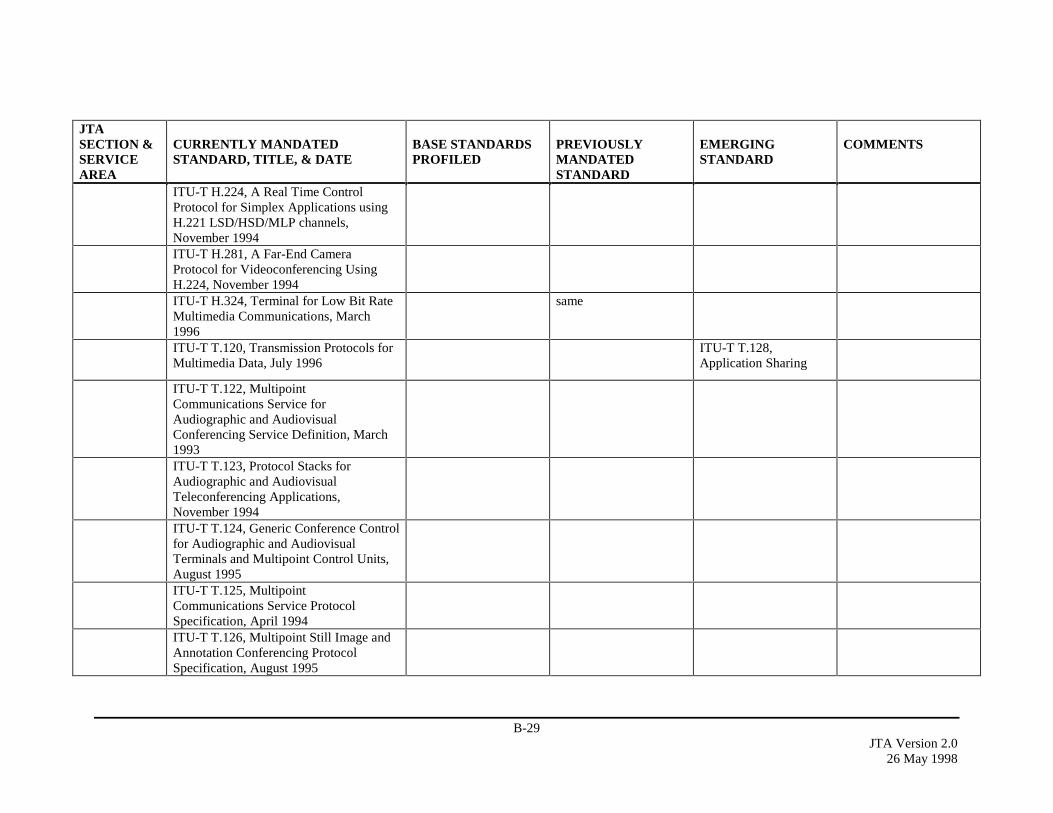
B-29JTA Version 2.0
26 May 1998
JTASECTION &SERVICEAREA
CURRENTLY MANDATEDSTANDARD, TITLE, & DATE
BASE STANDARDSPROFILED
PREVIOUSLYMANDATEDSTANDARD
EMERGINGSTANDARD
COMMENTS
ITU-T H.224, A Real Time ControlProtocol for Simplex Applications usingH.221 LSD/HSD/MLP channels,November 1994ITU-T H.281, A Far-End CameraProtocol for Videoconferencing UsingH.224, November 1994ITU-T H.324, Terminal for Low Bit RateMultimedia Communications, March1996
same
ITU-T T.120, Transmission Protocols forMultimedia Data, July 1996
ITU-T T.128,Application Sharing
ITU-T T.122, MultipointCommunications Service forAudiographic and AudiovisualConferencing Service Definition, March1993ITU-T T.123, Protocol Stacks forAudiographic and AudiovisualTeleconferencing Applications,November 1994ITU-T T.124, Generic Conference Controlfor Audiographic and AudiovisualTerminals and Multipoint Control Units,August 1995ITU-T T.125, MultipointCommunications Service ProtocolSpecification, April 1994ITU-T T.126, Multipoint Still Image andAnnotation Conferencing ProtocolSpecification, August 1995
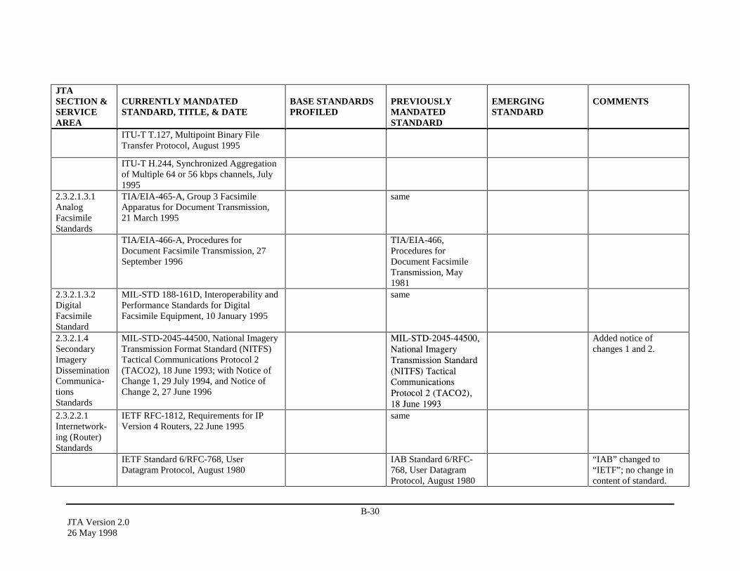
B-30JTA Version 2.026 May 1998
JTASECTION &SERVICEAREA
CURRENTLY MANDATEDSTANDARD, TITLE, & DATE
BASE STANDARDSPROFILED
PREVIOUSLYMANDATEDSTANDARD
EMERGINGSTANDARD
COMMENTS
ITU-T T.127, Multipoint Binary FileTransfer Protocol, August 1995
ITU-T H.244, Synchronized Aggregationof Multiple 64 or 56 kbps channels, July1995
2.3.2.1.3.1AnalogFacsimileStandards
TIA/EIA-465-A, Group 3 FacsimileApparatus for Document Transmission,21 March 1995
same
TIA/EIA-466-A, Procedures forDocument Facsimile Transmission, 27September 1996
TIA/EIA-466,Procedures forDocument FacsimileTransmission, May1981
2.3.2.1.3.2DigitalFacsimileStandard
MIL-STD 188-161D, Interoperability andPerformance Standards for DigitalFacsimile Equipment, 10 January 1995
same
2.3.2.1.4SecondaryImageryDisseminationCommunica-tionsStandards
MIL-STD-2045-44500, National ImageryTransmission Format Standard (NITFS)Tactical Communications Protocol 2(TACO2), 18 June 1993; with Notice ofChange 1, 29 July 1994, and Notice ofChange 2, 27 June 1996
0,/�67'������������1DWLRQDO�,PDJHU\7UDQVPLVVLRQ�6WDQGDUG�1,7)6��7DFWLFDO&RPPXQLFDWLRQV3URWRFRO����7$&2������-XQH�����
Added notice ofchanges 1 and 2.
2.3.2.2.1Internetwork-ing (Router)Standards
IETF RFC-1812, Requirements for IPVersion 4 Routers, 22 June 1995
same
IETF Standard 6/RFC-768, UserDatagram Protocol, August 1980
IAB Standard 6/RFC-768, User DatagramProtocol, August 1980
“IAB” changed to“IETF”; no change incontent of standard.
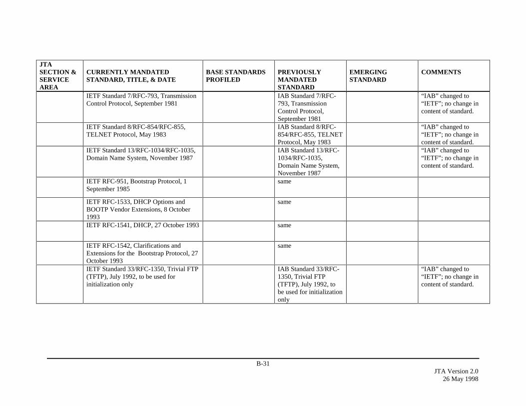
B-31JTA Version 2.0
26 May 1998
JTASECTION &SERVICEAREA
CURRENTLY MANDATEDSTANDARD, TITLE, & DATE
BASE STANDARDSPROFILED
PREVIOUSLYMANDATEDSTANDARD
EMERGINGSTANDARD
COMMENTS
IETF Standard 7/RFC-793, TransmissionControl Protocol, September 1981
IAB Standard 7/RFC-793, TransmissionControl Protocol,September 1981
“IAB” changed to“IETF”; no change incontent of standard.
IETF Standard 8/RFC-854/RFC-855,TELNET Protocol, May 1983
IAB Standard 8/RFC-854/RFC-855, TELNETProtocol, May 1983
“IAB” changed to“IETF”; no change incontent of standard.
IETF Standard 13/RFC-1034/RFC-1035,Domain Name System, November 1987
IAB Standard 13/RFC-1034/RFC-1035,Domain Name System,November 1987
“IAB” changed to“IETF”; no change incontent of standard.
IETF RFC-951, Bootstrap Protocol, 1September 1985
same
IETF RFC-1533, DHCP Options andBOOTP Vendor Extensions, 8 October1993
same
IETF RFC-1541, DHCP, 27 October 1993 same
IETF RFC-1542, Clarifications andExtensions for the Bootstrap Protocol, 27October 1993
same
IETF Standard 33/RFC-1350, Trivial FTP(TFTP), July 1992, to be used forinitialization only
IAB Standard 33/RFC-1350, Trivial FTP(TFTP), July 1992, tobe used for initializationonly
“IAB” changed to“IETF”; no change incontent of standard.

B-32JTA Version 2.026 May 1998
JTASECTION &SERVICEAREA
CURRENTLY MANDATEDSTANDARD, TITLE, & DATE
BASE STANDARDSPROFILED
PREVIOUSLYMANDATEDSTANDARD
EMERGINGSTANDARD
COMMENTS
2.3.2.2.1.1InternetProtocol (IP)
IETF Standard 5/RFC-791/RFC-950/RFC-919/RFC-922/RFC-792/RFC-1112, Internet Protocol,September 1981
IAB Standard 5/RFC-791/RFC-950/RFC-919/RFC-922/RFC-792/RFC-1112,Internet Protocol,September 1981
“IAB” changed to“IETF”; no change incontent of standard.
IETF RFC-1770, IPv4 Option for SenderDirected Multi-Destination Delivery, 28March 1995
To be used only withCombat Net Radio(CNR) routers.
2.3.2.2.1.2.1InteriorRouters
IETF RFC-1583, Open Shortest Path FirstRouting Version 2, 23 March 1994
same For unicast routing.
IETF RFC-1584, Multicast Extensions toOSPF, 24 March 1994
same For multicast routing.
2.3.2.2.1.2.2ExteriorRouters
IETF RFC-1771, Border GatewayProtocol 4, 21 March 1995
same
IETF RFC-1772, Application of BGP-4 Inthe Internet, 21 March 1995
same
2.3.2.2.2.1Local AreaNetwork(LAN) Access
ISO/IEC 8802-3:1996, Carrier SenseMultiple Access with Collision Detection(CSMA/CD) Access Method and PhysicalLayer Specification, 10BASE-T Medium-Access Unit (MAU)
ISO/IEC 8802-3:1993,Carrier Sense MultipleAccess with CollisionDetection (CSMA/CD)Access Method andPhysical LayerSpecifications, 10BaseTMedium-Access Unit(MAU)
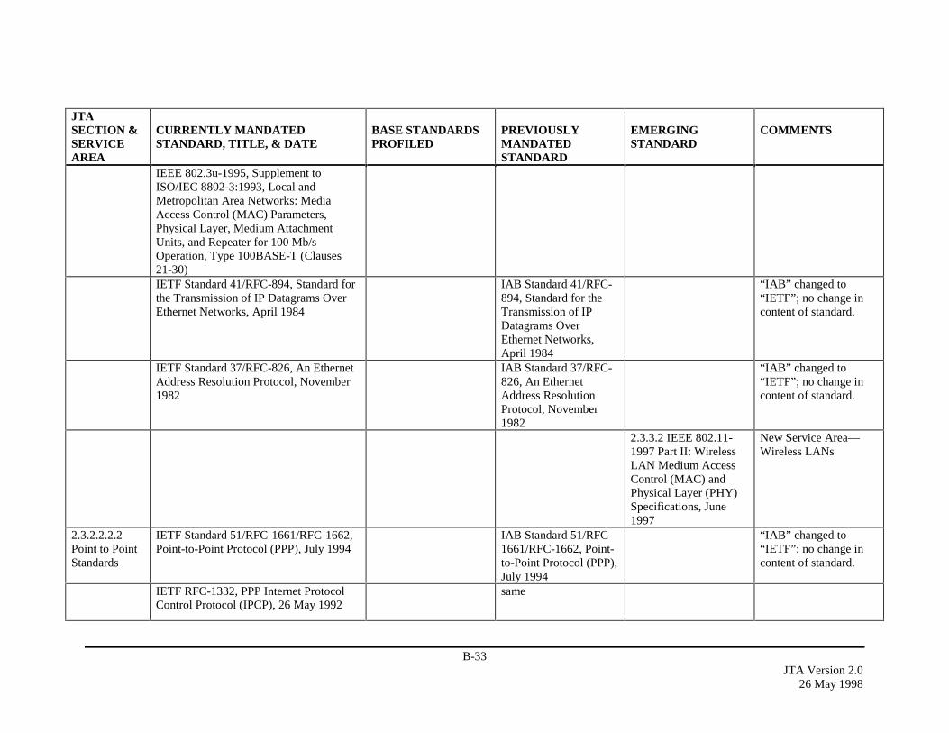
B-33JTA Version 2.0
26 May 1998
JTASECTION &SERVICEAREA
CURRENTLY MANDATEDSTANDARD, TITLE, & DATE
BASE STANDARDSPROFILED
PREVIOUSLYMANDATEDSTANDARD
EMERGINGSTANDARD
COMMENTS
IEEE 802.3u-1995, Supplement toISO/IEC 8802-3:1993, Local andMetropolitan Area Networks: MediaAccess Control (MAC) Parameters,Physical Layer, Medium AttachmentUnits, and Repeater for 100 Mb/sOperation, Type 100BASE-T (Clauses21-30)IETF Standard 41/RFC-894, Standard forthe Transmission of IP Datagrams OverEthernet Networks, April 1984
IAB Standard 41/RFC-894, Standard for theTransmission of IPDatagrams OverEthernet Networks,April 1984
“IAB” changed to“IETF”; no change incontent of standard.
IETF Standard 37/RFC-826, An EthernetAddress Resolution Protocol, November1982
IAB Standard 37/RFC-826, An EthernetAddress ResolutionProtocol, November1982
“IAB” changed to“IETF”; no change incontent of standard.
2.3.3.2 IEEE 802.11-1997 Part II: WirelessLAN Medium AccessControl (MAC) andPhysical Layer (PHY)Specifications, June1997
New Service Area—Wireless LANs
2.3.2.2.2.2Point to PointStandards
IETF Standard 51/RFC-1661/RFC-1662,Point-to-Point Protocol (PPP), July 1994
IAB Standard 51/RFC-1661/RFC-1662, Point-to-Point Protocol (PPP),July 1994
“IAB” changed to“IETF”; no change incontent of standard.
IETF RFC-1332, PPP Internet ProtocolControl Protocol (IPCP), 26 May 1992
same
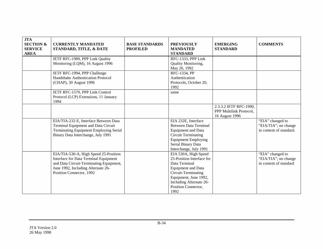
B-34JTA Version 2.026 May 1998
JTASECTION &SERVICEAREA
CURRENTLY MANDATEDSTANDARD, TITLE, & DATE
BASE STANDARDSPROFILED
PREVIOUSLYMANDATEDSTANDARD
EMERGINGSTANDARD
COMMENTS
IETF RFC-1989, PPP Link QualityMonitoring (LQM), 16 August 1996
RFC-1333, PPP LinkQuality Monitoring,May 26, 1992
IETF RFC-1994, PPP ChallengeHandshake Authentication Protocol(CHAP), 30 August 1996
RFC-1334, PPAuthenticationProtocols, October 20,1992
IETF RFC-1570, PPP Link ControlProtocol (LCP) Extensions, 11 January1994
same
2.3.3.2 IETF RFC-1990,PPP Multilink Protocol,16 August 1996
EIA/TIA-232-E, Interface Between DataTerminal Equipment and Data CircuitTerminating Equipment Employing SerialBinary Data Interchange, July 1991
EIA 232E, InterfaceBetween Data TerminalEquipment and DataCircuit TerminatingEquipment EmployingSerial Binary DataInterchange, July 1991
“EIA” changed to“EIA/TIA”; no changein content of standard.
EIA/TIA-530-A, High Speed 25-PositionInterface for Data Terminal Equipmentand Data Circuit-Terminating Equipment,June 1992, Including Alternate 26-Position Connector, 1992
EIA 530A, High Speed25-Position Interface forData TerminalEquipment and DataCircuit-TerminatingEquipment, June 1992,Including Alternate 26-Position Connector,1992
“EIA” changed to“EIA/TIA”; no changein content of standard

B-35JTA Version 2.0
26 May 1998
JTASECTION &SERVICEAREA
CURRENTLY MANDATEDSTANDARD, TITLE, & DATE
BASE STANDARDSPROFILED
PREVIOUSLYMANDATEDSTANDARD
EMERGINGSTANDARD
COMMENTS
EIA 449, GeneralPurpose 37-Position and9-Position Interface forData TerminalEquipment and DataCircuit TerminatingEquipment EmployingSerial Binary DataInterchange, February1980
2.3.2.2.2.3Combat NetRadio (CNR)Networking
MIL-STD-188-220B, InteroperabilityStandard for Digital Message TransferDevice (DMTD) Subsystems, 20 January1998
MIL-STD-188-220A,InteroperabilityStandard for DigitalMessage TransferDevice (DMTD)Subsystems, 27 July1995
2.3.2.2.2.4IntegratedServicesDigitalNetwork(ISDN)
ANSI T1.601, ISDN Basic AccessInterface for Use on Metallic Loops forApplication on the Network Side of theNT (Layer 1 Specification), 1992
same
ANSI T1.408, ISDN Primary Rate -Customer Installation Metallic Interfaces(Layer 1 Specification), 1990
same
ANSI T1.602, ISDN Data Link SignalingSpecification for Application at the UserNetwork Interface, 1996
ITU-T Q.921, ISDNUser-Network Interface- Data Link LayerSpecification - DigitalSubscriber SignalingSystem No. 1, 1993
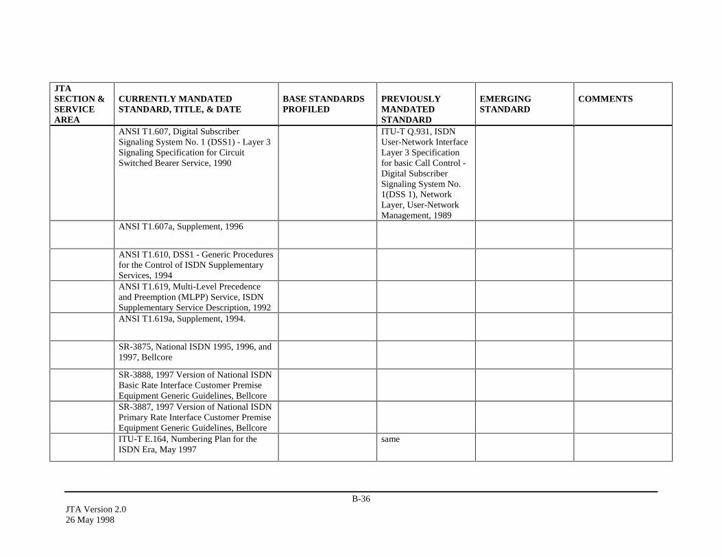
B-36JTA Version 2.026 May 1998
JTASECTION &SERVICEAREA
CURRENTLY MANDATEDSTANDARD, TITLE, & DATE
BASE STANDARDSPROFILED
PREVIOUSLYMANDATEDSTANDARD
EMERGINGSTANDARD
COMMENTS
ANSI T1.607, Digital SubscriberSignaling System No. 1 (DSS1) - Layer 3Signaling Specification for CircuitSwitched Bearer Service, 1990
ITU-T Q.931, ISDNUser-Network InterfaceLayer 3 Specificationfor basic Call Control -Digital SubscriberSignaling System No.1(DSS 1), NetworkLayer, User-NetworkManagement, 1989
ANSI T1.607a, Supplement, 1996
ANSI T1.610, DSS1 - Generic Proceduresfor the Control of ISDN SupplementaryServices, 1994ANSI T1.619, Multi-Level Precedenceand Preemption (MLPP) Service, ISDNSupplementary Service Description, 1992ANSI T1.619a, Supplement, 1994.
SR-3875, National ISDN 1995, 1996, and1997, Bellcore
SR-3888, 1997 Version of National ISDNBasic Rate Interface Customer PremiseEquipment Generic Guidelines, BellcoreSR-3887, 1997 Version of National ISDNPrimary Rate Interface Customer PremiseEquipment Generic Guidelines, BellcoreITU-T E.164, Numbering Plan for theISDN Era, May 1997
same
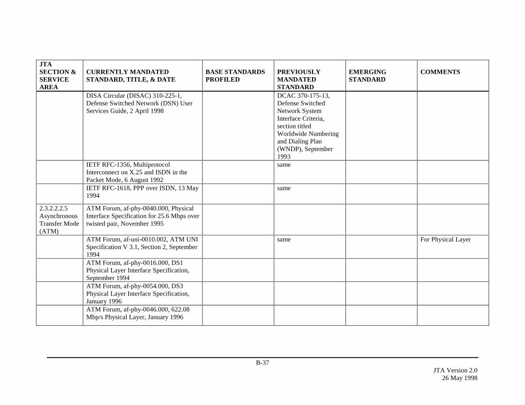
B-37JTA Version 2.0
26 May 1998
JTASECTION &SERVICEAREA
CURRENTLY MANDATEDSTANDARD, TITLE, & DATE
BASE STANDARDSPROFILED
PREVIOUSLYMANDATEDSTANDARD
EMERGINGSTANDARD
COMMENTS
DISA Circular (DISAC) 310-225-1,Defense Switched Network (DSN) UserServices Guide, 2 April 1998
DCAC 370-175-13,Defense SwitchedNetwork SystemInterface Criteria,section titledWorldwide Numberingand Dialing Plan(WNDP), September1993
IETF RFC-1356, MultiprotocolInterconnect on X.25 and ISDN in thePacket Mode, 6 August 1992
same
IETF RFC-1618, PPP over ISDN, 13 May1994
same
2.3.2.2.2.5AsynchronousTransfer Mode(ATM)
ATM Forum, af-phy-0040.000, PhysicalInterface Specification for 25.6 Mbps overtwisted pair, November 1995
ATM Forum, af-uni-0010.002, ATM UNISpecification V 3.1, Section 2, September1994
same For Physical Layer
ATM Forum, af-phy-0016.000, DS1Physical Layer Interface Specification,September 1994ATM Forum, af-phy-0054.000, DS3Physical Layer Interface Specification,January 1996ATM Forum, af-phy-0046.000, 622.08Mbp/s Physical Layer, January 1996

B-38JTA Version 2.026 May 1998
JTASECTION &SERVICEAREA
CURRENTLY MANDATEDSTANDARD, TITLE, & DATE
BASE STANDARDSPROFILED
PREVIOUSLYMANDATEDSTANDARD
EMERGINGSTANDARD
COMMENTS
ATM Forum, af-uni-0010.002, ATM UNISpecification V 3.1, September 1994
For User to NetworkInterface
ANSI T1.630, ATM Adaptation Layer forConstant Bit Rate (CBR) ServicesFunctionality and Specification, 1993
same
ANSI T1.635, ATM Adaptation LayerType 5 Common Part Functions andSpecifications, 1994, which adopts ITU-TI.363, section 6
same
ATM Forum, af-pnni-0055.000, PNNISpecification, Version 1.0, March 1996
ATM Forum, af-pnni-0066.000, PNNIVersion 1.0 Addendum, September 1996
ATM Forum, af-lane-0021.000, LANEover ATM, Ver. 1.0 January 1995
IETF RFC-1577,Classical IP andAddress ResolutionProtocol (ARP) overATM, 20 January 1994
ATM Forum, af-lane-0050.000, LANEVer. 1.0 Addendum, December 1995
ATM Forum, af-lane-0038.000, LANEClient Management Specification,September 1995ATM Forum, af-lane-0057.000, LANEServers Management Specification,March 1996ATM Addressing Format specified asNotice of Change 1, 20 October 1997, toMIL-STD-188-176, Standardized Profilefor ATM, 21 May 1996
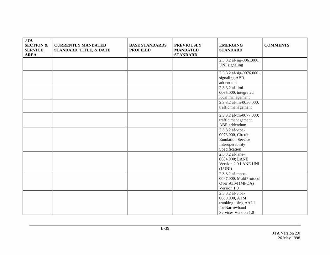
B-39JTA Version 2.0
26 May 1998
JTASECTION &SERVICEAREA
CURRENTLY MANDATEDSTANDARD, TITLE, & DATE
BASE STANDARDSPROFILED
PREVIOUSLYMANDATEDSTANDARD
EMERGINGSTANDARD
COMMENTS
2.3.3.2 af-sig-0061.000,UNI signaling
2.3.3.2 af-sig-0076.000,signaling ABRaddendum2.3.3.2 af-ilmi-0065.000, integratedlocal management2.3.3.2 af-tm-0056.000,traffic management
2.3.3.2 af-tm-0077.000;traffic managementABR addendum2.3.3.2 af-vtoa-0078.000, CircuitEmulation ServiceInteroperabilitySpecification2.3.3.2 af-lane-0084.000; LANEVersion 2.0 LANE UNI(LUNI)2.3.3.2 af-mpoa-0087.000, MultiProtocolOver ATM (MPOA)Version 1.02.3.3.2 af-vtoa-0089.000, ATMtrunking using AAL1for NarrowbandServices Version 1.0
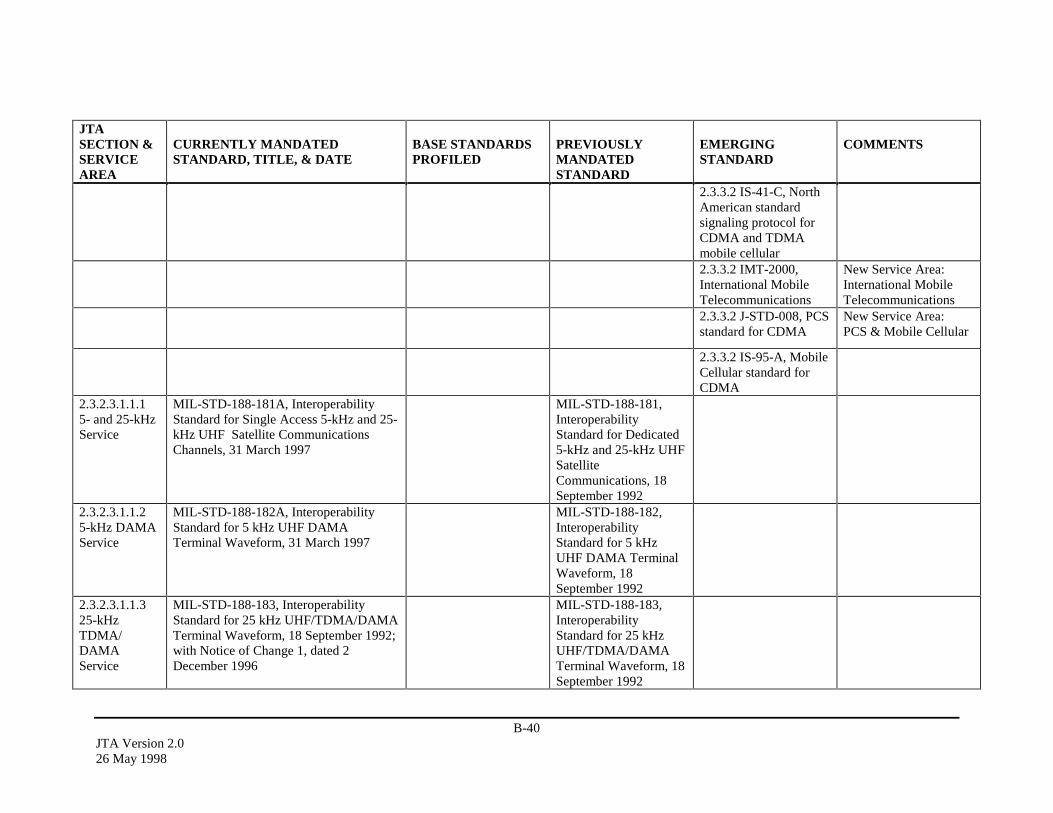
B-40JTA Version 2.026 May 1998
JTASECTION &SERVICEAREA
CURRENTLY MANDATEDSTANDARD, TITLE, & DATE
BASE STANDARDSPROFILED
PREVIOUSLYMANDATEDSTANDARD
EMERGINGSTANDARD
COMMENTS
2.3.3.2 IS-41-C, NorthAmerican standardsignaling protocol forCDMA and TDMAmobile cellular2.3.3.2 IMT-2000,International MobileTelecommunications
New Service Area:International MobileTelecommunications
2.3.3.2 J-STD-008, PCSstandard for CDMA
New Service Area:PCS & Mobile Cellular
2.3.3.2 IS-95-A, MobileCellular standard forCDMA
2.3.2.3.1.1.15- and 25-kHzService
MIL-STD-188-181A, InteroperabilityStandard for Single Access 5-kHz and 25-kHz UHF Satellite CommunicationsChannels, 31 March 1997
MIL-STD-188-181,InteroperabilityStandard for Dedicated5-kHz and 25-kHz UHFSatelliteCommunications, 18September 1992
2.3.2.3.1.1.25-kHz DAMAService
MIL-STD-188-182A, InteroperabilityStandard for 5 kHz UHF DAMATerminal Waveform, 31 March 1997
MIL-STD-188-182,InteroperabilityStandard for 5 kHzUHF DAMA TerminalWaveform, 18September 1992
2.3.2.3.1.1.325-kHzTDMA/DAMAService
MIL-STD-188-183, InteroperabilityStandard for 25 kHz UHF/TDMA/DAMATerminal Waveform, 18 September 1992;with Notice of Change 1, dated 2December 1996
MIL-STD-188-183,InteroperabilityStandard for 25 kHzUHF/TDMA/DAMATerminal Waveform, 18September 1992
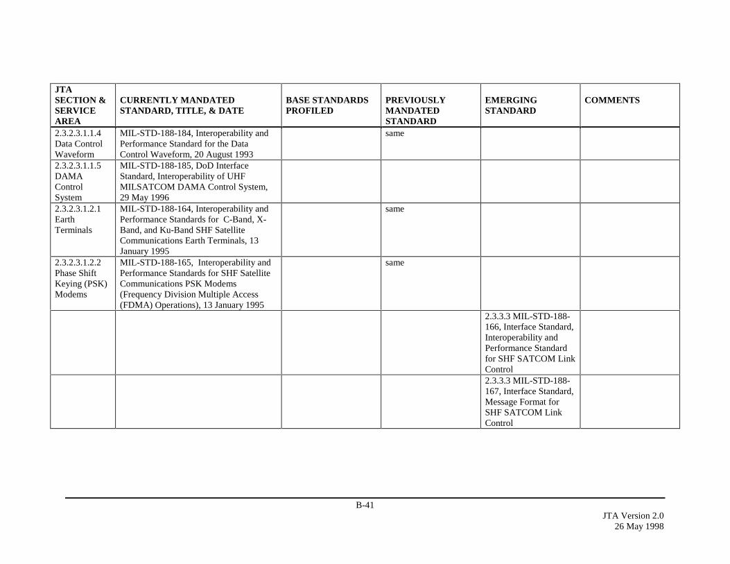
B-41JTA Version 2.0
26 May 1998
JTASECTION &SERVICEAREA
CURRENTLY MANDATEDSTANDARD, TITLE, & DATE
BASE STANDARDSPROFILED
PREVIOUSLYMANDATEDSTANDARD
EMERGINGSTANDARD
COMMENTS
2.3.2.3.1.1.4Data ControlWaveform
MIL-STD-188-184, Interoperability andPerformance Standard for the DataControl Waveform, 20 August 1993
same
2.3.2.3.1.1.5DAMAControlSystem
MIL-STD-188-185, DoD InterfaceStandard, Interoperability of UHFMILSATCOM DAMA Control System,29 May 1996
2.3.2.3.1.2.1EarthTerminals
MIL-STD-188-164, Interoperability andPerformance Standards for C-Band, X-Band, and Ku-Band SHF SatelliteCommunications Earth Terminals, 13January 1995
same
2.3.2.3.1.2.2Phase ShiftKeying (PSK)Modems
MIL-STD-188-165, Interoperability andPerformance Standards for SHF SatelliteCommunications PSK Modems(Frequency Division Multiple Access(FDMA) Operations), 13 January 1995
same
2.3.3.3 MIL-STD-188-166, Interface Standard,Interoperability andPerformance Standardfor SHF SATCOM LinkControl2.3.3.3 MIL-STD-188-167, Interface Standard,Message Format forSHF SATCOM LinkControl

B-42JTA Version 2.026 May 1998
JTASECTION &SERVICEAREA
CURRENTLY MANDATEDSTANDARD, TITLE, & DATE
BASE STANDARDSPROFILED
PREVIOUSLYMANDATEDSTANDARD
EMERGINGSTANDARD
COMMENTS
2.3.3.3 MIL-STD-188-168, Interface Standard,Interoperability andPerformance Standardsfor SHF SatelliteCommunicationsMulitplexers andDemultiplexers
2.3.2.3.1.3.1Low Data Rate(LDR)
MIL-STD-1582D, EHF LDR Uplinks andDownlinks, 30 September 1996; withNotice of Change 1, 14 February 1997
MIL-STD-1582, EHFLDR Uplinks andDownlinks, 10December 1992
2.3.2.3.1.3.2Medium DataRate (MDR)
MIL-STD-188-136, EHF MDR Uplinksand Downlinks, 26 August 1995; withNotice of Change 1, 15 August 1996, andNotice of Change 2, 14 February 1997
MIL-STD-188-136,EHF MDR Uplinks andDownlinks, 26 August1995
Added notice ofchanges 1 and 2.
2.3.2.3.2.1LowFrequency(LF) and VeryLowFrequency(VLF)
MIL-STD-188-140A, EquipmentTechnical Design Standards for CommonLong Haul/Tactical RadioCommunications in the LF Band andLower Frequency Bands, 1 May 1990
2.3.2.3.2.2.1HF andAutomatedLinkEstablishment(ALE)
MIL-STD-188-141A, Interoperability andPerformance Standards for Medium andHigh Frequency Radio EquipmentStandard, 15 September 1988; with Noticeof Change 1, 17 June 1992, and Notice ofChange 2, 10 September 1993
same
2.3.2.3.2.2.2Anti-JammingCapability
MIL-STD-188-148A, InteroperabilityStandard for Anti-Jam Communications inthe HF Band (2-30 MHz), 18 March 1992
same

B-43JTA Version 2.0
26 May 1998
JTASECTION &SERVICEAREA
CURRENTLY MANDATEDSTANDARD, TITLE, & DATE
BASE STANDARDSPROFILED
PREVIOUSLYMANDATEDSTANDARD
EMERGINGSTANDARD
COMMENTS
2.3.2.3.2.2.3Data Modems
MIL-STD-188-110A, Data Modems,Interoperability and PerformanceStandards, 30 September 1991
same
2.3.2.3.2.3Very HighFrequency(VHF)
MIL-STD-188-242, Tactical SingleChannel (VHF) Radio Equipment, 20June 1985
same
2.3.3.4 MIL-STD-188-241, RF InterfaceRequirements for VHFFrequency HoppingTactical Radio Systems
2.3.2.3.2.4.1UHF Radio
MIL-STD-188-243, Tactical SingleChannel (UHF) Radio Communications,15 March 1989
same
2.3.2.3.2.4.2Anti-JammingCapability
STANAG 4246, Edition 2, HAVEQUICK UHF Secure and Jam-ResistantCommunications Equipment, 17 June1987; with Amendment 3, August 1991
2.3.2.3.2.5Super HighFrequency(SHF)
MIL-STD-188-145, Digital Line-of-Sight(LOS) Microwave Radio Equipment, 7May 1987; with Notice of Change 1, 28July 1992
same
2.3.2.3.2.6Link 16TransmissionStandards
STANAG 4175, Edition 1, TechnicalCharacteristics of the MultifunctionalInformation Distribution System (MIDS),29 August 1991
same Previous section(service area) inVolume 1.0 was named“JTIDS/MIDSTransmission Media”
JTIDS System SegmentSpecification (Class 2Terminal)

B-44JTA Version 2.026 May 1998
JTASECTION &SERVICEAREA
CURRENTLY MANDATEDSTANDARD, TITLE, & DATE
BASE STANDARDSPROFILED
PREVIOUSLYMANDATEDSTANDARD
EMERGINGSTANDARD
COMMENTS
2.3.2.3.3SONETTransmissionFacilities
ANSI T1.105, Telecommunications -Synchronous Optical Network (SONET)Basic Description Including MultiplexStructure, Rates and Formats (ATIS)(Revision and Consolidation of ANSIT1.105-1991 and ANSI T1.105A-1991),1995
same
ANSI T1.107, Digital Hierarchy -Formats Specifications, 1995
same
ANSI T1.117, Digital Hierarchy - OpticalInterface Specifications (SONET) (SingleMode - Short Reach), 1991
same
2.3.2.4.1DataCommunica-tionsManagement
IETF Standard 15/RFC-1157, SimpleNetwork Management Protocol (SNMP),May 1990
same
IETF Standard 16/RFC-1155/RFC-1212,Structure of Management Information,May 1990
same
IETF Standard 17/RFC-1213,Management Information Base, March1991
same 2.3.3.5 IETF RFC-2011,SNMPv2 ManagementInformation Base for theInternet Protocol usingSMIv2, 12 November1996
IETF RFC-1514, Host Resources MIB,September 1993
IETF Standard 50/RFC-1643, Definitionsof Managed Objects for the Ethernet-likeInterface Types, July 1994
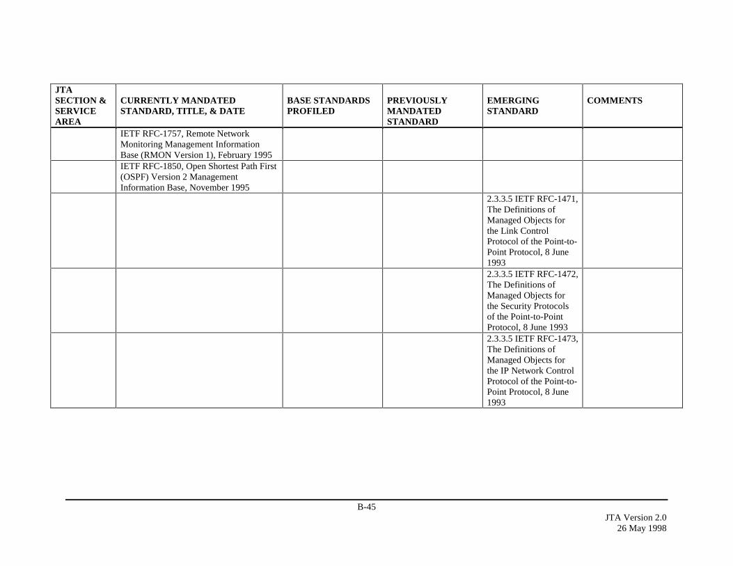
B-45JTA Version 2.0
26 May 1998
JTASECTION &SERVICEAREA
CURRENTLY MANDATEDSTANDARD, TITLE, & DATE
BASE STANDARDSPROFILED
PREVIOUSLYMANDATEDSTANDARD
EMERGINGSTANDARD
COMMENTS
IETF RFC-1757, Remote NetworkMonitoring Management InformationBase (RMON Version 1), February 1995IETF RFC-1850, Open Shortest Path First(OSPF) Version 2 ManagementInformation Base, November 1995
2.3.3.5 IETF RFC-1471,The Definitions ofManaged Objects forthe Link ControlProtocol of the Point-to-Point Protocol, 8 June19932.3.3.5 IETF RFC-1472,The Definitions ofManaged Objects forthe Security Protocolsof the Point-to-PointProtocol, 8 June 19932.3.3.5 IETF RFC-1473,The Definitions ofManaged Objects forthe IP Network ControlProtocol of the Point-to-Point Protocol, 8 June1993
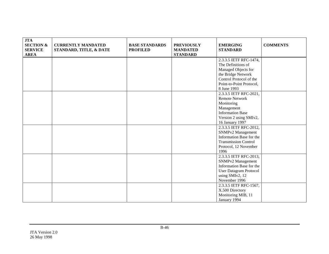
B-46JTA Version 2.026 May 1998
JTASECTION &SERVICEAREA
CURRENTLY MANDATEDSTANDARD, TITLE, & DATE
BASE STANDARDSPROFILED
PREVIOUSLYMANDATEDSTANDARD
EMERGINGSTANDARD
COMMENTS
2.3.3.5 IETF RFC-1474,The Definitions ofManaged Objects forthe Bridge NetworkControl Protocol of thePoint-to-Point Protocol,8 June 19932.3.3.5 IETF RFC-2021,Remote NetworkMonitoringManagementInformation BaseVersion 2 using SMIv2,16 January 19972.3.3.5 IETF RFC-2012,SNMPv2 ManagementInformation Base for theTransmission ControlProtocol, 12 November19962.3.3.5 IETF RFC-2013,SNMPv2 ManagementInformation Base for theUser Datagram Protocolusing SMIv2, 12November 19962.3.3.5 IETF RFC-1567,X.500 DirectoryMonitoring MIB, 11January 1994
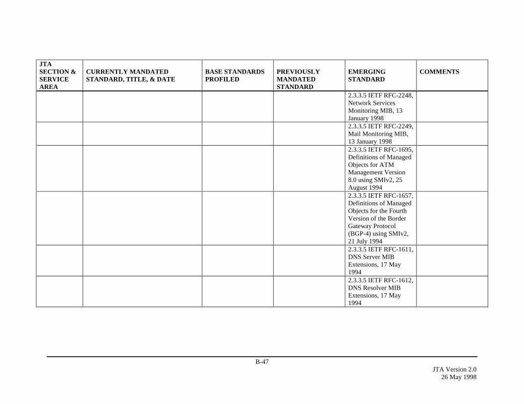
B-47JTA Version 2.0
26 May 1998
JTASECTION &SERVICEAREA
CURRENTLY MANDATEDSTANDARD, TITLE, & DATE
BASE STANDARDSPROFILED
PREVIOUSLYMANDATEDSTANDARD
EMERGINGSTANDARD
COMMENTS
2.3.3.5 IETF RFC-2248,Network ServicesMonitoring MIB, 13January 19982.3.3.5 IETF RFC-2249,Mail Monitoring MIB,13 January 19982.3.3.5 IETF RFC-1695,Definitions of ManagedObjects for ATMManagement Version8.0 using SMIv2, 25August 19942.3.3.5 IETF RFC-1657,Definitions of ManagedObjects for the FourthVersion of the BorderGateway Protocol(BGP-4) using SMIv2,21 July 19942.3.3.5 IETF RFC-1611,DNS Server MIBExtensions, 17 May19942.3.3.5 IETF RFC-1612,DNS Resolver MIBExtensions, 17 May1994
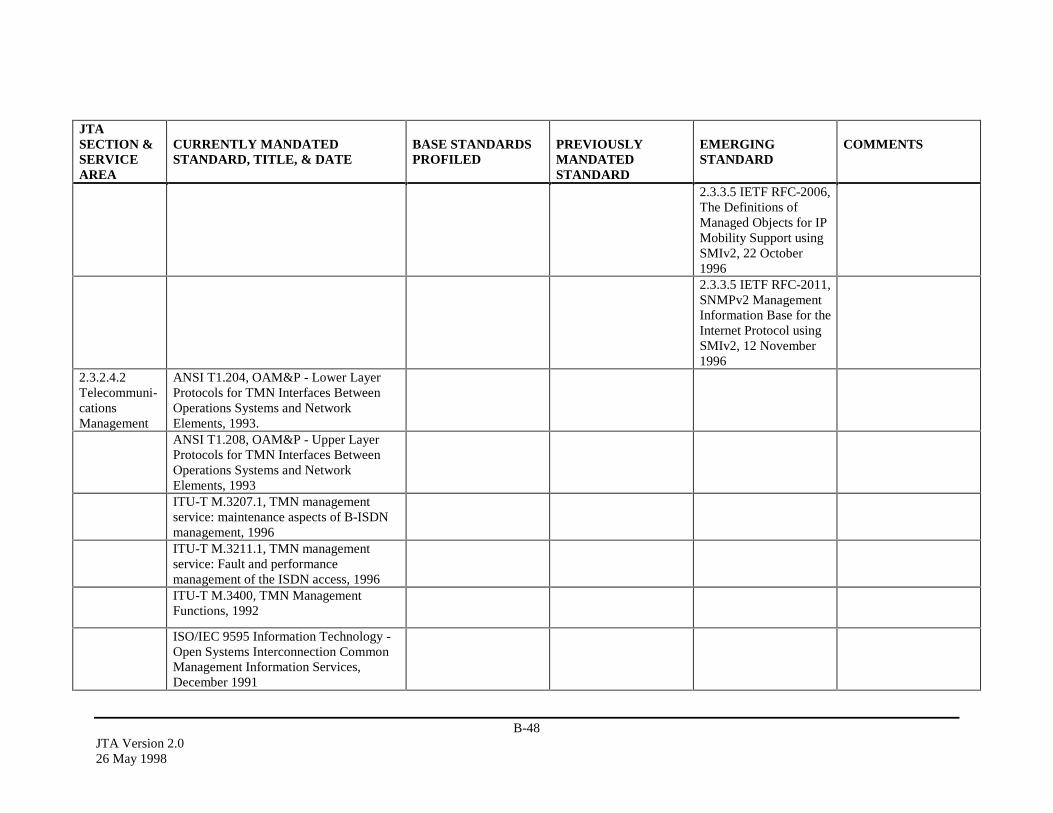
B-48JTA Version 2.026 May 1998
JTASECTION &SERVICEAREA
CURRENTLY MANDATEDSTANDARD, TITLE, & DATE
BASE STANDARDSPROFILED
PREVIOUSLYMANDATEDSTANDARD
EMERGINGSTANDARD
COMMENTS
2.3.3.5 IETF RFC-2006,The Definitions ofManaged Objects for IPMobility Support usingSMIv2, 22 October19962.3.3.5 IETF RFC-2011,SNMPv2 ManagementInformation Base for theInternet Protocol usingSMIv2, 12 November1996
2.3.2.4.2Telecommuni-cationsManagement
ANSI T1.204, OAM&P - Lower LayerProtocols for TMN Interfaces BetweenOperations Systems and NetworkElements, 1993.ANSI T1.208, OAM&P - Upper LayerProtocols for TMN Interfaces BetweenOperations Systems and NetworkElements, 1993ITU-T M.3207.1, TMN managementservice: maintenance aspects of B-ISDNmanagement, 1996ITU-T M.3211.1, TMN managementservice: Fault and performancemanagement of the ISDN access, 1996ITU-T M.3400, TMN ManagementFunctions, 1992
ISO/IEC 9595 Information Technology -Open Systems Interconnection CommonManagement Information Services,December 1991

B-49JTA Version 2.0
26 May 1998
JTASECTION &SERVICEAREA
CURRENTLY MANDATEDSTANDARD, TITLE, & DATE
BASE STANDARDSPROFILED
PREVIOUSLYMANDATEDSTANDARD
EMERGINGSTANDARD
COMMENTS
ISO/IEC 9596-1:1991 InformationTechnology - Open SystemsInterconnection - Common ManagementInformation Protocol (CMIP) - Part 1:SpecificationISO/IEC 9596-2:1993 InformationTechnology - Open SystemsInterconnection - Common ManagementInformation Protocol: ProtocolImplementation Conformance Statement(PICS) proforma
2.3.3.1.1InternetStandards
IETF RFC-1883 (IPv6Specification), 4January 1996IETF RFC-1884 (IPv6AddressingArchitecture), 4 January1996IETF RFC-1885(ICMPv6 for IPv6), 4January 1996IETF RFC-1886 (DNSExtensions to SupportIPv6), 4 January 1996IETF RFC-2136(DDNS), 21 April 1997
IETF RFC-2251(LDAPv3), 23December 1997IETF RFC-2002 (IPMobility Support), 22October 1996
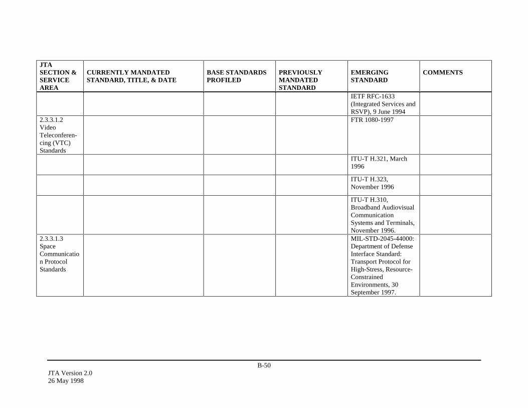
B-50JTA Version 2.026 May 1998
JTASECTION &SERVICEAREA
CURRENTLY MANDATEDSTANDARD, TITLE, & DATE
BASE STANDARDSPROFILED
PREVIOUSLYMANDATEDSTANDARD
EMERGINGSTANDARD
COMMENTS
IETF RFC-1633(Integrated Services andRSVP), 9 June 1994
2.3.3.1.2VideoTeleconferen-cing (VTC)Standards
FTR 1080-1997
ITU-T H.321, March1996
ITU-T H.323,November 1996
ITU-T H.310,Broadband AudiovisualCommunicationSystems and Terminals,November 1996.
2.3.3.1.3SpaceCommunication ProtocolStandards
MIL-STD-2045-44000:Department of DefenseInterface Standard:Transport Protocol forHigh-Stress, Resource-ConstrainedEnvironments, 30September 1997.

B-51JTA Version 2.0
26 May 1998
JTASECTION &SERVICEAREA
CURRENTLY MANDATEDSTANDARD, TITLE, & DATE
BASE STANDARDSPROFILED
PREVIOUSLYMANDATEDSTANDARD
EMERGINGSTANDARD
COMMENTS
MIL-STD-2045-43000:Department of DefenseInterface Standard:Network Protocol forHigh-Stress, Resource-ConstrainedEnvironments, 30September 1997MIL-STD-2045-47000:Department of DefenseInterface Standard: Fileand Record TransferProtocol for Resource-ConstrainedEnvironments, 30September 1997.MIL-STD-2045-43001:Department of DefenseInterface Standard:Network SecurityProtocol for Resource-ConstrainedEnvironments, 30September 1997
2.3.3.2NetworkStandards
IEEE 802.11-1997 PartII: Wireless LANMedium Access Control(MAC) and PhysicalLayer (PHY)Specifications, June1997
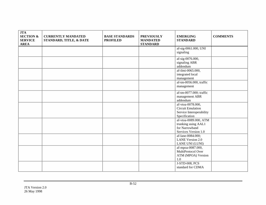
B-52JTA Version 2.026 May 1998
JTASECTION &SERVICEAREA
CURRENTLY MANDATEDSTANDARD, TITLE, & DATE
BASE STANDARDSPROFILED
PREVIOUSLYMANDATEDSTANDARD
EMERGINGSTANDARD
COMMENTS
af-sig-0061.000, UNIsignaling
af-sig-0076.000,signaling ABRaddendumaf-ilmi-0065.000,integrated localmanagementaf-tm-0056.000, trafficmanagement
af-tm-0077.000; trafficmanagement ABRaddendumaf-vtoa-0078.000,Circuit EmulationService InteroperabilitySpecificationaf-vtoa-0089.000, ATMtrunking using AAL1for NarrowbandServices Version 1.0af-lane-0084.000;LANE Version 2.0LANE UNI (LUNI)af-mpoa-0087.000,MultiProtocol OverATM (MPOA) Version1.0J-STD-008, PCSstandard for CDMA
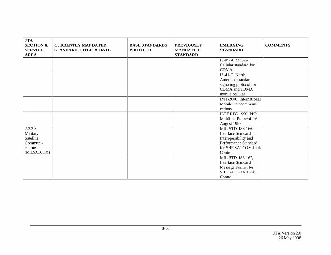
B-53JTA Version 2.0
26 May 1998
JTASECTION &SERVICEAREA
CURRENTLY MANDATEDSTANDARD, TITLE, & DATE
BASE STANDARDSPROFILED
PREVIOUSLYMANDATEDSTANDARD
EMERGINGSTANDARD
COMMENTS
IS-95-A, MobileCellular standard forCDMAIS-41-C, NorthAmerican standardsignaling protocol forCDMA and TDMAmobile cellularIMT-2000, InternationalMobile Telecommuni-cationsIETF RFC-1990, PPPMultilink Protocol, 16August 1996
2.3.3.3MilitarySatelliteCommuni-cations(MILSATCOM)
MIL-STD-188-166,Interface Standard,Interoperability andPerformance Standardfor SHF SATCOM LinkControlMIL-STD-188-167,Interface Standard,Message Format forSHF SATCOM LinkControl
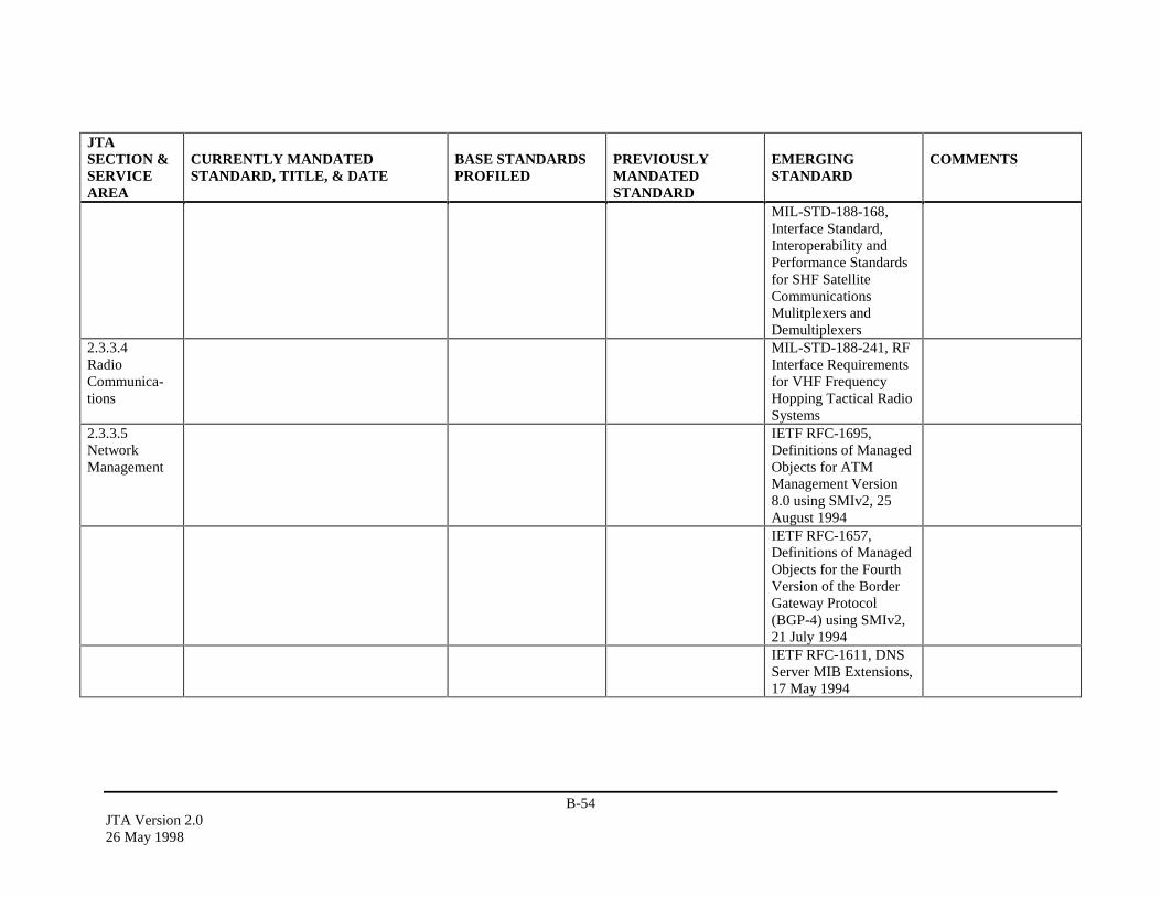
B-54JTA Version 2.026 May 1998
JTASECTION &SERVICEAREA
CURRENTLY MANDATEDSTANDARD, TITLE, & DATE
BASE STANDARDSPROFILED
PREVIOUSLYMANDATEDSTANDARD
EMERGINGSTANDARD
COMMENTS
MIL-STD-188-168,Interface Standard,Interoperability andPerformance Standardsfor SHF SatelliteCommunicationsMulitplexers andDemultiplexers
2.3.3.4RadioCommunica-tions
MIL-STD-188-241, RFInterface Requirementsfor VHF FrequencyHopping Tactical RadioSystems
2.3.3.5NetworkManagement
IETF RFC-1695,Definitions of ManagedObjects for ATMManagement Version8.0 using SMIv2, 25August 1994IETF RFC-1657,Definitions of ManagedObjects for the FourthVersion of the BorderGateway Protocol(BGP-4) using SMIv2,21 July 1994IETF RFC-1611, DNSServer MIB Extensions,17 May 1994
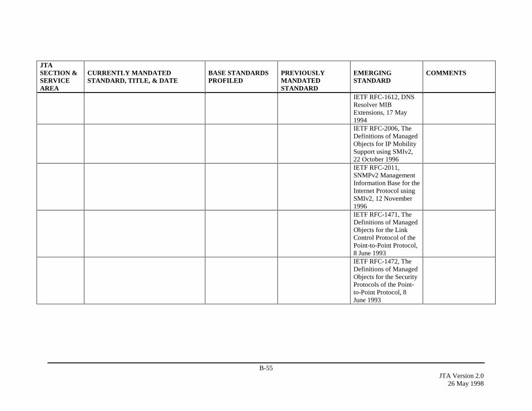
B-55JTA Version 2.0
26 May 1998
JTASECTION &SERVICEAREA
CURRENTLY MANDATEDSTANDARD, TITLE, & DATE
BASE STANDARDSPROFILED
PREVIOUSLYMANDATEDSTANDARD
EMERGINGSTANDARD
COMMENTS
IETF RFC-1612, DNSResolver MIBExtensions, 17 May1994IETF RFC-2006, TheDefinitions of ManagedObjects for IP MobilitySupport using SMIv2,22 October 1996IETF RFC-2011,SNMPv2 ManagementInformation Base for theInternet Protocol usingSMIv2, 12 November1996IETF RFC-1471, TheDefinitions of ManagedObjects for the LinkControl Protocol of thePoint-to-Point Protocol,8 June 1993IETF RFC-1472, TheDefinitions of ManagedObjects for the SecurityProtocols of the Point-to-Point Protocol, 8June 1993
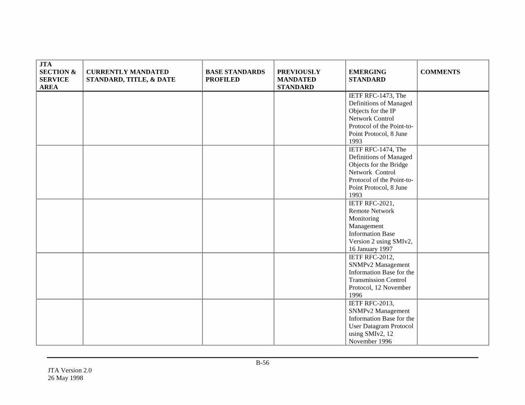
B-56JTA Version 2.026 May 1998
JTASECTION &SERVICEAREA
CURRENTLY MANDATEDSTANDARD, TITLE, & DATE
BASE STANDARDSPROFILED
PREVIOUSLYMANDATEDSTANDARD
EMERGINGSTANDARD
COMMENTS
IETF RFC-1473, TheDefinitions of ManagedObjects for the IPNetwork ControlProtocol of the Point-to-Point Protocol, 8 June1993IETF RFC-1474, TheDefinitions of ManagedObjects for the BridgeNetwork ControlProtocol of the Point-to-Point Protocol, 8 June1993IETF RFC-2021,Remote NetworkMonitoringManagementInformation BaseVersion 2 using SMIv2,16 January 1997IETF RFC-2012,SNMPv2 ManagementInformation Base for theTransmission ControlProtocol, 12 November1996IETF RFC-2013,SNMPv2 ManagementInformation Base for theUser Datagram Protocolusing SMIv2, 12November 1996

B-57JTA Version 2.0
26 May 1998
JTASECTION &SERVICEAREA
CURRENTLY MANDATEDSTANDARD, TITLE, & DATE
BASE STANDARDSPROFILED
PREVIOUSLYMANDATEDSTANDARD
EMERGINGSTANDARD
COMMENTS
IETF RFC-1567, X.500Directory MonitoringMIB, 11 January 1994IETF RFC-2248,Network ServicesMonitoring MIB, 13January 1998IETF RFC-2249, MailMonitoring MIB, 13January 1998
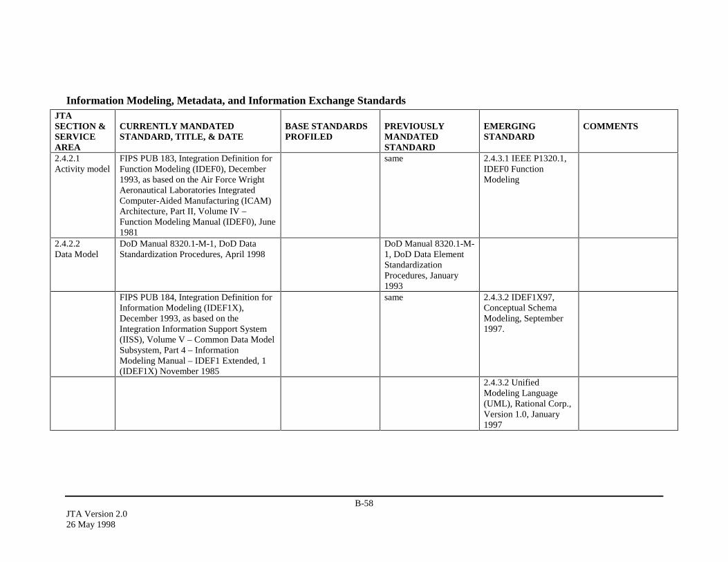
B-58JTA Version 2.026 May 1998
Information Modeling, Metadata, and Information Exchange StandardsJTASECTION &SERVICEAREA
CURRENTLY MANDATEDSTANDARD, TITLE, & DATE
BASE STANDARDSPROFILED
PREVIOUSLYMANDATEDSTANDARD
EMERGINGSTANDARD
COMMENTS
2.4.2.1Activity model
FIPS PUB 183, Integration Definition forFunction Modeling (IDEF0), December1993, as based on the Air Force WrightAeronautical Laboratories IntegratedComputer-Aided Manufacturing (ICAM)Architecture, Part II, Volume IV –Function Modeling Manual (IDEF0), June1981
same 2.4.3.1 IEEE P1320.1,IDEF0 FunctionModeling
2.4.2.2Data Model
DoD Manual 8320.1-M-1, DoD DataStandardization Procedures, April 1998
DoD Manual 8320.1-M-1, DoD Data ElementStandardizationProcedures, January1993
FIPS PUB 184, Integration Definition forInformation Modeling (IDEF1X),December 1993, as based on theIntegration Information Support System(IISS), Volume V – Common Data ModelSubsystem, Part 4 – InformationModeling Manual – IDEF1 Extended, 1(IDEF1X) November 1985
same 2.4.3.2 IDEF1X97,Conceptual SchemaModeling, September1997.
2.4.3.2 UnifiedModeling Language(UML), Rational Corp.,Version 1.0, January1997
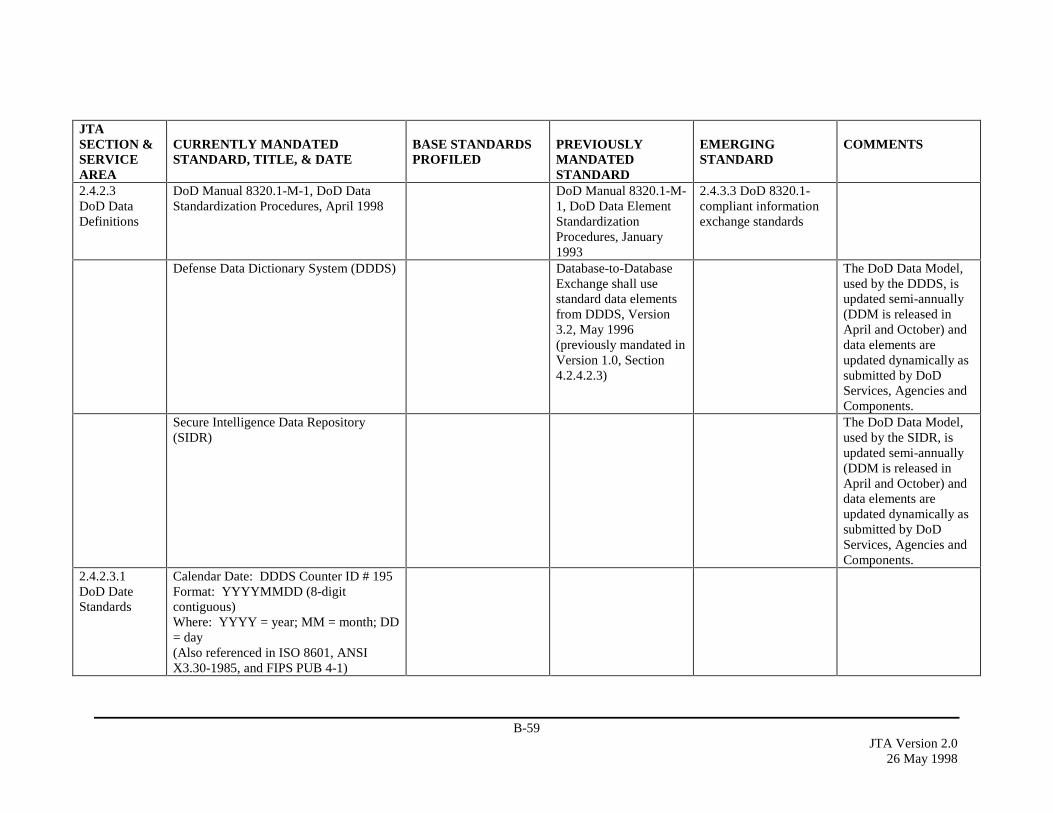
B-59JTA Version 2.0
26 May 1998
JTASECTION &SERVICEAREA
CURRENTLY MANDATEDSTANDARD, TITLE, & DATE
BASE STANDARDSPROFILED
PREVIOUSLYMANDATEDSTANDARD
EMERGINGSTANDARD
COMMENTS
2.4.2.3DoD DataDefinitions
DoD Manual 8320.1-M-1, DoD DataStandardization Procedures, April 1998
DoD Manual 8320.1-M-1, DoD Data ElementStandardizationProcedures, January1993
2.4.3.3 DoD 8320.1-compliant informationexchange standards
Defense Data Dictionary System (DDDS) Database-to-DatabaseExchange shall usestandard data elementsfrom DDDS, Version3.2, May 1996(previously mandated inVersion 1.0, Section4.2.4.2.3)
The DoD Data Model,used by the DDDS, isupdated semi-annually(DDM is released inApril and October) anddata elements areupdated dynamically assubmitted by DoDServices, Agencies andComponents.
Secure Intelligence Data Repository(SIDR)
The DoD Data Model,used by the SIDR, isupdated semi-annually(DDM is released inApril and October) anddata elements areupdated dynamically assubmitted by DoDServices, Agencies andComponents.
2.4.2.3.1DoD DateStandards
Calendar Date: DDDS Counter ID # 195Format: YYYYMMDD (8-digitcontiguous)Where: YYYY = year; MM = month; DD= day(Also referenced in ISO 8601, ANSIX3.30-1985, and FIPS PUB 4-1)
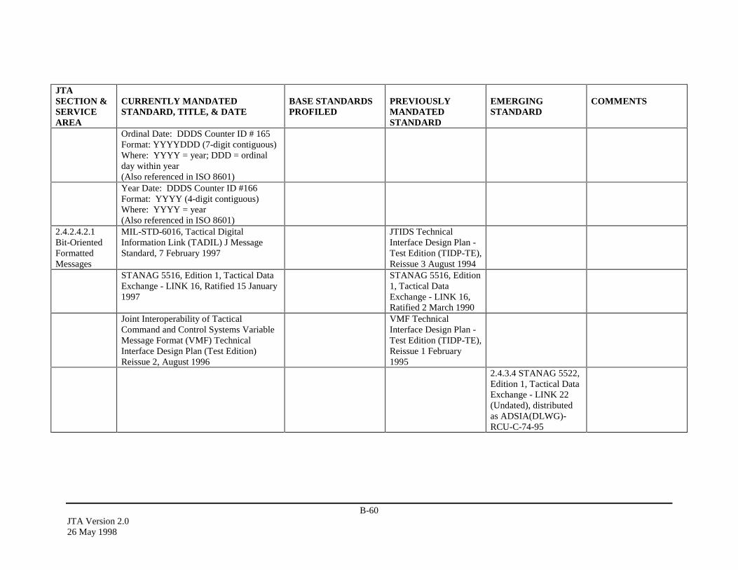
B-60JTA Version 2.026 May 1998
JTASECTION &SERVICEAREA
CURRENTLY MANDATEDSTANDARD, TITLE, & DATE
BASE STANDARDSPROFILED
PREVIOUSLYMANDATEDSTANDARD
EMERGINGSTANDARD
COMMENTS
Ordinal Date: DDDS Counter ID # 165Format: YYYYDDD (7-digit contiguous)Where: YYYY = year; DDD = ordinalday within year(Also referenced in ISO 8601)Year Date: DDDS Counter ID #166Format: YYYY (4-digit contiguous)Where: YYYY = year(Also referenced in ISO 8601)
2.4.2.4.2.1Bit-OrientedFormattedMessages
MIL-STD-6016, Tactical DigitalInformation Link (TADIL) J MessageStandard, 7 February 1997
JTIDS TechnicalInterface Design Plan -Test Edition (TIDP-TE),Reissue 3 August 1994
STANAG 5516, Edition 1, Tactical DataExchange - LINK 16, Ratified 15 January1997
STANAG 5516, Edition1, Tactical DataExchange - LINK 16,Ratified 2 March 1990
Joint Interoperability of TacticalCommand and Control Systems VariableMessage Format (VMF) TechnicalInterface Design Plan (Test Edition)Reissue 2, August 1996
VMF TechnicalInterface Design Plan -Test Edition (TIDP-TE),Reissue 1 February1995
2.4.3.4 STANAG 5522,Edition 1, Tactical DataExchange - LINK 22(Undated), distributedas ADSIA(DLWG)-RCU-C-74-95

B-61JTA Version 2.0
26 May 1998
JTASECTION &SERVICEAREA
CURRENTLY MANDATEDSTANDARD, TITLE, & DATE
BASE STANDARDSPROFILED
PREVIOUSLYMANDATEDSTANDARD
EMERGINGSTANDARD
COMMENTS
2.4.2.4.2.2Character-BasedFormattedMessages
MIL-STD-6040, United States MessageText Format (USMTF), 1 January 1997
same
2.4.3.1ActivityModeling
IEEE P1320.1, IDEF0Function Modeling
2.4.3.2Data Modeling
IDEF1X97, ConceptualSchema Modeling,September 1997.
Unified ModelingLanguage (UML),Rational Corp., Version1.0, January 1997
2.4.3.3DoD DataDefinitions
DoD 8320.1-compliantinformation exchangestandards
2.4.3.4InformationExchangeStandards
STANAG 5522, Edition1, Tactical DataExchange - LINK 22(Undated), distributedas ADSIA(DLWG)-RCU-C-74-95Multi-functionalInformation DistributionSystem (MIDS) SystemSpecification, 11 April1995.
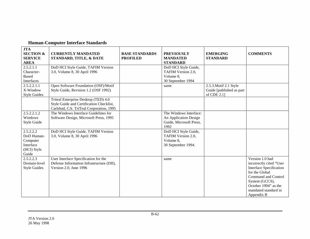
B-62JTA Version 2.026 May 1998
Human-Computer Interface StandardsJTASECTION &SERVICEAREA
CURRENTLY MANDATEDSTANDARD, TITLE, & DATE
BASE STANDARDSPROFILED
PREVIOUSLYMANDATEDSTANDARD
EMERGINGSTANDARD
COMMENTS
2.5.2.1.1Character-BasedInterfaces
DoD HCI Style Guide, TAFIM Version3.0, Volume 8, 30 April 1996
DoD HCI Style Guide,TAFIM Version 2.0,Volume 8,30 September 1994
2.5.2.2.1.1X-WindowStyle Guides
Open Software Foundation (OSF)/MotifStyle Guide, Revision 1.2 (OSF 1992)
same 2.5.3.Motif 2.1 StyleGuide [published as partof CDE 2.1]
Triteal Enterprise Desktop (TED) 4.0Style Guide and Certification Checklist,Carlsbad, CA: TriTeal Corporation, 1995
2.5.2.2.1.2WindowsStyle Guide
The Windows Interface Guidelines forSoftware Design, Microsoft Press, 1995
The Windows Interface:An Application DesignGuide, Microsoft Press,1992
2.5.2.2.2DoD Human-ComputerInterface(HCI) StyleGuide
DoD HCI Style Guide, TAFIM Version3.0, Volume 8, 30 April 1996
DoD HCI Style Guide,TAFIM Version 2.0,Volume 8,30 September 1994.
2.5.2.2.3Domain-levelStyle Guides
User Interface Specification for theDefense Information Infrastructure (DII),Version 2.0, June 1996
same Version 1.0 hadincorrectly cited “UserInterface Specificationfor the GlobalCommand and ControlSystem (GCCS),October 1994” as themandated standard inAppendix B
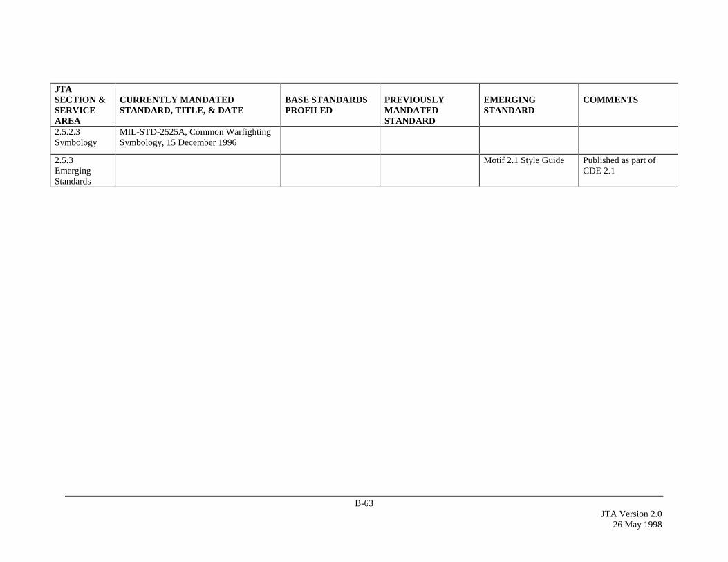
B-63JTA Version 2.0
26 May 1998
JTASECTION &SERVICEAREA
CURRENTLY MANDATEDSTANDARD, TITLE, & DATE
BASE STANDARDSPROFILED
PREVIOUSLYMANDATEDSTANDARD
EMERGINGSTANDARD
COMMENTS
2.5.2.3Symbology
MIL-STD-2525A, Common WarfightingSymbology, 15 December 1996
2.5.3EmergingStandards
Motif 2.1 Style Guide Published as part ofCDE 2.1
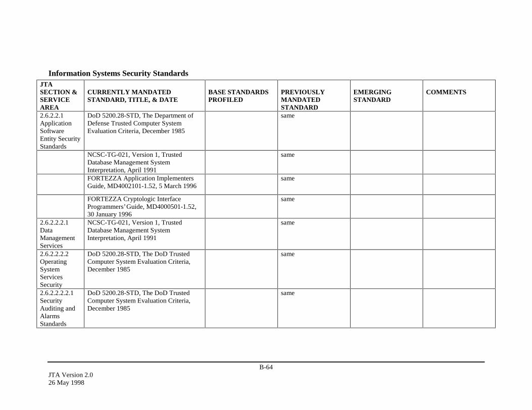
B-64JTA Version 2.026 May 1998
Information Systems Security StandardsJTASECTION &SERVICEAREA
CURRENTLY MANDATEDSTANDARD, TITLE, & DATE
BASE STANDARDSPROFILED
PREVIOUSLYMANDATEDSTANDARD
EMERGINGSTANDARD
COMMENTS
2.6.2.2.1ApplicationSoftwareEntity SecurityStandards
DoD 5200.28-STD, The Department ofDefense Trusted Computer SystemEvaluation Criteria, December 1985
same
NCSC-TG-021, Version 1, TrustedDatabase Management SystemInterpretation, April 1991
same
FORTEZZA Application ImplementersGuide, MD4002101-1.52, 5 March 1996
same
FORTEZZA Cryptologic InterfaceProgrammers’ Guide, MD4000501-1.52,30 January 1996
same
2.6.2.2.2.1DataManagementServices
NCSC-TG-021, Version 1, TrustedDatabase Management SystemInterpretation, April 1991
same
2.6.2.2.2.2OperatingSystemServicesSecurity
DoD 5200.28-STD, The DoD TrustedComputer System Evaluation Criteria,December 1985
same
2.6.2.2.2.2.1SecurityAuditing andAlarmsStandards
DoD 5200.28-STD, The DoD TrustedComputer System Evaluation Criteria,December 1985
same
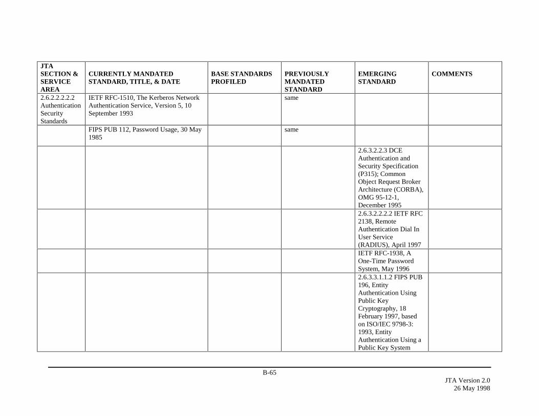
B-65JTA Version 2.0
26 May 1998
JTASECTION &SERVICEAREA
CURRENTLY MANDATEDSTANDARD, TITLE, & DATE
BASE STANDARDSPROFILED
PREVIOUSLYMANDATEDSTANDARD
EMERGINGSTANDARD
COMMENTS
2.6.2.2.2.2.2AuthenticationSecurityStandards
IETF RFC-1510, The Kerberos NetworkAuthentication Service, Version 5, 10September 1993
same
FIPS PUB 112, Password Usage, 30 May1985
same
2.6.3.2.2.3 DCEAuthentication andSecurity Specification(P315); CommonObject Request BrokerArchitecture (CORBA),OMG 95-12-1,December 19952.6.3.2.2.2.2 IETF RFC2138, RemoteAuthentication Dial InUser Service(RADIUS), April 1997IETF RFC-1938, AOne-Time PasswordSystem, May 19962.6.3.3.1.1.2 FIPS PUB196, EntityAuthentication UsingPublic KeyCryptography, 18February 1997, basedon ISO/IEC 9798-3:1993, EntityAuthentication Using aPublic Key System
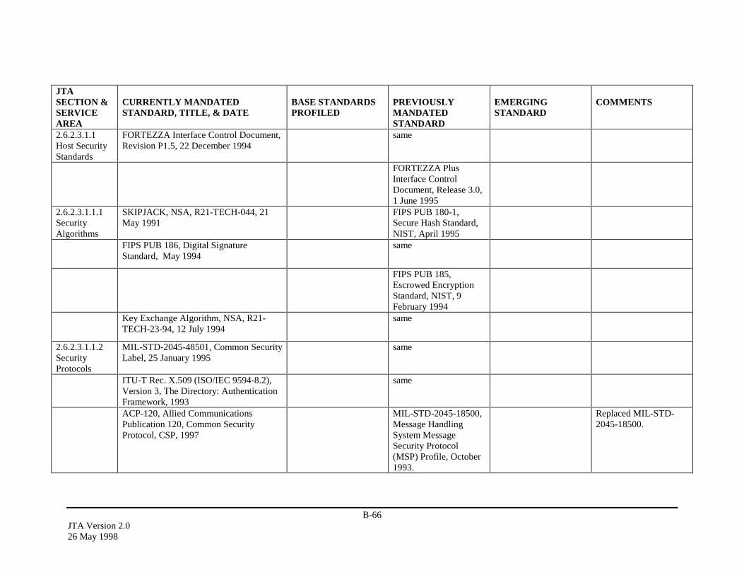
B-66JTA Version 2.026 May 1998
JTASECTION &SERVICEAREA
CURRENTLY MANDATEDSTANDARD, TITLE, & DATE
BASE STANDARDSPROFILED
PREVIOUSLYMANDATEDSTANDARD
EMERGINGSTANDARD
COMMENTS
2.6.2.3.1.1Host SecurityStandards
FORTEZZA Interface Control Document,Revision P1.5, 22 December 1994
same
FORTEZZA PlusInterface ControlDocument, Release 3.0,1 June 1995
2.6.2.3.1.1.1SecurityAlgorithms
SKIPJACK, NSA, R21-TECH-044, 21May 1991
FIPS PUB 180-1,Secure Hash Standard,NIST, April 1995
FIPS PUB 186, Digital SignatureStandard, May 1994
same
FIPS PUB 185,Escrowed EncryptionStandard, NIST, 9February 1994
Key Exchange Algorithm, NSA, R21-TECH-23-94, 12 July 1994
same
2.6.2.3.1.1.2SecurityProtocols
MIL-STD-2045-48501, Common SecurityLabel, 25 January 1995
same
ITU-T Rec. X.509 (ISO/IEC 9594-8.2),Version 3, The Directory: AuthenticationFramework, 1993
same
ACP-120, Allied CommunicationsPublication 120, Common SecurityProtocol, CSP, 1997
MIL-STD-2045-18500,Message HandlingSystem MessageSecurity Protocol(MSP) Profile, October1993.
Replaced MIL-STD-2045-18500.
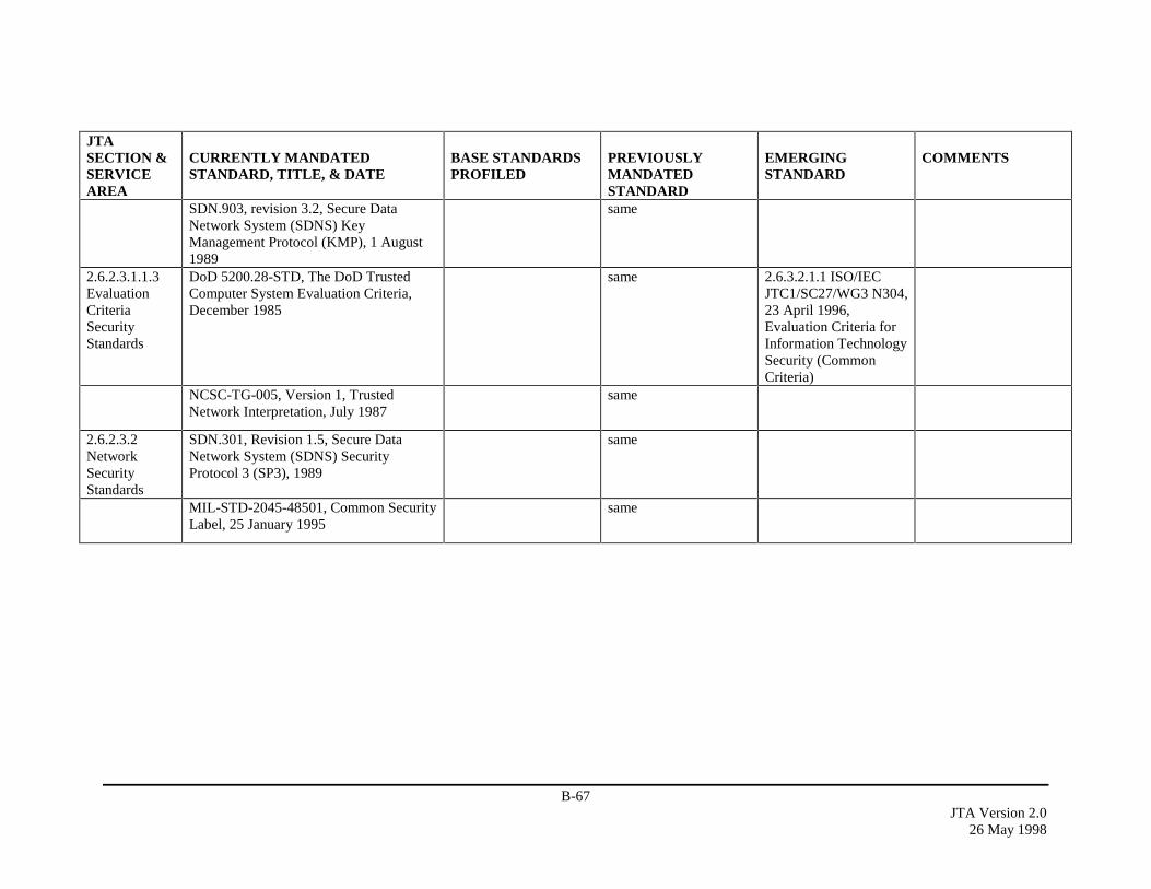
B-67JTA Version 2.0
26 May 1998
JTASECTION &SERVICEAREA
CURRENTLY MANDATEDSTANDARD, TITLE, & DATE
BASE STANDARDSPROFILED
PREVIOUSLYMANDATEDSTANDARD
EMERGINGSTANDARD
COMMENTS
SDN.903, revision 3.2, Secure DataNetwork System (SDNS) KeyManagement Protocol (KMP), 1 August1989
same
2.6.2.3.1.1.3EvaluationCriteriaSecurityStandards
DoD 5200.28-STD, The DoD TrustedComputer System Evaluation Criteria,December 1985
same 2.6.3.2.1.1 ISO/IECJTC1/SC27/WG3 N304,23 April 1996,Evaluation Criteria forInformation TechnologySecurity (CommonCriteria)
NCSC-TG-005, Version 1, TrustedNetwork Interpretation, July 1987
same
2.6.2.3.2NetworkSecurityStandards
SDN.301, Revision 1.5, Secure DataNetwork System (SDNS) SecurityProtocol 3 (SP3), 1989
same
MIL-STD-2045-48501, Common SecurityLabel, 25 January 1995
same
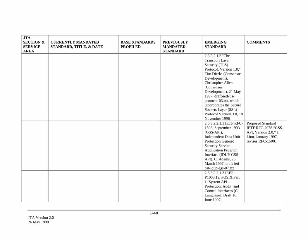
B-68JTA Version 2.026 May 1998
JTASECTION &SERVICEAREA
CURRENTLY MANDATEDSTANDARD, TITLE, & DATE
BASE STANDARDSPROFILED
PREVIOUSLYMANDATEDSTANDARD
EMERGINGSTANDARD
COMMENTS
2.6.3.2.1.2 "TheTransport LayerSecurity (TLS)Protocol, Version 1.0,"Tim Dierks (ConsensusDevelopment),Christopher Allen(ConsensusDevelopment), 21 May1997, draft-ietf-tls-protocol-03.txt, whichincorporates the SecureSockets Layer (SSL)Protocol Version 3.0, 18November 19962.6.3.2.2.1.1 IETF RFC-1508, September 1993(GSS-API);Independent Data UnitProtection GenericSecurity ServiceApplication ProgramInterface (IDUP-GSS-API), C. Adams, 25March 1997, draft-ietf-cat-idup-gss-07.txt
Proposed StandardIETF RFC-2078 “GSS-API, Version 2.0,” J.Linn, January 1997,revises RFC-1508.
2.6.3.2.2.1.2 IEEEP1003.1e, POSIX Part1: System API -Protection, Audit, andControl Interfaces [CLanguage], Draft 16,June 1997;

B-69JTA Version 2.0
26 May 1998
JTASECTION &SERVICEAREA
CURRENTLY MANDATEDSTANDARD, TITLE, & DATE
BASE STANDARDSPROFILED
PREVIOUSLYMANDATEDSTANDARD
EMERGINGSTANDARD
COMMENTS
2.6.3.2.2.1.2 IEEEP1003.2c, POSIX Part2: Shell and Utilities -Protection and ControlInterfaces, Draft 16,June 19972.6.3.3.1.1.1 IEEE802.10c/D13, Standardfor Interoperable LANSecurity-Part C: KeyManagement2.6.3.3.1.1.1 IEEE802.10g/D7, SecureData Exchange –Security Label, 19952.6.3.3.2.1 IETF RFC-1825, SecurityArchitecture for theInternet Protocol,August 19952.6.3.3.2.1 draft-ietf-ipsec-auth-05.txt, IPAuthentication Header(AH), 30 May 19972.6.3.3.2.1 draft-ietf-ipsec-esp-04.txt, IPEncapsulating SecurityPayload (ESP), 30 May1997
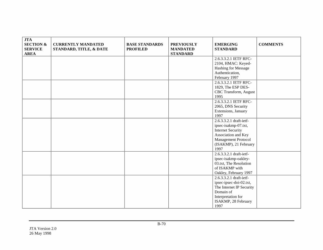
B-70JTA Version 2.026 May 1998
JTASECTION &SERVICEAREA
CURRENTLY MANDATEDSTANDARD, TITLE, & DATE
BASE STANDARDSPROFILED
PREVIOUSLYMANDATEDSTANDARD
EMERGINGSTANDARD
COMMENTS
2.6.3.3.2.1 IETF RFC-2104, HMAC: Keyed-Hashing for MessageAuthentication,February 19972.6.3.3.2.1 IETF RFC-1829, The ESP DES-CBC Transform, August19952.6.3.3.2.1 IETF RFC-2065, DNS SecurityExtensions, January19972.6.3.3.2.1 draft-ietf-ipsec-isakmp-07.txt,Internet SecurityAssociation and KeyManagement Protocol(ISAKMP), 21 February19972.6.3.3.2.1 draft-ietf-ipsec-isakmp-oakley-03.txt, The Resolutionof ISAKMP withOakley, February 19972.6.3.3.2.1 draft-ietf-ipsec-ipsec-doi-02.txt,The Internet IP SecurityDomain ofInterpretation forISAKMP, 28 February1997
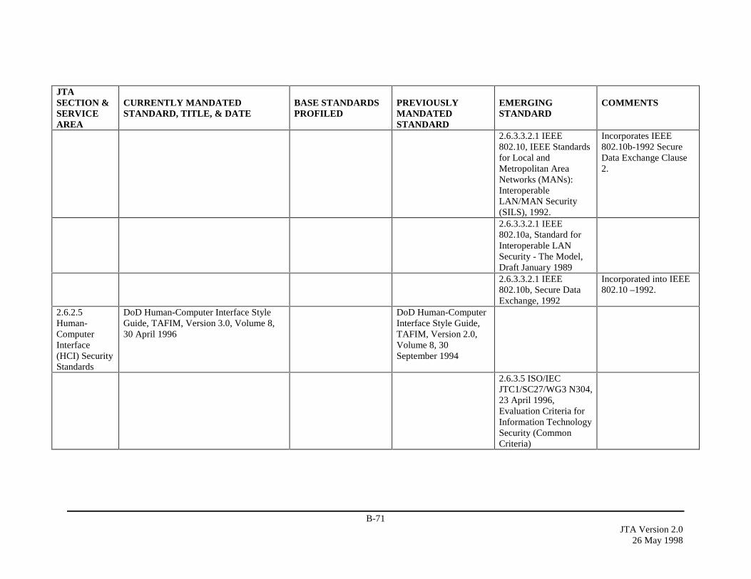
B-71JTA Version 2.0
26 May 1998
JTASECTION &SERVICEAREA
CURRENTLY MANDATEDSTANDARD, TITLE, & DATE
BASE STANDARDSPROFILED
PREVIOUSLYMANDATEDSTANDARD
EMERGINGSTANDARD
COMMENTS
2.6.3.3.2.1 IEEE802.10, IEEE Standardsfor Local andMetropolitan AreaNetworks (MANs):InteroperableLAN/MAN Security(SILS), 1992.
Incorporates IEEE802.10b-1992 SecureData Exchange Clause2.
2.6.3.3.2.1 IEEE802.10a, Standard forInteroperable LANSecurity - The Model,Draft January 19892.6.3.3.2.1 IEEE802.10b, Secure DataExchange, 1992
Incorporated into IEEE802.10 –1992.
2.6.2.5Human-ComputerInterface(HCI) SecurityStandards
DoD Human-Computer Interface StyleGuide, TAFIM, Version 3.0, Volume 8,30 April 1996
DoD Human-ComputerInterface Style Guide,TAFIM, Version 2.0,Volume 8, 30September 1994
2.6.3.5 ISO/IECJTC1/SC27/WG3 N304,23 April 1996,Evaluation Criteria forInformation TechnologySecurity (CommonCriteria)

B-72JTA Version 2.026 May 1998
JTASECTION &SERVICEAREA
CURRENTLY MANDATEDSTANDARD, TITLE, & DATE
BASE STANDARDSPROFILED
PREVIOUSLYMANDATEDSTANDARD
EMERGINGSTANDARD
COMMENTS
2.6.3.5 FIPS PUB 196,Entity AuthenticationUsing Public KeyCryptography, 18February 1997, basedon ISO/IEC 9798-3:1993, EntityAuthentication Using aPublic Key System
2.6.3.2.1.1EvaluationCriteriaSecurityStandards
ISO/IECJTC1/SC27/WG3 N304,23 April 1996,Evaluation Criteria forInformation TechnologySecurity (CommonCriteria)
2.6.3.2.1.2World WideWeb SecurityStandards
"The Transport LayerSecurity (TLS)Protocol, Version 1.0,"Tim Dierks (ConsensusDevelopment),Christopher Allen(ConsensusDevelopment), 21 May1997, draft-ietf-tls-protocol-03.txt, whichincorporates the SecureSockets Layer (SSL)Protocol Version 3.0, 18November 1996

B-73JTA Version 2.0
26 May 1998
JTASECTION &SERVICEAREA
CURRENTLY MANDATEDSTANDARD, TITLE, & DATE
BASE STANDARDSPROFILED
PREVIOUSLYMANDATEDSTANDARD
EMERGINGSTANDARD
COMMENTS
2.6.3.2.2.1.1GenericSecurityService (GSS)-ApplicationProgramInterface (API)Security
IETF RFC-1508,September 1993 (GSS-API); Independent DataUnit Protection GenericSecurity ServiceApplication ProgramInterface (IDUP-GSS-API), C. Adams, 25March 1997, draft-ietf-cat-idup-gss-07.txt
IETF RFC-2078 “GSS-API, Version 2.0,” J.Linn, January 1997,revises RFC-1508.
2.6.3.2.2.1.2POSIXSecurityStandards
IEEE P1003.1e, POSIXPart 1: System API -Protection, Audit, andControl Interfaces [CLanguage], Draft 16,June 1997IEEE P1003.2c, POSIXPart 2: Shell andUtilities - Protection andControl Interfaces, Draft16, June 1997
2.6.3.2.2.2.1EvaluationCriteriaSecurityStandards
ISO/IECJTC1/SC27/WG3 N304,23 April 1996,Evaluation Criteria forInformation TechnologySecurity (CommonCriteria)
2.6.3.2.2.2.2AuthenticationSecurityStandards
IETF RFC-1938, AOne-Time PasswordSystem, May 1996

B-74JTA Version 2.026 May 1998
JTASECTION &SERVICEAREA
CURRENTLY MANDATEDSTANDARD, TITLE, & DATE
BASE STANDARDSPROFILED
PREVIOUSLYMANDATEDSTANDARD
EMERGINGSTANDARD
COMMENTS
IETF RFC 2138,Remote AuthenticationDial In User Service(RADIUS), April 1997
2.6.3.2.2.3DistributedComputingServicesSecurityStandards
DCE Authenticationand SecuritySpecification (P315);Common ObjectRequest BrokerArchitecture (CORBA),OMG 95-12-1,December 1995;
2.6.3.3.1.1.1SecurityProtocols
IEEE 802.10c/D13,Standard forInteroperable LANSecurity-Part C: KeyManagementIEEE 802.10g/D7,Secure Data Exchange –Security Label, 1995
2.6.3.3.1.1.2Public KeyInfrastructureSecurityStandards
FIPS PUB 196, EntityAuthentication UsingPublic KeyCryptography, 18February 1997, basedon ISO/IEC 9798-3:1993, EntityAuthentication Using aPublic Key System
2.6.3.3.2.1Internetwork-ing SecurityStandards
IETF RFC-1825,Security Architecturefor the InternetProtocol, August 1995
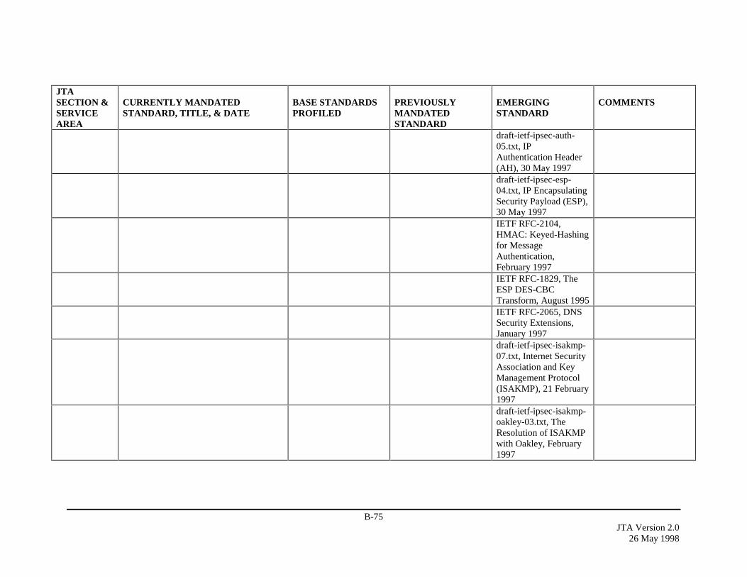
B-75JTA Version 2.0
26 May 1998
JTASECTION &SERVICEAREA
CURRENTLY MANDATEDSTANDARD, TITLE, & DATE
BASE STANDARDSPROFILED
PREVIOUSLYMANDATEDSTANDARD
EMERGINGSTANDARD
COMMENTS
draft-ietf-ipsec-auth-05.txt, IPAuthentication Header(AH), 30 May 1997draft-ietf-ipsec-esp-04.txt, IP EncapsulatingSecurity Payload (ESP),30 May 1997IETF RFC-2104,HMAC: Keyed-Hashingfor MessageAuthentication,February 1997IETF RFC-1829, TheESP DES-CBCTransform, August 1995IETF RFC-2065, DNSSecurity Extensions,January 1997draft-ietf-ipsec-isakmp-07.txt, Internet SecurityAssociation and KeyManagement Protocol(ISAKMP), 21 February1997draft-ietf-ipsec-isakmp-oakley-03.txt, TheResolution of ISAKMPwith Oakley, February1997
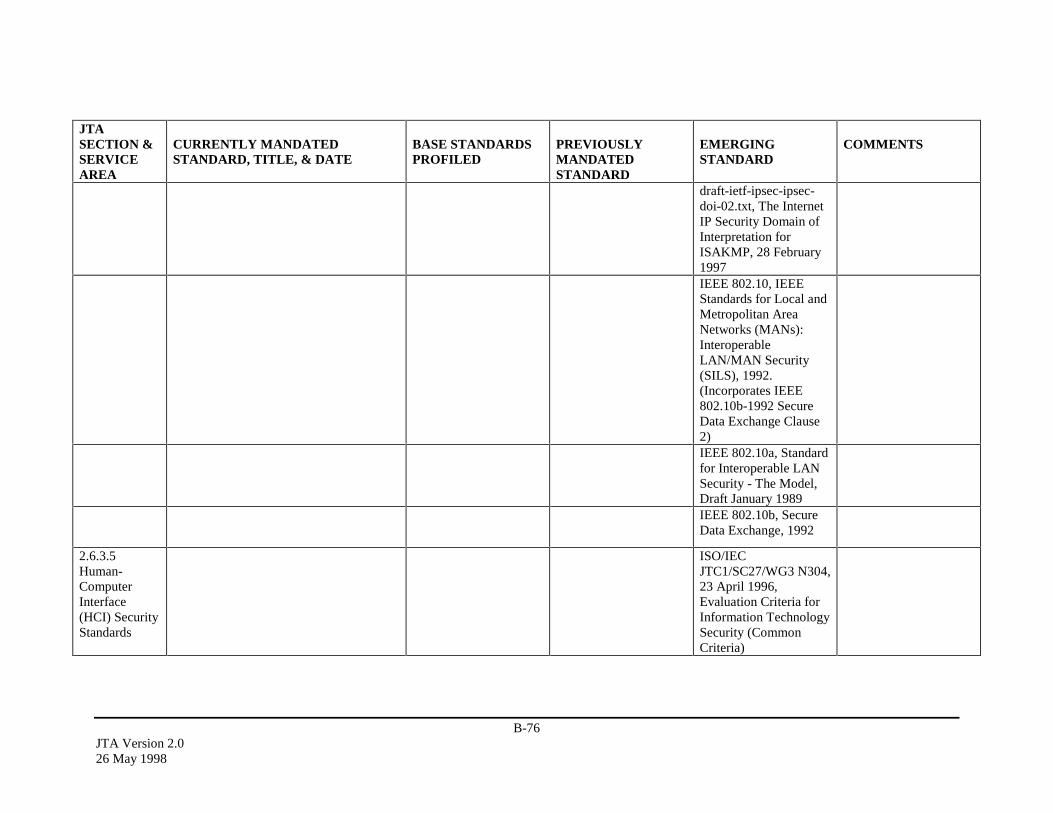
B-76JTA Version 2.026 May 1998
JTASECTION &SERVICEAREA
CURRENTLY MANDATEDSTANDARD, TITLE, & DATE
BASE STANDARDSPROFILED
PREVIOUSLYMANDATEDSTANDARD
EMERGINGSTANDARD
COMMENTS
draft-ietf-ipsec-ipsec-doi-02.txt, The InternetIP Security Domain ofInterpretation forISAKMP, 28 February1997IEEE 802.10, IEEEStandards for Local andMetropolitan AreaNetworks (MANs):InteroperableLAN/MAN Security(SILS), 1992.(Incorporates IEEE802.10b-1992 SecureData Exchange Clause2)IEEE 802.10a, Standardfor Interoperable LANSecurity - The Model,Draft January 1989IEEE 802.10b, SecureData Exchange, 1992
2.6.3.5Human-ComputerInterface(HCI) SecurityStandards
ISO/IECJTC1/SC27/WG3 N304,23 April 1996,Evaluation Criteria forInformation TechnologySecurity (CommonCriteria)

B-77JTA Version 2.0
26 May 1998
JTASECTION &SERVICEAREA
CURRENTLY MANDATEDSTANDARD, TITLE, & DATE
BASE STANDARDSPROFILED
PREVIOUSLYMANDATEDSTANDARD
EMERGINGSTANDARD
COMMENTS
FIPS PUB 196, EntityAuthentication UsingPublic KeyCryptography, 18February 1997, basedon ISO/IEC 9798-3:1993, EntityAuthentication Using aPublic Key System
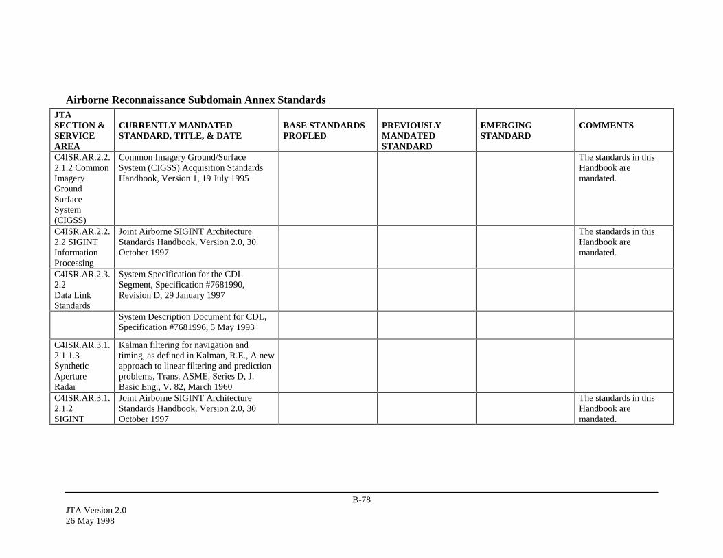
B-78JTA Version 2.026 May 1998
Airborne Reconnaissance Subdomain Annex StandardsJTASECTION &SERVICEAREA
CURRENTLY MANDATEDSTANDARD, TITLE, & DATE
BASE STANDARDSPROFLED
PREVIOUSLYMANDATEDSTANDARD
EMERGINGSTANDARD
COMMENTS
C4ISR.AR.2.2.2.1.2 CommonImageryGroundSurfaceSystem(CIGSS)
Common Imagery Ground/SurfaceSystem (CIGSS) Acquisition StandardsHandbook, Version 1, 19 July 1995
The standards in thisHandbook aremandated.
C4ISR.AR.2.2.2.2 SIGINTInformationProcessing
Joint Airborne SIGINT ArchitectureStandards Handbook, Version 2.0, 30October 1997
The standards in thisHandbook aremandated.
C4ISR.AR.2.3.2.2Data LinkStandards
System Specification for the CDLSegment, Specification #7681990,Revision D, 29 January 1997
System Description Document for CDL,Specification #7681996, 5 May 1993
C4ISR.AR.3.1.2.1.1.3SyntheticApertureRadar
Kalman filtering for navigation andtiming, as defined in Kalman, R.E., A newapproach to linear filtering and predictionproblems, Trans. ASME, Series D, J.Basic Eng., V. 82, March 1960
C4ISR.AR.3.1.2.1.2SIGINT
Joint Airborne SIGINT ArchitectureStandards Handbook, Version 2.0, 30October 1997
The standards in thisHandbook aremandated.
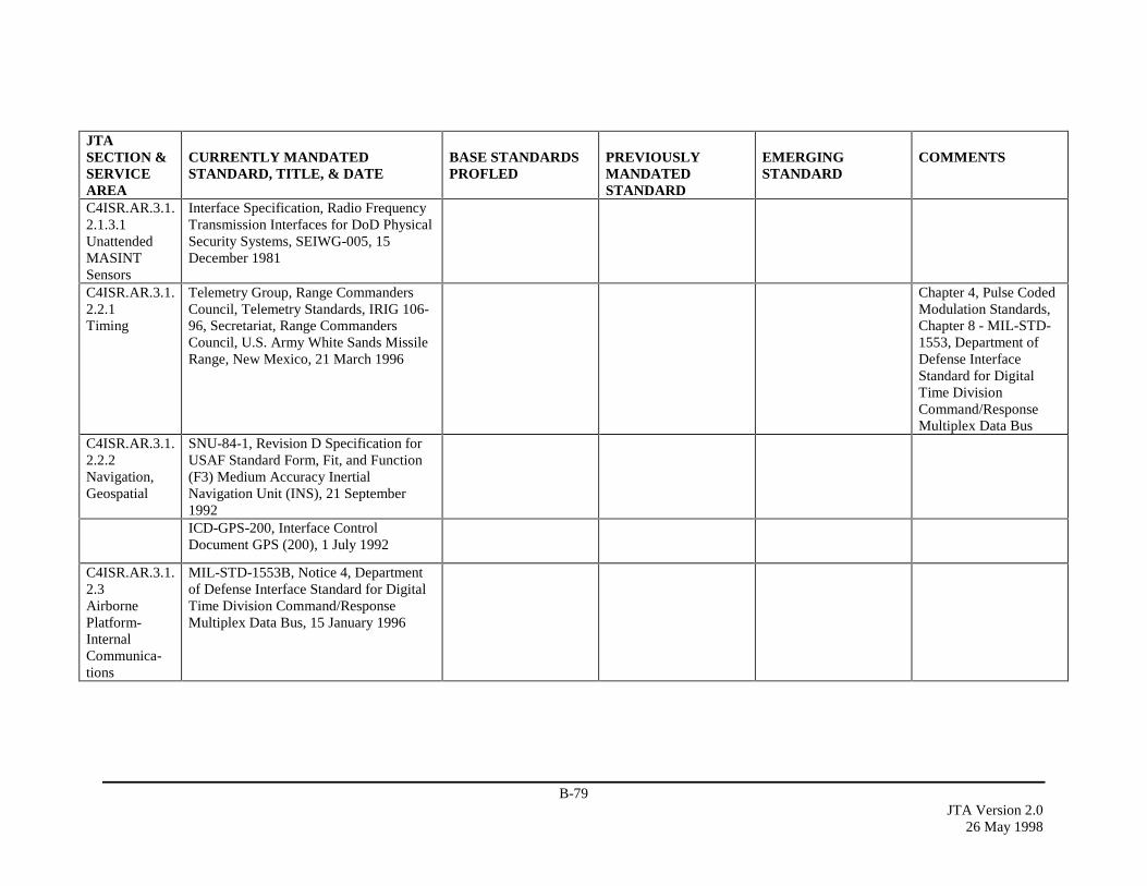
B-79JTA Version 2.0
26 May 1998
JTASECTION &SERVICEAREA
CURRENTLY MANDATEDSTANDARD, TITLE, & DATE
BASE STANDARDSPROFLED
PREVIOUSLYMANDATEDSTANDARD
EMERGINGSTANDARD
COMMENTS
C4ISR.AR.3.1.2.1.3.1UnattendedMASINTSensors
Interface Specification, Radio FrequencyTransmission Interfaces for DoD PhysicalSecurity Systems, SEIWG-005, 15December 1981
C4ISR.AR.3.1.2.2.1Timing
Telemetry Group, Range CommandersCouncil, Telemetry Standards, IRIG 106-96, Secretariat, Range CommandersCouncil, U.S. Army White Sands MissileRange, New Mexico, 21 March 1996
Chapter 4, Pulse CodedModulation Standards,Chapter 8 - MIL-STD-1553, Department ofDefense InterfaceStandard for DigitalTime DivisionCommand/ResponseMultiplex Data Bus
C4ISR.AR.3.1.2.2.2Navigation,Geospatial
SNU-84-1, Revision D Specification forUSAF Standard Form, Fit, and Function(F3) Medium Accuracy InertialNavigation Unit (INS), 21 September1992ICD-GPS-200, Interface ControlDocument GPS (200), 1 July 1992
C4ISR.AR.3.1.2.3AirbornePlatform-InternalCommunica-tions
MIL-STD-1553B, Notice 4, Departmentof Defense Interface Standard for DigitalTime Division Command/ResponseMultiplex Data Bus, 15 January 1996

B-80JTA Version 2.026 May 1998
JTASECTION &SERVICEAREA
CURRENTLY MANDATEDSTANDARD, TITLE, & DATE
BASE STANDARDSPROFLED
PREVIOUSLYMANDATEDSTANDARD
EMERGINGSTANDARD
COMMENTS
ANSI X3.184, Information Systems -Fiber Distributed Data Interface (FDDI)Single-Mode Fiber Physical LayerMedium Dependent (SMF-PMD) (100Mb/s dual counter rotating ring), 1January 1993ANSI X3.230, Information Technology -Fiber Channel - Physical and SignalingInterface (FC-PH), (800 Mb/s), 1 January1996
C4ISR.AR.3.1.2.4Air Vehicle/SensorTelemetryMandates
Telemetry Group, Range CommandersCouncil, Telemetry Standards, IRIG 106-96, Secretariat, Range CommandersCouncil, U.S. Army White Sands MissileRange, New Mexico, 21 March 1996
Chapter 4, Pulse CodedModulation Standards,Chapter 8 - MIL-STD-1553, Department ofDefense InterfaceStandard for DigitalTime DivisionCommand/ResponseMultiplex Data Bus
C4ISR.AR.3.1.2.5 MissionRecorderMandates
Compatibility with the published“AMPEX Digital InstrumentationRecorder DCRSi 240 User Manual”
ANSI X3.175, 19-mm Type ID-1Recorded Instrumentation - DigitalCassette Tape Form, 1990, ID 1Instrumentation Group (IRIG) B format asdefined in IRIG Document 104-70,August 1970
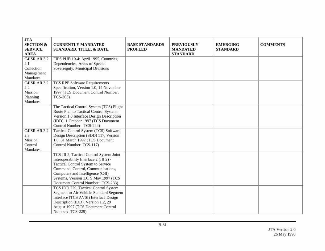
B-81JTA Version 2.0
26 May 1998
JTASECTION &SERVICEAREA
CURRENTLY MANDATEDSTANDARD, TITLE, & DATE
BASE STANDARDSPROFLED
PREVIOUSLYMANDATEDSTANDARD
EMERGINGSTANDARD
COMMENTS
C4ISR.AR.3.2.2.1CollectionManagementMandates
FIPS PUB 10-4: April 1995, Countries,Dependencies, Areas of SpecialSovereignty, Municipal Divisions
C4ISR.AR.3.2.2.2MissionPlanningMandates
TCS RPP Software RequirementsSpecification, Version 1.0, 14 November1997 (TCS Document Control Number:TCS-303)
The Tactical Control System (TCS) FlightRoute Plan to Tactical Control System,Version 1.0 Interface Design Description(IDD), 1 October 1997 (TCS DocumentControl Number: TCS-244)
C4ISR.AR.3.2.2.3MissionControlMandates
Tactical Control System (TCS) SoftwareDesign Description (SDD) 117, Version1.0, 31 March 1997 (TCS DocumentControl Number: TCS-117)
TCS JII 2, Tactical Control System JointInteroperability Interface 2 (JII 2) -Tactical Control System to ServiceCommand, Control, Communications,Computers and Intelligence (C4I)Systems, Version 1.0, 9 May 1997 (TCSDocument Control Number: TCS-233)TCS IDD 229, Tactical Control SystemSegment to Air Vehicle Standard SegmentInterface (TCS AVSI) Interface DesignDescription (IDD), Version 1.2, 29August 1997 (TCS Document ControlNumber: TCS-229)

B-82JTA Version 2.026 May 1998
Combat Support Domain Annex StandardsJTASECTION &SERVICEAREA
CURRENTLY MANDATEDSTANDARD, TITLE, & DATE
BASE STANDARDSPROFILED
PREVIOUSLYMANDATEDSTANDARD
EMERGINGSTANDARD
COMMENTS
CS.2.2.1DocumentInterchange
MIL-PRF-28001C, Markup Requirementsand Generic Style Specification forElectronic Printed Output and Exchangeof Text (CALS SGML), 2 May 1997MIL-STD-1840C, Automated Interchangeof Technical Information (AITI), 26 June1997
CS.2.2.2Graphics DataInterchange
ANSI/ISO 8632, as profiled by MIL-PRF-28003A, CGM Application Profile, withAmendment 1, 14 August 1992MIL-PRF-28002C, Requirements forRaster Graphics Representation in BinaryFormat, 30 September 1997NEMA/ACR DICOM V3.0, parts 1-12,Digital Imaging and Communication inMedicine, 1993
CS.2.2.3Product DataInterchange
FIPS PUB 177-1, IGES, adopts CALSIGES and ANSI/US PRO-100-1993,V5.2, 23 April 1996MIL-PRF-28000A with Amendment 1,Digital Representation forCommunications of Product Data: IGESApplication Subsets and IGESApplication Protocols, 14 December 1992ISO/IEC 10303-1:1994, Standards for theExchange of Product Model Data (STEP),Part 1: Overview and PrinciplesMIL-STD-2549, ConfigurationManagement Data Interface, 30 June 1997
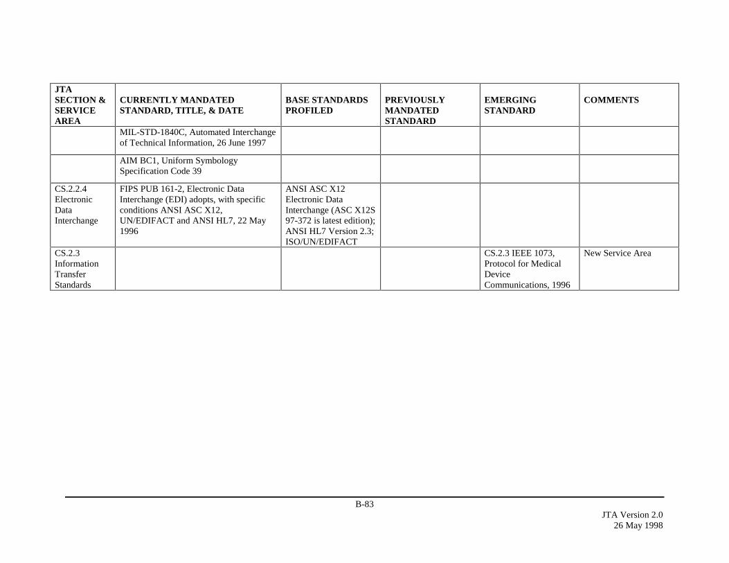
B-83JTA Version 2.0
26 May 1998
JTASECTION &SERVICEAREA
CURRENTLY MANDATEDSTANDARD, TITLE, & DATE
BASE STANDARDSPROFILED
PREVIOUSLYMANDATEDSTANDARD
EMERGINGSTANDARD
COMMENTS
MIL-STD-1840C, Automated Interchangeof Technical Information, 26 June 1997
AIM BC1, Uniform SymbologySpecification Code 39
CS.2.2.4ElectronicDataInterchange
FIPS PUB 161-2, Electronic DataInterchange (EDI) adopts, with specificconditions ANSI ASC X12,UN/EDIFACT and ANSI HL7, 22 May1996
ANSI ASC X12Electronic DataInterchange (ASC X12S97-372 is latest edition);ANSI HL7 Version 2.3;ISO/UN/EDIFACT
CS.2.3InformationTransferStandards
CS.2.3 IEEE 1073,Protocol for MedicalDeviceCommunications, 1996
New Service Area
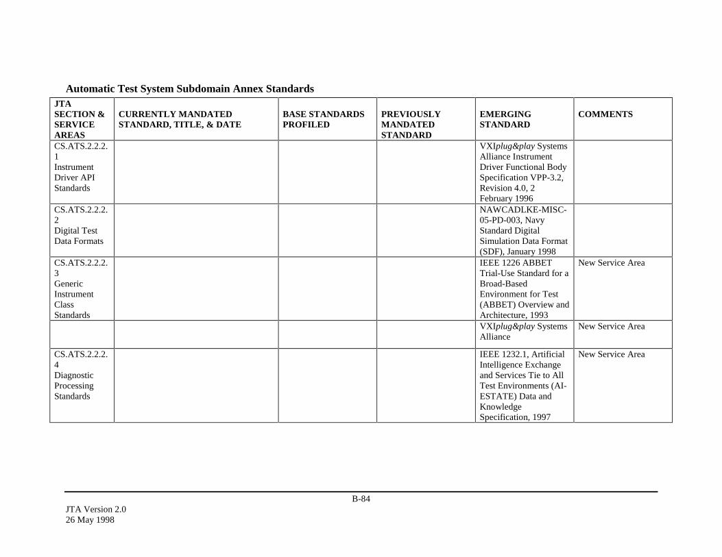
B-84JTA Version 2.026 May 1998
Automatic Test System Subdomain Annex StandardsJTASECTION &SERVICEAREAS
CURRENTLY MANDATEDSTANDARD, TITLE, & DATE
BASE STANDARDSPROFILED
PREVIOUSLYMANDATEDSTANDARD
EMERGINGSTANDARD
COMMENTS
CS.ATS.2.2.2.1InstrumentDriver APIStandards
VXIplug&play SystemsAlliance InstrumentDriver Functional BodySpecification VPP-3.2,Revision 4.0, 2February 1996
CS.ATS.2.2.2.2Digital TestData Formats
NAWCADLKE-MISC-05-PD-003, NavyStandard DigitalSimulation Data Format(SDF), January 1998
CS.ATS.2.2.2.3GenericInstrumentClassStandards
IEEE 1226 ABBETTrial-Use Standard for aBroad-BasedEnvironment for Test(ABBET) Overview andArchitecture, 1993
New Service Area
VXIplug&play SystemsAlliance
New Service Area
CS.ATS.2.2.2.4DiagnosticProcessingStandards
IEEE 1232.1, ArtificialIntelligence Exchangeand Services Tie to AllTest Environments (AI-ESTATE) Data andKnowledgeSpecification, 1997
New Service Area
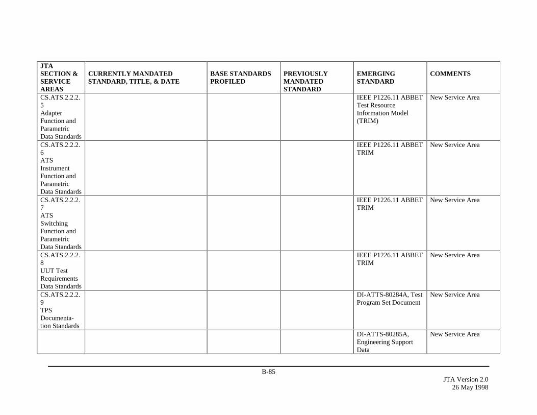
B-85JTA Version 2.0
26 May 1998
JTASECTION &SERVICEAREAS
CURRENTLY MANDATEDSTANDARD, TITLE, & DATE
BASE STANDARDSPROFILED
PREVIOUSLYMANDATEDSTANDARD
EMERGINGSTANDARD
COMMENTS
CS.ATS.2.2.2.5AdapterFunction andParametricData Standards
IEEE P1226.11 ABBETTest ResourceInformation Model(TRIM)
New Service Area
CS.ATS.2.2.2.6ATSInstrumentFunction andParametricData Standards
IEEE P1226.11 ABBETTRIM
New Service Area
CS.ATS.2.2.2.7ATSSwitchingFunction andParametricData Standards
IEEE P1226.11 ABBETTRIM
New Service Area
CS.ATS.2.2.2.8UUT TestRequirementsData Standards
IEEE P1226.11 ABBETTRIM
New Service Area
CS.ATS.2.2.2.9TPSDocumenta-tion Standards
DI-ATTS-80284A, TestProgram Set Document
New Service Area
DI-ATTS-80285A,Engineering SupportData
New Service Area
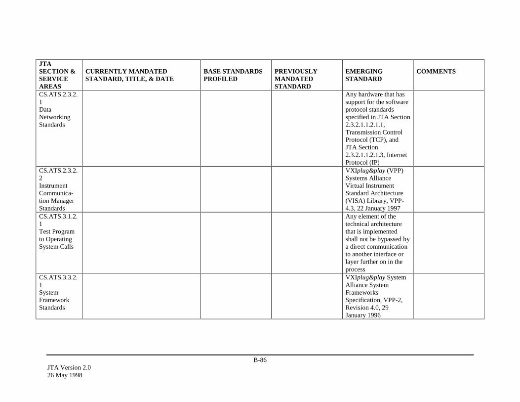
B-86JTA Version 2.026 May 1998
JTASECTION &SERVICEAREAS
CURRENTLY MANDATEDSTANDARD, TITLE, & DATE
BASE STANDARDSPROFILED
PREVIOUSLYMANDATEDSTANDARD
EMERGINGSTANDARD
COMMENTS
CS.ATS.2.3.2.1DataNetworkingStandards
Any hardware that hassupport for the softwareprotocol standardsspecified in JTA Section2.3.2.1.1.2.1.1,Transmission ControlProtocol (TCP), andJTA Section2.3.2.1.1.2.1.3, InternetProtocol (IP)
CS.ATS.2.3.2.2InstrumentCommunica-tion ManagerStandards
VXIplug&play (VPP)Systems AllianceVirtual InstrumentStandard Architecture(VISA) Library, VPP-4.3, 22 January 1997
CS.ATS.3.1.2.1Test Programto OperatingSystem Calls
Any element of thetechnical architecturethat is implementedshall not be bypassed bya direct communicationto another interface orlayer further on in theprocess
CS.ATS.3.3.2.1SystemFrameworkStandards
VXIplug&play SystemAlliance SystemFrameworksSpecification, VPP-2,Revision 4.0, 29January 1996
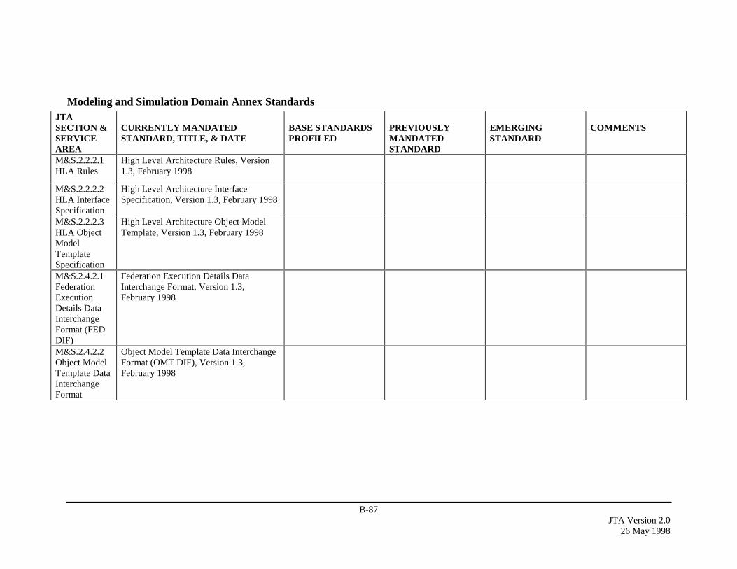
B-87JTA Version 2.0
26 May 1998
Modeling and Simulation Domain Annex StandardsJTASECTION &SERVICEAREA
CURRENTLY MANDATEDSTANDARD, TITLE, & DATE
BASE STANDARDSPROFILED
PREVIOUSLYMANDATEDSTANDARD
EMERGINGSTANDARD
COMMENTS
M&S.2.2.2.1HLA Rules
High Level Architecture Rules, Version1.3, February 1998
M&S.2.2.2.2HLA InterfaceSpecification
High Level Architecture InterfaceSpecification, Version 1.3, February 1998
M&S.2.2.2.3HLA ObjectModelTemplateSpecification
High Level Architecture Object ModelTemplate, Version 1.3, February 1998
M&S.2.4.2.1FederationExecutionDetails DataInterchangeFormat (FEDDIF)
Federation Execution Details DataInterchange Format, Version 1.3,February 1998
M&S.2.4.2.2Object ModelTemplate DataInterchangeFormat
Object Model Template Data InterchangeFormat (OMT DIF), Version 1.3,February 1998
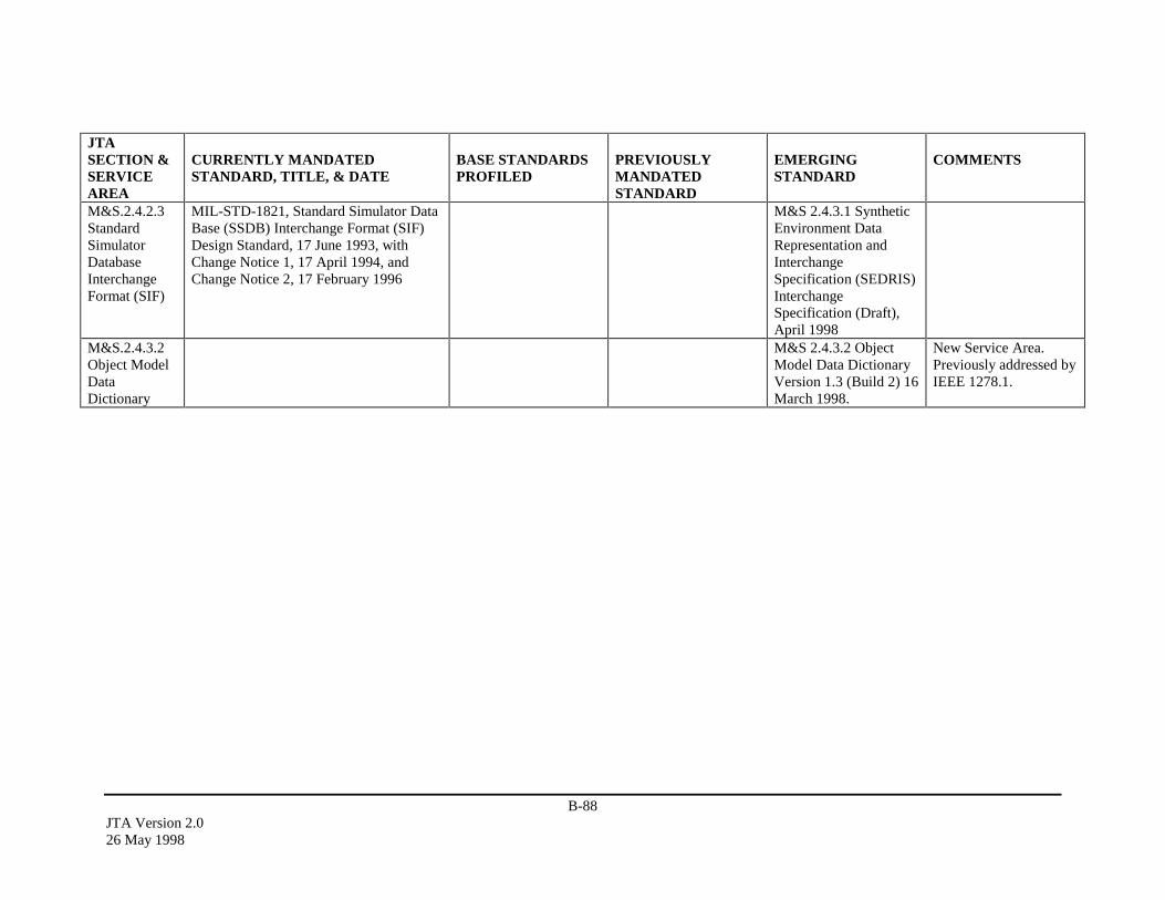
B-88JTA Version 2.026 May 1998
JTASECTION &SERVICEAREA
CURRENTLY MANDATEDSTANDARD, TITLE, & DATE
BASE STANDARDSPROFILED
PREVIOUSLYMANDATEDSTANDARD
EMERGINGSTANDARD
COMMENTS
M&S.2.4.2.3StandardSimulatorDatabaseInterchangeFormat (SIF)
MIL-STD-1821, Standard Simulator DataBase (SSDB) Interchange Format (SIF)Design Standard, 17 June 1993, withChange Notice 1, 17 April 1994, andChange Notice 2, 17 February 1996
M&S 2.4.3.1 SyntheticEnvironment DataRepresentation andInterchangeSpecification (SEDRIS)InterchangeSpecification (Draft),April 1998
M&S.2.4.3.2Object ModelDataDictionary
M&S 2.4.3.2 ObjectModel Data DictionaryVersion 1.3 (Build 2) 16March 1998.
New Service Area.Previously addressed byIEEE 1278.1.
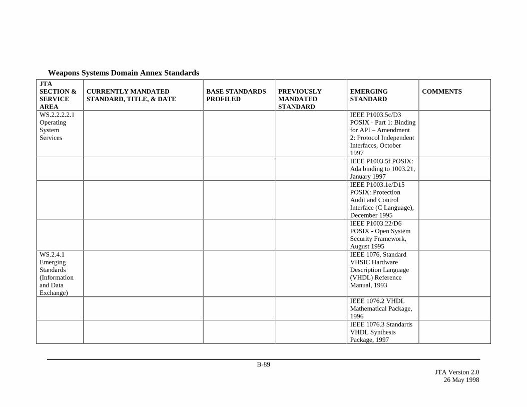
B-89JTA Version 2.0
26 May 1998
Weapons Systems Domain Annex StandardsJTASECTION &SERVICEAREA
CURRENTLY MANDATEDSTANDARD, TITLE, & DATE
BASE STANDARDSPROFILED
PREVIOUSLYMANDATEDSTANDARD
EMERGINGSTANDARD
COMMENTS
WS.2.2.2.2.1OperatingSystemServices
IEEE P1003.5c/D3POSIX - Part 1: Bindingfor API – Amendment2: Protocol IndependentInterfaces, October1997IEEE P1003.5f POSIX:Ada binding to 1003.21,January 1997IEEE P1003.1e/D15POSIX: ProtectionAudit and ControlInterface (C Language),December 1995IEEE P1003.22/D6POSIX - Open SystemSecurity Framework,August 1995
WS.2.4.1EmergingStandards(Informationand DataExchange)
IEEE 1076, StandardVHSIC HardwareDescription Language(VHDL) ReferenceManual, 1993
IEEE 1076.2 VHDLMathematical Package,1996IEEE 1076.3 StandardsVHDL SynthesisPackage, 1997
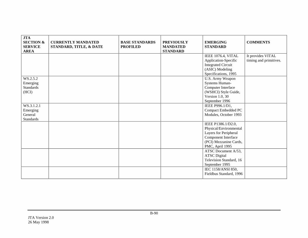
B-90JTA Version 2.026 May 1998
JTASECTION &SERVICEAREA
CURRENTLY MANDATEDSTANDARD, TITLE, & DATE
BASE STANDARDSPROFILED
PREVIOUSLYMANDATEDSTANDARD
EMERGINGSTANDARD
COMMENTS
IEEE 1076.4, VITALApplication-SpecificIntegrated Circuit(ASIC) ModelingSpecifications, 1995
It provides VITALtiming and primitives.
WS.2.5.2EmergingStandards(HCI)
U.S. Army WeaponSystems Human-Computer Interface(WSHCI) Style Guide,Version 1.0, 30September 1996
WS.3.1.2.1EmergingGeneralStandards
IEEE P996.1/D1,Compact Embedded PCModules, October 1993
IEEE P1386.1/D2.0,Physical/EnvironmentalLayers for PeripheralComponent Interface(PCI) Mezzanine Cards,PMC, April 1995ATSC Document A/53,ATSC DigitalTelevision Standard, 16September 1995IEC 1158/ANSI 850,Fieldbus Standard, 1996
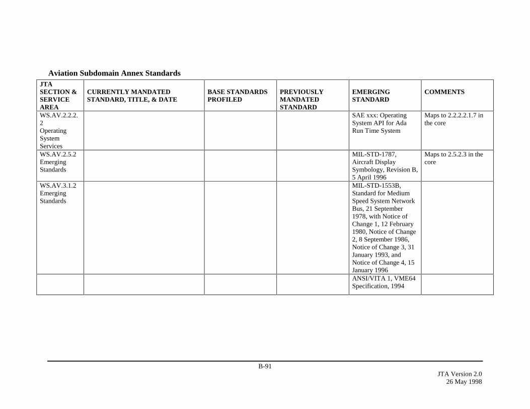
B-91JTA Version 2.0
26 May 1998
Aviation Subdomain Annex StandardsJTASECTION &SERVICEAREA
CURRENTLY MANDATEDSTANDARD, TITLE, & DATE
BASE STANDARDSPROFILED
PREVIOUSLYMANDATEDSTANDARD
EMERGINGSTANDARD
COMMENTS
WS.AV.2.2.2.2OperatingSystemServices
SAE xxx: OperatingSystem API for AdaRun Time System
Maps to 2.2.2.2.1.7 inthe core
WS.AV.2.5.2EmergingStandards
MIL-STD-1787,Aircraft DisplaySymbology, Revision B,5 April 1996
Maps to 2.5.2.3 in thecore
WS.AV.3.1.2EmergingStandards
MIL-STD-1553B,Standard for MediumSpeed System NetworkBus, 21 September1978, with Notice ofChange 1, 12 February1980, Notice of Change2, 8 September 1986,Notice of Change 3, 31January 1993, andNotice of Change 4, 15January 1996ANSI/VITA 1, VME64Specification, 1994
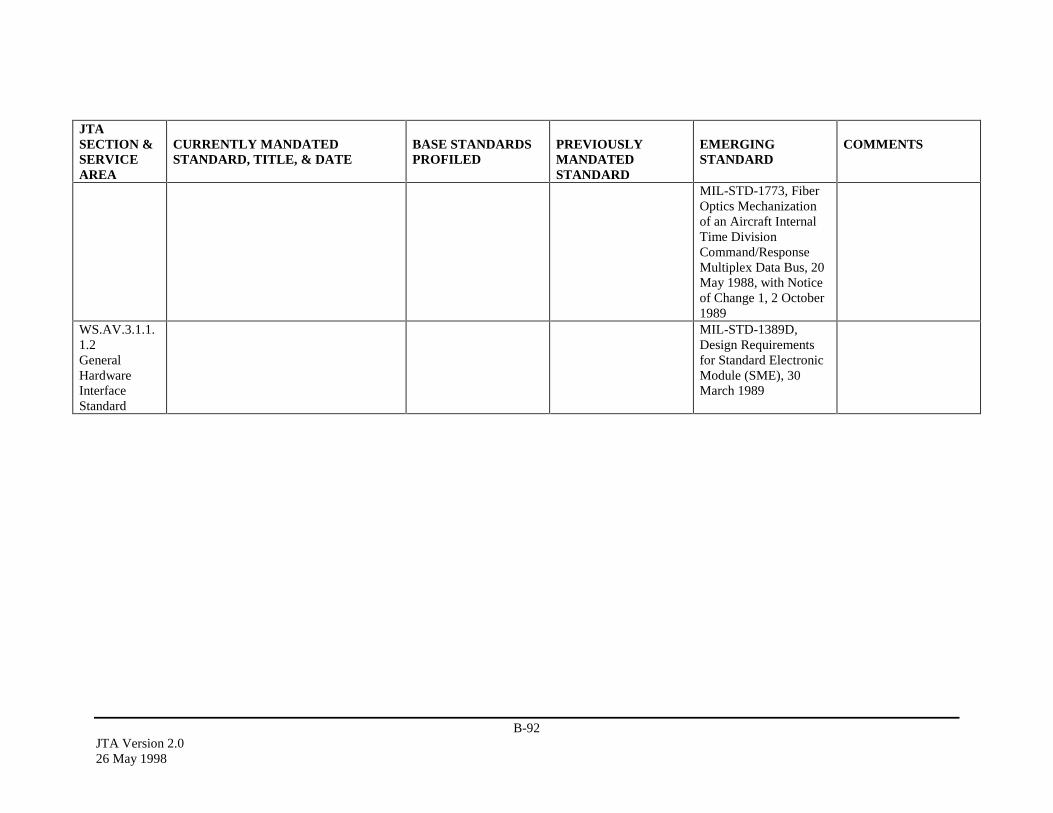
B-92JTA Version 2.026 May 1998
JTASECTION &SERVICEAREA
CURRENTLY MANDATEDSTANDARD, TITLE, & DATE
BASE STANDARDSPROFILED
PREVIOUSLYMANDATEDSTANDARD
EMERGINGSTANDARD
COMMENTS
MIL-STD-1773, FiberOptics Mechanizationof an Aircraft InternalTime DivisionCommand/ResponseMultiplex Data Bus, 20May 1988, with Noticeof Change 1, 2 October1989
WS.AV.3.1.1.1.2GeneralHardwareInterfaceStandard
MIL-STD-1389D,Design Requirementsfor Standard ElectronicModule (SME), 30March 1989
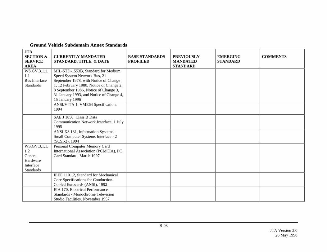
B-93JTA Version 2.0
26 May 1998
Ground Vehicle Subdomain Annex StandardsJTASECTION &SERVICEAREA
CURRENTLY MANDATEDSTANDARD, TITLE, & DATE
BASE STANDARDSPROFILED
PREVIOUSLYMANDATEDSTANDARD
EMERGINGSTANDARD
COMMENTS
WS.GV.3.1.1.1.1Bus InterfaceStandards
MIL-STD-1553B, Standard for MediumSpeed System Network Bus, 21September 1978, with Notice of Change1, 12 February 1980, Notice of Change 2,8 September 1986, Notice of Change 3,31 January 1993, and Notice of Change 4,15 January 1996ANSI/VITA 1, VME64 Specification,1994
SAE J 1850, Class B DataCommunication Network Interface, 1 July1995ANSI X3.131, Information Systems -Small Computer Systems Interface - 2(SCSI-2), 1994
WS.GV.3.1.1.1.2GeneralHardwareInterfaceStandards
Personal Computer Memory CardInternational Association (PCMCIA), PCCard Standard, March 1997
IEEE 1101.2, Standard for MechanicalCore Specifications for Conduction-Cooled Eurocards (ANSI), 1992EIA 170, Electrical PerformanceStandards - Monochrome TelevisionStudio Facilities, November 1957
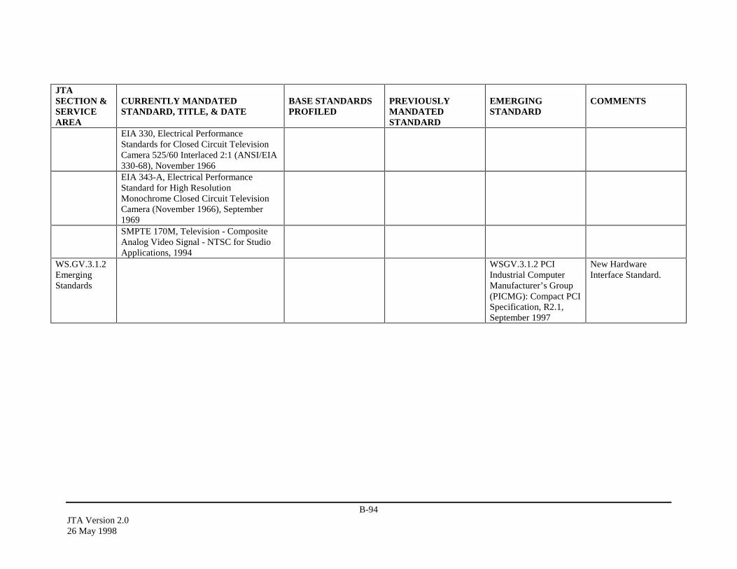
B-94JTA Version 2.026 May 1998
JTASECTION &SERVICEAREA
CURRENTLY MANDATEDSTANDARD, TITLE, & DATE
BASE STANDARDSPROFILED
PREVIOUSLYMANDATEDSTANDARD
EMERGINGSTANDARD
COMMENTS
EIA 330, Electrical PerformanceStandards for Closed Circuit TelevisionCamera 525/60 Interlaced 2:1 (ANSI/EIA330-68), November 1966EIA 343-A, Electrical PerformanceStandard for High ResolutionMonochrome Closed Circuit TelevisionCamera (November 1966), September1969SMPTE 170M, Television - CompositeAnalog Video Signal - NTSC for StudioApplications, 1994
WS.GV.3.1.2EmergingStandards
WSGV.3.1.2 PCIIndustrial ComputerManufacturer’s Group(PICMG): Compact PCISpecification, R2.1,September 1997
New HardwareInterface Standard.
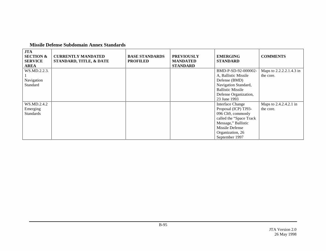
B-95JTA Version 2.0
26 May 1998
Missile Defense Subdomain Annex StandardsJTASECTION &SERVICEAREA
CURRENTLY MANDATEDSTANDARD, TITLE, & DATE
BASE STANDARDSPROFILED
PREVIOUSLYMANDATEDSTANDARD
EMERGINGSTANDARD
COMMENTS
WS.MD.2.2.3.1NavigationStandard
BMD-P-SD-92-000002-A, Ballistic MissileDefense (BMD)Navigation Standard,Ballistic MissileDefense Organization,23 June 1993
Maps to 2.2.2.2.1.4.3 inthe core.
WS.MD.2.4.2EmergingStandards
Interface ChangeProposal (ICP) TJ93-096 Ch9, commonlycalled the “Space TrackMessage,” BallisticMissile DefenseOrganization, 26September 1997
Maps to 2.4.2.4.2.1 inthe core.
B-96JTA Version 2.026 May 1998
This page intentionally left blank.

B-97JTA Version 2.0
26 May 1998
B.3 DOCUMENT SOURCES
Commercial Documents
Organization Source Location URLANSI American National Standards Institute,
Attention Customer Service,11 West 42nd St., New York, NY 10036 USATel: +1 212 642 4900.
http://www.ansi.org
CCITT International Telegraph and Telephone ConsultativeCommittee (CCITT) is now known as InternationalTelecommunications Union - TelecommunicationsStandardization Sector (ITU-T). See the ITU-T entry forsource location information.
http://www.itu.ch
CORBA Information about the Common Object Request BrokerArchitecture (CORBA) can be obtained from the ObjectManagement Group (OMG). See the OMG entry for sourcelocation information.
http://www.omg.org
EIA Electronics Industries AssociationGlobal Engineering Documents7730 Carondelet Ave., Suite 407Clayton, MO 63105 USATel: +1 800 854 7179
http://global.ihs.com
IAB Internet Architecture Board (IAB) documents are availablefrom Internet Engineering Task Force (IETF). See the IETFentry for source location information.
IEEE Secretary, IEEE Standards BoardInstitute of Electrical and Electronics Engineers, IncP.O. Box 1331, 445 Hoes LanePiscataway, NJ 08855-1331, USATel: +1 800 678 4333
http://standards.ieee.org
IETF Internet Engineering Task ForceSRI International, Room EJ291Network Information Systems Center333 Ravenswood AvenueMenlo Park, CA 94025, USAEmail: [email protected]( Include the phrase "Send rfcxxxx.txt" in the body of themessage to obtain a copy of the corresponding RFCstandard via email.)
http://www.ietf.org
ftp://ds.internic.net
ISO International Organization for Standardization (ISO)standards can be obtained from:
American National Standards Institute (ANSI)Attention Customer Service11 West 42nd St., New York, NY 10036 USATel: +1 212 642 4900
http://www.ansi.org
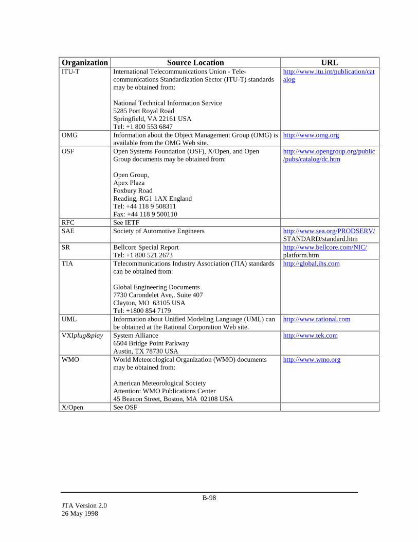
B-98JTA Version 2.026 May 1998
Organization Source Location URLITU-T International Telecommunications Union - Tele-
communications Standardization Sector (ITU-T) standardsmay be obtained from:
National Technical Information Service5285 Port Royal RoadSpringfield, VA 22161 USATel: +1 800 553 6847
http://www.itu.int/publication/catalog
OMG Information about the Object Management Group (OMG) isavailable from the OMG Web site.
http://www.omg.org
OSF Open Systems Foundation (OSF), X/Open, and OpenGroup documents may be obtained from:
Open Group,Apex PlazaFoxbury RoadReading, RG1 1AX EnglandTel: +44 118 9 508311Fax: +44 118 9 500110
http://www.opengroup.org/public/pubs/catalog/dc.htm
RFC See IETFSAE Society of Automotive Engineers http://www.sea.org/PRODSERV/
STANDARD/standard.htmSR Bellcore Special Report
Tel: +1 800 521 2673http://www.bellcore.com/NIC/platform.htm
TIA Telecommunications Industry Association (TIA) standardscan be obtained from:
Global Engineering Documents7730 Carondelet Ave,. Suite 407Clayton, MO 63105 USATel: +1800 854 7179
http://global.ihs.com
UML Information about Unified Modeling Language (UML) canbe obtained at the Rational Corporation Web site.
http://www.rational.com
VXIplug&play System Alliance6504 Bridge Point ParkwayAustin, TX 78730 USA
http://www.tek.com
WMO World Meteorological Organization (WMO) documentsmay be obtained from:
American Meteorological SocietyAttention: WMO Publications Center45 Beacon Street, Boston, MA 02108 USA
http://www.wmo.org
X/Open See OSF
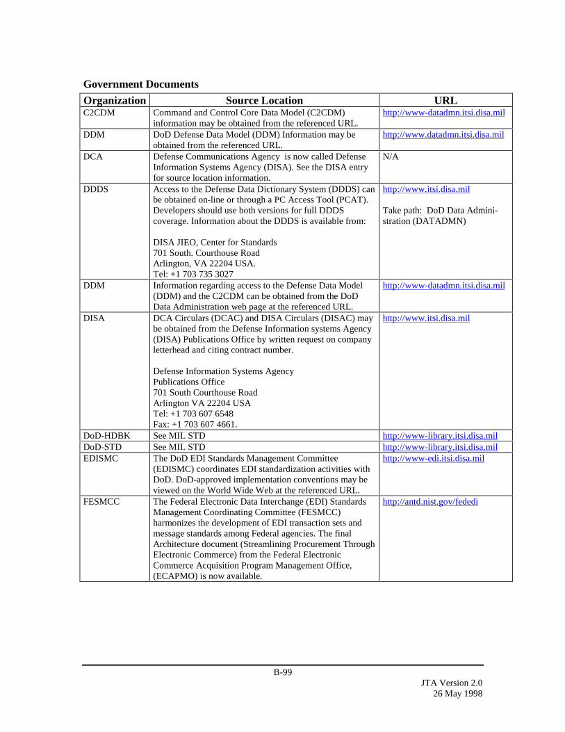
B-99JTA Version 2.0
26 May 1998
Government Documents
Organization Source Location URLC2CDM Command and Control Core Data Model (C2CDM)
information may be obtained from the referenced URL.http://www-datadmn.itsi.disa.mil
DDM DoD Defense Data Model (DDM) Information may beobtained from the referenced URL.
http://www.datadmn.itsi.disa.mil
DCA Defense Communications Agency is now called DefenseInformation Systems Agency (DISA). See the DISA entryfor source location information.
N/A
DDDS Access to the Defense Data Dictionary System (DDDS) canbe obtained on-line or through a PC Access Tool (PCAT).Developers should use both versions for full DDDScoverage. Information about the DDDS is available from:
DISA JIEO, Center for Standards701 South. Courthouse RoadArlington, VA 22204 USA.Tel: +1 703 735 3027
http://www.itsi.disa.mil
Take path: DoD Data Admini-stration (DATADMN)
DDM Information regarding access to the Defense Data Model(DDM) and the C2CDM can be obtained from the DoDData Administration web page at the referenced URL.
http://www-datadmn.itsi.disa.mil
DISA DCA Circulars (DCAC) and DISA Circulars (DISAC) maybe obtained from the Defense Information systems Agency(DISA) Publications Office by written request on companyletterhead and citing contract number.
Defense Information Systems AgencyPublications Office701 South Courthouse RoadArlington VA 22204 USATel: +1 703 607 6548Fax: +1 703 607 4661.
http://www.itsi.disa.mil
DoD-HDBK See MIL STD http://www-library.itsi.disa.milDoD-STD See MIL STD http://www-library.itsi.disa.milEDISMC The DoD EDI Standards Management Committee
(EDISMC) coordinates EDI standardization activities withDoD. DoD-approved implementation conventions may beviewed on the World Wide Web at the referenced URL.
http://www-edi.itsi.disa.mil
FESMCC The Federal Electronic Data Interchange (EDI) StandardsManagement Coordinating Committee (FESMCC)harmonizes the development of EDI transaction sets andmessage standards among Federal agencies. The finalArchitecture document (Streamlining Procurement ThroughElectronic Commerce) from the Federal ElectronicCommerce Acquisition Program Management Office,(ECAPMO) is now available.
http://antd.nist.gov/fededi
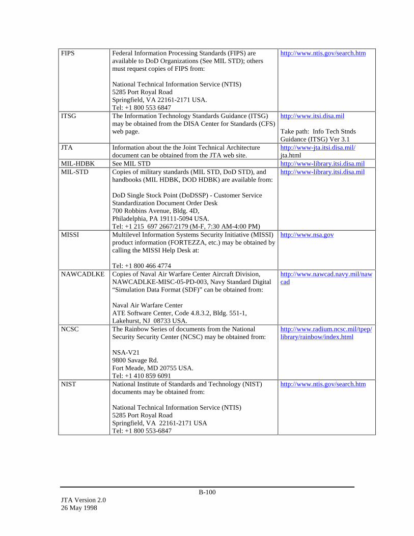
B-100JTA Version 2.026 May 1998
FIPS Federal Information Processing Standards (FIPS) areavailable to DoD Organizations (See MIL STD); othersmust request copies of FIPS from:
National Technical Information Service (NTIS)5285 Port Royal RoadSpringfield, VA 22161-2171 USA.Tel: +1 800 553 6847
http://www.ntis.gov/search.htm
ITSG The Information Technology Standards Guidance (ITSG)may be obtained from the DISA Center for Standards (CFS)web page.
http://www.itsi.disa.mil
Take path: Info Tech StndsGuidance (ITSG) Ver 3.1
JTA Information about the the Joint Technical Architecturedocument can be obtained from the JTA web site.
http://www-jta.itsi.disa.mil/jta.html
MIL-HDBK See MIL STD http://www-library.itsi.disa.milMIL-STD Copies of military standards (MIL STD, DoD STD), and
handbooks (MIL HDBK, DOD HDBK) are available from:
DoD Single Stock Point (DoDSSP) - Customer ServiceStandardization Document Order Desk700 Robbins Avenue, Bldg. 4D,Philadelphia, PA 19111-5094 USA.Tel: +1 215 697 2667/2179 (M-F, 7:30 AM-4:00 PM)
http://www-library.itsi.disa.mil
MISSI Multilevel Information Systems Security Initiative (MISSI)product information (FORTEZZA, etc.) may be obtained bycalling the MISSI Help Desk at:
Tel: +1 800 466 4774
http://www.nsa.gov
NAWCADLKE Copies of Naval Air Warfare Center Aircraft Division,NAWCADLKE-MISC-05-PD-003, Navy Standard Digital“Simulation Data Format (SDF)” can be obtained from:
Naval Air Warfare CenterATE Software Center, Code 4.8.3.2, Bldg. 551-1,Lakehurst, NJ 08733 USA.
http://www.nawcad.navy.mil/nawcad
NCSC The Rainbow Series of documents from the NationalSecurity Security Center (NCSC) may be obtained from:
NSA-V219800 Savage Rd.Fort Meade, MD 20755 USA.Tel: +1 410 859 6091
http://www.radium.ncsc.mil/tpep/library/rainbow/index.html
NIST National Institute of Standards and Technology (NIST)documents may be obtained from:
National Technical Information Service (NTIS)5285 Port Royal RoadSpringfield, VA 22161-2171 USATel: +1 800 553-6847
http://www.ntis.gov/search.htm

B-101JTA Version 2.0
26 May 1998
Organization Source Location URLSTANAG STANAG’s and other NATO standardization agreements
may be obtained by DoD, Federal agencies, and theircontractors from:
Central U.S. Registry3072 Army PentagonWashington, D.C. 20301-3072 USA.Tel: +1 703 697 5943/6432Fax: +1 703 693 0585
Contractor requests for documents should be forwardedthrough their COR (contracting officer representative) orother Government sponsor to establish need-to-know.
N/A
TAFIM Technical Architecture Framework for InformationManagement (TAFIM) information may be obtained fromthe TAFIM Support Line at the referenced URL.
http://www.itsi.disa.mil
TIDP Technical Interface Design Plans (TIDPs) may be obtainedvia the service POC’s to the Joint Multi-TADIL CCB from:
DISA/JIEO Center for Standards (CFS)TADIL Division, code JEBCA,
Tel: +1 703 735 3524Email: [email protected]
USIGS The United States Imagery and Geospatial InformationSystem (USIGS) is an umbrella term for the suites ofsystems formerly called the United States Imagery System(USIS) and the Global Geospatial Information and Services(GGIS). Information related to standards can be found on:the NIMA web page, or contact NIMA:
Tel: 301 227 3554E-Mail: [email protected]
http://www.nima.mil/aig/aigteams.html
USIS See USIGSVTC001 Industry Profile for Video Teleconferencing may be
obtained from:
Defense Information Systems Agency (DISA)Joint Interoperability and Engineering Organization (JIEO)code JEBBCFort Monmouth, NJ 07703 USA
http://multi.nosc.mil/profile.htm
Y2K DoD policy guidance on Year 2000 (Y2K) compliance canbe found in the “DoD Year 2000 Management Plan.” Theplan is available at the referenced URL.For procurement and acquisition purposes, the GeneralServices Administration (GSA) has made the followingdocuments available on its Web site: “recommended Year2000 Contract Language (11 September 1996)” and“Federal Acquisition Regulation Interim Rule on the Year2000 (2 January 1997).”
http://www.dtic.mil/c3i
http://www.itpolicy.gsa.gov/
B-102JTA Version 2.026 May 1998
This page intentionally left blank.
C-1JTA Version 2.0
26 May 1998
APPENDIX C: JTA RELATIONSHIP TO DODSTANDARDS REFORM
C.1 DOD (SPECIFICATIONS AND) STANDARDS REFORM - BACKGROUND ......................... C-1C.2 THE JTA AND THE DOD STANDARDS REFORM................................................................... C-1C.3 REFORM WAIVER POLICY........................................................................................................ C-1C.4 NON-DODISS STANDARDS NOT SUBJECT TO THE REFORM WAIVER POLICY............ C-2C.5 INTERFACE STANDARDS ARE WAIVER-FREE..................................................................... C-2C.6 NON-GOVERNMENT STANDARDS VS. MILITARY/FEDERAL STANDARDIZATION
DOCUMENTS................................................................................................................................ C-2
C.1 DOD (SPECIFICATIONS AND) STANDARDSREFORM - BACKGROUND
The DoD Standards Reform was begun in June 1994 when the Secretary of Defense issued hismemorandum entitled "Specifications and Standards - A New Way of Doing Business." the Secretary ofDefense directed that performance-based specifications and standards or nationally-recognized privatesector standards be used in future acquisitions. The intent of this initiative is to eliminate non-value addedrequirements, and thus to reduce the cost of weapon systems and materiel; remove impediments to gettingcommercial state-of-the-art technology into our weapon systems; and integrate the commercial and militaryindustrial bases to the greatest extent possible. The Defense Standards Improvement Council (DSIC)directs implementation of the Reform. The DSIC has interpreted and extended the Reform policy through aseries of numbered OSD policy memos. These policy memos and other DSIC decisions, newsletters andother standardization related information are posted on the Defense Standardization Program (DSP) WorldWide Web home page at:
http://www.acq.osd.mil/dsp.
C.2 THE JTA AND THE DOD STANDARDS REFORMThe standards and specifications and other standardization documents identified in the Joint TechnicalArchitecture (JTA) can be cited in solicitations without conflicting with the DoD Standards Reform. AllJTA standards have been granted Department-wide exemption from the waiver requirement by the DefenseStandards Improvement Council. Mandatory application of JTA standards to acquisition solicitations isauthorized. Contrary to interpretations that have been made in the recent past by some DoD organizations,the DoD Standards Reform is not eliminating military standards and specifications nor precluding their use.What the Reform is trying to eliminate is the automatic development and imposition of military-uniquestandards and specifications as the cultural norm. The JTA calls out non-Government standards in everycase where it makes sense and where it will lead to the use of commercial products and practices that meetthe DoD’s needs. The JTA only calls out Military and Federal standards and specifications in thoseinstances where no non-Government standard exists that is cost effective and meets the requirement orwhere the use of the non-Government standard must be clarified to enable interoperability of DoD systems.
C.3 REFORM WAIVER POLICYPolicy Memo 95-1 establishes procedures for waivers for use of specifications and standards cited asrequirements in solicitations. These waiver procedures apply to the types of standards that fall under theprovince of the Defense Standardization Program and are indexed in the DoD Index of Standards andSpecifications (DoDISS). Specifically of relevance to the JTA, Policy Memo 95-1 states that non-Government standards, Interface Standards, Federal Information Processing Standards (FIPS), andPerformance Specifications do not require waivers. Also, Policy Memo 95-9 provides that internationalstandardization agreements such as NATO STANAGs (and ACPs) do not require waivers. FederalTelecommunications Standards (FED-STDs) do not require a waiver when they qualify as interface

C-2JTA Version 2.026 May 1998
standards. All of the above waiver-free document types encompass most of the standards cited in the JTA.The DSP Home Page provides lists of waiver-free standards and in the near future the DoDIIS will indicatethose standards that can be used without a waiver.
C.4 NON-DODISS STANDARDS NOT SUBJECT TO THEREFORM WAIVER POLICY
There are a small number of JTA standards that are not among the types of Government standards that areindexed in the DoDISS and are therefore not subject to the Reform waiver policy. Therefore, they also donot require a waiver to be cited in a solicitation. (An example of a JTA document of a type that is notindexed in the DoDISS is DoD 5200.28-STD.) However, the citation of these non-DoDISS standards insolicitations must comply with Service/Agency requirements for preparation and approval of performance-based program unique specifications. A system specification used to procure a C4I system or a weaponsystem is a program unique specification. Procedures for preparing performance specifications are providedin MIL-STD-961D, Defense Specifications, Change 1, 22 August 1995 and in the DSP PerformanceSpecification Guide, SD-15, dated 29 June 1995. MIL-STD-961D defines a performance specification asfollows: "A specification that states requirements in terms of the required results with criteria for verifyingcompliance, but without stating the methods for achieving the required results. A performance specificationdefines the functional requirements for the item, the environment in which it must operate, and interfaceand interchangeability characteristics." By this definition, standards that define "interface" characteristicscan be properly cited in a performance specification. Therefore, JTA non-DoDISS standards that are usedto define interface characteristics are not in conflict with service/agency requirements for preparation andapproval of performance-based program unique specifications.
C.5 INTERFACE STANDARDS ARE WAIVER-FREEMost JTA standards qualify as Interface Standards. Policy Memo 95-6 defines the five types ofDoD-prepared standards as: interface standards, standard practices, test method standards, manufacturingprocess standards, and design criteria standards. Policy Memo 95-1 states that of these types, interfacestandards and standard practices do not require a waiver when cited in a solicitation. MIL-STD-962C (astandard practice) provides definitions, format, and content direction for military standards. It defines aninterface standard as follows: "A standard that specifies the physical, functional, or military operationalenvironment interface characteristics of systems, subsystems, equipment, assemblies, components, items orparts to permit interchangeability, interconnection, interoperability, compatibility, or communications."The use of military and Federal interface standards in solicitations is fully compliant with the DoDStandards Reform.
C.6 NON-GOVERNMENT STANDARDS VS.MILITARY/FEDERAL STANDARDIZATIONDOCUMENTS
One of DoD’s key acquisition reform goals is to reduce acquisition costs and remove impediments tocommercial-military integration by emulating commercial buying practices wherever possible. Thus, forany processes, practices, or methods that are described by a non-Government standard used by Commercialfirms and which meet DoD’s needs, DoD activities should also be using a non-Government standard insteadof applying, developing, or revising a military or Federal Standard. The standards selected for the JTA arepredominantly non-Government standards. Military or Federal standards have been selected for the JTAonly in those instances where non-Government standards failed to satisfy the DoD needs. In most of thoseinstances, in fact, the military or Federal standard is a profile of one or more non-Government standards.The military or Federal profile identifies the chosen classes, subsets, options, and parameters of one ormore base standards necessary for achieving interoperability (or other function). In some instances, theprofile specifies unique interface requirements not satisfied by the non-Government standard. Therefore theJTA complies fully with this key acquisition reform goal.
Related Documents