INCH-POUND MIL-HDBK-633A 26 January 2010 SUPERSEDING MIL-HDBK-633 20 February 1998 DEPARTMENT OF DEFENSE HANDBOOK STANDARD FAMILY OF MOBILE ELECTRIC POWER GENERATING SOURCES GENERAL DESCRIPTION INFORMATION AND CHARACTERISTICS DATA SHEETS This handbook is for guidance only. Do not cite this document as a requirement. AMSC N/A FSC 6115 Downloaded from http://www.everyspec.com

Welcome message from author
This document is posted to help you gain knowledge. Please leave a comment to let me know what you think about it! Share it to your friends and learn new things together.
Transcript
INCH-POUND
MIL-HDBK-633A
26 January 2010 SUPERSEDING MIL-HDBK-633
20 February 1998
DEPARTMENT OF DEFENSE HANDBOOK
STANDARD FAMILY OF MOBILE ELECTRIC POWER GENERATING SOURCES
GENERAL DESCRIPTION INFORMATION
AND CHARACTERISTICS DATA SHEETS
This handbook is for guidance only. Do not cite this document as a requirement.
AMSC N/A FSC 6115
Downloaded from http://www.everyspec.com
MIL-HDBK-633A
ii
FOREWORD
1. This handbook is approved for use by the Department and Agencies of the Department of Defense.
2. This Military Handbook provides information on standard mobile electric power sources for use by all Departments and Agencies of the Department of Defense (DoD).
3. Preparation of this document has been authorized by the Department of Defense Directive 4120.11, Standardization of Mobile Electric Power (MEP) Generating Sources, April 13, 2004, which assigns to the Project Manager, Mobile Electric Power the responsibility for establishing the Department of Defense (DoD) Standard Family of Mobile Electric Power Generating Sources (MEPGS). This MEP handbook revises the Standard Family by the deletion of Military Standard gasoline engine-driven generator sets, the addition of the 2 kW Military Tactical Generator (MTG), the MEP-501A (DC) and the MEP-531A (AC), and the replacement of the 3 kW - 60 kW Standard Family of Diesel Engine Driven (DED) models by Tactical Quiet Generators (TQG). These present and proposed MEPGS and their associated trailer mounted configurations are included in APPENDIX A The Auxiliary Power Units (APU) MEP-952A and MEP-903A, which have been added to the Standard Family in accordance with guidance provided in SARD-ZCS Memorandum, are in APPENDIX B. The power distribution systems are in APPENDIX C.
The following are extracts from DoD Directive 4120.11: (Additional information on this policy can be found at: http://www.dtic.mil/whs/directives/corres/pdf/412011p.pdf).
“4. POLICY
4.1. It is DoD policy to:
4.1.1. Establish, maintain, and provide a DoD standard family of MEP generating Sources for maximum DoD Component use.
4.1.2. Implement the standardization policies of DoD Instruction 5000.2 (reference (b)) on MEP generating sources through the establishment of common military operational requirements, design and development, procurement, logistic support, and operational use by:
4.1.2.1. Planning and coordinating the DoD development, engineering, and product improvement efforts. The requirements will be satisfied to the maximum practicable extent through the use of nondevelopmental items, in accordance with Part 6, Section L of reference (b).
4.1.2.2. Ensuring the availability of standard MEP generating sources that will meet DoD-wide needs with the required electrical performance, reliability, maintainability, durability, and versatility by the most cost-effective means.
4.1.2.3. Reducing diversification of MEP generating sources entering the DoD supply system, thus minimizing logistic support without compromising mission accomplishment of the DoD Components.
4.1.2.4. Standardizing, to the maximum extent practicable, the electrical output characteristics of the MEP generating sources, consistent with military systems and equipment needs under MIL-HDBK-633 (reference (c)).”
4. Fuel Standardization Policy
DoD Directive 4140.25, Subject: DoD Management Policy for Energy Commodities and Related Services establishes DoD bulk Petroleum Management Policy. The fuel standardization policy, paragraph 4.2 of the DOD Directive 4140.25, follows:
“4.2. Fuel Standardization. The Combatant Commanders shall develop plans to minimize the types of fuels required in joint operations. The Military Services shall design and
Downloaded from http://www.everyspec.com

MIL-HDBK-633A
iii
procure weapon systems, support equipment, and vehicles. The Military Services will also qualify new systems to use readily available commercial-type fuels. Standard fuels approved by the Defense Standardization Program are listed in the Department of Defense Specifications and Standards under Federal Supply Group 91 listed in the ASSIST database. Primary fuel support for land-based air and ground forces in all theaters (overseas and in the Continental United States) shall be accomplished using a single kerosene-based fuel, in order of precedence: JP-8, commercial jet fuel (with additive package), or commercial jet fuel (without additives), as approved by the Combatant Commander. Fuel support for ground forces may also be accomplished using commercially available diesel fuel when supplying jet fuel is not practicable or cost effective. Primary fuel support for sea-based aircraft shall be a high-flash kerosene-based fuel, designated JP-5. In overseas theaters where the predominant fuel requirement is in support of the Navy, JP-5 may be substituted for JP-8, as approved by the Combatant Commander. Conventionally powered ships shall use a distillate-type fuel, designated F-76 for propulsion. Military Sealift ships may use commercial marine fuels for propulsion. The type of fuel designated for the battlefield shall be specified by the Combatant Commander depending on fuel availability and equipment to be used within the theater. To the maximum extent practical, no new combat support or combat service support equipment or vehicles requiring gasoline-type fuels shall be acquired or developed unless the support concept is to supply fuel as a packaged product.”
5. Beneficial comments (recommendations, additions, deletions) and any pertinent data, which may be of use in improving this document, should be addressed to DEPARTMENT OF THE ARMY, DOD PROJECT MANAGER - MOBILE ELECTRIC POWER, 5809 DELAFIELD ROAD BLDG 324, FORT BELVOIR, VA 22060-5809. Since contact information can change you may want to verify the currency of this address information using the ASSIST Online database at : http://assist.daps.dla.mil.
Downloaded from http://www.everyspec.com
MIL-HDBK-633A
iv
TABLE OF CONTENT
Paragraph
FOREWORD ii
1. SCOPE 1 1.1 General. ........................................................................................................................................ 1 1.2 Application. ................................................................................................................................... 1
2. APPLICABLE DOCUMENTS 1 2.1 General. ........................................................................................................................................ 1 2.2 Government documents. .............................................................................................................. 1
3. DEFINITIONS 2 3.1 General. ........................................................................................................................................ 2 3.2 Acronyms used in this handbook . ................................................................................................ 2 3.3 Accessory box. .............................................................................................................................. 2 3.4 Bandwidth.. ................................................................................................................................... 2 3.5 Camouflage pattern. ..................................................................................................................... 2 3.6 Classification ................................................................................................................................. 2 3.7 Deviation Factor. ........................................................................................................................... 3 3.8 Dip ............................................................................................................................................... 3 3.9 Failure.. ......................................................................................................................................... 3 3.10 Harmonic. ...................................................................................................................................... 3 3.11 Hertz.. ........................................................................................................................................... 3 3.12 Mean Time Between Failure (MTBF) ............................................................................................ 3 3.13 Mobile Electric Power Generating Sources (MEPGS) .................................................................. 3 3.14 Observed Steady-State Band ....................................................................................................... 4 3.15 Overshoot ..................................................................................................................................... 4 3.16 Paralleling ..................................................................................................................................... 4 3.17 Phase Balance. ............................................................................................................................. 4 3.18 Power Factor ................................................................................................................................. 4 3.19 Power Plant (PP) .......................................................................................................................... 4 3.20 Power Unit (PU) ............................................................................................................................ 4 3.21 Primary Inventory Control Activity (PICA) ..................................................................................... 4 3.22 Rated load ..................................................................................................................................... 4 3.23 Reconnectable .............................................................................................................................. 4 3.24 Recovery Time.. ............................................................................................................................ 4 3.25 Regulation ..................................................................................................................................... 4 3.26 Ripple Voltage ............................................................................................................................... 4 3.27 Rise ............................................................................................................................................... 4 3.28 Stability ......................................................................................................................................... 4
Downloaded from http://www.everyspec.com
MIL-HDBK-633A
v
3.29 Steady-State ................................................................................................................................. 5 3.30 Type Classified for Army Use. ...................................................................................................... 5 3.31 Undershoot. .................................................................................................................................. 5 3.32 Voltage Modulation ....................................................................................................................... 5
4. GENERAL REQUIREMENTS 5 4.1 Safety. ........................................................................................................................................... 5 4.2 Delivered condition ....................................................................................................................... 5
5. DETAILED REQUIREMENTS. 6 5.1 Data Sheets .................................................................................................................................. 6
6. ITEMS OF NOTE 7 6.1 Purpose. ........................................................................................................................................ 7 6.2 Supersession Data........................................................................................................................ 7 6.3 National Stock Numbers (NSN) .................................................................................................... 7 6.4 MEPGS Program Status ............................................................................................................... 7 6.5 Mobile Electric Power Generating Source Development Program. ............................................ 7 6.6 Items not Army Type-Classified .................................................................................................... 7 6.7 Cross reference. ........................................................................................................................... 7 6.8 Subject term (key word) listing. ..................................................................................................... 7
APPENDIX A 11
A.1 SCOPE ....................................................................................................................................... 11 A.2 APPLICABLE DOCUMENTS ...................................................................................................... 12 A.3 DEFINITIONS ............................................................................................................................. 12 A.4 GENERAL DESCRIPTIONS ....................................................................................................... 12 A.5 DETAILED DESCRIPTIONS ...................................................................................................... 14
APPENDIX B 67 B.1 SCOPE ....................................................................................................................................... 67 B.2 APPLICABLE DOCUMENTS ...................................................................................................... 67 B.3 DEFINITIONS ............................................................................................................................. 67 B.4 GENERAL DESCRIPTIONS ....................................................................................................... 67 B.5 DETAILED DESCRIPTIONS ...................................................................................................... 67
APPENDIX C 73 C.1 SCOPE ....................................................................................................................................... 73 C.2 APPLICABLE DOCUMENTS ...................................................................................................... 73 C.3 DEFINITIONS ............................................................................................................................. 73 C.4 GENERAL DESCRIPTIONS ....................................................................................................... 73 C.5 DETAILED DESCRIPTIONS ...................................................................................................... 73
Downloaded from http://www.everyspec.com
MIL-HDBK-633A
vi
APPENDIX D 81 D.1. SCOPE ....................................................................................................................................... 81 D.2. APPLICABLE DOCUMENTS ...................................................................................................... 81 D.3. DEFINITIONS Acronyms used in this Appendix: ........................................................................ 81 D.4. GENERAL DESCRIPTIONS ....................................................................................................... 81 D.5. DETAILED DESCRIPTIONS ...................................................................................................... 83
APPENDIX E 95 E.1 SCOPE ....................................................................................................................................... 95 E.2 APPLICABLE DOCUMENTS ...................................................................................................... 96 E.3 DEFINITIONS ............................................................................................................................. 96 E.4 GENERAL DESCRIPTION ......................................................................................................... 96 E.5 DETAILED DESCRIPTIONS ...................................................................................................... 97
Tables Table I Cross Reference by Generator Size ................................................................................................ 8
Table II Cross Reference ordered by model number ................................................................................... 9
Table A- I Guide to CHARACTERISTICS DATA SHEETS of APPENDIX A 11
Table A- II Batteries and Auxiliary Equipment 13
Table B- I Guide to CHARACTERISTICS DATA SHEETS of APPENDIX B 67
Table C- I Guide to CHARACTERISTICS DATA SHEETS of APPENDIX C 73
Table D- I. Guide to CHARACTERISTICS DATA SHEETS of APPENDIX D 81
Table D- II Some PDISE - generator applications ..................................................................................... 91
Table D- III Approximate voltage losses at rated amperage* .................................................................... 91
Table D- IV Auxiliary equipment ................................................................................................................ 92
Table D- V Connector to phase links ......................................................................................................... 93
Table D- VI Common characteristics of PDISE/DISE ................................................................................ 93
Table E- I Guide to CHARACTERISTICS DATA SHEETS of APPENDIX E 95 Figures
Figures A to C For Characteristic Data sheets (figures) see TABLE I
Figure 1 Auxiliary Fuel Line.......................................................................................................................... 6
Figure D- 1 Power Distribution and Illumination System, Electrical (PDISE) Family 81
Figure D- 2 200 Amp per Phase Feeder System - 3 Phase ..................................................................... 84
Figure D- 3 100 Amp per Phase Feeder System - 3 Phase ..................................................................... 85
Figure D- 4 40 Amp per Phase Distribution System - 3 Phase .................................................................. 86
Figure D- 5 60 Amp Distribution System - 1 Phase ................................................................................... 87
Figure D- 6 Utility Receptacles and Lighting Set ....................................................................................... 88
Downloaded from http://www.everyspec.com
MIL-HDBK-633A
vii
Figure D- 7 Sample of a possible distribution arrangement ........................................................................ 89
Figure D- 8 Universal Adapter ................................................................................................................... 90
Downloaded from http://www.everyspec.com

MIL-HDBK-633A
viii
This Page Intentionally Left Blank
Downloaded from http://www.everyspec.com
MIL-HDBK-633A
1
1. SCOPE
1.1 General. This handbook provides detailed information on the physical and electrical characteristics and logistical data on the DoD approved Standard Family of Mobile Electric Power Generating Sources. This handbook is a catalog of all PM-MEP mobile power source products for use by all Departments and Agencies of the DoD. This handbook is for guidance only and cannot be cited as a requirement.
1.2 Application. The handbook has been prepared for use by all Departments and Agencies of the DoD in selecting engine-driven generator sets and ancillary equipment for applications requiring mobile sources of electric power and to assist the Project Manager, Mobile Electric Power (PM-MEP) in effecting management and standardization of such sources of power within the DoD. The engine-driven generator sets listed herein are the only mobile sets authorized for procurement. DoD components with mobile electric power requirements within the range of 0.5 kW through 1.1 megawatt, whose needs cannot be satisfied by one of the listed generator sets, must obtain deviation approval from the PM-MEP before taking any procurement action. Special instructions on the preparation and submittal of deviations are contained in the Logistics Joint Operating Procedures AR 700-101, AFI 63-110(I), NAVFACINST 4120.12, MCO 11310.8C, DLAR 4120.16 titled Management and Standardization of Mobile Electric Power Generating Sources. Online versions are available at: http://www.apd.army.mil/pdffiles/r700_101.pdf.
2. APPLICABLE DOCUMENTS
2.1 General. The documents listed below are not necessarily all of the documents referenced herein, but are the ones necessary to understand the information provided by this handbook.
2.2 Government documents.
2.2.1 Specifications and standards. The following specifications and standards form a part of this document to the extent referenced herein. Copies of these documents are available online at http://assist.daps.dla.mil/quicksearch/ or from the Standardization Document Order Desk, 700 Robbins Avenue, building 4D Philadelphia, PA 19111-5094.
DEPARTMENT OF DEFENSE
STANDARDS
MIL-STD-461 REQUIREMENTS FOR THE CONTROL OF ELECTROMAGNETIC INTERFERENCE CHARACTERISTICS OF SUBSYSTEMS AND EQUIPMENT
MIL-STD-705 GENERATOR SETS, ENGINE-DRIVEN, METHODS OF TESTS AND INSTRUCTIONS
MIL-STD-1332 DEFINITIONS OF TACTICAL, PRIME, PRECISE AND UTILITY TREMINOLIGIES FOR CLASSIFICATION OF THE DOD MOBILE ELECTRIC POWER ENGINE GENERATOR SET FAMILY
SPECIFICATIONS
MIL-DTL-53072 CHEMICAL AGENT RESISTANT COATING (CARC) SYSTEM APPLICATION PROCEDURES AND QUALITY CONTROL INSPECTION
MIL-DTL-22992 CONNECTORS, PLUGS AND RECEPTACLES, ELECTRICAL, WATERPROOF, QUICK DISCONNECT, HEAVY DUTY TYPE
Downloaded from http://www.everyspec.com

MIL-HDBK-633A
2
2.2.2 Other Government publications. The following other Government publication forms a part of this document to the extent specified herein. This document can be downloaded at the following link: http://www.globalsecurity.org/military/library/policy/army/fm/5-424/index.html.
ARMY FIELD MANUALS
FM 5-424 THEATER OF OPERATIONS ELECTRICAL MANUALS
3. DEFINITIONS
3.1 General. The following acronyms and definitions are used in this handbook .
3.2 Acronyms used in this handbook . Defined acronyms follow:
a. ABCA - American, British, Canadian, Australian (Quadripartite subset of NATO).
b. DED - Diesel Engine Driven.
c. DoD - Department of Defense.
d. DSN - Defense Switched Network (formerly AUTOVON). A military telephone system.
e. MTBEFF – Mean Time Between Essential Function Failure.
f. GED - Gasoline Engine Driven.
g. GS - General Support.
h. GTED - Gas Turbine Engine Driven.
i. LIN - Line Item Number. A six character identifier of a generic nomenclature, where the generic nomenclature is the family name of an item or group of items whose physical traits and functional abilities are sufficiently alike to be issued to meet the same operational requirements. A LIN generally includes several National Stock Numbers.
j. NATO - North Atlantic Treaty Organization.
k. NSN - National Stock Number. A unique identifier for stocking an item.
l. OEM - On Equipment Material.
m. PICA - Primary Inventory Control Activity. See 3.21
n. PU/PP - Power Unit/Power Plant. See 3.19 and 3.20.
o. RMS - Root Mean Square. An averaging method. For a sine wave RMS = .707 Peak.
p. SSN - Standard Study Number. A federal budget identifier for procuring an item.
q. STANAG - Standardization Agreement (of NATO).
r. QSTAG - Quadripartite Standardization Agreement (of ABCA).
3.3 Accessory box. An accessory box is an aluminum or steel box mounted to the PU/PP trailer which contains items necessary for the set-up, operation, or maintenance of the unit. These items include: ground rods, a sledge hammer or ground rod driver/puller, technical manuals and fuel can adapters, which are referred to as ancillary equipment.
3.4 Bandwidth. Bandwidth is the distance between two lines drawn parallel to the axis of chart movement, one each passing through the center points of maximum and minimum trace excursion respectively during any steady-state electrical load condition. Bandwidth may refer to voltage, frequency or speed and is expressed as a percentage of rated voltage, frequency or speed.
3.5 Camouflage pattern. A three-color pattern designed to disrupt the silhouette or outline of a piece of equipment making it difficult to distinguish the equipment from its surroundings.
3.6 Classification. See MIL-STD-1332 for classification of sets as to type, class, and mode.
Downloaded from http://www.everyspec.com
MIL-HDBK-633A
3
3.7 Deviation Factor. The deviation factor of a voltage waveform is the ratio of the maximum difference between corresponding ordinates of the voltage waveform and of the equivalent sine wave to the maximum ordinate of the equivalent sine wave when the waves are superimposed in such a way as to make this maximum difference as small as possible.
3.8 Dip. Voltage dip is the decrease in voltage resulting from sudden application of load to a generator set. It is measured from the mean of the observed steady-state voltage band prior to the load change to the minimum voltage excursion. Voltage dip includes the effects of voltage regulation, whereas undershoot does not.
3.9 Failure. The inability of an item to perform within previously specified limits.
3.9.1 Relevant Failure. A relevant failure is any malfunction the operator cannot remedy by normal adjustment action using the set controls and equipment and which causes or may cause any or all of the following: inability to commence operation, cessation of operation or degradation of performance capability of the system/subsystem below designated levels, serious damage to system/subsystem by continued operation; or serious personnel hazard.
3.9.2 Non-relevant Failures. Any failure not used to compute set/unit reliability such as:
a. Failures which do not prevent the set/unit from meeting the specified power output requirement, e.g., a panel light burns out.
b. Failures caused by operator error where proper procedures are documented in technical manuals, instruction plates mounted on the set/unit or both; e.g., use of improper lubricant.
c. Secondary failures caused by failures in the powered equipment or other occurrences in the environment when integral protection is not provided against such equipment failure or occurrence, e.g., explosion or fire.
d. Failures which may be corrected by normal operator functions, e.g., readjustment of voltage after the 4-hour long-term stability period.
e. Failures because of characteristics of the load, e.g., waveform distortion caused by saturated inductors.
f. Failures because of design deficiencies when subsequent testing demonstrates that the design deficiency has been corrected.
g. Secondary failures caused by primary failure because of a design deficiency when subsequent testing demonstrates that the design deficiency has been corrected.
h. Failures resulting from operating items beyond requirements, e.g., if ball joints scheduled for replacement at 2500 hours are run to failure to determine mean life, failures after 2500 hours are non-relevant failures.
3.10 Harmonic. A harmonic is a component of a periodic quantity which is an integral multiple of the fundamental frequency. For example, a component of frequency which is twice the fundamental frequency is called the second harmonic. For an AC generator set, the magnitudes (in percent of fundamental component amplitude) of any harmonics present may not exceed the "individual harmonic" value specified for the set.
3.11 Hertz. Hertz (Hz) is the international unit of frequency.
3.12 Mean Time Between Failure (MTBF). For exponentially distributed failures, the Mean Time Between Failure (MTBF) is the reciprocal of the failure rate. Observed MTBF is equal to the total operating time of the equipment divided by the number of relevant failures. Observed MTBF is a point estimate. Upper and lower confidence limits can be established for a given test plan.
3.13 Mobile Electric Power Generating Sources (MEPGS). All mobile, electric power generating sources, 920-kilowatt (kW) and smaller, which are skid mounted, wheel mounted, or man-portable that are complete equipment assemblages or part of an assemblage, and that are capable of independently producing electric power when operating on diesel, gasoline, or other fuel from integral or remotely located fuel sources. MEPGS that have been incorporated into the DoD Standard Family are identified in this military handbook .
Downloaded from http://www.everyspec.com
MIL-HDBK-633A
4
3.14 Observed Steady-State Band. The observed steady-state band is the actual bandwidth determined by test of the voltage, frequency or speed. The observed steady-state band is differentiated from the prescribed steady-state band in that the prescribed steady-state band is the maximum bandwidth permitted by the specification.
3.15 Overshoot. Overshoot is the surge increase in speed, frequency or voltage above the mean of the observed steady-state band resulting from a sudden decrease in electrical load on a generator set. Overshoot is specified as a percentage of the rated speed, frequency or voltage.
3.16 Paralleling. The electrical connection of two or more electrical power generating sources in order to meet a power demand greater than that supplied by any single unit.
3.17 Phase Balance Voltage. Phase balance voltage is the difference in percent of voltage between the phases of a multi-phase generator set when the set is operating at rated voltage, rated frequency, and no load.
3.18 Power Factor. The power factor is a ratio, between zero and one, used to correct the apparent power (volts x amps) to the actual power. A phase difference between the voltage and the current, caused by capacitive and/or inductive loads, reduces the power consumption since the peak voltage no longer multiplies the peak current and vice versa.
3.19 Power Plant (PP). A trailer mounted generator set configuration consisting of two generator sets, one or two trailers, a switch box and usually an accessory box (with hammer, ground rods, and puller) and a fire extinguisher on each trailer. Details are provided in Characteristics Sheet.
3.20 Power Unit (PU). A trailer mounted generator set configuration consisting of one generator set, one trailer and usually an accessory box (with hammer, ground rods, and puller) and a fire extinguisher. Details are provided in Characteristics Sheet.
3.21 Primary Inventory Control Activity (PICA). The activity within DoD designated as responsible for the functions of procurement, cataloging, depot maintenance, and disposal on an item basis.
3.22 Rated load. The condition resulting when a generator set is operating at rated frequency, rated voltage, rated current, and rated power factor as specified on the generator name plate. It is normally stated as a given kilowatt value at a given power factor.
3.23 Reconnectable. A reconnectable generator set has provisions for reconnecting the generator phase windings from single phase to three phase and from low voltage to high voltage depending on the size and type of generator set.
3.24 Recovery Time. Recovery time is the elapsed time from the time the frequency trace leaves the prescribed steady-state band until the trace returns to and remains within the prescribed steady-state band as a result of a load change. The same definition applies to voltage and frequency recovery time.
3.25 Regulation. Frequency regulation is the maximum difference between the no-load value of frequency, and the value at any load up to and including rated load. This difference is expressed as percentage of the rated frequency. The voltage regulation is expressed similarly except that the Root Mean Square (RMS) value of voltage is used.
3.26 Ripple Voltage. Ripple voltage is the alternating component in the output voltage of a DC generator.
3.27 Rise. Voltage rise is the surge in voltage resulting from sudden removal of load from a generator set. It is measured from the mean of the observed steady-state voltage band prior to the load change to maximum voltage excursion. Voltage rise includes the effects of voltage regulation, whereas overshoot does not.
3.28 Stability. Frequency stability describes the tendency of the frequency to remain at a constant value. Generally, the instantaneous value of frequency is not constant but varies randomly above and below a mean value. Stability may be described as either short-term or long term depending upon the length of time that the frequency is observed. Another term, bandwidth, describes the limits of these variations. Voltage stability is described similarly.
Downloaded from http://www.everyspec.com
MIL-HDBK-633A
5
3.29 Steady-State. Steady-state is the operating condition, at constant load, after transients have settled out.
3.30 Type Classified for Army Use. Type Classification (TC) is a process by which the Army identifies the degree of acceptability of a material item for Army use. The TC is the Army's implementation of the DoD requirement that an item is "approved for service use" before expending procurement funds. The types of classification categories are: Limited Procurement (LP), Standard (STD), and Generic.
3.31 Undershoot. Undershoot is the surge decrease in speed, frequency, or voltage below the mean of the observed steady-state band resulting from a sudden increase in electrical load on a generator set. Undershoot is specified as a percentage of the rated speed, frequency, or voltage.
3.32 Voltage Modulation: The peak value of a voltage waveform may vary with time. Voltage modulation is the difference in the absolute value of the peak voltage readings stated as a percentage of average absolute peak voltage.
4. GENERAL REQUIREMENTS
4.1 Safety.
4.1.1 Grounding. Electrical power generating and distribution systems must be properly grounded to prevent hazards to operators and using personnel. Techniques for grounding power generating systems are included in FM 5-424, Electric Power Generation in the Field. A three-piece sectional ground rod is available in the DoD supply system that can be used to obtain an adequate ground under most soil conditions.
4.1.2 Fire Protection. Adequate fire protection must be provided in the area in which the generator set will be used. Fire extinguisher, NSN: 4210-00-270-4512, is recommended.
4.1.3 Noise Protection. Adequate hearing protection must be utilized in the vicinity of most operating generator sets. Prolonged exposure to the high intensity noise produced by some operating generator sets can cause permanent hearing damage or complete loss of hearing. Operation of the TQG and other quiet generators does not require hearing protection as long as the acoustic covers are not opened or removed.
4.2 Delivered condition. Details of delivered condition, operating supplies, optional equipment, and accessories are contained in the applicable Appendix. Trailer mounted configurations are delivered with more accessories including the fire extinguisher and an additional set of ground rods.
4.2.1 Camouflage Patterns. Most items covered by this handbook are delivered with either a three color (green, brown, black) camouflage pattern or painted desert sand, as required. Some exceptions exist and some items may be painted a solid green while other items may be painted flight line yellow.
4.2.2 Chemical Agent Resistant Coating (CARC). Chemical Agent Resistant Coating (CARC), applied in accordance with MIL-DTL-53072, is the finish now required for all Army equipment. CARC, a polyurethane finish, is designed to be resistant to Nuclear, Biological, and Chemical (NBC) agents and allow easy clean up and decontamination. In addition, CARC will not be affected by the chemical agent decontamination chemicals which would remove most other paints.
4.2.3 Skid sets.
a. Safety Items. Production generator sets may or may not be delivered with fire extinguishers, ground rods or ground rod slide hammer/puller. Units may obtain a 5 pound carbon dioxide fire extinguisher (NSN 4210-00-270-4512), 3-foot-sections of ground rod (NSN 5975-00-878-3791) and a ground rod slide hammer/puller (NSN 5120-01-013-1676).
b. Batteries. All 3 kW through 840 kW generator sets use Optima batteries. The 2 kW set has no battery and is rope started and also has a starting motor powered through a NATO slave receptacle. The 100 and 200 kW TQG sets use 12V starved electrolyte batteries.
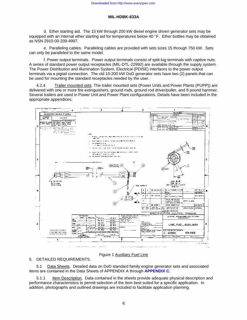
c. Auxiliary Fuel Line. A 25 foot auxiliary fuel line is furnished with the 5 kW through 200 kW diesel engine driven generator sets. Fuel lines for the other sets may be ordered or fabricated on site in accordance with drawing 69-668, titled, Auxiliary Fuel Line, see Figure 1.
Downloaded from http://www.everyspec.com
MIL-HDBK-633A
6
d. Ether starting aid. The 15 kW through 200 kW diesel engine driven generator sets may be equipped with an internal ether starting aid for temperatures below 40 °F. Ether bottles may be obtained as NSN 2910-00-209-4997.
e. Paralleling cables. Paralleling cables are provided with sets sizes 15 through 750 kW. Sets can only be paralleled to the same model.
f. Power output terminals. Power output terminals consist of split-lug terminals with captive nuts. A series of standard power output receptacles (MIL-DTL-22992) are available through the supply system. The Power Distribution and Illumination System, Electrical (PDISE) interfaces to the power output terminals via a pigtail connection. The old 15-200 kW DoD generator sets have two (2) panels that can be used for mounting the standard receptacles needed by the user.
4.2.4 Trailer mounted sets. The trailer mounted sets (Power Units and Power Plants (PUPP)) are delivered with one or more fire extinguishers, ground rods, ground rod driver/puller, and 8 pound hammer. Several trailers are used in Power Unit and Power Plant configurations. Details have been included in the appropriate appendices.
Figure 1 Auxiliary Fuel Line 5. DETAILED REQUIREMENTS.
5.1 Data Sheets. Detailed data on DoD standard family engine generator sets and associated items are contained in the Data Sheets of APPENDIX A through APPENDIX C.
5.1.1 Item Description. Data contained in the sheets provide adequate physical description and performance characteristics to permit selection of the item best suited for a specific application. In addition, photographs and outlined drawings are included to facilitate application planning.
Downloaded from http://www.everyspec.com

MIL-HDBK-633A
7
5.1.2 Parametric Values. The p arametric values cited within these data sheets are the maximum allowable limits over the specified environmental range. Specified parametric values were determined using the test procedures delineated in MIL-STD-705, Generator Sets, Engine-Driven, Methods of Tests and Instructions. For a more complete description, see applicable specifications, drawings, and referenced documents.
6. ITEMS OF NOTE
6.1 Purpose. This military handbook is a catalog of PM-MEP products. This document is not to be used for procurement purposes.
6.2 Supersession Data: MIL-HDBK-633A supersedes MIL-HDBK-633.
6.3 National Stock Numbers (NSN). National Stock Numbers for mobile electric power generator sets and associated equipment are provided in Tables: I, II, A-I, B-I and C-I, and in the individual data sheets.
6.4 MEPGS Program Status. Current information on the DoD MEPGS program is available on the PM-MEP website: http://www.pm-mep.army.mil. To determine the availability of desired generator sets or associated equipment and to assure proper and timely acquisition of MEPGS, users of this handbook are advised to contact PM-MEP at:
Project Manager - Mobile Electric Power 5850 Delafield Road, Bldg 324 Fort Belvoir, Virginia 22060-5809 Phone: (703)704-3162, DSN: 654-3162 Fax:(703)704-3257, DSN: 654-3257 Website: http://www.pm-mep.army.mil Email: See website
6.5 Mobile Electric Power Generating Source Development Program. A Mobile Electric Power Generating Source (MEPGS) development program is managed by the DoD Project Manager - Mobile Electric Power. The Advanced Medium Mobile Power Sources (AMMPS) program, which covers power sources in the 5 to 60 kW range, is presently in development. This program, which utilizes emerging and innovating technology, is expected to produce quieter, more efficient and lighter weight generator set in the FY 2011-2013 timeframe. If users of this handbook cannot find a suitable generator set within the DoD Mobile Electric Power Engine-Driven Generator Standard Family as presented in this Handbook , they are advised to contact the PM-MEP (see Para 6.4). The PM-MEP office can obtain status of any development program(s) and determine if a suitable power source will be available when needed.
6.6 Items not Army Type-Classified. Army Type-Classification (see 3.30) is a procedure described by AR 70-1 to designate Army materiel acquisition status. Some mobile electric power generating sources included in this document have not been Type-Classified for Army use and are identified by "Not Type-Classified for Army Use.” These items have been approved for use by another service. Other items, such as the Auxiliary Power Units (APUs), have been Army type-classified as part of a larger system and are not separately fielded. These items are identified by "Not Separately Type-Classified.”
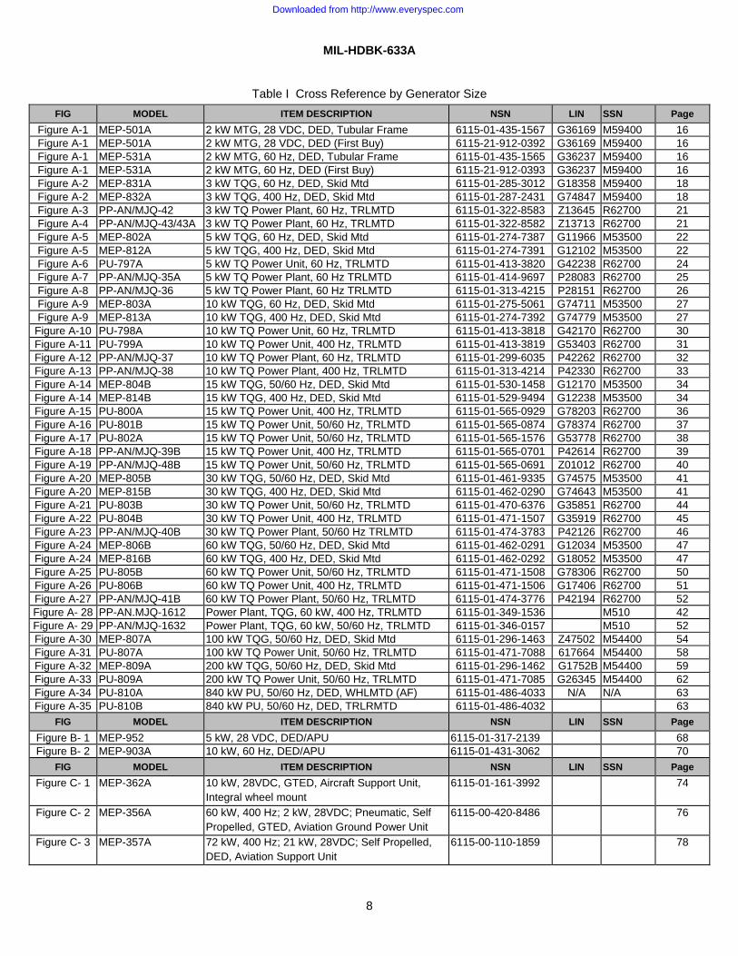
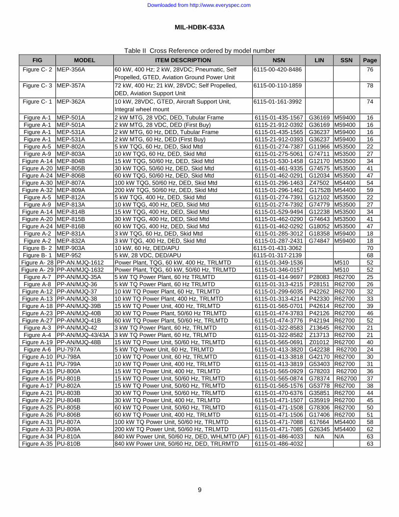
6.7 Cross reference. Table I provides a cross reference of the figure numbers to the model number, item descriptions, NSN, LIN, SSN, and page number. Table I is listed by generator size within the three appendices. Table II provides this information ordered by model number.
6.8 Subject term (key word) listing.
Auxiliary Power Generator Generator set Power Plant Power Unit Power Distribution
Downloaded from http://www.everyspec.com
MIL-HDBK-633A
8
Table I Cross Reference by Generator Size FIG MODEL ITEM DESCRIPTION NSN LIN SSN Page
Figure A-1 MEP-501A 2 kW MTG, 28 VDC, DED, Tubular Frame 6115-01-435-1567 G36169 M59400 16 Figure A-1 MEP-501A 2 kW MTG, 28 VDC, DED (First Buy) 6115-21-912-0392 G36169 M59400 16 Figure A-1 MEP-531A 2 kW MTG, 60 Hz, DED, Tubular Frame 6115-01-435-1565 G36237 M59400 16 Figure A-1 MEP-531A 2 kW MTG, 60 Hz, DED (First Buy) 6115-21-912-0393 G36237 M59400 16 Figure A-2 MEP-831A 3 kW TQG, 60 Hz, DED, Skid Mtd 6115-01-285-3012 G18358 M59400 18 Figure A-2 MEP-832A 3 kW TQG, 400 Hz, DED, Skid Mtd 6115-01-287-2431 G74847 M59400 18 Figure A-3 PP-AN/MJQ-42 3 kW TQ Power Plant, 60 Hz, TRLMTD 6115-01-322-8583 Z13645 R62700 21 Figure A-4 PP-AN/MJQ-43/43A 3 kW TQ Power Plant, 60 Hz, TRLMTD 6115-01-322-8582 Z13713 R62700 21 Figure A-5 MEP-802A 5 kW TQG, 60 Hz, DED, Skid Mtd 6115-01-274-7387 G11966 M53500 22 Figure A-5 MEP-812A 5 kW TQG, 400 Hz, DED, Skid Mtd 6115-01-274-7391 G12102 M53500 22 Figure A-6 PU-797A 5 kW TQ Power Unit, 60 Hz, TRLMTD 6115-01-413-3820 G42238 R62700 24 Figure A-7 PP-AN/MJQ-35A 5 kW TQ Power Plant, 60 Hz TRLMTD 6115-01-414-9697 P28083 R62700 25 Figure A-8 PP-AN/MJQ-36 5 kW TQ Power Plant, 60 Hz TRLMTD 6115-01-313-4215 P28151 R62700 26 Figure A-9 MEP-803A 10 kW TQG, 60 Hz, DED, Skid Mtd 6115-01-275-5061 G74711 M53500 27 Figure A-9 MEP-813A 10 kW TQG, 400 Hz, DED, Skid Mtd 6115-01-274-7392 G74779 M53500 27
Figure A-10 PU-798A 10 kW TQ Power Unit, 60 Hz, TRLMTD 6115-01-413-3818 G42170 R62700 30 Figure A-11 PU-799A 10 kW TQ Power Unit, 400 Hz, TRLMTD 6115-01-413-3819 G53403 R62700 31 Figure A-12 PP-AN/MJQ-37 10 kW TQ Power Plant, 60 Hz, TRLMTD 6115-01-299-6035 P42262 R62700 32 Figure A-13 PP-AN/MJQ-38 10 kW TQ Power Plant, 400 Hz, TRLMTD 6115-01-313-4214 P42330 R62700 33 Figure A-14 MEP-804B 15 kW TQG, 50/60 Hz, DED, Skid Mtd 6115-01-530-1458 G12170 M53500 34 Figure A-14 MEP-814B 15 kW TQG, 400 Hz, DED, Skid Mtd 6115-01-529-9494 G12238 M53500 34 Figure A-15 PU-800A 15 kW TQ Power Unit, 400 Hz, TRLMTD 6115-01-565-0929 G78203 R62700 36 Figure A-16 PU-801B 15 kW TQ Power Unit, 50/60 Hz, TRLMTD 6115-01-565-0874 G78374 R62700 37 Figure A-17 PU-802A 15 kW TQ Power Unit, 50/60 Hz, TRLMTD 6115-01-565-1576 G53778 R62700 38 Figure A-18 PP-AN/MJQ-39B 15 kW TQ Power Unit, 400 Hz, TRLMTD 6115-01-565-0701 P42614 R62700 39 Figure A-19 PP-AN/MJQ-48B 15 kW TQ Power Unit, 50/60 Hz, TRLMTD 6115-01-565-0691 Z01012 R62700 40 Figure A-20 MEP-805B 30 kW TQG, 50/60 Hz, DED, Skid Mtd 6115-01-461-9335 G74575 M53500 41 Figure A-20 MEP-815B 30 kW TQG, 400 Hz, DED, Skid Mtd 6115-01-462-0290 G74643 M53500 41 Figure A-21 PU-803B 30 kW TQ Power Unit, 50/60 Hz, TRLMTD 6115-01-470-6376 G35851 R62700 44 Figure A-22 PU-804B 30 kW TQ Power Unit, 400 Hz, TRLMTD 6115-01-471-1507 G35919 R62700 45 Figure A-23 PP-AN/MJQ-40B 30 kW TQ Power Plant, 50/60 Hz TRLMTD 6115-01-474-3783 P42126 R62700 46 Figure A-24 MEP-806B 60 kW TQG, 50/60 Hz, DED, Skid Mtd 6115-01-462-0291 G12034 M53500 47 Figure A-24 MEP-816B 60 kW TQG, 400 Hz, DED, Skid Mtd 6115-01-462-0292 G18052 M53500 47 Figure A-25 PU-805B 60 kW TQ Power Unit, 50/60 Hz, TRLMTD 6115-01-471-1508 G78306 R62700 50 Figure A-26 PU-806B 60 kW TQ Power Unit, 400 Hz, TRLMTD 6115-01-471-1506 G17406 R62700 51 Figure A-27 PP-AN/MJQ-41B 60 kW TQ Power Plant, 50/60 Hz, TRLMTD 6115-01-474-3776 P42194 R62700 52 Figure A- 28 PP-AN.MJQ-1612 Power Plant, TQG, 60 kW, 400 Hz, TRLMTD 6115-01-349-1536 M510 42 Figure A- 29 PP-AN/MJQ-1632 Power Plant, TQG, 60 kW, 50/60 Hz, TRLMTD 6115-01-346-0157 M510 52 Figure A-30 MEP-807A 100 kW TQG, 50/60 Hz, DED, Skid Mtd 6115-01-296-1463 Z47502 M54400 54 Figure A-31 PU-807A 100 kW TQ Power Unit, 50/60 Hz, TRLMTD 6115-01-471-7088 617664 M54400 58 Figure A-32 MEP-809A 200 kW TQG, 50/60 Hz, DED, Skid Mtd 6115-01-296-1462 G1752B M54400 59 Figure A-33 PU-809A 200 kW TQ Power Unit, 50/60 Hz, TRLMTD 6115-01-471-7085 G26345 M54400 62 Figure A-34 PU-810A 840 kW PU, 50/60 Hz, DED, WHLMTD (AF) 6115-01-486-4033 N/A N/A 63 Figure A-35 PU-810B 840 kW PU, 50/60 Hz, DED, TRLRMTD 6115-01-486-4032 63
FIG MODEL ITEM DESCRIPTION NSN LIN SSN Page Figure B- 1 MEP-952 5 kW, 28 VDC, DED/APU 6115-01-317-2139 68 Figure B- 2 MEP-903A 10 kW, 60 Hz, DED/APU 6115-01-431-3062 70
FIG MODEL ITEM DESCRIPTION NSN LIN SSN Page Figure C- 1 MEP-362A 10 kW, 28VDC, GTED, Aircraft Support Unit,
Integral wheel mount 6115-01-161-3992 74
Figure C- 2 MEP-356A 60 kW, 400 Hz; 2 kW, 28VDC; Pneumatic, Self Propelled, GTED, Aviation Ground Power Unit
6115-00-420-8486 76
Figure C- 3 MEP-357A 72 kW, 400 Hz; 21 kW, 28VDC; Self Propelled, DED, Aviation Support Unit
6115-00-110-1859 78
Downloaded from http://www.everyspec.com
MIL-HDBK-633A
9
Table II Cross Reference ordered by model number FIG MODEL ITEM DESCRIPTION NSN LIN SSN Page
Figure C- 2 MEP-356A 60 kW, 400 Hz; 2 kW, 28VDC; Pneumatic, Self Propelled, GTED, Aviation Ground Power Unit
6115-00-420-8486 76
Figure C- 3 MEP-357A 72 kW, 400 Hz; 21 kW, 28VDC; Self Propelled, DED, Aviation Support Unit
6115-00-110-1859 78
Figure C- 1 MEP-362A 10 kW, 28VDC, GTED, Aircraft Support Unit, Integral wheel mount
6115-01-161-3992 74
Figure A-1 MEP-501A 2 kW MTG, 28 VDC, DED, Tubular Frame 6115-01-435-1567 G36169 M59400 16 Figure A-1 MEP-501A 2 kW MTG, 28 VDC, DED (First Buy) 6115-21-912-0392 G36169 M59400 16 Figure A-1 MEP-531A 2 kW MTG, 60 Hz, DED, Tubular Frame 6115-01-435-1565 G36237 M59400 16 Figure A-1 MEP-531A 2 kW MTG, 60 Hz, DED (First Buy) 6115-21-912-0393 G36237 M59400 16 Figure A-5 MEP-802A 5 kW TQG, 60 Hz, DED, Skid Mtd 6115-01-274-7387 G11966 M53500 22 Figure A-9 MEP-803A 10 kW TQG, 60 Hz, DED, Skid Mtd 6115-01-275-5061 G74711 M53500 27
Figure A-14 MEP-804B 15 kW TQG, 50/60 Hz, DED, Skid Mtd 6115-01-530-1458 G12170 M53500 34 Figure A-20 MEP-805B 30 kW TQG, 50/60 Hz, DED, Skid Mtd 6115-01-461-9335 G74575 M53500 41 Figure A-24 MEP-806B 60 kW TQG, 50/60 Hz, DED, Skid Mtd 6115-01-462-0291 G12034 M53500 47 Figure A-30 MEP-807A 100 kW TQG, 50/60 Hz, DED, Skid Mtd 6115-01-296-1463 Z47502 M54400 54 Figure A-32 MEP-809A 200 kW TQG, 50/60 Hz, DED, Skid Mtd 6115-01-296-1462 G1752B M54400 59 Figure A-5 MEP-812A 5 kW TQG, 400 Hz, DED, Skid Mtd 6115-01-274-7391 G12102 M53500 22 Figure A-9 MEP-813A 10 kW TQG, 400 Hz, DED, Skid Mtd 6115-01-274-7392 G74779 M53500 27
Figure A-14 MEP-814B 15 kW TQG, 400 Hz, DED, Skid Mtd 6115-01-529-9494 G12238 M53500 34 Figure A-20 MEP-815B 30 kW TQG, 400 Hz, DED, Skid Mtd 6115-01-462-0290 G74643 M53500 41 Figure A-24 MEP-816B 60 kW TQG, 400 Hz, DED, Skid Mtd 6115-01-462-0292 G18052 M53500 47 Figure A-2 MEP-831A 3 kW TQG, 60 Hz, DED, Skid Mtd 6115-01-285-3012 G18358 M59400 18 Figure A-2 MEP-832A 3 kW TQG, 400 Hz, DED, Skid Mtd 6115-01-287-2431 G74847 M59400 18 Figure B- 2 MEP-903A 10 kW, 60 Hz, DED/APU 6115-01-431-3062 70 Figure B- 1 MEP-952 5 kW, 28 VDC, DED/APU 6115-01-317-2139 68
Figure A- 28 PP-AN.MJQ-1612 Power Plant, TQG, 60 kW, 400 Hz, TRLMTD 6115-01-349-1536 M510 52 Figure A- 29 PP-AN/MJQ-1632 Power Plant, TQG, 60 kW, 50/60 Hz, TRLMTD 6115-01-346-0157 M510 52 Figure A-7 PP-AN/MJQ-35A 5 kW TQ Power Plant, 60 Hz TRLMTD 6115-01-414-9697 P28083 R62700 25 Figure A-8 PP-AN/MJQ-36 5 kW TQ Power Plant, 60 Hz TRLMTD 6115-01-313-4215 P28151 R62700 26
Figure A-12 PP-AN/MJQ-37 10 kW TQ Power Plant, 60 Hz, TRLMTD 6115-01-299-6035 P42262 R62700 32 Figure A-13 PP-AN/MJQ-38 10 kW TQ Power Plant, 400 Hz, TRLMTD 6115-01-313-4214 P42330 R62700 33 Figure A-18 PP-AN/MJQ-39B 15 kW TQ Power Unit, 400 Hz, TRLMTD 6115-01-565-0701 P42614 R62700 39 Figure A-23 PP-AN/MJQ-40B 30 kW TQ Power Plant, 50/60 Hz TRLMTD 6115-01-474-3783 P42126 R62700 46 Figure A-27 PP-AN/MJQ-41B 60 kW TQ Power Plant, 50/60 Hz, TRLMTD 6115-01-474-3776 P42194 R62700 52 Figure A-3 PP-AN/MJQ-42 3 kW TQ Power Plant, 60 Hz, TRLMTD 6115-01-322-8583 Z13645 R62700 21 Figure A-4 PP-AN/MJQ-43/43A 3 kW TQ Power Plant, 60 Hz, TRLMTD 6115-01-322-8582 Z13713 R62700 21
Figure A-19 PP-AN/MJQ-48B 15 kW TQ Power Unit, 50/60 Hz, TRLMTD 6115-01-565-0691 Z01012 R62700 40 Figure A-6 PU-797A 5 kW TQ Power Unit, 60 Hz, TRLMTD 6115-01-413-3820 G42238 R62700 24
Figure A-10 PU-798A 10 kW TQ Power Unit, 60 Hz, TRLMTD 6115-01-413-3818 G42170 R62700 30 Figure A-11 PU-799A 10 kW TQ Power Unit, 400 Hz, TRLMTD 6115-01-413-3819 G53403 R62700 31 Figure A-15 PU-800A 15 kW TQ Power Unit, 400 Hz, TRLMTD 6115-01-565-0929 G78203 R62700 36 Figure A-16 PU-801B 15 kW TQ Power Unit, 50/60 Hz, TRLMTD 6115-01-565-0874 G78374 R62700 37 Figure A-17 PU-802A 15 kW TQ Power Unit, 50/60 Hz, TRLMTD 6115-01-565-1576 G53778 R62700 38 Figure A-21 PU-803B 30 kW TQ Power Unit, 50/60 Hz, TRLMTD 6115-01-470-6376 G35851 R62700 44 Figure A-22 PU-804B 30 kW TQ Power Unit, 400 Hz, TRLMTD 6115-01-471-1507 G35919 R62700 45 Figure A-25 PU-805B 60 kW TQ Power Unit, 50/60 Hz, TRLMTD 6115-01-471-1508 G78306 R62700 50 Figure A-26 PU-806B 60 kW TQ Power Unit, 400 Hz, TRLMTD 6115-01-471-1506 G17406 R62700 51 Figure A-31 PU-807A 100 kW TQ Power Unit, 50/60 Hz, TRLMTD 6115-01-471-7088 617664 M54400 58 Figure A-33 PU-809A 200 kW TQ Power Unit, 50/60 Hz, TRLMTD 6115-01-471-7085 G26345 M54400 62 Figure A-34 PU-810A 840 kW Power Unit, 50/60 Hz, DED, WHLMTD (AF) 6115-01-486-4033 N/A N/A 63 Figure A-35 PU-810B 840 kW Power Unit, 50/60 Hz, DED, TRLRMTD 6115-01-486-4032 63
Downloaded from http://www.everyspec.com

MIL-HDBK-633A
10
This Page Intentionally Left Blank
Downloaded from http://www.everyspec.com
MIL-HDBK-633A APPENDIX A
11
PRESENT STANDARD FAMILY OF MEPGS
A.1 SCOPE
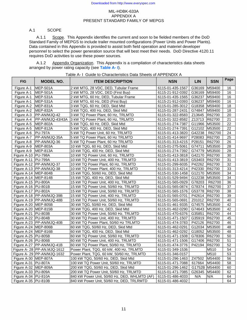
A.1.1 Scope. This Appendix identifies the current and soon to be fielded members of the DoD Standard Family of MEPGS to include trailer mounted configurations (Power Units and Power Plants). Data contained in this Appendix is provided to assist both field operation and materiel developer personnel to select the power generation source that will best meet their needs. DoD Directive 4120.11 requires DoD activities to use these power sources.
A.1.2 Appendix Organization. This Appendix is a compilation of characteristics data sheets arranged by power rating capacity (see Table A- I).
Table A- I Guide to Characteristics Data Sheets of APPENDIX A FIG MODEL NO. ITEM DESCRIPTION NSN LIN SSN Page
Figure A-1 MEP-501A 2 kW MTG, 28 VDC, DED, Tubular Frame 6115-01-435-1567 G36169 M59400 16 Figure A-1 MEP-501A 2 kW MTG, 28 VDC, DED (First Buy) 6115-21-912-0392 G36169 M59400 16 Figure A-1 MEP-531A 2 kW MTG, 60 Hz, DED, Tubular Frame 6115-01-435-1565 G36237 M59400 16 Figure A-1 MEP-531A 2 kW MTG, 60 Hz, DED (First Buy) 6115-21-912-0393 G36237 M59400 16 Figure A-2 MEP-831A 3 kW TQG, 60 Hz, DED, Skid Mtd 6115-01-285-3012 G18358 M59400 18 Figure A-2 MEP-832A 3 kW TQG, 400 Hz, DED, Skid Mtd 6115-01-287-2431 G74847 M59400 18 Figure A-3 PP-AN/MJQ-42 3 kW TQ Power Plant, 60 Hz, TRLMTD 6115-01-322-8583 Z13645 R62700 20 Figure A-4 PP-AN/MJQ-43/43A 3 kW TQ Power Plant, 60 Hz, TRLMTD 6115-01-322-8582 Z13713 R62700 21 Figure A-5 MEP-802A 5 kW TQG, 60 Hz, DED, Skid Mtd 6115-01-274-7387 G11966 M53500 22 Figure A-5 MEP-812A 5 kW TQG, 400 Hz, DED, Skid Mtd 6115-01-274-7391 G12102 M53500 22 Figure A-6 PU-797A 5 kW TQ Power Unit, 60 Hz, TRLMTD 6115-01-413-3820 G42238 R62700 24 Figure A-7 PP-AN/MJQ-35A 5 kW TQ Power Plant, 60 Hz TRLMTD 6115-01-414-9697 P28083 R62700 25 Figure A-8 PP-AN/MJQ-36 5 kW TQ Power Plant, 60 Hz TRLMTD 6115-01-313-4215 P28151 R62700 26 Figure A-9 MEP-803A 10 kW TQG, 60 Hz, DED, Skid Mtd 6115-01-275-5061 G74711 M53500 28 Figure A-9 MEP-813A 10 kW TQG, 400 Hz, DED, Skid Mtd 6115-01-274-7392 G74779 M53500 28
Figure A-10 PU-798A 10 kW TQ Power Unit, 60 Hz, TRLMTD 6115-01-413-3818 G42170 R62700 30 Figure A-11 PU-799A 10 kW TQ Power Unit, 400 Hz, TRLMTD 6115-01-413-3819 G53403 R62700 31 Figure A-12 PP-AN/MJQ-37 10 kW TQ Power Plant, 60 Hz, TRLMTD 6115-01-299-6035 P42262 R62700 32 Figure A-13 PP-AN/MJQ-38 10 kW TQ Power Plant, 400 Hz, TRLMTD 6115-01-313-4214 P42330 R62700 33 Figure A-14 MEP-804B 15 kW TQG, 50/60 Hz, DED, Skid Mtd 6115-01-530-1458 G12170 M53500 34 Figure A-14 MEP-814B 15 kW TQG, 400 Hz, DED, Skid Mtd 6115-01-529-9494 G12238 M53500 34 Figure A-15 PU-800A 15 kW TQ Power Unit, 400 Hz, TRLMTD 6115-01-565-0929 G78203 R62700 36 Figure A-16 PU-801B 15 kW TQ Power Unit, 50/60 Hz, TRLMTD 6115-01-565-0874 G78374 R62700 37 Figure A-17 PU-802A 15 kW TQ Power Unit, 50/60 Hz, TRLMTD 6115-01-565-1576 G53778 R62700 38 Figure A-18 PP-AN/MJQ-39B 15 kW TQ Power Unit, 400 Hz, TRLMTD 6115-01-565-0701 P42614 R62700 39 Figure A-19 PP-AN/MJQ-48B 15 kW TQ Power Unit, 50/60 Hz, TRLMTD 6115-01-565-0691 Z01012 R62700 40 Figure A-20 MEP-805B 30 kW TQG, 50/60 Hz, DED, Skid Mtd 6115-01-461-9335 G74575 M53500 42 Figure A-20 MEP-815B 30 kW TQG, 400 Hz, DED, Skid Mtd 6115-01-462-0290 G74643 M53500 42 Figure A-21 PU-803B 30 kW TQ Power Unit, 50/60 Hz, TRLMTD 6115-01-470-6376 G35851 R62700 44 Figure A-22 PU-804B 30 kW TQ Power Unit, 400 Hz, TRLMTD 6115-01-471-1507 G35919 R62700 45 Figure A-23 PP-AN/MJQ-40B 30 kW TQ Power Plant, 50/60 Hz TRLMTD 6115-01-474-3783 P42126 R62700 46 Figure A-24 MEP-806B 60 kW TQG, 50/60 Hz, DED, Skid Mtd 6115-01-462-0291 G12034 M53500 48 Figure A-24 MEP-816B 60 kW TQG, 400 Hz, DED, Skid Mtd 6115-01-462-0292 G18052 M53500 48 Figure A-25 PU-805B 60 kW TQ Power Unit, 50/60 Hz, TRLMTD 6115-01-471-1508 G78306 R62700 50 Figure A-26 PU-806B 60 kW TQ Power Unit, 400 Hz, TRLMTD 6115-01-471-1506 G17406 R62700 51 Figure A-27 PP-AN/MJQ-41B 60 kW TQ Power Plant, 50/60 Hz, TRLMTD 6115-01-474-3776 P42194 R62700 52 Figure A- 28 PP-AN.MJQ-1612 Power Plant, TQG, 60 kW, 400 Hz, TRLMTD 6115-01-349-1536 M510 54 Figure A- 29 PP-AN/MJQ-1632 Power Plant, TQG, 60 kW, 50/60 Hz, TRLMTD 6115-01-346-0157 M510 53 Figure A-30 MEP-807A 100 kW TQG, 50/60 Hz, DED, Skid Mtd 6115-01-296-1463 Z47502 M54400 56 Figure A-31 PU-807A 100 kW TQ Power Unit, 50/60 Hz, TRLMTD 6115-01-471-7088 617664 M54400 58 Figure A-32 MEP-809A 200 kW TQG, 50/60 Hz, DED, Skid Mtd 6115-01-296-1462 G1752B M54400 60 Figure A-33 PU-809A 200 kW TQ Power Unit, 50/60 Hz, TRLMTD 6115-01-471-7085 G26345 M54400 62 Figure A-34 PU-810A 840 kW Power Unit, 50/60 Hz, DED, WHLMTD (AF) 6115-01-486-4033 N/A N/A 64 Figure A-35 PU-810B 840 kW Power Unit, 50/60 Hz, DED, TRLRMTD 6115-01-486-4032 64
Downloaded from http://www.everyspec.com
MIL-HDBK-633A APPENDIX A
12
A.2 APPLICABLE DOCUMENTS
A.2.1 This section is not applicable to this appendix.
A.3 DEFINITIONS
A.3.1 Use definitions of basic document.
A.4 GENERAL DESCRIPTIONS
A.4.1 Item Descriptions.
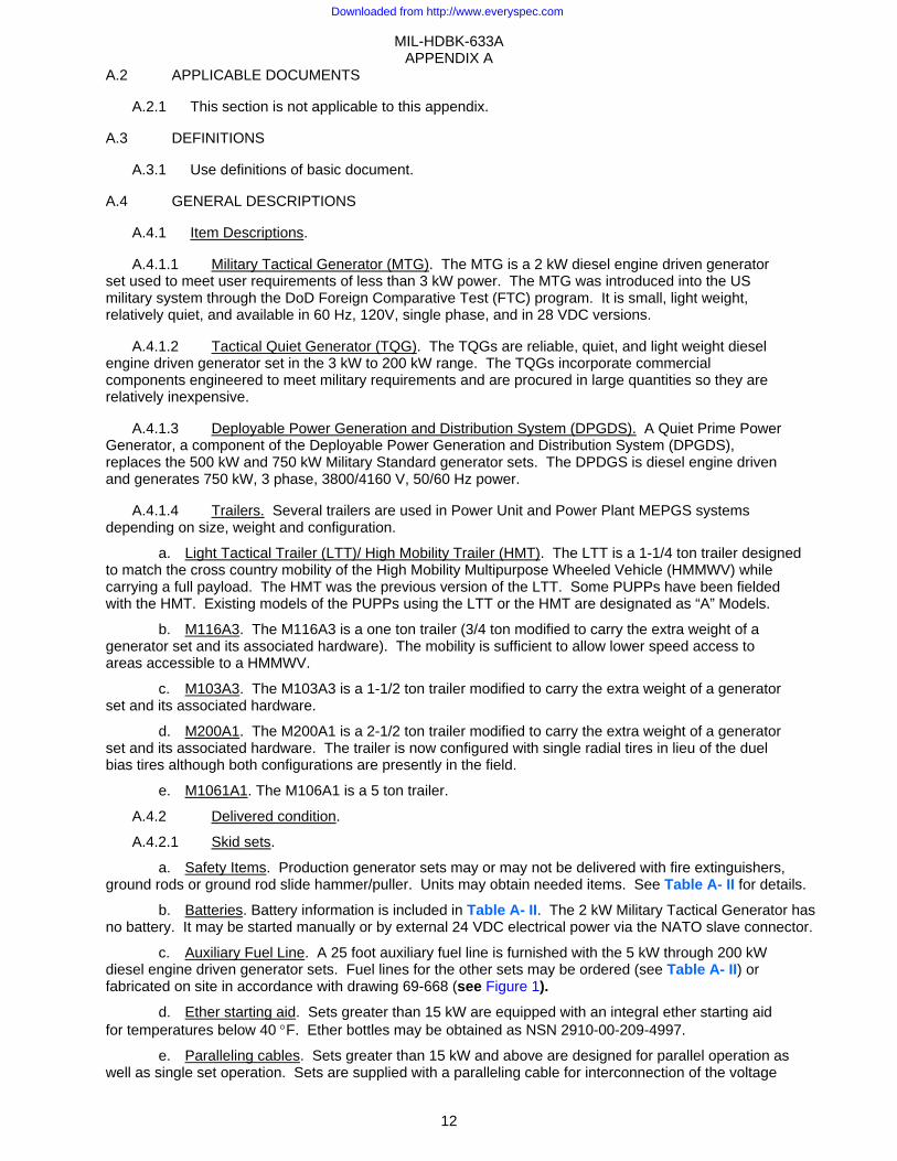
A.4.1.1 Military Tactical Generator (MTG). The MTG is a 2 kW diesel engine driven generator set used to meet user requirements of less than 3 kW power. The MTG was introduced into the US military system through the DoD Foreign Comparative Test (FTC) program. It is small, light weight, relatively quiet, and available in 60 Hz, 120V, single phase, and in 28 VDC versions.
A.4.1.2 Tactical Quiet Generator (TQG). The TQGs are reliable, quiet, and light weight diesel engine driven generator set in the 3 kW to 200 kW range. The TQGs incorporate commercial components engineered to meet military requirements and are procured in large quantities so they are relatively inexpensive.
A.4.1.3 Deployable Power Generation and Distribution System (DPGDS). A Quiet Prime Power Generator, a component of the Deployable Power Generation and Distribution System (DPGDS), replaces the 500 kW and 750 kW Military Standard generator sets. The DPDGS is diesel engine driven and generates 750 kW, 3 phase, 3800/4160 V, 50/60 Hz power.
A.4.1.4 Trailers. Several trailers are used in Power Unit and Power Plant MEPGS systems depending on size, weight and configuration.
a. Light Tactical Trailer (LTT)/ High Mobility Trailer (HMT). The LTT is a 1-1/4 ton trailer designed to match the cross country mobility of the High Mobility Multipurpose Wheeled Vehicle (HMMWV) while carrying a full payload. The HMT was the previous version of the LTT. Some PUPPs have been fielded with the HMT. Existing models of the PUPPs using the LTT or the HMT are designated as “A” Models.
b. M116A3. The M116A3 is a one ton trailer (3/4 ton modified to carry the extra weight of a generator set and its associated hardware). The mobility is sufficient to allow lower speed access to areas accessible to a HMMWV.
c. M103A3. The M103A3 is a 1-1/2 ton trailer modified to carry the extra weight of a generator set and its associated hardware.
d. M200A1. The M200A1 is a 2-1/2 ton trailer modified to carry the extra weight of a generator set and its associated hardware. The trailer is now configured with single radial tires in lieu of the duel bias tires although both configurations are presently in the field.
e. M1061A1. The M106A1 is a 5 ton trailer.
A.4.2 Delivered condition.
A.4.2.1 Skid sets.
a. Safety Items. Production generator sets may or may not be delivered with fire extinguishers, ground rods or ground rod slide hammer/puller. Units may obtain needed items. See Table A- II for details.
b. Batteries. Battery information is included in Table A- II. The 2 kW Military Tactical Generator has no battery. It may be started manually or by external 24 VDC electrical power via the NATO slave connector.
c. Auxiliary Fuel Line. A 25 foot auxiliary fuel line is furnished with the 5 kW through 200 kW diesel engine driven generator sets. Fuel lines for the other sets may be ordered (see Table A- II) or fabricated on site in accordance with drawing 69-668 (see Figure 1).
d. Ether starting aid. Sets greater than 15 kW are equipped with an integral ether starting aid for temperatures below 40 °F. Ether bottles may be obtained as NSN 2910-00-209-4997.
e. Paralleling cables. Sets greater than 15 kW and above are designed for parallel operation as well as single set operation. Sets are supplied with a paralleling cable for interconnection of the voltage
Downloaded from http://www.everyspec.com

MIL-HDBK-633A APPENDIX A
13
regulators and governor systems of the sets to be paralleled. Additional details on parallel operation are contained in the generator set manuals and FM 5-424, Electrical Power Generation in the Field.
f. Power output terminals. Power output terminals consist of split-lug terminals with captive nuts. The Power Distribution and Illumination System, Electrical (PDISE) interfaces to the power output terminals via a pigtail connection. In addition, a series of standard power output receptacles (MIL-DTL-22992) are available through the supply system and the US Army Missile Command (MICOM) has a series of missile system receptacles for the 15 kW through 60 kW DoD generator sets.
g. NATO slave receptacle. A NATO slave receptacle is provided with all generator sets listed in this Appendix. The slave receptacle can be used to start the generator set from an external 24 VDC power source.
h. Convenience receptacle. A convenience receptacle is provided on all 60 Hz generator sets in this Appendix.
A.4.2.2 Trailer mounted sets. The trailer mounted sets (Power Units and Power Plants) are normally delivered with ground kit (ground rods, connectors, ground terminal), ground rod driver/puller, 8 pound hammer, and a fire extinguisher per trailer. See Table A- II for details.
A.4.3 Winterization Kit. A fuel burning winterization kit can be installed inside the TQG sets to extend the starting and operation temperature down to –50 °F. The kit NSNs and application can be found in Table A- II that follows and in the Characteristics Data Sheets.
Table A- II Batteries and Auxiliary Equipment Batteries
Model Description Nsn ApplicationConcord Starved-Electrolyte – 24 Volt 6140-01-374-8502 3 kW TQG 2HN Lead-Acid – 12 Volt 6140-00-057-2553 5 kW TQG 6TL Lead-Acid – 12 Volt 6140-01-210-1964 15 kw - 60 kW TQG Optima d51r Starved Electrolyte – 12 Volt 6140-01-529-7226 5 kW TQG Optima 800s Starved-Electrolyte – 12 Volt 6140-01-374-2243 10 kW TQG Optima 800s Starved-Electrolyte – 12 Volt 6140-01-378-8232 15, 30,60 kW TQG Optima 8050-160 Starved-Electrolyte – 12 Volt 100 and 200 kW TQG Adapter For Optima 6160-01-453-0858
Grounding items Model Description Nsn Application
Ground Rod Kit (Includes Rod, Connectors, Terminal)
5975-00-828-3791 TQG, PU, PP
Ground Rod (3 Ft Sec) 5975-00-249-6798 TQG, PU, PP Driver/Puller (Slide Hammer) 5120-01-013-1676 PU, PP Hammer, 8 Pound 5120-00-251-4489 PU, PP
Fuel handling items Model Description Nsn Application
Auxiliary Fuel Line 4720-00-021-3320 TQG, PU, PP Fuel Container/Drum Adapter 2910-00-066-1235 PU, PP 5 Gal Fuel Can 7240-00-222-3088 PU, PP Spout 7240-00-177-6154 PU, PP
Fire extinguisher Model Description Nsn Application A-A-1106 5 lb CO2 Fire Extinguisher 4210-00-270-4512 All
Optional equipment Model Description Nsn Application Winterization Kit 6115-01-476-8973 5kW TQGs Winterization Kit 6115-01-477-0564 10kW TQGs Winterization Kit 6115-01-477-0566 15kW TQGs Winterization Kit 6115-01-474-8354 30kW TQGs Winterization Kit 6115-01-474-8244 60kW TQGs
Downloaded from http://www.everyspec.com
MIL-HDBK-633A APPENDIX A
14
A.5 DETAILED DESCRIPTIONS
A.5.1 Detailed Descriptions. Details of skid and trailer-mounted sets are contained in Figure A-1 through Figure A-35 CHARACTERISTICS DATA SHEETS. See Table A- I Guide to Characteristics Data Sheets of APPENDIX A
Downloaded from http://www.everyspec.com
MIL-HDBK-633A APPENDIX A
15
This Page Intentionally Left Blank
Downloaded from http://www.everyspec.com
MIL-HDBK-633A APPENDIX A
16
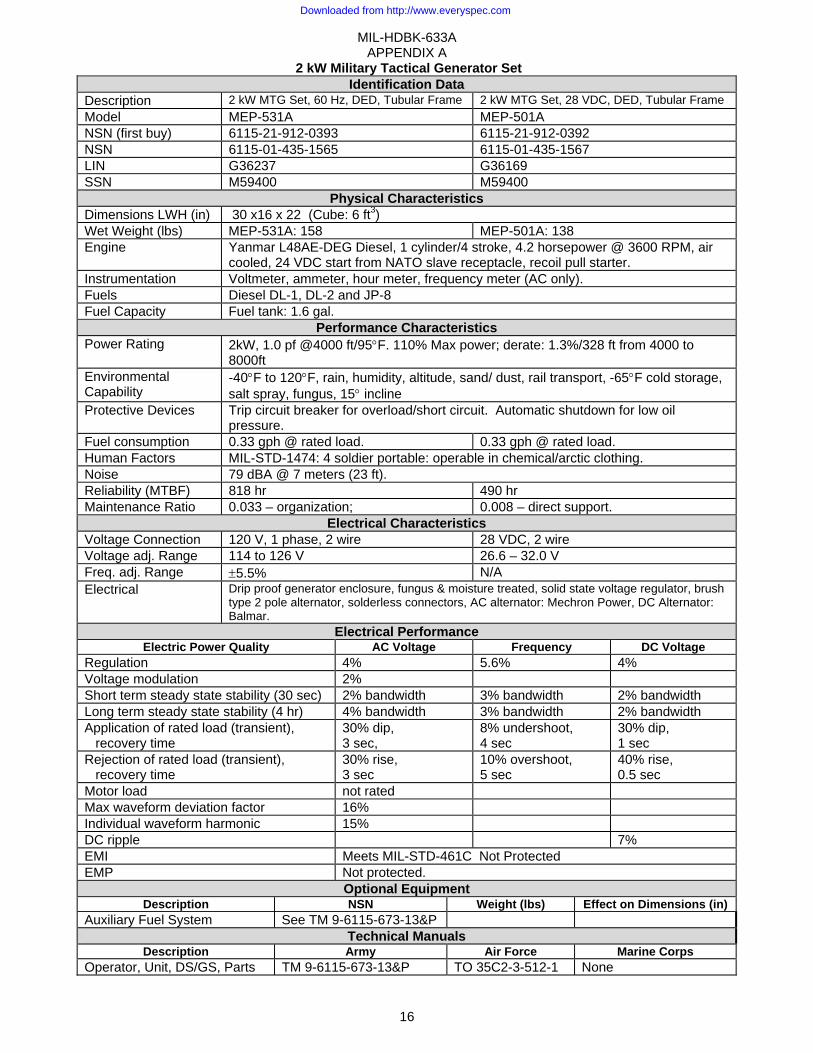
2 kW Military Tactical Generator Set Identification Data
Description 2 kW MTG Set, 60 Hz, DED, Tubular Frame 2 kW MTG Set, 28 VDC, DED, Tubular Frame Model MEP-531A MEP-501A NSN (first buy) 6115-21-912-0393 6115-21-912-0392 NSN 6115-01-435-1565 6115-01-435-1567 LIN G36237 G36169 SSN M59400 M59400
Physical Characteristics Dimensions LWH (in) 30 x16 x 22 (Cube: 6 ft3) Wet Weight (lbs) MEP-531A: 158 MEP-501A: 138 Engine Yanmar L48AE-DEG Diesel, 1 cylinder/4 stroke, 4.2 horsepower @ 3600 RPM, air
cooled, 24 VDC start from NATO slave receptacle, recoil pull starter. Instrumentation Voltmeter, ammeter, hour meter, frequency meter (AC only). Fuels Diesel DL-1, DL-2 and JP-8 Fuel Capacity Fuel tank: 1.6 gal.
Performance Characteristics Power Rating 2kW, 1.0 pf @4000 ft/95°F. 110% Max power; derate: 1.3%/328 ft from 4000 to
8000ft Environmental Capability
-40°F to 120°F, rain, humidity, altitude, sand/ dust, rail transport, -65°F cold storage, salt spray, fungus, 15° incline
Protective Devices Trip circuit breaker for overload/short circuit. Automatic shutdown for low oil pressure.
Fuel consumption 0.33 gph @ rated load. 0.33 gph @ rated load. Human Factors MIL-STD-1474: 4 soldier portable: operable in chemical/arctic clothing. Noise 79 dBA @ 7 meters (23 ft). Reliability (MTBF) 818 hr 490 hr Maintenance Ratio 0.033 – organization; 0.008 – direct support.
Electrical Characteristics Voltage Connection 120 V, 1 phase, 2 wire 28 VDC, 2 wire Voltage adj. Range 114 to 126 V 26.6 – 32.0 V Freq. adj. Range ±5.5% N/A Electrical Drip proof generator enclosure, fungus & moisture treated, solid state voltage regulator, brush
type 2 pole alternator, solderless connectors, AC alternator: Mechron Power, DC Alternator: Balmar.
Electrical Performance Electric Power Quality AC Voltage Frequency DC Voltage
Regulation 4% 5.6% 4% Voltage modulation 2% Short term steady state stability (30 sec) 2% bandwidth 3% bandwidth 2% bandwidth Long term steady state stability (4 hr) 4% bandwidth 3% bandwidth 2% bandwidth Application of rated load (transient), recovery time
30% dip, 3 sec,
8% undershoot, 4 sec
30% dip, 1 sec
Rejection of rated load (transient), recovery time
30% rise, 3 sec
10% overshoot, 5 sec
40% rise, 0.5 sec
Motor load not rated Max waveform deviation factor 16% Individual waveform harmonic 15% DC ripple 7% EMI Meets MIL-STD-461C Not Protected EMP Not protected.
Optional Equipment Description NSN Weight (lbs) Effect on Dimensions (in)
Auxiliary Fuel System See TM 9-6115-673-13&P Technical Manuals
Description Army Air Force Marine CorpsOperator, Unit, DS/GS, Parts TM 9-6115-673-13&P TO 35C2-3-512-1 None
Downloaded from http://www.everyspec.com

MIL-HDBK-633A APPENDIX A
17
MEP-501A, 28 VDC MEP-531A, 120 V, 60 Hz
has an additional meter (frequency) and a convenience receptacle
Figure A-1 2 kW Military Tactical Generator Set
Downloaded from http://www.everyspec.com
MIL-HDBK-633A APPENDIX A
18
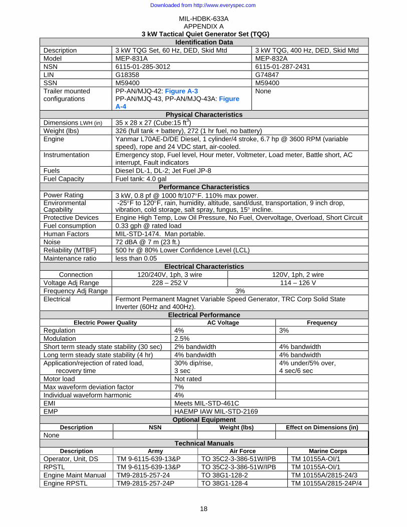
3 kW Tactical Quiet Generator Set (TQG) Identification Data
Description 3 kW TQG Set, 60 Hz, DED, Skid Mtd 3 kW TQG, 400 Hz, DED, Skid Mtd Model MEP-831A MEP-832A NSN 6115-01-285-3012 6115-01-287-2431 LIN G18358 G74847 SSN M59400 M59400 Trailer mounted configurations
PP-AN/MJQ-42: Figure A-3 PP-AN/MJQ-43, PP-AN/MJQ-43A: Figure A-4
None
Physical Characteristics Dimensions LWH (in) 35 x 28 x 27 (Cube:15 ft3) Weight (lbs) 326 (full tank + battery), 272 (1 hr fuel, no battery) Engine Yanmar L70AE-D/DE Diesel, 1 cylinder/4 stroke, 6.7 hp @ 3600 RPM (variable
speed), rope and 24 VDC start, air-cooled. Instrumentation Emergency stop, Fuel level, Hour meter, Voltmeter, Load meter, Battle short, AC
interrupt, Fault indicators Fuels Diesel DL-1, DL-2; Jet Fuel JP-8 Fuel Capacity Fuel tank: 4.0 gal
Performance Characteristics Power Rating 3 kW, 0.8 pf @ 1000 ft/107°F. 110% max power. Environmental Capability
-25°F to 120°F, rain, humidity, altitude, sand/dust, transportation, 9 inch drop, vibration, cold storage, salt spray, fungus, 15° incline.
Protective Devices Engine High Temp, Low Oil Pressure, No Fuel, Overvoltage, Overload, Short Circuit Fuel consumption 0.33 gph @ rated load Human Factors MIL-STD-1474. Man portable. Noise 72 dBA @ 7 m (23 ft.) Reliability (MTBF) 500 hr @ 80% Lower Confidence Level (LCL) Maintenance ratio less than 0.05
Electrical Characteristics Connection 120/240V, 1ph, 3 wire 120V, 1ph, 2 wire
Voltage Adj Range 228 – 252 V 114 – 126 V Frequency Adj Range 3% Electrical Fermont Permanent Magnet Variable Speed Generator, TRC Corp Solid State
Inverter (60Hz and 400Hz). Electrical Performance
Electric Power Quality AC Voltage FrequencyRegulation 4% 3% Modulation 2.5% Short term steady state stability (30 sec) 2% bandwidth 4% bandwidth Long term steady state stability (4 hr) 4% bandwidth 4% bandwidth Application/rejection of rated load,
recovery time 30% dip/rise, 3 sec
4% under/5% over, 4 sec/6 sec
Motor load Not rated Max waveform deviation factor 7% Individual waveform harmonic 4% EMI Meets MIL-STD-461C EMP HAEMP IAW MIL-STD-2169
Optional Equipment Description NSN Weight (lbs) Effect on Dimensions (in)
None Technical Manuals
Description Army Air Force Marine CorpsOperator, Unit, DS TM 9-6115-639-13&P TO 35C2-3-386-51W/IPB TM 10155A-OI/1 RPSTL TM 9-6115-639-13&P TO 35C2-3-386-51W/IPB TM 10155A-OI/1 Engine Maint Manual TM9-2815-257-24 TO 38G1-128-2 TM 10155A/2815-24/3 Engine RPSTL TM9-2815-257-24P TO 38G1-128-4 TM 10155A/2815-24P/4
Downloaded from http://www.everyspec.com
MIL-HDBK-633A APPENDIX A
19
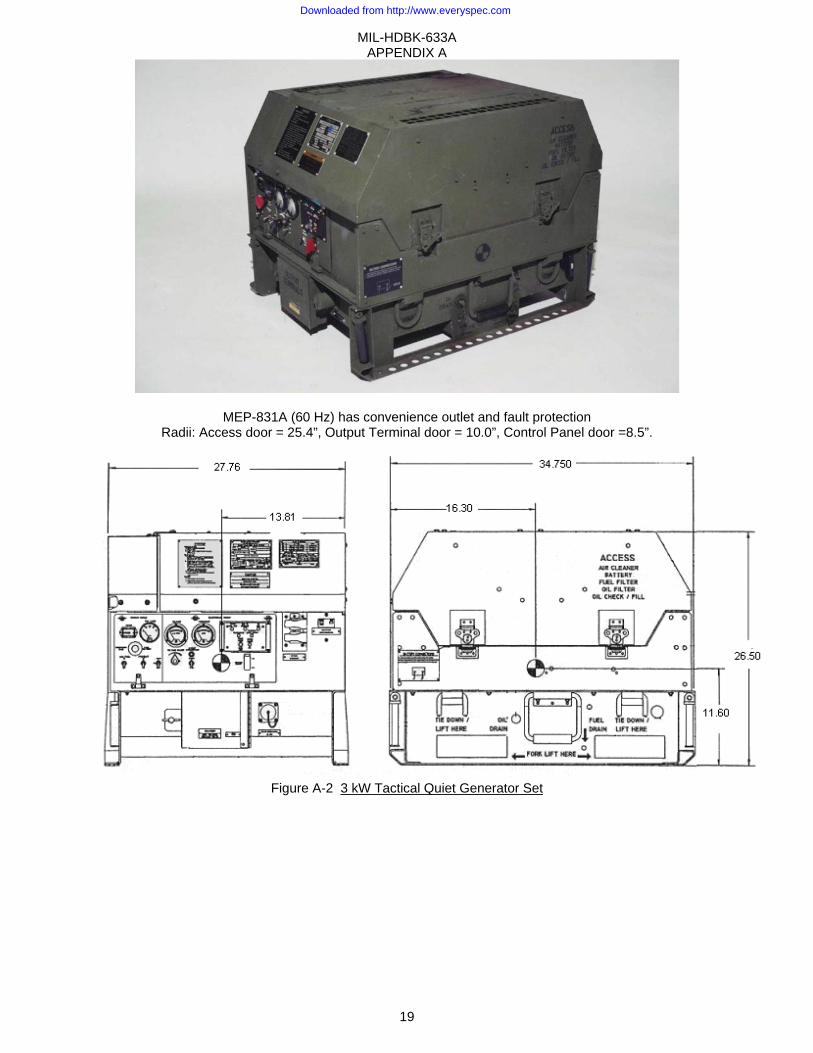
MEP-831A (60 Hz) has convenience outlet and fault protection Radii: Access door = 25.4”, Output Terminal door = 10.0”, Control Panel door =8.5”.
Figure A-2 3 kW Tactical Quiet Generator Set
Downloaded from http://www.everyspec.com
D
PT
P
Description Model
PP-AN/MJQ-4Tech. Manual
Model PP-AN/MJQ-4
FIND CO1 Mo2 TQ3 Fir4 Ac5 Sw6 Ra
3 kW TQ
42 6115-01Operato
Dimens42 145 x 84
OMPONENT odified 1 ton tQ Generator sre extinguisheccessory box witch box ack Assembly
3 kW Ta
Q Power PlanNSN
1-322-8583 or, Unit and D
sions:LWH (i4 x 76 & (533
trailer, M116Aset, DED, 3 kWer, 5 lb., A-A-
y (includes ca
MIL-AP
ctical Quiet Iden
nt, 60 Hz, TRLLIN
P42466 Direct Support
Physicain) & Cube(ft)
A3 W, 60. Hz, M1106
able reel)
Figure A-
-HDBK-633APPENDIX A
20
Power Planttification DaLMTD
SSNR62700
t al Characterit3) Ship Cu
533
EP-831A
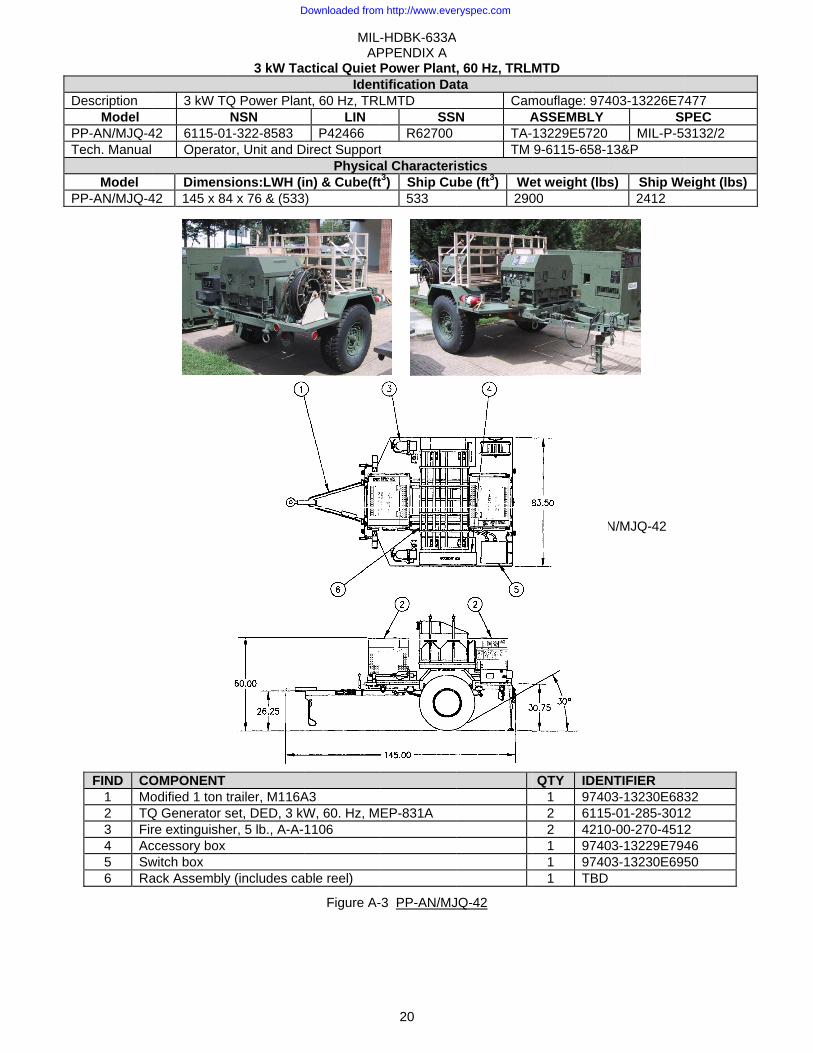
-3 PP-AN/MJ
A
, 60 Hz, TRLMta
CamN A
TA-TM
stics be (ft3) We
290
JQ-42
MTD
mouflage: 974ASSEMBLY 13229E5720 9-6115-658-1
et weight (lbs00
QTY IDEN
1 97402 61152 42101 97401 97401 TBD
PP-AN
403-13226E7S
MIL-P-513&P
s) Ship We2412
NTIFIER 03-13230E6835-01-285-30120-00-270-451203-13229E79403-13230E695
N/MJQ-42
477 PEC 3132/2
eight (lbs)
32 2 2 46 50
Downloaded from http://www.everyspec.com
DescriptionMod
PP-AN/MJPP-AN/MJTechnical *An “A” Mode
ModePP-AN/MJPP-AN/MJ
FIND CO1 Lig1 Mo2 TQ3 Fir4 Ac5 Sw
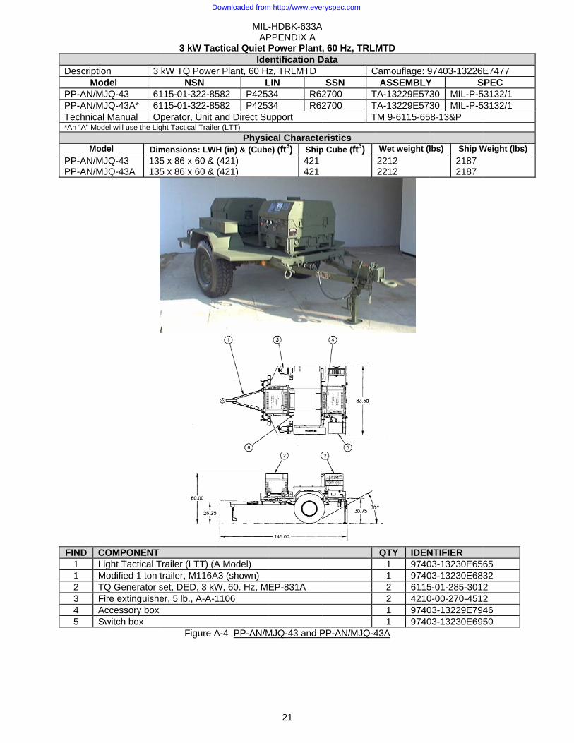
n 3 del JQ-43 61JQ-43A* 61Manual Opel will use the Lig
el DimJQ-43 JQ-43A
135135
OMPONENT ght Tactical Todified 1 ton tQ Generator sre extinguisheccessory box witch box
3 kW Ta
kW TQ PoweNSN
115-01-322-8115-01-322-8perator, Unit
ght Tactical Traile
mensions: LW5 x 86 x 60 & 5 x 86 x 60 &
Trailer (LTT) (Atrailer, M116Aset, DED, 3 kWer, 5 lb., A-A-
Figure A
MIL-AP
ctical Quiet Ide
er Plant, 60 HL
582 P4253582 P4253and Direct Suer (LTT)
PhysicWH (in) & (Cube
(421) (421)
A Model) A3 (shown) W, 60. Hz, M1106
A-4 PP-AN/M
-HDBK-633APPENDIX A
21
Power Plantentification Dz, TRLMTD
LIN 34 R6234 R62upport
cal Charactee) (ft3) Ship
421 421
EP-831A
MJQ-43 and P
A
, 60 Hz, TRLMData
CSSN
2700 T2700 T
T
eristics p Cube (ft3)
PP-AN/MJQ-4
MTD
Camouflage: 9ASSEMBLY
TA-13229E57TA-13229E57TM 9-6115-65
Wet weight (l2212 2212
QTY IDEN
1 97401 97402 61152 42101 97401 9740
43A
97403-13226EY S30 MIL-P-530 MIL-P-5
58-13&P
lbs) Ship W2187 2187
NTIFIER 03-13230E65603-13230E6835-01-285-30120-00-270-451203-13229E79403-13230E695
E7477 PEC
53132/1 53132/1
Weight (lbs)
65 32 2 2 46 50
Downloaded from http://www.everyspec.com
MIL-HDBK-633A APPENDIX A
22
5 kW Tactical Quiet Generator Set (TQG) Identification Data
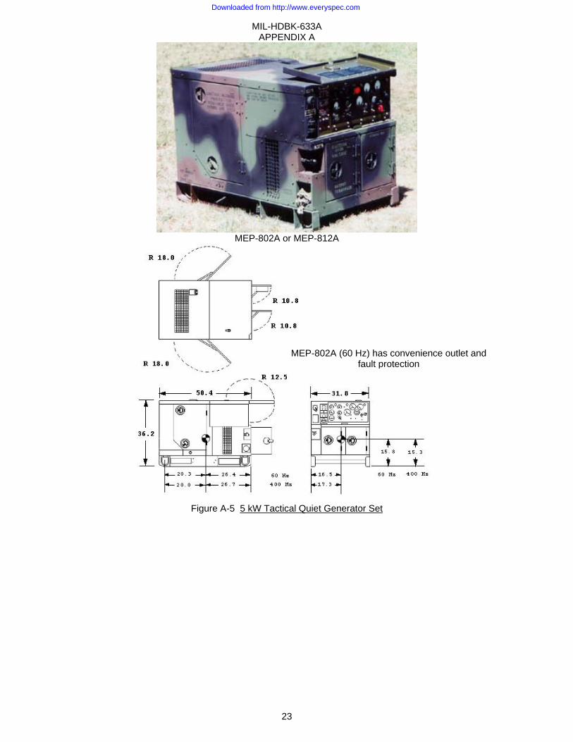
Description 5 kW TQG, 60 Hz, DED, Skid Mtd 5 kW TQG, DED, 400Hz, Skid Mtd Model MEP-802A MEP-812A NSN 6115-01-274-7387 6115-01-274-7391 LIN G11966 G12102 Specification MIL-DTL-53133/1 MIL-DTL-53133/2 SSN M53500 M53500 Trailer mounted configurations
PU- 797A: Figure A-6; AN/MJQ- 35A: Figure A-7 and; AN/MJQ-36: Figure A-8
None
Physical Characteristics Dimensions LWH (in) 51 x 32 x 37 (Cube:34 ft3) Wet Weight (lbs) 888 911 Engine Onan DN2M Diesel, 2 cylinder/4 stroke, 11.0hp @1800 RPM, 24VDC start, liquid-cooled. Instrumentation Hour meter, voltmeter, frequency, amps (% RL), oil pressure, fuel, coolant temp, battery amps,
emergency stop, battle short Fuels Diesel DL-1, DL-2; Jet Fuel JP-8 Fuel Capacity Fuel tank: 5 gallons
Performance Characteristics Power Rating 5kW, 0.8 pf @ 4000ft/120°F; 110% Max Power; De-rate: 3.5%/1000 ft from 4000 to 8000 ft Environmental Capability
-25°F (-50°F with Winterization Kit) to 125°F, rain, humidity, altitude, sand/dust, transportation, cold storage: -60°F, salt spray, fungus, 15° incline.
Protective Devices Automatic shut down with emergency bypass for low oil pressure, coolant high-temp, no fuel, and over-voltage.
Fuel Consumption 0.57 gph @ rated load. 0.56 gph @ rated load. Human Factors MIL-STD-1474. Noise 70 dBA @ 7 meters (23 ft). Reliability (MTBF) 486 hr @ 80% LCL 479 hr @ 80% LCL Maintenance Ratio less than 0.05
Electrical Characteristics Connection 120/240V, 1ph, 3 wire 120V, 1ph, 2 wire 120/208V, 3ph, 4 wire
Voltage Adj Range 228 –252 V 114 – 126 V 205 –220 V Frequency Adj Range ±3% Electrical Drip-proof generator enclosure, fungus & moisture treated, solid state voltage regulator, brushless
rotary exciter, solderless connectors, 60Hz: Onan alternator, 4 pole; 400Hz: Onan alternator, 24 pole. Convenience receptacle on 60Hz set.
Electrical Performance Electric Power Quality AC Voltage Frequency
Regulation 3% 3% Modulation 2.5% Short term steady state stability (30 sec) 2% bandwidth 2% bandwidth Long term steady state stability (4 hr) 4% bandwidth 3% bandwidth Appl./rejection of rated load, recovery time 20% dip/rise, 3 sec 3% under/4% over, 3 sec Motor load 35% dip, 5 sec to 95% init volt Max waveform deviation factor 6% (1 phase); 5% (3 phase) Individual waveform harmonic 3% (1 phase); 2% (3 phase) EMI Meets MIL-STD-461C, Part 9 EMP HAEMP IAW MIL-STD-2169
Optional Equipment Description NSN Tech Bulletin Effect on Dimensions (in)
Winterization kit 6115-01-476-8973 TB 9-6115-641-13 None (internal) Technical Manuals
Army Air Force Marine CorpsOperator TM 9-6115-641-10 TO 35C2-3-456-11 None Unit, DS, GS TM 9-6115-641-24 TO 35C2-3-456-12 RPSTL TM 9-6115-641-24P TO 35C2-3-456-14 Engine Maintenance TM 9-2815-252-24 TO 38G1-92-2 Engine Parts TM 9-2815-252-24P TO 38G1-92-4 Lube Order LO 9-6115-641-12 Warranty TB 9-6115-641-24
Downloaded from http://www.everyspec.com
MIL-HDBK-633A APPENDIX A
23
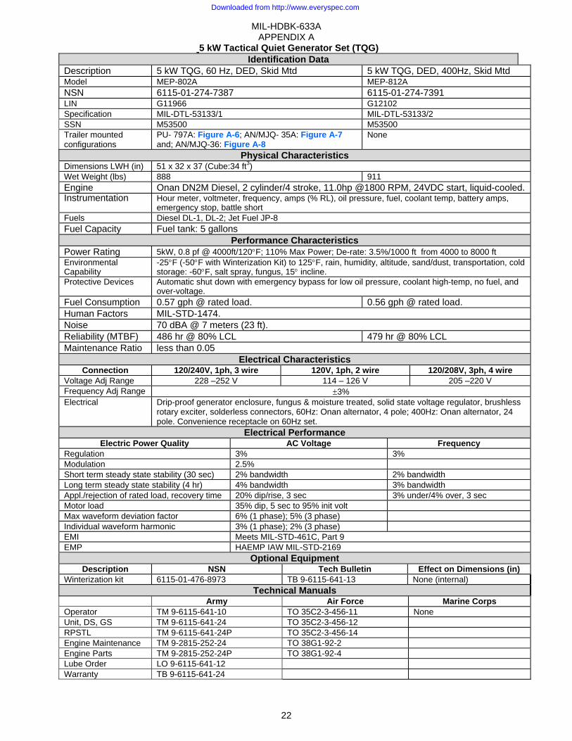
MEP-802A or MEP-812A
Figure A-5 5 kW Tactical Quiet Generator Set
MEP-802A (60 Hz) has convenience outlet and fault protection
Downloaded from http://www.everyspec.com
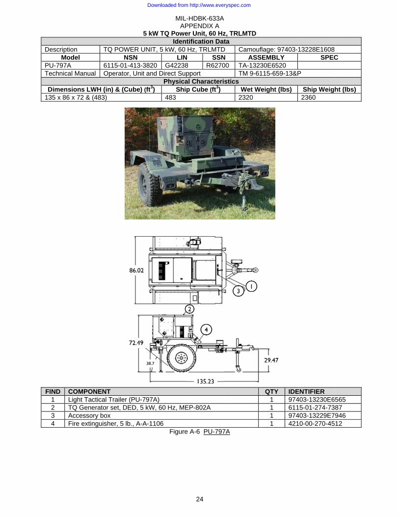
DescriptionMod
PU-797A Technical
Dimensio135 x 86 x
FIND CO1 Lig2 TQ3 Ac4 Fir
n TQel
611Manual Op
ons LWH (in)x 72 & (483)
OMPONENT ght Tactical TQ Generator sccessory box re extinguishe
5 k
Q POWER UNNSN
15-01-413-38erator, Unit a
) & (Cube) (ft
Trailer (PU-79set, DED, 5 kW
er, 5 lb., A-A-
MIL-AP
kW TQ PoweIdent
NIT, 5 kW, 60 LIN
820 G42238and Direct Sup
Physicat3) Ship
483
7A) W, 60 Hz, ME
1106 Figure
-HDBK-633APPENDIX A
24
er Unit, 60 Hztification DatHz, TRLMTD
N SSN8 R6270pport al Characterip Cube (ft3)
EP-802A
e A-6 PU-797
A
z, TRLMTD ta
D CamoufN ASS00 TA-1323
TM 9-61stics
Wet We2320
7A
flage: 97403-1SEMBLY 30E6520 115-659-13&P
eight (lbs)
QTY IDE
1 9741 6111 9741 421
13228E1608SPEC
P
Ship Weigh2360
ENTIFIER 403-13230E65
5-01-274-738403-13229E79
0-00-270-451
C
ht (lbs)
565 87 946 12
Downloaded from http://www.everyspec.com
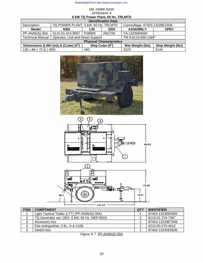
DescriptionMod
PP-AN/MJTechnical
Dimensio135 x 86 x
FIND CO1 Lig2 TQ3 Ac4 Fir5 Sw
n TQel
JQ-35A 611Manual Op
ons (LWH (in)x 72 & ( 483)
OMPONENT ght Tactical TQ Generator sccessory box re extinguishewitch box
5 k
Q POWER PLANSN
15-01-414-96erator, Unit a
)) & (Cube) (f
Trailer (LTT) (Pset, DED, 5 kW
er, 5 lb., A-A-
MIL-AP
kW TQ PoweIden
ANT, 5 kW, 6LIN
697 P28083and Direct Sup
Physicaft3) Shi
483
PP-AN/MJQ-3W, 60 Hz, ME
1106
Figure A-7
-HDBK-633APPENDIX A
25
r Plant, 60 Hntification Da60 Hz, TRLMT
SSN3 R62700pport al Characterip Cube (ft3)
35A) EP-802A
7 PP-AN/MJQ
A
z, TRLMTData TD CamouN AS0 TA-132
TM 9-6istics
Wet W3223
Q-35A
uflage: 97403SEMBLY 230E6560 6115-659-13&
Weight (lbs)
QTY IDE1 972 611 971 421 97
3-13228E1609SPE
&P
Ship Weig3140
ENTIFIER 403-13230E615-01-274-73403-13229E710-00-270-45403-13230E6
9 EC
ght (lbs)
6565 387 7946 512 6535
Downloaded from http://www.everyspec.com
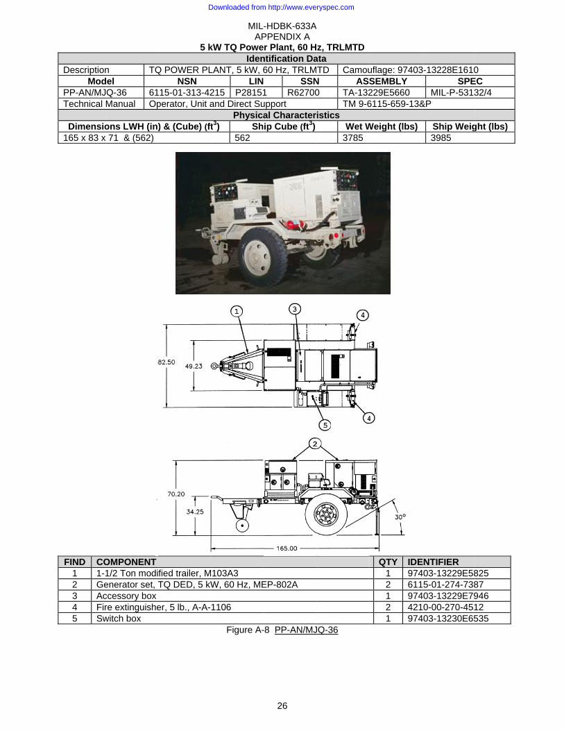
DescriptionMod
PP-AN/MJTechnical
Dimensio165 x 83 x
FIND CO1 1-2 Ge3 Ac4 Fir5 Sw
n TQdel JQ-36 61Manual Op
ons LWH (in)x 71 & (562)
OMPONENT 1/2 Ton modienerator set, Tccessory box re extinguishewitch box
5 k
Q POWER PLNSN
15-01-313-42perator, Unit a
) & (Cube) (ft
fied trailer, MTQ DED, 5 kW
er, 5 lb., A-A-
MIL-AP
kW TQ PoweIden
LANT, 5 kW, 6LIN
215 P28151and Direct Su
Physicat3) Sh
562
103A3 W, 60 Hz, ME
1106
Figure A-
-HDBK-633APPENDIX A
26
r Plant, 60 Hntification Da60 Hz, TRLM
SSN1 R62700upport al Characterip Cube (ft3)
EP-802A
-8 PP-AN/MJ
A
z, TRLMTData TD Camou
N ASS0 TA-132
TM 9-6istics
Wet W3785
JQ-36
uflage: 97403SEMBLY 229E5660 6115-659-13&
Weight (lbs)
QTY IDE
1 9742 6111 9742 4211 974
3-13228E1610SPE
MIL-P-5313&P
Ship Weig3985
ENTIFIER 403-13229E58
5-01-274-738403-13229E79
0-00-270-451403-13230E65
0 EC 32/4
ght (lbs)
825 87 946 12 535
Downloaded from http://www.everyspec.com

MIL-HDBK-633A APPENDIX A
27
This Page Intentionally Left Blank
Downloaded from http://www.everyspec.com
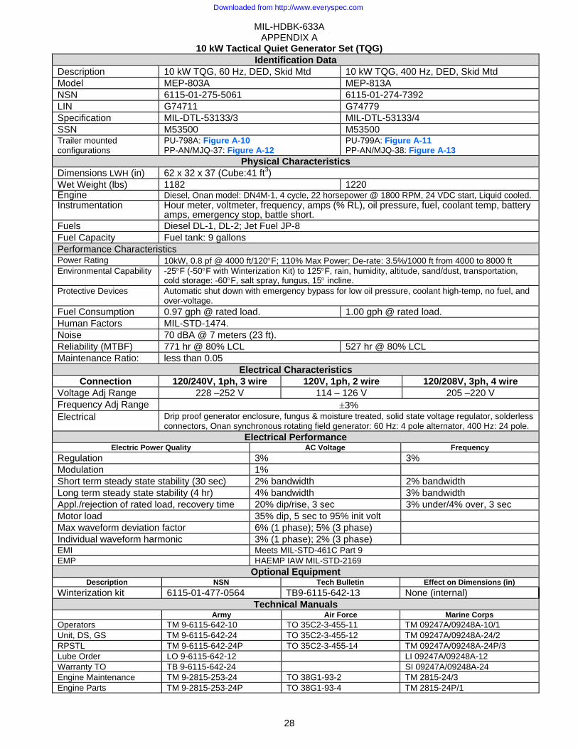
MIL-HDBK-633A APPENDIX A
28
10 kW Tactical Quiet Generator Set (TQG) Identification Data
Description 10 kW TQG, 60 Hz, DED, Skid Mtd 10 kW TQG, 400 Hz, DED, Skid Mtd Model MEP-803A MEP-813A NSN 6115-01-275-5061 6115-01-274-7392 LIN G74711 G74779 Specification MIL-DTL-53133/3 MIL-DTL-53133/4 SSN M53500 M53500 Trailer mounted configurations
PU-798A: Figure A-10PP-AN/MJQ-37: Figure A-12
PU-799A: Figure A-11 PP-AN/MJQ-38: Figure A-13
Physical Characteristics Dimensions LWH (in) 62 x 32 x 37 (Cube:41 ft3) Wet Weight (lbs) 1182 1220 Engine Diesel, Onan model: DN4M-1, 4 cycle, 22 horsepower @ 1800 RPM, 24 VDC start, Liquid cooled.Instrumentation Hour meter, voltmeter, frequency, amps (% RL), oil pressure, fuel, coolant temp, battery
amps, emergency stop, battle short.Fuels Diesel DL-1, DL-2; Jet Fuel JP-8 Fuel Capacity Fuel tank: 9 gallons Performance Characteristics Power Rating 10kW, 0.8 pf @ 4000 ft/120°F; 110% Max Power; De-rate: 3.5%/1000 ft from 4000 to 8000 ft Environmental Capability -25°F (-50°F with Winterization Kit) to 125°F, rain, humidity, altitude, sand/dust, transportation,
cold storage: -60°F, salt spray, fungus, 15° incline. Protective Devices Automatic shut down with emergency bypass for low oil pressure, coolant high-temp, no fuel, and
over-voltage. Fuel Consumption 0.97 gph @ rated load. 1.00 gph @ rated load. Human Factors MIL-STD-1474. Noise 70 dBA @ 7 meters (23 ft). Reliability (MTBF) 771 hr @ 80% LCL 527 hr @ 80% LCL Maintenance Ratio: less than 0.05
Electrical Characteristics Connection 120/240V, 1ph, 3 wire 120V, 1ph, 2 wire 120/208V, 3ph, 4 wire
Voltage Adj Range 228 –252 V 114 – 126 V 205 –220 V Frequency Adj Range ±3% Electrical Drip proof generator enclosure, fungus & moisture treated, solid state voltage regulator, solderless
connectors, Onan synchronous rotating field generator: 60 Hz: 4 pole alternator, 400 Hz: 24 pole. Electrical Performance
Electric Power Quality AC Voltage Frequency Regulation 3% 3% Modulation 1% Short term steady state stability (30 sec) 2% bandwidth 2% bandwidth Long term steady state stability (4 hr) 4% bandwidth 3% bandwidth Appl./rejection of rated load, recovery time 20% dip/rise, 3 sec 3% under/4% over, 3 sec Motor load 35% dip, 5 sec to 95% init volt Max waveform deviation factor 6% (1 phase); 5% (3 phase) Individual waveform harmonic 3% (1 phase); 2% (3 phase) EMI Meets MIL-STD-461C Part 9 EMP HAEMP IAW MIL-STD-2169
Optional Equipment Description NSN Tech Bulletin Effect on Dimensions (in)
Winterization kit 6115-01-477-0564 TB9-6115-642-13 None (internal) Technical Manuals
Army Air Force Marine Corps Operators TM 9-6115-642-10 TO 35C2-3-455-11 TM 09247A/09248A-10/1 Unit, DS, GS TM 9-6115-642-24 TO 35C2-3-455-12 TM 09247A/09248A-24/2 RPSTL TM 9-6115-642-24P TO 35C2-3-455-14 TM 09247A/09248A-24P/3 Lube Order LO 9-6115-642-12 LI 09247A/09248A-12 Warranty TO TB 9-6115-642-24 SI 09247A/09248A-24 Engine Maintenance TM 9-2815-253-24 TO 38G1-93-2 TM 2815-24/3 Engine Parts TM 9-2815-253-24P TO 38G1-93-4 TM 2815-24P/1
Downloaded from http://www.everyspec.com
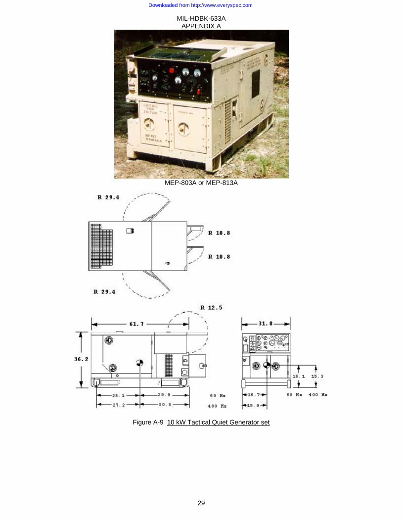
MIL-HDBK-633A APPENDIX A
29
MEP-803A or MEP-813A
Figure A-9 10 kW Tactical Quiet Generator set
Downloaded from http://www.everyspec.com
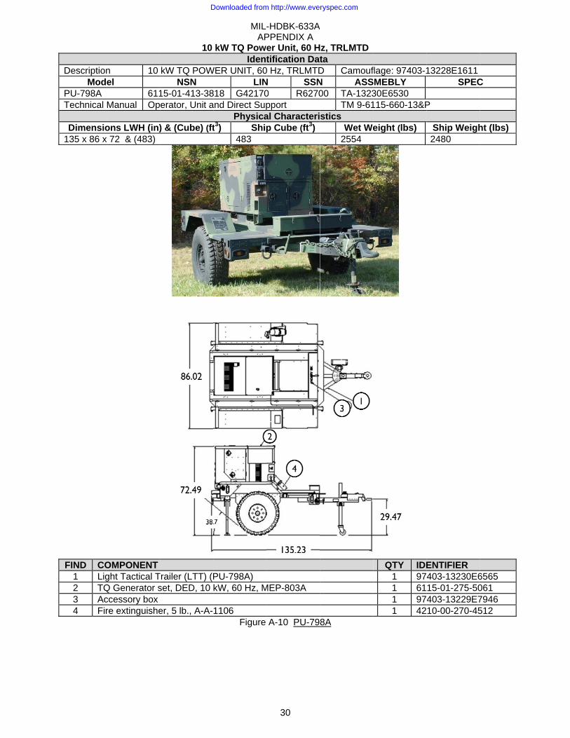
DescriptionMod
PU-798A Technical
Dimensio135 x 86 x
FIND CO1 Lig2 TQ3 Ac4 Fir
n 10 el
611Manual Op
ons LWH (in)x 72 & (483)
OMPONENT ght Tactical TQ Generator sccessory box re extinguishe
10
kW TQ POWNSN
15-01-413-38erator, Unit a
) & (Cube) (ft
Trailer (LTT) (Pset, DED, 10
er, 5 lb., A-A-
MIL-AP
kW TQ PowIdent
WER UNIT, 60LIN
818 G42170and Direct Sup
Physicat3) Ship
483
PU-798A) kW, 60 Hz, M
1106 Figure
-HDBK-633APPENDIX A
30
er Unit, 60 Htification Dat
0 Hz, TRLMTDN SSN0 R6270pport al Characterip Cube (ft3)
MEP-803A
A-10 PU-79
A
z, TRLMTDta D CamoufN ASS00 TA-1323
TM 9-61stics
Wet We2554
8A
flage: 97403-1SMEBLY 30E6530 115-660-13&P
eight (lbs)
QTY IDE
1 971 611 971 42
13228E1611SPEC
P
Ship Weigh2480
ENTIFIER 403-13230E615-01-275-50403-13229E710-00-270-45
C
ht (lbs)
6565 061 7946 512
Downloaded from http://www.everyspec.com
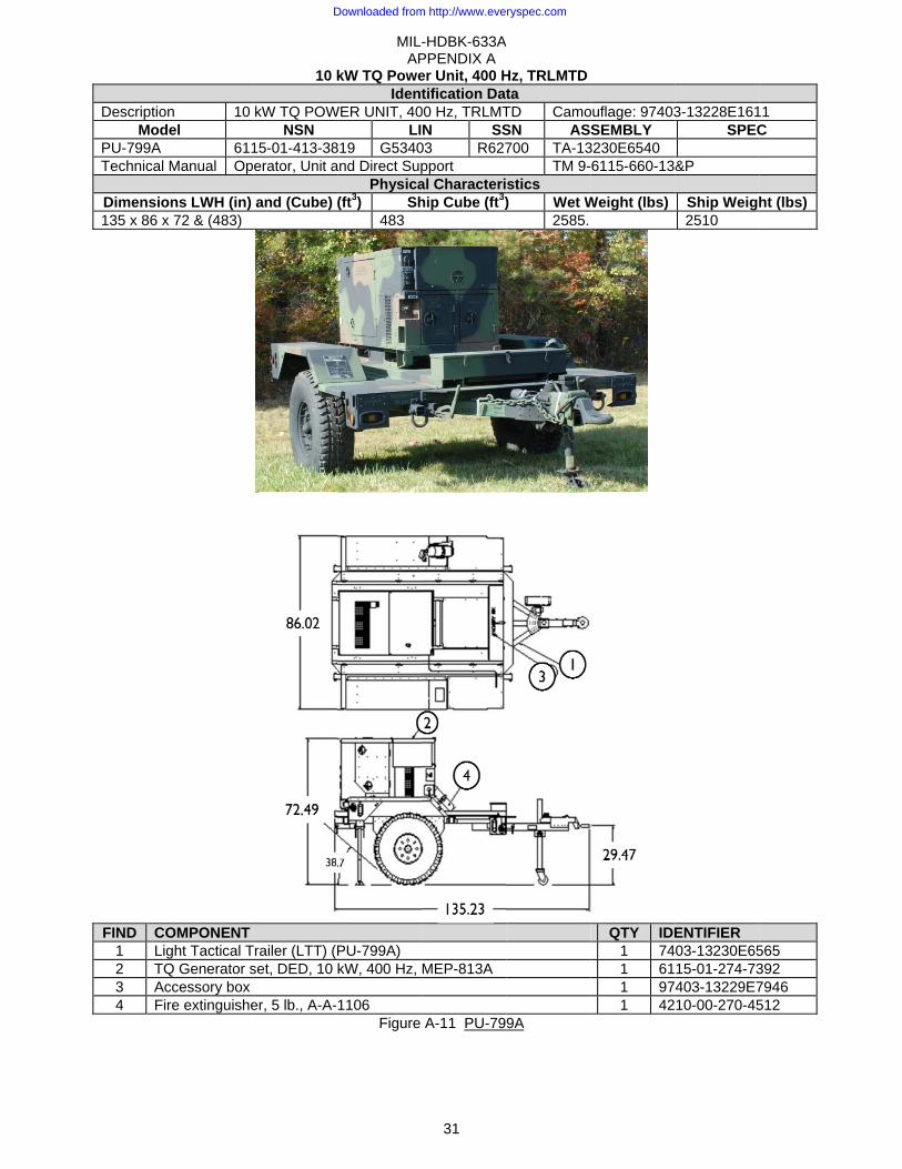
DescriptionMod
PU-799A Technical
Dimensio135 x 86 x
FIND CO1 Lig2 TQ3 Ac4 Fir
n 10 el
611Manual Op
ons LWH (in) x 72 & (483)
OMPONENT ght Tactical TQ Generator sccessory box re extinguishe
10 k
kW TQ POWNSN
15-01-413-38erator, Unit a
and (Cube)
Trailer (LTT) (Pset, DED, 10
er, 5 lb., A-A-
MIL-AP
kW TQ PoweIdent
WER UNIT, 40LI
819 G5340and Direct Sup
Physica(ft3) Sh
483
PU-799A) kW, 400 Hz,
1106 Figure
-HDBK-633APPENDIX A
31
er Unit, 400 Htification Dat
00 Hz, TRLMTN SS
03 R627pport al Characterihip Cube (ft3)
MEP-813A
A-11 PU-79
A
Hz, TRLMTDta TD CamoSN AS700 TA-13
TM 9-stics ) Wet W
2585.
9A
ouflage: 97403SEMBLY
3230E6540 6115-660-13
Weight (lbs)
QTY IDE
1 741 611 971 42
3-13228E161SPEC
&P
Ship Weigh2510
ENTIFIER 03-13230E6515-01-274-73403-13229E710-00-270-45
1 C
ht (lbs)
565 392 7946 512
Downloaded from http://www.everyspec.com
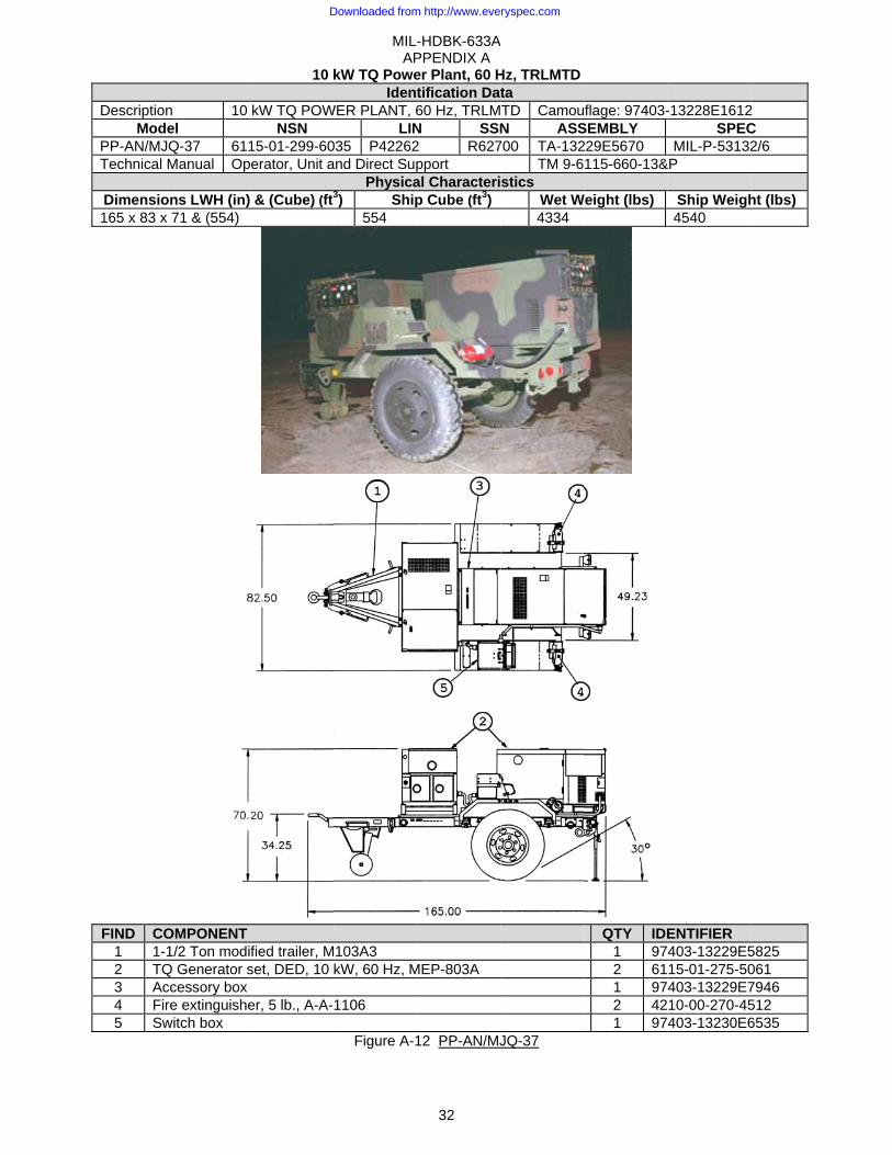
DescriptionMod
PP-AN/MJTechnical
Dimensio165 x 83 x
FIND CO1 1-2 TQ3 Ac4 Fir5 Sw
n 10 el
JQ-37 611Manual Op
ons LWH (in)x 71 & (554)
OMPONENT 1/2 Ton modi
Q Generator sccessory box re extinguishewitch box
10 k
kW TQ POWNSN
15-01-299-60erator, Unit a
& (Cube) (ft3
fied trailer, Mset, DED, 10
er, 5 lb., A-A-
MIL-AP
kW TQ PoweIdent
WER PLANT, 6LIN
035 P42262and Direct Sup
Physica3) Ship
554
103A3 kW, 60 Hz, M
1106
Figure A-1
-HDBK-633APPENDIX A
32
er Plant, 60 Htification Dat60 Hz, TRLMN SSN2 R627pport al Characterip Cube (ft3)
MEP-803A
12 PP-AN/MJ
A
Hz, TRLMTDta TD CamouN ASS
700 TA-132TM 9-6
stics Wet W4334
JQ-37
flage: 97403-SEMBLY 229E5670 115-660-13&
Weight (lbs)
QTY IDE1 972 611 972 421 97
-13228E1612SPEC
MIL-P-53132&P
Ship Weigh4540
ENTIFIER 403-13229E515-01-275-50403-13229E710-00-270-45403-13230E6
2 C 2/6
ht (lbs)
5825 061 7946 512 6535
Downloaded from http://www.everyspec.com
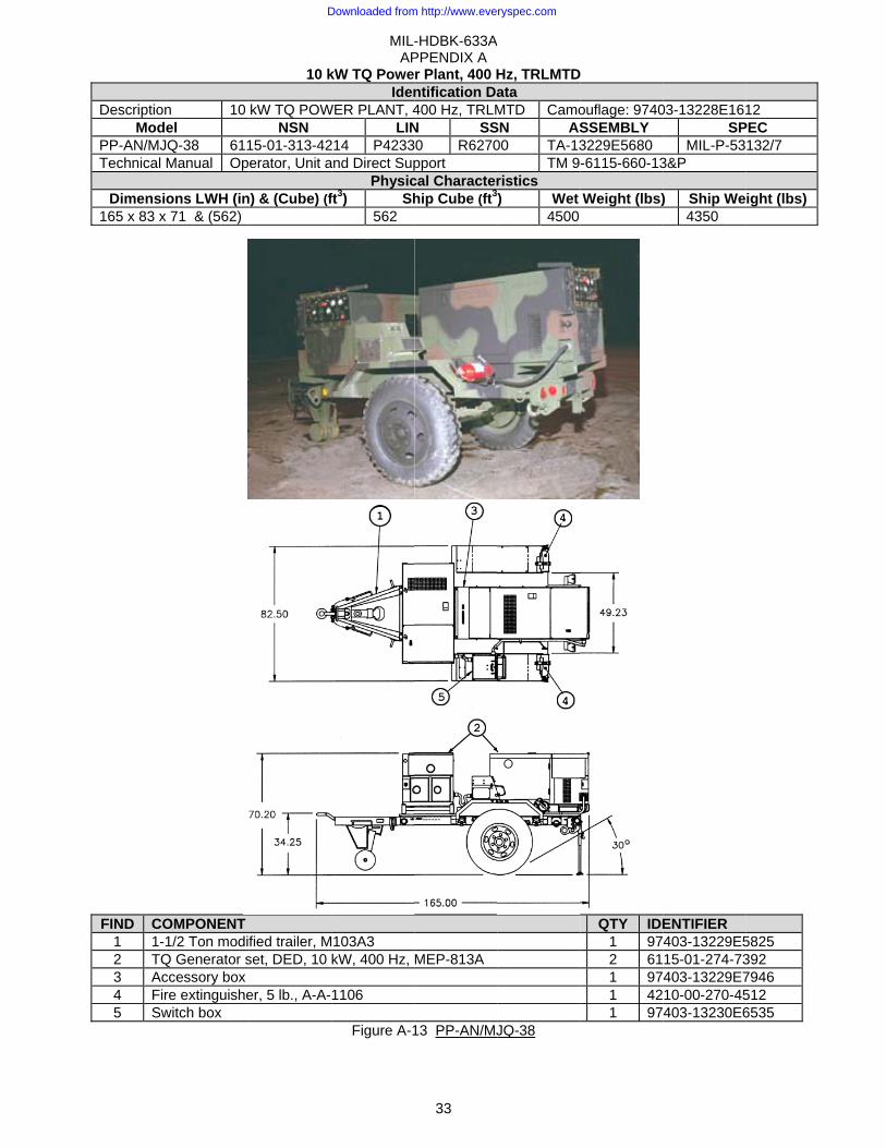
DescriptionMod
PP-AN/MJTechnical
Dimensi165 x 83 x
FIND CO1 1-2 TQ3 Ac4 Fir5 Sw
n 10 el
JQ-38 611Manual Op
ons LWH (inx 71 & (562)
OMPONENT 1/2 Ton modi
Q Generator sccessory box re extinguishewitch box
10 k
kW TQ POWNSN
15-01-313-42erator, Unit a
n) & (Cube) (f
fied trailer, Mset, DED, 10
er, 5 lb., A-A-
MIL-AP
kW TQ PoweIden
WER PLANT, 4LIN
214 P4233and Direct Sup
Physicft3) Sh
562
103A3 kW, 400 Hz,
1106
Figure A-1
-HDBK-633APPENDIX A
33
r Plant, 400 Hntification Da400 Hz, TRLMN SS30 R6270pport cal Characterhip Cube (ft3
MEP-813A
13 PP-AN/MJ
A
Hz, TRLMTData MTD Camo
SN AS00 TA-13
TM 9ristics ) Wet
4500
JQ-38
D
ouflage: 9740SSEMBLY 3229E5680 -6115-660-13
Weight (lbs)
QTY IDE
1 972 611 971 421 97
03-13228E16SP
MIL-P-533&P
) Ship We4350
ENTIFIER 403-13229E515-01-274-73403-13229E710-00-270-45403-13230E6
12 PEC 132/7
ight (lbs)
5825 392 7946 512 6535
Downloaded from http://www.everyspec.com

MIL-HDBK-633A APPENDIX A
34
15 kW Tactical Quiet Generator Set (TQG) Identification Data
Description 15 kW TQG, 50/60 Hz, DED, Skid Mtd 15 kW, TQG, 400 Hz, DED, Skid Mtd Model MEP-804A
MEP-804B MEP-814AMEP-814B
NSN Re-Engine
6115-01-274-7388B model 6115-01-530-1458
6115-01-274-7393 B model 6115-01-529-9494
LIN G12170 B model G12170
G12238B model G12238
Specification MIL-DTL-53133/5 MIL-DTL-53133/6 SSN M53500 M53500 Trailer mounted configurations
PU-801B: Figure A-16PU-802A: Figure A-17 PP-AN/MJQ-48B: Figure A-19
PU-800A: Figure A-15 PP-AN/MJQ-39B: Figure A-18
Physical Characteristics Dimensions LWH (in) 70 x 36 x 55 (Cube: 77 ft3) Wet Weight (lbs) 2124 2238 Engine Yanmar - Model:4TNV84T-DFM 4 Cycle, Liquid Cooled, 4 Cyl, 3.31 Inch Bore, 40
BHP @ 1800 RPM, 24 VDC starter, Instrumentation Hour meter, voltmeter, frequency, amps (% RL), oil pressure, fuel, coolant temp,
battery amps, emergency stop, battle short. Fuels Diesel DL-1, DL-2; Jet Fuel JP-8. Fuel Capacity Fuel tank: 14 gallons.
Performance Characteristics Power Rating 15 kW (12.5 kW @ 50 Hz), 0.8 pf @ 4000 ft/120 °F; 110% Max Power; De-rate:
3.5%/1000 ft from 4000 to 8000 ftEnvironmental Capability
-25°F (-50°F W/kit) to 125°F, rain, humidity, altitude, sand/dust, transportation, cold storage: -60°F, salt spray, fungus, 15° incline.
Protective Devices Automatic shut down with emergency bypass for low oil pressure, coolant high-temperature, no fuel, over-speed, and over-voltage.
Fuel Consumption 1.44 gph @ rated load. 1.75 gph @ rated load. Human Factors MIL-STD-1474. Noise 70 dBA @ 7 meters (23 ft). Reliability (MTBF) 594 hr @ 80% LCL 377 hr @ 80% LCL Maintenance Ratio less than 0.05
Electrical Characteristics Connection 120/208V, 3ph, 4 wire 240/416V, 3ph, 4 wire Freq adj range
Volt adj range (50Hz) 190 – 213 V 380 – 426 V 48 - 52 Hz Volt adj range (60Hz) 197 - 240 V 395 - 480 V 58 - 62 Hz Volt adj range (400Hz) 197 - 229 V 395 - 458 V 390 - 420 Hz Electrical Drip proof generator enclosure, fungus & moisture treated, solid state voltage regulator,
solderless connectors, brushless Marathon/Lima generator. Electrical Performance
Electric Power Quality AC Voltage Frequency 50/60 Hz 400 Hz 50/60 Hz 400 Hz
Regulation 1% 0.25% Modulation 1% Short term steady st stability (30 sec) 1% bandwidth 0.5% bandwidth Long term steady state stability (4 hr) 2% bandwidth 1% bandwidth Application/rejection of rated load,
Recovery time 15% dip/rise, 0.5 sec
12% dip/rise, 0.5 sec
4% und/ over, 2 sec
1.5%und/over,1 sec
Motor load 30% dip, .7 sec to 95% init volt
25% dip,.7 sec to 95% init volt
Max waveform deviation factor 5% Individual waveform harmonic 2% EMI Meets MIL-STD-461C Part 9 EMP HAEMP IAW MIL-STD-2169
Downloaded from http://www.everyspec.com
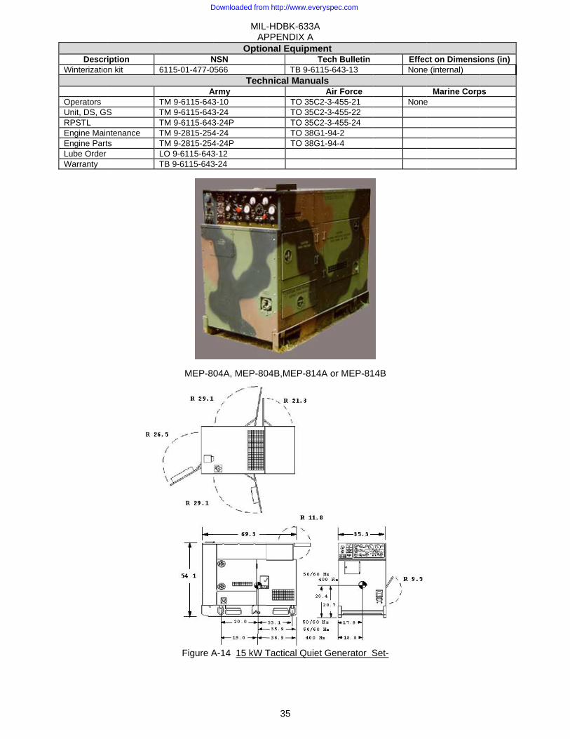
DescrWinterizatio
Operators Unit, DS, GRPSTL Engine MainEngine PartLube Order Warranty
ription on kit 6
TS T
Tntenance Tts T
LT
N6115-01-477-0
ATM 9-6115-643TM 9-6115-643TM 9-6115-643TM 9-2815-254TM 9-2815-254LO 9-6115-643TB 9-6115-643
MEP-8
Figure A
MIL-AP
OptioNSN 0566
TechArmy3-10 3-24 3-24P 4-24 4-24P 3-12 3-24
04A, MEP-80
A-14 15 kW T
-HDBK-633APPENDIX A
35
onal EquipmeT
TB 9-61hnical Manua
TO 35CTO 35CTO 35CTO 38GTO 38G
04B,MEP-814
Tactical Quiet
A
ent Tech Bulletin15-643-13
als Air Force
2-3-455-21 2-3-455-22 2-3-455-24 1-94-2 1-94-4
4A or MEP-81
t Generator S
EffecNone
None
4B
Set-
ct on Dimensie (internal)
Marine Corpe
ons (in)
ps
Downloaded from http://www.everyspec.com

DescriptionMod
PU-800A Technical
Dimensio165 x 95 x
FIND CO1 2 12 TQ3 Ac4 Fir
n 15 el
611Manual Op
ons LWH (in)x 84 & (761)
OMPONENT 1/2 Ton modifQ Generator sccessory box re extinguishe
15
kW TQ POWNSN
15-01-565-09erator, Unit a
) & (Cube) (ft
fied Trailer, Mset, DED, 15
er, 5 lb., A-A-
MIL-AP
kW TQ PoweIdent
WER UNIT, 40LIN
929 G78203and Direct Sup
Physicat3) Ship
761
M200A1 kW, 400 Hz,
1106 Figure
-HDBK-633APPENDIX A
36
er Unit, 400 Htification Dat
00 Hz, TRLMTSSN
3 R62700pport al Characterip Cube (ft3)
MEP-814B
A-15 PU-80
A
Hz, TRLMTDta TD Camouf ASS0 TA-97-2
TM 9-61stics
Wet We4975
0A
flage: 97403-1SEMBLY 2111 115-661-13&P
eight (lbs)
QTY IDE
1 971 611 971 42
13228E1614SPEC
MIL-P-53132P
Ship Weigh4855
ENTIFIER 403-13229E915-01-274-73403-13229E710-00-270-45
C 2
ht (lbs)
9623 393 7946 512
Downloaded from http://www.everyspec.com
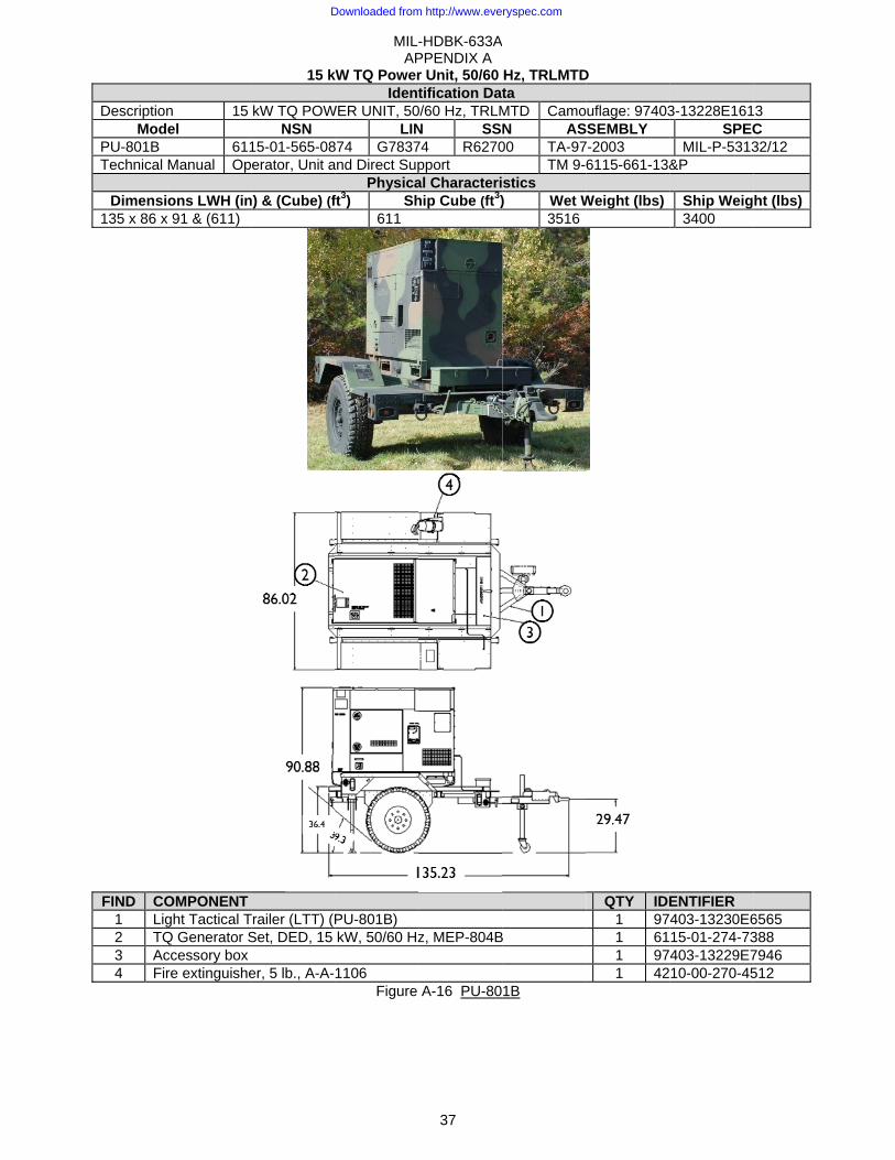
DescriptionMod
PU-801B Technical
Dimensi135 x 86 x
FIND CO1 Lig2 TQ3 Ac4 Fir
n 15 el
611Manual Op
ons LWH (inx 91 & (611)
OMPONENT ght Tactical TQ Generator Sccessory box re extinguishe
15 k
kW TQ POWNSN
15-01-565-08erator, Unit a
n) & (Cube) (f
Trailer (LTT) (PSet, DED, 15
er, 5 lb., A-A-
MIL-AP
kW TQ PowerIdent
WER UNIT, 50LIN
874 G7837and Direct Sup
Physicaft3) Sh
611
PU-801B) kW, 50/60 Hz
1106 Figure
-HDBK-633APPENDIX A
37
r Unit, 50/60 tification Dat
0/60 Hz, TRLMN SS74 R6270pport al Characterihip Cube (ft3)
z, MEP-804B
A-16 PU-80
A
Hz, TRLMTDta MTD CamoN AS00 TA-97
TM 9-stics ) Wet W
3516
B
1B
D
uflage: 97403SSEMBLY 7-2003 6115-661-13&
Weight (lbs)
QTY IDE
1 971 611 971 42
3-13228E161SPEC
MIL-P-5313&P
Ship Weig3400
ENTIFIER 403-13230E615-01-274-73403-13229E710-00-270-45
3 C 32/12
ht (lbs)
6565 388 7946 512
Downloaded from http://www.everyspec.com
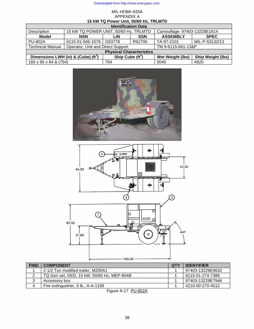
DescriptionMod
PU-802A Technical
Dimensio165 x 95 x
FIND CO1 2-2 TQ3 Ac4 Fir
n 15 el
61Manual Op
ons LWH (in)x 84 & (754)
OMPONENT 1/2 Ton modi
Q Gen set, DEccessory box re extinguishe
15 k
kW TQ POWNSN
15-01-565-15perator, Unit a
) & (Cube) (ft
fied trailer, MED, 15 kW, 50
er, 5 lb., A-A-
MIL-AP
kW TQ PowerIden
WER UNIT, 50LIN
576 G53778and Direct Su
Physicat3) Sh
754
200A1 0/60 Hz, MEP
1106 Figure
-HDBK-633APPENDIX A
38
r Unit, 50/60 ntification Da0/60 Hz, TRLMN SS8 R627pport al Character
hip Cube (ft3)
P-804B
A-17 PU-80
A
Hz, TRLMTData MTD CamoSN AS00 TA-97
TM 9istics ) Wet W
5040
2A
D
ouflage: 9740SSEMBLY 7-2101 -6115-661-13
Weight (lbs)
QTY IDE
1 971 611 971 42
03-13228E16SPE
MIL-P-53133&P
Ship Weig4920
ENTIFIER 403-13229E915-01-274-73403-13229E710-00-270-45
14 EC 32/13
ght (lbs)
9632 388 7946 512
Downloaded from http://www.everyspec.com
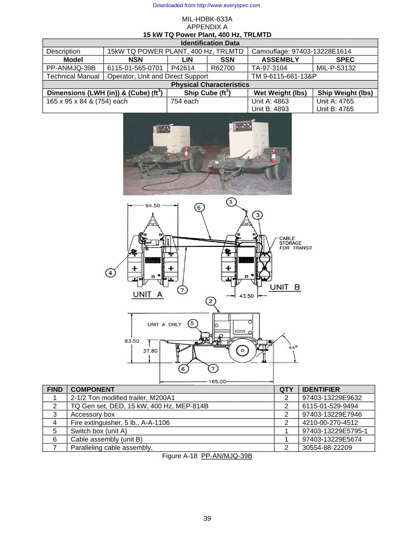
DescriptionMod
PP-ANMJQTechnical
Dimensio165 x 95 x
FIND CO1 2-2 TQ3 Ac4 Fir5 Sw6 Ca7 Pa
n 15kel Q-39B 611Manual Op
ns (LWH (in)x 84 & (754) e
OMPONENT 1/2 Ton modi
Q Gen set, DEccessory box re extinguishewitch box (uniable assemblyaralleling cabl
15 k
kW TQ POWENSN
15-01-565-07erator, Unit a
)) & (Cube) (feach
fied trailer, MED, 15 kW, 40
er, 5 lb., A-A-t A) y (unit B) le assembly,
MIL-AP
kW TQ PoweIden
ER PLANT, 4LIN
701 P42614and Direct Sup
Physicaft3) Shi
754 eac
200A1 00 Hz, MEP-8
1106
Figure A-1
-HDBK-633APPENDIX A
39
r Plant, 400 Hntification Da400 Hz, TRLM
SSN4 R62700pport al Characterip Cube (ft3)ch
814B
8 PP-AN/MJ
A
Hz, TRLMTData MTD CamouN AS0 TA-97-
TM 9-6istics
Wet WUnit A:Unit B:
Q-39B
D
uflage: 97403SEMBLY -3104 6115-661-13&
Weight (lbs) : 4863 : 4893
QTY IDE2 972 612 972 421 971 972 30
3-13228E1614SPE
MIL-P-5313&P
Ship WeigUnit A: 476Unit B: 476
ENTIFIER 403-13229E915-01-529-94403-13229E710-00-270-45403-13229E5403-13229E5554-88-2220
4 EC 32
ght (lbs) 65 65
9632 494 7946 512 5795-1 5674 9
Downloaded from http://www.everyspec.com
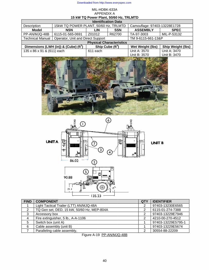
DescriptionMod
PP-AN/MJTechnical
Dimensio135 x 86 x
FIND CO1 Lig2 TQ3 Ac4 Fir5 Sw6 Ca7 Pa
n 15kel
JQ-48B 611Manual Op
ons (LWH (inx 91 & (611) e
OMPONENT ght Tactical TQ Gen set, DEccessory box re extinguishewitch box (uniable assemblyaralleling cabl
15 kW
kW TQ POWENSN
15-01-565-06erator, Unit a
n)) & (Cube) (each
Trailer (LTT) AED, 15 kW, 50
er, 5 lb., A-A-t A) y (unit B) le assembly,
MIL-AP
W TQ Power Iden
ER PLANT, 5LIN
691 Z0101and Direct Sup
Physic(ft3) S
611 ea
AN/MJQ-48A 0/60 Hz, MEP
1106
Figure A-1
-HDBK-633APPENDIX A
40
Plant, 50/60ntification Da
50/60 Hz, TRLN SS2 R627pport cal Characterhip Cube (ft3
ach
P-804A
9 PP-AN/MJ
A
Hz, TRLMTData LMTD CamSN A700 TA-9
TM 9ristics 3) Wet
Unit Unit
Q-48B
D
mouflage: 9740ASSEMBLY 97-3003 9-6115-661-1
t Weight (lbsA: 3570 B: 3570
QTY IDE2 972 612 972 421 971 972 30
03-13228E17SP
MIL-P-533&P
) Ship WeUnit A: 34Unit B: 34
ENTIFIER 403-13230E615-01-274-73403-13229E710-00-270-45403-13229E5403-13229E5554-88-2220
728 PEC 132
ight (lbs) 470 470
6565 388 7946 512 5795-1 5674 9
Downloaded from http://www.everyspec.com

MIL-HDBK-633A APPENDIX A
41
This Page Intentionally Left Blank
Downloaded from http://www.everyspec.com
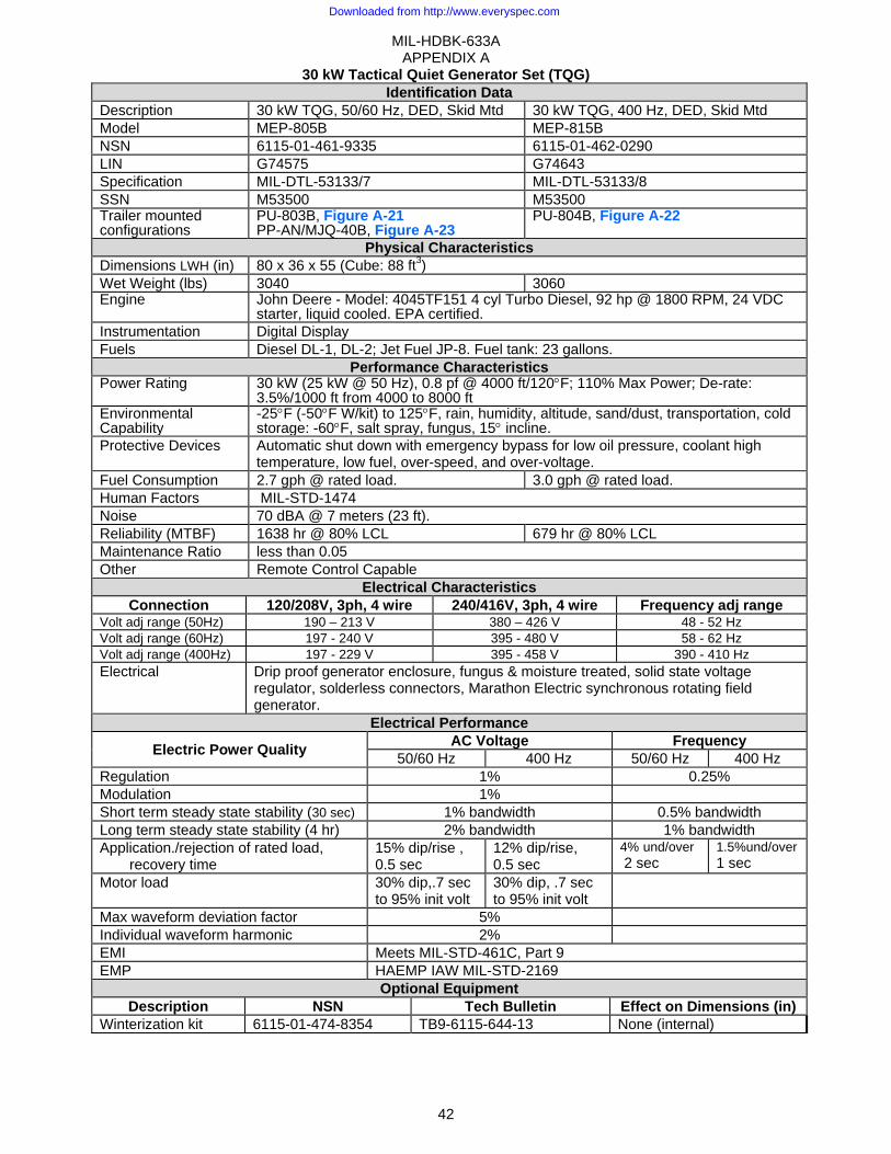
MIL-HDBK-633A APPENDIX A
42
30 kW Tactical Quiet Generator Set (TQG) Identification Data
Description 30 kW TQG, 50/60 Hz, DED, Skid Mtd 30 kW TQG, 400 Hz, DED, Skid Mtd Model MEP-805B MEP-815B NSN 6115-01-461-9335 6115-01-462-0290 LIN G74575 G74643 Specification MIL-DTL-53133/7 MIL-DTL-53133/8 SSN M53500 M53500 Trailer mounted configurations
PU-803B, Figure A-21PP-AN/MJQ-40B, Figure A-23
PU-804B, Figure A-22
Physical Characteristics Dimensions LWH (in) 80 x 36 x 55 (Cube: 88 ft3) Wet Weight (lbs) 3040 3060 Engine John Deere - Model: 4045TF151 4 cyl Turbo Diesel, 92 hp @ 1800 RPM, 24 VDC
starter, liquid cooled. EPA certified.Instrumentation Digital Display Fuels Diesel DL-1, DL-2; Jet Fuel JP-8. Fuel tank: 23 gallons.
Performance Characteristics Power Rating 30 kW (25 kW @ 50 Hz), 0.8 pf @ 4000 ft/120°F; 110% Max Power; De-rate:
3.5%/1000 ft from 4000 to 8000 ftEnvironmental Capability
-25°F (-50°F W/kit) to 125°F, rain, humidity, altitude, sand/dust, transportation, cold storage: -60°F, salt spray, fungus, 15° incline.
Protective Devices Automatic shut down with emergency bypass for low oil pressure, coolant high temperature, low fuel, over-speed, and over-voltage.
Fuel Consumption 2.7 gph @ rated load. 3.0 gph @ rated load. Human Factors MIL-STD-1474 Noise 70 dBA @ 7 meters (23 ft). Reliability (MTBF) 1638 hr @ 80% LCL 679 hr @ 80% LCL Maintenance Ratio less than 0.05 Other Remote Control Capable
Electrical Characteristics Connection 120/208V, 3ph, 4 wire 240/416V, 3ph, 4 wire Frequency adj range
Volt adj range (50Hz) 190 – 213 V 380 – 426 V 48 - 52 Hz Volt adj range (60Hz) 197 - 240 V 395 - 480 V 58 - 62 Hz Volt adj range (400Hz) 197 - 229 V 395 - 458 V 390 - 410 Hz Electrical Drip proof generator enclosure, fungus & moisture treated, solid state voltage
regulator, solderless connectors, Marathon Electric synchronous rotating field generator.
Electrical Performance
Electric Power Quality AC Voltage Frequency 50/60 Hz 400 Hz 50/60 Hz 400 Hz
Regulation 1% 0.25% Modulation 1% Short term steady state stability (30 sec) 1% bandwidth 0.5% bandwidth Long term steady state stability (4 hr) 2% bandwidth 1% bandwidth Application./rejection of rated load,
recovery time 15% dip/rise , 0.5 sec
12% dip/rise, 0.5 sec
4% und/over 2 sec
1.5%und/over 1 sec
Motor load 30% dip,.7 sec to 95% init volt
30% dip, .7 sec to 95% init volt
Max waveform deviation factor 5% Individual waveform harmonic 2% EMI Meets MIL-STD-461C, Part 9 EMP HAEMP IAW MIL-STD-2169
Optional Equipment Description NSN Tech Bulletin Effect on Dimensions (in)
Winterization kit 6115-01-474-8354 TB9-6115-644-13 None (internal)
Downloaded from http://www.everyspec.com

Operators, DRPSTL Engine MainEngine PartLube Order Warranty
DS, GS
ntenance ts
ARTM 9-6115-67TM 9-6115-67TM 9-2815-25TM 9-2815-25LO 9-6115-64TB 9-6115-67
Figure A-20
MIL-AP
TechRMY 71-14 71-24P 59-24 59-24P 44-12 71-24
MEP-80
30 kW Tactic
-HDBK-633APPENDIX A
43
hnical ManuaA
TO 35C2-3TO 35C2-3TO 38BG1TO 38BG1
05B or MEP-8
cal Quiet Gen
A
als Air Force 3-446-32 3-446-34 1-125-2 1-125-4
815B
nerator Set (re
MTM 092TM 092TM 092TM 092
e-engine)
Marine Corp249A/09246A-1249A/09246A-2249A/09246A-2249A/2815-24P
s 14 24P/3 24 P/4
Downloaded from http://www.everyspec.com
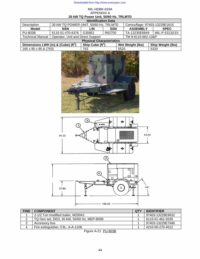
DescriptionMod
PU-803B Technical
Dimension165 x 95 x
FIND CO1 2-2 TQ3 Ac4 Fir
n 30 el
611Manual Op
ns LWH (in) x 85 & (763)
OMPONENT 1/2 Ton modi
Q Gen set, DEccessory box re extinguishe
84.5
30 k
kW TQ POWNSN
15-01-470-63erator, Unit a
& (Cube) (ft3
fied trailer, MED, 30 kW, 50
er, 5 lb., A-A-
MIL-AP
kW TQ PowerIdent
WER UNIT, 50LIN
376 G35851and Direct Sup
Physica3) Ship Cu
763
200A1 0/60 Hz, MEP
1106 Figure
-HDBK-633APPENDIX A
44
r Unit, 50/60 tification Dat
0/60 Hz, TRLMN S1 R627pport al Characteriube (ft3)
P-805B
A-21 PU-80
A
Hz, TRLMTDta MTD CamSN A
700 TA-TM
stics Wet Weig5525
3B
D
mouflage: 974ASSEMBLY 13230E6849 9-6115-662-1
ght (lbs)
QTY IDE1 971 611 971 42
403-13228E16SPE
MIL-P-5313&P
Ship Weight5320
ENTIFIER 403-13229E915-01-461-93403-13229E710-00-270-45
615 EC 132/15
t (lbs)
9632 335 7946 512
Downloaded from http://www.everyspec.com
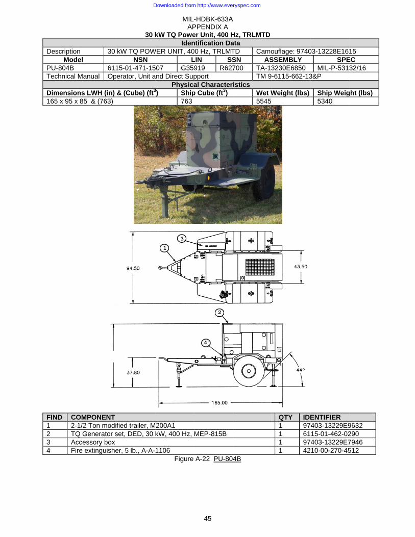
DescriptionMod
PU-804B Technical
Dimension165 x 95 x
FIND CO1 2-2 TQ3 Ac4 Fir
n 30 el
611Manual Op
ns LWH (in) x 85 & (763)
OMPONENT 1/2 Ton modi
Q Generator sccessory box re extinguishe
84.5
30 k
kW TQ POWNSN
15-01-471-15erator, Unit a
& (Cube) (ft3
fied trailer, Mset, DED, 30
er, 5 lb., A-A-
5
MIL-AP
kW TQ PoweIden
WER UNIT, 40L
507 G359and Direct Sup
Physica3) Ship
763
200A1 kW, 400 Hz,
1106 Figure
-HDBK-633APPENDIX A
45
er Unit, 400 Hntification Da00 Hz, TRLMTLIN SS919 R627pport al Character
p Cube (ft3)
MEP-815B
A-22 PU-80
A
Hz, TRLMTData TD CamoSN AS700 TA-13
TM 9istics
Wet W5545
4B
ouflage: 9740SSEMBLY 3230E6850 -6115-662-13
Weight (lbs)
QTY IDE1 971 611 971 42
03-13228E16SPE
MIL-P-53133&P
Ship Weig5340
ENTIFIER 403-13229E915-01-462-02403-13229E710-00-270-45
15 EC 32/16
ght (lbs)
9632 290 7946 512
Downloaded from http://www.everyspec.com
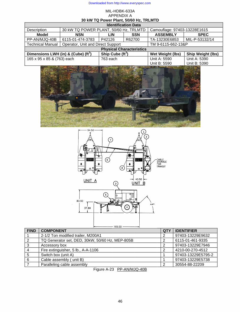
DescriptionMod
PP-AN/MJTechnical
Dimension165 x 95 x
FIND CO1 2-2 TQ3 Ac4 Fir5 Sw6 Ca7 Pa
n 30 el
JQ-40B 611Manual Op
ns LWH (in) x 85 & (763) e
OMPONENT 1/2 Ton modi
Q Generator sccessory box re extinguishewitch box (uniable assemblyaralleling cabl
30 kW
kW TQ POWNSN
15-01-474-37erator, Unit a
& (Cube) (ft3
each
fied trailer, Mset, DED, 30k
er, 5 lb., A-A-t A) y ( unit B) le assembly
MIL-AP
W TQ Power Ide
WER PLANT, 5LIN
783 P4212and Direct Sup
Physic3) Ship C
763 ea
200A1 kW, 50/60 Hz
1106
Figure A-23
-HDBK-633APPENDIX A
46
Plant, 50/60entification D50/60 Hz, TRN SS6 R627pport cal CharacteCube (ft3) ach
, MEP-805B
3 PP-AN/MJ
A
Hz, TRLMTDData RLMTD Cam
SN A700 TA-1
TM 9eristics
WetUnit Unit
JQ-40B
D
mouflage: 974ASSEMBLY 13230E6853 9-6115-662-1
t Weight (lbsA: 5590 B: 5590
QTY IDE2 972 612 972 421 971 972 30
403-13228E16SP
MIL-P-5313&P
) Ship WeUnit A: 53Unit B: 53
ENTIFIER 403-13229E915-01-461-93403-13229E710-00-270-45403-13229E5403-13229E5554-88-2220
615 PEC 132/14
ight (lbs) 390 390
9632 335 7946 512 5795-2 5738 9
Downloaded from http://www.everyspec.com
MIL-HDBK-633A APPENDIX A
47
This Page Intentionally Left Blank
Downloaded from http://www.everyspec.com
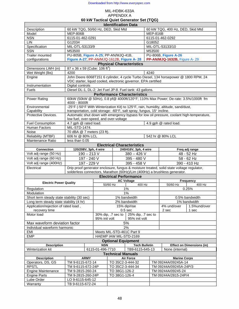
MIL-HDBK-633A APPENDIX A
48
60 kW Tactical Quiet Generator Set (TQG) Identification Data
Description 60 kW TQG, 50/60 Hz, DED, Skid Mtd 60 kW TQG, 400 Hz, DED, Skid Mtd Model MEP-806B MEP-816B NSN 6115-01-462-0291 6115-01-462-0292 LIN G12034 G18052 Specification MIL-DTL-53133/9 MIL-DTL-53133/10 SSN M53500 M53500 Trailer mounted configurations
PU-805B, Figure A-25; PP-AN/MJQ-41B, Figure A-27; PP-AN/MJQ-1612B, Figure A- 28
PU-806B, Figure A-26 PP-AN/MJQ-1632B, Figure A- 29
Physical Characteristics Dimensions LWH (in) 87 x 36 x 59 (Cube: 106 ft3) Wet Weight (lbs) 4200 4240 Engine John Deere 6068T151 6 cylinder, 4 cycle Turbo Diesel, 134 horsepower @ 1800 RPM, 24
VDC starter, liquid cooled, electronic governor. EPA certified Instrumentation Digital controls Fuels Diesel DL-1, DL-2; Jet Fuel JP-8. Fuel tank: 43 gallons.
Performance Characteristics Power Rating 60kW (50kW @ 50Hz), 0.8 pf@ 4000ft/120°F; 110% Max Power; De-rate: 3.5%/1000ft fm
4000 - 8000ft Environmental Capability
-25°F (-50°F With Winterization Kit) to 125°F, rain, humidity, altitude, sand/dust, transportation, cold storage: -60°F, salt spray, fungus, 15° incline.
Protective Devices. Automatic shut down with emergency bypass for low oil pressure, coolant high-temperature, low fuel, over-speed, and over-voltage
Fuel Consumption 4.7 gph @ rated load. 4.9 gph @ rated load. Human Factors MIL-STD-1474. Noise 70 dBA @ 7 meters (23 ft). Reliability (MTBF) 606 hr @ 80% LCL 542 hr @ 80% LCL Maintenance Ratio less than 0.05
Electrical Characteristics Connection 120/208V, 3ph, 4 wire 240/416V, 3ph, 4 wire Freq adj range
Volt adj range (50 Hz) 190 – 213 V 380 – 426 V 48 - 52 Hz Volt adj range (60 Hz) 197 - 240 V 395 - 480 V 58 - 62 Hz Volt adj range (400Hz) 197 - 229 V 395 - 458 V 390 - 410 Hz Electrical Drip proof generator enclosure, fungus & moisture treated, solid state voltage regulator,
solderless connectors, Marathon (60Hz)/Lim (400Hz) a brushless generator. Electrical Performance
Electric Power Quality AC Voltage Frequency 50/60 Hz 400 Hz 50/60 Hz 400 Hz
Regulation 1% 0.25% Modulation 1% Short term steady state stability (30 sec) 1% bandwidth 0.5% bandwidth Long term steady state stability (4 hr) 2% bandwidth 1% bandwidth Application/rejection of rated load ,
recovery time 15% dip/rise
0.5 sec 4% und/over 2 sec
1.5%und/over 1 sec
Motor load 30% dip, .7 sec to 95% init volt
25% dip, .7 sec to 95% init volt
Max waveform deviation factor 5% Individual waveform harmonic 2% EMI Meets MIL-STD-461C Part 9 EMP HAEMP IAW MIL-STD-2169
Optional Equipment Description NSN Tech Bulletin Effect on Dimensions (in)
Winterization kit 6115-01-496-7710 TB9-6115-645-13 None (internal) Technical Manuals
Description ARMY Air Force Marine Corps Operators, DS, GS TM 9-6115-672-14 TO 35C2-3-444-32 TM 09244A/09245A-14 RPSTL TM 9-6115-672-24P TO 35C2-3-444-34 TM 09244A/09245A-24P/3 Engine Maintenance TM 9-2815-260-24 TO 38G1-126-2 TM 09244A/09245-24 Engine Parts TM 9-2815-260-24P TO 38G1-126-4 TM 09244A/2815-24P/4 Lube Order LO 9-6115-645-12 Warranty TB 9-6115-672-24
Downloaded from http://www.everyspec.com
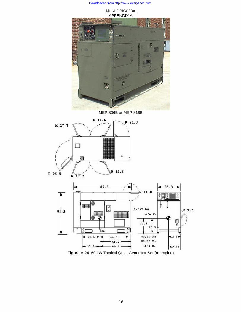
MIL-HDBK-633A APPENDIX A
49
MEP-806B or MEP-816B
Figure A-24 60 kW Tactical Quiet Generator Set (re-engine)
Downloaded from http://www.everyspec.com
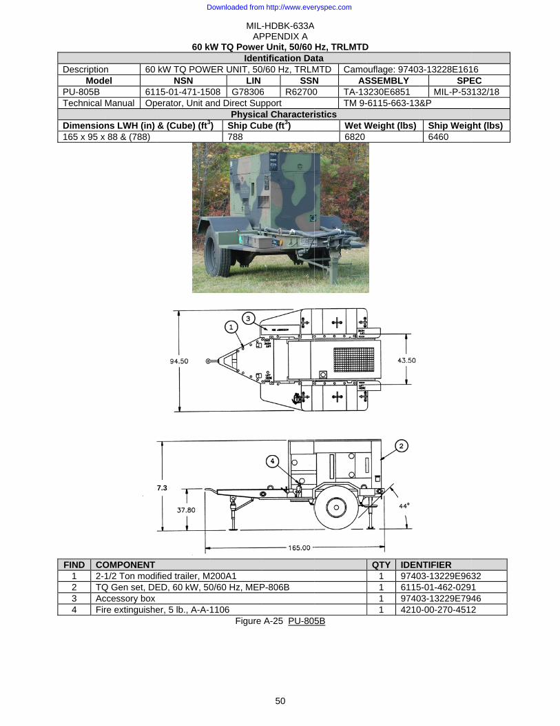
DescriptionMod
PU-805B Technical
Dimension165 x 95 x
FIND CO1 2-2 TQ3 Ac4 Fir
n 60 el
611Manual Op
ns LWH (in) x 88 & (788)
OMPONENT 1/2 Ton modi
Q Gen set, DEccessory box re extinguishe
8
60 k
kW TQ POWNSN
15-01-471-15erator, Unit a
& (Cube) (ft3
fied trailer, MED, 60 kW, 50
er, 5 lb., A-A-
7.3
MIL-AP
kW TQ PowerIden
WER UNIT, 50LIN
508 G78306and Direct Sup
Physica3) Ship Cu
788
200A1 0/60 Hz, MEP
1106 Figure
-HDBK-633APPENDIX A
50
r Unit, 50/60 ntification Da0/60 Hz, TRLM
SSN6 R62700pport al Characteribe (ft3)
P-806B
A-25 PU-80
A
Hz, TRLMTData MTD CamoN AS0 TA-13
TM 9-istics
Wet W6820
5B
D
ouflage: 97403SSEMBLY 3230E6851 -6115-663-13
Weight (lbs)
QTY IDEN1 97401 61151 97401 4210
3-13228E161SPE
MIL-P-53&P
Ship Weig6460
NTIFIER 03-13229E9635-01-462-02903-13229E7940-00-270-4512
16 EC 132/18
ght (lbs)
32 1 46 2
Downloaded from http://www.everyspec.com
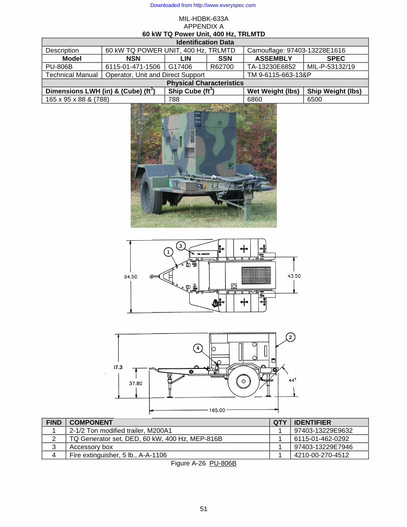
DescriptionMod
PU-806B Technical
Dimension165 x 95 x
FIND CO1 2-2 TQ3 Ac4 Fir
n 60 el
611Manual Op
ns LWH (in) x 88 & (788)
OMPONENT 1/2 Ton modi
Q Generator sccessory box re extinguishe
8
60 k
kW TQ POWNSN
15-01-471-15erator, Unit a
& (Cube) (ft3
fied trailer, Mset, DED, 60
er, 5 lb., A-A-
87.3
MIL-AP
kW TQ PoweIdent
WER UNIT, 40LIN
506 G17406and Direct Sup
Physica3) Ship Cu
788
200A1 kW, 400 Hz,
1106 Figure
-HDBK-633APPENDIX A
51
er Unit, 400 Htification Dat
00 Hz, TRLMTN SSN6 R6270pport al Characteriube (ft3)
MEP-816B
A-26 PU-80
A
Hz, TRLMTDta TD CamouN ASS00 TA-132
TM 9-6stics
Wet W6860
6B
uflage: 97403SEMBLY 230E6852 6115-663-13&
Weight (lbs)
QTY IDE
1 9741 6111 9741 421
3-13228E1616SPEC
MIL-P-53132&P
Ship Weigh6500
ENTIFIER 403-13229E96
5-01-462-029403-13229E79
0-00-270-451
6 C 2/19
ht (lbs)
632 92 946 12
Downloaded from http://www.everyspec.com
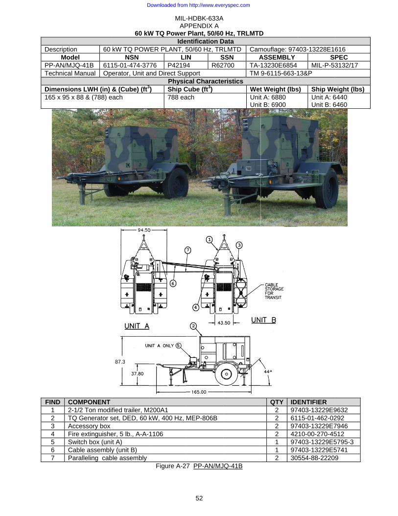
DescriptionMod
PP-AN/MJTechnical
Dimension165 x 95 x
FIND CO1 2-2 TQ3 Ac4 Fir5 Sw6 Ca7 Pa
n 60 el
JQ-41B 611Manual Op
ns LWH (in) x 88 & (788) e
OMPONENT 1/2 Ton modi
Q Generator sccessory box re extinguishewitch box (uniable assemblyaralleling cab
60 kW
kW TQ POWNSN
15-01-474-37erator, Unit a
& (Cube) (ft3
each
fied trailer, Mset, DED, 60
er, 5 lb., A-A-t A) y (unit B)
ble assembly
87.3
MIL-AP
W TQ Power Ide
WER PLANT, 5LI
776 P4219and Direct Sup
Physic3) Ship C
788 ea
200A1 kW, 400 Hz,
1106
Figure A-2
-HDBK-633APPENDIX A
52
Plant, 50/60entification D50/60 Hz, TRIN S
94 R62pport cal Characte
Cube (ft3) ach
MEP-806B
7 PP-AN/MJ
A
Hz, TRLMTDData RLMTD CamSSN A700 TA-
TM eristics
WetUnitUnit
Q-41B
D
mouflage: 974ASSEMBLY 13230E6854 9-6115-663-1
t Weight (lbst A: 6880 t B: 6900
QTY IDE
2 972 612 972 421 971 972 30
403-13228E16SP
MIL-P-5313&P
s) Ship WeUnit A: 6Unit B: 6
ENTIFIER 403-13229E915-01-462-02403-13229E710-00-270-45403-13229E5403-13229E5554-88-2220
616 PEC 3132/17
eight (lbs) 6440 6460
9632 292 7946 512 5795-3 5741 9
Downloaded from http://www.everyspec.com

MIL-HDBK-633A APPENDIX A
53
PP-AN/MJQ-1612, TQ POWER PLANT, DED, 60kW, 50/60 Hz, TRLMTD AIR FORCE POWER PLANT NOT TYPE CLASSIFIED FOR ARMY USE
Identification Data Description TQ POWER PLANT, DED, 60kW, 50/60Hz, TRLMTD AF Camouflage: 97403-13228E1617
Model NSN LIN SSN ASSEMBLY SPEC PP-AN/MJQ-1612 6115-01-349-1536 M510 TA-13229E9635 Technical Manual
Physical Characteristics Dimensions LWH (in) & (Cube) (ft3) Ship Cube (ft3) Wet Weight (lbs) Ship Weight (lbs)
222.6 x 96.0 x 96.0 & (1187) 1172 14700 15800
COMPONENT QTY FIND IDENTIFIER AF Trailer Generator Assembly, M1061A1 1 1 2330-01-573-0985 TQ Gen set, DED, 60 kW, 50/60 Hz, MEP-806B 2 2 6115-01-462-0291 Accessory box 1 3 97403-13229E7946 Fire extinguisher, 5 lb., A-A-1106 2 4 4210-00-270-4512 Switch box 1 5 97403-13230E4550 Cable storage box 1 6 97403-13230E4580
Figure A- 28 PP-AN/MJQ-1612
Downloaded from http://www.everyspec.com
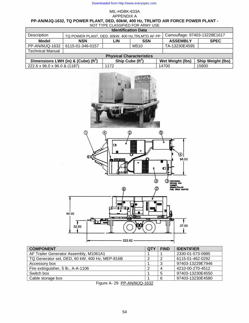
MIL-HDBK-633A APPENDIX A
54
PP-AN/MJQ-1632, TQ POWER PLANT, DED, 60kW, 400 Hz, TRLMTD AIR FORCE POWER PLANT - NOT TYPE CLASSIFIED FOR ARMY USE
Identification Data Description TQ POWER PLANT, DED, 60kW, 400 Hz,TRLMTD AF PP Camouflage: 97403-13228E1617
Model NSN LIN SSN ASSEMBLY SPEC PP-AN/MJQ-1632 6115-01-346-0157 M510 TA-13230E4595 Technical Manual
Physical Characteristics Dimensions LWH (in) & (Cube) (ft3) Ship Cube (ft3) Wet Weight (lbs) Ship Weight (lbs)
222.6 x 96.0 x 96.0 & (1187) 1172 14700 15800
COMPONENT QTY FIND IDENTIFIER AF Trailer Generator Assembly, M1061A1 1 1 2330-01-573-0985 TQ Generator set, DED, 60 kW, 400 Hz, MEP-816B 2 2 6115-01-462-0292 Accessory box 1 3 97403-13229E7946 Fire extinguisher, 5 lb., A-A-1106 2 4 4210-00-270-4512 Switch box 1 5 97403-13230E4550 Cable storage box 1 6 97403-13230E4580
Figure A- 29 PP-AN/MJQ-1632
Downloaded from http://www.everyspec.com

MIL-HDBK-633A APPENDIX A
55
This Page Intentionally Left Blank
Downloaded from http://www.everyspec.com
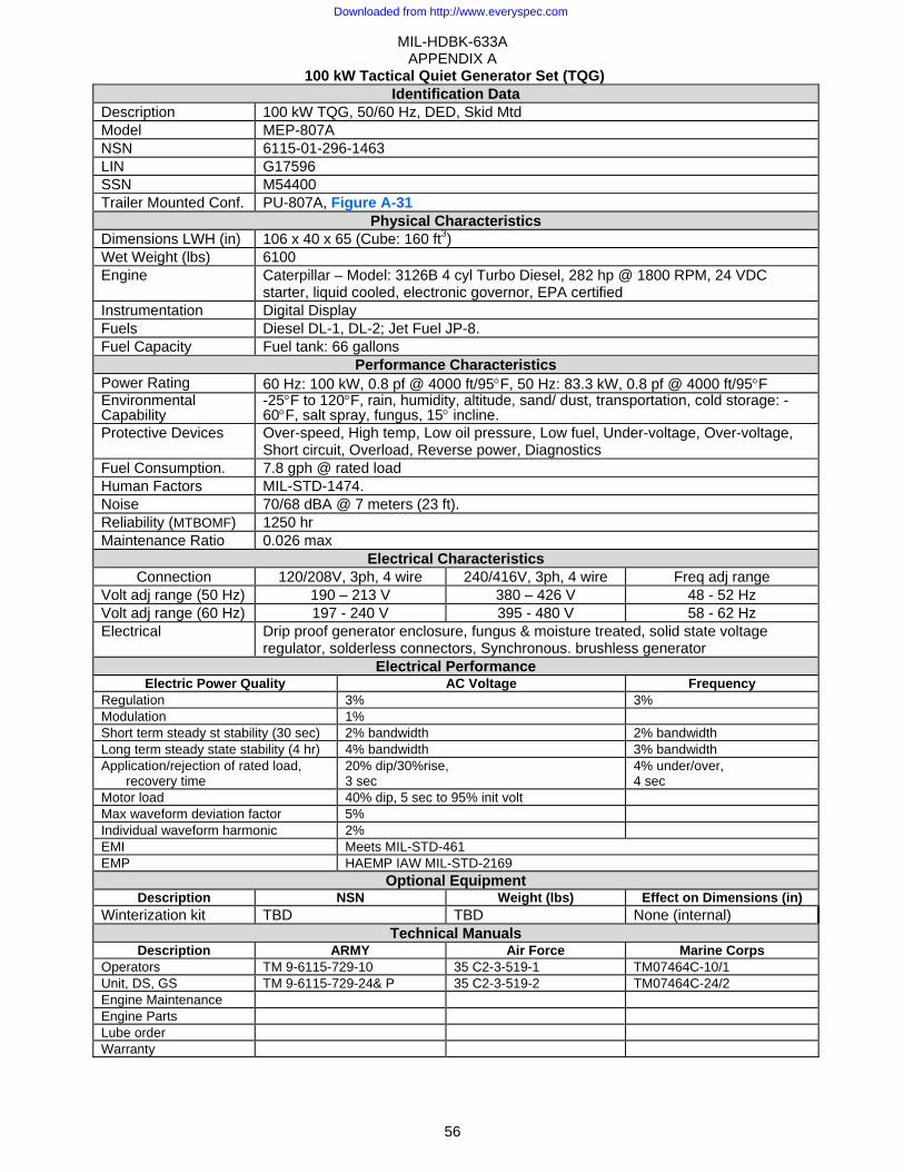
MIL-HDBK-633A APPENDIX A
56
100 kW Tactical Quiet Generator Set (TQG) Identification Data
Description 100 kW TQG, 50/60 Hz, DED, Skid Mtd Model MEP-807A NSN 6115-01-296-1463 LIN G17596 SSN M54400 Trailer Mounted Conf. PU-807A, Figure A-31
Physical Characteristics Dimensions LWH (in) 106 x 40 x 65 (Cube: 160 ft3) Wet Weight (lbs) 6100 Engine Caterpillar – Model: 3126B 4 cyl Turbo Diesel, 282 hp @ 1800 RPM, 24 VDC
starter, liquid cooled, electronic governor, EPA certified Instrumentation Digital Display Fuels Diesel DL-1, DL-2; Jet Fuel JP-8. Fuel Capacity Fuel tank: 66 gallons
Performance Characteristics Power Rating 60 Hz: 100 kW, 0.8 pf @ 4000 ft/95°F, 50 Hz: 83.3 kW, 0.8 pf @ 4000 ft/95°F Environmental Capability
-25°F to 120°F, rain, humidity, altitude, sand/ dust, transportation, cold storage: -60°F, salt spray, fungus, 15° incline.
Protective Devices Over-speed, High temp, Low oil pressure, Low fuel, Under-voltage, Over-voltage, Short circuit, Overload, Reverse power, Diagnostics
Fuel Consumption. 7.8 gph @ rated load Human Factors MIL-STD-1474. Noise 70/68 dBA @ 7 meters (23 ft). Reliability (MTBOMF) 1250 hr Maintenance Ratio 0.026 max
Electrical Characteristics Connection 120/208V, 3ph, 4 wire 240/416V, 3ph, 4 wire Freq adj range
Volt adj range (50 Hz) 190 – 213 V 380 – 426 V 48 - 52 Hz Volt adj range (60 Hz) 197 - 240 V 395 - 480 V 58 - 62 Hz Electrical Drip proof generator enclosure, fungus & moisture treated, solid state voltage
regulator, solderless connectors, Synchronous. brushless generator Electrical Performance
Electric Power Quality AC Voltage FrequencyRegulation 3% 3% Modulation 1% Short term steady st stability (30 sec) 2% bandwidth 2% bandwidth Long term steady state stability (4 hr) 4% bandwidth 3% bandwidth Application/rejection of rated load,
recovery time 20% dip/30%rise, 3 sec
4% under/over, 4 sec
Motor load 40% dip, 5 sec to 95% init volt Max waveform deviation factor 5% Individual waveform harmonic 2% EMI Meets MIL-STD-461 EMP HAEMP IAW MIL-STD-2169
Optional Equipment Description NSN Weight (lbs) Effect on Dimensions (in)
Winterization kit TBD TBD None (internal) Technical Manuals
Description ARMY Air Force Marine CorpsOperators TM 9-6115-729-10 35 C2-3-519-1 TM07464C-10/1 Unit, DS, GS TM 9-6115-729-24& P 35 C2-3-519-2 TM07464C-24/2 Engine Maintenance Engine Parts Lube order Warranty
Downloaded from http://www.everyspec.com
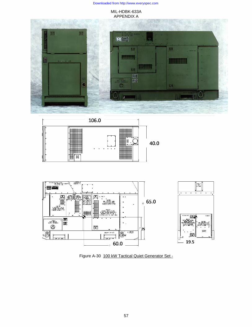
MIL-HDBK-633A APPENDIX A
57
Figure A-30 100 kW Tactical Quiet Generator Set -
Downloaded from http://www.everyspec.com
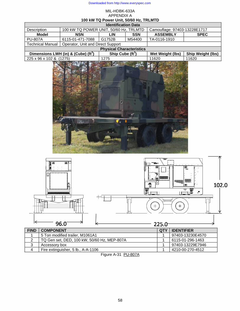
MIL-HDBK-633A APPENDIX A
58
100 kW TQ Power Unit, 50/60 Hz, TRLMTD Identification Data
Description 100 kW TQ POWER UNIT, 50/60 Hz, TRLMTD Camouflage: 97403-13228E1717 Model NSN LIN SSN ASSEMBLY SPEC
PU-807A 6115-01-471-7088 G1752B M54400 TA-0116-1910 Technical Manual Operator, Unit and Direct Support
Physical Characteristics Dimensions LWH (in) & (Cube) (ft3) Ship Cube (ft3) Wet Weight (lbs) Ship Weight (lbs)
225 x 96 x 102 & (1275) 1275 11620 11620
FIND COMPONENT QTY IDENTIFIER
1 5 Ton modified trailer, M1061A1 1 97403-13230E4570 2 TQ Gen set, DED, 100 kW, 50/60 Hz, MEP-807A 1 6115-01-296-1463 3 Accessory box 1 97403-13229E7946 4 Fire extinguisher, 5 lb., A-A-1106 1 4210-00-270-4512
Figure A-31 PU-807A
Downloaded from http://www.everyspec.com

MIL-HDBK-633A APPENDIX A
59
This Page Intentionally Left Blank
Downloaded from http://www.everyspec.com
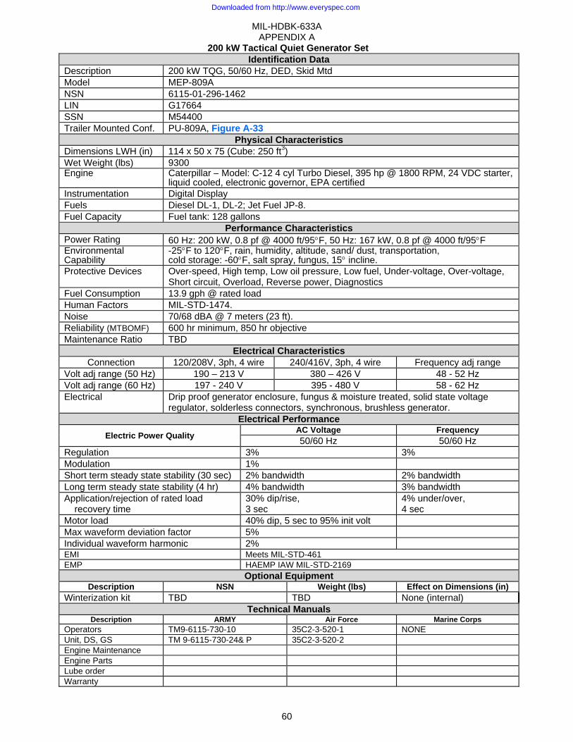
MIL-HDBK-633A APPENDIX A
60
200 kW Tactical Quiet Generator Set Identification Data
Description 200 kW TQG, 50/60 Hz, DED, Skid Mtd Model MEP-809A NSN 6115-01-296-1462 LIN G17664 SSN M54400 Trailer Mounted Conf. PU-809A, Figure A-33
Physical Characteristics Dimensions LWH (in) 114 x 50 x 75 (Cube: 250 ft3) Wet Weight (lbs) 9300 Engine Caterpillar – Model: C-12 4 cyl Turbo Diesel, 395 hp @ 1800 RPM, 24 VDC starter,
liquid cooled, electronic governor, EPA certifiedInstrumentation Digital Display Fuels Diesel DL-1, DL-2; Jet Fuel JP-8. Fuel Capacity Fuel tank: 128 gallons
Performance Characteristics Power Rating 60 Hz: 200 kW, 0.8 pf @ 4000 ft/95°F, 50 Hz: 167 kW, 0.8 pf @ 4000 ft/95°F Environmental Capability
-25°F to 120°F, rain, humidity, altitude, sand/ dust, transportation, cold storage: -60°F, salt spray, fungus, 15° incline.
Protective Devices Over-speed, High temp, Low oil pressure, Low fuel, Under-voltage, Over-voltage, Short circuit, Overload, Reverse power, Diagnostics
Fuel Consumption 13.9 gph @ rated load Human Factors MIL-STD-1474. Noise 70/68 dBA @ 7 meters (23 ft). Reliability (MTBOMF) 600 hr minimum, 850 hr objective Maintenance Ratio TBD
Electrical Characteristics Connection 120/208V, 3ph, 4 wire 240/416V, 3ph, 4 wire Frequency adj range
Volt adj range (50 Hz) 190 – 213 V 380 – 426 V 48 - 52 Hz Volt adj range (60 Hz) 197 - 240 V 395 - 480 V 58 - 62 Hz Electrical Drip proof generator enclosure, fungus & moisture treated, solid state voltage
regulator, solderless connectors, synchronous, brushless generator. Electrical Performance
Electric Power Quality AC Voltage Frequency50/60 Hz 50/60 Hz
Regulation 3% 3% Modulation 1% Short term steady state stability (30 sec) 2% bandwidth 2% bandwidth Long term steady state stability (4 hr) 4% bandwidth 3% bandwidth Application/rejection of rated load recovery time
30% dip/rise, 3 sec
4% under/over, 4 sec
Motor load 40% dip, 5 sec to 95% init volt Max waveform deviation factor 5% Individual waveform harmonic 2% EMI Meets MIL-STD-461 EMP HAEMP IAW MIL-STD-2169
Optional Equipment Description NSN Weight (lbs) Effect on Dimensions (in)
Winterization kit TBD TBD None (internal) Technical Manuals
Description ARMY Air Force Marine Corps Operators TM9-6115-730-10 35C2-3-520-1 NONE Unit, DS, GS TM 9-6115-730-24& P 35C2-3-520-2 Engine Maintenance Engine Parts Lube order Warranty
Downloaded from http://www.everyspec.com

MIL-HDBK-633A APPENDIX A
61
Figure A-32 200 kW Tactical Quiet Generator Set -
Downloaded from http://www.everyspec.com

MIL-HDBK-633A APPENDIX A
62
200 kW TQ Power Unit, 50/60 Hz, TRLMTD Identification Data
Description 200 kW TQ POWER UNIT, 50/60 Hz, TRLMTD Camouflage: 97403-13228E1718 Model NSN LIN SSN ASSEMBLY SPEC
PU-809A 6115-01-471-7085 G26345 M54400 TA-0116-2910 Technical Manual Operator, Unit and Direct Support
Physical Characteristics Dimensions LWH (in) & (Cube) (ft3) Ship Cube (ft3) Wet Weight (lbs) Ship Weight (lbs)
225 x 96 x 112 & (1400) 1400 14780 14780
FIND COMPONENT QTY IDENTIFIER
1 5 Ton modified trailer, M1061A1 1 97403-13230E4570 2 TQ Gen set, DED, 200 kW, 50/60 Hz, MEP-809A 1 6115-01-296-1462 3 Accessory box 1 97403-13229E7940 4 Fire extinguisher, 5 lb., A-A-1106 1 4210-00-270-4512
Figure A-33 PU-809A
Downloaded from http://www.everyspec.com

MIL-HDBK-633A APPENDIX A
63
This Page Intentionally Left Blank
Downloaded from http://www.everyspec.com
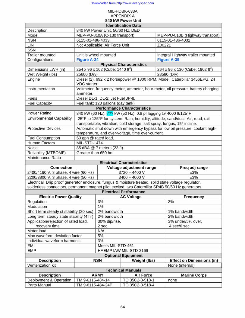
MIL-HDBK-633A APPENDIX A
64
840 kW Power Unit Identification Data
Description 840 kW Power Unit, 50/60 Hz, DED Model MEP-PU-810A (C-130 transport) MEP-PU-810B (Highway transport)NSN 6115-01-486-4033 6115-01-486-4032 LIN Not Applicable: Air Force Unit Z00221 SSN Trailer mounted Configurations
Unit is wheel mounted Figure A-34
Integral Highway trailer mounted Figure A-35
Physical Characteristics Dimensions LWH (in) 254 x 96 x 102 (Cube: 1440 ft3) 264 x 96 x 130 (Cube: 1902 ft3) Wet Weight (lbs) 25600 (Dry) 28580 (Dry) Engine Diesel (2), 692 x 2 horsepower @ 1800 RPM, Model: Caterpillar 3456EPG, 24
VDC starter. Instrumentation Voltmeter, frequency meter, ammeter, hour-meter, oil pressure, battery charging
ammeter. Fuels Diesel DL-1, DL-2; Jet Fuel JP-8. Fuel Capacity Fuel tank: 120 gallons (day tank)
Performance Characteristics Power Rating 840 kW (60 Hz), ??? kW (50 Hz), 0.8 pf lagging @ 4000 ft/125°F Environmental Capability -25°F to 125°F for system. Rain, humidity, altitude, sand/dust, Air, road, rail
transportable, vibration, cold storage, salt spray, fungus, 15° incline. Protective Devices Automatic shut down with emergency bypass for low oil pressure, coolant high-
temperature, and over-voltage, time over-current. Fuel Consumption 60 gph @ rated load. Human Factors MIL-STD-1474. Noise 85 dBA @ 7 meters (23 ft). Reliability (MTBOMF) Greater than 650 hrs Maintenance Ratio
Electrical Characteristics Connection Voltage adjustment range Freq adj range
2400/4160 V, 3 phase, 4 wire (60 Hz) 3720 – 4400 V ±3% 2200/3800 V, 3 phase, 4 wire (50 Hz) 3400 – 4000 V ±3% Electrical Drip proof generator enclosure, fungus & moisture treated, solid state voltage regulator, solderless connectors, permanent magnet pilot excited, two Caterpillar SR4B 50/60 Hz generators.
Electrical Performance Electric Power Quality AC Voltage Frequency
Regulation 3% 3% Modulation 1% Short term steady st stability (30 sec) 2% bandwidth 1% bandwidth Long term steady state stability (4 hr) 2% bandwidth 2% bandwidth Application/rejection of rated load,
recovery time 30% dip/rise, 2 sec
3% under/5% over, 4 sec/6 sec
Motor load N/A Max waveform deviation factor 5% Individual waveform harmonic 3% EMI Meets MIL-STD-461 EMP HAEMP IAW MIL-STD-2169
Optional Equipment Description NSN Weight (lbs) Effect on Dimensions (in)
Winterization kit None (internal) Technical Manuals
Description ARMY Air Force Marine Corps Deployment & Operation TM 9-6115-484-14 TO 35C2-3-518-1 none Parts Manual TM 9-6115-484-24P TO 35C2-3-518-4
Downloaded from http://www.everyspec.com

MIL-HDBK-633A APPENDIX A
65
PU-810A (C-130 Transportable)
Figure A-34 PU-810A
Downloaded from http://www.everyspec.com
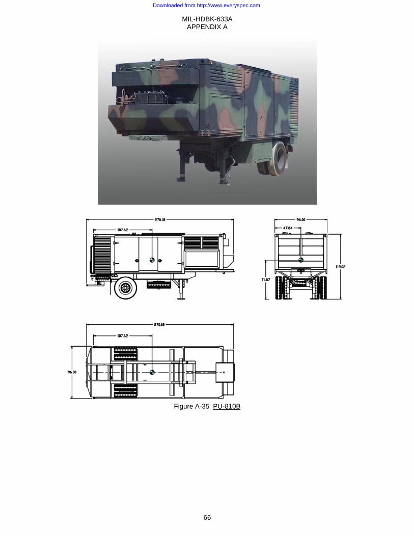
MIL-HDBK-633A APPENDIX A
66
Figure A-35 PU-810B
Downloaded from http://www.everyspec.com

MIL-STD-633F
67
APPENDIX B STANDARD FAMILY OF AUXILIARY POWER UNITS (APU)
B.1 SCOPE
B.1.1 Scope. This Appendix identifies the current Auxiliary Power Unit (APU) members of the DoD Standard Family of MEPGS. Data contained in this Appendix is for information only and is provided to assist both field operation and materiel developer personnel to select the power generation source that will best meet their needs. The APUs are not separately fielded items but are part of a vehicle or shelter system. DoD activities are to utilize these power sources to the maximum extent practicable per DoD DIRECTIVE 4120.11.
B.1.2 Appendix Organization. This Appendix is a compilation of characteristics data sheets (see Table B- I Guide to CHARACTERISTICS DATA SHEETS of APPENDIX B) arranged by power rating capacity.
Table B- I Guide to CHARACTERISTICS DATA SHEETS of APPENDIX B MODEL NO. ITEM DESCRIPTION NSN FIG PAGEMEP-952 5 kW, 28 VDC, DED/APU 6115-01-317-2139 Figure B- 1 68 MEP-903A 10 kW, 60 Hz, DED/APU 6115-01-431-3062 Figure B- 2 70
B.2 APPLICABLE DOCUMENTS
B.3 DEFINITIONS
B.3.1 Auxiliary Power Unit (APU). An Auxiliary Power Unit (APU) is a power source consisting of a self-contained engine and generator, including remote controls, capable of producing electrical power when connected to its host's source of fuel and starting power.
B.4 GENERAL DESCRIPTIONS
B.4.1 Item Descriptions.
B.4.1.1 5 kW 28 VDC Auxiliary Power Unit (APU). The 5 kW 28 VDC APU is a newly developed diesel engine driven replacement for the 4.2 kW gasoline engine driven APU used on M577 Armored Personnel Carriers. The 4.2 kW APUs are noisy, unreliable, difficult to maintain and require an additional fuel (gasoline), not used by other equipment, to be brought to the battlefield. The new 5 kW 28 VDC APU eliminates these problems. More importantly, the 5 kW 28 VDC APU also provides power to the M1068 tracked vehicle, which houses the communications, intelligence and command and control computer suite, a lynch pin in the Army's Force XXI strategy. The APU utilizes a standard NATO slave receptacle to connect to a DC power system. The APU is usually started by the power provided via the NATO slave receptacle, but has a hand crank to start the set if batteries are not charged or available.
B.4.1.2 10 kW, 60 Hz Auxiliary Power Unit (APU). The 10 kW, 60 Hz, 120/240 volt APU was a joint development effort among the Army project managers; Project Manager, Mobile Electric Power (PM, MEP), PM, Joint Tactical Area Communication System (PM, JTACS), PM, Platforms (previously the PM, Standard Integrated Command Post System (PM, SICPS)), and PM, Air Defense Command and Control Systems (PM, ADCCS). The differing rail and tunnel dimensions between the SICPS shelter and the JTACS shelter cause the SICPS APU to be slightly modified (rail and muffler) for the JTACS application. Electrical generation hardware and performance of the JTACS APU are identical to the SICPS APU. The 10 kW APU has a remotely located control panel, usually mounted inside the shelter, which interfaces through the shelter utility tunnel.
B.5 DETAILED DESCRIPTIONS
B.5.1 Detailed Descriptions. Details of these Auxiliary Power Units are contained in the CHARACTERISTICS DATA SHEETS of Figure B- 1 and Figure B- 2
Downloaded from http://www.everyspec.com
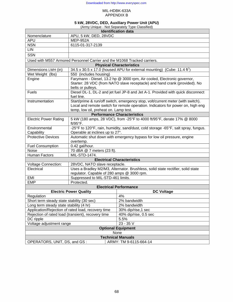
MIL-HDBK-633A APPENDIX B
68
5 kW, 28VDC, DED, Auxiliary Power Unit (APU) (Army Unique - Not Separately Type Classified)
Identification data Nomenclature APU, 5 kW, DED, 28VDC APU MEP-952A NSN 6115-01-317-2139 LIN SSN Used with M557 Armored Personnel Carrier and the M1068 Tracked carriers.
Physical Characteristics Dimensions LWH (in) 34.5 x 30.5 x 17.0 (housed APU for external mounting) (Cube: 11.4 ft3)Wet Weight (lbs) 550 (includes housing) Engine Farymann - Diesel, 13.2 hp @ 3000 rpm, Air cooled, Electronic governor,
Starter: 28 VDC (from NATO slave receptacle) and hand crank (provided). No belts or pulleys.
Fuels Diesel DL-1, DL-2 and jet fuel JP-8 and Jet A-1. Provided with quick disconnect fuel line.
Instrumentation Start/prime & run/off switch, emergency stop, volt/current meter (with switch). Local and remote switch for remote operation. Indicators for power on, high eng temp, low oil, preheat on. Lamp test.
Performance Characteristics Electric Power Rating 5 kW (180 amps, 28 VDC), from -25°F to 4000 ft/95°F, derate 17% @ 8000
ft/95°F. Environmental Capability
-25°F to 120°F, rain, humidity, sand/dust, cold storage -65°F, salt spray, fungus. Operable at inclines up to 27°.
Protective Devices Automatic shut down with emergency bypass for low oil pressure, engine overtemp.
Fuel Consumption 0.42 gal/hour. Noise 70 dBA @ 7 meters (23 ft). Human Factors MIL-STD-1474.
Electrical Characteristics Voltage Connection: 28VDC, NATO slave receptacle. Electrical Uses a Bradley M2/M3, Alternator. Brushless, solid state rectifier, solid state
regulator. Capable of 280 amps @ 3000 rpm. EMI Suppressed to MIL-STD-461 limits. EMP Protected.
Electrical Performance Electric Power Quality DC Voltage
Regulation 4% Short term steady state stability (30 sec) 2% bandwidth Long term steady state stability (4 hr) 2% bandwidth Application/Rejection of rated load, recovery time 30% dip/rise,1 sec Rejection of rated load (transient), recovery time 40% dip/rise, 0.5 sec DC ripple 5.5% Voltage adjustment range 23 - 35 V
Optional Equipment None
Technical Manuals OPERATORS, UNIT, DS, and GS : ARMY: TM 9-6115-664-14
Downloaded from http://www.everyspec.com
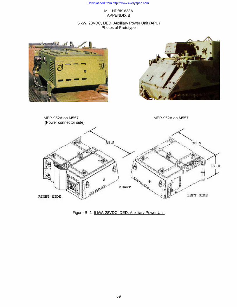
MIL-HDBK-633A APPENDIX B
69
5 kW, 28VDC, DED, Auxiliary Power Unit (APU) Photos of Prototype
MEP-952A on M557 MEP-952A on M557 (Power connector side)
Figure B- 1 5 kW, 28VDC, DED, Auxiliary Power Unit
Downloaded from http://www.everyspec.com
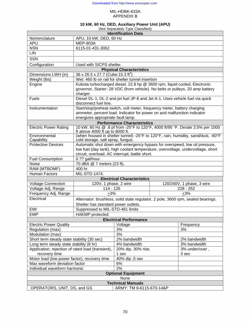
MIL-HDBK-633A APPENDIX B
70
10 kW, 60 Hz, DED, Auxiliary Power Unit (APU) (Not Separately Type Classified)
Identification Data Nomenclature APU, 10 kW, DED, 60 Hz APU MEP-903A NSN 6115-01-431-3062 LIN SSN Configuration Used with SICPS shelter.
Physical Characteristics Dimensions LWH (in) 36 x 26.5 x 27.7 (Cube:15.3 ft3) Weight (lbs) Wet: 460 lb on rail for shelter tunnel insertion Engine Kubota turbocharged diesel, 22.8 hp @ 3600 rpm, liquid cooled, Electronic
governor, Starter: 28 VDC (from vehicle). No belts or pulleys. 20 amp battery charger.
Fuels Diesel DL-1, DL-2 and jet fuel JP-8 and Jet A-1. Uses vehicle fuel via quick disconnect fuel line.
Instrumentation Start/stop/preheat switch, volt meter, frequency meter, battery charging ammeter, percent load. Indicator for power on and malfunction indicator energizes appropriate fault lamp.
Performance Characteristics Electric Power Rating 10 kW, 60 Hz @ .8 pf from -25°F to 120°F, 4000 ft/95 °F. Derate 3.5% per 1000
ft above 4000 ft up to 8000 ft.Environmental Capability
(when housed in shelter tunnel) -25°F to 120°F, rain, humidity, sand/dust, -60°F cold storage, salt spray, fungus.
Protective Devices Automatic shut down with emergency bypass for overspeed, low oil pressure, low fuel (day tank), high coolant temperature, overvoltage, undervoltage, short circuit, overload, AC interrupt, battle short.
Fuel Consumption 0.?? gal/hour. Noise 70 dBA @ 7 meters (23 ft). RAM (MTBOMF) 400 hr. Human Factors MIL-STD-1474.
Electrical Characteristics Voltage Connection 120V, 1 phase, 2 wire 120/240V, 1 phase, 3 wire Voltage Adj. Range 114 - 126 228 - 252 Frequency Adj. Range +3% +3% Electrical Alternator: brushless, solid state regulator, 2 pole, 3600 rpm, sealed bearings.
Shelter has standard power outlets. EMI Suppressed to MIL-STD-461 limits EMP HAEMP protected
Electrical Performance Electric Power Quality Voltage Frequency Regulation (max) 3% 3% Modulation (max) 3% Short term steady state stability (30 sec) 2% bandwidth 2% bandwidth Long term steady state stability (8 hr) 4% bandwidth 3% bandwidth Application, rejection of rated load (transient),
recovery time 20% dip, 30% rise, 1 sec
3% under/over , 3 sec
Motor load (low power factor), recovery time 40% dip ,5 sec Max waveform deviation factor 6% Individual waveform harmonic 2%
Optional Equipment None
Technical Manuals OPERATORS, UNIT, DS, and GS ARMY: TM 9-6115-670-14&P
Downloaded from http://www.everyspec.com
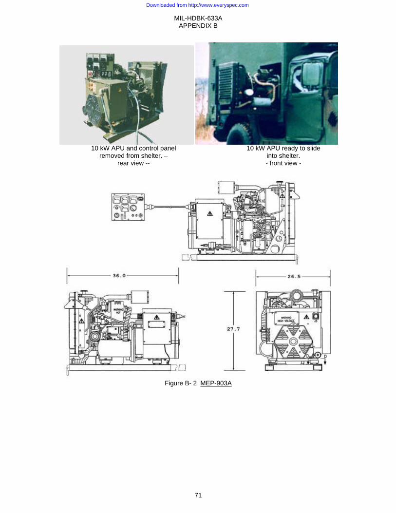
MIL-HDBK-633A APPENDIX B
71
Figure B- 2 MEP-903A
10 kW APU and control panel removed from shelter. –
rear view --
10 kW APU ready to slide into shelter. - front view -
Downloaded from http://www.everyspec.com

MIL-HDBK-633A APPENDIX B
72
This Page Intentionally Left Blank
Downloaded from http://www.everyspec.com
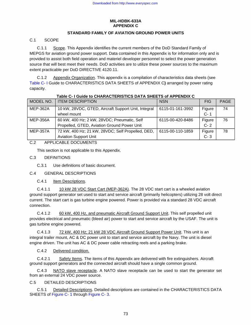
MIL-HDBK-633A
73
APPENDIX C
STANDARD FAMILY OF AVIATION GROUND POWER UNITS C.1 SCOPE
C.1.1 Scope. This Appendix identifies the current members of the DoD Standard Family of MEPGS for aviation ground power support. Data contained in this Appendix is for information only and is provided to assist both field operation and materiel developer personnel to select the power generation source that will best meet their needs. DoD activities are to utilize these power sources to the maximum extent practicable per DoD DIRECTIVE 4120.11.
C.1.2 Appendix Organization. This appendix is a compilation of characteristics data sheets (see Table C- I Guide to CHARACTERISTICS DATA SHEETS of APPENDIX C) arranged by power rating capacity.
Table C- I Guide to CHARACTERISTICS DATA SHEETS of APPENDIX C MODEL NO. ITEM DESCRIPTION NSN FIG PAGE
MEP-362A 10 kW, 28VDC, GTED, Aircraft Support Unit, Integral wheel mount
6115-01-161-3992 Figure C- 1
74
MEP-356A 60 kW, 400 Hz; 2 kW, 28VDC; Pneumatic, Self Propelled, GTED, Aviation Ground Power Unit
6115-00-420-8486 Figure C- 2
76
MEP-357A 72 kW, 400 Hz; 21 kW, 28VDC; Self Propelled, DED, Aviation Support Unit
6115-00-110-1859 Figure C- 3
78
C.2 APPLICABLE DOCUMENTS
This section is not applicable to this Appendix.
C.3 DEFINITIONS
C.3.1 Use definitions of basic document.
C.4 GENERAL DESCRIPTIONS
C.4.1 Item Descriptions.
C.4.1.1 10 kW 28 VDC Start Cart (MEP-362A). The 28 VDC start cart is a wheeled aviation ground support generator set used to start and service aircraft (primarily helicopters) utilizing 28 volt direct current. The start cart is gas turbine engine powered. Power is provided via a standard 28 VDC aircraft connection.
C.4.1.2 60 kW, 400 Hz, and pneumatic Aircraft Ground Support Unit. This self propelled unit provides electrical and pneumatic (bleed air) power to start and service aircraft by the USAF. The unit is gas turbine engine powered.
C.4.1.3 72 kW, 400 Hz; 21 kW 28 VDC Aircraft Ground Support Power Unit. This unit is an integral trailer mount, AC & DC power unit to start and service aircraft by the Navy. The unit is diesel engine driven. The unit has AC & DC power cable retracting reels and a parking brake.
C.4.2 Delivered condition.
C.4.2.1 Safety Items. The items of this Appendix are delivered with fire extinguishers. Aircraft ground support generators and the connected aircraft should have a single common ground.
C.4.3 NATO slave receptacle. A NATO slave receptacle can be used to start the generator set from an external 24 VDC power source.
C.5 DETAILED DESCRIPTIONS
C.5.1 Detailed Descriptions. Detailed descriptions are contained in the CHARACTERISTICS DATA SHEETS of Figure C- 1 through Figure C- 3.
Downloaded from http://www.everyspec.com

MIL-HDBK-633A APPENDIX C
74
10 kW, 28 VDC, GTE, Aircraft Support Unit Identification Data
Nomenclature GEN SET, 10kW, GTE, 28VDC Model Number MEP-362A NSN 6115-01-161-3992 LIN G38140 SSN
Physical Characteristics Dimensions LWH (in) 89.0 x 71.0 x 49.0 (Cube: 179 ft3 ) Weight (lbs) Dry: 960 Wet: 1175 Mobility All weather frame and housing, wheel mounted, parking brake. A 40 foot power
cable is provided. Engine Gas Turbine, 50300 rpm (12000 at gearbox), Tiernay Turbines Model:101800-1,
28 VDC starter. Fuels JP-8, Jet-A. Fuel tank: 32 gallons,. Instrumentation On/off switch, hourmeter, voltmeter, output current meter, battery charging
meter. Performance Characteristics
Electric Power Rating 10 kW @ 125°F/MSL, 107°F/5000 ft, 95°F/8000 ft. Environmental Capability
-65°F to 125°F, rain, humidity, altitude, sand/dust, transportation, cold storage -65°F, salt spray, fungus.
Protective Devices Automatic shut down with emergency bypass for low fuel, low oil pressure, engine overtemp, overspeed, overload, overvoltage, generator overtemp and undervoltage
Fuel Consumption 8 gal/hour Noise Not specified. Human Factors MIL-STD-1474.
Electrical Characteristics Voltage Connection: 28VDC, 2 wire with ground Electrical Drip proof generator enclosure, fungus & moisture treated, solid state voltage
regulator, generator: Teledyne Brown, model 481-007. EMI Suppressed to MIL-STD-461 limits. EMP HEAMP protected.
Electrical Performance Electric Power Quality DC Voltage
Regulation 4% Short term steady state stability (30 sec) 2% bandwidth Long term steady state stability (4 hr) 2% bandwidth Application of rated load (transient) recovery 30% dip 1 sec Rejection of rated load (transient) recovery 40% rise 0.5 sec DC ripple 5.5%
Optional Equipment None
Technical Manuals Army Air Force Marine Corps Navy
TM 5-6115-612-12 AG-320B0-OMM-OOOTM 5-6115-612-34 AG-320B0-MME-OOOTM 5-6115-612-24P TO 35C2-3-471-4 TM 6115-24P/1 AG-320B0-IPE-OOO
Downloaded from http://www.everyspec.com
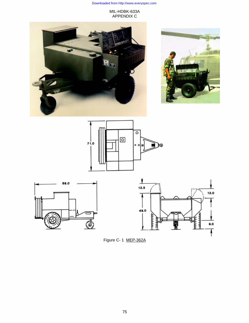
MIL-HDBK-633A APPENDIX C
75
Figure C- 1 MEP-362A
Downloaded from http://www.everyspec.com
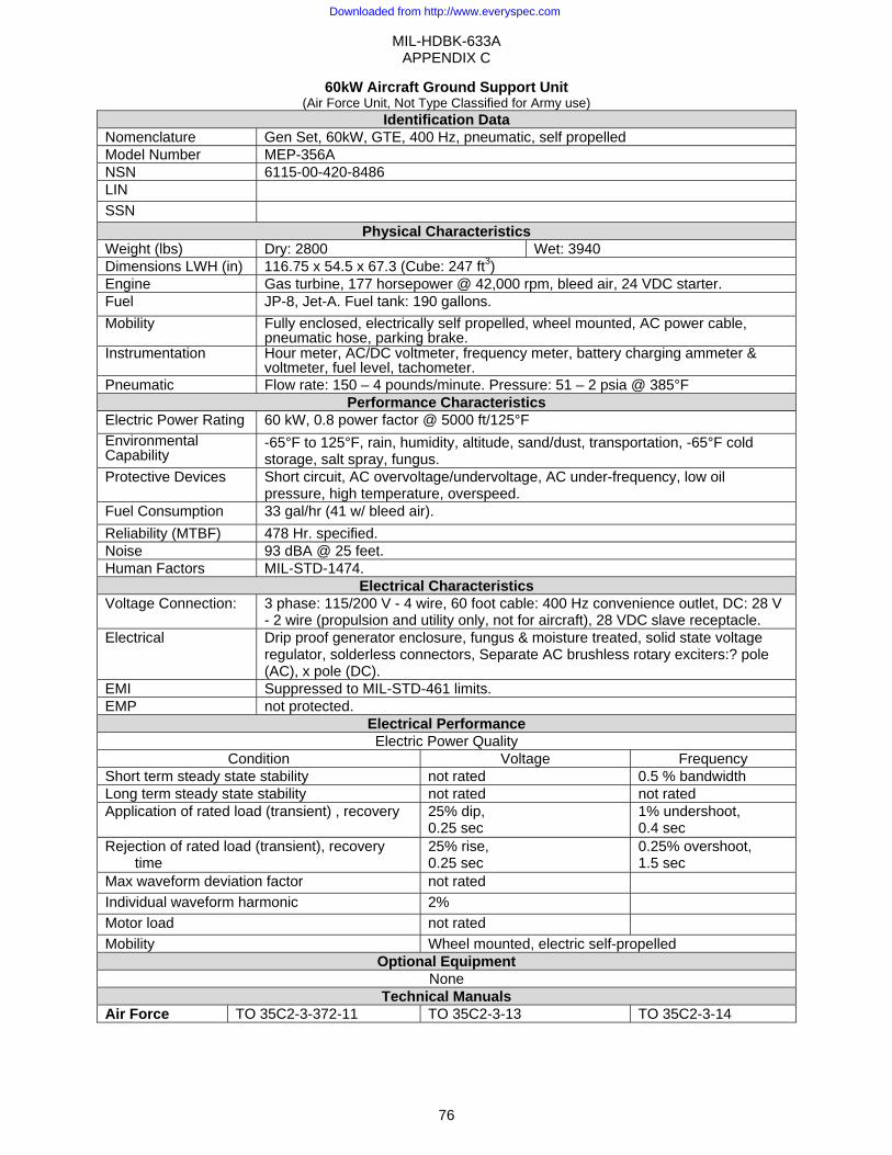
MIL-HDBK-633A APPENDIX C
76
60kW Aircraft Ground Support Unit (Air Force Unit, Not Type Classified for Army use)
Identification Data Nomenclature Gen Set, 60kW, GTE, 400 Hz, pneumatic, self propelled Model Number MEP-356A NSN 6115-00-420-8486 LIN SSN
Physical Characteristics Weight (lbs) Dry: 2800 Wet: 3940 Dimensions LWH (in) 116.75 x 54.5 x 67.3 (Cube: 247 ft3) Engine Gas turbine, 177 horsepower @ 42,000 rpm, bleed air, 24 VDC starter. Fuel JP-8, Jet-A. Fuel tank: 190 gallons. Mobility Fully enclosed, electrically self propelled, wheel mounted, AC power cable,
pneumatic hose, parking brake.Instrumentation Hour meter, AC/DC voltmeter, frequency meter, battery charging ammeter &
voltmeter, fuel level, tachometer.Pneumatic Flow rate: 150 – 4 pounds/minute. Pressure: 51 – 2 psia @ 385°F
Performance Characteristics Electric Power Rating 60 kW, 0.8 power factor @ 5000 ft/125°F Environmental Capability
-65°F to 125°F, rain, humidity, altitude, sand/dust, transportation, -65°F cold storage, salt spray, fungus.
Protective Devices Short circuit, AC overvoltage/undervoltage, AC under-frequency, low oil pressure, high temperature, overspeed.
Fuel Consumption 33 gal/hr (41 w/ bleed air). Reliability (MTBF) 478 Hr. specified. Noise 93 dBA @ 25 feet. Human Factors MIL-STD-1474.
Electrical Characteristics Voltage Connection:
3 phase: 115/200 V - 4 wire, 60 foot cable: 400 Hz convenience outlet, DC: 28 V - 2 wire (propulsion and utility only, not for aircraft), 28 VDC slave receptacle.
Electrical Drip proof generator enclosure, fungus & moisture treated, solid state voltage regulator, solderless connectors, Separate AC brushless rotary exciters:? pole (AC), x pole (DC).
EMI Suppressed to MIL-STD-461 limits. EMP not protected.
Electrical Performance Electric Power Quality
Condition Voltage Frequency Short term steady state stability not rated 0.5 % bandwidth Long term steady state stability not rated not rated Application of rated load (transient) , recovery 25% dip,
0.25 sec 1% undershoot, 0.4 sec
Rejection of rated load (transient), recovery time
25% rise, 0.25 sec
0.25% overshoot, 1.5 sec
Max waveform deviation factor not rated Individual waveform harmonic 2% Motor load not rated Mobility Wheel mounted, electric self-propelled
Optional Equipment None
Technical Manuals Air Force TO 35C2-3-372-11 TO 35C2-3-13 TO 35C2-3-14
Downloaded from http://www.everyspec.com
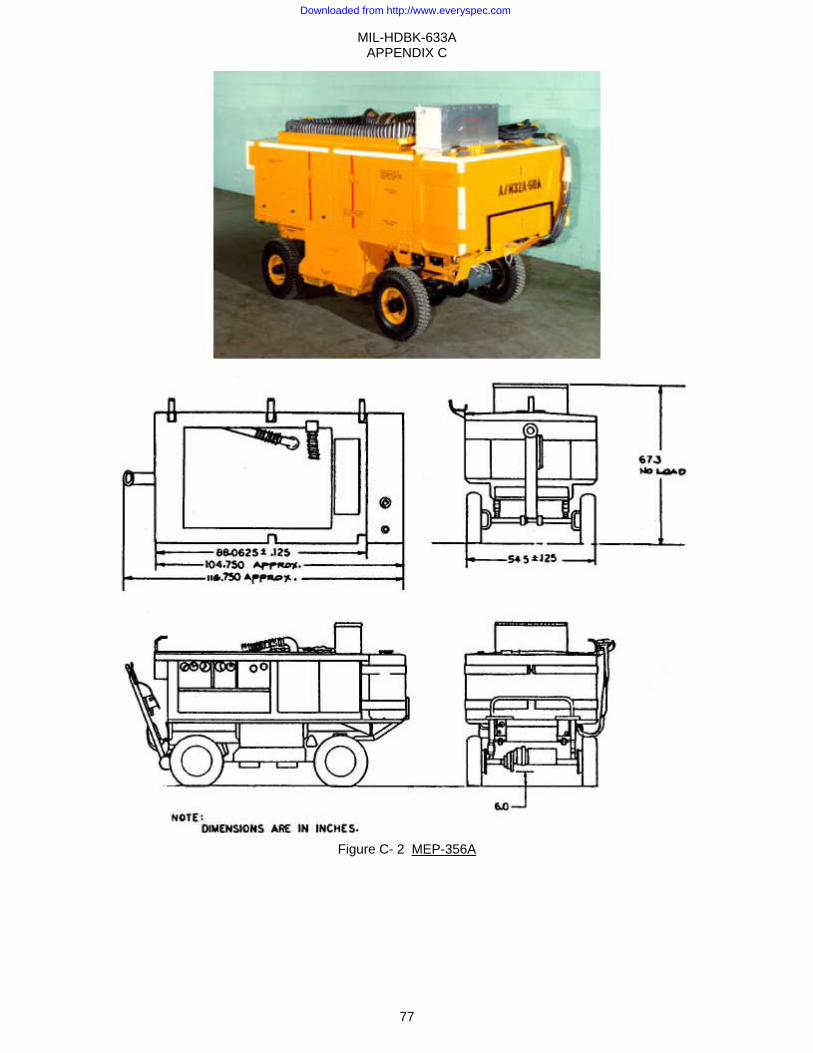
MIL-HDBK-633A APPENDIX C
77
Figure C- 2 MEP-356A
Downloaded from http://www.everyspec.com
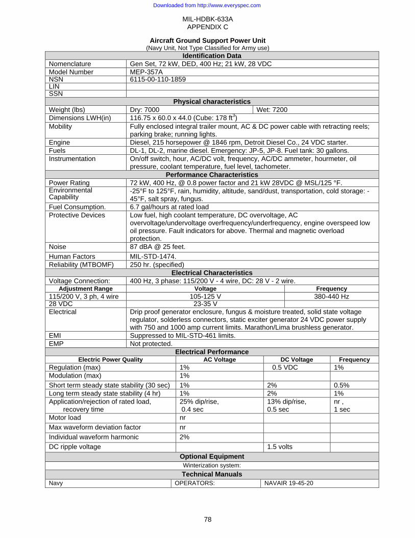
MIL-HDBK-633A APPENDIX C
78
Aircraft Ground Support Power Unit (Navy Unit, Not Type Classified for Army use)
Identification Data Nomenclature Gen Set, 72 kW, DED, 400 Hz; 21 kW, 28 VDC Model Number MEP-357A NSN 6115-00-110-1859 LIN SSN
Physical characteristics Weight (lbs) Dry: 7000 Wet: 7200 Dimensions LWH(in) 116.75 x 60.0 x 44.0 (Cube: 178 ft3) Mobility Fully enclosed integral trailer mount, AC & DC power cable with retracting reels;
parking brake; running lights. Engine Diesel, 215 horsepower @ 1846 rpm, Detroit Diesel Co., 24 VDC starter. Fuels DL-1, DL-2, marine diesel. Emergency: JP-5, JP-8. Fuel tank: 30 gallons. Instrumentation On/off switch, hour, AC/DC volt, frequency, AC/DC ammeter, hourmeter, oil
pressure, coolant temperature, fuel level, tachometer. Performance Characteristics
Power Rating 72 kW, 400 Hz, @ 0.8 power factor and 21 kW 28VDC @ MSL/125 °F. Environmental Capability
-25°F to 125°F, rain, humidity, altitude, sand/dust, transportation, cold storage: -45°F, salt spray, fungus.
Fuel Consumption. 6.7 gal/hours at rated load Protective Devices Low fuel, high coolant temperature, DC overvoltage, AC
overvoltage/undervoltage overfrequency/underfrequency, engine overspeed low oil pressure. Fault indicators for above. Thermal and magnetic overload protection.
Noise 87 dBA @ 25 feet. Human Factors MIL-STD-1474. Reliability (MTBOMF) 250 hr. (specified)
Electrical Characteristics Voltage Connection: 400 Hz, 3 phase: 115/200 V - 4 wire, DC: 28 V - 2 wire.
Adjustment Range Voltage Frequency115/200 V, 3 ph, 4 wire 105-125 V 380-440 Hz 28 VDC 23-35 V Electrical Drip proof generator enclosure, fungus & moisture treated, solid state voltage
regulator, solderless connectors, static exciter generator 24 VDC power supply with 750 and 1000 amp current limits. Marathon/Lima brushless generator.
EMI Suppressed to MIL-STD-461 limits. EMP Not protected.
Electrical Performance Electric Power Quality AC Voltage DC Voltage Frequency
Regulation (max) 1% �0.5 VDC 1% Modulation (max) 1% Short term steady state stability (30 sec) 1% 2% 0.5% Long term steady state stability (4 hr) 1% 2% 1% Application/rejection of rated load,
recovery time 25% dip/rise, 0.4 sec
13% dip/rise, 0.5 sec
nr , 1 sec
Motor load nr Max waveform deviation factor nr Individual waveform harmonic 2% DC ripple voltage 1.5 volts
Optional Equipment Winterization system: Technical Manuals
Navy OPERATORS: NAVAIR 19-45-20
Downloaded from http://www.everyspec.com
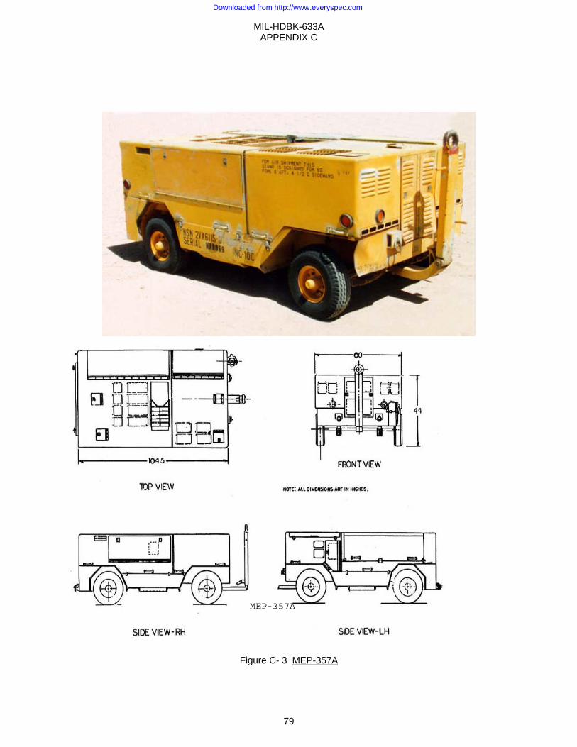
MIL-HDBK-633A APPENDIX C
79
Figure C- 3 MEP-357A
MEP-357A
Downloaded from http://www.everyspec.com

MIL-HDBK-633A APPENDIX C
80
This Page Intentionally Left Blank
Downloaded from http://www.everyspec.com
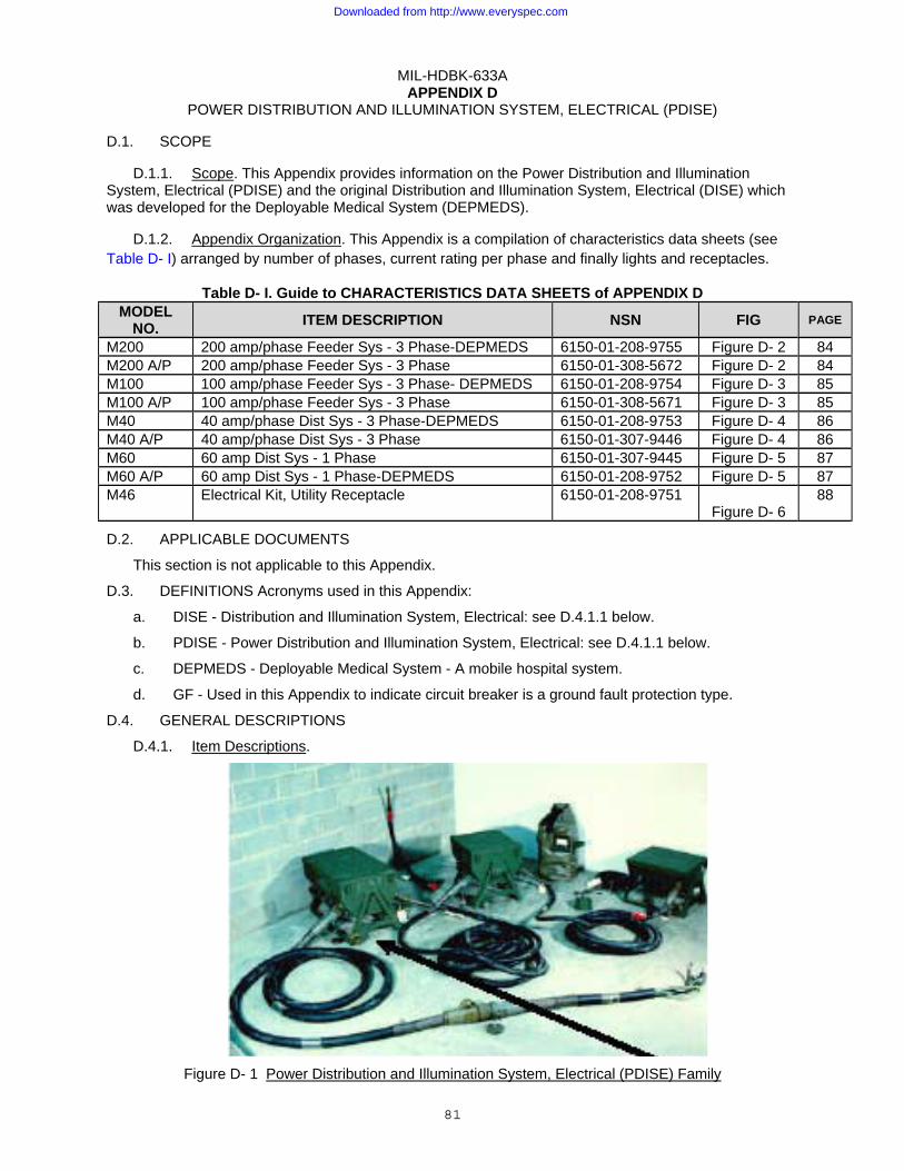
MIL-HDBK-633A
81
APPENDIX D POWER DISTRIBUTION AND ILLUMINATION SYSTEM, ELECTRICAL (PDISE)
D.1. SCOPE
D.1.1. Scope. This Appendix provides information on the Power Distribution and Illumination System, Electrical (PDISE) and the original Distribution and Illumination System, Electrical (DISE) which was developed for the Deployable Medical System (DEPMEDS).
D.1.2. Appendix Organization. This Appendix is a compilation of characteristics data sheets (see Table D- I) arranged by number of phases, current rating per phase and finally lights and receptacles.
Table D- I. Guide to CHARACTERISTICS DATA SHEETS of APPENDIX D MODEL
NO. ITEM DESCRIPTION NSN FIG PAGE
M200 200 amp/phase Feeder Sys - 3 Phase-DEPMEDS 6150-01-208-9755 Figure D- 2 84 M200 A/P 200 amp/phase Feeder Sys - 3 Phase 6150-01-308-5672 Figure D- 2 84 M100 100 amp/phase Feeder Sys - 3 Phase- DEPMEDS 6150-01-208-9754 Figure D- 3 85 M100 A/P 100 amp/phase Feeder Sys - 3 Phase 6150-01-308-5671 Figure D- 3 85 M40 40 amp/phase Dist Sys - 3 Phase-DEPMEDS 6150-01-208-9753 Figure D- 4 86 M40 A/P 40 amp/phase Dist Sys - 3 Phase 6150-01-307-9446 Figure D- 4 86 M60 60 amp Dist Sys - 1 Phase 6150-01-307-9445 Figure D- 5 87 M60 A/P 60 amp Dist Sys - 1 Phase-DEPMEDS 6150-01-208-9752 Figure D- 5 87 M46 Electrical Kit, Utility Receptacle 6150-01-208-9751
Figure D- 6 88
D.2. APPLICABLE DOCUMENTS
This section is not applicable to this Appendix.
D.3. DEFINITIONS Acronyms used in this Appendix:
a. DISE - Distribution and Illumination System, Electrical: see D.4.1.1 below.
b. PDISE - Power Distribution and Illumination System, Electrical: see D.4.1.1 below.
c. DEPMEDS - Deployable Medical System - A mobile hospital system.
d. GF - Used in this Appendix to indicate circuit breaker is a ground fault protection type.
D.4. GENERAL DESCRIPTIONS
D.4.1. Item Descriptions.
Figure D- 1 Power Distribution and Illumination System, Electrical (PDISE) Family
Downloaded from http://www.everyspec.com

MIL-HDBK-633A APPENDIX D
82
D.4.1.1. Power Distribution and Illumination System, Electrical (PDISE). The PDISE (and the original DISE used with DEPMEDS) is a set of man portable, reliable, modular, quick to assemble standardized electrical distribution system components. The PDISE provides power networks which can reduce the number of generator sets needed at a field location. The PDISE is not an end item (i.e. does not have an NSN), but a family of 5 end items, consisting of two feeder systems, two distribution systems and a utility receptacle and lighting system (each with an independent NSN), and associated auxiliary equipment. These items consist of cabling and circuit protection components which can be optimized (see D.4.2) to meet unique user applications. The APPENDIX D feeder systems and the 3-phase distribution system will subdivide and distribute 60 Hz, 3 phase, 120/208 volt power from a single power source to multiple 60 Hz, 120 volt, 1 phase or 120/208 volt, 3 phase equipment users within shelters and various unit complexes. The 60 amp single phase distribution system will distribute power from a 60 Hz, 120 V single phase generator set to multiple single phase users. The feeder and distribution system components interface with DoD standard MEPGS from 5 kW to 200 kW, as well as other power sources and components. Military standard connectors, receptacles and cabling supplemented with some hospital grade commercial receptacles are used throughout the systems. Cables for different phase and power ratings have unique connectors to prevent improper connections. The only exceptions are the pigtail cable, which is the primary interface to a generator set, and the universal adapter (see Figure D- 8). Extreme care should be taken to insure that the proper power characteristics are being provided by the pigtail connection or universal adapter.
D.4.1.2. Feeder System. The PDISE/DISE has two feeder systems, a 200 amp per phase system (M200) and a 100 amp per phase system (M100). Each system consists of a feeder center (circuit breaker box with military standard input and output connectors) with appropriate military standard connectors and military standard cabling that distributes the power from a 3-phase generator set to one or more 3 phase distribution systems.
D.4.1.3. Distribution System. The PDISE/DISE has two distribution systems. A three phase, 40 amp/phase distribution system (M40) consists of a housed circuit breaker system used to distribute 120/208 V, 3 phase power from a feeder system or smaller (5 kW -15 kW generator sets) to any 120/208 V, 3 phase loads and to 120V single phase loads. The single phase, 120 V, 60 amp (M60) distribution system was developed for applications which require up to 7.2 kW single phase power from a single phase generator set. It does not interface with either feeder system or the 40 amp distribution system. Both distribution systems interface with the utility receptacle and illumination kit.
D.4.1.4. Utility receptacle and illumination kit. The PDISE utility receptacle and illumination kit (M46) is a set of power cords, light sets and duplex boxes that can be connected to the feeder system to provide power and light to where it is needed. The PDISE utility receptacle and illumination kit has no self protection and should only be used with one of the PDISE distribution systems (i.e. M40 or M60). The PDISE utility receptacle and illumination kit provides internal tent and shelter wiring and lighting. The utility receptacles consist of hospital grade 120 volt "wall outlet" 20-ampere commercial receptacles.
D.4.1.5. Differences between systems. The primary difference between the PDISE and DISE systems is the circuit breakers. The PDISE uses hydraulic-magnetic circuit breakers and the DISE uses Thermal-magnetic circuit breakers. This difference also modifies the interior of the feeder and distribution centers but not the exteriors. In addition, the DISE utilizes ground fault protection circuit breakers on many of the 20 amp, single phase outputs.
D.4.2. Utilization Considerations.
D.4.2.1. Application Planning. This Appendix is not a substitute for proper training and detailed manuals, but does provide information on the size and types of PDISE hardware to assist planners. The number and types of power generating sources available and the details of the users power requirements, such as where and how much power is needed, will be the driving factors in determining which and how many PDISE components are required. The PDISE system is flexible and no single solution is a "best" solution. Some possible component quantities are given in Table D- II. A typical application is APPENDIX D presented in Figure D- 7. The basis of issue for PDISE may not necessarily be one kilowatt of PDISE capability for each kilowatt of generator set capability. PDISE may be issued
Downloaded from http://www.everyspec.com

MIL-HDBK-633A APPENDIX D
83
based on the user's load dispersion needs. It should be recognized that in some applications the PDISE total power capability can be much less than the generator set kW rating and in others, it can be much greater, but in all cases it should disburse the power to where the user needs it within a 100 foot radius of the generator set (300 feet when using the M100 and M200 to feed power to the M40).
D.4.2.2. Safety. Grounding of a PDISE is through the mobile electric power generating source. Care must be taken to insure that an adequate and proper neutral to ground connection is provided at this point. The system neutral should only be connected to ground at this single point or ground currents (faults) can be created. If connection is made to a grounded shelter, care must be taken to insure that the neutral is not connected to ground at the shelter. All warning and caution notices as described in the manuals and posted on the hardware are intended to prevent serious injury or death. As previously noted, the system has unique connectors which can not be interconnected. The only exceptions are the pigtail cable which is the primary interface to a generator set and the universal adapter (see D.4.1.1). Extreme care should be taken to insure that the pigtail connection to the generator or within the universal adapter is made properly.
D.4.2.3. Voltage Drop Considerations. The voltage drop, caused by resistance in the cabling, will limit the distance to which the power can be distributed. Generally, full rated power can be distributed about 100 feet from a distribution center and up to 200 feet from a Feeder system for a total of about 300 feet. Table D- III provides voltage drops for various cable size and length combinations. The voltage drops tabulated are for rated current. Since voltage drops are proportional to the current, 50% of rated would produce 50% of the drop listed in the table.
D.4.2.4. Auxiliary Equipment. Since application of PDISE can vary greatly, additional components may have to be added to the system. A table of Auxiliary equipment is provided at Table D- IV. These items may be used to tailor the PDISE to the user's requirements. The universal adapter, item 26 of Table D- IV, is of particular value and is shown in Figure D- 8. It is designed to connect electrical equipment, with a connection not supported by PDISE, to PDISE. It consists of a box with a three-phase 40/60 ampere input connector (for connection to the proper distribution center) and five terminals (for connecting the user's equipment with a user supplied cable). The universal adapter also enables users not having the required connectors for the 40 and 60 ampere outlets on the 100M and 200M Feeder systems, or the feed-thru on the 40 ampere Distribution system, to hook up to PDISE. Also note that a pneumatic crimping tool has been supplied to all direct support maintenance units in the Army. The pneumatic crimping tool gives the units the capability to repair damaged cables and connectors. Its use saves time and cost of ordering new cables.
D.4.2.5. Phase Balance. Phase balance must be considered when connecting single phase loads to a 3-phase generator. If a phase is unbalanced by more than 10% it can cause damage to the power generation source. The phase connections of the PDISE feeder and distribution centers are given in Table D- V.
D.5. DETAILED DESCRIPTIONS
D.5.1. Detailed Descriptions. Detailed descriptions are contained in the CHARACTERISTICS DATA SHEETS of Table D- I through Table D- V. Data common to all PDISE components are contained in Table D- VI.
Downloaded from http://www.everyspec.com
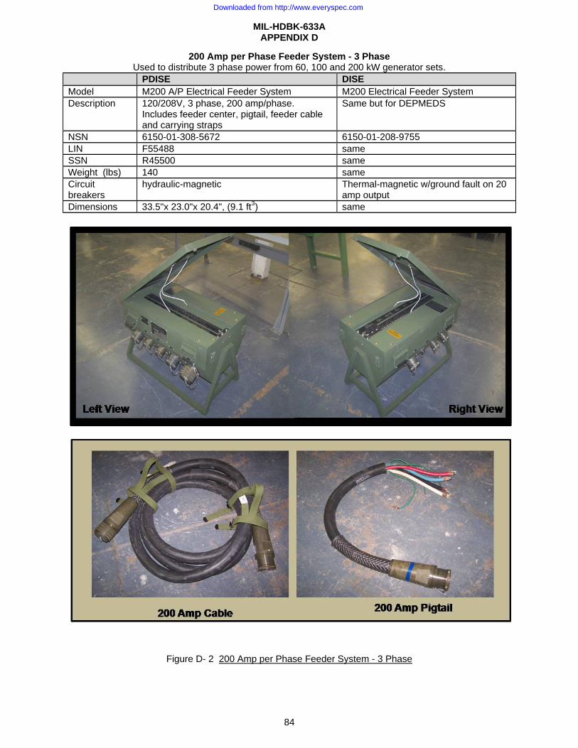
MIL-HDBK-633A APPENDIX D
84
200 Amp per Phase Feeder System - 3 Phase Used to distribute 3 phase power from 60, 100 and 200 kW generator sets.
PDISE DISE Model M200 A/P Electrical Feeder System M200 Electrical Feeder System Description 120/208V, 3 phase, 200 amp/phase.
Includes feeder center, pigtail, feeder cable and carrying straps
Same but for DEPMEDS
NSN 6150-01-308-5672 6150-01-208-9755 LIN F55488 same SSN R45500 same Weight (lbs) 140 same Circuit breakers
hydraulic-magnetic Thermal-magnetic w/ground fault on 20 amp output
Dimensions 33.5"x 23.0"x 20.4", (9.1 ft3) same
Figure D- 2 200 Amp per Phase Feeder System - 3 Phase
Downloaded from http://www.everyspec.com

MIL-HDBK-633A APPENDIX D
85
100 Amp per Phase Feeder System - 3 Phase Used to distribute 3 phase power from 30, 60, 100 and 200 kW generator sets.
PDISE DISE Model M100 A/P Electrical Feeder System M100 Electrical Feeder System Description 120/208 V, 3 phase, 100 amp/ ph. Includes feeder
center, pigtail, feeder cable and carrying straps. Same but for DEPMEDS
NSN 6150-01-308-5671 6150-01-208-9754 LIN F55487 same SSN R45400 same Weight (lbs) 77 same Circuit breakers
hydraulic-magnetic Thermal-magnetic w/ground fault on 20 amp output
Dimensions 24.3"x 22.4"x 20.4", ( 6.4 ft3) same
Figure D- 3 100 Amp per Phase Feeder System - 3 Phase
Downloaded from http://www.everyspec.com
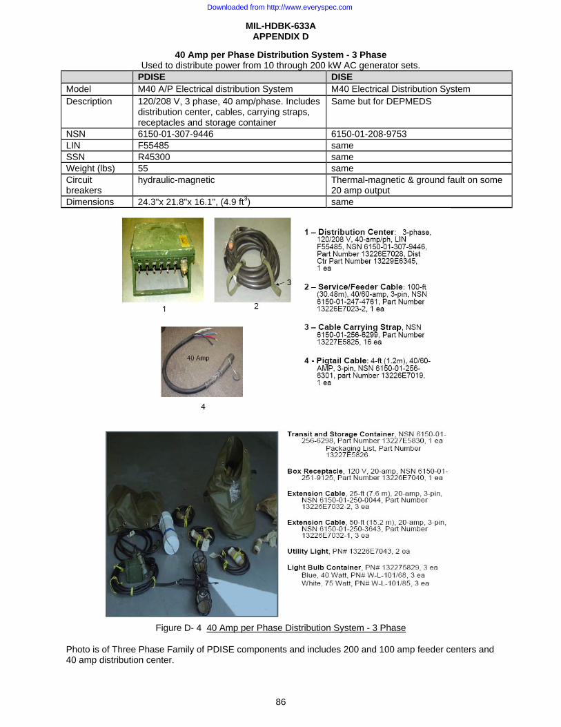
MIL-HDBK-633A APPENDIX D
86
40 Amp per Phase Distribution System - 3 Phase Used to distribute power from 10 through 200 kW AC generator sets.
PDISE DISE Model M40 A/P Electrical distribution System M40 Electrical Distribution System Description 120/208 V, 3 phase, 40 amp/phase. Includes
distribution center, cables, carrying straps, receptacles and storage container
Same but for DEPMEDS
NSN 6150-01-307-9446 6150-01-208-9753 LIN F55485 same SSN R45300 same Weight (lbs) 55 same Circuit breakers
hydraulic-magnetic Thermal-magnetic & ground fault on some 20 amp output
Dimensions 24.3"x 21.8"x 16.1", (4.9 ft3) same
Figure D- 4 40 Amp per Phase Distribution System - 3 Phase
Photo is of Three Phase Family of PDISE components and includes 200 and 100 amp feeder centers and 40 amp distribution center.
Downloaded from http://www.everyspec.com
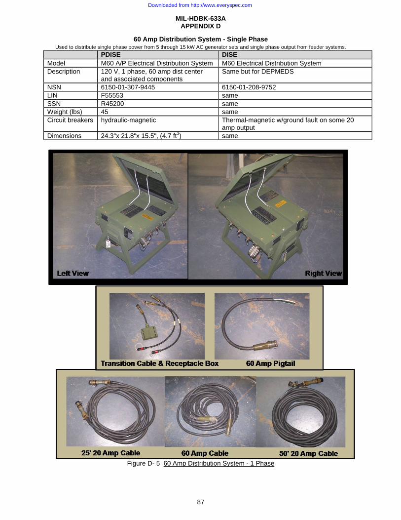
MIL-HDBK-633A APPENDIX D
87
60 Amp Distribution System - Single Phase Used to distribute single phase power from 5 through 15 kW AC generator sets and single phase output from feeder systems.
PDISE DISE Model M60 A/P Electrical Distribution System M60 Electrical Distribution System Description 120 V, 1 phase, 60 amp dist center
and associated components Same but for DEPMEDS
NSN 6150-01-307-9445 6150-01-208-9752 LIN F55553 same SSN R45200 same Weight (lbs) 45 same Circuit breakers hydraulic-magnetic Thermal-magnetic w/ground fault on some 20
amp output Dimensions 24.3"x 21.8"x 15.5", (4.7 ft3) same
Figure D- 5 60 Amp Distribution System - 1 Phase
Downloaded from http://www.everyspec.com
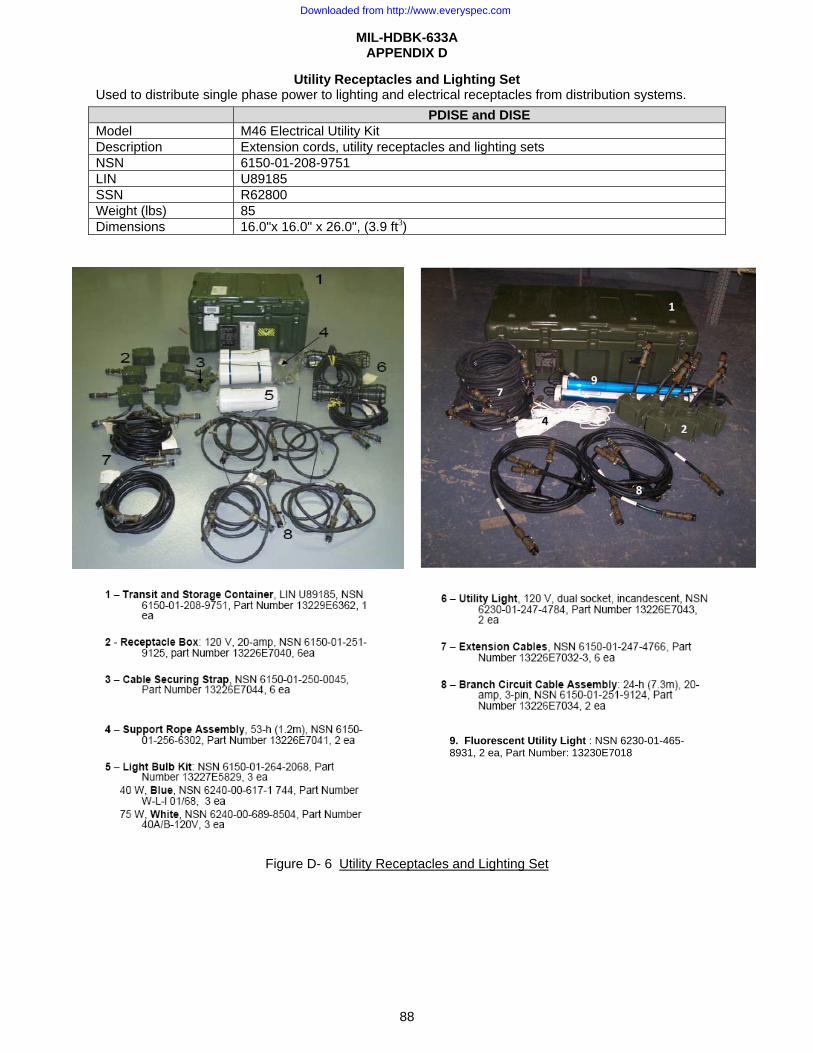
MIL-HDBK-633A APPENDIX D
88
Utility Receptacles and Lighting Set Used to distribute single phase power to lighting and electrical receptacles from distribution systems.
Figure D- 6 Utility Receptacles and Lighting Set
PDISE and DISE Model M46 Electrical Utility Kit Description Extension cords, utility receptacles and lighting sets NSN 6150-01-208-9751 LIN U89185 SSN R62800 Weight (lbs) 85 Dimensions 16.0"x 16.0" x 26.0", (3.9 ft3)
9. Fluorescent Utility Light : NSN 6230-01-465-8931, 2 ea, Part Number: 13230E7018
Downloaded from http://www.everyspec.com
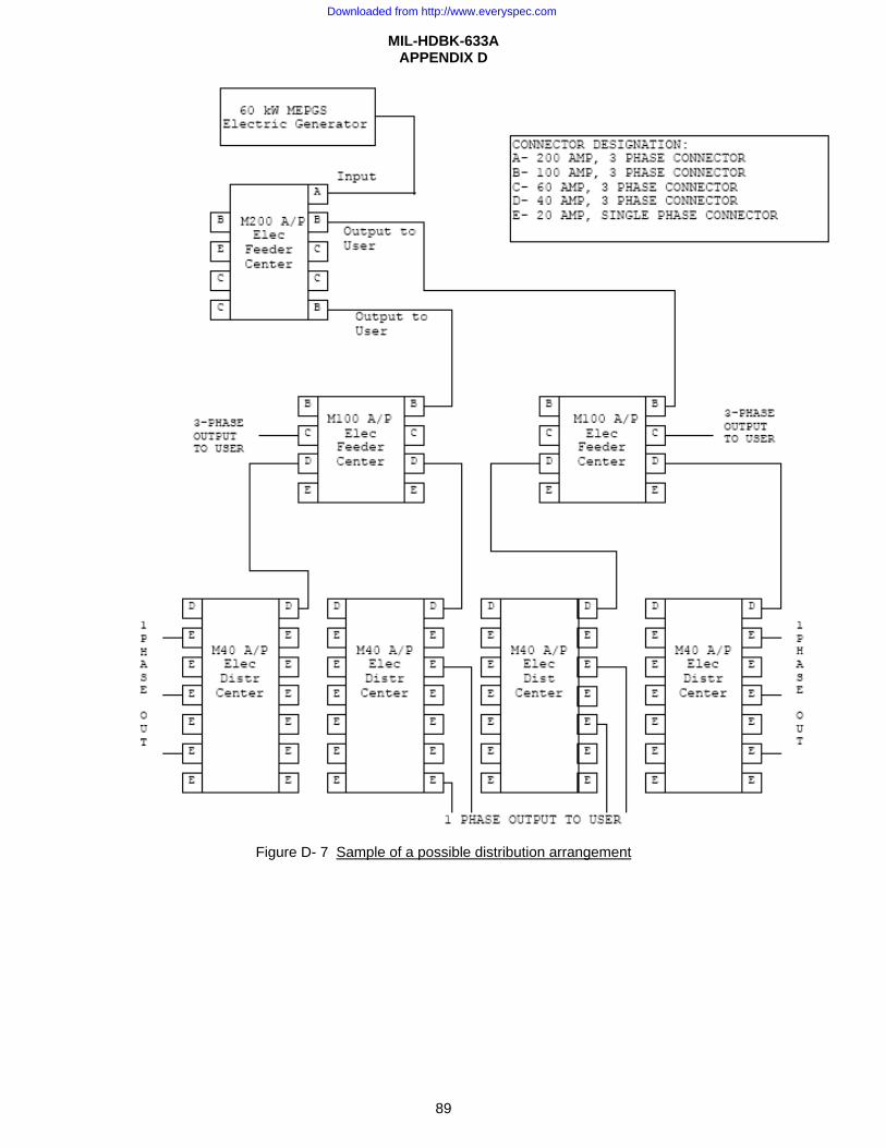
MIL-HDBK-633A APPENDIX D
89
Figure D- 7 Sample of a possible distribution arrangement
Downloaded from http://www.everyspec.com
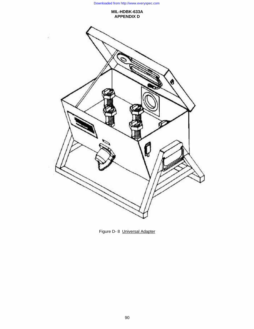
MIL-HDBK-633A APPENDIX D
90
Figure D- 8 Universal Adapter
Downloaded from http://www.everyspec.com
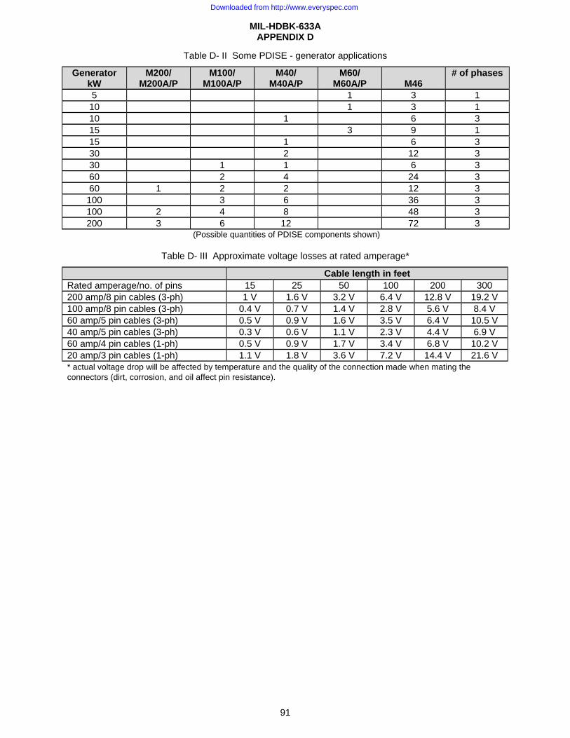
MIL-HDBK-633A APPENDIX D
91
Table D- II Some PDISE - generator applications
Generator kW
M200/ M200A/P
M100/ M100A/P
M40/ M40A/P
M60/ M60A/P M46
# of phases
5 1 3 1 10 1 3 1 10 1 6 3 15 3 9 1 15 1 6 3 30 2 12 3 30 1 1 6 3 60 2 4 24 3 60 1 2 2 12 3
100 3 6 36 3 100 2 4 8 48 3 200 3 6 12 72 3
(Possible quantities of PDISE components shown)
Table D- III Approximate voltage losses at rated amperage*
Cable length in feet Rated amperage/no. of pins 15 25 50 100 200 300 200 amp/8 pin cables (3-ph) 1 V 1.6 V 3.2 V 6.4 V 12.8 V 19.2 V 100 amp/8 pin cables (3-ph) 0.4 V 0.7 V 1.4 V 2.8 V 5.6 V 8.4 V 60 amp/5 pin cables (3-ph) 0.5 V 0.9 V 1.6 V 3.5 V 6.4 V 10.5 V 40 amp/5 pin cables (3-ph) 0.3 V 0.6 V 1.1 V 2.3 V 4.4 V 6.9 V 60 amp/4 pin cables (1-ph) 0.5 V 0.9 V 1.7 V 3.4 V 6.8 V 10.2 V 20 amp/3 pin cables (1-ph) 1.1 V 1.8 V 3.6 V 7.2 V 14.4 V 21.6 V * actual voltage drop will be affected by temperature and the quality of the connection made when mating the connectors (dirt, corrosion, and oil affect pin resistance).
Downloaded from http://www.everyspec.com

MIL-HDBK-633A APPENDIX D
92
Table D- IV Auxiliary equipment
Extras of existing PDISE components Item Description Weight lb NSN
1 Branch circuit cable, 8 ft, 20 amp, 3 pin 2 6150-01-250-5644 2 Branch circuit cable, 16 ft, 20 amp, 3 pin 4 6150-01-256-6297 3 Branch circuit cable, 24 ft, 20 amp, 3 pin 6 6150-01-251-9124 4 Cable carrying strap neglible 5 Cable securing strap neglible 6 Container, transit and storage 6150-01-256-6298 7 Duplex receptacle, 120 V, 20 amp 6150-01-251-9125 8 Extension cable, 3.5 ft, 20 amp, 3 pin 0.7 6150-01-258-1253 9 Extension cable, 15 ft, 20 amp, 3 pin 3 6150-01-247-4766 10 Extension cable, 25 ft, 20 amp, 3 pin 5 6150-01-250-0044 11 Extension cable, 50 ft, 20 amp, 3 pin 10 6150-01-250-3643 12 Florescent light, 4 ft, 120 V, single tube 6150-01-250-0046 13 Container, light bulb kit, 2-bulb 6150-01-256-2068 14 Pigtail cable, 4 ft, 40/60 amp, 5 pin 5 6150-01-256-6301 15 Pigtail cable, 4 ft, 60 amp, 4 pin 4 6150-01-247-4778 16 Pigtail cable, 4 ft, 100 amp, 8 pin 17 6150-01-256-6300 17 Pigtail cable, 4 ft, 200 amp, 8 pin 28 6150-01-247-4768 18 Rope support assembly, 53 ft 6150-01-256-6302 19 Service/feeder cable, 25 ft, 40/60 amp, 5 pin 27 6150-01-247-4780 20 Service/feeder cable, 25 ft, 200 amp, 8 pin 136 6150-01-247-4782 21 Service/feeder cable, 50 ft, 40/60 amp, 5 pin 53 6150-01-247-4781 22 Service/feeder cable, 50 ft, 60 amp, 4 pin 48 6150-01-256-6303 23 Service/feeder cable, 50 ft, 100 amp, 8 pin 100 6150-01-256-6304 24 Service/feeder cable, 100 ft, 40/60 amp, 5 pin 105 6150-01-247-4779 25 Service/feeder cable, 100 ft, 60 amp, 4 pin 96 6150-01-247-4793 26 Universal adapter 5975-01-247-4791 27 Utility light, 120 V, dual socket, incandescent 6230-01-247-4784 28 Interface cable, 40/60 amp, 5-ton expando van 6150-01-250-3564 29 Interface cable, 20 amp, general illumination lighting set 6150-01-256-4290 30 Cable carrying strap (double), 200 amp 31 Fluorescent Utility Light 6230-01-465-8931
Downloaded from http://www.everyspec.com
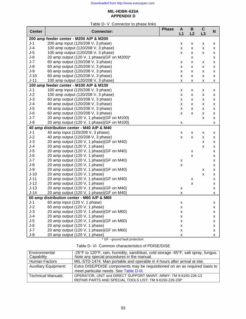
MIL-HDBK-633A APPENDIX D
93
Table D- V Connector to phase links
Center Connector: Phase A L1
B L2
C L3 N
200 amp feeder center - M200 A/P & M200 J-1 J-4 J-5 J-6 J-7 J-8 J-9 J-10 J-11
200 amp input (120/208 V, 3 phase) 100 amp output (120/208 V, 3 phase) 100 amp output (120/208 V, 3 phase) 20 amp output (120 V, 1 phase)(GF on M200)* 60 amp output (120/208 V, 3 phase) 60 amp output (120/208 V, 3 phase) 60 amp output (120/208 V, 3 phase) 60 amp output (120/208 V, 3 phase) 100 amp output (120/208 V, 3 phase)
x x x x x x x x
x x x x x x x x x
x x x x x x x x
x x x x x x x x x
100 amp feeder center - M100 A/P & M100 J-1 J-2 J-3 J-4 J-5 J-6 J-7 J-8
100 amp input (120/208 V, 3 phase) 100 amp output (120/208 V, 3 phase) 60 amp output (120/208 V, 3 phase) 40 amp output (120/208 V, 3 phase) 40 amp output (120/208 V, 3 phase) 60 amp output (120/208 V, 3 phase) 20 amp output (120 V, 1 phase)(GF on M100) 20 amp output (120 V, 1 phase)(GF on M100)
x x x x x x x
x x x x x x
x x x x x x x
x x x x x x x x
40 amp distribution center - M40 A/P & M40 J-1 J-2 J-3 J-4 J-5 J-6 J-7 J-8 J-9 J-10 J-11 J-12 J-13 J-14
40 amp input (120/208 V, 3 phase) 40 amp output (120/208 V, 3 phase) 20 amp output (120 V, 1 phase)(GF on M40) 20 amp output (120 V, 1 phase) 20 amp output (120 V, 1 phase)(GF on M40) 20 amp output (120 V, 1 phase) 20 amp output (120 V, 1 phase)(GF on M40) 20 amp output (120 V, 1 phase) 20 amp output (120 V, 1 phase)(GF on M40) 20 amp output (120 V, 1 phase) 20 amp output (120 V, 1 phase)(GF on M40) 20 amp output (120 V, 1 phase) 20 amp output (120 V, 1 phase)(GF on M40) 20 amp output (120 V, 1 phase)(GF on M40)
x x x x x x
x x x x x x
x x x x x x
x x x x x x x x x x x x x x
60 amp distribution center - M60 A/P & M60 J-1 J-2 J-3 J-4 J-5 J-6 J-7 J-8
60 amp input (120 V, 1 phase) 60 amp output (120 V, 1 phase) 20 amp output (120 V, 1 phase)(GF on M60) 20 amp output (120 V, 1 phase) 20 amp output (120 V, 1 phase)(GF on M60) 20 amp output (120 V, 1 phase) 20 amp output (120 V, 1 phase)(GF on M60) 20 amp output (120 V, 1 phase)
x x x x x x x x
x x x x x x x x
* GF - ground fault protection.
Table D- VI Common characteristics of PDISE/DISE
Environmental Capability
-25°F to 120°F, rain, humidity, sand/dust, cold storage -65°F, salt spray, fungus. Note any special procedures in the manual.
Human Factors MIL-STD-1474. Man portable and operable in 4 hours after arrival at site. Auxiliary Equipment: Extra DISE/PDISE components may be requisitioned on an as required basis to
meet particular needs. See Table D-III. Technical Manuals: OPERATOR, UNIT and DIRECT SUPPORT MAINT: ARMY: TM 9-6150-226-13
REPAIR PARTS AND SPECIAL TOOLS LIST: TM 9-6150-226-23P
Downloaded from http://www.everyspec.com

MIL-HDBK-633A APPENDIX D
94
This Page Intentionally Left Blank
Downloaded from http://www.everyspec.com
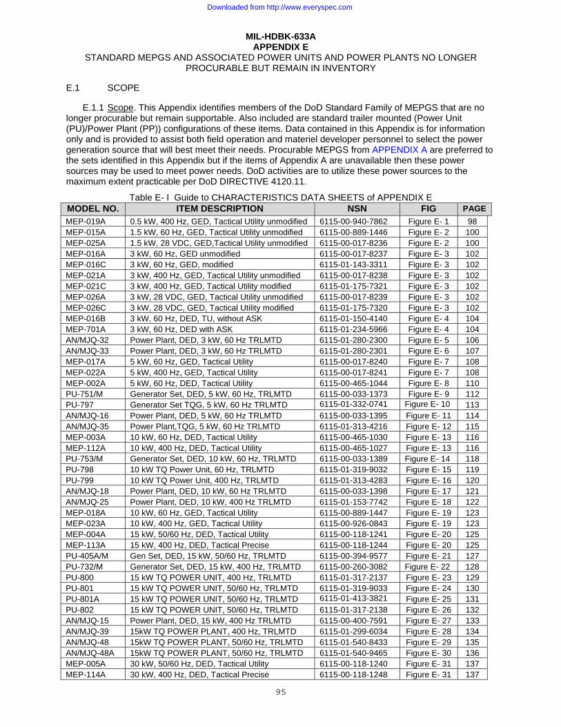
MIL-HDBK-633A
95
APPENDIX E STANDARD MEPGS AND ASSOCIATED POWER UNITS AND POWER PLANTS NO LONGER
PROCURABLE BUT REMAIN IN INVENTORY
E.1 SCOPE
E.1.1 Scope. This Appendix identifies members of the DoD Standard Family of MEPGS that are no longer procurable but remain supportable. Also included are standard trailer mounted (Power Unit (PU)/Power Plant (PP)) configurations of these items. Data contained in this Appendix is for information only and is provided to assist both field operation and materiel developer personnel to select the power generation source that will best meet their needs. Procurable MEPGS from APPENDIX A are preferred to the sets identified in this Appendix but if the items of Appendix A are unavailable then these power sources may be used to meet power needs. DoD activities are to utilize these power sources to the maximum extent practicable per DoD DIRECTIVE 4120.11.
Table E- I Guide to CHARACTERISTICS DATA SHEETS of APPENDIX E MODEL NO. ITEM DESCRIPTION NSN FIG PAGE MEP-019A 0.5 kW, 400 Hz, GED, Tactical Utility unmodified 6115-00-940-7862 Figure E- 1 98 MEP-015A 1.5 kW, 60 Hz, GED, Tactical Utility unmodified 6115-00-889-1446 Figure E- 2 100 MEP-025A 1.5 kW, 28 VDC, GED,Tactical Utility unmodified 6115-00-017-8236 Figure E- 2 100 MEP-016A 3 kW, 60 Hz, GED unmodified 6115-00-017-8237 Figure E- 3 102 MEP-016C 3 kW, 60 Hz, GED, modified 6115-01-143-3311 Figure E- 3 102 MEP-021A 3 kW, 400 Hz, GED, Tactical Utility unmodified 6115-00-017-8238 Figure E- 3 102 MEP-021C 3 kW, 400 Hz, GED, Tactical Utility modified 6115-01-175-7321 Figure E- 3 102 MEP-026A 3 kW, 28 VDC, GED, Tactical Utility unmodified 6115-00-017-8239 Figure E- 3 102 MEP-026C 3 kW, 28 VDC, GED, Tactical Utility modified 6115-01-175-7320 Figure E- 3 102 MEP-016B 3 kW, 60 Hz, DED, TU, without ASK 6115-01-150-4140 Figure E- 4 104 MEP-701A 3 kW, 60 Hz, DED with ASK 6115-01-234-5966 Figure E- 4 104 AN/MJQ-32 Power Plant, DED, 3 kW, 60 Hz TRLMTD 6115-01-280-2300 Figure E- 5 106 AN/MJQ-33 Power Plant, DED, 3 kW, 60 Hz TRLMTD 6115-01-280-2301 Figure E- 6 107 MEP-017A 5 kW, 60 Hz, GED, Tactical Utility 6115-00-017-8240 Figure E- 7 108 MEP-022A 5 kW, 400 Hz, GED, Tactical Utility 6115-00-017-8241 Figure E- 7 108 MEP-002A 5 kW, 60 Hz, DED, Tactical Utility 6115-00-465-1044 Figure E- 8 110 PU-751/M Generator Set, DED, 5 kW, 60 Hz, TRLMTD 6115-00-033-1373 Figure E- 9 112 PU-797 Generator Set TQG, 5 kW, 60 Hz TRLMTD 6115-01-332-0741 Figure E- 10 113 AN/MJQ-16 Power Plant, DED, 5 kW, 60 Hz TRLMTD 6115-00-033-1395 Figure E- 11 114 AN/MJQ-35 Power Plant,TQG, 5 kW, 60 Hz TRLMTD 6115-01-313-4216 Figure E- 12 115 MEP-003A 10 kW, 60 Hz, DED, Tactical Utility 6115-00-465-1030 Figure E- 13 116 MEP-112A 10 kW, 400 Hz, DED, Tactical Utility 6115-00-465-1027 Figure E- 13 116 PU-753/M Generator Set, DED, 10 kW, 60 Hz, TRLMTD 6115-00-033-1389 Figure E- 14 118 PU-798 10 kW TQ Power Unit, 60 Hz, TRLMTD 6115-01-319-9032 Figure E- 15 119 PU-799 10 kW TQ Power Unit, 400 Hz, TRLMTD 6115-01-313-4283 Figure E- 16 120 AN/MJQ-18 Power Plant, DED, 10 kW, 60 Hz TRLMTD 6115-00-033-1398 Figure E- 17 121 AN/MJQ-25 Power Plant, DED, 10 kW, 400 Hz TRLMTD 6115-01-153-7742 Figure E- 18 122 MEP-018A 10 kW, 60 Hz, GED, Tactical Utility 6115-00-889-1447 Figure E- 19 123 MEP-023A 10 kW, 400 Hz, GED, Tactical Utility 6115-00-926-0843 Figure E- 19 123 MEP-004A 15 kW, 50/60 Hz, DED, Tactical Utility 6115-00-118-1241 Figure E- 20 125 MEP-113A 15 kW, 400 Hz, DED, Tactical Precise 6115-00-118-1244 Figure E- 20 125 PU-405A/M Gen Set, DED, 15 kW, 50/60 Hz, TRLMTD 6115-00-394-9577 Figure E- 21 127 PU-732/M Generator Set, DED, 15 kW, 400 Hz, TRLMTD 6115-00-260-3082 Figure E- 22 128 PU-800 15 kW TQ POWER UNIT, 400 Hz, TRLMTD 6115-01-317-2137 Figure E- 23 129 PU-801 15 kW TQ POWER UNIT, 50/60 Hz, TRLMTD 6115-01-319-9033 Figure E- 24 130 PU-801A 15 kW TQ POWER UNIT, 50/60 Hz, TRLMTD 6115-01-413-3821 Figure E- 25 131 PU-802 15 kW TQ POWER UNIT, 50/60 Hz, TRLMTD 6115-01-317-2138 Figure E- 26 132 AN/MJQ-15 Power Plant, DED, 15 kW, 400 Hz TRLMTD 6115-00-400-7591 Figure E- 27 133 AN/MJQ-39 15kW TQ POWER PLANT, 400 Hz, TRLMTD 6115-01-299-6034 Figure E- 28 134 AN/MJQ-48 15kW TQ POWER PLANT, 50/60 Hz, TRLMTD 6115-01-540-8433 Figure E- 29 135 AN/MJQ-48A 15kW TQ POWER PLANT, 50/60 Hz, TRLMTD 6115-01-540-9465 Figure E- 30 136 MEP-005A 30 kW, 50/60 Hz, DED, Tactical Utility 6115-00-118-1240 Figure E- 31 137 MEP-114A 30 kW, 400 Hz, DED, Tactical Precise 6115-00-118-1248 Figure E- 31 137
Downloaded from http://www.everyspec.com
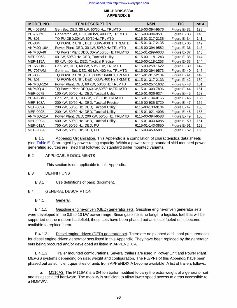
MIL-HDBK-633A APPENDIX E
96
MODEL NO. ITEM DESCRIPTION NSN FIG PAGE PU-406B/M Gen Set, DED, 30 kW, 50/60 Hz, TRLMTD 6115-00-394-9576 Figure E- 32 139 PU-760/M Generator Set, DED, 30 kW, 400 Hz, TRLMTD 6115-00-394-9581 Figure E- 33 140 PU-803 TQ PU,DED,30kW, 50/60Hz,TRLMTD 6115-01-317-2136 Figure E- 34 141 PU-804 TQ POWER UNIT, DED,30kW,400Hz, TRLMTD 6115-01-317-2135 Figure E- 35 142 AN/MJQ-10A Power Plant, DED, 30 kW, 50/60 Hz TRLMTD 6115-00-394-9582 Figure E- 36 143 AN/MJQ-40 TQ Power Plant,DED, 30kW,50/60 Hz,TRLMTD 6115-01-299-6033 Figure E- 37 143 MEP-006A 60 kW, 50/60 Hz, DED, Tactical Utility 6115-00-118-1243 Figure E- 38 144 MEP-115A 60 kW, 400 Hz, DED, Tactical Precise 6115-00-118-1253 Figure E- 38 144 PU-650B/G Gen Set, DED, 60 kW, 50/60 Hz, TRLMTD 6115-00-258-1622 Figure E- 39 147 PU-707A/M Generator Set, DED, 60 kW, 400 Hz, TRLMTD 6115-00-394-9573 Figure E- 40 148 PU-805 TQ POWER UNIT,DED,60kW,50/60Hz,TRLMTD 6115-01-317-2134 Figure E- 41 149 PU-806 TQ POWER UNIT, DED, 60kW,400 Hz,TRLMTD 6115-01-317-2133 Figure E- 42 150 AN/MJQ-12A Power Plant, DED, 60 kW, 50/60 Hz TRLMTD 6115-00-257-1602 Figure E- 43 151 AN/MJQ-41 TQ Power Plant,DED,60kW,50/60Hz,TRLMTD 6115-01-303-7896 Figure E- 44 151 MEP-007B 100 kW, 50/60 Hz, DED, Tactical Utility 6115-01-036-6374 Figure E- 45 153 PU-495B/G Gen Set, DED, 100 kW, 50/60 Hz, TRLMTD 6115-01-134-0165 Figure E- 46 155 MEP-108A 200 kW, 50/60 Hz, DED, Tactical Precise 6115-00-935-8729 Figure E- 47 156 MEP-009A 200 kW, 50/60 Hz, DED, Tactical Utility 6115-00-133-9104 Figure E- 47 156 MEP-009B 200 kW, 50/60 Hz, DED, Tactical Utility 6115-01-021-4096 Figure E- 48 158 AN/MJQ-11A Power Plant, DED, 200 kW, 50/60 Hz, TRLMTD 6115-00-394-9583 Figure E- 49 160 MEP-029A 500 kW, 50/60 Hz, DED, Tactical Utility 6115-01-030-6085 Figure E- 50 161 MEP-012A 750 kW, 50/60 Hz, DED, PU 6115-01-143-3850 Figure E- 51 163 MEP-208A 750 kW, 50/60 Hz, DED, PU 6115-00-450-5881 Figure E- 52 165
E.1.1 Appendix Organization. This Appendix is a compilation of characteristics data sheets (see Table E- I) arranged by power rating capacity. Within a power rating, standard skid mounted power generating sources are listed first followed by standard trailer mounted variants.
E.2 APPLICABLE DOCUMENTS
This section is not applicable to this Appendix.
E.3 DEFINITIONS
E.3.1 Use definitions of basic document.
E.4 GENERAL DESCRIPTION
E.4.1 General.
E.4.1.1 Gasoline engine-driven (GED) generator sets. Gasoline engine-driven generator sets were developed in the 0.5 to 10 kW power range. Since gasoline is no longer a logistics fuel that will be supported on the modern battlefield, these sets have been phased out as diesel fueled units become available to replace them.
E.4.1.2 Diesel engine-driven (DED) generator set. There are no planned additional procurements for diesel engine-driven generator sets listed in this Appendix. They have been replaced by the generator sets being procured and/or developed as listed in APPENDIX A.
E.4.1.3 Trailer mounted configurations. Several trailers are used in Power Unit and Power Plant MEPGS systems depending on size, weight and configuration. The PU/PPs of this Appendix have been phased out as sufficient quantities of units from APPENDIX A become available. A list of trailers follows.
a. M116A3. The M116A3 is a 3/4 ton trailer modified to carry the extra weight of a generator set and its associated hardware. The mobility is sufficient to allow lower speed access to areas accessible to a HMMWV.
Downloaded from http://www.everyspec.com
MIL-HDBK-633A APPENDIX E
97
b. M103A4. The M103A4 is a 1-1/2 ton trailer modified to carry the extra weight of a generator set and its associated hardware.
c. M200A1.The M200A1 is a 2-1/2 ton trailer modified to carry the extra weight of a generator set and its associated hardware.
E.4.2 Delivered condition.
This information is provided as a historical record. These items are not longer available.
E.5 DETAILED DESCRIPTIONS
E.5.1 Detailed Descriptions. Detailed descriptions are contained in the CHARACTERISTICS DATA SHEETS of Figure E- 1 through Figure E- 52.
Downloaded from http://www.everyspec.com
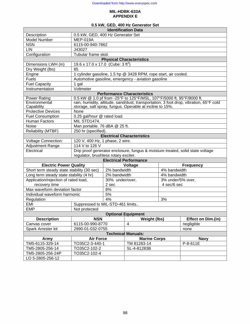
MIL-HDBK-633A APPENDIX E
98
0.5 kW, GED, 400 Hz Generator Set Identification Data
Description 0.5 kW, GED, 400 Hz Generator Set Model Number MEP-019A NSN 6115-00-940-7862 LIN J43027 Configuration Tubular frame skid.
Physical Characteristics Dimensions LWH (in) 19.6 x 17.0 x 17.0 (Cube: 3 ft3) Dry Weight (lbs) 85 Engine 1 cylinder gasoline, 1.5 hp @ 3428 RPM, rope start, air cooled. Fuels Automotive gasoline, emergency - aviation gasoline Fuel Capacity 1 gal Instrumentation Voltmeter
Performance Characteristics Power Rating 0.5 kW @ 1.0 pf from -25°F to 125°F/MSL, 107°F/5000 ft, 95°F/8000 ft.Environmental Capability
rain, humidity, altitude, sand/dust, transportation, 3 foot drop, vibration, 65°F cold storage, salt spray, fungus. Operable at incline to 15%.
Protective Devices None Fuel Consumption 0.25 gal/hour @ rated load. Human Factors MIL STD1474. Noise Man portable. 76 dBA @ 25 ft. Reliability (MTBF) 250 hr (specified).
Electrical Characteristics Voltage Connection: 120 V, 400 Hz, 1 phase, 2 wire. Adjustment Range 114 V to 126 V Electrical Drip proof generator enclosure, fungus & moisture treated, solid state voltage
regulator, brushless rotary exciter. Electrical Performance
Electric Power Quality Voltage Frequency Short term steady state stability (30 sec) 2% bandwidth 4% bandwidth Long term steady state stability (4 hr) 2% bandwidth 4% bandwidth Application/rejection of rated load,
recovery time 30% under/over, 2 sec
3% under/5% over, 4 sec/6 sec
Max waveform deviation factor 8% Individual waveform harmonic 5% Regulation 4% 3% EMI Suppressed to MIL-STD-461 limits.. EMP Not protected
Optional Equipment Description NSN Weight (lbs) Effect on Dim.(in)
Canvas cover 6115-00-990-8770 4 negligible Spark Arrester kit 2990-01-032-0755 none
Technical Manuals: Army Air Force Marine Corps Navy
TM5-6115-329-14 TO35C2-3-440-1 TM 81283-14 P-8-611E TM5-2805-256-14 TO35C2-102-2 SL-4-81283B TM5-2805-256-24P TO35C2-102-4 LO 5-2805-256-12
Downloaded from http://www.everyspec.com
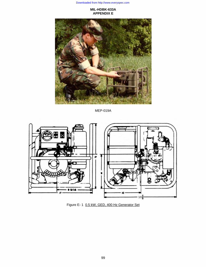
MIL-HDBK-633A APPENDIX E
99
MEP-019A
Figure E- 1 0.5 kW, GED, 400 Hz Generator Set
Downloaded from http://www.everyspec.com
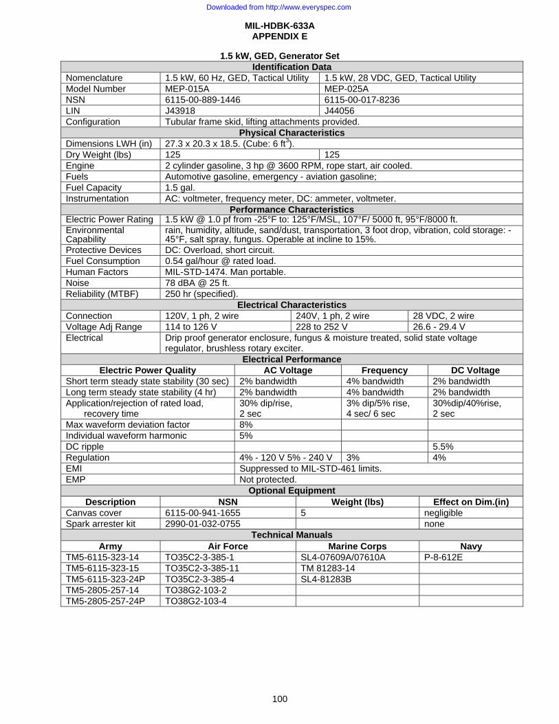
MIL-HDBK-633A APPENDIX E
100
1.5 kW, GED, Generator Set Identification Data
Nomenclature 1.5 kW, 60 Hz, GED, Tactical Utility 1.5 kW, 28 VDC, GED, Tactical Utility Model Number MEP-015A MEP-025A NSN 6115-00-889-1446 6115-00-017-8236 LIN J43918 J44056 Configuration Tubular frame skid, lifting attachments provided.
Physical Characteristics Dimensions LWH (in) 27.3 x 20.3 x 18.5. (Cube: 6 ft3). Dry Weight (lbs) 125 125 Engine 2 cylinder gasoline, 3 hp @ 3600 RPM, rope start, air cooled. Fuels Automotive gasoline, emergency - aviation gasoline; Fuel Capacity 1.5 gal. Instrumentation AC: voltmeter, frequency meter, DC: ammeter, voltmeter.
Performance Characteristics Electric Power Rating 1.5 kW @ 1.0 pf from -25°F to: 125°F/MSL, 107°F/ 5000 ft, 95°F/8000 ft.Environmental Capability
rain, humidity, altitude, sand/dust, transportation, 3 foot drop, vibration, cold storage: -45°F, salt spray, fungus. Operable at incline to 15%.
Protective Devices DC: Overload, short circuit. Fuel Consumption 0.54 gal/hour @ rated load. Human Factors MIL-STD-1474. Man portable. Noise 78 dBA @ 25 ft. Reliability (MTBF) 250 hr (specified).
Electrical Characteristics Connection 120V, 1 ph, 2 wire 240V, 1 ph, 2 wire 28 VDC, 2 wire Voltage Adj Range 114 to 126 V 228 to 252 V 26.6 - 29.4 V Electrical Drip proof generator enclosure, fungus & moisture treated, solid state voltage
regulator, brushless rotary exciter. Electrical Performance
Electric Power Quality AC Voltage Frequency DC Voltage Short term steady state stability (30 sec) 2% bandwidth 4% bandwidth 2% bandwidth Long term steady state stability (4 hr) 2% bandwidth 4% bandwidth 2% bandwidth Application/rejection of rated load,
recovery time 30% dip/rise, 2 sec
3% dip/5% rise, 4 sec/ 6 sec
30%dip/40%rise, 2 sec
Max waveform deviation factor 8% Individual waveform harmonic 5% DC ripple 5.5% Regulation 4% - 120 V 5% - 240 V 3% 4% EMI Suppressed to MIL-STD-461 limits. EMP Not protected.
Optional Equipment Description NSN Weight (lbs) Effect on Dim.(in)
Canvas cover 6115-00-941-1655 5 negligible Spark arrester kit 2990-01-032-0755 none
Technical Manuals Army Air Force Marine Corps Navy
TM5-6115-323-14 TO35C2-3-385-1 SL4-07609A/07610A P-8-612E TM5-6115-323-15 TO35C2-3-385-11 TM 81283-14 TM5-6115-323-24P TO35C2-3-385-4 SL4-81283B TM5-2805-257-14 TO38G2-103-2 TM5-2805-257-24P TO38G2-103-4
Downloaded from http://www.everyspec.com
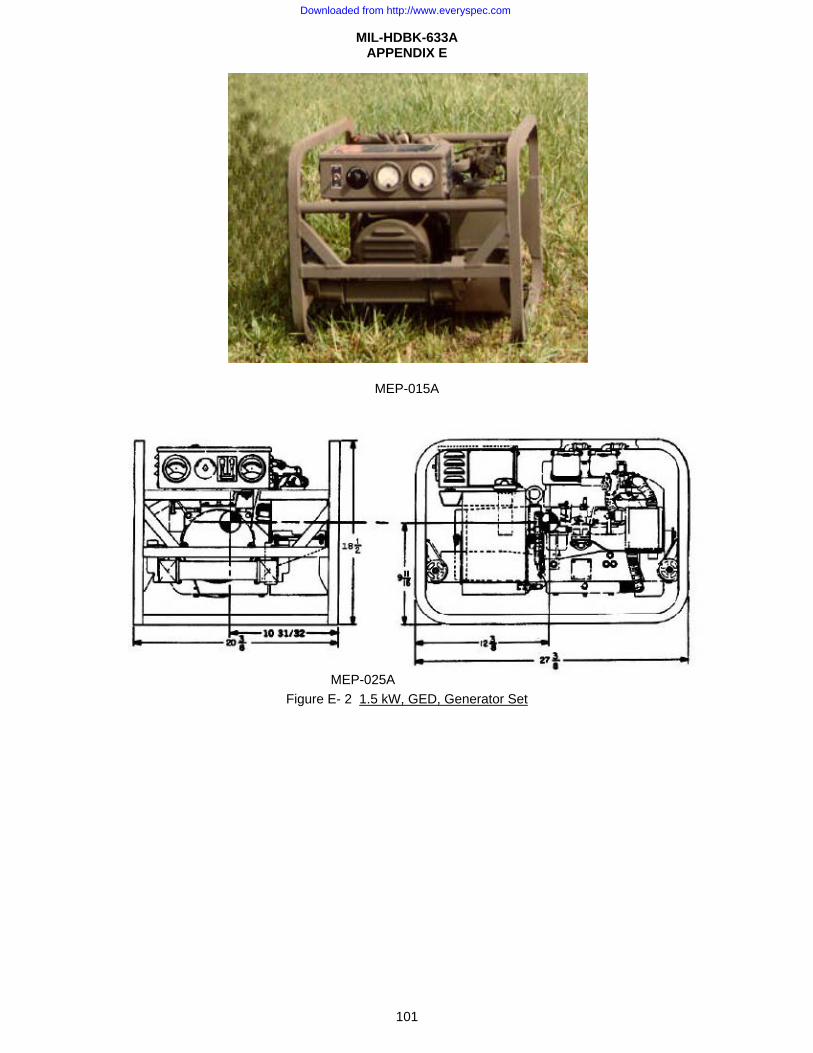
MIL-HDBK-633A APPENDIX E
101
MEP-015A
Figure E- 2 1.5 kW, GED, Generator Set
MEP-025A
Downloaded from http://www.everyspec.com
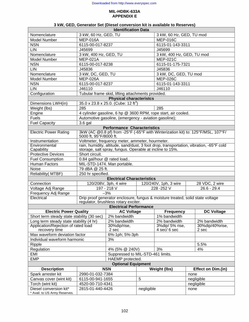
MIL-HDBK-633A APPENDIX E
102
3 kW, GED, Generator Set (Diesel conversion kit is available to Reserves) Identification Data
Nomenclature 3 kW, 60 Hz, GED, TU 3 kW, 60 Hz, GED, TU mod Model Number MEP-016A MEP-016C NSN 6115-00-017-8237 6115-01-143-3311 LIN J45699 J45699 Nomenclature 3 kW, 400 Hz, GED, TU 3 kW, 400 Hz, GED, TU mod Model Number MEP-021A MEP-021C NSN 6115-00-017-8238 6115-01-175-7321 LIN J45836 J45836 Nomenclature 3 kW, DC, GED, TU 3 kW, DC, GED, TU mod Model Number MEP-026A MEP-026C NSN 6115-00-017-8237 6115-01-143-3311 LIN J46110 J46110 Configuration Tubular frame skid, lifting attachments provided.
Physical characteristcs Dimensions LWH(in) 35.0 x 23.8 x 25.0. (Cube: 12 ft3) Weight (lbs) 285 285 Engine 4 cylinder gasoline, 6 hp @ 3600 RPM, rope start, air cooled. Fuels Automotive gasoline, (emergency - aviation gasoline); Fuel Capacity 3.6 gal
Performance Characteristics Electric Power Rating 3kW (AC @0.8 pf) from -25°F (-65°F with Winterization kit) to: 125°F/MSL, 107°F/
5000 ft, 95°F/8000 ft.Instrumentation Voltmeter, frequency meter, ammeter, hourmeter. Environmental Capability
rain, humidity, altitude, sand/dust, 3 foot drop, transportation, vibration, -65°F cold storage, salt spray, fungus. Operable at incline to 15%.
Protective Devices Short circuit. Fuel Consumption 0.84 gal/hour @ rated load.. Human Factors MIL-STD-1474. Man portable. Noise 79 dBA @ 25 ft. Reliability( MTBF) 250 hr specified.
Electrical Characteristics Connection 120/208V, 3ph, 4 wire 120/240V, 1ph, 3 wire 28 VDC, 2 wire Voltage Adj Range 197 - 218 V 228 -252 V 26.6 - 29.4 Frequency Adj Range –3% Electrical Drip proof generator enclosure, fungus & moisture treated, solid state voltage
regulator, brushless rotary exciter.Electrical Performance
Electric Power Quality AC Voltage Frequency DC Voltage Short term steady state stability (30 sec) 2% bandwidth 1% bandwidth Long term steady state stability (4 hr) 2% bandwidth 2% bandwidth 2% bandwidth Application/Rejection of rated load
recovery time 30%dip/rise, 2 sec
3%dip/ 5% rise, 4 sec/ 6 sec
30%dip/40%rise,2 sec
Max waveform deviation factor 6%-1ph; 5%-3ph Individual waveform harmonic 3% Ripple 5.5% Regulation 4% (5% @ 240V) 3% 4% EMI Suppressed to MIL-STD-461 limits. EMP HAEMP protected.
Optional Equipment Description NSN Weight (lbs) Effect on Dim.(in)
Spark arrester kit 2990-01-032-7384 none Canvas cover (wint kit) 6115-00-941-1655 5 negligible Torch (wint kit) 4520-00-710-4341 negligible Diesel conversion kit* * Avail. to US Army Reserves.
2815-01-440-4426 negligible none
Downloaded from http://www.everyspec.com
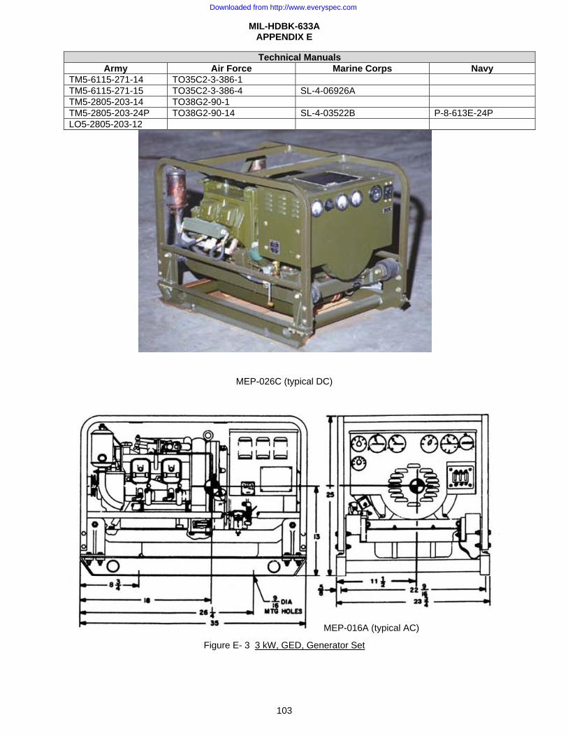
MIL-HDBK-633A APPENDIX E
103
Technical Manuals Army Air Force Marine Corps Navy
TM5-6115-271-14 TO35C2-3-386-1 TM5-6115-271-15 TO35C2-3-386-4 SL-4-06926A TM5-2805-203-14 TO38G2-90-1 TM5-2805-203-24P TO38G2-90-14 SL-4-03522B P-8-613E-24P LO5-2805-203-12
MEP-026C (typical DC)
Figure E- 3 3 kW, GED, Generator Set
MEP-016A (typical AC)
Downloaded from http://www.everyspec.com
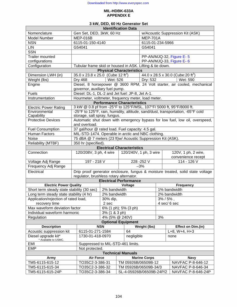
MIL-HDBK-633A APPENDIX E
104
3 kW, DED, 60 Hz Generator Set Identification Data
Nomenclature Gen Set, DED, 3kW, 60 Hz w/Acoustic Suppression Kit (ASK) Model Number MEP-016B MEP-701A NSN 6115-01-150-4140 6115-01-234-5966 LIN G54041 G54041 SSN Trailer mounted configurations
PP-AN/MJQ-32, Figure E- 5 PP-AN/MJQ-33, Figure E- 6
Configuration Tubular frame skid or housed in ASK. Lifting & tie down. Physical Characteristics
Dimension LWH (in) 35.0 x 23.8 x 25.0 (Cube 12 ft3) 44.0 x 28.5 x 30.0 (Cube:20 ft3) Weight (lbs) Dry 468 Wet: 526 Dry: 532 Wet: 590 Engine Diesel, 8 horsepower @ 3600 RPM, 24 Volt starter, air cooled, mechanical
governor, auxiliary fuel pump. Fuels Diesel: DL-1, DL-2 and Jet fuel: JP-8, Jet A-1. Instrumentation Hourmeter, voltmeter, frequency meter, load meter.
Performance Characteristics Electric Power Rating 3 kW @ 0.8 pf from -25°F to 125°F/MSL, 107°F/ 5000 ft, 95°F/8000 ft.Environmental Capability
-25°F to 125°F, rain, humidity, altitude, sand/dust, transportation, -65°F cold storage, salt spray, fungus.
Protective Devices Automatic shut down with emergency bypass for low fuel, low oil, overspeed, and overload.
Fuel Consumption 37 gal/hour @ rated load. Fuel capacity: 4.5 gal. Human Factors MIL-STD-1474. Operable in arctic and NBC clothing. Noise 75 dBA @ 7 meters (23 ft)w/ Acoustic Suppression Kit (ASK). Reliability (MTBF) 350 hr (specified).
Electrical Characteristics Connection 120/208V, 3 ph, 4 wire 120/240V, 1 ph, 3 wire 120V, 1 ph, 2 wire,
convenience recept Voltage Adj Range 197 - 218 V 228 -252 V 114 - 126 V Frequency Adj Range –3% Electrical Drip proof generator enclosure, fungus & moisture treated, solid state voltage
regulator, brushless rotary alternator. Electrical Performance
Electric Power Quality Voltage FrequencyShort term steady state stability (30 sec) 2% bandwidth 1% bandwidth Long term steady state stability (4 hr) 2% bandwidth 2% bandwidth Application/rejection of rated load,
recovery time 30% dip, 2 sec
3% / 5% , 4 sec/ 6 sec
Max waveform deviation factor 6% (1 ph); 5% (3 ph) Individual waveform harmonic 3% (1 & 3 ph) Regulation 4% (5% @ 240V) 3%
Optional Equipment Description NSN Weight (lbs) Effect on Dim.(in)
Acoustic suppression kit 6115-01-271-1584 64 L+8, W+4, H+3 Diesel upgrade kit*
* Available to USMC. 1730-01-418-0970 negligible none
EMI Suppressed to MIL-STD-461 limits. EMP Not protected.
Technical Manuals Army Air Force Marine Corps Navy
TM5-6115-615-12 TO35C2-3-386-31 TM 05926B/06509B-12 NAVFAC P-8-646-12 TM5-6115-615-34 TO35C2-3-386-32 TM 05926B/06509B-34/3 NAVFAC P-8-646-34 TM5-6115-615-24P TO35C2-3-386-34 SL-4-05926B/06509B-24P/2 NAVFAC P-8-646-24P
Downloaded from http://www.everyspec.com
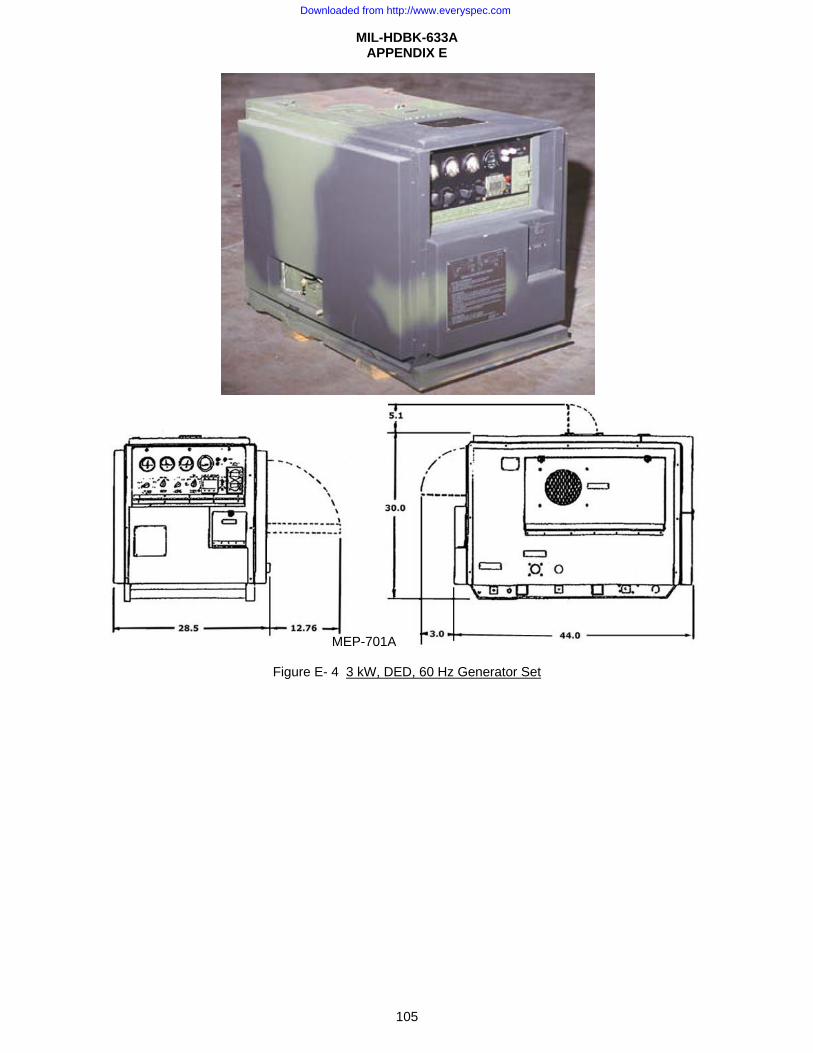
MIL-HDBK-633A APPENDIX E
105
Figure E- 4 3 kW, DED, 60 Hz Generator Set
MEP-701A
Downloaded from http://www.everyspec.com
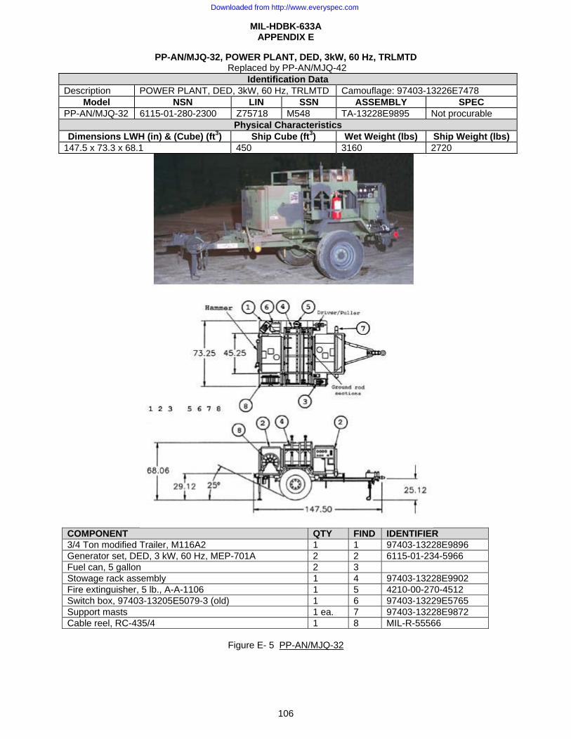
MIL-HDBK-633A APPENDIX E
106
PP-AN/MJQ-32, POWER PLANT, DED, 3kW, 60 Hz, TRLMTD Replaced by PP-AN/MJQ-42
Identification Data Description POWER PLANT, DED, 3kW, 60 Hz, TRLMTD Camouflage: 97403-13226E7478
Model NSN LIN SSN ASSEMBLY SPEC PP-AN/MJQ-32 6115-01-280-2300 Z75718 M548 TA-13228E9895 Not procurable
Physical Characteristics Dimensions LWH (in) & (Cube) (ft3) Ship Cube (ft3) Wet Weight (lbs) Ship Weight (lbs)
147.5 x 73.3 x 68.1 450 3160 2720
COMPONENT QTY FIND IDENTIFIER 3/4 Ton modified Trailer, M116A2 1 1 97403-13228E9896 Generator set, DED, 3 kW, 60 Hz, MEP-701A 2 2 6115-01-234-5966 Fuel can, 5 gallon 2 3 Stowage rack assembly 1 4 97403-13228E9902 Fire extinguisher, 5 lb., A-A-1106 1 5 4210-00-270-4512 Switch box, 97403-13205E5079-3 (old) 1 6 97403-13229E5765 Support masts 1 ea. 7 97403-13228E9872 Cable reel, RC-435/4 1 8 MIL-R-55566
Figure E- 5 PP-AN/MJQ-32
Downloaded from http://www.everyspec.com
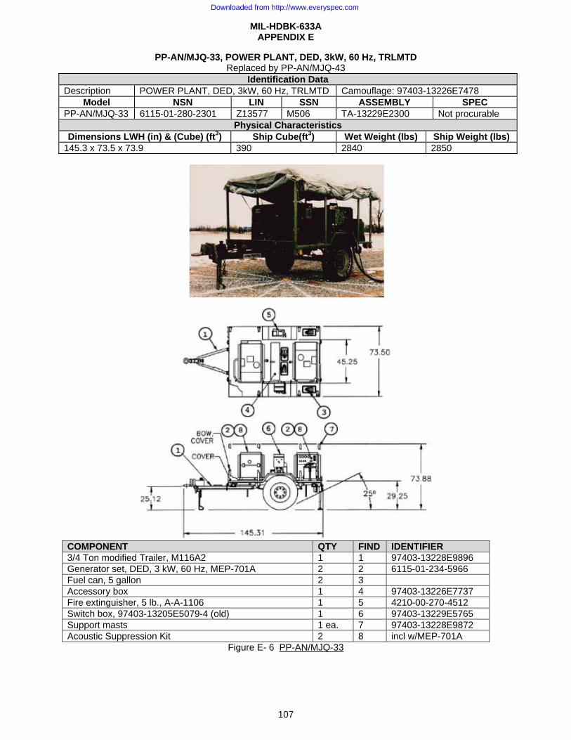
MIL-HDBK-633A APPENDIX E
107
PP-AN/MJQ-33, POWER PLANT, DED, 3kW, 60 Hz, TRLMTD Replaced by PP-AN/MJQ-43
Identification Data Description POWER PLANT, DED, 3kW, 60 Hz, TRLMTD Camouflage: 97403-13226E7478
Model NSN LIN SSN ASSEMBLY SPEC PP-AN/MJQ-33 6115-01-280-2301 Z13577 M506 TA-13229E2300 Not procurable
Physical Characteristics Dimensions LWH (in) & (Cube) (ft3) Ship Cube(ft3) Wet Weight (lbs) Ship Weight (lbs)
145.3 x 73.5 x 73.9 390 2840 2850
COMPONENT QTY FIND IDENTIFIER 3/4 Ton modified Trailer, M116A2 1 1 97403-13228E9896 Generator set, DED, 3 kW, 60 Hz, MEP-701A 2 2 6115-01-234-5966 Fuel can, 5 gallon 2 3 Accessory box 1 4 97403-13226E7737 Fire extinguisher, 5 lb., A-A-1106 1 5 4210-00-270-4512 Switch box, 97403-13205E5079-4 (old) 1 6 97403-13229E5765 Support masts 1 ea. 7 97403-13228E9872 Acoustic Suppression Kit 2 8 incl w/MEP-701A
Figure E- 6 PP-AN/MJQ-33
Downloaded from http://www.everyspec.com
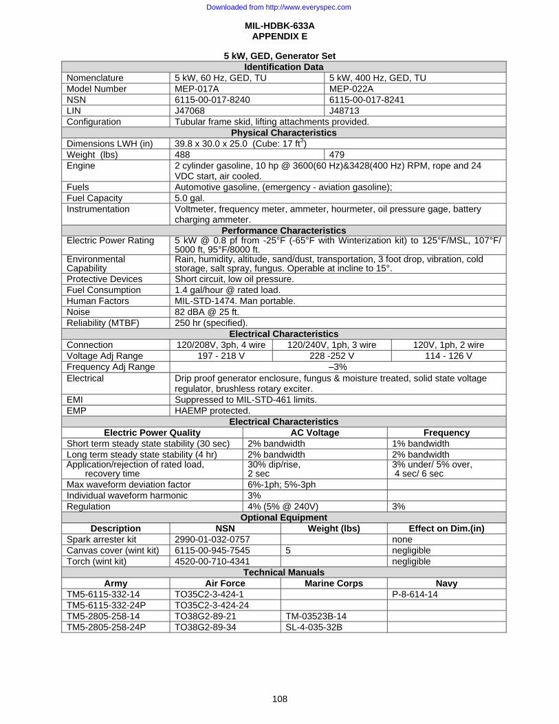
MIL-HDBK-633A APPENDIX E
108
5 kW, GED, Generator Set Identification Data
Nomenclature 5 kW, 60 Hz, GED, TU 5 kW, 400 Hz, GED, TU Model Number MEP-017A MEP-022A NSN 6115-00-017-8240 6115-00-017-8241 LIN J47068 J48713 Configuration Tubular frame skid, lifting attachments provided.
Physical Characteristics Dimensions LWH (in) 39.8 x 30.0 x 25.0 (Cube: 17 ft3) Weight (lbs) 488 479 Engine 2 cylinder gasoline, 10 hp @ 3600(60 Hz)&3428(400 Hz) RPM, rope and 24
VDC start, air cooled. Fuels Automotive gasoline, (emergency - aviation gasoline); Fuel Capacity 5.0 gal. Instrumentation Voltmeter, frequency meter, ammeter, hourmeter, oil pressure gage, battery
charging ammeter. Performance Characteristics
Electric Power Rating 5 kW @ 0.8 pf from -25°F (-65°F with Winterization kit) to 125°F/MSL, 107°F/ 5000 ft, 95°F/8000 ft.
Environmental Capability
Rain, humidity, altitude, sand/dust, transportation, 3 foot drop, vibration, cold storage, salt spray, fungus. Operable at incline to 15°.
Protective Devices Short circuit, low oil pressure. Fuel Consumption 1.4 gal/hour @ rated load. Human Factors MIL-STD-1474. Man portable. Noise 82 dBA @ 25 ft. Reliability (MTBF) 250 hr (specified).
Electrical Characteristics Connection 120/208V, 3ph, 4 wire 120/240V, 1ph, 3 wire 120V, 1ph, 2 wire Voltage Adj Range 197 - 218 V 228 -252 V 114 - 126 V Frequency Adj Range –3% Electrical Drip proof generator enclosure, fungus & moisture treated, solid state voltage
regulator, brushless rotary exciter. EMI Suppressed to MIL-STD-461 limits. EMP HAEMP protected.
Electrical Characteristics Electric Power Quality AC Voltage Frequency
Short term steady state stability (30 sec) 2% bandwidth 1% bandwidth Long term steady state stability (4 hr) 2% bandwidth 2% bandwidth Application/rejection of rated load,
recovery time 30% dip/rise,2 sec
3% under/ 5% over, 4 sec/ 6 sec
Max waveform deviation factor 6%-1ph; 5%-3ph Individual waveform harmonic 3% Regulation 4% (5% @ 240V) 3%
Optional Equipment Description NSN Weight (lbs) Effect on Dim.(in)
Spark arrester kit 2990-01-032-0757 none Canvas cover (wint kit) 6115-00-945-7545 5 negligible Torch (wint kit) 4520-00-710-4341 negligible
Technical Manuals Army Air Force Marine Corps Navy
TM5-6115-332-14 TO35C2-3-424-1 P-8-614-14 TM5-6115-332-24P TO35C2-3-424-24 TM5-2805-258-14 TO38G2-89-21 TM-03523B-14 TM5-2805-258-24P TO38G2-89-34 SL-4-035-32B
Downloaded from http://www.everyspec.com
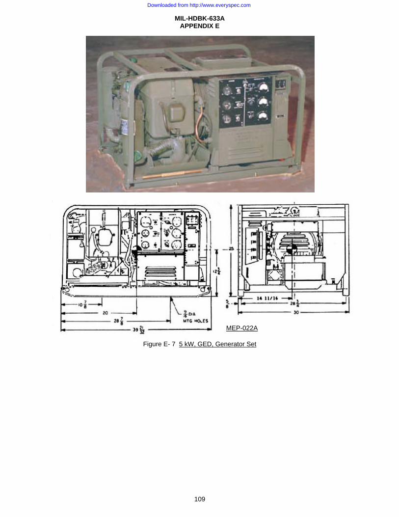
MIL-HDBK-633A APPENDIX E
109
Figure E- 7 5 kW, GED, Generator Set
MEP-022A
Downloaded from http://www.everyspec.com
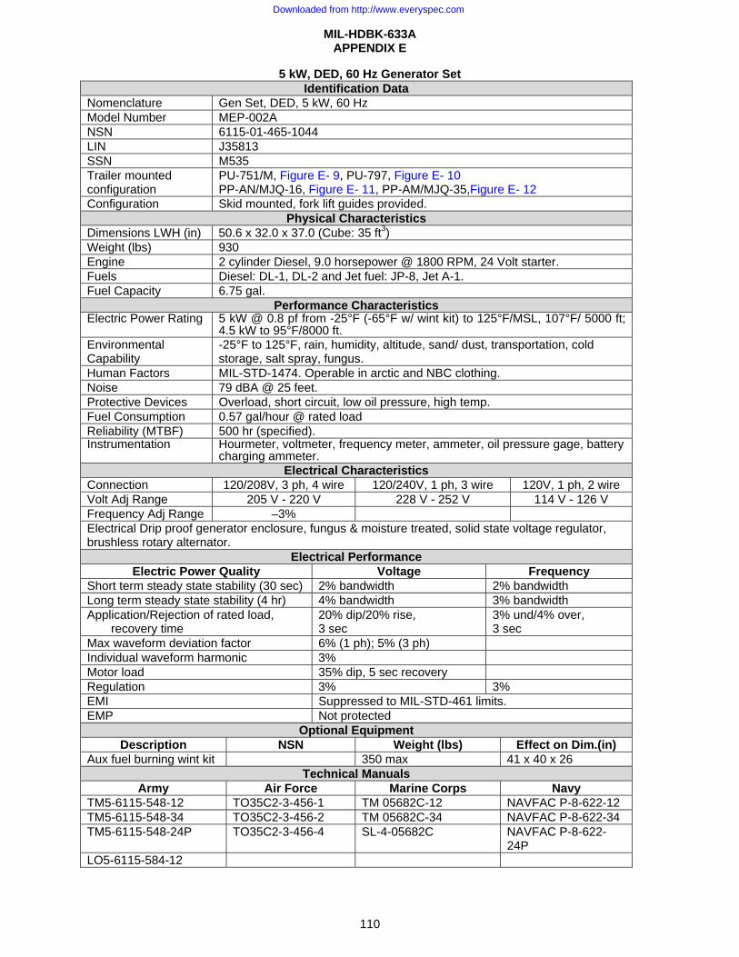
MIL-HDBK-633A APPENDIX E
110
5 kW, DED, 60 Hz Generator Set Identification Data
Nomenclature Gen Set, DED, 5 kW, 60 Hz Model Number MEP-002A NSN 6115-01-465-1044 LIN J35813 SSN M535 Trailer mounted configuration
PU-751/M, Figure E- 9, PU-797, Figure E- 10 PP-AN/MJQ-16, Figure E- 11, PP-AM/MJQ-35,Figure E- 12
Configuration Skid mounted, fork lift guides provided. Physical Characteristics
Dimensions LWH (in) 50.6 x 32.0 x 37.0 (Cube: 35 ft3) Weight (lbs) 930 Engine 2 cylinder Diesel, 9.0 horsepower @ 1800 RPM, 24 Volt starter. Fuels Diesel: DL-1, DL-2 and Jet fuel: JP-8, Jet A-1. Fuel Capacity 6.75 gal.
Performance Characteristics Electric Power Rating 5 kW @ 0.8 pf from -25°F (-65°F w/ wint kit) to 125°F/MSL, 107°F/ 5000 ft;
4.5 kW to 95°F/8000 ft.Environmental Capability
-25°F to 125°F, rain, humidity, altitude, sand/ dust, transportation, cold storage, salt spray, fungus.
Human Factors MIL-STD-1474. Operable in arctic and NBC clothing. Noise 79 dBA @ 25 feet. Protective Devices Overload, short circuit, low oil pressure, high temp. Fuel Consumption 0.57 gal/hour @ rated load Reliability (MTBF) 500 hr (specified). Instrumentation Hourmeter, voltmeter, frequency meter, ammeter, oil pressure gage, battery
charging ammeter.Electrical Characteristics
Connection 120/208V, 3 ph, 4 wire 120/240V, 1 ph, 3 wire 120V, 1 ph, 2 wire Volt Adj Range 205 V - 220 V 228 V - 252 V 114 V - 126 V Frequency Adj Range –3% Electrical Drip proof generator enclosure, fungus & moisture treated, solid state voltage regulator, brushless rotary alternator.
Electrical Performance Electric Power Quality Voltage Frequency
Short term steady state stability (30 sec) 2% bandwidth 2% bandwidth Long term steady state stability (4 hr) 4% bandwidth 3% bandwidth Application/Rejection of rated load,
recovery time 20% dip/20% rise, 3 sec
3% und/4% over, 3 sec
Max waveform deviation factor 6% (1 ph); 5% (3 ph) Individual waveform harmonic 3% Motor load 35% dip, 5 sec recovery Regulation 3% 3% EMI Suppressed to MIL-STD-461 limits. EMP Not protected
Optional Equipment Description NSN Weight (lbs) Effect on Dim.(in)
Aux fuel burning wint kit 350 max 41 x 40 x 26 Technical Manuals
Army Air Force Marine Corps Navy TM5-6115-548-12 TO35C2-3-456-1 TM 05682C-12 NAVFAC P-8-622-12 TM5-6115-548-34 TO35C2-3-456-2 TM 05682C-34 NAVFAC P-8-622-34 TM5-6115-548-24P TO35C2-3-456-4 SL-4-05682C NAVFAC P-8-622-
24P LO5-6115-584-12
Downloaded from http://www.everyspec.com
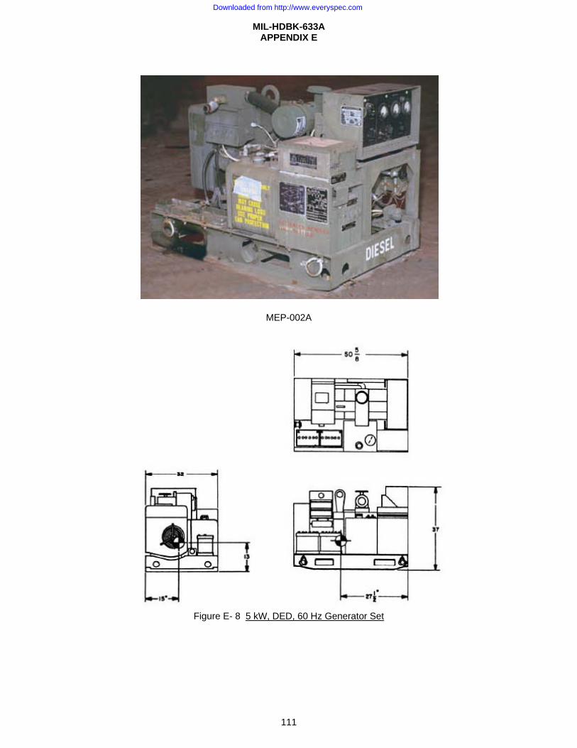
MIL-HDBK-633A APPENDIX E
111
MEP-002A
Figure E- 8 5 kW, DED, 60 Hz Generator Set
Downloaded from http://www.everyspec.com
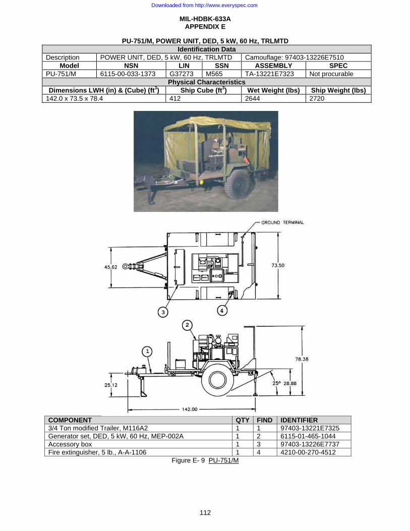
MIL-HDBK-633A APPENDIX E
112
PU-751/M, POWER UNIT, DED, 5 kW, 60 Hz, TRLMTD Identification Data
Description POWER UNIT, DED, 5 kW, 60 Hz, TRLMTD Camouflage: 97403-13226E7510 Model NSN LIN SSN ASSEMBLY SPEC
PU-751/M 6115-00-033-1373 G37273 M565 TA-13221E7323 Not procurable Physical Characteristics
Dimensions LWH (in) & (Cube) (ft3) Ship Cube (ft3) Wet Weight (lbs) Ship Weight (lbs) 142.0 x 73.5 x 78.4 412 2644 2720
COMPONENT QTY FIND IDENTIFIER 3/4 Ton modified Trailer, M116A2 1 1 97403-13221E7325 Generator set, DED, 5 kW, 60 Hz, MEP-002A 1 2 6115-01-465-1044 Accessory box 1 3 97403-13226E7737 Fire extinguisher, 5 lb., A-A-1106 1 4 4210-00-270-4512
Figure E- 9 PU-751/M
Downloaded from http://www.everyspec.com
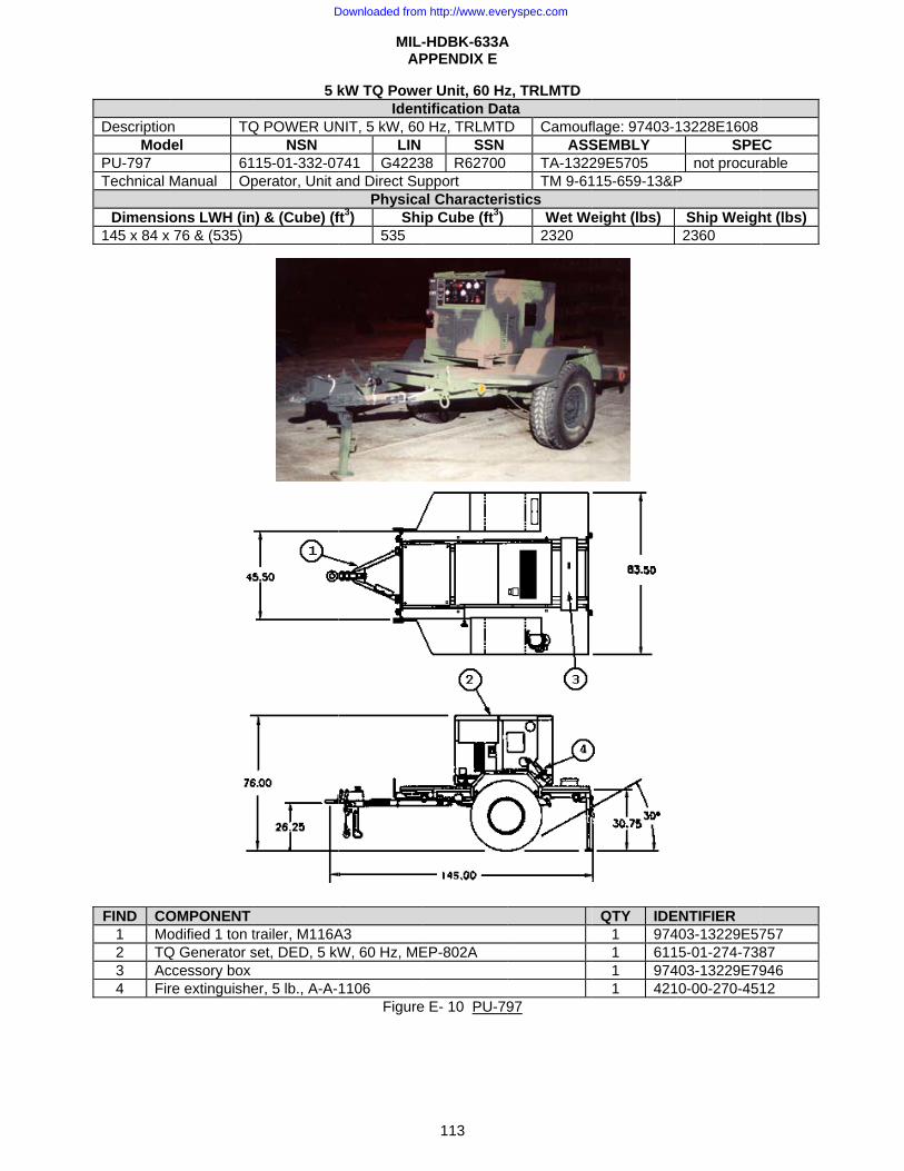
DescriptionMod
PU-797 Technical
Dimensi145 x 84 x
FIND CO1 Mo2 TQ3 Ac4 Fir
n TQdel
61Manual Op
ons LWH (inx 76 & (535)
OMPONENT odified 1 ton tQ Generator sccessory box re extinguishe
5 k
Q POWER UNNSN
15-01-332-07perator, Unit a
n) & (Cube) (f
trailer, M116Aset, DED, 5 kW
er, 5 lb., A-A-
MIL-AP
kW TQ PoweIdent
NIT, 5 kW, 60LIN
741 G4223and Direct Su
Physicaft3) Shi
535
A3 W, 60 Hz, ME
1106 Figure
-HDBK-633APPENDIX E
113
er Unit, 60 Hztification Dat
0 Hz, TRLMTDSSN
38 R62700upport al Characteriip Cube (ft3)
EP-802A
e E- 10 PU-79
A
z, TRLMTD ta D Camouf
ASSTA-1322TM 9-61
stics Wet We
2320
97
flage: 97403-1SEMBLY 29E5705 115-659-13&P
eight (lbs)
QTY IDE1 9741 6111 9741 421
13228E1608SPE
not procuraP
Ship Weigh2360
ENTIFIER 403-13229E57
5-01-274-738403-13229E79
0-00-270-451
C able
ht (lbs)
757 87 946 12
Downloaded from http://www.everyspec.com
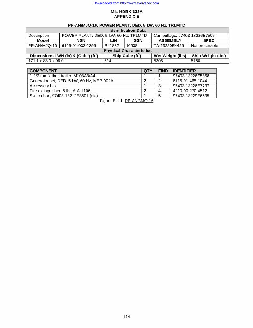
MIL-HDBK-633A APPENDIX E
114
PP-AN/MJQ-16, POWER PLANT, DED, 5 kW, 60 Hz, TRLMTD Identification Data
Description POWER PLANT, DED, 5 kW, 60 Hz, TRLMTD Camouflage: 97403-13226E7506 Model NSN LIN SSN ASSEMBLY SPEC
PP-AN/MJQ-16 6115-01-033-1395 P41832 M538 TA-13220E4455 Not procurable Physical Characteristics
Dimensions LWH (in) & (Cube) (ft3) Ship Cube (ft3) Wet Weight (lbs) Ship Weight (lbs) 171.1 x 83.0 x 98.0 614 5308 5160
COMPONENT QTY FIND IDENTIFIER 1-1/2 ton flatbed trailer, M103A3/A4 1 1 97403-13226E5858 Generator set, DED, 5 kW, 60 Hz, MEP-002A 2 2 6115-01-465-1044 Accessory box 1 3 97403-13226E7737 Fire extinguisher, 5 lb., A-A-1106 2 4 4210-00-270-4512 Switch box, 97403-13212E3601 (old) 1 5 97403-13229E6535
Figure E- 11 PP-AN/MJQ-16
Downloaded from http://www.everyspec.com
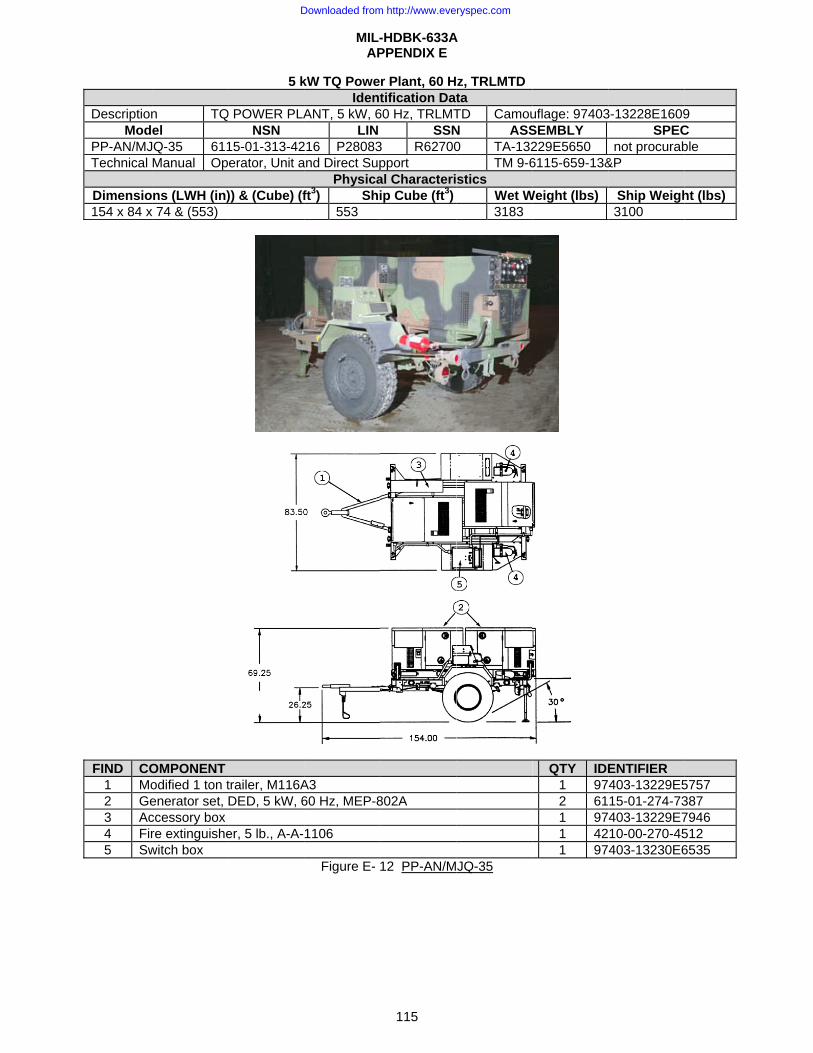
DescriptionMod
PP-AN/MJTechnical
Dimensio154 x 84 x
FIND CO
1 Mo2 Ge3 Ac4 Fir5 Sw
n TQel
JQ-35 611Manual Op
ns (LWH (in)x 74 & (553)
OMPONENT odified 1 ton tenerator set, ccessory box re extinguishewitch box
5 k
Q POWER PLANSN
15-01-313-42erator, Unit a
)) & (Cube) (f
trailer, M116ADED, 5 kW, 6
er, 5 lb., A-A-
MIL-AP
kW TQ PoweIdent
ANT, 5 kW, 6LIN
216 P28083and Direct Sup
Physicaft3) Shi
553
A3 60 Hz, MEP-8
1106
Figure E-
-HDBK-633APPENDIX E
115
r Plant, 60 Htification Dat
60 Hz, TRLMTSSN
3 R62700pport al Characteriip Cube (ft3)
802A
12 PP-AN/M
A
z, TRLMTD ta TD CamouN ASS0 TA-132
TM 9-6stics
Wet W3183
JQ-35
uflage: 97403SEMBLY 229E5650 6115-659-13&
Weight (lbs)
QTY IDE1 972 611 971 421 97
3-13228E1609SPEC
not procurab&P
Ship Weigh3100
ENTIFIER 403-13229E515-01-274-73403-13229E710-00-270-45403-13230E6
9 C ble
ht (lbs)
5757 387 7946 512 6535
Downloaded from http://www.everyspec.com

MIL-HDBK-633A APPENDIX E
116
10 kW, DED, Generator Set Identification Data
Nomenclature Gen Set, DED, 10kW, 60 Hz Gen Set, DED, 10kW, 400 Hz Model Number MEP-003A MEP-112A NSN 6115-00-465-1030 6115-01-465-1027 LIN J35825 G35981 SSN M529 M565 Trailer mounted configurations
PU-753M, Figure E- 14, PU-798,Figure E- 15 PP-AN/MJQ-18, Figure E- 17
PU-799, Figure E- 16 PP-AN/MJQ-25, Figure E- 18
Physical Characteristics Dimensions LWH (in) 50.6 x 32.0 x 37.0 (Cube: 35 ft3) 50.6 x 32.0 x 37.0 (Cube: 35 ft3) Weight (lbs): 1240 1325 Engine 4 cylinder Diesel, 20 hp @ 1800/2000 RPM, air cooled, 24 Volt starter. Fuels Diesel: DL-1, DL-2 and Jet fuel: JP-8, Jet A-1. Fuel Capacity 12.5 gal. Instrumentation Hourmeter, voltmeter, frequency meter, ammeter, oil pressure gage,
battery charging ammeter. Performance Characteristics
Electric Power Rating 10 kW @ 0.8 pf from -25°F (-65°F with winterization kit) to 125°F/MSL, 107°F/ 5000 ft, 9 kW to 95°F/8000 ft.
Environmental Capability
-25°F(-65°F w/wint kit) to 125°F, rain, humidity, altitude, sand/dust, transportation, cold storage, salt spray, fungus. Noise 77 dBA @ 25 feet.
Protective Devices Overload, short circuit, low oil pressure, high temp. Fuel Consumption 1.09 gal/hour @ rated load. Human Factors MIL-STD-1474. Operable in arctic and NBC clothing Reliability (MTBF) 500 hr (specified).
Electrical Characteristics Connection 120/208V, 3 ph, 4 wire 240V, 1 ph, 3 wire 120V, 1 ph, 2 wire Voltage Adj Range 205 V to 220 V 228 V to 252 V 114 V to 126 V Frequency Adj Range –3% - 60 Hz; –4% - 400 Hz Electrical Drip proof generator enclosure, fungus & moisture treated, solid state
voltage regulator, brushless rotary alternator. EMI Suppressed to MIL-STD-461 limits. EMP none
Electrical Performance Electric Power Quality Voltage Frequency
Short term steady state stability (30 sec) 2% bandwidth 2% bandwidth Long term steady state stability (4 hr) 4% bandwidth 3% bandwidth Application/rejection of rated load,
recovery time 20% dip/rise, 3 sec
3% under/4% over, 3 sec
Max waveform deviation factor 6% (1 ph); 5% (3 ph) Individual waveform harmonic 3% (1 ph); 2% (3 ph) Motor load 35% dip, 5 sec recovery Regulation 3% 3%
Optional Equipment Description NSN Weight (lbs) Effect on Dim.(in)
Aux fuel burning wint kit 350 max 41 x 40 x 26 Technical Manuals
Army Air Force Marine Corps Navy TM5-6115-585-12 TO35C2-3-455-1 TM 05684C-12 NAVFAC P-8-623-12 TM5-6115-585-34 TO35C2-3-455-2 TM 05684C-34 NAVFAC P-8-623-34 TM5-6115-585-24P TO35C2-3-455-4 SL-4-05684C NAVFAC P-8-623-24P
Downloaded from http://www.everyspec.com
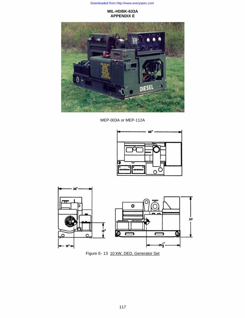
MIL-HDBK-633A APPENDIX E
117
MEP-003A or MEP-112A
Figure E- 13 10 kW, DED, Generator Set
Downloaded from http://www.everyspec.com
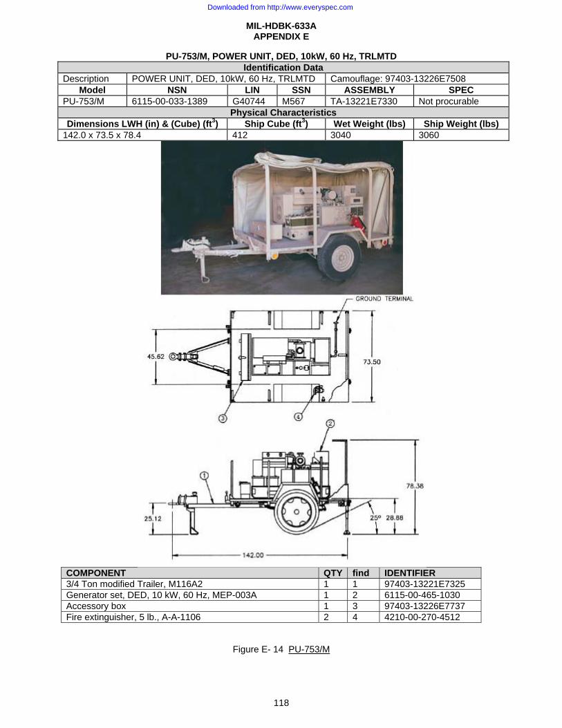
MIL-HDBK-633A APPENDIX E
118
PU-753/M, POWER UNIT, DED, 10kW, 60 Hz, TRLMTD Identification Data
Description POWER UNIT, DED, 10kW, 60 Hz, TRLMTD Camouflage: 97403-13226E7508 Model NSN LIN SSN ASSEMBLY SPEC
PU-753/M 6115-00-033-1389 G40744 M567 TA-13221E7330 Not procurable Physical Characteristics
Dimensions LWH (in) & (Cube) (ft3) Ship Cube (ft3) Wet Weight (lbs) Ship Weight (lbs) 142.0 x 73.5 x 78.4 412 3040 3060
COMPONENT QTY find IDENTIFIER 3/4 Ton modified Trailer, M116A2 1 1 97403-13221E7325 Generator set, DED, 10 kW, 60 Hz, MEP-003A 1 2 6115-00-465-1030 Accessory box 1 3 97403-13226E7737 Fire extinguisher, 5 lb., A-A-1106 2 4 4210-00-270-4512
Figure E- 14 PU-753/M
Downloaded from http://www.everyspec.com
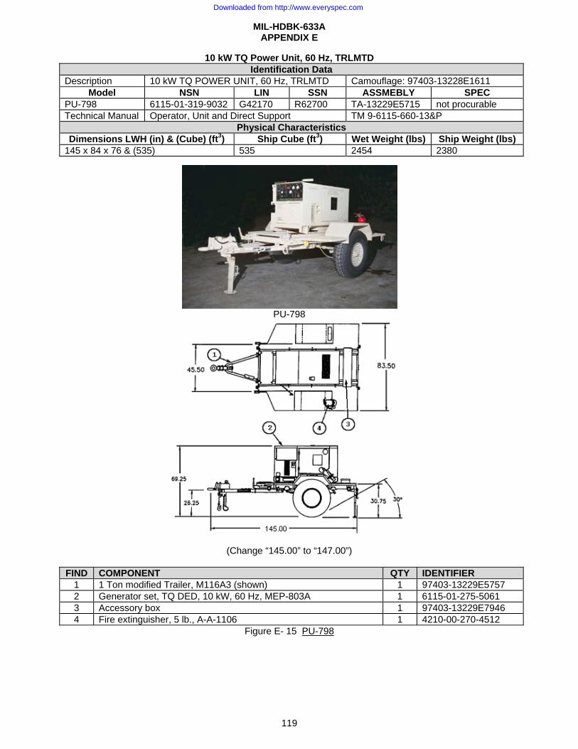
MIL-HDBK-633A APPENDIX E
119
10 kW TQ Power Unit, 60 Hz, TRLMTD Identification Data
Description 10 kW TQ POWER UNIT, 60 Hz, TRLMTD Camouflage: 97403-13228E1611 Model NSN LIN SSN ASSMEBLY SPEC
PU-798 6115-01-319-9032 G42170 R62700 TA-13229E5715 not procurable Technical Manual Operator, Unit and Direct Support TM 9-6115-660-13&P
Physical Characteristics Dimensions LWH (in) & (Cube) (ft3) Ship Cube (ft3) Wet Weight (lbs) Ship Weight (lbs)
145 x 84 x 76 & (535) 535 2454 2380
PU-798
(Change “145.00” to “147.00”)
FIND COMPONENT QTY IDENTIFIER
1 1 Ton modified Trailer, M116A3 (shown) 1 97403-13229E5757 2 Generator set, TQ DED, 10 kW, 60 Hz, MEP-803A 1 6115-01-275-5061 3 Accessory box 1 97403-13229E7946 4 Fire extinguisher, 5 lb., A-A-1106 1 4210-00-270-4512
Figure E- 15 PU-798
Downloaded from http://www.everyspec.com
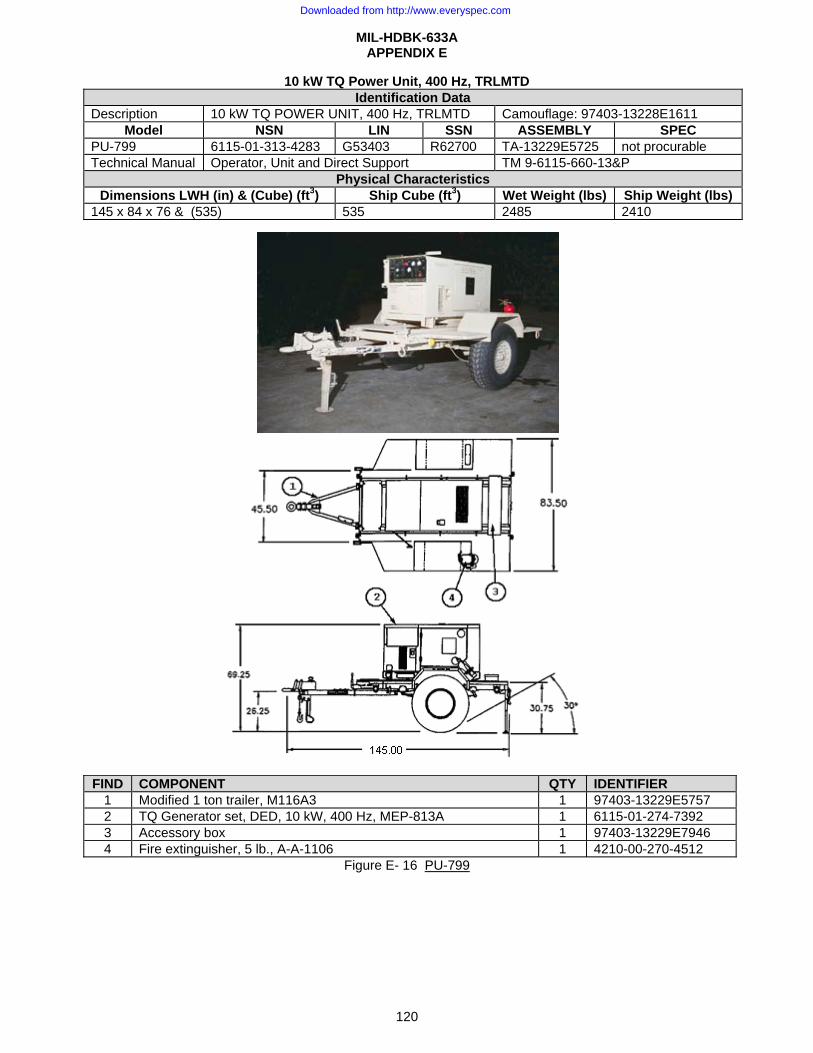
MIL-HDBK-633A APPENDIX E
120
10 kW TQ Power Unit, 400 Hz, TRLMTD Identification Data
Description 10 kW TQ POWER UNIT, 400 Hz, TRLMTD Camouflage: 97403-13228E1611 Model NSN LIN SSN ASSEMBLY SPEC
PU-799 6115-01-313-4283 G53403 R62700 TA-13229E5725 not procurable Technical Manual Operator, Unit and Direct Support TM 9-6115-660-13&P
Physical Characteristics Dimensions LWH (in) & (Cube) (ft3) Ship Cube (ft3) Wet Weight (lbs) Ship Weight (lbs)
145 x 84 x 76 & (535) 535 2485 2410
FIND COMPONENT QTY IDENTIFIER
1 Modified 1 ton trailer, M116A3 1 97403-13229E5757 2 TQ Generator set, DED, 10 kW, 400 Hz, MEP-813A 1 6115-01-274-7392 3 Accessory box 1 97403-13229E7946 4 Fire extinguisher, 5 lb., A-A-1106 1 4210-00-270-4512
Figure E- 16 PU-799
Downloaded from http://www.everyspec.com

MIL-HDBK-633A APPENDIX E
121
PP-AN/MJQ-18, POWER PLANT, DED, 10kW, 60 Hz, TRLMTD Identification Data
Description POWER PLANT, DED, 10kW, 60 Hz, TRLMTD Camouflage: 97403-13226E7504 Model NSN LIN SSN ASSEMBLY SPEC
PP-AN/MJQ-18 6115-00-033-1398 P28015 M540 TA-13220E4465 Not procurable Physical Characteristics
Dimensions LWH (in) & (Cube) (ft3) Ship Cube (ft3) Wet Weight (lbs) Ship Weight (lbs) 171.1 x 83.0 x 98.0 614 5930 5900
COMPONENT QTY FIND IDENTIFIER 1-1/2 ton flatbed trailer, M103A3/A4 1 1 97403-13226E5858 Generator set, DED, 10 kW, 60 Hz, MEP-003A 2 2 6115-00-465-1030 Accessory box 1 3 97403-13226E7737 Fire extinguisher, 5 lb., A-A-1106 2 4 4210-00-270-4512 Switch box, 97403-13226E5859 (old) 1 5 97403-13229E6535
Figure E- 17 PP-AN/MJQ-18
Downloaded from http://www.everyspec.com

MIL-HDBK-633A APPENDIX E
122
PP-AN/MJQ-25, POWER PLANT, DED, 10kW, 400 Hz, TRLMTD Identification Data
Description POWER PLANT, DED, 10kW, 400 Hz, TRLMTD Camouflage: 97403-13226E7512 Model NSN LIN SSN ASSEMBLY SPEC
PP-AN/MJQ-25 6115-01-153-7742 P42364 M523 TA-13226E5860 Not procurable Physical Characteristics
Dimensions LWH (in) & (Cube) (ft3) Ship Cube (ft3) Wet Weight (lbs) Ship Weight (lbs) 171.1 x 83.0 x 98.0 614 5980 5960
COMPONENT QTY FIND IDENTIFIER 1-1/2 ton flatbed trailer, M103A3/A4 1 1 97403-13226E5858 Generator set, DED, 10 kW, 400 Hz, MEP-112A 2 2 6115-01-465-1027 Accessory box 1 3 97403-13226E7737 Fire extinguisher, 5 lb., A-A-1106 2 4 4210-00-270-4512 Switch box 1 5 97403-13226E5859
Figure E- 18 PP-AN/MJQ-25
Downloaded from http://www.everyspec.com
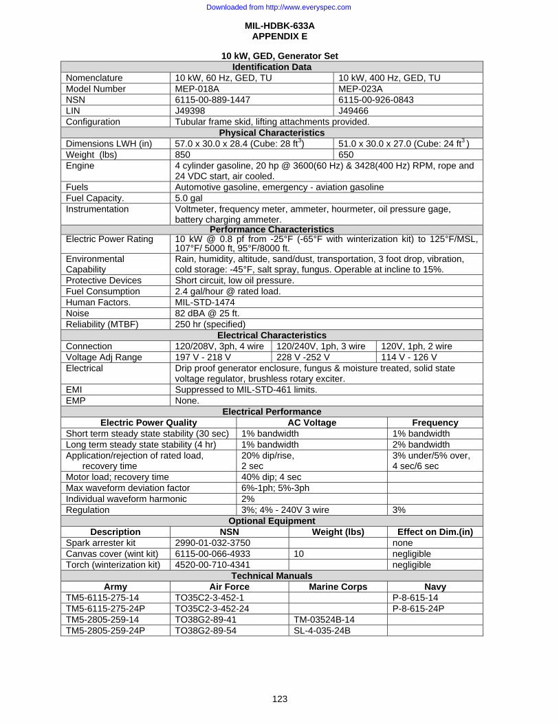
MIL-HDBK-633A APPENDIX E
123
10 kW, GED, Generator Set Identification Data
Nomenclature 10 kW, 60 Hz, GED, TU 10 kW, 400 Hz, GED, TU Model Number MEP-018A MEP-023A NSN 6115-00-889-1447 6115-00-926-0843 LIN J49398 J49466 Configuration Tubular frame skid, lifting attachments provided.
Physical Characteristics Dimensions LWH (in) 57.0 x 30.0 x 28.4 (Cube: 28 ft3) 51.0 x 30.0 x 27.0 (Cube: 24 ft3 ) Weight (lbs) 850 650 Engine 4 cylinder gasoline, 20 hp @ 3600(60 Hz) & 3428(400 Hz) RPM, rope and
24 VDC start, air cooled. Fuels Automotive gasoline, emergency - aviation gasoline Fuel Capacity. 5.0 gal Instrumentation Voltmeter, frequency meter, ammeter, hourmeter, oil pressure gage,
battery charging ammeter. Performance Characteristics
Electric Power Rating 10 kW @ 0.8 pf from -25°F (-65°F with winterization kit) to 125°F/MSL, 107°F/ 5000 ft, 95°F/8000 ft.
Environmental Capability
Rain, humidity, altitude, sand/dust, transportation, 3 foot drop, vibration, cold storage: -45°F, salt spray, fungus. Operable at incline to 15%.
Protective Devices Short circuit, low oil pressure. Fuel Consumption 2.4 gal/hour @ rated load. Human Factors. MIL-STD-1474 Noise 82 dBA @ 25 ft. Reliability (MTBF) 250 hr (specified)
Electrical Characteristics Connection 120/208V, 3ph, 4 wire 120/240V, 1ph, 3 wire 120V, 1ph, 2 wire Voltage Adj Range 197 V - 218 V 228 V -252 V 114 V - 126 V Electrical Drip proof generator enclosure, fungus & moisture treated, solid state
voltage regulator, brushless rotary exciter. EMI Suppressed to MIL-STD-461 limits. EMP None.
Electrical Performance Electric Power Quality AC Voltage Frequency
Short term steady state stability (30 sec) 1% bandwidth 1% bandwidth Long term steady state stability (4 hr) 1% bandwidth 2% bandwidth Application/rejection of rated load,
recovery time 20% dip/rise, 2 sec
3% under/5% over, 4 sec/6 sec
Motor load; recovery time 40% dip; 4 sec Max waveform deviation factor 6%-1ph; 5%-3ph Individual waveform harmonic 2% Regulation 3%; 4% - 240V 3 wire 3%
Optional Equipment Description NSN Weight (lbs) Effect on Dim.(in)
Spark arrester kit 2990-01-032-3750 none Canvas cover (wint kit) 6115-00-066-4933 10 negligible Torch (winterization kit) 4520-00-710-4341 negligible
Technical Manuals Army Air Force Marine Corps Navy
TM5-6115-275-14 TO35C2-3-452-1 P-8-615-14 TM5-6115-275-24P TO35C2-3-452-24 P-8-615-24P TM5-2805-259-14 TO38G2-89-41 TM-03524B-14 TM5-2805-259-24P TO38G2-89-54 SL-4-035-24B
Downloaded from http://www.everyspec.com
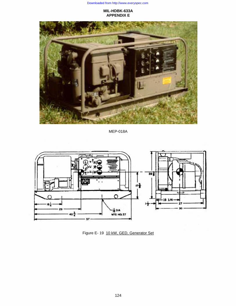
MIL-HDBK-633A APPENDIX E
124
MEP-018A
Figure E- 19 10 kW, GED, Generator Set
Downloaded from http://www.everyspec.com

MIL-HDBK-633A APPENDIX E
125
15 kW DED Generator set Identification Data
Nomenclature Gen Set, DED, 15 kW, 50/60 Hz Gen Set, DED, 15 kW, 400 Hz Model Number MEP-004A MEP-113A NSN 6115-00-118-1241 6115-00-118-1244 LIN J35835 J36006 SSN M549 M526 Trailer mounted configurations
PU-405A/M; Figure E-21;PU-801, Figure E- 24; PU-801A, Figure E- 25;PU-802;Figure E- 26; AN/MJQ-48,Figure E- 29; AN/MJQ-48A,Figure E- 30
PU-732/M; Figure E-22; PU-800,Figure E-23;AN/MJQ-15; Figure E- 27; AN/MJQ-39,Figure E- 28
Physical Characteristics Dimension LWH (in) 69.8 x 35.8 x 54.6 (Cube: 75 ft3) 69.8 x 35.8 x 54.6 (Cube: 75 ft3) Weight (lbs) 2450 2500 Engine 4 cylinder Diesel, 41 hp @ 1500/1800 RPM (50/60
Hz), liquid cooled, 24 Volt starter. 4 cylinder Diesel, 45 hp @ 2000 RPM (400 Hz) liquid cooled, 24 Volt starter
Fuels Diesel: DL-1, DL-2 and Jet fuel: JP-8, Jet A-1. Fuel Capacity 15 gal. Instrumentation Hourmeter, voltmeter, frequency meter, ammeter, wattmeter, oil pressure, battery charge, fault
indicating system, water temp, fuel. Performance Characteristics
Electric Power Rating 15kW, 60Hz (12.5kW, 50Hz) @ 0.8 pf from -25°F (-65°F w/wint kit) to 125°F/MSL; 107°F/ 5000 ft.Environmental Capability
-25°F to 125°F, rain, humidity, altitude, sand/dust, transportation, -65°F cold storage, salt spray, fungus.
Protective Devices Overload, over voltage, short circuit, reverse power, low oil pressure, high temp., low fuel, overspeed.
Fuel Consumption 1.5 gal/hour @ rated load Human Factors MIL-STD-1474. Noise 80 dBA @ 25 feet. Reliability (MTBF) 670 hr (50/60 Hz), 370 hr (400 Hz) (specified).
Electrical Characteristics Connection 120/208V, 3 phase, 4 wire 240/416V, 3 phase, 4 wireFrequency 50 Hz 60 Hz 400 Hz 50 Hz 60 Hz 400 Hz Voltage Adj Range 190 - 213 380 - 426 197 - 240 395 - 480 197 - 229 395 - 458 Frequency Adj Range –50% 390-420 Hz –50% 390-420 Hz Electrical Drip proof generator enclosure, fungus & moisture treated, solid state voltage regulator, brushless
rotary alternator. EMI. Suppressed to MIL-STD-461 limits EMP. Not protected
Electrical Performance Electric Power Quality 50/60 Hz 400 Hz
Volt Frequency Volt Frequency Short term steady state stability (30 sec) 2% bandwth 2% bandwth 1% bandwth 0.5% bw Long term steady state stability (4 hr) 4% bandwth 3% bandwth 2% bandwth 1% bandwth Applic./reject.of rated load/recovery 20% /3 sec 3%/4% /3 sec 12% /0.5 sec 1.5% /1 sec Max waveform deviation factor 5% 5% Individual waveform harmonic 2% 2% Motor load 40% dip 25% dip Recovery 5 sec 0.7 sec Regulation 3% 2-3% (adj) 1% 0.25%
Optional EquipmentDescription NSN Weight (lbs) Effect on Dim.(in)
Fuel burning winterization kit 6115-00-463-9083 45 Internal Electrical winterization kit 6115-00-463-9085 40 internal Aux fuel burning wint kit 6115-00-463-9098 350 41 x 40 x 26 (Aux) Aux electrical winterization kit 6115-00-463-9099 260 36 x 27 x 19 (Aux) Remote control box 6115-00-420-8490 8 internal Load bank 6115-00-291-9201 104 L+9 Wheel mounting kit 6115-00-463-9094 564 L+8, W+32, H+9 Auto load tranf panel 60 Hz 6115-00-471-7932 825 44 x 19 x 42 (Aux) Paralleling cable 6140-00-197-4934 4 negligible Precise relay assembly 6115-00-368-8202 internal Spark arrester kit 2990-01-032-0756 7.5 L+12
Downloaded from http://www.everyspec.com
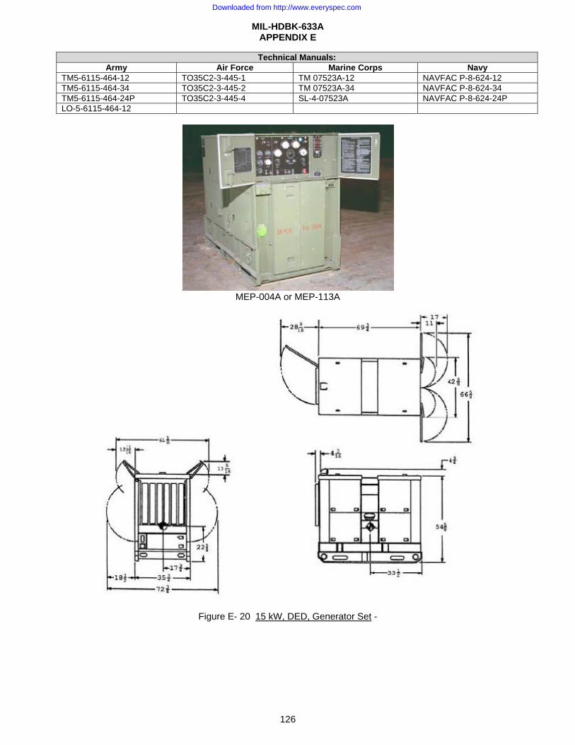
MIL-HDBK-633A APPENDIX E
126
Technical Manuals:Army Air Force Marine Corps Navy
TM5-6115-464-12 TO35C2-3-445-1 TM 07523A-12 NAVFAC P-8-624-12 TM5-6115-464-34 TO35C2-3-445-2 TM 07523A-34 NAVFAC P-8-624-34 TM5-6115-464-24P TO35C2-3-445-4 SL-4-07523A NAVFAC P-8-624-24P LO-5-6115-464-12
MEP-004A or MEP-113A
Figure E- 20 15 kW, DED, Generator Set -
Downloaded from http://www.everyspec.com
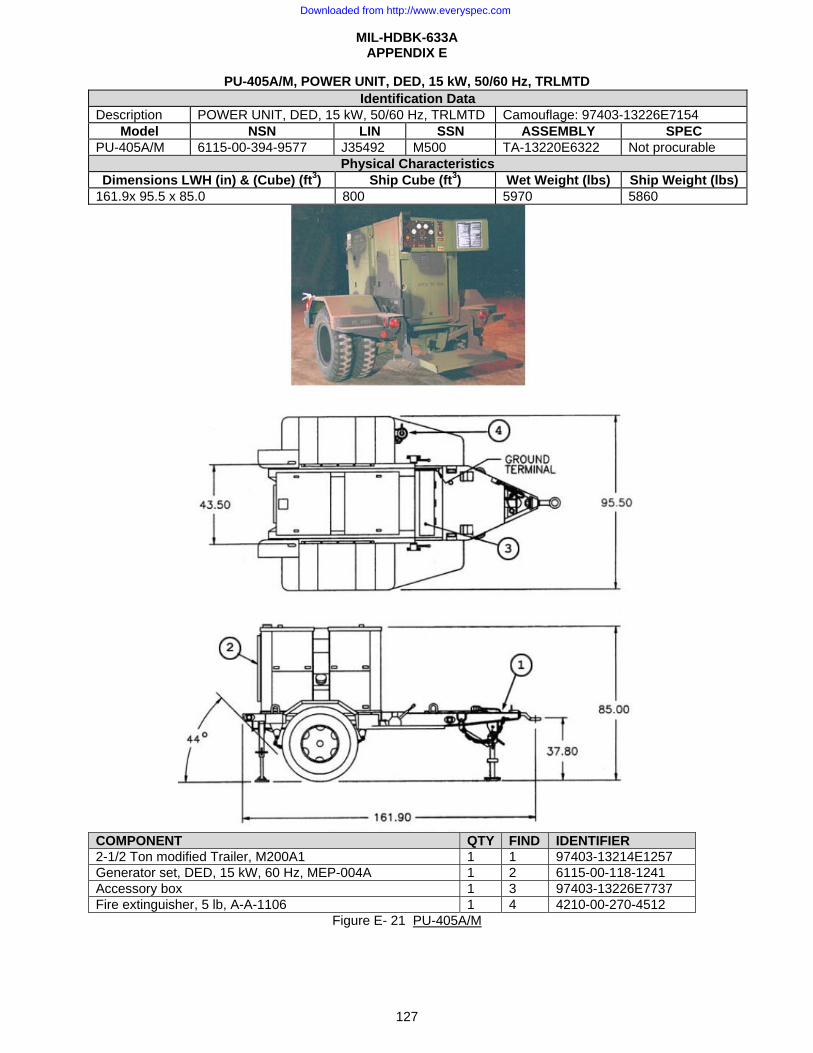
MIL-HDBK-633A APPENDIX E
127
PU-405A/M, POWER UNIT, DED, 15 kW, 50/60 Hz, TRLMTD
COMPONENT QTY FIND IDENTIFIER 2-1/2 Ton modified Trailer, M200A1 1 1 97403-13214E1257 Generator set, DED, 15 kW, 60 Hz, MEP-004A 1 2 6115-00-118-1241 Accessory box 1 3 97403-13226E7737 Fire extinguisher, 5 lb, A-A-1106 1 4 4210-00-270-4512
Figure E- 21 PU-405A/M
Identification Data Description POWER UNIT, DED, 15 kW, 50/60 Hz, TRLMTD Camouflage: 97403-13226E7154
Model NSN LIN SSN ASSEMBLY SPEC PU-405A/M 6115-00-394-9577 J35492 M500 TA-13220E6322 Not procurable
Physical Characteristics Dimensions LWH (in) & (Cube) (ft3) Ship Cube (ft3) Wet Weight (lbs) Ship Weight (lbs)
161.9x 95.5 x 85.0 800 5970 5860
Downloaded from http://www.everyspec.com
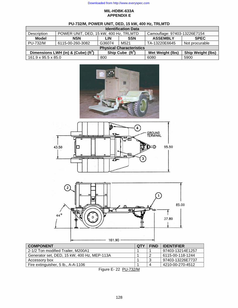
MIL-HDBK-633A APPENDIX E
128
PU-732/M, POWER UNIT, DED, 15 kW, 400 Hz, TRLMTD
COMPONENT QTY FIND IDENTIFIER 2-1/2 Ton modified Trailer, M200A1 1 1 97403-13214E1257 Generator set, DED, 15 kW, 400 Hz, MEP-113A 1 2 6115-00-118-1244 Accessory box 1 3 97403-13226E7737 Fire extinguisher, 5 lb., A-A-1106 1 4 4210-00-270-4512
Figure E- 22 PU-732/M
Identification Data Description POWER UNIT, DED, 15 kW, 400 Hz, TRLMTD Camouflage: 97403-13226E7154
Model NSN LIN SSN ASSEMBLY SPEC PU-732/M 6115-00-260-3082 G36074 M521 TA-13220E6645 Not procurable
Physical Characteristics Dimensions LWH (in) & (Cube) (ft3) Ship Cube (ft3) Wet Weight (lbs) Ship Weight (lbs)
161.9 x 95.5 x 85.0 800 6080 5900
Downloaded from http://www.everyspec.com
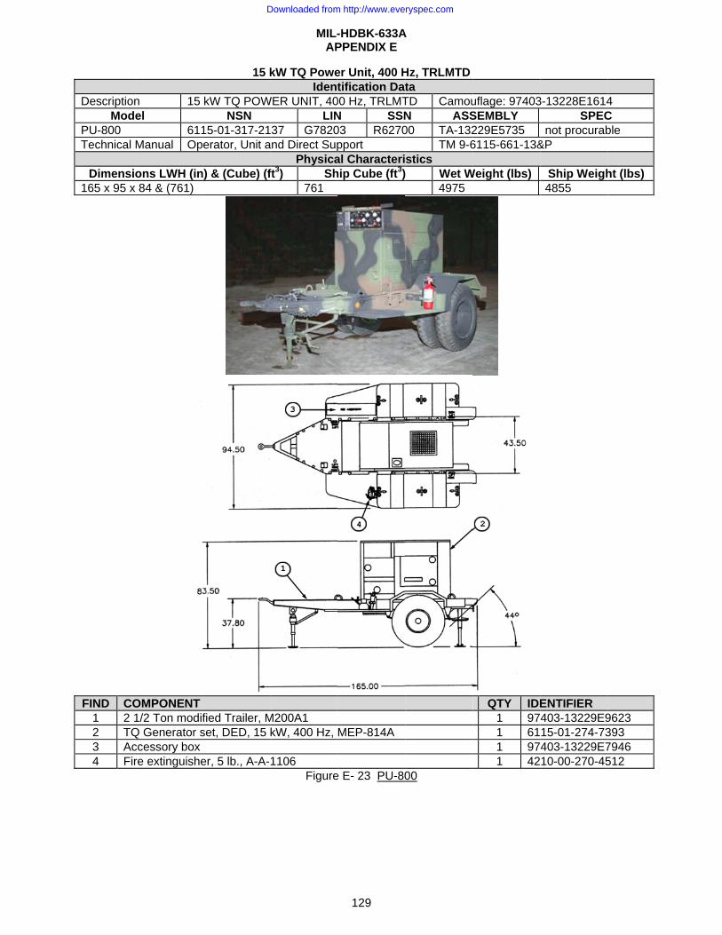
DescriptionMod
PU-800 Technical
Dimensi165 x 95 x
FIND CO1 2 12 TQ3 Ac4 Fir
n 15 el
611Manual Op
ons LWH (inx 84 & (761)
OMPONENT 1/2 Ton modifQ Generator sccessory box re extinguishe
15 k
kW TQ POWNSN
15-01-317-21erator, Unit a
n) & (Cube) (f
fied Trailer, Mset, DED, 15
er, 5 lb., A-A-
MIL-AP
kW TQ PoweIdent
WER UNIT, 40LIN
37 G7820and Direct Sup
Physicaft3) Sh
761
M200A1 kW, 400 Hz,
1106 Figure
-HDBK-633APPENDIX E
129
er Unit, 400 Htification Dat
00 Hz, TRLMTN SSN03 R6270pport al Characterihip Cube (ft3)
MEP-814A
e E- 23 PU-80
A
Hz, TRLMTDta TD CamouN ASS00 TA-132
TM 9-6stics Wet W
4975
00
uflage: 97403SEMBLY 229E5735 6115-661-13&
Weight (lbs)
QTY IDE
1 971 611 971 42
3-13228E1614SPEC
not procurab&P
Ship Weigh4855
ENTIFIER 403-13229E915-01-274-73403-13229E710-00-270-45
4 C ble
ht (lbs)
9623 393 7946 512
Downloaded from http://www.everyspec.com
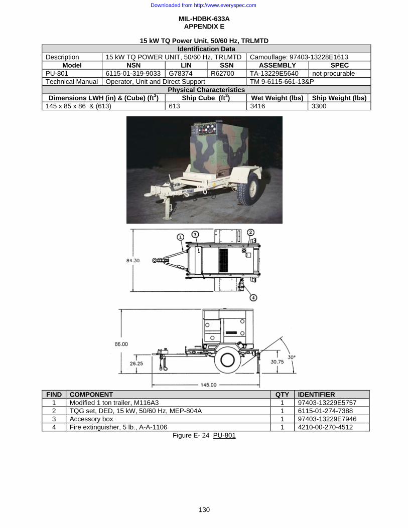
MIL-HDBK-633A APPENDIX E
130
15 kW TQ Power Unit, 50/60 Hz, TRLMTD Identification Data
Description 15 kW TQ POWER UNIT, 50/60 Hz, TRLMTD Camouflage: 97403-13228E1613 Model NSN LIN SSN ASSEMBLY SPEC
PU-801 6115-01-319-9033 G78374 R62700 TA-13229E5640 not procurable Technical Manual Operator, Unit and Direct Support TM 9-6115-661-13&P
Physical Characteristics Dimensions LWH (in) & (Cube) (ft3) Ship Cube (ft3) Wet Weight (lbs) Ship Weight (lbs)
145 x 85 x 86 & (613) 613 3416 3300
FIND COMPONENT QTY IDENTIFIER
1 Modified 1 ton trailer, M116A3 1 97403-13229E5757 2 TQG set, DED, 15 kW, 50/60 Hz, MEP-804A 1 6115-01-274-7388 3 Accessory box 1 97403-13229E7946 4 Fire extinguisher, 5 lb., A-A-1106 1 4210-00-270-4512
Figure E- 24 PU-801
Downloaded from http://www.everyspec.com

DescriptionMod
PU-801A Technical
Dimensio135 x 86 x
FIND CO1 Lig2 TQ3 Ac4 Fir
n 15 el
611Manual Op
ons LWH (in)x 91 & (611)
OMPONENT ght Tactical TQG set, DED,ccessory box re extinguishe
15 k
kW TQ POWNSN
15-01-413-38erator, Unit a
) & (Cube) (ft
Trailer (LTT) (P 15 kW, 50/60
er, 5 lb., A-A-
MIL-AP
kW TQ PowerIden
WER UNIT, 50LIN
821 G78374and Direct Sup
Physicat3) Shi
611
PU-801A) 0 Hz, MEP-80
1106 Figure
-HDBK-633APPENDIX E
131
r Unit, 50/60 ntification Da0/60 Hz, TRLMN SS4 R6270pport al Characterip Cube (ft3)
04A
E- 25 PU-80
A
Hz, TRLMTData MTD Camo
SN AS00 TA-13
TM 9-istics ) Wet W
3516
01A
D
ouflage: 9740SSEMBLY 3230E6560 -6115-661-13
Weight (lbs)
QTY IDE
1 971 611 971 42
03-13228E161SPE
not procura3&P
Ship Weig3400
ENTIFIER 403-13230E615-01-274-73403-13229E710-00-270-45
13 EC able
ght (lbs)
6565 388 7946 512
Downloaded from http://www.everyspec.com
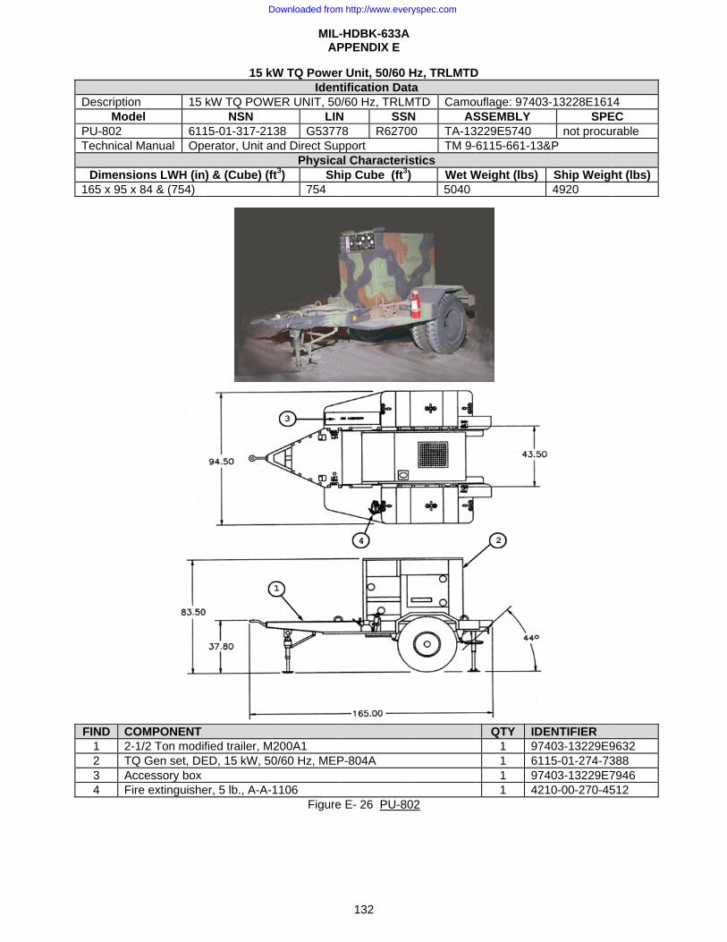
DescriptionMod
PU-802 Technical
Dimensi165 x 95 x
FIND CO1 2-2 TQ3 Ac4 Fir
n 15 el
611Manual Op
ons LWH (inx 84 & (754)
OMPONENT 1/2 Ton modi
Q Gen set, DEccessory box re extinguishe
15 k
kW TQ POWNSN
15-01-317-21erator, Unit a
n) & (Cube) (f
fied trailer, MED, 15 kW, 50
er, 5 lb., A-A-
MIL-AP
kW TQ PowerIdent
WER UNIT, 50LIN
38 G5377and Direct Sup
Physicaft3) Sh
754
200A1 0/60 Hz, MEP
1106 Figure
-HDBK-633APPENDIX E
132
r Unit, 50/60 tification Dat
0/60 Hz, TRLMN SS78 R6270pport al Characterihip Cube (ft3)
P-804A
e E- 26 PU-80
A
Hz, TRLMTDta MTD CamoN AS00 TA-13
TM 9-stics ) Wet W
5040
02
D
uflage: 97403SSEMBLY 3229E5740 6115-661-13&
Weight (lbs)
QTY IDE1 971 611 971 42
3-13228E161SPE
not procu&P
Ship Weigh4920
ENTIFIER 403-13229E915-01-274-73403-13229E710-00-270-45
4 EC rable
ht (lbs)
9632 388 7946 512
Downloaded from http://www.everyspec.com
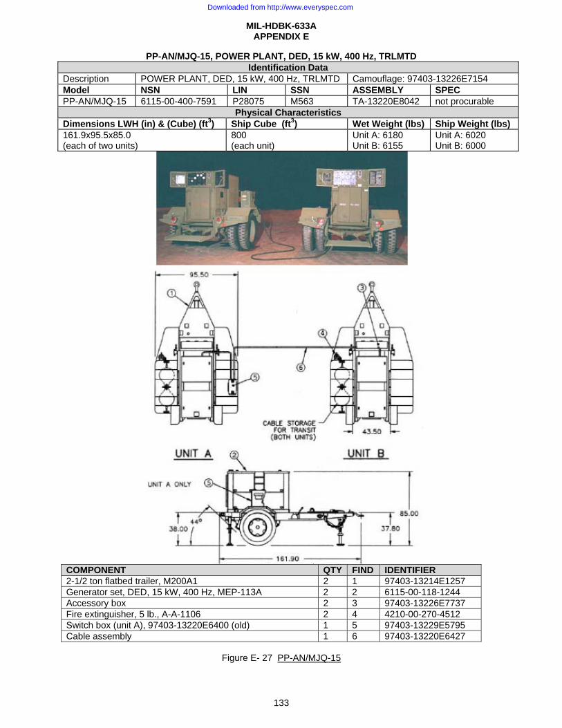
MIL-HDBK-633A APPENDIX E
133
PP-AN/MJQ-15, POWER PLANT, DED, 15 kW, 400 Hz, TRLMTD Identification Data
Description POWER PLANT, DED, 15 kW, 400 Hz, TRLMTD Camouflage: 97403-13226E7154 Model NSN LIN SSN ASSEMBLY SPEC PP-AN/MJQ-15 6115-00-400-7591 P28075 M563 TA-13220E8042 not procurable
Physical Characteristics Dimensions LWH (in) & (Cube) (ft3) Ship Cube (ft3) Wet Weight (lbs) Ship Weight (lbs) 161.9x95.5x85.0 (each of two units)
800 (each unit)
Unit A: 6180 Unit B: 6155
Unit A: 6020 Unit B: 6000
COMPONENT QTY FIND IDENTIFIER 2-1/2 ton flatbed trailer, M200A1 2 1 97403-13214E1257 Generator set, DED, 15 kW, 400 Hz, MEP-113A 2 2 6115-00-118-1244 Accessory box 2 3 97403-13226E7737 Fire extinguisher, 5 lb., A-A-1106 2 4 4210-00-270-4512 Switch box (unit A), 97403-13220E6400 (old) 1 5 97403-13229E5795 Cable assembly 1 6 97403-13220E6427
Figure E- 27 PP-AN/MJQ-15
Downloaded from http://www.everyspec.com
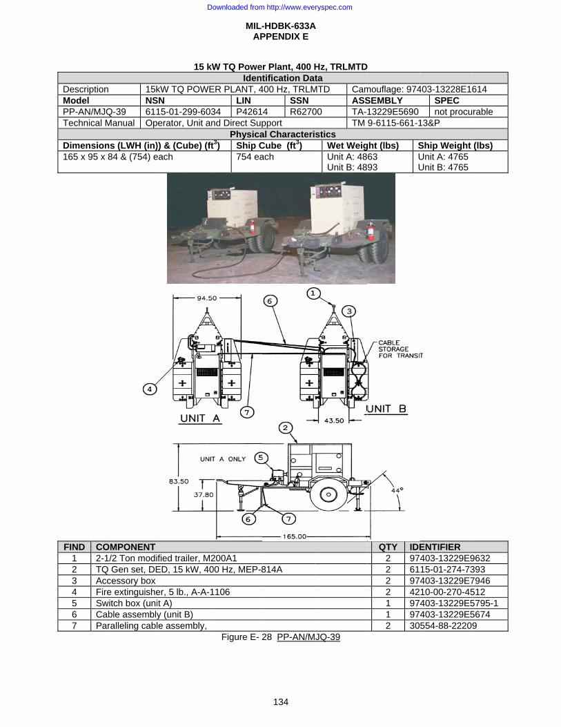
DescriptionModel PP-AN/MJTechnical
Dimension165 x 95 x
FIND CO1 2-2 TQ3 Ac4 Fir5 Sw6 Ca7 Pa
n 15kNS
JQ-39 611Manual Op
ns (LWH (in)x 84 & (754) e
OMPONENT 1/2 Ton modi
Q Gen set, DEccessory box re extinguishewitch box (uniable assemblyaralleling cabl
15 k
kW TQ POWESN 15-01-299-60erator, Unit a
)) & (Cube) (feach
fied trailer, MED, 15 kW, 40
er, 5 lb., A-A-t A) y (unit B) le assembly,
MIL-AP
kW TQ PoweIdent
ER PLANT, 4LIN
034 P4261and Direct Sup
Physicaft3) Ship C
754 ea
200A1 00 Hz, MEP-8
1106
Figure E- 2
-HDBK-633APPENDIX E
134
r Plant, 400 Htification Dat
400 Hz, TRLMSSN
4 R6270pport al CharacteriCube (ft3) ach
814A
28 PP-AN/M
A
Hz, TRLMTDta
MTD CamASS
00 TA-TM
stics Wet WeigUnit A: 48Unit B: 48
JQ-39
mouflage: 974SEMBLY 13229E5690 9-6115-661-1
ght (lbs) S63 93
UU
QTY IDE2 972 612 972 421 971 972 30
403-13228E16SPEC not procu
13&P
Ship Weight Unit A: 4765Unit B: 4765
ENTIFIER 403-13229E915-01-274-73403-13229E710-00-270-45403-13229E5403-13229E5554-88-2220
614
rable
(lbs)
9632 393 7946 512 5795-1 5674 9
Downloaded from http://www.everyspec.com
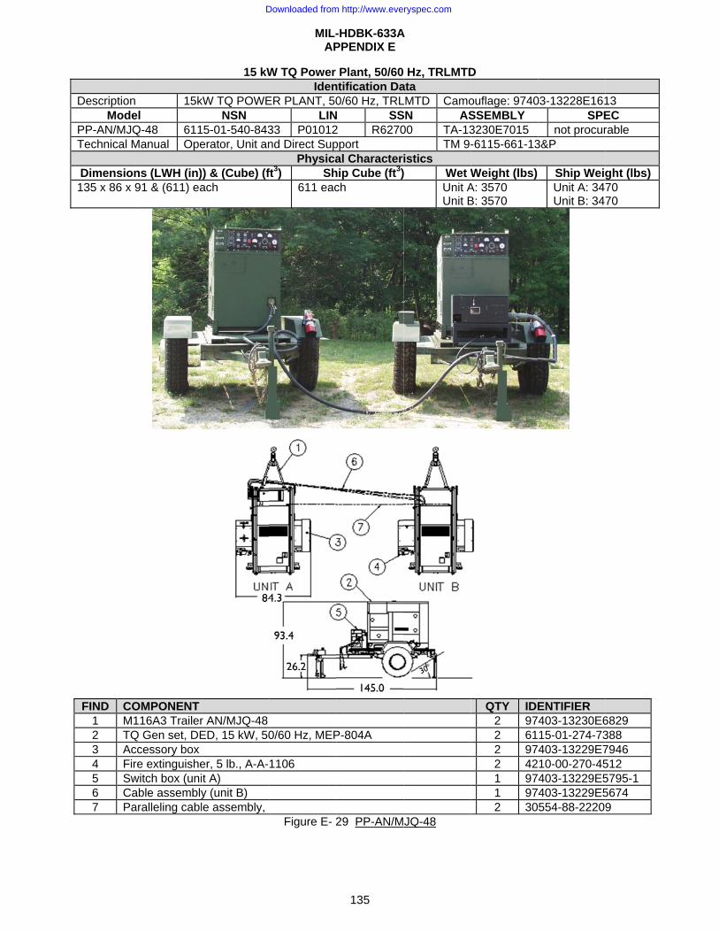
DescriptionMode
PP-AN/MJQTechnical M
Dimension135 x 86 x
FIND CO1 M12 TQ3 Ac4 Fir5 Sw6 Ca7 Pa
n 15kel Q-48 611Manual Ope
ns (LWH (in)91 & (611) ea
OMPONENT 116A3 TrailerQ Gen set, DEccessory box re extinguishewitch box (uniable assemblyaralleling cabl
15 kW
kW TQ POWENSN
5-01-540-843erator, Unit an
) & (Cube) (fach
r AN/MJQ-48 ED, 15 kW, 50
er, 5 lb., A-A-t A) y (unit B) le assembly,
MIL-AP
W TQ Power Iden
ER PLANT, 50LIN
33 P01012nd Direct Sup
Physicaft3) Sh
611 eac
0/60 Hz, MEP
1106
Figure E- 2
-HDBK-633APPENDIX E
135
Plant, 50/60ntification Da0/60 Hz, TRL
N SS2 R6270pport al Character
hip Cube (ft3)ch
P-804A
29 PP-AN/M
A
Hz, TRLMTData LMTD CamoSN AS00 TA-13
TM 9-istics ) Wet W
Unit AUnit B
JQ-48
D
ouflage: 9740SSEMBLY 3230E7015 -6115-661-13
Weight (lbs) A: 3570 B: 3570
QTY IDE
2 972 612 972 421 971 972 30
03-13228E161SPE
not procur3&P
Ship WeigUnit A: 34Unit B: 34
ENTIFIER 403-13230E615-01-274-73403-13229E710-00-270-45403-13229E5403-13229E5554-88-2220
13 EC rable
ght (lbs) 70 70
6829 388 7946 512 5795-1 5674 9
Downloaded from http://www.everyspec.com
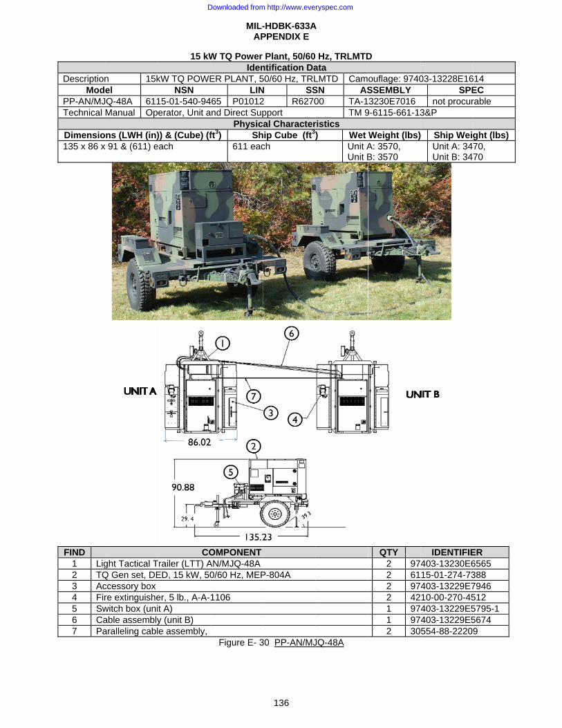
DescriptionMod
PP-AN/MJTechnical
Dimensio135 x 86 x
FIND 1 Lig2 TQ3 Ac4 Fir5 Sw6 Ca7 Pa
n 15kel
JQ-48A 611Manual Op
ns (LWH (in)x 91 & (611) e
ght Tactical TQ Gen set, DEccessory box re extinguishewitch box (uniable assemblyaralleling cabl
15 kW
kW TQ POWENSN
15-01-540-94erator, Unit a
)) & (Cube) (feach
COTrailer (LTT) AED, 15 kW, 50
er, 5 lb., A-A-t A) y (unit B) le assembly,
MIL-AP
W TQ Power Iden
ER PLANT, 5LIN
465 P01012and Direct Sup
Physicft3) Sh
611 eac
OMPONENTAN/MJQ-48A 0/60 Hz, MEP
1106
Figure E- 3
-HDBK-633APPENDIX E
136
Plant, 50/60ntification Da50/60 Hz, TRLN SS2 R6270pport al Character
hip Cube (ft3)ch
P-804A
30 PP-AN/MJ
A
Hz, TRLMTData LMTD CamSN AS00 TA-1
TM 9ristics ) Wet
Unit AUnit B
JQ-48A
D
ouflage: 9740SSEMBLY 3230E7016
9-6115-661-13
Weight (lbs)A: 3570, B: 3570
QTY 2 972 612 972 421 971 972 30
03-13228E16SPE
not procur3&P
Ship WeigUnit A: 34Unit B: 34
IDENTIFIE
403-13230E615-01-274-73403-13229E710-00-270-45403-13229E5403-13229E5554-88-2220
614 EC rable
ght (lbs) 70, 70
ER 6565 388 7946 512 5795-1 5674 9
Downloaded from http://www.everyspec.com

MIL-HDBK-633A APPENDIX E
137
30 kW, DED, Generator Set Identification data
Nomenclature Gen Set, DED, 30 kW, 50/60 Hz Gen Set, DED, 30 kW, 400 Hz Model Number MEP-005A MEP-114A NSN 6115-00-118-1240 6115-00-118-1248 LIN J36109 J36725 SSN M532 M501 Trailer Mounted Configurations
PU-406B/M; Figure E- 32; PU-803,Figure E- 34; AN/MJQ-10A; Figure E- 36; AN/MJQ-40, Figure E- 37
PU-760/M; Figure E- 33; PU-804, Figure E- 35
Physical Characteristics Dimensions LWH (in) 79.3 x 35.8 x 54.6 (Cube: 90 ft3) 79.3 x 35.8 x 54.6 (Cube:90 ft3) Weight (lbs) 2850 3000 Engine 6 cylinder Diesel, 57 hp @ 1800 RPM
(60 Hz), liquid cooled, 24 Volt starter. 6 cylinder Diesel, 64 hp @ 2000 RPM (400 Hz), liquid cooled, 24 Volt starter
Fuels Diesel: DL-1, DL-2 and Jet fuel: JP-8, Jet A-1. Fuel Capacity 26 gal. Instrumentation Hourmeter, voltmeter, frequency meter, ammeter, wattmeter, oil pressure gage, battery
charging ammeter, fault indicating system, temperature, fuel. Performance Characteristics
Electric Power Rating 30 kW, 60/400 Hz (25 kW, 50 Hz) @ 0.8 pf from -25°F (-65°F with winterization kit) to 125°F/MSL, 107°F/5000 ft.
Environmental Capability
-25°F(-65°F with winterization kit) to 125°F, rain, humidity, altitude, sand/dust, transportation, cold storage, salt spray, fungus.
Protective Devices Overload, over voltage, short circuit, reverse power, low oil pressure, high temperature, low fuel, overspeed.
Fuel Consumption 3 gal/hour @ rated load Human Factors MIL-STD-1474. Operable in arctic and NBC clothing. Noise 80 dBA @ 25 feet. Reliability (MTBF) 50/60 Hz: 670 hr (spec); 400 Hz: 370 hr (spec).
Electrical Characteristics Voltage Con: 120/208 V, 3 phase, 4 wire; 240/416 V, 3 phase, 4 wire. Operating Frequency 50 Hz 60 Hz 400 Hz Connection 120/208V 240/416V 120/208V 240/416V 120/208V 240/416V Voltage Adj Range 190 213 380 426 197 240 395 480 197-229 395 458 Electrical Drip proof generator enclosure, fungus & moisture treated, solid state voltage regulator,
brushless rotary alternator. Electrical Performance
Electric Power Quality 50/60 Hz 400 Hz Volt Frequency Volt Frequency
Regulation 3% 2-3% (adj) 1% 0.25% Short term steady state stab (30 sec) 2% 2% 1% 0.5% Long term steady state stab (4 hr) 4% 3% 2% 1% Application/rejection of rated load/rec.time 20% / 3 sec 3% /4% /3 sec 12% /0.5 sec 1.5% /1 sec Motor load/recovery time 40% dip /5 sec 25% dip/0.7 sec Max waveform deviation factor 5% 5% Individual waveform harmonic 2% 2% EMI Suppressed to MIL-STD-461 limits. EMP none
Optional EquipmentDescription NSN Weight (lbs) Effect on Dim.(in)
Fuel burning winterization kit 6115-00-463-9083 45 internal Electrical winterization kit 6115-00-463-9085 40 internal Aux fuel burning winterization kit 6115-00-463-9098 350 41 x 40 x 26 (Aux) Aux electrical winterization kit 6115-00-463-9099 260 36 x 27 x 19 (Aux) Remote control box 6115-00-420-8490 8 internal Load bank 6115-00-463-9088 L+9 Wheel mounting kit 6115-00-463-9094 564 L+8 W+32 H+9 Auto load tranf panel 60 Hz 6115-00-471-7932 825 44 x 19 x 42 (Aux) Paralleling cable 6140-00-197-4934 4 negligible Precise relay assembly 6115-00-368-8202 internal
Downloaded from http://www.everyspec.com
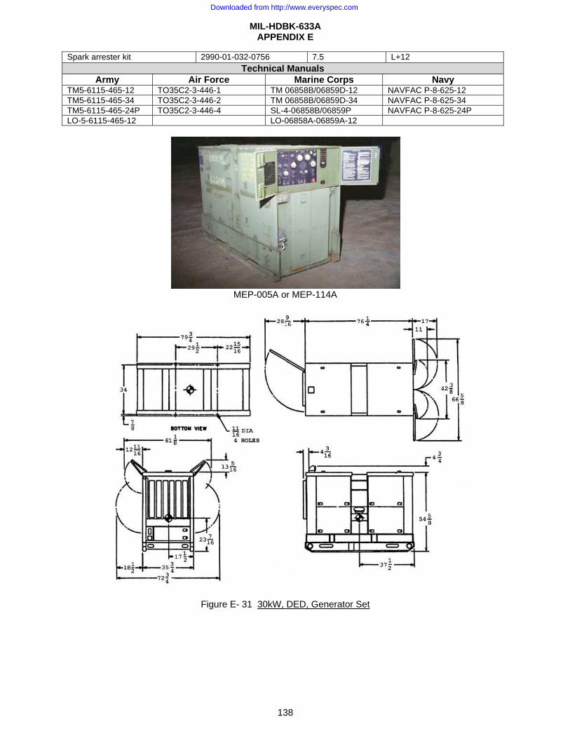
MIL-HDBK-633A APPENDIX E
138
Spark arrester kit 2990-01-032-0756 7.5 L+12 Technical Manuals
Army Air Force Marine Corps Navy TM5-6115-465-12 TO35C2-3-446-1 TM 06858B/06859D-12 NAVFAC P-8-625-12 TM5-6115-465-34 TO35C2-3-446-2 TM 06858B/06859D-34 NAVFAC P-8-625-34 TM5-6115-465-24P TO35C2-3-446-4 SL-4-06858B/06859P NAVFAC P-8-625-24P LO-5-6115-465-12 LO-06858A-06859A-12
MEP-005A or MEP-114A
Figure E- 31 30kW, DED, Generator Set
Downloaded from http://www.everyspec.com
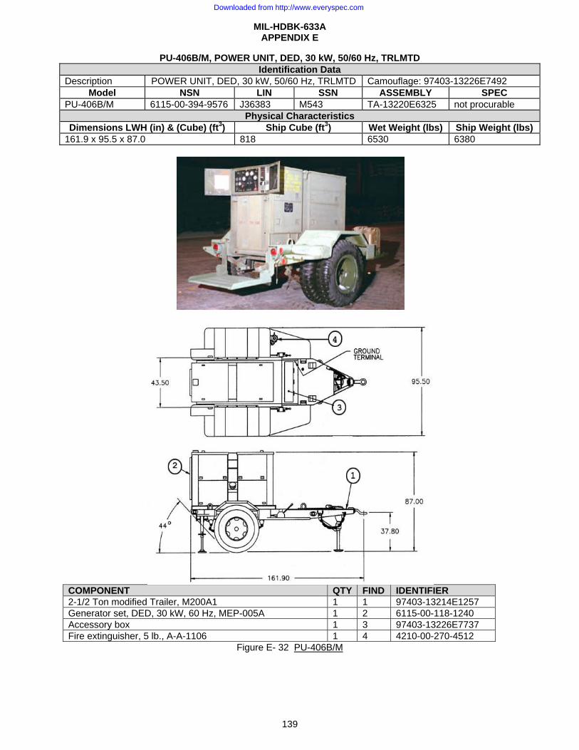
MIL-HDBK-633A APPENDIX E
139
PU-406B/M, POWER UNIT, DED, 30 kW, 50/60 Hz, TRLMTD Identification Data
Description POWER UNIT, DED, 30 kW, 50/60 Hz, TRLMTD Camouflage: 97403-13226E7492 Model NSN LIN SSN ASSEMBLY SPEC
PU-406B/M 6115-00-394-9576 J36383 M543 TA-13220E6325 not procurable Physical Characteristics
Dimensions LWH (in) & (Cube) (ft3) Ship Cube (ft3) Wet Weight (lbs) Ship Weight (lbs) 161.9 x 95.5 x 87.0 818 6530 6380
COMPONENT QTY FIND IDENTIFIER 2-1/2 Ton modified Trailer, M200A1 1 1 97403-13214E1257 Generator set, DED, 30 kW, 60 Hz, MEP-005A 1 2 6115-00-118-1240 Accessory box 1 3 97403-13226E7737 Fire extinguisher, 5 lb., A-A-1106 1 4 4210-00-270-4512
Figure E- 32 PU-406B/M
Downloaded from http://www.everyspec.com
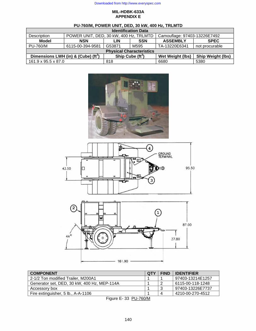
MIL-HDBK-633A APPENDIX E
140
PU-760/M, POWER UNIT, DED, 30 kW, 400 Hz, TRLMTD Identification Data
Description POWER UNIT, DED, 30 kW, 400 Hz, TRLMTD Camouflage: 97403-13226E7492 Model NSN LIN SSN ASSEMBLY SPEC
PU-760/M 6115-00-394-9581 G53871 M595 TA-13220E6341 not procurable Physical Characteristics
Dimensions LWH (in) & (Cube) (ft3) Ship Cube (ft3) Wet Weight (lbs) Ship Weight (lbs) 161.9 x 95.5 x 87.0 818 6680 5380
COMPONENT QTY FIND IDENTIFIER 2-1/2 Ton modified Trailer, M200A1 1 1 97403-13214E1257 Generator set, DED, 30 kW, 400 Hz, MEP-114A 1 2 6115-00-118-1248 Accessory box 1 3 97403-13226E7737 Fire extinguisher, 5 lb., A-A-1106 1 4 4210-00-270-4512
Figure E- 33 PU-760/M
Downloaded from http://www.everyspec.com

MIL-HDBK-633A APPENDIX E
141
PU-803, TQ POWER UNIT, DED, 30kW, 50/60 Hz, TRLMTD Identification Data
Description TQ POWER UNIT, DED, 30kW, 50/60 Hz, TRLMTD Camouflage: 97403-13228E1615 Model NSN LIN SSN ASSEMBLY SPEC PU-803 6115-01-317-2136 G35851 M54300 TA-13229E5745 not procurable
Physical Characteristics Dimensions LWH (in) & (Cube) (ft3) Ship Cube (ft3) Wet Weight (lbs) Ship Weight (lbs) 165.0 x 94.5 x 83.5 770 5900 6380
COMPONENT QTY FIND IDENTIFIER 2-1/2 Ton modified trailer, M200A1 1 1 97403-13214E1257 TQ Gen set, DED, 30 kW, 50/60 Hz, MEP-805A 1 2 6115-01-274-7389 Accessory box 1 3 97403-13229E7946 Fire extinguisher, 5 lb., A-A-1106 1 4 4210-00-270-4512
Figure E- 34 PU-803
Downloaded from http://www.everyspec.com
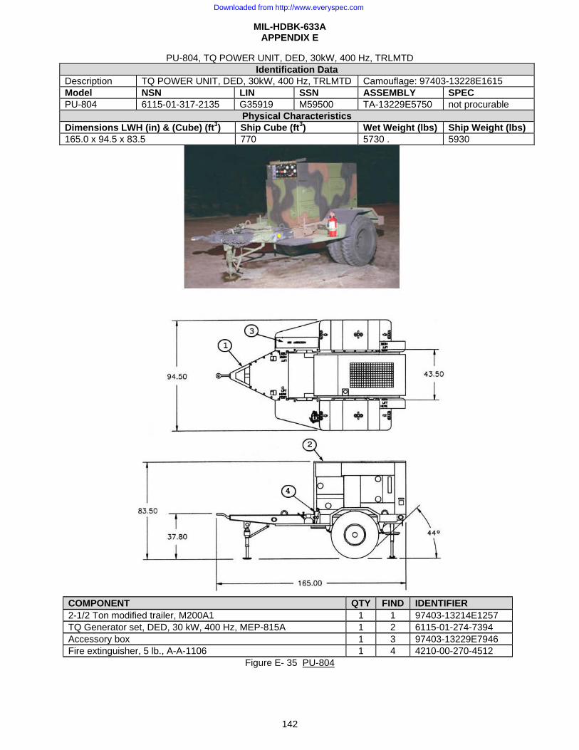
MIL-HDBK-633A APPENDIX E
142
PU-804, TQ POWER UNIT, DED, 30kW, 400 Hz, TRLMTD Identification Data
Description TQ POWER UNIT, DED, 30kW, 400 Hz, TRLMTD Camouflage: 97403-13228E1615 Model NSN LIN SSN ASSEMBLY SPEC PU-804 6115-01-317-2135 G35919 M59500 TA-13229E5750 not procurable
Physical Characteristics Dimensions LWH (in) & (Cube) (ft3) Ship Cube (ft3) Wet Weight (lbs) Ship Weight (lbs) 165.0 x 94.5 x 83.5 770 5730 . 5930
COMPONENT QTY FIND IDENTIFIER 2-1/2 Ton modified trailer, M200A1 1 1 97403-13214E1257 TQ Generator set, DED, 30 kW, 400 Hz, MEP-815A 1 2 6115-01-274-7394 Accessory box 1 3 97403-13229E7946 Fire extinguisher, 5 lb., A-A-1106 1 4 4210-00-270-4512
Figure E- 35 PU-804
Downloaded from http://www.everyspec.com
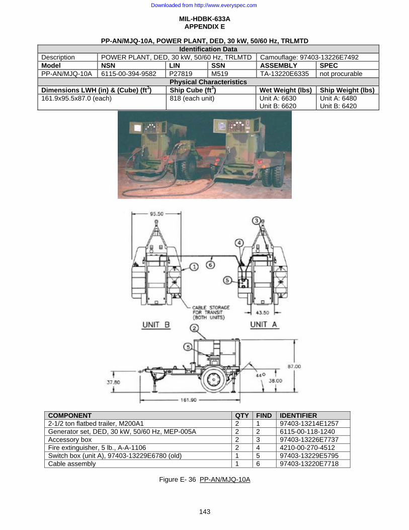
MIL-HDBK-633A APPENDIX E
143
PP-AN/MJQ-10A, POWER PLANT, DED, 30 kW, 50/60 Hz, TRLMTD Identification Data
Description POWER PLANT, DED, 30 kW, 50/60 Hz, TRLMTD Camouflage: 97403-13226E7492 Model NSN LIN SSN ASSEMBLY SPEC PP-AN/MJQ-10A 6115-00-394-9582 P27819 M519 TA-13220E6335 not procurable
Physical Characteristics Dimensions LWH (in) & (Cube) (ft3) Ship Cube (ft3) Wet Weight (lbs) Ship Weight (lbs) 161.9x95.5x87.0 (each) 818 (each unit) Unit A: 6630
Unit B: 6620 Unit A: 6480 Unit B: 6420
COMPONENT QTY FIND IDENTIFIER 2-1/2 ton flatbed trailer, M200A1 2 1 97403-13214E1257 Generator set, DED, 30 kW, 50/60 Hz, MEP-005A 2 2 6115-00-118-1240 Accessory box 2 3 97403-13226E7737 Fire extinguisher, 5 lb., A-A-1106 2 4 4210-00-270-4512 Switch box (unit A), 97403-13229E6780 (old) 1 5 97403-13229E5795 Cable assembly 1 6 97403-13220E7718
Figure E- 36 PP-AN/MJQ-10A
Downloaded from http://www.everyspec.com
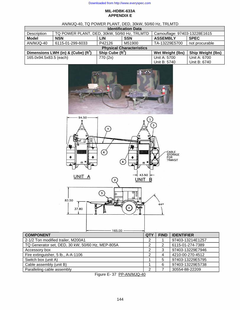
MIL-HDBK-633A APPENDIX E
144
AN/MJQ-40, TQ POWER PLANT, DED, 30kW, 50/60 Hz, TRLMTD Identification Data
Description TQ POWER PLANT, DED, 30kW, 50/60 Hz, TRLMTD Camouflage: 97403-13228E1615 Model NSN LIN SSN ASSEMBLY SPEC AN/MJQ-40 6115-01-299-6033 P42126 M51900 TA-13229E5700 not procurable
Physical Characteristics Dimensions LWH (in) & (Cube) (ft3) Ship Cube (ft3) Wet Weight (lbs) Ship Weight (lbs) 165.0x94.5x83.5 (each) 770 (2x) Unit A: 5700
Unit B: 5740 Unit A: 6700 Unit B: 6740
COMPONENT QTY FIND IDENTIFIER 2-1/2 Ton modified trailer, M200A1 2 1 97403-13214E1257 TQ Generator set, DED, 30 kW, 50/60 Hz, MEP-805A 2 2 6115-01-274-7389 Accessory box 2 3 97403-13229E7946 Fire extinguisher, 5 lb., A-A-1106 2 4 4210-00-270-4512 Switch box (unit A) 1 5 97403-13229E5795 Cable assembly (unit B) 1 6 97403-13229E5738 Paralleling cable assembly 2 7 30554-88-22209
Figure E- 37 PP-AN/MJQ-40
Downloaded from http://www.everyspec.com
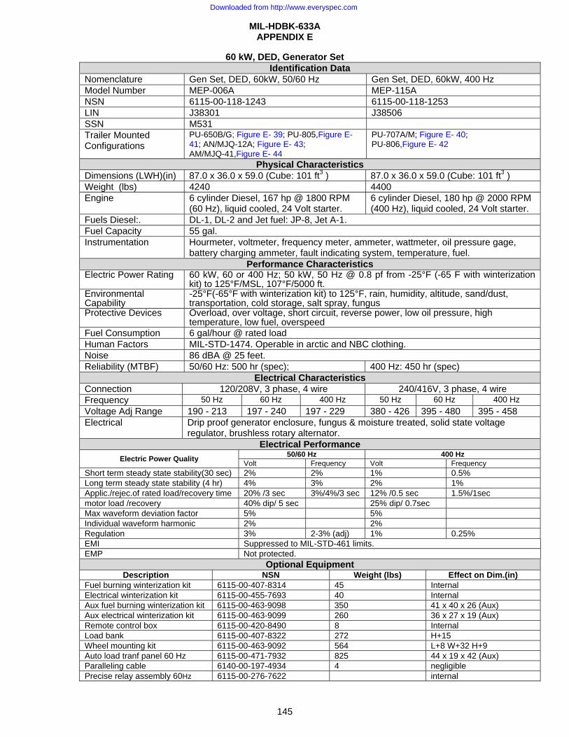
MIL-HDBK-633A APPENDIX E
145
60 kW, DED, Generator Set Identification Data
Nomenclature Gen Set, DED, 60kW, 50/60 Hz Gen Set, DED, 60kW, 400 Hz Model Number MEP-006A MEP-115A NSN 6115-00-118-1243 6115-00-118-1253 LIN J38301 J38506 SSN M531 Trailer Mounted Configurations
PU-650B/G; Figure E- 39; PU-805,Figure E- 41; AN/MJQ-12A; Figure E- 43; AM/MJQ-41,Figure E- 44
PU-707A/M; Figure E- 40; PU-806,Figure E- 42
Physical Characteristics Dimensions (LWH)(in) 87.0 x 36.0 x 59.0 (Cube: 101 ft3 ) 87.0 x 36.0 x 59.0 (Cube: 101 ft3 ) Weight (lbs) 4240 4400 Engine 6 cylinder Diesel, 167 hp @ 1800 RPM
(60 Hz), liquid cooled, 24 Volt starter. 6 cylinder Diesel, 180 hp @ 2000 RPM (400 Hz), liquid cooled, 24 Volt starter.
Fuels Diesel:. DL-1, DL-2 and Jet fuel: JP-8, Jet A-1. Fuel Capacity 55 gal. Instrumentation Hourmeter, voltmeter, frequency meter, ammeter, wattmeter, oil pressure gage,
battery charging ammeter, fault indicating system, temperature, fuel. Performance Characteristics
Electric Power Rating 60 kW, 60 or 400 Hz; 50 kW, 50 Hz @ 0.8 pf from -25°F (-65 F with winterization kit) to 125°F/MSL, 107°F/5000 ft.
Environmental Capability
-25°F(-65°F with winterization kit) to 125°F, rain, humidity, altitude, sand/dust, transportation, cold storage, salt spray, fungus
Protective Devices Overload, over voltage, short circuit, reverse power, low oil pressure, high temperature, low fuel, overspeed
Fuel Consumption 6 gal/hour @ rated load Human Factors MIL-STD-1474. Operable in arctic and NBC clothing. Noise 86 dBA @ 25 feet. Reliability (MTBF) 50/60 Hz: 500 hr (spec); 400 Hz: 450 hr (spec)
Electrical Characteristics Connection 120/208V, 3 phase, 4 wire 240/416V, 3 phase, 4 wire Frequency 50 Hz 60 Hz 400 Hz 50 Hz 60 Hz 400 Hz Voltage Adj Range 190 - 213 197 - 240 197 - 229 380 - 426 395 - 480 395 - 458 Electrical Drip proof generator enclosure, fungus & moisture treated, solid state voltage
regulator, brushless rotary alternator. Electrical Performance
Electric Power Quality 50/60 Hz 400 Hz Volt Frequency Volt Frequency
Short term steady state stability(30 sec) 2% 2% 1% 0.5% Long term steady state stability (4 hr) 4% 3% 2% 1% Applic./rejec.of rated load/recovery time 20% /3 sec 3%/4%/3 sec 12% /0.5 sec 1.5%/1sec motor load /recovery 40% dip/ 5 sec 25% dip/ 0.7sec Max waveform deviation factor 5% 5% Individual waveform harmonic 2% 2% Regulation 3% 2-3% (adj) 1% 0.25% EMI Suppressed to MIL-STD-461 limits. EMP Not protected.
Optional Equipment Description NSN Weight (lbs) Effect on Dim.(in)
Fuel burning winterization kit 6115-00-407-8314 45 Internal Electrical winterization kit 6115-00-455-7693 40 Internal Aux fuel burning winterization kit 6115-00-463-9098 350 41 x 40 x 26 (Aux) Aux electrical winterization kit 6115-00-463-9099 260 36 x 27 x 19 (Aux) Remote control box 6115-00-420-8490 8 Internal Load bank 6115-00-407-8322 272 H+15 Wheel mounting kit 6115-00-463-9092 564 L+8 W+32 H+9 Auto load tranf panel 60 Hz 6115-00-471-7932 825 44 x 19 x 42 (Aux) Paralleling cable 6140-00-197-4934 4 negligible Precise relay assembly 60Hz 6115-00-276-7622 internal
Downloaded from http://www.everyspec.com
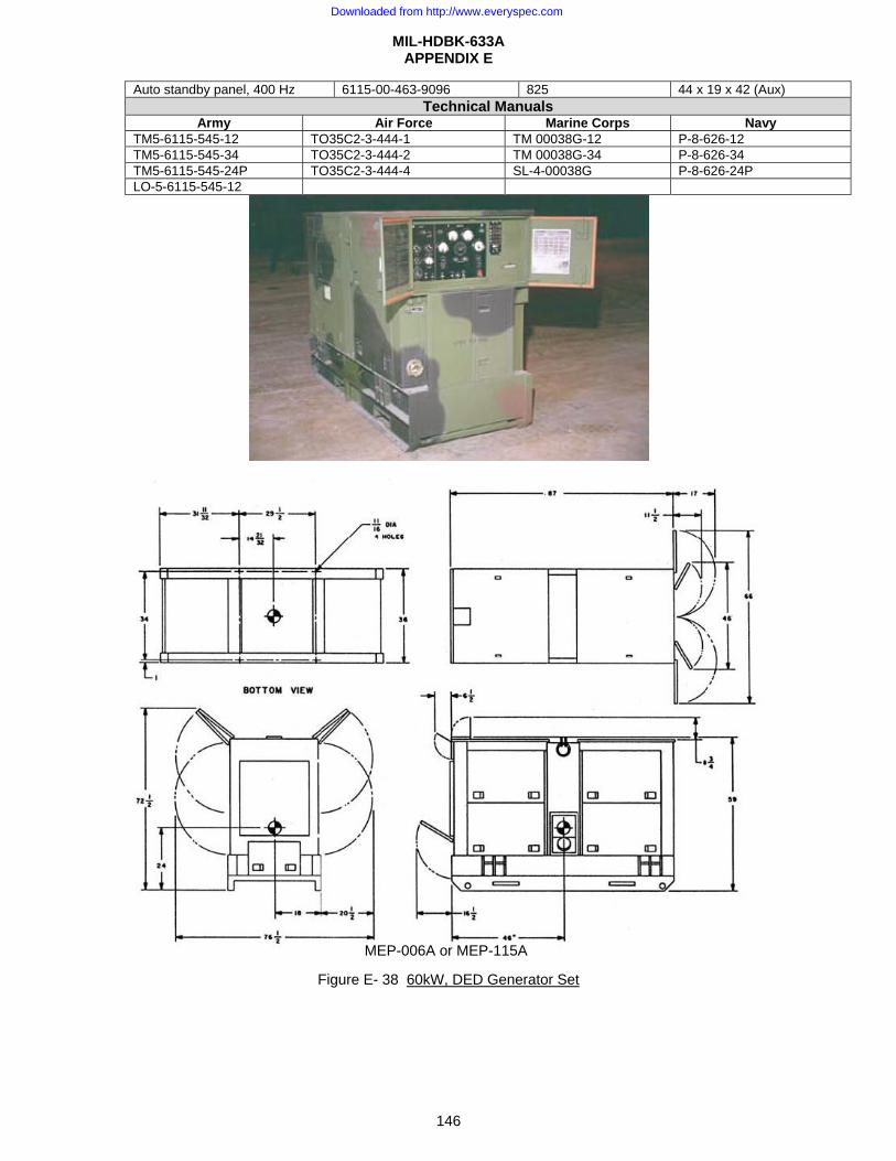
MIL-HDBK-633A APPENDIX E
146
Auto standby panel, 400 Hz 6115-00-463-9096 825 44 x 19 x 42 (Aux) Technical Manuals
Army Air Force Marine Corps NavyTM5-6115-545-12 TO35C2-3-444-1 TM 00038G-12 P-8-626-12 TM5-6115-545-34 TO35C2-3-444-2 TM 00038G-34 P-8-626-34 TM5-6115-545-24P TO35C2-3-444-4 SL-4-00038G P-8-626-24P LO-5-6115-545-12
Figure E- 38 60kW, DED Generator Set
MEP-006A or MEP-115A
Downloaded from http://www.everyspec.com
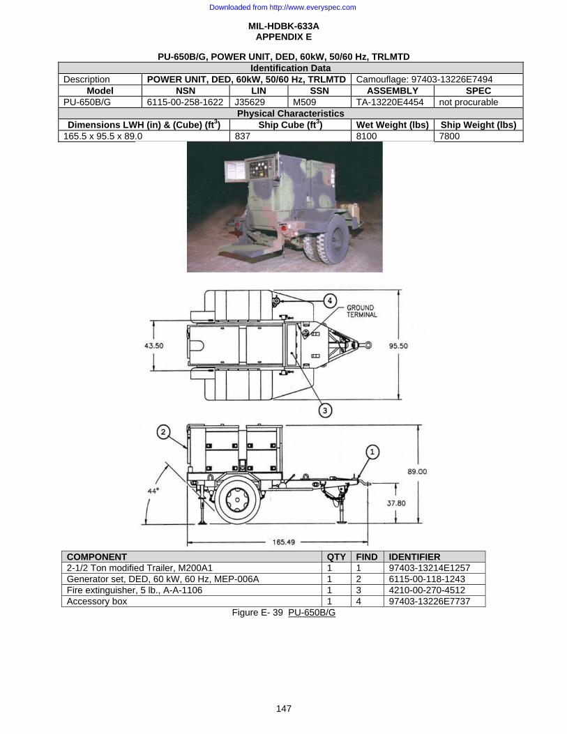
MIL-HDBK-633A APPENDIX E
147
PU-650B/G, POWER UNIT, DED, 60kW, 50/60 Hz, TRLMTD Identification Data
Description POWER UNIT, DED, 60kW, 50/60 Hz, TRLMTD Camouflage: 97403-13226E7494 Model NSN LIN SSN ASSEMBLY SPEC
PU-650B/G 6115-00-258-1622 J35629 M509 TA-13220E4454 not procurable Physical Characteristics
Dimensions LWH (in) & (Cube) (ft3) Ship Cube (ft3) Wet Weight (lbs) Ship Weight (lbs) 165.5 x 95.5 x 89.0 837 8100 7800
COMPONENT QTY FIND IDENTIFIER 2-1/2 Ton modified Trailer, M200A1 1 1 97403-13214E1257 Generator set, DED, 60 kW, 60 Hz, MEP-006A 1 2 6115-00-118-1243 Fire extinguisher, 5 lb., A-A-1106 1 3 4210-00-270-4512 Accessory box 1 4 97403-13226E7737
Figure E- 39 PU-650B/G
Downloaded from http://www.everyspec.com
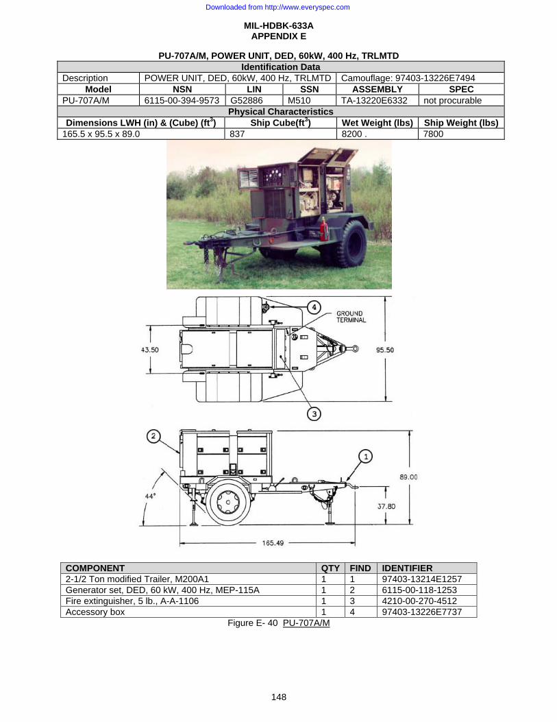
MIL-HDBK-633A APPENDIX E
148
PU-707A/M, POWER UNIT, DED, 60kW, 400 Hz, TRLMTD Identification Data
Description POWER UNIT, DED, 60kW, 400 Hz, TRLMTD Camouflage: 97403-13226E7494 Model NSN LIN SSN ASSEMBLY SPEC
PU-707A/M 6115-00-394-9573 G52886 M510 TA-13220E6332 not procurable Physical Characteristics
Dimensions LWH (in) & (Cube) (ft3) Ship Cube(ft3) Wet Weight (lbs) Ship Weight (lbs) 165.5 x 95.5 x 89.0 837 8200 . 7800
COMPONENT QTY FIND IDENTIFIER 2-1/2 Ton modified Trailer, M200A1 1 1 97403-13214E1257 Generator set, DED, 60 kW, 400 Hz, MEP-115A 1 2 6115-00-118-1253 Fire extinguisher, 5 lb., A-A-1106 1 3 4210-00-270-4512 Accessory box 1 4 97403-13226E7737
Figure E- 40 PU-707A/M
Downloaded from http://www.everyspec.com
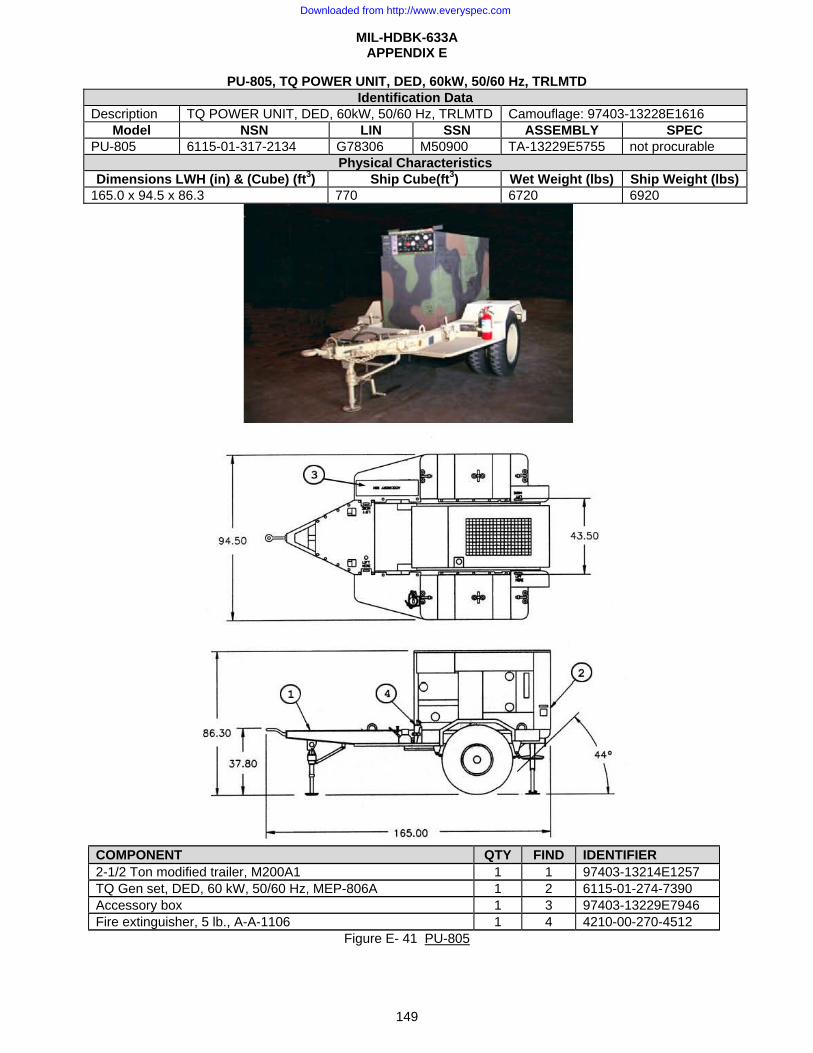
MIL-HDBK-633A APPENDIX E
149
PU-805, TQ POWER UNIT, DED, 60kW, 50/60 Hz, TRLMTD Identification Data
Description TQ POWER UNIT, DED, 60kW, 50/60 Hz, TRLMTD Camouflage: 97403-13228E1616 Model NSN LIN SSN ASSEMBLY SPEC
PU-805 6115-01-317-2134 G78306 M50900 TA-13229E5755 not procurable Physical Characteristics
Dimensions LWH (in) & (Cube) (ft3) Ship Cube(ft3) Wet Weight (lbs) Ship Weight (lbs) 165.0 x 94.5 x 86.3 770 6720 6920
COMPONENT QTY FIND IDENTIFIER 2-1/2 Ton modified trailer, M200A1 1 1 97403-13214E1257 TQ Gen set, DED, 60 kW, 50/60 Hz, MEP-806A 1 2 6115-01-274-7390 Accessory box 1 3 97403-13229E7946 Fire extinguisher, 5 lb., A-A-1106 1 4 4210-00-270-4512
Figure E- 41 PU-805
Downloaded from http://www.everyspec.com
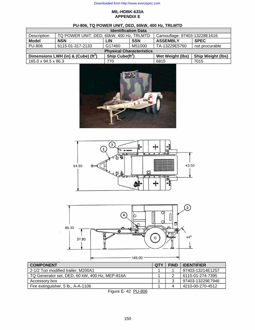
MIL-HDBK-633A APPENDIX E
150
PU-806, TQ POWER UNIT, DED, 60kW, 400 Hz, TRLMTD Identification Data
Description TQ POWER UNIT, DED, 60kW, 400 Hz, TRLMTD Camouflage: 97403-13228E1616 Model NSN LIN SSN ASSEMBLY SPEC PU-806 6115-01-317-2133 G17460 M51000 TA-13229E5760 not procurable
Physical Characteristics Dimensions LWH (in) & (Cube) (ft3) Ship Cube(ft3) Wet Weight (lbs) Ship Weight (lbs) 165.0 x 94.5 x 86.3 770 6815 7015
COMPONENT QTY FIND IDENTIFIER 2-1/2 Ton modified trailer, M200A1 1 1 97403-13214E1257 TQ Generator set, DED, 60 kW, 400 Hz, MEP-816A 1 2 6115-01-274-7395 Accessory box 1 3 97403-13229E7946 Fire extinguisher, 5 lb., A-A-1106 1 4 4210-00-270-4512
Figure E- 42 PU-806
Downloaded from http://www.everyspec.com

MIL-HDBK-633A APPENDIX E
151
PP-AN/MJQ-12A, POWER PLANT, DED, 60kW, 50/60 Hz, TRLMTD Identification Data
Description POWER PLANT, DED, 60kW, 50/60 Hz, TRLMTD Camouflage: 97403-13226E7494 Model NSN LIN SSN ASSEMBLY SPEC
PP-AN/MJQ-12A 6115-00-257-1602 P27823 M511 TA-13221E7350 not procurable Physical Characteristics
Dimensions LWH (in) & (Cube) (ft3) Ship Cube (ft3) Wet Weight (lbs) Ship Weight (lbs) 161.9 x 95.5 x 87.0 (each of 2 units) 818 (each unit) Unit A: 6630
Unit B:.6620 Unit A: 6480 Unit B: 6420
COMPONENT QTY FIND IDENTIFIER 2-1/2 ton flatbed trailer, M200A1 2 1 97403-13214E1257 Generator set, DED, 60 kW, 50/60 Hz, MEP-006A 2 2 6115-00-118-1243 Switch box (unit A), 97403-13229E6776 (old) 1 3 97403-13229E5795 Fire extinguisher, 5 lb., A-A-1106 2 4 4210-00-270-4512 Cable assembly 1 5 97403-13226E7626 Accessory box 2 6 97403-13226E7737
Figure E- 43 PP-AN/MJQ-12A
Downloaded from http://www.everyspec.com

MIL-HDBK-633A APPENDIX E
152
PP-AN/MJQ-41, TQ POWER PLANT, DED, 60kW, 50/60 Hz, TRLMTD Identification Data
Description TQ POWER PLANT, DED, 60kW, 50/60 Hz, TRLMTD Camouflage: 97403-13228E1616 Model NSN LIN SSN ASSEMBLY SPEC
PP-AN/MJQ-41 6115-01-303-7896 P42194 M51100 TA-13229E5710 not procurable Physical Characteristics
Dimensions LWH (in) & (Cube) (ft3) Ship Cube (ft3) Wet Weight (lbs) Ship Weight (lbs)165.0 x 94.5 x 86.3 (2x) 770 (2x) Unit A: 6695
Unit B: 6745 Unit A: 7695 Unit B: 7745
COMPONENT QTY FIND IDENTIFIER 2-1/2 Ton modified trailer, M200A1 2 1 97403-13214E1257 TQ Generator set, DED, 60 kW, 400 Hz, MEP-806A 2 2 6115-01-274-7390 Accessory box 2 3 97403-13229E7946 Fire extinguisher, 5 lb., A-A-1106 2 4 4210-00-270-4512 Switch box (unit A) 1 5 97403-13229E5795 Cable assembly (unit B) 1 6 97403-13229E5741 Paralleling cable assembly 2 7 30554-88-22209
Figure E- 44 PP-AN/MJQ-41
Downloaded from http://www.everyspec.com
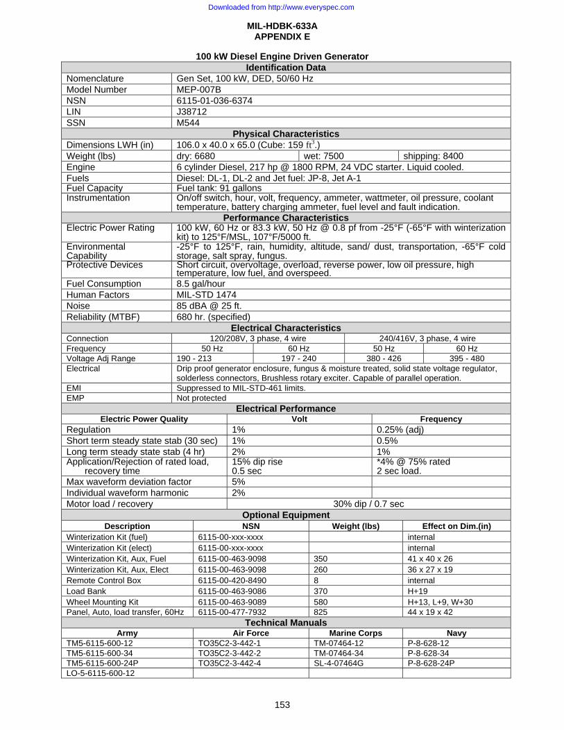
MIL-HDBK-633A APPENDIX E
153
100 kW Diesel Engine Driven Generator Identification Data
Nomenclature Gen Set, 100 kW, DED, 50/60 Hz Model Number MEP-007B NSN 6115-01-036-6374 LIN J38712 SSN M544
Physical Characteristics Dimensions LWH (in) 106.0 x 40.0 x 65.0 (Cube: 159 ft3.) Weight (lbs) dry: 6680 wet: 7500 shipping: 8400 Engine 6 cylinder Diesel, 217 hp @ 1800 RPM, 24 VDC starter. Liquid cooled. Fuels Diesel: DL-1, DL-2 and Jet fuel: JP-8, Jet A-1 Fuel Capacity Fuel tank: 91 gallonsInstrumentation On/off switch, hour, volt, frequency, ammeter, wattmeter, oil pressure, coolant
temperature, battery charging ammeter, fuel level and fault indication.Performance Characteristics
Electric Power Rating 100 kW, 60 Hz or 83.3 kW, 50 Hz @ 0.8 pf from -25°F (-65°F with winterizationkit) to 125°F/MSL, 107°F/5000 ft.
Environmental Capability
-25°F to 125°F, rain, humidity, altitude, sand/ dust, transportation, -65°F cold storage, salt spray, fungus.
Protective Devices Short circuit, overvoltage, overload, reverse power, low oil pressure, high temperature, low fuel, and overspeed.
Fuel Consumption 8.5 gal/hour Human Factors MIL-STD 1474 Noise 85 dBA @ 25 ft. Reliability (MTBF) 680 hr. (specified)
Electrical Characteristics Connection 120/208V, 3 phase, 4 wire 240/416V, 3 phase, 4 wireFrequency 50 Hz 60 Hz 50 Hz 60 Hz Voltage Adj Range 190 - 213 197 - 240 380 - 426 395 - 480 Electrical Drip proof generator enclosure, fungus & moisture treated, solid state voltage regulator,
solderless connectors, Brushless rotary exciter. Capable of parallel operation. EMI Suppressed to MIL-STD-461 limits. EMP Not protected
Electrical Performance Electric Power Quality Volt Frequency
Regulation 1% 0.25% (adj) Short term steady state stab (30 sec) 1% 0.5% Long term steady state stab (4 hr) 2% 1% Application/Rejection of rated load,
recovery time 15% dip rise0.5 sec
*4% @ 75% rated 2 sec load.
Max waveform deviation factor 5% Individual waveform harmonic 2% Motor load / recovery 30% dip / 0.7 sec
Optional Equipment Description NSN Weight (lbs) Effect on Dim.(in)
Winterization Kit (fuel) 6115-00-xxx-xxxx internal Winterization Kit (elect) 6115-00-xxx-xxxx internal Winterization Kit, Aux, Fuel 6115-00-463-9098 350 41 x 40 x 26 Winterization Kit, Aux, Elect 6115-00-463-9098 260 36 x 27 x 19 Remote Control Box 6115-00-420-8490 8 internal Load Bank 6115-00-463-9086 370 H+19 Wheel Mounting Kit 6115-00-463-9089 580 H+13, L+9, W+30 Panel, Auto, load transfer, 60Hz 6115-00-477-7932 825 44 x 19 x 42
Technical Manuals Army Air Force Marine Corps Navy
TM5-6115-600-12 TO35C2-3-442-1 TM-07464-12 P-8-628-12 TM5-6115-600-34 TO35C2-3-442-2 TM-07464-34 P-8-628-34 TM5-6115-600-24P TO35C2-3-442-4 SL-4-07464G P-8-628-24P LO-5-6115-600-12
Downloaded from http://www.everyspec.com
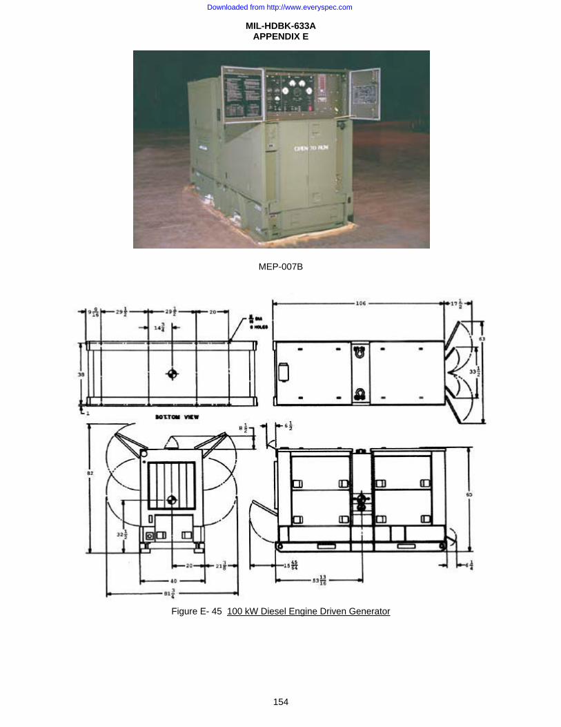
MIL-HDBK-633A APPENDIX E
154
MEP-007B
Figure E- 45 100 kW Diesel Engine Driven Generator
Downloaded from http://www.everyspec.com

MIL-HDBK-633A APPENDIX E
155
PU-495B/G, POWER UNIT, DED, 100 kW, 50/60 Hz, TRLMTD Identification Data
Description POWER UNIT, DED, 100 kW, 50/60 Hz, TRLMTD Camouflage: 97403-13226E7490 Model NSN LIN SSN ASSEMBLY SPEC
PU-495B/G 6115-01-134-0165 J35801 M547 TA-13226E1340 not procurable Physical Characteristics
Dimensions LWH (in) & (Cube) (ft3) Ship Cube (ft3) Wet Weight (lbs) Ship Weight (lbs) 183.1 x 96.0 x 81.5 855 10650 10400
COMPONENT QTY FIND IDENTIFIER 3-1/2 Ton modified Trailer, M353 1 1 97403-13220E6330 Generator set, DED, 100 kW, 50/60 Hz, MEP-007B 1 2 6115-01-036-6374 8 lb engineers hammer 1 3 5120-00-251-4489 Ground rod, 9 ft 1 4 5975-00-296-5324 Fire extinguisher, 5 lb., A-A-1106 1 5 4210-00-270-4512
Figure E- 46 PU-495B/G
Downloaded from http://www.everyspec.com
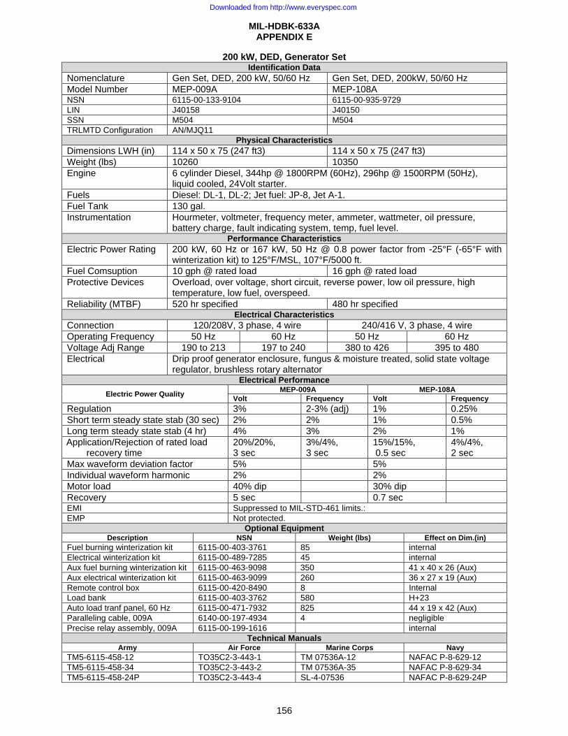
MIL-HDBK-633A APPENDIX E
156
200 kW, DED, Generator Set Identification Data
Nomenclature Gen Set, DED, 200 kW, 50/60 Hz Gen Set, DED, 200kW, 50/60 Hz Model Number MEP-009A MEP-108A NSN 6115-00-133-9104 6115-00-935-9729 LIN J40158 J40150 SSN M504 M504 TRLMTD Configuration AN/MJQ11
Physical CharacteristicsDimensions LWH (in) 114 x 50 x 75 (247 ft3) 114 x 50 x 75 (247 ft3) Weight (lbs) 10260 10350 Engine 6 cylinder Diesel, 344hp @ 1800RPM (60Hz), 296hp @ 1500RPM (50Hz),
liquid cooled, 24Volt starter. Fuels Diesel: DL-1, DL-2; Jet fuel: JP-8, Jet A-1. Fuel Tank 130 gal. Instrumentation Hourmeter, voltmeter, frequency meter, ammeter, wattmeter, oil pressure,
battery charge, fault indicating system, temp, fuel level. Performance Characteristics
Electric Power Rating 200 kW, 60 Hz or 167 kW, 50 Hz @ 0.8 power factor from -25°F (-65°F with winterization kit) to 125°F/MSL, 107°F/5000 ft.
Fuel Comsuption 10 gph @ rated load 16 gph @ rated load Protective Devices Overload, over voltage, short circuit, reverse power, low oil pressure, high
temperature, low fuel, overspeed. Reliability (MTBF) 520 hr specified 480 hr specified
Electrical CharacteristicsConnection 120/208V, 3 phase, 4 wire 240/416 V, 3 phase, 4 wire Operating Frequency 50 Hz 60 Hz 50 Hz 60 Hz Voltage Adj Range 190 to 213 197 to 240 380 to 426 395 to 480 Electrical Drip proof generator enclosure, fungus & moisture treated, solid state voltage
regulator, brushless rotary alternator Electrical Performance
Electric Power Quality MEP-009A MEP-108A Volt Frequency Volt Frequency
Regulation 3% 2-3% (adj) 1% 0.25% Short term steady state stab (30 sec) 2% 2% 1% 0.5% Long term steady state stab (4 hr) 4% 3% 2% 1% Application/Rejection of rated load
recovery time 20%/20%, 3 sec
3%/4%, 3 sec
15%/15%, 0.5 sec
4%/4%, 2 sec
Max waveform deviation factor 5% 5% Individual waveform harmonic 2% 2% Motor load 40% dip 30% dip Recovery 5 sec 0.7 sec EMI Suppressed to MIL-STD-461 limits.: EMP Not protected.
Optional EquipmentDescription NSN Weight (lbs) Effect on Dim.(in)
Fuel burning winterization kit 6115-00-403-3761 85 internal Electrical winterization kit 6115-00-489-7285 45 internal Aux fuel burning winterization kit 6115-00-463-9098 350 41 x 40 x 26 (Aux) Aux electrical winterization kit 6115-00-463-9099 260 36 x 27 x 19 (Aux) Remote control box 6115-00-420-8490 8 Internal Load bank 6115-00-403-3762 580 H+23 Auto load tranf panel, 60 Hz 6115-00-471-7932 825 44 x 19 x 42 (Aux) Paralleling cable, 009A 6140-00-197-4934 4 negligible Precise relay assembly, 009A 6115-00-199-1616 internal
Technical ManualsArmy Air Force Marine Corps Navy
TM5-6115-458-12 TO35C2-3-443-1 TM 07536A-12 NAFAC P-8-629-12 TM5-6115-458-34 TO35C2-3-443-2 TM 07536A-35 NAFAC P-8-629-34 TM5-6115-458-24P TO35C2-3-443-4 SL-4-07536 NAFAC P-8-629-24P
Downloaded from http://www.everyspec.com
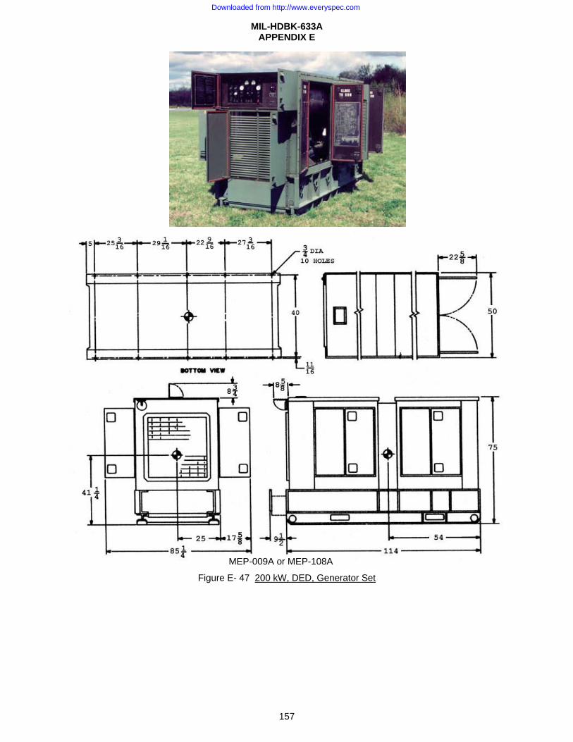
MIL-HDBK-633A APPENDIX E
157
Figure E- 47 200 kW, DED, Generator Set
MEP-009A or MEP-108A
Downloaded from http://www.everyspec.com
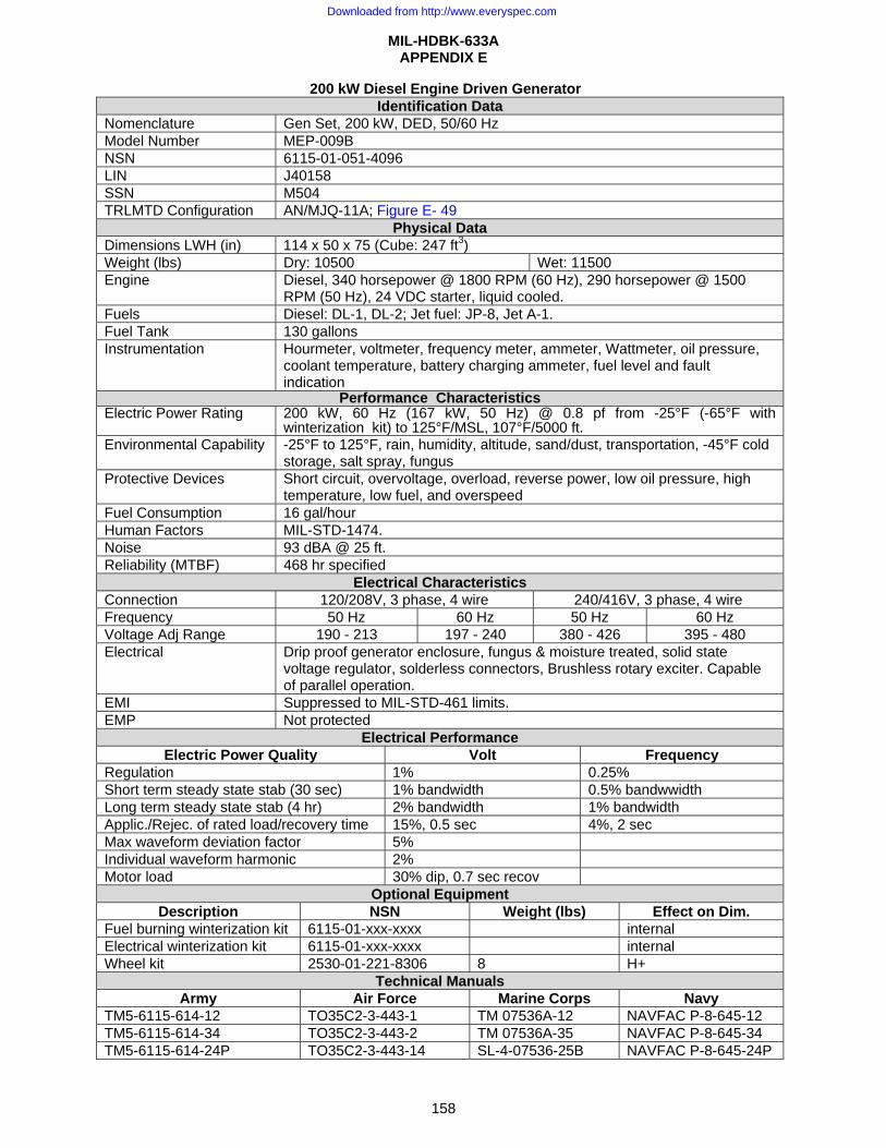
MIL-HDBK-633A APPENDIX E
158
200 kW Diesel Engine Driven Generator Identification Data
Nomenclature Gen Set, 200 kW, DED, 50/60 Hz Model Number MEP-009B NSN 6115-01-051-4096 LIN J40158 SSN M504 TRLMTD Configuration AN/MJQ-11A; Figure E- 49
Physical Data Dimensions LWH (in) 114 x 50 x 75 (Cube: 247 ft3) Weight (lbs) Dry: 10500 Wet: 11500 Engine Diesel, 340 horsepower @ 1800 RPM (60 Hz), 290 horsepower @ 1500
RPM (50 Hz), 24 VDC starter, liquid cooled. Fuels Diesel: DL-1, DL-2; Jet fuel: JP-8, Jet A-1. Fuel Tank 130 gallons Instrumentation Hourmeter, voltmeter, frequency meter, ammeter, Wattmeter, oil pressure,
coolant temperature, battery charging ammeter, fuel level and fault indication
Performance CharacteristicsElectric Power Rating 200 kW, 60 Hz (167 kW, 50 Hz) @ 0.8 pf from -25°F (-65°F with
winterization kit) to 125°F/MSL, 107°F/5000 ft.Environmental Capability -25°F to 125°F, rain, humidity, altitude, sand/dust, transportation, -45°F cold
storage, salt spray, fungus Protective Devices Short circuit, overvoltage, overload, reverse power, low oil pressure, high
temperature, low fuel, and overspeed Fuel Consumption 16 gal/hour Human Factors MIL-STD-1474. Noise 93 dBA @ 25 ft. Reliability (MTBF) 468 hr specified
Electrical Characteristics Connection 120/208V, 3 phase, 4 wire 240/416V, 3 phase, 4 wire Frequency 50 Hz 60 Hz 50 Hz 60 Hz Voltage Adj Range 190 - 213 197 - 240 380 - 426 395 - 480 Electrical Drip proof generator enclosure, fungus & moisture treated, solid state
voltage regulator, solderless connectors, Brushless rotary exciter. Capable of parallel operation.
EMI Suppressed to MIL-STD-461 limits. EMP Not protected
Electrical Performance Electric Power Quality Volt Frequency
Regulation 1% 0.25% Short term steady state stab (30 sec) 1% bandwidth 0.5% bandwwidth Long term steady state stab (4 hr) 2% bandwidth 1% bandwidth Applic./Rejec. of rated load/recovery time 15%, 0.5 sec 4%, 2 sec Max waveform deviation factor 5% Individual waveform harmonic 2% Motor load 30% dip, 0.7 sec recov
Optional Equipment Description NSN Weight (lbs) Effect on Dim.
Fuel burning winterization kit 6115-01-xxx-xxxx internal Electrical winterization kit 6115-01-xxx-xxxx internal Wheel kit 2530-01-221-8306 8 H+
Technical Manuals Army Air Force Marine Corps Navy
TM5-6115-614-12 TO35C2-3-443-1 TM 07536A-12 NAVFAC P-8-645-12 TM5-6115-614-34 TO35C2-3-443-2 TM 07536A-35 NAVFAC P-8-645-34 TM5-6115-614-24P TO35C2-3-443-14 SL-4-07536-25B NAVFAC P-8-645-24P
Downloaded from http://www.everyspec.com
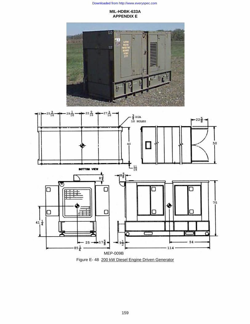
MIL-HDBK-633A APPENDIX E
159
Figure E- 48 200 kW Diesel Engine Driven Generator MEP-009B
Downloaded from http://www.everyspec.com
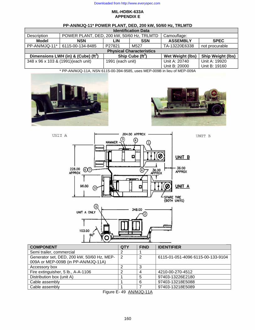
MIL-HDBK-633A APPENDIX E
160
PP-AN/MJQ-11* POWER PLANT, DED, 200 kW, 50/60 Hz, TRLMTD Identification Data
Description POWER PLANT, DED, 200 kW, 50/60 Hz, TRLMTD Camouflage: Model NSN LIN SSN ASSEMBLY SPEC
PP-AN/MJQ-11* 6115-00-134-8485 P27821 M527 TA-13220E6338 not procurable Physical Characteristics
Dimensions LWH (in) & (Cube) (ft3) Ship Cube (ft3) Wet Weight (lbs) Ship Weight (lbs) 348 x 96 x 103 & (1991)(each unit) 1991 (each unit) Unit A: 20740
Unit B: 20000 Unit A: 19920 Unit B: 19160
* PP-AN/MJQ-11A, NSN 6115-00-394-9585, uses MEP-009B in lieu of MEP-009A
COMPONENT QTY FIND IDENTIFIER Semi trailer, commercial 2 1 Generator set, DED, 200 kW, 50/60 Hz, MEP-009A or MEP-009B (in PP-AN/MJQ-11A)
2 2 6115-01-051-4096 6115-00-133-9104
Accessory box 2 3 Fire extinguisher, 5 lb., A-A-1106 2 4 4210-00-270-4512 Distribution box (unit A) 1 5 97403-13226E2180 Cable assembly 1 6 97403-13218E5088 Cable assembly 1 7 97403-13218E5089
Figure E- 49 AN/MJQ-11A
Downloaded from http://www.everyspec.com
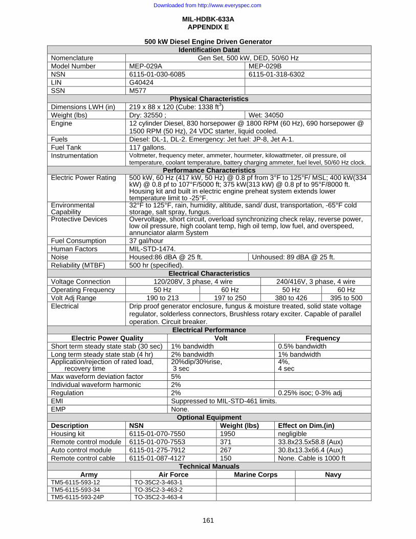
MIL-HDBK-633A APPENDIX E
161
500 kW Diesel Engine Driven Generator Identification Datat
Nomenclature Gen Set, 500 kW, DED, 50/60 Hz Model Number MEP-029A MEP-029B NSN 6115-01-030-6085 6115-01-318-6302 LIN G40424 SSN M577
Physical Characteristics Dimensions LWH (in) 219 x 88 x 120 (Cube: 1338 ft3) Weight (lbs) Dry: 32550 ; Wet: 34050 Engine 12 cylinder Diesel, 830 horsepower @ 1800 RPM (60 Hz), 690 horsepower @
1500 RPM (50 Hz), 24 VDC starter, liquid cooled. Fuels Diesel: DL-1, DL-2. Emergency: Jet fuel: JP-8, Jet A-1. Fuel Tank 117 gallons. Instrumentation Voltmeter, frequency meter, ammeter, hourmeter, kilowattmeter, oil pressure, oil
temperature, coolant temperature, battery charging ammeter, fuel level, 50/60 Hz clock. Performance Characteristics
Electric Power Rating 500 kW, 60 Hz (417 kW, 50 Hz) @ 0.8 pf from 3°F to 125°F/ MSL; 400 kW(334 kW) @ 0.8 pf to 107°F/5000 ft; 375 kW(313 kW) @ 0.8 pf to 95°F/8000 ft. Housing kit and built in electric engine preheat system extends lower temperature limit to -25°F.
Environmental Capability
32°F to 125°F, rain, humidity, altitude, sand/ dust, transportation, -65°F cold storage, salt spray, fungus.
Protective Devices Overvoltage, short circuit, overload synchronizing check relay, reverse power, low oil pressure, high coolant temp, high oil temp, low fuel, and overspeed, annunciator alarm System
Fuel Consumption 37 gal/hour Human Factors MIL-STD-1474. Noise Housed:86 dBA @ 25 ft. Unhoused: 89 dBA @ 25 ft. Reliability (MTBF) 500 hr (specified).
Electrical Characteristics Voltage Connection 120/208V, 3 phase, 4 wire 240/416V, 3 phase, 4 wire Operating Frequency 50 Hz 60 Hz 50 Hz 60 Hz Volt Adj Range 190 to 213 197 to 250 380 to 426 395 to 500 Electrical Drip proof generator enclosure, fungus & moisture treated, solid state voltage
regulator, solderless connectors, Brushless rotary exciter. Capable of parallel operation. Circuit breaker.
Electrical Performance Electric Power Quality Volt Frequency
Short term steady state stab (30 sec) 1% bandwidth 0.5% bandwidth Long term steady state stab (4 hr) 2% bandwidth 1% bandwidth Application/rejection of rated load,
recovery time 20%dip/30%rise,3 sec
4%, 4 sec
Max waveform deviation factor 5% Individual waveform harmonic 2% Regulation 2% 0.25% isoc; 0-3% adj EMI Suppressed to MIL-STD-461 limits. EMP None.
Optional Equipment Description NSN Weight (lbs) Effect on Dim.(in) Housing kit 6115-01-070-7550 1950 negligible Remote control module 6115-01-070-7553 371 33.8x23.5x58.8 (Aux) Auto control module 6115-01-275-7912 267 30.8x13.3x66.4 (Aux) Remote control cable 6115-01-087-4127 150 None. Cable is 1000 ft
Technical Manuals Army Air Force Marine Corps Navy
TM5-6115-593-12 TO-35C2-3-463-1 TM5-6115-593-34 TO-35C2-3-463-2 TM5-6115-593-24P TO-35C2-3-463-4
Downloaded from http://www.everyspec.com
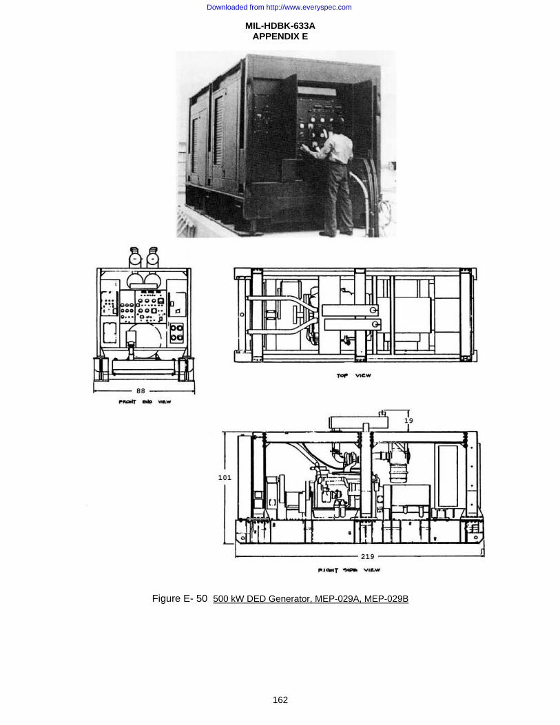
MIL-HDBK-633A APPENDIX E
162
Figure E- 50 500 kW DED Generator, MEP-029A, MEP-029B
Downloaded from http://www.everyspec.com
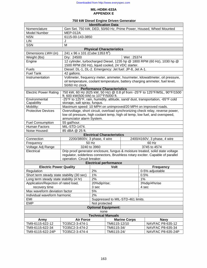
MIL-HDBK-633A APPENDIX E
163
750 kW Diesel Engine Driven Generator Identification Data
Nomenclature Gen Set, 750 kW, DED, 50/60 Hz, Prime Power, Housed, Wheel Mounted Model Number MEP-012A NSN 6115-00-143-3850 LIN J SSN M
Physical Characteristics Dimensions LWH (in) 241 x 96 x 101 (Cube:1353 ft3) Weight (lbs) Dry: 24500 Wet : 25374 Engine 12 cylinder, turbocharged Diesel, 1235 hp @ 1800 RPM (60 Hz), 1030 hp @
1500 RPM (50 Hz), liquid cooled, 24 VDC starter. Fuels Diesel: DL-1, DL-2. Emergency: Jet fuel: JP-8, Jet A-1. Fuel Tank 42 gallons. Instrumentation Voltmeter, frequency meter, ammeter, hourmeter, kilowattmeter, oil pressure,
oil temperature, coolant temperature, battery charging ammeter, fuel level, 50/60 Hz clock.
Performance CharacteristicsElectric Power Rating 750 kW, 60 Hz (625 kW, 50 Hz) @ 0.8 pf from -25°F to 125°F/MSL, 90°F/1500
ft; 600 kW(500 kW) to 107°F/5000 ft.Environmental Capability
-25°F to 125°F, rain, humidity, altitude, sand/ dust, transportation, -65°F cold storage, salt spray, fungus.
Mobility: Maximum speed: 10 MPH on unimproved/20 MPH on improved roads. Protective Devices Overvoltage, short circuit, overload synchronizing check relay, reverse power,
low oil pressure, high coolant temp, high oil temp, low fuel, and overspeed, annunciator alarm System.
Fuel Consumption 55 gal/hour. Human Factors MIL-STD-1474. Noise Housed: 85 dBA @ 25 ft.
Electrical Characteristics Connection 2200/3800V, 3 phase, 4 wire 2400/4160V, 3 phase, 4 wire Frequency 50 Hz 60 Hz Voltage Adj Range 3240 to 3960 3745 to 4574 Electrical Drip proof generator enclosure, fungus & moisture treated, solid state voltage
regulator, solderless connectors, Brushless rotary exciter. Capable of parallel operation. Circuit breaker.
Electrical performance Electric Power Quality Volt Frequency
Regulation 2% 0-5% adjustable Short term steady state stability (30 sec) 1% 0.5% Long term steady state stability (4 hr) 2% 1% Application/Rejection of rated load,
recovery time 20%dip/rise; 3 sec
3%dip/4%rise 4 sec
Max waveform deviation factor 5% Individual waveform harmonic 2% EMI Suppressed to MIL-STD-461 limits. EMP Not protected
Optional Equipment: none
Technical Manuals Army Air Force Marine Corps Navy
TM9-6115-622-12 TO35C2-3-474-1 TM6115-12/10 NAVFAC P8-635-12 TM9-6115-622-34 TO35C2-3-474-2 TM6115-34/ NAVFAC P8-635-34 TM9-6115-622-24P TO35C2-3-474-4 TM6115-24/ NAVFAC P8-635-24P
Downloaded from http://www.everyspec.com
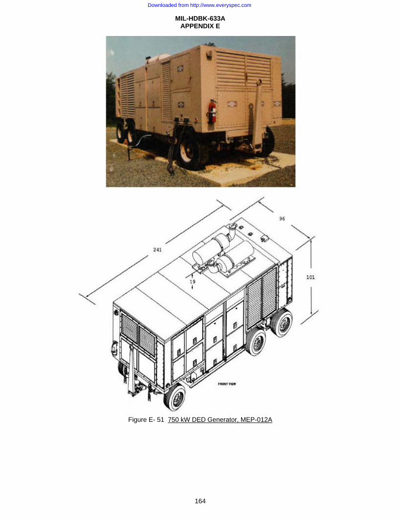
MIL-HDBK-633A APPENDIX E
164
Figure E- 51 750 kW DED Generator, MEP-012A
Downloaded from http://www.everyspec.com
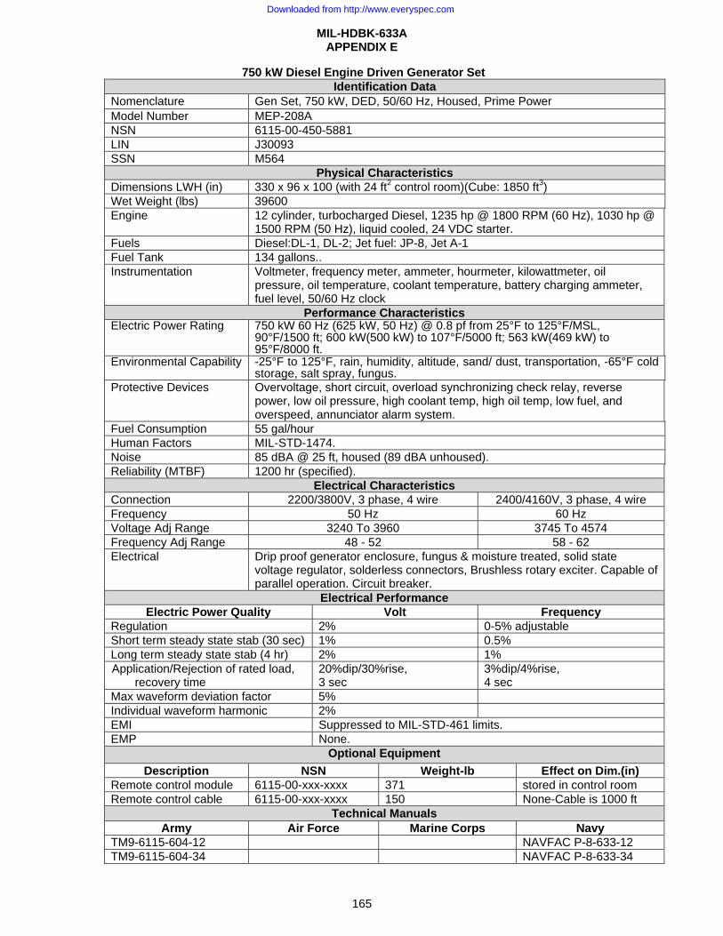
MIL-HDBK-633A APPENDIX E
165
750 kW Diesel Engine Driven Generator Set Identification Data
Nomenclature Gen Set, 750 kW, DED, 50/60 Hz, Housed, Prime Power Model Number MEP-208A NSN 6115-00-450-5881 LIN J30093 SSN M564
Physical Characteristics Dimensions LWH (in) 330 x 96 x 100 (with 24 ft2 control room)(Cube: 1850 ft3) Wet Weight (lbs) 39600 Engine 12 cylinder, turbocharged Diesel, 1235 hp @ 1800 RPM (60 Hz), 1030 hp @
1500 RPM (50 Hz), liquid cooled, 24 VDC starter. Fuels Diesel:DL-1, DL-2; Jet fuel: JP-8, Jet A-1 Fuel Tank 134 gallons.. Instrumentation Voltmeter, frequency meter, ammeter, hourmeter, kilowattmeter, oil
pressure, oil temperature, coolant temperature, battery charging ammeter, fuel level, 50/60 Hz clock
Performance Characteristics Electric Power Rating 750 kW 60 Hz (625 kW, 50 Hz) @ 0.8 pf from 25°F to 125°F/MSL,
90°F/1500 ft; 600 kW(500 kW) to 107°F/5000 ft; 563 kW(469 kW) to 95°F/8000 ft.
Environmental Capability -25°F to 125°F, rain, humidity, altitude, sand/ dust, transportation, -65°F cold storage, salt spray, fungus.
Protective Devices Overvoltage, short circuit, overload synchronizing check relay, reverse power, low oil pressure, high coolant temp, high oil temp, low fuel, and overspeed, annunciator alarm system.
Fuel Consumption 55 gal/hour Human Factors MIL-STD-1474. Noise 85 dBA @ 25 ft, housed (89 dBA unhoused). Reliability (MTBF) 1200 hr (specified).
Electrical Characteristics Connection 2200/3800V, 3 phase, 4 wire 2400/4160V, 3 phase, 4 wire Frequency 50 Hz 60 Hz Voltage Adj Range 3240 To 3960 3745 To 4574 Frequency Adj Range 48 - 52 58 - 62 Electrical Drip proof generator enclosure, fungus & moisture treated, solid state
voltage regulator, solderless connectors, Brushless rotary exciter. Capable of parallel operation. Circuit breaker.
Electrical Performance Electric Power Quality Volt Frequency
Regulation 2% 0-5% adjustable Short term steady state stab (30 sec) 1% 0.5% Long term steady state stab (4 hr) 2% 1% Application/Rejection of rated load,
recovery time 20%dip/30%rise, 3 sec
3%dip/4%rise, 4 sec
Max waveform deviation factor 5% Individual waveform harmonic 2% EMI Suppressed to MIL-STD-461 limits. EMP None.
Optional Equipment Description NSN Weight-lb Effect on Dim.(in)
Remote control module 6115-00-xxx-xxxx 371 stored in control room Remote control cable 6115-00-xxx-xxxx 150 None-Cable is 1000 ft
Technical Manuals Army Air Force Marine Corps Navy
TM9-6115-604-12 NAVFAC P-8-633-12 TM9-6115-604-34 NAVFAC P-8-633-34
Downloaded from http://www.everyspec.com
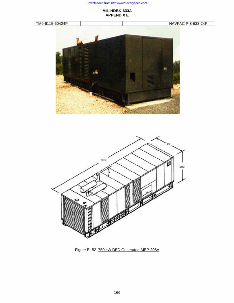
MIL-HDBK-633A APPENDIX E
166
TM9-6115-60424P NAVFAC P-8-633-24P
Figure E- 52 750 kW DED Generator, MEP-208A
Downloaded from http://www.everyspec.com
MIL-HDBK-633A
167
CONCLUDING MATERIAL Custodians: Preparing activity
Army-CR4 ARMY-CR4 Navy-YD (Project 6115-2009-003) Air Force-99
Review Activities:
Army - CE,MI, NAVY-AS,EC,MC Air Force -11 DLA - GS
NOTE: These activities listed above were interested in this document as of the date of this document. Since organizations and responsibilities can change, you should verify the currency of the information above using the ASSIST database at: http://assist.daps.dla.mil.
Downloaded from http://www.everyspec.com
Related Documents


![[DEFENSE & FOREIGN AFFAIRS HANDBOOK 1967/77]...Title [DEFENSE & FOREIGN AFFAIRS HANDBOOK 1967/77] Subject [DEFENSE & FOREIGN AFFAIRS HANDBOOK 1967/77] Keywords](https://static.cupdf.com/doc/110x72/5f2c74a40fc5d9696c286bc2/defense-foreign-affairs-handbook-196777-title-defense-foreign.jpg)