U.S. Department of Transportation Federal Aviation Administration AIRPORT DESIGN / INCORPORATES CHANGES 1 THRU 1 / AC: 150/5300-13 Date: 9/29/89 Advisory Circular

Welcome message from author
This document is posted to help you gain knowledge. Please leave a comment to let me know what you think about it! Share it to your friends and learn new things together.
Transcript

U.S. Department of Transportation
Federal Aviation Administration
AIRPORT DESIGN
/ INCORPORATES CHANGES 1 THRU 15 /
AC: 150/5300-13 Date: 9/29/89 Advisory Circular


3/28/07 AC 150/5300-13 CHG 11
iii
CONTENTS Paragraph Page
Chapter 1. REGULATORY REQUIREMENTS AND DEFINITION OF TERMS 1. GENERAL .................................................................................................................................................................... 1 2. DEFINITIONS .............................................................................................................................................................. 1 3. RELATED/REFERENCED READING MATERIAL.................................................................................................. 3 4. AIRPORT REFERENCE CODE (ARC)....................................................................................................................... 5 5. AIRPORT LAYOUT PLAN ......................................................................................................................................... 5 6. MODIFICATION OF AIRPORT DESIGN STANDARDS TO MEET LOCAL CONDITIONS ............................... 5 7. NOTICE TO THE FAA OF AIRPORT DEVELOPMENT.......................................................................................... 5 8. NOTICE TO THE FAA OF PROPOSED CONSTRUCTION ..................................................................................... 6 9. FAA STUDIES.............................................................................................................................................................. 6 10. FEDERAL ASSISTANCE ............................................................................................................................................ 6 11. ENVIRONMENTAL ASSESSMENTS........................................................................................................................ 6 12. STATE ROLE ............................................................................................................................................................... 6 13. LOCAL ROLE .............................................................................................................................................................. 6 14. to 199. RESERVED ........................................................................................................................................................... 6
Chapter 2. AIRPORT GEOMETRY 200. INTRODUCTION......................................................................................................................................................... 9 201. PRINCIPLES OF APPLICATION ............................................................................................................................... 9 202. RUNWAY LOCATION AND ORIENTATION .......................................................................................................... 9 203. ADDITIONAL RUNWAYS ........................................................................................................................................ 10 204. TAXIWAY SYSTEM .................................................................................................................................................. 10 205. AIRPORT APRONS .................................................................................................................................................... 10 206. SEPARATION STANDARDS .................................................................................................................................... 10 207. PARALLEL RUNWAY SEPARATION--SIMULTANEOUS VFR OPERATIONS................................................. 11 208. PARALLEL RUNWAY SEPARATION--SIMULTANEOUS IFR OPERATIONS .................................................. 11 209. RUNWAY TO PARALLEL TAXIWAY AND TAXILANE SEPARATION............................................................ 12 210. BUILDING RESTRICTION LINE (BRL) .................................................................................................................. 12 211. OBJECT CLEARING CRITERIA ............................................................................................................................... 12 212. RUNWAY PROTECTION ZONE (RPZ).................................................................................................................... 13 213. to 299. RESERVED ........................................................................................................................................................ 13
Chapter 3. RUNWAY DESIGN 300. INTRODUCTION........................................................................................................................................................ 21 301. RUNWAY LENGTH ................................................................................................................................................... 21 302. RUNWAY WIDTH...................................................................................................................................................... 21 303. RUNWAY SHOULDERS............................................................................................................................................ 21 304. RUNWAY BLAST PAD.............................................................................................................................................. 21 305. RUNWAY SAFETY AREA (RSA)............................................................................................................................. 21 306. OBSTACLE FREE ZONE (OFZ) ................................................................................................................................ 22 307. RUNWAY OBJECT FREE AREA.............................................................................................................................. 23 308. CLEARWAY STANDARDS....................................................................................................................................... 23 309. STOPWAY STANDARDS.......................................................................................................................................... 23 310. RESCUE AND FIREFIGHTING ACCESS................................................................................................................. 24 311. to 399. RESERVED ........................................................................................................................................................ 24
Chapter 4. TAXIWAY AND TAXILANE DESIGN 400. INTRODUCTION........................................................................................................................................................ 33 401. DIMENSIONAL STANDARDS ................................................................................................................................. 33 402. TAXIWAY SHOULDERS........................................................................................................................................... 33 403. TAXIWAY SAFETY AREA (TSA)............................................................................................................................ 33 404. TAXIWAY AND TAXILANE OBJECT FREE AREA (OFA) .................................................................................. 33 405. PARALLEL TAXIWAY.............................................................................................................................................. 33 406. TAXIWAY INTERSECTIONS ................................................................................................................................... 34

AC 150/5300-13 CHG 11 3/28/07
iv
407. ENTRANCE TAXIWAYS........................................................................................................................................... 34 408. BYPASS TAXIWAYS................................................................................................................................................. 34 409. HOLDING BAYS......................................................................................................................................................... 34 410. TURNAROUNDS ........................................................................................................................................................ 34 411. DUAL PARALLEL TAXIWAYS................................................................................................................................ 34 412. TAXIWAY BETWEEN PARALLEL RUNWAYS..................................................................................................... 35 413. EXIT TAXIWAYS....................................................................................................................................................... 35 414. APRON TAXIWAYS AND TAXILANES.................................................................................................................. 35 415. END-AROUND TAXIWAYS ......................................................................................................................................35 416. to 499. RESERVED......................................................................................................................................................... 38
Chapter 5. SURFACE GRADIENT AND LINE OF SIGHT 500. INTRODUCTION ........................................................................................................................................................ 49 501. BACKGROUND .......................................................................................................................................................... 49 502. SURFACE GRADIENT STANDARDS ...................................................................................................................... 49 503. LINE OF SIGHT STANDARDS.................................................................................................................................. 56 504. to 599. RESERVED......................................................................................................................................................... 56
Chapter 6. SITE REQUIREMENTS FOR NAVAID AND ATC FACILITIES 600. GENERAL.................................................................................................................................................................... 59 601. MICROWAVE LANDING SYSTEM ......................................................................................................................... 59 602. INSTRUMENT LANDING SYSTEM......................................................................................................................... 61 603. NONDIRECTIONAL BEACON.................................................................................................................................. 63 604. VERY HIGH FREQUENCY OMNIRANGE .............................................................................................................. 64 605. APPROACH LIGHTING SYSTEMS .......................................................................................................................... 64 606. OMNIDIRECTIONAL APPROACH LIGHTING SYSTEMS.................................................................................... 65 607. LEAD-IN LIGHTING SYSTEMS ............................................................................................................................... 65 608. AIRPORT ROTATING BEACONS ............................................................................................................................ 65 609. AIRPORT TRAFFIC CONTROL TOWERS............................................................................................................... 65 610. AIRPORT SURVEILLANCE RADAR ....................................................................................................................... 66 611. AIRPORT SURFACE DETECTION EQUIPMENT ................................................................................................... 66 612. RUNWAY VISUAL RANGE FACILITIES................................................................................................................ 66 613. AUTOMATIC WEATHER OBSERVATION STATIONS (AWOS) ......................................................................... 66 614. PHYSICAL SECURITY .............................................................................................................................................. 67 615. CABLE PROTECTION................................................................................................................................................ 67 616. to 699. RESERVED......................................................................................................................................................... 67
Chapter 7. RUNWAY AND TAXIWAY BRIDGES 700. INTRODUCTION ........................................................................................................................................................ 69 701. SITING PRECEPTS ..................................................................................................................................................... 69 702. DIMENSIONS.............................................................................................................................................................. 69 703. LOAD CONSIDERATIONS........................................................................................................................................ 69 704. DECK DESIGN............................................................................................................................................................ 69 705. MARKING AND LIGHTING...................................................................................................................................... 69 706. OTHER CONSIDERATIONS...................................................................................................................................... 69 707. PASSENGER AND BAGGAGE TUNNELS .............................................................................................................. 70 708. to 799. RESERVED......................................................................................................................................................... 70
Chapter 8. THE EFFECTS AND TREATMENT OF JET BLAST 800. INTRODUCTION ........................................................................................................................................................ 77 801. JET BLAST EFFECTS................................................................................................................................................. 77 802. BLAST FENCES.......................................................................................................................................................... 77 803. SHOULDERS AND BLAST PADS ............................................................................................................................ 78
3/28/07 AC 150/5300-13 CHG 11
v
Appendix 1. WIND ANALYSIS 1. OBJECTIVE................................................................................................................................................................. 87 2. CROSSWINDS ............................................................................................................................................................ 87 3. COVERAGE AND ORIENTATION OF RUNWAYS ............................................................................................... 87 4. ASSEMBLING WIND DATA..................................................................................................................................... 87 5. ANALYZING WIND DATA....................................................................................................................................... 88 6. CONCLUSIONS .......................................................................................................................................................... 88 7. ASSUMPTIONS .......................................................................................................................................................... 88 8. COMPUTER WIND ANALYSIS................................................................................................................................ 88
Appendix 2. RUNWAY END SITING REQUIREMENTS 1. PURPOSE.................................................................................................................................................................... 100 2. APPLICATION........................................................................................................................................................... 100 3. LIMITATIONS ........................................................................................................................................................... 100 4. EVALUATION CONSIDERATIONS........................................................................................................................ 100 5. CLEARANCE REQUIREMENTS ............................................................................................................................. 101
Appendix 3. AIRPORT REFERENCE POINT 1. DISCUSSION.............................................................................................................................................................. 109 2. SAMPLE COMPUTATION ....................................................................................................................................... 109 3. ACCURACY............................................................................................................................................................... 109
Appendix 4. COMPASS CALIBRATION PAD 1. PURPOSE.................................................................................................................................................................... 111 2. BACKGROUND......................................................................................................................................................... 111 3. APPLICATION........................................................................................................................................................... 111 4. DESIGN OF COMPASS CALIBRATION PAD........................................................................................................ 111 5. LOCATION OF COMPASS CALIBRATION PAD .................................................................................................. 112 6. CONSTRUCTION OF COMPASS CALIBRATION PAD........................................................................................ 112 7. VOR CHECKPOINT .................................................................................................................................................. 113
Appendix 5. SMALL AIRPORT BUILDINGS, AIRPLANE PARKING, AND TIEDOWNS
1. GENERAL .................................................................................................................................................................. 117 2. TRANSIENT APRON ................................................................................................................................................ 117 3. APRON FOR BASED AIRPLANES.......................................................................................................................... 117 4. TIEDOWNS ................................................................................................................................................................ 118 5. OTHER CONSIDERATIONS .................................................................................................................................... 118 6. HANGARS.................................................................................................................................................................. 118 7. ADMINISTRATION BUILDING .............................................................................................................................. 118 8. AIRPORT SURVEY ................................................................................................................................................... 122 9. BUILDING PLAN ...................................................................................................................................................... 122 10. EXPANSION .............................................................................................................................................................. 122 11. CIRCULATION .......................................................................................................................................................... 122 12. WAITING ROOM....................................................................................................................................................... 122 13. MANAGER'S OFFICE ............................................................................................................................................... 123 14. EATING FACILITIES................................................................................................................................................ 123 15. PUBLIC RESTROOMS .............................................................................................................................................. 123 16. ROADS AND AUTO PARKING ............................................................................................................................... 123
Appendix 6. METRIC CONVERSION AND TYPICAL AIRPORT LAYOUT PLAN
Appendix cancelled (pp. 125-130)
Appendix 7. AIRPORT LAYOUT PLAN COMPONENTS AND PREPARATION Appendix cancelled (pp. 131-138)

AC 150/5300-13 CHG 11 3/28/07
vi
Appendix 8. RUNWAY DESIGN RATIONALE 1. SEPARATIONS ..........................................................................................................................................................139 2. OBSTACLE FREE ZONE (OFZ) ...............................................................................................................................139 3. RUNWAY SAFETY AREA .......................................................................................................................................139 4. RUNWAY OBJECT FREE AREA (ROFA) ...............................................................................................................139 5. RUNWAY SHOULDERS AND BLAST PADS ........................................................................................................140 6. CLEARWAY...............................................................................................................................................................140 7. STOPWAY ..................................................................................................................................................................140 8. RUNWAY PROTECTION ZONE (RPZ) ...................................................................................................................140
Appendix 9. TAXIWAY AND TAXILANE DESIGN RATIONALE 1. INTRODUCTION .......................................................................................................................................................141 2. BACKGROUND AND RATIONALE........................................................................................................................141 3. EXIT TAXIWAY LOCATION...................................................................................................................................142 4. WINGTIP TRACE ......................................................................................................................................................146
Appendix 10. TAXIWAY FILLET DESIGN 1. INTRODUCTION .......................................................................................................................................................149 2. EXAMPLE NO. 1, JUDGMENTAL OVERSTEERING............................................................................................150 3. EXAMPLE NO. 2, MAINTAINING COCKPIT OVER CENTERLINE ...................................................................150
Appendix 11. COMPUTER PROGRAM 1. AIRPORT DESIGN (FOR MICROCOMPUTERS) VERSION 4.2 ...........................................................................153 2. HOW TO OBTAIN A COPY OF AIRPORT DESIGN (FOR MICROCOMPUTERS) VERSION 4.2.....................153 3. REQUIREMENTS.......................................................................................................................................................153 4. SETUP ON A MICROCOMPUTER...........................................................................................................................153 5. RUN AIRPORT DESIGN PROGRAM.......................................................................................................................153 6. HOT KEYS..................................................................................................................................................................153 7. RUNWAY AND TAXIWAY WIDTH AND CLEARANCE STANDARD DIMENSIONS.....................................154 8. RECOMMENDED RUNWAY LENGTHS ................................................................................................................154 9. STANDARD WIND ANALYSIS ...............................................................................................................................154 10. TAXIWAY DESIGN...................................................................................................................................................155 11. AIRPORT CAPACITY AND DELAY FOR LONG RANGE PLANNING ..............................................................156 12. DECLARED DISTANCE LENGTHS ........................................................................................................................156 13. INPUT AIRPLANE DATA AVAILABILITY ...........................................................................................................156
Appendix 12. AIRPLANE DATA 1. BACKGROUND .........................................................................................................................................................165 2. EXPLANATORY INFORMATION ...........................................................................................................................166
Appendix 13. AIRPLANES ARRANGED BY AIRPLANEMANUFACTURER AND AIRPORT REFERENCE CODE
Section 1. Alphabetical Listing (U.S. customary units)..........................................................................................................251 Section 2. Alphabetical Listing (SI units)...............................................................................................................................257 Section 3. Listing Small Airplanes by Airport Reference Code (U.S. customary units) ........................................................263 Section 4. Listing Large Airplanes by Airport Reference Code (U.S. customary units) ........................................................264 Section 5. Listing Small Airplanes by Airport Reference Code (SI units) .............................................................................269 Section 6. Listing Large Airplanes by Airport Reference Code (SI units) .............................................................................270

3/28/07 AC 150/5300-13 CHG 11
vii
Appendix 14. DECLARED DISTANCES 1. APPLICATION........................................................................................................................................................... 275 2. BACKGROUND......................................................................................................................................................... 275 3. FAA APPROVAL FOR APPLYING DECLARED DISTANCES IN AIRPORT DESIGN...................................... 275 4. RUNWAY SAFETY AREA (RSA) AND RUNWAY OBJECT FREE AREA (ROFA) LENGTHS........................ 276 5. RUNWAY PROTECTION ZONE (RPZ) LOCATION AND SIZE .......................................................................... 276 6. CLEARWAY LOCATION ......................................................................................................................................... 276 7. NOTIFICATION......................................................................................................................................................... 276
Appendix 15. TRANSFER OF ELECTRONIC DATA 1. INTRODUCTION....................................................................................................................................................... 283 2. BACKGROUND......................................................................................................................................................... 283 3. DEFINITIONS ............................................................................................................................................................ 283 4. APPLICATION........................................................................................................................................................... 283 5. CADD FILE DELIVERABLES.................................................................................................................................. 284 6. DATABASES DELIVERABLES............................................................................................................................... 286 7. PHOTOGRAMMETRY DELIVERABLES ............................................................................................................... 286 8. FEATURES AND OBJECTS CODE.......................................................................................................................... 287 9. MEDIA........................................................................................................................................................................ 289 10. FAA POINT OF CONTACT ...................................................................................................................................... 289
Appendix 16. NEW INSTRUMENT APPROACH PROCEDURES 1. BACKGROUND......................................................................................................................................................... 291 2. INTRODUCTION....................................................................................................................................................... 291 3. ACTION...................................................................................................................................................................... 291 4. DEFINITIONS ............................................................................................................................................................ 291
Appendix 17. MINIMUM DISTANCES BETWEEN CERTAIN AIRPORT FEATURES AND ANY ON-AIRPORT AGRICULTURE CROPS (1 page).
Appendix 18. ACRONYMS (1 page).
Appendix 19. INDEX (4 pages).

AC 150/5300-13 CHG 11 3/28/07
viii
Table Page 1-1. Increases in airport design standards associated with an upgrade in the
first component (aircraft approach category) of the airport reference code............................................................ 7 1-2. Increases in airport design standards to provide for lower approach visibility minimums ......................................... 8 2-1. Runway separation standards for aircraft approach categories A & B....................................................................... 14 2-2. Runway separation standards for aircraft approach categories C & D....................................................................... 15 2-3. Taxiway and taxilane separation standards ................................................................................................................ 16 2-4. Runway protection zone (RPZ) dimensions ............................................................................................................... 19 3-1. Runway design standards for aircraft approach category A & B visual runways and runways with
not lower than 3/4-statute mile (1 200 m) approach visibility minimums ..............................................................25 3-2. Runway design standards for aircraft approach categories A & B runways with
lower than 3/4-statute mile (1 200 m) approach visibility minimums ................................................................... 26 3-3. Runway design standards for aircraft approach categories C & D......................................................................... 26-1 4-1. Taxiway dimensional standards.................................................................................................................................. 38 4-2. Taxiway fillet dimensions .......................................................................................................................................... 40 4-3. Wingtip clearance standards....................................................................................................................................... 40 4-4. Visual screen height calculation formula (same elevation as runway).................................................................... 48-5 4-5. Visual screen height calculation formula (EAT below DER elevation) for Design Group III................................ 48-6 4-6. Visual screen height calculation formula (EAT below DER elevation) for Design Group IV ............................... 48-7 4-7. Visual screen height calculation formula (EAT below DER elevation) for Design Groups V and VI ................... 48-8 4-8. Visual screen vertical height calculation tables....................................................................................................... 48-9 4-9. Visual screen panel wind-loading deflection allowance ....................................................................................... 48-12 4-10. CIE chromaticity coordinate limits........................................................................................................................ 48-12 4-11. Minimum reflection levels..................................................................................................................................... 48-13 A2-1. Approach/Departure Requirements Table .................................................................................................................103 A9-1. Exit taxiway cumulative utilization percentages .......................................................................................................142 A16-1A. Precision instrument approach requirements.............................................................................................................292 A16-1B Approach procedure with vertical guidance (APV-RNP) approach requirements....................................................293 A16-1C Nonprecision approach requirements ........................................................................................................................294 A16-2 Survey requirements for instrument approach procedures ........................................................................................295 A17-1. Minimum Distances Between Certain Airport Features and Any On-Airport Agriculture Crops ............................296 Figure Page 2-1. Typical airport layout ................................................................................................................................................. 17 2-2. Parallel runway separation.......................................................................................................................................... 18 2-3. Runway protection zone ............................................................................................................................................. 20 3-1. Runway safety area..................................................................................................................................................... 27 3-2. Obstacle free zone (OFZ) for visual runways and runways with not lower than 3/4 statute mile (1 200 m)
approach visibility minimums........................................................................................................................................ 28 3-3. Obstacle free zone (OFZ) for runways serving small airplanes exclusively with lower than
3/4-statute mile (1 200 m) approach visibility minimums ..................................................................................... 29 3-4. Obstacle free zone (OFZ) for runways serving large airplanes with lower than 3/4-statute mile (1 200 m)
approach visibility minimums................................................................................................................................ 30 3-5. Obstacle free zone (OFZ) for runways serving large airplanes with lower than 3/4-statute mile (1 200 m)
approach visibility minimums and displaced threshold ......................................................................................... 31 3-6. Precision object free zone............................................................................................................................................32 3-7. Clearway................................................................................................................................................................. 32-1 3-8. Stopway .................................................................................................................................................................. 32-2 4-1. Taxiway intersection details ....................................................................................................................................... 39 4-2. Maintaining cockpit over centerline ........................................................................................................................... 41 4-3. Judgmental oversteering ............................................................................................................................................. 42 4-4. Example of pavement fillet computer program printout............................................................................................. 43 4-5. Entrance taxiway ........................................................................................................................................................ 44 4-6. Bypass taxiway........................................................................................................................................................... 44 4-7. Dual parallel taxiway entrance ................................................................................................................................... 45 4-8. Typical holding bay configurations............................................................................................................................ 46

3/28/07 AC 150/5300-13 CHG 11
ix
4-9. Taxiway turnaround ................................................................................................................................................... 46 4-10. Crossover taxiway...................................................................................................................................................... 47 4-11. Right-angled exit taxiway .......................................................................................................................................... 47 4-12. Acute-angled exit taxiway.......................................................................................................................................... 48 4-13. Example of acute-angled exit taxiway computer layout data page 1 ...................................................................... 48-1 4-14. Example of acute-angled exit taxiway computer layout data page 2 ...................................................................... 48-2 4-15. Typical end-around taxiway layout..........................................................................................................................48-3 4-16. End-around taxiway visual screen width calculations..............................................................................................48-4 4-17. Visual screen width calculation formula ..................................................................................................................48-5 4-18. Examples of mounting screen to vertical column ..................................................................................................48-10 4-19. Examples of panel layout for 13-foot-high screen .................................................................................................48-11 4-20. Diagonal stripe orientation .....................................................................................................................................48-12 4-21. Examples of frangibility connections.....................................................................................................................48-14 5-1. Longitudinal grade limitations for aircraft approach categories A & B..................................................................... 50 5-2. Transverse grade limitations for aircraft approach categories A & B........................................................................ 51 5-3. Longitudinal grade limitations for aircraft approach categories C & D..................................................................... 52 5-4. Transverse grade limitations for aircraft approach categories C & D........................................................................ 53 5-5. Runway safety area grade limitations beyond 200 feet (60 m) from the runway end................................................ 55 5-6. Runway visibility zone............................................................................................................................................... 57 6-1. AZ antenna siting ....................................................................................................................................................... 59 6-2. Typical NAVAID placement...................................................................................................................................... 60 6-3. AZ antenna critical area ............................................................................................................................................. 61 6-4. EL antenna siting........................................................................................................................................................ 61 6-5. EL antenna critical area.............................................................................................................................................. 61 6-6. ILS LOC siting and critical area................................................................................................................................. 62 6-7. GS siting and critical area .......................................................................................................................................... 62 6-8. Marker beacon site ..................................................................................................................................................... 63 6-9. NDB site..................................................................................................................................................................... 63 6-10. A TVOR installation .................................................................................................................................................. 64 7-1. Full width runway-taxiway bridge ............................................................................................................................. 71 7-2. Cross-section full width runway-taxiway bridge ....................................................................................................... 72 7-3. Minimum width taxiway bridge with positive edge protection, O'Hare Airport, Chicago, IL.................................. 73 7-4. Example structural deck and depressed roadway, O'Hare Airport, Chicago, IL........................................................ 74 7-5. Suggested shoulder marking of minimum width taxiway bridge............................................................................... 75 7-6. Controlled use service road, Los Angeles International Airport, Los Angeles, CA ................................................. 76 8-1. Velocity distance curves, DC-8.................................................................................................................................. 79 8-2. Velocity distance curves, B-727................................................................................................................................. 80 8-3. Velocity distance curves, B-747................................................................................................................................. 81 8-4. Velocity distance curves, DC-10................................................................................................................................ 82 8-5. Blast velocities of business jet airplanes .................................................................................................................... 83 8-6. Typical blast deflector fences, metal .......................................................................................................................... 84 8-7. Typical blast deflector fences, concrete ..................................................................................................................... 85 A1-1. Wind vector diagram.................................................................................................................................................. 89 A1-2. Typical environmental data service wind summary ................................................................................................... 90 A1-3. Windrose blank showing direction and divisions ...................................................................................................... 91 A1-4. Completed windrose using figure A1-2 data.............................................................................................................. 92 A1-5. Windrose analysis ...................................................................................................................................................... 93 A1-6. Windrose analysis--estimating area not included....................................................................................................... 94 A1-7. Computer printout page 1........................................................................................................................................... 95 A1-8. Computer printout page 2........................................................................................................................................... 96 A1-9. Computer printout page 3........................................................................................................................................... 97 A1-10. Lotus cell-formulas page 1......................................................................................................................................... 98 A1-11. Lotus cell-formulas page 2......................................................................................................................................... 99 A2-1. Approach slopes ........................................................................................................................................................ 105 A2-2. Approach slopes—with offset approach course........................................................................................................ 106 A2-3. Departure surface for Instrument Runways TERPS (40:1)....................................................................................... 107 A2-4. One-Engine Inoperative (OEI) Obstacle Identification Surface (62.5:1).................................................................. 108 A3-1. Sample layout............................................................................................................................................................ 109

AC 150/5300-13 CHG 11 3/28/07
x
A3-2. Sample computation - airport reference point ...........................................................................................................110 A4-1. Marking layout and details of wheel block ...............................................................................................................114 A4-2. Type I. compass calibration pad ................................................................................................................................115 A4-3. Type II. compass calibration pad...............................................................................................................................116 A5-1. Parking apron area.....................................................................................................................................................119 A5-2. Tiedown layouts ........................................................................................................................................................120 A5-3. T-hanger layout .........................................................................................................................................................121 A8-1. Approximate distance airplanes undershoot and overrun the runway end ................................................................140 A9-1. Wingtip clearance - parallel taxiways........................................................................................................................143 A9-2. Wingtip clearance from taxiway................................................................................................................................144 A9-3. Wingtip clearance from apron taxiway .....................................................................................................................144 A9-4. Wingtip clearance from taxilane................................................................................................................................145 A9-5. Pavement edge clearance on tangent .........................................................................................................................146 A9-6. McDonnell-Douglas MD-88 wingtip clearance trace for a 100-foot (30.5 m) radius centerline ..............................147 A9-7. McDonnell-Douglas MD-88 wingtip clearance trace for a 120-foot (36.5 m) radius offset centerline ....................147 A9-8. Boeing 727-200 wingtip clearance trace for a 120-foot (36.5 m) radius offset centerline........................................148 A9-9. Boeing 727-100 wingtip clearance trace for a 120-foot (36.5 m) radius offset centerline........................................148 A10-1. Taxiway intersection details ......................................................................................................................................151 A10-2. Depiction of symbols.................................................................................................................................................152 A11-1. THIS FIGURE INTENTIONALLY LEFT BLANK ................................................................................................156 A11-2. Estimated airplane data elements for input in the computer program .......................................................................157 A11-3. Example of the airport design airplane and airport data window..............................................................................158 A11-4. Example printout of width and clearance standard dimensions page 1 .....................................................................158 A11-5. Example printout of width and clearance standard dimensions page 2 .....................................................................159 A11-6. Example printout of wind analysis (two bi-directional runways)..............................................................................160 A11-7. Example printout of windrose (two bi-directional runways).....................................................................................161 A11-8. Example printout of wind analysis (one uni-directional runway) .............................................................................162 A11-9. Example printout of windrose (one uni-directional runway) ....................................................................................163 A11-10. Nomenclature used in the taxiway design task..........................................................................................................164 A11-11. Nomenclature used in the declared distance task ......................................................................................................164 A12-1. Single engine, high wing, tailwheel airplanes 8,000 lb. (3,628 Kg) or less ..............................................................167 A12-2. Single engine, high wing, tailwheel airplanes 8,000 lb. (3,628 Kg) or less (cont'd) .................................................168 A12-3. Single engine, high wing, tricycle gear airplanes 8,000 lb. (3,628 Kg) or less .........................................................169 A12-4. Single engine, low wing, tricycle gear airplanes 8,000 lb. (3,628 Kg) or less ..........................................................170 A12-5. Single engine, low wing, tricycle gear airplanes 8,000 lb. (3,628 Kg) or less (cont'd) .............................................171 A12-6. Twin engine, low or mid wing, tricycle gear airplanes 8,000 lb. (3,628 Kg) or less ................................................172 A12-7. Twin engine, low or mid wing, tricycle gear airplanes 8,000 lb. (3,628 Kg) or less (cont'd) ...................................173 A12-8. Twin engine, high or mid wing, tricycle gear airplanes 8,000 lb. (3,628 Kg) or less ...............................................174 A12-9. Aérospatiale Nord 262...............................................................................................................................................175 A12-10. Aérospatiale/Sud SE-210 Caravelle ..........................................................................................................................176 A12-11. Airbus Industries A300, 310, and 320.......................................................................................................................177 A12-12. Avions de Transport Regional ATR-42 & -72 ..........................................................................................................178 A12-13. Avions Marcel Dassault Mystère 20 (Fan Jet Falcon)...............................................................................................179 A12-14. BAe 1-11 ...................................................................................................................................................................180 A12-15. B.A.C./SNIAS Concorde...........................................................................................................................................181 A12-16. B.A.C./Vickers VC-10 ..............................................................................................................................................182 A12-17. B.A.C./Vickers Viscount ...........................................................................................................................................183 A12-18. Beech Starship ...........................................................................................................................................................184 A12-19. Beechcraft Airliner ....................................................................................................................................................185 A12-20. Beechcraft King Air ..................................................................................................................................................186 A12-21. Beechcraft Model 18 and Conversions......................................................................................................................187 A12-22. Beechcraft Queen Air ................................................................................................................................................188 A12-23. Boeing B-52 Stratofortress ........................................................................................................................................189 A12-24. Boeing KC-97L .........................................................................................................................................................190 A12-25. Boeing KC-135A.......................................................................................................................................................191 A12-26. Boeing 707-720 .........................................................................................................................................................192 A12-27. Boeing 727 ................................................................................................................................................................193 A12-28. Boeing 737 ................................................................................................................................................................194

3/28/07 AC 150/5300-13 CHG 11
xi
A12-29. Boeing 747 ................................................................................................................................................................ 195 A12-30. Boeing 757 ................................................................................................................................................................ 196 A12-31. Boeing 767 ................................................................................................................................................................ 197 A12-32. British Aerospace 146 ............................................................................................................................................... 198 A12-33. Canadiar CL-44......................................................................................................................................................... 199 A12-34. Canadiar CL-66......................................................................................................................................................... 200 A12-35. Cessna Citation.......................................................................................................................................................... 201 A12-36. Construcciones Aeronauticas CASA C-212 and 235................................................................................................ 202 A12-37. Convair-liner and Turboprop Conversions ............................................................................................................... 203 A12-38. De Havilland Canada C-7 Caribou............................................................................................................................ 204 A12-39. De Havilland Canada DASH 7 & DASH 8............................................................................................................... 205 A12-40. Douglas C-124 Globemaster ..................................................................................................................................... 206 A12-41. De Havilland Canada DHC-6 Twin Otter ................................................................................................................. 207 A12-42. Dornier Gmb H ......................................................................................................................................................... 208 A12-43. Douglas DC-3............................................................................................................................................................ 209 A12-44. Douglas DC-4/6/7 ..................................................................................................................................................... 210 A12-45. Embraer EmB 110..................................................................................................................................................... 211 A12-46. Embraer EmB 120..................................................................................................................................................... 212 A12-47. Fairchild C-119K Flying Boxcar............................................................................................................................... 213 A12-48. Fairchild C-123K Provider........................................................................................................................................ 214 A12-49. Fairchild F-27............................................................................................................................................................ 215 A12-50. Fokker F-27............................................................................................................................................................... 216 A12-51. Fokker F-28............................................................................................................................................................... 217 A12-52. Gates Learjet ............................................................................................................................................................. 218 A12-53. General Dynamics/Convair 880/990 ......................................................................................................................... 219 A12-54. Grumman Gulfstream I ............................................................................................................................................. 220 A12-55. Grumman Gulfstream II ............................................................................................................................................ 221 A12-56. Grumman G-64/G-III ................................................................................................................................................ 222 A12-57. Grumman G-73 ......................................................................................................................................................... 223 A12-58. Hamburger-Flugzeubau HFB-320 Hansa.................................................................................................................. 224 A12-59. Hawker Siddeley DH. 104 Dove............................................................................................................................... 225 A12-60. Hawker Siddeley DH. 114 Heron ............................................................................................................................. 226 A12-61. Hawker Siddeley HS-125.......................................................................................................................................... 227 A12-62. Hawker Siddeley HS-748.......................................................................................................................................... 228 A12-63. Ilyushin IL-62............................................................................................................................................................ 229 A12-64. Israel Aircraft Industries Westwind .......................................................................................................................... 230 A12-65. Lockheed Constellation and Super Constellation ..................................................................................................... 231 A12-66. Lockheed C-5B Galaxy............................................................................................................................................. 232 A12-67. Lockheed C-141 Starlifter......................................................................................................................................... 233 A12-68. Lockheed L-188 Electra II ........................................................................................................................................ 234 A12-69. Lockheed L-100 Hercules ......................................................................................................................................... 235 A12-70. Lockheed L-1011 Tristar........................................................................................................................................... 236 A12-71. Lockheed L-1329 Jetstar ........................................................................................................................................... 237 A12-72. Martin 404................................................................................................................................................................. 238 A12-73. McDonnell-Douglas DC-8 ........................................................................................................................................ 239 A12-74. McDonnell-Douglas DC-9 and MD-80..................................................................................................................... 240 A12-75. McDonnell-Douglas DC-10 ...................................................................................................................................... 241 A12-76. McDonnell-Douglas MD-11 ..................................................................................................................................... 242 A12-77. Mitsubishi MU-2....................................................................................................................................................... 243 A12-78. Nihon/N.A.M.C. YS-11A ......................................................................................................................................... 244 A12-79. Rockwell International NA-265 Sabreliner............................................................................................................... 245 A12-80. SAAB SF 340............................................................................................................................................................ 246 A12-81. Short Brothers ........................................................................................................................................................... 247 A12-82. Shorts SC. 5/10 Belfast ............................................................................................................................................. 248 A12-83. Swearingen Merlin .................................................................................................................................................... 249 A12-84. Swearingen Metro ..................................................................................................................................................... 250 A14-1. Takeoff run available (TORA).................................................................................................................................. 277 A14-2. Takeoff distance available (TODA).......................................................................................................................... 278

AC 150/5300-13 CHG 11 3/28/07
xii
A14-3. Accelerate-stop distance available (ASDA) ..............................................................................................................279 A14-4. Landing distance available (LDA) ............................................................................................................................280 A14-5. Example of a runway extended to 7000 feet .............................................................................................................281 A14-6. Example of a runway with threshold displaced for runway safety area ....................................................................282

1/3/08 AC 150/5300-13 CHG 12
Chap 1
1
Chapter 1. REGULATORY REQUIREMENTS AND DEFINITION OF TERMS
1. GENERAL. Section 103 of the Federal Aviation Act of 1958 states in part, “In the exercise and performance of his power and duties under this Act, the Secretary of Transportation shall consider the following, among other things, as being in the public interest: (a) The regulation of air commerce in such manner as to best promote its development and safety and fulfill the requirements of defense; (b) The promotion, encouragement, and development of civil aeronautics . . . .” This public charge, in effect, requires the development and maintenance of a national system of safe, delay-free, and cost-effective airports. The use of the standards and recommendations contained in this publication in the design of airports supports this public charge. These standards and recommendations, however, do not limit or regulate the operations of aircraft. 2. DEFINITIONS. As used in this publication, the following terms mean: Aircraft Approach Category. A grouping of aircraft based on 1.3 times their stall speed in their landing configuration at the certificated maximum flap setting and maximum landing weight at standard atmospheric conditions. The categories are as follows: Category A: Speed less than 91 knots. Category B: Speed 91 knots or more but less than 121 knots. Category C: Speed 121 knots or more but less than 141 knots. Category D: Speed 141 knots or more but less than 166 knots. Category E: Speed 166 knots or more. Airplane Design Group (ADG). A grouping of airplanes based on wingspan or tail height. Where an airplane is in two categories, the most demanding category should be used. The groups are as follows: Group I: Up to but not including 49 feet (15 m) wingspan or tail height up to but not including 20 feet. Group II: 49 feet (15 m) up to but not including 79 feet (24 m) wingspan or tail height from 20 up to but not including 30 feet.
Group III: 79 feet (24 m) up to but not including 118 feet (36 m) wingspan or tail height from 30 up to but not including 45 feet. Group IV: 118 feet (36 m) up to but not including 171 feet (52 m) wingspan or tail height from 45 up to but not including 60 feet. Group V: 171 feet (52 m) up to but not including 214 feet (65 m) wingspan or tail height from 60 up to but not including 66 feet. Group VI: 214 feet (65 m) up to but not including 262 feet (80 m) wingspan or tail height from 66 up to but not including 80 feet.
Table 1-1. Airplane Design Groups (ADG) Group # Tail Height (ft) Wingspan (ft)
I <20 <49 II 20 - <30 49 - <79 III 30 - <45 79 - <118 IV 45 - <60 118 - <171 V 60 - <66 171 - <214 VI 66 - <80 214 - <262
Airport Elevation. The highest point on an airport's usable runway expressed in feet above mean sea level (MSL). Airport Layout Plan (ALP). The plan of an airport showing the layout of existing and proposed airport facilities. Airport Reference Point (ARP). The latitude and longitude of the approximate center of the airport. Blast Fence. A barrier used to divert or dissipate jet blast or propeller wash. Building Restriction Line (BRL). A line which identifies suitable building area locations on airports. Clear Zone. See Runway Protection Zone. Clearway (CWY). A defined rectangular area beyond the end of a runway cleared or suitable for use in lieu of runway to satisfy takeoff distance requirements. Compass Calibration Pad. An airport facility used for calibrating an aircraft compass.

AC 150/5300-13 CHG 10 9/29/06
Chap 1 2
Declared Distances. The distances the airport owner declares available for the airplane's takeoff run, takeoff distance, accelerate-stop distance, and landing distance requirements. The distances are: Takeoff run available (TORA). The runway length declared available and suitable for the ground run of an airplane taking off; Takeoff distance available (TODA). The TORA plus the length of any remaining runway or clearway (CWY) beyond the far end of the TORA; NOTE: The full length of TODA may not be usable for all takeoffs because of obstacles in the departure area. The usable TODA length is aircraft performance dependent and, as such, must be determined by the aircraft operator before each takeoff and requires knowledge of the location of each controlling obstacle in the departure area. Accelerate-stop distance available (ASDA). The runway plus stopway (SWY) length declared available and suitable for the acceleration and deceleration of an airplane aborting a takeoff; and Landing distance available (LDA). The runway length declared available and suitable for a landing airplane. Fixed By Function NAVAID. An air navigation aid (NAVAID) that must be positioned in a particular location in order to provide an essential benefit for civil aviation is fixed by function. Exceptions are: a. Equipment shelters, junction boxes, transformers, and other appurtenances that support a fixed by function NAVAID are not fixed by function unless operational requirements require them to be located in close proximity to the NAVAID. b. Some NAVAIDs, such as localizers, can provide beneficial performance even when they are not located at their optimal location. These NAVAIDS are not fixed by function. Frangible NAVAID. A navigational aid (NAVAID) which retains its structural integrity and stiffness up to a designated maximum load, but on impact from a greater load, breaks, distorts, or yields in such a manner as to present the minimum hazard to aircraft. The term NAVAID includes electrical and visual air navigational aids, lights, signs, and associated supporting equipment. Hazard to Air Navigation. An object which, as a result of an aeronautical study, the FAA determines will have a substantial adverse effect upon the safe and efficient use of navigable airspace by aircraft, operation of air navigation facilities, or existing or potential airport capacity.
Large Airplane. An airplane of more than 12,500 pounds (5 700 kg) maximum certificated takeoff weight. Low Impact Resistant Supports (LIRS). Supports designed to resist operational and environmental static loads and fail when subjected to a shock load such as that from a colliding aircraft. Object. Includes, but is not limited to above ground structures, NAVAIDs, people, equipment, vehicles, natural growth, terrain, and parked aircraft. Object Free Area (OFA). An area on the ground centered on a runway, taxiway, or taxilane centerline provided to enhance the safety of aircraft operations by having the area free of objects, except for objects that need to be located in the OFA for air navigation or aircraft ground maneuvering purposes. Obstacle Clearance Surface (OCS). An inclined obstacle evaluation surface associated with a glidepath. The separation between this surface and the glidepath angle at any given distance from GPI defines the MINIMUM required obstruction clearance at that point. Obstacle Free Zone (OFZ). The OFZ is the airspace below 150 feet (45 m) above the established airport elevation and along the runway and extended runway centerline that is required to be clear of all objects, except for frangible visual NAVAIDs that need to be located in the OFZ because of their function, in order to provide clearance protection for aircraft landing or taking off from the runway, and for missed approaches. The OFZ is sub-divided as follows: Runway OFZ. The airspace above a surface centered on the runway centerline. Inner-approach OFZ. The airspace above a surface centered on the extended runway centerline. It applies to runways with an approach lighting system. Inner-transitional OFZ. The airspace above the surfaces located on the outer edges of the runway OFZ and the inner-approach OFZ. It applies to runways with approach visibility minimums lower than 3/4-statute mile (1 200 m). Obstruction to Air Navigation. An object of greater height than any of the heights or surfaces presented in Subpart C of Code of Federal Regulation (14 CFR), Part 77. (Obstructions to air navigation are presumed to be hazards to air navigation until an FAA study has determined otherwise.) Precision Approach Category I (CAT I) Runway. A runway with an instrument approach procedure which provides for approaches to a decision height (DH) of not less than 200 feet (60 m) and visibility of not less than 1/2 mile (800 m) or Runway Visual Range (RVR) 2400 (RVR 1800 with operative touchdown zone and runway centerline lights).
1/3/08 AC 150/5300-13 CHG 12
Chap 1 3
Precision Approach Category II (CAT II) Runway. A runway with an instrument approach procedure which provides for approaches to a minima less than CAT I to as low as a decision height (DH) of not less than 100 feet (30 m) and RVR of not less than RVR 1200. Precision Approach Category III (CAT III) Runway. A runway with an instrument approach procedure which provides for approaches to minima less than CAT II. Runway (RW). A defined rectangular surface on an airport prepared or suitable for the landing or takeoff of airplanes. Runway Blast Pad. A surface adjacent to the ends of runways provided to reduce the erosive effect of jet blast and propeller wash. Runway Protection Zone (RPZ). An area off the runway end to enhance the protection of people and property on the ground. Runway Safety Area (RSA). A defined surface surrounding the runway prepared or suitable for reducing the risk of damage to airplanes in the event of an undershoot, overshoot, or excursion from the runway. Shoulder. An area adjacent to the edge of paved runways, taxiways, or aprons providing a transition between the pavement and the adjacent surface; support for aircraft running off the pavement; enhanced drainage; and blast protection. Small Airplane. An airplane of 12,500 pounds (5 700 kg) or less maximum certificated takeoff weight. Stopway (SWY). A defined rectangular surface beyond the end of a runway prepared or suitable for use in lieu of runway to support an airplane, without causing structural damage to the airplane, during an aborted takeoff. Taxilane (TL). The portion of the aircraft parking area used for access between taxiways and aircraft parking positions. Taxiway (TW). A defined path established for the taxiing of aircraft from one part of an airport to another. Taxiway Safety Area (TSA). A defined surface alongside the taxiway prepared or suitable for reducing the risk of damage to an airplane unintentionally departing the taxiway. Threshold (TH). The beginning of that portion of the runway available for landing. In some instances, the landing threshold may be displaced.
Displaced Threshold. A threshold that is located at a point on the runway other than the designated beginning of the runway. Visual Runway. A runway without an existing or planned straight-in instrument approach procedure. 3. RELATED/REFERENCED READING MATERIAL. The following is a listing of documents referenced in other parts of this advisory circular. Advisory Circulars 00-2 and 00-44 may be obtained by writing to: The U.S. Department of Transportation; Utilization and Storage Section, M-443.2; Washington, D.C. 20590. The most current versions of the ACs listed below are available online at www.faa.gov. NOTE: Some of the ACs in this paragraph have been cancelled but are still referenced in the main document. They will continue to be listed here and shown as cancelled until the next complete revision of the document. a. AC 00-2, Advisory Circular Checklist. b. AC 00-44, Status of Federal Aviation Regulations. c. AC 20-35, Tiedown Sense. d. AC 70/7460-1, Obstruction Marking and Lighting. e. AC 70/7460-2, Proposed Construction or Alteration of Objects that May Affect the Navigable Airspace. (Cancelled) f. AC 107-1, Aviation Security-Airports. g. AC 120-29, Criteria for Approving Category I and Category II Landing Minima for FAR Part 121 Operators. h. AC 150/5000-3, Address List for Regional Airports Divisions and Airports District/Field Offices. (Cancelled) i. AC 150/5060-5, Airport Capacity and Delay. j. AC 150/5070-3, Planning the Airport Industrial Park. (Cancelled) k. AC 150/5070-6, Airport Master Plans. l. AC 150/5190-1, Minimum Standards for Commercial Aeronautical Activities on Public Airports. (Cancelled by AC 150/5190-5)

AC 150/5300-13 CHG 12 1/3/08
Chap 1 4
m. AC 150/5190-4, A Model Zoning Ordinance to Limit Height of Objects Around Airports. n. AC 150/5190-5, Exclusive Rights and Minimum Standards for Commercial Aeronautical Activities. (Cancelled by AC 150/5190-6 and AC 150/5190-7) o. AC 150/5190-6, Exclusive Rights at Federally-Obligated Airports p. AC 150/5190-7, Minimum Standards for Commercial Aeronautical Activities q. AC 150/5200-33, Hazardous Wildlife Attractants On or Near Airports. r. AC 150/5220-16, Automated Weather Observing Systems (AWOS) for Non-Federal Applications. s. AC 150/5230-4, Aircraft Fuel Storage, Handling, and Dispensing on Airports. t. AC 150/5320-5, Airport Drainage. u. AC 150/5320-6, Airport Pavement Design and Evaluation. v. AC 150/5320-14, Airport Landscaping for Noise Control Purposes. w. AC 150/5325-4, Runway Length Requirements for Airport Design. x. AC 150/5340-1, Standards for Airport Marking. y. AC 150/5340-5, Segmented Circle Marker Systems. z. AC 150/5340-14, Economy Approach Lighting Aids. (Cancelled by AC 150/5340-30) aa. AC 150/5340-18, Standards for Airport Sign Systems. bb. AC 150/5340-21, Airport Miscellaneous Lighting Visual Aids. (Cancelled by AC 150/5340-30) cc. AC 150/5340-24, Runway and Taxiway Edge Lighting System. (Cancelled by AC 150/5340-30) dd. AC 150/5340-28, Precision Approach Path Indicator (PAPI) Systems. (Cancelled by AC 150/5340-30) ee. AC 150/5340-30, Design and Installation Details for Airport Visual Aids ff. AC 150/5345-52, Generic Visual Slope Indicators (GVGI).
gg. AC 150/5360-13, Planning and Design Guidelines for Airport Terminal Facilities. hh. AC 150/5370-10, Standards for Specifying Construction of Airports.
ii. AC 150/5390-2, Heliport Design.
jj. 14 CFR Part 23, Airworthiness Standards: Normal, Utility, Acrobatic, and Commuter Category Airplanes. kk. 14 CFR Part 25, Airworthiness Standards: Transport Category Airplanes. ll. 14 CFR Part 77, Objects Affecting Navigable Airspace. mm. 14 CFR Part 97, Standard Instrument Approach Procedures. nn. 14 CFR Part 135, Operating Requirements: Commuter and On Demand Operations and Rules Governing Persons On Board Such Aircraft. oo. 14 CFR Part 139, Certification of Airports. pp. 14 CFR Part 151, Federal Aid to Airports. qq. 14 CFR Part 152, Airport Aid Program. rr. 14 CFR Part 153, Acquisition of U.S. Land for Public Airports. (Removed from Title 14) ss. 14 CFR Part 154, Acquisition of Land for Public Airports Under the Airport and Airway Development Act of 1970. (Removed from Title 14) tt. 14 CFR Part 157, Notice of Construction, Alteration, Activation, and Deactivation of Airports. uu. Order 1050.1, Policies and Procedures for Considering Environmental Impacts. vv. Order 5050.4, Airport Environmental Handbook. ww. Order 5100.38, Airport Improvement Program (AIP) Handbook. xx. Order 7400.2, Procedures for Handling Airspace Matters. yy. Order 8200.1, United States Standard Flight Inspection Manual. zz. Order 8260.3, United States Standard for Terminal Instrument Procedures (TERPS).

9/29/06 AC 150/5300-13 CHG 10
Chap 1 5
4. AIRPORT REFERENCE CODE (ARC). The ARC is a coding system used to relate airport design criteria to the operational and physical characteristics of the airplanes intended to operate at the airport. a. Coding System. The airport reference code has two components relating to the airport design aircraft. The first component, depicted by a letter, is the aircraft approach category and relates to aircraft approach speed (operational characteristic). The second component, depicted by a Roman numeral, is the airplane design group and relates to airplane wingspan or tailheight (physical characteristics), whichever is the most restrictive. Generally, runways standards are related to aircraft approach speed, airplane wingspan, and designated or planned approach visibility minimums. Taxiway and taxilane standards are related to airplane design group. b. Airport Design. Airport design first requires selecting the ARC(s), then the lowest designated or planned approach visibility minimums for each runway, and then applying the airport design criteria associated with the airport reference code and the designated or planned approach visibility minimums. (1) An upgrade in the first component of the ARC may result in an increase in airport design standards. Table 1-1 depicts these increases. (2) An upgrade in the second component of the ARC generally will result in a major increase in airport design standards. (3) An airport upgrade to provide for lower approach visibility minimums may result in an increase in airport design standards. Table 1-2 depicts these increases. (4) Operational minimums are based on current criteria, runways, airspace, and instrumentation. Unless this is taken into consideration in the development of the airport, the operational minimums may be other than proposed. (5) For airports with two or more runways, it may be desirable to design all airport elements to meet the requirements of the most demanding ARC. However, it may be more practical to design some airport elements, e.g., a secondary runway and its associated taxiway, to standards associated with a lesser demanding ARC. 5. AIRPORT LAYOUT PLAN. An Airport Layout Plan (ALP) is a scaled drawing of existing and proposed land and facilities necessary for the operation and development of the airport. Any airport will benefit from a carefully developed plan that reflects current FAA design standards and planning criteria. For guidance on developing Airport Master Plans, refer to AC 150/5070-6, Airport Master Plans. a. FAA-Approved ALP. All airport development carried out at Federally obligated airports must be done in accordance with an FAA-approved ALP. The FAA-approved
ALP, to the extent practicable, should conform to the FAA airport design standards existing at the time of its approval. Due to unique site, environmental, or other constraints, the FAA may approve an ALP not fully complying with design standards. Such approval requires an FAA study and finding that the proposed modification is safe for the specific site and conditions. When the FAA upgrades a standard, airport owners should, to the extent practicable, include the upgrade in the ALP before starting future development. b. Guidance. AC 150/5070-6, Airport Master Plans, contains background information on the development of ALPs, as well as a detailed listing of the various components that constitute a well-appointed ALP. c. Electronic Plans. The FAA recommends the development of electronic ALPs where practical. 6. MODIFICATION OF AIRPORT DESIGN STANDARDS TO MEET LOCAL CONDITIONS. “Modification to standards” means any change to FAA design standards other than dimensional standards for runway safety areas. Unique local conditions may require modification to airport design standards for a specific airport. A modification to an airport design standard related to new construction, reconstruction, expansion, or upgrade on an airport which received Federal aid requires FAA approval. The request for modification should show that the modification will provide an acceptable level of safety, economy, durability, and workmanship. Appendixes 8 and 9 discuss the relationship between airplane physical characteristics and the design of airport elements. This rationale along with the computer program cited in appendix 11 may be used to show that the modification will provide an acceptable level of safety for the specified conditions, including the type of aircraft. 7. NOTICE TO THE FAA OF AIRPORT DEVELOPMENT. 14 CFR Part 157, Notice of Construction, Activation, and Deactivation of Airports, requires persons proposing to construct, activate, or deactivate an airport to give notice of their intent to the FAA. The notice applies to proposed alterations to the takeoff and landing areas, traffic patterns, and airport use, e.g., a change from private-use to public-use. a. Notice Procedure. 14 CFR Part 157 requires airport proponents to notify the appropriate FAA Airports Regional or District Office at least 30 days before construction, alteration, deactivation, or the date of the proposed change in use. In an emergency involving essential public service, health, or safety, or when delay would result in a hardship, a proponent may notify the FAA by telephone and submit Form 7480-1, Notice of Landing Area Proposal, within 5 days. b. The Notice. The notice consists of a completed FAA Form 7480-1, a layout sketch, and a location map. The layout sketch should show the airport takeoff and landing area configuration in relation to buildings, trees, fences, power lines, and other similar significant features. The preferred type of location map is the 7.5 minute U.S. Geological Survey

AC 150/5300-13 CHG 10 9/29/06
Chap 1 6
Quadrangle Map showing the location of the airport site. Form 7480-1 lists FAA Airports Office addresses. c. FAA Action. The FAA evaluates the airport proposal for its impact upon the: safe and efficient use of navigable airspace; operation of air navigation facilities; existing or potential airport capacity; and safety of persons and property on the ground. The FAA notifies proponents of the results of the FAA evaluation. d. Penalty for Failure to Provide Notice. Persons who fail to give notice are subject to civil penalty. 8. NOTICE TO THE FAA OF PROPOSED CONSTRUCTION. 14 CFR Part 77, Objects Affecting Navigable Airspace, requires persons proposing any construction or alteration described in 14 CFR Section 77.13(a) to give 30-day notice to the FAA of their intent. This includes any construction or alteration of structures more than 200 feet (61 m) in height above the ground level or at a height that penetrates defined imaginary surfaces located in the vicinity of a public-use airport. a. Airport Data Requirements. Future airport development plans and feasibility studies on file with the FAA may influence the determinations resulting from 14 CFR Part 77 studies. To assure full consideration of future airport development in 14 CFR Part 77 studies, airport owners must have their plans on file with the FAA. The necessary plan data includes, as a minimum, planned runway end coordinates, elevation, and type of approach for any new runway or runway extension. b. Penalty for Failure to Provide Notice. Persons who knowingly and willingly fail to give such notice are subject to criminal prosecution. 9. FAA STUDIES. The FAA studies existing and proposed objects and activities, on and in the vicinity of public-use airports. These objects and activities are not limited to obstructions to air navigation, as defined in 14 CFR Part 77. These studies focus on the efficient use of the airport and the safety of persons and property on the ground. As the result of these studies, the FAA may resist, oppose, or recommend against the presence of objects or activities in the vicinity of a public-use airport that conflict with an airport planning or design standard/recommendation. This policy is stated as a notice on page 32152 of Volume 54, No. 149, of the Federal Register, dated Friday, August 4, 1989. FAA studies conclude: a. Whether an obstruction to air navigation is a hazard to air navigation;
b. Whether an object or activity on or in the vicinity of an airport is objectionable; c. Whether the need to alter, remove, mark, or light an object exists; d. Whether to approve an Airport Layout Plan; e. Whether proposed construction, enlargement, or modification to an airport would have an adverse effect on the safe and efficient use of navigable airspace; or f. Whether a change in an operational procedure is feasible. 10. FEDERAL ASSISTANCE. The FAA administers a grant program (per Order 5100.38, Airport Improvement Program (AIP) Handbook) which provides financial assistance for developing public-use airports. Persons interested in this program can obtain information from FAA Airports Regional or District Offices. Technical assistance in airport development is also available from these offices. 11. ENVIRONMENTAL ASSESSMENTS. Federal grant assistance in, or ALP approval of, new airport construction or major expansion normally requires an assessment of potential environmental impacts in accordance with FAA Order 5050.4B, National Environmental Policy Act (NEPA) Implementing Instructions for Airport Projects, and the National Environmental Policy Act of 1969. 12. STATE ROLE. Many State aeronautics commissions or similar departments require prior approval and, in some instances, a license for the establishment and operation of an airport. Some States administer a financial assistance program similar to the Federal program and technical advice. Proponents should contact their respective State aeronautics commissions or departments for information on licensing and assistance programs. 13. LOCAL ROLE. Most communities have zoning ordinances, building codes, and fire regulations which may affect airport development. Some have or are in the process of developing codes or ordinances regulating environmental issues such as noise and air quality. Others may have specific procedures for establishing an airport. 14. to 199. RESERVED

12/31/2009 AC 150/5300-13 CHG 15
Table 1-1. Increases in airport design standards associated with an upgrade in the first component (aircraft approach category) of the airport reference code
ARC upgrade Changes in airport design standards A-I s/ to B-I s/ No change in airport design standards. B-I s/ to C-I Increase in crosswind component. Refer to paragraph 203.b.
Increase in runway separation standards. Refer to tables 2-1 and 2-2. Increase in RPZ dimensions. Refer to table 2-4 and appendix 14, paragraph 5.b. Increase in OFZ dimensions. Refer to paragraph 306. Increase in runway design standards. Refer to tables 3-1, 3-2, and 3-3. Increase in surface gradient standards. Refer to paragraph 502. Increase in threshold siting standards. Refer to appendix 2, paragraph 5.
A-I to B-I No change in airport design standards. B-I / to C-I Increase in crosswind component. Refer to paragraph 203.b.
Increase in runway separation standards. Refer to tables 2-1 and 2-2. Increase in RPZ dimensions. Refer to table 2-4 and appendix 14, paragraph 5.b. Increase in runway design standards. Refer to tables 3-1, 3-2, and 3-3. Increase in surface gradient standards. Refer to paragraph 502.
A-II to B-II No change in airport design standards. B-II to C-II Increase in crosswind component. Refer to paragraph 203.b.
Increase in runway separation standards. Refer to tables 2-1 and 2-2. Increase in RPZ dimensions. Refer to table 2-4 and appendix 14, paragraph 5.b. Increase in runway design standards. Refer to tables 3-1, 3-2, and 3-3. Increase in surface gradient standards. Refer to paragraph 502.
A-III to B-III No change in airport standards. B-III to C-III Increase in runway separation standards. Refer to tables 2-1 and 2-2.
Increase in RPZ dimensions. Refer to table 2-4 and appendix 14, paragraph 5.b. Increase in runway design standards. Refer to tables 3-1, 3-2, and 3-3. Increase in surface gradient standards. Refer to paragraph 502.
A-IV to B-IV No change in airport design standards. B-IV to C-IV Increase in RPZ dimensions. Refer to table 2-4 and appendix 14, paragraph 5.b. Increase in surface
gradient standards. Refer to paragraph 502.
s/ These airport design standards pertain to facilities for small airplanes exclusively.
Chap 1 7

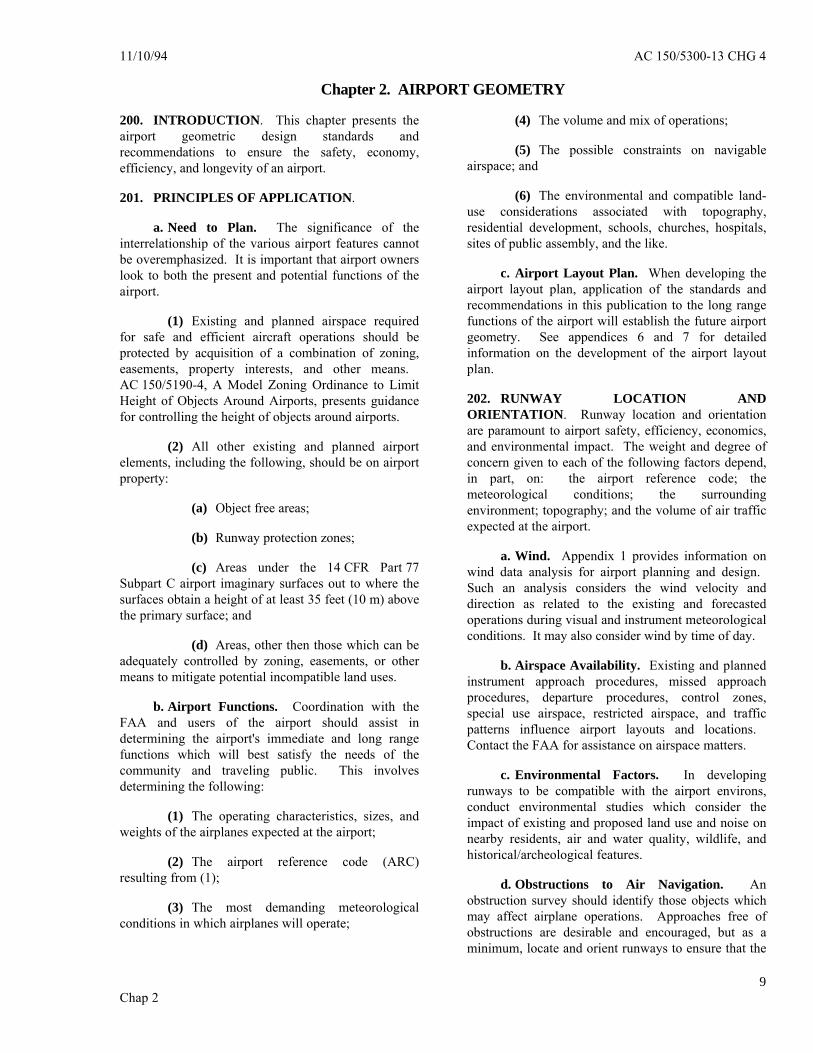
11/10/94 AC 150/5300-13 CHG 4
Chap 29
Chapter 2. AIRPORT GEOMETRY
200. INTRODUCTION. This chapter presents theairport geometric design standards andrecommendations to ensure the safety, economy,efficiency, and longevity of an airport.
201. PRINCIPLES OF APPLICATION.
a. Need to Plan. The significance of theinterrelationship of the various airport features cannotbe overemphasized. It is important that airport ownerslook to both the present and potential functions of theairport.
(1) Existing and planned airspace requiredfor safe and efficient aircraft operations should beprotected by acquisition of a combination of zoning,easements, property interests, and other means. AC 150/5190-4, A Model Zoning Ordinance to LimitHeight of Objects Around Airports, presents guidancefor controlling the height of objects around airports.
(2) All other existing and planned airportelements, including the following, should be on airportproperty:
(a) Object free areas;
(b) Runway protection zones;
(c) Areas under the 14 CFR Part 77Subpart C airport imaginary surfaces out to where thesurfaces obtain a height of at least 35 feet (10 m) abovethe primary surface; and
(d) Areas, other then those which can beadequately controlled by zoning, easements, or othermeans to mitigate potential incompatible land uses.
b. Airport Functions. Coordination with theFAA and users of the airport should assist indetermining the airport's immediate and long rangefunctions which will best satisfy the needs of thecommunity and traveling public. This involvesdetermining the following:
(1) The operating characteristics, sizes, andweights of the airplanes expected at the airport;
(2) The airport reference code (ARC)resulting from (1);
(3) The most demanding meteorologicalconditions in which airplanes will operate;
(4) The volume and mix of operations;
(5) The possible constraints on navigableairspace; and
(6) The environmental and compatible land-use considerations associated with topography,residential development, schools, churches, hospitals,sites of public assembly, and the like.
c. Airport Layout Plan. When developing theairport layout plan, application of the standards andrecommendations in this publication to the long rangefunctions of the airport will establish the future airportgeometry. See appendices 6 and 7 for detailedinformation on the development of the airport layoutplan.
202. RUNWAY LOCATION ANDORIENTATION. Runway location and orientationare paramount to airport safety, efficiency, economics,and environmental impact. The weight and degree ofconcern given to each of the following factors depend,in part, on: the airport reference code; themeteorological conditions; the surroundingenvironment; topography; and the volume of air trafficexpected at the airport.
a. Wind. Appendix 1 provides information onwind data analysis for airport planning and design. Such an analysis considers the wind velocity anddirection as related to the existing and forecastedoperations during visual and instrument meteorologicalconditions. It may also consider wind by time of day.
b. Airspace Availability. Existing and plannedinstrument approach procedures, missed approachprocedures, departure procedures, control zones,special use airspace, restricted airspace, and trafficpatterns influence airport layouts and locations. Contact the FAA for assistance on airspace matters.
c. Environmental Factors. In developingrunways to be compatible with the airport environs,conduct environmental studies which consider theimpact of existing and proposed land use and noise onnearby residents, air and water quality, wildlife, andhistorical/archeological features.
d. Obstructions to Air Navigation. Anobstruction survey should identify those objects whichmay affect airplane operations. Approaches free ofobstructions are desirable and encouraged, but as aminimum, locate and orient runways to ensure that the

AC 150/5300-13 CHG 6 9/30/00
Chap 210
approach areas associated with the ultimatedevelopment of the airport are clear of hazards to airnavigation.
e. Topography. Topography affects the amountof grading and drainage work required to construct arunway. In determining runway orientation, considerthe costs of both the initial work and ultimate airportdevelopment. See chapter 5 and AC 150/5320-5 forfurther guidance.
f. Airport Traffic Control Tower Visibility. The location and orientation of runways and taxiwaysmust be such that the existing (or future) airport trafficcontrol tower (ATCT) has a clear line of sight to: alltraffic patterns; the final approaches to all runways; allrunway structural pavement; and, other operationalsurfaces controlled by ATC. A clear line of sight totaxilane centerlines is desirable. Operational surfacesnot having a clear unobstructed line of sight from theATCT are designated by ATC as uncontrolled ornonmovement areas through a local agreement withthe airport owner. See chapter 6 for guidance onairport traffic control tower siting.
g. Wildlife Hazards. In orienting runways,consider the relative locations of bird sanctuaries,sanitary landfills, or other areas that may attract largenumbers of birds or wildlife. Where bird hazards exist,develop and implement bird control procedures tominimize such hazards. See AC 150/5xxx-xx,Announcement of Availability, FAA/USDA manualWildlife Hazard Management at Airports. Thismanual may be used to determine, on a case-by-casebasis, what uses may be compatible with a particularairport environment with respect to wildlifemanagement. Guidance is also available through localFAA Airports Offices.
203. ADDITIONAL RUNWAYS. An additionalrunway may be necessary to accommodate operationaldemands, minimize adverse wind conditions, orovercome environmental impacts.
a. Operational Demands. An additionalrunway, or runways, is necessary when traffic volumeexceeds the existing runway's operational capability. With rare exception, capacity-justified runways areparallel to the primary runway. Refer toAC 150/5060-5 for additional discussion.
b. Wind Conditions. When a runwayorientation provides less than 95 percent windcoverage for any aircraft forecasted to use the airporton a regular basis, a crosswind runway isrecommended. The 95 percent wind coverage iscomputed on the basis of the crosswind not exceeding
10.5 knots for Airport Reference Codes A-I and B-I,13 knots for Airport Reference Codes A-II and B-II, 16knots for Airport Reference Codes A-III, B-III, and C-Ithrough D-III, and 20 knots for Airport ReferenceCodes A-IV through D-VI. See Appendix 1 for themethodology on computing wind coverage.
c. Environmental Impact. An additionalrunway may be needed to divert traffic from overflyingan environmentally sensitive area.
204. TAXIWAY SYSTEM. As runway trafficincreases, the capacity of the taxiway system maybecome the limiting operational factor. Taxiways linkthe independent airport elements and require carefulplanning for optimum airport utility. The taxiwaysystem should provide for free movement to and fromthe runways, terminal/cargo, and parking areas. It isdesirable to maintain a smooth flow with a minimumnumber of points requiring a change in the airplane'staxiing speed.
a. System Composition. Through-taxiways andintersections comprise the taxiway system. It includesentrance and exit taxiways; bypass, crossover ortransverse taxiways; apron taxiways and taxilanes; andparallel and dual parallel taxiways. Chapter 4discusses taxiway design.
b. Design Principles:
(1) Provide each runway with a paralleltaxiway or the capability therefore;
(2) Build taxiways as direct as possible;
(3) Provide bypass capability or multipleaccess to runway ends;
(4) Minimize crossing runways;
(5) Provide ample curve and fillet radii;
(6) Provide airport traffic control tower lineof sight; and
(7) Avoid traffic bottlenecks.
205. AIRPORT APRONS. Chapter 5 containsgradient standards for airport aprons. The tables citedin paragraph 206 present separation criteria applicableto aprons. For other apron criteria, refer toAC 150/5360-13 and Appendix 5 herein.
206. SEPARATION STANDARDS. Tables 2-1,2-2, and 2-3 present the separation standards depictedin figure 2-1. The separation distances may need to beincreased with airport elevation to meet the runwayobstacle free zone (OFZ) standards. The
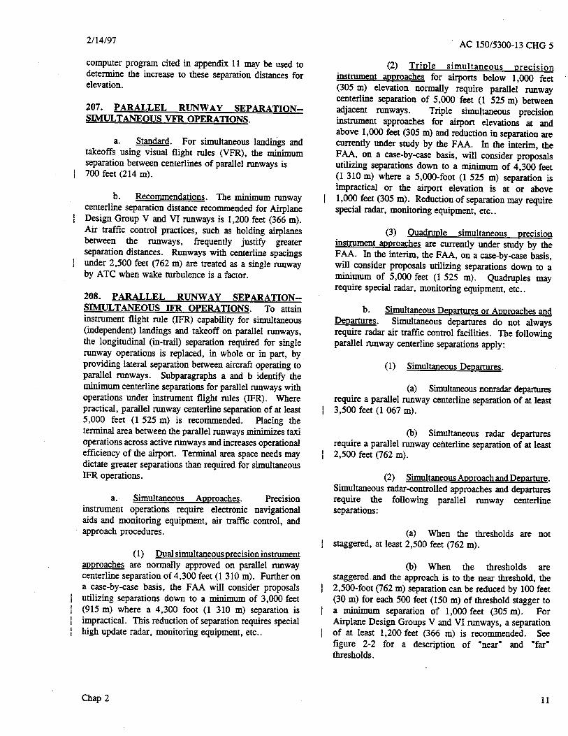

11/1/2008 AC 150/5300-13 CHG 14
Chap 2 13
b. Recommendations. Other objects that are desirable to clear, if practicable, are objects that do not have a substantial adverse effect on the airport but, if removed, will enhance operations. These include objects in the controlled activity area and obstructions to air navigation that are not covered in paragraph 211.a, especially those penetrating an approach surface. On a paved runway, the approach surface starts 200 feet (61 m) beyond the area usable for takeoff or landing, whichever is more demanding. On an unpaved runway, the approach surface starts at the end of the area usable for takeoff or landing.
212. RUNWAY PROTECTION ZONE (RPZ). The RPZ's function is to enhance the protection of people and property on the ground. This is achieved through airport owner control over RPZs. Such control includes clearing RPZ areas (and maintaining them clear) of incompatible objects and activities. Control is preferably exercised through the acquisition of sufficient property interest in the RPZ.
a. Standards.
(1) RPZ Configuration/Location. The RPZ is trapezoidal in shape and centered about the extended runway centerline. The central portion and controlled activity area the two components of the RPZ (see Figure 2-3). The RPZ dimension for a particular runway end is a function of the type of aircraft and approach visibility minimum associated with that runway end. Table 2-4 provides standard dimensions for RPZs. Other than with a special application of declared distances, the RPZ begins 200 feet (60 m) beyond the end of the area usable for takeoff or landing. With a special application of declared distances, see Appendix 14, separate approach and departure RPZs are required for each runway end.
(a) The Central Portion of the RPZ. The central portion of the RPZ extends from the beginning to the end of the RPZ, centered on the runway centerline. Its width is equal to the width of the runway OFA (see Figure 2-3). Paragraph 307 contains the dimensional standards for the OFA.
(b) The Controlled Activity Area. The controlled activity area is the portion of the RPZ to the sides of the central portion of the RPZ.
(2) Land Use. In addition to the criteria specified in paragraph 211, the following land use criteria apply within the RPZ:
(a) While it is desirable to clear all objects from the RPZ, some uses are permitted, provided they do not attract wildlife (see paragraph 202.g., Wildlife Hazards, and Appendix 17 for dimensional standards), are outside of the Runway OFA, and do not interfere with navigational aids. Automobile parking facilities, although discouraged, may be permitted, provided the parking facilities and any associated appurtenances, in addition to meeting all of the preceding conditions, are located outside of the central portion of the RPZ. Fuel storage facilities may not be located in the RPZ.
(b) Land uses prohibited from the RPZ are residences and places of public assembly. (Churches, schools, hospitals, office buildings, shopping centers, and other uses with similar concentrations of persons typify places of public assembly.) Fuel storage facilities may not be located in the RPZ.
b. Recommendations. Where it is determined to be impracticable for the airport owner to acquire and plan the land uses within the entire RPZ, the RPZ land use standards have recommendation status for that portion of the RPZ not controlled by the airport owner.
c. FAA Studies of Objects and Activities in the Vicinity of Airports. The FAA policy is to protect the public investment in the national airport system. To implement this policy, the FAA studies existing and proposed objects and activities, both off and on public-use airports, with respect to their effect upon the safe and efficient use of the airports and safety of persons and property on the ground. These objects need not be obstructions to air navigation, as defined in 14 CFR Part 77. As the result of a study, the FAA may issue an advisory recommendation in opposition to the presence of any off-airport object or activity in the vicinity of a public-use airport that conflicts with an airport planning or design standard or recommendation.
213. RUNWAY HOLDING POSITION (HOLDLINE). At airports with operating airport traffic control towers, runway holding positions (holdlines) identify the location on a taxiway where a pilot is to stop when he/she does not have clearance to proceed onto the runway. At airports without operating control towers, these holdlines identify the location where a pilot should assure there is adequate separation with other aircraft before proceeding onto the runway. The holdline standards, which assume a perpendicular distance from a runway centerline to an intersecting taxiway centerline, are in Tables 2-1 and 2-2. However, these distance standards may need to be longer and placed in such a way to take into account the largest aircraft (tail, body, or wing tip) expected to use the runway from penetrating the Obstacle Free Zone.
214. to 299. RESERVED

AC 150/5300-13 CHG 13 06/19/2008
Chap 2 14
Table 2-1. Runway Separation Standards for aircraft approach categories A & B
AIRPLANE DESIGN GROUP ITEM DIM 1/ I 2/ I II III IV
Visual runways and runways with not lower than ¾-statue mile (1200m) approach visibility minimums Runway Centerline to:
Parallel Runway Centerline
H Refer to paragraphs 207 and 208
Holdline 125ft 7/ 38m
200ft 60m
200ft 60m
200ft 5/ 60m
250ft 75m
Taxiway/Taxilane/ Centerline 3/
D 150ft 45m
225ft 67.5m
240ft 72m
300ft 90m
400ft 120m
Aircraft Parking Area G 125ft 37.5m
200ft 60m
250ft 75m
400ft 120m
500ft 150m
Helicopter Touchdown Pad
Refer to Advisory Circular 150/5390-2
Runways with lower than ¾-statue mile (1200m) approach visibility minimums 4/ Runway Centerline to:
Parallel Runway Centerline
H Refer to paragraphs 207 and 208
Holdline 175ft 7/ 53m
250ft 75m
250ft 75m
250ft 5/ 75m
250ft 6/ 75m
Taxiway/Taxilane/ Centerline 3/
D 200ft 60m
250ft 75m
300ft 90m
350ft 105m
400ft 120m
Aircraft Parking Area G 400ft 120m
400ft 120m
400ft 120m
400ft 120m
500ft 150m
Helicopter Touchdown Pad
Refer to Advisory Circular 150/5390-2
1/ Letters correspond to the dimensions on Figure 2-1.
2/ These dimensional standards pertain to facilities for small airplanes exclusively.
3/ The taxiway/taxilane centerline separation standards are for sea level. At higher elevations, an increase to these separation distances may be required to keep taxiing and holding airplanes clear of the OFZ (refer to paragraph 206).
4/ For approaches with visibility less than ½-statue miles, runway centerline to taxiway/taxilane centerline separation increases to 400 feet (120m).
5/ This distance is increased 1 foot for each 100 feet above 5,100 feet above sea level.
6/ This distance is increased 1 foot for each 100 feet above sea level.
7/ The holdline dimension standards pertains to facilities for small airplanes exclusively, including airplane design groups I & II

12/31/2009 AC 150/5300-13 CHG 15
Table 2-2. Runway Separation Standards for aircraft approach categories C & D7/
AIRPLANE DESIGN GROUP ITEM DIM 1/ I II III IV V VI
Visual runways and runways with not lower than ¾-statue mile (1200m) approach visibility minimums Runway Centerline to:
Parallel Runway Centerline
H Refer to paragraphs 207 and 208
Holdline 250ft 75m
250ft 75m
250ft 75m
250ft 75m
250ft 6/ 75m
280ft 6/ 85m
Taxiway/Taxilane/ Centerline 2/
D 300ft 90m
300ft 90m
400ft 120m
400ft 120m
3/ 3/
500ft 150m
Aircraft Parking Area
G 400ft 120m
400ft 120m
500ft 150m
500ft 150m
500ft 150m
500ft 150m
Helicopter Touchdown Pad
Refer to Advisory Circular 150/5390-2
Runways with lower than ¾-statue mile (1200m) approach visibility minimums Runway Centerline to:
Parallel Runway Centerline
H Refer to paragraphs 207 and 208
Holdline 250ft 75m
250ft 75m
250ft 75m
250ft 6/ 75m
280ft 6/ 85m
280ft 6/ 85m
Taxiway/Taxilane/ Centerline 2/
D 400ft 120m
400ft 120m
400ft 120m
400ft 120m
3/ 4/ 3/ 4/
5/ 5/
Aircraft Parking Area
G 500ft 150m
500ft 150m
500ft 150m
500ft 150m
500ft 150m
500ft 150m
Helicopter Touchdown Pad
Refer to Advisory Circular 150/5390-2
1/ Letters correspond to the dimensions on Figure 2-1.
2/ The taxiway/taxilane centerline separation standards are for sea level. At higher elevations, an increase to these separation distances may be required to keep taxiing and holding airplanes clear of the OFZ (refer to paragraph 206).
3/ For Airplane Design Group V, the standard runway centerline to parallel taxiway centerline separation distance is 400ft (120m) for airports at or below an elevation of 1,345feet (410m); 450feet (135m) for airports between elevations for 1,345 feet (410m) and 6,560 feet (2,000m); and 500 feet (150m) for airports above an elevation of 6,560 feet (2,000m).
4/ For approaches with visibility less than ½-statue mile, the separation distance increases to 500 feet (150m) plus required OFZ elevation adjustment.
5/ For approaches with visibility down to ½-statue mile, the separation distance increases to 500 feet (150m) plus elevation adjustment. For approaches with visibility less than ½-statue mile, the separation distance increases to 550 feet (168m) plus required OFZ elevation adjustment.
6/ For aircraft approach category C, the distance is increased 1 foot for each 100 feet above sea level.
7/ For all airplane design groups that are aircraft approach category D, all distances for all Items in Table 2-2 increase 1 foot for each 100 feet above sea level.
Chap 2 15
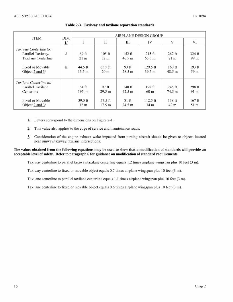
AC 150/5300-13 CHG 4 11/10/94
Chap 2 16
Table 2-3. Taxiway and taxilane separation standards
AIRPLANE DESIGN GROUP ITEM
DIM
1/ I II III IV V VI
Taxiway Centerline to: Parallel Taxiway/ Taxilane Centerline
J
69 ft 21 m
105 ft 32 m
152 ft 46.5 m
215 ft 65.5 m
267 ft 81 m
324 ft 99 m
Fixed or Movable Object 2 and 3/
K 44.5 ft 13.5 m
65.5 ft 20 m
93 ft 28.5 m
129.5 ft 39.5 m
160 ft 48.5 m
193 ft 59 m
Taxilane Centerline to: Parallel Taxilane Centerline
64 ft
195. m
97 ft
29.5 m
140 ft 42.5 m
198 ft 60 m
245 ft 74.5 m
298 ft 91 m
Fixed or Movable Object 2 and 3/
39.5 ft 12 m
57.5 ft 17.5 m
81 ft 24.5 m
112.5 ft 34 m
138 ft 42 m
167 ft 51 m
1/ Letters correspond to the dimensions on Figure 2-1.
2/ This value also applies to the edge of service and maintenance roads.
3/ Consideration of the engine exhaust wake impacted from turning aircraft should be given to objects located near runway/taxiway/taxilane intersections.
The values obtained from the following equations may be used to show that a modification of standards will provide an acceptable level of safety. Refer to paragraph 6 for guidance on modification of standard requirements.
Taxiway centerline to parallel taxiway/taxilane centerline equals 1.2 times airplane wingspan plus 10 feet (3 m).
Taxiway centerline to fixed or movable object equals 0.7 times airplane wingspan plus 10 feet (3 m).
Taxilane centerline to parallel taxilane centerline equals 1.1 times airplane wingspan plus 10 feet (3 m).
Taxilane centerline to fixed or movable object equals 0.6 times airplane wingspan plus 10 feet (3 m).


11/10/94 AC 150/5300-13 CHG 4
Chap 2
19
1/ The RPZ dimensional standards are for the runway end with the specified approach visibility minimums. The departure RPZ dimensional standards are equal to or less than the approach RPZ dimensional standards. When a RPZ begins other than 200 feet (60 m) beyond the runway end, separate approach and departure RPZs should be provided. Refer to Appendix 14 for approach and departure RPZs.
Table 2-4. Runway protection zone (RPZ) dimensions
Approach
Visibility
Minimums 1/
Facilities
Expected
To Serve
Dimensions
Length
L
Feet
Inner
Width
W1 feet
Outer
Width
W2 feet
RPZ
acres
(meters) (meters) (meters)
Visual
And
Not lower than
1-Mile (1 600 m)
Small
Aircraft
Exclusively
1,000
(300)
250
(75)
450
(135) 8.035
Aircraft
Approach
Categories
A & B
1,000
(300)
500
(150)
700
(210) 13.770
Aircraft
Approach
Categories
C & D
1,700
(510)
500
(150)
1,010
(303) 29.465
Not lower than
¾-Mile (1 200 m)
All
Aircraft
1,700
(510)
1,000
(300)
1,510
(453) 48.978
Lower than
¾-Mile (1 200 m)
All
Aircraft
2,500
(750)
1,000
(300)
1,750
(525) 78.914

AC 150/5300-13 CHG 12 1/3/08
Chap 2 20
CEN
TRA
L PO
RTI
ON
OF
THE
RPZ
NOTE: 1. See Table 2-4 for dimension
W1, W2, L 2. See Tables 3-1 through 3-3
for dimensions R, Q
Figure 2-3. Runway protection zone

10/1/02 AC 150/5300-13 CHG 7
Chap 3
21
Chapter 3. RUNWAY DESIGN300. INTRODUCTION. This chapter presents standards for runways and runway associated elements such as shoulders, blast pads, runway safety areas, obstacle free zones (OFZ), object free areas (OFA), clearways, and stopways. Tables 3-1, 3-2, and 3-3 present the standard widths and lengths for runway and runway-associated elements. Also included are design standards and recommendations for rescue and firefighting access roads. At new airports, the RSA and ROFA lengths and the RPZ location standards are tied to runway ends. At existing constrained airports, these criteria may, on a case-by-case basis, be applied with respect to declared distances ends. See appendix 14. 301. RUNWAY LENGTH. AC 150/5325-4 and airplane flight manuals provide guidance on runway lengths for airport design, including declared distance lengths. The computer program cited in appendix 11 may be used to determine the recommended runway length for airport design. 302. RUNWAY WIDTH. Tables 3-1, 3-2, and 3-3 present runway width standards that consider operations conducted during reduced visibility. 303. RUNWAY SHOULDERS. Runway shoulders provide resistance to blast erosion and accommodate the passage of maintenance and emergency equipment and the occasional passage of an airplane veering from the runway. Tables 3-1, 3-2, and 3-3 present runway shoulder width standards. A natural surface, e.g., turf, normally reduces the possibility of soil erosion and engine ingestion of foreign objects. Soil with turf not suitable for this purpose requires a stabilized or low cost paved surface. Refer to chapter 8 for further discussion. Figure 3-1 depicts runway shoulders. 304. RUNWAY BLAST PAD. Runway blast pads provide blast erosion protection beyond runway ends. Tables 3-1, 3-2, and 3-3 contain the standard length and width for blast pads for takeoff operations requiring blast erosion control. Refer to chapter 8 for further discussion. Figure 3-1 depicts runway blast pads. 305. RUNWAY SAFETY AREA (RSA). The runway safety area is centered on the runway centerline. Tables 3-1, 3-2, and 3-3 present runway safety area dimensional standards. Figure 3-1 depicts the runway safety area. Appendix 8 discusses the runway safety area's evolution.
a. Design Standards. The runway safety area shall be: (1) cleared and graded and have no potentially hazardous ruts, humps, depressions, or other surface variations; (2) drained by grading or storm sewers to prevent water accumulation; (3) capable, under dry conditions, of supporting snow removal equipment, aircraft rescue and firefighting equipment, and the occasional passage of aircraft without causing structural damage to the aircraft; and (4) free of objects, except for objects that need to be located in the runway safety area because of their function. Objects higher than 3 inches (7.6 cm) above grade should be constructed, to the extent practicable, on low impact resistant supports (frangible mounted structures) of the lowest practical height with the frangible point no higher than 3 inches (7.6 cm) above grade. Other objects, such as manholes, should be constructed at grade. In no case should their height exceed 3 inches (7.6 cm) above grade. b. Construction Standards. Compaction of runway safety areas shall be to FAA specification P-152 found in AC 150/5370-10. c. Sub-standard RSAs. RSA standards cannot be modified or waived like other airport design standards. The dimensional standards remain in effect regardless of the presence of natural or man-made objects or surface conditions that might create a hazard to aircraft that leave the runway surface. Facilities, including NAVAIDs, that would not normally be permitted in an RSA should not be installed inside the standard RSA dimensions even when the RSA does not meet standards in other respects. A continuous evaluation of all practicable alternatives for improving each sub-standard RSA is required until it meets all standards for grade, compaction, and object frangibility. FAA Order 5200.8, Runway Safety Area Program, explains the process for conducting this evaluation. Each FAA regional Airports division manager has a written determination of the best practicable alternative(s) for improving each RSA. Therefore, runway and RSA improvement projects must comply with the determination of the FAA regional Airports division manager.

AC 150/5300-13 CHG 8 9/30/04
Chap 3 22
d. Threshold Displacement. Incremental improvements that involve the displacement of a landing threshold need to be carefully planned so that they do not incur unnecessary costs or create situations that could compromise operational safety.
(1) Runway thresholds that are displaced temporarily pending the planned relocation of objects (such as Localizer antennas) should consider the extra costs associated with re-arranging the runway lights, approach lights and navigational aids.
(2) The displacement of a threshold that does not also include relocation of the lead-in taxiway can create an undesirable and confusing operating environment for the pilot. (See paragraph 204.)
e. Allowance for Navigational Aids. The RSA is intended to enhance the margin of safety for landing or departing aircraft. Accordingly, the design of an RSA must account for navigational aids that might impact the effectiveness of the RSA:
(1) RSA grades sometimes require approach lights to be mounted on massive towers that could create a hazard for aircraft. Therefore, consider any practicable RSA construction to a less demanding grade than the standard grade to avoid the need for massive structures.
(2) Instrument landing system (ILS) facilities (glide slopes and localizers) are not usually required to be located inside the RSA. However, they do require a graded area around the antenna. (See chapter 6 for more information on the siting of ILS facilities.) RSA construction that ends abruptly in a precipitous drop-off can result in design proposals where the facility is located inside the RSA. Therefore, consider any practicable RSA construction beyond the standard dimensions that could accommodate ILS facilities if and when they are installed.
306. OBSTACLE FREE ZONE (OFZ). The OFZ clearing standard precludes taxiing and parked airplanes and object penetrations, except for frangible visual NAVAIDs that need to be located in the OFZ because of their function. The runway OFZ and, when applicable, the precision OFZ, the inner-approach OFZ, and the inner-transitional OFZ comprise the obstacle free zone (OFZ). Figures 3-2, 3-3, 3-4, 3-5,and 3-6 show the OFZ.
a. Runway OFZ (ROFZ). The runway OFZ is a defined volume of airspace centered above the runway centerline. The runway OFZ is the airspace above a surface whose elevation at any point is the same as the elevation of the nearest point on the runway centerline. The runway OFZ extends 200 feet (60 m) beyond each end of the runway. Its width is as follows:
(1) For runways serving small airplanes exclusively:
(a) 300 feet (90 m) for runways with lower than 3/4-statute mile (1 200 m) approach visibility minimums.
(b) 250 feet (75 m) for other runways serving small airplanes with approach speeds of 50 knots or more.
(c) 120 feet (36 m) for other runways serving small airplanes with approach speeds of less than 50 knots.
(2) For runways serving large airplanes, 400 feet (120 m).
b. Inner-approach OFZ. The inner-approach OFZ is a defined volume of airspace centered on the approach area. It applies only to runways with an approach lighting system. The inner-approach OFZ begins 200 feet (60 m) from the runway threshold at the same elevation as the runway threshold and extends 200 feet (60 m) beyond the last light unit in the approach lighting system. Its width is the same as the runway OFZ and rises at a slope of 50 (horizontal) to 1 (vertical) from its beginning.
c. Inner-transitional OFZ. The inner-transitional OFZ is a defined volume of airspace along the sides of the runway OFZ and inner-approach OFZ. It applies only to runways with lower than 3/4-statute mile (1 200 m) approach visibility minimums.
(1) For runways serving small airplanes exclusively, the inner-transitional OFZ slopes 3 (horizontal) to 1 (vertical) out from the edges of the runway OFZ and inner-approach OFZ to a height of 150 feet (45 m) above the established airport elevation.
(2) For runways serving large airplanes, separate inner-transitional OFZ criteria apply for Category (CAT) I and CAT II/III runways.
(a) For CAT I runways, the inner-transitional OFZ begins at the edges of the runway OFZ and inner-approach OFZ, then rises vertically for a height "H", and then slopes 6 (horizontal) to 1 (vertical) out to a height of 150 feet (45 m) above the established airport elevation.
1) In U.S. customary units,
Hfeet = 61 - 0.094(Sfeet) - 0.003(Efeet).
2) In SI units,
Hmeters = 18.4 - 0.094(Smeters) - 0.003(Emeters).
3) S is equal to the most demanding wingspan of the airplanes using the runway and E is equal to the runway threshold elevation above sea level.
(b) For CAT II/III runways, the inner-transitional OFZ begins at the edges of the runway OFZ and inner-approach OFZ, then rises vertically for a height "H", then slopes 5 (horizontal) to 1 (vertical) out to a

9/30/04 AC 150/5300-13 CHG 8
Chap 3
23
distance "Y" from runway centerline, and then slopes 6 (horizontal) to 1 (vertical) out to a height of 150 feet (45 m) above the established airport elevation.
1) In U.S. customary units,
Hfeet = 53 - 0.13(Sfeet) - 0.0022(Efeet) and distance
Yfeet = 440 + 1.08(Sfeet) - 0.024(Efeet).
2) In SI units,
Hmeters = 16 - 0.13(Smeters)- 0.0022(Emeters) and distance
Ymeters = 132 + 1.08(Smeters) - 0.024(Emeters).
3) S is equal to the most demanding wingspan of the airplanes using the runway and E is equal to the runway threshold elevation above sea level. Beyond the distance "Y" from runway centerline the inner-transitional CAT II/III OFZ surface is identical to that for the CAT I OFZ.
d. Precision OFZ. The Precision Obstacle Free Zone (POFZ) is defined as a volume of airspace above an area beginning at the runway threshold, at the threshold elevation, and centered on the extended runway centerline, 200 feet (60m) long by 800 feet (240m) wide. See figure 3-6.
The surface is in effect only when all of the following operational conditions are met:
(1) Vertically guided approach
(2) Reported ceiling below 250 feet and/or visibility less than ¾ statute mile (or RVR below 4000 feet)
(3) An aircraft on final approach within two (2) miles of the runway threshold.
When the POFZ is in effect, a wing of an aircraft holding on a taxiway waiting for runway clearance may penetrate the POFZ; however neither the fuselage nor the tail may infringe on the POFZ.
The POFZ is applicable at all runway ends including displaced thresholds.
Note: POFZ takes effect no later than January 1, 2007 for all runway ends at which it applies.
307. OBJECT FREE AREA. The runway object free area (OFA) is centered on the runway centerline. The runway OFA clearing standard requires clearing the OFA of above ground objects protruding above the runway safety area edge elevation. Except where precluded by other clearing standards, it is acceptable to place objects that need to be located in the OFA for air navigation or aircraft ground maneuvering purposes and to taxi and hold aircraft in the OFA. Objects non-essential for air navigation or aircraft ground maneuvering purposes are not to be placed in the OFA. This includes parked airplanes
and agricultural operations. Tables 3-1, 3-2, and 3-3 specify the standard dimensions of the runway OFA. Extension of the OFA beyond the standard length to the maximum extent feasible is encouraged. See figure 2-3.
308. CLEARWAY STANDARDS. The clearway (See figure 3-7) is a clearly defined area connected to and extending beyond the runway end available for completion of the takeoff operation of turbine-powered airplanes. A clearway increases the allowable airplane operating takeoff weight without increasing runway length.
a. Dimensions. The clearway must be at least 500 feet (150 m) wide centered on the runway centerline. The practical limit for clearway length is 1,000 feet (300 m).
b. Clearway Plane Slope. The clearway plane slopes upward with a slope not greater than 1.25 percent.
c. Clearing. Except for threshold lights no higher than 26 inches (66 cm) and located off the runway sides, no object or terrain may protrude through the clearway plane. The area over which the clearway lies need not be suitable for stopping aircraft in the event of an aborted takeoff.
d. Control. An airport owner interested in providing a clearway should be aware of the requirement that the clearway be under its control, although not necessarily by direct ownership. The purpose of such control is to ensure that no fixed or movable object penetrates the clearway plane during a takeoff operation.
e. Notification. When a clearway is provided, the clearway length and the declared distances, as specified in appendix 14, paragraph 7, shall be provided in the Airport/Facility Directory (and in the Aeronautical Information Publication (AIP), for international airports) for each operational direction.
309. STOPWAY STANDARDS. A stopway is an area beyond the takeoff runway, centered on the extended runway centerline, and designated by the airport owner for use in decelerating an airplane during an aborted takeoff. It must be at least as wide as the runway and able to support an airplane during an aborted takeoff without causing structural damage to the airplane. Their limited use and high construction cost, when compared to a full-strength runway that is usable in both directions, makes their construction less cost effective. See figure 3-8. When a stopway is provided, the stopway length and the declared distances, as specified in appendix 14, paragraph 7, shall be provided in the Airport/Facility Directory (and in the Aeronautical Information Publication for international airports) for each operational direction.

AC 150/5300-13 CHG 10 9/29/06
Chap 3 24
310. RESCUE AND FIREFIGHTING ACCESS. Rescue and firefighting access roads are normally needed to provide unimpeded two-way access for rescue and firefighting equipment to potential accident areas. Connecting these access roads, to the extent practical, with the operational surfaces and other roads will facilitate aircraft rescue and firefighting operations.
a. Recommendation. It is recommended that the entire runway safety area (RSA) and runway protection zone (RPZ) be accessible to rescue and firefighting vehicles so that no part of the RSA or RPZ is more than 330 feet (100 m) from either an all weather road or a paved operational surface. Where an airport is adjacent to a body of water, it is recommended that boat launch ramps with appropriate access roads be provided.
b. All Weather Capability. Rescue and firefighting access roads are all weather roads designed to
support rescue and firefighting equipment traveling at normal response speeds. Establish the widths of the access roads on a case-by-case basis considering the type(s) of rescue and firefighting equipment available and planned at the airport. The first 300 feet (90 m) adjacent to a paved operational surface should be paved. Where an access road crosses a safety area, the safety area standards for smoothness and grading control. For other design and construction features, use local highway specifications.
c. Road Usage. Rescue and firefighting access roads are special purpose roads that supplement but do not duplicate or replace sections of a multi-purpose road system. Restricting their use to rescue and firefighting access equipment precludes their being a hazard to air navigation.
311. to 399. RESERVED.

1/3/08 AC 150/5300-13 CHG 12
Chap 3 25
Table 3-1. Runway design standards for aircraft approach category A & B visual runways and runways with not lower than 3/4-statute mile (1,200 m) approach visibility minimums
(Refer also to Appendix 16 for the establishment of new approaches)
AIRPLANE DESIGN GROUP ITEM DIM
1/ I 2/ I II III IV
Runway Length A - Refer to paragraph 301 -
Runway Width B 60 ft 60 ft 75 ft 100 ft 150 ft
18 m 18 m 23 m 30 m 45 m
Runway Shoulder Width 10 ft 10 ft 10 ft 20 ft 25 ft
3 m 3 m 3 m 6 m 7.5 m
Runway Blast Pad Width 80 ft 80 ft 95 ft 140 ft 200 ft
24 m 24 m 29 m 42 m 60 m
Runway Blast Pad Length 60 ft 100 ft 150 ft 200 ft 200 ft
18 m 30 m 45 m 60 m 60 m
Runway Safety Area Width C 120 ft 120 ft 150 ft 300 ft 500 ft
36 m 36 m 45 m 90 m 150 m
240 ft 240 ft 300 ft 600 ft 600 ft Runway Safety Area Length Prior to Landing Threshold 3/, 4/ 72 m 72 m 90 m 180 m 180 m
P 240 ft 240 ft 300 ft 600 ft 1,000 ft Runway Safety Area Length Beyond RW End 3/, 4/ 72 m 72 m 90 m 180 m 300 m
Obstacle Free Zone Width and Length
- Refer to paragraph 306 -
Q 250 ft 400 ft 500 ft 800 ft 800 ft Runway Object Free Area Width 75 m 120 m 150 m 240 m 240 m
R 240 ft 240 ft 300 ft 600 ft 1,000 ft Runway Object Free Area Length Beyond RW End 5/ 72 m 72 m 90 m 180 m 300 m
1/ Letters correspond to the dimensions on figures 2-1 and 2-3. Use this table only when both ends of the runway
provide not lower than ¾-statute mile approach visibility minimums. 2/ These dimensional standards pertain to facilities for small airplanes exclusively. 3/ The runway safety area (RSA) length begins at each runway end when a stopway is not provided. When a stopway
is provided, the length begins at the stopway end. 4/ The standard RSA length beyond the runway end may be reduced to the standard RSA length prior to landing
threshold if a standard Engineered Materials Arresting System (EMAS) is provided. To qualify for this reduction, the EMAS installation must provide the ability to stop the critical aircraft exiting the end of the runway at 70 knots, and the runway must provide either instrument or visual vertical guidance for approaches in the opposite direction. See AC 150/5220-22.
5/ The runway object free area length beyond the end of the runway never exceeds the standard RSA length beyond the runway end as provided by note 4 above.

AC 150/5300-13 CHG 12 1/3/08
Chap 3 26
Table 3-2. Runway design standards for aircraft approach category A & B runways with lower than 3/4-statute mile (1,200 m) approach visibility minimums
(Refer also to Appendix 16 for the establishment of new approaches)
AIRPLANE DESIGN GROUP ITEM DIM
1/ I 2/ I II III IV
Runway Length A - Refer to paragraph 301 -
Runway Width B 75 ft 100 ft 100 ft 100 ft 150 ft
23 m 30 m 30 m 30 m 45 m
Runway Shoulder Width 10 ft 10 ft 10 ft 20 ft 25 ft
3 m 3 m 3 m 6 m 7.5 m
Runway Blast Pad Width 95 ft 120 ft 120 ft 140 ft 200 ft
29 m 36 m 36 m 42 m 60 m
Runway Blast Pad Length 60 ft 100 ft 150 ft 200 ft 200 ft
18 m 30 m 45 m 60 m 60 m
Runway Safety Area Width C 300 ft 300 ft 300 ft 400 ft 500 ft
90 m 90 m 90 m 120 m 150 m
600 ft 600 ft 600 ft 600 ft 600 ft Runway Safety Area Length Prior to Landing Threshold 3/, 4/ 180 m 180 m 180 m 180 m 180 m
P 600 ft 600 ft 600 ft 800 ft 1,000 ft Runway Safety Area Length Beyond RW End 3/ 180 m 180 m 180 m 240 m 300 m
Obstacle Free Zone Width and Length
- Refer to paragraph 306 -
Q 800 ft 800 ft 800 ft 800 ft 800 ft Runway Object Free Area Width 240 m 240 m 240 m 240 m 240 m
R 600 ft 600 ft 600 ft 800 ft 1,000 ft Runway Object Free Area Length Beyond RW End 5/ 180 m 180 m 180 m 240 m 300 m
1/ Letters correspond to the dimensions on figures 2-1 and 2-3. Use this table for both ends of the runway even when
one end does not have lower than ¾-statute mile visibility minimums. 2/ These dimensional standards pertain to facilities for small airplanes exclusively. 3/ The runway safety area (RSA) length begins at each runway end when a stopway is not provided. When a stopway
is provided, the length begins at the stopway end. 4/ The standard RSA length beyond the runway end may be reduced to the standard RSA length prior to landing
threshold if a standard Engineered Materials Arresting System (EMAS) is provided. To qualify for this reduction, the EMAS installation must provide the ability to stop the critical aircraft exiting the end of the runway at 70 knots, and the runway must provide either instrument or visual vertical guidance for approaches in the opposite direction. See AC 150/5220-22.
5/ The runway object free area length beyond the end of the runway never exceeds the standard RSA length beyond the runway end as provided by note 4 above.

1/3/08 AC 150/5300-13 CHG 12
Chap 3 26-1
Table 3-3. Runway design standards for aircraft approach categories C & D (Refer also to Appendix 16 for the establishment of new approaches)
AIRPLANE DESIGN GROUP
ITEM DIM 1/
I II III IV V VI Runway Length A - Refer to paragraph 301 - Runway Width B 100 ft 100 ft 100 ft
2/ 150 ft 150 ft 200 ft
30 m 30 m 30 m 2/ 45 m 45 m 60 m
Runway Shoulder Width 3/ 10 ft 10 ft 20 ft 2/ 25 ft 35 ft 40 ft
3 m 3 m 6 m 2/ 7.5 m 10.5 m 12 m
Runway Blast Pad Width 120 ft 120 ft 140 ft 2/
200 ft 220 ft 280 ft
36 m 36 m 42 m 2/ 60 m 66 m 84 m
Runway Blast Pad Length 100 ft 150 ft 200 ft 200 ft 400 ft 400 ft
30 m 45 m 60 m 60 m 120 m 120 m
Runway Safety Area Width 4/ C 500 ft 500 ft 500 ft 500 ft 500 ft 500 ft
150 m 150 m 150 m 150 m 150 m 150 m
600 ft 600 ft 600 ft 600 ft 600 ft 600 ft Runway Safety Area Length Prior to Landing Threshold 5/, 6/
180 m 180 m 180 m 180 m 180 m 180 m
P 1,000 ft
1,000 ft
1,000 ft 1,000 ft
1,000 ft
1,000 ft
Runway Safety Area Length Beyond RW End 5/, 6/
300 m 300 m 300 m 300 m 300 m 300 m
Obstacle Free Zone Width and Length - Refer to paragraph 306 -
Runway Object Free Area Width Q 800 ft 800 ft 800 ft 800 ft 800 ft 800 ft
240 m 240 m 240 m 240 m 240 m 240 m
R 1,000 ft
1,000 ft
1,000 ft 1,000 ft
1,000 ft
1,000 ft
Runway Object Free Area Length Beyond RW End 7/
300 m 300 m 300 m 300 m 300 m 300 m
1/ Letters correspond to the dimensions on figures 2-1 and 2-3. 2/ For Airplane Design Group III serving airplanes with maximum certificated takeoff weight greater than 150,000 pounds
(68,100 kg), the standard runway width is 150 feet (45 m), the shoulder width is 25 feet (7.5 m), and the runway blast pad width is 200 feet (60 m).
3/ Design Groups V and VI normally require stabilized or paved shoulder surfaces. 4/ For Airport Reference Code C-I and C-II, a runway safety area width of 400 feet (120 m) is permissible. 5/ The runway safety area (RSA) length begins at each runway end when a stopway is not provided. When a stopway is
provided, the length begins at the stopway end. 6/ The standard RSA length beyond the runway end may be reduced to the standard RSA length prior to landing threshold if a
standard Engineered Materials Arresting System (EMAS) is provided. To qualify for this reduction, the EMAS installation must provide the ability to stop the critical aircraft exiting the end of the runway at 70 knots, and the runway must provide either instrument or visual vertical guidance for approaches in the opposite direction. See AC 150/5220-22.
7/ The runway object free area length beyond the end of the runway never exceeds the standard RSA length beyond the runway end as provided by note 6 above.

AC 150/5300-13 CHG 10 9/29/06
26-2 Chap 3
This page intentionally left blank


11/10/94 AC 150/5300-13 CHG 4
31
THE VERTICAL SCALE IS EXPANDED.
HORIZONTAL SURFACE150 FEET ( 45 M ) ABOVE AIRPORT ELEVATION
SECTION B-B
INNER TRANSITIONAL OFZ
SECTION A-A
RUNWAY OFZ
B
B
A A
RUNWAY END WITH ANAPPROACH LIGHT SYSTEM
FIGURE 3-5. OBSTACLE FREE ZONE (OFZ) FOR RUNWAYS SERVING LARGE AIRPLANES WITH
50:1
RUNWAY END WITHOUT ANAPPROACH LIGHT SYSTEM
INNER-TRANSITIONAL OFZ INNER-TRANSITIONAL OFZ
INNER-TRANSITIONAL OFZ INNER-TRANSITIONAL OFZ
RUNWAY OFZ
REFER TO PARAGRAPH 306
DISPLACED THRESHOLDINNER-APPROACH OFZ
DISPLACED THRESHOLD
H
LOWER THAN 3/4-STATUTE MILE (1 200 M) APPROACH VISIBILITY MINMUMS AND DISPLACED THRESHOLD

AC 150/5300-13 CHG 8 9/30/04
32
Figure 3-6. Precision Obstacle Free Zone

9/30/00 AC 150/5300-13 CHG 6
32-1 (and 32-2)
Figure 3-7. Clearway
Figure 3-8. Stopway

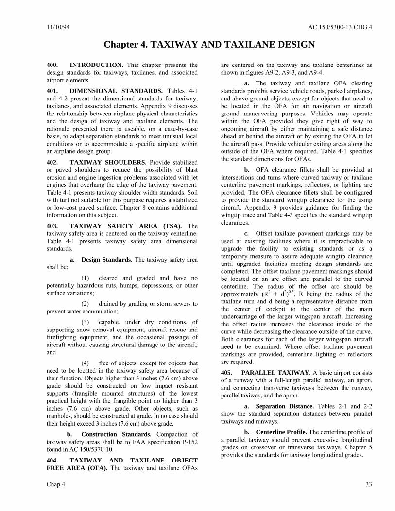
11/10/94 AC 150/5300-13 CHG 4
Chap 4 33
Chapter 4. TAXIWAY AND TAXILANE DESIGN 400. INTRODUCTION. This chapter presents the design standards for taxiways, taxilanes, and associated airport elements.
401. DIMENSIONAL STANDARDS. Tables 4-1 and 4-2 present the dimensional standards for taxiway, taxilanes, and associated elements. Appendix 9 discusses the relationship between airplane physical characteristics and the design of taxiway and taxilane elements. The rationale presented there is useable, on a case-by-case basis, to adapt separation standards to meet unusual local conditions or to accommodate a specific airplane within an airplane design group.
402. TAXIWAY SHOULDERS. Provide stabilized or paved shoulders to reduce the possibility of blast erosion and engine ingestion problems associated with jet engines that overhang the edge of the taxiway pavement. Table 4-1 presents taxiway shoulder width standards. Soil with turf not suitable for this purpose requires a stabilized or low-cost paved surface. Chapter 8 contains additional information on this subject.
403. TAXIWAY SAFETY AREA (TSA). The taxiway safety area is centered on the taxiway centerline. Table 4-1 presents taxiway safety area dimensional standards.
a. Design Standards. The taxiway safety area shall be:
(1) cleared and graded and have no potentially hazardous ruts, humps, depressions, or other surface variations;
(2) drained by grading or storm sewers to prevent water accumulation;
(3) capable, under dry conditions, of supporting snow removal equipment, aircraft rescue and firefighting equipment, and the occasional passage of aircraft without causing structural damage to the aircraft, and
(4) free of objects, except for objects that need to be located in the taxiway safety area because of their function. Objects higher than 3 inches (7.6 cm) above grade should be constructed on low impact resistant supports (frangible mounted structures) of the lowest practical height with the frangible point no higher than 3 inches (7.6 cm) above grade. Other objects, such as manholes, should be constructed at grade. In no case should their height exceed 3 inches (7.6 cm) above grade.
b. Construction Standards. Compaction of taxiway safety areas shall be to FAA specification P-152 found in AC 150/5370-10.
404. TAXIWAY AND TAXILANE OBJECT FREE AREA (OFA). The taxiway and taxilane OFAs
are centered on the taxiway and taxilane centerlines as shown in figures A9-2, A9-3, and A9-4.
a. The taxiway and taxilane OFA clearing standards prohibit service vehicle roads, parked airplanes, and above ground objects, except for objects that need to be located in the OFA for air navigation or aircraft ground maneuvering purposes. Vehicles may operate within the OFA provided they give right of way to oncoming aircraft by either maintaining a safe distance ahead or behind the aircraft or by exiting the OFA to let the aircraft pass. Provide vehicular exiting areas along the outside of the OFA where required. Table 4-1 specifies the standard dimensions for OFAs.
b. OFA clearance fillets shall be provided at intersections and turns where curved taxiway or taxilane centerline pavement markings, reflectors, or lighting are provided. The OFA clearance fillets shall be configured to provide the standard wingtip clearance for the using aircraft. Appendix 9 provides guidance for finding the wingtip trace and Table 4-3 specifies the standard wingtip clearances.
c. Offset taxilane pavement markings may be used at existing facilities where it is impracticable to upgrade the facility to existing standards or as a temporary measure to assure adequate wingtip clearance until upgraded facilities meeting design standards are completed. The offset taxilane pavement markings should be located on an arc offset and parallel to the curved centerline. The radius of the offset arc should be approximately (R2 + d2)0.5. R being the radius of the taxilane turn and d being a representative distance from the center of cockpit to the center of the main undercarriage of the larger wingspan aircraft. Increasing the offset radius increases the clearance inside of the curve while decreasing the clearance outside of the curve. Both clearances for each of the larger wingspan aircraft need to be examined. Where offset taxilane pavement markings are provided, centerline lighting or reflectors are required.
405. PARALLEL TAXIWAY. A basic airport consists of a runway with a full-length parallel taxiway, an apron, and connecting transverse taxiways between the runway, parallel taxiway, and the apron.
a. Separation Distance. Tables 2-1 and 2-2 show the standard separation distances between parallel taxiways and runways.
b. Centerline Profile. The centerline profile of a parallel taxiway should prevent excessive longitudinal grades on crossover or transverse taxiways. Chapter 5 provides the standards for taxiway longitudinal grades.
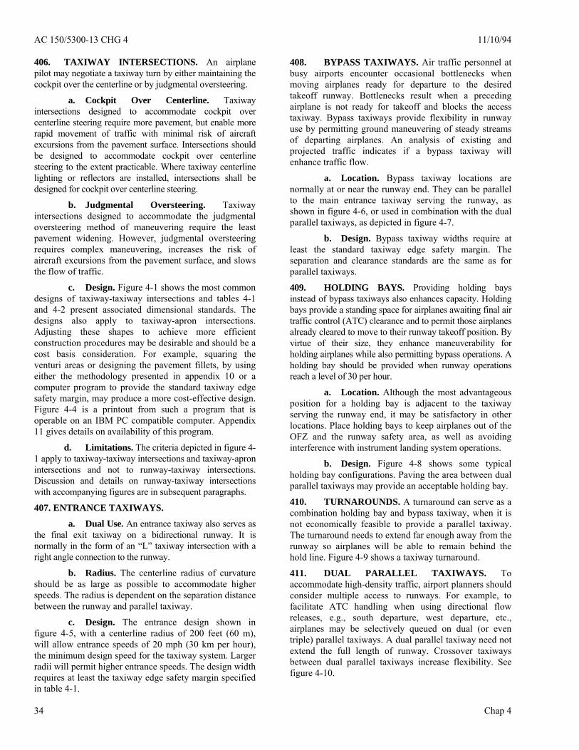
AC 150/5300-13 CHG 4 11/10/94
Chap 4 34
406. TAXIWAY INTERSECTIONS. An airplane pilot may negotiate a taxiway turn by either maintaining the cockpit over the centerline or by judgmental oversteering.
a. Cockpit Over Centerline. Taxiway intersections designed to accommodate cockpit over centerline steering require more pavement, but enable more rapid movement of traffic with minimal risk of aircraft excursions from the pavement surface. Intersections should be designed to accommodate cockpit over centerline steering to the extent practicable. Where taxiway centerline lighting or reflectors are installed, intersections shall be designed for cockpit over centerline steering.
b. Judgmental Oversteering. Taxiway intersections designed to accommodate the judgmental oversteering method of maneuvering require the least pavement widening. However, judgmental oversteering requires complex maneuvering, increases the risk of aircraft excursions from the pavement surface, and slows the flow of traffic.
c. Design. Figure 4-1 shows the most common designs of taxiway-taxiway intersections and tables 4-1 and 4-2 present associated dimensional standards. The designs also apply to taxiway-apron intersections. Adjusting these shapes to achieve more efficient construction procedures may be desirable and should be a cost basis consideration. For example, squaring the venturi areas or designing the pavement fillets, by using either the methodology presented in appendix 10 or a computer program to provide the standard taxiway edge safety margin, may produce a more cost-effective design. Figure 4-4 is a printout from such a program that is operable on an IBM PC compatible computer. Appendix 11 gives details on availability of this program.
d. Limitations. The criteria depicted in figure 4-1 apply to taxiway-taxiway intersections and taxiway-apron intersections and not to runway-taxiway intersections. Discussion and details on runway-taxiway intersections with accompanying figures are in subsequent paragraphs.
407. ENTRANCE TAXIWAYS.
a. Dual Use. An entrance taxiway also serves as the final exit taxiway on a bidirectional runway. It is normally in the form of an “L” taxiway intersection with a right angle connection to the runway.
b. Radius. The centerline radius of curvature should be as large as possible to accommodate higher speeds. The radius is dependent on the separation distance between the runway and parallel taxiway.
c. Design. The entrance design shown in figure 4-5, with a centerline radius of 200 feet (60 m), will allow entrance speeds of 20 mph (30 km per hour), the minimum design speed for the taxiway system. Larger radii will permit higher entrance speeds. The design width requires at least the taxiway edge safety margin specified in table 4-1.
408. BYPASS TAXIWAYS. Air traffic personnel at busy airports encounter occasional bottlenecks when moving airplanes ready for departure to the desired takeoff runway. Bottlenecks result when a preceding airplane is not ready for takeoff and blocks the access taxiway. Bypass taxiways provide flexibility in runway use by permitting ground maneuvering of steady streams of departing airplanes. An analysis of existing and projected traffic indicates if a bypass taxiway will enhance traffic flow.
a. Location. Bypass taxiway locations are normally at or near the runway end. They can be parallel to the main entrance taxiway serving the runway, as shown in figure 4-6, or used in combination with the dual parallel taxiways, as depicted in figure 4-7.
b. Design. Bypass taxiway widths require at least the standard taxiway edge safety margin. The separation and clearance standards are the same as for parallel taxiways.
409. HOLDING BAYS. Providing holding bays instead of bypass taxiways also enhances capacity. Holding bays provide a standing space for airplanes awaiting final air traffic control (ATC) clearance and to permit those airplanes already cleared to move to their runway takeoff position. By virtue of their size, they enhance maneuverability for holding airplanes while also permitting bypass operations. A holding bay should be provided when runway operations reach a level of 30 per hour.
a. Location. Although the most advantageous position for a holding bay is adjacent to the taxiway serving the runway end, it may be satisfactory in other locations. Place holding bays to keep airplanes out of the OFZ and the runway safety area, as well as avoiding interference with instrument landing system operations.
b. Design. Figure 4-8 shows some typical holding bay configurations. Paving the area between dual parallel taxiways may provide an acceptable holding bay.
410. TURNAROUNDS. A turnaround can serve as a combination holding bay and bypass taxiway, when it is not economically feasible to provide a parallel taxiway. The turnaround needs to extend far enough away from the runway so airplanes will be able to remain behind the hold line. Figure 4-9 shows a taxiway turnaround.
411. DUAL PARALLEL TAXIWAYS. To accommodate high-density traffic, airport planners should consider multiple access to runways. For example, to facilitate ATC handling when using directional flow releases, e.g., south departure, west departure, etc., airplanes may be selectively queued on dual (or even triple) parallel taxiways. A dual parallel taxiway need not extend the full length of runway. Crossover taxiways between dual parallel taxiways increase flexibility. See figure 4-10.

1/3/08 AC 150/5300-13 CHG 12
Chap 4
35
412. TAXIWAY BETWEEN PARALLEL RUNWAYS. A taxiway located between two parallel runways requires a centerline separation from each runway to meet the standard separation distance specified in table 2-1.
413. EXIT TAXIWAYS. Design and locate exit taxiways to meet the operational requirements of the airport.
a. Efficiency. Appendix 9 provides guidance on exit taxiway location utilization. AC 150/5060-5 provides guidance on the effect of exit taxiway location on runway capacity. Exit taxiways should permit free flow to the parallel taxiway or at least to a point where air traffic control considers the airplane clear of the runway.
b. Type. A decision to provide a right-angled exit taxiway or a standard acute-angled exit taxiway rests upon an analysis of the existing and contemplated traffic. The purpose of an acute-angled exit taxiway, commonly referred to as a “high speed exit,” is to enhance airport capacity. However, when the design peak hour traffic is less than 30 operations (landings and takeoffs), a properly located right-angled exit taxiway will achieve an efficient flow of traffic.
c. Separation. The type of exit taxiway influences runway and taxiway separation. The standard runway-taxiway separations specified in tables 2-1 and 2-2 are satisfactory for right-angled exit taxiways. A separation distance of at least 600 feet (180 m) is necessary for an efficient acute-angled exit taxiway, which includes a reverse curve for “double-back” operations. The runway-taxiway separations specified in tables 2-1 and 2-2 are adequate for acute-angled exits where the taxiway traffic flow is in the direction of landing.
d. Configuration. Figure 4-1 illustrates the configuration for a right-angled exit taxiway. An entrance spiral of at least 30 degrees and 300 feet (90 m) in length should be provided. Figure 4-12 illustrates the standard acute-angled exit taxiway with a 30-degree angle of intersection and a 1,400-foot (420 m) entrance spiral. When runway capacity needs justify the additional cost, high-visibility taxiway centerline lights can be added and the exit taxiway widened by doubling the taxiway edge safety margin. These design enhancements will increase pilot acceptance of an exit. Figures 4-13 and 4-14 present a computer printout of layout data for a 1,400-foot (420 m) spiral exit using a program operable on IBM compatible equipment. Appendix 11 gives details on the availability of this program.
414. APRON TAXIWAYS AND TAXILANES. Requirements often exist to provide through-taxi routes across an apron and to provide access to gate positions or other terminal areas.
a. Apron Taxiways. Apron taxiways may be located either inside or outside the movement area. Apron taxiways require the same separations as other taxiways. When the apron taxiway is along the edge of the
apron, locate its centerline inward from the apron edge at a distance equal to one-half of the width of the taxiway structural pavement. A shoulder is necessary along the outer edge in addition to the taxiway safety area and the separations specified in tables 2-1, 2-2, 2-3, and 4-1.
b. Taxilanes. Taxilanes are located outside the movement area. Taxilanes provide access from taxiways (usually an apron taxiway) to airplane parking positions and other terminal areas. When the taxilane is along the edge of the apron, locate its centerline inward from the apron edge at a distance equal to one-half of the width of the taxiway structural pavement and satisfy other apron edge taxiway criteria, i.e., a shoulder, safety area, and the separations specified in tables 2-1, 2-2, 2-3, and 4-1.
c. Visibility. Airport traffic control tower personnel require a clear line of sight to all apron taxiways under air traffic control (ATC). Although ATC is not responsible for controlling taxilane traffic, a clear line of sight to taxilanes is desirable.
415. END-AROUND TAXIWAYS. In an effort to increase operational capacity, airports have added dual and sometimes triple parallel runways, which can cause delays when outboard runway traffic has to cross active inboard runways to make its way to the terminal. To improve efficiency and provide a safe means of movement around the departure end of a runway, it might be feasible to construct a taxiway that allows aircraft to transition around the ends of the runway. This type of taxiway is called an End-Around Taxiway (EAT). Due to the safety critical nature of these operations, it is necessary for planners to work closely with the FAA prior to considering the use of an EAT. EATs should be done only to enhance safety and capacity. Before EAT projects are proposed and feasibility studies and/or design started, they must be pre-approved by the FAA Office of Airport Safety and Standards, Airport Engineering Division (AAS-100). Submission for project approval is through the local Airports District Office for coordination with the approval authority (AAS-100). See figure 4-15.
a. Design Considerations. End-around taxiways must remain outside of the standard runway safety area (RSA), which extends 1,000 feet along the centerline extended of the departure end of the runway (DER). In addition, the EAT must be entirely outside of the ILS critical area. An airspace study for each site should be performed to verify if the tail height of the critical design group aircraft operating on the EAT does not penetrate any FAA Order 8260.3 TERPS surface and meets the requirements of 14 CFR 121.189 for the net takeoff flight path to clear all obstacles either by a height of at least 35 feet vertically, or by at least 200 feet horizontally within the airport boundaries. b. Visual Screen. The placement and configuration of EATs must take into account additional

AC 150/5300-13 CHG 12 1/3/08
Chap 4 36
restrictions to prevent interfering with navigational aids, approaches and departures from the runway(s) with which they are associated. In order to avoid potential issues where pilots departing from a runway with an EAT might mistake an aircraft taxiing on the EAT for one actually crossing near the departure end of the runway, a visual screen type device may be required, depending on the elevation changes at a specific location. Through a partial or complete masking effect, the visual screen will enable pilots to better discern when an aircraft is crossing the active runway versus operating on the EAT. The intent is to eliminate any false perceptions of runway incursions, which could lead to unnecessary aborted takeoffs, and alert pilots to actual incursion situations. A visual screen is required for any new EAT unless the elevation of the EAT centerline, at a point in line with the extended runway centerline, is at least 29 feet below the elevation at the DER, so the terrain creates a natural masking of the aircraft on the EAT. Research has shown that “masking” is accomplished at a height where a critical design group aircraft’s wing-mounted engine nacelle would be blocked from view, as discerned from the V-1 point during take-off. DO not locate the visual screen structure within any runway safety area, taxiway obstacle free zone, critical ILS area, or should it penetrate the inner approach OFZ, the approach light plane or other TERPS surfaces.
(1) Screen Sizing. The size of the EAT visual screen is dependent on the runway geometry, the size of the critical design group aircraft operating at that particular airport (on both the departing and EAT), and the elevation relationship between the EAT and the departing runway.
(a) Horizontal Geometry. The width of the screen should be designed to be perceived to originate and end at the taxiway/runway hold line(s) at the DER from a position on the runway equivalent to V1 (take-off decision speed under maximum conditions) for the critical design group aircraft. In order to calculate the screen width, the distance to where the screen will be located beyond the runway end must first be determined. From the runway centerline location of V1 for the design aircraft, lines are drawn through the runway hold line position closest to the DER (normally derived from the Aircraft Holding Position Location in Advisory Circular 150/5340-18) and extended until they intersect with a line perpendicular to the runway at the screen location. See figure 4-16. Use the formula in Figure 4-17 to calculate the width of the visual screen.
(b) Vertical Geometry. The vertical height of the screen must be designed so the top of the screen will mask that portion of an aircraft that extends up to where the top of a wing-mounted engine nacelle would be of a critical design group aircraft taxiing on the EAT, as viewed from the cockpit of the same design group aircraft at the typical V1 point on the departure runway. In a situation where the EAT and the
DER elevation are the same, the lower edge of the visual panels should be at the same vertical height as the centerline of the DER. The visual panels of the screen should extend from that point, up to the heights shown in table 4-4, depending on the design group aircraft. For the higher design groups, it is permissible to have the lower limit of the visual screen up to two (2) feet above the DER elevation, as shown in table 4-4. Variations in terrain at the site where the screen is to be constructed will need to be considered, and they may result in the screen being a sizeable distance off the ground. In the event the EAT and DER are at different elevations, either higher or lower, the overall screen height will have to be adjusted to ensure the same masking capability. Tables 4-5, 4-6, and 4-7 provide guidance on determining the height of the visual screen for the respective design groups if the elevation of the EAT is below the elevation of the DER. If the EAT is lower than 29 feet in elevation as compared to the centerline of the DER, a screen is not required. Table 4-8 provides guidance on determining the height of the visual screen for design groups 3 through 6 if the elevation of the EAT is above the elevation of the DER. It may be feasible to grade the site of the visual screen to allow for an additional 2-foot separation between the visual screen panels and the ground for mowing access.
(2) Screen Construction. The visual screen must be constructed to perform as designed and be durable, resistant to weather, frangible, and resistant to excessive wind speeds. The visual screen comprises foundations, frame, connection hardware, and front panels.
(a) Foundations. The foundation of the screen structure should be sufficient to hold the visual screen in position. The base of the foundation should have a sufficient mow strip around it to provide a safety buffer between mowing equipment and the screen structure.
(b) Frame. The frame structure of the screen should be constructed so it is durable, able to withstand wind loading, and frangible in construction. Figure 4-18 illustrates three methods for constructing the frame structure, depending on the overall height of the structure. The visual screen structure should be constructed to allow the front panels of the screen to be angled upward 12 (±1°) degrees from the vertical plane. All connections within the frame structure, the panels, and the foundations should be designed to break away from the structure in the event an aircraft impacts them.
(c) Front Panel. The front panel of the visual screen should be designed so it is conspicuous from the runway side of the screen. The front panel should be constructed of aluminum honeycomb material, as described in the next paragraph. The replaceable front panels should be 12 feet long and 4

1/3/08 AC 150/5300-13 CHG 12
Chap 4
37
feet high and attached to the frame structure so as to allow easy replacement if necessary. See figure 4-19.
(i) Aluminum Honeycomb Performance Criteria. The screen panels should be constructed of aluminum honeycomb material, as described in this section. The front panel of the screen should be constructed of 4-foot-tall panels, with the remaining difference added as required. For example, three 4-foot-high panels plus one 1-foot-tall panel would be used to create a 13-foot-tall screen. These panels should be undersized by 0.50 inches to allow for thermal and deflection movements. The front and back panel faces should be specified to meet the required deflection allowance and should be a minimum 0.04 inches thick. The honeycomb material should be of sufficient thickness to meet the required deflection allowance, but should not be more than 3 inches thick. The internal aluminum honeycomb diameter should be of sufficient strength to meet the required deflection allowance, but should not be more than 0.75 inches in diameter. The panel edge closures should be of aluminum tube that is 1 inch times the thickness of the honeycomb and sealed. The deflection allowance for the screen is 0.50 inches maximum at the center of the panel when supported by four points at the corner of the panel. The panel faces should have a clear anodized finish on both front and back. The wind-loading deflection should be as specified in table 4-9.
(ii) Pattern. The front panel of the screen should visually depict a continuous, alternating red and white, diagonal striping of 12-foot-wide stripes set at a 45-degree angle ± five (5) degrees, sloped either all to the left or all to the right. To provide maximum contrast, the slope of the diagonal striping on the screen should be opposite the slope of aircraft tails operating in the predominant flow on the EAT, as shown in Figure 4-20.
(iii) Color. The front panel of the screen should be reflective red and white. The colors of the retroreflective sheeting used to create the visual screen must conform to Chromaticity Coordinate Limits shown in table 4-10, when measured in accordance with Federal Specification FP-85, Section 718.01(a), or ASTM D 4956.
(iv) Reflectivity. The surface of the front panel should be reflective on the runway side of the screen. Measurements should be made in accordance with ASTM E810, Standard Test Method for Coefficient of Retro-reflection of Retro-reflective Sheeting. The sheeting must maintain at least 90 percent of its values, as shown in table 4-11, with water falling on the surface, when measured in accordance with the standard rainfall test of FP-85, Section 718.02(a), and Section 7.10.0 of AASHTO M 268.
(v) Adhesion. The screen surface material must have a pressure-sensitive adhesive,
which conforms to adhesive requirements of FP-85 (Class 1) and ASTM D 4956 (Class 1). The pressure-sensitive adhesive is recommended for application by hand or with a mechanical squeeze roller applicator. This type adhesive lends itself to large-scale rapid production of signs. Applications should be made with sheeting and substrate at temperatures above 65˚ F (18˚C).
(3) Environmental Performance. The front panel of the screen surface material and all its required components must be designed for continuous outdoor use under the following conditions:
(a) Temperature. Screen surface material must withstand the following ambient temperature ranges: -4 degrees to +131 degrees F (-20 degrees to +55 degrees C).
(b) Wind Loading. The screen must be able to sustain exposure to wind velocities of at least 90 mph or the appropriate velocity rating anticipated for the specific airport location, whichever is greater.
(c) Rain. The screen surface material must withstand exposure to wind-driven rain.
(d) Sunlight. The screen surface material must withstand exposure to direct sunlight.
(e) Lighting. If required, the top edge of the visual screen should be illuminated with steady burning, L-810 FAA-approved obstruction lighting, as provided in the current version of AC 150/5345-43, and positioned as specified in paragraph 58(b) of the current version of AC 70/7460-1.
(4) Provision for Alternate Spacing of Visual Screen. If access is needed through the area where the visual screen is constructed, various sections of the screen may be staggered up to 50 feet from each other, as measured from the runway end, so an emergency vehicle can safely navigate between the staggered sections of screen. The sections of screen must be overlapped so the screen appears to be unbroken when viewed from the runway, at the V1 takeoff position.
(5) Frangibility. The screen structure, including all of its components, should be of the lowest mass possible to meet the design requirements so as to minimize damage should the structure be impacted. The foundations at ground level should be designed so they will shear on impact, the vertical supports should be designed so they will give way, and the front panels should be designed so they will release from the screen structure if impacted. The vertical support posts should be tethered at the base so they will not tumble when struck. Figure 4-21 provides information on how this level of frangibility can be achieved.
(6) Navigational Aid Consideration. The following considerations should be given when determining
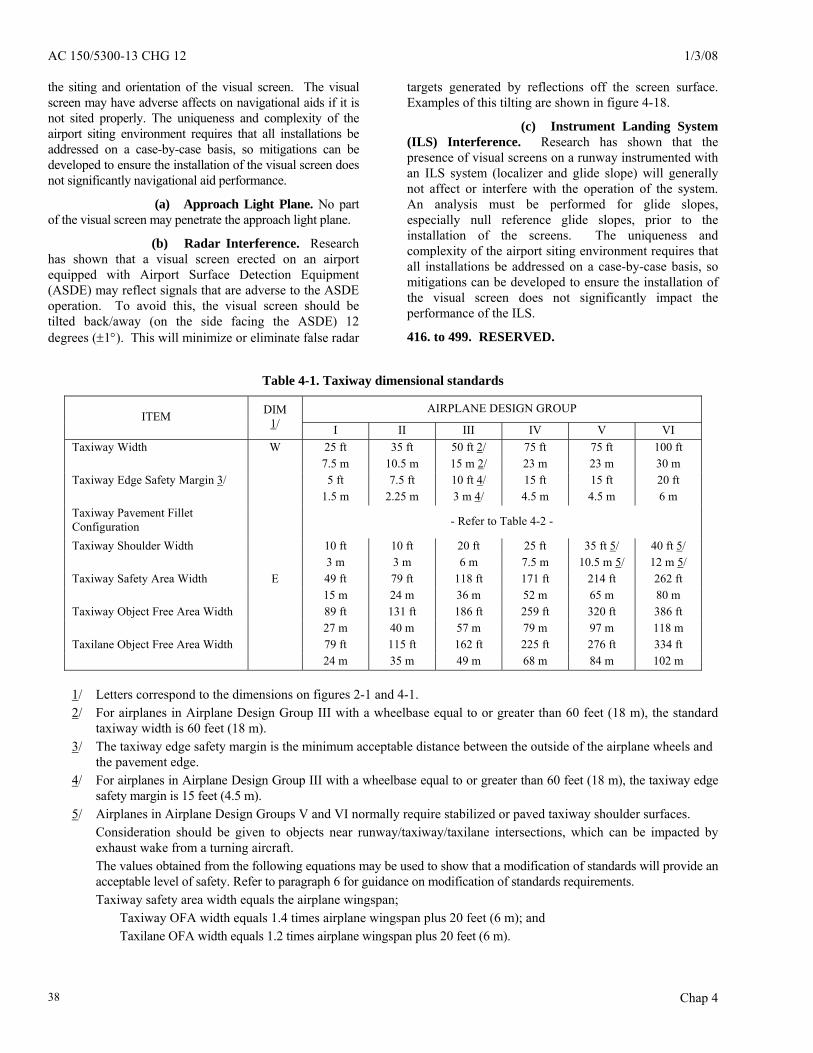
AC 150/5300-13 CHG 12 1/3/08
Chap 4 38
the siting and orientation of the visual screen. The visual screen may have adverse affects on navigational aids if it is not sited properly. The uniqueness and complexity of the airport siting environment requires that all installations be addressed on a case-by-case basis, so mitigations can be developed to ensure the installation of the visual screen does not significantly navigational aid performance.
(a) Approach Light Plane. No part of the visual screen may penetrate the approach light plane.
(b) Radar Interference. Research has shown that a visual screen erected on an airport equipped with Airport Surface Detection Equipment (ASDE) may reflect signals that are adverse to the ASDE operation. To avoid this, the visual screen should be tilted back/away (on the side facing the ASDE) 12 degrees (±1°). This will minimize or eliminate false radar
targets generated by reflections off the screen surface. Examples of this tilting are shown in figure 4-18.
(c) Instrument Landing System (ILS) Interference. Research has shown that the presence of visual screens on a runway instrumented with an ILS system (localizer and glide slope) will generally not affect or interfere with the operation of the system. An analysis must be performed for glide slopes, especially null reference glide slopes, prior to the installation of the screens. The uniqueness and complexity of the airport siting environment requires that all installations be addressed on a case-by-case basis, so mitigations can be developed to ensure the installation of the visual screen does not significantly impact the performance of the ILS.
416. to 499. RESERVED.
Table 4-1. Taxiway dimensional standards
AIRPLANE DESIGN GROUP ITEM DIM
1/ I II III IV V VI W 25 ft 35 ft 50 ft 2/ 75 ft 75 ft 100 ft Taxiway Width 7.5 m 10.5 m 15 m 2/ 23 m 23 m 30 m 5 ft 7.5 ft 10 ft 4/ 15 ft 15 ft 20 ft Taxiway Edge Safety Margin 3/ 1.5 m 2.25 m 3 m 4/ 4.5 m 4.5 m 6 m Taxiway Pavement Fillet
Configuration - Refer to Table 4-2 -
10 ft 10 ft 20 ft 25 ft 35 ft 5/ 40 ft 5/ Taxiway Shoulder Width 3 m 3 m 6 m 7.5 m 10.5 m 5/ 12 m 5/
E 49 ft 79 ft 118 ft 171 ft 214 ft 262 ft Taxiway Safety Area Width 15 m 24 m 36 m 52 m 65 m 80 m 89 ft 131 ft 186 ft 259 ft 320 ft 386 ft Taxiway Object Free Area Width 27 m 40 m 57 m 79 m 97 m 118 m 79 ft 115 ft 162 ft 225 ft 276 ft 334 ft Taxilane Object Free Area Width 24 m 35 m 49 m 68 m 84 m 102 m
1/ Letters correspond to the dimensions on figures 2-1 and 4-1. 2/ For airplanes in Airplane Design Group III with a wheelbase equal to or greater than 60 feet (18 m), the standard
taxiway width is 60 feet (18 m). 3/ The taxiway edge safety margin is the minimum acceptable distance between the outside of the airplane wheels and
the pavement edge. 4/ For airplanes in Airplane Design Group III with a wheelbase equal to or greater than 60 feet (18 m), the taxiway edge
safety margin is 15 feet (4.5 m). 5/ Airplanes in Airplane Design Groups V and VI normally require stabilized or paved taxiway shoulder surfaces.
Consideration should be given to objects near runway/taxiway/taxilane intersections, which can be impacted by exhaust wake from a turning aircraft. The values obtained from the following equations may be used to show that a modification of standards will provide an acceptable level of safety. Refer to paragraph 6 for guidance on modification of standards requirements.
Taxiway safety area width equals the airplane wingspan; Taxiway OFA width equals 1.4 times airplane wingspan plus 20 feet (6 m); and Taxilane OFA width equals 1.2 times airplane wingspan plus 20 feet (6 m).

11/10/94 AC 150/5300-13 CHG 4
Chap 4 39
W
L
W
L
RF
TAXIWAY CL
LTAXIWAY C
F
R
L
W
L
W
FRL
W
L
W
CL
Figure 4-1. Taxiway intersection details
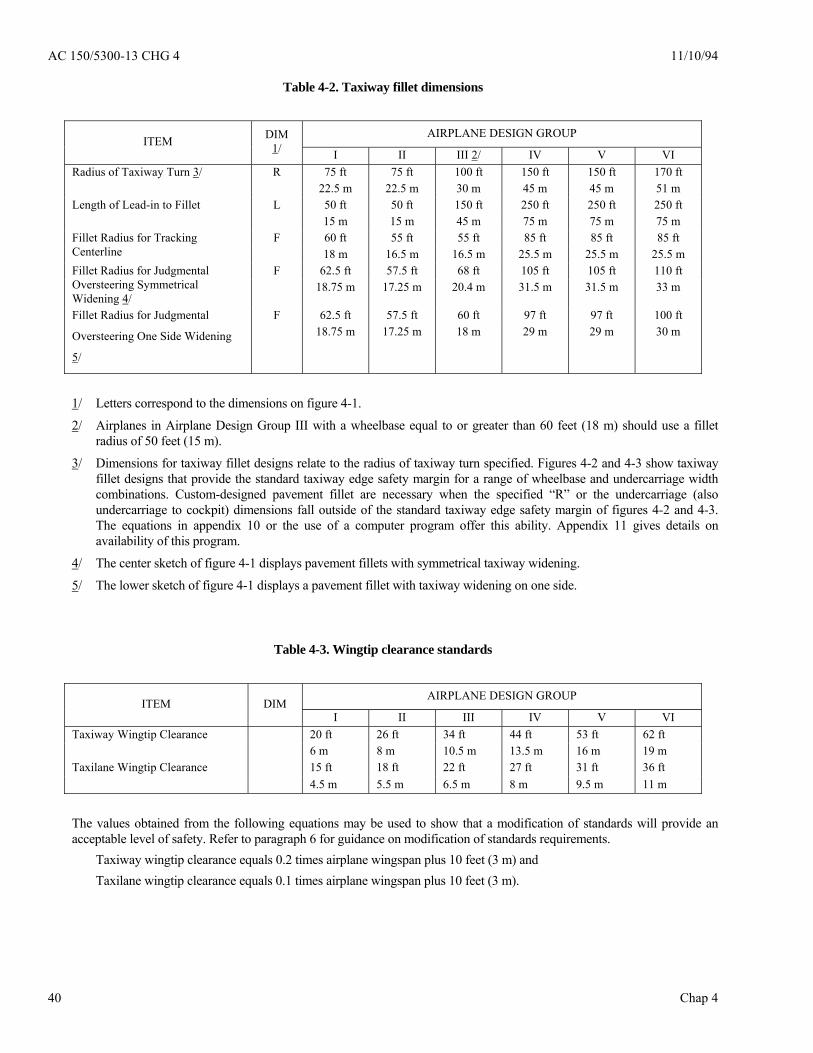
AC 150/5300-13 CHG 4 11/10/94
Chap 4 40
Table 4-2. Taxiway fillet dimensions
AIRPLANE DESIGN GROUP ITEM DIM
1/ I II III 2/ IV V VI 75 ft 75 ft 100 ft 150 ft 150 ft 170 ft Radius of Taxiway Turn 3/ R
22.5 m 22.5 m 30 m 45 m 45 m 51 m 50 ft 50 ft 150 ft 250 ft 250 ft 250 ft Length of Lead-in to Fillet L 15 m 15 m 45 m 75 m 75 m 75 m 60 ft 55 ft 55 ft 85 ft 85 ft 85 ft Fillet Radius for Tracking
Centerline F
18 m 16.5 m 16.5 m 25.5 m 25.5 m 25.5 m 62.5 ft 57.5 ft 68 ft 105 ft 105 ft 110 ft Fillet Radius for Judgmental
Oversteering Symmetrical Widening 4/
F 18.75 m 17.25 m 20.4 m 31.5 m 31.5 m 33 m
62.5 ft 57.5 ft 60 ft 97 ft 97 ft 100 ft Fillet Radius for Judgmental
Oversteering One Side Widening
5/
F 18.75 m 17.25 m 18 m 29 m 29 m 30 m
1/ Letters correspond to the dimensions on figure 4-1.
2/ Airplanes in Airplane Design Group III with a wheelbase equal to or greater than 60 feet (18 m) should use a fillet radius of 50 feet (15 m).
3/ Dimensions for taxiway fillet designs relate to the radius of taxiway turn specified. Figures 4-2 and 4-3 show taxiway fillet designs that provide the standard taxiway edge safety margin for a range of wheelbase and undercarriage width combinations. Custom-designed pavement fillet are necessary when the specified “R” or the undercarriage (also undercarriage to cockpit) dimensions fall outside of the standard taxiway edge safety margin of figures 4-2 and 4-3. The equations in appendix 10 or the use of a computer program offer this ability. Appendix 11 gives details on availability of this program.
4/ The center sketch of figure 4-1 displays pavement fillets with symmetrical taxiway widening.
5/ The lower sketch of figure 4-1 displays a pavement fillet with taxiway widening on one side.
Table 4-3. Wingtip clearance standards
AIRPLANE DESIGN GROUP ITEM DIM
I II III IV V VI 20 ft 26 ft 34 ft 44 ft 53 ft 62 ft Taxiway Wingtip Clearance 6 m 8 m 10.5 m 13.5 m 16 m 19 m 15 ft 18 ft 22 ft 27 ft 31 ft 36 ft Taxilane Wingtip Clearance 4.5 m 5.5 m 6.5 m 8 m 9.5 m 11 m
The values obtained from the following equations may be used to show that a modification of standards will provide an acceptable level of safety. Refer to paragraph 6 for guidance on modification of standards requirements. Taxiway wingtip clearance equals 0.2 times airplane wingspan plus 10 feet (3 m) and Taxilane wingtip clearance equals 0.1 times airplane wingspan plus 10 feet (3 m).
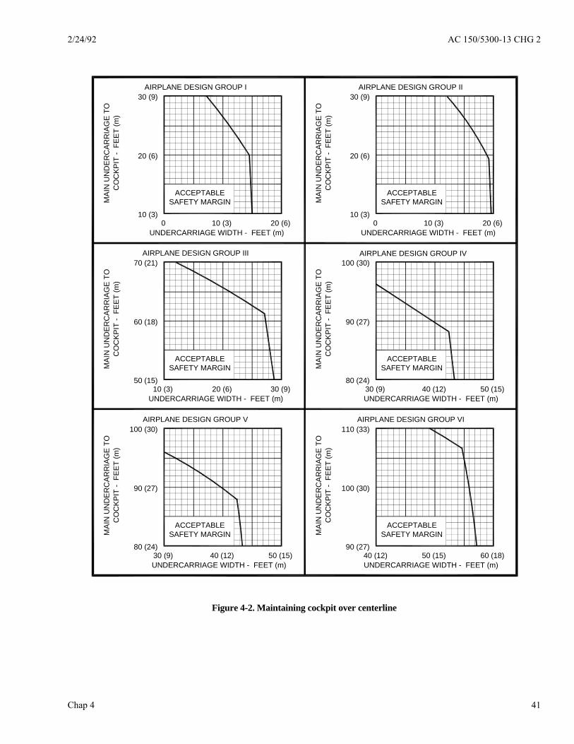
2/24/92 AC 150/5300-13 CHG 2
Chap 4 41
AIRPLANE DESIGN GROUP IV100 (30)
90 (27)
80 (24)40 (12) 50 (15)
UNDERCARRIAGE WIDTH - FEET (m)
MA
IN U
ND
ER
CA
RR
IAG
E T
OC
OC
KPIT
- F
EE
T (m
)
CO
CKP
IT -
FE
ET
(m)
MA
IN U
ND
ER
CA
RR
IAG
E T
O
UNDERCARRIAGE WIDTH - FEET (m)30 (9)20 (6)
50 (15)
60 (18)
70 (21)AIRPLANE DESIGN GROUP III
AIRPLANE DESIGN GROUP VI110 (33)
100 (30)
90 (27)60 (18)
UNDERCARRIAGE WIDTH - FEET (m)
MA
IN U
ND
ER
CA
RR
IAG
E T
OC
OC
KP
IT -
FE
ET
(m)
CO
CK
PIT
- F
EE
T (m
)M
AIN
UN
DE
RC
AR
RIA
GE
TO
UNDERCARRIAGE WIDTH - FEET (m)
AIRPLANE DESIGN GROUP V
ACCEPTABLESAFETY MARGIN
ACCEPTABLESAFETY MARGIN
ACCEPTABLESAFETY MARGIN
ACCEPTABLESAFETY MARGIN
ACCEPTABLESAFETY MARGIN
ACCEPTABLESAFETY MARGIN
10 (3) 30 (9)
100 (30)
90 (27)
80 (24)30 (9) 40 (12) 50 (15) 50 (15)40 (12)
AIRPLANE DESIGN GROUP I30 (9)
20 (6)
10 (3)0 10 (3) 20 (6)
UNDERCARRIAGE WIDTH - FEET (m)
MAI
N U
ND
ER
CAR
RIA
GE
TOC
OC
KP
IT -
FE
ET
(m)
CO
CK
PIT
- F
EE
T (m
)M
AIN
UN
DE
RC
ARR
IAG
E TO
UNDERCARRIAGE WIDTH - FEET (m)20 (6)10 (3)0
10 (3)
20 (6)
30 (9)AIRPLANE DESIGN GROUP II
Figure 4-2. Maintaining cockpit over centerline

AC 150/5300-13 CHG 2 2/24/92
Chap 4 42
AIRPLANE DESIGN GROUP IV100 (30)
90 (27)
80 (24)40 (12) 50 (15)
UNDERCARRIAGE WIDTH - FEET (m)UNDERCARRIAGE WIDTH - FEET (m)30 (9)20 (6)
50 (15)
60 (18)
70 (21)AIRPLANE DESIGN GROUP III
AIRPLANE DESIGN GROUP VI110 (33)
100 (30)
90 (27)60 (18)
UNDERCARRIAGE WIDTH - FEET (m)UNDERCARRIAGE WIDTH - FEET (m)
AIRPLANE DESIGN GROUP V
ACCEPTABLESAFETY MARGIN
ACCEPTABLESAFETY MARGIN
ACCEPTABLESAFETY MARGIN
ACCEPTABLESAFETY MARGIN
ACCEPTABLESAFETY MARGIN
ACCEPTABLESAFETY MARGIN
10 (3) 30 (9)
100 (30)
90 (27)
80 (24)30 (9) 40 (12) 50 (15) 50 (15)40 (12)
WH
EEL
BAS
E -
FEET
(m)
WH
EEL
BAS
E -
FEET
(m)
WH
EELB
ASE
- F
EET
(m)
WH
EEL
BAS
E -
FEET
(m)
WH
EEL
BAS
E -
FEET
(m)
WH
EELB
ASE
- F
EET
(m)
AIRPLANE DESIGN GROUP I30 (9)
20 (6)
10 (3)0 10 (3) 20 (6)
UNDERCARRIAGE WIDTH - FEET (m) UNDERCARRIAGE WIDTH - FEET (m)20 (6)10 (3)0
10 (3)
20 (6)
30 (9)AIRPLANE DESIGN GROUP II
Figure 4-3. Judgmental oversteering

2/24/92 AC 150/5300-13 CHG 2
Chap 4 43
Figure 4-4. Example of pavement fillet computer program printout

AC 150/5300-13 9/29/89
Chap 4 44
LC
C TAXIWAY L
RUNWAY
Figure 4-5. Entrance taxiway
RUNWAY C L
LC TAXIWAY
Figure 4-6. Bypass taxiway
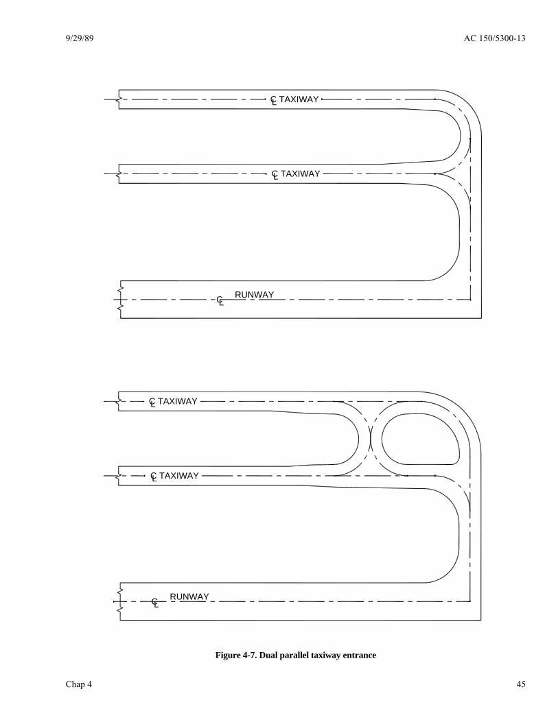
9/29/89 AC 150/5300-13
Chap 4 45
LC TAXIWAY
LC TAXIWAY
RUNWAY C L
LC RUNWAY
C TAXIWAY L
C TAXIWAY L
Figure 4-7. Dual parallel taxiway entrance

AC 150/5300-13 9/29/89
Chap 4 46
HOLDING BAY
BAYHOLDING
Figure 4-8. Typical holding bay configurations
LC RUNWAY
VAR
IES
HOLD LINE
Figure 4-9. Taxiway turnaround
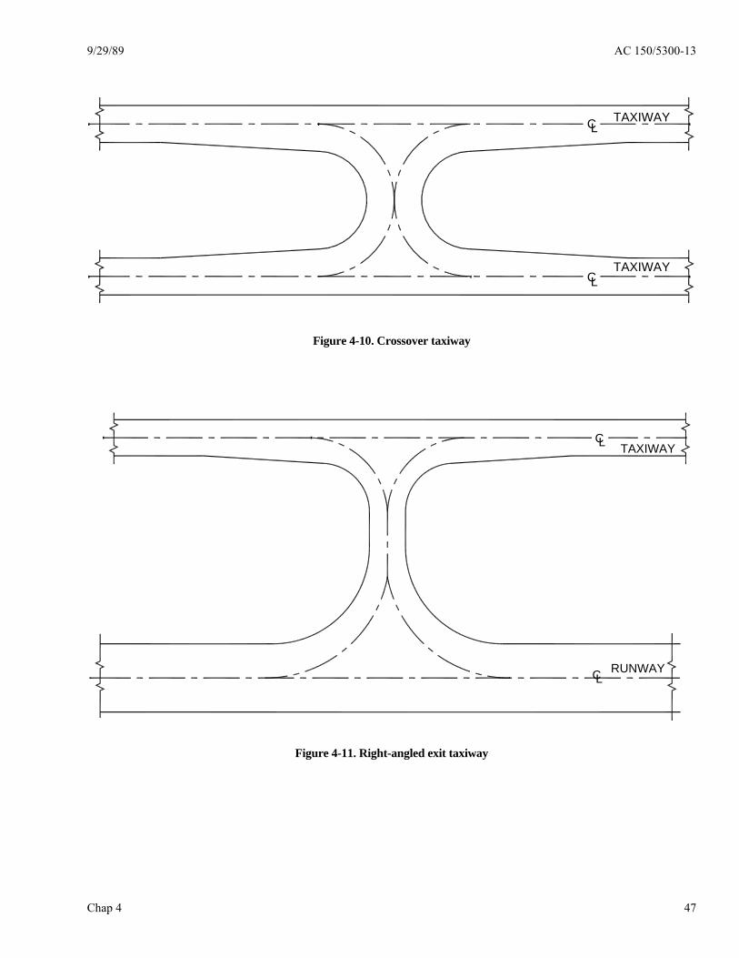
9/29/89 AC 150/5300-13
Chap 4 47
LC TAXIWAY
TAXIWAY C L
Figure 4-10. Crossover taxiway
TAXIWAY C L
LC RUNWAY
Figure 4-11. Right-angled exit taxiway
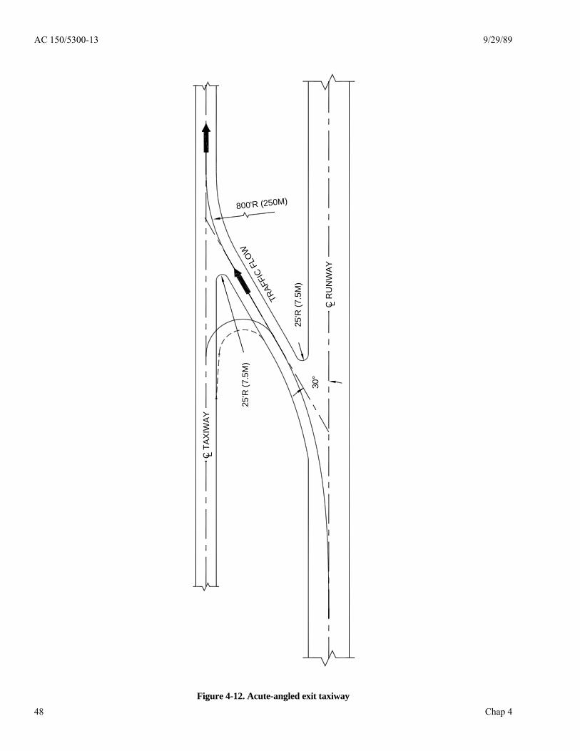
AC 150/5300-13 9/29/89
Chap 4 48
25'R
(7.5
M)
25'R
(7.5
M)
800'R (250M)
30°
TRAF
FIC
FLO
W
C T
AX
IWAY
L
LC R
UN
WAY
Figure 4-12. Acute-angled exit taxiway

2/24/92 AC 150/5300-13 CHG 2
Chap 4 48-1
Figure 4-13. Example of acute-angled exit taxiway computer layout data page 1
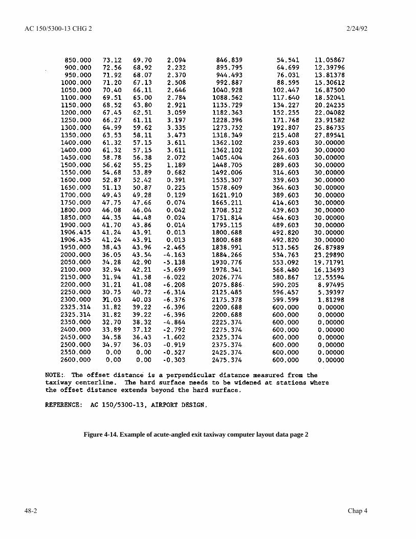
AC 150/5300-13 CHG 2 2/24/92
Chap 4 48-2
Figure 4-14. Example of acute-angled exit taxiway computer layout data page 2

9/29/06 AC 150/5300-13 CHG 10
Chap 4 48-3
TAX
IWA
Y
TAX
IWA
Y
RU
NW
AY
L
VIS
UA
L SC
RE
EN R
VIS
UA
L S
CR
EE
N L
END
AR
OU
ND
TAX
IWA
Y
TAX
IWA
Y
DIS
TAN
CE
FR
OM
RU
NW
AY
END
(D )
DIS
TAN
CE
FR
OM
RU
NW
AY
EN
D (D
)
RU
NW
AY
R
ss
D e
D e
DIS
TAN
CE
MA
Y V
AR
Y15
00' M
INIM
UM
ALT
ER
NA
TE S
TAG
GE
RE
DLA
YO
UT
FOR
AC
CE
SS
Figure 4-15. Typical end-around taxiway layout
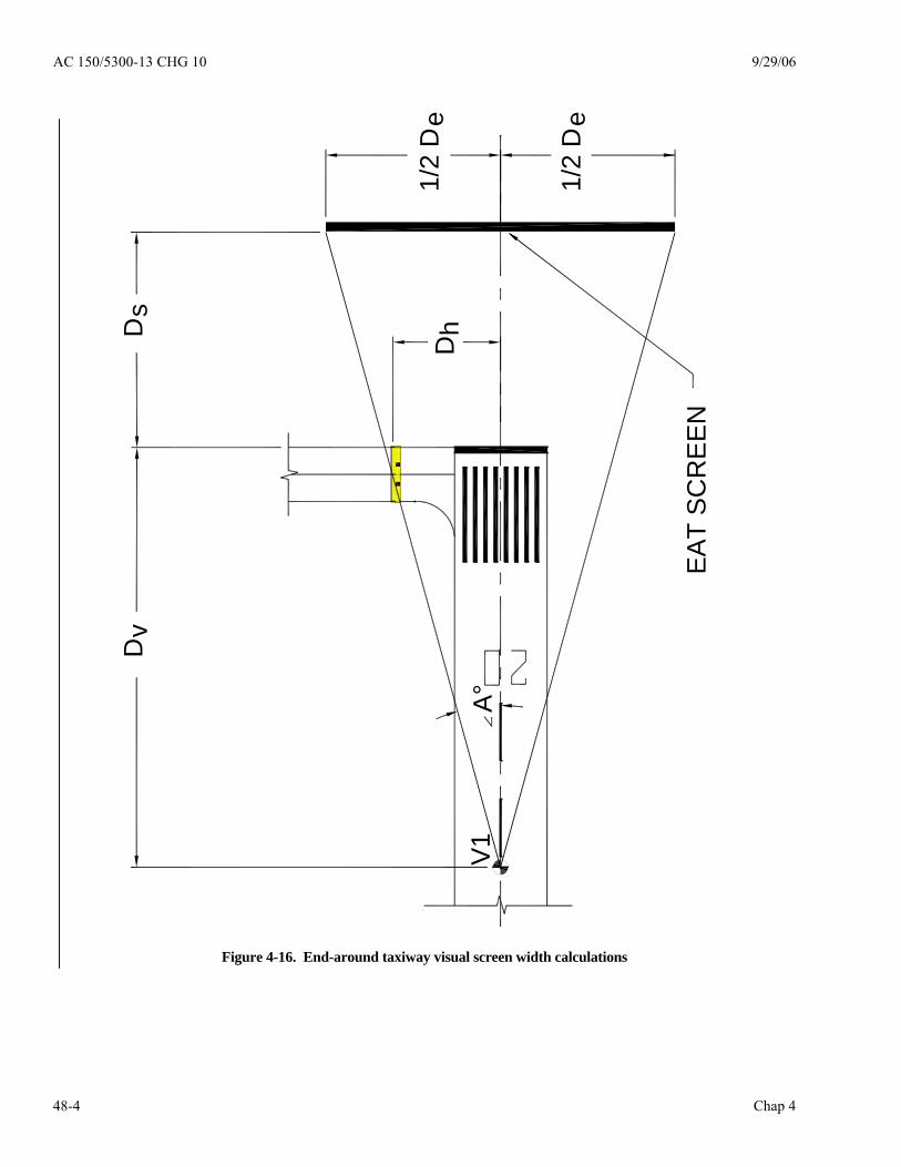
AC 150/5300-13 CHG 10 9/29/06
Chap 4 48-4
Dv
Ds
Dh
1/2
De
1/2
De
EA
T S
CR
EE
N
V1
A°
Figure 4-16. End-around taxiway visual screen width calculations
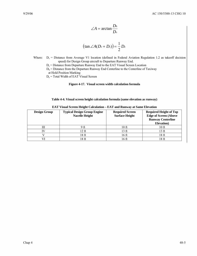
9/29/06 AC 150/5300-13 CHG 10
Chap 4 48-5
( ) esv
v
h
DDDA
DDA
21)(tan
arctan
=+∠
=∠
Where: Dv = Distance from Average V1 location (defined in Federal Aviation Regulation 1.2 as takeoff decision
speed) for Design Group aircraft to Departure Runway End. Ds = Distance from Departure Runway End to the EAT Visual Screen Location Dh = Distance from the Departure Runway End Centerline to the Centerline of Taxiway at Hold Position Marking De = Total Width of EAT Visual Screen
Figure 4-17. Visual screen width calculation formula
Table 4-4. Visual screen height calculation formula (same elevation as runway)
EAT Visual Screen Height Calculation – EAT and Runway at Same Elevation Design Group Typical Design Group Engine
Nacelle Height Required Screen Surface Height
Required Height of Top Edge of Screen (Above
Runway Centerline Elevation)
III 9 ft 10 ft 10 ft IV 12 ft 13 ft 13 ft V 18 ft 16 ft 18 ft VI 18 ft 16 ft 18 ft

AC 150/5300-13 CHG 10 9/29/06
Chap 4 48-6
Table 4-5. Visual screen height calculation formula (EAT below DER elevation) for Design Group III
Design Group III Aircraft
EAT Visual Screen Height Calculation – EAT At or Below DER Elevation
Elevation Difference
(ft)
Required Screen Surface
Height (ft)
Required Height of Top Edge of Screen (+ DER
Centerline Elevation) (ft)
0 10 10 1 10 10 2 10 10 3 10 10 4 10 10 5 10 10 6 10 10 7 10 10 8 10 10 9 10 10 10 10 10 11 9 9 12 9 9 13 9 9 14 9 9 15 9 9 16 9 9 17 9 9 18 9 9 19 9 9 20 8 8 21 8 8 22 8 8 23 8 8 24 8 8 25 8 8 26 8 8 27 8 8 28 8 8
29+ 0 0
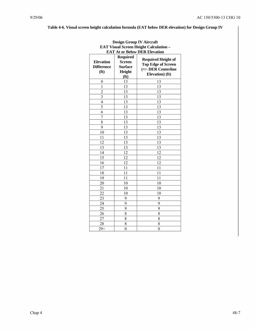
9/29/06 AC 150/5300-13 CHG 10
Chap 4 48-7
Table 4-6. Visual screen height calculation formula (EAT below DER elevation) for Design Group IV
Design Group IV Aircraft EAT Visual Screen Height Calculation –
EAT At or Below DER Elevation
Elevation Difference
(ft)
Required Screen Surface Height
(ft)
Required Height of Top Edge of Screen (+/- DER Centerline
Elevation) (ft)
0 13 13 1 13 13 2 13 13 3 13 13 4 13 13 5 13 13 6 13 13 7 13 13 8 13 13 9 13 13 10 13 13 11 13 13 12 13 13 13 13 13 14 12 12 15 12 12 16 12 12 17 11 11 18 11 11 19 11 11 20 10 10 21 10 10 22 10 10 23 9 9 24 9 9 25 9 9 26 8 8 27 8 8 28 8 8
29+ 0 0

AC 150/5300-13 CHG 10 9/29/06
Chap 4 48-8
Table 4-7. Visual screen height calculation formula (EAT below DER elevation) for Design Groups V and VI
Design Group V and VI Aircraft EAT Visual Screen Height Calculation –
EAT At or Below DER Elevation
Elevation Difference
(ft)
Required Screen Surface Height
(ft)
Required Height of Top Edge of Screen (+/- DER Centerline
Elevation) (ft)
0 13 18 1 13 18 2 13 18 3 13 18 4 13 18 5 13 17 6 13 16 7 13 15 8 13 14 9 13 13 10 13 13 11 13 13 12 13 13 13 13 13 14 12 12 15 12 12 16 12 12 17 11 11 18 11 11 19 11 11 20 10 10 21 10 10 22 10 10 23 9 9 24 9 9 25 9 9 26 8 8 27 8 8 28 8 8
29+ 0 0

9/29/06 AC 150/5300-13 CHG 10
Chap 4 48-9
Table 4-8. Visual screen vertical height calculation tables
Design Group III -VI Aircraft EAT Visual Screen Height Calculation – EAT Above DER Elevation
Design Group
Required Height of Top Edge of Screen (Above
Runway Centerline Elevation) (ft)
Add Elevation Difference – EAT above DER
Calculate: NEW Required Height of Top Edge of Screen
(Above DER Centerline Elevation) (ft)
III 10 IV 13 V 18 VI 18
+ Elevation Difference = New Required Height of Top Edge of Screen
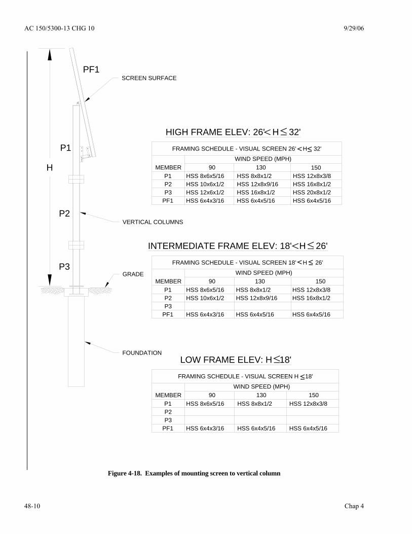
AC 150/5300-13 CHG 10 9/29/06
Chap 4 48-10
SCREEN SURFACE
VERTICAL COLUMNS
FOUNDATION
GRADE
P1
P2
P3
PF1
HIGH FRAME ELEV: 26' H 32'
90 130 150WIND SPEED (MPH)
MEMBER
INTERMEDIATE FRAME ELEV: 18' H 26'
HSS 8x6x5/16
HSS 6x4x3/16
HSS 8x8x1/2
HSS 6x4x5/16
FRAMING SCHEDULE - VISUAL SCREEN H 18'
90 130 150WIND SPEED (MPH)
MEMBER
90 130 150WIND SPEED (MPH)
MEMBER
FRAMING SCHEDULE - VISUAL SCREEN 18' H 26'
LOW FRAME ELEV: H 18'
FRAMING SCHEDULE - VISUAL SCREEN 26' H 32'
P1P2P3
PF1
P1P2P3
PF1
P1P2P3
PF1
HSS 8x6x5/16HSS 10x6x1/2
HSS 6x4x3/16
HSS 8x6x5/16HSS 10x6x1/2HSS 12x6x1/2 HSS 6x4x3/16
HSS 8x8x1/2HSS 12x8x9/16
HSS 6x4x5/16
HSS 12x8x3/8HSS 16x8x1/2
HSS 6x4x5/16
HSS 8x8x1/2HSS 12x8x9/16HSS 16x8x1/2 HSS 6x4x5/16
HSS 12x8x3/8HSS 16x8x1/2HSS 20x8x1/2 HSS 6x4x5/16
HSS 12x8x3/8
HSS 6x4x5/16
H
Figure 4-18. Examples of mounting screen to vertical column
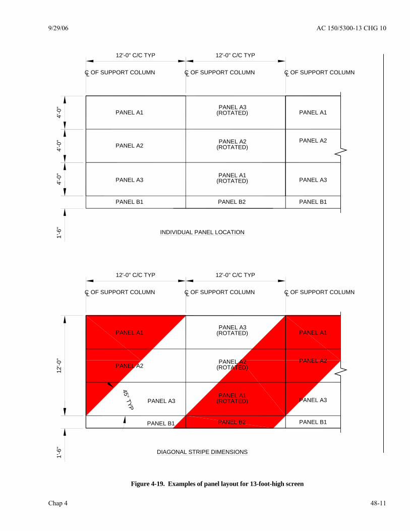
9/29/06 AC 150/5300-13 CHG 10
Chap 4 48-11
LC OF SUPPORT COLUMN LC LCOF SUPPORT COLUMN OF SUPPORT COLUMN
12'-0" C/C TYP 12'-0" C/C TYP
1'-6
"
PANEL A1
PANEL A2
PANEL A3
PANEL B1
PANEL A3(ROTATED)
PANEL A2(ROTATED)
PANEL A1(ROTATED)
PANEL B2
LC OF SUPPORT COLUMN LC LC
PANEL A1
PANEL A2
PANEL A3
PANEL B1
OF SUPPORT COLUMN OF SUPPORT COLUMN
12'-0" C/C TYP 12'-0" C/C TYP4'
-0"
4'-0
"4'
-0"
1'-6
"12
'-0"
45° TYP
INDIVIDUAL PANEL LOCATION
DIAGONAL STRIPE DIMENSIONS
PANEL A1
PANEL A2
PANEL A3
PANEL B1
PANEL A3(ROTATED)
PANEL A2(ROTATED)
PANEL A1(ROTATED)
PANEL B2
PANEL A1
PANEL A2
PANEL A3
PANEL B1
Figure 4-19. Examples of panel layout for 13-foot-high screen
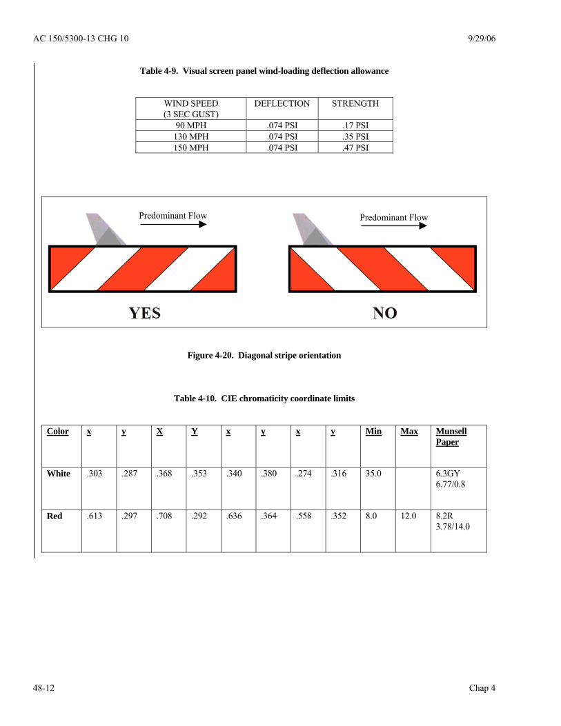
AC 150/5300-13 CHG 10 9/29/06
Chap 4 48-12
Table 4-9. Visual screen panel wind-loading deflection allowance
WIND SPEED (3 SEC GUST)
DEFLECTION STRENGTH
90 MPH .074 PSI .17 PSI 130 MPH .074 PSI .35 PSI 150 MPH .074 PSI .47 PSI
Figure 4-20. Diagonal stripe orientation
Table 4-10. CIE chromaticity coordinate limits
Color x y X Y x y x y Min Max Munsell Paper
White .303 .287 .368 .353 .340 .380 .274 .316 35.0 6.3GY 6.77/0.8
Red .613 .297 .708 .292 .636 .364 .558 .352 8.0 12.0 8.2R 3.78/14.0
Predominant Flow Predominant Flow
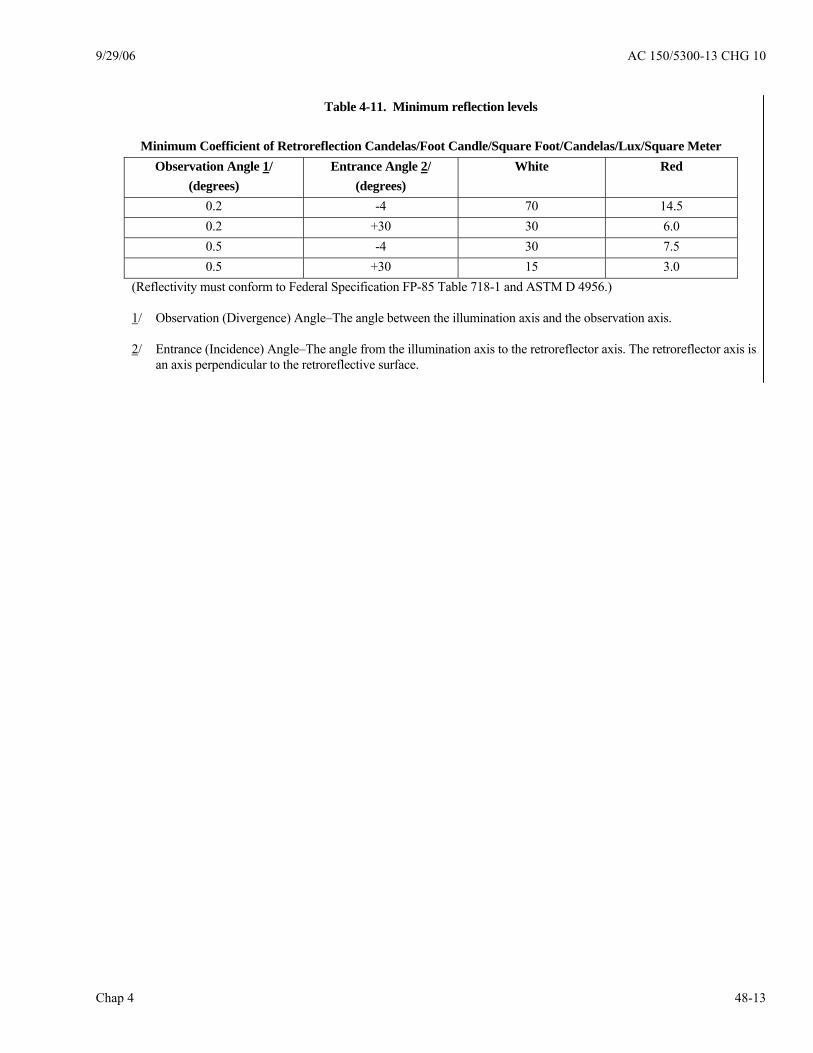
9/29/06 AC 150/5300-13 CHG 10
Chap 4 48-13
Table 4-11. Minimum reflection levels
Minimum Coefficient of Retroreflection Candelas/Foot Candle/Square Foot/Candelas/Lux/Square Meter
Observation Angle 1/
(degrees) Entrance Angle 2/
(degrees) White Red
0.2 -4 70 14.5 0.2 +30 30 6.0 0.5 -4 30 7.5 0.5 +30 15 3.0
(Reflectivity must conform to Federal Specification FP-85 Table 718-1 and ASTM D 4956.) 1/ Observation (Divergence) Angle–The angle between the illumination axis and the observation axis. 2/ Entrance (Incidence) Angle–The angle from the illumination axis to the retroreflector axis. The retroreflector axis is
an axis perpendicular to the retroreflective surface.

AC 150/5300-13 CHG 10 9/29/06
Chap 4 48-14
FRA
NG
IBLE
CO
NN
EC
TIO
N O
N P
AN
ELS
FRA
NG
IBLE
CO
NN
EC
TIO
N O
N C
OLU
MN
SR
AN
GIB
LE C
ON
NE
CTI
ON
BA
SE
UPP
ER
VE
RTI
CAL
FRA
NG
IBLE
LOW
ER V
ER
TIC
AL
VE
RTI
CAL
CO
LUM
N
CC
OLU
MN
L
CO
LUM
N
CO
LUM
N
CO
NN
EC
TOR
AN
CH
OR
BO
LTS
FRA
NG
IBLE
C
ON
NE
CTO
R
CC
OLU
MN
L
3"
CO
NC
RE
TE
FOU
ND
ATI
ON
GR
AD
E
CO
LUM
NB
AS
E P
LATE
DIS
SIM
ILAR
ME
TALS
SH
IM
T-S
HA
PED
BU
SH
ING
STA
INLE
SSST
EEL
WA
SHER
CO
NN
EC
TIO
NP
LATE
STA
INLE
SS
STE
EL
BOLT
ALU
MIN
UM
PA
NE
L
STA
INLE
SSS
TEE
L W
ASH
ER
3/4"
4 1/
2"
3/4"
1/2"
ALU
MIN
UM
HO
NE
YCO
MB
PA
NEL
Figure 4-21. Examples of frangibility connections
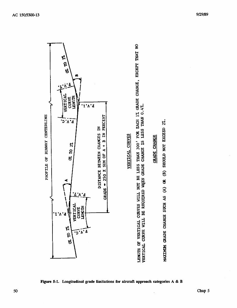
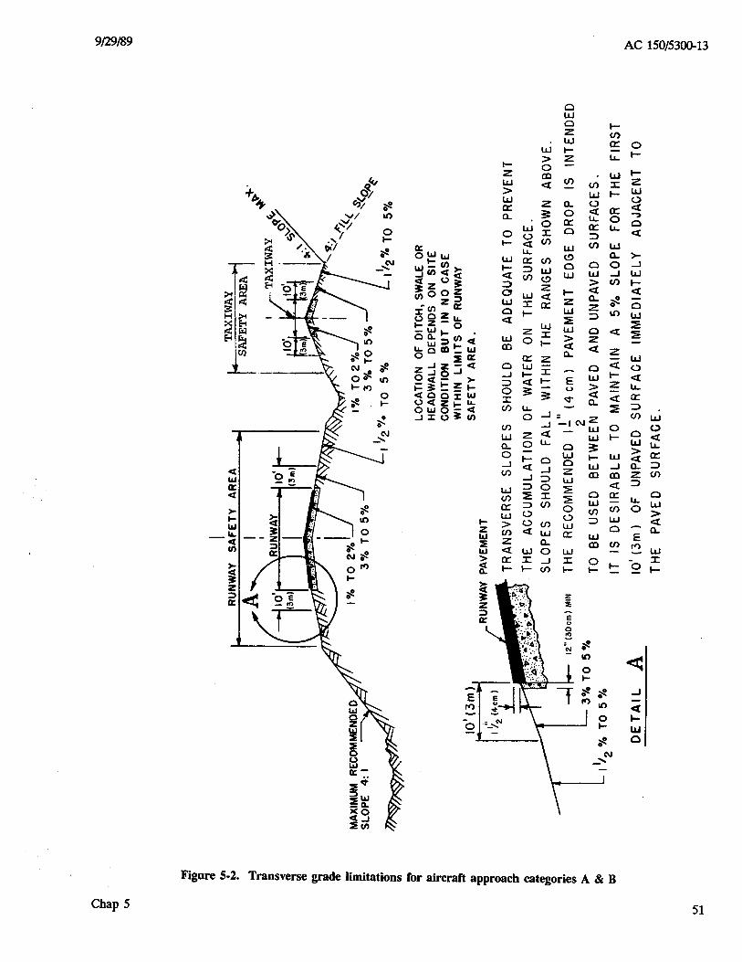


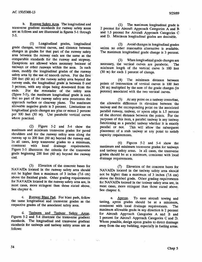


9/29/89 AC 150/5300-13
61
(2) AZ antennas require the area between the antenna and the stop end of the runway be cleared of objects that could reflect or block the signal. Figure 6-3 illustrates this area.
Figure 6-3. AZ antenna critical area a. Elevation Antenna. Descent guidance is provided by the elevation (EL) antenna. The signal area extends from the horizon to 30 degrees above the horizon. The EL antenna height depends upon the beam width but would not exceed 18.6 feet (5.7 m). (1) The EL antenna site is at least 400 feet (120 m) from the runway centerline and 800 to 1,000 feet (240 to 300 m) from the runway threshold and should provide a threshold crossing height of 50 feet (15 m). Figure 6-4 illustrates EL antenna siting.
Figure 6-4. EL antenna siting
(2) EL antenna critical areas begin at the runway near edge and extend to 33 feet (10 m) outboard of the antenna site. They are 1,000 feet (300 m) in length, measured from the antenna toward the approaching aircraft. These areas should be clear of objects that could reflect or block the signal. Figure 6-5 illustrates this area.
Figure 6-5. EL antenna critical area b. Distance Measuring Equipment. Range information is provided by distance measuring equipment (DME). DME antennas are 22 feet (6.7 m) in height and normally are collocated with the AZ antenna. To preclude penetration of an approach surface, the collocated AZ/DME antennas should be placed 1,300 feet (390 m) from the runway end. 602. INSTRUMENT LANDING SYSTEM. The instrument landing system (ILS) provides pilots with electronic guidance for aircraft alignment, descent gradient, and position until visual contact confirms the runway alignment and location. Figure 6-2 illustrated ILS component locations. a. General. The ILS uses a line-of-sight signal from the localizer antenna and marker beacons and a reflected signal from the ground plane in front of the glide slope antenna. (1) ILS antenna systems are susceptible to signal interference sources such as power lines, fences, metal buildings, etc. (2) Since ILS uses the ground in front of the glide slope antenna to develop the signal, this area should be graded to remove surface irregularities.

AC 150/5300-13 CHG 7 10/1/02
62
(3) ILS equipment shelters are located near but are not a physical part of the antenna installation. b. Localizer Antenna. The localizer (LOC) signal is used to establish and maintain the aircraft's horizontal position until visual contact confirms the runway alignment and location. (1) The LOC antenna is usually sited on the extended runway centerline outside the runway safety area between 1,000 to 2,000 feet (300 to 600 m) beyond the stop end of the runway. Where it is not practicable to locate the antenna beyond the end of the RSA, consult with the FAA Terminal Procedures Specialist (TERPS) and consider offsetting the localizer to the side to keep it clear of the RSA and to minimize the potential hazard to aircraft (See paragraph 305). The localizer critical area is illustrated in Figure 6-6.
NOTE: The X and Y dimensions vary depending
on the system used. X varies from 2,000 feet (600 m) to
7,000 feet (2100 m). Y varies from 400 feet (120 m) to 600 feet
(180 m). Figure 6-6. ILS LOC siting and critical area (2) The critical area depicted in figure 6-6 surrounding the LOC antenna and extending toward and overlying the stop end of the runway should be clear of objects. (3) The critical area should be smoothly graded. A constant +1 percent to -1.5 percent longitudinal grade is recommended. Transverse grades
should range from +1.0 percent to -3.0 percent, with smooth transitions between grade changes. Antenna supports shall be frangible and foundations should be flush with the ground. (4) The LOC equipment shelter is placed at least 250 feet (75 m) to either side of the antenna array and within 30 degrees of the extended longitudinal axis of the antenna array. c. Glide Slope Antenna. The glide slope (GS) signal is used to establish and maintain the aircraft's descent rate until visual contact confirms the runway alignment and location. A GS differentiates precision from nonprecision approaches. (1) The GS antenna may be located on either side of the runway. The most reliable operation is obtained when the GS is located on the side of the runway offering the least possibility of signal reflections from buildings, power lines, vehicles, aircraft, etc. The glide slope critical area is illustrated in Figure 6-7.
NOTE:The X and Y dimensions vary depending on the
system used. X varies from 800 feet (240 m) to 3,200 feet (960 m). Y varies from 100 feet (30 m) to 200 feet (60 m). Figure 6-7. GS siting and critical area (2) Signal quality is dependent upon the type of antenna used and the extent of reasonably level ground immediately in front of the antenna. (3) The GS equipment shelter is located 10 feet (3 m) behind the antenna and a minimum of 400 feet (120 m) from the runway centerline.

9/29/89 AC 150/5300-13
Chap 6 63
a. Marker Beacons. Marker beacons radiate coneor fan shaped signals vertically to activate aural andvisual indicators in the cockpit marking specific points inthe ILS approach.
(1) Marker beacons are located on the extendedrunway centerline at key points in the approach as notedbelow. Figure 6-2 illustrates the placement of markerbeacons for an ILS. Figure 6-8 illustrates typical markerbeacon installation.
Figure 6-8. Marker beacon site
(a) The outer marker (OM) beacon islocated 4 to 7 nautical miles (7.4 to 13 km) from the ILSrunway threshold to mark the point at which glide slopealtitude is verified or at which descent without glideslope is initiated.
(b) A middle marker (MM) beacon islocated 2,000 to 6,000 feet (600 to 1 800 m) from the ILSrunway threshold. It marks (approximately) the decisionpoint of a CAT I ILS approach.
(c) An inner marker (IM) beacon may belocated to mark the decision point of a CAT II or CAT IIIILS approach. Inner marker beacons are not used forCAT I ILS's.
(d) A "back course" marker beacon(comparable to an outer marker beacon) may be locatedto the rear of a bidirectional localizer facility to permitdevelopment of a nonprecision approach.
(2) Off airport marker beacons are located in afenced 6-foot by 6-foot (2 m by 2 m) tract situated on theextended runway centerline. Interference sources such asmetal buildings, power lines, trees, etc., shall be avoidedwithin 100 feet (30 m) of the antenna. A vehicle accessand parking area is required at the site.
(3) Marker beacon sites should be smooth,level, and well drained.
603. NONDIRECTIONAL BEACON. The non-directional beacon (NDB) radiates a signal whichprovides directional guidance to and from thetransmitting antenna. An NDB is normally mounted ona 35 foot (11 m) pole. Figure 6-9 illustrates an NDBantenna.
Figure 6-9. NDB site
a. Location. A NDB may be located on oradjacent to the airport. Metal buildings, power lines, ormetal fences should be kept 100 feet (30 m) from a NDBantenna.
b. Grading. The NDB site should be smooth,level, and well drained.
c. Equipment Shelter. Electronic equipment ishoused in a small collocated shelter.

AC 150/5300-13 CHG 6 9/30/00
64 Chap 6
604. VERY HIGH FREQUENCY OMNIRANGE.The standard very high frequency omnirange (VOR)located on an airport is known as a TVOR. TVORsradiate azimuth information for nonprecision instrumentapproach procedures. Figure 6-10 illustrates a typicalTVOR installation.
a. Location. If the airport has intersectingrunways, TVORs should be located adjacent to theintersection to provide approach guidance to both.TVORs should be located at least 500 feet (150 m) fromthe centerline of any runway and 250 feet (75 m) fromthe centerline of any taxiway.
Figure 6-10. A TVOR installation
b. Clearances. TVOR signals are susceptible todistortion caused by reflections. Structures should be atleast 1,000 feet (300 m) from the antenna. Metalstructures beyond 1,000 feet (300 m) should not penetratea 1.2 degree angle measured from the antenna base.Nonmetal structures beyond 1,000 feet (300 m) shouldnot penetrate a 2.5 degree angle measured from theantenna base. Metal fences should be at least 500 feet(150 m) from the antenna and overhead power andtelephone lines at least 1,200 feet (360 m) from theantenna. While trees should be at least 1,000 feet(300 m) from the antenna, a single tree may be toleratedif it is at least 500 feet (150 m) from the antenna. Beyonda 1,000 feet trees should not penetrate a 2.0 degree anglemeasured from the antenna.
Figure 6-11, TVOR Clearances
c. Grading. TVOR sites should be level within1000 feet (300 m) of the antenna. However, a downwardslope of as much as 4 percent is permitted between200 feet (60 m) and 1,000 feet (300 m) of the antenna.Surfaces should be cleared and smooth with no majorirregularities.
d. Equipment Shelter. All necessary electronicequipment is located within the structure.
605. APPROACH LIGHTING SYSTEMS. Allapproach lighting systems (ALS) are configurations oflights positioned symmetrically along the extendedrunway centerline. They begin at the runway thresholdand extend towards the approach. An ALS augments theelectronic navigational aids. Guidance on ALS systemsis found in AC 150/5340-14.
a. ALS Configurations. The FAA recognizes fourALS configurations to meet visual requirements forprecision and nonprecision approaches.
(1) An ALSF-2 is a 2,400 foot (720 m) highintensity ALS with sequenced flashing lights. It isrequired for CAT II and CAT III precision approaches.
(2) A MALSR is a 2,400 foot (720 m) mediumintensity ALS with runway alignment indicator lights(RAILs). It is an economy ALS system approved forCAT I precision approaches. The MALS portion of thesystem is 1,400 feet (420 m) in length. The RAILportion extends outward an additional 1,000 feet(300 m).
(3) A MALS is a 1,400 foot (420 m) mediumintensity ALS. It enhances nonprecision instrument andnight visual approaches.
(4) A MALSF is a medium intensity ALSidentical to the MALS above except that sequencedflashing lights are added to the outer three light bars. Thesequenced flashing lights improve pilot recognition of theALS when there are distracting lights in the airportvicinity.

9/30/00 AC 150/5300-13 CHG 6
Chap 6 65
b. Land Requirements. An ALS requires a sitecentered on the extended runway centerline. It is400 feet (120 m) wide. It starts at the threshold andextends 200 feet (60 m) beyond the outermost light of theALS.
c. Clearance Requirements. A clear line of sightis required between approaching aircraft and all lights inan ALS.
606. OMNIDIRECTIONAL APPROACHLIGHTING SYSTEMS. An omnidirectional approachlighting system (ODALS) may be installed on a runwaywith a nonprecision approach or on a runway that isdifficult to identify due to an excessive number of lightsin the area.
a. ODALS Configuration. ODALS consists ofseven capacitor discharge lights. Five of the seven lightsare sequence flashing omnidirectional lights. These fiveare located on the extended runway centerline, beginning300 feet (90 m) from the runway threshold and spaced at300-foot (90 m) intervals. The remaining two lights arelocated on either side of the runway threshold.
b. Land Requirements. ODALS require a sitecentered on the extended runway centerline. It is400 feet (120 m) wide. It starts at the threshold andextends 1,700feet (510 m).
c. Clearance Requirements. A clear line of sightis required between approaching aircraft and all lights inan ODALS.
607. LEAD-IN LIGHTING SYSTEMS. Lead-inlights (LDIN) consist of at least three flashing lightsinstalled at or near ground level to define the desiredcourse to an ALS or to a runway threshold.
a. LDIN Configuration. Each LDIN installationis unique. An LDIN is designed to overcome problemsassociated with hazardous terrain, obstructions, noisesensitive areas, etc. LDIN systems may be curved,straight, or a combination thereof. The lights are placedon the desired approach path, beginning at a point withinvisual range of the final approach. Generally the lightsare spaced at 3,000-foot (900 m) intervals.
b. Land Requirements. Sufficient land orproperty interest to permit installation and operation ofthe lights, together with the right to keep the lightsvisible to approaching aircraft, is required.
c. Clearance Requirements. A clear line of sightis required between approaching aircraft and the nextlight ahead of the aircraft.
608. AIRPORT ROTATING BEACONS. Airportrotating beacons indicate the location of an airport by
projecting beams of light spaced 180 degrees apart.Alternating white/green flashes identify a lighted civilairport; white/white flashes an unlighted civil airport.
a. Location. The beacon shall be located topreclude interference with pilot or controller vision.Beacons should be within 5,000 feet (1 500 m) of arunway.
b. Land Requirements. Most beacons are locatedon airport property. When located off the airport,sufficient land or property interest to permit installationand operation of the beacon, together with the right tokeep the beacon visible to approaching aircraft, isrequired.
c. Clearance Requirements. A beacon should bemounted high enough above the surface so that the beamsweep, aimed 2 degrees or more above the horizon, is notblocked by any natural or manmade object.
609. AIRPORT TRAFFIC CONTROL TOWERS.From airport traffic control towers (ATCTs), ATCpersonnel control flight operations within the airport'sdesignated airspace and the operation of aircraft andvehicles on the movement area. A site should bereserved for an ATCT after consulting with theappropriate FAA regional office.
a. Land Requirements. A typical ATCT site willrange from 1 to 4 acres (0.4 to 1.6 hectares). Additionalland may be needed for combined flight servicestations/towers.
b. Clearance Requirements. ATCT sites mustmeet these requirements:
(1) There must be maximum visibility of theairport's traffic patterns.
(2) There must be a clear, unobstructed, anddirect line of sight to the approaches, to all runways orlanding areas, and to all runway and taxiway surfaces.
(3) Most ATCTs penetrate an 14 CFR Part 77surface. A tower penetrating an 14 CFR Part 77 surfaceis an obstruction to air navigation. As such, it ispresumed to be a hazard to air navigation until an FAAstudy determines otherwise.
(4) The ATCT must not derogate the signalgenerated by any existing or planned electronic NAVAIDor an ATC facility.
(5) The proposed site must be large enough toaccommodate current and future building needs,including employee parking spaces.
AC 150/5300-13 9/29/89
66 Chap 6
610. AIRPORT SURVEILLANCE RADAR. Airportsurveillance radars (ASR) are used to control air traffic.ASR antennas scan through 360 degrees to present thecontroller with the location of all aircraft within60 nautical miles of the airport. The site for the ASRantenna is flexible, subject to the following guidelines:
a. Location. The ASR antenna should be locatedas close to the ATCT control room as practical. ASR-4,-5, -6, and -7 antennas should be within 12,000 feet(3 600 m) of the control room. ASR-8 antennas shouldbe within 20,000 feet (6 000 m) of the control room.ASR-9 antennas may be located over 20,000 feet (6 000m) from the control room.
b. Clearances. Antennas should be located atleast 1,500 feet (450 m) from any building or object thatmight cause signal reflections and at least one-half mile(.8 km) from other electronic equipment. ASR antennasmay be elevated to obtain line-of-sight clearance. TypicalASRs heights range from 25 to 85 feet (7.5 to 25.5 m)above ground.
611. AIRPORT SURFACE DETECTIONEQUIPMENT. Airport surface detection equipment(ASDE) compensates for the loss of line of sight tosurface traffic during periods of reduced visibility. ASDEshould be sited to provide line-of-sight coverage of theentire aircraft movement area. While the ideal locationfor the ASDE antenna is on the ATCT cab roof, theantenna may be placed on a freestanding tower up to100 feet (30 m) tall located within 6,000 feet (1 800 m)of the ATCT cab.
612. RUNWAY VISUAL RANGE FACILITIES.Runway visual range facilities provided a measurementof horizontal visibility, i.e., how far ahead the pilot of anaircraft should be able to see high intensity runway edgelights or contrasting objects. RVR installations consist ofa projector and a receiver. Existing systems will bereplaced by single-point systems in the 1990-1998 timeframe.
a. Number. The number of RVRs requireddepends upon the runway approach category and physicallength.
(1) CAT I runways require only a touchdownRVR.
(2) CAT II runways with authorized visibilityminimums down to 1,600 RVR require only a touchdownRVR. Minimums below 1,600 RVR require touchdownand rollout RVRs. CAT II runways more than 8,000 feet(2 400 m) in length require touchdown, roll-out, andmidpoint RVRs.
(3) CAT III runways with visibility minimumsbelow 1,200 RVR require touchdown, midpoint, androllout RVRs.
b. Longitudinal Location.
(1) Touchdown RVRs are located 750 to 1,000feet (225 to 300 m) from the runway threshold, normallybehind the MLS elevation antenna or ILS glide slopeantenna.
(2) Rollout RVRs are located 750 to 1,000 feet(225 to 300 m) from the rollout end of the runway.
(3) Mid-point RVRs are located within 250 feet(75 m) of the runway's center longitudinally.
c. Lateral Location. RVR installations arelocated adjacent to the instrument runway.
(1) Single-point visibility sensor installationsare located at least 400 feet (120 m) from the runwaycenterline and 150 feet (45 m) from a taxiway centerline.
(2) Transmissometer projectors are located atleast 400 feet (120 m) from the runway centerline and150 feet (45 m) from a taxiway centerline. Receivers arelocated between 250 feet (75 m) and 1,000 feet (300 m)from the runway centerline. The light beam between theprojector and receiver should be at an angle of 5 to14.5 degrees to the runway centerline. The light beammay be parallel to the runway centerlines wheninstallations are between parallel runways.
613. AUTOMATIC WEATHER OBSERVATIONSTATIONS (AWOS). Automatic recording instrumentshave been developed for measuring cloud height,visibility, wind speed and direction, temperature,dewpoint, etc.. The U.S. Department of Commerce'sNational Oceanic and Atmospheric Administrationpublication "Federal Standard for Siting MeteorologicalSensors at Airports" addresses siting of sensors.AC 150/5220-16, Automated Weather ObservingSystems (AWOS) for Non-Federal Applications providesadditional guidance.


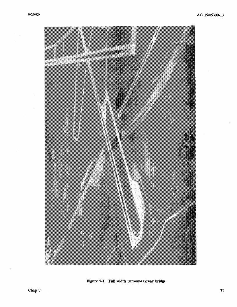
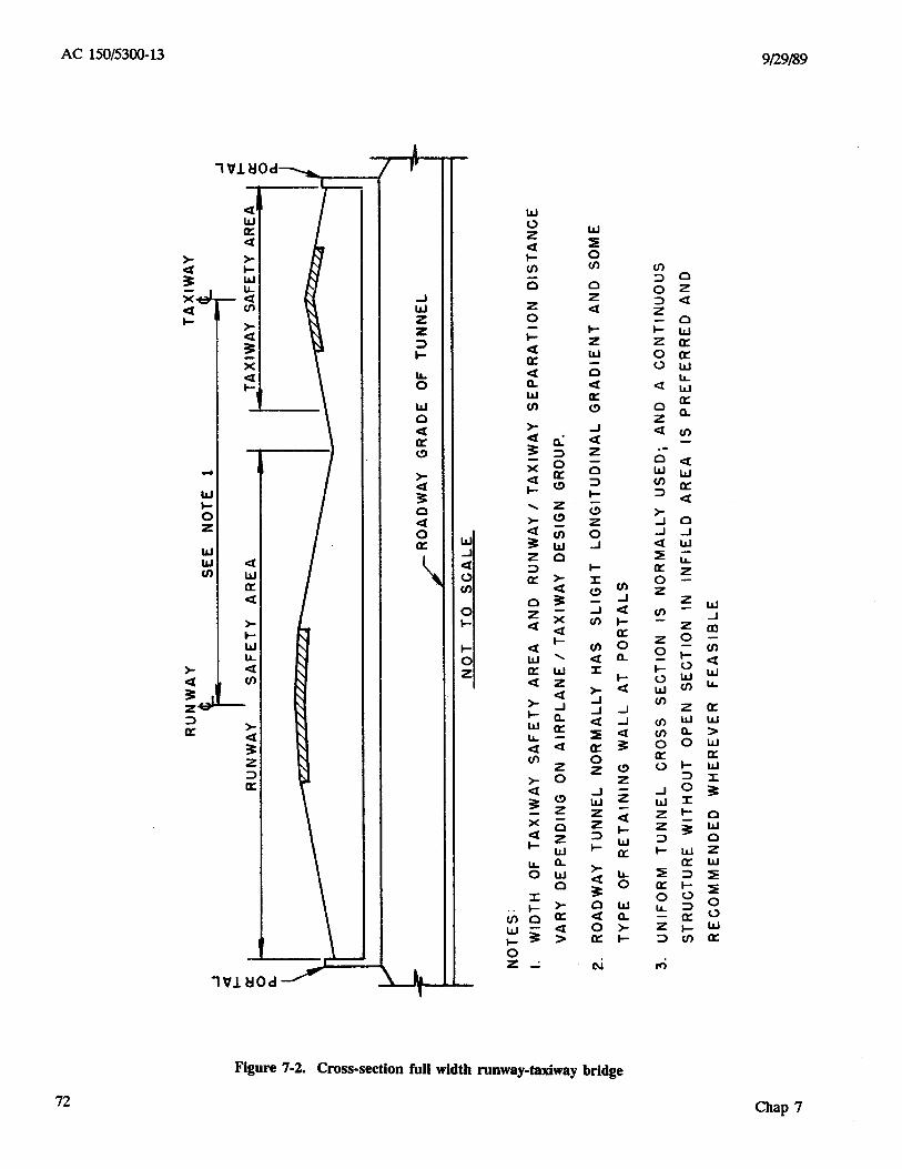


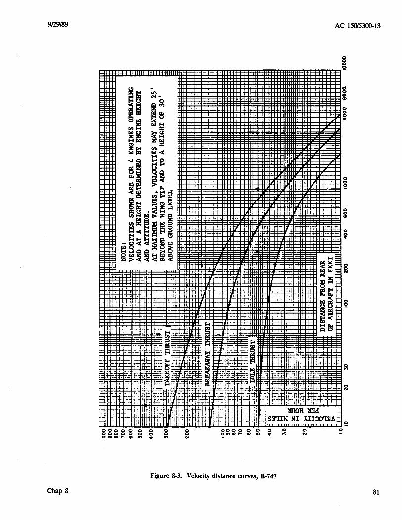

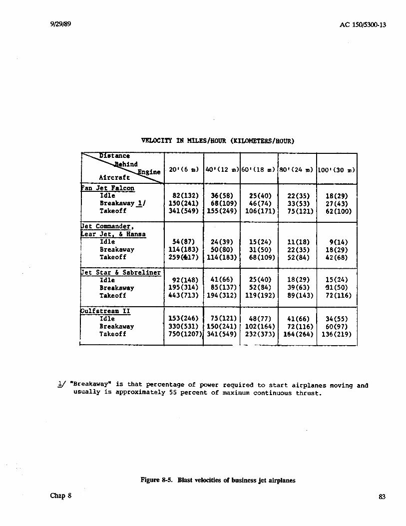
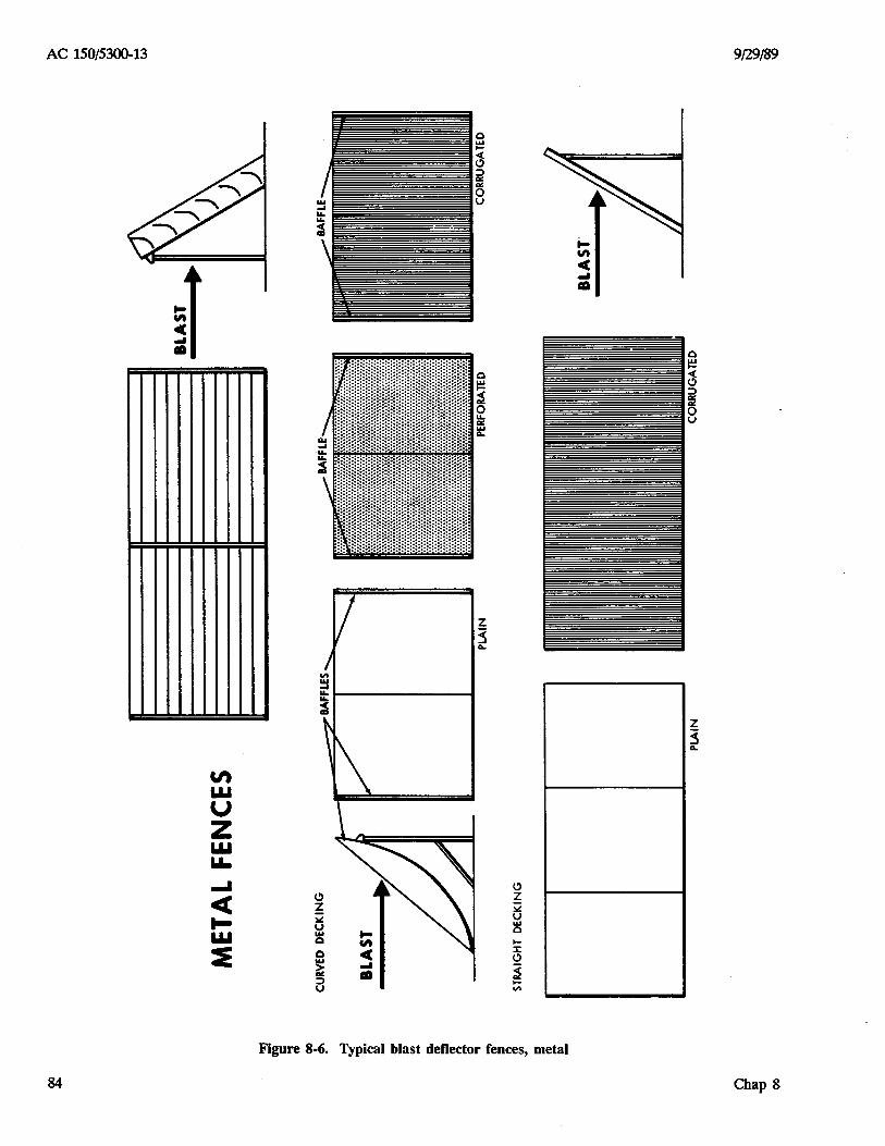
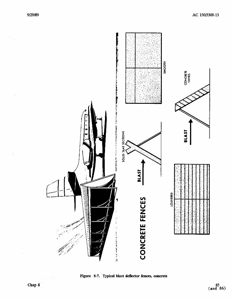

Related Documents