aerospace climate control electromechanical filtration fluid & gas handling hydraulics pneumatics process control sealing & shielding Denison GOLD CUP ® Product Catalog Piston Pumps & Motors For Open & Closed Circuits HY28-2667-01/GC/NA,EU Effective: March 01, 2010

Welcome message from author
This document is posted to help you gain knowledge. Please leave a comment to let me know what you think about it! Share it to your friends and learn new things together.
Transcript

aerospaceclimate controlelectromechanicalfiltrationfluid & gas handlinghydraulicspneumaticsprocess controlsealing & shielding
Denison GOLD CUP® Product Catalog Piston Pumps & MotorsFor Open & Closed CircuitsHY28-2667-01/GC/NA,EUEffective: March 01, 2010

2
WARNING - USER RESPONSIBILITYFAILURE OR IMPROPER SELECTION OR IMPROPER USE OF THE PRODUCTS DESCRIBED HEREIN OR RELATED ITEMS CAN CAUSE DEATH,PERSONAL INJURY AND PROPERTY DAMAGE.This document and other information from Parker-Hannifin Corporation, its subsidiaries and authorized distributors provide product or system options for further investigationby users having technical expertise.
The user, through its own analysis and testing, is solely responsible for making the final selection of the system and components and assuring that all performance, endurance,maintenance, safety and warning requirements of the application are met. The user must analyze all aspects of the application, follow applicable industry standards, and followthe information concerning the product in the current product catalog and in any other materials provided from Parker or its subsidiaries or authorized distributors.
To the extent that Parker or its subsidiaries or authorized distributors provide component or system options based upon data or specifications provided by the user, the user is responsible for determining that such data and specifications are suitable and sufficient for all applications and reasonably foreseeable uses of the components or systems.
OFFER OF SALEThe items described in this document are hereby offered for sale by Parker-Hannifin Corporation, its subsidiaries or its authorized distributor. This offer and its acceptanceare governed by the provisions stated in the detailed "Offer of Sale" elsewhere in this document.
Hydraulic Pump Division and Denison Hydraulics
The Hydraulic Pump Division of Parker Hannifin was formed in 2004 when our significant piston pump business was expanded through the acquisition of Denison Hydraulics. The addition of Denison allowed us to marry the wealth of knowledge that both companies have in the design, manufacture, and application of piston products in both open circuit and closed circuit system applications. Since before WWII, Denison products have been chosen for Military test stand applications and for shipboard hydraulic applications being recognized as technology leaders.
The heavy duty GOLD CUP® series of pumps and motors in this catalog represent a broadening of our product offering with hydrostatic transmission applications in marine, drilling, and shredding applications, among others. The tried and true design of the GOLD CUP® product line incorporates features such as integral servo and replenishing pump, hot oil shuttle, and a unique servo control system; all of which combine to provide a rugged self contained package which can withstand the harshest of conditions and continue to perform with trouble free long life.
The division is a leading worldwide manufacturer of hydraulic components and systems for earthmoving and construction vehicles; for mining equipment; for pulp and paper, chemical and other processing equipment; for ships and ordnance equipment; and for such in-plant machines as machine tools, plastic molding, die casters, and stamping presses.
© Copyright 2010, Parker Hannifin Corporation. All Rights Reserved.Mining Photo on Front Cover is the Property of Atlas Copco.
The product information, specifications, and descriptions contained in this publication have been compiled for the use and convenience of our customers from information furnished by the manufacturer; and we can not, and do not, accept any responsibility for the accuracy or correctness of any description, calculation, specifica-tion, or information contained herein. No such description, calculation, specification, or information regarding the products being sold has been made part of the basis of the bargain, nor has same created or amounted to an express warranty that the products would conform thereto. We are selling the goods and merchandise illustrated and described on this publication on an “as is” basis, and disclaim any implied warranty, including any warranty of merchantability or warranty of fitness for any particular purpose whatsoever, with respect to the goods and mer-chandise sold. All manufacturer warranties shall be passed on to our customers, but we shall not be responsible for special, indirect, incidental, or consequential damages resulting from the use of any of the products or informa-tion contained or described on this publication. Further, we reserve the right to revise or otherwise make product improvements at any time without notification.

3
Parker Hannifin CorporationHydraulic Pump DivisionMarysville, Ohio USA
HY28-2667-01/GC/NA,EU Hydrostatic Transmission Piston PumpsGOLD CUP® Series - Open & Closed Circuits
Contents .............................................................................................................................................................3
Technical Data ...............................................................................................................................................4
Features..............................................................................................................................................................7
Description .......................................................................................................................................................8
Pump, Motor DimensionsP6, 7, 8 ....................................................................................................................................................................10M6, 7, 8....................................................................................................................................................................14P11, 14 ....................................................................................................................................................................17M11, 14....................................................................................................................................................................21P24, 30 ....................................................................................................................................................................24M24, 30....................................................................................................................................................................29
Controls Dimensions10, 2A ................................................................................................................................................................34, 412H, 4A......................................................................................................................................................................355A, 5C................................................................................................................................................................36, 417D, 7J ......................................................................................................................................................................377F, 7K ......................................................................................................................................................................388A, 8C................................................................................................................................................................39, 429A, 9C................................................................................................................................................................40, 42**4............................................................................................................................................................................43**6, **8, **2 ..............................................................................................................................................................44
Rear Adapterstable.........................................................................................................................................................................45P6,7,8 .................................................................................................................................................................46-47P11,14 ..........................................................................................................................................................46, 48-50P24,30 ................................................................................................................................................................51-54
Inlet Conditions ...........................................................................................................................................55
Performance Curves ...........................................................................................................................56-61
Pump Primary Displacement Control Options...................................................................62-70
Secondary Control Options ............................................................................................................70-71
Hydraulic Schematics........................................................................................................................72-76
GOLD CUP® Pump Control Combinations...................................................................................77
Pump Ordering Code ...........................................................................................................................78-79
GOLD CUP® Motor Control Combinations ..................................................................................81
Motor Ordering Code...........................................................................................................................82-83
Offer of Sale ...................................................................................................................................................87
Contents
Contents

4
Parker Hannifin CorporationHydraulic Pump DivisionMarysville, Ohio USA
HY28-2667-01/GC/NA,EU Hydrostatic Transmission Piston PumpsGOLD CUP® Series - Open & Closed CircuitsTechnical Data
03P42P41P11P8P7P6PsmreTseireSDisplacement Max. displacement in3/rev. 6.00 7.25 8.00 11.00 14.00 24.60 30.60
cm3/rev. 98,3 118,8 131,1 180,3 229,5 403,2 501,5Pressure Continuous psi 5000 5000 3600 5000 5000 50001) 50001)
bar 350 350 250 350 350 3501) 3501)
Intermittent psi 60007) 60007) 45007) 60007) 60007) 55001)7) 55001)7)
bar 4207) 4207) 3107) 4207) 4207) 3701)7) 3701)7)
Speed (Pump) max. @ full stroke rpm 3000 3000 2100 2400 2400 21002) 1800(Motor ) max. @ full stroke rpm 3000 3000 NA 2400 2400 21002) 1800(Motor ) max. @ 50% stroke rpm 3600 3600 NA 2800 2800 21002) 1800
Mounting Flange -2 bolt SAE 127-2 (C) 127-2 (C) 127-2 (C) - - - -Flange -4 bolt (opt. on 6,7 & 8) SAE 152-4 (D) 152-4 (D) 152-4 (D) 165-4 (E) 165-4 (E) 177-4 (F) 177-4 (F)
Shaft - keyed SAE 32-1 (C) 32-1 (C) 32-1 (C) 44-1 (E) 44-1 (E) 50-1 (F) 50-1 (F)keyed SAE 44-1 (D) 44-1 (D) 44-1 (D) - - - -
Shaft - splined SAE 32-4 (C) 32-4 (C) 32-4 (C) 44-4 (E) 44-4 (E) 50-4(F) 50-4 (F)splined SAE 44-4 (D) 44-4 (D) 44-4 (D) - - - -
Weight (Pump) less controls lbs 175-300 175-300 175-300 325-530 325-530 750-835 750-835Mass kg. 80-135 80-135 80-135 145-240 145-240 340-375 340-375
Weight (Motor Fixed) lbs 110 110 N/A 250 250 510 600Mass kg. 50 50 N/A 110 110 230 270
Weight ( Motor Variable) less controls lbs 110 110 N/A 300 300 650 670Mass kg. 50 50 N/A 135 135 290 300
Rotating inertia lbs-in2 92 92 92 290 290 821 977kg.m2 0,027 0,027 0,027 0,085 0,085 0,240 0,286
Torque (Motor) theo. max. per 100 psi lbs-in 95.5 115.4 NA 175 222 392 487per 100 bar Nm 157 189 NA 287 362 623 797at 5000 psi lbs-in 4774 5769 NA 8750 11100 19576 24351at 350 bar Nm 539,5 651,9 NA 990 1250 2158 2752
Power (Motor) theo. max.at 5000 psi, 350 barper 100 rpm hp 7.6 9.2 NA 13.8 17.6 31.1 38.6
kW 5,7 6,8 NA 10,3 13,1 23,1 28,8at 2000 rpm hp 151.5 183.1 NA 277.8 353.5 621.3 695
kW 113,0 136,6 NA 207,0 263,7 463,5 518,2Torque (Motor) efficiency - approx. stalled % theo. 81 81 NA 81 81 81 81
running % theo. 93 93 NA 93 93 93 93Case pressure: max. allowable continuous psi 75 75 75 75 75 75
bar 5,2 5,2 5,2 5,2 5,2 5,2 5,2 5,2intermittent psi 125 125 125 125 125 125 125
bar 8,6 8,6 8,6 8,6 8,6 8,6 8,6(Not to exceed 25 psi,1,7 bar above inlet in open circuit units)Flow (Pump) theo.at max.displ.@1500 rpm gpm 39 47 52 71 91 160 199
lpm 148 178 197 269 344 606 753@1800 rpm gpm 47 57 62 86 109 192 238
lpm 178 216 235 326 413 727 901Displacement (Internal aux. pump) P6,7,8P,S,V P11,14P,S P11,14V P24P P24S3) P30P P30S3)
in3/rev. 1.07 (2) 1.074) 1.075) 2.816) 2.816) 2.816) 2.816)
cm3/rev. 17,5 (2) 17,5 17,5 46,1 46,1 46,1 46,1Flow (Internal aux. pump) @1500 rpm gpm 6.9 (2) 6.9 6.9 18.2 6.5 18.2 6.5
lpm 26,1 (2) 26,1 26,1 68,9 24,6 69,1 24,6@1800 rpm gpm 8.3 (2) 8.3 8.3 21.9 7.8 21.9 7.8
lpm 31,4 (2) 31,4 31,4 82,9 29,5 82,9 29,5
1) Max. pressure 5000 psi, (350 bar) for M24 and 30 series variable motors. Higher servo pressure may be required - consult Parker.
2) On HF-1 fluids, 1800 RPM Max. on HF-0 fluids.
3) Internal cartridge provides servo flow and must be supercharged from external replenishing flow, from external auxiliary pump.
4) One servo cartridge and one replenishing cartridge.
5) Servo cartridge only.
6) Standard, other sizes available, see ordering code.
7) 10% of operation time, not exceeding 6 successive seconds.

5
Parker Hannifin CorporationHydraulic Pump DivisionMarysville, Ohio USA
HY28-2667-01/GC/NA,EU Hydrostatic Transmission Piston PumpsGOLD CUP® Series - Open & Closed CircuitsTechnical Data
Replenishing pressure (Internal aux. pump) P6,7,8,11,14,24P P6,7,8,11,14,24S P30P P30S
12,4-15,2 12,4-15,2 12,4-15,2 12,4-15,2Servo pressure (Internal aux. pump) psi 308-420 308-420 308-420 308-420Servo pressure minus case pressure bar 21,2-29,0 21,2-29,0 21,2-29,0 21,2-29,0at 0 psi, 0 bar discharge pressure
03P42P41P11P8P7P6PsmreTseireSControlsCompensator response off-stroke sec. 0.05 0.05 0.05 0.07 0.07 0.10 0.10(per SAE J497 @ 5000 psi, 350 bar) on-stroke sec. 0.9 0.9 0.9 1.5 1.5 1.8 1.8Compensator adjustment psi/turn 2000 2000 2000 2000 2000 2000 2000
bar/turn 138 138 138 138 138 138 138Torque to turn rotary servo shaft in.-lbs 20 20 20 20 20 20 20
Nm 2,3 2,3 2,3 2,3 2,3 2,3 2,3
The maximum inlet at the auxiliary pump inlet is 200 psi. (13,8 bar)
Minimum compensating pressure will always be 100-200 psi. (6,9-13,8 bar) over servo pressure.
Any inlet pressures above atmospheric will increase noise levels and decrease efficiencies noted in this literature. Exact measurements dependon each application and operating conditions. Please consult your nearest Parker Office for further details.
*Standard factory compensating pressure is 1,000 psi. (69,0 bar).
*Note: Nominal setting, may be increased if required.
**Replenish pressure minus case pressure psi 180-220 180-220 180-220 180-220 bar
Servo pressure (Internal aux. pump) psi 500-650 500-650 500-650 500-650for HI-IQ control units. Servo pressure minus bar 34,5-44,8 34,5-44,8 34,5-44,8 34,5-44,8case pressure at 5000 psi, 350 bar discharge pressure - at system pressure range 0 to 5000 psi, 350 bar.
(Aboverepl.)

6
Parker Hannifin CorporationHydraulic Pump DivisionMarysville, Ohio USA
HY28-2667-01/GC/NA,EU Hydrostatic Transmission Piston PumpsGOLD CUP® Series - Open & Closed CircuitsTechnical Data
REAR DRIVE TORQUE CAPACITY
TFAHSTUPTUORAERSGNITNUOMRAERTFAHSTUPNITNORFSAE
SERIES TYPE TORQUE CAPACITY A B C D E F TORQUE CAPACITY
P6,7,8 Keyed SAE 32-1(C) 6920 in-lbs. • • 1750 in-lbs.P,S,V,X Spline SAE 32-4(C) (780 Nm) • • (195 Nm)
P6,7,8 Keyed SAE 44-1(D) 6920 in-lbs. • • 1750 in-lbs.P,S,V,X Spline SAE 44-4(D) (780 Nm) • •
• • •• • •
(195 Nm)
P6,7,8 Keyed SAE 32-1(C)* 13,845 in-lbs. 6920 in-lbs.R,L,D only Spline SAE 32-4C (1565 Nm)
• • •• • • (780 Nm)
P11,14 Keyed SAE 44-1(E) 13,370 in-lbs. 2400 in-lbs.P,S,V,X Spline SAE 44-4(E) (1510 Nm) (270 Nm)
P11,14 Keyed SAE 44-1(E)* 26735 in-lbs. 13,370 in-lbs.R,L only Spline SAE 44-4(E) (3020 Nm)
• • • • •• • • • • (1510 Nm)
P24,30 Keyed SAE 50-1(F) 24350 in-lbs. • • 2700 in-lbs.P,S,X Spline SAE 50-4(F) (2750 Nm) • • (305 Nm)
P24,30 Keyed SAE 50-1(F) 48,700* in-lbs. • • • • • 24,350 in-lbsR,L only Spline SAE 50-4(F) (5,500 Nm) • • • • • (2750 Nm)
* Coupling for keyed shaft must be pressed fit for full torque capability.
P6/7/8 SAE 127-2 Mtg., 32-1, 4 Shaft Bearing 230-82140 (6007)Speed (rpm) 1000 1000 1000 1000 1200 1200 1200 1200 1500 1500 1500 1500 1800 1800 1800 1800
00010001000100010001000100010001)sbl(daoLtfahS84448444844484448444844484448444)N(daoLtfahS
Case Pressure (psi) 0 25 0 25 0 25 0 25 0 25 0 25 0 25 0 25Case Pressure (bar) 0.0 1.7 0.0 1.7 0.0 1.7 0.0 1.7 0.0 1.7 0.0 1.7 0.0 1.7 0.0 1.7B-10 Life (hours x 1000) 8E+08 1833 0.778 0.778 6E+08 1528 0.648 0.648 5E+08 1222 0.518 0.518 4E+08 1018 0.432 0.432
P6/7/8 SAE 152-4 Mtg., 44-1, 4 Shaft Bearing 230-00207-0 (6207)Speed (rpm) 1000 1000 1000 1000 1200 1200 1200 1200 1500 1500 1500 1500 1800 1800 1800 1800
00010001000100010001000100010001)sbl(daoLtfahS84448444844484448444844484448444)N(daoLtfahS
Case Pressure (psi) 0 25 0 25 0 25 0 25 0 25 0 25 0 25 0 25Case Pressure (bar) 0.0 1.7 0.0 1.7 0.0 1.7 0.0 1.7 0.0 1.7 0.0 1.7 0.0 1.7 0.0 1.7B-10 Life (hours x 1000) 3E+09 7394 3.136 3.136 3E+09 6161 2.613 2.613 2E+09 4929 2.09 2.09 2E+09 4170 1.742 1.742
Speed (rpm) 1000 1000 1000 1000 1200 1200 1200 1200 1500 1500 1500 1500 1800 1800 1800 1800Shaft Load (lbs) 0 0 1000 1000 0 0 1000 1000 0 0 1000 1000 0 0 1000 1000Shaft Load (N) 0 0 4448 4448 0 0 4448 4448 0 0 4448 4448 0 0 4448 4448Case Pressure (psi) 0 25 0 25 0 25 0 25 0 25 0 25 0 25 0 25Case Pressure (bar) 0.0 1.7 0.0 1.7 0.0 1.7 0.0 1.7 0.0 1.7 0.0 1.7 0.0 1.7 0.0 1.7B-10 Life (hours x 1000) 2E+09 535 1.907 1.907 2E+09 446 1.589 1.589 1E+09 356 1.272 1.272 1E+09 297 1.06 1.06
P11/14 SAE 165-4 Mtg., 44-1, 4 Spherical Roller Shaft Bearing 230-82214-0 (22208) (7 & 8 Shaft Codes)Speed (rpm) 1000 1000 1000 1000 1200 1200 1200 1200 1500 1500 1500 1500 1800 1800 1800 1800Shaft Load (lbs) 0 0 1000 1000 0 0 1000 1000 0 0 1000 1000 0 0 1000 1000Shaft Load (N) 0 0 4448 4448 0 0 4448 4448 0 0 4448 4448 0 0 4448 4448Case Pressure (psi) 0 25 0 25 0 25 0 25 0 25 0 25 0 25 0 25Case Pressure (bar) 0.0 1.7 0.0 1.7 0.0 1.7 0.0 1.7 0.0 1.7 0.0 1.7 0.0 1.7 0.0 1.7B-10 Life (hours x 1000) 16856 2452 275 172 14046 2043 230 143 11237 1635 184 114.8 9364 1363 153 95.7
P24 SAE 177-4 Mtg., 50-1, 4 Shaft Bearing 230-82213-0 (22311)Speed (rpm) 1000 1000 1000 1000 1200 1200 1200 1200 1500 1500 1500 1500 1800 1800 1800 1800Shaft Load (lbs) 0 0 1000 1000 0 0 1000 1000 0 0 1000 1000 0 0 1000 1000Shaft Load (N) 0 0 4448 4448 0 0 4448 4448 0 0 4448 4448 0 0 4448 4448Case Pressure (psi) 0 25 0 25 0 25 0 25 0 25 0 25 0 25 0 25Case Pressure (bar) 0.0 1.7 0.0 1.7 0.0 1.7 0.0 1.7 0.0 1.7 0.0 1.7 0.0 1.7 0.0 1.7B-10 Life (hours x 1000) 591.6 428.5 276.7 213.5 493 357 230.5 178 394.4 991.6 184.4 142.3 328.7 238 153.7 118.6
P30 SAE 177-4 Mtg., 50-1, 4 Shaft Bearing 230-82213-0 (22311)Speed (rpm) 1000 1000 1000 1000 1200 1200 1200 1200 1500 1500 1500 1500 1800 1800 1800 1800Shaft Load (lbs) 0 0 1000 1000 0 0 1000 1000 0 0 1000 1000 0 0 1000 1000Shaft Load (N) 0 0 4448 4448 0 0 4448 4448 0 0 4448 4448 0 0 4448 4448Case Pressure (psi) 0 25 0 25 0 25 0 25 0 25 0 25 0 25 0 25Case Pressure (bar) 0.0 1.7 0.0 1.7 0.0 1.7 0.0 1.7 0.0 1.7 0.0 1.7 0.0 1.7 0.0 1.7B-10 Life (hours x 1000) 227 177.7 126.4 102.8 189.2 148 105.3 85.6 151.3 118.4 84.2 68.5 126.1 98.7 70.2 57.1
Note: Variation in life is due to variations in tolerances within the pump.Contact Parker Hydraulics for B-10 with other operating conditions and with other case pressure values.Consult Parker Hydraulics for shaft side loads of P*R units.
*radial load at center of key or spline
0 00 0
0 00 0
0 00 0
0 00 0
**
**
P11/14 SAE 165-4 Mtg., 44-1, 4 Radial Shaft Bearing 230-82148-0 (6010) (2 & 3 Shaft Codes)
0 00 0
0 00 0
0 00 0
0 00 0
**
**
**
**

7
Parker Hannifin CorporationHydraulic Pump DivisionMarysville, Ohio USA
HY28-2667-01/GC/NA,EU Hydrostatic Transmission Piston PumpsGOLD CUP® Series - Open & Closed Circuits
17
18
19
20
21
Patented ring style replenishing checksfastest operation with no sliding poppetsor parts and low pressure drop
Hot oil shuttle available - fast, reliableoperation
8
96
19
21
Quick change valve block - easy toservice or replace
Quick change controls - easy toservice and change
Dampened low inertia rocker cam -more stable, quieter and faster thanother designs
Exclusive zero-backlash rotary servodesign - lifetime accuracy
Field adjustable compensator override -easily adjusted without removing frommachinery
Precision barrel bearing, a distinctiveDenison Hydraulics feature for over 30years - permits high speeds, highpressure and provides long life
Versatile controls - can be located oneither side of pump or motor formaximum freedom of design
1
2
3
4
5
6
7
Auxiliary pump can be changed withoutdisassembling the transmission
Standard SAE keyed or splined driveshafts are available
High pressure mechanical shaft sealscan be changed without disassemblingthe transmission. Double lip seals are alsoavailable
One piece stroking vane/cam means nolost motion, zero backlash, better control,and no linkages to wear out
Stroking vane seals are pressure loadedfor longer life
Manual)
12
13
14
Standard compensator vent ports allowfor a wide variety of controls (SeeApplications
1510
11
Modulated servo pressure saves power
Standard Code 62 SAE split flangeconnections
Conforms to SAE mounting standards.
Fast compensator response. See page 5.
Variable motors available for multiplespeed ranges or constant power
Note: 1. These products, with exception of 8 cubic inch units, are qualified tomeet Military specifications MIL-P-17869A and MIL-S-901-C Grade A.
2. All GOLD CUP® Pumps and Motors* have ATEX approval.*See ordering code for availability.
3. Consult factory for other approvals such as ABS and Lloyd's Registry.
Rocker cam displacement indicator helpstroubleshoot the system16
Features
or parts and low pressure drop
Hot oil shuttle available - fast, reliableoperation
9
1914
13
11
12
6
16
17
15
18
51
20
7
2
3
188
10
12
116
19
4
72
21

8
Parker Hannifin CorporationHydraulic Pump DivisionMarysville, Ohio USA
HY28-2667-01/GC/NA,EU Hydrostatic Transmission Piston PumpsGOLD CUP® Series - Open & Closed Circuits
CLOSED HYDRAULIC CIRCUIT Variable Pump/Fixed Motor. This combination provides for a constant torque output at a fixed maximum pressure over the full speed range. Speed and direction are controlled with a variable displacement over-center pump. Power from overhauling loads is regenerated back into the pump prime mover. Motor speed is limited to the maximum speed permitted by full pump displacement.System is capable of full power only at maximum pump displacement.
Variable Pump/Variable Motor. This combination provides for an extended range of motor speeds. The motor, at full displacement, delivers maximum torque while its speed and direction respond to displacement changes of the crossover center pump. Power is proportional to motor speed.
This transmission system has the capability of constant torque and rising power until the pump reaches full displacement and full power at elevated speeds as motor displacement and torque are reduced.
The package pump contains the circuit elements shown in the hydraulic schematic on pgs. 72-74. These include the axial piston over-center variable displacement pump which controls the speed and direction of the motor, the auxiliary pump which supplies servo pressure (for controlling the displacement of the variable pump) and replenishment pressure, the servo pressure relief valve, the replenishment pressure relief valve and the replenishment check valves for ports A and B. The pump package also includes the displacement control valves as well as an external arm which shows actual displacement.The various control features are described below.
The package motor, shown in schematic pgs. 72-74, contains the axial piston fluid motor, the shuttle valve that continuously removes hot oil from the low pressure side of the loop and a relief valve to establish minimum hydraulic loop pressure at the motor. The fluid motor is available with fixed displacement or with the variable displacement option. The standard variable motors include an external indicator which shows displacement.
The open circuit pump contains the circuit elements shown on pages 75,76.These include a cross-center variable displacement pump which is normally limited to one side of center. The auxiliary pump supplies only servo pressure to control the main pump displacement and inlet porting is enlarged to improve the pump’s inlet characteristics. As the open loop pump operates on one side of center only, not all controls are available.
Additional auxiliary flow is available with the rear drive pump option. The rear drive may also be utilized for servo and other purposes. See ordering code for additional detail.
“R” & “L” style pumps have no rear shaft seal, so any pump driven must be able to withstand case pressure of the pump driving it.
Integral to the package pump’s envelope is the gerotor auxiliary pump.(P24P, P24S, P30P & P30S have vane integral pump). It provides servo and replenishing pressure. See page 5 for factory settings.NOTE: Auxiliary pump inlet must be connected directly to the reservoir.Customer must supply external line from integral auxiliary pump back into main pump for filtering servo and/or replenishing oil.(see installation drawings starting on pg 10.)
POWER CHARACTERISTICS OFHYDROSTATIC TRANSMISSIONS
PACKAGE PUMP
PACKAGE MOTOR
OPEN CIRCUIT PUMP
AUXILIARY REAR DRIVE
AUXILIARY PUMP
Description
9
Parker Hannifin CorporationHydraulic Pump DivisionMarysville, Ohio USA
HY28-2667-01/GC/NA,EU Hydrostatic Transmission Piston PumpsGOLD CUP® Series - Open & Closed Circuits
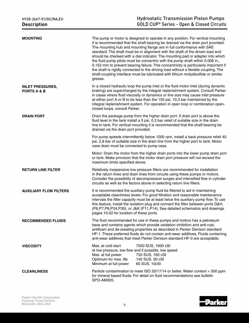
The pump or motor is designed to operate in any position. For vertical mounting it is recommended that the shaft bearing be drained via the drain port provided.The mounting hub and mounting flange are in full conformance with SAE standard. The shaft must be in alignment with the shaft of the driven load and should be checked with a dial indicator. The mounting pad or adapter into which the fluid pump pilots must be concentric with the pump shaft within 0.006 in.,0,152 mm to prevent bearing failure. This concentricity is particularly important if the shaft is rigidly connected to the driving load without a flexible coupling. The shaft-coupling interface must be lubricated with lithium molydisulfide or similar grease.
In a closed hydraulic loop the pump inlet or the fluid motor inlet (during dynamic braking) are supercharged by the integral replenishment system. Consult Parker in cases where fluid viscosity or dynamics or line size may cause inlet pressure at either port A or B to be less than the 150 psi, 10,3 bar maintained by the integral replenishment system. For operation in open loop or combination open-closed loops, consult Parker.
Drain the package pump from the higher drain port. If drain port is above the fluid level in the tank install a 5 psi, 0,3 bar relief of suitable size in the drain line to tank. For vertical mounting it is recommended that the shaft bearing be drained via the drain port provided.
For pump speeds intermittently below 1000 rpm, install a back pressure relief 40 psi, 2,8 bar of suitable size in the drain line from the higher port to tank. Motor case drain must be connected to pump case.
Motor: Drain the motor from the higher drain ports into the lower pump drain port or tank. Make provision that the motor drain port pressure will not exceed the maximum limits specified above.
Relatively inexpensive low pressure filters are recommended for installation in the return lines and drain lines from circuits using these pumps or motors.Consider the possibility of decompression surges and intensified flow in cylinder circuits as well as the factors above in selecting return line filters.
It is recommended the auxiliary pump fluid be filtered to aid in maintaining acceptable cleanliness levels. For good filtration and reasonable maintenance intervals the filter capacity must be at least twice the auxiliary pump flow. To use this feature, install the isolation plug and connect the filter between ports G&H, (P6,P7,P8,P24,P30), or J&K (P11,P14). See detailed schematics and drawings pages 10-22 for location of these ports.
The fluid recommended for use in these pumps and motors has a petroleum base and contains agents which provide oxidation inhibition and anti-rust, antifoam and de-areating properties as described in Parker Denison standard HF-1. These preferred fluids do not contain anti-wear additives. Fluids containing anti-wear additives that meet Parker Denison standard HF-0 are acceptable.
Max. at cold start 7500 SUS, 1600 cStat low pressure, low flow and if possible, low speed Max. at full power 750 SUS, 160 cSt Optimum for max. life 140 SUS, 30 cSt Minimum at full power 60 SUS, 10cSt
Particle contamination to meet ISO 20/17/14 or better. Water content < 500 ppm for mineral based fluids. For detail on fluid recommendations see bulletin SPO-AM305.
MOUNTING
INLET PRESSURES,PORTS A & B
DRAIN PORT
RETURN LINE FILTER
AUXILIARY FLOW FILTERS
RECOMMENDED FLUIDS
VISCOSITY
CLEANLINESS
Description

10
Parker Hannifin CorporationHydraulic Pump DivisionMarysville, Ohio USA
HY28-2667-01/GC/NA,EU Hydrostatic Transmission Piston PumpsGOLD CUP® Series - Open & Closed Circuits
.89
(22,6)
(21,6)
.85
(124,5)
5.30
(134,6)
(257,6)
10.14
10.54
(267,7)
4.9013.40
(340,4)
13.80
(350,5)
L4L3L2MOUNTING
(SAE-C)
(SAE-D)
SAE 127-2
SAE 152-4
L1
(291,1)
11.46
11.06
(280,9)
11.59
(294,3)
11.19
(284,2).85
(21,6)
.89
(22,6)
(124,5)
(134,6)
5.30
4.90
L1MOUNTING
(SAE-C)
(SAE-D)
SAE 127-2
SAE 152-4
L4L2 L3
P6-P7-P8F, M Dimensions
NOTE: See page 16 for shaft information.See pages 45-54 for rear drive information.
D2 ALT. DRAIN CONN.
(291,1)
11.46
11.06
(280,9)
11.59
(294,3)
11.19
(284,2)
SAE-12 STR. THD.
.85
(21,6)
.89
(22,6)
(124,5)
(134,6)
5.30
4.90
1.68
(42,7)
DIA.
1.05
(207 BARS)
(26,7)-13UNC x DEEP
SAE-
1/24-PLACES
(50,8)4-BOLT FLG. CONN.
DEEP 3000 PSI 2.00
4-PLACES5/8-11UNC x
(33,0)1.30
(36,6)
1.44
(414 BARS)
6000 PSI
DRAIN CONN.
D1SAE-12 STR. THD.
DIA.SAE-(38,1)
1.50
SAE-12 STR. THD."D" CASE DRAIN CONN.
4-BOLT FLG. CONN.(21,3)
.84
(76,2)
3.00
(76,2)
3.00
(77,7)
3.06(38,9)
1.53
(18,3)
.72
(39,6)
3.12
(79,2)
1.56
P*FL1MOUNTING
(SAE-C)
(SAE-D)
SAE 127-2
SAE 152-4
L2L1
L4A
L4L2 L3
L3A
AB
(114,3)
4.50
SAE-12 STR. THD.DRAIN CONN.
D1
3.94
(99,9)
(99,9)
3.94
SAE-12 STR. THD.D2 ALT. DRAIN CONN.
.89
(22,6)
(21,6)
.85
1.56
(39.6)
(33,0)1.30 DP.
(124,5)
5.30
(134,6)
(257,6)
10.14
10.54
(267,7)
4.90
1.44
(36.6)
4 PLACES AS SHOWN5/8-11 UNC-2B TAP x
(18.3)
.72
3.12
(79.2)
.25(6.4)
(114,3)
4.50
13.40
(340,4)
13.80
(350,5)
L4
L3
L2L1
A
A
SYSTEM PORT B (NEAR SIDE)SYSTEM PORT A (FAR SIDE)
L4L3L2
6000 PSI(418 BARS)
MOUNTING
(SAE-C)
(SAE-D)
SAE 127-2
SAE 152-4
1.50(38.1)
SAE- DIA.
L1
4-BOLT FLG. CON
P*F
P*M
11
Parker Hannifin CorporationHydraulic Pump DivisionMarysville, Ohio USA
HY28-2667-01/GC/NA,EU Hydrostatic Transmission Piston PumpsGOLD CUP® Series - Open & Closed Circuits
15.04
(382,1)
(348,0)
13.70
16.85
(427,9)
15.51
(393,9)
5.15
6.49
(164,8)
(130,9)
8.36
(212,3)
11.98
(304,3)
10.64
(270,3)
1.00
(25,4)
.86
(21,8)
(178,3)
7.02
L2TABLE 1
L1MOUNTING
(SAE-C)
(SAE-D)
SAE 127-2
SAE 152-4
L7L5L4L3
P6-P7-P8V, D, P Dimensions (Less Controls)
PORT "B"
(114,3)(114,3)
MAIN LOOP GAGE CONN.
K AUXILIARY REPLENISH PORTSAE-16 STR. THD.
AG FAR SIDEBG THIS SIDE
SAE-6 STR. THD.C AUXILIARY PUMP INLET
SAE-16 STR. THD.
ALT. DRAIN CONN. D2SAE-12 STR. THD.
SAE-12 STR. THD.ALT. DRAIN CONN.
D1
3.87
(98,3)TYP.
(93,9)
3.70
3.12
(79,2)
1.56
(39,6)
5.27
(133,9)
.84
(21,3)
3.06
(77,7)
1.53
(38,9)
(26,7)1.05
1.68
(42,7)
4-PLACES1/2-13UNC x
3.00
(76,2)
1.38(35,1)
DEEP
3.00
(76,2)
.72
(18,3)
(36,6)
1.44
(414 bar)
6000 PSI (38,1)
1.50SAE-
4-BOLT FLG. CONN
DIA.
5/8-11UNC x
4-PLACES
SAE-8 STR. THD.
(NEAR SIDE) AUXILIARY PUMP OUTLET GTO EXTERNAL FILTER & SERVO GAGE CONN.
4.504.50
SAE-8 STR. THD.
FILTER RETURN PORTH AUXILIARY PUMP (FAR SIDE)
PORT "A"
4-BOLT FLG. CONN
SAE-(50,8)2.00 DIA.
(207 bar) 3000 PSI
AB
L1A
P*V L2TABLE 1
L7L3
L1MOUNTING
L4L5
L2A
L7L5L4L3
6.0 & 7.25 GOLD CUP®
NOTE: See page 16 for shaft information.See appropriate controls mounting starting on page 34.
1.56
MAIN LOOP GAGE CONN.SAE-12 STR. THD.ALT. DRAIN CONN. D2
SAE-16 STR. THD.C AUXILIARY PUMP INLET
SAE-6 STR. THD.
AG FAR SIDEBG THIS SIDE
(36,6)
1.44
(79,2)
3.12
(39,6)
TYP. PORTS "A" & "B"
DEEP(35,1)
1.38
8-PLACES5/8-11UNC x
(39,6)
1.56
3.12
(79,2)
DIA.(38,1)
1.50SAE-
4-BOLT FLG. CONN
(93,9)
3.70
1.44
(36,6)
6000 PSI
(414 bar)
SAE-16 STR. THD.K AUXILIARY REPLENISH PORT
SAE-8 STR. THD.TO EXTERNAL FILTER & SERVO GAGE CONN.
(NEAR SIDE) AUXILIARY PUMP OUTLET G
D1
TYP.(98,3)
3.87
ALT. DRAIN CONN.SAE-12 STR. THD.
.72
(18,3)
4.50
(114,3)(114,3)
4.50
(76,2)
3.00 3.00
(76,2)
SAE-8 STR. THD.
FILTER RETURN PORTH AUXILIARY PUMP (FAR SIDE)
.72
(18,3)
5.27
(133,9)
AB
A
L4L5
L2A
L7L3
L1
P*V
P*D & P*P

12
Parker Hannifin CorporationHydraulic Pump DivisionMarysville, Ohio USA
HY28-2667-01/GC/NA,EU Hydrostatic Transmission Piston PumpsGOLD CUP® Series - Open & Closed CircuitsP6-P7-P8X, R Dimensions (Less Controls)
NOTE: See page 16 for shaft information.See pages 45-54 for rear drive information.See appropriate controls mounting starting on page 34.
REAR ADAPTER
(114,3)
(114,3)
4.50
4.50 (114,3)
(114,3)
4.50
4.50
K REPLENISHING PORT INLET
H SERVO GAGE CONN.
SAE-8 STR. THD.
SAE-6 STR. THD.A1 SYSTEM GAGE CONN.
SAE-16 STR. THD.
G CONTROL PRESSURE INLET
3.87
(98,3)
SAE-6 STR. THD.B1 SYSTEM GAGE CONN.
SAE-12 STR. THD.ALT. DRAIN CONN. D2
5.15
6.49
(164,8)
(130,9)10.647.02
(178,3)
1.00
(25,4)
15.51
(393,9)
.86
(21,8)
8.36
(212,3)
16.85
(427,9)
(270,3)
11.98
(304,3)
6.02
(152,8)
11.88
(301,8)
(335,9)
13.22 16.48
15.14
(384,6)
(418,7)
3.70
(94,0)
SAE-4 STR. THD.
.25
(6.3)3.87
(98,3)
D1SAE-12 STR. THD.
DRAIN CONN.
6.07
(154,1)
(36.6)
1.44
DP.
3.12
(79.2)
.72
5/8-11 UNC-2B TAP x4 PLACES AS SHOWN
(18.3)
1.30(33,0)
(39.6)
1.56
P*RA
A
SYSTEM PORT B (NEAR SIDE)
L4
L6L2
L5
TABLE 2
L7L6L5L3 L4L1 L2
SAE 152-4
SAE 127-2
(SAE-D)
(SAE-C)
MOUNTING
DIA.SAE-(38.1)1.50
4-BOLT FLG. CON
6000 PSI(418 BARS)
L7L3
L1
SYSTEM PORT A (FAR SIDE)
4 BOLT FLG. CONNECTION
B A
(33,3)
1.31
(455,2)
(421,2)
17.9211.98
(304,3)
16.48
(418,6)18.61
(472,6)
(438,6)
17.27
(21,8)
.86
(25,4)
1.00
(212,3)
8.36
(178,3)
7.02
(98,3)
3.87
(98,3)
3.87
SAE-16 STR. THD.C AUXILIARY PUMP INLET
10.6415.14
(384,6) (270,3)
ALT. DRAIN CONN. D2SAE-12 STR. THD.
16.58 5.15
6.49
(164,8)
(130,9)
(133,9)
5.27
3.13
(79,4)
-11UNC-2B THREAD x
(39,7)
1.56
(18,3)
.72
1.44
(36,6)
8-PLACES5/8
R3.38(85,8)
(23,0).90
.90(23,0)
(93,9)
3.70
DEEP
(136,5)5.38
H AUXILIARY PUMP (FAR SIDE)
D1
ALT. DRAIN CONN.SAE-12 STR. THD.
(NEAR SIDE) AUXILIARY PUMP OUTLET GTO EXTERNAL FILTER & SERVO GAGE CONN.
SAE-8 STR. THD.SAE-8 STR. THD.FILTER RETURN PORT PUMP FILTER RETURN PORT
SAE-12 STR. THD.
K AUXILIARY REPLENISH AND
5.38(136,5)
SYSTEM PORT B (NEAR SIDE)SYSTEM PORT A (FAR SIDE)
SEE DETAIL "A"
P*X
A
TABLE 3
L4 L5L2 L3 L6MOUNTING
(SAE-C)
(SAE-D)
SAE 127-2
SAE 152-4
L1
L4L5L2
L1
L7
SYSTEM PORT B (NEAR SIDE)SYSTEM PORT A (FAR SIDE)
(414 BARS) 6000 PSI
(38,1)SAE- 1.50 DIA.
4-BOLT FLG. CONNECTION
A
L7L3
L6
(455,2)
(421,2)
17.9211.98
(304,3)
16.48
(418,6)18.61
(472,6)
(438,6)
17.27
(21,8)
.86
(25,4)
1.00
(212,3)
8.36
(178,3)
7.02
SAE-16 STR. THD.C AUXILIARY PUMP INLET
10.6415.14
(384,6) (270,3)
16.58 5.15
6.49
(164,8)
(130,9)
TABLE 3
L4 L5L2 L3 L6MOUNTING
(SAE-C)
(SAE-D)
SAE 127-2
SAE 152-4
L1 L7
5.15
6.49
(164,8)
(130,9)10.647.02
(178,3)
1.00
(25,4)
15.51
(393,9)
.86
(21,8)
8.36
(212,3)
16.85
(427,9)
(270,3)
11.98
(304,3)
11.88
(301,8)
(335,9)
13.22 16.48
15.14
(384,6)
(418,7)
TABLE 2
L7L6L5L3 L4L1 L2
SAE 152-4
SAE 127-2
(SAE-D)
(SAE-C)
MOUNTING
(38.1) 4-BOLT FLG. CON
(418 BARS)
13
Parker Hannifin CorporationHydraulic Pump DivisionMarysville, Ohio USA
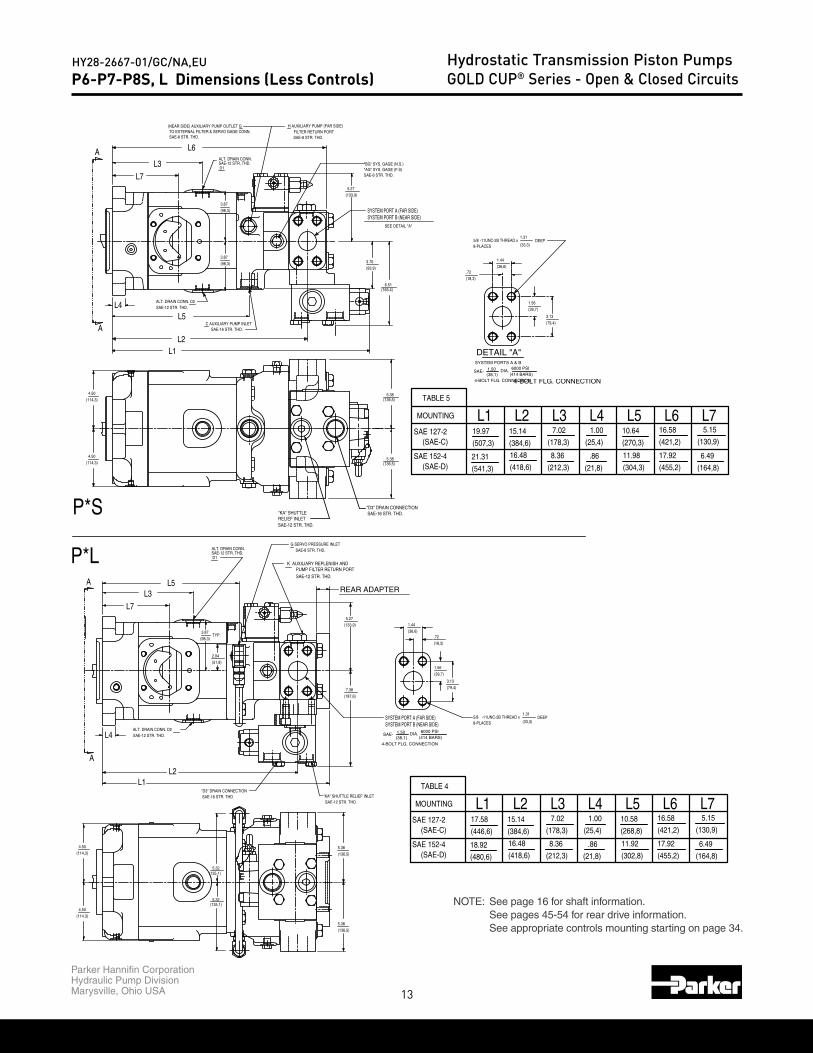
HY28-2667-01/GC/NA,EU Hydrostatic Transmission Piston PumpsGOLD CUP® Series - Open & Closed CircuitsP6-P7-P8S, L Dimensions (Less Controls)
NOTE: See page 16 for shaft information.See pages 45-54 for rear drive information.See appropriate controls mounting starting on page 34.
REAR ADAPTER
5.15
(164,8)
(130,9)
DEEP
(114,3)
(114,3)
4.50
4.50
(187,6)
SAE-12 STR. THD."KA" SHUTTLE RELIEF INLET
"D3" DRAIN CONNECTIONSAE-16 STR. THD.
ALT. DRAIN CONN. D2SAE-12 STR. THD.
(135,1)
(135,1)5.32
5.32
6.49
1.31
(33,3)5/8 -11UNC-2B THREAD x8-PLACES
(421,2)
(455,2)
17.92
16.5810.58
(268,8)
11.92
(302,8)
(384,6)
(418,6)
16.48
15.14(178,3)
(212,3)
8.36
7.0217.58
(446,6)
18.92
(480,6)
(25,4)
(21,8)
.86
1.00
5.38
5.38
(136,5)
(136,5)
SYSTEM PORT B (NEAR SIDE)SYSTEM PORT A (FAR SIDE)
G SERVO PRESSURE INLET
PUMP FILTER RETURN PORTK AUXILIARY REPLENISH AND
SAE-12 STR. THD.
SAE-8 STR. THD.
TYP.
2.04
(51,8)
(98,3)
3.87
D1SAE-12 STR. THD.ALT. DRAIN CONN.
1.44
(36,6)
(39,7)
1.56
(18,3)
.72
3.13
(79,4)
5.27
(133,9)
7.38
A
L4
P*LA
L2L1
TABLE 4
L7L5 L6L2 L3MOUNTING L1
DIA.1.50(38,1) (414 BARS)
6000 PSI
L4
SAE 152-4
SAE 127-2(SAE-C)
(SAE-D)
4-BOLT FLG. CONNECTION
SAE-
L7L3
L5
DETAIL "A"
(79,4)
(421,2)
(455,2)
17.92
16.58
C AUXILIARY PUMP INLET
(114,3)
4.50
4.50
(114,3)
SAE-16 STR. THD.
(25,4)
8.36 11.98
(21,8)
.86
7.02 10.641.00
(270,3)
(304,3)
(507,3) (384,6)
(541,3)
21.31(418,6)
16.48
19.97 15.14
5.38
5.38
(178,3)
(212,3)
(136,5)
(136,5)
FILTER RETURN PORTH AUXILIARY PUMP (FAR SIDE)
SAE-8 STR. THD.
3.87
D1
(98,3)
SAE-12 STR. THD.ALT. DRAIN CONN.
SAE-8 STR. THD.
(NEAR SIDE) AUXILIARY PUMP OUTLET GTO EXTERNAL FILTER & SERVO GAGE CONN.
3.87
(98,3)
ALT. DRAIN CONN. D2SAE-12 STR. THD.
(33,3)
1.31DEEP5/8
8-PLACES-11UNC-2B THREAD x
3.13
(39,7)
1.56
1.44
(36,6)
(18,3)
.72
SAE-6 STR. THD.
(133,9)
5.27
3.70
(93,9)
"AG" SYS. GAGE (F.S)"BG" SYS. GAGE (N.S.)
6.51(165,4)
SEE DETAIL "A"
SYSTEM PORT A (FAR SIDE)SYSTEM PORT B (NEAR SIDE)
5.15
6.49
(164,8)
(130,9)
SAE-12 STR. THD.
"KA" SHUTTLERELIEF INLET
"D3" DRAIN CONNECTIONSAE-16 STR. THD.
L6
P*S
A
L1L2
TABLE 5
(414 BARS) 6000 PSIDIA.
L3 L4 L5
SAE-
L1 L2
(SAE-C)
(SAE-D)SAE 152-4
MOUNTING
SAE 127-2
4-BOLT FLG. CONNECTION(38,1)
SYSTEM PORTS A & B
1.50
L4
A
L7L3
L6
L5
L7
(421,2)
(455,2)
17.92
16.58
(25,4)
8.36 11.98
(21,8)
.86
7.02 10.641.00
(270,3)
(304,3)
(507,3) (384,6)
(541,3)
21.31(418,6)
16.48
19.97 15.14(178,3)
(212,3)
5.15
6.49
(164,8)
(130,9)
L6TABLE 5
L3 L4 L5L1 L2
(SAE-C)
(SAE-D)SAE 152-4
MOUNTING
SAE 127-2
4-BOLT FLG. CONNECTION
L7
5.15
(164,8)
(130,9)
6.49
(421,2)
(455,2)
17.92
16.5810.58
(268,8)
11.92
(302,8)
(384,6)
(418,6)
16.48
15.14(178,3)
(212,3)
8.36
7.0217.58
(446,6)
18.92
(480,6)
(25,4)
(21,8)
.86
1.00
TABLE 4
L7L5 L6L2 L3MOUNTING L1 L4
SAE 152-4
SAE 127-2(SAE-C)
(SAE-D)
14
Parker Hannifin CorporationHydraulic Pump DivisionMarysville, Ohio USA
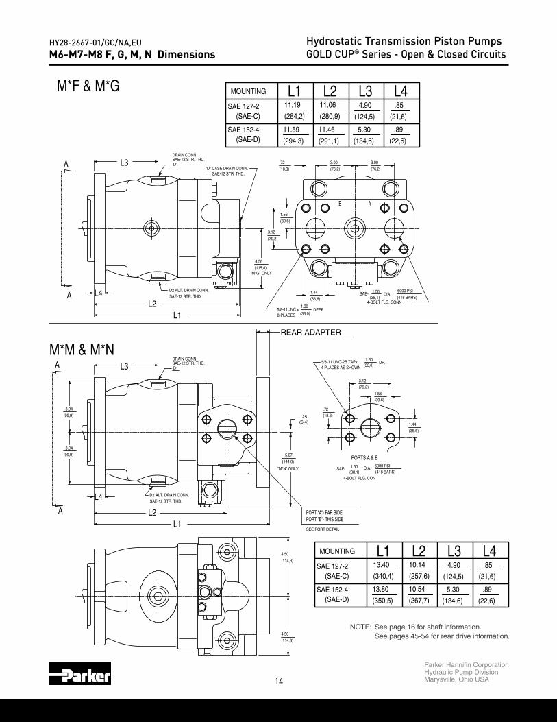
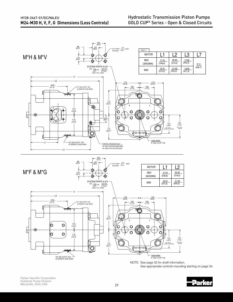
HY28-2667-01/GC/NA,EU Hydrostatic Transmission Piston PumpsGOLD CUP® Series - Open & Closed CircuitsM6-M7-M8 F, G, M, N Dimensions
NOTE: See page 16 for shaft information.See pages 45-54 for rear drive information.
REAR ADAPTER
D2 ALT. DRAIN CONN.SAE-12 STR. THD.
D1
DRAIN CONN.SAE-12 STR. THD.
3.94
3.94
(99,9)
(99,9)
4.50
(114,3)
4.90
(134,6)
5.30
(124,5)
(350,5)
13.80
(340,4)
13.40
(267,7)
10.54
10.14
(257,6).85
(21,6)
(22,6)
.89
PORT "A"- FAR SIDEPORT "B"- THIS SIDE
(36.6)
1.44
DP.
3.12
(79.2)
.72
5/8-11 UNC-2B TAPx4 PLACES AS SHOWN
(18.3)
4.50
(114,3)
5.67
(144,0)
"M*N" ONLY
.25(6.4)
1.30(33,0)
(39.6)
1.56
M*M & M*N
L2L1
L4
L3A
A
L3L1 L2 L4
SAE 152-4
SAE 127-2
(SAE-D)
(SAE-C)
MOUNTING
SEE PORT DETAIL
DIA.SAE-(38.1)1.50
PORTS A & B
4-BOLT FLG. CON
6000 PSI(418 BARS)
"M*G" ONLY
SAE-12 STR. THD.D2 ALT. DRAIN CONN.
DIA.1.50
(418 BARS)
6000 PSI SAE-
DEEP1.30
4-BOLT FLG. CONN(38,1)
(33,0)
(79,2)
8-PLACES
4.56
(115,8)
5/8-11UNC x
(36,6)
1.44
D1
DRAIN CONN.SAE-12 STR. THD.
"D" CASE DRAIN CONN.SAE-12 STR. THD.
3.00
(76,2)
3.00
(76,2)
.72
(18,3)
1.56
3.12
(39,6)
AB
A L4
L1L2
A L3
M*M & M*N
M*F & M*G
4.90
(134,6)
5.30
(124,5)
(350,5)
13.80
(340,4)
13.40
(267,7)
10.54
10.14
(257,6).85
(21,6)
(22,6)
.89
L3L1 L2 L4
SAE 152-4
SAE 127-2
(SAE-D)
(SAE-C)
MOUNTING
4.90
5.30
(134,6)
(124,5)
.89
.85(284,2)
11.19
(294,3)
11.59
11.06
11.46
(280,9)
(291,1) (22,6)
(21,6)
SAE 152-4
SAE 127-2
MOUNTING L3 L4L2L1
(SAE-D)
(SAE-C)

15
Parker Hannifin CorporationHydraulic Pump DivisionMarysville, Ohio USA
HY28-2667-01/GC/NA,EU Hydrostatic Transmission Piston PumpsGOLD CUP® Series - Open & Closed CircuitsM6-M7-M8 H, V, R, L Motor Dimensions (Less Controls)
NOTE: See page 16 for shaft information.See pages 45-54 for rear drive information.See appropriate controls mounting starting on page 34.
REAR ADAPTER
SAE-12 STR. THD. DRAIN CONN.
4.50
(114,3)
(114,3)
4.50
3.87
(98,3)
3.87
(98,3)
D1
SAE-12 STR. THD.ALT. DRAIN CONN. D2
10.36
(263,1)
11.70
(397,2)
SYSTEM PORT A (FAR SIDE)SYSTEM PORT B (NEAR SIDE)
(418,7)
16.48
15.14
(384,6)
(21,8)
.86
(25,4)
1.00
13.22
(335,9)
(301,8)
11.88
(212,3)
8.36
(178,3)
7.02
(114,3)
4.50
4.50
(114,3)
(36.6)
1.44
DP.
3.12
(79.2)
.72
5/8-11 UNC-2B TAP x4 PLACES AS SHOWN
(18.3)
1.30(33,0)
(39.6)
1.56
5.67
(144,0)"M*L" ONLY
1.94
(49,3)
.25
(6.3)
H2 CONTROL PRESSURE INLET
H1 CONTROL PRESSURE INLET
SAE-8 STR. THD. (FAR SIDE)
SAE-8 STR. THD. (NEAR SIDE)
5.15
(164,8)
6.49
(130,9)
L3
M*R & M*L
L1L2
L7
L3
A
A
L5TABLE 13
L4L2MOUNTING
(SAE-C)
(SAE-D)
SAE 127-2
SAE 152-4
L1 L3
DIA.SAE-(38.1)1.50
4-BOLT FLG. CON
6000 PSI(418 BARS)
L7
H1
(FAR SIDE)H2 CONTROL PRESSURE INLET
ALT. DRAIN CONN.SAE-12 STR. THD.
SAE-8 STR. THD.
3.87
3.87
(98,3)
(98,3)
D1
SAE-12 STR. THD.ALT. DRAIN CONN. D2
D CASE DRAIN PORTSAE-12 STR. THD.
4.56
(115,8)"M*H" ONLY
4.50
(114,3)(114,3)
4.50
3.00
(76,2)
3.00
(76,2)
SAE-8 STR. THD. (NEAR SIDE)
.72
(18,3)
H1 CONTROL PRESSURE INLET
1.50 DIA.SAE-
DEEP4-BOLT FLG. CONN
(38,1)
2-PLACES
3.12
(79,2)
(39,6)
1.56
1.44
(36,6)
1.38
8-PLACES5/8-11UNC x
(35,1)
(414 bar)
6000 PSI
1.16
(29,5)
L1
L7L3
L4
L5L2
A
A
AB
M*R & M*L
M*H & M*V
5.15
6.49
(164,8)
(130,9)7.02
(178,3)
8.36
(212,3)
1.00
(25,4)
.86
(21,8)
10.58
(268,8)
(302,8)
11.92
(334,3)
13.16
(368,3)
14.50
(325,1)
12.80
(359,2)
14.14
TABLE 14
L7L5L3 L4L1 L2
SAE 152-4
SAE 127-2
(SAE-D)
(SAE-C)
MOUNTING
10.36
(263,1)
11.70
(397,2)(418,7)
16.48
15.14
(384,6)
(21,8)
.86
(25,4)
1.00
13.22
(335,9)
(301,8)
11.88
(212,3)
8.36
(178,3)
7.02 5.15
(164,8)
6.49
(130,9)
L5TABLE 13
L4L2MOUNTING
(SAE-C)
(SAE-D)
SAE 127-2
SAE 152-4
L1 L3 L7

16
Parker Hannifin CorporationHydraulic Pump DivisionMarysville, Ohio USA
HY28-2667-01/GC/NA,EU Hydrostatic Transmission Piston PumpsGOLD CUP® Series - Open & Closed CircuitsFor 6-7-8 Pumps & Motors
)DIA.
5.9986.000
152,40152,35
DIA.
(
SPLINE LENGTH
x 45˚
(7,9)
.31
2.91
73,975,4
2.97
( )
30˚
(1,5)
.06
.12
(3,0)
2.76
(70,1)
(43,4)
1.71
.25
(6,4)
.49
(12,4)
MAX.
44,4544,43 (
DIA.
(.12
(3,0)
30˚
1.7494
(49,35)
1.7500
1.943
4.50
4.50
6.36
(161,6)
8.88
(225,6)
(114,3)
(114,3)
3.18
4.44
(112,8)
(80,8)
DEEP.83
(21,1)
3.18
(80,8)
(19,8)
.78(M10 x 1.5) METRIC THREAD x
(161,6)
6.36
S2
M*F, M*G, M*H, M*V, P*S, P*X, P*D, P*P, P*V & P*F M*R, M*L, M*M, M*N, P*L & P*R
SAE 152-4 ("D" 4 BOLT)SAE 44-1
("D" KEYED)
FOR SAE 152-4 ("D" 4-BOLT)
S1
S3
("D" SPLINE)SAE 44-4
SAE 152-4 ("D" 4 BOLT)
(30,2)
1.19
(
30˚
(2,3)
.09
DIA.MIN.
1.30
(33,0)
3.56
(90,4)
SEE NOTE 2
SEE NOTE 1SPLINE LENGTH
)( 54,6
2.23
56,62.15
(180,8)
7.12
5.000
126,95127,00
4.998
)DIA.
.09
(2,3)
(114,3)
x 45˚
4.50
(
1.75
(44,5)
2.232.1556,654,6
30˚
)
(1,5)
.06
DIA.
SPLINE LENGTH
(.49
.24
(12,4)
(6,1)
.31
(7,9)
DIA.
1.386
)
(35,20)
1.24941.2500
31,73531,750
.78
(19,8)
4.22
4.22
(107,2)
DEEP
(107,2)
.73
(18,4)DIA.(215,9)
8.50
(M10 x 1.5) METRIC THREAD x
SAE 127-2 ("C" 2-BOLT)
2. SPLINE LENGTH ONLY FOR:
1. SPLINE LENGTH ONLY FOR:M*F, M*G, M*H, M*V, P*S, P*X, P*D, P*P, P*V & P*F
M*R, M*L, M*M, M*N, P*L & P*R
NOTES:
S2
S1
SAE 32-1("C" KEYED)
SAE 127-2 ("C" 2-BOLT)
("C" SPLINE)SAE 32-4
S3
("C" 2-BOLT)FOR SAE 127-2
(67,0)
2.64
(75,4/73,9)
2.97/2.91
(44,4)(11,12/11,10)SQ. KEY x
57.1734./834.
S2S1SHAFT
(SAE-D Key)SAE 44-1
SHAFT DEGIGNATIONPUMP MODEL CODE
04
S3
13 TEETH
MAJOR DIA1.7210-1.7160(43,713/43,586)
SAE INVOLUTE SPLINE J498-B 1969EXTERNAL CLASS 1 FLAT ROOT
30˚ PRESSURE ANGLE8/16 DIA. PITCH
SIDE FIT
05
SHAFT DEGIGNATIONPUMP MODEL CODE
2.23/2.15
(56,6/54,6)
3.36/3.28
(85,3/83,3)
SQ. KEY x LG.(31,8/31,0)
1.25/1.22
SQ. KEY x LG.(60,4/59,7)
2.38/2.35
1.88
(47,8)
(76,4)
3.01
(7,92/7,87)
.312/.310
.312/.310
(7,92/7,87)
S102 or 07
09 or 10
SHAFT DEGIGNATIONPUMP MODEL CODE SHAFT
(SAE-C)
(SAE-C)
SAE 32-1
SAE 32-1 LONG
S3S2DIA. PITCH
30˚ PRESSURE ANGLE
(31,224/31,097)1.2293-1.2243
SAE INVOLUTE SPLINE J498-B 1969EXTERNAL CLASS 1 FLAT ROOT12/24
14 TEETH
SIDE FIT
MAJOR DIA
PUMP MODEL CODESHAFT DEGIGNATION
03 or 08

17
Parker Hannifin CorporationHydraulic Pump DivisionMarysville, Ohio USA
HY28-2667-01/GC/NA,EU Hydrostatic Transmission Piston PumpsGOLD CUP® Series - Open & Closed CircuitsP11-P14 M, F Dimensions
(36,6)
(39,7)
1.56
1.44
REAR ADAPTER
"D2" ALT. DRAIN CONN.SAE-16 STR. THD.
13.60(345,4)
(155.4)6.12
(28.4)1.12
(413,4)16.28
6.12(155.4)
1.12(28.4)
(122,4)4.82
(79,4)
8-PLACES-11UNC-2B THREAD x
(33,3)
1.31
4-BOLT FLG. CONN. (CODE 62)
SAE-16 STR. THD."D1" ALT. DRAIN CONN.
.72
(18,3)
5/8
(414 bar)6000 P.S.I.
DIA.(38.1)
(76.2)3.00
8-PLACES5/8-11UNC-2B THREAD x
1.44
(18.3).72
(36.4)
2-PLACES
SAE-1.50
(388,0)15.28
16.51(419,4)
"D2" ALT. DRAIN CONN.SAE-16 STR. THD.
(122,4)4.82
(122,4)4.82
1.31
(33,3)
5.94
DEEP
(150,9)(150,9)
5.94
1.44
(39,6)
1.56
(18.3).72
(79,2)
3.12
(36.4)
(76.2)3.00
DEEP
"D" DRAIN CONNECTIONSAE-16 STR. THD.
3.13
(150,0)
5.91
SAE-16 STR. THD."D1" DRAIN CONN.
B
P*M
P*F
B
B
B
SYSTEM PORT B (NEAR SIDE)SYSTEM PORT A (FAR SIDE)
(38,1)1.50
(414 BAR) 6000 PSIDIA.
4-BOLT FLG. CONNECTION
SAE-
B
B A
NOTE: See page 23 for shaft information.See pages 45-54 for rear drive information.

18
Parker Hannifin CorporationHydraulic Pump DivisionMarysville, Ohio USA
HY28-2667-01/GC/NA,EU Hydrostatic Transmission Piston PumpsGOLD CUP® Series - Open & Closed CircuitsP11-P14 P, V Dimensions (Less Controls)
B A
B A
4.915.17
1.12
(28,4)
3.12
(79,2)
5/8-11UNC-2B x4-PLACES
"C" AUXILIARY PUMP INLETSAE-20 STR. THD.
SAE-16 STR. THD."D2" ALT. DRAIN CONN.
SAE-16 STR. THD."D1" DRAIN CONN.
(415 bar)SAE-1.50
(38.1)DIA.
6000 P.S.I.
4-BOLT FLG. CONN. (CODE 62)
(131,3)
5.17 (148,0)
5.83
5.33
(135,3)
5.17
(131,3)
"C" AUXILIARY PUMP INLETSAE-20 STR. THD.
(124,7)
4.91
(124,7)(131,3) 5.33
SAE-16 STR. THD."D2" ALT. DRAIN CONN.
(135,3)
(162,0)6.38
(503,8)19.83
DEEP(30,2)
1.191/2-13UNC-2B x
4-PLACES
3.50
(88,9)
(44,4)
1.75
(50,8)
2.00
4-BOLT FLG.DIA.(63,5)
2.50
(172 BARS)
2500 PSI
(82,6)
3.253.00
(76,2)
141,3( )5.56
(36,6)
1.44
(18,3)
.72
(39,6)
1.38
(35,1)DEEP
1.56
(387,4)15.25
5.56141,3
141,35.56 5.56
( )141,3
(25,4)
1.00
8.48
(215,3)
DEEP(35,1)
1.38
8-PLACES
(465,2)18.31
5/8-11UNC-2B x
1.12
(28,4)
4-BOLT FLG. CONN. (CODE 62)
(79,2)
"D1" DRAIN CONN.SAE-16 STR. THD.
TYPICAL 2-PLACES
5.17
(131,3)
6000 P.S.I.(415 bar)(38.1)
DIA.SAE-1.50
(148,0)
5.83
(76,2)
3.003.00
(76,2)
1.44
.72
(18,3)
(39,6)
1.56
3.12
(36,6)
L4L7
L7L4
L3
P*V
P*P
B
B
B
P11V, P14V
P11P, P14P
PUMP
TABLE 6L2
L2
L1
&
L7L4L2 L3L1
L3B
L1
NOTE: See page 23 for shaft information.See appropriate controls mounting starting on page 34.

19
Parker Hannifin CorporationHydraulic Pump DivisionMarysville, Ohio USA
HY28-2667-01/GC/NA,EU Hydrostatic Transmission Piston PumpsGOLD CUP® Series - Open & Closed CircuitsP11-P14 S, X Dimensions (Less Controls)
AB
AB
1.12
(28,4)
5.33
(135,3)
"D2" ALT. DRAIN CONN.SAE-16 STR. THD.
5.17
(131,3)4.91
(124,7)
SAE-20 STR. THD."C" AUXILIARY PUMP INLET
5.38(136,5)
5.38(136,5)
5.56141,3( )
5.56141,3
(23,0)
.90(23,0)
(165,4)
.72
(18,3)
(162,0)
6.38(538.3)
21.19
5.83
(148,0)
4.91
(124,7)
5.17
(131,3)
(387,4)
15.25
5.17
24.58
(131,3)
SAE-16 STR. THD."D2" ALT. DRAIN CONN.
(624,4)
SAE-20 STR. THD."C" AUXILIARY PUMP INLET
(148,0)
5.83
8.48
(215,3)
(131,3)
5.17
"D1" DRAIN CONN.SAE-16 STR. THD.
"K" AUXILIARY REPLENISH AND
SAE-12 STR. THD.PUMP FILTER RETURN PORT
(555,7)
21.88
19.75
(501,7)
(85,8)3.38 R
6.51
5.56141,3( )
5.38(136,5)
5.56141,3
5.38(136,5)
(23,0).90
.90(23,0)
SYSTEM PORT A (FAR SIDE)SYSTEM PORT B (NEAR SIDE)
1.31
(33,3)8-PLACES
(36,6)
1.44
DEEP5/8 -11UNC-2B THREAD x
(39,7)
1.56
3.13
(79,4)
.90
R(85,8)
3.38
(28,4)
1.12
SAE-12 STR. THD.
"K" AUXILIARY REPLENISH ANDPUMP FILTER RETURN PORT
SAE-16 STR. THD."D1" DRAIN CONN.
L7L4B
L7L4
L3
P*S
B
P*X
B
L2
L1
L5
L2L1
P*X
L5L4L3 L7P*S
PUMP L2L1TABLE 7
(38,1)DIA.1.50SAE-
4-BOLT FLG. CONNECTION(414 BARS)
6000 PSI
L3B
L5
NOTE: See page 23 for shaft information.See pages 45-53 for rear drive information.See appropriate controls mounting starting on page 34.
(162,0)
6.38(538.3)
21.19
(387,4)
15.2524.58
(624,4)
SAE-20 STR. THD."C" AUXILIARY PUMP INLET
8.48
(215,3)
(555,7)
21.88
19.75
(501,7)P*X
L5L4L3 L7P*S
PUMP L2L1TABLE 7
P*S
P*X
20
Parker Hannifin CorporationHydraulic Pump DivisionMarysville, Ohio USA
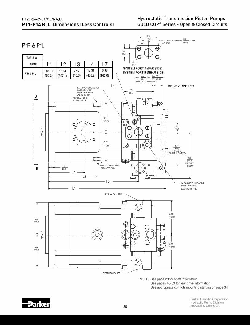
HY28-2667-01/GC/NA,EU Hydrostatic Transmission Piston PumpsGOLD CUP® Series - Open & Closed CircuitsP11-P14 R, L Dimensions (Less Controls)
(39,7)
1.56
(36,6)
1.44
(215,3)
8.48
(465,2)18.31
(397,1)15.64
(150,9)
(150,9)
5.94
5.94
-11UNC-2B THREAD x
REAR ADAPTER
(162,0)
6.38
5/8(79,4)
3.13
.72
(18,3)
8-PLACES
18.31
(465,2)
DEEP 1.31
(33,3)
SAE-16 STR. THD."D1" DRAIN CONN.
INLET CONN. "G2"(NEAR & FAR SIDES)SAE-8 STR. THD.
EXTERNAL SERVO SUPPLY
(28,4)
141,35.56
( )
5.56141,3( )
1.12SAE-16 STR. THD.
SYSTEM PORT B REF.
SYSTEM PORT A REF.
SAE-12 STR. THD.(NEAR & FAR SIDES)"K" AUXILIARY REPLENISH
SHOWN IN PHANTOM"P*R" ONLY
(150,0)
(43,9)
(130,8)
5.15
"D2" ALT. DRAIN CONN.
(131,3)
5.17
5.17
(131,3)
SHOWN
"P*L" ONLY(205,1)
8.08
5.91
1.73
L3
P*R & P*L
L7
L1
PUMP L1TABLE 8
L2P*R & P*L
L3L2
SYSTEM PORT B (NEAR SIDE)SYSTEM PORT A (FAR SIDE)
L7L4
(38,1)1.50
(414 BARS) 6000 PSIDIA.
4-BOLT FLG. CONNECTION
SAE-
B
B
L4
NOTE: See page 23 for shaft information.See pages 45-53 for rear drive information.See appropriate controls mounting starting on page 34.
P*R & P*L
(215,3)
8.48
(465,2)18.31
(397,1)15.64
(162,0)
6.3818.31
(465,2)
L3PUMP L1TABLE 8
L2P*R & P*L
L7L4

21
Parker Hannifin CorporationHydraulic Pump DivisionMarysville, Ohio USA
HY28-2667-01/GC/NA,EU Hydrostatic Transmission Piston PumpsGOLD CUP® Series - Open & Closed CircuitsM11-M14 H, V, F, G Dimensions (Less Controls)
"D1" ALT. DRAIN CONN.SAE-16 STR. THD.
(419,4)16.51
SAE-16 STR. THD."D2" ALT. DRAIN CONN.
15.28(388,0)
1.12(28.4)
6.12(155.4)
DEEP
"D2" ALT. DRAIN CONN. (69,8)
(451.9)
17.79
SAE-16 STR. THD.
2.75
4.82(122,4)
1.31
3.00
(33,3)
1.44
(76.2)
8-PLACES5/8-11UNC-2B THREAD x
(18.3).72
4.82(122,4)
(36.4)
SHUTTLE ("M*G" ONLY)
(162,0)6.38
(215,3)
8.48
(369,9)14.56
5.56141,3 141,3( )
5.56
"D" DRAIN CONNECTIONSAE-12 STR. THD.
(439.9)17.32
6000 P.S.I.(414 bar)
.72(18.3)
3.12
1.56
(39,6)
SAE-1.50(38.1)
3.00
1.44
(76.2)
2-PLACES
(36.4)
DIA.
4-BOLT FLG. CONN. (CODE 62)
(79,2)
SAE-16 STR. THD."D" DRAIN CONNECTION
(28.4)
1.12
1.44(36.4)
5/8-11 UNC-2B THREAD x
SAE-16 STR. THD."D1" ALT. DRAIN CONN.
5.17(131.3)
8-PLACES
(18.3)
"H2" (FAR SIDE)"H1" (NEAR SIDE)
2-PLACESSAE-8 STR. THD.CONTROL PRESSURE INLET
.72
(131.3)5.17
(36.3)1.43
(79,2)
3.12
1.56
(39,6)
6000 P.S.I.SAE-1.50(415 bar)
2-PLACES
(38.1)
1.31
3.00
1.44
(76.2)
(33,3)
3.00(76.2)
DEEP
DIA.
4-BOLT FLG. CONN. (CODE 62)
.72(18.3)
(36.4)
M*H & M*V
M*F & M*G
L2L7B
B
B
L1
&M14H, M14V
M11H, M11V
MOTOR L1TABLE 15
L7L2 L3 L4
L3B
L4
11-14 MOTOR DIMENSIONS
B A
AB
NOTE: See page 23 for shaft information.See appropriate controls mounting starting on page 34.

22
Parker Hannifin CorporationHydraulic Pump DivisionMarysville, Ohio USA
HY28-2667-01/GC/NA,EU Hydrostatic Transmission Piston PumpsGOLD CUP® Series - Open & Closed Circuits
(162,0)6.38
(369,9)14.56
(215,3)
8.48
(465,2)18.31
(397,1)
15.64&
MOTOR
M14R, M14L
M11R, M11L
TABLE 16
L7L3 L4L1 L2
M11-M14 M, N, R, L Dimensions (Less Controls)
REAR ADAPTER
1.56
(39,7)
(36,6)
1.44
REAR ADAPTER
(150,9)
5.94
(150,9)
5.94
(162,0)6.38
(369,9)14.56
(215,3)
8.48
(465,2)18.31
(397,1)
15.64
SAE-16 STR. THD."D2" ALT. DRAIN CONN.
16.28(413,4)
4.82(122,4)
1.12(28.4)
6.12(155.4)
(345,4)13.60
(79,4)
3.13
(18,3)
.72
SHOWN
5.91
SHOWN IN PHANTOM"M*M" ONLY
"M*N" ONLY(196,1)
7.72
(150,0)
DEEP(33,3)8-PLACES
-11UNC-2B THREAD x 1.31
5/8
(150,9)
5.945.94
(150,9)
ALTERNATE EXTERNAL SERVO SUPPLY
1.12
(28,4)
SAE-16 STR. THD."D1" DRAIN CONN.
( )
( )
5.56141,3
141,35.56
INLET CONN. "G2"SAE-8 STR. THD.
SYSTEM PORT A REF.
(196,1)"M*L" ONLY
SHOWN"D2" ALT. DRAIN CONN.SAE-16 STR. THD.
7.72
(150,0)"M*R" ONLY
5.91
SHOWN IN PHANTOM
5.17
(131,3)
(130,8)
5.15
(43,9)1.73
5.17
(131,3)
SYSTEM PORT B REF.
"D1" DRAIN CONN.SAE-16 STR. THD.
DIA.SAE- 1.50
L2L1
4-BOLT FLG. CONNECTION
&
MOTOR
M14R, M14L
M11R, M11L
TABLE 16
(38,1)
L7L3 L4L1 L2
(414 BARS)
M*R & M*L
M*M & M*N
B
B
SYSTEM PORT B (NEAR SIDE)SYSTEM PORT A (FAR SIDE)
B
6000 PSI
L3L7
B
B
NOTE: See page 23 for shaft information.See pages 45-54 for rear drive information.See appropriate controls mounting starting on page 34.

23
Parker Hannifin CorporationHydraulic Pump DivisionMarysville, Ohio USA
HY28-2667-01/GC/NA,EU Hydrostatic Transmission Piston PumpsGOLD CUP® Series - Open & Closed Circuits
.437/.435
(11,10/11.05)
.437/.435
(11,10/11.05)
(100,8/99,1)
3.97/3.90
(75,4/73,7)
2.97/2.90
(63,5)
2.50SQ. KEY x LG.
(38,1)
1.50SQ. KEY x LG.02 or 07
09 or 10
SHAFT DEGIGNATIONPUMP MODEL CODE
SAE 44-1 LONG
SAE 44-1
(SAE-E)
(SAE-E)
SHAFT S1 S3
1.7210-1.7160
(43,713-43,586)
30˚ PRESSURE ANGLE
FLAT ROOT SIDE FIT EXTERNAL CLASS 1SAE INVOLUTE SPLINE DATA J498B 1969
13 TEETH
8/16 PITCH
MAJOR DIA.
03 or 08
PUMP MODEL CODESHAFT DEGIGNATION
For 11-14 Pumps & Motors
44,43
.437/.435
(11,10/11.05)
.437/.435
(11,10/11.05)
1.7210-1.7160
(43,713-43,586)
30˚ PRESSURE ANGLE
(1,5)
.06
FLAT ROOT SIDE FIT EXTERNAL CLASS 1SAE INVOLUTE SPLINE DATA J498B 1969
13 TEETH
8/16 PITCH
(100,8/99,1)
3.97/3.90
(75,4/73,7)
2.97/2.90
MAJOR DIA.
x 45˚
(63,5)
2.50SQ. KEY x LG.
(38,1)
1.50SQ. KEY x LG.
SPLINE LENGTH
(2,3)
SEE NOTE 1
1.50
(38,1)
.09
2.75
DIA.(69.8)
DIA.165.1
6.5006.498
165.0 NECKSEE NOTE 1
(41,1)
1.62SPLINE LENGTHSEE NOTE 2
75,473,7
2.972.90
1.941
44,45
1.75001.7495
(49,30)
.36(9.1)
2.97
75,473,7
15,3715,88.605.625
2.90
30˚
DIA.
30˚
(2,3)
.09
M*R, M*L, M*M, M*N, P*L & P*R
M*F, M*G, M*H, M*V, P*S, P*X, P*P, P*V & P*F2. SPLINE LENGTH ONLY FOR:
1. SPLINE LENGTH AND NECK ONLY FOR:NOTES:
("E" KEYED)SAE 44-1
SAE 165-4 ("E" 4-BOLT)
VIEW B-B 03 or 08
PUMP MODEL CODESHAFT DEGIGNATION
02 or 07
09 or 10
SHAFT DEGIGNATIONPUMP MODEL CODE
("E" SPLINE)SAE 44-4
SAE 165-4 ("E" 4-BOLT)
SAE 44-1 LONG
SAE 44-1
(SAE-E)
(SAE-E)
SHAFT S1 S3
M*F, M*G, M*H, M*V, P*S, P*X, P*P, P*V & P*F M*R, M*L, M*M, M*N, P*L & P*R
S3
S1
("E" KEYED)SAE 44-1
SAE 165-4 ("E" 4-BOLT)
("E" SPLINE)SAE 44-4
SAE 165-4 ("E" 4-BOLT)

24
Parker Hannifin CorporationHydraulic Pump DivisionMarysville, Ohio USA
HY28-2667-01/GC/NA,EU Hydrostatic Transmission Piston PumpsGOLD CUP® Series - Open & Closed CircuitsP24-P30 M, F Dimensions
OVERHUNG SUPPORT POINT
(31,8)7/8"-9 UNC x 1.25
DEEP
CASE DRAIN
C
C
C
C
REAR ADAPTER
3/4-10UNC x 8-PLACES
(592,6)23.33
(618,0)24.33
(548,8)
"D" SAE-16 STR. THD.
7.86(199,6)
(199,6)7.86
22.61(44,4)
(157,0)
6.18
ALTERNATE CASE DRAIN"D1" SAE-20 STR. THD.(277,5)
10.92
(157,0)
6.18
ALTERNATE CASE DRAIN"D2" SAE-20 STR. THD.
(574,2)
(111,2)4.38
(199,6)7.86
(199,6)7.86
(111,2)4.38
7.31
(185,7)
7.31
(185,7)
(97,0)3.82
CASE DRAIN"D2" SAE-20 STR. THD.
(31,7)
1.25
1.91(48,5)(22,3)
.88
1.75
6.44
(163,6)
(163,6)
6.44
(31,8)
1.25
21.61
DEEP3/4-10 UNC x 8-PLACES
1.50
(38,1)
7.31
(185,7)
7.31
(185,7)
6.18
6.18
CASE DRAIN"D1" SAE-20 STR. THD.
10.92(277,5)
(157,0)
(157,0)
(97,0)3.82
1.91(48,5)
(173,7)
6.84
.88
1.75
(22,3)
(163,6)6.44
(44,4)
21.46(545,0)
(140.1)
5.52(173,0)
6.81
(484,8)19.09
18.09(459,4)
(519,6)20.46
DEEP1.50
(38,1)
"M*F" ONLYSHOWN IN PHANTOM SHOWN
"M*G" ONLY
SYSTEM PORT B (NEAR SIDE)
P*M
P*F
(414 bar)
6000 PSI SYSTEM PORTS A & B
4-BOLT FLG. CONN
DIA.(50,8)
2.00
L1
SAE-
L2
P30F
PUMP
(SHOWN)
P30M
P24M
L1
L1MOTOR
P24F(SHOWN)
L1
L2
SAE- DIA.2.00(50,8)
SYSTEM PORT A (FAR SIDE)
4-BOLT FLG. CONN
6000 PSI
(414 bar)
L2
L2
AB
B
K
G
B
NOTE: See page 32 for shaft information.
(592,6)23.33
(618,0)24.33
(484,8)19.09
18.09(459,4)
PUMP
(SHOWN)
P30M
P24M
L1 L2
(548,8)
22.61(574,2)
21.61
21.46(545,0)
(519,6)20.46
P30F
L1MOTOR
P24F(SHOWN)
L2
25
Parker Hannifin CorporationHydraulic Pump DivisionMarysville, Ohio USA
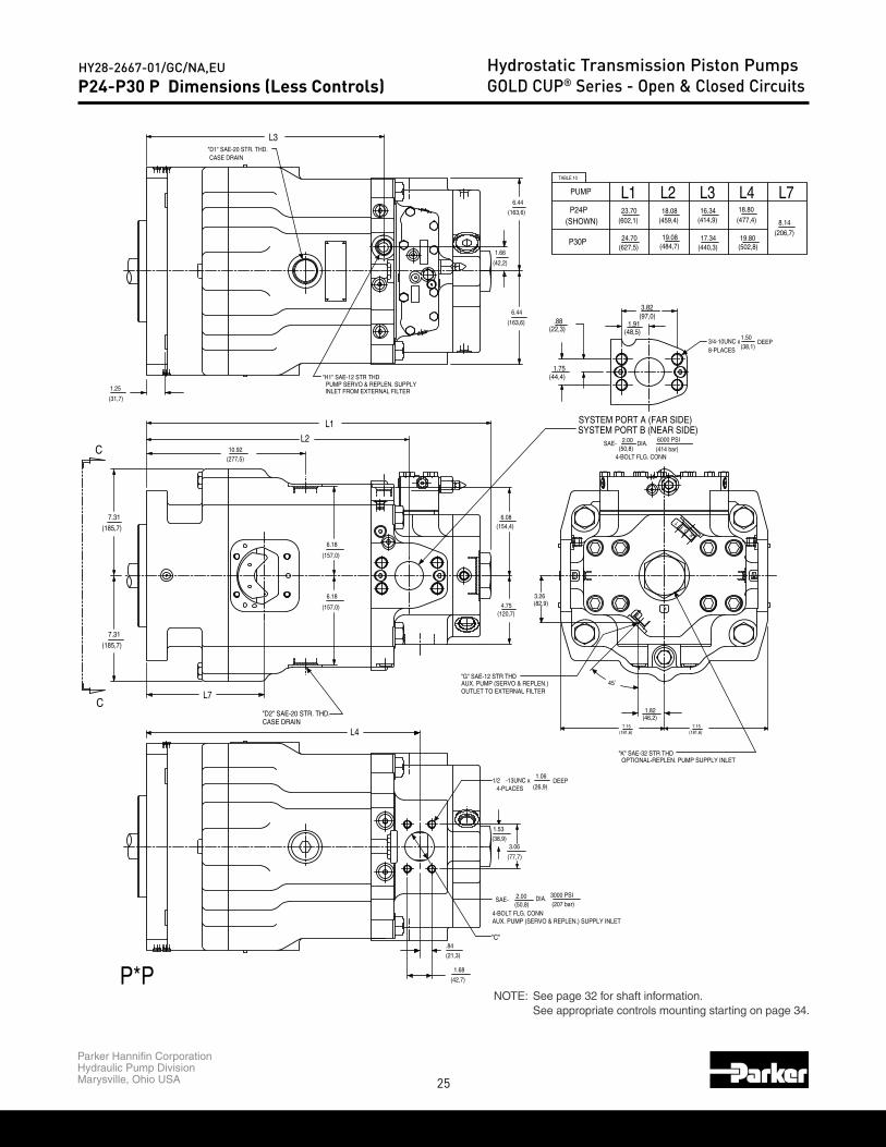
HY28-2667-01/GC/NA,EU Hydrostatic Transmission Piston PumpsGOLD CUP® Series - Open & Closed CircuitsP24-P30 P Dimensions (Less Controls)
B A
C
C
OPTIONAL-REPLEN. PUMP SUPPLY INLET"K" SAE-32 STR THD
(484,7)
(185,7) (154,4)
7.31
(185,7)
(21,3)
1.68
(42,7)
"D2" SAE-20 STR. THD. CASE DRAIN
6.18
(157,0)
(157,0)
6.18
"G" SAE-12 STR THD
OUTLET TO EXTERNAL FILTER
(82,9)3.26
AUX. PUMP (SERVO & REPLEN.)
1.82(46,2)
45˚
(120,7)4.75
.84
AUX. PUMP (SERVO & REPLEN.) SUPPLY INLET
DEEP1.06
(26,9)
DIA.2.00
(38,9)
1.53
1/2
SAE-
3.06
(77,7)
4-PLACES-13UNC x
"C"
4-BOLT FLG. CONN(50,8) (207 bar)
3000 PSI
7.15(181,6)
"D1" SAE-20 STR. THD.
7.31
(31,7)
1.25
CASE DRAIN
"H1" SAE-12 STR THD
INLET FROM EXTERNAL FILTERPUMP SERVO & REPLEN. SUPPLY
10.92(277,5)
(48,5)1.91
3.82(97,0)
6.44
6.44.88
(22,3)
1.66
(42,2)
(163,6)
(163,6)
(44,4)
6.08
(459,4)
19.08
18.08(602,1)
(627,5)24.70
23.70
1.75
(181,6)7.15
8.14(206,7)
19.80
18.80(477,4)
(502,8)
DEEP1.50(38,1)8-PLACES
3/4-10UNC x
(414,9)
17.34(440,3)
16.34
(414 bar)
6000 PSI
SYSTEM PORT A (FAR SIDE)SYSTEM PORT B (NEAR SIDE)
P*P
L7
L4
L3
L1
L2
TABLE 10
(50,8)2.00SAE-
4-BOLT FLG. CONN
DIA.
L2L1
(SHOWN)
P30P
P24P
PUMP L7L4L3
K
GK
TP
O
NOTE: See page 32 for shaft information.See appropriate controls mounting starting on page 34.

26
Parker Hannifin CorporationHydraulic Pump DivisionMarysville, Ohio USA
HY28-2667-01/GC/NA,EU Hydrostatic Transmission Piston PumpsGOLD CUP® Series - Open & Closed CircuitsP24-P30 X Dimensions (Less Controls)
B A
C
C
CASE DRAIN"D2" SAE-20 STR. THD.
(181,6)7.15
DEEP1.06
(26,9)
(38,9)
1.53
1/2
3.06
4-PLACES-13UNC x
DIA.2.00(50,8)
1.68
(42,7)
.84
(21,3)
SAE-
"C"
(77,7)
4-BOLT FLG. CONNAUX. PUMP (SERVO & REPLEN.) SUPPLY INLET
(207 bar) 3000 PSI
7.15(181,6)
REAR ADAPTER
(459,4)
(484,7)
"D1" SAE-20 STR. THD.
7.31
(185,7)
7.31
(185,7)
1.25
(31,7)
(605,3)
PUMP SERVO & REPLEN. SUPPLYINLET FROM EXTERNAL FILTER
"H1" SAE-12 STR THD
6.18
(157,0)
(157,0)
6.18
10.92(277,5)
1.91(48,5)
(97,0)3.82
(22,3).88
6.44
(42,2)
1.66
(163,6)
1.75(44,4)
(154,4)
(120,7)4.75
6.08
CASE DRAIN
23.83
(579,9)22.83
19.08
18.086.44
(163,6)
(502,8)(440,3)
DEEP(38,1)
1.503/4-10UNC x 8-PLACES
8.14(206,7)
18.80(477,4)
19.8017.34
16.34(414,9)
P*X
L7
L4
6000 PSI
(414 bar)
SYSTEM PORT B (NEAR SIDE)SYSTEM PORT A (FAR SIDE)
P30X
L1
L2SAE- 2.00
(50,8) DIA.
4-BOLT FLG. CONN
L3
TABLE 11
L1 L2
(SHOWN)P24X
PUMP L7L4L3
G
OK
PT
NOTE: See page 32 for shaft information.See pages 45-53 for rear drive information.See appropriate controls mounting starting on page 34.

27
Parker Hannifin CorporationHydraulic Pump DivisionMarysville, Ohio USA
HY28-2667-01/GC/NA,EU Hydrostatic Transmission Piston PumpsGOLD CUP® Series - Open & Closed CircuitsP24-P30 S Dimensions (Less Controls)
9.89
(251,3)
"D3" DRAIN CONNECTIONSAE-16 STR. THD.
B A
C
C
REAR ADAPTER
(459,4)
(484,8)
INLET FROM EXTERNAL FILTER
(185,7)
7.31
(185,7)
7.31
(31,7)
(605,3)23.83 19.09
6.18
(157,0)
10.92(277,5)
(157,0)
6.18
"D2" SAE-20 STR. THD. CASE DRAIN
(181,6)7.15
6.08(154,4)
(579,9)22.83 18.09
"D1" SAE-20 STR. THD.
1.25
CASE DRAIN
"H1" SAE-12 STR THDPUMP SERVO & REPLEN. SUPPLY
6.44
(163,6)
1.66
(42,2)
(163,6)
6.44 (97,0)3.82
(48,5)1.91.88
(22,3)
1.75(44,4)
(206,7)17.34(440,3)
8.14
7.15(181,6)
16.34(414,9)
DEEP1.50
3/4-10UNC x (38,1)8-PLACES
SYSTEM PORT A (FAR SIDE)SYSTEM PORT B (NEAR SIDE)
(414 bar)
6000 PSI
P*S
P30S
L7
L1
L2
TABLE 9
L1PUMP
(SHOWN)P24S
DIA.SAE-
4-BOLT FLG. CONN(50,8)
2.00
L2
L3
L7L3
G
OK
PT
NOTE: See page 32 for shaft information.See pages 45-53 for rear drive information.See appropriate controls mounting starting on page 34.
28
Parker Hannifin CorporationHydraulic Pump DivisionMarysville, Ohio USA
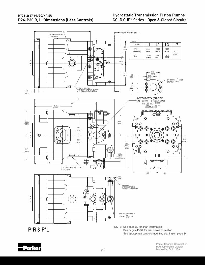
HY28-2667-01/GC/NA,EU Hydrostatic Transmission Piston PumpsGOLD CUP® Series - Open & Closed CircuitsP24-P30 R, L Dimensions (Less Controls)
OVERHUNG SUPPORT POINT
7/8"-9 UNC x DEEP(31,8)1.25
(251,3)
9.89
B A
REAR ADAPTER"D1" SAE-20 STR. THD.
7.31
(185,7)
7.31
(185,7)
(31,7)
1.25
"D2" SAE-20 STR. THD. CASE DRAIN
6.18
(157,0)
(157,0)
6.18
10.92(277,5)
(196,2)
7.72
OPTIONAL
REPLEN. SUPPLY INLET"K" SAE-16 STR THD
(31,8)
1.25
6.08(154,4)
(181,6)7.15
CASE DRAIN
"H1" SAE-12 STR THD
INLET FROM EXTERNAL FILTERPUMP SERVO & REPLEN. SUPPLY
24.33(618,0)
23.33(592,6)
18.08
(484,7)19.08
(459,4)
(48,5)1.91
3.82(97,0)
6.44
6.44.88
(22,3)
1.66
(42,2)
(163,6)
(163,6)
(44,4)1.75
6.44(163,6)
7.15(181,6)
8.14(206,7)
DEEP(38,1)
1.50
(440,3)
(414,9)16.34
17.34
8-PLACES3/4-10UNC x
SHOWN"P*L" ONLY
"P*R" ONLYSHOWN IN PHANTOM
(414 bar)
6000 PSI
SYSTEM PORT A (FAR SIDE)SYSTEM PORT B (NEAR SIDE)
P*R & P*L
L7
L1
L2(50,8)
2.00SAE-
4-BOLT FLG. CONN
DIA.
L3
TABLE 12
L2L1PUMP
P24
P30
(SHOWN)
L7L3
B
K
BG
NOTE: See page 32 for shaft information.See pages 45-54 for rear drive information.See appropriate controls mounting starting on page 34.
29
Parker Hannifin CorporationHydraulic Pump DivisionMarysville, Ohio USA
HY28-2667-01/GC/NA,EU Hydrostatic Transmission Piston PumpsGOLD CUP® Series - Open & Closed Circuits
(452,0)
21.46(545,0)
(519,6)
22.61(574,2)
(548,8) 8.14(206,7)
18.80(477,4)
20.4621.61 17.80
M30
(SHOWN)
L2TABLE 17
L1MOTOR
M24
L7L3
21.46(545,0)
20.46(519,6)
(574,2)22.61
(548,8)21.61
L2L1
(SHOWN)
M30
M24
MOTOR
M24-M30 H, V, F, G Dimensions (Less Controls)
CASE DRAIN
CONTROL PRESSURE INLET
CASE DRAIN
1.91.88
"D1" SAE-20 STR. THD.ALTERNATE CASE DRAIN
ALTERNATE CASE DRAIN
(44,4)1.75
(22,3)
6.18
(157,0)
10.92(277,5)
6.18
(157,0)
"D2" SAE-20 STR. THD.
21.46(545,0)
4.38(111,2)
20.46(519,6)
(574,2)22.61
(185,7)
7.31
(185,7)
7.31
7.86(199,6)
(48,5)(38,1)
1.50
8-PLACES3/4-10 UNC x DEEP
4.38(111,2)
(548,8)21.61
7.86(199,6)
6.81
(173,0)5.52
(140.1)
"D" SAE-16 STR. THD.
ALTERNATE CASE DRAIN"D1" SAE-20 STR. THD.
6.18
(157,0)
6.18
(277,5)10.92
"D2" SAE-20 STR. THD.ALTERNATE CASE DRAIN
(157,0)
.88(22,3)
(44,4)1.75
(452,0)
21.46(545,0)
(519,6)
4.38(111,2)
"H1" SAE-4 STR THD (NEAR SIDE)"H2" SAE-4 STR THD (FAR SIDE)
(58,7)2.31
22.61(574,2)
(548,8)
4.38
7.15
(185,7)
7.31
(181,6)
(111,2)
(185,7)
7.31
(97,0)3.82
8.14(206,7)
7.15(181,6)
6.81
(173,0)(138,4)
5.45
"D" SAE-16 STR. THD.
18.80(477,4)
20.4621.61
1.50
(38,1)3/4-10 UNC x 8-PLACES
DEEP1.91
(48,5)
(97,0)3.82
17.80
"M*G" ONLYSHOWNSHOWN IN PHANTOM
"M*F" ONLY
"M*H" ONLYSHOWNSHOWN IN PHANTOM
"M*V" ONLY
2.00(50,8)
4-BOLT FLG. CONN
SYSTEM PORTS A & B
M*F & M*G
SAE-
L1
L2
L2
6000 PSI
(414 bar) DIA.
L1
(SHOWN)
M30
M24
MOTOR
(50,8)2.00
4-BOLT FLG. CONN
SYSTEM PORTS A & B
L7
L3
SAE-
L1
L2
M*H & M*V
M30
(SHOWN)
DIA. (414 bar)
6000 PSI
L2TABLE 17
L1MOTOR
M24
L7L3
B A
B A
NOTE: See page 32 for shaft information.See appropriate controls mounting starting on page 34.

30
Parker Hannifin CorporationHydraulic Pump DivisionMarysville, Ohio USA
HY28-2667-01/GC/NA,EU Hydrostatic Transmission Piston PumpsGOLD CUP® Series - Open & Closed CircuitsM24-M30 M, N Dimensions
7/8"-9 UNC x DEEP
OVERHUNG SUPPORT POINT1.25
(31,8)
REAR ADAPTER(31,7) (31,8)
(199,6)
(199,6)
7.86
7.86 6.44
(163,6)
6.44
(163,6)
CASE DRAIN"D1" SAE-20 STR. THD.
7.31
(185,7)
7.31
(185,7)
1.25
10.92(277,5)
6.18
(157,0)
(157,0)
6.18
"D2" SAE-20 STR. THD. CASE DRAIN
DEEP24.33(618,0)
19.09(484,8)
(459,4)18.09
(592,6)23.33
1.25
.88
1.75
1.503/4-10UNC x 8-PLACES (38,1)
(97,0)3.82
1.91(48,5)(22,3)
(44,4)
8.13
(206,5)
(163,6)6.44
6.84
(173,7)
SHOWN"M*N" ONLY
SHOWN IN PHANTOM"M*M" ONLY
PUMP
(SHOWN)
M*M & M*N
M30
M24
L1
L2
SYSTEM PORT B (NEAR SIDE)SYSTEM PORT A (FAR SIDE)
4-BOLT FLG. CONN
6000 PSI
(414 bar)
L1 L2
DIA.SAE- 2.00(50,8)
B
G
K
B
NOTE: See page 32 for shaft information.See pages 45-54 for rear drive information.

31
Parker Hannifin CorporationHydraulic Pump DivisionMarysville, Ohio USA
HY28-2667-01/GC/NA,EU Hydrostatic Transmission Piston PumpsGOLD CUP® Series - Open & Closed CircuitsM24-M30 R, L Dimensions
(31,8)1.25
OVERHUNG SUPPORT POINT
7/8"-9 UNC x DEEP
6.44
REAR ADAPTER"D2" SAE-20 STR. THD.
(181,6)
(181,6)
(185,7)
7.31
7.15
7.15
CASE DRAIN(31,7)
1.25
6.18
(157,0)
(206,5)
8.13
6.84
(163,6)
1.25
(31,8)
(173,7)
(163,6)
6.44
(163,6)
6.44
23.33(592,6)
(618,0)24.33
(185,7)
7.31
(277,5)10.92
(157,0)
6.18
"H1" SAE-6 STR THD (NEAR SIDE)"H2" SAE-6 STR THD (FAR SIDE)
DEEP
CONTROL PRESSURE INLET
(50,7)
2.00
8.14(206,7)
(38,1)
1.50
(48,5)1.91
(97,0)3.82
18.09(459,4)
(484,8)19.09
(44,4)
(22,3)
1.75
.88"D1" SAE-20 STR. THD.CASE DRAIN
8-PLACES3/4-10UNC x
"M*L" ONLYSHOWN
"M*R" ONLYSHOWN IN PHANTOM
L7
L1M*R & M*LTABLE 18
M24
M30
(SHOWN)
PUMP
L2
L1
(414 bar)
6000 PSI
4-BOLT FLG. CONN
SYSTEM PORT A (FAR SIDE)SYSTEM PORT B (NEAR SIDE)
L7
(50,8)2.00SAE- DIA.
L2
K
B
BG
NOTE: See page 32 for shaft information.See pages 45-54 for rear drive information.See appropriate controls mounting starting on page 34.

32
Parker Hannifin CorporationHydraulic Pump DivisionMarysville, Ohio USA
HY28-2667-01/GC/NA,EU Hydrostatic Transmission Piston PumpsGOLD CUP® Series - Open & Closed CircuitsFor 24-30 Pumps & Motors
(M16 x 2) METRIC THREAD x
6.998
177,80177,75
7.000
(123,7)
SQ.
4.87
TYP.
(247,6)9.75
(50,8)4 PLACES
DIA. THRU1.06
(26,9)2.00
DIA. S'FACE (FAR SIDE)
SPLINE LENGTHSEE NOTE 2
DEEP1.00
(25,4)
2.12
(53,8)SEE NOTE 1SPLINE LENGTH
DIA.
(44,4)
(6,2)
1.75
.25(15,5)
DIA.
2.75
(69,8)
(8,1).32
(3,0)
.12x 45˚
(12,70/12.65)
.500/.498
2.25
(57,1)
4.13
(104,9)
3.47/3.41
(88,1/86,6)
5.35/5.29
(135,9/134,4)
(12,70/12.65)
.500/.498SQ. KEY x LG.
SQ. KEY x LG.
(3,0)
.06
(1,5)
DIA.
x 45˚
56,18
.12
2.21256,34
2.218
50,78
1.999450,80
x 45˚
88,1
3.473.41
86,688,1
3.473.41
86,6
.61
M*F, M*G, M*H, M*V, P*S, P*X, P*P & P*F M*R, M*L, M*M, M*N, P*L & P*R
15 TEETH
8/16 PITCH
1.9710-1.9660/ (50,063-49,936) MAJOR DIA.
30˚ PRESSURE ANGLE
FLAT ROOT SIDE FIT EXTERNAL CLASS-1SAE INVOLUTE SPLINE DATA J498-B 1969
03 or 08
SHAFT DEGIGNATIONPUMP MODEL CODE
NOTES:1. SPLINE LENGTH AND NECK ONLY FOR:
2. SPLINE LENGTH ONLY FOR:M*F, M*G, M*H, M*V, P*S, P*X, P*P & P*F
M*R, M*L, M*M, M*N, P*L & P*R 09 or 10
02 or 07
PUMP MODEL CODESHAFT DEGIGNATION
("F" SPLINE)SAE 50-4
SAE 177-4 ("F" 4-BOLT)
SAE 177-4SAE F
S3
SAE 50-1("F" KEYED)
S1SHAFT
SAE 177-4 ("F" 4-BOLT)
(SAE-F)
(SAE-F)
SAE 50-1
SAE 50-1 LONG
S3
S1
(12,70/12.65)
.500/.498
2.25
(57,1)
4.13
(104,9)
3.47/3.41
(88,1/86,6)
5.35/5.29
(135,9/134,4)
(12,70/12.65)
.500/.498SQ. KEY x LG.
SQ. KEY x LG.09 or 10
02 or 07
PUMP MODEL CODESHAFT DEGIGNATION
S3S1SHAFT
(SAE-F)
(SAE-F)
SAE 50-1
SAE 50-1 LONG
15 TEETH
8/16 PITCH
1.9710-1.9660/ (50,063-49,936) MAJOR DIA.
30˚ PRESSURE ANGLE
FLAT ROOT SIDE FIT EXTERNAL CLASS-1SAE INVOLUTE SPLINE DATA J498-B 1969
03 or 08
SHAFT DEGIGNATIONPUMP MODEL CODE
("F" SPLINE)SAE 50-4
SAE 177-4 ("F" 4-BOLT)

33
Parker Hannifin CorporationHydraulic Pump DivisionMarysville, Ohio USA
HY28-2667-01/GC/NA,EU Hydrostatic Transmission Piston PumpsGOLD CUP® Series - Open & Closed CircuitsGOLD CUP® Valve Block
VA INDIVIDUAL ("A" SIDE)
SAE-4 STR. THD.COMPENSATOR VENT CONN.
KG REPLENISHING PRESS. GAGE CONN.
"V" COMMON COMPENSATOR VENT CONN.
V
COMPENSATOR ADJUSTMENT2000 PSI PER TURN
SAE-3 STR.THD.ACCESS PORT PILOT RELIEF VALVE
(UNDER PLUG)150 PSI PER TURN
SAE-4 STR.THD.VB INDIVIDUAL ("B" SIDE) COMPENSATOR VENT CONN.
SAE-6 STR. THD.
SAE-4 STR. THD.

34
Parker Hannifin CorporationHydraulic Pump DivisionMarysville, Ohio USA
HY28-2667-01/GC/NA,EU Hydrostatic Transmission Piston PumpsGOLD CUP® Series - Open & Closed CircuitsPump Primary Controls
FIGURE -1
SHAFT DETAILSEE ROTARY SERVO
FIGURE -1
SHAFT DETAILSEE ROTARY SERVO
FIGURE -2
SEE ROTARY SERVO
ROTARY SERVO SHAFT DETAIL
SHAFT DETAIL
FIGURE -2
SEE ROTARY SERVOSHAFT DETAIL
1.00(25,4)(35,6)
(11,5).45
MIN. VOLUME STOP (CW ROT.)MAX. VOLUME STOP (CCW ROT.) (25,4)
1.00
(63,5)2.50
1.40
"Y""X"
SCREW ADJ. (CCW ROT.)MIN. VOLUME STOP (CW ROT.)
(35,6)1.40
(11,4)
MAX. VOLUME STOP (CW ROT.)MIN. VOLUME STOP (CCW ROT.)
MAX. VOLUME STOP (CW ROT.)MIN. VOLUME STOP (CCW ROT.)
.25(6,4)
.32
(8,1)1/4-20UNC TAP x DEEP
.513
.508
13.0312.90( )
MAJOR DIA. KNURL(32 TEETH PER INCH)
(25,4)1.00
1.00(25,4)
2.50(63,5)
"Y" "X"
1.40(35,6)
(11,5).45
SCREW ADJ. (CCW ROT.)MIN. VOLUME STOP (CW ROT.)MIN. VOLUME STOP (CCW ROT.)
.45
SCREW ADJ. (CW ROT.)(35,6)1.40
MAX. VOL.
MIN. VOL.
1/8-27 N.P.T.F.PORT "Y"
CONTROL SPRING OFF-SET TO MIN, VOLUME
PRESSURE SIGNAL TO:
-B- CONTROL MTG. POSITION
-B- CONTROL MTG. POSITION
CONTROLOPTION
"2A*"
PORT "X"
MIN. VOL.
MAX. VOL.CW
CCW
ROT.PUMP
1/8-27 N.P.T.F.
1
1
FIG.
SEE TABLES 1-18L7
"10*"
OPTIONCONTROL
SEE TABLES 1-18L7
ROTARY SERVO
CCW
CW
PUMP
CCW
CW1
1
ROT.FIG. INPUT SHAFT ROTATION
-A- CONTROL MTG. POSITION
PRESSURE SIGNAL TO:
FIG.
2
CONTROLOPTION
2"2A*"
INLET
PORT
INLET
"A"
CW
ROT.PUMP
1/8-27 N.P.T.F.PORT "X"
MIN. VOL.
1/8-27 N.P.T.F.PORT "Y"
MAX. VOL.
CCW MAX. VOL. MIN. VOL.
SEE TABLES 1-18
CONTROL SPRING OFF-SET TO MIN, VOLUME
L7
INLET
PORT
"A"
INLET
PORT
INLET
INLET
-A- CONTROL MTG. POSITIONFIG.
CONTROLOPTION
"10*"2
2
PORT
INLET
INLET
"A"
SEE TABLES 1-18L7
PUMP
CW
CCW
CW
ROT.ROTARY SERVO
INPUT SHAFT ROTATION
CCW
"A"
F O F
F O F
F O F
F O F

35
Parker Hannifin CorporationHydraulic Pump DivisionMarysville, Ohio USA
HY28-2667-01/GC/NA,EU Hydrostatic Transmission Piston PumpsGOLD CUP® Series - Open & Closed CircuitsPump Primary Controls
FIGURE -1
SHAFT DETAILSEE ROTARY SERVO
FIGURE -1
SHAFT DETAILSEE ROTARY SERVO
SEE ROTARY SERVO
FIGURE -2
ROTARY SERVO SHAFT DETAIL
SHAFT DETAIL
FIGURE -2
SEE ROTARY SERVOSHAFT DETAIL
TRIMMER ADJ.
TRIMMER ADJ.
(25,4)1.00
(12,0)
(35,6)1.40
MAX. VOLUME STOP
(35,6)
2.47(62,7)
1.00(25,4)
1.40
MAX. VOLUME STOP
.47
MAX. VOLUME STOP
MAX. VOLUME STOP
MAX. VOLUME STOP
MAX. VOLUME STOP
(11,4)
.45
(8,1)
.32
.513
.25(6,4)
1/4-20UNC TAP x DEEP
(32 TEETH PER INCH)MAJOR DIA. KNURL
.508
13.03( )12.90 TRIMMER ADJ.
2.47(62,7)
"X" "Y"
1.00
(25,4)1.00(25,4)
1.40(35,6)
1.40(35,6)
OUTLET
OUTLET
INLET
INLET
PORT
CONTROL SPRING OFF-SET TO MIN, VOLUME
-B- CONTROL MTG. POSITION
CCW
CW
CW
CCW
ROTATION
ROTARY SERVOINPUT SHAFT
-B- CONTROL MTG. POSITIONCONTROL SPRING OFF-SET TO MIN, VOLUME
L7
OPTION
"4A*"
CONTROL"A"
INLET
INLET
OUTLET
OUTLET
PORTROT.
CCW
CW
CW
CCW
PUMP
1
1
1
1
FIG.ROTARY SERVO
INPUT SHAFTROTATION
CCW
CW
CW
CCW
SEE TABLES 1-18
SEE TABLES 1-18
L7
CONTROLOPTION
"2H*"
"X"
"Y"
1
1
CCW
CW
"Y"
"X"
STR. THD. PORT:
CW
ROT.PUMP TO SAE-4
1
FIG.PRESSURE SIGNAL
CCW1
L7
"A"
OUTLET
OUTLET
INLET
INLET
PORT
-A- CONTROL MTG. POSITIONCONTROL SPRING OFF-SET TO MIN, VOLUME
"B"INPUT SHAFT
CW
CCW
CCW
CW
ROTATION
ROTARY SERVOFIG.
2
2
2
2
CCW
CW
CW
CCW
ROT.PUMPCONTROL
"4A*"
OPTION
SEE TABLES 1-18
SEE TABLES 1-18
L7
INLET
INLET
OUTLET
OUTLET
"B"
PORT
PORT
OUTLET
OUTLET
INLET
INLET
"A"
-A- CONTROL MTG. POSITION
CONTROL
2
2
2
2"2H*"
OPTION FIG.
INLET
INLET
OUTLET
OUTLET
OUTLET
OUTLET
"B"
PORT
INLET
PORT
"A"
INLET
PUMPPRESSURE SIGNAL
"Y"
"X"
"X"
"Y"
CCW
CW
CW
CCW
ROT.STR. THD. PORT:
TO SAE-4
CW
CCW
CCW
CW
ROTATIONINPUT SHAFT
ROTARY SERVO
CONTROL SPRING OFF-SET TO MIN, VOLUME
PORT
INLET
INLET
OUTLET
OUTLET
"B"
FOF
FF
"X""Y" O
FOF
F FO

36
Parker Hannifin CorporationHydraulic Pump DivisionMarysville, Ohio USA
HY28-2667-01/GC/NA,EU Hydrostatic Transmission Piston PumpsGOLD CUP® Series - Open & Closed CircuitsPump Primary Controls
FIGURE -1 FIGURE -2
SEE ROTARY SERVOSHAFT DETAIL
ELECTRICAL INPUT
FIGURE -1
SEE ROTARY SERVOSHAFT DETAIL
SEE ROTARY SERVO
SEE ROTARY SERVO
MANUAL OVERRIDE DETAIL
SHAFT DETAIL
FIGURE -2
SHAFT DETAIL
MAX. VOLUME STOP
(11,4).45
4.30(109,3)
"Z" BRAKE ACTUATOR PORT
(219,4)8.64
6.77(171,9)
(157,4)6.20
(206,7)8.14
6.38(162,0)
6.49(164,8)
(130,9)5.15
SAE-6 STR. THD.
TRIMMER ADJ.
MAX. VOLUME STOP
(15,1).59
(104,0)4.10
SCREWNULL ADJ.
STOP)(MECH.
MAX. VOLUME STOP
4.30
ATING CONN. HALF,ECT. RECEPTACLE CONN. 5/8-24UNEF x
NULL ADJ.SCREW
WITH ELECTRICAL POLARITY AS SHOWNINPUT SHAFT WILL ROTATE CCW
MS3106E-10SL-4S)
.390(9,91) MAX.
(15,1).59
(62,7)2.47
4.10(104,0)
BA+
25 NOM.
350 MA. NOM.COIL RESISTANCE
CURRENT AT FULL DISPL.
(109,3)
SCREWNULL ADJ.
5.02(127,6)
(104,0)4.10
MAX. VOLUME STOP
DO NOT EXCEED
SUPPLY TO STROKERTO OPERATE, DISCONNECT OIL
SAE-6 STR. THD."Z" BRAKE ACTUATOR PORT
TRIMMER ADJ.
DIA.
(9,538)(9,550)
.3755.3760
A+
STOP)(MECH.CCW
O
OA
19˚ CCWINPUT
19˚ CW
POLARITY
CW
TRIMMER ADJ.
(62,7)2.47
(109,3)4.30
MAX. VOLUME STOP
(104,0)4.10
.31(7,9) DIA. WITH .20 WIDE FLAT
.56
(14,2)
.49(12,5)
TORQUE.50in/lbs(6 N.m)
.15(3,8)
TRIMMER ADJ.
(127,6)5.02
(109,3)4.30
MAX. VOLUME STOP
(11,4).45
SCREWNULL ADJ.
CONTROL SPRING OFF-SET TO MIN, VOLUME
-B- CONTROL MTG. POSITION
OPTIONCONTROL
"5C*"
"A"
PORTFIG. ROT.
PUMP INPUT SHAFTROTARY SERVO
ROTATION
INLET
OUTLET
CW
OUTLETCCW
CW
CCW
CW
1
1
CCW1
INLETCCW1 CW
"A"
PORT
OUTLET
INLET
OUTLET
INLET
-A- CONTROL MTG. POSITIONCONTROL SPRING OFF-SET TO MIN, VOLUME
6, 7 & 8(SAE 152-4)
24 & 30
11 & 14
(SAE 127-2)6, 7 & 8
SERIES SIZE L7 L8
"B"
OUTLET
OUTLET
INLET
INLET
PORT
CCW
CW
CCW
CW
FIG. ROT.PUMP
OPTIONCONTROL
2
2
CW
CCW
2 CCW
"5C*"
2 CW
INPUT SHAFTROTARY SERVO
ROTATION "B"
PORT
OUTLET
INLET
INLET
OUTLET
-B- CONTROL MTG. POSITIONCONTROL SPRING OFF-SET TO MIN, VOLUME
PORT
INLET
INLET
OUTLET
OUTLET
L7
CONTROL
"5A*"
OPTION
SEE TABLES 1-18L7
PORTPUMPROTARY SERVO
CCW
CW
CW
CCW
OUTLET
OUTLET
INLET
INLET
"A"
1
1
1
1
CCW
CW
CW
CCW
ROT.ROTATION
INPUT SHAFTFIG.PORT
INLET
INLET
OUTLET
OUTLET
"A"
CONTROL SPRING OFF-SET TO MIN, VOLUME
-A- CONTROL MTG. POSITION
L8
L7
"B"
SEE TABLES 1-18L7
CW
CCW
CCW
CW
PUMPCONTROLROT.
CCW
CW
CW
CCW
2
2
2
2
OPTION
"5A*"
FIG.ROTARY SERVO
ROTATIONINPUT SHAFT
PORT
"B"
OUTLET
OUTLET
INLET
INLET
MARYSVILLE , OHIO U.S.A.
ASS'Y NO.
B-8241 9- 330
L = 1.5 mh MAX.
GROUPS A, B, C, AND D.1. NONINCENDIVE CLASS I, DIVISION 2,
LOCATION IS KNOWN TO BENONHAZARDOUS.
ELEC. RATINGS:I = 330 ma MAX.
HAZARDOUS LOCATION SUITABILITY:
V = 10.56 VOLTS D.C. MAX.
2. CLASS II, DIVISION 2, GROUPS F AND G.WARNING- DO NOT DISCONNECTWHILE CIRCUIT IS LIVE UNLESS
SERIAL NO.
SERIAL NO.
WHILE CIRCUIT IS LIVE UNLESSWARNING- DO NOT DISCONNECT
HAZARDOUS LOCATION SUITABILITY:
ELEC. RATINGS:
NONHAZARDOUS.LOCATION IS KNOWN TO BE
ASS'Y NO.
2. CLASS II, DIVISION 2, GROUPS F AND G.
V = 10.56 VOLTS D.C. MAX. I = 330 ma MAX.
1. NONINCENDIVE CLASS I, DIVISION 2,GROUPS A, B, C, AND D.
L = 1.5 mh MAX.
B-82
419-
3 30
MARYSVILLE , OHIO U.S.A.
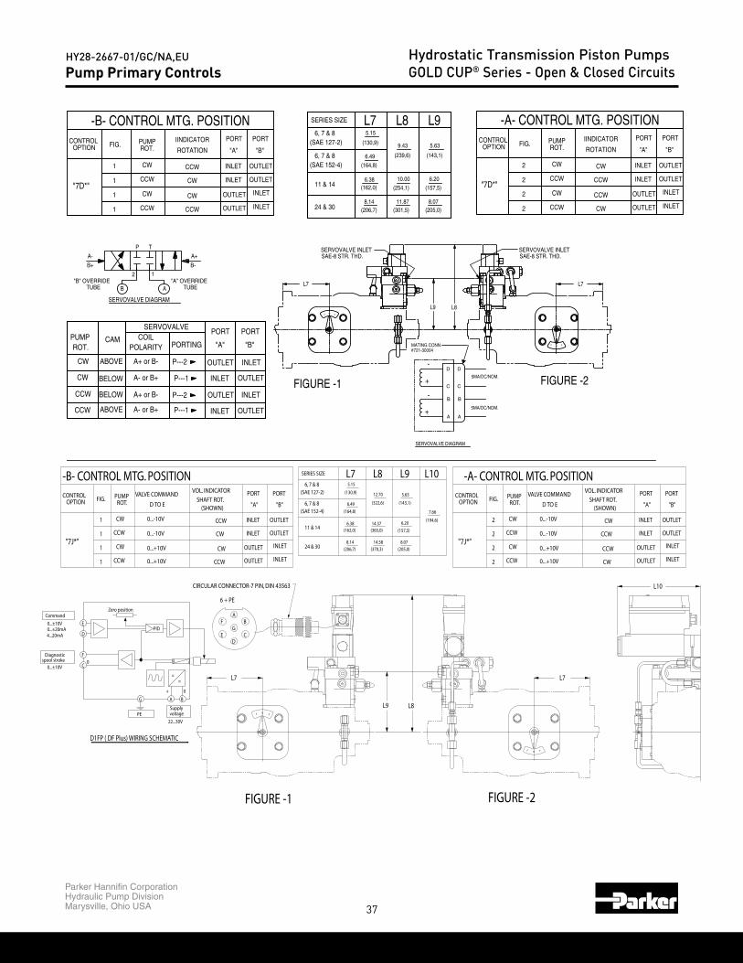
37
Parker Hannifin CorporationHydraulic Pump DivisionMarysville, Ohio USA
HY28-2667-01/GC/NA,EU Hydrostatic Transmission Piston PumpsGOLD CUP® Series - Open & Closed CircuitsPump Primary Controls
SupplyPE voltage
22...30V
0...±20mA4...20mA
Command
0...±10V
0...±10Vspool stroke
Diagnostic F
G
0C
+
A B
0
=
U
=
Zero position
D
EPID
D1FP ( DF Plus) WIRING SCHEMATIC
0...-10V
0...+10V
0...+10V
0...-10V
D TO E
VALVE COMMAND
-A- CONTROL MTG. POSITION
2
CW
CCW2
"7J*"2
CONTROL FIG. PUMPROT.
CW
CCW
2
OPTION
CCW INLET
INLET
INLETCW
CCW
OUTLET
OUTLET
PORT
OUTLET
OUTLET
(SHOWN)SHAFT ROT.
CW INLET
"A"
VOL. INDICATOR PORT
"B"
-B- CONTROL MTG. POSITION
0...-10VCCW1"7J*"
1 CCW
1 CW
0...+10V
0...+10V
OPTIONCONTROL VALVE COMMANDPUMP
1 CW
FIG.ROT.
0...-10V
D TO E
CW OUTLETINLET
CCW
CW
OUTLET INLET
OUTLET INLET
PORT PORT
CCW
(SHOWN)SHAFT ROT.
INLET OUTLET
"A" "B"
VOL. INDICATOR
(157,5)(162,0) (365,0)
(370,3)
14.58
(206,7)
8.14
(205,0)
8.07
12.70
(322,6)
14.37
(130,9)
(164,8)
6.38
6.49
5.15
5.63
7.66
(194,6)6.20
(143,1)
24 & 30
L8
(SAE 127-2)
(SAE 152-4)6, 7 & 8
11 & 14
SERIES SIZE
6, 7 & 8
L7 L10L9
SERVOVALVE DIAGRAM
SERVOVALVE DIAGRAM
FIGURE -2FIGURE -1
MATING CONN.#721-30004
SAE-8 STR. THD.SERVOVALVE INLET SERVOVALVE INLET
SAE-8 STR. THD.
5MA/DC/NOM.
5MA/DC/NOM.A- or B+
A+ or B-
A- or B+
POLARITY
A+ or B-
B
ABOVE
BELOW
BELOW
CCW
CCW
CW
CW
ROT.PUMP
ABOVE
CAM
A-
B+
TUBE"B" OVERRIDE
OUTLETINLETP---1
P---2 INLET
P---1
P---2
PORT
"A" "B"
PORT
OUTLET
INLET
INLET
OUTLET
OUTLET
COILSERVOVALVE
PORTING
B-
A+
"A" OVERRIDETUBEA
12
P T
L7L7
L9 L8
FOF
FOF
-
D D
+
-
C
B B
C
+
A A
ROTATION
IINDICATOR
-A- CONTROL MTG. POSITION
CW
CCW
CW
PUMPROT.
CCW
CW
CW
CCW
2
2
2
2
FIG.
"7D*"
OPTIONCONTROL
CCW
OUTLET
OUTLET
PORT
INLET
INLET
"A"
PORT
INLET
INLET
OUTLET
OUTLET
"B"
-B- CONTROL MTG. POSITION
"7D*"
1
1
1
FIG.
1
OPTIONCONTROL
OUTLET
OUTLETCW
INLET
PORT
"A"
INLET
"B"
INLET
INLET
OUTLET
OUTLET
PORTPUMP
CCW
CW
CW
ROT.
CCW
CCW
CW
CCW
ROTATION
IINDICATOR
8.07(205,0)
11.87(301,5)
(157,5)
6.20
(254,1)
10.00
5.63
(143,1)
9.43
(239,6)
(206,7)8.14
6.38(162,0)
6.49
(164,8)
(130,9)
5.15
6, 7 & 8(SAE 152-4)
(SAE 127-2)
24 & 30
11 & 14
L96, 7 & 8
SERIES SIZE L7 L8
A- or B+
A+ or B-
A- or B+
POLARITY
A+ or B-
ABOVE
BELOW
BELOW
CCW
CCW
CW
CW
ROT.PUMP
ABOVE
CAM
OUTLETINLETP---1
P---2 INLET
P---1
P---2
PORT
"A" "B"
PORT
OUTLET
INLET
INLET
OUTLET
OUTLET
COILSERVOVALVE
PORTING
FIGURE -1 FIGURE -2
CIRCULAR CONNECTOR-7 PIN, DIN 43563
L8L9
L7 L7
L10
FOF
FOF
AF
G
DE
B
C
6 + PE

38
Parker Hannifin CorporationHydraulic Pump DivisionMarysville, Ohio USA
HY28-2667-01/GC/NA,EU Hydrostatic Transmission Piston PumpsGOLD CUP® Series - Open & Closed CircuitsPump Primary Controls
SEE ROTARY SERVO
FIGURE -1
SERVOVALVE DIAGRAM
SHAFT DETAIL
FIGURE -2
ROYTARY SERVO SHAFT DETAIL
MANUAL SERVOVALVE SHUT-OFF
SHAFT DETAILSEE ROTARY SERVO
5.15
(130,9)
(143 1)
5.63
(270 1)
10.63
(35,6)1.40
MAX. VOLUME STOP
TRIMMER ADJ.
12.90( )13.03
.508MAJOR DIA. KNURL
.513
(32 TEETH PER INCH)
SHOWN IN OPEN POSITION
1/4-20UNC TAP x DEEP
MAX. VOLUME STOP
(6,4).25
MAX. VOLUME STOPTRIMMER ADJ.
SERVOVALVE INLETSAE-8 STR. THD.
.45
(11,4).32
(8,1)
SAE-8 STR. THD.SERVOVALVE INLET
(35,6)1.40
(SAE 127-2)
SERIES SIZE
&
6, 7 & 8
L7 L9L8
COIL
A+ or B-
POLARITY
A- or B+
A+ or B-
A- or B+
B
B+
A-
PUMP
"B" OVERRIDETUBE
ROT.
CW
CW
CCW
CCW
ABOVE
BELOW
BELOW
ABOVE
CAMPORT
OUTLET
INLET
INLET
OUTLET
"B"
TP
2 1
A
SERVOVALVE PORT
PORTING
OUTLET
INLET
OUTLET
P---2
P---1
P---2
P---1 INLET
"A"
TUBE"A" OVERRIDE
A+
B-
L7
L8L9
B
B
A
A
L7
FOF
FOF
Diagnosticspool stroke
0...±10V
0...±10V
Command
4...20mA0...±20mA
SupplyPE
22...30V
voltage
G
0
BA
+
PID
F
C0
D
=
U
=
Zero position
E
D1FP ( DF Plus) WIRING SCHEMATIC
OPTIONCONTROL
"7K*"
OUTLET
INLET
OUTLET
INLETCCW2 0...+10V
CW
CW
CCW2
2
2
0...-10V
0...+10V
0...-10V
CW OUTLET
CCW
CCW
CW
INLET
OUTLET
INLET
PORT
"B"
VALVE COMMAND
-A- CONTROL MTG. POSITION
ROT.PUMPFIG.
D TO E
CONTROL INPUT
SHAFT ROT.(SHOWN) "A"
PORTCONTROL
-B- CONTROL MTG. POSITION
OPTION
"7K*"
1 CCW 0...+10V
1 CCW
1 CW
1 CW
0...-10V
0...+10V
0...-10V
OUTLETCCW INLET
OUTLET
CW
CW
CCW
INLET OUTLET
INLET
OUTLETINLET
CONTROL INPUTVALVE COMMANDPUMPFIG.
ROT. D TO E (SHOWN)SHAFT ROT.
PORT PORT
"A" "B"(164,8) 7.66
14.37
14.58
(365,0)
(370,3)(206,7)
(162,0)
8.14
6.38
(205,0)
(194,6)
(157,5)
8.07
6.20
(322,6)
12.70(130,9)
6.49
5.15
5.63
(143,1)
(SAE 152-4)
11 & 14
24 & 30
L8SERIES SIZE L7
6, 7 & 8
(SAE 127-2)6, 7 & 8
L10L9
1
1
1
1
"7F*"
OUTLET
OUTLET
INLET
INLET
INLET
INLET
OUTLET
OUTLET
CCW
CW
CCW
CCW
CW
CW
CCW
CW
-B- CONTROL MTG. POSITIONCONTROL
OPTION FIG.ROTARY SERVO
INPUT SHAFTROTATION
PORTPORT
"B""A"PUMPROT.
(164,8)
6.20
(157,5)
(205,0)8.07
(162,0)6.38
8.14(206,7)
10.00
(254,1)
(301,5)11.87
(143,1)
5.63
5.15
(130,9)
(239,6)
9.43
6.49
(SAE 152-4)
11 & 14
24 & 30
L9L8L7SERIES SIZE
6, 7 & 8(SAE 127-2)
6, 7 & 8
CCW
CW
CW
CCW
2
2
2
2
"7F*"
OUTLET
OUTLET
INLET
INLET
INLET
INLET
OUTLET
OUTLET
CCW
CW
CCW
CW
PUMP
-A- CONTROL MTG. POSITION
ROT.CONTROL
OPTION FIG.ROTARY SERVO
INPUT SHAFTROTATION
PORTPORT
"B""A"
COIL
A+ or B-
POLARITY
A- or B+
A+ or B-
A- or B+
PUMPROT.
CW
CW
CCW
CCW
ABOVE
BELOW
BELOW
ABOVE
CAMPORT
OUTLET
INLET
INLET
OUTLET
"B"
SERVOVALVE PORT
PORTING
OUTLET
INLET
OUTLET
P---2
P---1
P---2
P---1 INLET
"A"
FIGURE -2FIGURE -1
MANUAL SERVOVALVE SHUT-OFF
SHAFT DETAILSEE ROTARY SERVO
MAX. VOLUME STOPTRIMMER ADJ.MAX. VOLUME STOP
SupplyPE
22...30V
voltage
G
0
BA
+
MAX. VOLUME STOP
TRIMMER ADJ.
PID
=
U
=
n
SHOWN IN OPEN POSITIONCIRCULAR CONNECTOR-7 PIN, DIN 43563
AF
G
DE
B
C
6 + PE
WIRING SCHEMATIC
L9 L8
L7 L7
L10
FOF
FOF

39
Parker Hannifin CorporationHydraulic Pump DivisionMarysville, Ohio USA
HY28-2667-01/GC/NA,EU Hydrostatic Transmission Piston PumpsGOLD CUP® Series - Open & Closed CircuitsPump Primary Controls
SHAFT DETAILSEE ROTARY SERVO
FIGURE -1
SEE ROTARY SERVO
ROTARY SERVO SHAFT DETAIL
SHAFT DETAIL
FIGURE -2
SEE ROTARY SERVOSHAFT DETAIL
FIGURE -1
SEE ROTARY SERVOSHAFT DETAIL
FIGURE -2
"P2" "P1"
(15,1)
(25,4)1.00
12.90( )13.03
.508
.513
.54(13,7)
(37,9)
37 1/2˚ FLARED FITTING9/16-18 UNF
"Z" BRAKE ACTUATOR PORT
.59
4.39(111,4)
(62,7)2.47
1.00(25,4)
1.49
MAX. VOLUME STOP MAX. VOLUME STOP
9/16-18 UNF
"Z" BRAKE ACTUATOR PORT37 1/2˚ FLARED FITTING
(157,4)6.20
MAX. VOLUME STOP
TRIMMER ADJ. LOCKNUT
TRIMMER ADJ.
MAJOR DIA. KNURL(32 TEETH PER INCH)
.59(15,1)
(111,4)4.39
(25,4)1.00
2.47(62,7)
1.00(25,4)
.54
(37,9)1.49
(13,7)
1.00(25,4)
(13,7)
(37,9)
.54
(62,7)2.47
(25,4)1.00
1.49
MAX. VOLUME STOP MAX. VOLUME STOP
TRIMMER ADJ. LOCKNUT
.45
(11,4)
(6,4).25 .32
(8,1)
MAX. VOLUME STOP
1/4-20UNC TAP x DEEP
TRIMMER ADJ. 1.00(25,4)
(62,7)2.47
(25,4)1.00
.54(13,7)
1.49(37,9)
ROTARY SERVOINPUT SHAFT
CCW
CW
CW
CCW
ROTATION
-B- CONTROL MTG. POSITIONCONTROL SPRING OFF-SET TO MIN, VOLUME
"8C*" "P2"
"P2"
"P1"1
1
CCW
CW
CCW1
CONTROLOPTION ROT.
PUMPFIG.
"P1"CW1
STR. THD. PORT:TO SAE-4
PRESSURE SIGNAL
SEE TABLES 1-18L7
PORT
"A"
-A- CONTROL MTG. POSITION
OUTLET
OUTLET
INLET
INLET
2
2
2
INLET
INLET
OUTLET
OUTLET
OUTLET
INLET "8C*" "P1"
"P1"
"P2" CWCCW
CW
CCW
CCW
CCW
FIG."B"
PORTPORT
"A"CONTROL
OPTION
2OUTLETINLET
TO SAE-4PUMPROT.
PRESSURE SIGNAL
CONTROL SPRING OFF-SET TO MIN, VOLUME
INPUT SHAFTROTARY SERVO
"P2"CW CW
ROTATIONSTR. THD. PORT:
SEE TABLES 1-18L7
INLET
INLET
OUTLET
PORT
"B"
OUTLET
INPUT SHAFTROTATION
CCW
CW
CW
CCW
CONTROL SPRING OFF-SET TO MIN, VOLUME
-B- CONTROL MTG. POSITION
ROTARY SERVO
"8A*"
OPTIONCONTROL
"P1"
"P2"
"P2"
"P1"
1 CCW
FIG.
1
PUMPROT.
CW
CW
CCW
1
1
PRESSURE SIGNALTO SAE-4
STR. THD. PORT:
L7SEE TABLES 1-18
"A"
INLET
INLET
OUTLET
OUTLET
PORT
-A- CONTROL MTG. POSITION
FIG.OPTION
"8A*" 2
2
2
2
CONTROL
INLET
"A"
PORT
INLET
PORT
"B"
OUTLET
OUTLET
OUTLET
OUTLET
INLET
INLET
CW
CCW
CCW
CW
TO SAE-4STR. THD. PORT:
"P2"
"P1"
"P1"
"P2"
PRESSURE SIGNAL ROTARY SERVOINPUT SHAFT
ROTATIONROT.
CCW
CW
CW
CCW
CONTROL SPRING OFF-SET TO MIN, VOLUME
PUMP
L7SEE TABLES 1-18
"B"
OUTLET
OUTLET
INLET
INLET
PORT
"P1""P2"
FOF
"P1" "P2"
FOF
OF F
O FF

40
Parker Hannifin CorporationHydraulic Pump DivisionMarysville, Ohio USA
HY28-2667-01/GC/NA,EU Hydrostatic Transmission Piston PumpsGOLD CUP® Series - Open & Closed CircuitsPump Primary Controls
FIGURE -1SHAFT DETAILSEE MANUAL OVERRIDE
SHAFT DETAILSEE MANUAL OVERRIDE
FIGURE -1
FIGURE -2 SEE MANUAL OVERRIDESHAFT DETAIL
FIGURE -2
SHAFT DETAILMANUAL OVERRIDE
SHAFT DETAILSEE MANUAL OVERRIDE
TRIMMER ADJ. LOCKNUT
MAX. VOLUME STOP
TRIMMER ADJ. LOCKNUT
MAX. VOLUME STOP
(67,8)
MAX. VOLUME STOP
(130,1)5.12
3.17(80,5)
4.39(111,4)
(13,7).54
SOL. "A""B"SOL.
6.20(157,4)
(15,1).59
TRIMMER ADJ.
"Z" BRAKE ACTUATOR PORT37 1/2˚ FLARED FITTING
2.67
2.67(67,8)
(130,1)5.12
(80,5)3.17
MAX. VOLUME STOP
9/16-18 UNF
"B"SOL.SOL. "A"
(14,0).55
TRIMMER ADJ.
"B"SOL.
5.12(130,1)
4.39(111,4)
SOL. "A"
.59(15,1)
37 1/2˚ FLARED FITTING9/16-18 UNF
"Z" BRAKE ACTUATOR PORT
(80,5)
2.67(67,8)
.54(13,7)
MAX. VOLUME STOP
(130,1)5.12
"B"SOL.SOL. "A"
.12(3,0)
.19
(4,8)HEX RECESS x DEEP
3.17
2.67(67,8)
3.17(80,5)
MAX. VOLUME STOP
INLET OUTLET"B"CW2OUTLETCCW INLET CW"A"CW1
ENERGIZESOLENOID
-B- CONTROL MTG. POSITION
SEE TABLES 1-18
PUMPROT.
1 CCW
1 CW "A"
"B"
OPTIONCONTROL
"9C*"
FIG.
CCW1 "A"
CW1 "B"
L7
OUTLET
OUTLET
PORT
"B"ROTATION
CCW
CW
MANUALOVERRIDE SHAFT
INLET
INLET
"A"
PORT
INLETCCW OUTLET
OUTLETCW INLET
L7SEE TABLES 1-18
"B"
"B"
"A"1
1
CCW
CW
CCW1"9A*"
INLET
INLET
OUTLET
CCW
CW
CW
OUTLET
OUTLET
INLET
-A- CONTROL MTG. POSITION-A- CONTROL MTG. POSITION
OVERRIDE SHAFTENERGIZESOLENOID
"B"
"A"2
2
CCW
CW
FIG. ROT.PUMP
OPTIONCONTROL
"9C*"
"B"2 CCW
2 CW "A"
OUTLET
OUTLETINLET
INLET
"B""A"
PORTPORT
INLETOUTLET
INLETOUTLET
CW
CW
CCW
CCW
MANUAL
ROTATION
L7SEE TABLES 1-18
"A"
"A"
"B"CCW
CW
CCW
2
2
2"9A*"
SEE TABLES 1-18L7
OUTLET
OUTLET
INLET
INLET
INLET
OUTLET
CW
CCW
CCW
-B- CONTROL MTG. POSITION
SOLENOIDENERGIZE
ROT.PUMPCONTROL
OPTION FIG."B"
PORTMANUALOVERRIDE SHAFT
PORT
"A"ROTATIONOVERRIDE SHAFT
-A- CONTROL MTG. POSITION
SOLENOIDENERGIZEPUMP
ROT.FIG.CONTROLOPTION
ROTATION
MANUAL PORT PORT
"A" "B"
O
O
O
O

41
Parker Hannifin CorporationHydraulic Pump DivisionMarysville, Ohio USA
HY28-2667-01/GC/NA,EU Hydrostatic Transmission Piston PumpsGOLD CUP® Series - Open & Closed Circuits
FIGURE -1
SHAFT DETAILSEE ROTARY SERVO
FIGURE -2
SHAFT DETAILSEE ROTARY SERVO
MIN. VOLUME STOP
MAJOR DIA. KNURL(32 TEETH PER INCH)
(25,4)
.45(11,5)
1.40
2.50(63,5)
MIN. VOLUME STOP
(35,6)
.513
( )12.9013.03
.508
"X" "Y"
(25,4)1.001.00 MAX. VOLUME STOP
"Y" "X"
(25,4)1.00(25,4)
1.00
.45(11,5)
1.40(35,6)
(63,5)2.50
MAX. VOLUME STOP
SEE TABLES 1-18L7 L7
SEE TABLES 1-18
FOF
FOF
PRESSURE SIGNAL TO:
1/8-27 N.P.T.F.PORT "X"
REDUCED SPEED
FIG.OPTIONCONTROL
1
MOTORROT.
CW
1 CCW"2A*"
"A"
PORT
INLET
PORT "Y"1/8-27 N.P.T.F.
OUTLETFULL SPEED
-B- CONTROL MTG. POSITIONCONTROL SPRING OFF-SET TO FULL VOLUME
PRESSURE SIGNAL TO:
FIG.OPTION
2
MOTORROT.
CWFULL SPEED
PORT "X"1/8-27 N.P.T.F.
CONTROL
2 CCW"2A*"
"A"
PORT
INLETREDUCED SPEED
PORT "Y"1/8-27 N.P.T.F.
OUTLET
CONTROL SPRING OFF-SET TO FULL VOLUME
-A- CONTROL MTG. POSITION
FIGURE -1
SHAFT DETAILSEE ROTARY SERVO
FIGURE -2
ROTARY SERVO SHAFT DETAIL
SHAFT DETAILSEE ROTARY SERVO
(11,4)
MAJOR DIA. KNURL(32 TEETH PER INCH)
.45
.513
(8,1)
.32(6,4).251/4-20UNC TAP x DEEP
( )12.9013.03
.508
.45
(25,4)MIN. VOLUME STOP
(25,4)
.45.45 TRIMMER ADJ.
MAX. VOLUME STOP
Motor Primary Controls
FIGURE -1
SEE ROTARY SERVOSHAFT DETAIL
FIGURE -2
SHAFT DETAILSEE ROTARY SERVO
MAX. VOLUME STOP
5.02(127,6)
4.10(104,0)
NULL ADJ.SCREW
4.30(109,3) TRIMMER ADJ.
MIN. VOLUME STOP
MAX. VOLUME STOPTRIMMER ADJ.
MIN. VOLUME STOP
4.30(109,3)
NULL ADJ.SCREW
5.02(127,6)
4.10(104,0)
L7SEE TABLES 1-18 L7
SEE TABLES 1-18
MARYSVILLE , OHIO U.S.A.
ASS'Y NO.
B-82419-330
L = 1.5 mh MAX.
GROUPS A, B, C, AND D.1. NONINCENDIVE CLASS I, DIVISION 2,
LOCATION IS KNOWN TO BENONHAZARDOUS.
ELEC. RATINGS:I = 330 ma MAX.
HAZARDOUS LOCATION SUITABILITY:
V = 10.56 VOLTS D.C. MAX.
2. CLASS II, DIVISION 2, GROUPS F AND G.WARNING- DO NOT DISCONNECTWHILE CIRCUIT IS LIVE UNLESS
SERIAL NO.
SERIAL NO.
WHILE CIRCUIT IS LIVE UNLESSWARNING- DO NOT DISCONNECT
HAZARDOUS LOCATION SUITABILITY:
ELEC. RATINGS:
NONHAZARDOUS.LOCATION IS KNOWN TO BE
ASS'Y NO.
2. CLASS II, DIVISION 2, GROUPS F AND G.
V = 10.56 VOLTS D.C. MAX. I = 330 ma MAX.
1. NONINCENDIVE CLASS I, DIVISION 2,GROUPS A, B, C, AND D.
L = 1.5 mh MAX.
B-82
419-
3 30
MARYSVILLE , OHIO U.S.A.
OUTLET
CCW ROTATION
ROTARY SERVO
REDUCED SPEED
CONTROL SPRING OFF-SET TO FULL VOLUME
-B- CONTROL MTG. POSITION
OPTIONCONTROL FIG. ROT.
MOTOR
"5A*" CCW1
CW1FULL SPEED
CW ROTATIONINPUT SHAFT
ROTARY SERVO PORTINPUT SHAFT
"A"
PORT
"B"
INLETOUTLET
INLET
CONTROL SPRING OFF-SET TO FULL VOLUME
ROTARY SERVO
-A- CONTROL MTG. POSITION
CW
CCW
ROT.MOTOR
FIG.
2
2FULL SPEED
CCW ROTATIONINPUT SHAFT
"5A*"
OPTIONCONTROL
INLET
OUTLET
PORT
"B"
REDUCED SPEED
CW ROTATIONINPUT SHAFT
ROTARY SERVO
INLET
"A"
PORT
OUTLET

42
Parker Hannifin CorporationHydraulic Pump DivisionMarysville, Ohio USA
HY28-2667-01/GC/NA,EU Hydrostatic Transmission Piston PumpsGOLD CUP® Series - Open & Closed CircuitsMotor Primary Controls
ELECTRICAL INPUT
MANUAL OVERRIDE DETAILSERVO MUST BE DISCONNECTED
.3760.3755
(9,550)(9,538)
STOP)
POLARITY
OA A+
(9,91).390
MATING CONN. HALF,(ELECT. RECEPTACLE CONN. 5/8-24UNEF x
MS3106E-10SL-4S)
(MECH.STOP)
19˚ NULLED AT 0 CURRENT
O(MECH.6˚ CW
COIL RESISTANCE350 MA. NOM.
25 NOM.
+A
CURRENT AT FULL DISPL.
INPUT SHAFT WILL ROTATE CWWITH ELECTRICAL POLARITY AS SHOWN
B
.15(3,8)
MAX.
.20 WIDE FLATDIA. WITH
DIA.
(14,2)
.56
(12,5).49
(7,9).31
FIGURE -1 FIGURE -2
MANUAL OVERRIDESHAFT DETAIL
SHAFT DETAILSEE MANUAL OVERRIDE SHAFT DETAIL
SEE MANUAL OVERRIDE
(80,5)
MIN. VOLUME STOP
MAX. VOLUME STOP MAX. VOLUME STOP
MIN. VOLUME STOP
(67,8)2.67
3.17
5.12(130,1)
MAX. VOL. LOCKNUT
.55(14,0)
(130,1)
.12(3,0)
DEEP
MAX. VOL. LOCKNUT
(4,8)
.19HEX RECESS x
5.12
(80,5)3.17
(67,8)2.67
O
O
CONTROL SPRING OFF-SET TO FULL VOLUME
-B- CONTROL MTG. POSITION
ENERGIZESOLENOID
FULL SPEED
SEE TABLES 1-18
"9A*"1 CCW
1 CW
FIG.OPTIONCONTROL MOTOR
ROT.
INLET
OUTLET
OUTLET
INLET
"A"
PORT PORT
"B"ROTATION
CW
CW
MANUALOVERRIDE SHAFT
L7
CONTROL SPRING OFF-SET TO FULL VOLUME
-A- CONTROL MTG. POSITION
ENERGIZESOLENOIDROT.
MOTOR
CCWFULL SPEED
CW
OPTIONCONTROL
2"9A*"
2
FIG.
L7SEE TABLES 1-18
"A"
PORT PORT
"B"ROTATION
MANUALOVERRIDE SHAFT
CCW OUTLET INLET
CCW INLET OUTLET
FIGURE -1FIGURE -2
SHAFT DETAILSEE ROTARY SERVO
SHAFT DETAILSEE ROTARY SERVO
(11,4)
(8,1)
.32(6,4).251/4-20UNC TAP x DEEP
TRIMMER ADJ. LOCKNUT
MIN. VOLUME STOP
TRIMMER ADJ.
MAX. VOLUME STOP
TRIMMER ADJ. LOCKNUT
(25,4)
.54
(37,9)
(13,7)
1.49
2.47(62,7)
MIN. VOLUME STOP
1.00 (25,4)1.00
1.001.00
(25,4)(25,4)
.45.45 TRIMMER ADJ.
(37,9)1.49
.54
2.47(62,7)
(13,7)
MAX. VOLUME STOP
"P2""P1"
FOF "P1""P2"
OF F
STR. THD. PORTTO SAE-4
PRESSURE SIGNAL
FULL SPEED
SEE TABLES 1-18
-B- CONTROL MTG. POSITIONCONTROL SPRING OFF-SET TO FULL VOLUME
CONTROLOPTION
"8A*"CW
ROT.MOTOR
1
FIG.
CCW1
P2
OUTLET
OUTLET
"B"
PORT
INLET
PORT
"A"
INLETCW
CW
ROTATION
ROTARY SERVOINPUT SHAFT
L7
STR. THD. PORT
PRESSURE SIGNAL
CONTROL SPRING OFF-SET TO FULL VOLUME
FULL SPEED
-A- CONTROL MTG. POSITION
TO SAE-4
CW2
P1
ROT.MOTOR
CCW2
CONTROLOPTION
"8A*"
FIG.
L7SEE TABLES 1-18
CCW OUTLETINLET
ROTARY SERVOINPUT SHAFT
ROTATION
PORT
"A"
PORT
"B"
OUTLET INLETCCW
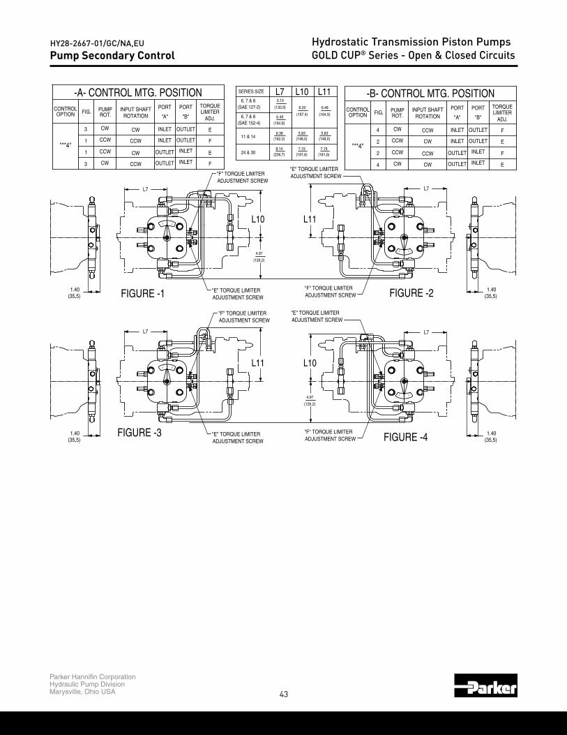
43
Parker Hannifin CorporationHydraulic Pump DivisionMarysville, Ohio USA
HY28-2667-01/GC/NA,EU Hydrostatic Transmission Piston PumpsGOLD CUP® Series - Open & Closed CircuitsPump Secondary Control
FIGURE -3
FIGURE -1
FIGURE -4
FIGURE -2
ADJUSTMENT SCREW"E" TORQUE LIMITER
ADJUSTMENT SCREW"F" TORQUE LIMITER
ADJUSTMENT SCREW"E" TORQUE LIMITER
1.40(35,5)
(35,5)1.40
ADJUSTMENT SCREW"F" TORQUE LIMITER
(126,2)
4.97
(35,5)1.40
"E" TORQUE LIMITERADJUSTMENT SCREW
"E" TORQUE LIMITERADJUSTMENT SCREW
ADJUSTMENT SCREW"F" TORQUE LIMITER
ADJUSTMENT SCREW"F" TORQUE LIMITER
7.15(181,6)
5.83(148,0)
4.97
(126,2)
(206,7)8.14
6.38(162,0) (148,0)
5.83
7.15(181,6)
1.40(35,5)
6.48
(164,5)
6.20
(157,4)6.49
5.15
(130,9)
(164,8)
TORQUELIMITER
EINLET OUTLETCWCW3
"**4"E
F
F
L7
OUTLET
INLET
INLET
OUTLET
OUTLET INLET
CW
CCW
CCW
CCW
1
1
CCWCW
L7
3
-A- CONTROL MTG. POSITION
OPTIONCONTROL
ADJ.
PORT
"A"
PORT
"B"PUMPROT. ROTATION
INPUT SHAFTFIG.TORQUE
-B- CONTROL MTG. POSITION
F
F
ADJ.LIMITER
OUTLET4 CW CCW INLET
"**4"
L11 L10
L11L10
11 & 14
24 & 30
INLET
OUTLET
INLET
2
2
4
CCW
CCW
CW
CW
CCW
CW OUTLET
INLET
OUTLET
L7
L7
CONTROLOPTION
L11L10(SAE 127-2)
SERIES SIZE
6, 7 & 8
6, 7 & 8
L7
(SAE 152-4)
PORTPUMP INPUT SHAFT PORT
"B"ROT. ROTATION "A"FIG.
E
E
FOF
FOF
F O F
F O F

44
Parker Hannifin CorporationHydraulic Pump DivisionMarysville, Ohio USA
HY28-2667-01/GC/NA,EU Hydrostatic Transmission Piston PumpsGOLD CUP® Series - Open & Closed CircuitsPump & Motor Secondary Controls
DC RVDT DIAGRAM
FIGURE -2 FIGURE -1
POTENTIOMETER DIAGRAM
FIGURE -2 FIGURE -1
1.40(35,5)
1.40(35,5)
4.15"**8"(105,4)
("**8" REF.)
3.76(95,5)
"**6"MATING CONN.
#721-30059
"**8"4.15DRED8 D
("**6" REF.)
4
FWH
F
B
C
GN
BL
7
2
B
C
(105,4)
#721-30059MATING CONN.
"**6"3.76(95,5)
SEE TABLES 1-18
-A- CONTROL MTG. POSITION
CW
CCW
CW
CCW
ROT.PUMP
L7
"**2"
CONTROLOPTION
2
2
2
2
FIG.
OUTLET
OUTLET
INLET
INLET
INLET
INLET
OUTLET
OUTLET
"B"
PORT
"A"
PORT
CCW
CW
CCW
CW
INPUT SHAFTROTATION
-15VDC
OUTBLUE
GREEN
-15VDC
OUT
COMMON
BLACK
+15VDC
F
C
D D
C
F
SEE TABLES 1-18
ROT.PUMP
CCW
CW
CCW
CW
-A- CONTROL MTG. POSITIONCONTROL
OPTION FIG.
L7
"**6"or
"**8"
2
2
2
2
"B"
PORT
"A"
PORT
OUTLET
OUTLET
INLET
INLET
INLET
INLET
OUTLET
OUTLET
+15VDCRED
BB
CCW
CW
CCW
CW
INPUT SHAFTROTATION
INPUT SHAFTROTATION
-B- CONTROL MTG. POSITION
SEE TABLES 1-18L7
CW
1
1
1
1
CCW
CW
CCW
CW
FIG. ROT.PUMP
CCW
CCW
CW
CONTROL
"**2"
OPTION
OUTLET
OUTLET
INLET
INLET
INLET
INLET
OUTLET
OUTLET
PORT
"A"
PORT
"B"
-B- CONTROL MTG. POSITIONINPUT SHAFT
ROTATION
SEE TABLES 1-18
"**8"or
"**6"
FIG. ROT.PUMPCONTROL
OPTION
L7
1
1
1
1
CCW
CW
CCW
CW CCW
CW
CCW
CW
PORT
"B""A"
PORT
OUTLET
OUTLET
INLET
INLET
INLET
INLET
OUTLET
OUTLET
F O F
OF F
C
FOF
SME
TSYS
CIL
UAR
DYH
ORT
C EL E
ASU
0403
4OI
HO,
ELLI
V SY
R AM
N/ SN/ P
F O F
P/NS/N
ASU
04034OI
HO,ELLIVSY
RAM
SME TS YS
CILUA
RDY
HO
RTCEL E

45
Parker Hannifin CorporationHydraulic Pump DivisionMarysville, Ohio USA
HY28-2667-01/GC/NA,EU Hydrostatic Transmission Piston PumpsGOLD CUP® Series - Open & Closed CircuitsRear Adapters
SAEMounting and Coupling
MountingBlanking
Plate82-2 (A) 101-2 (B) 101-4 (B) 127-2 (C) 127-4 (C) 152-4 (D) 165-4 (E) 177-4 (F)
Coupling None 16-4 (A) 22-4 (B) 22-4 (B) 32-4 (C) 32-4 (C) 44-4 (D) 44-4 (E) 50-4 (F)
Pu
mp
s
P6/7/8 S, X M A B - - - - - -
P6/7/8 R, L , M M A B - C - - - -
P11/14 S, X M A B - - - - - -
P11/14 R, L, M M A B B C C D E
P24/30 S, X - - B - C - - - -
P24/30 R, L, M M - B B C C D E F
Mo
tors
M6/7/8 R, L, M, N M A B - C - - - -
M11/14 R, L, M, N M A B B C C D E -
M24/30 R, L, M, N M - B B C C D E F
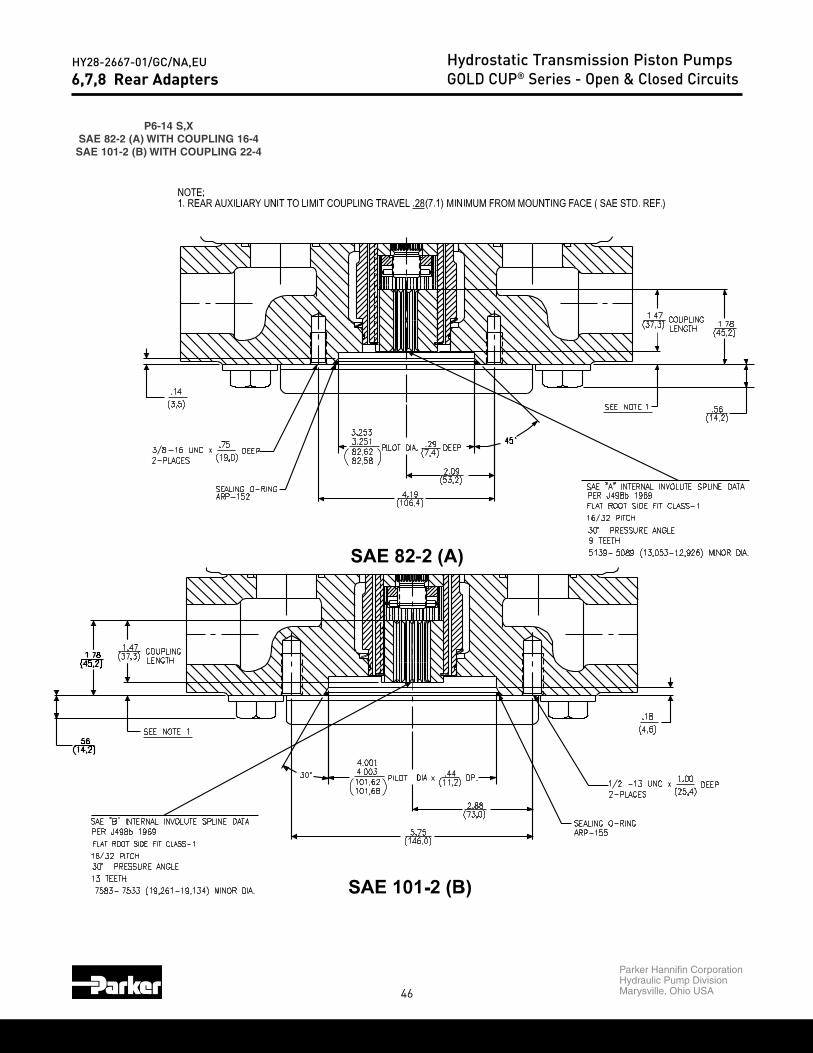
46
Parker Hannifin CorporationHydraulic Pump DivisionMarysville, Ohio USA
HY28-2667-01/GC/NA,EU Hydrostatic Transmission Piston PumpsGOLD CUP® Series - Open & Closed Circuits6,7,8 Rear Adapters
P6-14 S,XSAE 82-2 (A) WITH COUPLING 16-4SAE 101-2 (B) WITH COUPLING 22-4

47
Parker Hannifin CorporationHydraulic Pump DivisionMarysville, Ohio USA
HY28-2667-01/GC/NA,EU Hydrostatic Transmission Piston PumpsGOLD CUP® Series - Open & Closed Circuits
M6,7 R,L,M,NP6,7,8 R,L,M
SAE 127-2 (C) WITH COUPLING 32-4SAE 101-2 (B) WITH COUPLING 22-4SAE 82-2 (A) WITH COUPLING 16-4
SAE "A"AUX. MTG.
3/8
82,6382,583.2533.251
SAE-"A" INTERNAL SPLINE DATA
16-32 PITCH
(13,053-12,926)
(16,154-15,875.5139-.5089
.6360-.6250
FLAT ROOT SIDE FIT J498B
30˚ PRESSURE ANGLE
9 TEETH
MAJOR DIA.
MINOR DIA.
.29(7,4)
)
2.09
(53,1)
X 45˚
(106,4)
4.19
(3,6)
DIA.
.14
2 PLACES AS SHOWN(19,0)
-16 UNC-2B TAP x DP. .75
(22,504-22,225
(19,261-19,134)
FLAT ROOT
30˚ PRESSU
SAE-"B" INTE
16-32 PITCH
.8860-.8750
.7583-.7533
13 TEETH
MIN.2.40(61,0)
MIN.
.39(9,9)
1.38(34,9)
SPLINE LENGTH
)A(2-28EAS
AUX. MTG.SAE "B"
N(19,0)
P x DP. .75
(22,504-22,225
(19,261-19,134)
FLAT ROOT SIDE FIT J498B
30˚ PRESSURE ANGLE
SAE-"B" INTERNAL SPLINE DATA
16-32 PITCH
.8860-.8750
.7583-.7533
13 TEETH
2 PLACES AS SHOWN1/2
SPLINE LENGTH
2.88
(73,0)
MAJOR DIA.
MINOR DIA.
)
MIN.
(34,9)1.38
(9,9)MIN.
.39
2.40(61,0)
(10,2).40
101,75101,654.0064.002
-13 UNC-2B TAP x
(146,0)
X 45˚.08
5.75
(2,0)
DIA.
1.00(25.4)
DP.
SAE-C INT
1.0862-1.09(31.750-32.01.2500-1.2630˚ PRESS
(27.589-27.7
FLAT ROOT
12-24 PITC14 TEETH
SAE "C"AUX. MTG.WN
P x 1.00(25.4)
DP.
2.24
(56,9)
MINOR DIAMETER
SAE-C INTERNAL SPLINE DATA
MAJOR DIAMETER
1.0862-1.0912(31.750-32.080)1.2500-1.263030˚ PRESSURE ANGLE
(27.589-27.716)
FLAT ROOT SIDE FIT
12-24 PITCH14 TEETH
SPLINE LENGTH
(J498B)
(25.4)1.00
3.56
(90,4)
5/82 PLACES AS SHOWN
MIN.
1.32
(33,5)
(13.5)
5.002
127.05127.15
5.006
.74
.53
(18,8)
x45˚
-11 UNC-2B TAP x
(180,8)
(2.0)
.08
7.12
DIA.
MIN.
DP.
)C(2-721EAS
6,7,8 Rear Adapters
)B(2-101EAS

48
Parker Hannifin CorporationHydraulic Pump DivisionMarysville, Ohio USA
HY28-2667-01/GC/NA,EU Hydrostatic Transmission Piston PumpsGOLD CUP® Series - Open & Closed Circuits11,14 Rear Adapters
M11,14 R,L,M,NP11,14 R,L
BLANKING PLATE
M11,14 R,L,M,NP11,14 R,L,M
SAE 82-2 (A) WITH COUPLING 16-4

49
Parker Hannifin CorporationHydraulic Pump DivisionMarysville, Ohio USA
HY28-2667-01/GC/NA,EU Hydrostatic Transmission Piston PumpsGOLD CUP® Series - Open & Closed Circuits11,14 Rear Adapters
M11,14 R,L,M,NP11,14 R,L,M
SAE 101-2 (B) WITH COUPLING 22-4SAE 101-4 (B) WITH COUPLING 22-4
M11,14 R,L,M,NP11,14 R,L,M
SAE 127-2 (C) WITH COUPLING 32-4SAE 127-4 (C) WITH COUPLING 32-4

50
Parker Hannifin CorporationHydraulic Pump DivisionMarysville, Ohio USA
HY28-2667-01/GC/NA,EU Hydrostatic Transmission Piston PumpsGOLD CUP® Series - Open & Closed Circuits11,14 Rear Adapters
1.06(26.9)
3.50(88.9)
3.50(88.9)
M11,14 R,L,M,NP11,14 R,L,M
SAE 165-4 (E) WITH COUPLING 44-4
M11,14 R,L,M,NP11,14 R,L,M
SAE 152-4 (D) WITH COUPLING 44-4
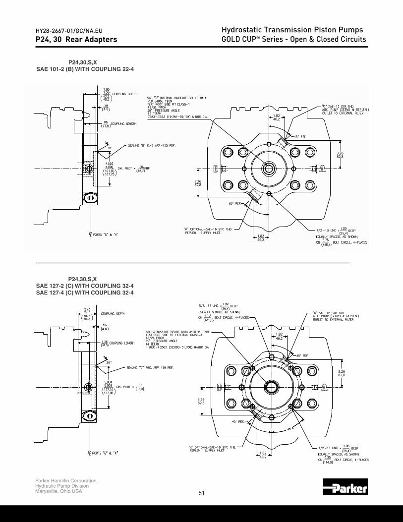
51
Parker Hannifin CorporationHydraulic Pump DivisionMarysville, Ohio USA
HY28-2667-01/GC/NA,EU Hydrostatic Transmission Piston PumpsGOLD CUP® Series - Open & Closed CircuitsP24, 30 Rear Adapters
P24,30,S,XSAE 101-2 (B) WITH COUPLING 22-4
P24,30,S,XSAE 127-2 (C) WITH COUPLING 32-4SAE 127-4 (C) WITH COUPLING 32-4
3.2682,8
1.8246,2
1.8246,2
3.2682,8
3.2682,8
1.8246,2
1.8246,2
3.2682,8

52
Parker Hannifin CorporationHydraulic Pump DivisionMarysville, Ohio USA
HY28-2667-01/GC/NA,EU Hydrostatic Transmission Piston PumpsGOLD CUP® Series - Open & Closed Circuits
.67(17.1)
7/8"-9 UNC X1.25 (31,8) DP.
OVERHUNG SUPPORTFITTING
146,05( )
ARP - 155SEALING "O" RING
( ).4411,2
EQUALLY SPACED(127,00)
(25,4)-13 UNC X 1.00 DP.
1/24 BOLT MOUNT
ON 5.000 BOLT CIRCLE
( )
4.004
101,69101,67
4.002 DIA.
1/2
AS SHOWN
2 BOLT MOUNT
(25,4)-13 UNC X 1.00 DP.
73,022.875
( )
MIN.
5.750
45˚
(64,0)
2.52 ( )17,013,2.67
30 ˚
DIA4.21(107,0)
7/8"-9 UNC X1.25 (31,8) DP.
OVERHUNG SUPPORTFITTING
16/32 PITCH30˚ PRESSURE ANGLE
.7583-.7533 (19,261-19,134) MINOR DIA.13 TEETH
SAE 22-4 ("B")
FLAT ROOT SIDE FIT CLASS-1
SAE 22-4 INTERNAL INVOLUTE SPLINE DATAPER J498b 1969
SAE 101-4 ("B" 4 BOLT)SAE 101-2 ("B" 2 BOLT)
.52
24, 30 Rear Adapters
M24,30 R,L,M,NP24,30 R,L,M
BLANKING PLATE
M24,30 R,L,M,NP24,30 R,L,M
SAE 101-2 (B) WITH COUPLING 22-4SAE 101-4 (B) WITH COUPLING 22-4

53
Parker Hannifin CorporationHydraulic Pump DivisionMarysville, Ohio USA
HY28-2667-01/GC/NA,EU Hydrostatic Transmission Piston PumpsGOLD CUP® Series - Open & Closed Circuits
ARP - 163SEALING "O" RING
( )12,7
(33,3)
3.8297,0( )
18,013,7
.71.54
( )
.50
1.31
152.46152.44152.46( )6.0026.0046.002 DIA.
8 PLACES - EQUALLY SPACEDAS SHOWN
(228,60)
8 BOLT MOUNT-10 UNC THRU (1.31 DEEP REF.)
ON 9.000 BOLT CIRCLE3/4
30˚
DIA6.21(157,8)
7/8"-9 UNC X1.25 (31,8) DP.
OVERHUNG SUPPORTFITTING
SAE 152-4 ("D" 4 BOLT)
1.5110-1.5060 (38,379-38,252) MINOR DIA.
SAE 44-4 INTERNAL INVOLUTE SPLINE DATA
30˚ PRESSURE ANGLE
FLAT ROOT SIDE FIT CLASS-1
SAE 44-4 ("D" & "E")
8/16 PITCH
13 TEETH
PER J498b 1969
(180,98)
EQUALLY SPACED(161,93)
4 BOLT MOUNT
ON 7.125 BOLT CIRCLE
ON 6.375 BOLT CIRCLE
-13 UNC X 1.00 DP.
-11 UNC X 1.25 DP.2 BOLT MOUNT
( )
SEALING "O" RINGARP - 159
1/2
5.002127.09
5.0045.002127.09127.07( )
DIA.
35. 35.13,5
AS SHOWN
5/8
(25,4)
(31,8)
45˚
90˚
18,013,7
.71
97,03.82
( )( )
.54
(33,3)1.31
30˚
DIA5.21(132,4)
7/8"-9 UNC X1.25 (31,8) DP.
OVERHUNG SUPPORTFITTING
1.0912-1.0862 (27,716-27,589) MINOR DIA.
SAE 32-4 INTERNAL INVOLUTE SPLINE DATA
SAE 32-4 ("C")
FLAT ROOT SIDE FIT CLASS-1
30˚ PRESSURE ANGLE12/24 PITCH
PER J498b 1969
SAE 127-2 ("C" 2 BOLT)
SAE 127-4 ("C" 4 BOLT)
24, 30 Rear Adapters
M24,30 R,L,M,NP24,30 R,L,M
SAE 127-2 (C) WITH COUPLING 32-4SAE 127-4 (C) WITH COUPLING 32-4
M24,30 R,L,M,NP24,30 R,L,M
SAE 152-4 (D) WITH COUPLING 44-4

54
Parker Hannifin CorporationHydraulic Pump DivisionMarysville, Ohio USA
HY28-2667-01/GC/NA,EU Hydrostatic Transmission Piston PumpsGOLD CUP® Series - Open & Closed Circuits24, 30 Rear Adapters
M24,30 R,L,M,NP24,30 R,L,M
SAE 165-4 (E) WITH COUPLING 44-4.64
( )165.12
ARP - 165SEALING "O" RING
165.14
6.5026.5046.502
16,3( )
DIA.
(317,50)
4 BOLT MOUNT
4 PLACES - EQUALLY SPACED
ON 12.500 BOLT CIRCLE
3/4-10 UNC THRUDIA
(419,6)16.52
18,013,7
.71
97,03.82
( )( )
.54
(33,3)1.31
˚30
DIA6.71(170,6)
7/8"-9 UNC X1.25 (31,8) DP.
OVERHUNG SUPPORTFITTING
SAE 165-4 ("E" 4 BOLT)
SAE 44-4 INTERNAL INVOLUTE SPLINE DATA
1.5110-1.5060 (38,379-38,252) MINOR DIA.
PER J498b 1969
30˚ PRESSURE ANGLE
FLAT ROOT SIDE FIT CLASS-1
SAE 44-4 ("D" & "E")
8/16 PITCH
13 TEETH
M24,30 R,L,M,NP24,30 R,L,M
SAE 177-4 (F) WITH COUPLING 50-4
7.0037.001
ARP - 167SEALING "O" RING
177,88177,82( )
( )16,3.64
DIA.
4-PLACES
-8 UNC X 1.31 DP.4 BOLT MOUNT1"
(33,3)
DIA(419,6)16.52
123,8( )4.88
SQUARE247,69.75
( )
(33,3)1.31
18,013,7
.71
( )
.54
97,03.82
( )
˚30
DIA7.28(184,9)
7/8"-9 UNC X1.25 (31,8) DP.
OVERHUNG SUPPORTFITTING
SAE 177-4 ("F" 4 BOLT)1.7524-1.7574 (44,511-44,638) MINOR DIA.
FLAT ROOT SIDE FIT CLASS-1
30˚ PRESSURE ANGLE15 TEETH
PER J498b 1969
8/16 PITCH
SAE 50-4 INTERNAL INVOLUTE SPLINE DATASAE 50-4 ("F")
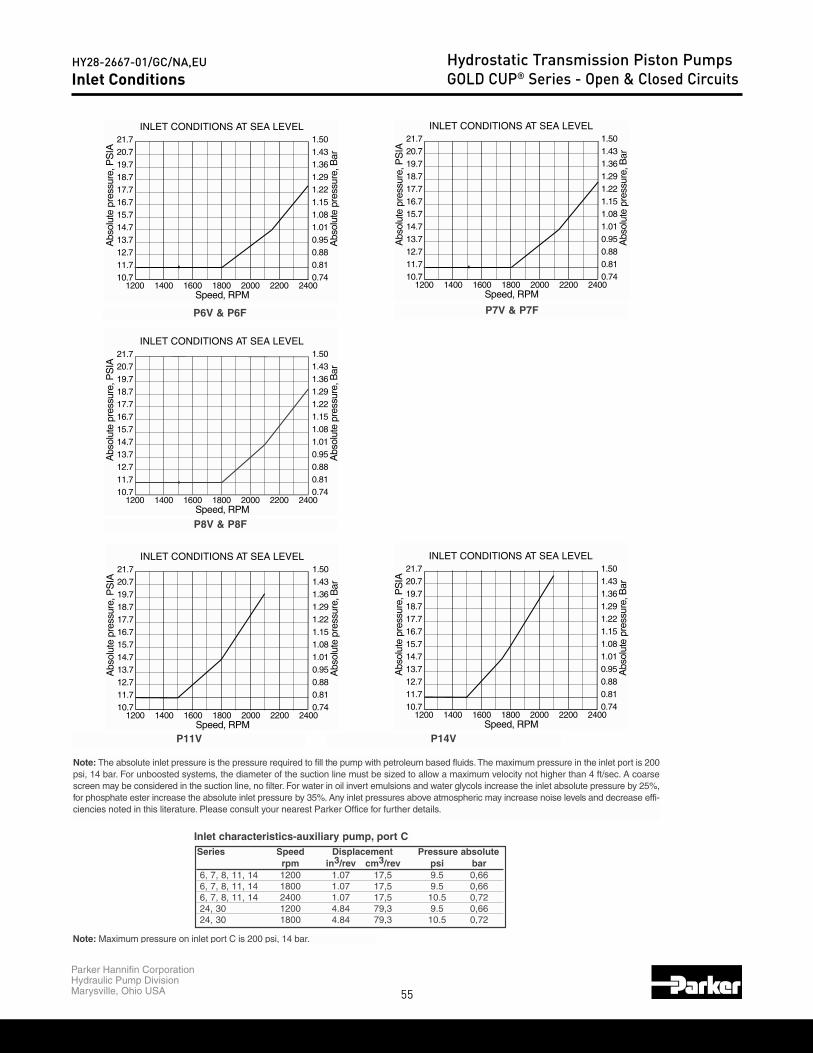
55
Parker Hannifin CorporationHydraulic Pump DivisionMarysville, Ohio USA
HY28-2667-01/GC/NA,EU Hydrostatic Transmission Piston PumpsGOLD CUP® Series - Open & Closed CircuitsInlet Conditions
INLET CONDITIONS AT SEA LEVEL
Speed, RPM
AIS
P,erusserpetulosb
A
etulosbA
perusser,
raB
21.720.719.718.717.716.715.714.713.712.711.710.7
1.501.431.361.291.221.151.081.010.950.880.810.74
1200 1400 1600 1800 2000 2200 2400
INLET CONDITIONS AT SEA LEVEL
Speed, RPM
AIS
P,erusser pe tu losb
A
raB,erusserp
etulosbA
21.720.719.718.717.716.715.714.713.712.711.710.7
1.501.431.361.291.221.151.081.010.950.880.810.74
1200 1400 1600 1800 2000 2200 2400
INLET CONDITIONS AT SEA LEVEL
Speed, RPM
AIS
P,erusserpetulosb
A Aosbl
petu
russere
, Ba r
21.720.719.718.717.716.715.714.713.712.711.710.7
1.501.431.361.291.221.151.081.010.950.880.810.74
1200 1400 1600 1800 2000 2200 2400
P6V & P6F P7V & P7F
P8V & P8F
INLET CONDITIONS AT SEA LEVEL
Speed, RPM
AIS
P,erusserpetulosb
A
etulo sbA
pe rus ser,
raB
21.720.719.718.717.716.715.714.713.712.711.710.7
1.501.431.361.291.221.151.081.010.950.880.810.74
1200 1400 1600 1800 2000 2200 2400
INLET CONDITIONS AT SEA LEVEL
Speed, RPM
AIS
P,erusse rpetu losb
A
raB,er usserp
et ulosbA
21.720.719.718.717.716.715.714.713.712.711.710.7
1.501.431.361.291.221.151.081.010.950.880.810.74
1200 1400 1600 1800 2000 2200 2400
P11V P14V
Note: The absolute inlet pressure is the pressure required to fill the pump with petroleum based fluids.The maximum pressure in the inlet port is 200psi, 14 bar. For unboosted systems, the diameter of the suction line must be sized to allow a maximum velocity not higher than 4 ft/sec. A coarsescreen may be considered in the suction line, no filter. For water in oil invert emulsions and water glycols increase the inlet absolute pressure by 25%,for phosphate ester increase the absolute inlet pressure by 35%. Any inlet pressures above atmospheric may increase noise levels and decrease effi-ciencies noted in this literature. Please consult your nearest Parker Office for further details.
Inlet characteristics-auxiliary pump, port CSeries Speed Displacement Pressure absolute
rpm in3/rev cm3/rev psi bar6, 7, 8, 11, 14 1200 1.07 17,5 9.5 0,666, 7, 8, 11, 14 1800 1.07 17,5 9.5 0,666, 7, 8, 11, 14 2400 1.07 17,5 10.5 0,7224, 30 1200 4.84 79,3 9.5 0,6624, 30 1800 4.84 79,3 10.5 0,72
Note: Maximum pressure on inlet port C is 200 psi, 14 bar.

56
Parker Hannifin CorporationHydraulic Pump DivisionMarysville, Ohio USA
HY28-2667-01/GC/NA,EU Hydrostatic Transmission Piston PumpsGOLD CUP® Series - Open & Closed CircuitsPerformance Curves U.S./METRIC
Performance curves Series 6Motor at full displacement
Performance curves Series 6Pump at full displacement
Performance curves Series 6Pump at full displacement
Performance curves Series 6Motor at full displacement
PRESSURE - BARPRESSURE - PSI
SPEED - RPM SPEED - RPM

57
Parker Hannifin CorporationHydraulic Pump DivisionMarysville, Ohio USA
HY28-2667-01/GC/NA,EU Hydrostatic Transmission Piston PumpsGOLD CUP® Series - Open & Closed CircuitsPerformance Curves U.S./METRIC
Performance curves Series 7Pump at full displacement
Performance curves Series 7Motor at full displacement
Performance curves Series 7Motor at full displacement
Performance curves Series 7Pump at full displacement
PRESSURE - PSI PRESSURE - BAR
SPEED - RPM SPEED - RPM
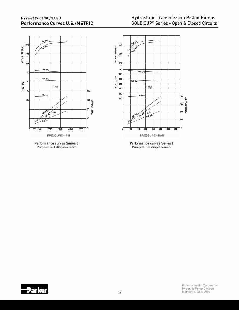
58
Parker Hannifin CorporationHydraulic Pump DivisionMarysville, Ohio USA
HY28-2667-01/GC/NA,EU Hydrostatic Transmission Piston PumpsGOLD CUP® Series - Open & Closed CircuitsPerformance Curves U.S./METRIC
Performance curves Series 8Pump at full displacement
Performance curves Series 8Pump at full displacement
PRESSURE - PSI PRESSURE - BAR

59
Parker Hannifin CorporationHydraulic Pump DivisionMarysville, Ohio USA
HY28-2667-01/GC/NA,EU Hydrostatic Transmission Piston PumpsGOLD CUP® Series - Open & Closed CircuitsPerformance Curves U.S./METRIC
Performance curves Series 11Pump at full displacement
Performance curves Series 11Motor at full displacement
Performance curves Series 11Pump at full displacement
Performance curves Series 11Motor at full displacement
PRESSURE - PSI PRESSURE - BAR
SPEED - RPM SPEED - RPM

60
Parker Hannifin CorporationHydraulic Pump DivisionMarysville, Ohio USA
HY28-2667-01/GC/NA,EU Hydrostatic Transmission Piston PumpsGOLD CUP® Series - Open & Closed CircuitsPerformance Curves U.S./METRIC
Performance curves Series 14Pump at full displacement
Performance curves Series 14Motor at full displacement
Performance curves Series 14Pump at full displacement
Performance curves Series 14Motor at full displacement
PRESSURE - PSI PRESSURE - BAR
SPEED - RPM SPEED - RPM

61
Parker Hannifin CorporationHydraulic Pump DivisionMarysville, Ohio USA
HY28-2667-01/GC/NA,EU Hydrostatic Transmission Piston PumpsGOLD CUP® Series - Open & Closed CircuitsPerformance Curves U.S./METRIC
*PRESSURE-BAR
Performance curves Series 24Pump at full displacement
Performance curves Series 30Pump at full displacement
Performance curves Series 24Pump at full displacement
Performance curves Series 30Pump at full displacement
* PRESSURE - PSI * PRESSURE - BAR
* PRESSURE - PSI * PRESSURE - BAR

62
Parker Hannifin CorporationHydraulic Pump DivisionMarysville, Ohio USA
HY28-2667-01/GC/NA,EU Hydrostatic Transmission Piston PumpsGOLD CUP® Series - Open & Closed Circuits
CODE DESCRIPTION HYDRAULIC CIRCUIT
10 MANUAL SCREW ADJUST
2A TWO POSITION CONTROL
2H 3 POSITION CONTROL
2M2 POSITION CONTROL WITH
CEPTOP3, NG6 VALVE
TO VANE CHAMBERS
SERVO
TO VANE CHAMBERS
SERVO
TO VANE CHAMBERS
SERVO
TO VANE CHAMBERS
SERVO
Pump Primary Displacement Control Options

63
Parker Hannifin CorporationHydraulic Pump DivisionMarysville, Ohio USA
HY28-2667-01/GC/NA,EU Hydrostatic Transmission Piston PumpsGOLD CUP® Series - Open & Closed Circuits
TYPICAL PERFORMANCE DESCRIPTION OF OPERATION
Spring loaded toward maximum displacement, with an adjustment screw to limit the displacement anywhere between 0% and 100%. A minimum volume stop is also supplied so that when the rotary servo shaft is turned, the displacement can be varied only between the minimum and maximum settings.
Torque required to rotate servo shaft: 20 lb-in, 2.56 Nm.
Hydraulically piloted non-proportionally between adjustable minimum and maximum displacements. The control is spring loaded toward minimum when used on pumps, to maximum on motors. Servo pres-sure is switched by an external valve to drive the control in either direction. When used on motors, the minimum setting can be set no lower than 30% of maximum.
Hydraulically piloted non-proportionally between an adjustable minimum displacement of 0±5% and two fully adjustable maximum displacements, one in either direction, and spring loaded toward minimum. Servo pressure is switched by an external valve to drive the control in either direction.
Same as 2A except a CEPTOP3, NG6 two position directional valve is mounted to the control. With the solenoid de-energized, the control is spring loaded to zero for pumps and to maximum displacement for motors. Energizing the solenoid drives the control toward maximum displacement on pumps, minimum on motors. When used on motors, the minimum settings can be no less than 30% of maximum.
19
19
19
19
o
o
o
o
CAM ANGLE
SHAFT ROTATION
19
19
o
o
MIN MAX
CAM ANGLE
SERVOSHAFT
ROTATION
19
19
19
19
o
o
o
o
1
2
3
CAM ANGLE
SHAFTROTATION
19
19
o
o
CAM ANGLE
SHAFT ROTATION
Pump Primary Displacement Control Options

64
Parker Hannifin CorporationHydraulic Pump DivisionMarysville, Ohio USA
HY28-2667-01/GC/NA,EU Hydrostatic Transmission Piston PumpsGOLD CUP® Series - Open & Closed Circuits
CODE DESCRIPTION HYDRAULIC CIRCUIT
2N3 POSITION CONTROL
WITH CEPTOP3, NG6 VALVE
40SPRING CENTERED
ROTARY SERVO
4ASPRING CENTERED ROTARYSERVO WITH ADJUSTABLE
STOPS
4B
SPRING CENTERED ROTARYSERVO WITH AUTOMATIC
BRAKE AND BYPASSCONTROL
TO VANE CHAMBERS
SERVO
TO VANE CHAMBERS
SERVO
TO VANE CHAMBERS
SERVO
TO VANE CHAMBERS
SERVO
REPLENISHINGBRAKE
Pump Primary Displacement Control Options
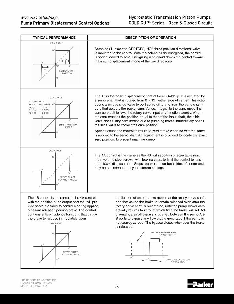
65
Parker Hannifin CorporationHydraulic Pump DivisionMarysville, Ohio USA
HY28-2667-01/GC/NA,EU Hydrostatic Transmission Piston PumpsGOLD CUP® Series - Open & Closed Circuits
TYPICAL PERFORMANCE DESCRIPTION OF OPERATION
Same as 2H except a CEPTOP3, NG6 three position directional valve is mounted to the control. With the solenoids de-energized, the control is spring loaded to zero. Energizing a solenoid drives the control toward maximumdisplacement in one of the two directions.
The 40 is the basic displacement control for all Goldcup. It is actuated by a servo shaft that is rotated from 0º - 19º, either side of center. This action opens a unique slide valve to port servo oil to and from the vane cham-bers that actuate the rocker cam. Vanes, integral to the cam, move the cam so that it follows the rotary servo input shaft motion exactly. When the cam reaches the position equal to that of the input shaft, the slide valve closes. Any cam motion due to pumping forces immediately opens the slide valve to correct the cam position.
Springs cause the control to return to zero stroke when no external force is applied to the servo shaft. An adjustment is provided to locate the exact zero position, to prevent machine creep.
The 4A control is the same as the 40, with addition of adjustable maxi-mum volume stop screws, with locking caps, to limit the control to less than 100% displacement. Stops are present on both sides of center and may be set independently to different settings.
The 4B control is the same as the 4A control, with the addition of an output port that will pro-vide servo pressure to control a spring applied, pressure released parking brake. The control contains anticoincidence functions that cause the brake to release immediately upon
application of an on-stroke motion at the rotary servo shaft, and that cause the brake to remain released even after the rotary servo shaft is recentered, until the pump rocker cam actually returns to zero, at which time the brake will set. Ad-ditionally, a small bypass is opened between the pump A & B ports to bypass any flow that is generated if the pump is not exactly zeroed. The bypass closes whenever the brake is released.
19
19
19
19
o
o
o
o
1
2
3
CAM ANGLE
SERVO SHAFTROTATION
19
19
19
19
o
o
o
o
CAM ANGLE
SHAFT ROTATIONANGLE
STROKE RATEZERO TO MAXIMUMP6,7,8 0.8 SECP11,14 1.5 SECP24, 30 1.8 SEC
19
19
19
19
o
o
o
o
CAM ANGLE
SERVO SHAFTROTATION ANGLE
19
19
19
19
o
o
o
o
CAM ANGLE
SERVO SHAFTROTATION ANGLE
19±2
o
o19
o
BRAKE PRESSURE HIGHBYPASS CLOSED
BRAKE PRESSURE LOWBYPASS OPEN
Pump Primary Displacement Control Options

66
Parker Hannifin CorporationHydraulic Pump DivisionMarysville, Ohio USA
HY28-2667-01/GC/NA,EU Hydrostatic Transmission Piston PumpsGOLD CUP® Series - Open & Closed Circuits
CODE DESCRIPTION HYDRAULIC CIRCUIT
4CSPRING CENTERED BRAKE AND ADJUSTABLE BYPASS CONTROL (AUTOMATIC BRAKE CONTROL)
5A ELECTROHYDRAULIC CONTROL
8A HYDRAULIC STROKER
TO VANE CHAMBERS
SERVO
TO VANE CHAMBERS
SERVO
TO VANE CHAMBERS
SERVO
P2 P1
Pump Primary Displacement Control Options

67
Parker Hannifin CorporationHydraulic Pump DivisionMarysville, Ohio USA
HY28-2667-01/GC/NA,EU Hydrostatic Transmission Piston PumpsGOLD CUP® Series - Open & Closed Circuits
TYPICAL PERFORMANCE DESCRIPTION OF OPERATION
This control combines the features of the 4A and 4B controls.Seeabove descriptions.
The 5A control controls displacement in proportion to an electric cur-rent between zero and 350 milliamps. The control is available with or without a 10% deadband. Positive polarity drives the control in one direction, and negative polarity in the other. Adjustable maximum displacement stops are included. The 5C option, with automatic brake control, is also available.
The 8A control controls displacement in proportion to a hydraulic pressure, values listed below. Pressure applied in the P1 port drives the pump on stroke in one direction, P2 port in the other. Adjustable maximum displacement stops are included. The 8C option, with automatic brake control, is also available.
19
19
19
19
o
o
o
o
CAM ANGLE
SERVO SHAFTROTATION ANGLE
19
19
o
o
IMAXIMAX
CAM ANGLE
INPUT CURRENT
DEADBAND
19
19
o
o
IMAXIMAX
CAM ANGLE
P MAX
P MAX
Pump Primary Displacement Control Options

68
Parker Hannifin CorporationHydraulic Pump DivisionMarysville, Ohio USA
HY28-2667-01/GC/NA,EU Hydrostatic Transmission Piston PumpsGOLD CUP® Series - Open & Closed Circuits
CODE DESCRIPTION HYDRAULIC CIRCUIT
9A ELECTRIC STROKER
7D67D87F67F8
HIGH IQ SERVOVALVE CONTROL
TO VANE CHAMBERS
SERVO
FEEDBACK(POTENTIOMETEROR RVDT
SERVO
TO VANE CHAMBERS
COMMAND
COMPENSATORPILOT
(V PORT)
Pump Primary Displacement Control Options

69
Parker Hannifin CorporationHydraulic Pump DivisionMarysville, Ohio USA
HY28-2667-01/GC/NA,EU Hydrostatic Transmission Piston PumpsGOLD CUP® Series - Open & Closed Circuits
TYPICAL PERFORMANCE DESCRIPTION OF OPERATION
The 9A control controls displacement in proportion to an electric current between zero and 350 milliamps for the 24 volt version, and up to 650 mil-liamps for the 12 volt version. The control signal is a Pulse Width Modulated signal. Current signal to one coil drives the pump in one direction, and to the other coil in the opposite. Adjustable maximum displacement stops are included. The 9C option, with automatic brake control, is also available.
The 7** control is a high response displacement control that uses a servovalve to direct high flow levels to and from the vane chambers, in order to achieve high stroke rates on the pump. A feedback potentiometer or RVDT (Rotary Variable Differential Transformer) is used to feed back the rocker cam position to the controlling electronics to achieve stable operation.
The 7D6 control uses a servovalve and a feedback potentiometer for feedback, the 7D8 uses an RVDT.
The 7F6 control uses servovalve and a the feedback potentiometer, but also has a special valve block with a valve in it to shut off the servovalve, so that control may be taken over by a 4A2 control also mounted to the pump as a manual override. The 7F8 is the same, except using an RVDT.
19
19
o
o
IMAXIMAX
CAM ANGLE
INPUTCURRENT
100%
19
100%
19
o
o
COMMAND
CAM ANGLE
Specifications forSpecifications for 7D,7F:
03/42P41,11P8,7,6P<siseretsyH ± <%1 ±1% ±1%<ytiraeniL ± <%5.0 ±0.5% ±0.5%
sM063sM003sm081esnopseRpetSSmall Signal Frequency Response 10 Hz, 400 psi (28 bar) 8.2 Hz,, 440 psi (30 bar) 6 Hz,, 500 psi (35 bar)
17 Hz,, 1000psi (70 bar) 13 Hz,, 1000 psi (70 bar) 9 Hz,, 1000 psi (70 bar)Servo Pressure 1000 psi (70 bar) nominalCoil Resistance 1000 ohmsElectrical Input 0-10 maFeedback Pot Output, ±3 VDC 19", 15 VDC excitationFeedback RVDT Output, ±2.4 VDC 19", 15 VDC excitation
llAsepyTdiulFFluid Cleanliness NAS 1638, class8 or ISO 17/14Available Drivers Jupiter High IQ S20-11958Electrical Connectors supplied with pump
Specifications:
mumixam%8,lacipyt%5siseretsyH%8ytiraeniL
abroekortsllufotorez,sdnoces9.08,7,6PesnopseR ckP11,14 1.5 seconds, zero to full stroke or backP24, 30 1.8 seconds, zero to full stroke or back
Repeatability 2%Temperature null shift <2% per 100ºF (38º C)Servo pressure required 200-1000 psi (14-70 bar), 400 nominal (28 bar)Coil resistance 41 ohms (24v coil) & 10 ohms (12v coil)Electrical input* 270 ma minimum, 325 ma nominal, 350 ma maximum (24v coil)Neutral deadband* 150 ma minimum, 180 ma nominal, 210 ma maximum (24v coil)Manual override 3/16" Allen wrench, 30 in-lb (3.4Nm) with zero signalFluid types All
Availableopen-loop drivers
Jupiter 900 card S20-14078Dual Driver module 027-22071-0
Power supply 762-30026-0Euro card holder EX00-S07
Electrical connector DIN 43650 type AF, 16-01008-8Fluid cleanliness NAS 1638, class 8 or ISO 17/14
Pump Primary Displacement Control Options
* 12V coils are twice these values
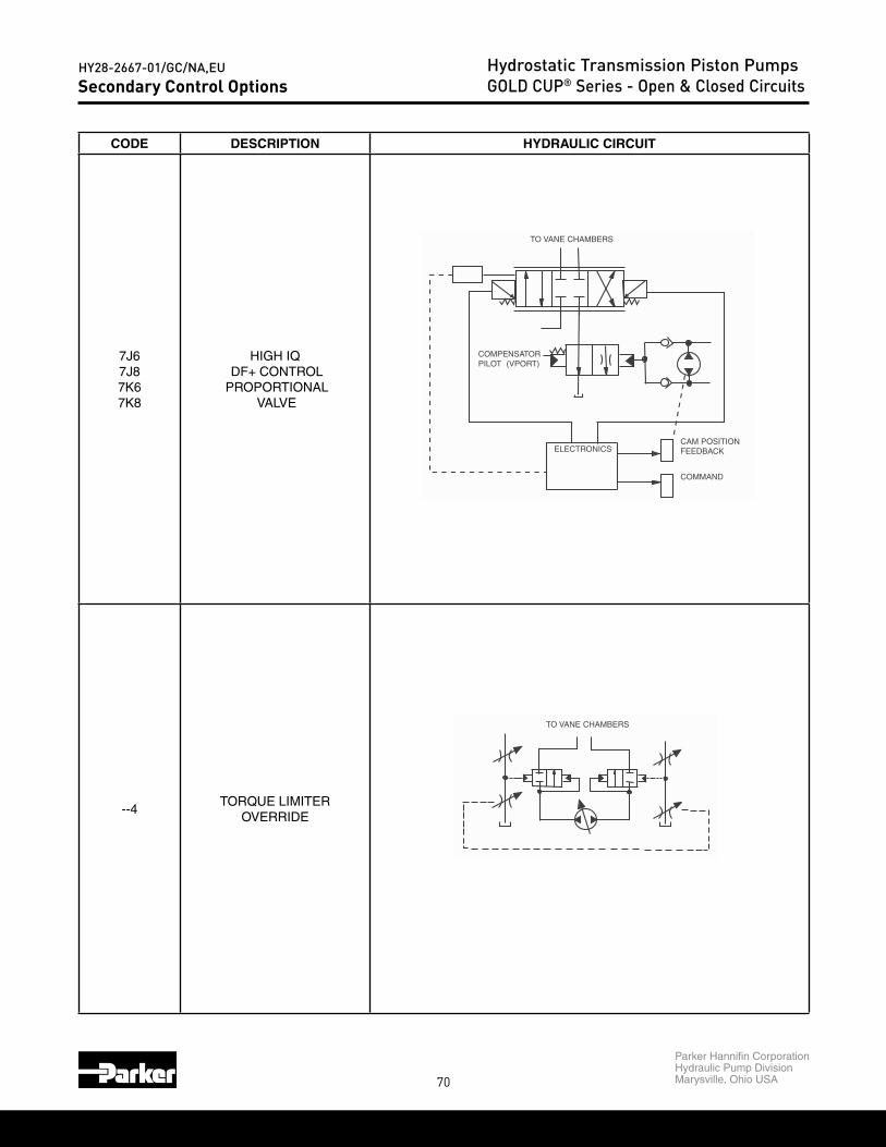
70
Parker Hannifin CorporationHydraulic Pump DivisionMarysville, Ohio USA
HY28-2667-01/GC/NA,EU Hydrostatic Transmission Piston PumpsGOLD CUP® Series - Open & Closed Circuits
CODE DESCRIPTION HYDRAULIC CIRCUIT
7J67J87K67K8
HIGH IQ DF+ CONTROL
PROPORTIONAL VALVE
--4TORQUE LIMITER
OVERRIDE
TO VANE CHAMBERS
COMPENSATORPILOT (VPORT)
ELECTRONICSCAM POSITIONFEEDBACK
COMMAND
TO VANE CHAMBERS
Secondary Control Options

71
Parker Hannifin CorporationHydraulic Pump DivisionMarysville, Ohio USA
HY28-2667-01/GC/NA,EU Hydrostatic Transmission Piston PumpsGOLD CUP® Series - Open & Closed Circuits
TYPICAL PERFORMANCE DESCRIPTION OF OPERATION
The 700 controls are high response displacement controls that use propor-tional directional flow control valves to direct high flow levels to and from the vane chambers, in order to achieve high stroke rates on the pump A feedback potentiometer or RVDT (Rotary Variable Differential Transformer) is used to feed back the rocker cam position to the controlling electronics to achieve stable operation.
The 7J6 control uses a proportional directional control valve and a feedback potentiometer for feedback, the 7J8 uses an RVDT.
The 7K6 control uses proportional directional control valve and a the feedbackpotentiometer, but also has a special valve block with a valve in it to shut off the servovalve, so that control may be taken over by a 4A2 control also mounted to the pump as a manual override. The 7K8 is the same, except using an RVDT.
The **4 control option can be added to any other control, exceptthe 7**, and will limit the amount of torque accepted by the driveshaft on the pump by reducing displacement if the product of pressure and flow (displacement) exceed a preset value. This will allow the pump to go to full stroke, but not at maximum pressure, and it will allow the pump to go to full pressure, but not at maximum flow. When the condition causing the overload disappears, the pump control reverts to the main displacement control. The pressure compensator override is always in effect, at all times, and its function is not effected by this control in any way.
Minimum setting is 25% of maximum input torque.(5000 (PSI) x MAX Displacement / 2
Specifications for 7J, 7K
03/42P41,11P8,7,6P
<siseretsyH ± <%1 ±1% <±1%
<ytiraeniL ± <%9.0 ±0.9% ±0.9%
sm003sm003sm081esnopseRpetS
Small Signal Frequency Response 16 Hz, 400 psi (28 bar) 12 Hz,, 440 psi (30 bar) 8Hz,, 500 psi (35 bar)
25 Hz,, 1000 psi (70 bar) 20 Hz,, 1000 psi (70 bar) 10 Hz,, 1000 psi (70 bar)
lanimon)rab07(isp0001erusserPovreS
Coil Resistance 4 ohms
Feedback Pot Output ±3 VDC at 19º, 15 VDC excitation
Feedback RVDT Output, ±2.4 VDC at 19º, 15 VDC excitation
llAsepyTdiulF
41/71OSIro8ssalc,8361SANssenilnaelCdiulF
Available Drivers Digital EC01 cards (see publication LT3-00055-1)Electrical Connector
100%
19
100%
19
o
o
CAM ANGLE
COMMAND
19o
19o
150
150
P
TORQUE
Secondary Control Options
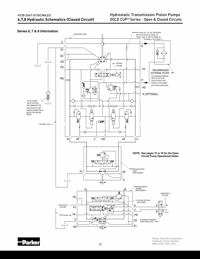
72
Parker Hannifin CorporationHydraulic Pump DivisionMarysville, Ohio USA
HY28-2667-01/GC/NA,EU Hydrostatic Transmission Piston PumpsGOLD CUP® Series - Open & Closed Circuits
Series 6, 7 & 8 Information
6,7,8 Hydraulic Schematics (Closed Circuit)
FA
D
DG
H1
D1
A B
D2
D
A
BY
D1
D2
FB
X
T
P
B
C
BG
FB
DG
D2
D1
VB V KG VA A
K (OPTIONAL)
G
AG
FA
H2
H
EXTERNAL FILTERRECOMMENDED
OPTIONAL LINE
ON PUMPFROM PORT G
CUSTOMER FURNISHEDDIRECTIONAL VALVE
DISPLACEMENT
PACKAGE MOTOR
(2A0 SHOWN)CONTROL OPTIONS
PACKAGE MOTOR
DISPLACEMENT
VARIABLE
FIXED
FROM PORT GON PUMP
40 PSI (2.8 BAR)RELIEF-OPTIONAL
(RECOMMENDED FOR
CIRCUITS WITH PUMP
BELOW 1000 RPM-SEESPEEDS INTERMITTENTLY
OPTIONAL LINE
PAGE 6)
2A
A
A 1/2A
1/2A
2A
A
PACKAGE PUMP
CONTROL
OPTIONS
(NYLOK OR SPOTLOK) INSTALL IN3/8"-16UNC-2A x 1/2" SOC. SETSCREW
PORT H. ONLY IF PORT G CONNECTSEXTERNALLY TO TO PORT H
THE MAXIMUM PRESSUREDROP IN THE FILTER
CIRCUIT SHOULD NOT
EXCEED 150 PSI UNDER
COLD START CONDITIONS
NOTE: See pages 75 or 76 for the Open Circuit Pump Operational Notes

73
Parker Hannifin CorporationHydraulic Pump DivisionMarysville, Ohio USA
HY28-2667-01/GC/NA,EU Hydrostatic Transmission Piston PumpsGOLD CUP® Series - Open & Closed Circuits
Series 11 & 14 Information
11,14 Hydraulic Schematics (Closed Circuit)
FA
D
DG
AG
H1
DG
D
A B
D2
D1
A
BY
D1
D2
FB
X
BG
T
P
B
BG2
C
BG
FB
DG
D2
D1
VB V KG VA
RECOMMENDEDEXTERNAL FILTER
A
AG2
J
K
G
AG
FA
G2
H2
OPTIONAL LINE
ON PUMPFROM PORT G
CC
CUSTOMER FURNISHEDDIRECTIONAL VALVE
DISPLACEMENT
PACKAGE MOTOR
(2A0 SHOWN)CONTROL OPTIONS
PACKAGE MOTOR
DISPLACEMENT
VARIABLE
FIXED
FROM PORT GON PUMP
40 PSI (2.8 BAR)RELIEF-OPTIONAL
(RECOMMENDED FOR
CIRCUITS WITH PUMP
BELOW 1000 RPM-SEESPEEDS INTERMITTENTLY
OPTIONAL LINE
PAGE 6)
C
C
B
A
2A
A
A 1/2A
1/2A
2A
A
PACKAGE PUMP
CONTROL
OPTIONS
PLUG ON FACE OF PORT BLOCK
COLD START CONDITIONS
EXCEED 150 PSI UNDER
CIRCUIT SHOULD NOT
DROP IN THE FILTERTHE MAXIMUM PRESSURE
C
C
PLUG INSTALLED ONLY
1/8-27 NPTF PIPE
IF PORT "J" CONNECTS
PLUG ON FACE OF
EXTERNALLY TO
PORT BLOCK
1/8" PLUG UNDERPORT "K". INSERT
D
NOTE: See pages 75 or 76 for the Open Circuit Pump Operational Notes

74
Parker Hannifin CorporationHydraulic Pump DivisionMarysville, Ohio USA
HY28-2667-01/GC/NA,EU Hydrostatic Transmission Piston PumpsGOLD CUP® Series - Open & Closed Circuits24,30 Hydraulic Schematics (Closed Circuit)
FA
D
DG
H1
D1
A B
D2
D
A
BY
D1
D2
FB
X
T
P
B
C
BG1
FB
DG
D2
D1
VB V KG VA A
K (OPTIONAL)
G
AG1
FA
H2
H
EXTERNAL FILTERRECOMMENDED
CAUTION:
H2
BG2 AG2
DG
OPTIONAL LINE
ON PUMPFROM PORT G
CUSTOMER FURNISHEDDIRECTIONAL VALVE
DISPLACEMENT
PACKAGE MOTOR
(2A0 SHOWN)CONTROL OPTIONS
PACKAGE MOTOR
DISPLACEMENT
VARIABLE
FIXED
FROM PORT GON PUMP
40 PSI (2.8 BAR)RELIEF-OPTIONAL
(RECOMMENDED FOR
CIRCUITS WITH PUMP
BELOW 1000 RPM-SEESPEEDS INTERMITTENTLY
OPTIONAL LINE
PAGE 6)
2A
A
A 1/2A
1/2A
2A
A
PACKAGE PUMP
CONTROL
OPTIONS
THE MAXIMUM PRESSUREDROP IN THE FILTER
CIRCUIT SHOULD NOT
EXCEED 150 PSI UNDER
COLD START CONDITIONS
OCCUR TO AUX. PUMPSTART-UP OR DAMAGE WILLPORT G AND H1 PRIOR TO
EXTERNAL LINEMUST BE CONNECTED BETWEEN
Series 24 & 30 Information
NOTE: See pages 75 or 76 for the Open Circuit Pump Operational Notes

75
Parker Hannifin CorporationHydraulic Pump DivisionMarysville, Ohio USA
HY28-2667-01/GC/NA,EU Hydrostatic Transmission Piston PumpsGOLD CUP® Series - Open & Closed Circuits6,7,8 Hydraulic Schematics (Open Circuit)
RECOMMENDEDCHECK VALVE
B VB
BG
FB
DG
KGV
C
D2
D1
VA A
K
FA
G
AG
RECOMMENDEDEXTERNAL FILTER
H
OPTIONS
CONTROL
A
A
2A
A
2A
1/2A
1/2A
PACKAGE PUMP
PLUG ON FACE OF PORT BLOCK
COLD START CONDITIONS
EXCEED 150 PSI UNDER
CIRCUIT SHOULD NOT
DROP IN THE FILTERTHE MAXIMUM PRESSURE
EXTERNALLY TO PORT "H".
PORT "H". INSTALL1/8" PLUG IN PORT "H"
INSTALLED ONLY IF PORT "G" CONNECTS
3/8"-16 UNC-2A x 1/2" SOC. SETSCREWSeries 6, 7 & 8 Information
pump rotary servo input port portrotation shaft rotation “A” “B”
input command “A” side R CW inlet outletL CCW inlet outlet
input command “B” side R CCW inlet outletL CW inlet outlet
NOTES:
1. The auxiliary pump inlet must be connected directly to the reservoir. See page 55for main pump and auxiliary pump inlet requirements.
2. Case pressure must not exceed inlet pressure by more than 25 psi, 1,7 bar.
3. Maximum allowable inlet (port C) pressure: 200 psi, 13,8 bar.
4. Filters must use bypass valves.
5. Absolute inlet pressure must be increased for the following fluids:a. 25% for water glycolsb. 35% for phosphate esters
6. A check valve in the outlet line between the pump and load is highly recommendedwhere hoses, accumulators or other components may decompress when pump isvented by the compensator.
OPEN CIRCUIT PUMP

76
Parker Hannifin CorporationHydraulic Pump DivisionMarysville, Ohio USA
HY28-2667-01/GC/NA,EU Hydrostatic Transmission Piston PumpsGOLD CUP® Series - Open & Closed Circuits11,14 Hydraulic Schematics (Open Circuit)
RECOMMENDEDCHECK VALVE
BG2
B VB
BG
FB
DG
KGV
C
D2
D1
VA
AG2
A
K
FA
G
OPTIONS
CONTROL
A
A
2A
A
2A
1/2A
1/2A
PACKAGE PUMP
Series 11 & 14 Information
pump rotary servo input port portrotation shaft rotation “A” “B”
input command “A” side R CW inlet outletL CCW inlet outlet
input command “B” side R CCW inlet outletL CW inlet outlet
NOTES:
1. The auxiliary pump inlet must be connected directly to the reservoir. See page 55for main pump and auxiliary pump inlet requirements.
2. Case pressure must not exceed inlet pressure by more than 25 psi, 1,7 bar.
3. Maximum allowable inlet (port C) pressure: 200 psi, 13,8 bar.
4. Filters must use bypass valves.
5. Absolute inlet pressure must be increased for the following fluids:a. 25% for water glycolsb. 35% for phosphate esters
6. A check valve in the outlet line between the pump and load is highly recommendedwhere hoses, accumulators or other components may decompress when pump isvented by the compensator.
OPEN CIRCUIT PUMP
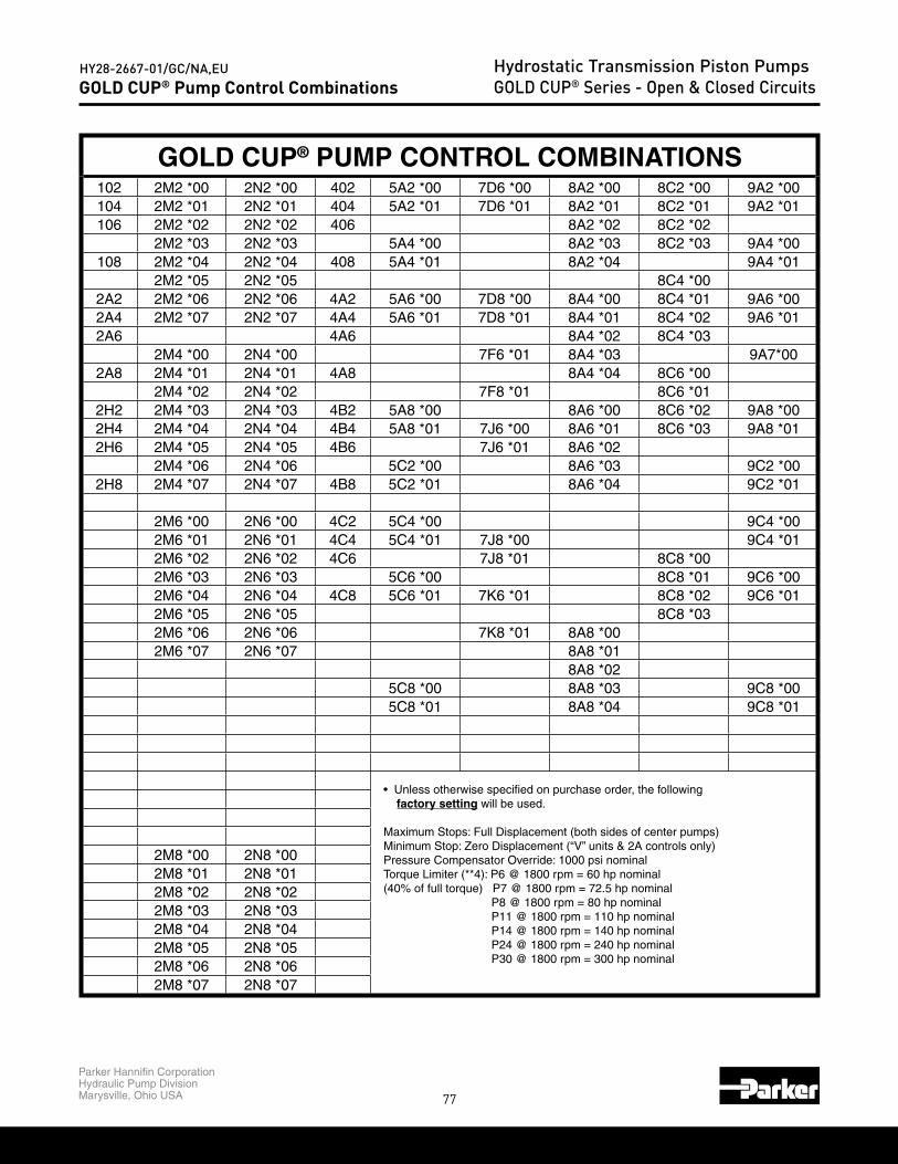
77
Parker Hannifin CorporationHydraulic Pump DivisionMarysville, Ohio USA
HY28-2667-01/GC/NA,EU Hydrostatic Transmission Piston PumpsGOLD CUP® Series - Open & Closed CircuitsGOLD CUP® Pump Control Combinations
GOLD CUP® PUMP CONTROL COMBINATIONS102 2M2 *00 2N2 *00 402 5A2 *00 7D6 *00 8A2 *00 8C2 *00 9A2 *00104 2M2 *01 2N2 *01 404 5A2 *01 7D6 *01 8A2 *01 8C2 *01 9A2 *01106 2M2 *02 2N2 *02 406 8A2 *02 8C2 *02
2M2 *03 2N2 *03 5A4 *00 8A2 *03 8C2 *03 9A4 *00108 2M2 *04 2N2 *04 408 5A4 *01 8A2 *04 9A4 *01
2M2 *05 2N2 *05 8C4 *002A2 2M2 *06 2N2 *06 4A2 5A6 *00 7D8 *00 8A4 *00 8C4 *01 9A6 *002A4 2M2 *07 2N2 *07 4A4 5A6 *01 7D8 *01 8A4 *01 8C4 *02 9A6 *012A6 4A6 8A4 *02 8C4 *03
2M4 *00 2N4 *00 7F6 *01 8A4 *03 9A7*002A8 2M4 *01 2N4 *01 4A8 8A4 *04 8C6 *00
2M4 *02 2N4 *02 7F8 *01 8C6 *012H2 2M4 *03 2N4 *03 4B2 5A8 *00 8A6 *00 8C6 *02 9A8 *002H4 2M4 *04 2N4 *04 4B4 5A8 *01 7J6 *00 8A6 *01 8C6 *03 9A8 *012H6 2M4 *05 2N4 *05 4B6 7J6 *01 8A6 *02
2M4 *06 2N4 *06 5C2 *00 8A6 *03 9C2 *002H8 2M4 *07 2N4 *07 4B8 5C2 *01 8A6 *04 9C2 *01
2M6 *00 2N6 *00 4C2 5C4 *00 9C4 *002M6 *01 2N6 *01 4C4 5C4 *01 7J8 *00 9C4 *012M6 *02 2N6 *02 4C6 7J8 *01 8C8 *002M6 *03 2N6 *03 5C6 *00 8C8 *01 9C6 *002M6 *04 2N6 *04 4C8 5C6 *01 7K6 *01 8C8 *02 9C6 *012M6 *05 2N6 *05 8C8 *032M6 *06 2N6 *06 7K8 *01 8A8 *002M6 *07 2N6 *07 8A8 *01
8A8 *025C8 *00 8A8 *03 9C8 *005C8 *01 8A8 *04 9C8 *01
• Unless otherwise specified on purchase order, the followingfactory setting will be used.
Maximum Stops: Full Displacement (both sides of center pumps)Minimum Stop: Zero Displacement (“V” units & 2A controls only)Pressure Compensator Override: 1000 psi nominalTorque Limiter (**4): P6 @ 1800 rpm = 60 hp nominal(40% of full torque) P7 @ 1800 rpm = 72.5 hp nominal P8 @ 1800 rpm = 80 hp nominal P11 @ 1800 rpm = 110 hp nominal P14 @ 1800 rpm = 140 hp nominal P24 @ 1800 rpm = 240 hp nominal P30 @ 1800 rpm = 300 hp nominal
2M8 *00 2N8 *002M8 *01 2N8 *012M8 *02 2N8 *022M8 *03 2N8 *032M8 *04 2N8 *042M8 *05 2N8 *052M8 *06 2N8 *062M8 *07 2N8 *07

78
Parker Hannifin CorporationHydraulic Pump DivisionMarysville, Ohio USA
HY28-2667-01/GC/NA,EU Hydrostatic Transmission Piston PumpsGOLD CUP® Series - Open & Closed CircuitsPump Ordering Code
Code Shaft
-2 Keyed SAE – Mechanical Shaft Seal (Single Lip Seal on P6, 7, 8F/M)
-3 Splined SAE – Mechanical Shaft Seal(Single Lip Seal on P6, 7, 8F/M)
-4Keyed SAE-D (Mounting & Shaft) – Mechanical Shaft Seal (P6, 7 & 8 only, Single Lip Seal on Fixed Displacement Pumps)
-5Splined SAE-D (Mounting & Shaft) – Mechanical Shaft Seal (P6, 7 & 8 only, Single Lip Seal on Fixed Displacement Pumps)
-7 Keyed SAE – Double Lip Shaft Seal
-8 Splined SAE – Double Lip Shaft Seal
-9 Keyed (long) SAE – Double Lip Shaft Seal
-10 Keyed (long) SAE – Mechanical Shaft Seal
P
Pump
= Omit if not required
Displacement
Code Efficiency
HHighEfficiency(P24 only)
Omit StandardEfficiency
Type Efficiency
Code Rotation
R Clockwise
L Counterclockwise Code Seals
1 Nitrile (Buna-N)
4 EPR 1, 3
5 Fluorocarbon
Design 2
Code Secondary Controls
Omit None (Fixed Displacement only)
2 Volume Indicator
4 Torque Limiter & Volume Indicator
6 Cam Position Feedback Potentiometer 1
7 Cam Position Feedback RVDT (AC)1
8 Cam Position Feedback R VDT (DC) 1
Code Control Location
Omit None (Fixed Displacement only)
-A Primary Control on Port A Side
-B Primary Control on Port B Side
RotationShaft Seals Primary Controls
Secondary Controls
ControlLocation
1 Not ATEX approved.2 Assigned by manufacturer3 Not available when using “5A” or
“5C” primary controls. Pump will be unpainted unless otherwise specified.
Code Displacement
6 6.00 in3/rev (98 cc/rev)
7 7.25 in3/rev (119 cc/rev)
8 8.00 in3/rev (131 cc/rev)
11 11.0 in3/rev (180 cc/rev)
14 14.0 in3/rev (229 cc/rev)
24 24.6 in3/rev (403 cc/rev)
30 30.6 in3/rev (501 cc/rev)
Code Type
F Fixed Displacement, Open/Closed Circuit
M Fixed Displacement with High Torque Thru-Drive, Open/Closed Circuit
P Variable Displacement, Closed Circuit
X Variable Displacement with Medium Torque Thru-Drive, Closed Circuit
S Variable Displacement with Medium Torque Thru-Drive & Shuttle Package, Closed Circuit
R Variable Displacement with High Torque Thru-Drive, Closed Circuit
L Variable Displacement with High Torque Thru-Drive & Shuttle Package, Closed Circuit
V Variable Displacement, Open Circuit(P6, 7, 8, 11 & 14 only)
D Variable Displacement, Open & Closed Circuit (P6, 7 & 8 only)
Code Primary Controls
Omit None (Fixed Displacement only)
-10 Screw Adjustment (Spring Offset to Maximum Displacement)
-2A Cylinder Control w/Adjustable Maximum Volume Stops
-2H Cylinder Control – 3-Position (Spring Control with Zero Adjustment)
-2M Cylinder Control – 2-Position Electrohydraulic w/Adjustable Maximum Volume Stop (Spring Offset to Maximum Displacement) 1
-2N Cylinder Control – 3-Position (Spring Centered) Electrohydraulic 1
-40 Rotary Servo – Spring Centered
-4A Rotary Servo – Spring Centered w/Adjustable Maximum Volume Stops
-4B Rotary Servo – Spring Centered w/Automatic Brake Control
-4C Rotary Servo – Spring centered w/Adjustable Maximum Volume Stops & Automatic Brake Control
-5A Electrohydraulic Stroker w/Adjustable Maximum Volume Stops 1
-5C Electrhydraulic Stroker w/Adjustable Maximum Volume Stops & Automatic Brake Control 1
-7D High IQ with 10 GPM Servo Valve & Volume Indicator 1
-7F High IQ with 10 GPM Servovalve & 4A (Rotary Servo) Control 1
-7J High IQ with DF+ Valve & Volume Indicator 1
-7K High IQ with DF+ Valve & 4A (Rotary Servo) Control 1
-8A Hydraulic Stroker w/Adjustable Maximum Volume Stops
-8C Hydraulic Stroker w/Adjustable Maximum Volume Stops & Automatic Brake Control
-9A Electrohydraulic Stroker w/Adjustable Maximum Volume Stops 1
-9C Electrohydraulic Stroker w/Adjustable Maximum Volume Stops & Automatic Brake Control 1
-9D Electro-hydraulic stroker w/ adjustable maximum volume stops

79
Parker Hannifin CorporationHydraulic Pump DivisionMarysville, Ohio USA
HY28-2667-01/GC/NA,EU Hydrostatic Transmission Piston PumpsGOLD CUP® Series - Open & Closed CircuitsPump Ordering Code
Control &Displacement
Features
= Omit if not required
Code Internal Pump
-01.07 in3/rev (17.5 cc/rev) – P6, 7, 8P/S/X/V/D & P11, 14V only**2.14 in3/rev (35 cc/rev) – P11, 14P/S/X only**2.81 in3/rev (46 cc.rev) – P24, 30P/S/X only (standard)**
-1 1.61 in3/rev (26.4 cc/rev) – P24, 30P/S/X only(auxiliary external replenishing flow required)
-2 1.05 in3/rev (17.2 cc/rev) – P24, 30P/S/X only(auxiliary external replenishing flow required)
-3 3.56 in3/rev (58.3 cc/rev) – P24, 30P/S/X only
-4 4.84 in3/rev (79.3 cc/rev) – P24, 30P/S/X only
-5 5.42 in3/rev (88.8 cc/rev) – P24, 30P/S/X only
-6 6.10 in3/rev (100.0 cc/rev) – P24, 30P/S/X only
-X No Internal Pump (standard on P*R/L/F/M)
** Omit code if no external drive is required.
Code External Drive
Omit None 1
M Blanking plate – for P6, 7, 8, 11, 14S/X only
A SAE-A (SAE 82-2) – P6, 7, 8, 11, 14S/X/R/L/M only
B SAE-B (SAE 101-2) – P6, 7, 8, 11, 14, 24, 30/S/X/R/L/MSAE-B (SAE 101-4) – P11, 14, 24, 30R/L/M
C SAE-C (SAE 127-2) – P6, 7, 8, 11, 14, 24, 30R/L/M & P24, 30S/XSAE-C (SAE 127-4) – P11, 14, 24, 30R/L/M
D SAE-D (SAE 152-4) – P11, 14, 24, 30R/L/M only
E SAE-E (SAE 165-4) – P11, 14, 24, 30R/L/M only
F SAE-F (SAE 177-4) – P24, 30R/L/M only
Code External Mounting
Omit No External Drive Required
0 No External Pump Mounted
1 External Pump Mounted (must be separately specified) – Requires Special Modification “-M2”1
2 ATEX Externally Mounted Pump
Code Special Modifications
Omit None
-NP No Paint 1
-EX ATEX APPROVED PUMP must consult engineering.
-M2
Other Special Modification (example: bronze caged barrel bearing for low viscosity fluids, tandem pumps, etc.) 1
ExternalDrive
External Mounting
Special Modifications
Control Code Control Feature
2M* & 2N*
00 CETOP3, NG6 Valve, 110AC/60Hz with Hirschmann Connector 1
01 CETOP3, NG6 Valve, 12VDC with Hirschmann Connector 1
02 CETOP3, NG6 Valve, 240VAC/50Hz with Hirschmann Connector 1
03 CETOP3, NG6 Valve, 110VAC/60Hz, Wiring Box 1
04 CETOP3, NG6 Valve, 12VDC, Wiring Box 1
05 CETOP3 (D03, NG6) Interface, No Valve 1
06 CETOP3, NG6 Valve, 24VDC with Hirschmann Connector 1
07 CETOP3, NG6 Valve, 110VAC/50Hz with Hirschmann Connector 1
5**00 With Deadband 1
01 Without Deadband 1
7**00 Without Manual Override Shutoff 1
01 With Manual Override Shutoff 1
(required for D, F, J & K primary options)
8**
00 75-350 PSI (5-24 Bar)
01 75-435 PSI (5-30 Bar)
02 100-300 PSI (7-26 Bar)
03 150-400 PSI (10-28 Bar)
04 75-250 PSI (5-17 Bar)
9**00 24VDC
01 12VDC
AllOther 00 None 1
Pump Code Reduced Displacement
P**F&
P**M
00 Standard Cam (19°)
10
P6 with 17° Cam – 5.3 in3/rev (87cc/rev)P7 with 17° Cam – 6.4 in3/rec (105 cc/rev)P8 with 17° Cam – 7.1 in3/rev (116 cc/rev)P11 with 17° Cam – 9.7 in3/rev (160 cc/rev)P14 with 17° Cam – 12.5 in3/rev (205 cc/rev)P24 with 17° Cam – 22.0 in3/rev (360 cc/rev)P30 with 17° Cam – 27.2 in3/rev (446 cc/rev)
20
P6 with 15° Cam – 4.6 in3/rev (76 cc/rev)P7 with 15° Cam – 5.6 in3/rev (92 cc/rev)P8 with 15° Cam – 6.2 in3/rev (102 cc/rev)P11 with 15° Cam – 8.5 in3/rev (140 cc/rev)P14 with 15° Cam – 10.9 in3/rev (179 cc/rev)
30P6 with 13° Cam – 4.0 in3/rev (66 cc/rev)P7 with 13° Cam – 4.8 in3/rev (79 cc/rev)P8 with 13° Cam – 5.3 in3/rev (88 cc/rev)
InternalPump

80
Parker Hannifin CorporationHydraulic Pump DivisionMarysville, Ohio USA
HY28-2667-01/GC/NA,EU Hydrostatic Transmission Piston PumpsGOLD CUP® Series - Open & Closed Circuits
Notes
Notes

81
Parker Hannifin CorporationHydraulic Pump DivisionMarysville, Ohio USA
HY28-2667-01/GC/NA,EU Hydrostatic Transmission Piston PumpsGOLD CUP® Series - Open & Closed Circuits
GOLD CUP® MOTOR CONTROL COMBINATIONS2A0 *2M3 *0 5A0 *0 8A0 *0 9A0 *0*2A3 *2M3 *1 5A0 *1 8A0 *1 9A0 *1*2A5 *2M3 *22A6 *2M3 *3 5A3 *0 8A3 *0 9A3 *0
*2M3 *4 5A3 *1 8A3 *1 9A3 *12A8 *2M3 *5
*2M3 *6 5A5 *0 8A5 *0 9A5 *02M0 *0 5A5 *1 8A5 *1 9A5 *12M0 *12M0 *2 *2M5 *0 5A6 *0 8A6 *0 9A6 *02M0 *3 *2M5 *1 5A6 *1 8A6 *1 9A6 *12M0 *4 *2M5 *22M0 *5 *2M5 *32M0 *6 *2M5 *4
*2M5 *5*2M5 *6 5A8 *0 8A8 *0 9A8 *0
5A8 *1 8A8 *1 9A8 *1
*2M6 *0 9D0*0*2M6 *1 9D081*2M6 *2*2M6 *3*2M6 *4*2M6 *5*2M6 *6
• Not available for M24 or M30
Unless otherwise specified on purchase order, the followingfactory setting will be used.Maximum Stop: Full DisplacementMinimum Stop: Approximately 30% DisplacementReverse Pressure Compensator Override (**3 & **5): 1000 psinominal
*2M8 *0*2M8 *1*2M8 *2*2M8 *3*2M8 *4*2M8 *5*2M8 *6
GOLD CUP® Motor Control Combinations

82
Parker Hannifin CorporationHydraulic Pump DivisionMarysville, Ohio USA
HY28-2667-01/GC/NA,EU Hydrostatic Transmission Piston PumpsGOLD CUP® Series - Open & Closed CircuitsMotor Ordering Code
Code Shaft
-2 Keyed SAE – Mechanical Shaft Seal (Single Lip Seal on M6, 7, 8F/G/M/N)
-3 Splined SAE – Mechanical Shaft Seal(Single Lip Seal on M6, 7, 8F/G/M/N)
-4Keyed SAE-D (Mounting & Shaft) – Mechanical Shaft Seal (M6, 7 & 8 only, Single Lip Seal on Fixed Displacement Motors)
-5Splined SAE-D (Mounting & Shaft) – Mechanical Shaft Seal (P6, 7 & 8 only, Single Lip Seal on Fixed Displacement Motors)
-7 Keyed SAE – Double Lip Shaft Seal
-8 Splined SAE – Double Lip Shaft Seal
-9 Keyed (long) SAE – Double Lip Shaft Seal
-10 Keyed (long) SAE – Mechanical Shaft Seal
M
Code Displacement
6 6.00 in3/rev (98cc/rev)
7 7.25 in3/rev (119 cc/rev)
8 8.00 in3/rev (131 cc/rev)
11 11.0 in3/rev (180 cc/rev)
14 14.0 in3/rev (229 cc/rev)
24 24.6 in3/rev (403 cc/rev)
30 30.6 in3/rev (501 cc/rev)
Motor
Code Type
F Fixed Displacement
G Fixed Displacement with Shuttle Package
M Fixed Displacement with Thru-Drive
N Fixed Displacement with Thru-Drive & Shuttle Package
V Variable Displacement
H Variable Displacement with Shuttle Package
R Variable Displacement with Thru-Drive
L Variable Displacement with Thru-Drive & Shuttle Package
= Omit if not required
Displacement
Code Efficiency
HHighEfficiency(M24 only)
Omit StandardEfficiency
Type
Code Rotation
N Bi-directional
Code Seals
1 Nitrile (Buna-N)
4 EPR 3
5 Fluorocarbon
Design 2
Code Primary Controls
Omit None (Fixed Displacement only)
-2A Cylinder Control w/Adjustable Maximum Volume Stops
-2MCylinder Control – 2-Position Electrohydraulic w/Ad-justable Maximum Volume Stop (Spring Offset to Maximum Displacement)1
-5A Electrohydraulic Stroker w/Adjustable Maximum Volume Stops1
-8A Hydraulic Stroker w/Adjustable Maximum Volume Stops
-9A Electrohydraulic Stroker w/Adjustable Maximum Volume Stops1
Code Secondary Controls
Omit None (Fixed Displacement only)
0 Volume Indicator
3 Reverse Compensator (spring offset to maximum displace-ment) + Volume Indicator
5 Reverse Compensator (spring offset to minimum displacement) + Volume Indicator
6 Cam Position Feedback Potentiometer1
7 Cam Position Feedback RVDT (AC)1
8 Cam Position Feedback RVDT (DC)1
U Reverse Compensator (3) + Cam Position Feedback Potentiom-eter (6)1
W Reverse Compensator (3) + Cam Position Feedback RVDT (8)1
X Reverse Compensator (5) + Cam Position Feedback Potentiom-eter (6)1
Z Reverse Compensator (5) + Cam Position Feedback RVDT (8)1
Code Control Location
Omit None (Fixed Displacement only)
-A Primary Control on Port A Side
-B Primary Control on Port B Side
RotationShaft Seals Primary Controls
Secondary Controls
ControlLocation
1 Not ATEX approved.2 Assigned by manufacturer.3 Not available when using “5A”
primary control. Motor will be unpainted unless otherwise specified.
Efficiency

83
Parker Hannifin CorporationHydraulic Pump DivisionMarysville, Ohio USA
HY28-2667-01/GC/NA,EU Hydrostatic Transmission Piston PumpsGOLD CUP® Series - Open & Closed CircuitsMotor Ordering Code
Control &Displacement
Features
= Omit if not required
Code External Drive
Omit None (M*F/G/V/H units only)
-A SAE-A (SAE 82-2) – M6, 7, 8, 11, 14M/N/R/L only
-B SAE-B (SAE 101-2) – M6, 7, 8M/N/R/L SAE-B (SAE 101-2 & 101-4) – M11, 14, 24, 30M/N/R/L
-C SAE-C (SAE 127-2) – M6, 7, 8M/N/R/LSAE-C (SAE 127-2 & 127-4) – M11, 14, 24, 30M/N/R/L
-D SAE-D (SAE 152-4) – M11, 14, 24, 30M/N/R/L only
-E SAE-E (SAE 165-4) – M11, 14, 24, 30M/N/R/L only
-F SAE-F (SAE 177-4) – M24, 30M/N/R/L only
-M Blanking Plate-less Coupling
Code External Mounting
0 No External Motor Mounted
1External Motor Mounted (must be separately specified) – Requires Special Modification “-M2”
2 ATEX Externally Mounted Motor
Code Special Modifications
Omit None
-NP No Paint
-M2
Other Special Modification (example: bronze caged barrel bearing for low viscosity fluids, tandem motors, etc.)
-EX ATEX APPROVED PUMP must consult engineering.
ExternalDrive
External Mounting
Special Modifications
Control Code Control Feature
2M
0 CETOP3, NG6 Valve, 110AC/60Hz with Hirschmann Connector1
1 CETOP3, NG6 Valve, 12VDC with Hirschmann Connector1
2 CETOP3, NG6 Valve, 240VAC/50Hz with Hirschmann Connector1
3 CETOP3, NG6 Valve, 110VAC/60Hz, Wiring Box1
4 CETOP3, NG6 Valve, 12VDC, Wiring Box1
5 CETOP3 (D03, NG6) Interface, No Valve1
6 CETOP3, NG6 Valve, 24VDC with Hirschmann Connector1
7 CETOP3, NG6 Valve, 110VAC/50Hz with Hirschmann Connector1
5A0 With Deadband1
1 Without Deadband1
8A0 75-250 PSI (5-17 Bar)
1 250-450 PSI (17-31 Bar)
9A0 24VDC1
1 12VDC1
All Other 0 None
Motor Code Reduced Displacement
M*FM*GM*MM*N
0 Standard Cam (19°)
1
M6 with 17° Cam – 5.3 in3/rev (87cc/rev)M7 with 17° Cam – 6.4 in3/rec (105 cc/rev)M8 with 17° Cam – 7.1 in3/rev (116 cc/rev)M11 with 17° Cam – 9.7 in3/rev (160 cc/rev)M14 with 17° Cam – 12.5 in3/rev (205 cc/rev)M24 with 17° Cam – 22.0 in3/rev (360 cc/rev)M30 with 17° Cam – 27.2 in3/rev (446 cc/rev)
2
M6 with 15° Cam – 4.6 in3/rev (76 cc/rev)M7 with 15° Cam – 5.6 in3/rev (92 cc/rev)M8 with 15° Cam – 6.2 in3/rev (102 cc/rev)M11 with 15° Cam – 8.5 in3/rev (140 cc/rev)M14 with 15° Cam – 10.9 in3/rev (179 cc/rev)
3M6 with 13° Cam – 4.0 in3/rev (66 cc/rev)M7 with 13° Cam – 4.8 in3/rev (79 cc/rev)M8 with 13° Cam – 5.3 in3/rev (88 cc/rev)
Shuttle Valve
Features
Code Shuttle Valve Features
Omit M*F/M/V/R Motors only
0 Without Orifices
2 With Orifices
84
Parker Hannifin CorporationHydraulic Pump DivisionMarysville, Ohio USA
HY28-2667-01/GC/NA,EU Hydrostatic Transmission Piston PumpsGOLD CUP® Series - Open & Closed Circuits
Notes
Notes

85
Parker Hannifin CorporationHydraulic Pump DivisionMarysville, Ohio USA
HY28-2667-01/GC/NA,EU Hydrostatic Transmission Piston PumpsGOLD CUP® Series - Open & Closed Circuits
Notes
Notes

86
Parker Hannifin CorporationHydraulic Pump DivisionMarysville, Ohio USA
HY28-2667-01/GC/NA,EU Hydrostatic Transmission Piston PumpsGOLD CUP® Series - Open & Closed Circuits
Notes
Notes

87
Parker Hannifin CorporationHydraulic Pump DivisionMarysville, Ohio USA
HY28-2667-01/GC/NA,EU Hydrostatic Transmission Piston PumpsGOLD CUP® Series - Open & Closed CircuitsOffer of Sale
The items described in this document and other documents and descriptions provided by Parker Hannifin Corporation, Hydraulics Group, and its authorized distributors (“Seller”) are hereby offered for sale at prices to be established by Seller. This offer and its acceptance by any customer (“Buyer”) shall be governed by all of the following Terms and Conditions. Buyer’s order for any item described in its document, when communicated to Seller verbally, or in writing, shall constitute acceptance of this offer. All goods or work described will be referred to as “Products”.
1. Terms and Conditions. Seller’s willingness to offer Products, or accept an order for Products, to or from Buyer is expressly conditioned on Buyer’s assent to these Terms and Conditions and to the terms and conditions found on-line at www.parker.com/saleterms/. Seller objects to any contrary or additional term or condition of Buyer’s order or any other document issued by Buyer.2. Price Adjustments; Payments. Prices stated on the reverse side or preceding pages of this document are valid for 30 days. After 30 days, Seller may change prices to reflect any increase in its costs resulting from state, federal or local legislation, price increases from its suppliers, or any change in the rate, charge, or classification of any carrier. The prices stated on the reverse or preceding pages of this document do not include any sales, use, or other taxes unless so stated specifically. Unless otherwise specified by Seller, all prices are F.O.B. Seller’s facility, and payment is due 30 days from the date of invoice. After 30 days, Buyer shall pay interest on any unpaid invoices at the rate of 1.5% per month or the maximum allowable rate under applicable law.3. Delivery Dates; Title and Risk; Shipment. All delivery dates are approximate and Seller shall not be responsible for any damages resulting from any delay. Regardless of the manner of shipment, title to any products and risk of loss or damage shall pass to Buyer upon tender to the carrier at Seller’s facility (i.e., when it’s on the truck, it’s yours). Unless otherwise stated, Seller may exercise its judgment in choosing the carrier and means of delivery. No deferment of shipment at Buyers’ request beyond the respective dates indicated will be made except on terms that will indemnify, defend and hold Seller harmless against all loss and additional expense. Buyer shall be responsible for any additional shipping charges incurred by Seller due to Buyer’s changes in shipping, product specifications or in accordance with Section 13, herein.4. Warranty. Seller warrants that the Products sold hereunder shall be free from defects in material or workmanship for a period of eighteen months from the date of delivery to Buyer. The prices charged for Seller’s products are based upon the exclusive limited warranty stated above, and upon the following disclaimer: DISCLAIMER OF WARRANTY: THIS WARRANTY COMPRISES THE SOLE AND ENTIRE WARRANTY PERTAINING TO PRODUCTS PROVIDED HEREUNDER. SELLER DISCLAIMS ALL OTHER WARRAN-TIES, EXPRESS AND IMPLIED, INCLUDING MERCHANTABILITY AND FITNESS FOR A PARTICULAR PURPOSE.5. Claims; Commencement of Actions. Buyer shall promptly inspect all Products upon delivery. No claims for shortages will be allowed unless reported to the Seller within 10 days of delivery. No other claims against Seller will be allowed unless asserted in writing within 60 days after delivery or, in the case of an alleged breach of warranty, within 30 days after the date within the warranty period on which the defect is or should have been discovered by Buyer. Any action based upon breach of this agreement or upon any other claim arising out of this sale (other than an action by Seller for any amount due to Seller from Buyer) must be commenced within thirteen months from the date of tender of delivery by Seller or, for a cause of action based upon an alleged breach of warranty, within thirteen months from the date within the warranty period on which the defect is or should have been discovered by Buyer.6. LIMITATION OF LIABILITY. UPON NOTIFICATION, SELLER WILL, AT ITS OPTION, REPAIR OR REPLACE A DEFECTIVE PRODUCT, OR REFUND THE PURCHASE PRICE. IN NO EVENT SHALL SELLER BE LIABLE TO BUYER FOR ANY SPECIAL, INDIRECT, INCIDENTAL OR CONSEQUENTIAL DAMAGES ARISING OUT OF, OR AS THE RESULT OF, THE SALE, DELIVERY, NON-DELIVERY, SERVICING, USE OR LOSS OF USE OF THE PRODUCTS OR ANY PART THEREOF, OR FOR ANY CHARGES OR EXPENSES OF ANY NATURE INCURRED WITHOUT SELLER’S WRITTEN CONSENT, EVEN IF SELLER HAS BEEN NEGLIGENT, WHETHER IN CONTRACT, TORT OR OTHER LEGAL THEORY. IN NO EVENT SHALL SELLER’S LIABILITY UNDER ANY CLAIM MADE BY BUYER EXCEED THE PURCHASE PRICE OF THE PRODUCTS.7. Contingencies. Seller shall not be liable for any default or delay in performance if caused by circumstances beyond the reasonable control of Seller.8. User Responsibility. The user, through its own analysis and testing, is solely responsible for making the final selection of the system and Product and assuring that all performance, endurance, maintenance, safety and warning requirements of the application are met. The user must analyze all aspects of the application and follow applicable industry standards and Product information. If Seller provides Product or system options, the user is responsible for determining that such data and specifications are suitable and sufficient for all applications and reasonably foreseeable uses of the Products or systems.9. Loss to Buyer’s Property. Any designs, tools, patterns, materials, drawings, confiden-tial information or equipment furnished by Buyer or any other items which become Buyer’s property, may be considered obsolete and may be destroyed by Seller after two consecutive years have elapsed without Buyer placing an order for the items which are manufactured using such property. Seller shall not be responsible for any loss or damage to such property while it is in Seller’s possession or control.10. Special Tooling. A tooling charge may be imposed for any special tooling, including without limitation, dies, fixtures, molds and patterns, acquired to manufacture Products. Such special tooling shall be and remain Seller’s property notwithstanding payment of any charges by Buyer. In no event will Buyer acquire any interest in apparatus belonging to Seller which is utilized in the manufacture of the Products, even if such apparatus has been specially converted or adapted for such manufacture and notwithstanding any charges paid by Buyer. Unless otherwise agreed, Seller shall have the right to alter, discard or otherwise dispose of any special tooling or other property in its sole discretion at any time.
11. Buyer’s Obligation; Rights of Seller. To secure payment of all sums due or otherwise, Seller shall retain a security interest in the goods delivered and this agreement shall be deemed a Security Agreement under the Uniform Commercial Code. Buyer authorizes Seller as its attorney to execute and file on Buyer’s behalf all documents Seller deems necessary to perfect its security interest. Seller shall have a security interest in, and lien upon, any property of Buyer in Seller’s possession as security for the payment of any amounts owed to Seller by Buyer.12. Improper Use and Indemnity. Buyer shall indemnify, defend, and hold Seller harmless from any claim, liability, damages, lawsuits, and costs (including attorney fees), whether for personal injury, property damage, patent, trademark or copyright infringement or any other claim, brought by or incurred by Buyer, Buyer’s employees, or any other person, arising out of: (a) improper selection, improper application or other misuse of Products purchased by Buyer from Seller; (b) any act or omission, negligent or otherwise, of Buyer; (c) Seller’s use of patterns, plans, drawings, or specifications furnished by Buyer to manufacture Product; or (d) Buyer’s failure to comply with these terms and conditions. Seller shall not indemnify Buyer under any circumstance except as otherwise provided.13. Cancellations and Changes. Orders shall not be subject to cancellation or change by Buyer for any reason, except with Seller’s written consent and upon terms that will indemnify, defend and hold Seller harmless against all direct, incidental and consequential loss or damage. Seller may change product features, specifications, designs and availability with notice to Buyer.14. Limitation on Assignment. Buyer may not assign its rights or obligations under this agreement without the prior written consent of Seller.15. Entire Agreement. This agreement contains the entire agreement between the Buyer and Seller and constitutes the final, complete and exclusive expression of the terms of the agreement. All prior or contemporaneous written or oral agreements or negotiations with respect to the subject matter are herein merged. 16. Waiver and Severability. Failure to enforce any provision of this agreement will not waive that provision nor will any such failure prejudice Seller’s right to enforce that provision in the future. Invalidation of any provision of this agreement by legislation or other rule of law shall not invalidate any other provision herein. The remaining provisions of this agreement will remain in full force and effect.17. Termination. This agreement may be terminated by Seller for any reason and at any time by giving Buyer thirty (30) days written notice of termination. In addition, Seller may by written notice immediately terminate this agreement for the following: (a) Buyer commits a breach of any provision of this agreement (b) the appointment of a trustee, receiver or custo-dian for all or any part of Buyer’s property (c) the filing of a petition for relief in bankruptcy of the other Party on its own behalf, or by a third party (d) an assignment for the benefit of creditors, or (e) the dissolution or liquidation of the Buyer.18. Governing Law. This agreement and the sale and delivery of all Products hereunder shall be deemed to have taken place in and shall be governed and construed in accordance with the laws of the State of Ohio, as applicable to contracts executed and wholly performed therein and without regard to conflicts of laws principles. Buyer irrevocably agrees and consents to the exclusive jurisdiction and venue of the courts of Cuyahoga County, Ohio with respect to any dispute, controversy or claim arising out of or relating to this agreement. Disputes between the parties shall not be settled by arbitration unless, after a dispute has arisen, both parties expressly agree in writing to arbitrate the dispute. 19. Indemnity for Infringement of Intellectual Property Rights. Seller shall have no liability for infringement of any patents, trademarks, copyrights, trade dress, trade secrets or similar rights except as provided in this Section. Seller will defend and indemnify Buyer against allegations of infringement of U.S. patents, U.S. trademarks, copyrights, trade dress and trade secrets (“Intellectual Property Rights”). Seller will defend at its expense and will pay the cost of any settlement or damages awarded in an action brought against Buyer based on an allegation that a Product sold pursuant to this Agreement infringes the Intel-lectual Property Rights of a third party. Seller’s obligation to defend and indemnify Buyer is contingent on Buyer notifying Seller within ten (10) days after Buyer becomes aware of such allegations of infringement, and Seller having sole control over the defense of any allegations or actions including all negotiations for settlement or compromise. If a Product is subject to a claim that it infringes the Intellectual Property Rights of a third party, Seller may, at its sole expense and option, procure for Buyer the right to continue using the Product, replace or modify the Product so as to make it noninfringing, or offer to accept return of the Product and return the purchase price less a reasonable allowance for depreciation. Notwithstanding the foregoing, Seller shall have no liability for claims of infringement based on information provided by Buyer, or directed to Products delivered hereunder for which the designs are specified in whole or part by Buyer, or infringements resulting from the modification, combination or use in a system of any Product sold hereunder. The foregoing provisions of this Section shall constitute Seller’s sole and exclusive liability and Buyer’s sole and exclusive remedy for infringement of Intellectual Property Rights.20. Taxes. Unless otherwise indicated, all prices and charges are exclusive of excise, sales, use, property, occupational or like taxes which may be imposed by any taxing authority upon the manufacture, sale or delivery of Products.21. Equal Opportunity Clause. For the performance of government contracts and where dollar value of the Products exceed $10,000, the equal employment opportunity clauses in Executive Order 11246, VEVRAA, and 41 C.F.R. §§ 60-1.4(a), 60-741.5(a), and 60-250.4, are hereby incorporated.

Parker Hannifin CorporationHydraulic Pump Division14249 Industrial ParkwayMarysville, OH 43040 USAphone 937.644.4532fax 937.642.3639www.parkerhpd.com
© 2010 Parker Hannifin Corporation, all rights reserved This literature replaces ALL previous literature3/10 NP HY28-2667-01/GC/NA,EU
Effective: March 01, 2010
North AmericaIndustrialUSAChicago RegionNaperville, ILTel: (630) 964 0796Great Lakes RegionFairlawn, OHTel: (330) 670 2680Northeast RegionLebanon, NJTel: (908) 236 4121Pacific RegionBuena Park, CA Tel: (714) 228 2509Southern RegionAlpharetta, GA Tel: (770) 619 9767CanadaMilton, Ontario Tel: (905) 693 3000
MéxicoToluca, Edo. de MéxicoTel: (52) 72 2275 4200
MobileUSAGlobal MobileLincolnshire, ILTel: (847) 821 1500Central RegionLincolnshire, ILTel: (847) 821 1500Eastern RegionNorth Canton, OHTel: (330) 284 3355Midwest RegionHiawatha, IATel: (319) 393 1221Southern RegionAledo, TXTel: (817) 441 1794Western RegionBuena Park, CATel: (714) 228 2509CanadaMilton, Ontario Tel: (905) 693 3000
MéxicoApodaca, N.L.Tel: (52) 81 8156 6000
TruckUSAEastern RegionCleveland, OHTel: (440) 519 1125
Western RegionSan Ramon, CATel: (925) 735 9573CanadaMilton, Ontario Tel: (905) 693 3000
MéxicoApodaca, N.L.Tel: (52) 81 8156 6000
EuropeAustriaWiener Neustadt Tel: (43) 2622 23501 0 BelgiumNivellesTel: (32) 67 280 900Czech Republic andSlovakiaKlecanyTel: (420) 284 083 111DenmarkBallerupTel: (45) 4356 0400FinlandVantaaTel: (358) 20 753 2500FranceContamine-sur-ArveTel: (33) 4 50 25 80 25GermanyKaarstTel: (49) 2131 4016 0GreeceAthensTel: (30) 210 933 6450
HungaryBudapestTel: (36) 1 220 4155IrelandCounty Dublin, BaldonnellTel: (353) 1 466 6370
ItalyCorsico, MilanoTel: (39) 02 45 19 21
The NetherlandsOldenzaalTel: (31) 541 585000
NorwaySkiTel: (47) 64 91 10 00
PolandWarsawTel: (48) 22 57 32400
PortugalLeca da PalmeiraTel: (351) 22 999 7360RomaniaBucharestTel: (40) 21 252 1382
RussiaMoscowTel: (7) 495 580 9145SloveniaNovo MestoTel: (386) 7 337 6650
SpainMadridTel: (34) 91 675 7300
SwedenSpangaTel: (46) 8 597 95000
UkraineKievTel: (380) 44 494 2731United KingdomWarwick,Tel: (44) 1926 317878
Asia PacificAustraliaCastle HillTel: (61) 2 9634 7777
ChinaBeijingTel: (86) 10 6561 0520ShanghaiTel: (86) 21 5031 2525
Hong KongTel: (852) 2428 8008
IndiaMahape, Navi Mumbai Tel: (91) 22 5613 7081
KoreaSeoulTel: (82) 2 559 0400
MalaysiaSubang JayaTel: (60) 3 5638 1476
New ZealandMt. WellingtonTel: (64) 9 574 1744
JapanTokyoTel: (81) 3 6408 3900
SingaporeJurong TownTel: (65) 6 887 6300
TaiwanTaipeiTel: (886) 2 2298 8987
ThailandBangkokTel: (662) 717 8140
Middle EastUnited Arab EmiratesAbu DhabiTel: (971) 2 678 8587
Latin AmericaPan American DivisionMiami, FLTel: (305) 470 8800
ArgentinaBuenos AiresTel: (54) 33 2744 4129
BrazilCachoeirinha RSTel: (55) 51 3470 9144
VenezuelaCaracasTel: (58) 212 238 5422
AfricaSouth AfricaKempton ParkTel: (27) 11 961 0700
Related Documents