Presented by Jad William Nehme 6/16/2014 D ENIAL -O F -S ERVICE E MULATION Using GNS3 Beside the emulation, the goal is to test ASA Firewall’s protective capabilities when it comes to DOS attacks. Attacks emulation were conducted, before and after configuring Cisco’s ASA Firewall. Supervised by Dr Abdel Latif Samhat

Welcome message from author
This document is posted to help you gain knowledge. Please leave a comment to let me know what you think about it! Share it to your friends and learn new things together.
Transcript
Presented by
Jad William Nehme
6/16/2014
DENIAL-OF-SERVICE
EMULATION
Using GNS3
Beside the emulation, the goal is to test ASA Firewall’s protective
capabilities when it comes to DOS attacks. Attacks emulation were
conducted, before and after configuring Cisco’s ASA Firewall.
Supervised by
Dr Abdel Latif Samhat
1
This page was intentionally left blank
2
Table of Contents
TABLE OF FIGURES ........................................................................................................................... 4
ABSTRACT ........................................................................................................................................... 5
METHODS OF ATTACK ...................................................................................................................... 6
INTRODUCTION ................................................................................................................................................................ 6
MOST COMMON METHODS ............................................................................................................................................ 6
SYN Flood ...................................................................................................................................................................... 6
Teardrop attacks ........................................................................................................................................................... 7
Peer-to-peer attacks...................................................................................................................................................... 7
Nuke ................................................................................................................................................................................ 7
Permanent denial-of-service attacks .......................................................................................................................... 8
Distributed attack ......................................................................................................................................................... 8
Reflected / Spoofed attack ............................................................................................................................................ 9
SYN FLOODING ATTACKS ............................................................................................................. 10
BASIC VULNERABILITY ................................................................................................................................................ 10
ATTACK DESCRIPTION ................................................................................................................................................. 11
CISCO’S SOLUTION .......................................................................................................................... 12
INTRODUCING ASA ....................................................................................................................................................... 12
EXPERIMENTAL SETUP ................................................................................................................................................ 13
RESULTS .......................................................................................................................................................................... 14
Processor Consumption By IPS under TCP-SYN without legitimate traffic .................................................... 14
Performance of Cisco IPS under TCP-SYN Attack Along with the legitimate connections ........................... 14
3
EMULATING A DOS ATTACK ............................................................................................................. 16
DESCRIPTION ................................................................................................................................................................. 16
Choosing GNS3 ........................................................................................................................................................... 16
Topology ....................................................................................................................................................................... 16
PREPARING THE ENVIRONMENT ............................................................................................................................... 17
Deploying the Virtual Machine ................................................................................................................................ 17
GNS3 Installation ...................................................................................................................................................... 17
Creating a loopback adapter..................................................................................................................................... 17
TESTING THE ENVIRONMENT ..................................................................................................................................... 18
CONDUCTING THE ATTACK WITH ASA FIREWALL DISABLED ............................................................................ 21
Starting SYN Flood .................................................................................................................................................... 21
Client attempts to establish a TCP connection ..................................................................................................... 22
CONFIGURING ASA FIREWALL .................................................................................................................................. 23
Testing the connection .............................................................................................................................................. 24
CONDUCTING THE ATTACK WITH ASA FIREWALL ENABLED ............................................................................. 25
RESULTS .......................................................................................................................................................................... 25
CONCLUSION .................................................................................................................................... 26
PERSPECTIVE ................................................................................................................................... 27
REFERENCES .............................................................................................................................................. 28
4
TABLE OF FIGURES
Figure 1: TCP Three-Way-Handshake ................................................................................................................................................... 9
Figure 2: HTTP Server Saturation ....................................................................................................................................................... 10
Figure 3: Typical SYN Attack ............................................................................................................................................................... 10
Figure 4: Cisco ASA Protective function ............................................................................................................................................... 11
Figure 5: Experimental topology ........................................................................................................................................................... 12
Figure 6: Processor Consumption by Cisco IPS under TCP-SYN attack ............................................................................................ 13
Figure 7: Comparaison of successful client connections with TCP Protection on ASA enabled and Disabled, under TCP SYN
attack ....................................................................................................................................................................................................... 14
Figure 8: Comparaison of total datagrams received with and without TCP protection on ASA, under TCP SYN attack ............... 14
Figure 9: GNS3 Topology ...................................................................................................................................................................... 15
Figure 10: Testing connectivity between the attacker and the web server ........................................................................................... 17
Figure 11: Testing connectivity between the client and the web server ............................................................................................... 18
Figure 12: TCP connection between the client and the web server (Protection disabled) ................................................................... 18
Figure 13: Ping between web server and Net Tools (Protection disabled) ........................................................................................... 19
Figure 14: Starting SYN-Flood (Protection disabled) ......................................................................................................................... 20
Figure 15: Client attempts to establish a TCP connection with web server ........................................................................................ 21
Figure 16: Configuring ASA Firewall .................................................................................................................................................. 22
Figure 17: TCP connection between the client and the web server (Protection enabled) .................................................................... 23
Figure 18: Ping between web server and Net Tools (Protection enabled) ............................................................................................ 23
Figure 19: Starting SYN-Flood (Protection enabled) ........................................................................................................................... 24
5
ABSTRACT
In computing, a denial-of-service (DoS) or distributed denial-of-service (DDoS) attack is an attempt to make a
machine or network resource unavailable to its intended users. Although the means to carry out, motives for, and
targets of a DoS attack may vary, it generally consists of efforts to temporarily or indefinitely interrupt or suspend
services of a host connected to the Internet. As clarification, DDoS (Distributed Denial of Service) attacks are sent
by two or more persons, or bots. DoS (Denial of Service) attacks are sent by one person or system. As of 2014, the
frequency of recognized DDoS attacks had reached an average rate of 28 per hour.
Conductors of DoS attacks typically target sites or services hosted on high-profile web servers such as banks, credit
card payment gateways. DoS threats are also common in business, and are sometimes responsible for website
attacks. This technique has now seen extensive use in certain games, used by server owners, or disgruntled
competitors on games, such as server owners' popular Minecraft servers. Increasingly, DoS attacks have also been
used as a form of resistance. Richard Stallman has stated that DoS is a form of 'Internet Street Protests’.
6
METHODS OF ATTACK
INTRODUCTION
A DoS attack can be perpetrated in a number of ways. Attacks can fundamentally be classified into five families:
1. Consumption of computational resources, such as bandwidth, memory, disk space, or processor time.
2. Disruption of configuration information, such as routing information.
3. Disruption of state information, such as unsolicited resetting of TCP sessions.
4. Disruption of physical network components.
5. Obstructing the communication media between the intended users and the victim so that they can no longer
communicate adequately.
A DoS attack may include execution of malware intended to:
1. Max out the processor's usage, preventing any work from occurring.
2. Trigger errors in the microcode of the machine.
3. Trigger errors in the sequencing of instructions, so as to force the computer into an unstable state or lock-up.
4. Exploit errors in the operating system, causing resource starvation and/or thrashing, i.e. to use up all
available facilities so no real work can be accomplished or it can crash the system itself
5. Crash the operating system itself.
In most cases DoS attacks involve forging of IP sender addresses (IP address spoofing) so that the location of the
attacking machines cannot easily be identified and to prevent filtering of the packets based on the source address.
Methods of attacks are many, and increasing continuously, we will list and describe next some of the most common
among them.
MOST COMMON METHODS
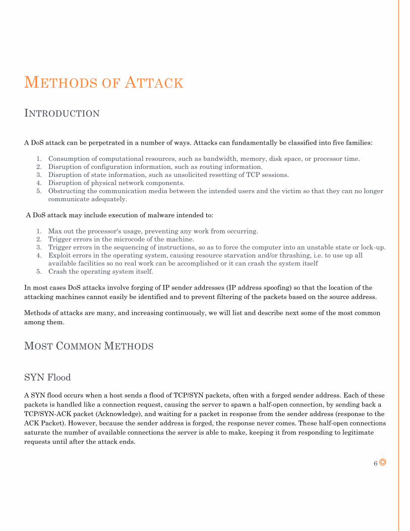
SYN Flood
A SYN flood occurs when a host sends a flood of TCP/SYN packets, often with a forged sender address. Each of these
packets is handled like a connection request, causing the server to spawn a half-open connection, by sending back a
TCP/SYN-ACK packet (Acknowledge), and waiting for a packet in response from the sender address (response to the
ACK Packet). However, because the sender address is forged, the response never comes. These half-open connections
saturate the number of available connections the server is able to make, keeping it from responding to legitimate
requests until after the attack ends.
7
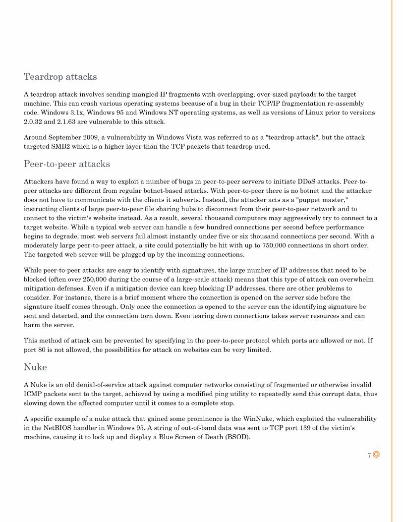
Teardrop attacks
A teardrop attack involves sending mangled IP fragments with overlapping, over-sized payloads to the target
machine. This can crash various operating systems because of a bug in their TCP/IP fragmentation re-assembly
code. Windows 3.1x, Windows 95 and Windows NT operating systems, as well as versions of Linux prior to versions
2.0.32 and 2.1.63 are vulnerable to this attack.
Around September 2009, a vulnerability in Windows Vista was referred to as a "teardrop attack", but the attack
targeted SMB2 which is a higher layer than the TCP packets that teardrop used.
Peer-to-peer attacks
Attackers have found a way to exploit a number of bugs in peer-to-peer servers to initiate DDoS attacks. Peer-to-
peer attacks are different from regular botnet-based attacks. With peer-to-peer there is no botnet and the attacker
does not have to communicate with the clients it subverts. Instead, the attacker acts as a "puppet master,"
instructing clients of large peer-to-peer file sharing hubs to disconnect from their peer-to-peer network and to
connect to the victim's website instead. As a result, several thousand computers may aggressively try to connect to a
target website. While a typical web server can handle a few hundred connections per second before performance
begins to degrade, most web servers fail almost instantly under five or six thousand connections per second. With a
moderately large peer-to-peer attack, a site could potentially be hit with up to 750,000 connections in short order.
The targeted web server will be plugged up by the incoming connections.
While peer-to-peer attacks are easy to identify with signatures, the large number of IP addresses that need to be
blocked (often over 250,000 during the course of a large-scale attack) means that this type of attack can overwhelm
mitigation defenses. Even if a mitigation device can keep blocking IP addresses, there are other problems to
consider. For instance, there is a brief moment where the connection is opened on the server side before the
signature itself comes through. Only once the connection is opened to the server can the identifying signature be
sent and detected, and the connection torn down. Even tearing down connections takes server resources and can
harm the server.
This method of attack can be prevented by specifying in the peer-to-peer protocol which ports are allowed or not. If
port 80 is not allowed, the possibilities for attack on websites can be very limited.
Nuke
A Nuke is an old denial-of-service attack against computer networks consisting of fragmented or otherwise invalid
ICMP packets sent to the target, achieved by using a modified ping utility to repeatedly send this corrupt data, thus
slowing down the affected computer until it comes to a complete stop.
A specific example of a nuke attack that gained some prominence is the WinNuke, which exploited the vulnerability
in the NetBIOS handler in Windows 95. A string of out-of-band data was sent to TCP port 139 of the victim's
machine, causing it to lock up and display a Blue Screen of Death (BSOD).
8
Permanent denial-of-service attacks
A permanent denial-of-service (PDoS), also known loosely as phlashing, is an attack that damages a system so badly
that it requires replacement or reinstallation of hardware. Unlike the distributed denial-of-service attack, a PDoS
attack exploits security flaws which allow remote administration on the management interfaces of the victim's
hardware, such as routers, printers, or other networking hardware. The attacker uses these vulnerabilities to
replace a device's firmware with a modified, corrupt, or defective firmware image - a process which when done
legitimately is known as flashing. This therefore "bricks" the device, rendering it unusable for its original purpose
until it can be repaired or replaced.
The PDoS is a pure hardware targeted attack which can be much faster and requires fewer resources than using a
botnet in a DDoS attack. Because of these features, and the potential and high probability of security exploits on
Network Enabled Embedded Devices (NEEDs), this technique has come to the attention of numerous hacker
communities.
Distributed attack
A Distributed Denial of Service Attack (DDoS) occurs when multiple systems flood the bandwidth or resources
of a targeted system, usually one or more web servers. This is the result of multiple compromised systems (for
example a botnet) flooding the targeted system with traffic. When a server is overloaded with connections, new
connections can no longer be accepted. The major advantages to an attacker of using a distributed denial-of-
service attack are that multiple machines can generate more attack traffic than one machine, multiple attack
machines are harder to turn off than one attack machine, and that the behavior of each attack machine can be
stealthier, making it harder to track and shut down. These attacker advantages cause challenges for defense
mechanisms. For example, merely purchasing more incoming bandwidth than the current volume of the attack
might not help, because the attacker might be able to simply add more attack machines.
Simple attacks such as SYN floods may appear with a wide range of source IP addresses, giving the appearance
of a well distributed DoS. These flood attacks do not require completion of the TCP three way handshake and
attempt to exhaust the destination SYN queue or the server bandwidth. Because the source IP addresses can be
trivially spoofed, an attack could come from a limited set of sources, or may even originate from a single host.
Stack enhancements such as syn cookies may be effective mitigation against SYN queue flooding, however
complete bandwidth exhaustion may require involvement. If an attacker mounts an attack from a single host it
would be classified as a DoS attack. In fact, any attack against availability would be classed as a Denial of
Service attack. On the other hand, if an attacker uses many systems to simultaneously launch attacks against a
remote host, this would be classified as a DDoS attack.
9
Reflected / Spoofed attack
A distributed denial of service attack may involve sending forged requests of some type to a very large number
of computers that will reply to the requests. Using Internet Protocol address spoofing, the source address is set
to that of the targeted victim, which means all the replies will go to (and flood) the target. (This reflected attack
form is sometimes called a "DRDOS".
ICMP Echo Request attacks (Smurf Attack) can be considered one form of reflected attack, as the flooding
host(s) send Echo Requests to the broadcast addresses of mis-configured networks, thereby enticing hosts to
send Echo Reply packets to the victim. Some early DDoS programs implemented a distributed form of this
attack.
10
SYN FLOODING ATTACKS
The attack exploits an implementation characteristic of the Transmission Control Protocol (TCP), and can be used to
make server processes incapable of answering a legitimate client application's requests for new TCP connections.
Any service that binds to and listens on a TCP socket is potentially vulnerable to TCP SYN flooding attacks.
Because this includes popular server applications for e-mail, Web, and file storage services, understanding and
knowing how to protect against these attacks is a critical part of practical network engineering.
The attack has been well-known for a decade, and variations of it are still seen. Although effective techniques exist
to combat SYN flooding, no single standard remedy for TCP implementations has emerged. Varied solutions can be
found among current operating systems and equipment, with differing implications for both the applications and
networks under defense. This report describes the attack and why it works, and follows with an example of the
current tactics that are used in both end hosts and network devices to combat SYN flooding attacks.
BASIC VULNERABILITY
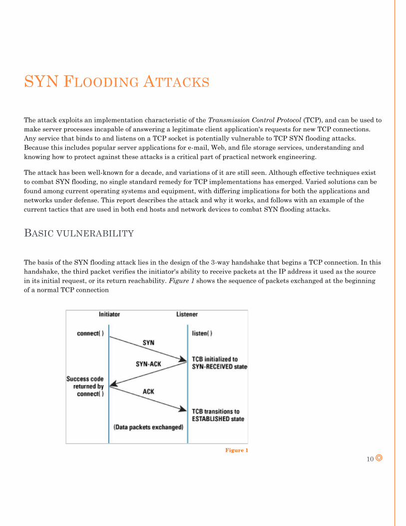
The basis of the SYN flooding attack lies in the design of the 3-way handshake that begins a TCP connection. In this
handshake, the third packet verifies the initiator's ability to receive packets at the IP address it used as the source
in its initial request, or its return reachability. Figure 1 shows the sequence of packets exchanged at the beginning
of a normal TCP connection
Figure 1
11
ATTACK DESCRIPTION
The Transmission Control Block (TCB) is a transport protocol data structure (actually a set of structures in many
operations systems) that holdsall the information about a connection. The memory footprint of a single TCB depends
on what TCP options and other features animplementation provides and has enabled for a connection. Usually, each
TCB exceeds at least 280 bytes, and in some operating systemscurrently takes more than 1300 bytes. The TCP SYN-
RECEIVED state is used to indicate that the connection is only half open, and that thelegitimacy of the request is
still in question. The important aspect to note is that the TCB is allocated based on reception of the SYN packet—
before the connection is fully established or the initiator's return reachability has been verified. This situation leads
to a clear potential DoS attack where incoming SYNs cause the allocation of so many TCBs that a host's kernel
memory isexhausted. In order to avoid this memory exhaustion, operating systems generally associate a "backlog"
parameter with a listening socket thatsets a cap on the number of TCBs simultaneously in the SYN-RECEIVED
state. Although this action protects a host's available memory resourcefrom attack, the backlog itself represents
another (smaller) resource vulnerable to attack. With no room left in the backlog, it is impossible toservice new
connection requests until some TCBs can be reaped or otherwise removed from the SYN-RECEIVED state.
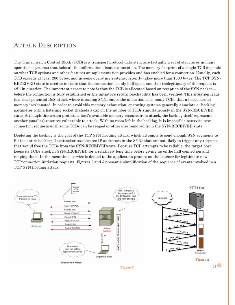
Depleting the backlog is the goal of the TCP SYN flooding attack, which attempts to send enough SYN segments to
fill the entire backlog. Theattacker uses source IP addresses in the SYNs that are not likely to trigger any response
that would free the TCBs from the SYN-RECEIVEDstate. Because TCP attempts to be reliable, the target host
keeps its TCBs stuck in SYN-RECEIVED for a relatively long time before giving up onthe half connection and
reaping them. In the meantime, service is denied to the application process on the listener for legitimate new
TCPconnection initiation requests. Figures 2 and 3 present a simplification of the sequence of events involved in a
TCP SYN flooding attack.
Figure 3
Figure 2
12
CISCO’S SOLUTION
INTRODUCING ASA
Layer-4 TCP SYN attack is a well-known DoS attack. Any service that binds to TCP socket is probably vulnerable to
TCP SYN flooding attacks. This includes popular web server applications for browsing, file storage and e-mail
services on Internet. Protection against this attack is an important for network security.
Cisco ASA provides the SYN-Proxy protection technique to defend the TCP-SYN attack traffic. Maximum
connections and maximum embryonic connections are configured, where number is an integer between 0 and 65,535.
The default is 0, which means no limit on connections. The following command is used to set the number of
connections on the Cisco IOS:
hostname(config-pmap-c)#set connection { [conn-max number] [embryonic-conn-max number] [per-client-
embryonic-max number] [per-client-max number] [random-sequence-number {enable | disable}] }
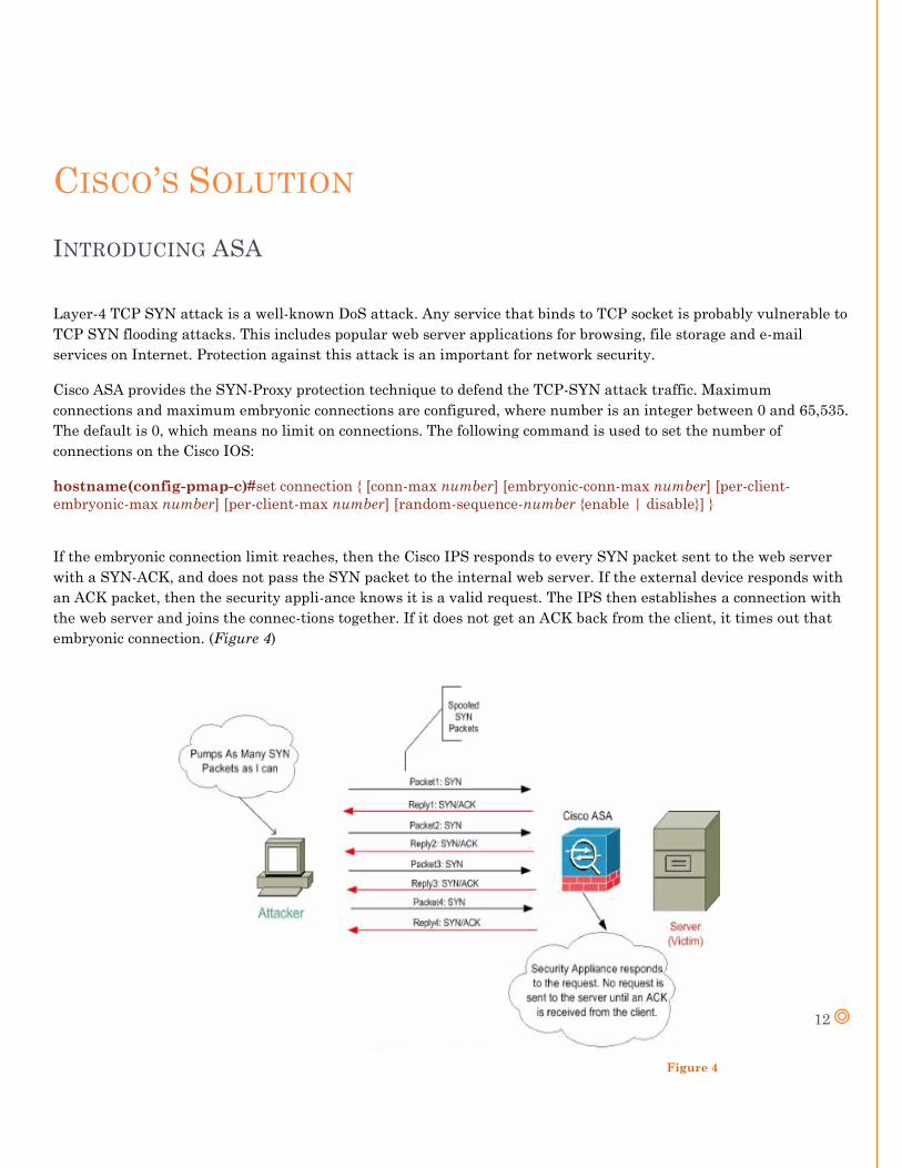
If the embryonic connection limit reaches, then the Cisco IPS responds to every SYN packet sent to the web server
with a SYN-ACK, and does not pass the SYN packet to the internal web server. If the external device responds with
an ACK packet, then the security appli-ance knows it is a valid request. The IPS then establishes a connection with
the web server and joins the connec-tions together. If it does not get an ACK back from the client, it times out that
embryonic connection. (Figure 4)
Figure 4
13
EXPERIMENTAL SETUP
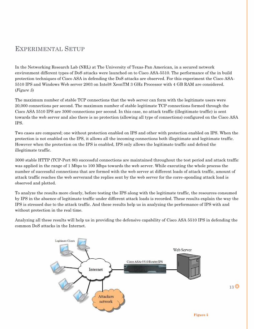
In the Networking Research Lab (NRL) at The University of Texas-Pan American, in a secured network
environment different types of DoS attacks were launched on to Cisco ASA-5510. The performance of the in build
protection techniques of Cisco ASA in defending the DoS attacks are observed. For this experiment the Cisco ASA-
5510 IPS and Windows Web server 2003 on Intel® XeonTM 3 GHz Processor with 4 GB RAM are considered.
(Figure 5)
The maximum number of stable TCP connections that the web server can form with the legitimate users were
20,000 connections per second. The maximum number of stable legitimate TCP connections formed through the
Cisco ASA 5510 IPS are 3000 connections per second. In this case, no attack traffic (illegitimate traffic) is sent
towards the web server and also there is no protection (allowing all type of connections) configured on the Cisco ASA
IPS.
Two cases are compared; one without protection enabled on IPS and other with protection enabled on IPS. When the
protection is not enabled on the IPS, it allows all the incoming connections both illegitimate and legitimate traffic.
However when the protection on the IPS is enabled, IPS only allows the legitimate traffic and defend the
illegitimate traffic.
3000 stable HTTP (TCP-Port 80) successful connections are maintained throughout the test period and attack traffic
was applied in the range of 1 Mbps to 100 Mbps towards the web server. While executing the whole process the
number of successful connections that are formed with the web server at different loads of attack traffic, amount of
attack traffic reaches the web serverand the replies sent by the web server for the corre-sponding attack load is
observed and plotted.
To analyze the results more clearly, before testing the IPS along with the legitimate traffic, the resources consumed
by IPS in the absence of legitimate traffic under different attack loads is recorded. These results explain the way the
IPS is stressed due to the attack traffic. And these results help us in analyzing the performance of IPS with and
without protection in the real time.
Analyzing all these results will help us in providing the defensive capability of Cisco ASA 5510 IPS in defending the
common DoS attacks in the Internet.
Figure 5
14
RESULTS
Processor Consumption by IPS under TCP-SYN without Legitimate Traffic
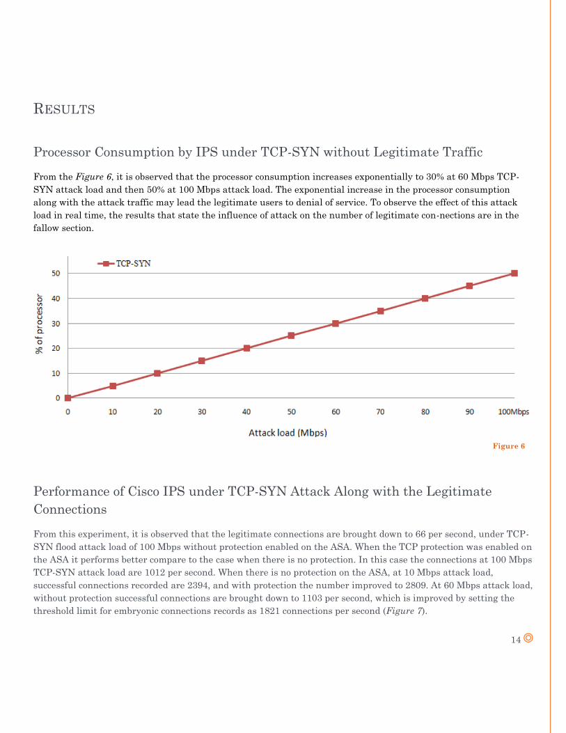
From the Figure 6, it is observed that the processor consumption increases exponentially to 30% at 60 Mbps TCP-
SYN attack load and then 50% at 100 Mbps attack load. The exponential increase in the processor consumption
along with the attack traffic may lead the legitimate users to denial of service. To observe the effect of this attack
load in real time, the results that state the influence of attack on the number of legitimate con-nections are in the
fallow section.
Performance of Cisco IPS under TCP-SYN Attack Along with the Legitimate
Connections
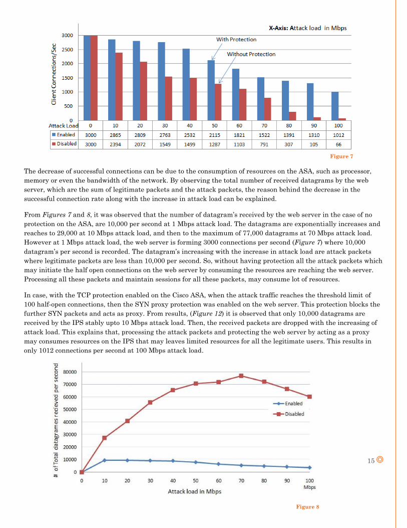
From this experiment, it is observed that the legitimate connections are brought down to 66 per second, under TCP-
SYN flood attack load of 100 Mbps without protection enabled on the ASA. When the TCP protection was enabled on
the ASA it performs better compare to the case when there is no protection. In this case the connections at 100 Mbps
TCP-SYN attack load are 1012 per second. When there is no protection on the ASA, at 10 Mbps attack load,
successful connections recorded are 2394, and with protection the number improved to 2809. At 60 Mbps attack load,
without protection successful connections are brought down to 1103 per second, which is improved by setting the
threshold limit for embryonic connections records as 1821 connections per second (Figure 7).
Figure 6
15
The decrease of successful connections can be due to the consumption of resources on the ASA, such as processor,
memory or even the bandwidth of the network. By observing the total number of received datagrams by the web
server, which are the sum of legitimate packets and the attack packets, the reason behind the decrease in the
successful connection rate along with the increase in attack load can be explained.
From Figures 7 and 8, it was observed that the number of datagram’s received by the web server in the case of no
protection on the ASA, are 10,000 per second at 1 Mbps attack load. The datagrams are exponentially increases and
reaches to 29,000 at 10 Mbps attack load, and then to the maximum of 77,000 datagrams at 70 Mbps attack load.
However at 1 Mbps attack load, the web server is forming 3000 connections per second (Figure 7) where 10,000
datagram’s per second is recorded. The datagram’s increasing with the increase in attack load are attack packets
where legitimate packets are less than 10,000 per second. So, without having protection all the attack packets which
may initiate the half open connections on the web server by consuming the resources are reaching the web server.
Processing all these packets and maintain sessions for all these packets, may consume lot of resources.
In case, with the TCP protection enabled on the Cisco ASA, when the attack traffic reaches the threshold limit of
100 half-open connections, then the SYN proxy protection was enabled on the web server. This protection blocks the
further SYN packets and acts as proxy. From results, (Figure 12) it is observed that only 10,000 datagrams are
received by the IPS stably upto 10 Mbps attack load. Then, the received packets are dropped with the increasing of
attack load. This explains that, processing the attack packets and protecting the web server by acting as a proxy
may consumes resources on the IPS that may leaves limited resources for all the legitimate users. This results in
only 1012 connections per second at 100 Mbps attack load.
Figure 7
Figure 8
16
EMULATING A DOS ATTACK
DESCRIPTION
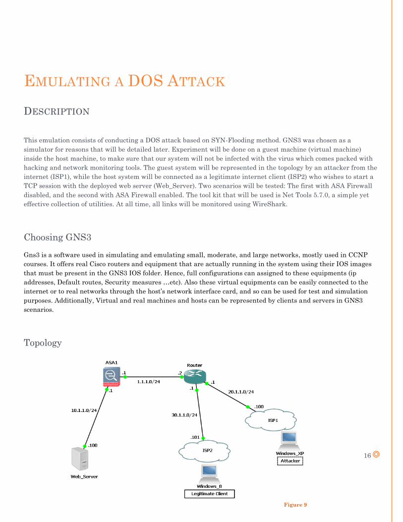
This emulation consists of conducting a DOS attack based on SYN-Flooding method. GNS3 was chosen as a
simulator for reasons that will be detailed later. Experiment will be done on a guest machine (virtual machine)
inside the host machine, to make sure that our system will not be infected with the virus which comes packed with
hacking and network monitoring tools. The guest system will be represented in the topology by an attacker from the
internet (ISP1), while the host system will be connected as a legitimate internet client (ISP2) who wishes to start a
TCP session with the deployed web server (Web_Server). Two scenarios will be tested: The first with ASA Firewall
disabled, and the second with ASA Firewall enabled. The tool kit that will be used is Net Tools 5.7.0, a simple yet
effective collection of utilities. At all time, all links will be monitored using WireShark.
Choosing GNS3
Gns3 is a software used in simulating and emulating small, moderate, and large networks, mostly used in CCNP
courses. It offers real Cisco routers and equipment that are actually running in the system using their IOS images
that must be present in the GNS3 IOS folder. Hence, full configurations can assigned to these equipments (ip
addresses, Default routes, Security measures …etc). Also these virtual equipments can be easily connected to the
internet or to real networks through the host’s network interface card, and so can be used for test and simulation
purposes. Additionally, Virtual and real machines and hosts can be represented by clients and servers in GNS3
scenarios.
Topology
Figure 9
17
PREPARING THE ENVIRONMENT
Deploying the Virtual Machine
The first step is installing the Vmware Workstation, which is the platform used for installing our virtual machine.
Vmware 9.0 is the version used in this project.
After that, the operating system is loaded and installed using an OS image. In our case, the operating system is
Windows XP Professional.
The next step would be installing the softwares that will be needed in the experiment: Wireshark, Net Tools 5.7.0,
and GNS3. It is worth to recommend downloading Net Tools 5.7.0 from a trustworth website, since networking
hacking and monitoring tools mostly come packed with viruses and trojans.
GNS3 Installation
GNS3 Installation Wizard mostly come packed with the softwares that he needs, including WireShark, Wincap,
Putty …etc. To get the full package, it is recommended to download the installation files from the official and
legitimate website (www.sourceforge.net).
After installing GNS3, and to be able to use its equipment, you need to acquire the IOS image for each router or
firewall that you will be needing in your scenario. These files can be downloaded from offcial cisco websites, using
the barcode on the back of the cisco router as a proof of legal and authorised use, as they can be downloaded from
unofficial sources.
After putting your hand on these images, all you still need to do is to group them in one directory (folder) and set the
path of that directory in GNS3 preferences.
As for ASA and some other firewall equipments, some additional configuration will be required in GNS3 preferences
before becoming able to use them. (Refer to the installation manual provided in www.sourceforge.net or to any video
tutorial)
Creating a loopback adapter
A loopback adapter needs to be configured on the guest machine so it can be connected as a host in GNS3. The
simplest way to do that is to go to command prompt (cmd) and type “hdwwiz.exe”, this is the shortcut to: “Add new
Hardware”.
When the “add new hardware” wizard comes up, choose “Install the hardware manually”, after that, we choose
the “Network adapter”. The next step would be choosing “Microsoft Loopback Adapter”. Finally, the adapter
will appear among the network connections, and you will be free to configure it as any other network adapter.
18
TESTING THE ENVIRONMENT
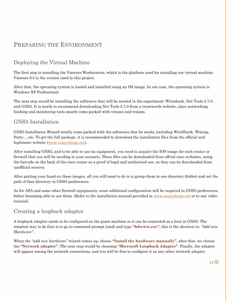
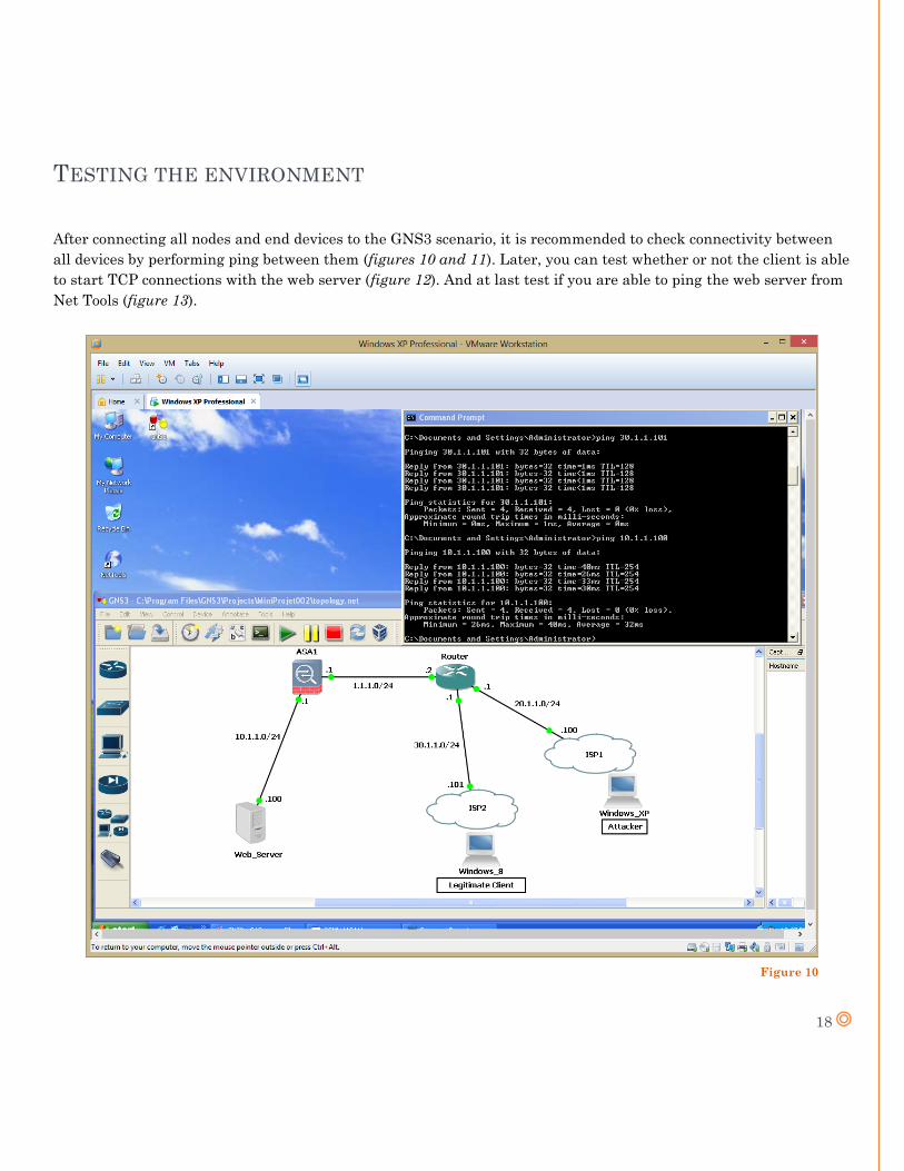
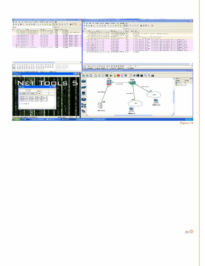
After connecting all nodes and end devices to the GNS3 scenario, it is recommended to check connectivity between
all devices by performing ping between them (figures 10 and 11). Later, you can test whether or not the client is able
to start TCP connections with the web server (figure 12). And at last test if you are able to ping the web server from
Net Tools (figure 13).
Figure 10
19
Figure 11
Figure 12
20
Figure 13
21
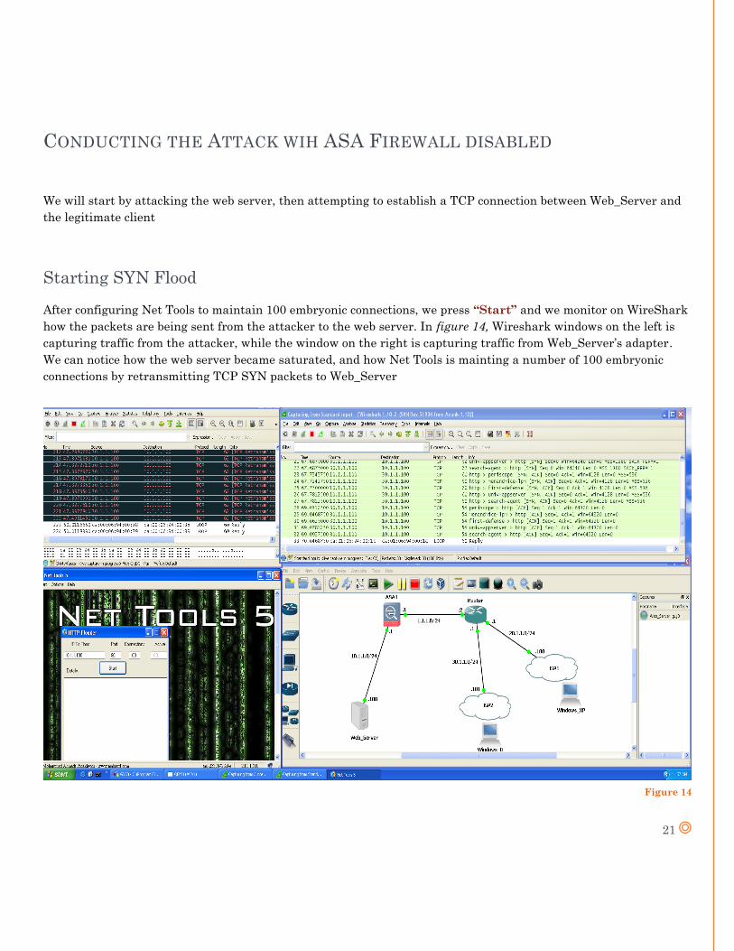
CONDUCTING THE ATTACK WIH ASA FIREWALL DISABLED
We will start by attacking the web server, then attempting to establish a TCP connection between Web_Server and
the legitimate client
Starting SYN Flood
After configuring Net Tools to maintain 100 embryonic connections, we press “Start” and we monitor on WireShark
how the packets are being sent from the attacker to the web server. In figure 14, Wireshark windows on the left is
capturing traffic from the attacker, while the window on the right is capturing traffic from Web_Server’s adapter.
We can notice how the web server became saturated, and how Net Tools is mainting a number of 100 embryonic
connections by retransmitting TCP SYN packets to Web_Server
Figure 14
22
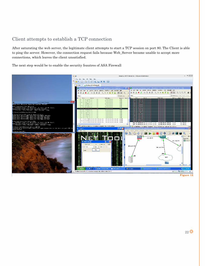
Client attempts to establish a TCP connection
After saturating the web server, the legitimate client attempts to start a TCP session on port 80. The Client is able
to ping the server. However, the connection request fails because Web_Server became unable to accept more
connections, which leaves the client unsatisfied.
The next step would be to enable the security feautres of ASA Firewall
Figure 15
23
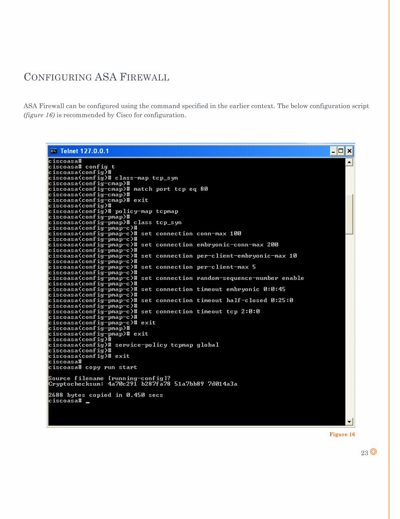
CONFIGURING ASA FIREWALL
ASA Firewall can be configured using the command specified in the earlier context. The below configuration script
(figure 16) is recommended by Cisco for configuration.
Figure 16
24
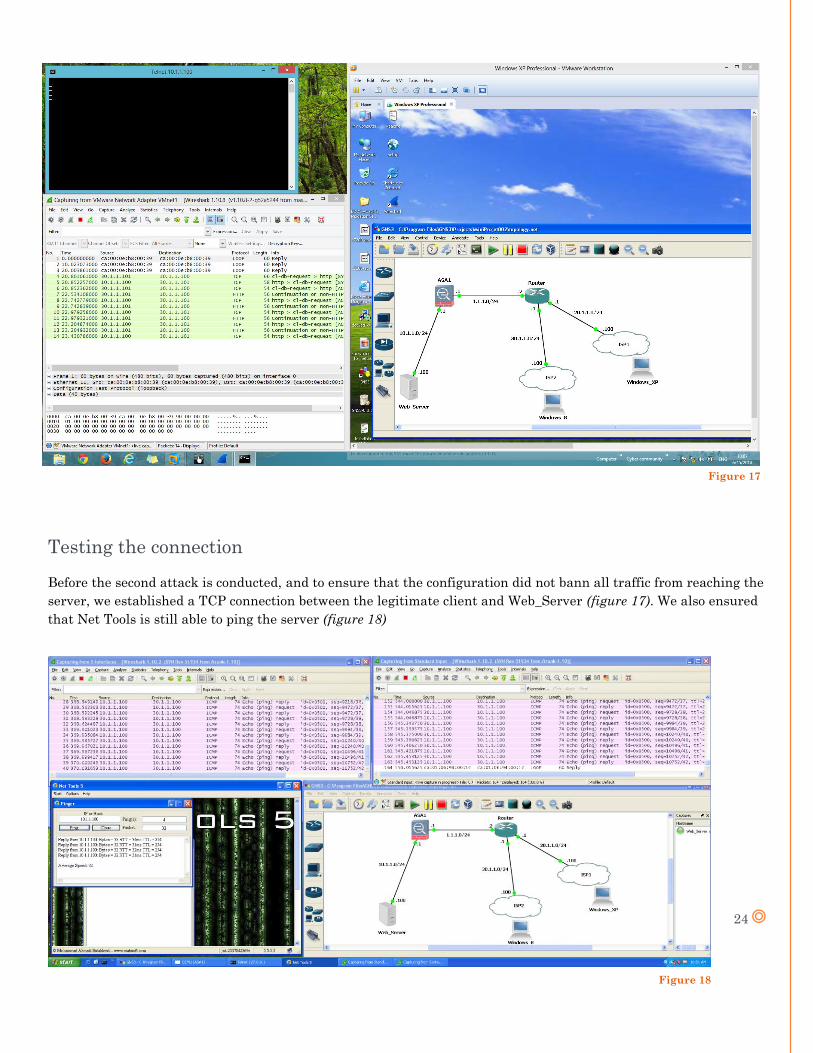
Testing the connection
Before the second attack is conducted, and to ensure that the configuration did not bann all traffic from reaching the
server, we established a TCP connection between the legitimate client and Web_Server (figure 17). We also ensured
that Net Tools is still able to ping the server (figure 18)
Figure 18
Figure 17
25
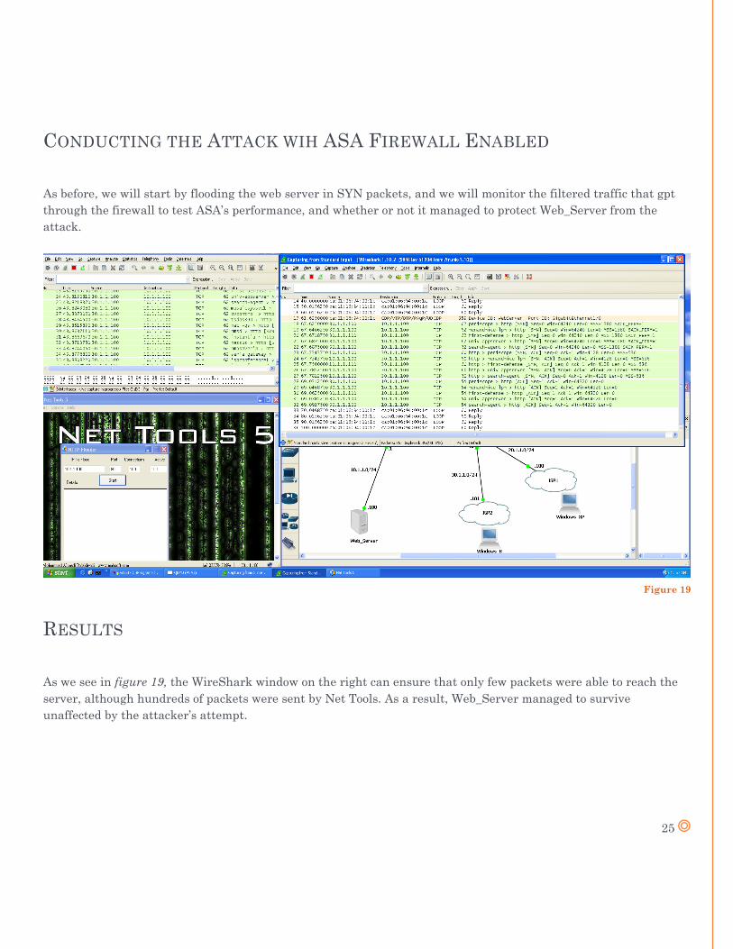
CONDUCTING THE ATTACK WIH ASA FIREWALL ENABLED
As before, we will start by flooding the web server in SYN packets, and we will monitor the filtered traffic that gpt
through the firewall to test ASA’s performance, and whether or not it managed to protect Web_Server from the
attack.
RESULTS
As we see in figure 19, the WireShark window on the right can ensure that only few packets were able to reach the
server, although hundreds of packets were sent by Net Tools. As a result, Web_Server managed to survive
unaffected by the attacker’s attempt.
Figure 19
26
CONCLUSION
This Experiment demonstrated ASA Firewall’s role in migitating against SYN-Flood attacks. Its
is also demonstrated that ASA is capable of protecting networks from other DOS attacks as well,
such as UDP flood attacks, ICMP Ping attacks and ICMP land attacks
Network based attacks are getting more and more aggressive amd complicated with each and
every sunrise. New attack methods and techniques are being developped and used, accompagned
with a siginficant evolution in hacking and penetration tools.
Until now, ASA firewall is a convenient solution to migitate against lots of DOS attacks, and can
provide immunity against some DDOS attacks.
However, despite the existence of such security systems, raising the “Awareness” remains one of
the best practices to decrease vulnerabilities, and reduce the effect of the daily attacks
27
PERSPECTIVE
As I discovered some of GNS3 features in this project, the next step would be to increase my
exoerience in this emulator, to find out more about its capabilities and field of use.
A Distributed-Denial-Of-Service attack is interesting to conduct, in order to test ASA’s behaviour
and capabilities, since it was mainly tested against DOS attacks, and haven’t yet proven
efficiency migitating against DDOS based attacks.
28
REFERENCES
Wikipedia: http://en.wikipedia.org/wiki/Denial-of-service_attack
http://en.wikipedia.org/wiki/TCP_handshake#Connection_establishment
Journal of Information Security, 2012, 3, 122-137: Experimental Evaluation of Cisco ASA-5510 Intrusion Prevention System against Denial of Service Attacks
Cisco (www.cisco.com): ASA/PIX 7.x and Later: Mitigating the Network Attacks
The Internet Protocol Journal - Volume 9, Number 4 – Cisco Systems: Defenses against TCP SYN Flooding Attacks
Scribd (www.scribd.com): DDOS Attack and its Mitigation - Simulation in GNS3
NetHow: How to configure Cisco ASA 8.4 on GNS3
The Diary of a Networker: Emulating Cisco ASA 8.4.2 on GNS3
Free CCNA Workbook: Configuring a GNS3 Ethernet NIO Cloud
Youtube videos: [GNS3 Lab 00] GNS3 Tutorial for Beginners [part 1_2]
Adding your own PC to GNS3 with MS Loopback – YouTube
GNS3 Tutorial - Connecting GNS3 Routers to Real Hardware Switches and Network Equipment
GNS3 Tutorial - Connecting GNS3 Routers to the Internet in Windows 7
GNS3 Tutorial - Getting Started with GNS3 on Windows 7 - Building & Saving Your Topologies
GNS3 Tutorial - Installing, Configuring then Connecting VirtualBox on Windows 7 to GNS3
GNS3 Tutorial - Installing, configuring, then tweaking GNS3 on Windows 7
GNS3 Tutorial - Method 2 - Accessing GNS3 Network Remotely via Terminal_Console
How to Add ASA Firewall to GNS3 _ GNS3 Tutorial _ Cisco Training Videos
Related Documents