Deliverable D300.1 RTD Methodology WP 300 – Task 310 Grant Agreement number: FP7-ICT-2009-247831 Project acronym: DEMI Project title: Product and Process Design for AmI Supported Energy Efficient Manufacturing Installations Funding Scheme: STREP Date of latest version of Annex I against which the assessment will be made: 03.11.2009 Start date of the project: 01.02.2010 Duration: 36 months Project co-ordinator name, title and organisation: Dr. Mikel Sorli Fundación Tecnalia Research & Innovation Tel: + 34 699 983 170 Fax: + 34 946 460 900 E-mail: [email protected] Project website address: http://www.demi-online.eu/ Authors: TEC, ATB, IVL, LEI Contributors: Due date of deliverable: 31.07.2011 Document Identifier: DEMI D300.1 - RTD Methodology v1.0 Revision Date: 18.11.2011

Welcome message from author
This document is posted to help you gain knowledge. Please leave a comment to let me know what you think about it! Share it to your friends and learn new things together.
Transcript
Deliverable D300.1
RTD Methodology
WP 300 – Task 310
Grant Agreement number: FP7-ICT-2009-247831
Project acronym: DEMI
Project title: Product and Process Design for AmI Supported Energy Efficient Manufacturing Installations
Funding Scheme: STREP
Date of latest version of Annex I against which the assessment will be made: 03.11.2009
Start date of the project: 01.02.2010
Duration: 36 months
Project co-ordinator name, title and organisation:
Dr. Mikel Sorli Fundación Tecnalia Research & Innovation
Tel: + 34 699 983 170
Fax: + 34 946 460 900
E-mail: [email protected]
Project website address: http://www.demi-online.eu/
Authors: TEC, ATB, IVL, LEI
Contributors:
Due date of deliverable: 31.07.2011
Document Identifier: DEMI D300.1 - RTD Methodology v1.0
Revision
Date: 18.11.2011

DEMI - FP7-ICT-2009-247831 30.12.2011
DEMI_D300.1 RTD Methodology_v1.0 Page 2 of 42
Dissemination Level
PU Public X
PP Restricted to other programme participants (including the Commission Services)
RE Restricted to a group specified by the consortium (including the Commission Services)
CO Confidential, only for members of the consortium (including the Commission Services)
This document is the property of the DEMI Consortium.
This document may not be copied, reproduced, or modified in the whole or in the part for any purpose without written permission from the DEMI coordinator with acceptance of the Project Consortium.
This publication was completed with the support of the European Commission under the 7th Framework Programme. The contents of this publication do not necessarily reflect the Commission's own position.

DEMI - FP7-ICT-2009-247831
DEMI_D300.1 RTD Methodology_v1.0 Page III of 42
Summary
The DEMI project aims to provide means to enhance existing manufacturing process design methods and tools to optimise energy use pattern over the process life cycle by developing both a generic methodology on how to optimally take into account energy efficiency issues within process design in manufacturing industry, and new generic software components.
DEMI Methodology includes guidelines on introduction of energy efficiency aspects and use of AmI in manufacturing process design, and is tailored to three different target audiences: RTD, ICT vendors, and manufacturing companies.
While ICT Methodology will support ICT vendors on how to extend their product/process design tools with energy optimisation aspects, and Industrial Methodology will guide manufacturing companies to apply the new approach and tools to improve their process energy efficiency, this RTD Methodology is addressed to the RTD community aiming at the area of energy use optimisation in production/processes design based on AmI, Eco-innovation supported by TRIZ, process optimisation analysis and energy use simulation.
The purpose of this report is therefore to provide theoretical background to RTD practitioners who would like to apply DEMI approaches in future activities related to energy efficiency optimisation in manufacturing processes. The topics comprise different aspects like the manufacturing process design knowledge representation and use, the use of TRIZ principles to solve trade-off problems in manufacturing process design, AmI implementation in manufacturing environments, the DEMI approach for manufacturing process optimisation, manufacturing process modelling and energy use simulation, as well as for setting-up a Knowledge Repository.
DEMI - FP7-ICT-2009-247831
DEMI_D300.1 RTD Methodology_v1.0 Page IV of 42
Table of Contents
1 Introduction ....................................................................................................... 6
2 Manufacturing process design knowledge representation and use................... 7
2.1 Case Based Reasoning..................................................................................................7
2.2 Rule Based Reasoning ..................................................................................................9
3 Innovation aspects based on TRIZ principles to solve trade-off problems in manufacturing process design..................................................... 12
4 AmI implementation in manufacturing environments. Methods for transferring AmI information into Knowledge ............................................... 15
4.1 AmI System in Manufacturing Industry and DEMI focus .........................................15
4.2 DEMI ICT Components in the AmI enhanced Manufacturing Environment ............19
4.3 Interaction of Design with Production and Maintenance ...........................................21
4.4 Usage of Collaborative Working Environment Principles by Design and related Manufacturing Activities .........................................................................23
4.5 AmI based Acquisition of Knowledge .......................................................................25
4.6 Combination of AmI Systems with existing Design Systems ....................................27
5 Manufacturing process optimisation............................................................... 29
5.1 A standardized process description ............................................................................30
5.2 LCC computation........................................................................................................30
5.3 Configuration optimization.........................................................................................31
6 Manufacturing process modelling and energy use simulation........................ 32
7 Setting-up of an Eco-knowledge Repository for a specific industrial environment..................................................................................................... 35
8 References ....................................................................................................... 42
DEMI - FP7-ICT-2009-247831
DEMI_D300.1 RTD Methodology_v1.0 Page V of 42
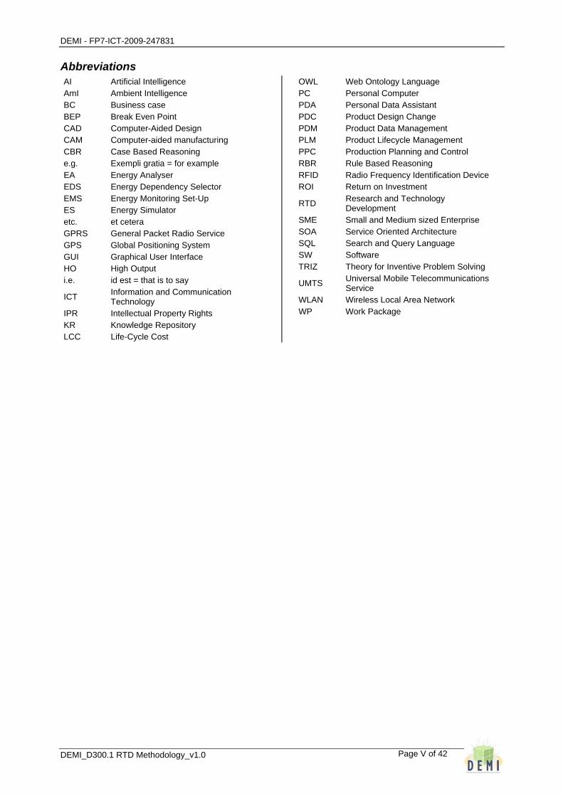
Abbreviations AI Artificial Intelligence AmI Ambient Intelligence BC Business case BEP Break Even Point CAD Computer-Aided Design CAM Computer-aided manufacturing CBR Case Based Reasoning e.g. Exempli gratia = for example EA Energy Analyser EDS Energy Dependency Selector EMS Energy Monitoring Set-Up ES Energy Simulator etc. et cetera GPRS General Packet Radio Service GPS Global Positioning System GUI Graphical User Interface HO High Output i.e. id est = that is to say
ICT Information and Communication Technology
IPR Intellectual Property Rights KR Knowledge Repository LCC Life-Cycle Cost
OWL Web Ontology Language PC Personal Computer PDA Personal Data Assistant PDC Product Design Change PDM Product Data Management PLM Product Lifecycle Management PPC Production Planning and Control RBR Rule Based Reasoning RFID Radio Frequency Identification Device ROI Return on Investment
RTD Research and Technology Development
SME Small and Medium sized Enterprise SOA Service Oriented Architecture SQL Search and Query Language SW Software TRIZ Theory for Inventive Problem Solving
UMTS Universal Mobile Telecommunications Service
WLAN Wireless Local Area Network WP Work Package

DEMI - FP7-ICT-2009-247831
DEMI_D300.1 RTD Methodology_v1.0
Page 6 of 42
1 Introduction
This report is DEMI deliverable D300.1 ‘DEMI RTD Methodology’. It further develops the RTD topics involved in DEMI which are identified in D200.2 ‘Methodology Specification’. This RTD Methodology is aimed at the RTD community providing a theoretical framework for the DEMI approaches to the design of energy efficient manufacturing processes. These topics identified in the Methodology Specification are described in detail in the subsequent chapters, as follows:
Chapter 2 is aimed to describe the approach for the knowledge representation and use, relevant to the manufacturing process design, focusing on the Rule Based Reasoning and Case Based Reasoning approaches.
Chapter 3 presents the trade-off problem solving approach based on TRIZ principles for energy efficient manufacturing process design.
Chapter 4 addresses AmI implementation in manufacturing environments including methods for transferring AmI information into knowledge and focuses on aspects like DEMI ICT components in the AmI enhanced manufacturing environment, interaction of design with production and maintenance or use of AmI with existing design systems.
Chapter 5 is aimed to manufacturing process optimisation approach, focusing on standardized process description, Life-Cycle Cost computation and configuration optimization.
Chapter 6 describes the approach for manufacturing process modelling and energy use simulation.
Chapter 7 describes the setting-up of an Eco-knowledge repository for an industrial environment.
Further information on DEMI concept can be found in DEMI deliverable D100.4 ‘Public DEMI Concept’.

DEMI - FP7-ICT-2009-247831
DEMI_D300.1 RTD Methodology_v1.0
Page 7 of 42
2 Manufacturing process design knowledge representation and use
Some of the DEMI functionalities support the manufacturing process designer in decision making by providing information about historic processes as well as rule based feedback in process design. These functionalities require a previous definition of historic processes database as well as manufacturing process design rules, defined by experts but also by using ‘data mining’ techniques. So these functionalities demand the identification, storage and tools allowing ease of use of the relevant knowledge present in different ways in the company. The approach proposed is that of Case Based Reasoning (CBR) for historic processes knowledge management and the Rule Based Reasoning (RBR) approach for design criteria and rules management.
2.1 Case Based Reasoning
The past experience at the company in manufacturing process design can be used in future process design, as normally processes are not designed from scratch but based on experts’ experience in ‘similar’ situations. The Case Based Reasoning approach allows the manufacturing process design engineer to be able to get a suitable existing process design from database as preliminary design for the manufacturing process being designed, by providing some initial requirements.
Case Based Reasoning is a paradigm for combining problem solving and learning that has become one of the most successfully applied subfields of AI in recent years. CBR is based on the intuition that problems tend to recur, which means that new problems are often similar to previously encountered problems and, therefore, that past solutions may be of use in the current situation. CBR is rooted in the works of Roger Schank on dynamic memory and the central role that a reminding of earlier cases and situation patterns has in problem solving and learning. Central tasks that all CBR methods have to deal with are: to identify the current problem situation, find a past case similar to the new one, use that case to suggest a solution to the current problem, evaluate the proposed solution, and update the system by learning from this experience [1].
The underlying ideas of CBR can be applied consistently across application domains although a CBR system designer has to decide from among a range of different methods for organizing, retrieving and reusing the knowledge retained in past cases: Cases may be kept as concrete experiences, or a set of similar cases may form a generalized case. Cases may be stored as separate knowledge units, or distributed within the knowledge structure. Cases may be indexed by a prefixed or open vocabulary, and within a flat or hierarchical index structure. The solution from a previous case may be directly applied to the present problem, or adapted according to differences between the two cases. The matching of cases, adaptation of solutions, and learning from an experience may be supported by a deep model of general domain knowledge, by more shallow and compiled knowledge, or be based on an apparent, syntactic similarity only [2].
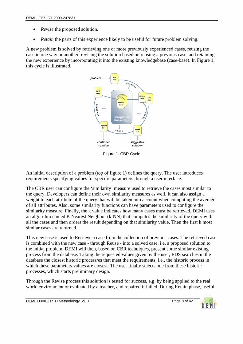
At the highest level of generality, a general CBR application can be described by a cycle composed of the following four processes:
• Retrieve the most similar case or cases.
• Reuse the information and knowledge in that case to solve the problem.
DEMI - FP7-ICT-2009-247831
DEMI_D300.1 RTD Methodology_v1.0
Page 8 of 42
• Revise the proposed solution.
• Retain the parts of this experience likely to be useful for future problem solving.
A new problem is solved by retrieving one or more previously experienced cases, reusing the case in one way or another, revising the solution based on reusing a previous case, and retaining the new experience by incorporating it into the existing knowledgebase (case-base). In Figure 1, this cycle is illustrated.
Figure 1. CBR Cycle
An initial description of a problem (top of figure 1) defines the query. The user introduces requirements specifying values for specific parameters through a user interface.
The CBR user can configure the ‘similarity’ measure used to retrieve the cases most similar to the query. Developers can define their own similarity measures as well. It can also assign a weight to each attribute of the query that will be taken into account when computing the average of all attributes. Also, some similarity functions can have parameters used to configure the similarity measure. Finally, the k value indicates how many cases must be retrieved. DEMI uses an algorithm named K Nearest Neighbor (k-NN) that computes the similarity of the query with all the cases and then orders the result depending on that similarity value. Then the first k most similar cases are returned.
This new case is used to Retrieve a case from the collection of previous cases. The retrieved case is combined with the new case - through Reuse - into a solved case, i.e. a proposed solution to the initial problem. DEMI will then, based on CBR techniques, present some similar existing process from the database. Taking the requested values given by the user, EDS searches in the database the closest historic process/es that meet the requirements, i.e., the historic process in which these parameters values are closest. The user finally selects one from these historic processes, which starts preliminary design.
Through the Revise process this solution is tested for success, e.g. by being applied to the real world environment or evaluated by a teacher, and repaired if failed. During Retain phase, useful

DEMI - FP7-ICT-2009-247831
DEMI_D300.1 RTD Methodology_v1.0
Page 9 of 42
experience is retained for future reuse, and the case base is updated by a new learned case, or by modification of some existing cases.
As indicated in the figure 1, general knowledge usually plays a part in this cycle, by supporting the CBR processes. This support may range from very weak (or none) to very strong, depending on the type of CBR method. By general knowledge we mean general domain-dependent knowledge, as opposed to specific knowledge embodied by cases.
CBR tool in DEMI is based on JColibri tool (developed by Universidad Politécnica de Madrid). Jcolobri is a tool to help application designers to develop and quickly prototype CBR systems. It offers a simplified development process that is based on the reuse of past designs and implementations. It formalizes the CBR knowledge using a domain-independent CBR ontology which is mapped into the classes of framework, a knowledge level description of the CBR tasks and a library of reusable problem solving methods.
Figure 2. Case representation
jCOLIBRI represents a case in a very general way. As shown in figure 2, a case is just an individual that can have any number of relationships with other individuals (the attributes of the case). The framework is populated with a number of predefined primitive data types that support the definition of any case structure, and a GUI-based tool is provided to build it. This abstract settlement, inspired on the Composite design pattern, allows for a uniform treatment of arbitrarily complex case structures as long as they conform to the Individual related through Individual Relation to other Individual. Cases are often derived from legacy databases, thereby converting existing organizational resources into exploitable knowledge. To take advantage of these previously existing resources, facilitate intelligent access to existing information, and incorporate it as the seed knowledge in the CBR system (the case base) jCOLIBRI offers a set of connectors to manage persistence of cases.
2.2 Rule Based Reasoning
Rule Based Reasoning approach is used to create a preliminary process design from generic basic requirements. The process designer will be able to define it making decisions on the use of specific equipment, parameters values, etc., with the support of RBR functionality which will give rules based feedback. In this way the user can analyse the impact of process parameters modifications according to the process rules implemented, thus comparing different possible
DEMI - FP7-ICT-2009-247831
DEMI_D300.1 RTD Methodology_v1.0
Page 10 of 42
designs and checking possible inconsistencies, incompatibilities, rules not fulfilled by specific parameters, values/states required for some parameters depending on those given to others, etc.
The ICT approach for this functionality development is based on ‘KnowWE’ tool (developed by University of Wurzburg). This functionality is web based, and access can be limited to some users. Like process design engineers. Knowledge Wiki Environment (KnowWE) is a collaborative knowledge engineering approach based on the widespread wiki technique. The interface of a standard wiki system is extended to allow for the capture, the maintenance and the use of knowledge systems. It enables domain specialists and experienced users to build knowledge based consultation systems collaboratively on the web.
Consultation systems can be used for recommendation and selections tasks. Knowledge wikis extend classic wiki systems by an explicit knowledge mark-up that is formalized together with the normal text within the edit pane of the wiki. Entered knowledge is interpreted and maintained by an additional knowledge wiki engine. The user can then browse the knowledge wiki using the normal web links but is also able to activate an interactive problem solving process using the explicit knowledge. The distributed and open nature of a knowledge wiki may help to weaken important issues of the knowledge engineering bottleneck:
• the total knowledge acquisition and maintenance costs of single developers,
• the dependency of single domain specialists, and
• the complexity of building and maintaining large knowledge bases.
For explicit problem solving knowledge it can be distinguished:
• terminological knowledge for the (hierarchical) definition of user inputs and derivable system outputs, and
• problem solving knowledge to derive solutions for given inputs.
For both, KnowWE provides textual representations to be entered through the classic wiki interface. Usually, the terminology is defined manually using a predefined wiki syntax shown in Figure 3. Here, the user inputs are defined as questions [3].
The possible answers of these questions are denoted below each question. Similarly, the hierarchy of solutions can also be defined in a wiki-like way. For the definition of problem solving knowledge KnowWE provides heuristic rules, decision trees, and set covering models. When saving the edited content and knowledge, respectively, the knowledge wiki engine is extracting the knowledge parts from the wiki text. The textual representation of the knowledge is then translated into an executable knowledge base and stored in a knowledge repository together with its namespace, i.e., the wiki page it occurs in. Solutions and user inputs in different knowledge bases but with identical names and identical structure are aligned automatically. More complex alignments can be defined by specific alignment rules. Compiled knowledge can either be used by starting a structured dialog with the user or by using the in place answering technique provided by the knowledge wiki.
Structured questionnaires are generated by the manually defined user inputs and help to present a list of questions in a standardized way. Based on the expressiveness of OWL (Lite/DL) the

DEMI - FP7-ICT-2009-247831
DEMI_D300.1 RTD Methodology_v1.0
Page 11 of 42
defined ontologies are able to capture a wide range of general knowledge but lack in the possibility to represent active problem-solving knowledge that is necessary to generate and drive a semi-automated problem-solving session with a user [4]. Such knowledge typically relates the class of findings provided as user inputs and describing the current problem with the class of solutions that are derived for the given problem description.
The presented concept provides strong support to represent explicit knowledge like rules and models. A knowledge wiki also captures the problem-solving knowledge that is necessary for deriving the particular concept. Then, every wiki page embeds not only semantically annotated text and multimedia but also explicit problem-solving knowledge.
As a typical use case, the user of a semantic knowledge wiki can browse the contents of the wiki in a classic web-style possibly using semantic navigation and/or semantic search features. Moreover, the user is also able to start an interactive interview where giving a problem description. Based on these inputs an appropriate list of solutions is presented that are in turn linked to the wiki pages representing these particular concepts. Thus, every solution represented in the wiki is considered during a problem-solving process. Instead of using an interactive interview mode the user can enter findings inline by clicking on inline answers embedded in the normal wiki page.
In general, a knowledge wiki extends the functionality of a semantic wiki by the representation, the reasoning, and the engineering of explicit problem–solving knowledge [5]. Rules will relate process parameters, both quantitative and qualitative in a logical way. Quantitative parameters will be characterised by intervals of possible values, and qualitative parameters will be characterised by different possible states. The user will be able to define different kind of rules in this way as well as edit/modify them, using this functionality.
In DEMI project the KnowWE tool will be enhanced in at least two ways. First, the static questionnaire offered by KnowWE means that the questions are already fixed regardless the answers given by the user. In DEMI in is expected to develop the possibility of providing ‘dynamic questionnaires’, where some questions are different depending on the previous answers provided by the user. On the other hand, in addition the KnowWE tool will be enhanced with the possibility of transferring data to/from a Knowledge Repository so that design rules can be read from it and manufacturing process configuration can be exported for further optimisation with DEMI Energy Analyser component.
In addition to these rules manually defined by company experts, DEMI will also provide support in inferring rules from the historic processes database by using data mining techniques. The ICT approach for this functionality development will be based on ‘WEKA’ tool, which allows inferring rules from historic cases database.
DEMI - FP7-ICT-2009-247831
DEMI_D300.1 RTD Methodology_v1.0
Page 12 of 42
3 Innovation aspects based on TRIZ principles to solve trade-off problems in manufacturing process design
Trade-off problems can be found in manufacturing process design when optimising process specifications are in conflict with the objective of minimising energy consumption. This is an example of contradiction where an innovative solution can give us the opportunity of solving both problems at the same time, in this way overcoming the contradiction. The approach used in DEMI is based on TRIZ methodology.
TRIZ is a Russian methodology for innovation and developing creative ideas for problem solving. It is also recognized as theory of innovative problem solving. TRIZ methodology is first to formulate the problem, then analyzing the system, next is to carry out failure analysis and ultimately goes for solution. So, advantage of applying TRIZ is that it provides a systematic way of solution finding, instead of hit and trial method, ultimately resulting in the form of more innovative product. TRIZ invention was basically to focus on manufacturing related problems, but different experts are using it in formulating service related problems, production problems, to carry out failure analysis and for finding optimal results.
This methodology has established a form of representing the essence of problems, i.e., technical contradictions, and provided a table of useful hints to solutions. Technical contradictions are the cases where if we try to improve an aspect (or a parameter) of the system, some other aspect becomes intolerably worse. In order to represent the situations of technical contradictions, 39 different parameters of systems were selected and a problem matrix defined. Then, by surveying a huge number of patents, each patent was analyzed to find which type of technical contradiction it treated and which principle of invention (among 40, see below) it used in its solution.
Accumulation of this analysis has revealed which principles were most used in each of the 39 x 39 types of problems. The top 4 principles in each type of problem were recorded in a tabular form of 39 x 39 elements; the resultant table is called “Altshuller's Contradiction Matrix” [6]. For using this matrix, one has to think of which matrix element user’s problem should be assigned to and then has to consider about the four principles of inventions suggested by the matrix as the hints, so as to realize them into a solution to user’s own problem. For using these hints, capability of flexible thinking is needed.
DEMI uses this Matrix to provide guidelines from TRIZ principles, which will guide the user in the search for innovative solutions to specific trade-off problems related to the manufacturing process design. Generic guidelines given by TRIZ will be complemented with more specific guidelines for the different manufacturing processes represented in the different business cases.
On the other hand, the above mentioned TRIZ 40 Principles are listed below:
Segmentation, Taking out or Extraction, Local quality, Asymmetry, Merging/Consolidation, Universality, Nested doll, Anti-weight, Preliminary anti-action, Preliminary action, Beforehand cushioning, Equipotentiality, The other way round, Spheroidality – Curvature, Dynamics, Partial or Excessive actions, Another dimension, Mechanical vibration, Periodic action, Continuity of useful action, Skipping / Rushing Through, Blessing in disguise - Harm into benefit, Feedback, Intermediary/Mediator , Self-Service, Copying, Cheap short-living objects, Mechanics substitution, Pneumatics and hydraulics, Flexible shells and thin films, Porous materials, Colour
DEMI - FP7-ICT-2009-247831
DEMI_D300.1 RTD Methodology_v1.0
Page 13 of 42
changes, Homogeneity, Rejecting, Discarding – Recovering, Regeneration, Parameter Changes, Phase transitions, Thermal expansion, Accelerated oxidation, Inert atmosphere, Composite materials.
For each principle TRIZ methodology has defined some different generic guidelines. DEMI will define more specific guidelines for the different business cases involved in the project, but as an example the following paragraphs present some of these generic guidelines for the first four principles.
• Principle 1 Segmentation:
o Divide an object into independent parts (e.g. Different focal length lenses for a camera, Multiple pistons in combustion engine, etc)
o Make an object sectional - easy to assemble or disassemble (e.g. Rapid-release fasteners)
o Increase the degree of fragmentation or segmentation (e.g. Multiple control surfaces on aerodynamic structures)
• Principle 2 Taking out or Extraction:
o Extract the disturbing part or property from an object (e.g.: Air Conditioning in the room where you want it with the noise of the system outside the room. The contradiction here is noise vs coolness- the cooler it gets the noisier it gets- this solves the contradiction by putting the noise elsewhere).
o Extract the only necessary part (or property) of an object (This involves understanding all the functionality and selecting only what you want- e.g. windows provide ventilation and light - with air conditioning you may not need windows which open)
• Principle 3 Local quality:
o Change of an object's structure from uniform to non-uniform (e.g. Reduce drag on aerodynamic surfaces by adding riblets or 'shark-skin' protrusions)
o Make each part of an object function in conditions most suitable for its operation (e.g. Freezer compartment in refrigerator)
o Make each part of an object fulfil a different and/or complementary useful function (e.g. Rubber on the end of a pencil)
• Principle 4 Asymmetry:
o Change the shape or properties of an object from symmetrical to asymmetrical (e.g. Asymmetrical funnel allows higher flow-rate than normal funnel).
o Change the shape of an object to suit external asymmetries (e.g. Human-shaped seating)

DEMI - FP7-ICT-2009-247831
DEMI_D300.1 RTD Methodology_v1.0
Page 14 of 42
o If an object is asymmetrical, increase its degree of asymmetry (e.g. Introduction of several different measurement scales on a ruler)
DEMI - FP7-ICT-2009-247831
DEMI_D300.1 RTD Methodology_v1.0
Page 15 of 42
4 AmI implementation in manufacturing environments. Methods for transferring AmI information into Knowledge
4.1 AmI System in Manufacturing Industry and DEMI focus
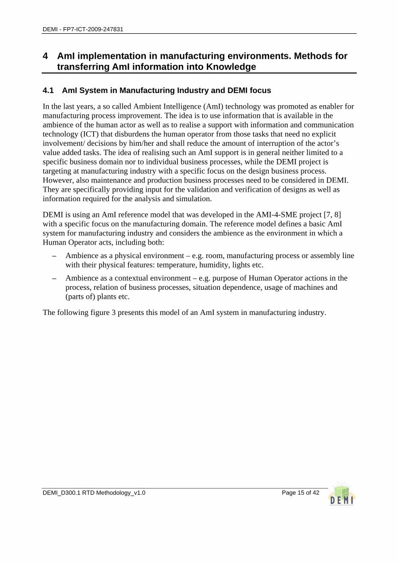
In the last years, a so called Ambient Intelligence (AmI) technology was promoted as enabler for manufacturing process improvement. The idea is to use information that is available in the ambience of the human actor as well as to realise a support with information and communication technology (ICT) that disburdens the human operator from those tasks that need no explicit involvement/ decisions by him/her and shall reduce the amount of interruption of the actor’s value added tasks. The idea of realising such an AmI support is in general neither limited to a specific business domain nor to individual business processes, while the DEMI project is targeting at manufacturing industry with a specific focus on the design business process. However, also maintenance and production business processes need to be considered in DEMI. They are specifically providing input for the validation and verification of designs as well as information required for the analysis and simulation.
DEMI is using an AmI reference model that was developed in the AMI-4-SME project [7, 8] with a specific focus on the manufacturing domain. The reference model defines a basic AmI system for manufacturing industry and considers the ambience as the environment in which a Human Operator acts, including both:
– Ambience as a physical environment – e.g. room, manufacturing process or assembly line with their physical features: temperature, humidity, lights etc.
– Ambience as a contextual environment – e.g. purpose of Human Operator actions in the process, relation of business processes, situation dependence, usage of machines and (parts of) plants etc.
The following figure 3 presents this model of an AmI system in manufacturing industry.
DEMI - FP7-ICT-2009-247831
DEMI_D300.1 RTD Methodology_v1.0
Page 16 of 42
Figure 3: AmI-System in manufacturing industry [AMI-4-SME].
For being able to add the related “intelligence” to the AmI system the knowledge about the human operator itself (e.g. preferences, responsibilities, access rights), the ambience (i.e. environment, process, plant and machine) and the context (e.g. process status, quality, interrelationships) need to be generated. This knowledge is generated, by observing the explicit/ implicit inputs as well as other existing knowledge and information.
Subsequently, the AmI-System uses this knowledge to provide the related functionality in order to support the human actor in its interaction with the ambience. Output to the human operator and the ambience is generated by the so called “controller” part of the AmI-System. It explicitly provides information/knowledge to the human operator that is required to accomplish the business process. At the same time, the AmI-System shall intelligently interact with the ambience, taking into account both the environment and the process. The combination of the observer and controller part of the AmI-System is presented in the following figure 4.

DEMI - FP7-ICT-2009-247831
DEMI_D300.1 RTD Methodology_v1.0
Page 17 of 42
Figure 4: Observer and controller part of the AmI system.
The DEMI project adapted the AmI reference model with a focus on the product/ process design and aiming at the realisation of functionalities to generally improve the energy efficiency. This is further explained for the observer and the controller part of an AmI-System, by structuring the description with respect to input and output relationships.
• Information and knowledge acquisition – observer part:
– Designer initiating and operating the business process DEMI is focusing on:
Explicitly providing knowledge with respect to his/her experience on the design procedure itself and with respect to problem solving. Past experience can be formulated as rules as well as used for the identification of previous designs.
Implicitly preferring certain design alternatives, solution strategies and combinations of objects (e.g. tools, machines, materials) for a specific kind of design challenge.
Design related statistics with respect to time, effort and problems of a product/ process design that can be put into relation with the energy efficiency and the productivity of a designed product/ process as well as taking into account the design purpose (e.g. design for series or single production, feasibility study).
– Maintenance staff maintaining products/ processes after start of their operative life:
Explicitly providing knowledge about corrective maintenance w.r.t. products/ processes. They can identify problems w.r.t. product, tool, machine and/ or process

DEMI - FP7-ICT-2009-247831
DEMI_D300.1 RTD Methodology_v1.0
Page 18 of 42
combinations as well as most appropriate combinations. Aggregating information/ knowledge that was measured/ analysed, also highlighting error cause relationships.
Identifying/referencing additional information/ knowledge that is available in other systems or databases in the scope of measurement cycles.
Measuring energy related parameters with respect to the products/ processes that were designed.
– Production staff operating the machines, equipment and processes:
Regularly updating the machine, equipment and process related data, accompanying to their daily work and based on the production orders to be accomplished. Measuring and assessing the product/ process quality as well as scrap rates.
Implicitly generating production related details like machine set-up times, tool change time, productivity, tool life. Also identifying product/ process related problems with their error messages.
– Other existing systems using and generating information and knowledge (e.g. CAD, PDC, PDM/PLM, PPC):
Generating information/ knowledge in relation to the product/process that needs to be designed. This includes specific physical information (e.g. geometry, selected materials) and context related information assuming specific combinations or settings (e.g. expected production cycle times, envisaged level of quality, effort required for design/ set-up/ maintenance).
Implicitly generating information/ knowledge about the different individuals that need to be involved as well as how much effort is required to generate a specific design (i.e. enabling to balance the design efforts to be invested and the energy efficiency to be achieved). Also providing information to calculate the costs for a specific product/ process design accordingly.
– Machines and equipment used for the production or are using/ applying the process:
Depending on the installed machines and related equipment, they can automatically or semi-automatically generate production/ process related data w.r.t. a specific design. This could already enable to automatically identify the context with respect to the manufacturing process (e.g. batch size, performance/ quality requested, type of production) as well as to identify the relationships between different measurement values (e.g. performance data in relation to the process cycle, material, detailed product characteristics, costs).
– Manufacturing environment surrounding the design, production, maintenance processes:
The overall ambience in production/ design is closely connected with the current design/ manufacturing context and related implication, considering e.g. current workload, time pressure, capacity utilisation, degree of automation, sickness absence rate, planned batch sizes, availability of supplies.
At the same time, the manufacturing environment is limited with respect to its basic characteristics, like flexibility to change, available energy bandwidth, energy constraints, available types of energy, contribution margin, degree of connection with the means of transportation, available supplies.
DEMI - FP7-ICT-2009-247831
DEMI_D300.1 RTD Methodology_v1.0
Page 19 of 42
The specific environments are also limited with respect to their capability for ICT based integration. This directly enables or limits the automatic gathering of information generated in the ambience.
• Intelligent interaction of the AmI-system to support the human operator with information to facilitate the design with respect to energy efficient manufacturing installations – controller part:
– Knowledge Provision to human operator:
Provision of information/ knowledge to select an appropriate design alternative w.r.t. the energy efficiency.
Outlining dependencies and consequences of potential design alternatives and reference cases.
Assisting the design with problem solving strategies that are considering the context and potential alternatives for an energy efficient design.
Facilitating the set-up of appropriate product/process and manufacturing ambience combinations (e.g. machines, equipment).
– Intelligent interaction with environment related ambience:
Due to the focus on the design, there is not a focus on the direct control of the environment related ambience. The ambience of the designer can be considered as a quite stable and office type environment that generally does not require the intelligent interaction with an AmI-System in relation to energy efficiency.
Only the measurement related processes in maintenance and production might benefit from an AmI-System, by providing information that could facilitate the adoption of the environment (e.g. changing the environmental setting, initiating transport capacities, giving access to existing systems). The direct feedback to the production planning and control functionalities shall not be covered by the DEMI approach as this would address a completely different problem domain.
– Intelligent interaction with process related ambience:
When considering the existing design systems as part of the process related ambience, there will be a direct feedback from the AmI-System to select most appropriate alternatives of product/process designs. This could be based on previous design cases as well as on analysed alternatives.
The measurement set-up will provide defined settings for using the machines, equipment and parts of the plant. This considers an optimal combination of the process related ambience to use an energy efficient configuration of the installation.
4.2 DEMI ICT Components in the AmI enhanced Manufacturing Environment
The envisaged AmI-System is not an additional ICT dimension in the DEMI project, it is considered as an integral part of the RTD work – the DEMI ICT components themselves are the key to realise such an AmI-System for increasing the energy efficiency in design. The main information exchange with the human operator as well as with the ambience (see figure ) shall be realised. The key objective is to make such data/ knowledge available that is required for
DEMI - FP7-ICT-2009-247831
DEMI_D300.1 RTD Methodology_v1.0
Page 20 of 42
increasing the energy efficiency. At the same time it needs to be assured to not increase the design complexity.
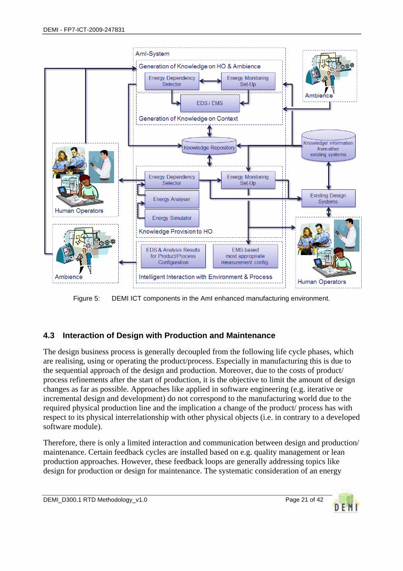
The AmI-System reference model is highly user centric and the support of the human operator is the main driver for designing the envisaged functionalities. Therefore, from a DEMI point of view, especially the Energy Monitoring Set-up (EMS) and the Energy Dependency Selector (EDS) components are representing a the key components for realising an intelligent interaction. The Energy Analyser (EA) and the Energy Simulator (ES) could be considered as AmI-System internal functionalities for generating information/ knowledge that is required by the human operator to make energy efficiency related decisions.
Whether it is an explicit or an implicit in-/ output, the gathering and provision of information requires a certain infrastructure installation in the ambience. Measurement systems, sensors, interfaces to existing systems as well as interfaces for the human operator need to be available. Such an infrastructure is generally quite individual for a manufacturing organisation. This will be experienced in the three DEMI business cases at Volkswagen, Estanda and MBAS. Each is realising an individual test bed that is customised to the available infrastructure and in accordance to the related design problems and questions.
The following figure 5 is structuring the DEMI ICT components based on the AmI-System reference model, and identifies the reusable elements and the manufacturing test bed related elements that are specific to the different business cases.
DEMI - FP7-ICT-2009-247831
DEMI_D300.1 RTD Methodology_v1.0
Page 21 of 42
Figure 5: DEMI ICT components in the AmI enhanced manufacturing environment.
4.3 Interaction of Design with Production and Maintenance
The design business process is generally decoupled from the following life cycle phases, which are realising, using or operating the product/process. Especially in manufacturing this is due to the sequential approach of the design and production. Moreover, due to the costs of product/ process refinements after the start of production, it is the objective to limit the amount of design changes as far as possible. Approaches like applied in software engineering (e.g. iterative or incremental design and development) do not correspond to the manufacturing world due to the required physical production line and the implication a change of the product/ process has with respect to its physical interrelationship with other physical objects (i.e. in contrary to a developed software module).
Therefore, there is only a limited interaction and communication between design and production/ maintenance. Certain feedback cycles are installed based on e.g. quality management or lean production approaches. However, these feedback loops are generally addressing topics like design for production or design for maintenance. The systematic consideration of an energy
DEMI - FP7-ICT-2009-247831
DEMI_D300.1 RTD Methodology_v1.0
Page 22 of 42
efficiency dimension cannot be assumed. On top of that, the measurement and analysis of energy consumption is not yet very well developed in the manufacturing industry.
Therefore, DEMI proposes the idea to directly couple the different product/ process life-cycle phases with the energy efficiency related monitoring, based on the usage of the Energy Monitoring Set-up component:
– Design business process: It is formulating measurement requirements as result of the design work. As soon as the designer identifies a potential question that cannot be answered based on the design data, the request is forwarded to a department that takes care for the energy related measurement. To answer specific design and energy efficiency related questions, the designer can access measurement results of previous designs. Data can be aggregated and indicators can be calculated for specific types of objects that are under design.
– Product/ Process Realisation: This business process is translating the design into the physical objects and layout for production and process operation, while the key characteristics of the product/ process were already determined by the design. However, within this phase the final maintenance requirements can be summarised based on the design and the final decisions made during the product/ process realisation.
– Production/ Process Operation: This is the daily task of operating the processes and to produce the final products. This added-value task has generally first priority. The planning of maintenance and measurement needs to optimally coordinate their activities with this task to reduce the interruption of value-added tasks at the minimum.
– Maintenance & Monitoring: Finally, the maintenance and monitoring is carried out in the organisation. The idea is not to limit the combination of monitoring with maintenance to a specific type of maintenance activity, but to generally consider the combination as it fits in the daily tasks. It is generally expected that the monitoring is mainly planned in combination with regularly planned maintenance cycles (i.e. predictive and preventive maintenance). However, it could also be combined with e.g. corrective and condition-based maintenance. The EMS would specifically provide the details for initiating and realising the measurement tasks.
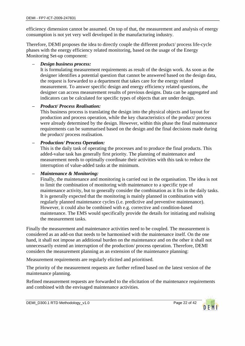
Finally the measurement and maintenance activities need to be coupled. The measurement is considered as an add-on that needs to be harmonised with the maintenance itself. On the one hand, it shall not impose an additional burden on the maintenance and on the other it shall not unnecessarily extend an interruption of the production/ process operation. Therefore, DEMI considers the measurement planning as an extension of the maintenance planning:
Measurement requirements are regularly elicited and prioritised.
The priority of the measurement requests are further refined based on the latest version of the maintenance planning.
Refined measurement requests are forwarded to the elicitation of the maintenance requirements and combined with the envisaged maintenance activities.
DEMI - FP7-ICT-2009-247831
DEMI_D300.1 RTD Methodology_v1.0
Page 23 of 42
The maintenance plan is prepared based on the maintenance and measurement requirements.
Based on the maintenance and measurement planning, the final work plan is prepared and managed. The control will also react to short term changes in production/ process operation as well as with respect to and prioritised requests from measurement/ maintenance planning.
The measurement data processing is realised as a follow-up activity as soon as the results are available.
This integrated view on the realisation of the energy monitoring in relation to the product/ process life-cycle is presented in the following figure 6.
Figure 6: Energy Monitoring Set-up in relation to the product/process life-cycle.
4.4 Usage of Collaborative Working Environment Principles by Design and related Manufacturing Activities
Key component in the DEMI project to couple the design questions with the monitoring and maintenance is the energy monitoring set-up. The energy dependency selector can be considered as the module to support the designer within the design context with respect to energy efficiency related questions. Therefore, in combination with the EA and ES, the EDS also supports the identification of energy efficiency related questions that cannot be answered directly and require
DEMI - FP7-ICT-2009-247831
DEMI_D300.1 RTD Methodology_v1.0
Page 24 of 42
further analysis of the product/ process. Those questions are serving as input for the EMS and are triggering the collaboration of design and representatives from other life-cycle phases.
However, as soon as energy efficiency related questions are identified, they need to be assigned to the corresponding design and product/process context. This is required for being able to set-up the appropriate monitoring environment and to properly communicate the question. The questions/ requirements need also to be exchanged between different departments, teams and/or employees. The usage of collaborative working environment principles shall facilitate this cooperation and help to coordinate the related workflow. Main collaborative working principles that were considered for this collaboration are listed in the following:
– Collaboration traceability: Tracking the collaborative activities that are taking place between different life-cycle phases as well as between different actors in a life-cycle phase. The objective is to track additional knowledge that could be used for the planning and realisation of monitoring as well as for the later analysis of product/ process related knowledge. The actions of the users would be generally recorded with respect to the design related question/ monitoring requirement without requiring users to explicitly document their actions while at the same time respecting privacy and IPR issues. This information can enable an enhanced search and grouping of monitoring requirements as input for the measurement planning and control.
– Resource discovery: Identifying potential actors that could be involved to take care for the energy efficiency analysis. The actors can be discovered based on their expertise, location and availability. Also the infrastructure required with respect to the monitoring requirements can be taken into account to assure that the identified resources will be able to react accordingly.
– Decision support: The EDS is the main component for providing an energy efficiency related decision support. However, to set-up the monitoring activities, the related schedule and infrastructure need to be defined. To make the related decisions, the employees need further information with respect to the current schedule and the most appropriate combinations of equipment. Therefore, EMS offers information to support those decisions.
– Team composition: Identifying all those potential members of a team that is required to accomplish the related requirements. The team composition is realised for both the general identification of type of team members that need to be involved and the identification of specific team members that will be listed in the work orders.
– Product/ process knowledge provision: The provision of product/process related knowledge is already a kernel functionality of the DEMI ICT components. On top of this, extended services are considered as specific functionalities that can be implemented for a business case to provide highly individual functionalities. Such extended services can specifically provide a defined set knowledge like key energy efficiency indicators that are derived from measured parameters. Therefore, the realisation of feedback loops between different collaborating groups can be

DEMI - FP7-ICT-2009-247831
DEMI_D300.1 RTD Methodology_v1.0
Page 25 of 42
facilitated when pro-actively providing such knowledge as soon as it is available, not requiring an explicit request by a designer.
The following figure 7 is presenting those collaborative working environment principles in relation to the product/process life-cycle and the integrated maintenance and measurement activities.
Figure 7: Basic collaborative working environment principles to support the interaction of related
stakeholders.
As presented in figure 7, specifically the collaboration traceability and the product/process knowledge provision are considered as principles that are facilitating the collaboration of the design business process and the maintenance/ measurement activities.
4.5 AmI based Acquisition of Knowledge
The AmI system model identifies four channels that are used by the AmI system to acquire inputs: (1) explicit inputs from HO, (2) implicit inputs from HO, (3) ambience inputs from the environment and (4) ambience inputs from the process/ plant/ machine. Each channel need to be considered by the EMS, since all of them could provide relevant knowledge as input for the energy efficiency related analysis. The following table 1 is listing specific AmI related ways for the acquisition of knowledge (i.e. AmI features) and lists relevant technologies that could provide the potentials to realise the collection of information. Table 1: AmI based acquisition of knowledge from ambience and human operator.
AmI Features Related Technologies Key examples for DEMI
Explicit inputs from HO to the AmI system
• Natural HO inputs: i.e. spoken language, handwriting, touch screen, gesture, gaze to forward unstructured information and
• Digital pen, touch screen, handwriting recognition, speech recognition
• Time measurement equipment to measure cycle phases

DEMI - FP7-ICT-2009-247831
DEMI_D300.1 RTD Methodology_v1.0
Page 26 of 42
AmI Features Related Technologies Key examples for DEMI
observation to the AmI System. • Simultaneous exchange of information
over multiple channels at different levels of abstraction, e.g. speech, natural language, gesture, animation, non-speech audio.
• Provision of observations and experiences of the HO on status and problems in process and environment.
• Request for data without knowing specific file names, location or format.
• Automated user identification and authentication/ authorisation.
• Forwarding unstructured communication needs with collaborating partners.
• Inputs during collaborative work. • Activity oriented interaction (user needs
not to think on applications but on his activity).
• Mobile or nomadic access.
technologies. • Wireless handheld devices
like PDAs, tablet PC or mobile phones.
• Wearable input devices like e.g. key boards sewed in cloth, data glove etc.
• Biometric authentication and authorisation technologies.
• Video conference technologies.
• Mobile communication and interoperability technologies (Bluetooth, WLAN, GPRS, UMTS etc.).
• Collaborative working environment.
• Network interoperability and ubiquitous communication.
• Handheld devices to manually gather measurement results
• CAM equipment to gather user input
• General computer interfaces to gather information in relation to the interaction with the ambience.
Implicit inputs from HO to the AmI System
• Assessment of physiological data of the HO to supervise his health and performance status.
• Assessment of physiological data of the HO as reference for the control of environmental conditions of the HO.
• Identification of the location and attitude of the HO.
• Tracking of movements of the HO. • Automated user identification and
authentication and authorisation. • Imprecise HO inputs as combinations of
body posture, gestures and gaze. • Mobile access.
• RFID tags, authentication and position identification also covering RFID reader and writer.
• Biometric authentication and authorisation technologies.
• Wearable ambient sensors for the assessment of physiological data.
• Camera systems and GPS technologies for movement tracking and localisation identification.
• Sensor systems for motion and attitude control, e.g. gyros, accelerometers etc.
• Mobile ambient sensor networks.
• Identification of users based on their usage of applications, devices and equipment
• Tracking of design and measurement efforts based on time recording systems
•
Ambience (environment) inputs to the AmI System
• Information on basic environmental conditions like temperature, humidity vibration etc.
• Information on spatial situation and constraints in respect to the HO activity relevant environment.
• Information on hazardous changes in the
• Wireless networks of basic ambient sensor like temperature, humidity vibration sensors.
• Localisation and identification of “things” by camera systems for spatial
• Sensors to measure the temperature and humidity of the manufacturing ambience and infrastructure
• Cameras to record and
DEMI - FP7-ICT-2009-247831
DEMI_D300.1 RTD Methodology_v1.0
Page 27 of 42
AmI Features Related Technologies Key examples for DEMI
environment critical for HO, but unaware to HO.
surveillance and detection of changes.
• Network interoperability and ubiquitous communication (WLAN, GPRS, UMTS technologies).
identify the location of objects in the ambience
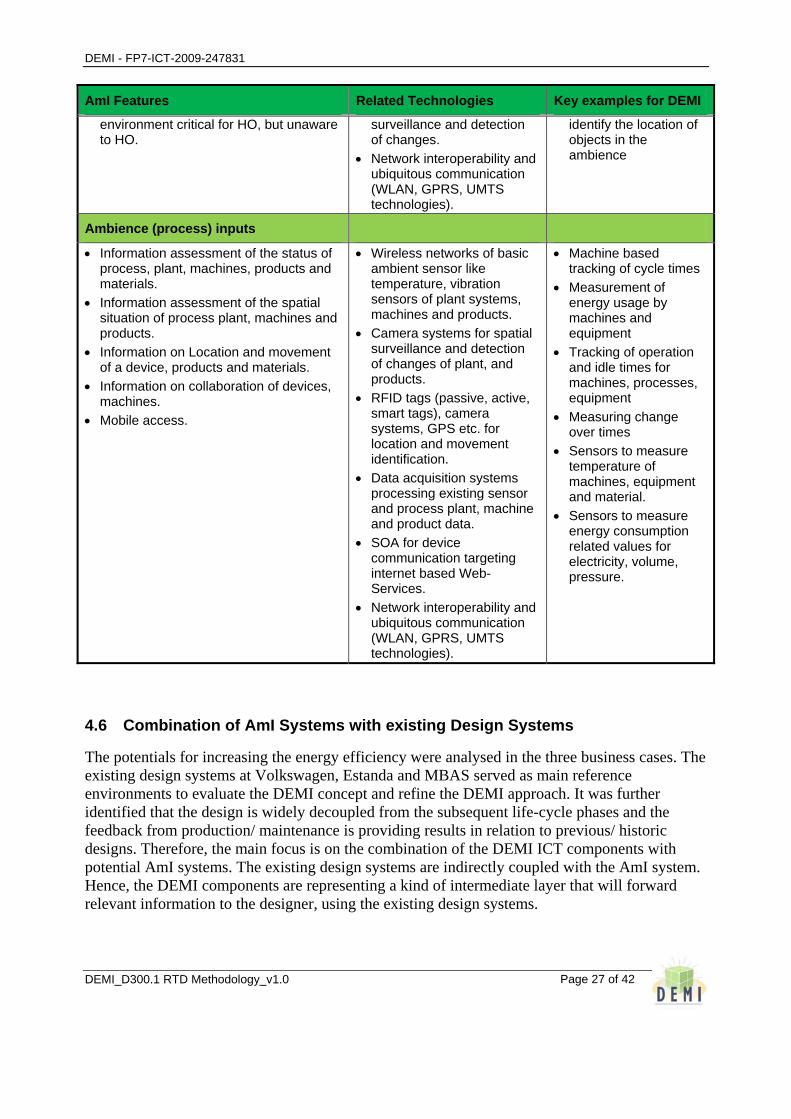
Ambience (process) inputs
• Information assessment of the status of process, plant, machines, products and materials.
• Information assessment of the spatial situation of process plant, machines and products.
• Information on Location and movement of a device, products and materials.
• Information on collaboration of devices, machines.
• Mobile access.
• Wireless networks of basic ambient sensor like temperature, vibration sensors of plant systems, machines and products.
• Camera systems for spatial surveillance and detection of changes of plant, and products.
• RFID tags (passive, active, smart tags), camera systems, GPS etc. for location and movement identification.
• Data acquisition systems processing existing sensor and process plant, machine and product data.
• SOA for device communication targeting internet based Web-Services.
• Network interoperability and ubiquitous communication (WLAN, GPRS, UMTS technologies).
• Machine based tracking of cycle times
• Measurement of energy usage by machines and equipment
• Tracking of operation and idle times for machines, processes, equipment
• Measuring change over times
• Sensors to measure temperature of machines, equipment and material.
• Sensors to measure energy consumption related values for electricity, volume, pressure.
4.6 Combination of AmI Systems with existing Design Systems
The potentials for increasing the energy efficiency were analysed in the three business cases. The existing design systems at Volkswagen, Estanda and MBAS served as main reference environments to evaluate the DEMI concept and refine the DEMI approach. It was further identified that the design is widely decoupled from the subsequent life-cycle phases and the feedback from production/ maintenance is providing results in relation to previous/ historic designs. Therefore, the main focus is on the combination of the DEMI ICT components with potential AmI systems. The existing design systems are indirectly coupled with the AmI system. Hence, the DEMI components are representing a kind of intermediate layer that will forward relevant information to the designer, using the existing design systems.

DEMI - FP7-ICT-2009-247831
DEMI_D300.1 RTD Methodology_v1.0
Page 28 of 42
However, a basic strategy for integrating the existing design systems with the DEMI ICT components is elaborated. This integration is abstracting the integration of the AmI systems and will allow to forward input to the design systems as well as to use design system related information within the DEMI ICT components.
A further detailed approach for integrating the DEMI ICT components with the existing design systems will be elaborated in the project and further specified in the DEMI full prototype requirement specification document.

DEMI - FP7-ICT-2009-247831
DEMI_D300.1 RTD Methodology_v1.0
Page 29 of 42
5 Manufacturing process optimisation
A manufacturing process can often be defined as raw materials going through a chain of treatments leading to final products. The design of these treatments can vary as long as the products meet their specifications. Manufacturing process optimization is about finding the optimal treatment chain, configuration, according to some criteria such as economy (LCC, RoI, BEP) and/or energy consumption. The optimal configuration involves choice of equipment, processing phases, and their set-points in a wide sense.
The way a process can be described has been standardized as part of the project, see below.
An optimization task assumes that the degrees of freedom of the optimizer are specified, as well as its boundaries and constraints. This can be based on specifications from a user interface. The optimization task is implemented in the project by the Energy Analyser module, EA.
As the optimizer searches for the optimum it needs to evaluate each candidate configuration in terms of its energy consumption and LCC. Energy consumption is a complex sub-task, and is performed, on-the-fly, by simulation, in the project implemented by the Energy Simulator, ES, described below. The LCC is based on costs and economic assumptions, in a 10 years perspective.
The simulation is made to fit a typical production pattern. This can be based on an audit at the production site, if available. A module for this was implemented in the project and called the Energy Monitoring Setup, EMS.
It is obvious that manufacturing process optimization involves much data, preferably stored in a database, in the project we use an SQL database called the Knowledge Repository module, KR.
Optimization of a manufacturing process involves a high degree of user interaction, used for initial process configuration, specification, optimization objectives, etc. This is implemented in the project via the Energy Dependency Selector module, EDS.
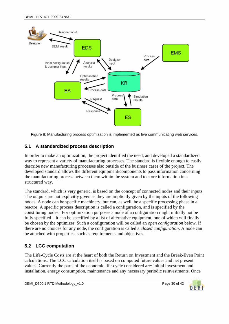
The different modules: EDS, EMS, EA, KR, and ES are implemented as web-services in order to facilitate development and maintenance. The web services can be placed on the Intranet inside a firewall or on different computers accessible over the Internet. Most of the data exchange goes via KR.
DEMI - FP7-ICT-2009-247831
DEMI_D300.1 RTD Methodology_v1.0
Page 30 of 42
Figure 8: Manufacturing process optimization is implemented as five communicating web services.
5.1 A standardized process description
In order to make an optimization, the project identified the need, and developed a standardized way to represent a variety of manufacturing processes. The standard is flexible enough to easily describe new manufacturing processes also outside of the business cases of the project. The developed standard allows the different equipment/components to pass information concerning the manufacturing process between them within the system and to store information in a structured way.
The standard, which is very generic, is based on the concept of connected nodes and their inputs. The outputs are not explicitly given as they are implicitly given by the inputs of the following nodes. A node can be specific machinery, but can, as well, be a specific processing phase in a reactor. A specific process description is called a configuration, and is specified by the constituting nodes. For optimization purposes a node of a configuration might initially not be fully specified – it can be specified by a list of alternative equipment, one of which will finally be chosen by the optimizer. Such a configuration will be called an open configuration below. If there are no choices for any node, the configuration is called a closed configuration. A node can be attached with properties, such as requirements and objectives.
5.2 LCC computation
The Life-Cycle Costs are at the heart of both the Return on Investment and the Break-Even Point calculations. The LCC calculation itself is based on computed future values and net present values. Currently the parts of the economic life-cycle considered are: initial investment and installation, energy consumption, maintenance and any necessary periodic reinvestments. Once

DEMI - FP7-ICT-2009-247831
DEMI_D300.1 RTD Methodology_v1.0
Page 31 of 42
again it is necessary for the user to contribute with information such as cost of capital, inflation rate and energy prices. In order to evaluate a configuration according to return on investment and break-even point there is a need for the user to input economic data concerning the old process, if any, in order to compute a LCC to compare with.
As normal in the case of life cycle cost calculations the bases of this analysis are future cost and present value. These consider the effect of inflation and growth and well-being of the investing company.
5.3 Configuration optimization
From the optimisation variables and the limits given; the EA composes the optimizer objective function, its boundaries and constraints. The initial open configuration is picked up from the KR. The nodes with a list of choices are identified, leading to a number of integer permutations, and all these closed configurations are automatically constructed, n.b. there may still be degrees of freedom in the continuous process parameter settings. The configurations enter a constrained multi-objective optimisation routine processing the composed objective function. Each closed configuration is optimised to perform at its most efficient state. The performance is evaluated by the ES.
So far the list-choices in a node are considered as qualitative variables in the optimization, meaning that all choices have to be evaluated. Could the list-choices be ranked, it could be treated as a discrete variable by the optimizer, and the number of optimizer iterations could be reduced.
The results of the optimisation, based on the objectives chosen be the user, are returned to the user. Possibly the results could also consist a Pareto front plot showing the trade-off on performance when the importance of different objectives are changed.

DEMI - FP7-ICT-2009-247831
DEMI_D300.1 RTD Methodology_v1.0
Page 32 of 42
6 Manufacturing process modelling and energy use simulation
The Energy Simulator (ES) complements the Energy Analyzer (EA) with the functionality to calculate energy use depending on the various data/configuration or so called “what-if” scenarios, that are relevant alternatives for design optimization and are stored in the Knowlege Repository (KR). With such a link to the EA, the calculation of energy use in ES means that simulation/estimation of energy are at least suitable for ranking and optimisation purpose.
The ES results is based on simulation/estimation, which is driven by the configuration info provided by EA. The configuration and related data are treated as input, which is preprocesed for simulation/estimation purpose. After the calculations in the ES the results are postprocessed and transmited as responce info for the collection in the KR and future optimization in the EA.
Figure 9: Interaction between Analyzer (EA), KR and Simulator (ES).
The ES should be constructed as an on-the-fly setup and simulation service able to simulate new/innovative manufacturing system or process/product designs or/and estimate energy use for them. The modelling and simulation should be based on “block-based modelling” rather than on purely “process-based modelling”. It means that whole physical system or physical process is decomposed into sub-systems or sub-processes represented by independent blocks (one block for one sub-systems or sub-process).
Sub-system is a specific physical equipment (installation) providing process related output, which depends on process related boundary conditions and sub-system parameters (block parameters). Sub-system may be expressed using differential equations with specific parameters.
Sub-process is process variable (output of block) related to physical behaviour of other variables (inputs of block) with their weighting coefficients (block parameters). Sub-process may be expressed as a process variable or function dependent on other process variables.
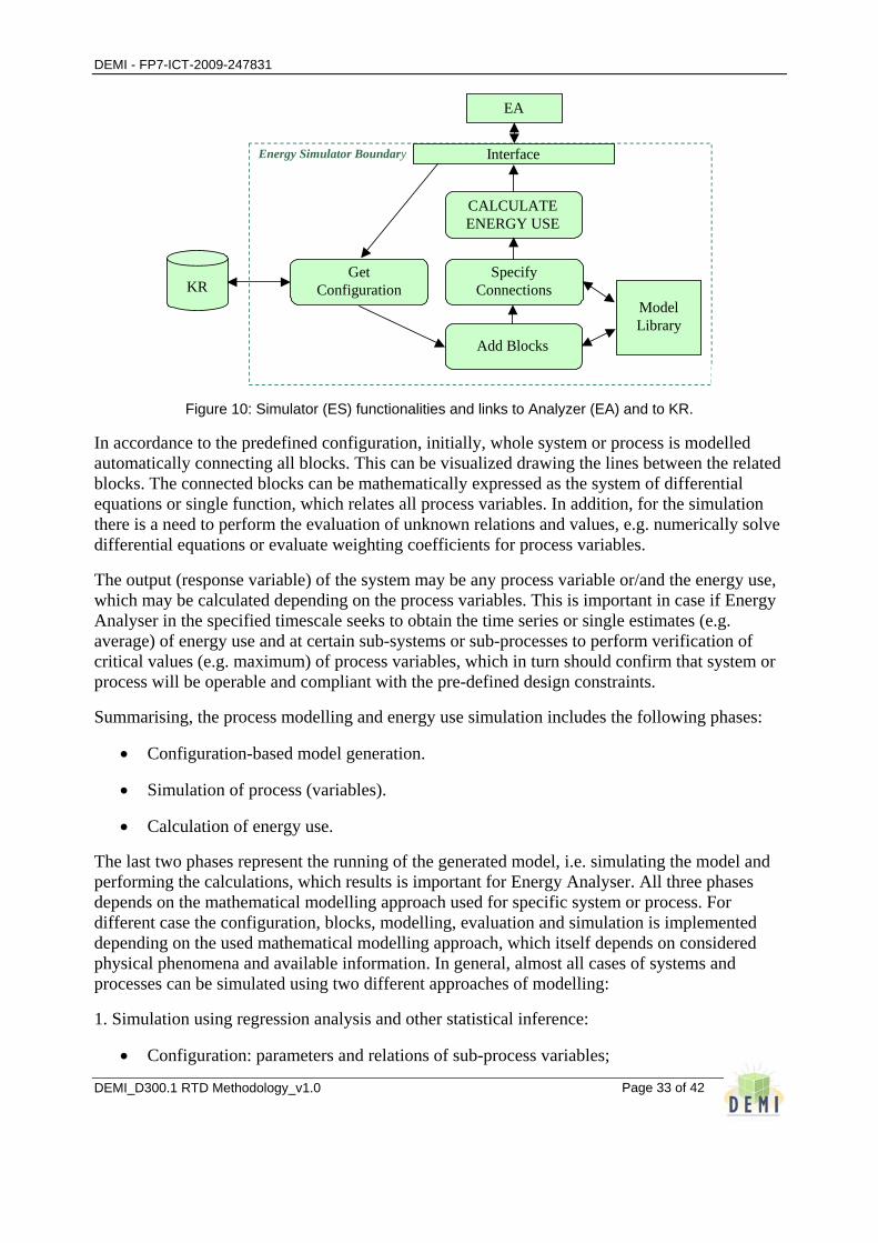
The list and relation of blocks together with blocks’ parameters gives the process configuration, which is the basic information for automatic model generation. This includes the following three ES functionalities: Get Configuration; Add Blocks and Specify Connections. The last two functionalities may be related to the application of Model Library, which includes predefined models of possible blocks, i.e. all models of sub-systems or sub-processes.
DEMI - FP7-ICT-2009-247831
DEMI_D300.1 RTD Methodology_v1.0
Page 33 of 42
CALCULATE ENERGY USE
Interface
EA
Model Library
Specify Connections
Add Blocks
Get Configuration KR
Energy Simulator Boundary
Figure 10: Simulator (ES) functionalities and links to Analyzer (EA) and to KR.
In accordance to the predefined configuration, initially, whole system or process is modelled automatically connecting all blocks. This can be visualized drawing the lines between the related blocks. The connected blocks can be mathematically expressed as the system of differential equations or single function, which relates all process variables. In addition, for the simulation there is a need to perform the evaluation of unknown relations and values, e.g. numerically solve differential equations or evaluate weighting coefficients for process variables.
The output (response variable) of the system may be any process variable or/and the energy use, which may be calculated depending on the process variables. This is important in case if Energy Analyser in the specified timescale seeks to obtain the time series or single estimates (e.g. average) of energy use and at certain sub-systems or sub-processes to perform verification of critical values (e.g. maximum) of process variables, which in turn should confirm that system or process will be operable and compliant with the pre-defined design constraints.
Summarising, the process modelling and energy use simulation includes the following phases:
• Configuration-based model generation.
• Simulation of process (variables).
• Calculation of energy use.
The last two phases represent the running of the generated model, i.e. simulating the model and performing the calculations, which results is important for Energy Analyser. All three phases depends on the mathematical modelling approach used for specific system or process. For different case the configuration, blocks, modelling, evaluation and simulation is implemented depending on the used mathematical modelling approach, which itself depends on considered physical phenomena and available information. In general, almost all cases of systems and processes can be simulated using two different approaches of modelling:
1. Simulation using regression analysis and other statistical inference:
• Configuration: parameters and relations of sub-process variables;
DEMI - FP7-ICT-2009-247831
DEMI_D300.1 RTD Methodology_v1.0
Page 34 of 42
• Blocks: sub-process variables with regression coefficients;
• Model: connection of variables to the regression function;
• Evaluation: finding the regression coefficients;
• Simulation: calculation of response variables;
2. Simulation using dynamic modelling with differential equations:
• Configuration: parameters and connections of sub-systems;
• Blocks: differential equations with specific parameters;
• Model: sub-systems connection to the whole system;
• Evaluation: solving the differential equations;
• Simulation: calculation of response variables;
As it was mentioned previously, the calculation of response variables can include the calculation of energy use, which depends on the process variables. The process variables may be the same as sub-process variables or may be expressed either as variables of functions or variables of equations, which express the relations (e.g. balance of mass and energy).
In case if energy use is directly calculated on the basis of configuration, which represents the process itself, then values of process variables are not simulated, but just expressed as a functions or given as time series. Separate blocks as functions or parts of time series may be related to the sub-processes or event some set points, which define these sub-processes. The modelling representing the whole process then automatically connects all sub-processes and is used for analysis of innovative design and calculation of energy use.
DEMI - FP7-ICT-2009-247831
DEMI_D300.1 RTD Methodology_v1.0
Page 35 of 42
7 Setting-up of an Eco-knowledge Repository for a specific industrial environment
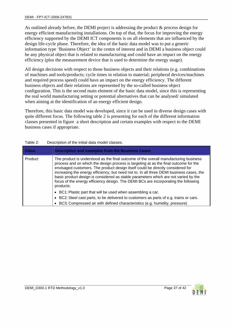
Key objective addressed by the DEMI project is to enable manufacturing organisations to reduce the energy consumption by improving the product and process design for AmI supported energy efficient manufacturing installations. This requires the acquisition and storage of data/ information and further generation of knowledge that will assist the human actors in making the design related decisions. DEMI aims at the realisation of a so-called Knowledge Repository that can be used for the compilation of such data.
For enabling a reuse of the project results beyond the three manufacturing business cases, DEMI is elaborating a knowledge repository that shall be applicable in diverse organisations and in different product and process context. The applicability shouldn’t be restricted to a specific manufacturing domain or an individual industrial environment.
However, the evaluation of the specification and involvement of the manufacturing end users as well as design system developers indicated a certain similarity of the relevant information models but also an amount of differences, especially with respect to detailed information items. The basic objective remained to elaborate a reusable model that is also applicable to cases beyond the DEMI project. Therefore, the following aspects served as reference for analysing the reusability potential and remaining usefulness for manufacturing business cases:
− Relevance – the knowledge repository shall contain the main classes of information that is required in the manufacturing environment context, classifying major groupings/ classes of information that are characterising main objects in relation to manufacturing products and processes.
− Level of detail – the level of detail shall be limited not imposing specific characteristics that are highly specific to a particular industrial environment, a specific design question or a particular design/ legacy system.
− Modularity – the knowledge repository shall be composed on defined classes that are enabling a kind of “opt in” and “opt out”. Also enabling the replacement of complete modules with adapted and domain specific modules.
− Adaptability – the developed knowledge repository shall not impose a specific overall architecture at the manufacturing site. It is not considered to develop a kind of universal interface as the interfacing in an organisation is generally quite specific.
− Purpose – the repository shall specifically focus on the compilation of main information groups for analysing and designing the energy efficiency dimension.
Moreover, the knowledge repository should contain data/knowledge elements that are not bound to a specific DEMI ICT component, but need to be shared between the DEMI ICT components and possibly also with additional external systems. It is not assumed that the knowledge repository will replace data bases of existing systems or databases/ data storage of all DEMI ICT
DEMI - FP7-ICT-2009-247831
DEMI_D300.1 RTD Methodology_v1.0
Page 36 of 42
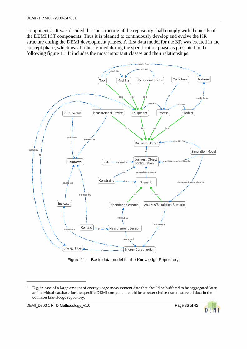
components1. It was decided that the structure of the repository shall comply with the needs of the DEMI ICT components. Thus it is planned to continuously develop and evolve the KR structure during the DEMI development phases. A first data model for the KR was created in the concept phase, which was further refined during the specification phase as presented in the following figure 11. It includes the most important classes and their relationships.
Figure 11: Basic data model for the Knowledge Repository.
1 E.g. in case of a large amount of energy usage measurement data that should be buffered to be aggregated later,
an individual database for the specific DEMI component could be a better choice than to store all data in the common knowledge repository.
DEMI - FP7-ICT-2009-247831
DEMI_D300.1 RTD Methodology_v1.0
Page 37 of 42
As outlined already before, the DEMI project is addressing the product & process design for energy efficient manufacturing installations. On top of that, the focus for improving the energy efficiency supported by the DEMI ICT components is on all elements that are influenced by the design life-cycle phase. Therefore, the idea of the basic data model was to put a generic information type ‘Business Object’ in the centre of interest and in DEMI a business object could be any physical object that is related to manufacturing and could have an impact on the energy efficiency (plus the measurement device that is used to determine the energy usage).
All design decisions with respect to those business objects and their relations (e.g. combinations of machines and tools/products; cycle times in relation to material; peripheral devices/machines and required process speed) could have an impact on the energy efficiency. The different business objects and their relations are represented by the so-called business object configuration. This is the second main element of the basic data model, since this is representing the real world manufacturing setting or potential alternatives that can be analysed/ simulated when aiming at the identification of an energy efficient design.
Therefore, this basic data model was developed, since it can be used in diverse design cases with quite different focus. The following table 2 is presenting for each of the different information classes presented in figure a short description and certain examples with respect to the DEMI business cases if appropriate.
Table 2: Description of the initial data model classes.
Class Description and examples from the Business Cases
Product The product is understood as the final outcome of the overall manufacturing business process and on which the design process is targeting at as the final outcome for the envisaged customers. The product design itself could be directly considered for increasing the energy efficiency, but need not to. In all three DEMI business cases, the basic product design is considered as stable parameters which are not varied by the focus of the energy efficiency design. The DEMI BCs are incorporating the following products: • BC1: Plastic part that will be used when assembling a car. • BC2: Steel cast parts, to be delivered to customers as parts of e.g. trains or cars. • BC3: Compressed air with defined characteristics (e.g. humidity, pressure)
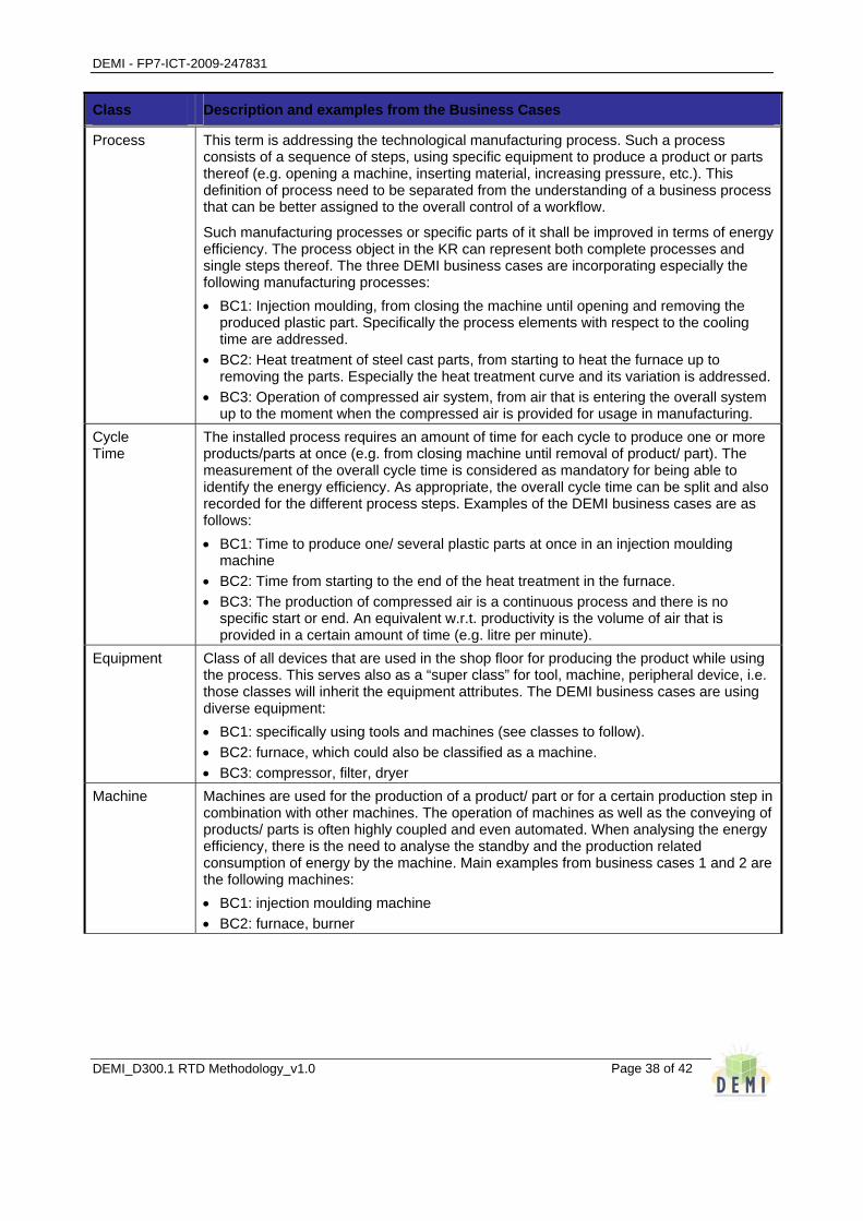
DEMI - FP7-ICT-2009-247831
DEMI_D300.1 RTD Methodology_v1.0
Page 38 of 42
Class Description and examples from the Business Cases
Process This term is addressing the technological manufacturing process. Such a process consists of a sequence of steps, using specific equipment to produce a product or parts thereof (e.g. opening a machine, inserting material, increasing pressure, etc.). This definition of process need to be separated from the understanding of a business process that can be better assigned to the overall control of a workflow.
Such manufacturing processes or specific parts of it shall be improved in terms of energy efficiency. The process object in the KR can represent both complete processes and single steps thereof. The three DEMI business cases are incorporating especially the following manufacturing processes: • BC1: Injection moulding, from closing the machine until opening and removing the
produced plastic part. Specifically the process elements with respect to the cooling time are addressed.
• BC2: Heat treatment of steel cast parts, from starting to heat the furnace up to removing the parts. Especially the heat treatment curve and its variation is addressed.
• BC3: Operation of compressed air system, from air that is entering the overall system up to the moment when the compressed air is provided for usage in manufacturing.
Cycle Time
The installed process requires an amount of time for each cycle to produce one or more products/parts at once (e.g. from closing machine until removal of product/ part). The measurement of the overall cycle time is considered as mandatory for being able to identify the energy efficiency. As appropriate, the overall cycle time can be split and also recorded for the different process steps. Examples of the DEMI business cases are as follows: • BC1: Time to produce one/ several plastic parts at once in an injection moulding
machine • BC2: Time from starting to the end of the heat treatment in the furnace. • BC3: The production of compressed air is a continuous process and there is no
specific start or end. An equivalent w.r.t. productivity is the volume of air that is provided in a certain amount of time (e.g. litre per minute).
Equipment Class of all devices that are used in the shop floor for producing the product while using the process. This serves also as a “super class” for tool, machine, peripheral device, i.e. those classes will inherit the equipment attributes. The DEMI business cases are using diverse equipment: • BC1: specifically using tools and machines (see classes to follow). • BC2: furnace, which could also be classified as a machine. • BC3: compressor, filter, dryer
Machine Machines are used for the production of a product/ part or for a certain production step in combination with other machines. The operation of machines as well as the conveying of products/ parts is often highly coupled and even automated. When analysing the energy efficiency, there is the need to analyse the standby and the production related consumption of energy by the machine. Main examples from business cases 1 and 2 are the following machines: • BC1: injection moulding machine • BC2: furnace, burner
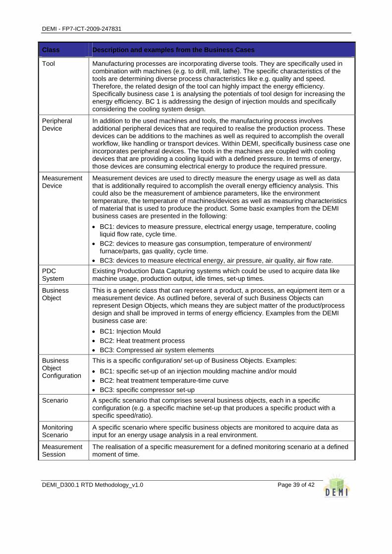
DEMI - FP7-ICT-2009-247831
DEMI_D300.1 RTD Methodology_v1.0
Page 39 of 42
Class Description and examples from the Business Cases
Tool Manufacturing processes are incorporating diverse tools. They are specifically used in combination with machines (e.g. to drill, mill, lathe). The specific characteristics of the tools are determining diverse process characteristics like e.g. quality and speed. Therefore, the related design of the tool can highly impact the energy efficiency. Specifically business case 1 is analysing the potentials of tool design for increasing the energy efficiency. BC 1 is addressing the design of injection moulds and specifically considering the cooling system design.
Peripheral Device
In addition to the used machines and tools, the manufacturing process involves additional peripheral devices that are required to realise the production process. These devices can be additions to the machines as well as required to accomplish the overall workflow, like handling or transport devices. Within DEMI, specifically business case one incorporates peripheral devices. The tools in the machines are coupled with cooling devices that are providing a cooling liquid with a defined pressure. In terms of energy, those devices are consuming electrical energy to produce the required pressure.
Measurement Device
Measurement devices are used to directly measure the energy usage as well as data that is additionally required to accomplish the overall energy efficiency analysis. This could also be the measurement of ambience parameters, like the environment temperature, the temperature of machines/devices as well as measuring characteristics of material that is used to produce the product. Some basic examples from the DEMI business cases are presented in the following: • BC1: devices to measure pressure, electrical energy usage, temperature, cooling
liquid flow rate, cycle time. • BC2: devices to measure gas consumption, temperature of environment/
furnace/parts, gas quality, cycle time. • BC3: devices to measure electrical energy, air pressure, air quality, air flow rate.
PDC System
Existing Production Data Capturing systems which could be used to acquire data like machine usage, production output, idle times, set-up times.
Business Object
This is a generic class that can represent a product, a process, an equipment item or a measurement device. As outlined before, several of such Business Objects can represent Design Objects, which means they are subject matter of the product/process design and shall be improved in terms of energy efficiency. Examples from the DEMI business case are: • BC1: Injection Mould • BC2: Heat treatment process • BC3: Compressed air system elements
Business Object Configuration
This is a specific configuration/ set-up of Business Objects. Examples: • BC1: specific set-up of an injection moulding machine and/or mould • BC2: heat treatment temperature-time curve • BC3: specific compressor set-up
Scenario A specific scenario that comprises several business objects, each in a specific configuration (e.g. a specific machine set-up that produces a specific product with a specific speed/ratio).
Monitoring Scenario
A specific scenario where specific business objects are monitored to acquire data as input for an energy usage analysis in a real environment.
Measurement Session
The realisation of a specific measurement for a defined monitoring scenario at a defined moment of time.
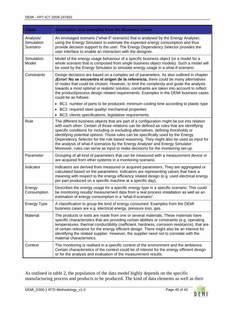
DEMI - FP7-ICT-2009-247831
DEMI_D300.1 RTD Methodology_v1.0
Page 40 of 42
Class Description and examples from the Business Cases
Analysis/ Simulation Scenario
An envisaged scenario (“what-if”-scenario) that is analysed by the Energy Analyser, using the Energy Simulator to estimate the expected energy consumption and thus provide decision support to the user. The Energy Dependency Selector provides the user interface to enable an interaction with the designer.
Simulation Model
Model of the energy usage behaviour of a specific business object (or a model for a whole scenario that is composed from single business object models). Such a model will be used by the Energy Simulator to simulate energy usage in a what-if-scenario.
Constraints Design decisions are based on a complex set of parameters. As also outlined in chapter ¡Error! No se encuentra el origen de la referencia. there could be many alternatives of nodes that could be chosen. However, to limit the complexity and guide the analysis towards a most optimal or realistic solution, constraints are taken into account to reflect the product/process design related requirements. Examples in the DEMI business cases could be as follows: • BC1: number of parts to be produced; minimum cooling time according to plastic type • BC2: required steel quality/ mechanical properties • BC3: clients specifications, legislative requirements
Rule The different business objects that are part of a configuration might be put into relation with each other. Certain of those relations can be defined as rules that are identifying specific conditions for including or excluding alternatives, defining thresholds or identifying potential options. Those rules can be specifically used by the Energy Dependency Selector for the rule based reasoning. They might also be used as input for the analysis of what-if scenarios by the Energy Analyser and Energy Simulator. Moreover, rules can serve as input to make decisions for the monitoring set-up.
Parameter Grouping of all kind of parameters that can be measured with a measurement device or are acquired from other systems in a monitoring scenario.
Indicator Indicators are derived from measured or acquired parameters. They are aggregated or calculated based on the parameters. Indicators are representing values that have a meaning with respect to the energy efficiency related design (e.g. used electrical energy per part produced on a specific machine at a specific day).
Energy Consumption
Describes the energy usage for a specific energy type in a specific scenario. This could be monitoring results/ measurement data from a real process installation as well as an estimation of energy consumption in a “what-if-scenario”.
Energy Type A classification to group the kind of energy consumed. Examples from the DEMI business cases are e.g. electrical energy, pressure loss, gas.
Material The products or tools are made from one or several materials. These materials have specific characteristics that are providing certain abilities or constraints (e.g. operating temperatures, thermal conductibility coefficient, hardness, corrosion resistance), that are of certain relevance for the energy efficient design. There might also be an interest for identifying the related supplier. However, the supplier need not to correlate with the material characteristics.
Context The monitoring is realised in a specific context of the environment and the ambience. Certain characteristics of the context could be of interest for the energy efficient design or for the analysis and evaluation of the measurement results.
As outlined in table 2, the population of the data model highly depends on the specific manufacturing process and products to be produced. The kind of data elements as well as their

DEMI - FP7-ICT-2009-247831
DEMI_D300.1 RTD Methodology_v1.0
Page 41 of 42
detail and relevance for an energy efficient design is affected. Moreover, the type of industry can also have an impact on the data model, as there are highly varying constraints and requirements with respect to e.g. accuracy, quantity or degree of automation. The basic data model will be further refined and extended along the DEMI project realisation. Specifically the different classes will be further populated and evaluated in the scope of the three DEMI business cases.

DEMI - FP7-ICT-2009-247831
DEMI_D300.1 RTD Methodology_v1.0
Page 42 of 42
8 References [1] Belén Díaz-Agudo, Pedro A. González-Calero, Juan A. Recio-García. Building CBR systems with
Jcolibri. Facultad de Informática, Universidad Complutense de Madrid, Spain
[2] Belén Díaz-Agudo, Pedro A. González-Calero, Juan A. Recio-García. JColibri Tutorial. Facultad de Informatica, Universidad Complutense de Madrid, Madrid, Spain
[3] Baumeister, J Reutelshoefer, J and Puppe F. KnowWE – Community based Knowledge Capture with Knowledge Wikis. Institute of Computer Science, University of Würzburg, Germany
[4] Baumeister, J Reutelshoefer, J and Puppe F. Ad-Hoc Knowledge Engineering with Semantic Knowledge Wikis. Institute for Computer Science, University of Würzburg, Germany
[5] Baumeister, J Reutelshoefer, J and Puppe F. Web–Based Knowledge Engineering with KnowledgeWikis. Institute of Computer Science, University of Würzburg, Germany
[6] Nakawa, T. Introduction to TRIZ (Theory of Inventive Problem Solving): A Technological Philosophy for Creative Problem Solving. http://www.trizsite.com/
[7] Stokic, Dragan; Kirchhoff, Uwe; Sundmaeker, Harald; Ambient Intelligence in Manufacturing Industry: Control System Point of View. The Eighth IASTED International Conference on Control And Applications; Montreal, Quebec, Canada, 24-26. May 2006, pp. 63-68.
[8] AMI-4-SME Project; Deliverable D1.4, Business Cases & AMI-4-SME Solution Concept. August 2006.
Related Documents