October 2021 Product Data Sheet DeltaV SIS Process Safety System Optimized process reliability Simplified safety lifecycle management Flexibility to meet project needs I/O anywhere you need it Reduces installed cost of system Field mounted capable hardware DeltaV Safety Instrumented System (SIS) ™ with Electronic Marshalling The DeltaV SIS ™ process safety system has the world’s first CHARMs Smart SIS Logic Solver, using the power of predictive intelligence to increase the availability of the entire safety instrumented function in combination with the advantages of the Emerson Electronic Marshalling solution. Introduction The DeltaV SIS ™ process safety system has a uniquely scalable modular architecture that is based on the CHARMs Smart Logic Solver (CSLS) and the unprecedented flexibility and ease of use of the Emerson Electronic Marshalling solution. Each CSLS provides I/O processing, Safety Integrity Level 3-capable logic solving, and diagnostics in a single logic solver. The CSLS supports up to 96 local individually configurable channels, allowing flexibility for implementing safety instrumented functions and is designed specifically for multi-core home run cables or field junction box installation. All communications are completely redundant from the channel (LS CHARM) to the CSLS. Integrated HART ® I/O brings field diagnostics into the CSLS.

Welcome message from author
This document is posted to help you gain knowledge. Please leave a comment to let me know what you think about it! Share it to your friends and learn new things together.
Transcript
October 2021Product Data SheetDeltaV SIS Process Safety System
� Optimized process reliability
� Simplified safety lifecycle management
� Flexibility to meet project needs
� I/O anywhere you need it
� Reduces installed cost of system
� Field mounted capable hardware
DeltaV Safety Instrumented System (SIS)™ with Electronic Marshalling
The DeltaV SIS™ process safety system has the world’s first CHARMs Smart SIS Logic Solver, using the power of predictive intelligence to increase the availability of the entire safety instrumented function in combination with the advantages of the Emerson Electronic Marshalling solution.
Introduction
The DeltaV SIS™ process safety system has a uniquely scalable modular architecture that is based on the CHARMs Smart Logic Solver (CSLS) and the unprecedented flexibility and ease of use of the Emerson Electronic Marshalling solution. Each CSLS provides I/O processing, Safety Integrity Level 3-capable logic solving, and diagnostics in a single logic solver.
The CSLS supports up to 96 local individually configurable channels, allowing flexibility for implementing safety instrumented functions and is designed specifically for multi-core home run cables or field junction box installation. All communications are completely redundant from the channel (LS CHARM) to the CSLS. Integrated HART® I/O brings field diagnostics into the CSLS.
October 2021DeltaV SIS with Electronic Marshalling
www.emerson.com/deltavsis 2
Benefits
Optimized process reliability: Emerson has extended DeltaV Electronic Marshalling technology to safety instrumented systems, with DeltaV SIS being a key component of the Smart SIS Solution. Research shows that more than 90% of all faults in SIS applications occur in field instruments and final elements. The DeltaV SIS process safety system has the world’s first Smart Logic Solver using LS CHARMs. It communicates with intelligent field devices using the HART protocol to diagnose faults before they cause spurious trips. This approach increases process availability and reduces lifecycle costs.
Flexibility to meet project needs: Whether you have an isolated wellhead or a large emergency shutdown (ESD) application, the DeltaV SIS system scales to provide you with the safety coverage you need for your SIL 1, 2, and 3 safety functions. Each CHARMs Smart Logic Solver provides I/O processing, SIL 3-capable logic solving, and diagnostics. This means that processing power is added as the system expands. If the I/O limit is reached, a CSLS is added increasing memory and processing capacity along the additional I/O. This allows for I/O scalability without impacting the scan rate.
Modularity also provides isolation of safety instrumented functions (SIF). This isolation eliminates single-points of failure for improved availability and safety integrity.
DeltaV SIS components can be added online to facilitate system expansions.
Simplified safety lifecycle management: The DeltaV SIS CSLSs are SIL 3-rated for both simplex and redundant architectures. Redundant CSLS pairs are installed for increased process availability of your SIFs.
I/O anywhere you need it: The DeltaV SIS CSLS provides an unprecedented flexibility in safety system I/O topology. Using standard Ethernet infrastructure hardware you can add safety related I/O anywhere you need it. From a local I/O cabinet to remote enclosures miles away, simply install the CSLS and connect it to the Local Safety Network (LSN). Each CSLS directly read the input signals from any other CSLS on the same LSN every 50 ms, the same way as the inputs wired directly to its own LS CHARM system. The distributed CHARMs provides even further flexibility for I/O deployment. For additional details on Electronic Marshalling with Distributed CHARMs, please consult the product data sheet.
Reduces installed cost of system: DeltaV SIS Electronic Marshalling helps reduce overall system costs by eliminating internal cabinet cross wiring, reducing overall footprint, simplifying SIF design, and reducing Factory Acceptance Test (FAT) activities. Electronic Marshalling provides separation between I&E hardware installation schedules and SIF development. Wiring can begin earlier knowing any late changes can be done without lifting a wire. The ability to read any input on the LSN allows more efficient cabinet designs and accommodates late scope changes to add I/O anywhere. Adding additional SIF capacity does not require re-wiring I/O. Simply read the I/O signals from the proper CSLS.
Fully redundant communications: The CSLS architecture is fully redundant. It starts with the two logic solvers on a carrier. The carrier has redundant Safety Network Ports (SNP) for communication with primary and secondary LSN connections. There are two 24V DC input power connections. The carrier connects to the CHARMs base plates providing redundant power and communication buses to the LS CHARMs. Everything is redundant down to the individual channel. If required for availability you have the option to use redundant output LS CHARM Terminal Blocks with or without internal 1 A relays for both DTA and ETA service.
Field mounted capable hardware: All components of the CSLS are rated for installation in Class 1/Div 2 or Zone 2 hazardous locations. The extended operating temperature ranges and G3 environment rating allows them to be installed in field mounted junction boxes. This further reduces the footprint required in central equipment rooms, as well as reduces the overall wiring infrastructure of traditional multi-core instrumentation cable.
Plug and Play CHARMs: The DeltaV SIS CSLS has been designed for ease of use, both in physical installation and its software tools. Components snap together with secure DIN-rail latches and interlocking carrier connectors. Attach a series of 96 characterization module (CHARM) to a DIN-rail in a matter of minutes. Insert the LS CHARMs and auto sense the node to create the definition automatically in your DeltaV SIS configuration database. LS CHARMs use a self keying system to automatically set a channel for a specific LS CHARM type. Users cannot mistakenly insert a LS CHARM into the wrong terminal block.
Field power is provided through a redundant 24V DC bus to each LS CHARM. Higher current channels can be powered through the integrated power injection bus local to each CHARM base plate. LS Discrete Output terminal blocks with integrated relays are also available.
October 2021DeltaV SIS with Electronic Marshalling
www.emerson.com/deltavsis 3
Product Description
For Use in SIL 3 Applications
With a safe failure fraction (SFF) greater than 99%, both simplex and redundant installations of the DeltaV SIS CSLS meet the SIL 3 requirements of IEC 61508 with no restrictions. Redundant CSLSs increase availability, but because both simplex and redundant CSLSs provide hardware fault tolerance and SFF to meet SIL 3 requirements, redundancy does not increase safety.
Safety Instrumented Function (SIF) - Based Approach
The DeltaV SIS system design is based on IEC 61511 SIF concept, where every logic solver is a container for a small number of SIFs. Unlike other system architectures, with modular logic solving architecture, the logic solver is no longer a single point of failure for the entire safety instrumented system. If failures were to occur, only the SIFs tied to the logic solver would be affected, all other SIFs executed in different logic solvers will not be impacted.
The DeltaV SIS SIF-based approach does not mean that all of the safety logic and I/O must fit into one logic solver. All input data is made available to every logic solver on the LSN every 50 ms the same as the local inputs on every CSLS.
With DeltaV SIS logic solvers, neither the scan rate nor the execution of a SIF is altered by changes or additions to another SIF. DeltaV SIS logic solvers always execute deterministically, regardless of how much I/O is running on the system.
Redundancy
The redundant logic solvers include two CSLSs installed side-by- side on the CSLS Carrier. The CSLS Carrier has redundant power and communication connections to the base plates that are wired to the field devices. Each CSLS of the redundant pair has a separate power supply.
No control strategy configuration is required to take advantage of CSLS redundancy because the DeltaV SIS auto-sense capability automatically recognizes the redundant pair of cards.
When redundancy is chosen, the two CSLSs run in lock-step at all times. Both read the inputs from the I/O terminals, both execute the safety logic and both compute outputs that are compared between the two CSLS but only the “active” CSLS drives the output to the CHARM.
Another difference between the “active” and “standby” CSLS is that only the active communicates with the engineering and operator workstations. Both CSLSs communicate with the Local Safety Network. The active card is indicated via DeltaV Diagnostics and by the LEDs on the physical card (the CSLS has the active light illuminated).
Logic Solver Switchover
In the event that a failure is detected in one of the CSLSs, the CSLS will automatically go into a failed state. In this condition, there is no impact to the partner CSLS or the physical outputs. The partner CSLS continues to read inputs, execute logic, and drive outputs. The transition from redundant to simplex is completely bumpless.
Both logic solvers in a redundant pair are monitored for integrity alarms at all times, and an integrity error in either CSLS will notify the operator of a failure. Events that can cause integrity alarms include:
� Hardware failure within a logic solver.
� Communications failure between a logic solver and the LSN.
� Communications failure between a redundant pair of logic solvers.
� Removal of a logic solver from the carrier.
The health and status of both logic solvers and their channels are available in the Diagnostics Explorer.
When one CSLS of a redundant pair of logic solvers is removed online, there is no disturbance to the process. When the missing CSLS is replaced with another, the new CSLS completes its power-up self-tests before the active CSLS cross-loads the current database. In safe areas, failed CSLSs can be replaced under power. In hazardous areas, appropriate installation procedures must be followed.
Online Proof Testing
Online proof testing can be performed on a redundant pair of logic solvers. The desired proof-test interval is set in the configuration. The logic solvers perform the proof test automatically, with a warning provided to the operator before the automatic proof test is started.
October 2021DeltaV SIS with Electronic Marshalling
www.emerson.com/deltavsis 4
Diagnostics
The DeltaV SIS logic solvers execute extensive self-testing on a continuous basis to detect potential faults. Faults detected by logic solver diagnostics can be associated with the logic solver itself or associated with field devices, field wiring, or other conditions not related to hardware.
DeltaV SIS provides standard alarms to annunciate faults detected by logic solvers in the operator interface. No special configuration is required. When a diagnostic alarm occurs, it appears on the alarm banner of the operator interface. The operator is shown the type of alarm (failed, maintenance, etc.), as well as text for the active condition or “multiple conditions” if more than one alert condition is active for the particular alarm.
Sequence of Events Capability
With DeltaV SIS, events are automatically generated as function blocks are executed within a module scan. Events are time stamped with a resolution of <1 ms, and they are recorded in the sequence that they occur in the Event Chronicle. When using standard function blocks such as input blocks, voter blocks, and cause and effect blocks, a standard set of events are automatically generated without special configuration or programing required. For example, I/O failures, trip limits, first outs, and other similar events are automatically time stamped by function blocks and recorded in the Event Chronicle. When a process variable exceeds the trip limit, DeltaV SIS records the event along with the analog value and the trip condition.
In general, when there is a plant event that triggers an ESD from the SIS, one input will exceed a trip limit on one scan and this will cause outputs to trip and more inputs will then change state. Sequence of Events Recording has been used to find that first input that caused the trip by looking at all of the inputs in the plant. With the DeltaV SIS system, the operator simply filters the Event Chronicle for first-out trips, and the first-out is clearly visible.
If higher resolution is required for some channels then they can be wired to both the DeltaV SIS Logic Solver and also to a DeltaV Discrete Input Card for Sequence of Events, which provides a resolution of 0.25 ms.
Integrated HART
Integrated HART I/O brings field diagnostics into the logic solver. Field device diagnostics information is not just for pass-through to AMS Device Manager; it is available inside the logic solver.
The DeltaV SIS logic solver can also generate HART commands to initiate a partial stroke test in a digital valve controller. The operators can initiate partial stroke tests manually from their operator workstations or they can be scheduled to occur automatically based on the specified test interval. The results from these tests are captured and integrated with the system event history. An alarm can be generated if a partial stroke test fails, alerting maintenance that there is a potential problem with a valve.
DeltaV SIS Electronic Marshalling Hardware Includes:
� CHARM Smart Logic Solver Carrier (DIN rail mounted and supports a redundant pair of CHARM Smart Logic Solvers, redundant 24V DC power connectivity, and redundant Ethernet Safety Network communication Ports).
� CHARM Smart Logic Solver (provides redundant safety logic processing and communication to up to 96 LS-CHARMs).
� CHARM Base plate (DIN rail mounted with interleaving power and bus connectors. Supports 12 LS CHARMS and their terminal blocks, as well as connection for injected field power).
� LS CHARM Terminal Block (removable terminal block providing terminal connections to field wiring and physical latch for LS-CHARM).
� LS CHARMs (Logic Solver Characterization Module for each field signal. Provides basic characterization and isolation to the redundant communication bus).
� Cable Extenders that provide flexibility in carrier mounting.
� I/O bus termination (provides bus terminations for redundant I/O bus).
� Labeling features for base plate and channel identification.
The CHARM Smart Logic Solver carrier is mounted to the top of a vertical DIN rail and up to eight CHARM Base plates are mounted below it, snapping easily to the DIN rail as they are connected to each other. The bus termination assembly is attached at the bottom. A standard DIN-rail lock is used to keep the entire assembly in place.
A pair of CHARM Smart Logic solvers install on the carrier and communicate over a redundant Ethernet safety network with up to 15 other CSLSs and 1 SZ controller, allowing great flexibility and ease of system expansion. SNPs are available for copper only.
October 2021DeltaV SIS with Electronic Marshalling
www.emerson.com/deltavsis 5
SZ controllers connect to both the area control network and the LSN to isolate the CSLSs from the process control system. The SZ controllers has replaceable Ethernet Isolation Ports for connection to both LSN and the DeltaV Area Control network. Starting in DeltaV v14.3 a new Keylock Ethernet Isolation Port, in yellow color plastic, which enable the key inhibit unlock switch on the carrier to allow the key to inhibit the unlock command to all CSLSs on the LSN.
Only DeltaV SIS Smart Switches are supported on the Local Safety Network (LAN).
Each baseplate is ordered with 12 terminal blocks: standard terminal blocks or fused, injected power terminal blocks. Electronic Marshalling eliminates the need to partition the I/O wiring to specific channels based on signal type. Simply connect field signal multi-cores in an orderly fashion as desired. Install the appropriate LS CHARM to complete the field circuit and the signal is ready to be used by the CSLS. No cross-wiring required.
Each LS CHARM acts as a circuit protection device and field wiring disconnect. Signals are inherently current limited to protect against wiring faults to ground. Each LS CHARM provides surge protection to meet industry standards in the area of EMC. Under extreme overvoltage conditions due to incorrect field wiring, the LS CHARM will act as a fuse to protect adjacent channels. Signal faults are thus isolated to the single LS CHARM.
LS CHARMs can be partially ejected to a locked position that disconnects the field wiring from the system to perform field maintenance actions or to remove power to a field device. Activating the LS CHARM latch ejects the LS CHARM to the detent position. Closing the latch locks the LS CHARM in place and isolates the field wiring for field work.
Baseplate extenders and cables provide great flexibility to the LS CHARM installation in existing cabinets or in custom enclosures. Cables are redundant, each carrying 24V DC field power, 6.3V DC LS-CHARM power, and one of the communication busses.
Bus termination provides added robustness for the communication bus and is installed at the end of the physical bus.
Label features are available to identify channel usage and Baseplate identification to help with maintenance.
LS CHARMs can be added to any existing base plate position and autosensed online. Additional CSLS can be added online.
LS CHARM Types
A variety of analog and discrete LS CHARMs are available to meet your specific requirements. The following LS CHARMs are available:
� LS AI 4-20 mA HART
� LS RTD
� LS Thermocouple / mV
� LS AI 0-10V DC Isolated
� LS DI NAMUR
� LS DI 24V DC low-side sense (dry contact)
� LS DI 24V DC Isolated
� LS 24V DC Power
� LS DO 24V DC DTA
� LS DO 24V DC ETA
� LS DVC HART DTA
� LS DO 24V DC Redundant DTA
� LS DO 24V DC Redundant ETA
� LS DVC HART Redundant DTA
� LS DI 120V AC Isolated
� LS DI 120V AC Isolated Plus
� LS DI 230V AC Isolated
All LS CHARMs have a bi-color Power/Integrity LED that indicates the health of the LS CHARM. The indications provide clear, actionable instruction to the maintenance personnel.
Green Solid: Normal Operation
Green Blink: Normal awaiting configuration
Red Blink: Fault detected on wiring
Red Solid: Internal Fault detected
Discrete LS CHARMs have a Yellow LED to indicate the state of the field signal. (On = circuit is energized)
All LS CHARMs meet ISA 71.04-1985 severity level G3 (harsh) corrosion specifications.
October 2021DeltaV SIS with Electronic Marshalling
www.emerson.com/deltavsis 6
I/O Terminal Block Options
There are 11 different I/O terminal blocks available to meet the wiring needs of field signals.
� Standard Terminal Block
� Fused Injected Power Terminal Block
� 3-wire DI Fused Injected Power Terminal Block
� Thermocouple / mV Terminal Block
� 3-wire AI Fused Injected Power Terminal Block
� LS DVC Terminal Block
� LS Redundant Terminal Block
� LS Redundant DTA Fused Injected Power Relay Terminal Block
� LS Redundant DTA Relay Terminal Block
� LS Redundant ETA Relay Terminal Block
� LS Redundant DVC Terminal Block
� LS Relay Output Terminal Block
The Standard Terminal Block Block can be used with all LS AI, DI, and RTD CHARM types. For traditional wiring of field instrumentation, the LS CHARMs provide loop power through the internally distributed 24V DC field power. Refer to specific LS CHARM specifications for wiring information.
The Fused Injected Power Terminal block, the 3-wire DI Fused Injected Power Terminal block, and the 3-wire AI Fused Injected Power Terminal block include a 2A field replaceable fuse. The 3-wire DI Fused Injected Power Terminal block is designed to be used with all Isolated discrete Input CHARM types, the 3-wire AI Fused Injected Power is used with the LS AI 4-20mA HART CHARM type, and the Fused Injected Power Terminal block is designed to work with the LS 24V DC Power CHARM, creating a system-powered circuit that can deliver up to 1 amp (DC) to the field. Each baseplate has a local power bus that can be connected to 24V DC or 120/230V AC through the injected power input terminals, located on the Address Plug terminal block. Fused Injected power Terminal Blocks connect to this power bus to provide system power to the field circuit through the isolated LS CHARM. You can combine isolated and system powered circuits on the same baseplate; however, all system powered channels on a baseplate share the same power source.
The Thermocouple / mV Terminal Block is specially designed for the usage with the LS Thermocouple / mV CHARM. The Thermocouple / mV Terminal Block has fixed key positions to prevent a mismatch in the field and can only be ordered as an assembly with the LS Thermocouple / mV CHARM.
The 3-wire AI Fused Injected Power Terminal Block is designed for 3 wire analog transmitters and can be used with the LS AI 4-20mA HART CHARM. The field power is supplied from the injected power bus on the baseplate, but the power is not removed from the field device when the AI CHARM is removed from the baseplate. There is a Green LED on the terminal block that is lit when power is supplied to the field and the 2A fuse also functions as a means to disconnect power from the field device. Although this terminal block was introduced in 2017, it is backwards compatible to any version of DeltaV SIS with Electronic Marshalling.
The LS DVC Terminal Block can be used with the LS DVC HART DTA CHARM type. Refer to specific LS CHARM specifications for wiring information.
The LS Redundant Terminal Block can be used with the Redundant DVC Output LS CHARM type. Refer to specific LS CHARM specifications for wiring information.
The LS Redundant DTA Fused Injected Power Terminal Blocks are designed for high output current applications and requires the LS DO 24V DC Redundant DTA or ETA CHARM to drive the relay coil. The Redundant Relay Output Term blocks provide a normally open and normally closed contact with the following ratings:
� 28.8V DC at 1 A switching current
� 48V DC at 0.2 A switching current
� 125V DC at 0.1 A switching current
� 250V AC at 1 A switching current
The LS Redundant DTA Relay Terminal Block can be used with the LS DO Redundant DTA CHARM type. Refer to specific LS CHARM specifications for wiring information.
The LS Redundant ETA Relay Terminal Block can be used with the LS DO Redundant ETA CHARMs type. Refer to specific LS CHARM specifications for wiring information.
The LS Redundant DVC Terminal Block can be used with the LS DVC HART Redundant DTA CHARM Refer to specific LS CHARM specifications for wiring information type.
October 2021DeltaV SIS with Electronic Marshalling
www.emerson.com/deltavsis 7
The LS Relay Output Terminal Block is designed for high output current applications and requires either LS DO 24V DC DTA CHARM or LS DO 24V DC ETA CHARM. The Relay Output Term blocks provide a normally open and normally closed contact with the following ratings:
� 28.8V DC at 2.5 A switching current
� 48V DC at 0.2 A switching current
� 125V DC at 0.1 A switching current
� 250V AC at 2.5 A switching current
Although any signal type can be installed in any location on the CHARM baseplates, it is recommended that AC voltage circuits be separated from low voltage signals to comply with safety recommendations and to mitigate induced noise in the signals.
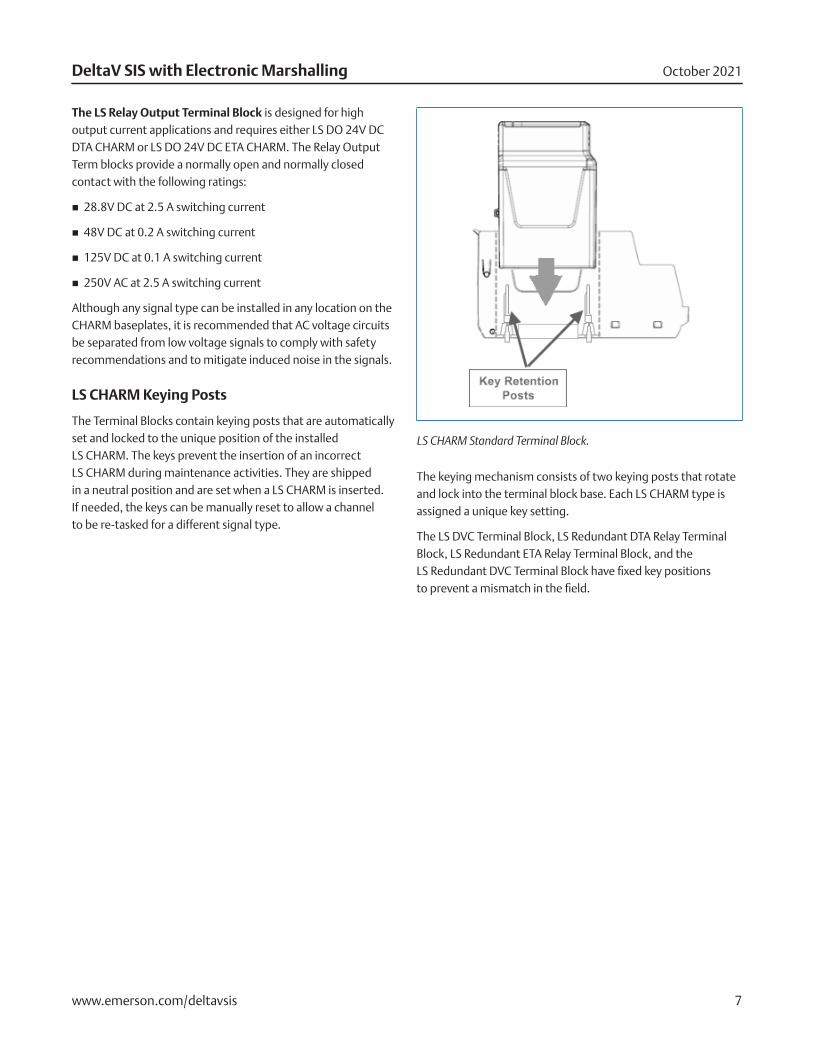
LS CHARM Keying Posts
The Terminal Blocks contain keying posts that are automatically set and locked to the unique position of the installed LS CHARM. The keys prevent the insertion of an incorrect LS CHARM during maintenance activities. They are shipped in a neutral position and are set when a LS CHARM is inserted. If needed, the keys can be manually reset to allow a channel to be re-tasked for a different signal type.
LS CHARM Standard Terminal Block.
The keying mechanism consists of two keying posts that rotate and lock into the terminal block base. Each LS CHARM type is assigned a unique key setting.
The LS DVC Terminal Block, LS Redundant DTA Relay Terminal Block, LS Redundant ETA Relay Terminal Block, and the LS Redundant DVC Terminal Block have fixed key positions to prevent a mismatch in the field.
October 2021DeltaV SIS with Electronic Marshalling
www.emerson.com/deltavsis 8
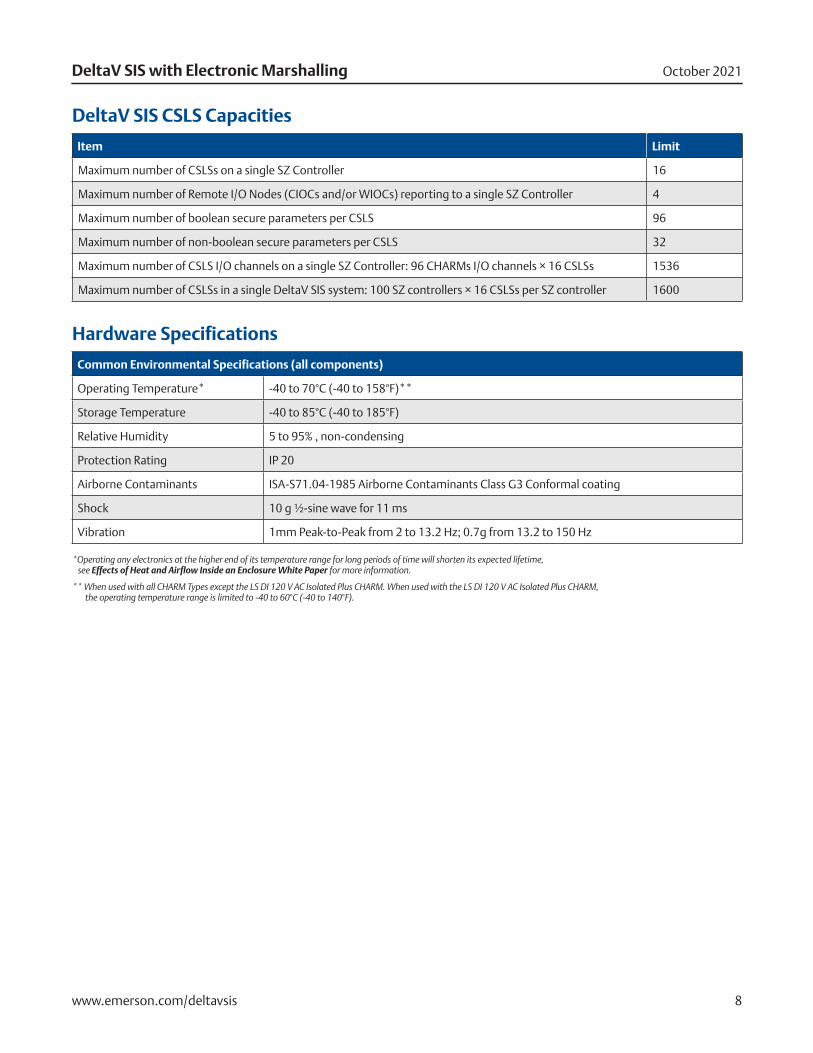
DeltaV SIS CSLS Capacities
Item Limit
Maximum number of CSLSs on a single SZ Controller 16
Maximum number of Remote I/O Nodes (CIOCs and/or WIOCs) reporting to a single SZ Controller 4
Maximum number of boolean secure parameters per CSLS 96
Maximum number of non-boolean secure parameters per CSLS 32
Maximum number of CSLS I/O channels on a single SZ Controller: 96 CHARMs I/O channels × 16 CSLSs 1536
Maximum number of CSLSs in a single DeltaV SIS system: 100 SZ controllers × 16 CSLSs per SZ controller 1600
Hardware Specifications
Common Environmental Specifications (all components)
Operating Temperature* -40 to 70°C (-40 to 158°F)**
Storage Temperature -40 to 85°C (-40 to 185°F)
Relative Humidity 5 to 95% , non-condensing
Protection Rating IP 20
Airborne Contaminants ISA-S71.04-1985 Airborne Contaminants Class G3 Conformal coating
Shock 10 g ½-sine wave for 11 ms
Vibration 1mm Peak-to-Peak from 2 to 13.2 Hz; 0.7g from 13.2 to 150 Hz
*Operating any electronics at the higher end of its temperature range for long periods of time will shorten its expected lifetime, see Effects of Heat and Airflow Inside an Enclosure White Paper for more information.
** When used with all CHARM Types except the LS DI 120 V AC Isolated Plus CHARM. When used with the LS DI 120 V AC Isolated Plus CHARM, the operating temperature range is limited to -40 to 60°C (-40 to 140°F).
October 2021DeltaV SIS with Electronic Marshalling
www.emerson.com/deltavsis 9
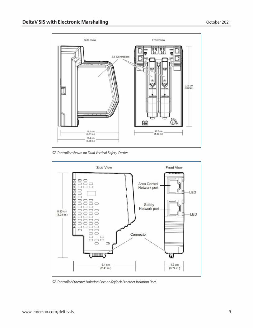
SZ Controller shown on Dual Vertical Safety Carrier.
SZ Controller Ethernet Isolation Port or Keylock Ethernet Isolation Port.
October 2021DeltaV SIS with Electronic Marshalling
www.emerson.com/deltavsis 10
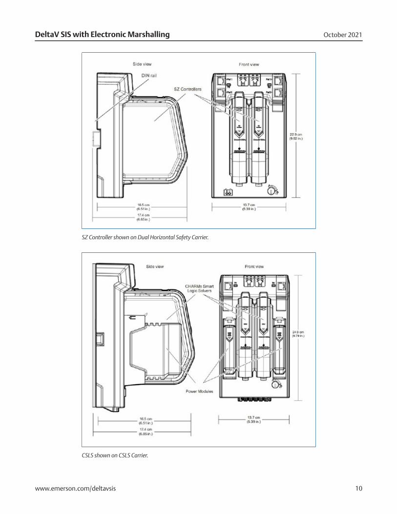
SZ Controller shown on Dual Horizontal Safety Carrier.
CSLS shown on CSLS Carrier.
October 2021DeltaV SIS with Electronic Marshalling
www.emerson.com/deltavsis 11
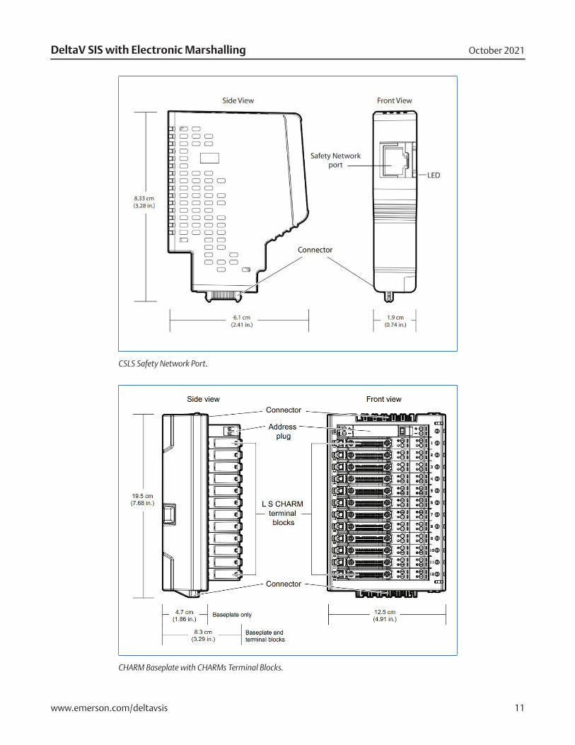
CSLS Safety Network Port.
CHARM Baseplate with CHARMs Terminal Blocks.
October 2021DeltaV SIS with Electronic Marshalling
www.emerson.com/deltavsis 12
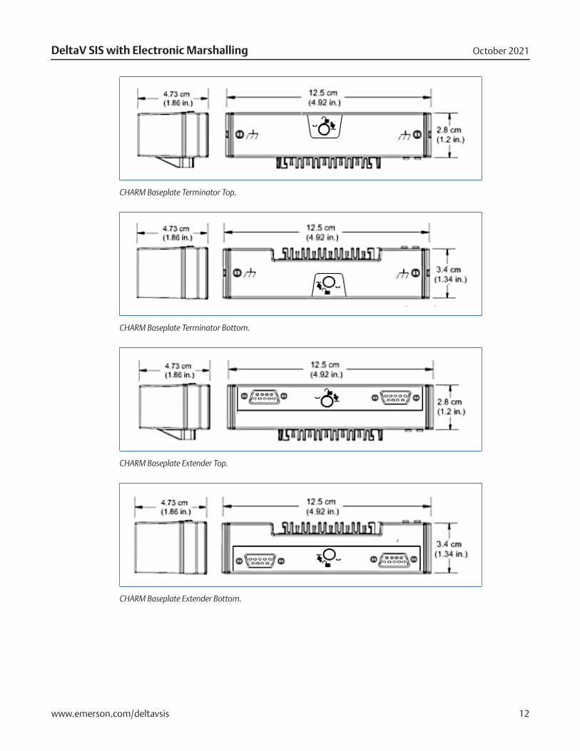
CHARM Baseplate Terminator Top.
CHARM Baseplate Terminator Bottom.
CHARM Baseplate Extender Top.
CHARM Baseplate Extender Bottom.
October 2021DeltaV SIS with Electronic Marshalling
www.emerson.com/deltavsis 13
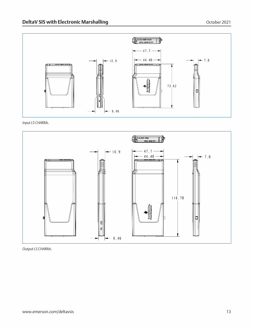
Input LS CHARMs.
Output LS CHARMs.
October 2021DeltaV SIS with Electronic Marshalling
www.emerson.com/deltavsis 14
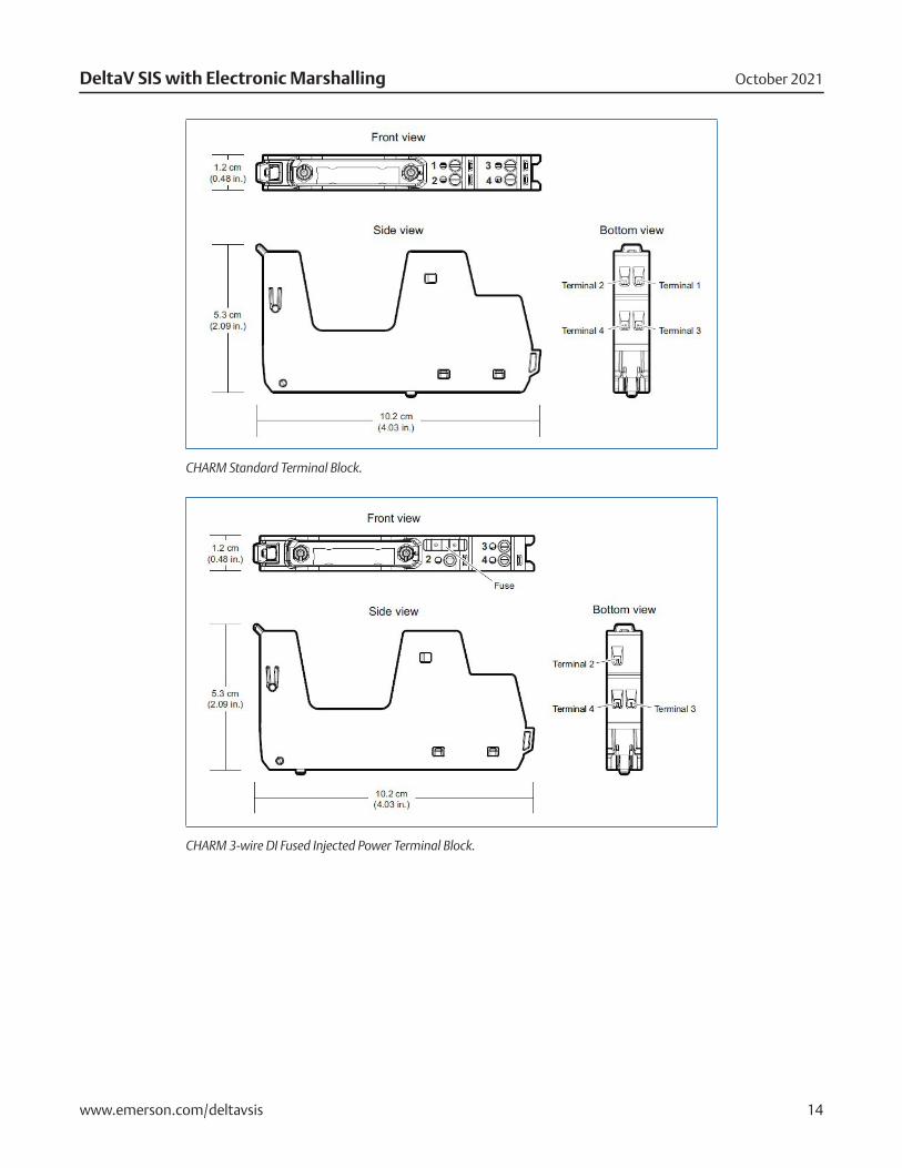
CHARM Standard Terminal Block.
CHARM 3-wire DI Fused Injected Power Terminal Block.
October 2021DeltaV SIS with Electronic Marshalling
www.emerson.com/deltavsis 15
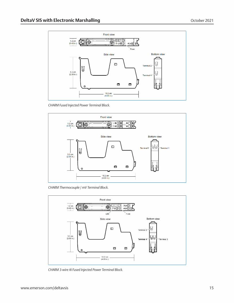
CHARM Fused Injected Power Terminal Block.
CHARM Thermocouple / mV Terminal Block.
CHARM 3-wire AI Fused Injected Power Terminal Block.
October 2021DeltaV SIS with Electronic Marshalling
www.emerson.com/deltavsis 16
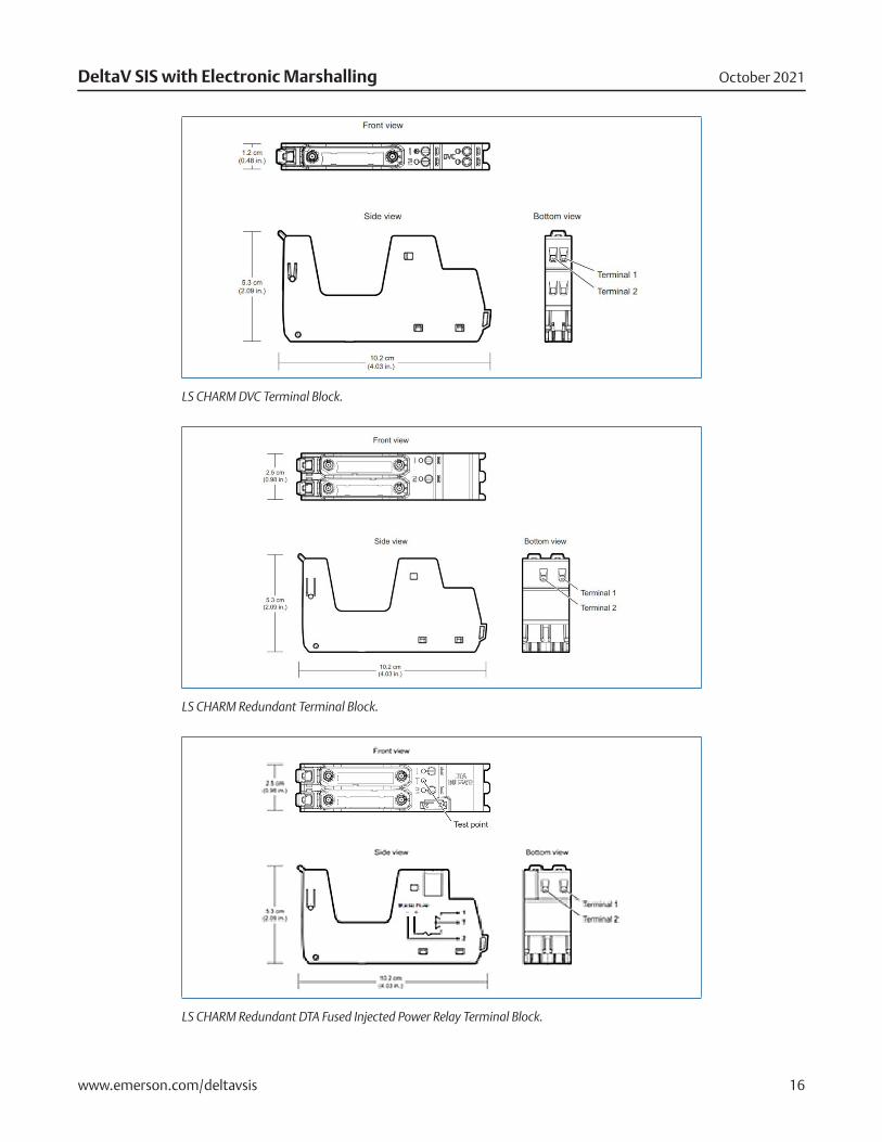
LS CHARM DVC Terminal Block.
LS CHARM Redundant Terminal Block.
LS CHARM Redundant DTA Fused Injected Power Relay Terminal Block.
October 2021DeltaV SIS with Electronic Marshalling
www.emerson.com/deltavsis 17
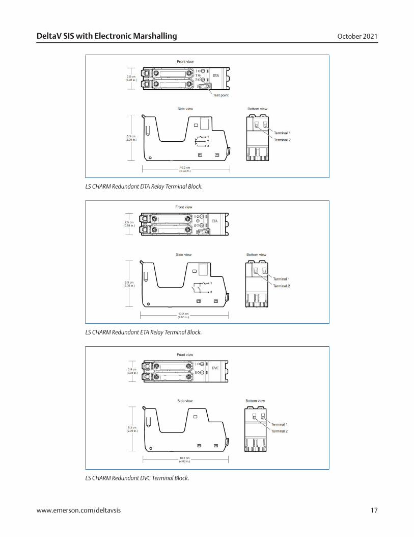
LS CHARM Redundant DTA Relay Terminal Block.
LS CHARM Redundant ETA Relay Terminal Block.
LS CHARM Redundant DVC Terminal Block.
October 2021DeltaV SIS with Electronic Marshalling
www.emerson.com/deltavsis 18
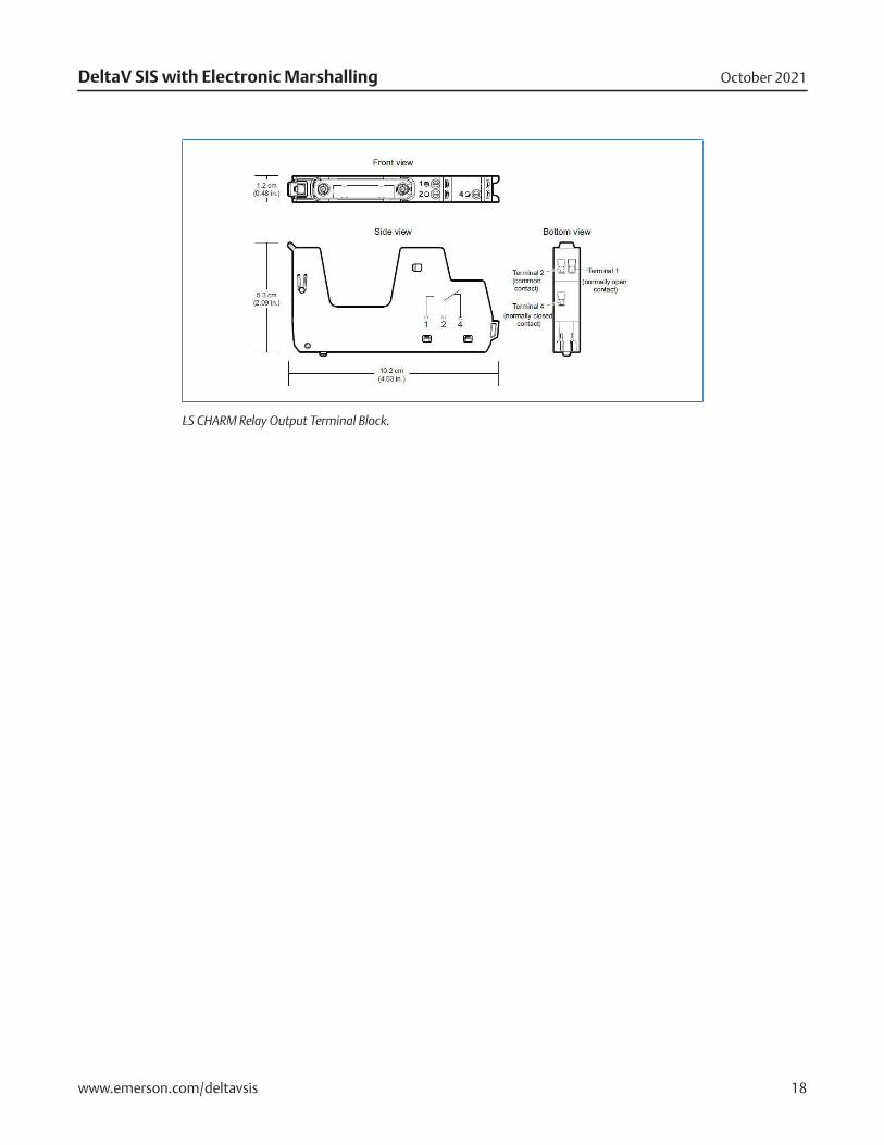
LS CHARM Relay Output Terminal Block.
October 2021DeltaV SIS with Electronic Marshalling
www.emerson.com/deltavsis 19
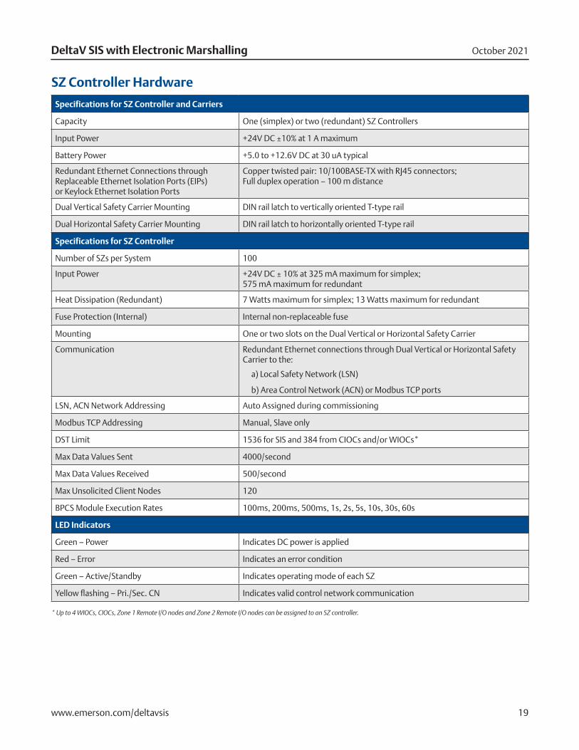
SZ Controller Hardware
Specifications for SZ Controller and Carriers
Capacity One (simplex) or two (redundant) SZ Controllers
Input Power +24V DC ±10% at 1 A maximum
Battery Power +5.0 to +12.6V DC at 30 uA typical
Redundant Ethernet Connections through Replaceable Ethernet Isolation Ports (EIPs) or Keylock Ethernet Isolation Ports
Copper twisted pair: 10/100BASE-TX with RJ45 connectors; Full duplex operation – 100 m distance
Dual Vertical Safety Carrier Mounting DIN rail latch to vertically oriented T-type rail
Dual Horizontal Safety Carrier Mounting DIN rail latch to horizontally oriented T-type rail
Specifications for SZ Controller
Number of SZs per System 100
Input Power +24V DC ± 10% at 325 mA maximum for simplex; 575 mA maximum for redundant
Heat Dissipation (Redundant) 7 Watts maximum for simplex; 13 Watts maximum for redundant
Fuse Protection (Internal) Internal non-replaceable fuse
Mounting One or two slots on the Dual Vertical or Horizontal Safety Carrier
Communication Redundant Ethernet connections through Dual Vertical or Horizontal Safety Carrier to the:
a) Local Safety Network (LSN)
b) Area Control Network (ACN) or Modbus TCP ports
LSN, ACN Network Addressing Auto Assigned during commissioning
Modbus TCP Addressing Manual, Slave only
DST Limit 1536 for SIS and 384 from CIOCs and/or WIOCs*
Max Data Values Sent 4000/second
Max Data Values Received 500/second
Max Unsolicited Client Nodes 120
BPCS Module Execution Rates 100ms, 200ms, 500ms, 1s, 2s, 5s, 10s, 30s, 60s
LED Indicators
Green – Power Indicates DC power is applied
Red – Error Indicates an error condition
Green – Active/Standby Indicates operating mode of each SZ
Yellow flashing – Pri./Sec. CN Indicates valid control network communication
* Up to 4 WIOCs, CIOCs, Zone 1 Remote I/O nodes and Zone 2 Remote I/O nodes can be assigned to an SZ controller.
October 2021DeltaV SIS with Electronic Marshalling
www.emerson.com/deltavsis 20
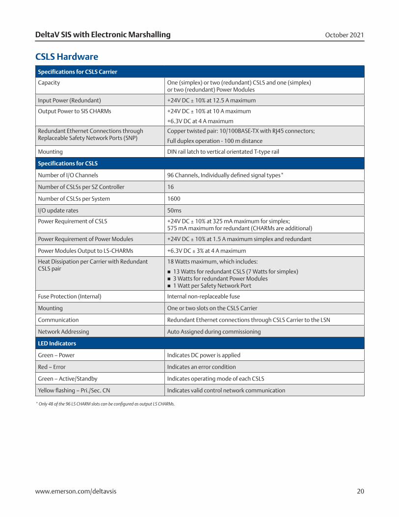
CSLS Hardware
Specifications for CSLS Carrier
Capacity One (simplex) or two (redundant) CSLS and one (simplex) or two (redundant) Power Modules
Input Power (Redundant) +24V DC ± 10% at 12.5 A maximum
Output Power to SIS CHARMs +24V DC ± 10% at 10 A maximum
+6.3V DC at 4 A maximum
Redundant Ethernet Connections through Replaceable Safety Network Ports (SNP)
Copper twisted pair: 10/100BASE-TX with RJ45 connectors;
Full duplex operation - 100 m distance
Mounting DIN rail latch to vertical orientated T-type rail
Specifications for CSLS
Number of I/O Channels 96 Channels, Individually defined signal types*
Number of CSLSs per SZ Controller 16
Number of CSLSs per System 1600
I/O update rates 50ms
Power Requirement of CSLS +24V DC ± 10% at 325 mA maximum for simplex; 575 mA maximum for redundant (CHARMs are additional)
Power Requirement of Power Modules +24V DC ± 10% at 1.5 A maximum simplex and redundant
Power Modules Output to LS-CHARMs +6.3V DC ± 3% at 4 A maximum
Heat Dissipation per Carrier with Redundant CSLS pair
18 Watts maximum, which includes:
� 13 Watts for redundant CSLS (7 Watts for simplex) � 3 Watts for redundant Power Modules � 1 Watt per Safety Network Port
Fuse Protection (Internal) Internal non-replaceable fuse
Mounting One or two slots on the CSLS Carrier
Communication Redundant Ethernet connections through CSLS Carrier to the LSN
Network Addressing Auto Assigned during commissioning
LED Indicators
Green – Power Indicates DC power is applied
Red – Error Indicates an error condition
Green – Active/Standby Indicates operating mode of each CSLS
Yellow flashing – Pri./Sec. CN Indicates valid control network communication
* Only 48 of the 96 LS CHARM slots can be configured as output LS CHARMs.
October 2021DeltaV SIS with Electronic Marshalling
www.emerson.com/deltavsis 21
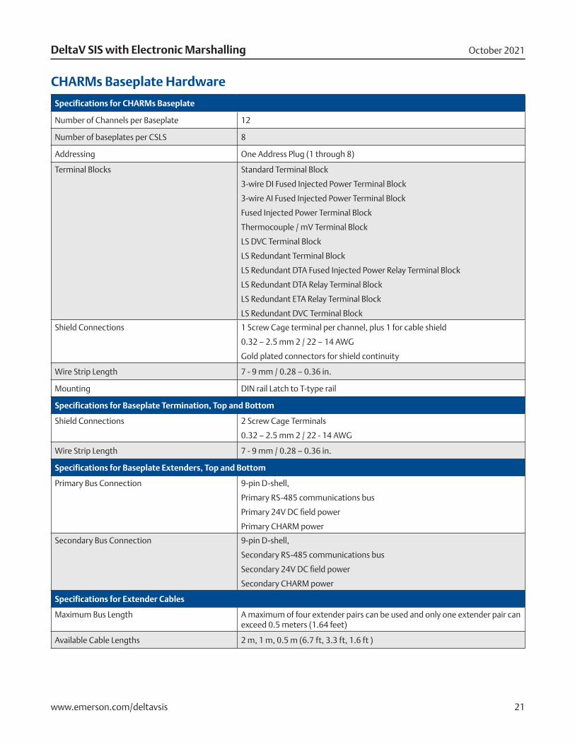
CHARMs Baseplate Hardware
Specifications for CHARMs Baseplate
Number of Channels per Baseplate 12
Number of baseplates per CSLS 8
Addressing One Address Plug (1 through 8)
Terminal Blocks Standard Terminal Block
3-wire DI Fused Injected Power Terminal Block
3-wire AI Fused Injected Power Terminal Block
Fused Injected Power Terminal Block
Thermocouple / mV Terminal Block
LS DVC Terminal Block
LS Redundant Terminal Block
LS Redundant DTA Fused Injected Power Relay Terminal Block
LS Redundant DTA Relay Terminal Block
LS Redundant ETA Relay Terminal Block
LS Redundant DVC Terminal Block
Shield Connections 1 Screw Cage terminal per channel, plus 1 for cable shield
0.32 – 2.5 mm 2 / 22 – 14 AWG
Gold plated connectors for shield continuity
Wire Strip Length 7 - 9 mm / 0.28 – 0.36 in.
Mounting DIN rail Latch to T-type rail
Specifications for Baseplate Termination, Top and Bottom
Shield Connections 2 Screw Cage Terminals
0.32 – 2.5 mm 2 / 22 - 14 AWG
Wire Strip Length 7 - 9 mm / 0.28 – 0.36 in.
Specifications for Baseplate Extenders, Top and Bottom
Primary Bus Connection 9-pin D-shell,
Primary RS-485 communications bus
Primary 24V DC field power
Primary CHARM power
Secondary Bus Connection 9-pin D-shell,
Secondary RS-485 communications bus
Secondary 24V DC field power
Secondary CHARM power
Specifications for Extender Cables
Maximum Bus Length A maximum of four extender pairs can be used and only one extender pair can exceed 0.5 meters (1.64 feet)
Available Cable Lengths 2 m, 1 m, 0.5 m (6.7 ft, 3.3 ft, 1.6 ft )
October 2021DeltaV SIS with Electronic Marshalling
www.emerson.com/deltavsis 22
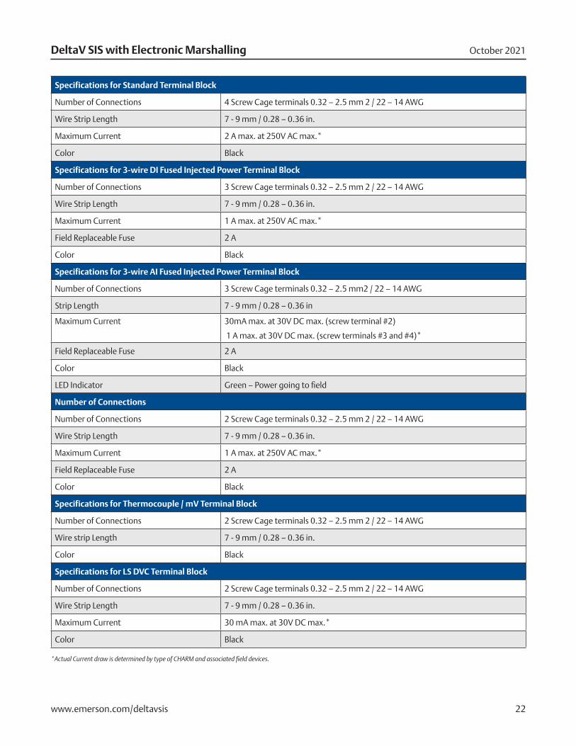
Specifications for Standard Terminal Block
Number of Connections 4 Screw Cage terminals 0.32 – 2.5 mm 2 / 22 – 14 AWG
Wire Strip Length 7 - 9 mm / 0.28 – 0.36 in.
Maximum Current 2 A max. at 250V AC max.*
Color Black
Specifications for 3-wire DI Fused Injected Power Terminal Block
Number of Connections 3 Screw Cage terminals 0.32 – 2.5 mm 2 / 22 – 14 AWG
Wire Strip Length 7 - 9 mm / 0.28 – 0.36 in.
Maximum Current 1 A max. at 250V AC max.*
Field Replaceable Fuse 2 A
Color Black
Specifications for 3-wire AI Fused Injected Power Terminal Block
Number of Connections 3 Screw Cage terminals 0.32 – 2.5 mm2 / 22 – 14 AWG
Strip Length 7 - 9 mm / 0.28 – 0.36 in
Maximum Current 30mA max. at 30V DC max. (screw terminal #2)
1 A max. at 30V DC max. (screw terminals #3 and #4)*
Field Replaceable Fuse 2 A
Color Black
LED Indicator Green – Power going to field
Number of Connections
Number of Connections 2 Screw Cage terminals 0.32 – 2.5 mm 2 / 22 – 14 AWG
Wire Strip Length 7 - 9 mm / 0.28 – 0.36 in.
Maximum Current 1 A max. at 250V AC max.*
Field Replaceable Fuse 2 A
Color Black
Specifications for Thermocouple / mV Terminal Block
Number of Connections 2 Screw Cage terminals 0.32 – 2.5 mm 2 / 22 – 14 AWG
Wire strip Length 7 - 9 mm / 0.28 – 0.36 in.
Color Black
Specifications for LS DVC Terminal Block
Number of Connections 2 Screw Cage terminals 0.32 – 2.5 mm 2 / 22 – 14 AWG
Wire Strip Length 7 - 9 mm / 0.28 – 0.36 in.
Maximum Current 30 mA max. at 30V DC max.*
Color Black
*Actual Current draw is determined by type of CHARM and associated field devices.
October 2021DeltaV SIS with Electronic Marshalling
www.emerson.com/deltavsis 23
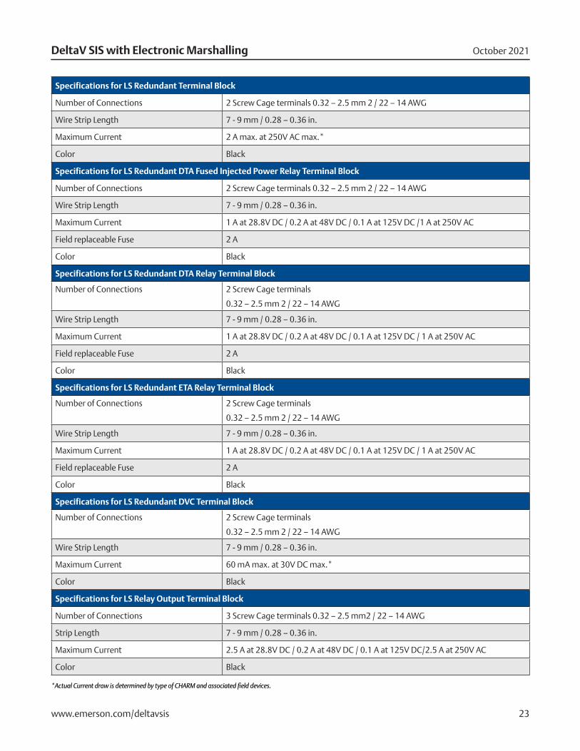
Specifications for LS Redundant Terminal Block
Number of Connections 2 Screw Cage terminals 0.32 – 2.5 mm 2 / 22 – 14 AWG
Wire Strip Length 7 - 9 mm / 0.28 – 0.36 in.
Maximum Current 2 A max. at 250V AC max.*
Color Black
Specifications for LS Redundant DTA Fused Injected Power Relay Terminal Block
Number of Connections 2 Screw Cage terminals 0.32 – 2.5 mm 2 / 22 – 14 AWG
Wire Strip Length 7 - 9 mm / 0.28 – 0.36 in.
Maximum Current 1 A at 28.8V DC / 0.2 A at 48V DC / 0.1 A at 125V DC /1 A at 250V AC
Field replaceable Fuse 2 A
Color Black
Specifications for LS Redundant DTA Relay Terminal Block
Number of Connections 2 Screw Cage terminals
0.32 – 2.5 mm 2 / 22 – 14 AWG
Wire Strip Length 7 - 9 mm / 0.28 – 0.36 in.
Maximum Current 1 A at 28.8V DC / 0.2 A at 48V DC / 0.1 A at 125V DC / 1 A at 250V AC
Field replaceable Fuse 2 A
Color Black
Specifications for LS Redundant ETA Relay Terminal Block
Number of Connections 2 Screw Cage terminals
0.32 – 2.5 mm 2 / 22 – 14 AWG
Wire Strip Length 7 - 9 mm / 0.28 – 0.36 in.
Maximum Current 1 A at 28.8V DC / 0.2 A at 48V DC / 0.1 A at 125V DC / 1 A at 250V AC
Field replaceable Fuse 2 A
Color Black
Specifications for LS Redundant DVC Terminal Block
Number of Connections 2 Screw Cage terminals
0.32 – 2.5 mm 2 / 22 – 14 AWG
Wire Strip Length 7 - 9 mm / 0.28 – 0.36 in.
Maximum Current 60 mA max. at 30V DC max.*
Color Black
Specifications for LS Relay Output Terminal Block
Number of Connections 3 Screw Cage terminals 0.32 – 2.5 mm2 / 22 – 14 AWG
Strip Length 7 - 9 mm / 0.28 – 0.36 in.
Maximum Current 2.5 A at 28.8V DC / 0.2 A at 48V DC / 0.1 A at 125V DC/2.5 A at 250V AC
Color Black
*Actual Current draw is determined by type of CHARM and associated field devices.*Actual Current draw is determined by type of CHARM and associated field devices.
October 2021DeltaV SIS with Electronic Marshalling
www.emerson.com/deltavsis 24
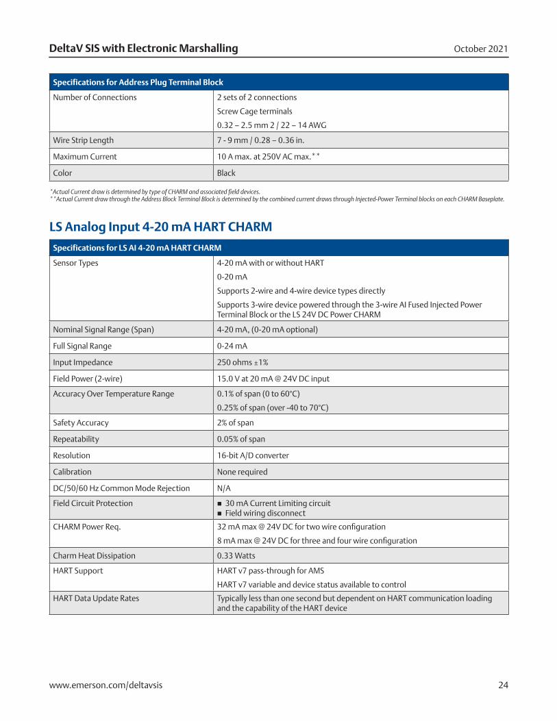
Specifications for Address Plug Terminal Block
Number of Connections 2 sets of 2 connections
Screw Cage terminals
0.32 – 2.5 mm 2 / 22 – 14 AWG
Wire Strip Length 7 - 9 mm / 0.28 – 0.36 in.
Maximum Current 10 A max. at 250V AC max.**
Color Black
*Actual Current draw is determined by type of CHARM and associated field devices.**Actual Current draw through the Address Block Terminal Block is determined by the combined current draws through Injected-Power Terminal blocks on each CHARM Baseplate.
LS Analog Input 4-20 mA HART CHARM
Specifications for LS AI 4-20 mA HART CHARM
Sensor Types 4-20 mA with or without HART
0-20 mA
Supports 2-wire and 4-wire device types directly
Supports 3-wire device powered through the 3-wire AI Fused Injected Power Terminal Block or the LS 24V DC Power CHARM
Nominal Signal Range (Span) 4-20 mA, (0-20 mA optional)
Full Signal Range 0-24 mA
Input Impedance 250 ohms ±1%
Field Power (2-wire) 15.0 V at 20 mA @ 24V DC input
Accuracy Over Temperature Range 0.1% of span (0 to 60°C)
0.25% of span (over -40 to 70°C)
Safety Accuracy 2% of span
Repeatability 0.05% of span
Resolution 16-bit A/D converter
Calibration None required
DC/50/60 Hz Common Mode Rejection N/A
Field Circuit Protection � 30 mA Current Limiting circuit � Field wiring disconnect
CHARM Power Req. 32 mA max @ 24V DC for two wire configuration
8 mA max @ 24V DC for three and four wire configuration
Charm Heat Dissipation 0.33 Watts
HART Support HART v7 pass-through for AMS
HART v7 variable and device status available to control
HART Data Update Rates Typically less than one second but dependent on HART communication loading and the capability of the HART device
October 2021DeltaV SIS with Electronic Marshalling
www.emerson.com/deltavsis 25
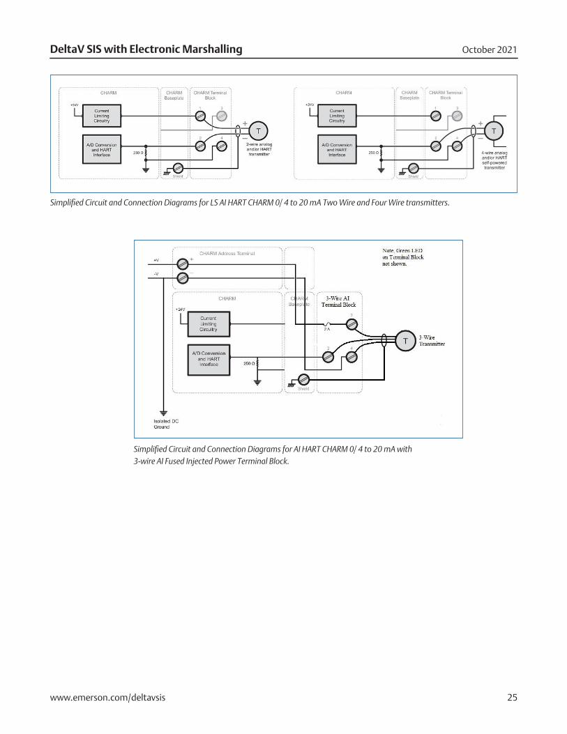
Simplified Circuit and Connection Diagrams for LS AI HART CHARM 0/ 4 to 20 mA Two Wire and Four Wire transmitters.
Simplified Circuit and Connection Diagrams for AI HART CHARM 0/ 4 to 20 mA with 3-wire AI Fused Injected Power Terminal Block.
October 2021DeltaV SIS with Electronic Marshalling
www.emerson.com/deltavsis 26
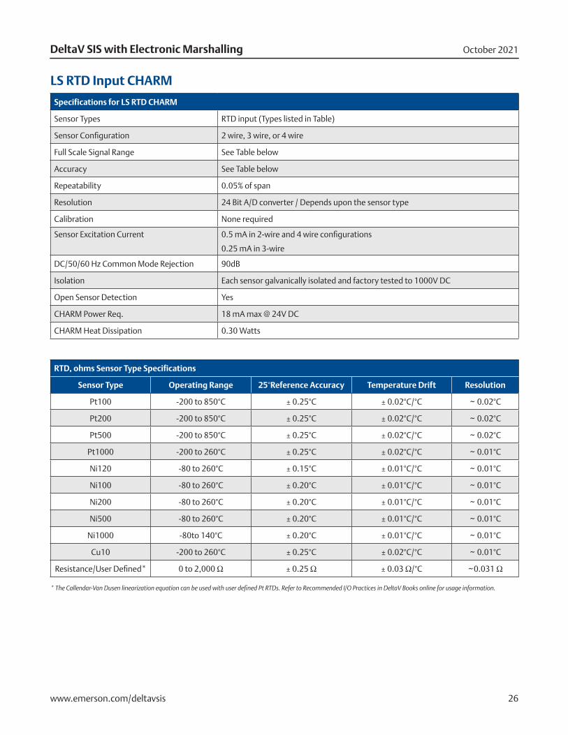
LS RTD Input CHARM
Specifications for LS RTD CHARM
Sensor Types RTD input (Types listed in Table)
Sensor Configuration 2 wire, 3 wire, or 4 wire
Full Scale Signal Range See Table below
Accuracy See Table below
Repeatability 0.05% of span
Resolution 24 Bit A/D converter / Depends upon the sensor type
Calibration None required
Sensor Excitation Current 0.5 mA in 2-wire and 4 wire configurations
0.25 mA in 3-wire
DC/50/60 Hz Common Mode Rejection 90dB
Isolation Each sensor galvanically isolated and factory tested to 1000V DC
Open Sensor Detection Yes
CHARM Power Req. 18 mA max @ 24V DC
CHARM Heat Dissipation 0.30 Watts
RTD, ohms Sensor Type Specifications
Sensor Type Operating Range 25°Reference Accuracy Temperature Drift Resolution
Pt100 -200 to 850°C ± 0.25°C ± 0.02°C/°C ~ 0.02°C
Pt200 -200 to 850°C ± 0.25°C ± 0.02°C/°C ~ 0.02°C
Pt500 -200 to 850°C ± 0.25°C ± 0.02°C/°C ~ 0.02°C
Pt1000 -200 to 260°C ± 0.25°C ± 0.02°C/°C ~ 0.01°C
Ni120 -80 to 260°C ± 0.15°C ± 0.01°C/°C ~ 0.01°C
Ni100 -80 to 260°C ± 0.20°C ± 0.01°C/°C ~ 0.01°C
Ni200 -80 to 260°C ± 0.20°C ± 0.01°C/°C ~ 0.01°C
Ni500 -80 to 260°C ± 0.20°C ± 0.01°C/°C ~ 0.01°C
Ni1000 -80to 140°C ± 0.20°C ± 0.01°C/°C ~ 0.01°C
Cu10 -200 to 260°C ± 0.25°C ± 0.02°C/°C ~ 0.01°C
Resistance/User Defined* 0 to 2,000 Ω ± 0.25 Ω ± 0.03 Ω/°C ~0.031 Ω
* The Callendar-Van Dusen linearization equation can be used with user defined Pt RTDs. Refer to Recommended I/O Practices in DeltaV Books online for usage information.
October 2021DeltaV SIS with Electronic Marshalling
www.emerson.com/deltavsis 27
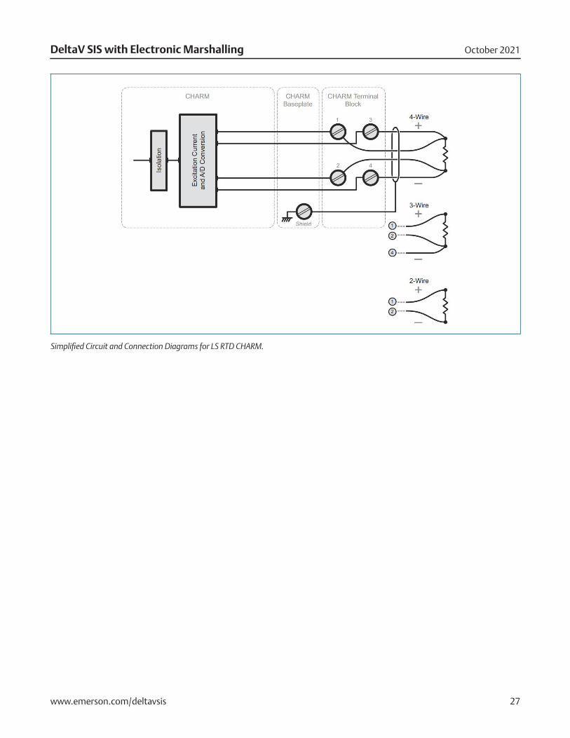
Simplified Circuit and Connection Diagrams for LS RTD CHARM.
October 2021DeltaV SIS with Electronic Marshalling
www.emerson.com/deltavsis 28
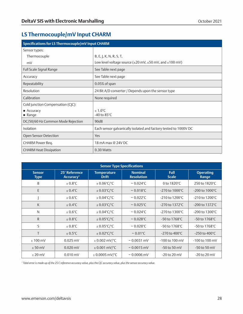
LS Thermocouple/mV Input CHARM
Specifications for LS Thermocouple/mV Input CHARM
Sensor types:
Thermocouple
mV
B, E, J, K, N, R, S, T,
Low level voltage source (±20 mV, ±50 mV, and ±100 mV)
Full Scale Signal Range See Table next page
Accuracy See Table next page
Repeatability 0.05% of span
Resolution 24 Bit A/D converter / Depends upon the sensor type
Calibration None required
Cold junction Compensation (CJC):
� Accuracy � Range
± 1.0°C -40 to 85°C
DC/50/60 Hz Common Mode Rejection 90dB
Isolation Each sensor galvanically isolated and factory tested to 1000V DC
Open Sensor Detection Yes
CHARM Power Req. 18 mA max @ 24V DC
CHARM Heat Dissipation 0.30 Watts
Sensor Type Specifications
Sensor Type
25° Reference Accuracy1
Temperature Drift
Nominal Resolution
Full Scale
Operating Range
B ± 0.8°C ± 0.06°C/°C ~ 0.024°C 0 to 1820°C 250 to 1820°C
E ± 0.4°C ± 0.03°C/°C ~ 0.018°C -270 to 1000°C -200 to 1000°C
J ± 0.6°C ± 0.04°C/°C ~ 0.022°C -210 to 1200°C -210 to 1200°C
K ± 0.4°C ± 0.03°C/°C ~ 0.025°C -270 to 1372°C -200 to 1372°C
N ± 0.6°C ± 0.04°C/°C ~ 0.024°C -270 to 1300°C -200 to 1300°C
R ± 0.8°C ± 0.05°C/°C ~ 0.028°C -50 to 1768°C -50 to 1768°C
S ± 0.8°C ± 0.05°C/°C ~ 0.028°C -50 to 1768°C -50 to 1768°C
T ± 0.5°C ± 0.02°C/°C ~ 0.01°C -270 to 400°C -250 to 400°C
± 100 mV 0.025 mV ± 0.002 mV/°C ~ 0.0031 mV -100 to 100 mV -100 to 100 mV
± 50 mV 0.020 mV ± 0.001 mV/°C ~ 0.0015 mV -50 to 50 mV -50 to 50 mV
± 20 mV 0.010 mV ± 0.0005 mV/°C ~ 0.0006 mV -20 to 20 mV -20 to 20 mV
1 Total error is made up of the 25 C reference accuracy value, plus the CJC accuracy value, plus the sensor accuracy value.
October 2021DeltaV SIS with Electronic Marshalling
www.emerson.com/deltavsis 29
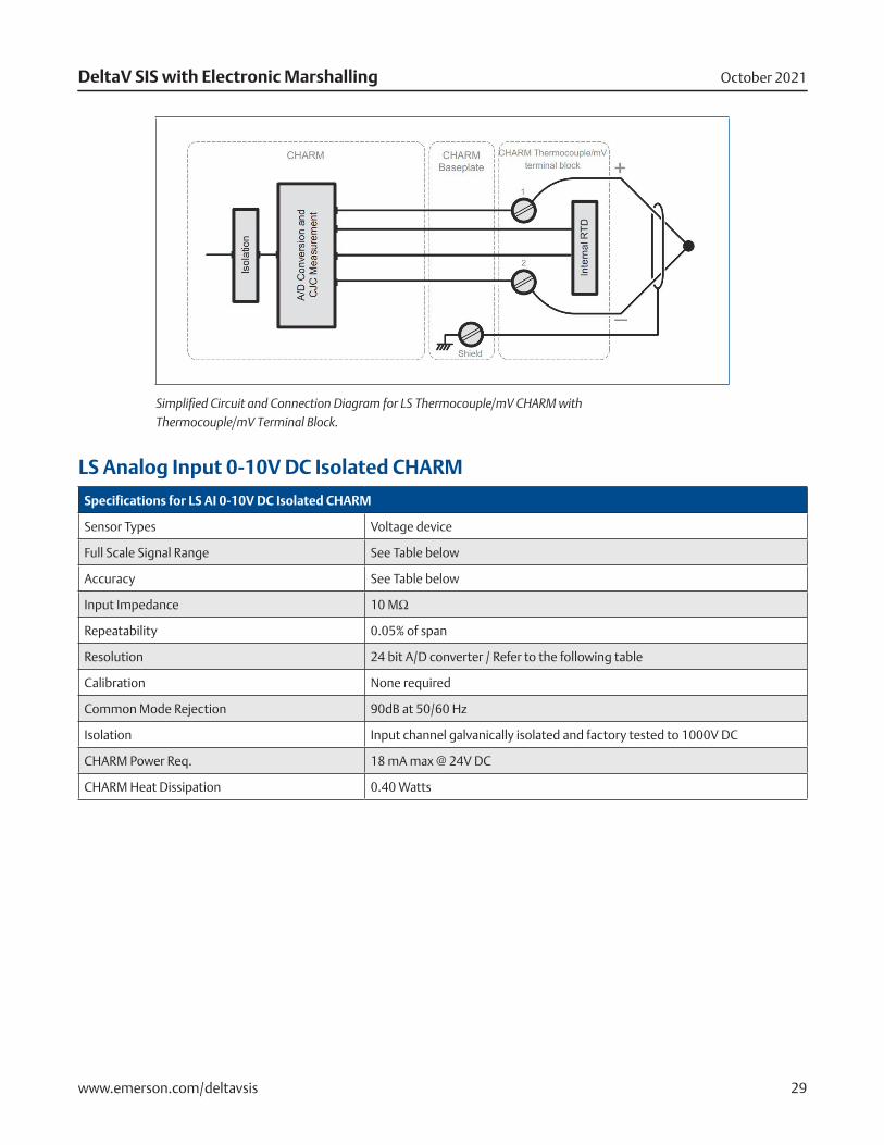
Simplified Circuit and Connection Diagram for LS Thermocouple/mV CHARM with Thermocouple/mV Terminal Block.
LS Analog Input 0-10V DC Isolated CHARM
Specifications for LS AI 0-10V DC Isolated CHARM
Sensor Types Voltage device
Full Scale Signal Range See Table below
Accuracy See Table below
Input Impedance 10 MΩ
Repeatability 0.05% of span
Resolution 24 bit A/D converter / Refer to the following table
Calibration None required
Common Mode Rejection 90dB at 50/60 Hz
Isolation Input channel galvanically isolated and factory tested to 1000V DC
CHARM Power Req. 18 mA max @ 24V DC
CHARM Heat Dissipation 0.40 Watts
October 2021DeltaV SIS with Electronic Marshalling
www.emerson.com/deltavsis 30
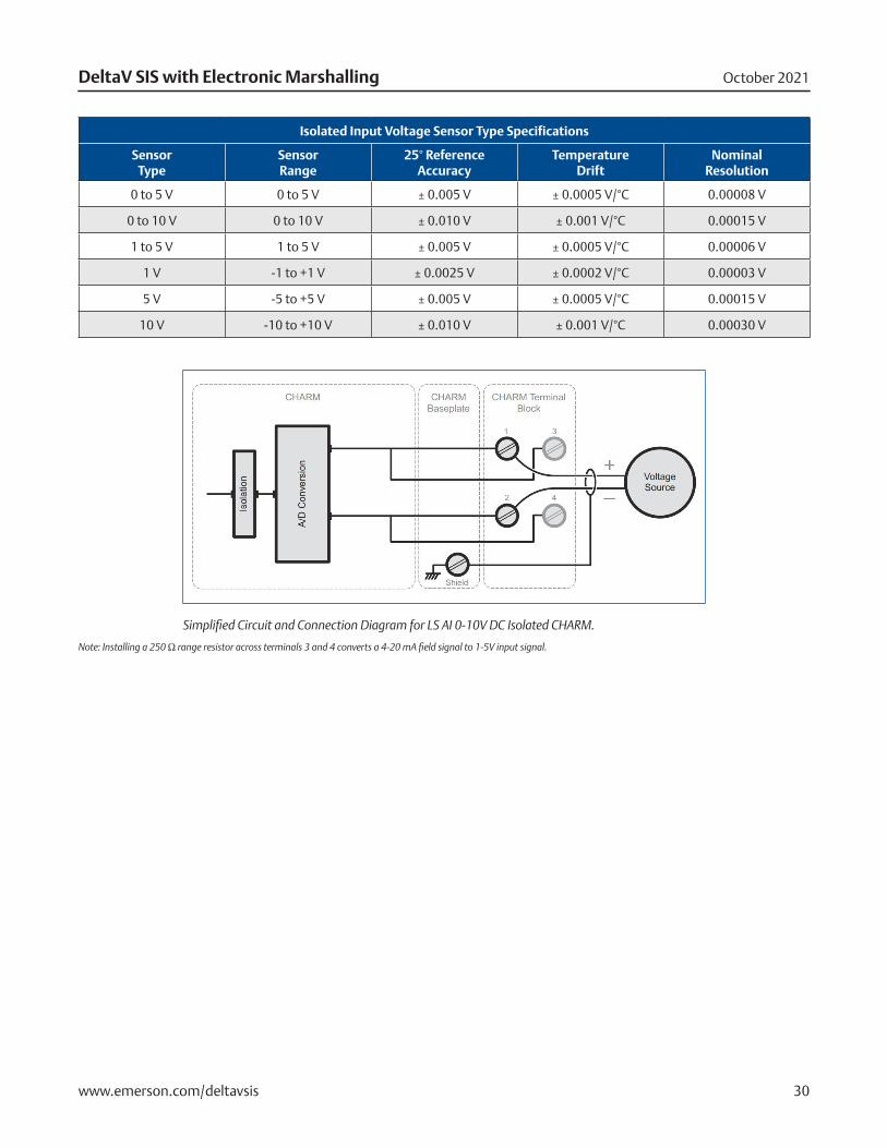
Isolated Input Voltage Sensor Type Specifications
Sensor Type
Sensor Range
25° Reference Accuracy
Temperature Drift
Nominal Resolution
0 to 5 V 0 to 5 V ± 0.005 V ± 0.0005 V/°C 0.00008 V
0 to 10 V 0 to 10 V ± 0.010 V ± 0.001 V/°C 0.00015 V
1 to 5 V 1 to 5 V ± 0.005 V ± 0.0005 V/°C 0.00006 V
1 V -1 to +1 V ± 0.0025 V ± 0.0002 V/°C 0.00003 V
5 V -5 to +5 V ± 0.005 V ± 0.0005 V/°C 0.00015 V
10 V -10 to +10 V ± 0.010 V ± 0.001 V/°C 0.00030 V
Simplified Circuit and Connection Diagram for LS AI 0-10V DC Isolated CHARM.
Note: Installing a 250 Ω range resistor across terminals 3 and 4 converts a 4-20 mA field signal to 1-5V input signal.
October 2021DeltaV SIS with Electronic Marshalling
www.emerson.com/deltavsis 31
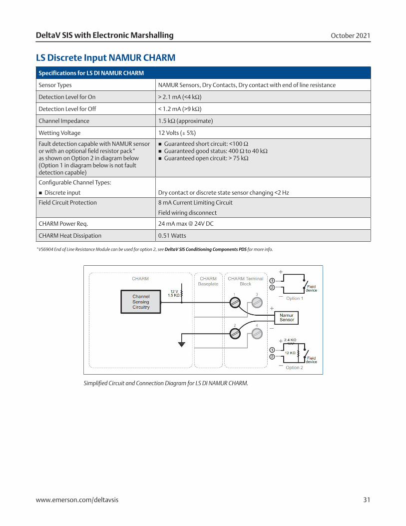
LS Discrete Input NAMUR CHARM
Specifications for LS DI NAMUR CHARM
Sensor Types NAMUR Sensors, Dry Contacts, Dry contact with end of line resistance
Detection Level for On > 2.1 mA (<4 kΩ)
Detection Level for Off < 1.2 mA (>9 kΩ)
Channel Impedance 1.5 kΩ (approximate)
Wetting Voltage 12 Volts (± 5%)
Fault detection capable with NAMUR sensor or with an optional field resistor pack* as shown on Option 2 in diagram below (Option 1 in diagram below is not fault detection capable)
� Guaranteed short circuit: <100 Ω � Guaranteed good status: 400 Ω to 40 kΩ � Guaranteed open circuit: > 75 kΩ
Configurable Channel Types:
� Discrete input
Dry contact or discrete state sensor changing <2 Hz
Field Circuit Protection 8 mA Current Limiting Circuit
Field wiring disconnect
CHARM Power Req. 24 mA max @ 24V DC
CHARM Heat Dissipation 0.51 Watts
*VS6904 End of Line Resistance Module can be used for option 2, see DeltaV SIS Conditioning Components PDS for more info.
Simplified Circuit and Connection Diagram for LS DI NAMUR CHARM.
October 2021DeltaV SIS with Electronic Marshalling
www.emerson.com/deltavsis 32
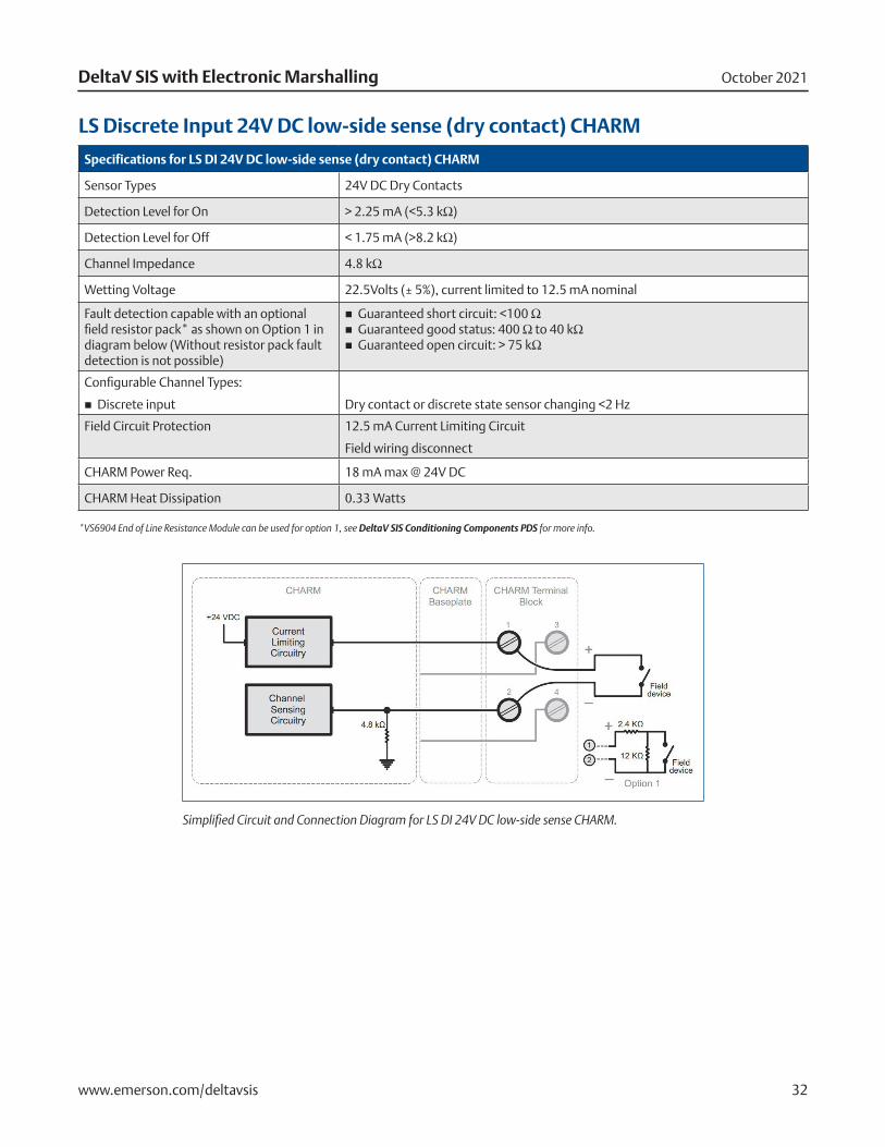
LS Discrete Input 24V DC low-side sense (dry contact) CHARM
Specifications for LS DI 24V DC low-side sense (dry contact) CHARM
Sensor Types 24V DC Dry Contacts
Detection Level for On > 2.25 mA (<5.3 kΩ)
Detection Level for Off < 1.75 mA (>8.2 kΩ)
Channel Impedance 4.8 kΩ
Wetting Voltage 22.5Volts (± 5%), current limited to 12.5 mA nominal
Fault detection capable with an optional field resistor pack* as shown on Option 1 in diagram below (Without resistor pack fault detection is not possible)
� Guaranteed short circuit: <100 Ω � Guaranteed good status: 400 Ω to 40 kΩ � Guaranteed open circuit: > 75 kΩ
Configurable Channel Types:
� Discrete input
Dry contact or discrete state sensor changing <2 Hz
Field Circuit Protection 12.5 mA Current Limiting Circuit
Field wiring disconnect
CHARM Power Req. 18 mA max @ 24V DC
CHARM Heat Dissipation 0.33 Watts
*VS6904 End of Line Resistance Module can be used for option 1, see DeltaV SIS Conditioning Components PDS for more info.
Simplified Circuit and Connection Diagram for LS DI 24V DC low-side sense CHARM.
October 2021DeltaV SIS with Electronic Marshalling
www.emerson.com/deltavsis 33
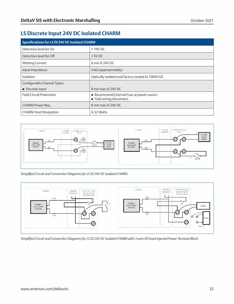
LS Discrete Input 24V DC Isolated CHARM
Specifications for LS DI 24V DC Isolated CHARM
Detection level for On > 10V DC
Detection level for Off < 5V DC
Wetting Current 6 mA @ 24V DC
Input Impedance 4 kΩ (approximately)
Isolation Optically isolated and factory tested to 1000V DC
Configurable Channel Types:
� Discrete input
8 mA max @ 24V DC
Field Circuit Protection � Recommend External Fuse at power source � Field wiring disconnect
CHARM Power Req. 8 mA max @ 24V DC
CHARM Heat Dissipation 0.32 Watts
Simplified Circuit and Connection Diagrams for LS DI 24V DC Isolated CHARM.
Simplified Circuit and Connection Diagrams for LS DI 24V DC Isolated CHARM with 3-wire DI Fused Injected Power Terminal Block.
October 2021DeltaV SIS with Electronic Marshalling
www.emerson.com/deltavsis 34
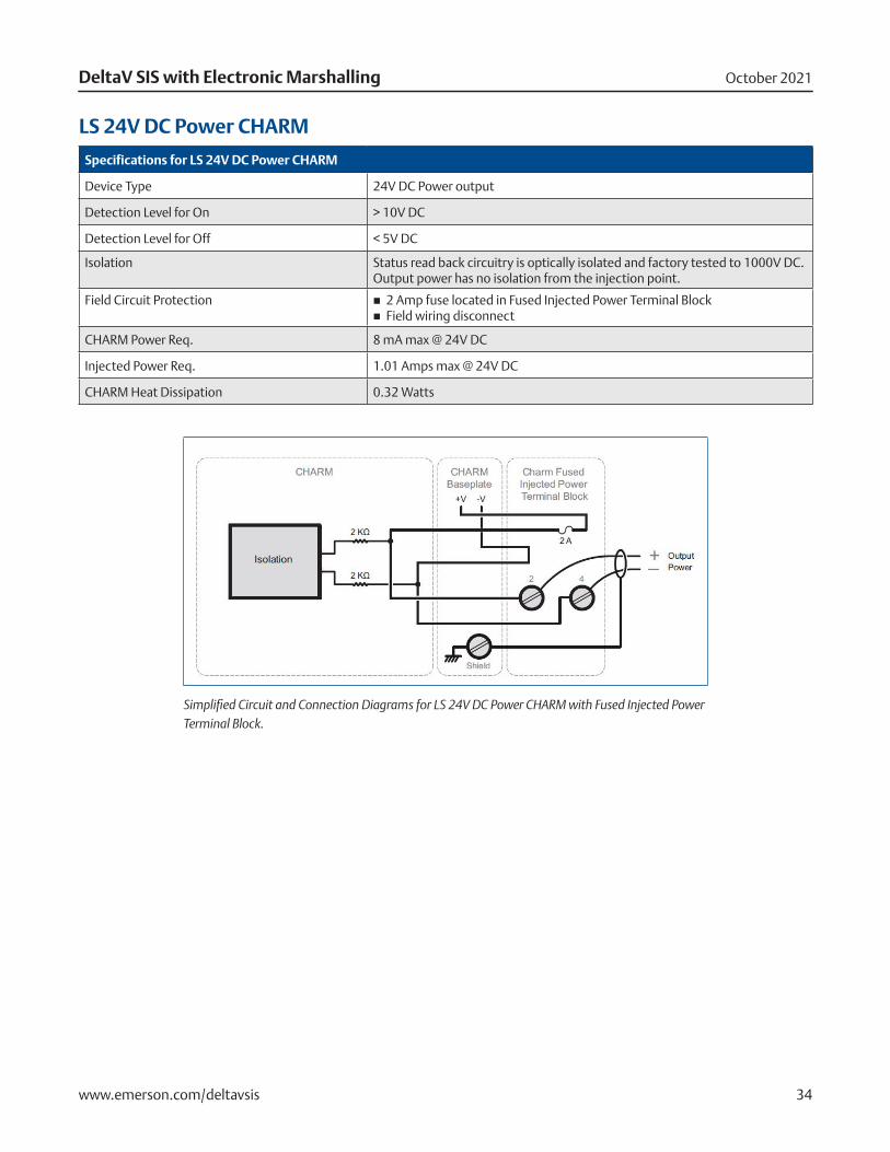
LS 24V DC Power CHARM
Specifications for LS 24V DC Power CHARM
Device Type 24V DC Power output
Detection Level for On > 10V DC
Detection Level for Off < 5V DC
Isolation Status read back circuitry is optically isolated and factory tested to 1000V DC. Output power has no isolation from the injection point.
Field Circuit Protection � 2 Amp fuse located in Fused Injected Power Terminal Block � Field wiring disconnect
CHARM Power Req. 8 mA max @ 24V DC
Injected Power Req. 1.01 Amps max @ 24V DC
CHARM Heat Dissipation 0.32 Watts
Simplified Circuit and Connection Diagrams for LS 24V DC Power CHARM with Fused Injected Power Terminal Block.
October 2021DeltaV SIS with Electronic Marshalling
www.emerson.com/deltavsis 35
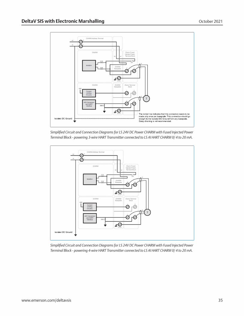
Simplified Circuit and Connection Diagrams for LS 24V DC Power CHARM with Fused Injected Power Terminal Block - powering 3-wire HART Transmitter connected to LS AI HART CHARM 0/ 4 to 20 mA.
Simplified Circuit and Connection Diagrams for LS 24V DC Power CHARM with Fused Injected Power Terminal Block - powering 4-wire HART Transmitter connected to LS AI HART CHARM 0/ 4 to 20 mA.
October 2021DeltaV SIS with Electronic Marshalling
www.emerson.com/deltavsis 36
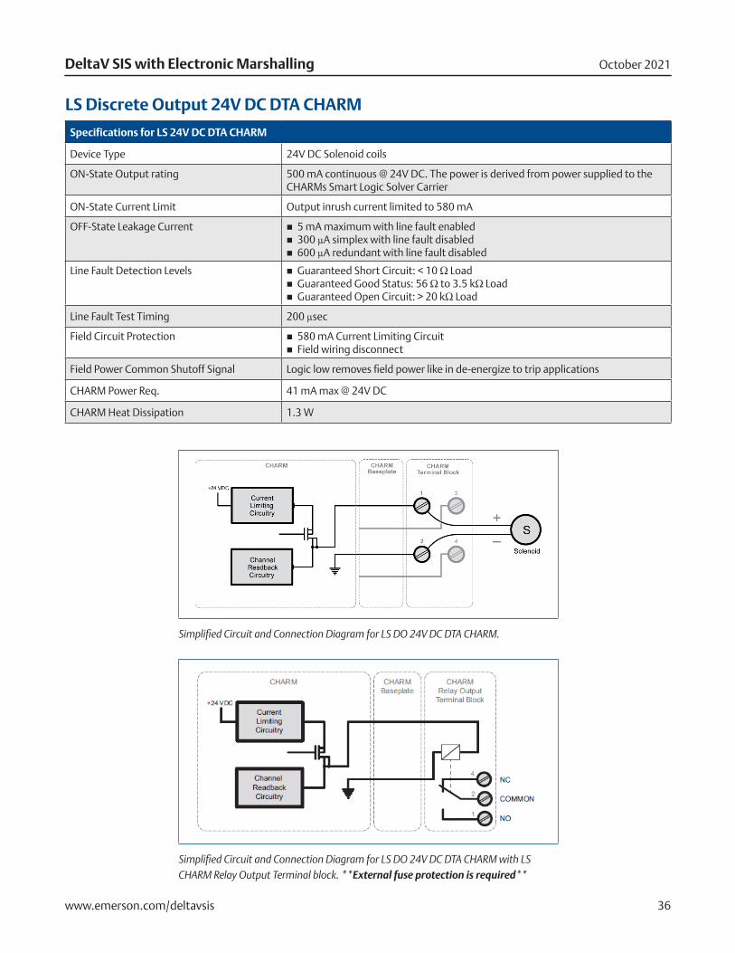
LS Discrete Output 24V DC DTA CHARM
Specifications for LS 24V DC DTA CHARM
Device Type 24V DC Solenoid coils
ON-State Output rating 500 mA continuous @ 24V DC. The power is derived from power supplied to the CHARMs Smart Logic Solver Carrier
ON-State Current Limit Output inrush current limited to 580 mA
OFF-State Leakage Current � 5 mA maximum with line fault enabled � 300 µA simplex with line fault disabled � 600 µA redundant with line fault disabled
Line Fault Detection Levels � Guaranteed Short Circuit: < 10 Ω Load � Guaranteed Good Status: 56 Ω to 3.5 kΩ Load � Guaranteed Open Circuit: > 20 kΩ Load
Line Fault Test Timing 200 µsec
Field Circuit Protection � 580 mA Current Limiting Circuit � Field wiring disconnect
Field Power Common Shutoff Signal Logic low removes field power like in de-energize to trip applications
CHARM Power Req. 41 mA max @ 24V DC
CHARM Heat Dissipation 1.3 W
Simplified Circuit and Connection Diagram for LS DO 24V DC DTA CHARM.
Simplified Circuit and Connection Diagram for LS DO 24V DC DTA CHARM with LS CHARM Relay Output Terminal block. **External fuse protection is required**
October 2021DeltaV SIS with Electronic Marshalling
www.emerson.com/deltavsis 37
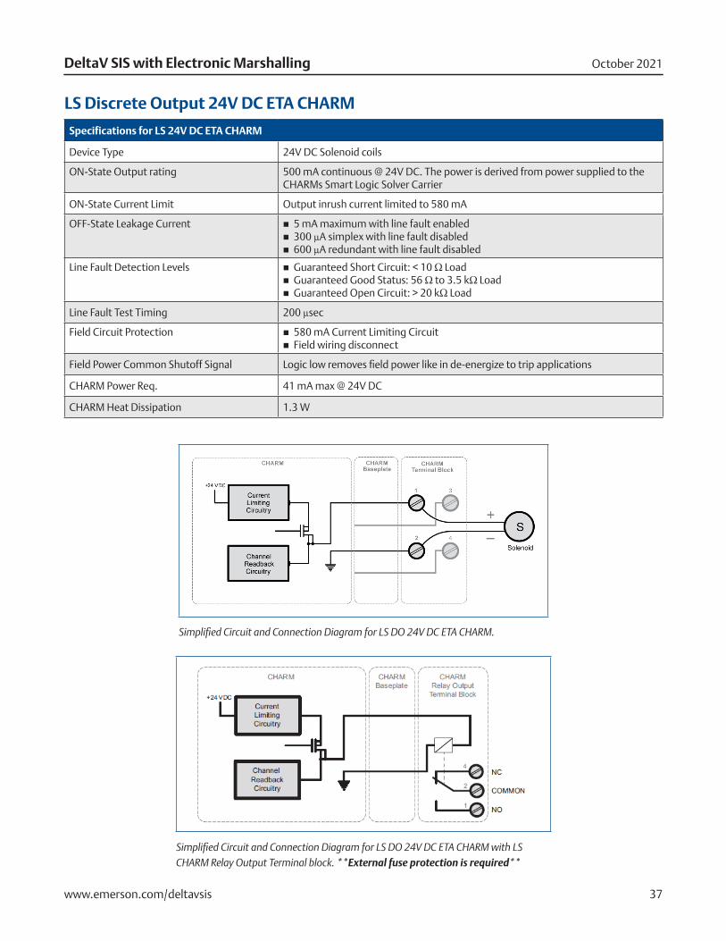
LS Discrete Output 24V DC ETA CHARM
Specifications for LS 24V DC ETA CHARM
Device Type 24V DC Solenoid coils
ON-State Output rating 500 mA continuous @ 24V DC. The power is derived from power supplied to the CHARMs Smart Logic Solver Carrier
ON-State Current Limit Output inrush current limited to 580 mA
OFF-State Leakage Current � 5 mA maximum with line fault enabled � 300 µA simplex with line fault disabled � 600 µA redundant with line fault disabled
Line Fault Detection Levels � Guaranteed Short Circuit: < 10 Ω Load � Guaranteed Good Status: 56 Ω to 3.5 kΩ Load � Guaranteed Open Circuit: > 20 kΩ Load
Line Fault Test Timing 200 µsec
Field Circuit Protection � 580 mA Current Limiting Circuit � Field wiring disconnect
Field Power Common Shutoff Signal Logic low removes field power like in de-energize to trip applications
CHARM Power Req. 41 mA max @ 24V DC
CHARM Heat Dissipation 1.3 W
Simplified Circuit and Connection Diagram for LS DO 24V DC ETA CHARM.
Simplified Circuit and Connection Diagram for LS DO 24V DC ETA CHARM with LS CHARM Relay Output Terminal block. **External fuse protection is required**
October 2021DeltaV SIS with Electronic Marshalling
www.emerson.com/deltavsis 38
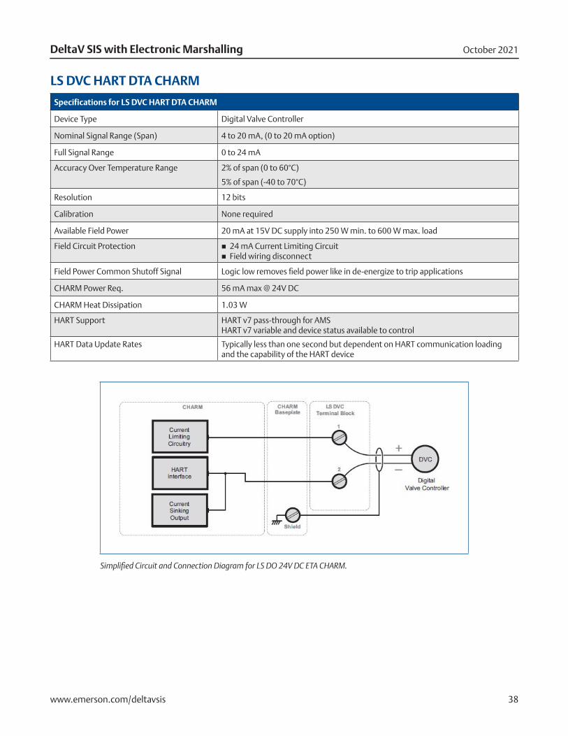
LS DVC HART DTA CHARM
Specifications for LS DVC HART DTA CHARM
Device Type Digital Valve Controller
Nominal Signal Range (Span) 4 to 20 mA, (0 to 20 mA option)
Full Signal Range 0 to 24 mA
Accuracy Over Temperature Range 2% of span (0 to 60°C)
5% of span (-40 to 70°C)
Resolution 12 bits
Calibration None required
Available Field Power 20 mA at 15V DC supply into 250 W min. to 600 W max. load
Field Circuit Protection � 24 mA Current Limiting Circuit � Field wiring disconnect
Field Power Common Shutoff Signal Logic low removes field power like in de-energize to trip applications
CHARM Power Req. 56 mA max @ 24V DC
CHARM Heat Dissipation 1.03 W
HART Support HART v7 pass-through for AMS HART v7 variable and device status available to control
HART Data Update Rates Typically less than one second but dependent on HART communication loading and the capability of the HART device
Simplified Circuit and Connection Diagram for LS DO 24V DC ETA CHARM.
October 2021DeltaV SIS with Electronic Marshalling
www.emerson.com/deltavsis 39
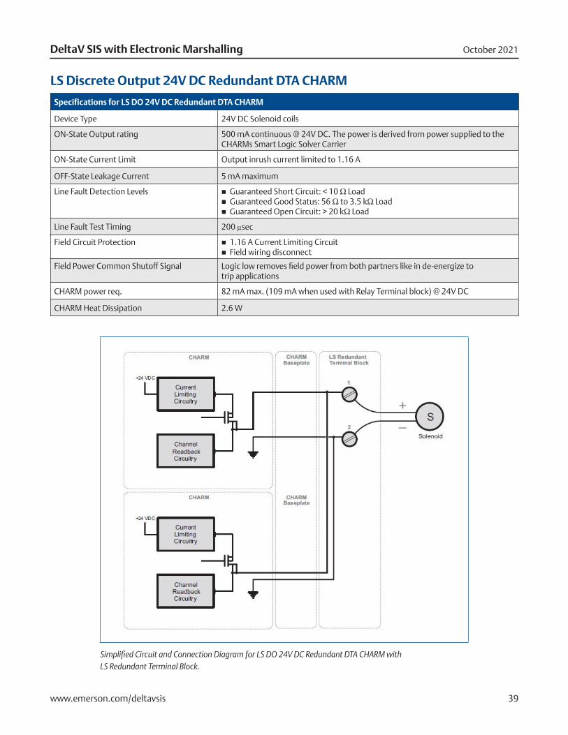
LS Discrete Output 24V DC Redundant DTA CHARM
Specifications for LS DO 24V DC Redundant DTA CHARM
Device Type 24V DC Solenoid coils
ON-State Output rating 500 mA continuous @ 24V DC. The power is derived from power supplied to the CHARMs Smart Logic Solver Carrier
ON-State Current Limit Output inrush current limited to 1.16 A
OFF-State Leakage Current 5 mA maximum
Line Fault Detection Levels � Guaranteed Short Circuit: < 10 Ω Load � Guaranteed Good Status: 56 Ω to 3.5 kΩ Load � Guaranteed Open Circuit: > 20 kΩ Load
Line Fault Test Timing 200 µsec
Field Circuit Protection � 1.16 A Current Limiting Circuit � Field wiring disconnect
Field Power Common Shutoff Signal Logic low removes field power from both partners like in de-energize to trip applications
CHARM power req. 82 mA max. (109 mA when used with Relay Terminal block) @ 24V DC
CHARM Heat Dissipation 2.6 W
Simplified Circuit and Connection Diagram for LS DO 24V DC Redundant DTA CHARM with LS Redundant Terminal Block.
October 2021DeltaV SIS with Electronic Marshalling
www.emerson.com/deltavsis 40
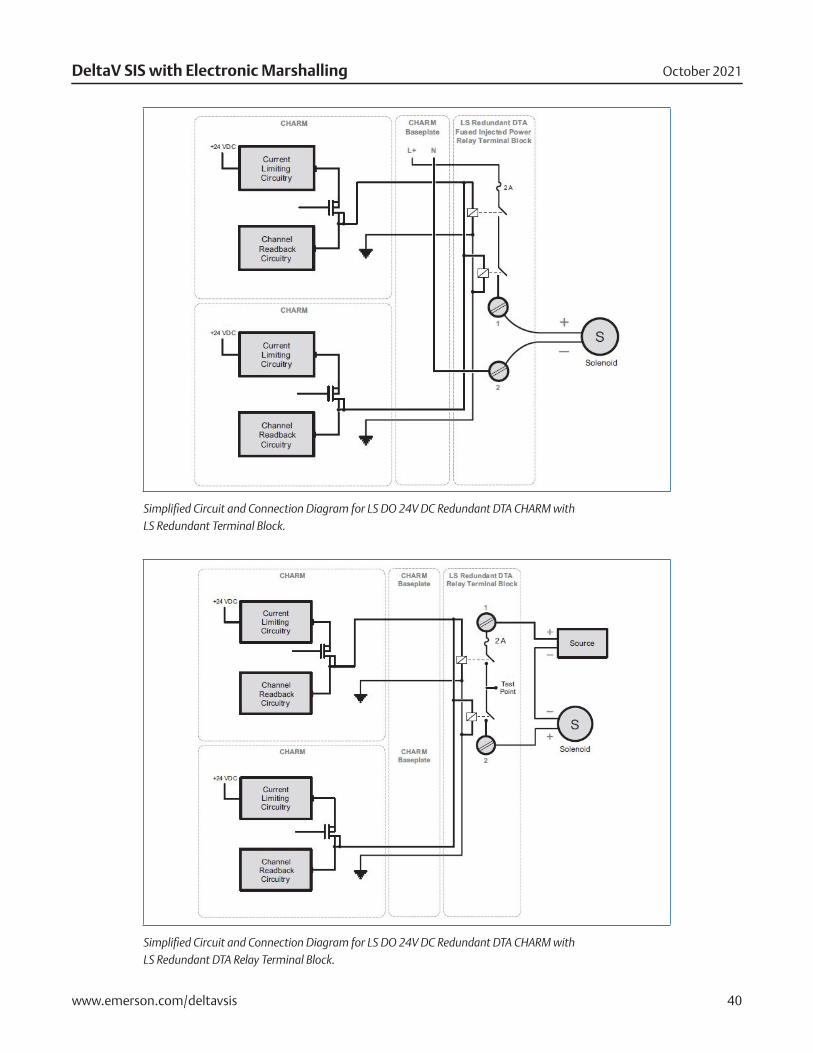
Simplified Circuit and Connection Diagram for LS DO 24V DC Redundant DTA CHARM with LS Redundant Terminal Block.
Simplified Circuit and Connection Diagram for LS DO 24V DC Redundant DTA CHARM with LS Redundant DTA Relay Terminal Block.

October 2021DeltaV SIS with Electronic Marshalling
www.emerson.com/deltavsis 41
LS Discrete Output 24V DC Redundant ETA CHARM
Specifications for LS DO 24V DC Redundant ETA CHARM
Device Type 24V DC Solenoid coils
ON-State Output rating 500 mA continuous @ 24V DC. The power is derived from power supplied to the CHARMs Smart Logic Solver Carrier
ON-State Current Limit Output inrush current limited to 1.16 A
OFF-State Leakage Current 5 mA maximum
Line Fault Detection Levels � Guaranteed Short Circuit: < 10 Ω Load � Guaranteed Good Status: 56 Ω to 3.5 kΩ Load � Guaranteed Open Circuit: > 20 kΩ Load
Line Fault Test Timing 200 µsec
Field Circuit Protection � 1.16 A Current Limiting Circuit � Field wiring disconnect
Field Power Common Shutoff Signal Logic low removes field power from both partners like in de-energize to trip applications
CHARM Power Req. 82 mA max.(109 mA when used with Relay Terminal block) @ 24V DC
CHARM Heat Dissipation 2.6 W
Simplified Circuit and Connection Diagram for LS DO 24V DC Redundant ETA CHARM with LS Redundant Terminal Block.
October 2021DeltaV SIS with Electronic Marshalling
www.emerson.com/deltavsis 42
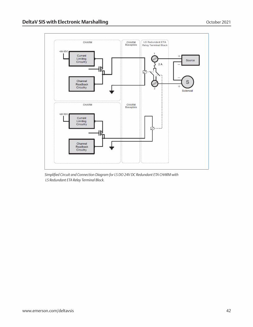
Simplified Circuit and Connection Diagram for LS DO 24V DC Redundant ETA CHARM with LS Redundant ETA Relay Terminal Block.
October 2021DeltaV SIS with Electronic Marshalling
www.emerson.com/deltavsis 43
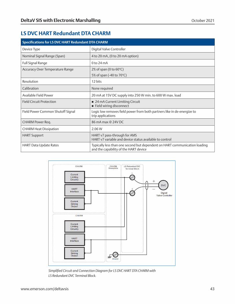
LS DVC HART Redundant DTA CHARM
Specifications for LS DVC HART Redundant DTA CHARM
Device Type Digital Valve Controller
Nominal Signal Range (Span) 4 to 20 mA, (0 to 20 mA option)
Full Signal Range 0 to 24 mA
Accuracy Over Temperature Range 2% of span (0 to 60°C)
5% of span (-40 to 70°C)
Resolution 12 bits
Calibration None required
Available Field Power 20 mA at 15V DC supply into 250 W min. to 600 W max. load
Field Circuit Protection � 24 mA Current Limiting Circuit � Field wiring disconnect
Field Power Common Shutoff Signal Logic low removes field power from both partners like in de-energize to trip applications
CHARM Power Req. 86 mA max @ 24V DC
CHARM Heat Dissipation 2.06 W
HART Support HART v7 pass-through for AMS HART v7 variable and device status available to control
HART Data Update Rates Typically less than one second but dependent on HART communication loading and the capability of the HART device
Simplified Circuit and Connection Diagram for LS DVC HART DTA CHARM with LS Redundant DVC Terminal Block.
October 2021DeltaV SIS with Electronic Marshalling
www.emerson.com/deltavsis 44
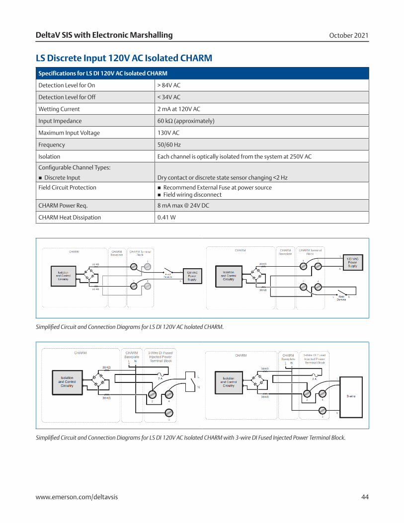
LS Discrete Input 120V AC Isolated CHARM
Specifications for LS DI 120V AC Isolated CHARM
Detection Level for On > 84V AC
Detection Level for Off < 34V AC
Wetting Current 2 mA at 120V AC
Input Impedance 60 kΩ (approximately)
Maximum Input Voltage 130V AC
Frequency 50/60 Hz
Isolation Each channel is optically isolated from the system at 250V AC
Configurable Channel Types:
� Discrete Input Dry contact or discrete state sensor changing <2 Hz
Field Circuit Protection � Recommend External Fuse at power source � Field wiring disconnect
CHARM Power Req. 8 mA max @ 24V DC
CHARM Heat Dissipation 0.41 W
Simplified Circuit and Connection Diagrams for LS DI 120V AC Isolated CHARM.
Simplified Circuit and Connection Diagrams for LS DI 120V AC Isolated CHARM with 3-wire DI Fused Injected Power Terminal Block.
October 2021DeltaV SIS with Electronic Marshalling
www.emerson.com/deltavsis 45
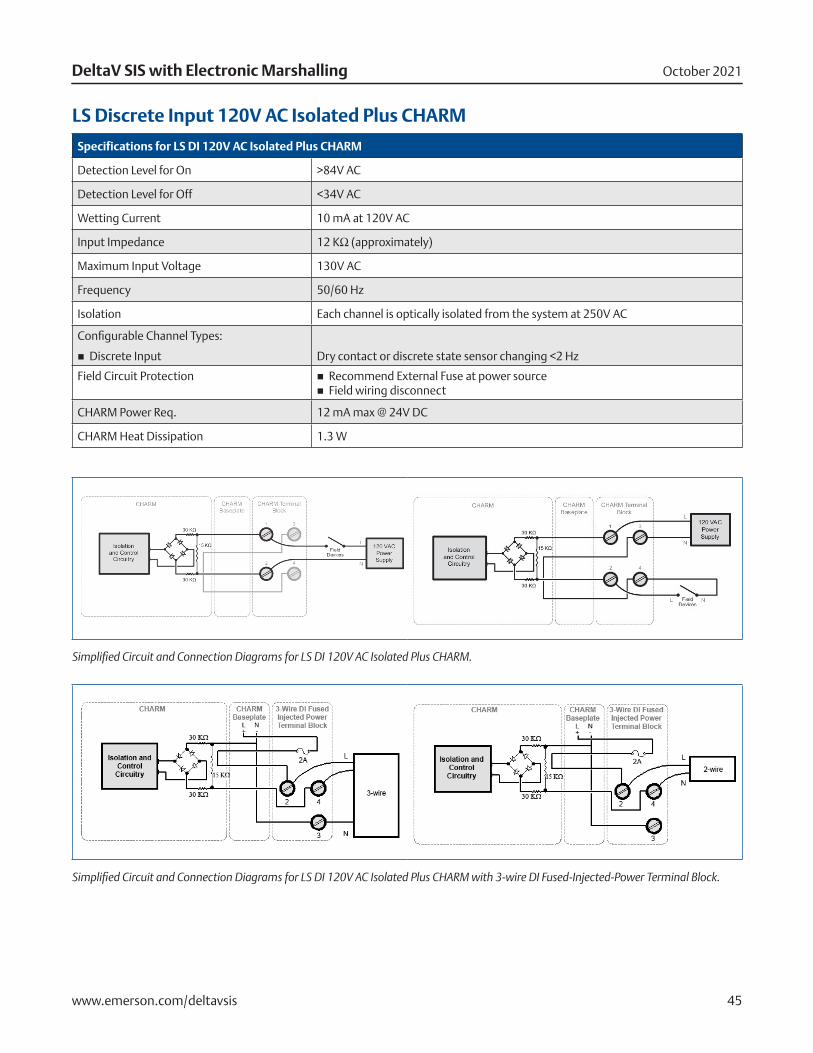
LS Discrete Input 120V AC Isolated Plus CHARM
Specifications for LS DI 120V AC Isolated Plus CHARM
Detection Level for On >84V AC
Detection Level for Off <34V AC
Wetting Current 10 mA at 120V AC
Input Impedance 12 KΩ (approximately)
Maximum Input Voltage 130V AC
Frequency 50/60 Hz
Isolation Each channel is optically isolated from the system at 250V AC
Configurable Channel Types:
� Discrete Input Dry contact or discrete state sensor changing <2 Hz
Field Circuit Protection � Recommend External Fuse at power source � Field wiring disconnect
CHARM Power Req. 12 mA max @ 24V DC
CHARM Heat Dissipation 1.3 W
Simplified Circuit and Connection Diagrams for LS DI 120V AC Isolated Plus CHARM.
Simplified Circuit and Connection Diagrams for LS DI 120V AC Isolated Plus CHARM with 3-wire DI Fused-Injected-Power Terminal Block.
October 2021DeltaV SIS with Electronic Marshalling
www.emerson.com/deltavsis 46
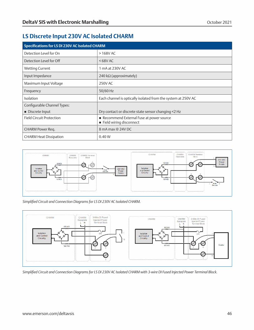
LS Discrete Input 230V AC Isolated CHARM
Specifications for LS DI 230V AC Isolated CHARM
Detection Level for On > 168V AC
Detection Level for Off < 68V AC
Wetting Current 1 mA at 230V AC
Input Impedance 240 kΩ (approximately)
Maximum Input Voltage 250V AC
Frequency 50/60 Hz
Isolation Each channel is optically isolated from the system at 250V AC
Configurable Channel Types:
� Discrete Input Dry contact or discrete state sensor changing <2 Hz
Field Circuit Protection � Recommend External Fuse at power source � Field wiring disconnect
CHARM Power Req. 8 mA max @ 24V DC
CHARM Heat Dissipation 0.40 W
Simplified Circuit and Connection Diagrams for LS DI 230V AC Isolated CHARM.
Simplified Circuit and Connection Diagrams for LS DI 230V AC Isolated CHARM with 3-wire DI Fused Injected Power Terminal Block.
October 2021DeltaV SIS with Electronic Marshalling
www.emerson.com/deltavsis 47
System Compatibility
DeltaV SIS with Electronic Marshalling hardware requires:
� v12.3 DeltaV SIS or later software SZ Controllers
� CHARMs Smart Logic Solvers (CSLS)
� LS-CHARMs
� DeltaV SIS Smart Switches
� AC power filter/suppressor
Certifications
The following certifications are available for DeltaV SIS with Electronic Marshalling:
� CE
EMC- EN 61326-1
� FM
FM 3600
FM 3611
� CSA
CSA C22.2 No. 213-M1987
CSA C22.2 No. 61010-1
� ATEX
EN60079-0
EN60079-15
� IEC-Ex
IEC60079-0
IEC60079-15
� Marine Certifications: IACS 10 ABS Certificate of Design Assessment DNV-GL Marine Certificate
� Achilles Communications Certification SZ Controller:
z Level 1 (v12.3)
z Level 2 (v13.3.1, v14.3, v14.FP1)
Hazardous Area/Location
DeltaV SIS with Electronic Marshalling can be installed and used based on the following Standards:
� FM (USA) Class I, Division 2, Groups A, B, C, D, T4
� cFM (Canada) Class I, Division 2, Groups A, B, C, D, T4
� ATEX II 3G Ex nA IIC T4 Gc II 3G Ex nA [nL] IIC T4 Gc II 3G Ex nA [ic] IIC T4 Gc II 3G Ex nA nC IIC T4 Gc
� IEC-Ex II 3G Ex nA IIC T4 Gc II 3G Ex nA nL IIC T4 Gc II 3G Ex nA ic IIC T4 Gc II 3G Ex nA nC IIC T4 Gc
Regarding the Installation instructions please refer to the following Documents:
Class 1 Division 2 Installation Instructions CHARM Subsystem 12P5401Class 1 Division 2 Installation Instructions DeltaV S-series 12P5402Zone 2 Installation Instructions CHARM Subsystem 12P5403Zone 2 Installation Instructions DeltaV S-series 12P5404
October 2021DeltaV SIS with Electronic Marshalling
www.emerson.com/deltavsis 48
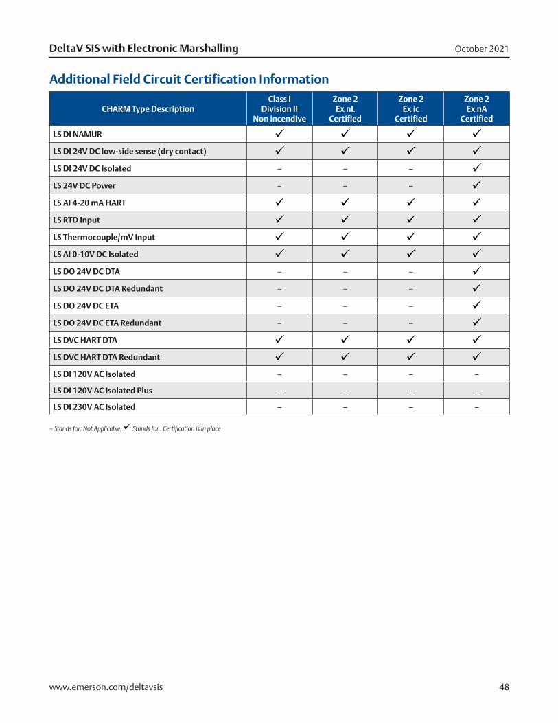
Additional Field Circuit Certification Information
CHARM Type DescriptionClass I
Division II Non incendive
Zone 2 Ex nL
Certified
Zone 2 Ex ic
Certified
Zone 2 Ex nA
Certified
LS DI NAMUR ü ü ü ü
LS DI 24V DC low-side sense (dry contact) ü ü ü ü
LS DI 24V DC Isolated – – – ü
LS 24V DC Power – – – ü
LS AI 4-20 mA HART ü ü ü üLS RTD Input ü ü ü ü
LS Thermocouple/mV Input ü ü ü ü
LS AI 0-10V DC Isolated ü ü ü ü
LS DO 24V DC DTA – – – ü
LS DO 24V DC DTA Redundant – – – ü
LS DO 24V DC ETA – – – ü
LS DO 24V DC ETA Redundant – – – ü
LS DVC HART DTA ü ü ü ü
LS DVC HART DTA Redundant ü ü ü ü
LS DI 120V AC Isolated – – – –
LS DI 120V AC Isolated Plus – – – –
LS DI 230V AC Isolated – – – –
– Stands for: Not Applicable; ü Stands for : Certification is in place
October 2021DeltaV SIS with Electronic Marshalling
www.emerson.com/deltavsis 49
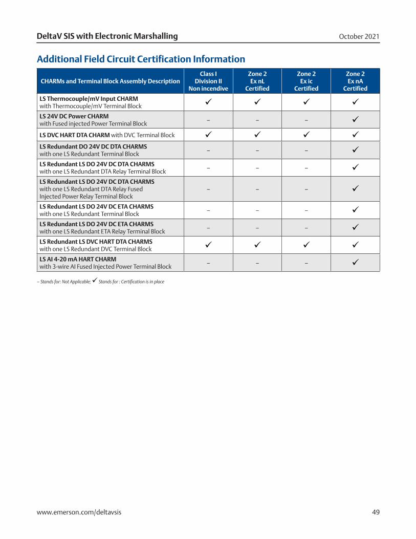
Additional Field Circuit Certification Information
CHARMs and Terminal Block Assembly DescriptionClass I
Division II Non incendive
Zone 2 Ex nL
Certified
Zone 2 Ex ic
Certified
Zone 2 Ex nA
Certified
LS Thermocouple/mV Input CHARM with Thermocouple/mV Terminal Block ü ü ü ü
LS 24V DC Power CHARM with Fused injected Power Terminal Block
– – – ü
LS DVC HART DTA CHARM with DVC Terminal Block ü ü ü üLS Redundant DO 24V DC DTA CHARMS with one LS Redundant Terminal Block
– – – üLS Redundant LS DO 24V DC DTA CHARMS with one LS Redundant DTA Relay Terminal Block
– – – üLS Redundant LS DO 24V DC DTA CHARMS with one LS Redundant DTA Relay Fused Injected Power Relay Terminal Block
– – – ü
LS Redundant LS DO 24V DC ETA CHARMS with one LS Redundant Terminal Block
– – – üLS Redundant LS DO 24V DC ETA CHARMS with one LS Redundant ETA Relay Terminal Block
– – – üLS Redundant LS DVC HART DTA CHARMS with one LS Redundant DVC Terminal Block ü ü ü üLS AI 4-20 mA HART CHARM with 3-wire AI Fused Injected Power Terminal Block
– – – ü
– Stands for: Not Applicable; ü Stands for : Certification is in place
October 2021DeltaV SIS with Electronic Marshalling
www.emerson.com/deltavsis 50
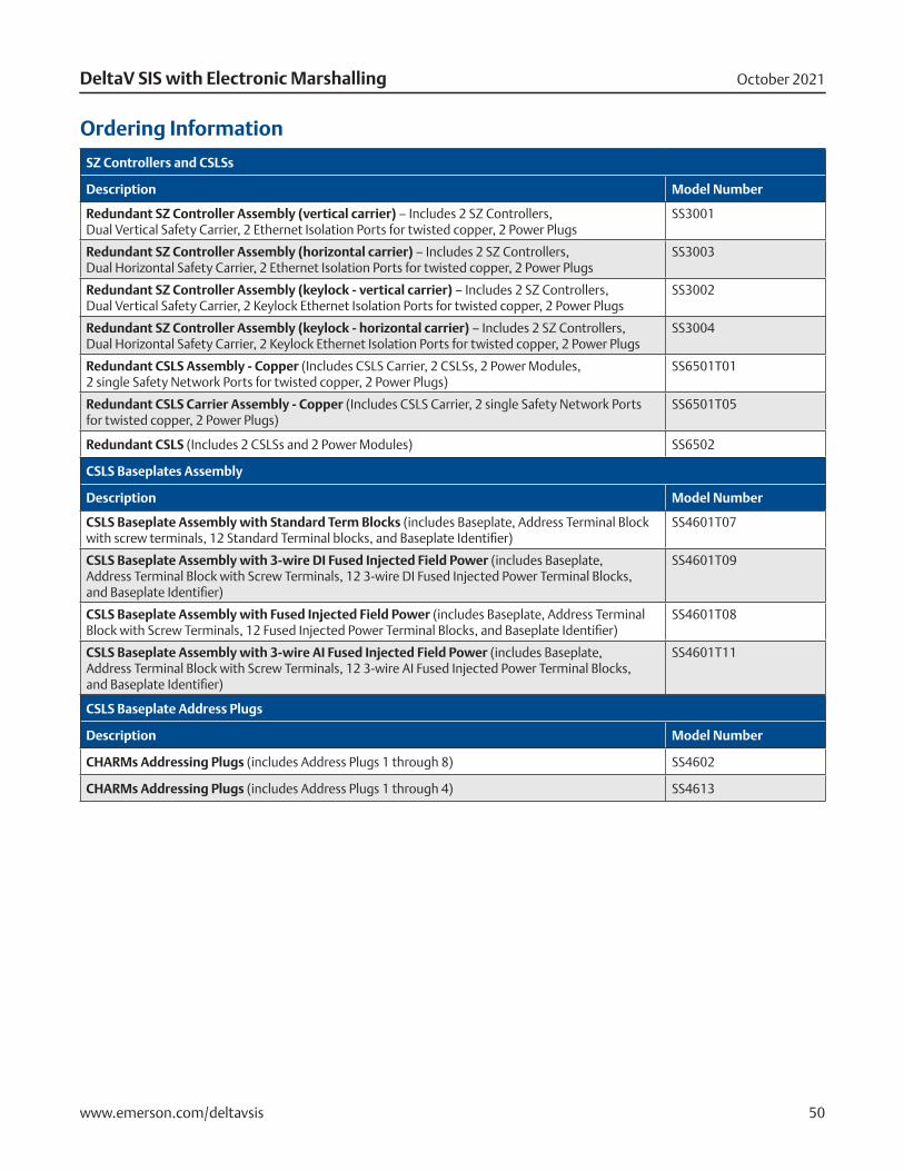
Ordering Information
SZ Controllers and CSLSs
Description Model Number
Redundant SZ Controller Assembly (vertical carrier) – Includes 2 SZ Controllers, Dual Vertical Safety Carrier, 2 Ethernet Isolation Ports for twisted copper, 2 Power Plugs
SS3001
Redundant SZ Controller Assembly (horizontal carrier) – Includes 2 SZ Controllers, Dual Horizontal Safety Carrier, 2 Ethernet Isolation Ports for twisted copper, 2 Power Plugs
SS3003
Redundant SZ Controller Assembly (keylock - vertical carrier) – Includes 2 SZ Controllers, Dual Vertical Safety Carrier, 2 Keylock Ethernet Isolation Ports for twisted copper, 2 Power Plugs
SS3002
Redundant SZ Controller Assembly (keylock - horizontal carrier) – Includes 2 SZ Controllers, Dual Horizontal Safety Carrier, 2 Keylock Ethernet Isolation Ports for twisted copper, 2 Power Plugs
SS3004
Redundant CSLS Assembly - Copper (Includes CSLS Carrier, 2 CSLSs, 2 Power Modules, 2 single Safety Network Ports for twisted copper, 2 Power Plugs)
SS6501T01
Redundant CSLS Carrier Assembly - Copper (Includes CSLS Carrier, 2 single Safety Network Ports for twisted copper, 2 Power Plugs)
SS6501T05
Redundant CSLS (Includes 2 CSLSs and 2 Power Modules) SS6502
CSLS Baseplates Assembly
Description Model Number
CSLS Baseplate Assembly with Standard Term Blocks (includes Baseplate, Address Terminal Block with screw terminals, 12 Standard Terminal blocks, and Baseplate Identifier)
SS4601T07
CSLS Baseplate Assembly with 3-wire DI Fused Injected Field Power (includes Baseplate, Address Terminal Block with Screw Terminals, 12 3-wire DI Fused Injected Power Terminal Blocks, and Baseplate Identifier)
SS4601T09
CSLS Baseplate Assembly with Fused Injected Field Power (includes Baseplate, Address Terminal Block with Screw Terminals, 12 Fused Injected Power Terminal Blocks, and Baseplate Identifier)
SS4601T08
CSLS Baseplate Assembly with 3-wire AI Fused Injected Field Power (includes Baseplate, Address Terminal Block with Screw Terminals, 12 3-wire AI Fused Injected Power Terminal Blocks, and Baseplate Identifier)
SS4601T11
CSLS Baseplate Address Plugs
Description Model Number
CHARMs Addressing Plugs (includes Address Plugs 1 through 8) SS4602
CHARMs Addressing Plugs (includes Address Plugs 1 through 4) SS4613
October 2021DeltaV SIS with Electronic Marshalling
www.emerson.com/deltavsis 51
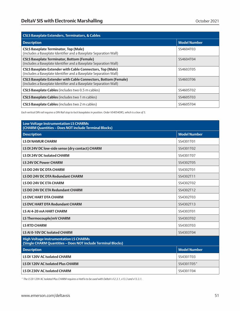
CSLS Baseplate Extenders, Terminators, & Cables
Description Model Number
CSLS Baseplate Terminator, Top (Male) (includes a Baseplate Identifier and a Baseplate Separation Wall)
SS4604T03
CSLS Baseplate Terminator, Bottom (Female) (includes a Baseplate Identifier and a Baseplate Separation Wall)
SS4604T04
CSLS Baseplate Extender with Cable Connectors, Top (Male) (includes a Baseplate Identifier and a Baseplate Separation Wall)
SS4603T05
CSLS Baseplate Extender with Cable Connectors, Bottom (Female) (includes a Baseplate Identifier and a Baseplate Separation Wall)
SS4603T06
CSLS Baseplate Cables (includes two 0.5 m cables) SS4605T02
CSLS Baseplate Cables (includes two 1 m cables) SS4605T03
CSLS Baseplate Cables (includes two 2 m cables) SS4605T04
Each vertical DIN rail requires a DIN Rail stop to lock baseplates in position. Order VE4054DRS, which is a box of 5.
Low Voltage Instrumentation LS CHARMs (CHARM Quantities – Does NOT include Terminal Blocks)
Description Model Number
LS DI NAMUR CHARM SS4301T01
LS DI 24V DC low-side sense (dry contact) CHARM SS4301T02
LS DI 24V DC Isolated CHARM SS4301T07
LS 24V DC Power CHARM SS4302T05
LS DO 24V DC DTA CHARM SS4302T01
LS DO 24V DC DTA Redundant CHARM SS4302T11
LS DO 24V DC ETA CHARM SS4302T02
LS DO 24V DC ETA Redundant CHARM SS4302T12
LS DVC HART DTA CHARM SS4302T03
LS DVC HART DTA Redundant CHARM SS4302T13
LS AI 4-20 mA HART CHARM SS4303T01
LS Thermocouple/mV CHARM SS4303T02
LS RTD CHARM SS4303T03
LS AI 0-10V DC Isolated CHARM SS4303T04
High Voltage Instrumentation LS CHARMs (Single CHARM Quantities – Does NOT include Terminal Blocks)
Description Model Number
LS DI 120V AC Isolated CHARM SS4301T03
LS DI 120V AC Isolated Plus CHARM SS4301T05*
LS DI 230V AC Isolated CHARM SS4301T04
* The LS DI 120V AC Isolated Plus CHARM requires a HotFix to be used with DeltaV v12.3.1, v13.3 and v13.3.1.
October 2021DeltaV SIS with Electronic Marshalling
www.emerson.com/deltavsis 52
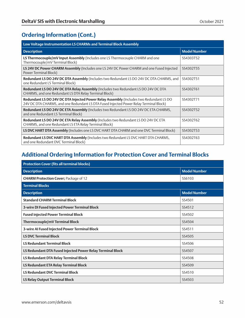
Ordering Information (Cont.)
Low Voltage Instrumentation LS CHARMs and Terminal Block Assembly
Description Model Number
LS Thermocouple/mV Input Assembly (Includes one LS Thermocouple CHARM and one Thermocouple/mV Terminal Block)
SS4303T52
LS 24V DC Power CHARM Assembly (Includes one LS 24V DC Power CHARM and one Fused Injected Power Terminal Block)
SS4302T55
Redundant LS DO 24V DC DTA Assembly (Includes two Redundant LS DO 24V DC DTA CHARMS, and one Redundant LS Terminal Block)
SS4302T51
Redundant LS DO 24V DC DTA Relay Assembly (Includes two Redundant LS DO 24V DC DTA CHARMS, and one Redundant LS DTA Relay Terminal Block)
SS4302T61
Redundant LS DO 24V DC DTA Injected Power Relay Assembly (Includes two Redundant LS DO 24V DC DTA CHARMS, and one Redundant LS DTA Fused Injected Power Relay Terminal Block)
SS4302T71
Redundant LS DO 24V DC ETA Assembly (Includes two Redundant LS DO 24V DC ETA CHARMS, and one Redundant LS Terminal Block)
SS4302T52
Redundant LS DO 24V DC ETA Relay Assembly (Includes two Redundant LS DO 24V DC ETA CHARMS, and one Redundant LS ETA Relay Terminal Block)
SS4302T62
LS DVC HART DTA Assembly (Includes one LS DVC HART DTA CHARM and one DVC Terminal Block) SS4302T53
Redundant LS DVC HART DTA Assembly (Includes two Redundant LS DVC HART DTA CHARMS, and one Redundant DVC Terminal Block)
SS4302T63
Additional Ordering Information for Protection Cover and Terminal Blocks
Protection Cover (fits all terminal blocks)
Description Model Number
CHARM Protection Cover; Package of 12 SS6103
Terminal Blocks
Description Model Number
Standard CHARM Terminal Block SS4501
3-wire DI Fused Injected Power Terminal Block SS4512
Fused injected Power Terminal Block SS4502
Thermocouple/mV Terminal Block SS4504
3-wire AI Fused Injected Power Terminal Block SS4511
LS DVC Terminal Block SS4505
LS Redundant Terminal Block SS4506
LS Redundant DTA Fused Injected Power Relay Terminal Block SS4507
LS Redundant DTA Relay Terminal Block SS4508
LS Redundant ETA Relay Terminal Block SS4509
LS Redundant DVC Terminal Block SS4510
LS Relay Output Terminal Block SS4503
October 2021DeltaV SIS with Electronic Marshalling
Contact Us www.emerson.com/contactus
©2021, Emerson. All rights reserved.
The Emerson logo is a trademark and service mark of Emerson Electric Co. The DeltaV logo is a mark of one of the Emerson family of companies. All other marks are the property of their respective owners.
The contents of this publication are presented for informational purposes only, and while diligent efforts were made to ensure their accuracy, they are not to be construed as warranties or guarantees, express or implied, regarding the products or services described herein or their use or applicability. All sales are governed by our terms and conditions, which are available on request. We reserve the right to modify or improve the designs or specifications of our products at any time without notice.
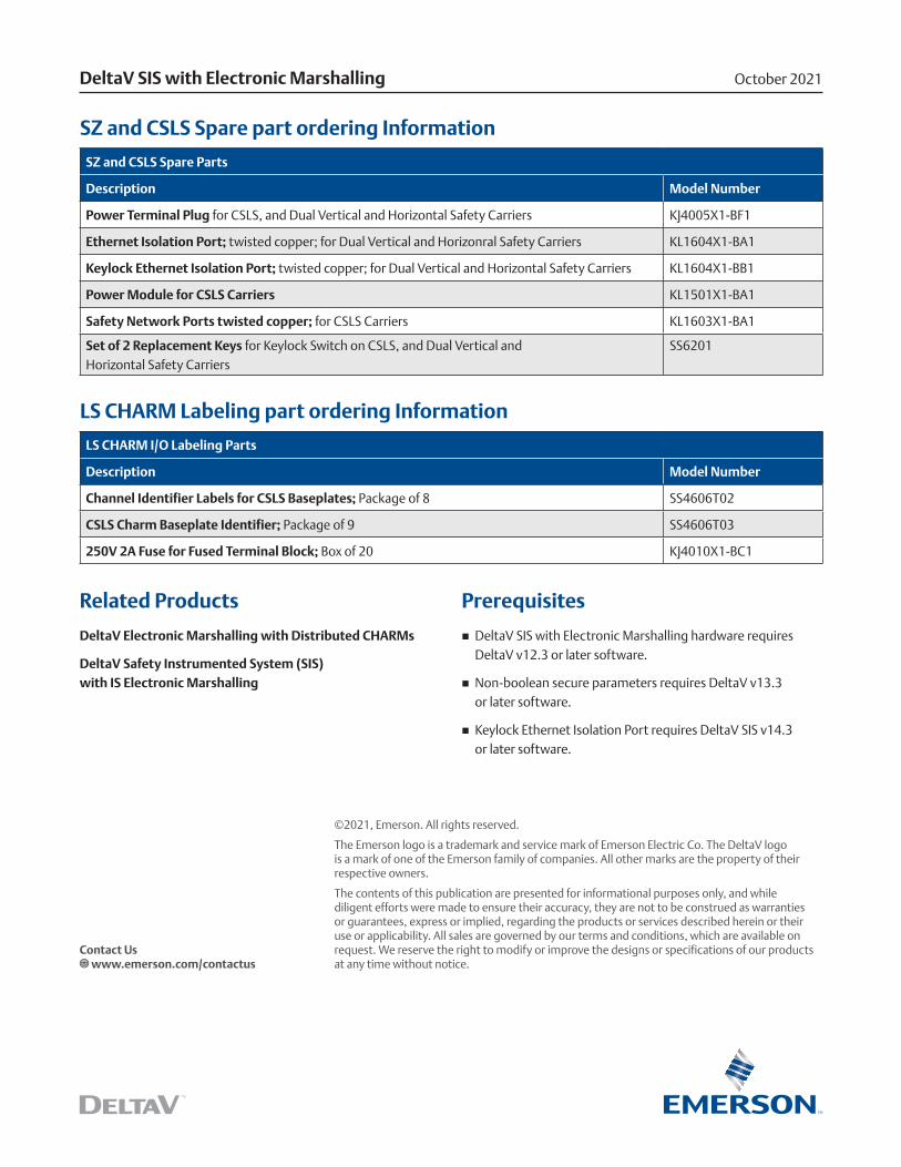
SZ and CSLS Spare part ordering Information
SZ and CSLS Spare Parts
Description Model Number
Power Terminal Plug for CSLS, and Dual Vertical and Horizontal Safety Carriers KJ4005X1-BF1
Ethernet Isolation Port; twisted copper; for Dual Vertical and Horizonral Safety Carriers KL1604X1-BA1
Keylock Ethernet Isolation Port; twisted copper; for Dual Vertical and Horizontal Safety Carriers KL1604X1-BB1
Power Module for CSLS Carriers KL1501X1-BA1
Safety Network Ports twisted copper; for CSLS Carriers KL1603X1-BA1
Set of 2 Replacement Keys for Keylock Switch on CSLS, and Dual Vertical and Horizontal Safety Carriers
SS6201
LS CHARM Labeling part ordering Information
LS CHARM I/O Labeling Parts
Description Model Number
Channel Identifier Labels for CSLS Baseplates; Package of 8 SS4606T02
CSLS Charm Baseplate Identifier; Package of 9 SS4606T03
250V 2A Fuse for Fused Terminal Block; Box of 20 KJ4010X1-BC1
Related Products
DeltaV Electronic Marshalling with Distributed CHARMs
DeltaV Safety Instrumented System (SIS) with IS Electronic Marshalling
Prerequisites
� DeltaV SIS with Electronic Marshalling hardware requires DeltaV v12.3 or later software.
� Non-boolean secure parameters requires DeltaV v13.3 or later software.
� Keylock Ethernet Isolation Port requires DeltaV SIS v14.3 or later software.
Related Documents