Digitized Automation for a Changing World www.deltaww.com Delta AC Servo Drive & Motor ASDA-M Series

Welcome message from author
This document is posted to help you gain knowledge. Please leave a comment to let me know what you think about it! Share it to your friends and learn new things together.
Transcript

Digitized Automation for a Changing World
www.deltaww.com
Delta AC Servo Drive & MotorASDA-M Series
1
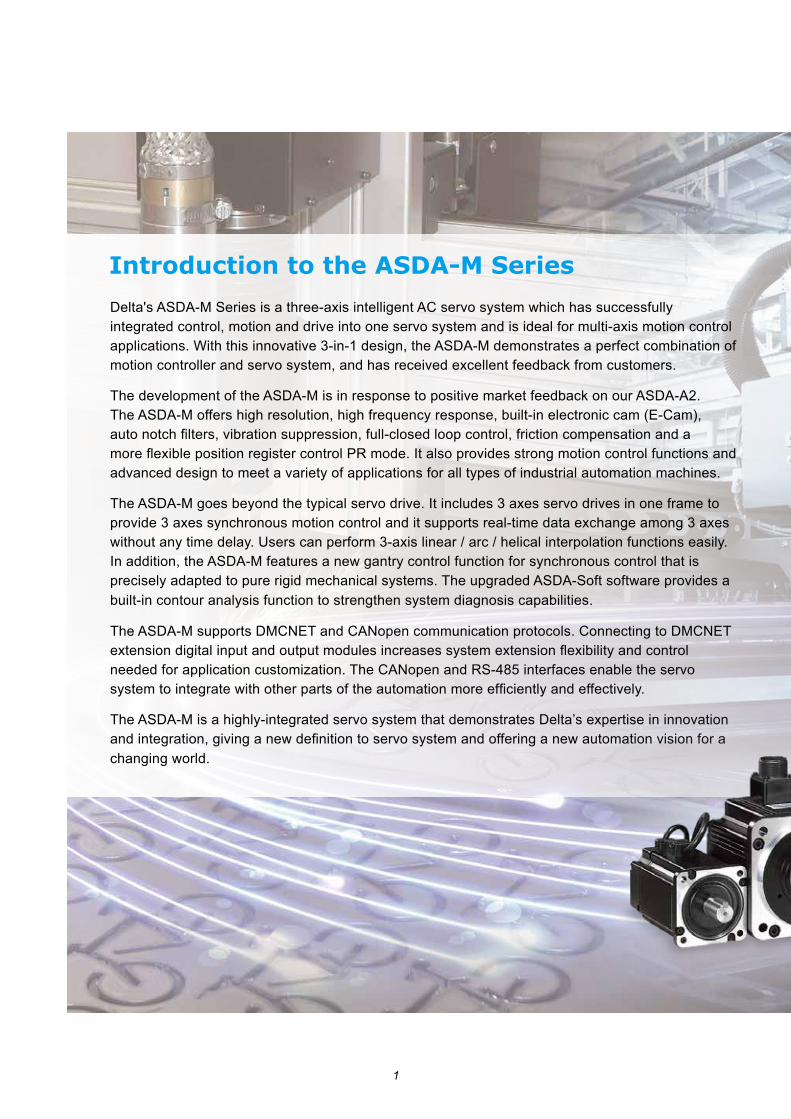
Delta's ASDA-M Series is a three-axis intelligent AC servo system which has successfully integrated control, motion and drive into one servo system and is ideal for multi-axis motion control applications. With this innovative 3-in-1 design, the ASDA-M demonstrates a perfect combination of motion controller and servo system, and has received excellent feedback from customers.
The development of the ASDA-M is in response to positive market feedback on our ASDA-A2. The ASDA-M offers high resolution, high frequency response, built-in electronic cam (E-Cam), auto notch filters, vibration suppression, full-closed loop control, friction compensation and a more flexible position register control PR mode. It also provides strong motion control functions and advanced design to meet a variety of applications for all types of industrial automation machines.
The ASDA-M goes beyond the typical servo drive. It includes 3 axes servo drives in one frame to provide 3 axes synchronous motion control and it supports real-time data exchange among 3 axes without any time delay. Users can perform 3-axis linear / arc / helical interpolation functions easily. In addition, the ASDA-M features a new gantry control function for synchronous control that is precisely adapted to pure rigid mechanical systems. The upgraded ASDA-Soft software provides a built-in contour analysis function to strengthen system diagnosis capabilities.
The ASDA-M supports DMCNET and CANopen communication protocols. Connecting to DMCNET extension digital input and output modules increases system extension flexibility and control needed for application customization. The CANopen and RS-485 interfaces enable the servo system to integrate with other parts of the automation more efficiently and effectively.
The ASDA-M is a highly-integrated servo system that demonstrates Delta’s expertise in innovation and integration, giving a new definition to servo system and offering a new automation vision for a changing world.
Introduction to the ASDA-M Series
2
1
3
15
17
18
19
20
21
23
28
29
31
34
37
39
41
46
50
50
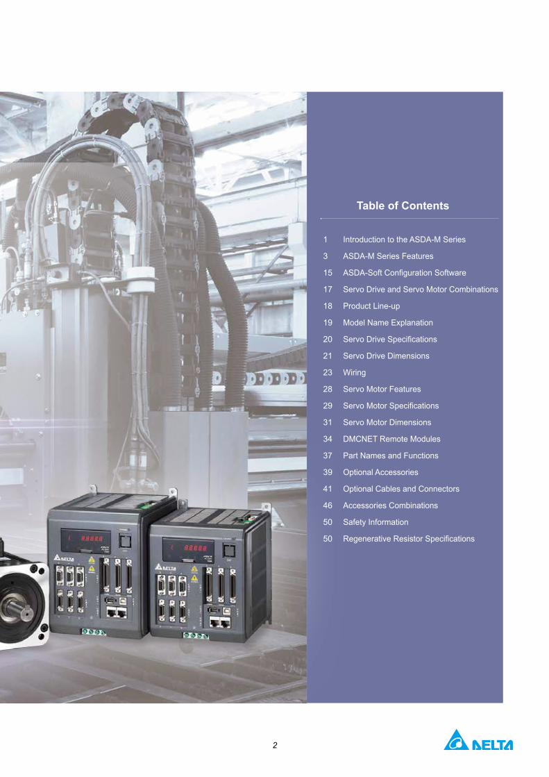
Table of Contents
Introduction to the ASDA-M Series
ASDA-M Series Features
ASDA-Soft Configuration Software
Servo Drive and Servo Motor Combinations
Product Line-up
Model Name Explanation
Servo Drive Specifications
Servo Drive Dimensions
Wiring
Servo Motor Features
Servo Motor Specifications
Servo Motor Dimensions
DMCNET Remote Modules
Part Names and Functions
Optional Accessories
Optional Cables and Connectors
Accessories Combinations
Safety Information
Regenerative Resistor Specifications

3
DT3
ASDA-M Series Features
ASDA-M Series Servo System
Real Time I/O (18 Inputs / 9 Outputs)
USB Connection Port for Direct Connection to Personal Computers or Notebooks
Z-Axis Y-Axis X-Axis
Highly Integrated System
■ Built-in motion control and PLC functions■ Multi-axis synchronous interpolation■ Advanced gantry control■ Flexible electronic cam (E-Cam) function■ High-speed frequency response
■ Excellent vibration and resonance suppression
■ High-precision full-closed loop control■ Versatile PR mode■ Real-time Capture and Compare functions

4
Real Time I/O (18 Inputs / 9 Outputs)
HMC SeriesController with Human Machine Interface
ASDA-A2 Series Servo DrivesASD-A2- * -F
DMCNET High-Speed Motion Control
Supports DMCNET Communication Protocol
32 DI / 32 DO or
16 DI / 16 DO
16-bit 4 D/Aor
16-bit 4 A/D4-Channel
Pulse Interface
■ Supports DMCNET and CANopen communication protocols.
■ With the aid of Delta's Human Machine Controller (HMC), it can establish an integrated system configuration by DMCNET.
■ Supports DMCNET interface for I/O extension modules.
High Precision, High Performance
■ Supports incremental type and absolute type encoders.
■ Incremental type encoder provides up to
1280000 p/rev resolution for high-precision positioning.
Real Time, Reliable and High-Speed Motion Control Network
5
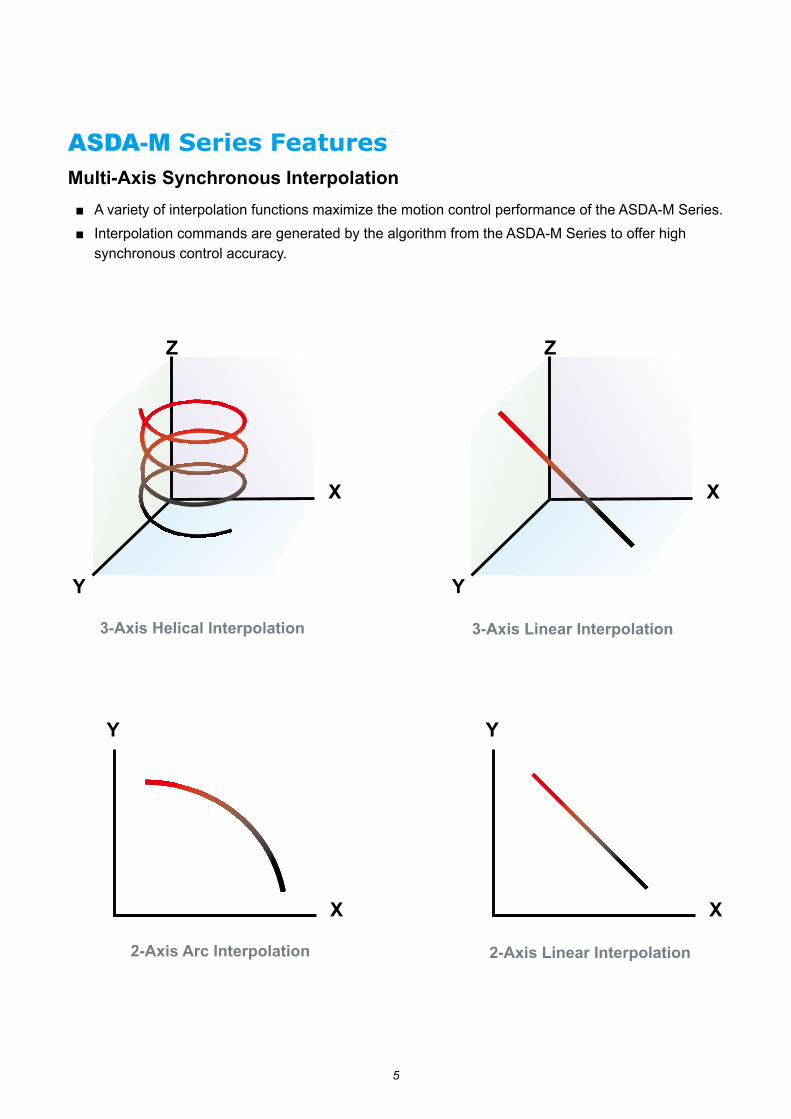
ASDA-M Series FeaturesMulti-Axis Synchronous Interpolation■ A variety of interpolation functions maximize the motion control performance of the ASDA-M Series.■ Interpolation commands are generated by the algorithm from the ASDA-M Series to offer high
synchronous control accuracy.
3-Axis Linear Interpolation3-Axis Helical Interpolation
2-Axis Arc Interpolation 2-Axis Linear Interpolation

6
Position, Speed and Torque commands are exchanged
between Axis 1 and Axis 2 every 62μs (16kHz)
Same DSP, Real Time, Excellent Synchronous Control
Advanced Gantry Control■ A large amount of data and calculations among two axes can be completed with the same DSP (Digital Signal Processor). Precise synchronization is easy to achieve. This greatly increases the efficiency and performance of gantry control.
■ In rigid or general mechanical systems, no matter if the loading on multiple axes is equal or not, the ASDA-M Series can perform precise motion control and drive each axis simultaneously.
Axis 1 Axis 2
Gantry Control
7
ASDA-M Series Features
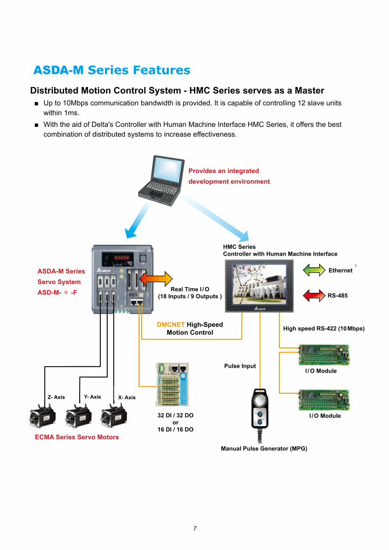
Distributed Motion Control System - HMC Series serves as a Master
Provides an integrated development environment
HMC SeriesController with Human Machine Interface
Real Time I / O (18 Inputs / 9 Outputs )
ASDA-M Series Servo SystemASD-M- * -F
Ethernet
RS-485
High speed RS-422 (10 Mbps)
I / O Module
I / O Module
Pulse Input
DMCNET High-Speed Motion Control
32 DI / 32 DO or
16 DI / 16 DO
Manual Pulse Generator (MPG)
ECMA Series Servo Motors
Z- Axis Y- Axis X- Axis
■ Up to 10Mbps communication bandwidth is provided. It is capable of controlling 12 slave units within 1ms.
■ With the aid of Delta's Controller with Human Machine Interface HMC Series, it offers the best combination of distributed systems to increase effectiveness.
8
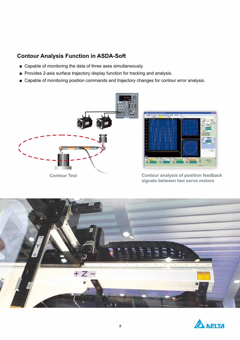
Contour Analysis Function in ASDA-Soft■ Capable of monitoring the data of three axes simultaneously.■ Provides 2-axis surface trajectory display function for tracking and analysis.■ Capable of monitoring position commands and trajectory changes for contour error analysis.
Contour Test Contour analysis of position feedback signals between two servo motors
9
ASDA-M Series Features
電子凸輪
Flexible Electronic Cam (E-Cam)
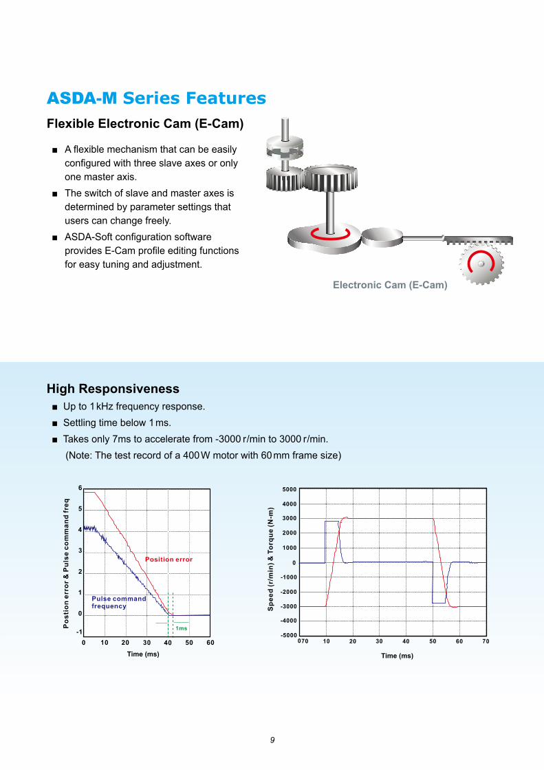
High Responsiveness■ Up to 1 kHz frequency response. ■ Settling time below 1 ms.■ Takes only 7ms to accelerate from -3000 r/min to 3000 r/min. (Note: The test record of a 400 W motor with 60 mm frame size)
■ A flexible mechanism that can be easily configured with three slave axes or only one master axis.
■ The switch of slave and master axes is determined by parameter settings that users can change freely.
■ ASDA-Soft configuration software provides E-Cam profile editing functions for easy tuning and adjustment.
Electronic Cam (E-Cam)
Time (ms) Time (ms)
10
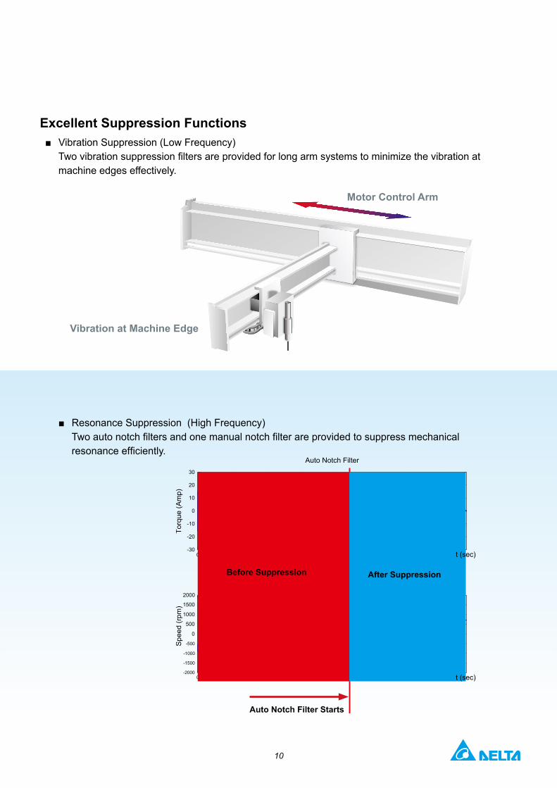
Excellent Suppression Functions■ Vibration Suppression (Low Frequency)
Two vibration suppression filters are provided for long arm systems to minimize the vibration at machine edges effectively.
■ Resonance Suppression (High Frequency) Two auto notch filters and one manual notch filter are provided to suppress mechanical resonance efficiently.
0 1 2 3 4 5 6 7-30
-20
-10
0
10
20
30
Torq
ue (A
mp)
Auto Notch Filter
0 1 2 3 4 5 6 7-2000
-1500
-1000
-500
0
500
1000
1500
2000
Spe
ed (r
pm)
t (sec)
t (sec)
Motor Control Arm
Vibration at Machine Edge
Before Suppression After Suppression
Auto Notch Filter Starts
11
ASDA-M Series Features
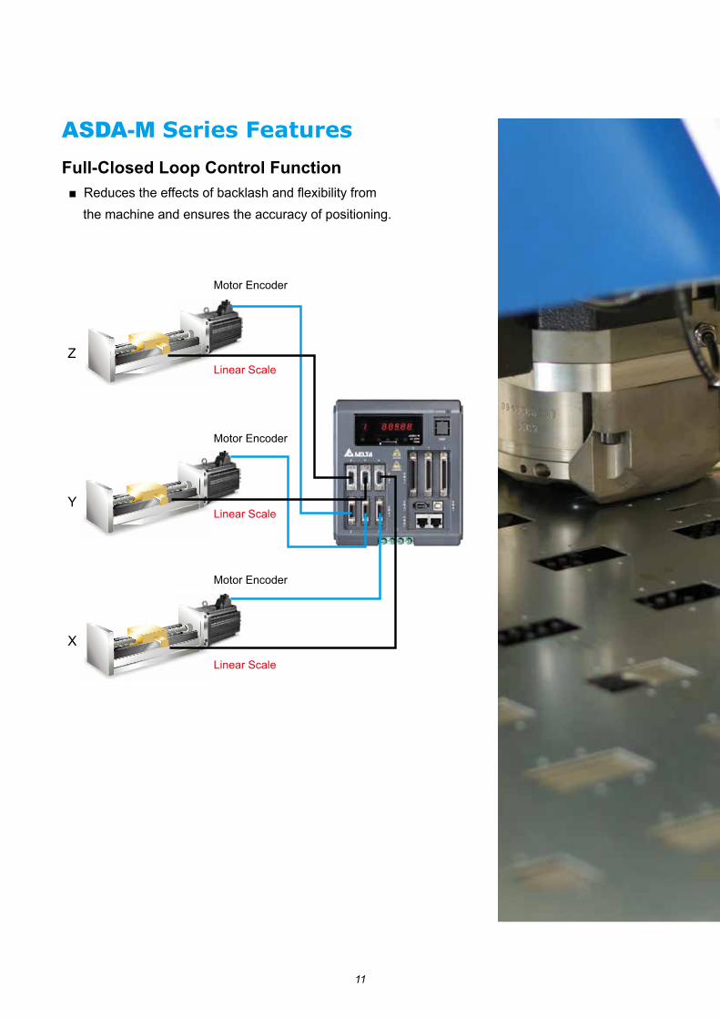
Full-Closed Loop Control Function■ Reduces the effects of backlash and flexibility from the machine and ensures the accuracy of positioning.
Motor Encoder
Motor Encoder
Motor Encoder
Linear Scale
Linear Scale
Linear Scale
X
Y
Z
12
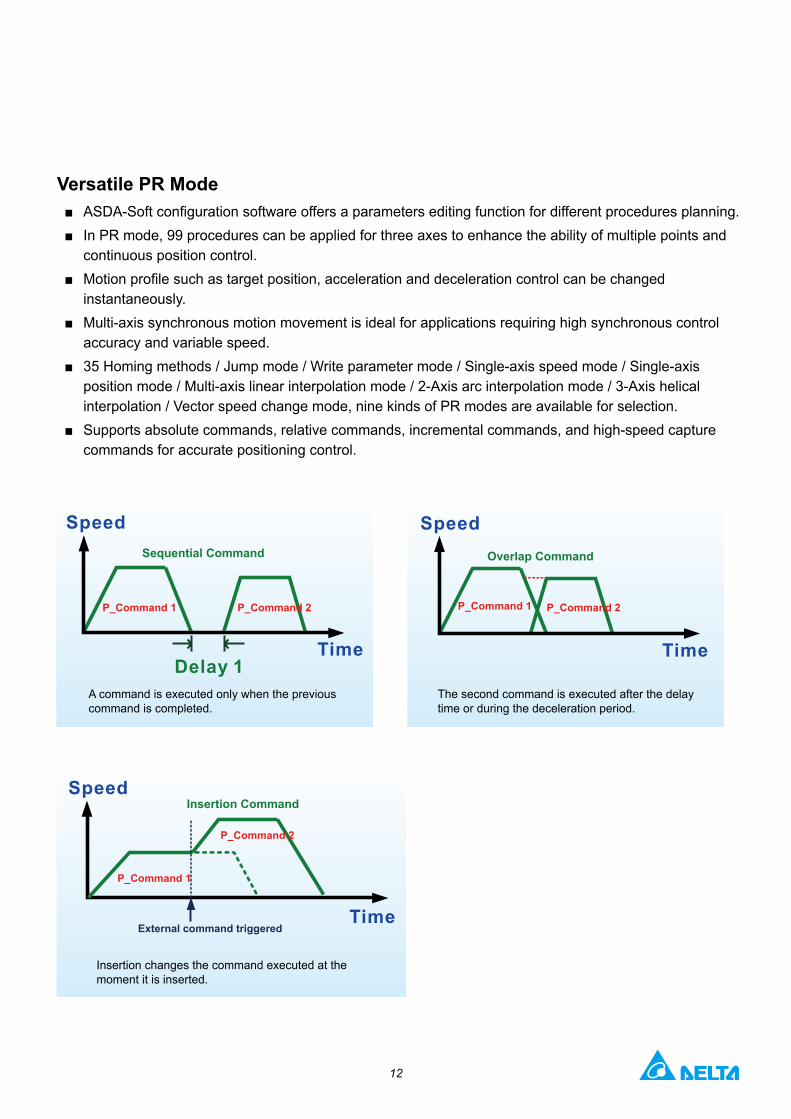
Versatile PR Mode■ ASDA-Soft configuration software offers a parameters editing function for different procedures planning.■ In PR mode, 99 procedures can be applied for three axes to enhance the ability of multiple points and
continuous position control.■ Motion profile such as target position, acceleration and deceleration control can be changed
instantaneously.■ Multi-axis synchronous motion movement is ideal for applications requiring high synchronous control
accuracy and variable speed.■ 35 Homing methods / Jump mode / Write parameter mode / Single-axis speed mode / Single-axis
position mode / Multi-axis linear interpolation mode / 2-Axis arc interpolation mode / 3-Axis helical interpolation / Vector speed change mode, nine kinds of PR modes are available for selection.
■ Supports absolute commands, relative commands, incremental commands, and high-speed capture commands for accurate positioning control.
Insertion changes the command executed at the moment it is inserted.
Sequential Command
P_Command 1 P_Command 1 P_Command 2 P_Command 2
Overlap Command
A command is executed only when the previous command is completed.
The second command is executed after the delay time or during the deceleration period.
Insertion Command
P_Command 1
External command triggered
P_Command 2

13
ASDA-M Series FeaturesReal Time Capture and Compare Functions Position Latch Function (Capture)■ Captures the coordinate value on the reference axis with a
response time less than 8μs. ■ It can be used to do mark tracking.■ Maximum 1500 records.
Position Detection Function (Compare)■ Promptly outputs pulses upon the axis reaching the target
position with a response time less than 5μs.■ It can be used for CCD camera applications.■ Maximum 1500 records.
When the record in Data Array is the same as the detected position, DO3 will output.
Motor Encoder
Position Detection Function (Compare)
==
Data Array
Data Array
Linear Encoder
Pulse Train
Motor Encoder

14
High-Accuracy Positioning ■ ECMA Series servo motors feature incremental encoders with 20-bit resolution
(1280000 p/rev) which can eliminate unstable commands at low speed, smooth motor operation and enhance the accuracy of positioning.
■ Supports 17-bit absolute system.
Reliable Communication on High-Speed Motion Control Network■ Complies with CANopen DS301 protocol, providing up to 1Mbps communication rate.■ Capable of connecting to maximum servo systems in position, speed and torque modes through
CANopen communication.
Incremental encoder resolution: 1280000 p/rev
Maximum 127 axes systems working on the same bus
Delta High-speed Communication Network
CANopen Master Module

15
ASDA-Soft Configuration Software
■ Strong Capture and Compare functions for position latch and detection help you complete system configuration quickly.
■ User-friendly E-Cam editing interface is provided for designing E-Cam profiles. Quick settings for flying shear and rotary cut applications are also offered.

16
■ Versatile monitoring function, similar to a digital oscilloscope is able to quickly record the status and data of each axis. Real-time monitoring is easy.
■ Convenient alarm display function is capable of troubleshooting the system easily and recommending timely corrective actions.
■ Easy-to-use editing interface is designed for new and enhanced PR control mode. Homing, point-to-point and other motion control functions for multi-axis positioning control are easy to achieve.
17
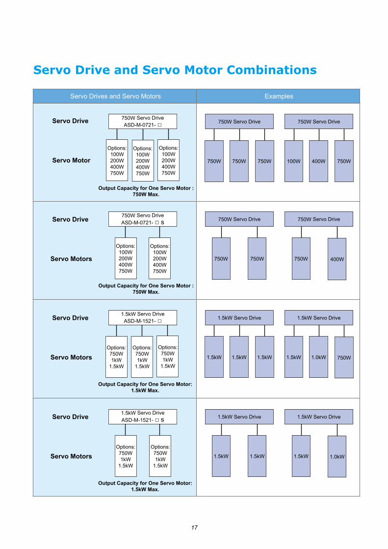
Servo Drives and Servo Motors Examples
Output Capacity for One Servo Motor : 750W Max.
Output Capacity for One Servo Motor: 1.5kW Max.
Servo Drive and Servo Motor Combinations
750W Servo Drive ASD-M-0721- □Servo Drive
Servo Motor
750W Servo Drive ASD-M-0721- □ s
Options:100W200W400W750W
Servo Drive
Servo Motors
750W Servo Drive
750W 750W 750W
750W Servo Drive
100W 400W 750W
750W Servo Drive
750W 750W
750W Servo Drive
750W 400W
1.5kW Servo Drive ASD-M-1521- □Servo Drive
Servo Motors
1.5kW Servo Drive
1.5kW 1.5kW 1.5kW
1.5kW Servo Drive
1.5kW 1.0kW 750W
1.5kW Servo Drive ASD-M-1521- □ s
Options:750W1kW
1.5kW
Servo Drive
Servo Motors
1.5kW Servo Drive
1.5kW 1.5kW
1.5kW Servo Drive
1.5kW 1.0kW
Options:750W1kW
1.5kW
Options:750W1kW
1.5kW
Options:750W1kW
1.5kW
Options:750W1kW
1.5kW
Options:100W200W400W750W
Options:100W200W400W750W
Options:100W200W400W750W
Options:100W200W400W750W
Output Capacity for One Servo Motor : 750W Max.
Output Capacity for One Servo Motor: 1.5kW Max.

18
Product Line-up
Note:1) The boxes ( □ ) at the ends of ASD-M servo drives are for optional configurations. Please refer to the actual servo drive product for more model name information.2) The triangles ( ) in the model names of the servo motors represent encoder type. =1: Incremental encoder, 20-bit ; =A: Absolute encoder, 17-bit ; =W: Absolute encoder, 24-bit (To be provided) 3) The boxes ( □ ) in the model names of the servo motors represent shaft end/brake or the number of oil seal.
Servo Drives
750W 1.5kW
ASD-M-0721- □ASD-M-0721- □ S
ASD-M-1521- □ASD-M-1521- □ S
Servo Motors
40ECMA-C1040F □ S
ECMA-C▲ 0401 □ S
60
ECMA-C▲ 0602 □ S
ECMA-C▲ 0604 □ S
ECMA-C▲ 0604 □ H
80
ECMA-C▲ 0804 □ 7
ECMA-C▲ 0807 □ S
ECMA-C▲ 0807 □ H
86ECMA-C▲ 0907 □ S
ECMA-C▲ 0910 □ S
100 ECMA-C▲ 1010 □ S
130
ECMA-E▲ 1305 □ S
ECMA-G▲ 1303 □ S
ECMA-G▲ 1306 □ S
ECMA-F▲ 1308 □ S
ECMA-F▲ 1313 □ S
ECMA-E▲ 1310 □ S
ECMA-E▲ 1315 □ S
ECMA-G▲ 1309 □ S
19
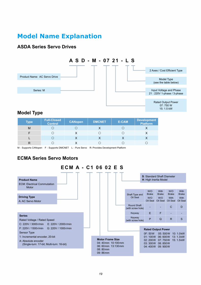
Model Name Explanation
ASDA Series Servo Drives
Model Type
Series: M
ECMA Series Servo Motors
ECM A - C1 06 02 E S
Product NameECM: Electrical Commutation Motor
Driving TypeA: AC Servo Motor
S: Standard Shaft DiameterH: High Inertia Model
Rated Output Power0F: 50W 05: 500W 10: 1.0kW01: 100W 06: 600W 13: 1.3kW02: 200W 07: 750W 15: 1.5kW03: 300W 08: 850W 04: 400W 09: 900W
SeriesRated Voltage / Rated SpeedC: 220V / 3000r/min E: 220V / 2000r/minF: 220V / 1500r/min G: 220V / 1000r/minSensor Type1: Incremental encoder, 20-bitA: Absolute encoder (Single-turn: 17-bit; Multi-turn: 16-bit)
Motor Frame Size04: 40mm 10:100mm 06: 60mm 13:130mm 08: 80mm 09: 86mm
Shaft Type and Oil Seal
W/O BrakeW/O
Oil Seal
With BrakeW/O
Oil Seal
W/O BrakeWith
Oil Seal
With BrakeWith
Oil Seal
Round Shaft (with screw hole) - - C D
Keyway E F - -Keyway
(with screw hole) P Q R S
A S D - M - 07 21 - L S
Model Type (see the table below)
2 Axes / Cost Efficient Type
Input Voltage and Phase 21 : 220V 1-phase / 3-phase
Rated Output Power07: 750 W 15: 1.5 kW
Product Name: AC Servo Drive
Type Full-ClosedControl CANopen DMCNET E-CAM Development
PlatformM ○ ○ X ○ XF ○ X ○ ○ XL ○ X X X XR ○ X ○ ○ ○
M:Supports CANopen F:Supports DMCNET L:Pure Servo R: Provides Development Platform

20
Servo Drive Specifications220V Series
ASDA-M Series750 W 1.5 kW
07 15
0721- □ 0721- □ S 1521- □ 1521- □ S
Pow
er
Supp
ly
Phase / Voltage Three-Phase or Single-Phase 220 VAC
Permissible Voltage Range Three-Phase or Single-Phase 200~230 VAC, -15% ~ 10%Input Current (3PH) (Units: Arms) 9.3 6.2 18.6 12.4Input Current (1PH) (Units: Arms) 17.817.8 11.811.8 33.3 22.222.2Continuous output current 5.1 8.3
Cooling System Fan CoolingEncoder Resolution / Feedback Resolution 20-bit (1280000 p/rev)Control of Main Circuit SVPWM (Space Vector Pulse Width Modulation) ControlTuning Modes Auto / ManualRegenerative Resistor None
Posi
tion
Con
trol
M
ode
Max. Input Pulse Frequency Max. 500 Kpps / 4 Mpps (Line driver) Max. 200 Kpps (Open collector)Pulse Type Pulse + Direction, A phase + B phase, CCW pulse + CW pulseCommand Source External pulse train (Pt mode) / Internal procedures (Pr mode)Smoothing Strategy Low-pass and P-curve filterElectronic Gear Electronic gear N/M multiple N: 1~32767, M: 1:32767 (1/50<N/M<25600)Torque Limit Operation Set by parametersFeed Forward Compensation Set by parameters
Spee
d C
ontr
ol M
ode
Analog Input Command
Voltage Range 0 ~ ±10 VDC
Input Resistance 10 KΩTime Constant 2.2 μs
Speed Control Range *1 1 : 5000Command Source External analog signal / Internal parametersSmoothing Strategy Low-pass and S-curve filterTorque Limit Operation Set by parameters or via analog inputFrequency Response Characteristic Maximum 1 kHz
Speed Accuracy *2
(at rated rotation speed)
0.01% or less at 0 to 100% load fluctuation0.01% or less at ±10% power fluctuation
0.01% or less at 0 ºC to 50 ºC ambient temperature fluctuation
Torq
ue
Con
trol
Mod
e Analog Input Command
Voltage Range 0 ~ ±10 VDC
Input Resistance 10 KΩTime Constant 2.2 μs
Command Source External analog signal / Internal parametersSmoothing Strategy Low-pass filterSpeed Limit Operation Set by parameters or via analog input
Analog Monitor Output Monitor signal can be set by parameters (Output voltage range: ±8 V)
Dig
ital
Inpu
ts/O
utpu
ts Inputs
Servo On, Reset, Gain switching, Pulse clear, Zero speed CLAMP, Command input reverse control, Command triggered, Speed/Torque limit enabled, Position command selection, Motor stop, Speed Position Selection, Position / Speed mode switching, Speed / Torque mode switching, Torque / Position mode switching, Pt / Pr command switching, Emergency stop, Forward / Reverse inhibit limit, Reference "Home" sensor, Forward / Reverse operation torque limit, Move to "Home", Electronic cam, Forward / Reverse JOG input, Event trigger Pr command, Electronic gear ratio (Numerator) selection and Pulse inhibit input
Outputs
Encoder signal output (A, B, Z Line Driver and Z Open Collector )Servo ready, Servo On, At Zero speed, At Speed reached, At Positioning completed, At Torques limit, Servo alarm (Servo fault) activated, Electromagnetic brake control, Homing completed, Output overload warning, Servo warning activated, Position command overflow, Forward / Reverse software limit, Internal position command completed, Capture operation completed output, Motion control completed output, Master position of E-CAM (electronic CAM)
Protective FunctionsOvercurrent, Overvoltage, Undervoltage, Motor overheated, Regeneration error, Overload, Overspeed, Abnormal pulse control command, Excessive deviation, Encoder error, Adjustment error, Emergency stop activated, Reverse/ Forward limit switch error, Position excessive deviation of full-close control loop, Serial communication error, Input power phase loss, Serial communication time out, short circuit protection of U, V, W, and CN1, CN2, CN3 terminals
Communication Interface RS-232 / RS-485 / CANopen / USB
Envi
ronm
ent
Installation Site Indoor location (free from direct sunlight), no corrosive liquid and gas (far away from oil mist,flammable gas, dust)Altitude Altitude 2000m or lower above sea levelAtmospheric pressure 86 kPa ~ 106 kPaOperating Temperature 0 ºC ~ 55 ºC(If operating temperature is above 45oC, forced cooling will be required)Storage Temperature -20 ºC ~ 65 ºC Humidity 0 ~ 90% RH (non-condensing)Vibration 20 Hz or below 9.80665 m/s2(1G),20 ~ 50Hz 5.88 m/s2(0.6 G)IP Rating IP20Power System TN System*3
Certifications IEC/EN 61800-5-1,UL 508C
Footnote:*1. Rated rotation speed: With a full load, speed ratio is defined as the minimum speed (the motor will not pause).*2. When command is rated rotation speed, the speed fluctuation rate is defined as: (Empty load rotation speed - Full load rotation speed) / Rated rotation speed*3. TN system: A power distribution system having one point directly earthed,
the exposed conductive parts of the installation being connected to that point by a protective earth conductor.

21
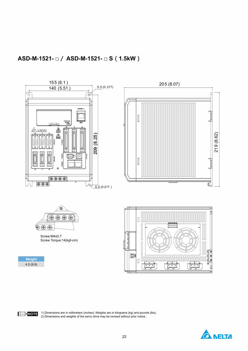
Servo Drive Dimensions
1) Dimensions are in millimeters (inches); Weights are in kilograms (kg) and pounds (lbs).2) Dimensions and weights of the servo drive may be revised without prior notice.
Weight3.5 (7.7)
185 (7.28)
267.
32 (7
.93)
190
(7.
48)
140 (5.51) 5.5 (0.217)
155 (6.1 )
Screw:M4x0.7Screw Torque:14(kgf-cm)
5.5 (0.217)
5.5 (0.217)
ASD-M-0721- □/ ASD-M-0721- □ S(750W)
22
1) Dimensions are in millimeters (inches); Weights are in kilograms (kg) and pounds (lbs).2) Dimensions and weights of the servo drive may be revised without prior notice.
Weight4.5 (9.9)
140 (5.51 )155 (6.1 )
209
(8.
25)
209
(8.
25)
5.5 (0. 217)
5.5 (0.217 )
205 (8.07)
219
(8.6
2)
Screw:M4x0.7Screw Torque:14(kgf-cm)
ASD-M-1521- □/ ASD-M-1521- □ S(1.5kW)

23
WiringPosition (PT) Control Mode (for Pulse Command Input)
High-speed pulse input (Line driver)
Pulse input (Open-collector PNP), for the use of internal power supply
Pulse input (Open-collector NPN), for the use of external power supply
Pulse input (Open-collector PNP), for the use of external power supply
Pulse input (Line driver)
Pulse input (Line driver).It requires 5 V power supply only.Never apply a 24 V power supply.
High-speed pulse input (Line driver).It requires 5 V power supply only.Never apply a 24 V power supply.
DC24V
51Ω
51Ω
51Ω
Approx. 1KΩ
Approx. 1KΩ
Max. Input pulse frequency is200Kpps
Max. Input pulse frequency is200Kpps
51Ω
SG
COM-
/SIGN
/PULSE
Pull-hi_S
VDD 17
35
45
37
41
Controller Servo Drive
Pull-hi_P 39
*
*
DC24V
51Ω
51Ω
51Ω
51Ω
SG COM-
/SIGN
/PULSE
VDD 17
35
45
37
41
39Pull-hi_P*
Pull-hi_S*
Controller Servo Drive
Max. Input pulse frequency is 200Kpps
Max. Input pulse frequency is 200Kpps
Approx. 1KΩ
Approx. 1KΩ
DC24V51Ω
51Ω
51Ω
51Ω
SG
COM-
/SIGN
/PULSE
Pull-hi_S 35
45
37
41
Pull-hi_P 39
*
*
+-
Controller Servo Drive
Approx. 1KΩ
Approx. 1KΩ
Max. Input pulse frequency is 200Kpps
Max. Input pulse frequency is 200Kpps
1KΩ 51Ω
51Ω
51Ω
51ΩSG
COM-
/SIGN
/PULSE
35
45
37
41
39Pull-hi_P*
Pull-hi_S*
DC24V+-
Controller Servo Drive
Max. Input pulse frequency is 200Kpps
Max. Input pulse frequency is 200Kpps
Approx.
1KΩApprox.
51Ω
51Ω
51Ω
51Ω
SG
/SIGN
/PULSE
SIGN 36
37
43 PULSE
41
Controller Servo Drive
Max. Input pulse frequency is 200Kpps
Max. Input pulse frequency is 200Kpps
2KΩ
2KΩ
2KΩ
2KΩ
SG
/HSIGN
/HPULSE
HSIGN 46
40
38 HPULSE
29
100Ω
100Ω
GNDGND13
Controller Servo Drive
* The wiring method of Pull-hi_S and Pull-hi_P is different from the ASDA-A2 Series. The purpose of this design is for connecting a PNP Transistor in a circuit.
SIGN/SIGN
12,13,19
45,47,49
T+
T-
-
+5V
-
GND
CN1
PDC
UVW
RST
L1cL2c
MCMCCBAC200/230V
Single-phase/Three-phase
50/60Hz
ASDA-M SeriesServo Drive
SONCCLRTCM0TCM1ARSTEMGS
1.5K
1.5K
1.5K
SRDY
ZSPD
HOME
24V
A Phase Pulse
Z
Phase Open Collector
10K
10K
Pulse InputLine Driver)
10K10V
High-speed Pulse InputLine Receiver)
10K
10K
DC 24V
SG
SG
Brake
Power Supply
Encoder
24V
3 groups
3 groups
3 groups
CANopen / DMCNET
Regenerative Resistor
Twisted-pair or twisted-shield cable
Encoder Pulse Output
RS485-
RS485+
RS232_RX
-
RS232_TX
GND
6
5
4
3
2
1
+5V DC
Data-
Data+
GND
CN3
5
4
7
9
14,16
13,15
CN2
CN41
2
3
4
CN5
8
4
5
3
2
9
1
6
7
+
Opt B
Opt/B
Opt Z
Opt/Z
GND
5V
Opt A
Opt/A
GND
CN61, 9
2, 10
3, 11
4, 12
5, 13
6, 14
7, 15
8, 16
CAN H / FRA1
CAN H / FRA1
- / FRA2
-
-
-
- / FRB2
-
8
4
5
3
2
9
1
6
7
37
36
41
43
18
13
40
46
29
38
16
15
17
11
9
10
34
8
33
32
7
6
5
4
3
2
21
22
25
23
50
24
48
13
/SIGN
SIGN
/PULSE
PULSE
T-REF
GND
/HSIGN
HSIGN
/HPULSE
HPULSE
MON1
GND
MON2
VDD
COM+
COM-
DI1
DI2
DI3
DI4
DI5
DI 6
DO1+
DO1-
DO2+
DO2-
DO3+
DO3-
OA
/OA
OB
/OB
OZ
/OZ
OCZ
GND
Red
White
Black
Green
Blue
Blue/Black
Green
Green/Black
Black
Red
Twisted-pair or twisted-shield cable
B Phase Pulse
Z Phase Pulse
EMGS BRKR *1
*²
ΩΩ
Ω
Ω
Ω
Ω
Ω
Ω
(
(
⊕
±
4.7KΩ
4.7KΩ
4.7KΩ
4.7KΩ
4.7KΩ
4.7KΩ
Max. OutputCurrent 50mAVoltage 30V
**1:2:
The CN6 port of ASD-M-xxxx-M models arefor CANopen communication. The CN6 port of ASD-M-xxxx-F models arefor DMCNET communication.
The brake oil has no polarity.Please note:
24
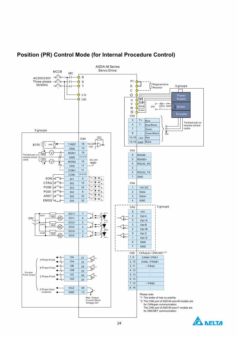
Position (PR) Control Mode (for Internal Procedure Control)
12,13,19
45,47,49
18
13
16
CN1
RST
L1cL2c
MCMCCB
AC200/230V
50/60HzThree-phase
SONCTRGPOS0POS1ARSTEMGS
1.5K
1.5K
1.5K
SRDY
ZSPD
HOME
24V
10K
10K
10K10V10K
10K
DC 24V
SG
PDC
UVW
SG
24V
3 groups
CANH / FRA1
CANL / FRAB1
- / FRA2
-
-
- / FRB2
-
CN2
CN3
6
5
4
3
2
1
RS485-
RS485+
RS232_RX
-
RS232_TX
GND
CN4
1
2
3
4
+5V DC
Data-
Data+
GND
3 groupsCN5
8
4
5
3
2
9
1
6
7
+5V
Opt A
Opt /A
Opt B
Opt /B
Opt Z
Opt /Z
GND
GND
CN61, 9
2, 10
3, 11
4, 12
5, 13
6, 14
7, 15
8, 16
CANopen / DMCNET
3 groups
T-REF
GND
MON1
GND
MON2
VDD
COM+
COM-
DI1
DI2
DI3
DI4
DI5
DI6
DO1+
DO1-
DO2+
DO2-
DO3+
DO3-
OA
/OA
OB
/OB
OZ
/OZ
15
17
11
9
10
34
8
33
32
7
6
5
4
3
2
21
22
25
23
50
24
48
13
OCZ
GND
Twisted-pair ortwisted-shieldcable
RegenerativeResistor
Green
RedWhite
Black
Twisted-pair ortwisted-shieldcable
T+
T-
-
+5V
-
GND
5
4
7
9
14,16
13,15
Blue
Blue/Black
Green
Green/Black
Black
Red
A Phase Pulse
Z Phase OpenCollector
EncoderPulse Output
B Phase Pulse
Z Phase Pulse
Max. OutputCurrent 50mAVoltage 30V
EMGS BRKR *1
*²
ΩΩ
Ω
Ω
Ω
Ω
Ω
Ω
⊕
±
4.7KΩ
4.7KΩ
4.7KΩ
4.7KΩ
4.7KΩ
4.7KΩ
Brake
Power Supply
Encoder
ASDA-M SeriesServo Drive
**1:2:
The CN6 port of ASD-M-xxxx-M models arefor CANopen communication. The CN6 port of ASD-M-xxxx-F models arefor DMCNET communication.
The brake oil has no polarity.Please note:

25
WiringSpeed (S, Sz) Control Mode (for Analog Voltage Input and Internal Parameter Setting)
12,13,19
45,47,49
CN1
RST
L1cL2c
MCMCCB
SONTRQLM
SPD0SPD1ARSTEMGS
1.5K
1.5K
1.5K
SRDY
ZSPD
TSPD
24V
10K
10K
10K10V10K
10K
DC 24V
SG
10K
10K10K10V
PDC
UVW
SG
24V
3 groups
RS485-
RS485+
RS232_RX
-
RS232_TX
GND
6
5
4
3
2
1
CN3
CN2
+5V DC
Data-
Data+
GND
CN4
1
2
3
4
3 groupsCN5+
Opt B
Opt/B
Opt Z
Opt/Z
GND
5V
Opt A
Opt/A
GND
8
4
5
3
2
9
1
6
7
CANopen / DMCNETCN61, 9
2, 10
3, 11
4, 12
5, 13
6, 14
7, 15
8, 16
CAN H / FRA1
CAN H / FRA1
- / FRA2
-
-
-
- / FRB2
-
V-REF
GND
T-REF
GND
MON1
GND
MON2
VDD
COM+
COM-
DI1
DI2
DI3
DI4
DI5
DI16
DO1+
DO1-
DO2+
DO2-
DO3+
DO3-
OA
/OA
OB
/OB
OZ
/OZ
42
44
18
13
16
15
17
11
9
10
34
8
33
32
7
6
5
4
3
2
21
22
25
23
50
24
48
13
OCZ
GND
3 groups
AC200/230V
50/60HzThree-phase
T+
T-
-
+5V
-
GND
5
4
7
9
14,16
13,15
Blue
Blue/Black
Green
Green/Black
Black
Red
Red
White
Black
Green
A Phase Pulse
Z Phase OpenCollector
EncoderPulse Output
B Phase Pulse
Z Phase Pulse
Max. OutputCurrent 50mAVoltage 30V
Twisted-pair ortwisted-shieldcable
Twisted-pair ortwisted-shieldcable
RegenerativeResistor
EMGS BRKR *1
*²
Ω Ω
Ω
Ω
Ω
4.7KΩ
4.7KΩ
4.7KΩ
4.7KΩ
4.7KΩ
4.7KΩ
Ω
⊕
±
±
Ω
Ω
Ω
Ω
Ω
Brake
Power Supply
Encoder
Please note:**1:2:
The CN6 port of ASD-M-xxxx-M models arefor CANopen communication. The CN6 port of ASD-M-xxxx-F models arefor DMCNET communication.
ASDA-M SeriesServo Drive
The brake oil has no polarity.

26
Torque (T, Tz) Control Mode (for Analog Voltage Input and Internal Parameter Setting)
12,13,19
45,47,49
CN1
RST
L1cL2c
MCMCCB
SONSPDLM
TCM0TCM1ARSTEMGS
1.5K
1.5K
1.5K
SRDY
ZSPD
TSPD
24V
10K
10K
10K10V10K
10K
DC 24V
SG
10K
10K10K10V
PDC
UVW
SG
24V
4.7K
4.7K
4.7K
4.7K
4.7K
4.7K
3 groups
CN2
CN36
5
4
3
2
1
RS485-
RS485+
RS232_RX
-
RS232_TX
GND
CN4
1
2
3
4
+5V DC
Data-
Data+
GND
CN5
8
4
5
3
2
9
1
6
7
+5V
Opt A
Opt /A
Opt B
Opt /B
Opt Z
Opt /Z
GND
GND
3 groups
CANH / FRA1
CANL / FRAB1
- / FRA2
-
-
- / FRB2
-
CN6 CANopen / DMCNET1, 9
2, 10
3, 11
4, 12
5, 13
6, 14
7, 15
8, 1648
13
OCZ
GND
42
44
18
13
16
3 groups
V-REF
GND
T-REF
GND
MON1
GND
MON2
VDD
COM+
COM-
DI1
DI2
DI3
DI4
DI5
DI6
DO1+
DO1-
DO2+
DO2-
DO3+
DO3-
OA
/OA
OB
/OB
OZ
/OZ
15
17
11
9
10
34
8
33
32
7
6
5
4
3
2
21
22
25
23
50
24
AC200/230V
50/60HzThree-phase Regenerative
Resistor
Twisted-pair ortwisted-shieldcable
Green
RedWhite
Black
T+
T-
-
+5V
-
GND
5
4
7
9
14,16
13,15
Blue
Blue/Black
Green
Green/Black
Black
Red
Twisted-pair ortwisted-shieldcable
A Phase Pulse
Z Phase OpenCollector
EncoderPulse Output
B Phase Pulse
Z Phase Pulse
Max. OutputCurrent 50mAVoltage 30V
*²
EMGS BRKR *1
Ω
Ω
ΩΩ
ΩΩ
⊕
±
±
Ω
Ω
Ω
Ω
Ω
Ω
Ω
Ω
Ω
Ω
Ω
Brake
Power Supply
Encoder
ASDA-M SeriesServo Drive
**1:2:
The CN6 port of ASD-M-xxxx-M models arefor CANopen communication. The CN6 port of ASD-M-xxxx-F models arefor DMCNET communication.
The brake oil has no polarity.Please note:

27
Wiring CANopen / DMCNET Communication Mode ( for ASDA-M-M Series and ASDA-M-F Series )
45,47,49
CN1
RST
L1cL2c
MCMCCB
PLEMGS
1.5K
1.5K
1.5K
SRDY
ZSPD
HOME
DC 24V
PDC
UVW
SG
24V
Data Input
ORGPNL
24V
3 groups
CN2
+5V
Data-
Data+
GND
CN4
1
2
3
4
3 groupsCN5+
Opt B
Opt/B
Opt Z
Opt/Z
GND
5V
Opt A
Opt/A
GND
8
4
5
3
2
9
1
6
7
CANopen / DMCNETCN61
2
3
4
5
6
7
8
CAN H / FRA1
CAN H / FRA1
- / FRA2
-
-
-
- / FRB2
-
CAN H / FRA1
CAN H / FRA1
- / FRA2
-
-
-
- / FRB2
-
9
10
11
12
13
14
15
16
48
13
OCZ
GND
3 groups
17
11
19
10
34
8
33
32
7
6
5
4
3
2
21
22
25
23
50
24
VDD
COM+
COM-
Di1
DI2
DI3
DI4
DI5
DI6
DO1+
DO1-
DO2+
DO2-
DO3+
DO3-
OA
/OA
OB
/OB
OZ
/OZ
RS485-
RS485+
RS232_RX
-
RS232_TX
GND
6
5
4
3
2
1
CN3
A Phase Pulse
Z Phase OpenCollector
EncoderPulse Output
B Phase Pulse
Z Phase Pulse
Max. OutputCurrent 50mAVoltage 30V
AC200/230V
50/60HzThree-phase Regenerative
Resistor
Twisted-pair ortwisted-shieldcable
T+
T-
-
+5V
-
GND
5
4
7
9
14,16
13,15
Blue
Blue/Black
Green
Green/Black
Black
Red
Green
RedWhite
Black
Data Input
EMGS BRKR *1
ReservedReserved
*²
⊕
4.7KΩ
4.7KΩ
4.7KΩ
4.7KΩ
4.7KΩ
4.7KΩ
Ω
Ω
Ω
DC
Brake
Power Supply
Encoder
**1:2:
The CN6 port of ASD-M-xxxx-M models arefor CANopen communication. The CN6 port of ASD-M-xxxx-F models arefor DMCNET communication.
The brake oil has no polarity.
ASDA-M SeriesServo Drive
Please note:

28
Servo Motor Features
ECMA Series servo motors are permanent AC servo motors. There are six kinds of frame sizes available: 40mm, 60mm, 80mm, 86mm, 100mm and 130mm. The motor speed is up to 5000 r/min and the torque output can reach 21.48 N-m.
In terms of optional configurations, the ECMA Series provides a brake and oil seals to fully support our customers' needs. It also offers two different shaft selections, round shaft and keyway, for various applications.

29
Low Inertia Series
ECMA SeriesC104 C 04 C 06 C 08 C 09 C 10
0F 01 02 04 □ S 04 07 07 10 10 Rated output power (kW) 0.05 0.1 0.2 0.4 0.4 0.75 0.75 1.0 1.0
Rated torque (N-m)*1 0.159 0.32 0.64 1.27 1.27 2.39 2.39 3.18 3.18
Maximum torque (N-m) 0.477 0.96 1.92 3.82 3.82 7.16 7.14 8.78 9.54
Rated speed (r/min) 3000 3000 3000
Maximum speed (r/min) 5000 3000 5000
Rated current (A) 0.69 0.90 1.55 2.6 2.6 5.1 3.66 4.25 7.3
Maximum current (A) 2.05 2.70 4.65 7.8 7.8 15.3 11 12.37 21.9
Power rating (kW/s) 12.27 27.7 22.4 57.6 24.0 50.4 29.6 38.6 38.1
Rotor moment of inertia (x10-4kg-m2) 0.0206 0.037 0.177 0.277 0.68 1.13 1.93 2.62 2.65
Mechanical time constant (ms) 1.14 0.75 0.80 0.53 0.74 0.63 1.72 1.20 0.74
Torque constant-KT (N-m/A) 0.23 0.36 0.41 0.49 0.49 0.47 0.65 0.75 0.44
Voltage constant-KE(mV/(r/min) 9.8 13.6 16 17.4 18.5 17.2 24.2 27.5 16.8
Armature resistance (Ohm) 12.7 9.30 2.79 1.55 0.93 0.42 1.34 0.897 0.20
Armature inductance (mH) 26 24.0 12.07 6.71 7.39 3.53 7.55 5.7 1.81
Electrical time constant (ms) 2.05 2.58 4.3 4.3 7.96 8.36 5.66 6.35 9.3
Insulation class Class A (UL), Class B (CE)
Insulation resistance 100MΩ ,DC 500V
Insulation strength 1.8k VAC,1 sec
Weight (kg) (without brake) 0.42 0.5 1.2 1.6 2.1 3.0 2.9 3.8 4.3
Weight (kg) (with brake) -- 0.8 1.5 2.0 2.9 3.8 3.69 5.5 4.7
Max. radial shaft load (N) 78.4 78.4 196 196 245 245 245 245 490
Max. thrust shaft load (N) 39.2 39.2 68 68 98 98 98 98 98
Power rating (kW/s) (with brake) -- 25.6 21.3 53.8 22.1 48.4 29.3 37.9 30.4Rotor moment of inertia
(Kg.m2) (with brake) -- 0.04 0.19 0.30 0.73 1.18 1.95 2.67 3.33
Mechanical time constant (ms) (with brake) -- 0.81 0.85 0.57 0.78 0.65 1.74 1.22 0.93
Brake holding torque [Nt-m (min)] -- 0.3 1.3 1.3 2.5 2.5 2.5 2.5 8
Brake power consumption(at 20oC) [W] -- 7.3 6.5 6.5 8.2 8.2 8.2 8.2 18.7
Brake release time [ms (Max)] -- 5 10 10 10 10 10 10 10
Brake pull-in time [ms (Max)] -- 25 70 70 70 70 70 70 70
Vibration grade ( μm ) 15
Operating temperature ( oC) 0 OC to 40 OC
Storage temperature ( oC) -10 OC to 80 OC
Operating humidity 20 to 90%RH (non-condensing)
Storage humidity 20 to 90%RH (non-condensing)
Vibration capacity 2.5G
IP Rating IP65 (when waterproof connectors are used, or when an oil seal is fitted to the rotating shaft (an oil seal model is used)
Certifications IEC/EN 61800-5-1,UL 508C
Footnote:*1. Rate torque values are continuous permissible values at 0~ 40°C ambient temperature when attaching with the sizes of heatsinks listed below:
ECMA-_ _ 04 / 06 / 08:250mm x 250mm x 6mm ECMA-_ _ 10:300mm x 300mm x 12mmECMA-_ _ 13:400mm x 400mm x 20mmMaterial type : Aluminum F40, F60, F80, F100, F130
*2. The holding brake is used to hold the motor shaft, not for braking the rotation. Never use it for decelerating or stopping the machine.
Servo Motor Specifications
30
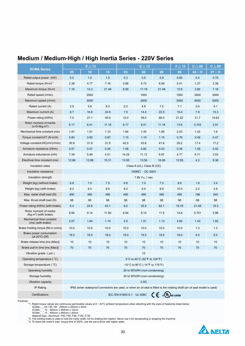
Medium / Medium-High / High Inertia Series - 220V Series
ECMA Series E 13 G 13 F 13 C 06 C 08
05 10 15 03 06 09 08 04 □ H 07 □ HRated output power (kW) 0.5 1.0 1.5 0.3 0.6 0.9 0.85 0.4 0.75
Rated torque (N-m)*1 2.39 4.77 7.16 2.86 5.73 8.59 5.41 1.27 2.39
Maximum torque (N-m) 7.16 14.3 21.48 8.59 17.19 21.48 13.8 3.82 7.16
Rated speed (r/min) 2000 1000 1500 3000 3000
Maximum speed (r/min) 3000 2000 3000 5000 5000
Rated current (A) 2.9 5.6 8.3 2.5 4.8 7.5 7.1 2.6 5.1
Maximum current (A) 8.7 16.8 24.9 7.5 14.4 22.5 19.4 7.8 15.3
Power rating (kW/s) 7.0 27.1 45.9 10.0 39.0 66.0 21.52 21.7 19.63
Rotor moment of inertia (x10-4kg-m2) 8.17 8.41 11.18 8.17 8.41 11.18 13.6 0.743 2.91
Mechanical time constant (ms) 1.91 1.51 1.10 1.84 1.40 1.06 2.43 1.42 1.6
Torque constant-KT (N-m/A) 0.83 0.85 0.87 1.15 1.19 1.15 0.76 0.49 0.47
Voltage constant-KE(mV/(r/min) 30.9 31.9 31.8 42.5 43.8 41.6 29.2 17.4 17.2
Armature resistance (Ohm) 0.57 0.47 0.26 1.06 0.82 0.43 0.38 1.55 0.42
Armature inductance (mH) 7.39 5.99 4.01 14.29 11.12 6.97 4.77 6.71 3.53
Electrical time constant (ms) 12.96 12.88 15.31 13.55 13.50 16.06 12.55 4.3 8.36
Insulation class Class A (UL), Class B (CE)
Insulation resistance 100MΩ ,DC 500V
Insulation strength 1.8k VAC,1 sec
Weight (kg) (without brake) 6.8 7.0 7.5 6.8 7.0 7.5 8.6 1.8 3.4
Weight (kg) (with brake) 8.2 8.4 8.9 8.2 8.4 8.9 10.0 2.2 3.9
Max. radial shaft load (N) 490 490 490 490 490 490 490 196 245
Max. thrust shaft load (N) 98 98 98 98 98 98 98 68 98
Power rating (kW/s) (with brake) 6.4 24.9 43.1 9.2 35.9 62.1 19.78 21.48 19.3
Rotor moment of inertia (Kg.m2) (with brake) 8.94 9.14 11.90 8.94 9.14 11.9 14.8 0.751 2.96
Mechanical time constant (ms) (with brake) 2.07 1.64 1.19 2.0 1.51 1.13 2.65 1.43 1.62
Brake holding torque [Nt-m (min)] 10.0 10.0 10.0 10.0 10.0 10.0 10.0 1.3 1.3
Brake power consumption(at 20oC) [W] 19.0 19.0 19.0 19.0 19.0 19.0 19.0 6.5 6.5
Brake release time [ms (Max)] 10 10 10 10 10 10 10 10 10
Brake pull-in time [ms (Max)] 70 70 70 70 70 70 70 70 70
Vibration grade ( μm ) 15
Operating temperature ( oC) 0 OC to 40 OC (32 OF to 104 OF)
Storage temperature ( oC) -10 OC to 80 OC (-14 OF to 176 OF)
Operating humidity 20 to 90%RH (non-condensing)
Storage humidity 20 to 90%RH (non-condensing)
Vibration capacity 2.5G
IP Rating IP65 (when waterproof connectors are used, or when an oil seal is fitted to the rotating shaft (an oil seal model is used)
Certifications IEC / EN 61800-5-1,UL 508C
Footnote:*1. Rated torque values are continuous permissible values at 0 ~ 40°C ambient temperature when attaching with the sizes of heatsinks listed below:
ECMA-_ _ 04 / 06 / 08:250mm x 250mm x 6mm ECMA-_ _ 10:300mm x 300mm x 12mmECMA-_ _ 13:400mm x 400mm x 20mmMaterial type : Aluminum F40, F60, F80, F100, F130
*2. The holding brake is used to hold the motor shaft, not for braking the rotation. Never use it for decelerating or stopping the machine.*3. To reach the motor's max. torque limit of 250%, use the servo drive with higher watts.

31
Frame Size 86mm and below
Servo Motor Dimensions
Torque Curves (T-N Curves)
Units: mm
Model C1040F S C 0401 S C 0602 S C 0604 S C 0604 H C 0804 7 C 0807 S C 0807 H C 0907 S C 0910 S
LC 40 40 60 60 60 80 80 80 86 86
LZ 4.5 4.5 5.5 5.5 5.5 6.6 6.6 6.6 6.6 6.6
LA 46 46 70 70 70 90 90 90 100 100
S 8 ( +0- 0.009 ) 8 ( +0
- 0.009 ) 14 ( +0- 0.011 ) 14 ( +0
- 0.011 ) 14 ( +0- 0.011 ) 14 ( +0
- 0.011 ) 19 ( +0- 0.013 ) 19 ( +0
- 0.013 ) 16 ( +0- 0.011 ) 16 ( +0
- 0.011 )
LB 30 ( +0- 0.021 ) 30 ( +0
- 0.021 ) 50 ( +0- 0.025 ) 50 ( +0
- 0.025 ) 50 ( +0- 0.025 ) 70 ( +0
- 0.030 ) 70 ( +0- 0.030 ) 70 ( +0
- 0.030 ) 80 ( +0- 0.030 ) 80 ( +0
- 0.030 )
LL(W/O Brake) 79.1 100.6 105.5 130.7 145.8 112.3 138.3 151.1 130.2 153.2
LL(With Brake) -- 136.8 141.6 166.8 176.37 152.8 178 189 161.3 184.3
LS 20 20 27 27 27 27 32 32 30 30
LR 25 25 30 30 30 30 35 35 35 35
LE 2.5 2.5 3 3 3 3 3 3 3 3
LG 5 5 7.5 7.5 7.5 8 8 8 8 8
LW 16 16 20 20 20 20 25 25 20 20
RH 6.2 6.2 11 11 11 11 15.5 15.5 13 13
WK 3 3 5 5 5 5 6 6 5 5
W 3 3 5 5 5 5 6 6 5 5
T 3 3 5 5 5 5 6 6 5 5
TP - M3Depth 8
M4Depth 15
M4Depth 15
M4Depth 15
M4Depth 15
M6Depth 20
M6Depth 20
M5Depth 15
M5Depth 15
ECMA-C △ 0602 □ S ECMA-C △ 0804 □ SECMA-C △ 0804 □ H ECMA-C △ 0804 □ 7
ECMA-C △ 0401 □ S
Torque (N-m)
ECMA-C1040F □ S
1) Dimensions are in millimeters.2) Dimensions of the servo motors may be revised without prior notice.3) The boxes ( □ ) in the model names are for optional configurations (keyway, brake and oil seal).4) The triangles (▲ ) in the model names are for encoder resolution types (▲ =1: Incremental encoder, 20-bit; ▲ =2: Absolute encoder, 17-bit).
Intermittent Duty Zone
Intermittent Duty Zone
Intermittent Duty Zone
Intermittent Duty Zone
Torque (N-m)
Continuous Duty Zone
Continuous Duty Zone
Continuous Duty Zone
Continuous Duty Zone
Speed (r/min)Speed (r/min) Speed (r/min) Speed (r/min)
Torque (N-m) Torque (N-m)

32
Units: mm
Model C1040F S C 0401 S C 0602 S C 0604 S C 0604 H C 0804 7 C 0807 S C 0807 H C 0907 S C 0910 S
LC 40 40 60 60 60 80 80 80 86 86
LZ 4.5 4.5 5.5 5.5 5.5 6.6 6.6 6.6 6.6 6.6
LA 46 46 70 70 70 90 90 90 100 100
S 8 ( +0- 0.009 ) 8 ( +0
- 0.009 ) 14 ( +0- 0.011 ) 14 ( +0
- 0.011 ) 14 ( +0- 0.011 ) 14 ( +0
- 0.011 ) 19 ( +0- 0.013 ) 19 ( +0
- 0.013 ) 16 ( +0- 0.011 ) 16 ( +0
- 0.011 )
LB 30 ( +0- 0.021 ) 30 ( +0
- 0.021 ) 50 ( +0- 0.025 ) 50 ( +0
- 0.025 ) 50 ( +0- 0.025 ) 70 ( +0
- 0.030 ) 70 ( +0- 0.030 ) 70 ( +0
- 0.030 ) 80 ( +0- 0.030 ) 80 ( +0
- 0.030 )
LL(W/O Brake) 79.1 100.6 105.5 130.7 145.8 112.3 138.3 151.1 130.2 153.2
LL(With Brake) -- 136.8 141.6 166.8 176.37 152.8 178 189 161.3 184.3
LS 20 20 27 27 27 27 32 32 30 30
LR 25 25 30 30 30 30 35 35 35 35
LE 2.5 2.5 3 3 3 3 3 3 3 3
LG 5 5 7.5 7.5 7.5 8 8 8 8 8
LW 16 16 20 20 20 20 25 25 20 20
RH 6.2 6.2 11 11 11 11 15.5 15.5 13 13
WK 3 3 5 5 5 5 6 6 5 5
W 3 3 5 5 5 5 6 6 5 5
T 3 3 5 5 5 5 6 6 5 5
TP - M3Depth 8
M4Depth 15
M4Depth 15
M4Depth 15
M4Depth 15
M6Depth 20
M6Depth 20
M5Depth 15
M5Depth 15
ECMA-C △ 0807 □ SECMA-C △ 0807 □ H
Intermittent Duty Zone
Continuous Duty Zone
Speed (r/min)
Torque (N-m)
ECMA-C10910 □ S
Torque (N-m)
7.14(298%)
2.38(100%)
6.00(251%)
Speed (r/min)
ECMA-C10907 □ S
Continuous Duty Zone
Intermittent Duty Zone
8.78(276%)
3.18(100%)
2,000 3,000
Torque (N-m)
Speed (r/min)
Continuous Duty Zone
Intermittent Duty Zone
5.85(184%)

33
Frame Size 100m ~ 130m
LG LR
LE
LS
LW
LBh7
SHAFT END DETAILS
KEY DETAILS
Sh6
4-ZPCD-A
W -0
.036
0
-0.0
360
T
TP
RH
LC
LL
Units: mmModel C 1010 S E 1305 S E 1310 S E 1315 S F 1308 S G 1303 S G 1306 S G 1309 S
LC 100 130 130 130 130 130 130 130LZ 9 9 9 9 9 9 9 9LA 115 145 145 145 145 145 145 145S 22 ( +0
- 0.013 ) 22 ( +0- 0.013 ) 22 ( +0
- 0.013 ) 22 ( +0- 0.013 ) 22 ( +0
- 0.013 ) 22 ( +0- 0.013 ) 22 ( +0
- 0.013 ) 22 ( +0- 0.013 )
LB 95 ( +0- 0.035 ) 110 ( +0
- 0.035 ) 110 ( +0- 0.035 ) 110 ( +0
- 0.035 ) 110 ( +0- 0.035 ) 110 ( +0
- 0.035 ) 110 ( +0- 0.035 ) 110 ( +0
- 0.035 )
LL(W/O Brake) 153.3 147.5 147.5 167.5 152.5 147.5 147.5 163.5
LL(With Brake) 192.5 183.5 183.5 202 181 183.5 183.5 198
LS 37 47 47 47 47 47 47 47LR 45 55 55 55 55 55 55 55LE 5 6 6 6 6 6 6 6LG 12 11.5 11.5 11.5 11.5 11.5 11.5 11.5LW 32 36 36 36 36 36 36 36RH 18 18 18 18 18 18 18 18WK 8 8 8 8 8 8 8 8W 8 8 8 8 8 8 8 8T 7 7 7 7 7 7 7 7
TP M6Depth 20
M6Depth 20
M6Depth 20
M6Depth 20
M6Depth 20
M6Depth 20
M6Depth 20
M6Depth 20
1) Dimensions are in millimeters.2) Dimensions of the servo motors may be revised without prior notice.3) The boxes ( □ ) in the model names are for optional configurations (keyway, brake and oil seal).4) The triangles (▲ ) in the model names are for encoder resolution types (▲ =1: Incremental encoder, 20-bit; ▲ =2: Absolute encoder, 17-bit).
Torque Curves (T-N Curves)
ECMA-C △ 1010 □ S
ECMA-G △ 1306 □ S ECMA-G △ 1309 □ S
ECMA-E △ 1310 □ S ECMA-F △ 1308 □ S
2,300
ECMA-G △ 1303 □ S
ECMA-E △ 1305 □ S
Servo Motor Dimensions
ECMA-E △ 1315 □ S
Torque (N-m)
Intermittent Duty Zone
Continuous Duty Zone
Speed (r/min)
Torque (N-m) Torque (N-m) Torque (N-m) Torque (N-m)
Torque (N-m) Torque (N-m) Torque (N-m)
Intermittent Duty Zone
Intermittent Duty Zone
Intermittent Duty Zone
Intermittent Duty Zone
Intermittent Duty Zone
Intermittent Duty Zone
Intermittent Duty Zone
Continuous Duty Zone
Continuous Duty Zone
Continuous Duty Zone
Continuous Duty Zone
Continuous Duty Zone
Continuous Duty Zone
Continuous Duty Zone
Speed (r/min) Speed (r/min) Speed (r/min) Speed (r/min)
Speed (r/min)Speed (r/min)Speed (r/min)

34
DMCNET Remote ModulesDigital I/O Remote Modules■ ASD-DMC-RM32MN / ASD-DMC-RM32NT■ ASD-DMC-RM64MN / ASD-DMC-RM64NT
Electrical Specifications
Installation & Wiring
Item RM32MN / RM64MN RM32NT / RM64NT
Circuit Type Single Transistor
Signal Type SINK / SOURCE SINK
Power Supply Voltage 24VDC (5mA) 24VDC (0.1A / 1 Point)
Response Time / Work Frequency 0 ~ 3ms (adjustable) 1KHz
Active Level (OFF ON) > 16.5VDC 20µs
Active Level (ON OFF) < 8VDC 30µs
Noise ImmunityESD (IEC 61131-2, IEC 61000-4-2): 8KV Air Discharge
EFT (IEC 61131-2, IEC 61000-4-4): Power Line: 2KV, Communication I/O: 1KV RS (IEC 61131-2, IEC 61000-4-3): 80MHz ~ 1GHz, 10V/m
Operation / Storage Environment Operation: 0ºC ~ 50ºC (32ºF ~ 122ºF)Storage: -20ºC ~ 70ºC (-4ºF ~ 158ºF)
OR OR
W: 75 mm W: 75 mm
W: 75 mm W: 75 mm
H: 43 mm H: 43 mm
H: 43 mm H: 43 mm
L: 100 mm L: 168 mm
L: 168 mmL: 100 mm
HMC HMC
ASDA-M ASDA-MASDA-A2 ASDA-A2

35
DMCNET Remote Modules
■ ASD-DMC-RM04PIElectrical Specifications
ASD-DMC-RM04PI
Item Input (QA,QB,QZ,DI1,DI2)
Circuit Type Single
Signal Type SINK
Power Supply Voltage 5VDC
Work Frequency
QA, QB, QZ:200KHz (5mA / 1 Point)QA, QB,QZ: 200KHz (5mA/1 Point)
Noise Immunity
• ESD (IEC 61131-2, IEC 61000-4-2): 8KV Air Discharge
• EFT (IEC 61131-2, IEC 61000-4-4): Power Line: 2KV, Communication I/O: 1KV
• RS (IEC 61131-2, IEC 61000-4-3): 80MHz ~ 1GHz, 10V/m
Operation / Storage Environment
Operation: 0ºC ~ 50ºC (32ºF ~ 122ºF)Storage: -20ºC ~ 70ºC (-4ºF ~ 158ºF)
ASD-DMC-RM04PI
Item Input (QA,QB,QZ,DI1,DI2) Output (MEL,PEL,ORG,SLD)
Circuit Type Single Transistor
Signal Type SINK / SOURCE SINK
Power Supply Voltage 24VDC (5mA) 5~24VDC (30mA / 1 Point)
Work Frequency 1ms CW, CCW:200KHzDO1, DO2:1KHz
Active Level (OFF ON) > 16.5VDC --
Active Level (OFF ON) < 8VDC --
Noise Immunity
• ESD (IEC 61131-2, IEC 61000-4-2): 8KV Air Discharge• EFT (IEC 61131-2, IEC 61000-4-4): Power Line:
2KV, Communication I/O: 1KV• RS (IEC 61131-2, IEC 61000-4-3): 80MHz ~ 1GHz, 10V/m
Operation / Storage Environment
Operation: 0ºC ~ 50ºC (32ºF ~ 122ºF)Storage: -20ºC ~ 70ºC (-4ºF ~ 158ºF)
OR
HMC
ASDA-M
Stepping Motors
ASDA-A2
Pulse Remote Modules

36
■ ASD-DMC-RM04DA / ASD-DMC-RM04ADElectrical Specifications
ASD-DMC-RM04DA
Item Analog to Digital - Input Point (RM04AD)
Analog Output Channel 4-Channel / Module
Range of Analog Voltage Output -10 ~ 10V ; -5 ~ 5V ; 0 ~ 10V ; 0 ~ 5V
Range of Analog Current Output 0 ~ 24mA ; 0 ~ 20mA ; 4 ~ 20mA
Over Range of Analog Output 10%
Max. Output Current 20mA
Allowable Load Impedance 0 ~ 500Ω
Range of Digital Data 0 ~ 4096
Resolution 16 bits
DC Output Impedance 0.3Ω
Response Time 1ms
Digital Data Format 16bits
Isolation Internal circuit and analog output terminals are isolated by optical coupler.
ProtectionVoltage output is protected by a circuit breaker. But, a short circuit lasting for too long may cause damage to internal circuits. Current output can be open circuit.
Noise Immunity
• ESD (IEC 61131-2, IEC 61000-4-2): 8KV Air Discharge
• EFT (IEC 61131-2, IEC 61000-4-4): Power Line: 2KV,
• Communication I/O: 1KV• RS (IEC 61131-2, IEC 61000-4-3): 80MHz ~
1GHz, 10V/m
Operation / Storage Environment
Operation: 0ºC ~ 50ºC (32ºF ~ 122ºF)Storage: -20ºC ~ 70ºC (-4ºF ~ 158ºF)
ASD-DMC-RM04AD
Item Analog to Digital - Input Point (RM04AD)
Analog Output Channel 4-Channel / Module
Range of Analog Voltage Output -10 ~ 10V ; -5 ~ 5V ; 0 ~ 10V ; 0 ~ 5V
Range of Analog Current Output 0 ~ 24mA
Range of Digital Data 0 ~ 65535
Resolution 16 bits
Voltage Input Impedance 140Ω
Current Input Impedance 249Ω
Overall Accuracy±0.5% when in full scale (25ºC, 77ºF)
±1% when in full scale within the range of 0ºC ~ 55ºC, 32ºF ~ 131ºF
Response Time Min. 1ms. Max. 3ms × the number of channels
Isolation Internal circuit and analog output terminals are isolated by optical coupler.
Range of Absolute Voltage Input -15 ~ 15 V
Range of Absolute Current Input 32mA
Digital Data Format 16bits
Noise Immunity
• ESD (IEC 61131-2, IEC 61000-4-2): 8KV Air Discharge
• EFT (IEC 61131-2, IEC 61000-4-4): Power Line: 2KV,
• Communication I/O: 1KV• RS (IEC 61131-2, IEC 61000-4-3): 80MHz ~
1GHz, 10V/m
Operation / Storage Environment
Operation: 0ºC ~ 50ºC (32ºF ~ 122ºF)Storage: -20ºC ~ 70ºC (-4ºF ~ 158ºF)
HMCHMC
ASDA-MASDA-M
ASDA-A2ASDA-A2
OROR
Analog I/O Remote Modules

37
Part Names and Functions ● LED Display / Operation Panel■ LED Display
The 5 digit, 7 segment LED displays the servo status or fault codes■ Operation Panel
Function keys used to perform status display, monitor and diagnostic, function and parameter setting.
■ Function Keys: MODE: Press this key to select/change mode SHIFT: Press this key to shift cursor to the left UP: Press this key to increase values on the display DOWN: Press this key to decrease values on the display SET: Press this key to store data
● I/O Interface■ Used to connect Delta's DVP Series PLC or
other external controllers for controlling I/O signals.
●Charge LED■ A lit LED indicates that either power
is connected to the servo drive or a residual charge is present in the drive's internal power components.
● Full-Closed Loop Control Interface■ Used to connect linear scale and
encoder for controlling A, B, Z phase signals for inputs of X, Y, Z axes.
●Motor Encoder Interface■ Used to connect the encoder of the servo
motor and feedback the signals to X, Y, Z axes of the servo drive.
● Serial Communication Port■ Used to connect PLC, HMI, and other controllers for RS-485 / RS-232 serial communication.
●High-speed Communication Port■ Used to connect CANopen networks.■ DMCNE Tinterface, supporting motion modes for CANopen
DS402 implementation.■ CANbus interface, supporting motion modes for CANopen
DS402 implementation.
●Ground Terminal■ Used to connect grounding wire of power supply and servo motor.
●USB Connection PortVer 1.1 USB is equipped as standard.■ Direct connectivity to personal computers or notebooks, capable of accessing data
through ASDA-Soft configuration software.■ Remote monitoring speed via ASDA-Soft configuration software is up to 1 Mbps.

38
●Control Circuit Terminal / Main Circuit Terminal / Internal & External Regenerative Resistor Terminal
●Ground Terminal■ Used to connect grounding wire of power
supply and servo motor.
● Servo Motor Output (U, V, W)■ Used to connect servo motor. Never connect
the output terminal to main circuit power as the AC drive may be damaged beyond repair if incorrect cables are connected to the output terminals.
●Ground Terminal■ Used to connect grounding wire of
power supply and servo motor.
■ Control Circuit Terminal (L1c, L2c) L1c, L2c are used to connect 200~230Vac, 50/60Hz single-phase or three-phase power supply.
■ Main Circuit Terminal (R, S, T) Used to connect 200~230Vac, 50/60Hz commercial power supply.
■ When using an external braking unit, connect it to P and .
■ Internal & External Regenerative Resistor Terminal 1. When using an external resistor, connect it to P and C,
and ensure an open circuit between P and D. 2. When using an internal resistor, ensure the circuit
is closed between P and D, and the circuit is open between P and C. (Note: Please refer to the table of regenerative resistor specifications for the models with a built-in regenerative resistor.)
3. When using an external braking unit, connect it to P and , and ensure an open circuit between P and D, and P and C.
The figures are for illustration purposes only. Actual models may differ slightly in appearance from illustrations provided.

39
Optional Accessories ●Quick Connectors■ Used for 750W to 1.5kW servo drives■ One operating lever is provided for wire
to terminal block insertion.
● Power Cables■ 3m and 5m standard cables are available.■ Customized service is offered to meet the
needs of customers.■ Two types are selectable: with brake and
without brake.
● Encoder Cables■ 3m and 5m standard cables are available.■ Customized service is offered to
meet the needs of customers.
●RS-232 Communication Cables■ Connects ASDA-M to PLC, HMI, and
other controllers via RS-232 communication.■ Standard cable length is 3m.■ Delta Part Number: ASD-CARS0003

40
● Terminal Block Modules■ Easy installation and wiring 0.5m
connection cable is provided. ■ Easy to reduce the space required.■ Easy to expand system's I/O
configuration.■ Delta Part Number: ASD-BM-50A
●Regenerative Resistors■ For selecting a regenerative
resistor, please refer to the table of regenerative resistor specifications on page 50.
●USB Communication Cables (for PC)■ Connects ASDA-A2 to a PC (via
ASDA-Soft configuration software)■ USB1.1 is equipped as standard.■ Delta Part Number: DOP-CAUSBAB
●CANopen Accessories■ Delta's TAP-CN03 distribution box
connects ASDA-A2 to Delta's PLC CAN Master.
■ For selecting CANopen accessories, please refer to the table of other accessories on page 49.
●RS-485 Connectors■ Used to connect multiple
ASDA-M systems by RS-485 interface through Modbus serial communication.
■ Delta Part Number: ASD-CNIE0B06
The figures are for illustration purposes only. Actual models may differ slightly in appearance from illustrations provided.
41
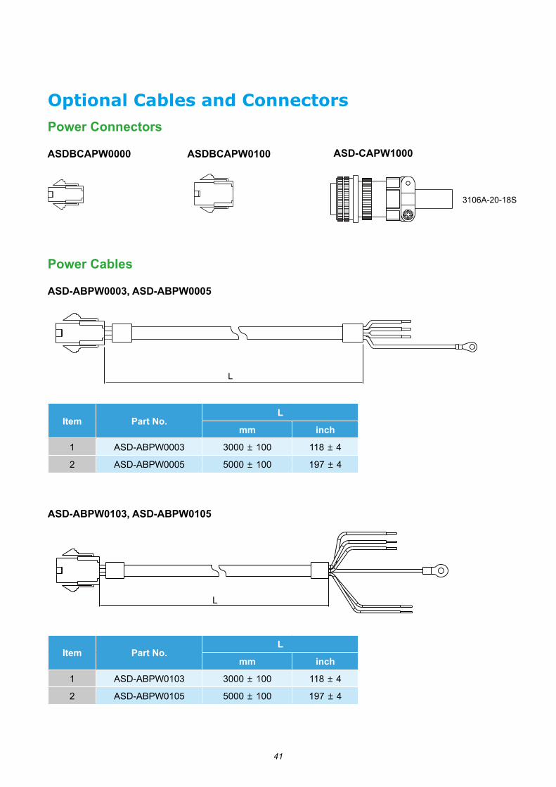
Optional Cables and Connectors Power Connectors
Power Cables
ASDBCAPW0000
ASD-ABPW0003, ASD-ABPW0005
ASDBCAPW0100 ASD-CAPW1000
Item Part No.L
mm inch
1 ASD-ABPW0003 3000 ± 100 118 ± 4
2 ASD-ABPW0005 5000 ± 100 197 ± 4
Item Part No.L
mm inch
1 ASD-ABPW0103 3000 ± 100 118 ± 4
2 ASD-ABPW0105 5000 ± 100 197 ± 4
3106A-20-18S
L
L
ASD-ABPW0103, ASD-ABPW0105

42
Power Cables
(80 mm)(3.15 mm)
(50mm)(1.97mm)
L
(3.15inch)(80mm)
(1.97inch)(50mm)
L
ASD-CAPW1003, ASD-CAPW1005
ASD-CAPW1103,ASD-CAPW1105
Item Part No. StraightL
mm inch
1 ASD-CAPW1003 3106A-20-18S 3000 ± 100 118 ± 4
2 ASD-CAPW1005 3106A-20-18S 5000 ± 100 197 ± 4
Item Part No. StraightL
mm inch
1 ASD-CAPW1103 3106A-20-18S 3000 ± 100 118 ± 4
2 ASD-CAPW1105 3106A-20-18S 5000 ± 100 197 ± 4

43
Optional Cables and Connectors
Encoder CablesASD-ABEN0003, ASD-ABEN0005
ASD-CAEN1003, ASD-CAEN1005
Item Part No. StraightL
mm inch1 ASD-CAEN1003 3106A-20-29S 3000 ± 100 118 ± 42 ASD-CAEN1005 3106A-20-29S 5000 ± 100 197 ± 4
L
L
Encoder Connectors
ASD-ABEN0000 ASD-CAEN1000
Item Part No.L
mm inch
1 ASD-ABEN0003 3000 ± 100 118 ± 4
2 ASD-ABEN0005 5000 ± 100 197 ± 4

44
Optional Cables and Connectors I/O Signal Connector
ASD-CNSC0050
Terminal Block Module
ASD-BM-50A
RS-232 Communication Cable
ASD-CARS0003
Communication Cable between Drive and Computer (for PC)
DOP-CAUSBAB
L
146.4 mm
50.7
mm
86.8
mm
0.5m
86.8
m
50.7
m
146.4m
P4P1
120.5 120.5
140030A BP2
P1
P3
P4
CONDUCTOR INSULATOR
ALUMINUMTINNED COPPER BRAIDPVC JACKET
Item Part No.L
mm inch
1 ASD-CARS0003 3000 ± 100 118 ± 4
Item Part No.L
mm inch
1 DOP-CAUSBAB 1400 ± 30 55 ± 1.2
45
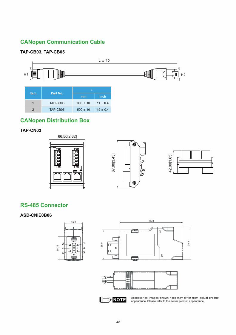
66.50[2.62]
87.0
0[3.
43]
42.0
0[1.
65]
H1
1
8
L ± 10
8
1H2
CANopen Communication Cable
TAP-CB03, TAP-CB05
CANopen Distribution Box
TAP-CN03
RS-485 Connector
ASD-CNIE0B06
Item Part No.L
mm inch
1 TAP-CB03 300 ± 10 11 ± 0.4
2 TAP-CB05 500 ± 10 19 ± 0.4
Accessories images shown here may differ from actual product appearance. Please refer to the actual product appearance.

46
Accessories Combinations
750W Servo Drive and 100W Low Inertia Servo Motor
750W Servo Drive and 50W Low Inertia Servo Motor
750W Servo Drive and 200W Low Inertia Servo Motor
Servo Drive ASD-M-0721-
Low Inertia Servo Motor ECMA-C △ 0401 S
Power Cable (Without Brake) ASD-ABPW000X
Power Connector (Without Brake) ASDBCAPW0000
Power Cable (With Brake) ASD-ABPW010X
Power Connector (With Brake) ASDBCAPW0100
Incremental Encoder Cable ASD-ABEN000X
Absolute Encoder Cable ASD-A2EB000X
Encoder Connector ASD-ABEN0000
(X=3 indicates that the cable length is 3m; X=5 indicates that the cable length is 5m)
Servo Drive ASD-M-0721-
Low Inertia Servo Motor ECMA-C △ 0602 S
Power Cable (Without Brake) ASD-ABPW000X
Power Connector (Without Brake) ASDBCAPW0000
Power Cable (With Brake) ASD-ABPW010X
Power Connector (With Brake) ASDBCAPW0100
Incremental Encoder Cable ASD-ABEN000X
Absolute Encoder Cable ASD-A2EB000X
Encoder Connector ASD-ABEN0000
(X=3 indicates that the cable length is 3m; X=5 indicates that the cable length is 5m)
Servo Drive ASD-M-0721-
Low Inertia Servo Motor ECMA-C1040F S
Power Cable (Without Brake) ASD-ABPW000X
Power Connector (Without Brake) ASDBCAPW0000
Power Cable (With Brake) ASD-ABPW010X
Power Connector (With Brake) ASDBCAPW0100
Incremental Encoder Cable ASD-ABEN000X
Absolute Encoder Cable ASD-A2EB000X
Encoder Connector ASD-ABEN0000
(X=3 indicates that the cable length is 3m; X=5 indicates that the cable length is 5m)

47
Accessories Combinations
750W Servo Drive and 500W Medium Inertia Servo Motor
750W Servo Drive and 300W High Inertia Servo Motor
750W Servo Drive and 400W Low Inertia Servo Motor Servo Drive ASD-M-0721-
Low Inertia Servo MotorECMA-C △ 0604 SECMA-C △ 0604 HECMA-C △ 0804 7
Power Cable (Without Brake) ASD-ABPW000X
Power Connector (Without Brake) ASDBCAPW0000
Power Cable (With Brake) ASD-ABPW010X
Power Connector (With Brake) ASDBCAPW0100
Incremental Encoder Cable ASD-ABEN000X
Absolute Encoder Cable ASD-A2EB000X
Encoder Connector ASD-ABEN0000
(X=3 indicates that the cable length is 3m; X=5 indicates that the cable length is 5m)
Servo Drive ASD-M-0721-
Medium Inertia Servo Motor ECMA-E △ 1305 S
Power Cable (Without Brake) ASD-CAPW100X
Power Cable (With Brake) ASD-CAPW110X
Power Connector ASD-CAPW1000
Power Connector (With Brake) ASD-CAEN100X
Incremental Encoder Cable ASD-CAEN100X
Absolute Encoder Cable ASD-A2EB100X
Encoder Connector ASD-CAEN1000
(X=3 indicates that the cable length is 3m; X=5 indicates that the cable length is 5m)
Servo Drive ASD-M-0721-
High Inertia Servo Motor ECMA-G △ 1303 S
Power Cable (Without Brake) ASD-CAPW100X
Power Connector (Without Brake) ASD-CAPW110X
Power Cable (With Brake) ASD-CAPW1000
Power Connector (With Brake) ASD-CAEN100X
Incremental Encoder Cable ASD-A2EB100X
Absolute Encoder Cable ASD-CAEN1000
Encoder Connector ASD-CAEN1000
(X=3 indicates that the cable length is 3m; X=5 indicates that the cable length is 5m)
48
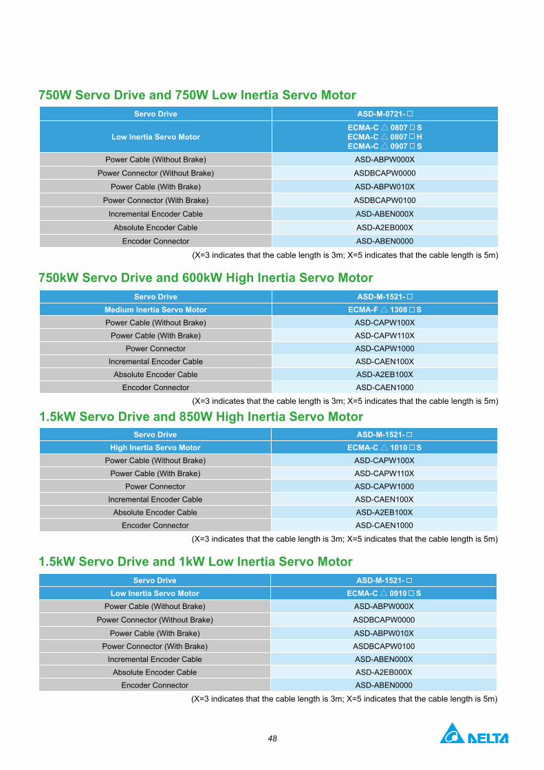
750kW Servo Drive and 600kW High Inertia Servo Motor
1.5kW Servo Drive and 850W High Inertia Servo Motor
750W Servo Drive and 750W Low Inertia Servo Motor
1.5kW Servo Drive and 1kW Low Inertia Servo Motor
Servo Drive ASD-M-1521-Medium Inertia Servo Motor ECMA-F △ 1308 SPower Cable (Without Brake) ASD-CAPW100X
Power Cable (With Brake) ASD-CAPW110XPower Connector ASD-CAPW1000
Incremental Encoder Cable ASD-CAEN100XAbsolute Encoder Cable ASD-A2EB100X
Encoder Connector ASD-CAEN1000
(X=3 indicates that the cable length is 3m; X=5 indicates that the cable length is 5m)
Servo Drive ASD-M-1521-High Inertia Servo Motor ECMA-C △ 1010 S
Power Cable (Without Brake) ASD-CAPW100XPower Cable (With Brake) ASD-CAPW110X
Power Connector ASD-CAPW1000Incremental Encoder Cable ASD-CAEN100X
Absolute Encoder Cable ASD-A2EB100XEncoder Connector ASD-CAEN1000
(X=3 indicates that the cable length is 3m; X=5 indicates that the cable length is 5m)
Servo Drive ASD-M-0721-
Low Inertia Servo MotorECMA-C △ 0807 SECMA-C △ 0807 HECMA-C △ 0907 S
Power Cable (Without Brake) ASD-ABPW000X
Power Connector (Without Brake) ASDBCAPW0000
Power Cable (With Brake) ASD-ABPW010X
Power Connector (With Brake) ASDBCAPW0100
Incremental Encoder Cable ASD-ABEN000X
Absolute Encoder Cable ASD-A2EB000X
Encoder Connector ASD-ABEN0000
(X=3 indicates that the cable length is 3m; X=5 indicates that the cable length is 5m)
Servo Drive ASD-M-1521-Low Inertia Servo Motor ECMA-C △ 0910 S
Power Cable (Without Brake) ASD-ABPW000X
Power Connector (Without Brake) ASDBCAPW0000
Power Cable (With Brake) ASD-ABPW010XPower Connector (With Brake) ASDBCAPW0100
Incremental Encoder Cable ASD-ABEN000XAbsolute Encoder Cable ASD-A2EB000X
Encoder Connector ASD-ABEN0000
(X=3 indicates that the cable length is 3m; X=5 indicates that the cable length is 5m)
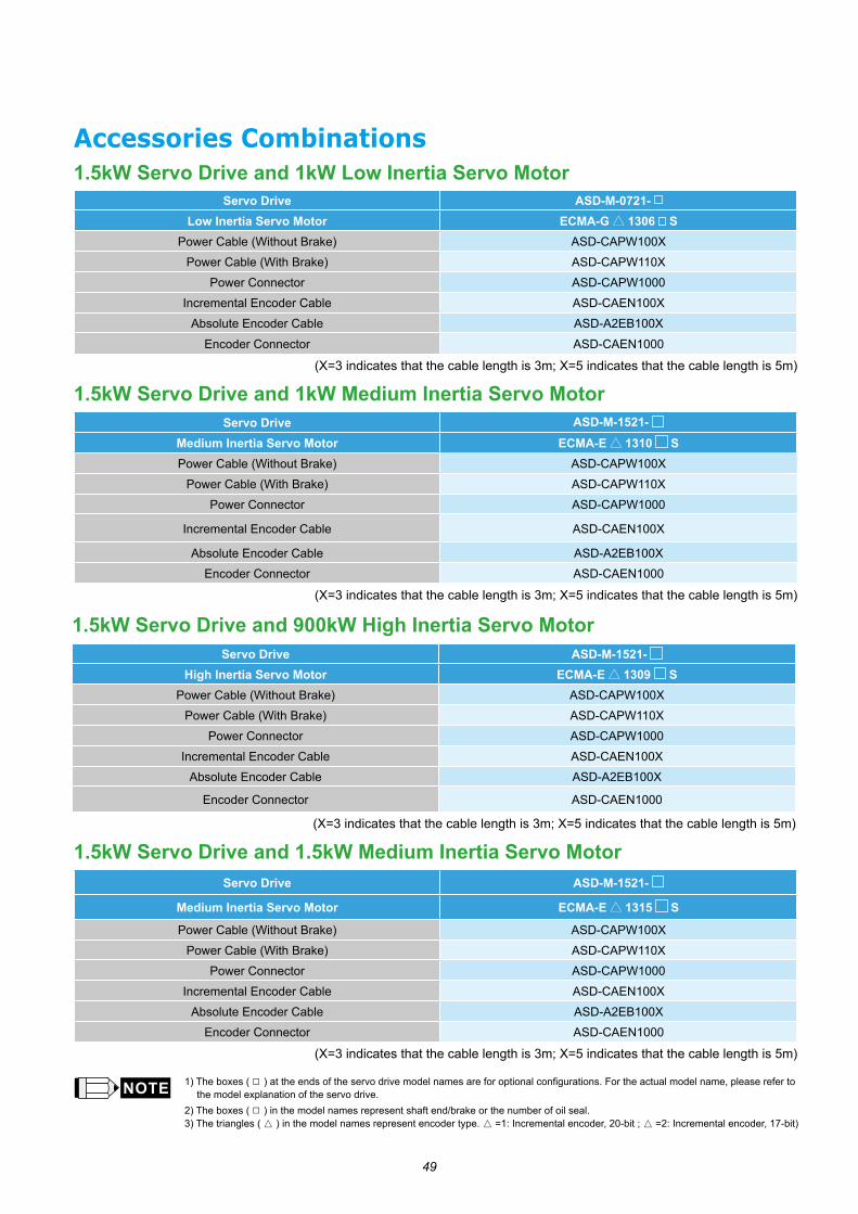
49
1.5kW Servo Drive and 900kW High Inertia Servo Motor
1.5kW Servo Drive and 1kW Medium Inertia Servo Motor
1.5kW Servo Drive and 1.5kW Medium Inertia Servo Motor
Servo Drive ASD-M-1521-High Inertia Servo Motor ECMA-E △ 1309 S
Power Cable (Without Brake) ASD-CAPW100XPower Cable (With Brake) ASD-CAPW110X
Power Connector ASD-CAPW1000Incremental Encoder Cable ASD-CAEN100X
Absolute Encoder Cable ASD-A2EB100X
Encoder Connector ASD-CAEN1000
(X=3 indicates that the cable length is 3m; X=5 indicates that the cable length is 5m)
Servo Drive ASD-M-1521-
Medium Inertia Servo Motor ECMA-E △ 1315 S
Power Cable (Without Brake) ASD-CAPW100XPower Cable (With Brake) ASD-CAPW110X
Power Connector ASD-CAPW1000Incremental Encoder Cable ASD-CAEN100X
Absolute Encoder Cable ASD-A2EB100XEncoder Connector ASD-CAEN1000
(X=3 indicates that the cable length is 3m; X=5 indicates that the cable length is 5m)
Servo Drive ASD-M-1521-Medium Inertia Servo Motor ECMA-E △ 1310 SPower Cable (Without Brake) ASD-CAPW100X
Power Cable (With Brake) ASD-CAPW110XPower Connector ASD-CAPW1000
Incremental Encoder Cable ASD-CAEN100X
Absolute Encoder Cable ASD-A2EB100XEncoder Connector ASD-CAEN1000
(X=3 indicates that the cable length is 3m; X=5 indicates that the cable length is 5m)
1) The boxes ( □ ) at the ends of the servo drive model names are for optional configurations. For the actual model name, please refer to the model explanation of the servo drive.
2) The boxes ( □ ) in the model names represent shaft end/brake or the number of oil seal.3) The triangles (▲ ) in the model names represent encoder type. ▲ =1: Incremental encoder, 20-bit ; ▲ =2: Incremental encoder, 17-bit)
Accessories Combinations1.5kW Servo Drive and 1kW Low Inertia Servo Motor
Servo Drive ASD-M-0721-Low Inertia Servo Motor ECMA-G △ 1306 S
Power Cable (Without Brake) ASD-CAPW100XPower Cable (With Brake) ASD-CAPW110X
Power Connector ASD-CAPW1000Incremental Encoder Cable ASD-CAEN100X
Absolute Encoder Cable ASD-A2EB100XEncoder Connector ASD-CAEN1000
(X=3 indicates that the cable length is 3m; X=5 indicates that the cable length is 5m)

50
Accessories Combinations
Safety Information
Other Accessories(for ASDA-M Series all models)
Description Delta Part Number
50-Pin I/O Signal Connector (Cn1) ASD-CNSC0050
Terminal Block Module ASD-BM-50A
RS-232 Communication Cable ASD-CARS0003
Communication Cable between Drive and Computer (for PC) DOP-CAUSBAB
CANopen Communication Cable TAP-CB03 / TAP-CB05
CANopen Distribution Box TAP-CN03 / TAP-CN05
RS-485 Connector ASD-CNIE0B06
Regenerative Resistor 400W 40Ω BR400W040
Regenerative Resistor 1kW 20Ω BR1K0W020
Regenerative Resistor 1.5kW 5Ω BR1K5W005
Global Standards ASDA-M Series is designed to fully comply with demanding international standards,such as IEC and EN, and others. for all fields of industrial automation technology.
EMS Standard
EN61000-4-6 Level 3
EN61000-4-3 Level 3
EN61000-4-2 Level 2 and 3
EN61000-4-4 Level 3 ※ in the process of application to EN61000-4-4
EN61000-4-8 Level 4
EN61000-4-5 Level 3
Conducted & Radiated Emissions Complies with EN550011 Class A Group 1, with external EMC filter
CE Marking CE recognized. Complies with Directive 2006/95/EC of the European Parliament and EMC Directive 2004/108/EC.※ in the process of application to EMC Directive 2004/108/EC
UL Approval UL (U.S.), cUL (Canada) recognized.
Test StandardIEC/EN50178, IEC/EN60529
IP20
Vibration 1G less than 20Hz, 0.6G 20 to 50Hz. Complies with IEC/EN50178
Shock 15gn 11ms. Complies with IEC/EN600028-2-27
Pollution Degree Degree 2. Complies with IEC/EN61800-5-1
Servo Drive (kW)
Specifications of Built-in Regenerative ResistorsMin. Allowable Resistance
(Ohm)Resistance (parameter P1-52) (Ohm)
Capacity (parameter P1-53) (Watt)
0.75 40Ω 60W 20Ω
1.5 20Ω 100W 10Ω
Note
■ When the fault, ALE05 (Regeneration Error) occurs, please increase the regenerative resistor capacity or decrease the regenerative resistor resistance. (The regenerative resistor resistance should not be less than the minimum allowable resistance listed in the above table.)
■ If the situation is not improved after increasing the regenerative resistor capacity or decreasing the regenerative resistor resistance, please purchase regenerative resistor module.
■ When combining multiple small-capacity regenerative resistors in parallel to increase the regenerative resistor capacity, make sure that the total resistance value of the regenerative resistors is not less than the minimum allowable resistance listed in the above table.
Regenerative Resistor Specifications

DELTA_IA-ASDA_ASDA-M_C_EN_20200813
Industrial Automation HeadquartersDelta Electronics, Inc. Taoyuan Technology CenterNo.18, Xinglong Rd., Taoyuan District, Taoyuan City 33068, TaiwanTEL: 886-3-362-6301 / FAX: 886-3-371-6301
AsiaDelta Electronics (Shanghai) Co., Ltd.No.182 Minyu Rd., Pudong Shanghai, P.R.C.Post code : 201209 TEL: 86-21-6872-3988 / FAX: 86-21-6872-3996Customer Service: 400-820-9595
Delta Electronics (Japan), Inc.Tokyo Office Industrial Automation Sales Department 2-1-14 Shibadaimon, Minato-kuTokyo, Japan 105-0012TEL: 81-3-5733-1155 / FAX: 81-3-5733-1255
Delta Electronics (Korea), Inc.Seoul Office1511, 219, Gasan Digital 1-Ro., Geumcheon-gu, Seoul, 08501 South KoreaTEL: 82-2-515-5305 / FAX: 82-2-515-5302
Delta Energy Systems (Singapore) Pte Ltd.4 Kaki Bukit Avenue 1, #05-04, Singapore 417939TEL: 65-6747-5155 / FAX: 65-6744-9228
Delta Electronics (India) Pvt. Ltd.Plot No.43, Sector 35, HSIIDC Gurgaon, PIN 122001, Haryana, IndiaTEL: 91-124-4874900 / FAX : 91-124-4874945
Delta Electronics (Thailand) PCL. 909 Soi 9, Moo 4, Bangpoo Industrial Estate (E.P.Z), Pattana 1 Rd., T.Phraksa, A.Muang, Samutprakarn 10280, ThailandTEL: 66-2709-2800 / FAX : 662-709-2827
Delta Electronics (Australia) Pty Ltd.Unit 20-21/45 Normanby Rd., Notting Hill Vic 3168, AustraliaTEL: 61-3-9543-3720
AmericasDelta Electronics (Americas) Ltd.Raleigh OfficeP.O. Box 12173, 5101 Davis Drive, Research Triangle Park, NC 27709, U.S.A.TEL: 1-919-767-3813 / FAX: 1-919-767-3969
Delta Electronics Brazil São Paulo Sales Office Rua Itapeva, 26 - 3°, andar Edificio Itapeva, One - Bela Vista 01332-000 - São Paulo - SP - Brazil TEL: 55-12-3932-2300 / FAX: 55-12-3932-237
Delta Electronics International Mexico S.A. de C.V.Mexico OfficeGustavo Baz No. 309 Edificio E PB 103Colonia La Loma, CP 54060Tlalnepantla, Estado de MéxicoTEL: 52-55-3603-9200
*We reserve the right to change the information in this catalogue without prior notice.
EMEAHeadquarters: Delta Electronics (Netherlands) B.V. Sales: [email protected] Marketing: [email protected] Technical Support: [email protected] Customer Support: [email protected] Service: [email protected]: +31(0)40 800 3900
BENELUX: Delta Electronics (Netherlands) B.V.De Witbogt 20, 5652 AG Eindhoven, The Netherlands Mail: [email protected]: +31(0)40 800 3900
DACH: Delta Electronics (Netherlands) B.V.Coesterweg 45, D-59494 Soest, GermanyMail: [email protected]: +49(0)2921 987 0
France: Delta Electronics (France) S.A.ZI du bois Challand 2, 15 rue des Pyrénées, Lisses, 91090 Evry Cedex, France Mail: [email protected]: +33(0)1 69 77 82 60
Iberia: Delta Electronics Solutions (Spain) S.L.UCtra. De Villaverde a Vallecas, 265 1º Dcha Ed. Hormigueras – P.I. de Vallecas 28031 Madrid TEL: +34(0)91 223 74 20
Carrer Llacuna 166, 08018 Barcelona, SpainMail: [email protected]
Italy: Delta Electronics (Italy) S.r.l.Via Meda 2–22060 Novedrate(CO) Piazza Grazioli 18 00186 Roma ItalyMail: [email protected]: +39 039 8900365
Russia: Delta Energy System LLC Vereyskaya Plaza II, office 112 Vereyskaya str. 17 121357 Moscow Russia Mail: [email protected]: +7 495 644 3240
Turkey: Delta Greentech Elektronik San. Ltd. Sti. (Turkey) Şerifali Mah. Hendem Cad. Kule Sok. No:16-A 34775 Ümraniye – İstanbulMail: [email protected]: + 90 216 499 9910
GCC: Delta Energy Systems AG (Dubai BR)P.O. Box 185668, Gate 7, 3rd Floor, Hamarain Centre Dubai, United Arab Emirates Mail: [email protected]: +971(0)4 2690148
Egypt + North Africa: Delta ElectronicsUnit 318, 3rd Floor, Trivium Business Complex, North 90 street, New Cairo, Cairo, Egypt Mail: [email protected]
Related Documents