Delta AC Servo Drive & Motor ASDA-A2 Series Automation for a Changing World www.deltaww.com

Welcome message from author
This document is posted to help you gain knowledge. Please leave a comment to let me know what you think about it! Share it to your friends and learn new things together.
Transcript
Delta AC Servo Drive & Motor ASDA-A2 Series
Automation for a Changing World
www.del taww.com
9
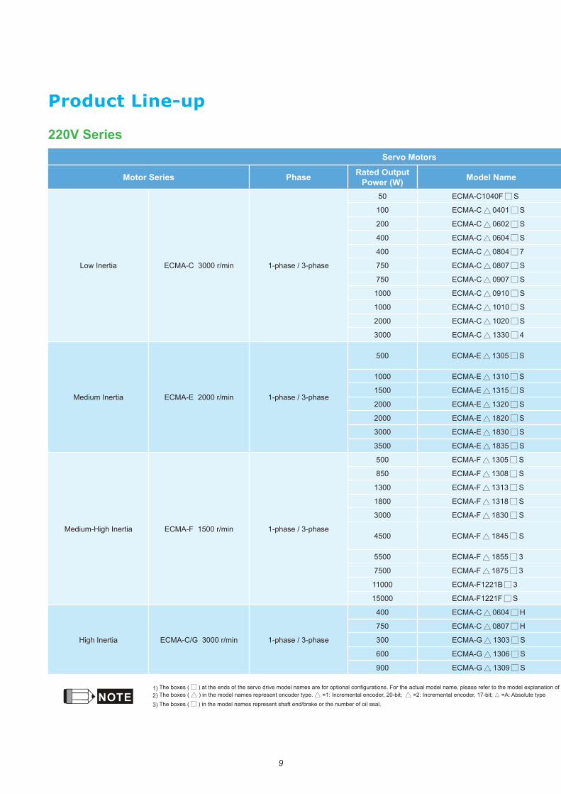
Product Line-up
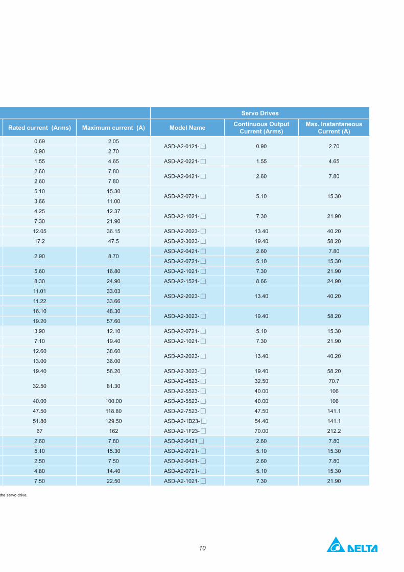
220V Series Servo Motors Servo Drives
Motor Series Phase Rated Output Power (W) Model Name Rated current (Arms) Maximum current (A) Model Name Continuous Output
Current (Arms)Max. Instantaneous
Current (A)
Low Inertia ECMA-C 3000 r/min 1-phase / 3-phase
50 ECMA-C1040F S 0.69 2.05 ASD-A2-0121- 0.90 2.70
100 ECMA-C 0401 S 0.90 2.70
200 ECMA-C 0602 S 1.55 4.65 ASD-A2-0221- 1.55 4.65
400 ECMA-C 0604 S 2.60 7.80 ASD-A2-0421- 2.60 7.80
400 ECMA-C 0804 7 2.60 7.80
750 ECMA-C 0807 S 5.10 15.30 ASD-A2-0721- 5.10 15.30
750 ECMA-C 0907 S 3.66 11.00
1000 ECMA-C 0910 S 4.25 12.37 ASD-A2-1021- 7.30 21.90
1000 ECMA-C 1010 S 7.30 21.90
2000 ECMA-C 1020 S 12.05 36.15 ASD-A2-2023- 13.40 40.20
3000 ECMA-C 1330 4 17.2 47.5 ASD-A2-3023- 19.40 58.20
Medium Inertia ECMA-E 2000 r/min 1-phase / 3-phase
500 ECMA-E 1305 S 2.90 8.70 ASD-A2-0421- 2.60 7.80
ASD-A2-0721- 5.10 15.30
1000 ECMA-E 1310 S 5.60 16.80 ASD-A2-1021- 7.30 21.90
1500 ECMA-E 1315 S 8.30 24.90 ASD-A2-1521- 8.66 24.90
2000 ECMA-E 1320 S 11.01 33.03 ASD-A2-2023- 13.40 40.20
2000 ECMA-E 1820 S 11.22 33.66
3000 ECMA-E 1830 S 16.10 48.30 ASD-A2-3023- 19.40 58.20
3500 ECMA-E 1835 S 19.20 57.60
Medium-High Inertia ECMA-F 1500 r/min 1-phase / 3-phase
500 ECMA-F 1305 S 3.90 12.10 ASD-A2-0721- 5.10 15.30
850 ECMA-F 1308 S 7.10 19.40 ASD-A2-1021- 7.30 21.90
1300 ECMA-F 1313 S 12.60 38.60 ASD-A2-2023- 13.40 40.20
1800 ECMA-F 1318 S 13.00 36.00
3000 ECMA-F 1830 S 19.40 58.20 ASD-A2-3023- 19.40 58.20
4500 ECMA-F 1845 S 32.50 81.30 ASD-A2-4523- 32.50 70.7
ASD-A2-5523- 40.00 106
5500 ECMA-F 1855 3 40.00 100.00 ASD-A2-5523- 40.00 106
7500 ECMA-F 1875 3 47.50 118.80 ASD-A2-7523- 47.50 141.1
11000 ECMA-F1221B 3 51.80 129.50 ASD-A2-1B23- 54.40 141.1
15000 ECMA-F1221F S 67 162 ASD-A2-1F23- 70.00 212.2
High Inertia ECMA-C/G 3000 r/min 1-phase / 3-phase
400 ECMA-C 0604 H 2.60 7.80 ASD-A2-0421 2.60 7.80
750 ECMA-C 0807 H 5.10 15.30 ASD-A2-0721- 5.10 15.30
300 ECMA-G 1303 S 2.50 7.50 ASD-A2-0421- 2.60 7.80
600 ECMA-G 1306 S 4.80 14.40 ASD-A2-0721- 5.10 15.30
900 ECMA-G 1309 S 7.50 22.50 ASD-A2-1021- 7.30 21.90
NOTE1) The boxes ( ) at the ends of the servo drive model names are for optional configurations. For the actual model name, please refer to the model explanation of the servo drive.2) The boxes ( ) in the model names represent encoder type. =1: Incremental encoder, 20-bit; =2: Incremental encoder, 17-bit; ▲ =A: Absolute type
3) The boxes ( ) in the model names represent shaft end/brake or the number of oil seal.
10
220V Series Servo Motors Servo Drives
Motor Series Phase Rated Output Power (W) Model Name Rated current (Arms) Maximum current (A) Model Name Continuous Output
Current (Arms)Max. Instantaneous
Current (A)
Low Inertia ECMA-C 3000 r/min 1-phase / 3-phase
50 ECMA-C1040F S 0.69 2.05 ASD-A2-0121- 0.90 2.70
100 ECMA-C 0401 S 0.90 2.70
200 ECMA-C 0602 S 1.55 4.65 ASD-A2-0221- 1.55 4.65
400 ECMA-C 0604 S 2.60 7.80 ASD-A2-0421- 2.60 7.80
400 ECMA-C 0804 7 2.60 7.80
750 ECMA-C 0807 S 5.10 15.30 ASD-A2-0721- 5.10 15.30
750 ECMA-C 0907 S 3.66 11.00
1000 ECMA-C 0910 S 4.25 12.37 ASD-A2-1021- 7.30 21.90
1000 ECMA-C 1010 S 7.30 21.90
2000 ECMA-C 1020 S 12.05 36.15 ASD-A2-2023- 13.40 40.20
3000 ECMA-C 1330 4 17.2 47.5 ASD-A2-3023- 19.40 58.20
Medium Inertia ECMA-E 2000 r/min 1-phase / 3-phase
500 ECMA-E 1305 S 2.90 8.70 ASD-A2-0421- 2.60 7.80
ASD-A2-0721- 5.10 15.30
1000 ECMA-E 1310 S 5.60 16.80 ASD-A2-1021- 7.30 21.90
1500 ECMA-E 1315 S 8.30 24.90 ASD-A2-1521- 8.66 24.90
2000 ECMA-E 1320 S 11.01 33.03 ASD-A2-2023- 13.40 40.20
2000 ECMA-E 1820 S 11.22 33.66
3000 ECMA-E 1830 S 16.10 48.30 ASD-A2-3023- 19.40 58.20
3500 ECMA-E 1835 S 19.20 57.60
Medium-High Inertia ECMA-F 1500 r/min 1-phase / 3-phase
500 ECMA-F 1305 S 3.90 12.10 ASD-A2-0721- 5.10 15.30
850 ECMA-F 1308 S 7.10 19.40 ASD-A2-1021- 7.30 21.90
1300 ECMA-F 1313 S 12.60 38.60 ASD-A2-2023- 13.40 40.20
1800 ECMA-F 1318 S 13.00 36.00
3000 ECMA-F 1830 S 19.40 58.20 ASD-A2-3023- 19.40 58.20
4500 ECMA-F 1845 S 32.50 81.30 ASD-A2-4523- 32.50 70.7
ASD-A2-5523- 40.00 106
5500 ECMA-F 1855 3 40.00 100.00 ASD-A2-5523- 40.00 106
7500 ECMA-F 1875 3 47.50 118.80 ASD-A2-7523- 47.50 141.1
11000 ECMA-F1221B 3 51.80 129.50 ASD-A2-1B23- 54.40 141.1
15000 ECMA-F1221F S 67 162 ASD-A2-1F23- 70.00 212.2
High Inertia ECMA-C/G 3000 r/min 1-phase / 3-phase
400 ECMA-C 0604 H 2.60 7.80 ASD-A2-0421 2.60 7.80
750 ECMA-C 0807 H 5.10 15.30 ASD-A2-0721- 5.10 15.30
300 ECMA-G 1303 S 2.50 7.50 ASD-A2-0421- 2.60 7.80
600 ECMA-G 1306 S 4.80 14.40 ASD-A2-0721- 5.10 15.30
900 ECMA-G 1309 S 7.50 22.50 ASD-A2-1021- 7.30 21.90
NOTE1) The boxes ( ) at the ends of the servo drive model names are for optional configurations. For the actual model name, please refer to the model explanation of the servo drive.2) The boxes ( ) in the model names represent encoder type. =1: Incremental encoder, 20-bit; =2: Incremental encoder, 17-bit; ▲ =A: Absolute type
3) The boxes ( ) in the model names represent shaft end/brake or the number of oil seal.
11
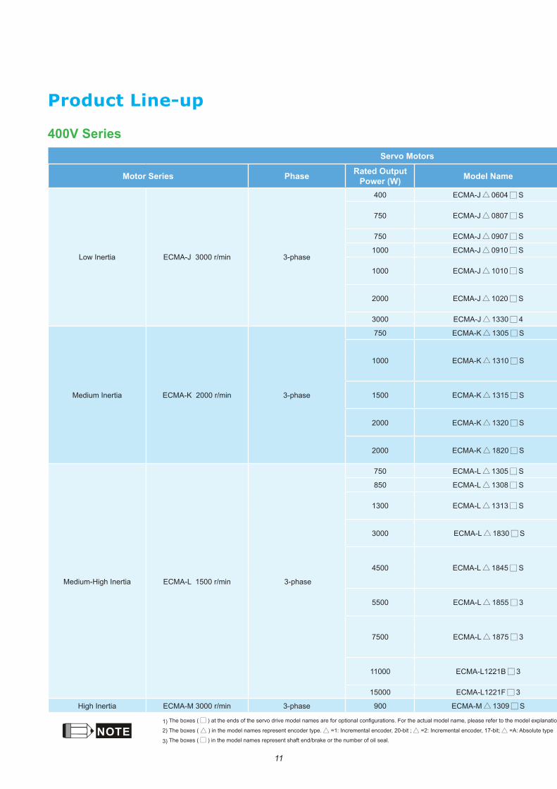
Product Line-up
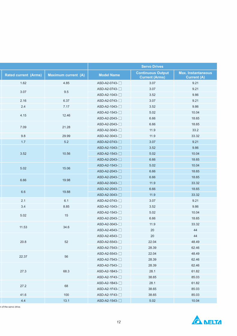
400V Series Servo Motors Servo Drives
Motor Series Phase Rated Output Power (W) Model Name Rated current (Arms) Maximum current (A) Model Name Continuous Output
Current (Arms)Max. Instantaneous
Current (A)
Low Inertia ECMA-J 3000 r/min 3-phase
400 ECMA-J 0604 S 1.62 4.85 ASD-A2-0743- 3.07 9.21
750 ECMA-J 0807 S 3.07 9.5ASD-A2-0743- 3.07 9.21
ASD-A2-1043- 3.52 9.86
750 ECMA-J 0907 S 2.16 6.37 ASD-A2-0743- 3.07 9.21
1000 ECMA-J 0910 S 2.4 7.17 ASD-A2-1043- 3.52 9.86
1000 ECMA-J 1010 S 4.15 12.46ASD-A2-1543- 5.02 10.04
ASD-A2-2043- 6.66 18.65
2000 ECMA-J 1020 S 7.09 21.28ASD-A2-2043- 6.66 18.65
ASD-A2-3043- 11.9 33.2
3000 ECMA-J 1330 4 9.8 29.99 ASD-A2-3043- 11.9 33.32
Medium Inertia ECMA-K 2000 r/min 3-phase
750 ECMA-K 1305 S 1.7 5.2 ASD-A2-0743- 3.07 9.21
1000 ECMA-K 1310 S 3.52 10.56
ASD-A2-1043- 3.52 9.86
ASD-A2-1543- 5.02 10.04
ASD-A2-2043- 6.66 18.65
1500 ECMA-K 1315 S 5.02 15.06ASD-A2-1543- 5.02 10.04
ASD-A2-2043- 6.66 18.65
2000 ECMA-K 1320 S 6.66 19.98ASD-A2-2043- 6.66 18.65
ASD-A2-3043- 11.9 33.32
2000 ECMA-K 1820 S 6.6 19.88ASD-A2-2043- 6.66 18.65
ASD-A2-3043- 11.9 33.32
Medium-High Inertia ECMA-L 1500 r/min 3-phase
750 ECMA-L 1305 S 2.1 6.1 ASD-A2-0743- 3.07 9.21
850 ECMA-L 1308 S 3.4 8.85 ASD-A2-1043- 3.52 9.86
1300 ECMA-L 1313 S 5.02 15ASD-A2-1543- 5.02 10.04
ASD-A2-2043- 6.66 18.65
3000 ECMA-L 1830 S 11.53 34.6ASD-A2-3043- 11.9 33.32
ASD-A2-4543- 20 44
4500 ECMA-L 1845 S 20.8 52
ASD-A2-4543- 20 44
ASD-A2-5543- 22.04 48.49
ASD-A2-7543- 28.39 62.46
5500 ECMA-L 1855 3 22.37 56ASD-A2-5543- 22.04 48.49
ASD-A2-7543- 28.39 62.46
7500 ECMA-L 1875 3 27.3 68.3
ASD-A2-7543- 28.39 62.46
ASD-A2-1B43- 28.1 61.82
ASD-A2-1F43- 38.65 85.03
11000 ECMA-L1221B 3 27.2 68ASD-A2-1B43- 28.1 61.82
ASD-A2-1F43- 38.65 85.03
15000 ECMA-L1221F 3 41.6 100 ASD-A2-1F43- 38.65 85.03
High Inertia ECMA-M 3000 r/min 3-phase 900 ECMA-M 1309 S 4.4 13.1 ASD-A2-1543- 5.02 10.04
NOTE1) The boxes ( ) at the ends of the servo drive model names are for optional configurations. For the actual model name, please refer to the model explanation of the servo drive.
2) The boxes ( ) in the model names represent encoder type. =1: Incremental encoder, 20-bit ; =2: Incremental encoder, 17-bit; =A: Absolute type
3) The boxes ( ) in the model names represent shaft end/brake or the number of oil seal.
12
400V Series Servo Motors Servo Drives
Motor Series Phase Rated Output Power (W) Model Name Rated current (Arms) Maximum current (A) Model Name Continuous Output
Current (Arms)Max. Instantaneous
Current (A)
Low Inertia ECMA-J 3000 r/min 3-phase
400 ECMA-J 0604 S 1.62 4.85 ASD-A2-0743- 3.07 9.21
750 ECMA-J 0807 S 3.07 9.5ASD-A2-0743- 3.07 9.21
ASD-A2-1043- 3.52 9.86
750 ECMA-J 0907 S 2.16 6.37 ASD-A2-0743- 3.07 9.21
1000 ECMA-J 0910 S 2.4 7.17 ASD-A2-1043- 3.52 9.86
1000 ECMA-J 1010 S 4.15 12.46ASD-A2-1543- 5.02 10.04
ASD-A2-2043- 6.66 18.65
2000 ECMA-J 1020 S 7.09 21.28ASD-A2-2043- 6.66 18.65
ASD-A2-3043- 11.9 33.2
3000 ECMA-J 1330 4 9.8 29.99 ASD-A2-3043- 11.9 33.32
Medium Inertia ECMA-K 2000 r/min 3-phase
750 ECMA-K 1305 S 1.7 5.2 ASD-A2-0743- 3.07 9.21
1000 ECMA-K 1310 S 3.52 10.56
ASD-A2-1043- 3.52 9.86
ASD-A2-1543- 5.02 10.04
ASD-A2-2043- 6.66 18.65
1500 ECMA-K 1315 S 5.02 15.06ASD-A2-1543- 5.02 10.04
ASD-A2-2043- 6.66 18.65
2000 ECMA-K 1320 S 6.66 19.98ASD-A2-2043- 6.66 18.65
ASD-A2-3043- 11.9 33.32
2000 ECMA-K 1820 S 6.6 19.88ASD-A2-2043- 6.66 18.65
ASD-A2-3043- 11.9 33.32
Medium-High Inertia ECMA-L 1500 r/min 3-phase
750 ECMA-L 1305 S 2.1 6.1 ASD-A2-0743- 3.07 9.21
850 ECMA-L 1308 S 3.4 8.85 ASD-A2-1043- 3.52 9.86
1300 ECMA-L 1313 S 5.02 15ASD-A2-1543- 5.02 10.04
ASD-A2-2043- 6.66 18.65
3000 ECMA-L 1830 S 11.53 34.6ASD-A2-3043- 11.9 33.32
ASD-A2-4543- 20 44
4500 ECMA-L 1845 S 20.8 52
ASD-A2-4543- 20 44
ASD-A2-5543- 22.04 48.49
ASD-A2-7543- 28.39 62.46
5500 ECMA-L 1855 3 22.37 56ASD-A2-5543- 22.04 48.49
ASD-A2-7543- 28.39 62.46
7500 ECMA-L 1875 3 27.3 68.3
ASD-A2-7543- 28.39 62.46
ASD-A2-1B43- 28.1 61.82
ASD-A2-1F43- 38.65 85.03
11000 ECMA-L1221B 3 27.2 68ASD-A2-1B43- 28.1 61.82
ASD-A2-1F43- 38.65 85.03
15000 ECMA-L1221F 3 41.6 100 ASD-A2-1F43- 38.65 85.03
High Inertia ECMA-M 3000 r/min 3-phase 900 ECMA-M 1309 S 4.4 13.1 ASD-A2-1543- 5.02 10.04
NOTE1) The boxes ( ) at the ends of the servo drive model names are for optional configurations. For the actual model name, please refer to the model explanation of the servo drive.
2) The boxes ( ) in the model names represent encoder type. =1: Incremental encoder, 20-bit ; =2: Incremental encoder, 17-bit; =A: Absolute type
3) The boxes ( ) in the model names represent shaft end/brake or the number of oil seal.
13
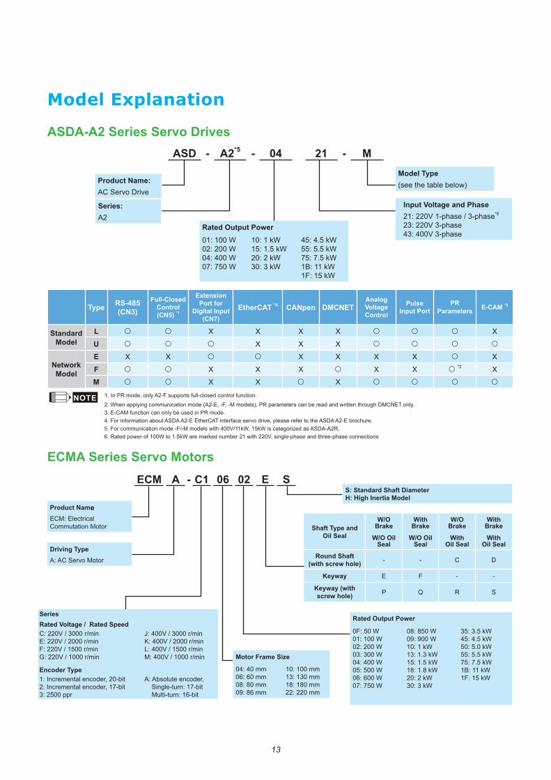
Model Explanation
ASDA-A2 Series Servo Drives
ECMA Series Servo Motors
ASD - A2*5 - 04 21 - M
ECM A - C1 06 02 E S
Product Name: AC Servo Drive
Product NameECM: Electrical Commutation Motor
S: Standard Shaft DiameterH: High Inertia Model
Driving TypeA: AC Servo Motor
Rated Output Power
0F: 50 W01: 100 W 02: 200 W 03: 300 W 04: 400 W05: 500 W 06: 600 W07: 750 W
08: 850 W09: 900 W10: 1 kW13: 1.3 kW15: 1.5 kW18: 1.8 kW20: 2 kW30: 3 kW
35: 3.5 kW45: 4.5 kW50: 5.0 kW55: 5.5 kW75: 7.5 kW1B: 11 kW1F: 15 kW
Shaft Type and Oil Seal
W/O Brake
W/O Oil Seal
With Brake
W/O Oil Seal
W/O Brake
With Oil Seal
With Brake
With Oil Seal
Round Shaft (with screw hole) - - C D
Keyway E F - -
Keyway (with screw hole) P Q R S
Model Type (see the table below)
Input Voltage and Phase21: 220V 1-phase / 3-phase*6
23: 220V 3-phase43: 400V 3-phase
Rated Output Power01: 100 W02: 200 W04: 400 W07: 750 W
10: 1 kW15: 1.5 kW20: 2 kW30: 3 kW
45: 4.5 kW55: 5.5 kW75: 7.5 kW1B: 11 kW1F: 15 kW
Series: A2
Series Rated Voltage / Rated SpeedC: 220V / 3000 r/minE: 220V / 2000 r/minF: 220V / 1500 r/minG: 220V / 1000 r/min
J: 400V / 3000 r/minK: 400V / 2000 r/minL: 400V / 1500 r/minM: 400V / 1000 r/min
Encoder Type1: Incremental encoder, 20-bit2: Incremental encoder, 17-bit3: 2500 ppr
A: Absolute encoder, Single-turn: 17-bit Multi-turn: 16-bit
Motor Frame Size 04: 40 mm 06: 60 mm 08: 80 mm 09: 86 mm
10: 100 mm13: 130 mm 18: 180 mm22: 220 mm
Type RS-485(CN3)
Full-Closed Control (CN5) *1
Extension Port for
Digital Input(CN7)
EtherCAT *4 CANpen DMCNETAnalog Voltage Control
Pulse Input Port
PR Parameters E-CAM *3
Standard Model
L ○ ○ X X X X ○ ○ ○ X
U ○ ○ ○ X X X ○ ○ ○ ○
Network Model
E X X ○ ○ X X X X ○ X
F ○ ○ X X X ○ X X ○ *2 X
M ○ ○ X X ○ X ○ ○ ○ ○
NOTE 1. In PR mode, only A2-F supports full-closed control function. 2. When applying communication mode (A2-E, -F, -M models), PR parameters can be read and written through DMCNET only. 3. E-CAM function can only be used in PR mode. 4. For information about ASDA A2-E EtherCAT interface servo drive, please refer to the ASDA A2-E brochure. 5. For communication mode -F/-M models with 400V/11kW, 15kW is categorized as ASDA-A2R. 6. Rated power of 100W to 1.5kW are marked number 21 with 220V, single-phase and three-phase connections
15
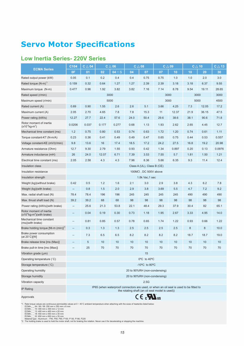
Low Inertia Series- 220V SeriesECMA Series
C104 C 04 C 06 C 08 C 09 C 10 C 130F 01 02 04 □ S 04 07 07 10 10 20 30
Rated output power (kW) 0.05 0.1 0.2 0.4 0.4 0.75 0.75 1.0 1.0 2.0 3.0
Rated torque (N-m)*1 0.159 0.32 0.64 1.27 1.27 2.39 2.39 3.18 3.18 6.37 9.55
Maximum torque (N-m) 0.477 0.96 1.92 3.82 3.82 7.16 7.14 8.78 9.54 19.11 28.65
Rated speed (r/min) 3000 3000 3000 3000
Maximum speed (r/min) 5000 3000 5000 4500
Rated current (A) 0.69 0.90 1.55 2.6 2.6 5.1 3.66 4.25 7.3 12.05 17.2
Maximum current (A) 2.05 2.70 4.65 7.8 7.8 15.3 11 12.37 21.9 36.15 47.5
Power rating (kW/s) 12.27 27.7 22.4 57.6 24.0 50.4 29.6 38.6 38.1 90.6 71.8
Rotor moment of inertia (x10-4kg-m2) 0.0206 0.037 0.177 0.277 0.68 1.13 1.93 2.62 2.65 4.45 12.7
Mechanical time constant (ms) 1.2 0.75 0.80 0.53 0.74 0.63 1.72 1.20 0.74 0.61 1.11
Torque constant-KT (N-m/A) 0.23 0.36 0.41 0.49 0.49 0.47 0.65 0.75 0.44 0.53 0.557
Voltage constant-KE (mV/(r/min) 9.8 13.6 16 17.4 18.5 17.2 24.2 27.5 16.8 19.2 20.98
Armature resistance (Ohm) 12.7 9.30 2.79 1.55 0.93 0.42 1.34 0.897 0.20 0.13 0.0976
Armature inductance (mH) 26 24.0 12.07 6.71 7.39 3.53 7.55 5.7 1.81 1.50 1.21
Electrical time constant (ms) 2.05 2.58 4.3 4.3 7.96 8.36 5.66 6.35 9.3 11.4 12.4
Insulation class Class A (UL), Class B (CE)
Insulation resistance 100MΩ , DC 500V above
Insulation strength 1.8k Vac,1 sec
Weight (kg)(without brake) 0.42 0.5 1.2 1.6 2.1 3.0 2.9 3.8 4.3 6.2 7.8
Weight (kg)(with brake) -- 0.8 1.5 2.0 2.9 3.8 3.69 5.5 4.7 7.2 9.2
Max. radial shaft load (N) 78.4 78.4 196 196 245 245 245 245 490 490 490
Max. thrust shaft load (N) 39.2 39.2 68 68 98 98 98 98 98 98 98
Power rating (kW/s)(with brake) -- 25.6 21.3 53.8 22.1 48.4 29.3 37.9 30.4 82 65.1
Rotor moment of inertia (x10-4kg-m2)(with brake) -- 0.04 0.19 0.30 0.73 1.18 1.95 2.67 3.33 4.95 14.0
Mechanical time constant (ms)(with brake) -- 0.81 0.85 0.57 0.78 0.65 1.74 1.22 0.93 0.66 1.22
Brake holding torque [Nt-m (min)]*2 -- 0.3 1.3 1.3 2.5 2.5 2.5 2.5 8 8 10.0
Brake power consumption (at 20˚C)[W] -- 7.3 6.5 6.5 8.2 8.2 8.2 8.2 18.7 18.7 19.0
Brake release time [ms (Max)] -- 5 10 10 10 10 10 10 10 10 10
Brake pull-in time [ms (Max)] -- 25 70 70 70 70 70 70 70 70 70
Vibration grade (μm) 15
Operating temperature (˚C) 0ºC to 40ºC
Storage temperature (˚C) -10ºC to 80ºC
Operating humidity 20 to 90%RH (non-condensing)
Storage humidity 20 to 90%RH (non-condensing)
Vibration capacity 2.5G
IP Rating IP65 (when waterproof connectors are used, or when an oil seal is used to be fitted to the rotating shaft (an oil seal model is used))
Approvals
*1. Rate torque values are continuous permissible values at 0 ~ 40˚C ambient temperature when attaching with the sizes of heatsinks listed below: ECMA-_ _ 04 / 06 / 08: 250 mm x 250 mm x 6 mm ECMA-_ _ 10: 300 mm x 300 mm x 12 mm ECMA-_ _ 13: 400 mm x 400 mm x 20 mm ECMA-_ _ 18: 550 mm x 550 mm x 30 mm ECMA-_ _ 22: 650 mm x 650 mm x 35 mm Material type : Aluminum – F40, F60, F80, F100, F130, F180, F220
*2. The holding brake is used to hold the motor shaft, not for braking the rotation. Never use it for decelerating or stopping the machine.
Servo Motor Specifications
16
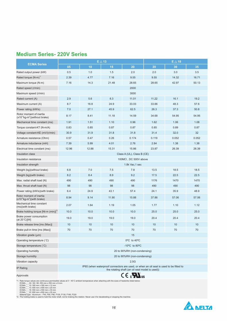
Medium Series- 220V SeriesECMA Series
E 13 E 1805 10 15 20 20 30 35
Rated output power (kW) 0.5 1.0 1.5 2.0 2.0 3.0 3.5
Rated torque (N-m)*1 2.39 4.77 7.16 9.55 9.55 14.32 16.71
Maximum torque (N-m) 7.16 14.3 21.48 28.65 28.65 42.97 50.13
Rated speed (r/min) 2000
Maximum speed (r/min) 3000
Rated current (A) 2.9 5.6 8.3 11.01 11.22 16.1 19.2
Maximum current (A) 8.7 16.8 24.9 33.03 33.66 48.3 57.6
Power rating (kW/s) 7.0 27.1 45.9 62.5 26.3 37.3 50.8
Rotor moment of inertia (x10-4kg-m2)(without brake) 8.17 8.41 11.18 14.59 34.68 54.95 54.95
Mechanical time constant (ms) 1.91 1.51 1.10 0.96 1.62 1.06 1.08
Torque constant-KT (N-m/A) 0.83 0.85 0.87 0.87 0.85 0.89 0.87
Voltage constant-KE (mV/(r/min) 30.9 31.9 31.8 31.8 31.4 32.0 32
Armature resistance (Ohm) 0.57 0.47 0.26 0.174 0.119 0.052 0.052
Armature inductance (mH) 7.39 5.99 4.01 2.76 2.84 1.38 1.38
Electrical time constant (ms) 12.96 12.88 15.31 15.86 23.87 26.39 26.39
Insulation class Class A (UL), Class B (CE)
Insulation resistance 100MΩ , DC 500V above
Insulation strength 1.8k Vac,1 sec
Weight (kg)(without brake) 6.8 7.0 7.5 7.8 13.5 18.5 18.5
Weight (kg)(with brake) 8.2 8.4 8.9 9.2 17.5 22.5 22.5
Max. radial shaft load (N) 490 490 490 490 1176 1470 1470
Max. thrust shaft load (N) 98 98 98 98 490 490 490
Power rating (kW/s)(with brake) 6.4 24.9 43.1 57.4 24.1 35.9 48.9
Rotor moment of inertia (x10-4kg-m2)(with brake) 8.94 9.14 11.90 15.88 37.86 57.06 57.06
Mechanical time constant (ms)(with brake) 2.07 1.64 1.19 1.05 1.77 1.10 1.12
Brake holding torque [Nt-m (min)]*2 10.0 10.0 10.0 10.0 25.0 25.0 25.0
Brake power consumption (at 20˚C)[W] 19.0 19.0 19.0 19.0 20.4 20.4 20.4
Brake release time [ms (Max)] 10 10 10 10 10 10 10
Brake pull-in time [ms (Max)] 70 70 70 70 70 70 70
Vibration grade (μm) 15
Operating temperature (˚C) 0ºC to 40ºC
Storage temperature (˚C) -10ºC to 80ºC
Operating humidity 20 to 90%RH (non-condensing)
Storage humidity 20 to 90%RH (non-condensing)
Vibration capacity 2.5G
IP Rating IP65 (when waterproof connectors are used, or when an oil seal is used to be fitted to the rotating shaft (an oil seal model is used))
Approvals
*1. Rate torque values are continuous permissible values at 0 ~ 40˚C ambient temperature when attaching with the sizes of heatsinks listed below: ECMA-_ _ 04 / 06 / 08: 250 mm x 250 mm x 6 mm ECMA-_ _ 10: 300 mm x 300 mm x 12 mm ECMA-_ _ 13: 400 mm x 400 mm x 20 mm ECMA-_ _ 18: 550 mm x 550 mm x 30 mm ECMA-_ _ 22: 650 mm x 650 mm x 35 mm Material type : Aluminum – F40, F60, F80, F100, F130, F180, F220
*2. The holding brake is used to hold the motor shaft, not for braking the rotation. Never use it for decelerating or stopping the machine.

17
Medium-High Inertia Series- 220V SeriesECMA Series
F 13 F 18 F12205 08 13 18 30 45 55 75 1B 1F
Rated output power (kW) 0.5 0.85 1.3 1.8 3.0 4.5 5.5 7.5 11 15
Rated torque (N-m)*1 3.18 5.41 8.34 11.48 19.10 28.65 35.01 47.74 70 95.4
Maximum torque (N-m) 8.92 13.8 23.3 28.7 57.29 71.62 87.53 119.36 175 224.0
Rated speed (r/min) 1500
Maximum speed (r/min) 3000 2000
Rated current (A) 3.9 7.1 12.6 13 19.4 32.5 40.0 47.5 51.8 67
Maximum current (A) 12.1 19.4 38.6 36 58.2 81.3 100.0 118.8 129.5 162
Power rating (kW/s) 9.8 21.52 34.78 52.93 66.4 105.5 122.9 159.7 144.9 201.8
Rotor moment of inertia (x10-4kg-m2)(without brake) 10.3 13.6 20 24.9 54.95 77.75 99.78 142.7 338 451
Mechanical time constant (ms) 2.8 2.43 1.62 1.7 1.28 0.92 0.96 0.63 1.38 1.23
Torque constant-KT (N-m/A) 0.82 0.76 0.66 0.88 0.98 0.88 0.88 1.01 1.37 1.42
Voltage constant-KE (mV/(r/min) 29.5 29.2 24.2 32.2 35.0 32.0 31.0 35.5 49 50
Armature resistance (Ohm) 0.624 0.38 0.124 0.185 0.077 0.032 0.025 0.015 0.026 0.0184
Armature inductance (mH) 7 4.77 1.7 2.6 1.27 0.89 0.60 0.40 0.65 0.48
Electrical time constant (ms) 11.22 12.55 13.71 14.05 16.5 27.8 24.0 26.7 24.79 26.09
Insulation class Class A (UL), Class B (CE)
Insulation resistance 100MΩ , DC 500V above
Insulation strength 1.8k Vac,1 sec
Weight (kg)(without brake) 6.3 8.6 9.4 10.5 18.5 23.5 30.5 40.5 56.4 75
Weight (kg)(with brake) 7.7 10.0 10.8 11.9 22.5 29 36 46 68.4 87
Max. radial shaft load (N) 490 490 490 490 1470 1470 1764 1764 3300 3300
Max. thrust shaft load (N) 98 98 98 98 490 490 588 588 1100 1100
Power rating (kW/s)(with brake) 8.8 19.78 32.66 50.3 63.9 101.8 119.4 156.6 141.4 197.1
Rotor moment of inertia (x10-4kg-m2)(with brake) 11.5 14.8 21.3 26.2 57.06 80.65 102.70 145.55 346.5 461.8
Mechanical time constant (ms)(with brake) 3.12 2.65 1.73 1.79 1.33 0.96 0.99 0.64 1.41 1.25
Brake holding torque[Nt-m(min)]*2 10 10.0 10.0 10.0 25.0 55.0 55.0 55.0 115 115
Brake power consumption (at 20˚C)[W] 19 19.0 19.0 19.0 20.4 19.9 19.9 19.9 28.8 28.8
Brake release time [ms (Max)] 10 10 10 10 10 10 10 10 10 10
Brake pull-in time [ms (Max)] 70 70 70 70 70 70 70 70 70 70
Vibration grade (μm) 15
Operating temperature (˚C) 0ºC to 40ºC
Storage temperature (˚C) -10ºC to 80ºC
Operating humidity 20 to 90%RH (non-condensing)
Storage humidity 20 to 90%RH (non-condensing)
Vibration capacity 2.5G
IP Rating IP65 (when waterproof connectors are used, or when an oil seal is used to be fitted to the rotating shaft (an oil seal model is used))
Approvals
*1. Rate torque values are continuous permissible values at 0 ~ 40˚C ambient temperature when attaching with the sizes of heatsinks listed below: ECMA-_ _ 04 / 06 / 08: 250 mm x 250 mm x 6 mm ECMA-_ _ 10: 300 mm x 300 mm x 12 mm ECMA-_ _ 13: 400 mm x 400 mm x 20 mm ECMA-_ _ 18: 550 mm x 550 mm x 30 mm ECMA-_ _ 22: 650 mm x 650 mm x 35 mm Material type : Aluminum – F40, F60, F80, F100, F130, F180, F220
*2. The holding brake is used to hold the motor shaft, not for braking the rotation. Never use it for decelerating or stopping the machine.
Servo Motor Specifications
18
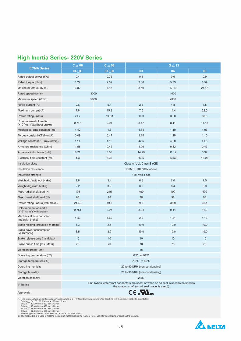
High Inertia Series- 220V SeriesECMA Series
C 06 C 08 G 1304 ▅ H 07 ▅ H 03 06 09
Rated output power (kW) 0.4 0.75 0.3 0.6 0.9
Rated torque (N-m)*1 1.27 2.39 2.86 5.73 8.59
Maximum torque (N-m) 3.82 7.16 8.59 17.19 21.48
Rated speed (r/min) 3000 1000
Maximum speed (r/min) 5000 2000
Rated current (A) 2.6 5.1 2.5 4.8 7.5
Maximum current (A) 7.8 15.3 7.5 14.4 22.5
Power rating (kW/s) 21.7 19.63 10.0 39.0 66.0
Rotor moment of inertia (x10-4kg-m2)(without brake) 0.743 2.91 8.17 8.41 11.18
Mechanical time constant (ms) 1.42 1.6 1.84 1.40 1.06
Torque constant-KT (N-m/A) 0.49 0.47 1.15 1.19 1.15
Voltage constant-KE (mV/(r/min) 17.4 17.2 42.5 43.8 41.6
Armature resistance (Ohm) 1.55 0.42 1.06 0.82 0.43
Armature inductance (mH) 6.71 3.53 14.29 11.12 6.97
Electrical time constant (ms) 4.3 8.36 13.5 13.50 16.06
Insulation class Class A (UL), Class B (CE)
Insulation resistance 100MΩ , DC 500V above
Insulation strength 1.8k Vac,1 sec
Weight (kg)(without brake) 1.8 3.4 6.8 7.0 7.5
Weight (kg)(with brake) 2.2 3.9 8.2 8.4 8.9
Max. radial shaft load (N) 196 245 490 490 490
Max. thrust shaft load (N) 68 98 98 98 98
Power rating (kW/s)(with brake) 21.48 19.3 9.2 35.9 62.1
Rotor moment of inertia (x10-4kg-m2)(with brake) 0.751 2.96 8.94 9.14 11.9
Mechanical time constant (ms)(with brake) 1.43 1.62 2.0 1.51 1.13
Brake holding torque [Nt-m (min)]*2 1.3 2.5 10.0 10.0 10.0
Brake power consumption (at 20˚C)[W] 6.5 8.2 19.0 19.0 19.0
Brake release time [ms (Max)] 10 10 10 10 10
Brake pull-in time [ms (Max)] 70 70 70 70 70
Vibration grade (μm) 15
Operating temperature (˚C) 0ºC to 40ºC
Storage temperature (˚C) -10ºC to 80ºC
Operating humidity 20 to 90%RH (non-condensing)
Storage humidity 20 to 90%RH (non-condensing)
Vibration capacity 2.5G
IP Rating IP65 (when waterproof connectors are used, or when an oil seal is used to be fitted to the rotating shaft (an oil seal model is used))
Approvals
*1. Rate torque values are continuous permissible values at 0 ~ 40˚C ambient temperature when attaching with the sizes of heatsinks listed below: ECMA-_ _ 04 / 06 / 08: 250 mm x 250 mm x 6 mm ECMA-_ _ 10: 300 mm x 300 mm x 12 mm ECMA-_ _ 13: 400 mm x 400 mm x 20 mm ECMA-_ _ 18: 550 mm x 550 mm x 30 mm ECMA-_ _ 22: 650 mm x 650 mm x 35 mm Material type : Aluminum – F40, F60, F80, F100, F130, F180, F220
*2. The holding brake is used to hold the motor shaft, not for braking the rotation. Never use it for decelerating or stopping the machine.
19
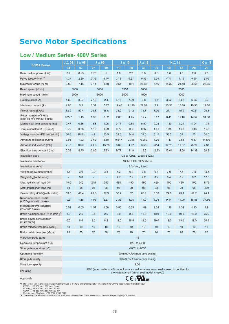
Low / Medium Series- 400V SeriesECMA Series
J 06 J 08 J 09 J 10 J 13 K 13 K 1804 07 07 10 10 20 30 05 10 15 20 20
Rated output power (kW) 0.4 0.75 0.75 1 1.0 2.0 3.0 0.5 1.0 1.5 2.0 2.0
Rated torque (N-m)*1 1.27 2.39 2.39 3.18 3.18 6.37 9.55 2.39 4.77 7.16 9.55 9.55
Maximum torque (N-m) 3.82 7.16 7.14 8.78 9.54 19.1 28.65 7.16 14.32 21.48 28.65 28.65
Rated speed (r/min) 3000 3000 3000 3000 2000
Maximum speed (r/min) 5000 3000 5000 4500 3000
Rated current (A) 1.62 3.07 2.16 2.4 4.15 7.09 9.8 1.7 3.52 5.02 6.66 6.6
Maximum current (A) 4.85 9.5 6.37 7.17 12.46 21.28 29.99 5.2 10.56 15.06 19.98 19.88
Power rating (kW/s) 58.2 50.4 29.6 38.6 38.2 91.2 71.8 6.99 27.1 45.9 62.5 26.3
Rotor moment of inertia (x10-4kg-m2)(without brake) 0.277 1.13 1.93 2.62 2.65 4.45 12.7 8.17 8.41 11.18 14.59 34.68
Mechanical time constant (ms) 0.47 0.66 1.56 1.06 0.77 0.58 0.99 2.08 1.80 1.24 1.04 1.74
Torque constant-KT (N-m/A) 0.79 0.78 1.12 1.29 0.77 0.9 0.97 1.41 1.35 1.43 1.43 1.45
Voltage constant-KE (mV/(r/min) 30.6 28.24 42 50.9 29.0 34.4 37.3 51.5 53.2 55 55 54.0
Armature resistance (Ohm) 3.95 1.22 3.62 2.58 0.617 0.388 0.269 1.76 1.47 0.83 0.57 0.376
Armature inductance (mH) 21.3 10.68 21.2 15.28 6.03 4.62 3.55 22.4 17.79 11.67 8.29 7.87
Electrical time constant (ms) 5.39 8.75 5.85 5.93 9.77 11.9 13.2 12.73 12.04 14.04 14.39 20.9
Insulation class Class A (UL), Class B (CE)
Insulation resistance 100MΩ, DC 500V above
Insulation strength 2.3k Vac, 1 sec
Weight (kg)(without brake) 1.6 3.0 2.9 3.8 4.3 6.2 7.8 6.8 7.0 7.5 7.8 13.5
Weight (kg)(with brake) 2 3.8 - - 4.7 7.2 9.2 8.2 8.4 8.9 9.2 17.5
Max. radial shaft load (N) 19.6 245 245 245 490 490 490 490 490 490 490 1176
Max. thrust shaft load (N) 68 98 98 98 98 98 98 98 98 98 98 490
Power rating (kW/s)(with brake) 53.8 48.4 29.3 37.9 30.4 82 65.1 6.39 24.9 43.1 59.7 24.1
Rotor moment of inertia (x10-4kg-m2)(with brake) 0.3 1.18 1.95 2.67 3.33 4.95 14.0 8.94 9.14 11.90 15.88 37.86
Mechanical time constant (ms)(with brake) 0.52 0.65 1.57 1.08 0.96 0.65 1.09 2.28 1.96 1.32 1.13 1.9
Brake holding torque [Nt-m (min)]*2 1.3 2.5 2.5 2.5 8.0 8.0 10.0 10.0 10.0 10.0 10.0 25.0
Brake power consumption (at 20˚C)[W] 6.5 8.5 8.2 8.2 18.5 18.5 19.0 19.0 19.0 19.0 19.0 20.4
Brake release time [ms (Max)] 10 10 10 10 10 10 10 10 10 10 10 10
Brake pull-in time [ms (Max)] 70 70 70 70 70 70 70 70 70 70 70 70
Vibration grade (μm) 15
Operating temperature (˚C) 0ºC to 40ºC
Storage temperature (˚C) -10ºC to 80ºC
Operating humidity 20 to 90%RH (non-condensing)
Storage humidity 20 to 90%RH (non-condensing)
Vibration capacity 2.5G
IP Rating IP65 (when waterproof connectors are used, or when an oil seal is used to be fitted to the rotating shaft (an oil seal model is used))
Approvals
*1. Rate torque values are continuous permissible values at 0 ~ 40˚C ambient temperature when attaching with the sizes of heatsinks listed below: ECMA-_ _ 08: 250 mm x 250 mm x 6 mm ECMA-_ _ 13: 400 mm x 400 mm x 20 mm ECMA-_ _ 18: 550 mm x 550 mm x 30 mm Material type : Aluminum – F80, F130, F180, F220
*2. The holding brake is used to hold the motor shaft, not for braking the rotation. Never use it for decelerating or stopping the machine.
Servo Motor Specifications
20
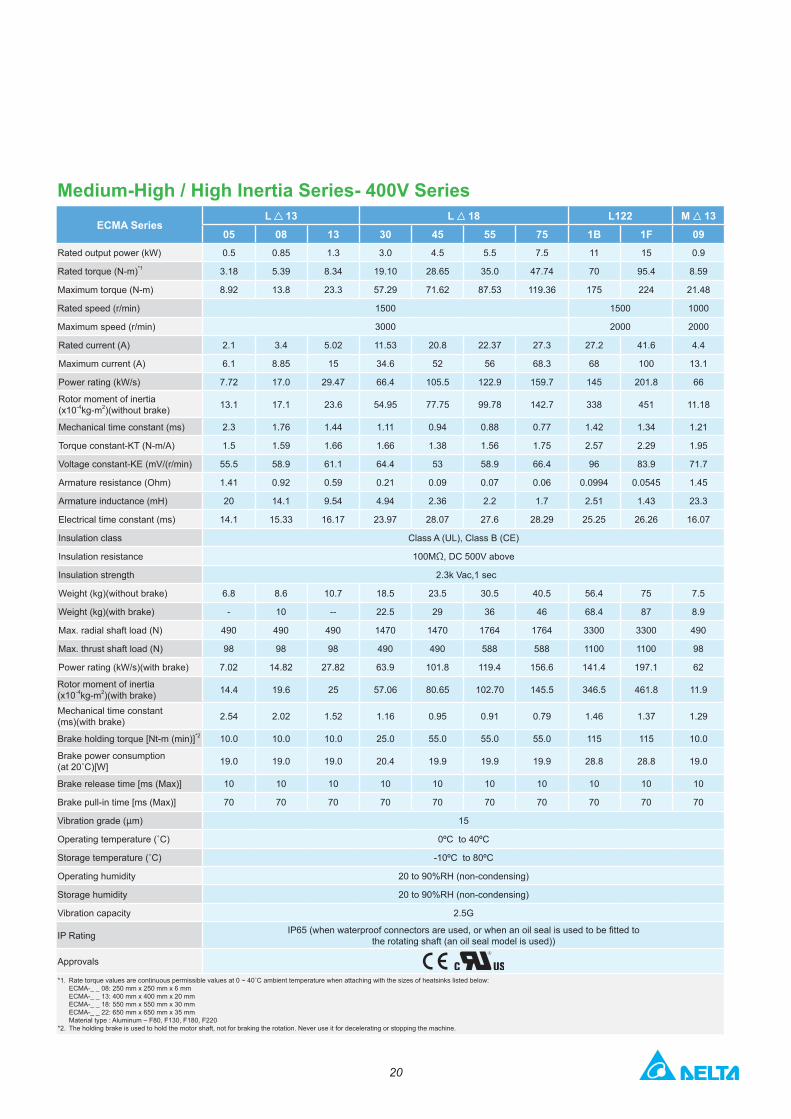
Medium-High / High Inertia Series- 400V SeriesECMA Series
L 13 L 18 L122 M 1305 08 13 30 45 55 75 1B 1F 09
Rated output power (kW) 0.5 0.85 1.3 3.0 4.5 5.5 7.5 11 15 0.9
Rated torque (N-m)*1 3.18 5.39 8.34 19.10 28.65 35.0 47.74 70 95.4 8.59
Maximum torque (N-m) 8.92 13.8 23.3 57.29 71.62 87.53 119.36 175 224 21.48
Rated speed (r/min) 1500 1500 1000
Maximum speed (r/min) 3000 2000 2000
Rated current (A) 2.1 3.4 5.02 11.53 20.8 22.37 27.3 27.2 41.6 4.4
Maximum current (A) 6.1 8.85 15 34.6 52 56 68.3 68 100 13.1
Power rating (kW/s) 7.72 17.0 29.47 66.4 105.5 122.9 159.7 145 201.8 66
Rotor moment of inertia (x10-4kg-m2)(without brake) 13.1 17.1 23.6 54.95 77.75 99.78 142.7 338 451 11.18
Mechanical time constant (ms) 2.3 1.76 1.44 1.11 0.94 0.88 0.77 1.42 1.34 1.21
Torque constant-KT (N-m/A) 1.5 1.59 1.66 1.66 1.38 1.56 1.75 2.57 2.29 1.95
Voltage constant-KE (mV/(r/min) 55.5 58.9 61.1 64.4 53 58.9 66.4 96 83.9 71.7
Armature resistance (Ohm) 1.41 0.92 0.59 0.21 0.09 0.07 0.06 0.0994 0.0545 1.45
Armature inductance (mH) 20 14.1 9.54 4.94 2.36 2.2 1.7 2.51 1.43 23.3
Electrical time constant (ms) 14.1 15.33 16.17 23.97 28.07 27.6 28.29 25.25 26.26 16.07
Insulation class Class A (UL), Class B (CE)
Insulation resistance 100MΩ, DC 500V above
Insulation strength 2.3k Vac,1 sec
Weight (kg)(without brake) 6.8 8.6 10.7 18.5 23.5 30.5 40.5 56.4 75 7.5
Weight (kg)(with brake) - 10 -- 22.5 29 36 46 68.4 87 8.9
Max. radial shaft load (N) 490 490 490 1470 1470 1764 1764 3300 3300 490
Max. thrust shaft load (N) 98 98 98 490 490 588 588 1100 1100 98
Power rating (kW/s)(with brake) 7.02 14.82 27.82 63.9 101.8 119.4 156.6 141.4 197.1 62
Rotor moment of inertia (x10-4kg-m2)(with brake) 14.4 19.6 25 57.06 80.65 102.70 145.5 346.5 461.8 11.9
Mechanical time constant (ms)(with brake) 2.54 2.02 1.52 1.16 0.95 0.91 0.79 1.46 1.37 1.29
Brake holding torque [Nt-m (min)]*2 10.0 10.0 10.0 25.0 55.0 55.0 55.0 115 115 10.0
Brake power consumption (at 20˚C)[W] 19.0 19.0 19.0 20.4 19.9 19.9 19.9 28.8 28.8 19.0
Brake release time [ms (Max)] 10 10 10 10 10 10 10 10 10 10
Brake pull-in time [ms (Max)] 70 70 70 70 70 70 70 70 70 70
Vibration grade (μm) 15
Operating temperature (˚C) 0ºC to 40ºC
Storage temperature (˚C) -10ºC to 80ºC
Operating humidity 20 to 90%RH (non-condensing)
Storage humidity 20 to 90%RH (non-condensing)
Vibration capacity 2.5G
IP Rating IP65 (when waterproof connectors are used, or when an oil seal is used to be fitted to the rotating shaft (an oil seal model is used))
Approvals
*1. Rate torque values are continuous permissible values at 0 ~ 40˚C ambient temperature when attaching with the sizes of heatsinks listed below: ECMA-_ _ 08: 250 mm x 250 mm x 6 mm ECMA-_ _ 13: 400 mm x 400 mm x 20 mm ECMA-_ _ 18: 550 mm x 550 mm x 30 mm ECMA-_ _ 22: 650 mm x 650 mm x 35 mm Material type : Aluminum – F80, F130, F180, F220
*2. The holding brake is used to hold the motor shaft, not for braking the rotation. Never use it for decelerating or stopping the machine.
21
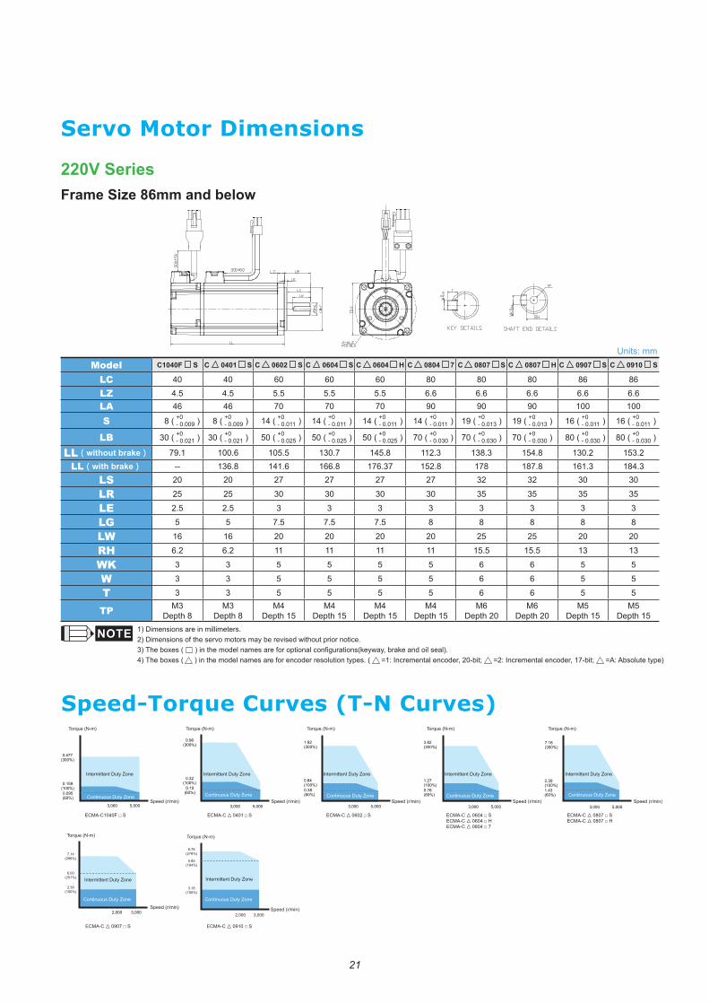
220V SeriesFrame Size 86mm and below
Servo Motor Dimensions
Speed-Torque Curves (T-N Curves)
Units: mmModel C1040F S C 0401 S C 0602 S C 0604 S C 0604 H C 0804 7 C 0807 S C 0807 H C 0907 S C 0910 S
LC 40 40 60 60 60 80 80 80 86 86
LZ 4.5 4.5 5.5 5.5 5.5 6.6 6.6 6.6 6.6 6.6LA 46 46 70 70 70 90 90 90 100 100
S 8 ( +0- 0.009 ) 8 ( +0
- 0.009 ) 14 ( +0- 0.011 ) 14 ( +0
- 0.011 ) 14 ( +0- 0.011 ) 14 ( +0
- 0.011 ) 19 ( +0- 0.013 ) 19 ( +0
- 0.013 ) 16 ( +0- 0.011 ) 16 ( +0
- 0.011 )
LB 30 ( +0- 0.021 ) 30 ( +0
- 0.021 ) 50 ( +0- 0.025 ) 50 ( +0
- 0.025 ) 50 ( +0- 0.025 ) 70 ( +0
- 0.030 ) 70 ( +0- 0.030 ) 70 ( +0
- 0.030 ) 80 ( +0- 0.030 ) 80 ( +0
- 0.030 )
LL(without brake) 79.1 100.6 105.5 130.7 145.8 112.3 138.3 154.8 130.2 153.2LL(with brake) -- 136.8 141.6 166.8 176.37 152.8 178 187.8 161.3 184.3
LS 20 20 27 27 27 27 32 32 30 30
LR 25 25 30 30 30 30 35 35 35 35
LE 2.5 2.5 3 3 3 3 3 3 3 3
LG 5 5 7.5 7.5 7.5 8 8 8 8 8
LW 16 16 20 20 20 20 25 25 20 20
RH 6.2 6.2 11 11 11 11 15.5 15.5 13 13
WK 3 3 5 5 5 5 6 6 5 5
W 3 3 5 5 5 5 6 6 5 5
T 3 3 5 5 5 5 6 6 5 5
TP M3Depth 8
M3Depth 8
M4Depth 15
M4Depth 15
M4Depth 15
M4Depth 15
M6Depth 20
M6Depth 20
M5Depth 15
M5Depth 15
1) Dimensions are in millimeters. 2) Dimensions of the servo motors may be revised without prior notice.3) The boxes ( ) in the model names are for optional configurations(keyway, brake and oil seal).4) The boxes ( ) in the model names are for encoder resolution types. ( =1: Incremental encoder, 20-bit; =2: Incremental encoder, 17-bit; =A: Absolute type)
Torque (N-m)
ECMA-C▲ 0602 □ S ECMA-C▲ 0807 □ SECMA-C▲ 0807 □ H
Torque (N-m) Torque (N-m)
ECMA-C▲ 0604 □ SECMA-C▲ 0604 □ HECMA-C▲ 0804 □ 7
Torque (N-m)
Continuous Duty Zone Continuous Duty Zone Continuous Duty Zone Continuous Duty Zone
ECMA-C▲ 0401 □ S
Torque (N-m)
Speed (r/min) Speed (r/min) Speed (r/min) Speed (r/min) Speed (r/min)Continuous Duty Zone
Intermittent Duty Zone Intermittent Duty Zone Intermittent Duty Zone Intermittent Duty Zone Intermittent Duty Zone
ECMA-C1040F □ S
ECMA-C▲ 0910 □ S
Torque (N-m)
7.14(298%)
2.38(100%)
6.00(251%)
Speed (r/min)
ECMA-C▲ 0907 □ S
8.78(276%)
3.18(100%)
2,000 3,000
Torque (N-m)
Speed (r/min)
Continuous Duty Zone
Intermittent Duty Zone
5.85(184%)
Continuous Duty Zone
Intermittent Duty Zone
22
Speed-Torque Curves (T-N Curves)
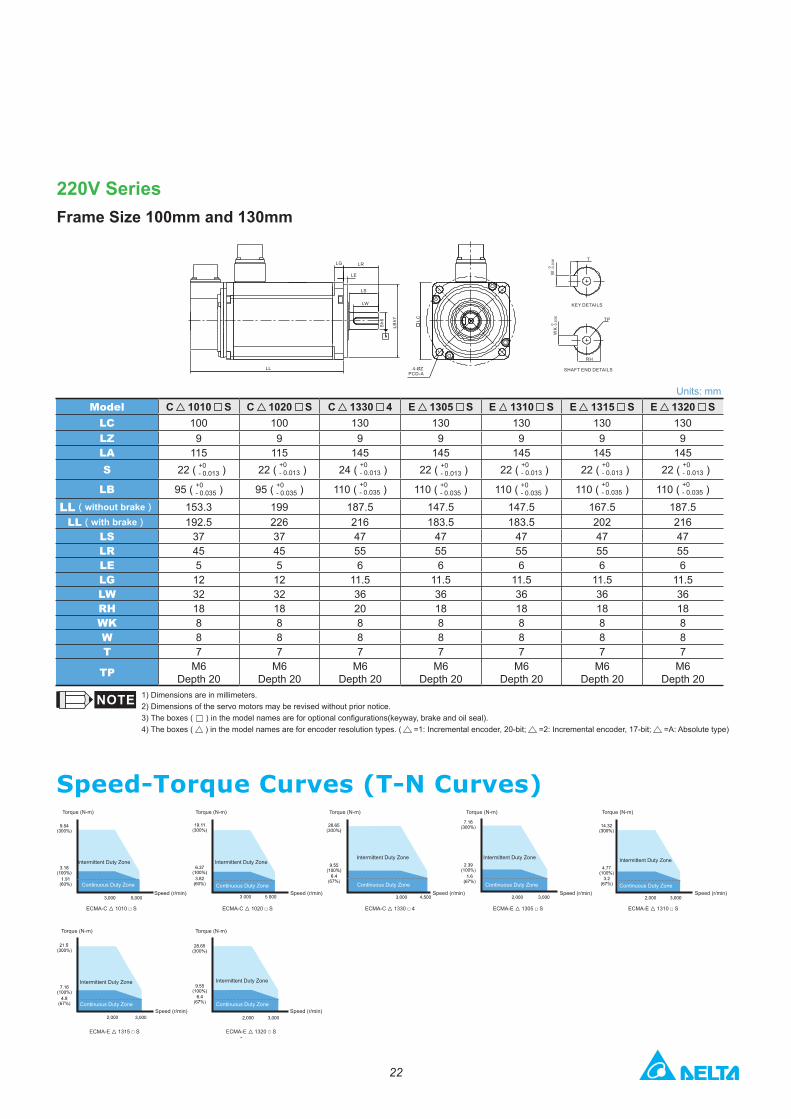
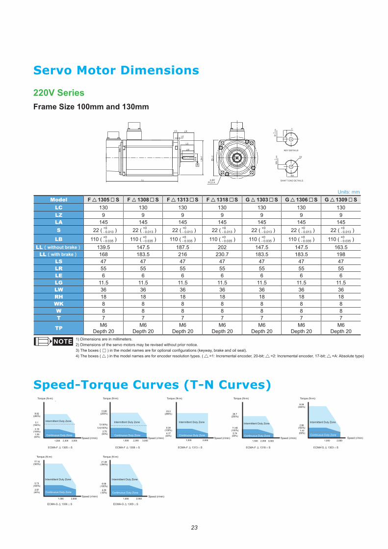
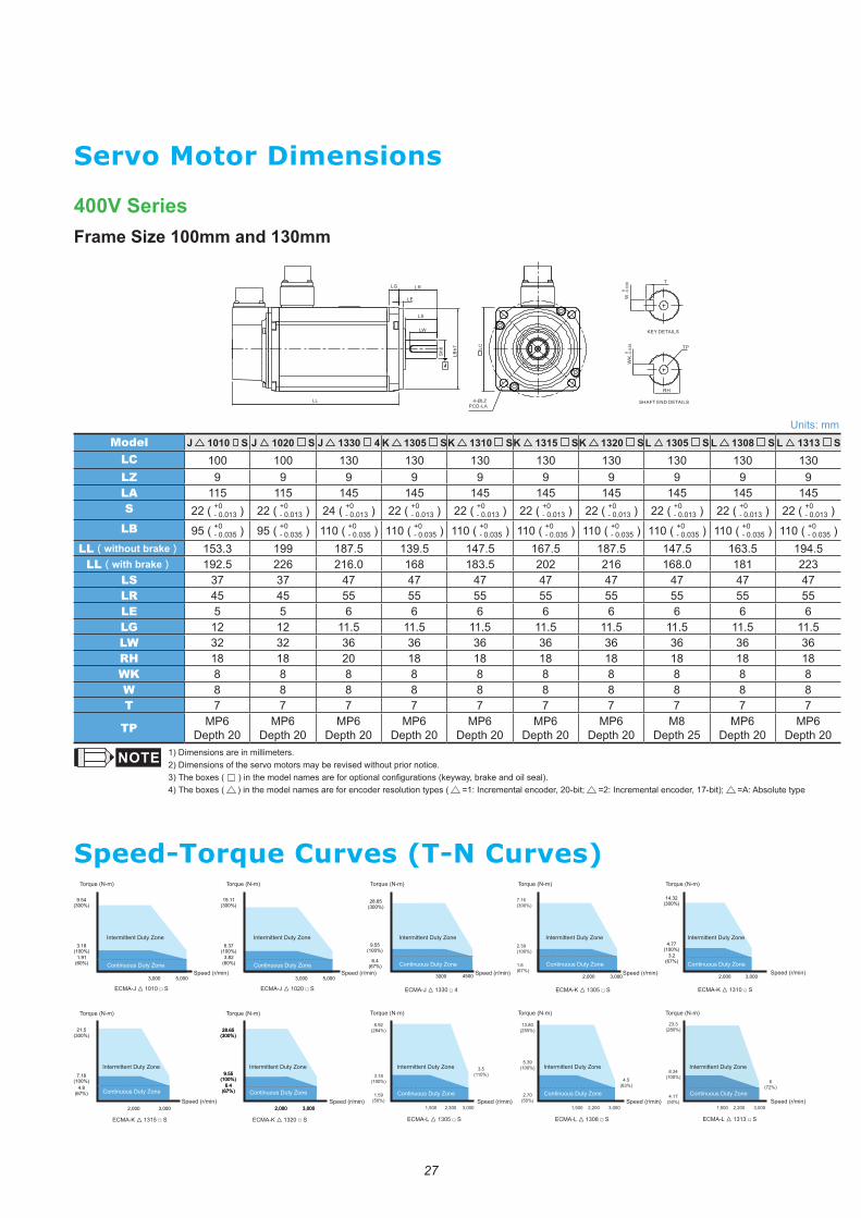
220V SeriesFrame Size 100mm and 130mm
Units: mmModel C 1010 S C 1020 S C 1330 4 E 1305 S E 1310 S E 1315 S E 1320 S
LC 100 100 130 130 130 130 130LZ 9 9 9 9 9 9 9LA 115 115 145 145 145 145 145S 22 ( +0
- 0.013 ) 22 ( +0- 0.013 ) 24 ( +0
- 0.013 ) 22 ( +0- 0.013 ) 22 ( +0
- 0.013 ) 22 ( +0- 0.013 ) 22 ( +0
- 0.013 )
LB 95 ( +0- 0.035 ) 95 ( +0
- 0.035 ) 110 ( +0- 0.035 ) 110 ( +0
- 0.035 ) 110 ( +0- 0.035 ) 110 ( +0
- 0.035 ) 110 ( +0- 0.035 )
LL(without brake) 153.3 199 187.5 147.5 147.5 167.5 187.5LL(with brake) 192.5 226 216 183.5 183.5 202 216
LS 37 37 47 47 47 47 47LR 45 45 55 55 55 55 55LE 5 5 6 6 6 6 6LG 12 12 11.5 11.5 11.5 11.5 11.5LW 32 32 36 36 36 36 36RH 18 18 20 18 18 18 18WK 8 8 8 8 8 8 8W 8 8 8 8 8 8 8T 7 7 7 7 7 7 7
TP M6Depth 20
M6Depth 20
M6Depth 20
M6Depth 20
M6Depth 20
M6Depth 20
M6Depth 20
1) Dimensions are in millimeters. 2) Dimensions of the servo motors may be revised without prior notice.3) The boxes ( ) in the model names are for optional configurations(keyway, brake and oil seal).4) The boxes ( ) in the model names are for encoder resolution types. ( =1: Incremental encoder, 20-bit; =2: Incremental encoder, 17-bit; =A: Absolute type)
LG LR
LE
LS
LW
LBh7
SHAFT END DETAILS
KEY DETAILS
Sh6
4-ØZPCD-A
W -0
.036
0
-0.0
360
T
TP
RH
LC
LL
Torque (N-m)Torque (N-m)
Torque (N-m)
Torque (N-m)
Torque (N-m)
Torque (N-m)
Speed (r/min) Speed (r/min)
ECMA-C▲ 1020 □ SECMA-C▲ 1010 □ S
Speed (r/min)
ECMA-C▲ 1330 □ 4
Torque (N-m)
Speed (r/min)
ECMA-E▲ 1305 □ S
Speed (r/min)
ECMA-E▲ 1310 □ S
Speed (r/min)
ECMA-E▲ 1315 □ S
Speed (r/min)
ECMA-E▲ 1320 □ S
Continuous Duty Zone
Continuous Duty Zone Continuous Duty Zone
Continuous Duty Zone Continuous Duty Zone Continuous Duty Zone Continuous Duty Zone
Intermittent Duty Zone
Intermittent Duty Zone Intermittent Duty Zone
Intermittent Duty ZoneIntermittent Duty Zone Intermittent Duty Zone Intermittent Duty Zone
23
Units: mmModel F 1305 S F 1308 S F 1313 S F 1318 S G 1303 S G 1306 S G 1309 S
LC 130 130 130 130 130 130 130LZ 9 9 9 9 9 9 9LA 145 145 145 145 145 145 145S 22 ( +0
- 0.013 ) 22 ( +0- 0.013 ) 22 ( +0
- 0.013 ) 22 ( +0- 0.013 ) 22 ( +0
- 0.013 ) 22 ( +0- 0.013 ) 22 ( +0
- 0.013 )
LB 110 ( +0- 0.035 ) 110 ( +0
- 0.035 ) 110 ( +0- 0.035 ) 110 ( +0
- 0.035 ) 110 ( +0- 0.035 ) 110 ( +0
- 0.035 ) 110 ( +0- 0.035 )
LL(without brake) 139.5 147.5 187.5 202 147.5 147.5 163.5LL(with brake) 168 183.5 216 230.7 183.5 183.5 198
LS 47 47 47 47 47 47 47LR 55 55 55 55 55 55 55LE 6 6 6 6 6 6 6LG 11.5 11.5 11.5 11.5 11.5 11.5 11.5LW 36 36 36 36 36 36 36RH 18 18 18 18 18 18 18WK 8 8 8 8 8 8 8W 8 8 8 8 8 8 8T 7 7 7 7 7 7 7
TP M6Depth 20
M6Depth 20
M6Depth 20
M6Depth 20
M6Depth 20
M6Depth 20
M6Depth 20
1) Dimensions are in millimeters. 2) Dimensions of the servo motors may be revised without prior notice.3) The boxes ( ) in the model names are for optional configurations (keyway, brake and oil seal).4) The boxes ( ) in the model names are for encoder resolution types. ( =1: Incremental encoder, 20-bit; =2: Incremental encoder, 17-bit; =A: Absolute type)
220V SeriesFrame Size 100mm and 130mm
Servo Motor Dimensions
Speed-Torque Curves (T-N Curves)
LG LR
LE
LS
LW
LBh7
SHAFT END DETAILS
KEY DETAILS
Sh6
4-ØZPCD-A
W -0
.036
0
-0.0
360
T
TP
RH
LC
LL
3,0002,3001,500
8.92(280%)
3.18(100%)
1.59(50%)
5.1(160%)
ECMA-F▲ 1318 □ S ECMA-G▲ 1303 □ SECMA-F▲ 1313 □ SECMA-F▲ 1305 □ S
ECMA-G▲ 1306 □ S ECMA-G▲ 1309 □ S
ECMA-F▲ 1308 □ S
Torque (N-m) Torque (N-m) Torque (N-m)Torque (N-m)Torque (N-m)
Torque (N-m)Torque (N-m)
Speed (r/min) Speed (r/min) Speed (r/min) Speed (r/min) Speed (r/min)
Speed (r/min)Speed (r/min)
Continuous Duty Zone
Intermittent Duty Zone
Continuous Duty Zone
Intermittent Duty Zone
Continuous Duty Zone
Intermittent Duty Zone
Continuous Duty Zone
Intermittent Duty Zone
Continuous Duty Zone
Intermittent Duty Zone
Continuous Duty Zone
Intermittent Duty Zone
Continuous Duty Zone
Intermittent Duty Zone
24
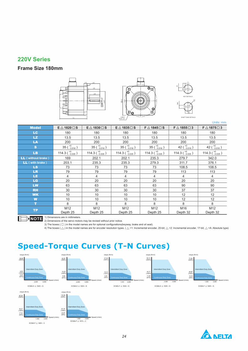
220V SeriesFrame Size 180mm
Units: mmModel E 1820 S E 1830 S E 1835 S F 1845 S F 1855 3 F 1875 3
LC 180 180 180 180 180 180LZ 13.5 13.5 13.5 13.5 13.5 13.5LA 200 200 200 200 200 200S 35 ( +0
- 0.016 ) 35 ( +0- 0.016 ) 35 ( +0
- 0.016 ) 35 ( +0- 0.016 ) 42 ( +0
- 0.016 ) 42 ( +0- 0.016 )
LB 114.3 ( +0- 0.035 ) 114.3 ( +0
- 0.035 ) 114.3 ( +0- 0.035 ) 114.3 ( +0
- 0.035 ) 114.3 ( +0- 0.035 ) 114.3 ( +0
- 0.035 )LL(without brake) 169 202.1 202.1 235.3 279.7 342.0
LL(with brake) 203.1 235.3 235.3 279.3 311.7 376.1LS 73 73 73 73 108.5 108.5LR 79 79 79 79 113 113LE 4 4 4 4 4 4LG 20 20 20 20 20 20LW 63 63 63 63 90 90RH 30 30 30 30 37 37WK 10 10 10 10 12 12W 10 10 10 10 12 12T 8 8 8 8 8 8
TP M12Depth 25
M12Depth 25
M12Depth 25
M12Depth 25
M16Depth 32
M12Depth 32
1) Dimensions are in millimeters. 2) Dimensions of the servo motors may be revised without prior notice.3) The boxes ( ) in the model names are for optional configurations(keyway, brake and oil seal).4) The boxes ( ) in the model names are for encoder resolution types. ( =1: Incremental encoder, 20-bit; =2: Incremental encoder, 17-bit; =A: Absolute type)
Speed-Torque Curves (T-N Curves)
LR
Sh6
LL
LGLE
LS
LW
Lbh7
SHAFT END DETAILS
KEY DETAILS
4-ØLZPCD -LA
T
LC
W
TP
RH
28.65(300%)
9.55(100%)
6.40(67%)
3,0002,000
42.97(300%)
14.32(100%)
9.59(67%)
3,000 3,0002,000
ECMA-E▲ 1820 □ S ECMA-E▲ 1830 □ S ECMA-F▲ 1830 □ S ECMA-F▲ 1845 □ SECMA-E▲ 1835 □ S
71.62(300%)
28.65(100%)
14.33(50%)
3,0001,500
50.13(300%)
16.71(100%)
11.20(67%)
3,0002,000Speed (r/min) Speed (r/min) Speed (r/min) Speed (r/min) Speed (r/min)
orque (N-m) orque (N-m) orque (N-m) orque (N-m) orque (N-m)
orque (N-m)
ECMA-F▲ 1875 □ 3
119.36(250%)
47.74(100%)
23.87(50%)
3,0001,500Speed (r/min)
ECMA-F▲ 1855 □ 3
87.53(300%)
35.01(100%)
17.51(50%)
3,0001,500Speed (r/min)
orque (N-m)
1,500
57.29(300%)
19.10(100%)
9.55(50%)Continuous Duty Zone
Intermittent Duty Zone
Continuous Duty Zone
Intermittent Duty Zone
Continuous Duty Zone
Intermittent Duty Zone
Continuous Duty Zone
Intermittent Duty Zone
Continuous Duty Zone
Intermittent Duty Zone
Continuous Duty Zone
Intermittent Duty Zone
Continuous Duty Zone
Intermittent Duty Zone
25
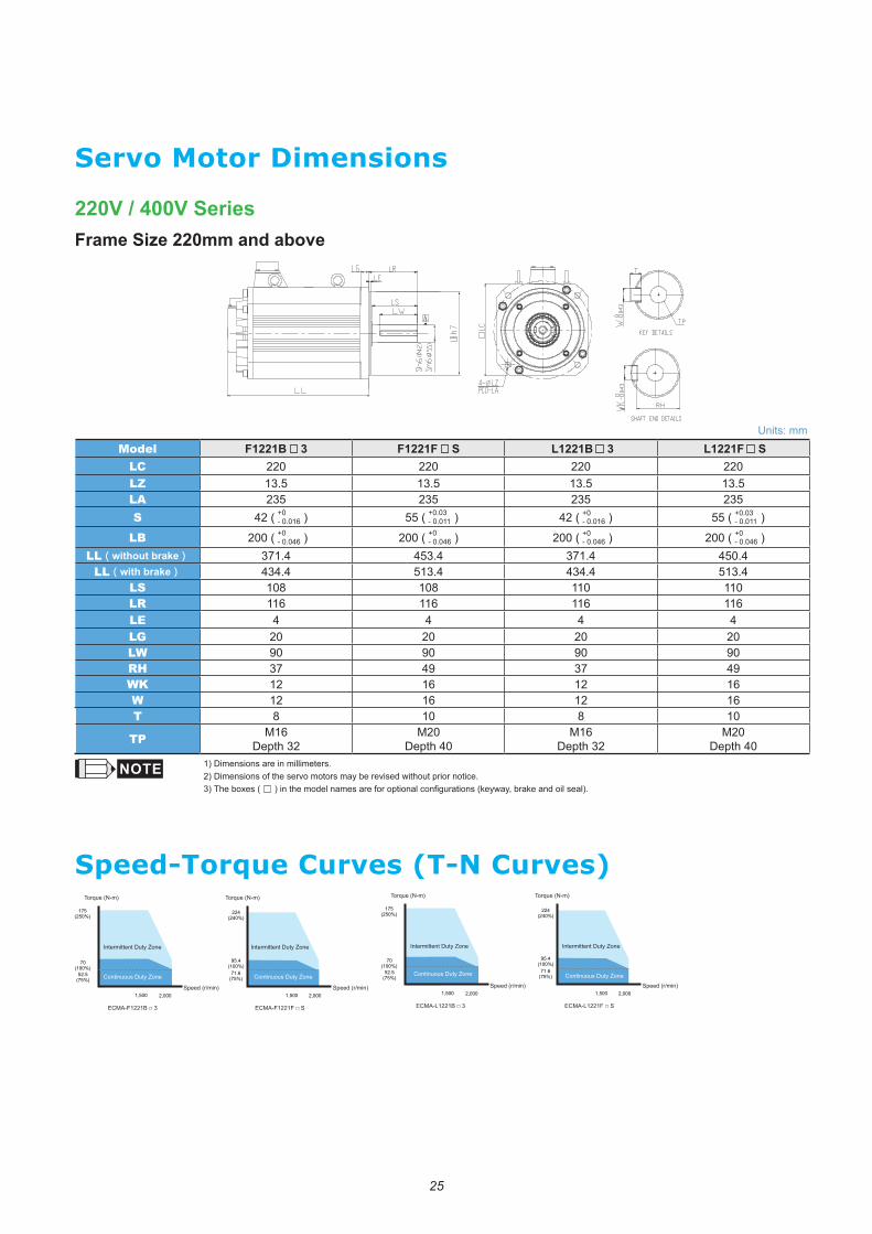
220V / 400V SeriesFrame Size 220mm and above
Servo Motor Dimensions
Units: mmModel F1221B 3 F1221F S L1221B 3 L1221F S
LC 220 220 220 220LZ 13.5 13.5 13.5 13.5LA 235 235 235 235S 42 ( +0
- 0.016 ) 55 ( +0.03- 0.011 ) 42 ( +0
- 0.016 ) 55 ( +0.03- 0.011 )
LB 200 ( +0- 0.046 ) 200 ( +0
- 0.046 ) 200 ( +0- 0.046 ) 200 ( +0
- 0.046 )LL(without brake) 371.4 453.4 371.4 450.4
LL(with brake) 434.4 513.4 434.4 513.4LS 108 108 110 110LR 116 116 116 116LE 4 4 4 4LG 20 20 20 20LW 90 90 90 90RH 37 49 37 49WK 12 16 12 16W 12 16 12 16T 8 10 8 10
TP M16Depth 32
M20Depth 40
M16Depth 32
M20Depth 40
1) Dimensions are in millimeters. 2) Dimensions of the servo motors may be revised without prior notice.3) The boxes ( ) in the model names are for optional configurations (keyway, brake and oil seal).
Speed-Torque Curves (T-N Curves)
A
2,0001,500
175(250%)
70(100%)
52.5(75%)
2,0001,500
224(240%)
95.4(100%)
71.6(75%)
ECMA-F1221B □ 3 ECMA-F1221F □ S
Torque (N-m)Torque (N-m)
Speed (r/min) Speed (r/min)
Continuous Duty Zone
Intermittent Duty Zone
Continuous Duty Zone
Intermittent Duty Zone
2,0001,500
175(250%)
70(100%)
52.5(75%)
2,0001,500
224(240%)
95.4(100%)
71.6(75%)
ECMA-L1221B □ 3 ECMA-L1221F □ S
Torque (N-m)Torque (N-m)
Speed (r/min) Speed (r/min)Continuous Duty Zone
Intermittent Duty Zone
Continuous Duty Zone
Intermittent Duty Zone
26
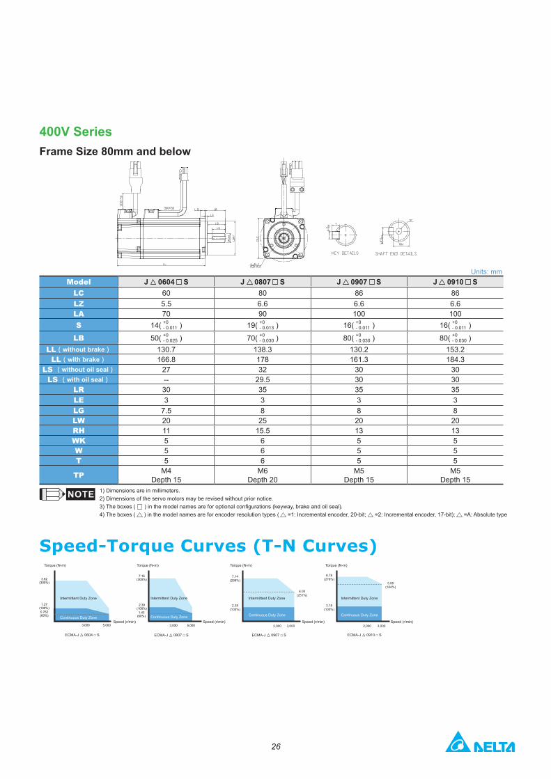
400V SeriesFrame Size 80mm and below
Units: mmModel J 0604 S J 0807 S J 0907 S J 0910 S
LC 60 80 86 86LZ 5.5 6.6 6.6 6.6LA 70 90 100 100S 14( +0
- 0.011 ) 19( +0- 0.013 ) 16( +0
- 0.011 ) 16( +0- 0.011 )
LB 50( +0- 0.025 ) 70( +0
- 0.030 ) 80( +0- 0.030 ) 80( +0
- 0.030 )LL(without brake) 130.7 138.3 130.2 153.2
LL(with brake) 166.8 178 161.3 184.3LS (without oil seal) 27 32 30 30
LS (with oil seal) -- 29.5 30 30LR 30 35 35 35LE 3 3 3 3LG 7.5 8 8 8LW 20 25 20 20RH 11 15.5 13 13WK 5 6 5 5W 5 6 5 5T 5 6 5 5
TP M4Depth 15
M6Depth 20
M5 Depth 15
M5 Depth 15
1) Dimensions are in millimeters. 2) Dimensions of the servo motors may be revised without prior notice.3) The boxes ( ) in the model names are for optional configurations (keyway, brake and oil seal).4) The boxes ( ) in the model names are for encoder resolution types ( =1: Incremental encoder, 20-bit; =2: Incremental encoder, 17-bit); =A: Absolute type
Speed-Torque Curves (T-N Curves)
5,0003,000
7.16(300%)
2.39(100%)1.43
(60%)
5,0003,000
3.82(300%)
1.27(100%)0.762(60%)
7.14(298%)
6.00(251%)
2.38(100%)
8.78(276%)
3.18(100%)
2,0002,000 3,0003,000
ECMA-J▲ 0604 □ S ECMA-J▲ 0907 □ S ECMA-J▲ 0910 □ SECMA-J▲ 0807 □ S
Torque (N-m) Torque (N-m) Torque (N-m) Torque (N-m)
Speed (r/min) Speed (r/min) Speed (r/min) Speed (r/min)
5.85(184%)
Continuous Duty Zone
Intermittent Duty Zone
Continuous Duty Zone
Intermittent Duty Zone
Continuous Duty Zone
Intermittent Duty Zone
Continuous Duty Zone
Intermittent Duty Zone
27
400V SeriesFrame Size 100mm and 130mm
Servo Motor Dimensions
Units: mmModel J 1010 S J 1020 S J 1330 4 K 1305 SK 1310 SK 1315 SK 1320 SL 1305 S L 1308 S L 1313 S
LC 100 100 130 130 130 130 130 130 130 130LZ 9 9 9 9 9 9 9 9 9 9LA 115 115 145 145 145 145 145 145 145 145S 22 ( +0
- 0.013 ) 22 ( +0- 0.013 ) 24 ( +0
- 0.013 ) 22 ( +0- 0.013 ) 22 ( +0
- 0.013 ) 22 ( +0- 0.013 ) 22 ( +0
- 0.013 ) 22 ( +0- 0.013 ) 22 ( +0
- 0.013 ) 22 ( +0- 0.013 )
LB 95 ( +0- 0.035 ) 95 ( +0
- 0.035 ) 110 ( +0- 0.035 ) 110 ( +0
- 0.035 ) 110 ( +0- 0.035 ) 110 ( +0
- 0.035 ) 110 ( +0- 0.035 ) 110 ( +0
- 0.035 ) 110 ( +0- 0.035 ) 110 ( +0
- 0.035 )LL(without brake) 153.3 199 187.5 139.5 147.5 167.5 187.5 147.5 163.5 194.5
LL(with brake) 192.5 226 216.0 168 183.5 202 216 168.0 181 223LS 37 37 47 47 47 47 47 47 47 47LR 45 45 55 55 55 55 55 55 55 55LE 5 5 6 6 6 6 6 6 6 6LG 12 12 11.5 11.5 11.5 11.5 11.5 11.5 11.5 11.5LW 32 32 36 36 36 36 36 36 36 36RH 18 18 20 18 18 18 18 18 18 18WK 8 8 8 8 8 8 8 8 8 8W 8 8 8 8 8 8 8 8 8 8T 7 7 7 7 7 7 7 7 7 7
TP MP6Depth 20
MP6Depth 20
MP6Depth 20
MP6Depth 20
MP6Depth 20
MP6Depth 20
MP6Depth 20
M8Depth 25
MP6Depth 20
MP6Depth 20
1) Dimensions are in millimeters. 2) Dimensions of the servo motors may be revised without prior notice.3) The boxes ( ) in the model names are for optional configurations (keyway, brake and oil seal).4) The boxes ( ) in the model names are for encoder resolution types ( =1: Incremental encoder, 20-bit; =2: Incremental encoder, 17-bit); =A: Absolute type
LG LR
LE
LS
LW
LBh7
SHAFT END DETAILS
KEY DETAILS
Sh6
4-ØLZPCD-LA
W -0
.036
0
-0.0
360
T
TP
RH
LC
LL
3,0003,000 2,0002,000
14.32(300%)
4.77(100%)
3.2(67%)
ECMA-K▲ 1310 □ S
23.3(280%)
8.34(100%)
6(72%)
4.17(50%)
7.16(300%)
2.39(100%)
1.6(67%)
1,500 1,500 1,5002,300 2,200 2,2003,000 3,000 3,000
8.92(284%)
3.5(110%)3.18
(100%)
1.59(50%)
13.80(255%)
5.39(100%)
4.5(83%)
2.70(50%)
ECMA-K▲ 1305 □ S
5,0003,000
9.54(300%)
3.18(100%)
1.91(60%)
ECMA-J▲ 1010 □ S
3,0002,000
21.5(300%)
7.16(100%)
4.8(67%)
ECMA-K▲ 1315 □ S
5,0003,000
19.11(300%)
6.37(100%)
3.82(60%)
ECMA-J▲ 1020 □ S
3,0002,000
加速領
28.65(300%)
9.55(100%)
6.4(67%)
28.65(300%)
9.55(100%)
6.4(67%)
3,0002,000
ECMA-K▲ 1320 □ S
28.65(300%)
9.55(100%)
6.4(67%)
45003000
ECMA-J▲ 1330 □ 4
ECMA-L▲ 1308 □ SECMA-L▲ 1305 □ S ECMA-L▲ 1313 □ S
Torque (N-m)
Torque (N-m)
Torque (N-m)
Torque (N-m)
Torque (N-m)
Torque (N-m)
Torque (N-m)Torque (N-m)
Torque (N-m)Torque (N-m)
Speed (r/min) Speed (r/min) Speed (r/min) Speed (r/min) Speed (r/min)
Speed (r/min)Speed (r/min) Speed (r/min) Speed (r/min)Speed (r/min)
Speed-Torque Curves (T-N Curves)
Continuous Duty Zone
Intermittent Duty Zone
Continuous Duty Zone
Intermittent Duty Zone
Continuous Duty Zone
Intermittent Duty Zone
Continuous Duty Zone
Intermittent Duty Zone
Continuous Duty Zone
Intermittent Duty Zone
Continuous Duty Zone
Intermittent Duty Zone
Continuous Duty Zone
Intermittent Duty Zone
Continuous Duty Zone
Intermittent Duty Zone
Continuous Duty Zone
Intermittent Duty Zone
Continuous Duty Zone
Intermittent Duty Zone
28
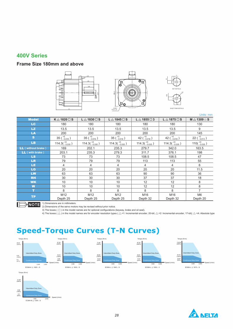
400V SeriesFrame Size 180mm and above
Units: mmModel K 1820 S L 1830 S L 1845 S L 1855 3 L 1875 S M 1309 □ S
LC 180 180 180 180 180 130LZ 13.5 13.5 13.5 13.5 13.5 9LA 200 200 200 200 200 145S 35 ( +0
- 0.016 ) 35 ( +0- 0.016 ) 35 ( +0
- 0.016 ) 42 ( +0- 0.016 ) 42 ( +0
- 0.016 ) 22 ( +0- 0.013 )
LB 114.3( +0- 0.035 ) 114.3( +0
- 0.035 ) 114.3( +0- 0.035 ) 114.3( +0
- 0.035 ) 114.3( +0- 0.035 ) 110( +0
- 0.035 )LL(without brake) 169 202.1 235.3 279.7 342.0 163.5
LL(with brake) 203.1 235.3 279.3 311.7 376.1 198LS 73 73 73 108.5 108.5 47LR 79 79 79 113 113 55LE 4 4 4 4 4 6LG 20 20 20 20 20 11.5LW 63 63 63 90 90 36RH 30 30 30 37 37 18WK 10 10 10 12 12 8W 10 10 10 12 12 8T 8 8 8 8 8 7
TP M12Depth 25
M12Depth 25
M12Depth 25
M16Depth 32
M16Depth 32
M6Depth 20
1) Dimensions are in millimeters. 2) Dimensions of the servo motors may be revised without prior notice.3) The boxes ( ) in the model names are for optional configurations (keyway, brake and oil seal).4) The boxes ( ) in the model names are for encoder resolution types ( =1: Incremental encoder, 20-bit; =2: Incremental encoder, 17-bit); =A: Absolute type
LR
Sh6
LL
LGLE
LS
LW
Lbh7
SHAFT END DETAILS
KEY DETAILS
4-ØLZPCD -LA
T
LC
W
TP
RH
28.66(300%)
9.55(100%)
2,000 3,000
6.4(67%)
57.29(300%)
19.10(100%)
9.55(50%)
3,0001,500
ECMA-L▲ 1830 □ SECMA-K▲ 1820 □ S
21.48(250%)
8.59(100%)
4.3(50%)
2,0001,000ECMA-M▲ 1309 □ S
71.62(300%)
28.65(100%)
14.33(50%)
3,0001,500
ECMA-L▲ 1845 □ S
87.53(300%)
35.01(100%)
17.51(50%)
3,0001,500
ECMA-L▲ 1855 □ 3
119.36(250%)
47.74(100%)
23.87(50%)
3,0001,500
ECMA-L▲ 1875 □ S
Torque (N-m)Torque (N-m)
Torque (N-m)
Torque (N-m) Torque (N-m) Torque (N-m)
Speed (r/min) Speed (r/min) Speed (r/min) Speed (r/min) Speed (r/min)
Speed (r/min)
Continuous Duty Zone Continuous Duty Zone
Intermittent Duty Zone Intermittent Duty Zone
Speed-Torque Curves (T-N Curves)
Continuous Duty Zone
Intermittent Duty Zone
Continuous Duty Zone
Intermittent Duty Zone
Continuous Duty Zone
Intermittent Duty Zone
Continuous Duty Zone
Intermittent Duty Zone
Continuous Duty Zone
43
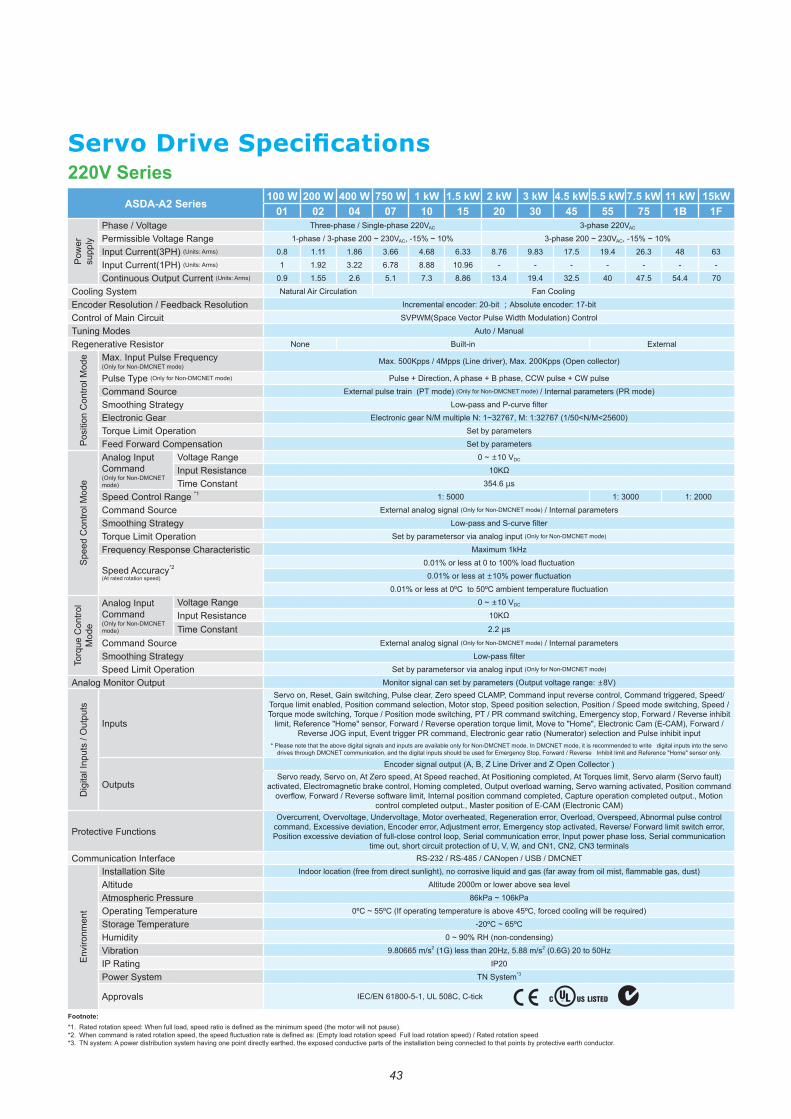
Servo Drive Specifications220V Series
ASDA-A2 Series 100 W 200 W 400 W 750 W 1 kW 1.5 kW 2 kW 3 kW 4.5 kW 5.5 kW 7.5 kW 11 kW 15kW01 02 04 07 10 15 20 30 45 55 75 1B 1F
Pow
er
supp
ly
Phase / Voltage Three-phase / Single-phase 220VAC 3-phase 220VAC
Permissible Voltage Range 1-phase / 3-phase 200 ~ 230VAC, -15% ~ 10% 3-phase 200 ~ 230VAC, -15% ~ 10%
Input Current(3PH) (Units: Arms) 0.8 1.11 1.86 3.66 4.68 6.33 8.76 9.83 17.5 19.4 26.3 48 63
Input Current(1PH) (Units: Arms) 1 1.92 3.22 6.78 8.88 10.96 - - - - - - -
Continuous Output Current (Units: Arms) 0.9 1.55 2.6 5.1 7.3 8.86 13.4 19.4 32.5 40 47.5 54.4 70
Cooling System Natural Air Circulation Fan Cooling
Encoder Resolution / Feedback Resolution Incremental encoder: 20-bit ;Absolute encoder: 17-bit
Control of Main Circuit SVPWM(Space Vector Pulse Width Modulation) Control
Tuning Modes Auto / Manual
Regenerative Resistor None Built-in External
Posi
tion
Con
trol M
ode Max. Input Pulse Frequency
(Only for Non-DMCNET mode)Max. 500Kpps / 4Mpps (Line driver), Max. 200Kpps (Open collector)
Pulse Type (Only for Non-DMCNET mode) Pulse + Direction, A phase + B phase, CCW pulse + CW pulse
Command Source External pulse train (PT mode) (Only for Non-DMCNET mode) / Internal parameters (PR mode)
Smoothing Strategy Low-pass and P-curve filterElectronic Gear Electronic gear N/M multiple N: 1~32767, M: 1:32767 (1/50<N/M<25600)
Torque Limit Operation Set by parameters
Feed Forward Compensation Set by parameters
Spee
d C
ontro
l Mod
e
Analog Input Command(Only for Non-DMCNET mode)
Voltage Range 0 ~ ±10 VDC
Input Resistance 10KΩ
Time Constant 354.6 μs
Speed Control Range *1 1: 5000 1: 3000 1: 2000
Command Source External analog signal (Only for Non-DMCNET mode) / Internal parameters
Smoothing Strategy Low-pass and S-curve filter
Torque Limit Operation Set by parametersor via analog input (Only for Non-DMCNET mode)
Frequency Response Characteristic Maximum 1kHz
Speed Accuracy*2
(At rated rotation speed)
0.01% or less at 0 to 100% load fluctuation0.01% or less at ±10% power fluctuation
0.01% or less at 0ºC to 50ºC ambient temperature fluctuation
Torq
ue C
ontro
l M
ode
Analog Input Command(Only for Non-DMCNET mode)
Voltage Range 0 ~ ±10 VDC
Input Resistance 10KΩ
Time Constant 2.2 μs
Command Source External analog signal (Only for Non-DMCNET mode) / Internal parameters
Smoothing Strategy Low-pass filter
Speed Limit Operation Set by parametersor via analog input (Only for Non-DMCNET mode)
Analog Monitor Output Monitor signal can set by parameters (Output voltage range: ±8V)
Dig
ital I
nput
s / O
utpu
ts
Inputs
Servo on, Reset, Gain switching, Pulse clear, Zero speed CLAMP, Command input reverse control, Command triggered, Speed/Torque limit enabled, Position command selection, Motor stop, Speed position selection, Position / Speed mode switching, Speed / Torque mode switching, Torque / Position mode switching, PT / PR command switching, Emergency stop, Forward / Reverse inhibit
limit, Reference "Home" sensor, Forward / Reverse operation torque limit, Move to "Home", Electronic Cam (E-CAM), Forward / Reverse JOG input, Event trigger PR command, Electronic gear ratio (Numerator) selection and Pulse inhibit input
* Please note that the above digital signals and inputs are available only for Non-DMCNET mode. In DMCNET mode, it is recommended to write digital inputs into the servo drives through DMCNET communication, and the digital inputs should be used for Emergency Stop, Forward / Reverse Inhibit limit and Reference "Home" sensor only.
Outputs
Encoder signal output (A, B, Z Line Driver and Z Open Collector )Servo ready, Servo on, At Zero speed, At Speed reached, At Positioning completed, At Torques limit, Servo alarm (Servo fault)
activated, Electromagnetic brake control, Homing completed, Output overload warning, Servo warning activated, Position command overflow, Forward / Reverse software limit, Internal position command completed, Capture operation completed output., Motion
control completed output., Master position of E-CAM (Electronic CAM)
Protective FunctionsOvercurrent, Overvoltage, Undervoltage, Motor overheated, Regeneration error, Overload, Overspeed, Abnormal pulse control
command, Excessive deviation, Encoder error, Adjustment error, Emergency stop activated, Reverse/ Forward limit switch error, Position excessive deviation of full-close control loop, Serial communication error, Input power phase loss, Serial communication
time out, short circuit protection of U, V, W, and CN1, CN2, CN3 terminalsCommunication Interface RS-232 / RS-485 / CANopen / USB / DMCNET
Envi
ronm
ent
Installation Site Indoor location (free from direct sunlight), no corrosive liquid and gas (far away from oil mist, flammable gas, dust)
Altitude Altitude 2000m or lower above sea level
Atmospheric Pressure 86kPa ~ 106kPa
Operating Temperature 0ºC ~ 55ºC (If operating temperature is above 45ºC, forced cooling will be required)
Storage Temperature -20ºC ~ 65ºC
Humidity 0 ~ 90% RH (non-condensing)
Vibration 9.80665 m/s2 (1G) less than 20Hz, 5.88 m/s2 (0.6G) 20 to 50Hz
IP Rating IP20
Power System TN System*3
Approvals IEC/EN 61800-5-1, UL 508C, C-tick
Footnote:*1. Rated rotation speed: When full load, speed ratio is defined as the minimum speed (the motor will not pause).*2. When command is rated rotation speed, the speed fluctuation rate is defined as: (Empty load rotation speed Full load rotation speed) / Rated rotation speed*3. TN system: A power distribution system having one point directly earthed, the exposed conductive parts of the installation being connected to that points by protective earth conductor.
44
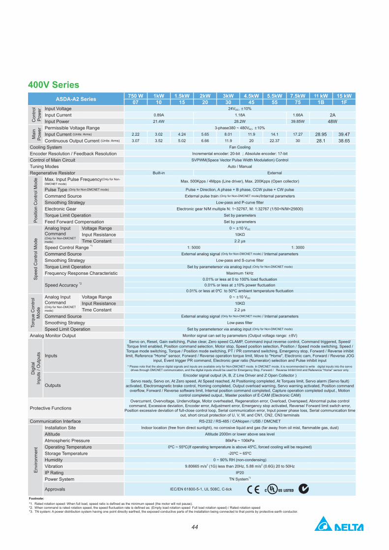
400V SeriesASDA-A2 Series 750 W 1kW 1.5kW 2kW 3kW 4.5kW 5.5kW 7.5kW 11 kW 15 kW
07 10 15 20 30 45 55 75 1B 1F
Con
trol
Pow
er Input Voltage 24VDC, ±10%Input Current 0.89A 1.18A 1.66A 2AInput Power 21.4W 28.2W 39.85W 48W
Mai
n Po
wer Permissible Voltage Range 3-phase380 ~ 480VAC, ±10%
Input Current (Units: Arms) 2.22 3.02 4.24 5.65 8.01 11.9 14.1 17.27 28.95 39.47Continuous Output Current (Units: Arms) 3.07 3.52 5.02 6.66 11.9 20 22.37 30 28.1 38.65
Cooling System Fan CoolingEncoder Resolution / Feedback Resolution Incremental encoder: 20-bit ;Absolute encoder: 17-bitControl of Main Circuit SVPWM(Space Vector Pulse Width Modulation) ControlTuning Modes Auto / ManualRegenerative Resistor Built-in External
Posi
tion
Con
trol M
ode Max. Input Pulse Frequency(Only for Non-
DMCNET mode)Max. 500Kpps / 4Mpps (Line driver), Max. 200Kpps (Open collector)
Pulse Type (Only for Non-DMCNET mode) Pulse + Direction, A phase + B phase, CCW pulse + CW pulseCommand Source External pulse train (Only for Non-DMCNET mode)/Internal parametersSmoothing Strategy Low-pass and P-curve filterElectronic Gear Electronic gear N/M multiple N: 1~32767, M: 1:32767 (1/50<N/M<25600)Torque Limit Operation Set by parametersFeed Forward Compensation Set by parameters
Spee
d C
ontro
l Mod
e
Analog Input Command(Only for Non-DMCNET mode)
Voltage Range 0 ~ ±10 VDC
Input Resistance 10KΩ
Time Constant 2.2 μs
Speed Control Range *1 1: 5000 1: 3000Command Source External analog signal (Only for Non-DMCNET mode) / Internal parametersSmoothing Strategy Low-pass and S-curve filterTorque Limit Operation Set by parametersor via analog input (Only for Non-DMCNET mode)
Frequency Response Characteristic Maximum 1kHz
Speed Accuracy *20.01% or less at 0 to 100% load fluctuation0.01% or less at ±10% power fluctuation
0.01% or less at 0ºC to 50ºC ambient temperature fluctuation
Torq
ue C
ontro
l M
ode
Analog Input Command(Only for Non-DMCNET mode)
Voltage Range 0 ~ ±10 VDC
Input Resistance 10KΩ
Time Constant 2.2 μs
Command Source External analog signal (Only for Non-DMCNET mode) / Internal parametersSmoothing Strategy Low-pass filterSpeed Limit Operation Set by parametersor via analog input (Only for Non-DMCNET mode)
Analog Monitor Output Monitor signal can set by parameters (Output voltage range: ±8V)
Dig
ital
Inpu
ts /
Out
puts Inputs
Servo on, Reset, Gain switching, Pulse clear, Zero speed CLAMP, Command input reverse control, Command triggered, Speed/Torque limit enabled, Position command selection, Motor stop, Speed position selection, Position / Speed mode switching, Speed / Torque mode switching, Torque / Position mode switching, PT / PR command switching, Emergency stop, Forward / Reverse inhibit limit, Reference "Home" sensor, Forward / Reverse operation torque limit, Move to "Home", Electronic cam, Forward / Reverse JOG
input, Event trigger PR command, Electronic gear ratio (Numerator) selection and Pulse inhibit input* Please note that the above digital signals and inputs are available only for Non-DMCNET mode. In DMCNET mode, it is recommended to write digital inputs into the servo
drives through DMCNET communication, and the digital inputs should be used for Emergency Stop, Forward / Reverse Inhibit limit and Reference "Home" sensor only.
Outputs
Encoder signal output (A, B, Z Line Driver and Z Open Collector )Servo ready, Servo on, At Zero speed, At Speed reached, At Positioning completed, At Torques limit, Servo alarm (Servo fault)
activated, Electromagnetic brake control, Homing completed, Output overload warning, Servo warning activated, Position command overflow, Forward / Reverse software limit, Internal position command completed, Capture operation completed output., Motion
control completed output., Master position of E-CAM (Electronic CAM)
Protective FunctionsOvercurrent, Overvoltage, Undervoltage, Motor overheated, Regeneration error, Overload, Overspeed, Abnormal pulse control
command, Excessive deviation, Encoder error, Adjustment error, Emergency stop activated, Reverse/ Forward limit switch error, Position excessive deviation of full-close control loop, Serial communication error, Input power phase loss, Serial communication time
out, short circuit protection of U, V, W, and CN1, CN2, CN3 terminalsCommunication Interface RS-232 / RS-485 / CANopen / USB / DMCNET
Envi
ronm
ent
Installation Site Indoor location (free from direct sunlight), no corrosive liquid and gas (far away from oil mist, flammable gas, dust)Altitude Altitude 2000m or lower above sea levelAtmospheric Pressure 86kPa ~ 106kPaOperating Temperature 0ºC ~ 55ºC(If operating temperature is above 45ºC, forced cooling will be required)Storage Temperature -20ºC ~ 65ºCHumidity 0 ~ 90% RH (non-condensing)Vibration 9.80665 m/s2 (1G) less than 20Hz, 5.88 m/s2 (0.6G) 20 to 50HzIP Rating IP20Power System TN System*3
Approvals IEC/EN 61800-5-1, UL 508C, C-tick
Footnote:*1. Rated rotation speed: When full load, speed ratio is defined as the minimum speed (the motor will not pause).*2. When command is rated rotation speed, the speed fluctuation rate is defined as: (Empty load rotation speed Full load rotation speed) / Rated rotation speed*3. TN system: A power distribution system having one point directly earthed, the exposed conductive parts of the installation being connected to that points by protective earth conductor.
45
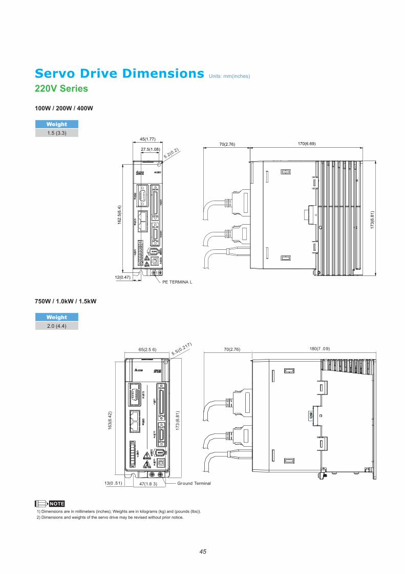
Servo Drive Dimensions220V Series
173(
6.81
)
170(6.69)70(2.76)45(1.77)
27.5(1.08)
5.2(0.2)
162.
5(6.
4)
12(0.47)PE TERMINA L
65(2.5 6) 70(2.76) 180(7 .09)
13(0 .51) 47(1.8 3) Ground Terminal
163(
6.42
)
173
(6.8
1)
5.5(0.217)
100W / 200W / 400W
Weight1.5 (3.3)
750W / 1.0kW / 1.5kW
Weight2.0 (4.4)
Units: mm(inches)
1) Dimensions are in millimeters (inches); Weights are in kilograms (kg) and (pounds (lbs)).2) Dimensions and weights of the servo drive may be revised without prior notice.
46
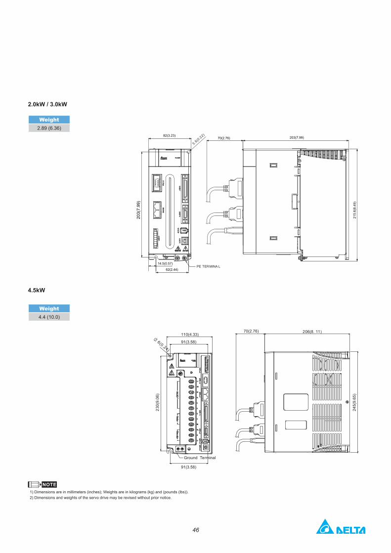
82(3.23)
5.5(0.22)
203(
7.99
)
14.5(0.57)
62(2.44)PE TERMINA L
70(2.76) 203(7.99)
215.
6(8.
49)
110(4.33)70(2.76) 206(8. 11)
91(3.58)
91(3.58)
Ground Terminal
245(
9.65
)
230(
9.06
)
6(0.24)
1) Dimensions are in millimeters (inches); Weights are in kilograms (kg) and (pounds (lbs)).2) Dimensions and weights of the servo drive may be revised without prior notice.
2.0kW / 3.0kW
Weight2.89 (6.36)
4.5kW
Weight4.4 (10.0)
47
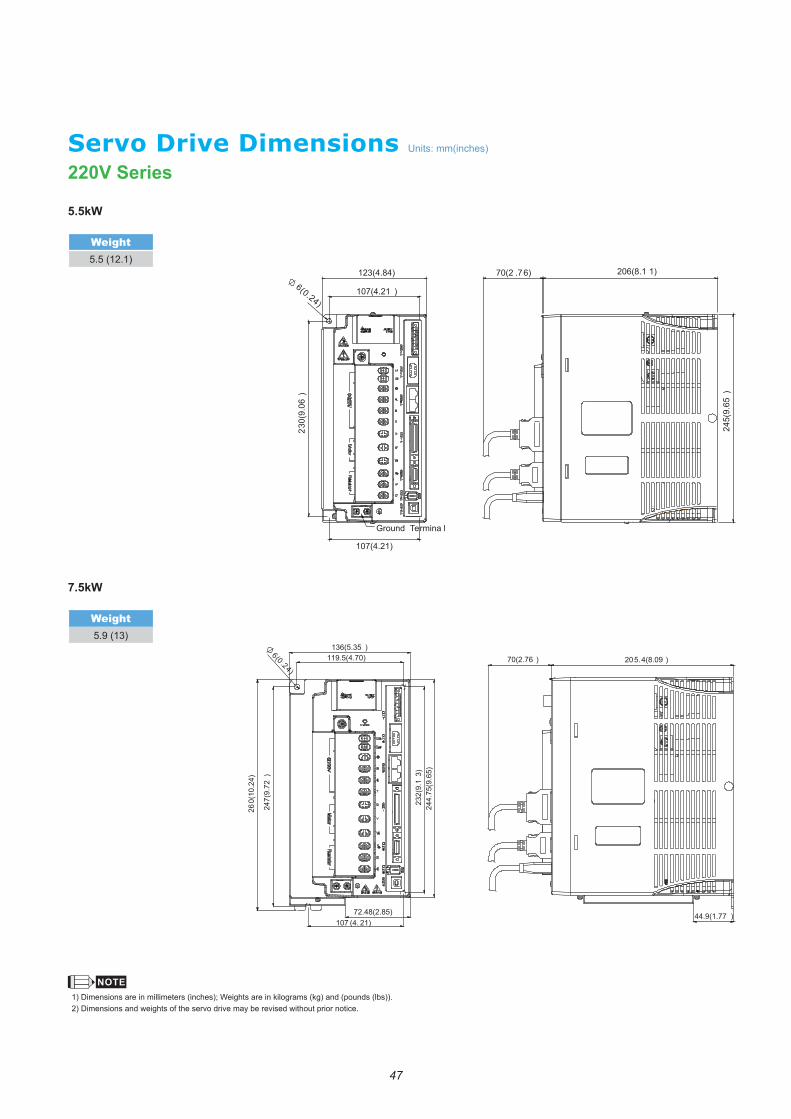
Servo Drive Dimensions220V Series
5.5kW
Weight5.5 (12.1)
7.5kW
Weight5.9 (13)
123(4.84) 70(2 .76) 206(8.1 1)
107(4.21 )
107(4.21)
Ground Termina l
245(
9.65
)
230(
9.06
)
6(0.24)
70(2.76 ) 205.4(8.09 )
44.9(1.77 )
136(5.35 )119.5(4.70)
72.48(2.85)107 (4. 21)
232(
9.1
3)24
4.75
(9.6
5)
260(
10.2
4)
247(
9.72
)
6(0 .24)
1) Dimensions are in millimeters (inches); Weights are in kilograms (kg) and (pounds (lbs)).2) Dimensions and weights of the servo drive may be revised without prior notice.
Units: mm(inches)
48
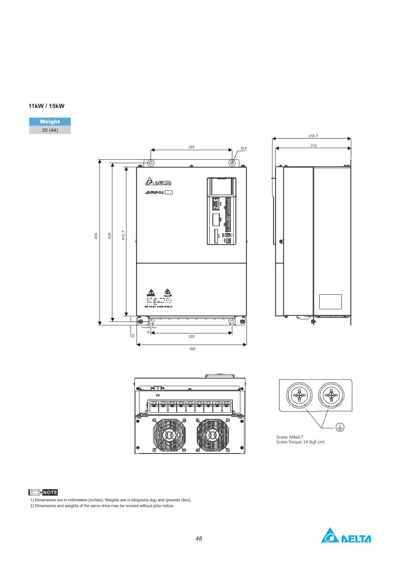
11kW / 15kW
Weight20 (44)
225 8210
218 .7
225
305
458
438
412.
7
8
10
Screw: M4x0.7Screw Torque: 14 (kgf-cm)
1) Dimensions are in millimeters (inches); Weights are in kilograms (kg) and (pounds (lbs)).2) Dimensions and weights of the servo drive may be revised without prior notice.
49
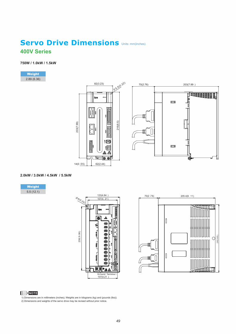
Servo Drive Dimensions400V Series
750W / 1.0kW / 1.5kW
Weight2.89 (6.36)
2.0kW / 3.0kW / 4.5kW / 5.5kW
Weight5.5 (12.1)
82(3.23)
5.5(0.22)
14(0 .55) 62(2.44)
203(
7.99
)
216(
8.5)
70(2.76) 203(7.99 )
123(4.84 )107(4. 21 )
70(2 .76) 205.4(8. 11)6(0.24)
107(4.21 )Ground Termina l
230(
9.06
)
245(
9.65
)
Units: mm(inches)
1) Dimensions are in millimeters (inches); Weights are in kilograms (kg) and (pounds (lbs)).2) Dimensions and weights of the servo drive may be revised without prior notice.
50
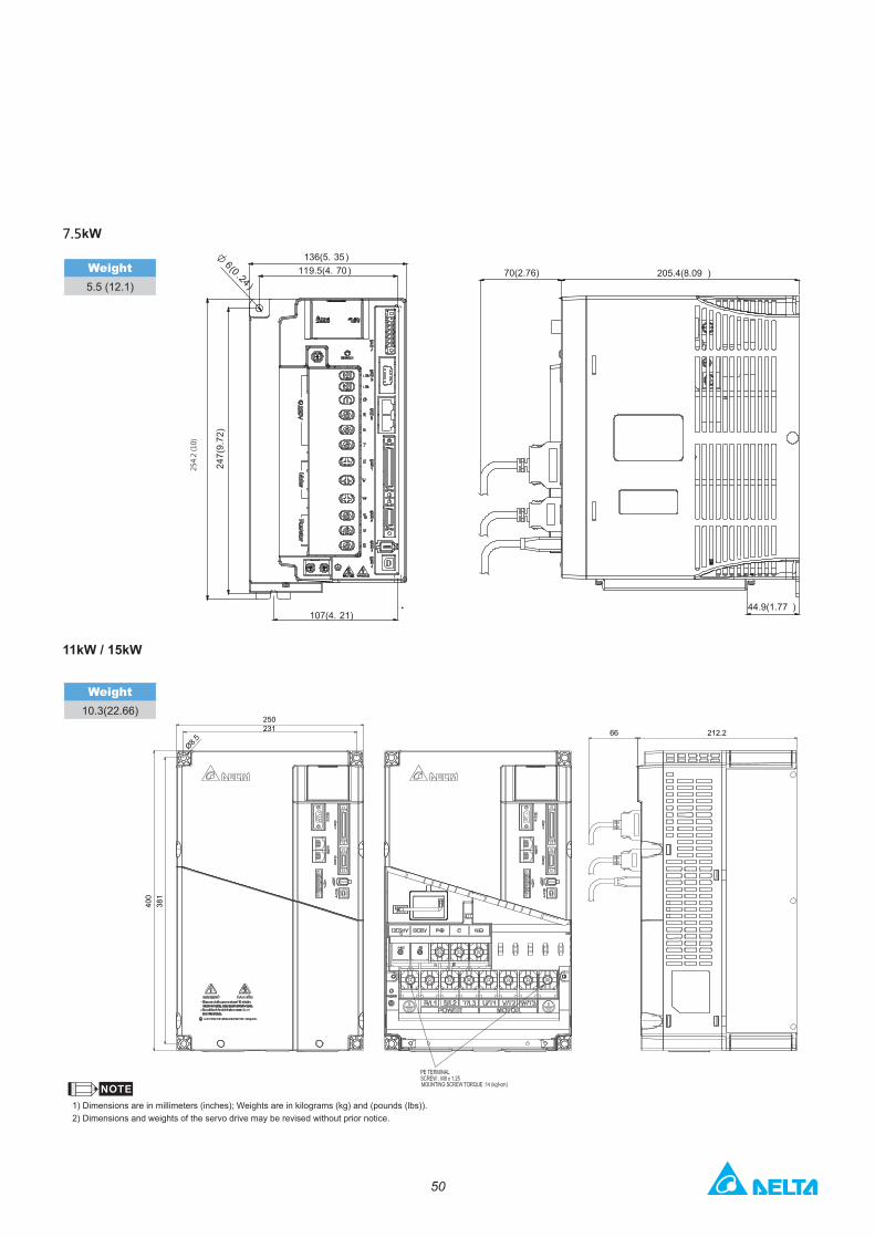
1) Dimensions are in millimeters (inches); Weights are in kilograms (kg) and (pounds (lbs)).2) Dimensions and weights of the servo drive may be revised without prior notice.
7.5kW
Weight5.5 (12.1)
254.
2 (1
0)
70(2.76) 205.4(8.09 )
44.9(1.77 )
136(5. 35 )119.5(4. 70 )
107(4. 21)
247(
9.72
)
6(0 .24 )
11kW / 15kW
Weight10.3(22.66)
250231 66 212.2
400
381
Ø8.5
51
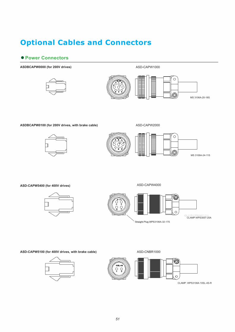
Optional Cables and Connectors
●Power Connectors
ASDBCAPW0000 (for 200V drives)
ASDBCAPW0100 (for 200V drives, with brake cable)
ASD-CAPW5400 (for 400V drives)
ASD-CAPW5100 (for 400V drives, with brake cable)
ASD-CAPW1000
ASD-CAPW2000
ASD-CNBR1000
1010SLSL-4-4SS10SL-4S
CLAMP: WPS3106A 10SL-4S-R
ASD-CAPW4000
CLAMP:WPS3057-20ACLAMP:WPS3057-20A
StraightStraight P Plulug Wg WStraight Plug WPS3106A-32-17S
CLAMP:WPS3057-20A
MS 3106A-24-11S
MS 3106A-20-18S

52
●Power Cables
L
L
ASD-ABPW0003, ASD-ABPW0005 (for 200V drives)
ASD-CAPW5403, ASD-CAPW5405 (for 400V drives)
AASD-ABPW0103, ASD-ABPW0105 (for 200V drives, with brake cable)
ASD-CAPW5103, ASD-CAPW5105 (for 400V drives, with brake cable)
L
L
Item Part No. Lmm inch
1 ASD-ABPW0003 3000 ± 100 118 ± 4
2 ASD-ABPW0005 5000 ± 100 197 ± 4
Item Part No. Lmm inch
1 ASD-ABPW0103 3000 ± 100 118 ± 4
2 ASD-ABPW0105 5000 ± 100 197 ± 4
Item Part No. Lmm inch
1 ASD-CAPW5403 3000 ± 100 118 ± 4
2 ASD-CAPW5405 5000 ± 100 197 ± 4
Item Part No. Lmm inch
1 ASD-CAPW5103 3000 ± 100 118 ± 4
2 ASD-CAPW5105 5000 ± 100 197 ± 4
Item Part No. Straight Lmm inch
1 ASD-CAPW1003 3106A-20-18S 3000 ± 100 118 ± 4
2 ASD-CAPW1005 3106A-20-18S 5000 ± 100 197 ± 4
ASD-CAPW1003, ASD-CAPW1005
L
(50 mm)(1.97 inch)
(80 mm)(3.15 inch)
53
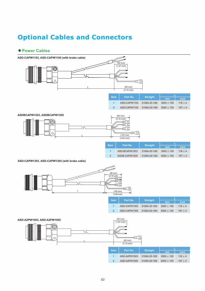
●Power Cables
Optional Cables and Connectors
ASDBCAPW1203, ASDBCAPW1205
Item Part No. Straight Lmm inch
1 ASD-CAPW1103 3106A-20-18S 3000 ± 100 118 ± 4
2 ASD-CAPW1105 3106A-20-18S 5000 ± 100 197 ± 4
Item Part No. Straight Lmm inch
1 ASD-A2PW1003 3106A-20-18S 3000 ± 100 118 ± 4
2 ASD-A2PW1005 3106A-20-18S 5000 ± 100 197 ± 4
Item Part No. Straight Lmm inch
1 ASD-BCAPW1203 3106A-20-18S 3000 ± 100 118 ± 4
2 ASDB-CAPW1205 3106A-20-18S 5000 ± 100 197 ± 4
Item Part No. Straight Lmm inch
1 ASD-CAPW1303 3106A-20-18S 3000 ± 100 118 ± 4
2 ASD-CAPW1305 3106A-20-18S 5000 ± 100 197 ± 4
ASD-CAPW1303, ASD-CAPW1305 (with brake cable)
L
(80 mm)(3.15 inch)
(100 mm)(3.94 inch)
ASD-CAPW1103, ASD-CAPW1105 (with brake cable)
L
(50 mm)(1.97 inch)
(80 mm)(3.15 inch)
(100 mm)(3.94 inch)
(80 mm)(3.15 inch)
L
ASD-A2PW1003, ASD-A2PW1005
L
(50 mm)(1.97 inch)
(80 mm)(3.15 inch)
54
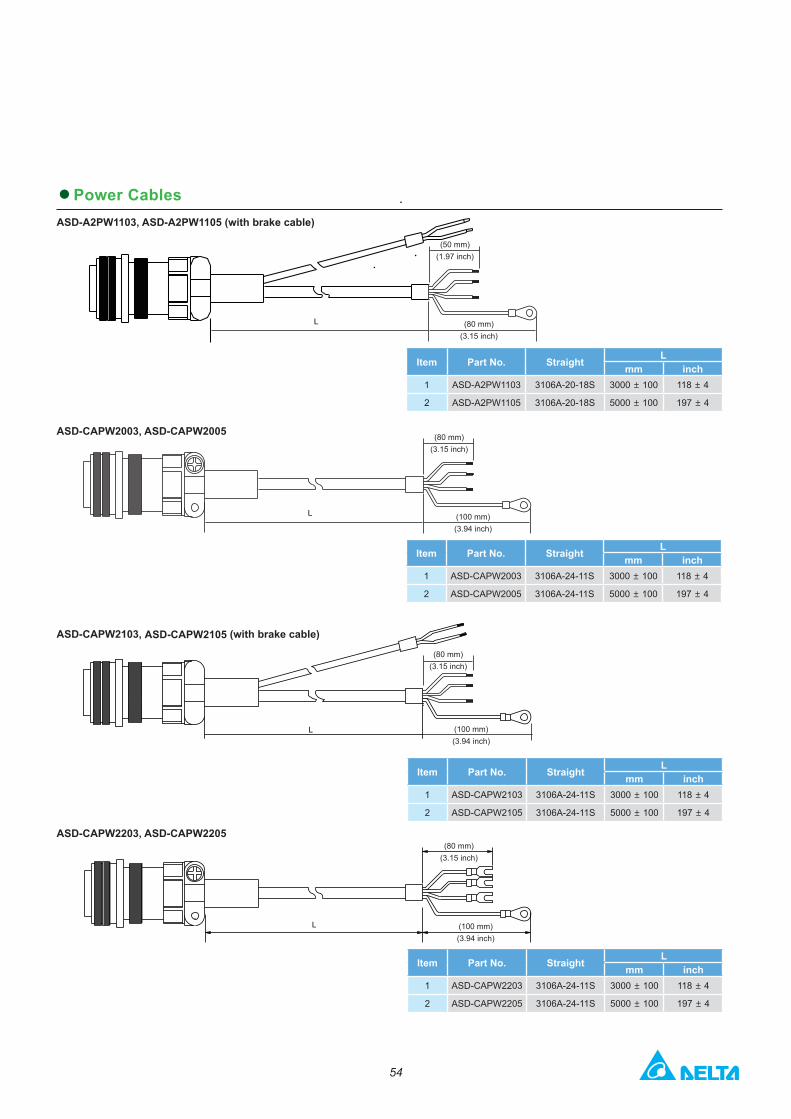
●Power CablesASD-A2PW1103, ASD-A2PW1105 (with brake cable)
L
Item Part No. Straight Lmm inch
1 ASD-A2PW1103 3106A-20-18S 3000 ± 100 118 ± 4
2 ASD-A2PW1105 3106A-20-18S 5000 ± 100 197 ± 4
L
Item Part No. Straight Lmm inch
1 ASD-CAPW2003 3106A-24-11S 3000 ± 100 118 ± 4
2 ASD-CAPW2005 3106A-24-11S 5000 ± 100 197 ± 4
L
ASD-CAPW2003, ASD-CAPW2005
ASD-CAPW2103, ASD-CAPW2105 (with brake cable)
Item Part No. Straight Lmm inch
1 ASD-CAPW2103 3106A-24-11S 3000 ± 100 118 ± 4
2 ASD-CAPW2105 3106A-24-11S 5000 ± 100 197 ± 4
L
ASD-CAPW2203, ASD-CAPW2205
Item Part No. Straight Lmm inch
1 ASD-CAPW2203 3106A-24-11S 3000 ± 100 118 ± 4
2 ASD-CAPW2205 3106A-24-11S 5000 ± 100 197 ± 4
(50 mm)(1.97 inch)
(80 mm)(3.15 inch)
(80 mm)(3.15 inch)
(100 mm)(3.94 inch)
(80 mm)(3.15 inch)
(100 mm)(3.94 inch)
(80 mm)(3.15 inch)
(100 mm)(3.94 inch)
55
Optional Cables and Connectors
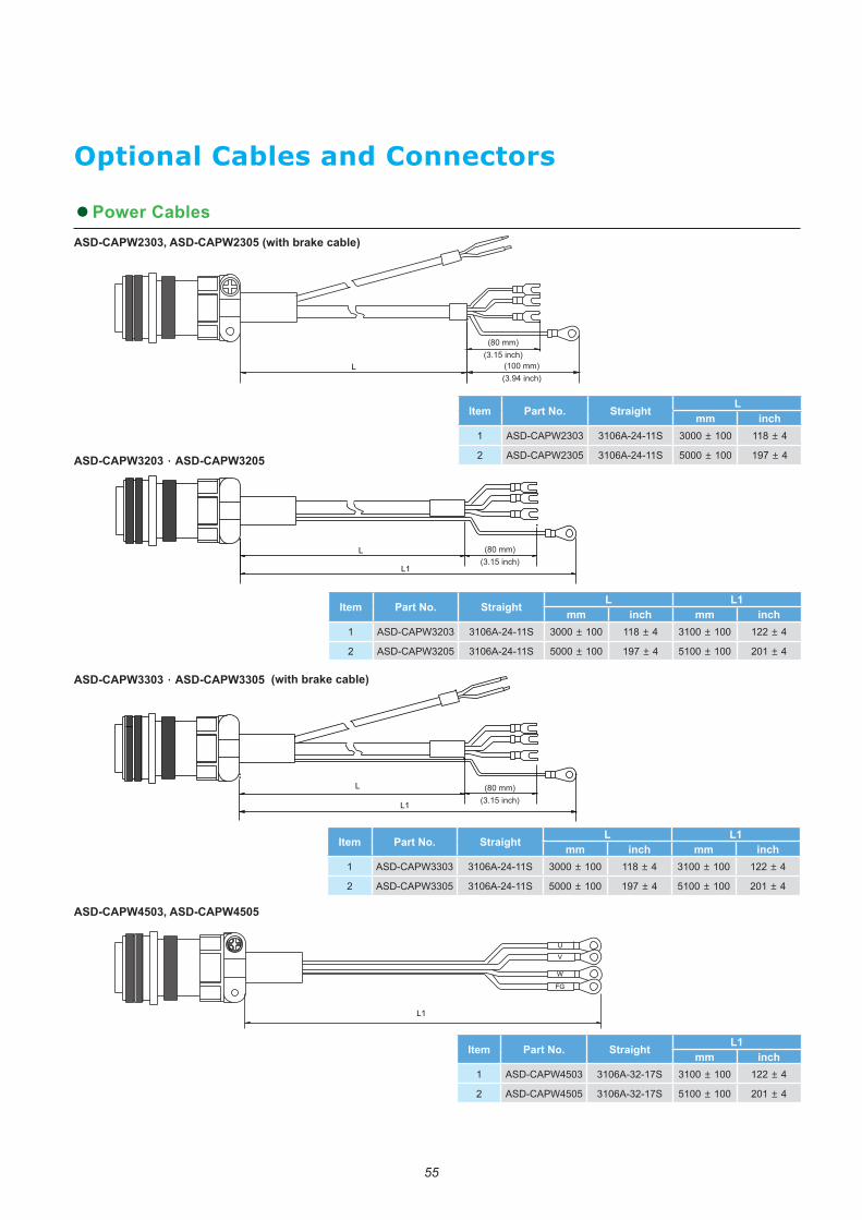
●Power CablesASD-CAPW2303, ASD-CAPW2305 (with brake cable)
L
Item Part No. Straight Lmm inch
1 ASD-CAPW2303 3106A-24-11S 3000 ± 100 118 ± 4
2 ASD-CAPW2305 3106A-24-11S 5000 ± 100 197 ± 4ASD-CAPW3203,ASD-CAPW3205
L
L1
Item Part No. Straight L L1mm inch mm inch
1 ASD-CAPW3203 3106A-24-11S 3000 ± 100 118 ± 4 3100 ± 100 122 ± 4
2 ASD-CAPW3205 3106A-24-11S 5000 ± 100 197 ± 4 5100 ± 100 201 ± 4
L
L1
ASD-CAPW3303,ASD-CAPW3305 (with brake cable)
Item Part No. Straight L L1mm inch mm inch
1 ASD-CAPW3303 3106A-24-11S 3000 ± 100 118 ± 4 3100 ± 100 122 ± 4
2 ASD-CAPW3305 3106A-24-11S 5000 ± 100 197 ± 4 5100 ± 100 201 ± 4
(80 mm)(3.15 inch)
(100 mm)(3.94 inch)
(80 mm)(3.15 inch)
(80 mm)(3.15 inch)
ASD-CAPW4503, ASD-CAPW4505
Item Part No. Straight L1mm inch
1 ASD-CAPW4503 3106A-32-17S 3100 ± 100 122 ± 4
2 ASD-CAPW4505 3106A-32-17S 5100 ± 100 201 ± 4
L1
56
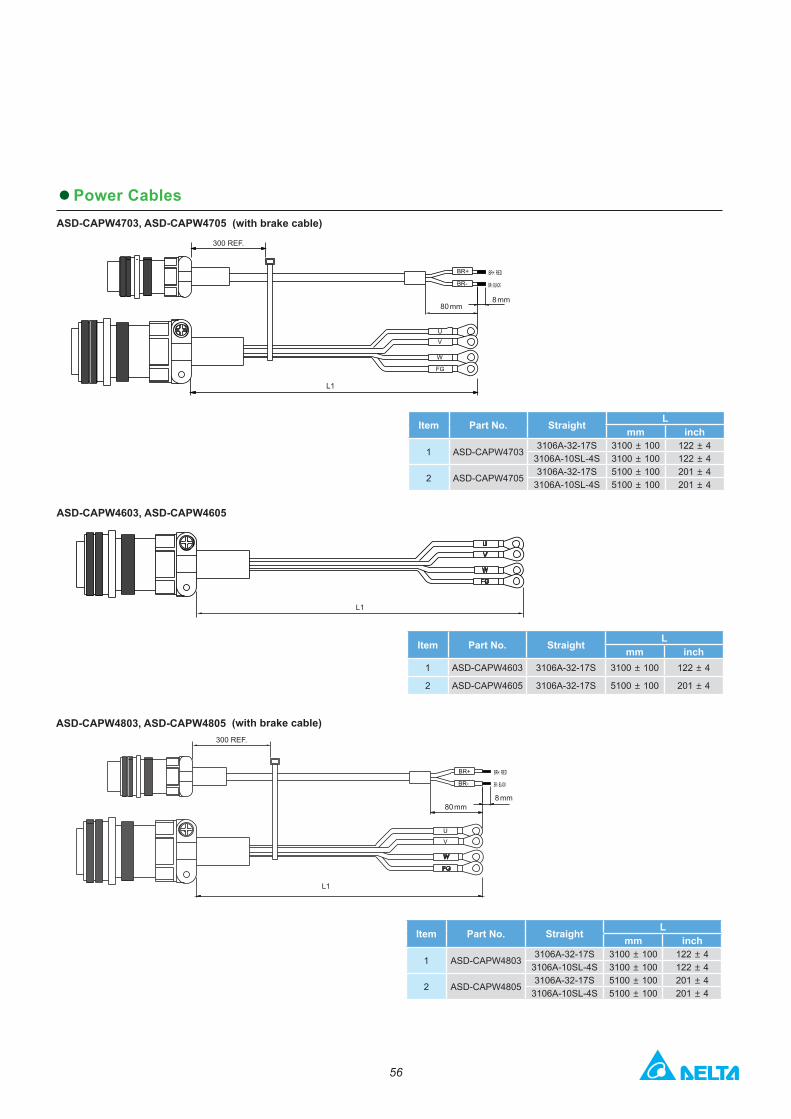
●Power CablesASD-CAPW4703, ASD-CAPW4705 (with brake cable)
300 REF.
L1
80 mm8 mm
Item Part No. Straight Lmm inch
1 ASD-CAPW47033106A-32-17S 3100 ± 100 122 ± 4
3106A-10SL-4S 3100 ± 100 122 ± 4
2 ASD-CAPW47053106A-32-17S 5100 ± 100 201 ± 4
3106A-10SL-4S 5100 ± 100 201 ± 4
ASD-CAPW4603, ASD-CAPW4605
L1
Item Part No. Straight Lmm inch
1 ASD-CAPW4603 3106A-32-17S 3100 ± 100 122 ± 4
2 ASD-CAPW4605 3106A-32-17S 5100 ± 100 201 ± 4
ASD-CAPW4803, ASD-CAPW4805 (with brake cable)
Item Part No. Straight Lmm inch
1 ASD-CAPW48033106A-32-17S 3100 ± 100 122 ± 4
3106A-10SL-4S 3100 ± 100 122 ± 4
2 ASD-CAPW48053106A-32-17S 5100 ± 100 201 ± 4
3106A-10SL-4S 5100 ± 100 201 ± 4
300 REF.
L1
80 mm8 mm
57
Optional Cables and Connectors
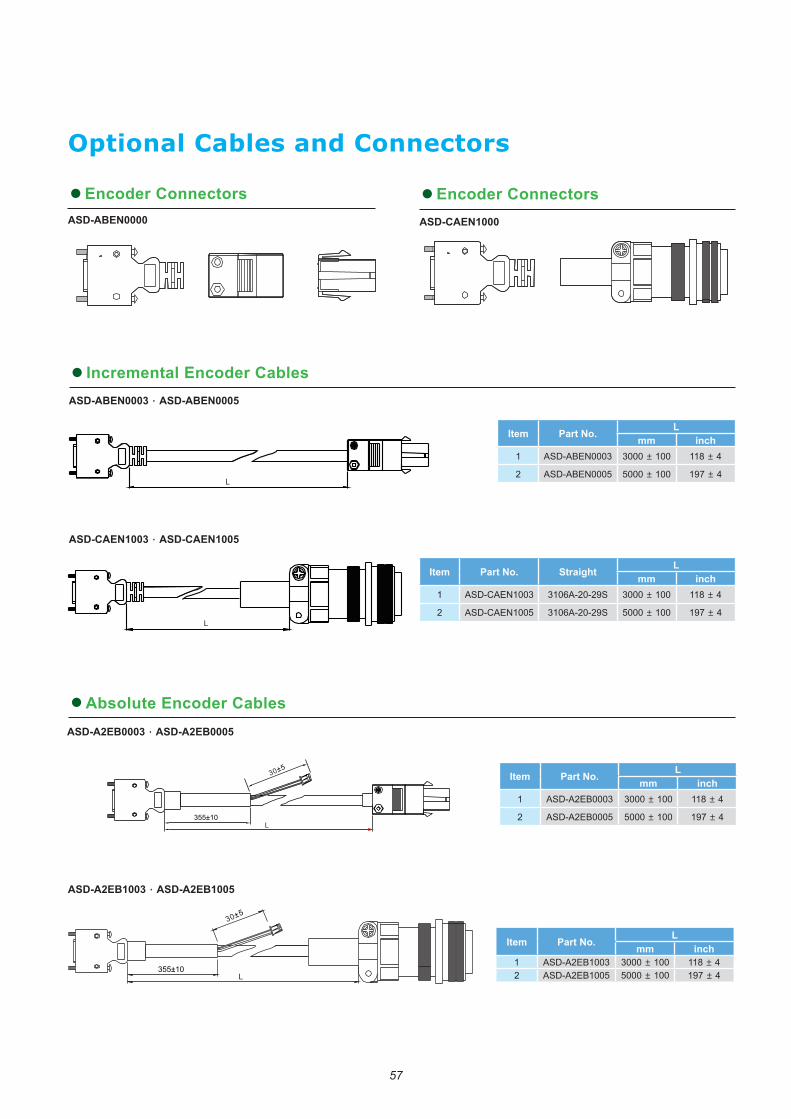
355±10
30±5
L
Item Part No. Lmm inch
1 ASD-A2EB1003 3000 ± 100 118 ± 42 ASD-A2EB1005 5000 ± 100 197 ± 4
ASD-A2EB1003,ASD-A2EB1005
●Absolute Encoder Cables
355±10
30±5
L
ASD-A2EB0003,ASD-A2EB0005
Item Part No. Lmm inch
1 ASD-A2EB0003 3000 ± 100 118 ± 4
2 ASD-A2EB0005 5000 ± 100 197 ± 4
● Incremental Encoder CablesASD-ABEN0003,ASD-ABEN0005
ASD-CAEN1003,ASD-CAEN1005
L
Item Part No. Lmm inch
1 ASD-ABEN0003 3000 ± 100 118 ± 4
2 ASD-ABEN0005 5000 ± 100 197 ± 4
L
Item Part No. Straight Lmm inch
1 ASD-CAEN1003 3106A-20-29S 3000 ± 100 118 ± 4
2 ASD-CAEN1005 3106A-20-29S 5000 ± 100 197 ± 4
●Encoder Connectors ●Encoder ConnectorsASD-ABEN0000 ASD-CAEN1000
58
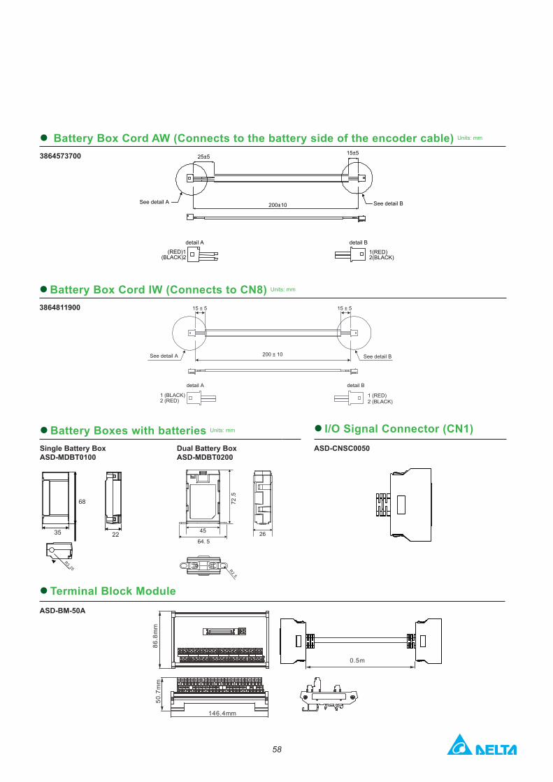
● Battery Box Cord AW (Connects to the battery side of the encoder cable) Units: mm
3864573700
200±10
15±525±5
See detail BSee detail A
detail B
1(RED)2(BLACK)
(RED)1(BLACK)2
detail A
86.8
mm
0.5m
86.8
mm
146.4 mm
50.7
mm50
.7m
m
146.4mm
15 ± 5
200 ± 10 See detail B
detail B
1 (RED)2 (BLACK)
15 ± 5
See detail A
detail A
2 (RED)1 (BLACK)
●Battery Box Cord IW (Connects to CN8) Units: mm
3864811900
●Battery Boxes with batteries Units: mm
Single Battery BoxASD-MDBT0100
Dual Battery BoxASD-MDBT0200
● I/O Signal Connector (CN1)ASD-CNSC0050
68
35 22
R3.25
64. 526
R2.5
45
72.5
● Terminal Block ModuleASD-BM-50A
59
Optional Cables and Connectors
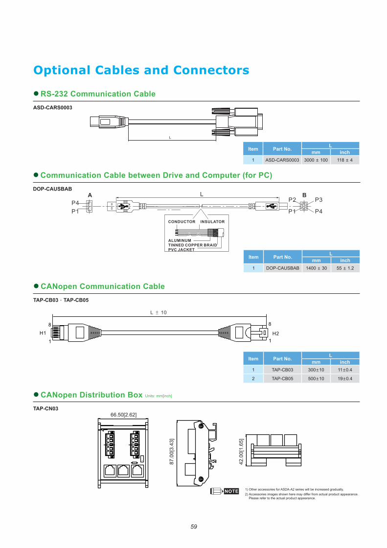
1) Other accessories for ASDA-A2 series will be increased gradually. 2) Accessories images shown here may differ from actual product appearance.
Please refer to the actual product appearance.
Item Part No. Lmm inch
1 TAP-CB03 300±10 11±0.4
2 TAP-CB05 500±10 19±0.4
H1 H2
L ± 10
1
8 8
1
87.0
0[3.
43]
66.50[2.62]
42.0
0[1.
65]
Item Part No. Lmm inch
1 DOP-CAUSBAB 1400 ± 30 55 ± 1.2
P4P1
LA BP2
P1
P3
P4CONDUCTOR INSULATOR
ALUMINUMTINNED COPPER BRAIDPVC JACKET
L
Item Part No. Lmm inch
1 ASD-CARS0003 3000 ± 100 118 ± 4
●Communication Cable between Drive and Computer (for PC)DOP-CAUSBAB
●CANopen Communication CableTAP-CB03,TAP-CB05
●CANopen Distribution Box Units: mm[inch]
TAP-CN03
●RS-232 Communication CableASD-CARS0003

60
●RS-485 Connector Units: mm[inch]
ASD-CNIE0B06
1. 2.
14.5
15.28
25
52.4
41.3 1
2
PIN11:PULL_HI_PS
PIN12:/PULSE
PIN17:GND
PIN18:DO4+
PIN20:CN_GND
PIN19:DO3+
PIN16:OCZ
PIN15:SIGN
PIN14:/SIGN
PIN13:PULSE
PIN10:DO2+
PIN9:DO1+
PIN4:DI1-
PIN3:COM-
PIN1:VDD
PIN2:COM+
PIN5:DI2-
PIN6:DI3-
PIN7:DI4-
PIN8:DI7-
ASD-IF-SC5020
PIN10:DO2+
PIN9:DO1+
PIN4:DI1-
PIN3:COM-
PIN1:VDD
PIN2:COM+
PIN5:DI2-
PIN6:DI3-
PIN7:DI4-
PIN8:DI7-
22.83
45.5
7.7
PIN11:PULL_HI_PS
PIN12:/PULSE
PIN17:GND
PIN18:DO4+
PIN20:CN_GND
PIN19:DO3+
PIN16:OCZ
PIN15:SIGN
PIN14:/SIGN
PIN13:PULSE
45.5
22.83
7.7
15.8
20.3
5
64
5312 26
.0
9.5
55.0
28.3
17.6
●CN1 I/O Connector Units: mm[inch]
ASD-IF-SC5020
Related Documents