Dell Precision Workstation M6500 Service Manual · Dell Precision™ Workstation M6500 Service Manual Working on Your Computer Removing and Replacing Parts Specifications Diagnostics
This document is posted to help you gain knowledge. Please leave a comment to let me know what you think about it! Share it to your friends and learn new things together.
Transcript
Dell Precisiontrade Workstation M6500 Service ManualWorking on Your ComputerRemoving and Replacing PartsSpecificationsDiagnosticsSystem Setup
Notes Cautions and Warnings
NOTE A NOTE indicates important information that helps you make better use of your computer
CAUTION A CAUTION indicates potential damage to hardware or loss of data if instructions are notfollowed
WARNING A WARNING indicates a potential for property damage personal injury or death
If you purchased a Delltrade n Series computer any references in this document to Microsoftreg Windowsreg operating systems arenot applicable
Information in this document is subject to change without noticecopy 2009-2010 Dell Inc All rights reserved
Reproduction of this material in any manner whatsoever without the written permission of Dell Inc is strictly forbidden
Trademarks used in this text Dell the DELL logo and Vostroare trademarks of Dell Inc Intel Pentium Celeron and Core are either trademarksor registered trademarks of Intel Corporation Bluetooth is a registered trademark owned by Bluetooth SIG Inc and is used by Dell under licenseMicrosoft Windows Windows Vista and the Windows Vista start button are either trademarks or registered trademarks of Microsoft Corporation inthe United States andor other countries Adobe the Adobe logo and Flash are either registered trademarks or trademarks of Adobe SystemsIncorporated in the United States andor other countries ATI FirePro is a trademark of Advanced Micro Devices Inc
Other trademarks and trade names may be used in this document to refer to either the entities claiming the marks and names or their productsDell Inc disclaims any proprietary interest in trademarks and trade names other than its own
March 2010 Rev A01
Back to Contents Page
Working on Your ComputerDell Precisiontrade Workstation M6500 Service Manual
Before Working Inside Your Computer
Recommended Tools
Turning Off Your Computer
After Working Inside Your Computer
Before Working Inside Your ComputerUse the following safety guidelines to help protect your computer from potential damage and to help to ensure your personalsafety Unless otherwise noted each procedure included in this document assumes that the following conditions exist
You have performed the steps in Working on Your ComputerYou have read the safety information that shipped with your computerA component can be replaced ormdashif purchased separatelymdashinstalled by performing the removal procedure in reverseorder
WARNING Before working inside your computer read the safety information that shipped with yourcomputer For additional safety best practices information see the Regulatory Compliance Homepage atwwwdellcomregulatory_compliance
CAUTION Many repairs may only be done by a certified service technician You should only performtroubleshooting and simple repairs as authorized in your product documentation or as directed by theonline or telephone service and support team Damage due to servicing that is not authorized by Dell isnot covered by your warranty Read and follow the safety instructions that came with the product
CAUTION To avoid electrostatic discharge ground yourself by using a wrist grounding strap or byperiodically touching an unpainted metal surface such as a connector on the back of the computer
CAUTION Handle components and cards with care Do not touch the components or contacts on a cardHold a card by its edges or by its metal mounting bracket Hold a component such as a processor by itsedges not by its pins
CAUTION When you disconnect a cable pull on its connector or on its pull-tab not on the cable itselfSome cables have connectors with locking tabs if you are disconnecting this type of cable press in on thelocking tabs before you disconnect the cable As you pull connectors apart keep them evenly aligned toavoid bending any connector pins Also before you connect a cable ensure that both connectors arecorrectly oriented and aligned
NOTE The color of your computer and certain components may appear differently than shown in this document
To avoid damaging your computer perform the following steps before you begin working inside the computer
1 Ensure that your work surface is flat and clean to prevent the computer cover from being scratched2 Turn off your computer (see Turning Off Your Computer)3 If the computer is connected to a docking device (docked) undock it
CAUTION To disconnect a network cable first unplug the cable from your computer and then unplug thecable from the network device
4 Disconnect all network cables from the computer5 Disconnect your computer and all attached devices from their electrical outlets6 Where applicable disconnect any adapters from the computer6 Close the display and turn the computer upside-down on a flat work surface
CAUTION To avoid damaging the system board you must remove the main battery before you service thecomputer
7 Remove the main Battery8 Turn the computer top-side up9 Open the display
10 Press the power button to ground the system board
CAUTION To guard against electrical shock always unplug your computer from the electrical outlet beforeopening the display
CAUTION Before touching anything inside your computer ground yourself by touching an unpainted metalsurface such as the metal at the back of the computer While you work periodically touch an unpaintedmetal surface to dissipate static electricity which could harm internal components
11 Remove any installed ExpressCards or Smart Cards from the appropriate slots12 Remove the Hard Drive
Recommended Tools
The procedures in this document may require the following tools
Small flat-blade screwdriver0 Phillips screwdriver1 Phillips screwdriverSmall plastic scribeFlash BIOS update program CD
Turning Off Your Computer
CAUTION To avoid losing data save and close all open files and exit all open programs before you turn offyour computer
1 Shut down the operating system
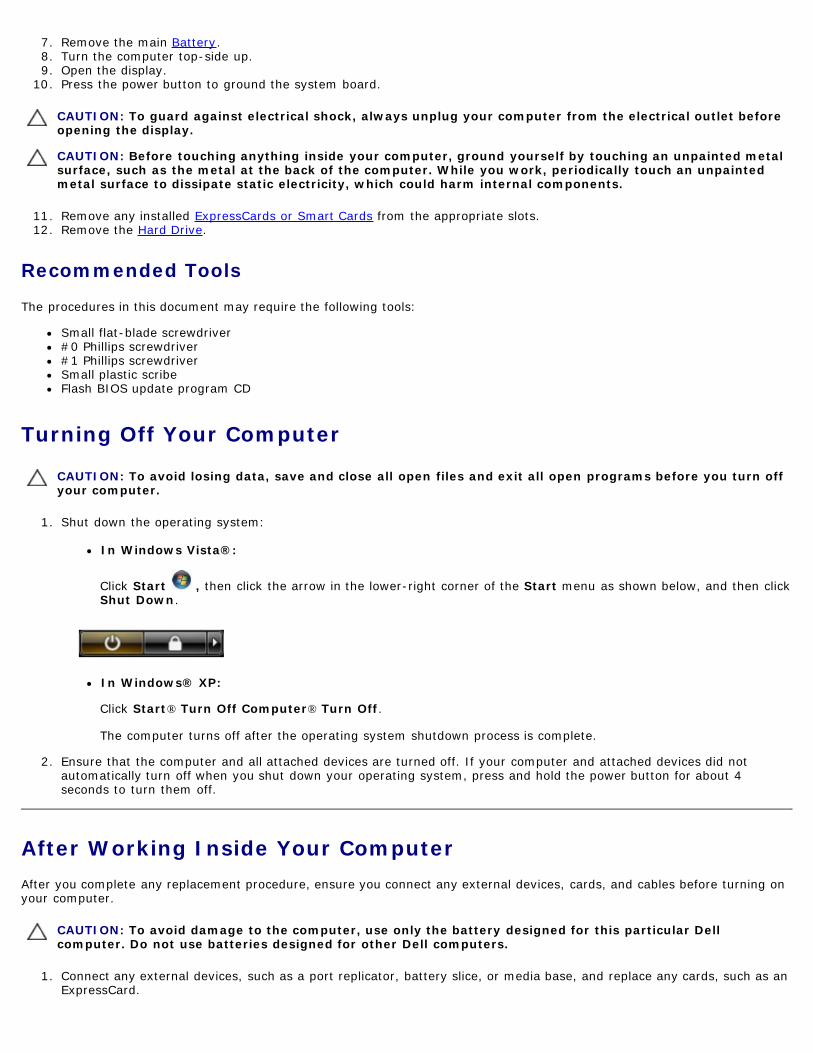
In Windows Vistareg
Click Start then click the arrow in the lower-right corner of the Start menu as shown below and then clickShut Down
In Windowsreg XP
Click Startreg Turn Off Computerreg Turn Off
The computer turns off after the operating system shutdown process is complete
2 Ensure that the computer and all attached devices are turned off If your computer and attached devices did notautomatically turn off when you shut down your operating system press and hold the power button for about 4seconds to turn them off
After Working Inside Your ComputerAfter you complete any replacement procedure ensure you connect any external devices cards and cables before turning onyour computer
CAUTION To avoid damage to the computer use only the battery designed for this particular Dellcomputer Do not use batteries designed for other Dell computers
1 Connect any external devices such as a port replicator battery slice or media base and replace any cards such as anExpressCard
2 Connect any telephone or network cables to your computer
CAUTION To connect a network cable first plug the cable into the network device and then plug it into thecomputer
3 Replace the Battery4 Connect your computer and all attached devices to their electrical outlets5 Turn on your computer
Back to Contents Page
Back to Contents Page
Removing and Replacing PartsDell Precisiontrade Workstation M6500 Service Manual
ExpressCard
PCMCIA Card
Battery
Coin-Cell Battery
Hard Drive
Secondary Hard Drive
Wireless Wide Area Network (WWAN) Card
Flash Cache Module (FCM)
Memory
Camera
PCMCIA Card Cage
Heat Sink
Processor
System Board
SIM Card
Media Card
Access Panel
Hinge Cover
Optical Drive
Wireless Local Area Network (WLAN) card
Wireless Personal Area Network (WPAN) card
Keyboard
Display Assembly
Palm Rest
IO and IEEE 1394 Board
Fan
Video Card Assembly
Back to Contents Page
Back to Contents Page
Technical Specifications System Information
Memory
Audio
PC Card
Smart Card
Display
Touchpad
Battery
Physical
Processor
Video
Communications
ExpressCard
Ports and Connectors
Keyboard
Fingerprint Reader (optional)
AC Adapter
Environmental
NOTE Offerings may vary by region For more information regarding the configuration of your computer click StartregHelp and Support and select the option to view information about your computer
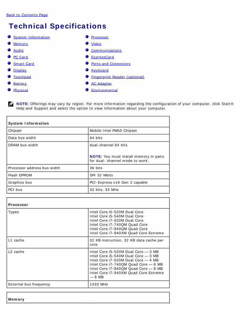
System Information
Chipset Mobile Intel PM55 Chipset
Data bus width 64 bits
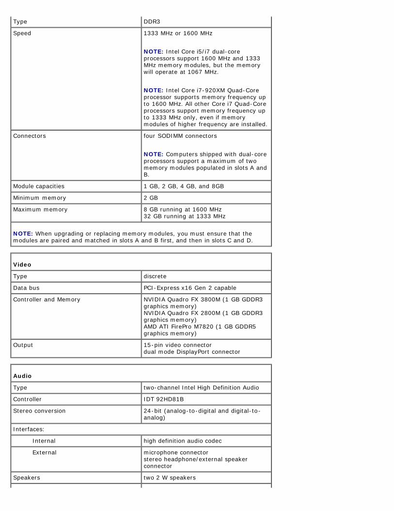
DRAM bus width dual-channel 64 bits
NOTE You must install memory in pairsfor dual- channel mode to work
NOTE Intel Core i5i7 dual-coreprocessors support 1600 MHz and 1333MHz memory modules but the memorywill operate at 1067 MHz
NOTE Intel Core i7-920XM Quad-Coreprocessor supports memory frequency upto 1600 MHz All other Core i7 Quad-Coreprocessors support memory frequency upto 1333 MHz only even if memorymodules of higher frequency are installed
Connectors four SODIMM connectors
NOTE Computers shipped with dual-coreprocessors support a maximum of twomemory modules populated in slots A andB
Module capacities 1 GB 2 GB 4 GB and 8GB
Minimum memory 2 GB
Maximum memory 8 GB running at 1600 MHz32 GB running at 1333 MHz
NOTE When upgrading or replacing memory modules you must ensure that themodules are paired and matched in slots A and B first and then in slots C and D
Video
Type discrete
Data bus PCI-Express x16 Gen 2 capable
Controller and Memory NVIDIA Quadro FX 3800M (1 GB GDDR3graphics memory)NVIDIA Quadro FX 2800M (1 GB GDDR3graphics memory)AMD ATI FirePro M7820 (1 GB GDDR5graphics memory)
Output 15-pin video connectordual mode DisplayPort connector
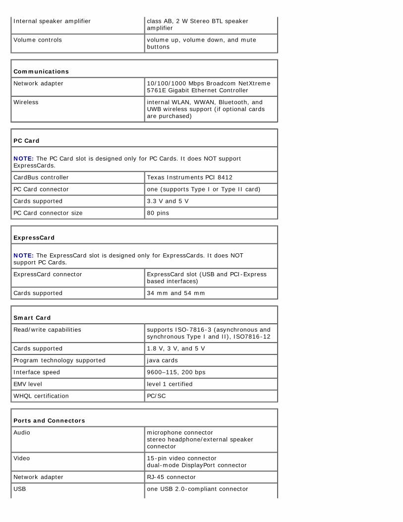
Audio
Type two-channel Intel High Definition Audio
Controller IDT 92HD81B
Stereo conversion 24-bit (analog-to-digital and digital-to-analog)
Type (active-matrix TFT) 17 inches WXGA+ LED17 inches WUXGA LED RGB or RGBedge-to-edge glass
Active area (XY) 3673 mm x 2295 mm
Dimensions
Height
WXGA+WUXGA 245 mm (964 inches)
WUXGA 248 mm (976 inches)
Width (WXGA+WUXGA) 383 mm (1508 inches)
Diagonal 432 mm (1700 inches)
Maximum resolutions and brightness
WXGA+ 1440 x 900 at 262 K colors 220 nits
WUXGA 1920 x 1200 at 262 K colors 300 nits
WUXGA RGB 1920 x 1200 at 167 M colors 300 nits
Operating angle 0deg (closed) to 152deg
Refresh rate 60 Hz
Viewing angles
WXGA+ Horizontal 40deg40deg
WXGA+ Vertical 15deg30deg
WUXGA Horizontal 60deg60deg
WUXGA Vertical 45deg45deg
Pixel pitch
WXGA+ 0191 mm
WUXGA 0225 mm
Keyboard
Number of keys United States 101 keysUnited Kingdom 102 keysBrazil 104 keysJapan 105 keys
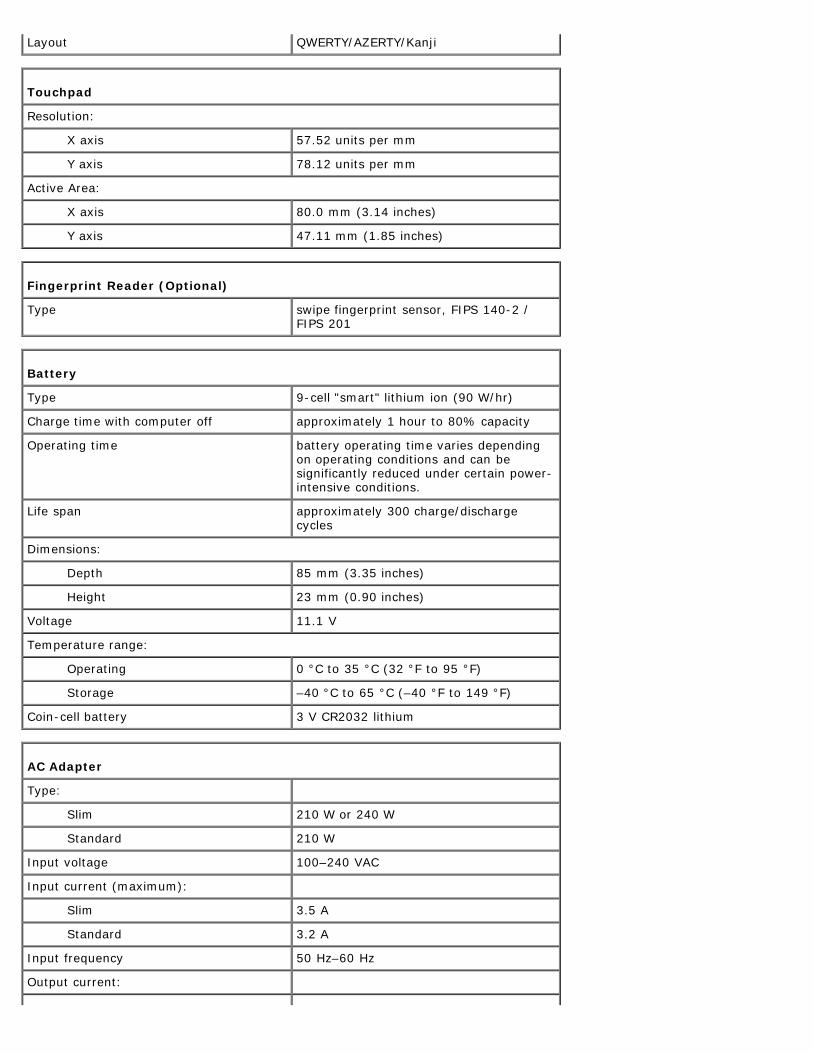
Layout QWERTYAZERTYKanji
Touchpad
Resolution
X axis 5752 units per mm
Y axis 7812 units per mm
Active Area
X axis 800 mm (314 inches)
Y axis 4711 mm (185 inches)
Fingerprint Reader (Optional)
Type swipe fingerprint sensor FIPS 140-2 FIPS 201
Battery
Type 9-cell smart lithium ion (90 Whr)
Charge time with computer off approximately 1 hour to 80 capacity
Operating time battery operating time varies dependingon operating conditions and can besignificantly reduced under certain power-intensive conditions
Life span approximately 300 chargedischargecycles
Dimensions
Depth 85 mm (335 inches)
Height 23 mm (090 inches)
Voltage 111 V
Temperature range
Operating 0 degC to 35 degC (32 degF to 95 degF)
Storage ndash40 degC to 65 degC (ndash40 degF to 149 degF)
Coin-cell battery 3 V CR2032 lithium
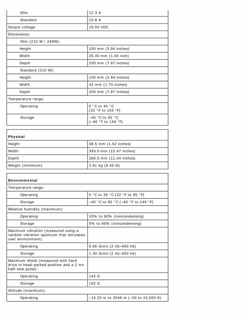
AC Adapter
Type
Slim 210 W or 240 W
Standard 210 W
Input voltage 100ndash240 VAC
Input current (maximum)
Slim 35 A
Standard 32 A
Input frequency 50 Hzndash60 Hz
Output current
Slim 123 A
Standard 108 A
Output voltage 1950 VDC
Dimensions
Slim (210 W 240W)
Height 100 mm (394 inches)
Width 2540 mm (100 inch)
Depth 200 mm (787 inches)
Standard (210 W)
Height 100 mm (394 inches)
Width 43 mm (170 inches)
Depth 200 mm (787 inches)
Temperature range
Operating 0 degC to 40 degC (32 degF to 104 degF)
Storage ndash40 degC to 65 degC (ndash40 degF to 149 degF)
Physical
Height 385 mm (152 inches)
Width 3930 mm (1547 inches)
Depth 2805 mm (1104 inches)
Weight (minimum) 381 kg (840 lb)
Environmental
Temperature range
Operating 0 degC to 35 degC (32 degF to 95 degF)
Storage ndash40 degC to 65 degC (ndash40 degF to 149 degF)
Relative humidity (maximum)
Operating 10 to 90 (noncondensing)
Storage 5 to 95 (noncondensing)
Maximum vibration (measured using arandom vibration spectrum that simulatesuser environment)
Operating 066 Grms (2 Hzndash600 Hz)
Storage 130 Grms (2 Hzndash600 Hz)
Maximum shock (measured with harddrive in head-parked position and a 2 mshalf-sine pulse)
Operating 142 G
Storage 162 G
Altitude (maximum)
Operating ndash1520 m to 3048 m (ndash50 to 10000 ft)
Storage ndash1520 m to 10668 m (ndash50 to 35000 ft)
Airborne contaminant level G2 or lower as defined by ANSIISA-S7104-1985
Back to Contents Page
Back to Contents Page
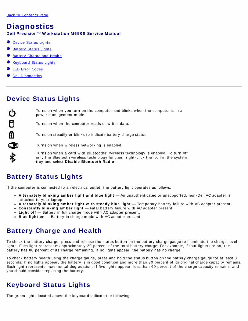
DiagnosticsDell Precisiontrade Workstation M6500 Service Manual
Device Status Lights
Battery Status Lights
Battery Charge and Health
Keyboard Status Lights
LED Error Codes
Dell Diagnostics
Device Status LightsTurns on when you turn on the computer and blinks when the computer is in apower management mode
Turns on when the computer reads or writes data
Turns on steadily or blinks to indicate battery charge status
Turns on when wireless networking is enabled
Turns on when a card with Bluetoothreg wireless technology is enabled To turn offonly the Bluetooth wireless technology function right-click the icon in the systemtray and select Disable Bluetooth Radio
Battery Status LightsIf the computer is connected to an electrical outlet the battery light operates as follows
Alternately blinking amber light and blue light mdash An unauthenticated or unsupported non-Dell AC adapter isattached to your laptopAlternately blinking amber light with steady blue light mdash Temporary battery failure with AC adapter presentConstantly blinking amber light mdash Fatal battery failure with AC adapter presentLight off mdash Battery in full charge mode with AC adapter presentBlue light on mdash Battery in charge mode with AC adapter present
Battery Charge and HealthTo check the battery charge press and release the status button on the battery charge gauge to illuminate the charge-levellights Each light represents approximately 20 percent of the total battery charge For example if four lights are on thebattery has 80 percent of its charge remaining If no lights appear the battery has no charge
To check battery health using the charge gauge press and hold the status button on the battery charge gauge for at least 3seconds If no lights appear the battery is in good condition and more than 80 percent of its original charge capacity remainsEach light represents incremental degradation If five lights appear less than 60 percent of the charge capacity remains andyou should consider replacing the battery
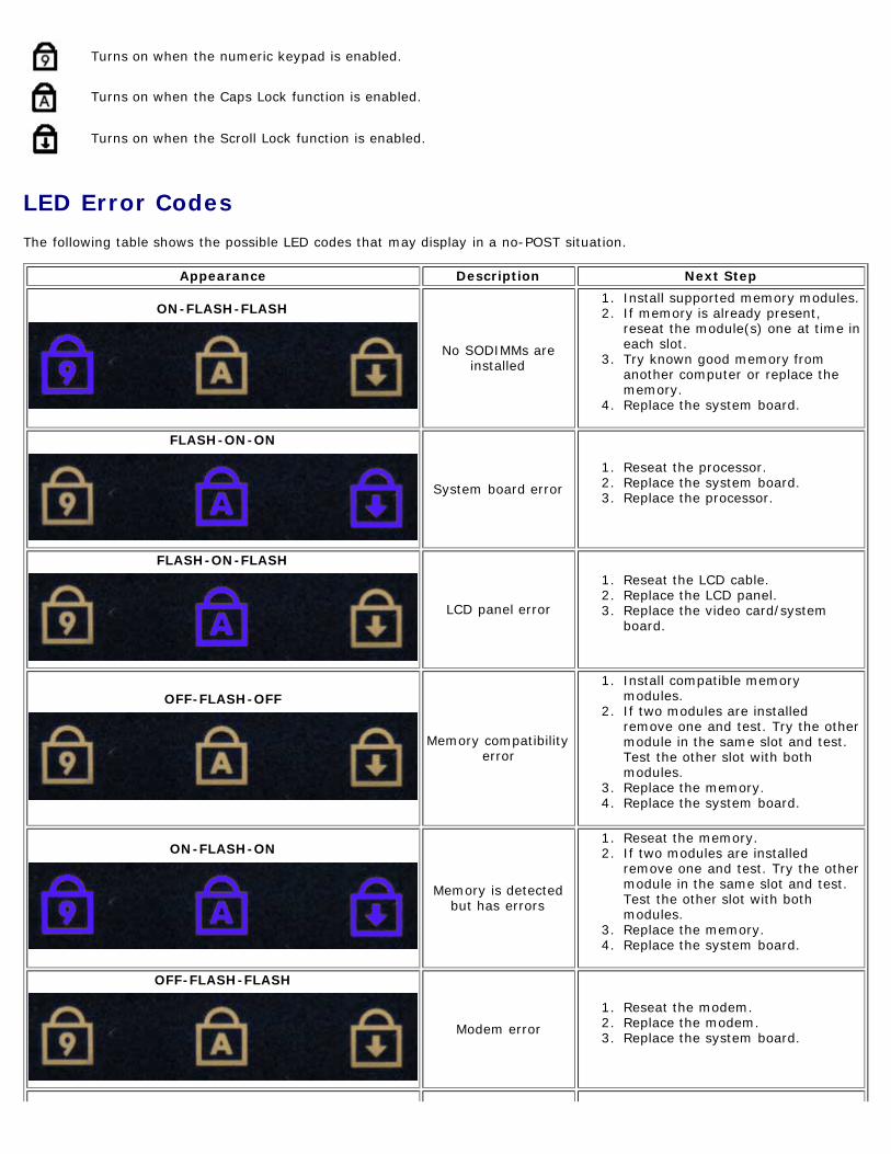
Keyboard Status LightsThe green lights located above the keyboard indicate the following
Turns on when the numeric keypad is enabled
Turns on when the Caps Lock function is enabled
Turns on when the Scroll Lock function is enabled
LED Error CodesThe following table shows the possible LED codes that may display in a no-POST situation
Appearance Description Next Step
ON-FLASH-FLASH
No SODIMMs areinstalled
1 Install supported memory modules2 If memory is already present
reseat the module(s) one at time ineach slot
3 Try known good memory fromanother computer or replace thememory
4 Replace the system board
FLASH-ON-ON
System board error1 Reseat the processor2 Replace the system board3 Replace the processor
FLASH-ON-FLASH
LCD panel error
1 Reseat the LCD cable2 Replace the LCD panel3 Replace the video cardsystem
board
OFF-FLASH-OFF
Memory compatibilityerror
1 Install compatible memorymodules
2 If two modules are installedremove one and test Try the othermodule in the same slot and testTest the other slot with bothmodules
3 Replace the memory4 Replace the system board
ON-FLASH-ON
Memory is detectedbut has errors
1 Reseat the memory2 If two modules are installed
remove one and test Try the othermodule in the same slot and testTest the other slot with bothmodules
3 Replace the memory4 Replace the system board
OFF-FLASH-FLASH
Modem error1 Reseat the modem2 Replace the modem3 Replace the system board
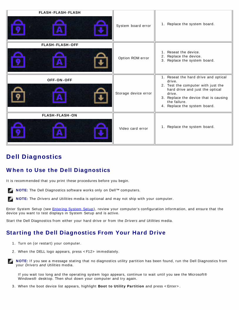
FLASH-FLASH-FLASH
System board error 1 Replace the system board
FLASH-FLASH-OFF
Option ROM error1 Reseat the device2 Replace the device3 Replace the system board
OFF-ON-OFF
Storage device error
1 Reseat the hard drive and opticaldrive
2 Test the computer with just thehard drive and just the opticaldrive
3 Replace the device that is causingthe failure
4 Replace the system board
FLASH-FLASH-ON
Video card error 1 Replace the system board
Dell Diagnostics
When to Use the Dell Diagnostics
It is recommended that you print these procedures before you begin
NOTE The Dell Diagnostics software works only on Delltrade computers
NOTE The Drivers and Utilities media is optional and may not ship with your computer
Enter System Setup (see Entering System Setup) review your computers configuration information and ensure that thedevice you want to test displays in System Setup and is active
Start the Dell Diagnostics from either your hard drive or from the Drivers and Utilities media
Starting the Dell Diagnostics From Your Hard Drive
1 Turn on (or restart) your computer
2 When the DELL logo appears press ltF12gt immediately
NOTE If you see a message stating that no diagnostics utility partition has been found run the Dell Diagnostics fromyour Drivers and Utilities media
If you wait too long and the operating system logo appears continue to wait until you see the MicrosoftregWindowsreg desktop Then shut down your computer and try again
3 When the boot device list appears highlight Boot to Utility Partition and press ltEntergt
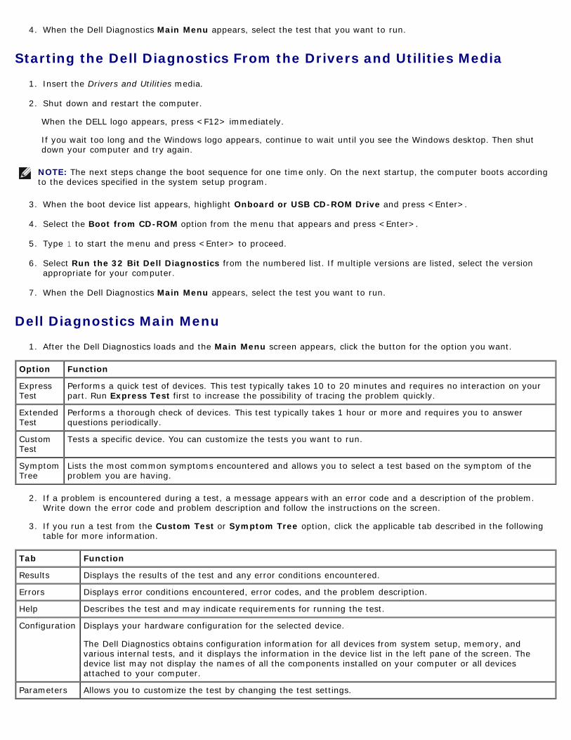
4 When the Dell Diagnostics Main Menu appears select the test that you want to run
Starting the Dell Diagnostics From the Drivers and Utilities Media
1 Insert the Drivers and Utilities media
2 Shut down and restart the computer
When the DELL logo appears press ltF12gt immediately
If you wait too long and the Windows logo appears continue to wait until you see the Windows desktop Then shutdown your computer and try again
NOTE The next steps change the boot sequence for one time only On the next startup the computer boots accordingto the devices specified in the system setup program
3 When the boot device list appears highlight Onboard or USB CD-ROM Drive and press ltEntergt
4 Select the Boot from CD-ROM option from the menu that appears and press ltEntergt
5 Type 1 to start the menu and press ltEntergt to proceed
6 Select Run the 32 Bit Dell Diagnostics from the numbered list If multiple versions are listed select the versionappropriate for your computer
7 When the Dell Diagnostics Main Menu appears select the test you want to run
Dell Diagnostics Main Menu
1 After the Dell Diagnostics loads and the Main Menu screen appears click the button for the option you want
Option Function
ExpressTest
Performs a quick test of devices This test typically takes 10 to 20 minutes and requires no interaction on yourpart Run Express Test first to increase the possibility of tracing the problem quickly
ExtendedTest
Performs a thorough check of devices This test typically takes 1 hour or more and requires you to answerquestions periodically
CustomTest
Tests a specific device You can customize the tests you want to run
SymptomTree
Lists the most common symptoms encountered and allows you to select a test based on the symptom of theproblem you are having
2 If a problem is encountered during a test a message appears with an error code and a description of the problemWrite down the error code and problem description and follow the instructions on the screen
3 If you run a test from the Custom Test or Symptom Tree option click the applicable tab described in the followingtable for more information
Tab Function
Results Displays the results of the test and any error conditions encountered
Errors Displays error conditions encountered error codes and the problem description
Help Describes the test and may indicate requirements for running the test
Configuration Displays your hardware configuration for the selected device
The Dell Diagnostics obtains configuration information for all devices from system setup memory andvarious internal tests and it displays the information in the device list in the left pane of the screen Thedevice list may not display the names of all the components installed on your computer or all devicesattached to your computer
Parameters Allows you to customize the test by changing the test settings
4 When the tests are completed if you are running the Dell Diagnostics from the Drivers and Utilities media remove themedia
5 Close the test screen to return to the Main Menu screen To exit the Dell Diagnostics and restart the computer closethe Main Menu screen
Back to Contents Page
Back to Contents Page
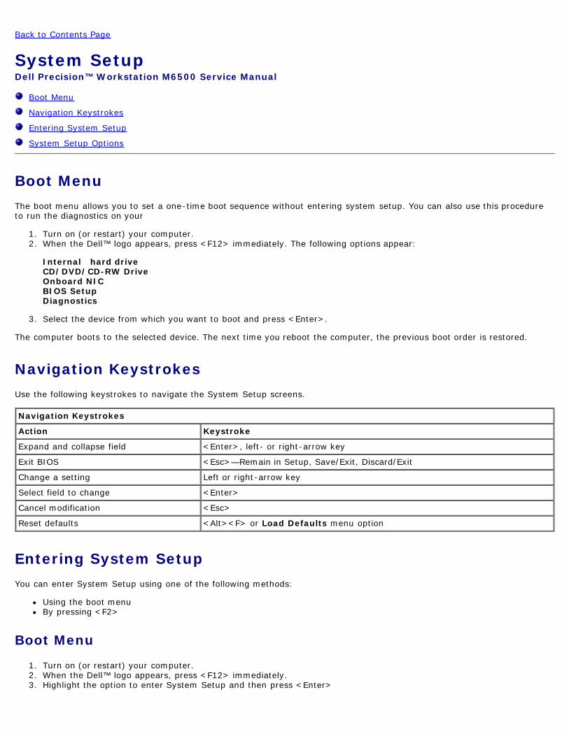
System SetupDell Precisiontrade Workstation M6500 Service Manual
Boot Menu
Navigation Keystrokes
Entering System Setup
System Setup Options
Boot MenuThe boot menu allows you to set a one-time boot sequence without entering system setup You can also use this procedureto run the diagnostics on your
1 Turn on (or restart) your computer2 When the Delltrade logo appears press ltF12gt immediately The following options appear
Internal hard drive CDDVDCD-RW Drive Onboard NIC BIOS Setup Diagnostics
3 Select the device from which you want to boot and press ltEntergt
The computer boots to the selected device The next time you reboot the computer the previous boot order is restored
Navigation KeystrokesUse the following keystrokes to navigate the System Setup screens
Navigation Keystrokes
Action Keystroke
Expand and collapse field ltEntergt left- or right-arrow key
Exit BIOS ltEscgtmdashRemain in Setup SaveExit DiscardExit
Change a setting Left or right-arrow key
Select field to change ltEntergt
Cancel modification ltEscgt
Reset defaults ltAltgtltFgt or Load Defaults menu option
Entering System SetupYou can enter System Setup using one of the following methods
Using the boot menuBy pressing ltF2gt
Boot Menu
1 Turn on (or restart) your computer2 When the Delltrade logo appears press ltF12gt immediately3 Highlight the option to enter System Setup and then press ltEntergt
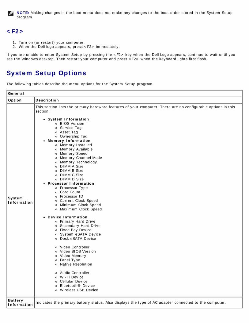
NOTE Making changes in the boot menu does not make any changes to the boot order stored in the System Setupprogram
ltF2gt
1 Turn on (or restart) your computer2 When the Dell logo appears press ltF2gt immediately
If you are unable to enter System Setup by pressing the ltF2gt key when the Dell Logo appears continue to wait until yousee the Windows desktop Then restart your computer and press ltF2gt when the keyboard lights first flash
System Setup OptionsThe following tables describe the menu options for the System Setup program
General
Option Description
SystemInformation
This section lists the primary hardware features of your computer There are no configurable options in thissection
System InformationBIOS VersionService TagAsset TagOwnership Tag
Memory InformationMemory InstalledMemory AvailableMemory SpeedMemory Channel ModeMemory TechnologyDIMM A SizeDIMM B SizeDIMM C SizeDIMM D Size
Device InformationPrimary Hard DriveSecondary Hard DriveFixed Bay DeviceSystem eSATA DeviceDock eSATA Device Video ControllerVideo BIOS VersionVideo MemoryPanel TypeNative Resolution Audio ControllerWi-Fi DeviceCellular DeviceBluetoothreg DeviceWireless USB Device
BatteryInformation Indicates the primary battery status Also displays the type of AC adapter connected to the computer
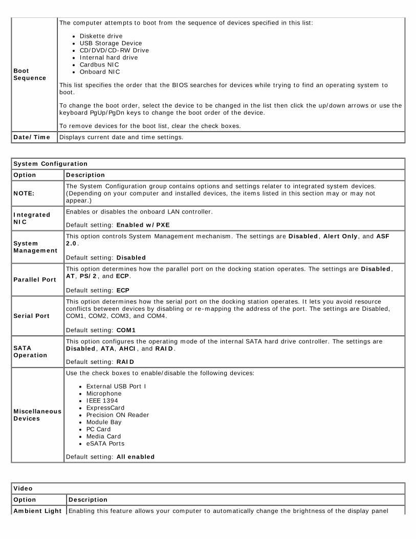
BootSequence
The computer attempts to boot from the sequence of devices specified in this list
Diskette driveUSB Storage DeviceCDDVDCD-RW DriveInternal hard driveCardbus NICOnboard NIC
This list specifies the order that the BIOS searches for devices while trying to find an operating system toboot
To change the boot order select the device to be changed in the list then click the updown arrows or use thekeyboard PgUpPgDn keys to change the boot order of the device
To remove devices for the boot list clear the check boxes
DateTime Displays current date and time settings
System Configuration
Option Description
NOTEThe System Configuration group contains options and settings relater to integrated system devices(Depending on your computer and installed devices the items listed in this section may or may notappear)
IntegratedNIC
Enables or disables the onboard LAN controller
Default setting Enabled wPXE
SystemManagement
This option controls System Management mechanism The settings are Disabled Alert Only and ASF20
Default setting Disabled
Parallel Port
This option determines how the parallel port on the docking station operates The settings are DisabledAT PS2 and ECP
Default setting ECP
Serial Port
This option determines how the serial port on the docking station operates It lets you avoid resourceconflicts between devices by disabling or re-mapping the address of the port The settings are DisabledCOM1 COM2 COM3 and COM4
Default setting COM1
SATAOperation
This option configures the operating mode of the internal SATA hard drive controller The settings areDisabled ATA AHCI and RAID
Default setting RAID
MiscellaneousDevices
Use the check boxes to enabledisable the following devices
External USB Port IMicrophoneIEEE 1394ExpressCardPrecision ON ReaderModule BayPC CardMedia CardeSATA Ports
Default setting All enabled
Video
Option Description
Ambient Light Enabling this feature allows your computer to automatically change the brightness of the display panel
Sensor based on the amount of light in the surroundings
LCDBrightness
This option (represented by a slider bar for On Battery and On AC) sets the panel brightness when theambient light sensor is off
Security
Option Description
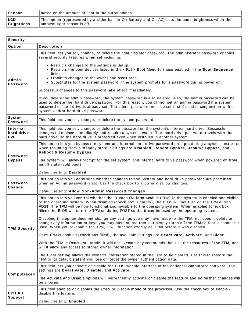
AdminPassword
This field lets you set change or delete the administrator password The administrator password enablesseveral security features when set including
Restricts changes to the settings in SetupRestricts the boot devices listed in the ltF12gt Boot Menu to those enabled in the Boot SequencefieldProhibits changes to the owner and asset tagsSubstitutes for the system password if the system prompts for a password during power on
Successful changes to this password take effect immediately
If you delete the admin password the system password is also deleted Also the admin password can beused to delete the hard drive password For this reason you cannot set an admin password if a systempassword or hard drive is already set The admin password must be set first if used in conjunction with asystem andor hard drive password
SystemPassword This field lets you set change or delete the system password
Internal hard drivePW
This field lets you set change or delete the password on the systems internal hard drive Successfulchanges take place immediately and require a system restart The hard drive password travels with thehard drive so the hard drive is protected even when installed in another system
PasswordBypass
This option lets you bypass the system and internal hard drive password prompts during a system restart orwhen resuming from a standby state Settings are Disabled Reboot Bypass Resume Bypass andReboot amp Resume Bypass
The system will always prompt for the set system and internal hard drive password when powered on froman off state (cold boot)
Default setting Disabled
PasswordChange
This option lets you determine whether changes to the System and hard drive passwords are permittedwhen an Admin password is set Use the check box to allow or disallow changes
Default setting Allow Non-Admin Password Changes
TPM Security
This option lets you control whether the Trusted Platform Module (TPM) in the system is enabled and visibleto the operating system When disabled (check box is empty) the BIOS will not turn on the TPM duringPOST The TPM will be non-functional and invisible to the operating system When enabled (check boxfilled) the BIOS will turn the TPM on during POST so the it can be used by the operating system
Disabling this option does not change any settings you may have made to the TPM nor does it delete orchange any information or keys you may have stored there It simply turns off the TPM so that it cannot beused When you re-enable the TPM it will function exactly as it did before it was disabled
Once TPM is enabled (check box filled) the available settings are Deactivate Activate and Clear
With the TPM in Deactivate mode it will not execute any commands that use the resources of the TPM norwill it allow any access to stored owner information
The Clear setting allows the owners information stored in the TPM to be cleared Use this to restore theTPM to its default state if you lose or forget the owner authentication data
Computracereg
This field lets you activate or disable the BIOS module interface of the optional Computrace software Thesettings are Deactivate Disable and Activate
The Activate and Disable options will permanently activate or disable the feature and no further changes willbe allowed
CPU XDSupport
This field enables or disables the Execute Disable mode of the processor Use the check box to enable disable this feature
Default setting Enabled
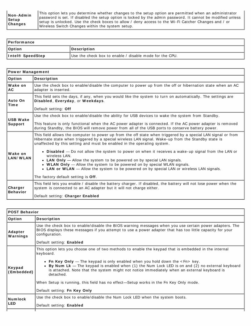
Non-AdminSetupChanges
This option lets you determine whether changes to the setup option are permitted when an administratorpassword is set If disabled the setup option is locked by the admin password It cannot be modified unlesssetup is unlocked Use the check boxes to allow deny access to the Wi-Fi Catcher Changes and orWireless Switch Changes within the system setup
Performance
Option Description
Intelreg SpeedStep Use the check box to enable disable mode for the CPU
Power Management
Option Description
Wake onAC
Use the check box to enabledisable the computer to power up from the off or hibernation state when an ACadapter is inserted
Auto OnTime
This field sets the days if any when you would like the system to turn on automatically The settings areDisabled Everyday or Weekdays
Default setting Off
USB WakeSupport
Use the check box to enabledisable the ability for USB devices to wake the system from Standby
This feature is only functional when the AC power adapter is connected If the AC power adapter is removedduring Standby the BIOS will remove power from all of the USB ports to conserve battery power
Wake onLANWLAN
This field allows the computer to power up from the off state when triggered by a special LAN signal or fromHibernate state when triggered by a special wireless LAN signal Wake-up from the Standby state isunaffected by this setting and must be enabled in the operating system
Disabled mdash Do not allow the system to power on when it receives a wake-up signal from the LAN orwireless LANLAN Only mdash Allow the system to be powered on by special LAN signalsWLAN Only mdash Allow the system to be powered on by special WLAN signalsLAN or WLAN mdash Allow the system to be powered on by special LAN or wireless LAN signals
The factory default setting is Off
ChargerBehavior
This field lets you enable disable the battery charger If disabled the battery will not lose power when thesystem is connected to an AC adapter but it will not charge either
Default setting Charger Enabled
POST Behavior
Option Description
AdapterWarnings
Use the check box to enabledisable the BIOS warning messages when you use certain power adapters TheBIOS displays these messages if you attempt to use a power adapter that has too little capacity for yourconfiguration
Default setting Enabled
Keypad(Embedded)
This option lets you choose one of two methods to enable the keypad that is embedded in the internalkeyboard
Fn Key Only mdash The keypad is only enabled when you hold down the ltFngt keyBy Num Lk mdash The keypad is enabled when (1) the Num Lock LED is on and (2) no external keyboardis attached Note that the system might not notice immediately when an external keyboard isdetached
When Setup is running this field has no effectmdashSetup works in the Fn Key Only mode
Default setting Fn Key Only
NumlockLED
Use the check box to enabledisable the Num Lock LED when the system boots
Default setting Enabled
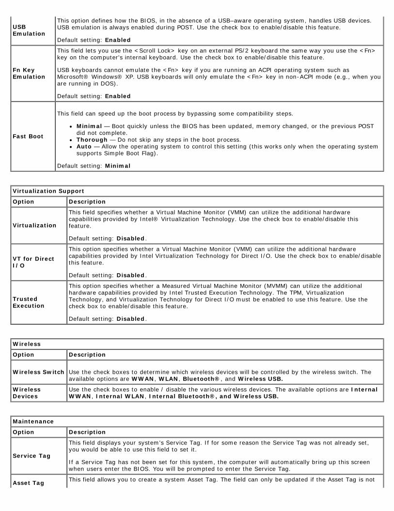
USBEmulation
This option defines how the BIOS in the absence of a USBndashaware operating system handles USB devicesUSB emulation is always enabled during POST Use the check box to enabledisable this feature
Default setting Enabled
Fn KeyEmulation
This field lets you use the ltScroll Lockgt key on an external PS2 keyboard the same way you use the ltFngtkey on the computers internal keyboard Use the check box to enabledisable this feature
USB keyboards cannot emulate the ltFngt key if you are running an ACPI operating system such asMicrosoftreg Windowsreg XP USB keyboards will only emulate the ltFngt key in non-ACPI mode (eg when youare running in DOS)
Default setting Enabled
Fast Boot
This field can speed up the boot process by bypassing some compatibility steps
Minimal mdash Boot quickly unless the BIOS has been updated memory changed or the previous POSTdid not completeThorough mdash Do not skip any steps in the boot processAuto mdash Allow the operating system to control this setting (this works only when the operating systemsupports Simple Boot Flag)
Default setting Minimal
Virtualization Support
Option Description
Virtualization
This field specifies whether a Virtual Machine Monitor (VMM) can utilize the additional hardwarecapabilities provided by Intelreg Virtualization Technology Use the check box to enabledisable thisfeature
Default setting Disabled
VT for DirectIO
This option specifies whether a Virtual Machine Monitor (VMM) can utilize the additional hardwarecapabilities provided by Intel Virtualization Technology for Direct IO Use the check box to enabledisablethis feature
Default setting Disabled
TrustedExecution
This option specifies whether a Measured Virtual Machine Monitor (MVMM) can utilize the additionalhardware capabilities provided by Intel Trusted Execution Technology The TPM VirtualizationTechnology and Virtualization Technology for Direct IO must be enabled to use this feature Use thecheck box to enabledisable this feature
Default setting Disabled
Wireless
Option Description
Wireless Switch Use the check boxes to determine which wireless devices will be controlled by the wireless switch Theavailable options are WWAN WLAN Bluetoothreg and Wireless USB
WirelessDevices
Use the check boxes to enable disable the various wireless devices The available options are InternalWWAN Internal WLAN Internal Bluetoothreg and Wireless USB
Maintenance
Option Description
Service Tag
This field displays your systems Service Tag If for some reason the Service Tag was not already setyou would be able to use this field to set it
If a Service Tag has not been set for this system the computer will automatically bring up this screenwhen users enter the BIOS You will be prompted to enter the Service Tag
Asset Tag This field allows you to create a system Asset Tag The field can only be updated if the Asset Tag is not
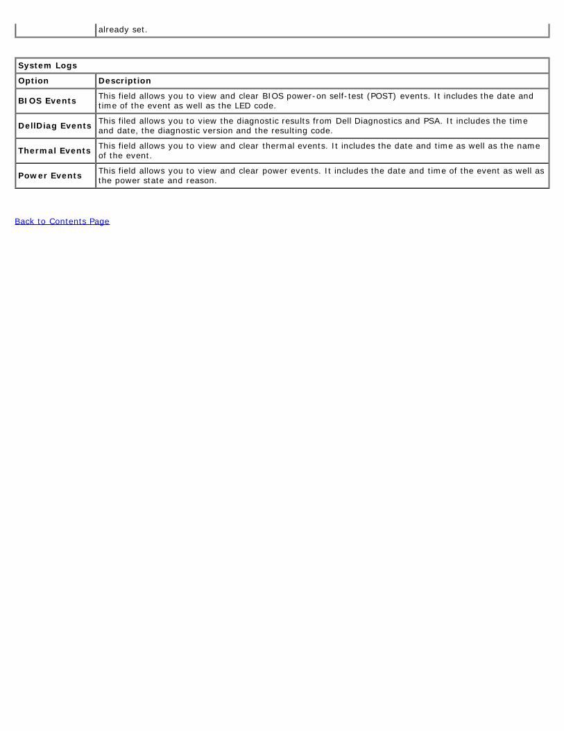
already set
System Logs
Option Description
BIOS Events This field allows you to view and clear BIOS power-on self-test (POST) events It includes the date andtime of the event as well as the LED code
DellDiag Events This filed allows you to view the diagnostic results from Dell Diagnostics and PSA It includes the timeand date the diagnostic version and the resulting code
Thermal Events This field allows you to view and clear thermal events It includes the date and time as well as the nameof the event
Power Events This field allows you to view and clear power events It includes the date and time of the event as well asthe power state and reason
Back to Contents Page
Back to Contents Page
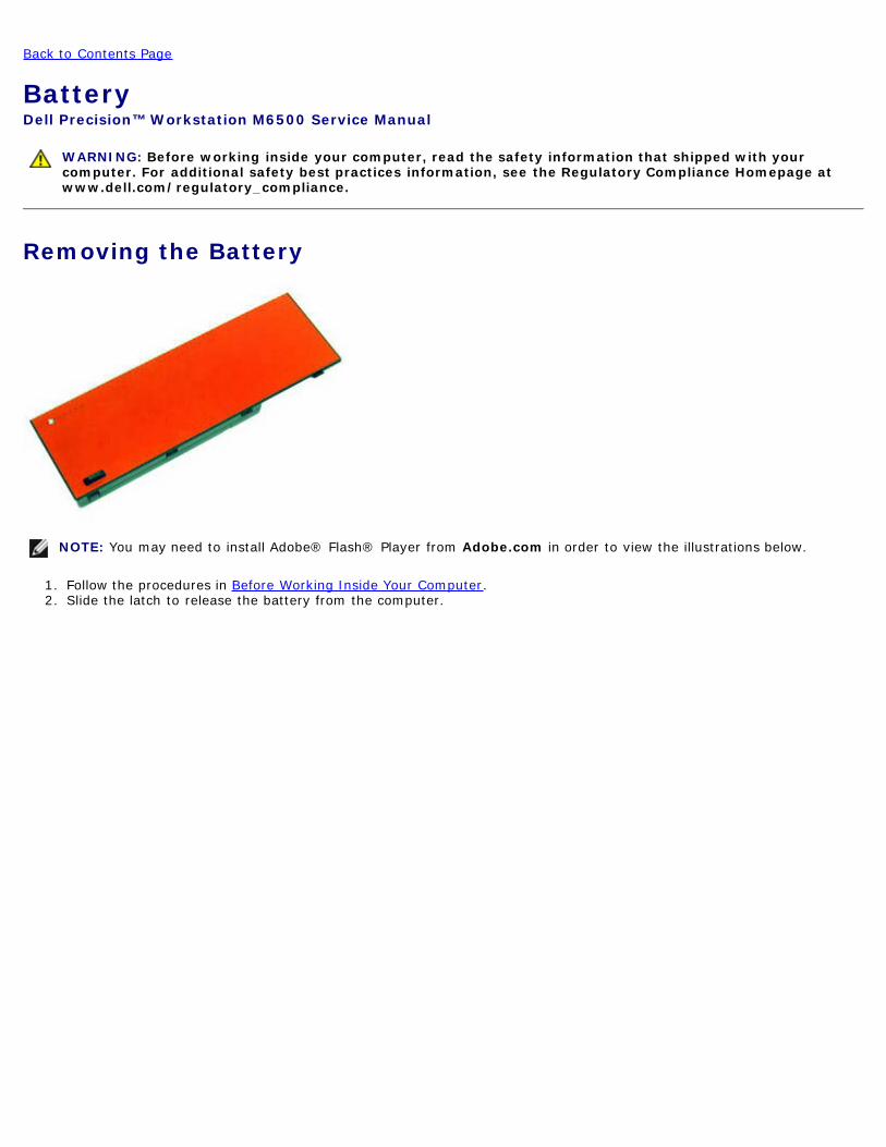
BatteryDell Precisiontrade Workstation M6500 Service Manual
WARNING Before working inside your computer read the safety information that shipped with yourcomputer For additional safety best practices information see the Regulatory Compliance Homepage atwwwdellcomregulatory_compliance
Removing the Battery
NOTE You may need to install Adobereg Flashreg Player from Adobecom in order to view the illustrations below
1 Follow the procedures in Before Working Inside Your Computer2 Slide the latch to release the battery from the computer
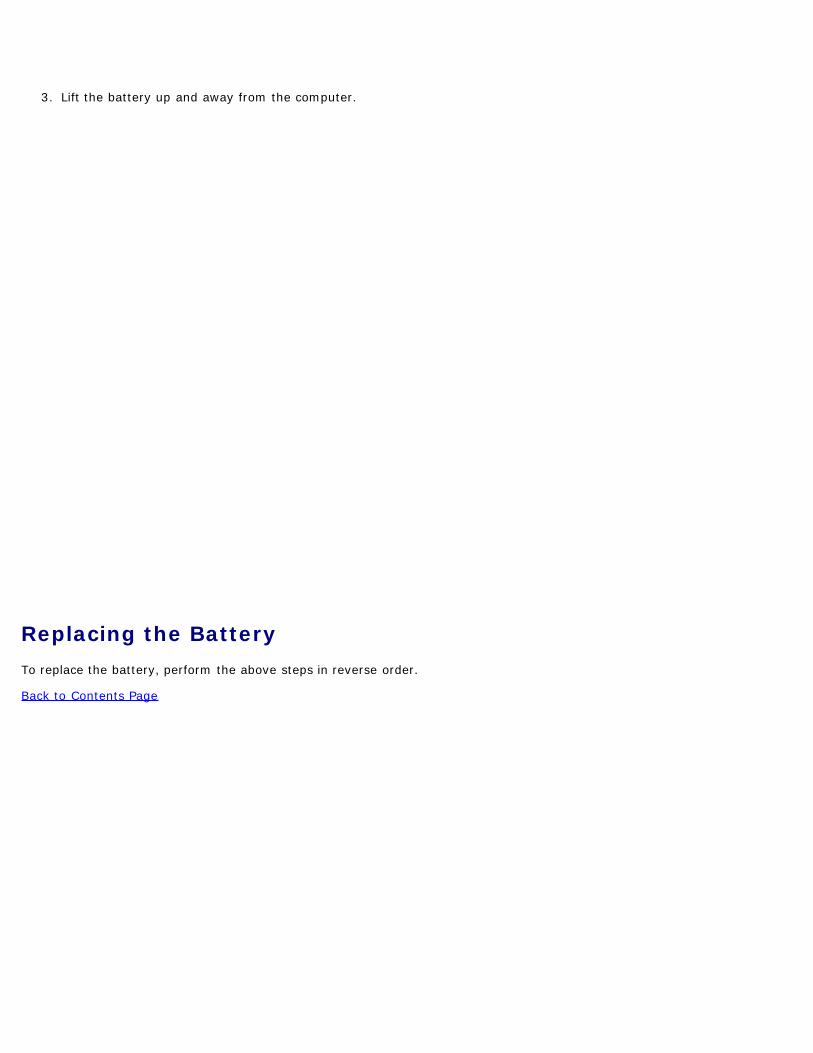
3 Lift the battery up and away from the computer
Replacing the BatteryTo replace the battery perform the above steps in reverse order
Back to Contents Page
Back to Contents Page
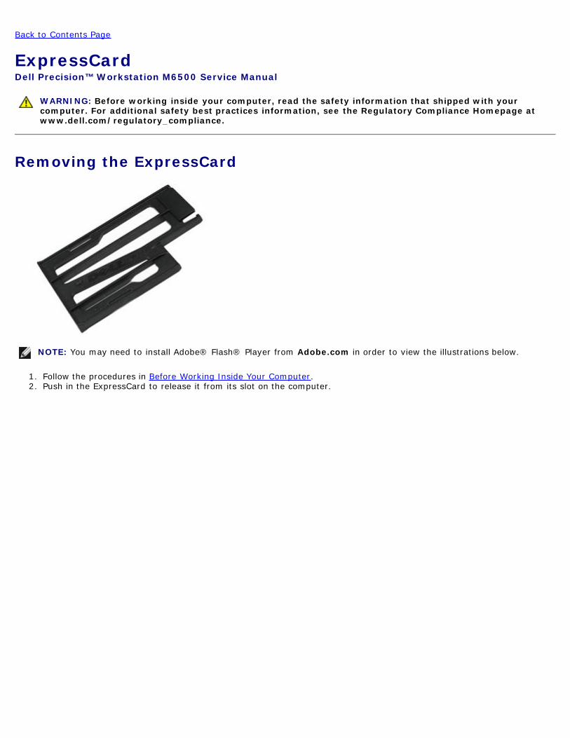
ExpressCardDell Precisiontrade Workstation M6500 Service Manual
WARNING Before working inside your computer read the safety information that shipped with yourcomputer For additional safety best practices information see the Regulatory Compliance Homepage atwwwdellcomregulatory_compliance
Removing the ExpressCard
NOTE You may need to install Adobereg Flashreg Player from Adobecom in order to view the illustrations below
1 Follow the procedures in Before Working Inside Your Computer2 Push in the ExpressCard to release it from its slot on the computer
3 Pull out the ExpressCard and remove it from the computer
Replacing the ExpressCardTo replace the ExpressCard perform the above steps in reverse order
Back to Contents Page
Back to Contents Page
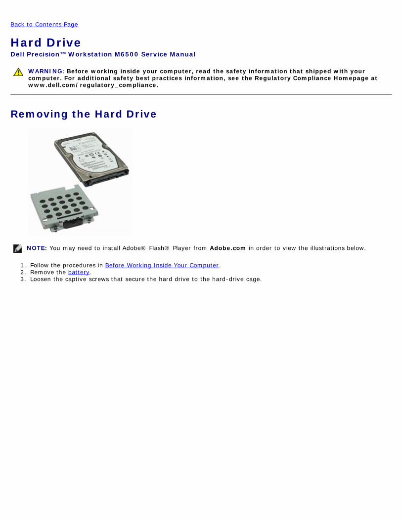
Hard DriveDell Precisiontrade Workstation M6500 Service Manual
WARNING Before working inside your computer read the safety information that shipped with yourcomputer For additional safety best practices information see the Regulatory Compliance Homepage atwwwdellcomregulatory_compliance
Removing the Hard Drive
NOTE You may need to install Adobereg Flashreg Player from Adobecom in order to view the illustrations below
1 Follow the procedures in Before Working Inside Your Computer2 Remove the battery3 Loosen the captive screws that secure the hard drive to the hard-drive cage
4 Pull the release tab to release the hard-drive cage from the computer
5 Remove the hard-drive cage from the computer
6 Slide the hard drive away from the computer
7 Using the black pull-tab lift the hard drive up and remove it from the computer
8 Remove the screws that secure the black pull-tab bar to the hard drive
9 Remove the black pull-tab bar from the hard drive
Replacing the Hard DriveTo replace the hard drive perform the above steps in reverse order
Back to Contents Page
Back to Contents Page
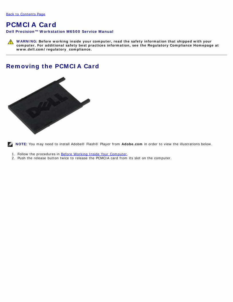
PCMCIA CardDell Precisiontrade Workstation M6500 Service Manual
WARNING Before working inside your computer read the safety information that shipped with yourcomputer For additional safety best practices information see the Regulatory Compliance Homepage atwwwdellcomregulatory_compliance
Removing the PCMCIA Card
NOTE You may need to install Adobereg Flashreg Player from Adobecom in order to view the illustrations below
1 Follow the procedures in Before Working Inside Your Computer2 Push the release button twice to release the PCMCIA card from its slot on the computer
3 Pull the PCMCIA card from the computer
Replacing the PCMCIA CardTo replace the PCMCIA card perform the above steps in reverse order
Back to Contents Page
Back to Contents Page
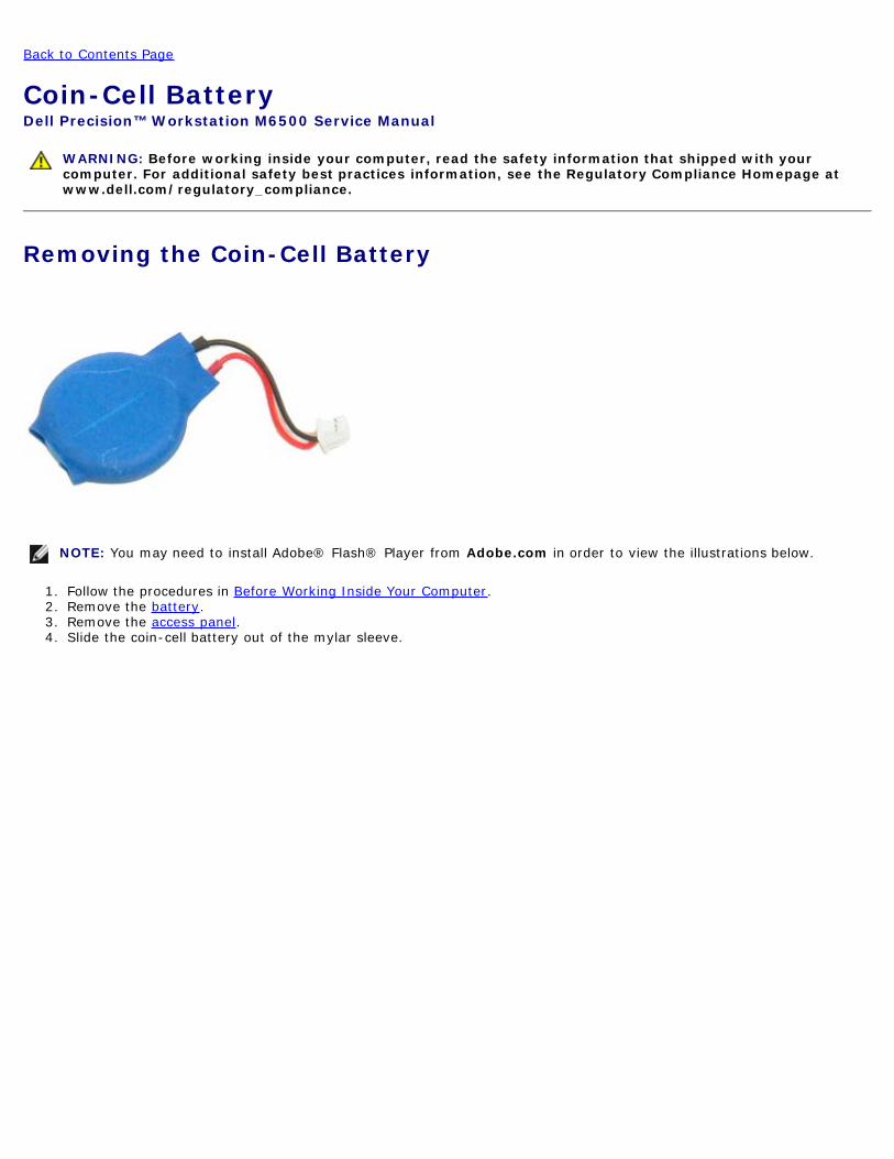
Coin-Cell BatteryDell Precisiontrade Workstation M6500 Service Manual
WARNING Before working inside your computer read the safety information that shipped with yourcomputer For additional safety best practices information see the Regulatory Compliance Homepage atwwwdellcomregulatory_compliance
Removing the Coin-Cell Battery
NOTE You may need to install Adobereg Flashreg Player from Adobecom in order to view the illustrations below
1 Follow the procedures in Before Working Inside Your Computer2 Remove the battery3 Remove the access panel4 Slide the coin-cell battery out of the mylar sleeve
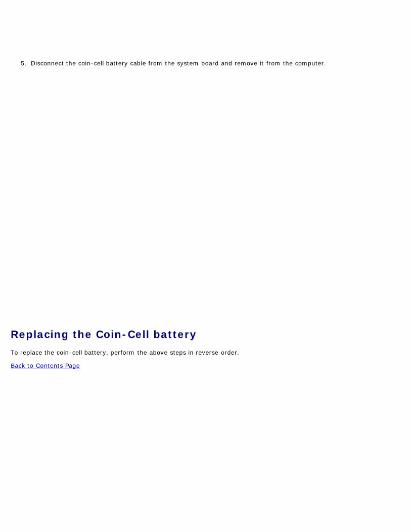
5 Disconnect the coin-cell battery cable from the system board and remove it from the computer
Replacing the Coin-Cell batteryTo replace the coin-cell battery perform the above steps in reverse order
Back to Contents Page
Back to Contents Page
Hard DriveDell Precisiontrade Workstation M6500 Service Manual
WARNING Before working inside your computer read the safety information that shipped with yourcomputer For additional safety best practices information see the Regulatory Compliance Homepage atwwwdellcomregulatory_compliance
Removing the Hard Drive
NOTE You may need to install Adobereg Flashreg Player from Adobecom in order to view the illustrations below
1 Follow the procedures in Before Working Inside Your Computer2 Remove the battery3 Loosen the captive screws that secure the hard drive to the hard-drive cage
4 Pull the release tab to release the hard-drive cage from the computer
5 Remove the hard-drive cage from the computer
6 Slide the hard drive away from the computer
7 Using the black pull-tab lift the hard drive up and remove it from the computer
8 Remove the screws that secure the black pull-tab bar to the hard drive
9 Remove the black pull-tab bar from the hard drive
Replacing the Hard DriveTo replace the hard drive perform the above steps in reverse order
Back to Contents Page
Back to Contents Page
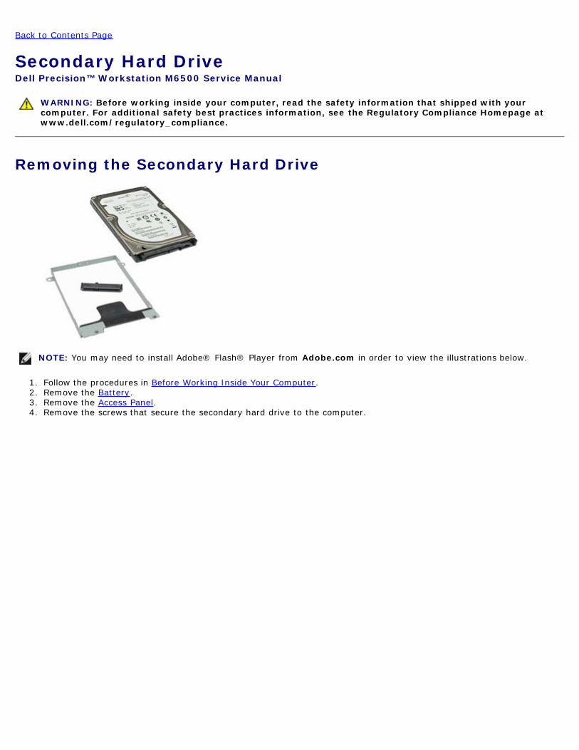
Secondary Hard DriveDell Precisiontrade Workstation M6500 Service Manual
WARNING Before working inside your computer read the safety information that shipped with yourcomputer For additional safety best practices information see the Regulatory Compliance Homepage atwwwdellcomregulatory_compliance
Removing the Secondary Hard Drive
NOTE You may need to install Adobereg Flashreg Player from Adobecom in order to view the illustrations below
1 Follow the procedures in Before Working Inside Your Computer2 Remove the Battery3 Remove the Access Panel4 Remove the screws that secure the secondary hard drive to the computer
5 Pull the black tab to lift the hard drive up and away from the computer
6 Remove the screws on either sides of the hard drive to release the hard-drive bracket from the hard drive
7 Remove the hard-drive bracket from the hard drive
8 Remove the hard-drive interposer from the hard drive
Replacing the Secondary Hard DriveTo replace the secondary hard drive perform the above steps in reverse order
Back to Contents Page
Back to Contents Page
Wireless Wide Area Network (WWAN) CardDell Precisiontrade Workstation M6500 Service Manual
WARNING Before working inside your computer read the safety information that shipped with yourcomputer For additional safety best practices information see the Regulatory Compliance Homepage atwwwdellcomregulatory_compliance
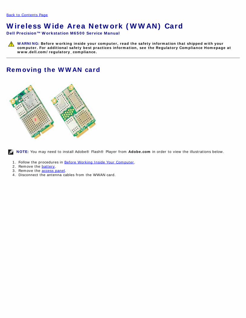
Removing the WWAN card
NOTE You may need to install Adobereg Flashreg Player from Adobecom in order to view the illustrations below
1 Follow the procedures in Before Working Inside Your Computer2 Remove the battery3 Remove the access panel4 Disconnect the antenna cables from the WWAN card
5 Remove the screw that secures the WWAN card to the system boardThe card pops up at a 45-degree angle
6 Slide the WWAN card out of the connector on the system board
Replacing the WWAN CardTo replace the WWAN card perform the above steps in reverse order
Back to Contents Page
Back to Contents Page
Flash Cache Module (FCM)Dell Precisiontrade Workstation M6500 Service Manual
WARNING Before working inside your computer read the safety information that shipped with yourcomputer For additional safety best practices information see the Regulatory Compliance Homepage atwwwdellcomregulatory_compliance
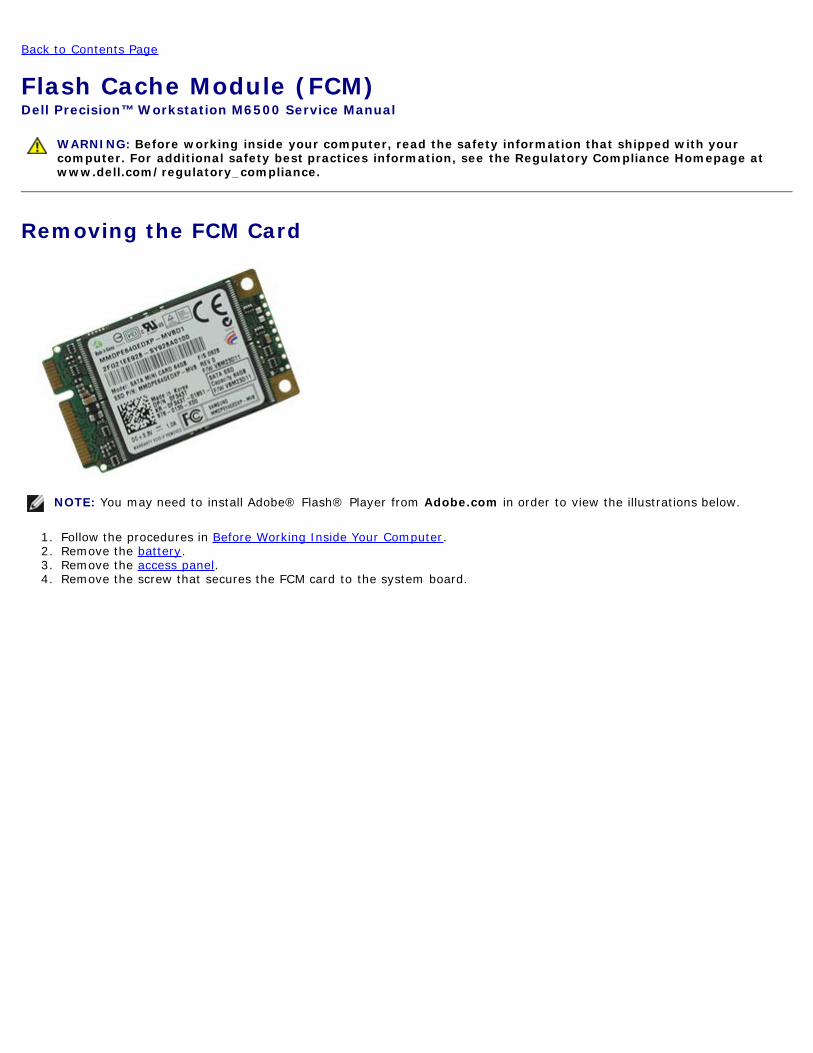
Removing the FCM Card
NOTE You may need to install Adobereg Flashreg Player from Adobecom in order to view the illustrations below
1 Follow the procedures in Before Working Inside Your Computer2 Remove the battery3 Remove the access panel4 Remove the screw that secures the FCM card to the system board
5 Pull the FCM card away from the computer
Replacing the FCM CardTo replace the FCM card perform the above steps in reverse order
Back to Contents Page
Back to Contents Page
MemoryDell Precisiontrade Workstation M6500 Service Manual
WARNING Before working inside your computer read the safety information that shipped with yourcomputer For additional safety best practices information see the Regulatory Compliance Homepage atwwwdellcomregulatory_compliance
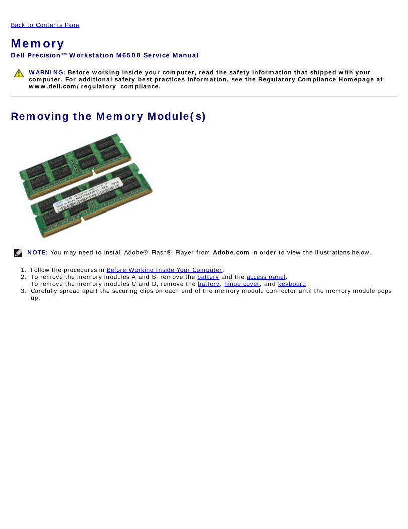
Removing the Memory Module(s)
NOTE You may need to install Adobereg Flashreg Player from Adobecom in order to view the illustrations below
1 Follow the procedures in Before Working Inside Your Computer2 To remove the memory modules A and B remove the battery and the access panel
To remove the memory modules C and D remove the battery hinge cover and keyboard3 Carefully spread apart the securing clips on each end of the memory module connector until the memory module pops
up
4 Remove the memory module from the connector
Replacing the Memory Module(s)To replace the memory module(s) perform the above steps in reverse order
Back to Contents Page
Back to Contents Page
CameraDell Precisiontrade Workstation M6500 Service Manual
WARNING Before working inside your computer read the safety information that shipped with yourcomputer For additional safety best practices information see the Regulatory Compliance Homepage atwwwdellcomregulatory_compliance
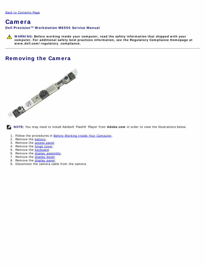
Removing the Camera
NOTE You may need to install Adobereg Flashreg Player from Adobecom in order to view the illustrations below
1 Follow the procedures in Before Working Inside Your Computer2 Remove the battery3 Remove the access panel4 Remove the hinge cover5 Remove the keyboard6 Remove the display assembly7 Remove the display bezel8 Remove the display panel9 Disconnect the camera cable from the camera
10 Remove the screws that secure the camera to the display assembly
11 Remove the camera from the display assembly
Replacing the CameraTo replace the camera perform the above steps in reverse order
Back to Contents Page
Back to Contents Page
PCMCIA Card CageDell Precisiontrade Workstation M6500 Service Manual
WARNING Before working inside your computer read the safety information that shipped with yourcomputer For additional safety best practices information see the Regulatory Compliance Homepage atwwwdellcomregulatory_compliance
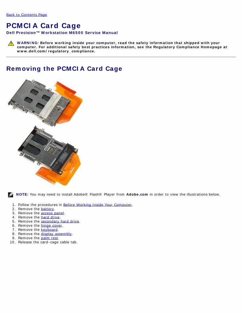
Removing the PCMCIA Card Cage
NOTE You may need to install Adobereg Flashreg Player from Adobecom in order to view the illustrations below
1 Follow the procedures in Before Working Inside Your Computer2 Remove the battery3 Remove the access panel4 Remove the hard drive5 Remove the secondary hard drive6 Remove the hinge cover7 Remove the keyboard8 Remove the display assembly9 Remove the palm rest
10 Release the card-cage cable tab
11 Disconnect the card cage cable from the system board
12 Remove the screws that secure the card cage to the computer
13 Remove the card cage from the computer
Replacing the PCMCIA Card CageTo replace the PCMCIA card cage perform the above steps in reverse order
Back to Contents Page
Back to Contents Page
Heat SinkDell Precision Workstation M6500 Service Manual
WARNING Before working inside your computer read the safety information that shipped with yourcomputer For additional safety best practices information see the Regulatory Compliance Homepage atwwwdellcomregulatory_compliance
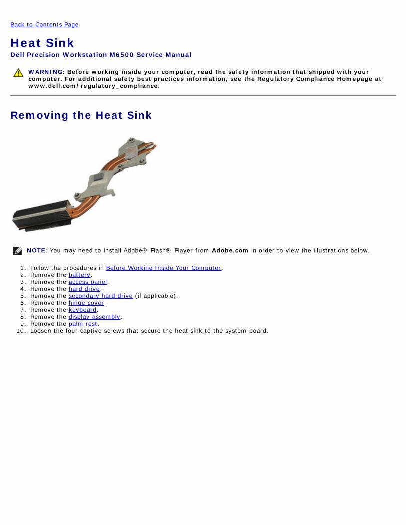
Removing the Heat Sink
NOTE You may need to install Adobereg Flashreg Player from Adobecom in order to view the illustrations below
1 Follow the procedures in Before Working Inside Your Computer2 Remove the battery3 Remove the access panel4 Remove the hard drive5 Remove the secondary hard drive (if applicable)6 Remove the hinge cover7 Remove the keyboard8 Remove the display assembly9 Remove the palm rest
10 Loosen the four captive screws that secure the heat sink to the system board
11 Remove the heat sink from the computer
Replacing the Heat SinkTo replace the heat sink perform the above steps in reverse order
Back to Contents Page
Back to Contents Page
ProcessorDell Precisiontrade Workstation M6500 Service Manual
WARNING Before working inside your computer read the safety information that shipped with yourcomputer For additional safety best practices information see the Regulatory Compliance Homepage atwwwdellcomregulatory_compliance
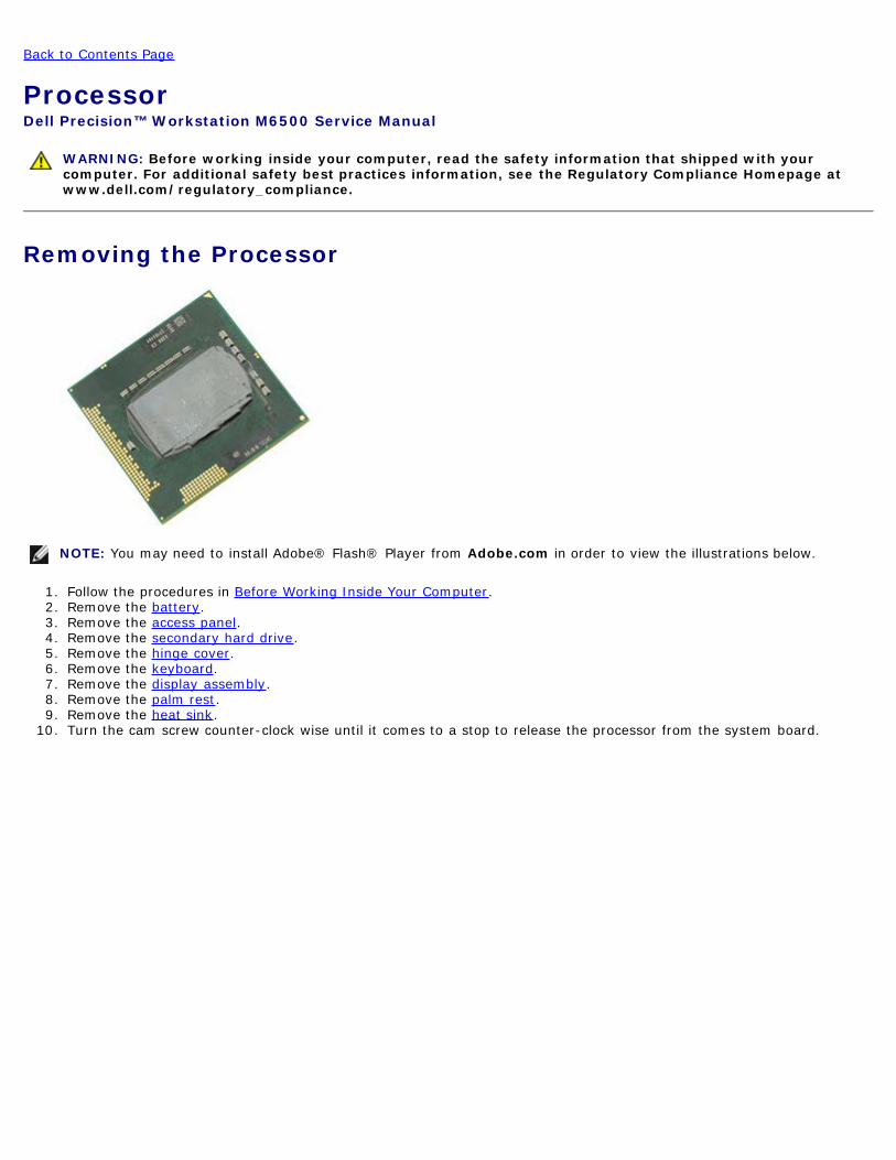
Removing the Processor
NOTE You may need to install Adobereg Flashreg Player from Adobecom in order to view the illustrations below
1 Follow the procedures in Before Working Inside Your Computer2 Remove the battery3 Remove the access panel4 Remove the secondary hard drive5 Remove the hinge cover6 Remove the keyboard7 Remove the display assembly8 Remove the palm rest9 Remove the heat sink
10 Turn the cam screw counter-clock wise until it comes to a stop to release the processor from the system board
11 Carefully lift the processor straight up from the slot and remove the processor from the computer
Replacing the ProcessorTo replace the processor perform the above steps in reverse order
Back to Contents Page
Back to Contents Page
System BoardDell Precisiontrade Workstation M6500 Service Manual
WARNING Before working inside your computer read the safety information that shipped with yourcomputer For additional safety best practices information see the Regulatory Compliance Homepage atwwwdellcomregulatory_compliance
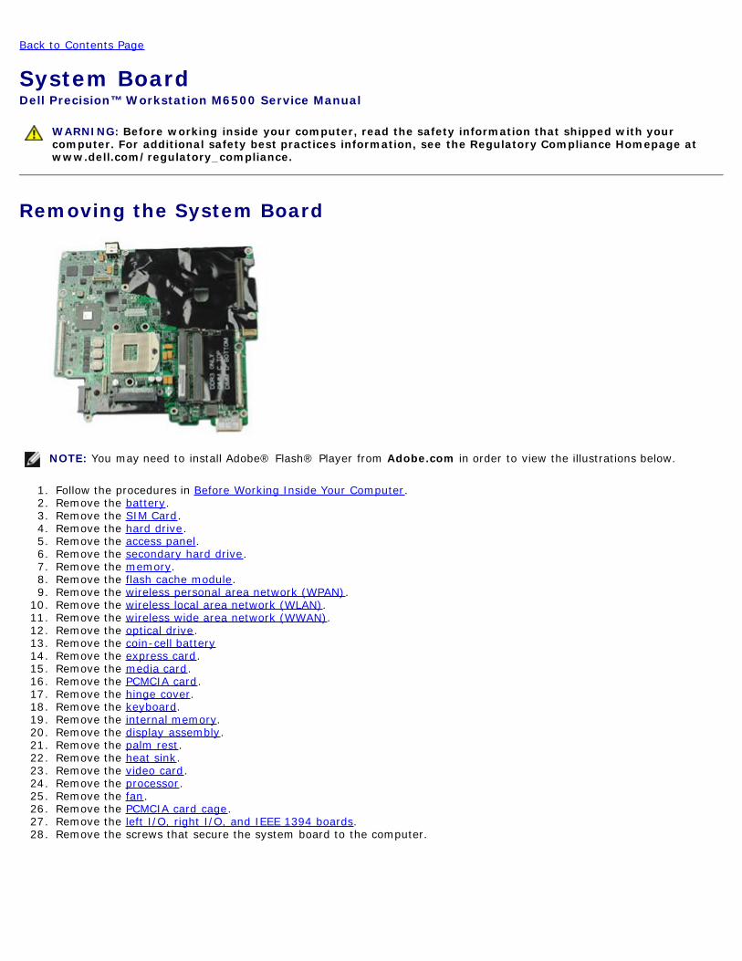
Removing the System Board
NOTE You may need to install Adobereg Flashreg Player from Adobecom in order to view the illustrations below
1 Follow the procedures in Before Working Inside Your Computer2 Remove the battery3 Remove the SIM Card4 Remove the hard drive5 Remove the access panel6 Remove the secondary hard drive7 Remove the memory8 Remove the flash cache module9 Remove the wireless personal area network (WPAN)
10 Remove the wireless local area network (WLAN)11 Remove the wireless wide area network (WWAN)12 Remove the optical drive13 Remove the coin-cell battery14 Remove the express card15 Remove the media card16 Remove the PCMCIA card17 Remove the hinge cover18 Remove the keyboard19 Remove the internal memory20 Remove the display assembly21 Remove the palm rest22 Remove the heat sink23 Remove the video card24 Remove the processor25 Remove the fan26 Remove the PCMCIA card cage27 Remove the left IO right IO and IEEE 1394 boards28 Remove the screws that secure the system board to the computer
29 Remove the system board from the computer
Replacing the System BoardTo replace the system board perform the above steps in reverse order
Back to Contents Page
Back to Contents Page
SIM CardDell Precisiontrade Workstation M6500 Service Manual
WARNING Before working inside your computer read the safety information that shipped with yourcomputer For additional safety best practices information see the Regulatory Compliance Homepage atwwwdellcomregulatory_compliance
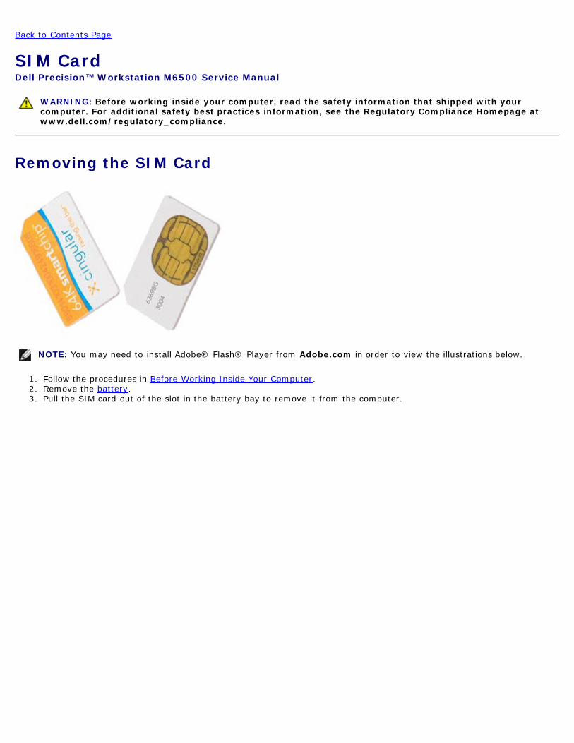
Removing the SIM Card
NOTE You may need to install Adobereg Flashreg Player from Adobecom in order to view the illustrations below
1 Follow the procedures in Before Working Inside Your Computer2 Remove the battery3 Pull the SIM card out of the slot in the battery bay to remove it from the computer
Replacing the SIM CardTo replace the SIM card perform the above steps in reverse order
Back to Contents Page
Back to Contents Page
Media CardDell Precisiontrade Workstation M6500 Service Manual
WARNING Before working inside your computer read the safety information that shipped with yourcomputer For additional safety best practices information see the Regulatory Compliance Homepage atwwwdellcomregulatory_compliance
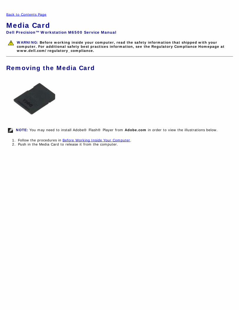
Removing the Media Card
NOTE You may need to install Adobereg Flashreg Player from Adobecom in order to view the illustrations below
1 Follow the procedures in Before Working Inside Your Computer2 Push in the Media Card to release it from the computer
3 Pull the Media Card out to remove it from the computer
Replacing the Media CardTo replace the Media Card perform the above steps in reverse order
Back to Contents Page
Back to Contents Page
Access PanelDell Precisiontrade Workstation M6500 Service Manual
WARNING Before working inside your computer read the safety information that shipped with yourcomputer For additional safety best practices information see the Regulatory Compliance Homepage atwwwdellcomregulatory_compliance
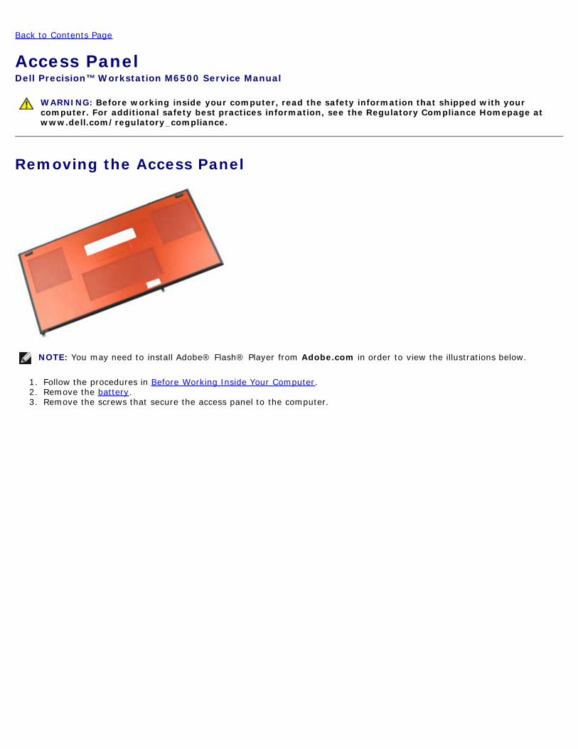
Removing the Access Panel
NOTE You may need to install Adobereg Flashreg Player from Adobecom in order to view the illustrations below
1 Follow the procedures in Before Working Inside Your Computer2 Remove the battery3 Remove the screws that secure the access panel to the computer
4 Slide the access panel towards the battery compartment
5 Pull the access panel away from the computer
Replacing the Access PanelTo replace the access panel perform the above steps in reverse order
Back to Contents Page
Back to Contents Page
Hinge CoverDell Precisiontrade Workstation M6500 Service Manual
WARNING Before working inside your computer read the safety information that shipped with yourcomputer For additional safety best practices information see the Regulatory Compliance Homepage atwwwdellcomregulatory_compliance
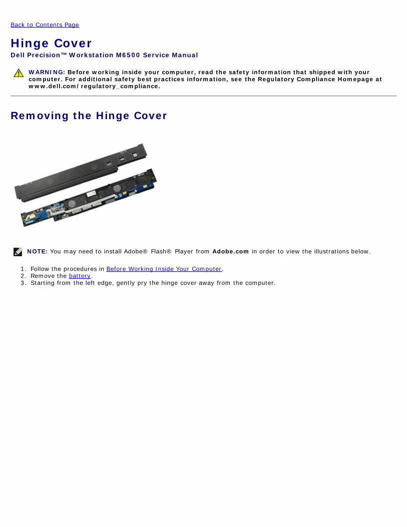
Removing the Hinge Cover
NOTE You may need to install Adobereg Flashreg Player from Adobecom in order to view the illustrations below
1 Follow the procedures in Before Working Inside Your Computer2 Remove the battery3 Starting from the left edge gently pry the hinge cover away from the computer
4 Flip the hinge cover over and place it on the keyboard
5 Disconnect the cables that connect the hinge cover to the computer
6 Remove the hinge cover from the computer
Replacing the Hinge CoverTo replace the hinge cover perform the above steps in reverse order
Back to Contents Page
Back to Contents Page
Optical DriveDell Precisiontrade Workstation M6500 Service Manual
WARNING Before working inside your computer read the safety information that shipped with yourcomputer For additional safety best practices information see the Regulatory Compliance Homepage atwwwdellcomregulatory_compliance
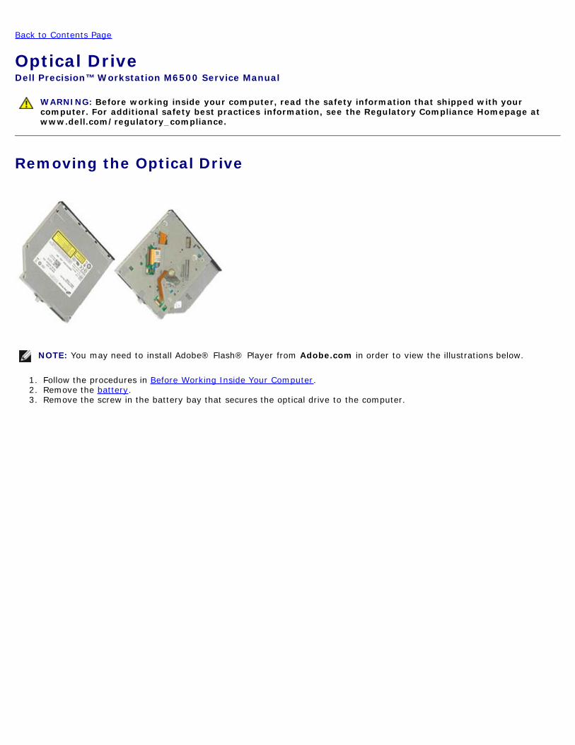
Removing the Optical Drive
NOTE You may need to install Adobereg Flashreg Player from Adobecom in order to view the illustrations below
1 Follow the procedures in Before Working Inside Your Computer2 Remove the battery3 Remove the screw in the battery bay that secures the optical drive to the computer
4 Using a screwdriver or a small plastic scribe nudge the optical drive towards the outside edge of the computer
5 Pull the optical drive out of the optical-drive bay and away from the computer
Replacing the Optical DriveTo replace the optical drive perform the above steps in reverse order
Back to Contents Page
Back to Contents Page
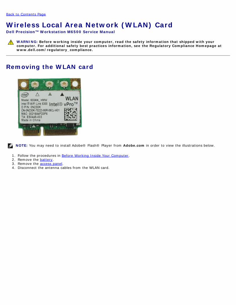
Wireless Local Area Network (WLAN) CardDell Precisiontrade Workstation M6500 Service Manual
WARNING Before working inside your computer read the safety information that shipped with yourcomputer For additional safety best practices information see the Regulatory Compliance Homepage atwwwdellcomregulatory_compliance
Removing the WLAN card
NOTE You may need to install Adobereg Flashreg Player from Adobecom in order to view the illustrations below
1 Follow the procedures in Before Working Inside Your Computer2 Remove the battery3 Remove the access panel4 Disconnect the antenna cables from the WLAN card
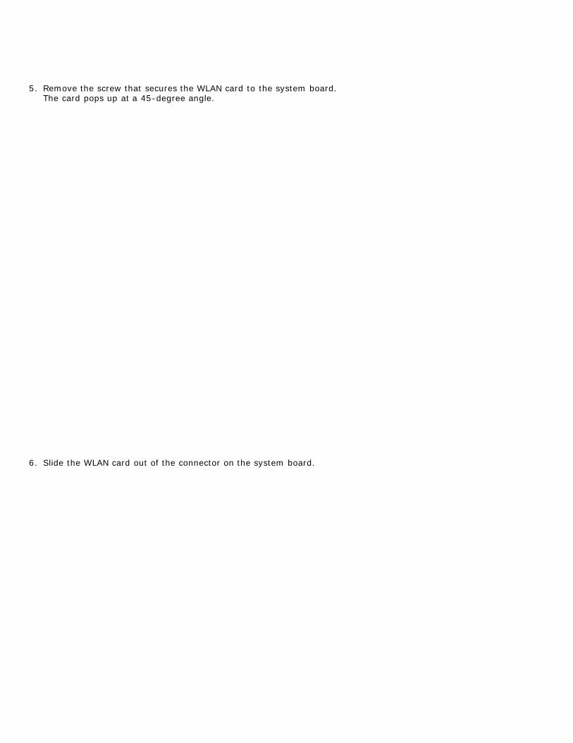
5 Remove the screw that secures the WLAN card to the system boardThe card pops up at a 45-degree angle
6 Slide the WLAN card out of the connector on the system board
Replacing the WLAN CardTo replace the WLAN card perform the above steps in reverse order
Back to Contents Page
Back to Contents Page
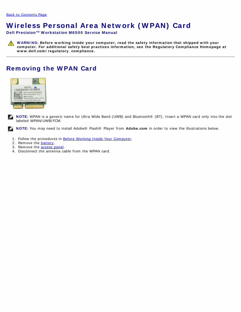
Wireless Personal Area Network (WPAN) CardDell Precisiontrade Workstation M6500 Service Manual
WARNING Before working inside your computer read the safety information that shipped with yourcomputer For additional safety best practices information see the Regulatory Compliance Homepage atwwwdellcomregulatory_compliance
Removing the WPAN Card
NOTE WPAN is a generic name for Ultra Wide Band (UWB) and Bluetoothreg (BT) Insert a WPAN card only into the slotlabeled WPANUWBFCM
NOTE You may need to install Adobereg Flashreg Player from Adobecom in order to view the illustrations below
1 Follow the procedures in Before Working Inside Your Computer2 Remove the battery3 Remove the access panel4 Disconnect the antenna cable from the WPAN card
5 Remove the screw that secures the card to the computer The card pops up at a 45-degree angle
6 Slide the WPAN card out of the connector on the system board
Replacing the WPAN CardTo replace the WPAN card perform the above steps in reverse order
Back to Contents Page
Back to Contents Page
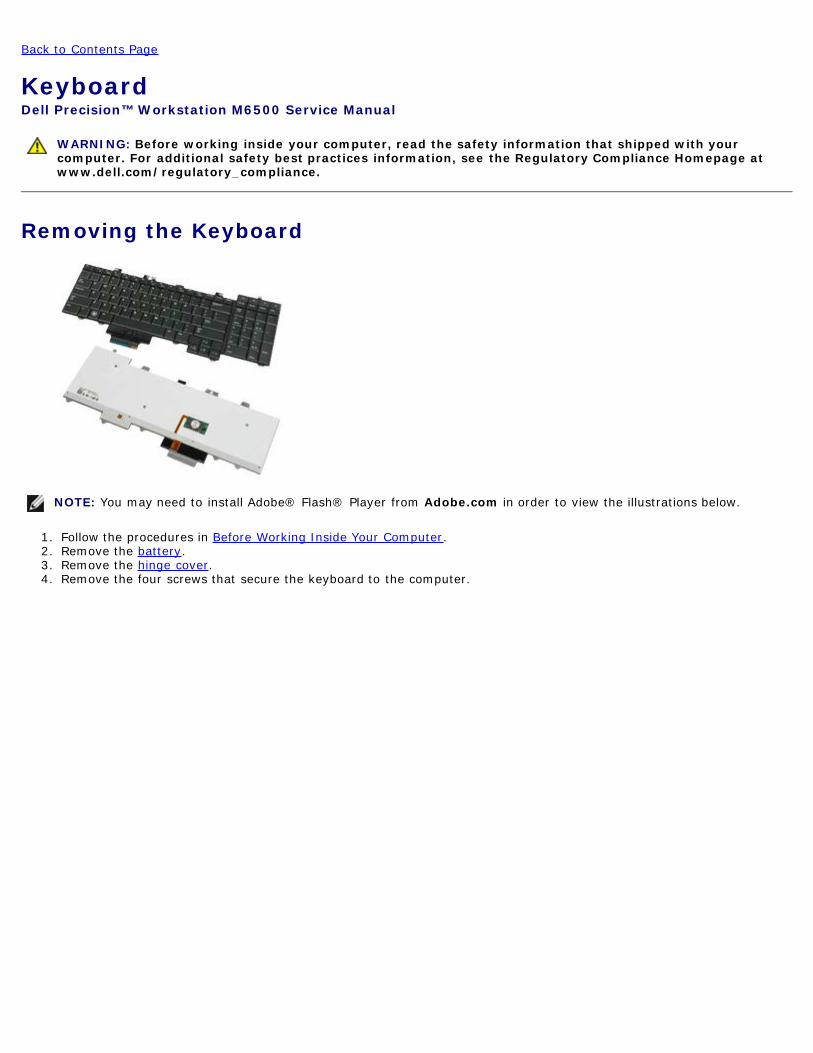
KeyboardDell Precisiontrade Workstation M6500 Service Manual
WARNING Before working inside your computer read the safety information that shipped with yourcomputer For additional safety best practices information see the Regulatory Compliance Homepage atwwwdellcomregulatory_compliance
Removing the Keyboard
NOTE You may need to install Adobereg Flashreg Player from Adobecom in order to view the illustrations below
1 Follow the procedures in Before Working Inside Your Computer2 Remove the battery3 Remove the hinge cover4 Remove the four screws that secure the keyboard to the computer
5 Slide the keyboard towards the display to disconnect it from the system board
6 Remove the keyboard from the computer
Replacing the KeyboardTo replace the keyboard perform the above steps in reverse order
Back to Contents Page
Back to Contents Page
Display AssemblyDell Precisiontrade Workstation M6500 Service Manual
WARNING Before working inside your computer read the safety information that shipped with yourcomputer For additional safety best practices information see the Regulatory Compliance Homepage atwwwdellcomregulatory_compliance
Removing the Display Assembly
Replacing the Display Assembly
Removing the Display Bezel
Replacing the Display Bezel
Removing the Display Panel
Replacing the Display Panel
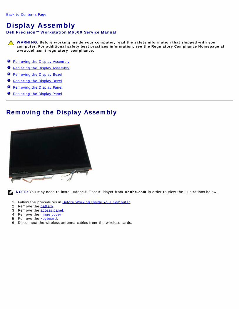
Removing the Display Assembly
NOTE You may need to install Adobereg Flashreg Player from Adobecom in order to view the illustrations below
1 Follow the procedures in Before Working Inside Your Computer2 Remove the battery3 Remove the access panel4 Remove the hinge cover5 Remove the keyboard6 Disconnect the wireless antenna cables from the wireless cards
7 Remove the wireless antenna cables from their routing guides
8 Remove the four screws that secure the display assembly to the computer
9 Turn over the computer and open the display10 Disconnect the two display cables from the connectors on the system board
11 Remove the screw that secures the display assembly to the computer
12 Loosen the captive screw and remove the cable retention bar that secures the display assembly to the computer
13 Disconnect the display cable from the connector on the computer
14 Remove the antenna cables from their routing guides
15 Remove the screws that secure the display assembly to the computer
16 Remove the display assembly from the computer
Replacing the Display AssemblyTo replace the display assembly perform the above steps in reverse order
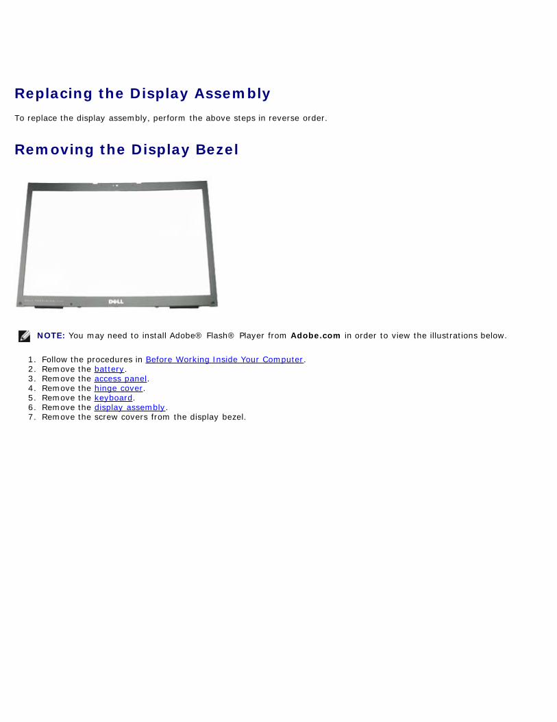
Removing the Display Bezel
NOTE You may need to install Adobereg Flashreg Player from Adobecom in order to view the illustrations below
1 Follow the procedures in Before Working Inside Your Computer2 Remove the battery3 Remove the access panel4 Remove the hinge cover5 Remove the keyboard6 Remove the display assembly7 Remove the screw covers from the display bezel
8 Remove the screws that secure the display bezel to the display panel
9 Gently pry the display bezel away from the display panel by rolling your fingers between the edge of the bezel anddisplay panel
10 Remove the display bezel from the display panel
Replacing the Display BezelTo replace the display bezel perform the above steps in reverse order
Removing the Display Panel
NOTE You may need to install Adobereg Flashreg Player from Adobecom in order to view the illustrations below
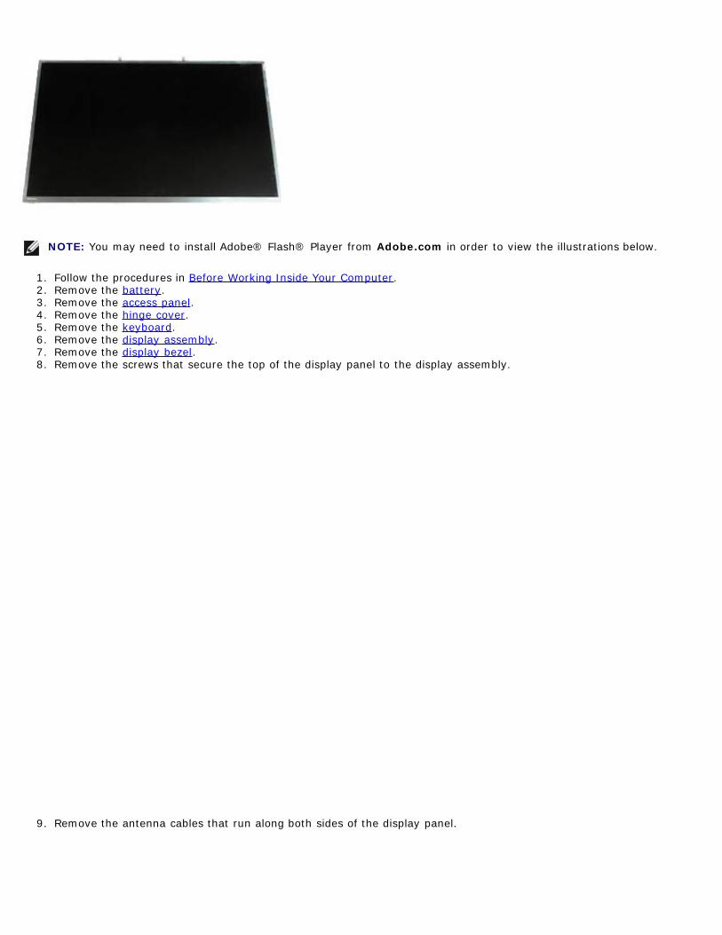
1 Follow the procedures in Before Working Inside Your Computer2 Remove the battery3 Remove the access panel4 Remove the hinge cover5 Remove the keyboard6 Remove the display assembly7 Remove the display bezel8 Remove the screws that secure the top of the display panel to the display assembly
9 Remove the antenna cables that run along both sides of the display panel
10 Remove the screws on either sides of the display panel
11 Peel the tape that secures the flex cable to the display panel
12 Use the display connector release tabs to disconnect the display cable from the display
13 Remove the display panel from the display assembly
Replacing the Display PanelTo replace the display panel perform the above steps in reverse order
Back to Contents Page
Back to Contents Page
Palm RestDell Precisiontrade Workstation M6500 Service Manual
WARNING Before working inside your computer read the safety information that shipped with yourcomputer For additional safety best practices information see the Regulatory Compliance Homepage atwwwdellcomregulatory_compliance
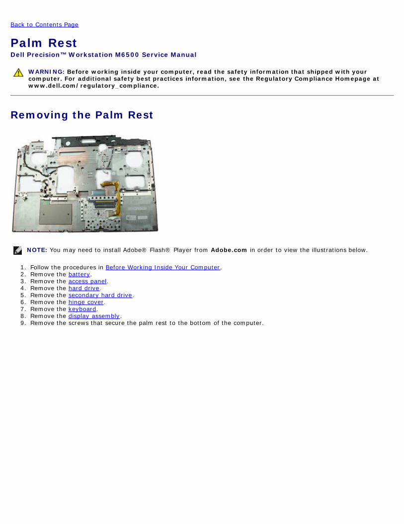
Removing the Palm Rest
NOTE You may need to install Adobereg Flashreg Player from Adobecom in order to view the illustrations below
1 Follow the procedures in Before Working Inside Your Computer2 Remove the battery3 Remove the access panel4 Remove the hard drive5 Remove the secondary hard drive6 Remove the hinge cover7 Remove the keyboard8 Remove the display assembly9 Remove the screws that secure the palm rest to the bottom of the computer
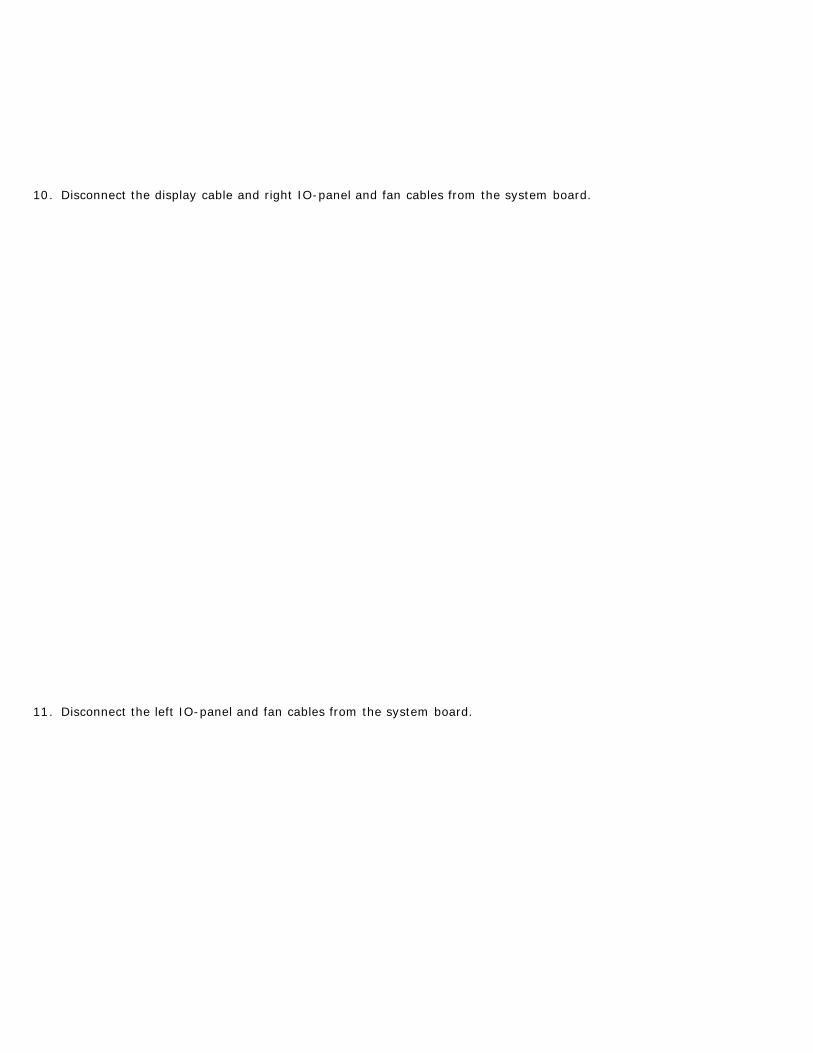
10 Disconnect the display cable and right IO-panel and fan cables from the system board
11 Disconnect the left IO-panel and fan cables from the system board
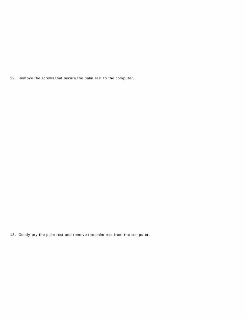
12 Remove the screws that secure the palm rest to the computer
13 Gently pry the palm rest and remove the palm rest from the computer
Replacing the Palm RestTo replace the palm rest perform the above steps in reverse order
Back to Contents Page
Back to Contents Page
IO and IEEE 1394 BoardDell Precisiontrade Workstation M6500 Service Manual
WARNING Before working inside your computer read the safety information that shipped with yourcomputer For additional safety best practices information see the Regulatory Compliance Homepage atwwwdellcomregulatory_compliance
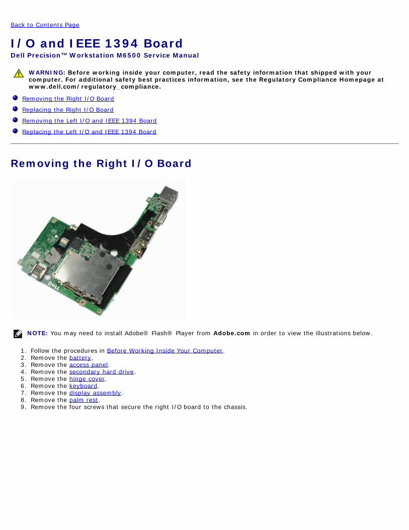
Removing the Right IO Board
Replacing the Right IO Board
Removing the Left IO and IEEE 1394 Board
Replacing the Left IO and IEEE 1394 Board
Removing the Right IO Board
NOTE You may need to install Adobereg Flashreg Player from Adobecom in order to view the illustrations below
1 Follow the procedures in Before Working Inside Your Computer2 Remove the battery3 Remove the access panel4 Remove the secondary hard drive5 Remove the hinge cover6 Remove the keyboard7 Remove the display assembly8 Remove the palm rest9 Remove the four screws that secure the right IO board to the chassis
10 Lift the right IO board up and away from the computer
Replacing the Right IO BoardTo replace the right IO board perform the above steps in reverse order
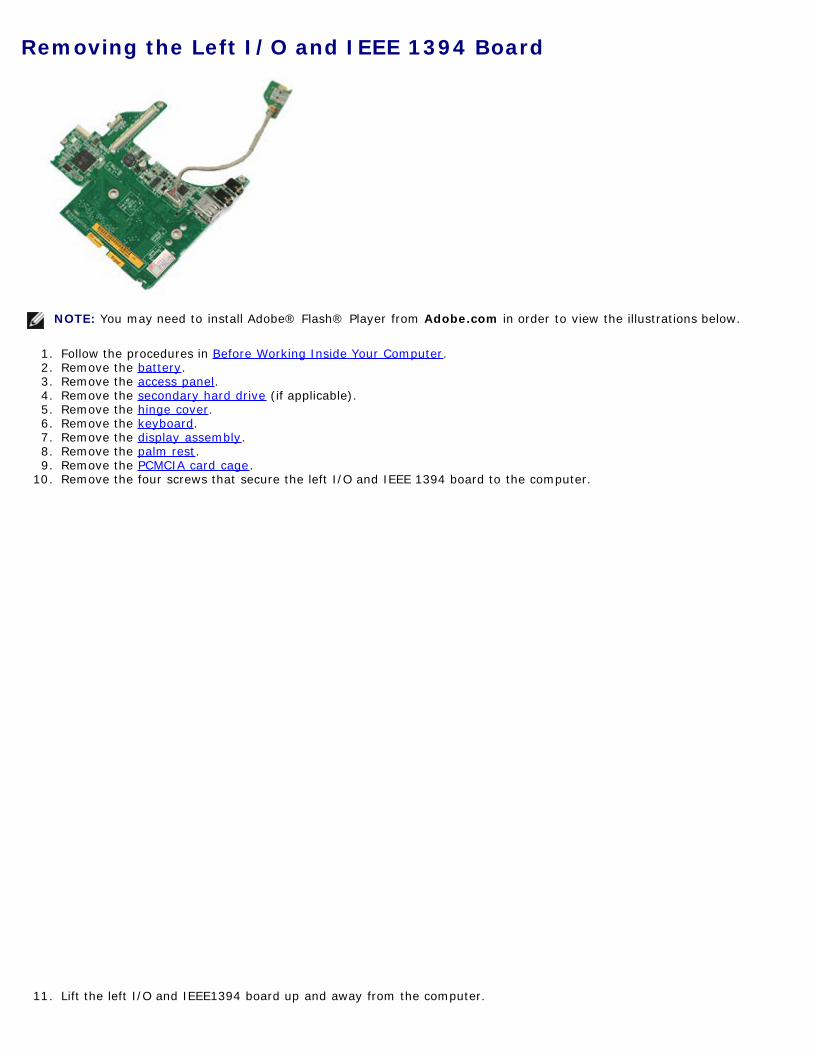
Removing the Left IO and IEEE 1394 Board
NOTE You may need to install Adobereg Flashreg Player from Adobecom in order to view the illustrations below
1 Follow the procedures in Before Working Inside Your Computer2 Remove the battery3 Remove the access panel4 Remove the secondary hard drive (if applicable)5 Remove the hinge cover6 Remove the keyboard7 Remove the display assembly8 Remove the palm rest9 Remove the PCMCIA card cage
10 Remove the four screws that secure the left IO and IEEE 1394 board to the computer
11 Lift the left IO and IEEE1394 board up and away from the computer
12 Disconnect the cable that connects the IEEE 1394 board to the left IO board
Replacing the Left IO and IEEE 1394 BoardTo replace the left IO and IEEE 1394 board perform the above steps in reverse order
Back to Contents Page
Back to Contents Page
FanDell Precisiontrade Workstation M6500 Service Manual
WARNING Before working inside your computer read the safety information that shipped with yourcomputer For additional safety best practices information see the Regulatory Compliance Homepage atwwwdellcomregulatory_compliance
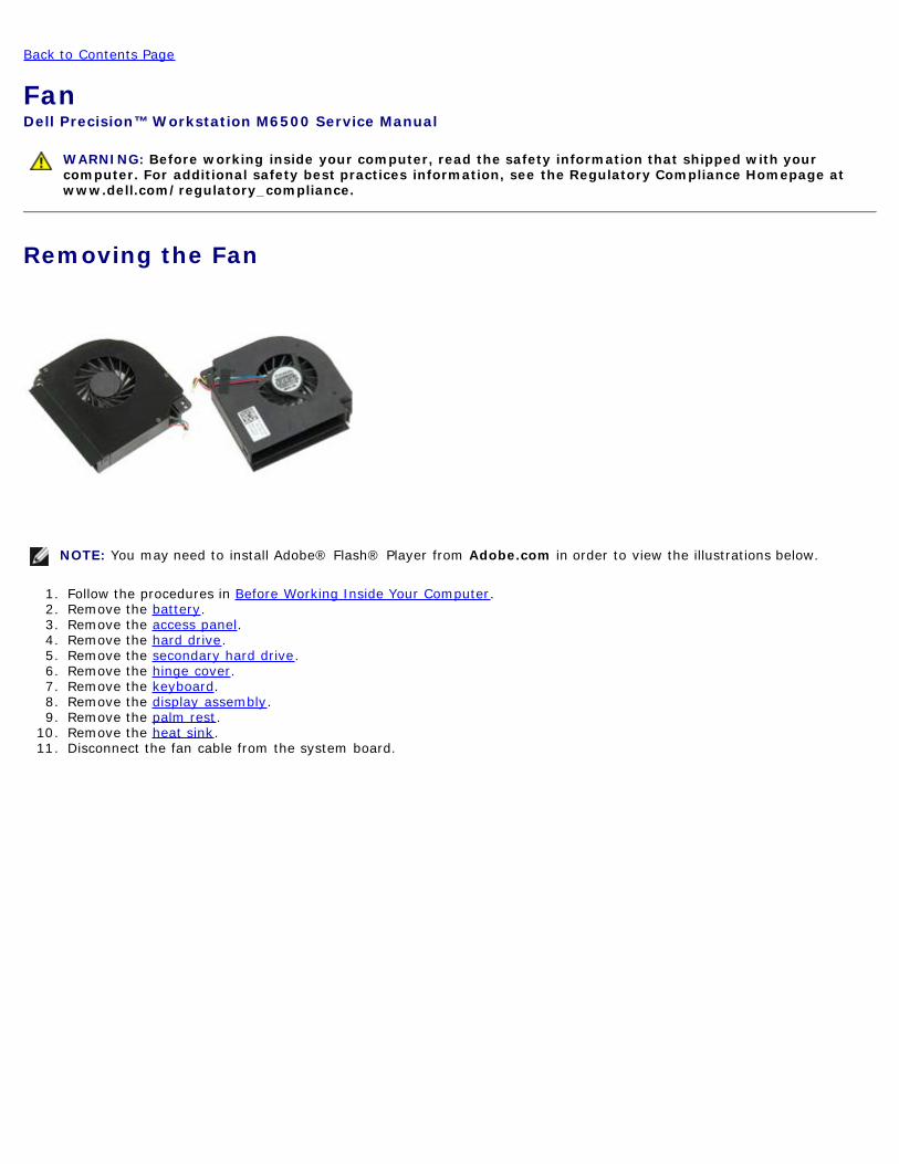
Removing the Fan
NOTE You may need to install Adobereg Flashreg Player from Adobecom in order to view the illustrations below
1 Follow the procedures in Before Working Inside Your Computer2 Remove the battery3 Remove the access panel4 Remove the hard drive5 Remove the secondary hard drive6 Remove the hinge cover7 Remove the keyboard8 Remove the display assembly9 Remove the palm rest
10 Remove the heat sink11 Disconnect the fan cable from the system board
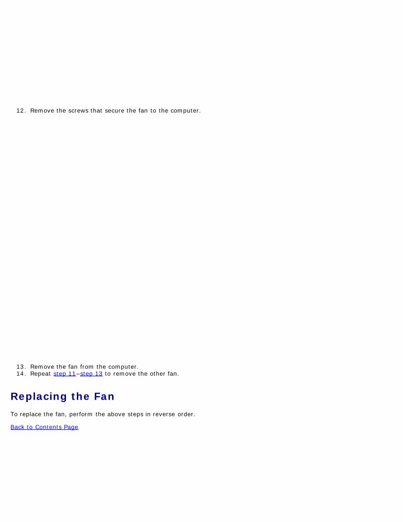
12 Remove the screws that secure the fan to the computer
13 Remove the fan from the computer14 Repeat step 11ndashstep 13 to remove the other fan
Replacing the FanTo replace the fan perform the above steps in reverse order
Back to Contents Page
Back to Contents Page
Video-Card AssemblyDell Precisiontrade Workstation M6500 Service Manual
WARNING Before working inside your computer read the safety information that shipped with yourcomputer For additional safety best practices information see the Regulatory Compliance Homepage atwwwdellcomregulatory_compliance
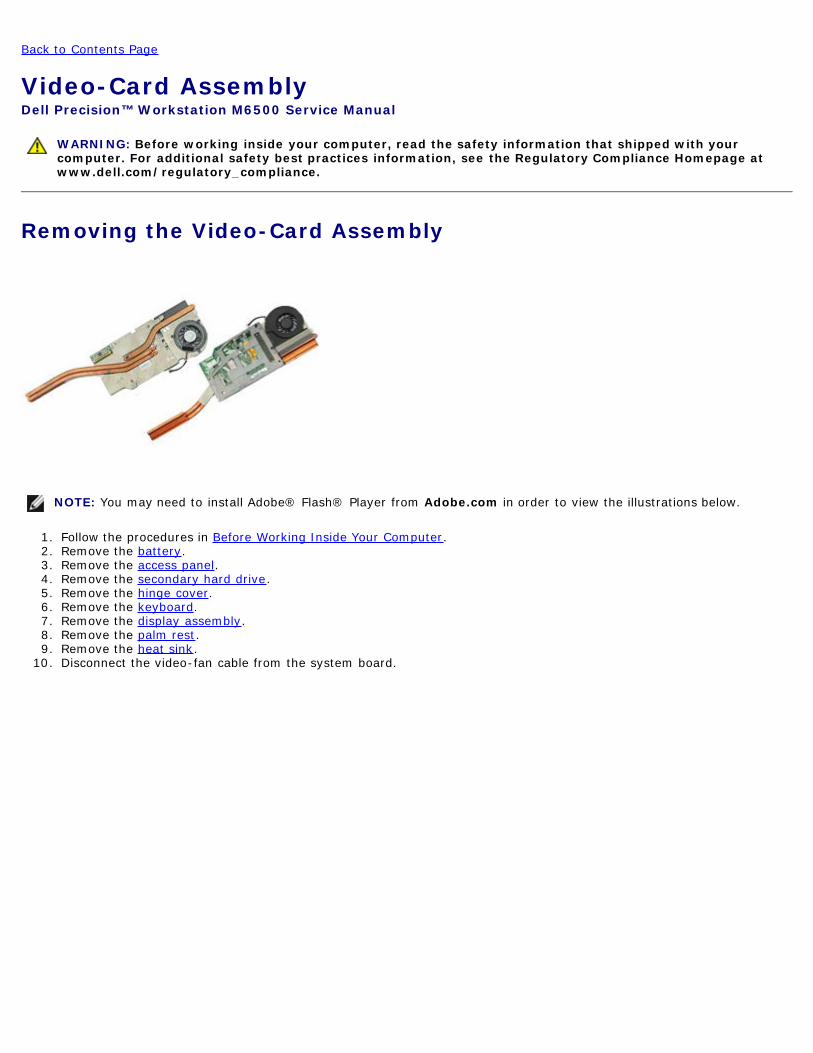
Removing the Video-Card Assembly
NOTE You may need to install Adobereg Flashreg Player from Adobecom in order to view the illustrations below
1 Follow the procedures in Before Working Inside Your Computer2 Remove the battery3 Remove the access panel4 Remove the secondary hard drive5 Remove the hinge cover6 Remove the keyboard7 Remove the display assembly8 Remove the palm rest9 Remove the heat sink
10 Disconnect the video-fan cable from the system board
11 Loosen the captive screws that secure the video-card assembly to the computer
12 Remove the video-card assembly from the computer
Replacing the Video-Card AssemblyTo replace the video-card assembly perform the above steps in reverse order
Back to Contents Page
Back to Contents Page
Internal MemoryDell Precisiontrade Workstation M6500 Service Manual
WARNING Before working inside your computer read the safety information that shipped with yourcomputer For additional safety best practices information see the Regulatory Compliance Homepage atwwwdellcomregulatory_compliance
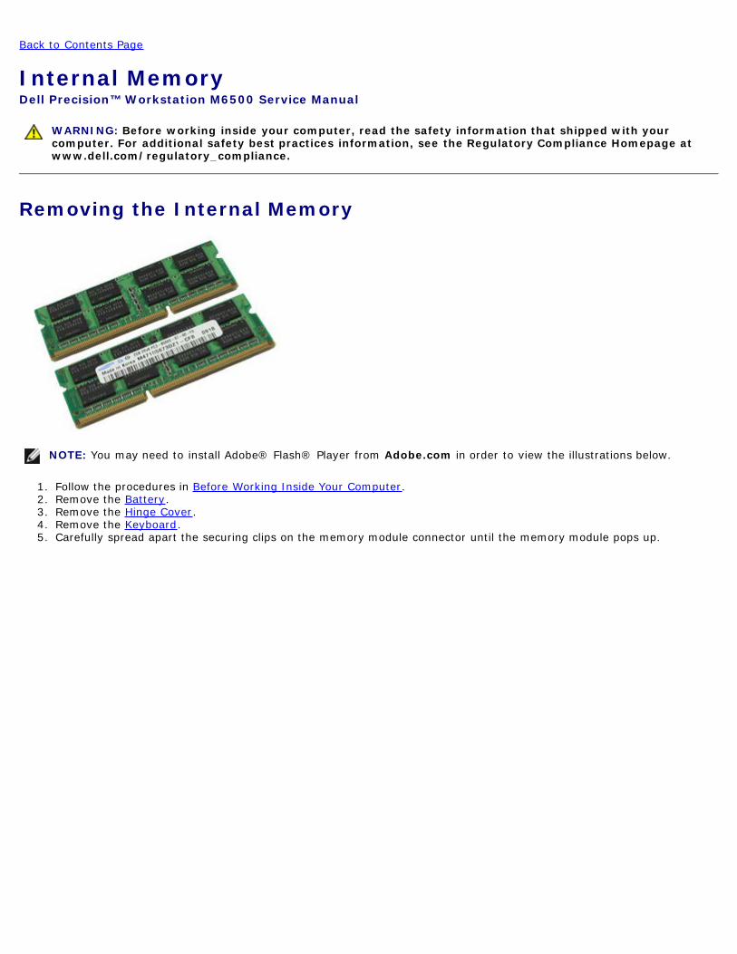
Removing the Internal Memory
NOTE You may need to install Adobereg Flashreg Player from Adobecom in order to view the illustrations below
1 Follow the procedures in Before Working Inside Your Computer2 Remove the Battery3 Remove the Hinge Cover4 Remove the Keyboard5 Carefully spread apart the securing clips on the memory module connector until the memory module pops up
6 Pull the memory module from its slot to remove it from the computer
Replacing the Internal MemoryTo replace the internal memory perform the above steps in reverse order
Back to Contents Page
Local Disk
Dell Precision Workstation M6500 Service Manual
Dell Precision Workstation M6500 Service Manual--Working on Your Computer
Dell Precision Workstation M6500 Service Manual--Removing and Replacing Parts
Dell Precision M6500 ndash Specifications
Dell Precision Workstation M6500 Service Manual--Diagnostics
Dell Precision workstation M6500 Service Manual--System BIOS
Dell Precision Workstation M6500 Service Manual--Removing the Battery
Dell Precision Workstation M6500 Service Manual--Removing the Express Card
Dell Precision Workstation M6500 Service Manual--Removing the Hard Drive
Dell Precision Workstation M6500 Service Manual--Removing the PCMCIA Card
Dell Precisiontrade Workstation M6500 Service Manual--Removing the Coin-cell Battery
Dell Precision Workstation M6500 Service Manual--Removing the Hard Drive
Dell Precision Workstation M6500 Service Manual--Removing the Secondary Hard Drive
Dell Precision Workstation M6500 Service Manual--Removing the WWAN Card
Dell Precision Workstation M6500 Service Manual--Removing the FCM Card
Dell Precision Workstation M6500 Service Manual--Removing the Memory
Dell Precision Workstation M6500 Service Manual--Removing the Camera
Dell Precision Workstation M6500 Service Manual--Removing the PCMCIA Card Cage
Dell Precision Workstation M6500 Service Manual--Removing the Heat Sink
Dell Precision Workstation M6500 Service Manual--Removing the Processor
Dell Precision Workstation M6500 Service Manual--Removing the System Board
Dell Precision Workstation M6500 Service Manual--Removing the SIM Card
Dell Precision Workstation M6500 Service Manual--Removing the Media Card
Dell Precision Workstation M6500 Service Manual--Removing the Access Panel
Dell Precision Workstation M6500 Service Manual--Removing the Hinge Cover
Dell Precision Workstation M6500 Service Manual--Removing the Optical Drive
Dell Precision Workstation M6500 Service Manual--Removing the WLAN Card
Dell Precision Workstation M6500 Service Manual--Removing the WPAN Card
Dell Precision Workstation M6500 Service Manual--Removing the Keyboard
Dell Precision Workstation M6500 Service Manual--Removing the LCD Assembly
Dell Precision Workstation M6500 Service Manual--Removing the Palm Rest
Dell Precision Workstation M6500 Service Manual--Removing the InputOutput and IEEE 1394 Board
Dell Precision Workstation M6500 Service Manual--Removing the System Fan
Dell Precision Workstation M6500 Service Manual--Removing the Video Card
Dell Precision Workstation M6500 Service Manual--Removing the Internal Memory
Back to Contents Page
Working on Your ComputerDell Precisiontrade Workstation M6500 Service Manual
Before Working Inside Your Computer
Recommended Tools
Turning Off Your Computer
After Working Inside Your Computer
Before Working Inside Your ComputerUse the following safety guidelines to help protect your computer from potential damage and to help to ensure your personalsafety Unless otherwise noted each procedure included in this document assumes that the following conditions exist
You have performed the steps in Working on Your ComputerYou have read the safety information that shipped with your computerA component can be replaced ormdashif purchased separatelymdashinstalled by performing the removal procedure in reverseorder
WARNING Before working inside your computer read the safety information that shipped with yourcomputer For additional safety best practices information see the Regulatory Compliance Homepage atwwwdellcomregulatory_compliance
CAUTION Many repairs may only be done by a certified service technician You should only performtroubleshooting and simple repairs as authorized in your product documentation or as directed by theonline or telephone service and support team Damage due to servicing that is not authorized by Dell isnot covered by your warranty Read and follow the safety instructions that came with the product
CAUTION To avoid electrostatic discharge ground yourself by using a wrist grounding strap or byperiodically touching an unpainted metal surface such as a connector on the back of the computer
CAUTION Handle components and cards with care Do not touch the components or contacts on a cardHold a card by its edges or by its metal mounting bracket Hold a component such as a processor by itsedges not by its pins
CAUTION When you disconnect a cable pull on its connector or on its pull-tab not on the cable itselfSome cables have connectors with locking tabs if you are disconnecting this type of cable press in on thelocking tabs before you disconnect the cable As you pull connectors apart keep them evenly aligned toavoid bending any connector pins Also before you connect a cable ensure that both connectors arecorrectly oriented and aligned
NOTE The color of your computer and certain components may appear differently than shown in this document
To avoid damaging your computer perform the following steps before you begin working inside the computer
1 Ensure that your work surface is flat and clean to prevent the computer cover from being scratched2 Turn off your computer (see Turning Off Your Computer)3 If the computer is connected to a docking device (docked) undock it
CAUTION To disconnect a network cable first unplug the cable from your computer and then unplug thecable from the network device
4 Disconnect all network cables from the computer5 Disconnect your computer and all attached devices from their electrical outlets6 Where applicable disconnect any adapters from the computer6 Close the display and turn the computer upside-down on a flat work surface
CAUTION To avoid damaging the system board you must remove the main battery before you service thecomputer
7 Remove the main Battery8 Turn the computer top-side up9 Open the display
10 Press the power button to ground the system board
CAUTION To guard against electrical shock always unplug your computer from the electrical outlet beforeopening the display
CAUTION Before touching anything inside your computer ground yourself by touching an unpainted metalsurface such as the metal at the back of the computer While you work periodically touch an unpaintedmetal surface to dissipate static electricity which could harm internal components
11 Remove any installed ExpressCards or Smart Cards from the appropriate slots12 Remove the Hard Drive
Recommended Tools
The procedures in this document may require the following tools
Small flat-blade screwdriver0 Phillips screwdriver1 Phillips screwdriverSmall plastic scribeFlash BIOS update program CD
Turning Off Your Computer
CAUTION To avoid losing data save and close all open files and exit all open programs before you turn offyour computer
1 Shut down the operating system
In Windows Vistareg
Click Start then click the arrow in the lower-right corner of the Start menu as shown below and then clickShut Down
In Windowsreg XP
Click Startreg Turn Off Computerreg Turn Off
The computer turns off after the operating system shutdown process is complete
2 Ensure that the computer and all attached devices are turned off If your computer and attached devices did notautomatically turn off when you shut down your operating system press and hold the power button for about 4seconds to turn them off
After Working Inside Your ComputerAfter you complete any replacement procedure ensure you connect any external devices cards and cables before turning onyour computer
CAUTION To avoid damage to the computer use only the battery designed for this particular Dellcomputer Do not use batteries designed for other Dell computers
1 Connect any external devices such as a port replicator battery slice or media base and replace any cards such as anExpressCard
2 Connect any telephone or network cables to your computer
CAUTION To connect a network cable first plug the cable into the network device and then plug it into thecomputer
3 Replace the Battery4 Connect your computer and all attached devices to their electrical outlets5 Turn on your computer
Back to Contents Page
Back to Contents Page
Removing and Replacing PartsDell Precisiontrade Workstation M6500 Service Manual
ExpressCard
PCMCIA Card
Battery
Coin-Cell Battery
Hard Drive
Secondary Hard Drive
Wireless Wide Area Network (WWAN) Card
Flash Cache Module (FCM)
Memory
Camera
PCMCIA Card Cage
Heat Sink
Processor
System Board
SIM Card
Media Card
Access Panel
Hinge Cover
Optical Drive
Wireless Local Area Network (WLAN) card
Wireless Personal Area Network (WPAN) card
Keyboard
Display Assembly
Palm Rest
IO and IEEE 1394 Board
Fan
Video Card Assembly
Back to Contents Page
Back to Contents Page
Technical Specifications System Information
Memory
Audio
PC Card
Smart Card
Display
Touchpad
Battery
Physical
Processor
Video
Communications
ExpressCard
Ports and Connectors
Keyboard
Fingerprint Reader (optional)
AC Adapter
Environmental
NOTE Offerings may vary by region For more information regarding the configuration of your computer click StartregHelp and Support and select the option to view information about your computer
System Information
Chipset Mobile Intel PM55 Chipset
Data bus width 64 bits
DRAM bus width dual-channel 64 bits
NOTE You must install memory in pairsfor dual- channel mode to work
NOTE Intel Core i5i7 dual-coreprocessors support 1600 MHz and 1333MHz memory modules but the memorywill operate at 1067 MHz
NOTE Intel Core i7-920XM Quad-Coreprocessor supports memory frequency upto 1600 MHz All other Core i7 Quad-Coreprocessors support memory frequency upto 1333 MHz only even if memorymodules of higher frequency are installed
Connectors four SODIMM connectors
NOTE Computers shipped with dual-coreprocessors support a maximum of twomemory modules populated in slots A andB
Module capacities 1 GB 2 GB 4 GB and 8GB
Minimum memory 2 GB
Maximum memory 8 GB running at 1600 MHz32 GB running at 1333 MHz
NOTE When upgrading or replacing memory modules you must ensure that themodules are paired and matched in slots A and B first and then in slots C and D
Video
Type discrete
Data bus PCI-Express x16 Gen 2 capable
Controller and Memory NVIDIA Quadro FX 3800M (1 GB GDDR3graphics memory)NVIDIA Quadro FX 2800M (1 GB GDDR3graphics memory)AMD ATI FirePro M7820 (1 GB GDDR5graphics memory)
Output 15-pin video connectordual mode DisplayPort connector
Audio
Type two-channel Intel High Definition Audio
Controller IDT 92HD81B
Stereo conversion 24-bit (analog-to-digital and digital-to-analog)
Type (active-matrix TFT) 17 inches WXGA+ LED17 inches WUXGA LED RGB or RGBedge-to-edge glass
Active area (XY) 3673 mm x 2295 mm
Dimensions
Height
WXGA+WUXGA 245 mm (964 inches)
WUXGA 248 mm (976 inches)
Width (WXGA+WUXGA) 383 mm (1508 inches)
Diagonal 432 mm (1700 inches)
Maximum resolutions and brightness
WXGA+ 1440 x 900 at 262 K colors 220 nits
WUXGA 1920 x 1200 at 262 K colors 300 nits
WUXGA RGB 1920 x 1200 at 167 M colors 300 nits
Operating angle 0deg (closed) to 152deg
Refresh rate 60 Hz
Viewing angles
WXGA+ Horizontal 40deg40deg
WXGA+ Vertical 15deg30deg
WUXGA Horizontal 60deg60deg
WUXGA Vertical 45deg45deg
Pixel pitch
WXGA+ 0191 mm
WUXGA 0225 mm
Keyboard
Number of keys United States 101 keysUnited Kingdom 102 keysBrazil 104 keysJapan 105 keys
Layout QWERTYAZERTYKanji
Touchpad
Resolution
X axis 5752 units per mm
Y axis 7812 units per mm
Active Area
X axis 800 mm (314 inches)
Y axis 4711 mm (185 inches)
Fingerprint Reader (Optional)
Type swipe fingerprint sensor FIPS 140-2 FIPS 201
Battery
Type 9-cell smart lithium ion (90 Whr)
Charge time with computer off approximately 1 hour to 80 capacity
Operating time battery operating time varies dependingon operating conditions and can besignificantly reduced under certain power-intensive conditions
Life span approximately 300 chargedischargecycles
Dimensions
Depth 85 mm (335 inches)
Height 23 mm (090 inches)
Voltage 111 V
Temperature range
Operating 0 degC to 35 degC (32 degF to 95 degF)
Storage ndash40 degC to 65 degC (ndash40 degF to 149 degF)
Coin-cell battery 3 V CR2032 lithium
AC Adapter
Type
Slim 210 W or 240 W
Standard 210 W
Input voltage 100ndash240 VAC
Input current (maximum)
Slim 35 A
Standard 32 A
Input frequency 50 Hzndash60 Hz
Output current
Slim 123 A
Standard 108 A
Output voltage 1950 VDC
Dimensions
Slim (210 W 240W)
Height 100 mm (394 inches)
Width 2540 mm (100 inch)
Depth 200 mm (787 inches)
Standard (210 W)
Height 100 mm (394 inches)
Width 43 mm (170 inches)
Depth 200 mm (787 inches)
Temperature range
Operating 0 degC to 40 degC (32 degF to 104 degF)
Storage ndash40 degC to 65 degC (ndash40 degF to 149 degF)
Physical
Height 385 mm (152 inches)
Width 3930 mm (1547 inches)
Depth 2805 mm (1104 inches)
Weight (minimum) 381 kg (840 lb)
Environmental
Temperature range
Operating 0 degC to 35 degC (32 degF to 95 degF)
Storage ndash40 degC to 65 degC (ndash40 degF to 149 degF)
Relative humidity (maximum)
Operating 10 to 90 (noncondensing)
Storage 5 to 95 (noncondensing)
Maximum vibration (measured using arandom vibration spectrum that simulatesuser environment)
Operating 066 Grms (2 Hzndash600 Hz)
Storage 130 Grms (2 Hzndash600 Hz)
Maximum shock (measured with harddrive in head-parked position and a 2 mshalf-sine pulse)
Operating 142 G
Storage 162 G
Altitude (maximum)
Operating ndash1520 m to 3048 m (ndash50 to 10000 ft)
Storage ndash1520 m to 10668 m (ndash50 to 35000 ft)
Airborne contaminant level G2 or lower as defined by ANSIISA-S7104-1985
Back to Contents Page
Back to Contents Page
DiagnosticsDell Precisiontrade Workstation M6500 Service Manual
Device Status Lights
Battery Status Lights
Battery Charge and Health
Keyboard Status Lights
LED Error Codes
Dell Diagnostics
Device Status LightsTurns on when you turn on the computer and blinks when the computer is in apower management mode
Turns on when the computer reads or writes data
Turns on steadily or blinks to indicate battery charge status
Turns on when wireless networking is enabled
Turns on when a card with Bluetoothreg wireless technology is enabled To turn offonly the Bluetooth wireless technology function right-click the icon in the systemtray and select Disable Bluetooth Radio
Battery Status LightsIf the computer is connected to an electrical outlet the battery light operates as follows
Alternately blinking amber light and blue light mdash An unauthenticated or unsupported non-Dell AC adapter isattached to your laptopAlternately blinking amber light with steady blue light mdash Temporary battery failure with AC adapter presentConstantly blinking amber light mdash Fatal battery failure with AC adapter presentLight off mdash Battery in full charge mode with AC adapter presentBlue light on mdash Battery in charge mode with AC adapter present
Battery Charge and HealthTo check the battery charge press and release the status button on the battery charge gauge to illuminate the charge-levellights Each light represents approximately 20 percent of the total battery charge For example if four lights are on thebattery has 80 percent of its charge remaining If no lights appear the battery has no charge
To check battery health using the charge gauge press and hold the status button on the battery charge gauge for at least 3seconds If no lights appear the battery is in good condition and more than 80 percent of its original charge capacity remainsEach light represents incremental degradation If five lights appear less than 60 percent of the charge capacity remains andyou should consider replacing the battery
Keyboard Status LightsThe green lights located above the keyboard indicate the following
Turns on when the numeric keypad is enabled
Turns on when the Caps Lock function is enabled
Turns on when the Scroll Lock function is enabled
LED Error CodesThe following table shows the possible LED codes that may display in a no-POST situation
Appearance Description Next Step
ON-FLASH-FLASH
No SODIMMs areinstalled
1 Install supported memory modules2 If memory is already present
reseat the module(s) one at time ineach slot
3 Try known good memory fromanother computer or replace thememory
4 Replace the system board
FLASH-ON-ON
System board error1 Reseat the processor2 Replace the system board3 Replace the processor
FLASH-ON-FLASH
LCD panel error
1 Reseat the LCD cable2 Replace the LCD panel3 Replace the video cardsystem
board
OFF-FLASH-OFF
Memory compatibilityerror
1 Install compatible memorymodules
2 If two modules are installedremove one and test Try the othermodule in the same slot and testTest the other slot with bothmodules
3 Replace the memory4 Replace the system board
ON-FLASH-ON
Memory is detectedbut has errors
1 Reseat the memory2 If two modules are installed
remove one and test Try the othermodule in the same slot and testTest the other slot with bothmodules
3 Replace the memory4 Replace the system board
OFF-FLASH-FLASH
Modem error1 Reseat the modem2 Replace the modem3 Replace the system board
FLASH-FLASH-FLASH
System board error 1 Replace the system board
FLASH-FLASH-OFF
Option ROM error1 Reseat the device2 Replace the device3 Replace the system board
OFF-ON-OFF
Storage device error
1 Reseat the hard drive and opticaldrive
2 Test the computer with just thehard drive and just the opticaldrive
3 Replace the device that is causingthe failure
4 Replace the system board
FLASH-FLASH-ON
Video card error 1 Replace the system board
Dell Diagnostics
When to Use the Dell Diagnostics
It is recommended that you print these procedures before you begin
NOTE The Dell Diagnostics software works only on Delltrade computers
NOTE The Drivers and Utilities media is optional and may not ship with your computer
Enter System Setup (see Entering System Setup) review your computers configuration information and ensure that thedevice you want to test displays in System Setup and is active
Start the Dell Diagnostics from either your hard drive or from the Drivers and Utilities media
Starting the Dell Diagnostics From Your Hard Drive
1 Turn on (or restart) your computer
2 When the DELL logo appears press ltF12gt immediately
NOTE If you see a message stating that no diagnostics utility partition has been found run the Dell Diagnostics fromyour Drivers and Utilities media
If you wait too long and the operating system logo appears continue to wait until you see the MicrosoftregWindowsreg desktop Then shut down your computer and try again
3 When the boot device list appears highlight Boot to Utility Partition and press ltEntergt
4 When the Dell Diagnostics Main Menu appears select the test that you want to run
Starting the Dell Diagnostics From the Drivers and Utilities Media
1 Insert the Drivers and Utilities media
2 Shut down and restart the computer
When the DELL logo appears press ltF12gt immediately
If you wait too long and the Windows logo appears continue to wait until you see the Windows desktop Then shutdown your computer and try again
NOTE The next steps change the boot sequence for one time only On the next startup the computer boots accordingto the devices specified in the system setup program
3 When the boot device list appears highlight Onboard or USB CD-ROM Drive and press ltEntergt
4 Select the Boot from CD-ROM option from the menu that appears and press ltEntergt
5 Type 1 to start the menu and press ltEntergt to proceed
6 Select Run the 32 Bit Dell Diagnostics from the numbered list If multiple versions are listed select the versionappropriate for your computer
7 When the Dell Diagnostics Main Menu appears select the test you want to run
Dell Diagnostics Main Menu
1 After the Dell Diagnostics loads and the Main Menu screen appears click the button for the option you want
Option Function
ExpressTest
Performs a quick test of devices This test typically takes 10 to 20 minutes and requires no interaction on yourpart Run Express Test first to increase the possibility of tracing the problem quickly
ExtendedTest
Performs a thorough check of devices This test typically takes 1 hour or more and requires you to answerquestions periodically
CustomTest
Tests a specific device You can customize the tests you want to run
SymptomTree
Lists the most common symptoms encountered and allows you to select a test based on the symptom of theproblem you are having
2 If a problem is encountered during a test a message appears with an error code and a description of the problemWrite down the error code and problem description and follow the instructions on the screen
3 If you run a test from the Custom Test or Symptom Tree option click the applicable tab described in the followingtable for more information
Tab Function
Results Displays the results of the test and any error conditions encountered
Errors Displays error conditions encountered error codes and the problem description
Help Describes the test and may indicate requirements for running the test
Configuration Displays your hardware configuration for the selected device
The Dell Diagnostics obtains configuration information for all devices from system setup memory andvarious internal tests and it displays the information in the device list in the left pane of the screen Thedevice list may not display the names of all the components installed on your computer or all devicesattached to your computer
Parameters Allows you to customize the test by changing the test settings
4 When the tests are completed if you are running the Dell Diagnostics from the Drivers and Utilities media remove themedia
5 Close the test screen to return to the Main Menu screen To exit the Dell Diagnostics and restart the computer closethe Main Menu screen
Back to Contents Page
Back to Contents Page
System SetupDell Precisiontrade Workstation M6500 Service Manual
Boot Menu
Navigation Keystrokes
Entering System Setup
System Setup Options
Boot MenuThe boot menu allows you to set a one-time boot sequence without entering system setup You can also use this procedureto run the diagnostics on your
1 Turn on (or restart) your computer2 When the Delltrade logo appears press ltF12gt immediately The following options appear
Internal hard drive CDDVDCD-RW Drive Onboard NIC BIOS Setup Diagnostics
3 Select the device from which you want to boot and press ltEntergt
The computer boots to the selected device The next time you reboot the computer the previous boot order is restored
Navigation KeystrokesUse the following keystrokes to navigate the System Setup screens
Navigation Keystrokes
Action Keystroke
Expand and collapse field ltEntergt left- or right-arrow key
Exit BIOS ltEscgtmdashRemain in Setup SaveExit DiscardExit
Change a setting Left or right-arrow key
Select field to change ltEntergt
Cancel modification ltEscgt
Reset defaults ltAltgtltFgt or Load Defaults menu option
Entering System SetupYou can enter System Setup using one of the following methods
Using the boot menuBy pressing ltF2gt
Boot Menu
1 Turn on (or restart) your computer2 When the Delltrade logo appears press ltF12gt immediately3 Highlight the option to enter System Setup and then press ltEntergt
NOTE Making changes in the boot menu does not make any changes to the boot order stored in the System Setupprogram
ltF2gt
1 Turn on (or restart) your computer2 When the Dell logo appears press ltF2gt immediately
If you are unable to enter System Setup by pressing the ltF2gt key when the Dell Logo appears continue to wait until yousee the Windows desktop Then restart your computer and press ltF2gt when the keyboard lights first flash
System Setup OptionsThe following tables describe the menu options for the System Setup program
General
Option Description
SystemInformation
This section lists the primary hardware features of your computer There are no configurable options in thissection
System InformationBIOS VersionService TagAsset TagOwnership Tag
Memory InformationMemory InstalledMemory AvailableMemory SpeedMemory Channel ModeMemory TechnologyDIMM A SizeDIMM B SizeDIMM C SizeDIMM D Size
Device InformationPrimary Hard DriveSecondary Hard DriveFixed Bay DeviceSystem eSATA DeviceDock eSATA Device Video ControllerVideo BIOS VersionVideo MemoryPanel TypeNative Resolution Audio ControllerWi-Fi DeviceCellular DeviceBluetoothreg DeviceWireless USB Device
BatteryInformation Indicates the primary battery status Also displays the type of AC adapter connected to the computer
BootSequence
The computer attempts to boot from the sequence of devices specified in this list
Diskette driveUSB Storage DeviceCDDVDCD-RW DriveInternal hard driveCardbus NICOnboard NIC
This list specifies the order that the BIOS searches for devices while trying to find an operating system toboot
To change the boot order select the device to be changed in the list then click the updown arrows or use thekeyboard PgUpPgDn keys to change the boot order of the device
To remove devices for the boot list clear the check boxes
DateTime Displays current date and time settings
System Configuration
Option Description
NOTEThe System Configuration group contains options and settings relater to integrated system devices(Depending on your computer and installed devices the items listed in this section may or may notappear)
IntegratedNIC
Enables or disables the onboard LAN controller
Default setting Enabled wPXE
SystemManagement
This option controls System Management mechanism The settings are Disabled Alert Only and ASF20
Default setting Disabled
Parallel Port
This option determines how the parallel port on the docking station operates The settings are DisabledAT PS2 and ECP
Default setting ECP
Serial Port
This option determines how the serial port on the docking station operates It lets you avoid resourceconflicts between devices by disabling or re-mapping the address of the port The settings are DisabledCOM1 COM2 COM3 and COM4
Default setting COM1
SATAOperation
This option configures the operating mode of the internal SATA hard drive controller The settings areDisabled ATA AHCI and RAID
Default setting RAID
MiscellaneousDevices
Use the check boxes to enabledisable the following devices
External USB Port IMicrophoneIEEE 1394ExpressCardPrecision ON ReaderModule BayPC CardMedia CardeSATA Ports
Default setting All enabled
Video
Option Description
Ambient Light Enabling this feature allows your computer to automatically change the brightness of the display panel
Sensor based on the amount of light in the surroundings
LCDBrightness
This option (represented by a slider bar for On Battery and On AC) sets the panel brightness when theambient light sensor is off
Security
Option Description
AdminPassword
This field lets you set change or delete the administrator password The administrator password enablesseveral security features when set including
Restricts changes to the settings in SetupRestricts the boot devices listed in the ltF12gt Boot Menu to those enabled in the Boot SequencefieldProhibits changes to the owner and asset tagsSubstitutes for the system password if the system prompts for a password during power on
Successful changes to this password take effect immediately
If you delete the admin password the system password is also deleted Also the admin password can beused to delete the hard drive password For this reason you cannot set an admin password if a systempassword or hard drive is already set The admin password must be set first if used in conjunction with asystem andor hard drive password
SystemPassword This field lets you set change or delete the system password
Internal hard drivePW
This field lets you set change or delete the password on the systems internal hard drive Successfulchanges take place immediately and require a system restart The hard drive password travels with thehard drive so the hard drive is protected even when installed in another system
PasswordBypass
This option lets you bypass the system and internal hard drive password prompts during a system restart orwhen resuming from a standby state Settings are Disabled Reboot Bypass Resume Bypass andReboot amp Resume Bypass
The system will always prompt for the set system and internal hard drive password when powered on froman off state (cold boot)
Default setting Disabled
PasswordChange
This option lets you determine whether changes to the System and hard drive passwords are permittedwhen an Admin password is set Use the check box to allow or disallow changes
Default setting Allow Non-Admin Password Changes
TPM Security
This option lets you control whether the Trusted Platform Module (TPM) in the system is enabled and visibleto the operating system When disabled (check box is empty) the BIOS will not turn on the TPM duringPOST The TPM will be non-functional and invisible to the operating system When enabled (check boxfilled) the BIOS will turn the TPM on during POST so the it can be used by the operating system
Disabling this option does not change any settings you may have made to the TPM nor does it delete orchange any information or keys you may have stored there It simply turns off the TPM so that it cannot beused When you re-enable the TPM it will function exactly as it did before it was disabled
Once TPM is enabled (check box filled) the available settings are Deactivate Activate and Clear
With the TPM in Deactivate mode it will not execute any commands that use the resources of the TPM norwill it allow any access to stored owner information
The Clear setting allows the owners information stored in the TPM to be cleared Use this to restore theTPM to its default state if you lose or forget the owner authentication data
Computracereg
This field lets you activate or disable the BIOS module interface of the optional Computrace software Thesettings are Deactivate Disable and Activate
The Activate and Disable options will permanently activate or disable the feature and no further changes willbe allowed
CPU XDSupport
This field enables or disables the Execute Disable mode of the processor Use the check box to enable disable this feature
Default setting Enabled
Non-AdminSetupChanges
This option lets you determine whether changes to the setup option are permitted when an administratorpassword is set If disabled the setup option is locked by the admin password It cannot be modified unlesssetup is unlocked Use the check boxes to allow deny access to the Wi-Fi Catcher Changes and orWireless Switch Changes within the system setup
Performance
Option Description
Intelreg SpeedStep Use the check box to enable disable mode for the CPU
Power Management
Option Description
Wake onAC
Use the check box to enabledisable the computer to power up from the off or hibernation state when an ACadapter is inserted
Auto OnTime
This field sets the days if any when you would like the system to turn on automatically The settings areDisabled Everyday or Weekdays
Default setting Off
USB WakeSupport
Use the check box to enabledisable the ability for USB devices to wake the system from Standby
This feature is only functional when the AC power adapter is connected If the AC power adapter is removedduring Standby the BIOS will remove power from all of the USB ports to conserve battery power
Wake onLANWLAN
This field allows the computer to power up from the off state when triggered by a special LAN signal or fromHibernate state when triggered by a special wireless LAN signal Wake-up from the Standby state isunaffected by this setting and must be enabled in the operating system
Disabled mdash Do not allow the system to power on when it receives a wake-up signal from the LAN orwireless LANLAN Only mdash Allow the system to be powered on by special LAN signalsWLAN Only mdash Allow the system to be powered on by special WLAN signalsLAN or WLAN mdash Allow the system to be powered on by special LAN or wireless LAN signals
The factory default setting is Off
ChargerBehavior
This field lets you enable disable the battery charger If disabled the battery will not lose power when thesystem is connected to an AC adapter but it will not charge either
Default setting Charger Enabled
POST Behavior
Option Description
AdapterWarnings
Use the check box to enabledisable the BIOS warning messages when you use certain power adapters TheBIOS displays these messages if you attempt to use a power adapter that has too little capacity for yourconfiguration
Default setting Enabled
Keypad(Embedded)
This option lets you choose one of two methods to enable the keypad that is embedded in the internalkeyboard
Fn Key Only mdash The keypad is only enabled when you hold down the ltFngt keyBy Num Lk mdash The keypad is enabled when (1) the Num Lock LED is on and (2) no external keyboardis attached Note that the system might not notice immediately when an external keyboard isdetached
When Setup is running this field has no effectmdashSetup works in the Fn Key Only mode
Default setting Fn Key Only
NumlockLED
Use the check box to enabledisable the Num Lock LED when the system boots
Default setting Enabled
USBEmulation
This option defines how the BIOS in the absence of a USBndashaware operating system handles USB devicesUSB emulation is always enabled during POST Use the check box to enabledisable this feature
Default setting Enabled
Fn KeyEmulation
This field lets you use the ltScroll Lockgt key on an external PS2 keyboard the same way you use the ltFngtkey on the computers internal keyboard Use the check box to enabledisable this feature
USB keyboards cannot emulate the ltFngt key if you are running an ACPI operating system such asMicrosoftreg Windowsreg XP USB keyboards will only emulate the ltFngt key in non-ACPI mode (eg when youare running in DOS)
Default setting Enabled
Fast Boot
This field can speed up the boot process by bypassing some compatibility steps
Minimal mdash Boot quickly unless the BIOS has been updated memory changed or the previous POSTdid not completeThorough mdash Do not skip any steps in the boot processAuto mdash Allow the operating system to control this setting (this works only when the operating systemsupports Simple Boot Flag)
Default setting Minimal
Virtualization Support
Option Description
Virtualization
This field specifies whether a Virtual Machine Monitor (VMM) can utilize the additional hardwarecapabilities provided by Intelreg Virtualization Technology Use the check box to enabledisable thisfeature
Default setting Disabled
VT for DirectIO
This option specifies whether a Virtual Machine Monitor (VMM) can utilize the additional hardwarecapabilities provided by Intel Virtualization Technology for Direct IO Use the check box to enabledisablethis feature
Default setting Disabled
TrustedExecution
This option specifies whether a Measured Virtual Machine Monitor (MVMM) can utilize the additionalhardware capabilities provided by Intel Trusted Execution Technology The TPM VirtualizationTechnology and Virtualization Technology for Direct IO must be enabled to use this feature Use thecheck box to enabledisable this feature
Default setting Disabled
Wireless
Option Description
Wireless Switch Use the check boxes to determine which wireless devices will be controlled by the wireless switch Theavailable options are WWAN WLAN Bluetoothreg and Wireless USB
WirelessDevices
Use the check boxes to enable disable the various wireless devices The available options are InternalWWAN Internal WLAN Internal Bluetoothreg and Wireless USB
Maintenance
Option Description
Service Tag
This field displays your systems Service Tag If for some reason the Service Tag was not already setyou would be able to use this field to set it
If a Service Tag has not been set for this system the computer will automatically bring up this screenwhen users enter the BIOS You will be prompted to enter the Service Tag
Asset Tag This field allows you to create a system Asset Tag The field can only be updated if the Asset Tag is not
already set
System Logs
Option Description
BIOS Events This field allows you to view and clear BIOS power-on self-test (POST) events It includes the date andtime of the event as well as the LED code
DellDiag Events This filed allows you to view the diagnostic results from Dell Diagnostics and PSA It includes the timeand date the diagnostic version and the resulting code
Thermal Events This field allows you to view and clear thermal events It includes the date and time as well as the nameof the event
Power Events This field allows you to view and clear power events It includes the date and time of the event as well asthe power state and reason
Back to Contents Page
Back to Contents Page
BatteryDell Precisiontrade Workstation M6500 Service Manual
WARNING Before working inside your computer read the safety information that shipped with yourcomputer For additional safety best practices information see the Regulatory Compliance Homepage atwwwdellcomregulatory_compliance
Removing the Battery
NOTE You may need to install Adobereg Flashreg Player from Adobecom in order to view the illustrations below
1 Follow the procedures in Before Working Inside Your Computer2 Slide the latch to release the battery from the computer
3 Lift the battery up and away from the computer
Replacing the BatteryTo replace the battery perform the above steps in reverse order
Back to Contents Page
Back to Contents Page
ExpressCardDell Precisiontrade Workstation M6500 Service Manual
WARNING Before working inside your computer read the safety information that shipped with yourcomputer For additional safety best practices information see the Regulatory Compliance Homepage atwwwdellcomregulatory_compliance
Removing the ExpressCard
NOTE You may need to install Adobereg Flashreg Player from Adobecom in order to view the illustrations below
1 Follow the procedures in Before Working Inside Your Computer2 Push in the ExpressCard to release it from its slot on the computer
3 Pull out the ExpressCard and remove it from the computer
Replacing the ExpressCardTo replace the ExpressCard perform the above steps in reverse order
Back to Contents Page
Back to Contents Page
Hard DriveDell Precisiontrade Workstation M6500 Service Manual
WARNING Before working inside your computer read the safety information that shipped with yourcomputer For additional safety best practices information see the Regulatory Compliance Homepage atwwwdellcomregulatory_compliance
Removing the Hard Drive
NOTE You may need to install Adobereg Flashreg Player from Adobecom in order to view the illustrations below
1 Follow the procedures in Before Working Inside Your Computer2 Remove the battery3 Loosen the captive screws that secure the hard drive to the hard-drive cage
4 Pull the release tab to release the hard-drive cage from the computer
5 Remove the hard-drive cage from the computer
6 Slide the hard drive away from the computer
7 Using the black pull-tab lift the hard drive up and remove it from the computer
8 Remove the screws that secure the black pull-tab bar to the hard drive
9 Remove the black pull-tab bar from the hard drive
Replacing the Hard DriveTo replace the hard drive perform the above steps in reverse order
Back to Contents Page
Back to Contents Page
PCMCIA CardDell Precisiontrade Workstation M6500 Service Manual
WARNING Before working inside your computer read the safety information that shipped with yourcomputer For additional safety best practices information see the Regulatory Compliance Homepage atwwwdellcomregulatory_compliance
Removing the PCMCIA Card
NOTE You may need to install Adobereg Flashreg Player from Adobecom in order to view the illustrations below
1 Follow the procedures in Before Working Inside Your Computer2 Push the release button twice to release the PCMCIA card from its slot on the computer
3 Pull the PCMCIA card from the computer
Replacing the PCMCIA CardTo replace the PCMCIA card perform the above steps in reverse order
Back to Contents Page
Back to Contents Page
Coin-Cell BatteryDell Precisiontrade Workstation M6500 Service Manual
WARNING Before working inside your computer read the safety information that shipped with yourcomputer For additional safety best practices information see the Regulatory Compliance Homepage atwwwdellcomregulatory_compliance
Removing the Coin-Cell Battery
NOTE You may need to install Adobereg Flashreg Player from Adobecom in order to view the illustrations below
1 Follow the procedures in Before Working Inside Your Computer2 Remove the battery3 Remove the access panel4 Slide the coin-cell battery out of the mylar sleeve
5 Disconnect the coin-cell battery cable from the system board and remove it from the computer
Replacing the Coin-Cell batteryTo replace the coin-cell battery perform the above steps in reverse order
Back to Contents Page
Back to Contents Page
Hard DriveDell Precisiontrade Workstation M6500 Service Manual
WARNING Before working inside your computer read the safety information that shipped with yourcomputer For additional safety best practices information see the Regulatory Compliance Homepage atwwwdellcomregulatory_compliance
Removing the Hard Drive
NOTE You may need to install Adobereg Flashreg Player from Adobecom in order to view the illustrations below
1 Follow the procedures in Before Working Inside Your Computer2 Remove the battery3 Loosen the captive screws that secure the hard drive to the hard-drive cage
4 Pull the release tab to release the hard-drive cage from the computer
5 Remove the hard-drive cage from the computer
6 Slide the hard drive away from the computer
7 Using the black pull-tab lift the hard drive up and remove it from the computer
8 Remove the screws that secure the black pull-tab bar to the hard drive
9 Remove the black pull-tab bar from the hard drive
Replacing the Hard DriveTo replace the hard drive perform the above steps in reverse order
Back to Contents Page
Back to Contents Page
Secondary Hard DriveDell Precisiontrade Workstation M6500 Service Manual
WARNING Before working inside your computer read the safety information that shipped with yourcomputer For additional safety best practices information see the Regulatory Compliance Homepage atwwwdellcomregulatory_compliance
Removing the Secondary Hard Drive
NOTE You may need to install Adobereg Flashreg Player from Adobecom in order to view the illustrations below
1 Follow the procedures in Before Working Inside Your Computer2 Remove the Battery3 Remove the Access Panel4 Remove the screws that secure the secondary hard drive to the computer
5 Pull the black tab to lift the hard drive up and away from the computer
6 Remove the screws on either sides of the hard drive to release the hard-drive bracket from the hard drive
7 Remove the hard-drive bracket from the hard drive
8 Remove the hard-drive interposer from the hard drive
Replacing the Secondary Hard DriveTo replace the secondary hard drive perform the above steps in reverse order
Back to Contents Page
Back to Contents Page
Wireless Wide Area Network (WWAN) CardDell Precisiontrade Workstation M6500 Service Manual
WARNING Before working inside your computer read the safety information that shipped with yourcomputer For additional safety best practices information see the Regulatory Compliance Homepage atwwwdellcomregulatory_compliance
Removing the WWAN card
NOTE You may need to install Adobereg Flashreg Player from Adobecom in order to view the illustrations below
1 Follow the procedures in Before Working Inside Your Computer2 Remove the battery3 Remove the access panel4 Disconnect the antenna cables from the WWAN card
5 Remove the screw that secures the WWAN card to the system boardThe card pops up at a 45-degree angle
6 Slide the WWAN card out of the connector on the system board
Replacing the WWAN CardTo replace the WWAN card perform the above steps in reverse order
Back to Contents Page
Back to Contents Page
Flash Cache Module (FCM)Dell Precisiontrade Workstation M6500 Service Manual
WARNING Before working inside your computer read the safety information that shipped with yourcomputer For additional safety best practices information see the Regulatory Compliance Homepage atwwwdellcomregulatory_compliance
Removing the FCM Card
NOTE You may need to install Adobereg Flashreg Player from Adobecom in order to view the illustrations below
1 Follow the procedures in Before Working Inside Your Computer2 Remove the battery3 Remove the access panel4 Remove the screw that secures the FCM card to the system board
5 Pull the FCM card away from the computer
Replacing the FCM CardTo replace the FCM card perform the above steps in reverse order
Back to Contents Page
Back to Contents Page
MemoryDell Precisiontrade Workstation M6500 Service Manual
WARNING Before working inside your computer read the safety information that shipped with yourcomputer For additional safety best practices information see the Regulatory Compliance Homepage atwwwdellcomregulatory_compliance
Removing the Memory Module(s)
NOTE You may need to install Adobereg Flashreg Player from Adobecom in order to view the illustrations below
1 Follow the procedures in Before Working Inside Your Computer2 To remove the memory modules A and B remove the battery and the access panel
To remove the memory modules C and D remove the battery hinge cover and keyboard3 Carefully spread apart the securing clips on each end of the memory module connector until the memory module pops
up
4 Remove the memory module from the connector
Replacing the Memory Module(s)To replace the memory module(s) perform the above steps in reverse order
Back to Contents Page
Back to Contents Page
CameraDell Precisiontrade Workstation M6500 Service Manual
WARNING Before working inside your computer read the safety information that shipped with yourcomputer For additional safety best practices information see the Regulatory Compliance Homepage atwwwdellcomregulatory_compliance
Removing the Camera
NOTE You may need to install Adobereg Flashreg Player from Adobecom in order to view the illustrations below
1 Follow the procedures in Before Working Inside Your Computer2 Remove the battery3 Remove the access panel4 Remove the hinge cover5 Remove the keyboard6 Remove the display assembly7 Remove the display bezel8 Remove the display panel9 Disconnect the camera cable from the camera
10 Remove the screws that secure the camera to the display assembly
11 Remove the camera from the display assembly
Replacing the CameraTo replace the camera perform the above steps in reverse order
Back to Contents Page
Back to Contents Page
PCMCIA Card CageDell Precisiontrade Workstation M6500 Service Manual
WARNING Before working inside your computer read the safety information that shipped with yourcomputer For additional safety best practices information see the Regulatory Compliance Homepage atwwwdellcomregulatory_compliance
Removing the PCMCIA Card Cage
NOTE You may need to install Adobereg Flashreg Player from Adobecom in order to view the illustrations below
1 Follow the procedures in Before Working Inside Your Computer2 Remove the battery3 Remove the access panel4 Remove the hard drive5 Remove the secondary hard drive6 Remove the hinge cover7 Remove the keyboard8 Remove the display assembly9 Remove the palm rest
10 Release the card-cage cable tab
11 Disconnect the card cage cable from the system board
12 Remove the screws that secure the card cage to the computer
13 Remove the card cage from the computer
Replacing the PCMCIA Card CageTo replace the PCMCIA card cage perform the above steps in reverse order
Back to Contents Page
Back to Contents Page
Heat SinkDell Precision Workstation M6500 Service Manual
WARNING Before working inside your computer read the safety information that shipped with yourcomputer For additional safety best practices information see the Regulatory Compliance Homepage atwwwdellcomregulatory_compliance
Removing the Heat Sink
NOTE You may need to install Adobereg Flashreg Player from Adobecom in order to view the illustrations below
1 Follow the procedures in Before Working Inside Your Computer2 Remove the battery3 Remove the access panel4 Remove the hard drive5 Remove the secondary hard drive (if applicable)6 Remove the hinge cover7 Remove the keyboard8 Remove the display assembly9 Remove the palm rest
10 Loosen the four captive screws that secure the heat sink to the system board
11 Remove the heat sink from the computer
Replacing the Heat SinkTo replace the heat sink perform the above steps in reverse order
Back to Contents Page
Back to Contents Page
ProcessorDell Precisiontrade Workstation M6500 Service Manual
WARNING Before working inside your computer read the safety information that shipped with yourcomputer For additional safety best practices information see the Regulatory Compliance Homepage atwwwdellcomregulatory_compliance
Removing the Processor
NOTE You may need to install Adobereg Flashreg Player from Adobecom in order to view the illustrations below
1 Follow the procedures in Before Working Inside Your Computer2 Remove the battery3 Remove the access panel4 Remove the secondary hard drive5 Remove the hinge cover6 Remove the keyboard7 Remove the display assembly8 Remove the palm rest9 Remove the heat sink
10 Turn the cam screw counter-clock wise until it comes to a stop to release the processor from the system board
11 Carefully lift the processor straight up from the slot and remove the processor from the computer
Replacing the ProcessorTo replace the processor perform the above steps in reverse order
Back to Contents Page
Back to Contents Page
System BoardDell Precisiontrade Workstation M6500 Service Manual
WARNING Before working inside your computer read the safety information that shipped with yourcomputer For additional safety best practices information see the Regulatory Compliance Homepage atwwwdellcomregulatory_compliance
Removing the System Board
NOTE You may need to install Adobereg Flashreg Player from Adobecom in order to view the illustrations below
1 Follow the procedures in Before Working Inside Your Computer2 Remove the battery3 Remove the SIM Card4 Remove the hard drive5 Remove the access panel6 Remove the secondary hard drive7 Remove the memory8 Remove the flash cache module9 Remove the wireless personal area network (WPAN)
10 Remove the wireless local area network (WLAN)11 Remove the wireless wide area network (WWAN)12 Remove the optical drive13 Remove the coin-cell battery14 Remove the express card15 Remove the media card16 Remove the PCMCIA card17 Remove the hinge cover18 Remove the keyboard19 Remove the internal memory20 Remove the display assembly21 Remove the palm rest22 Remove the heat sink23 Remove the video card24 Remove the processor25 Remove the fan26 Remove the PCMCIA card cage27 Remove the left IO right IO and IEEE 1394 boards28 Remove the screws that secure the system board to the computer
29 Remove the system board from the computer
Replacing the System BoardTo replace the system board perform the above steps in reverse order
Back to Contents Page
Back to Contents Page
SIM CardDell Precisiontrade Workstation M6500 Service Manual
WARNING Before working inside your computer read the safety information that shipped with yourcomputer For additional safety best practices information see the Regulatory Compliance Homepage atwwwdellcomregulatory_compliance
Removing the SIM Card
NOTE You may need to install Adobereg Flashreg Player from Adobecom in order to view the illustrations below
1 Follow the procedures in Before Working Inside Your Computer2 Remove the battery3 Pull the SIM card out of the slot in the battery bay to remove it from the computer
Replacing the SIM CardTo replace the SIM card perform the above steps in reverse order
Back to Contents Page
Back to Contents Page
Media CardDell Precisiontrade Workstation M6500 Service Manual
WARNING Before working inside your computer read the safety information that shipped with yourcomputer For additional safety best practices information see the Regulatory Compliance Homepage atwwwdellcomregulatory_compliance
Removing the Media Card
NOTE You may need to install Adobereg Flashreg Player from Adobecom in order to view the illustrations below
1 Follow the procedures in Before Working Inside Your Computer2 Push in the Media Card to release it from the computer
3 Pull the Media Card out to remove it from the computer
Replacing the Media CardTo replace the Media Card perform the above steps in reverse order
Back to Contents Page
Back to Contents Page
Access PanelDell Precisiontrade Workstation M6500 Service Manual
WARNING Before working inside your computer read the safety information that shipped with yourcomputer For additional safety best practices information see the Regulatory Compliance Homepage atwwwdellcomregulatory_compliance
Removing the Access Panel
NOTE You may need to install Adobereg Flashreg Player from Adobecom in order to view the illustrations below
1 Follow the procedures in Before Working Inside Your Computer2 Remove the battery3 Remove the screws that secure the access panel to the computer
4 Slide the access panel towards the battery compartment
5 Pull the access panel away from the computer
Replacing the Access PanelTo replace the access panel perform the above steps in reverse order
Back to Contents Page
Back to Contents Page
Hinge CoverDell Precisiontrade Workstation M6500 Service Manual
WARNING Before working inside your computer read the safety information that shipped with yourcomputer For additional safety best practices information see the Regulatory Compliance Homepage atwwwdellcomregulatory_compliance
Removing the Hinge Cover
NOTE You may need to install Adobereg Flashreg Player from Adobecom in order to view the illustrations below
1 Follow the procedures in Before Working Inside Your Computer2 Remove the battery3 Starting from the left edge gently pry the hinge cover away from the computer
4 Flip the hinge cover over and place it on the keyboard
5 Disconnect the cables that connect the hinge cover to the computer
6 Remove the hinge cover from the computer
Replacing the Hinge CoverTo replace the hinge cover perform the above steps in reverse order
Back to Contents Page
Back to Contents Page
Optical DriveDell Precisiontrade Workstation M6500 Service Manual
WARNING Before working inside your computer read the safety information that shipped with yourcomputer For additional safety best practices information see the Regulatory Compliance Homepage atwwwdellcomregulatory_compliance
Removing the Optical Drive
NOTE You may need to install Adobereg Flashreg Player from Adobecom in order to view the illustrations below
1 Follow the procedures in Before Working Inside Your Computer2 Remove the battery3 Remove the screw in the battery bay that secures the optical drive to the computer
4 Using a screwdriver or a small plastic scribe nudge the optical drive towards the outside edge of the computer
5 Pull the optical drive out of the optical-drive bay and away from the computer
Replacing the Optical DriveTo replace the optical drive perform the above steps in reverse order
Back to Contents Page
Back to Contents Page
Wireless Local Area Network (WLAN) CardDell Precisiontrade Workstation M6500 Service Manual
WARNING Before working inside your computer read the safety information that shipped with yourcomputer For additional safety best practices information see the Regulatory Compliance Homepage atwwwdellcomregulatory_compliance
Removing the WLAN card
NOTE You may need to install Adobereg Flashreg Player from Adobecom in order to view the illustrations below
1 Follow the procedures in Before Working Inside Your Computer2 Remove the battery3 Remove the access panel4 Disconnect the antenna cables from the WLAN card
5 Remove the screw that secures the WLAN card to the system boardThe card pops up at a 45-degree angle
6 Slide the WLAN card out of the connector on the system board
Replacing the WLAN CardTo replace the WLAN card perform the above steps in reverse order
Back to Contents Page
Back to Contents Page
Wireless Personal Area Network (WPAN) CardDell Precisiontrade Workstation M6500 Service Manual
WARNING Before working inside your computer read the safety information that shipped with yourcomputer For additional safety best practices information see the Regulatory Compliance Homepage atwwwdellcomregulatory_compliance
Removing the WPAN Card
NOTE WPAN is a generic name for Ultra Wide Band (UWB) and Bluetoothreg (BT) Insert a WPAN card only into the slotlabeled WPANUWBFCM
NOTE You may need to install Adobereg Flashreg Player from Adobecom in order to view the illustrations below
1 Follow the procedures in Before Working Inside Your Computer2 Remove the battery3 Remove the access panel4 Disconnect the antenna cable from the WPAN card
5 Remove the screw that secures the card to the computer The card pops up at a 45-degree angle
6 Slide the WPAN card out of the connector on the system board
Replacing the WPAN CardTo replace the WPAN card perform the above steps in reverse order
Back to Contents Page
Back to Contents Page
KeyboardDell Precisiontrade Workstation M6500 Service Manual
WARNING Before working inside your computer read the safety information that shipped with yourcomputer For additional safety best practices information see the Regulatory Compliance Homepage atwwwdellcomregulatory_compliance
Removing the Keyboard
NOTE You may need to install Adobereg Flashreg Player from Adobecom in order to view the illustrations below
1 Follow the procedures in Before Working Inside Your Computer2 Remove the battery3 Remove the hinge cover4 Remove the four screws that secure the keyboard to the computer
5 Slide the keyboard towards the display to disconnect it from the system board
6 Remove the keyboard from the computer
Replacing the KeyboardTo replace the keyboard perform the above steps in reverse order
Back to Contents Page
Back to Contents Page
Display AssemblyDell Precisiontrade Workstation M6500 Service Manual
WARNING Before working inside your computer read the safety information that shipped with yourcomputer For additional safety best practices information see the Regulatory Compliance Homepage atwwwdellcomregulatory_compliance
Removing the Display Assembly
Replacing the Display Assembly
Removing the Display Bezel
Replacing the Display Bezel
Removing the Display Panel
Replacing the Display Panel
Removing the Display Assembly
NOTE You may need to install Adobereg Flashreg Player from Adobecom in order to view the illustrations below
1 Follow the procedures in Before Working Inside Your Computer2 Remove the battery3 Remove the access panel4 Remove the hinge cover5 Remove the keyboard6 Disconnect the wireless antenna cables from the wireless cards
7 Remove the wireless antenna cables from their routing guides
8 Remove the four screws that secure the display assembly to the computer
9 Turn over the computer and open the display10 Disconnect the two display cables from the connectors on the system board
11 Remove the screw that secures the display assembly to the computer
12 Loosen the captive screw and remove the cable retention bar that secures the display assembly to the computer
13 Disconnect the display cable from the connector on the computer
14 Remove the antenna cables from their routing guides
15 Remove the screws that secure the display assembly to the computer
16 Remove the display assembly from the computer
Replacing the Display AssemblyTo replace the display assembly perform the above steps in reverse order
Removing the Display Bezel
NOTE You may need to install Adobereg Flashreg Player from Adobecom in order to view the illustrations below
1 Follow the procedures in Before Working Inside Your Computer2 Remove the battery3 Remove the access panel4 Remove the hinge cover5 Remove the keyboard6 Remove the display assembly7 Remove the screw covers from the display bezel
8 Remove the screws that secure the display bezel to the display panel
9 Gently pry the display bezel away from the display panel by rolling your fingers between the edge of the bezel anddisplay panel
10 Remove the display bezel from the display panel
Replacing the Display BezelTo replace the display bezel perform the above steps in reverse order
Removing the Display Panel
NOTE You may need to install Adobereg Flashreg Player from Adobecom in order to view the illustrations below
1 Follow the procedures in Before Working Inside Your Computer2 Remove the battery3 Remove the access panel4 Remove the hinge cover5 Remove the keyboard6 Remove the display assembly7 Remove the display bezel8 Remove the screws that secure the top of the display panel to the display assembly
9 Remove the antenna cables that run along both sides of the display panel
10 Remove the screws on either sides of the display panel
11 Peel the tape that secures the flex cable to the display panel
12 Use the display connector release tabs to disconnect the display cable from the display
13 Remove the display panel from the display assembly
Replacing the Display PanelTo replace the display panel perform the above steps in reverse order
Back to Contents Page
Back to Contents Page
Palm RestDell Precisiontrade Workstation M6500 Service Manual
WARNING Before working inside your computer read the safety information that shipped with yourcomputer For additional safety best practices information see the Regulatory Compliance Homepage atwwwdellcomregulatory_compliance
Removing the Palm Rest
NOTE You may need to install Adobereg Flashreg Player from Adobecom in order to view the illustrations below
1 Follow the procedures in Before Working Inside Your Computer2 Remove the battery3 Remove the access panel4 Remove the hard drive5 Remove the secondary hard drive6 Remove the hinge cover7 Remove the keyboard8 Remove the display assembly9 Remove the screws that secure the palm rest to the bottom of the computer
10 Disconnect the display cable and right IO-panel and fan cables from the system board
11 Disconnect the left IO-panel and fan cables from the system board
12 Remove the screws that secure the palm rest to the computer
13 Gently pry the palm rest and remove the palm rest from the computer
Replacing the Palm RestTo replace the palm rest perform the above steps in reverse order
Back to Contents Page
Back to Contents Page
IO and IEEE 1394 BoardDell Precisiontrade Workstation M6500 Service Manual
WARNING Before working inside your computer read the safety information that shipped with yourcomputer For additional safety best practices information see the Regulatory Compliance Homepage atwwwdellcomregulatory_compliance
Removing the Right IO Board
Replacing the Right IO Board
Removing the Left IO and IEEE 1394 Board
Replacing the Left IO and IEEE 1394 Board
Removing the Right IO Board
NOTE You may need to install Adobereg Flashreg Player from Adobecom in order to view the illustrations below
1 Follow the procedures in Before Working Inside Your Computer2 Remove the battery3 Remove the access panel4 Remove the secondary hard drive5 Remove the hinge cover6 Remove the keyboard7 Remove the display assembly8 Remove the palm rest9 Remove the four screws that secure the right IO board to the chassis
10 Lift the right IO board up and away from the computer
Replacing the Right IO BoardTo replace the right IO board perform the above steps in reverse order
Removing the Left IO and IEEE 1394 Board
NOTE You may need to install Adobereg Flashreg Player from Adobecom in order to view the illustrations below
1 Follow the procedures in Before Working Inside Your Computer2 Remove the battery3 Remove the access panel4 Remove the secondary hard drive (if applicable)5 Remove the hinge cover6 Remove the keyboard7 Remove the display assembly8 Remove the palm rest9 Remove the PCMCIA card cage
10 Remove the four screws that secure the left IO and IEEE 1394 board to the computer
11 Lift the left IO and IEEE1394 board up and away from the computer
12 Disconnect the cable that connects the IEEE 1394 board to the left IO board
Replacing the Left IO and IEEE 1394 BoardTo replace the left IO and IEEE 1394 board perform the above steps in reverse order
Back to Contents Page
Back to Contents Page
FanDell Precisiontrade Workstation M6500 Service Manual
WARNING Before working inside your computer read the safety information that shipped with yourcomputer For additional safety best practices information see the Regulatory Compliance Homepage atwwwdellcomregulatory_compliance
Removing the Fan
NOTE You may need to install Adobereg Flashreg Player from Adobecom in order to view the illustrations below
1 Follow the procedures in Before Working Inside Your Computer2 Remove the battery3 Remove the access panel4 Remove the hard drive5 Remove the secondary hard drive6 Remove the hinge cover7 Remove the keyboard8 Remove the display assembly9 Remove the palm rest
10 Remove the heat sink11 Disconnect the fan cable from the system board
12 Remove the screws that secure the fan to the computer
13 Remove the fan from the computer14 Repeat step 11ndashstep 13 to remove the other fan
Replacing the FanTo replace the fan perform the above steps in reverse order
Back to Contents Page
Back to Contents Page
Video-Card AssemblyDell Precisiontrade Workstation M6500 Service Manual
WARNING Before working inside your computer read the safety information that shipped with yourcomputer For additional safety best practices information see the Regulatory Compliance Homepage atwwwdellcomregulatory_compliance
Removing the Video-Card Assembly
NOTE You may need to install Adobereg Flashreg Player from Adobecom in order to view the illustrations below
1 Follow the procedures in Before Working Inside Your Computer2 Remove the battery3 Remove the access panel4 Remove the secondary hard drive5 Remove the hinge cover6 Remove the keyboard7 Remove the display assembly8 Remove the palm rest9 Remove the heat sink
10 Disconnect the video-fan cable from the system board
11 Loosen the captive screws that secure the video-card assembly to the computer
12 Remove the video-card assembly from the computer
Replacing the Video-Card AssemblyTo replace the video-card assembly perform the above steps in reverse order
Back to Contents Page
Back to Contents Page
Internal MemoryDell Precisiontrade Workstation M6500 Service Manual
WARNING Before working inside your computer read the safety information that shipped with yourcomputer For additional safety best practices information see the Regulatory Compliance Homepage atwwwdellcomregulatory_compliance
Removing the Internal Memory
NOTE You may need to install Adobereg Flashreg Player from Adobecom in order to view the illustrations below
1 Follow the procedures in Before Working Inside Your Computer2 Remove the Battery3 Remove the Hinge Cover4 Remove the Keyboard5 Carefully spread apart the securing clips on the memory module connector until the memory module pops up
6 Pull the memory module from its slot to remove it from the computer
Replacing the Internal MemoryTo replace the internal memory perform the above steps in reverse order
Back to Contents Page
Local Disk
Dell Precision Workstation M6500 Service Manual
Dell Precision Workstation M6500 Service Manual--Working on Your Computer
Dell Precision Workstation M6500 Service Manual--Removing and Replacing Parts
Dell Precision M6500 ndash Specifications
Dell Precision Workstation M6500 Service Manual--Diagnostics
Dell Precision workstation M6500 Service Manual--System BIOS
Dell Precision Workstation M6500 Service Manual--Removing the Battery
Dell Precision Workstation M6500 Service Manual--Removing the Express Card
Dell Precision Workstation M6500 Service Manual--Removing the Hard Drive
Dell Precision Workstation M6500 Service Manual--Removing the PCMCIA Card
Dell Precisiontrade Workstation M6500 Service Manual--Removing the Coin-cell Battery
Dell Precision Workstation M6500 Service Manual--Removing the Hard Drive
Dell Precision Workstation M6500 Service Manual--Removing the Secondary Hard Drive
Dell Precision Workstation M6500 Service Manual--Removing the WWAN Card
Dell Precision Workstation M6500 Service Manual--Removing the FCM Card
Dell Precision Workstation M6500 Service Manual--Removing the Memory
Dell Precision Workstation M6500 Service Manual--Removing the Camera
Dell Precision Workstation M6500 Service Manual--Removing the PCMCIA Card Cage
Dell Precision Workstation M6500 Service Manual--Removing the Heat Sink
Dell Precision Workstation M6500 Service Manual--Removing the Processor
Dell Precision Workstation M6500 Service Manual--Removing the System Board
Dell Precision Workstation M6500 Service Manual--Removing the SIM Card
Dell Precision Workstation M6500 Service Manual--Removing the Media Card
Dell Precision Workstation M6500 Service Manual--Removing the Access Panel
Dell Precision Workstation M6500 Service Manual--Removing the Hinge Cover
Dell Precision Workstation M6500 Service Manual--Removing the Optical Drive
Dell Precision Workstation M6500 Service Manual--Removing the WLAN Card
Dell Precision Workstation M6500 Service Manual--Removing the WPAN Card
Dell Precision Workstation M6500 Service Manual--Removing the Keyboard
Dell Precision Workstation M6500 Service Manual--Removing the LCD Assembly
Dell Precision Workstation M6500 Service Manual--Removing the Palm Rest
Dell Precision Workstation M6500 Service Manual--Removing the InputOutput and IEEE 1394 Board
Dell Precision Workstation M6500 Service Manual--Removing the System Fan
Dell Precision Workstation M6500 Service Manual--Removing the Video Card
Dell Precision Workstation M6500 Service Manual--Removing the Internal Memory
Back to Contents Page
Technical Specifications System Information
Memory
Audio
PC Card
Smart Card
Display
Touchpad
Battery
Physical
Processor
Video
Communications
ExpressCard
Ports and Connectors
Keyboard
Fingerprint Reader (optional)
AC Adapter
Environmental
NOTE Offerings may vary by region For more information regarding the configuration of your computer click StartregHelp and Support and select the option to view information about your computer
System Information
Chipset Mobile Intel PM55 Chipset
Data bus width 64 bits
DRAM bus width dual-channel 64 bits
NOTE You must install memory in pairsfor dual- channel mode to work
NOTE Intel Core i5i7 dual-coreprocessors support 1600 MHz and 1333MHz memory modules but the memorywill operate at 1067 MHz
NOTE Intel Core i7-920XM Quad-Coreprocessor supports memory frequency upto 1600 MHz All other Core i7 Quad-Coreprocessors support memory frequency upto 1333 MHz only even if memorymodules of higher frequency are installed
Connectors four SODIMM connectors
NOTE Computers shipped with dual-coreprocessors support a maximum of twomemory modules populated in slots A andB
Module capacities 1 GB 2 GB 4 GB and 8GB
Minimum memory 2 GB
Maximum memory 8 GB running at 1600 MHz32 GB running at 1333 MHz
NOTE When upgrading or replacing memory modules you must ensure that themodules are paired and matched in slots A and B first and then in slots C and D
Video
Type discrete
Data bus PCI-Express x16 Gen 2 capable
Controller and Memory NVIDIA Quadro FX 3800M (1 GB GDDR3graphics memory)NVIDIA Quadro FX 2800M (1 GB GDDR3graphics memory)AMD ATI FirePro M7820 (1 GB GDDR5graphics memory)
Output 15-pin video connectordual mode DisplayPort connector
Audio
Type two-channel Intel High Definition Audio
Controller IDT 92HD81B
Stereo conversion 24-bit (analog-to-digital and digital-to-analog)
Type (active-matrix TFT) 17 inches WXGA+ LED17 inches WUXGA LED RGB or RGBedge-to-edge glass
Active area (XY) 3673 mm x 2295 mm
Dimensions
Height
WXGA+WUXGA 245 mm (964 inches)
WUXGA 248 mm (976 inches)
Width (WXGA+WUXGA) 383 mm (1508 inches)
Diagonal 432 mm (1700 inches)
Maximum resolutions and brightness
WXGA+ 1440 x 900 at 262 K colors 220 nits
WUXGA 1920 x 1200 at 262 K colors 300 nits
WUXGA RGB 1920 x 1200 at 167 M colors 300 nits
Operating angle 0deg (closed) to 152deg
Refresh rate 60 Hz
Viewing angles
WXGA+ Horizontal 40deg40deg
WXGA+ Vertical 15deg30deg
WUXGA Horizontal 60deg60deg
WUXGA Vertical 45deg45deg
Pixel pitch
WXGA+ 0191 mm
WUXGA 0225 mm
Keyboard
Number of keys United States 101 keysUnited Kingdom 102 keysBrazil 104 keysJapan 105 keys
Layout QWERTYAZERTYKanji
Touchpad
Resolution
X axis 5752 units per mm
Y axis 7812 units per mm
Active Area
X axis 800 mm (314 inches)
Y axis 4711 mm (185 inches)
Fingerprint Reader (Optional)
Type swipe fingerprint sensor FIPS 140-2 FIPS 201
Battery
Type 9-cell smart lithium ion (90 Whr)
Charge time with computer off approximately 1 hour to 80 capacity
Operating time battery operating time varies dependingon operating conditions and can besignificantly reduced under certain power-intensive conditions
Life span approximately 300 chargedischargecycles
Dimensions
Depth 85 mm (335 inches)
Height 23 mm (090 inches)
Voltage 111 V
Temperature range
Operating 0 degC to 35 degC (32 degF to 95 degF)
Storage ndash40 degC to 65 degC (ndash40 degF to 149 degF)
Coin-cell battery 3 V CR2032 lithium
AC Adapter
Type
Slim 210 W or 240 W
Standard 210 W
Input voltage 100ndash240 VAC
Input current (maximum)
Slim 35 A
Standard 32 A
Input frequency 50 Hzndash60 Hz
Output current
Slim 123 A
Standard 108 A
Output voltage 1950 VDC
Dimensions
Slim (210 W 240W)
Height 100 mm (394 inches)
Width 2540 mm (100 inch)
Depth 200 mm (787 inches)
Standard (210 W)
Height 100 mm (394 inches)
Width 43 mm (170 inches)
Depth 200 mm (787 inches)
Temperature range
Operating 0 degC to 40 degC (32 degF to 104 degF)
Storage ndash40 degC to 65 degC (ndash40 degF to 149 degF)
Physical
Height 385 mm (152 inches)
Width 3930 mm (1547 inches)
Depth 2805 mm (1104 inches)
Weight (minimum) 381 kg (840 lb)
Environmental
Temperature range
Operating 0 degC to 35 degC (32 degF to 95 degF)
Storage ndash40 degC to 65 degC (ndash40 degF to 149 degF)
Relative humidity (maximum)
Operating 10 to 90 (noncondensing)
Storage 5 to 95 (noncondensing)
Maximum vibration (measured using arandom vibration spectrum that simulatesuser environment)
Operating 066 Grms (2 Hzndash600 Hz)
Storage 130 Grms (2 Hzndash600 Hz)
Maximum shock (measured with harddrive in head-parked position and a 2 mshalf-sine pulse)
Operating 142 G
Storage 162 G
Altitude (maximum)
Operating ndash1520 m to 3048 m (ndash50 to 10000 ft)
Storage ndash1520 m to 10668 m (ndash50 to 35000 ft)
Airborne contaminant level G2 or lower as defined by ANSIISA-S7104-1985
Back to Contents Page
Back to Contents Page
DiagnosticsDell Precisiontrade Workstation M6500 Service Manual
Device Status Lights
Battery Status Lights
Battery Charge and Health
Keyboard Status Lights
LED Error Codes
Dell Diagnostics
Device Status LightsTurns on when you turn on the computer and blinks when the computer is in apower management mode
Turns on when the computer reads or writes data
Turns on steadily or blinks to indicate battery charge status
Turns on when wireless networking is enabled
Turns on when a card with Bluetoothreg wireless technology is enabled To turn offonly the Bluetooth wireless technology function right-click the icon in the systemtray and select Disable Bluetooth Radio
Battery Status LightsIf the computer is connected to an electrical outlet the battery light operates as follows
Alternately blinking amber light and blue light mdash An unauthenticated or unsupported non-Dell AC adapter isattached to your laptopAlternately blinking amber light with steady blue light mdash Temporary battery failure with AC adapter presentConstantly blinking amber light mdash Fatal battery failure with AC adapter presentLight off mdash Battery in full charge mode with AC adapter presentBlue light on mdash Battery in charge mode with AC adapter present
Battery Charge and HealthTo check the battery charge press and release the status button on the battery charge gauge to illuminate the charge-levellights Each light represents approximately 20 percent of the total battery charge For example if four lights are on thebattery has 80 percent of its charge remaining If no lights appear the battery has no charge
To check battery health using the charge gauge press and hold the status button on the battery charge gauge for at least 3seconds If no lights appear the battery is in good condition and more than 80 percent of its original charge capacity remainsEach light represents incremental degradation If five lights appear less than 60 percent of the charge capacity remains andyou should consider replacing the battery
Keyboard Status LightsThe green lights located above the keyboard indicate the following
Turns on when the numeric keypad is enabled
Turns on when the Caps Lock function is enabled
Turns on when the Scroll Lock function is enabled
LED Error CodesThe following table shows the possible LED codes that may display in a no-POST situation
Appearance Description Next Step
ON-FLASH-FLASH
No SODIMMs areinstalled
1 Install supported memory modules2 If memory is already present
reseat the module(s) one at time ineach slot
3 Try known good memory fromanother computer or replace thememory
4 Replace the system board
FLASH-ON-ON
System board error1 Reseat the processor2 Replace the system board3 Replace the processor
FLASH-ON-FLASH
LCD panel error
1 Reseat the LCD cable2 Replace the LCD panel3 Replace the video cardsystem
board
OFF-FLASH-OFF
Memory compatibilityerror
1 Install compatible memorymodules
2 If two modules are installedremove one and test Try the othermodule in the same slot and testTest the other slot with bothmodules
3 Replace the memory4 Replace the system board
ON-FLASH-ON
Memory is detectedbut has errors
1 Reseat the memory2 If two modules are installed
remove one and test Try the othermodule in the same slot and testTest the other slot with bothmodules
3 Replace the memory4 Replace the system board
OFF-FLASH-FLASH
Modem error1 Reseat the modem2 Replace the modem3 Replace the system board
FLASH-FLASH-FLASH
System board error 1 Replace the system board
FLASH-FLASH-OFF
Option ROM error1 Reseat the device2 Replace the device3 Replace the system board
OFF-ON-OFF
Storage device error
1 Reseat the hard drive and opticaldrive
2 Test the computer with just thehard drive and just the opticaldrive
3 Replace the device that is causingthe failure
4 Replace the system board
FLASH-FLASH-ON
Video card error 1 Replace the system board
Dell Diagnostics
When to Use the Dell Diagnostics
It is recommended that you print these procedures before you begin
NOTE The Dell Diagnostics software works only on Delltrade computers
NOTE The Drivers and Utilities media is optional and may not ship with your computer
Enter System Setup (see Entering System Setup) review your computers configuration information and ensure that thedevice you want to test displays in System Setup and is active
Start the Dell Diagnostics from either your hard drive or from the Drivers and Utilities media
Starting the Dell Diagnostics From Your Hard Drive
1 Turn on (or restart) your computer
2 When the DELL logo appears press ltF12gt immediately
NOTE If you see a message stating that no diagnostics utility partition has been found run the Dell Diagnostics fromyour Drivers and Utilities media
If you wait too long and the operating system logo appears continue to wait until you see the MicrosoftregWindowsreg desktop Then shut down your computer and try again
3 When the boot device list appears highlight Boot to Utility Partition and press ltEntergt
4 When the Dell Diagnostics Main Menu appears select the test that you want to run
Starting the Dell Diagnostics From the Drivers and Utilities Media
1 Insert the Drivers and Utilities media
2 Shut down and restart the computer
When the DELL logo appears press ltF12gt immediately
If you wait too long and the Windows logo appears continue to wait until you see the Windows desktop Then shutdown your computer and try again
NOTE The next steps change the boot sequence for one time only On the next startup the computer boots accordingto the devices specified in the system setup program
3 When the boot device list appears highlight Onboard or USB CD-ROM Drive and press ltEntergt
4 Select the Boot from CD-ROM option from the menu that appears and press ltEntergt
5 Type 1 to start the menu and press ltEntergt to proceed
6 Select Run the 32 Bit Dell Diagnostics from the numbered list If multiple versions are listed select the versionappropriate for your computer
7 When the Dell Diagnostics Main Menu appears select the test you want to run
Dell Diagnostics Main Menu
1 After the Dell Diagnostics loads and the Main Menu screen appears click the button for the option you want
Option Function
ExpressTest
Performs a quick test of devices This test typically takes 10 to 20 minutes and requires no interaction on yourpart Run Express Test first to increase the possibility of tracing the problem quickly
ExtendedTest
Performs a thorough check of devices This test typically takes 1 hour or more and requires you to answerquestions periodically
CustomTest
Tests a specific device You can customize the tests you want to run
SymptomTree
Lists the most common symptoms encountered and allows you to select a test based on the symptom of theproblem you are having
2 If a problem is encountered during a test a message appears with an error code and a description of the problemWrite down the error code and problem description and follow the instructions on the screen
3 If you run a test from the Custom Test or Symptom Tree option click the applicable tab described in the followingtable for more information
Tab Function
Results Displays the results of the test and any error conditions encountered
Errors Displays error conditions encountered error codes and the problem description
Help Describes the test and may indicate requirements for running the test
Configuration Displays your hardware configuration for the selected device
The Dell Diagnostics obtains configuration information for all devices from system setup memory andvarious internal tests and it displays the information in the device list in the left pane of the screen Thedevice list may not display the names of all the components installed on your computer or all devicesattached to your computer
Parameters Allows you to customize the test by changing the test settings
4 When the tests are completed if you are running the Dell Diagnostics from the Drivers and Utilities media remove themedia
5 Close the test screen to return to the Main Menu screen To exit the Dell Diagnostics and restart the computer closethe Main Menu screen
Back to Contents Page
Back to Contents Page
System SetupDell Precisiontrade Workstation M6500 Service Manual
Boot Menu
Navigation Keystrokes
Entering System Setup
System Setup Options
Boot MenuThe boot menu allows you to set a one-time boot sequence without entering system setup You can also use this procedureto run the diagnostics on your
1 Turn on (or restart) your computer2 When the Delltrade logo appears press ltF12gt immediately The following options appear
Internal hard drive CDDVDCD-RW Drive Onboard NIC BIOS Setup Diagnostics
3 Select the device from which you want to boot and press ltEntergt
The computer boots to the selected device The next time you reboot the computer the previous boot order is restored
Navigation KeystrokesUse the following keystrokes to navigate the System Setup screens
Navigation Keystrokes
Action Keystroke
Expand and collapse field ltEntergt left- or right-arrow key
Exit BIOS ltEscgtmdashRemain in Setup SaveExit DiscardExit
Change a setting Left or right-arrow key
Select field to change ltEntergt
Cancel modification ltEscgt
Reset defaults ltAltgtltFgt or Load Defaults menu option
Entering System SetupYou can enter System Setup using one of the following methods
Using the boot menuBy pressing ltF2gt
Boot Menu
1 Turn on (or restart) your computer2 When the Delltrade logo appears press ltF12gt immediately3 Highlight the option to enter System Setup and then press ltEntergt
NOTE Making changes in the boot menu does not make any changes to the boot order stored in the System Setupprogram
ltF2gt
1 Turn on (or restart) your computer2 When the Dell logo appears press ltF2gt immediately
If you are unable to enter System Setup by pressing the ltF2gt key when the Dell Logo appears continue to wait until yousee the Windows desktop Then restart your computer and press ltF2gt when the keyboard lights first flash
System Setup OptionsThe following tables describe the menu options for the System Setup program
General
Option Description
SystemInformation
This section lists the primary hardware features of your computer There are no configurable options in thissection
System InformationBIOS VersionService TagAsset TagOwnership Tag
Memory InformationMemory InstalledMemory AvailableMemory SpeedMemory Channel ModeMemory TechnologyDIMM A SizeDIMM B SizeDIMM C SizeDIMM D Size
Device InformationPrimary Hard DriveSecondary Hard DriveFixed Bay DeviceSystem eSATA DeviceDock eSATA Device Video ControllerVideo BIOS VersionVideo MemoryPanel TypeNative Resolution Audio ControllerWi-Fi DeviceCellular DeviceBluetoothreg DeviceWireless USB Device
BatteryInformation Indicates the primary battery status Also displays the type of AC adapter connected to the computer
BootSequence
The computer attempts to boot from the sequence of devices specified in this list
Diskette driveUSB Storage DeviceCDDVDCD-RW DriveInternal hard driveCardbus NICOnboard NIC
This list specifies the order that the BIOS searches for devices while trying to find an operating system toboot
To change the boot order select the device to be changed in the list then click the updown arrows or use thekeyboard PgUpPgDn keys to change the boot order of the device
To remove devices for the boot list clear the check boxes
DateTime Displays current date and time settings
System Configuration
Option Description
NOTEThe System Configuration group contains options and settings relater to integrated system devices(Depending on your computer and installed devices the items listed in this section may or may notappear)
IntegratedNIC
Enables or disables the onboard LAN controller
Default setting Enabled wPXE
SystemManagement
This option controls System Management mechanism The settings are Disabled Alert Only and ASF20
Default setting Disabled
Parallel Port
This option determines how the parallel port on the docking station operates The settings are DisabledAT PS2 and ECP
Default setting ECP
Serial Port
This option determines how the serial port on the docking station operates It lets you avoid resourceconflicts between devices by disabling or re-mapping the address of the port The settings are DisabledCOM1 COM2 COM3 and COM4
Default setting COM1
SATAOperation
This option configures the operating mode of the internal SATA hard drive controller The settings areDisabled ATA AHCI and RAID
Default setting RAID
MiscellaneousDevices
Use the check boxes to enabledisable the following devices
External USB Port IMicrophoneIEEE 1394ExpressCardPrecision ON ReaderModule BayPC CardMedia CardeSATA Ports
Default setting All enabled
Video
Option Description
Ambient Light Enabling this feature allows your computer to automatically change the brightness of the display panel
Sensor based on the amount of light in the surroundings
LCDBrightness
This option (represented by a slider bar for On Battery and On AC) sets the panel brightness when theambient light sensor is off
Security
Option Description
AdminPassword
This field lets you set change or delete the administrator password The administrator password enablesseveral security features when set including
Restricts changes to the settings in SetupRestricts the boot devices listed in the ltF12gt Boot Menu to those enabled in the Boot SequencefieldProhibits changes to the owner and asset tagsSubstitutes for the system password if the system prompts for a password during power on
Successful changes to this password take effect immediately
If you delete the admin password the system password is also deleted Also the admin password can beused to delete the hard drive password For this reason you cannot set an admin password if a systempassword or hard drive is already set The admin password must be set first if used in conjunction with asystem andor hard drive password
SystemPassword This field lets you set change or delete the system password
Internal hard drivePW
This field lets you set change or delete the password on the systems internal hard drive Successfulchanges take place immediately and require a system restart The hard drive password travels with thehard drive so the hard drive is protected even when installed in another system
PasswordBypass
This option lets you bypass the system and internal hard drive password prompts during a system restart orwhen resuming from a standby state Settings are Disabled Reboot Bypass Resume Bypass andReboot amp Resume Bypass
The system will always prompt for the set system and internal hard drive password when powered on froman off state (cold boot)
Default setting Disabled
PasswordChange
This option lets you determine whether changes to the System and hard drive passwords are permittedwhen an Admin password is set Use the check box to allow or disallow changes
Default setting Allow Non-Admin Password Changes
TPM Security
This option lets you control whether the Trusted Platform Module (TPM) in the system is enabled and visibleto the operating system When disabled (check box is empty) the BIOS will not turn on the TPM duringPOST The TPM will be non-functional and invisible to the operating system When enabled (check boxfilled) the BIOS will turn the TPM on during POST so the it can be used by the operating system
Disabling this option does not change any settings you may have made to the TPM nor does it delete orchange any information or keys you may have stored there It simply turns off the TPM so that it cannot beused When you re-enable the TPM it will function exactly as it did before it was disabled
Once TPM is enabled (check box filled) the available settings are Deactivate Activate and Clear
With the TPM in Deactivate mode it will not execute any commands that use the resources of the TPM norwill it allow any access to stored owner information
The Clear setting allows the owners information stored in the TPM to be cleared Use this to restore theTPM to its default state if you lose or forget the owner authentication data
Computracereg
This field lets you activate or disable the BIOS module interface of the optional Computrace software Thesettings are Deactivate Disable and Activate
The Activate and Disable options will permanently activate or disable the feature and no further changes willbe allowed
CPU XDSupport
This field enables or disables the Execute Disable mode of the processor Use the check box to enable disable this feature
Default setting Enabled
Non-AdminSetupChanges
This option lets you determine whether changes to the setup option are permitted when an administratorpassword is set If disabled the setup option is locked by the admin password It cannot be modified unlesssetup is unlocked Use the check boxes to allow deny access to the Wi-Fi Catcher Changes and orWireless Switch Changes within the system setup
Performance
Option Description
Intelreg SpeedStep Use the check box to enable disable mode for the CPU
Power Management
Option Description
Wake onAC
Use the check box to enabledisable the computer to power up from the off or hibernation state when an ACadapter is inserted
Auto OnTime
This field sets the days if any when you would like the system to turn on automatically The settings areDisabled Everyday or Weekdays
Default setting Off
USB WakeSupport
Use the check box to enabledisable the ability for USB devices to wake the system from Standby
This feature is only functional when the AC power adapter is connected If the AC power adapter is removedduring Standby the BIOS will remove power from all of the USB ports to conserve battery power
Wake onLANWLAN
This field allows the computer to power up from the off state when triggered by a special LAN signal or fromHibernate state when triggered by a special wireless LAN signal Wake-up from the Standby state isunaffected by this setting and must be enabled in the operating system
Disabled mdash Do not allow the system to power on when it receives a wake-up signal from the LAN orwireless LANLAN Only mdash Allow the system to be powered on by special LAN signalsWLAN Only mdash Allow the system to be powered on by special WLAN signalsLAN or WLAN mdash Allow the system to be powered on by special LAN or wireless LAN signals
The factory default setting is Off
ChargerBehavior
This field lets you enable disable the battery charger If disabled the battery will not lose power when thesystem is connected to an AC adapter but it will not charge either
Default setting Charger Enabled
POST Behavior
Option Description
AdapterWarnings
Use the check box to enabledisable the BIOS warning messages when you use certain power adapters TheBIOS displays these messages if you attempt to use a power adapter that has too little capacity for yourconfiguration
Default setting Enabled
Keypad(Embedded)
This option lets you choose one of two methods to enable the keypad that is embedded in the internalkeyboard
Fn Key Only mdash The keypad is only enabled when you hold down the ltFngt keyBy Num Lk mdash The keypad is enabled when (1) the Num Lock LED is on and (2) no external keyboardis attached Note that the system might not notice immediately when an external keyboard isdetached
When Setup is running this field has no effectmdashSetup works in the Fn Key Only mode
Default setting Fn Key Only
NumlockLED
Use the check box to enabledisable the Num Lock LED when the system boots
Default setting Enabled
USBEmulation
This option defines how the BIOS in the absence of a USBndashaware operating system handles USB devicesUSB emulation is always enabled during POST Use the check box to enabledisable this feature
Default setting Enabled
Fn KeyEmulation
This field lets you use the ltScroll Lockgt key on an external PS2 keyboard the same way you use the ltFngtkey on the computers internal keyboard Use the check box to enabledisable this feature
USB keyboards cannot emulate the ltFngt key if you are running an ACPI operating system such asMicrosoftreg Windowsreg XP USB keyboards will only emulate the ltFngt key in non-ACPI mode (eg when youare running in DOS)
Default setting Enabled
Fast Boot
This field can speed up the boot process by bypassing some compatibility steps
Minimal mdash Boot quickly unless the BIOS has been updated memory changed or the previous POSTdid not completeThorough mdash Do not skip any steps in the boot processAuto mdash Allow the operating system to control this setting (this works only when the operating systemsupports Simple Boot Flag)
Default setting Minimal
Virtualization Support
Option Description
Virtualization
This field specifies whether a Virtual Machine Monitor (VMM) can utilize the additional hardwarecapabilities provided by Intelreg Virtualization Technology Use the check box to enabledisable thisfeature
Default setting Disabled
VT for DirectIO
This option specifies whether a Virtual Machine Monitor (VMM) can utilize the additional hardwarecapabilities provided by Intel Virtualization Technology for Direct IO Use the check box to enabledisablethis feature
Default setting Disabled
TrustedExecution
This option specifies whether a Measured Virtual Machine Monitor (MVMM) can utilize the additionalhardware capabilities provided by Intel Trusted Execution Technology The TPM VirtualizationTechnology and Virtualization Technology for Direct IO must be enabled to use this feature Use thecheck box to enabledisable this feature
Default setting Disabled
Wireless
Option Description
Wireless Switch Use the check boxes to determine which wireless devices will be controlled by the wireless switch Theavailable options are WWAN WLAN Bluetoothreg and Wireless USB
WirelessDevices
Use the check boxes to enable disable the various wireless devices The available options are InternalWWAN Internal WLAN Internal Bluetoothreg and Wireless USB
Maintenance
Option Description
Service Tag
This field displays your systems Service Tag If for some reason the Service Tag was not already setyou would be able to use this field to set it
If a Service Tag has not been set for this system the computer will automatically bring up this screenwhen users enter the BIOS You will be prompted to enter the Service Tag
Asset Tag This field allows you to create a system Asset Tag The field can only be updated if the Asset Tag is not
already set
System Logs
Option Description
BIOS Events This field allows you to view and clear BIOS power-on self-test (POST) events It includes the date andtime of the event as well as the LED code
DellDiag Events This filed allows you to view the diagnostic results from Dell Diagnostics and PSA It includes the timeand date the diagnostic version and the resulting code
Thermal Events This field allows you to view and clear thermal events It includes the date and time as well as the nameof the event
Power Events This field allows you to view and clear power events It includes the date and time of the event as well asthe power state and reason
Back to Contents Page
Back to Contents Page
BatteryDell Precisiontrade Workstation M6500 Service Manual
WARNING Before working inside your computer read the safety information that shipped with yourcomputer For additional safety best practices information see the Regulatory Compliance Homepage atwwwdellcomregulatory_compliance
Removing the Battery
NOTE You may need to install Adobereg Flashreg Player from Adobecom in order to view the illustrations below
1 Follow the procedures in Before Working Inside Your Computer2 Slide the latch to release the battery from the computer
3 Lift the battery up and away from the computer
Replacing the BatteryTo replace the battery perform the above steps in reverse order
Back to Contents Page
Back to Contents Page
ExpressCardDell Precisiontrade Workstation M6500 Service Manual
WARNING Before working inside your computer read the safety information that shipped with yourcomputer For additional safety best practices information see the Regulatory Compliance Homepage atwwwdellcomregulatory_compliance
Removing the ExpressCard
NOTE You may need to install Adobereg Flashreg Player from Adobecom in order to view the illustrations below
1 Follow the procedures in Before Working Inside Your Computer2 Push in the ExpressCard to release it from its slot on the computer
3 Pull out the ExpressCard and remove it from the computer
Replacing the ExpressCardTo replace the ExpressCard perform the above steps in reverse order
Back to Contents Page
Back to Contents Page
Hard DriveDell Precisiontrade Workstation M6500 Service Manual
WARNING Before working inside your computer read the safety information that shipped with yourcomputer For additional safety best practices information see the Regulatory Compliance Homepage atwwwdellcomregulatory_compliance
Removing the Hard Drive
NOTE You may need to install Adobereg Flashreg Player from Adobecom in order to view the illustrations below
1 Follow the procedures in Before Working Inside Your Computer2 Remove the battery3 Loosen the captive screws that secure the hard drive to the hard-drive cage
4 Pull the release tab to release the hard-drive cage from the computer
5 Remove the hard-drive cage from the computer
6 Slide the hard drive away from the computer
7 Using the black pull-tab lift the hard drive up and remove it from the computer
8 Remove the screws that secure the black pull-tab bar to the hard drive
9 Remove the black pull-tab bar from the hard drive
Replacing the Hard DriveTo replace the hard drive perform the above steps in reverse order
Back to Contents Page
Back to Contents Page
PCMCIA CardDell Precisiontrade Workstation M6500 Service Manual
WARNING Before working inside your computer read the safety information that shipped with yourcomputer For additional safety best practices information see the Regulatory Compliance Homepage atwwwdellcomregulatory_compliance
Removing the PCMCIA Card
NOTE You may need to install Adobereg Flashreg Player from Adobecom in order to view the illustrations below
1 Follow the procedures in Before Working Inside Your Computer2 Push the release button twice to release the PCMCIA card from its slot on the computer
3 Pull the PCMCIA card from the computer
Replacing the PCMCIA CardTo replace the PCMCIA card perform the above steps in reverse order
Back to Contents Page
Back to Contents Page
Coin-Cell BatteryDell Precisiontrade Workstation M6500 Service Manual
WARNING Before working inside your computer read the safety information that shipped with yourcomputer For additional safety best practices information see the Regulatory Compliance Homepage atwwwdellcomregulatory_compliance
Removing the Coin-Cell Battery
NOTE You may need to install Adobereg Flashreg Player from Adobecom in order to view the illustrations below
1 Follow the procedures in Before Working Inside Your Computer2 Remove the battery3 Remove the access panel4 Slide the coin-cell battery out of the mylar sleeve
5 Disconnect the coin-cell battery cable from the system board and remove it from the computer
Replacing the Coin-Cell batteryTo replace the coin-cell battery perform the above steps in reverse order
Back to Contents Page
Back to Contents Page
Hard DriveDell Precisiontrade Workstation M6500 Service Manual
WARNING Before working inside your computer read the safety information that shipped with yourcomputer For additional safety best practices information see the Regulatory Compliance Homepage atwwwdellcomregulatory_compliance
Removing the Hard Drive
NOTE You may need to install Adobereg Flashreg Player from Adobecom in order to view the illustrations below
1 Follow the procedures in Before Working Inside Your Computer2 Remove the battery3 Loosen the captive screws that secure the hard drive to the hard-drive cage
4 Pull the release tab to release the hard-drive cage from the computer
5 Remove the hard-drive cage from the computer
6 Slide the hard drive away from the computer
7 Using the black pull-tab lift the hard drive up and remove it from the computer
8 Remove the screws that secure the black pull-tab bar to the hard drive
9 Remove the black pull-tab bar from the hard drive
Replacing the Hard DriveTo replace the hard drive perform the above steps in reverse order
Back to Contents Page
Back to Contents Page
Secondary Hard DriveDell Precisiontrade Workstation M6500 Service Manual
WARNING Before working inside your computer read the safety information that shipped with yourcomputer For additional safety best practices information see the Regulatory Compliance Homepage atwwwdellcomregulatory_compliance
Removing the Secondary Hard Drive
NOTE You may need to install Adobereg Flashreg Player from Adobecom in order to view the illustrations below
1 Follow the procedures in Before Working Inside Your Computer2 Remove the Battery3 Remove the Access Panel4 Remove the screws that secure the secondary hard drive to the computer
5 Pull the black tab to lift the hard drive up and away from the computer
6 Remove the screws on either sides of the hard drive to release the hard-drive bracket from the hard drive
7 Remove the hard-drive bracket from the hard drive
8 Remove the hard-drive interposer from the hard drive
Replacing the Secondary Hard DriveTo replace the secondary hard drive perform the above steps in reverse order
Back to Contents Page
Back to Contents Page
Wireless Wide Area Network (WWAN) CardDell Precisiontrade Workstation M6500 Service Manual
WARNING Before working inside your computer read the safety information that shipped with yourcomputer For additional safety best practices information see the Regulatory Compliance Homepage atwwwdellcomregulatory_compliance
Removing the WWAN card
NOTE You may need to install Adobereg Flashreg Player from Adobecom in order to view the illustrations below
1 Follow the procedures in Before Working Inside Your Computer2 Remove the battery3 Remove the access panel4 Disconnect the antenna cables from the WWAN card
5 Remove the screw that secures the WWAN card to the system boardThe card pops up at a 45-degree angle
6 Slide the WWAN card out of the connector on the system board
Replacing the WWAN CardTo replace the WWAN card perform the above steps in reverse order
Back to Contents Page
Back to Contents Page
Flash Cache Module (FCM)Dell Precisiontrade Workstation M6500 Service Manual
WARNING Before working inside your computer read the safety information that shipped with yourcomputer For additional safety best practices information see the Regulatory Compliance Homepage atwwwdellcomregulatory_compliance
Removing the FCM Card
NOTE You may need to install Adobereg Flashreg Player from Adobecom in order to view the illustrations below
1 Follow the procedures in Before Working Inside Your Computer2 Remove the battery3 Remove the access panel4 Remove the screw that secures the FCM card to the system board
5 Pull the FCM card away from the computer
Replacing the FCM CardTo replace the FCM card perform the above steps in reverse order
Back to Contents Page
Back to Contents Page
MemoryDell Precisiontrade Workstation M6500 Service Manual
WARNING Before working inside your computer read the safety information that shipped with yourcomputer For additional safety best practices information see the Regulatory Compliance Homepage atwwwdellcomregulatory_compliance
Removing the Memory Module(s)
NOTE You may need to install Adobereg Flashreg Player from Adobecom in order to view the illustrations below
1 Follow the procedures in Before Working Inside Your Computer2 To remove the memory modules A and B remove the battery and the access panel
To remove the memory modules C and D remove the battery hinge cover and keyboard3 Carefully spread apart the securing clips on each end of the memory module connector until the memory module pops
up
4 Remove the memory module from the connector
Replacing the Memory Module(s)To replace the memory module(s) perform the above steps in reverse order
Back to Contents Page
Back to Contents Page
CameraDell Precisiontrade Workstation M6500 Service Manual
WARNING Before working inside your computer read the safety information that shipped with yourcomputer For additional safety best practices information see the Regulatory Compliance Homepage atwwwdellcomregulatory_compliance
Removing the Camera
NOTE You may need to install Adobereg Flashreg Player from Adobecom in order to view the illustrations below
1 Follow the procedures in Before Working Inside Your Computer2 Remove the battery3 Remove the access panel4 Remove the hinge cover5 Remove the keyboard6 Remove the display assembly7 Remove the display bezel8 Remove the display panel9 Disconnect the camera cable from the camera
10 Remove the screws that secure the camera to the display assembly
11 Remove the camera from the display assembly
Replacing the CameraTo replace the camera perform the above steps in reverse order
Back to Contents Page
Back to Contents Page
PCMCIA Card CageDell Precisiontrade Workstation M6500 Service Manual
WARNING Before working inside your computer read the safety information that shipped with yourcomputer For additional safety best practices information see the Regulatory Compliance Homepage atwwwdellcomregulatory_compliance
Removing the PCMCIA Card Cage
NOTE You may need to install Adobereg Flashreg Player from Adobecom in order to view the illustrations below
1 Follow the procedures in Before Working Inside Your Computer2 Remove the battery3 Remove the access panel4 Remove the hard drive5 Remove the secondary hard drive6 Remove the hinge cover7 Remove the keyboard8 Remove the display assembly9 Remove the palm rest
10 Release the card-cage cable tab
11 Disconnect the card cage cable from the system board
12 Remove the screws that secure the card cage to the computer
13 Remove the card cage from the computer
Replacing the PCMCIA Card CageTo replace the PCMCIA card cage perform the above steps in reverse order
Back to Contents Page
Back to Contents Page
Heat SinkDell Precision Workstation M6500 Service Manual
WARNING Before working inside your computer read the safety information that shipped with yourcomputer For additional safety best practices information see the Regulatory Compliance Homepage atwwwdellcomregulatory_compliance
Removing the Heat Sink
NOTE You may need to install Adobereg Flashreg Player from Adobecom in order to view the illustrations below
1 Follow the procedures in Before Working Inside Your Computer2 Remove the battery3 Remove the access panel4 Remove the hard drive5 Remove the secondary hard drive (if applicable)6 Remove the hinge cover7 Remove the keyboard8 Remove the display assembly9 Remove the palm rest
10 Loosen the four captive screws that secure the heat sink to the system board
11 Remove the heat sink from the computer
Replacing the Heat SinkTo replace the heat sink perform the above steps in reverse order
Back to Contents Page
Back to Contents Page
ProcessorDell Precisiontrade Workstation M6500 Service Manual
WARNING Before working inside your computer read the safety information that shipped with yourcomputer For additional safety best practices information see the Regulatory Compliance Homepage atwwwdellcomregulatory_compliance
Removing the Processor
NOTE You may need to install Adobereg Flashreg Player from Adobecom in order to view the illustrations below
1 Follow the procedures in Before Working Inside Your Computer2 Remove the battery3 Remove the access panel4 Remove the secondary hard drive5 Remove the hinge cover6 Remove the keyboard7 Remove the display assembly8 Remove the palm rest9 Remove the heat sink
10 Turn the cam screw counter-clock wise until it comes to a stop to release the processor from the system board
11 Carefully lift the processor straight up from the slot and remove the processor from the computer
Replacing the ProcessorTo replace the processor perform the above steps in reverse order
Back to Contents Page
Back to Contents Page
System BoardDell Precisiontrade Workstation M6500 Service Manual
WARNING Before working inside your computer read the safety information that shipped with yourcomputer For additional safety best practices information see the Regulatory Compliance Homepage atwwwdellcomregulatory_compliance
Removing the System Board
NOTE You may need to install Adobereg Flashreg Player from Adobecom in order to view the illustrations below
1 Follow the procedures in Before Working Inside Your Computer2 Remove the battery3 Remove the SIM Card4 Remove the hard drive5 Remove the access panel6 Remove the secondary hard drive7 Remove the memory8 Remove the flash cache module9 Remove the wireless personal area network (WPAN)
10 Remove the wireless local area network (WLAN)11 Remove the wireless wide area network (WWAN)12 Remove the optical drive13 Remove the coin-cell battery14 Remove the express card15 Remove the media card16 Remove the PCMCIA card17 Remove the hinge cover18 Remove the keyboard19 Remove the internal memory20 Remove the display assembly21 Remove the palm rest22 Remove the heat sink23 Remove the video card24 Remove the processor25 Remove the fan26 Remove the PCMCIA card cage27 Remove the left IO right IO and IEEE 1394 boards28 Remove the screws that secure the system board to the computer
29 Remove the system board from the computer
Replacing the System BoardTo replace the system board perform the above steps in reverse order
Back to Contents Page
Back to Contents Page
SIM CardDell Precisiontrade Workstation M6500 Service Manual
WARNING Before working inside your computer read the safety information that shipped with yourcomputer For additional safety best practices information see the Regulatory Compliance Homepage atwwwdellcomregulatory_compliance
Removing the SIM Card
NOTE You may need to install Adobereg Flashreg Player from Adobecom in order to view the illustrations below
1 Follow the procedures in Before Working Inside Your Computer2 Remove the battery3 Pull the SIM card out of the slot in the battery bay to remove it from the computer
Replacing the SIM CardTo replace the SIM card perform the above steps in reverse order
Back to Contents Page
Back to Contents Page
Media CardDell Precisiontrade Workstation M6500 Service Manual
WARNING Before working inside your computer read the safety information that shipped with yourcomputer For additional safety best practices information see the Regulatory Compliance Homepage atwwwdellcomregulatory_compliance
Removing the Media Card
NOTE You may need to install Adobereg Flashreg Player from Adobecom in order to view the illustrations below
1 Follow the procedures in Before Working Inside Your Computer2 Push in the Media Card to release it from the computer
3 Pull the Media Card out to remove it from the computer
Replacing the Media CardTo replace the Media Card perform the above steps in reverse order
Back to Contents Page
Back to Contents Page
Access PanelDell Precisiontrade Workstation M6500 Service Manual
WARNING Before working inside your computer read the safety information that shipped with yourcomputer For additional safety best practices information see the Regulatory Compliance Homepage atwwwdellcomregulatory_compliance
Removing the Access Panel
NOTE You may need to install Adobereg Flashreg Player from Adobecom in order to view the illustrations below
1 Follow the procedures in Before Working Inside Your Computer2 Remove the battery3 Remove the screws that secure the access panel to the computer
4 Slide the access panel towards the battery compartment
5 Pull the access panel away from the computer
Replacing the Access PanelTo replace the access panel perform the above steps in reverse order
Back to Contents Page
Back to Contents Page
Hinge CoverDell Precisiontrade Workstation M6500 Service Manual
WARNING Before working inside your computer read the safety information that shipped with yourcomputer For additional safety best practices information see the Regulatory Compliance Homepage atwwwdellcomregulatory_compliance
Removing the Hinge Cover
NOTE You may need to install Adobereg Flashreg Player from Adobecom in order to view the illustrations below
1 Follow the procedures in Before Working Inside Your Computer2 Remove the battery3 Starting from the left edge gently pry the hinge cover away from the computer
4 Flip the hinge cover over and place it on the keyboard
5 Disconnect the cables that connect the hinge cover to the computer
6 Remove the hinge cover from the computer
Replacing the Hinge CoverTo replace the hinge cover perform the above steps in reverse order
Back to Contents Page
Back to Contents Page
Optical DriveDell Precisiontrade Workstation M6500 Service Manual
WARNING Before working inside your computer read the safety information that shipped with yourcomputer For additional safety best practices information see the Regulatory Compliance Homepage atwwwdellcomregulatory_compliance
Removing the Optical Drive
NOTE You may need to install Adobereg Flashreg Player from Adobecom in order to view the illustrations below
1 Follow the procedures in Before Working Inside Your Computer2 Remove the battery3 Remove the screw in the battery bay that secures the optical drive to the computer
4 Using a screwdriver or a small plastic scribe nudge the optical drive towards the outside edge of the computer
5 Pull the optical drive out of the optical-drive bay and away from the computer
Replacing the Optical DriveTo replace the optical drive perform the above steps in reverse order
Back to Contents Page
Back to Contents Page
Wireless Local Area Network (WLAN) CardDell Precisiontrade Workstation M6500 Service Manual
WARNING Before working inside your computer read the safety information that shipped with yourcomputer For additional safety best practices information see the Regulatory Compliance Homepage atwwwdellcomregulatory_compliance
Removing the WLAN card
NOTE You may need to install Adobereg Flashreg Player from Adobecom in order to view the illustrations below
1 Follow the procedures in Before Working Inside Your Computer2 Remove the battery3 Remove the access panel4 Disconnect the antenna cables from the WLAN card
5 Remove the screw that secures the WLAN card to the system boardThe card pops up at a 45-degree angle
6 Slide the WLAN card out of the connector on the system board
Replacing the WLAN CardTo replace the WLAN card perform the above steps in reverse order
Back to Contents Page
Back to Contents Page
Wireless Personal Area Network (WPAN) CardDell Precisiontrade Workstation M6500 Service Manual
WARNING Before working inside your computer read the safety information that shipped with yourcomputer For additional safety best practices information see the Regulatory Compliance Homepage atwwwdellcomregulatory_compliance
Removing the WPAN Card
NOTE WPAN is a generic name for Ultra Wide Band (UWB) and Bluetoothreg (BT) Insert a WPAN card only into the slotlabeled WPANUWBFCM
NOTE You may need to install Adobereg Flashreg Player from Adobecom in order to view the illustrations below
1 Follow the procedures in Before Working Inside Your Computer2 Remove the battery3 Remove the access panel4 Disconnect the antenna cable from the WPAN card
5 Remove the screw that secures the card to the computer The card pops up at a 45-degree angle
6 Slide the WPAN card out of the connector on the system board
Replacing the WPAN CardTo replace the WPAN card perform the above steps in reverse order
Back to Contents Page
Back to Contents Page
KeyboardDell Precisiontrade Workstation M6500 Service Manual
WARNING Before working inside your computer read the safety information that shipped with yourcomputer For additional safety best practices information see the Regulatory Compliance Homepage atwwwdellcomregulatory_compliance
Removing the Keyboard
NOTE You may need to install Adobereg Flashreg Player from Adobecom in order to view the illustrations below
1 Follow the procedures in Before Working Inside Your Computer2 Remove the battery3 Remove the hinge cover4 Remove the four screws that secure the keyboard to the computer
5 Slide the keyboard towards the display to disconnect it from the system board
6 Remove the keyboard from the computer
Replacing the KeyboardTo replace the keyboard perform the above steps in reverse order
Back to Contents Page
Back to Contents Page
Display AssemblyDell Precisiontrade Workstation M6500 Service Manual
WARNING Before working inside your computer read the safety information that shipped with yourcomputer For additional safety best practices information see the Regulatory Compliance Homepage atwwwdellcomregulatory_compliance
Removing the Display Assembly
Replacing the Display Assembly
Removing the Display Bezel
Replacing the Display Bezel
Removing the Display Panel
Replacing the Display Panel
Removing the Display Assembly
NOTE You may need to install Adobereg Flashreg Player from Adobecom in order to view the illustrations below
1 Follow the procedures in Before Working Inside Your Computer2 Remove the battery3 Remove the access panel4 Remove the hinge cover5 Remove the keyboard6 Disconnect the wireless antenna cables from the wireless cards
7 Remove the wireless antenna cables from their routing guides
8 Remove the four screws that secure the display assembly to the computer
9 Turn over the computer and open the display10 Disconnect the two display cables from the connectors on the system board
11 Remove the screw that secures the display assembly to the computer
12 Loosen the captive screw and remove the cable retention bar that secures the display assembly to the computer
13 Disconnect the display cable from the connector on the computer
14 Remove the antenna cables from their routing guides
15 Remove the screws that secure the display assembly to the computer
16 Remove the display assembly from the computer
Replacing the Display AssemblyTo replace the display assembly perform the above steps in reverse order
Removing the Display Bezel
NOTE You may need to install Adobereg Flashreg Player from Adobecom in order to view the illustrations below
1 Follow the procedures in Before Working Inside Your Computer2 Remove the battery3 Remove the access panel4 Remove the hinge cover5 Remove the keyboard6 Remove the display assembly7 Remove the screw covers from the display bezel
8 Remove the screws that secure the display bezel to the display panel
9 Gently pry the display bezel away from the display panel by rolling your fingers between the edge of the bezel anddisplay panel
10 Remove the display bezel from the display panel
Replacing the Display BezelTo replace the display bezel perform the above steps in reverse order
Removing the Display Panel
NOTE You may need to install Adobereg Flashreg Player from Adobecom in order to view the illustrations below
1 Follow the procedures in Before Working Inside Your Computer2 Remove the battery3 Remove the access panel4 Remove the hinge cover5 Remove the keyboard6 Remove the display assembly7 Remove the display bezel8 Remove the screws that secure the top of the display panel to the display assembly
9 Remove the antenna cables that run along both sides of the display panel
10 Remove the screws on either sides of the display panel
11 Peel the tape that secures the flex cable to the display panel
12 Use the display connector release tabs to disconnect the display cable from the display
13 Remove the display panel from the display assembly
Replacing the Display PanelTo replace the display panel perform the above steps in reverse order
Back to Contents Page
Back to Contents Page
Palm RestDell Precisiontrade Workstation M6500 Service Manual
WARNING Before working inside your computer read the safety information that shipped with yourcomputer For additional safety best practices information see the Regulatory Compliance Homepage atwwwdellcomregulatory_compliance
Removing the Palm Rest
NOTE You may need to install Adobereg Flashreg Player from Adobecom in order to view the illustrations below
1 Follow the procedures in Before Working Inside Your Computer2 Remove the battery3 Remove the access panel4 Remove the hard drive5 Remove the secondary hard drive6 Remove the hinge cover7 Remove the keyboard8 Remove the display assembly9 Remove the screws that secure the palm rest to the bottom of the computer
10 Disconnect the display cable and right IO-panel and fan cables from the system board
11 Disconnect the left IO-panel and fan cables from the system board
12 Remove the screws that secure the palm rest to the computer
13 Gently pry the palm rest and remove the palm rest from the computer
Replacing the Palm RestTo replace the palm rest perform the above steps in reverse order
Back to Contents Page
Back to Contents Page
IO and IEEE 1394 BoardDell Precisiontrade Workstation M6500 Service Manual
WARNING Before working inside your computer read the safety information that shipped with yourcomputer For additional safety best practices information see the Regulatory Compliance Homepage atwwwdellcomregulatory_compliance
Removing the Right IO Board
Replacing the Right IO Board
Removing the Left IO and IEEE 1394 Board
Replacing the Left IO and IEEE 1394 Board
Removing the Right IO Board
NOTE You may need to install Adobereg Flashreg Player from Adobecom in order to view the illustrations below
1 Follow the procedures in Before Working Inside Your Computer2 Remove the battery3 Remove the access panel4 Remove the secondary hard drive5 Remove the hinge cover6 Remove the keyboard7 Remove the display assembly8 Remove the palm rest9 Remove the four screws that secure the right IO board to the chassis
10 Lift the right IO board up and away from the computer
Replacing the Right IO BoardTo replace the right IO board perform the above steps in reverse order
Removing the Left IO and IEEE 1394 Board
NOTE You may need to install Adobereg Flashreg Player from Adobecom in order to view the illustrations below
1 Follow the procedures in Before Working Inside Your Computer2 Remove the battery3 Remove the access panel4 Remove the secondary hard drive (if applicable)5 Remove the hinge cover6 Remove the keyboard7 Remove the display assembly8 Remove the palm rest9 Remove the PCMCIA card cage
10 Remove the four screws that secure the left IO and IEEE 1394 board to the computer
11 Lift the left IO and IEEE1394 board up and away from the computer
12 Disconnect the cable that connects the IEEE 1394 board to the left IO board
Replacing the Left IO and IEEE 1394 BoardTo replace the left IO and IEEE 1394 board perform the above steps in reverse order
Back to Contents Page
Back to Contents Page
FanDell Precisiontrade Workstation M6500 Service Manual
WARNING Before working inside your computer read the safety information that shipped with yourcomputer For additional safety best practices information see the Regulatory Compliance Homepage atwwwdellcomregulatory_compliance
Removing the Fan
NOTE You may need to install Adobereg Flashreg Player from Adobecom in order to view the illustrations below
1 Follow the procedures in Before Working Inside Your Computer2 Remove the battery3 Remove the access panel4 Remove the hard drive5 Remove the secondary hard drive6 Remove the hinge cover7 Remove the keyboard8 Remove the display assembly9 Remove the palm rest
10 Remove the heat sink11 Disconnect the fan cable from the system board
12 Remove the screws that secure the fan to the computer
13 Remove the fan from the computer14 Repeat step 11ndashstep 13 to remove the other fan
Replacing the FanTo replace the fan perform the above steps in reverse order
Back to Contents Page
Back to Contents Page
Video-Card AssemblyDell Precisiontrade Workstation M6500 Service Manual
WARNING Before working inside your computer read the safety information that shipped with yourcomputer For additional safety best practices information see the Regulatory Compliance Homepage atwwwdellcomregulatory_compliance
Removing the Video-Card Assembly
NOTE You may need to install Adobereg Flashreg Player from Adobecom in order to view the illustrations below
1 Follow the procedures in Before Working Inside Your Computer2 Remove the battery3 Remove the access panel4 Remove the secondary hard drive5 Remove the hinge cover6 Remove the keyboard7 Remove the display assembly8 Remove the palm rest9 Remove the heat sink
10 Disconnect the video-fan cable from the system board
11 Loosen the captive screws that secure the video-card assembly to the computer
12 Remove the video-card assembly from the computer
Replacing the Video-Card AssemblyTo replace the video-card assembly perform the above steps in reverse order
Back to Contents Page
Back to Contents Page
Internal MemoryDell Precisiontrade Workstation M6500 Service Manual
WARNING Before working inside your computer read the safety information that shipped with yourcomputer For additional safety best practices information see the Regulatory Compliance Homepage atwwwdellcomregulatory_compliance
Removing the Internal Memory
NOTE You may need to install Adobereg Flashreg Player from Adobecom in order to view the illustrations below
1 Follow the procedures in Before Working Inside Your Computer2 Remove the Battery3 Remove the Hinge Cover4 Remove the Keyboard5 Carefully spread apart the securing clips on the memory module connector until the memory module pops up
6 Pull the memory module from its slot to remove it from the computer
Replacing the Internal MemoryTo replace the internal memory perform the above steps in reverse order
Back to Contents Page
Local Disk
Dell Precision Workstation M6500 Service Manual
Dell Precision Workstation M6500 Service Manual--Working on Your Computer
Dell Precision Workstation M6500 Service Manual--Removing and Replacing Parts
Dell Precision M6500 ndash Specifications
Dell Precision Workstation M6500 Service Manual--Diagnostics
Dell Precision workstation M6500 Service Manual--System BIOS
Dell Precision Workstation M6500 Service Manual--Removing the Battery
Dell Precision Workstation M6500 Service Manual--Removing the Express Card
Dell Precision Workstation M6500 Service Manual--Removing the Hard Drive
Dell Precision Workstation M6500 Service Manual--Removing the PCMCIA Card
Dell Precisiontrade Workstation M6500 Service Manual--Removing the Coin-cell Battery
Dell Precision Workstation M6500 Service Manual--Removing the Hard Drive
Dell Precision Workstation M6500 Service Manual--Removing the Secondary Hard Drive
Dell Precision Workstation M6500 Service Manual--Removing the WWAN Card
Dell Precision Workstation M6500 Service Manual--Removing the FCM Card
Dell Precision Workstation M6500 Service Manual--Removing the Memory
Dell Precision Workstation M6500 Service Manual--Removing the Camera
Dell Precision Workstation M6500 Service Manual--Removing the PCMCIA Card Cage
Dell Precision Workstation M6500 Service Manual--Removing the Heat Sink
Dell Precision Workstation M6500 Service Manual--Removing the Processor
Dell Precision Workstation M6500 Service Manual--Removing the System Board
Dell Precision Workstation M6500 Service Manual--Removing the SIM Card
Dell Precision Workstation M6500 Service Manual--Removing the Media Card
Dell Precision Workstation M6500 Service Manual--Removing the Access Panel
Dell Precision Workstation M6500 Service Manual--Removing the Hinge Cover
Dell Precision Workstation M6500 Service Manual--Removing the Optical Drive
Dell Precision Workstation M6500 Service Manual--Removing the WLAN Card
Dell Precision Workstation M6500 Service Manual--Removing the WPAN Card
Dell Precision Workstation M6500 Service Manual--Removing the Keyboard
Dell Precision Workstation M6500 Service Manual--Removing the LCD Assembly
Dell Precision Workstation M6500 Service Manual--Removing the Palm Rest
Dell Precision Workstation M6500 Service Manual--Removing the InputOutput and IEEE 1394 Board
Dell Precision Workstation M6500 Service Manual--Removing the System Fan
Dell Precision Workstation M6500 Service Manual--Removing the Video Card
Dell Precision Workstation M6500 Service Manual--Removing the Internal Memory
Type DDR3
Speed 1333 MHz or 1600 MHz
NOTE Intel Core i5i7 dual-coreprocessors support 1600 MHz and 1333MHz memory modules but the memorywill operate at 1067 MHz
NOTE Intel Core i7-920XM Quad-Coreprocessor supports memory frequency upto 1600 MHz All other Core i7 Quad-Coreprocessors support memory frequency upto 1333 MHz only even if memorymodules of higher frequency are installed
Connectors four SODIMM connectors
NOTE Computers shipped with dual-coreprocessors support a maximum of twomemory modules populated in slots A andB
Module capacities 1 GB 2 GB 4 GB and 8GB
Minimum memory 2 GB
Maximum memory 8 GB running at 1600 MHz32 GB running at 1333 MHz
NOTE When upgrading or replacing memory modules you must ensure that themodules are paired and matched in slots A and B first and then in slots C and D
Video
Type discrete
Data bus PCI-Express x16 Gen 2 capable
Controller and Memory NVIDIA Quadro FX 3800M (1 GB GDDR3graphics memory)NVIDIA Quadro FX 2800M (1 GB GDDR3graphics memory)AMD ATI FirePro M7820 (1 GB GDDR5graphics memory)
Output 15-pin video connectordual mode DisplayPort connector
Audio
Type two-channel Intel High Definition Audio
Controller IDT 92HD81B
Stereo conversion 24-bit (analog-to-digital and digital-to-analog)
Type (active-matrix TFT) 17 inches WXGA+ LED17 inches WUXGA LED RGB or RGBedge-to-edge glass
Active area (XY) 3673 mm x 2295 mm
Dimensions
Height
WXGA+WUXGA 245 mm (964 inches)
WUXGA 248 mm (976 inches)
Width (WXGA+WUXGA) 383 mm (1508 inches)
Diagonal 432 mm (1700 inches)
Maximum resolutions and brightness
WXGA+ 1440 x 900 at 262 K colors 220 nits
WUXGA 1920 x 1200 at 262 K colors 300 nits
WUXGA RGB 1920 x 1200 at 167 M colors 300 nits
Operating angle 0deg (closed) to 152deg
Refresh rate 60 Hz
Viewing angles
WXGA+ Horizontal 40deg40deg
WXGA+ Vertical 15deg30deg
WUXGA Horizontal 60deg60deg
WUXGA Vertical 45deg45deg
Pixel pitch
WXGA+ 0191 mm
WUXGA 0225 mm
Keyboard
Number of keys United States 101 keysUnited Kingdom 102 keysBrazil 104 keysJapan 105 keys
Layout QWERTYAZERTYKanji
Touchpad
Resolution
X axis 5752 units per mm
Y axis 7812 units per mm
Active Area
X axis 800 mm (314 inches)
Y axis 4711 mm (185 inches)
Fingerprint Reader (Optional)
Type swipe fingerprint sensor FIPS 140-2 FIPS 201
Battery
Type 9-cell smart lithium ion (90 Whr)
Charge time with computer off approximately 1 hour to 80 capacity
Operating time battery operating time varies dependingon operating conditions and can besignificantly reduced under certain power-intensive conditions
Life span approximately 300 chargedischargecycles
Dimensions
Depth 85 mm (335 inches)
Height 23 mm (090 inches)
Voltage 111 V
Temperature range
Operating 0 degC to 35 degC (32 degF to 95 degF)
Storage ndash40 degC to 65 degC (ndash40 degF to 149 degF)
Coin-cell battery 3 V CR2032 lithium
AC Adapter
Type
Slim 210 W or 240 W
Standard 210 W
Input voltage 100ndash240 VAC
Input current (maximum)
Slim 35 A
Standard 32 A
Input frequency 50 Hzndash60 Hz
Output current
Slim 123 A
Standard 108 A
Output voltage 1950 VDC
Dimensions
Slim (210 W 240W)
Height 100 mm (394 inches)
Width 2540 mm (100 inch)
Depth 200 mm (787 inches)
Standard (210 W)
Height 100 mm (394 inches)
Width 43 mm (170 inches)
Depth 200 mm (787 inches)
Temperature range
Operating 0 degC to 40 degC (32 degF to 104 degF)
Storage ndash40 degC to 65 degC (ndash40 degF to 149 degF)
Physical
Height 385 mm (152 inches)
Width 3930 mm (1547 inches)
Depth 2805 mm (1104 inches)
Weight (minimum) 381 kg (840 lb)
Environmental
Temperature range
Operating 0 degC to 35 degC (32 degF to 95 degF)
Storage ndash40 degC to 65 degC (ndash40 degF to 149 degF)
Relative humidity (maximum)
Operating 10 to 90 (noncondensing)
Storage 5 to 95 (noncondensing)
Maximum vibration (measured using arandom vibration spectrum that simulatesuser environment)
Operating 066 Grms (2 Hzndash600 Hz)
Storage 130 Grms (2 Hzndash600 Hz)
Maximum shock (measured with harddrive in head-parked position and a 2 mshalf-sine pulse)
Operating 142 G
Storage 162 G
Altitude (maximum)
Operating ndash1520 m to 3048 m (ndash50 to 10000 ft)
Storage ndash1520 m to 10668 m (ndash50 to 35000 ft)
Airborne contaminant level G2 or lower as defined by ANSIISA-S7104-1985
Back to Contents Page
Back to Contents Page
DiagnosticsDell Precisiontrade Workstation M6500 Service Manual
Device Status Lights
Battery Status Lights
Battery Charge and Health
Keyboard Status Lights
LED Error Codes
Dell Diagnostics
Device Status LightsTurns on when you turn on the computer and blinks when the computer is in apower management mode
Turns on when the computer reads or writes data
Turns on steadily or blinks to indicate battery charge status
Turns on when wireless networking is enabled
Turns on when a card with Bluetoothreg wireless technology is enabled To turn offonly the Bluetooth wireless technology function right-click the icon in the systemtray and select Disable Bluetooth Radio
Battery Status LightsIf the computer is connected to an electrical outlet the battery light operates as follows
Alternately blinking amber light and blue light mdash An unauthenticated or unsupported non-Dell AC adapter isattached to your laptopAlternately blinking amber light with steady blue light mdash Temporary battery failure with AC adapter presentConstantly blinking amber light mdash Fatal battery failure with AC adapter presentLight off mdash Battery in full charge mode with AC adapter presentBlue light on mdash Battery in charge mode with AC adapter present
Battery Charge and HealthTo check the battery charge press and release the status button on the battery charge gauge to illuminate the charge-levellights Each light represents approximately 20 percent of the total battery charge For example if four lights are on thebattery has 80 percent of its charge remaining If no lights appear the battery has no charge
To check battery health using the charge gauge press and hold the status button on the battery charge gauge for at least 3seconds If no lights appear the battery is in good condition and more than 80 percent of its original charge capacity remainsEach light represents incremental degradation If five lights appear less than 60 percent of the charge capacity remains andyou should consider replacing the battery
Keyboard Status LightsThe green lights located above the keyboard indicate the following
Turns on when the numeric keypad is enabled
Turns on when the Caps Lock function is enabled
Turns on when the Scroll Lock function is enabled
LED Error CodesThe following table shows the possible LED codes that may display in a no-POST situation
Appearance Description Next Step
ON-FLASH-FLASH
No SODIMMs areinstalled
1 Install supported memory modules2 If memory is already present
reseat the module(s) one at time ineach slot
3 Try known good memory fromanother computer or replace thememory
4 Replace the system board
FLASH-ON-ON
System board error1 Reseat the processor2 Replace the system board3 Replace the processor
FLASH-ON-FLASH
LCD panel error
1 Reseat the LCD cable2 Replace the LCD panel3 Replace the video cardsystem
board
OFF-FLASH-OFF
Memory compatibilityerror
1 Install compatible memorymodules
2 If two modules are installedremove one and test Try the othermodule in the same slot and testTest the other slot with bothmodules
3 Replace the memory4 Replace the system board
ON-FLASH-ON
Memory is detectedbut has errors
1 Reseat the memory2 If two modules are installed
remove one and test Try the othermodule in the same slot and testTest the other slot with bothmodules
3 Replace the memory4 Replace the system board
OFF-FLASH-FLASH
Modem error1 Reseat the modem2 Replace the modem3 Replace the system board
FLASH-FLASH-FLASH
System board error 1 Replace the system board
FLASH-FLASH-OFF
Option ROM error1 Reseat the device2 Replace the device3 Replace the system board
OFF-ON-OFF
Storage device error
1 Reseat the hard drive and opticaldrive
2 Test the computer with just thehard drive and just the opticaldrive
3 Replace the device that is causingthe failure
4 Replace the system board
FLASH-FLASH-ON
Video card error 1 Replace the system board
Dell Diagnostics
When to Use the Dell Diagnostics
It is recommended that you print these procedures before you begin
NOTE The Dell Diagnostics software works only on Delltrade computers
NOTE The Drivers and Utilities media is optional and may not ship with your computer
Enter System Setup (see Entering System Setup) review your computers configuration information and ensure that thedevice you want to test displays in System Setup and is active
Start the Dell Diagnostics from either your hard drive or from the Drivers and Utilities media
Starting the Dell Diagnostics From Your Hard Drive
1 Turn on (or restart) your computer
2 When the DELL logo appears press ltF12gt immediately
NOTE If you see a message stating that no diagnostics utility partition has been found run the Dell Diagnostics fromyour Drivers and Utilities media
If you wait too long and the operating system logo appears continue to wait until you see the MicrosoftregWindowsreg desktop Then shut down your computer and try again
3 When the boot device list appears highlight Boot to Utility Partition and press ltEntergt
4 When the Dell Diagnostics Main Menu appears select the test that you want to run
Starting the Dell Diagnostics From the Drivers and Utilities Media
1 Insert the Drivers and Utilities media
2 Shut down and restart the computer
When the DELL logo appears press ltF12gt immediately
If you wait too long and the Windows logo appears continue to wait until you see the Windows desktop Then shutdown your computer and try again
NOTE The next steps change the boot sequence for one time only On the next startup the computer boots accordingto the devices specified in the system setup program
3 When the boot device list appears highlight Onboard or USB CD-ROM Drive and press ltEntergt
4 Select the Boot from CD-ROM option from the menu that appears and press ltEntergt
5 Type 1 to start the menu and press ltEntergt to proceed
6 Select Run the 32 Bit Dell Diagnostics from the numbered list If multiple versions are listed select the versionappropriate for your computer
7 When the Dell Diagnostics Main Menu appears select the test you want to run
Dell Diagnostics Main Menu
1 After the Dell Diagnostics loads and the Main Menu screen appears click the button for the option you want
Option Function
ExpressTest
Performs a quick test of devices This test typically takes 10 to 20 minutes and requires no interaction on yourpart Run Express Test first to increase the possibility of tracing the problem quickly
ExtendedTest
Performs a thorough check of devices This test typically takes 1 hour or more and requires you to answerquestions periodically
CustomTest
Tests a specific device You can customize the tests you want to run
SymptomTree
Lists the most common symptoms encountered and allows you to select a test based on the symptom of theproblem you are having
2 If a problem is encountered during a test a message appears with an error code and a description of the problemWrite down the error code and problem description and follow the instructions on the screen
3 If you run a test from the Custom Test or Symptom Tree option click the applicable tab described in the followingtable for more information
Tab Function
Results Displays the results of the test and any error conditions encountered
Errors Displays error conditions encountered error codes and the problem description
Help Describes the test and may indicate requirements for running the test
Configuration Displays your hardware configuration for the selected device
The Dell Diagnostics obtains configuration information for all devices from system setup memory andvarious internal tests and it displays the information in the device list in the left pane of the screen Thedevice list may not display the names of all the components installed on your computer or all devicesattached to your computer
Parameters Allows you to customize the test by changing the test settings
4 When the tests are completed if you are running the Dell Diagnostics from the Drivers and Utilities media remove themedia
5 Close the test screen to return to the Main Menu screen To exit the Dell Diagnostics and restart the computer closethe Main Menu screen
Back to Contents Page
Back to Contents Page
System SetupDell Precisiontrade Workstation M6500 Service Manual
Boot Menu
Navigation Keystrokes
Entering System Setup
System Setup Options
Boot MenuThe boot menu allows you to set a one-time boot sequence without entering system setup You can also use this procedureto run the diagnostics on your
1 Turn on (or restart) your computer2 When the Delltrade logo appears press ltF12gt immediately The following options appear
Internal hard drive CDDVDCD-RW Drive Onboard NIC BIOS Setup Diagnostics
3 Select the device from which you want to boot and press ltEntergt
The computer boots to the selected device The next time you reboot the computer the previous boot order is restored
Navigation KeystrokesUse the following keystrokes to navigate the System Setup screens
Navigation Keystrokes
Action Keystroke
Expand and collapse field ltEntergt left- or right-arrow key
Exit BIOS ltEscgtmdashRemain in Setup SaveExit DiscardExit
Change a setting Left or right-arrow key
Select field to change ltEntergt
Cancel modification ltEscgt
Reset defaults ltAltgtltFgt or Load Defaults menu option
Entering System SetupYou can enter System Setup using one of the following methods
Using the boot menuBy pressing ltF2gt
Boot Menu
1 Turn on (or restart) your computer2 When the Delltrade logo appears press ltF12gt immediately3 Highlight the option to enter System Setup and then press ltEntergt
NOTE Making changes in the boot menu does not make any changes to the boot order stored in the System Setupprogram
ltF2gt
1 Turn on (or restart) your computer2 When the Dell logo appears press ltF2gt immediately
If you are unable to enter System Setup by pressing the ltF2gt key when the Dell Logo appears continue to wait until yousee the Windows desktop Then restart your computer and press ltF2gt when the keyboard lights first flash
System Setup OptionsThe following tables describe the menu options for the System Setup program
General
Option Description
SystemInformation
This section lists the primary hardware features of your computer There are no configurable options in thissection
System InformationBIOS VersionService TagAsset TagOwnership Tag
Memory InformationMemory InstalledMemory AvailableMemory SpeedMemory Channel ModeMemory TechnologyDIMM A SizeDIMM B SizeDIMM C SizeDIMM D Size
Device InformationPrimary Hard DriveSecondary Hard DriveFixed Bay DeviceSystem eSATA DeviceDock eSATA Device Video ControllerVideo BIOS VersionVideo MemoryPanel TypeNative Resolution Audio ControllerWi-Fi DeviceCellular DeviceBluetoothreg DeviceWireless USB Device
BatteryInformation Indicates the primary battery status Also displays the type of AC adapter connected to the computer
BootSequence
The computer attempts to boot from the sequence of devices specified in this list
Diskette driveUSB Storage DeviceCDDVDCD-RW DriveInternal hard driveCardbus NICOnboard NIC
This list specifies the order that the BIOS searches for devices while trying to find an operating system toboot
To change the boot order select the device to be changed in the list then click the updown arrows or use thekeyboard PgUpPgDn keys to change the boot order of the device
To remove devices for the boot list clear the check boxes
DateTime Displays current date and time settings
System Configuration
Option Description
NOTEThe System Configuration group contains options and settings relater to integrated system devices(Depending on your computer and installed devices the items listed in this section may or may notappear)
IntegratedNIC
Enables or disables the onboard LAN controller
Default setting Enabled wPXE
SystemManagement
This option controls System Management mechanism The settings are Disabled Alert Only and ASF20
Default setting Disabled
Parallel Port
This option determines how the parallel port on the docking station operates The settings are DisabledAT PS2 and ECP
Default setting ECP
Serial Port
This option determines how the serial port on the docking station operates It lets you avoid resourceconflicts between devices by disabling or re-mapping the address of the port The settings are DisabledCOM1 COM2 COM3 and COM4
Default setting COM1
SATAOperation
This option configures the operating mode of the internal SATA hard drive controller The settings areDisabled ATA AHCI and RAID
Default setting RAID
MiscellaneousDevices
Use the check boxes to enabledisable the following devices
External USB Port IMicrophoneIEEE 1394ExpressCardPrecision ON ReaderModule BayPC CardMedia CardeSATA Ports
Default setting All enabled
Video
Option Description
Ambient Light Enabling this feature allows your computer to automatically change the brightness of the display panel
Sensor based on the amount of light in the surroundings
LCDBrightness
This option (represented by a slider bar for On Battery and On AC) sets the panel brightness when theambient light sensor is off
Security
Option Description
AdminPassword
This field lets you set change or delete the administrator password The administrator password enablesseveral security features when set including
Restricts changes to the settings in SetupRestricts the boot devices listed in the ltF12gt Boot Menu to those enabled in the Boot SequencefieldProhibits changes to the owner and asset tagsSubstitutes for the system password if the system prompts for a password during power on
Successful changes to this password take effect immediately
If you delete the admin password the system password is also deleted Also the admin password can beused to delete the hard drive password For this reason you cannot set an admin password if a systempassword or hard drive is already set The admin password must be set first if used in conjunction with asystem andor hard drive password
SystemPassword This field lets you set change or delete the system password
Internal hard drivePW
This field lets you set change or delete the password on the systems internal hard drive Successfulchanges take place immediately and require a system restart The hard drive password travels with thehard drive so the hard drive is protected even when installed in another system
PasswordBypass
This option lets you bypass the system and internal hard drive password prompts during a system restart orwhen resuming from a standby state Settings are Disabled Reboot Bypass Resume Bypass andReboot amp Resume Bypass
The system will always prompt for the set system and internal hard drive password when powered on froman off state (cold boot)
Default setting Disabled
PasswordChange
This option lets you determine whether changes to the System and hard drive passwords are permittedwhen an Admin password is set Use the check box to allow or disallow changes
Default setting Allow Non-Admin Password Changes
TPM Security
This option lets you control whether the Trusted Platform Module (TPM) in the system is enabled and visibleto the operating system When disabled (check box is empty) the BIOS will not turn on the TPM duringPOST The TPM will be non-functional and invisible to the operating system When enabled (check boxfilled) the BIOS will turn the TPM on during POST so the it can be used by the operating system
Disabling this option does not change any settings you may have made to the TPM nor does it delete orchange any information or keys you may have stored there It simply turns off the TPM so that it cannot beused When you re-enable the TPM it will function exactly as it did before it was disabled
Once TPM is enabled (check box filled) the available settings are Deactivate Activate and Clear
With the TPM in Deactivate mode it will not execute any commands that use the resources of the TPM norwill it allow any access to stored owner information
The Clear setting allows the owners information stored in the TPM to be cleared Use this to restore theTPM to its default state if you lose or forget the owner authentication data
Computracereg
This field lets you activate or disable the BIOS module interface of the optional Computrace software Thesettings are Deactivate Disable and Activate
The Activate and Disable options will permanently activate or disable the feature and no further changes willbe allowed
CPU XDSupport
This field enables or disables the Execute Disable mode of the processor Use the check box to enable disable this feature
Default setting Enabled
Non-AdminSetupChanges
This option lets you determine whether changes to the setup option are permitted when an administratorpassword is set If disabled the setup option is locked by the admin password It cannot be modified unlesssetup is unlocked Use the check boxes to allow deny access to the Wi-Fi Catcher Changes and orWireless Switch Changes within the system setup
Performance
Option Description
Intelreg SpeedStep Use the check box to enable disable mode for the CPU
Power Management
Option Description
Wake onAC
Use the check box to enabledisable the computer to power up from the off or hibernation state when an ACadapter is inserted
Auto OnTime
This field sets the days if any when you would like the system to turn on automatically The settings areDisabled Everyday or Weekdays
Default setting Off
USB WakeSupport
Use the check box to enabledisable the ability for USB devices to wake the system from Standby
This feature is only functional when the AC power adapter is connected If the AC power adapter is removedduring Standby the BIOS will remove power from all of the USB ports to conserve battery power
Wake onLANWLAN
This field allows the computer to power up from the off state when triggered by a special LAN signal or fromHibernate state when triggered by a special wireless LAN signal Wake-up from the Standby state isunaffected by this setting and must be enabled in the operating system
Disabled mdash Do not allow the system to power on when it receives a wake-up signal from the LAN orwireless LANLAN Only mdash Allow the system to be powered on by special LAN signalsWLAN Only mdash Allow the system to be powered on by special WLAN signalsLAN or WLAN mdash Allow the system to be powered on by special LAN or wireless LAN signals
The factory default setting is Off
ChargerBehavior
This field lets you enable disable the battery charger If disabled the battery will not lose power when thesystem is connected to an AC adapter but it will not charge either
Default setting Charger Enabled
POST Behavior
Option Description
AdapterWarnings
Use the check box to enabledisable the BIOS warning messages when you use certain power adapters TheBIOS displays these messages if you attempt to use a power adapter that has too little capacity for yourconfiguration
Default setting Enabled
Keypad(Embedded)
This option lets you choose one of two methods to enable the keypad that is embedded in the internalkeyboard
Fn Key Only mdash The keypad is only enabled when you hold down the ltFngt keyBy Num Lk mdash The keypad is enabled when (1) the Num Lock LED is on and (2) no external keyboardis attached Note that the system might not notice immediately when an external keyboard isdetached
When Setup is running this field has no effectmdashSetup works in the Fn Key Only mode
Default setting Fn Key Only
NumlockLED
Use the check box to enabledisable the Num Lock LED when the system boots
Default setting Enabled
USBEmulation
This option defines how the BIOS in the absence of a USBndashaware operating system handles USB devicesUSB emulation is always enabled during POST Use the check box to enabledisable this feature
Default setting Enabled
Fn KeyEmulation
This field lets you use the ltScroll Lockgt key on an external PS2 keyboard the same way you use the ltFngtkey on the computers internal keyboard Use the check box to enabledisable this feature
USB keyboards cannot emulate the ltFngt key if you are running an ACPI operating system such asMicrosoftreg Windowsreg XP USB keyboards will only emulate the ltFngt key in non-ACPI mode (eg when youare running in DOS)
Default setting Enabled
Fast Boot
This field can speed up the boot process by bypassing some compatibility steps
Minimal mdash Boot quickly unless the BIOS has been updated memory changed or the previous POSTdid not completeThorough mdash Do not skip any steps in the boot processAuto mdash Allow the operating system to control this setting (this works only when the operating systemsupports Simple Boot Flag)
Default setting Minimal
Virtualization Support
Option Description
Virtualization
This field specifies whether a Virtual Machine Monitor (VMM) can utilize the additional hardwarecapabilities provided by Intelreg Virtualization Technology Use the check box to enabledisable thisfeature
Default setting Disabled
VT for DirectIO
This option specifies whether a Virtual Machine Monitor (VMM) can utilize the additional hardwarecapabilities provided by Intel Virtualization Technology for Direct IO Use the check box to enabledisablethis feature
Default setting Disabled
TrustedExecution
This option specifies whether a Measured Virtual Machine Monitor (MVMM) can utilize the additionalhardware capabilities provided by Intel Trusted Execution Technology The TPM VirtualizationTechnology and Virtualization Technology for Direct IO must be enabled to use this feature Use thecheck box to enabledisable this feature
Default setting Disabled
Wireless
Option Description
Wireless Switch Use the check boxes to determine which wireless devices will be controlled by the wireless switch Theavailable options are WWAN WLAN Bluetoothreg and Wireless USB
WirelessDevices
Use the check boxes to enable disable the various wireless devices The available options are InternalWWAN Internal WLAN Internal Bluetoothreg and Wireless USB
Maintenance
Option Description
Service Tag
This field displays your systems Service Tag If for some reason the Service Tag was not already setyou would be able to use this field to set it
If a Service Tag has not been set for this system the computer will automatically bring up this screenwhen users enter the BIOS You will be prompted to enter the Service Tag
Asset Tag This field allows you to create a system Asset Tag The field can only be updated if the Asset Tag is not
already set
System Logs
Option Description
BIOS Events This field allows you to view and clear BIOS power-on self-test (POST) events It includes the date andtime of the event as well as the LED code
DellDiag Events This filed allows you to view the diagnostic results from Dell Diagnostics and PSA It includes the timeand date the diagnostic version and the resulting code
Thermal Events This field allows you to view and clear thermal events It includes the date and time as well as the nameof the event
Power Events This field allows you to view and clear power events It includes the date and time of the event as well asthe power state and reason
Back to Contents Page
Back to Contents Page
BatteryDell Precisiontrade Workstation M6500 Service Manual
WARNING Before working inside your computer read the safety information that shipped with yourcomputer For additional safety best practices information see the Regulatory Compliance Homepage atwwwdellcomregulatory_compliance
Removing the Battery
NOTE You may need to install Adobereg Flashreg Player from Adobecom in order to view the illustrations below
1 Follow the procedures in Before Working Inside Your Computer2 Slide the latch to release the battery from the computer
3 Lift the battery up and away from the computer
Replacing the BatteryTo replace the battery perform the above steps in reverse order
Back to Contents Page
Back to Contents Page
ExpressCardDell Precisiontrade Workstation M6500 Service Manual
WARNING Before working inside your computer read the safety information that shipped with yourcomputer For additional safety best practices information see the Regulatory Compliance Homepage atwwwdellcomregulatory_compliance
Removing the ExpressCard
NOTE You may need to install Adobereg Flashreg Player from Adobecom in order to view the illustrations below
1 Follow the procedures in Before Working Inside Your Computer2 Push in the ExpressCard to release it from its slot on the computer
3 Pull out the ExpressCard and remove it from the computer
Replacing the ExpressCardTo replace the ExpressCard perform the above steps in reverse order
Back to Contents Page
Back to Contents Page
Hard DriveDell Precisiontrade Workstation M6500 Service Manual
WARNING Before working inside your computer read the safety information that shipped with yourcomputer For additional safety best practices information see the Regulatory Compliance Homepage atwwwdellcomregulatory_compliance
Removing the Hard Drive
NOTE You may need to install Adobereg Flashreg Player from Adobecom in order to view the illustrations below
1 Follow the procedures in Before Working Inside Your Computer2 Remove the battery3 Loosen the captive screws that secure the hard drive to the hard-drive cage
4 Pull the release tab to release the hard-drive cage from the computer
5 Remove the hard-drive cage from the computer
6 Slide the hard drive away from the computer
7 Using the black pull-tab lift the hard drive up and remove it from the computer
8 Remove the screws that secure the black pull-tab bar to the hard drive
9 Remove the black pull-tab bar from the hard drive
Replacing the Hard DriveTo replace the hard drive perform the above steps in reverse order
Back to Contents Page
Back to Contents Page
PCMCIA CardDell Precisiontrade Workstation M6500 Service Manual
WARNING Before working inside your computer read the safety information that shipped with yourcomputer For additional safety best practices information see the Regulatory Compliance Homepage atwwwdellcomregulatory_compliance
Removing the PCMCIA Card
NOTE You may need to install Adobereg Flashreg Player from Adobecom in order to view the illustrations below
1 Follow the procedures in Before Working Inside Your Computer2 Push the release button twice to release the PCMCIA card from its slot on the computer
3 Pull the PCMCIA card from the computer
Replacing the PCMCIA CardTo replace the PCMCIA card perform the above steps in reverse order
Back to Contents Page
Back to Contents Page
Coin-Cell BatteryDell Precisiontrade Workstation M6500 Service Manual
WARNING Before working inside your computer read the safety information that shipped with yourcomputer For additional safety best practices information see the Regulatory Compliance Homepage atwwwdellcomregulatory_compliance
Removing the Coin-Cell Battery
NOTE You may need to install Adobereg Flashreg Player from Adobecom in order to view the illustrations below
1 Follow the procedures in Before Working Inside Your Computer2 Remove the battery3 Remove the access panel4 Slide the coin-cell battery out of the mylar sleeve
5 Disconnect the coin-cell battery cable from the system board and remove it from the computer
Replacing the Coin-Cell batteryTo replace the coin-cell battery perform the above steps in reverse order
Back to Contents Page
Back to Contents Page
Hard DriveDell Precisiontrade Workstation M6500 Service Manual
WARNING Before working inside your computer read the safety information that shipped with yourcomputer For additional safety best practices information see the Regulatory Compliance Homepage atwwwdellcomregulatory_compliance
Removing the Hard Drive
NOTE You may need to install Adobereg Flashreg Player from Adobecom in order to view the illustrations below
1 Follow the procedures in Before Working Inside Your Computer2 Remove the battery3 Loosen the captive screws that secure the hard drive to the hard-drive cage
4 Pull the release tab to release the hard-drive cage from the computer
5 Remove the hard-drive cage from the computer
6 Slide the hard drive away from the computer
7 Using the black pull-tab lift the hard drive up and remove it from the computer
8 Remove the screws that secure the black pull-tab bar to the hard drive
9 Remove the black pull-tab bar from the hard drive
Replacing the Hard DriveTo replace the hard drive perform the above steps in reverse order
Back to Contents Page
Back to Contents Page
Secondary Hard DriveDell Precisiontrade Workstation M6500 Service Manual
WARNING Before working inside your computer read the safety information that shipped with yourcomputer For additional safety best practices information see the Regulatory Compliance Homepage atwwwdellcomregulatory_compliance
Removing the Secondary Hard Drive
NOTE You may need to install Adobereg Flashreg Player from Adobecom in order to view the illustrations below
1 Follow the procedures in Before Working Inside Your Computer2 Remove the Battery3 Remove the Access Panel4 Remove the screws that secure the secondary hard drive to the computer
5 Pull the black tab to lift the hard drive up and away from the computer
6 Remove the screws on either sides of the hard drive to release the hard-drive bracket from the hard drive
7 Remove the hard-drive bracket from the hard drive
8 Remove the hard-drive interposer from the hard drive
Replacing the Secondary Hard DriveTo replace the secondary hard drive perform the above steps in reverse order
Back to Contents Page
Back to Contents Page
Wireless Wide Area Network (WWAN) CardDell Precisiontrade Workstation M6500 Service Manual
WARNING Before working inside your computer read the safety information that shipped with yourcomputer For additional safety best practices information see the Regulatory Compliance Homepage atwwwdellcomregulatory_compliance
Removing the WWAN card
NOTE You may need to install Adobereg Flashreg Player from Adobecom in order to view the illustrations below
1 Follow the procedures in Before Working Inside Your Computer2 Remove the battery3 Remove the access panel4 Disconnect the antenna cables from the WWAN card
5 Remove the screw that secures the WWAN card to the system boardThe card pops up at a 45-degree angle
6 Slide the WWAN card out of the connector on the system board
Replacing the WWAN CardTo replace the WWAN card perform the above steps in reverse order
Back to Contents Page
Back to Contents Page
Flash Cache Module (FCM)Dell Precisiontrade Workstation M6500 Service Manual
WARNING Before working inside your computer read the safety information that shipped with yourcomputer For additional safety best practices information see the Regulatory Compliance Homepage atwwwdellcomregulatory_compliance
Removing the FCM Card
NOTE You may need to install Adobereg Flashreg Player from Adobecom in order to view the illustrations below
1 Follow the procedures in Before Working Inside Your Computer2 Remove the battery3 Remove the access panel4 Remove the screw that secures the FCM card to the system board
5 Pull the FCM card away from the computer
Replacing the FCM CardTo replace the FCM card perform the above steps in reverse order
Back to Contents Page
Back to Contents Page
MemoryDell Precisiontrade Workstation M6500 Service Manual
WARNING Before working inside your computer read the safety information that shipped with yourcomputer For additional safety best practices information see the Regulatory Compliance Homepage atwwwdellcomregulatory_compliance
Removing the Memory Module(s)
NOTE You may need to install Adobereg Flashreg Player from Adobecom in order to view the illustrations below
1 Follow the procedures in Before Working Inside Your Computer2 To remove the memory modules A and B remove the battery and the access panel
To remove the memory modules C and D remove the battery hinge cover and keyboard3 Carefully spread apart the securing clips on each end of the memory module connector until the memory module pops
up
4 Remove the memory module from the connector
Replacing the Memory Module(s)To replace the memory module(s) perform the above steps in reverse order
Back to Contents Page
Back to Contents Page
CameraDell Precisiontrade Workstation M6500 Service Manual
WARNING Before working inside your computer read the safety information that shipped with yourcomputer For additional safety best practices information see the Regulatory Compliance Homepage atwwwdellcomregulatory_compliance
Removing the Camera
NOTE You may need to install Adobereg Flashreg Player from Adobecom in order to view the illustrations below
1 Follow the procedures in Before Working Inside Your Computer2 Remove the battery3 Remove the access panel4 Remove the hinge cover5 Remove the keyboard6 Remove the display assembly7 Remove the display bezel8 Remove the display panel9 Disconnect the camera cable from the camera
10 Remove the screws that secure the camera to the display assembly
11 Remove the camera from the display assembly
Replacing the CameraTo replace the camera perform the above steps in reverse order
Back to Contents Page
Back to Contents Page
PCMCIA Card CageDell Precisiontrade Workstation M6500 Service Manual
WARNING Before working inside your computer read the safety information that shipped with yourcomputer For additional safety best practices information see the Regulatory Compliance Homepage atwwwdellcomregulatory_compliance
Removing the PCMCIA Card Cage
NOTE You may need to install Adobereg Flashreg Player from Adobecom in order to view the illustrations below
1 Follow the procedures in Before Working Inside Your Computer2 Remove the battery3 Remove the access panel4 Remove the hard drive5 Remove the secondary hard drive6 Remove the hinge cover7 Remove the keyboard8 Remove the display assembly9 Remove the palm rest
10 Release the card-cage cable tab
11 Disconnect the card cage cable from the system board
12 Remove the screws that secure the card cage to the computer
13 Remove the card cage from the computer
Replacing the PCMCIA Card CageTo replace the PCMCIA card cage perform the above steps in reverse order
Back to Contents Page
Back to Contents Page
Heat SinkDell Precision Workstation M6500 Service Manual
WARNING Before working inside your computer read the safety information that shipped with yourcomputer For additional safety best practices information see the Regulatory Compliance Homepage atwwwdellcomregulatory_compliance
Removing the Heat Sink
NOTE You may need to install Adobereg Flashreg Player from Adobecom in order to view the illustrations below
1 Follow the procedures in Before Working Inside Your Computer2 Remove the battery3 Remove the access panel4 Remove the hard drive5 Remove the secondary hard drive (if applicable)6 Remove the hinge cover7 Remove the keyboard8 Remove the display assembly9 Remove the palm rest
10 Loosen the four captive screws that secure the heat sink to the system board
11 Remove the heat sink from the computer
Replacing the Heat SinkTo replace the heat sink perform the above steps in reverse order
Back to Contents Page
Back to Contents Page
ProcessorDell Precisiontrade Workstation M6500 Service Manual
WARNING Before working inside your computer read the safety information that shipped with yourcomputer For additional safety best practices information see the Regulatory Compliance Homepage atwwwdellcomregulatory_compliance
Removing the Processor
NOTE You may need to install Adobereg Flashreg Player from Adobecom in order to view the illustrations below
1 Follow the procedures in Before Working Inside Your Computer2 Remove the battery3 Remove the access panel4 Remove the secondary hard drive5 Remove the hinge cover6 Remove the keyboard7 Remove the display assembly8 Remove the palm rest9 Remove the heat sink
10 Turn the cam screw counter-clock wise until it comes to a stop to release the processor from the system board
11 Carefully lift the processor straight up from the slot and remove the processor from the computer
Replacing the ProcessorTo replace the processor perform the above steps in reverse order
Back to Contents Page
Back to Contents Page
System BoardDell Precisiontrade Workstation M6500 Service Manual
WARNING Before working inside your computer read the safety information that shipped with yourcomputer For additional safety best practices information see the Regulatory Compliance Homepage atwwwdellcomregulatory_compliance
Removing the System Board
NOTE You may need to install Adobereg Flashreg Player from Adobecom in order to view the illustrations below
1 Follow the procedures in Before Working Inside Your Computer2 Remove the battery3 Remove the SIM Card4 Remove the hard drive5 Remove the access panel6 Remove the secondary hard drive7 Remove the memory8 Remove the flash cache module9 Remove the wireless personal area network (WPAN)
10 Remove the wireless local area network (WLAN)11 Remove the wireless wide area network (WWAN)12 Remove the optical drive13 Remove the coin-cell battery14 Remove the express card15 Remove the media card16 Remove the PCMCIA card17 Remove the hinge cover18 Remove the keyboard19 Remove the internal memory20 Remove the display assembly21 Remove the palm rest22 Remove the heat sink23 Remove the video card24 Remove the processor25 Remove the fan26 Remove the PCMCIA card cage27 Remove the left IO right IO and IEEE 1394 boards28 Remove the screws that secure the system board to the computer
29 Remove the system board from the computer
Replacing the System BoardTo replace the system board perform the above steps in reverse order
Back to Contents Page
Back to Contents Page
SIM CardDell Precisiontrade Workstation M6500 Service Manual
WARNING Before working inside your computer read the safety information that shipped with yourcomputer For additional safety best practices information see the Regulatory Compliance Homepage atwwwdellcomregulatory_compliance
Removing the SIM Card
NOTE You may need to install Adobereg Flashreg Player from Adobecom in order to view the illustrations below
1 Follow the procedures in Before Working Inside Your Computer2 Remove the battery3 Pull the SIM card out of the slot in the battery bay to remove it from the computer
Replacing the SIM CardTo replace the SIM card perform the above steps in reverse order
Back to Contents Page
Back to Contents Page
Media CardDell Precisiontrade Workstation M6500 Service Manual
WARNING Before working inside your computer read the safety information that shipped with yourcomputer For additional safety best practices information see the Regulatory Compliance Homepage atwwwdellcomregulatory_compliance
Removing the Media Card
NOTE You may need to install Adobereg Flashreg Player from Adobecom in order to view the illustrations below
1 Follow the procedures in Before Working Inside Your Computer2 Push in the Media Card to release it from the computer
3 Pull the Media Card out to remove it from the computer
Replacing the Media CardTo replace the Media Card perform the above steps in reverse order
Back to Contents Page
Back to Contents Page
Access PanelDell Precisiontrade Workstation M6500 Service Manual
WARNING Before working inside your computer read the safety information that shipped with yourcomputer For additional safety best practices information see the Regulatory Compliance Homepage atwwwdellcomregulatory_compliance
Removing the Access Panel
NOTE You may need to install Adobereg Flashreg Player from Adobecom in order to view the illustrations below
1 Follow the procedures in Before Working Inside Your Computer2 Remove the battery3 Remove the screws that secure the access panel to the computer
4 Slide the access panel towards the battery compartment
5 Pull the access panel away from the computer
Replacing the Access PanelTo replace the access panel perform the above steps in reverse order
Back to Contents Page
Back to Contents Page
Hinge CoverDell Precisiontrade Workstation M6500 Service Manual
WARNING Before working inside your computer read the safety information that shipped with yourcomputer For additional safety best practices information see the Regulatory Compliance Homepage atwwwdellcomregulatory_compliance
Removing the Hinge Cover
NOTE You may need to install Adobereg Flashreg Player from Adobecom in order to view the illustrations below
1 Follow the procedures in Before Working Inside Your Computer2 Remove the battery3 Starting from the left edge gently pry the hinge cover away from the computer
4 Flip the hinge cover over and place it on the keyboard
5 Disconnect the cables that connect the hinge cover to the computer
6 Remove the hinge cover from the computer
Replacing the Hinge CoverTo replace the hinge cover perform the above steps in reverse order
Back to Contents Page
Back to Contents Page
Optical DriveDell Precisiontrade Workstation M6500 Service Manual
WARNING Before working inside your computer read the safety information that shipped with yourcomputer For additional safety best practices information see the Regulatory Compliance Homepage atwwwdellcomregulatory_compliance
Removing the Optical Drive
NOTE You may need to install Adobereg Flashreg Player from Adobecom in order to view the illustrations below
1 Follow the procedures in Before Working Inside Your Computer2 Remove the battery3 Remove the screw in the battery bay that secures the optical drive to the computer
4 Using a screwdriver or a small plastic scribe nudge the optical drive towards the outside edge of the computer
5 Pull the optical drive out of the optical-drive bay and away from the computer
Replacing the Optical DriveTo replace the optical drive perform the above steps in reverse order
Back to Contents Page
Back to Contents Page
Wireless Local Area Network (WLAN) CardDell Precisiontrade Workstation M6500 Service Manual
WARNING Before working inside your computer read the safety information that shipped with yourcomputer For additional safety best practices information see the Regulatory Compliance Homepage atwwwdellcomregulatory_compliance
Removing the WLAN card
NOTE You may need to install Adobereg Flashreg Player from Adobecom in order to view the illustrations below
1 Follow the procedures in Before Working Inside Your Computer2 Remove the battery3 Remove the access panel4 Disconnect the antenna cables from the WLAN card
5 Remove the screw that secures the WLAN card to the system boardThe card pops up at a 45-degree angle
6 Slide the WLAN card out of the connector on the system board
Replacing the WLAN CardTo replace the WLAN card perform the above steps in reverse order
Back to Contents Page
Back to Contents Page
Wireless Personal Area Network (WPAN) CardDell Precisiontrade Workstation M6500 Service Manual
WARNING Before working inside your computer read the safety information that shipped with yourcomputer For additional safety best practices information see the Regulatory Compliance Homepage atwwwdellcomregulatory_compliance
Removing the WPAN Card
NOTE WPAN is a generic name for Ultra Wide Band (UWB) and Bluetoothreg (BT) Insert a WPAN card only into the slotlabeled WPANUWBFCM
NOTE You may need to install Adobereg Flashreg Player from Adobecom in order to view the illustrations below
1 Follow the procedures in Before Working Inside Your Computer2 Remove the battery3 Remove the access panel4 Disconnect the antenna cable from the WPAN card
5 Remove the screw that secures the card to the computer The card pops up at a 45-degree angle
6 Slide the WPAN card out of the connector on the system board
Replacing the WPAN CardTo replace the WPAN card perform the above steps in reverse order
Back to Contents Page
Back to Contents Page
KeyboardDell Precisiontrade Workstation M6500 Service Manual
WARNING Before working inside your computer read the safety information that shipped with yourcomputer For additional safety best practices information see the Regulatory Compliance Homepage atwwwdellcomregulatory_compliance
Removing the Keyboard
NOTE You may need to install Adobereg Flashreg Player from Adobecom in order to view the illustrations below
1 Follow the procedures in Before Working Inside Your Computer2 Remove the battery3 Remove the hinge cover4 Remove the four screws that secure the keyboard to the computer
5 Slide the keyboard towards the display to disconnect it from the system board
6 Remove the keyboard from the computer
Replacing the KeyboardTo replace the keyboard perform the above steps in reverse order
Back to Contents Page
Back to Contents Page
Display AssemblyDell Precisiontrade Workstation M6500 Service Manual
WARNING Before working inside your computer read the safety information that shipped with yourcomputer For additional safety best practices information see the Regulatory Compliance Homepage atwwwdellcomregulatory_compliance
Removing the Display Assembly
Replacing the Display Assembly
Removing the Display Bezel
Replacing the Display Bezel
Removing the Display Panel
Replacing the Display Panel
Removing the Display Assembly
NOTE You may need to install Adobereg Flashreg Player from Adobecom in order to view the illustrations below
1 Follow the procedures in Before Working Inside Your Computer2 Remove the battery3 Remove the access panel4 Remove the hinge cover5 Remove the keyboard6 Disconnect the wireless antenna cables from the wireless cards
7 Remove the wireless antenna cables from their routing guides
8 Remove the four screws that secure the display assembly to the computer
9 Turn over the computer and open the display10 Disconnect the two display cables from the connectors on the system board
11 Remove the screw that secures the display assembly to the computer
12 Loosen the captive screw and remove the cable retention bar that secures the display assembly to the computer
13 Disconnect the display cable from the connector on the computer
14 Remove the antenna cables from their routing guides
15 Remove the screws that secure the display assembly to the computer
16 Remove the display assembly from the computer
Replacing the Display AssemblyTo replace the display assembly perform the above steps in reverse order
Removing the Display Bezel
NOTE You may need to install Adobereg Flashreg Player from Adobecom in order to view the illustrations below
1 Follow the procedures in Before Working Inside Your Computer2 Remove the battery3 Remove the access panel4 Remove the hinge cover5 Remove the keyboard6 Remove the display assembly7 Remove the screw covers from the display bezel
8 Remove the screws that secure the display bezel to the display panel
9 Gently pry the display bezel away from the display panel by rolling your fingers between the edge of the bezel anddisplay panel
10 Remove the display bezel from the display panel
Replacing the Display BezelTo replace the display bezel perform the above steps in reverse order
Removing the Display Panel
NOTE You may need to install Adobereg Flashreg Player from Adobecom in order to view the illustrations below
1 Follow the procedures in Before Working Inside Your Computer2 Remove the battery3 Remove the access panel4 Remove the hinge cover5 Remove the keyboard6 Remove the display assembly7 Remove the display bezel8 Remove the screws that secure the top of the display panel to the display assembly
9 Remove the antenna cables that run along both sides of the display panel
10 Remove the screws on either sides of the display panel
11 Peel the tape that secures the flex cable to the display panel
12 Use the display connector release tabs to disconnect the display cable from the display
13 Remove the display panel from the display assembly
Replacing the Display PanelTo replace the display panel perform the above steps in reverse order
Back to Contents Page
Back to Contents Page
Palm RestDell Precisiontrade Workstation M6500 Service Manual
WARNING Before working inside your computer read the safety information that shipped with yourcomputer For additional safety best practices information see the Regulatory Compliance Homepage atwwwdellcomregulatory_compliance
Removing the Palm Rest
NOTE You may need to install Adobereg Flashreg Player from Adobecom in order to view the illustrations below
1 Follow the procedures in Before Working Inside Your Computer2 Remove the battery3 Remove the access panel4 Remove the hard drive5 Remove the secondary hard drive6 Remove the hinge cover7 Remove the keyboard8 Remove the display assembly9 Remove the screws that secure the palm rest to the bottom of the computer
10 Disconnect the display cable and right IO-panel and fan cables from the system board
11 Disconnect the left IO-panel and fan cables from the system board
12 Remove the screws that secure the palm rest to the computer
13 Gently pry the palm rest and remove the palm rest from the computer
Replacing the Palm RestTo replace the palm rest perform the above steps in reverse order
Back to Contents Page
Back to Contents Page
IO and IEEE 1394 BoardDell Precisiontrade Workstation M6500 Service Manual
WARNING Before working inside your computer read the safety information that shipped with yourcomputer For additional safety best practices information see the Regulatory Compliance Homepage atwwwdellcomregulatory_compliance
Removing the Right IO Board
Replacing the Right IO Board
Removing the Left IO and IEEE 1394 Board
Replacing the Left IO and IEEE 1394 Board
Removing the Right IO Board
NOTE You may need to install Adobereg Flashreg Player from Adobecom in order to view the illustrations below
1 Follow the procedures in Before Working Inside Your Computer2 Remove the battery3 Remove the access panel4 Remove the secondary hard drive5 Remove the hinge cover6 Remove the keyboard7 Remove the display assembly8 Remove the palm rest9 Remove the four screws that secure the right IO board to the chassis
10 Lift the right IO board up and away from the computer
Replacing the Right IO BoardTo replace the right IO board perform the above steps in reverse order
Removing the Left IO and IEEE 1394 Board
NOTE You may need to install Adobereg Flashreg Player from Adobecom in order to view the illustrations below
1 Follow the procedures in Before Working Inside Your Computer2 Remove the battery3 Remove the access panel4 Remove the secondary hard drive (if applicable)5 Remove the hinge cover6 Remove the keyboard7 Remove the display assembly8 Remove the palm rest9 Remove the PCMCIA card cage
10 Remove the four screws that secure the left IO and IEEE 1394 board to the computer
11 Lift the left IO and IEEE1394 board up and away from the computer
12 Disconnect the cable that connects the IEEE 1394 board to the left IO board
Replacing the Left IO and IEEE 1394 BoardTo replace the left IO and IEEE 1394 board perform the above steps in reverse order
Back to Contents Page
Back to Contents Page
FanDell Precisiontrade Workstation M6500 Service Manual
WARNING Before working inside your computer read the safety information that shipped with yourcomputer For additional safety best practices information see the Regulatory Compliance Homepage atwwwdellcomregulatory_compliance
Removing the Fan
NOTE You may need to install Adobereg Flashreg Player from Adobecom in order to view the illustrations below
1 Follow the procedures in Before Working Inside Your Computer2 Remove the battery3 Remove the access panel4 Remove the hard drive5 Remove the secondary hard drive6 Remove the hinge cover7 Remove the keyboard8 Remove the display assembly9 Remove the palm rest
10 Remove the heat sink11 Disconnect the fan cable from the system board
12 Remove the screws that secure the fan to the computer
13 Remove the fan from the computer14 Repeat step 11ndashstep 13 to remove the other fan
Replacing the FanTo replace the fan perform the above steps in reverse order
Back to Contents Page
Back to Contents Page
Video-Card AssemblyDell Precisiontrade Workstation M6500 Service Manual
WARNING Before working inside your computer read the safety information that shipped with yourcomputer For additional safety best practices information see the Regulatory Compliance Homepage atwwwdellcomregulatory_compliance
Removing the Video-Card Assembly
NOTE You may need to install Adobereg Flashreg Player from Adobecom in order to view the illustrations below
1 Follow the procedures in Before Working Inside Your Computer2 Remove the battery3 Remove the access panel4 Remove the secondary hard drive5 Remove the hinge cover6 Remove the keyboard7 Remove the display assembly8 Remove the palm rest9 Remove the heat sink
10 Disconnect the video-fan cable from the system board
11 Loosen the captive screws that secure the video-card assembly to the computer
12 Remove the video-card assembly from the computer
Replacing the Video-Card AssemblyTo replace the video-card assembly perform the above steps in reverse order
Back to Contents Page
Back to Contents Page
Internal MemoryDell Precisiontrade Workstation M6500 Service Manual
WARNING Before working inside your computer read the safety information that shipped with yourcomputer For additional safety best practices information see the Regulatory Compliance Homepage atwwwdellcomregulatory_compliance
Removing the Internal Memory
NOTE You may need to install Adobereg Flashreg Player from Adobecom in order to view the illustrations below
1 Follow the procedures in Before Working Inside Your Computer2 Remove the Battery3 Remove the Hinge Cover4 Remove the Keyboard5 Carefully spread apart the securing clips on the memory module connector until the memory module pops up
6 Pull the memory module from its slot to remove it from the computer
Replacing the Internal MemoryTo replace the internal memory perform the above steps in reverse order
Back to Contents Page
Local Disk
Dell Precision Workstation M6500 Service Manual
Dell Precision Workstation M6500 Service Manual--Working on Your Computer
Dell Precision Workstation M6500 Service Manual--Removing and Replacing Parts
Dell Precision M6500 ndash Specifications
Dell Precision Workstation M6500 Service Manual--Diagnostics
Dell Precision workstation M6500 Service Manual--System BIOS
Dell Precision Workstation M6500 Service Manual--Removing the Battery
Dell Precision Workstation M6500 Service Manual--Removing the Express Card
Dell Precision Workstation M6500 Service Manual--Removing the Hard Drive
Dell Precision Workstation M6500 Service Manual--Removing the PCMCIA Card
Dell Precisiontrade Workstation M6500 Service Manual--Removing the Coin-cell Battery
Dell Precision Workstation M6500 Service Manual--Removing the Hard Drive
Dell Precision Workstation M6500 Service Manual--Removing the Secondary Hard Drive
Dell Precision Workstation M6500 Service Manual--Removing the WWAN Card
Dell Precision Workstation M6500 Service Manual--Removing the FCM Card
Dell Precision Workstation M6500 Service Manual--Removing the Memory
Dell Precision Workstation M6500 Service Manual--Removing the Camera
Dell Precision Workstation M6500 Service Manual--Removing the PCMCIA Card Cage
Dell Precision Workstation M6500 Service Manual--Removing the Heat Sink
Dell Precision Workstation M6500 Service Manual--Removing the Processor
Dell Precision Workstation M6500 Service Manual--Removing the System Board
Dell Precision Workstation M6500 Service Manual--Removing the SIM Card
Dell Precision Workstation M6500 Service Manual--Removing the Media Card
Dell Precision Workstation M6500 Service Manual--Removing the Access Panel
Dell Precision Workstation M6500 Service Manual--Removing the Hinge Cover
Dell Precision Workstation M6500 Service Manual--Removing the Optical Drive
Dell Precision Workstation M6500 Service Manual--Removing the WLAN Card
Dell Precision Workstation M6500 Service Manual--Removing the WPAN Card
Dell Precision Workstation M6500 Service Manual--Removing the Keyboard
Dell Precision Workstation M6500 Service Manual--Removing the LCD Assembly
Dell Precision Workstation M6500 Service Manual--Removing the Palm Rest
Dell Precision Workstation M6500 Service Manual--Removing the InputOutput and IEEE 1394 Board
Dell Precision Workstation M6500 Service Manual--Removing the System Fan
Dell Precision Workstation M6500 Service Manual--Removing the Video Card
Dell Precision Workstation M6500 Service Manual--Removing the Internal Memory
Internal speaker amplifier class AB 2 W Stereo BTL speakeramplifier
Volume controls volume up volume down and mutebuttons
Type (active-matrix TFT) 17 inches WXGA+ LED17 inches WUXGA LED RGB or RGBedge-to-edge glass
Active area (XY) 3673 mm x 2295 mm
Dimensions
Height
WXGA+WUXGA 245 mm (964 inches)
WUXGA 248 mm (976 inches)
Width (WXGA+WUXGA) 383 mm (1508 inches)
Diagonal 432 mm (1700 inches)
Maximum resolutions and brightness
WXGA+ 1440 x 900 at 262 K colors 220 nits
WUXGA 1920 x 1200 at 262 K colors 300 nits
WUXGA RGB 1920 x 1200 at 167 M colors 300 nits
Operating angle 0deg (closed) to 152deg
Refresh rate 60 Hz
Viewing angles
WXGA+ Horizontal 40deg40deg
WXGA+ Vertical 15deg30deg
WUXGA Horizontal 60deg60deg
WUXGA Vertical 45deg45deg
Pixel pitch
WXGA+ 0191 mm
WUXGA 0225 mm
Keyboard
Number of keys United States 101 keysUnited Kingdom 102 keysBrazil 104 keysJapan 105 keys
Layout QWERTYAZERTYKanji
Touchpad
Resolution
X axis 5752 units per mm
Y axis 7812 units per mm
Active Area
X axis 800 mm (314 inches)
Y axis 4711 mm (185 inches)
Fingerprint Reader (Optional)
Type swipe fingerprint sensor FIPS 140-2 FIPS 201
Battery
Type 9-cell smart lithium ion (90 Whr)
Charge time with computer off approximately 1 hour to 80 capacity
Operating time battery operating time varies dependingon operating conditions and can besignificantly reduced under certain power-intensive conditions
Life span approximately 300 chargedischargecycles
Dimensions
Depth 85 mm (335 inches)
Height 23 mm (090 inches)
Voltage 111 V
Temperature range
Operating 0 degC to 35 degC (32 degF to 95 degF)
Storage ndash40 degC to 65 degC (ndash40 degF to 149 degF)
Coin-cell battery 3 V CR2032 lithium
AC Adapter
Type
Slim 210 W or 240 W
Standard 210 W
Input voltage 100ndash240 VAC
Input current (maximum)
Slim 35 A
Standard 32 A
Input frequency 50 Hzndash60 Hz
Output current
Slim 123 A
Standard 108 A
Output voltage 1950 VDC
Dimensions
Slim (210 W 240W)
Height 100 mm (394 inches)
Width 2540 mm (100 inch)
Depth 200 mm (787 inches)
Standard (210 W)
Height 100 mm (394 inches)
Width 43 mm (170 inches)
Depth 200 mm (787 inches)
Temperature range
Operating 0 degC to 40 degC (32 degF to 104 degF)
Storage ndash40 degC to 65 degC (ndash40 degF to 149 degF)
Physical
Height 385 mm (152 inches)
Width 3930 mm (1547 inches)
Depth 2805 mm (1104 inches)
Weight (minimum) 381 kg (840 lb)
Environmental
Temperature range
Operating 0 degC to 35 degC (32 degF to 95 degF)
Storage ndash40 degC to 65 degC (ndash40 degF to 149 degF)
Relative humidity (maximum)
Operating 10 to 90 (noncondensing)
Storage 5 to 95 (noncondensing)
Maximum vibration (measured using arandom vibration spectrum that simulatesuser environment)
Operating 066 Grms (2 Hzndash600 Hz)
Storage 130 Grms (2 Hzndash600 Hz)
Maximum shock (measured with harddrive in head-parked position and a 2 mshalf-sine pulse)
Operating 142 G
Storage 162 G
Altitude (maximum)
Operating ndash1520 m to 3048 m (ndash50 to 10000 ft)
Storage ndash1520 m to 10668 m (ndash50 to 35000 ft)
Airborne contaminant level G2 or lower as defined by ANSIISA-S7104-1985
Back to Contents Page
Back to Contents Page
DiagnosticsDell Precisiontrade Workstation M6500 Service Manual
Device Status Lights
Battery Status Lights
Battery Charge and Health
Keyboard Status Lights
LED Error Codes
Dell Diagnostics
Device Status LightsTurns on when you turn on the computer and blinks when the computer is in apower management mode
Turns on when the computer reads or writes data
Turns on steadily or blinks to indicate battery charge status
Turns on when wireless networking is enabled
Turns on when a card with Bluetoothreg wireless technology is enabled To turn offonly the Bluetooth wireless technology function right-click the icon in the systemtray and select Disable Bluetooth Radio
Battery Status LightsIf the computer is connected to an electrical outlet the battery light operates as follows
Alternately blinking amber light and blue light mdash An unauthenticated or unsupported non-Dell AC adapter isattached to your laptopAlternately blinking amber light with steady blue light mdash Temporary battery failure with AC adapter presentConstantly blinking amber light mdash Fatal battery failure with AC adapter presentLight off mdash Battery in full charge mode with AC adapter presentBlue light on mdash Battery in charge mode with AC adapter present
Battery Charge and HealthTo check the battery charge press and release the status button on the battery charge gauge to illuminate the charge-levellights Each light represents approximately 20 percent of the total battery charge For example if four lights are on thebattery has 80 percent of its charge remaining If no lights appear the battery has no charge
To check battery health using the charge gauge press and hold the status button on the battery charge gauge for at least 3seconds If no lights appear the battery is in good condition and more than 80 percent of its original charge capacity remainsEach light represents incremental degradation If five lights appear less than 60 percent of the charge capacity remains andyou should consider replacing the battery
Keyboard Status LightsThe green lights located above the keyboard indicate the following
Turns on when the numeric keypad is enabled
Turns on when the Caps Lock function is enabled
Turns on when the Scroll Lock function is enabled
LED Error CodesThe following table shows the possible LED codes that may display in a no-POST situation
Appearance Description Next Step
ON-FLASH-FLASH
No SODIMMs areinstalled
1 Install supported memory modules2 If memory is already present
reseat the module(s) one at time ineach slot
3 Try known good memory fromanother computer or replace thememory
4 Replace the system board
FLASH-ON-ON
System board error1 Reseat the processor2 Replace the system board3 Replace the processor
FLASH-ON-FLASH
LCD panel error
1 Reseat the LCD cable2 Replace the LCD panel3 Replace the video cardsystem
board
OFF-FLASH-OFF
Memory compatibilityerror
1 Install compatible memorymodules
2 If two modules are installedremove one and test Try the othermodule in the same slot and testTest the other slot with bothmodules
3 Replace the memory4 Replace the system board
ON-FLASH-ON
Memory is detectedbut has errors
1 Reseat the memory2 If two modules are installed
remove one and test Try the othermodule in the same slot and testTest the other slot with bothmodules
3 Replace the memory4 Replace the system board
OFF-FLASH-FLASH
Modem error1 Reseat the modem2 Replace the modem3 Replace the system board
FLASH-FLASH-FLASH
System board error 1 Replace the system board
FLASH-FLASH-OFF
Option ROM error1 Reseat the device2 Replace the device3 Replace the system board
OFF-ON-OFF
Storage device error
1 Reseat the hard drive and opticaldrive
2 Test the computer with just thehard drive and just the opticaldrive
3 Replace the device that is causingthe failure
4 Replace the system board
FLASH-FLASH-ON
Video card error 1 Replace the system board
Dell Diagnostics
When to Use the Dell Diagnostics
It is recommended that you print these procedures before you begin
NOTE The Dell Diagnostics software works only on Delltrade computers
NOTE The Drivers and Utilities media is optional and may not ship with your computer
Enter System Setup (see Entering System Setup) review your computers configuration information and ensure that thedevice you want to test displays in System Setup and is active
Start the Dell Diagnostics from either your hard drive or from the Drivers and Utilities media
Starting the Dell Diagnostics From Your Hard Drive
1 Turn on (or restart) your computer
2 When the DELL logo appears press ltF12gt immediately
NOTE If you see a message stating that no diagnostics utility partition has been found run the Dell Diagnostics fromyour Drivers and Utilities media
If you wait too long and the operating system logo appears continue to wait until you see the MicrosoftregWindowsreg desktop Then shut down your computer and try again
3 When the boot device list appears highlight Boot to Utility Partition and press ltEntergt
4 When the Dell Diagnostics Main Menu appears select the test that you want to run
Starting the Dell Diagnostics From the Drivers and Utilities Media
1 Insert the Drivers and Utilities media
2 Shut down and restart the computer
When the DELL logo appears press ltF12gt immediately
If you wait too long and the Windows logo appears continue to wait until you see the Windows desktop Then shutdown your computer and try again
NOTE The next steps change the boot sequence for one time only On the next startup the computer boots accordingto the devices specified in the system setup program
3 When the boot device list appears highlight Onboard or USB CD-ROM Drive and press ltEntergt
4 Select the Boot from CD-ROM option from the menu that appears and press ltEntergt
5 Type 1 to start the menu and press ltEntergt to proceed
6 Select Run the 32 Bit Dell Diagnostics from the numbered list If multiple versions are listed select the versionappropriate for your computer
7 When the Dell Diagnostics Main Menu appears select the test you want to run
Dell Diagnostics Main Menu
1 After the Dell Diagnostics loads and the Main Menu screen appears click the button for the option you want
Option Function
ExpressTest
Performs a quick test of devices This test typically takes 10 to 20 minutes and requires no interaction on yourpart Run Express Test first to increase the possibility of tracing the problem quickly
ExtendedTest
Performs a thorough check of devices This test typically takes 1 hour or more and requires you to answerquestions periodically
CustomTest
Tests a specific device You can customize the tests you want to run
SymptomTree
Lists the most common symptoms encountered and allows you to select a test based on the symptom of theproblem you are having
2 If a problem is encountered during a test a message appears with an error code and a description of the problemWrite down the error code and problem description and follow the instructions on the screen
3 If you run a test from the Custom Test or Symptom Tree option click the applicable tab described in the followingtable for more information
Tab Function
Results Displays the results of the test and any error conditions encountered
Errors Displays error conditions encountered error codes and the problem description
Help Describes the test and may indicate requirements for running the test
Configuration Displays your hardware configuration for the selected device
The Dell Diagnostics obtains configuration information for all devices from system setup memory andvarious internal tests and it displays the information in the device list in the left pane of the screen Thedevice list may not display the names of all the components installed on your computer or all devicesattached to your computer
Parameters Allows you to customize the test by changing the test settings
4 When the tests are completed if you are running the Dell Diagnostics from the Drivers and Utilities media remove themedia
5 Close the test screen to return to the Main Menu screen To exit the Dell Diagnostics and restart the computer closethe Main Menu screen
Back to Contents Page
Back to Contents Page
System SetupDell Precisiontrade Workstation M6500 Service Manual
Boot Menu
Navigation Keystrokes
Entering System Setup
System Setup Options
Boot MenuThe boot menu allows you to set a one-time boot sequence without entering system setup You can also use this procedureto run the diagnostics on your
1 Turn on (or restart) your computer2 When the Delltrade logo appears press ltF12gt immediately The following options appear
Internal hard drive CDDVDCD-RW Drive Onboard NIC BIOS Setup Diagnostics
3 Select the device from which you want to boot and press ltEntergt
The computer boots to the selected device The next time you reboot the computer the previous boot order is restored
Navigation KeystrokesUse the following keystrokes to navigate the System Setup screens
Navigation Keystrokes
Action Keystroke
Expand and collapse field ltEntergt left- or right-arrow key
Exit BIOS ltEscgtmdashRemain in Setup SaveExit DiscardExit
Change a setting Left or right-arrow key
Select field to change ltEntergt
Cancel modification ltEscgt
Reset defaults ltAltgtltFgt or Load Defaults menu option
Entering System SetupYou can enter System Setup using one of the following methods
Using the boot menuBy pressing ltF2gt
Boot Menu
1 Turn on (or restart) your computer2 When the Delltrade logo appears press ltF12gt immediately3 Highlight the option to enter System Setup and then press ltEntergt
NOTE Making changes in the boot menu does not make any changes to the boot order stored in the System Setupprogram
ltF2gt
1 Turn on (or restart) your computer2 When the Dell logo appears press ltF2gt immediately
If you are unable to enter System Setup by pressing the ltF2gt key when the Dell Logo appears continue to wait until yousee the Windows desktop Then restart your computer and press ltF2gt when the keyboard lights first flash
System Setup OptionsThe following tables describe the menu options for the System Setup program
General
Option Description
SystemInformation
This section lists the primary hardware features of your computer There are no configurable options in thissection
System InformationBIOS VersionService TagAsset TagOwnership Tag
Memory InformationMemory InstalledMemory AvailableMemory SpeedMemory Channel ModeMemory TechnologyDIMM A SizeDIMM B SizeDIMM C SizeDIMM D Size
Device InformationPrimary Hard DriveSecondary Hard DriveFixed Bay DeviceSystem eSATA DeviceDock eSATA Device Video ControllerVideo BIOS VersionVideo MemoryPanel TypeNative Resolution Audio ControllerWi-Fi DeviceCellular DeviceBluetoothreg DeviceWireless USB Device
BatteryInformation Indicates the primary battery status Also displays the type of AC adapter connected to the computer
BootSequence
The computer attempts to boot from the sequence of devices specified in this list
Diskette driveUSB Storage DeviceCDDVDCD-RW DriveInternal hard driveCardbus NICOnboard NIC
This list specifies the order that the BIOS searches for devices while trying to find an operating system toboot
To change the boot order select the device to be changed in the list then click the updown arrows or use thekeyboard PgUpPgDn keys to change the boot order of the device
To remove devices for the boot list clear the check boxes
DateTime Displays current date and time settings
System Configuration
Option Description
NOTEThe System Configuration group contains options and settings relater to integrated system devices(Depending on your computer and installed devices the items listed in this section may or may notappear)
IntegratedNIC
Enables or disables the onboard LAN controller
Default setting Enabled wPXE
SystemManagement
This option controls System Management mechanism The settings are Disabled Alert Only and ASF20
Default setting Disabled
Parallel Port
This option determines how the parallel port on the docking station operates The settings are DisabledAT PS2 and ECP
Default setting ECP
Serial Port
This option determines how the serial port on the docking station operates It lets you avoid resourceconflicts between devices by disabling or re-mapping the address of the port The settings are DisabledCOM1 COM2 COM3 and COM4
Default setting COM1
SATAOperation
This option configures the operating mode of the internal SATA hard drive controller The settings areDisabled ATA AHCI and RAID
Default setting RAID
MiscellaneousDevices
Use the check boxes to enabledisable the following devices
External USB Port IMicrophoneIEEE 1394ExpressCardPrecision ON ReaderModule BayPC CardMedia CardeSATA Ports
Default setting All enabled
Video
Option Description
Ambient Light Enabling this feature allows your computer to automatically change the brightness of the display panel
Sensor based on the amount of light in the surroundings
LCDBrightness
This option (represented by a slider bar for On Battery and On AC) sets the panel brightness when theambient light sensor is off
Security
Option Description
AdminPassword
This field lets you set change or delete the administrator password The administrator password enablesseveral security features when set including
Restricts changes to the settings in SetupRestricts the boot devices listed in the ltF12gt Boot Menu to those enabled in the Boot SequencefieldProhibits changes to the owner and asset tagsSubstitutes for the system password if the system prompts for a password during power on
Successful changes to this password take effect immediately
If you delete the admin password the system password is also deleted Also the admin password can beused to delete the hard drive password For this reason you cannot set an admin password if a systempassword or hard drive is already set The admin password must be set first if used in conjunction with asystem andor hard drive password
SystemPassword This field lets you set change or delete the system password
Internal hard drivePW
This field lets you set change or delete the password on the systems internal hard drive Successfulchanges take place immediately and require a system restart The hard drive password travels with thehard drive so the hard drive is protected even when installed in another system
PasswordBypass
This option lets you bypass the system and internal hard drive password prompts during a system restart orwhen resuming from a standby state Settings are Disabled Reboot Bypass Resume Bypass andReboot amp Resume Bypass
The system will always prompt for the set system and internal hard drive password when powered on froman off state (cold boot)
Default setting Disabled
PasswordChange
This option lets you determine whether changes to the System and hard drive passwords are permittedwhen an Admin password is set Use the check box to allow or disallow changes
Default setting Allow Non-Admin Password Changes
TPM Security
This option lets you control whether the Trusted Platform Module (TPM) in the system is enabled and visibleto the operating system When disabled (check box is empty) the BIOS will not turn on the TPM duringPOST The TPM will be non-functional and invisible to the operating system When enabled (check boxfilled) the BIOS will turn the TPM on during POST so the it can be used by the operating system
Disabling this option does not change any settings you may have made to the TPM nor does it delete orchange any information or keys you may have stored there It simply turns off the TPM so that it cannot beused When you re-enable the TPM it will function exactly as it did before it was disabled
Once TPM is enabled (check box filled) the available settings are Deactivate Activate and Clear
With the TPM in Deactivate mode it will not execute any commands that use the resources of the TPM norwill it allow any access to stored owner information
The Clear setting allows the owners information stored in the TPM to be cleared Use this to restore theTPM to its default state if you lose or forget the owner authentication data
Computracereg
This field lets you activate or disable the BIOS module interface of the optional Computrace software Thesettings are Deactivate Disable and Activate
The Activate and Disable options will permanently activate or disable the feature and no further changes willbe allowed
CPU XDSupport
This field enables or disables the Execute Disable mode of the processor Use the check box to enable disable this feature
Default setting Enabled
Non-AdminSetupChanges
This option lets you determine whether changes to the setup option are permitted when an administratorpassword is set If disabled the setup option is locked by the admin password It cannot be modified unlesssetup is unlocked Use the check boxes to allow deny access to the Wi-Fi Catcher Changes and orWireless Switch Changes within the system setup
Performance
Option Description
Intelreg SpeedStep Use the check box to enable disable mode for the CPU
Power Management
Option Description
Wake onAC
Use the check box to enabledisable the computer to power up from the off or hibernation state when an ACadapter is inserted
Auto OnTime
This field sets the days if any when you would like the system to turn on automatically The settings areDisabled Everyday or Weekdays
Default setting Off
USB WakeSupport
Use the check box to enabledisable the ability for USB devices to wake the system from Standby
This feature is only functional when the AC power adapter is connected If the AC power adapter is removedduring Standby the BIOS will remove power from all of the USB ports to conserve battery power
Wake onLANWLAN
This field allows the computer to power up from the off state when triggered by a special LAN signal or fromHibernate state when triggered by a special wireless LAN signal Wake-up from the Standby state isunaffected by this setting and must be enabled in the operating system
Disabled mdash Do not allow the system to power on when it receives a wake-up signal from the LAN orwireless LANLAN Only mdash Allow the system to be powered on by special LAN signalsWLAN Only mdash Allow the system to be powered on by special WLAN signalsLAN or WLAN mdash Allow the system to be powered on by special LAN or wireless LAN signals
The factory default setting is Off
ChargerBehavior
This field lets you enable disable the battery charger If disabled the battery will not lose power when thesystem is connected to an AC adapter but it will not charge either
Default setting Charger Enabled
POST Behavior
Option Description
AdapterWarnings
Use the check box to enabledisable the BIOS warning messages when you use certain power adapters TheBIOS displays these messages if you attempt to use a power adapter that has too little capacity for yourconfiguration
Default setting Enabled
Keypad(Embedded)
This option lets you choose one of two methods to enable the keypad that is embedded in the internalkeyboard
Fn Key Only mdash The keypad is only enabled when you hold down the ltFngt keyBy Num Lk mdash The keypad is enabled when (1) the Num Lock LED is on and (2) no external keyboardis attached Note that the system might not notice immediately when an external keyboard isdetached
When Setup is running this field has no effectmdashSetup works in the Fn Key Only mode
Default setting Fn Key Only
NumlockLED
Use the check box to enabledisable the Num Lock LED when the system boots
Default setting Enabled
USBEmulation
This option defines how the BIOS in the absence of a USBndashaware operating system handles USB devicesUSB emulation is always enabled during POST Use the check box to enabledisable this feature
Default setting Enabled
Fn KeyEmulation
This field lets you use the ltScroll Lockgt key on an external PS2 keyboard the same way you use the ltFngtkey on the computers internal keyboard Use the check box to enabledisable this feature
USB keyboards cannot emulate the ltFngt key if you are running an ACPI operating system such asMicrosoftreg Windowsreg XP USB keyboards will only emulate the ltFngt key in non-ACPI mode (eg when youare running in DOS)
Default setting Enabled
Fast Boot
This field can speed up the boot process by bypassing some compatibility steps
Minimal mdash Boot quickly unless the BIOS has been updated memory changed or the previous POSTdid not completeThorough mdash Do not skip any steps in the boot processAuto mdash Allow the operating system to control this setting (this works only when the operating systemsupports Simple Boot Flag)
Default setting Minimal
Virtualization Support
Option Description
Virtualization
This field specifies whether a Virtual Machine Monitor (VMM) can utilize the additional hardwarecapabilities provided by Intelreg Virtualization Technology Use the check box to enabledisable thisfeature
Default setting Disabled
VT for DirectIO
This option specifies whether a Virtual Machine Monitor (VMM) can utilize the additional hardwarecapabilities provided by Intel Virtualization Technology for Direct IO Use the check box to enabledisablethis feature
Default setting Disabled
TrustedExecution
This option specifies whether a Measured Virtual Machine Monitor (MVMM) can utilize the additionalhardware capabilities provided by Intel Trusted Execution Technology The TPM VirtualizationTechnology and Virtualization Technology for Direct IO must be enabled to use this feature Use thecheck box to enabledisable this feature
Default setting Disabled
Wireless
Option Description
Wireless Switch Use the check boxes to determine which wireless devices will be controlled by the wireless switch Theavailable options are WWAN WLAN Bluetoothreg and Wireless USB
WirelessDevices
Use the check boxes to enable disable the various wireless devices The available options are InternalWWAN Internal WLAN Internal Bluetoothreg and Wireless USB
Maintenance
Option Description
Service Tag
This field displays your systems Service Tag If for some reason the Service Tag was not already setyou would be able to use this field to set it
If a Service Tag has not been set for this system the computer will automatically bring up this screenwhen users enter the BIOS You will be prompted to enter the Service Tag
Asset Tag This field allows you to create a system Asset Tag The field can only be updated if the Asset Tag is not
already set
System Logs
Option Description
BIOS Events This field allows you to view and clear BIOS power-on self-test (POST) events It includes the date andtime of the event as well as the LED code
DellDiag Events This filed allows you to view the diagnostic results from Dell Diagnostics and PSA It includes the timeand date the diagnostic version and the resulting code
Thermal Events This field allows you to view and clear thermal events It includes the date and time as well as the nameof the event
Power Events This field allows you to view and clear power events It includes the date and time of the event as well asthe power state and reason
Back to Contents Page
Back to Contents Page
BatteryDell Precisiontrade Workstation M6500 Service Manual
WARNING Before working inside your computer read the safety information that shipped with yourcomputer For additional safety best practices information see the Regulatory Compliance Homepage atwwwdellcomregulatory_compliance
Removing the Battery
NOTE You may need to install Adobereg Flashreg Player from Adobecom in order to view the illustrations below
1 Follow the procedures in Before Working Inside Your Computer2 Slide the latch to release the battery from the computer
3 Lift the battery up and away from the computer
Replacing the BatteryTo replace the battery perform the above steps in reverse order
Back to Contents Page
Back to Contents Page
ExpressCardDell Precisiontrade Workstation M6500 Service Manual
WARNING Before working inside your computer read the safety information that shipped with yourcomputer For additional safety best practices information see the Regulatory Compliance Homepage atwwwdellcomregulatory_compliance
Removing the ExpressCard
NOTE You may need to install Adobereg Flashreg Player from Adobecom in order to view the illustrations below
1 Follow the procedures in Before Working Inside Your Computer2 Push in the ExpressCard to release it from its slot on the computer
3 Pull out the ExpressCard and remove it from the computer
Replacing the ExpressCardTo replace the ExpressCard perform the above steps in reverse order
Back to Contents Page
Back to Contents Page
Hard DriveDell Precisiontrade Workstation M6500 Service Manual
WARNING Before working inside your computer read the safety information that shipped with yourcomputer For additional safety best practices information see the Regulatory Compliance Homepage atwwwdellcomregulatory_compliance
Removing the Hard Drive
NOTE You may need to install Adobereg Flashreg Player from Adobecom in order to view the illustrations below
1 Follow the procedures in Before Working Inside Your Computer2 Remove the battery3 Loosen the captive screws that secure the hard drive to the hard-drive cage
4 Pull the release tab to release the hard-drive cage from the computer
5 Remove the hard-drive cage from the computer
6 Slide the hard drive away from the computer
7 Using the black pull-tab lift the hard drive up and remove it from the computer
8 Remove the screws that secure the black pull-tab bar to the hard drive
9 Remove the black pull-tab bar from the hard drive
Replacing the Hard DriveTo replace the hard drive perform the above steps in reverse order
Back to Contents Page
Back to Contents Page
PCMCIA CardDell Precisiontrade Workstation M6500 Service Manual
WARNING Before working inside your computer read the safety information that shipped with yourcomputer For additional safety best practices information see the Regulatory Compliance Homepage atwwwdellcomregulatory_compliance
Removing the PCMCIA Card
NOTE You may need to install Adobereg Flashreg Player from Adobecom in order to view the illustrations below
1 Follow the procedures in Before Working Inside Your Computer2 Push the release button twice to release the PCMCIA card from its slot on the computer
3 Pull the PCMCIA card from the computer
Replacing the PCMCIA CardTo replace the PCMCIA card perform the above steps in reverse order
Back to Contents Page
Back to Contents Page
Coin-Cell BatteryDell Precisiontrade Workstation M6500 Service Manual
WARNING Before working inside your computer read the safety information that shipped with yourcomputer For additional safety best practices information see the Regulatory Compliance Homepage atwwwdellcomregulatory_compliance
Removing the Coin-Cell Battery
NOTE You may need to install Adobereg Flashreg Player from Adobecom in order to view the illustrations below
1 Follow the procedures in Before Working Inside Your Computer2 Remove the battery3 Remove the access panel4 Slide the coin-cell battery out of the mylar sleeve
5 Disconnect the coin-cell battery cable from the system board and remove it from the computer
Replacing the Coin-Cell batteryTo replace the coin-cell battery perform the above steps in reverse order
Back to Contents Page
Back to Contents Page
Hard DriveDell Precisiontrade Workstation M6500 Service Manual
WARNING Before working inside your computer read the safety information that shipped with yourcomputer For additional safety best practices information see the Regulatory Compliance Homepage atwwwdellcomregulatory_compliance
Removing the Hard Drive
NOTE You may need to install Adobereg Flashreg Player from Adobecom in order to view the illustrations below
1 Follow the procedures in Before Working Inside Your Computer2 Remove the battery3 Loosen the captive screws that secure the hard drive to the hard-drive cage
4 Pull the release tab to release the hard-drive cage from the computer
5 Remove the hard-drive cage from the computer
6 Slide the hard drive away from the computer
7 Using the black pull-tab lift the hard drive up and remove it from the computer
8 Remove the screws that secure the black pull-tab bar to the hard drive
9 Remove the black pull-tab bar from the hard drive
Replacing the Hard DriveTo replace the hard drive perform the above steps in reverse order
Back to Contents Page
Back to Contents Page
Secondary Hard DriveDell Precisiontrade Workstation M6500 Service Manual
WARNING Before working inside your computer read the safety information that shipped with yourcomputer For additional safety best practices information see the Regulatory Compliance Homepage atwwwdellcomregulatory_compliance
Removing the Secondary Hard Drive
NOTE You may need to install Adobereg Flashreg Player from Adobecom in order to view the illustrations below
1 Follow the procedures in Before Working Inside Your Computer2 Remove the Battery3 Remove the Access Panel4 Remove the screws that secure the secondary hard drive to the computer
5 Pull the black tab to lift the hard drive up and away from the computer
6 Remove the screws on either sides of the hard drive to release the hard-drive bracket from the hard drive
7 Remove the hard-drive bracket from the hard drive
8 Remove the hard-drive interposer from the hard drive
Replacing the Secondary Hard DriveTo replace the secondary hard drive perform the above steps in reverse order
Back to Contents Page
Back to Contents Page
Wireless Wide Area Network (WWAN) CardDell Precisiontrade Workstation M6500 Service Manual
WARNING Before working inside your computer read the safety information that shipped with yourcomputer For additional safety best practices information see the Regulatory Compliance Homepage atwwwdellcomregulatory_compliance
Removing the WWAN card
NOTE You may need to install Adobereg Flashreg Player from Adobecom in order to view the illustrations below
1 Follow the procedures in Before Working Inside Your Computer2 Remove the battery3 Remove the access panel4 Disconnect the antenna cables from the WWAN card
5 Remove the screw that secures the WWAN card to the system boardThe card pops up at a 45-degree angle
6 Slide the WWAN card out of the connector on the system board
Replacing the WWAN CardTo replace the WWAN card perform the above steps in reverse order
Back to Contents Page
Back to Contents Page
Flash Cache Module (FCM)Dell Precisiontrade Workstation M6500 Service Manual
WARNING Before working inside your computer read the safety information that shipped with yourcomputer For additional safety best practices information see the Regulatory Compliance Homepage atwwwdellcomregulatory_compliance
Removing the FCM Card
NOTE You may need to install Adobereg Flashreg Player from Adobecom in order to view the illustrations below
1 Follow the procedures in Before Working Inside Your Computer2 Remove the battery3 Remove the access panel4 Remove the screw that secures the FCM card to the system board
5 Pull the FCM card away from the computer
Replacing the FCM CardTo replace the FCM card perform the above steps in reverse order
Back to Contents Page
Back to Contents Page
MemoryDell Precisiontrade Workstation M6500 Service Manual
WARNING Before working inside your computer read the safety information that shipped with yourcomputer For additional safety best practices information see the Regulatory Compliance Homepage atwwwdellcomregulatory_compliance
Removing the Memory Module(s)
NOTE You may need to install Adobereg Flashreg Player from Adobecom in order to view the illustrations below
1 Follow the procedures in Before Working Inside Your Computer2 To remove the memory modules A and B remove the battery and the access panel
To remove the memory modules C and D remove the battery hinge cover and keyboard3 Carefully spread apart the securing clips on each end of the memory module connector until the memory module pops
up
4 Remove the memory module from the connector
Replacing the Memory Module(s)To replace the memory module(s) perform the above steps in reverse order
Back to Contents Page
Back to Contents Page
CameraDell Precisiontrade Workstation M6500 Service Manual
WARNING Before working inside your computer read the safety information that shipped with yourcomputer For additional safety best practices information see the Regulatory Compliance Homepage atwwwdellcomregulatory_compliance
Removing the Camera
NOTE You may need to install Adobereg Flashreg Player from Adobecom in order to view the illustrations below
1 Follow the procedures in Before Working Inside Your Computer2 Remove the battery3 Remove the access panel4 Remove the hinge cover5 Remove the keyboard6 Remove the display assembly7 Remove the display bezel8 Remove the display panel9 Disconnect the camera cable from the camera
10 Remove the screws that secure the camera to the display assembly
11 Remove the camera from the display assembly
Replacing the CameraTo replace the camera perform the above steps in reverse order
Back to Contents Page
Back to Contents Page
PCMCIA Card CageDell Precisiontrade Workstation M6500 Service Manual
WARNING Before working inside your computer read the safety information that shipped with yourcomputer For additional safety best practices information see the Regulatory Compliance Homepage atwwwdellcomregulatory_compliance
Removing the PCMCIA Card Cage
NOTE You may need to install Adobereg Flashreg Player from Adobecom in order to view the illustrations below
1 Follow the procedures in Before Working Inside Your Computer2 Remove the battery3 Remove the access panel4 Remove the hard drive5 Remove the secondary hard drive6 Remove the hinge cover7 Remove the keyboard8 Remove the display assembly9 Remove the palm rest
10 Release the card-cage cable tab
11 Disconnect the card cage cable from the system board
12 Remove the screws that secure the card cage to the computer
13 Remove the card cage from the computer
Replacing the PCMCIA Card CageTo replace the PCMCIA card cage perform the above steps in reverse order
Back to Contents Page
Back to Contents Page
Heat SinkDell Precision Workstation M6500 Service Manual
WARNING Before working inside your computer read the safety information that shipped with yourcomputer For additional safety best practices information see the Regulatory Compliance Homepage atwwwdellcomregulatory_compliance
Removing the Heat Sink
NOTE You may need to install Adobereg Flashreg Player from Adobecom in order to view the illustrations below
1 Follow the procedures in Before Working Inside Your Computer2 Remove the battery3 Remove the access panel4 Remove the hard drive5 Remove the secondary hard drive (if applicable)6 Remove the hinge cover7 Remove the keyboard8 Remove the display assembly9 Remove the palm rest
10 Loosen the four captive screws that secure the heat sink to the system board
11 Remove the heat sink from the computer
Replacing the Heat SinkTo replace the heat sink perform the above steps in reverse order
Back to Contents Page
Back to Contents Page
ProcessorDell Precisiontrade Workstation M6500 Service Manual
WARNING Before working inside your computer read the safety information that shipped with yourcomputer For additional safety best practices information see the Regulatory Compliance Homepage atwwwdellcomregulatory_compliance
Removing the Processor
NOTE You may need to install Adobereg Flashreg Player from Adobecom in order to view the illustrations below
1 Follow the procedures in Before Working Inside Your Computer2 Remove the battery3 Remove the access panel4 Remove the secondary hard drive5 Remove the hinge cover6 Remove the keyboard7 Remove the display assembly8 Remove the palm rest9 Remove the heat sink
10 Turn the cam screw counter-clock wise until it comes to a stop to release the processor from the system board
11 Carefully lift the processor straight up from the slot and remove the processor from the computer
Replacing the ProcessorTo replace the processor perform the above steps in reverse order
Back to Contents Page
Back to Contents Page
System BoardDell Precisiontrade Workstation M6500 Service Manual
WARNING Before working inside your computer read the safety information that shipped with yourcomputer For additional safety best practices information see the Regulatory Compliance Homepage atwwwdellcomregulatory_compliance
Removing the System Board
NOTE You may need to install Adobereg Flashreg Player from Adobecom in order to view the illustrations below
1 Follow the procedures in Before Working Inside Your Computer2 Remove the battery3 Remove the SIM Card4 Remove the hard drive5 Remove the access panel6 Remove the secondary hard drive7 Remove the memory8 Remove the flash cache module9 Remove the wireless personal area network (WPAN)
10 Remove the wireless local area network (WLAN)11 Remove the wireless wide area network (WWAN)12 Remove the optical drive13 Remove the coin-cell battery14 Remove the express card15 Remove the media card16 Remove the PCMCIA card17 Remove the hinge cover18 Remove the keyboard19 Remove the internal memory20 Remove the display assembly21 Remove the palm rest22 Remove the heat sink23 Remove the video card24 Remove the processor25 Remove the fan26 Remove the PCMCIA card cage27 Remove the left IO right IO and IEEE 1394 boards28 Remove the screws that secure the system board to the computer
29 Remove the system board from the computer
Replacing the System BoardTo replace the system board perform the above steps in reverse order
Back to Contents Page
Back to Contents Page
SIM CardDell Precisiontrade Workstation M6500 Service Manual
WARNING Before working inside your computer read the safety information that shipped with yourcomputer For additional safety best practices information see the Regulatory Compliance Homepage atwwwdellcomregulatory_compliance
Removing the SIM Card
NOTE You may need to install Adobereg Flashreg Player from Adobecom in order to view the illustrations below
1 Follow the procedures in Before Working Inside Your Computer2 Remove the battery3 Pull the SIM card out of the slot in the battery bay to remove it from the computer
Replacing the SIM CardTo replace the SIM card perform the above steps in reverse order
Back to Contents Page
Back to Contents Page
Media CardDell Precisiontrade Workstation M6500 Service Manual
WARNING Before working inside your computer read the safety information that shipped with yourcomputer For additional safety best practices information see the Regulatory Compliance Homepage atwwwdellcomregulatory_compliance
Removing the Media Card
NOTE You may need to install Adobereg Flashreg Player from Adobecom in order to view the illustrations below
1 Follow the procedures in Before Working Inside Your Computer2 Push in the Media Card to release it from the computer
3 Pull the Media Card out to remove it from the computer
Replacing the Media CardTo replace the Media Card perform the above steps in reverse order
Back to Contents Page
Back to Contents Page
Access PanelDell Precisiontrade Workstation M6500 Service Manual
WARNING Before working inside your computer read the safety information that shipped with yourcomputer For additional safety best practices information see the Regulatory Compliance Homepage atwwwdellcomregulatory_compliance
Removing the Access Panel
NOTE You may need to install Adobereg Flashreg Player from Adobecom in order to view the illustrations below
1 Follow the procedures in Before Working Inside Your Computer2 Remove the battery3 Remove the screws that secure the access panel to the computer
4 Slide the access panel towards the battery compartment
5 Pull the access panel away from the computer
Replacing the Access PanelTo replace the access panel perform the above steps in reverse order
Back to Contents Page
Back to Contents Page
Hinge CoverDell Precisiontrade Workstation M6500 Service Manual
WARNING Before working inside your computer read the safety information that shipped with yourcomputer For additional safety best practices information see the Regulatory Compliance Homepage atwwwdellcomregulatory_compliance
Removing the Hinge Cover
NOTE You may need to install Adobereg Flashreg Player from Adobecom in order to view the illustrations below
1 Follow the procedures in Before Working Inside Your Computer2 Remove the battery3 Starting from the left edge gently pry the hinge cover away from the computer
4 Flip the hinge cover over and place it on the keyboard
5 Disconnect the cables that connect the hinge cover to the computer
6 Remove the hinge cover from the computer
Replacing the Hinge CoverTo replace the hinge cover perform the above steps in reverse order
Back to Contents Page
Back to Contents Page
Optical DriveDell Precisiontrade Workstation M6500 Service Manual
WARNING Before working inside your computer read the safety information that shipped with yourcomputer For additional safety best practices information see the Regulatory Compliance Homepage atwwwdellcomregulatory_compliance
Removing the Optical Drive
NOTE You may need to install Adobereg Flashreg Player from Adobecom in order to view the illustrations below
1 Follow the procedures in Before Working Inside Your Computer2 Remove the battery3 Remove the screw in the battery bay that secures the optical drive to the computer
4 Using a screwdriver or a small plastic scribe nudge the optical drive towards the outside edge of the computer
5 Pull the optical drive out of the optical-drive bay and away from the computer
Replacing the Optical DriveTo replace the optical drive perform the above steps in reverse order
Back to Contents Page
Back to Contents Page
Wireless Local Area Network (WLAN) CardDell Precisiontrade Workstation M6500 Service Manual
WARNING Before working inside your computer read the safety information that shipped with yourcomputer For additional safety best practices information see the Regulatory Compliance Homepage atwwwdellcomregulatory_compliance
Removing the WLAN card
NOTE You may need to install Adobereg Flashreg Player from Adobecom in order to view the illustrations below
1 Follow the procedures in Before Working Inside Your Computer2 Remove the battery3 Remove the access panel4 Disconnect the antenna cables from the WLAN card
5 Remove the screw that secures the WLAN card to the system boardThe card pops up at a 45-degree angle
6 Slide the WLAN card out of the connector on the system board
Replacing the WLAN CardTo replace the WLAN card perform the above steps in reverse order
Back to Contents Page
Back to Contents Page
Wireless Personal Area Network (WPAN) CardDell Precisiontrade Workstation M6500 Service Manual
WARNING Before working inside your computer read the safety information that shipped with yourcomputer For additional safety best practices information see the Regulatory Compliance Homepage atwwwdellcomregulatory_compliance
Removing the WPAN Card
NOTE WPAN is a generic name for Ultra Wide Band (UWB) and Bluetoothreg (BT) Insert a WPAN card only into the slotlabeled WPANUWBFCM
NOTE You may need to install Adobereg Flashreg Player from Adobecom in order to view the illustrations below
1 Follow the procedures in Before Working Inside Your Computer2 Remove the battery3 Remove the access panel4 Disconnect the antenna cable from the WPAN card
5 Remove the screw that secures the card to the computer The card pops up at a 45-degree angle
6 Slide the WPAN card out of the connector on the system board
Replacing the WPAN CardTo replace the WPAN card perform the above steps in reverse order
Back to Contents Page
Back to Contents Page
KeyboardDell Precisiontrade Workstation M6500 Service Manual
WARNING Before working inside your computer read the safety information that shipped with yourcomputer For additional safety best practices information see the Regulatory Compliance Homepage atwwwdellcomregulatory_compliance
Removing the Keyboard
NOTE You may need to install Adobereg Flashreg Player from Adobecom in order to view the illustrations below
1 Follow the procedures in Before Working Inside Your Computer2 Remove the battery3 Remove the hinge cover4 Remove the four screws that secure the keyboard to the computer
5 Slide the keyboard towards the display to disconnect it from the system board
6 Remove the keyboard from the computer
Replacing the KeyboardTo replace the keyboard perform the above steps in reverse order
Back to Contents Page
Back to Contents Page
Display AssemblyDell Precisiontrade Workstation M6500 Service Manual
WARNING Before working inside your computer read the safety information that shipped with yourcomputer For additional safety best practices information see the Regulatory Compliance Homepage atwwwdellcomregulatory_compliance
Removing the Display Assembly
Replacing the Display Assembly
Removing the Display Bezel
Replacing the Display Bezel
Removing the Display Panel
Replacing the Display Panel
Removing the Display Assembly
NOTE You may need to install Adobereg Flashreg Player from Adobecom in order to view the illustrations below
1 Follow the procedures in Before Working Inside Your Computer2 Remove the battery3 Remove the access panel4 Remove the hinge cover5 Remove the keyboard6 Disconnect the wireless antenna cables from the wireless cards
7 Remove the wireless antenna cables from their routing guides
8 Remove the four screws that secure the display assembly to the computer
9 Turn over the computer and open the display10 Disconnect the two display cables from the connectors on the system board
11 Remove the screw that secures the display assembly to the computer
12 Loosen the captive screw and remove the cable retention bar that secures the display assembly to the computer
13 Disconnect the display cable from the connector on the computer
14 Remove the antenna cables from their routing guides
15 Remove the screws that secure the display assembly to the computer
16 Remove the display assembly from the computer
Replacing the Display AssemblyTo replace the display assembly perform the above steps in reverse order
Removing the Display Bezel
NOTE You may need to install Adobereg Flashreg Player from Adobecom in order to view the illustrations below
1 Follow the procedures in Before Working Inside Your Computer2 Remove the battery3 Remove the access panel4 Remove the hinge cover5 Remove the keyboard6 Remove the display assembly7 Remove the screw covers from the display bezel
8 Remove the screws that secure the display bezel to the display panel
9 Gently pry the display bezel away from the display panel by rolling your fingers between the edge of the bezel anddisplay panel
10 Remove the display bezel from the display panel
Replacing the Display BezelTo replace the display bezel perform the above steps in reverse order
Removing the Display Panel
NOTE You may need to install Adobereg Flashreg Player from Adobecom in order to view the illustrations below
1 Follow the procedures in Before Working Inside Your Computer2 Remove the battery3 Remove the access panel4 Remove the hinge cover5 Remove the keyboard6 Remove the display assembly7 Remove the display bezel8 Remove the screws that secure the top of the display panel to the display assembly
9 Remove the antenna cables that run along both sides of the display panel
10 Remove the screws on either sides of the display panel
11 Peel the tape that secures the flex cable to the display panel
12 Use the display connector release tabs to disconnect the display cable from the display
13 Remove the display panel from the display assembly
Replacing the Display PanelTo replace the display panel perform the above steps in reverse order
Back to Contents Page
Back to Contents Page
Palm RestDell Precisiontrade Workstation M6500 Service Manual
WARNING Before working inside your computer read the safety information that shipped with yourcomputer For additional safety best practices information see the Regulatory Compliance Homepage atwwwdellcomregulatory_compliance
Removing the Palm Rest
NOTE You may need to install Adobereg Flashreg Player from Adobecom in order to view the illustrations below
1 Follow the procedures in Before Working Inside Your Computer2 Remove the battery3 Remove the access panel4 Remove the hard drive5 Remove the secondary hard drive6 Remove the hinge cover7 Remove the keyboard8 Remove the display assembly9 Remove the screws that secure the palm rest to the bottom of the computer
10 Disconnect the display cable and right IO-panel and fan cables from the system board
11 Disconnect the left IO-panel and fan cables from the system board
12 Remove the screws that secure the palm rest to the computer
13 Gently pry the palm rest and remove the palm rest from the computer
Replacing the Palm RestTo replace the palm rest perform the above steps in reverse order
Back to Contents Page
Back to Contents Page
IO and IEEE 1394 BoardDell Precisiontrade Workstation M6500 Service Manual
WARNING Before working inside your computer read the safety information that shipped with yourcomputer For additional safety best practices information see the Regulatory Compliance Homepage atwwwdellcomregulatory_compliance
Removing the Right IO Board
Replacing the Right IO Board
Removing the Left IO and IEEE 1394 Board
Replacing the Left IO and IEEE 1394 Board
Removing the Right IO Board
NOTE You may need to install Adobereg Flashreg Player from Adobecom in order to view the illustrations below
1 Follow the procedures in Before Working Inside Your Computer2 Remove the battery3 Remove the access panel4 Remove the secondary hard drive5 Remove the hinge cover6 Remove the keyboard7 Remove the display assembly8 Remove the palm rest9 Remove the four screws that secure the right IO board to the chassis
10 Lift the right IO board up and away from the computer
Replacing the Right IO BoardTo replace the right IO board perform the above steps in reverse order
Removing the Left IO and IEEE 1394 Board
NOTE You may need to install Adobereg Flashreg Player from Adobecom in order to view the illustrations below
1 Follow the procedures in Before Working Inside Your Computer2 Remove the battery3 Remove the access panel4 Remove the secondary hard drive (if applicable)5 Remove the hinge cover6 Remove the keyboard7 Remove the display assembly8 Remove the palm rest9 Remove the PCMCIA card cage
10 Remove the four screws that secure the left IO and IEEE 1394 board to the computer
11 Lift the left IO and IEEE1394 board up and away from the computer
12 Disconnect the cable that connects the IEEE 1394 board to the left IO board
Replacing the Left IO and IEEE 1394 BoardTo replace the left IO and IEEE 1394 board perform the above steps in reverse order
Back to Contents Page
Back to Contents Page
FanDell Precisiontrade Workstation M6500 Service Manual
WARNING Before working inside your computer read the safety information that shipped with yourcomputer For additional safety best practices information see the Regulatory Compliance Homepage atwwwdellcomregulatory_compliance
Removing the Fan
NOTE You may need to install Adobereg Flashreg Player from Adobecom in order to view the illustrations below
1 Follow the procedures in Before Working Inside Your Computer2 Remove the battery3 Remove the access panel4 Remove the hard drive5 Remove the secondary hard drive6 Remove the hinge cover7 Remove the keyboard8 Remove the display assembly9 Remove the palm rest
10 Remove the heat sink11 Disconnect the fan cable from the system board
12 Remove the screws that secure the fan to the computer
13 Remove the fan from the computer14 Repeat step 11ndashstep 13 to remove the other fan
Replacing the FanTo replace the fan perform the above steps in reverse order
Back to Contents Page
Back to Contents Page
Video-Card AssemblyDell Precisiontrade Workstation M6500 Service Manual
WARNING Before working inside your computer read the safety information that shipped with yourcomputer For additional safety best practices information see the Regulatory Compliance Homepage atwwwdellcomregulatory_compliance
Removing the Video-Card Assembly
NOTE You may need to install Adobereg Flashreg Player from Adobecom in order to view the illustrations below
1 Follow the procedures in Before Working Inside Your Computer2 Remove the battery3 Remove the access panel4 Remove the secondary hard drive5 Remove the hinge cover6 Remove the keyboard7 Remove the display assembly8 Remove the palm rest9 Remove the heat sink
10 Disconnect the video-fan cable from the system board
11 Loosen the captive screws that secure the video-card assembly to the computer
12 Remove the video-card assembly from the computer
Replacing the Video-Card AssemblyTo replace the video-card assembly perform the above steps in reverse order
Back to Contents Page
Back to Contents Page
Internal MemoryDell Precisiontrade Workstation M6500 Service Manual
WARNING Before working inside your computer read the safety information that shipped with yourcomputer For additional safety best practices information see the Regulatory Compliance Homepage atwwwdellcomregulatory_compliance
Removing the Internal Memory
NOTE You may need to install Adobereg Flashreg Player from Adobecom in order to view the illustrations below
1 Follow the procedures in Before Working Inside Your Computer2 Remove the Battery3 Remove the Hinge Cover4 Remove the Keyboard5 Carefully spread apart the securing clips on the memory module connector until the memory module pops up
6 Pull the memory module from its slot to remove it from the computer
Replacing the Internal MemoryTo replace the internal memory perform the above steps in reverse order
Back to Contents Page
Local Disk
Dell Precision Workstation M6500 Service Manual
Dell Precision Workstation M6500 Service Manual--Working on Your Computer
Dell Precision Workstation M6500 Service Manual--Removing and Replacing Parts
Dell Precision M6500 ndash Specifications
Dell Precision Workstation M6500 Service Manual--Diagnostics
Dell Precision workstation M6500 Service Manual--System BIOS
Dell Precision Workstation M6500 Service Manual--Removing the Battery
Dell Precision Workstation M6500 Service Manual--Removing the Express Card
Dell Precision Workstation M6500 Service Manual--Removing the Hard Drive
Dell Precision Workstation M6500 Service Manual--Removing the PCMCIA Card
Dell Precisiontrade Workstation M6500 Service Manual--Removing the Coin-cell Battery
Dell Precision Workstation M6500 Service Manual--Removing the Hard Drive
Dell Precision Workstation M6500 Service Manual--Removing the Secondary Hard Drive
Dell Precision Workstation M6500 Service Manual--Removing the WWAN Card
Dell Precision Workstation M6500 Service Manual--Removing the FCM Card
Dell Precision Workstation M6500 Service Manual--Removing the Memory
Dell Precision Workstation M6500 Service Manual--Removing the Camera
Dell Precision Workstation M6500 Service Manual--Removing the PCMCIA Card Cage
Dell Precision Workstation M6500 Service Manual--Removing the Heat Sink
Dell Precision Workstation M6500 Service Manual--Removing the Processor
Dell Precision Workstation M6500 Service Manual--Removing the System Board
Dell Precision Workstation M6500 Service Manual--Removing the SIM Card
Dell Precision Workstation M6500 Service Manual--Removing the Media Card
Dell Precision Workstation M6500 Service Manual--Removing the Access Panel
Dell Precision Workstation M6500 Service Manual--Removing the Hinge Cover
Dell Precision Workstation M6500 Service Manual--Removing the Optical Drive
Dell Precision Workstation M6500 Service Manual--Removing the WLAN Card
Dell Precision Workstation M6500 Service Manual--Removing the WPAN Card
Dell Precision Workstation M6500 Service Manual--Removing the Keyboard
Dell Precision Workstation M6500 Service Manual--Removing the LCD Assembly
Dell Precision Workstation M6500 Service Manual--Removing the Palm Rest
Dell Precision Workstation M6500 Service Manual--Removing the InputOutput and IEEE 1394 Board
Dell Precision Workstation M6500 Service Manual--Removing the System Fan
Dell Precision Workstation M6500 Service Manual--Removing the Video Card
Dell Precision Workstation M6500 Service Manual--Removing the Internal Memory
one eSATAUSB 20-compliant connectortwo USB 30-compliant connectors
Type (active-matrix TFT) 17 inches WXGA+ LED17 inches WUXGA LED RGB or RGBedge-to-edge glass
Active area (XY) 3673 mm x 2295 mm
Dimensions
Height
WXGA+WUXGA 245 mm (964 inches)
WUXGA 248 mm (976 inches)
Width (WXGA+WUXGA) 383 mm (1508 inches)
Diagonal 432 mm (1700 inches)
Maximum resolutions and brightness
WXGA+ 1440 x 900 at 262 K colors 220 nits
WUXGA 1920 x 1200 at 262 K colors 300 nits
WUXGA RGB 1920 x 1200 at 167 M colors 300 nits
Operating angle 0deg (closed) to 152deg
Refresh rate 60 Hz
Viewing angles
WXGA+ Horizontal 40deg40deg
WXGA+ Vertical 15deg30deg
WUXGA Horizontal 60deg60deg
WUXGA Vertical 45deg45deg
Pixel pitch
WXGA+ 0191 mm
WUXGA 0225 mm
Keyboard
Number of keys United States 101 keysUnited Kingdom 102 keysBrazil 104 keysJapan 105 keys
Layout QWERTYAZERTYKanji
Touchpad
Resolution
X axis 5752 units per mm
Y axis 7812 units per mm
Active Area
X axis 800 mm (314 inches)
Y axis 4711 mm (185 inches)
Fingerprint Reader (Optional)
Type swipe fingerprint sensor FIPS 140-2 FIPS 201
Battery
Type 9-cell smart lithium ion (90 Whr)
Charge time with computer off approximately 1 hour to 80 capacity
Operating time battery operating time varies dependingon operating conditions and can besignificantly reduced under certain power-intensive conditions
Life span approximately 300 chargedischargecycles
Dimensions
Depth 85 mm (335 inches)
Height 23 mm (090 inches)
Voltage 111 V
Temperature range
Operating 0 degC to 35 degC (32 degF to 95 degF)
Storage ndash40 degC to 65 degC (ndash40 degF to 149 degF)
Coin-cell battery 3 V CR2032 lithium
AC Adapter
Type
Slim 210 W or 240 W
Standard 210 W
Input voltage 100ndash240 VAC
Input current (maximum)
Slim 35 A
Standard 32 A
Input frequency 50 Hzndash60 Hz
Output current
Slim 123 A
Standard 108 A
Output voltage 1950 VDC
Dimensions
Slim (210 W 240W)
Height 100 mm (394 inches)
Width 2540 mm (100 inch)
Depth 200 mm (787 inches)
Standard (210 W)
Height 100 mm (394 inches)
Width 43 mm (170 inches)
Depth 200 mm (787 inches)
Temperature range
Operating 0 degC to 40 degC (32 degF to 104 degF)
Storage ndash40 degC to 65 degC (ndash40 degF to 149 degF)
Physical
Height 385 mm (152 inches)
Width 3930 mm (1547 inches)
Depth 2805 mm (1104 inches)
Weight (minimum) 381 kg (840 lb)
Environmental
Temperature range
Operating 0 degC to 35 degC (32 degF to 95 degF)
Storage ndash40 degC to 65 degC (ndash40 degF to 149 degF)
Relative humidity (maximum)
Operating 10 to 90 (noncondensing)
Storage 5 to 95 (noncondensing)
Maximum vibration (measured using arandom vibration spectrum that simulatesuser environment)
Operating 066 Grms (2 Hzndash600 Hz)
Storage 130 Grms (2 Hzndash600 Hz)
Maximum shock (measured with harddrive in head-parked position and a 2 mshalf-sine pulse)
Operating 142 G
Storage 162 G
Altitude (maximum)
Operating ndash1520 m to 3048 m (ndash50 to 10000 ft)
Storage ndash1520 m to 10668 m (ndash50 to 35000 ft)
Airborne contaminant level G2 or lower as defined by ANSIISA-S7104-1985
Back to Contents Page
Back to Contents Page
DiagnosticsDell Precisiontrade Workstation M6500 Service Manual
Device Status Lights
Battery Status Lights
Battery Charge and Health
Keyboard Status Lights
LED Error Codes
Dell Diagnostics
Device Status LightsTurns on when you turn on the computer and blinks when the computer is in apower management mode
Turns on when the computer reads or writes data
Turns on steadily or blinks to indicate battery charge status
Turns on when wireless networking is enabled
Turns on when a card with Bluetoothreg wireless technology is enabled To turn offonly the Bluetooth wireless technology function right-click the icon in the systemtray and select Disable Bluetooth Radio
Battery Status LightsIf the computer is connected to an electrical outlet the battery light operates as follows
Alternately blinking amber light and blue light mdash An unauthenticated or unsupported non-Dell AC adapter isattached to your laptopAlternately blinking amber light with steady blue light mdash Temporary battery failure with AC adapter presentConstantly blinking amber light mdash Fatal battery failure with AC adapter presentLight off mdash Battery in full charge mode with AC adapter presentBlue light on mdash Battery in charge mode with AC adapter present
Battery Charge and HealthTo check the battery charge press and release the status button on the battery charge gauge to illuminate the charge-levellights Each light represents approximately 20 percent of the total battery charge For example if four lights are on thebattery has 80 percent of its charge remaining If no lights appear the battery has no charge
To check battery health using the charge gauge press and hold the status button on the battery charge gauge for at least 3seconds If no lights appear the battery is in good condition and more than 80 percent of its original charge capacity remainsEach light represents incremental degradation If five lights appear less than 60 percent of the charge capacity remains andyou should consider replacing the battery
Keyboard Status LightsThe green lights located above the keyboard indicate the following
Turns on when the numeric keypad is enabled
Turns on when the Caps Lock function is enabled
Turns on when the Scroll Lock function is enabled
LED Error CodesThe following table shows the possible LED codes that may display in a no-POST situation
Appearance Description Next Step
ON-FLASH-FLASH
No SODIMMs areinstalled
1 Install supported memory modules2 If memory is already present
reseat the module(s) one at time ineach slot
3 Try known good memory fromanother computer or replace thememory
4 Replace the system board
FLASH-ON-ON
System board error1 Reseat the processor2 Replace the system board3 Replace the processor
FLASH-ON-FLASH
LCD panel error
1 Reseat the LCD cable2 Replace the LCD panel3 Replace the video cardsystem
board
OFF-FLASH-OFF
Memory compatibilityerror
1 Install compatible memorymodules
2 If two modules are installedremove one and test Try the othermodule in the same slot and testTest the other slot with bothmodules
3 Replace the memory4 Replace the system board
ON-FLASH-ON
Memory is detectedbut has errors
1 Reseat the memory2 If two modules are installed
remove one and test Try the othermodule in the same slot and testTest the other slot with bothmodules
3 Replace the memory4 Replace the system board
OFF-FLASH-FLASH
Modem error1 Reseat the modem2 Replace the modem3 Replace the system board
FLASH-FLASH-FLASH
System board error 1 Replace the system board
FLASH-FLASH-OFF
Option ROM error1 Reseat the device2 Replace the device3 Replace the system board
OFF-ON-OFF
Storage device error
1 Reseat the hard drive and opticaldrive
2 Test the computer with just thehard drive and just the opticaldrive
3 Replace the device that is causingthe failure
4 Replace the system board
FLASH-FLASH-ON
Video card error 1 Replace the system board
Dell Diagnostics
When to Use the Dell Diagnostics
It is recommended that you print these procedures before you begin
NOTE The Dell Diagnostics software works only on Delltrade computers
NOTE The Drivers and Utilities media is optional and may not ship with your computer
Enter System Setup (see Entering System Setup) review your computers configuration information and ensure that thedevice you want to test displays in System Setup and is active
Start the Dell Diagnostics from either your hard drive or from the Drivers and Utilities media
Starting the Dell Diagnostics From Your Hard Drive
1 Turn on (or restart) your computer
2 When the DELL logo appears press ltF12gt immediately
NOTE If you see a message stating that no diagnostics utility partition has been found run the Dell Diagnostics fromyour Drivers and Utilities media
If you wait too long and the operating system logo appears continue to wait until you see the MicrosoftregWindowsreg desktop Then shut down your computer and try again
3 When the boot device list appears highlight Boot to Utility Partition and press ltEntergt
4 When the Dell Diagnostics Main Menu appears select the test that you want to run
Starting the Dell Diagnostics From the Drivers and Utilities Media
1 Insert the Drivers and Utilities media
2 Shut down and restart the computer
When the DELL logo appears press ltF12gt immediately
If you wait too long and the Windows logo appears continue to wait until you see the Windows desktop Then shutdown your computer and try again
NOTE The next steps change the boot sequence for one time only On the next startup the computer boots accordingto the devices specified in the system setup program
3 When the boot device list appears highlight Onboard or USB CD-ROM Drive and press ltEntergt
4 Select the Boot from CD-ROM option from the menu that appears and press ltEntergt
5 Type 1 to start the menu and press ltEntergt to proceed
6 Select Run the 32 Bit Dell Diagnostics from the numbered list If multiple versions are listed select the versionappropriate for your computer
7 When the Dell Diagnostics Main Menu appears select the test you want to run
Dell Diagnostics Main Menu
1 After the Dell Diagnostics loads and the Main Menu screen appears click the button for the option you want
Option Function
ExpressTest
Performs a quick test of devices This test typically takes 10 to 20 minutes and requires no interaction on yourpart Run Express Test first to increase the possibility of tracing the problem quickly
ExtendedTest
Performs a thorough check of devices This test typically takes 1 hour or more and requires you to answerquestions periodically
CustomTest
Tests a specific device You can customize the tests you want to run
SymptomTree
Lists the most common symptoms encountered and allows you to select a test based on the symptom of theproblem you are having
2 If a problem is encountered during a test a message appears with an error code and a description of the problemWrite down the error code and problem description and follow the instructions on the screen
3 If you run a test from the Custom Test or Symptom Tree option click the applicable tab described in the followingtable for more information
Tab Function
Results Displays the results of the test and any error conditions encountered
Errors Displays error conditions encountered error codes and the problem description
Help Describes the test and may indicate requirements for running the test
Configuration Displays your hardware configuration for the selected device
The Dell Diagnostics obtains configuration information for all devices from system setup memory andvarious internal tests and it displays the information in the device list in the left pane of the screen Thedevice list may not display the names of all the components installed on your computer or all devicesattached to your computer
Parameters Allows you to customize the test by changing the test settings
4 When the tests are completed if you are running the Dell Diagnostics from the Drivers and Utilities media remove themedia
5 Close the test screen to return to the Main Menu screen To exit the Dell Diagnostics and restart the computer closethe Main Menu screen
Back to Contents Page
Back to Contents Page
System SetupDell Precisiontrade Workstation M6500 Service Manual
Boot Menu
Navigation Keystrokes
Entering System Setup
System Setup Options
Boot MenuThe boot menu allows you to set a one-time boot sequence without entering system setup You can also use this procedureto run the diagnostics on your
1 Turn on (or restart) your computer2 When the Delltrade logo appears press ltF12gt immediately The following options appear
Internal hard drive CDDVDCD-RW Drive Onboard NIC BIOS Setup Diagnostics
3 Select the device from which you want to boot and press ltEntergt
The computer boots to the selected device The next time you reboot the computer the previous boot order is restored
Navigation KeystrokesUse the following keystrokes to navigate the System Setup screens
Navigation Keystrokes
Action Keystroke
Expand and collapse field ltEntergt left- or right-arrow key
Exit BIOS ltEscgtmdashRemain in Setup SaveExit DiscardExit
Change a setting Left or right-arrow key
Select field to change ltEntergt
Cancel modification ltEscgt
Reset defaults ltAltgtltFgt or Load Defaults menu option
Entering System SetupYou can enter System Setup using one of the following methods
Using the boot menuBy pressing ltF2gt
Boot Menu
1 Turn on (or restart) your computer2 When the Delltrade logo appears press ltF12gt immediately3 Highlight the option to enter System Setup and then press ltEntergt
NOTE Making changes in the boot menu does not make any changes to the boot order stored in the System Setupprogram
ltF2gt
1 Turn on (or restart) your computer2 When the Dell logo appears press ltF2gt immediately
If you are unable to enter System Setup by pressing the ltF2gt key when the Dell Logo appears continue to wait until yousee the Windows desktop Then restart your computer and press ltF2gt when the keyboard lights first flash
System Setup OptionsThe following tables describe the menu options for the System Setup program
General
Option Description
SystemInformation
This section lists the primary hardware features of your computer There are no configurable options in thissection
System InformationBIOS VersionService TagAsset TagOwnership Tag
Memory InformationMemory InstalledMemory AvailableMemory SpeedMemory Channel ModeMemory TechnologyDIMM A SizeDIMM B SizeDIMM C SizeDIMM D Size
Device InformationPrimary Hard DriveSecondary Hard DriveFixed Bay DeviceSystem eSATA DeviceDock eSATA Device Video ControllerVideo BIOS VersionVideo MemoryPanel TypeNative Resolution Audio ControllerWi-Fi DeviceCellular DeviceBluetoothreg DeviceWireless USB Device
BatteryInformation Indicates the primary battery status Also displays the type of AC adapter connected to the computer
BootSequence
The computer attempts to boot from the sequence of devices specified in this list
Diskette driveUSB Storage DeviceCDDVDCD-RW DriveInternal hard driveCardbus NICOnboard NIC
This list specifies the order that the BIOS searches for devices while trying to find an operating system toboot
To change the boot order select the device to be changed in the list then click the updown arrows or use thekeyboard PgUpPgDn keys to change the boot order of the device
To remove devices for the boot list clear the check boxes
DateTime Displays current date and time settings
System Configuration
Option Description
NOTEThe System Configuration group contains options and settings relater to integrated system devices(Depending on your computer and installed devices the items listed in this section may or may notappear)
IntegratedNIC
Enables or disables the onboard LAN controller
Default setting Enabled wPXE
SystemManagement
This option controls System Management mechanism The settings are Disabled Alert Only and ASF20
Default setting Disabled
Parallel Port
This option determines how the parallel port on the docking station operates The settings are DisabledAT PS2 and ECP
Default setting ECP
Serial Port
This option determines how the serial port on the docking station operates It lets you avoid resourceconflicts between devices by disabling or re-mapping the address of the port The settings are DisabledCOM1 COM2 COM3 and COM4
Default setting COM1
SATAOperation
This option configures the operating mode of the internal SATA hard drive controller The settings areDisabled ATA AHCI and RAID
Default setting RAID
MiscellaneousDevices
Use the check boxes to enabledisable the following devices
External USB Port IMicrophoneIEEE 1394ExpressCardPrecision ON ReaderModule BayPC CardMedia CardeSATA Ports
Default setting All enabled
Video
Option Description
Ambient Light Enabling this feature allows your computer to automatically change the brightness of the display panel
Sensor based on the amount of light in the surroundings
LCDBrightness
This option (represented by a slider bar for On Battery and On AC) sets the panel brightness when theambient light sensor is off
Security
Option Description
AdminPassword
This field lets you set change or delete the administrator password The administrator password enablesseveral security features when set including
Restricts changes to the settings in SetupRestricts the boot devices listed in the ltF12gt Boot Menu to those enabled in the Boot SequencefieldProhibits changes to the owner and asset tagsSubstitutes for the system password if the system prompts for a password during power on
Successful changes to this password take effect immediately
If you delete the admin password the system password is also deleted Also the admin password can beused to delete the hard drive password For this reason you cannot set an admin password if a systempassword or hard drive is already set The admin password must be set first if used in conjunction with asystem andor hard drive password
SystemPassword This field lets you set change or delete the system password
Internal hard drivePW
This field lets you set change or delete the password on the systems internal hard drive Successfulchanges take place immediately and require a system restart The hard drive password travels with thehard drive so the hard drive is protected even when installed in another system
PasswordBypass
This option lets you bypass the system and internal hard drive password prompts during a system restart orwhen resuming from a standby state Settings are Disabled Reboot Bypass Resume Bypass andReboot amp Resume Bypass
The system will always prompt for the set system and internal hard drive password when powered on froman off state (cold boot)
Default setting Disabled
PasswordChange
This option lets you determine whether changes to the System and hard drive passwords are permittedwhen an Admin password is set Use the check box to allow or disallow changes
Default setting Allow Non-Admin Password Changes
TPM Security
This option lets you control whether the Trusted Platform Module (TPM) in the system is enabled and visibleto the operating system When disabled (check box is empty) the BIOS will not turn on the TPM duringPOST The TPM will be non-functional and invisible to the operating system When enabled (check boxfilled) the BIOS will turn the TPM on during POST so the it can be used by the operating system
Disabling this option does not change any settings you may have made to the TPM nor does it delete orchange any information or keys you may have stored there It simply turns off the TPM so that it cannot beused When you re-enable the TPM it will function exactly as it did before it was disabled
Once TPM is enabled (check box filled) the available settings are Deactivate Activate and Clear
With the TPM in Deactivate mode it will not execute any commands that use the resources of the TPM norwill it allow any access to stored owner information
The Clear setting allows the owners information stored in the TPM to be cleared Use this to restore theTPM to its default state if you lose or forget the owner authentication data
Computracereg
This field lets you activate or disable the BIOS module interface of the optional Computrace software Thesettings are Deactivate Disable and Activate
The Activate and Disable options will permanently activate or disable the feature and no further changes willbe allowed
CPU XDSupport
This field enables or disables the Execute Disable mode of the processor Use the check box to enable disable this feature
Default setting Enabled
Non-AdminSetupChanges
This option lets you determine whether changes to the setup option are permitted when an administratorpassword is set If disabled the setup option is locked by the admin password It cannot be modified unlesssetup is unlocked Use the check boxes to allow deny access to the Wi-Fi Catcher Changes and orWireless Switch Changes within the system setup
Performance
Option Description
Intelreg SpeedStep Use the check box to enable disable mode for the CPU
Power Management
Option Description
Wake onAC
Use the check box to enabledisable the computer to power up from the off or hibernation state when an ACadapter is inserted
Auto OnTime
This field sets the days if any when you would like the system to turn on automatically The settings areDisabled Everyday or Weekdays
Default setting Off
USB WakeSupport
Use the check box to enabledisable the ability for USB devices to wake the system from Standby
This feature is only functional when the AC power adapter is connected If the AC power adapter is removedduring Standby the BIOS will remove power from all of the USB ports to conserve battery power
Wake onLANWLAN
This field allows the computer to power up from the off state when triggered by a special LAN signal or fromHibernate state when triggered by a special wireless LAN signal Wake-up from the Standby state isunaffected by this setting and must be enabled in the operating system
Disabled mdash Do not allow the system to power on when it receives a wake-up signal from the LAN orwireless LANLAN Only mdash Allow the system to be powered on by special LAN signalsWLAN Only mdash Allow the system to be powered on by special WLAN signalsLAN or WLAN mdash Allow the system to be powered on by special LAN or wireless LAN signals
The factory default setting is Off
ChargerBehavior
This field lets you enable disable the battery charger If disabled the battery will not lose power when thesystem is connected to an AC adapter but it will not charge either
Default setting Charger Enabled
POST Behavior
Option Description
AdapterWarnings
Use the check box to enabledisable the BIOS warning messages when you use certain power adapters TheBIOS displays these messages if you attempt to use a power adapter that has too little capacity for yourconfiguration
Default setting Enabled
Keypad(Embedded)
This option lets you choose one of two methods to enable the keypad that is embedded in the internalkeyboard
Fn Key Only mdash The keypad is only enabled when you hold down the ltFngt keyBy Num Lk mdash The keypad is enabled when (1) the Num Lock LED is on and (2) no external keyboardis attached Note that the system might not notice immediately when an external keyboard isdetached
When Setup is running this field has no effectmdashSetup works in the Fn Key Only mode
Default setting Fn Key Only
NumlockLED
Use the check box to enabledisable the Num Lock LED when the system boots
Default setting Enabled
USBEmulation
This option defines how the BIOS in the absence of a USBndashaware operating system handles USB devicesUSB emulation is always enabled during POST Use the check box to enabledisable this feature
Default setting Enabled
Fn KeyEmulation
This field lets you use the ltScroll Lockgt key on an external PS2 keyboard the same way you use the ltFngtkey on the computers internal keyboard Use the check box to enabledisable this feature
USB keyboards cannot emulate the ltFngt key if you are running an ACPI operating system such asMicrosoftreg Windowsreg XP USB keyboards will only emulate the ltFngt key in non-ACPI mode (eg when youare running in DOS)
Default setting Enabled
Fast Boot
This field can speed up the boot process by bypassing some compatibility steps
Minimal mdash Boot quickly unless the BIOS has been updated memory changed or the previous POSTdid not completeThorough mdash Do not skip any steps in the boot processAuto mdash Allow the operating system to control this setting (this works only when the operating systemsupports Simple Boot Flag)
Default setting Minimal
Virtualization Support
Option Description
Virtualization
This field specifies whether a Virtual Machine Monitor (VMM) can utilize the additional hardwarecapabilities provided by Intelreg Virtualization Technology Use the check box to enabledisable thisfeature
Default setting Disabled
VT for DirectIO
This option specifies whether a Virtual Machine Monitor (VMM) can utilize the additional hardwarecapabilities provided by Intel Virtualization Technology for Direct IO Use the check box to enabledisablethis feature
Default setting Disabled
TrustedExecution
This option specifies whether a Measured Virtual Machine Monitor (MVMM) can utilize the additionalhardware capabilities provided by Intel Trusted Execution Technology The TPM VirtualizationTechnology and Virtualization Technology for Direct IO must be enabled to use this feature Use thecheck box to enabledisable this feature
Default setting Disabled
Wireless
Option Description
Wireless Switch Use the check boxes to determine which wireless devices will be controlled by the wireless switch Theavailable options are WWAN WLAN Bluetoothreg and Wireless USB
WirelessDevices
Use the check boxes to enable disable the various wireless devices The available options are InternalWWAN Internal WLAN Internal Bluetoothreg and Wireless USB
Maintenance
Option Description
Service Tag
This field displays your systems Service Tag If for some reason the Service Tag was not already setyou would be able to use this field to set it
If a Service Tag has not been set for this system the computer will automatically bring up this screenwhen users enter the BIOS You will be prompted to enter the Service Tag
Asset Tag This field allows you to create a system Asset Tag The field can only be updated if the Asset Tag is not
already set
System Logs
Option Description
BIOS Events This field allows you to view and clear BIOS power-on self-test (POST) events It includes the date andtime of the event as well as the LED code
DellDiag Events This filed allows you to view the diagnostic results from Dell Diagnostics and PSA It includes the timeand date the diagnostic version and the resulting code
Thermal Events This field allows you to view and clear thermal events It includes the date and time as well as the nameof the event
Power Events This field allows you to view and clear power events It includes the date and time of the event as well asthe power state and reason
Back to Contents Page
Back to Contents Page
BatteryDell Precisiontrade Workstation M6500 Service Manual
WARNING Before working inside your computer read the safety information that shipped with yourcomputer For additional safety best practices information see the Regulatory Compliance Homepage atwwwdellcomregulatory_compliance
Removing the Battery
NOTE You may need to install Adobereg Flashreg Player from Adobecom in order to view the illustrations below
1 Follow the procedures in Before Working Inside Your Computer2 Slide the latch to release the battery from the computer
3 Lift the battery up and away from the computer
Replacing the BatteryTo replace the battery perform the above steps in reverse order
Back to Contents Page
Back to Contents Page
ExpressCardDell Precisiontrade Workstation M6500 Service Manual
WARNING Before working inside your computer read the safety information that shipped with yourcomputer For additional safety best practices information see the Regulatory Compliance Homepage atwwwdellcomregulatory_compliance
Removing the ExpressCard
NOTE You may need to install Adobereg Flashreg Player from Adobecom in order to view the illustrations below
1 Follow the procedures in Before Working Inside Your Computer2 Push in the ExpressCard to release it from its slot on the computer
3 Pull out the ExpressCard and remove it from the computer
Replacing the ExpressCardTo replace the ExpressCard perform the above steps in reverse order
Back to Contents Page
Back to Contents Page
Hard DriveDell Precisiontrade Workstation M6500 Service Manual
WARNING Before working inside your computer read the safety information that shipped with yourcomputer For additional safety best practices information see the Regulatory Compliance Homepage atwwwdellcomregulatory_compliance
Removing the Hard Drive
NOTE You may need to install Adobereg Flashreg Player from Adobecom in order to view the illustrations below
1 Follow the procedures in Before Working Inside Your Computer2 Remove the battery3 Loosen the captive screws that secure the hard drive to the hard-drive cage
4 Pull the release tab to release the hard-drive cage from the computer
5 Remove the hard-drive cage from the computer
6 Slide the hard drive away from the computer
7 Using the black pull-tab lift the hard drive up and remove it from the computer
8 Remove the screws that secure the black pull-tab bar to the hard drive
9 Remove the black pull-tab bar from the hard drive
Replacing the Hard DriveTo replace the hard drive perform the above steps in reverse order
Back to Contents Page
Back to Contents Page
PCMCIA CardDell Precisiontrade Workstation M6500 Service Manual
WARNING Before working inside your computer read the safety information that shipped with yourcomputer For additional safety best practices information see the Regulatory Compliance Homepage atwwwdellcomregulatory_compliance
Removing the PCMCIA Card
NOTE You may need to install Adobereg Flashreg Player from Adobecom in order to view the illustrations below
1 Follow the procedures in Before Working Inside Your Computer2 Push the release button twice to release the PCMCIA card from its slot on the computer
3 Pull the PCMCIA card from the computer
Replacing the PCMCIA CardTo replace the PCMCIA card perform the above steps in reverse order
Back to Contents Page
Back to Contents Page
Coin-Cell BatteryDell Precisiontrade Workstation M6500 Service Manual
WARNING Before working inside your computer read the safety information that shipped with yourcomputer For additional safety best practices information see the Regulatory Compliance Homepage atwwwdellcomregulatory_compliance
Removing the Coin-Cell Battery
NOTE You may need to install Adobereg Flashreg Player from Adobecom in order to view the illustrations below
1 Follow the procedures in Before Working Inside Your Computer2 Remove the battery3 Remove the access panel4 Slide the coin-cell battery out of the mylar sleeve
5 Disconnect the coin-cell battery cable from the system board and remove it from the computer
Replacing the Coin-Cell batteryTo replace the coin-cell battery perform the above steps in reverse order
Back to Contents Page
Back to Contents Page
Hard DriveDell Precisiontrade Workstation M6500 Service Manual
WARNING Before working inside your computer read the safety information that shipped with yourcomputer For additional safety best practices information see the Regulatory Compliance Homepage atwwwdellcomregulatory_compliance
Removing the Hard Drive
NOTE You may need to install Adobereg Flashreg Player from Adobecom in order to view the illustrations below
1 Follow the procedures in Before Working Inside Your Computer2 Remove the battery3 Loosen the captive screws that secure the hard drive to the hard-drive cage
4 Pull the release tab to release the hard-drive cage from the computer
5 Remove the hard-drive cage from the computer
6 Slide the hard drive away from the computer
7 Using the black pull-tab lift the hard drive up and remove it from the computer
8 Remove the screws that secure the black pull-tab bar to the hard drive
9 Remove the black pull-tab bar from the hard drive
Replacing the Hard DriveTo replace the hard drive perform the above steps in reverse order
Back to Contents Page
Back to Contents Page
Secondary Hard DriveDell Precisiontrade Workstation M6500 Service Manual
WARNING Before working inside your computer read the safety information that shipped with yourcomputer For additional safety best practices information see the Regulatory Compliance Homepage atwwwdellcomregulatory_compliance
Removing the Secondary Hard Drive
NOTE You may need to install Adobereg Flashreg Player from Adobecom in order to view the illustrations below
1 Follow the procedures in Before Working Inside Your Computer2 Remove the Battery3 Remove the Access Panel4 Remove the screws that secure the secondary hard drive to the computer
5 Pull the black tab to lift the hard drive up and away from the computer
6 Remove the screws on either sides of the hard drive to release the hard-drive bracket from the hard drive
7 Remove the hard-drive bracket from the hard drive
8 Remove the hard-drive interposer from the hard drive
Replacing the Secondary Hard DriveTo replace the secondary hard drive perform the above steps in reverse order
Back to Contents Page
Back to Contents Page
Wireless Wide Area Network (WWAN) CardDell Precisiontrade Workstation M6500 Service Manual
WARNING Before working inside your computer read the safety information that shipped with yourcomputer For additional safety best practices information see the Regulatory Compliance Homepage atwwwdellcomregulatory_compliance
Removing the WWAN card
NOTE You may need to install Adobereg Flashreg Player from Adobecom in order to view the illustrations below
1 Follow the procedures in Before Working Inside Your Computer2 Remove the battery3 Remove the access panel4 Disconnect the antenna cables from the WWAN card
5 Remove the screw that secures the WWAN card to the system boardThe card pops up at a 45-degree angle
6 Slide the WWAN card out of the connector on the system board
Replacing the WWAN CardTo replace the WWAN card perform the above steps in reverse order
Back to Contents Page
Back to Contents Page
Flash Cache Module (FCM)Dell Precisiontrade Workstation M6500 Service Manual
WARNING Before working inside your computer read the safety information that shipped with yourcomputer For additional safety best practices information see the Regulatory Compliance Homepage atwwwdellcomregulatory_compliance
Removing the FCM Card
NOTE You may need to install Adobereg Flashreg Player from Adobecom in order to view the illustrations below
1 Follow the procedures in Before Working Inside Your Computer2 Remove the battery3 Remove the access panel4 Remove the screw that secures the FCM card to the system board
5 Pull the FCM card away from the computer
Replacing the FCM CardTo replace the FCM card perform the above steps in reverse order
Back to Contents Page
Back to Contents Page
MemoryDell Precisiontrade Workstation M6500 Service Manual
WARNING Before working inside your computer read the safety information that shipped with yourcomputer For additional safety best practices information see the Regulatory Compliance Homepage atwwwdellcomregulatory_compliance
Removing the Memory Module(s)
NOTE You may need to install Adobereg Flashreg Player from Adobecom in order to view the illustrations below
1 Follow the procedures in Before Working Inside Your Computer2 To remove the memory modules A and B remove the battery and the access panel
To remove the memory modules C and D remove the battery hinge cover and keyboard3 Carefully spread apart the securing clips on each end of the memory module connector until the memory module pops
up
4 Remove the memory module from the connector
Replacing the Memory Module(s)To replace the memory module(s) perform the above steps in reverse order
Back to Contents Page
Back to Contents Page
CameraDell Precisiontrade Workstation M6500 Service Manual
WARNING Before working inside your computer read the safety information that shipped with yourcomputer For additional safety best practices information see the Regulatory Compliance Homepage atwwwdellcomregulatory_compliance
Removing the Camera
NOTE You may need to install Adobereg Flashreg Player from Adobecom in order to view the illustrations below
1 Follow the procedures in Before Working Inside Your Computer2 Remove the battery3 Remove the access panel4 Remove the hinge cover5 Remove the keyboard6 Remove the display assembly7 Remove the display bezel8 Remove the display panel9 Disconnect the camera cable from the camera
10 Remove the screws that secure the camera to the display assembly
11 Remove the camera from the display assembly
Replacing the CameraTo replace the camera perform the above steps in reverse order
Back to Contents Page
Back to Contents Page
PCMCIA Card CageDell Precisiontrade Workstation M6500 Service Manual
WARNING Before working inside your computer read the safety information that shipped with yourcomputer For additional safety best practices information see the Regulatory Compliance Homepage atwwwdellcomregulatory_compliance
Removing the PCMCIA Card Cage
NOTE You may need to install Adobereg Flashreg Player from Adobecom in order to view the illustrations below
1 Follow the procedures in Before Working Inside Your Computer2 Remove the battery3 Remove the access panel4 Remove the hard drive5 Remove the secondary hard drive6 Remove the hinge cover7 Remove the keyboard8 Remove the display assembly9 Remove the palm rest
10 Release the card-cage cable tab
11 Disconnect the card cage cable from the system board
12 Remove the screws that secure the card cage to the computer
13 Remove the card cage from the computer
Replacing the PCMCIA Card CageTo replace the PCMCIA card cage perform the above steps in reverse order
Back to Contents Page
Back to Contents Page
Heat SinkDell Precision Workstation M6500 Service Manual
WARNING Before working inside your computer read the safety information that shipped with yourcomputer For additional safety best practices information see the Regulatory Compliance Homepage atwwwdellcomregulatory_compliance
Removing the Heat Sink
NOTE You may need to install Adobereg Flashreg Player from Adobecom in order to view the illustrations below
1 Follow the procedures in Before Working Inside Your Computer2 Remove the battery3 Remove the access panel4 Remove the hard drive5 Remove the secondary hard drive (if applicable)6 Remove the hinge cover7 Remove the keyboard8 Remove the display assembly9 Remove the palm rest
10 Loosen the four captive screws that secure the heat sink to the system board
11 Remove the heat sink from the computer
Replacing the Heat SinkTo replace the heat sink perform the above steps in reverse order
Back to Contents Page
Back to Contents Page
ProcessorDell Precisiontrade Workstation M6500 Service Manual
WARNING Before working inside your computer read the safety information that shipped with yourcomputer For additional safety best practices information see the Regulatory Compliance Homepage atwwwdellcomregulatory_compliance
Removing the Processor
NOTE You may need to install Adobereg Flashreg Player from Adobecom in order to view the illustrations below
1 Follow the procedures in Before Working Inside Your Computer2 Remove the battery3 Remove the access panel4 Remove the secondary hard drive5 Remove the hinge cover6 Remove the keyboard7 Remove the display assembly8 Remove the palm rest9 Remove the heat sink
10 Turn the cam screw counter-clock wise until it comes to a stop to release the processor from the system board
11 Carefully lift the processor straight up from the slot and remove the processor from the computer
Replacing the ProcessorTo replace the processor perform the above steps in reverse order
Back to Contents Page
Back to Contents Page
System BoardDell Precisiontrade Workstation M6500 Service Manual
WARNING Before working inside your computer read the safety information that shipped with yourcomputer For additional safety best practices information see the Regulatory Compliance Homepage atwwwdellcomregulatory_compliance
Removing the System Board
NOTE You may need to install Adobereg Flashreg Player from Adobecom in order to view the illustrations below
1 Follow the procedures in Before Working Inside Your Computer2 Remove the battery3 Remove the SIM Card4 Remove the hard drive5 Remove the access panel6 Remove the secondary hard drive7 Remove the memory8 Remove the flash cache module9 Remove the wireless personal area network (WPAN)
10 Remove the wireless local area network (WLAN)11 Remove the wireless wide area network (WWAN)12 Remove the optical drive13 Remove the coin-cell battery14 Remove the express card15 Remove the media card16 Remove the PCMCIA card17 Remove the hinge cover18 Remove the keyboard19 Remove the internal memory20 Remove the display assembly21 Remove the palm rest22 Remove the heat sink23 Remove the video card24 Remove the processor25 Remove the fan26 Remove the PCMCIA card cage27 Remove the left IO right IO and IEEE 1394 boards28 Remove the screws that secure the system board to the computer
29 Remove the system board from the computer
Replacing the System BoardTo replace the system board perform the above steps in reverse order
Back to Contents Page
Back to Contents Page
SIM CardDell Precisiontrade Workstation M6500 Service Manual
WARNING Before working inside your computer read the safety information that shipped with yourcomputer For additional safety best practices information see the Regulatory Compliance Homepage atwwwdellcomregulatory_compliance
Removing the SIM Card
NOTE You may need to install Adobereg Flashreg Player from Adobecom in order to view the illustrations below
1 Follow the procedures in Before Working Inside Your Computer2 Remove the battery3 Pull the SIM card out of the slot in the battery bay to remove it from the computer
Replacing the SIM CardTo replace the SIM card perform the above steps in reverse order
Back to Contents Page
Back to Contents Page
Media CardDell Precisiontrade Workstation M6500 Service Manual
WARNING Before working inside your computer read the safety information that shipped with yourcomputer For additional safety best practices information see the Regulatory Compliance Homepage atwwwdellcomregulatory_compliance
Removing the Media Card
NOTE You may need to install Adobereg Flashreg Player from Adobecom in order to view the illustrations below
1 Follow the procedures in Before Working Inside Your Computer2 Push in the Media Card to release it from the computer
3 Pull the Media Card out to remove it from the computer
Replacing the Media CardTo replace the Media Card perform the above steps in reverse order
Back to Contents Page
Back to Contents Page
Access PanelDell Precisiontrade Workstation M6500 Service Manual
WARNING Before working inside your computer read the safety information that shipped with yourcomputer For additional safety best practices information see the Regulatory Compliance Homepage atwwwdellcomregulatory_compliance
Removing the Access Panel
NOTE You may need to install Adobereg Flashreg Player from Adobecom in order to view the illustrations below
1 Follow the procedures in Before Working Inside Your Computer2 Remove the battery3 Remove the screws that secure the access panel to the computer
4 Slide the access panel towards the battery compartment
5 Pull the access panel away from the computer
Replacing the Access PanelTo replace the access panel perform the above steps in reverse order
Back to Contents Page
Back to Contents Page
Hinge CoverDell Precisiontrade Workstation M6500 Service Manual
WARNING Before working inside your computer read the safety information that shipped with yourcomputer For additional safety best practices information see the Regulatory Compliance Homepage atwwwdellcomregulatory_compliance
Removing the Hinge Cover
NOTE You may need to install Adobereg Flashreg Player from Adobecom in order to view the illustrations below
1 Follow the procedures in Before Working Inside Your Computer2 Remove the battery3 Starting from the left edge gently pry the hinge cover away from the computer
4 Flip the hinge cover over and place it on the keyboard
5 Disconnect the cables that connect the hinge cover to the computer
6 Remove the hinge cover from the computer
Replacing the Hinge CoverTo replace the hinge cover perform the above steps in reverse order
Back to Contents Page
Back to Contents Page
Optical DriveDell Precisiontrade Workstation M6500 Service Manual
WARNING Before working inside your computer read the safety information that shipped with yourcomputer For additional safety best practices information see the Regulatory Compliance Homepage atwwwdellcomregulatory_compliance
Removing the Optical Drive
NOTE You may need to install Adobereg Flashreg Player from Adobecom in order to view the illustrations below
1 Follow the procedures in Before Working Inside Your Computer2 Remove the battery3 Remove the screw in the battery bay that secures the optical drive to the computer
4 Using a screwdriver or a small plastic scribe nudge the optical drive towards the outside edge of the computer
5 Pull the optical drive out of the optical-drive bay and away from the computer
Replacing the Optical DriveTo replace the optical drive perform the above steps in reverse order
Back to Contents Page
Back to Contents Page
Wireless Local Area Network (WLAN) CardDell Precisiontrade Workstation M6500 Service Manual
WARNING Before working inside your computer read the safety information that shipped with yourcomputer For additional safety best practices information see the Regulatory Compliance Homepage atwwwdellcomregulatory_compliance
Removing the WLAN card
NOTE You may need to install Adobereg Flashreg Player from Adobecom in order to view the illustrations below
1 Follow the procedures in Before Working Inside Your Computer2 Remove the battery3 Remove the access panel4 Disconnect the antenna cables from the WLAN card
5 Remove the screw that secures the WLAN card to the system boardThe card pops up at a 45-degree angle
6 Slide the WLAN card out of the connector on the system board
Replacing the WLAN CardTo replace the WLAN card perform the above steps in reverse order
Back to Contents Page
Back to Contents Page
Wireless Personal Area Network (WPAN) CardDell Precisiontrade Workstation M6500 Service Manual
WARNING Before working inside your computer read the safety information that shipped with yourcomputer For additional safety best practices information see the Regulatory Compliance Homepage atwwwdellcomregulatory_compliance
Removing the WPAN Card
NOTE WPAN is a generic name for Ultra Wide Band (UWB) and Bluetoothreg (BT) Insert a WPAN card only into the slotlabeled WPANUWBFCM
NOTE You may need to install Adobereg Flashreg Player from Adobecom in order to view the illustrations below
1 Follow the procedures in Before Working Inside Your Computer2 Remove the battery3 Remove the access panel4 Disconnect the antenna cable from the WPAN card
5 Remove the screw that secures the card to the computer The card pops up at a 45-degree angle
6 Slide the WPAN card out of the connector on the system board
Replacing the WPAN CardTo replace the WPAN card perform the above steps in reverse order
Back to Contents Page
Back to Contents Page
KeyboardDell Precisiontrade Workstation M6500 Service Manual
WARNING Before working inside your computer read the safety information that shipped with yourcomputer For additional safety best practices information see the Regulatory Compliance Homepage atwwwdellcomregulatory_compliance
Removing the Keyboard
NOTE You may need to install Adobereg Flashreg Player from Adobecom in order to view the illustrations below
1 Follow the procedures in Before Working Inside Your Computer2 Remove the battery3 Remove the hinge cover4 Remove the four screws that secure the keyboard to the computer
5 Slide the keyboard towards the display to disconnect it from the system board
6 Remove the keyboard from the computer
Replacing the KeyboardTo replace the keyboard perform the above steps in reverse order
Back to Contents Page
Back to Contents Page
Display AssemblyDell Precisiontrade Workstation M6500 Service Manual
WARNING Before working inside your computer read the safety information that shipped with yourcomputer For additional safety best practices information see the Regulatory Compliance Homepage atwwwdellcomregulatory_compliance
Removing the Display Assembly
Replacing the Display Assembly
Removing the Display Bezel
Replacing the Display Bezel
Removing the Display Panel
Replacing the Display Panel
Removing the Display Assembly
NOTE You may need to install Adobereg Flashreg Player from Adobecom in order to view the illustrations below
1 Follow the procedures in Before Working Inside Your Computer2 Remove the battery3 Remove the access panel4 Remove the hinge cover5 Remove the keyboard6 Disconnect the wireless antenna cables from the wireless cards
7 Remove the wireless antenna cables from their routing guides
8 Remove the four screws that secure the display assembly to the computer
9 Turn over the computer and open the display10 Disconnect the two display cables from the connectors on the system board
11 Remove the screw that secures the display assembly to the computer
12 Loosen the captive screw and remove the cable retention bar that secures the display assembly to the computer
13 Disconnect the display cable from the connector on the computer
14 Remove the antenna cables from their routing guides
15 Remove the screws that secure the display assembly to the computer
16 Remove the display assembly from the computer
Replacing the Display AssemblyTo replace the display assembly perform the above steps in reverse order
Removing the Display Bezel
NOTE You may need to install Adobereg Flashreg Player from Adobecom in order to view the illustrations below
1 Follow the procedures in Before Working Inside Your Computer2 Remove the battery3 Remove the access panel4 Remove the hinge cover5 Remove the keyboard6 Remove the display assembly7 Remove the screw covers from the display bezel
8 Remove the screws that secure the display bezel to the display panel
9 Gently pry the display bezel away from the display panel by rolling your fingers between the edge of the bezel anddisplay panel
10 Remove the display bezel from the display panel
Replacing the Display BezelTo replace the display bezel perform the above steps in reverse order
Removing the Display Panel
NOTE You may need to install Adobereg Flashreg Player from Adobecom in order to view the illustrations below
1 Follow the procedures in Before Working Inside Your Computer2 Remove the battery3 Remove the access panel4 Remove the hinge cover5 Remove the keyboard6 Remove the display assembly7 Remove the display bezel8 Remove the screws that secure the top of the display panel to the display assembly
9 Remove the antenna cables that run along both sides of the display panel
10 Remove the screws on either sides of the display panel
11 Peel the tape that secures the flex cable to the display panel
12 Use the display connector release tabs to disconnect the display cable from the display
13 Remove the display panel from the display assembly
Replacing the Display PanelTo replace the display panel perform the above steps in reverse order
Back to Contents Page
Back to Contents Page
Palm RestDell Precisiontrade Workstation M6500 Service Manual
WARNING Before working inside your computer read the safety information that shipped with yourcomputer For additional safety best practices information see the Regulatory Compliance Homepage atwwwdellcomregulatory_compliance
Removing the Palm Rest
NOTE You may need to install Adobereg Flashreg Player from Adobecom in order to view the illustrations below
1 Follow the procedures in Before Working Inside Your Computer2 Remove the battery3 Remove the access panel4 Remove the hard drive5 Remove the secondary hard drive6 Remove the hinge cover7 Remove the keyboard8 Remove the display assembly9 Remove the screws that secure the palm rest to the bottom of the computer
10 Disconnect the display cable and right IO-panel and fan cables from the system board
11 Disconnect the left IO-panel and fan cables from the system board
12 Remove the screws that secure the palm rest to the computer
13 Gently pry the palm rest and remove the palm rest from the computer
Replacing the Palm RestTo replace the palm rest perform the above steps in reverse order
Back to Contents Page
Back to Contents Page
IO and IEEE 1394 BoardDell Precisiontrade Workstation M6500 Service Manual
WARNING Before working inside your computer read the safety information that shipped with yourcomputer For additional safety best practices information see the Regulatory Compliance Homepage atwwwdellcomregulatory_compliance
Removing the Right IO Board
Replacing the Right IO Board
Removing the Left IO and IEEE 1394 Board
Replacing the Left IO and IEEE 1394 Board
Removing the Right IO Board
NOTE You may need to install Adobereg Flashreg Player from Adobecom in order to view the illustrations below
1 Follow the procedures in Before Working Inside Your Computer2 Remove the battery3 Remove the access panel4 Remove the secondary hard drive5 Remove the hinge cover6 Remove the keyboard7 Remove the display assembly8 Remove the palm rest9 Remove the four screws that secure the right IO board to the chassis
10 Lift the right IO board up and away from the computer
Replacing the Right IO BoardTo replace the right IO board perform the above steps in reverse order
Removing the Left IO and IEEE 1394 Board
NOTE You may need to install Adobereg Flashreg Player from Adobecom in order to view the illustrations below
1 Follow the procedures in Before Working Inside Your Computer2 Remove the battery3 Remove the access panel4 Remove the secondary hard drive (if applicable)5 Remove the hinge cover6 Remove the keyboard7 Remove the display assembly8 Remove the palm rest9 Remove the PCMCIA card cage
10 Remove the four screws that secure the left IO and IEEE 1394 board to the computer
11 Lift the left IO and IEEE1394 board up and away from the computer
12 Disconnect the cable that connects the IEEE 1394 board to the left IO board
Replacing the Left IO and IEEE 1394 BoardTo replace the left IO and IEEE 1394 board perform the above steps in reverse order
Back to Contents Page
Back to Contents Page
FanDell Precisiontrade Workstation M6500 Service Manual
WARNING Before working inside your computer read the safety information that shipped with yourcomputer For additional safety best practices information see the Regulatory Compliance Homepage atwwwdellcomregulatory_compliance
Removing the Fan
NOTE You may need to install Adobereg Flashreg Player from Adobecom in order to view the illustrations below
1 Follow the procedures in Before Working Inside Your Computer2 Remove the battery3 Remove the access panel4 Remove the hard drive5 Remove the secondary hard drive6 Remove the hinge cover7 Remove the keyboard8 Remove the display assembly9 Remove the palm rest
10 Remove the heat sink11 Disconnect the fan cable from the system board
12 Remove the screws that secure the fan to the computer
13 Remove the fan from the computer14 Repeat step 11ndashstep 13 to remove the other fan
Replacing the FanTo replace the fan perform the above steps in reverse order
Back to Contents Page
Back to Contents Page
Video-Card AssemblyDell Precisiontrade Workstation M6500 Service Manual
WARNING Before working inside your computer read the safety information that shipped with yourcomputer For additional safety best practices information see the Regulatory Compliance Homepage atwwwdellcomregulatory_compliance
Removing the Video-Card Assembly
NOTE You may need to install Adobereg Flashreg Player from Adobecom in order to view the illustrations below
1 Follow the procedures in Before Working Inside Your Computer2 Remove the battery3 Remove the access panel4 Remove the secondary hard drive5 Remove the hinge cover6 Remove the keyboard7 Remove the display assembly8 Remove the palm rest9 Remove the heat sink
10 Disconnect the video-fan cable from the system board
11 Loosen the captive screws that secure the video-card assembly to the computer
12 Remove the video-card assembly from the computer
Replacing the Video-Card AssemblyTo replace the video-card assembly perform the above steps in reverse order
Back to Contents Page
Back to Contents Page
Internal MemoryDell Precisiontrade Workstation M6500 Service Manual
WARNING Before working inside your computer read the safety information that shipped with yourcomputer For additional safety best practices information see the Regulatory Compliance Homepage atwwwdellcomregulatory_compliance
Removing the Internal Memory
NOTE You may need to install Adobereg Flashreg Player from Adobecom in order to view the illustrations below
1 Follow the procedures in Before Working Inside Your Computer2 Remove the Battery3 Remove the Hinge Cover4 Remove the Keyboard5 Carefully spread apart the securing clips on the memory module connector until the memory module pops up
6 Pull the memory module from its slot to remove it from the computer
Replacing the Internal MemoryTo replace the internal memory perform the above steps in reverse order
Back to Contents Page
Local Disk
Dell Precision Workstation M6500 Service Manual
Dell Precision Workstation M6500 Service Manual--Working on Your Computer
Dell Precision Workstation M6500 Service Manual--Removing and Replacing Parts
Dell Precision M6500 ndash Specifications
Dell Precision Workstation M6500 Service Manual--Diagnostics
Dell Precision workstation M6500 Service Manual--System BIOS
Dell Precision Workstation M6500 Service Manual--Removing the Battery
Dell Precision Workstation M6500 Service Manual--Removing the Express Card
Dell Precision Workstation M6500 Service Manual--Removing the Hard Drive
Dell Precision Workstation M6500 Service Manual--Removing the PCMCIA Card
Dell Precisiontrade Workstation M6500 Service Manual--Removing the Coin-cell Battery
Dell Precision Workstation M6500 Service Manual--Removing the Hard Drive
Dell Precision Workstation M6500 Service Manual--Removing the Secondary Hard Drive
Dell Precision Workstation M6500 Service Manual--Removing the WWAN Card
Dell Precision Workstation M6500 Service Manual--Removing the FCM Card
Dell Precision Workstation M6500 Service Manual--Removing the Memory
Dell Precision Workstation M6500 Service Manual--Removing the Camera
Dell Precision Workstation M6500 Service Manual--Removing the PCMCIA Card Cage
Dell Precision Workstation M6500 Service Manual--Removing the Heat Sink
Dell Precision Workstation M6500 Service Manual--Removing the Processor
Dell Precision Workstation M6500 Service Manual--Removing the System Board
Dell Precision Workstation M6500 Service Manual--Removing the SIM Card
Dell Precision Workstation M6500 Service Manual--Removing the Media Card
Dell Precision Workstation M6500 Service Manual--Removing the Access Panel
Dell Precision Workstation M6500 Service Manual--Removing the Hinge Cover
Dell Precision Workstation M6500 Service Manual--Removing the Optical Drive
Dell Precision Workstation M6500 Service Manual--Removing the WLAN Card
Dell Precision Workstation M6500 Service Manual--Removing the WPAN Card
Dell Precision Workstation M6500 Service Manual--Removing the Keyboard
Dell Precision Workstation M6500 Service Manual--Removing the LCD Assembly
Dell Precision Workstation M6500 Service Manual--Removing the Palm Rest
Dell Precision Workstation M6500 Service Manual--Removing the InputOutput and IEEE 1394 Board
Dell Precision Workstation M6500 Service Manual--Removing the System Fan
Dell Precision Workstation M6500 Service Manual--Removing the Video Card
Dell Precision Workstation M6500 Service Manual--Removing the Internal Memory
Back to Contents Page
DiagnosticsDell Precisiontrade Workstation M6500 Service Manual
Device Status Lights
Battery Status Lights
Battery Charge and Health
Keyboard Status Lights
LED Error Codes
Dell Diagnostics
Device Status LightsTurns on when you turn on the computer and blinks when the computer is in apower management mode
Turns on when the computer reads or writes data
Turns on steadily or blinks to indicate battery charge status
Turns on when wireless networking is enabled
Turns on when a card with Bluetoothreg wireless technology is enabled To turn offonly the Bluetooth wireless technology function right-click the icon in the systemtray and select Disable Bluetooth Radio
Battery Status LightsIf the computer is connected to an electrical outlet the battery light operates as follows
Alternately blinking amber light and blue light mdash An unauthenticated or unsupported non-Dell AC adapter isattached to your laptopAlternately blinking amber light with steady blue light mdash Temporary battery failure with AC adapter presentConstantly blinking amber light mdash Fatal battery failure with AC adapter presentLight off mdash Battery in full charge mode with AC adapter presentBlue light on mdash Battery in charge mode with AC adapter present
Battery Charge and HealthTo check the battery charge press and release the status button on the battery charge gauge to illuminate the charge-levellights Each light represents approximately 20 percent of the total battery charge For example if four lights are on thebattery has 80 percent of its charge remaining If no lights appear the battery has no charge
To check battery health using the charge gauge press and hold the status button on the battery charge gauge for at least 3seconds If no lights appear the battery is in good condition and more than 80 percent of its original charge capacity remainsEach light represents incremental degradation If five lights appear less than 60 percent of the charge capacity remains andyou should consider replacing the battery
Keyboard Status LightsThe green lights located above the keyboard indicate the following
Turns on when the numeric keypad is enabled
Turns on when the Caps Lock function is enabled
Turns on when the Scroll Lock function is enabled
LED Error CodesThe following table shows the possible LED codes that may display in a no-POST situation
Appearance Description Next Step
ON-FLASH-FLASH
No SODIMMs areinstalled
1 Install supported memory modules2 If memory is already present
reseat the module(s) one at time ineach slot
3 Try known good memory fromanother computer or replace thememory
4 Replace the system board
FLASH-ON-ON
System board error1 Reseat the processor2 Replace the system board3 Replace the processor
FLASH-ON-FLASH
LCD panel error
1 Reseat the LCD cable2 Replace the LCD panel3 Replace the video cardsystem
board
OFF-FLASH-OFF
Memory compatibilityerror
1 Install compatible memorymodules
2 If two modules are installedremove one and test Try the othermodule in the same slot and testTest the other slot with bothmodules
3 Replace the memory4 Replace the system board
ON-FLASH-ON
Memory is detectedbut has errors
1 Reseat the memory2 If two modules are installed
remove one and test Try the othermodule in the same slot and testTest the other slot with bothmodules
3 Replace the memory4 Replace the system board
OFF-FLASH-FLASH
Modem error1 Reseat the modem2 Replace the modem3 Replace the system board
FLASH-FLASH-FLASH
System board error 1 Replace the system board
FLASH-FLASH-OFF
Option ROM error1 Reseat the device2 Replace the device3 Replace the system board
OFF-ON-OFF
Storage device error
1 Reseat the hard drive and opticaldrive
2 Test the computer with just thehard drive and just the opticaldrive
3 Replace the device that is causingthe failure
4 Replace the system board
FLASH-FLASH-ON
Video card error 1 Replace the system board
Dell Diagnostics
When to Use the Dell Diagnostics
It is recommended that you print these procedures before you begin
NOTE The Dell Diagnostics software works only on Delltrade computers
NOTE The Drivers and Utilities media is optional and may not ship with your computer
Enter System Setup (see Entering System Setup) review your computers configuration information and ensure that thedevice you want to test displays in System Setup and is active
Start the Dell Diagnostics from either your hard drive or from the Drivers and Utilities media
Starting the Dell Diagnostics From Your Hard Drive
1 Turn on (or restart) your computer
2 When the DELL logo appears press ltF12gt immediately
NOTE If you see a message stating that no diagnostics utility partition has been found run the Dell Diagnostics fromyour Drivers and Utilities media
If you wait too long and the operating system logo appears continue to wait until you see the MicrosoftregWindowsreg desktop Then shut down your computer and try again
3 When the boot device list appears highlight Boot to Utility Partition and press ltEntergt
4 When the Dell Diagnostics Main Menu appears select the test that you want to run
Starting the Dell Diagnostics From the Drivers and Utilities Media
1 Insert the Drivers and Utilities media
2 Shut down and restart the computer
When the DELL logo appears press ltF12gt immediately
If you wait too long and the Windows logo appears continue to wait until you see the Windows desktop Then shutdown your computer and try again
NOTE The next steps change the boot sequence for one time only On the next startup the computer boots accordingto the devices specified in the system setup program
3 When the boot device list appears highlight Onboard or USB CD-ROM Drive and press ltEntergt
4 Select the Boot from CD-ROM option from the menu that appears and press ltEntergt
5 Type 1 to start the menu and press ltEntergt to proceed
6 Select Run the 32 Bit Dell Diagnostics from the numbered list If multiple versions are listed select the versionappropriate for your computer
7 When the Dell Diagnostics Main Menu appears select the test you want to run
Dell Diagnostics Main Menu
1 After the Dell Diagnostics loads and the Main Menu screen appears click the button for the option you want
Option Function
ExpressTest
Performs a quick test of devices This test typically takes 10 to 20 minutes and requires no interaction on yourpart Run Express Test first to increase the possibility of tracing the problem quickly
ExtendedTest
Performs a thorough check of devices This test typically takes 1 hour or more and requires you to answerquestions periodically
CustomTest
Tests a specific device You can customize the tests you want to run
SymptomTree
Lists the most common symptoms encountered and allows you to select a test based on the symptom of theproblem you are having
2 If a problem is encountered during a test a message appears with an error code and a description of the problemWrite down the error code and problem description and follow the instructions on the screen
3 If you run a test from the Custom Test or Symptom Tree option click the applicable tab described in the followingtable for more information
Tab Function
Results Displays the results of the test and any error conditions encountered
Errors Displays error conditions encountered error codes and the problem description
Help Describes the test and may indicate requirements for running the test
Configuration Displays your hardware configuration for the selected device
The Dell Diagnostics obtains configuration information for all devices from system setup memory andvarious internal tests and it displays the information in the device list in the left pane of the screen Thedevice list may not display the names of all the components installed on your computer or all devicesattached to your computer
Parameters Allows you to customize the test by changing the test settings
4 When the tests are completed if you are running the Dell Diagnostics from the Drivers and Utilities media remove themedia
5 Close the test screen to return to the Main Menu screen To exit the Dell Diagnostics and restart the computer closethe Main Menu screen
Back to Contents Page
Back to Contents Page
System SetupDell Precisiontrade Workstation M6500 Service Manual
Boot Menu
Navigation Keystrokes
Entering System Setup
System Setup Options
Boot MenuThe boot menu allows you to set a one-time boot sequence without entering system setup You can also use this procedureto run the diagnostics on your
1 Turn on (or restart) your computer2 When the Delltrade logo appears press ltF12gt immediately The following options appear
Internal hard drive CDDVDCD-RW Drive Onboard NIC BIOS Setup Diagnostics
3 Select the device from which you want to boot and press ltEntergt
The computer boots to the selected device The next time you reboot the computer the previous boot order is restored
Navigation KeystrokesUse the following keystrokes to navigate the System Setup screens
Navigation Keystrokes
Action Keystroke
Expand and collapse field ltEntergt left- or right-arrow key
Exit BIOS ltEscgtmdashRemain in Setup SaveExit DiscardExit
Change a setting Left or right-arrow key
Select field to change ltEntergt
Cancel modification ltEscgt
Reset defaults ltAltgtltFgt or Load Defaults menu option
Entering System SetupYou can enter System Setup using one of the following methods
Using the boot menuBy pressing ltF2gt
Boot Menu
1 Turn on (or restart) your computer2 When the Delltrade logo appears press ltF12gt immediately3 Highlight the option to enter System Setup and then press ltEntergt
NOTE Making changes in the boot menu does not make any changes to the boot order stored in the System Setupprogram
ltF2gt
1 Turn on (or restart) your computer2 When the Dell logo appears press ltF2gt immediately
If you are unable to enter System Setup by pressing the ltF2gt key when the Dell Logo appears continue to wait until yousee the Windows desktop Then restart your computer and press ltF2gt when the keyboard lights first flash
System Setup OptionsThe following tables describe the menu options for the System Setup program
General
Option Description
SystemInformation
This section lists the primary hardware features of your computer There are no configurable options in thissection
System InformationBIOS VersionService TagAsset TagOwnership Tag
Memory InformationMemory InstalledMemory AvailableMemory SpeedMemory Channel ModeMemory TechnologyDIMM A SizeDIMM B SizeDIMM C SizeDIMM D Size
Device InformationPrimary Hard DriveSecondary Hard DriveFixed Bay DeviceSystem eSATA DeviceDock eSATA Device Video ControllerVideo BIOS VersionVideo MemoryPanel TypeNative Resolution Audio ControllerWi-Fi DeviceCellular DeviceBluetoothreg DeviceWireless USB Device
BatteryInformation Indicates the primary battery status Also displays the type of AC adapter connected to the computer
BootSequence
The computer attempts to boot from the sequence of devices specified in this list
Diskette driveUSB Storage DeviceCDDVDCD-RW DriveInternal hard driveCardbus NICOnboard NIC
This list specifies the order that the BIOS searches for devices while trying to find an operating system toboot
To change the boot order select the device to be changed in the list then click the updown arrows or use thekeyboard PgUpPgDn keys to change the boot order of the device
To remove devices for the boot list clear the check boxes
DateTime Displays current date and time settings
System Configuration
Option Description
NOTEThe System Configuration group contains options and settings relater to integrated system devices(Depending on your computer and installed devices the items listed in this section may or may notappear)
IntegratedNIC
Enables or disables the onboard LAN controller
Default setting Enabled wPXE
SystemManagement
This option controls System Management mechanism The settings are Disabled Alert Only and ASF20
Default setting Disabled
Parallel Port
This option determines how the parallel port on the docking station operates The settings are DisabledAT PS2 and ECP
Default setting ECP
Serial Port
This option determines how the serial port on the docking station operates It lets you avoid resourceconflicts between devices by disabling or re-mapping the address of the port The settings are DisabledCOM1 COM2 COM3 and COM4
Default setting COM1
SATAOperation
This option configures the operating mode of the internal SATA hard drive controller The settings areDisabled ATA AHCI and RAID
Default setting RAID
MiscellaneousDevices
Use the check boxes to enabledisable the following devices
External USB Port IMicrophoneIEEE 1394ExpressCardPrecision ON ReaderModule BayPC CardMedia CardeSATA Ports
Default setting All enabled
Video
Option Description
Ambient Light Enabling this feature allows your computer to automatically change the brightness of the display panel
Sensor based on the amount of light in the surroundings
LCDBrightness
This option (represented by a slider bar for On Battery and On AC) sets the panel brightness when theambient light sensor is off
Security
Option Description
AdminPassword
This field lets you set change or delete the administrator password The administrator password enablesseveral security features when set including
Restricts changes to the settings in SetupRestricts the boot devices listed in the ltF12gt Boot Menu to those enabled in the Boot SequencefieldProhibits changes to the owner and asset tagsSubstitutes for the system password if the system prompts for a password during power on
Successful changes to this password take effect immediately
If you delete the admin password the system password is also deleted Also the admin password can beused to delete the hard drive password For this reason you cannot set an admin password if a systempassword or hard drive is already set The admin password must be set first if used in conjunction with asystem andor hard drive password
SystemPassword This field lets you set change or delete the system password
Internal hard drivePW
This field lets you set change or delete the password on the systems internal hard drive Successfulchanges take place immediately and require a system restart The hard drive password travels with thehard drive so the hard drive is protected even when installed in another system
PasswordBypass
This option lets you bypass the system and internal hard drive password prompts during a system restart orwhen resuming from a standby state Settings are Disabled Reboot Bypass Resume Bypass andReboot amp Resume Bypass
The system will always prompt for the set system and internal hard drive password when powered on froman off state (cold boot)
Default setting Disabled
PasswordChange
This option lets you determine whether changes to the System and hard drive passwords are permittedwhen an Admin password is set Use the check box to allow or disallow changes
Default setting Allow Non-Admin Password Changes
TPM Security
This option lets you control whether the Trusted Platform Module (TPM) in the system is enabled and visibleto the operating system When disabled (check box is empty) the BIOS will not turn on the TPM duringPOST The TPM will be non-functional and invisible to the operating system When enabled (check boxfilled) the BIOS will turn the TPM on during POST so the it can be used by the operating system
Disabling this option does not change any settings you may have made to the TPM nor does it delete orchange any information or keys you may have stored there It simply turns off the TPM so that it cannot beused When you re-enable the TPM it will function exactly as it did before it was disabled
Once TPM is enabled (check box filled) the available settings are Deactivate Activate and Clear
With the TPM in Deactivate mode it will not execute any commands that use the resources of the TPM norwill it allow any access to stored owner information
The Clear setting allows the owners information stored in the TPM to be cleared Use this to restore theTPM to its default state if you lose or forget the owner authentication data
Computracereg
This field lets you activate or disable the BIOS module interface of the optional Computrace software Thesettings are Deactivate Disable and Activate
The Activate and Disable options will permanently activate or disable the feature and no further changes willbe allowed
CPU XDSupport
This field enables or disables the Execute Disable mode of the processor Use the check box to enable disable this feature
Default setting Enabled
Non-AdminSetupChanges
This option lets you determine whether changes to the setup option are permitted when an administratorpassword is set If disabled the setup option is locked by the admin password It cannot be modified unlesssetup is unlocked Use the check boxes to allow deny access to the Wi-Fi Catcher Changes and orWireless Switch Changes within the system setup
Performance
Option Description
Intelreg SpeedStep Use the check box to enable disable mode for the CPU
Power Management
Option Description
Wake onAC
Use the check box to enabledisable the computer to power up from the off or hibernation state when an ACadapter is inserted
Auto OnTime
This field sets the days if any when you would like the system to turn on automatically The settings areDisabled Everyday or Weekdays
Default setting Off
USB WakeSupport
Use the check box to enabledisable the ability for USB devices to wake the system from Standby
This feature is only functional when the AC power adapter is connected If the AC power adapter is removedduring Standby the BIOS will remove power from all of the USB ports to conserve battery power
Wake onLANWLAN
This field allows the computer to power up from the off state when triggered by a special LAN signal or fromHibernate state when triggered by a special wireless LAN signal Wake-up from the Standby state isunaffected by this setting and must be enabled in the operating system
Disabled mdash Do not allow the system to power on when it receives a wake-up signal from the LAN orwireless LANLAN Only mdash Allow the system to be powered on by special LAN signalsWLAN Only mdash Allow the system to be powered on by special WLAN signalsLAN or WLAN mdash Allow the system to be powered on by special LAN or wireless LAN signals
The factory default setting is Off
ChargerBehavior
This field lets you enable disable the battery charger If disabled the battery will not lose power when thesystem is connected to an AC adapter but it will not charge either
Default setting Charger Enabled
POST Behavior
Option Description
AdapterWarnings
Use the check box to enabledisable the BIOS warning messages when you use certain power adapters TheBIOS displays these messages if you attempt to use a power adapter that has too little capacity for yourconfiguration
Default setting Enabled
Keypad(Embedded)
This option lets you choose one of two methods to enable the keypad that is embedded in the internalkeyboard
Fn Key Only mdash The keypad is only enabled when you hold down the ltFngt keyBy Num Lk mdash The keypad is enabled when (1) the Num Lock LED is on and (2) no external keyboardis attached Note that the system might not notice immediately when an external keyboard isdetached
When Setup is running this field has no effectmdashSetup works in the Fn Key Only mode
Default setting Fn Key Only
NumlockLED
Use the check box to enabledisable the Num Lock LED when the system boots
Default setting Enabled
USBEmulation
This option defines how the BIOS in the absence of a USBndashaware operating system handles USB devicesUSB emulation is always enabled during POST Use the check box to enabledisable this feature
Default setting Enabled
Fn KeyEmulation
This field lets you use the ltScroll Lockgt key on an external PS2 keyboard the same way you use the ltFngtkey on the computers internal keyboard Use the check box to enabledisable this feature
USB keyboards cannot emulate the ltFngt key if you are running an ACPI operating system such asMicrosoftreg Windowsreg XP USB keyboards will only emulate the ltFngt key in non-ACPI mode (eg when youare running in DOS)
Default setting Enabled
Fast Boot
This field can speed up the boot process by bypassing some compatibility steps
Minimal mdash Boot quickly unless the BIOS has been updated memory changed or the previous POSTdid not completeThorough mdash Do not skip any steps in the boot processAuto mdash Allow the operating system to control this setting (this works only when the operating systemsupports Simple Boot Flag)
Default setting Minimal
Virtualization Support
Option Description
Virtualization
This field specifies whether a Virtual Machine Monitor (VMM) can utilize the additional hardwarecapabilities provided by Intelreg Virtualization Technology Use the check box to enabledisable thisfeature
Default setting Disabled
VT for DirectIO
This option specifies whether a Virtual Machine Monitor (VMM) can utilize the additional hardwarecapabilities provided by Intel Virtualization Technology for Direct IO Use the check box to enabledisablethis feature
Default setting Disabled
TrustedExecution
This option specifies whether a Measured Virtual Machine Monitor (MVMM) can utilize the additionalhardware capabilities provided by Intel Trusted Execution Technology The TPM VirtualizationTechnology and Virtualization Technology for Direct IO must be enabled to use this feature Use thecheck box to enabledisable this feature
Default setting Disabled
Wireless
Option Description
Wireless Switch Use the check boxes to determine which wireless devices will be controlled by the wireless switch Theavailable options are WWAN WLAN Bluetoothreg and Wireless USB
WirelessDevices
Use the check boxes to enable disable the various wireless devices The available options are InternalWWAN Internal WLAN Internal Bluetoothreg and Wireless USB
Maintenance
Option Description
Service Tag
This field displays your systems Service Tag If for some reason the Service Tag was not already setyou would be able to use this field to set it
If a Service Tag has not been set for this system the computer will automatically bring up this screenwhen users enter the BIOS You will be prompted to enter the Service Tag
Asset Tag This field allows you to create a system Asset Tag The field can only be updated if the Asset Tag is not
already set
System Logs
Option Description
BIOS Events This field allows you to view and clear BIOS power-on self-test (POST) events It includes the date andtime of the event as well as the LED code
DellDiag Events This filed allows you to view the diagnostic results from Dell Diagnostics and PSA It includes the timeand date the diagnostic version and the resulting code
Thermal Events This field allows you to view and clear thermal events It includes the date and time as well as the nameof the event
Power Events This field allows you to view and clear power events It includes the date and time of the event as well asthe power state and reason
Back to Contents Page
Back to Contents Page
BatteryDell Precisiontrade Workstation M6500 Service Manual
WARNING Before working inside your computer read the safety information that shipped with yourcomputer For additional safety best practices information see the Regulatory Compliance Homepage atwwwdellcomregulatory_compliance
Removing the Battery
NOTE You may need to install Adobereg Flashreg Player from Adobecom in order to view the illustrations below
1 Follow the procedures in Before Working Inside Your Computer2 Slide the latch to release the battery from the computer
3 Lift the battery up and away from the computer
Replacing the BatteryTo replace the battery perform the above steps in reverse order
Back to Contents Page
Back to Contents Page
ExpressCardDell Precisiontrade Workstation M6500 Service Manual
WARNING Before working inside your computer read the safety information that shipped with yourcomputer For additional safety best practices information see the Regulatory Compliance Homepage atwwwdellcomregulatory_compliance
Removing the ExpressCard
NOTE You may need to install Adobereg Flashreg Player from Adobecom in order to view the illustrations below
1 Follow the procedures in Before Working Inside Your Computer2 Push in the ExpressCard to release it from its slot on the computer
3 Pull out the ExpressCard and remove it from the computer
Replacing the ExpressCardTo replace the ExpressCard perform the above steps in reverse order
Back to Contents Page
Back to Contents Page
Hard DriveDell Precisiontrade Workstation M6500 Service Manual
WARNING Before working inside your computer read the safety information that shipped with yourcomputer For additional safety best practices information see the Regulatory Compliance Homepage atwwwdellcomregulatory_compliance
Removing the Hard Drive
NOTE You may need to install Adobereg Flashreg Player from Adobecom in order to view the illustrations below
1 Follow the procedures in Before Working Inside Your Computer2 Remove the battery3 Loosen the captive screws that secure the hard drive to the hard-drive cage
4 Pull the release tab to release the hard-drive cage from the computer
5 Remove the hard-drive cage from the computer
6 Slide the hard drive away from the computer
7 Using the black pull-tab lift the hard drive up and remove it from the computer
8 Remove the screws that secure the black pull-tab bar to the hard drive
9 Remove the black pull-tab bar from the hard drive
Replacing the Hard DriveTo replace the hard drive perform the above steps in reverse order
Back to Contents Page
Back to Contents Page
PCMCIA CardDell Precisiontrade Workstation M6500 Service Manual
WARNING Before working inside your computer read the safety information that shipped with yourcomputer For additional safety best practices information see the Regulatory Compliance Homepage atwwwdellcomregulatory_compliance
Removing the PCMCIA Card
NOTE You may need to install Adobereg Flashreg Player from Adobecom in order to view the illustrations below
1 Follow the procedures in Before Working Inside Your Computer2 Push the release button twice to release the PCMCIA card from its slot on the computer
3 Pull the PCMCIA card from the computer
Replacing the PCMCIA CardTo replace the PCMCIA card perform the above steps in reverse order
Back to Contents Page
Back to Contents Page
Coin-Cell BatteryDell Precisiontrade Workstation M6500 Service Manual
WARNING Before working inside your computer read the safety information that shipped with yourcomputer For additional safety best practices information see the Regulatory Compliance Homepage atwwwdellcomregulatory_compliance
Removing the Coin-Cell Battery
NOTE You may need to install Adobereg Flashreg Player from Adobecom in order to view the illustrations below
1 Follow the procedures in Before Working Inside Your Computer2 Remove the battery3 Remove the access panel4 Slide the coin-cell battery out of the mylar sleeve
5 Disconnect the coin-cell battery cable from the system board and remove it from the computer
Replacing the Coin-Cell batteryTo replace the coin-cell battery perform the above steps in reverse order
Back to Contents Page
Back to Contents Page
Hard DriveDell Precisiontrade Workstation M6500 Service Manual
WARNING Before working inside your computer read the safety information that shipped with yourcomputer For additional safety best practices information see the Regulatory Compliance Homepage atwwwdellcomregulatory_compliance
Removing the Hard Drive
NOTE You may need to install Adobereg Flashreg Player from Adobecom in order to view the illustrations below
1 Follow the procedures in Before Working Inside Your Computer2 Remove the battery3 Loosen the captive screws that secure the hard drive to the hard-drive cage
4 Pull the release tab to release the hard-drive cage from the computer
5 Remove the hard-drive cage from the computer
6 Slide the hard drive away from the computer
7 Using the black pull-tab lift the hard drive up and remove it from the computer
8 Remove the screws that secure the black pull-tab bar to the hard drive
9 Remove the black pull-tab bar from the hard drive
Replacing the Hard DriveTo replace the hard drive perform the above steps in reverse order
Back to Contents Page
Back to Contents Page
Secondary Hard DriveDell Precisiontrade Workstation M6500 Service Manual
WARNING Before working inside your computer read the safety information that shipped with yourcomputer For additional safety best practices information see the Regulatory Compliance Homepage atwwwdellcomregulatory_compliance
Removing the Secondary Hard Drive
NOTE You may need to install Adobereg Flashreg Player from Adobecom in order to view the illustrations below
1 Follow the procedures in Before Working Inside Your Computer2 Remove the Battery3 Remove the Access Panel4 Remove the screws that secure the secondary hard drive to the computer
5 Pull the black tab to lift the hard drive up and away from the computer
6 Remove the screws on either sides of the hard drive to release the hard-drive bracket from the hard drive
7 Remove the hard-drive bracket from the hard drive
8 Remove the hard-drive interposer from the hard drive
Replacing the Secondary Hard DriveTo replace the secondary hard drive perform the above steps in reverse order
Back to Contents Page
Back to Contents Page
Wireless Wide Area Network (WWAN) CardDell Precisiontrade Workstation M6500 Service Manual
WARNING Before working inside your computer read the safety information that shipped with yourcomputer For additional safety best practices information see the Regulatory Compliance Homepage atwwwdellcomregulatory_compliance
Removing the WWAN card
NOTE You may need to install Adobereg Flashreg Player from Adobecom in order to view the illustrations below
1 Follow the procedures in Before Working Inside Your Computer2 Remove the battery3 Remove the access panel4 Disconnect the antenna cables from the WWAN card
5 Remove the screw that secures the WWAN card to the system boardThe card pops up at a 45-degree angle
6 Slide the WWAN card out of the connector on the system board
Replacing the WWAN CardTo replace the WWAN card perform the above steps in reverse order
Back to Contents Page
Back to Contents Page
Flash Cache Module (FCM)Dell Precisiontrade Workstation M6500 Service Manual
WARNING Before working inside your computer read the safety information that shipped with yourcomputer For additional safety best practices information see the Regulatory Compliance Homepage atwwwdellcomregulatory_compliance
Removing the FCM Card
NOTE You may need to install Adobereg Flashreg Player from Adobecom in order to view the illustrations below
1 Follow the procedures in Before Working Inside Your Computer2 Remove the battery3 Remove the access panel4 Remove the screw that secures the FCM card to the system board
5 Pull the FCM card away from the computer
Replacing the FCM CardTo replace the FCM card perform the above steps in reverse order
Back to Contents Page
Back to Contents Page
MemoryDell Precisiontrade Workstation M6500 Service Manual
WARNING Before working inside your computer read the safety information that shipped with yourcomputer For additional safety best practices information see the Regulatory Compliance Homepage atwwwdellcomregulatory_compliance
Removing the Memory Module(s)
NOTE You may need to install Adobereg Flashreg Player from Adobecom in order to view the illustrations below
1 Follow the procedures in Before Working Inside Your Computer2 To remove the memory modules A and B remove the battery and the access panel
To remove the memory modules C and D remove the battery hinge cover and keyboard3 Carefully spread apart the securing clips on each end of the memory module connector until the memory module pops
up
4 Remove the memory module from the connector
Replacing the Memory Module(s)To replace the memory module(s) perform the above steps in reverse order
Back to Contents Page
Back to Contents Page
CameraDell Precisiontrade Workstation M6500 Service Manual
WARNING Before working inside your computer read the safety information that shipped with yourcomputer For additional safety best practices information see the Regulatory Compliance Homepage atwwwdellcomregulatory_compliance
Removing the Camera
NOTE You may need to install Adobereg Flashreg Player from Adobecom in order to view the illustrations below
1 Follow the procedures in Before Working Inside Your Computer2 Remove the battery3 Remove the access panel4 Remove the hinge cover5 Remove the keyboard6 Remove the display assembly7 Remove the display bezel8 Remove the display panel9 Disconnect the camera cable from the camera
10 Remove the screws that secure the camera to the display assembly
11 Remove the camera from the display assembly
Replacing the CameraTo replace the camera perform the above steps in reverse order
Back to Contents Page
Back to Contents Page
PCMCIA Card CageDell Precisiontrade Workstation M6500 Service Manual
WARNING Before working inside your computer read the safety information that shipped with yourcomputer For additional safety best practices information see the Regulatory Compliance Homepage atwwwdellcomregulatory_compliance
Removing the PCMCIA Card Cage
NOTE You may need to install Adobereg Flashreg Player from Adobecom in order to view the illustrations below
1 Follow the procedures in Before Working Inside Your Computer2 Remove the battery3 Remove the access panel4 Remove the hard drive5 Remove the secondary hard drive6 Remove the hinge cover7 Remove the keyboard8 Remove the display assembly9 Remove the palm rest
10 Release the card-cage cable tab
11 Disconnect the card cage cable from the system board
12 Remove the screws that secure the card cage to the computer
13 Remove the card cage from the computer
Replacing the PCMCIA Card CageTo replace the PCMCIA card cage perform the above steps in reverse order
Back to Contents Page
Back to Contents Page
Heat SinkDell Precision Workstation M6500 Service Manual
WARNING Before working inside your computer read the safety information that shipped with yourcomputer For additional safety best practices information see the Regulatory Compliance Homepage atwwwdellcomregulatory_compliance
Removing the Heat Sink
NOTE You may need to install Adobereg Flashreg Player from Adobecom in order to view the illustrations below
1 Follow the procedures in Before Working Inside Your Computer2 Remove the battery3 Remove the access panel4 Remove the hard drive5 Remove the secondary hard drive (if applicable)6 Remove the hinge cover7 Remove the keyboard8 Remove the display assembly9 Remove the palm rest
10 Loosen the four captive screws that secure the heat sink to the system board
11 Remove the heat sink from the computer
Replacing the Heat SinkTo replace the heat sink perform the above steps in reverse order
Back to Contents Page
Back to Contents Page
ProcessorDell Precisiontrade Workstation M6500 Service Manual
WARNING Before working inside your computer read the safety information that shipped with yourcomputer For additional safety best practices information see the Regulatory Compliance Homepage atwwwdellcomregulatory_compliance
Removing the Processor
NOTE You may need to install Adobereg Flashreg Player from Adobecom in order to view the illustrations below
1 Follow the procedures in Before Working Inside Your Computer2 Remove the battery3 Remove the access panel4 Remove the secondary hard drive5 Remove the hinge cover6 Remove the keyboard7 Remove the display assembly8 Remove the palm rest9 Remove the heat sink
10 Turn the cam screw counter-clock wise until it comes to a stop to release the processor from the system board
11 Carefully lift the processor straight up from the slot and remove the processor from the computer
Replacing the ProcessorTo replace the processor perform the above steps in reverse order
Back to Contents Page
Back to Contents Page
System BoardDell Precisiontrade Workstation M6500 Service Manual
WARNING Before working inside your computer read the safety information that shipped with yourcomputer For additional safety best practices information see the Regulatory Compliance Homepage atwwwdellcomregulatory_compliance
Removing the System Board
NOTE You may need to install Adobereg Flashreg Player from Adobecom in order to view the illustrations below
1 Follow the procedures in Before Working Inside Your Computer2 Remove the battery3 Remove the SIM Card4 Remove the hard drive5 Remove the access panel6 Remove the secondary hard drive7 Remove the memory8 Remove the flash cache module9 Remove the wireless personal area network (WPAN)
10 Remove the wireless local area network (WLAN)11 Remove the wireless wide area network (WWAN)12 Remove the optical drive13 Remove the coin-cell battery14 Remove the express card15 Remove the media card16 Remove the PCMCIA card17 Remove the hinge cover18 Remove the keyboard19 Remove the internal memory20 Remove the display assembly21 Remove the palm rest22 Remove the heat sink23 Remove the video card24 Remove the processor25 Remove the fan26 Remove the PCMCIA card cage27 Remove the left IO right IO and IEEE 1394 boards28 Remove the screws that secure the system board to the computer
29 Remove the system board from the computer
Replacing the System BoardTo replace the system board perform the above steps in reverse order
Back to Contents Page
Back to Contents Page
SIM CardDell Precisiontrade Workstation M6500 Service Manual
WARNING Before working inside your computer read the safety information that shipped with yourcomputer For additional safety best practices information see the Regulatory Compliance Homepage atwwwdellcomregulatory_compliance
Removing the SIM Card
NOTE You may need to install Adobereg Flashreg Player from Adobecom in order to view the illustrations below
1 Follow the procedures in Before Working Inside Your Computer2 Remove the battery3 Pull the SIM card out of the slot in the battery bay to remove it from the computer
Replacing the SIM CardTo replace the SIM card perform the above steps in reverse order
Back to Contents Page
Back to Contents Page
Media CardDell Precisiontrade Workstation M6500 Service Manual
WARNING Before working inside your computer read the safety information that shipped with yourcomputer For additional safety best practices information see the Regulatory Compliance Homepage atwwwdellcomregulatory_compliance
Removing the Media Card
NOTE You may need to install Adobereg Flashreg Player from Adobecom in order to view the illustrations below
1 Follow the procedures in Before Working Inside Your Computer2 Push in the Media Card to release it from the computer
3 Pull the Media Card out to remove it from the computer
Replacing the Media CardTo replace the Media Card perform the above steps in reverse order
Back to Contents Page
Back to Contents Page
Access PanelDell Precisiontrade Workstation M6500 Service Manual
WARNING Before working inside your computer read the safety information that shipped with yourcomputer For additional safety best practices information see the Regulatory Compliance Homepage atwwwdellcomregulatory_compliance
Removing the Access Panel
NOTE You may need to install Adobereg Flashreg Player from Adobecom in order to view the illustrations below
1 Follow the procedures in Before Working Inside Your Computer2 Remove the battery3 Remove the screws that secure the access panel to the computer
4 Slide the access panel towards the battery compartment
5 Pull the access panel away from the computer
Replacing the Access PanelTo replace the access panel perform the above steps in reverse order
Back to Contents Page
Back to Contents Page
Hinge CoverDell Precisiontrade Workstation M6500 Service Manual
WARNING Before working inside your computer read the safety information that shipped with yourcomputer For additional safety best practices information see the Regulatory Compliance Homepage atwwwdellcomregulatory_compliance
Removing the Hinge Cover
NOTE You may need to install Adobereg Flashreg Player from Adobecom in order to view the illustrations below
1 Follow the procedures in Before Working Inside Your Computer2 Remove the battery3 Starting from the left edge gently pry the hinge cover away from the computer
4 Flip the hinge cover over and place it on the keyboard
5 Disconnect the cables that connect the hinge cover to the computer
6 Remove the hinge cover from the computer
Replacing the Hinge CoverTo replace the hinge cover perform the above steps in reverse order
Back to Contents Page
Back to Contents Page
Optical DriveDell Precisiontrade Workstation M6500 Service Manual
WARNING Before working inside your computer read the safety information that shipped with yourcomputer For additional safety best practices information see the Regulatory Compliance Homepage atwwwdellcomregulatory_compliance
Removing the Optical Drive
NOTE You may need to install Adobereg Flashreg Player from Adobecom in order to view the illustrations below
1 Follow the procedures in Before Working Inside Your Computer2 Remove the battery3 Remove the screw in the battery bay that secures the optical drive to the computer
4 Using a screwdriver or a small plastic scribe nudge the optical drive towards the outside edge of the computer
5 Pull the optical drive out of the optical-drive bay and away from the computer
Replacing the Optical DriveTo replace the optical drive perform the above steps in reverse order
Back to Contents Page
Back to Contents Page
Wireless Local Area Network (WLAN) CardDell Precisiontrade Workstation M6500 Service Manual
WARNING Before working inside your computer read the safety information that shipped with yourcomputer For additional safety best practices information see the Regulatory Compliance Homepage atwwwdellcomregulatory_compliance
Removing the WLAN card
NOTE You may need to install Adobereg Flashreg Player from Adobecom in order to view the illustrations below
1 Follow the procedures in Before Working Inside Your Computer2 Remove the battery3 Remove the access panel4 Disconnect the antenna cables from the WLAN card
5 Remove the screw that secures the WLAN card to the system boardThe card pops up at a 45-degree angle
6 Slide the WLAN card out of the connector on the system board
Replacing the WLAN CardTo replace the WLAN card perform the above steps in reverse order
Back to Contents Page
Back to Contents Page
Wireless Personal Area Network (WPAN) CardDell Precisiontrade Workstation M6500 Service Manual
WARNING Before working inside your computer read the safety information that shipped with yourcomputer For additional safety best practices information see the Regulatory Compliance Homepage atwwwdellcomregulatory_compliance
Removing the WPAN Card
NOTE WPAN is a generic name for Ultra Wide Band (UWB) and Bluetoothreg (BT) Insert a WPAN card only into the slotlabeled WPANUWBFCM
NOTE You may need to install Adobereg Flashreg Player from Adobecom in order to view the illustrations below
1 Follow the procedures in Before Working Inside Your Computer2 Remove the battery3 Remove the access panel4 Disconnect the antenna cable from the WPAN card
5 Remove the screw that secures the card to the computer The card pops up at a 45-degree angle
6 Slide the WPAN card out of the connector on the system board
Replacing the WPAN CardTo replace the WPAN card perform the above steps in reverse order
Back to Contents Page
Back to Contents Page
KeyboardDell Precisiontrade Workstation M6500 Service Manual
WARNING Before working inside your computer read the safety information that shipped with yourcomputer For additional safety best practices information see the Regulatory Compliance Homepage atwwwdellcomregulatory_compliance
Removing the Keyboard
NOTE You may need to install Adobereg Flashreg Player from Adobecom in order to view the illustrations below
1 Follow the procedures in Before Working Inside Your Computer2 Remove the battery3 Remove the hinge cover4 Remove the four screws that secure the keyboard to the computer
5 Slide the keyboard towards the display to disconnect it from the system board
6 Remove the keyboard from the computer
Replacing the KeyboardTo replace the keyboard perform the above steps in reverse order
Back to Contents Page
Back to Contents Page
Display AssemblyDell Precisiontrade Workstation M6500 Service Manual
WARNING Before working inside your computer read the safety information that shipped with yourcomputer For additional safety best practices information see the Regulatory Compliance Homepage atwwwdellcomregulatory_compliance
Removing the Display Assembly
Replacing the Display Assembly
Removing the Display Bezel
Replacing the Display Bezel
Removing the Display Panel
Replacing the Display Panel
Removing the Display Assembly
NOTE You may need to install Adobereg Flashreg Player from Adobecom in order to view the illustrations below
1 Follow the procedures in Before Working Inside Your Computer2 Remove the battery3 Remove the access panel4 Remove the hinge cover5 Remove the keyboard6 Disconnect the wireless antenna cables from the wireless cards
7 Remove the wireless antenna cables from their routing guides
8 Remove the four screws that secure the display assembly to the computer
9 Turn over the computer and open the display10 Disconnect the two display cables from the connectors on the system board
11 Remove the screw that secures the display assembly to the computer
12 Loosen the captive screw and remove the cable retention bar that secures the display assembly to the computer
13 Disconnect the display cable from the connector on the computer
14 Remove the antenna cables from their routing guides
15 Remove the screws that secure the display assembly to the computer
16 Remove the display assembly from the computer
Replacing the Display AssemblyTo replace the display assembly perform the above steps in reverse order
Removing the Display Bezel
NOTE You may need to install Adobereg Flashreg Player from Adobecom in order to view the illustrations below
1 Follow the procedures in Before Working Inside Your Computer2 Remove the battery3 Remove the access panel4 Remove the hinge cover5 Remove the keyboard6 Remove the display assembly7 Remove the screw covers from the display bezel
8 Remove the screws that secure the display bezel to the display panel
9 Gently pry the display bezel away from the display panel by rolling your fingers between the edge of the bezel anddisplay panel
10 Remove the display bezel from the display panel
Replacing the Display BezelTo replace the display bezel perform the above steps in reverse order
Removing the Display Panel
NOTE You may need to install Adobereg Flashreg Player from Adobecom in order to view the illustrations below
1 Follow the procedures in Before Working Inside Your Computer2 Remove the battery3 Remove the access panel4 Remove the hinge cover5 Remove the keyboard6 Remove the display assembly7 Remove the display bezel8 Remove the screws that secure the top of the display panel to the display assembly
9 Remove the antenna cables that run along both sides of the display panel
10 Remove the screws on either sides of the display panel
11 Peel the tape that secures the flex cable to the display panel
12 Use the display connector release tabs to disconnect the display cable from the display
13 Remove the display panel from the display assembly
Replacing the Display PanelTo replace the display panel perform the above steps in reverse order
Back to Contents Page
Back to Contents Page
Palm RestDell Precisiontrade Workstation M6500 Service Manual
WARNING Before working inside your computer read the safety information that shipped with yourcomputer For additional safety best practices information see the Regulatory Compliance Homepage atwwwdellcomregulatory_compliance
Removing the Palm Rest
NOTE You may need to install Adobereg Flashreg Player from Adobecom in order to view the illustrations below
1 Follow the procedures in Before Working Inside Your Computer2 Remove the battery3 Remove the access panel4 Remove the hard drive5 Remove the secondary hard drive6 Remove the hinge cover7 Remove the keyboard8 Remove the display assembly9 Remove the screws that secure the palm rest to the bottom of the computer
10 Disconnect the display cable and right IO-panel and fan cables from the system board
11 Disconnect the left IO-panel and fan cables from the system board
12 Remove the screws that secure the palm rest to the computer
13 Gently pry the palm rest and remove the palm rest from the computer
Replacing the Palm RestTo replace the palm rest perform the above steps in reverse order
Back to Contents Page
Back to Contents Page
IO and IEEE 1394 BoardDell Precisiontrade Workstation M6500 Service Manual
WARNING Before working inside your computer read the safety information that shipped with yourcomputer For additional safety best practices information see the Regulatory Compliance Homepage atwwwdellcomregulatory_compliance
Removing the Right IO Board
Replacing the Right IO Board
Removing the Left IO and IEEE 1394 Board
Replacing the Left IO and IEEE 1394 Board
Removing the Right IO Board
NOTE You may need to install Adobereg Flashreg Player from Adobecom in order to view the illustrations below
1 Follow the procedures in Before Working Inside Your Computer2 Remove the battery3 Remove the access panel4 Remove the secondary hard drive5 Remove the hinge cover6 Remove the keyboard7 Remove the display assembly8 Remove the palm rest9 Remove the four screws that secure the right IO board to the chassis
10 Lift the right IO board up and away from the computer
Replacing the Right IO BoardTo replace the right IO board perform the above steps in reverse order
Removing the Left IO and IEEE 1394 Board
NOTE You may need to install Adobereg Flashreg Player from Adobecom in order to view the illustrations below
1 Follow the procedures in Before Working Inside Your Computer2 Remove the battery3 Remove the access panel4 Remove the secondary hard drive (if applicable)5 Remove the hinge cover6 Remove the keyboard7 Remove the display assembly8 Remove the palm rest9 Remove the PCMCIA card cage
10 Remove the four screws that secure the left IO and IEEE 1394 board to the computer
11 Lift the left IO and IEEE1394 board up and away from the computer
12 Disconnect the cable that connects the IEEE 1394 board to the left IO board
Replacing the Left IO and IEEE 1394 BoardTo replace the left IO and IEEE 1394 board perform the above steps in reverse order
Back to Contents Page
Back to Contents Page
FanDell Precisiontrade Workstation M6500 Service Manual
WARNING Before working inside your computer read the safety information that shipped with yourcomputer For additional safety best practices information see the Regulatory Compliance Homepage atwwwdellcomregulatory_compliance
Removing the Fan
NOTE You may need to install Adobereg Flashreg Player from Adobecom in order to view the illustrations below
1 Follow the procedures in Before Working Inside Your Computer2 Remove the battery3 Remove the access panel4 Remove the hard drive5 Remove the secondary hard drive6 Remove the hinge cover7 Remove the keyboard8 Remove the display assembly9 Remove the palm rest
10 Remove the heat sink11 Disconnect the fan cable from the system board
12 Remove the screws that secure the fan to the computer
13 Remove the fan from the computer14 Repeat step 11ndashstep 13 to remove the other fan
Replacing the FanTo replace the fan perform the above steps in reverse order
Back to Contents Page
Back to Contents Page
Video-Card AssemblyDell Precisiontrade Workstation M6500 Service Manual
WARNING Before working inside your computer read the safety information that shipped with yourcomputer For additional safety best practices information see the Regulatory Compliance Homepage atwwwdellcomregulatory_compliance
Removing the Video-Card Assembly
NOTE You may need to install Adobereg Flashreg Player from Adobecom in order to view the illustrations below
1 Follow the procedures in Before Working Inside Your Computer2 Remove the battery3 Remove the access panel4 Remove the secondary hard drive5 Remove the hinge cover6 Remove the keyboard7 Remove the display assembly8 Remove the palm rest9 Remove the heat sink
10 Disconnect the video-fan cable from the system board
11 Loosen the captive screws that secure the video-card assembly to the computer
12 Remove the video-card assembly from the computer
Replacing the Video-Card AssemblyTo replace the video-card assembly perform the above steps in reverse order
Back to Contents Page
Back to Contents Page
Internal MemoryDell Precisiontrade Workstation M6500 Service Manual
WARNING Before working inside your computer read the safety information that shipped with yourcomputer For additional safety best practices information see the Regulatory Compliance Homepage atwwwdellcomregulatory_compliance
Removing the Internal Memory
NOTE You may need to install Adobereg Flashreg Player from Adobecom in order to view the illustrations below
1 Follow the procedures in Before Working Inside Your Computer2 Remove the Battery3 Remove the Hinge Cover4 Remove the Keyboard5 Carefully spread apart the securing clips on the memory module connector until the memory module pops up
6 Pull the memory module from its slot to remove it from the computer
Replacing the Internal MemoryTo replace the internal memory perform the above steps in reverse order
Back to Contents Page
Local Disk
Dell Precision Workstation M6500 Service Manual
Dell Precision Workstation M6500 Service Manual--Working on Your Computer
Dell Precision Workstation M6500 Service Manual--Removing and Replacing Parts
Dell Precision M6500 ndash Specifications
Dell Precision Workstation M6500 Service Manual--Diagnostics
Dell Precision workstation M6500 Service Manual--System BIOS
Dell Precision Workstation M6500 Service Manual--Removing the Battery
Dell Precision Workstation M6500 Service Manual--Removing the Express Card
Dell Precision Workstation M6500 Service Manual--Removing the Hard Drive
Dell Precision Workstation M6500 Service Manual--Removing the PCMCIA Card
Dell Precisiontrade Workstation M6500 Service Manual--Removing the Coin-cell Battery
Dell Precision Workstation M6500 Service Manual--Removing the Hard Drive
Dell Precision Workstation M6500 Service Manual--Removing the Secondary Hard Drive
Dell Precision Workstation M6500 Service Manual--Removing the WWAN Card
Dell Precision Workstation M6500 Service Manual--Removing the FCM Card
Dell Precision Workstation M6500 Service Manual--Removing the Memory
Dell Precision Workstation M6500 Service Manual--Removing the Camera
Dell Precision Workstation M6500 Service Manual--Removing the PCMCIA Card Cage
Dell Precision Workstation M6500 Service Manual--Removing the Heat Sink
Dell Precision Workstation M6500 Service Manual--Removing the Processor
Dell Precision Workstation M6500 Service Manual--Removing the System Board
Dell Precision Workstation M6500 Service Manual--Removing the SIM Card
Dell Precision Workstation M6500 Service Manual--Removing the Media Card
Dell Precision Workstation M6500 Service Manual--Removing the Access Panel
Dell Precision Workstation M6500 Service Manual--Removing the Hinge Cover
Dell Precision Workstation M6500 Service Manual--Removing the Optical Drive
Dell Precision Workstation M6500 Service Manual--Removing the WLAN Card
Dell Precision Workstation M6500 Service Manual--Removing the WPAN Card
Dell Precision Workstation M6500 Service Manual--Removing the Keyboard
Dell Precision Workstation M6500 Service Manual--Removing the LCD Assembly
Dell Precision Workstation M6500 Service Manual--Removing the Palm Rest
Dell Precision Workstation M6500 Service Manual--Removing the InputOutput and IEEE 1394 Board
Dell Precision Workstation M6500 Service Manual--Removing the System Fan
Dell Precision Workstation M6500 Service Manual--Removing the Video Card
Dell Precision Workstation M6500 Service Manual--Removing the Internal Memory
Back to Contents Page
System SetupDell Precisiontrade Workstation M6500 Service Manual
Boot Menu
Navigation Keystrokes
Entering System Setup
System Setup Options
Boot MenuThe boot menu allows you to set a one-time boot sequence without entering system setup You can also use this procedureto run the diagnostics on your
1 Turn on (or restart) your computer2 When the Delltrade logo appears press ltF12gt immediately The following options appear
Internal hard drive CDDVDCD-RW Drive Onboard NIC BIOS Setup Diagnostics
3 Select the device from which you want to boot and press ltEntergt
The computer boots to the selected device The next time you reboot the computer the previous boot order is restored
Navigation KeystrokesUse the following keystrokes to navigate the System Setup screens
Navigation Keystrokes
Action Keystroke
Expand and collapse field ltEntergt left- or right-arrow key
Exit BIOS ltEscgtmdashRemain in Setup SaveExit DiscardExit
Change a setting Left or right-arrow key
Select field to change ltEntergt
Cancel modification ltEscgt
Reset defaults ltAltgtltFgt or Load Defaults menu option
Entering System SetupYou can enter System Setup using one of the following methods
Using the boot menuBy pressing ltF2gt
Boot Menu
1 Turn on (or restart) your computer2 When the Delltrade logo appears press ltF12gt immediately3 Highlight the option to enter System Setup and then press ltEntergt
NOTE Making changes in the boot menu does not make any changes to the boot order stored in the System Setupprogram
ltF2gt
1 Turn on (or restart) your computer2 When the Dell logo appears press ltF2gt immediately
If you are unable to enter System Setup by pressing the ltF2gt key when the Dell Logo appears continue to wait until yousee the Windows desktop Then restart your computer and press ltF2gt when the keyboard lights first flash
System Setup OptionsThe following tables describe the menu options for the System Setup program
General
Option Description
SystemInformation
This section lists the primary hardware features of your computer There are no configurable options in thissection
System InformationBIOS VersionService TagAsset TagOwnership Tag
Memory InformationMemory InstalledMemory AvailableMemory SpeedMemory Channel ModeMemory TechnologyDIMM A SizeDIMM B SizeDIMM C SizeDIMM D Size
Device InformationPrimary Hard DriveSecondary Hard DriveFixed Bay DeviceSystem eSATA DeviceDock eSATA Device Video ControllerVideo BIOS VersionVideo MemoryPanel TypeNative Resolution Audio ControllerWi-Fi DeviceCellular DeviceBluetoothreg DeviceWireless USB Device
BatteryInformation Indicates the primary battery status Also displays the type of AC adapter connected to the computer
BootSequence
The computer attempts to boot from the sequence of devices specified in this list
Diskette driveUSB Storage DeviceCDDVDCD-RW DriveInternal hard driveCardbus NICOnboard NIC
This list specifies the order that the BIOS searches for devices while trying to find an operating system toboot
To change the boot order select the device to be changed in the list then click the updown arrows or use thekeyboard PgUpPgDn keys to change the boot order of the device
To remove devices for the boot list clear the check boxes
DateTime Displays current date and time settings
System Configuration
Option Description
NOTEThe System Configuration group contains options and settings relater to integrated system devices(Depending on your computer and installed devices the items listed in this section may or may notappear)
IntegratedNIC
Enables or disables the onboard LAN controller
Default setting Enabled wPXE
SystemManagement
This option controls System Management mechanism The settings are Disabled Alert Only and ASF20
Default setting Disabled
Parallel Port
This option determines how the parallel port on the docking station operates The settings are DisabledAT PS2 and ECP
Default setting ECP
Serial Port
This option determines how the serial port on the docking station operates It lets you avoid resourceconflicts between devices by disabling or re-mapping the address of the port The settings are DisabledCOM1 COM2 COM3 and COM4
Default setting COM1
SATAOperation
This option configures the operating mode of the internal SATA hard drive controller The settings areDisabled ATA AHCI and RAID
Default setting RAID
MiscellaneousDevices
Use the check boxes to enabledisable the following devices
External USB Port IMicrophoneIEEE 1394ExpressCardPrecision ON ReaderModule BayPC CardMedia CardeSATA Ports
Default setting All enabled
Video
Option Description
Ambient Light Enabling this feature allows your computer to automatically change the brightness of the display panel
Sensor based on the amount of light in the surroundings
LCDBrightness
This option (represented by a slider bar for On Battery and On AC) sets the panel brightness when theambient light sensor is off
Security
Option Description
AdminPassword
This field lets you set change or delete the administrator password The administrator password enablesseveral security features when set including
Restricts changes to the settings in SetupRestricts the boot devices listed in the ltF12gt Boot Menu to those enabled in the Boot SequencefieldProhibits changes to the owner and asset tagsSubstitutes for the system password if the system prompts for a password during power on
Successful changes to this password take effect immediately
If you delete the admin password the system password is also deleted Also the admin password can beused to delete the hard drive password For this reason you cannot set an admin password if a systempassword or hard drive is already set The admin password must be set first if used in conjunction with asystem andor hard drive password
SystemPassword This field lets you set change or delete the system password
Internal hard drivePW
This field lets you set change or delete the password on the systems internal hard drive Successfulchanges take place immediately and require a system restart The hard drive password travels with thehard drive so the hard drive is protected even when installed in another system
PasswordBypass
This option lets you bypass the system and internal hard drive password prompts during a system restart orwhen resuming from a standby state Settings are Disabled Reboot Bypass Resume Bypass andReboot amp Resume Bypass
The system will always prompt for the set system and internal hard drive password when powered on froman off state (cold boot)
Default setting Disabled
PasswordChange
This option lets you determine whether changes to the System and hard drive passwords are permittedwhen an Admin password is set Use the check box to allow or disallow changes
Default setting Allow Non-Admin Password Changes
TPM Security
This option lets you control whether the Trusted Platform Module (TPM) in the system is enabled and visibleto the operating system When disabled (check box is empty) the BIOS will not turn on the TPM duringPOST The TPM will be non-functional and invisible to the operating system When enabled (check boxfilled) the BIOS will turn the TPM on during POST so the it can be used by the operating system
Disabling this option does not change any settings you may have made to the TPM nor does it delete orchange any information or keys you may have stored there It simply turns off the TPM so that it cannot beused When you re-enable the TPM it will function exactly as it did before it was disabled
Once TPM is enabled (check box filled) the available settings are Deactivate Activate and Clear
With the TPM in Deactivate mode it will not execute any commands that use the resources of the TPM norwill it allow any access to stored owner information
The Clear setting allows the owners information stored in the TPM to be cleared Use this to restore theTPM to its default state if you lose or forget the owner authentication data
Computracereg
This field lets you activate or disable the BIOS module interface of the optional Computrace software Thesettings are Deactivate Disable and Activate
The Activate and Disable options will permanently activate or disable the feature and no further changes willbe allowed
CPU XDSupport
This field enables or disables the Execute Disable mode of the processor Use the check box to enable disable this feature
Default setting Enabled
Non-AdminSetupChanges
This option lets you determine whether changes to the setup option are permitted when an administratorpassword is set If disabled the setup option is locked by the admin password It cannot be modified unlesssetup is unlocked Use the check boxes to allow deny access to the Wi-Fi Catcher Changes and orWireless Switch Changes within the system setup
Performance
Option Description
Intelreg SpeedStep Use the check box to enable disable mode for the CPU
Power Management
Option Description
Wake onAC
Use the check box to enabledisable the computer to power up from the off or hibernation state when an ACadapter is inserted
Auto OnTime
This field sets the days if any when you would like the system to turn on automatically The settings areDisabled Everyday or Weekdays
Default setting Off
USB WakeSupport
Use the check box to enabledisable the ability for USB devices to wake the system from Standby
This feature is only functional when the AC power adapter is connected If the AC power adapter is removedduring Standby the BIOS will remove power from all of the USB ports to conserve battery power
Wake onLANWLAN
This field allows the computer to power up from the off state when triggered by a special LAN signal or fromHibernate state when triggered by a special wireless LAN signal Wake-up from the Standby state isunaffected by this setting and must be enabled in the operating system
Disabled mdash Do not allow the system to power on when it receives a wake-up signal from the LAN orwireless LANLAN Only mdash Allow the system to be powered on by special LAN signalsWLAN Only mdash Allow the system to be powered on by special WLAN signalsLAN or WLAN mdash Allow the system to be powered on by special LAN or wireless LAN signals
The factory default setting is Off
ChargerBehavior
This field lets you enable disable the battery charger If disabled the battery will not lose power when thesystem is connected to an AC adapter but it will not charge either
Default setting Charger Enabled
POST Behavior
Option Description
AdapterWarnings
Use the check box to enabledisable the BIOS warning messages when you use certain power adapters TheBIOS displays these messages if you attempt to use a power adapter that has too little capacity for yourconfiguration
Default setting Enabled
Keypad(Embedded)
This option lets you choose one of two methods to enable the keypad that is embedded in the internalkeyboard
Fn Key Only mdash The keypad is only enabled when you hold down the ltFngt keyBy Num Lk mdash The keypad is enabled when (1) the Num Lock LED is on and (2) no external keyboardis attached Note that the system might not notice immediately when an external keyboard isdetached
When Setup is running this field has no effectmdashSetup works in the Fn Key Only mode
Default setting Fn Key Only
NumlockLED
Use the check box to enabledisable the Num Lock LED when the system boots
Default setting Enabled
USBEmulation
This option defines how the BIOS in the absence of a USBndashaware operating system handles USB devicesUSB emulation is always enabled during POST Use the check box to enabledisable this feature
Default setting Enabled
Fn KeyEmulation
This field lets you use the ltScroll Lockgt key on an external PS2 keyboard the same way you use the ltFngtkey on the computers internal keyboard Use the check box to enabledisable this feature
USB keyboards cannot emulate the ltFngt key if you are running an ACPI operating system such asMicrosoftreg Windowsreg XP USB keyboards will only emulate the ltFngt key in non-ACPI mode (eg when youare running in DOS)
Default setting Enabled
Fast Boot
This field can speed up the boot process by bypassing some compatibility steps
Minimal mdash Boot quickly unless the BIOS has been updated memory changed or the previous POSTdid not completeThorough mdash Do not skip any steps in the boot processAuto mdash Allow the operating system to control this setting (this works only when the operating systemsupports Simple Boot Flag)
Default setting Minimal
Virtualization Support
Option Description
Virtualization
This field specifies whether a Virtual Machine Monitor (VMM) can utilize the additional hardwarecapabilities provided by Intelreg Virtualization Technology Use the check box to enabledisable thisfeature
Default setting Disabled
VT for DirectIO
This option specifies whether a Virtual Machine Monitor (VMM) can utilize the additional hardwarecapabilities provided by Intel Virtualization Technology for Direct IO Use the check box to enabledisablethis feature
Default setting Disabled
TrustedExecution
This option specifies whether a Measured Virtual Machine Monitor (MVMM) can utilize the additionalhardware capabilities provided by Intel Trusted Execution Technology The TPM VirtualizationTechnology and Virtualization Technology for Direct IO must be enabled to use this feature Use thecheck box to enabledisable this feature
Default setting Disabled
Wireless
Option Description
Wireless Switch Use the check boxes to determine which wireless devices will be controlled by the wireless switch Theavailable options are WWAN WLAN Bluetoothreg and Wireless USB
WirelessDevices
Use the check boxes to enable disable the various wireless devices The available options are InternalWWAN Internal WLAN Internal Bluetoothreg and Wireless USB
Maintenance
Option Description
Service Tag
This field displays your systems Service Tag If for some reason the Service Tag was not already setyou would be able to use this field to set it
If a Service Tag has not been set for this system the computer will automatically bring up this screenwhen users enter the BIOS You will be prompted to enter the Service Tag
Asset Tag This field allows you to create a system Asset Tag The field can only be updated if the Asset Tag is not
already set
System Logs
Option Description
BIOS Events This field allows you to view and clear BIOS power-on self-test (POST) events It includes the date andtime of the event as well as the LED code
DellDiag Events This filed allows you to view the diagnostic results from Dell Diagnostics and PSA It includes the timeand date the diagnostic version and the resulting code
Thermal Events This field allows you to view and clear thermal events It includes the date and time as well as the nameof the event
Power Events This field allows you to view and clear power events It includes the date and time of the event as well asthe power state and reason
Back to Contents Page
Back to Contents Page
BatteryDell Precisiontrade Workstation M6500 Service Manual
WARNING Before working inside your computer read the safety information that shipped with yourcomputer For additional safety best practices information see the Regulatory Compliance Homepage atwwwdellcomregulatory_compliance
Removing the Battery
NOTE You may need to install Adobereg Flashreg Player from Adobecom in order to view the illustrations below
1 Follow the procedures in Before Working Inside Your Computer2 Slide the latch to release the battery from the computer
3 Lift the battery up and away from the computer
Replacing the BatteryTo replace the battery perform the above steps in reverse order
Back to Contents Page
Back to Contents Page
ExpressCardDell Precisiontrade Workstation M6500 Service Manual
WARNING Before working inside your computer read the safety information that shipped with yourcomputer For additional safety best practices information see the Regulatory Compliance Homepage atwwwdellcomregulatory_compliance
Removing the ExpressCard
NOTE You may need to install Adobereg Flashreg Player from Adobecom in order to view the illustrations below
1 Follow the procedures in Before Working Inside Your Computer2 Push in the ExpressCard to release it from its slot on the computer
3 Pull out the ExpressCard and remove it from the computer
Replacing the ExpressCardTo replace the ExpressCard perform the above steps in reverse order
Back to Contents Page
Back to Contents Page
Hard DriveDell Precisiontrade Workstation M6500 Service Manual
WARNING Before working inside your computer read the safety information that shipped with yourcomputer For additional safety best practices information see the Regulatory Compliance Homepage atwwwdellcomregulatory_compliance
Removing the Hard Drive
NOTE You may need to install Adobereg Flashreg Player from Adobecom in order to view the illustrations below
1 Follow the procedures in Before Working Inside Your Computer2 Remove the battery3 Loosen the captive screws that secure the hard drive to the hard-drive cage
4 Pull the release tab to release the hard-drive cage from the computer
5 Remove the hard-drive cage from the computer
6 Slide the hard drive away from the computer
7 Using the black pull-tab lift the hard drive up and remove it from the computer
8 Remove the screws that secure the black pull-tab bar to the hard drive
9 Remove the black pull-tab bar from the hard drive
Replacing the Hard DriveTo replace the hard drive perform the above steps in reverse order
Back to Contents Page
Back to Contents Page
PCMCIA CardDell Precisiontrade Workstation M6500 Service Manual
WARNING Before working inside your computer read the safety information that shipped with yourcomputer For additional safety best practices information see the Regulatory Compliance Homepage atwwwdellcomregulatory_compliance
Removing the PCMCIA Card
NOTE You may need to install Adobereg Flashreg Player from Adobecom in order to view the illustrations below
1 Follow the procedures in Before Working Inside Your Computer2 Push the release button twice to release the PCMCIA card from its slot on the computer
3 Pull the PCMCIA card from the computer
Replacing the PCMCIA CardTo replace the PCMCIA card perform the above steps in reverse order
Back to Contents Page
Back to Contents Page
Coin-Cell BatteryDell Precisiontrade Workstation M6500 Service Manual
WARNING Before working inside your computer read the safety information that shipped with yourcomputer For additional safety best practices information see the Regulatory Compliance Homepage atwwwdellcomregulatory_compliance
Removing the Coin-Cell Battery
NOTE You may need to install Adobereg Flashreg Player from Adobecom in order to view the illustrations below
1 Follow the procedures in Before Working Inside Your Computer2 Remove the battery3 Remove the access panel4 Slide the coin-cell battery out of the mylar sleeve
5 Disconnect the coin-cell battery cable from the system board and remove it from the computer
Replacing the Coin-Cell batteryTo replace the coin-cell battery perform the above steps in reverse order
Back to Contents Page
Back to Contents Page
Hard DriveDell Precisiontrade Workstation M6500 Service Manual
WARNING Before working inside your computer read the safety information that shipped with yourcomputer For additional safety best practices information see the Regulatory Compliance Homepage atwwwdellcomregulatory_compliance
Removing the Hard Drive
NOTE You may need to install Adobereg Flashreg Player from Adobecom in order to view the illustrations below
1 Follow the procedures in Before Working Inside Your Computer2 Remove the battery3 Loosen the captive screws that secure the hard drive to the hard-drive cage
4 Pull the release tab to release the hard-drive cage from the computer
5 Remove the hard-drive cage from the computer
6 Slide the hard drive away from the computer
7 Using the black pull-tab lift the hard drive up and remove it from the computer
8 Remove the screws that secure the black pull-tab bar to the hard drive
9 Remove the black pull-tab bar from the hard drive
Replacing the Hard DriveTo replace the hard drive perform the above steps in reverse order
Back to Contents Page
Back to Contents Page
Secondary Hard DriveDell Precisiontrade Workstation M6500 Service Manual
WARNING Before working inside your computer read the safety information that shipped with yourcomputer For additional safety best practices information see the Regulatory Compliance Homepage atwwwdellcomregulatory_compliance
Removing the Secondary Hard Drive
NOTE You may need to install Adobereg Flashreg Player from Adobecom in order to view the illustrations below
1 Follow the procedures in Before Working Inside Your Computer2 Remove the Battery3 Remove the Access Panel4 Remove the screws that secure the secondary hard drive to the computer
5 Pull the black tab to lift the hard drive up and away from the computer
6 Remove the screws on either sides of the hard drive to release the hard-drive bracket from the hard drive
7 Remove the hard-drive bracket from the hard drive
8 Remove the hard-drive interposer from the hard drive
Replacing the Secondary Hard DriveTo replace the secondary hard drive perform the above steps in reverse order
Back to Contents Page
Back to Contents Page
Wireless Wide Area Network (WWAN) CardDell Precisiontrade Workstation M6500 Service Manual
WARNING Before working inside your computer read the safety information that shipped with yourcomputer For additional safety best practices information see the Regulatory Compliance Homepage atwwwdellcomregulatory_compliance
Removing the WWAN card
NOTE You may need to install Adobereg Flashreg Player from Adobecom in order to view the illustrations below
1 Follow the procedures in Before Working Inside Your Computer2 Remove the battery3 Remove the access panel4 Disconnect the antenna cables from the WWAN card
5 Remove the screw that secures the WWAN card to the system boardThe card pops up at a 45-degree angle
6 Slide the WWAN card out of the connector on the system board
Replacing the WWAN CardTo replace the WWAN card perform the above steps in reverse order
Back to Contents Page
Back to Contents Page
Flash Cache Module (FCM)Dell Precisiontrade Workstation M6500 Service Manual
WARNING Before working inside your computer read the safety information that shipped with yourcomputer For additional safety best practices information see the Regulatory Compliance Homepage atwwwdellcomregulatory_compliance
Removing the FCM Card
NOTE You may need to install Adobereg Flashreg Player from Adobecom in order to view the illustrations below
1 Follow the procedures in Before Working Inside Your Computer2 Remove the battery3 Remove the access panel4 Remove the screw that secures the FCM card to the system board
5 Pull the FCM card away from the computer
Replacing the FCM CardTo replace the FCM card perform the above steps in reverse order
Back to Contents Page
Back to Contents Page
MemoryDell Precisiontrade Workstation M6500 Service Manual
WARNING Before working inside your computer read the safety information that shipped with yourcomputer For additional safety best practices information see the Regulatory Compliance Homepage atwwwdellcomregulatory_compliance
Removing the Memory Module(s)
NOTE You may need to install Adobereg Flashreg Player from Adobecom in order to view the illustrations below
1 Follow the procedures in Before Working Inside Your Computer2 To remove the memory modules A and B remove the battery and the access panel
To remove the memory modules C and D remove the battery hinge cover and keyboard3 Carefully spread apart the securing clips on each end of the memory module connector until the memory module pops
up
4 Remove the memory module from the connector
Replacing the Memory Module(s)To replace the memory module(s) perform the above steps in reverse order
Back to Contents Page
Back to Contents Page
CameraDell Precisiontrade Workstation M6500 Service Manual
WARNING Before working inside your computer read the safety information that shipped with yourcomputer For additional safety best practices information see the Regulatory Compliance Homepage atwwwdellcomregulatory_compliance
Removing the Camera
NOTE You may need to install Adobereg Flashreg Player from Adobecom in order to view the illustrations below
1 Follow the procedures in Before Working Inside Your Computer2 Remove the battery3 Remove the access panel4 Remove the hinge cover5 Remove the keyboard6 Remove the display assembly7 Remove the display bezel8 Remove the display panel9 Disconnect the camera cable from the camera
10 Remove the screws that secure the camera to the display assembly
11 Remove the camera from the display assembly
Replacing the CameraTo replace the camera perform the above steps in reverse order
Back to Contents Page
Back to Contents Page
PCMCIA Card CageDell Precisiontrade Workstation M6500 Service Manual
WARNING Before working inside your computer read the safety information that shipped with yourcomputer For additional safety best practices information see the Regulatory Compliance Homepage atwwwdellcomregulatory_compliance
Removing the PCMCIA Card Cage
NOTE You may need to install Adobereg Flashreg Player from Adobecom in order to view the illustrations below
1 Follow the procedures in Before Working Inside Your Computer2 Remove the battery3 Remove the access panel4 Remove the hard drive5 Remove the secondary hard drive6 Remove the hinge cover7 Remove the keyboard8 Remove the display assembly9 Remove the palm rest
10 Release the card-cage cable tab
11 Disconnect the card cage cable from the system board
12 Remove the screws that secure the card cage to the computer
13 Remove the card cage from the computer
Replacing the PCMCIA Card CageTo replace the PCMCIA card cage perform the above steps in reverse order
Back to Contents Page
Back to Contents Page
Heat SinkDell Precision Workstation M6500 Service Manual
WARNING Before working inside your computer read the safety information that shipped with yourcomputer For additional safety best practices information see the Regulatory Compliance Homepage atwwwdellcomregulatory_compliance
Removing the Heat Sink
NOTE You may need to install Adobereg Flashreg Player from Adobecom in order to view the illustrations below
1 Follow the procedures in Before Working Inside Your Computer2 Remove the battery3 Remove the access panel4 Remove the hard drive5 Remove the secondary hard drive (if applicable)6 Remove the hinge cover7 Remove the keyboard8 Remove the display assembly9 Remove the palm rest
10 Loosen the four captive screws that secure the heat sink to the system board
11 Remove the heat sink from the computer
Replacing the Heat SinkTo replace the heat sink perform the above steps in reverse order
Back to Contents Page
Back to Contents Page
ProcessorDell Precisiontrade Workstation M6500 Service Manual
WARNING Before working inside your computer read the safety information that shipped with yourcomputer For additional safety best practices information see the Regulatory Compliance Homepage atwwwdellcomregulatory_compliance
Removing the Processor
NOTE You may need to install Adobereg Flashreg Player from Adobecom in order to view the illustrations below
1 Follow the procedures in Before Working Inside Your Computer2 Remove the battery3 Remove the access panel4 Remove the secondary hard drive5 Remove the hinge cover6 Remove the keyboard7 Remove the display assembly8 Remove the palm rest9 Remove the heat sink
10 Turn the cam screw counter-clock wise until it comes to a stop to release the processor from the system board
11 Carefully lift the processor straight up from the slot and remove the processor from the computer
Replacing the ProcessorTo replace the processor perform the above steps in reverse order
Back to Contents Page
Back to Contents Page
System BoardDell Precisiontrade Workstation M6500 Service Manual
WARNING Before working inside your computer read the safety information that shipped with yourcomputer For additional safety best practices information see the Regulatory Compliance Homepage atwwwdellcomregulatory_compliance
Removing the System Board
NOTE You may need to install Adobereg Flashreg Player from Adobecom in order to view the illustrations below
1 Follow the procedures in Before Working Inside Your Computer2 Remove the battery3 Remove the SIM Card4 Remove the hard drive5 Remove the access panel6 Remove the secondary hard drive7 Remove the memory8 Remove the flash cache module9 Remove the wireless personal area network (WPAN)
10 Remove the wireless local area network (WLAN)11 Remove the wireless wide area network (WWAN)12 Remove the optical drive13 Remove the coin-cell battery14 Remove the express card15 Remove the media card16 Remove the PCMCIA card17 Remove the hinge cover18 Remove the keyboard19 Remove the internal memory20 Remove the display assembly21 Remove the palm rest22 Remove the heat sink23 Remove the video card24 Remove the processor25 Remove the fan26 Remove the PCMCIA card cage27 Remove the left IO right IO and IEEE 1394 boards28 Remove the screws that secure the system board to the computer
29 Remove the system board from the computer
Replacing the System BoardTo replace the system board perform the above steps in reverse order
Back to Contents Page
Back to Contents Page
SIM CardDell Precisiontrade Workstation M6500 Service Manual
WARNING Before working inside your computer read the safety information that shipped with yourcomputer For additional safety best practices information see the Regulatory Compliance Homepage atwwwdellcomregulatory_compliance
Removing the SIM Card
NOTE You may need to install Adobereg Flashreg Player from Adobecom in order to view the illustrations below
1 Follow the procedures in Before Working Inside Your Computer2 Remove the battery3 Pull the SIM card out of the slot in the battery bay to remove it from the computer
Replacing the SIM CardTo replace the SIM card perform the above steps in reverse order
Back to Contents Page
Back to Contents Page
Media CardDell Precisiontrade Workstation M6500 Service Manual
WARNING Before working inside your computer read the safety information that shipped with yourcomputer For additional safety best practices information see the Regulatory Compliance Homepage atwwwdellcomregulatory_compliance
Removing the Media Card
NOTE You may need to install Adobereg Flashreg Player from Adobecom in order to view the illustrations below
1 Follow the procedures in Before Working Inside Your Computer2 Push in the Media Card to release it from the computer
3 Pull the Media Card out to remove it from the computer
Replacing the Media CardTo replace the Media Card perform the above steps in reverse order
Back to Contents Page
Back to Contents Page
Access PanelDell Precisiontrade Workstation M6500 Service Manual
WARNING Before working inside your computer read the safety information that shipped with yourcomputer For additional safety best practices information see the Regulatory Compliance Homepage atwwwdellcomregulatory_compliance
Removing the Access Panel
NOTE You may need to install Adobereg Flashreg Player from Adobecom in order to view the illustrations below
1 Follow the procedures in Before Working Inside Your Computer2 Remove the battery3 Remove the screws that secure the access panel to the computer
4 Slide the access panel towards the battery compartment
5 Pull the access panel away from the computer
Replacing the Access PanelTo replace the access panel perform the above steps in reverse order
Back to Contents Page
Back to Contents Page
Hinge CoverDell Precisiontrade Workstation M6500 Service Manual
WARNING Before working inside your computer read the safety information that shipped with yourcomputer For additional safety best practices information see the Regulatory Compliance Homepage atwwwdellcomregulatory_compliance
Removing the Hinge Cover
NOTE You may need to install Adobereg Flashreg Player from Adobecom in order to view the illustrations below
1 Follow the procedures in Before Working Inside Your Computer2 Remove the battery3 Starting from the left edge gently pry the hinge cover away from the computer
4 Flip the hinge cover over and place it on the keyboard
5 Disconnect the cables that connect the hinge cover to the computer
6 Remove the hinge cover from the computer
Replacing the Hinge CoverTo replace the hinge cover perform the above steps in reverse order
Back to Contents Page
Back to Contents Page
Optical DriveDell Precisiontrade Workstation M6500 Service Manual
WARNING Before working inside your computer read the safety information that shipped with yourcomputer For additional safety best practices information see the Regulatory Compliance Homepage atwwwdellcomregulatory_compliance
Removing the Optical Drive
NOTE You may need to install Adobereg Flashreg Player from Adobecom in order to view the illustrations below
1 Follow the procedures in Before Working Inside Your Computer2 Remove the battery3 Remove the screw in the battery bay that secures the optical drive to the computer
4 Using a screwdriver or a small plastic scribe nudge the optical drive towards the outside edge of the computer
5 Pull the optical drive out of the optical-drive bay and away from the computer
Replacing the Optical DriveTo replace the optical drive perform the above steps in reverse order
Back to Contents Page
Back to Contents Page
Wireless Local Area Network (WLAN) CardDell Precisiontrade Workstation M6500 Service Manual
WARNING Before working inside your computer read the safety information that shipped with yourcomputer For additional safety best practices information see the Regulatory Compliance Homepage atwwwdellcomregulatory_compliance
Removing the WLAN card
NOTE You may need to install Adobereg Flashreg Player from Adobecom in order to view the illustrations below
1 Follow the procedures in Before Working Inside Your Computer2 Remove the battery3 Remove the access panel4 Disconnect the antenna cables from the WLAN card
5 Remove the screw that secures the WLAN card to the system boardThe card pops up at a 45-degree angle
6 Slide the WLAN card out of the connector on the system board
Replacing the WLAN CardTo replace the WLAN card perform the above steps in reverse order
Back to Contents Page
Back to Contents Page
Wireless Personal Area Network (WPAN) CardDell Precisiontrade Workstation M6500 Service Manual
WARNING Before working inside your computer read the safety information that shipped with yourcomputer For additional safety best practices information see the Regulatory Compliance Homepage atwwwdellcomregulatory_compliance
Removing the WPAN Card
NOTE WPAN is a generic name for Ultra Wide Band (UWB) and Bluetoothreg (BT) Insert a WPAN card only into the slotlabeled WPANUWBFCM
NOTE You may need to install Adobereg Flashreg Player from Adobecom in order to view the illustrations below
1 Follow the procedures in Before Working Inside Your Computer2 Remove the battery3 Remove the access panel4 Disconnect the antenna cable from the WPAN card
5 Remove the screw that secures the card to the computer The card pops up at a 45-degree angle
6 Slide the WPAN card out of the connector on the system board
Replacing the WPAN CardTo replace the WPAN card perform the above steps in reverse order
Back to Contents Page
Back to Contents Page
KeyboardDell Precisiontrade Workstation M6500 Service Manual
WARNING Before working inside your computer read the safety information that shipped with yourcomputer For additional safety best practices information see the Regulatory Compliance Homepage atwwwdellcomregulatory_compliance
Removing the Keyboard
NOTE You may need to install Adobereg Flashreg Player from Adobecom in order to view the illustrations below
1 Follow the procedures in Before Working Inside Your Computer2 Remove the battery3 Remove the hinge cover4 Remove the four screws that secure the keyboard to the computer
5 Slide the keyboard towards the display to disconnect it from the system board
6 Remove the keyboard from the computer
Replacing the KeyboardTo replace the keyboard perform the above steps in reverse order
Back to Contents Page
Back to Contents Page
Display AssemblyDell Precisiontrade Workstation M6500 Service Manual
WARNING Before working inside your computer read the safety information that shipped with yourcomputer For additional safety best practices information see the Regulatory Compliance Homepage atwwwdellcomregulatory_compliance
Removing the Display Assembly
Replacing the Display Assembly
Removing the Display Bezel
Replacing the Display Bezel
Removing the Display Panel
Replacing the Display Panel
Removing the Display Assembly
NOTE You may need to install Adobereg Flashreg Player from Adobecom in order to view the illustrations below
1 Follow the procedures in Before Working Inside Your Computer2 Remove the battery3 Remove the access panel4 Remove the hinge cover5 Remove the keyboard6 Disconnect the wireless antenna cables from the wireless cards
7 Remove the wireless antenna cables from their routing guides
8 Remove the four screws that secure the display assembly to the computer
9 Turn over the computer and open the display10 Disconnect the two display cables from the connectors on the system board
11 Remove the screw that secures the display assembly to the computer
12 Loosen the captive screw and remove the cable retention bar that secures the display assembly to the computer
13 Disconnect the display cable from the connector on the computer
14 Remove the antenna cables from their routing guides
15 Remove the screws that secure the display assembly to the computer
16 Remove the display assembly from the computer
Replacing the Display AssemblyTo replace the display assembly perform the above steps in reverse order
Removing the Display Bezel
NOTE You may need to install Adobereg Flashreg Player from Adobecom in order to view the illustrations below
1 Follow the procedures in Before Working Inside Your Computer2 Remove the battery3 Remove the access panel4 Remove the hinge cover5 Remove the keyboard6 Remove the display assembly7 Remove the screw covers from the display bezel
8 Remove the screws that secure the display bezel to the display panel
9 Gently pry the display bezel away from the display panel by rolling your fingers between the edge of the bezel anddisplay panel
10 Remove the display bezel from the display panel
Replacing the Display BezelTo replace the display bezel perform the above steps in reverse order
Removing the Display Panel
NOTE You may need to install Adobereg Flashreg Player from Adobecom in order to view the illustrations below
1 Follow the procedures in Before Working Inside Your Computer2 Remove the battery3 Remove the access panel4 Remove the hinge cover5 Remove the keyboard6 Remove the display assembly7 Remove the display bezel8 Remove the screws that secure the top of the display panel to the display assembly
9 Remove the antenna cables that run along both sides of the display panel
10 Remove the screws on either sides of the display panel
11 Peel the tape that secures the flex cable to the display panel
12 Use the display connector release tabs to disconnect the display cable from the display
13 Remove the display panel from the display assembly
Replacing the Display PanelTo replace the display panel perform the above steps in reverse order
Back to Contents Page
Back to Contents Page
Palm RestDell Precisiontrade Workstation M6500 Service Manual
WARNING Before working inside your computer read the safety information that shipped with yourcomputer For additional safety best practices information see the Regulatory Compliance Homepage atwwwdellcomregulatory_compliance
Removing the Palm Rest
NOTE You may need to install Adobereg Flashreg Player from Adobecom in order to view the illustrations below
1 Follow the procedures in Before Working Inside Your Computer2 Remove the battery3 Remove the access panel4 Remove the hard drive5 Remove the secondary hard drive6 Remove the hinge cover7 Remove the keyboard8 Remove the display assembly9 Remove the screws that secure the palm rest to the bottom of the computer
10 Disconnect the display cable and right IO-panel and fan cables from the system board
11 Disconnect the left IO-panel and fan cables from the system board
12 Remove the screws that secure the palm rest to the computer
13 Gently pry the palm rest and remove the palm rest from the computer
Replacing the Palm RestTo replace the palm rest perform the above steps in reverse order
Back to Contents Page
Back to Contents Page
IO and IEEE 1394 BoardDell Precisiontrade Workstation M6500 Service Manual
WARNING Before working inside your computer read the safety information that shipped with yourcomputer For additional safety best practices information see the Regulatory Compliance Homepage atwwwdellcomregulatory_compliance
Removing the Right IO Board
Replacing the Right IO Board
Removing the Left IO and IEEE 1394 Board
Replacing the Left IO and IEEE 1394 Board
Removing the Right IO Board
NOTE You may need to install Adobereg Flashreg Player from Adobecom in order to view the illustrations below
1 Follow the procedures in Before Working Inside Your Computer2 Remove the battery3 Remove the access panel4 Remove the secondary hard drive5 Remove the hinge cover6 Remove the keyboard7 Remove the display assembly8 Remove the palm rest9 Remove the four screws that secure the right IO board to the chassis
10 Lift the right IO board up and away from the computer
Replacing the Right IO BoardTo replace the right IO board perform the above steps in reverse order
Removing the Left IO and IEEE 1394 Board
NOTE You may need to install Adobereg Flashreg Player from Adobecom in order to view the illustrations below
1 Follow the procedures in Before Working Inside Your Computer2 Remove the battery3 Remove the access panel4 Remove the secondary hard drive (if applicable)5 Remove the hinge cover6 Remove the keyboard7 Remove the display assembly8 Remove the palm rest9 Remove the PCMCIA card cage
10 Remove the four screws that secure the left IO and IEEE 1394 board to the computer
11 Lift the left IO and IEEE1394 board up and away from the computer
12 Disconnect the cable that connects the IEEE 1394 board to the left IO board
Replacing the Left IO and IEEE 1394 BoardTo replace the left IO and IEEE 1394 board perform the above steps in reverse order
Back to Contents Page
Back to Contents Page
FanDell Precisiontrade Workstation M6500 Service Manual
WARNING Before working inside your computer read the safety information that shipped with yourcomputer For additional safety best practices information see the Regulatory Compliance Homepage atwwwdellcomregulatory_compliance
Removing the Fan
NOTE You may need to install Adobereg Flashreg Player from Adobecom in order to view the illustrations below
1 Follow the procedures in Before Working Inside Your Computer2 Remove the battery3 Remove the access panel4 Remove the hard drive5 Remove the secondary hard drive6 Remove the hinge cover7 Remove the keyboard8 Remove the display assembly9 Remove the palm rest
10 Remove the heat sink11 Disconnect the fan cable from the system board
12 Remove the screws that secure the fan to the computer
13 Remove the fan from the computer14 Repeat step 11ndashstep 13 to remove the other fan
Replacing the FanTo replace the fan perform the above steps in reverse order
Back to Contents Page
Back to Contents Page
Video-Card AssemblyDell Precisiontrade Workstation M6500 Service Manual
WARNING Before working inside your computer read the safety information that shipped with yourcomputer For additional safety best practices information see the Regulatory Compliance Homepage atwwwdellcomregulatory_compliance
Removing the Video-Card Assembly
NOTE You may need to install Adobereg Flashreg Player from Adobecom in order to view the illustrations below
1 Follow the procedures in Before Working Inside Your Computer2 Remove the battery3 Remove the access panel4 Remove the secondary hard drive5 Remove the hinge cover6 Remove the keyboard7 Remove the display assembly8 Remove the palm rest9 Remove the heat sink
10 Disconnect the video-fan cable from the system board
11 Loosen the captive screws that secure the video-card assembly to the computer
12 Remove the video-card assembly from the computer
Replacing the Video-Card AssemblyTo replace the video-card assembly perform the above steps in reverse order
Back to Contents Page
Back to Contents Page
Internal MemoryDell Precisiontrade Workstation M6500 Service Manual
WARNING Before working inside your computer read the safety information that shipped with yourcomputer For additional safety best practices information see the Regulatory Compliance Homepage atwwwdellcomregulatory_compliance
Removing the Internal Memory
NOTE You may need to install Adobereg Flashreg Player from Adobecom in order to view the illustrations below
1 Follow the procedures in Before Working Inside Your Computer2 Remove the Battery3 Remove the Hinge Cover4 Remove the Keyboard5 Carefully spread apart the securing clips on the memory module connector until the memory module pops up
6 Pull the memory module from its slot to remove it from the computer
Replacing the Internal MemoryTo replace the internal memory perform the above steps in reverse order
Back to Contents Page
Local Disk
Dell Precision Workstation M6500 Service Manual
Dell Precision Workstation M6500 Service Manual--Working on Your Computer
Dell Precision Workstation M6500 Service Manual--Removing and Replacing Parts
Dell Precision M6500 ndash Specifications
Dell Precision Workstation M6500 Service Manual--Diagnostics
Dell Precision workstation M6500 Service Manual--System BIOS
Dell Precision Workstation M6500 Service Manual--Removing the Battery
Dell Precision Workstation M6500 Service Manual--Removing the Express Card
Dell Precision Workstation M6500 Service Manual--Removing the Hard Drive
Dell Precision Workstation M6500 Service Manual--Removing the PCMCIA Card
Dell Precisiontrade Workstation M6500 Service Manual--Removing the Coin-cell Battery
Dell Precision Workstation M6500 Service Manual--Removing the Hard Drive
Dell Precision Workstation M6500 Service Manual--Removing the Secondary Hard Drive
Dell Precision Workstation M6500 Service Manual--Removing the WWAN Card
Dell Precision Workstation M6500 Service Manual--Removing the FCM Card
Dell Precision Workstation M6500 Service Manual--Removing the Memory
Dell Precision Workstation M6500 Service Manual--Removing the Camera
Dell Precision Workstation M6500 Service Manual--Removing the PCMCIA Card Cage
Dell Precision Workstation M6500 Service Manual--Removing the Heat Sink
Dell Precision Workstation M6500 Service Manual--Removing the Processor
Dell Precision Workstation M6500 Service Manual--Removing the System Board
Dell Precision Workstation M6500 Service Manual--Removing the SIM Card
Dell Precision Workstation M6500 Service Manual--Removing the Media Card
Dell Precision Workstation M6500 Service Manual--Removing the Access Panel
Dell Precision Workstation M6500 Service Manual--Removing the Hinge Cover
Dell Precision Workstation M6500 Service Manual--Removing the Optical Drive
Dell Precision Workstation M6500 Service Manual--Removing the WLAN Card
Dell Precision Workstation M6500 Service Manual--Removing the WPAN Card
Dell Precision Workstation M6500 Service Manual--Removing the Keyboard
Dell Precision Workstation M6500 Service Manual--Removing the LCD Assembly
Dell Precision Workstation M6500 Service Manual--Removing the Palm Rest
Dell Precision Workstation M6500 Service Manual--Removing the InputOutput and IEEE 1394 Board
Dell Precision Workstation M6500 Service Manual--Removing the System Fan
Dell Precision Workstation M6500 Service Manual--Removing the Video Card
Dell Precision Workstation M6500 Service Manual--Removing the Internal Memory
Back to Contents Page
BatteryDell Precisiontrade Workstation M6500 Service Manual
WARNING Before working inside your computer read the safety information that shipped with yourcomputer For additional safety best practices information see the Regulatory Compliance Homepage atwwwdellcomregulatory_compliance
Removing the Battery
NOTE You may need to install Adobereg Flashreg Player from Adobecom in order to view the illustrations below
1 Follow the procedures in Before Working Inside Your Computer2 Slide the latch to release the battery from the computer
3 Lift the battery up and away from the computer
Replacing the BatteryTo replace the battery perform the above steps in reverse order
Back to Contents Page
Back to Contents Page
ExpressCardDell Precisiontrade Workstation M6500 Service Manual
WARNING Before working inside your computer read the safety information that shipped with yourcomputer For additional safety best practices information see the Regulatory Compliance Homepage atwwwdellcomregulatory_compliance
Removing the ExpressCard
NOTE You may need to install Adobereg Flashreg Player from Adobecom in order to view the illustrations below
1 Follow the procedures in Before Working Inside Your Computer2 Push in the ExpressCard to release it from its slot on the computer
3 Pull out the ExpressCard and remove it from the computer
Replacing the ExpressCardTo replace the ExpressCard perform the above steps in reverse order
Back to Contents Page
Back to Contents Page
Hard DriveDell Precisiontrade Workstation M6500 Service Manual
WARNING Before working inside your computer read the safety information that shipped with yourcomputer For additional safety best practices information see the Regulatory Compliance Homepage atwwwdellcomregulatory_compliance
Removing the Hard Drive
NOTE You may need to install Adobereg Flashreg Player from Adobecom in order to view the illustrations below
1 Follow the procedures in Before Working Inside Your Computer2 Remove the battery3 Loosen the captive screws that secure the hard drive to the hard-drive cage
4 Pull the release tab to release the hard-drive cage from the computer
5 Remove the hard-drive cage from the computer
6 Slide the hard drive away from the computer
7 Using the black pull-tab lift the hard drive up and remove it from the computer
8 Remove the screws that secure the black pull-tab bar to the hard drive
9 Remove the black pull-tab bar from the hard drive
Replacing the Hard DriveTo replace the hard drive perform the above steps in reverse order
Back to Contents Page
Back to Contents Page
PCMCIA CardDell Precisiontrade Workstation M6500 Service Manual
WARNING Before working inside your computer read the safety information that shipped with yourcomputer For additional safety best practices information see the Regulatory Compliance Homepage atwwwdellcomregulatory_compliance
Removing the PCMCIA Card
NOTE You may need to install Adobereg Flashreg Player from Adobecom in order to view the illustrations below
1 Follow the procedures in Before Working Inside Your Computer2 Push the release button twice to release the PCMCIA card from its slot on the computer
3 Pull the PCMCIA card from the computer
Replacing the PCMCIA CardTo replace the PCMCIA card perform the above steps in reverse order
Back to Contents Page
Back to Contents Page
Coin-Cell BatteryDell Precisiontrade Workstation M6500 Service Manual
WARNING Before working inside your computer read the safety information that shipped with yourcomputer For additional safety best practices information see the Regulatory Compliance Homepage atwwwdellcomregulatory_compliance
Removing the Coin-Cell Battery
NOTE You may need to install Adobereg Flashreg Player from Adobecom in order to view the illustrations below
1 Follow the procedures in Before Working Inside Your Computer2 Remove the battery3 Remove the access panel4 Slide the coin-cell battery out of the mylar sleeve
5 Disconnect the coin-cell battery cable from the system board and remove it from the computer
Replacing the Coin-Cell batteryTo replace the coin-cell battery perform the above steps in reverse order
Back to Contents Page
Back to Contents Page
Hard DriveDell Precisiontrade Workstation M6500 Service Manual
WARNING Before working inside your computer read the safety information that shipped with yourcomputer For additional safety best practices information see the Regulatory Compliance Homepage atwwwdellcomregulatory_compliance
Removing the Hard Drive
NOTE You may need to install Adobereg Flashreg Player from Adobecom in order to view the illustrations below
1 Follow the procedures in Before Working Inside Your Computer2 Remove the battery3 Loosen the captive screws that secure the hard drive to the hard-drive cage
4 Pull the release tab to release the hard-drive cage from the computer
5 Remove the hard-drive cage from the computer
6 Slide the hard drive away from the computer
7 Using the black pull-tab lift the hard drive up and remove it from the computer
8 Remove the screws that secure the black pull-tab bar to the hard drive
9 Remove the black pull-tab bar from the hard drive
Replacing the Hard DriveTo replace the hard drive perform the above steps in reverse order
Back to Contents Page
Back to Contents Page
Secondary Hard DriveDell Precisiontrade Workstation M6500 Service Manual
WARNING Before working inside your computer read the safety information that shipped with yourcomputer For additional safety best practices information see the Regulatory Compliance Homepage atwwwdellcomregulatory_compliance
Removing the Secondary Hard Drive
NOTE You may need to install Adobereg Flashreg Player from Adobecom in order to view the illustrations below
1 Follow the procedures in Before Working Inside Your Computer2 Remove the Battery3 Remove the Access Panel4 Remove the screws that secure the secondary hard drive to the computer
5 Pull the black tab to lift the hard drive up and away from the computer
6 Remove the screws on either sides of the hard drive to release the hard-drive bracket from the hard drive
7 Remove the hard-drive bracket from the hard drive
8 Remove the hard-drive interposer from the hard drive
Replacing the Secondary Hard DriveTo replace the secondary hard drive perform the above steps in reverse order
Back to Contents Page
Back to Contents Page
Wireless Wide Area Network (WWAN) CardDell Precisiontrade Workstation M6500 Service Manual
WARNING Before working inside your computer read the safety information that shipped with yourcomputer For additional safety best practices information see the Regulatory Compliance Homepage atwwwdellcomregulatory_compliance
Removing the WWAN card
NOTE You may need to install Adobereg Flashreg Player from Adobecom in order to view the illustrations below
1 Follow the procedures in Before Working Inside Your Computer2 Remove the battery3 Remove the access panel4 Disconnect the antenna cables from the WWAN card
5 Remove the screw that secures the WWAN card to the system boardThe card pops up at a 45-degree angle
6 Slide the WWAN card out of the connector on the system board
Replacing the WWAN CardTo replace the WWAN card perform the above steps in reverse order
Back to Contents Page
Back to Contents Page
Flash Cache Module (FCM)Dell Precisiontrade Workstation M6500 Service Manual
WARNING Before working inside your computer read the safety information that shipped with yourcomputer For additional safety best practices information see the Regulatory Compliance Homepage atwwwdellcomregulatory_compliance
Removing the FCM Card
NOTE You may need to install Adobereg Flashreg Player from Adobecom in order to view the illustrations below
1 Follow the procedures in Before Working Inside Your Computer2 Remove the battery3 Remove the access panel4 Remove the screw that secures the FCM card to the system board
5 Pull the FCM card away from the computer
Replacing the FCM CardTo replace the FCM card perform the above steps in reverse order
Back to Contents Page
Back to Contents Page
MemoryDell Precisiontrade Workstation M6500 Service Manual
WARNING Before working inside your computer read the safety information that shipped with yourcomputer For additional safety best practices information see the Regulatory Compliance Homepage atwwwdellcomregulatory_compliance
Removing the Memory Module(s)
NOTE You may need to install Adobereg Flashreg Player from Adobecom in order to view the illustrations below
1 Follow the procedures in Before Working Inside Your Computer2 To remove the memory modules A and B remove the battery and the access panel
To remove the memory modules C and D remove the battery hinge cover and keyboard3 Carefully spread apart the securing clips on each end of the memory module connector until the memory module pops
up
4 Remove the memory module from the connector
Replacing the Memory Module(s)To replace the memory module(s) perform the above steps in reverse order
Back to Contents Page
Back to Contents Page
CameraDell Precisiontrade Workstation M6500 Service Manual
WARNING Before working inside your computer read the safety information that shipped with yourcomputer For additional safety best practices information see the Regulatory Compliance Homepage atwwwdellcomregulatory_compliance
Removing the Camera
NOTE You may need to install Adobereg Flashreg Player from Adobecom in order to view the illustrations below
1 Follow the procedures in Before Working Inside Your Computer2 Remove the battery3 Remove the access panel4 Remove the hinge cover5 Remove the keyboard6 Remove the display assembly7 Remove the display bezel8 Remove the display panel9 Disconnect the camera cable from the camera
10 Remove the screws that secure the camera to the display assembly
11 Remove the camera from the display assembly
Replacing the CameraTo replace the camera perform the above steps in reverse order
Back to Contents Page
Back to Contents Page
PCMCIA Card CageDell Precisiontrade Workstation M6500 Service Manual
WARNING Before working inside your computer read the safety information that shipped with yourcomputer For additional safety best practices information see the Regulatory Compliance Homepage atwwwdellcomregulatory_compliance
Removing the PCMCIA Card Cage
NOTE You may need to install Adobereg Flashreg Player from Adobecom in order to view the illustrations below
1 Follow the procedures in Before Working Inside Your Computer2 Remove the battery3 Remove the access panel4 Remove the hard drive5 Remove the secondary hard drive6 Remove the hinge cover7 Remove the keyboard8 Remove the display assembly9 Remove the palm rest
10 Release the card-cage cable tab
11 Disconnect the card cage cable from the system board
12 Remove the screws that secure the card cage to the computer
13 Remove the card cage from the computer
Replacing the PCMCIA Card CageTo replace the PCMCIA card cage perform the above steps in reverse order
Back to Contents Page
Back to Contents Page
Heat SinkDell Precision Workstation M6500 Service Manual
WARNING Before working inside your computer read the safety information that shipped with yourcomputer For additional safety best practices information see the Regulatory Compliance Homepage atwwwdellcomregulatory_compliance
Removing the Heat Sink
NOTE You may need to install Adobereg Flashreg Player from Adobecom in order to view the illustrations below
1 Follow the procedures in Before Working Inside Your Computer2 Remove the battery3 Remove the access panel4 Remove the hard drive5 Remove the secondary hard drive (if applicable)6 Remove the hinge cover7 Remove the keyboard8 Remove the display assembly9 Remove the palm rest
10 Loosen the four captive screws that secure the heat sink to the system board
11 Remove the heat sink from the computer
Replacing the Heat SinkTo replace the heat sink perform the above steps in reverse order
Back to Contents Page
Back to Contents Page
ProcessorDell Precisiontrade Workstation M6500 Service Manual
WARNING Before working inside your computer read the safety information that shipped with yourcomputer For additional safety best practices information see the Regulatory Compliance Homepage atwwwdellcomregulatory_compliance
Removing the Processor
NOTE You may need to install Adobereg Flashreg Player from Adobecom in order to view the illustrations below
1 Follow the procedures in Before Working Inside Your Computer2 Remove the battery3 Remove the access panel4 Remove the secondary hard drive5 Remove the hinge cover6 Remove the keyboard7 Remove the display assembly8 Remove the palm rest9 Remove the heat sink
10 Turn the cam screw counter-clock wise until it comes to a stop to release the processor from the system board
11 Carefully lift the processor straight up from the slot and remove the processor from the computer
Replacing the ProcessorTo replace the processor perform the above steps in reverse order
Back to Contents Page
Back to Contents Page
System BoardDell Precisiontrade Workstation M6500 Service Manual
WARNING Before working inside your computer read the safety information that shipped with yourcomputer For additional safety best practices information see the Regulatory Compliance Homepage atwwwdellcomregulatory_compliance
Removing the System Board
NOTE You may need to install Adobereg Flashreg Player from Adobecom in order to view the illustrations below
1 Follow the procedures in Before Working Inside Your Computer2 Remove the battery3 Remove the SIM Card4 Remove the hard drive5 Remove the access panel6 Remove the secondary hard drive7 Remove the memory8 Remove the flash cache module9 Remove the wireless personal area network (WPAN)
10 Remove the wireless local area network (WLAN)11 Remove the wireless wide area network (WWAN)12 Remove the optical drive13 Remove the coin-cell battery14 Remove the express card15 Remove the media card16 Remove the PCMCIA card17 Remove the hinge cover18 Remove the keyboard19 Remove the internal memory20 Remove the display assembly21 Remove the palm rest22 Remove the heat sink23 Remove the video card24 Remove the processor25 Remove the fan26 Remove the PCMCIA card cage27 Remove the left IO right IO and IEEE 1394 boards28 Remove the screws that secure the system board to the computer
29 Remove the system board from the computer
Replacing the System BoardTo replace the system board perform the above steps in reverse order
Back to Contents Page
Back to Contents Page
SIM CardDell Precisiontrade Workstation M6500 Service Manual
WARNING Before working inside your computer read the safety information that shipped with yourcomputer For additional safety best practices information see the Regulatory Compliance Homepage atwwwdellcomregulatory_compliance
Removing the SIM Card
NOTE You may need to install Adobereg Flashreg Player from Adobecom in order to view the illustrations below
1 Follow the procedures in Before Working Inside Your Computer2 Remove the battery3 Pull the SIM card out of the slot in the battery bay to remove it from the computer
Replacing the SIM CardTo replace the SIM card perform the above steps in reverse order
Back to Contents Page
Back to Contents Page
Media CardDell Precisiontrade Workstation M6500 Service Manual
WARNING Before working inside your computer read the safety information that shipped with yourcomputer For additional safety best practices information see the Regulatory Compliance Homepage atwwwdellcomregulatory_compliance
Removing the Media Card
NOTE You may need to install Adobereg Flashreg Player from Adobecom in order to view the illustrations below
1 Follow the procedures in Before Working Inside Your Computer2 Push in the Media Card to release it from the computer
3 Pull the Media Card out to remove it from the computer
Replacing the Media CardTo replace the Media Card perform the above steps in reverse order
Back to Contents Page
Back to Contents Page
Access PanelDell Precisiontrade Workstation M6500 Service Manual
WARNING Before working inside your computer read the safety information that shipped with yourcomputer For additional safety best practices information see the Regulatory Compliance Homepage atwwwdellcomregulatory_compliance
Removing the Access Panel
NOTE You may need to install Adobereg Flashreg Player from Adobecom in order to view the illustrations below
1 Follow the procedures in Before Working Inside Your Computer2 Remove the battery3 Remove the screws that secure the access panel to the computer
4 Slide the access panel towards the battery compartment
5 Pull the access panel away from the computer
Replacing the Access PanelTo replace the access panel perform the above steps in reverse order
Back to Contents Page
Back to Contents Page
Hinge CoverDell Precisiontrade Workstation M6500 Service Manual
WARNING Before working inside your computer read the safety information that shipped with yourcomputer For additional safety best practices information see the Regulatory Compliance Homepage atwwwdellcomregulatory_compliance
Removing the Hinge Cover
NOTE You may need to install Adobereg Flashreg Player from Adobecom in order to view the illustrations below
1 Follow the procedures in Before Working Inside Your Computer2 Remove the battery3 Starting from the left edge gently pry the hinge cover away from the computer
4 Flip the hinge cover over and place it on the keyboard
5 Disconnect the cables that connect the hinge cover to the computer
6 Remove the hinge cover from the computer
Replacing the Hinge CoverTo replace the hinge cover perform the above steps in reverse order
Back to Contents Page
Back to Contents Page
Optical DriveDell Precisiontrade Workstation M6500 Service Manual
WARNING Before working inside your computer read the safety information that shipped with yourcomputer For additional safety best practices information see the Regulatory Compliance Homepage atwwwdellcomregulatory_compliance
Removing the Optical Drive
NOTE You may need to install Adobereg Flashreg Player from Adobecom in order to view the illustrations below
1 Follow the procedures in Before Working Inside Your Computer2 Remove the battery3 Remove the screw in the battery bay that secures the optical drive to the computer
4 Using a screwdriver or a small plastic scribe nudge the optical drive towards the outside edge of the computer
5 Pull the optical drive out of the optical-drive bay and away from the computer
Replacing the Optical DriveTo replace the optical drive perform the above steps in reverse order
Back to Contents Page
Back to Contents Page
Wireless Local Area Network (WLAN) CardDell Precisiontrade Workstation M6500 Service Manual
WARNING Before working inside your computer read the safety information that shipped with yourcomputer For additional safety best practices information see the Regulatory Compliance Homepage atwwwdellcomregulatory_compliance
Removing the WLAN card
NOTE You may need to install Adobereg Flashreg Player from Adobecom in order to view the illustrations below
1 Follow the procedures in Before Working Inside Your Computer2 Remove the battery3 Remove the access panel4 Disconnect the antenna cables from the WLAN card
5 Remove the screw that secures the WLAN card to the system boardThe card pops up at a 45-degree angle
6 Slide the WLAN card out of the connector on the system board
Replacing the WLAN CardTo replace the WLAN card perform the above steps in reverse order
Back to Contents Page
Back to Contents Page
Wireless Personal Area Network (WPAN) CardDell Precisiontrade Workstation M6500 Service Manual
WARNING Before working inside your computer read the safety information that shipped with yourcomputer For additional safety best practices information see the Regulatory Compliance Homepage atwwwdellcomregulatory_compliance
Removing the WPAN Card
NOTE WPAN is a generic name for Ultra Wide Band (UWB) and Bluetoothreg (BT) Insert a WPAN card only into the slotlabeled WPANUWBFCM
NOTE You may need to install Adobereg Flashreg Player from Adobecom in order to view the illustrations below
1 Follow the procedures in Before Working Inside Your Computer2 Remove the battery3 Remove the access panel4 Disconnect the antenna cable from the WPAN card
5 Remove the screw that secures the card to the computer The card pops up at a 45-degree angle
6 Slide the WPAN card out of the connector on the system board
Replacing the WPAN CardTo replace the WPAN card perform the above steps in reverse order
Back to Contents Page
Back to Contents Page
KeyboardDell Precisiontrade Workstation M6500 Service Manual
WARNING Before working inside your computer read the safety information that shipped with yourcomputer For additional safety best practices information see the Regulatory Compliance Homepage atwwwdellcomregulatory_compliance
Removing the Keyboard
NOTE You may need to install Adobereg Flashreg Player from Adobecom in order to view the illustrations below
1 Follow the procedures in Before Working Inside Your Computer2 Remove the battery3 Remove the hinge cover4 Remove the four screws that secure the keyboard to the computer
5 Slide the keyboard towards the display to disconnect it from the system board
6 Remove the keyboard from the computer
Replacing the KeyboardTo replace the keyboard perform the above steps in reverse order
Back to Contents Page
Back to Contents Page
Display AssemblyDell Precisiontrade Workstation M6500 Service Manual
WARNING Before working inside your computer read the safety information that shipped with yourcomputer For additional safety best practices information see the Regulatory Compliance Homepage atwwwdellcomregulatory_compliance
Removing the Display Assembly
Replacing the Display Assembly
Removing the Display Bezel
Replacing the Display Bezel
Removing the Display Panel
Replacing the Display Panel
Removing the Display Assembly
NOTE You may need to install Adobereg Flashreg Player from Adobecom in order to view the illustrations below
1 Follow the procedures in Before Working Inside Your Computer2 Remove the battery3 Remove the access panel4 Remove the hinge cover5 Remove the keyboard6 Disconnect the wireless antenna cables from the wireless cards
7 Remove the wireless antenna cables from their routing guides
8 Remove the four screws that secure the display assembly to the computer
9 Turn over the computer and open the display10 Disconnect the two display cables from the connectors on the system board
11 Remove the screw that secures the display assembly to the computer
12 Loosen the captive screw and remove the cable retention bar that secures the display assembly to the computer
13 Disconnect the display cable from the connector on the computer
14 Remove the antenna cables from their routing guides
15 Remove the screws that secure the display assembly to the computer
16 Remove the display assembly from the computer
Replacing the Display AssemblyTo replace the display assembly perform the above steps in reverse order
Removing the Display Bezel
NOTE You may need to install Adobereg Flashreg Player from Adobecom in order to view the illustrations below
1 Follow the procedures in Before Working Inside Your Computer2 Remove the battery3 Remove the access panel4 Remove the hinge cover5 Remove the keyboard6 Remove the display assembly7 Remove the screw covers from the display bezel
8 Remove the screws that secure the display bezel to the display panel
9 Gently pry the display bezel away from the display panel by rolling your fingers between the edge of the bezel anddisplay panel
10 Remove the display bezel from the display panel
Replacing the Display BezelTo replace the display bezel perform the above steps in reverse order
Removing the Display Panel
NOTE You may need to install Adobereg Flashreg Player from Adobecom in order to view the illustrations below
1 Follow the procedures in Before Working Inside Your Computer2 Remove the battery3 Remove the access panel4 Remove the hinge cover5 Remove the keyboard6 Remove the display assembly7 Remove the display bezel8 Remove the screws that secure the top of the display panel to the display assembly
9 Remove the antenna cables that run along both sides of the display panel
10 Remove the screws on either sides of the display panel
11 Peel the tape that secures the flex cable to the display panel
12 Use the display connector release tabs to disconnect the display cable from the display
13 Remove the display panel from the display assembly
Replacing the Display PanelTo replace the display panel perform the above steps in reverse order
Back to Contents Page
Back to Contents Page
Palm RestDell Precisiontrade Workstation M6500 Service Manual
WARNING Before working inside your computer read the safety information that shipped with yourcomputer For additional safety best practices information see the Regulatory Compliance Homepage atwwwdellcomregulatory_compliance
Removing the Palm Rest
NOTE You may need to install Adobereg Flashreg Player from Adobecom in order to view the illustrations below
1 Follow the procedures in Before Working Inside Your Computer2 Remove the battery3 Remove the access panel4 Remove the hard drive5 Remove the secondary hard drive6 Remove the hinge cover7 Remove the keyboard8 Remove the display assembly9 Remove the screws that secure the palm rest to the bottom of the computer
10 Disconnect the display cable and right IO-panel and fan cables from the system board
11 Disconnect the left IO-panel and fan cables from the system board
12 Remove the screws that secure the palm rest to the computer
13 Gently pry the palm rest and remove the palm rest from the computer
Replacing the Palm RestTo replace the palm rest perform the above steps in reverse order
Back to Contents Page
Back to Contents Page
IO and IEEE 1394 BoardDell Precisiontrade Workstation M6500 Service Manual
WARNING Before working inside your computer read the safety information that shipped with yourcomputer For additional safety best practices information see the Regulatory Compliance Homepage atwwwdellcomregulatory_compliance
Removing the Right IO Board
Replacing the Right IO Board
Removing the Left IO and IEEE 1394 Board
Replacing the Left IO and IEEE 1394 Board
Removing the Right IO Board
NOTE You may need to install Adobereg Flashreg Player from Adobecom in order to view the illustrations below
1 Follow the procedures in Before Working Inside Your Computer2 Remove the battery3 Remove the access panel4 Remove the secondary hard drive5 Remove the hinge cover6 Remove the keyboard7 Remove the display assembly8 Remove the palm rest9 Remove the four screws that secure the right IO board to the chassis
10 Lift the right IO board up and away from the computer
Replacing the Right IO BoardTo replace the right IO board perform the above steps in reverse order
Removing the Left IO and IEEE 1394 Board
NOTE You may need to install Adobereg Flashreg Player from Adobecom in order to view the illustrations below
1 Follow the procedures in Before Working Inside Your Computer2 Remove the battery3 Remove the access panel4 Remove the secondary hard drive (if applicable)5 Remove the hinge cover6 Remove the keyboard7 Remove the display assembly8 Remove the palm rest9 Remove the PCMCIA card cage
10 Remove the four screws that secure the left IO and IEEE 1394 board to the computer
11 Lift the left IO and IEEE1394 board up and away from the computer
12 Disconnect the cable that connects the IEEE 1394 board to the left IO board
Replacing the Left IO and IEEE 1394 BoardTo replace the left IO and IEEE 1394 board perform the above steps in reverse order
Back to Contents Page
Back to Contents Page
FanDell Precisiontrade Workstation M6500 Service Manual
WARNING Before working inside your computer read the safety information that shipped with yourcomputer For additional safety best practices information see the Regulatory Compliance Homepage atwwwdellcomregulatory_compliance
Removing the Fan
NOTE You may need to install Adobereg Flashreg Player from Adobecom in order to view the illustrations below
1 Follow the procedures in Before Working Inside Your Computer2 Remove the battery3 Remove the access panel4 Remove the hard drive5 Remove the secondary hard drive6 Remove the hinge cover7 Remove the keyboard8 Remove the display assembly9 Remove the palm rest
10 Remove the heat sink11 Disconnect the fan cable from the system board
12 Remove the screws that secure the fan to the computer
13 Remove the fan from the computer14 Repeat step 11ndashstep 13 to remove the other fan
Replacing the FanTo replace the fan perform the above steps in reverse order
Back to Contents Page
Back to Contents Page
Video-Card AssemblyDell Precisiontrade Workstation M6500 Service Manual
WARNING Before working inside your computer read the safety information that shipped with yourcomputer For additional safety best practices information see the Regulatory Compliance Homepage atwwwdellcomregulatory_compliance
Removing the Video-Card Assembly
NOTE You may need to install Adobereg Flashreg Player from Adobecom in order to view the illustrations below
1 Follow the procedures in Before Working Inside Your Computer2 Remove the battery3 Remove the access panel4 Remove the secondary hard drive5 Remove the hinge cover6 Remove the keyboard7 Remove the display assembly8 Remove the palm rest9 Remove the heat sink
10 Disconnect the video-fan cable from the system board
11 Loosen the captive screws that secure the video-card assembly to the computer
12 Remove the video-card assembly from the computer
Replacing the Video-Card AssemblyTo replace the video-card assembly perform the above steps in reverse order
Back to Contents Page
Back to Contents Page
Internal MemoryDell Precisiontrade Workstation M6500 Service Manual
WARNING Before working inside your computer read the safety information that shipped with yourcomputer For additional safety best practices information see the Regulatory Compliance Homepage atwwwdellcomregulatory_compliance
Removing the Internal Memory
NOTE You may need to install Adobereg Flashreg Player from Adobecom in order to view the illustrations below
1 Follow the procedures in Before Working Inside Your Computer2 Remove the Battery3 Remove the Hinge Cover4 Remove the Keyboard5 Carefully spread apart the securing clips on the memory module connector until the memory module pops up
6 Pull the memory module from its slot to remove it from the computer
Replacing the Internal MemoryTo replace the internal memory perform the above steps in reverse order
Back to Contents Page
Local Disk
Dell Precision Workstation M6500 Service Manual
Dell Precision Workstation M6500 Service Manual--Working on Your Computer
Dell Precision Workstation M6500 Service Manual--Removing and Replacing Parts
Dell Precision M6500 ndash Specifications
Dell Precision Workstation M6500 Service Manual--Diagnostics
Dell Precision workstation M6500 Service Manual--System BIOS
Dell Precision Workstation M6500 Service Manual--Removing the Battery
Dell Precision Workstation M6500 Service Manual--Removing the Express Card
Dell Precision Workstation M6500 Service Manual--Removing the Hard Drive
Dell Precision Workstation M6500 Service Manual--Removing the PCMCIA Card
Dell Precisiontrade Workstation M6500 Service Manual--Removing the Coin-cell Battery
Dell Precision Workstation M6500 Service Manual--Removing the Hard Drive
Dell Precision Workstation M6500 Service Manual--Removing the Secondary Hard Drive
Dell Precision Workstation M6500 Service Manual--Removing the WWAN Card
Dell Precision Workstation M6500 Service Manual--Removing the FCM Card
Dell Precision Workstation M6500 Service Manual--Removing the Memory
Dell Precision Workstation M6500 Service Manual--Removing the Camera
Dell Precision Workstation M6500 Service Manual--Removing the PCMCIA Card Cage
Dell Precision Workstation M6500 Service Manual--Removing the Heat Sink
Dell Precision Workstation M6500 Service Manual--Removing the Processor
Dell Precision Workstation M6500 Service Manual--Removing the System Board
Dell Precision Workstation M6500 Service Manual--Removing the SIM Card
Dell Precision Workstation M6500 Service Manual--Removing the Media Card
Dell Precision Workstation M6500 Service Manual--Removing the Access Panel
Dell Precision Workstation M6500 Service Manual--Removing the Hinge Cover
Dell Precision Workstation M6500 Service Manual--Removing the Optical Drive
Dell Precision Workstation M6500 Service Manual--Removing the WLAN Card
Dell Precision Workstation M6500 Service Manual--Removing the WPAN Card
Dell Precision Workstation M6500 Service Manual--Removing the Keyboard
Dell Precision Workstation M6500 Service Manual--Removing the LCD Assembly
Dell Precision Workstation M6500 Service Manual--Removing the Palm Rest
Dell Precision Workstation M6500 Service Manual--Removing the InputOutput and IEEE 1394 Board
Dell Precision Workstation M6500 Service Manual--Removing the System Fan
Dell Precision Workstation M6500 Service Manual--Removing the Video Card
Dell Precision Workstation M6500 Service Manual--Removing the Internal Memory
Back to Contents Page
ExpressCardDell Precisiontrade Workstation M6500 Service Manual
WARNING Before working inside your computer read the safety information that shipped with yourcomputer For additional safety best practices information see the Regulatory Compliance Homepage atwwwdellcomregulatory_compliance
Removing the ExpressCard
NOTE You may need to install Adobereg Flashreg Player from Adobecom in order to view the illustrations below
1 Follow the procedures in Before Working Inside Your Computer2 Push in the ExpressCard to release it from its slot on the computer
3 Pull out the ExpressCard and remove it from the computer
Replacing the ExpressCardTo replace the ExpressCard perform the above steps in reverse order
Back to Contents Page
Back to Contents Page
Hard DriveDell Precisiontrade Workstation M6500 Service Manual
WARNING Before working inside your computer read the safety information that shipped with yourcomputer For additional safety best practices information see the Regulatory Compliance Homepage atwwwdellcomregulatory_compliance
Removing the Hard Drive
NOTE You may need to install Adobereg Flashreg Player from Adobecom in order to view the illustrations below
1 Follow the procedures in Before Working Inside Your Computer2 Remove the battery3 Loosen the captive screws that secure the hard drive to the hard-drive cage
4 Pull the release tab to release the hard-drive cage from the computer
5 Remove the hard-drive cage from the computer
6 Slide the hard drive away from the computer
7 Using the black pull-tab lift the hard drive up and remove it from the computer
8 Remove the screws that secure the black pull-tab bar to the hard drive
9 Remove the black pull-tab bar from the hard drive
Replacing the Hard DriveTo replace the hard drive perform the above steps in reverse order
Back to Contents Page
Back to Contents Page
PCMCIA CardDell Precisiontrade Workstation M6500 Service Manual
WARNING Before working inside your computer read the safety information that shipped with yourcomputer For additional safety best practices information see the Regulatory Compliance Homepage atwwwdellcomregulatory_compliance
Removing the PCMCIA Card
NOTE You may need to install Adobereg Flashreg Player from Adobecom in order to view the illustrations below
1 Follow the procedures in Before Working Inside Your Computer2 Push the release button twice to release the PCMCIA card from its slot on the computer
3 Pull the PCMCIA card from the computer
Replacing the PCMCIA CardTo replace the PCMCIA card perform the above steps in reverse order
Back to Contents Page
Back to Contents Page
Coin-Cell BatteryDell Precisiontrade Workstation M6500 Service Manual
WARNING Before working inside your computer read the safety information that shipped with yourcomputer For additional safety best practices information see the Regulatory Compliance Homepage atwwwdellcomregulatory_compliance
Removing the Coin-Cell Battery
NOTE You may need to install Adobereg Flashreg Player from Adobecom in order to view the illustrations below
1 Follow the procedures in Before Working Inside Your Computer2 Remove the battery3 Remove the access panel4 Slide the coin-cell battery out of the mylar sleeve
5 Disconnect the coin-cell battery cable from the system board and remove it from the computer
Replacing the Coin-Cell batteryTo replace the coin-cell battery perform the above steps in reverse order
Back to Contents Page
Back to Contents Page
Hard DriveDell Precisiontrade Workstation M6500 Service Manual
WARNING Before working inside your computer read the safety information that shipped with yourcomputer For additional safety best practices information see the Regulatory Compliance Homepage atwwwdellcomregulatory_compliance
Removing the Hard Drive
NOTE You may need to install Adobereg Flashreg Player from Adobecom in order to view the illustrations below
1 Follow the procedures in Before Working Inside Your Computer2 Remove the battery3 Loosen the captive screws that secure the hard drive to the hard-drive cage
4 Pull the release tab to release the hard-drive cage from the computer
5 Remove the hard-drive cage from the computer
6 Slide the hard drive away from the computer
7 Using the black pull-tab lift the hard drive up and remove it from the computer
8 Remove the screws that secure the black pull-tab bar to the hard drive
9 Remove the black pull-tab bar from the hard drive
Replacing the Hard DriveTo replace the hard drive perform the above steps in reverse order
Back to Contents Page
Back to Contents Page
Secondary Hard DriveDell Precisiontrade Workstation M6500 Service Manual
WARNING Before working inside your computer read the safety information that shipped with yourcomputer For additional safety best practices information see the Regulatory Compliance Homepage atwwwdellcomregulatory_compliance
Removing the Secondary Hard Drive
NOTE You may need to install Adobereg Flashreg Player from Adobecom in order to view the illustrations below
1 Follow the procedures in Before Working Inside Your Computer2 Remove the Battery3 Remove the Access Panel4 Remove the screws that secure the secondary hard drive to the computer
5 Pull the black tab to lift the hard drive up and away from the computer
6 Remove the screws on either sides of the hard drive to release the hard-drive bracket from the hard drive
7 Remove the hard-drive bracket from the hard drive
8 Remove the hard-drive interposer from the hard drive
Replacing the Secondary Hard DriveTo replace the secondary hard drive perform the above steps in reverse order
Back to Contents Page
Back to Contents Page
Wireless Wide Area Network (WWAN) CardDell Precisiontrade Workstation M6500 Service Manual
WARNING Before working inside your computer read the safety information that shipped with yourcomputer For additional safety best practices information see the Regulatory Compliance Homepage atwwwdellcomregulatory_compliance
Removing the WWAN card
NOTE You may need to install Adobereg Flashreg Player from Adobecom in order to view the illustrations below
1 Follow the procedures in Before Working Inside Your Computer2 Remove the battery3 Remove the access panel4 Disconnect the antenna cables from the WWAN card
5 Remove the screw that secures the WWAN card to the system boardThe card pops up at a 45-degree angle
6 Slide the WWAN card out of the connector on the system board
Replacing the WWAN CardTo replace the WWAN card perform the above steps in reverse order
Back to Contents Page
Back to Contents Page
Flash Cache Module (FCM)Dell Precisiontrade Workstation M6500 Service Manual
WARNING Before working inside your computer read the safety information that shipped with yourcomputer For additional safety best practices information see the Regulatory Compliance Homepage atwwwdellcomregulatory_compliance
Removing the FCM Card
NOTE You may need to install Adobereg Flashreg Player from Adobecom in order to view the illustrations below
1 Follow the procedures in Before Working Inside Your Computer2 Remove the battery3 Remove the access panel4 Remove the screw that secures the FCM card to the system board
5 Pull the FCM card away from the computer
Replacing the FCM CardTo replace the FCM card perform the above steps in reverse order
Back to Contents Page
Back to Contents Page
MemoryDell Precisiontrade Workstation M6500 Service Manual
WARNING Before working inside your computer read the safety information that shipped with yourcomputer For additional safety best practices information see the Regulatory Compliance Homepage atwwwdellcomregulatory_compliance
Removing the Memory Module(s)
NOTE You may need to install Adobereg Flashreg Player from Adobecom in order to view the illustrations below
1 Follow the procedures in Before Working Inside Your Computer2 To remove the memory modules A and B remove the battery and the access panel
To remove the memory modules C and D remove the battery hinge cover and keyboard3 Carefully spread apart the securing clips on each end of the memory module connector until the memory module pops
up
4 Remove the memory module from the connector
Replacing the Memory Module(s)To replace the memory module(s) perform the above steps in reverse order
Back to Contents Page
Back to Contents Page
CameraDell Precisiontrade Workstation M6500 Service Manual
WARNING Before working inside your computer read the safety information that shipped with yourcomputer For additional safety best practices information see the Regulatory Compliance Homepage atwwwdellcomregulatory_compliance
Removing the Camera
NOTE You may need to install Adobereg Flashreg Player from Adobecom in order to view the illustrations below
1 Follow the procedures in Before Working Inside Your Computer2 Remove the battery3 Remove the access panel4 Remove the hinge cover5 Remove the keyboard6 Remove the display assembly7 Remove the display bezel8 Remove the display panel9 Disconnect the camera cable from the camera
10 Remove the screws that secure the camera to the display assembly
11 Remove the camera from the display assembly
Replacing the CameraTo replace the camera perform the above steps in reverse order
Back to Contents Page
Back to Contents Page
PCMCIA Card CageDell Precisiontrade Workstation M6500 Service Manual
WARNING Before working inside your computer read the safety information that shipped with yourcomputer For additional safety best practices information see the Regulatory Compliance Homepage atwwwdellcomregulatory_compliance
Removing the PCMCIA Card Cage
NOTE You may need to install Adobereg Flashreg Player from Adobecom in order to view the illustrations below
1 Follow the procedures in Before Working Inside Your Computer2 Remove the battery3 Remove the access panel4 Remove the hard drive5 Remove the secondary hard drive6 Remove the hinge cover7 Remove the keyboard8 Remove the display assembly9 Remove the palm rest
10 Release the card-cage cable tab
11 Disconnect the card cage cable from the system board
12 Remove the screws that secure the card cage to the computer
13 Remove the card cage from the computer
Replacing the PCMCIA Card CageTo replace the PCMCIA card cage perform the above steps in reverse order
Back to Contents Page
Back to Contents Page
Heat SinkDell Precision Workstation M6500 Service Manual
WARNING Before working inside your computer read the safety information that shipped with yourcomputer For additional safety best practices information see the Regulatory Compliance Homepage atwwwdellcomregulatory_compliance
Removing the Heat Sink
NOTE You may need to install Adobereg Flashreg Player from Adobecom in order to view the illustrations below
1 Follow the procedures in Before Working Inside Your Computer2 Remove the battery3 Remove the access panel4 Remove the hard drive5 Remove the secondary hard drive (if applicable)6 Remove the hinge cover7 Remove the keyboard8 Remove the display assembly9 Remove the palm rest
10 Loosen the four captive screws that secure the heat sink to the system board
11 Remove the heat sink from the computer
Replacing the Heat SinkTo replace the heat sink perform the above steps in reverse order
Back to Contents Page
Back to Contents Page
ProcessorDell Precisiontrade Workstation M6500 Service Manual
WARNING Before working inside your computer read the safety information that shipped with yourcomputer For additional safety best practices information see the Regulatory Compliance Homepage atwwwdellcomregulatory_compliance
Removing the Processor
NOTE You may need to install Adobereg Flashreg Player from Adobecom in order to view the illustrations below
1 Follow the procedures in Before Working Inside Your Computer2 Remove the battery3 Remove the access panel4 Remove the secondary hard drive5 Remove the hinge cover6 Remove the keyboard7 Remove the display assembly8 Remove the palm rest9 Remove the heat sink
10 Turn the cam screw counter-clock wise until it comes to a stop to release the processor from the system board
11 Carefully lift the processor straight up from the slot and remove the processor from the computer
Replacing the ProcessorTo replace the processor perform the above steps in reverse order
Back to Contents Page
Back to Contents Page
System BoardDell Precisiontrade Workstation M6500 Service Manual
WARNING Before working inside your computer read the safety information that shipped with yourcomputer For additional safety best practices information see the Regulatory Compliance Homepage atwwwdellcomregulatory_compliance
Removing the System Board
NOTE You may need to install Adobereg Flashreg Player from Adobecom in order to view the illustrations below
1 Follow the procedures in Before Working Inside Your Computer2 Remove the battery3 Remove the SIM Card4 Remove the hard drive5 Remove the access panel6 Remove the secondary hard drive7 Remove the memory8 Remove the flash cache module9 Remove the wireless personal area network (WPAN)
10 Remove the wireless local area network (WLAN)11 Remove the wireless wide area network (WWAN)12 Remove the optical drive13 Remove the coin-cell battery14 Remove the express card15 Remove the media card16 Remove the PCMCIA card17 Remove the hinge cover18 Remove the keyboard19 Remove the internal memory20 Remove the display assembly21 Remove the palm rest22 Remove the heat sink23 Remove the video card24 Remove the processor25 Remove the fan26 Remove the PCMCIA card cage27 Remove the left IO right IO and IEEE 1394 boards28 Remove the screws that secure the system board to the computer
29 Remove the system board from the computer
Replacing the System BoardTo replace the system board perform the above steps in reverse order
Back to Contents Page
Back to Contents Page
SIM CardDell Precisiontrade Workstation M6500 Service Manual
WARNING Before working inside your computer read the safety information that shipped with yourcomputer For additional safety best practices information see the Regulatory Compliance Homepage atwwwdellcomregulatory_compliance
Removing the SIM Card
NOTE You may need to install Adobereg Flashreg Player from Adobecom in order to view the illustrations below
1 Follow the procedures in Before Working Inside Your Computer2 Remove the battery3 Pull the SIM card out of the slot in the battery bay to remove it from the computer
Replacing the SIM CardTo replace the SIM card perform the above steps in reverse order
Back to Contents Page
Back to Contents Page
Media CardDell Precisiontrade Workstation M6500 Service Manual
WARNING Before working inside your computer read the safety information that shipped with yourcomputer For additional safety best practices information see the Regulatory Compliance Homepage atwwwdellcomregulatory_compliance
Removing the Media Card
NOTE You may need to install Adobereg Flashreg Player from Adobecom in order to view the illustrations below
1 Follow the procedures in Before Working Inside Your Computer2 Push in the Media Card to release it from the computer
3 Pull the Media Card out to remove it from the computer
Replacing the Media CardTo replace the Media Card perform the above steps in reverse order
Back to Contents Page
Back to Contents Page
Access PanelDell Precisiontrade Workstation M6500 Service Manual
WARNING Before working inside your computer read the safety information that shipped with yourcomputer For additional safety best practices information see the Regulatory Compliance Homepage atwwwdellcomregulatory_compliance
Removing the Access Panel
NOTE You may need to install Adobereg Flashreg Player from Adobecom in order to view the illustrations below
1 Follow the procedures in Before Working Inside Your Computer2 Remove the battery3 Remove the screws that secure the access panel to the computer
4 Slide the access panel towards the battery compartment
5 Pull the access panel away from the computer
Replacing the Access PanelTo replace the access panel perform the above steps in reverse order
Back to Contents Page
Back to Contents Page
Hinge CoverDell Precisiontrade Workstation M6500 Service Manual
WARNING Before working inside your computer read the safety information that shipped with yourcomputer For additional safety best practices information see the Regulatory Compliance Homepage atwwwdellcomregulatory_compliance
Removing the Hinge Cover
NOTE You may need to install Adobereg Flashreg Player from Adobecom in order to view the illustrations below
1 Follow the procedures in Before Working Inside Your Computer2 Remove the battery3 Starting from the left edge gently pry the hinge cover away from the computer
4 Flip the hinge cover over and place it on the keyboard
5 Disconnect the cables that connect the hinge cover to the computer
6 Remove the hinge cover from the computer
Replacing the Hinge CoverTo replace the hinge cover perform the above steps in reverse order
Back to Contents Page
Back to Contents Page
Optical DriveDell Precisiontrade Workstation M6500 Service Manual
WARNING Before working inside your computer read the safety information that shipped with yourcomputer For additional safety best practices information see the Regulatory Compliance Homepage atwwwdellcomregulatory_compliance
Removing the Optical Drive
NOTE You may need to install Adobereg Flashreg Player from Adobecom in order to view the illustrations below
1 Follow the procedures in Before Working Inside Your Computer2 Remove the battery3 Remove the screw in the battery bay that secures the optical drive to the computer
4 Using a screwdriver or a small plastic scribe nudge the optical drive towards the outside edge of the computer
5 Pull the optical drive out of the optical-drive bay and away from the computer
Replacing the Optical DriveTo replace the optical drive perform the above steps in reverse order
Back to Contents Page
Back to Contents Page
Wireless Local Area Network (WLAN) CardDell Precisiontrade Workstation M6500 Service Manual
WARNING Before working inside your computer read the safety information that shipped with yourcomputer For additional safety best practices information see the Regulatory Compliance Homepage atwwwdellcomregulatory_compliance
Removing the WLAN card
NOTE You may need to install Adobereg Flashreg Player from Adobecom in order to view the illustrations below
1 Follow the procedures in Before Working Inside Your Computer2 Remove the battery3 Remove the access panel4 Disconnect the antenna cables from the WLAN card
5 Remove the screw that secures the WLAN card to the system boardThe card pops up at a 45-degree angle
6 Slide the WLAN card out of the connector on the system board
Replacing the WLAN CardTo replace the WLAN card perform the above steps in reverse order
Back to Contents Page
Back to Contents Page
Wireless Personal Area Network (WPAN) CardDell Precisiontrade Workstation M6500 Service Manual
WARNING Before working inside your computer read the safety information that shipped with yourcomputer For additional safety best practices information see the Regulatory Compliance Homepage atwwwdellcomregulatory_compliance
Removing the WPAN Card
NOTE WPAN is a generic name for Ultra Wide Band (UWB) and Bluetoothreg (BT) Insert a WPAN card only into the slotlabeled WPANUWBFCM
NOTE You may need to install Adobereg Flashreg Player from Adobecom in order to view the illustrations below
1 Follow the procedures in Before Working Inside Your Computer2 Remove the battery3 Remove the access panel4 Disconnect the antenna cable from the WPAN card
5 Remove the screw that secures the card to the computer The card pops up at a 45-degree angle
6 Slide the WPAN card out of the connector on the system board
Replacing the WPAN CardTo replace the WPAN card perform the above steps in reverse order
Back to Contents Page
Back to Contents Page
KeyboardDell Precisiontrade Workstation M6500 Service Manual
WARNING Before working inside your computer read the safety information that shipped with yourcomputer For additional safety best practices information see the Regulatory Compliance Homepage atwwwdellcomregulatory_compliance
Removing the Keyboard
NOTE You may need to install Adobereg Flashreg Player from Adobecom in order to view the illustrations below
1 Follow the procedures in Before Working Inside Your Computer2 Remove the battery3 Remove the hinge cover4 Remove the four screws that secure the keyboard to the computer
5 Slide the keyboard towards the display to disconnect it from the system board
6 Remove the keyboard from the computer
Replacing the KeyboardTo replace the keyboard perform the above steps in reverse order
Back to Contents Page
Back to Contents Page
Display AssemblyDell Precisiontrade Workstation M6500 Service Manual
WARNING Before working inside your computer read the safety information that shipped with yourcomputer For additional safety best practices information see the Regulatory Compliance Homepage atwwwdellcomregulatory_compliance
Removing the Display Assembly
Replacing the Display Assembly
Removing the Display Bezel
Replacing the Display Bezel
Removing the Display Panel
Replacing the Display Panel
Removing the Display Assembly
NOTE You may need to install Adobereg Flashreg Player from Adobecom in order to view the illustrations below
1 Follow the procedures in Before Working Inside Your Computer2 Remove the battery3 Remove the access panel4 Remove the hinge cover5 Remove the keyboard6 Disconnect the wireless antenna cables from the wireless cards
7 Remove the wireless antenna cables from their routing guides
8 Remove the four screws that secure the display assembly to the computer
9 Turn over the computer and open the display10 Disconnect the two display cables from the connectors on the system board
11 Remove the screw that secures the display assembly to the computer
12 Loosen the captive screw and remove the cable retention bar that secures the display assembly to the computer
13 Disconnect the display cable from the connector on the computer
14 Remove the antenna cables from their routing guides
15 Remove the screws that secure the display assembly to the computer
16 Remove the display assembly from the computer
Replacing the Display AssemblyTo replace the display assembly perform the above steps in reverse order
Removing the Display Bezel
NOTE You may need to install Adobereg Flashreg Player from Adobecom in order to view the illustrations below
1 Follow the procedures in Before Working Inside Your Computer2 Remove the battery3 Remove the access panel4 Remove the hinge cover5 Remove the keyboard6 Remove the display assembly7 Remove the screw covers from the display bezel
8 Remove the screws that secure the display bezel to the display panel
9 Gently pry the display bezel away from the display panel by rolling your fingers between the edge of the bezel anddisplay panel
10 Remove the display bezel from the display panel
Replacing the Display BezelTo replace the display bezel perform the above steps in reverse order
Removing the Display Panel
NOTE You may need to install Adobereg Flashreg Player from Adobecom in order to view the illustrations below
1 Follow the procedures in Before Working Inside Your Computer2 Remove the battery3 Remove the access panel4 Remove the hinge cover5 Remove the keyboard6 Remove the display assembly7 Remove the display bezel8 Remove the screws that secure the top of the display panel to the display assembly
9 Remove the antenna cables that run along both sides of the display panel
10 Remove the screws on either sides of the display panel
11 Peel the tape that secures the flex cable to the display panel
12 Use the display connector release tabs to disconnect the display cable from the display
13 Remove the display panel from the display assembly
Replacing the Display PanelTo replace the display panel perform the above steps in reverse order
Back to Contents Page
Back to Contents Page
Palm RestDell Precisiontrade Workstation M6500 Service Manual
WARNING Before working inside your computer read the safety information that shipped with yourcomputer For additional safety best practices information see the Regulatory Compliance Homepage atwwwdellcomregulatory_compliance
Removing the Palm Rest
NOTE You may need to install Adobereg Flashreg Player from Adobecom in order to view the illustrations below
1 Follow the procedures in Before Working Inside Your Computer2 Remove the battery3 Remove the access panel4 Remove the hard drive5 Remove the secondary hard drive6 Remove the hinge cover7 Remove the keyboard8 Remove the display assembly9 Remove the screws that secure the palm rest to the bottom of the computer
10 Disconnect the display cable and right IO-panel and fan cables from the system board
11 Disconnect the left IO-panel and fan cables from the system board
12 Remove the screws that secure the palm rest to the computer
13 Gently pry the palm rest and remove the palm rest from the computer
Replacing the Palm RestTo replace the palm rest perform the above steps in reverse order
Back to Contents Page
Back to Contents Page
IO and IEEE 1394 BoardDell Precisiontrade Workstation M6500 Service Manual
WARNING Before working inside your computer read the safety information that shipped with yourcomputer For additional safety best practices information see the Regulatory Compliance Homepage atwwwdellcomregulatory_compliance
Removing the Right IO Board
Replacing the Right IO Board
Removing the Left IO and IEEE 1394 Board
Replacing the Left IO and IEEE 1394 Board
Removing the Right IO Board
NOTE You may need to install Adobereg Flashreg Player from Adobecom in order to view the illustrations below
1 Follow the procedures in Before Working Inside Your Computer2 Remove the battery3 Remove the access panel4 Remove the secondary hard drive5 Remove the hinge cover6 Remove the keyboard7 Remove the display assembly8 Remove the palm rest9 Remove the four screws that secure the right IO board to the chassis
10 Lift the right IO board up and away from the computer
Replacing the Right IO BoardTo replace the right IO board perform the above steps in reverse order
Removing the Left IO and IEEE 1394 Board
NOTE You may need to install Adobereg Flashreg Player from Adobecom in order to view the illustrations below
1 Follow the procedures in Before Working Inside Your Computer2 Remove the battery3 Remove the access panel4 Remove the secondary hard drive (if applicable)5 Remove the hinge cover6 Remove the keyboard7 Remove the display assembly8 Remove the palm rest9 Remove the PCMCIA card cage
10 Remove the four screws that secure the left IO and IEEE 1394 board to the computer
11 Lift the left IO and IEEE1394 board up and away from the computer
12 Disconnect the cable that connects the IEEE 1394 board to the left IO board
Replacing the Left IO and IEEE 1394 BoardTo replace the left IO and IEEE 1394 board perform the above steps in reverse order
Back to Contents Page
Back to Contents Page
FanDell Precisiontrade Workstation M6500 Service Manual
WARNING Before working inside your computer read the safety information that shipped with yourcomputer For additional safety best practices information see the Regulatory Compliance Homepage atwwwdellcomregulatory_compliance
Removing the Fan
NOTE You may need to install Adobereg Flashreg Player from Adobecom in order to view the illustrations below
1 Follow the procedures in Before Working Inside Your Computer2 Remove the battery3 Remove the access panel4 Remove the hard drive5 Remove the secondary hard drive6 Remove the hinge cover7 Remove the keyboard8 Remove the display assembly9 Remove the palm rest
10 Remove the heat sink11 Disconnect the fan cable from the system board
12 Remove the screws that secure the fan to the computer
13 Remove the fan from the computer14 Repeat step 11ndashstep 13 to remove the other fan
Replacing the FanTo replace the fan perform the above steps in reverse order
Back to Contents Page
Back to Contents Page
Video-Card AssemblyDell Precisiontrade Workstation M6500 Service Manual
WARNING Before working inside your computer read the safety information that shipped with yourcomputer For additional safety best practices information see the Regulatory Compliance Homepage atwwwdellcomregulatory_compliance
Removing the Video-Card Assembly
NOTE You may need to install Adobereg Flashreg Player from Adobecom in order to view the illustrations below
1 Follow the procedures in Before Working Inside Your Computer2 Remove the battery3 Remove the access panel4 Remove the secondary hard drive5 Remove the hinge cover6 Remove the keyboard7 Remove the display assembly8 Remove the palm rest9 Remove the heat sink
10 Disconnect the video-fan cable from the system board
11 Loosen the captive screws that secure the video-card assembly to the computer
12 Remove the video-card assembly from the computer
Replacing the Video-Card AssemblyTo replace the video-card assembly perform the above steps in reverse order
Back to Contents Page
Back to Contents Page
Internal MemoryDell Precisiontrade Workstation M6500 Service Manual
WARNING Before working inside your computer read the safety information that shipped with yourcomputer For additional safety best practices information see the Regulatory Compliance Homepage atwwwdellcomregulatory_compliance
Removing the Internal Memory
NOTE You may need to install Adobereg Flashreg Player from Adobecom in order to view the illustrations below
1 Follow the procedures in Before Working Inside Your Computer2 Remove the Battery3 Remove the Hinge Cover4 Remove the Keyboard5 Carefully spread apart the securing clips on the memory module connector until the memory module pops up
6 Pull the memory module from its slot to remove it from the computer
Replacing the Internal MemoryTo replace the internal memory perform the above steps in reverse order
Back to Contents Page
Local Disk
Dell Precision Workstation M6500 Service Manual
Dell Precision Workstation M6500 Service Manual--Working on Your Computer
Dell Precision Workstation M6500 Service Manual--Removing and Replacing Parts
Dell Precision M6500 ndash Specifications
Dell Precision Workstation M6500 Service Manual--Diagnostics
Dell Precision workstation M6500 Service Manual--System BIOS
Dell Precision Workstation M6500 Service Manual--Removing the Battery
Dell Precision Workstation M6500 Service Manual--Removing the Express Card
Dell Precision Workstation M6500 Service Manual--Removing the Hard Drive
Dell Precision Workstation M6500 Service Manual--Removing the PCMCIA Card
Dell Precisiontrade Workstation M6500 Service Manual--Removing the Coin-cell Battery
Dell Precision Workstation M6500 Service Manual--Removing the Hard Drive
Dell Precision Workstation M6500 Service Manual--Removing the Secondary Hard Drive
Dell Precision Workstation M6500 Service Manual--Removing the WWAN Card
Dell Precision Workstation M6500 Service Manual--Removing the FCM Card
Dell Precision Workstation M6500 Service Manual--Removing the Memory
Dell Precision Workstation M6500 Service Manual--Removing the Camera
Dell Precision Workstation M6500 Service Manual--Removing the PCMCIA Card Cage
Dell Precision Workstation M6500 Service Manual--Removing the Heat Sink
Dell Precision Workstation M6500 Service Manual--Removing the Processor
Dell Precision Workstation M6500 Service Manual--Removing the System Board
Dell Precision Workstation M6500 Service Manual--Removing the SIM Card
Dell Precision Workstation M6500 Service Manual--Removing the Media Card
Dell Precision Workstation M6500 Service Manual--Removing the Access Panel
Dell Precision Workstation M6500 Service Manual--Removing the Hinge Cover
Dell Precision Workstation M6500 Service Manual--Removing the Optical Drive
Dell Precision Workstation M6500 Service Manual--Removing the WLAN Card
Dell Precision Workstation M6500 Service Manual--Removing the WPAN Card
Dell Precision Workstation M6500 Service Manual--Removing the Keyboard
Dell Precision Workstation M6500 Service Manual--Removing the LCD Assembly
Dell Precision Workstation M6500 Service Manual--Removing the Palm Rest
Dell Precision Workstation M6500 Service Manual--Removing the InputOutput and IEEE 1394 Board
Dell Precision Workstation M6500 Service Manual--Removing the System Fan
Dell Precision Workstation M6500 Service Manual--Removing the Video Card
Dell Precision Workstation M6500 Service Manual--Removing the Internal Memory
Back to Contents Page
Hard DriveDell Precisiontrade Workstation M6500 Service Manual
WARNING Before working inside your computer read the safety information that shipped with yourcomputer For additional safety best practices information see the Regulatory Compliance Homepage atwwwdellcomregulatory_compliance
Removing the Hard Drive
NOTE You may need to install Adobereg Flashreg Player from Adobecom in order to view the illustrations below
1 Follow the procedures in Before Working Inside Your Computer2 Remove the battery3 Loosen the captive screws that secure the hard drive to the hard-drive cage
4 Pull the release tab to release the hard-drive cage from the computer
5 Remove the hard-drive cage from the computer
6 Slide the hard drive away from the computer
7 Using the black pull-tab lift the hard drive up and remove it from the computer
8 Remove the screws that secure the black pull-tab bar to the hard drive
9 Remove the black pull-tab bar from the hard drive
Replacing the Hard DriveTo replace the hard drive perform the above steps in reverse order
Back to Contents Page
Back to Contents Page
PCMCIA CardDell Precisiontrade Workstation M6500 Service Manual
WARNING Before working inside your computer read the safety information that shipped with yourcomputer For additional safety best practices information see the Regulatory Compliance Homepage atwwwdellcomregulatory_compliance
Removing the PCMCIA Card
NOTE You may need to install Adobereg Flashreg Player from Adobecom in order to view the illustrations below
1 Follow the procedures in Before Working Inside Your Computer2 Push the release button twice to release the PCMCIA card from its slot on the computer
3 Pull the PCMCIA card from the computer
Replacing the PCMCIA CardTo replace the PCMCIA card perform the above steps in reverse order
Back to Contents Page
Back to Contents Page
Coin-Cell BatteryDell Precisiontrade Workstation M6500 Service Manual
WARNING Before working inside your computer read the safety information that shipped with yourcomputer For additional safety best practices information see the Regulatory Compliance Homepage atwwwdellcomregulatory_compliance
Removing the Coin-Cell Battery
NOTE You may need to install Adobereg Flashreg Player from Adobecom in order to view the illustrations below
1 Follow the procedures in Before Working Inside Your Computer2 Remove the battery3 Remove the access panel4 Slide the coin-cell battery out of the mylar sleeve
5 Disconnect the coin-cell battery cable from the system board and remove it from the computer
Replacing the Coin-Cell batteryTo replace the coin-cell battery perform the above steps in reverse order
Back to Contents Page
Back to Contents Page
Hard DriveDell Precisiontrade Workstation M6500 Service Manual
WARNING Before working inside your computer read the safety information that shipped with yourcomputer For additional safety best practices information see the Regulatory Compliance Homepage atwwwdellcomregulatory_compliance
Removing the Hard Drive
NOTE You may need to install Adobereg Flashreg Player from Adobecom in order to view the illustrations below
1 Follow the procedures in Before Working Inside Your Computer2 Remove the battery3 Loosen the captive screws that secure the hard drive to the hard-drive cage
4 Pull the release tab to release the hard-drive cage from the computer
5 Remove the hard-drive cage from the computer
6 Slide the hard drive away from the computer
7 Using the black pull-tab lift the hard drive up and remove it from the computer
8 Remove the screws that secure the black pull-tab bar to the hard drive
9 Remove the black pull-tab bar from the hard drive
Replacing the Hard DriveTo replace the hard drive perform the above steps in reverse order
Back to Contents Page
Back to Contents Page
Secondary Hard DriveDell Precisiontrade Workstation M6500 Service Manual
WARNING Before working inside your computer read the safety information that shipped with yourcomputer For additional safety best practices information see the Regulatory Compliance Homepage atwwwdellcomregulatory_compliance
Removing the Secondary Hard Drive
NOTE You may need to install Adobereg Flashreg Player from Adobecom in order to view the illustrations below
1 Follow the procedures in Before Working Inside Your Computer2 Remove the Battery3 Remove the Access Panel4 Remove the screws that secure the secondary hard drive to the computer
5 Pull the black tab to lift the hard drive up and away from the computer
6 Remove the screws on either sides of the hard drive to release the hard-drive bracket from the hard drive
7 Remove the hard-drive bracket from the hard drive
8 Remove the hard-drive interposer from the hard drive
Replacing the Secondary Hard DriveTo replace the secondary hard drive perform the above steps in reverse order
Back to Contents Page
Back to Contents Page
Wireless Wide Area Network (WWAN) CardDell Precisiontrade Workstation M6500 Service Manual
WARNING Before working inside your computer read the safety information that shipped with yourcomputer For additional safety best practices information see the Regulatory Compliance Homepage atwwwdellcomregulatory_compliance
Removing the WWAN card
NOTE You may need to install Adobereg Flashreg Player from Adobecom in order to view the illustrations below
1 Follow the procedures in Before Working Inside Your Computer2 Remove the battery3 Remove the access panel4 Disconnect the antenna cables from the WWAN card
5 Remove the screw that secures the WWAN card to the system boardThe card pops up at a 45-degree angle
6 Slide the WWAN card out of the connector on the system board
Replacing the WWAN CardTo replace the WWAN card perform the above steps in reverse order
Back to Contents Page
Back to Contents Page
Flash Cache Module (FCM)Dell Precisiontrade Workstation M6500 Service Manual
WARNING Before working inside your computer read the safety information that shipped with yourcomputer For additional safety best practices information see the Regulatory Compliance Homepage atwwwdellcomregulatory_compliance
Removing the FCM Card
NOTE You may need to install Adobereg Flashreg Player from Adobecom in order to view the illustrations below
1 Follow the procedures in Before Working Inside Your Computer2 Remove the battery3 Remove the access panel4 Remove the screw that secures the FCM card to the system board
5 Pull the FCM card away from the computer
Replacing the FCM CardTo replace the FCM card perform the above steps in reverse order
Back to Contents Page
Back to Contents Page
MemoryDell Precisiontrade Workstation M6500 Service Manual
WARNING Before working inside your computer read the safety information that shipped with yourcomputer For additional safety best practices information see the Regulatory Compliance Homepage atwwwdellcomregulatory_compliance
Removing the Memory Module(s)
NOTE You may need to install Adobereg Flashreg Player from Adobecom in order to view the illustrations below
1 Follow the procedures in Before Working Inside Your Computer2 To remove the memory modules A and B remove the battery and the access panel
To remove the memory modules C and D remove the battery hinge cover and keyboard3 Carefully spread apart the securing clips on each end of the memory module connector until the memory module pops
up
4 Remove the memory module from the connector
Replacing the Memory Module(s)To replace the memory module(s) perform the above steps in reverse order
Back to Contents Page
Back to Contents Page
CameraDell Precisiontrade Workstation M6500 Service Manual
WARNING Before working inside your computer read the safety information that shipped with yourcomputer For additional safety best practices information see the Regulatory Compliance Homepage atwwwdellcomregulatory_compliance
Removing the Camera
NOTE You may need to install Adobereg Flashreg Player from Adobecom in order to view the illustrations below
1 Follow the procedures in Before Working Inside Your Computer2 Remove the battery3 Remove the access panel4 Remove the hinge cover5 Remove the keyboard6 Remove the display assembly7 Remove the display bezel8 Remove the display panel9 Disconnect the camera cable from the camera
10 Remove the screws that secure the camera to the display assembly
11 Remove the camera from the display assembly
Replacing the CameraTo replace the camera perform the above steps in reverse order
Back to Contents Page
Back to Contents Page
PCMCIA Card CageDell Precisiontrade Workstation M6500 Service Manual
WARNING Before working inside your computer read the safety information that shipped with yourcomputer For additional safety best practices information see the Regulatory Compliance Homepage atwwwdellcomregulatory_compliance
Removing the PCMCIA Card Cage
NOTE You may need to install Adobereg Flashreg Player from Adobecom in order to view the illustrations below
1 Follow the procedures in Before Working Inside Your Computer2 Remove the battery3 Remove the access panel4 Remove the hard drive5 Remove the secondary hard drive6 Remove the hinge cover7 Remove the keyboard8 Remove the display assembly9 Remove the palm rest
10 Release the card-cage cable tab
11 Disconnect the card cage cable from the system board
12 Remove the screws that secure the card cage to the computer
13 Remove the card cage from the computer
Replacing the PCMCIA Card CageTo replace the PCMCIA card cage perform the above steps in reverse order
Back to Contents Page
Back to Contents Page
Heat SinkDell Precision Workstation M6500 Service Manual
WARNING Before working inside your computer read the safety information that shipped with yourcomputer For additional safety best practices information see the Regulatory Compliance Homepage atwwwdellcomregulatory_compliance
Removing the Heat Sink
NOTE You may need to install Adobereg Flashreg Player from Adobecom in order to view the illustrations below
1 Follow the procedures in Before Working Inside Your Computer2 Remove the battery3 Remove the access panel4 Remove the hard drive5 Remove the secondary hard drive (if applicable)6 Remove the hinge cover7 Remove the keyboard8 Remove the display assembly9 Remove the palm rest
10 Loosen the four captive screws that secure the heat sink to the system board
11 Remove the heat sink from the computer
Replacing the Heat SinkTo replace the heat sink perform the above steps in reverse order
Back to Contents Page
Back to Contents Page
ProcessorDell Precisiontrade Workstation M6500 Service Manual
WARNING Before working inside your computer read the safety information that shipped with yourcomputer For additional safety best practices information see the Regulatory Compliance Homepage atwwwdellcomregulatory_compliance
Removing the Processor
NOTE You may need to install Adobereg Flashreg Player from Adobecom in order to view the illustrations below
1 Follow the procedures in Before Working Inside Your Computer2 Remove the battery3 Remove the access panel4 Remove the secondary hard drive5 Remove the hinge cover6 Remove the keyboard7 Remove the display assembly8 Remove the palm rest9 Remove the heat sink
10 Turn the cam screw counter-clock wise until it comes to a stop to release the processor from the system board
11 Carefully lift the processor straight up from the slot and remove the processor from the computer
Replacing the ProcessorTo replace the processor perform the above steps in reverse order
Back to Contents Page
Back to Contents Page
System BoardDell Precisiontrade Workstation M6500 Service Manual
WARNING Before working inside your computer read the safety information that shipped with yourcomputer For additional safety best practices information see the Regulatory Compliance Homepage atwwwdellcomregulatory_compliance
Removing the System Board
NOTE You may need to install Adobereg Flashreg Player from Adobecom in order to view the illustrations below
1 Follow the procedures in Before Working Inside Your Computer2 Remove the battery3 Remove the SIM Card4 Remove the hard drive5 Remove the access panel6 Remove the secondary hard drive7 Remove the memory8 Remove the flash cache module9 Remove the wireless personal area network (WPAN)
10 Remove the wireless local area network (WLAN)11 Remove the wireless wide area network (WWAN)12 Remove the optical drive13 Remove the coin-cell battery14 Remove the express card15 Remove the media card16 Remove the PCMCIA card17 Remove the hinge cover18 Remove the keyboard19 Remove the internal memory20 Remove the display assembly21 Remove the palm rest22 Remove the heat sink23 Remove the video card24 Remove the processor25 Remove the fan26 Remove the PCMCIA card cage27 Remove the left IO right IO and IEEE 1394 boards28 Remove the screws that secure the system board to the computer
29 Remove the system board from the computer
Replacing the System BoardTo replace the system board perform the above steps in reverse order
Back to Contents Page
Back to Contents Page
SIM CardDell Precisiontrade Workstation M6500 Service Manual
WARNING Before working inside your computer read the safety information that shipped with yourcomputer For additional safety best practices information see the Regulatory Compliance Homepage atwwwdellcomregulatory_compliance
Removing the SIM Card
NOTE You may need to install Adobereg Flashreg Player from Adobecom in order to view the illustrations below
1 Follow the procedures in Before Working Inside Your Computer2 Remove the battery3 Pull the SIM card out of the slot in the battery bay to remove it from the computer
Replacing the SIM CardTo replace the SIM card perform the above steps in reverse order
Back to Contents Page
Back to Contents Page
Media CardDell Precisiontrade Workstation M6500 Service Manual
WARNING Before working inside your computer read the safety information that shipped with yourcomputer For additional safety best practices information see the Regulatory Compliance Homepage atwwwdellcomregulatory_compliance
Removing the Media Card
NOTE You may need to install Adobereg Flashreg Player from Adobecom in order to view the illustrations below
1 Follow the procedures in Before Working Inside Your Computer2 Push in the Media Card to release it from the computer
3 Pull the Media Card out to remove it from the computer
Replacing the Media CardTo replace the Media Card perform the above steps in reverse order
Back to Contents Page
Back to Contents Page
Access PanelDell Precisiontrade Workstation M6500 Service Manual
WARNING Before working inside your computer read the safety information that shipped with yourcomputer For additional safety best practices information see the Regulatory Compliance Homepage atwwwdellcomregulatory_compliance
Removing the Access Panel
NOTE You may need to install Adobereg Flashreg Player from Adobecom in order to view the illustrations below
1 Follow the procedures in Before Working Inside Your Computer2 Remove the battery3 Remove the screws that secure the access panel to the computer
4 Slide the access panel towards the battery compartment
5 Pull the access panel away from the computer
Replacing the Access PanelTo replace the access panel perform the above steps in reverse order
Back to Contents Page
Back to Contents Page
Hinge CoverDell Precisiontrade Workstation M6500 Service Manual
WARNING Before working inside your computer read the safety information that shipped with yourcomputer For additional safety best practices information see the Regulatory Compliance Homepage atwwwdellcomregulatory_compliance
Removing the Hinge Cover
NOTE You may need to install Adobereg Flashreg Player from Adobecom in order to view the illustrations below
1 Follow the procedures in Before Working Inside Your Computer2 Remove the battery3 Starting from the left edge gently pry the hinge cover away from the computer
4 Flip the hinge cover over and place it on the keyboard
5 Disconnect the cables that connect the hinge cover to the computer
6 Remove the hinge cover from the computer
Replacing the Hinge CoverTo replace the hinge cover perform the above steps in reverse order
Back to Contents Page
Back to Contents Page
Optical DriveDell Precisiontrade Workstation M6500 Service Manual
WARNING Before working inside your computer read the safety information that shipped with yourcomputer For additional safety best practices information see the Regulatory Compliance Homepage atwwwdellcomregulatory_compliance
Removing the Optical Drive
NOTE You may need to install Adobereg Flashreg Player from Adobecom in order to view the illustrations below
1 Follow the procedures in Before Working Inside Your Computer2 Remove the battery3 Remove the screw in the battery bay that secures the optical drive to the computer
4 Using a screwdriver or a small plastic scribe nudge the optical drive towards the outside edge of the computer
5 Pull the optical drive out of the optical-drive bay and away from the computer
Replacing the Optical DriveTo replace the optical drive perform the above steps in reverse order
Back to Contents Page
Back to Contents Page
Wireless Local Area Network (WLAN) CardDell Precisiontrade Workstation M6500 Service Manual
WARNING Before working inside your computer read the safety information that shipped with yourcomputer For additional safety best practices information see the Regulatory Compliance Homepage atwwwdellcomregulatory_compliance
Removing the WLAN card
NOTE You may need to install Adobereg Flashreg Player from Adobecom in order to view the illustrations below
1 Follow the procedures in Before Working Inside Your Computer2 Remove the battery3 Remove the access panel4 Disconnect the antenna cables from the WLAN card
5 Remove the screw that secures the WLAN card to the system boardThe card pops up at a 45-degree angle
6 Slide the WLAN card out of the connector on the system board
Replacing the WLAN CardTo replace the WLAN card perform the above steps in reverse order
Back to Contents Page
Back to Contents Page
Wireless Personal Area Network (WPAN) CardDell Precisiontrade Workstation M6500 Service Manual
WARNING Before working inside your computer read the safety information that shipped with yourcomputer For additional safety best practices information see the Regulatory Compliance Homepage atwwwdellcomregulatory_compliance
Removing the WPAN Card
NOTE WPAN is a generic name for Ultra Wide Band (UWB) and Bluetoothreg (BT) Insert a WPAN card only into the slotlabeled WPANUWBFCM
NOTE You may need to install Adobereg Flashreg Player from Adobecom in order to view the illustrations below
1 Follow the procedures in Before Working Inside Your Computer2 Remove the battery3 Remove the access panel4 Disconnect the antenna cable from the WPAN card
5 Remove the screw that secures the card to the computer The card pops up at a 45-degree angle
6 Slide the WPAN card out of the connector on the system board
Replacing the WPAN CardTo replace the WPAN card perform the above steps in reverse order
Back to Contents Page
Back to Contents Page
KeyboardDell Precisiontrade Workstation M6500 Service Manual
WARNING Before working inside your computer read the safety information that shipped with yourcomputer For additional safety best practices information see the Regulatory Compliance Homepage atwwwdellcomregulatory_compliance
Removing the Keyboard
NOTE You may need to install Adobereg Flashreg Player from Adobecom in order to view the illustrations below
1 Follow the procedures in Before Working Inside Your Computer2 Remove the battery3 Remove the hinge cover4 Remove the four screws that secure the keyboard to the computer
5 Slide the keyboard towards the display to disconnect it from the system board
6 Remove the keyboard from the computer
Replacing the KeyboardTo replace the keyboard perform the above steps in reverse order
Back to Contents Page
Back to Contents Page
Display AssemblyDell Precisiontrade Workstation M6500 Service Manual
WARNING Before working inside your computer read the safety information that shipped with yourcomputer For additional safety best practices information see the Regulatory Compliance Homepage atwwwdellcomregulatory_compliance
Removing the Display Assembly
Replacing the Display Assembly
Removing the Display Bezel
Replacing the Display Bezel
Removing the Display Panel
Replacing the Display Panel
Removing the Display Assembly
NOTE You may need to install Adobereg Flashreg Player from Adobecom in order to view the illustrations below
1 Follow the procedures in Before Working Inside Your Computer2 Remove the battery3 Remove the access panel4 Remove the hinge cover5 Remove the keyboard6 Disconnect the wireless antenna cables from the wireless cards
7 Remove the wireless antenna cables from their routing guides
8 Remove the four screws that secure the display assembly to the computer
9 Turn over the computer and open the display10 Disconnect the two display cables from the connectors on the system board
11 Remove the screw that secures the display assembly to the computer
12 Loosen the captive screw and remove the cable retention bar that secures the display assembly to the computer
13 Disconnect the display cable from the connector on the computer
14 Remove the antenna cables from their routing guides
15 Remove the screws that secure the display assembly to the computer
16 Remove the display assembly from the computer
Replacing the Display AssemblyTo replace the display assembly perform the above steps in reverse order
Removing the Display Bezel
NOTE You may need to install Adobereg Flashreg Player from Adobecom in order to view the illustrations below
1 Follow the procedures in Before Working Inside Your Computer2 Remove the battery3 Remove the access panel4 Remove the hinge cover5 Remove the keyboard6 Remove the display assembly7 Remove the screw covers from the display bezel
8 Remove the screws that secure the display bezel to the display panel
9 Gently pry the display bezel away from the display panel by rolling your fingers between the edge of the bezel anddisplay panel
10 Remove the display bezel from the display panel
Replacing the Display BezelTo replace the display bezel perform the above steps in reverse order
Removing the Display Panel
NOTE You may need to install Adobereg Flashreg Player from Adobecom in order to view the illustrations below
1 Follow the procedures in Before Working Inside Your Computer2 Remove the battery3 Remove the access panel4 Remove the hinge cover5 Remove the keyboard6 Remove the display assembly7 Remove the display bezel8 Remove the screws that secure the top of the display panel to the display assembly
9 Remove the antenna cables that run along both sides of the display panel
10 Remove the screws on either sides of the display panel
11 Peel the tape that secures the flex cable to the display panel
12 Use the display connector release tabs to disconnect the display cable from the display
13 Remove the display panel from the display assembly
Replacing the Display PanelTo replace the display panel perform the above steps in reverse order
Back to Contents Page
Back to Contents Page
Palm RestDell Precisiontrade Workstation M6500 Service Manual
WARNING Before working inside your computer read the safety information that shipped with yourcomputer For additional safety best practices information see the Regulatory Compliance Homepage atwwwdellcomregulatory_compliance
Removing the Palm Rest
NOTE You may need to install Adobereg Flashreg Player from Adobecom in order to view the illustrations below
1 Follow the procedures in Before Working Inside Your Computer2 Remove the battery3 Remove the access panel4 Remove the hard drive5 Remove the secondary hard drive6 Remove the hinge cover7 Remove the keyboard8 Remove the display assembly9 Remove the screws that secure the palm rest to the bottom of the computer
10 Disconnect the display cable and right IO-panel and fan cables from the system board
11 Disconnect the left IO-panel and fan cables from the system board
12 Remove the screws that secure the palm rest to the computer
13 Gently pry the palm rest and remove the palm rest from the computer
Replacing the Palm RestTo replace the palm rest perform the above steps in reverse order
Back to Contents Page
Back to Contents Page
IO and IEEE 1394 BoardDell Precisiontrade Workstation M6500 Service Manual
WARNING Before working inside your computer read the safety information that shipped with yourcomputer For additional safety best practices information see the Regulatory Compliance Homepage atwwwdellcomregulatory_compliance
Removing the Right IO Board
Replacing the Right IO Board
Removing the Left IO and IEEE 1394 Board
Replacing the Left IO and IEEE 1394 Board
Removing the Right IO Board
NOTE You may need to install Adobereg Flashreg Player from Adobecom in order to view the illustrations below
1 Follow the procedures in Before Working Inside Your Computer2 Remove the battery3 Remove the access panel4 Remove the secondary hard drive5 Remove the hinge cover6 Remove the keyboard7 Remove the display assembly8 Remove the palm rest9 Remove the four screws that secure the right IO board to the chassis
10 Lift the right IO board up and away from the computer
Replacing the Right IO BoardTo replace the right IO board perform the above steps in reverse order
Removing the Left IO and IEEE 1394 Board
NOTE You may need to install Adobereg Flashreg Player from Adobecom in order to view the illustrations below
1 Follow the procedures in Before Working Inside Your Computer2 Remove the battery3 Remove the access panel4 Remove the secondary hard drive (if applicable)5 Remove the hinge cover6 Remove the keyboard7 Remove the display assembly8 Remove the palm rest9 Remove the PCMCIA card cage
10 Remove the four screws that secure the left IO and IEEE 1394 board to the computer
11 Lift the left IO and IEEE1394 board up and away from the computer
12 Disconnect the cable that connects the IEEE 1394 board to the left IO board
Replacing the Left IO and IEEE 1394 BoardTo replace the left IO and IEEE 1394 board perform the above steps in reverse order
Back to Contents Page
Back to Contents Page
FanDell Precisiontrade Workstation M6500 Service Manual
WARNING Before working inside your computer read the safety information that shipped with yourcomputer For additional safety best practices information see the Regulatory Compliance Homepage atwwwdellcomregulatory_compliance
Removing the Fan
NOTE You may need to install Adobereg Flashreg Player from Adobecom in order to view the illustrations below
1 Follow the procedures in Before Working Inside Your Computer2 Remove the battery3 Remove the access panel4 Remove the hard drive5 Remove the secondary hard drive6 Remove the hinge cover7 Remove the keyboard8 Remove the display assembly9 Remove the palm rest
10 Remove the heat sink11 Disconnect the fan cable from the system board
12 Remove the screws that secure the fan to the computer
13 Remove the fan from the computer14 Repeat step 11ndashstep 13 to remove the other fan
Replacing the FanTo replace the fan perform the above steps in reverse order
Back to Contents Page
Back to Contents Page
Video-Card AssemblyDell Precisiontrade Workstation M6500 Service Manual
WARNING Before working inside your computer read the safety information that shipped with yourcomputer For additional safety best practices information see the Regulatory Compliance Homepage atwwwdellcomregulatory_compliance
Removing the Video-Card Assembly
NOTE You may need to install Adobereg Flashreg Player from Adobecom in order to view the illustrations below
1 Follow the procedures in Before Working Inside Your Computer2 Remove the battery3 Remove the access panel4 Remove the secondary hard drive5 Remove the hinge cover6 Remove the keyboard7 Remove the display assembly8 Remove the palm rest9 Remove the heat sink
10 Disconnect the video-fan cable from the system board
11 Loosen the captive screws that secure the video-card assembly to the computer
12 Remove the video-card assembly from the computer
Replacing the Video-Card AssemblyTo replace the video-card assembly perform the above steps in reverse order
Back to Contents Page
Back to Contents Page
Internal MemoryDell Precisiontrade Workstation M6500 Service Manual
WARNING Before working inside your computer read the safety information that shipped with yourcomputer For additional safety best practices information see the Regulatory Compliance Homepage atwwwdellcomregulatory_compliance
Removing the Internal Memory
NOTE You may need to install Adobereg Flashreg Player from Adobecom in order to view the illustrations below
1 Follow the procedures in Before Working Inside Your Computer2 Remove the Battery3 Remove the Hinge Cover4 Remove the Keyboard5 Carefully spread apart the securing clips on the memory module connector until the memory module pops up
6 Pull the memory module from its slot to remove it from the computer
Replacing the Internal MemoryTo replace the internal memory perform the above steps in reverse order
Back to Contents Page
Local Disk
Dell Precision Workstation M6500 Service Manual
Dell Precision Workstation M6500 Service Manual--Working on Your Computer
Dell Precision Workstation M6500 Service Manual--Removing and Replacing Parts
Dell Precision M6500 ndash Specifications
Dell Precision Workstation M6500 Service Manual--Diagnostics
Dell Precision workstation M6500 Service Manual--System BIOS
Dell Precision Workstation M6500 Service Manual--Removing the Battery
Dell Precision Workstation M6500 Service Manual--Removing the Express Card
Dell Precision Workstation M6500 Service Manual--Removing the Hard Drive
Dell Precision Workstation M6500 Service Manual--Removing the PCMCIA Card
Dell Precisiontrade Workstation M6500 Service Manual--Removing the Coin-cell Battery
Dell Precision Workstation M6500 Service Manual--Removing the Hard Drive
Dell Precision Workstation M6500 Service Manual--Removing the Secondary Hard Drive
Dell Precision Workstation M6500 Service Manual--Removing the WWAN Card
Dell Precision Workstation M6500 Service Manual--Removing the FCM Card
Dell Precision Workstation M6500 Service Manual--Removing the Memory
Dell Precision Workstation M6500 Service Manual--Removing the Camera
Dell Precision Workstation M6500 Service Manual--Removing the PCMCIA Card Cage
Dell Precision Workstation M6500 Service Manual--Removing the Heat Sink
Dell Precision Workstation M6500 Service Manual--Removing the Processor
Dell Precision Workstation M6500 Service Manual--Removing the System Board
Dell Precision Workstation M6500 Service Manual--Removing the SIM Card
Dell Precision Workstation M6500 Service Manual--Removing the Media Card
Dell Precision Workstation M6500 Service Manual--Removing the Access Panel
Dell Precision Workstation M6500 Service Manual--Removing the Hinge Cover
Dell Precision Workstation M6500 Service Manual--Removing the Optical Drive
Dell Precision Workstation M6500 Service Manual--Removing the WLAN Card
Dell Precision Workstation M6500 Service Manual--Removing the WPAN Card
Dell Precision Workstation M6500 Service Manual--Removing the Keyboard
Dell Precision Workstation M6500 Service Manual--Removing the LCD Assembly
Dell Precision Workstation M6500 Service Manual--Removing the Palm Rest
Dell Precision Workstation M6500 Service Manual--Removing the InputOutput and IEEE 1394 Board
Dell Precision Workstation M6500 Service Manual--Removing the System Fan
Dell Precision Workstation M6500 Service Manual--Removing the Video Card
Dell Precision Workstation M6500 Service Manual--Removing the Internal Memory
4 Pull the release tab to release the hard-drive cage from the computer
5 Remove the hard-drive cage from the computer
6 Slide the hard drive away from the computer
7 Using the black pull-tab lift the hard drive up and remove it from the computer
8 Remove the screws that secure the black pull-tab bar to the hard drive
9 Remove the black pull-tab bar from the hard drive
Replacing the Hard DriveTo replace the hard drive perform the above steps in reverse order
Back to Contents Page
Back to Contents Page
PCMCIA CardDell Precisiontrade Workstation M6500 Service Manual
WARNING Before working inside your computer read the safety information that shipped with yourcomputer For additional safety best practices information see the Regulatory Compliance Homepage atwwwdellcomregulatory_compliance
Removing the PCMCIA Card
NOTE You may need to install Adobereg Flashreg Player from Adobecom in order to view the illustrations below
1 Follow the procedures in Before Working Inside Your Computer2 Push the release button twice to release the PCMCIA card from its slot on the computer
3 Pull the PCMCIA card from the computer
Replacing the PCMCIA CardTo replace the PCMCIA card perform the above steps in reverse order
Back to Contents Page
Back to Contents Page
Coin-Cell BatteryDell Precisiontrade Workstation M6500 Service Manual
WARNING Before working inside your computer read the safety information that shipped with yourcomputer For additional safety best practices information see the Regulatory Compliance Homepage atwwwdellcomregulatory_compliance
Removing the Coin-Cell Battery
NOTE You may need to install Adobereg Flashreg Player from Adobecom in order to view the illustrations below
1 Follow the procedures in Before Working Inside Your Computer2 Remove the battery3 Remove the access panel4 Slide the coin-cell battery out of the mylar sleeve
5 Disconnect the coin-cell battery cable from the system board and remove it from the computer
Replacing the Coin-Cell batteryTo replace the coin-cell battery perform the above steps in reverse order
Back to Contents Page
Back to Contents Page
Hard DriveDell Precisiontrade Workstation M6500 Service Manual
WARNING Before working inside your computer read the safety information that shipped with yourcomputer For additional safety best practices information see the Regulatory Compliance Homepage atwwwdellcomregulatory_compliance
Removing the Hard Drive
NOTE You may need to install Adobereg Flashreg Player from Adobecom in order to view the illustrations below
1 Follow the procedures in Before Working Inside Your Computer2 Remove the battery3 Loosen the captive screws that secure the hard drive to the hard-drive cage
4 Pull the release tab to release the hard-drive cage from the computer
5 Remove the hard-drive cage from the computer
6 Slide the hard drive away from the computer
7 Using the black pull-tab lift the hard drive up and remove it from the computer
8 Remove the screws that secure the black pull-tab bar to the hard drive
9 Remove the black pull-tab bar from the hard drive
Replacing the Hard DriveTo replace the hard drive perform the above steps in reverse order
Back to Contents Page
Back to Contents Page
Secondary Hard DriveDell Precisiontrade Workstation M6500 Service Manual
WARNING Before working inside your computer read the safety information that shipped with yourcomputer For additional safety best practices information see the Regulatory Compliance Homepage atwwwdellcomregulatory_compliance
Removing the Secondary Hard Drive
NOTE You may need to install Adobereg Flashreg Player from Adobecom in order to view the illustrations below
1 Follow the procedures in Before Working Inside Your Computer2 Remove the Battery3 Remove the Access Panel4 Remove the screws that secure the secondary hard drive to the computer
5 Pull the black tab to lift the hard drive up and away from the computer
6 Remove the screws on either sides of the hard drive to release the hard-drive bracket from the hard drive
7 Remove the hard-drive bracket from the hard drive
8 Remove the hard-drive interposer from the hard drive
Replacing the Secondary Hard DriveTo replace the secondary hard drive perform the above steps in reverse order
Back to Contents Page
Back to Contents Page
Wireless Wide Area Network (WWAN) CardDell Precisiontrade Workstation M6500 Service Manual
WARNING Before working inside your computer read the safety information that shipped with yourcomputer For additional safety best practices information see the Regulatory Compliance Homepage atwwwdellcomregulatory_compliance
Removing the WWAN card
NOTE You may need to install Adobereg Flashreg Player from Adobecom in order to view the illustrations below
1 Follow the procedures in Before Working Inside Your Computer2 Remove the battery3 Remove the access panel4 Disconnect the antenna cables from the WWAN card
5 Remove the screw that secures the WWAN card to the system boardThe card pops up at a 45-degree angle
6 Slide the WWAN card out of the connector on the system board
Replacing the WWAN CardTo replace the WWAN card perform the above steps in reverse order
Back to Contents Page
Back to Contents Page
Flash Cache Module (FCM)Dell Precisiontrade Workstation M6500 Service Manual
WARNING Before working inside your computer read the safety information that shipped with yourcomputer For additional safety best practices information see the Regulatory Compliance Homepage atwwwdellcomregulatory_compliance
Removing the FCM Card
NOTE You may need to install Adobereg Flashreg Player from Adobecom in order to view the illustrations below
1 Follow the procedures in Before Working Inside Your Computer2 Remove the battery3 Remove the access panel4 Remove the screw that secures the FCM card to the system board
5 Pull the FCM card away from the computer
Replacing the FCM CardTo replace the FCM card perform the above steps in reverse order
Back to Contents Page
Back to Contents Page
MemoryDell Precisiontrade Workstation M6500 Service Manual
WARNING Before working inside your computer read the safety information that shipped with yourcomputer For additional safety best practices information see the Regulatory Compliance Homepage atwwwdellcomregulatory_compliance
Removing the Memory Module(s)
NOTE You may need to install Adobereg Flashreg Player from Adobecom in order to view the illustrations below
1 Follow the procedures in Before Working Inside Your Computer2 To remove the memory modules A and B remove the battery and the access panel
To remove the memory modules C and D remove the battery hinge cover and keyboard3 Carefully spread apart the securing clips on each end of the memory module connector until the memory module pops
up
4 Remove the memory module from the connector
Replacing the Memory Module(s)To replace the memory module(s) perform the above steps in reverse order
Back to Contents Page
Back to Contents Page
CameraDell Precisiontrade Workstation M6500 Service Manual
WARNING Before working inside your computer read the safety information that shipped with yourcomputer For additional safety best practices information see the Regulatory Compliance Homepage atwwwdellcomregulatory_compliance
Removing the Camera
NOTE You may need to install Adobereg Flashreg Player from Adobecom in order to view the illustrations below
1 Follow the procedures in Before Working Inside Your Computer2 Remove the battery3 Remove the access panel4 Remove the hinge cover5 Remove the keyboard6 Remove the display assembly7 Remove the display bezel8 Remove the display panel9 Disconnect the camera cable from the camera
10 Remove the screws that secure the camera to the display assembly
11 Remove the camera from the display assembly
Replacing the CameraTo replace the camera perform the above steps in reverse order
Back to Contents Page
Back to Contents Page
PCMCIA Card CageDell Precisiontrade Workstation M6500 Service Manual
WARNING Before working inside your computer read the safety information that shipped with yourcomputer For additional safety best practices information see the Regulatory Compliance Homepage atwwwdellcomregulatory_compliance
Removing the PCMCIA Card Cage
NOTE You may need to install Adobereg Flashreg Player from Adobecom in order to view the illustrations below
1 Follow the procedures in Before Working Inside Your Computer2 Remove the battery3 Remove the access panel4 Remove the hard drive5 Remove the secondary hard drive6 Remove the hinge cover7 Remove the keyboard8 Remove the display assembly9 Remove the palm rest
10 Release the card-cage cable tab
11 Disconnect the card cage cable from the system board
12 Remove the screws that secure the card cage to the computer
13 Remove the card cage from the computer
Replacing the PCMCIA Card CageTo replace the PCMCIA card cage perform the above steps in reverse order
Back to Contents Page
Back to Contents Page
Heat SinkDell Precision Workstation M6500 Service Manual
WARNING Before working inside your computer read the safety information that shipped with yourcomputer For additional safety best practices information see the Regulatory Compliance Homepage atwwwdellcomregulatory_compliance
Removing the Heat Sink
NOTE You may need to install Adobereg Flashreg Player from Adobecom in order to view the illustrations below
1 Follow the procedures in Before Working Inside Your Computer2 Remove the battery3 Remove the access panel4 Remove the hard drive5 Remove the secondary hard drive (if applicable)6 Remove the hinge cover7 Remove the keyboard8 Remove the display assembly9 Remove the palm rest
10 Loosen the four captive screws that secure the heat sink to the system board
11 Remove the heat sink from the computer
Replacing the Heat SinkTo replace the heat sink perform the above steps in reverse order
Back to Contents Page
Back to Contents Page
ProcessorDell Precisiontrade Workstation M6500 Service Manual
WARNING Before working inside your computer read the safety information that shipped with yourcomputer For additional safety best practices information see the Regulatory Compliance Homepage atwwwdellcomregulatory_compliance
Removing the Processor
NOTE You may need to install Adobereg Flashreg Player from Adobecom in order to view the illustrations below
1 Follow the procedures in Before Working Inside Your Computer2 Remove the battery3 Remove the access panel4 Remove the secondary hard drive5 Remove the hinge cover6 Remove the keyboard7 Remove the display assembly8 Remove the palm rest9 Remove the heat sink
10 Turn the cam screw counter-clock wise until it comes to a stop to release the processor from the system board
11 Carefully lift the processor straight up from the slot and remove the processor from the computer
Replacing the ProcessorTo replace the processor perform the above steps in reverse order
Back to Contents Page
Back to Contents Page
System BoardDell Precisiontrade Workstation M6500 Service Manual
WARNING Before working inside your computer read the safety information that shipped with yourcomputer For additional safety best practices information see the Regulatory Compliance Homepage atwwwdellcomregulatory_compliance
Removing the System Board
NOTE You may need to install Adobereg Flashreg Player from Adobecom in order to view the illustrations below
1 Follow the procedures in Before Working Inside Your Computer2 Remove the battery3 Remove the SIM Card4 Remove the hard drive5 Remove the access panel6 Remove the secondary hard drive7 Remove the memory8 Remove the flash cache module9 Remove the wireless personal area network (WPAN)
10 Remove the wireless local area network (WLAN)11 Remove the wireless wide area network (WWAN)12 Remove the optical drive13 Remove the coin-cell battery14 Remove the express card15 Remove the media card16 Remove the PCMCIA card17 Remove the hinge cover18 Remove the keyboard19 Remove the internal memory20 Remove the display assembly21 Remove the palm rest22 Remove the heat sink23 Remove the video card24 Remove the processor25 Remove the fan26 Remove the PCMCIA card cage27 Remove the left IO right IO and IEEE 1394 boards28 Remove the screws that secure the system board to the computer
29 Remove the system board from the computer
Replacing the System BoardTo replace the system board perform the above steps in reverse order
Back to Contents Page
Back to Contents Page
SIM CardDell Precisiontrade Workstation M6500 Service Manual
WARNING Before working inside your computer read the safety information that shipped with yourcomputer For additional safety best practices information see the Regulatory Compliance Homepage atwwwdellcomregulatory_compliance
Removing the SIM Card
NOTE You may need to install Adobereg Flashreg Player from Adobecom in order to view the illustrations below
1 Follow the procedures in Before Working Inside Your Computer2 Remove the battery3 Pull the SIM card out of the slot in the battery bay to remove it from the computer
Replacing the SIM CardTo replace the SIM card perform the above steps in reverse order
Back to Contents Page
Back to Contents Page
Media CardDell Precisiontrade Workstation M6500 Service Manual
WARNING Before working inside your computer read the safety information that shipped with yourcomputer For additional safety best practices information see the Regulatory Compliance Homepage atwwwdellcomregulatory_compliance
Removing the Media Card
NOTE You may need to install Adobereg Flashreg Player from Adobecom in order to view the illustrations below
1 Follow the procedures in Before Working Inside Your Computer2 Push in the Media Card to release it from the computer
3 Pull the Media Card out to remove it from the computer
Replacing the Media CardTo replace the Media Card perform the above steps in reverse order
Back to Contents Page
Back to Contents Page
Access PanelDell Precisiontrade Workstation M6500 Service Manual
WARNING Before working inside your computer read the safety information that shipped with yourcomputer For additional safety best practices information see the Regulatory Compliance Homepage atwwwdellcomregulatory_compliance
Removing the Access Panel
NOTE You may need to install Adobereg Flashreg Player from Adobecom in order to view the illustrations below
1 Follow the procedures in Before Working Inside Your Computer2 Remove the battery3 Remove the screws that secure the access panel to the computer
4 Slide the access panel towards the battery compartment
5 Pull the access panel away from the computer
Replacing the Access PanelTo replace the access panel perform the above steps in reverse order
Back to Contents Page
Back to Contents Page
Hinge CoverDell Precisiontrade Workstation M6500 Service Manual
WARNING Before working inside your computer read the safety information that shipped with yourcomputer For additional safety best practices information see the Regulatory Compliance Homepage atwwwdellcomregulatory_compliance
Removing the Hinge Cover
NOTE You may need to install Adobereg Flashreg Player from Adobecom in order to view the illustrations below
1 Follow the procedures in Before Working Inside Your Computer2 Remove the battery3 Starting from the left edge gently pry the hinge cover away from the computer
4 Flip the hinge cover over and place it on the keyboard
5 Disconnect the cables that connect the hinge cover to the computer
6 Remove the hinge cover from the computer
Replacing the Hinge CoverTo replace the hinge cover perform the above steps in reverse order
Back to Contents Page
Back to Contents Page
Optical DriveDell Precisiontrade Workstation M6500 Service Manual
WARNING Before working inside your computer read the safety information that shipped with yourcomputer For additional safety best practices information see the Regulatory Compliance Homepage atwwwdellcomregulatory_compliance
Removing the Optical Drive
NOTE You may need to install Adobereg Flashreg Player from Adobecom in order to view the illustrations below
1 Follow the procedures in Before Working Inside Your Computer2 Remove the battery3 Remove the screw in the battery bay that secures the optical drive to the computer
4 Using a screwdriver or a small plastic scribe nudge the optical drive towards the outside edge of the computer
5 Pull the optical drive out of the optical-drive bay and away from the computer
Replacing the Optical DriveTo replace the optical drive perform the above steps in reverse order
Back to Contents Page
Back to Contents Page
Wireless Local Area Network (WLAN) CardDell Precisiontrade Workstation M6500 Service Manual
WARNING Before working inside your computer read the safety information that shipped with yourcomputer For additional safety best practices information see the Regulatory Compliance Homepage atwwwdellcomregulatory_compliance
Removing the WLAN card
NOTE You may need to install Adobereg Flashreg Player from Adobecom in order to view the illustrations below
1 Follow the procedures in Before Working Inside Your Computer2 Remove the battery3 Remove the access panel4 Disconnect the antenna cables from the WLAN card
5 Remove the screw that secures the WLAN card to the system boardThe card pops up at a 45-degree angle
6 Slide the WLAN card out of the connector on the system board
Replacing the WLAN CardTo replace the WLAN card perform the above steps in reverse order
Back to Contents Page
Back to Contents Page
Wireless Personal Area Network (WPAN) CardDell Precisiontrade Workstation M6500 Service Manual
WARNING Before working inside your computer read the safety information that shipped with yourcomputer For additional safety best practices information see the Regulatory Compliance Homepage atwwwdellcomregulatory_compliance
Removing the WPAN Card
NOTE WPAN is a generic name for Ultra Wide Band (UWB) and Bluetoothreg (BT) Insert a WPAN card only into the slotlabeled WPANUWBFCM
NOTE You may need to install Adobereg Flashreg Player from Adobecom in order to view the illustrations below
1 Follow the procedures in Before Working Inside Your Computer2 Remove the battery3 Remove the access panel4 Disconnect the antenna cable from the WPAN card
5 Remove the screw that secures the card to the computer The card pops up at a 45-degree angle
6 Slide the WPAN card out of the connector on the system board
Replacing the WPAN CardTo replace the WPAN card perform the above steps in reverse order
Back to Contents Page
Back to Contents Page
KeyboardDell Precisiontrade Workstation M6500 Service Manual
WARNING Before working inside your computer read the safety information that shipped with yourcomputer For additional safety best practices information see the Regulatory Compliance Homepage atwwwdellcomregulatory_compliance
Removing the Keyboard
NOTE You may need to install Adobereg Flashreg Player from Adobecom in order to view the illustrations below
1 Follow the procedures in Before Working Inside Your Computer2 Remove the battery3 Remove the hinge cover4 Remove the four screws that secure the keyboard to the computer
5 Slide the keyboard towards the display to disconnect it from the system board
6 Remove the keyboard from the computer
Replacing the KeyboardTo replace the keyboard perform the above steps in reverse order
Back to Contents Page
Back to Contents Page
Display AssemblyDell Precisiontrade Workstation M6500 Service Manual
WARNING Before working inside your computer read the safety information that shipped with yourcomputer For additional safety best practices information see the Regulatory Compliance Homepage atwwwdellcomregulatory_compliance
Removing the Display Assembly
Replacing the Display Assembly
Removing the Display Bezel
Replacing the Display Bezel
Removing the Display Panel
Replacing the Display Panel
Removing the Display Assembly
NOTE You may need to install Adobereg Flashreg Player from Adobecom in order to view the illustrations below
1 Follow the procedures in Before Working Inside Your Computer2 Remove the battery3 Remove the access panel4 Remove the hinge cover5 Remove the keyboard6 Disconnect the wireless antenna cables from the wireless cards
7 Remove the wireless antenna cables from their routing guides
8 Remove the four screws that secure the display assembly to the computer
9 Turn over the computer and open the display10 Disconnect the two display cables from the connectors on the system board
11 Remove the screw that secures the display assembly to the computer
12 Loosen the captive screw and remove the cable retention bar that secures the display assembly to the computer
13 Disconnect the display cable from the connector on the computer
14 Remove the antenna cables from their routing guides
15 Remove the screws that secure the display assembly to the computer
16 Remove the display assembly from the computer
Replacing the Display AssemblyTo replace the display assembly perform the above steps in reverse order
Removing the Display Bezel
NOTE You may need to install Adobereg Flashreg Player from Adobecom in order to view the illustrations below
1 Follow the procedures in Before Working Inside Your Computer2 Remove the battery3 Remove the access panel4 Remove the hinge cover5 Remove the keyboard6 Remove the display assembly7 Remove the screw covers from the display bezel
8 Remove the screws that secure the display bezel to the display panel
9 Gently pry the display bezel away from the display panel by rolling your fingers between the edge of the bezel anddisplay panel
10 Remove the display bezel from the display panel
Replacing the Display BezelTo replace the display bezel perform the above steps in reverse order
Removing the Display Panel
NOTE You may need to install Adobereg Flashreg Player from Adobecom in order to view the illustrations below
1 Follow the procedures in Before Working Inside Your Computer2 Remove the battery3 Remove the access panel4 Remove the hinge cover5 Remove the keyboard6 Remove the display assembly7 Remove the display bezel8 Remove the screws that secure the top of the display panel to the display assembly
9 Remove the antenna cables that run along both sides of the display panel
10 Remove the screws on either sides of the display panel
11 Peel the tape that secures the flex cable to the display panel
12 Use the display connector release tabs to disconnect the display cable from the display
13 Remove the display panel from the display assembly
Replacing the Display PanelTo replace the display panel perform the above steps in reverse order
Back to Contents Page
Back to Contents Page
Palm RestDell Precisiontrade Workstation M6500 Service Manual
WARNING Before working inside your computer read the safety information that shipped with yourcomputer For additional safety best practices information see the Regulatory Compliance Homepage atwwwdellcomregulatory_compliance
Removing the Palm Rest
NOTE You may need to install Adobereg Flashreg Player from Adobecom in order to view the illustrations below
1 Follow the procedures in Before Working Inside Your Computer2 Remove the battery3 Remove the access panel4 Remove the hard drive5 Remove the secondary hard drive6 Remove the hinge cover7 Remove the keyboard8 Remove the display assembly9 Remove the screws that secure the palm rest to the bottom of the computer
10 Disconnect the display cable and right IO-panel and fan cables from the system board
11 Disconnect the left IO-panel and fan cables from the system board
12 Remove the screws that secure the palm rest to the computer
13 Gently pry the palm rest and remove the palm rest from the computer
Replacing the Palm RestTo replace the palm rest perform the above steps in reverse order
Back to Contents Page
Back to Contents Page
IO and IEEE 1394 BoardDell Precisiontrade Workstation M6500 Service Manual
WARNING Before working inside your computer read the safety information that shipped with yourcomputer For additional safety best practices information see the Regulatory Compliance Homepage atwwwdellcomregulatory_compliance
Removing the Right IO Board
Replacing the Right IO Board
Removing the Left IO and IEEE 1394 Board
Replacing the Left IO and IEEE 1394 Board
Removing the Right IO Board
NOTE You may need to install Adobereg Flashreg Player from Adobecom in order to view the illustrations below
1 Follow the procedures in Before Working Inside Your Computer2 Remove the battery3 Remove the access panel4 Remove the secondary hard drive5 Remove the hinge cover6 Remove the keyboard7 Remove the display assembly8 Remove the palm rest9 Remove the four screws that secure the right IO board to the chassis
10 Lift the right IO board up and away from the computer
Replacing the Right IO BoardTo replace the right IO board perform the above steps in reverse order
Removing the Left IO and IEEE 1394 Board
NOTE You may need to install Adobereg Flashreg Player from Adobecom in order to view the illustrations below
1 Follow the procedures in Before Working Inside Your Computer2 Remove the battery3 Remove the access panel4 Remove the secondary hard drive (if applicable)5 Remove the hinge cover6 Remove the keyboard7 Remove the display assembly8 Remove the palm rest9 Remove the PCMCIA card cage
10 Remove the four screws that secure the left IO and IEEE 1394 board to the computer
11 Lift the left IO and IEEE1394 board up and away from the computer
12 Disconnect the cable that connects the IEEE 1394 board to the left IO board
Replacing the Left IO and IEEE 1394 BoardTo replace the left IO and IEEE 1394 board perform the above steps in reverse order
Back to Contents Page
Back to Contents Page
FanDell Precisiontrade Workstation M6500 Service Manual
WARNING Before working inside your computer read the safety information that shipped with yourcomputer For additional safety best practices information see the Regulatory Compliance Homepage atwwwdellcomregulatory_compliance
Removing the Fan
NOTE You may need to install Adobereg Flashreg Player from Adobecom in order to view the illustrations below
1 Follow the procedures in Before Working Inside Your Computer2 Remove the battery3 Remove the access panel4 Remove the hard drive5 Remove the secondary hard drive6 Remove the hinge cover7 Remove the keyboard8 Remove the display assembly9 Remove the palm rest
10 Remove the heat sink11 Disconnect the fan cable from the system board
12 Remove the screws that secure the fan to the computer
13 Remove the fan from the computer14 Repeat step 11ndashstep 13 to remove the other fan
Replacing the FanTo replace the fan perform the above steps in reverse order
Back to Contents Page
Back to Contents Page
Video-Card AssemblyDell Precisiontrade Workstation M6500 Service Manual
WARNING Before working inside your computer read the safety information that shipped with yourcomputer For additional safety best practices information see the Regulatory Compliance Homepage atwwwdellcomregulatory_compliance
Removing the Video-Card Assembly
NOTE You may need to install Adobereg Flashreg Player from Adobecom in order to view the illustrations below
1 Follow the procedures in Before Working Inside Your Computer2 Remove the battery3 Remove the access panel4 Remove the secondary hard drive5 Remove the hinge cover6 Remove the keyboard7 Remove the display assembly8 Remove the palm rest9 Remove the heat sink
10 Disconnect the video-fan cable from the system board
11 Loosen the captive screws that secure the video-card assembly to the computer
12 Remove the video-card assembly from the computer
Replacing the Video-Card AssemblyTo replace the video-card assembly perform the above steps in reverse order
Back to Contents Page
Back to Contents Page
Internal MemoryDell Precisiontrade Workstation M6500 Service Manual
WARNING Before working inside your computer read the safety information that shipped with yourcomputer For additional safety best practices information see the Regulatory Compliance Homepage atwwwdellcomregulatory_compliance
Removing the Internal Memory
NOTE You may need to install Adobereg Flashreg Player from Adobecom in order to view the illustrations below
1 Follow the procedures in Before Working Inside Your Computer2 Remove the Battery3 Remove the Hinge Cover4 Remove the Keyboard5 Carefully spread apart the securing clips on the memory module connector until the memory module pops up
6 Pull the memory module from its slot to remove it from the computer
Replacing the Internal MemoryTo replace the internal memory perform the above steps in reverse order
Back to Contents Page
Local Disk
Dell Precision Workstation M6500 Service Manual
Dell Precision Workstation M6500 Service Manual--Working on Your Computer
Dell Precision Workstation M6500 Service Manual--Removing and Replacing Parts
Dell Precision M6500 ndash Specifications
Dell Precision Workstation M6500 Service Manual--Diagnostics
Dell Precision workstation M6500 Service Manual--System BIOS
Dell Precision Workstation M6500 Service Manual--Removing the Battery
Dell Precision Workstation M6500 Service Manual--Removing the Express Card
Dell Precision Workstation M6500 Service Manual--Removing the Hard Drive
Dell Precision Workstation M6500 Service Manual--Removing the PCMCIA Card
Dell Precisiontrade Workstation M6500 Service Manual--Removing the Coin-cell Battery
Dell Precision Workstation M6500 Service Manual--Removing the Hard Drive
Dell Precision Workstation M6500 Service Manual--Removing the Secondary Hard Drive
Dell Precision Workstation M6500 Service Manual--Removing the WWAN Card
Dell Precision Workstation M6500 Service Manual--Removing the FCM Card
Dell Precision Workstation M6500 Service Manual--Removing the Memory
Dell Precision Workstation M6500 Service Manual--Removing the Camera
Dell Precision Workstation M6500 Service Manual--Removing the PCMCIA Card Cage
Dell Precision Workstation M6500 Service Manual--Removing the Heat Sink
Dell Precision Workstation M6500 Service Manual--Removing the Processor
Dell Precision Workstation M6500 Service Manual--Removing the System Board
Dell Precision Workstation M6500 Service Manual--Removing the SIM Card
Dell Precision Workstation M6500 Service Manual--Removing the Media Card
Dell Precision Workstation M6500 Service Manual--Removing the Access Panel
Dell Precision Workstation M6500 Service Manual--Removing the Hinge Cover
Dell Precision Workstation M6500 Service Manual--Removing the Optical Drive
Dell Precision Workstation M6500 Service Manual--Removing the WLAN Card
Dell Precision Workstation M6500 Service Manual--Removing the WPAN Card
Dell Precision Workstation M6500 Service Manual--Removing the Keyboard
Dell Precision Workstation M6500 Service Manual--Removing the LCD Assembly
Dell Precision Workstation M6500 Service Manual--Removing the Palm Rest
Dell Precision Workstation M6500 Service Manual--Removing the InputOutput and IEEE 1394 Board
Dell Precision Workstation M6500 Service Manual--Removing the System Fan
Dell Precision Workstation M6500 Service Manual--Removing the Video Card
Dell Precision Workstation M6500 Service Manual--Removing the Internal Memory
6 Slide the hard drive away from the computer
7 Using the black pull-tab lift the hard drive up and remove it from the computer
8 Remove the screws that secure the black pull-tab bar to the hard drive
9 Remove the black pull-tab bar from the hard drive
Replacing the Hard DriveTo replace the hard drive perform the above steps in reverse order
Back to Contents Page
Back to Contents Page
PCMCIA CardDell Precisiontrade Workstation M6500 Service Manual
WARNING Before working inside your computer read the safety information that shipped with yourcomputer For additional safety best practices information see the Regulatory Compliance Homepage atwwwdellcomregulatory_compliance
Removing the PCMCIA Card
NOTE You may need to install Adobereg Flashreg Player from Adobecom in order to view the illustrations below
1 Follow the procedures in Before Working Inside Your Computer2 Push the release button twice to release the PCMCIA card from its slot on the computer
3 Pull the PCMCIA card from the computer
Replacing the PCMCIA CardTo replace the PCMCIA card perform the above steps in reverse order
Back to Contents Page
Back to Contents Page
Coin-Cell BatteryDell Precisiontrade Workstation M6500 Service Manual
WARNING Before working inside your computer read the safety information that shipped with yourcomputer For additional safety best practices information see the Regulatory Compliance Homepage atwwwdellcomregulatory_compliance
Removing the Coin-Cell Battery
NOTE You may need to install Adobereg Flashreg Player from Adobecom in order to view the illustrations below
1 Follow the procedures in Before Working Inside Your Computer2 Remove the battery3 Remove the access panel4 Slide the coin-cell battery out of the mylar sleeve
5 Disconnect the coin-cell battery cable from the system board and remove it from the computer
Replacing the Coin-Cell batteryTo replace the coin-cell battery perform the above steps in reverse order
Back to Contents Page
Back to Contents Page
Hard DriveDell Precisiontrade Workstation M6500 Service Manual
WARNING Before working inside your computer read the safety information that shipped with yourcomputer For additional safety best practices information see the Regulatory Compliance Homepage atwwwdellcomregulatory_compliance
Removing the Hard Drive
NOTE You may need to install Adobereg Flashreg Player from Adobecom in order to view the illustrations below
1 Follow the procedures in Before Working Inside Your Computer2 Remove the battery3 Loosen the captive screws that secure the hard drive to the hard-drive cage
4 Pull the release tab to release the hard-drive cage from the computer
5 Remove the hard-drive cage from the computer
6 Slide the hard drive away from the computer
7 Using the black pull-tab lift the hard drive up and remove it from the computer
8 Remove the screws that secure the black pull-tab bar to the hard drive
9 Remove the black pull-tab bar from the hard drive
Replacing the Hard DriveTo replace the hard drive perform the above steps in reverse order
Back to Contents Page
Back to Contents Page
Secondary Hard DriveDell Precisiontrade Workstation M6500 Service Manual
WARNING Before working inside your computer read the safety information that shipped with yourcomputer For additional safety best practices information see the Regulatory Compliance Homepage atwwwdellcomregulatory_compliance
Removing the Secondary Hard Drive
NOTE You may need to install Adobereg Flashreg Player from Adobecom in order to view the illustrations below
1 Follow the procedures in Before Working Inside Your Computer2 Remove the Battery3 Remove the Access Panel4 Remove the screws that secure the secondary hard drive to the computer
5 Pull the black tab to lift the hard drive up and away from the computer
6 Remove the screws on either sides of the hard drive to release the hard-drive bracket from the hard drive
7 Remove the hard-drive bracket from the hard drive
8 Remove the hard-drive interposer from the hard drive
Replacing the Secondary Hard DriveTo replace the secondary hard drive perform the above steps in reverse order
Back to Contents Page
Back to Contents Page
Wireless Wide Area Network (WWAN) CardDell Precisiontrade Workstation M6500 Service Manual
WARNING Before working inside your computer read the safety information that shipped with yourcomputer For additional safety best practices information see the Regulatory Compliance Homepage atwwwdellcomregulatory_compliance
Removing the WWAN card
NOTE You may need to install Adobereg Flashreg Player from Adobecom in order to view the illustrations below
1 Follow the procedures in Before Working Inside Your Computer2 Remove the battery3 Remove the access panel4 Disconnect the antenna cables from the WWAN card
5 Remove the screw that secures the WWAN card to the system boardThe card pops up at a 45-degree angle
6 Slide the WWAN card out of the connector on the system board
Replacing the WWAN CardTo replace the WWAN card perform the above steps in reverse order
Back to Contents Page
Back to Contents Page
Flash Cache Module (FCM)Dell Precisiontrade Workstation M6500 Service Manual
WARNING Before working inside your computer read the safety information that shipped with yourcomputer For additional safety best practices information see the Regulatory Compliance Homepage atwwwdellcomregulatory_compliance
Removing the FCM Card
NOTE You may need to install Adobereg Flashreg Player from Adobecom in order to view the illustrations below
1 Follow the procedures in Before Working Inside Your Computer2 Remove the battery3 Remove the access panel4 Remove the screw that secures the FCM card to the system board
5 Pull the FCM card away from the computer
Replacing the FCM CardTo replace the FCM card perform the above steps in reverse order
Back to Contents Page
Back to Contents Page
MemoryDell Precisiontrade Workstation M6500 Service Manual
WARNING Before working inside your computer read the safety information that shipped with yourcomputer For additional safety best practices information see the Regulatory Compliance Homepage atwwwdellcomregulatory_compliance
Removing the Memory Module(s)
NOTE You may need to install Adobereg Flashreg Player from Adobecom in order to view the illustrations below
1 Follow the procedures in Before Working Inside Your Computer2 To remove the memory modules A and B remove the battery and the access panel
To remove the memory modules C and D remove the battery hinge cover and keyboard3 Carefully spread apart the securing clips on each end of the memory module connector until the memory module pops
up
4 Remove the memory module from the connector
Replacing the Memory Module(s)To replace the memory module(s) perform the above steps in reverse order
Back to Contents Page
Back to Contents Page
CameraDell Precisiontrade Workstation M6500 Service Manual
WARNING Before working inside your computer read the safety information that shipped with yourcomputer For additional safety best practices information see the Regulatory Compliance Homepage atwwwdellcomregulatory_compliance
Removing the Camera
NOTE You may need to install Adobereg Flashreg Player from Adobecom in order to view the illustrations below
1 Follow the procedures in Before Working Inside Your Computer2 Remove the battery3 Remove the access panel4 Remove the hinge cover5 Remove the keyboard6 Remove the display assembly7 Remove the display bezel8 Remove the display panel9 Disconnect the camera cable from the camera
10 Remove the screws that secure the camera to the display assembly
11 Remove the camera from the display assembly
Replacing the CameraTo replace the camera perform the above steps in reverse order
Back to Contents Page
Back to Contents Page
PCMCIA Card CageDell Precisiontrade Workstation M6500 Service Manual
WARNING Before working inside your computer read the safety information that shipped with yourcomputer For additional safety best practices information see the Regulatory Compliance Homepage atwwwdellcomregulatory_compliance
Removing the PCMCIA Card Cage
NOTE You may need to install Adobereg Flashreg Player from Adobecom in order to view the illustrations below
1 Follow the procedures in Before Working Inside Your Computer2 Remove the battery3 Remove the access panel4 Remove the hard drive5 Remove the secondary hard drive6 Remove the hinge cover7 Remove the keyboard8 Remove the display assembly9 Remove the palm rest
10 Release the card-cage cable tab
11 Disconnect the card cage cable from the system board
12 Remove the screws that secure the card cage to the computer
13 Remove the card cage from the computer
Replacing the PCMCIA Card CageTo replace the PCMCIA card cage perform the above steps in reverse order
Back to Contents Page
Back to Contents Page
Heat SinkDell Precision Workstation M6500 Service Manual
WARNING Before working inside your computer read the safety information that shipped with yourcomputer For additional safety best practices information see the Regulatory Compliance Homepage atwwwdellcomregulatory_compliance
Removing the Heat Sink
NOTE You may need to install Adobereg Flashreg Player from Adobecom in order to view the illustrations below
1 Follow the procedures in Before Working Inside Your Computer2 Remove the battery3 Remove the access panel4 Remove the hard drive5 Remove the secondary hard drive (if applicable)6 Remove the hinge cover7 Remove the keyboard8 Remove the display assembly9 Remove the palm rest
10 Loosen the four captive screws that secure the heat sink to the system board
11 Remove the heat sink from the computer
Replacing the Heat SinkTo replace the heat sink perform the above steps in reverse order
Back to Contents Page
Back to Contents Page
ProcessorDell Precisiontrade Workstation M6500 Service Manual
WARNING Before working inside your computer read the safety information that shipped with yourcomputer For additional safety best practices information see the Regulatory Compliance Homepage atwwwdellcomregulatory_compliance
Removing the Processor
NOTE You may need to install Adobereg Flashreg Player from Adobecom in order to view the illustrations below
1 Follow the procedures in Before Working Inside Your Computer2 Remove the battery3 Remove the access panel4 Remove the secondary hard drive5 Remove the hinge cover6 Remove the keyboard7 Remove the display assembly8 Remove the palm rest9 Remove the heat sink
10 Turn the cam screw counter-clock wise until it comes to a stop to release the processor from the system board
11 Carefully lift the processor straight up from the slot and remove the processor from the computer
Replacing the ProcessorTo replace the processor perform the above steps in reverse order
Back to Contents Page
Back to Contents Page
System BoardDell Precisiontrade Workstation M6500 Service Manual
WARNING Before working inside your computer read the safety information that shipped with yourcomputer For additional safety best practices information see the Regulatory Compliance Homepage atwwwdellcomregulatory_compliance
Removing the System Board
NOTE You may need to install Adobereg Flashreg Player from Adobecom in order to view the illustrations below
1 Follow the procedures in Before Working Inside Your Computer2 Remove the battery3 Remove the SIM Card4 Remove the hard drive5 Remove the access panel6 Remove the secondary hard drive7 Remove the memory8 Remove the flash cache module9 Remove the wireless personal area network (WPAN)
10 Remove the wireless local area network (WLAN)11 Remove the wireless wide area network (WWAN)12 Remove the optical drive13 Remove the coin-cell battery14 Remove the express card15 Remove the media card16 Remove the PCMCIA card17 Remove the hinge cover18 Remove the keyboard19 Remove the internal memory20 Remove the display assembly21 Remove the palm rest22 Remove the heat sink23 Remove the video card24 Remove the processor25 Remove the fan26 Remove the PCMCIA card cage27 Remove the left IO right IO and IEEE 1394 boards28 Remove the screws that secure the system board to the computer
29 Remove the system board from the computer
Replacing the System BoardTo replace the system board perform the above steps in reverse order
Back to Contents Page
Back to Contents Page
SIM CardDell Precisiontrade Workstation M6500 Service Manual
WARNING Before working inside your computer read the safety information that shipped with yourcomputer For additional safety best practices information see the Regulatory Compliance Homepage atwwwdellcomregulatory_compliance
Removing the SIM Card
NOTE You may need to install Adobereg Flashreg Player from Adobecom in order to view the illustrations below
1 Follow the procedures in Before Working Inside Your Computer2 Remove the battery3 Pull the SIM card out of the slot in the battery bay to remove it from the computer
Replacing the SIM CardTo replace the SIM card perform the above steps in reverse order
Back to Contents Page
Back to Contents Page
Media CardDell Precisiontrade Workstation M6500 Service Manual
WARNING Before working inside your computer read the safety information that shipped with yourcomputer For additional safety best practices information see the Regulatory Compliance Homepage atwwwdellcomregulatory_compliance
Removing the Media Card
NOTE You may need to install Adobereg Flashreg Player from Adobecom in order to view the illustrations below
1 Follow the procedures in Before Working Inside Your Computer2 Push in the Media Card to release it from the computer
3 Pull the Media Card out to remove it from the computer
Replacing the Media CardTo replace the Media Card perform the above steps in reverse order
Back to Contents Page
Back to Contents Page
Access PanelDell Precisiontrade Workstation M6500 Service Manual
WARNING Before working inside your computer read the safety information that shipped with yourcomputer For additional safety best practices information see the Regulatory Compliance Homepage atwwwdellcomregulatory_compliance
Removing the Access Panel
NOTE You may need to install Adobereg Flashreg Player from Adobecom in order to view the illustrations below
1 Follow the procedures in Before Working Inside Your Computer2 Remove the battery3 Remove the screws that secure the access panel to the computer
4 Slide the access panel towards the battery compartment
5 Pull the access panel away from the computer
Replacing the Access PanelTo replace the access panel perform the above steps in reverse order
Back to Contents Page
Back to Contents Page
Hinge CoverDell Precisiontrade Workstation M6500 Service Manual
WARNING Before working inside your computer read the safety information that shipped with yourcomputer For additional safety best practices information see the Regulatory Compliance Homepage atwwwdellcomregulatory_compliance
Removing the Hinge Cover
NOTE You may need to install Adobereg Flashreg Player from Adobecom in order to view the illustrations below
1 Follow the procedures in Before Working Inside Your Computer2 Remove the battery3 Starting from the left edge gently pry the hinge cover away from the computer
4 Flip the hinge cover over and place it on the keyboard
5 Disconnect the cables that connect the hinge cover to the computer
6 Remove the hinge cover from the computer
Replacing the Hinge CoverTo replace the hinge cover perform the above steps in reverse order
Back to Contents Page
Back to Contents Page
Optical DriveDell Precisiontrade Workstation M6500 Service Manual
WARNING Before working inside your computer read the safety information that shipped with yourcomputer For additional safety best practices information see the Regulatory Compliance Homepage atwwwdellcomregulatory_compliance
Removing the Optical Drive
NOTE You may need to install Adobereg Flashreg Player from Adobecom in order to view the illustrations below
1 Follow the procedures in Before Working Inside Your Computer2 Remove the battery3 Remove the screw in the battery bay that secures the optical drive to the computer
4 Using a screwdriver or a small plastic scribe nudge the optical drive towards the outside edge of the computer
5 Pull the optical drive out of the optical-drive bay and away from the computer
Replacing the Optical DriveTo replace the optical drive perform the above steps in reverse order
Back to Contents Page
Back to Contents Page
Wireless Local Area Network (WLAN) CardDell Precisiontrade Workstation M6500 Service Manual
WARNING Before working inside your computer read the safety information that shipped with yourcomputer For additional safety best practices information see the Regulatory Compliance Homepage atwwwdellcomregulatory_compliance
Removing the WLAN card
NOTE You may need to install Adobereg Flashreg Player from Adobecom in order to view the illustrations below
1 Follow the procedures in Before Working Inside Your Computer2 Remove the battery3 Remove the access panel4 Disconnect the antenna cables from the WLAN card
5 Remove the screw that secures the WLAN card to the system boardThe card pops up at a 45-degree angle
6 Slide the WLAN card out of the connector on the system board
Replacing the WLAN CardTo replace the WLAN card perform the above steps in reverse order
Back to Contents Page
Back to Contents Page
Wireless Personal Area Network (WPAN) CardDell Precisiontrade Workstation M6500 Service Manual
WARNING Before working inside your computer read the safety information that shipped with yourcomputer For additional safety best practices information see the Regulatory Compliance Homepage atwwwdellcomregulatory_compliance
Removing the WPAN Card
NOTE WPAN is a generic name for Ultra Wide Band (UWB) and Bluetoothreg (BT) Insert a WPAN card only into the slotlabeled WPANUWBFCM
NOTE You may need to install Adobereg Flashreg Player from Adobecom in order to view the illustrations below
1 Follow the procedures in Before Working Inside Your Computer2 Remove the battery3 Remove the access panel4 Disconnect the antenna cable from the WPAN card
5 Remove the screw that secures the card to the computer The card pops up at a 45-degree angle
6 Slide the WPAN card out of the connector on the system board
Replacing the WPAN CardTo replace the WPAN card perform the above steps in reverse order
Back to Contents Page
Back to Contents Page
KeyboardDell Precisiontrade Workstation M6500 Service Manual
WARNING Before working inside your computer read the safety information that shipped with yourcomputer For additional safety best practices information see the Regulatory Compliance Homepage atwwwdellcomregulatory_compliance
Removing the Keyboard
NOTE You may need to install Adobereg Flashreg Player from Adobecom in order to view the illustrations below
1 Follow the procedures in Before Working Inside Your Computer2 Remove the battery3 Remove the hinge cover4 Remove the four screws that secure the keyboard to the computer
5 Slide the keyboard towards the display to disconnect it from the system board
6 Remove the keyboard from the computer
Replacing the KeyboardTo replace the keyboard perform the above steps in reverse order
Back to Contents Page
Back to Contents Page
Display AssemblyDell Precisiontrade Workstation M6500 Service Manual
WARNING Before working inside your computer read the safety information that shipped with yourcomputer For additional safety best practices information see the Regulatory Compliance Homepage atwwwdellcomregulatory_compliance
Removing the Display Assembly
Replacing the Display Assembly
Removing the Display Bezel
Replacing the Display Bezel
Removing the Display Panel
Replacing the Display Panel
Removing the Display Assembly
NOTE You may need to install Adobereg Flashreg Player from Adobecom in order to view the illustrations below
1 Follow the procedures in Before Working Inside Your Computer2 Remove the battery3 Remove the access panel4 Remove the hinge cover5 Remove the keyboard6 Disconnect the wireless antenna cables from the wireless cards
7 Remove the wireless antenna cables from their routing guides
8 Remove the four screws that secure the display assembly to the computer
9 Turn over the computer and open the display10 Disconnect the two display cables from the connectors on the system board
11 Remove the screw that secures the display assembly to the computer
12 Loosen the captive screw and remove the cable retention bar that secures the display assembly to the computer
13 Disconnect the display cable from the connector on the computer
14 Remove the antenna cables from their routing guides
15 Remove the screws that secure the display assembly to the computer
16 Remove the display assembly from the computer
Replacing the Display AssemblyTo replace the display assembly perform the above steps in reverse order
Removing the Display Bezel
NOTE You may need to install Adobereg Flashreg Player from Adobecom in order to view the illustrations below
1 Follow the procedures in Before Working Inside Your Computer2 Remove the battery3 Remove the access panel4 Remove the hinge cover5 Remove the keyboard6 Remove the display assembly7 Remove the screw covers from the display bezel
8 Remove the screws that secure the display bezel to the display panel
9 Gently pry the display bezel away from the display panel by rolling your fingers between the edge of the bezel anddisplay panel
10 Remove the display bezel from the display panel
Replacing the Display BezelTo replace the display bezel perform the above steps in reverse order
Removing the Display Panel
NOTE You may need to install Adobereg Flashreg Player from Adobecom in order to view the illustrations below
1 Follow the procedures in Before Working Inside Your Computer2 Remove the battery3 Remove the access panel4 Remove the hinge cover5 Remove the keyboard6 Remove the display assembly7 Remove the display bezel8 Remove the screws that secure the top of the display panel to the display assembly
9 Remove the antenna cables that run along both sides of the display panel
10 Remove the screws on either sides of the display panel
11 Peel the tape that secures the flex cable to the display panel
12 Use the display connector release tabs to disconnect the display cable from the display
13 Remove the display panel from the display assembly
Replacing the Display PanelTo replace the display panel perform the above steps in reverse order
Back to Contents Page
Back to Contents Page
Palm RestDell Precisiontrade Workstation M6500 Service Manual
WARNING Before working inside your computer read the safety information that shipped with yourcomputer For additional safety best practices information see the Regulatory Compliance Homepage atwwwdellcomregulatory_compliance
Removing the Palm Rest
NOTE You may need to install Adobereg Flashreg Player from Adobecom in order to view the illustrations below
1 Follow the procedures in Before Working Inside Your Computer2 Remove the battery3 Remove the access panel4 Remove the hard drive5 Remove the secondary hard drive6 Remove the hinge cover7 Remove the keyboard8 Remove the display assembly9 Remove the screws that secure the palm rest to the bottom of the computer
10 Disconnect the display cable and right IO-panel and fan cables from the system board
11 Disconnect the left IO-panel and fan cables from the system board
12 Remove the screws that secure the palm rest to the computer
13 Gently pry the palm rest and remove the palm rest from the computer
Replacing the Palm RestTo replace the palm rest perform the above steps in reverse order
Back to Contents Page
Back to Contents Page
IO and IEEE 1394 BoardDell Precisiontrade Workstation M6500 Service Manual
WARNING Before working inside your computer read the safety information that shipped with yourcomputer For additional safety best practices information see the Regulatory Compliance Homepage atwwwdellcomregulatory_compliance
Removing the Right IO Board
Replacing the Right IO Board
Removing the Left IO and IEEE 1394 Board
Replacing the Left IO and IEEE 1394 Board
Removing the Right IO Board
NOTE You may need to install Adobereg Flashreg Player from Adobecom in order to view the illustrations below
1 Follow the procedures in Before Working Inside Your Computer2 Remove the battery3 Remove the access panel4 Remove the secondary hard drive5 Remove the hinge cover6 Remove the keyboard7 Remove the display assembly8 Remove the palm rest9 Remove the four screws that secure the right IO board to the chassis
10 Lift the right IO board up and away from the computer
Replacing the Right IO BoardTo replace the right IO board perform the above steps in reverse order
Removing the Left IO and IEEE 1394 Board
NOTE You may need to install Adobereg Flashreg Player from Adobecom in order to view the illustrations below
1 Follow the procedures in Before Working Inside Your Computer2 Remove the battery3 Remove the access panel4 Remove the secondary hard drive (if applicable)5 Remove the hinge cover6 Remove the keyboard7 Remove the display assembly8 Remove the palm rest9 Remove the PCMCIA card cage
10 Remove the four screws that secure the left IO and IEEE 1394 board to the computer
11 Lift the left IO and IEEE1394 board up and away from the computer
12 Disconnect the cable that connects the IEEE 1394 board to the left IO board
Replacing the Left IO and IEEE 1394 BoardTo replace the left IO and IEEE 1394 board perform the above steps in reverse order
Back to Contents Page
Back to Contents Page
FanDell Precisiontrade Workstation M6500 Service Manual
WARNING Before working inside your computer read the safety information that shipped with yourcomputer For additional safety best practices information see the Regulatory Compliance Homepage atwwwdellcomregulatory_compliance
Removing the Fan
NOTE You may need to install Adobereg Flashreg Player from Adobecom in order to view the illustrations below
1 Follow the procedures in Before Working Inside Your Computer2 Remove the battery3 Remove the access panel4 Remove the hard drive5 Remove the secondary hard drive6 Remove the hinge cover7 Remove the keyboard8 Remove the display assembly9 Remove the palm rest
10 Remove the heat sink11 Disconnect the fan cable from the system board
12 Remove the screws that secure the fan to the computer
13 Remove the fan from the computer14 Repeat step 11ndashstep 13 to remove the other fan
Replacing the FanTo replace the fan perform the above steps in reverse order
Back to Contents Page
Back to Contents Page
Video-Card AssemblyDell Precisiontrade Workstation M6500 Service Manual
WARNING Before working inside your computer read the safety information that shipped with yourcomputer For additional safety best practices information see the Regulatory Compliance Homepage atwwwdellcomregulatory_compliance
Removing the Video-Card Assembly
NOTE You may need to install Adobereg Flashreg Player from Adobecom in order to view the illustrations below
1 Follow the procedures in Before Working Inside Your Computer2 Remove the battery3 Remove the access panel4 Remove the secondary hard drive5 Remove the hinge cover6 Remove the keyboard7 Remove the display assembly8 Remove the palm rest9 Remove the heat sink
10 Disconnect the video-fan cable from the system board
11 Loosen the captive screws that secure the video-card assembly to the computer
12 Remove the video-card assembly from the computer
Replacing the Video-Card AssemblyTo replace the video-card assembly perform the above steps in reverse order
Back to Contents Page
Back to Contents Page
Internal MemoryDell Precisiontrade Workstation M6500 Service Manual
WARNING Before working inside your computer read the safety information that shipped with yourcomputer For additional safety best practices information see the Regulatory Compliance Homepage atwwwdellcomregulatory_compliance
Removing the Internal Memory
NOTE You may need to install Adobereg Flashreg Player from Adobecom in order to view the illustrations below
1 Follow the procedures in Before Working Inside Your Computer2 Remove the Battery3 Remove the Hinge Cover4 Remove the Keyboard5 Carefully spread apart the securing clips on the memory module connector until the memory module pops up
6 Pull the memory module from its slot to remove it from the computer
Replacing the Internal MemoryTo replace the internal memory perform the above steps in reverse order
Back to Contents Page
Local Disk
Dell Precision Workstation M6500 Service Manual
Dell Precision Workstation M6500 Service Manual--Working on Your Computer
Dell Precision Workstation M6500 Service Manual--Removing and Replacing Parts
Dell Precision M6500 ndash Specifications
Dell Precision Workstation M6500 Service Manual--Diagnostics
Dell Precision workstation M6500 Service Manual--System BIOS
Dell Precision Workstation M6500 Service Manual--Removing the Battery
Dell Precision Workstation M6500 Service Manual--Removing the Express Card
Dell Precision Workstation M6500 Service Manual--Removing the Hard Drive
Dell Precision Workstation M6500 Service Manual--Removing the PCMCIA Card
Dell Precisiontrade Workstation M6500 Service Manual--Removing the Coin-cell Battery
Dell Precision Workstation M6500 Service Manual--Removing the Hard Drive
Dell Precision Workstation M6500 Service Manual--Removing the Secondary Hard Drive
Dell Precision Workstation M6500 Service Manual--Removing the WWAN Card
Dell Precision Workstation M6500 Service Manual--Removing the FCM Card
Dell Precision Workstation M6500 Service Manual--Removing the Memory
Dell Precision Workstation M6500 Service Manual--Removing the Camera
Dell Precision Workstation M6500 Service Manual--Removing the PCMCIA Card Cage
Dell Precision Workstation M6500 Service Manual--Removing the Heat Sink
Dell Precision Workstation M6500 Service Manual--Removing the Processor
Dell Precision Workstation M6500 Service Manual--Removing the System Board
Dell Precision Workstation M6500 Service Manual--Removing the SIM Card
Dell Precision Workstation M6500 Service Manual--Removing the Media Card
Dell Precision Workstation M6500 Service Manual--Removing the Access Panel
Dell Precision Workstation M6500 Service Manual--Removing the Hinge Cover
Dell Precision Workstation M6500 Service Manual--Removing the Optical Drive
Dell Precision Workstation M6500 Service Manual--Removing the WLAN Card
Dell Precision Workstation M6500 Service Manual--Removing the WPAN Card
Dell Precision Workstation M6500 Service Manual--Removing the Keyboard
Dell Precision Workstation M6500 Service Manual--Removing the LCD Assembly
Dell Precision Workstation M6500 Service Manual--Removing the Palm Rest
Dell Precision Workstation M6500 Service Manual--Removing the InputOutput and IEEE 1394 Board
Dell Precision Workstation M6500 Service Manual--Removing the System Fan
Dell Precision Workstation M6500 Service Manual--Removing the Video Card
Dell Precision Workstation M6500 Service Manual--Removing the Internal Memory
8 Remove the screws that secure the black pull-tab bar to the hard drive
9 Remove the black pull-tab bar from the hard drive
Replacing the Hard DriveTo replace the hard drive perform the above steps in reverse order
Back to Contents Page
Back to Contents Page
PCMCIA CardDell Precisiontrade Workstation M6500 Service Manual
WARNING Before working inside your computer read the safety information that shipped with yourcomputer For additional safety best practices information see the Regulatory Compliance Homepage atwwwdellcomregulatory_compliance
Removing the PCMCIA Card
NOTE You may need to install Adobereg Flashreg Player from Adobecom in order to view the illustrations below
1 Follow the procedures in Before Working Inside Your Computer2 Push the release button twice to release the PCMCIA card from its slot on the computer
3 Pull the PCMCIA card from the computer
Replacing the PCMCIA CardTo replace the PCMCIA card perform the above steps in reverse order
Back to Contents Page
Back to Contents Page
Coin-Cell BatteryDell Precisiontrade Workstation M6500 Service Manual
WARNING Before working inside your computer read the safety information that shipped with yourcomputer For additional safety best practices information see the Regulatory Compliance Homepage atwwwdellcomregulatory_compliance
Removing the Coin-Cell Battery
NOTE You may need to install Adobereg Flashreg Player from Adobecom in order to view the illustrations below
1 Follow the procedures in Before Working Inside Your Computer2 Remove the battery3 Remove the access panel4 Slide the coin-cell battery out of the mylar sleeve
5 Disconnect the coin-cell battery cable from the system board and remove it from the computer
Replacing the Coin-Cell batteryTo replace the coin-cell battery perform the above steps in reverse order
Back to Contents Page
Back to Contents Page
Hard DriveDell Precisiontrade Workstation M6500 Service Manual
WARNING Before working inside your computer read the safety information that shipped with yourcomputer For additional safety best practices information see the Regulatory Compliance Homepage atwwwdellcomregulatory_compliance
Removing the Hard Drive
NOTE You may need to install Adobereg Flashreg Player from Adobecom in order to view the illustrations below
1 Follow the procedures in Before Working Inside Your Computer2 Remove the battery3 Loosen the captive screws that secure the hard drive to the hard-drive cage
4 Pull the release tab to release the hard-drive cage from the computer
5 Remove the hard-drive cage from the computer
6 Slide the hard drive away from the computer
7 Using the black pull-tab lift the hard drive up and remove it from the computer
8 Remove the screws that secure the black pull-tab bar to the hard drive
9 Remove the black pull-tab bar from the hard drive
Replacing the Hard DriveTo replace the hard drive perform the above steps in reverse order
Back to Contents Page
Back to Contents Page
Secondary Hard DriveDell Precisiontrade Workstation M6500 Service Manual
WARNING Before working inside your computer read the safety information that shipped with yourcomputer For additional safety best practices information see the Regulatory Compliance Homepage atwwwdellcomregulatory_compliance
Removing the Secondary Hard Drive
NOTE You may need to install Adobereg Flashreg Player from Adobecom in order to view the illustrations below
1 Follow the procedures in Before Working Inside Your Computer2 Remove the Battery3 Remove the Access Panel4 Remove the screws that secure the secondary hard drive to the computer
5 Pull the black tab to lift the hard drive up and away from the computer
6 Remove the screws on either sides of the hard drive to release the hard-drive bracket from the hard drive
7 Remove the hard-drive bracket from the hard drive
8 Remove the hard-drive interposer from the hard drive
Replacing the Secondary Hard DriveTo replace the secondary hard drive perform the above steps in reverse order
Back to Contents Page
Back to Contents Page
Wireless Wide Area Network (WWAN) CardDell Precisiontrade Workstation M6500 Service Manual
WARNING Before working inside your computer read the safety information that shipped with yourcomputer For additional safety best practices information see the Regulatory Compliance Homepage atwwwdellcomregulatory_compliance
Removing the WWAN card
NOTE You may need to install Adobereg Flashreg Player from Adobecom in order to view the illustrations below
1 Follow the procedures in Before Working Inside Your Computer2 Remove the battery3 Remove the access panel4 Disconnect the antenna cables from the WWAN card
5 Remove the screw that secures the WWAN card to the system boardThe card pops up at a 45-degree angle
6 Slide the WWAN card out of the connector on the system board
Replacing the WWAN CardTo replace the WWAN card perform the above steps in reverse order
Back to Contents Page
Back to Contents Page
Flash Cache Module (FCM)Dell Precisiontrade Workstation M6500 Service Manual
WARNING Before working inside your computer read the safety information that shipped with yourcomputer For additional safety best practices information see the Regulatory Compliance Homepage atwwwdellcomregulatory_compliance
Removing the FCM Card
NOTE You may need to install Adobereg Flashreg Player from Adobecom in order to view the illustrations below
1 Follow the procedures in Before Working Inside Your Computer2 Remove the battery3 Remove the access panel4 Remove the screw that secures the FCM card to the system board
5 Pull the FCM card away from the computer
Replacing the FCM CardTo replace the FCM card perform the above steps in reverse order
Back to Contents Page
Back to Contents Page
MemoryDell Precisiontrade Workstation M6500 Service Manual
WARNING Before working inside your computer read the safety information that shipped with yourcomputer For additional safety best practices information see the Regulatory Compliance Homepage atwwwdellcomregulatory_compliance
Removing the Memory Module(s)
NOTE You may need to install Adobereg Flashreg Player from Adobecom in order to view the illustrations below
1 Follow the procedures in Before Working Inside Your Computer2 To remove the memory modules A and B remove the battery and the access panel
To remove the memory modules C and D remove the battery hinge cover and keyboard3 Carefully spread apart the securing clips on each end of the memory module connector until the memory module pops
up
4 Remove the memory module from the connector
Replacing the Memory Module(s)To replace the memory module(s) perform the above steps in reverse order
Back to Contents Page
Back to Contents Page
CameraDell Precisiontrade Workstation M6500 Service Manual
WARNING Before working inside your computer read the safety information that shipped with yourcomputer For additional safety best practices information see the Regulatory Compliance Homepage atwwwdellcomregulatory_compliance
Removing the Camera
NOTE You may need to install Adobereg Flashreg Player from Adobecom in order to view the illustrations below
1 Follow the procedures in Before Working Inside Your Computer2 Remove the battery3 Remove the access panel4 Remove the hinge cover5 Remove the keyboard6 Remove the display assembly7 Remove the display bezel8 Remove the display panel9 Disconnect the camera cable from the camera
10 Remove the screws that secure the camera to the display assembly
11 Remove the camera from the display assembly
Replacing the CameraTo replace the camera perform the above steps in reverse order
Back to Contents Page
Back to Contents Page
PCMCIA Card CageDell Precisiontrade Workstation M6500 Service Manual
WARNING Before working inside your computer read the safety information that shipped with yourcomputer For additional safety best practices information see the Regulatory Compliance Homepage atwwwdellcomregulatory_compliance
Removing the PCMCIA Card Cage
NOTE You may need to install Adobereg Flashreg Player from Adobecom in order to view the illustrations below
1 Follow the procedures in Before Working Inside Your Computer2 Remove the battery3 Remove the access panel4 Remove the hard drive5 Remove the secondary hard drive6 Remove the hinge cover7 Remove the keyboard8 Remove the display assembly9 Remove the palm rest
10 Release the card-cage cable tab
11 Disconnect the card cage cable from the system board
12 Remove the screws that secure the card cage to the computer
13 Remove the card cage from the computer
Replacing the PCMCIA Card CageTo replace the PCMCIA card cage perform the above steps in reverse order
Back to Contents Page
Back to Contents Page
Heat SinkDell Precision Workstation M6500 Service Manual
WARNING Before working inside your computer read the safety information that shipped with yourcomputer For additional safety best practices information see the Regulatory Compliance Homepage atwwwdellcomregulatory_compliance
Removing the Heat Sink
NOTE You may need to install Adobereg Flashreg Player from Adobecom in order to view the illustrations below
1 Follow the procedures in Before Working Inside Your Computer2 Remove the battery3 Remove the access panel4 Remove the hard drive5 Remove the secondary hard drive (if applicable)6 Remove the hinge cover7 Remove the keyboard8 Remove the display assembly9 Remove the palm rest
10 Loosen the four captive screws that secure the heat sink to the system board
11 Remove the heat sink from the computer
Replacing the Heat SinkTo replace the heat sink perform the above steps in reverse order
Back to Contents Page
Back to Contents Page
ProcessorDell Precisiontrade Workstation M6500 Service Manual
WARNING Before working inside your computer read the safety information that shipped with yourcomputer For additional safety best practices information see the Regulatory Compliance Homepage atwwwdellcomregulatory_compliance
Removing the Processor
NOTE You may need to install Adobereg Flashreg Player from Adobecom in order to view the illustrations below
1 Follow the procedures in Before Working Inside Your Computer2 Remove the battery3 Remove the access panel4 Remove the secondary hard drive5 Remove the hinge cover6 Remove the keyboard7 Remove the display assembly8 Remove the palm rest9 Remove the heat sink
10 Turn the cam screw counter-clock wise until it comes to a stop to release the processor from the system board
11 Carefully lift the processor straight up from the slot and remove the processor from the computer
Replacing the ProcessorTo replace the processor perform the above steps in reverse order
Back to Contents Page
Back to Contents Page
System BoardDell Precisiontrade Workstation M6500 Service Manual
WARNING Before working inside your computer read the safety information that shipped with yourcomputer For additional safety best practices information see the Regulatory Compliance Homepage atwwwdellcomregulatory_compliance
Removing the System Board
NOTE You may need to install Adobereg Flashreg Player from Adobecom in order to view the illustrations below
1 Follow the procedures in Before Working Inside Your Computer2 Remove the battery3 Remove the SIM Card4 Remove the hard drive5 Remove the access panel6 Remove the secondary hard drive7 Remove the memory8 Remove the flash cache module9 Remove the wireless personal area network (WPAN)
10 Remove the wireless local area network (WLAN)11 Remove the wireless wide area network (WWAN)12 Remove the optical drive13 Remove the coin-cell battery14 Remove the express card15 Remove the media card16 Remove the PCMCIA card17 Remove the hinge cover18 Remove the keyboard19 Remove the internal memory20 Remove the display assembly21 Remove the palm rest22 Remove the heat sink23 Remove the video card24 Remove the processor25 Remove the fan26 Remove the PCMCIA card cage27 Remove the left IO right IO and IEEE 1394 boards28 Remove the screws that secure the system board to the computer
29 Remove the system board from the computer
Replacing the System BoardTo replace the system board perform the above steps in reverse order
Back to Contents Page
Back to Contents Page
SIM CardDell Precisiontrade Workstation M6500 Service Manual
WARNING Before working inside your computer read the safety information that shipped with yourcomputer For additional safety best practices information see the Regulatory Compliance Homepage atwwwdellcomregulatory_compliance
Removing the SIM Card
NOTE You may need to install Adobereg Flashreg Player from Adobecom in order to view the illustrations below
1 Follow the procedures in Before Working Inside Your Computer2 Remove the battery3 Pull the SIM card out of the slot in the battery bay to remove it from the computer
Replacing the SIM CardTo replace the SIM card perform the above steps in reverse order
Back to Contents Page
Back to Contents Page
Media CardDell Precisiontrade Workstation M6500 Service Manual
WARNING Before working inside your computer read the safety information that shipped with yourcomputer For additional safety best practices information see the Regulatory Compliance Homepage atwwwdellcomregulatory_compliance
Removing the Media Card
NOTE You may need to install Adobereg Flashreg Player from Adobecom in order to view the illustrations below
1 Follow the procedures in Before Working Inside Your Computer2 Push in the Media Card to release it from the computer
3 Pull the Media Card out to remove it from the computer
Replacing the Media CardTo replace the Media Card perform the above steps in reverse order
Back to Contents Page
Back to Contents Page
Access PanelDell Precisiontrade Workstation M6500 Service Manual
WARNING Before working inside your computer read the safety information that shipped with yourcomputer For additional safety best practices information see the Regulatory Compliance Homepage atwwwdellcomregulatory_compliance
Removing the Access Panel
NOTE You may need to install Adobereg Flashreg Player from Adobecom in order to view the illustrations below
1 Follow the procedures in Before Working Inside Your Computer2 Remove the battery3 Remove the screws that secure the access panel to the computer
4 Slide the access panel towards the battery compartment
5 Pull the access panel away from the computer
Replacing the Access PanelTo replace the access panel perform the above steps in reverse order
Back to Contents Page
Back to Contents Page
Hinge CoverDell Precisiontrade Workstation M6500 Service Manual
WARNING Before working inside your computer read the safety information that shipped with yourcomputer For additional safety best practices information see the Regulatory Compliance Homepage atwwwdellcomregulatory_compliance
Removing the Hinge Cover
NOTE You may need to install Adobereg Flashreg Player from Adobecom in order to view the illustrations below
1 Follow the procedures in Before Working Inside Your Computer2 Remove the battery3 Starting from the left edge gently pry the hinge cover away from the computer
4 Flip the hinge cover over and place it on the keyboard
5 Disconnect the cables that connect the hinge cover to the computer
6 Remove the hinge cover from the computer
Replacing the Hinge CoverTo replace the hinge cover perform the above steps in reverse order
Back to Contents Page
Back to Contents Page
Optical DriveDell Precisiontrade Workstation M6500 Service Manual
WARNING Before working inside your computer read the safety information that shipped with yourcomputer For additional safety best practices information see the Regulatory Compliance Homepage atwwwdellcomregulatory_compliance
Removing the Optical Drive
NOTE You may need to install Adobereg Flashreg Player from Adobecom in order to view the illustrations below
1 Follow the procedures in Before Working Inside Your Computer2 Remove the battery3 Remove the screw in the battery bay that secures the optical drive to the computer
4 Using a screwdriver or a small plastic scribe nudge the optical drive towards the outside edge of the computer
5 Pull the optical drive out of the optical-drive bay and away from the computer
Replacing the Optical DriveTo replace the optical drive perform the above steps in reverse order
Back to Contents Page
Back to Contents Page
Wireless Local Area Network (WLAN) CardDell Precisiontrade Workstation M6500 Service Manual
WARNING Before working inside your computer read the safety information that shipped with yourcomputer For additional safety best practices information see the Regulatory Compliance Homepage atwwwdellcomregulatory_compliance
Removing the WLAN card
NOTE You may need to install Adobereg Flashreg Player from Adobecom in order to view the illustrations below
1 Follow the procedures in Before Working Inside Your Computer2 Remove the battery3 Remove the access panel4 Disconnect the antenna cables from the WLAN card
5 Remove the screw that secures the WLAN card to the system boardThe card pops up at a 45-degree angle
6 Slide the WLAN card out of the connector on the system board
Replacing the WLAN CardTo replace the WLAN card perform the above steps in reverse order
Back to Contents Page
Back to Contents Page
Wireless Personal Area Network (WPAN) CardDell Precisiontrade Workstation M6500 Service Manual
WARNING Before working inside your computer read the safety information that shipped with yourcomputer For additional safety best practices information see the Regulatory Compliance Homepage atwwwdellcomregulatory_compliance
Removing the WPAN Card
NOTE WPAN is a generic name for Ultra Wide Band (UWB) and Bluetoothreg (BT) Insert a WPAN card only into the slotlabeled WPANUWBFCM
NOTE You may need to install Adobereg Flashreg Player from Adobecom in order to view the illustrations below
1 Follow the procedures in Before Working Inside Your Computer2 Remove the battery3 Remove the access panel4 Disconnect the antenna cable from the WPAN card
5 Remove the screw that secures the card to the computer The card pops up at a 45-degree angle
6 Slide the WPAN card out of the connector on the system board
Replacing the WPAN CardTo replace the WPAN card perform the above steps in reverse order
Back to Contents Page
Back to Contents Page
KeyboardDell Precisiontrade Workstation M6500 Service Manual
WARNING Before working inside your computer read the safety information that shipped with yourcomputer For additional safety best practices information see the Regulatory Compliance Homepage atwwwdellcomregulatory_compliance
Removing the Keyboard
NOTE You may need to install Adobereg Flashreg Player from Adobecom in order to view the illustrations below
1 Follow the procedures in Before Working Inside Your Computer2 Remove the battery3 Remove the hinge cover4 Remove the four screws that secure the keyboard to the computer
5 Slide the keyboard towards the display to disconnect it from the system board
6 Remove the keyboard from the computer
Replacing the KeyboardTo replace the keyboard perform the above steps in reverse order
Back to Contents Page
Back to Contents Page
Display AssemblyDell Precisiontrade Workstation M6500 Service Manual
WARNING Before working inside your computer read the safety information that shipped with yourcomputer For additional safety best practices information see the Regulatory Compliance Homepage atwwwdellcomregulatory_compliance
Removing the Display Assembly
Replacing the Display Assembly
Removing the Display Bezel
Replacing the Display Bezel
Removing the Display Panel
Replacing the Display Panel
Removing the Display Assembly
NOTE You may need to install Adobereg Flashreg Player from Adobecom in order to view the illustrations below
1 Follow the procedures in Before Working Inside Your Computer2 Remove the battery3 Remove the access panel4 Remove the hinge cover5 Remove the keyboard6 Disconnect the wireless antenna cables from the wireless cards
7 Remove the wireless antenna cables from their routing guides
8 Remove the four screws that secure the display assembly to the computer
9 Turn over the computer and open the display10 Disconnect the two display cables from the connectors on the system board
11 Remove the screw that secures the display assembly to the computer
12 Loosen the captive screw and remove the cable retention bar that secures the display assembly to the computer
13 Disconnect the display cable from the connector on the computer
14 Remove the antenna cables from their routing guides
15 Remove the screws that secure the display assembly to the computer
16 Remove the display assembly from the computer
Replacing the Display AssemblyTo replace the display assembly perform the above steps in reverse order
Removing the Display Bezel
NOTE You may need to install Adobereg Flashreg Player from Adobecom in order to view the illustrations below
1 Follow the procedures in Before Working Inside Your Computer2 Remove the battery3 Remove the access panel4 Remove the hinge cover5 Remove the keyboard6 Remove the display assembly7 Remove the screw covers from the display bezel
8 Remove the screws that secure the display bezel to the display panel
9 Gently pry the display bezel away from the display panel by rolling your fingers between the edge of the bezel anddisplay panel
10 Remove the display bezel from the display panel
Replacing the Display BezelTo replace the display bezel perform the above steps in reverse order
Removing the Display Panel
NOTE You may need to install Adobereg Flashreg Player from Adobecom in order to view the illustrations below
1 Follow the procedures in Before Working Inside Your Computer2 Remove the battery3 Remove the access panel4 Remove the hinge cover5 Remove the keyboard6 Remove the display assembly7 Remove the display bezel8 Remove the screws that secure the top of the display panel to the display assembly
9 Remove the antenna cables that run along both sides of the display panel
10 Remove the screws on either sides of the display panel
11 Peel the tape that secures the flex cable to the display panel
12 Use the display connector release tabs to disconnect the display cable from the display
13 Remove the display panel from the display assembly
Replacing the Display PanelTo replace the display panel perform the above steps in reverse order
Back to Contents Page
Back to Contents Page
Palm RestDell Precisiontrade Workstation M6500 Service Manual
WARNING Before working inside your computer read the safety information that shipped with yourcomputer For additional safety best practices information see the Regulatory Compliance Homepage atwwwdellcomregulatory_compliance
Removing the Palm Rest
NOTE You may need to install Adobereg Flashreg Player from Adobecom in order to view the illustrations below
1 Follow the procedures in Before Working Inside Your Computer2 Remove the battery3 Remove the access panel4 Remove the hard drive5 Remove the secondary hard drive6 Remove the hinge cover7 Remove the keyboard8 Remove the display assembly9 Remove the screws that secure the palm rest to the bottom of the computer
10 Disconnect the display cable and right IO-panel and fan cables from the system board
11 Disconnect the left IO-panel and fan cables from the system board
12 Remove the screws that secure the palm rest to the computer
13 Gently pry the palm rest and remove the palm rest from the computer
Replacing the Palm RestTo replace the palm rest perform the above steps in reverse order
Back to Contents Page
Back to Contents Page
IO and IEEE 1394 BoardDell Precisiontrade Workstation M6500 Service Manual
WARNING Before working inside your computer read the safety information that shipped with yourcomputer For additional safety best practices information see the Regulatory Compliance Homepage atwwwdellcomregulatory_compliance
Removing the Right IO Board
Replacing the Right IO Board
Removing the Left IO and IEEE 1394 Board
Replacing the Left IO and IEEE 1394 Board
Removing the Right IO Board
NOTE You may need to install Adobereg Flashreg Player from Adobecom in order to view the illustrations below
1 Follow the procedures in Before Working Inside Your Computer2 Remove the battery3 Remove the access panel4 Remove the secondary hard drive5 Remove the hinge cover6 Remove the keyboard7 Remove the display assembly8 Remove the palm rest9 Remove the four screws that secure the right IO board to the chassis
10 Lift the right IO board up and away from the computer
Replacing the Right IO BoardTo replace the right IO board perform the above steps in reverse order
Removing the Left IO and IEEE 1394 Board
NOTE You may need to install Adobereg Flashreg Player from Adobecom in order to view the illustrations below
1 Follow the procedures in Before Working Inside Your Computer2 Remove the battery3 Remove the access panel4 Remove the secondary hard drive (if applicable)5 Remove the hinge cover6 Remove the keyboard7 Remove the display assembly8 Remove the palm rest9 Remove the PCMCIA card cage
10 Remove the four screws that secure the left IO and IEEE 1394 board to the computer
11 Lift the left IO and IEEE1394 board up and away from the computer
12 Disconnect the cable that connects the IEEE 1394 board to the left IO board
Replacing the Left IO and IEEE 1394 BoardTo replace the left IO and IEEE 1394 board perform the above steps in reverse order
Back to Contents Page
Back to Contents Page
FanDell Precisiontrade Workstation M6500 Service Manual
WARNING Before working inside your computer read the safety information that shipped with yourcomputer For additional safety best practices information see the Regulatory Compliance Homepage atwwwdellcomregulatory_compliance
Removing the Fan
NOTE You may need to install Adobereg Flashreg Player from Adobecom in order to view the illustrations below
1 Follow the procedures in Before Working Inside Your Computer2 Remove the battery3 Remove the access panel4 Remove the hard drive5 Remove the secondary hard drive6 Remove the hinge cover7 Remove the keyboard8 Remove the display assembly9 Remove the palm rest
10 Remove the heat sink11 Disconnect the fan cable from the system board
12 Remove the screws that secure the fan to the computer
13 Remove the fan from the computer14 Repeat step 11ndashstep 13 to remove the other fan
Replacing the FanTo replace the fan perform the above steps in reverse order
Back to Contents Page
Back to Contents Page
Video-Card AssemblyDell Precisiontrade Workstation M6500 Service Manual
WARNING Before working inside your computer read the safety information that shipped with yourcomputer For additional safety best practices information see the Regulatory Compliance Homepage atwwwdellcomregulatory_compliance
Removing the Video-Card Assembly
NOTE You may need to install Adobereg Flashreg Player from Adobecom in order to view the illustrations below
1 Follow the procedures in Before Working Inside Your Computer2 Remove the battery3 Remove the access panel4 Remove the secondary hard drive5 Remove the hinge cover6 Remove the keyboard7 Remove the display assembly8 Remove the palm rest9 Remove the heat sink
10 Disconnect the video-fan cable from the system board
11 Loosen the captive screws that secure the video-card assembly to the computer
12 Remove the video-card assembly from the computer
Replacing the Video-Card AssemblyTo replace the video-card assembly perform the above steps in reverse order
Back to Contents Page
Back to Contents Page
Internal MemoryDell Precisiontrade Workstation M6500 Service Manual
WARNING Before working inside your computer read the safety information that shipped with yourcomputer For additional safety best practices information see the Regulatory Compliance Homepage atwwwdellcomregulatory_compliance
Removing the Internal Memory
NOTE You may need to install Adobereg Flashreg Player from Adobecom in order to view the illustrations below
1 Follow the procedures in Before Working Inside Your Computer2 Remove the Battery3 Remove the Hinge Cover4 Remove the Keyboard5 Carefully spread apart the securing clips on the memory module connector until the memory module pops up
6 Pull the memory module from its slot to remove it from the computer
Replacing the Internal MemoryTo replace the internal memory perform the above steps in reverse order
Back to Contents Page
Local Disk
Dell Precision Workstation M6500 Service Manual
Dell Precision Workstation M6500 Service Manual--Working on Your Computer
Dell Precision Workstation M6500 Service Manual--Removing and Replacing Parts
Dell Precision M6500 ndash Specifications
Dell Precision Workstation M6500 Service Manual--Diagnostics
Dell Precision workstation M6500 Service Manual--System BIOS
Dell Precision Workstation M6500 Service Manual--Removing the Battery
Dell Precision Workstation M6500 Service Manual--Removing the Express Card
Dell Precision Workstation M6500 Service Manual--Removing the Hard Drive
Dell Precision Workstation M6500 Service Manual--Removing the PCMCIA Card
Dell Precisiontrade Workstation M6500 Service Manual--Removing the Coin-cell Battery
Dell Precision Workstation M6500 Service Manual--Removing the Hard Drive
Dell Precision Workstation M6500 Service Manual--Removing the Secondary Hard Drive
Dell Precision Workstation M6500 Service Manual--Removing the WWAN Card
Dell Precision Workstation M6500 Service Manual--Removing the FCM Card
Dell Precision Workstation M6500 Service Manual--Removing the Memory
Dell Precision Workstation M6500 Service Manual--Removing the Camera
Dell Precision Workstation M6500 Service Manual--Removing the PCMCIA Card Cage
Dell Precision Workstation M6500 Service Manual--Removing the Heat Sink
Dell Precision Workstation M6500 Service Manual--Removing the Processor
Dell Precision Workstation M6500 Service Manual--Removing the System Board
Dell Precision Workstation M6500 Service Manual--Removing the SIM Card
Dell Precision Workstation M6500 Service Manual--Removing the Media Card
Dell Precision Workstation M6500 Service Manual--Removing the Access Panel
Dell Precision Workstation M6500 Service Manual--Removing the Hinge Cover
Dell Precision Workstation M6500 Service Manual--Removing the Optical Drive
Dell Precision Workstation M6500 Service Manual--Removing the WLAN Card
Dell Precision Workstation M6500 Service Manual--Removing the WPAN Card
Dell Precision Workstation M6500 Service Manual--Removing the Keyboard
Dell Precision Workstation M6500 Service Manual--Removing the LCD Assembly
Dell Precision Workstation M6500 Service Manual--Removing the Palm Rest
Dell Precision Workstation M6500 Service Manual--Removing the InputOutput and IEEE 1394 Board
Dell Precision Workstation M6500 Service Manual--Removing the System Fan
Dell Precision Workstation M6500 Service Manual--Removing the Video Card
Dell Precision Workstation M6500 Service Manual--Removing the Internal Memory
Replacing the Hard DriveTo replace the hard drive perform the above steps in reverse order
Back to Contents Page
Back to Contents Page
PCMCIA CardDell Precisiontrade Workstation M6500 Service Manual
WARNING Before working inside your computer read the safety information that shipped with yourcomputer For additional safety best practices information see the Regulatory Compliance Homepage atwwwdellcomregulatory_compliance
Removing the PCMCIA Card
NOTE You may need to install Adobereg Flashreg Player from Adobecom in order to view the illustrations below
1 Follow the procedures in Before Working Inside Your Computer2 Push the release button twice to release the PCMCIA card from its slot on the computer
3 Pull the PCMCIA card from the computer
Replacing the PCMCIA CardTo replace the PCMCIA card perform the above steps in reverse order
Back to Contents Page
Back to Contents Page
Coin-Cell BatteryDell Precisiontrade Workstation M6500 Service Manual
WARNING Before working inside your computer read the safety information that shipped with yourcomputer For additional safety best practices information see the Regulatory Compliance Homepage atwwwdellcomregulatory_compliance
Removing the Coin-Cell Battery
NOTE You may need to install Adobereg Flashreg Player from Adobecom in order to view the illustrations below
1 Follow the procedures in Before Working Inside Your Computer2 Remove the battery3 Remove the access panel4 Slide the coin-cell battery out of the mylar sleeve
5 Disconnect the coin-cell battery cable from the system board and remove it from the computer
Replacing the Coin-Cell batteryTo replace the coin-cell battery perform the above steps in reverse order
Back to Contents Page
Back to Contents Page
Hard DriveDell Precisiontrade Workstation M6500 Service Manual
WARNING Before working inside your computer read the safety information that shipped with yourcomputer For additional safety best practices information see the Regulatory Compliance Homepage atwwwdellcomregulatory_compliance
Removing the Hard Drive
NOTE You may need to install Adobereg Flashreg Player from Adobecom in order to view the illustrations below
1 Follow the procedures in Before Working Inside Your Computer2 Remove the battery3 Loosen the captive screws that secure the hard drive to the hard-drive cage
4 Pull the release tab to release the hard-drive cage from the computer
5 Remove the hard-drive cage from the computer
6 Slide the hard drive away from the computer
7 Using the black pull-tab lift the hard drive up and remove it from the computer
8 Remove the screws that secure the black pull-tab bar to the hard drive
9 Remove the black pull-tab bar from the hard drive
Replacing the Hard DriveTo replace the hard drive perform the above steps in reverse order
Back to Contents Page
Back to Contents Page
Secondary Hard DriveDell Precisiontrade Workstation M6500 Service Manual
WARNING Before working inside your computer read the safety information that shipped with yourcomputer For additional safety best practices information see the Regulatory Compliance Homepage atwwwdellcomregulatory_compliance
Removing the Secondary Hard Drive
NOTE You may need to install Adobereg Flashreg Player from Adobecom in order to view the illustrations below
1 Follow the procedures in Before Working Inside Your Computer2 Remove the Battery3 Remove the Access Panel4 Remove the screws that secure the secondary hard drive to the computer
5 Pull the black tab to lift the hard drive up and away from the computer
6 Remove the screws on either sides of the hard drive to release the hard-drive bracket from the hard drive
7 Remove the hard-drive bracket from the hard drive
8 Remove the hard-drive interposer from the hard drive
Replacing the Secondary Hard DriveTo replace the secondary hard drive perform the above steps in reverse order
Back to Contents Page
Back to Contents Page
Wireless Wide Area Network (WWAN) CardDell Precisiontrade Workstation M6500 Service Manual
WARNING Before working inside your computer read the safety information that shipped with yourcomputer For additional safety best practices information see the Regulatory Compliance Homepage atwwwdellcomregulatory_compliance
Removing the WWAN card
NOTE You may need to install Adobereg Flashreg Player from Adobecom in order to view the illustrations below
1 Follow the procedures in Before Working Inside Your Computer2 Remove the battery3 Remove the access panel4 Disconnect the antenna cables from the WWAN card
5 Remove the screw that secures the WWAN card to the system boardThe card pops up at a 45-degree angle
6 Slide the WWAN card out of the connector on the system board
Replacing the WWAN CardTo replace the WWAN card perform the above steps in reverse order
Back to Contents Page
Back to Contents Page
Flash Cache Module (FCM)Dell Precisiontrade Workstation M6500 Service Manual
WARNING Before working inside your computer read the safety information that shipped with yourcomputer For additional safety best practices information see the Regulatory Compliance Homepage atwwwdellcomregulatory_compliance
Removing the FCM Card
NOTE You may need to install Adobereg Flashreg Player from Adobecom in order to view the illustrations below
1 Follow the procedures in Before Working Inside Your Computer2 Remove the battery3 Remove the access panel4 Remove the screw that secures the FCM card to the system board
5 Pull the FCM card away from the computer
Replacing the FCM CardTo replace the FCM card perform the above steps in reverse order
Back to Contents Page
Back to Contents Page
MemoryDell Precisiontrade Workstation M6500 Service Manual
WARNING Before working inside your computer read the safety information that shipped with yourcomputer For additional safety best practices information see the Regulatory Compliance Homepage atwwwdellcomregulatory_compliance
Removing the Memory Module(s)
NOTE You may need to install Adobereg Flashreg Player from Adobecom in order to view the illustrations below
1 Follow the procedures in Before Working Inside Your Computer2 To remove the memory modules A and B remove the battery and the access panel
To remove the memory modules C and D remove the battery hinge cover and keyboard3 Carefully spread apart the securing clips on each end of the memory module connector until the memory module pops
up
4 Remove the memory module from the connector
Replacing the Memory Module(s)To replace the memory module(s) perform the above steps in reverse order
Back to Contents Page
Back to Contents Page
CameraDell Precisiontrade Workstation M6500 Service Manual
WARNING Before working inside your computer read the safety information that shipped with yourcomputer For additional safety best practices information see the Regulatory Compliance Homepage atwwwdellcomregulatory_compliance
Removing the Camera
NOTE You may need to install Adobereg Flashreg Player from Adobecom in order to view the illustrations below
1 Follow the procedures in Before Working Inside Your Computer2 Remove the battery3 Remove the access panel4 Remove the hinge cover5 Remove the keyboard6 Remove the display assembly7 Remove the display bezel8 Remove the display panel9 Disconnect the camera cable from the camera
10 Remove the screws that secure the camera to the display assembly
11 Remove the camera from the display assembly
Replacing the CameraTo replace the camera perform the above steps in reverse order
Back to Contents Page
Back to Contents Page
PCMCIA Card CageDell Precisiontrade Workstation M6500 Service Manual
WARNING Before working inside your computer read the safety information that shipped with yourcomputer For additional safety best practices information see the Regulatory Compliance Homepage atwwwdellcomregulatory_compliance
Removing the PCMCIA Card Cage
NOTE You may need to install Adobereg Flashreg Player from Adobecom in order to view the illustrations below
1 Follow the procedures in Before Working Inside Your Computer2 Remove the battery3 Remove the access panel4 Remove the hard drive5 Remove the secondary hard drive6 Remove the hinge cover7 Remove the keyboard8 Remove the display assembly9 Remove the palm rest
10 Release the card-cage cable tab
11 Disconnect the card cage cable from the system board
12 Remove the screws that secure the card cage to the computer
13 Remove the card cage from the computer
Replacing the PCMCIA Card CageTo replace the PCMCIA card cage perform the above steps in reverse order
Back to Contents Page
Back to Contents Page
Heat SinkDell Precision Workstation M6500 Service Manual
WARNING Before working inside your computer read the safety information that shipped with yourcomputer For additional safety best practices information see the Regulatory Compliance Homepage atwwwdellcomregulatory_compliance
Removing the Heat Sink
NOTE You may need to install Adobereg Flashreg Player from Adobecom in order to view the illustrations below
1 Follow the procedures in Before Working Inside Your Computer2 Remove the battery3 Remove the access panel4 Remove the hard drive5 Remove the secondary hard drive (if applicable)6 Remove the hinge cover7 Remove the keyboard8 Remove the display assembly9 Remove the palm rest
10 Loosen the four captive screws that secure the heat sink to the system board
11 Remove the heat sink from the computer
Replacing the Heat SinkTo replace the heat sink perform the above steps in reverse order
Back to Contents Page
Back to Contents Page
ProcessorDell Precisiontrade Workstation M6500 Service Manual
WARNING Before working inside your computer read the safety information that shipped with yourcomputer For additional safety best practices information see the Regulatory Compliance Homepage atwwwdellcomregulatory_compliance
Removing the Processor
NOTE You may need to install Adobereg Flashreg Player from Adobecom in order to view the illustrations below
1 Follow the procedures in Before Working Inside Your Computer2 Remove the battery3 Remove the access panel4 Remove the secondary hard drive5 Remove the hinge cover6 Remove the keyboard7 Remove the display assembly8 Remove the palm rest9 Remove the heat sink
10 Turn the cam screw counter-clock wise until it comes to a stop to release the processor from the system board
11 Carefully lift the processor straight up from the slot and remove the processor from the computer
Replacing the ProcessorTo replace the processor perform the above steps in reverse order
Back to Contents Page
Back to Contents Page
System BoardDell Precisiontrade Workstation M6500 Service Manual
WARNING Before working inside your computer read the safety information that shipped with yourcomputer For additional safety best practices information see the Regulatory Compliance Homepage atwwwdellcomregulatory_compliance
Removing the System Board
NOTE You may need to install Adobereg Flashreg Player from Adobecom in order to view the illustrations below
1 Follow the procedures in Before Working Inside Your Computer2 Remove the battery3 Remove the SIM Card4 Remove the hard drive5 Remove the access panel6 Remove the secondary hard drive7 Remove the memory8 Remove the flash cache module9 Remove the wireless personal area network (WPAN)
10 Remove the wireless local area network (WLAN)11 Remove the wireless wide area network (WWAN)12 Remove the optical drive13 Remove the coin-cell battery14 Remove the express card15 Remove the media card16 Remove the PCMCIA card17 Remove the hinge cover18 Remove the keyboard19 Remove the internal memory20 Remove the display assembly21 Remove the palm rest22 Remove the heat sink23 Remove the video card24 Remove the processor25 Remove the fan26 Remove the PCMCIA card cage27 Remove the left IO right IO and IEEE 1394 boards28 Remove the screws that secure the system board to the computer
29 Remove the system board from the computer
Replacing the System BoardTo replace the system board perform the above steps in reverse order
Back to Contents Page
Back to Contents Page
SIM CardDell Precisiontrade Workstation M6500 Service Manual
WARNING Before working inside your computer read the safety information that shipped with yourcomputer For additional safety best practices information see the Regulatory Compliance Homepage atwwwdellcomregulatory_compliance
Removing the SIM Card
NOTE You may need to install Adobereg Flashreg Player from Adobecom in order to view the illustrations below
1 Follow the procedures in Before Working Inside Your Computer2 Remove the battery3 Pull the SIM card out of the slot in the battery bay to remove it from the computer
Replacing the SIM CardTo replace the SIM card perform the above steps in reverse order
Back to Contents Page
Back to Contents Page
Media CardDell Precisiontrade Workstation M6500 Service Manual
WARNING Before working inside your computer read the safety information that shipped with yourcomputer For additional safety best practices information see the Regulatory Compliance Homepage atwwwdellcomregulatory_compliance
Removing the Media Card
NOTE You may need to install Adobereg Flashreg Player from Adobecom in order to view the illustrations below
1 Follow the procedures in Before Working Inside Your Computer2 Push in the Media Card to release it from the computer
3 Pull the Media Card out to remove it from the computer
Replacing the Media CardTo replace the Media Card perform the above steps in reverse order
Back to Contents Page
Back to Contents Page
Access PanelDell Precisiontrade Workstation M6500 Service Manual
WARNING Before working inside your computer read the safety information that shipped with yourcomputer For additional safety best practices information see the Regulatory Compliance Homepage atwwwdellcomregulatory_compliance
Removing the Access Panel
NOTE You may need to install Adobereg Flashreg Player from Adobecom in order to view the illustrations below
1 Follow the procedures in Before Working Inside Your Computer2 Remove the battery3 Remove the screws that secure the access panel to the computer
4 Slide the access panel towards the battery compartment
5 Pull the access panel away from the computer
Replacing the Access PanelTo replace the access panel perform the above steps in reverse order
Back to Contents Page
Back to Contents Page
Hinge CoverDell Precisiontrade Workstation M6500 Service Manual
WARNING Before working inside your computer read the safety information that shipped with yourcomputer For additional safety best practices information see the Regulatory Compliance Homepage atwwwdellcomregulatory_compliance
Removing the Hinge Cover
NOTE You may need to install Adobereg Flashreg Player from Adobecom in order to view the illustrations below
1 Follow the procedures in Before Working Inside Your Computer2 Remove the battery3 Starting from the left edge gently pry the hinge cover away from the computer
4 Flip the hinge cover over and place it on the keyboard
5 Disconnect the cables that connect the hinge cover to the computer
6 Remove the hinge cover from the computer
Replacing the Hinge CoverTo replace the hinge cover perform the above steps in reverse order
Back to Contents Page
Back to Contents Page
Optical DriveDell Precisiontrade Workstation M6500 Service Manual
WARNING Before working inside your computer read the safety information that shipped with yourcomputer For additional safety best practices information see the Regulatory Compliance Homepage atwwwdellcomregulatory_compliance
Removing the Optical Drive
NOTE You may need to install Adobereg Flashreg Player from Adobecom in order to view the illustrations below
1 Follow the procedures in Before Working Inside Your Computer2 Remove the battery3 Remove the screw in the battery bay that secures the optical drive to the computer
4 Using a screwdriver or a small plastic scribe nudge the optical drive towards the outside edge of the computer
5 Pull the optical drive out of the optical-drive bay and away from the computer
Replacing the Optical DriveTo replace the optical drive perform the above steps in reverse order
Back to Contents Page
Back to Contents Page
Wireless Local Area Network (WLAN) CardDell Precisiontrade Workstation M6500 Service Manual
WARNING Before working inside your computer read the safety information that shipped with yourcomputer For additional safety best practices information see the Regulatory Compliance Homepage atwwwdellcomregulatory_compliance
Removing the WLAN card
NOTE You may need to install Adobereg Flashreg Player from Adobecom in order to view the illustrations below
1 Follow the procedures in Before Working Inside Your Computer2 Remove the battery3 Remove the access panel4 Disconnect the antenna cables from the WLAN card
5 Remove the screw that secures the WLAN card to the system boardThe card pops up at a 45-degree angle
6 Slide the WLAN card out of the connector on the system board
Replacing the WLAN CardTo replace the WLAN card perform the above steps in reverse order
Back to Contents Page
Back to Contents Page
Wireless Personal Area Network (WPAN) CardDell Precisiontrade Workstation M6500 Service Manual
WARNING Before working inside your computer read the safety information that shipped with yourcomputer For additional safety best practices information see the Regulatory Compliance Homepage atwwwdellcomregulatory_compliance
Removing the WPAN Card
NOTE WPAN is a generic name for Ultra Wide Band (UWB) and Bluetoothreg (BT) Insert a WPAN card only into the slotlabeled WPANUWBFCM
NOTE You may need to install Adobereg Flashreg Player from Adobecom in order to view the illustrations below
1 Follow the procedures in Before Working Inside Your Computer2 Remove the battery3 Remove the access panel4 Disconnect the antenna cable from the WPAN card
5 Remove the screw that secures the card to the computer The card pops up at a 45-degree angle
6 Slide the WPAN card out of the connector on the system board
Replacing the WPAN CardTo replace the WPAN card perform the above steps in reverse order
Back to Contents Page
Back to Contents Page
KeyboardDell Precisiontrade Workstation M6500 Service Manual
WARNING Before working inside your computer read the safety information that shipped with yourcomputer For additional safety best practices information see the Regulatory Compliance Homepage atwwwdellcomregulatory_compliance
Removing the Keyboard
NOTE You may need to install Adobereg Flashreg Player from Adobecom in order to view the illustrations below
1 Follow the procedures in Before Working Inside Your Computer2 Remove the battery3 Remove the hinge cover4 Remove the four screws that secure the keyboard to the computer
5 Slide the keyboard towards the display to disconnect it from the system board
6 Remove the keyboard from the computer
Replacing the KeyboardTo replace the keyboard perform the above steps in reverse order
Back to Contents Page
Back to Contents Page
Display AssemblyDell Precisiontrade Workstation M6500 Service Manual
WARNING Before working inside your computer read the safety information that shipped with yourcomputer For additional safety best practices information see the Regulatory Compliance Homepage atwwwdellcomregulatory_compliance
Removing the Display Assembly
Replacing the Display Assembly
Removing the Display Bezel
Replacing the Display Bezel
Removing the Display Panel
Replacing the Display Panel
Removing the Display Assembly
NOTE You may need to install Adobereg Flashreg Player from Adobecom in order to view the illustrations below
1 Follow the procedures in Before Working Inside Your Computer2 Remove the battery3 Remove the access panel4 Remove the hinge cover5 Remove the keyboard6 Disconnect the wireless antenna cables from the wireless cards
7 Remove the wireless antenna cables from their routing guides
8 Remove the four screws that secure the display assembly to the computer
9 Turn over the computer and open the display10 Disconnect the two display cables from the connectors on the system board
11 Remove the screw that secures the display assembly to the computer
12 Loosen the captive screw and remove the cable retention bar that secures the display assembly to the computer
13 Disconnect the display cable from the connector on the computer
14 Remove the antenna cables from their routing guides
15 Remove the screws that secure the display assembly to the computer
16 Remove the display assembly from the computer
Replacing the Display AssemblyTo replace the display assembly perform the above steps in reverse order
Removing the Display Bezel
NOTE You may need to install Adobereg Flashreg Player from Adobecom in order to view the illustrations below
1 Follow the procedures in Before Working Inside Your Computer2 Remove the battery3 Remove the access panel4 Remove the hinge cover5 Remove the keyboard6 Remove the display assembly7 Remove the screw covers from the display bezel
8 Remove the screws that secure the display bezel to the display panel
9 Gently pry the display bezel away from the display panel by rolling your fingers between the edge of the bezel anddisplay panel
10 Remove the display bezel from the display panel
Replacing the Display BezelTo replace the display bezel perform the above steps in reverse order
Removing the Display Panel
NOTE You may need to install Adobereg Flashreg Player from Adobecom in order to view the illustrations below
1 Follow the procedures in Before Working Inside Your Computer2 Remove the battery3 Remove the access panel4 Remove the hinge cover5 Remove the keyboard6 Remove the display assembly7 Remove the display bezel8 Remove the screws that secure the top of the display panel to the display assembly
9 Remove the antenna cables that run along both sides of the display panel
10 Remove the screws on either sides of the display panel
11 Peel the tape that secures the flex cable to the display panel
12 Use the display connector release tabs to disconnect the display cable from the display
13 Remove the display panel from the display assembly
Replacing the Display PanelTo replace the display panel perform the above steps in reverse order
Back to Contents Page
Back to Contents Page
Palm RestDell Precisiontrade Workstation M6500 Service Manual
WARNING Before working inside your computer read the safety information that shipped with yourcomputer For additional safety best practices information see the Regulatory Compliance Homepage atwwwdellcomregulatory_compliance
Removing the Palm Rest
NOTE You may need to install Adobereg Flashreg Player from Adobecom in order to view the illustrations below
1 Follow the procedures in Before Working Inside Your Computer2 Remove the battery3 Remove the access panel4 Remove the hard drive5 Remove the secondary hard drive6 Remove the hinge cover7 Remove the keyboard8 Remove the display assembly9 Remove the screws that secure the palm rest to the bottom of the computer
10 Disconnect the display cable and right IO-panel and fan cables from the system board
11 Disconnect the left IO-panel and fan cables from the system board
12 Remove the screws that secure the palm rest to the computer
13 Gently pry the palm rest and remove the palm rest from the computer
Replacing the Palm RestTo replace the palm rest perform the above steps in reverse order
Back to Contents Page
Back to Contents Page
IO and IEEE 1394 BoardDell Precisiontrade Workstation M6500 Service Manual
WARNING Before working inside your computer read the safety information that shipped with yourcomputer For additional safety best practices information see the Regulatory Compliance Homepage atwwwdellcomregulatory_compliance
Removing the Right IO Board
Replacing the Right IO Board
Removing the Left IO and IEEE 1394 Board
Replacing the Left IO and IEEE 1394 Board
Removing the Right IO Board
NOTE You may need to install Adobereg Flashreg Player from Adobecom in order to view the illustrations below
1 Follow the procedures in Before Working Inside Your Computer2 Remove the battery3 Remove the access panel4 Remove the secondary hard drive5 Remove the hinge cover6 Remove the keyboard7 Remove the display assembly8 Remove the palm rest9 Remove the four screws that secure the right IO board to the chassis
10 Lift the right IO board up and away from the computer
Replacing the Right IO BoardTo replace the right IO board perform the above steps in reverse order
Removing the Left IO and IEEE 1394 Board
NOTE You may need to install Adobereg Flashreg Player from Adobecom in order to view the illustrations below
1 Follow the procedures in Before Working Inside Your Computer2 Remove the battery3 Remove the access panel4 Remove the secondary hard drive (if applicable)5 Remove the hinge cover6 Remove the keyboard7 Remove the display assembly8 Remove the palm rest9 Remove the PCMCIA card cage
10 Remove the four screws that secure the left IO and IEEE 1394 board to the computer
11 Lift the left IO and IEEE1394 board up and away from the computer
12 Disconnect the cable that connects the IEEE 1394 board to the left IO board
Replacing the Left IO and IEEE 1394 BoardTo replace the left IO and IEEE 1394 board perform the above steps in reverse order
Back to Contents Page
Back to Contents Page
FanDell Precisiontrade Workstation M6500 Service Manual
WARNING Before working inside your computer read the safety information that shipped with yourcomputer For additional safety best practices information see the Regulatory Compliance Homepage atwwwdellcomregulatory_compliance
Removing the Fan
NOTE You may need to install Adobereg Flashreg Player from Adobecom in order to view the illustrations below
1 Follow the procedures in Before Working Inside Your Computer2 Remove the battery3 Remove the access panel4 Remove the hard drive5 Remove the secondary hard drive6 Remove the hinge cover7 Remove the keyboard8 Remove the display assembly9 Remove the palm rest
10 Remove the heat sink11 Disconnect the fan cable from the system board
12 Remove the screws that secure the fan to the computer
13 Remove the fan from the computer14 Repeat step 11ndashstep 13 to remove the other fan
Replacing the FanTo replace the fan perform the above steps in reverse order
Back to Contents Page
Back to Contents Page
Video-Card AssemblyDell Precisiontrade Workstation M6500 Service Manual
WARNING Before working inside your computer read the safety information that shipped with yourcomputer For additional safety best practices information see the Regulatory Compliance Homepage atwwwdellcomregulatory_compliance
Removing the Video-Card Assembly
NOTE You may need to install Adobereg Flashreg Player from Adobecom in order to view the illustrations below
1 Follow the procedures in Before Working Inside Your Computer2 Remove the battery3 Remove the access panel4 Remove the secondary hard drive5 Remove the hinge cover6 Remove the keyboard7 Remove the display assembly8 Remove the palm rest9 Remove the heat sink
10 Disconnect the video-fan cable from the system board
11 Loosen the captive screws that secure the video-card assembly to the computer
12 Remove the video-card assembly from the computer
Replacing the Video-Card AssemblyTo replace the video-card assembly perform the above steps in reverse order
Back to Contents Page
Back to Contents Page
Internal MemoryDell Precisiontrade Workstation M6500 Service Manual
WARNING Before working inside your computer read the safety information that shipped with yourcomputer For additional safety best practices information see the Regulatory Compliance Homepage atwwwdellcomregulatory_compliance
Removing the Internal Memory
NOTE You may need to install Adobereg Flashreg Player from Adobecom in order to view the illustrations below
1 Follow the procedures in Before Working Inside Your Computer2 Remove the Battery3 Remove the Hinge Cover4 Remove the Keyboard5 Carefully spread apart the securing clips on the memory module connector until the memory module pops up
6 Pull the memory module from its slot to remove it from the computer
Replacing the Internal MemoryTo replace the internal memory perform the above steps in reverse order
Back to Contents Page
Local Disk
Dell Precision Workstation M6500 Service Manual
Dell Precision Workstation M6500 Service Manual--Working on Your Computer
Dell Precision Workstation M6500 Service Manual--Removing and Replacing Parts
Dell Precision M6500 ndash Specifications
Dell Precision Workstation M6500 Service Manual--Diagnostics
Dell Precision workstation M6500 Service Manual--System BIOS
Dell Precision Workstation M6500 Service Manual--Removing the Battery
Dell Precision Workstation M6500 Service Manual--Removing the Express Card
Dell Precision Workstation M6500 Service Manual--Removing the Hard Drive
Dell Precision Workstation M6500 Service Manual--Removing the PCMCIA Card
Dell Precisiontrade Workstation M6500 Service Manual--Removing the Coin-cell Battery
Dell Precision Workstation M6500 Service Manual--Removing the Hard Drive
Dell Precision Workstation M6500 Service Manual--Removing the Secondary Hard Drive
Dell Precision Workstation M6500 Service Manual--Removing the WWAN Card
Dell Precision Workstation M6500 Service Manual--Removing the FCM Card
Dell Precision Workstation M6500 Service Manual--Removing the Memory
Dell Precision Workstation M6500 Service Manual--Removing the Camera
Dell Precision Workstation M6500 Service Manual--Removing the PCMCIA Card Cage
Dell Precision Workstation M6500 Service Manual--Removing the Heat Sink
Dell Precision Workstation M6500 Service Manual--Removing the Processor
Dell Precision Workstation M6500 Service Manual--Removing the System Board
Dell Precision Workstation M6500 Service Manual--Removing the SIM Card
Dell Precision Workstation M6500 Service Manual--Removing the Media Card
Dell Precision Workstation M6500 Service Manual--Removing the Access Panel
Dell Precision Workstation M6500 Service Manual--Removing the Hinge Cover
Dell Precision Workstation M6500 Service Manual--Removing the Optical Drive
Dell Precision Workstation M6500 Service Manual--Removing the WLAN Card
Dell Precision Workstation M6500 Service Manual--Removing the WPAN Card
Dell Precision Workstation M6500 Service Manual--Removing the Keyboard
Dell Precision Workstation M6500 Service Manual--Removing the LCD Assembly
Dell Precision Workstation M6500 Service Manual--Removing the Palm Rest
Dell Precision Workstation M6500 Service Manual--Removing the InputOutput and IEEE 1394 Board
Dell Precision Workstation M6500 Service Manual--Removing the System Fan
Dell Precision Workstation M6500 Service Manual--Removing the Video Card
Dell Precision Workstation M6500 Service Manual--Removing the Internal Memory
Back to Contents Page
PCMCIA CardDell Precisiontrade Workstation M6500 Service Manual
WARNING Before working inside your computer read the safety information that shipped with yourcomputer For additional safety best practices information see the Regulatory Compliance Homepage atwwwdellcomregulatory_compliance
Removing the PCMCIA Card
NOTE You may need to install Adobereg Flashreg Player from Adobecom in order to view the illustrations below
1 Follow the procedures in Before Working Inside Your Computer2 Push the release button twice to release the PCMCIA card from its slot on the computer
3 Pull the PCMCIA card from the computer
Replacing the PCMCIA CardTo replace the PCMCIA card perform the above steps in reverse order
Back to Contents Page
Back to Contents Page
Coin-Cell BatteryDell Precisiontrade Workstation M6500 Service Manual
WARNING Before working inside your computer read the safety information that shipped with yourcomputer For additional safety best practices information see the Regulatory Compliance Homepage atwwwdellcomregulatory_compliance
Removing the Coin-Cell Battery
NOTE You may need to install Adobereg Flashreg Player from Adobecom in order to view the illustrations below
1 Follow the procedures in Before Working Inside Your Computer2 Remove the battery3 Remove the access panel4 Slide the coin-cell battery out of the mylar sleeve
5 Disconnect the coin-cell battery cable from the system board and remove it from the computer
Replacing the Coin-Cell batteryTo replace the coin-cell battery perform the above steps in reverse order
Back to Contents Page
Back to Contents Page
Hard DriveDell Precisiontrade Workstation M6500 Service Manual
WARNING Before working inside your computer read the safety information that shipped with yourcomputer For additional safety best practices information see the Regulatory Compliance Homepage atwwwdellcomregulatory_compliance
Removing the Hard Drive
NOTE You may need to install Adobereg Flashreg Player from Adobecom in order to view the illustrations below
1 Follow the procedures in Before Working Inside Your Computer2 Remove the battery3 Loosen the captive screws that secure the hard drive to the hard-drive cage
4 Pull the release tab to release the hard-drive cage from the computer
5 Remove the hard-drive cage from the computer
6 Slide the hard drive away from the computer
7 Using the black pull-tab lift the hard drive up and remove it from the computer
8 Remove the screws that secure the black pull-tab bar to the hard drive
9 Remove the black pull-tab bar from the hard drive
Replacing the Hard DriveTo replace the hard drive perform the above steps in reverse order
Back to Contents Page
Back to Contents Page
Secondary Hard DriveDell Precisiontrade Workstation M6500 Service Manual
WARNING Before working inside your computer read the safety information that shipped with yourcomputer For additional safety best practices information see the Regulatory Compliance Homepage atwwwdellcomregulatory_compliance
Removing the Secondary Hard Drive
NOTE You may need to install Adobereg Flashreg Player from Adobecom in order to view the illustrations below
1 Follow the procedures in Before Working Inside Your Computer2 Remove the Battery3 Remove the Access Panel4 Remove the screws that secure the secondary hard drive to the computer
5 Pull the black tab to lift the hard drive up and away from the computer
6 Remove the screws on either sides of the hard drive to release the hard-drive bracket from the hard drive
7 Remove the hard-drive bracket from the hard drive
8 Remove the hard-drive interposer from the hard drive
Replacing the Secondary Hard DriveTo replace the secondary hard drive perform the above steps in reverse order
Back to Contents Page
Back to Contents Page
Wireless Wide Area Network (WWAN) CardDell Precisiontrade Workstation M6500 Service Manual
WARNING Before working inside your computer read the safety information that shipped with yourcomputer For additional safety best practices information see the Regulatory Compliance Homepage atwwwdellcomregulatory_compliance
Removing the WWAN card
NOTE You may need to install Adobereg Flashreg Player from Adobecom in order to view the illustrations below
1 Follow the procedures in Before Working Inside Your Computer2 Remove the battery3 Remove the access panel4 Disconnect the antenna cables from the WWAN card
5 Remove the screw that secures the WWAN card to the system boardThe card pops up at a 45-degree angle
6 Slide the WWAN card out of the connector on the system board
Replacing the WWAN CardTo replace the WWAN card perform the above steps in reverse order
Back to Contents Page
Back to Contents Page
Flash Cache Module (FCM)Dell Precisiontrade Workstation M6500 Service Manual
WARNING Before working inside your computer read the safety information that shipped with yourcomputer For additional safety best practices information see the Regulatory Compliance Homepage atwwwdellcomregulatory_compliance
Removing the FCM Card
NOTE You may need to install Adobereg Flashreg Player from Adobecom in order to view the illustrations below
1 Follow the procedures in Before Working Inside Your Computer2 Remove the battery3 Remove the access panel4 Remove the screw that secures the FCM card to the system board
5 Pull the FCM card away from the computer
Replacing the FCM CardTo replace the FCM card perform the above steps in reverse order
Back to Contents Page
Back to Contents Page
MemoryDell Precisiontrade Workstation M6500 Service Manual
WARNING Before working inside your computer read the safety information that shipped with yourcomputer For additional safety best practices information see the Regulatory Compliance Homepage atwwwdellcomregulatory_compliance
Removing the Memory Module(s)
NOTE You may need to install Adobereg Flashreg Player from Adobecom in order to view the illustrations below
1 Follow the procedures in Before Working Inside Your Computer2 To remove the memory modules A and B remove the battery and the access panel
To remove the memory modules C and D remove the battery hinge cover and keyboard3 Carefully spread apart the securing clips on each end of the memory module connector until the memory module pops
up
4 Remove the memory module from the connector
Replacing the Memory Module(s)To replace the memory module(s) perform the above steps in reverse order
Back to Contents Page
Back to Contents Page
CameraDell Precisiontrade Workstation M6500 Service Manual
WARNING Before working inside your computer read the safety information that shipped with yourcomputer For additional safety best practices information see the Regulatory Compliance Homepage atwwwdellcomregulatory_compliance
Removing the Camera
NOTE You may need to install Adobereg Flashreg Player from Adobecom in order to view the illustrations below
1 Follow the procedures in Before Working Inside Your Computer2 Remove the battery3 Remove the access panel4 Remove the hinge cover5 Remove the keyboard6 Remove the display assembly7 Remove the display bezel8 Remove the display panel9 Disconnect the camera cable from the camera
10 Remove the screws that secure the camera to the display assembly
11 Remove the camera from the display assembly
Replacing the CameraTo replace the camera perform the above steps in reverse order
Back to Contents Page
Back to Contents Page
PCMCIA Card CageDell Precisiontrade Workstation M6500 Service Manual
WARNING Before working inside your computer read the safety information that shipped with yourcomputer For additional safety best practices information see the Regulatory Compliance Homepage atwwwdellcomregulatory_compliance
Removing the PCMCIA Card Cage
NOTE You may need to install Adobereg Flashreg Player from Adobecom in order to view the illustrations below
1 Follow the procedures in Before Working Inside Your Computer2 Remove the battery3 Remove the access panel4 Remove the hard drive5 Remove the secondary hard drive6 Remove the hinge cover7 Remove the keyboard8 Remove the display assembly9 Remove the palm rest
10 Release the card-cage cable tab
11 Disconnect the card cage cable from the system board
12 Remove the screws that secure the card cage to the computer
13 Remove the card cage from the computer
Replacing the PCMCIA Card CageTo replace the PCMCIA card cage perform the above steps in reverse order
Back to Contents Page
Back to Contents Page
Heat SinkDell Precision Workstation M6500 Service Manual
WARNING Before working inside your computer read the safety information that shipped with yourcomputer For additional safety best practices information see the Regulatory Compliance Homepage atwwwdellcomregulatory_compliance
Removing the Heat Sink
NOTE You may need to install Adobereg Flashreg Player from Adobecom in order to view the illustrations below
1 Follow the procedures in Before Working Inside Your Computer2 Remove the battery3 Remove the access panel4 Remove the hard drive5 Remove the secondary hard drive (if applicable)6 Remove the hinge cover7 Remove the keyboard8 Remove the display assembly9 Remove the palm rest
10 Loosen the four captive screws that secure the heat sink to the system board
11 Remove the heat sink from the computer
Replacing the Heat SinkTo replace the heat sink perform the above steps in reverse order
Back to Contents Page
Back to Contents Page
ProcessorDell Precisiontrade Workstation M6500 Service Manual
WARNING Before working inside your computer read the safety information that shipped with yourcomputer For additional safety best practices information see the Regulatory Compliance Homepage atwwwdellcomregulatory_compliance
Removing the Processor
NOTE You may need to install Adobereg Flashreg Player from Adobecom in order to view the illustrations below
1 Follow the procedures in Before Working Inside Your Computer2 Remove the battery3 Remove the access panel4 Remove the secondary hard drive5 Remove the hinge cover6 Remove the keyboard7 Remove the display assembly8 Remove the palm rest9 Remove the heat sink
10 Turn the cam screw counter-clock wise until it comes to a stop to release the processor from the system board
11 Carefully lift the processor straight up from the slot and remove the processor from the computer
Replacing the ProcessorTo replace the processor perform the above steps in reverse order
Back to Contents Page
Back to Contents Page
System BoardDell Precisiontrade Workstation M6500 Service Manual
WARNING Before working inside your computer read the safety information that shipped with yourcomputer For additional safety best practices information see the Regulatory Compliance Homepage atwwwdellcomregulatory_compliance
Removing the System Board
NOTE You may need to install Adobereg Flashreg Player from Adobecom in order to view the illustrations below
1 Follow the procedures in Before Working Inside Your Computer2 Remove the battery3 Remove the SIM Card4 Remove the hard drive5 Remove the access panel6 Remove the secondary hard drive7 Remove the memory8 Remove the flash cache module9 Remove the wireless personal area network (WPAN)
10 Remove the wireless local area network (WLAN)11 Remove the wireless wide area network (WWAN)12 Remove the optical drive13 Remove the coin-cell battery14 Remove the express card15 Remove the media card16 Remove the PCMCIA card17 Remove the hinge cover18 Remove the keyboard19 Remove the internal memory20 Remove the display assembly21 Remove the palm rest22 Remove the heat sink23 Remove the video card24 Remove the processor25 Remove the fan26 Remove the PCMCIA card cage27 Remove the left IO right IO and IEEE 1394 boards28 Remove the screws that secure the system board to the computer
29 Remove the system board from the computer
Replacing the System BoardTo replace the system board perform the above steps in reverse order
Back to Contents Page
Back to Contents Page
SIM CardDell Precisiontrade Workstation M6500 Service Manual
WARNING Before working inside your computer read the safety information that shipped with yourcomputer For additional safety best practices information see the Regulatory Compliance Homepage atwwwdellcomregulatory_compliance
Removing the SIM Card
NOTE You may need to install Adobereg Flashreg Player from Adobecom in order to view the illustrations below
1 Follow the procedures in Before Working Inside Your Computer2 Remove the battery3 Pull the SIM card out of the slot in the battery bay to remove it from the computer
Replacing the SIM CardTo replace the SIM card perform the above steps in reverse order
Back to Contents Page
Back to Contents Page
Media CardDell Precisiontrade Workstation M6500 Service Manual
WARNING Before working inside your computer read the safety information that shipped with yourcomputer For additional safety best practices information see the Regulatory Compliance Homepage atwwwdellcomregulatory_compliance
Removing the Media Card
NOTE You may need to install Adobereg Flashreg Player from Adobecom in order to view the illustrations below
1 Follow the procedures in Before Working Inside Your Computer2 Push in the Media Card to release it from the computer
3 Pull the Media Card out to remove it from the computer
Replacing the Media CardTo replace the Media Card perform the above steps in reverse order
Back to Contents Page
Back to Contents Page
Access PanelDell Precisiontrade Workstation M6500 Service Manual
WARNING Before working inside your computer read the safety information that shipped with yourcomputer For additional safety best practices information see the Regulatory Compliance Homepage atwwwdellcomregulatory_compliance
Removing the Access Panel
NOTE You may need to install Adobereg Flashreg Player from Adobecom in order to view the illustrations below
1 Follow the procedures in Before Working Inside Your Computer2 Remove the battery3 Remove the screws that secure the access panel to the computer
4 Slide the access panel towards the battery compartment
5 Pull the access panel away from the computer
Replacing the Access PanelTo replace the access panel perform the above steps in reverse order
Back to Contents Page
Back to Contents Page
Hinge CoverDell Precisiontrade Workstation M6500 Service Manual
WARNING Before working inside your computer read the safety information that shipped with yourcomputer For additional safety best practices information see the Regulatory Compliance Homepage atwwwdellcomregulatory_compliance
Removing the Hinge Cover
NOTE You may need to install Adobereg Flashreg Player from Adobecom in order to view the illustrations below
1 Follow the procedures in Before Working Inside Your Computer2 Remove the battery3 Starting from the left edge gently pry the hinge cover away from the computer
4 Flip the hinge cover over and place it on the keyboard
5 Disconnect the cables that connect the hinge cover to the computer
6 Remove the hinge cover from the computer
Replacing the Hinge CoverTo replace the hinge cover perform the above steps in reverse order
Back to Contents Page
Back to Contents Page
Optical DriveDell Precisiontrade Workstation M6500 Service Manual
WARNING Before working inside your computer read the safety information that shipped with yourcomputer For additional safety best practices information see the Regulatory Compliance Homepage atwwwdellcomregulatory_compliance
Removing the Optical Drive
NOTE You may need to install Adobereg Flashreg Player from Adobecom in order to view the illustrations below
1 Follow the procedures in Before Working Inside Your Computer2 Remove the battery3 Remove the screw in the battery bay that secures the optical drive to the computer
4 Using a screwdriver or a small plastic scribe nudge the optical drive towards the outside edge of the computer
5 Pull the optical drive out of the optical-drive bay and away from the computer
Replacing the Optical DriveTo replace the optical drive perform the above steps in reverse order
Back to Contents Page
Back to Contents Page
Wireless Local Area Network (WLAN) CardDell Precisiontrade Workstation M6500 Service Manual
WARNING Before working inside your computer read the safety information that shipped with yourcomputer For additional safety best practices information see the Regulatory Compliance Homepage atwwwdellcomregulatory_compliance
Removing the WLAN card
NOTE You may need to install Adobereg Flashreg Player from Adobecom in order to view the illustrations below
1 Follow the procedures in Before Working Inside Your Computer2 Remove the battery3 Remove the access panel4 Disconnect the antenna cables from the WLAN card
5 Remove the screw that secures the WLAN card to the system boardThe card pops up at a 45-degree angle
6 Slide the WLAN card out of the connector on the system board
Replacing the WLAN CardTo replace the WLAN card perform the above steps in reverse order
Back to Contents Page
Back to Contents Page
Wireless Personal Area Network (WPAN) CardDell Precisiontrade Workstation M6500 Service Manual
WARNING Before working inside your computer read the safety information that shipped with yourcomputer For additional safety best practices information see the Regulatory Compliance Homepage atwwwdellcomregulatory_compliance
Removing the WPAN Card
NOTE WPAN is a generic name for Ultra Wide Band (UWB) and Bluetoothreg (BT) Insert a WPAN card only into the slotlabeled WPANUWBFCM
NOTE You may need to install Adobereg Flashreg Player from Adobecom in order to view the illustrations below
1 Follow the procedures in Before Working Inside Your Computer2 Remove the battery3 Remove the access panel4 Disconnect the antenna cable from the WPAN card
5 Remove the screw that secures the card to the computer The card pops up at a 45-degree angle
6 Slide the WPAN card out of the connector on the system board
Replacing the WPAN CardTo replace the WPAN card perform the above steps in reverse order
Back to Contents Page
Back to Contents Page
KeyboardDell Precisiontrade Workstation M6500 Service Manual
WARNING Before working inside your computer read the safety information that shipped with yourcomputer For additional safety best practices information see the Regulatory Compliance Homepage atwwwdellcomregulatory_compliance
Removing the Keyboard
NOTE You may need to install Adobereg Flashreg Player from Adobecom in order to view the illustrations below
1 Follow the procedures in Before Working Inside Your Computer2 Remove the battery3 Remove the hinge cover4 Remove the four screws that secure the keyboard to the computer
5 Slide the keyboard towards the display to disconnect it from the system board
6 Remove the keyboard from the computer
Replacing the KeyboardTo replace the keyboard perform the above steps in reverse order
Back to Contents Page
Back to Contents Page
Display AssemblyDell Precisiontrade Workstation M6500 Service Manual
WARNING Before working inside your computer read the safety information that shipped with yourcomputer For additional safety best practices information see the Regulatory Compliance Homepage atwwwdellcomregulatory_compliance
Removing the Display Assembly
Replacing the Display Assembly
Removing the Display Bezel
Replacing the Display Bezel
Removing the Display Panel
Replacing the Display Panel
Removing the Display Assembly
NOTE You may need to install Adobereg Flashreg Player from Adobecom in order to view the illustrations below
1 Follow the procedures in Before Working Inside Your Computer2 Remove the battery3 Remove the access panel4 Remove the hinge cover5 Remove the keyboard6 Disconnect the wireless antenna cables from the wireless cards
7 Remove the wireless antenna cables from their routing guides
8 Remove the four screws that secure the display assembly to the computer
9 Turn over the computer and open the display10 Disconnect the two display cables from the connectors on the system board
11 Remove the screw that secures the display assembly to the computer
12 Loosen the captive screw and remove the cable retention bar that secures the display assembly to the computer
13 Disconnect the display cable from the connector on the computer
14 Remove the antenna cables from their routing guides
15 Remove the screws that secure the display assembly to the computer
16 Remove the display assembly from the computer
Replacing the Display AssemblyTo replace the display assembly perform the above steps in reverse order
Removing the Display Bezel
NOTE You may need to install Adobereg Flashreg Player from Adobecom in order to view the illustrations below
1 Follow the procedures in Before Working Inside Your Computer2 Remove the battery3 Remove the access panel4 Remove the hinge cover5 Remove the keyboard6 Remove the display assembly7 Remove the screw covers from the display bezel
8 Remove the screws that secure the display bezel to the display panel
9 Gently pry the display bezel away from the display panel by rolling your fingers between the edge of the bezel anddisplay panel
10 Remove the display bezel from the display panel
Replacing the Display BezelTo replace the display bezel perform the above steps in reverse order
Removing the Display Panel
NOTE You may need to install Adobereg Flashreg Player from Adobecom in order to view the illustrations below
1 Follow the procedures in Before Working Inside Your Computer2 Remove the battery3 Remove the access panel4 Remove the hinge cover5 Remove the keyboard6 Remove the display assembly7 Remove the display bezel8 Remove the screws that secure the top of the display panel to the display assembly
9 Remove the antenna cables that run along both sides of the display panel
10 Remove the screws on either sides of the display panel
11 Peel the tape that secures the flex cable to the display panel
12 Use the display connector release tabs to disconnect the display cable from the display
13 Remove the display panel from the display assembly
Replacing the Display PanelTo replace the display panel perform the above steps in reverse order
Back to Contents Page
Back to Contents Page
Palm RestDell Precisiontrade Workstation M6500 Service Manual
WARNING Before working inside your computer read the safety information that shipped with yourcomputer For additional safety best practices information see the Regulatory Compliance Homepage atwwwdellcomregulatory_compliance
Removing the Palm Rest
NOTE You may need to install Adobereg Flashreg Player from Adobecom in order to view the illustrations below
1 Follow the procedures in Before Working Inside Your Computer2 Remove the battery3 Remove the access panel4 Remove the hard drive5 Remove the secondary hard drive6 Remove the hinge cover7 Remove the keyboard8 Remove the display assembly9 Remove the screws that secure the palm rest to the bottom of the computer
10 Disconnect the display cable and right IO-panel and fan cables from the system board
11 Disconnect the left IO-panel and fan cables from the system board
12 Remove the screws that secure the palm rest to the computer
13 Gently pry the palm rest and remove the palm rest from the computer
Replacing the Palm RestTo replace the palm rest perform the above steps in reverse order
Back to Contents Page
Back to Contents Page
IO and IEEE 1394 BoardDell Precisiontrade Workstation M6500 Service Manual
WARNING Before working inside your computer read the safety information that shipped with yourcomputer For additional safety best practices information see the Regulatory Compliance Homepage atwwwdellcomregulatory_compliance
Removing the Right IO Board
Replacing the Right IO Board
Removing the Left IO and IEEE 1394 Board
Replacing the Left IO and IEEE 1394 Board
Removing the Right IO Board
NOTE You may need to install Adobereg Flashreg Player from Adobecom in order to view the illustrations below
1 Follow the procedures in Before Working Inside Your Computer2 Remove the battery3 Remove the access panel4 Remove the secondary hard drive5 Remove the hinge cover6 Remove the keyboard7 Remove the display assembly8 Remove the palm rest9 Remove the four screws that secure the right IO board to the chassis
10 Lift the right IO board up and away from the computer
Replacing the Right IO BoardTo replace the right IO board perform the above steps in reverse order
Removing the Left IO and IEEE 1394 Board
NOTE You may need to install Adobereg Flashreg Player from Adobecom in order to view the illustrations below
1 Follow the procedures in Before Working Inside Your Computer2 Remove the battery3 Remove the access panel4 Remove the secondary hard drive (if applicable)5 Remove the hinge cover6 Remove the keyboard7 Remove the display assembly8 Remove the palm rest9 Remove the PCMCIA card cage
10 Remove the four screws that secure the left IO and IEEE 1394 board to the computer
11 Lift the left IO and IEEE1394 board up and away from the computer
12 Disconnect the cable that connects the IEEE 1394 board to the left IO board
Replacing the Left IO and IEEE 1394 BoardTo replace the left IO and IEEE 1394 board perform the above steps in reverse order
Back to Contents Page
Back to Contents Page
FanDell Precisiontrade Workstation M6500 Service Manual
WARNING Before working inside your computer read the safety information that shipped with yourcomputer For additional safety best practices information see the Regulatory Compliance Homepage atwwwdellcomregulatory_compliance
Removing the Fan
NOTE You may need to install Adobereg Flashreg Player from Adobecom in order to view the illustrations below
1 Follow the procedures in Before Working Inside Your Computer2 Remove the battery3 Remove the access panel4 Remove the hard drive5 Remove the secondary hard drive6 Remove the hinge cover7 Remove the keyboard8 Remove the display assembly9 Remove the palm rest
10 Remove the heat sink11 Disconnect the fan cable from the system board
12 Remove the screws that secure the fan to the computer
13 Remove the fan from the computer14 Repeat step 11ndashstep 13 to remove the other fan
Replacing the FanTo replace the fan perform the above steps in reverse order
Back to Contents Page
Back to Contents Page
Video-Card AssemblyDell Precisiontrade Workstation M6500 Service Manual
WARNING Before working inside your computer read the safety information that shipped with yourcomputer For additional safety best practices information see the Regulatory Compliance Homepage atwwwdellcomregulatory_compliance
Removing the Video-Card Assembly
NOTE You may need to install Adobereg Flashreg Player from Adobecom in order to view the illustrations below
1 Follow the procedures in Before Working Inside Your Computer2 Remove the battery3 Remove the access panel4 Remove the secondary hard drive5 Remove the hinge cover6 Remove the keyboard7 Remove the display assembly8 Remove the palm rest9 Remove the heat sink
10 Disconnect the video-fan cable from the system board
11 Loosen the captive screws that secure the video-card assembly to the computer
12 Remove the video-card assembly from the computer
Replacing the Video-Card AssemblyTo replace the video-card assembly perform the above steps in reverse order
Back to Contents Page
Back to Contents Page
Internal MemoryDell Precisiontrade Workstation M6500 Service Manual
WARNING Before working inside your computer read the safety information that shipped with yourcomputer For additional safety best practices information see the Regulatory Compliance Homepage atwwwdellcomregulatory_compliance
Removing the Internal Memory
NOTE You may need to install Adobereg Flashreg Player from Adobecom in order to view the illustrations below
1 Follow the procedures in Before Working Inside Your Computer2 Remove the Battery3 Remove the Hinge Cover4 Remove the Keyboard5 Carefully spread apart the securing clips on the memory module connector until the memory module pops up
6 Pull the memory module from its slot to remove it from the computer
Replacing the Internal MemoryTo replace the internal memory perform the above steps in reverse order
Back to Contents Page
Local Disk
Dell Precision Workstation M6500 Service Manual
Dell Precision Workstation M6500 Service Manual--Working on Your Computer
Dell Precision Workstation M6500 Service Manual--Removing and Replacing Parts
Dell Precision M6500 ndash Specifications
Dell Precision Workstation M6500 Service Manual--Diagnostics
Dell Precision workstation M6500 Service Manual--System BIOS
Dell Precision Workstation M6500 Service Manual--Removing the Battery
Dell Precision Workstation M6500 Service Manual--Removing the Express Card
Dell Precision Workstation M6500 Service Manual--Removing the Hard Drive
Dell Precision Workstation M6500 Service Manual--Removing the PCMCIA Card
Dell Precisiontrade Workstation M6500 Service Manual--Removing the Coin-cell Battery
Dell Precision Workstation M6500 Service Manual--Removing the Hard Drive
Dell Precision Workstation M6500 Service Manual--Removing the Secondary Hard Drive
Dell Precision Workstation M6500 Service Manual--Removing the WWAN Card
Dell Precision Workstation M6500 Service Manual--Removing the FCM Card
Dell Precision Workstation M6500 Service Manual--Removing the Memory
Dell Precision Workstation M6500 Service Manual--Removing the Camera
Dell Precision Workstation M6500 Service Manual--Removing the PCMCIA Card Cage
Dell Precision Workstation M6500 Service Manual--Removing the Heat Sink
Dell Precision Workstation M6500 Service Manual--Removing the Processor
Dell Precision Workstation M6500 Service Manual--Removing the System Board
Dell Precision Workstation M6500 Service Manual--Removing the SIM Card
Dell Precision Workstation M6500 Service Manual--Removing the Media Card
Dell Precision Workstation M6500 Service Manual--Removing the Access Panel
Dell Precision Workstation M6500 Service Manual--Removing the Hinge Cover
Dell Precision Workstation M6500 Service Manual--Removing the Optical Drive
Dell Precision Workstation M6500 Service Manual--Removing the WLAN Card
Dell Precision Workstation M6500 Service Manual--Removing the WPAN Card
Dell Precision Workstation M6500 Service Manual--Removing the Keyboard
Dell Precision Workstation M6500 Service Manual--Removing the LCD Assembly
Dell Precision Workstation M6500 Service Manual--Removing the Palm Rest
Dell Precision Workstation M6500 Service Manual--Removing the InputOutput and IEEE 1394 Board
Dell Precision Workstation M6500 Service Manual--Removing the System Fan
Dell Precision Workstation M6500 Service Manual--Removing the Video Card
Dell Precision Workstation M6500 Service Manual--Removing the Internal Memory
Back to Contents Page
Coin-Cell BatteryDell Precisiontrade Workstation M6500 Service Manual
WARNING Before working inside your computer read the safety information that shipped with yourcomputer For additional safety best practices information see the Regulatory Compliance Homepage atwwwdellcomregulatory_compliance
Removing the Coin-Cell Battery
NOTE You may need to install Adobereg Flashreg Player from Adobecom in order to view the illustrations below
1 Follow the procedures in Before Working Inside Your Computer2 Remove the battery3 Remove the access panel4 Slide the coin-cell battery out of the mylar sleeve
5 Disconnect the coin-cell battery cable from the system board and remove it from the computer
Replacing the Coin-Cell batteryTo replace the coin-cell battery perform the above steps in reverse order
Back to Contents Page
Back to Contents Page
Hard DriveDell Precisiontrade Workstation M6500 Service Manual
WARNING Before working inside your computer read the safety information that shipped with yourcomputer For additional safety best practices information see the Regulatory Compliance Homepage atwwwdellcomregulatory_compliance
Removing the Hard Drive
NOTE You may need to install Adobereg Flashreg Player from Adobecom in order to view the illustrations below
1 Follow the procedures in Before Working Inside Your Computer2 Remove the battery3 Loosen the captive screws that secure the hard drive to the hard-drive cage
4 Pull the release tab to release the hard-drive cage from the computer
5 Remove the hard-drive cage from the computer
6 Slide the hard drive away from the computer
7 Using the black pull-tab lift the hard drive up and remove it from the computer
8 Remove the screws that secure the black pull-tab bar to the hard drive
9 Remove the black pull-tab bar from the hard drive
Replacing the Hard DriveTo replace the hard drive perform the above steps in reverse order
Back to Contents Page
Back to Contents Page
Secondary Hard DriveDell Precisiontrade Workstation M6500 Service Manual
WARNING Before working inside your computer read the safety information that shipped with yourcomputer For additional safety best practices information see the Regulatory Compliance Homepage atwwwdellcomregulatory_compliance
Removing the Secondary Hard Drive
NOTE You may need to install Adobereg Flashreg Player from Adobecom in order to view the illustrations below
1 Follow the procedures in Before Working Inside Your Computer2 Remove the Battery3 Remove the Access Panel4 Remove the screws that secure the secondary hard drive to the computer
5 Pull the black tab to lift the hard drive up and away from the computer
6 Remove the screws on either sides of the hard drive to release the hard-drive bracket from the hard drive
7 Remove the hard-drive bracket from the hard drive
8 Remove the hard-drive interposer from the hard drive
Replacing the Secondary Hard DriveTo replace the secondary hard drive perform the above steps in reverse order
Back to Contents Page
Back to Contents Page
Wireless Wide Area Network (WWAN) CardDell Precisiontrade Workstation M6500 Service Manual
WARNING Before working inside your computer read the safety information that shipped with yourcomputer For additional safety best practices information see the Regulatory Compliance Homepage atwwwdellcomregulatory_compliance
Removing the WWAN card
NOTE You may need to install Adobereg Flashreg Player from Adobecom in order to view the illustrations below
1 Follow the procedures in Before Working Inside Your Computer2 Remove the battery3 Remove the access panel4 Disconnect the antenna cables from the WWAN card
5 Remove the screw that secures the WWAN card to the system boardThe card pops up at a 45-degree angle
6 Slide the WWAN card out of the connector on the system board
Replacing the WWAN CardTo replace the WWAN card perform the above steps in reverse order
Back to Contents Page
Back to Contents Page
Flash Cache Module (FCM)Dell Precisiontrade Workstation M6500 Service Manual
WARNING Before working inside your computer read the safety information that shipped with yourcomputer For additional safety best practices information see the Regulatory Compliance Homepage atwwwdellcomregulatory_compliance
Removing the FCM Card
NOTE You may need to install Adobereg Flashreg Player from Adobecom in order to view the illustrations below
1 Follow the procedures in Before Working Inside Your Computer2 Remove the battery3 Remove the access panel4 Remove the screw that secures the FCM card to the system board
5 Pull the FCM card away from the computer
Replacing the FCM CardTo replace the FCM card perform the above steps in reverse order
Back to Contents Page
Back to Contents Page
MemoryDell Precisiontrade Workstation M6500 Service Manual
WARNING Before working inside your computer read the safety information that shipped with yourcomputer For additional safety best practices information see the Regulatory Compliance Homepage atwwwdellcomregulatory_compliance
Removing the Memory Module(s)
NOTE You may need to install Adobereg Flashreg Player from Adobecom in order to view the illustrations below
1 Follow the procedures in Before Working Inside Your Computer2 To remove the memory modules A and B remove the battery and the access panel
To remove the memory modules C and D remove the battery hinge cover and keyboard3 Carefully spread apart the securing clips on each end of the memory module connector until the memory module pops
up
4 Remove the memory module from the connector
Replacing the Memory Module(s)To replace the memory module(s) perform the above steps in reverse order
Back to Contents Page
Back to Contents Page
CameraDell Precisiontrade Workstation M6500 Service Manual
WARNING Before working inside your computer read the safety information that shipped with yourcomputer For additional safety best practices information see the Regulatory Compliance Homepage atwwwdellcomregulatory_compliance
Removing the Camera
NOTE You may need to install Adobereg Flashreg Player from Adobecom in order to view the illustrations below
1 Follow the procedures in Before Working Inside Your Computer2 Remove the battery3 Remove the access panel4 Remove the hinge cover5 Remove the keyboard6 Remove the display assembly7 Remove the display bezel8 Remove the display panel9 Disconnect the camera cable from the camera
10 Remove the screws that secure the camera to the display assembly
11 Remove the camera from the display assembly
Replacing the CameraTo replace the camera perform the above steps in reverse order
Back to Contents Page
Back to Contents Page
PCMCIA Card CageDell Precisiontrade Workstation M6500 Service Manual
WARNING Before working inside your computer read the safety information that shipped with yourcomputer For additional safety best practices information see the Regulatory Compliance Homepage atwwwdellcomregulatory_compliance
Removing the PCMCIA Card Cage
NOTE You may need to install Adobereg Flashreg Player from Adobecom in order to view the illustrations below
1 Follow the procedures in Before Working Inside Your Computer2 Remove the battery3 Remove the access panel4 Remove the hard drive5 Remove the secondary hard drive6 Remove the hinge cover7 Remove the keyboard8 Remove the display assembly9 Remove the palm rest
10 Release the card-cage cable tab
11 Disconnect the card cage cable from the system board
12 Remove the screws that secure the card cage to the computer
13 Remove the card cage from the computer
Replacing the PCMCIA Card CageTo replace the PCMCIA card cage perform the above steps in reverse order
Back to Contents Page
Back to Contents Page
Heat SinkDell Precision Workstation M6500 Service Manual
WARNING Before working inside your computer read the safety information that shipped with yourcomputer For additional safety best practices information see the Regulatory Compliance Homepage atwwwdellcomregulatory_compliance
Removing the Heat Sink
NOTE You may need to install Adobereg Flashreg Player from Adobecom in order to view the illustrations below
1 Follow the procedures in Before Working Inside Your Computer2 Remove the battery3 Remove the access panel4 Remove the hard drive5 Remove the secondary hard drive (if applicable)6 Remove the hinge cover7 Remove the keyboard8 Remove the display assembly9 Remove the palm rest
10 Loosen the four captive screws that secure the heat sink to the system board
11 Remove the heat sink from the computer
Replacing the Heat SinkTo replace the heat sink perform the above steps in reverse order
Back to Contents Page
Back to Contents Page
ProcessorDell Precisiontrade Workstation M6500 Service Manual
WARNING Before working inside your computer read the safety information that shipped with yourcomputer For additional safety best practices information see the Regulatory Compliance Homepage atwwwdellcomregulatory_compliance
Removing the Processor
NOTE You may need to install Adobereg Flashreg Player from Adobecom in order to view the illustrations below
1 Follow the procedures in Before Working Inside Your Computer2 Remove the battery3 Remove the access panel4 Remove the secondary hard drive5 Remove the hinge cover6 Remove the keyboard7 Remove the display assembly8 Remove the palm rest9 Remove the heat sink
10 Turn the cam screw counter-clock wise until it comes to a stop to release the processor from the system board
11 Carefully lift the processor straight up from the slot and remove the processor from the computer
Replacing the ProcessorTo replace the processor perform the above steps in reverse order
Back to Contents Page
Back to Contents Page
System BoardDell Precisiontrade Workstation M6500 Service Manual
WARNING Before working inside your computer read the safety information that shipped with yourcomputer For additional safety best practices information see the Regulatory Compliance Homepage atwwwdellcomregulatory_compliance
Removing the System Board
NOTE You may need to install Adobereg Flashreg Player from Adobecom in order to view the illustrations below
1 Follow the procedures in Before Working Inside Your Computer2 Remove the battery3 Remove the SIM Card4 Remove the hard drive5 Remove the access panel6 Remove the secondary hard drive7 Remove the memory8 Remove the flash cache module9 Remove the wireless personal area network (WPAN)
10 Remove the wireless local area network (WLAN)11 Remove the wireless wide area network (WWAN)12 Remove the optical drive13 Remove the coin-cell battery14 Remove the express card15 Remove the media card16 Remove the PCMCIA card17 Remove the hinge cover18 Remove the keyboard19 Remove the internal memory20 Remove the display assembly21 Remove the palm rest22 Remove the heat sink23 Remove the video card24 Remove the processor25 Remove the fan26 Remove the PCMCIA card cage27 Remove the left IO right IO and IEEE 1394 boards28 Remove the screws that secure the system board to the computer
29 Remove the system board from the computer
Replacing the System BoardTo replace the system board perform the above steps in reverse order
Back to Contents Page
Back to Contents Page
SIM CardDell Precisiontrade Workstation M6500 Service Manual
WARNING Before working inside your computer read the safety information that shipped with yourcomputer For additional safety best practices information see the Regulatory Compliance Homepage atwwwdellcomregulatory_compliance
Removing the SIM Card
NOTE You may need to install Adobereg Flashreg Player from Adobecom in order to view the illustrations below
1 Follow the procedures in Before Working Inside Your Computer2 Remove the battery3 Pull the SIM card out of the slot in the battery bay to remove it from the computer
Replacing the SIM CardTo replace the SIM card perform the above steps in reverse order
Back to Contents Page
Back to Contents Page
Media CardDell Precisiontrade Workstation M6500 Service Manual
WARNING Before working inside your computer read the safety information that shipped with yourcomputer For additional safety best practices information see the Regulatory Compliance Homepage atwwwdellcomregulatory_compliance
Removing the Media Card
NOTE You may need to install Adobereg Flashreg Player from Adobecom in order to view the illustrations below
1 Follow the procedures in Before Working Inside Your Computer2 Push in the Media Card to release it from the computer
3 Pull the Media Card out to remove it from the computer
Replacing the Media CardTo replace the Media Card perform the above steps in reverse order
Back to Contents Page
Back to Contents Page
Access PanelDell Precisiontrade Workstation M6500 Service Manual
WARNING Before working inside your computer read the safety information that shipped with yourcomputer For additional safety best practices information see the Regulatory Compliance Homepage atwwwdellcomregulatory_compliance
Removing the Access Panel
NOTE You may need to install Adobereg Flashreg Player from Adobecom in order to view the illustrations below
1 Follow the procedures in Before Working Inside Your Computer2 Remove the battery3 Remove the screws that secure the access panel to the computer
4 Slide the access panel towards the battery compartment
5 Pull the access panel away from the computer
Replacing the Access PanelTo replace the access panel perform the above steps in reverse order
Back to Contents Page
Back to Contents Page
Hinge CoverDell Precisiontrade Workstation M6500 Service Manual
WARNING Before working inside your computer read the safety information that shipped with yourcomputer For additional safety best practices information see the Regulatory Compliance Homepage atwwwdellcomregulatory_compliance
Removing the Hinge Cover
NOTE You may need to install Adobereg Flashreg Player from Adobecom in order to view the illustrations below
1 Follow the procedures in Before Working Inside Your Computer2 Remove the battery3 Starting from the left edge gently pry the hinge cover away from the computer
4 Flip the hinge cover over and place it on the keyboard
5 Disconnect the cables that connect the hinge cover to the computer
6 Remove the hinge cover from the computer
Replacing the Hinge CoverTo replace the hinge cover perform the above steps in reverse order
Back to Contents Page
Back to Contents Page
Optical DriveDell Precisiontrade Workstation M6500 Service Manual
WARNING Before working inside your computer read the safety information that shipped with yourcomputer For additional safety best practices information see the Regulatory Compliance Homepage atwwwdellcomregulatory_compliance
Removing the Optical Drive
NOTE You may need to install Adobereg Flashreg Player from Adobecom in order to view the illustrations below
1 Follow the procedures in Before Working Inside Your Computer2 Remove the battery3 Remove the screw in the battery bay that secures the optical drive to the computer
4 Using a screwdriver or a small plastic scribe nudge the optical drive towards the outside edge of the computer
5 Pull the optical drive out of the optical-drive bay and away from the computer
Replacing the Optical DriveTo replace the optical drive perform the above steps in reverse order
Back to Contents Page
Back to Contents Page
Wireless Local Area Network (WLAN) CardDell Precisiontrade Workstation M6500 Service Manual
WARNING Before working inside your computer read the safety information that shipped with yourcomputer For additional safety best practices information see the Regulatory Compliance Homepage atwwwdellcomregulatory_compliance
Removing the WLAN card
NOTE You may need to install Adobereg Flashreg Player from Adobecom in order to view the illustrations below
1 Follow the procedures in Before Working Inside Your Computer2 Remove the battery3 Remove the access panel4 Disconnect the antenna cables from the WLAN card
5 Remove the screw that secures the WLAN card to the system boardThe card pops up at a 45-degree angle
6 Slide the WLAN card out of the connector on the system board
Replacing the WLAN CardTo replace the WLAN card perform the above steps in reverse order
Back to Contents Page
Back to Contents Page
Wireless Personal Area Network (WPAN) CardDell Precisiontrade Workstation M6500 Service Manual
WARNING Before working inside your computer read the safety information that shipped with yourcomputer For additional safety best practices information see the Regulatory Compliance Homepage atwwwdellcomregulatory_compliance
Removing the WPAN Card
NOTE WPAN is a generic name for Ultra Wide Band (UWB) and Bluetoothreg (BT) Insert a WPAN card only into the slotlabeled WPANUWBFCM
NOTE You may need to install Adobereg Flashreg Player from Adobecom in order to view the illustrations below
1 Follow the procedures in Before Working Inside Your Computer2 Remove the battery3 Remove the access panel4 Disconnect the antenna cable from the WPAN card
5 Remove the screw that secures the card to the computer The card pops up at a 45-degree angle
6 Slide the WPAN card out of the connector on the system board
Replacing the WPAN CardTo replace the WPAN card perform the above steps in reverse order
Back to Contents Page
Back to Contents Page
KeyboardDell Precisiontrade Workstation M6500 Service Manual
WARNING Before working inside your computer read the safety information that shipped with yourcomputer For additional safety best practices information see the Regulatory Compliance Homepage atwwwdellcomregulatory_compliance
Removing the Keyboard
NOTE You may need to install Adobereg Flashreg Player from Adobecom in order to view the illustrations below
1 Follow the procedures in Before Working Inside Your Computer2 Remove the battery3 Remove the hinge cover4 Remove the four screws that secure the keyboard to the computer
5 Slide the keyboard towards the display to disconnect it from the system board
6 Remove the keyboard from the computer
Replacing the KeyboardTo replace the keyboard perform the above steps in reverse order
Back to Contents Page
Back to Contents Page
Display AssemblyDell Precisiontrade Workstation M6500 Service Manual
WARNING Before working inside your computer read the safety information that shipped with yourcomputer For additional safety best practices information see the Regulatory Compliance Homepage atwwwdellcomregulatory_compliance
Removing the Display Assembly
Replacing the Display Assembly
Removing the Display Bezel
Replacing the Display Bezel
Removing the Display Panel
Replacing the Display Panel
Removing the Display Assembly
NOTE You may need to install Adobereg Flashreg Player from Adobecom in order to view the illustrations below
1 Follow the procedures in Before Working Inside Your Computer2 Remove the battery3 Remove the access panel4 Remove the hinge cover5 Remove the keyboard6 Disconnect the wireless antenna cables from the wireless cards
7 Remove the wireless antenna cables from their routing guides
8 Remove the four screws that secure the display assembly to the computer
9 Turn over the computer and open the display10 Disconnect the two display cables from the connectors on the system board
11 Remove the screw that secures the display assembly to the computer
12 Loosen the captive screw and remove the cable retention bar that secures the display assembly to the computer
13 Disconnect the display cable from the connector on the computer
14 Remove the antenna cables from their routing guides
15 Remove the screws that secure the display assembly to the computer
16 Remove the display assembly from the computer
Replacing the Display AssemblyTo replace the display assembly perform the above steps in reverse order
Removing the Display Bezel
NOTE You may need to install Adobereg Flashreg Player from Adobecom in order to view the illustrations below
1 Follow the procedures in Before Working Inside Your Computer2 Remove the battery3 Remove the access panel4 Remove the hinge cover5 Remove the keyboard6 Remove the display assembly7 Remove the screw covers from the display bezel
8 Remove the screws that secure the display bezel to the display panel
9 Gently pry the display bezel away from the display panel by rolling your fingers between the edge of the bezel anddisplay panel
10 Remove the display bezel from the display panel
Replacing the Display BezelTo replace the display bezel perform the above steps in reverse order
Removing the Display Panel
NOTE You may need to install Adobereg Flashreg Player from Adobecom in order to view the illustrations below
1 Follow the procedures in Before Working Inside Your Computer2 Remove the battery3 Remove the access panel4 Remove the hinge cover5 Remove the keyboard6 Remove the display assembly7 Remove the display bezel8 Remove the screws that secure the top of the display panel to the display assembly
9 Remove the antenna cables that run along both sides of the display panel
10 Remove the screws on either sides of the display panel
11 Peel the tape that secures the flex cable to the display panel
12 Use the display connector release tabs to disconnect the display cable from the display
13 Remove the display panel from the display assembly
Replacing the Display PanelTo replace the display panel perform the above steps in reverse order
Back to Contents Page
Back to Contents Page
Palm RestDell Precisiontrade Workstation M6500 Service Manual
WARNING Before working inside your computer read the safety information that shipped with yourcomputer For additional safety best practices information see the Regulatory Compliance Homepage atwwwdellcomregulatory_compliance
Removing the Palm Rest
NOTE You may need to install Adobereg Flashreg Player from Adobecom in order to view the illustrations below
1 Follow the procedures in Before Working Inside Your Computer2 Remove the battery3 Remove the access panel4 Remove the hard drive5 Remove the secondary hard drive6 Remove the hinge cover7 Remove the keyboard8 Remove the display assembly9 Remove the screws that secure the palm rest to the bottom of the computer
10 Disconnect the display cable and right IO-panel and fan cables from the system board
11 Disconnect the left IO-panel and fan cables from the system board
12 Remove the screws that secure the palm rest to the computer
13 Gently pry the palm rest and remove the palm rest from the computer
Replacing the Palm RestTo replace the palm rest perform the above steps in reverse order
Back to Contents Page
Back to Contents Page
IO and IEEE 1394 BoardDell Precisiontrade Workstation M6500 Service Manual
WARNING Before working inside your computer read the safety information that shipped with yourcomputer For additional safety best practices information see the Regulatory Compliance Homepage atwwwdellcomregulatory_compliance
Removing the Right IO Board
Replacing the Right IO Board
Removing the Left IO and IEEE 1394 Board
Replacing the Left IO and IEEE 1394 Board
Removing the Right IO Board
NOTE You may need to install Adobereg Flashreg Player from Adobecom in order to view the illustrations below
1 Follow the procedures in Before Working Inside Your Computer2 Remove the battery3 Remove the access panel4 Remove the secondary hard drive5 Remove the hinge cover6 Remove the keyboard7 Remove the display assembly8 Remove the palm rest9 Remove the four screws that secure the right IO board to the chassis
10 Lift the right IO board up and away from the computer
Replacing the Right IO BoardTo replace the right IO board perform the above steps in reverse order
Removing the Left IO and IEEE 1394 Board
NOTE You may need to install Adobereg Flashreg Player from Adobecom in order to view the illustrations below
1 Follow the procedures in Before Working Inside Your Computer2 Remove the battery3 Remove the access panel4 Remove the secondary hard drive (if applicable)5 Remove the hinge cover6 Remove the keyboard7 Remove the display assembly8 Remove the palm rest9 Remove the PCMCIA card cage
10 Remove the four screws that secure the left IO and IEEE 1394 board to the computer
11 Lift the left IO and IEEE1394 board up and away from the computer
12 Disconnect the cable that connects the IEEE 1394 board to the left IO board
Replacing the Left IO and IEEE 1394 BoardTo replace the left IO and IEEE 1394 board perform the above steps in reverse order
Back to Contents Page
Back to Contents Page
FanDell Precisiontrade Workstation M6500 Service Manual
WARNING Before working inside your computer read the safety information that shipped with yourcomputer For additional safety best practices information see the Regulatory Compliance Homepage atwwwdellcomregulatory_compliance
Removing the Fan
NOTE You may need to install Adobereg Flashreg Player from Adobecom in order to view the illustrations below
1 Follow the procedures in Before Working Inside Your Computer2 Remove the battery3 Remove the access panel4 Remove the hard drive5 Remove the secondary hard drive6 Remove the hinge cover7 Remove the keyboard8 Remove the display assembly9 Remove the palm rest
10 Remove the heat sink11 Disconnect the fan cable from the system board
12 Remove the screws that secure the fan to the computer
13 Remove the fan from the computer14 Repeat step 11ndashstep 13 to remove the other fan
Replacing the FanTo replace the fan perform the above steps in reverse order
Back to Contents Page
Back to Contents Page
Video-Card AssemblyDell Precisiontrade Workstation M6500 Service Manual
WARNING Before working inside your computer read the safety information that shipped with yourcomputer For additional safety best practices information see the Regulatory Compliance Homepage atwwwdellcomregulatory_compliance
Removing the Video-Card Assembly
NOTE You may need to install Adobereg Flashreg Player from Adobecom in order to view the illustrations below
1 Follow the procedures in Before Working Inside Your Computer2 Remove the battery3 Remove the access panel4 Remove the secondary hard drive5 Remove the hinge cover6 Remove the keyboard7 Remove the display assembly8 Remove the palm rest9 Remove the heat sink
10 Disconnect the video-fan cable from the system board
11 Loosen the captive screws that secure the video-card assembly to the computer
12 Remove the video-card assembly from the computer
Replacing the Video-Card AssemblyTo replace the video-card assembly perform the above steps in reverse order
Back to Contents Page
Back to Contents Page
Internal MemoryDell Precisiontrade Workstation M6500 Service Manual
WARNING Before working inside your computer read the safety information that shipped with yourcomputer For additional safety best practices information see the Regulatory Compliance Homepage atwwwdellcomregulatory_compliance
Removing the Internal Memory
NOTE You may need to install Adobereg Flashreg Player from Adobecom in order to view the illustrations below
1 Follow the procedures in Before Working Inside Your Computer2 Remove the Battery3 Remove the Hinge Cover4 Remove the Keyboard5 Carefully spread apart the securing clips on the memory module connector until the memory module pops up
6 Pull the memory module from its slot to remove it from the computer
Replacing the Internal MemoryTo replace the internal memory perform the above steps in reverse order
Back to Contents Page
Local Disk
Dell Precision Workstation M6500 Service Manual
Dell Precision Workstation M6500 Service Manual--Working on Your Computer
Dell Precision Workstation M6500 Service Manual--Removing and Replacing Parts
Dell Precision M6500 ndash Specifications
Dell Precision Workstation M6500 Service Manual--Diagnostics
Dell Precision workstation M6500 Service Manual--System BIOS
Dell Precision Workstation M6500 Service Manual--Removing the Battery
Dell Precision Workstation M6500 Service Manual--Removing the Express Card
Dell Precision Workstation M6500 Service Manual--Removing the Hard Drive
Dell Precision Workstation M6500 Service Manual--Removing the PCMCIA Card
Dell Precisiontrade Workstation M6500 Service Manual--Removing the Coin-cell Battery
Dell Precision Workstation M6500 Service Manual--Removing the Hard Drive
Dell Precision Workstation M6500 Service Manual--Removing the Secondary Hard Drive
Dell Precision Workstation M6500 Service Manual--Removing the WWAN Card
Dell Precision Workstation M6500 Service Manual--Removing the FCM Card
Dell Precision Workstation M6500 Service Manual--Removing the Memory
Dell Precision Workstation M6500 Service Manual--Removing the Camera
Dell Precision Workstation M6500 Service Manual--Removing the PCMCIA Card Cage
Dell Precision Workstation M6500 Service Manual--Removing the Heat Sink
Dell Precision Workstation M6500 Service Manual--Removing the Processor
Dell Precision Workstation M6500 Service Manual--Removing the System Board
Dell Precision Workstation M6500 Service Manual--Removing the SIM Card
Dell Precision Workstation M6500 Service Manual--Removing the Media Card
Dell Precision Workstation M6500 Service Manual--Removing the Access Panel
Dell Precision Workstation M6500 Service Manual--Removing the Hinge Cover
Dell Precision Workstation M6500 Service Manual--Removing the Optical Drive
Dell Precision Workstation M6500 Service Manual--Removing the WLAN Card
Dell Precision Workstation M6500 Service Manual--Removing the WPAN Card
Dell Precision Workstation M6500 Service Manual--Removing the Keyboard
Dell Precision Workstation M6500 Service Manual--Removing the LCD Assembly
Dell Precision Workstation M6500 Service Manual--Removing the Palm Rest
Dell Precision Workstation M6500 Service Manual--Removing the InputOutput and IEEE 1394 Board
Dell Precision Workstation M6500 Service Manual--Removing the System Fan
Dell Precision Workstation M6500 Service Manual--Removing the Video Card
Dell Precision Workstation M6500 Service Manual--Removing the Internal Memory
Back to Contents Page
Hard DriveDell Precisiontrade Workstation M6500 Service Manual
WARNING Before working inside your computer read the safety information that shipped with yourcomputer For additional safety best practices information see the Regulatory Compliance Homepage atwwwdellcomregulatory_compliance
Removing the Hard Drive
NOTE You may need to install Adobereg Flashreg Player from Adobecom in order to view the illustrations below
1 Follow the procedures in Before Working Inside Your Computer2 Remove the battery3 Loosen the captive screws that secure the hard drive to the hard-drive cage
4 Pull the release tab to release the hard-drive cage from the computer
5 Remove the hard-drive cage from the computer
6 Slide the hard drive away from the computer
7 Using the black pull-tab lift the hard drive up and remove it from the computer
8 Remove the screws that secure the black pull-tab bar to the hard drive
9 Remove the black pull-tab bar from the hard drive
Replacing the Hard DriveTo replace the hard drive perform the above steps in reverse order
Back to Contents Page
Back to Contents Page
Secondary Hard DriveDell Precisiontrade Workstation M6500 Service Manual
WARNING Before working inside your computer read the safety information that shipped with yourcomputer For additional safety best practices information see the Regulatory Compliance Homepage atwwwdellcomregulatory_compliance
Removing the Secondary Hard Drive
NOTE You may need to install Adobereg Flashreg Player from Adobecom in order to view the illustrations below
1 Follow the procedures in Before Working Inside Your Computer2 Remove the Battery3 Remove the Access Panel4 Remove the screws that secure the secondary hard drive to the computer
5 Pull the black tab to lift the hard drive up and away from the computer
6 Remove the screws on either sides of the hard drive to release the hard-drive bracket from the hard drive
7 Remove the hard-drive bracket from the hard drive
8 Remove the hard-drive interposer from the hard drive
Replacing the Secondary Hard DriveTo replace the secondary hard drive perform the above steps in reverse order
Back to Contents Page
Back to Contents Page
Wireless Wide Area Network (WWAN) CardDell Precisiontrade Workstation M6500 Service Manual
WARNING Before working inside your computer read the safety information that shipped with yourcomputer For additional safety best practices information see the Regulatory Compliance Homepage atwwwdellcomregulatory_compliance
Removing the WWAN card
NOTE You may need to install Adobereg Flashreg Player from Adobecom in order to view the illustrations below
1 Follow the procedures in Before Working Inside Your Computer2 Remove the battery3 Remove the access panel4 Disconnect the antenna cables from the WWAN card
5 Remove the screw that secures the WWAN card to the system boardThe card pops up at a 45-degree angle
6 Slide the WWAN card out of the connector on the system board
Replacing the WWAN CardTo replace the WWAN card perform the above steps in reverse order
Back to Contents Page
Back to Contents Page
Flash Cache Module (FCM)Dell Precisiontrade Workstation M6500 Service Manual
WARNING Before working inside your computer read the safety information that shipped with yourcomputer For additional safety best practices information see the Regulatory Compliance Homepage atwwwdellcomregulatory_compliance
Removing the FCM Card
NOTE You may need to install Adobereg Flashreg Player from Adobecom in order to view the illustrations below
1 Follow the procedures in Before Working Inside Your Computer2 Remove the battery3 Remove the access panel4 Remove the screw that secures the FCM card to the system board
5 Pull the FCM card away from the computer
Replacing the FCM CardTo replace the FCM card perform the above steps in reverse order
Back to Contents Page
Back to Contents Page
MemoryDell Precisiontrade Workstation M6500 Service Manual
WARNING Before working inside your computer read the safety information that shipped with yourcomputer For additional safety best practices information see the Regulatory Compliance Homepage atwwwdellcomregulatory_compliance
Removing the Memory Module(s)
NOTE You may need to install Adobereg Flashreg Player from Adobecom in order to view the illustrations below
1 Follow the procedures in Before Working Inside Your Computer2 To remove the memory modules A and B remove the battery and the access panel
To remove the memory modules C and D remove the battery hinge cover and keyboard3 Carefully spread apart the securing clips on each end of the memory module connector until the memory module pops
up
4 Remove the memory module from the connector
Replacing the Memory Module(s)To replace the memory module(s) perform the above steps in reverse order
Back to Contents Page
Back to Contents Page
CameraDell Precisiontrade Workstation M6500 Service Manual
WARNING Before working inside your computer read the safety information that shipped with yourcomputer For additional safety best practices information see the Regulatory Compliance Homepage atwwwdellcomregulatory_compliance
Removing the Camera
NOTE You may need to install Adobereg Flashreg Player from Adobecom in order to view the illustrations below
1 Follow the procedures in Before Working Inside Your Computer2 Remove the battery3 Remove the access panel4 Remove the hinge cover5 Remove the keyboard6 Remove the display assembly7 Remove the display bezel8 Remove the display panel9 Disconnect the camera cable from the camera
10 Remove the screws that secure the camera to the display assembly
11 Remove the camera from the display assembly
Replacing the CameraTo replace the camera perform the above steps in reverse order
Back to Contents Page
Back to Contents Page
PCMCIA Card CageDell Precisiontrade Workstation M6500 Service Manual
WARNING Before working inside your computer read the safety information that shipped with yourcomputer For additional safety best practices information see the Regulatory Compliance Homepage atwwwdellcomregulatory_compliance
Removing the PCMCIA Card Cage
NOTE You may need to install Adobereg Flashreg Player from Adobecom in order to view the illustrations below
1 Follow the procedures in Before Working Inside Your Computer2 Remove the battery3 Remove the access panel4 Remove the hard drive5 Remove the secondary hard drive6 Remove the hinge cover7 Remove the keyboard8 Remove the display assembly9 Remove the palm rest
10 Release the card-cage cable tab
11 Disconnect the card cage cable from the system board
12 Remove the screws that secure the card cage to the computer
13 Remove the card cage from the computer
Replacing the PCMCIA Card CageTo replace the PCMCIA card cage perform the above steps in reverse order
Back to Contents Page
Back to Contents Page
Heat SinkDell Precision Workstation M6500 Service Manual
WARNING Before working inside your computer read the safety information that shipped with yourcomputer For additional safety best practices information see the Regulatory Compliance Homepage atwwwdellcomregulatory_compliance
Removing the Heat Sink
NOTE You may need to install Adobereg Flashreg Player from Adobecom in order to view the illustrations below
1 Follow the procedures in Before Working Inside Your Computer2 Remove the battery3 Remove the access panel4 Remove the hard drive5 Remove the secondary hard drive (if applicable)6 Remove the hinge cover7 Remove the keyboard8 Remove the display assembly9 Remove the palm rest
10 Loosen the four captive screws that secure the heat sink to the system board
11 Remove the heat sink from the computer
Replacing the Heat SinkTo replace the heat sink perform the above steps in reverse order
Back to Contents Page
Back to Contents Page
ProcessorDell Precisiontrade Workstation M6500 Service Manual
WARNING Before working inside your computer read the safety information that shipped with yourcomputer For additional safety best practices information see the Regulatory Compliance Homepage atwwwdellcomregulatory_compliance
Removing the Processor
NOTE You may need to install Adobereg Flashreg Player from Adobecom in order to view the illustrations below
1 Follow the procedures in Before Working Inside Your Computer2 Remove the battery3 Remove the access panel4 Remove the secondary hard drive5 Remove the hinge cover6 Remove the keyboard7 Remove the display assembly8 Remove the palm rest9 Remove the heat sink
10 Turn the cam screw counter-clock wise until it comes to a stop to release the processor from the system board
11 Carefully lift the processor straight up from the slot and remove the processor from the computer
Replacing the ProcessorTo replace the processor perform the above steps in reverse order
Back to Contents Page
Back to Contents Page
System BoardDell Precisiontrade Workstation M6500 Service Manual
WARNING Before working inside your computer read the safety information that shipped with yourcomputer For additional safety best practices information see the Regulatory Compliance Homepage atwwwdellcomregulatory_compliance
Removing the System Board
NOTE You may need to install Adobereg Flashreg Player from Adobecom in order to view the illustrations below
1 Follow the procedures in Before Working Inside Your Computer2 Remove the battery3 Remove the SIM Card4 Remove the hard drive5 Remove the access panel6 Remove the secondary hard drive7 Remove the memory8 Remove the flash cache module9 Remove the wireless personal area network (WPAN)
10 Remove the wireless local area network (WLAN)11 Remove the wireless wide area network (WWAN)12 Remove the optical drive13 Remove the coin-cell battery14 Remove the express card15 Remove the media card16 Remove the PCMCIA card17 Remove the hinge cover18 Remove the keyboard19 Remove the internal memory20 Remove the display assembly21 Remove the palm rest22 Remove the heat sink23 Remove the video card24 Remove the processor25 Remove the fan26 Remove the PCMCIA card cage27 Remove the left IO right IO and IEEE 1394 boards28 Remove the screws that secure the system board to the computer
29 Remove the system board from the computer
Replacing the System BoardTo replace the system board perform the above steps in reverse order
Back to Contents Page
Back to Contents Page
SIM CardDell Precisiontrade Workstation M6500 Service Manual
WARNING Before working inside your computer read the safety information that shipped with yourcomputer For additional safety best practices information see the Regulatory Compliance Homepage atwwwdellcomregulatory_compliance
Removing the SIM Card
NOTE You may need to install Adobereg Flashreg Player from Adobecom in order to view the illustrations below
1 Follow the procedures in Before Working Inside Your Computer2 Remove the battery3 Pull the SIM card out of the slot in the battery bay to remove it from the computer
Replacing the SIM CardTo replace the SIM card perform the above steps in reverse order
Back to Contents Page
Back to Contents Page
Media CardDell Precisiontrade Workstation M6500 Service Manual
WARNING Before working inside your computer read the safety information that shipped with yourcomputer For additional safety best practices information see the Regulatory Compliance Homepage atwwwdellcomregulatory_compliance
Removing the Media Card
NOTE You may need to install Adobereg Flashreg Player from Adobecom in order to view the illustrations below
1 Follow the procedures in Before Working Inside Your Computer2 Push in the Media Card to release it from the computer
3 Pull the Media Card out to remove it from the computer
Replacing the Media CardTo replace the Media Card perform the above steps in reverse order
Back to Contents Page
Back to Contents Page
Access PanelDell Precisiontrade Workstation M6500 Service Manual
WARNING Before working inside your computer read the safety information that shipped with yourcomputer For additional safety best practices information see the Regulatory Compliance Homepage atwwwdellcomregulatory_compliance
Removing the Access Panel
NOTE You may need to install Adobereg Flashreg Player from Adobecom in order to view the illustrations below
1 Follow the procedures in Before Working Inside Your Computer2 Remove the battery3 Remove the screws that secure the access panel to the computer
4 Slide the access panel towards the battery compartment
5 Pull the access panel away from the computer
Replacing the Access PanelTo replace the access panel perform the above steps in reverse order
Back to Contents Page
Back to Contents Page
Hinge CoverDell Precisiontrade Workstation M6500 Service Manual
WARNING Before working inside your computer read the safety information that shipped with yourcomputer For additional safety best practices information see the Regulatory Compliance Homepage atwwwdellcomregulatory_compliance
Removing the Hinge Cover
NOTE You may need to install Adobereg Flashreg Player from Adobecom in order to view the illustrations below
1 Follow the procedures in Before Working Inside Your Computer2 Remove the battery3 Starting from the left edge gently pry the hinge cover away from the computer
4 Flip the hinge cover over and place it on the keyboard
5 Disconnect the cables that connect the hinge cover to the computer
6 Remove the hinge cover from the computer
Replacing the Hinge CoverTo replace the hinge cover perform the above steps in reverse order
Back to Contents Page
Back to Contents Page
Optical DriveDell Precisiontrade Workstation M6500 Service Manual
WARNING Before working inside your computer read the safety information that shipped with yourcomputer For additional safety best practices information see the Regulatory Compliance Homepage atwwwdellcomregulatory_compliance
Removing the Optical Drive
NOTE You may need to install Adobereg Flashreg Player from Adobecom in order to view the illustrations below
1 Follow the procedures in Before Working Inside Your Computer2 Remove the battery3 Remove the screw in the battery bay that secures the optical drive to the computer
4 Using a screwdriver or a small plastic scribe nudge the optical drive towards the outside edge of the computer
5 Pull the optical drive out of the optical-drive bay and away from the computer
Replacing the Optical DriveTo replace the optical drive perform the above steps in reverse order
Back to Contents Page
Back to Contents Page
Wireless Local Area Network (WLAN) CardDell Precisiontrade Workstation M6500 Service Manual
WARNING Before working inside your computer read the safety information that shipped with yourcomputer For additional safety best practices information see the Regulatory Compliance Homepage atwwwdellcomregulatory_compliance
Removing the WLAN card
NOTE You may need to install Adobereg Flashreg Player from Adobecom in order to view the illustrations below
1 Follow the procedures in Before Working Inside Your Computer2 Remove the battery3 Remove the access panel4 Disconnect the antenna cables from the WLAN card
5 Remove the screw that secures the WLAN card to the system boardThe card pops up at a 45-degree angle
6 Slide the WLAN card out of the connector on the system board
Replacing the WLAN CardTo replace the WLAN card perform the above steps in reverse order
Back to Contents Page
Back to Contents Page
Wireless Personal Area Network (WPAN) CardDell Precisiontrade Workstation M6500 Service Manual
WARNING Before working inside your computer read the safety information that shipped with yourcomputer For additional safety best practices information see the Regulatory Compliance Homepage atwwwdellcomregulatory_compliance
Removing the WPAN Card
NOTE WPAN is a generic name for Ultra Wide Band (UWB) and Bluetoothreg (BT) Insert a WPAN card only into the slotlabeled WPANUWBFCM
NOTE You may need to install Adobereg Flashreg Player from Adobecom in order to view the illustrations below
1 Follow the procedures in Before Working Inside Your Computer2 Remove the battery3 Remove the access panel4 Disconnect the antenna cable from the WPAN card
5 Remove the screw that secures the card to the computer The card pops up at a 45-degree angle
6 Slide the WPAN card out of the connector on the system board
Replacing the WPAN CardTo replace the WPAN card perform the above steps in reverse order
Back to Contents Page
Back to Contents Page
KeyboardDell Precisiontrade Workstation M6500 Service Manual
WARNING Before working inside your computer read the safety information that shipped with yourcomputer For additional safety best practices information see the Regulatory Compliance Homepage atwwwdellcomregulatory_compliance
Removing the Keyboard
NOTE You may need to install Adobereg Flashreg Player from Adobecom in order to view the illustrations below
1 Follow the procedures in Before Working Inside Your Computer2 Remove the battery3 Remove the hinge cover4 Remove the four screws that secure the keyboard to the computer
5 Slide the keyboard towards the display to disconnect it from the system board
6 Remove the keyboard from the computer
Replacing the KeyboardTo replace the keyboard perform the above steps in reverse order
Back to Contents Page
Back to Contents Page
Display AssemblyDell Precisiontrade Workstation M6500 Service Manual
WARNING Before working inside your computer read the safety information that shipped with yourcomputer For additional safety best practices information see the Regulatory Compliance Homepage atwwwdellcomregulatory_compliance
Removing the Display Assembly
Replacing the Display Assembly
Removing the Display Bezel
Replacing the Display Bezel
Removing the Display Panel
Replacing the Display Panel
Removing the Display Assembly
NOTE You may need to install Adobereg Flashreg Player from Adobecom in order to view the illustrations below
1 Follow the procedures in Before Working Inside Your Computer2 Remove the battery3 Remove the access panel4 Remove the hinge cover5 Remove the keyboard6 Disconnect the wireless antenna cables from the wireless cards
7 Remove the wireless antenna cables from their routing guides
8 Remove the four screws that secure the display assembly to the computer
9 Turn over the computer and open the display10 Disconnect the two display cables from the connectors on the system board
11 Remove the screw that secures the display assembly to the computer
12 Loosen the captive screw and remove the cable retention bar that secures the display assembly to the computer
13 Disconnect the display cable from the connector on the computer
14 Remove the antenna cables from their routing guides
15 Remove the screws that secure the display assembly to the computer
16 Remove the display assembly from the computer
Replacing the Display AssemblyTo replace the display assembly perform the above steps in reverse order
Removing the Display Bezel
NOTE You may need to install Adobereg Flashreg Player from Adobecom in order to view the illustrations below
1 Follow the procedures in Before Working Inside Your Computer2 Remove the battery3 Remove the access panel4 Remove the hinge cover5 Remove the keyboard6 Remove the display assembly7 Remove the screw covers from the display bezel
8 Remove the screws that secure the display bezel to the display panel
9 Gently pry the display bezel away from the display panel by rolling your fingers between the edge of the bezel anddisplay panel
10 Remove the display bezel from the display panel
Replacing the Display BezelTo replace the display bezel perform the above steps in reverse order
Removing the Display Panel
NOTE You may need to install Adobereg Flashreg Player from Adobecom in order to view the illustrations below
1 Follow the procedures in Before Working Inside Your Computer2 Remove the battery3 Remove the access panel4 Remove the hinge cover5 Remove the keyboard6 Remove the display assembly7 Remove the display bezel8 Remove the screws that secure the top of the display panel to the display assembly
9 Remove the antenna cables that run along both sides of the display panel
10 Remove the screws on either sides of the display panel
11 Peel the tape that secures the flex cable to the display panel
12 Use the display connector release tabs to disconnect the display cable from the display
13 Remove the display panel from the display assembly
Replacing the Display PanelTo replace the display panel perform the above steps in reverse order
Back to Contents Page
Back to Contents Page
Palm RestDell Precisiontrade Workstation M6500 Service Manual
WARNING Before working inside your computer read the safety information that shipped with yourcomputer For additional safety best practices information see the Regulatory Compliance Homepage atwwwdellcomregulatory_compliance
Removing the Palm Rest
NOTE You may need to install Adobereg Flashreg Player from Adobecom in order to view the illustrations below
1 Follow the procedures in Before Working Inside Your Computer2 Remove the battery3 Remove the access panel4 Remove the hard drive5 Remove the secondary hard drive6 Remove the hinge cover7 Remove the keyboard8 Remove the display assembly9 Remove the screws that secure the palm rest to the bottom of the computer
10 Disconnect the display cable and right IO-panel and fan cables from the system board
11 Disconnect the left IO-panel and fan cables from the system board
12 Remove the screws that secure the palm rest to the computer
13 Gently pry the palm rest and remove the palm rest from the computer
Replacing the Palm RestTo replace the palm rest perform the above steps in reverse order
Back to Contents Page
Back to Contents Page
IO and IEEE 1394 BoardDell Precisiontrade Workstation M6500 Service Manual
WARNING Before working inside your computer read the safety information that shipped with yourcomputer For additional safety best practices information see the Regulatory Compliance Homepage atwwwdellcomregulatory_compliance
Removing the Right IO Board
Replacing the Right IO Board
Removing the Left IO and IEEE 1394 Board
Replacing the Left IO and IEEE 1394 Board
Removing the Right IO Board
NOTE You may need to install Adobereg Flashreg Player from Adobecom in order to view the illustrations below
1 Follow the procedures in Before Working Inside Your Computer2 Remove the battery3 Remove the access panel4 Remove the secondary hard drive5 Remove the hinge cover6 Remove the keyboard7 Remove the display assembly8 Remove the palm rest9 Remove the four screws that secure the right IO board to the chassis
10 Lift the right IO board up and away from the computer
Replacing the Right IO BoardTo replace the right IO board perform the above steps in reverse order
Removing the Left IO and IEEE 1394 Board
NOTE You may need to install Adobereg Flashreg Player from Adobecom in order to view the illustrations below
1 Follow the procedures in Before Working Inside Your Computer2 Remove the battery3 Remove the access panel4 Remove the secondary hard drive (if applicable)5 Remove the hinge cover6 Remove the keyboard7 Remove the display assembly8 Remove the palm rest9 Remove the PCMCIA card cage
10 Remove the four screws that secure the left IO and IEEE 1394 board to the computer
11 Lift the left IO and IEEE1394 board up and away from the computer
12 Disconnect the cable that connects the IEEE 1394 board to the left IO board
Replacing the Left IO and IEEE 1394 BoardTo replace the left IO and IEEE 1394 board perform the above steps in reverse order
Back to Contents Page
Back to Contents Page
FanDell Precisiontrade Workstation M6500 Service Manual
WARNING Before working inside your computer read the safety information that shipped with yourcomputer For additional safety best practices information see the Regulatory Compliance Homepage atwwwdellcomregulatory_compliance
Removing the Fan
NOTE You may need to install Adobereg Flashreg Player from Adobecom in order to view the illustrations below
1 Follow the procedures in Before Working Inside Your Computer2 Remove the battery3 Remove the access panel4 Remove the hard drive5 Remove the secondary hard drive6 Remove the hinge cover7 Remove the keyboard8 Remove the display assembly9 Remove the palm rest
10 Remove the heat sink11 Disconnect the fan cable from the system board
12 Remove the screws that secure the fan to the computer
13 Remove the fan from the computer14 Repeat step 11ndashstep 13 to remove the other fan
Replacing the FanTo replace the fan perform the above steps in reverse order
Back to Contents Page
Back to Contents Page
Video-Card AssemblyDell Precisiontrade Workstation M6500 Service Manual
WARNING Before working inside your computer read the safety information that shipped with yourcomputer For additional safety best practices information see the Regulatory Compliance Homepage atwwwdellcomregulatory_compliance
Removing the Video-Card Assembly
NOTE You may need to install Adobereg Flashreg Player from Adobecom in order to view the illustrations below
1 Follow the procedures in Before Working Inside Your Computer2 Remove the battery3 Remove the access panel4 Remove the secondary hard drive5 Remove the hinge cover6 Remove the keyboard7 Remove the display assembly8 Remove the palm rest9 Remove the heat sink
10 Disconnect the video-fan cable from the system board
11 Loosen the captive screws that secure the video-card assembly to the computer
12 Remove the video-card assembly from the computer
Replacing the Video-Card AssemblyTo replace the video-card assembly perform the above steps in reverse order
Back to Contents Page
Back to Contents Page
Internal MemoryDell Precisiontrade Workstation M6500 Service Manual
WARNING Before working inside your computer read the safety information that shipped with yourcomputer For additional safety best practices information see the Regulatory Compliance Homepage atwwwdellcomregulatory_compliance
Removing the Internal Memory
NOTE You may need to install Adobereg Flashreg Player from Adobecom in order to view the illustrations below
1 Follow the procedures in Before Working Inside Your Computer2 Remove the Battery3 Remove the Hinge Cover4 Remove the Keyboard5 Carefully spread apart the securing clips on the memory module connector until the memory module pops up
6 Pull the memory module from its slot to remove it from the computer
Replacing the Internal MemoryTo replace the internal memory perform the above steps in reverse order
Back to Contents Page
Local Disk
Dell Precision Workstation M6500 Service Manual
Dell Precision Workstation M6500 Service Manual--Working on Your Computer
Dell Precision Workstation M6500 Service Manual--Removing and Replacing Parts
Dell Precision M6500 ndash Specifications
Dell Precision Workstation M6500 Service Manual--Diagnostics
Dell Precision workstation M6500 Service Manual--System BIOS
Dell Precision Workstation M6500 Service Manual--Removing the Battery
Dell Precision Workstation M6500 Service Manual--Removing the Express Card
Dell Precision Workstation M6500 Service Manual--Removing the Hard Drive
Dell Precision Workstation M6500 Service Manual--Removing the PCMCIA Card
Dell Precisiontrade Workstation M6500 Service Manual--Removing the Coin-cell Battery
Dell Precision Workstation M6500 Service Manual--Removing the Hard Drive
Dell Precision Workstation M6500 Service Manual--Removing the Secondary Hard Drive
Dell Precision Workstation M6500 Service Manual--Removing the WWAN Card
Dell Precision Workstation M6500 Service Manual--Removing the FCM Card
Dell Precision Workstation M6500 Service Manual--Removing the Memory
Dell Precision Workstation M6500 Service Manual--Removing the Camera
Dell Precision Workstation M6500 Service Manual--Removing the PCMCIA Card Cage
Dell Precision Workstation M6500 Service Manual--Removing the Heat Sink
Dell Precision Workstation M6500 Service Manual--Removing the Processor
Dell Precision Workstation M6500 Service Manual--Removing the System Board
Dell Precision Workstation M6500 Service Manual--Removing the SIM Card
Dell Precision Workstation M6500 Service Manual--Removing the Media Card
Dell Precision Workstation M6500 Service Manual--Removing the Access Panel
Dell Precision Workstation M6500 Service Manual--Removing the Hinge Cover
Dell Precision Workstation M6500 Service Manual--Removing the Optical Drive
Dell Precision Workstation M6500 Service Manual--Removing the WLAN Card
Dell Precision Workstation M6500 Service Manual--Removing the WPAN Card
Dell Precision Workstation M6500 Service Manual--Removing the Keyboard
Dell Precision Workstation M6500 Service Manual--Removing the LCD Assembly
Dell Precision Workstation M6500 Service Manual--Removing the Palm Rest
Dell Precision Workstation M6500 Service Manual--Removing the InputOutput and IEEE 1394 Board
Dell Precision Workstation M6500 Service Manual--Removing the System Fan
Dell Precision Workstation M6500 Service Manual--Removing the Video Card
Dell Precision Workstation M6500 Service Manual--Removing the Internal Memory
Back to Contents Page
Secondary Hard DriveDell Precisiontrade Workstation M6500 Service Manual
WARNING Before working inside your computer read the safety information that shipped with yourcomputer For additional safety best practices information see the Regulatory Compliance Homepage atwwwdellcomregulatory_compliance
Removing the Secondary Hard Drive
NOTE You may need to install Adobereg Flashreg Player from Adobecom in order to view the illustrations below
1 Follow the procedures in Before Working Inside Your Computer2 Remove the Battery3 Remove the Access Panel4 Remove the screws that secure the secondary hard drive to the computer
5 Pull the black tab to lift the hard drive up and away from the computer
6 Remove the screws on either sides of the hard drive to release the hard-drive bracket from the hard drive
7 Remove the hard-drive bracket from the hard drive
8 Remove the hard-drive interposer from the hard drive
Replacing the Secondary Hard DriveTo replace the secondary hard drive perform the above steps in reverse order
Back to Contents Page
Back to Contents Page
Wireless Wide Area Network (WWAN) CardDell Precisiontrade Workstation M6500 Service Manual
WARNING Before working inside your computer read the safety information that shipped with yourcomputer For additional safety best practices information see the Regulatory Compliance Homepage atwwwdellcomregulatory_compliance
Removing the WWAN card
NOTE You may need to install Adobereg Flashreg Player from Adobecom in order to view the illustrations below
1 Follow the procedures in Before Working Inside Your Computer2 Remove the battery3 Remove the access panel4 Disconnect the antenna cables from the WWAN card
5 Remove the screw that secures the WWAN card to the system boardThe card pops up at a 45-degree angle
6 Slide the WWAN card out of the connector on the system board
Replacing the WWAN CardTo replace the WWAN card perform the above steps in reverse order
Back to Contents Page
Back to Contents Page
Flash Cache Module (FCM)Dell Precisiontrade Workstation M6500 Service Manual
WARNING Before working inside your computer read the safety information that shipped with yourcomputer For additional safety best practices information see the Regulatory Compliance Homepage atwwwdellcomregulatory_compliance
Removing the FCM Card
NOTE You may need to install Adobereg Flashreg Player from Adobecom in order to view the illustrations below
1 Follow the procedures in Before Working Inside Your Computer2 Remove the battery3 Remove the access panel4 Remove the screw that secures the FCM card to the system board
5 Pull the FCM card away from the computer
Replacing the FCM CardTo replace the FCM card perform the above steps in reverse order
Back to Contents Page
Back to Contents Page
MemoryDell Precisiontrade Workstation M6500 Service Manual
WARNING Before working inside your computer read the safety information that shipped with yourcomputer For additional safety best practices information see the Regulatory Compliance Homepage atwwwdellcomregulatory_compliance
Removing the Memory Module(s)
NOTE You may need to install Adobereg Flashreg Player from Adobecom in order to view the illustrations below
1 Follow the procedures in Before Working Inside Your Computer2 To remove the memory modules A and B remove the battery and the access panel
To remove the memory modules C and D remove the battery hinge cover and keyboard3 Carefully spread apart the securing clips on each end of the memory module connector until the memory module pops
up
4 Remove the memory module from the connector
Replacing the Memory Module(s)To replace the memory module(s) perform the above steps in reverse order
Back to Contents Page
Back to Contents Page
CameraDell Precisiontrade Workstation M6500 Service Manual
WARNING Before working inside your computer read the safety information that shipped with yourcomputer For additional safety best practices information see the Regulatory Compliance Homepage atwwwdellcomregulatory_compliance
Removing the Camera
NOTE You may need to install Adobereg Flashreg Player from Adobecom in order to view the illustrations below
1 Follow the procedures in Before Working Inside Your Computer2 Remove the battery3 Remove the access panel4 Remove the hinge cover5 Remove the keyboard6 Remove the display assembly7 Remove the display bezel8 Remove the display panel9 Disconnect the camera cable from the camera
10 Remove the screws that secure the camera to the display assembly
11 Remove the camera from the display assembly
Replacing the CameraTo replace the camera perform the above steps in reverse order
Back to Contents Page
Back to Contents Page
PCMCIA Card CageDell Precisiontrade Workstation M6500 Service Manual
WARNING Before working inside your computer read the safety information that shipped with yourcomputer For additional safety best practices information see the Regulatory Compliance Homepage atwwwdellcomregulatory_compliance
Removing the PCMCIA Card Cage
NOTE You may need to install Adobereg Flashreg Player from Adobecom in order to view the illustrations below
1 Follow the procedures in Before Working Inside Your Computer2 Remove the battery3 Remove the access panel4 Remove the hard drive5 Remove the secondary hard drive6 Remove the hinge cover7 Remove the keyboard8 Remove the display assembly9 Remove the palm rest
10 Release the card-cage cable tab
11 Disconnect the card cage cable from the system board
12 Remove the screws that secure the card cage to the computer
13 Remove the card cage from the computer
Replacing the PCMCIA Card CageTo replace the PCMCIA card cage perform the above steps in reverse order
Back to Contents Page
Back to Contents Page
Heat SinkDell Precision Workstation M6500 Service Manual
WARNING Before working inside your computer read the safety information that shipped with yourcomputer For additional safety best practices information see the Regulatory Compliance Homepage atwwwdellcomregulatory_compliance
Removing the Heat Sink
NOTE You may need to install Adobereg Flashreg Player from Adobecom in order to view the illustrations below
1 Follow the procedures in Before Working Inside Your Computer2 Remove the battery3 Remove the access panel4 Remove the hard drive5 Remove the secondary hard drive (if applicable)6 Remove the hinge cover7 Remove the keyboard8 Remove the display assembly9 Remove the palm rest
10 Loosen the four captive screws that secure the heat sink to the system board
11 Remove the heat sink from the computer
Replacing the Heat SinkTo replace the heat sink perform the above steps in reverse order
Back to Contents Page
Back to Contents Page
ProcessorDell Precisiontrade Workstation M6500 Service Manual
WARNING Before working inside your computer read the safety information that shipped with yourcomputer For additional safety best practices information see the Regulatory Compliance Homepage atwwwdellcomregulatory_compliance
Removing the Processor
NOTE You may need to install Adobereg Flashreg Player from Adobecom in order to view the illustrations below
1 Follow the procedures in Before Working Inside Your Computer2 Remove the battery3 Remove the access panel4 Remove the secondary hard drive5 Remove the hinge cover6 Remove the keyboard7 Remove the display assembly8 Remove the palm rest9 Remove the heat sink
10 Turn the cam screw counter-clock wise until it comes to a stop to release the processor from the system board
11 Carefully lift the processor straight up from the slot and remove the processor from the computer
Replacing the ProcessorTo replace the processor perform the above steps in reverse order
Back to Contents Page
Back to Contents Page
System BoardDell Precisiontrade Workstation M6500 Service Manual
WARNING Before working inside your computer read the safety information that shipped with yourcomputer For additional safety best practices information see the Regulatory Compliance Homepage atwwwdellcomregulatory_compliance
Removing the System Board
NOTE You may need to install Adobereg Flashreg Player from Adobecom in order to view the illustrations below
1 Follow the procedures in Before Working Inside Your Computer2 Remove the battery3 Remove the SIM Card4 Remove the hard drive5 Remove the access panel6 Remove the secondary hard drive7 Remove the memory8 Remove the flash cache module9 Remove the wireless personal area network (WPAN)
10 Remove the wireless local area network (WLAN)11 Remove the wireless wide area network (WWAN)12 Remove the optical drive13 Remove the coin-cell battery14 Remove the express card15 Remove the media card16 Remove the PCMCIA card17 Remove the hinge cover18 Remove the keyboard19 Remove the internal memory20 Remove the display assembly21 Remove the palm rest22 Remove the heat sink23 Remove the video card24 Remove the processor25 Remove the fan26 Remove the PCMCIA card cage27 Remove the left IO right IO and IEEE 1394 boards28 Remove the screws that secure the system board to the computer
29 Remove the system board from the computer
Replacing the System BoardTo replace the system board perform the above steps in reverse order
Back to Contents Page
Back to Contents Page
SIM CardDell Precisiontrade Workstation M6500 Service Manual
WARNING Before working inside your computer read the safety information that shipped with yourcomputer For additional safety best practices information see the Regulatory Compliance Homepage atwwwdellcomregulatory_compliance
Removing the SIM Card
NOTE You may need to install Adobereg Flashreg Player from Adobecom in order to view the illustrations below
1 Follow the procedures in Before Working Inside Your Computer2 Remove the battery3 Pull the SIM card out of the slot in the battery bay to remove it from the computer
Replacing the SIM CardTo replace the SIM card perform the above steps in reverse order
Back to Contents Page
Back to Contents Page
Media CardDell Precisiontrade Workstation M6500 Service Manual
WARNING Before working inside your computer read the safety information that shipped with yourcomputer For additional safety best practices information see the Regulatory Compliance Homepage atwwwdellcomregulatory_compliance
Removing the Media Card
NOTE You may need to install Adobereg Flashreg Player from Adobecom in order to view the illustrations below
1 Follow the procedures in Before Working Inside Your Computer2 Push in the Media Card to release it from the computer
3 Pull the Media Card out to remove it from the computer
Replacing the Media CardTo replace the Media Card perform the above steps in reverse order
Back to Contents Page
Back to Contents Page
Access PanelDell Precisiontrade Workstation M6500 Service Manual
WARNING Before working inside your computer read the safety information that shipped with yourcomputer For additional safety best practices information see the Regulatory Compliance Homepage atwwwdellcomregulatory_compliance
Removing the Access Panel
NOTE You may need to install Adobereg Flashreg Player from Adobecom in order to view the illustrations below
1 Follow the procedures in Before Working Inside Your Computer2 Remove the battery3 Remove the screws that secure the access panel to the computer
4 Slide the access panel towards the battery compartment
5 Pull the access panel away from the computer
Replacing the Access PanelTo replace the access panel perform the above steps in reverse order
Back to Contents Page
Back to Contents Page
Hinge CoverDell Precisiontrade Workstation M6500 Service Manual
WARNING Before working inside your computer read the safety information that shipped with yourcomputer For additional safety best practices information see the Regulatory Compliance Homepage atwwwdellcomregulatory_compliance
Removing the Hinge Cover
NOTE You may need to install Adobereg Flashreg Player from Adobecom in order to view the illustrations below
1 Follow the procedures in Before Working Inside Your Computer2 Remove the battery3 Starting from the left edge gently pry the hinge cover away from the computer
4 Flip the hinge cover over and place it on the keyboard
5 Disconnect the cables that connect the hinge cover to the computer
6 Remove the hinge cover from the computer
Replacing the Hinge CoverTo replace the hinge cover perform the above steps in reverse order
Back to Contents Page
Back to Contents Page
Optical DriveDell Precisiontrade Workstation M6500 Service Manual
WARNING Before working inside your computer read the safety information that shipped with yourcomputer For additional safety best practices information see the Regulatory Compliance Homepage atwwwdellcomregulatory_compliance
Removing the Optical Drive
NOTE You may need to install Adobereg Flashreg Player from Adobecom in order to view the illustrations below
1 Follow the procedures in Before Working Inside Your Computer2 Remove the battery3 Remove the screw in the battery bay that secures the optical drive to the computer
4 Using a screwdriver or a small plastic scribe nudge the optical drive towards the outside edge of the computer
5 Pull the optical drive out of the optical-drive bay and away from the computer
Replacing the Optical DriveTo replace the optical drive perform the above steps in reverse order
Back to Contents Page
Back to Contents Page
Wireless Local Area Network (WLAN) CardDell Precisiontrade Workstation M6500 Service Manual
WARNING Before working inside your computer read the safety information that shipped with yourcomputer For additional safety best practices information see the Regulatory Compliance Homepage atwwwdellcomregulatory_compliance
Removing the WLAN card
NOTE You may need to install Adobereg Flashreg Player from Adobecom in order to view the illustrations below
1 Follow the procedures in Before Working Inside Your Computer2 Remove the battery3 Remove the access panel4 Disconnect the antenna cables from the WLAN card
5 Remove the screw that secures the WLAN card to the system boardThe card pops up at a 45-degree angle
6 Slide the WLAN card out of the connector on the system board
Replacing the WLAN CardTo replace the WLAN card perform the above steps in reverse order
Back to Contents Page
Back to Contents Page
Wireless Personal Area Network (WPAN) CardDell Precisiontrade Workstation M6500 Service Manual
WARNING Before working inside your computer read the safety information that shipped with yourcomputer For additional safety best practices information see the Regulatory Compliance Homepage atwwwdellcomregulatory_compliance
Removing the WPAN Card
NOTE WPAN is a generic name for Ultra Wide Band (UWB) and Bluetoothreg (BT) Insert a WPAN card only into the slotlabeled WPANUWBFCM
NOTE You may need to install Adobereg Flashreg Player from Adobecom in order to view the illustrations below
1 Follow the procedures in Before Working Inside Your Computer2 Remove the battery3 Remove the access panel4 Disconnect the antenna cable from the WPAN card
5 Remove the screw that secures the card to the computer The card pops up at a 45-degree angle
6 Slide the WPAN card out of the connector on the system board
Replacing the WPAN CardTo replace the WPAN card perform the above steps in reverse order
Back to Contents Page
Back to Contents Page
KeyboardDell Precisiontrade Workstation M6500 Service Manual
WARNING Before working inside your computer read the safety information that shipped with yourcomputer For additional safety best practices information see the Regulatory Compliance Homepage atwwwdellcomregulatory_compliance
Removing the Keyboard
NOTE You may need to install Adobereg Flashreg Player from Adobecom in order to view the illustrations below
1 Follow the procedures in Before Working Inside Your Computer2 Remove the battery3 Remove the hinge cover4 Remove the four screws that secure the keyboard to the computer
5 Slide the keyboard towards the display to disconnect it from the system board
6 Remove the keyboard from the computer
Replacing the KeyboardTo replace the keyboard perform the above steps in reverse order
Back to Contents Page
Back to Contents Page
Display AssemblyDell Precisiontrade Workstation M6500 Service Manual
WARNING Before working inside your computer read the safety information that shipped with yourcomputer For additional safety best practices information see the Regulatory Compliance Homepage atwwwdellcomregulatory_compliance
Removing the Display Assembly
Replacing the Display Assembly
Removing the Display Bezel
Replacing the Display Bezel
Removing the Display Panel
Replacing the Display Panel
Removing the Display Assembly
NOTE You may need to install Adobereg Flashreg Player from Adobecom in order to view the illustrations below
1 Follow the procedures in Before Working Inside Your Computer2 Remove the battery3 Remove the access panel4 Remove the hinge cover5 Remove the keyboard6 Disconnect the wireless antenna cables from the wireless cards
7 Remove the wireless antenna cables from their routing guides
8 Remove the four screws that secure the display assembly to the computer
9 Turn over the computer and open the display10 Disconnect the two display cables from the connectors on the system board
11 Remove the screw that secures the display assembly to the computer
12 Loosen the captive screw and remove the cable retention bar that secures the display assembly to the computer
13 Disconnect the display cable from the connector on the computer
14 Remove the antenna cables from their routing guides
15 Remove the screws that secure the display assembly to the computer
16 Remove the display assembly from the computer
Replacing the Display AssemblyTo replace the display assembly perform the above steps in reverse order
Removing the Display Bezel
NOTE You may need to install Adobereg Flashreg Player from Adobecom in order to view the illustrations below
1 Follow the procedures in Before Working Inside Your Computer2 Remove the battery3 Remove the access panel4 Remove the hinge cover5 Remove the keyboard6 Remove the display assembly7 Remove the screw covers from the display bezel
8 Remove the screws that secure the display bezel to the display panel
9 Gently pry the display bezel away from the display panel by rolling your fingers between the edge of the bezel anddisplay panel
10 Remove the display bezel from the display panel
Replacing the Display BezelTo replace the display bezel perform the above steps in reverse order
Removing the Display Panel
NOTE You may need to install Adobereg Flashreg Player from Adobecom in order to view the illustrations below
1 Follow the procedures in Before Working Inside Your Computer2 Remove the battery3 Remove the access panel4 Remove the hinge cover5 Remove the keyboard6 Remove the display assembly7 Remove the display bezel8 Remove the screws that secure the top of the display panel to the display assembly
9 Remove the antenna cables that run along both sides of the display panel
10 Remove the screws on either sides of the display panel
11 Peel the tape that secures the flex cable to the display panel
12 Use the display connector release tabs to disconnect the display cable from the display
13 Remove the display panel from the display assembly
Replacing the Display PanelTo replace the display panel perform the above steps in reverse order
Back to Contents Page
Back to Contents Page
Palm RestDell Precisiontrade Workstation M6500 Service Manual
WARNING Before working inside your computer read the safety information that shipped with yourcomputer For additional safety best practices information see the Regulatory Compliance Homepage atwwwdellcomregulatory_compliance
Removing the Palm Rest
NOTE You may need to install Adobereg Flashreg Player from Adobecom in order to view the illustrations below
1 Follow the procedures in Before Working Inside Your Computer2 Remove the battery3 Remove the access panel4 Remove the hard drive5 Remove the secondary hard drive6 Remove the hinge cover7 Remove the keyboard8 Remove the display assembly9 Remove the screws that secure the palm rest to the bottom of the computer
10 Disconnect the display cable and right IO-panel and fan cables from the system board
11 Disconnect the left IO-panel and fan cables from the system board
12 Remove the screws that secure the palm rest to the computer
13 Gently pry the palm rest and remove the palm rest from the computer
Replacing the Palm RestTo replace the palm rest perform the above steps in reverse order
Back to Contents Page
Back to Contents Page
IO and IEEE 1394 BoardDell Precisiontrade Workstation M6500 Service Manual
WARNING Before working inside your computer read the safety information that shipped with yourcomputer For additional safety best practices information see the Regulatory Compliance Homepage atwwwdellcomregulatory_compliance
Removing the Right IO Board
Replacing the Right IO Board
Removing the Left IO and IEEE 1394 Board
Replacing the Left IO and IEEE 1394 Board
Removing the Right IO Board
NOTE You may need to install Adobereg Flashreg Player from Adobecom in order to view the illustrations below
1 Follow the procedures in Before Working Inside Your Computer2 Remove the battery3 Remove the access panel4 Remove the secondary hard drive5 Remove the hinge cover6 Remove the keyboard7 Remove the display assembly8 Remove the palm rest9 Remove the four screws that secure the right IO board to the chassis
10 Lift the right IO board up and away from the computer
Replacing the Right IO BoardTo replace the right IO board perform the above steps in reverse order
Removing the Left IO and IEEE 1394 Board
NOTE You may need to install Adobereg Flashreg Player from Adobecom in order to view the illustrations below
1 Follow the procedures in Before Working Inside Your Computer2 Remove the battery3 Remove the access panel4 Remove the secondary hard drive (if applicable)5 Remove the hinge cover6 Remove the keyboard7 Remove the display assembly8 Remove the palm rest9 Remove the PCMCIA card cage
10 Remove the four screws that secure the left IO and IEEE 1394 board to the computer
11 Lift the left IO and IEEE1394 board up and away from the computer
12 Disconnect the cable that connects the IEEE 1394 board to the left IO board
Replacing the Left IO and IEEE 1394 BoardTo replace the left IO and IEEE 1394 board perform the above steps in reverse order
Back to Contents Page
Back to Contents Page
FanDell Precisiontrade Workstation M6500 Service Manual
WARNING Before working inside your computer read the safety information that shipped with yourcomputer For additional safety best practices information see the Regulatory Compliance Homepage atwwwdellcomregulatory_compliance
Removing the Fan
NOTE You may need to install Adobereg Flashreg Player from Adobecom in order to view the illustrations below
1 Follow the procedures in Before Working Inside Your Computer2 Remove the battery3 Remove the access panel4 Remove the hard drive5 Remove the secondary hard drive6 Remove the hinge cover7 Remove the keyboard8 Remove the display assembly9 Remove the palm rest
10 Remove the heat sink11 Disconnect the fan cable from the system board
12 Remove the screws that secure the fan to the computer
13 Remove the fan from the computer14 Repeat step 11ndashstep 13 to remove the other fan
Replacing the FanTo replace the fan perform the above steps in reverse order
Back to Contents Page
Back to Contents Page
Video-Card AssemblyDell Precisiontrade Workstation M6500 Service Manual
WARNING Before working inside your computer read the safety information that shipped with yourcomputer For additional safety best practices information see the Regulatory Compliance Homepage atwwwdellcomregulatory_compliance
Removing the Video-Card Assembly
NOTE You may need to install Adobereg Flashreg Player from Adobecom in order to view the illustrations below
1 Follow the procedures in Before Working Inside Your Computer2 Remove the battery3 Remove the access panel4 Remove the secondary hard drive5 Remove the hinge cover6 Remove the keyboard7 Remove the display assembly8 Remove the palm rest9 Remove the heat sink
10 Disconnect the video-fan cable from the system board
11 Loosen the captive screws that secure the video-card assembly to the computer
12 Remove the video-card assembly from the computer
Replacing the Video-Card AssemblyTo replace the video-card assembly perform the above steps in reverse order
Back to Contents Page
Back to Contents Page
Internal MemoryDell Precisiontrade Workstation M6500 Service Manual
WARNING Before working inside your computer read the safety information that shipped with yourcomputer For additional safety best practices information see the Regulatory Compliance Homepage atwwwdellcomregulatory_compliance
Removing the Internal Memory
NOTE You may need to install Adobereg Flashreg Player from Adobecom in order to view the illustrations below
1 Follow the procedures in Before Working Inside Your Computer2 Remove the Battery3 Remove the Hinge Cover4 Remove the Keyboard5 Carefully spread apart the securing clips on the memory module connector until the memory module pops up
6 Pull the memory module from its slot to remove it from the computer
Replacing the Internal MemoryTo replace the internal memory perform the above steps in reverse order
Back to Contents Page
Local Disk
Dell Precision Workstation M6500 Service Manual
Dell Precision Workstation M6500 Service Manual--Working on Your Computer
Dell Precision Workstation M6500 Service Manual--Removing and Replacing Parts
Dell Precision M6500 ndash Specifications
Dell Precision Workstation M6500 Service Manual--Diagnostics
Dell Precision workstation M6500 Service Manual--System BIOS
Dell Precision Workstation M6500 Service Manual--Removing the Battery
Dell Precision Workstation M6500 Service Manual--Removing the Express Card
Dell Precision Workstation M6500 Service Manual--Removing the Hard Drive
Dell Precision Workstation M6500 Service Manual--Removing the PCMCIA Card
Dell Precisiontrade Workstation M6500 Service Manual--Removing the Coin-cell Battery
Dell Precision Workstation M6500 Service Manual--Removing the Hard Drive
Dell Precision Workstation M6500 Service Manual--Removing the Secondary Hard Drive
Dell Precision Workstation M6500 Service Manual--Removing the WWAN Card
Dell Precision Workstation M6500 Service Manual--Removing the FCM Card
Dell Precision Workstation M6500 Service Manual--Removing the Memory
Dell Precision Workstation M6500 Service Manual--Removing the Camera
Dell Precision Workstation M6500 Service Manual--Removing the PCMCIA Card Cage
Dell Precision Workstation M6500 Service Manual--Removing the Heat Sink
Dell Precision Workstation M6500 Service Manual--Removing the Processor
Dell Precision Workstation M6500 Service Manual--Removing the System Board
Dell Precision Workstation M6500 Service Manual--Removing the SIM Card
Dell Precision Workstation M6500 Service Manual--Removing the Media Card
Dell Precision Workstation M6500 Service Manual--Removing the Access Panel
Dell Precision Workstation M6500 Service Manual--Removing the Hinge Cover
Dell Precision Workstation M6500 Service Manual--Removing the Optical Drive
Dell Precision Workstation M6500 Service Manual--Removing the WLAN Card
Dell Precision Workstation M6500 Service Manual--Removing the WPAN Card
Dell Precision Workstation M6500 Service Manual--Removing the Keyboard
Dell Precision Workstation M6500 Service Manual--Removing the LCD Assembly
Dell Precision Workstation M6500 Service Manual--Removing the Palm Rest
Dell Precision Workstation M6500 Service Manual--Removing the InputOutput and IEEE 1394 Board
Dell Precision Workstation M6500 Service Manual--Removing the System Fan
Dell Precision Workstation M6500 Service Manual--Removing the Video Card
Dell Precision Workstation M6500 Service Manual--Removing the Internal Memory
Back to Contents Page
Wireless Wide Area Network (WWAN) CardDell Precisiontrade Workstation M6500 Service Manual
WARNING Before working inside your computer read the safety information that shipped with yourcomputer For additional safety best practices information see the Regulatory Compliance Homepage atwwwdellcomregulatory_compliance
Removing the WWAN card
NOTE You may need to install Adobereg Flashreg Player from Adobecom in order to view the illustrations below
1 Follow the procedures in Before Working Inside Your Computer2 Remove the battery3 Remove the access panel4 Disconnect the antenna cables from the WWAN card
5 Remove the screw that secures the WWAN card to the system boardThe card pops up at a 45-degree angle
6 Slide the WWAN card out of the connector on the system board
Replacing the WWAN CardTo replace the WWAN card perform the above steps in reverse order
Back to Contents Page
Back to Contents Page
Flash Cache Module (FCM)Dell Precisiontrade Workstation M6500 Service Manual
WARNING Before working inside your computer read the safety information that shipped with yourcomputer For additional safety best practices information see the Regulatory Compliance Homepage atwwwdellcomregulatory_compliance
Removing the FCM Card
NOTE You may need to install Adobereg Flashreg Player from Adobecom in order to view the illustrations below
1 Follow the procedures in Before Working Inside Your Computer2 Remove the battery3 Remove the access panel4 Remove the screw that secures the FCM card to the system board
5 Pull the FCM card away from the computer
Replacing the FCM CardTo replace the FCM card perform the above steps in reverse order
Back to Contents Page
Back to Contents Page
MemoryDell Precisiontrade Workstation M6500 Service Manual
WARNING Before working inside your computer read the safety information that shipped with yourcomputer For additional safety best practices information see the Regulatory Compliance Homepage atwwwdellcomregulatory_compliance
Removing the Memory Module(s)
NOTE You may need to install Adobereg Flashreg Player from Adobecom in order to view the illustrations below
1 Follow the procedures in Before Working Inside Your Computer2 To remove the memory modules A and B remove the battery and the access panel
To remove the memory modules C and D remove the battery hinge cover and keyboard3 Carefully spread apart the securing clips on each end of the memory module connector until the memory module pops
up
4 Remove the memory module from the connector
Replacing the Memory Module(s)To replace the memory module(s) perform the above steps in reverse order
Back to Contents Page
Back to Contents Page
CameraDell Precisiontrade Workstation M6500 Service Manual
WARNING Before working inside your computer read the safety information that shipped with yourcomputer For additional safety best practices information see the Regulatory Compliance Homepage atwwwdellcomregulatory_compliance
Removing the Camera
NOTE You may need to install Adobereg Flashreg Player from Adobecom in order to view the illustrations below
1 Follow the procedures in Before Working Inside Your Computer2 Remove the battery3 Remove the access panel4 Remove the hinge cover5 Remove the keyboard6 Remove the display assembly7 Remove the display bezel8 Remove the display panel9 Disconnect the camera cable from the camera
10 Remove the screws that secure the camera to the display assembly
11 Remove the camera from the display assembly
Replacing the CameraTo replace the camera perform the above steps in reverse order
Back to Contents Page
Back to Contents Page
PCMCIA Card CageDell Precisiontrade Workstation M6500 Service Manual
WARNING Before working inside your computer read the safety information that shipped with yourcomputer For additional safety best practices information see the Regulatory Compliance Homepage atwwwdellcomregulatory_compliance
Removing the PCMCIA Card Cage
NOTE You may need to install Adobereg Flashreg Player from Adobecom in order to view the illustrations below
1 Follow the procedures in Before Working Inside Your Computer2 Remove the battery3 Remove the access panel4 Remove the hard drive5 Remove the secondary hard drive6 Remove the hinge cover7 Remove the keyboard8 Remove the display assembly9 Remove the palm rest
10 Release the card-cage cable tab
11 Disconnect the card cage cable from the system board
12 Remove the screws that secure the card cage to the computer
13 Remove the card cage from the computer
Replacing the PCMCIA Card CageTo replace the PCMCIA card cage perform the above steps in reverse order
Back to Contents Page
Back to Contents Page
Heat SinkDell Precision Workstation M6500 Service Manual
WARNING Before working inside your computer read the safety information that shipped with yourcomputer For additional safety best practices information see the Regulatory Compliance Homepage atwwwdellcomregulatory_compliance
Removing the Heat Sink
NOTE You may need to install Adobereg Flashreg Player from Adobecom in order to view the illustrations below
1 Follow the procedures in Before Working Inside Your Computer2 Remove the battery3 Remove the access panel4 Remove the hard drive5 Remove the secondary hard drive (if applicable)6 Remove the hinge cover7 Remove the keyboard8 Remove the display assembly9 Remove the palm rest
10 Loosen the four captive screws that secure the heat sink to the system board
11 Remove the heat sink from the computer
Replacing the Heat SinkTo replace the heat sink perform the above steps in reverse order
Back to Contents Page
Back to Contents Page
ProcessorDell Precisiontrade Workstation M6500 Service Manual
WARNING Before working inside your computer read the safety information that shipped with yourcomputer For additional safety best practices information see the Regulatory Compliance Homepage atwwwdellcomregulatory_compliance
Removing the Processor
NOTE You may need to install Adobereg Flashreg Player from Adobecom in order to view the illustrations below
1 Follow the procedures in Before Working Inside Your Computer2 Remove the battery3 Remove the access panel4 Remove the secondary hard drive5 Remove the hinge cover6 Remove the keyboard7 Remove the display assembly8 Remove the palm rest9 Remove the heat sink
10 Turn the cam screw counter-clock wise until it comes to a stop to release the processor from the system board
11 Carefully lift the processor straight up from the slot and remove the processor from the computer
Replacing the ProcessorTo replace the processor perform the above steps in reverse order
Back to Contents Page
Back to Contents Page
System BoardDell Precisiontrade Workstation M6500 Service Manual
WARNING Before working inside your computer read the safety information that shipped with yourcomputer For additional safety best practices information see the Regulatory Compliance Homepage atwwwdellcomregulatory_compliance
Removing the System Board
NOTE You may need to install Adobereg Flashreg Player from Adobecom in order to view the illustrations below
1 Follow the procedures in Before Working Inside Your Computer2 Remove the battery3 Remove the SIM Card4 Remove the hard drive5 Remove the access panel6 Remove the secondary hard drive7 Remove the memory8 Remove the flash cache module9 Remove the wireless personal area network (WPAN)
10 Remove the wireless local area network (WLAN)11 Remove the wireless wide area network (WWAN)12 Remove the optical drive13 Remove the coin-cell battery14 Remove the express card15 Remove the media card16 Remove the PCMCIA card17 Remove the hinge cover18 Remove the keyboard19 Remove the internal memory20 Remove the display assembly21 Remove the palm rest22 Remove the heat sink23 Remove the video card24 Remove the processor25 Remove the fan26 Remove the PCMCIA card cage27 Remove the left IO right IO and IEEE 1394 boards28 Remove the screws that secure the system board to the computer
29 Remove the system board from the computer
Replacing the System BoardTo replace the system board perform the above steps in reverse order
Back to Contents Page
Back to Contents Page
SIM CardDell Precisiontrade Workstation M6500 Service Manual
WARNING Before working inside your computer read the safety information that shipped with yourcomputer For additional safety best practices information see the Regulatory Compliance Homepage atwwwdellcomregulatory_compliance
Removing the SIM Card
NOTE You may need to install Adobereg Flashreg Player from Adobecom in order to view the illustrations below
1 Follow the procedures in Before Working Inside Your Computer2 Remove the battery3 Pull the SIM card out of the slot in the battery bay to remove it from the computer
Replacing the SIM CardTo replace the SIM card perform the above steps in reverse order
Back to Contents Page
Back to Contents Page
Media CardDell Precisiontrade Workstation M6500 Service Manual
WARNING Before working inside your computer read the safety information that shipped with yourcomputer For additional safety best practices information see the Regulatory Compliance Homepage atwwwdellcomregulatory_compliance
Removing the Media Card
NOTE You may need to install Adobereg Flashreg Player from Adobecom in order to view the illustrations below
1 Follow the procedures in Before Working Inside Your Computer2 Push in the Media Card to release it from the computer
3 Pull the Media Card out to remove it from the computer
Replacing the Media CardTo replace the Media Card perform the above steps in reverse order
Back to Contents Page
Back to Contents Page
Access PanelDell Precisiontrade Workstation M6500 Service Manual
WARNING Before working inside your computer read the safety information that shipped with yourcomputer For additional safety best practices information see the Regulatory Compliance Homepage atwwwdellcomregulatory_compliance
Removing the Access Panel
NOTE You may need to install Adobereg Flashreg Player from Adobecom in order to view the illustrations below
1 Follow the procedures in Before Working Inside Your Computer2 Remove the battery3 Remove the screws that secure the access panel to the computer
4 Slide the access panel towards the battery compartment
5 Pull the access panel away from the computer
Replacing the Access PanelTo replace the access panel perform the above steps in reverse order
Back to Contents Page
Back to Contents Page
Hinge CoverDell Precisiontrade Workstation M6500 Service Manual
WARNING Before working inside your computer read the safety information that shipped with yourcomputer For additional safety best practices information see the Regulatory Compliance Homepage atwwwdellcomregulatory_compliance
Removing the Hinge Cover
NOTE You may need to install Adobereg Flashreg Player from Adobecom in order to view the illustrations below
1 Follow the procedures in Before Working Inside Your Computer2 Remove the battery3 Starting from the left edge gently pry the hinge cover away from the computer
4 Flip the hinge cover over and place it on the keyboard
5 Disconnect the cables that connect the hinge cover to the computer
6 Remove the hinge cover from the computer
Replacing the Hinge CoverTo replace the hinge cover perform the above steps in reverse order
Back to Contents Page
Back to Contents Page
Optical DriveDell Precisiontrade Workstation M6500 Service Manual
WARNING Before working inside your computer read the safety information that shipped with yourcomputer For additional safety best practices information see the Regulatory Compliance Homepage atwwwdellcomregulatory_compliance
Removing the Optical Drive
NOTE You may need to install Adobereg Flashreg Player from Adobecom in order to view the illustrations below
1 Follow the procedures in Before Working Inside Your Computer2 Remove the battery3 Remove the screw in the battery bay that secures the optical drive to the computer
4 Using a screwdriver or a small plastic scribe nudge the optical drive towards the outside edge of the computer
5 Pull the optical drive out of the optical-drive bay and away from the computer
Replacing the Optical DriveTo replace the optical drive perform the above steps in reverse order
Back to Contents Page
Back to Contents Page
Wireless Local Area Network (WLAN) CardDell Precisiontrade Workstation M6500 Service Manual
WARNING Before working inside your computer read the safety information that shipped with yourcomputer For additional safety best practices information see the Regulatory Compliance Homepage atwwwdellcomregulatory_compliance
Removing the WLAN card
NOTE You may need to install Adobereg Flashreg Player from Adobecom in order to view the illustrations below
1 Follow the procedures in Before Working Inside Your Computer2 Remove the battery3 Remove the access panel4 Disconnect the antenna cables from the WLAN card
5 Remove the screw that secures the WLAN card to the system boardThe card pops up at a 45-degree angle
6 Slide the WLAN card out of the connector on the system board
Replacing the WLAN CardTo replace the WLAN card perform the above steps in reverse order
Back to Contents Page
Back to Contents Page
Wireless Personal Area Network (WPAN) CardDell Precisiontrade Workstation M6500 Service Manual
WARNING Before working inside your computer read the safety information that shipped with yourcomputer For additional safety best practices information see the Regulatory Compliance Homepage atwwwdellcomregulatory_compliance
Removing the WPAN Card
NOTE WPAN is a generic name for Ultra Wide Band (UWB) and Bluetoothreg (BT) Insert a WPAN card only into the slotlabeled WPANUWBFCM
NOTE You may need to install Adobereg Flashreg Player from Adobecom in order to view the illustrations below
1 Follow the procedures in Before Working Inside Your Computer2 Remove the battery3 Remove the access panel4 Disconnect the antenna cable from the WPAN card
5 Remove the screw that secures the card to the computer The card pops up at a 45-degree angle
6 Slide the WPAN card out of the connector on the system board
Replacing the WPAN CardTo replace the WPAN card perform the above steps in reverse order
Back to Contents Page
Back to Contents Page
KeyboardDell Precisiontrade Workstation M6500 Service Manual
WARNING Before working inside your computer read the safety information that shipped with yourcomputer For additional safety best practices information see the Regulatory Compliance Homepage atwwwdellcomregulatory_compliance
Removing the Keyboard
NOTE You may need to install Adobereg Flashreg Player from Adobecom in order to view the illustrations below
1 Follow the procedures in Before Working Inside Your Computer2 Remove the battery3 Remove the hinge cover4 Remove the four screws that secure the keyboard to the computer
5 Slide the keyboard towards the display to disconnect it from the system board
6 Remove the keyboard from the computer
Replacing the KeyboardTo replace the keyboard perform the above steps in reverse order
Back to Contents Page
Back to Contents Page
Display AssemblyDell Precisiontrade Workstation M6500 Service Manual
WARNING Before working inside your computer read the safety information that shipped with yourcomputer For additional safety best practices information see the Regulatory Compliance Homepage atwwwdellcomregulatory_compliance
Removing the Display Assembly
Replacing the Display Assembly
Removing the Display Bezel
Replacing the Display Bezel
Removing the Display Panel
Replacing the Display Panel
Removing the Display Assembly
NOTE You may need to install Adobereg Flashreg Player from Adobecom in order to view the illustrations below
1 Follow the procedures in Before Working Inside Your Computer2 Remove the battery3 Remove the access panel4 Remove the hinge cover5 Remove the keyboard6 Disconnect the wireless antenna cables from the wireless cards
7 Remove the wireless antenna cables from their routing guides
8 Remove the four screws that secure the display assembly to the computer
9 Turn over the computer and open the display10 Disconnect the two display cables from the connectors on the system board
11 Remove the screw that secures the display assembly to the computer
12 Loosen the captive screw and remove the cable retention bar that secures the display assembly to the computer
13 Disconnect the display cable from the connector on the computer
14 Remove the antenna cables from their routing guides
15 Remove the screws that secure the display assembly to the computer
16 Remove the display assembly from the computer
Replacing the Display AssemblyTo replace the display assembly perform the above steps in reverse order
Removing the Display Bezel
NOTE You may need to install Adobereg Flashreg Player from Adobecom in order to view the illustrations below
1 Follow the procedures in Before Working Inside Your Computer2 Remove the battery3 Remove the access panel4 Remove the hinge cover5 Remove the keyboard6 Remove the display assembly7 Remove the screw covers from the display bezel
8 Remove the screws that secure the display bezel to the display panel
9 Gently pry the display bezel away from the display panel by rolling your fingers between the edge of the bezel anddisplay panel
10 Remove the display bezel from the display panel
Replacing the Display BezelTo replace the display bezel perform the above steps in reverse order
Removing the Display Panel
NOTE You may need to install Adobereg Flashreg Player from Adobecom in order to view the illustrations below
1 Follow the procedures in Before Working Inside Your Computer2 Remove the battery3 Remove the access panel4 Remove the hinge cover5 Remove the keyboard6 Remove the display assembly7 Remove the display bezel8 Remove the screws that secure the top of the display panel to the display assembly
9 Remove the antenna cables that run along both sides of the display panel
10 Remove the screws on either sides of the display panel
11 Peel the tape that secures the flex cable to the display panel
12 Use the display connector release tabs to disconnect the display cable from the display
13 Remove the display panel from the display assembly
Replacing the Display PanelTo replace the display panel perform the above steps in reverse order
Back to Contents Page
Back to Contents Page
Palm RestDell Precisiontrade Workstation M6500 Service Manual
WARNING Before working inside your computer read the safety information that shipped with yourcomputer For additional safety best practices information see the Regulatory Compliance Homepage atwwwdellcomregulatory_compliance
Removing the Palm Rest
NOTE You may need to install Adobereg Flashreg Player from Adobecom in order to view the illustrations below
1 Follow the procedures in Before Working Inside Your Computer2 Remove the battery3 Remove the access panel4 Remove the hard drive5 Remove the secondary hard drive6 Remove the hinge cover7 Remove the keyboard8 Remove the display assembly9 Remove the screws that secure the palm rest to the bottom of the computer
10 Disconnect the display cable and right IO-panel and fan cables from the system board
11 Disconnect the left IO-panel and fan cables from the system board
12 Remove the screws that secure the palm rest to the computer
13 Gently pry the palm rest and remove the palm rest from the computer
Replacing the Palm RestTo replace the palm rest perform the above steps in reverse order
Back to Contents Page
Back to Contents Page
IO and IEEE 1394 BoardDell Precisiontrade Workstation M6500 Service Manual
WARNING Before working inside your computer read the safety information that shipped with yourcomputer For additional safety best practices information see the Regulatory Compliance Homepage atwwwdellcomregulatory_compliance
Removing the Right IO Board
Replacing the Right IO Board
Removing the Left IO and IEEE 1394 Board
Replacing the Left IO and IEEE 1394 Board
Removing the Right IO Board
NOTE You may need to install Adobereg Flashreg Player from Adobecom in order to view the illustrations below
1 Follow the procedures in Before Working Inside Your Computer2 Remove the battery3 Remove the access panel4 Remove the secondary hard drive5 Remove the hinge cover6 Remove the keyboard7 Remove the display assembly8 Remove the palm rest9 Remove the four screws that secure the right IO board to the chassis
10 Lift the right IO board up and away from the computer
Replacing the Right IO BoardTo replace the right IO board perform the above steps in reverse order
Removing the Left IO and IEEE 1394 Board
NOTE You may need to install Adobereg Flashreg Player from Adobecom in order to view the illustrations below
1 Follow the procedures in Before Working Inside Your Computer2 Remove the battery3 Remove the access panel4 Remove the secondary hard drive (if applicable)5 Remove the hinge cover6 Remove the keyboard7 Remove the display assembly8 Remove the palm rest9 Remove the PCMCIA card cage
10 Remove the four screws that secure the left IO and IEEE 1394 board to the computer
11 Lift the left IO and IEEE1394 board up and away from the computer
12 Disconnect the cable that connects the IEEE 1394 board to the left IO board
Replacing the Left IO and IEEE 1394 BoardTo replace the left IO and IEEE 1394 board perform the above steps in reverse order
Back to Contents Page
Back to Contents Page
FanDell Precisiontrade Workstation M6500 Service Manual
WARNING Before working inside your computer read the safety information that shipped with yourcomputer For additional safety best practices information see the Regulatory Compliance Homepage atwwwdellcomregulatory_compliance
Removing the Fan
NOTE You may need to install Adobereg Flashreg Player from Adobecom in order to view the illustrations below
1 Follow the procedures in Before Working Inside Your Computer2 Remove the battery3 Remove the access panel4 Remove the hard drive5 Remove the secondary hard drive6 Remove the hinge cover7 Remove the keyboard8 Remove the display assembly9 Remove the palm rest
10 Remove the heat sink11 Disconnect the fan cable from the system board
12 Remove the screws that secure the fan to the computer
13 Remove the fan from the computer14 Repeat step 11ndashstep 13 to remove the other fan
Replacing the FanTo replace the fan perform the above steps in reverse order
Back to Contents Page
Back to Contents Page
Video-Card AssemblyDell Precisiontrade Workstation M6500 Service Manual
WARNING Before working inside your computer read the safety information that shipped with yourcomputer For additional safety best practices information see the Regulatory Compliance Homepage atwwwdellcomregulatory_compliance
Removing the Video-Card Assembly
NOTE You may need to install Adobereg Flashreg Player from Adobecom in order to view the illustrations below
1 Follow the procedures in Before Working Inside Your Computer2 Remove the battery3 Remove the access panel4 Remove the secondary hard drive5 Remove the hinge cover6 Remove the keyboard7 Remove the display assembly8 Remove the palm rest9 Remove the heat sink
10 Disconnect the video-fan cable from the system board
11 Loosen the captive screws that secure the video-card assembly to the computer
12 Remove the video-card assembly from the computer
Replacing the Video-Card AssemblyTo replace the video-card assembly perform the above steps in reverse order
Back to Contents Page
Back to Contents Page
Internal MemoryDell Precisiontrade Workstation M6500 Service Manual
WARNING Before working inside your computer read the safety information that shipped with yourcomputer For additional safety best practices information see the Regulatory Compliance Homepage atwwwdellcomregulatory_compliance
Removing the Internal Memory
NOTE You may need to install Adobereg Flashreg Player from Adobecom in order to view the illustrations below
1 Follow the procedures in Before Working Inside Your Computer2 Remove the Battery3 Remove the Hinge Cover4 Remove the Keyboard5 Carefully spread apart the securing clips on the memory module connector until the memory module pops up
6 Pull the memory module from its slot to remove it from the computer
Replacing the Internal MemoryTo replace the internal memory perform the above steps in reverse order
Back to Contents Page
Local Disk
Dell Precision Workstation M6500 Service Manual
Dell Precision Workstation M6500 Service Manual--Working on Your Computer
Dell Precision Workstation M6500 Service Manual--Removing and Replacing Parts
Dell Precision M6500 ndash Specifications
Dell Precision Workstation M6500 Service Manual--Diagnostics
Dell Precision workstation M6500 Service Manual--System BIOS
Dell Precision Workstation M6500 Service Manual--Removing the Battery
Dell Precision Workstation M6500 Service Manual--Removing the Express Card
Dell Precision Workstation M6500 Service Manual--Removing the Hard Drive
Dell Precision Workstation M6500 Service Manual--Removing the PCMCIA Card
Dell Precisiontrade Workstation M6500 Service Manual--Removing the Coin-cell Battery
Dell Precision Workstation M6500 Service Manual--Removing the Hard Drive
Dell Precision Workstation M6500 Service Manual--Removing the Secondary Hard Drive
Dell Precision Workstation M6500 Service Manual--Removing the WWAN Card
Dell Precision Workstation M6500 Service Manual--Removing the FCM Card
Dell Precision Workstation M6500 Service Manual--Removing the Memory
Dell Precision Workstation M6500 Service Manual--Removing the Camera
Dell Precision Workstation M6500 Service Manual--Removing the PCMCIA Card Cage
Dell Precision Workstation M6500 Service Manual--Removing the Heat Sink
Dell Precision Workstation M6500 Service Manual--Removing the Processor
Dell Precision Workstation M6500 Service Manual--Removing the System Board
Dell Precision Workstation M6500 Service Manual--Removing the SIM Card
Dell Precision Workstation M6500 Service Manual--Removing the Media Card
Dell Precision Workstation M6500 Service Manual--Removing the Access Panel
Dell Precision Workstation M6500 Service Manual--Removing the Hinge Cover
Dell Precision Workstation M6500 Service Manual--Removing the Optical Drive
Dell Precision Workstation M6500 Service Manual--Removing the WLAN Card
Dell Precision Workstation M6500 Service Manual--Removing the WPAN Card
Dell Precision Workstation M6500 Service Manual--Removing the Keyboard
Dell Precision Workstation M6500 Service Manual--Removing the LCD Assembly
Dell Precision Workstation M6500 Service Manual--Removing the Palm Rest
Dell Precision Workstation M6500 Service Manual--Removing the InputOutput and IEEE 1394 Board
Dell Precision Workstation M6500 Service Manual--Removing the System Fan
Dell Precision Workstation M6500 Service Manual--Removing the Video Card
Dell Precision Workstation M6500 Service Manual--Removing the Internal Memory
Back to Contents Page
Flash Cache Module (FCM)Dell Precisiontrade Workstation M6500 Service Manual
WARNING Before working inside your computer read the safety information that shipped with yourcomputer For additional safety best practices information see the Regulatory Compliance Homepage atwwwdellcomregulatory_compliance
Removing the FCM Card
NOTE You may need to install Adobereg Flashreg Player from Adobecom in order to view the illustrations below
1 Follow the procedures in Before Working Inside Your Computer2 Remove the battery3 Remove the access panel4 Remove the screw that secures the FCM card to the system board
5 Pull the FCM card away from the computer
Replacing the FCM CardTo replace the FCM card perform the above steps in reverse order
Back to Contents Page
Back to Contents Page
MemoryDell Precisiontrade Workstation M6500 Service Manual
WARNING Before working inside your computer read the safety information that shipped with yourcomputer For additional safety best practices information see the Regulatory Compliance Homepage atwwwdellcomregulatory_compliance
Removing the Memory Module(s)
NOTE You may need to install Adobereg Flashreg Player from Adobecom in order to view the illustrations below
1 Follow the procedures in Before Working Inside Your Computer2 To remove the memory modules A and B remove the battery and the access panel
To remove the memory modules C and D remove the battery hinge cover and keyboard3 Carefully spread apart the securing clips on each end of the memory module connector until the memory module pops
up
4 Remove the memory module from the connector
Replacing the Memory Module(s)To replace the memory module(s) perform the above steps in reverse order
Back to Contents Page
Back to Contents Page
CameraDell Precisiontrade Workstation M6500 Service Manual
WARNING Before working inside your computer read the safety information that shipped with yourcomputer For additional safety best practices information see the Regulatory Compliance Homepage atwwwdellcomregulatory_compliance
Removing the Camera
NOTE You may need to install Adobereg Flashreg Player from Adobecom in order to view the illustrations below
1 Follow the procedures in Before Working Inside Your Computer2 Remove the battery3 Remove the access panel4 Remove the hinge cover5 Remove the keyboard6 Remove the display assembly7 Remove the display bezel8 Remove the display panel9 Disconnect the camera cable from the camera
10 Remove the screws that secure the camera to the display assembly
11 Remove the camera from the display assembly
Replacing the CameraTo replace the camera perform the above steps in reverse order
Back to Contents Page
Back to Contents Page
PCMCIA Card CageDell Precisiontrade Workstation M6500 Service Manual
WARNING Before working inside your computer read the safety information that shipped with yourcomputer For additional safety best practices information see the Regulatory Compliance Homepage atwwwdellcomregulatory_compliance
Removing the PCMCIA Card Cage
NOTE You may need to install Adobereg Flashreg Player from Adobecom in order to view the illustrations below
1 Follow the procedures in Before Working Inside Your Computer2 Remove the battery3 Remove the access panel4 Remove the hard drive5 Remove the secondary hard drive6 Remove the hinge cover7 Remove the keyboard8 Remove the display assembly9 Remove the palm rest
10 Release the card-cage cable tab
11 Disconnect the card cage cable from the system board
12 Remove the screws that secure the card cage to the computer
13 Remove the card cage from the computer
Replacing the PCMCIA Card CageTo replace the PCMCIA card cage perform the above steps in reverse order
Back to Contents Page
Back to Contents Page
Heat SinkDell Precision Workstation M6500 Service Manual
WARNING Before working inside your computer read the safety information that shipped with yourcomputer For additional safety best practices information see the Regulatory Compliance Homepage atwwwdellcomregulatory_compliance
Removing the Heat Sink
NOTE You may need to install Adobereg Flashreg Player from Adobecom in order to view the illustrations below
1 Follow the procedures in Before Working Inside Your Computer2 Remove the battery3 Remove the access panel4 Remove the hard drive5 Remove the secondary hard drive (if applicable)6 Remove the hinge cover7 Remove the keyboard8 Remove the display assembly9 Remove the palm rest
10 Loosen the four captive screws that secure the heat sink to the system board
11 Remove the heat sink from the computer
Replacing the Heat SinkTo replace the heat sink perform the above steps in reverse order
Back to Contents Page
Back to Contents Page
ProcessorDell Precisiontrade Workstation M6500 Service Manual
WARNING Before working inside your computer read the safety information that shipped with yourcomputer For additional safety best practices information see the Regulatory Compliance Homepage atwwwdellcomregulatory_compliance
Removing the Processor
NOTE You may need to install Adobereg Flashreg Player from Adobecom in order to view the illustrations below
1 Follow the procedures in Before Working Inside Your Computer2 Remove the battery3 Remove the access panel4 Remove the secondary hard drive5 Remove the hinge cover6 Remove the keyboard7 Remove the display assembly8 Remove the palm rest9 Remove the heat sink
10 Turn the cam screw counter-clock wise until it comes to a stop to release the processor from the system board
11 Carefully lift the processor straight up from the slot and remove the processor from the computer
Replacing the ProcessorTo replace the processor perform the above steps in reverse order
Back to Contents Page
Back to Contents Page
System BoardDell Precisiontrade Workstation M6500 Service Manual
WARNING Before working inside your computer read the safety information that shipped with yourcomputer For additional safety best practices information see the Regulatory Compliance Homepage atwwwdellcomregulatory_compliance
Removing the System Board
NOTE You may need to install Adobereg Flashreg Player from Adobecom in order to view the illustrations below
1 Follow the procedures in Before Working Inside Your Computer2 Remove the battery3 Remove the SIM Card4 Remove the hard drive5 Remove the access panel6 Remove the secondary hard drive7 Remove the memory8 Remove the flash cache module9 Remove the wireless personal area network (WPAN)
10 Remove the wireless local area network (WLAN)11 Remove the wireless wide area network (WWAN)12 Remove the optical drive13 Remove the coin-cell battery14 Remove the express card15 Remove the media card16 Remove the PCMCIA card17 Remove the hinge cover18 Remove the keyboard19 Remove the internal memory20 Remove the display assembly21 Remove the palm rest22 Remove the heat sink23 Remove the video card24 Remove the processor25 Remove the fan26 Remove the PCMCIA card cage27 Remove the left IO right IO and IEEE 1394 boards28 Remove the screws that secure the system board to the computer
29 Remove the system board from the computer
Replacing the System BoardTo replace the system board perform the above steps in reverse order
Back to Contents Page
Back to Contents Page
SIM CardDell Precisiontrade Workstation M6500 Service Manual
WARNING Before working inside your computer read the safety information that shipped with yourcomputer For additional safety best practices information see the Regulatory Compliance Homepage atwwwdellcomregulatory_compliance
Removing the SIM Card
NOTE You may need to install Adobereg Flashreg Player from Adobecom in order to view the illustrations below
1 Follow the procedures in Before Working Inside Your Computer2 Remove the battery3 Pull the SIM card out of the slot in the battery bay to remove it from the computer
Replacing the SIM CardTo replace the SIM card perform the above steps in reverse order
Back to Contents Page
Back to Contents Page
Media CardDell Precisiontrade Workstation M6500 Service Manual
WARNING Before working inside your computer read the safety information that shipped with yourcomputer For additional safety best practices information see the Regulatory Compliance Homepage atwwwdellcomregulatory_compliance
Removing the Media Card
NOTE You may need to install Adobereg Flashreg Player from Adobecom in order to view the illustrations below
1 Follow the procedures in Before Working Inside Your Computer2 Push in the Media Card to release it from the computer
3 Pull the Media Card out to remove it from the computer
Replacing the Media CardTo replace the Media Card perform the above steps in reverse order
Back to Contents Page
Back to Contents Page
Access PanelDell Precisiontrade Workstation M6500 Service Manual
WARNING Before working inside your computer read the safety information that shipped with yourcomputer For additional safety best practices information see the Regulatory Compliance Homepage atwwwdellcomregulatory_compliance
Removing the Access Panel
NOTE You may need to install Adobereg Flashreg Player from Adobecom in order to view the illustrations below
1 Follow the procedures in Before Working Inside Your Computer2 Remove the battery3 Remove the screws that secure the access panel to the computer
4 Slide the access panel towards the battery compartment
5 Pull the access panel away from the computer
Replacing the Access PanelTo replace the access panel perform the above steps in reverse order
Back to Contents Page
Back to Contents Page
Hinge CoverDell Precisiontrade Workstation M6500 Service Manual
WARNING Before working inside your computer read the safety information that shipped with yourcomputer For additional safety best practices information see the Regulatory Compliance Homepage atwwwdellcomregulatory_compliance
Removing the Hinge Cover
NOTE You may need to install Adobereg Flashreg Player from Adobecom in order to view the illustrations below
1 Follow the procedures in Before Working Inside Your Computer2 Remove the battery3 Starting from the left edge gently pry the hinge cover away from the computer
4 Flip the hinge cover over and place it on the keyboard
5 Disconnect the cables that connect the hinge cover to the computer
6 Remove the hinge cover from the computer
Replacing the Hinge CoverTo replace the hinge cover perform the above steps in reverse order
Back to Contents Page
Back to Contents Page
Optical DriveDell Precisiontrade Workstation M6500 Service Manual
WARNING Before working inside your computer read the safety information that shipped with yourcomputer For additional safety best practices information see the Regulatory Compliance Homepage atwwwdellcomregulatory_compliance
Removing the Optical Drive
NOTE You may need to install Adobereg Flashreg Player from Adobecom in order to view the illustrations below
1 Follow the procedures in Before Working Inside Your Computer2 Remove the battery3 Remove the screw in the battery bay that secures the optical drive to the computer
4 Using a screwdriver or a small plastic scribe nudge the optical drive towards the outside edge of the computer
5 Pull the optical drive out of the optical-drive bay and away from the computer
Replacing the Optical DriveTo replace the optical drive perform the above steps in reverse order
Back to Contents Page
Back to Contents Page
Wireless Local Area Network (WLAN) CardDell Precisiontrade Workstation M6500 Service Manual
WARNING Before working inside your computer read the safety information that shipped with yourcomputer For additional safety best practices information see the Regulatory Compliance Homepage atwwwdellcomregulatory_compliance
Removing the WLAN card
NOTE You may need to install Adobereg Flashreg Player from Adobecom in order to view the illustrations below
1 Follow the procedures in Before Working Inside Your Computer2 Remove the battery3 Remove the access panel4 Disconnect the antenna cables from the WLAN card
5 Remove the screw that secures the WLAN card to the system boardThe card pops up at a 45-degree angle
6 Slide the WLAN card out of the connector on the system board
Replacing the WLAN CardTo replace the WLAN card perform the above steps in reverse order
Back to Contents Page
Back to Contents Page
Wireless Personal Area Network (WPAN) CardDell Precisiontrade Workstation M6500 Service Manual
WARNING Before working inside your computer read the safety information that shipped with yourcomputer For additional safety best practices information see the Regulatory Compliance Homepage atwwwdellcomregulatory_compliance
Removing the WPAN Card
NOTE WPAN is a generic name for Ultra Wide Band (UWB) and Bluetoothreg (BT) Insert a WPAN card only into the slotlabeled WPANUWBFCM
NOTE You may need to install Adobereg Flashreg Player from Adobecom in order to view the illustrations below
1 Follow the procedures in Before Working Inside Your Computer2 Remove the battery3 Remove the access panel4 Disconnect the antenna cable from the WPAN card
5 Remove the screw that secures the card to the computer The card pops up at a 45-degree angle
6 Slide the WPAN card out of the connector on the system board
Replacing the WPAN CardTo replace the WPAN card perform the above steps in reverse order
Back to Contents Page
Back to Contents Page
KeyboardDell Precisiontrade Workstation M6500 Service Manual
WARNING Before working inside your computer read the safety information that shipped with yourcomputer For additional safety best practices information see the Regulatory Compliance Homepage atwwwdellcomregulatory_compliance
Removing the Keyboard
NOTE You may need to install Adobereg Flashreg Player from Adobecom in order to view the illustrations below
1 Follow the procedures in Before Working Inside Your Computer2 Remove the battery3 Remove the hinge cover4 Remove the four screws that secure the keyboard to the computer
5 Slide the keyboard towards the display to disconnect it from the system board
6 Remove the keyboard from the computer
Replacing the KeyboardTo replace the keyboard perform the above steps in reverse order
Back to Contents Page
Back to Contents Page
Display AssemblyDell Precisiontrade Workstation M6500 Service Manual
WARNING Before working inside your computer read the safety information that shipped with yourcomputer For additional safety best practices information see the Regulatory Compliance Homepage atwwwdellcomregulatory_compliance
Removing the Display Assembly
Replacing the Display Assembly
Removing the Display Bezel
Replacing the Display Bezel
Removing the Display Panel
Replacing the Display Panel
Removing the Display Assembly
NOTE You may need to install Adobereg Flashreg Player from Adobecom in order to view the illustrations below
1 Follow the procedures in Before Working Inside Your Computer2 Remove the battery3 Remove the access panel4 Remove the hinge cover5 Remove the keyboard6 Disconnect the wireless antenna cables from the wireless cards
7 Remove the wireless antenna cables from their routing guides
8 Remove the four screws that secure the display assembly to the computer
9 Turn over the computer and open the display10 Disconnect the two display cables from the connectors on the system board
11 Remove the screw that secures the display assembly to the computer
12 Loosen the captive screw and remove the cable retention bar that secures the display assembly to the computer
13 Disconnect the display cable from the connector on the computer
14 Remove the antenna cables from their routing guides
15 Remove the screws that secure the display assembly to the computer
16 Remove the display assembly from the computer
Replacing the Display AssemblyTo replace the display assembly perform the above steps in reverse order
Removing the Display Bezel
NOTE You may need to install Adobereg Flashreg Player from Adobecom in order to view the illustrations below
1 Follow the procedures in Before Working Inside Your Computer2 Remove the battery3 Remove the access panel4 Remove the hinge cover5 Remove the keyboard6 Remove the display assembly7 Remove the screw covers from the display bezel
8 Remove the screws that secure the display bezel to the display panel
9 Gently pry the display bezel away from the display panel by rolling your fingers between the edge of the bezel anddisplay panel
10 Remove the display bezel from the display panel
Replacing the Display BezelTo replace the display bezel perform the above steps in reverse order
Removing the Display Panel
NOTE You may need to install Adobereg Flashreg Player from Adobecom in order to view the illustrations below
1 Follow the procedures in Before Working Inside Your Computer2 Remove the battery3 Remove the access panel4 Remove the hinge cover5 Remove the keyboard6 Remove the display assembly7 Remove the display bezel8 Remove the screws that secure the top of the display panel to the display assembly
9 Remove the antenna cables that run along both sides of the display panel
10 Remove the screws on either sides of the display panel
11 Peel the tape that secures the flex cable to the display panel
12 Use the display connector release tabs to disconnect the display cable from the display
13 Remove the display panel from the display assembly
Replacing the Display PanelTo replace the display panel perform the above steps in reverse order
Back to Contents Page
Back to Contents Page
Palm RestDell Precisiontrade Workstation M6500 Service Manual
WARNING Before working inside your computer read the safety information that shipped with yourcomputer For additional safety best practices information see the Regulatory Compliance Homepage atwwwdellcomregulatory_compliance
Removing the Palm Rest
NOTE You may need to install Adobereg Flashreg Player from Adobecom in order to view the illustrations below
1 Follow the procedures in Before Working Inside Your Computer2 Remove the battery3 Remove the access panel4 Remove the hard drive5 Remove the secondary hard drive6 Remove the hinge cover7 Remove the keyboard8 Remove the display assembly9 Remove the screws that secure the palm rest to the bottom of the computer
10 Disconnect the display cable and right IO-panel and fan cables from the system board
11 Disconnect the left IO-panel and fan cables from the system board
12 Remove the screws that secure the palm rest to the computer
13 Gently pry the palm rest and remove the palm rest from the computer
Replacing the Palm RestTo replace the palm rest perform the above steps in reverse order
Back to Contents Page
Back to Contents Page
IO and IEEE 1394 BoardDell Precisiontrade Workstation M6500 Service Manual
WARNING Before working inside your computer read the safety information that shipped with yourcomputer For additional safety best practices information see the Regulatory Compliance Homepage atwwwdellcomregulatory_compliance
Removing the Right IO Board
Replacing the Right IO Board
Removing the Left IO and IEEE 1394 Board
Replacing the Left IO and IEEE 1394 Board
Removing the Right IO Board
NOTE You may need to install Adobereg Flashreg Player from Adobecom in order to view the illustrations below
1 Follow the procedures in Before Working Inside Your Computer2 Remove the battery3 Remove the access panel4 Remove the secondary hard drive5 Remove the hinge cover6 Remove the keyboard7 Remove the display assembly8 Remove the palm rest9 Remove the four screws that secure the right IO board to the chassis
10 Lift the right IO board up and away from the computer
Replacing the Right IO BoardTo replace the right IO board perform the above steps in reverse order
Removing the Left IO and IEEE 1394 Board
NOTE You may need to install Adobereg Flashreg Player from Adobecom in order to view the illustrations below
1 Follow the procedures in Before Working Inside Your Computer2 Remove the battery3 Remove the access panel4 Remove the secondary hard drive (if applicable)5 Remove the hinge cover6 Remove the keyboard7 Remove the display assembly8 Remove the palm rest9 Remove the PCMCIA card cage
10 Remove the four screws that secure the left IO and IEEE 1394 board to the computer
11 Lift the left IO and IEEE1394 board up and away from the computer
12 Disconnect the cable that connects the IEEE 1394 board to the left IO board
Replacing the Left IO and IEEE 1394 BoardTo replace the left IO and IEEE 1394 board perform the above steps in reverse order
Back to Contents Page
Back to Contents Page
FanDell Precisiontrade Workstation M6500 Service Manual
WARNING Before working inside your computer read the safety information that shipped with yourcomputer For additional safety best practices information see the Regulatory Compliance Homepage atwwwdellcomregulatory_compliance
Removing the Fan
NOTE You may need to install Adobereg Flashreg Player from Adobecom in order to view the illustrations below
1 Follow the procedures in Before Working Inside Your Computer2 Remove the battery3 Remove the access panel4 Remove the hard drive5 Remove the secondary hard drive6 Remove the hinge cover7 Remove the keyboard8 Remove the display assembly9 Remove the palm rest
10 Remove the heat sink11 Disconnect the fan cable from the system board
12 Remove the screws that secure the fan to the computer
13 Remove the fan from the computer14 Repeat step 11ndashstep 13 to remove the other fan
Replacing the FanTo replace the fan perform the above steps in reverse order
Back to Contents Page
Back to Contents Page
Video-Card AssemblyDell Precisiontrade Workstation M6500 Service Manual
WARNING Before working inside your computer read the safety information that shipped with yourcomputer For additional safety best practices information see the Regulatory Compliance Homepage atwwwdellcomregulatory_compliance
Removing the Video-Card Assembly
NOTE You may need to install Adobereg Flashreg Player from Adobecom in order to view the illustrations below
1 Follow the procedures in Before Working Inside Your Computer2 Remove the battery3 Remove the access panel4 Remove the secondary hard drive5 Remove the hinge cover6 Remove the keyboard7 Remove the display assembly8 Remove the palm rest9 Remove the heat sink
10 Disconnect the video-fan cable from the system board
11 Loosen the captive screws that secure the video-card assembly to the computer
12 Remove the video-card assembly from the computer
Replacing the Video-Card AssemblyTo replace the video-card assembly perform the above steps in reverse order
Back to Contents Page
Back to Contents Page
Internal MemoryDell Precisiontrade Workstation M6500 Service Manual
WARNING Before working inside your computer read the safety information that shipped with yourcomputer For additional safety best practices information see the Regulatory Compliance Homepage atwwwdellcomregulatory_compliance
Removing the Internal Memory
NOTE You may need to install Adobereg Flashreg Player from Adobecom in order to view the illustrations below
1 Follow the procedures in Before Working Inside Your Computer2 Remove the Battery3 Remove the Hinge Cover4 Remove the Keyboard5 Carefully spread apart the securing clips on the memory module connector until the memory module pops up
6 Pull the memory module from its slot to remove it from the computer
Replacing the Internal MemoryTo replace the internal memory perform the above steps in reverse order
Back to Contents Page
Local Disk
Dell Precision Workstation M6500 Service Manual
Dell Precision Workstation M6500 Service Manual--Working on Your Computer
Dell Precision Workstation M6500 Service Manual--Removing and Replacing Parts
Dell Precision M6500 ndash Specifications
Dell Precision Workstation M6500 Service Manual--Diagnostics
Dell Precision workstation M6500 Service Manual--System BIOS
Dell Precision Workstation M6500 Service Manual--Removing the Battery
Dell Precision Workstation M6500 Service Manual--Removing the Express Card
Dell Precision Workstation M6500 Service Manual--Removing the Hard Drive
Dell Precision Workstation M6500 Service Manual--Removing the PCMCIA Card
Dell Precisiontrade Workstation M6500 Service Manual--Removing the Coin-cell Battery
Dell Precision Workstation M6500 Service Manual--Removing the Hard Drive
Dell Precision Workstation M6500 Service Manual--Removing the Secondary Hard Drive
Dell Precision Workstation M6500 Service Manual--Removing the WWAN Card
Dell Precision Workstation M6500 Service Manual--Removing the FCM Card
Dell Precision Workstation M6500 Service Manual--Removing the Memory
Dell Precision Workstation M6500 Service Manual--Removing the Camera
Dell Precision Workstation M6500 Service Manual--Removing the PCMCIA Card Cage
Dell Precision Workstation M6500 Service Manual--Removing the Heat Sink
Dell Precision Workstation M6500 Service Manual--Removing the Processor
Dell Precision Workstation M6500 Service Manual--Removing the System Board
Dell Precision Workstation M6500 Service Manual--Removing the SIM Card
Dell Precision Workstation M6500 Service Manual--Removing the Media Card
Dell Precision Workstation M6500 Service Manual--Removing the Access Panel
Dell Precision Workstation M6500 Service Manual--Removing the Hinge Cover
Dell Precision Workstation M6500 Service Manual--Removing the Optical Drive
Dell Precision Workstation M6500 Service Manual--Removing the WLAN Card
Dell Precision Workstation M6500 Service Manual--Removing the WPAN Card
Dell Precision Workstation M6500 Service Manual--Removing the Keyboard
Dell Precision Workstation M6500 Service Manual--Removing the LCD Assembly
Dell Precision Workstation M6500 Service Manual--Removing the Palm Rest
Dell Precision Workstation M6500 Service Manual--Removing the InputOutput and IEEE 1394 Board
Dell Precision Workstation M6500 Service Manual--Removing the System Fan
Dell Precision Workstation M6500 Service Manual--Removing the Video Card
Dell Precision Workstation M6500 Service Manual--Removing the Internal Memory
Back to Contents Page
MemoryDell Precisiontrade Workstation M6500 Service Manual
WARNING Before working inside your computer read the safety information that shipped with yourcomputer For additional safety best practices information see the Regulatory Compliance Homepage atwwwdellcomregulatory_compliance
Removing the Memory Module(s)
NOTE You may need to install Adobereg Flashreg Player from Adobecom in order to view the illustrations below
1 Follow the procedures in Before Working Inside Your Computer2 To remove the memory modules A and B remove the battery and the access panel
To remove the memory modules C and D remove the battery hinge cover and keyboard3 Carefully spread apart the securing clips on each end of the memory module connector until the memory module pops
up
4 Remove the memory module from the connector
Replacing the Memory Module(s)To replace the memory module(s) perform the above steps in reverse order
Back to Contents Page
Back to Contents Page
CameraDell Precisiontrade Workstation M6500 Service Manual
WARNING Before working inside your computer read the safety information that shipped with yourcomputer For additional safety best practices information see the Regulatory Compliance Homepage atwwwdellcomregulatory_compliance
Removing the Camera
NOTE You may need to install Adobereg Flashreg Player from Adobecom in order to view the illustrations below
1 Follow the procedures in Before Working Inside Your Computer2 Remove the battery3 Remove the access panel4 Remove the hinge cover5 Remove the keyboard6 Remove the display assembly7 Remove the display bezel8 Remove the display panel9 Disconnect the camera cable from the camera
10 Remove the screws that secure the camera to the display assembly
11 Remove the camera from the display assembly
Replacing the CameraTo replace the camera perform the above steps in reverse order
Back to Contents Page
Back to Contents Page
PCMCIA Card CageDell Precisiontrade Workstation M6500 Service Manual
WARNING Before working inside your computer read the safety information that shipped with yourcomputer For additional safety best practices information see the Regulatory Compliance Homepage atwwwdellcomregulatory_compliance
Removing the PCMCIA Card Cage
NOTE You may need to install Adobereg Flashreg Player from Adobecom in order to view the illustrations below
1 Follow the procedures in Before Working Inside Your Computer2 Remove the battery3 Remove the access panel4 Remove the hard drive5 Remove the secondary hard drive6 Remove the hinge cover7 Remove the keyboard8 Remove the display assembly9 Remove the palm rest
10 Release the card-cage cable tab
11 Disconnect the card cage cable from the system board
12 Remove the screws that secure the card cage to the computer
13 Remove the card cage from the computer
Replacing the PCMCIA Card CageTo replace the PCMCIA card cage perform the above steps in reverse order
Back to Contents Page
Back to Contents Page
Heat SinkDell Precision Workstation M6500 Service Manual
WARNING Before working inside your computer read the safety information that shipped with yourcomputer For additional safety best practices information see the Regulatory Compliance Homepage atwwwdellcomregulatory_compliance
Removing the Heat Sink
NOTE You may need to install Adobereg Flashreg Player from Adobecom in order to view the illustrations below
1 Follow the procedures in Before Working Inside Your Computer2 Remove the battery3 Remove the access panel4 Remove the hard drive5 Remove the secondary hard drive (if applicable)6 Remove the hinge cover7 Remove the keyboard8 Remove the display assembly9 Remove the palm rest
10 Loosen the four captive screws that secure the heat sink to the system board
11 Remove the heat sink from the computer
Replacing the Heat SinkTo replace the heat sink perform the above steps in reverse order
Back to Contents Page
Back to Contents Page
ProcessorDell Precisiontrade Workstation M6500 Service Manual
WARNING Before working inside your computer read the safety information that shipped with yourcomputer For additional safety best practices information see the Regulatory Compliance Homepage atwwwdellcomregulatory_compliance
Removing the Processor
NOTE You may need to install Adobereg Flashreg Player from Adobecom in order to view the illustrations below
1 Follow the procedures in Before Working Inside Your Computer2 Remove the battery3 Remove the access panel4 Remove the secondary hard drive5 Remove the hinge cover6 Remove the keyboard7 Remove the display assembly8 Remove the palm rest9 Remove the heat sink
10 Turn the cam screw counter-clock wise until it comes to a stop to release the processor from the system board
11 Carefully lift the processor straight up from the slot and remove the processor from the computer
Replacing the ProcessorTo replace the processor perform the above steps in reverse order
Back to Contents Page
Back to Contents Page
System BoardDell Precisiontrade Workstation M6500 Service Manual
WARNING Before working inside your computer read the safety information that shipped with yourcomputer For additional safety best practices information see the Regulatory Compliance Homepage atwwwdellcomregulatory_compliance
Removing the System Board
NOTE You may need to install Adobereg Flashreg Player from Adobecom in order to view the illustrations below
1 Follow the procedures in Before Working Inside Your Computer2 Remove the battery3 Remove the SIM Card4 Remove the hard drive5 Remove the access panel6 Remove the secondary hard drive7 Remove the memory8 Remove the flash cache module9 Remove the wireless personal area network (WPAN)
10 Remove the wireless local area network (WLAN)11 Remove the wireless wide area network (WWAN)12 Remove the optical drive13 Remove the coin-cell battery14 Remove the express card15 Remove the media card16 Remove the PCMCIA card17 Remove the hinge cover18 Remove the keyboard19 Remove the internal memory20 Remove the display assembly21 Remove the palm rest22 Remove the heat sink23 Remove the video card24 Remove the processor25 Remove the fan26 Remove the PCMCIA card cage27 Remove the left IO right IO and IEEE 1394 boards28 Remove the screws that secure the system board to the computer
29 Remove the system board from the computer
Replacing the System BoardTo replace the system board perform the above steps in reverse order
Back to Contents Page
Back to Contents Page
SIM CardDell Precisiontrade Workstation M6500 Service Manual
WARNING Before working inside your computer read the safety information that shipped with yourcomputer For additional safety best practices information see the Regulatory Compliance Homepage atwwwdellcomregulatory_compliance
Removing the SIM Card
NOTE You may need to install Adobereg Flashreg Player from Adobecom in order to view the illustrations below
1 Follow the procedures in Before Working Inside Your Computer2 Remove the battery3 Pull the SIM card out of the slot in the battery bay to remove it from the computer
Replacing the SIM CardTo replace the SIM card perform the above steps in reverse order
Back to Contents Page
Back to Contents Page
Media CardDell Precisiontrade Workstation M6500 Service Manual
WARNING Before working inside your computer read the safety information that shipped with yourcomputer For additional safety best practices information see the Regulatory Compliance Homepage atwwwdellcomregulatory_compliance
Removing the Media Card
NOTE You may need to install Adobereg Flashreg Player from Adobecom in order to view the illustrations below
1 Follow the procedures in Before Working Inside Your Computer2 Push in the Media Card to release it from the computer
3 Pull the Media Card out to remove it from the computer
Replacing the Media CardTo replace the Media Card perform the above steps in reverse order
Back to Contents Page
Back to Contents Page
Access PanelDell Precisiontrade Workstation M6500 Service Manual
WARNING Before working inside your computer read the safety information that shipped with yourcomputer For additional safety best practices information see the Regulatory Compliance Homepage atwwwdellcomregulatory_compliance
Removing the Access Panel
NOTE You may need to install Adobereg Flashreg Player from Adobecom in order to view the illustrations below
1 Follow the procedures in Before Working Inside Your Computer2 Remove the battery3 Remove the screws that secure the access panel to the computer
4 Slide the access panel towards the battery compartment
5 Pull the access panel away from the computer
Replacing the Access PanelTo replace the access panel perform the above steps in reverse order
Back to Contents Page
Back to Contents Page
Hinge CoverDell Precisiontrade Workstation M6500 Service Manual
WARNING Before working inside your computer read the safety information that shipped with yourcomputer For additional safety best practices information see the Regulatory Compliance Homepage atwwwdellcomregulatory_compliance
Removing the Hinge Cover
NOTE You may need to install Adobereg Flashreg Player from Adobecom in order to view the illustrations below
1 Follow the procedures in Before Working Inside Your Computer2 Remove the battery3 Starting from the left edge gently pry the hinge cover away from the computer
4 Flip the hinge cover over and place it on the keyboard
5 Disconnect the cables that connect the hinge cover to the computer
6 Remove the hinge cover from the computer
Replacing the Hinge CoverTo replace the hinge cover perform the above steps in reverse order
Back to Contents Page
Back to Contents Page
Optical DriveDell Precisiontrade Workstation M6500 Service Manual
WARNING Before working inside your computer read the safety information that shipped with yourcomputer For additional safety best practices information see the Regulatory Compliance Homepage atwwwdellcomregulatory_compliance
Removing the Optical Drive
NOTE You may need to install Adobereg Flashreg Player from Adobecom in order to view the illustrations below
1 Follow the procedures in Before Working Inside Your Computer2 Remove the battery3 Remove the screw in the battery bay that secures the optical drive to the computer
4 Using a screwdriver or a small plastic scribe nudge the optical drive towards the outside edge of the computer
5 Pull the optical drive out of the optical-drive bay and away from the computer
Replacing the Optical DriveTo replace the optical drive perform the above steps in reverse order
Back to Contents Page
Back to Contents Page
Wireless Local Area Network (WLAN) CardDell Precisiontrade Workstation M6500 Service Manual
WARNING Before working inside your computer read the safety information that shipped with yourcomputer For additional safety best practices information see the Regulatory Compliance Homepage atwwwdellcomregulatory_compliance
Removing the WLAN card
NOTE You may need to install Adobereg Flashreg Player from Adobecom in order to view the illustrations below
1 Follow the procedures in Before Working Inside Your Computer2 Remove the battery3 Remove the access panel4 Disconnect the antenna cables from the WLAN card
5 Remove the screw that secures the WLAN card to the system boardThe card pops up at a 45-degree angle
6 Slide the WLAN card out of the connector on the system board
Replacing the WLAN CardTo replace the WLAN card perform the above steps in reverse order
Back to Contents Page
Back to Contents Page
Wireless Personal Area Network (WPAN) CardDell Precisiontrade Workstation M6500 Service Manual
WARNING Before working inside your computer read the safety information that shipped with yourcomputer For additional safety best practices information see the Regulatory Compliance Homepage atwwwdellcomregulatory_compliance
Removing the WPAN Card
NOTE WPAN is a generic name for Ultra Wide Band (UWB) and Bluetoothreg (BT) Insert a WPAN card only into the slotlabeled WPANUWBFCM
NOTE You may need to install Adobereg Flashreg Player from Adobecom in order to view the illustrations below
1 Follow the procedures in Before Working Inside Your Computer2 Remove the battery3 Remove the access panel4 Disconnect the antenna cable from the WPAN card
5 Remove the screw that secures the card to the computer The card pops up at a 45-degree angle
6 Slide the WPAN card out of the connector on the system board
Replacing the WPAN CardTo replace the WPAN card perform the above steps in reverse order
Back to Contents Page
Back to Contents Page
KeyboardDell Precisiontrade Workstation M6500 Service Manual
WARNING Before working inside your computer read the safety information that shipped with yourcomputer For additional safety best practices information see the Regulatory Compliance Homepage atwwwdellcomregulatory_compliance
Removing the Keyboard
NOTE You may need to install Adobereg Flashreg Player from Adobecom in order to view the illustrations below
1 Follow the procedures in Before Working Inside Your Computer2 Remove the battery3 Remove the hinge cover4 Remove the four screws that secure the keyboard to the computer
5 Slide the keyboard towards the display to disconnect it from the system board
6 Remove the keyboard from the computer
Replacing the KeyboardTo replace the keyboard perform the above steps in reverse order
Back to Contents Page
Back to Contents Page
Display AssemblyDell Precisiontrade Workstation M6500 Service Manual
WARNING Before working inside your computer read the safety information that shipped with yourcomputer For additional safety best practices information see the Regulatory Compliance Homepage atwwwdellcomregulatory_compliance
Removing the Display Assembly
Replacing the Display Assembly
Removing the Display Bezel
Replacing the Display Bezel
Removing the Display Panel
Replacing the Display Panel
Removing the Display Assembly
NOTE You may need to install Adobereg Flashreg Player from Adobecom in order to view the illustrations below
1 Follow the procedures in Before Working Inside Your Computer2 Remove the battery3 Remove the access panel4 Remove the hinge cover5 Remove the keyboard6 Disconnect the wireless antenna cables from the wireless cards
7 Remove the wireless antenna cables from their routing guides
8 Remove the four screws that secure the display assembly to the computer
9 Turn over the computer and open the display10 Disconnect the two display cables from the connectors on the system board
11 Remove the screw that secures the display assembly to the computer
12 Loosen the captive screw and remove the cable retention bar that secures the display assembly to the computer
13 Disconnect the display cable from the connector on the computer
14 Remove the antenna cables from their routing guides
15 Remove the screws that secure the display assembly to the computer
16 Remove the display assembly from the computer
Replacing the Display AssemblyTo replace the display assembly perform the above steps in reverse order
Removing the Display Bezel
NOTE You may need to install Adobereg Flashreg Player from Adobecom in order to view the illustrations below
1 Follow the procedures in Before Working Inside Your Computer2 Remove the battery3 Remove the access panel4 Remove the hinge cover5 Remove the keyboard6 Remove the display assembly7 Remove the screw covers from the display bezel
8 Remove the screws that secure the display bezel to the display panel
9 Gently pry the display bezel away from the display panel by rolling your fingers between the edge of the bezel anddisplay panel
10 Remove the display bezel from the display panel
Replacing the Display BezelTo replace the display bezel perform the above steps in reverse order
Removing the Display Panel
NOTE You may need to install Adobereg Flashreg Player from Adobecom in order to view the illustrations below
1 Follow the procedures in Before Working Inside Your Computer2 Remove the battery3 Remove the access panel4 Remove the hinge cover5 Remove the keyboard6 Remove the display assembly7 Remove the display bezel8 Remove the screws that secure the top of the display panel to the display assembly
9 Remove the antenna cables that run along both sides of the display panel
10 Remove the screws on either sides of the display panel
11 Peel the tape that secures the flex cable to the display panel
12 Use the display connector release tabs to disconnect the display cable from the display
13 Remove the display panel from the display assembly
Replacing the Display PanelTo replace the display panel perform the above steps in reverse order
Back to Contents Page
Back to Contents Page
Palm RestDell Precisiontrade Workstation M6500 Service Manual
WARNING Before working inside your computer read the safety information that shipped with yourcomputer For additional safety best practices information see the Regulatory Compliance Homepage atwwwdellcomregulatory_compliance
Removing the Palm Rest
NOTE You may need to install Adobereg Flashreg Player from Adobecom in order to view the illustrations below
1 Follow the procedures in Before Working Inside Your Computer2 Remove the battery3 Remove the access panel4 Remove the hard drive5 Remove the secondary hard drive6 Remove the hinge cover7 Remove the keyboard8 Remove the display assembly9 Remove the screws that secure the palm rest to the bottom of the computer
10 Disconnect the display cable and right IO-panel and fan cables from the system board
11 Disconnect the left IO-panel and fan cables from the system board
12 Remove the screws that secure the palm rest to the computer
13 Gently pry the palm rest and remove the palm rest from the computer
Replacing the Palm RestTo replace the palm rest perform the above steps in reverse order
Back to Contents Page
Back to Contents Page
IO and IEEE 1394 BoardDell Precisiontrade Workstation M6500 Service Manual
WARNING Before working inside your computer read the safety information that shipped with yourcomputer For additional safety best practices information see the Regulatory Compliance Homepage atwwwdellcomregulatory_compliance
Removing the Right IO Board
Replacing the Right IO Board
Removing the Left IO and IEEE 1394 Board
Replacing the Left IO and IEEE 1394 Board
Removing the Right IO Board
NOTE You may need to install Adobereg Flashreg Player from Adobecom in order to view the illustrations below
1 Follow the procedures in Before Working Inside Your Computer2 Remove the battery3 Remove the access panel4 Remove the secondary hard drive5 Remove the hinge cover6 Remove the keyboard7 Remove the display assembly8 Remove the palm rest9 Remove the four screws that secure the right IO board to the chassis
10 Lift the right IO board up and away from the computer
Replacing the Right IO BoardTo replace the right IO board perform the above steps in reverse order
Removing the Left IO and IEEE 1394 Board
NOTE You may need to install Adobereg Flashreg Player from Adobecom in order to view the illustrations below
1 Follow the procedures in Before Working Inside Your Computer2 Remove the battery3 Remove the access panel4 Remove the secondary hard drive (if applicable)5 Remove the hinge cover6 Remove the keyboard7 Remove the display assembly8 Remove the palm rest9 Remove the PCMCIA card cage
10 Remove the four screws that secure the left IO and IEEE 1394 board to the computer
11 Lift the left IO and IEEE1394 board up and away from the computer
12 Disconnect the cable that connects the IEEE 1394 board to the left IO board
Replacing the Left IO and IEEE 1394 BoardTo replace the left IO and IEEE 1394 board perform the above steps in reverse order
Back to Contents Page
Back to Contents Page
FanDell Precisiontrade Workstation M6500 Service Manual
WARNING Before working inside your computer read the safety information that shipped with yourcomputer For additional safety best practices information see the Regulatory Compliance Homepage atwwwdellcomregulatory_compliance
Removing the Fan
NOTE You may need to install Adobereg Flashreg Player from Adobecom in order to view the illustrations below
1 Follow the procedures in Before Working Inside Your Computer2 Remove the battery3 Remove the access panel4 Remove the hard drive5 Remove the secondary hard drive6 Remove the hinge cover7 Remove the keyboard8 Remove the display assembly9 Remove the palm rest
10 Remove the heat sink11 Disconnect the fan cable from the system board
12 Remove the screws that secure the fan to the computer
13 Remove the fan from the computer14 Repeat step 11ndashstep 13 to remove the other fan
Replacing the FanTo replace the fan perform the above steps in reverse order
Back to Contents Page
Back to Contents Page
Video-Card AssemblyDell Precisiontrade Workstation M6500 Service Manual
WARNING Before working inside your computer read the safety information that shipped with yourcomputer For additional safety best practices information see the Regulatory Compliance Homepage atwwwdellcomregulatory_compliance
Removing the Video-Card Assembly
NOTE You may need to install Adobereg Flashreg Player from Adobecom in order to view the illustrations below
1 Follow the procedures in Before Working Inside Your Computer2 Remove the battery3 Remove the access panel4 Remove the secondary hard drive5 Remove the hinge cover6 Remove the keyboard7 Remove the display assembly8 Remove the palm rest9 Remove the heat sink
10 Disconnect the video-fan cable from the system board
11 Loosen the captive screws that secure the video-card assembly to the computer
12 Remove the video-card assembly from the computer
Replacing the Video-Card AssemblyTo replace the video-card assembly perform the above steps in reverse order
Back to Contents Page
Back to Contents Page
Internal MemoryDell Precisiontrade Workstation M6500 Service Manual
WARNING Before working inside your computer read the safety information that shipped with yourcomputer For additional safety best practices information see the Regulatory Compliance Homepage atwwwdellcomregulatory_compliance
Removing the Internal Memory
NOTE You may need to install Adobereg Flashreg Player from Adobecom in order to view the illustrations below
1 Follow the procedures in Before Working Inside Your Computer2 Remove the Battery3 Remove the Hinge Cover4 Remove the Keyboard5 Carefully spread apart the securing clips on the memory module connector until the memory module pops up
6 Pull the memory module from its slot to remove it from the computer
Replacing the Internal MemoryTo replace the internal memory perform the above steps in reverse order
Back to Contents Page
Local Disk
Dell Precision Workstation M6500 Service Manual
Dell Precision Workstation M6500 Service Manual--Working on Your Computer
Dell Precision Workstation M6500 Service Manual--Removing and Replacing Parts
Dell Precision M6500 ndash Specifications
Dell Precision Workstation M6500 Service Manual--Diagnostics
Dell Precision workstation M6500 Service Manual--System BIOS
Dell Precision Workstation M6500 Service Manual--Removing the Battery
Dell Precision Workstation M6500 Service Manual--Removing the Express Card
Dell Precision Workstation M6500 Service Manual--Removing the Hard Drive
Dell Precision Workstation M6500 Service Manual--Removing the PCMCIA Card
Dell Precisiontrade Workstation M6500 Service Manual--Removing the Coin-cell Battery
Dell Precision Workstation M6500 Service Manual--Removing the Hard Drive
Dell Precision Workstation M6500 Service Manual--Removing the Secondary Hard Drive
Dell Precision Workstation M6500 Service Manual--Removing the WWAN Card
Dell Precision Workstation M6500 Service Manual--Removing the FCM Card
Dell Precision Workstation M6500 Service Manual--Removing the Memory
Dell Precision Workstation M6500 Service Manual--Removing the Camera
Dell Precision Workstation M6500 Service Manual--Removing the PCMCIA Card Cage
Dell Precision Workstation M6500 Service Manual--Removing the Heat Sink
Dell Precision Workstation M6500 Service Manual--Removing the Processor
Dell Precision Workstation M6500 Service Manual--Removing the System Board
Dell Precision Workstation M6500 Service Manual--Removing the SIM Card
Dell Precision Workstation M6500 Service Manual--Removing the Media Card
Dell Precision Workstation M6500 Service Manual--Removing the Access Panel
Dell Precision Workstation M6500 Service Manual--Removing the Hinge Cover
Dell Precision Workstation M6500 Service Manual--Removing the Optical Drive
Dell Precision Workstation M6500 Service Manual--Removing the WLAN Card
Dell Precision Workstation M6500 Service Manual--Removing the WPAN Card
Dell Precision Workstation M6500 Service Manual--Removing the Keyboard
Dell Precision Workstation M6500 Service Manual--Removing the LCD Assembly
Dell Precision Workstation M6500 Service Manual--Removing the Palm Rest
Dell Precision Workstation M6500 Service Manual--Removing the InputOutput and IEEE 1394 Board
Dell Precision Workstation M6500 Service Manual--Removing the System Fan
Dell Precision Workstation M6500 Service Manual--Removing the Video Card
Dell Precision Workstation M6500 Service Manual--Removing the Internal Memory
Back to Contents Page
CameraDell Precisiontrade Workstation M6500 Service Manual
WARNING Before working inside your computer read the safety information that shipped with yourcomputer For additional safety best practices information see the Regulatory Compliance Homepage atwwwdellcomregulatory_compliance
Removing the Camera
NOTE You may need to install Adobereg Flashreg Player from Adobecom in order to view the illustrations below
1 Follow the procedures in Before Working Inside Your Computer2 Remove the battery3 Remove the access panel4 Remove the hinge cover5 Remove the keyboard6 Remove the display assembly7 Remove the display bezel8 Remove the display panel9 Disconnect the camera cable from the camera
10 Remove the screws that secure the camera to the display assembly
11 Remove the camera from the display assembly
Replacing the CameraTo replace the camera perform the above steps in reverse order
Back to Contents Page
Back to Contents Page
PCMCIA Card CageDell Precisiontrade Workstation M6500 Service Manual
WARNING Before working inside your computer read the safety information that shipped with yourcomputer For additional safety best practices information see the Regulatory Compliance Homepage atwwwdellcomregulatory_compliance
Removing the PCMCIA Card Cage
NOTE You may need to install Adobereg Flashreg Player from Adobecom in order to view the illustrations below
1 Follow the procedures in Before Working Inside Your Computer2 Remove the battery3 Remove the access panel4 Remove the hard drive5 Remove the secondary hard drive6 Remove the hinge cover7 Remove the keyboard8 Remove the display assembly9 Remove the palm rest
10 Release the card-cage cable tab
11 Disconnect the card cage cable from the system board
12 Remove the screws that secure the card cage to the computer
13 Remove the card cage from the computer
Replacing the PCMCIA Card CageTo replace the PCMCIA card cage perform the above steps in reverse order
Back to Contents Page
Back to Contents Page
Heat SinkDell Precision Workstation M6500 Service Manual
WARNING Before working inside your computer read the safety information that shipped with yourcomputer For additional safety best practices information see the Regulatory Compliance Homepage atwwwdellcomregulatory_compliance
Removing the Heat Sink
NOTE You may need to install Adobereg Flashreg Player from Adobecom in order to view the illustrations below
1 Follow the procedures in Before Working Inside Your Computer2 Remove the battery3 Remove the access panel4 Remove the hard drive5 Remove the secondary hard drive (if applicable)6 Remove the hinge cover7 Remove the keyboard8 Remove the display assembly9 Remove the palm rest
10 Loosen the four captive screws that secure the heat sink to the system board
11 Remove the heat sink from the computer
Replacing the Heat SinkTo replace the heat sink perform the above steps in reverse order
Back to Contents Page
Back to Contents Page
ProcessorDell Precisiontrade Workstation M6500 Service Manual
WARNING Before working inside your computer read the safety information that shipped with yourcomputer For additional safety best practices information see the Regulatory Compliance Homepage atwwwdellcomregulatory_compliance
Removing the Processor
NOTE You may need to install Adobereg Flashreg Player from Adobecom in order to view the illustrations below
1 Follow the procedures in Before Working Inside Your Computer2 Remove the battery3 Remove the access panel4 Remove the secondary hard drive5 Remove the hinge cover6 Remove the keyboard7 Remove the display assembly8 Remove the palm rest9 Remove the heat sink
10 Turn the cam screw counter-clock wise until it comes to a stop to release the processor from the system board
11 Carefully lift the processor straight up from the slot and remove the processor from the computer
Replacing the ProcessorTo replace the processor perform the above steps in reverse order
Back to Contents Page
Back to Contents Page
System BoardDell Precisiontrade Workstation M6500 Service Manual
WARNING Before working inside your computer read the safety information that shipped with yourcomputer For additional safety best practices information see the Regulatory Compliance Homepage atwwwdellcomregulatory_compliance
Removing the System Board
NOTE You may need to install Adobereg Flashreg Player from Adobecom in order to view the illustrations below
1 Follow the procedures in Before Working Inside Your Computer2 Remove the battery3 Remove the SIM Card4 Remove the hard drive5 Remove the access panel6 Remove the secondary hard drive7 Remove the memory8 Remove the flash cache module9 Remove the wireless personal area network (WPAN)
10 Remove the wireless local area network (WLAN)11 Remove the wireless wide area network (WWAN)12 Remove the optical drive13 Remove the coin-cell battery14 Remove the express card15 Remove the media card16 Remove the PCMCIA card17 Remove the hinge cover18 Remove the keyboard19 Remove the internal memory20 Remove the display assembly21 Remove the palm rest22 Remove the heat sink23 Remove the video card24 Remove the processor25 Remove the fan26 Remove the PCMCIA card cage27 Remove the left IO right IO and IEEE 1394 boards28 Remove the screws that secure the system board to the computer
29 Remove the system board from the computer
Replacing the System BoardTo replace the system board perform the above steps in reverse order
Back to Contents Page
Back to Contents Page
SIM CardDell Precisiontrade Workstation M6500 Service Manual
WARNING Before working inside your computer read the safety information that shipped with yourcomputer For additional safety best practices information see the Regulatory Compliance Homepage atwwwdellcomregulatory_compliance
Removing the SIM Card
NOTE You may need to install Adobereg Flashreg Player from Adobecom in order to view the illustrations below
1 Follow the procedures in Before Working Inside Your Computer2 Remove the battery3 Pull the SIM card out of the slot in the battery bay to remove it from the computer
Replacing the SIM CardTo replace the SIM card perform the above steps in reverse order
Back to Contents Page
Back to Contents Page
Media CardDell Precisiontrade Workstation M6500 Service Manual
WARNING Before working inside your computer read the safety information that shipped with yourcomputer For additional safety best practices information see the Regulatory Compliance Homepage atwwwdellcomregulatory_compliance
Removing the Media Card
NOTE You may need to install Adobereg Flashreg Player from Adobecom in order to view the illustrations below
1 Follow the procedures in Before Working Inside Your Computer2 Push in the Media Card to release it from the computer
3 Pull the Media Card out to remove it from the computer
Replacing the Media CardTo replace the Media Card perform the above steps in reverse order
Back to Contents Page
Back to Contents Page
Access PanelDell Precisiontrade Workstation M6500 Service Manual
WARNING Before working inside your computer read the safety information that shipped with yourcomputer For additional safety best practices information see the Regulatory Compliance Homepage atwwwdellcomregulatory_compliance
Removing the Access Panel
NOTE You may need to install Adobereg Flashreg Player from Adobecom in order to view the illustrations below
1 Follow the procedures in Before Working Inside Your Computer2 Remove the battery3 Remove the screws that secure the access panel to the computer
4 Slide the access panel towards the battery compartment
5 Pull the access panel away from the computer
Replacing the Access PanelTo replace the access panel perform the above steps in reverse order
Back to Contents Page
Back to Contents Page
Hinge CoverDell Precisiontrade Workstation M6500 Service Manual
WARNING Before working inside your computer read the safety information that shipped with yourcomputer For additional safety best practices information see the Regulatory Compliance Homepage atwwwdellcomregulatory_compliance
Removing the Hinge Cover
NOTE You may need to install Adobereg Flashreg Player from Adobecom in order to view the illustrations below
1 Follow the procedures in Before Working Inside Your Computer2 Remove the battery3 Starting from the left edge gently pry the hinge cover away from the computer
4 Flip the hinge cover over and place it on the keyboard
5 Disconnect the cables that connect the hinge cover to the computer
6 Remove the hinge cover from the computer
Replacing the Hinge CoverTo replace the hinge cover perform the above steps in reverse order
Back to Contents Page
Back to Contents Page
Optical DriveDell Precisiontrade Workstation M6500 Service Manual
WARNING Before working inside your computer read the safety information that shipped with yourcomputer For additional safety best practices information see the Regulatory Compliance Homepage atwwwdellcomregulatory_compliance
Removing the Optical Drive
NOTE You may need to install Adobereg Flashreg Player from Adobecom in order to view the illustrations below
1 Follow the procedures in Before Working Inside Your Computer2 Remove the battery3 Remove the screw in the battery bay that secures the optical drive to the computer
4 Using a screwdriver or a small plastic scribe nudge the optical drive towards the outside edge of the computer
5 Pull the optical drive out of the optical-drive bay and away from the computer
Replacing the Optical DriveTo replace the optical drive perform the above steps in reverse order
Back to Contents Page
Back to Contents Page
Wireless Local Area Network (WLAN) CardDell Precisiontrade Workstation M6500 Service Manual
WARNING Before working inside your computer read the safety information that shipped with yourcomputer For additional safety best practices information see the Regulatory Compliance Homepage atwwwdellcomregulatory_compliance
Removing the WLAN card
NOTE You may need to install Adobereg Flashreg Player from Adobecom in order to view the illustrations below
1 Follow the procedures in Before Working Inside Your Computer2 Remove the battery3 Remove the access panel4 Disconnect the antenna cables from the WLAN card
5 Remove the screw that secures the WLAN card to the system boardThe card pops up at a 45-degree angle
6 Slide the WLAN card out of the connector on the system board
Replacing the WLAN CardTo replace the WLAN card perform the above steps in reverse order
Back to Contents Page
Back to Contents Page
Wireless Personal Area Network (WPAN) CardDell Precisiontrade Workstation M6500 Service Manual
WARNING Before working inside your computer read the safety information that shipped with yourcomputer For additional safety best practices information see the Regulatory Compliance Homepage atwwwdellcomregulatory_compliance
Removing the WPAN Card
NOTE WPAN is a generic name for Ultra Wide Band (UWB) and Bluetoothreg (BT) Insert a WPAN card only into the slotlabeled WPANUWBFCM
NOTE You may need to install Adobereg Flashreg Player from Adobecom in order to view the illustrations below
1 Follow the procedures in Before Working Inside Your Computer2 Remove the battery3 Remove the access panel4 Disconnect the antenna cable from the WPAN card
5 Remove the screw that secures the card to the computer The card pops up at a 45-degree angle
6 Slide the WPAN card out of the connector on the system board
Replacing the WPAN CardTo replace the WPAN card perform the above steps in reverse order
Back to Contents Page
Back to Contents Page
KeyboardDell Precisiontrade Workstation M6500 Service Manual
WARNING Before working inside your computer read the safety information that shipped with yourcomputer For additional safety best practices information see the Regulatory Compliance Homepage atwwwdellcomregulatory_compliance
Removing the Keyboard
NOTE You may need to install Adobereg Flashreg Player from Adobecom in order to view the illustrations below
1 Follow the procedures in Before Working Inside Your Computer2 Remove the battery3 Remove the hinge cover4 Remove the four screws that secure the keyboard to the computer
5 Slide the keyboard towards the display to disconnect it from the system board
6 Remove the keyboard from the computer
Replacing the KeyboardTo replace the keyboard perform the above steps in reverse order
Back to Contents Page
Back to Contents Page
Display AssemblyDell Precisiontrade Workstation M6500 Service Manual
WARNING Before working inside your computer read the safety information that shipped with yourcomputer For additional safety best practices information see the Regulatory Compliance Homepage atwwwdellcomregulatory_compliance
Removing the Display Assembly
Replacing the Display Assembly
Removing the Display Bezel
Replacing the Display Bezel
Removing the Display Panel
Replacing the Display Panel
Removing the Display Assembly
NOTE You may need to install Adobereg Flashreg Player from Adobecom in order to view the illustrations below
1 Follow the procedures in Before Working Inside Your Computer2 Remove the battery3 Remove the access panel4 Remove the hinge cover5 Remove the keyboard6 Disconnect the wireless antenna cables from the wireless cards
7 Remove the wireless antenna cables from their routing guides
8 Remove the four screws that secure the display assembly to the computer
9 Turn over the computer and open the display10 Disconnect the two display cables from the connectors on the system board
11 Remove the screw that secures the display assembly to the computer
12 Loosen the captive screw and remove the cable retention bar that secures the display assembly to the computer
13 Disconnect the display cable from the connector on the computer
14 Remove the antenna cables from their routing guides
15 Remove the screws that secure the display assembly to the computer
16 Remove the display assembly from the computer
Replacing the Display AssemblyTo replace the display assembly perform the above steps in reverse order
Removing the Display Bezel
NOTE You may need to install Adobereg Flashreg Player from Adobecom in order to view the illustrations below
1 Follow the procedures in Before Working Inside Your Computer2 Remove the battery3 Remove the access panel4 Remove the hinge cover5 Remove the keyboard6 Remove the display assembly7 Remove the screw covers from the display bezel
8 Remove the screws that secure the display bezel to the display panel
9 Gently pry the display bezel away from the display panel by rolling your fingers between the edge of the bezel anddisplay panel
10 Remove the display bezel from the display panel
Replacing the Display BezelTo replace the display bezel perform the above steps in reverse order
Removing the Display Panel
NOTE You may need to install Adobereg Flashreg Player from Adobecom in order to view the illustrations below
1 Follow the procedures in Before Working Inside Your Computer2 Remove the battery3 Remove the access panel4 Remove the hinge cover5 Remove the keyboard6 Remove the display assembly7 Remove the display bezel8 Remove the screws that secure the top of the display panel to the display assembly
9 Remove the antenna cables that run along both sides of the display panel
10 Remove the screws on either sides of the display panel
11 Peel the tape that secures the flex cable to the display panel
12 Use the display connector release tabs to disconnect the display cable from the display
13 Remove the display panel from the display assembly
Replacing the Display PanelTo replace the display panel perform the above steps in reverse order
Back to Contents Page
Back to Contents Page
Palm RestDell Precisiontrade Workstation M6500 Service Manual
WARNING Before working inside your computer read the safety information that shipped with yourcomputer For additional safety best practices information see the Regulatory Compliance Homepage atwwwdellcomregulatory_compliance
Removing the Palm Rest
NOTE You may need to install Adobereg Flashreg Player from Adobecom in order to view the illustrations below
1 Follow the procedures in Before Working Inside Your Computer2 Remove the battery3 Remove the access panel4 Remove the hard drive5 Remove the secondary hard drive6 Remove the hinge cover7 Remove the keyboard8 Remove the display assembly9 Remove the screws that secure the palm rest to the bottom of the computer
10 Disconnect the display cable and right IO-panel and fan cables from the system board
11 Disconnect the left IO-panel and fan cables from the system board
12 Remove the screws that secure the palm rest to the computer
13 Gently pry the palm rest and remove the palm rest from the computer
Replacing the Palm RestTo replace the palm rest perform the above steps in reverse order
Back to Contents Page
Back to Contents Page
IO and IEEE 1394 BoardDell Precisiontrade Workstation M6500 Service Manual
WARNING Before working inside your computer read the safety information that shipped with yourcomputer For additional safety best practices information see the Regulatory Compliance Homepage atwwwdellcomregulatory_compliance
Removing the Right IO Board
Replacing the Right IO Board
Removing the Left IO and IEEE 1394 Board
Replacing the Left IO and IEEE 1394 Board
Removing the Right IO Board
NOTE You may need to install Adobereg Flashreg Player from Adobecom in order to view the illustrations below
1 Follow the procedures in Before Working Inside Your Computer2 Remove the battery3 Remove the access panel4 Remove the secondary hard drive5 Remove the hinge cover6 Remove the keyboard7 Remove the display assembly8 Remove the palm rest9 Remove the four screws that secure the right IO board to the chassis
10 Lift the right IO board up and away from the computer
Replacing the Right IO BoardTo replace the right IO board perform the above steps in reverse order
Removing the Left IO and IEEE 1394 Board
NOTE You may need to install Adobereg Flashreg Player from Adobecom in order to view the illustrations below
1 Follow the procedures in Before Working Inside Your Computer2 Remove the battery3 Remove the access panel4 Remove the secondary hard drive (if applicable)5 Remove the hinge cover6 Remove the keyboard7 Remove the display assembly8 Remove the palm rest9 Remove the PCMCIA card cage
10 Remove the four screws that secure the left IO and IEEE 1394 board to the computer
11 Lift the left IO and IEEE1394 board up and away from the computer
12 Disconnect the cable that connects the IEEE 1394 board to the left IO board
Replacing the Left IO and IEEE 1394 BoardTo replace the left IO and IEEE 1394 board perform the above steps in reverse order
Back to Contents Page
Back to Contents Page
FanDell Precisiontrade Workstation M6500 Service Manual
WARNING Before working inside your computer read the safety information that shipped with yourcomputer For additional safety best practices information see the Regulatory Compliance Homepage atwwwdellcomregulatory_compliance
Removing the Fan
NOTE You may need to install Adobereg Flashreg Player from Adobecom in order to view the illustrations below
1 Follow the procedures in Before Working Inside Your Computer2 Remove the battery3 Remove the access panel4 Remove the hard drive5 Remove the secondary hard drive6 Remove the hinge cover7 Remove the keyboard8 Remove the display assembly9 Remove the palm rest
10 Remove the heat sink11 Disconnect the fan cable from the system board
12 Remove the screws that secure the fan to the computer
13 Remove the fan from the computer14 Repeat step 11ndashstep 13 to remove the other fan
Replacing the FanTo replace the fan perform the above steps in reverse order
Back to Contents Page
Back to Contents Page
Video-Card AssemblyDell Precisiontrade Workstation M6500 Service Manual
WARNING Before working inside your computer read the safety information that shipped with yourcomputer For additional safety best practices information see the Regulatory Compliance Homepage atwwwdellcomregulatory_compliance
Removing the Video-Card Assembly
NOTE You may need to install Adobereg Flashreg Player from Adobecom in order to view the illustrations below
1 Follow the procedures in Before Working Inside Your Computer2 Remove the battery3 Remove the access panel4 Remove the secondary hard drive5 Remove the hinge cover6 Remove the keyboard7 Remove the display assembly8 Remove the palm rest9 Remove the heat sink
10 Disconnect the video-fan cable from the system board
11 Loosen the captive screws that secure the video-card assembly to the computer
12 Remove the video-card assembly from the computer
Replacing the Video-Card AssemblyTo replace the video-card assembly perform the above steps in reverse order
Back to Contents Page
Back to Contents Page
Internal MemoryDell Precisiontrade Workstation M6500 Service Manual
WARNING Before working inside your computer read the safety information that shipped with yourcomputer For additional safety best practices information see the Regulatory Compliance Homepage atwwwdellcomregulatory_compliance
Removing the Internal Memory
NOTE You may need to install Adobereg Flashreg Player from Adobecom in order to view the illustrations below
1 Follow the procedures in Before Working Inside Your Computer2 Remove the Battery3 Remove the Hinge Cover4 Remove the Keyboard5 Carefully spread apart the securing clips on the memory module connector until the memory module pops up
6 Pull the memory module from its slot to remove it from the computer
Replacing the Internal MemoryTo replace the internal memory perform the above steps in reverse order
Back to Contents Page
Local Disk
Dell Precision Workstation M6500 Service Manual
Dell Precision Workstation M6500 Service Manual--Working on Your Computer
Dell Precision Workstation M6500 Service Manual--Removing and Replacing Parts
Dell Precision M6500 ndash Specifications
Dell Precision Workstation M6500 Service Manual--Diagnostics
Dell Precision workstation M6500 Service Manual--System BIOS
Dell Precision Workstation M6500 Service Manual--Removing the Battery
Dell Precision Workstation M6500 Service Manual--Removing the Express Card
Dell Precision Workstation M6500 Service Manual--Removing the Hard Drive
Dell Precision Workstation M6500 Service Manual--Removing the PCMCIA Card
Dell Precisiontrade Workstation M6500 Service Manual--Removing the Coin-cell Battery
Dell Precision Workstation M6500 Service Manual--Removing the Hard Drive
Dell Precision Workstation M6500 Service Manual--Removing the Secondary Hard Drive
Dell Precision Workstation M6500 Service Manual--Removing the WWAN Card
Dell Precision Workstation M6500 Service Manual--Removing the FCM Card
Dell Precision Workstation M6500 Service Manual--Removing the Memory
Dell Precision Workstation M6500 Service Manual--Removing the Camera
Dell Precision Workstation M6500 Service Manual--Removing the PCMCIA Card Cage
Dell Precision Workstation M6500 Service Manual--Removing the Heat Sink
Dell Precision Workstation M6500 Service Manual--Removing the Processor
Dell Precision Workstation M6500 Service Manual--Removing the System Board
Dell Precision Workstation M6500 Service Manual--Removing the SIM Card
Dell Precision Workstation M6500 Service Manual--Removing the Media Card
Dell Precision Workstation M6500 Service Manual--Removing the Access Panel
Dell Precision Workstation M6500 Service Manual--Removing the Hinge Cover
Dell Precision Workstation M6500 Service Manual--Removing the Optical Drive
Dell Precision Workstation M6500 Service Manual--Removing the WLAN Card
Dell Precision Workstation M6500 Service Manual--Removing the WPAN Card
Dell Precision Workstation M6500 Service Manual--Removing the Keyboard
Dell Precision Workstation M6500 Service Manual--Removing the LCD Assembly
Dell Precision Workstation M6500 Service Manual--Removing the Palm Rest
Dell Precision Workstation M6500 Service Manual--Removing the InputOutput and IEEE 1394 Board
Dell Precision Workstation M6500 Service Manual--Removing the System Fan
Dell Precision Workstation M6500 Service Manual--Removing the Video Card
Dell Precision Workstation M6500 Service Manual--Removing the Internal Memory
Back to Contents Page
PCMCIA Card CageDell Precisiontrade Workstation M6500 Service Manual
WARNING Before working inside your computer read the safety information that shipped with yourcomputer For additional safety best practices information see the Regulatory Compliance Homepage atwwwdellcomregulatory_compliance
Removing the PCMCIA Card Cage
NOTE You may need to install Adobereg Flashreg Player from Adobecom in order to view the illustrations below
1 Follow the procedures in Before Working Inside Your Computer2 Remove the battery3 Remove the access panel4 Remove the hard drive5 Remove the secondary hard drive6 Remove the hinge cover7 Remove the keyboard8 Remove the display assembly9 Remove the palm rest
10 Release the card-cage cable tab
11 Disconnect the card cage cable from the system board
12 Remove the screws that secure the card cage to the computer
13 Remove the card cage from the computer
Replacing the PCMCIA Card CageTo replace the PCMCIA card cage perform the above steps in reverse order
Back to Contents Page
Back to Contents Page
Heat SinkDell Precision Workstation M6500 Service Manual
WARNING Before working inside your computer read the safety information that shipped with yourcomputer For additional safety best practices information see the Regulatory Compliance Homepage atwwwdellcomregulatory_compliance
Removing the Heat Sink
NOTE You may need to install Adobereg Flashreg Player from Adobecom in order to view the illustrations below
1 Follow the procedures in Before Working Inside Your Computer2 Remove the battery3 Remove the access panel4 Remove the hard drive5 Remove the secondary hard drive (if applicable)6 Remove the hinge cover7 Remove the keyboard8 Remove the display assembly9 Remove the palm rest
10 Loosen the four captive screws that secure the heat sink to the system board
11 Remove the heat sink from the computer
Replacing the Heat SinkTo replace the heat sink perform the above steps in reverse order
Back to Contents Page
Back to Contents Page
ProcessorDell Precisiontrade Workstation M6500 Service Manual
WARNING Before working inside your computer read the safety information that shipped with yourcomputer For additional safety best practices information see the Regulatory Compliance Homepage atwwwdellcomregulatory_compliance
Removing the Processor
NOTE You may need to install Adobereg Flashreg Player from Adobecom in order to view the illustrations below
1 Follow the procedures in Before Working Inside Your Computer2 Remove the battery3 Remove the access panel4 Remove the secondary hard drive5 Remove the hinge cover6 Remove the keyboard7 Remove the display assembly8 Remove the palm rest9 Remove the heat sink
10 Turn the cam screw counter-clock wise until it comes to a stop to release the processor from the system board
11 Carefully lift the processor straight up from the slot and remove the processor from the computer
Replacing the ProcessorTo replace the processor perform the above steps in reverse order
Back to Contents Page
Back to Contents Page
System BoardDell Precisiontrade Workstation M6500 Service Manual
WARNING Before working inside your computer read the safety information that shipped with yourcomputer For additional safety best practices information see the Regulatory Compliance Homepage atwwwdellcomregulatory_compliance
Removing the System Board
NOTE You may need to install Adobereg Flashreg Player from Adobecom in order to view the illustrations below
1 Follow the procedures in Before Working Inside Your Computer2 Remove the battery3 Remove the SIM Card4 Remove the hard drive5 Remove the access panel6 Remove the secondary hard drive7 Remove the memory8 Remove the flash cache module9 Remove the wireless personal area network (WPAN)
10 Remove the wireless local area network (WLAN)11 Remove the wireless wide area network (WWAN)12 Remove the optical drive13 Remove the coin-cell battery14 Remove the express card15 Remove the media card16 Remove the PCMCIA card17 Remove the hinge cover18 Remove the keyboard19 Remove the internal memory20 Remove the display assembly21 Remove the palm rest22 Remove the heat sink23 Remove the video card24 Remove the processor25 Remove the fan26 Remove the PCMCIA card cage27 Remove the left IO right IO and IEEE 1394 boards28 Remove the screws that secure the system board to the computer
29 Remove the system board from the computer
Replacing the System BoardTo replace the system board perform the above steps in reverse order
Back to Contents Page
Back to Contents Page
SIM CardDell Precisiontrade Workstation M6500 Service Manual
WARNING Before working inside your computer read the safety information that shipped with yourcomputer For additional safety best practices information see the Regulatory Compliance Homepage atwwwdellcomregulatory_compliance
Removing the SIM Card
NOTE You may need to install Adobereg Flashreg Player from Adobecom in order to view the illustrations below
1 Follow the procedures in Before Working Inside Your Computer2 Remove the battery3 Pull the SIM card out of the slot in the battery bay to remove it from the computer
Replacing the SIM CardTo replace the SIM card perform the above steps in reverse order
Back to Contents Page
Back to Contents Page
Media CardDell Precisiontrade Workstation M6500 Service Manual
WARNING Before working inside your computer read the safety information that shipped with yourcomputer For additional safety best practices information see the Regulatory Compliance Homepage atwwwdellcomregulatory_compliance
Removing the Media Card
NOTE You may need to install Adobereg Flashreg Player from Adobecom in order to view the illustrations below
1 Follow the procedures in Before Working Inside Your Computer2 Push in the Media Card to release it from the computer
3 Pull the Media Card out to remove it from the computer
Replacing the Media CardTo replace the Media Card perform the above steps in reverse order
Back to Contents Page
Back to Contents Page
Access PanelDell Precisiontrade Workstation M6500 Service Manual
WARNING Before working inside your computer read the safety information that shipped with yourcomputer For additional safety best practices information see the Regulatory Compliance Homepage atwwwdellcomregulatory_compliance
Removing the Access Panel
NOTE You may need to install Adobereg Flashreg Player from Adobecom in order to view the illustrations below
1 Follow the procedures in Before Working Inside Your Computer2 Remove the battery3 Remove the screws that secure the access panel to the computer
4 Slide the access panel towards the battery compartment
5 Pull the access panel away from the computer
Replacing the Access PanelTo replace the access panel perform the above steps in reverse order
Back to Contents Page
Back to Contents Page
Hinge CoverDell Precisiontrade Workstation M6500 Service Manual
WARNING Before working inside your computer read the safety information that shipped with yourcomputer For additional safety best practices information see the Regulatory Compliance Homepage atwwwdellcomregulatory_compliance
Removing the Hinge Cover
NOTE You may need to install Adobereg Flashreg Player from Adobecom in order to view the illustrations below
1 Follow the procedures in Before Working Inside Your Computer2 Remove the battery3 Starting from the left edge gently pry the hinge cover away from the computer
4 Flip the hinge cover over and place it on the keyboard
5 Disconnect the cables that connect the hinge cover to the computer
6 Remove the hinge cover from the computer
Replacing the Hinge CoverTo replace the hinge cover perform the above steps in reverse order
Back to Contents Page
Back to Contents Page
Optical DriveDell Precisiontrade Workstation M6500 Service Manual
WARNING Before working inside your computer read the safety information that shipped with yourcomputer For additional safety best practices information see the Regulatory Compliance Homepage atwwwdellcomregulatory_compliance
Removing the Optical Drive
NOTE You may need to install Adobereg Flashreg Player from Adobecom in order to view the illustrations below
1 Follow the procedures in Before Working Inside Your Computer2 Remove the battery3 Remove the screw in the battery bay that secures the optical drive to the computer
4 Using a screwdriver or a small plastic scribe nudge the optical drive towards the outside edge of the computer
5 Pull the optical drive out of the optical-drive bay and away from the computer
Replacing the Optical DriveTo replace the optical drive perform the above steps in reverse order
Back to Contents Page
Back to Contents Page
Wireless Local Area Network (WLAN) CardDell Precisiontrade Workstation M6500 Service Manual
WARNING Before working inside your computer read the safety information that shipped with yourcomputer For additional safety best practices information see the Regulatory Compliance Homepage atwwwdellcomregulatory_compliance
Removing the WLAN card
NOTE You may need to install Adobereg Flashreg Player from Adobecom in order to view the illustrations below
1 Follow the procedures in Before Working Inside Your Computer2 Remove the battery3 Remove the access panel4 Disconnect the antenna cables from the WLAN card
5 Remove the screw that secures the WLAN card to the system boardThe card pops up at a 45-degree angle
6 Slide the WLAN card out of the connector on the system board
Replacing the WLAN CardTo replace the WLAN card perform the above steps in reverse order
Back to Contents Page
Back to Contents Page
Wireless Personal Area Network (WPAN) CardDell Precisiontrade Workstation M6500 Service Manual
WARNING Before working inside your computer read the safety information that shipped with yourcomputer For additional safety best practices information see the Regulatory Compliance Homepage atwwwdellcomregulatory_compliance
Removing the WPAN Card
NOTE WPAN is a generic name for Ultra Wide Band (UWB) and Bluetoothreg (BT) Insert a WPAN card only into the slotlabeled WPANUWBFCM
NOTE You may need to install Adobereg Flashreg Player from Adobecom in order to view the illustrations below
1 Follow the procedures in Before Working Inside Your Computer2 Remove the battery3 Remove the access panel4 Disconnect the antenna cable from the WPAN card
5 Remove the screw that secures the card to the computer The card pops up at a 45-degree angle
6 Slide the WPAN card out of the connector on the system board
Replacing the WPAN CardTo replace the WPAN card perform the above steps in reverse order
Back to Contents Page
Back to Contents Page
KeyboardDell Precisiontrade Workstation M6500 Service Manual
WARNING Before working inside your computer read the safety information that shipped with yourcomputer For additional safety best practices information see the Regulatory Compliance Homepage atwwwdellcomregulatory_compliance
Removing the Keyboard
NOTE You may need to install Adobereg Flashreg Player from Adobecom in order to view the illustrations below
1 Follow the procedures in Before Working Inside Your Computer2 Remove the battery3 Remove the hinge cover4 Remove the four screws that secure the keyboard to the computer
5 Slide the keyboard towards the display to disconnect it from the system board
6 Remove the keyboard from the computer
Replacing the KeyboardTo replace the keyboard perform the above steps in reverse order
Back to Contents Page
Back to Contents Page
Display AssemblyDell Precisiontrade Workstation M6500 Service Manual
WARNING Before working inside your computer read the safety information that shipped with yourcomputer For additional safety best practices information see the Regulatory Compliance Homepage atwwwdellcomregulatory_compliance
Removing the Display Assembly
Replacing the Display Assembly
Removing the Display Bezel
Replacing the Display Bezel
Removing the Display Panel
Replacing the Display Panel
Removing the Display Assembly
NOTE You may need to install Adobereg Flashreg Player from Adobecom in order to view the illustrations below
1 Follow the procedures in Before Working Inside Your Computer2 Remove the battery3 Remove the access panel4 Remove the hinge cover5 Remove the keyboard6 Disconnect the wireless antenna cables from the wireless cards
7 Remove the wireless antenna cables from their routing guides
8 Remove the four screws that secure the display assembly to the computer
9 Turn over the computer and open the display10 Disconnect the two display cables from the connectors on the system board
11 Remove the screw that secures the display assembly to the computer
12 Loosen the captive screw and remove the cable retention bar that secures the display assembly to the computer
13 Disconnect the display cable from the connector on the computer
14 Remove the antenna cables from their routing guides
15 Remove the screws that secure the display assembly to the computer
16 Remove the display assembly from the computer
Replacing the Display AssemblyTo replace the display assembly perform the above steps in reverse order
Removing the Display Bezel
NOTE You may need to install Adobereg Flashreg Player from Adobecom in order to view the illustrations below
1 Follow the procedures in Before Working Inside Your Computer2 Remove the battery3 Remove the access panel4 Remove the hinge cover5 Remove the keyboard6 Remove the display assembly7 Remove the screw covers from the display bezel
8 Remove the screws that secure the display bezel to the display panel
9 Gently pry the display bezel away from the display panel by rolling your fingers between the edge of the bezel anddisplay panel
10 Remove the display bezel from the display panel
Replacing the Display BezelTo replace the display bezel perform the above steps in reverse order
Removing the Display Panel
NOTE You may need to install Adobereg Flashreg Player from Adobecom in order to view the illustrations below
1 Follow the procedures in Before Working Inside Your Computer2 Remove the battery3 Remove the access panel4 Remove the hinge cover5 Remove the keyboard6 Remove the display assembly7 Remove the display bezel8 Remove the screws that secure the top of the display panel to the display assembly
9 Remove the antenna cables that run along both sides of the display panel
10 Remove the screws on either sides of the display panel
11 Peel the tape that secures the flex cable to the display panel
12 Use the display connector release tabs to disconnect the display cable from the display
13 Remove the display panel from the display assembly
Replacing the Display PanelTo replace the display panel perform the above steps in reverse order
Back to Contents Page
Back to Contents Page
Palm RestDell Precisiontrade Workstation M6500 Service Manual
WARNING Before working inside your computer read the safety information that shipped with yourcomputer For additional safety best practices information see the Regulatory Compliance Homepage atwwwdellcomregulatory_compliance
Removing the Palm Rest
NOTE You may need to install Adobereg Flashreg Player from Adobecom in order to view the illustrations below
1 Follow the procedures in Before Working Inside Your Computer2 Remove the battery3 Remove the access panel4 Remove the hard drive5 Remove the secondary hard drive6 Remove the hinge cover7 Remove the keyboard8 Remove the display assembly9 Remove the screws that secure the palm rest to the bottom of the computer
10 Disconnect the display cable and right IO-panel and fan cables from the system board
11 Disconnect the left IO-panel and fan cables from the system board
12 Remove the screws that secure the palm rest to the computer
13 Gently pry the palm rest and remove the palm rest from the computer
Replacing the Palm RestTo replace the palm rest perform the above steps in reverse order
Back to Contents Page
Back to Contents Page
IO and IEEE 1394 BoardDell Precisiontrade Workstation M6500 Service Manual
WARNING Before working inside your computer read the safety information that shipped with yourcomputer For additional safety best practices information see the Regulatory Compliance Homepage atwwwdellcomregulatory_compliance
Removing the Right IO Board
Replacing the Right IO Board
Removing the Left IO and IEEE 1394 Board
Replacing the Left IO and IEEE 1394 Board
Removing the Right IO Board
NOTE You may need to install Adobereg Flashreg Player from Adobecom in order to view the illustrations below
1 Follow the procedures in Before Working Inside Your Computer2 Remove the battery3 Remove the access panel4 Remove the secondary hard drive5 Remove the hinge cover6 Remove the keyboard7 Remove the display assembly8 Remove the palm rest9 Remove the four screws that secure the right IO board to the chassis
10 Lift the right IO board up and away from the computer
Replacing the Right IO BoardTo replace the right IO board perform the above steps in reverse order
Removing the Left IO and IEEE 1394 Board
NOTE You may need to install Adobereg Flashreg Player from Adobecom in order to view the illustrations below
1 Follow the procedures in Before Working Inside Your Computer2 Remove the battery3 Remove the access panel4 Remove the secondary hard drive (if applicable)5 Remove the hinge cover6 Remove the keyboard7 Remove the display assembly8 Remove the palm rest9 Remove the PCMCIA card cage
10 Remove the four screws that secure the left IO and IEEE 1394 board to the computer
11 Lift the left IO and IEEE1394 board up and away from the computer
12 Disconnect the cable that connects the IEEE 1394 board to the left IO board
Replacing the Left IO and IEEE 1394 BoardTo replace the left IO and IEEE 1394 board perform the above steps in reverse order
Back to Contents Page
Back to Contents Page
FanDell Precisiontrade Workstation M6500 Service Manual
WARNING Before working inside your computer read the safety information that shipped with yourcomputer For additional safety best practices information see the Regulatory Compliance Homepage atwwwdellcomregulatory_compliance
Removing the Fan
NOTE You may need to install Adobereg Flashreg Player from Adobecom in order to view the illustrations below
1 Follow the procedures in Before Working Inside Your Computer2 Remove the battery3 Remove the access panel4 Remove the hard drive5 Remove the secondary hard drive6 Remove the hinge cover7 Remove the keyboard8 Remove the display assembly9 Remove the palm rest
10 Remove the heat sink11 Disconnect the fan cable from the system board
12 Remove the screws that secure the fan to the computer
13 Remove the fan from the computer14 Repeat step 11ndashstep 13 to remove the other fan
Replacing the FanTo replace the fan perform the above steps in reverse order
Back to Contents Page
Back to Contents Page
Video-Card AssemblyDell Precisiontrade Workstation M6500 Service Manual
WARNING Before working inside your computer read the safety information that shipped with yourcomputer For additional safety best practices information see the Regulatory Compliance Homepage atwwwdellcomregulatory_compliance
Removing the Video-Card Assembly
NOTE You may need to install Adobereg Flashreg Player from Adobecom in order to view the illustrations below
1 Follow the procedures in Before Working Inside Your Computer2 Remove the battery3 Remove the access panel4 Remove the secondary hard drive5 Remove the hinge cover6 Remove the keyboard7 Remove the display assembly8 Remove the palm rest9 Remove the heat sink
10 Disconnect the video-fan cable from the system board
11 Loosen the captive screws that secure the video-card assembly to the computer
12 Remove the video-card assembly from the computer
Replacing the Video-Card AssemblyTo replace the video-card assembly perform the above steps in reverse order
Back to Contents Page
Back to Contents Page
Internal MemoryDell Precisiontrade Workstation M6500 Service Manual
WARNING Before working inside your computer read the safety information that shipped with yourcomputer For additional safety best practices information see the Regulatory Compliance Homepage atwwwdellcomregulatory_compliance
Removing the Internal Memory
NOTE You may need to install Adobereg Flashreg Player from Adobecom in order to view the illustrations below
1 Follow the procedures in Before Working Inside Your Computer2 Remove the Battery3 Remove the Hinge Cover4 Remove the Keyboard5 Carefully spread apart the securing clips on the memory module connector until the memory module pops up
6 Pull the memory module from its slot to remove it from the computer
Replacing the Internal MemoryTo replace the internal memory perform the above steps in reverse order
Back to Contents Page
Local Disk
Dell Precision Workstation M6500 Service Manual
Dell Precision Workstation M6500 Service Manual--Working on Your Computer
Dell Precision Workstation M6500 Service Manual--Removing and Replacing Parts
Dell Precision M6500 ndash Specifications
Dell Precision Workstation M6500 Service Manual--Diagnostics
Dell Precision workstation M6500 Service Manual--System BIOS
Dell Precision Workstation M6500 Service Manual--Removing the Battery
Dell Precision Workstation M6500 Service Manual--Removing the Express Card
Dell Precision Workstation M6500 Service Manual--Removing the Hard Drive
Dell Precision Workstation M6500 Service Manual--Removing the PCMCIA Card
Dell Precisiontrade Workstation M6500 Service Manual--Removing the Coin-cell Battery
Dell Precision Workstation M6500 Service Manual--Removing the Hard Drive
Dell Precision Workstation M6500 Service Manual--Removing the Secondary Hard Drive
Dell Precision Workstation M6500 Service Manual--Removing the WWAN Card
Dell Precision Workstation M6500 Service Manual--Removing the FCM Card
Dell Precision Workstation M6500 Service Manual--Removing the Memory
Dell Precision Workstation M6500 Service Manual--Removing the Camera
Dell Precision Workstation M6500 Service Manual--Removing the PCMCIA Card Cage
Dell Precision Workstation M6500 Service Manual--Removing the Heat Sink
Dell Precision Workstation M6500 Service Manual--Removing the Processor
Dell Precision Workstation M6500 Service Manual--Removing the System Board
Dell Precision Workstation M6500 Service Manual--Removing the SIM Card
Dell Precision Workstation M6500 Service Manual--Removing the Media Card
Dell Precision Workstation M6500 Service Manual--Removing the Access Panel
Dell Precision Workstation M6500 Service Manual--Removing the Hinge Cover
Dell Precision Workstation M6500 Service Manual--Removing the Optical Drive
Dell Precision Workstation M6500 Service Manual--Removing the WLAN Card
Dell Precision Workstation M6500 Service Manual--Removing the WPAN Card
Dell Precision Workstation M6500 Service Manual--Removing the Keyboard
Dell Precision Workstation M6500 Service Manual--Removing the LCD Assembly
Dell Precision Workstation M6500 Service Manual--Removing the Palm Rest
Dell Precision Workstation M6500 Service Manual--Removing the InputOutput and IEEE 1394 Board
Dell Precision Workstation M6500 Service Manual--Removing the System Fan
Dell Precision Workstation M6500 Service Manual--Removing the Video Card
Dell Precision Workstation M6500 Service Manual--Removing the Internal Memory
Back to Contents Page
Back to Contents Page
Heat SinkDell Precision Workstation M6500 Service Manual
WARNING Before working inside your computer read the safety information that shipped with yourcomputer For additional safety best practices information see the Regulatory Compliance Homepage atwwwdellcomregulatory_compliance
Removing the Heat Sink
NOTE You may need to install Adobereg Flashreg Player from Adobecom in order to view the illustrations below
1 Follow the procedures in Before Working Inside Your Computer2 Remove the battery3 Remove the access panel4 Remove the hard drive5 Remove the secondary hard drive (if applicable)6 Remove the hinge cover7 Remove the keyboard8 Remove the display assembly9 Remove the palm rest
10 Loosen the four captive screws that secure the heat sink to the system board
11 Remove the heat sink from the computer
Replacing the Heat SinkTo replace the heat sink perform the above steps in reverse order
Back to Contents Page
Back to Contents Page
ProcessorDell Precisiontrade Workstation M6500 Service Manual
WARNING Before working inside your computer read the safety information that shipped with yourcomputer For additional safety best practices information see the Regulatory Compliance Homepage atwwwdellcomregulatory_compliance
Removing the Processor
NOTE You may need to install Adobereg Flashreg Player from Adobecom in order to view the illustrations below
1 Follow the procedures in Before Working Inside Your Computer2 Remove the battery3 Remove the access panel4 Remove the secondary hard drive5 Remove the hinge cover6 Remove the keyboard7 Remove the display assembly8 Remove the palm rest9 Remove the heat sink
10 Turn the cam screw counter-clock wise until it comes to a stop to release the processor from the system board
11 Carefully lift the processor straight up from the slot and remove the processor from the computer
Replacing the ProcessorTo replace the processor perform the above steps in reverse order
Back to Contents Page
Back to Contents Page
System BoardDell Precisiontrade Workstation M6500 Service Manual
WARNING Before working inside your computer read the safety information that shipped with yourcomputer For additional safety best practices information see the Regulatory Compliance Homepage atwwwdellcomregulatory_compliance
Removing the System Board
NOTE You may need to install Adobereg Flashreg Player from Adobecom in order to view the illustrations below
1 Follow the procedures in Before Working Inside Your Computer2 Remove the battery3 Remove the SIM Card4 Remove the hard drive5 Remove the access panel6 Remove the secondary hard drive7 Remove the memory8 Remove the flash cache module9 Remove the wireless personal area network (WPAN)
10 Remove the wireless local area network (WLAN)11 Remove the wireless wide area network (WWAN)12 Remove the optical drive13 Remove the coin-cell battery14 Remove the express card15 Remove the media card16 Remove the PCMCIA card17 Remove the hinge cover18 Remove the keyboard19 Remove the internal memory20 Remove the display assembly21 Remove the palm rest22 Remove the heat sink23 Remove the video card24 Remove the processor25 Remove the fan26 Remove the PCMCIA card cage27 Remove the left IO right IO and IEEE 1394 boards28 Remove the screws that secure the system board to the computer
29 Remove the system board from the computer
Replacing the System BoardTo replace the system board perform the above steps in reverse order
Back to Contents Page
Back to Contents Page
SIM CardDell Precisiontrade Workstation M6500 Service Manual
WARNING Before working inside your computer read the safety information that shipped with yourcomputer For additional safety best practices information see the Regulatory Compliance Homepage atwwwdellcomregulatory_compliance
Removing the SIM Card
NOTE You may need to install Adobereg Flashreg Player from Adobecom in order to view the illustrations below
1 Follow the procedures in Before Working Inside Your Computer2 Remove the battery3 Pull the SIM card out of the slot in the battery bay to remove it from the computer
Replacing the SIM CardTo replace the SIM card perform the above steps in reverse order
Back to Contents Page
Back to Contents Page
Media CardDell Precisiontrade Workstation M6500 Service Manual
WARNING Before working inside your computer read the safety information that shipped with yourcomputer For additional safety best practices information see the Regulatory Compliance Homepage atwwwdellcomregulatory_compliance
Removing the Media Card
NOTE You may need to install Adobereg Flashreg Player from Adobecom in order to view the illustrations below
1 Follow the procedures in Before Working Inside Your Computer2 Push in the Media Card to release it from the computer
3 Pull the Media Card out to remove it from the computer
Replacing the Media CardTo replace the Media Card perform the above steps in reverse order
Back to Contents Page
Back to Contents Page
Access PanelDell Precisiontrade Workstation M6500 Service Manual
WARNING Before working inside your computer read the safety information that shipped with yourcomputer For additional safety best practices information see the Regulatory Compliance Homepage atwwwdellcomregulatory_compliance
Removing the Access Panel
NOTE You may need to install Adobereg Flashreg Player from Adobecom in order to view the illustrations below
1 Follow the procedures in Before Working Inside Your Computer2 Remove the battery3 Remove the screws that secure the access panel to the computer
4 Slide the access panel towards the battery compartment
5 Pull the access panel away from the computer
Replacing the Access PanelTo replace the access panel perform the above steps in reverse order
Back to Contents Page
Back to Contents Page
Hinge CoverDell Precisiontrade Workstation M6500 Service Manual
WARNING Before working inside your computer read the safety information that shipped with yourcomputer For additional safety best practices information see the Regulatory Compliance Homepage atwwwdellcomregulatory_compliance
Removing the Hinge Cover
NOTE You may need to install Adobereg Flashreg Player from Adobecom in order to view the illustrations below
1 Follow the procedures in Before Working Inside Your Computer2 Remove the battery3 Starting from the left edge gently pry the hinge cover away from the computer
4 Flip the hinge cover over and place it on the keyboard
5 Disconnect the cables that connect the hinge cover to the computer
6 Remove the hinge cover from the computer
Replacing the Hinge CoverTo replace the hinge cover perform the above steps in reverse order
Back to Contents Page
Back to Contents Page
Optical DriveDell Precisiontrade Workstation M6500 Service Manual
WARNING Before working inside your computer read the safety information that shipped with yourcomputer For additional safety best practices information see the Regulatory Compliance Homepage atwwwdellcomregulatory_compliance
Removing the Optical Drive
NOTE You may need to install Adobereg Flashreg Player from Adobecom in order to view the illustrations below
1 Follow the procedures in Before Working Inside Your Computer2 Remove the battery3 Remove the screw in the battery bay that secures the optical drive to the computer
4 Using a screwdriver or a small plastic scribe nudge the optical drive towards the outside edge of the computer
5 Pull the optical drive out of the optical-drive bay and away from the computer
Replacing the Optical DriveTo replace the optical drive perform the above steps in reverse order
Back to Contents Page
Back to Contents Page
Wireless Local Area Network (WLAN) CardDell Precisiontrade Workstation M6500 Service Manual
WARNING Before working inside your computer read the safety information that shipped with yourcomputer For additional safety best practices information see the Regulatory Compliance Homepage atwwwdellcomregulatory_compliance
Removing the WLAN card
NOTE You may need to install Adobereg Flashreg Player from Adobecom in order to view the illustrations below
1 Follow the procedures in Before Working Inside Your Computer2 Remove the battery3 Remove the access panel4 Disconnect the antenna cables from the WLAN card
5 Remove the screw that secures the WLAN card to the system boardThe card pops up at a 45-degree angle
6 Slide the WLAN card out of the connector on the system board
Replacing the WLAN CardTo replace the WLAN card perform the above steps in reverse order
Back to Contents Page
Back to Contents Page
Wireless Personal Area Network (WPAN) CardDell Precisiontrade Workstation M6500 Service Manual
WARNING Before working inside your computer read the safety information that shipped with yourcomputer For additional safety best practices information see the Regulatory Compliance Homepage atwwwdellcomregulatory_compliance
Removing the WPAN Card
NOTE WPAN is a generic name for Ultra Wide Band (UWB) and Bluetoothreg (BT) Insert a WPAN card only into the slotlabeled WPANUWBFCM
NOTE You may need to install Adobereg Flashreg Player from Adobecom in order to view the illustrations below
1 Follow the procedures in Before Working Inside Your Computer2 Remove the battery3 Remove the access panel4 Disconnect the antenna cable from the WPAN card
5 Remove the screw that secures the card to the computer The card pops up at a 45-degree angle
6 Slide the WPAN card out of the connector on the system board
Replacing the WPAN CardTo replace the WPAN card perform the above steps in reverse order
Back to Contents Page
Back to Contents Page
KeyboardDell Precisiontrade Workstation M6500 Service Manual
WARNING Before working inside your computer read the safety information that shipped with yourcomputer For additional safety best practices information see the Regulatory Compliance Homepage atwwwdellcomregulatory_compliance
Removing the Keyboard
NOTE You may need to install Adobereg Flashreg Player from Adobecom in order to view the illustrations below
1 Follow the procedures in Before Working Inside Your Computer2 Remove the battery3 Remove the hinge cover4 Remove the four screws that secure the keyboard to the computer
5 Slide the keyboard towards the display to disconnect it from the system board
6 Remove the keyboard from the computer
Replacing the KeyboardTo replace the keyboard perform the above steps in reverse order
Back to Contents Page
Back to Contents Page
Display AssemblyDell Precisiontrade Workstation M6500 Service Manual
WARNING Before working inside your computer read the safety information that shipped with yourcomputer For additional safety best practices information see the Regulatory Compliance Homepage atwwwdellcomregulatory_compliance
Removing the Display Assembly
Replacing the Display Assembly
Removing the Display Bezel
Replacing the Display Bezel
Removing the Display Panel
Replacing the Display Panel
Removing the Display Assembly
NOTE You may need to install Adobereg Flashreg Player from Adobecom in order to view the illustrations below
1 Follow the procedures in Before Working Inside Your Computer2 Remove the battery3 Remove the access panel4 Remove the hinge cover5 Remove the keyboard6 Disconnect the wireless antenna cables from the wireless cards
7 Remove the wireless antenna cables from their routing guides
8 Remove the four screws that secure the display assembly to the computer
9 Turn over the computer and open the display10 Disconnect the two display cables from the connectors on the system board
11 Remove the screw that secures the display assembly to the computer
12 Loosen the captive screw and remove the cable retention bar that secures the display assembly to the computer
13 Disconnect the display cable from the connector on the computer
14 Remove the antenna cables from their routing guides
15 Remove the screws that secure the display assembly to the computer
16 Remove the display assembly from the computer
Replacing the Display AssemblyTo replace the display assembly perform the above steps in reverse order
Removing the Display Bezel
NOTE You may need to install Adobereg Flashreg Player from Adobecom in order to view the illustrations below
1 Follow the procedures in Before Working Inside Your Computer2 Remove the battery3 Remove the access panel4 Remove the hinge cover5 Remove the keyboard6 Remove the display assembly7 Remove the screw covers from the display bezel
8 Remove the screws that secure the display bezel to the display panel
9 Gently pry the display bezel away from the display panel by rolling your fingers between the edge of the bezel anddisplay panel
10 Remove the display bezel from the display panel
Replacing the Display BezelTo replace the display bezel perform the above steps in reverse order
Removing the Display Panel
NOTE You may need to install Adobereg Flashreg Player from Adobecom in order to view the illustrations below
1 Follow the procedures in Before Working Inside Your Computer2 Remove the battery3 Remove the access panel4 Remove the hinge cover5 Remove the keyboard6 Remove the display assembly7 Remove the display bezel8 Remove the screws that secure the top of the display panel to the display assembly
9 Remove the antenna cables that run along both sides of the display panel
10 Remove the screws on either sides of the display panel
11 Peel the tape that secures the flex cable to the display panel
12 Use the display connector release tabs to disconnect the display cable from the display
13 Remove the display panel from the display assembly
Replacing the Display PanelTo replace the display panel perform the above steps in reverse order
Back to Contents Page
Back to Contents Page
Palm RestDell Precisiontrade Workstation M6500 Service Manual
WARNING Before working inside your computer read the safety information that shipped with yourcomputer For additional safety best practices information see the Regulatory Compliance Homepage atwwwdellcomregulatory_compliance
Removing the Palm Rest
NOTE You may need to install Adobereg Flashreg Player from Adobecom in order to view the illustrations below
1 Follow the procedures in Before Working Inside Your Computer2 Remove the battery3 Remove the access panel4 Remove the hard drive5 Remove the secondary hard drive6 Remove the hinge cover7 Remove the keyboard8 Remove the display assembly9 Remove the screws that secure the palm rest to the bottom of the computer
10 Disconnect the display cable and right IO-panel and fan cables from the system board
11 Disconnect the left IO-panel and fan cables from the system board
12 Remove the screws that secure the palm rest to the computer
13 Gently pry the palm rest and remove the palm rest from the computer
Replacing the Palm RestTo replace the palm rest perform the above steps in reverse order
Back to Contents Page
Back to Contents Page
IO and IEEE 1394 BoardDell Precisiontrade Workstation M6500 Service Manual
WARNING Before working inside your computer read the safety information that shipped with yourcomputer For additional safety best practices information see the Regulatory Compliance Homepage atwwwdellcomregulatory_compliance
Removing the Right IO Board
Replacing the Right IO Board
Removing the Left IO and IEEE 1394 Board
Replacing the Left IO and IEEE 1394 Board
Removing the Right IO Board
NOTE You may need to install Adobereg Flashreg Player from Adobecom in order to view the illustrations below
1 Follow the procedures in Before Working Inside Your Computer2 Remove the battery3 Remove the access panel4 Remove the secondary hard drive5 Remove the hinge cover6 Remove the keyboard7 Remove the display assembly8 Remove the palm rest9 Remove the four screws that secure the right IO board to the chassis
10 Lift the right IO board up and away from the computer
Replacing the Right IO BoardTo replace the right IO board perform the above steps in reverse order
Removing the Left IO and IEEE 1394 Board
NOTE You may need to install Adobereg Flashreg Player from Adobecom in order to view the illustrations below
1 Follow the procedures in Before Working Inside Your Computer2 Remove the battery3 Remove the access panel4 Remove the secondary hard drive (if applicable)5 Remove the hinge cover6 Remove the keyboard7 Remove the display assembly8 Remove the palm rest9 Remove the PCMCIA card cage
10 Remove the four screws that secure the left IO and IEEE 1394 board to the computer
11 Lift the left IO and IEEE1394 board up and away from the computer
12 Disconnect the cable that connects the IEEE 1394 board to the left IO board
Replacing the Left IO and IEEE 1394 BoardTo replace the left IO and IEEE 1394 board perform the above steps in reverse order
Back to Contents Page
Back to Contents Page
FanDell Precisiontrade Workstation M6500 Service Manual
WARNING Before working inside your computer read the safety information that shipped with yourcomputer For additional safety best practices information see the Regulatory Compliance Homepage atwwwdellcomregulatory_compliance
Removing the Fan
NOTE You may need to install Adobereg Flashreg Player from Adobecom in order to view the illustrations below
1 Follow the procedures in Before Working Inside Your Computer2 Remove the battery3 Remove the access panel4 Remove the hard drive5 Remove the secondary hard drive6 Remove the hinge cover7 Remove the keyboard8 Remove the display assembly9 Remove the palm rest
10 Remove the heat sink11 Disconnect the fan cable from the system board
12 Remove the screws that secure the fan to the computer
13 Remove the fan from the computer14 Repeat step 11ndashstep 13 to remove the other fan
Replacing the FanTo replace the fan perform the above steps in reverse order
Back to Contents Page
Back to Contents Page
Video-Card AssemblyDell Precisiontrade Workstation M6500 Service Manual
WARNING Before working inside your computer read the safety information that shipped with yourcomputer For additional safety best practices information see the Regulatory Compliance Homepage atwwwdellcomregulatory_compliance
Removing the Video-Card Assembly
NOTE You may need to install Adobereg Flashreg Player from Adobecom in order to view the illustrations below
1 Follow the procedures in Before Working Inside Your Computer2 Remove the battery3 Remove the access panel4 Remove the secondary hard drive5 Remove the hinge cover6 Remove the keyboard7 Remove the display assembly8 Remove the palm rest9 Remove the heat sink
10 Disconnect the video-fan cable from the system board
11 Loosen the captive screws that secure the video-card assembly to the computer
12 Remove the video-card assembly from the computer
Replacing the Video-Card AssemblyTo replace the video-card assembly perform the above steps in reverse order
Back to Contents Page
Back to Contents Page
Internal MemoryDell Precisiontrade Workstation M6500 Service Manual
WARNING Before working inside your computer read the safety information that shipped with yourcomputer For additional safety best practices information see the Regulatory Compliance Homepage atwwwdellcomregulatory_compliance
Removing the Internal Memory
NOTE You may need to install Adobereg Flashreg Player from Adobecom in order to view the illustrations below
1 Follow the procedures in Before Working Inside Your Computer2 Remove the Battery3 Remove the Hinge Cover4 Remove the Keyboard5 Carefully spread apart the securing clips on the memory module connector until the memory module pops up
6 Pull the memory module from its slot to remove it from the computer
Replacing the Internal MemoryTo replace the internal memory perform the above steps in reverse order
Back to Contents Page
Local Disk
Dell Precision Workstation M6500 Service Manual
Dell Precision Workstation M6500 Service Manual--Working on Your Computer
Dell Precision Workstation M6500 Service Manual--Removing and Replacing Parts
Dell Precision M6500 ndash Specifications
Dell Precision Workstation M6500 Service Manual--Diagnostics
Dell Precision workstation M6500 Service Manual--System BIOS
Dell Precision Workstation M6500 Service Manual--Removing the Battery
Dell Precision Workstation M6500 Service Manual--Removing the Express Card
Dell Precision Workstation M6500 Service Manual--Removing the Hard Drive
Dell Precision Workstation M6500 Service Manual--Removing the PCMCIA Card
Dell Precisiontrade Workstation M6500 Service Manual--Removing the Coin-cell Battery
Dell Precision Workstation M6500 Service Manual--Removing the Hard Drive
Dell Precision Workstation M6500 Service Manual--Removing the Secondary Hard Drive
Dell Precision Workstation M6500 Service Manual--Removing the WWAN Card
Dell Precision Workstation M6500 Service Manual--Removing the FCM Card
Dell Precision Workstation M6500 Service Manual--Removing the Memory
Dell Precision Workstation M6500 Service Manual--Removing the Camera
Dell Precision Workstation M6500 Service Manual--Removing the PCMCIA Card Cage
Dell Precision Workstation M6500 Service Manual--Removing the Heat Sink
Dell Precision Workstation M6500 Service Manual--Removing the Processor
Dell Precision Workstation M6500 Service Manual--Removing the System Board
Dell Precision Workstation M6500 Service Manual--Removing the SIM Card
Dell Precision Workstation M6500 Service Manual--Removing the Media Card
Dell Precision Workstation M6500 Service Manual--Removing the Access Panel
Dell Precision Workstation M6500 Service Manual--Removing the Hinge Cover
Dell Precision Workstation M6500 Service Manual--Removing the Optical Drive
Dell Precision Workstation M6500 Service Manual--Removing the WLAN Card
Dell Precision Workstation M6500 Service Manual--Removing the WPAN Card
Dell Precision Workstation M6500 Service Manual--Removing the Keyboard
Dell Precision Workstation M6500 Service Manual--Removing the LCD Assembly
Dell Precision Workstation M6500 Service Manual--Removing the Palm Rest
Dell Precision Workstation M6500 Service Manual--Removing the InputOutput and IEEE 1394 Board
Dell Precision Workstation M6500 Service Manual--Removing the System Fan
Dell Precision Workstation M6500 Service Manual--Removing the Video Card
Dell Precision Workstation M6500 Service Manual--Removing the Internal Memory
Back to Contents Page
Heat SinkDell Precision Workstation M6500 Service Manual
WARNING Before working inside your computer read the safety information that shipped with yourcomputer For additional safety best practices information see the Regulatory Compliance Homepage atwwwdellcomregulatory_compliance
Removing the Heat Sink
NOTE You may need to install Adobereg Flashreg Player from Adobecom in order to view the illustrations below
1 Follow the procedures in Before Working Inside Your Computer2 Remove the battery3 Remove the access panel4 Remove the hard drive5 Remove the secondary hard drive (if applicable)6 Remove the hinge cover7 Remove the keyboard8 Remove the display assembly9 Remove the palm rest
10 Loosen the four captive screws that secure the heat sink to the system board
11 Remove the heat sink from the computer
Replacing the Heat SinkTo replace the heat sink perform the above steps in reverse order
Back to Contents Page
Back to Contents Page
ProcessorDell Precisiontrade Workstation M6500 Service Manual
WARNING Before working inside your computer read the safety information that shipped with yourcomputer For additional safety best practices information see the Regulatory Compliance Homepage atwwwdellcomregulatory_compliance
Removing the Processor
NOTE You may need to install Adobereg Flashreg Player from Adobecom in order to view the illustrations below
1 Follow the procedures in Before Working Inside Your Computer2 Remove the battery3 Remove the access panel4 Remove the secondary hard drive5 Remove the hinge cover6 Remove the keyboard7 Remove the display assembly8 Remove the palm rest9 Remove the heat sink
10 Turn the cam screw counter-clock wise until it comes to a stop to release the processor from the system board
11 Carefully lift the processor straight up from the slot and remove the processor from the computer
Replacing the ProcessorTo replace the processor perform the above steps in reverse order
Back to Contents Page
Back to Contents Page
System BoardDell Precisiontrade Workstation M6500 Service Manual
WARNING Before working inside your computer read the safety information that shipped with yourcomputer For additional safety best practices information see the Regulatory Compliance Homepage atwwwdellcomregulatory_compliance
Removing the System Board
NOTE You may need to install Adobereg Flashreg Player from Adobecom in order to view the illustrations below
1 Follow the procedures in Before Working Inside Your Computer2 Remove the battery3 Remove the SIM Card4 Remove the hard drive5 Remove the access panel6 Remove the secondary hard drive7 Remove the memory8 Remove the flash cache module9 Remove the wireless personal area network (WPAN)
10 Remove the wireless local area network (WLAN)11 Remove the wireless wide area network (WWAN)12 Remove the optical drive13 Remove the coin-cell battery14 Remove the express card15 Remove the media card16 Remove the PCMCIA card17 Remove the hinge cover18 Remove the keyboard19 Remove the internal memory20 Remove the display assembly21 Remove the palm rest22 Remove the heat sink23 Remove the video card24 Remove the processor25 Remove the fan26 Remove the PCMCIA card cage27 Remove the left IO right IO and IEEE 1394 boards28 Remove the screws that secure the system board to the computer
29 Remove the system board from the computer
Replacing the System BoardTo replace the system board perform the above steps in reverse order
Back to Contents Page
Back to Contents Page
SIM CardDell Precisiontrade Workstation M6500 Service Manual
WARNING Before working inside your computer read the safety information that shipped with yourcomputer For additional safety best practices information see the Regulatory Compliance Homepage atwwwdellcomregulatory_compliance
Removing the SIM Card
NOTE You may need to install Adobereg Flashreg Player from Adobecom in order to view the illustrations below
1 Follow the procedures in Before Working Inside Your Computer2 Remove the battery3 Pull the SIM card out of the slot in the battery bay to remove it from the computer
Replacing the SIM CardTo replace the SIM card perform the above steps in reverse order
Back to Contents Page
Back to Contents Page
Media CardDell Precisiontrade Workstation M6500 Service Manual
WARNING Before working inside your computer read the safety information that shipped with yourcomputer For additional safety best practices information see the Regulatory Compliance Homepage atwwwdellcomregulatory_compliance
Removing the Media Card
NOTE You may need to install Adobereg Flashreg Player from Adobecom in order to view the illustrations below
1 Follow the procedures in Before Working Inside Your Computer2 Push in the Media Card to release it from the computer
3 Pull the Media Card out to remove it from the computer
Replacing the Media CardTo replace the Media Card perform the above steps in reverse order
Back to Contents Page
Back to Contents Page
Access PanelDell Precisiontrade Workstation M6500 Service Manual
WARNING Before working inside your computer read the safety information that shipped with yourcomputer For additional safety best practices information see the Regulatory Compliance Homepage atwwwdellcomregulatory_compliance
Removing the Access Panel
NOTE You may need to install Adobereg Flashreg Player from Adobecom in order to view the illustrations below
1 Follow the procedures in Before Working Inside Your Computer2 Remove the battery3 Remove the screws that secure the access panel to the computer
4 Slide the access panel towards the battery compartment
5 Pull the access panel away from the computer
Replacing the Access PanelTo replace the access panel perform the above steps in reverse order
Back to Contents Page
Back to Contents Page
Hinge CoverDell Precisiontrade Workstation M6500 Service Manual
WARNING Before working inside your computer read the safety information that shipped with yourcomputer For additional safety best practices information see the Regulatory Compliance Homepage atwwwdellcomregulatory_compliance
Removing the Hinge Cover
NOTE You may need to install Adobereg Flashreg Player from Adobecom in order to view the illustrations below
1 Follow the procedures in Before Working Inside Your Computer2 Remove the battery3 Starting from the left edge gently pry the hinge cover away from the computer
4 Flip the hinge cover over and place it on the keyboard
5 Disconnect the cables that connect the hinge cover to the computer
6 Remove the hinge cover from the computer
Replacing the Hinge CoverTo replace the hinge cover perform the above steps in reverse order
Back to Contents Page
Back to Contents Page
Optical DriveDell Precisiontrade Workstation M6500 Service Manual
WARNING Before working inside your computer read the safety information that shipped with yourcomputer For additional safety best practices information see the Regulatory Compliance Homepage atwwwdellcomregulatory_compliance
Removing the Optical Drive
NOTE You may need to install Adobereg Flashreg Player from Adobecom in order to view the illustrations below
1 Follow the procedures in Before Working Inside Your Computer2 Remove the battery3 Remove the screw in the battery bay that secures the optical drive to the computer
4 Using a screwdriver or a small plastic scribe nudge the optical drive towards the outside edge of the computer
5 Pull the optical drive out of the optical-drive bay and away from the computer
Replacing the Optical DriveTo replace the optical drive perform the above steps in reverse order
Back to Contents Page
Back to Contents Page
Wireless Local Area Network (WLAN) CardDell Precisiontrade Workstation M6500 Service Manual
WARNING Before working inside your computer read the safety information that shipped with yourcomputer For additional safety best practices information see the Regulatory Compliance Homepage atwwwdellcomregulatory_compliance
Removing the WLAN card
NOTE You may need to install Adobereg Flashreg Player from Adobecom in order to view the illustrations below
1 Follow the procedures in Before Working Inside Your Computer2 Remove the battery3 Remove the access panel4 Disconnect the antenna cables from the WLAN card
5 Remove the screw that secures the WLAN card to the system boardThe card pops up at a 45-degree angle
6 Slide the WLAN card out of the connector on the system board
Replacing the WLAN CardTo replace the WLAN card perform the above steps in reverse order
Back to Contents Page
Back to Contents Page
Wireless Personal Area Network (WPAN) CardDell Precisiontrade Workstation M6500 Service Manual
WARNING Before working inside your computer read the safety information that shipped with yourcomputer For additional safety best practices information see the Regulatory Compliance Homepage atwwwdellcomregulatory_compliance
Removing the WPAN Card
NOTE WPAN is a generic name for Ultra Wide Band (UWB) and Bluetoothreg (BT) Insert a WPAN card only into the slotlabeled WPANUWBFCM
NOTE You may need to install Adobereg Flashreg Player from Adobecom in order to view the illustrations below
1 Follow the procedures in Before Working Inside Your Computer2 Remove the battery3 Remove the access panel4 Disconnect the antenna cable from the WPAN card
5 Remove the screw that secures the card to the computer The card pops up at a 45-degree angle
6 Slide the WPAN card out of the connector on the system board
Replacing the WPAN CardTo replace the WPAN card perform the above steps in reverse order
Back to Contents Page
Back to Contents Page
KeyboardDell Precisiontrade Workstation M6500 Service Manual
WARNING Before working inside your computer read the safety information that shipped with yourcomputer For additional safety best practices information see the Regulatory Compliance Homepage atwwwdellcomregulatory_compliance
Removing the Keyboard
NOTE You may need to install Adobereg Flashreg Player from Adobecom in order to view the illustrations below
1 Follow the procedures in Before Working Inside Your Computer2 Remove the battery3 Remove the hinge cover4 Remove the four screws that secure the keyboard to the computer
5 Slide the keyboard towards the display to disconnect it from the system board
6 Remove the keyboard from the computer
Replacing the KeyboardTo replace the keyboard perform the above steps in reverse order
Back to Contents Page
Back to Contents Page
Display AssemblyDell Precisiontrade Workstation M6500 Service Manual
WARNING Before working inside your computer read the safety information that shipped with yourcomputer For additional safety best practices information see the Regulatory Compliance Homepage atwwwdellcomregulatory_compliance
Removing the Display Assembly
Replacing the Display Assembly
Removing the Display Bezel
Replacing the Display Bezel
Removing the Display Panel
Replacing the Display Panel
Removing the Display Assembly
NOTE You may need to install Adobereg Flashreg Player from Adobecom in order to view the illustrations below
1 Follow the procedures in Before Working Inside Your Computer2 Remove the battery3 Remove the access panel4 Remove the hinge cover5 Remove the keyboard6 Disconnect the wireless antenna cables from the wireless cards
7 Remove the wireless antenna cables from their routing guides
8 Remove the four screws that secure the display assembly to the computer
9 Turn over the computer and open the display10 Disconnect the two display cables from the connectors on the system board
11 Remove the screw that secures the display assembly to the computer
12 Loosen the captive screw and remove the cable retention bar that secures the display assembly to the computer
13 Disconnect the display cable from the connector on the computer
14 Remove the antenna cables from their routing guides
15 Remove the screws that secure the display assembly to the computer
16 Remove the display assembly from the computer
Replacing the Display AssemblyTo replace the display assembly perform the above steps in reverse order
Removing the Display Bezel
NOTE You may need to install Adobereg Flashreg Player from Adobecom in order to view the illustrations below
1 Follow the procedures in Before Working Inside Your Computer2 Remove the battery3 Remove the access panel4 Remove the hinge cover5 Remove the keyboard6 Remove the display assembly7 Remove the screw covers from the display bezel
8 Remove the screws that secure the display bezel to the display panel
9 Gently pry the display bezel away from the display panel by rolling your fingers between the edge of the bezel anddisplay panel
10 Remove the display bezel from the display panel
Replacing the Display BezelTo replace the display bezel perform the above steps in reverse order
Removing the Display Panel
NOTE You may need to install Adobereg Flashreg Player from Adobecom in order to view the illustrations below
1 Follow the procedures in Before Working Inside Your Computer2 Remove the battery3 Remove the access panel4 Remove the hinge cover5 Remove the keyboard6 Remove the display assembly7 Remove the display bezel8 Remove the screws that secure the top of the display panel to the display assembly
9 Remove the antenna cables that run along both sides of the display panel
10 Remove the screws on either sides of the display panel
11 Peel the tape that secures the flex cable to the display panel
12 Use the display connector release tabs to disconnect the display cable from the display
13 Remove the display panel from the display assembly
Replacing the Display PanelTo replace the display panel perform the above steps in reverse order
Back to Contents Page
Back to Contents Page
Palm RestDell Precisiontrade Workstation M6500 Service Manual
WARNING Before working inside your computer read the safety information that shipped with yourcomputer For additional safety best practices information see the Regulatory Compliance Homepage atwwwdellcomregulatory_compliance
Removing the Palm Rest
NOTE You may need to install Adobereg Flashreg Player from Adobecom in order to view the illustrations below
1 Follow the procedures in Before Working Inside Your Computer2 Remove the battery3 Remove the access panel4 Remove the hard drive5 Remove the secondary hard drive6 Remove the hinge cover7 Remove the keyboard8 Remove the display assembly9 Remove the screws that secure the palm rest to the bottom of the computer
10 Disconnect the display cable and right IO-panel and fan cables from the system board
11 Disconnect the left IO-panel and fan cables from the system board
12 Remove the screws that secure the palm rest to the computer
13 Gently pry the palm rest and remove the palm rest from the computer
Replacing the Palm RestTo replace the palm rest perform the above steps in reverse order
Back to Contents Page
Back to Contents Page
IO and IEEE 1394 BoardDell Precisiontrade Workstation M6500 Service Manual
WARNING Before working inside your computer read the safety information that shipped with yourcomputer For additional safety best practices information see the Regulatory Compliance Homepage atwwwdellcomregulatory_compliance
Removing the Right IO Board
Replacing the Right IO Board
Removing the Left IO and IEEE 1394 Board
Replacing the Left IO and IEEE 1394 Board
Removing the Right IO Board
NOTE You may need to install Adobereg Flashreg Player from Adobecom in order to view the illustrations below
1 Follow the procedures in Before Working Inside Your Computer2 Remove the battery3 Remove the access panel4 Remove the secondary hard drive5 Remove the hinge cover6 Remove the keyboard7 Remove the display assembly8 Remove the palm rest9 Remove the four screws that secure the right IO board to the chassis
10 Lift the right IO board up and away from the computer
Replacing the Right IO BoardTo replace the right IO board perform the above steps in reverse order
Removing the Left IO and IEEE 1394 Board
NOTE You may need to install Adobereg Flashreg Player from Adobecom in order to view the illustrations below
1 Follow the procedures in Before Working Inside Your Computer2 Remove the battery3 Remove the access panel4 Remove the secondary hard drive (if applicable)5 Remove the hinge cover6 Remove the keyboard7 Remove the display assembly8 Remove the palm rest9 Remove the PCMCIA card cage
10 Remove the four screws that secure the left IO and IEEE 1394 board to the computer
11 Lift the left IO and IEEE1394 board up and away from the computer
12 Disconnect the cable that connects the IEEE 1394 board to the left IO board
Replacing the Left IO and IEEE 1394 BoardTo replace the left IO and IEEE 1394 board perform the above steps in reverse order
Back to Contents Page
Back to Contents Page
FanDell Precisiontrade Workstation M6500 Service Manual
WARNING Before working inside your computer read the safety information that shipped with yourcomputer For additional safety best practices information see the Regulatory Compliance Homepage atwwwdellcomregulatory_compliance
Removing the Fan
NOTE You may need to install Adobereg Flashreg Player from Adobecom in order to view the illustrations below
1 Follow the procedures in Before Working Inside Your Computer2 Remove the battery3 Remove the access panel4 Remove the hard drive5 Remove the secondary hard drive6 Remove the hinge cover7 Remove the keyboard8 Remove the display assembly9 Remove the palm rest
10 Remove the heat sink11 Disconnect the fan cable from the system board
12 Remove the screws that secure the fan to the computer
13 Remove the fan from the computer14 Repeat step 11ndashstep 13 to remove the other fan
Replacing the FanTo replace the fan perform the above steps in reverse order
Back to Contents Page
Back to Contents Page
Video-Card AssemblyDell Precisiontrade Workstation M6500 Service Manual
WARNING Before working inside your computer read the safety information that shipped with yourcomputer For additional safety best practices information see the Regulatory Compliance Homepage atwwwdellcomregulatory_compliance
Removing the Video-Card Assembly
NOTE You may need to install Adobereg Flashreg Player from Adobecom in order to view the illustrations below
1 Follow the procedures in Before Working Inside Your Computer2 Remove the battery3 Remove the access panel4 Remove the secondary hard drive5 Remove the hinge cover6 Remove the keyboard7 Remove the display assembly8 Remove the palm rest9 Remove the heat sink
10 Disconnect the video-fan cable from the system board
11 Loosen the captive screws that secure the video-card assembly to the computer
12 Remove the video-card assembly from the computer
Replacing the Video-Card AssemblyTo replace the video-card assembly perform the above steps in reverse order
Back to Contents Page
Back to Contents Page
Internal MemoryDell Precisiontrade Workstation M6500 Service Manual
WARNING Before working inside your computer read the safety information that shipped with yourcomputer For additional safety best practices information see the Regulatory Compliance Homepage atwwwdellcomregulatory_compliance
Removing the Internal Memory
NOTE You may need to install Adobereg Flashreg Player from Adobecom in order to view the illustrations below
1 Follow the procedures in Before Working Inside Your Computer2 Remove the Battery3 Remove the Hinge Cover4 Remove the Keyboard5 Carefully spread apart the securing clips on the memory module connector until the memory module pops up
6 Pull the memory module from its slot to remove it from the computer
Replacing the Internal MemoryTo replace the internal memory perform the above steps in reverse order
Back to Contents Page
Local Disk
Dell Precision Workstation M6500 Service Manual
Dell Precision Workstation M6500 Service Manual--Working on Your Computer
Dell Precision Workstation M6500 Service Manual--Removing and Replacing Parts
Dell Precision M6500 ndash Specifications
Dell Precision Workstation M6500 Service Manual--Diagnostics
Dell Precision workstation M6500 Service Manual--System BIOS
Dell Precision Workstation M6500 Service Manual--Removing the Battery
Dell Precision Workstation M6500 Service Manual--Removing the Express Card
Dell Precision Workstation M6500 Service Manual--Removing the Hard Drive
Dell Precision Workstation M6500 Service Manual--Removing the PCMCIA Card
Dell Precisiontrade Workstation M6500 Service Manual--Removing the Coin-cell Battery
Dell Precision Workstation M6500 Service Manual--Removing the Hard Drive
Dell Precision Workstation M6500 Service Manual--Removing the Secondary Hard Drive
Dell Precision Workstation M6500 Service Manual--Removing the WWAN Card
Dell Precision Workstation M6500 Service Manual--Removing the FCM Card
Dell Precision Workstation M6500 Service Manual--Removing the Memory
Dell Precision Workstation M6500 Service Manual--Removing the Camera
Dell Precision Workstation M6500 Service Manual--Removing the PCMCIA Card Cage
Dell Precision Workstation M6500 Service Manual--Removing the Heat Sink
Dell Precision Workstation M6500 Service Manual--Removing the Processor
Dell Precision Workstation M6500 Service Manual--Removing the System Board
Dell Precision Workstation M6500 Service Manual--Removing the SIM Card
Dell Precision Workstation M6500 Service Manual--Removing the Media Card
Dell Precision Workstation M6500 Service Manual--Removing the Access Panel
Dell Precision Workstation M6500 Service Manual--Removing the Hinge Cover
Dell Precision Workstation M6500 Service Manual--Removing the Optical Drive
Dell Precision Workstation M6500 Service Manual--Removing the WLAN Card
Dell Precision Workstation M6500 Service Manual--Removing the WPAN Card
Dell Precision Workstation M6500 Service Manual--Removing the Keyboard
Dell Precision Workstation M6500 Service Manual--Removing the LCD Assembly
Dell Precision Workstation M6500 Service Manual--Removing the Palm Rest
Dell Precision Workstation M6500 Service Manual--Removing the InputOutput and IEEE 1394 Board
Dell Precision Workstation M6500 Service Manual--Removing the System Fan
Dell Precision Workstation M6500 Service Manual--Removing the Video Card
Dell Precision Workstation M6500 Service Manual--Removing the Internal Memory
Back to Contents Page
ProcessorDell Precisiontrade Workstation M6500 Service Manual
WARNING Before working inside your computer read the safety information that shipped with yourcomputer For additional safety best practices information see the Regulatory Compliance Homepage atwwwdellcomregulatory_compliance
Removing the Processor
NOTE You may need to install Adobereg Flashreg Player from Adobecom in order to view the illustrations below
1 Follow the procedures in Before Working Inside Your Computer2 Remove the battery3 Remove the access panel4 Remove the secondary hard drive5 Remove the hinge cover6 Remove the keyboard7 Remove the display assembly8 Remove the palm rest9 Remove the heat sink
10 Turn the cam screw counter-clock wise until it comes to a stop to release the processor from the system board
11 Carefully lift the processor straight up from the slot and remove the processor from the computer
Replacing the ProcessorTo replace the processor perform the above steps in reverse order
Back to Contents Page
Back to Contents Page
System BoardDell Precisiontrade Workstation M6500 Service Manual
WARNING Before working inside your computer read the safety information that shipped with yourcomputer For additional safety best practices information see the Regulatory Compliance Homepage atwwwdellcomregulatory_compliance
Removing the System Board
NOTE You may need to install Adobereg Flashreg Player from Adobecom in order to view the illustrations below
1 Follow the procedures in Before Working Inside Your Computer2 Remove the battery3 Remove the SIM Card4 Remove the hard drive5 Remove the access panel6 Remove the secondary hard drive7 Remove the memory8 Remove the flash cache module9 Remove the wireless personal area network (WPAN)
10 Remove the wireless local area network (WLAN)11 Remove the wireless wide area network (WWAN)12 Remove the optical drive13 Remove the coin-cell battery14 Remove the express card15 Remove the media card16 Remove the PCMCIA card17 Remove the hinge cover18 Remove the keyboard19 Remove the internal memory20 Remove the display assembly21 Remove the palm rest22 Remove the heat sink23 Remove the video card24 Remove the processor25 Remove the fan26 Remove the PCMCIA card cage27 Remove the left IO right IO and IEEE 1394 boards28 Remove the screws that secure the system board to the computer
29 Remove the system board from the computer
Replacing the System BoardTo replace the system board perform the above steps in reverse order
Back to Contents Page
Back to Contents Page
SIM CardDell Precisiontrade Workstation M6500 Service Manual
WARNING Before working inside your computer read the safety information that shipped with yourcomputer For additional safety best practices information see the Regulatory Compliance Homepage atwwwdellcomregulatory_compliance
Removing the SIM Card
NOTE You may need to install Adobereg Flashreg Player from Adobecom in order to view the illustrations below
1 Follow the procedures in Before Working Inside Your Computer2 Remove the battery3 Pull the SIM card out of the slot in the battery bay to remove it from the computer
Replacing the SIM CardTo replace the SIM card perform the above steps in reverse order
Back to Contents Page
Back to Contents Page
Media CardDell Precisiontrade Workstation M6500 Service Manual
WARNING Before working inside your computer read the safety information that shipped with yourcomputer For additional safety best practices information see the Regulatory Compliance Homepage atwwwdellcomregulatory_compliance
Removing the Media Card
NOTE You may need to install Adobereg Flashreg Player from Adobecom in order to view the illustrations below
1 Follow the procedures in Before Working Inside Your Computer2 Push in the Media Card to release it from the computer
3 Pull the Media Card out to remove it from the computer
Replacing the Media CardTo replace the Media Card perform the above steps in reverse order
Back to Contents Page
Back to Contents Page
Access PanelDell Precisiontrade Workstation M6500 Service Manual
WARNING Before working inside your computer read the safety information that shipped with yourcomputer For additional safety best practices information see the Regulatory Compliance Homepage atwwwdellcomregulatory_compliance
Removing the Access Panel
NOTE You may need to install Adobereg Flashreg Player from Adobecom in order to view the illustrations below
1 Follow the procedures in Before Working Inside Your Computer2 Remove the battery3 Remove the screws that secure the access panel to the computer
4 Slide the access panel towards the battery compartment
5 Pull the access panel away from the computer
Replacing the Access PanelTo replace the access panel perform the above steps in reverse order
Back to Contents Page
Back to Contents Page
Hinge CoverDell Precisiontrade Workstation M6500 Service Manual
WARNING Before working inside your computer read the safety information that shipped with yourcomputer For additional safety best practices information see the Regulatory Compliance Homepage atwwwdellcomregulatory_compliance
Removing the Hinge Cover
NOTE You may need to install Adobereg Flashreg Player from Adobecom in order to view the illustrations below
1 Follow the procedures in Before Working Inside Your Computer2 Remove the battery3 Starting from the left edge gently pry the hinge cover away from the computer
4 Flip the hinge cover over and place it on the keyboard
5 Disconnect the cables that connect the hinge cover to the computer
6 Remove the hinge cover from the computer
Replacing the Hinge CoverTo replace the hinge cover perform the above steps in reverse order
Back to Contents Page
Back to Contents Page
Optical DriveDell Precisiontrade Workstation M6500 Service Manual
WARNING Before working inside your computer read the safety information that shipped with yourcomputer For additional safety best practices information see the Regulatory Compliance Homepage atwwwdellcomregulatory_compliance
Removing the Optical Drive
NOTE You may need to install Adobereg Flashreg Player from Adobecom in order to view the illustrations below
1 Follow the procedures in Before Working Inside Your Computer2 Remove the battery3 Remove the screw in the battery bay that secures the optical drive to the computer
4 Using a screwdriver or a small plastic scribe nudge the optical drive towards the outside edge of the computer
5 Pull the optical drive out of the optical-drive bay and away from the computer
Replacing the Optical DriveTo replace the optical drive perform the above steps in reverse order
Back to Contents Page
Back to Contents Page
Wireless Local Area Network (WLAN) CardDell Precisiontrade Workstation M6500 Service Manual
WARNING Before working inside your computer read the safety information that shipped with yourcomputer For additional safety best practices information see the Regulatory Compliance Homepage atwwwdellcomregulatory_compliance
Removing the WLAN card
NOTE You may need to install Adobereg Flashreg Player from Adobecom in order to view the illustrations below
1 Follow the procedures in Before Working Inside Your Computer2 Remove the battery3 Remove the access panel4 Disconnect the antenna cables from the WLAN card
5 Remove the screw that secures the WLAN card to the system boardThe card pops up at a 45-degree angle
6 Slide the WLAN card out of the connector on the system board
Replacing the WLAN CardTo replace the WLAN card perform the above steps in reverse order
Back to Contents Page
Back to Contents Page
Wireless Personal Area Network (WPAN) CardDell Precisiontrade Workstation M6500 Service Manual
WARNING Before working inside your computer read the safety information that shipped with yourcomputer For additional safety best practices information see the Regulatory Compliance Homepage atwwwdellcomregulatory_compliance
Removing the WPAN Card
NOTE WPAN is a generic name for Ultra Wide Band (UWB) and Bluetoothreg (BT) Insert a WPAN card only into the slotlabeled WPANUWBFCM
NOTE You may need to install Adobereg Flashreg Player from Adobecom in order to view the illustrations below
1 Follow the procedures in Before Working Inside Your Computer2 Remove the battery3 Remove the access panel4 Disconnect the antenna cable from the WPAN card
5 Remove the screw that secures the card to the computer The card pops up at a 45-degree angle
6 Slide the WPAN card out of the connector on the system board
Replacing the WPAN CardTo replace the WPAN card perform the above steps in reverse order
Back to Contents Page
Back to Contents Page
KeyboardDell Precisiontrade Workstation M6500 Service Manual
WARNING Before working inside your computer read the safety information that shipped with yourcomputer For additional safety best practices information see the Regulatory Compliance Homepage atwwwdellcomregulatory_compliance
Removing the Keyboard
NOTE You may need to install Adobereg Flashreg Player from Adobecom in order to view the illustrations below
1 Follow the procedures in Before Working Inside Your Computer2 Remove the battery3 Remove the hinge cover4 Remove the four screws that secure the keyboard to the computer
5 Slide the keyboard towards the display to disconnect it from the system board
6 Remove the keyboard from the computer
Replacing the KeyboardTo replace the keyboard perform the above steps in reverse order
Back to Contents Page
Back to Contents Page
Display AssemblyDell Precisiontrade Workstation M6500 Service Manual
WARNING Before working inside your computer read the safety information that shipped with yourcomputer For additional safety best practices information see the Regulatory Compliance Homepage atwwwdellcomregulatory_compliance
Removing the Display Assembly
Replacing the Display Assembly
Removing the Display Bezel
Replacing the Display Bezel
Removing the Display Panel
Replacing the Display Panel
Removing the Display Assembly
NOTE You may need to install Adobereg Flashreg Player from Adobecom in order to view the illustrations below
1 Follow the procedures in Before Working Inside Your Computer2 Remove the battery3 Remove the access panel4 Remove the hinge cover5 Remove the keyboard6 Disconnect the wireless antenna cables from the wireless cards
7 Remove the wireless antenna cables from their routing guides
8 Remove the four screws that secure the display assembly to the computer
9 Turn over the computer and open the display10 Disconnect the two display cables from the connectors on the system board
11 Remove the screw that secures the display assembly to the computer
12 Loosen the captive screw and remove the cable retention bar that secures the display assembly to the computer
13 Disconnect the display cable from the connector on the computer
14 Remove the antenna cables from their routing guides
15 Remove the screws that secure the display assembly to the computer
16 Remove the display assembly from the computer
Replacing the Display AssemblyTo replace the display assembly perform the above steps in reverse order
Removing the Display Bezel
NOTE You may need to install Adobereg Flashreg Player from Adobecom in order to view the illustrations below
1 Follow the procedures in Before Working Inside Your Computer2 Remove the battery3 Remove the access panel4 Remove the hinge cover5 Remove the keyboard6 Remove the display assembly7 Remove the screw covers from the display bezel
8 Remove the screws that secure the display bezel to the display panel
9 Gently pry the display bezel away from the display panel by rolling your fingers between the edge of the bezel anddisplay panel
10 Remove the display bezel from the display panel
Replacing the Display BezelTo replace the display bezel perform the above steps in reverse order
Removing the Display Panel
NOTE You may need to install Adobereg Flashreg Player from Adobecom in order to view the illustrations below
1 Follow the procedures in Before Working Inside Your Computer2 Remove the battery3 Remove the access panel4 Remove the hinge cover5 Remove the keyboard6 Remove the display assembly7 Remove the display bezel8 Remove the screws that secure the top of the display panel to the display assembly
9 Remove the antenna cables that run along both sides of the display panel
10 Remove the screws on either sides of the display panel
11 Peel the tape that secures the flex cable to the display panel
12 Use the display connector release tabs to disconnect the display cable from the display
13 Remove the display panel from the display assembly
Replacing the Display PanelTo replace the display panel perform the above steps in reverse order
Back to Contents Page
Back to Contents Page
Palm RestDell Precisiontrade Workstation M6500 Service Manual
WARNING Before working inside your computer read the safety information that shipped with yourcomputer For additional safety best practices information see the Regulatory Compliance Homepage atwwwdellcomregulatory_compliance
Removing the Palm Rest
NOTE You may need to install Adobereg Flashreg Player from Adobecom in order to view the illustrations below
1 Follow the procedures in Before Working Inside Your Computer2 Remove the battery3 Remove the access panel4 Remove the hard drive5 Remove the secondary hard drive6 Remove the hinge cover7 Remove the keyboard8 Remove the display assembly9 Remove the screws that secure the palm rest to the bottom of the computer
10 Disconnect the display cable and right IO-panel and fan cables from the system board
11 Disconnect the left IO-panel and fan cables from the system board
12 Remove the screws that secure the palm rest to the computer
13 Gently pry the palm rest and remove the palm rest from the computer
Replacing the Palm RestTo replace the palm rest perform the above steps in reverse order
Back to Contents Page
Back to Contents Page
IO and IEEE 1394 BoardDell Precisiontrade Workstation M6500 Service Manual
WARNING Before working inside your computer read the safety information that shipped with yourcomputer For additional safety best practices information see the Regulatory Compliance Homepage atwwwdellcomregulatory_compliance
Removing the Right IO Board
Replacing the Right IO Board
Removing the Left IO and IEEE 1394 Board
Replacing the Left IO and IEEE 1394 Board
Removing the Right IO Board
NOTE You may need to install Adobereg Flashreg Player from Adobecom in order to view the illustrations below
1 Follow the procedures in Before Working Inside Your Computer2 Remove the battery3 Remove the access panel4 Remove the secondary hard drive5 Remove the hinge cover6 Remove the keyboard7 Remove the display assembly8 Remove the palm rest9 Remove the four screws that secure the right IO board to the chassis
10 Lift the right IO board up and away from the computer
Replacing the Right IO BoardTo replace the right IO board perform the above steps in reverse order
Removing the Left IO and IEEE 1394 Board
NOTE You may need to install Adobereg Flashreg Player from Adobecom in order to view the illustrations below
1 Follow the procedures in Before Working Inside Your Computer2 Remove the battery3 Remove the access panel4 Remove the secondary hard drive (if applicable)5 Remove the hinge cover6 Remove the keyboard7 Remove the display assembly8 Remove the palm rest9 Remove the PCMCIA card cage
10 Remove the four screws that secure the left IO and IEEE 1394 board to the computer
11 Lift the left IO and IEEE1394 board up and away from the computer
12 Disconnect the cable that connects the IEEE 1394 board to the left IO board
Replacing the Left IO and IEEE 1394 BoardTo replace the left IO and IEEE 1394 board perform the above steps in reverse order
Back to Contents Page
Back to Contents Page
FanDell Precisiontrade Workstation M6500 Service Manual
WARNING Before working inside your computer read the safety information that shipped with yourcomputer For additional safety best practices information see the Regulatory Compliance Homepage atwwwdellcomregulatory_compliance
Removing the Fan
NOTE You may need to install Adobereg Flashreg Player from Adobecom in order to view the illustrations below
1 Follow the procedures in Before Working Inside Your Computer2 Remove the battery3 Remove the access panel4 Remove the hard drive5 Remove the secondary hard drive6 Remove the hinge cover7 Remove the keyboard8 Remove the display assembly9 Remove the palm rest
10 Remove the heat sink11 Disconnect the fan cable from the system board
12 Remove the screws that secure the fan to the computer
13 Remove the fan from the computer14 Repeat step 11ndashstep 13 to remove the other fan
Replacing the FanTo replace the fan perform the above steps in reverse order
Back to Contents Page
Back to Contents Page
Video-Card AssemblyDell Precisiontrade Workstation M6500 Service Manual
WARNING Before working inside your computer read the safety information that shipped with yourcomputer For additional safety best practices information see the Regulatory Compliance Homepage atwwwdellcomregulatory_compliance
Removing the Video-Card Assembly
NOTE You may need to install Adobereg Flashreg Player from Adobecom in order to view the illustrations below
1 Follow the procedures in Before Working Inside Your Computer2 Remove the battery3 Remove the access panel4 Remove the secondary hard drive5 Remove the hinge cover6 Remove the keyboard7 Remove the display assembly8 Remove the palm rest9 Remove the heat sink
10 Disconnect the video-fan cable from the system board
11 Loosen the captive screws that secure the video-card assembly to the computer
12 Remove the video-card assembly from the computer
Replacing the Video-Card AssemblyTo replace the video-card assembly perform the above steps in reverse order
Back to Contents Page
Back to Contents Page
Internal MemoryDell Precisiontrade Workstation M6500 Service Manual
WARNING Before working inside your computer read the safety information that shipped with yourcomputer For additional safety best practices information see the Regulatory Compliance Homepage atwwwdellcomregulatory_compliance
Removing the Internal Memory
NOTE You may need to install Adobereg Flashreg Player from Adobecom in order to view the illustrations below
1 Follow the procedures in Before Working Inside Your Computer2 Remove the Battery3 Remove the Hinge Cover4 Remove the Keyboard5 Carefully spread apart the securing clips on the memory module connector until the memory module pops up
6 Pull the memory module from its slot to remove it from the computer
Replacing the Internal MemoryTo replace the internal memory perform the above steps in reverse order
Back to Contents Page
Local Disk
Dell Precision Workstation M6500 Service Manual
Dell Precision Workstation M6500 Service Manual--Working on Your Computer
Dell Precision Workstation M6500 Service Manual--Removing and Replacing Parts
Dell Precision M6500 ndash Specifications
Dell Precision Workstation M6500 Service Manual--Diagnostics
Dell Precision workstation M6500 Service Manual--System BIOS
Dell Precision Workstation M6500 Service Manual--Removing the Battery
Dell Precision Workstation M6500 Service Manual--Removing the Express Card
Dell Precision Workstation M6500 Service Manual--Removing the Hard Drive
Dell Precision Workstation M6500 Service Manual--Removing the PCMCIA Card
Dell Precisiontrade Workstation M6500 Service Manual--Removing the Coin-cell Battery
Dell Precision Workstation M6500 Service Manual--Removing the Hard Drive
Dell Precision Workstation M6500 Service Manual--Removing the Secondary Hard Drive
Dell Precision Workstation M6500 Service Manual--Removing the WWAN Card
Dell Precision Workstation M6500 Service Manual--Removing the FCM Card
Dell Precision Workstation M6500 Service Manual--Removing the Memory
Dell Precision Workstation M6500 Service Manual--Removing the Camera
Dell Precision Workstation M6500 Service Manual--Removing the PCMCIA Card Cage
Dell Precision Workstation M6500 Service Manual--Removing the Heat Sink
Dell Precision Workstation M6500 Service Manual--Removing the Processor
Dell Precision Workstation M6500 Service Manual--Removing the System Board
Dell Precision Workstation M6500 Service Manual--Removing the SIM Card
Dell Precision Workstation M6500 Service Manual--Removing the Media Card
Dell Precision Workstation M6500 Service Manual--Removing the Access Panel
Dell Precision Workstation M6500 Service Manual--Removing the Hinge Cover
Dell Precision Workstation M6500 Service Manual--Removing the Optical Drive
Dell Precision Workstation M6500 Service Manual--Removing the WLAN Card
Dell Precision Workstation M6500 Service Manual--Removing the WPAN Card
Dell Precision Workstation M6500 Service Manual--Removing the Keyboard
Dell Precision Workstation M6500 Service Manual--Removing the LCD Assembly
Dell Precision Workstation M6500 Service Manual--Removing the Palm Rest
Dell Precision Workstation M6500 Service Manual--Removing the InputOutput and IEEE 1394 Board
Dell Precision Workstation M6500 Service Manual--Removing the System Fan
Dell Precision Workstation M6500 Service Manual--Removing the Video Card
Dell Precision Workstation M6500 Service Manual--Removing the Internal Memory
Back to Contents Page
System BoardDell Precisiontrade Workstation M6500 Service Manual
WARNING Before working inside your computer read the safety information that shipped with yourcomputer For additional safety best practices information see the Regulatory Compliance Homepage atwwwdellcomregulatory_compliance
Removing the System Board
NOTE You may need to install Adobereg Flashreg Player from Adobecom in order to view the illustrations below
1 Follow the procedures in Before Working Inside Your Computer2 Remove the battery3 Remove the SIM Card4 Remove the hard drive5 Remove the access panel6 Remove the secondary hard drive7 Remove the memory8 Remove the flash cache module9 Remove the wireless personal area network (WPAN)
10 Remove the wireless local area network (WLAN)11 Remove the wireless wide area network (WWAN)12 Remove the optical drive13 Remove the coin-cell battery14 Remove the express card15 Remove the media card16 Remove the PCMCIA card17 Remove the hinge cover18 Remove the keyboard19 Remove the internal memory20 Remove the display assembly21 Remove the palm rest22 Remove the heat sink23 Remove the video card24 Remove the processor25 Remove the fan26 Remove the PCMCIA card cage27 Remove the left IO right IO and IEEE 1394 boards28 Remove the screws that secure the system board to the computer
29 Remove the system board from the computer
Replacing the System BoardTo replace the system board perform the above steps in reverse order
Back to Contents Page
Back to Contents Page
SIM CardDell Precisiontrade Workstation M6500 Service Manual
WARNING Before working inside your computer read the safety information that shipped with yourcomputer For additional safety best practices information see the Regulatory Compliance Homepage atwwwdellcomregulatory_compliance
Removing the SIM Card
NOTE You may need to install Adobereg Flashreg Player from Adobecom in order to view the illustrations below
1 Follow the procedures in Before Working Inside Your Computer2 Remove the battery3 Pull the SIM card out of the slot in the battery bay to remove it from the computer
Replacing the SIM CardTo replace the SIM card perform the above steps in reverse order
Back to Contents Page
Back to Contents Page
Media CardDell Precisiontrade Workstation M6500 Service Manual
WARNING Before working inside your computer read the safety information that shipped with yourcomputer For additional safety best practices information see the Regulatory Compliance Homepage atwwwdellcomregulatory_compliance
Removing the Media Card
NOTE You may need to install Adobereg Flashreg Player from Adobecom in order to view the illustrations below
1 Follow the procedures in Before Working Inside Your Computer2 Push in the Media Card to release it from the computer
3 Pull the Media Card out to remove it from the computer
Replacing the Media CardTo replace the Media Card perform the above steps in reverse order
Back to Contents Page
Back to Contents Page
Access PanelDell Precisiontrade Workstation M6500 Service Manual
WARNING Before working inside your computer read the safety information that shipped with yourcomputer For additional safety best practices information see the Regulatory Compliance Homepage atwwwdellcomregulatory_compliance
Removing the Access Panel
NOTE You may need to install Adobereg Flashreg Player from Adobecom in order to view the illustrations below
1 Follow the procedures in Before Working Inside Your Computer2 Remove the battery3 Remove the screws that secure the access panel to the computer
4 Slide the access panel towards the battery compartment
5 Pull the access panel away from the computer
Replacing the Access PanelTo replace the access panel perform the above steps in reverse order
Back to Contents Page
Back to Contents Page
Hinge CoverDell Precisiontrade Workstation M6500 Service Manual
WARNING Before working inside your computer read the safety information that shipped with yourcomputer For additional safety best practices information see the Regulatory Compliance Homepage atwwwdellcomregulatory_compliance
Removing the Hinge Cover
NOTE You may need to install Adobereg Flashreg Player from Adobecom in order to view the illustrations below
1 Follow the procedures in Before Working Inside Your Computer2 Remove the battery3 Starting from the left edge gently pry the hinge cover away from the computer
4 Flip the hinge cover over and place it on the keyboard
5 Disconnect the cables that connect the hinge cover to the computer
6 Remove the hinge cover from the computer
Replacing the Hinge CoverTo replace the hinge cover perform the above steps in reverse order
Back to Contents Page
Back to Contents Page
Optical DriveDell Precisiontrade Workstation M6500 Service Manual
WARNING Before working inside your computer read the safety information that shipped with yourcomputer For additional safety best practices information see the Regulatory Compliance Homepage atwwwdellcomregulatory_compliance
Removing the Optical Drive
NOTE You may need to install Adobereg Flashreg Player from Adobecom in order to view the illustrations below
1 Follow the procedures in Before Working Inside Your Computer2 Remove the battery3 Remove the screw in the battery bay that secures the optical drive to the computer
4 Using a screwdriver or a small plastic scribe nudge the optical drive towards the outside edge of the computer
5 Pull the optical drive out of the optical-drive bay and away from the computer
Replacing the Optical DriveTo replace the optical drive perform the above steps in reverse order
Back to Contents Page
Back to Contents Page
Wireless Local Area Network (WLAN) CardDell Precisiontrade Workstation M6500 Service Manual
WARNING Before working inside your computer read the safety information that shipped with yourcomputer For additional safety best practices information see the Regulatory Compliance Homepage atwwwdellcomregulatory_compliance
Removing the WLAN card
NOTE You may need to install Adobereg Flashreg Player from Adobecom in order to view the illustrations below
1 Follow the procedures in Before Working Inside Your Computer2 Remove the battery3 Remove the access panel4 Disconnect the antenna cables from the WLAN card
5 Remove the screw that secures the WLAN card to the system boardThe card pops up at a 45-degree angle
6 Slide the WLAN card out of the connector on the system board
Replacing the WLAN CardTo replace the WLAN card perform the above steps in reverse order
Back to Contents Page
Back to Contents Page
Wireless Personal Area Network (WPAN) CardDell Precisiontrade Workstation M6500 Service Manual
WARNING Before working inside your computer read the safety information that shipped with yourcomputer For additional safety best practices information see the Regulatory Compliance Homepage atwwwdellcomregulatory_compliance
Removing the WPAN Card
NOTE WPAN is a generic name for Ultra Wide Band (UWB) and Bluetoothreg (BT) Insert a WPAN card only into the slotlabeled WPANUWBFCM
NOTE You may need to install Adobereg Flashreg Player from Adobecom in order to view the illustrations below
1 Follow the procedures in Before Working Inside Your Computer2 Remove the battery3 Remove the access panel4 Disconnect the antenna cable from the WPAN card
5 Remove the screw that secures the card to the computer The card pops up at a 45-degree angle
6 Slide the WPAN card out of the connector on the system board
Replacing the WPAN CardTo replace the WPAN card perform the above steps in reverse order
Back to Contents Page
Back to Contents Page
KeyboardDell Precisiontrade Workstation M6500 Service Manual
WARNING Before working inside your computer read the safety information that shipped with yourcomputer For additional safety best practices information see the Regulatory Compliance Homepage atwwwdellcomregulatory_compliance
Removing the Keyboard
NOTE You may need to install Adobereg Flashreg Player from Adobecom in order to view the illustrations below
1 Follow the procedures in Before Working Inside Your Computer2 Remove the battery3 Remove the hinge cover4 Remove the four screws that secure the keyboard to the computer
5 Slide the keyboard towards the display to disconnect it from the system board
6 Remove the keyboard from the computer
Replacing the KeyboardTo replace the keyboard perform the above steps in reverse order
Back to Contents Page
Back to Contents Page
Display AssemblyDell Precisiontrade Workstation M6500 Service Manual
WARNING Before working inside your computer read the safety information that shipped with yourcomputer For additional safety best practices information see the Regulatory Compliance Homepage atwwwdellcomregulatory_compliance
Removing the Display Assembly
Replacing the Display Assembly
Removing the Display Bezel
Replacing the Display Bezel
Removing the Display Panel
Replacing the Display Panel
Removing the Display Assembly
NOTE You may need to install Adobereg Flashreg Player from Adobecom in order to view the illustrations below
1 Follow the procedures in Before Working Inside Your Computer2 Remove the battery3 Remove the access panel4 Remove the hinge cover5 Remove the keyboard6 Disconnect the wireless antenna cables from the wireless cards
7 Remove the wireless antenna cables from their routing guides
8 Remove the four screws that secure the display assembly to the computer
9 Turn over the computer and open the display10 Disconnect the two display cables from the connectors on the system board
11 Remove the screw that secures the display assembly to the computer
12 Loosen the captive screw and remove the cable retention bar that secures the display assembly to the computer
13 Disconnect the display cable from the connector on the computer
14 Remove the antenna cables from their routing guides
15 Remove the screws that secure the display assembly to the computer
16 Remove the display assembly from the computer
Replacing the Display AssemblyTo replace the display assembly perform the above steps in reverse order
Removing the Display Bezel
NOTE You may need to install Adobereg Flashreg Player from Adobecom in order to view the illustrations below
1 Follow the procedures in Before Working Inside Your Computer2 Remove the battery3 Remove the access panel4 Remove the hinge cover5 Remove the keyboard6 Remove the display assembly7 Remove the screw covers from the display bezel
8 Remove the screws that secure the display bezel to the display panel
9 Gently pry the display bezel away from the display panel by rolling your fingers between the edge of the bezel anddisplay panel
10 Remove the display bezel from the display panel
Replacing the Display BezelTo replace the display bezel perform the above steps in reverse order
Removing the Display Panel
NOTE You may need to install Adobereg Flashreg Player from Adobecom in order to view the illustrations below
1 Follow the procedures in Before Working Inside Your Computer2 Remove the battery3 Remove the access panel4 Remove the hinge cover5 Remove the keyboard6 Remove the display assembly7 Remove the display bezel8 Remove the screws that secure the top of the display panel to the display assembly
9 Remove the antenna cables that run along both sides of the display panel
10 Remove the screws on either sides of the display panel
11 Peel the tape that secures the flex cable to the display panel
12 Use the display connector release tabs to disconnect the display cable from the display
13 Remove the display panel from the display assembly
Replacing the Display PanelTo replace the display panel perform the above steps in reverse order
Back to Contents Page
Back to Contents Page
Palm RestDell Precisiontrade Workstation M6500 Service Manual
WARNING Before working inside your computer read the safety information that shipped with yourcomputer For additional safety best practices information see the Regulatory Compliance Homepage atwwwdellcomregulatory_compliance
Removing the Palm Rest
NOTE You may need to install Adobereg Flashreg Player from Adobecom in order to view the illustrations below
1 Follow the procedures in Before Working Inside Your Computer2 Remove the battery3 Remove the access panel4 Remove the hard drive5 Remove the secondary hard drive6 Remove the hinge cover7 Remove the keyboard8 Remove the display assembly9 Remove the screws that secure the palm rest to the bottom of the computer
10 Disconnect the display cable and right IO-panel and fan cables from the system board
11 Disconnect the left IO-panel and fan cables from the system board
12 Remove the screws that secure the palm rest to the computer
13 Gently pry the palm rest and remove the palm rest from the computer
Replacing the Palm RestTo replace the palm rest perform the above steps in reverse order
Back to Contents Page
Back to Contents Page
IO and IEEE 1394 BoardDell Precisiontrade Workstation M6500 Service Manual
WARNING Before working inside your computer read the safety information that shipped with yourcomputer For additional safety best practices information see the Regulatory Compliance Homepage atwwwdellcomregulatory_compliance
Removing the Right IO Board
Replacing the Right IO Board
Removing the Left IO and IEEE 1394 Board
Replacing the Left IO and IEEE 1394 Board
Removing the Right IO Board
NOTE You may need to install Adobereg Flashreg Player from Adobecom in order to view the illustrations below
1 Follow the procedures in Before Working Inside Your Computer2 Remove the battery3 Remove the access panel4 Remove the secondary hard drive5 Remove the hinge cover6 Remove the keyboard7 Remove the display assembly8 Remove the palm rest9 Remove the four screws that secure the right IO board to the chassis
10 Lift the right IO board up and away from the computer
Replacing the Right IO BoardTo replace the right IO board perform the above steps in reverse order
Removing the Left IO and IEEE 1394 Board
NOTE You may need to install Adobereg Flashreg Player from Adobecom in order to view the illustrations below
1 Follow the procedures in Before Working Inside Your Computer2 Remove the battery3 Remove the access panel4 Remove the secondary hard drive (if applicable)5 Remove the hinge cover6 Remove the keyboard7 Remove the display assembly8 Remove the palm rest9 Remove the PCMCIA card cage
10 Remove the four screws that secure the left IO and IEEE 1394 board to the computer
11 Lift the left IO and IEEE1394 board up and away from the computer
12 Disconnect the cable that connects the IEEE 1394 board to the left IO board
Replacing the Left IO and IEEE 1394 BoardTo replace the left IO and IEEE 1394 board perform the above steps in reverse order
Back to Contents Page
Back to Contents Page
FanDell Precisiontrade Workstation M6500 Service Manual
WARNING Before working inside your computer read the safety information that shipped with yourcomputer For additional safety best practices information see the Regulatory Compliance Homepage atwwwdellcomregulatory_compliance
Removing the Fan
NOTE You may need to install Adobereg Flashreg Player from Adobecom in order to view the illustrations below
1 Follow the procedures in Before Working Inside Your Computer2 Remove the battery3 Remove the access panel4 Remove the hard drive5 Remove the secondary hard drive6 Remove the hinge cover7 Remove the keyboard8 Remove the display assembly9 Remove the palm rest
10 Remove the heat sink11 Disconnect the fan cable from the system board
12 Remove the screws that secure the fan to the computer
13 Remove the fan from the computer14 Repeat step 11ndashstep 13 to remove the other fan
Replacing the FanTo replace the fan perform the above steps in reverse order
Back to Contents Page
Back to Contents Page
Video-Card AssemblyDell Precisiontrade Workstation M6500 Service Manual
WARNING Before working inside your computer read the safety information that shipped with yourcomputer For additional safety best practices information see the Regulatory Compliance Homepage atwwwdellcomregulatory_compliance
Removing the Video-Card Assembly
NOTE You may need to install Adobereg Flashreg Player from Adobecom in order to view the illustrations below
1 Follow the procedures in Before Working Inside Your Computer2 Remove the battery3 Remove the access panel4 Remove the secondary hard drive5 Remove the hinge cover6 Remove the keyboard7 Remove the display assembly8 Remove the palm rest9 Remove the heat sink
10 Disconnect the video-fan cable from the system board
11 Loosen the captive screws that secure the video-card assembly to the computer
12 Remove the video-card assembly from the computer
Replacing the Video-Card AssemblyTo replace the video-card assembly perform the above steps in reverse order
Back to Contents Page
Back to Contents Page
Internal MemoryDell Precisiontrade Workstation M6500 Service Manual
WARNING Before working inside your computer read the safety information that shipped with yourcomputer For additional safety best practices information see the Regulatory Compliance Homepage atwwwdellcomregulatory_compliance
Removing the Internal Memory
NOTE You may need to install Adobereg Flashreg Player from Adobecom in order to view the illustrations below
1 Follow the procedures in Before Working Inside Your Computer2 Remove the Battery3 Remove the Hinge Cover4 Remove the Keyboard5 Carefully spread apart the securing clips on the memory module connector until the memory module pops up
6 Pull the memory module from its slot to remove it from the computer
Replacing the Internal MemoryTo replace the internal memory perform the above steps in reverse order
Back to Contents Page
Local Disk
Dell Precision Workstation M6500 Service Manual
Dell Precision Workstation M6500 Service Manual--Working on Your Computer
Dell Precision Workstation M6500 Service Manual--Removing and Replacing Parts
Dell Precision M6500 ndash Specifications
Dell Precision Workstation M6500 Service Manual--Diagnostics
Dell Precision workstation M6500 Service Manual--System BIOS
Dell Precision Workstation M6500 Service Manual--Removing the Battery
Dell Precision Workstation M6500 Service Manual--Removing the Express Card
Dell Precision Workstation M6500 Service Manual--Removing the Hard Drive
Dell Precision Workstation M6500 Service Manual--Removing the PCMCIA Card
Dell Precisiontrade Workstation M6500 Service Manual--Removing the Coin-cell Battery
Dell Precision Workstation M6500 Service Manual--Removing the Hard Drive
Dell Precision Workstation M6500 Service Manual--Removing the Secondary Hard Drive
Dell Precision Workstation M6500 Service Manual--Removing the WWAN Card
Dell Precision Workstation M6500 Service Manual--Removing the FCM Card
Dell Precision Workstation M6500 Service Manual--Removing the Memory
Dell Precision Workstation M6500 Service Manual--Removing the Camera
Dell Precision Workstation M6500 Service Manual--Removing the PCMCIA Card Cage
Dell Precision Workstation M6500 Service Manual--Removing the Heat Sink
Dell Precision Workstation M6500 Service Manual--Removing the Processor
Dell Precision Workstation M6500 Service Manual--Removing the System Board
Dell Precision Workstation M6500 Service Manual--Removing the SIM Card
Dell Precision Workstation M6500 Service Manual--Removing the Media Card
Dell Precision Workstation M6500 Service Manual--Removing the Access Panel
Dell Precision Workstation M6500 Service Manual--Removing the Hinge Cover
Dell Precision Workstation M6500 Service Manual--Removing the Optical Drive
Dell Precision Workstation M6500 Service Manual--Removing the WLAN Card
Dell Precision Workstation M6500 Service Manual--Removing the WPAN Card
Dell Precision Workstation M6500 Service Manual--Removing the Keyboard
Dell Precision Workstation M6500 Service Manual--Removing the LCD Assembly
Dell Precision Workstation M6500 Service Manual--Removing the Palm Rest
Dell Precision Workstation M6500 Service Manual--Removing the InputOutput and IEEE 1394 Board
Dell Precision Workstation M6500 Service Manual--Removing the System Fan
Dell Precision Workstation M6500 Service Manual--Removing the Video Card
Dell Precision Workstation M6500 Service Manual--Removing the Internal Memory
Back to Contents Page
SIM CardDell Precisiontrade Workstation M6500 Service Manual
WARNING Before working inside your computer read the safety information that shipped with yourcomputer For additional safety best practices information see the Regulatory Compliance Homepage atwwwdellcomregulatory_compliance
Removing the SIM Card
NOTE You may need to install Adobereg Flashreg Player from Adobecom in order to view the illustrations below
1 Follow the procedures in Before Working Inside Your Computer2 Remove the battery3 Pull the SIM card out of the slot in the battery bay to remove it from the computer
Replacing the SIM CardTo replace the SIM card perform the above steps in reverse order
Back to Contents Page
Back to Contents Page
Media CardDell Precisiontrade Workstation M6500 Service Manual
WARNING Before working inside your computer read the safety information that shipped with yourcomputer For additional safety best practices information see the Regulatory Compliance Homepage atwwwdellcomregulatory_compliance
Removing the Media Card
NOTE You may need to install Adobereg Flashreg Player from Adobecom in order to view the illustrations below
1 Follow the procedures in Before Working Inside Your Computer2 Push in the Media Card to release it from the computer
3 Pull the Media Card out to remove it from the computer
Replacing the Media CardTo replace the Media Card perform the above steps in reverse order
Back to Contents Page
Back to Contents Page
Access PanelDell Precisiontrade Workstation M6500 Service Manual
WARNING Before working inside your computer read the safety information that shipped with yourcomputer For additional safety best practices information see the Regulatory Compliance Homepage atwwwdellcomregulatory_compliance
Removing the Access Panel
NOTE You may need to install Adobereg Flashreg Player from Adobecom in order to view the illustrations below
1 Follow the procedures in Before Working Inside Your Computer2 Remove the battery3 Remove the screws that secure the access panel to the computer
4 Slide the access panel towards the battery compartment
5 Pull the access panel away from the computer
Replacing the Access PanelTo replace the access panel perform the above steps in reverse order
Back to Contents Page
Back to Contents Page
Hinge CoverDell Precisiontrade Workstation M6500 Service Manual
WARNING Before working inside your computer read the safety information that shipped with yourcomputer For additional safety best practices information see the Regulatory Compliance Homepage atwwwdellcomregulatory_compliance
Removing the Hinge Cover
NOTE You may need to install Adobereg Flashreg Player from Adobecom in order to view the illustrations below
1 Follow the procedures in Before Working Inside Your Computer2 Remove the battery3 Starting from the left edge gently pry the hinge cover away from the computer
4 Flip the hinge cover over and place it on the keyboard
5 Disconnect the cables that connect the hinge cover to the computer
6 Remove the hinge cover from the computer
Replacing the Hinge CoverTo replace the hinge cover perform the above steps in reverse order
Back to Contents Page
Back to Contents Page
Optical DriveDell Precisiontrade Workstation M6500 Service Manual
WARNING Before working inside your computer read the safety information that shipped with yourcomputer For additional safety best practices information see the Regulatory Compliance Homepage atwwwdellcomregulatory_compliance
Removing the Optical Drive
NOTE You may need to install Adobereg Flashreg Player from Adobecom in order to view the illustrations below
1 Follow the procedures in Before Working Inside Your Computer2 Remove the battery3 Remove the screw in the battery bay that secures the optical drive to the computer
4 Using a screwdriver or a small plastic scribe nudge the optical drive towards the outside edge of the computer
5 Pull the optical drive out of the optical-drive bay and away from the computer
Replacing the Optical DriveTo replace the optical drive perform the above steps in reverse order
Back to Contents Page
Back to Contents Page
Wireless Local Area Network (WLAN) CardDell Precisiontrade Workstation M6500 Service Manual
WARNING Before working inside your computer read the safety information that shipped with yourcomputer For additional safety best practices information see the Regulatory Compliance Homepage atwwwdellcomregulatory_compliance
Removing the WLAN card
NOTE You may need to install Adobereg Flashreg Player from Adobecom in order to view the illustrations below
1 Follow the procedures in Before Working Inside Your Computer2 Remove the battery3 Remove the access panel4 Disconnect the antenna cables from the WLAN card
5 Remove the screw that secures the WLAN card to the system boardThe card pops up at a 45-degree angle
6 Slide the WLAN card out of the connector on the system board
Replacing the WLAN CardTo replace the WLAN card perform the above steps in reverse order
Back to Contents Page
Back to Contents Page
Wireless Personal Area Network (WPAN) CardDell Precisiontrade Workstation M6500 Service Manual
WARNING Before working inside your computer read the safety information that shipped with yourcomputer For additional safety best practices information see the Regulatory Compliance Homepage atwwwdellcomregulatory_compliance
Removing the WPAN Card
NOTE WPAN is a generic name for Ultra Wide Band (UWB) and Bluetoothreg (BT) Insert a WPAN card only into the slotlabeled WPANUWBFCM
NOTE You may need to install Adobereg Flashreg Player from Adobecom in order to view the illustrations below
1 Follow the procedures in Before Working Inside Your Computer2 Remove the battery3 Remove the access panel4 Disconnect the antenna cable from the WPAN card
5 Remove the screw that secures the card to the computer The card pops up at a 45-degree angle
6 Slide the WPAN card out of the connector on the system board
Replacing the WPAN CardTo replace the WPAN card perform the above steps in reverse order
Back to Contents Page
Back to Contents Page
KeyboardDell Precisiontrade Workstation M6500 Service Manual
WARNING Before working inside your computer read the safety information that shipped with yourcomputer For additional safety best practices information see the Regulatory Compliance Homepage atwwwdellcomregulatory_compliance
Removing the Keyboard
NOTE You may need to install Adobereg Flashreg Player from Adobecom in order to view the illustrations below
1 Follow the procedures in Before Working Inside Your Computer2 Remove the battery3 Remove the hinge cover4 Remove the four screws that secure the keyboard to the computer
5 Slide the keyboard towards the display to disconnect it from the system board
6 Remove the keyboard from the computer
Replacing the KeyboardTo replace the keyboard perform the above steps in reverse order
Back to Contents Page
Back to Contents Page
Display AssemblyDell Precisiontrade Workstation M6500 Service Manual
WARNING Before working inside your computer read the safety information that shipped with yourcomputer For additional safety best practices information see the Regulatory Compliance Homepage atwwwdellcomregulatory_compliance
Removing the Display Assembly
Replacing the Display Assembly
Removing the Display Bezel
Replacing the Display Bezel
Removing the Display Panel
Replacing the Display Panel
Removing the Display Assembly
NOTE You may need to install Adobereg Flashreg Player from Adobecom in order to view the illustrations below
1 Follow the procedures in Before Working Inside Your Computer2 Remove the battery3 Remove the access panel4 Remove the hinge cover5 Remove the keyboard6 Disconnect the wireless antenna cables from the wireless cards
7 Remove the wireless antenna cables from their routing guides
8 Remove the four screws that secure the display assembly to the computer
9 Turn over the computer and open the display10 Disconnect the two display cables from the connectors on the system board
11 Remove the screw that secures the display assembly to the computer
12 Loosen the captive screw and remove the cable retention bar that secures the display assembly to the computer
13 Disconnect the display cable from the connector on the computer
14 Remove the antenna cables from their routing guides
15 Remove the screws that secure the display assembly to the computer
16 Remove the display assembly from the computer
Replacing the Display AssemblyTo replace the display assembly perform the above steps in reverse order
Removing the Display Bezel
NOTE You may need to install Adobereg Flashreg Player from Adobecom in order to view the illustrations below
1 Follow the procedures in Before Working Inside Your Computer2 Remove the battery3 Remove the access panel4 Remove the hinge cover5 Remove the keyboard6 Remove the display assembly7 Remove the screw covers from the display bezel
8 Remove the screws that secure the display bezel to the display panel
9 Gently pry the display bezel away from the display panel by rolling your fingers between the edge of the bezel anddisplay panel
10 Remove the display bezel from the display panel
Replacing the Display BezelTo replace the display bezel perform the above steps in reverse order
Removing the Display Panel
NOTE You may need to install Adobereg Flashreg Player from Adobecom in order to view the illustrations below
1 Follow the procedures in Before Working Inside Your Computer2 Remove the battery3 Remove the access panel4 Remove the hinge cover5 Remove the keyboard6 Remove the display assembly7 Remove the display bezel8 Remove the screws that secure the top of the display panel to the display assembly
9 Remove the antenna cables that run along both sides of the display panel
10 Remove the screws on either sides of the display panel
11 Peel the tape that secures the flex cable to the display panel
12 Use the display connector release tabs to disconnect the display cable from the display
13 Remove the display panel from the display assembly
Replacing the Display PanelTo replace the display panel perform the above steps in reverse order
Back to Contents Page
Back to Contents Page
Palm RestDell Precisiontrade Workstation M6500 Service Manual
WARNING Before working inside your computer read the safety information that shipped with yourcomputer For additional safety best practices information see the Regulatory Compliance Homepage atwwwdellcomregulatory_compliance
Removing the Palm Rest
NOTE You may need to install Adobereg Flashreg Player from Adobecom in order to view the illustrations below
1 Follow the procedures in Before Working Inside Your Computer2 Remove the battery3 Remove the access panel4 Remove the hard drive5 Remove the secondary hard drive6 Remove the hinge cover7 Remove the keyboard8 Remove the display assembly9 Remove the screws that secure the palm rest to the bottom of the computer
10 Disconnect the display cable and right IO-panel and fan cables from the system board
11 Disconnect the left IO-panel and fan cables from the system board
12 Remove the screws that secure the palm rest to the computer
13 Gently pry the palm rest and remove the palm rest from the computer
Replacing the Palm RestTo replace the palm rest perform the above steps in reverse order
Back to Contents Page
Back to Contents Page
IO and IEEE 1394 BoardDell Precisiontrade Workstation M6500 Service Manual
WARNING Before working inside your computer read the safety information that shipped with yourcomputer For additional safety best practices information see the Regulatory Compliance Homepage atwwwdellcomregulatory_compliance
Removing the Right IO Board
Replacing the Right IO Board
Removing the Left IO and IEEE 1394 Board
Replacing the Left IO and IEEE 1394 Board
Removing the Right IO Board
NOTE You may need to install Adobereg Flashreg Player from Adobecom in order to view the illustrations below
1 Follow the procedures in Before Working Inside Your Computer2 Remove the battery3 Remove the access panel4 Remove the secondary hard drive5 Remove the hinge cover6 Remove the keyboard7 Remove the display assembly8 Remove the palm rest9 Remove the four screws that secure the right IO board to the chassis
10 Lift the right IO board up and away from the computer
Replacing the Right IO BoardTo replace the right IO board perform the above steps in reverse order
Removing the Left IO and IEEE 1394 Board
NOTE You may need to install Adobereg Flashreg Player from Adobecom in order to view the illustrations below
1 Follow the procedures in Before Working Inside Your Computer2 Remove the battery3 Remove the access panel4 Remove the secondary hard drive (if applicable)5 Remove the hinge cover6 Remove the keyboard7 Remove the display assembly8 Remove the palm rest9 Remove the PCMCIA card cage
10 Remove the four screws that secure the left IO and IEEE 1394 board to the computer
11 Lift the left IO and IEEE1394 board up and away from the computer
12 Disconnect the cable that connects the IEEE 1394 board to the left IO board
Replacing the Left IO and IEEE 1394 BoardTo replace the left IO and IEEE 1394 board perform the above steps in reverse order
Back to Contents Page
Back to Contents Page
FanDell Precisiontrade Workstation M6500 Service Manual
WARNING Before working inside your computer read the safety information that shipped with yourcomputer For additional safety best practices information see the Regulatory Compliance Homepage atwwwdellcomregulatory_compliance
Removing the Fan
NOTE You may need to install Adobereg Flashreg Player from Adobecom in order to view the illustrations below
1 Follow the procedures in Before Working Inside Your Computer2 Remove the battery3 Remove the access panel4 Remove the hard drive5 Remove the secondary hard drive6 Remove the hinge cover7 Remove the keyboard8 Remove the display assembly9 Remove the palm rest
10 Remove the heat sink11 Disconnect the fan cable from the system board
12 Remove the screws that secure the fan to the computer
13 Remove the fan from the computer14 Repeat step 11ndashstep 13 to remove the other fan
Replacing the FanTo replace the fan perform the above steps in reverse order
Back to Contents Page
Back to Contents Page
Video-Card AssemblyDell Precisiontrade Workstation M6500 Service Manual
WARNING Before working inside your computer read the safety information that shipped with yourcomputer For additional safety best practices information see the Regulatory Compliance Homepage atwwwdellcomregulatory_compliance
Removing the Video-Card Assembly
NOTE You may need to install Adobereg Flashreg Player from Adobecom in order to view the illustrations below
1 Follow the procedures in Before Working Inside Your Computer2 Remove the battery3 Remove the access panel4 Remove the secondary hard drive5 Remove the hinge cover6 Remove the keyboard7 Remove the display assembly8 Remove the palm rest9 Remove the heat sink
10 Disconnect the video-fan cable from the system board
11 Loosen the captive screws that secure the video-card assembly to the computer
12 Remove the video-card assembly from the computer
Replacing the Video-Card AssemblyTo replace the video-card assembly perform the above steps in reverse order
Back to Contents Page
Back to Contents Page
Internal MemoryDell Precisiontrade Workstation M6500 Service Manual
WARNING Before working inside your computer read the safety information that shipped with yourcomputer For additional safety best practices information see the Regulatory Compliance Homepage atwwwdellcomregulatory_compliance
Removing the Internal Memory
NOTE You may need to install Adobereg Flashreg Player from Adobecom in order to view the illustrations below
1 Follow the procedures in Before Working Inside Your Computer2 Remove the Battery3 Remove the Hinge Cover4 Remove the Keyboard5 Carefully spread apart the securing clips on the memory module connector until the memory module pops up
6 Pull the memory module from its slot to remove it from the computer
Replacing the Internal MemoryTo replace the internal memory perform the above steps in reverse order
Back to Contents Page
Local Disk
Dell Precision Workstation M6500 Service Manual
Dell Precision Workstation M6500 Service Manual--Working on Your Computer
Dell Precision Workstation M6500 Service Manual--Removing and Replacing Parts
Dell Precision M6500 ndash Specifications
Dell Precision Workstation M6500 Service Manual--Diagnostics
Dell Precision workstation M6500 Service Manual--System BIOS
Dell Precision Workstation M6500 Service Manual--Removing the Battery
Dell Precision Workstation M6500 Service Manual--Removing the Express Card
Dell Precision Workstation M6500 Service Manual--Removing the Hard Drive
Dell Precision Workstation M6500 Service Manual--Removing the PCMCIA Card
Dell Precisiontrade Workstation M6500 Service Manual--Removing the Coin-cell Battery
Dell Precision Workstation M6500 Service Manual--Removing the Hard Drive
Dell Precision Workstation M6500 Service Manual--Removing the Secondary Hard Drive
Dell Precision Workstation M6500 Service Manual--Removing the WWAN Card
Dell Precision Workstation M6500 Service Manual--Removing the FCM Card
Dell Precision Workstation M6500 Service Manual--Removing the Memory
Dell Precision Workstation M6500 Service Manual--Removing the Camera
Dell Precision Workstation M6500 Service Manual--Removing the PCMCIA Card Cage
Dell Precision Workstation M6500 Service Manual--Removing the Heat Sink
Dell Precision Workstation M6500 Service Manual--Removing the Processor
Dell Precision Workstation M6500 Service Manual--Removing the System Board
Dell Precision Workstation M6500 Service Manual--Removing the SIM Card
Dell Precision Workstation M6500 Service Manual--Removing the Media Card
Dell Precision Workstation M6500 Service Manual--Removing the Access Panel
Dell Precision Workstation M6500 Service Manual--Removing the Hinge Cover
Dell Precision Workstation M6500 Service Manual--Removing the Optical Drive
Dell Precision Workstation M6500 Service Manual--Removing the WLAN Card
Dell Precision Workstation M6500 Service Manual--Removing the WPAN Card
Dell Precision Workstation M6500 Service Manual--Removing the Keyboard
Dell Precision Workstation M6500 Service Manual--Removing the LCD Assembly
Dell Precision Workstation M6500 Service Manual--Removing the Palm Rest
Dell Precision Workstation M6500 Service Manual--Removing the InputOutput and IEEE 1394 Board
Dell Precision Workstation M6500 Service Manual--Removing the System Fan
Dell Precision Workstation M6500 Service Manual--Removing the Video Card
Dell Precision Workstation M6500 Service Manual--Removing the Internal Memory
Back to Contents Page
Media CardDell Precisiontrade Workstation M6500 Service Manual
WARNING Before working inside your computer read the safety information that shipped with yourcomputer For additional safety best practices information see the Regulatory Compliance Homepage atwwwdellcomregulatory_compliance
Removing the Media Card
NOTE You may need to install Adobereg Flashreg Player from Adobecom in order to view the illustrations below
1 Follow the procedures in Before Working Inside Your Computer2 Push in the Media Card to release it from the computer
3 Pull the Media Card out to remove it from the computer
Replacing the Media CardTo replace the Media Card perform the above steps in reverse order
Back to Contents Page
Back to Contents Page
Access PanelDell Precisiontrade Workstation M6500 Service Manual
WARNING Before working inside your computer read the safety information that shipped with yourcomputer For additional safety best practices information see the Regulatory Compliance Homepage atwwwdellcomregulatory_compliance
Removing the Access Panel
NOTE You may need to install Adobereg Flashreg Player from Adobecom in order to view the illustrations below
1 Follow the procedures in Before Working Inside Your Computer2 Remove the battery3 Remove the screws that secure the access panel to the computer
4 Slide the access panel towards the battery compartment
5 Pull the access panel away from the computer
Replacing the Access PanelTo replace the access panel perform the above steps in reverse order
Back to Contents Page
Back to Contents Page
Hinge CoverDell Precisiontrade Workstation M6500 Service Manual
WARNING Before working inside your computer read the safety information that shipped with yourcomputer For additional safety best practices information see the Regulatory Compliance Homepage atwwwdellcomregulatory_compliance
Removing the Hinge Cover
NOTE You may need to install Adobereg Flashreg Player from Adobecom in order to view the illustrations below
1 Follow the procedures in Before Working Inside Your Computer2 Remove the battery3 Starting from the left edge gently pry the hinge cover away from the computer
4 Flip the hinge cover over and place it on the keyboard
5 Disconnect the cables that connect the hinge cover to the computer
6 Remove the hinge cover from the computer
Replacing the Hinge CoverTo replace the hinge cover perform the above steps in reverse order
Back to Contents Page
Back to Contents Page
Optical DriveDell Precisiontrade Workstation M6500 Service Manual
WARNING Before working inside your computer read the safety information that shipped with yourcomputer For additional safety best practices information see the Regulatory Compliance Homepage atwwwdellcomregulatory_compliance
Removing the Optical Drive
NOTE You may need to install Adobereg Flashreg Player from Adobecom in order to view the illustrations below
1 Follow the procedures in Before Working Inside Your Computer2 Remove the battery3 Remove the screw in the battery bay that secures the optical drive to the computer
4 Using a screwdriver or a small plastic scribe nudge the optical drive towards the outside edge of the computer
5 Pull the optical drive out of the optical-drive bay and away from the computer
Replacing the Optical DriveTo replace the optical drive perform the above steps in reverse order
Back to Contents Page
Back to Contents Page
Wireless Local Area Network (WLAN) CardDell Precisiontrade Workstation M6500 Service Manual
WARNING Before working inside your computer read the safety information that shipped with yourcomputer For additional safety best practices information see the Regulatory Compliance Homepage atwwwdellcomregulatory_compliance
Removing the WLAN card
NOTE You may need to install Adobereg Flashreg Player from Adobecom in order to view the illustrations below
1 Follow the procedures in Before Working Inside Your Computer2 Remove the battery3 Remove the access panel4 Disconnect the antenna cables from the WLAN card
5 Remove the screw that secures the WLAN card to the system boardThe card pops up at a 45-degree angle
6 Slide the WLAN card out of the connector on the system board
Replacing the WLAN CardTo replace the WLAN card perform the above steps in reverse order
Back to Contents Page
Back to Contents Page
Wireless Personal Area Network (WPAN) CardDell Precisiontrade Workstation M6500 Service Manual
WARNING Before working inside your computer read the safety information that shipped with yourcomputer For additional safety best practices information see the Regulatory Compliance Homepage atwwwdellcomregulatory_compliance
Removing the WPAN Card
NOTE WPAN is a generic name for Ultra Wide Band (UWB) and Bluetoothreg (BT) Insert a WPAN card only into the slotlabeled WPANUWBFCM
NOTE You may need to install Adobereg Flashreg Player from Adobecom in order to view the illustrations below
1 Follow the procedures in Before Working Inside Your Computer2 Remove the battery3 Remove the access panel4 Disconnect the antenna cable from the WPAN card
5 Remove the screw that secures the card to the computer The card pops up at a 45-degree angle
6 Slide the WPAN card out of the connector on the system board
Replacing the WPAN CardTo replace the WPAN card perform the above steps in reverse order
Back to Contents Page
Back to Contents Page
KeyboardDell Precisiontrade Workstation M6500 Service Manual
WARNING Before working inside your computer read the safety information that shipped with yourcomputer For additional safety best practices information see the Regulatory Compliance Homepage atwwwdellcomregulatory_compliance
Removing the Keyboard
NOTE You may need to install Adobereg Flashreg Player from Adobecom in order to view the illustrations below
1 Follow the procedures in Before Working Inside Your Computer2 Remove the battery3 Remove the hinge cover4 Remove the four screws that secure the keyboard to the computer
5 Slide the keyboard towards the display to disconnect it from the system board
6 Remove the keyboard from the computer
Replacing the KeyboardTo replace the keyboard perform the above steps in reverse order
Back to Contents Page
Back to Contents Page
Display AssemblyDell Precisiontrade Workstation M6500 Service Manual
WARNING Before working inside your computer read the safety information that shipped with yourcomputer For additional safety best practices information see the Regulatory Compliance Homepage atwwwdellcomregulatory_compliance
Removing the Display Assembly
Replacing the Display Assembly
Removing the Display Bezel
Replacing the Display Bezel
Removing the Display Panel
Replacing the Display Panel
Removing the Display Assembly
NOTE You may need to install Adobereg Flashreg Player from Adobecom in order to view the illustrations below
1 Follow the procedures in Before Working Inside Your Computer2 Remove the battery3 Remove the access panel4 Remove the hinge cover5 Remove the keyboard6 Disconnect the wireless antenna cables from the wireless cards
7 Remove the wireless antenna cables from their routing guides
8 Remove the four screws that secure the display assembly to the computer
9 Turn over the computer and open the display10 Disconnect the two display cables from the connectors on the system board
11 Remove the screw that secures the display assembly to the computer
12 Loosen the captive screw and remove the cable retention bar that secures the display assembly to the computer
13 Disconnect the display cable from the connector on the computer
14 Remove the antenna cables from their routing guides
15 Remove the screws that secure the display assembly to the computer
16 Remove the display assembly from the computer
Replacing the Display AssemblyTo replace the display assembly perform the above steps in reverse order
Removing the Display Bezel
NOTE You may need to install Adobereg Flashreg Player from Adobecom in order to view the illustrations below
1 Follow the procedures in Before Working Inside Your Computer2 Remove the battery3 Remove the access panel4 Remove the hinge cover5 Remove the keyboard6 Remove the display assembly7 Remove the screw covers from the display bezel
8 Remove the screws that secure the display bezel to the display panel
9 Gently pry the display bezel away from the display panel by rolling your fingers between the edge of the bezel anddisplay panel
10 Remove the display bezel from the display panel
Replacing the Display BezelTo replace the display bezel perform the above steps in reverse order
Removing the Display Panel
NOTE You may need to install Adobereg Flashreg Player from Adobecom in order to view the illustrations below
1 Follow the procedures in Before Working Inside Your Computer2 Remove the battery3 Remove the access panel4 Remove the hinge cover5 Remove the keyboard6 Remove the display assembly7 Remove the display bezel8 Remove the screws that secure the top of the display panel to the display assembly
9 Remove the antenna cables that run along both sides of the display panel
10 Remove the screws on either sides of the display panel
11 Peel the tape that secures the flex cable to the display panel
12 Use the display connector release tabs to disconnect the display cable from the display
13 Remove the display panel from the display assembly
Replacing the Display PanelTo replace the display panel perform the above steps in reverse order
Back to Contents Page
Back to Contents Page
Palm RestDell Precisiontrade Workstation M6500 Service Manual
WARNING Before working inside your computer read the safety information that shipped with yourcomputer For additional safety best practices information see the Regulatory Compliance Homepage atwwwdellcomregulatory_compliance
Removing the Palm Rest
NOTE You may need to install Adobereg Flashreg Player from Adobecom in order to view the illustrations below
1 Follow the procedures in Before Working Inside Your Computer2 Remove the battery3 Remove the access panel4 Remove the hard drive5 Remove the secondary hard drive6 Remove the hinge cover7 Remove the keyboard8 Remove the display assembly9 Remove the screws that secure the palm rest to the bottom of the computer
10 Disconnect the display cable and right IO-panel and fan cables from the system board
11 Disconnect the left IO-panel and fan cables from the system board
12 Remove the screws that secure the palm rest to the computer
13 Gently pry the palm rest and remove the palm rest from the computer
Replacing the Palm RestTo replace the palm rest perform the above steps in reverse order
Back to Contents Page
Back to Contents Page
IO and IEEE 1394 BoardDell Precisiontrade Workstation M6500 Service Manual
WARNING Before working inside your computer read the safety information that shipped with yourcomputer For additional safety best practices information see the Regulatory Compliance Homepage atwwwdellcomregulatory_compliance
Removing the Right IO Board
Replacing the Right IO Board
Removing the Left IO and IEEE 1394 Board
Replacing the Left IO and IEEE 1394 Board
Removing the Right IO Board
NOTE You may need to install Adobereg Flashreg Player from Adobecom in order to view the illustrations below
1 Follow the procedures in Before Working Inside Your Computer2 Remove the battery3 Remove the access panel4 Remove the secondary hard drive5 Remove the hinge cover6 Remove the keyboard7 Remove the display assembly8 Remove the palm rest9 Remove the four screws that secure the right IO board to the chassis
10 Lift the right IO board up and away from the computer
Replacing the Right IO BoardTo replace the right IO board perform the above steps in reverse order
Removing the Left IO and IEEE 1394 Board
NOTE You may need to install Adobereg Flashreg Player from Adobecom in order to view the illustrations below
1 Follow the procedures in Before Working Inside Your Computer2 Remove the battery3 Remove the access panel4 Remove the secondary hard drive (if applicable)5 Remove the hinge cover6 Remove the keyboard7 Remove the display assembly8 Remove the palm rest9 Remove the PCMCIA card cage
10 Remove the four screws that secure the left IO and IEEE 1394 board to the computer
11 Lift the left IO and IEEE1394 board up and away from the computer
12 Disconnect the cable that connects the IEEE 1394 board to the left IO board
Replacing the Left IO and IEEE 1394 BoardTo replace the left IO and IEEE 1394 board perform the above steps in reverse order
Back to Contents Page
Back to Contents Page
FanDell Precisiontrade Workstation M6500 Service Manual
WARNING Before working inside your computer read the safety information that shipped with yourcomputer For additional safety best practices information see the Regulatory Compliance Homepage atwwwdellcomregulatory_compliance
Removing the Fan
NOTE You may need to install Adobereg Flashreg Player from Adobecom in order to view the illustrations below
1 Follow the procedures in Before Working Inside Your Computer2 Remove the battery3 Remove the access panel4 Remove the hard drive5 Remove the secondary hard drive6 Remove the hinge cover7 Remove the keyboard8 Remove the display assembly9 Remove the palm rest
10 Remove the heat sink11 Disconnect the fan cable from the system board
12 Remove the screws that secure the fan to the computer
13 Remove the fan from the computer14 Repeat step 11ndashstep 13 to remove the other fan
Replacing the FanTo replace the fan perform the above steps in reverse order
Back to Contents Page
Back to Contents Page
Video-Card AssemblyDell Precisiontrade Workstation M6500 Service Manual
WARNING Before working inside your computer read the safety information that shipped with yourcomputer For additional safety best practices information see the Regulatory Compliance Homepage atwwwdellcomregulatory_compliance
Removing the Video-Card Assembly
NOTE You may need to install Adobereg Flashreg Player from Adobecom in order to view the illustrations below
1 Follow the procedures in Before Working Inside Your Computer2 Remove the battery3 Remove the access panel4 Remove the secondary hard drive5 Remove the hinge cover6 Remove the keyboard7 Remove the display assembly8 Remove the palm rest9 Remove the heat sink
10 Disconnect the video-fan cable from the system board
11 Loosen the captive screws that secure the video-card assembly to the computer
12 Remove the video-card assembly from the computer
Replacing the Video-Card AssemblyTo replace the video-card assembly perform the above steps in reverse order
Back to Contents Page
Back to Contents Page
Internal MemoryDell Precisiontrade Workstation M6500 Service Manual
WARNING Before working inside your computer read the safety information that shipped with yourcomputer For additional safety best practices information see the Regulatory Compliance Homepage atwwwdellcomregulatory_compliance
Removing the Internal Memory
NOTE You may need to install Adobereg Flashreg Player from Adobecom in order to view the illustrations below
1 Follow the procedures in Before Working Inside Your Computer2 Remove the Battery3 Remove the Hinge Cover4 Remove the Keyboard5 Carefully spread apart the securing clips on the memory module connector until the memory module pops up
6 Pull the memory module from its slot to remove it from the computer
Replacing the Internal MemoryTo replace the internal memory perform the above steps in reverse order
Back to Contents Page
Local Disk
Dell Precision Workstation M6500 Service Manual
Dell Precision Workstation M6500 Service Manual--Working on Your Computer
Dell Precision Workstation M6500 Service Manual--Removing and Replacing Parts
Dell Precision M6500 ndash Specifications
Dell Precision Workstation M6500 Service Manual--Diagnostics
Dell Precision workstation M6500 Service Manual--System BIOS
Dell Precision Workstation M6500 Service Manual--Removing the Battery
Dell Precision Workstation M6500 Service Manual--Removing the Express Card
Dell Precision Workstation M6500 Service Manual--Removing the Hard Drive
Dell Precision Workstation M6500 Service Manual--Removing the PCMCIA Card
Dell Precisiontrade Workstation M6500 Service Manual--Removing the Coin-cell Battery
Dell Precision Workstation M6500 Service Manual--Removing the Hard Drive
Dell Precision Workstation M6500 Service Manual--Removing the Secondary Hard Drive
Dell Precision Workstation M6500 Service Manual--Removing the WWAN Card
Dell Precision Workstation M6500 Service Manual--Removing the FCM Card
Dell Precision Workstation M6500 Service Manual--Removing the Memory
Dell Precision Workstation M6500 Service Manual--Removing the Camera
Dell Precision Workstation M6500 Service Manual--Removing the PCMCIA Card Cage
Dell Precision Workstation M6500 Service Manual--Removing the Heat Sink
Dell Precision Workstation M6500 Service Manual--Removing the Processor
Dell Precision Workstation M6500 Service Manual--Removing the System Board
Dell Precision Workstation M6500 Service Manual--Removing the SIM Card
Dell Precision Workstation M6500 Service Manual--Removing the Media Card
Dell Precision Workstation M6500 Service Manual--Removing the Access Panel
Dell Precision Workstation M6500 Service Manual--Removing the Hinge Cover
Dell Precision Workstation M6500 Service Manual--Removing the Optical Drive
Dell Precision Workstation M6500 Service Manual--Removing the WLAN Card
Dell Precision Workstation M6500 Service Manual--Removing the WPAN Card
Dell Precision Workstation M6500 Service Manual--Removing the Keyboard
Dell Precision Workstation M6500 Service Manual--Removing the LCD Assembly
Dell Precision Workstation M6500 Service Manual--Removing the Palm Rest
Dell Precision Workstation M6500 Service Manual--Removing the InputOutput and IEEE 1394 Board
Dell Precision Workstation M6500 Service Manual--Removing the System Fan
Dell Precision Workstation M6500 Service Manual--Removing the Video Card
Dell Precision Workstation M6500 Service Manual--Removing the Internal Memory
Back to Contents Page
Access PanelDell Precisiontrade Workstation M6500 Service Manual
WARNING Before working inside your computer read the safety information that shipped with yourcomputer For additional safety best practices information see the Regulatory Compliance Homepage atwwwdellcomregulatory_compliance
Removing the Access Panel
NOTE You may need to install Adobereg Flashreg Player from Adobecom in order to view the illustrations below
1 Follow the procedures in Before Working Inside Your Computer2 Remove the battery3 Remove the screws that secure the access panel to the computer
4 Slide the access panel towards the battery compartment
5 Pull the access panel away from the computer
Replacing the Access PanelTo replace the access panel perform the above steps in reverse order
Back to Contents Page
Back to Contents Page
Hinge CoverDell Precisiontrade Workstation M6500 Service Manual
WARNING Before working inside your computer read the safety information that shipped with yourcomputer For additional safety best practices information see the Regulatory Compliance Homepage atwwwdellcomregulatory_compliance
Removing the Hinge Cover
NOTE You may need to install Adobereg Flashreg Player from Adobecom in order to view the illustrations below
1 Follow the procedures in Before Working Inside Your Computer2 Remove the battery3 Starting from the left edge gently pry the hinge cover away from the computer
4 Flip the hinge cover over and place it on the keyboard
5 Disconnect the cables that connect the hinge cover to the computer
6 Remove the hinge cover from the computer
Replacing the Hinge CoverTo replace the hinge cover perform the above steps in reverse order
Back to Contents Page
Back to Contents Page
Optical DriveDell Precisiontrade Workstation M6500 Service Manual
WARNING Before working inside your computer read the safety information that shipped with yourcomputer For additional safety best practices information see the Regulatory Compliance Homepage atwwwdellcomregulatory_compliance
Removing the Optical Drive
NOTE You may need to install Adobereg Flashreg Player from Adobecom in order to view the illustrations below
1 Follow the procedures in Before Working Inside Your Computer2 Remove the battery3 Remove the screw in the battery bay that secures the optical drive to the computer
4 Using a screwdriver or a small plastic scribe nudge the optical drive towards the outside edge of the computer
5 Pull the optical drive out of the optical-drive bay and away from the computer
Replacing the Optical DriveTo replace the optical drive perform the above steps in reverse order
Back to Contents Page
Back to Contents Page
Wireless Local Area Network (WLAN) CardDell Precisiontrade Workstation M6500 Service Manual
WARNING Before working inside your computer read the safety information that shipped with yourcomputer For additional safety best practices information see the Regulatory Compliance Homepage atwwwdellcomregulatory_compliance
Removing the WLAN card
NOTE You may need to install Adobereg Flashreg Player from Adobecom in order to view the illustrations below
1 Follow the procedures in Before Working Inside Your Computer2 Remove the battery3 Remove the access panel4 Disconnect the antenna cables from the WLAN card
5 Remove the screw that secures the WLAN card to the system boardThe card pops up at a 45-degree angle
6 Slide the WLAN card out of the connector on the system board
Replacing the WLAN CardTo replace the WLAN card perform the above steps in reverse order
Back to Contents Page
Back to Contents Page
Wireless Personal Area Network (WPAN) CardDell Precisiontrade Workstation M6500 Service Manual
WARNING Before working inside your computer read the safety information that shipped with yourcomputer For additional safety best practices information see the Regulatory Compliance Homepage atwwwdellcomregulatory_compliance
Removing the WPAN Card
NOTE WPAN is a generic name for Ultra Wide Band (UWB) and Bluetoothreg (BT) Insert a WPAN card only into the slotlabeled WPANUWBFCM
NOTE You may need to install Adobereg Flashreg Player from Adobecom in order to view the illustrations below
1 Follow the procedures in Before Working Inside Your Computer2 Remove the battery3 Remove the access panel4 Disconnect the antenna cable from the WPAN card
5 Remove the screw that secures the card to the computer The card pops up at a 45-degree angle
6 Slide the WPAN card out of the connector on the system board
Replacing the WPAN CardTo replace the WPAN card perform the above steps in reverse order
Back to Contents Page
Back to Contents Page
KeyboardDell Precisiontrade Workstation M6500 Service Manual
WARNING Before working inside your computer read the safety information that shipped with yourcomputer For additional safety best practices information see the Regulatory Compliance Homepage atwwwdellcomregulatory_compliance
Removing the Keyboard
NOTE You may need to install Adobereg Flashreg Player from Adobecom in order to view the illustrations below
1 Follow the procedures in Before Working Inside Your Computer2 Remove the battery3 Remove the hinge cover4 Remove the four screws that secure the keyboard to the computer
5 Slide the keyboard towards the display to disconnect it from the system board
6 Remove the keyboard from the computer
Replacing the KeyboardTo replace the keyboard perform the above steps in reverse order
Back to Contents Page
Back to Contents Page
Display AssemblyDell Precisiontrade Workstation M6500 Service Manual
WARNING Before working inside your computer read the safety information that shipped with yourcomputer For additional safety best practices information see the Regulatory Compliance Homepage atwwwdellcomregulatory_compliance
Removing the Display Assembly
Replacing the Display Assembly
Removing the Display Bezel
Replacing the Display Bezel
Removing the Display Panel
Replacing the Display Panel
Removing the Display Assembly
NOTE You may need to install Adobereg Flashreg Player from Adobecom in order to view the illustrations below
1 Follow the procedures in Before Working Inside Your Computer2 Remove the battery3 Remove the access panel4 Remove the hinge cover5 Remove the keyboard6 Disconnect the wireless antenna cables from the wireless cards
7 Remove the wireless antenna cables from their routing guides
8 Remove the four screws that secure the display assembly to the computer
9 Turn over the computer and open the display10 Disconnect the two display cables from the connectors on the system board
11 Remove the screw that secures the display assembly to the computer
12 Loosen the captive screw and remove the cable retention bar that secures the display assembly to the computer
13 Disconnect the display cable from the connector on the computer
14 Remove the antenna cables from their routing guides
15 Remove the screws that secure the display assembly to the computer
16 Remove the display assembly from the computer
Replacing the Display AssemblyTo replace the display assembly perform the above steps in reverse order
Removing the Display Bezel
NOTE You may need to install Adobereg Flashreg Player from Adobecom in order to view the illustrations below
1 Follow the procedures in Before Working Inside Your Computer2 Remove the battery3 Remove the access panel4 Remove the hinge cover5 Remove the keyboard6 Remove the display assembly7 Remove the screw covers from the display bezel
8 Remove the screws that secure the display bezel to the display panel
9 Gently pry the display bezel away from the display panel by rolling your fingers between the edge of the bezel anddisplay panel
10 Remove the display bezel from the display panel
Replacing the Display BezelTo replace the display bezel perform the above steps in reverse order
Removing the Display Panel
NOTE You may need to install Adobereg Flashreg Player from Adobecom in order to view the illustrations below
1 Follow the procedures in Before Working Inside Your Computer2 Remove the battery3 Remove the access panel4 Remove the hinge cover5 Remove the keyboard6 Remove the display assembly7 Remove the display bezel8 Remove the screws that secure the top of the display panel to the display assembly
9 Remove the antenna cables that run along both sides of the display panel
10 Remove the screws on either sides of the display panel
11 Peel the tape that secures the flex cable to the display panel
12 Use the display connector release tabs to disconnect the display cable from the display
13 Remove the display panel from the display assembly
Replacing the Display PanelTo replace the display panel perform the above steps in reverse order
Back to Contents Page
Back to Contents Page
Palm RestDell Precisiontrade Workstation M6500 Service Manual
WARNING Before working inside your computer read the safety information that shipped with yourcomputer For additional safety best practices information see the Regulatory Compliance Homepage atwwwdellcomregulatory_compliance
Removing the Palm Rest
NOTE You may need to install Adobereg Flashreg Player from Adobecom in order to view the illustrations below
1 Follow the procedures in Before Working Inside Your Computer2 Remove the battery3 Remove the access panel4 Remove the hard drive5 Remove the secondary hard drive6 Remove the hinge cover7 Remove the keyboard8 Remove the display assembly9 Remove the screws that secure the palm rest to the bottom of the computer
10 Disconnect the display cable and right IO-panel and fan cables from the system board
11 Disconnect the left IO-panel and fan cables from the system board
12 Remove the screws that secure the palm rest to the computer
13 Gently pry the palm rest and remove the palm rest from the computer
Replacing the Palm RestTo replace the palm rest perform the above steps in reverse order
Back to Contents Page
Back to Contents Page
IO and IEEE 1394 BoardDell Precisiontrade Workstation M6500 Service Manual
WARNING Before working inside your computer read the safety information that shipped with yourcomputer For additional safety best practices information see the Regulatory Compliance Homepage atwwwdellcomregulatory_compliance
Removing the Right IO Board
Replacing the Right IO Board
Removing the Left IO and IEEE 1394 Board
Replacing the Left IO and IEEE 1394 Board
Removing the Right IO Board
NOTE You may need to install Adobereg Flashreg Player from Adobecom in order to view the illustrations below
1 Follow the procedures in Before Working Inside Your Computer2 Remove the battery3 Remove the access panel4 Remove the secondary hard drive5 Remove the hinge cover6 Remove the keyboard7 Remove the display assembly8 Remove the palm rest9 Remove the four screws that secure the right IO board to the chassis
10 Lift the right IO board up and away from the computer
Replacing the Right IO BoardTo replace the right IO board perform the above steps in reverse order
Removing the Left IO and IEEE 1394 Board
NOTE You may need to install Adobereg Flashreg Player from Adobecom in order to view the illustrations below
1 Follow the procedures in Before Working Inside Your Computer2 Remove the battery3 Remove the access panel4 Remove the secondary hard drive (if applicable)5 Remove the hinge cover6 Remove the keyboard7 Remove the display assembly8 Remove the palm rest9 Remove the PCMCIA card cage
10 Remove the four screws that secure the left IO and IEEE 1394 board to the computer
11 Lift the left IO and IEEE1394 board up and away from the computer
12 Disconnect the cable that connects the IEEE 1394 board to the left IO board
Replacing the Left IO and IEEE 1394 BoardTo replace the left IO and IEEE 1394 board perform the above steps in reverse order
Back to Contents Page
Back to Contents Page
FanDell Precisiontrade Workstation M6500 Service Manual
WARNING Before working inside your computer read the safety information that shipped with yourcomputer For additional safety best practices information see the Regulatory Compliance Homepage atwwwdellcomregulatory_compliance
Removing the Fan
NOTE You may need to install Adobereg Flashreg Player from Adobecom in order to view the illustrations below
1 Follow the procedures in Before Working Inside Your Computer2 Remove the battery3 Remove the access panel4 Remove the hard drive5 Remove the secondary hard drive6 Remove the hinge cover7 Remove the keyboard8 Remove the display assembly9 Remove the palm rest
10 Remove the heat sink11 Disconnect the fan cable from the system board
12 Remove the screws that secure the fan to the computer
13 Remove the fan from the computer14 Repeat step 11ndashstep 13 to remove the other fan
Replacing the FanTo replace the fan perform the above steps in reverse order
Back to Contents Page
Back to Contents Page
Video-Card AssemblyDell Precisiontrade Workstation M6500 Service Manual
WARNING Before working inside your computer read the safety information that shipped with yourcomputer For additional safety best practices information see the Regulatory Compliance Homepage atwwwdellcomregulatory_compliance
Removing the Video-Card Assembly
NOTE You may need to install Adobereg Flashreg Player from Adobecom in order to view the illustrations below
1 Follow the procedures in Before Working Inside Your Computer2 Remove the battery3 Remove the access panel4 Remove the secondary hard drive5 Remove the hinge cover6 Remove the keyboard7 Remove the display assembly8 Remove the palm rest9 Remove the heat sink
10 Disconnect the video-fan cable from the system board
11 Loosen the captive screws that secure the video-card assembly to the computer
12 Remove the video-card assembly from the computer
Replacing the Video-Card AssemblyTo replace the video-card assembly perform the above steps in reverse order
Back to Contents Page
Back to Contents Page
Internal MemoryDell Precisiontrade Workstation M6500 Service Manual
WARNING Before working inside your computer read the safety information that shipped with yourcomputer For additional safety best practices information see the Regulatory Compliance Homepage atwwwdellcomregulatory_compliance
Removing the Internal Memory
NOTE You may need to install Adobereg Flashreg Player from Adobecom in order to view the illustrations below
1 Follow the procedures in Before Working Inside Your Computer2 Remove the Battery3 Remove the Hinge Cover4 Remove the Keyboard5 Carefully spread apart the securing clips on the memory module connector until the memory module pops up
6 Pull the memory module from its slot to remove it from the computer
Replacing the Internal MemoryTo replace the internal memory perform the above steps in reverse order
Back to Contents Page
Local Disk
Dell Precision Workstation M6500 Service Manual
Dell Precision Workstation M6500 Service Manual--Working on Your Computer
Dell Precision Workstation M6500 Service Manual--Removing and Replacing Parts
Dell Precision M6500 ndash Specifications
Dell Precision Workstation M6500 Service Manual--Diagnostics
Dell Precision workstation M6500 Service Manual--System BIOS
Dell Precision Workstation M6500 Service Manual--Removing the Battery
Dell Precision Workstation M6500 Service Manual--Removing the Express Card
Dell Precision Workstation M6500 Service Manual--Removing the Hard Drive
Dell Precision Workstation M6500 Service Manual--Removing the PCMCIA Card
Dell Precisiontrade Workstation M6500 Service Manual--Removing the Coin-cell Battery
Dell Precision Workstation M6500 Service Manual--Removing the Hard Drive
Dell Precision Workstation M6500 Service Manual--Removing the Secondary Hard Drive
Dell Precision Workstation M6500 Service Manual--Removing the WWAN Card
Dell Precision Workstation M6500 Service Manual--Removing the FCM Card
Dell Precision Workstation M6500 Service Manual--Removing the Memory
Dell Precision Workstation M6500 Service Manual--Removing the Camera
Dell Precision Workstation M6500 Service Manual--Removing the PCMCIA Card Cage
Dell Precision Workstation M6500 Service Manual--Removing the Heat Sink
Dell Precision Workstation M6500 Service Manual--Removing the Processor
Dell Precision Workstation M6500 Service Manual--Removing the System Board
Dell Precision Workstation M6500 Service Manual--Removing the SIM Card
Dell Precision Workstation M6500 Service Manual--Removing the Media Card
Dell Precision Workstation M6500 Service Manual--Removing the Access Panel
Dell Precision Workstation M6500 Service Manual--Removing the Hinge Cover
Dell Precision Workstation M6500 Service Manual--Removing the Optical Drive
Dell Precision Workstation M6500 Service Manual--Removing the WLAN Card
Dell Precision Workstation M6500 Service Manual--Removing the WPAN Card
Dell Precision Workstation M6500 Service Manual--Removing the Keyboard
Dell Precision Workstation M6500 Service Manual--Removing the LCD Assembly
Dell Precision Workstation M6500 Service Manual--Removing the Palm Rest
Dell Precision Workstation M6500 Service Manual--Removing the InputOutput and IEEE 1394 Board
Dell Precision Workstation M6500 Service Manual--Removing the System Fan
Dell Precision Workstation M6500 Service Manual--Removing the Video Card
Dell Precision Workstation M6500 Service Manual--Removing the Internal Memory
Back to Contents Page
Hinge CoverDell Precisiontrade Workstation M6500 Service Manual
WARNING Before working inside your computer read the safety information that shipped with yourcomputer For additional safety best practices information see the Regulatory Compliance Homepage atwwwdellcomregulatory_compliance
Removing the Hinge Cover
NOTE You may need to install Adobereg Flashreg Player from Adobecom in order to view the illustrations below
1 Follow the procedures in Before Working Inside Your Computer2 Remove the battery3 Starting from the left edge gently pry the hinge cover away from the computer
4 Flip the hinge cover over and place it on the keyboard
5 Disconnect the cables that connect the hinge cover to the computer
6 Remove the hinge cover from the computer
Replacing the Hinge CoverTo replace the hinge cover perform the above steps in reverse order
Back to Contents Page
Back to Contents Page
Optical DriveDell Precisiontrade Workstation M6500 Service Manual
WARNING Before working inside your computer read the safety information that shipped with yourcomputer For additional safety best practices information see the Regulatory Compliance Homepage atwwwdellcomregulatory_compliance
Removing the Optical Drive
NOTE You may need to install Adobereg Flashreg Player from Adobecom in order to view the illustrations below
1 Follow the procedures in Before Working Inside Your Computer2 Remove the battery3 Remove the screw in the battery bay that secures the optical drive to the computer
4 Using a screwdriver or a small plastic scribe nudge the optical drive towards the outside edge of the computer
5 Pull the optical drive out of the optical-drive bay and away from the computer
Replacing the Optical DriveTo replace the optical drive perform the above steps in reverse order
Back to Contents Page
Back to Contents Page
Wireless Local Area Network (WLAN) CardDell Precisiontrade Workstation M6500 Service Manual
WARNING Before working inside your computer read the safety information that shipped with yourcomputer For additional safety best practices information see the Regulatory Compliance Homepage atwwwdellcomregulatory_compliance
Removing the WLAN card
NOTE You may need to install Adobereg Flashreg Player from Adobecom in order to view the illustrations below
1 Follow the procedures in Before Working Inside Your Computer2 Remove the battery3 Remove the access panel4 Disconnect the antenna cables from the WLAN card
5 Remove the screw that secures the WLAN card to the system boardThe card pops up at a 45-degree angle
6 Slide the WLAN card out of the connector on the system board
Replacing the WLAN CardTo replace the WLAN card perform the above steps in reverse order
Back to Contents Page
Back to Contents Page
Wireless Personal Area Network (WPAN) CardDell Precisiontrade Workstation M6500 Service Manual
WARNING Before working inside your computer read the safety information that shipped with yourcomputer For additional safety best practices information see the Regulatory Compliance Homepage atwwwdellcomregulatory_compliance
Removing the WPAN Card
NOTE WPAN is a generic name for Ultra Wide Band (UWB) and Bluetoothreg (BT) Insert a WPAN card only into the slotlabeled WPANUWBFCM
NOTE You may need to install Adobereg Flashreg Player from Adobecom in order to view the illustrations below
1 Follow the procedures in Before Working Inside Your Computer2 Remove the battery3 Remove the access panel4 Disconnect the antenna cable from the WPAN card
5 Remove the screw that secures the card to the computer The card pops up at a 45-degree angle
6 Slide the WPAN card out of the connector on the system board
Replacing the WPAN CardTo replace the WPAN card perform the above steps in reverse order
Back to Contents Page
Back to Contents Page
KeyboardDell Precisiontrade Workstation M6500 Service Manual
WARNING Before working inside your computer read the safety information that shipped with yourcomputer For additional safety best practices information see the Regulatory Compliance Homepage atwwwdellcomregulatory_compliance
Removing the Keyboard
NOTE You may need to install Adobereg Flashreg Player from Adobecom in order to view the illustrations below
1 Follow the procedures in Before Working Inside Your Computer2 Remove the battery3 Remove the hinge cover4 Remove the four screws that secure the keyboard to the computer
5 Slide the keyboard towards the display to disconnect it from the system board
6 Remove the keyboard from the computer
Replacing the KeyboardTo replace the keyboard perform the above steps in reverse order
Back to Contents Page
Back to Contents Page
Display AssemblyDell Precisiontrade Workstation M6500 Service Manual
WARNING Before working inside your computer read the safety information that shipped with yourcomputer For additional safety best practices information see the Regulatory Compliance Homepage atwwwdellcomregulatory_compliance
Removing the Display Assembly
Replacing the Display Assembly
Removing the Display Bezel
Replacing the Display Bezel
Removing the Display Panel
Replacing the Display Panel
Removing the Display Assembly
NOTE You may need to install Adobereg Flashreg Player from Adobecom in order to view the illustrations below
1 Follow the procedures in Before Working Inside Your Computer2 Remove the battery3 Remove the access panel4 Remove the hinge cover5 Remove the keyboard6 Disconnect the wireless antenna cables from the wireless cards
7 Remove the wireless antenna cables from their routing guides
8 Remove the four screws that secure the display assembly to the computer
9 Turn over the computer and open the display10 Disconnect the two display cables from the connectors on the system board
11 Remove the screw that secures the display assembly to the computer
12 Loosen the captive screw and remove the cable retention bar that secures the display assembly to the computer
13 Disconnect the display cable from the connector on the computer
14 Remove the antenna cables from their routing guides
15 Remove the screws that secure the display assembly to the computer
16 Remove the display assembly from the computer
Replacing the Display AssemblyTo replace the display assembly perform the above steps in reverse order
Removing the Display Bezel
NOTE You may need to install Adobereg Flashreg Player from Adobecom in order to view the illustrations below
1 Follow the procedures in Before Working Inside Your Computer2 Remove the battery3 Remove the access panel4 Remove the hinge cover5 Remove the keyboard6 Remove the display assembly7 Remove the screw covers from the display bezel
8 Remove the screws that secure the display bezel to the display panel
9 Gently pry the display bezel away from the display panel by rolling your fingers between the edge of the bezel anddisplay panel
10 Remove the display bezel from the display panel
Replacing the Display BezelTo replace the display bezel perform the above steps in reverse order
Removing the Display Panel
NOTE You may need to install Adobereg Flashreg Player from Adobecom in order to view the illustrations below
1 Follow the procedures in Before Working Inside Your Computer2 Remove the battery3 Remove the access panel4 Remove the hinge cover5 Remove the keyboard6 Remove the display assembly7 Remove the display bezel8 Remove the screws that secure the top of the display panel to the display assembly
9 Remove the antenna cables that run along both sides of the display panel
10 Remove the screws on either sides of the display panel
11 Peel the tape that secures the flex cable to the display panel
12 Use the display connector release tabs to disconnect the display cable from the display
13 Remove the display panel from the display assembly
Replacing the Display PanelTo replace the display panel perform the above steps in reverse order
Back to Contents Page
Back to Contents Page
Palm RestDell Precisiontrade Workstation M6500 Service Manual
WARNING Before working inside your computer read the safety information that shipped with yourcomputer For additional safety best practices information see the Regulatory Compliance Homepage atwwwdellcomregulatory_compliance
Removing the Palm Rest
NOTE You may need to install Adobereg Flashreg Player from Adobecom in order to view the illustrations below
1 Follow the procedures in Before Working Inside Your Computer2 Remove the battery3 Remove the access panel4 Remove the hard drive5 Remove the secondary hard drive6 Remove the hinge cover7 Remove the keyboard8 Remove the display assembly9 Remove the screws that secure the palm rest to the bottom of the computer
10 Disconnect the display cable and right IO-panel and fan cables from the system board
11 Disconnect the left IO-panel and fan cables from the system board
12 Remove the screws that secure the palm rest to the computer
13 Gently pry the palm rest and remove the palm rest from the computer
Replacing the Palm RestTo replace the palm rest perform the above steps in reverse order
Back to Contents Page
Back to Contents Page
IO and IEEE 1394 BoardDell Precisiontrade Workstation M6500 Service Manual
WARNING Before working inside your computer read the safety information that shipped with yourcomputer For additional safety best practices information see the Regulatory Compliance Homepage atwwwdellcomregulatory_compliance
Removing the Right IO Board
Replacing the Right IO Board
Removing the Left IO and IEEE 1394 Board
Replacing the Left IO and IEEE 1394 Board
Removing the Right IO Board
NOTE You may need to install Adobereg Flashreg Player from Adobecom in order to view the illustrations below
1 Follow the procedures in Before Working Inside Your Computer2 Remove the battery3 Remove the access panel4 Remove the secondary hard drive5 Remove the hinge cover6 Remove the keyboard7 Remove the display assembly8 Remove the palm rest9 Remove the four screws that secure the right IO board to the chassis
10 Lift the right IO board up and away from the computer
Replacing the Right IO BoardTo replace the right IO board perform the above steps in reverse order
Removing the Left IO and IEEE 1394 Board
NOTE You may need to install Adobereg Flashreg Player from Adobecom in order to view the illustrations below
1 Follow the procedures in Before Working Inside Your Computer2 Remove the battery3 Remove the access panel4 Remove the secondary hard drive (if applicable)5 Remove the hinge cover6 Remove the keyboard7 Remove the display assembly8 Remove the palm rest9 Remove the PCMCIA card cage
10 Remove the four screws that secure the left IO and IEEE 1394 board to the computer
11 Lift the left IO and IEEE1394 board up and away from the computer
12 Disconnect the cable that connects the IEEE 1394 board to the left IO board
Replacing the Left IO and IEEE 1394 BoardTo replace the left IO and IEEE 1394 board perform the above steps in reverse order
Back to Contents Page
Back to Contents Page
FanDell Precisiontrade Workstation M6500 Service Manual
WARNING Before working inside your computer read the safety information that shipped with yourcomputer For additional safety best practices information see the Regulatory Compliance Homepage atwwwdellcomregulatory_compliance
Removing the Fan
NOTE You may need to install Adobereg Flashreg Player from Adobecom in order to view the illustrations below
1 Follow the procedures in Before Working Inside Your Computer2 Remove the battery3 Remove the access panel4 Remove the hard drive5 Remove the secondary hard drive6 Remove the hinge cover7 Remove the keyboard8 Remove the display assembly9 Remove the palm rest
10 Remove the heat sink11 Disconnect the fan cable from the system board
12 Remove the screws that secure the fan to the computer
13 Remove the fan from the computer14 Repeat step 11ndashstep 13 to remove the other fan
Replacing the FanTo replace the fan perform the above steps in reverse order
Back to Contents Page
Back to Contents Page
Video-Card AssemblyDell Precisiontrade Workstation M6500 Service Manual
WARNING Before working inside your computer read the safety information that shipped with yourcomputer For additional safety best practices information see the Regulatory Compliance Homepage atwwwdellcomregulatory_compliance
Removing the Video-Card Assembly
NOTE You may need to install Adobereg Flashreg Player from Adobecom in order to view the illustrations below
1 Follow the procedures in Before Working Inside Your Computer2 Remove the battery3 Remove the access panel4 Remove the secondary hard drive5 Remove the hinge cover6 Remove the keyboard7 Remove the display assembly8 Remove the palm rest9 Remove the heat sink
10 Disconnect the video-fan cable from the system board
11 Loosen the captive screws that secure the video-card assembly to the computer
12 Remove the video-card assembly from the computer
Replacing the Video-Card AssemblyTo replace the video-card assembly perform the above steps in reverse order
Back to Contents Page
Back to Contents Page
Internal MemoryDell Precisiontrade Workstation M6500 Service Manual
WARNING Before working inside your computer read the safety information that shipped with yourcomputer For additional safety best practices information see the Regulatory Compliance Homepage atwwwdellcomregulatory_compliance
Removing the Internal Memory
NOTE You may need to install Adobereg Flashreg Player from Adobecom in order to view the illustrations below
1 Follow the procedures in Before Working Inside Your Computer2 Remove the Battery3 Remove the Hinge Cover4 Remove the Keyboard5 Carefully spread apart the securing clips on the memory module connector until the memory module pops up
6 Pull the memory module from its slot to remove it from the computer
Replacing the Internal MemoryTo replace the internal memory perform the above steps in reverse order
Back to Contents Page
Local Disk
Dell Precision Workstation M6500 Service Manual
Dell Precision Workstation M6500 Service Manual--Working on Your Computer
Dell Precision Workstation M6500 Service Manual--Removing and Replacing Parts
Dell Precision M6500 ndash Specifications
Dell Precision Workstation M6500 Service Manual--Diagnostics
Dell Precision workstation M6500 Service Manual--System BIOS
Dell Precision Workstation M6500 Service Manual--Removing the Battery
Dell Precision Workstation M6500 Service Manual--Removing the Express Card
Dell Precision Workstation M6500 Service Manual--Removing the Hard Drive
Dell Precision Workstation M6500 Service Manual--Removing the PCMCIA Card
Dell Precisiontrade Workstation M6500 Service Manual--Removing the Coin-cell Battery
Dell Precision Workstation M6500 Service Manual--Removing the Hard Drive
Dell Precision Workstation M6500 Service Manual--Removing the Secondary Hard Drive
Dell Precision Workstation M6500 Service Manual--Removing the WWAN Card
Dell Precision Workstation M6500 Service Manual--Removing the FCM Card
Dell Precision Workstation M6500 Service Manual--Removing the Memory
Dell Precision Workstation M6500 Service Manual--Removing the Camera
Dell Precision Workstation M6500 Service Manual--Removing the PCMCIA Card Cage
Dell Precision Workstation M6500 Service Manual--Removing the Heat Sink
Dell Precision Workstation M6500 Service Manual--Removing the Processor
Dell Precision Workstation M6500 Service Manual--Removing the System Board
Dell Precision Workstation M6500 Service Manual--Removing the SIM Card
Dell Precision Workstation M6500 Service Manual--Removing the Media Card
Dell Precision Workstation M6500 Service Manual--Removing the Access Panel
Dell Precision Workstation M6500 Service Manual--Removing the Hinge Cover
Dell Precision Workstation M6500 Service Manual--Removing the Optical Drive
Dell Precision Workstation M6500 Service Manual--Removing the WLAN Card
Dell Precision Workstation M6500 Service Manual--Removing the WPAN Card
Dell Precision Workstation M6500 Service Manual--Removing the Keyboard
Dell Precision Workstation M6500 Service Manual--Removing the LCD Assembly
Dell Precision Workstation M6500 Service Manual--Removing the Palm Rest
Dell Precision Workstation M6500 Service Manual--Removing the InputOutput and IEEE 1394 Board
Dell Precision Workstation M6500 Service Manual--Removing the System Fan
Dell Precision Workstation M6500 Service Manual--Removing the Video Card
Dell Precision Workstation M6500 Service Manual--Removing the Internal Memory
Back to Contents Page
Optical DriveDell Precisiontrade Workstation M6500 Service Manual
WARNING Before working inside your computer read the safety information that shipped with yourcomputer For additional safety best practices information see the Regulatory Compliance Homepage atwwwdellcomregulatory_compliance
Removing the Optical Drive
NOTE You may need to install Adobereg Flashreg Player from Adobecom in order to view the illustrations below
1 Follow the procedures in Before Working Inside Your Computer2 Remove the battery3 Remove the screw in the battery bay that secures the optical drive to the computer
4 Using a screwdriver or a small plastic scribe nudge the optical drive towards the outside edge of the computer
5 Pull the optical drive out of the optical-drive bay and away from the computer
Replacing the Optical DriveTo replace the optical drive perform the above steps in reverse order
Back to Contents Page
Back to Contents Page
Wireless Local Area Network (WLAN) CardDell Precisiontrade Workstation M6500 Service Manual
WARNING Before working inside your computer read the safety information that shipped with yourcomputer For additional safety best practices information see the Regulatory Compliance Homepage atwwwdellcomregulatory_compliance
Removing the WLAN card
NOTE You may need to install Adobereg Flashreg Player from Adobecom in order to view the illustrations below
1 Follow the procedures in Before Working Inside Your Computer2 Remove the battery3 Remove the access panel4 Disconnect the antenna cables from the WLAN card
5 Remove the screw that secures the WLAN card to the system boardThe card pops up at a 45-degree angle
6 Slide the WLAN card out of the connector on the system board
Replacing the WLAN CardTo replace the WLAN card perform the above steps in reverse order
Back to Contents Page
Back to Contents Page
Wireless Personal Area Network (WPAN) CardDell Precisiontrade Workstation M6500 Service Manual
WARNING Before working inside your computer read the safety information that shipped with yourcomputer For additional safety best practices information see the Regulatory Compliance Homepage atwwwdellcomregulatory_compliance
Removing the WPAN Card
NOTE WPAN is a generic name for Ultra Wide Band (UWB) and Bluetoothreg (BT) Insert a WPAN card only into the slotlabeled WPANUWBFCM
NOTE You may need to install Adobereg Flashreg Player from Adobecom in order to view the illustrations below
1 Follow the procedures in Before Working Inside Your Computer2 Remove the battery3 Remove the access panel4 Disconnect the antenna cable from the WPAN card
5 Remove the screw that secures the card to the computer The card pops up at a 45-degree angle
6 Slide the WPAN card out of the connector on the system board
Replacing the WPAN CardTo replace the WPAN card perform the above steps in reverse order
Back to Contents Page
Back to Contents Page
KeyboardDell Precisiontrade Workstation M6500 Service Manual
WARNING Before working inside your computer read the safety information that shipped with yourcomputer For additional safety best practices information see the Regulatory Compliance Homepage atwwwdellcomregulatory_compliance
Removing the Keyboard
NOTE You may need to install Adobereg Flashreg Player from Adobecom in order to view the illustrations below
1 Follow the procedures in Before Working Inside Your Computer2 Remove the battery3 Remove the hinge cover4 Remove the four screws that secure the keyboard to the computer
5 Slide the keyboard towards the display to disconnect it from the system board
6 Remove the keyboard from the computer
Replacing the KeyboardTo replace the keyboard perform the above steps in reverse order
Back to Contents Page
Back to Contents Page
Display AssemblyDell Precisiontrade Workstation M6500 Service Manual
WARNING Before working inside your computer read the safety information that shipped with yourcomputer For additional safety best practices information see the Regulatory Compliance Homepage atwwwdellcomregulatory_compliance
Removing the Display Assembly
Replacing the Display Assembly
Removing the Display Bezel
Replacing the Display Bezel
Removing the Display Panel
Replacing the Display Panel
Removing the Display Assembly
NOTE You may need to install Adobereg Flashreg Player from Adobecom in order to view the illustrations below
1 Follow the procedures in Before Working Inside Your Computer2 Remove the battery3 Remove the access panel4 Remove the hinge cover5 Remove the keyboard6 Disconnect the wireless antenna cables from the wireless cards
7 Remove the wireless antenna cables from their routing guides
8 Remove the four screws that secure the display assembly to the computer
9 Turn over the computer and open the display10 Disconnect the two display cables from the connectors on the system board
11 Remove the screw that secures the display assembly to the computer
12 Loosen the captive screw and remove the cable retention bar that secures the display assembly to the computer
13 Disconnect the display cable from the connector on the computer
14 Remove the antenna cables from their routing guides
15 Remove the screws that secure the display assembly to the computer
16 Remove the display assembly from the computer
Replacing the Display AssemblyTo replace the display assembly perform the above steps in reverse order
Removing the Display Bezel
NOTE You may need to install Adobereg Flashreg Player from Adobecom in order to view the illustrations below
1 Follow the procedures in Before Working Inside Your Computer2 Remove the battery3 Remove the access panel4 Remove the hinge cover5 Remove the keyboard6 Remove the display assembly7 Remove the screw covers from the display bezel
8 Remove the screws that secure the display bezel to the display panel
9 Gently pry the display bezel away from the display panel by rolling your fingers between the edge of the bezel anddisplay panel
10 Remove the display bezel from the display panel
Replacing the Display BezelTo replace the display bezel perform the above steps in reverse order
Removing the Display Panel
NOTE You may need to install Adobereg Flashreg Player from Adobecom in order to view the illustrations below
1 Follow the procedures in Before Working Inside Your Computer2 Remove the battery3 Remove the access panel4 Remove the hinge cover5 Remove the keyboard6 Remove the display assembly7 Remove the display bezel8 Remove the screws that secure the top of the display panel to the display assembly
9 Remove the antenna cables that run along both sides of the display panel
10 Remove the screws on either sides of the display panel
11 Peel the tape that secures the flex cable to the display panel
12 Use the display connector release tabs to disconnect the display cable from the display
13 Remove the display panel from the display assembly
Replacing the Display PanelTo replace the display panel perform the above steps in reverse order
Back to Contents Page
Back to Contents Page
Palm RestDell Precisiontrade Workstation M6500 Service Manual
WARNING Before working inside your computer read the safety information that shipped with yourcomputer For additional safety best practices information see the Regulatory Compliance Homepage atwwwdellcomregulatory_compliance
Removing the Palm Rest
NOTE You may need to install Adobereg Flashreg Player from Adobecom in order to view the illustrations below
1 Follow the procedures in Before Working Inside Your Computer2 Remove the battery3 Remove the access panel4 Remove the hard drive5 Remove the secondary hard drive6 Remove the hinge cover7 Remove the keyboard8 Remove the display assembly9 Remove the screws that secure the palm rest to the bottom of the computer
10 Disconnect the display cable and right IO-panel and fan cables from the system board
11 Disconnect the left IO-panel and fan cables from the system board
12 Remove the screws that secure the palm rest to the computer
13 Gently pry the palm rest and remove the palm rest from the computer
Replacing the Palm RestTo replace the palm rest perform the above steps in reverse order
Back to Contents Page
Back to Contents Page
IO and IEEE 1394 BoardDell Precisiontrade Workstation M6500 Service Manual
WARNING Before working inside your computer read the safety information that shipped with yourcomputer For additional safety best practices information see the Regulatory Compliance Homepage atwwwdellcomregulatory_compliance
Removing the Right IO Board
Replacing the Right IO Board
Removing the Left IO and IEEE 1394 Board
Replacing the Left IO and IEEE 1394 Board
Removing the Right IO Board
NOTE You may need to install Adobereg Flashreg Player from Adobecom in order to view the illustrations below
1 Follow the procedures in Before Working Inside Your Computer2 Remove the battery3 Remove the access panel4 Remove the secondary hard drive5 Remove the hinge cover6 Remove the keyboard7 Remove the display assembly8 Remove the palm rest9 Remove the four screws that secure the right IO board to the chassis
10 Lift the right IO board up and away from the computer
Replacing the Right IO BoardTo replace the right IO board perform the above steps in reverse order
Removing the Left IO and IEEE 1394 Board
NOTE You may need to install Adobereg Flashreg Player from Adobecom in order to view the illustrations below
1 Follow the procedures in Before Working Inside Your Computer2 Remove the battery3 Remove the access panel4 Remove the secondary hard drive (if applicable)5 Remove the hinge cover6 Remove the keyboard7 Remove the display assembly8 Remove the palm rest9 Remove the PCMCIA card cage
10 Remove the four screws that secure the left IO and IEEE 1394 board to the computer
11 Lift the left IO and IEEE1394 board up and away from the computer
12 Disconnect the cable that connects the IEEE 1394 board to the left IO board
Replacing the Left IO and IEEE 1394 BoardTo replace the left IO and IEEE 1394 board perform the above steps in reverse order
Back to Contents Page
Back to Contents Page
FanDell Precisiontrade Workstation M6500 Service Manual
WARNING Before working inside your computer read the safety information that shipped with yourcomputer For additional safety best practices information see the Regulatory Compliance Homepage atwwwdellcomregulatory_compliance
Removing the Fan
NOTE You may need to install Adobereg Flashreg Player from Adobecom in order to view the illustrations below
1 Follow the procedures in Before Working Inside Your Computer2 Remove the battery3 Remove the access panel4 Remove the hard drive5 Remove the secondary hard drive6 Remove the hinge cover7 Remove the keyboard8 Remove the display assembly9 Remove the palm rest
10 Remove the heat sink11 Disconnect the fan cable from the system board
12 Remove the screws that secure the fan to the computer
13 Remove the fan from the computer14 Repeat step 11ndashstep 13 to remove the other fan
Replacing the FanTo replace the fan perform the above steps in reverse order
Back to Contents Page
Back to Contents Page
Video-Card AssemblyDell Precisiontrade Workstation M6500 Service Manual
WARNING Before working inside your computer read the safety information that shipped with yourcomputer For additional safety best practices information see the Regulatory Compliance Homepage atwwwdellcomregulatory_compliance
Removing the Video-Card Assembly
NOTE You may need to install Adobereg Flashreg Player from Adobecom in order to view the illustrations below
1 Follow the procedures in Before Working Inside Your Computer2 Remove the battery3 Remove the access panel4 Remove the secondary hard drive5 Remove the hinge cover6 Remove the keyboard7 Remove the display assembly8 Remove the palm rest9 Remove the heat sink
10 Disconnect the video-fan cable from the system board
11 Loosen the captive screws that secure the video-card assembly to the computer
12 Remove the video-card assembly from the computer
Replacing the Video-Card AssemblyTo replace the video-card assembly perform the above steps in reverse order
Back to Contents Page
Back to Contents Page
Internal MemoryDell Precisiontrade Workstation M6500 Service Manual
WARNING Before working inside your computer read the safety information that shipped with yourcomputer For additional safety best practices information see the Regulatory Compliance Homepage atwwwdellcomregulatory_compliance
Removing the Internal Memory
NOTE You may need to install Adobereg Flashreg Player from Adobecom in order to view the illustrations below
1 Follow the procedures in Before Working Inside Your Computer2 Remove the Battery3 Remove the Hinge Cover4 Remove the Keyboard5 Carefully spread apart the securing clips on the memory module connector until the memory module pops up
6 Pull the memory module from its slot to remove it from the computer
Replacing the Internal MemoryTo replace the internal memory perform the above steps in reverse order
Back to Contents Page
Local Disk
Dell Precision Workstation M6500 Service Manual
Dell Precision Workstation M6500 Service Manual--Working on Your Computer
Dell Precision Workstation M6500 Service Manual--Removing and Replacing Parts
Dell Precision M6500 ndash Specifications
Dell Precision Workstation M6500 Service Manual--Diagnostics
Dell Precision workstation M6500 Service Manual--System BIOS
Dell Precision Workstation M6500 Service Manual--Removing the Battery
Dell Precision Workstation M6500 Service Manual--Removing the Express Card
Dell Precision Workstation M6500 Service Manual--Removing the Hard Drive
Dell Precision Workstation M6500 Service Manual--Removing the PCMCIA Card
Dell Precisiontrade Workstation M6500 Service Manual--Removing the Coin-cell Battery
Dell Precision Workstation M6500 Service Manual--Removing the Hard Drive
Dell Precision Workstation M6500 Service Manual--Removing the Secondary Hard Drive
Dell Precision Workstation M6500 Service Manual--Removing the WWAN Card
Dell Precision Workstation M6500 Service Manual--Removing the FCM Card
Dell Precision Workstation M6500 Service Manual--Removing the Memory
Dell Precision Workstation M6500 Service Manual--Removing the Camera
Dell Precision Workstation M6500 Service Manual--Removing the PCMCIA Card Cage
Dell Precision Workstation M6500 Service Manual--Removing the Heat Sink
Dell Precision Workstation M6500 Service Manual--Removing the Processor
Dell Precision Workstation M6500 Service Manual--Removing the System Board
Dell Precision Workstation M6500 Service Manual--Removing the SIM Card
Dell Precision Workstation M6500 Service Manual--Removing the Media Card
Dell Precision Workstation M6500 Service Manual--Removing the Access Panel
Dell Precision Workstation M6500 Service Manual--Removing the Hinge Cover
Dell Precision Workstation M6500 Service Manual--Removing the Optical Drive
Dell Precision Workstation M6500 Service Manual--Removing the WLAN Card
Dell Precision Workstation M6500 Service Manual--Removing the WPAN Card
Dell Precision Workstation M6500 Service Manual--Removing the Keyboard
Dell Precision Workstation M6500 Service Manual--Removing the LCD Assembly
Dell Precision Workstation M6500 Service Manual--Removing the Palm Rest
Dell Precision Workstation M6500 Service Manual--Removing the InputOutput and IEEE 1394 Board
Dell Precision Workstation M6500 Service Manual--Removing the System Fan
Dell Precision Workstation M6500 Service Manual--Removing the Video Card
Dell Precision Workstation M6500 Service Manual--Removing the Internal Memory
Back to Contents Page
Wireless Local Area Network (WLAN) CardDell Precisiontrade Workstation M6500 Service Manual
WARNING Before working inside your computer read the safety information that shipped with yourcomputer For additional safety best practices information see the Regulatory Compliance Homepage atwwwdellcomregulatory_compliance
Removing the WLAN card
NOTE You may need to install Adobereg Flashreg Player from Adobecom in order to view the illustrations below
1 Follow the procedures in Before Working Inside Your Computer2 Remove the battery3 Remove the access panel4 Disconnect the antenna cables from the WLAN card
5 Remove the screw that secures the WLAN card to the system boardThe card pops up at a 45-degree angle
6 Slide the WLAN card out of the connector on the system board
Replacing the WLAN CardTo replace the WLAN card perform the above steps in reverse order
Back to Contents Page
Back to Contents Page
Wireless Personal Area Network (WPAN) CardDell Precisiontrade Workstation M6500 Service Manual
WARNING Before working inside your computer read the safety information that shipped with yourcomputer For additional safety best practices information see the Regulatory Compliance Homepage atwwwdellcomregulatory_compliance
Removing the WPAN Card
NOTE WPAN is a generic name for Ultra Wide Band (UWB) and Bluetoothreg (BT) Insert a WPAN card only into the slotlabeled WPANUWBFCM
NOTE You may need to install Adobereg Flashreg Player from Adobecom in order to view the illustrations below
1 Follow the procedures in Before Working Inside Your Computer2 Remove the battery3 Remove the access panel4 Disconnect the antenna cable from the WPAN card
5 Remove the screw that secures the card to the computer The card pops up at a 45-degree angle
6 Slide the WPAN card out of the connector on the system board
Replacing the WPAN CardTo replace the WPAN card perform the above steps in reverse order
Back to Contents Page
Back to Contents Page
KeyboardDell Precisiontrade Workstation M6500 Service Manual
WARNING Before working inside your computer read the safety information that shipped with yourcomputer For additional safety best practices information see the Regulatory Compliance Homepage atwwwdellcomregulatory_compliance
Removing the Keyboard
NOTE You may need to install Adobereg Flashreg Player from Adobecom in order to view the illustrations below
1 Follow the procedures in Before Working Inside Your Computer2 Remove the battery3 Remove the hinge cover4 Remove the four screws that secure the keyboard to the computer
5 Slide the keyboard towards the display to disconnect it from the system board
6 Remove the keyboard from the computer
Replacing the KeyboardTo replace the keyboard perform the above steps in reverse order
Back to Contents Page
Back to Contents Page
Display AssemblyDell Precisiontrade Workstation M6500 Service Manual
WARNING Before working inside your computer read the safety information that shipped with yourcomputer For additional safety best practices information see the Regulatory Compliance Homepage atwwwdellcomregulatory_compliance
Removing the Display Assembly
Replacing the Display Assembly
Removing the Display Bezel
Replacing the Display Bezel
Removing the Display Panel
Replacing the Display Panel
Removing the Display Assembly
NOTE You may need to install Adobereg Flashreg Player from Adobecom in order to view the illustrations below
1 Follow the procedures in Before Working Inside Your Computer2 Remove the battery3 Remove the access panel4 Remove the hinge cover5 Remove the keyboard6 Disconnect the wireless antenna cables from the wireless cards
7 Remove the wireless antenna cables from their routing guides
8 Remove the four screws that secure the display assembly to the computer
9 Turn over the computer and open the display10 Disconnect the two display cables from the connectors on the system board
11 Remove the screw that secures the display assembly to the computer
12 Loosen the captive screw and remove the cable retention bar that secures the display assembly to the computer
13 Disconnect the display cable from the connector on the computer
14 Remove the antenna cables from their routing guides
15 Remove the screws that secure the display assembly to the computer
16 Remove the display assembly from the computer
Replacing the Display AssemblyTo replace the display assembly perform the above steps in reverse order
Removing the Display Bezel
NOTE You may need to install Adobereg Flashreg Player from Adobecom in order to view the illustrations below
1 Follow the procedures in Before Working Inside Your Computer2 Remove the battery3 Remove the access panel4 Remove the hinge cover5 Remove the keyboard6 Remove the display assembly7 Remove the screw covers from the display bezel
8 Remove the screws that secure the display bezel to the display panel
9 Gently pry the display bezel away from the display panel by rolling your fingers between the edge of the bezel anddisplay panel
10 Remove the display bezel from the display panel
Replacing the Display BezelTo replace the display bezel perform the above steps in reverse order
Removing the Display Panel
NOTE You may need to install Adobereg Flashreg Player from Adobecom in order to view the illustrations below
1 Follow the procedures in Before Working Inside Your Computer2 Remove the battery3 Remove the access panel4 Remove the hinge cover5 Remove the keyboard6 Remove the display assembly7 Remove the display bezel8 Remove the screws that secure the top of the display panel to the display assembly
9 Remove the antenna cables that run along both sides of the display panel
10 Remove the screws on either sides of the display panel
11 Peel the tape that secures the flex cable to the display panel
12 Use the display connector release tabs to disconnect the display cable from the display
13 Remove the display panel from the display assembly
Replacing the Display PanelTo replace the display panel perform the above steps in reverse order
Back to Contents Page
Back to Contents Page
Palm RestDell Precisiontrade Workstation M6500 Service Manual
WARNING Before working inside your computer read the safety information that shipped with yourcomputer For additional safety best practices information see the Regulatory Compliance Homepage atwwwdellcomregulatory_compliance
Removing the Palm Rest
NOTE You may need to install Adobereg Flashreg Player from Adobecom in order to view the illustrations below
1 Follow the procedures in Before Working Inside Your Computer2 Remove the battery3 Remove the access panel4 Remove the hard drive5 Remove the secondary hard drive6 Remove the hinge cover7 Remove the keyboard8 Remove the display assembly9 Remove the screws that secure the palm rest to the bottom of the computer
10 Disconnect the display cable and right IO-panel and fan cables from the system board
11 Disconnect the left IO-panel and fan cables from the system board
12 Remove the screws that secure the palm rest to the computer
13 Gently pry the palm rest and remove the palm rest from the computer
Replacing the Palm RestTo replace the palm rest perform the above steps in reverse order
Back to Contents Page
Back to Contents Page
IO and IEEE 1394 BoardDell Precisiontrade Workstation M6500 Service Manual
WARNING Before working inside your computer read the safety information that shipped with yourcomputer For additional safety best practices information see the Regulatory Compliance Homepage atwwwdellcomregulatory_compliance
Removing the Right IO Board
Replacing the Right IO Board
Removing the Left IO and IEEE 1394 Board
Replacing the Left IO and IEEE 1394 Board
Removing the Right IO Board
NOTE You may need to install Adobereg Flashreg Player from Adobecom in order to view the illustrations below
1 Follow the procedures in Before Working Inside Your Computer2 Remove the battery3 Remove the access panel4 Remove the secondary hard drive5 Remove the hinge cover6 Remove the keyboard7 Remove the display assembly8 Remove the palm rest9 Remove the four screws that secure the right IO board to the chassis
10 Lift the right IO board up and away from the computer
Replacing the Right IO BoardTo replace the right IO board perform the above steps in reverse order
Removing the Left IO and IEEE 1394 Board
NOTE You may need to install Adobereg Flashreg Player from Adobecom in order to view the illustrations below
1 Follow the procedures in Before Working Inside Your Computer2 Remove the battery3 Remove the access panel4 Remove the secondary hard drive (if applicable)5 Remove the hinge cover6 Remove the keyboard7 Remove the display assembly8 Remove the palm rest9 Remove the PCMCIA card cage
10 Remove the four screws that secure the left IO and IEEE 1394 board to the computer
11 Lift the left IO and IEEE1394 board up and away from the computer
12 Disconnect the cable that connects the IEEE 1394 board to the left IO board
Replacing the Left IO and IEEE 1394 BoardTo replace the left IO and IEEE 1394 board perform the above steps in reverse order
Back to Contents Page
Back to Contents Page
FanDell Precisiontrade Workstation M6500 Service Manual
WARNING Before working inside your computer read the safety information that shipped with yourcomputer For additional safety best practices information see the Regulatory Compliance Homepage atwwwdellcomregulatory_compliance
Removing the Fan
NOTE You may need to install Adobereg Flashreg Player from Adobecom in order to view the illustrations below
1 Follow the procedures in Before Working Inside Your Computer2 Remove the battery3 Remove the access panel4 Remove the hard drive5 Remove the secondary hard drive6 Remove the hinge cover7 Remove the keyboard8 Remove the display assembly9 Remove the palm rest
10 Remove the heat sink11 Disconnect the fan cable from the system board
12 Remove the screws that secure the fan to the computer
13 Remove the fan from the computer14 Repeat step 11ndashstep 13 to remove the other fan
Replacing the FanTo replace the fan perform the above steps in reverse order
Back to Contents Page
Back to Contents Page
Video-Card AssemblyDell Precisiontrade Workstation M6500 Service Manual
WARNING Before working inside your computer read the safety information that shipped with yourcomputer For additional safety best practices information see the Regulatory Compliance Homepage atwwwdellcomregulatory_compliance
Removing the Video-Card Assembly
NOTE You may need to install Adobereg Flashreg Player from Adobecom in order to view the illustrations below
1 Follow the procedures in Before Working Inside Your Computer2 Remove the battery3 Remove the access panel4 Remove the secondary hard drive5 Remove the hinge cover6 Remove the keyboard7 Remove the display assembly8 Remove the palm rest9 Remove the heat sink
10 Disconnect the video-fan cable from the system board
11 Loosen the captive screws that secure the video-card assembly to the computer
12 Remove the video-card assembly from the computer
Replacing the Video-Card AssemblyTo replace the video-card assembly perform the above steps in reverse order
Back to Contents Page
Back to Contents Page
Internal MemoryDell Precisiontrade Workstation M6500 Service Manual
WARNING Before working inside your computer read the safety information that shipped with yourcomputer For additional safety best practices information see the Regulatory Compliance Homepage atwwwdellcomregulatory_compliance
Removing the Internal Memory
NOTE You may need to install Adobereg Flashreg Player from Adobecom in order to view the illustrations below
1 Follow the procedures in Before Working Inside Your Computer2 Remove the Battery3 Remove the Hinge Cover4 Remove the Keyboard5 Carefully spread apart the securing clips on the memory module connector until the memory module pops up
6 Pull the memory module from its slot to remove it from the computer
Replacing the Internal MemoryTo replace the internal memory perform the above steps in reverse order
Back to Contents Page
Local Disk
Dell Precision Workstation M6500 Service Manual
Dell Precision Workstation M6500 Service Manual--Working on Your Computer
Dell Precision Workstation M6500 Service Manual--Removing and Replacing Parts
Dell Precision M6500 ndash Specifications
Dell Precision Workstation M6500 Service Manual--Diagnostics
Dell Precision workstation M6500 Service Manual--System BIOS
Dell Precision Workstation M6500 Service Manual--Removing the Battery
Dell Precision Workstation M6500 Service Manual--Removing the Express Card
Dell Precision Workstation M6500 Service Manual--Removing the Hard Drive
Dell Precision Workstation M6500 Service Manual--Removing the PCMCIA Card
Dell Precisiontrade Workstation M6500 Service Manual--Removing the Coin-cell Battery
Dell Precision Workstation M6500 Service Manual--Removing the Hard Drive
Dell Precision Workstation M6500 Service Manual--Removing the Secondary Hard Drive
Dell Precision Workstation M6500 Service Manual--Removing the WWAN Card
Dell Precision Workstation M6500 Service Manual--Removing the FCM Card
Dell Precision Workstation M6500 Service Manual--Removing the Memory
Dell Precision Workstation M6500 Service Manual--Removing the Camera
Dell Precision Workstation M6500 Service Manual--Removing the PCMCIA Card Cage
Dell Precision Workstation M6500 Service Manual--Removing the Heat Sink
Dell Precision Workstation M6500 Service Manual--Removing the Processor
Dell Precision Workstation M6500 Service Manual--Removing the System Board
Dell Precision Workstation M6500 Service Manual--Removing the SIM Card
Dell Precision Workstation M6500 Service Manual--Removing the Media Card
Dell Precision Workstation M6500 Service Manual--Removing the Access Panel
Dell Precision Workstation M6500 Service Manual--Removing the Hinge Cover
Dell Precision Workstation M6500 Service Manual--Removing the Optical Drive
Dell Precision Workstation M6500 Service Manual--Removing the WLAN Card
Dell Precision Workstation M6500 Service Manual--Removing the WPAN Card
Dell Precision Workstation M6500 Service Manual--Removing the Keyboard
Dell Precision Workstation M6500 Service Manual--Removing the LCD Assembly
Dell Precision Workstation M6500 Service Manual--Removing the Palm Rest
Dell Precision Workstation M6500 Service Manual--Removing the InputOutput and IEEE 1394 Board
Dell Precision Workstation M6500 Service Manual--Removing the System Fan
Dell Precision Workstation M6500 Service Manual--Removing the Video Card
Dell Precision Workstation M6500 Service Manual--Removing the Internal Memory
Back to Contents Page
Wireless Personal Area Network (WPAN) CardDell Precisiontrade Workstation M6500 Service Manual
WARNING Before working inside your computer read the safety information that shipped with yourcomputer For additional safety best practices information see the Regulatory Compliance Homepage atwwwdellcomregulatory_compliance
Removing the WPAN Card
NOTE WPAN is a generic name for Ultra Wide Band (UWB) and Bluetoothreg (BT) Insert a WPAN card only into the slotlabeled WPANUWBFCM
NOTE You may need to install Adobereg Flashreg Player from Adobecom in order to view the illustrations below
1 Follow the procedures in Before Working Inside Your Computer2 Remove the battery3 Remove the access panel4 Disconnect the antenna cable from the WPAN card
5 Remove the screw that secures the card to the computer The card pops up at a 45-degree angle
6 Slide the WPAN card out of the connector on the system board
Replacing the WPAN CardTo replace the WPAN card perform the above steps in reverse order
Back to Contents Page
Back to Contents Page
KeyboardDell Precisiontrade Workstation M6500 Service Manual
WARNING Before working inside your computer read the safety information that shipped with yourcomputer For additional safety best practices information see the Regulatory Compliance Homepage atwwwdellcomregulatory_compliance
Removing the Keyboard
NOTE You may need to install Adobereg Flashreg Player from Adobecom in order to view the illustrations below
1 Follow the procedures in Before Working Inside Your Computer2 Remove the battery3 Remove the hinge cover4 Remove the four screws that secure the keyboard to the computer
5 Slide the keyboard towards the display to disconnect it from the system board
6 Remove the keyboard from the computer
Replacing the KeyboardTo replace the keyboard perform the above steps in reverse order
Back to Contents Page
Back to Contents Page
Display AssemblyDell Precisiontrade Workstation M6500 Service Manual
WARNING Before working inside your computer read the safety information that shipped with yourcomputer For additional safety best practices information see the Regulatory Compliance Homepage atwwwdellcomregulatory_compliance
Removing the Display Assembly
Replacing the Display Assembly
Removing the Display Bezel
Replacing the Display Bezel
Removing the Display Panel
Replacing the Display Panel
Removing the Display Assembly
NOTE You may need to install Adobereg Flashreg Player from Adobecom in order to view the illustrations below
1 Follow the procedures in Before Working Inside Your Computer2 Remove the battery3 Remove the access panel4 Remove the hinge cover5 Remove the keyboard6 Disconnect the wireless antenna cables from the wireless cards
7 Remove the wireless antenna cables from their routing guides
8 Remove the four screws that secure the display assembly to the computer
9 Turn over the computer and open the display10 Disconnect the two display cables from the connectors on the system board
11 Remove the screw that secures the display assembly to the computer
12 Loosen the captive screw and remove the cable retention bar that secures the display assembly to the computer
13 Disconnect the display cable from the connector on the computer
14 Remove the antenna cables from their routing guides
15 Remove the screws that secure the display assembly to the computer
16 Remove the display assembly from the computer
Replacing the Display AssemblyTo replace the display assembly perform the above steps in reverse order
Removing the Display Bezel
NOTE You may need to install Adobereg Flashreg Player from Adobecom in order to view the illustrations below
1 Follow the procedures in Before Working Inside Your Computer2 Remove the battery3 Remove the access panel4 Remove the hinge cover5 Remove the keyboard6 Remove the display assembly7 Remove the screw covers from the display bezel
8 Remove the screws that secure the display bezel to the display panel
9 Gently pry the display bezel away from the display panel by rolling your fingers between the edge of the bezel anddisplay panel
10 Remove the display bezel from the display panel
Replacing the Display BezelTo replace the display bezel perform the above steps in reverse order
Removing the Display Panel
NOTE You may need to install Adobereg Flashreg Player from Adobecom in order to view the illustrations below
1 Follow the procedures in Before Working Inside Your Computer2 Remove the battery3 Remove the access panel4 Remove the hinge cover5 Remove the keyboard6 Remove the display assembly7 Remove the display bezel8 Remove the screws that secure the top of the display panel to the display assembly
9 Remove the antenna cables that run along both sides of the display panel
10 Remove the screws on either sides of the display panel
11 Peel the tape that secures the flex cable to the display panel
12 Use the display connector release tabs to disconnect the display cable from the display
13 Remove the display panel from the display assembly
Replacing the Display PanelTo replace the display panel perform the above steps in reverse order
Back to Contents Page
Back to Contents Page
Palm RestDell Precisiontrade Workstation M6500 Service Manual
WARNING Before working inside your computer read the safety information that shipped with yourcomputer For additional safety best practices information see the Regulatory Compliance Homepage atwwwdellcomregulatory_compliance
Removing the Palm Rest
NOTE You may need to install Adobereg Flashreg Player from Adobecom in order to view the illustrations below
1 Follow the procedures in Before Working Inside Your Computer2 Remove the battery3 Remove the access panel4 Remove the hard drive5 Remove the secondary hard drive6 Remove the hinge cover7 Remove the keyboard8 Remove the display assembly9 Remove the screws that secure the palm rest to the bottom of the computer
10 Disconnect the display cable and right IO-panel and fan cables from the system board
11 Disconnect the left IO-panel and fan cables from the system board
12 Remove the screws that secure the palm rest to the computer
13 Gently pry the palm rest and remove the palm rest from the computer
Replacing the Palm RestTo replace the palm rest perform the above steps in reverse order
Back to Contents Page
Back to Contents Page
IO and IEEE 1394 BoardDell Precisiontrade Workstation M6500 Service Manual
WARNING Before working inside your computer read the safety information that shipped with yourcomputer For additional safety best practices information see the Regulatory Compliance Homepage atwwwdellcomregulatory_compliance
Removing the Right IO Board
Replacing the Right IO Board
Removing the Left IO and IEEE 1394 Board
Replacing the Left IO and IEEE 1394 Board
Removing the Right IO Board
NOTE You may need to install Adobereg Flashreg Player from Adobecom in order to view the illustrations below
1 Follow the procedures in Before Working Inside Your Computer2 Remove the battery3 Remove the access panel4 Remove the secondary hard drive5 Remove the hinge cover6 Remove the keyboard7 Remove the display assembly8 Remove the palm rest9 Remove the four screws that secure the right IO board to the chassis
10 Lift the right IO board up and away from the computer
Replacing the Right IO BoardTo replace the right IO board perform the above steps in reverse order
Removing the Left IO and IEEE 1394 Board
NOTE You may need to install Adobereg Flashreg Player from Adobecom in order to view the illustrations below
1 Follow the procedures in Before Working Inside Your Computer2 Remove the battery3 Remove the access panel4 Remove the secondary hard drive (if applicable)5 Remove the hinge cover6 Remove the keyboard7 Remove the display assembly8 Remove the palm rest9 Remove the PCMCIA card cage
10 Remove the four screws that secure the left IO and IEEE 1394 board to the computer
11 Lift the left IO and IEEE1394 board up and away from the computer
12 Disconnect the cable that connects the IEEE 1394 board to the left IO board
Replacing the Left IO and IEEE 1394 BoardTo replace the left IO and IEEE 1394 board perform the above steps in reverse order
Back to Contents Page
Back to Contents Page
FanDell Precisiontrade Workstation M6500 Service Manual
WARNING Before working inside your computer read the safety information that shipped with yourcomputer For additional safety best practices information see the Regulatory Compliance Homepage atwwwdellcomregulatory_compliance
Removing the Fan
NOTE You may need to install Adobereg Flashreg Player from Adobecom in order to view the illustrations below
1 Follow the procedures in Before Working Inside Your Computer2 Remove the battery3 Remove the access panel4 Remove the hard drive5 Remove the secondary hard drive6 Remove the hinge cover7 Remove the keyboard8 Remove the display assembly9 Remove the palm rest
10 Remove the heat sink11 Disconnect the fan cable from the system board
12 Remove the screws that secure the fan to the computer
13 Remove the fan from the computer14 Repeat step 11ndashstep 13 to remove the other fan
Replacing the FanTo replace the fan perform the above steps in reverse order
Back to Contents Page
Back to Contents Page
Video-Card AssemblyDell Precisiontrade Workstation M6500 Service Manual
WARNING Before working inside your computer read the safety information that shipped with yourcomputer For additional safety best practices information see the Regulatory Compliance Homepage atwwwdellcomregulatory_compliance
Removing the Video-Card Assembly
NOTE You may need to install Adobereg Flashreg Player from Adobecom in order to view the illustrations below
1 Follow the procedures in Before Working Inside Your Computer2 Remove the battery3 Remove the access panel4 Remove the secondary hard drive5 Remove the hinge cover6 Remove the keyboard7 Remove the display assembly8 Remove the palm rest9 Remove the heat sink
10 Disconnect the video-fan cable from the system board
11 Loosen the captive screws that secure the video-card assembly to the computer
12 Remove the video-card assembly from the computer
Replacing the Video-Card AssemblyTo replace the video-card assembly perform the above steps in reverse order
Back to Contents Page
Back to Contents Page
Internal MemoryDell Precisiontrade Workstation M6500 Service Manual
WARNING Before working inside your computer read the safety information that shipped with yourcomputer For additional safety best practices information see the Regulatory Compliance Homepage atwwwdellcomregulatory_compliance
Removing the Internal Memory
NOTE You may need to install Adobereg Flashreg Player from Adobecom in order to view the illustrations below
1 Follow the procedures in Before Working Inside Your Computer2 Remove the Battery3 Remove the Hinge Cover4 Remove the Keyboard5 Carefully spread apart the securing clips on the memory module connector until the memory module pops up
6 Pull the memory module from its slot to remove it from the computer
Replacing the Internal MemoryTo replace the internal memory perform the above steps in reverse order
Back to Contents Page
Local Disk
Dell Precision Workstation M6500 Service Manual
Dell Precision Workstation M6500 Service Manual--Working on Your Computer
Dell Precision Workstation M6500 Service Manual--Removing and Replacing Parts
Dell Precision M6500 ndash Specifications
Dell Precision Workstation M6500 Service Manual--Diagnostics
Dell Precision workstation M6500 Service Manual--System BIOS
Dell Precision Workstation M6500 Service Manual--Removing the Battery
Dell Precision Workstation M6500 Service Manual--Removing the Express Card
Dell Precision Workstation M6500 Service Manual--Removing the Hard Drive
Dell Precision Workstation M6500 Service Manual--Removing the PCMCIA Card
Dell Precisiontrade Workstation M6500 Service Manual--Removing the Coin-cell Battery
Dell Precision Workstation M6500 Service Manual--Removing the Hard Drive
Dell Precision Workstation M6500 Service Manual--Removing the Secondary Hard Drive
Dell Precision Workstation M6500 Service Manual--Removing the WWAN Card
Dell Precision Workstation M6500 Service Manual--Removing the FCM Card
Dell Precision Workstation M6500 Service Manual--Removing the Memory
Dell Precision Workstation M6500 Service Manual--Removing the Camera
Dell Precision Workstation M6500 Service Manual--Removing the PCMCIA Card Cage
Dell Precision Workstation M6500 Service Manual--Removing the Heat Sink
Dell Precision Workstation M6500 Service Manual--Removing the Processor
Dell Precision Workstation M6500 Service Manual--Removing the System Board
Dell Precision Workstation M6500 Service Manual--Removing the SIM Card
Dell Precision Workstation M6500 Service Manual--Removing the Media Card
Dell Precision Workstation M6500 Service Manual--Removing the Access Panel
Dell Precision Workstation M6500 Service Manual--Removing the Hinge Cover
Dell Precision Workstation M6500 Service Manual--Removing the Optical Drive
Dell Precision Workstation M6500 Service Manual--Removing the WLAN Card
Dell Precision Workstation M6500 Service Manual--Removing the WPAN Card
Dell Precision Workstation M6500 Service Manual--Removing the Keyboard
Dell Precision Workstation M6500 Service Manual--Removing the LCD Assembly
Dell Precision Workstation M6500 Service Manual--Removing the Palm Rest
Dell Precision Workstation M6500 Service Manual--Removing the InputOutput and IEEE 1394 Board
Dell Precision Workstation M6500 Service Manual--Removing the System Fan
Dell Precision Workstation M6500 Service Manual--Removing the Video Card
Dell Precision Workstation M6500 Service Manual--Removing the Internal Memory
Back to Contents Page
KeyboardDell Precisiontrade Workstation M6500 Service Manual
WARNING Before working inside your computer read the safety information that shipped with yourcomputer For additional safety best practices information see the Regulatory Compliance Homepage atwwwdellcomregulatory_compliance
Removing the Keyboard
NOTE You may need to install Adobereg Flashreg Player from Adobecom in order to view the illustrations below
1 Follow the procedures in Before Working Inside Your Computer2 Remove the battery3 Remove the hinge cover4 Remove the four screws that secure the keyboard to the computer
5 Slide the keyboard towards the display to disconnect it from the system board
6 Remove the keyboard from the computer
Replacing the KeyboardTo replace the keyboard perform the above steps in reverse order
Back to Contents Page
Back to Contents Page
Display AssemblyDell Precisiontrade Workstation M6500 Service Manual
WARNING Before working inside your computer read the safety information that shipped with yourcomputer For additional safety best practices information see the Regulatory Compliance Homepage atwwwdellcomregulatory_compliance
Removing the Display Assembly
Replacing the Display Assembly
Removing the Display Bezel
Replacing the Display Bezel
Removing the Display Panel
Replacing the Display Panel
Removing the Display Assembly
NOTE You may need to install Adobereg Flashreg Player from Adobecom in order to view the illustrations below
1 Follow the procedures in Before Working Inside Your Computer2 Remove the battery3 Remove the access panel4 Remove the hinge cover5 Remove the keyboard6 Disconnect the wireless antenna cables from the wireless cards
7 Remove the wireless antenna cables from their routing guides
8 Remove the four screws that secure the display assembly to the computer
9 Turn over the computer and open the display10 Disconnect the two display cables from the connectors on the system board
11 Remove the screw that secures the display assembly to the computer
12 Loosen the captive screw and remove the cable retention bar that secures the display assembly to the computer
13 Disconnect the display cable from the connector on the computer
14 Remove the antenna cables from their routing guides
15 Remove the screws that secure the display assembly to the computer
16 Remove the display assembly from the computer
Replacing the Display AssemblyTo replace the display assembly perform the above steps in reverse order
Removing the Display Bezel
NOTE You may need to install Adobereg Flashreg Player from Adobecom in order to view the illustrations below
1 Follow the procedures in Before Working Inside Your Computer2 Remove the battery3 Remove the access panel4 Remove the hinge cover5 Remove the keyboard6 Remove the display assembly7 Remove the screw covers from the display bezel
8 Remove the screws that secure the display bezel to the display panel
9 Gently pry the display bezel away from the display panel by rolling your fingers between the edge of the bezel anddisplay panel
10 Remove the display bezel from the display panel
Replacing the Display BezelTo replace the display bezel perform the above steps in reverse order
Removing the Display Panel
NOTE You may need to install Adobereg Flashreg Player from Adobecom in order to view the illustrations below
1 Follow the procedures in Before Working Inside Your Computer2 Remove the battery3 Remove the access panel4 Remove the hinge cover5 Remove the keyboard6 Remove the display assembly7 Remove the display bezel8 Remove the screws that secure the top of the display panel to the display assembly
9 Remove the antenna cables that run along both sides of the display panel
10 Remove the screws on either sides of the display panel
11 Peel the tape that secures the flex cable to the display panel
12 Use the display connector release tabs to disconnect the display cable from the display
13 Remove the display panel from the display assembly
Replacing the Display PanelTo replace the display panel perform the above steps in reverse order
Back to Contents Page
Back to Contents Page
Palm RestDell Precisiontrade Workstation M6500 Service Manual
WARNING Before working inside your computer read the safety information that shipped with yourcomputer For additional safety best practices information see the Regulatory Compliance Homepage atwwwdellcomregulatory_compliance
Removing the Palm Rest
NOTE You may need to install Adobereg Flashreg Player from Adobecom in order to view the illustrations below
1 Follow the procedures in Before Working Inside Your Computer2 Remove the battery3 Remove the access panel4 Remove the hard drive5 Remove the secondary hard drive6 Remove the hinge cover7 Remove the keyboard8 Remove the display assembly9 Remove the screws that secure the palm rest to the bottom of the computer
10 Disconnect the display cable and right IO-panel and fan cables from the system board
11 Disconnect the left IO-panel and fan cables from the system board
12 Remove the screws that secure the palm rest to the computer
13 Gently pry the palm rest and remove the palm rest from the computer
Replacing the Palm RestTo replace the palm rest perform the above steps in reverse order
Back to Contents Page
Back to Contents Page
IO and IEEE 1394 BoardDell Precisiontrade Workstation M6500 Service Manual
WARNING Before working inside your computer read the safety information that shipped with yourcomputer For additional safety best practices information see the Regulatory Compliance Homepage atwwwdellcomregulatory_compliance
Removing the Right IO Board
Replacing the Right IO Board
Removing the Left IO and IEEE 1394 Board
Replacing the Left IO and IEEE 1394 Board
Removing the Right IO Board
NOTE You may need to install Adobereg Flashreg Player from Adobecom in order to view the illustrations below
1 Follow the procedures in Before Working Inside Your Computer2 Remove the battery3 Remove the access panel4 Remove the secondary hard drive5 Remove the hinge cover6 Remove the keyboard7 Remove the display assembly8 Remove the palm rest9 Remove the four screws that secure the right IO board to the chassis
10 Lift the right IO board up and away from the computer
Replacing the Right IO BoardTo replace the right IO board perform the above steps in reverse order
Removing the Left IO and IEEE 1394 Board
NOTE You may need to install Adobereg Flashreg Player from Adobecom in order to view the illustrations below
1 Follow the procedures in Before Working Inside Your Computer2 Remove the battery3 Remove the access panel4 Remove the secondary hard drive (if applicable)5 Remove the hinge cover6 Remove the keyboard7 Remove the display assembly8 Remove the palm rest9 Remove the PCMCIA card cage
10 Remove the four screws that secure the left IO and IEEE 1394 board to the computer
11 Lift the left IO and IEEE1394 board up and away from the computer
12 Disconnect the cable that connects the IEEE 1394 board to the left IO board
Replacing the Left IO and IEEE 1394 BoardTo replace the left IO and IEEE 1394 board perform the above steps in reverse order
Back to Contents Page
Back to Contents Page
FanDell Precisiontrade Workstation M6500 Service Manual
WARNING Before working inside your computer read the safety information that shipped with yourcomputer For additional safety best practices information see the Regulatory Compliance Homepage atwwwdellcomregulatory_compliance
Removing the Fan
NOTE You may need to install Adobereg Flashreg Player from Adobecom in order to view the illustrations below
1 Follow the procedures in Before Working Inside Your Computer2 Remove the battery3 Remove the access panel4 Remove the hard drive5 Remove the secondary hard drive6 Remove the hinge cover7 Remove the keyboard8 Remove the display assembly9 Remove the palm rest
10 Remove the heat sink11 Disconnect the fan cable from the system board
12 Remove the screws that secure the fan to the computer
13 Remove the fan from the computer14 Repeat step 11ndashstep 13 to remove the other fan
Replacing the FanTo replace the fan perform the above steps in reverse order
Back to Contents Page
Back to Contents Page
Video-Card AssemblyDell Precisiontrade Workstation M6500 Service Manual
WARNING Before working inside your computer read the safety information that shipped with yourcomputer For additional safety best practices information see the Regulatory Compliance Homepage atwwwdellcomregulatory_compliance
Removing the Video-Card Assembly
NOTE You may need to install Adobereg Flashreg Player from Adobecom in order to view the illustrations below
1 Follow the procedures in Before Working Inside Your Computer2 Remove the battery3 Remove the access panel4 Remove the secondary hard drive5 Remove the hinge cover6 Remove the keyboard7 Remove the display assembly8 Remove the palm rest9 Remove the heat sink
10 Disconnect the video-fan cable from the system board
11 Loosen the captive screws that secure the video-card assembly to the computer
12 Remove the video-card assembly from the computer
Replacing the Video-Card AssemblyTo replace the video-card assembly perform the above steps in reverse order
Back to Contents Page
Back to Contents Page
Internal MemoryDell Precisiontrade Workstation M6500 Service Manual
WARNING Before working inside your computer read the safety information that shipped with yourcomputer For additional safety best practices information see the Regulatory Compliance Homepage atwwwdellcomregulatory_compliance
Removing the Internal Memory
NOTE You may need to install Adobereg Flashreg Player from Adobecom in order to view the illustrations below
1 Follow the procedures in Before Working Inside Your Computer2 Remove the Battery3 Remove the Hinge Cover4 Remove the Keyboard5 Carefully spread apart the securing clips on the memory module connector until the memory module pops up
6 Pull the memory module from its slot to remove it from the computer
Replacing the Internal MemoryTo replace the internal memory perform the above steps in reverse order
Back to Contents Page
Local Disk
Dell Precision Workstation M6500 Service Manual
Dell Precision Workstation M6500 Service Manual--Working on Your Computer
Dell Precision Workstation M6500 Service Manual--Removing and Replacing Parts
Dell Precision M6500 ndash Specifications
Dell Precision Workstation M6500 Service Manual--Diagnostics
Dell Precision workstation M6500 Service Manual--System BIOS
Dell Precision Workstation M6500 Service Manual--Removing the Battery
Dell Precision Workstation M6500 Service Manual--Removing the Express Card
Dell Precision Workstation M6500 Service Manual--Removing the Hard Drive
Dell Precision Workstation M6500 Service Manual--Removing the PCMCIA Card
Dell Precisiontrade Workstation M6500 Service Manual--Removing the Coin-cell Battery
Dell Precision Workstation M6500 Service Manual--Removing the Hard Drive
Dell Precision Workstation M6500 Service Manual--Removing the Secondary Hard Drive
Dell Precision Workstation M6500 Service Manual--Removing the WWAN Card
Dell Precision Workstation M6500 Service Manual--Removing the FCM Card
Dell Precision Workstation M6500 Service Manual--Removing the Memory
Dell Precision Workstation M6500 Service Manual--Removing the Camera
Dell Precision Workstation M6500 Service Manual--Removing the PCMCIA Card Cage
Dell Precision Workstation M6500 Service Manual--Removing the Heat Sink
Dell Precision Workstation M6500 Service Manual--Removing the Processor
Dell Precision Workstation M6500 Service Manual--Removing the System Board
Dell Precision Workstation M6500 Service Manual--Removing the SIM Card
Dell Precision Workstation M6500 Service Manual--Removing the Media Card
Dell Precision Workstation M6500 Service Manual--Removing the Access Panel
Dell Precision Workstation M6500 Service Manual--Removing the Hinge Cover
Dell Precision Workstation M6500 Service Manual--Removing the Optical Drive
Dell Precision Workstation M6500 Service Manual--Removing the WLAN Card
Dell Precision Workstation M6500 Service Manual--Removing the WPAN Card
Dell Precision Workstation M6500 Service Manual--Removing the Keyboard
Dell Precision Workstation M6500 Service Manual--Removing the LCD Assembly
Dell Precision Workstation M6500 Service Manual--Removing the Palm Rest
Dell Precision Workstation M6500 Service Manual--Removing the InputOutput and IEEE 1394 Board
Dell Precision Workstation M6500 Service Manual--Removing the System Fan
Dell Precision Workstation M6500 Service Manual--Removing the Video Card
Dell Precision Workstation M6500 Service Manual--Removing the Internal Memory
Back to Contents Page
Display AssemblyDell Precisiontrade Workstation M6500 Service Manual
WARNING Before working inside your computer read the safety information that shipped with yourcomputer For additional safety best practices information see the Regulatory Compliance Homepage atwwwdellcomregulatory_compliance
Removing the Display Assembly
Replacing the Display Assembly
Removing the Display Bezel
Replacing the Display Bezel
Removing the Display Panel
Replacing the Display Panel
Removing the Display Assembly
NOTE You may need to install Adobereg Flashreg Player from Adobecom in order to view the illustrations below
1 Follow the procedures in Before Working Inside Your Computer2 Remove the battery3 Remove the access panel4 Remove the hinge cover5 Remove the keyboard6 Disconnect the wireless antenna cables from the wireless cards
7 Remove the wireless antenna cables from their routing guides
8 Remove the four screws that secure the display assembly to the computer
9 Turn over the computer and open the display10 Disconnect the two display cables from the connectors on the system board
11 Remove the screw that secures the display assembly to the computer
12 Loosen the captive screw and remove the cable retention bar that secures the display assembly to the computer
13 Disconnect the display cable from the connector on the computer
14 Remove the antenna cables from their routing guides
15 Remove the screws that secure the display assembly to the computer
16 Remove the display assembly from the computer
Replacing the Display AssemblyTo replace the display assembly perform the above steps in reverse order
Removing the Display Bezel
NOTE You may need to install Adobereg Flashreg Player from Adobecom in order to view the illustrations below
1 Follow the procedures in Before Working Inside Your Computer2 Remove the battery3 Remove the access panel4 Remove the hinge cover5 Remove the keyboard6 Remove the display assembly7 Remove the screw covers from the display bezel
8 Remove the screws that secure the display bezel to the display panel
9 Gently pry the display bezel away from the display panel by rolling your fingers between the edge of the bezel anddisplay panel
10 Remove the display bezel from the display panel
Replacing the Display BezelTo replace the display bezel perform the above steps in reverse order
Removing the Display Panel
NOTE You may need to install Adobereg Flashreg Player from Adobecom in order to view the illustrations below
1 Follow the procedures in Before Working Inside Your Computer2 Remove the battery3 Remove the access panel4 Remove the hinge cover5 Remove the keyboard6 Remove the display assembly7 Remove the display bezel8 Remove the screws that secure the top of the display panel to the display assembly
9 Remove the antenna cables that run along both sides of the display panel
10 Remove the screws on either sides of the display panel
11 Peel the tape that secures the flex cable to the display panel
12 Use the display connector release tabs to disconnect the display cable from the display
13 Remove the display panel from the display assembly
Replacing the Display PanelTo replace the display panel perform the above steps in reverse order
Back to Contents Page
Back to Contents Page
Palm RestDell Precisiontrade Workstation M6500 Service Manual
WARNING Before working inside your computer read the safety information that shipped with yourcomputer For additional safety best practices information see the Regulatory Compliance Homepage atwwwdellcomregulatory_compliance
Removing the Palm Rest
NOTE You may need to install Adobereg Flashreg Player from Adobecom in order to view the illustrations below
1 Follow the procedures in Before Working Inside Your Computer2 Remove the battery3 Remove the access panel4 Remove the hard drive5 Remove the secondary hard drive6 Remove the hinge cover7 Remove the keyboard8 Remove the display assembly9 Remove the screws that secure the palm rest to the bottom of the computer
10 Disconnect the display cable and right IO-panel and fan cables from the system board
11 Disconnect the left IO-panel and fan cables from the system board
12 Remove the screws that secure the palm rest to the computer
13 Gently pry the palm rest and remove the palm rest from the computer
Replacing the Palm RestTo replace the palm rest perform the above steps in reverse order
Back to Contents Page
Back to Contents Page
IO and IEEE 1394 BoardDell Precisiontrade Workstation M6500 Service Manual
WARNING Before working inside your computer read the safety information that shipped with yourcomputer For additional safety best practices information see the Regulatory Compliance Homepage atwwwdellcomregulatory_compliance
Removing the Right IO Board
Replacing the Right IO Board
Removing the Left IO and IEEE 1394 Board
Replacing the Left IO and IEEE 1394 Board
Removing the Right IO Board
NOTE You may need to install Adobereg Flashreg Player from Adobecom in order to view the illustrations below
1 Follow the procedures in Before Working Inside Your Computer2 Remove the battery3 Remove the access panel4 Remove the secondary hard drive5 Remove the hinge cover6 Remove the keyboard7 Remove the display assembly8 Remove the palm rest9 Remove the four screws that secure the right IO board to the chassis
10 Lift the right IO board up and away from the computer
Replacing the Right IO BoardTo replace the right IO board perform the above steps in reverse order
Removing the Left IO and IEEE 1394 Board
NOTE You may need to install Adobereg Flashreg Player from Adobecom in order to view the illustrations below
1 Follow the procedures in Before Working Inside Your Computer2 Remove the battery3 Remove the access panel4 Remove the secondary hard drive (if applicable)5 Remove the hinge cover6 Remove the keyboard7 Remove the display assembly8 Remove the palm rest9 Remove the PCMCIA card cage
10 Remove the four screws that secure the left IO and IEEE 1394 board to the computer
11 Lift the left IO and IEEE1394 board up and away from the computer
12 Disconnect the cable that connects the IEEE 1394 board to the left IO board
Replacing the Left IO and IEEE 1394 BoardTo replace the left IO and IEEE 1394 board perform the above steps in reverse order
Back to Contents Page
Back to Contents Page
FanDell Precisiontrade Workstation M6500 Service Manual
WARNING Before working inside your computer read the safety information that shipped with yourcomputer For additional safety best practices information see the Regulatory Compliance Homepage atwwwdellcomregulatory_compliance
Removing the Fan
NOTE You may need to install Adobereg Flashreg Player from Adobecom in order to view the illustrations below
1 Follow the procedures in Before Working Inside Your Computer2 Remove the battery3 Remove the access panel4 Remove the hard drive5 Remove the secondary hard drive6 Remove the hinge cover7 Remove the keyboard8 Remove the display assembly9 Remove the palm rest
10 Remove the heat sink11 Disconnect the fan cable from the system board
12 Remove the screws that secure the fan to the computer
13 Remove the fan from the computer14 Repeat step 11ndashstep 13 to remove the other fan
Replacing the FanTo replace the fan perform the above steps in reverse order
Back to Contents Page
Back to Contents Page
Video-Card AssemblyDell Precisiontrade Workstation M6500 Service Manual
WARNING Before working inside your computer read the safety information that shipped with yourcomputer For additional safety best practices information see the Regulatory Compliance Homepage atwwwdellcomregulatory_compliance
Removing the Video-Card Assembly
NOTE You may need to install Adobereg Flashreg Player from Adobecom in order to view the illustrations below
1 Follow the procedures in Before Working Inside Your Computer2 Remove the battery3 Remove the access panel4 Remove the secondary hard drive5 Remove the hinge cover6 Remove the keyboard7 Remove the display assembly8 Remove the palm rest9 Remove the heat sink
10 Disconnect the video-fan cable from the system board
11 Loosen the captive screws that secure the video-card assembly to the computer
12 Remove the video-card assembly from the computer
Replacing the Video-Card AssemblyTo replace the video-card assembly perform the above steps in reverse order
Back to Contents Page
Back to Contents Page
Internal MemoryDell Precisiontrade Workstation M6500 Service Manual
WARNING Before working inside your computer read the safety information that shipped with yourcomputer For additional safety best practices information see the Regulatory Compliance Homepage atwwwdellcomregulatory_compliance
Removing the Internal Memory
NOTE You may need to install Adobereg Flashreg Player from Adobecom in order to view the illustrations below
1 Follow the procedures in Before Working Inside Your Computer2 Remove the Battery3 Remove the Hinge Cover4 Remove the Keyboard5 Carefully spread apart the securing clips on the memory module connector until the memory module pops up
6 Pull the memory module from its slot to remove it from the computer
Replacing the Internal MemoryTo replace the internal memory perform the above steps in reverse order
Back to Contents Page
Local Disk
Dell Precision Workstation M6500 Service Manual
Dell Precision Workstation M6500 Service Manual--Working on Your Computer
Dell Precision Workstation M6500 Service Manual--Removing and Replacing Parts
Dell Precision M6500 ndash Specifications
Dell Precision Workstation M6500 Service Manual--Diagnostics
Dell Precision workstation M6500 Service Manual--System BIOS
Dell Precision Workstation M6500 Service Manual--Removing the Battery
Dell Precision Workstation M6500 Service Manual--Removing the Express Card
Dell Precision Workstation M6500 Service Manual--Removing the Hard Drive
Dell Precision Workstation M6500 Service Manual--Removing the PCMCIA Card
Dell Precisiontrade Workstation M6500 Service Manual--Removing the Coin-cell Battery
Dell Precision Workstation M6500 Service Manual--Removing the Hard Drive
Dell Precision Workstation M6500 Service Manual--Removing the Secondary Hard Drive
Dell Precision Workstation M6500 Service Manual--Removing the WWAN Card
Dell Precision Workstation M6500 Service Manual--Removing the FCM Card
Dell Precision Workstation M6500 Service Manual--Removing the Memory
Dell Precision Workstation M6500 Service Manual--Removing the Camera
Dell Precision Workstation M6500 Service Manual--Removing the PCMCIA Card Cage
Dell Precision Workstation M6500 Service Manual--Removing the Heat Sink
Dell Precision Workstation M6500 Service Manual--Removing the Processor
Dell Precision Workstation M6500 Service Manual--Removing the System Board
Dell Precision Workstation M6500 Service Manual--Removing the SIM Card
Dell Precision Workstation M6500 Service Manual--Removing the Media Card
Dell Precision Workstation M6500 Service Manual--Removing the Access Panel
Dell Precision Workstation M6500 Service Manual--Removing the Hinge Cover
Dell Precision Workstation M6500 Service Manual--Removing the Optical Drive
Dell Precision Workstation M6500 Service Manual--Removing the WLAN Card
Dell Precision Workstation M6500 Service Manual--Removing the WPAN Card
Dell Precision Workstation M6500 Service Manual--Removing the Keyboard
Dell Precision Workstation M6500 Service Manual--Removing the LCD Assembly
Dell Precision Workstation M6500 Service Manual--Removing the Palm Rest
Dell Precision Workstation M6500 Service Manual--Removing the InputOutput and IEEE 1394 Board
Dell Precision Workstation M6500 Service Manual--Removing the System Fan
Dell Precision Workstation M6500 Service Manual--Removing the Video Card
Dell Precision Workstation M6500 Service Manual--Removing the Internal Memory
NOTE You may need to install Adobereg Flashreg Player from Adobecom in order to view the illustrations below
1 Follow the procedures in Before Working Inside Your Computer2 Remove the battery3 Remove the access panel4 Remove the hinge cover5 Remove the keyboard6 Remove the display assembly7 Remove the display bezel8 Remove the screws that secure the top of the display panel to the display assembly
9 Remove the antenna cables that run along both sides of the display panel
10 Remove the screws on either sides of the display panel
11 Peel the tape that secures the flex cable to the display panel
12 Use the display connector release tabs to disconnect the display cable from the display
13 Remove the display panel from the display assembly
Replacing the Display PanelTo replace the display panel perform the above steps in reverse order
Back to Contents Page
Back to Contents Page
Palm RestDell Precisiontrade Workstation M6500 Service Manual
WARNING Before working inside your computer read the safety information that shipped with yourcomputer For additional safety best practices information see the Regulatory Compliance Homepage atwwwdellcomregulatory_compliance
Removing the Palm Rest
NOTE You may need to install Adobereg Flashreg Player from Adobecom in order to view the illustrations below
1 Follow the procedures in Before Working Inside Your Computer2 Remove the battery3 Remove the access panel4 Remove the hard drive5 Remove the secondary hard drive6 Remove the hinge cover7 Remove the keyboard8 Remove the display assembly9 Remove the screws that secure the palm rest to the bottom of the computer
10 Disconnect the display cable and right IO-panel and fan cables from the system board
11 Disconnect the left IO-panel and fan cables from the system board
12 Remove the screws that secure the palm rest to the computer
13 Gently pry the palm rest and remove the palm rest from the computer
Replacing the Palm RestTo replace the palm rest perform the above steps in reverse order
Back to Contents Page
Back to Contents Page
IO and IEEE 1394 BoardDell Precisiontrade Workstation M6500 Service Manual
WARNING Before working inside your computer read the safety information that shipped with yourcomputer For additional safety best practices information see the Regulatory Compliance Homepage atwwwdellcomregulatory_compliance
Removing the Right IO Board
Replacing the Right IO Board
Removing the Left IO and IEEE 1394 Board
Replacing the Left IO and IEEE 1394 Board
Removing the Right IO Board
NOTE You may need to install Adobereg Flashreg Player from Adobecom in order to view the illustrations below
1 Follow the procedures in Before Working Inside Your Computer2 Remove the battery3 Remove the access panel4 Remove the secondary hard drive5 Remove the hinge cover6 Remove the keyboard7 Remove the display assembly8 Remove the palm rest9 Remove the four screws that secure the right IO board to the chassis
10 Lift the right IO board up and away from the computer
Replacing the Right IO BoardTo replace the right IO board perform the above steps in reverse order
Removing the Left IO and IEEE 1394 Board
NOTE You may need to install Adobereg Flashreg Player from Adobecom in order to view the illustrations below
1 Follow the procedures in Before Working Inside Your Computer2 Remove the battery3 Remove the access panel4 Remove the secondary hard drive (if applicable)5 Remove the hinge cover6 Remove the keyboard7 Remove the display assembly8 Remove the palm rest9 Remove the PCMCIA card cage
10 Remove the four screws that secure the left IO and IEEE 1394 board to the computer
11 Lift the left IO and IEEE1394 board up and away from the computer
12 Disconnect the cable that connects the IEEE 1394 board to the left IO board
Replacing the Left IO and IEEE 1394 BoardTo replace the left IO and IEEE 1394 board perform the above steps in reverse order
Back to Contents Page
Back to Contents Page
FanDell Precisiontrade Workstation M6500 Service Manual
WARNING Before working inside your computer read the safety information that shipped with yourcomputer For additional safety best practices information see the Regulatory Compliance Homepage atwwwdellcomregulatory_compliance
Removing the Fan
NOTE You may need to install Adobereg Flashreg Player from Adobecom in order to view the illustrations below
1 Follow the procedures in Before Working Inside Your Computer2 Remove the battery3 Remove the access panel4 Remove the hard drive5 Remove the secondary hard drive6 Remove the hinge cover7 Remove the keyboard8 Remove the display assembly9 Remove the palm rest
10 Remove the heat sink11 Disconnect the fan cable from the system board
12 Remove the screws that secure the fan to the computer
13 Remove the fan from the computer14 Repeat step 11ndashstep 13 to remove the other fan
Replacing the FanTo replace the fan perform the above steps in reverse order
Back to Contents Page
Back to Contents Page
Video-Card AssemblyDell Precisiontrade Workstation M6500 Service Manual
WARNING Before working inside your computer read the safety information that shipped with yourcomputer For additional safety best practices information see the Regulatory Compliance Homepage atwwwdellcomregulatory_compliance
Removing the Video-Card Assembly
NOTE You may need to install Adobereg Flashreg Player from Adobecom in order to view the illustrations below
1 Follow the procedures in Before Working Inside Your Computer2 Remove the battery3 Remove the access panel4 Remove the secondary hard drive5 Remove the hinge cover6 Remove the keyboard7 Remove the display assembly8 Remove the palm rest9 Remove the heat sink
10 Disconnect the video-fan cable from the system board
11 Loosen the captive screws that secure the video-card assembly to the computer
12 Remove the video-card assembly from the computer
Replacing the Video-Card AssemblyTo replace the video-card assembly perform the above steps in reverse order
Back to Contents Page
Back to Contents Page
Internal MemoryDell Precisiontrade Workstation M6500 Service Manual
WARNING Before working inside your computer read the safety information that shipped with yourcomputer For additional safety best practices information see the Regulatory Compliance Homepage atwwwdellcomregulatory_compliance
Removing the Internal Memory
NOTE You may need to install Adobereg Flashreg Player from Adobecom in order to view the illustrations below
1 Follow the procedures in Before Working Inside Your Computer2 Remove the Battery3 Remove the Hinge Cover4 Remove the Keyboard5 Carefully spread apart the securing clips on the memory module connector until the memory module pops up
6 Pull the memory module from its slot to remove it from the computer
Replacing the Internal MemoryTo replace the internal memory perform the above steps in reverse order
Back to Contents Page
Local Disk
Dell Precision Workstation M6500 Service Manual
Dell Precision Workstation M6500 Service Manual--Working on Your Computer
Dell Precision Workstation M6500 Service Manual--Removing and Replacing Parts
Dell Precision M6500 ndash Specifications
Dell Precision Workstation M6500 Service Manual--Diagnostics
Dell Precision workstation M6500 Service Manual--System BIOS
Dell Precision Workstation M6500 Service Manual--Removing the Battery
Dell Precision Workstation M6500 Service Manual--Removing the Express Card
Dell Precision Workstation M6500 Service Manual--Removing the Hard Drive
Dell Precision Workstation M6500 Service Manual--Removing the PCMCIA Card
Dell Precisiontrade Workstation M6500 Service Manual--Removing the Coin-cell Battery
Dell Precision Workstation M6500 Service Manual--Removing the Hard Drive
Dell Precision Workstation M6500 Service Manual--Removing the Secondary Hard Drive
Dell Precision Workstation M6500 Service Manual--Removing the WWAN Card
Dell Precision Workstation M6500 Service Manual--Removing the FCM Card
Dell Precision Workstation M6500 Service Manual--Removing the Memory
Dell Precision Workstation M6500 Service Manual--Removing the Camera
Dell Precision Workstation M6500 Service Manual--Removing the PCMCIA Card Cage
Dell Precision Workstation M6500 Service Manual--Removing the Heat Sink
Dell Precision Workstation M6500 Service Manual--Removing the Processor
Dell Precision Workstation M6500 Service Manual--Removing the System Board
Dell Precision Workstation M6500 Service Manual--Removing the SIM Card
Dell Precision Workstation M6500 Service Manual--Removing the Media Card
Dell Precision Workstation M6500 Service Manual--Removing the Access Panel
Dell Precision Workstation M6500 Service Manual--Removing the Hinge Cover
Dell Precision Workstation M6500 Service Manual--Removing the Optical Drive
Dell Precision Workstation M6500 Service Manual--Removing the WLAN Card
Dell Precision Workstation M6500 Service Manual--Removing the WPAN Card
Dell Precision Workstation M6500 Service Manual--Removing the Keyboard
Dell Precision Workstation M6500 Service Manual--Removing the LCD Assembly
Dell Precision Workstation M6500 Service Manual--Removing the Palm Rest
Dell Precision Workstation M6500 Service Manual--Removing the InputOutput and IEEE 1394 Board
Dell Precision Workstation M6500 Service Manual--Removing the System Fan
Dell Precision Workstation M6500 Service Manual--Removing the Video Card
Dell Precision Workstation M6500 Service Manual--Removing the Internal Memory
Back to Contents Page
Palm RestDell Precisiontrade Workstation M6500 Service Manual
WARNING Before working inside your computer read the safety information that shipped with yourcomputer For additional safety best practices information see the Regulatory Compliance Homepage atwwwdellcomregulatory_compliance
Removing the Palm Rest
NOTE You may need to install Adobereg Flashreg Player from Adobecom in order to view the illustrations below
1 Follow the procedures in Before Working Inside Your Computer2 Remove the battery3 Remove the access panel4 Remove the hard drive5 Remove the secondary hard drive6 Remove the hinge cover7 Remove the keyboard8 Remove the display assembly9 Remove the screws that secure the palm rest to the bottom of the computer
10 Disconnect the display cable and right IO-panel and fan cables from the system board
11 Disconnect the left IO-panel and fan cables from the system board
12 Remove the screws that secure the palm rest to the computer
13 Gently pry the palm rest and remove the palm rest from the computer
Replacing the Palm RestTo replace the palm rest perform the above steps in reverse order
Back to Contents Page
Back to Contents Page
IO and IEEE 1394 BoardDell Precisiontrade Workstation M6500 Service Manual
WARNING Before working inside your computer read the safety information that shipped with yourcomputer For additional safety best practices information see the Regulatory Compliance Homepage atwwwdellcomregulatory_compliance
Removing the Right IO Board
Replacing the Right IO Board
Removing the Left IO and IEEE 1394 Board
Replacing the Left IO and IEEE 1394 Board
Removing the Right IO Board
NOTE You may need to install Adobereg Flashreg Player from Adobecom in order to view the illustrations below
1 Follow the procedures in Before Working Inside Your Computer2 Remove the battery3 Remove the access panel4 Remove the secondary hard drive5 Remove the hinge cover6 Remove the keyboard7 Remove the display assembly8 Remove the palm rest9 Remove the four screws that secure the right IO board to the chassis
10 Lift the right IO board up and away from the computer
Replacing the Right IO BoardTo replace the right IO board perform the above steps in reverse order
Removing the Left IO and IEEE 1394 Board
NOTE You may need to install Adobereg Flashreg Player from Adobecom in order to view the illustrations below
1 Follow the procedures in Before Working Inside Your Computer2 Remove the battery3 Remove the access panel4 Remove the secondary hard drive (if applicable)5 Remove the hinge cover6 Remove the keyboard7 Remove the display assembly8 Remove the palm rest9 Remove the PCMCIA card cage
10 Remove the four screws that secure the left IO and IEEE 1394 board to the computer
11 Lift the left IO and IEEE1394 board up and away from the computer
12 Disconnect the cable that connects the IEEE 1394 board to the left IO board
Replacing the Left IO and IEEE 1394 BoardTo replace the left IO and IEEE 1394 board perform the above steps in reverse order
Back to Contents Page
Back to Contents Page
FanDell Precisiontrade Workstation M6500 Service Manual
WARNING Before working inside your computer read the safety information that shipped with yourcomputer For additional safety best practices information see the Regulatory Compliance Homepage atwwwdellcomregulatory_compliance
Removing the Fan
NOTE You may need to install Adobereg Flashreg Player from Adobecom in order to view the illustrations below
1 Follow the procedures in Before Working Inside Your Computer2 Remove the battery3 Remove the access panel4 Remove the hard drive5 Remove the secondary hard drive6 Remove the hinge cover7 Remove the keyboard8 Remove the display assembly9 Remove the palm rest
10 Remove the heat sink11 Disconnect the fan cable from the system board
12 Remove the screws that secure the fan to the computer
13 Remove the fan from the computer14 Repeat step 11ndashstep 13 to remove the other fan
Replacing the FanTo replace the fan perform the above steps in reverse order
Back to Contents Page
Back to Contents Page
Video-Card AssemblyDell Precisiontrade Workstation M6500 Service Manual
WARNING Before working inside your computer read the safety information that shipped with yourcomputer For additional safety best practices information see the Regulatory Compliance Homepage atwwwdellcomregulatory_compliance
Removing the Video-Card Assembly
NOTE You may need to install Adobereg Flashreg Player from Adobecom in order to view the illustrations below
1 Follow the procedures in Before Working Inside Your Computer2 Remove the battery3 Remove the access panel4 Remove the secondary hard drive5 Remove the hinge cover6 Remove the keyboard7 Remove the display assembly8 Remove the palm rest9 Remove the heat sink
10 Disconnect the video-fan cable from the system board
11 Loosen the captive screws that secure the video-card assembly to the computer
12 Remove the video-card assembly from the computer
Replacing the Video-Card AssemblyTo replace the video-card assembly perform the above steps in reverse order
Back to Contents Page
Back to Contents Page
Internal MemoryDell Precisiontrade Workstation M6500 Service Manual
WARNING Before working inside your computer read the safety information that shipped with yourcomputer For additional safety best practices information see the Regulatory Compliance Homepage atwwwdellcomregulatory_compliance
Removing the Internal Memory
NOTE You may need to install Adobereg Flashreg Player from Adobecom in order to view the illustrations below
1 Follow the procedures in Before Working Inside Your Computer2 Remove the Battery3 Remove the Hinge Cover4 Remove the Keyboard5 Carefully spread apart the securing clips on the memory module connector until the memory module pops up
6 Pull the memory module from its slot to remove it from the computer
Replacing the Internal MemoryTo replace the internal memory perform the above steps in reverse order
Back to Contents Page
Local Disk
Dell Precision Workstation M6500 Service Manual
Dell Precision Workstation M6500 Service Manual--Working on Your Computer
Dell Precision Workstation M6500 Service Manual--Removing and Replacing Parts
Dell Precision M6500 ndash Specifications
Dell Precision Workstation M6500 Service Manual--Diagnostics
Dell Precision workstation M6500 Service Manual--System BIOS
Dell Precision Workstation M6500 Service Manual--Removing the Battery
Dell Precision Workstation M6500 Service Manual--Removing the Express Card
Dell Precision Workstation M6500 Service Manual--Removing the Hard Drive
Dell Precision Workstation M6500 Service Manual--Removing the PCMCIA Card
Dell Precisiontrade Workstation M6500 Service Manual--Removing the Coin-cell Battery
Dell Precision Workstation M6500 Service Manual--Removing the Hard Drive
Dell Precision Workstation M6500 Service Manual--Removing the Secondary Hard Drive
Dell Precision Workstation M6500 Service Manual--Removing the WWAN Card
Dell Precision Workstation M6500 Service Manual--Removing the FCM Card
Dell Precision Workstation M6500 Service Manual--Removing the Memory
Dell Precision Workstation M6500 Service Manual--Removing the Camera
Dell Precision Workstation M6500 Service Manual--Removing the PCMCIA Card Cage
Dell Precision Workstation M6500 Service Manual--Removing the Heat Sink
Dell Precision Workstation M6500 Service Manual--Removing the Processor
Dell Precision Workstation M6500 Service Manual--Removing the System Board
Dell Precision Workstation M6500 Service Manual--Removing the SIM Card
Dell Precision Workstation M6500 Service Manual--Removing the Media Card
Dell Precision Workstation M6500 Service Manual--Removing the Access Panel
Dell Precision Workstation M6500 Service Manual--Removing the Hinge Cover
Dell Precision Workstation M6500 Service Manual--Removing the Optical Drive
Dell Precision Workstation M6500 Service Manual--Removing the WLAN Card
Dell Precision Workstation M6500 Service Manual--Removing the WPAN Card
Dell Precision Workstation M6500 Service Manual--Removing the Keyboard
Dell Precision Workstation M6500 Service Manual--Removing the LCD Assembly
Dell Precision Workstation M6500 Service Manual--Removing the Palm Rest
Dell Precision Workstation M6500 Service Manual--Removing the InputOutput and IEEE 1394 Board
Dell Precision Workstation M6500 Service Manual--Removing the System Fan
Dell Precision Workstation M6500 Service Manual--Removing the Video Card
Dell Precision Workstation M6500 Service Manual--Removing the Internal Memory
Back to Contents Page
IO and IEEE 1394 BoardDell Precisiontrade Workstation M6500 Service Manual
WARNING Before working inside your computer read the safety information that shipped with yourcomputer For additional safety best practices information see the Regulatory Compliance Homepage atwwwdellcomregulatory_compliance
Removing the Right IO Board
Replacing the Right IO Board
Removing the Left IO and IEEE 1394 Board
Replacing the Left IO and IEEE 1394 Board
Removing the Right IO Board
NOTE You may need to install Adobereg Flashreg Player from Adobecom in order to view the illustrations below
1 Follow the procedures in Before Working Inside Your Computer2 Remove the battery3 Remove the access panel4 Remove the secondary hard drive5 Remove the hinge cover6 Remove the keyboard7 Remove the display assembly8 Remove the palm rest9 Remove the four screws that secure the right IO board to the chassis
10 Lift the right IO board up and away from the computer
Replacing the Right IO BoardTo replace the right IO board perform the above steps in reverse order
Removing the Left IO and IEEE 1394 Board
NOTE You may need to install Adobereg Flashreg Player from Adobecom in order to view the illustrations below
1 Follow the procedures in Before Working Inside Your Computer2 Remove the battery3 Remove the access panel4 Remove the secondary hard drive (if applicable)5 Remove the hinge cover6 Remove the keyboard7 Remove the display assembly8 Remove the palm rest9 Remove the PCMCIA card cage
10 Remove the four screws that secure the left IO and IEEE 1394 board to the computer
11 Lift the left IO and IEEE1394 board up and away from the computer
12 Disconnect the cable that connects the IEEE 1394 board to the left IO board
Replacing the Left IO and IEEE 1394 BoardTo replace the left IO and IEEE 1394 board perform the above steps in reverse order
Back to Contents Page
Back to Contents Page
FanDell Precisiontrade Workstation M6500 Service Manual
WARNING Before working inside your computer read the safety information that shipped with yourcomputer For additional safety best practices information see the Regulatory Compliance Homepage atwwwdellcomregulatory_compliance
Removing the Fan
NOTE You may need to install Adobereg Flashreg Player from Adobecom in order to view the illustrations below
1 Follow the procedures in Before Working Inside Your Computer2 Remove the battery3 Remove the access panel4 Remove the hard drive5 Remove the secondary hard drive6 Remove the hinge cover7 Remove the keyboard8 Remove the display assembly9 Remove the palm rest
10 Remove the heat sink11 Disconnect the fan cable from the system board
12 Remove the screws that secure the fan to the computer
13 Remove the fan from the computer14 Repeat step 11ndashstep 13 to remove the other fan
Replacing the FanTo replace the fan perform the above steps in reverse order
Back to Contents Page
Back to Contents Page
Video-Card AssemblyDell Precisiontrade Workstation M6500 Service Manual
WARNING Before working inside your computer read the safety information that shipped with yourcomputer For additional safety best practices information see the Regulatory Compliance Homepage atwwwdellcomregulatory_compliance
Removing the Video-Card Assembly
NOTE You may need to install Adobereg Flashreg Player from Adobecom in order to view the illustrations below
1 Follow the procedures in Before Working Inside Your Computer2 Remove the battery3 Remove the access panel4 Remove the secondary hard drive5 Remove the hinge cover6 Remove the keyboard7 Remove the display assembly8 Remove the palm rest9 Remove the heat sink
10 Disconnect the video-fan cable from the system board
11 Loosen the captive screws that secure the video-card assembly to the computer
12 Remove the video-card assembly from the computer
Replacing the Video-Card AssemblyTo replace the video-card assembly perform the above steps in reverse order
Back to Contents Page
Back to Contents Page
Internal MemoryDell Precisiontrade Workstation M6500 Service Manual
WARNING Before working inside your computer read the safety information that shipped with yourcomputer For additional safety best practices information see the Regulatory Compliance Homepage atwwwdellcomregulatory_compliance
Removing the Internal Memory
NOTE You may need to install Adobereg Flashreg Player from Adobecom in order to view the illustrations below
1 Follow the procedures in Before Working Inside Your Computer2 Remove the Battery3 Remove the Hinge Cover4 Remove the Keyboard5 Carefully spread apart the securing clips on the memory module connector until the memory module pops up
6 Pull the memory module from its slot to remove it from the computer
Replacing the Internal MemoryTo replace the internal memory perform the above steps in reverse order
Back to Contents Page
Local Disk
Dell Precision Workstation M6500 Service Manual
Dell Precision Workstation M6500 Service Manual--Working on Your Computer
Dell Precision Workstation M6500 Service Manual--Removing and Replacing Parts
Dell Precision M6500 ndash Specifications
Dell Precision Workstation M6500 Service Manual--Diagnostics
Dell Precision workstation M6500 Service Manual--System BIOS
Dell Precision Workstation M6500 Service Manual--Removing the Battery
Dell Precision Workstation M6500 Service Manual--Removing the Express Card
Dell Precision Workstation M6500 Service Manual--Removing the Hard Drive
Dell Precision Workstation M6500 Service Manual--Removing the PCMCIA Card
Dell Precisiontrade Workstation M6500 Service Manual--Removing the Coin-cell Battery
Dell Precision Workstation M6500 Service Manual--Removing the Hard Drive
Dell Precision Workstation M6500 Service Manual--Removing the Secondary Hard Drive
Dell Precision Workstation M6500 Service Manual--Removing the WWAN Card
Dell Precision Workstation M6500 Service Manual--Removing the FCM Card
Dell Precision Workstation M6500 Service Manual--Removing the Memory
Dell Precision Workstation M6500 Service Manual--Removing the Camera
Dell Precision Workstation M6500 Service Manual--Removing the PCMCIA Card Cage
Dell Precision Workstation M6500 Service Manual--Removing the Heat Sink
Dell Precision Workstation M6500 Service Manual--Removing the Processor
Dell Precision Workstation M6500 Service Manual--Removing the System Board
Dell Precision Workstation M6500 Service Manual--Removing the SIM Card
Dell Precision Workstation M6500 Service Manual--Removing the Media Card
Dell Precision Workstation M6500 Service Manual--Removing the Access Panel
Dell Precision Workstation M6500 Service Manual--Removing the Hinge Cover
Dell Precision Workstation M6500 Service Manual--Removing the Optical Drive
Dell Precision Workstation M6500 Service Manual--Removing the WLAN Card
Dell Precision Workstation M6500 Service Manual--Removing the WPAN Card
Dell Precision Workstation M6500 Service Manual--Removing the Keyboard
Dell Precision Workstation M6500 Service Manual--Removing the LCD Assembly
Dell Precision Workstation M6500 Service Manual--Removing the Palm Rest
Dell Precision Workstation M6500 Service Manual--Removing the InputOutput and IEEE 1394 Board
Dell Precision Workstation M6500 Service Manual--Removing the System Fan
Dell Precision Workstation M6500 Service Manual--Removing the Video Card
Dell Precision Workstation M6500 Service Manual--Removing the Internal Memory
Back to Contents Page
FanDell Precisiontrade Workstation M6500 Service Manual
WARNING Before working inside your computer read the safety information that shipped with yourcomputer For additional safety best practices information see the Regulatory Compliance Homepage atwwwdellcomregulatory_compliance
Removing the Fan
NOTE You may need to install Adobereg Flashreg Player from Adobecom in order to view the illustrations below
1 Follow the procedures in Before Working Inside Your Computer2 Remove the battery3 Remove the access panel4 Remove the hard drive5 Remove the secondary hard drive6 Remove the hinge cover7 Remove the keyboard8 Remove the display assembly9 Remove the palm rest
10 Remove the heat sink11 Disconnect the fan cable from the system board
12 Remove the screws that secure the fan to the computer
13 Remove the fan from the computer14 Repeat step 11ndashstep 13 to remove the other fan
Replacing the FanTo replace the fan perform the above steps in reverse order
Back to Contents Page
Back to Contents Page
Video-Card AssemblyDell Precisiontrade Workstation M6500 Service Manual
WARNING Before working inside your computer read the safety information that shipped with yourcomputer For additional safety best practices information see the Regulatory Compliance Homepage atwwwdellcomregulatory_compliance
Removing the Video-Card Assembly
NOTE You may need to install Adobereg Flashreg Player from Adobecom in order to view the illustrations below
1 Follow the procedures in Before Working Inside Your Computer2 Remove the battery3 Remove the access panel4 Remove the secondary hard drive5 Remove the hinge cover6 Remove the keyboard7 Remove the display assembly8 Remove the palm rest9 Remove the heat sink
10 Disconnect the video-fan cable from the system board
11 Loosen the captive screws that secure the video-card assembly to the computer
12 Remove the video-card assembly from the computer
Replacing the Video-Card AssemblyTo replace the video-card assembly perform the above steps in reverse order
Back to Contents Page
Back to Contents Page
Internal MemoryDell Precisiontrade Workstation M6500 Service Manual
WARNING Before working inside your computer read the safety information that shipped with yourcomputer For additional safety best practices information see the Regulatory Compliance Homepage atwwwdellcomregulatory_compliance
Removing the Internal Memory
NOTE You may need to install Adobereg Flashreg Player from Adobecom in order to view the illustrations below
1 Follow the procedures in Before Working Inside Your Computer2 Remove the Battery3 Remove the Hinge Cover4 Remove the Keyboard5 Carefully spread apart the securing clips on the memory module connector until the memory module pops up
6 Pull the memory module from its slot to remove it from the computer
Replacing the Internal MemoryTo replace the internal memory perform the above steps in reverse order
Back to Contents Page
Local Disk
Dell Precision Workstation M6500 Service Manual
Dell Precision Workstation M6500 Service Manual--Working on Your Computer
Dell Precision Workstation M6500 Service Manual--Removing and Replacing Parts
Dell Precision M6500 ndash Specifications
Dell Precision Workstation M6500 Service Manual--Diagnostics
Dell Precision workstation M6500 Service Manual--System BIOS
Dell Precision Workstation M6500 Service Manual--Removing the Battery
Dell Precision Workstation M6500 Service Manual--Removing the Express Card
Dell Precision Workstation M6500 Service Manual--Removing the Hard Drive
Dell Precision Workstation M6500 Service Manual--Removing the PCMCIA Card
Dell Precisiontrade Workstation M6500 Service Manual--Removing the Coin-cell Battery
Dell Precision Workstation M6500 Service Manual--Removing the Hard Drive
Dell Precision Workstation M6500 Service Manual--Removing the Secondary Hard Drive
Dell Precision Workstation M6500 Service Manual--Removing the WWAN Card
Dell Precision Workstation M6500 Service Manual--Removing the FCM Card
Dell Precision Workstation M6500 Service Manual--Removing the Memory
Dell Precision Workstation M6500 Service Manual--Removing the Camera
Dell Precision Workstation M6500 Service Manual--Removing the PCMCIA Card Cage
Dell Precision Workstation M6500 Service Manual--Removing the Heat Sink
Dell Precision Workstation M6500 Service Manual--Removing the Processor
Dell Precision Workstation M6500 Service Manual--Removing the System Board
Dell Precision Workstation M6500 Service Manual--Removing the SIM Card
Dell Precision Workstation M6500 Service Manual--Removing the Media Card
Dell Precision Workstation M6500 Service Manual--Removing the Access Panel
Dell Precision Workstation M6500 Service Manual--Removing the Hinge Cover
Dell Precision Workstation M6500 Service Manual--Removing the Optical Drive
Dell Precision Workstation M6500 Service Manual--Removing the WLAN Card
Dell Precision Workstation M6500 Service Manual--Removing the WPAN Card
Dell Precision Workstation M6500 Service Manual--Removing the Keyboard
Dell Precision Workstation M6500 Service Manual--Removing the LCD Assembly
Dell Precision Workstation M6500 Service Manual--Removing the Palm Rest
Dell Precision Workstation M6500 Service Manual--Removing the InputOutput and IEEE 1394 Board
Dell Precision Workstation M6500 Service Manual--Removing the System Fan
Dell Precision Workstation M6500 Service Manual--Removing the Video Card
Dell Precision Workstation M6500 Service Manual--Removing the Internal Memory
Back to Contents Page
Video-Card AssemblyDell Precisiontrade Workstation M6500 Service Manual
WARNING Before working inside your computer read the safety information that shipped with yourcomputer For additional safety best practices information see the Regulatory Compliance Homepage atwwwdellcomregulatory_compliance
Removing the Video-Card Assembly
NOTE You may need to install Adobereg Flashreg Player from Adobecom in order to view the illustrations below
1 Follow the procedures in Before Working Inside Your Computer2 Remove the battery3 Remove the access panel4 Remove the secondary hard drive5 Remove the hinge cover6 Remove the keyboard7 Remove the display assembly8 Remove the palm rest9 Remove the heat sink
10 Disconnect the video-fan cable from the system board
11 Loosen the captive screws that secure the video-card assembly to the computer
12 Remove the video-card assembly from the computer
Replacing the Video-Card AssemblyTo replace the video-card assembly perform the above steps in reverse order
Back to Contents Page
Back to Contents Page
Internal MemoryDell Precisiontrade Workstation M6500 Service Manual
WARNING Before working inside your computer read the safety information that shipped with yourcomputer For additional safety best practices information see the Regulatory Compliance Homepage atwwwdellcomregulatory_compliance
Removing the Internal Memory
NOTE You may need to install Adobereg Flashreg Player from Adobecom in order to view the illustrations below
1 Follow the procedures in Before Working Inside Your Computer2 Remove the Battery3 Remove the Hinge Cover4 Remove the Keyboard5 Carefully spread apart the securing clips on the memory module connector until the memory module pops up
6 Pull the memory module from its slot to remove it from the computer
Replacing the Internal MemoryTo replace the internal memory perform the above steps in reverse order
Back to Contents Page
Local Disk
Dell Precision Workstation M6500 Service Manual
Dell Precision Workstation M6500 Service Manual--Working on Your Computer
Dell Precision Workstation M6500 Service Manual--Removing and Replacing Parts
Dell Precision M6500 ndash Specifications
Dell Precision Workstation M6500 Service Manual--Diagnostics
Dell Precision workstation M6500 Service Manual--System BIOS
Dell Precision Workstation M6500 Service Manual--Removing the Battery
Dell Precision Workstation M6500 Service Manual--Removing the Express Card
Dell Precision Workstation M6500 Service Manual--Removing the Hard Drive
Dell Precision Workstation M6500 Service Manual--Removing the PCMCIA Card
Dell Precisiontrade Workstation M6500 Service Manual--Removing the Coin-cell Battery
Dell Precision Workstation M6500 Service Manual--Removing the Hard Drive
Dell Precision Workstation M6500 Service Manual--Removing the Secondary Hard Drive
Dell Precision Workstation M6500 Service Manual--Removing the WWAN Card
Dell Precision Workstation M6500 Service Manual--Removing the FCM Card
Dell Precision Workstation M6500 Service Manual--Removing the Memory
Dell Precision Workstation M6500 Service Manual--Removing the Camera
Dell Precision Workstation M6500 Service Manual--Removing the PCMCIA Card Cage
Dell Precision Workstation M6500 Service Manual--Removing the Heat Sink
Dell Precision Workstation M6500 Service Manual--Removing the Processor
Dell Precision Workstation M6500 Service Manual--Removing the System Board
Dell Precision Workstation M6500 Service Manual--Removing the SIM Card
Dell Precision Workstation M6500 Service Manual--Removing the Media Card
Dell Precision Workstation M6500 Service Manual--Removing the Access Panel
Dell Precision Workstation M6500 Service Manual--Removing the Hinge Cover
Dell Precision Workstation M6500 Service Manual--Removing the Optical Drive
Dell Precision Workstation M6500 Service Manual--Removing the WLAN Card
Dell Precision Workstation M6500 Service Manual--Removing the WPAN Card
Dell Precision Workstation M6500 Service Manual--Removing the Keyboard
Dell Precision Workstation M6500 Service Manual--Removing the LCD Assembly
Dell Precision Workstation M6500 Service Manual--Removing the Palm Rest
Dell Precision Workstation M6500 Service Manual--Removing the InputOutput and IEEE 1394 Board
Dell Precision Workstation M6500 Service Manual--Removing the System Fan
Dell Precision Workstation M6500 Service Manual--Removing the Video Card
Dell Precision Workstation M6500 Service Manual--Removing the Internal Memory
Back to Contents Page
Internal MemoryDell Precisiontrade Workstation M6500 Service Manual
WARNING Before working inside your computer read the safety information that shipped with yourcomputer For additional safety best practices information see the Regulatory Compliance Homepage atwwwdellcomregulatory_compliance
Removing the Internal Memory
NOTE You may need to install Adobereg Flashreg Player from Adobecom in order to view the illustrations below
1 Follow the procedures in Before Working Inside Your Computer2 Remove the Battery3 Remove the Hinge Cover4 Remove the Keyboard5 Carefully spread apart the securing clips on the memory module connector until the memory module pops up
6 Pull the memory module from its slot to remove it from the computer
Replacing the Internal MemoryTo replace the internal memory perform the above steps in reverse order
Back to Contents Page
Local Disk
Dell Precision Workstation M6500 Service Manual
Dell Precision Workstation M6500 Service Manual--Working on Your Computer
Dell Precision Workstation M6500 Service Manual--Removing and Replacing Parts
Dell Precision M6500 ndash Specifications
Dell Precision Workstation M6500 Service Manual--Diagnostics
Dell Precision workstation M6500 Service Manual--System BIOS
Dell Precision Workstation M6500 Service Manual--Removing the Battery
Dell Precision Workstation M6500 Service Manual--Removing the Express Card
Dell Precision Workstation M6500 Service Manual--Removing the Hard Drive
Dell Precision Workstation M6500 Service Manual--Removing the PCMCIA Card
Dell Precisiontrade Workstation M6500 Service Manual--Removing the Coin-cell Battery
Dell Precision Workstation M6500 Service Manual--Removing the Hard Drive
Dell Precision Workstation M6500 Service Manual--Removing the Secondary Hard Drive
Dell Precision Workstation M6500 Service Manual--Removing the WWAN Card
Dell Precision Workstation M6500 Service Manual--Removing the FCM Card
Dell Precision Workstation M6500 Service Manual--Removing the Memory
Dell Precision Workstation M6500 Service Manual--Removing the Camera
Dell Precision Workstation M6500 Service Manual--Removing the PCMCIA Card Cage
Dell Precision Workstation M6500 Service Manual--Removing the Heat Sink
Dell Precision Workstation M6500 Service Manual--Removing the Processor
Dell Precision Workstation M6500 Service Manual--Removing the System Board
Dell Precision Workstation M6500 Service Manual--Removing the SIM Card
Dell Precision Workstation M6500 Service Manual--Removing the Media Card
Dell Precision Workstation M6500 Service Manual--Removing the Access Panel
Dell Precision Workstation M6500 Service Manual--Removing the Hinge Cover
Dell Precision Workstation M6500 Service Manual--Removing the Optical Drive
Dell Precision Workstation M6500 Service Manual--Removing the WLAN Card
Dell Precision Workstation M6500 Service Manual--Removing the WPAN Card
Dell Precision Workstation M6500 Service Manual--Removing the Keyboard
Dell Precision Workstation M6500 Service Manual--Removing the LCD Assembly
Dell Precision Workstation M6500 Service Manual--Removing the Palm Rest
Dell Precision Workstation M6500 Service Manual--Removing the InputOutput and IEEE 1394 Board
Dell Precision Workstation M6500 Service Manual--Removing the System Fan
Dell Precision Workstation M6500 Service Manual--Removing the Video Card
Dell Precision Workstation M6500 Service Manual--Removing the Internal Memory