Dell EMC Data Domain ® Operating System Version 6.2 Administration Guide 302-005-407 REV. 04 March 2020

Welcome message from author
This document is posted to help you gain knowledge. Please leave a comment to let me know what you think about it! Share it to your friends and learn new things together.
Transcript
Dell EMC Data Domain® Operating SystemVersion 6.2
Administration Guide302-005-407
REV. 04
March 2020
Copyright © 2010-2020 Dell Inc. or its subsidiaries All rights reserved.
Dell believes the information in this publication is accurate as of its publication date. The information is subject to change without notice.
THE INFORMATION IN THIS PUBLICATION IS PROVIDED “AS-IS.” DELL MAKES NO REPRESENTATIONS OR WARRANTIES OF ANY KIND
WITH RESPECT TO THE INFORMATION IN THIS PUBLICATION, AND SPECIFICALLY DISCLAIMS IMPLIED WARRANTIES OF
MERCHANTABILITY OR FITNESS FOR A PARTICULAR PURPOSE. USE, COPYING, AND DISTRIBUTION OF ANY DELL SOFTWARE DESCRIBED
IN THIS PUBLICATION REQUIRES AN APPLICABLE SOFTWARE LICENSE.
Dell Technologies, Dell, EMC, Dell EMC and other trademarks are trademarks of Dell Inc. or its subsidiaries. Other trademarks may be the property
of their respective owners. Published in the USA.
Dell EMCHopkinton, Massachusetts 01748-91031-508-435-1000 In North America 1-866-464-7381www.DellEMC.com
2 Dell EMC Data Domain® Operating System Administration Guide
Preface 15
Data Domain System Features and Integration 19Revision history................................................................................................ 20Data Domain system overview.......................................................................... 20Data Domain system features............................................................................21
Data integrity........................................................................................21Data deduplication............................................................................... 22Restore operations...............................................................................22Data Domain Replicator........................................................................22Multipath and load balancing................................................................22High Availability....................................................................................23Random I/O handling........................................................................... 24System administrator access............................................................... 24Licensed features.................................................................................25
Storage environment integration...................................................................... 26
Getting Started 29Dell EMC Data Domain System Manager overview........................................... 30Logging in and out of DD System Manager....................................................... 30
Logging in using a certificate............................................................... 32Logging in using single sign-on (SSO)..................................................32
The DD System Manager interface................................................................... 33Page elements..................................................................................... 33Banner................................................................................................. 33Navigation panel...................................................................................34Information panel................................................................................. 34Footer.................................................................................................. 34Help buttons........................................................................................ 35End User License Agreement............................................................... 35
Configuring the system with the configuration wizard...................................... 35License page........................................................................................ 35Network...............................................................................................36File System.......................................................................................... 38System Settings...................................................................................42DD Boost protocol................................................................................43CIFS protocol.......................................................................................45NFS protocol........................................................................................46DD VTL protocol.................................................................................. 46
Data Domain Command Line Interface.............................................................. 48Logging into the CLI..........................................................................................48CLI online help guidelines.................................................................................. 49
Managing Data Domain Systems 51System management overview......................................................................... 52
HA system management overview....................................................... 52HA system planned maintenance......................................................... 52
Rebooting a system.......................................................................................... 53
Chapter 1
Chapter 2
Chapter 3
CONTENTS
Dell EMC Data Domain® Operating System Administration Guide 3

Powering a system on or off ............................................................................ 53Power a system on...............................................................................54
System upgrade management.......................................................................... 55Pre-upgrade checklists and overview...................................................55Viewing upgrade packages on the system............................................60Obtaining and verifying upgrade packages...........................................60Upgrading a Data Domain system......................................................... 61Removing an upgrade package.............................................................63
Managing electronic licenses............................................................................ 63HA system license management...........................................................63
System storage management............................................................................63Viewing system storage information.................................................... 64Physically locating an enclosure...........................................................69Physically locating a disk......................................................................69Configuring storage............................................................................. 69DD3300 capacity expansion................................................................. 70Fail and unfail disks............................................................................... 71
Network connection management.....................................................................72HA system network connection management...................................... 72Network interface management........................................................... 72General network settings management................................................86Network route management................................................................ 89
System passphrase management......................................................................92Setting the system passphrase............................................................ 92Changing the system passphrase.........................................................93
System access management.............................................................................93Role-based access control................................................................... 94Access management for IP protocols...................................................95Local user account management......................................................... 101Directory user and group management............................................... 108Diagnosing authentication issues........................................................ 124Change system authentication method...............................................124
Configuring mail server settings...................................................................... 125Managing time and date settings..................................................................... 126Managing system properties............................................................................127SNMP management.........................................................................................127
Viewing SNMP status and configuration.............................................128Enabling and disabling SNMP............................................................. 129Downloading the SNMP MIB.............................................................. 129Configuring SNMP properties.............................................................130SNMP V3 user management...............................................................130SNMP V2C community management..................................................132SNMP trap host management............................................................ 134
Autosupport report management.....................................................................135HA system autosupport and support bundle manageability.................135Enabling and disabling autosupport reporting to Data Domain............ 136Reviewing generated autosupport reports.......................................... 136Configuring the autosupport mailing list............................................. 136Verifying the Data Domain is able to send ASUP and alert emails toexternal recipients.............................................................................. 137
Support bundle management...........................................................................138Generating a support bundle...............................................................139Viewing the support bundles list......................................................... 139
Coredump management.................................................................................. 139Alert notification management........................................................................ 140
HA system alert notification management.......................................... 140
Contents
4 Dell EMC Data Domain® Operating System Administration Guide
Viewing the notification group list....................................................... 141Creating a notification group.............................................................. 142Managing the subscriber list for a group............................................. 143Modifying a notification group............................................................ 143Deleting a notification group............................................................... 144Resetting the notification group configuration....................................144Configuring the daily summary schedule and distribution list.............. 145Enabling and disabling alert notification to Data Domain.....................146Testing the alerts email feature.......................................................... 146
Support delivery management......................................................................... 147Selecting standard email delivery to Data Domain...............................147Selecting and configuring Secure Remote Services delivery...............148Testing ConnectEMC operation..........................................................149
Log file management....................................................................................... 149Viewing log files in DD System Manager............................................. 150Displaying a log file in the CLI............................................................. 150Learning more about log messages......................................................151Saving a copy of log files.................................................................... 152Log message transmission to remote systems.................................... 152
Remote system power management with IPMI................................................154IPMI and SOL limitations.................................................................... 154Adding and deleting IPMI users with DD System Manager..................155Changing an IPMI user password........................................................155Configuring an IPMI port.................................................................... 155Preparing for remote power management and console monitoring withthe CLI................................................................................................157Managing power with DD System Manager........................................ 158Managing power with the CLI............................................................. 158
Monitoring Data Domain Systems 161Viewing individual system status and identity information............................... 162
Dashboard Alerts area.........................................................................162Dashboard File System area................................................................163Dashboard Services area.................................................................... 163Dashboard HA Readiness area............................................................ 164Dashboard Hardware area.................................................................. 164Maintenance System area.................................................................. 164
Health Alerts panel.......................................................................................... 165Viewing and clearing current alerts..................................................................165
Current Alerts tab...............................................................................165Viewing the alerts history................................................................................ 166
Alerts History tab................................................................................167Viewing hardware component status............................................................... 167
Fan status...........................................................................................168Temperature status............................................................................ 168Management panel status...................................................................169SSD status (DD6300 only)................................................................. 169Power supply status........................................................................... 169PCI slot status.................................................................................... 170NVRAM status.................................................................................... 170
Viewing system statistics................................................................................. 171Performance statistics graphs.............................................................171
Viewing active users........................................................................................ 172History report management............................................................................. 172
Types of reports................................................................................. 173
Chapter 4
Contents
Dell EMC Data Domain® Operating System Administration Guide 5
Viewing the Task Log.......................................................................................176Viewing the system High Availability status..................................................... 177
High Availability status........................................................................178
File System 181File system overview....................................................................................... 182
How the file system stores data..........................................................182How the file system reports space usage............................................182How the file system uses compression .............................................. 182How the file system implements data integrity................................... 183How the file system reclaims storage space with file system cleaning....184Supported interfaces ......................................................................... 185Supported backup software................................................................185Data streams sent to a Data Domain system ......................................185File system limitations.........................................................................188
Monitoring file system usage........................................................................... 189Accessing the file system view........................................................... 189
Managing file system operations..................................................................... 196Performing basic operations............................................................... 197Performing cleaning............................................................................199Performing sanitization.......................................................................201Modifying basic settings.................................................................... 202
Fast copy operations.......................................................................................204Performing a fast copy operation.......................................................204
MTrees 207MTrees overview............................................................................................ 208
MTree limits.......................................................................................208Quotas............................................................................................... 208About the MTree panel...................................................................... 209About the summary view....................................................................209About the space usage view (MTrees)................................................214About the daily written view (MTrees)............................................... 215
Monitoring MTree usage................................................................................. 215Understanding physical capacity measurement.................................. 216
Managing MTree operations............................................................................219Creating an MTree..............................................................................219Configure and enable/disable MTree quotas......................................220Deleting an MTree.............................................................................. 221Undeleting an MTree.......................................................................... 221Renaming an MTree............................................................................221
Snapshots 223Snapshots overview........................................................................................ 224Monitoring snapshots and their schedules...................................................... 224
About the snapshots view.................................................................. 224Managing snapshots....................................................................................... 226
Creating a snapshot........................................................................... 226Modifying a snapshot expiration date.................................................226Renaming a snapshot......................................................................... 227Expiring a snapshot............................................................................ 227
Managing snapshot schedules.........................................................................227Creating a snapshot schedule............................................................ 228
Chapter 5
Chapter 6
Chapter 7
Contents
6 Dell EMC Data Domain® Operating System Administration Guide
Modifying a snapshot schedule.......................................................... 229Deleting a snapshot schedule............................................................. 229
Recover data from a snapshot........................................................................ 229
CIFS 231CIFS overview.................................................................................................232Configuring SMB signing.................................................................................232Performing CIFS setup....................................................................................233
HA systems and CIFS.........................................................................233Preparing clients for access to Data Domain systems........................ 233Enabling CIFS services.......................................................................233Naming the CIFS server..................................................................... 234Setting authentication parameters.....................................................234Disabling CIFS services...................................................................... 235
Working with shares....................................................................................... 235Creating shares on the Data Domain system......................................235Modifying a share on a Data Domain system...................................... 237Creating a share from an existing share............................................. 238Disabling a share on a Data Domain system........................................238Enabling a share on a Data Domain system........................................ 238Deleting a share on a Data Domain system.........................................238Performing MMC administration........................................................239Connecting to a Data Domain system from a CIFS client................... 239Displaying CIFS information ...............................................................241
Managing access control................................................................................. 241Accessing shares from a Windows client............................................ 241Providing domain users administrative access.................................... 241Allowing administrative access to a Data Domain system for domainusers.................................................................................................. 242Restricting administrative access from Windows............................... 242File access..........................................................................................242
Monitoring CIFS operation..............................................................................245Displaying CIFS status....................................................................... 245Display CIFS configuration................................................................. 246Displaying CIFS statistics...................................................................248
Performing CIFS troubleshooting....................................................................248Displaying clients current activity.......................................................248Setting the maximum open files on a connection............................... 249Data Domain system clock................................................................. 250Synchronizing from a Windows domain controller..............................250Synchronize from an NTP server....................................................... 250
NFS 251NFS overview................................................................................................. 252
HA systems and NFS......................................................................... 252Managing NFS client access to the Data Domain system................................253
Enabling NFS services........................................................................253Disabling NFS services.......................................................................253Creating an export............................................................................. 253Modifying an export........................................................................... 254Creating an export from an existing export........................................ 255Deleting an export..............................................................................256
Displaying NFS information.............................................................................256Viewing NFS status............................................................................256
Chapter 8
Chapter 9
Contents
Dell EMC Data Domain® Operating System Administration Guide 7
Viewing NFS exports..........................................................................256Viewing active NFS clients................................................................. 257
Integrating a DDR into a Kerberos domain.......................................................257Add and delete KDC servers after initial configuration.................................... 258
NFSv4 261Introduction to NFSv4.................................................................................... 262
NFSv4 compared to NFSv3 on Data Domain systems........................ 262NFSv4 ports.......................................................................................263
ID Mapping Overview......................................................................................263External formats............................................................................................. 263
Standard identifier formats................................................................ 263ACE extended identifiers....................................................................264Alternative formats............................................................................ 264
Internal Identifier Formats...............................................................................264When ID mapping occurs................................................................................ 264
Input mapping.................................................................................... 265Output mapping................................................................................. 265Credential mapping............................................................................ 265
NFSv4 and CIFS/SMB Interoperability........................................................... 266CIFS/SMB Active Directory Integration.............................................266Default DACL for NFSv4.................................................................... 266System Default SIDs.......................................................................... 266Common identifiers in NFSv4 ACLs and SIDs.....................................267
NFS Referrals................................................................................................. 267Referral Locations..............................................................................267Referral location names......................................................................267Referrals and Scaleout Systems.........................................................268
NFSv4 and High Availability............................................................................ 268NFSv4 Global Namespaces............................................................................. 268
NFSv4 global namespaces and NFSv3 submounts............................. 269NFSv4 Configuration...................................................................................... 269
Enabling the NFSv4 Server................................................................ 270Setting the default server to include NFSv4.......................................270Updating existing exports...................................................................270
Kerberos and NFSv4........................................................................................271Configuring Kerberos with a Linux-Based KDC................................... 271Configuring the Data Domain System to Use Kerberos Authentication....272Configuring Clients.............................................................................273
Enabling Active Directory................................................................................273Configuring Active Directory.............................................................. 274Configuring clients on Active Directory.............................................. 274
Storage Migration 275Storage migration overview............................................................................ 276Migration planning considerations...................................................................276
DS60 shelf considerations.................................................................. 277Viewing migration status................................................................................. 278Evaluating migration readiness........................................................................278Migrating storage using DD System Manager................................................. 279Storage migration dialog descriptions............................................................. 279
Select a Task dialog........................................................................... 280Select Existing Enclosures dialog....................................................... 280
Chapter 10
Chapter 11
Contents
8 Dell EMC Data Domain® Operating System Administration Guide
Select New Enclosures dialog............................................................ 280Review Migration Plan dialog............................................................. 280Verify Migration Preconditions dialog................................................ 280Migration progress dialogs..................................................................281
Migrating storage using the CLI...................................................................... 282CLI storage migration example........................................................................283
Metadata on Flash 289Overview of Metadata on Flash (MDoF) ........................................................ 290MDoF licensing and capacity.......................................................................... 290SSD cache tier.................................................................................................291MDoF SSD cache tier - system management ................................................. 291
Managing the SSD cache tier.............................................................292SSD alerts.......................................................................................................295
SCSI Target 297SCSI Target overview..................................................................................... 298Fibre Channel view..........................................................................................299
Enabling NPIV.................................................................................... 299Disabling NPIV.................................................................................... 301Resources tab.................................................................................... 302Access Groups tab............................................................................. 308
Differences in FC link monitoring among DD OS versions............................... 308
Working with DD Boost 311About Data Domain Boost................................................................................312Managing DD Boost with DD System Manager................................................ 312
Specifying DD Boost user names........................................................ 313Changing DD Boost user passwords................................................... 313Removing a DD Boost user name........................................................ 314Enabling DD Boost.............................................................................. 314Configuring Kerberos..........................................................................314Disabling DD Boost............................................................................. 315Viewing DD Boost storage units..........................................................315Creating a storage unit....................................................................... 316Viewing storage unit information........................................................ 317Modifying a storage unit..................................................................... 319Renaming a storage unit.....................................................................320Deleting a storage unit........................................................................321Undeleting a storage unit....................................................................321Selecting DD Boost options................................................................ 321Managing certificates for DD Boost................................................... 323Managing DD Boost client access and encryption.............................. 324
About interface groups................................................................................... 326Interfaces...........................................................................................327Clients................................................................................................327Creating interface groups.................................................................. 328Enabling and disabling interface groups............................................. 329Modifying an interface group's name and interfaces.......................... 329Deleting an interface group................................................................329Adding a client to an interface group..................................................330Modifying a client's name or interface group..................................... 330Deleting a client from the interface group...........................................331Using interface groups for Managed File Replication (MFR)...............331
Chapter 12
Chapter 13
Chapter 14
Contents
Dell EMC Data Domain® Operating System Administration Guide 9
Destroying DD Boost.......................................................................................333Configuring DD Boost-over-Fibre Channel......................................................333
Enabling DD Boost users.................................................................... 333Configuring DD Boost........................................................................ 334Verifying connectivity and creating access groups.............................335
Using DD Boost on HA systems.......................................................................337About the DD Boost tabs.................................................................................337
Settings............................................................................................. 338Active Connections............................................................................ 338IP Network.........................................................................................339Fibre Channel.....................................................................................339Storage Units.....................................................................................339
DD Virtual Tape Library 343DD Virtual Tape Library overview.................................................................... 344Planning a DD VTL.......................................................................................... 344
DD VTL limits..................................................................................... 345Number of drives supported by a DD VTL.......................................... 348Tape barcodes................................................................................... 349LTO tape drive compatibility.............................................................. 350Setting up a DD VTL.......................................................................... 350HA systems and DD VTL.................................................................... 350DD VTL tape out to cloud................................................................... 351
Managing a DD VTL.........................................................................................351Enabling DD VTL................................................................................ 352Disabling DD VTL............................................................................... 353DD VTL option defaults...................................................................... 353Configuring DD VTL default options...................................................354
Working with libraries..................................................................................... 355Creating libraries................................................................................355Deleting libraries................................................................................ 357Searching for tapes............................................................................358
Working with a selected library....................................................................... 358Creating tapes................................................................................... 359Deleting tapes....................................................................................360Importing tapes.................................................................................. 361Exporting tapes..................................................................................362Moving tapes between devices within a library.................................. 363Adding slots....................................................................................... 364Deleting slots..................................................................................... 365Adding CAPs......................................................................................365Deleting CAPs....................................................................................365
Viewing changer information...........................................................................366Working with drives........................................................................................ 366
Creating drives...................................................................................367Deleting drives................................................................................... 368
Working with a selected drive......................................................................... 368Working with tapes......................................................................................... 369
Changing a tape's write or retention lock state.................................. 370Working with the vault.................................................................................... 370Working with the cloud-based vault.................................................................371
Prepare the VTL pool for data movement...........................................372Remove tapes from the backup application inventory........................ 373Select tape volumes for data movement............................................ 373Restore data held in the cloud............................................................376
Chapter 15
Contents
10 Dell EMC Data Domain® Operating System Administration Guide

Manually recall a tape volume from cloud storage.............................. 376Working with access groups............................................................................377
Creating an access group................................................................... 378Deleting an access group.................................................................... 381
Working with a selected access group.............................................................381Selecting endpoints for a device........................................................ 382Configuring the NDMP device TapeServer group...............................382
Working with resources.................................................................................. 383Working with initiators....................................................................... 384Working with endpoints..................................................................... 385Working with a selected endpoint...................................................... 386
Working with pools......................................................................................... 388Creating pools....................................................................................389Deleting pools.................................................................................... 390
Working with a selected pool.......................................................................... 390Converting a directory pool to an MTree pool ................................... 392Moving tapes between pools..............................................................393Copying tapes between pools............................................................ 394Renaming pools..................................................................................395
DD Replicator 397DD Replicator overview...................................................................................398Prerequisites for replication configuration...................................................... 399Replication version compatibility.....................................................................402Replication types............................................................................................ 406
Managed file replication .................................................................... 407Directory replication...........................................................................407MTree replication...............................................................................408Collection replication ......................................................................... 410
Using DD Encryption with DD Replicator..........................................................411Replication topologies......................................................................................412
One-to-one replication........................................................................414Bi-directional replication..................................................................... 414One-to-many replication.....................................................................415Many-to-one replication..................................................................... 415Cascaded replication.......................................................................... 416
Managing replication........................................................................................417Replication status............................................................................... 418Summary view.................................................................................... 418DD Boost view....................................................................................428Performance view.............................................................................. 429Advanced Settings view.....................................................................429
Monitoring replication .................................................................................... 432Viewing estimated completion time for backup jobs...........................432Checking replication context performance.........................................433Tracking status of a replication process............................................. 433Replication lag....................................................................................433
Replication with HA.........................................................................................433Replicating a system with quotas to one without............................................ 434Replication Scaling Context ........................................................................... 434Directory-to-MTree replication migration....................................................... 434
Performing migration from directory replication to MTree replication435Viewing directory-to-MTree migration progress................................ 436Checking the status of directory-to-MTree replication migration...... 436Aborting D2M replication ...................................................................437
Chapter 16
Contents
Dell EMC Data Domain® Operating System Administration Guide 11

Troubleshooting D2M.........................................................................437Additional D2M troubleshooting......................................................... 438
Using collection replication for disaster recovery with SMT............................439
DD Secure Multitenancy 441Data Domain Secure Multi-tenancy overview..................................................442
SMT architecture basics.................................................................... 442Terminology used in Secure Multi-Tenancy (SMT)............................ 442Control path and network isolation.....................................................443Understanding RBAC in SMT............................................................. 444
Provisioning a Tenant Unit.............................................................................. 445Enabling Tenant Self-Service mode................................................................ 449Data access by protocol..................................................................................449
Multi-User DD Boost and Storage Units in SMT.................................449Configuring access for CIFS.............................................................. 450Configuring NFS access.....................................................................450Configuring access for DD VTL.......................................................... 450Using DD VTL NDMP TapeServer ......................................................451
Data management operations.......................................................................... 451Collecting performance statistics....................................................... 451Modifying quotas................................................................................451SMT and replication........................................................................... 452SMT Tenant alerts............................................................................. 453Managing snapshots.......................................................................... 453Performing a file system Fast Copy................................................... 454
DD Cloud Tier 455DD Cloud Tier overview.................................................................................. 456
Supported platforms.......................................................................... 456DD Cloud Tier performance................................................................458
Configuring Cloud Tier.................................................................................... 459Configuring storage for DD Cloud Tier............................................... 459
Configuring cloud units................................................................................... 460Firewall and proxy settings.................................................................460Importing CA certificates....................................................................461Adding a cloud unit for Elastic Cloud Storage (ECS)..........................462Adding a cloud unit for Alibaba...........................................................463Adding a cloud unit for Amazon Web Services S3.............................. 465Adding a cloud unit for Azure............................................................. 466Adding a cloud unit for Google Cloud Provider................................... 467Adding an S3 Flexible provider cloud unit...........................................468Modifying a cloud unit or cloud profile............................................... 469Deleting a cloud unit...........................................................................470
Data movement............................................................................................... 471Adding data movement policies to MTrees......................................... 471Moving data manually.........................................................................472Moving data automatically..................................................................472Recalling a file from the Cloud Tier.....................................................473Using the CLI to recall a file from the cloud tier................................. 473Direct restore from the cloud tier.......................................................475
Using the Command Line Interface (CLI) to configure DD Cloud Tier............. 475Configuring encryption for DD cloud units...................................................... 479Information needed in the event of system loss.............................................. 479Using DD Replicator with Cloud Tier............................................................... 479
Chapter 17
Chapter 18
Contents
12 Dell EMC Data Domain® Operating System Administration Guide
Using DD Virtual Tape Library (VTL) with Cloud Tier...................................... 480Displaying capacity consumption charts for DD Cloud Tier............................. 480DD Cloud Tier logs........................................................................................... 481Using the Command Line Interface (CLI) to remove DD Cloud Tier.................481
DD Extended Retention 483DD Extended Retention overview................................................................... 484Supported protocols in DD Extended Retention..............................................485High Availability and Extended Retention........................................................486Using DD Replicator with DD Extended Retention.......................................... 486
Collection replication with DD Extended Retention............................ 486Directory replication with DD Extended Retention............................. 486MTree replication with DD Extended Retention................................. 486Managed file replication with DD Extended Retention........................487
Hardware and licensing for DD Extended Retention........................................487Hardware supported for DD Extended Retention............................... 487Licensing for DD Extended Retention................................................ 490Adding shelf capacity licenses for DD Extended Retention................ 490Configuring storage for DD Extended Retention.................................491Customer-provided infrastructure for DD Extended Retention...........491
Managing DD Extended Retention.................................................................. 492Enabling DD systems for DD Extended Retention.............................. 492Creating a two-tiered file system for DD Extended Retention............493File system panel for DD Extended Retention.................................... 494File system tabs for DD Extended Retention......................................496
Upgrades and recovery with DD Extended Retention...................................... 501Upgrading to DD OS 5.7 with DD Extended Retention........................501Upgrading hardware with DD Extended Retention..............................501Recovering a DD Extended Retention-enabled system...................... 502
Migrate data from Archive Tier to DD Cloud Tier............................................ 502Capacity planning...............................................................................503Stop data movement to the Archive Tier........................................... 505Check file locations............................................................................506Apply the Data Domain replication license..........................................506Initiate replication from source system to target system....................507Monitor replication progress.............................................................. 509Confirm replication initialization is complete or in-synch....................509Break the replication context.............................................................509Repurpose the source system............................................................ 510Configure DD Cloud Tier on the target system....................................511
DD Retention Lock 515DD Retention Lock overview........................................................................... 516
DD Retention Lock protocol................................................................517DD Retention Lock flow...................................................................... 517Automatic retention lock.....................................................................517
Supported data access protocols.................................................................... 518Enabling DD Retention Lock on an MTree....................................................... 519
Enabling DD Retention Lock Governance on an MTree.......................519Enabling DD Retention Lock Compliance on an MTree....................... 521
Client-Side Retention Lock file control........................................................... 522Setting Retention Locking on a file.................................................... 523Extending Retention Locking on a file................................................ 525Identifying a Retention-Locked file.................................................... 526
Chapter 19
Chapter 20
Contents
Dell EMC Data Domain® Operating System Administration Guide 13
Specifying a directory and touching only those files.......................... 526Reading a list of files and touching only those files............................ 526Deleting or expiring a file....................................................................526Using ctime or mtime on Retention-Locked files................................ 527
System behavior with DD Retention Lock....................................................... 527DD Retention Lock governance..........................................................527DD Retention Lock compliance.......................................................... 529
DD Encryption 539DD encryption overview..................................................................................540Configuring encryption................................................................................... 540About key management................................................................................... 541
Rectifying lost or corrupted keys....................................................... 542Key manager support......................................................................... 542Working with the RSA DPM Key Manager......................................... 542Working with the Embedded Key Manager........................................ 545Working with KeySecure Key Manager.............................................. 546Using DD System Manager to set up and manage the KeySecure KeyManager.............................................................................................546Using the Data Domain CLI to manage the KeySecure Key Manager. 548How the cleaning operation works..................................................... 552
Key manager setup......................................................................................... 552RSA DPM Key Manager encryption setup..........................................552Setting up KMIP key manager............................................................554
Changing key managers after setup................................................................556Managing certificates for RSA Key Manager......................................557
Checking settings for encryption of data at rest.............................................558Enabling and disabling encryption of data at rest............................................558
Enabling encryption of data at rest.................................................... 558Disabling encryption of data at rest................................................... 558
Locking and unlocking the file system.............................................................559Locking the file system...................................................................... 559Unlocking the file system...................................................................560Changing the encryption algorithm.................................................... 560
Chapter 21
Contents
14 Dell EMC Data Domain® Operating System Administration Guide
Preface
As part of an effort to improve its product lines, Data Domain periodically releases revisions of itssoftware and hardware. Therefore, some functions described in this document might not besupported by all versions of the software or hardware currently in use. The product release notesprovide the most up-to-date information on product features, software updates, softwarecompatibility guides, and information about Data Domain products, licensing, and service.
Contact your technical support professional if a product does not function properly or does notfunction as described in this document.
Note: This document was accurate at publication time. Go to Online Support (https://support.emc.com) to ensure that you are using the latest version of this document.
Purpose
This guide explains how to manage the Data Domain® systems with an emphasis on proceduresusing the Data Domain System Manager (DD System Manager), a browser-based graphical userinterface (GUI). If an important administrative task is not supported in DD System Manager, theCommand Line Interface (CLI) commands are described.
Note:
l DD System Manager was formerly known as the Enterprise Manager.
l In some cases, a CLI command may offer more options than those offered by thecorresponding DD System Manager feature. See the Data Domain Operating SystemCommand Reference Guide for a complete description of a command and its options.
Audience
This guide is for system administrators who are familiar with standard backup software packagesand general backup administration.
Related documentation
The following Data Domain system documents provide additional information:
l Installation and setup guide for your system, for example, Data Domain DD9300 SystemInstallation Guide
l Data Domain Hardware Features and Specifications Guide
l Data Domain Operating System USB Installation Guide
l Data Domain Operating System DVD Installation Guide
l Data Domain Operating System Release Notes
l Data Domain Operating System Initial Configuration Guide
l Data Domain Security Configuration Guide
l Data Domain Operating System High Availability White Paper
l Data Domain Operating System Command Reference Guide
l Data Domain Operating System MIB Quick Reference
l Data Domain Operating System Offline Diagnostics Suite User's Guide
l Field replacement guides for your system components, for example, Field Replacement Guide,Data Domain DD4200, DD4500, and DD7200 Systems, IO Module and Management ModuleReplacement or Upgrade
Dell EMC Data Domain® Operating System Administration Guide 15
l Data Domain, System Controller Upgrade Guide
l Data Domain Expansion Shelf, Hardware Guide (for shelf model ES30/FS15, or DS60)
l Data Domain Boost for Partner Integration Administration Guide
l Data Domain Boost for OpenStorage Administration Guide
l Data Domain Boost for Oracle Recovery Manager Administration Guide
l Statement of Volatility for the Data Domain DD2500 System
l Statement of Volatility for the Data Domain DD4200, DD4500, or DD7200 System
l Statement of Volatility for the Data Domain DD6300, DD6800, or DD9300 System
l Statement of Volatility for the Data Domain DD9500 or DD9800 System
If you have the optional RSA Data Protection (DPM) Key Manager, see the latest version of theRSA Data Protection Manager Server Administrator's Guide, available with the RSA Key Managerproduct.
Special notice conventions used in this document
Data Domain uses the following conventions for special notices:
NOTICE A notice identifies content that warns of a potential business or data loss.
Note: A note identifies information that is incidental, but not essential, to the topic. Notes canprovide an explanation, a comment, reinforcement of a point in the text, or just a related point.
Typographical conventions
Data Domain uses the following type style conventions in this document:
Table 1 Typography
Bold Indicates interface element names, such as names of windows, dialogboxes, buttons, fields, tab names, key names, and menu paths (whatthe user specifically selects or clicks)
Italic Highlights publication titles listed in text
Monospace Indicates system information, such as:
l System code
l System output, such as an error message or script
l Pathnames, filenames, prompts, and syntax
l Commands and options
Monospace italic Highlights a variable name that must be replaced with a variablevalue
Monospace bold Indicates text for user input
[ ] Square brackets enclose optional values
| Vertical bar indicates alternate selections—the bar means “or”
{ } Braces enclose content that the user must specify, such as x or y orz
... Ellipses indicate nonessential information omitted from the example
Where to get help
Data Domain support, product, and licensing information can be obtained as follows:
Preface
16 Dell EMC Data Domain® Operating System Administration Guide
Product information
For documentation, release notes, software updates, or information about Data Domainproducts, go to Online Support at https://support.emc.com.
Technical support
Go to Online Support and click Service Center. You will see several options for contactingTechnical Support. Note that to open a service request, you must have a valid supportagreement. Contact your sales representative for details about obtaining a valid supportagreement or with questions about your account.
Your comments
Your suggestions will help us continue to improve the accuracy, organization, and overall quality ofthe user publications. Send your opinions of this document to: [email protected].
Preface
Dell EMC Data Domain® Operating System Administration Guide 17

Preface
18 Dell EMC Data Domain® Operating System Administration Guide
CHAPTER 1
Data Domain System Features and Integration
This chapter includes:
l Revision history.....................................................................................................................20l Data Domain system overview...............................................................................................20l Data Domain system features................................................................................................ 21l Storage environment integration...........................................................................................26
Dell EMC Data Domain® Operating System Administration Guide 19
Revision historyThe revision history lists the major changes to this document to support DD OS Release 6.2.
Table 2 Document revision history
Revision Date Description
04 (6.2.0) March 2020 This revision includes the following corrections andclarifications:
l Removed an unsupported US location for configuringa cloud unit for Google.
l Add the CLI steps to register the system with anESRS gateway.
l Added additional information about snapshotretention after breaking an MTree replicationcontext.
l Added additional information about licensingrequirements for storage migration.
03 (6.2.0) April 2019 This revision includes information about the AutomaticRetention Lock feature.
02 (6.2.0) February 2019 This revision includes information about the Single Sign-On (SSO) feature, and corrections to the steam countsfor DD2200 system with 8 GB of memory .
01 (6.2.0) December 2018 This revision includes information about these newfeatures:
l Configuring mail server credentials as part of the DDSM Configuration Wizard.
l DD300 8 TB to 16 TB capacity expansion.
l Secure LDAP authentication.
l Active Directory connection diagnosis tool.
l Saving coredump files to a USB drive.
l SMB Change Notify.
l Trusted Domain offline access.
l DD Cloud Tier support for Alibaba and Google CloudPlatform cloud providers.
Data Domain system overviewData Domain systems are disk-based inline deduplication appliances that provide data protectionand disaster recovery (DR) in the enterprise environment.
All systems run the Data Domain Operating System (DD OS), which provides both a command-lineinterface (CLI) for performing all system operations, and the Data Domain System Manager (DDSystem Manager) graphical user interface (GUI) for configuration, management, and monitoring.
Data Domain System Features and Integration
20 Dell EMC Data Domain® Operating System Administration Guide
Note: DD System Manager was formerly known as the Enterprise Manager.
Systems consist of appliances that vary in storage capacity and data throughput. Systems aretypically configured with expansion enclosures that add storage space.
Data Domain system featuresData Domain system features ensure data integrity, reliable restoration, efficient resource usage,and ease of management. Licensed features allow you to scale the system feature set to matchyour needs and budget.
Data integrityThe DD OS Data Invulnerability Architecture™ protects against data loss from hardware andsoftware failures.
l When writing to disk, the DD OS creates and stores checksums and self-describing metadatafor all data received. After writing the data to disk, the DD OS then recomputes and verifiesthe checksums and metadata.
l An append-only write policy guards against overwriting valid data.
l After a backup completes, a validation process examines what was written to disk and verifiesthat all file segments are logically correct within the file system and that the data is identicalbefore and after writing to disk.
l In the background, the online verify operation continuously checks that data on the disks iscorrect and unchanged since the earlier validation process.
l Storage in most Data Domain systems is set up in a double parity RAID 6 configuration (twoparity drives). Additionally, most configurations include a hot spare in each enclosure, exceptthe DD1xx series systems, which use eight disks. Each parity stripe uses block checksums toensure that data is correct. Checksums are constantly used during the online verify operationand while data is read from the Data Domain system. With double parity, the system can fixsimultaneous errors on as many as two disks.
l To keep data synchronized during a hardware or power failure, the Data Domain system usesNVRAM (non-volatile RAM) to track outstanding I/O operations. An NVRAM card with fullycharged batteries (the typical state) can retain data for a period of hours, which is determinedby the hardware in use.
l When reading data back on a restore operation, the DD OS uses multiple layers of consistencychecks to verify that restored data is correct.
l When writing to SSD cache, the DD OS:
n Creates an SL checksum for every record stored in the cache to detect corruption to cachedata. This checksum is validated for every cache read.
n Treats corruption to cache data as a cache miss and does not result in data loss. Thereforecache clients cannot store the latest copy of the data without some other backupmechanism such as NVRAM or HDD.
n Removes the need for inline verification of cache writes, as cache clients can detect andhandle misdirected or lost writes. This also saves I/O bandwidth.
n Removes the need for SSD scrubbing of the the file system is, as the data in the cachekeeps changing frequently and is already scrubbed by SAS Background Media Scan (BMS).
Data Domain System Features and Integration
Dell EMC Data Domain® Operating System Administration Guide 21
Data deduplicationDD OS data deduplication identifies redundant data during each backup and stores unique data justonce.
The storage of unique data is invisible to backup software and independent of data format. Datacan be structured, such as databases, or unstructured, such as text files. Data can derive from filesystems or from raw volumes.
Typical deduplication ratios are 20-to-1, on average, over many weeks. This ratio assumes thereare weekly full backups and daily incremental backups. A backup that includes many duplicate orsimilar files (files copied several times with minor changes) benefits the most from deduplication.
Depending on backup volume, size, retention period, and rate of change, the amount ofdeduplication can vary. The best deduplication happens with backup volume sizes of at least10 MiB (MiB is the base 2 equivalent of MB).
To take full advantage of multiple Data Domain systems, a site with more than one Data Domainsystem must consistently backup the same client system or set of data to the same Data Domainsystem. For example, if a full back up of all sales data goes to Data Domain system A, maximumdeduplication is achieved when the incremental backups and future full backups for sales data alsogo to Data Domain system A.
Restore operationsFile restore operations create little or no contention with backup or other restore operations.
When backing up to disks on a Data Domain system, incremental backups are always reliable andcan be easily accessed. With tape backups, a restore operation may rely on multiple tapes holdingincremental backups. Also, the more incremental backups a site stores on multiple tapes, the moretime-consuming and risky the restore process. One bad tape can kill the restore.
Using a Data Domain system, you can perform full backups more frequently without the penalty ofstoring redundant data. Unlike tape drive backups, multiple processes can access a Data Domainsystem simultaneously. A Data Domain system allows your site to offer safe, user-driven, single-filerestore operations.
Data Domain ReplicatorThe Data Domain Replicator sets up and manages the replication of backup data between two DataDomain systems.
A DD Replicator pair consists of a source and a destination system and replicates a complete dataset or directory from the source system to the destination system. An individual Data Domainsystem can be a part of multiple replication pairs and can serve as a source for one or more pairsand a destination for one or more pairs. After replication is started, the source systemautomatically sends any new backup data to the destination system.
Multipath and load balancingIn a Fibre Channel multipath configuration, multiple paths are established between a Data Domainsystem and a backup server or backup destination array. When multiple paths are present, thesystem automatically balances the backup load between the available paths.
At least two HBA ports are required to create a multipath configuration. When connected to abackup server, each of the HBA ports on the multipath is connected to a separate port on thebackup server.
Data Domain System Features and Integration
22 Dell EMC Data Domain® Operating System Administration Guide
High AvailabilityThe High Availability (HA) feature lets you configure two Data Domain systems as an Active-Standby pair, providing redundancy in the event of a system failure. HA keeps the active andstandby systems in sync, so that if the active node were to fail due to hardware or software issues,the standby node can take over services and continue where the failing node left off.
The HA feature:
l Supports failover of backup, restore, replication and management services in a two-nodesystem. Automatic failover requires no user intervention.
l Provides a fully redundant design with no single point of failure within the system whenconfigured as recommended.
l Provides an Active-Standby system with no loss of performance on failover.
l Provides failover within 10 minutes for most operations. CIFS, DD VTL, and NDMP must berestarted manually.
Note: Recovery of DD Boost applications may take longer than 10 minutes, because Boostapplication recovery cannot begin until the DD server failover is complete. In addition,Boost application recovery cannot start until the application invokes the Boost library.Similarly, NFS may require additional time to recover.
l Supports ease of management and configuration through DD OS CLIs.
l Provides alerts for malfunctioning hardware.
l Preserves single-node performance and scalability within an HA configuration in both normaland degraded mode.
l Supports the same feature set as stand-alone DD systems.Note: DD Extended Retention and vDisk are not supported.
l Supports systems with all SAS drives. This includes legacy systems upgraded to systems withall SAS drives.
Note: The Hardware Overview and Installation Guides for the Data Domain systems thatsupport HA describes how to install a new HA system. The Data Domain Single Node to HAUpgrade describes how to upgrade an existing system to an HA pair.
l Does not impact the ability to scale the product.
l Supports nondisruptive software updates.
HA is supported on the following Data Domain systems:
l DD6800
l DD9300
l DD9500
l DD9800
HA architectureHA functionality is available for both IP and FC connections. Both nodes must have access to thesame IP networks, FC SANs, and hosts in order to achieve high availability for the environment.
Over IP networks, HA uses a floating IP address to provide data access to the Data Domain HA pairregardless of which physical node is the active node.
Over FC SANs, HA uses NPIV to move the FC WWNs between nodes, allowing the FC initiators tore-establish connections after a failover.
Figure 1 on page 24 shows the HA architecture.
Data Domain System Features and Integration
Dell EMC Data Domain® Operating System Administration Guide 23
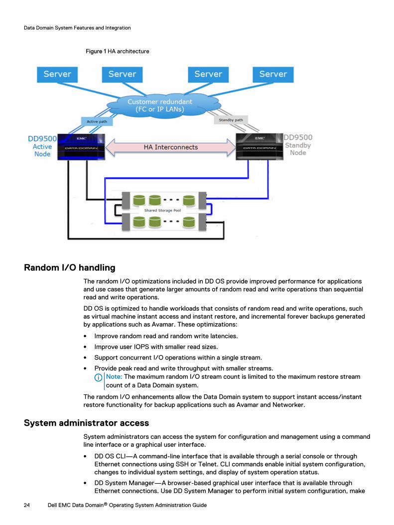
Figure 1 HA architecture
Random I/O handlingThe random I/O optimizations included in DD OS provide improved performance for applicationsand use cases that generate larger amounts of random read and write operations than sequentialread and write operations.
DD OS is optimized to handle workloads that consists of random read and write operations, suchas virtual machine instant access and instant restore, and incremental forever backups generatedby applications such as Avamar. These optimizations:
l Improve random read and random write latencies.
l Improve user IOPS with smaller read sizes.
l Support concurrent I/O operations within a single stream.
l Provide peak read and write throughput with smaller streams.Note: The maximum random I/O stream count is limited to the maximum restore streamcount of a Data Domain system.
The random I/O enhancements allow the Data Domain system to support instant access/instantrestore functionality for backup applications such as Avamar and Networker.
System administrator accessSystem administrators can access the system for configuration and management using a commandline interface or a graphical user interface.
l DD OS CLI—A command-line interface that is available through a serial console or throughEthernet connections using SSH or Telnet. CLI commands enable initial system configuration,changes to individual system settings, and display of system operation status.
l DD System Manager—A browser-based graphical user interface that is available throughEthernet connections. Use DD System Manager to perform initial system configuration, make
Data Domain System Features and Integration
24 Dell EMC Data Domain® Operating System Administration Guide
configuration changes after initial configuration, display system and component status, andgenerate reports and charts.
Note: Some systems support access using a keyboard and monitor attached directly to thesystem.
Licensed featuresFeature licenses allow you to purchase only those features you intend to use. Some examples offeatures that require licenses are DD Extended Retention, DD Boost, and storage capacityincreases.
Consult with your sales representative for information on purchasing licensed features.
Table 3 Features requiring licenses
Feature Name License Name inSoftware
Description
Data DomainArchiveStore
ARCHIVESTORE Licenses Data Domain systems for archive use,such as file and email archiving, file tiering, andcontent and database archiving.
Data Domain Boost DDBOOST Enables the use of a Data Domain system withthe following applications: Avamar, NetWorker,Oracle RMAN, Quest vRanger, Symantec VeritasNetBackup (NBU), and Backup Exec. Themanaged file replication (MFR) feature of DDBoost also requires the DD Replicator license.
Data Domain Capacityon Demand
CONTROLLER-COD
Enables an on-demand capacity increase for 4 TBDD2200 systems to 7.5 TB or 13.18 TB. Anincrease to 13.18 TB also requires theEXPANDED-STORAGE license.
Data Domain CloudTier
CLOUDTIER-CAPACITY
Enables a Data Domain system to move data fromthe active tier to low-cost, high-capacity objectstorage in the public, private, or hybrid cloud forlong-term retention.
Data DomainEncryption
ENCRYPTION Allows data on system drives or external storageto be encrypted while being saved and lockedwhen moving the system to another location.
Data DomainExpansion Storage
EXPANDED-STORAGE
Allows Data Domain system storage to beexpanded beyond the level provided in the basesystem.
Data DomainExtended Retention(formerly DDArchiver)
EXTENDED-RETENTION
Licenses the DD Extended Retention storagefeature.
Data Domain I/OS(for IBM i operatingenvironments)
I/OS An I/OS license is required when DD VTL is usedto backup systems in the IBM i operatingenvironment. Apply this license before addingvirtual tape drives to libraries.
Data DomainReplicator
REPLICATION Adds DD Replicator for replication of data fromone Data Domain system to another. A license isrequired on each system.
Data Domain System Features and Integration
Dell EMC Data Domain® Operating System Administration Guide 25
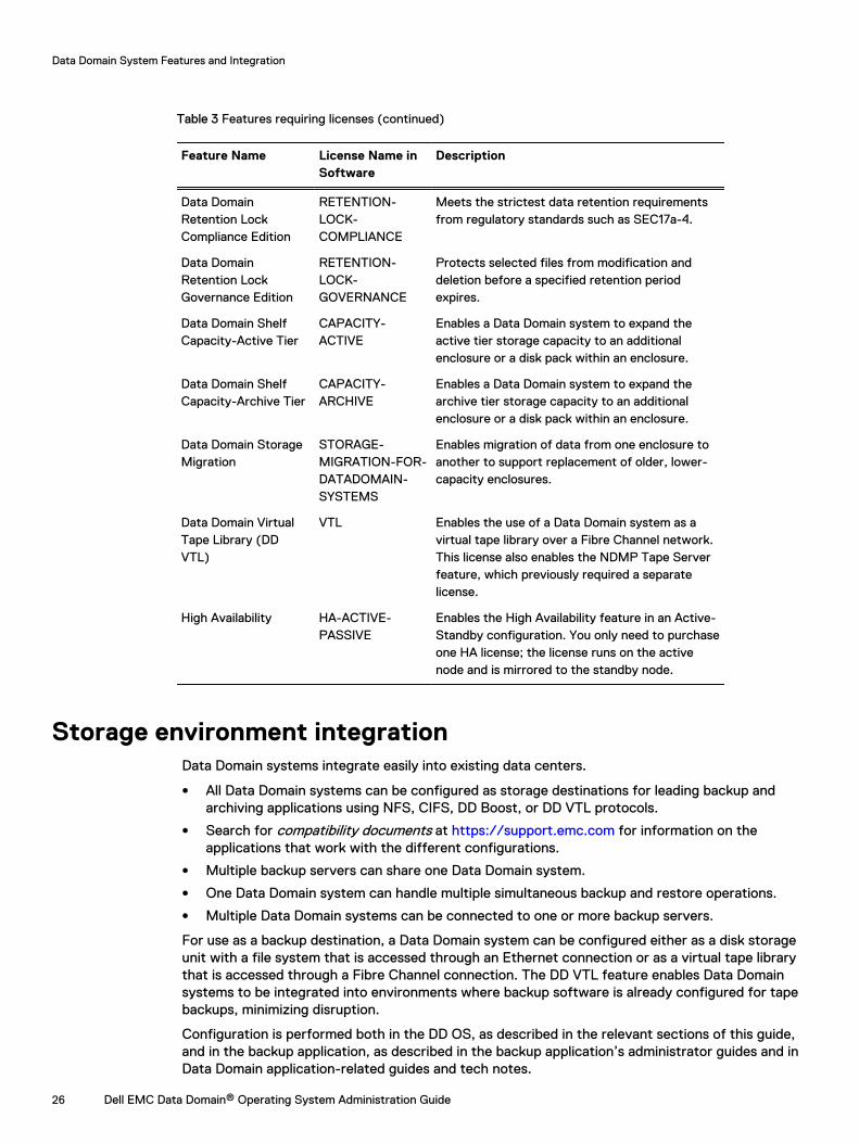
Table 3 Features requiring licenses (continued)
Feature Name License Name inSoftware
Description
Data DomainRetention LockCompliance Edition
RETENTION-LOCK-COMPLIANCE
Meets the strictest data retention requirementsfrom regulatory standards such as SEC17a-4.
Data DomainRetention LockGovernance Edition
RETENTION-LOCK-GOVERNANCE
Protects selected files from modification anddeletion before a specified retention periodexpires.
Data Domain ShelfCapacity-Active Tier
CAPACITY-ACTIVE
Enables a Data Domain system to expand theactive tier storage capacity to an additionalenclosure or a disk pack within an enclosure.
Data Domain ShelfCapacity-Archive Tier
CAPACITY-ARCHIVE
Enables a Data Domain system to expand thearchive tier storage capacity to an additionalenclosure or a disk pack within an enclosure.
Data Domain StorageMigration
STORAGE-MIGRATION-FOR-DATADOMAIN-SYSTEMS
Enables migration of data from one enclosure toanother to support replacement of older, lower-capacity enclosures.
Data Domain VirtualTape Library (DDVTL)
VTL Enables the use of a Data Domain system as avirtual tape library over a Fibre Channel network.This license also enables the NDMP Tape Serverfeature, which previously required a separatelicense.
High Availability HA-ACTIVE-PASSIVE
Enables the High Availability feature in an Active-Standby configuration. You only need to purchaseone HA license; the license runs on the activenode and is mirrored to the standby node.
Storage environment integrationData Domain systems integrate easily into existing data centers.
l All Data Domain systems can be configured as storage destinations for leading backup andarchiving applications using NFS, CIFS, DD Boost, or DD VTL protocols.
l Search for compatibility documents at https://support.emc.com for information on theapplications that work with the different configurations.
l Multiple backup servers can share one Data Domain system.
l One Data Domain system can handle multiple simultaneous backup and restore operations.
l Multiple Data Domain systems can be connected to one or more backup servers.
For use as a backup destination, a Data Domain system can be configured either as a disk storageunit with a file system that is accessed through an Ethernet connection or as a virtual tape librarythat is accessed through a Fibre Channel connection. The DD VTL feature enables Data Domainsystems to be integrated into environments where backup software is already configured for tapebackups, minimizing disruption.
Configuration is performed both in the DD OS, as described in the relevant sections of this guide,and in the backup application, as described in the backup application’s administrator guides and inData Domain application-related guides and tech notes.
Data Domain System Features and Integration
26 Dell EMC Data Domain® Operating System Administration Guide
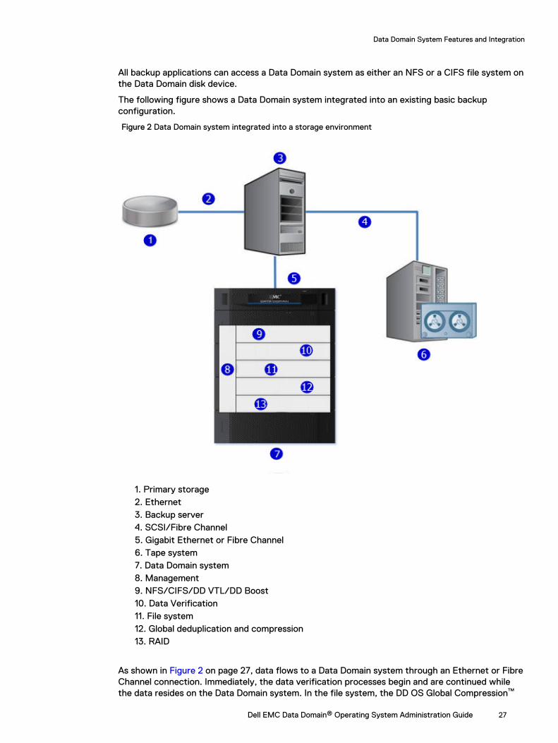
All backup applications can access a Data Domain system as either an NFS or a CIFS file system onthe Data Domain disk device.
The following figure shows a Data Domain system integrated into an existing basic backupconfiguration.
Figure 2 Data Domain system integrated into a storage environment
1. Primary storage2. Ethernet3. Backup server4. SCSI/Fibre Channel5. Gigabit Ethernet or Fibre Channel6. Tape system7. Data Domain system8. Management9. NFS/CIFS/DD VTL/DD Boost10. Data Verification11. File system12. Global deduplication and compression13. RAID
As shown in Figure 2 on page 27, data flows to a Data Domain system through an Ethernet or FibreChannel connection. Immediately, the data verification processes begin and are continued whilethe data resides on the Data Domain system. In the file system, the DD OS Global Compression™
Data Domain System Features and Integration
Dell EMC Data Domain® Operating System Administration Guide 27
algorithms dedupe and compress the data for storage. Data is then sent to the disk RAIDsubsystem. When a restore operation is required, data is retrieved from Data Domain storage,decompressed, verified for consistency, and transferred via Ethernet to the backup servers usingEthernet (for NFS, CIFS, DD Boost), or using Fiber Channel (for DD VTL and DD Boost).
The DD OS accommodates relatively large streams of sequential data from backup software and isoptimized for high throughput, continuous data verification, and high compression. It alsoaccommodates the large numbers of smaller files in nearline storage (DD ArchiveStore).
Data Domain system performance is best when storing data from applications that are notspecifically backup software under the following circumstances.
l Data is sent to the Data Domain system as sequential writes (no overwrites).
l Data is neither compressed nor encrypted before being sent to the Data Domain system.
Data Domain System Features and Integration
28 Dell EMC Data Domain® Operating System Administration Guide
CHAPTER 2
Getting Started
This chapter includes:
l Dell EMC Data Domain System Manager overview................................................................30l Logging in and out of DD System Manager............................................................................30l The DD System Manager interface........................................................................................33l Configuring the system with the configuration wizard.......................................................... 35l Data Domain Command Line Interface.................................................................................. 48l Logging into the CLI.............................................................................................................. 48l CLI online help guidelines...................................................................................................... 49
Dell EMC Data Domain® Operating System Administration Guide 29

Dell EMC Data Domain System Manager overviewDD System Manager is a browser-based user interface, available through Ethernet connections,for managing a single system from any location. DD System Manager provides a single,consolidated management interface that enables for configuration and monitoring of many systemfeatures and system settings.
Note: Data Domain Management Center enables you to manage multiple systems from a singlebrowser window.
DD System Manager provides real-time graphs and tables that enable you to monitor the status ofsystem hardware components and configured features.
Additionally, a command set that performs all system functions is available to users at thecommand-line interface (CLI). Commands configure system settings and provide displays ofsystem hardware status, feature configuration, and operation.
The command-line interface is available through a serial console or through an Ethernetconnection using SSH or Telnet.
Note: Some systems support access using a keyboard and monitor attached directly to thesystem.
DD OS Software Versions
DD OS software releases have three public statuses, indicating the number of installed systemsrunning the version.
l General Availability releases have completed Data Domain Internal QA Testing and areavailable for installation in production environments.
l Directed Availability - Controlled (Directed Availability) releases are carefully controlledaccess releases, directed to a small number of installations. Customers may request to bequalified for access to these releases.
l Target Code - It is recommended that all systems upgrade to the Data Domain OS target codewithin a release family as soon as practical.
Note: There is only one Target Code release in a given family. Target Code releases havemet the installation and run-time hours and quality metrics to indicate that they are stableand have no problems that would affect most customers. For some families, there may beno target code identified, due to limited customer uptake, quality issues, or otherconsiderations.
Upgrading between families may have product compatibility considerations, and a careful review ofproduct compatibility should precede any upgrade to a new release family.
Logging in and out of DD System ManagerUse a browser to log in to DD System Manager.
About this task
When connecting to DD System Manager from a web browser, all HTTP connections willautomatically redirect to HTTPS.
Procedure
1. Open a web browser and enter the IP address or hostname to connect to DD SystemManager. It must be:
l A fully qualified domain name (for example, http://dd01.emc.com)
Getting Started
30 Dell EMC Data Domain® Operating System Administration Guide
l A hostname (http://dd01)
l An IP address (http://10.5.50.5)
Note: DD System Manager uses HTTP port 80 and HTTPS port 443. If your DataDomain system is behind a firewall, you may need to enable port 80 if using HTTP, orport 443 if using HTTPS to reach the system. The port numbers can be easily changed ifsecurity requirements dictate.
Note: If the Data Domain System Manager is unable to launch from any web browser,the displayed error message is "The GUI Service is temporarily unavailable. Pleaserefresh your browser. If the problem persists, please contact Data Domain support forassistance." SSH can be used to login to the Data Domain system and can run allcommands.If you have not upgraded the DD OS but still encounter this GUI error, use the followingprocedure:
a. Close the web browser session on the Data Domain system with the reported error.
b. Run these commands in sequence:
l adminaccess disable httpl adminaccess disable httpsl adminaccess enable httpl adminaccess enable https
c. Wait 5 minutes to allow the http and https services to start completely.
d. Open a web browser, and connect to Data Domain System Manager.
If you see this GUI issue after a DD OS upgrade, use the following procedure:
a. Close the web browser session on the Data Domain system with the reported error.
b. Run these commands in sequence:
l adminaccess disable httpl adminaccess disable httpsl adminaccess certificate generate self-signed-certl adminaccess enable httpl adminaccess enable https
a. Wait 5 minutes to allow the http and https services to start completely.
b. Open a web browser, and connect to Data Domain System Manager.
2. For HTTPS secure login, click Secure Login.
Secure login with HTTPS requires a digital certificate to validate the identity of the DD OSsystem and to support bi-directional encryption between DD System Manager and abrowser. DD OS includes a self-signed certificate, and DD OS allows you to import your owncertificate.
3. Enter your assigned username and password.
Note: The initial username is sysadmin and the initial password is the system serialnumber. For information about setting up a new system, see the Data Domain OperatingSystem Initial Configuration Guide.
Getting Started
Dell EMC Data Domain® Operating System Administration Guide 31
4. Click Log In.
If this is the first time you have logged in, the Home view is displayed in the Informationpanel.
Note: If you enter an incorrect password 4 consecutive times, the system locks out thespecified username for 120 seconds. The login count and lockout period are configurableand might be different on your system.
Note: If this is the first time you are logging in, you might be required to change yourpassword. If the system administrator has configured your username to require apassword change, you must change the password before gaining access to DD SystemManager.
5. To log out, click the log out button in the DD System Manager banner.
When you log out, the system displays the log in page with a message that your log out iscomplete.
Logging in using a certificateAs an alternative to logging in using a username and password, you can log in to DD SystemManager with a certificate issued by a Certificate Authority (CA).
About this task
To log in using a certificate, you must have authorization privileges on the Data Domain system,and the Data Domain system must trust the CA certificate. Your username must be specified in thecommon-name field in the certificate.
Procedure
1. Ensure that you have a user account on the Data Domain system.
You can be either a local user or a name service user (NIS/AD). For a name service user,your group-to-role mapping must be configured on the Data Domain system.
2. Use the following CLI command to import the public key from the CA that issued thecertificate: adminaccess certificate import ca application login-auth.
3. Load the certificate in PKCS12 format in your browser.
Once the CA certificate is trusted by the Data Domain system, a Log in with certificate linkis visible on the HTTPS login screen.
4. Click Log in with certificate and choose the certificate from the list of certificatesprompted by the browser.
Results
The Data Domain system validates the user certificate against the trust store. Based onauthorization privileges associated with your account, a System Manager session is created foryou.
Logging in using single sign-on (SSO)As an alternative to logging in using a local username and password, you can log in to DD SystemManager with a username and password from a supported SSO provider .
Before you begin
To log in using SSO, SSO must be enabled and the Data Domain system must be registered with anSSO provider.
Getting Started
32 Dell EMC Data Domain® Operating System Administration Guide
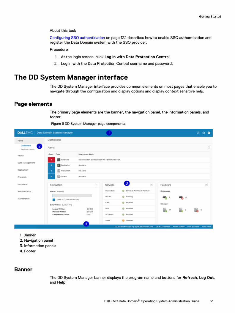
About this task
Configuring SSO authentication on page 122 describes how to enable SSO authentication andregister the Data Domain system with the SSO provider.
Procedure
1. At the login screen, click Log in with Data Protection Central.
2. Log in with the Data Protection Central username and password.
The DD System Manager interfaceThe DD System Manager interface provides common elements on most pages that enable you tonavigate through the configuration and display options and display context sensitive help.
Page elementsThe primary page elements are the banner, the navigation panel, the information panels, andfooter.
Figure 3 DD System Manager page components
1. Banner2. Navigation panel3. Information panels4. Footer
BannerThe DD System Manager banner displays the program name and buttons for Refresh, Log Out,and Help.
Getting Started
Dell EMC Data Domain® Operating System Administration Guide 33
Navigation panelThe Navigation panel displays the highest level menu selections that you can use to identify thesystem component or task that you want to manage.
The Navigation panel displays the top two levels of the navigation system. Click any top level titleto display the second level titles. Tabs and menus in the Information panel provide additionalnavigation controls.
Information panelThe Information panel displays information and controls related to the selected item in theNavigation panel. The information panel is where you find system status information and configurea system.
Depending on the feature or task selected in the Navigation panel, the Information panel maydisplay a tab bar, topic areas, table view controls, and the More Tasks menu.
Tab bar
Tabs provide access to different aspects of the topic selected in the Navigation panel.
Topic areas
Topic areas divide the Information panel into sections that represent different aspects of the topicselected in the Navigation panel or parent tab.
For high-availability (HA) systems, the HA Readiness tab on the System Manager dashboardindicates whether the HA system is ready to fail over from the active node to the standby node.You can click on HA Readiness to navigate to the High Availability section under HEALTH.
Working with table view options
Many of the views with tables of items contain controls for filtering, navigating, and sorting theinformation in the table.
How to use common table controls:
l Click the diamond icon in a column heading to reverse the sort order of items in the column.
l Click the < and > arrows at the bottom right of the view to move forward or backward throughthe pages. To skip to the beginning of a sequence of pages, click |<. To skip to the end, click>|.
l Use the scroll bar to view all items in a table.
l Enter text in the Filter By box to search for or prioritize the listing of those items.
l Click Update to refresh the list.
l Click Reset to return to the default listing.
More Tasks menu
Some pages provide a More Tasks menu at the top right of the view that contains commandsrelated to the current view.
FooterThe DD System Manager footer displays important information about the management session.
The banner lists the following information.
l System hostname.
Getting Started
34 Dell EMC Data Domain® Operating System Administration Guide
l DD OS version
l Selected system model number.
l User name and role for the current logged in user.
Help buttonsHelp buttons display a ? and appear in the banner, in the title of many areas of the Informationpanel, and in many dialogs. Click the help button to display a help window related to the currentfeature you are using.
The help window provides a contents button and navigation button above the help. Click thecontents button to display the guide contents and a search button that you can use to search thehelp. Use the directional arrow buttons to page through the help topics in sequential order.
End User License AgreementTo view the End User License Agreement (EULA), select Maintenance > System > View EULA.
Configuring the system with the configuration wizardThere are two wizards, a DD System Manager configuration wizard and a Command Line Interface(CLI) configuration wizard. The configuration wizards guide you through a simplified configurationof your system to get your system operating quickly.
About this task
After you complete the basic configuration with a wizard, you can use additional configurationcontrols in DD System Manager and the CLI to further configure your system.
Note: The following procedure describes how to start and run the DD System Managerconfiguration wizard after the initial configuration of your system. For instructions on runningthe configuration wizards at system startup, see the Data Domain Operating System InitialConfiguration Guide.
Note: If you want to configure your system for high availability (HA), you must perform thisoperation using the CLI Configuration Wizard. For more information, see the Data DomainDD9500/DD9800 Hardware Overview and Installation Guide and the Data Domain OperatingSystem Initial Configuration Guide.
Procedure
1. Select Maintenance > System > Configure System.
2. Use the controls at the bottom of the Configuration Wizard dialog to select which featuresyou want to configure and to advance through the wizard. To display help for a feature, clickthe help icon (question mark) in the lower left corner of the dialog.
License pageThe License page displays all installed licenses. Click Yes to add, modify, or delete a license, orclick No to skip license installation.
Getting Started
Dell EMC Data Domain® Operating System Administration Guide 35
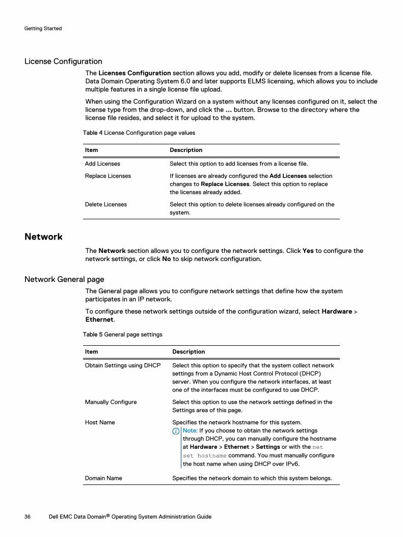
License ConfigurationThe Licenses Configuration section allows you add, modify or delete licenses from a license file.Data Domain Operating System 6.0 and later supports ELMS licensing, which allows you to includemultiple features in a single license file upload.
When using the Configuration Wizard on a system without any licenses configured on it, select thelicense type from the drop-down, and click the ... button. Browse to the directory where thelicense file resides, and select it for upload to the system.
Table 4 License Configuration page values
Item Description
Add Licenses Select this option to add licenses from a license file.
Replace Licenses If licenses are already configured the Add Licenses selectionchanges to Replace Licenses. Select this option to replacethe licenses already added.
Delete Licenses Select this option to delete licenses already configured on thesystem.
NetworkThe Network section allows you to configure the network settings. Click Yes to configure thenetwork settings, or click No to skip network configuration.
Network General pageThe General page allows you to configure network settings that define how the systemparticipates in an IP network.
To configure these network settings outside of the configuration wizard, select Hardware >Ethernet.
Table 5 General page settings
Item Description
Obtain Settings using DHCP Select this option to specify that the system collect networksettings from a Dynamic Host Control Protocol (DHCP)server. When you configure the network interfaces, at leastone of the interfaces must be configured to use DHCP.
Manually Configure Select this option to use the network settings defined in theSettings area of this page.
Host Name Specifies the network hostname for this system.Note: If you choose to obtain the network settingsthrough DHCP, you can manually configure the hostnameat Hardware > Ethernet > Settings or with the netset hostname command. You must manually configure
the host name when using DHCP over IPv6.
Domain Name Specifies the network domain to which this system belongs.
Getting Started
36 Dell EMC Data Domain® Operating System Administration Guide
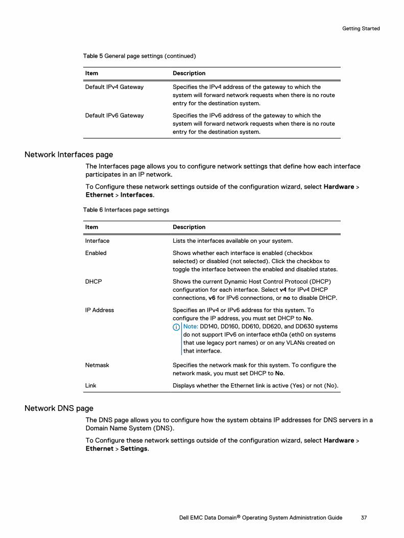
Table 5 General page settings (continued)
Item Description
Default IPv4 Gateway Specifies the IPv4 address of the gateway to which thesystem will forward network requests when there is no routeentry for the destination system.
Default IPv6 Gateway Specifies the IPv6 address of the gateway to which thesystem will forward network requests when there is no routeentry for the destination system.
Network Interfaces pageThe Interfaces page allows you to configure network settings that define how each interfaceparticipates in an IP network.
To Configure these network settings outside of the configuration wizard, select Hardware >Ethernet > Interfaces.
Table 6 Interfaces page settings
Item Description
Interface Lists the interfaces available on your system.
Enabled Shows whether each interface is enabled (checkboxselected) or disabled (not selected). Click the checkbox totoggle the interface between the enabled and disabled states.
DHCP Shows the current Dynamic Host Control Protocol (DHCP)configuration for each interface. Select v4 for IPv4 DHCPconnections, v6 for IPv6 connections, or no to disable DHCP.
IP Address Specifies an IPv4 or IPv6 address for this system. Toconfigure the IP address, you must set DHCP to No.
Note: DD140, DD160, DD610, DD620, and DD630 systemsdo not support IPv6 on interface eth0a (eth0 on systemsthat use legacy port names) or on any VLANs created onthat interface.
Netmask Specifies the network mask for this system. To configure thenetwork mask, you must set DHCP to No.
Link Displays whether the Ethernet link is active (Yes) or not (No).
Network DNS pageThe DNS page allows you to configure how the system obtains IP addresses for DNS servers in aDomain Name System (DNS).
To Configure these network settings outside of the configuration wizard, select Hardware >Ethernet > Settings.
Getting Started
Dell EMC Data Domain® Operating System Administration Guide 37
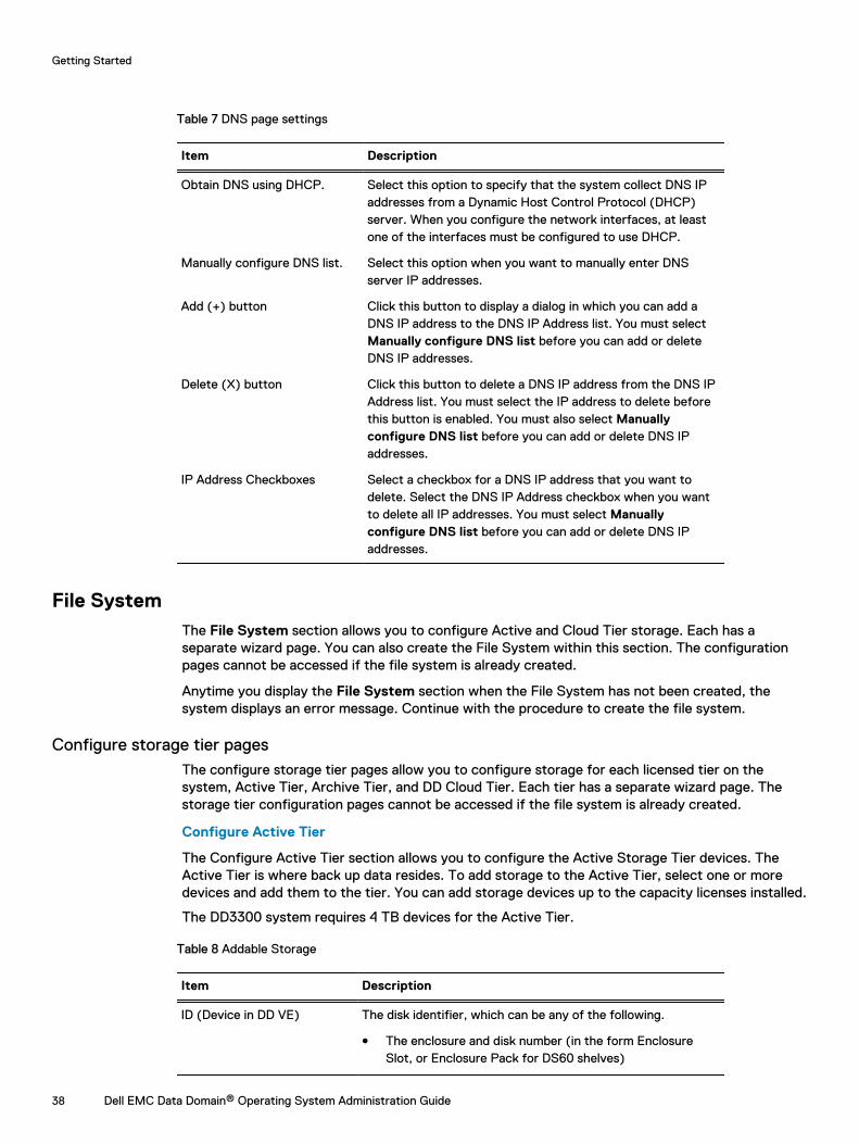
Table 7 DNS page settings
Item Description
Obtain DNS using DHCP. Select this option to specify that the system collect DNS IPaddresses from a Dynamic Host Control Protocol (DHCP)server. When you configure the network interfaces, at leastone of the interfaces must be configured to use DHCP.
Manually configure DNS list. Select this option when you want to manually enter DNSserver IP addresses.
Add (+) button Click this button to display a dialog in which you can add aDNS IP address to the DNS IP Address list. You must selectManually configure DNS list before you can add or deleteDNS IP addresses.
Delete (X) button Click this button to delete a DNS IP address from the DNS IPAddress list. You must select the IP address to delete beforethis button is enabled. You must also select Manuallyconfigure DNS list before you can add or delete DNS IPaddresses.
IP Address Checkboxes Select a checkbox for a DNS IP address that you want todelete. Select the DNS IP Address checkbox when you wantto delete all IP addresses. You must select Manuallyconfigure DNS list before you can add or delete DNS IPaddresses.
File SystemThe File System section allows you to configure Active and Cloud Tier storage. Each has aseparate wizard page. You can also create the File System within this section. The configurationpages cannot be accessed if the file system is already created.
Anytime you display the File System section when the File System has not been created, thesystem displays an error message. Continue with the procedure to create the file system.
Configure storage tier pagesThe configure storage tier pages allow you to configure storage for each licensed tier on thesystem, Active Tier, Archive Tier, and DD Cloud Tier. Each tier has a separate wizard page. Thestorage tier configuration pages cannot be accessed if the file system is already created.
Configure Active Tier
The Configure Active Tier section allows you to configure the Active Storage Tier devices. TheActive Tier is where back up data resides. To add storage to the Active Tier, select one or moredevices and add them to the tier. You can add storage devices up to the capacity licenses installed.
The DD3300 system requires 4 TB devices for the Active Tier.
Table 8 Addable Storage
Item Description
ID (Device in DD VE) The disk identifier, which can be any of the following.
l The enclosure and disk number (in the form EnclosureSlot, or Enclosure Pack for DS60 shelves)
Getting Started
38 Dell EMC Data Domain® Operating System Administration Guide
Table 8 Addable Storage (continued)
Item Description
l A device number for a logical device such as those used byDD VTL and vDisk
l A LUN
Disks The disks that comprise the disk pack or LUN. This does notapply to DD VE instances.
Model The type of disk shelf. This does not apply to DD VE instances.
Disk Count The number of disks in the disk pack or LUN. This does notapply to DD VE instances.
Disk Size (Size in DD VE) The data storage capacity of the disk when used in a DataDomain system.a
License Needed The licensed capacity required to add the storage to the tier.
Failed Disks Failed disks in the disk pack or LUN. This does not apply to DDVE instances.
Type SCSI. This only applies to DD VE instances.
a. The Data Domain convention for computing disk space defines one gibibyte as 230 bytes,giving a different disk capacity than the manufacturer’s rating.
Table 9 Active Tier values
Item Description
ID (Device in DD VE) The disk identifier, which can be any of the following.
l The enclosure and disk number (in the form EnclosureSlot, or Enclosure Pack for DS60 shelves). This does notapply to DD VE instances.
l A device number for a logical device such as those used byDD VTL and vDisk
l A LUN
Disks The disks that comprise the disk pack or LUN. This does notapply to DD VE instances.
Model The type of disk shelf. This does not apply to DD VE instances.
Disk Count The number of disks in the disk pack or LUN. This does notapply to DD VE instances.
Disk Size (Size in DD VE) The data storage capacity of the disk when used in a DataDomain system.a
License Used The licensed capacity consumed by the storage.
Failed Disks Failed disks in the disk pack or LUN. This does not apply to DDVE instances.
Configured New or existing storage. This does not apply to DD VEinstances.
Type SCSI. This only applies to DD VE instances.
Getting Started
Dell EMC Data Domain® Operating System Administration Guide 39
Table 9 Active Tier values (continued)
a. The Data Domain convention for computing disk space defines one gibibyte as 230 bytes,giving a different disk capacity than the manufacturer’s rating.
Configure Archive Tier
The Configure Archive Tier section allows you to configure the Archive Storage Tier devices. TheArchive Tier is where data archived with the DD Extended Retention feature resides. To addstorage to the Archive Tier, select one or more devices and add them to the tier. You can addstorage devices up to the capacity licenses installed.
Archive Tier storage is not available on the DD3300 system, or on DD VE instances.
Table 10 Addable Storage
Item Description
ID The disk identifier, which can be any of the following.
l The enclosure and disk number (in the form EnclosureSlot, or Enclosure Pack for DS60 shelves)
l A device number for a logical device such as those used byDD VTL and vDisk
l A LUN
Disks The disks that comprise the disk pack or LUN.
Model The type of disk shelf.
Disk Count The number of disks in the disk pack or LUN.
Disk Size (Size in DD VE) The data storage capacity of the disk when used in a DataDomain system.a
License Needed The licensed capacity required to add the storage to the tier.
Failed Disks Failed disks in the disk pack or LUN.
a. The Data Domain convention for computing disk space defines one gibibyte as 230 bytes,giving a different disk capacity than the manufacturer’s rating.
Table 11 Archive Tier values
Item Description
ID The disk identifier, which can be any of the following.
l The enclosure and disk number (in the form EnclosureSlot, or Enclosure Pack for DS60 shelves). This does notapply to DD VE instances.
l A device number for a logical device such as those used byDD VTL and vDisk
l A LUN
Disks The disks that comprise the disk pack or LUN.
Model The type of disk shelf.
Disk Count The number of disks in the disk pack or LUN.
Getting Started
40 Dell EMC Data Domain® Operating System Administration Guide
Table 11 Archive Tier values (continued)
Item Description
Disk Size (Size in DD VE) The data storage capacity of the disk when used in a DataDomain system.a
License Used The licensed capacity consumed by the storage.
Failed Disks Failed disks in the disk pack or LUN.
Configured New or existing storage.
a. The Data Domain convention for computing disk space defines one gibibyte as 230 bytes,giving a different disk capacity than the manufacturer’s rating.
Configure Cloud Tier
The Configure Cloud Tier section allows you to configure the Cloud Storage Tier devices. To addstorage to the Cloud Tier, select one or more devices and add them to the tier. You can addstorage devices up to the capacity licenses installed.
The DD3300 system requires 1 TB devices for DD Cloud Tier.
Table 12 Addable Storage
Item Description
ID (Device in DD VE) The disk identifier, which can be any of the following.
l The enclosure and disk number (in the form EnclosureSlot, or Enclosure Pack for DS60 shelves)
l A device number for a logical device such as those used byDD VTL and vDisk
l A LUN
Disks The disks that comprise the disk pack or LUN. This does notapply to DD VE instances.
Model The type of disk shelf. This does not apply to DD VE instances.
Disk Count The number of disks in the disk pack or LUN. This does notapply to DD VE instances.
Disk Size (Size in DD VE) The data storage capacity of the disk when used in a DataDomain system.a
License Needed The licensed capacity required to add the storage to the tier.
Failed Disks Failed disks in the disk pack or LUN. This does not apply to DDVE instances.
Type SCSI. This only applies to DD VE instances.
a. The Data Domain convention for computing disk space defines one gibibyte as 230 bytes,giving a different disk capacity than the manufacturer’s rating.
Table 13 Cloud Tier values
Item Description
ID (Device in DD VE) The disk identifier, which can be any of the following.
Getting Started
Dell EMC Data Domain® Operating System Administration Guide 41
Table 13 Cloud Tier values (continued)
Item Description
l The enclosure and disk number (in the form EnclosureSlot, or Enclosure Pack for DS60 shelves). This does notapply to DD VE instances.
l A device number for a logical device such as those used byDD VTL and vDisk
l A LUN
Disks The disks that comprise the disk pack or LUN. This does notapply to DD VE instances.
Model The type of disk shelf. This does not apply to DD VE instances.
Disk Count The number of disks in the disk pack or LUN. This does notapply to DD VE instances.
Disk Size (Size in DD VE) The data storage capacity of the disk when used in a DataDomain system.a
License Used The licensed capacity consumed by the storage.
Failed Disks Failed disks in the disk pack or LUN. This does not apply to DDVE instances.
Configured New or existing storage. This does not apply to DD VEinstances.
Type SCSI. This only applies to DD VE instances.
a. The Data Domain convention for computing disk space defines one gibibyte as 230 bytes,giving a different disk capacity than the manufacturer’s rating.
Create File System pageThe Create File System page displays the allowed size of each storage tier in the file system, andallows you to automatically enable the file system after it is created.
System SettingsThe System Settings section allows you to configure system passwords, and email settings. ClickYes to configure the system settings, or click No to skip system settings configuration.
System Settings Administrator pageThe Administrator page allows you to configure the administrator password and how the systemcommunicates with the administrator.
Table 14 Administrator page settings
Item Description
User Name The default administrator name is sysadmin. The sysadminuser cannot be renamed or deleted.
Old Password Type the old password for sysadmin.
New Password Type the new password for sysadmin.
Getting Started
42 Dell EMC Data Domain® Operating System Administration Guide
Table 14 Administrator page settings (continued)
Item Description
Verify New Password Retype the new password for sysadmin.
Admin Email Specify the email address to which DD System Managersends alert and autosupport email messages.
Send Alert Notification Emailsto this address
Check to configure DD System Manager to send alertnotifications to the Admin email address as alert eventsoccur.
Send Daily Alert SummaryEmails to this address
Check to configure DD System Manager to send alertsummaries to the Admin email address at the end of each day.
Send Autosupport Emails tothis address
Check to configure DD System Manager to send the Adminuser autosupport emails, which are daily reports thatdocument system activity and status.
System Settings Email/Location pageThe Email/Location page allows you to configure the mail server name, control what systeminformation is sent to Data Domain, and specify a location name to identify your system.
Table 15 Email/Location page settings
Item Description
Mail Server Specify the name of the mail server that manages emails toand from the system.
Credentials Select whether or not to require credentials for the mailserver.
User Name If credentials are enabled, specify the mail server username.
Password If credentials are enabled, specify the mail server password.
Send Alert Notification Emailsto Data Domain
Check to configure DD System Manager to send alertnotification emails to Data Domain.
Send Vendor SupportNotification Emails to DataDomain
Check to configure DD System Manager to send vendorsupport notification emails to Data Domain.
Location Use this optional attribute as needed to record the location ofyour system. If you specify a location, this information isstored as the SNMP system location.
DD Boost protocolThe DD Boost settings section allows you to configure the DD Boost protocol settings. Click Yesto configure the DD Boost Protocol settings, or click No to skip DD Boost configuration.
Getting Started
Dell EMC Data Domain® Operating System Administration Guide 43
DD Boost Protocol Storage Unit pageThe Storage Unit page allows you to configure DD Boost storage units.
To configure these settings outside of the configuration wizard, select Protocols > DD Boost >Storage Units > + (plus sign) to add a storage unit, the pencil to modify a storage unit, or X todelete a storage unit.
Table 16 Storage Unit page settings
Item Description
Storage Unit The name of your DD Boost Storage Unit. You may optionallychange this name.
User For the default DD Boost user, either select an existing user,or select Create a new Local User, and enter their User name,Password, and Management Role. This role can be one of thefollowing:
l Admin role: Lets you configure and monitor the entireData Domain system.
l User role: Lets you monitor Data Domain systems andchange your own password.
l Security role: In addition to user role privileges, lets youset up security-officer configurations and manage othersecurity-officer operators.
l Backup-operator role: In addition to user role privileges,lets you create snapshots, import and export tapes to, ormove tapes within a DD VTL.
l None role: Intended only for DD Boost authentication, soyou cannot monitor or configure a Data Domain system.None is also the parent role for the SMT tenant-adminand tenant-user roles. None is also the preferred usertype for DD Boost storage owners. Creating a new localuser here only allows that user to have the "none" role.
DD Boost Protocol Fibre Channel pageThe Fibre Channel page allows you to configure DD Boost Access Groups over Fibre Channel.
To configure these settings outside of the configuration wizard, select Protocols > DD Boost >Fibre Channel > + (plus sign) to add an access group, the pencil to modify an access group, or Xto delete an access group.
Table 17 Fibre Channel page settings
Item Description
Configure DD Boost over FibreChannel
Select the checkbox if you want to configure DD Boost overFibre Channel.
Group Name (1-128 Chars) Create an Access Group. Enter a unique name. Duplicateaccess groups are not supported.
Getting Started
44 Dell EMC Data Domain® Operating System Administration Guide
Table 17 Fibre Channel page settings (continued)
Item Description
Initiators Select one or more initiators. Optionally, replace the initiatorname by entering a new one. An initiator is a backup clientthat connects to the system to read and write data using theFC (Fibre Channel) protocol. A specific initiator can supportDD Boost over FC or DD VTL, but not both.
Devices The devices to be used are listed. They are available on allendpoints. An endpoint is the logical target on the DataDomain system to which the initiator connects.
CIFS protocolThe CIFS Protocol settings section allows you to configure the CIFS protocol settings. Click Yesto configure the CIFS protocol settings, or click No to skip CIFS configuration.
Data Domain systems use the term MTree to describe directories. When you configure a directorypath, DD OS creates an MTree where the data will reside.
CIFS Protocol Authentication pageThe Authentication page enables you to configure Active Directory and Workgroup for yoursystem.
To configure these settings outside of the configuration wizard, select Administration > Access >Authentication.
Table 18 Authentication page settings
Item Description
Active Directory/KerberosAuthentication
Expand this panel to enable, disable, and configure ActiveDirectory Kerberos authentication.
Workgroup Authentication Expand this panel to configure Workgroup authentication.
LDAP Authentication Expand this panel to configure LDAP authentication.
NIS Authentication Expand this panel to configure NIS authentication.
CIFS Protocol Share pageThe Share page enables you to configure a CIFS protocol share name and a directory path for yoursystem.
To configure these settings outside of the configuration wizard, select Protocols > CIFS >Shares > Create.
Table 19 Share page settings
Item Description
Share Name Enter a share name for the system.
Directory Path Enter a directory path for the system.
Add (+) button Click + to enter a system client, user, or group.
Getting Started
Dell EMC Data Domain® Operating System Administration Guide 45

Table 19 Share page settings (continued)
Item Description
Pencil icon Modify a client, user, or group.
Delete (X) button Click X to delete a selected client, user. or group.
NFS protocolThe NFS Protocol settings section allows you to configure the NFS protocol settings. Click Yes toconfigure the NFS protocol settings, or click No to skip NFS configuration.
Data Domain systems use the term MTree to describe directories. When you configure a directorypath, DD OS creates an MTree where the data will reside.
NFS Protocol Export pageThe Export page enables you to configure an NFS protocol export directory path, network clients,and NFSv4 referrals.
To configure these settings outside of the configuration wizard, select Protocols > NFS > Create.
Table 20 Export page settings
Item Description
Directory Path Enter a pathname for the export.
Add (+) button Click + to enter a system client or NFSv4 referral.
Pencil icon Modify a client or NFSv4 referral.
Delete (X) button Click X to delete a selected client or NFSv4 referral.
DD VTL protocolThe DD VTL Protocol settings section allows you to configure the Data Domain Virtual TapeLibrary settings. Click Yes to configure the DD VTL settings, or click No to skip DD VTLconfiguration.
VTL Protocol Library pageThe Library page allows you to configure the DD VTL protocol settings for a library.
To configure these settings outside of the configuration wizard, select PROTOCOLS > VTL >Virtual Tape Libraries > VTL Service > Libraries > More Tasks > Library > Create
Table 21 Library page settings
Item Description
Library Name Enter a name of from 1 to 32 alphanumeric characters.
Number of Drives Number of supported tape drives.
Drive Model Select the desired model from the drop-down list:
l IBM-LTO-1
l IBM-LTO-2
Getting Started
46 Dell EMC Data Domain® Operating System Administration Guide
Table 21 Library page settings (continued)
Item Description
l IBM-LTO-3
l IBM-LTO-4
l IBM-LTO-5 (default)
l HP-LTO-3
l HP-LTO-4
Number of Slots Enter the number of slots per library:
l Up to 32,000 slots per library
l Up to 64,000 slots per system
l This should be equal to, or greater than, the number of drives.
Number of CAPs (Optional) Enter the number of cartridge access ports (CAPs):
l Up to 100 CAPs per library
l Up to 1000 CAPs per system
Changer Model Name Select the desired model from the drop-down list:
l L180 (default)
l RESTORER-L180
l TS3500
l I2000
l I6000
l DDVTL
Starting Barcode Enter the desired barcode for the first tape, in the formatA990000LA.
Tape Capacity (Optional) Enter the tape capacity. If not specified, the capacity isderived from the last character of the barcode.
VTL Protocol Access Group pageThe Access Group page allows you to configure DD VTL protocol settings for an access group.
To configure these settings outside of the configuration wizard, select PROTOCOLS > VTL >Access Groups > Groups > More Tasks > Group > Create.
Table 22 Access Group page settings
Item Description
Group Name Enter a unique name of from 1 - 128 characters. Duplicate access groupsare not supported.
Initiators Select one or more initiators. Optionally, replace the initiator name byentering a new one. An initiator is a backup client that connects to asystem to read and write data using the Fibre Channel (FC) protocol. Aspecific initiator can support DD Boost over FC or DD VTL, but not both.
Getting Started
Dell EMC Data Domain® Operating System Administration Guide 47
Table 22 Access Group page settings (continued)
Item Description
Devices The devices (drives and changer) to be used are listed. These areavailable on all endpoints. An endpoint is the logical target on the DataDomain system to which the initiator connects.
Data Domain Command Line InterfaceThe Command Line Interface (CLI) is a text driven interface that can be used instead of or inaddition to DD System Manager. Most management tasks can be performed in DD SystemManager or with the CLI. In some cases, the CLI offers configuration options and reports that arenot yet supported in DD System Manager.
Any Data Domain system command that accepts a list, such as a list of IP addresses, acceptsentries separated by commas, by spaces, or both.
The Tab key can be used to do the following.
l Complete a command entry when that entry is unique. Tab completion is supported for allkeywords. For example, entering syst Tab shTab st Tab displays the command systemshow stats.
l Show the next available option, if you do not enter any characters before pressing the Tab key.
l Show partial matched tokens or complete a unique entry, if you enter characters beforepressing the Tab key.
The Data Domain Operating System Command Reference Guide provides information for each of theCLI commands. Online help is available and provides the complete syntax for each command.
Logging into the CLIYou can access the CLI using a direct connection to the system or using an Ethernet connectionthrough SSH or Telenet.
Before you begin
To use the CLI, you must establish a local or remote connection to the system using one of thefollowing methods.
l If you are connecting through a serial console port on the system, connect a terminal consoleto the port and use the communication settings: 9600 baud, 8 data bits, no parity, and 1 stopbit.
l If the system provides keyboard and monitor ports, connect a keyboard and monitor to thoseports.
l If you are connecting through Ethernet, connect a computer with SSH or Telnet clientsoftware to an Ethernet network that can communicate with the system.
Procedure
1. If you are using an SSH or Telnet connection to access the CLI, start the SSH or Telnetclient and specify the IP address or host name of the system.
For information on initiating the connection, see the documentation for the client software.The system prompts you for your username.
2. When prompted, enter your system username.
Getting Started
48 Dell EMC Data Domain® Operating System Administration Guide
3. When prompted, enter your system password.
The following example shows SSH login to a system named mysystem using SSHclient software.
# ssh -l sysadmin mysystem.mydomain.com Data Domain OS 5.6.0.0-19899 Password:
CLI online help guidelinesThe CLI displays two types of help, syntax-only help and command-description help that includesthe command syntax. Both types of help offer features that allow you reduce the time it takes tofind the information you need.
The following guidelines describe how to use syntax-only help.
l To list the top-level CLI commands, enter a question mark (?), or type the command help atthe prompt.
l To list all forms of a top-level command, enter the command with no options at the prompt orenter command ?.
l To list all commands that use a specific keyword, enter help keyword or ? keyword.For example, ? password displays all Data Domain system commands that use the passwordargument.
The following guidelines describe how to use command-description help.
l To list the top-level CLI commands, enter a question mark (?), or type the command help atthe prompt.
l To list all forms of a top-level command with an introduction, enter help command or ?command.
l The end of each help description is marked END. Press Enter to return to the CLI prompt.
l When the complete help description does not fit in the display, the colon prompt (:) appears atthe bottom of the display. The following guidelines describe what you can do when this promptappears.
n To move through the help display, use the up and down arrow keys.
n To quit the current help display and return to the CLI prompt, press q.
n To display help for navigating the help display, press h.
n To search for text in the help display, enter a slash character (/) followed by a pattern touse as search criteria and press Enter. Matches are highlighted.
Getting Started
Dell EMC Data Domain® Operating System Administration Guide 49

Getting Started
50 Dell EMC Data Domain® Operating System Administration Guide
CHAPTER 3
Managing Data Domain Systems
This chapter includes:
l System management overview..............................................................................................52l Rebooting a system...............................................................................................................53l Powering a system on or off .................................................................................................53l System upgrade management...............................................................................................55l Managing electronic licenses.................................................................................................63l System storage management................................................................................................ 63l Network connection management......................................................................................... 72l System passphrase management.......................................................................................... 92l System access management................................................................................................. 93l Configuring mail server settings...........................................................................................125l Managing time and date settings......................................................................................... 126l Managing system properties................................................................................................ 127l SNMP management............................................................................................................. 127l Autosupport report management......................................................................................... 135l Support bundle management............................................................................................... 138l Coredump management....................................................................................................... 139l Alert notification management............................................................................................. 140l Support delivery management..............................................................................................147l Log file management............................................................................................................149l Remote system power management with IPMI.................................................................... 154
Dell EMC Data Domain® Operating System Administration Guide 51
System management overviewDD System Manager allows you to manage the system on which DD System Manager is installed.
To support replication, DD System Manager supports the addition of systems running the previoustwo versions, the current version and the next two versions as they become available. DD SystemManager supports the addition of systems up to two releases back as replication targets. The DDOS 6.2 release includes DD OS 6.1 and DD OS 6.0.
Note: When processing a heavy load, a system might be less responsive than normal. In thiscase, management commands issued from either DD System Manager or the CLI might takelonger to complete. When the duration exceeds allowed limits, a timeout error is returned,even if the operation completed.
The following table lists the recommendations for the maximum number of user sessions supportedby DD System Manager:
Table 23 Maximum number of users supported by DD System Manager
System Model Maximum Active Users Maximum Logged InUsers
4 GB modelsa 5 10
8 GB modelsb 10 15
16 GB and greater modelsc 10 20
a. Includes DD140 and DD2200 (4 TB)b. Includes DD610 and DD630c. Includes DD670, DD860, DD890, DD990, DD2200 (>7.5TB), DD4200, DD4500, DD6300,
DD6800, DD7200, DD9300, DD9500, and DD9800
Note: Initial HA system set-up cannot be configured from the DD System Manager, but thestatus of a configured HA system can be viewed from DD System Manager.
HA system management overviewThe HA relationship between the two nodes, one active and one standby, is setup through DDSHCLIs.
Initial set-up can be run on either of the two nodes but only one at a time. It is a precondition of HAthat the system interconnect and identical hardware is setup on both nodes first.
Note: Both DDRs are required to have identical hardware which will be validated during setupand system boot-up.
If set-up is from a fresh install of systems, the ha create command needs to be run on the nodewith the license installed. If setup is from an existing system and a new fresh install system(upgrade), then it should be run from the existing system.
HA system planned maintenanceThe HA architecture provides a rolling upgrade, which reduces maintenance downtime for a DD OSupgrade.
With a rolling upgrade, the HA nodes are upgraded one by one, coordinately and automatically. Thestandby node is rebooted and upgraded first. The newly upgraded node then takes over the activerole through an HA failover. After the failover, the second node is rebooted and assumes the roleof the standby node after the upgrade.
Managing Data Domain Systems
52 Dell EMC Data Domain® Operating System Administration Guide
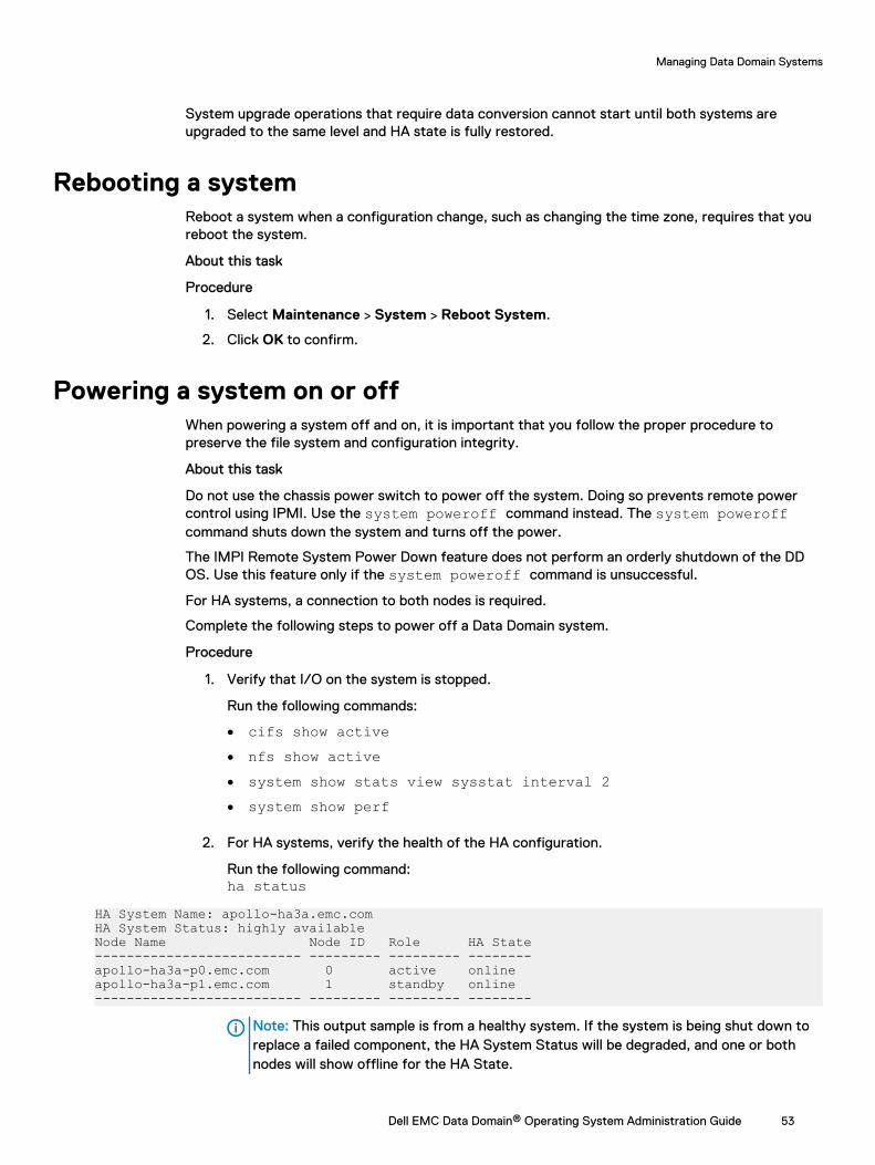
System upgrade operations that require data conversion cannot start until both systems areupgraded to the same level and HA state is fully restored.
Rebooting a systemReboot a system when a configuration change, such as changing the time zone, requires that youreboot the system.
About this task
Procedure
1. Select Maintenance > System > Reboot System.
2. Click OK to confirm.
Powering a system on or offWhen powering a system off and on, it is important that you follow the proper procedure topreserve the file system and configuration integrity.
About this task
Do not use the chassis power switch to power off the system. Doing so prevents remote powercontrol using IPMI. Use the system poweroff command instead. The system poweroffcommand shuts down the system and turns off the power.
The IMPI Remote System Power Down feature does not perform an orderly shutdown of the DDOS. Use this feature only if the system poweroff command is unsuccessful.
For HA systems, a connection to both nodes is required.
Complete the following steps to power off a Data Domain system.
Procedure
1. Verify that I/O on the system is stopped.
Run the following commands:
l cifs show activel nfs show activel system show stats view sysstat interval 2l system show perf
2. For HA systems, verify the health of the HA configuration.
Run the following command:ha status
HA System Name: apollo-ha3a.emc.comHA System Status: highly availableNode Name Node ID Role HA State-------------------------- --------- --------- --------apollo-ha3a-p0.emc.com 0 active onlineapollo-ha3a-p1.emc.com 1 standby online-------------------------- --------- --------- --------
Note: This output sample is from a healthy system. If the system is being shut down toreplace a failed component, the HA System Status will be degraded, and one or bothnodes will show offline for the HA State.
Managing Data Domain Systems
Dell EMC Data Domain® Operating System Administration Guide 53
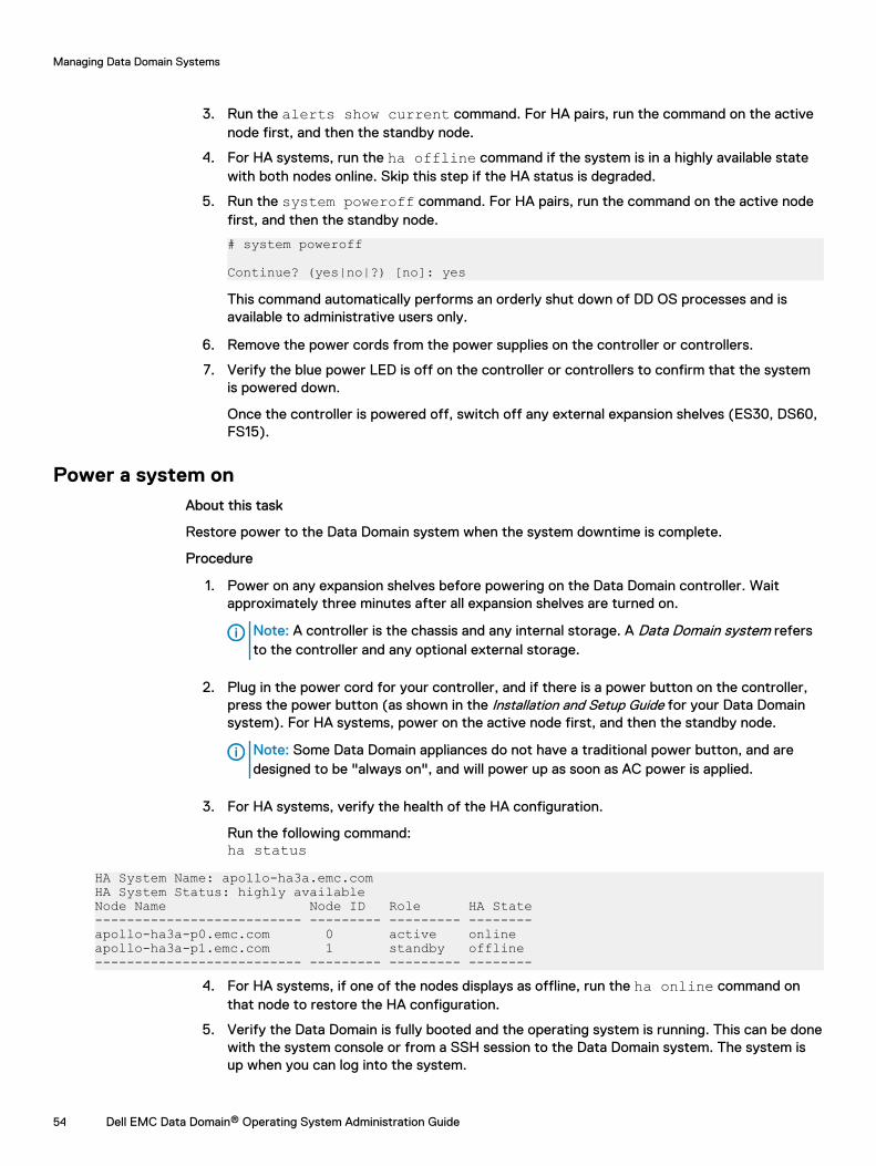
3. Run the alerts show current command. For HA pairs, run the command on the activenode first, and then the standby node.
4. For HA systems, run the ha offline command if the system is in a highly available statewith both nodes online. Skip this step if the HA status is degraded.
5. Run the system poweroff command. For HA pairs, run the command on the active nodefirst, and then the standby node.
# system poweroff
Continue? (yes|no|?) [no]: yes
This command automatically performs an orderly shut down of DD OS processes and isavailable to administrative users only.
6. Remove the power cords from the power supplies on the controller or controllers.
7. Verify the blue power LED is off on the controller or controllers to confirm that the systemis powered down.
Once the controller is powered off, switch off any external expansion shelves (ES30, DS60,FS15).
Power a system onAbout this task
Restore power to the Data Domain system when the system downtime is complete.
Procedure
1. Power on any expansion shelves before powering on the Data Domain controller. Waitapproximately three minutes after all expansion shelves are turned on.
Note: A controller is the chassis and any internal storage. A Data Domain system refersto the controller and any optional external storage.
2. Plug in the power cord for your controller, and if there is a power button on the controller,press the power button (as shown in the Installation and Setup Guide for your Data Domainsystem). For HA systems, power on the active node first, and then the standby node.
Note: Some Data Domain appliances do not have a traditional power button, and aredesigned to be "always on", and will power up as soon as AC power is applied.
3. For HA systems, verify the health of the HA configuration.
Run the following command:ha status
HA System Name: apollo-ha3a.emc.comHA System Status: highly availableNode Name Node ID Role HA State-------------------------- --------- --------- --------apollo-ha3a-p0.emc.com 0 active onlineapollo-ha3a-p1.emc.com 1 standby offline-------------------------- --------- --------- --------
4. For HA systems, if one of the nodes displays as offline, run the ha online command onthat node to restore the HA configuration.
5. Verify the Data Domain is fully booted and the operating system is running. This can be donewith the system console or from a SSH session to the Data Domain system. The system isup when you can log into the system.
Managing Data Domain Systems
54 Dell EMC Data Domain® Operating System Administration Guide

6. Run the alerts show current command. For HA pairs, run the command on the activenode first, and then the standby node.
System upgrade managementTo upgrade a DD OS system, you must verify that there is sufficient room for the new software onthe target system, transfer the software to the system to be upgraded, and then start theupgrade. For an HA system, transfer the software to the active node and start the upgrade fromthe active node.
For HA systems, use the floating IP address to access DD System Manager to perform softwareupgrades.
If the system uses MD5-signed certificates, regenerate the certificates with a stronger hashalgorithm during the upgrade process.
Minimally disruptive upgrade
The minimally disruptive upgrade (MDU) feature lets you upgrade specific software components orapply bug fixes without needing to perform a system reboot. Only those services that depend onthe component being upgraded are disrupted, so the MDU feature can prevent significantdowntime during certain software upgrades.
Not all software components qualify for a minimally disruptive upgrade; such components must beupgraded as part of a regular DD OS system software upgrade. A DD OS software upgrade uses alarge RPM (upgrade bundle), which performs upgrade actions for all of the components of DD OS.MDU uses smaller component bundles, which upgrade specific software components individually.
RPM signature verification
RPM signature verification validates Data Domain RPMs that you download for upgrade. If theRPM has not been tampered with, the digital signature is valid and you can use the RPM as usual.If the RPM has been tampered with, the corruption invalidates the digital signature, and the RPMis rejected by DD OS. An appropriate error message is displayed.
Support software
DD OS 6.1 introduces a type of software package called support software. Support software isprovided by Data Domain Support Engineering to address specific issues. By default, the DataDomain system does not allow support software to be installed on the system. Contact Support formore information about support software.
Pre-upgrade checklists and overviewBefore performing any DD OS upgrade, you should review the items in these checklists beforeproceeding. Doing so can simplify the upgrade process and ward off potential difficulties.
Pre-upgrade manual tasks
CAUTION Failure to perform the tasks in this section may result in an upgrade failure.
These are tasks that you should plan to do prior to the upgrade. These tasks are not performedautomatically by any process.
1. Reboot the Data Domain system. For HA systems, follow the reboot instructions described in Upgrade considerations for HA systems on page 57 after performing the rest of the checks inthis section.
2. Check for current alerts; this can reveal many such disk and other hardware failures thatshould be addressed prior to upgrading:
Managing Data Domain Systems
Dell EMC Data Domain® Operating System Administration Guide 55
# alert show current3. Check that registry settings for config.net.*, crontab, and those related to networking
are valid.
For example, use the reg show config.net operation, and check to see whethernoauto.enabled, noauto.speed, and noauto.full_duplex are appropriately set. Thiswill allow the network to negotiate speed. Also check to see whether .use_dhcp=true,because this will allow quick setup of not only the IP address and netmask, but also thegateway.
This check is important because if these elements are mis-configured, rebooting may cause thenetwork to be unavailable.
4. Check whether all network interfaces are up and have appropriate IP addresses, and checkwhether the Data Domain system is accessible via the Data Domain System Manager or anyother client used:
# net show5. Check the disk states, and do not perform the upgrade if the Data Domain system is low on
spares or has disks that show in the absent, failed, or reconstructing states:
# disk show state
# disk show reliability-data6. Check the disk reliability, and replace any disks that have more than 50 reallocated sectors:
# disk show reliability-data7. Check the enclosure status:
# enclosure show allIt should say “OK” for all devices.
8. Check whether the enclosure topology is correct:
# enclosure show topologyAlso check whether any error appears with an asterisk (*) next to the enc.ctrl.port field. Alsocheck the Error Message field for any errors such as "A possible problem wasdetected for this shelf controller or the cable connected to it."
9. Check that the device port mapping is correct:
# system show hardware10. Check the link speed for connected ports:
# system show ports11. Check the status of the file system to determine that file system is enabled and running
normally:
# filesys status12. Check if file system cleaning is running, and if so, stop it:
# filesys clean status# filesys clean stop
13. If replication is enabled, check its status:
# replication status14. If the system is in a cluster configuration, check whether the cluster is up and running:
Managing Data Domain Systems
56 Dell EMC Data Domain® Operating System Administration Guide
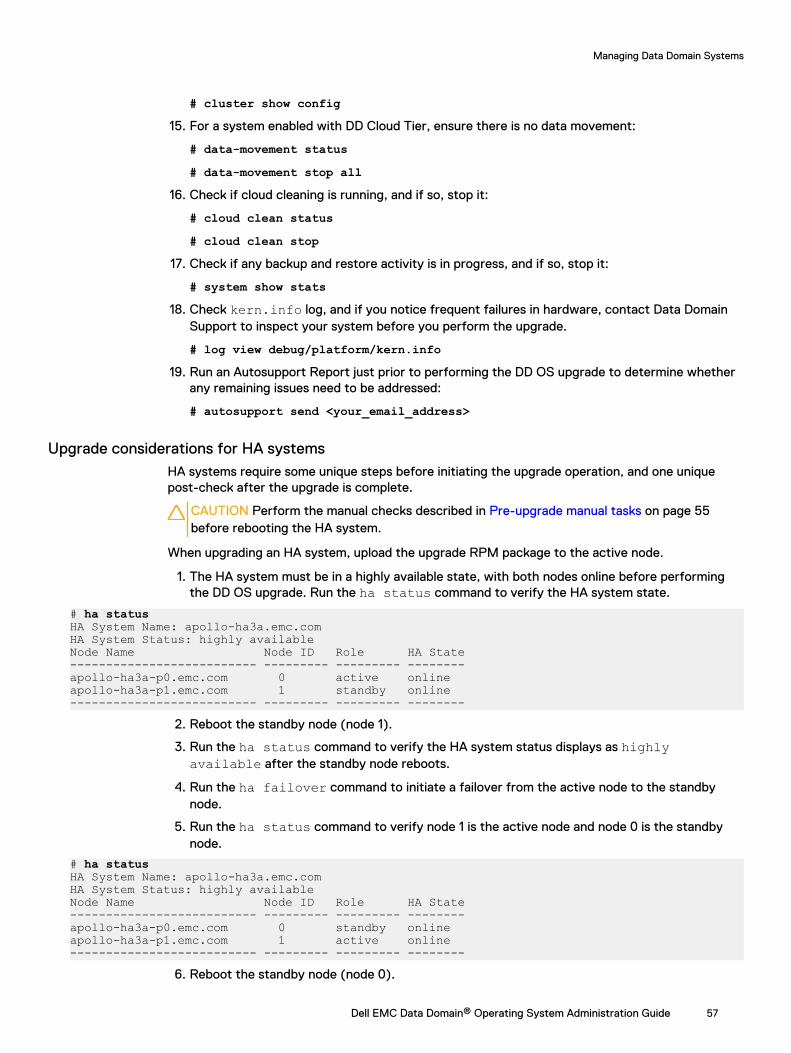
# cluster show config15. For a system enabled with DD Cloud Tier, ensure there is no data movement:
# data-movement status# data-movement stop all
16. Check if cloud cleaning is running, and if so, stop it:
# cloud clean status# cloud clean stop
17. Check if any backup and restore activity is in progress, and if so, stop it:
# system show stats18. Check kern.info log, and if you notice frequent failures in hardware, contact Data Domain
Support to inspect your system before you perform the upgrade.
# log view debug/platform/kern.info19. Run an Autosupport Report just prior to performing the DD OS upgrade to determine whether
any remaining issues need to be addressed:
# autosupport send <your_email_address>
Upgrade considerations for HA systemsHA systems require some unique steps before initiating the upgrade operation, and one uniquepost-check after the upgrade is complete.
CAUTION Perform the manual checks described in Pre-upgrade manual tasks on page 55before rebooting the HA system.
When upgrading an HA system, upload the upgrade RPM package to the active node.
1. The HA system must be in a highly available state, with both nodes online before performingthe DD OS upgrade. Run the ha status command to verify the HA system state.
# ha statusHA System Name: apollo-ha3a.emc.comHA System Status: highly availableNode Name Node ID Role HA State-------------------------- --------- --------- --------apollo-ha3a-p0.emc.com 0 active onlineapollo-ha3a-p1.emc.com 1 standby online-------------------------- --------- --------- --------
2. Reboot the standby node (node 1).
3. Run the ha status command to verify the HA system status displays as highlyavailable after the standby node reboots.
4. Run the ha failover command to initiate a failover from the active node to the standbynode.
5. Run the ha status command to verify node 1 is the active node and node 0 is the standbynode.
# ha statusHA System Name: apollo-ha3a.emc.comHA System Status: highly availableNode Name Node ID Role HA State-------------------------- --------- --------- --------apollo-ha3a-p0.emc.com 0 standby onlineapollo-ha3a-p1.emc.com 1 active online-------------------------- --------- --------- --------
6. Reboot the standby node (node 0).
Managing Data Domain Systems
Dell EMC Data Domain® Operating System Administration Guide 57
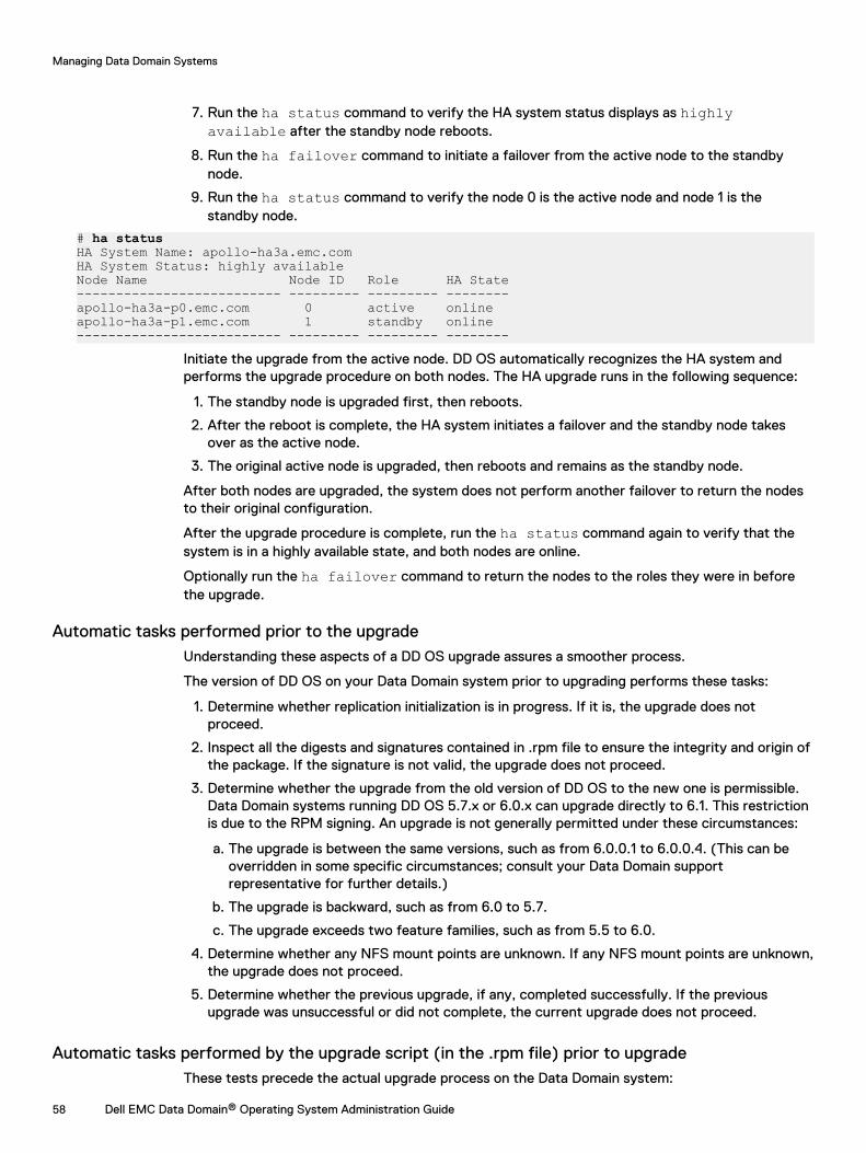
7. Run the ha status command to verify the HA system status displays as highlyavailable after the standby node reboots.
8. Run the ha failover command to initiate a failover from the active node to the standbynode.
9. Run the ha status command to verify the node 0 is the active node and node 1 is thestandby node.
# ha statusHA System Name: apollo-ha3a.emc.comHA System Status: highly availableNode Name Node ID Role HA State-------------------------- --------- --------- --------apollo-ha3a-p0.emc.com 0 active onlineapollo-ha3a-p1.emc.com 1 standby online-------------------------- --------- --------- --------
Initiate the upgrade from the active node. DD OS automatically recognizes the HA system andperforms the upgrade procedure on both nodes. The HA upgrade runs in the following sequence:
1. The standby node is upgraded first, then reboots.
2. After the reboot is complete, the HA system initiates a failover and the standby node takesover as the active node.
3. The original active node is upgraded, then reboots and remains as the standby node.
After both nodes are upgraded, the system does not perform another failover to return the nodesto their original configuration.
After the upgrade procedure is complete, run the ha status command again to verify that thesystem is in a highly available state, and both nodes are online.
Optionally run the ha failover command to return the nodes to the roles they were in beforethe upgrade.
Automatic tasks performed prior to the upgradeUnderstanding these aspects of a DD OS upgrade assures a smoother process.
The version of DD OS on your Data Domain system prior to upgrading performs these tasks:
1. Determine whether replication initialization is in progress. If it is, the upgrade does notproceed.
2. Inspect all the digests and signatures contained in .rpm file to ensure the integrity and origin ofthe package. If the signature is not valid, the upgrade does not proceed.
3. Determine whether the upgrade from the old version of DD OS to the new one is permissible.Data Domain systems running DD OS 5.7.x or 6.0.x can upgrade directly to 6.1. This restrictionis due to the RPM signing. An upgrade is not generally permitted under these circumstances:
a. The upgrade is between the same versions, such as from 6.0.0.1 to 6.0.0.4. (This can beoverridden in some specific circumstances; consult your Data Domain supportrepresentative for further details.)
b. The upgrade is backward, such as from 6.0 to 5.7.
c. The upgrade exceeds two feature families, such as from 5.5 to 6.0.
4. Determine whether any NFS mount points are unknown. If any NFS mount points are unknown,the upgrade does not proceed.
5. Determine whether the previous upgrade, if any, completed successfully. If the previousupgrade was unsuccessful or did not complete, the current upgrade does not proceed.
Automatic tasks performed by the upgrade script (in the .rpm file) prior to upgradeThese tests precede the actual upgrade process on the Data Domain system:
Managing Data Domain Systems
58 Dell EMC Data Domain® Operating System Administration Guide
1. Determine whether two different kinds of NVRAM cards are present.
2. Check the /ddr partition and / (root) partition sizes for space utilization.
3. Check the OST version.
4. Determine whether the RAID metagroup is assembled. If it is not assembled, the upgradeprocess does not begin.
5. Determine available space for the file system.
6. Determine whether sufficient space is available for the upgrade.
7. Check the VTL version, if VTL is present.
8. Determine whether the file system is enabled, and if it is not enabled, enable it.
9. Determine whether VTL is enabled.
10. Check the VTL pools to insure that they can be converted to MTrees.
11. Determine whether sufficient VTL space is available.
12. Insure that the numbers of MTrees and VTL pools do not exceed 100. (This check enforcedfrom DD OS version 5.0 onward.)
13. Determine whether all dg0 disks are located on head unit. If not, the upgrade process does notbegin, and the problem must be addressed.
14. Check if ConnectEMC has been configured. If it is, a warning message is displayed informingthe customer to reconfigure ConnectEMC after the upgrade.
In addition to these checks, the system determines whether the file system can be shutdowncleanly and without problems. If the file system cannot be shut down in a clean manner, theupgrade process will stop.
Conditions that prevent the upgrade processSeveral conditions can cause the upgrade process to be stopped:
l The Data Domain system is not in a functional state. For example:
n Storage is functionally deficient, such as an enclosure is missing.
n The file system did not shutdown cleanly, resulting in a core dump.
n The previous upgrade did not complete correctly.
l Space usage is problematic. For example:
n The / (root) or /ddr partition is full with log files, core dumps, and so forth.
n Insufficient storage space is available to perform the data upgrade.
l The Data Domain system is not configured correctly. For example, NFS mount points weremanually created under root.
l Storage unit names fail to be converted to MTree names. In order to convert to MTree names,the storage unit names must contain only upper and lower case letters (a-z, A-Z), digits (0-9),and underscore (_) and be no longer than 50 characters.
The goal of checking these conditions is to prevent any problematic upgrades or file systemanomalies to occur or propagate. The conditions are also applied in upgrades involving source anddestination partner systems in replication. A failed upgrade or file system anomaly on a DataDomain system serving as a replication source causes no corruption in the file system on a DataDomain system serving as a replication destination.
Managing Data Domain Systems
Dell EMC Data Domain® Operating System Administration Guide 59
Viewing upgrade packages on the systemDD System Manager allows you to view and manage up to five upgrade packages on a system.Before you can upgrade a system, you must download an upgrade package from the OnlineSupport site to a local computer, and then upload it to the target system.
Procedure
1. Select Maintenance > System.
2. Optionally, select an upgrade package and click View Checksum to display the MD5 andSHA256 checksums of the upgrade package.
Results
For every package stored on the system, DD System Manager displays the filename, file size, andlast modified date in the list titled: Upgrade Packages Available on Data Domain System.
Obtaining and verifying upgrade packagesYou can use DD System Manager to locate upgrade package files on the Data Domain SupportWeb site and upload copies of those files to a system.
About this task
Note: You can use FTP or NFS to copy an upgrade package to a system. DD System Manageris limited to managing 5 system upgrade packages, but there are no restrictions, other thanspace limitations, when you manage the files directly in the /ddvar/releases directory.FTP is disabled by default. To use NFS, /ddvar needs to be exported and mounted from anexternal host).
Procedure
1. Select Maintenance > System.
2. To obtain an upgrade package, click the EMC Online Support link, click Downloads, and usethe search function to locate the package recommended for your system by Supportpersonnel. Save the upgrade package to the local computer.
3. Verify that there are no more than four packages listed in the Upgrade Packages Availableon Data Domain System list.
DD System Manager can manage up to five upgrade packages. If five packages appear inthe list, remove at least one package before uploading the new package.
4. Click Upload Upgrade Package to initiate the transfer of the upgrade package to thesystem.
5. In the Upload Upgrade Package dialog, click Browse to open the Choose File to Uploaddialog. Navigate to the folder with the downloaded file, select the file, and click Open.
6. Click OK.
An upload progress dialog appears. Upon successful completion of the upload, the downloadfile (with a .rpm extension) appears in the list titled: Upgrade Packages Available on DataDomain System.
7. To verify the upgrade package integrity, click View Checksum and compare the calculatedchecksum displayed in the dialog to the authoritative checksum on the Online Support site.
8. To manually initiate an upgrade precheck, select an upgrade package and click UpgradePrecheck.
Managing Data Domain Systems
60 Dell EMC Data Domain® Operating System Administration Guide
Upgrading a Data Domain systemWhen an upgrade package file is present on a system, you can use DD System Manager to performan upgrade using that upgrade package.
Before you begin
Read the DD OS Release Notes for the complete upgrade instructions and coverage of all theissues that can impact the upgrade.
About this task
The procedure that follows describes how to initiate an upgrade using DD System Manager. Logout of any Data Domain CLI sessions on the system where the upgrade is to be performed beforeusing DD System Manager to upgrade the system.
Note: Upgrade package files use the .rpm file extension. This topic assumes that you areupdating only DD OS. If you make hardware changes, such as adding, swapping, or movinginterface cards, you must update the DD OS configuration to correspond with the hardwarechanges.
Procedure
1. Log into DD System Manager on the system where the upgrade is to be performed.
Note: As recommended in the Release Notes, reboot the Data Domain system beforeupgrading to verify that the hardware is in a clean state. If any issues are discoveredduring the reboot, resolve those issues before starting the upgrade. For an MDUupgrade, a reboot may not be needed.
2. Select Data Management > File System, and verify that the file system is enabled andrunning.
3. Select Maintenance > System.
4. From the Upgrade Packages Available on Data Domain System list, select the package touse for the upgrade.
Note: You must select an upgrade package for a newer version of DD OS. DD OS doesnot support downgrades to previous versions.
5. Click Perform System Upgrade.
The System Upgrade dialog appears and displays information about the upgrade and a list ofusers who are currently logged in to the system to be upgraded.
6. Verify the version of the upgrade package, and click OK to continue with the upgrade.
The System Upgrade dialog displays the upgrade status and the time remaining.
When upgrading the system, you must wait for the upgrade to complete before using DDSystem Manager to manage the system. If the system restarts, the upgrade might continueafter the restart, and DD System Manager displays the upgrade status after login. Ifpossible, keep the System Upgrade progress dialog open until the upgrade completes or thesystem powers off. When upgrading DD OS Release 5.5 or later to a newer version, and ifthe system upgrade does not require a power off, a Login link appears when the upgrade iscomplete.
Note: To view the status of an upgrade using the CLI, enter the system upgradestatus command. Log messages for the upgrade are stored in /ddvar/log/debug/
Managing Data Domain Systems
Dell EMC Data Domain® Operating System Administration Guide 61
platform/upgrade-error.log and /ddvar/log/debug/platform/upgrade-info.log.
7. If the system powers down, you must remove AC power from the system to clear the priorconfiguration. Unplug all of the power cables for 30 seconds and then plug them back in.The system powers on and reboots.
8. If the system does not automatically power on and there is a power button on the frontpanel, press the button.
After you finish
The following requirements may apply after completing an upgrade.
l For environments that use self-signed SHA-256 certificates, the certificates must beregenerated manually after the upgrade process is complete, an trust must be re-establishedwith external systems that connect to the Data Domain system.
1. Run the adminaccess certificate generate self-signed-cert regenerate-cacommand to regenerate the self-signed CA and host certificates. Regenerating thecertificates breaks existing trust relationships with external systems.
2. Run the adminaccess trust add host hostname type mutual command to reestablishmutual trust between the Data Domain system and the external system.
l If the system shows existing or configured FC ports with missing WWPN or WWNNinformation, or reports that no FC host bus adapter (HBA) driver is installed, run thescsitarget endpoint enable all command.
Replication notesWith collection replication, no files are visible on the destination Data Domain system if replicationwas not finished before starting the upgrade. After the upgrade, wait until replication completes tosee files on the destination.
ConnectEMC notes
In this release, ConnectEMC has been changed to support the Secure Remote Service VirtualEdition (Secure Remote Services VE) gateway. This change requires a reconfiguration of the DataDomain system to ConnectEMC after the upgrade.
Note: ConnectEMC only works with Service Remote Services VE (V3) and can not send emailswith older versions of Service Remote Services or on it s own. If ConnectEMC has been usedwith previous releases of DD OS (e.g., 5.7 or 5.6), the Service Remote Services VE serverconfiguration will need to be re-entered as it was removed during the upgrade process due tothe to technology upgrade.
Note: If an older Service Remote Services gateway is being used, the Service Remote ServicesVE gateway will need to be implemented to allow for secure communications.
During the upgrade, if ConnectEMC is detected as configured, the existing configuration will beremoved. In addition, if the support notification method is configured as ConnectEMC to sendevent messages to the company, it will switch to email. After the upgrade, you can reconfigure theConnectEMC with new ConnectEMC command: support connectemc device register.
After ConnectEMC is configured, enable ConnectEMC with support notification methodset connectemc.
Managing Data Domain Systems
62 Dell EMC Data Domain® Operating System Administration Guide
Removing an upgrade packageA maximum of five upgrade packages can be uploaded to a system with DD System Manager. Ifthe system you are upgrading contains five upgrade packages, you must remove at least onepackage before you can upgrade the system.
About this task
Procedure
1. Select Maintenance > System.
2. From the list titled Upgrade Packages Available on Data Domain System, select the packageto remove. One package can be removed at a time.
3. Click Remove Upgrade Package.
Managing electronic licensesAdd and delete electronic licenses from the Data Domain system. Refer to the applicable DataDomain Operating System Release Notes for the most up-to-date information on product features,software updates, software compatibility guides, and information about products, licensing, andservice.
HA system license managementHA is a licensed feature, and the system licensing key is registered by following the same steps toadd any other license to the DD system.
A system will be configured as Active-Standby, where one node is designated "standby." Only oneset of licenses will be required rather than needing individual licenses for each node. Duringfailover, the licenses on one node will failover to the other node.
System storage managementSystem storage management features enable you to view the status and configuration of yourstorage space, flash a disk LED to facilitate disk identification, and change the storageconfiguration.
Note: All storage that is connected or used by the two-node Active-Standby HA system can beviewed as a single system.
Using the CLI to calculate usable storage space
The following values are required to calculate the usable storage on a Data Domain system afteraccounting for RAID overhead:
l N= Number of disks in use in the disk group (dg).
l C = Capacity of each disk after formatting.
l R = 2 (Number of disks used for RAID 6 parity)
This calculation does not work for Cache Tier storage, because the Cache Tier disks are not RAIDprotected.
Run the storage show all command to get the values for N and C.
Managing Data Domain Systems
Dell EMC Data Domain® Operating System Administration Guide 63
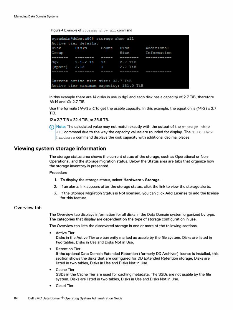
Figure 4 Example of storage show all command
In this example there are 14 disks in use in dg2 and each disk has a capacity of 2.7 TiB, thereforeN=14 and C= 2.7 TiB
Use the formula (N-R) x C to get the usable capacity. In this example, the equation is (14-2) x 2.7TiB.
12 x 2.7 TiB = 32.4 TiB, or 35.6 TB.
Note: The calculated value may not match exactly with the output of the storage showall command due to the way the capacity values are rounded for display. The disk showhardware command displays the disk capacity with additional decimal places.
Viewing system storage informationThe storage status area shows the current status of the storage, such as Operational or Non-Operational, and the storage migration status. Below the Status area are tabs that organize howthe storage inventory is presented.
Procedure
1. To display the storage status, select Hardware > Storage.
2. If an alerts link appears after the storage status, click the link to view the storage alerts.
3. If the Storage Migration Status is Not licensed, you can click Add License to add the licensefor this feature.
Overview tabThe Overview tab displays information for all disks in the Data Domain system organized by type.The categories that display are dependent on the type of storage configuration in use.
The Overview tab lists the discovered storage in one or more of the following sections.
l Active TierDisks in the Active Tier are currently marked as usable by the file system. Disks are listed intwo tables, Disks in Use and Disks Not in Use.
l Retention TierIf the optional Data Domain Extended Retention (formerly DD Archiver) license is installed, thissection shows the disks that are configured for DD Extended Retention storage. Disks arelisted in two tables, Disks in Use and Disks Not in Use.
l Cache TierSSDs in the Cache Tier are used for caching metadata. The SSDs are not usable by the filesystem. Disks are listed in two tables, Disks in Use and Disks Not in Use.
l Cloud Tier
Managing Data Domain Systems
64 Dell EMC Data Domain® Operating System Administration Guide
Disks in the Cloud Tier are used to store the metadata for data that resides in cloud storage.The disks are not usable by the file system. Disks are listed in two tables, Disks in Use andDisks Not in Use.
l Addable StorageFor systems with optional enclosures, this section shows the disks and enclosures that can beadded to the system.
l Failed/Foreign/Absent Disks (Excluding Systems Disks)Shows the disks that are in a failed state; these cannot be added to the system Active orRetention tiers.
l Systems DisksShows the disks where the DD OS resides when the Data Domain controller does not containdata storage disks.
l Migration HistoryShows the history of migrations.
Each section heading displays a summary of the storage configured for that section. The summaryshows tallies for the total number of disks, disks in use, spare disks, reconstructing spare disks,available disks, and known disks.
Click a section plus (+) button to display detailed information, or click the minus (-) button to hidethe detailed information.
Table 24 Disks In Use column label descriptions
Item Description
Disk Group The name of the disk group that was created by the filesystem (for example, dg1).
State The status of the disk (for example Normal, Warning).
Disks Reconstructing The disks that are undergoing reconstruction, by disk ID (forexample, 1.11).
Total Disks The total number of usable disks (for example, 14).
Disks The disk IDs of the usable disks (for example, 2.1-2.14).
Size The size of the disk group (for example, 25.47 TiB).
Table 25 Disks Not In Use column label descriptions
Item Description
Disk The disk identifier, which can be any of the following.
l The enclosure and disk number (in the form EnclosureSlot)
l A device number for a logical device such as those used byDD VTL and vDisk
l A LUN
Slot The enclosure where the disk is located.
Pack The disk pack, 1-4, within the enclosure where the disk islocated. This value will only be 2-4 for DS60 expansionshelves.
State The status of the disk, for example In Use, Available, Spare.
Managing Data Domain Systems
Dell EMC Data Domain® Operating System Administration Guide 65
Table 25 Disks Not In Use column label descriptions (continued)
Item Description
Size The data storage capacity of the disk when used in a DataDomain system.a
Type The disk connectivity and type (For example, SAS).
a. The Data Domain convention for computing disk space defines one gibibyte as 230 bytes,giving a different disk capacity than the manufacturer’s rating.
Enclosures tabThe Enclosures tab displays a table summarizing the details of the enclosures connected to thesystem.
The Enclosures tab provides the following details.
Table 26 Enclosures tab column label descriptions
Item Description
Enclosure The enclosure number. Enclosure 1 is the head unit.
Serial Number The enclosure serial number.
Disks The disks contained in the enclosure, in the format<Enclosure-number>.1-<Enclosure-number>.<N>.
Model The enclosure model. For enclosure 1, the model is Head Unit.
Disk Count The number of disks in the enclosure.
Disk Size The data storage capacity of the disk when used in a DataDomain system.a
Failed Disks The failed disks in the enclosure.
Temperature Status The temperature status of the enclosure.
a. The Data Domain convention for computing disk space defines one gibibyte as 230 bytes,giving a different disk capacity than the manufacturer’s rating.
Disks tabThe Disks tab displays information on each of the system disks. You can filter the disks viewed todisplay all disks, disks in a specific tier, or disks in a specific group.
The Disk State table displays a summary status table showing the state of all system disks.
Table 27 Disks State table column label descriptions
Item Description
Total The total number of inventoried disks in the Data Domainsystem.
In Use The number of disks currently in use by the file system.
Spare The number of spare disks (available to replace failed disks).
Spare (reconstructing) The number of disks that are in the process of datareconstruction (spare disks replacing failed disks).
Managing Data Domain Systems
66 Dell EMC Data Domain® Operating System Administration Guide
Table 27 Disks State table column label descriptions (continued)
Item Description
Available The number of disks that are available for allocation to anActive or DD Extended Retention storage tier.
Known The number of known unallocated disks.
Unknown The number of unknown unallocated disks.
Failed The number of failed disks.
Foreign The number of foreign disks.
Absent The number of absent disks.
Migrating The number of disks serving as the source of a storagemigration.
Destination The number of disks serving as the destination of a storagemigration.
Powered Off The number of disks not powered on.
Not Installed The number of empty disk slots that the system can detect.
The Disks table displays specific information about each disk installed in the system.
Table 28 Disks table column label descriptions
Item Description
Disk The disk identifier, which can be:
l The enclosure and disk number (in the formEnclosure.Slot).
l A device number for a logical device such as those used byDD VTL and vDisk..
l A LUN.
Size The size of the disk.
Slot The enclosure where the disk is located.
Pack The disk pack, 1-4, within the enclosure where the disk islocated. This value will only be 2-4 for DS60 expansionshelves.
State The status of the disk, which can be one of the following.
l Absent. No disk is installed in the indicated location.
l Available. An available disk is allocated to the active orretention tier, but it is not currently in use.
l Copy Recovery. The disk has a high error rate but is notfailed. RAID is currently copying the contents onto a sparedrive and will fail the drive once the copy reconstruction iscomplete.
l Destination. The disk is in use as the destination forstorage migration.
l Error. The disk has a high error rate but is not failed. Thedisk is in the queue for copy reconstruction. The state will
Managing Data Domain Systems
Dell EMC Data Domain® Operating System Administration Guide 67
Table 28 Disks table column label descriptions (continued)
Item Description
change to Copy Recovery when copy reconstructionbegins.
l Foreign. The disk has been assigned to a tier, but the diskdata indicates the disk may be owned by another system.
l In-Use. The disk is being used for backup data storage.
l Known. The disk is a supported disk that is ready forallocation.
l Migrating. The disk is in use as the source for storagemigration.
l Powered Off. The disk power has been removed bySupport.
l Reconstruction. The disk is reconstructing in response toa disk fail command or by direction from RAID/SSM.
l Spare. The disk is available for use as a spare.
l System. System disks store DD OS and system data. Nobackup data is stored on system disks.
l Unknown. An unknown disk is not allocated to the activeor retention tier. It might have been failed administrativelyor by the RAID system.
Manufacturer/Model The manufacturer’s model designation. The display mayinclude a model ID or RAID type or other informationdepending on the vendor string sent by the storage array.
Firmware The firmware level used by the third-party physical-diskstorage controller.
Serial Number The manufacturer’s serial number for the disk.
Disk Life Used The percentage of an SSD's rated life span consumed.
Type The disk connectivity and type (For example, SAS).
Reconstruction tabThe Reconstruction tab displays a table that provides additional information on reconstructingdisks.
The following table describes the entries in the Reconstructing table.
Table 29 Reconstruction table column label descriptions
Item Description
Disk Identifies disks that are being reconstructed. Disk labels are ofthe format enclosure.disk. Enclosure 1 is the Data Domainsystem, and external shelves start numbering with enclosure 2.For example, the label 3.4 is the fourth disk in the secondshelf.
Disk Group Shows the RAID group (dg#) for the reconstructing disk.
Managing Data Domain Systems
68 Dell EMC Data Domain® Operating System Administration Guide
Table 29 Reconstruction table column label descriptions (continued)
Item Description
Tier The name of the tier where the failed disk is beingreconstructed.
Time Remaining The amount of time before the reconstruction is complete.
Percentage Complete The percentage of reconstruction that is complete.
When a spare disk is available, the file system automatically replaces a failed disk with a spare andbegins the reconstruction process to integrate the spare into the RAID disk group. The disk usedisplays Spare and the status becomes Reconstructing. Reconstruction is performed on onedisk at a time.
Physically locating an enclosureIf you have trouble determining which physical enclosure corresponds to an enclosure displayed inDD System Manager, you can use the CLI beacon feature to flash the enclosure IDENT LEDs andall the disk LEDs that indicate normal operation.
Procedure
1. Establish a CLI session with the system.
2. Type enclosure beacon enclosure.
3. Press Ctrl-C to stop the LED flashing.
Physically locating a diskIf you have trouble determining which physical disk corresponds to a disk displayed in DD SystemManager, you can use the beacon feature to flash an LED on the physical disk.
Procedure
1. Select Hardware > Storage > Disks.
2. Select a disk from the Disks table and click Beacon.
Note: You can select one disk at a time.
The Beaconing Disk dialog box appears, and the LED light on the disk begins flashing.
3. Click Stop to stop the LED beaconing.
Configuring storageStorage configuration features allow you to add and remove storage expansion enclosures fromthe active, retention, and cloud tiers. Storage in an expansion enclosure (which is sometimes calledan expansion shelf) is not available for use until it is added to a tier.
About this task
Note: Additional storage requires the appropriate license or licenses and sufficient memory tosupport the new storage capacity. Error messages display if more licenses or memory isneeded.
DD6300 systems support the option to use ES30 enclosures with 4 TB drives ( 43.6 TiB) at 50%utilization (21.8 TiB) in the active tier if the available licensed capacity is exactly 21.8 TiB. Thefollowing guidelines apply to using partial capacity shelves.
Managing Data Domain Systems
Dell EMC Data Domain® Operating System Administration Guide 69
l No other enclosure types or drive sizes are supported for use at partial capacity.
l A partial shelf can only exist in the Active tier.
l Only one partial ES30 can exist in the Active tier.
l Once a partial shelf exists in a tier, no additional ES30s can be configured in that tier until thepartial shelf is added at full capacity.
Note: This requires licensing enough additional capacity to use the remaining 21.8 TiB ofthe partial shelf.
l If the available capacity exceeds 21.8 TB, a partial shelf cannot be added.
l Deleting a 21 TiB license will not automatically convert a fully-used shelf to a partial shelf. Theshelf must be removed, and added back as a partial shelf.
Procedure
1. Select Hardware > Storage > Overview.
2. Expand the dialog for one of the available storage tiers:
l Active Tier
l Extended Retention Tier
l Cache Tier
l Cloud Tier
3. Click Configure.
4. In the Configure Storage dialog, select the storage to be added from the Addable Storagelist.
5. In the Configure list, select either Active Tier or Retention Tier.
The maximum amount of storage that can be added to the active tier depends on the DDcontroller used.
Note: The licensed capacity bar shows the portion of licensed capacity (used andremaining) for the installed enclosures.
6. Select the checkbox for the Shelf to be added.
7. Click the Add to Tier button.
8. Click OK to add the storage.
Note: To remove an added shelf, select it in the Tier Configuration list, click Removefrom Configuration, and click OK.
DD3300 capacity expansionThe DD3300 system is available in three different capacity configurations. Capacity expansionsfrom one configuration to another are supported.
The DD3300 system is available in the following capacity configurations:
l 4 TB
l 8 TB
l 16 TB
l 32 TB
The following upgrade considerations apply:
Managing Data Domain Systems
70 Dell EMC Data Domain® Operating System Administration Guide
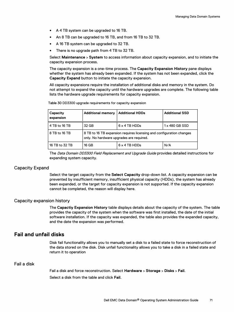
l A 4 TB system can be upgraded to 16 TB.
l An 8 TB can be upgraded to 16 TB, and from 16 TB to 32 TB.
l A 16 TB system can be upgraded to 32 TB.
l There is no upgrade path from 4 TB to 32 TB.
Select Maintenance > System to access information about capacity expansion, and to initiate thecapacity expansion process.
The capacity expansion is a one-time process. The Capacity Expansion History pane displayswhether the system has already been expanded. If the system has not been expanded, click theCapacity Expand button to initiate the capacity expansion.
All capacity expansions require the installation of additional disks and memory in the system. Donot attempt to expand the capacity until the hardware upgrades are complete. The following tablelists the hardware upgrade requirements for capacity expansion.
Table 30 DD3300 upgrade requirements for capacity expansion
Capacityexpansion
Additional memory Additional HDDs Additional SSD
4 TB to 16 TB 32 GB 6 x 4 TB HDDs 1 x 480 GB SSD
8 TB to 16 TB 8 TB to 16 TB expansion requires licensing and configuration changesonly. No hardware upgrades are required.
16 TB to 32 TB 16 GB 6 x 4 TB HDDs N/A
The Data Domain DD3300 Field Replacement and Upgrade Guide provides detailed instructions forexpanding system capacity.
Capacity ExpandSelect the target capacity from the Select Capacity drop-down list. A capacity expansion can beprevented by insufficient memory, insufficient physical capacity (HDDs), the system has alreadybeen expanded, or the target for capacity expansion is not supported. If the capacity expansioncannot be completed, the reason will display here.
Capacity expansion historyThe Capactiy Expansion History table displays details about the capacity of the system. The tableprovides the capacity of the system when the software was first installed, the date of the initialsoftware installation. If the capacity was expanded, the table also provides the expanded capacity,and the date the expansion was performed.
Fail and unfail disksDisk fail functionality allows you to manually set a disk to a failed state to force reconstruction ofthe data stored on the disk. Disk unfail functionality allows you to take a disk in a failed state andreturn it to operation
Fail a diskFail a disk and force reconstruction. Select Hardware > Storage > Disks > Fail.
Select a disk from the table and click Fail.
Managing Data Domain Systems
Dell EMC Data Domain® Operating System Administration Guide 71
Unfail a diskMake a disk previously marked Failed or Foreign usable to the system. Select Hardware >Storage > Disks > Unfail.
Select a disk from the table and click Unfail.
Network connection managementNetwork connection management features allow you view and configure network interfaces,general network settings, and network routes.
HA system network connection managementThe HA system relies on two different types of IP addresses, fixed and floating. Each type hasspecific behaviors and limitations.
On an HA system, Fixed IP addresses:
l Are used for node management via the CLI
l Are attached ("fixed") to the node
l Can be static or DHCP, IPv6 SLAAC
l Configuration is done on the specific node with the optional type fixed argument
Note: All filesystem access should be through a floating IP.
Floating IP addresses only exist in the two-node HA system; during failover, the IP address "float"to the new active node and are:
l Only configured on the active node
l Used for filesystem access and most configuration
l Can only be static
l Configuration requires the type floating argument
Network interface managementNetwork interface management features allow you to manage the physical interfaces that connectthe system to a network and create logical interfaces to support link aggregation, load balancing,and link or node failover.
Viewing interface informationThe Interfaces tab allows you to manage physical and virtual interfaces, VLANs, DHCP, DDNS, andIP addresses and aliases.
About this task
Consider the following guidelines when managing IPv6 interfaces.
l The command-line interface (CLI) supports IPv6 for basic Data Domain network andreplication commands, but not for backup and DD Extended Retention (archive) commands.CLI commands manage the IPv6 addresses. You can view IPv6 addresses using the DD SystemManager, but you cannot manage IPv6 with the DD System Manager.
l Collection, directory, and MTree replication are supported over IPv6 networks, which allowsyou to take advantage of the IPv6 address space. Simultaneous replication over IPv6 and IPv4networks is also supported, as is Managed File Replication using DD Boost.
Managing Data Domain Systems
72 Dell EMC Data Domain® Operating System Administration Guide
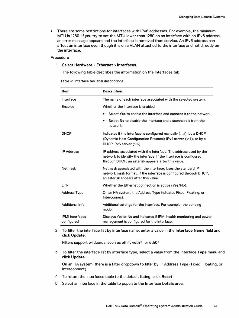
l There are some restrictions for interfaces with IPv6 addresses. For example, the minimumMTU is 1280. If you try to set the MTU lower than 1280 on an interface with an IPv6 address,an error message appears and the interface is removed from service. An IPv6 address canaffect an interface even though it is on a VLAN attached to the interface and not directly onthe interface.
Procedure
1. Select Hardware > Ethernet > Interfaces.
The following table describes the information on the Interfaces tab.
Table 31 Interface tab label descriptions
Item Description
Interface The name of each interface associated with the selected system.
Enabled Whether the interface is enabled.
l Select Yes to enable the interface and connect it to the network.
l Select No to disable the interface and disconnect it from thenetwork.
DHCP Indicates if the interface is configured manually (no), by a DHCP
(Dynamic Host Configuration Protocol) IPv4 server (v4), or by a
DHCP IPv6 server (v6).
IP Address IP address associated with the interface. The address used by thenetwork to identify the interface. If the interface is configuredthrough DHCP, an asterisk appears after this value.
Netmask Netmask associated with the interface. Uses the standard IPnetwork mask format. If the interface is configured through DHCP,an asterisk appears after this value.
Link Whether the Ethernet connection is active (Yes/No).
Address Type On an HA system, the Address Type indicates Fixed, Floating, orInterconnect.
Additional Info Additional settings for the interface. For example, the bondingmode.
IPMI interfacesconfigured
Displays Yes or No and indicates if IPMI health monitoring and powermanagement is configured for the interface.
2. To filter the interface list by interface name, enter a value in the Interface Name field andclick Update.
Filters support wildcards, such as eth*, veth*, or eth0*
3. To filter the interface list by interface type, select a value from the Interface Type menu andclick Update.
On an HA system, there is a filter dropdown to filter by IP Address Type (Fixed, Floating, orInterconnect).
4. To return the interfaces table to the default listing, click Reset.
5. Select an interface in the table to populate the Interface Details area.
Managing Data Domain Systems
Dell EMC Data Domain® Operating System Administration Guide 73
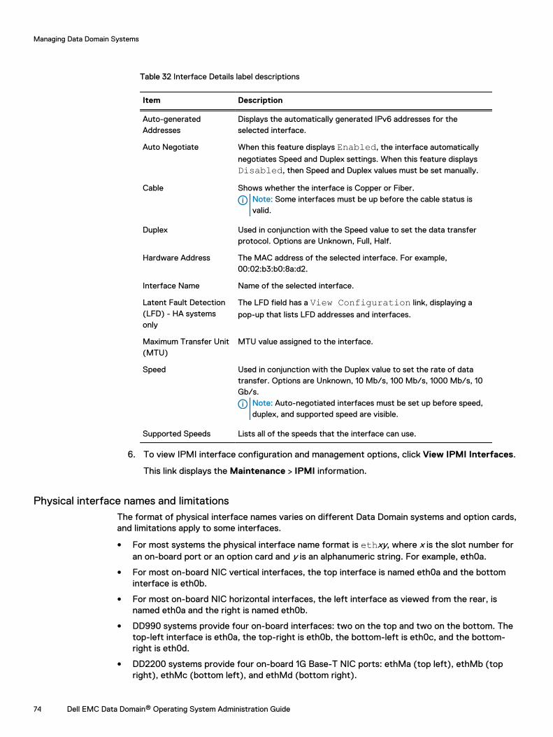
Table 32 Interface Details label descriptions
Item Description
Auto-generatedAddresses
Displays the automatically generated IPv6 addresses for theselected interface.
Auto Negotiate When this feature displays Enabled, the interface automatically
negotiates Speed and Duplex settings. When this feature displaysDisabled, then Speed and Duplex values must be set manually.
Cable Shows whether the interface is Copper or Fiber.Note: Some interfaces must be up before the cable status isvalid.
Duplex Used in conjunction with the Speed value to set the data transferprotocol. Options are Unknown, Full, Half.
Hardware Address The MAC address of the selected interface. For example,00:02:b3:b0:8a:d2.
Interface Name Name of the selected interface.
Latent Fault Detection(LFD) - HA systemsonly
The LFD field has a View Configuration link, displaying a
pop-up that lists LFD addresses and interfaces.
Maximum Transfer Unit(MTU)
MTU value assigned to the interface.
Speed Used in conjunction with the Duplex value to set the rate of datatransfer. Options are Unknown, 10 Mb/s, 100 Mb/s, 1000 Mb/s, 10Gb/s.
Note: Auto-negotiated interfaces must be set up before speed,duplex, and supported speed are visible.
Supported Speeds Lists all of the speeds that the interface can use.
6. To view IPMI interface configuration and management options, click View IPMI Interfaces.
This link displays the Maintenance > IPMI information.
Physical interface names and limitationsThe format of physical interface names varies on different Data Domain systems and option cards,and limitations apply to some interfaces.
l For most systems the physical interface name format is ethxy, where x is the slot number foran on-board port or an option card and y is an alphanumeric string. For example, eth0a.
l For most on-board NIC vertical interfaces, the top interface is named eth0a and the bottominterface is eth0b.
l For most on-board NIC horizontal interfaces, the left interface as viewed from the rear, isnamed eth0a and the right is named eth0b.
l DD990 systems provide four on-board interfaces: two on the top and two on the bottom. Thetop-left interface is eth0a, the top-right is eth0b, the bottom-left is eth0c, and the bottom-right is eth0d.
l DD2200 systems provide four on-board 1G Base-T NIC ports: ethMa (top left), ethMb (topright), ethMc (bottom left), and ethMd (bottom right).
Managing Data Domain Systems
74 Dell EMC Data Domain® Operating System Administration Guide
l DD2500 systems provide six on-board interfaces. The four on-board 1G Base-T NIC ports areethMa (top left), ethMb (top right), ethMc (bottom left), and ethMd (bottom right). The twoon-board 10G Base-T NIC ports are ethMe (top) and ethMf (bottom).
l DD4200, DD4500, and DD7200 systems provide one on-board Ethernet port, which is ethMa.
l For systems ranging between DD140 and DD990, the physical interface names for I/O modulesstart at the top of the module or at the left side. The first interface is ethxa, the next is ethxb,the next is ethxc, and so forth.
l The port numbers on the horizontal DD2500 I/O modules are labeled in sequence from the endopposite the module handle (left side). The first port is labeled 0 and corresponds to physicalinterface name ethxa, the next is 1/ethxb, the next is 2/ethxc, and so forth.
l The port numbers on the vertical DD4200, DD4500, and DD7200 I/O modules are labeled insequence from the end opposite the module handle (bottom). The first port is labeled 0 andcorresponds to physical interface name ethxa, the next is 1/ethxb, the next is 2/ethxc, and soforth.
General interface configuration guidelinesReview the general interface configuration guidelines before configuring system interfaces.
l When supporting both backup and replication traffic, if possible, use different interfaces foreach traffic type so that neither traffic type impacts the other.
l When replication traffic is expected to be less than 1 Gb/s, if possible, do not use 10 GbEinterfaces for replication traffic because 10 GbE interfaces are optimized for faster traffic.
l If a Data Domain service uses a non-standard port and the user wants to upgrade to DD OS6.0, or the user wants to change a service to use a non-standard port on a DD OS 6.0 system,add a net filter function for all the clients using that service to allow the client IP addresses touse the new port.
l On DD4200, DD4500, and DD7200 systems that use IPMI, if possible, reserve interface ethMafor IPMI traffic and system management traffic (using protocols such as HTTP, Telnet, andSSH). Backup data traffic should be directed to other interfaces.
Configuring physical interfacesYou must configure at least one physical interface before the system can connect to a network.
Procedure
1. Select Hardware > Ethernet > Interfaces.
2. Select an interface to configure.
Note: DD140, DD160, DD610, DD620, and DD630 systems do not support IPv6 oninterface eth0a (eth0 on systems that use legacy port names) or on any VLANs createdon that interface.
3. Click Configure.
4. In the Configure Interface dialog, determine how the interface IP address is to be set:
Note: On an HA system, the Configure Interface dialog has a field for whether or not todesignate the Floating IP (Yes/No). Selecting Yes the Manually Configure IPAddress radio button is auto-selected; Floating IP interfaces can only be manuallyconfigured.
l Use DHCP to assign the IP address—in the IP Settings area, select Obtain IP Addressusing DHCP and select either DHCPv4 for IPv4 access or DHCPv6 for IPv6 access.Setting a physical interface to use DHCP automatically enables the interface.
Managing Data Domain Systems
Dell EMC Data Domain® Operating System Administration Guide 75
Note: If you choose to obtain the network settings through DHCP, you can manuallyconfigure the hostname at Hardware > Ethernet > Settings or with the net sethostname command. You must manually configure the host name when using DHCPover IPv6.
l Specify IP Settings manually—in the IP Settings area, select Manually configure IPAddress.The IP Address and Netmask fields become active.
5. If you chose to manually enter the IP address, enter an IPv4 or IPv6 address. If you enteredan IPv4 address, enter a netmask address.
Note: You can assign just one IP address to an interface with this procedure. If youassign another IP address, the new address replaces the old address. To attach anadditional IP address to an interface, create an IP alias.
6. Specify Speed/Duplex settings.
The combination of speed and duplex settings define the rate of data transfer through theinterface. Select one of these options:
l Autonegotiate Speed/Duplex — Select this option to allow the network interface cardto autonegotiate the line speed and duplex setting for an interface. Autonegotiation isnot supported on the following DD2500, DD4200, DD4500, and DD7200 I/O modules:
n Dual Port 10GbE SR Optical with LC connectors (using SFPs)
n Dual Port 10GbE Direct Attach Copper (SFP+ cables)
n Quad port 2 port 1GbE Copper (RJ45) /2 port 1GbE SR Optical
l Manually configure Speed/Duplex — Select this option to manually set an interfacedata transfer rate. Select the speed and duplex from the menus.
n Duplex options are half-duplex, full-duplex, and unknown.
n Speed options listed are limited to the capabilities of the hardware device. Optionsare 10 Mb, 100 Mb, 1000 Mb (1 Gb), 10 Gb, and unknown. The 10G Base-T hardwaresupports only the 100 Mb, 1000 Mb and 10 Gb settings.
n Half-duplex is only available for 10 Mb and 100 Mb speeds.
n 1000 Mb and 10 Gb line speeds require full-duplex.
n On DD2500, DD4200, DD4500, and DD7200 10GbE I/O modules, copper interfacessupport only the 10 Gb speed setting.
n The default setting for 10G Base-T interfaces is Autonegotiate Speed/Duplex. If youmanually set the speed to 1000 Mb or 10 Gb, you must set the Duplex setting to Full.
7. Specify the MTU (Maximum Transfer Unit) size for the physical (Ethernet) interface.
Do the following:
l Click the Default button to return the setting to the default value.
l Ensure that all of your network components support the size set with this option.
8. Optionally, select Dynamic DNS Registration.
Dynamic DNS (DDNS) is a protocol that registers local IP addresses on a Domain NameSystem (DNS) server. In this release, DD System Manager supports Windows mode DDNS.To use UNIX mode DDNS, use the net ddns CLI command.
The DDNS must be registered to enable this option.
Managing Data Domain Systems
76 Dell EMC Data Domain® Operating System Administration Guide
Note: This option disables DHCP for this interface.
9. Click Next.
The Configure Interface Settings summary page appears. The values listed reflect the newsystem and interface state, which are applied after you click Finish.
10. Click Finish and OK.
MTU size values
The MTU size must be set properly to optimize the performance of a network connection. Anincorrect MTU size can negatively affect interface performance.
Supported values for setting the maximum Transfer Unit (MTU) size for the physical (Ethernet)interface range from 350 to 9000. For 100 Base-T and gigabit networks, 1500 is the standarddefault.
Note: The minimum MTU for IPv6 interfaces is 1280. The interface fails if you try to set theMTU lower than 1280.
Moving a static IP addressA specific static IP address must be assigned to only one interface on a system. A static IP addressmust be properly removed from an interface before it is configured on another interface.
Procedure
1. If the interface that hosts the static IP address is part of a DD Boost interface group,remove the interface from that group.
2. Select Hardware > Ethernet > Interfaces.
3. Remove the static IP address that you want to move.
a. Select the interface that is currently using the IP address you want to move.
b. In the Enabled column, select No to disable the interface.
c. Click Configure.
d. Set the IP Address to 0.
Note: Set the IP address to 0 when there is no other IP address to assign to theinterface. The same IP address must not be assigned to multiple interfaces.
e. Click Next, and click Finish.
4. Add the removed static IP address to another interface.
a. Select the interface to which you want to move the IP address.
b. In the Enabled column, select No to disable the interface.
c. Click Configure.
d. Set the IP Address to the match the static IP address you removed.
e. Click Next, and click Finish.
f. In the Enabled column, select Yes to enable the updated interface.
Managing Data Domain Systems
Dell EMC Data Domain® Operating System Administration Guide 77
Virtual interface configuration guidelinesVirtual interface configuration guidelines apply to failover and aggregate virtual interfaces. Thereare additional guidelines that apply to either failover or aggregate interfaces but not both.
l The virtual-name must be in the form vethx where x is a number. The recommended maximumnumber is 99 because of name size limitations.
l You can create as many virtual interfaces as there are physical interfaces.
l Each interface used in a virtual interface must first be disabled. An interface that is part of avirtual interface is seen as disabled for other network configuration options.
l After a virtual interface is destroyed, the physical interfaces associated with it remain disabled.You must manually re-enable the physical interfaces.
l The number and type of cards installed determines the number of Ethernet ports available.
l Each physical interface can belong to one virtual interface.
l A system can support multiple mixed failover and aggregation virtual interfaces, subject to therestrictions above.
l Virtual interfaces must be created from identical physical interfaces. For example, all copper,all optical, all 1 Gb, or all 10 Gb. However, 1 Gb interfaces support bonding a mix of copper andoptical interfaces. This applies to virtual interfaces across different cards with identicalphysical interfaces, except for Chelsio cards. For Chelsio cards, only failover is supported, andthat is only across interfaces on the same card.
l Failover and aggregate links improve network performance and resiliency by using two or morenetwork interfaces in parallel, thus increasing the link speed for aggregated links and reliabilityover that of a single interface.
l Remove functionality is available using the Configure button. Click a virtual interface in the listof interfaces on the Interfaces tab and click Configure. From the list of interfaces in the dialogbox, clear the checkbox for the interface to remove it from bonding (failover or aggregate),and click Next.
l For a bonded interface, the bonded interface is created with remaining slaves if the hardwarefor a slave interface fails. If no slaves, the bonded interface id created with no slaves. Thisslave hardware failure will generate managed alerts, one per failed slave.
Note: The alert for a failed slave disappears after the failed slave is removed from thesystem. If new hardware is installed, the alerts disappear and the bonded interface usesthe new slave interface after the reboot.
l On DD3300, DD4200, DD4500, and DD7200 systems, the ethMa interface does not supportfailover or link aggregation.
Guidelines for configuring a virtual interface for link aggregation
Link aggregation provides improved network performance and resiliency by using one or morenetwork interfaces in parallel, thus increasing the link speed and reliability over that of a singleinterface. These guidelines are provided to help you optimize your use of link aggregation.
l Changes to disabled Ethernet interfaces flush the routing table. It is recommended that youmake interface changes only during scheduled maintenance downtime. Afterwards, reconfigurethe routing rules and gateways.
l Enable aggregation on an existing virtual interface by specifying the physical interfaces andmode and giving it an IP address.
l 10 Gb single-port optical Ethernet cards do not support link aggregation.
Managing Data Domain Systems
78 Dell EMC Data Domain® Operating System Administration Guide
l 1 GbE and 10 GbE interfaces cannot be aggregated together.
l Copper and optical interfaces cannot be aggregated together.
l On DD4200, DD4500, and DD7200 systems, the ethMA interface does not support linkaggregation.
Guidelines for configuring a virtual interface for failover
Link failover provides improved network stability and performance by identifying backup interfacesthat can support network traffic when the primary interface is not operating. These guidelines areprovided to help you optimize your use of link failover.
l A primary interface must be part of the failover. If a primary interface removal is attemptedfrom a failover, an error message appears.
l When a primary interface is used in a failover configuration, it must be explicitly specified andmust also be a bonded interface to the virtual interface. If the primary interface goes down andmultiple interfaces are still available, the next interface is randomly selected.
l All interfaces in a virtual interface must be on the same physical network. Network switchesused by a virtual interface must be on the same physical network.
l The recommended number of physical interfaces for failover is greater than one. You can,however, configure one primary interface and one or more failover interfaces, except with thefollowing:
n 10 Gb CX4 Ethernet card, which are restricted to one primary interface and one failoverinterface from the same card, and
n 10 Gb single-port optical Ethernet cards, which cannot be used.
l On DD4200, DD4500, and DD7200 systems, the ethMA interface does not support linkfailover.
Virtual interface creationCreate a virtual interface to support link aggregation or failover. The virtual interface serves as acontainer for the links to be aggregated or associated for failover.
Creating a virtual interface for link aggregation
Create a virtual interface for link aggregation to serve as a container to associate the links thatparticipate in aggregation.
About this task
A link aggregation interface must specify a link bonding mode and may require a hash selection.For example, you might enable link aggregation on virtual interface veth1 to physical interfaceseth1 and eth2 in mode LACP (Link Aggregation Control Protocol) and hash XOR-L2L3.
Procedure
1. Select Hardware > Ethernet > Interfaces.
2. In the Interfaces table, disable the physical interface where the virtual interface is to beadded by clicking No in the Enabled column.
3. From the Create menu, select Virtual Interface.
4. In the Create Virtual Interface dialog, specify a virtual interface name in the veth box.
Enter a virtual interface name in the form vethx, where x is a unique ID (typically one or twodigits). A typical full virtual interface name with VLAN and IP Alias is veth56.3999:199. Themaximum length of the full name is 15 characters. Special characters are not allowed.Numbers must be between 0 and 4094, inclusively.
Managing Data Domain Systems
Dell EMC Data Domain® Operating System Administration Guide 79
5. In the Bonding Type list, select Aggregate.
Note: Registry settings can be different from the bonding configuration. Wheninterfaces are added to the virtual interface, the information is not sent to the bondingmodule until the virtual interface is given an IP address and brought up. Until that timethe registry and the bonding driver configuration are different.
6. In the Mode list, select a bonding mode.
Specify the mode that is compatible with the requirements of the system to which theinterfaces are directly attached.
l Round-robinTransmit packets in sequential order from the first available link through the last in theaggregated group.
l BalancedData is sent over interfaces as determined by the hash method selected. This requiresthe associated interfaces on the switch to be grouped into an Ether channel (trunk) andgiven a hash via the Load Balance parameter.
l LACPLink Aggregation Control Protocol is similar to Balanced, except that it uses a controlprotocol that communicates to the other end and coordinates which links within thebond are available for use. LACP provides a kind of heartbeat failover and must beconfigured at both ends of the link.
7. If you selected Balanced or LACP mode, specify a bonding hash type in the Hash list.
Options are: XOR-L2, XOR-L2L3, or XOR-L3L4.
XOR-L2 transmits through a bonded interface with an XOR hash of Layer 2 (inbound andoutbound MAC addresses).
XOR-L2L3 transmits through a bonded interface with an XOR hash of Layer 2 (inbound andoutbound MAC addresses) and Layer 3 (inbound and outbound IP addresses).
XOR-L3L4 transmits through a bonded interface with an XOR hash of Layer 3 (inbound andoutbound IP addresses) and Layer 4 (inbound and outbound ports).
8. To select an interface to add to the aggregate configuration, select the checkbox thatcorresponds to the interface, and then click Next.
The Create virtual interface veth_name dialog appears.
9. Enter an IP address, or enter 0 to specify no IP address.
10. Enter a netmask address or prefix.
11. Specify Speed/Duplex options.
The combination of speed and duplex settings define the rate of data transfer through theinterface. Select either:
l Autonegotiate Speed/DuplexSelect this option to allow the network interface card to autonegotiate the line speed andduplex setting for an interface.
l Manually configure Speed/DuplexSelect this option to manually set an interface data transfer rate.
n Duplex options are half-duplex or full-duplex.
n Speed options listed are limited to the capabilities of the hardware device. Optionsare 10 Mb, 100 Mb, 1000 Mb, and 10 Gb.
Managing Data Domain Systems
80 Dell EMC Data Domain® Operating System Administration Guide
n Half-duplex is only available for 10 Mb and 100 Mb speeds.
n 1000 Mb and 10 Gb line speeds require full-duplex.
n Optical interfaces require the Autonegotiate option.
n The 10 GbE copper NIC default is 10 Gb. If a copper interface is set to 1000 Mb or 10Gb line speed, duplex must be full-duplex.
12. Specify the MTU setting.
l To select the default value (1500), click Default.
l To select a different setting, enter the setting in the MTU box. Ensure that all of yournetwork components support the size set with this option.
13. Optionally, select Dynamic DNS Registration option.
Dynamic DNS (DDNS) is a protocol that registers local IP addresses on a Domain NameSystem (DNS) server. In this release, DD System Manager supports Windows mode DDNS.To use UNIX mode DDNS, use the net ddns CLI command.
The DDNS must be registered to enable this option.
14. Click Next.
The Configure Interface Settings summary page appears. The values listed reflect the newsystem and interface state.
15. Click Finish and OK.
Creating a virtual interface for link failover
Create a virtual interface for link failover to serve as a container to associate the links that willparticipate in failover.
About this task
The failover-enabled virtual interface represents a group of secondary interfaces, one of which canbe specified as the primary. The system makes the primary interface the active interface wheneverthe primary interface is operational. A configurable Down Delay failover option allows you toconfigure a failover delay in 900 millisecond intervals. The failover delay guards against multiplefailovers when a network is unstable.
Procedure
1. Select Hardware > Ethernet > Interfaces.
2. In the interfaces table, disable the physical interface to which the virtual interface is to beadded by clicking No in the Enabled column.
3. From the Create menu, select Virtual Interface.
4. In the Create Virtual Interface dialog, specify a virtual interface name in the veth box.
Enter a virtual interface name in the form vethx, where x is a unique ID (typically one ortwo digits). A typical full virtual interface name with VLAN and IP Alias is veth56.3999:199.The maximum length of the full name is 15 characters. Special characters are not allowed.Numbers must be between 0 and 4094, inclusively.
5. In the Bonding Type list, select Failover.
6. Select an interface to add to the failover configuration, and click Next. Virtual aggregateinterfaces can be used for failover.
The Create virtual interface veth_name dialog appears.
Managing Data Domain Systems
Dell EMC Data Domain® Operating System Administration Guide 81
7. Enter an IP address, or enter 0 to specify no IP address.
8. Enter a netmask or prefix.
9. Specify the Speed/Duplex options.
The combination of speed and duplex settings defines the rate of data transfer through theinterface.
l Select Autonegotiate Speed/Duplex to allow the network interface card toautonegotiate the line speed and duplex setting for an interface.
l Select Manually configure Speed/Duplex to manually set an interface data-transferrate.
n Duplex options are either half duplex or full duplex.
n Speed options listed are limited to the capabilities of the hardware device. Optionsare 10 Mb, 100 Mb, 1000 Mb, and 10 Gb.
n Half-duplex is available for 10 Mb and 100 Mb speeds only.
n 1000 Mb and 10 Gb line speeds require full-duplex.
n Optical interfaces require the Autonegotiate option.
n The copper interface default is 10 Gb. If a copper interface is set to 1000 Gb or 10 Gbline speed, the duplex must be full-duplex.
10. Specify MTU setting.
l To select the default value (1500), click Default.
l To select a different setting, enter the setting in the MTU box. Ensure that all of yournetwork path components support the size set with this option.
11. Optionally, select Dynamic DNS Registration option.
Dynamic DNS (DDNS) is a protocol that registers local IP addresses on a Domain NameSystem (DNS) server. In this release, DD System Manager supports Windows mode DDNS.To use UNIX mode DDNS, use the net ddns CLI command.
The DDNS must be registered to enable this option.
Note: This option disables DHCP for this interface.
12. Click Next.
The Configure Interface Settings summary page appears. The values listed reflect the newsystem and interface state.
13. Complete the Interface, click Finish and OK.
Modifying a virtual interfaceAfter you create a virtual interface, you can update the settings to respond to network changes orresolve issues.
Procedure
1. Select Hardware > Ethernet > Interfaces.
2. In the Interfaces column, select the interface and disable the virtual interface by clicking Noin the Enabled column. Click OK in the warning dialog.
3. In the Interfaces column, select the interface and click Configure.
Managing Data Domain Systems
82 Dell EMC Data Domain® Operating System Administration Guide
4. In the Configure Virtual Interface dialog, change the settings.
5. Click Next and Finish.
Configuring a VLANCreate a new VLAN interface from either a physical interface or a virtual interface.
About this task
The recommended total VLAN count is 80. You can create up to 100 interfaces (minus the numberof aliases, physical and virtual interfaces) before the system prevents you from creating any more.
Procedure
1. Select Hardware > Ethernet > Interfaces.
2. In the interfaces table, select the interface to which you want to add the VLAN.
The interface you select must be configured with an IP address before you can add a VLAN.
3. Click Create and selectVLAN.
4. In the Create VLAN dialog box, specify a VLAN ID by entering a number in the VLAN Id box.
The range of a VLAN ID is between 1 and 4094 inclusive.
5. Enter an IP address, or enter 0 to specify no IP address.
The Internet Protocol (IP) address is the numerical label assigned to the interface. Forexample, 192.168.10.23.
6. Enter a netmask or prefix.
7. Specify the MTU setting.
The VLAN MTU must be less than or equal to the MTU defined for the physical or virtualinterface to which it is assigned. If the MTU defined for the supporting physical or virtualinterface is reduced below the configured VLAN value, the VLAN value is automaticallyreduced to match the supporting interface. If the MTU value for the supporting interface isincreased above the configured VLAN value, the VLAN value is unchanged.
l To select the default value (1500), click Default.
l To select a different setting, enter the setting in the MTU box. DD System Manager doesnot accept an MTU size that is larger than that defined for the physical or virtualinterface to which the VLAN is assigned.
8. Specify Dynamic DNS Registration option.
Dynamic DNS (DDNS) is a protocol that registers local IP addresses on a Domain NameSystem (DNS) server. In this release, DD System Manager supports Windows mode DDNS.To use UNIX mode DDNS, use the net ddns CLI command.
The DDNS must be registered to enable this option.
9. Click Next.
The Create VLAN summary page appears.
10. Review the configuration settings, click Finish, and click OK.
Managing Data Domain Systems
Dell EMC Data Domain® Operating System Administration Guide 83
Modifying a VLAN interfaceAfter you create a VLAN interface, you can update the settings to respond to network changes orresolve issues.
Procedure
1. Select Hardware > Ethernet > Interfaces.
2. In the Interfaces column, select the checkbox of the interface and disable the VLANinterface by clicking No in the Enabled column. Click OK in the warning dialog box.
3. In the Interfaces column, select the checkbox of the interface and click Configure.
4. In the Configure VLAN Interface dialog, change the settings.
5. Click Next and Finish.
Configuring an IP aliasAn IP alias assigns an additional IP address to a physical interface, a virtual interface, or a VLAN.
About this task
The recommended total number of IP aliases, VLAN, physical, and virtual interfaces that can existon the system is 80. Although up to 100 interfaces are supported, as the maximum number isapproached, you might notice slowness in the display.
Note: When using a Data Domain HA system, if a user is created and logins to the standbynode without logging into the active node first, the user will not have a default alias to use.Therefore, in order to use aliases on the standby node, the user should login to the active nodefirst.
Procedure
1. Select Hardware > Ethernet > Interfaces.
2. Click Create, and select IP Alias.
The Create IP Alias dialog appears.
3. Specify an IP alias ID by entering a number in the IP ALIAS Id box.
The range is 1 to 4094 inclusive.
4. Enter an IPv4 or IPv6 address.
5. If you entered an IPv4 address, enter a netmask address.
6. Specify Dynamic DNS Registration option.
Dynamic DNS (DDNS) is a protocol that registers local IP addresses on a Domain NameSystem (DNS) server. In this release, DD System Manager supports Windows mode DDNS.To use UNIX mode DDNS, use the net ddns CLI command.
The DDNS must be registered to enable this option.
7. Click Next.
The Create IP Alias summary page appears.
8. Review the configuration settings, click Finish, and OK.
Managing Data Domain Systems
84 Dell EMC Data Domain® Operating System Administration Guide
Modifying an IP alias interfaceAfter you create an IP alias, you can update the settings to respond to network changes or resolveissues.
Procedure
1. Select Hardware > Ethernet > Interfaces.
2. In the Interfaces column, select the checkbox of the interface and disable the IP aliasinterface by clicking No in the Enabled column. Click OK in the warning dialog box.
3. In the Interfaces column, select the checkbox of the interface and click Configure.
4. In the Configure IP Alias dialog box, change the settings as described in the procedure forcreating an IP Alias.
5. Click Next and Finish.
Registering interfaces with DDNSDynamic DNS (DDNS) is a protocol that registers local IP addresses on a Domain Name System(DNS) server.
About this task
In this release, DD System Manager supports Windows mode DDNS. To use UNIX mode DDNS,use the net ddns CLI command. You can do the following.
l Manually register (add) configured interfaces to the DDNS registration list.
l Remove interfaces from the DDNS registration list.
l Enable or disable DNS updates.
l Display whether DDNS registration is enabled or not.
l Display interfaces in the DDNS registration list.
Procedure
1. Select Hardware > Ethernet > Interfaces > DDNS Registration.
2. In the DDNS Windows Mode Registration dialog, click Add to add an interface to the DDNS.
The Add Interface dialog box appears.
a. Enter a name in the Interface field.
b. Click OK.
3. Optionally, to remove an interface from the DDNS:
a. Select the interface to remove, and click Remove.
b. In the Confirm Remove dialog box, click OK.
4. Specify the DDNS Status.
l Select Enable to enable updates for all interfaces already registered.
l Click Default to select the default settings for DDNS updates.
l Clear Enable to disable DDNS updates for the registered interfaces.
5. To complete the DDNS registration, click OK.
Managing Data Domain Systems
Dell EMC Data Domain® Operating System Administration Guide 85
Destroying an interfaceYou can use DD System Manager to destroy or delete virtual, VLAN, and IP alias interfaces.
About this task
When a virtual interface is destroyed, the system deletes the virtual interface, releases its bondedphysical interface, and deletes any VLANs or aliases attached to the virtual interface. When youdelete a VLAN interface, the OS deletes the VLAN and any IP alias interfaces that are createdunder it. When you destroy an IP alias, the OS deletes only that alias interface.
Procedure
1. Select Hardware > Ethernet > Interfaces.
2. Click the box next to each interface you want to destroy (Virtual or VLAN or IP Alias).
3. Click Destroy.
4. Click OK to confirm.
Viewing an interface hierarchy in the tree viewThe Tree View dialog displays the association between physical and virtual interfaces.
Procedure
1. Select Hardware > Ethernet > Interfaces > Tree View.
2. In the Tree View dialog box, click the plus or minus boxes to expand or contract the treeview that shows the hierarchy.
3. Click Close to exit this view.
General network settings managementThe configuration settings for hostname, domain name, search domains, host mapping, and DNSlist are managed together on the Settings tab.
Viewing network settings informationThe Settings tab displays the current configuration for the hostname, domain name, searchdomains, host mapping, and DNS.
Procedure
1. Select Hardware > Ethernet > Settings.
Results
The Settings tab displays the following information.
Host Settings
Host Name
The hostname of the selected system.
Domain Name
The fully qualified domain name associated with the selected system.
Search Domain List
Search Domain
A list of search domains that the selected system uses. The system applies the searchdomain as a suffix to the hostname.
Managing Data Domain Systems
86 Dell EMC Data Domain® Operating System Administration Guide
Hosts Mapping
IP Address
IP address of the host to resolve.
Host Name
Hostnames associated with the IP address.
DNS List
DNS IP Address
Current DNS IP addresses associated with the selected system. An asterisk (*) indicatesthat the IP addresses were assigned through DHCP.
Setting the DD System Manager hostnameYou can configure the DD System Manager hostname and domain name manually, or you canconfigure DD OS to automatically receive the host and domain names from a Dynamic HostConfiguration Protocol (DHCP) server.
About this task
One advantage to manually configuring the host and domain names is that you remove thedependency on the DHCP server and the interface leading to the DHCP server. To minimize therisk of service interruption, if possible, manually configure the host and domain names.
When configuring the hostname and domain name, consider the following guidelines.
l Do not include an underscore in the hostname; it is incompatible with some browsers.
l Replication and CIFS authentication must be reconfigured after you change the names.
l If a system was previously added without a fully qualified name (no domain name), a domainname change requires that you remove and add the affected system or update the SearchDomain List to include the new domain name.
Procedure
1. Select Hardware > Ethernet > Settings.
2. Click Edit in the Host Settings area. The Configure Host dialog appears.
3. To manually configure the host and domain names:
a. Select Manually configure host.
b. Enter a hostname in the Host Name box.
For example, id##.yourcompany.com
c. Enter a domain name in the Domain Name box.
This is the domain name associated with your Data Domain system and, usually, yourcompany’s domain name. For example, yourcompany.com
d. Click OK.
The system displays progress messages as the changes are applied.
4. To obtain the host and domain names from a DHCP server, select Obtain Settings usingDHCP and click OK.
At least one interface must be configured to use DHCP.
Managing Data Domain Systems
Dell EMC Data Domain® Operating System Administration Guide 87
Managing the domain search listUse the domain search list to define which domains the system can search.
Procedure
1. Select Hardware > Ethernet > Settings.
2. Click Edit in the Search Domain List area.
3. To add a search domain using the Configure Search Domains dialog:
a. Click Add (+).
b. In the Add Search Domain dialog, enter a name in the Search Domain box.
For example, id##.yourcompany.com
c. Click OK.
The system adds the new domain to the list of searchable domains.
d. Click OK to apply changes and return to the Settings view.
4. To remove a search domain using the Configure Search Domains dialog:
a. Select the search domain to remove.
b. Click Delete (X).
The system removes the selected domain from the list of searchable domains.
c. Click OK to apply changes and return to the Settings view.
Adding and deleting host mapsA host map links an IP address to a hostname, so that either the IP address or the hostname canbe used to specify the host.
Procedure
1. Select Hardware > Ethernet > Settings.
2. To add a host map, do the following.
a. In the Hosts Mapping area, click Add.
b. In the Add Hosts dialog, enter the IP address of the host in the IP Address box.
c. Click Add (+).
d. In the Add Host dialog, enter a hostname, such as id##.yourcompany.com, in the HostName box.
e. Click OK to add the new hostname to the Host Name list.
f. Click OK to return to the Settings tab.
3. To delete a host map, do the following.
a. In the Hosts Mapping area, select the host mapping to delete.
b. Click Delete (X).
Managing Data Domain Systems
88 Dell EMC Data Domain® Operating System Administration Guide
Configuring DNS IP addressesDNS IP addresses specify the DNS servers the system can use to get IP addresses for host namesthat are not in the host mapping table.
About this task
You can configure the DNS IP addresses manually, or you can configure DD OS to automaticallyreceive IP addresses from a DHCP server. One advantage to manually configuring DNS IPaddresses is that you remove the dependency on the DHCP server and the interface leading to theDHCP server. To minimize the risk of service interruption, EMC recommends that you manuallyconfigure the DNS IP addresses.
Procedure
1. Select Hardware > Ethernet > Settings.
2. Click Edit in the DNS List area.
3. To manually add a DNS IP address:
a. Select Manually configure DNS list.
The DNS IP address checkboxes become active.
b. Click Add (+).
c. In the Add DNS dialog box, enter the DNS IP address to add.
d. Click OK.
The system adds the new IP address to the list of DNS IP addresses.
e. Click OK to apply the changes.
4. To delete a DNS IP address from the list:
a. Select Manually configure DNS list.
The DNS IP address checkboxes become active.
b. Select the DNS IP address to delete and click Delete (X).
The system removes the IP address from the list of DNS IP addresses.
c. Click OK to apply the changes.
5. To obtain DNS addresses from a DHCP server, select Obtain DNS using DHCP and clickOK.
At least one interface must be configured to use DHCP.
Network route managementRoutes determine the path taken to transfer data to and from the localhost (the Data Domainsystem) to another network or host.
Data Domain systems do not generate or respond to any of the network routing managementprotocols (RIP, EGRP/EIGRP, and BGP). The only routing implemented on a Data Domain systemis IPv4 policy-based routing, which allows only one route to a default gateway per routing table.There can be multiple route tables and multiple default gateways. A routing table is created foreach address that has the same subnet as a default gateway. The routing rules send the packetswith the source IP address that matches the IP address used to create the table to that routingtable. All other packets that do not have source IP addresses that match a routing table are sent tothe main routing table.
Managing Data Domain Systems
Dell EMC Data Domain® Operating System Administration Guide 89
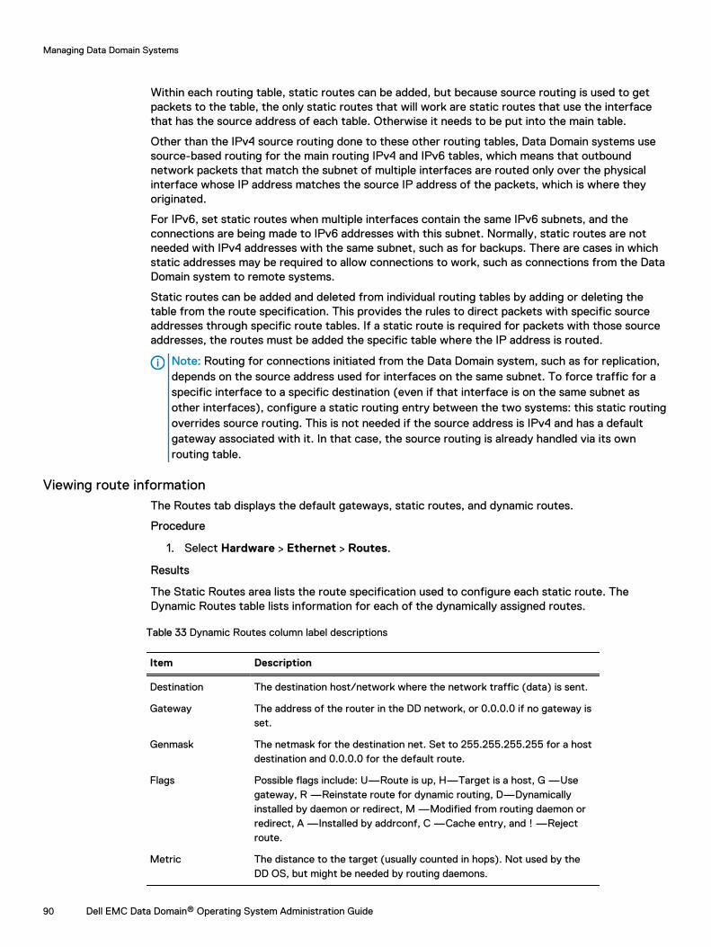
Within each routing table, static routes can be added, but because source routing is used to getpackets to the table, the only static routes that will work are static routes that use the interfacethat has the source address of each table. Otherwise it needs to be put into the main table.
Other than the IPv4 source routing done to these other routing tables, Data Domain systems usesource-based routing for the main routing IPv4 and IPv6 tables, which means that outboundnetwork packets that match the subnet of multiple interfaces are routed only over the physicalinterface whose IP address matches the source IP address of the packets, which is where theyoriginated.
For IPv6, set static routes when multiple interfaces contain the same IPv6 subnets, and theconnections are being made to IPv6 addresses with this subnet. Normally, static routes are notneeded with IPv4 addresses with the same subnet, such as for backups. There are cases in whichstatic addresses may be required to allow connections to work, such as connections from the DataDomain system to remote systems.
Static routes can be added and deleted from individual routing tables by adding or deleting thetable from the route specification. This provides the rules to direct packets with specific sourceaddresses through specific route tables. If a static route is required for packets with those sourceaddresses, the routes must be added the specific table where the IP address is routed.
Note: Routing for connections initiated from the Data Domain system, such as for replication,depends on the source address used for interfaces on the same subnet. To force traffic for aspecific interface to a specific destination (even if that interface is on the same subnet asother interfaces), configure a static routing entry between the two systems: this static routingoverrides source routing. This is not needed if the source address is IPv4 and has a defaultgateway associated with it. In that case, the source routing is already handled via its ownrouting table.
Viewing route informationThe Routes tab displays the default gateways, static routes, and dynamic routes.
Procedure
1. Select Hardware > Ethernet > Routes.
Results
The Static Routes area lists the route specification used to configure each static route. TheDynamic Routes table lists information for each of the dynamically assigned routes.
Table 33 Dynamic Routes column label descriptions
Item Description
Destination The destination host/network where the network traffic (data) is sent.
Gateway The address of the router in the DD network, or 0.0.0.0 if no gateway isset.
Genmask The netmask for the destination net. Set to 255.255.255.255 for a hostdestination and 0.0.0.0 for the default route.
Flags Possible flags include: U—Route is up, H—Target is a host, G —Usegateway, R —Reinstate route for dynamic routing, D—Dynamicallyinstalled by daemon or redirect, M —Modified from routing daemon orredirect, A —Installed by addrconf, C —Cache entry, and ! —Rejectroute.
Metric The distance to the target (usually counted in hops). Not used by theDD OS, but might be needed by routing daemons.
Managing Data Domain Systems
90 Dell EMC Data Domain® Operating System Administration Guide
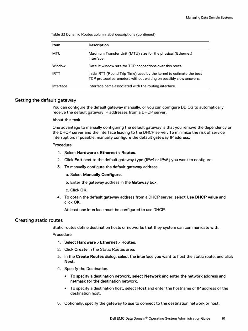
Table 33 Dynamic Routes column label descriptions (continued)
Item Description
MTU Maximum Transfer Unit (MTU) size for the physical (Ethernet)interface.
Window Default window size for TCP connections over this route.
IRTT Initial RTT (Round Trip Time) used by the kernel to estimate the bestTCP protocol parameters without waiting on possibly slow answers.
Interface Interface name associated with the routing interface.
Setting the default gatewayYou can configure the default gateway manually, or you can configure DD OS to automaticallyreceive the default gateway IP addresses from a DHCP server.
About this task
One advantage to manually configuring the default gateway is that you remove the dependency onthe DHCP server and the interface leading to the DHCP server. To minimize the risk of serviceinterruption, if possible, manually configure the default gateway IP address.
Procedure
1. Select Hardware > Ethernet > Routes.
2. Click Edit next to the default gateway type (IPv4 or IPv6) you want to configure.
3. To manually configure the default gateway address:
a. Select Manually Configure.
b. Enter the gateway address in the Gateway box.
c. Click OK.
4. To obtain the default gateway address from a DHCP server, select Use DHCP value andclick OK.
At least one interface must be configured to use DHCP.
Creating static routesStatic routes define destination hosts or networks that they system can communicate with.
Procedure
1. Select Hardware > Ethernet > Routes.
2. Click Create in the Static Routes area.
3. In the Create Routes dialog, select the interface you want to host the static route, and clickNext.
4. Specify the Destination.
l To specify a destination network, select Network and enter the network address andnetmask for the destination network.
l To specify a destination host, select Host and enter the hostname or IP address of thedestination host.
5. Optionally, specify the gateway to use to connect to the destination network or host.
Managing Data Domain Systems
Dell EMC Data Domain® Operating System Administration Guide 91
a. Select Specify a gateway for this route.
b. Enter the gateway address in the Gateway box.
6. Review the configuration and click Next.
The create routes Summary page appears.
7. Click Finish.
8. After the process is completed, click OK.
The new route specification is listed in the Route Spec list.
Deleting static routesDelete a static route when you no longer want the system to communicate with a destination hostor network.
Procedure
1. Select Hardware > Ethernet > Routes.
2. Select the Route Spec of the route specification to delete.
3. Click Delete.
4. Click Delete to confirm and then click Close.
The selected route specification is removed from the Route Spec list.
System passphrase managementThe system passphrase is a key that allows a Data Domain system to be transported withencryption keys on the system. The encryption keys protect the data and the system passphraseprotects the encryption keys.
The system passphrase is a human-readable (understandable) key (like a smart card) which is usedto generate a machine usable AES 256 encryption key. If the system is stolen in transit, anattacker cannot easily recover the data; at most, they can recover the encrypted user data and theencrypted keys.
The passphrase is stored internally on a hidden part the Data Domain storage subsystem. Thisallows the Data Domain system to boot and continue servicing data access without anyadministrator intervention.
Setting the system passphraseThe system passphrase must be set before the system can support data encryption or requestdigital certificates.
Before you begin
No minimum system passphrase length is configured when DD OS is installed, but the CLI providesa command to set a minimum length. To determine if a minimum length is configured for thepassphrase, enter the system passphrase option show CLI command.
Procedure
1. Select Administration > Access > Administrator Access.
If the system passphrase is not set, the Set Passphrase button appears in the Passphrasearea. If a system passphrase is configured, the Change Passphrase button appears, andyour only option is to change the passphrase.
Managing Data Domain Systems
92 Dell EMC Data Domain® Operating System Administration Guide
2. Click the Set Passphrase button.
The Set Passphrase dialog appears.
3. Enter the system passphrase in the boxes and click Next.
If a minimum length is configured for the system passphrase, the passphrase you enter mustcontain the minimum number of characters.
Results
The system passphrase is set and the Change Passphrase button replaces the Set Passphrasebutton.
Changing the system passphraseThe administrator can change the passphrase without having to manipulate the actual encryptionkeys. Changing the passphrase indirectly changes the encryption of the keys, but does not affectuser data or the underlying encryption key.
About this task
Changing the passphrase requires two-user authentication to protect against data shredding.
Procedure
1. Select Administration > Access > Administrator Access.
2. To change the system passphrase, click Change Passphrase.
The Change Passphrase dialog appears.
Note: The file system must be disabled to change the passphrase. If the file system isrunning, you are prompted to disable it.
3. In the text fields, provide:
l The user name and password of a Security Officer account (an authorized user in theSecurity User group on that Data Domain system).
l The current passphrase when changing the passphrase.
l The new passphrase, which must contain the minimum number of characters configuredwith the system passphrase option set min-length command.
4. Click the checkbox for Enable file system now.
5. Click OK.
NOTICE Be sure to take care of the passphrase. If the passphrase is lost, you can neverunlock the file system and access the data; the data is irrevocably lost.
System access managementSystem access management features allow you to control system access to users in a localdatabase or in a network directory. Additional controls define different access levels and controlwhich protocols can access the system.
Managing Data Domain Systems
Dell EMC Data Domain® Operating System Administration Guide 93
Role-based access controlRole-based access control (RBAC) is an authentication policy that controls which DD SystemManager controls and CLI commands a user can access on a system.
For example, users who are assigned the admin role can configure and monitor an entire system,while users who are assigned the user role are limited to monitoring a system. When logged intoDD System Manager, users see only the program features that they are permitted to use based onthe role assigned to the user. The following roles are available for administering and managing theDD OS.
admin
An admin role user can configure and monitor the entire Data Domain system. Mostconfiguration features and commands are available only to admin role users. However, somefeatures and commands require the approval of a security role user before a task iscompleted.
limited-admin
The limited-admin role can configure and monitor the Data Domain system with somelimitations. Users who are assigned this role cannot perform data deletion operations, edit theregistry, or enter bash or SE mode.
user
The user role enables users to monitor systems and change their own password. Users whoare assigned the user management role can view system status, but they cannot change thesystem configuration.
security (security officer)
A security role user, who may be referred to as a security officer, can manage other securityofficers, authorize procedures that require security officer approval, and perform all taskssupported for user-role users.
The security role is provided to comply with the Write Once Read-Many (WORM) regulation.This regulation requires electronically stored corporate data be kept in an unaltered, originalstate for purposes such as eDiscovery. Data Domain added auditing and logging capabilities toenhance this feature. As a result of compliance regulations, most command options foradministering sensitive operations, such as DD Encryption, DD Retention Lock Compliance,and archiving now require security officer approval.
In a typical scenario, an admin role user issues a command and, if security officer approval isrequired, the system displays a prompt for approval. To proceed with the original task, thesecurity officer must enter his or her username and password on the same console at whichthe command was run. If the system recognizes the security officer credentials, theprocedure is authorized. If not, a security alert is generated.
The following are some guidelines that apply to security-role users:
l Only the sysadmin user (the default user created during the DD OS installation) can createthe first security officer, after which the privilege to create security officers is removedfrom the sysadmin user.
l After the first security officer is created, only security officers can create other securityofficers.
l Creating a security officer does not enable the authorization policy. To enable theauthorization policy, a security officer must log in and enable the authorization policy.
l Separation of privilege and duty apply. admin role users cannot perform security officertasks, and security officers cannot perform system configuration tasks.
Managing Data Domain Systems
94 Dell EMC Data Domain® Operating System Administration Guide
l During an upgrade, if the system configuration contains security officers, a sec-off-defaults permission is created that includes a list of all current security officers.
backup-operator
A backup-operator role user can perform all tasks permitted for user role users, createsnapshots for MTrees, import, export, and move tapes between elements in a virtual tapelibrary, and copy tapes across pools.
A backup-operator role user can also add and delete SSH public keys for non-password-required log ins. (This function is used mostly for automated scripting.) He or she can add,delete, reset and view CLI command aliases, synchronize modified files, and wait forreplication to complete on the destination system.
none
The none role is for DD Boost authentication and tenant-unit users only. A none role user canlog in to a Data Domain system and can change his or her password, but cannot monitor,manage, or configure the primary system. When the primary system is partitioned into tenantunits, either the tenant-admin or the tenant-user role is used to define a user's role withrespect to a specific tenant unit. The tenant user is first assigned the none role to minimizeaccess to the primary system, and then either the tenant-admin or the tenant-user role isappended to that user.
tenant-admin
A tenant-admin role can be appended to the other (non-tenant) roles when the Secure Multi-Tenancy (SMT) feature is enabled. A tenant-admin user can configure and monitor a specifictenant unit.
tenant-user
A tenant-user role can be appended to the other (non-tenant) roles when the SMT feature isenabled. The tenant-user role enables a user to monitor a specific tenant unit and change theuser password. Users who are assigned the tenant-user management role can view tenant unitstatus, but they cannot change the tenant unit configuration.
Access management for IP protocolsThis feature manages system access for the FTP, FTPS, HTTP, HTTPS, SSH, SCP, and Telnetprotocols.
Viewing the IP services configurationThe Administrator Access tab displays the configuration status for the IP protocols that can beused to access the system. FTP and FTPS are the only protocols that are restricted toadministrators.
Procedure
1. Select Administration > Access > Administrator Access.
Results
The Access Management page displays the Administrator Access, Local Users, Authentication, andActive Users tabs.
Managing Data Domain Systems
Dell EMC Data Domain® Operating System Administration Guide 95
Table 34 Administrator Access tab information
Item Description
Passphrase If no passphrase is set, the Set Passphrase button appears. If apassphrase is set, the Change Passphrase button appears.
Services The name of a service/protocol that can access the system.
Enabled (Yes/No) The status of the service. If the service is disabled, enable it byselecting it in the list and clicking Configure. Fill out the Generaltab of the dialog box. If the service is enabled, modify its settingsby selecting it in the list and clicking Configure. Edit the settings inthe General tab of the dialog box.
Allowed Hosts The host or hosts that can access the service.
Service Options The port or session timeout value for the service selected in thelist.
FTP/FTPS Only the session timeout can be set.
HTTP port The port number opened for the HTTP protocol (port 80, bydefault).
HTTPS port The port number opened for the HTTPS protocol (port 443, bydefault).
SSH/SCP port The port number opened for the SSH/SCP protocol (port 22, bydefault).
Telnet No port number can be set.
Session Timeout The amount of inactive time allowed before a connection closes.The default is Infinite, that is, the connection does not close. Ifpossible, set a session timeout maximum of five minutes. Use theAdvanced tab of the dialog box to set a timeout in seconds.
Managing FTP accessThe File Transfer Protocol (FTP) allows administrators to access files on the Data Domain system.
About this task
You can enable either FTP or FTPS access to users who are assigned the admin management role.FTP access allows admin user names and passwords to cross the network in clear text, makingFTP an insecure access method. FTPS is recommended as a secure access method. When youenable either FTP or FTPS access, the other access method is disabled.
Note: Only users who are assigned the admin management role are permitted to access thesystem using FTP
Note: LFTP clients that connect to a Data Domain system via FTPS or FTP are disconnectedafter reaching a set timeout limit. However the LFTP client uses its cached username andpassword to reconnect after the timeout while you are running any command.
Procedure
1. Select Administration > Access > Administrator Access.
2. Select FTP and click Configure.
3. To manage FTP access and which hosts can connect, select the General tab and do thefollowing:
Managing Data Domain Systems
96 Dell EMC Data Domain® Operating System Administration Guide
a. To enable FTP access, select Allow FTP Access.
b. To enable all hosts to connect, select Allow all hosts to connect.
c. To restrict access to select hosts, select Limit Access to the following systems, andmodify the Allowed Hosts list.
Note: You can identify a host using a fully qualified hostname, an IPv4 address, or anIPv6 address.
l To add a host, click Add (+). Enter the host identification and click OK.
l To modify a host ID, select the host in the Hosts list and click Edit (pencil). Changethe host ID and click OK.
l To remove a host ID, select the host in the Hosts list and click Delete (X).
4. To set a session timeout, select the Advanced tab, and enter the timeout value in seconds.
Note: The session timeout default is Infinite, that is, the connection does not close.
5. Click OK.
If FTPS is enabled, a warning message appears with a prompt to click OK to proceed.
Managing FTPS accessThe FTP Secure (FTPS) protocol allows administrators to access files on the Data Domain system.
About this task
FTPS provides additional security over using FTP, such as support for the Transport LayerSecurity (TLS) and for the Secure Sockets Layer (SSL) cryptographic protocols. Consider thefollowing guidelines when using FTPS.
l Only users who are assigned the admin management role are permitted to access the systemusing FTPS.
l When you enable FTPS access, FTP access is disabled.
l FTPS does not show up as a service for DD systems that run DD OS 5.2, managed from a DDsystem running DD OS 5.3 or later.
l When you issue the get command, the fatal error message SSL_read: wrong versionnumber lftp appears if matching versions of SSL are not installed on the Data Domainsystem and compiled on the LFTP client . As a workaround, attempt to re-issue the getcommand on the same file.
Procedure
1. Select Administration > Access > Administrator Access.
2. Select FTPS and click Configure.
3. To manage FTPS access and which hosts can connect, select the General tab and do thefollowing:
a. To enable FTPS access, select Allow FTPS Access.
b. To enable all hosts to connect, select Allow all hosts to connect.
c. To restrict access to select hosts, select Limit Access to the following systems, andmodify the hosts list.
Note: You can identify a host using a fully qualified hostname, an IPv4 address, or anIPv6 address.
Managing Data Domain Systems
Dell EMC Data Domain® Operating System Administration Guide 97
l To add a host, click Add (+). Enter the host identification and click OK.
l To modify a host ID, select the host in the Hosts list and click Edit (pencil). Changethe host ID and click OK.
l To remove a host ID, select the host in the Hosts list and click Delete (X).
4. To set a session timeout, select the Advanced tab and enter the timeout value in seconds.
Note: The session timeout default is Infinite, that is, the connection does not close.
5. Click OK. If FTP is enabled, a warning message appears and prompts you to click OK toproceed.
Managing HTTP and HTTPS accessHTTP or HTTPS access is required to support browser access to DD System Manager.
Procedure
1. Select Administration > Access > Administrator Access.
2. Select HTTP or HTTPS and click Configure.
The Configure HTTP/HTTPS Access dialog appears and displays tabs for generalconfiguration, advanced configuration, and certificate management.
3. To manage the access method and which hosts can connect, select the General tab and dothe following:
a. Select the checkboxes for the access methods you want to allow.
b. To enable all hosts to connect, select Allow all hosts to connect.
c. To restrict access to select hosts, select Limit Access to the following systems, andmodify the host list.
Note: You can identify a host using a fully qualified hostname, an IPv4 address, or anIPv6 address.
l To add a host, click Add (+). Enter the host identification and click OK.
l To modify a host ID, select the host in the Hosts list and click Edit (pencil). Changethe host ID and click OK.
l To remove a host ID, select the host in the Hosts list and click Delete (X).
4. To configure system ports and session timeout values, select the Advanced tab, andcomplete the form.
l In the HTTP Port box, enter the port number. Port 80 is assigned by default.
l In the HTTPS Port box, enter the number. Port 443 is assigned by default.
l In the Session Timeout box, enter the interval in seconds that must elapse before aconnection closes. The minimum is 60 seconds and the maximum is 31536000 seconds(one year).
Note: The session timeout default is 10,800 seconds.
5. Click OK.
Managing Data Domain Systems
98 Dell EMC Data Domain® Operating System Administration Guide
Managing host certificates for HTTP and HTTPSA host certificate allows browsers to verify the identity of the system when establishingmanagement sessions.
Requesting a host certificate for HTTP and HTTPS
You can use DD System Manager to generate a host certificate request, which you can thenforward to a Certificate Authority (CA).
About this task
Note: You must configure a system passphrase (system passphrase set) before you cangenerate a CSR.
Procedure
1. Select Administration > Access > Administrator Access.
2. In the Services area, select HTTP or HTTPSand click Configure.
3. Select the Certificate tab.
4. Click Add.
A dialog appears for the protocol you selected earlier in this procedure.
5. Click Generate the CSR for this Data Domain system.
The dialog expands to display a CSR form.Note: DD OS supports one active CSR at a time. After a CSR is generated, theGenerate the CSR for this Data Domain system link is replaced with the Downloadthe CSR for this Data Domain system link. To delete a CSR, use the adminaccesscertificate cert-signing-request delete CLI command.
6. Complete the CSR form and click Generate and download a CSR.
The CSR file is saved at the following path: /ddvar/certificates/CertificateSigningRequest.csr. Use SCP, FTP or FTPS to transfer the CSR filefrom the system to a computer from which you can send the CSR to a CA.
Adding a host certificate for HTTP and HTTPS
You can use DD System Manager to add a host certificate to the system.
Procedure
1. If you did not requested a host certificate, request a host certificate from a certificateauthority.
2. When you receive a host certificate, copy or move it to the computer from which you runDD Service Manager.
3. Select Administration > Access > Administrator Access.
4. In the Services area, select HTTP or HTTPS and click Configure.
5. Select the Certificate tab.
6. Click Add.
A dialog appears for the protocol you selected earlier in this procedure.
7. To add a host certificate enclosed in a .p12 file, do the following:
a. Select I want to upload the certificate as a .p12 file.
Managing Data Domain Systems
Dell EMC Data Domain® Operating System Administration Guide 99
b. Type the password in the Password box.
c. Click Browse and select the host certificate file to upload to the system.
d. Click Add.
8. To add a host certificate enclosed in a .pem file, do the following:
a. Select I want to upload the public key as a .pem file and use a generated private key.
b. Click Browse and select the host certificate file to upload to the system.
c. Click Add.
Deleting a host certificate for HTTP and HTTPS
DD OS supports one host certificate for HTTP and HTTPS. If the system is currently using a hostcertificate and you want to use a different host certificate, you must delete the current certificatebefore adding the new certificate.
Procedure
1. Select Administration > Access > Administrator Access.
2. In the Services area, select HTTP or HTTPS and click Configure.
3. Select the Certificate tab.
4. Select the certificate you want to delete.
5. Click Delete, and click OK.
Managing SSH and SCP accessSSH is a secure protocol that enables network access to the system CLI, with or without SCP(secure copy). You can use DD System Manager to enable system access using the SSH protocol.SCP requires SSH, so when SSH is disabled, SCP is automatically disabled.
Procedure
1. Select Administration > Access > Administrator Access.
2. Select SSH or SCP and click Configure.
3. To manage the access method and which hosts can connect, select the General tab.
a. Select the checkboxes for the access methods you want to allow.
b. To enable all hosts to connect, select Allow all hosts to connect.
c. To restrict access to select hosts, select Limit Access to the following systems, andmodify the host list.
Note: You can identify a host using a fully qualified hostname, an IPv4 address, or anIPv6 address.
l To add a host, click Add (+). Enter the host identification and click OK.
l To modify a host ID, select the host in the Hosts list and click Edit (pencil). Changethe host ID and click OK.
l To remove a host ID, select the host in the Hosts list and click Delete (X).
4. To configure system ports and session timeout values, click the Advanced tab.
l In the SSH/SCP Port text entry box, enter the port number. Port 22 is assigned bydefault.
l In the Session Timeout box, enter the interval in seconds that must elapse beforeconnection closes.
Managing Data Domain Systems
100 Dell EMC Data Domain® Operating System Administration Guide
Note: The session timeout default is Infinite, that is, the connection does not close.
Note: Click Default to revert to the default value.
5. Click OK.
Managing Telnet accessTelnet is an insecure protocol that enables network access to the system CLI.
About this task
Note: Telnet access allows user names and passwords to cross the network in clear text,making Telnet an insecure access method.
Procedure
1. Select Administration > Access > Administrator Access.
2. Select Telnet and click Configure.
3. To manage Telnet access and which hosts can connect, select the General tab.
a. To enable Telnet access, select Allow Telnet Access.
b. To enable all hosts to connect, select Allow all hosts to connect.
c. To restrict access to select hosts, select Limit Access to the following systems, andmodify the host list.
Note: You can identify a host using a fully qualified hostname, an IPv4 address, or anIPv6 address.
l To add a host, click Add (+). Enter the host identification and click OK.
l To modify a host ID, select the host in the Hosts list and click Edit (pencil). Changethe host ID and click OK.
l To remove a host ID, select the host in the Hosts list and click Delete (X).
4. To set a session timeout, select the Advanced tab and enter the timeout value in seconds.
Note: The session timeout default is Infinite, that is, the connection does not close.
5. Click OK.
Local user account managementA local user is a user account (user name and password) that is configured on the Data Domainsystem instead of being defined in a Windows Active Directory, Windows Workgroup, or NISdirectory.
After a trusted domain is configured, users who belong to that domain will be able to log into theData Domain system even if that trusted domain is offline.
UID conflicts: local user and NIS user accountsWhen you set up a Data Domain system in an NIS environment, be aware of potential UID conflictsbetween local and NIS user accounts.
Local user accounts on a Data Domain system start with a UID of 500. To avoid conflicts, considerthe size of potential local accounts when you define allowable UID ranges for NIS users.
Managing Data Domain Systems
Dell EMC Data Domain® Operating System Administration Guide 101
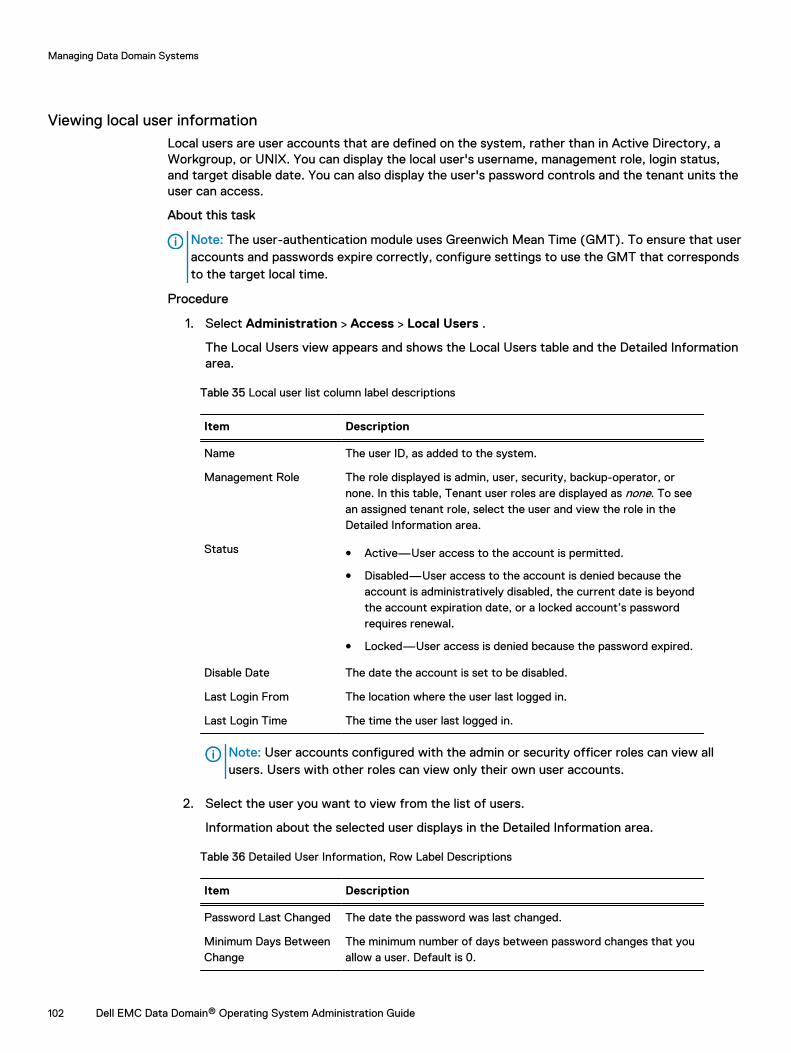
Viewing local user informationLocal users are user accounts that are defined on the system, rather than in Active Directory, aWorkgroup, or UNIX. You can display the local user's username, management role, login status,and target disable date. You can also display the user's password controls and the tenant units theuser can access.
About this task
Note: The user-authentication module uses Greenwich Mean Time (GMT). To ensure that useraccounts and passwords expire correctly, configure settings to use the GMT that correspondsto the target local time.
Procedure
1. Select Administration > Access > Local Users .
The Local Users view appears and shows the Local Users table and the Detailed Informationarea.
Table 35 Local user list column label descriptions
Item Description
Name The user ID, as added to the system.
Management Role The role displayed is admin, user, security, backup-operator, ornone. In this table, Tenant user roles are displayed as none. To seean assigned tenant role, select the user and view the role in theDetailed Information area.
Status l Active—User access to the account is permitted.
l Disabled—User access to the account is denied because theaccount is administratively disabled, the current date is beyondthe account expiration date, or a locked account’s passwordrequires renewal.
l Locked—User access is denied because the password expired.
Disable Date The date the account is set to be disabled.
Last Login From The location where the user last logged in.
Last Login Time The time the user last logged in.
Note: User accounts configured with the admin or security officer roles can view allusers. Users with other roles can view only their own user accounts.
2. Select the user you want to view from the list of users.
Information about the selected user displays in the Detailed Information area.
Table 36 Detailed User Information, Row Label Descriptions
Item Description
Password Last Changed The date the password was last changed.
Minimum Days BetweenChange
The minimum number of days between password changes that youallow a user. Default is 0.
Managing Data Domain Systems
102 Dell EMC Data Domain® Operating System Administration Guide
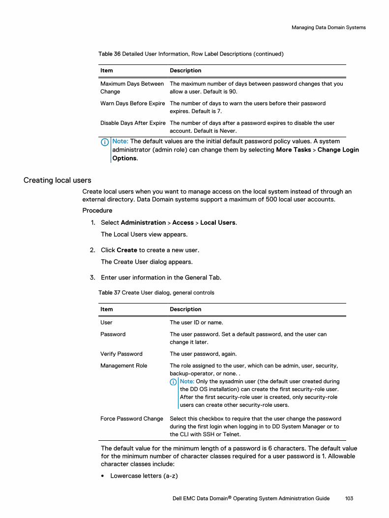
Table 36 Detailed User Information, Row Label Descriptions (continued)
Item Description
Maximum Days BetweenChange
The maximum number of days between password changes that youallow a user. Default is 90.
Warn Days Before Expire The number of days to warn the users before their passwordexpires. Default is 7.
Disable Days After Expire The number of days after a password expires to disable the useraccount. Default is Never.
Note: The default values are the initial default password policy values. A systemadministrator (admin role) can change them by selecting More Tasks > Change LoginOptions.
Creating local usersCreate local users when you want to manage access on the local system instead of through anexternal directory. Data Domain systems support a maximum of 500 local user accounts.
Procedure
1. Select Administration > Access > Local Users.
The Local Users view appears.
2. Click Create to create a new user.
The Create User dialog appears.
3. Enter user information in the General Tab.
Table 37 Create User dialog, general controls
Item Description
User The user ID or name.
Password The user password. Set a default password, and the user canchange it later.
Verify Password The user password, again.
Management Role The role assigned to the user, which can be admin, user, security,backup-operator, or none. .
Note: Only the sysadmin user (the default user created duringthe DD OS installation) can create the first security-role user.After the first security-role user is created, only security-roleusers can create other security-role users.
Force Password Change Select this checkbox to require that the user change the passwordduring the first login when logging in to DD System Manager or tothe CLI with SSH or Telnet.
The default value for the minimum length of a password is 6 characters. The default valuefor the minimum number of character classes required for a user password is 1. Allowablecharacter classes include:
l Lowercase letters (a-z)
Managing Data Domain Systems
Dell EMC Data Domain® Operating System Administration Guide 103
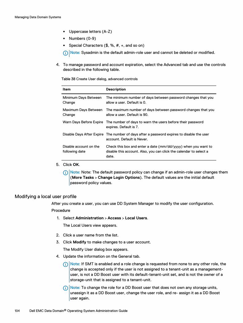
l Uppercase letters (A-Z)
l Numbers (0-9)
l Special Characters ($, %, #, +, and so on)
Note: Sysadmin is the default admin-role user and cannot be deleted or modified.
4. To manage password and account expiration, select the Advanced tab and use the controlsdescribed in the following table.
Table 38 Create User dialog, advanced controls
Item Description
Minimum Days BetweenChange
The minimum number of days between password changes that youallow a user. Default is 0.
Maximum Days BetweenChange
The maximum number of days between password changes that youallow a user. Default is 90.
Warn Days Before Expire The number of days to warn the users before their passwordexpires. Default is 7.
Disable Days After Expire The number of days after a password expires to disable the useraccount. Default is Never.
Disable account on thefollowing date
Check this box and enter a date (mm/dd/yyyy) when you want todisable this account. Also, you can click the calendar to select adate.
5. Click OK.
Note: Note: The default password policy can change if an admin-role user changes them(More Tasks > Change Login Options). The default values are the initial defaultpassword policy values.
Modifying a local user profileAfter you create a user, you can use DD System Manager to modify the user configuration.
Procedure
1. Select Administration > Access > Local Users.
The Local Users view appears.
2. Click a user name from the list.
3. Click Modify to make changes to a user account.
The Modify User dialog box appears.
4. Update the information on the General tab.
Note: If SMT is enabled and a role change is requested from none to any other role, thechange is accepted only if the user is not assigned to a tenant-unit as a management-user, is not a DD Boost user with its default-tenant-unit set, and is not the owner of astorage-unit that is assigned to a tenant-unit.
Note: To change the role for a DD Boost user that does not own any storage units,unassign it as a DD Boost user, change the user role, and re- assign it as a DD Boostuser again.
Managing Data Domain Systems
104 Dell EMC Data Domain® Operating System Administration Guide
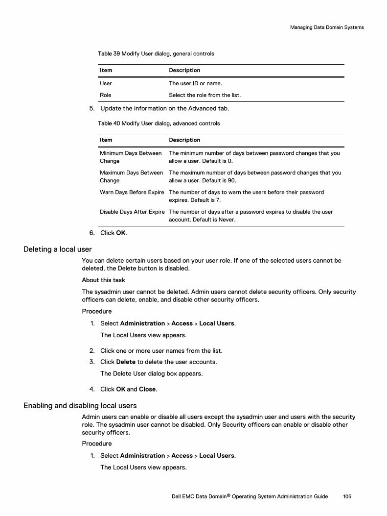
Table 39 Modify User dialog, general controls
Item Description
User The user ID or name.
Role Select the role from the list.
5. Update the information on the Advanced tab.
Table 40 Modify User dialog, advanced controls
Item Description
Minimum Days BetweenChange
The minimum number of days between password changes that youallow a user. Default is 0.
Maximum Days BetweenChange
The maximum number of days between password changes that youallow a user. Default is 90.
Warn Days Before Expire The number of days to warn the users before their passwordexpires. Default is 7.
Disable Days After Expire The number of days after a password expires to disable the useraccount. Default is Never.
6. Click OK.
Deleting a local userYou can delete certain users based on your user role. If one of the selected users cannot bedeleted, the Delete button is disabled.
About this task
The sysadmin user cannot be deleted. Admin users cannot delete security officers. Only securityofficers can delete, enable, and disable other security officers.
Procedure
1. Select Administration > Access > Local Users.
The Local Users view appears.
2. Click one or more user names from the list.
3. Click Delete to delete the user accounts.
The Delete User dialog box appears.
4. Click OK and Close.
Enabling and disabling local usersAdmin users can enable or disable all users except the sysadmin user and users with the securityrole. The sysadmin user cannot be disabled. Only Security officers can enable or disable othersecurity officers.
Procedure
1. Select Administration > Access > Local Users.
The Local Users view appears.
Managing Data Domain Systems
Dell EMC Data Domain® Operating System Administration Guide 105
2. Click one or more user names from the list.
3. Click either Enable or Disable to enable or disable user accounts.
The Enable or Disable User dialog box appears.
4. Click OK and Close.
Enabling security authorizationYou can use the Data Domain system command-line interface (CLI) to enable and disable thesecurity authorization policy.
About this task
For information on the commands used in this procedure, see the Data Domain Operating SystemCommand Reference Guide.
Note: The DD Retention Lock Compliance license must be installed. You are not permitted todisable the authorization policy on DD Retention Lock Compliance systems.
Procedure
1. Log into the CLI using a security officer username and password.
2. To enable the security officer authorization policy, enter: # authorization policy setsecurity-officer enabled
Changing user passwordsAfter you create a user, you can use DD System Manager to change the user's password.Individual users can also change their own passwords.
Procedure
1. Click Administration > Access > Local Users.
The Local Users view is displayed.
2. Click a username from the list.
3. To change the user password, click Change Password.
The Change Password dialog box is displayed.
4. Enter the old password into the Old Password box.
5. Enter the new password into the New Password box.
6. Enter the new password again into Verify New Password box.
7. Click OK.
Only users with an "admin" role may change the password of other users. The administratorcan change the password of other users from the CLI by running the user changepassword [<user>] command.
Note: For security reasons, users with an "admin" role cannot change other "admin"users' passwords. If an "admin" user password needs to be changed by logging in asanother user, contact DELL-EMC Support by creating a Support Request or chatrequest for assistance.
Managing Data Domain Systems
106 Dell EMC Data Domain® Operating System Administration Guide
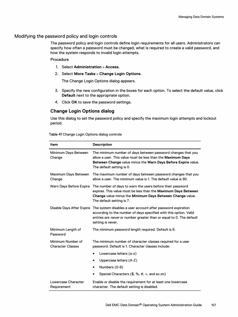
Modifying the password policy and login controlsThe password policy and login controls define login requirements for all users. Administrators canspecify how often a password must be changed, what is required to create a valid password, andhow the system responds to invalid login attempts.
Procedure
1. Select Administration > Access.
2. Select More Tasks > Change Login Options.
The Change Login Options dialog appears.
3. Specify the new configuration in the boxes for each option. To select the default value, clickDefault next to the appropriate option.
4. Click OK to save the password settings.
Change Login Options dialog
Use this dialog to set the password policy and specify the maximum login attempts and lockoutperiod.
Table 41 Change Login Options dialog controls
Item Description
Minimum Days BetweenChange
The minimum number of days between password changes that youallow a user. This value must be less than the Maximum DaysBetween Change value minus the Warn Days Before Expire value.The default setting is 0.
Maximum Days BetweenChange
The maximum number of days between password changes that youallow a user. The minimum value is 1. The default value is 90.
Warn Days Before Expire The number of days to warn the users before their passwordexpires. This value must be less than the Maximum Days BetweenChange value minus the Minimum Days Between Change value.The default setting is 7.
Disable Days After Expire The system disables a user account after password expirationaccording to the number of days specified with this option. Validentries are never or number greater than or equal to 0. The defaultsetting is never.
Minimum Length ofPassword
The minimum password length required. Default is 6.
Minimum Number ofCharacter Classes
The minimum number of character classes required for a userpassword. Default is 1. Character classes include:
l Lowercase letters (a-z)
l Uppercase letters (A-Z)
l Numbers (0-9)
l Special Characters ($, %, #, +, and so on)
Lowercase CharacterRequirement
Enable or disable the requirement for at least one lowercasecharacter. The default setting is disabled.
Managing Data Domain Systems
Dell EMC Data Domain® Operating System Administration Guide 107
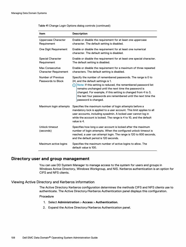
Table 41 Change Login Options dialog controls (continued)
Item Description
Uppercase CharacterRequirement
Enable or disable the requirement for at least one uppercasecharacter. The default setting is disabled.
One Digit Requirement Enable or disable the requirement for at least one numericalcharacter. The default setting is disabled.
Special CharacterRequirement
Enable or disable the requirement for at least one special character.The default setting is disabled.
Max ConsecutiveCharacter Requirement
Enable or disable the requirement for a maximum of three repeatedcharacters. The default setting is disabled.
Number of PreviousPasswords to Block
Specify the number of remembered passwords. The range is 0 to24, and the default settings is 1.
Note: If this setting is reduced, the remembered password listremains unchanged until the next time the password ischanged. For example, if this setting is changed from 4 to 3,the last four passwords are remembered until the next time thepassword is changed.
Maximum login attempts Specifies the maximum number of login attempts before amandatory lock is applied to a user account. This limit applies to alluser accounts, including sysadmin. A locked user cannot log inwhile the account is locked. The range is 4 to 10, and the defaultvalue is 4.
Unlock timeout(seconds)
Specifies how long a user account is locked after the maximumnumber of login attempts. When the configured unlock timeout isreached, a user can attempt login. The range is 120 to 600 seconds,and the default period is 120 seconds.
Maximum active logins Specifies the maximum number of active logins to allow. Thedefault value is 100.
Directory user and group managementYou can use DD System Manager to manage access to the system for users and groups inWindows Active Directory, Windows Workgroup, and NIS. Kerberos authentication is an option forCIFS and NFS clients.
Viewing Active Directory and Kerberos informationThe Active Directory Kerberos configuration determines the methods CIFS and NFS clients use toauthenticate. The Active Directory/Kerberos Authentication panel displays this configuration.
Procedure
1. Select Administration > Access > Authentication.
2. Expand the Active Directory/Kerberos Authentication panel.
Managing Data Domain Systems
108 Dell EMC Data Domain® Operating System Administration Guide
Table 42 Active Directory/ Kerberos Authentication label descriptions
Item Description
Mode The type of authentication mode. In Windows/Active Directorymode, CIFS clients use Active Directory and Kerberosauthentication, and NFS clients use Kerberos authentication. InUnix mode, CIFS clients use Workgroup authentication (withoutKerberos), and NFS clients use Kerberos authentication. InDisabled mode, Kerberos authentication is disabled and CIFSclients use Workgroup authentication.
Realm The realm name of the Workgroup or Active Directory.
DDNS Whether or not the Dynamic Domain Name System is enabled.
Domain Controllers The name of the domain controller for the Workgroup or ActiveDirectory.
Organizational Unit The name of the organizations unit for the Workgroup or ActiveDirectory.
CIFS Server Name The name of the CIFS server in use (Windows mode only).
WINS Server The name of the WINS server in use (Windows mode only).
Short Domain Name An abbreviated name for the domain.
NTP Enabled/Disabled (UNIX mode only)
NIS Enabled/Disabled (UNIX mode only)
Key Distribution Centers Hostname(s) or IP(s) of KDC in use (UNIX mode only)
Active DirectoryAdministrative Access
Enabled/Disabled: Click to Enable or disable administrative accessfor Active Directory (Windows) groups.
Table 43 Active Directory administrative groups and roles
Item Description
Windows Group The name of the Windows group.
Management Role The role of the group (admin, user, and so on)
Configuring Active Directory and Kerberos authenticationConfiguring Active Directory authentication makes the Data Domain system part of a WindowsActive Directory realm. CIFS clients and NFS clients use Kerberos authentication.
Procedure
1. Select Administration > Access > Authentication.
The Authentication view appears.
2. Expand the Active Directory/Kerberos Authentication panel.
3. Click Configure... next to Mode to start the configuration wizard.
The Active Directory/Kerberos Authentication dialog appears.
4. Select Windows/Active Directory and click Next.
5. Enter the full realm name for the system (for example: domain1.local), the user name, andpassword for the Data Domain system. Then click Next.
Managing Data Domain Systems
Dell EMC Data Domain® Operating System Administration Guide 109
Note: Use the complete realm name. Ensure that the user is assigned sufficientprivileges to join the system to the domain. The user name and password must becompatible with Microsoft requirements for the Active Directory domain. This user mustalso be assigned permission to create accounts in this domain.
6. Select the default CIFS server name, or select Manual and enter a CIFS server name.
7. To select domain controllers, select Automatically assign, or select Manual and enter up tothree domain controller names.
You can enter fully qualified domain names, hostnames, or IP (IPv4 or IPv6) addresses.
8. To select an organizational unit, select Use default Computers, or select Manual and enteran organization unit name.
Note: The account is moved to the new organizational unit.
9. Click Next.
The Summary page for the configuration appears.
10. Click Finish.
The system displays the configuration information in the Authentication view.
11. To enable administrative access, click Enable to the right of Active DirectoryAdministrative Access.
Authentication mode selections
The authentication mode selection determines how CIFS and NFS clients authenticate usingsupported combinations of Active Directory, Workgroup, and Kerberos authentication.
About this task
DD OS supports the following authentication options.
l Disabled: Kerberos authentication is disabled for CIFS and NFS clients. CIFS clients useWorkgroup authentication.
l Windows/Active Directory: Kerberos authentication is enabled for CIFS and NFS clients. CIFSclients use Active Directory authentication.
l Unix: Kerberos authentication is enabled for only NFS clients. CIFS clients use Workgroupauthentication.
Managing administrative groups for Active DirectoryYou can use the Active Directory/Kerberos Authentication panel to create, modify, and deleteActive Directory (Windows) groups and assign management roles (admin, backup-operator, and soon) to those groups.
To prepare for managing groups, select Administration > Access > Authentication , expand theActive Directory/Kerberos Authentication panel, and click the Active Directory AdministrativeAccess Enable button.
Creating administrative groups for Active Directory
Create an administrative group when you want to assign a management role to all the usersconfigured in an Active Directory group.
Before you begin
Enable Active Directory Administrative Access on the Active Directory/Kerberos Authenticationpanel in the Administration > Access > Authentication page.
Managing Data Domain Systems
110 Dell EMC Data Domain® Operating System Administration Guide
Procedure
1. Click Create....
2. Enter the domain and group name separated by a backslash. For example: domainname\groupname.
3. Select the management role for the group from the drop-down menu.
4. Click OK.
Modifying administrative groups for Active Directory
Modify an administrative group when you want to change the administrative group name ormanagement role configured for an Active Directory group.
Before you begin
Enable Active Directory Administrative Access on the Active Directory/Kerberos Authenticationpanel in the Administration > Access > Authentication page.
Procedure
1. Select a group to modify under the Active Directory Administrative Access heading.
2. Click Modify....
3. Modify the domain and group name. These names are separated by a backslash. Forexample: domainname\groupname.
4. Modify the management role for the group by selecting a different role from the drop-downmenu.
Deleting administrative groups for Active Directory
Delete an administrative group when you want to terminate system access for all the usersconfigured in an Active Directory group.
Before you begin
Enable Active Directory Administrative Access on the Active Directory/Kerberos Authenticationpanel in the Administration > Access > Authentication page.
Procedure
1. Select a group to delete under the Active Directory Administrative Access heading.
2. Click Delete.
Configuring UNIX Kerberos authenticationConfiguring UNIX Kerberos authentication enables NFS clients to use Kerberos authentication.CIFS clients use Workgroup authentication.
Before you begin
NIS must be running for UNIX-mode Kerberos authentication to function. For instructions aboutenabling Kerberos, see the section regarding enabling NIS services.
About this task
Configuring Kerberos for UNIX enables NFS clients to use Kerberos authentication. CIFS clientsuse Workgroup authentication.
Procedure
1. Select Administration > Access > Authentication.
The Authentication view appears.
Managing Data Domain Systems
Dell EMC Data Domain® Operating System Administration Guide 111
2. Expand the Active Directory/Kerberos Authentication panel.
3. Click Configure... next to Mode to start the configuration wizard.
The Active Directory/Kerberos Authentication dialog appears.
4. Select Unix and click Next.
5. Enter the realm name (for example: domain1.local), and up to three host names or IPaddresses (IPv4 or IPv6) for key distribution centers (KDCs).
6. Optionally, click Browse to upload a keytab file, and click Next.
The Summary page for the configuration appears.Note: Keytab files are generated on the authentication servers (KDCs) and contain ashared secret between the KDC server and the DDR.
NOTICE A keytab file must be uploaded and imported for Kerberos authentication tooperate correctly.
7. Click Finish.
The system displays the configuration information in the Active Directory/KerberosAuthentication panel.
Disabling Kerberos authenticationDisabling Kerberos authentication prevents CIFS and NFS clients from using Kerberosauthentication. CIFS clients use Workgroup authentication.
Procedure
1. Select Administration > Access Management > Authentication.
The Authentication view appears.
2. Expand the Active Directory/Kerberos Authentication panel.
3. Click Configure... next to Mode to start the configuration wizard.
The Active Directory/Kerberos Authentication dialog appears.
4. Select Disabled and click Next.
The system displays a summary page with changes appearing in bold text.
5. Click Finish.
The system displays Disabled next to Mode in the Active Directory/Kerberos Authenticationpanel.
Viewing Workgroup authentication informationUse the Workgroup Authentication panel to view Workgroup configuration information.
Procedure
1. Select Administration > Access > Authentication.
2. Expand the Workgroup Authentication panel.
Table 44 Workgroup Authentication label descriptions
Item Description
Mode The type of authentication mode (Workgroup or Active Directory).
Workgroup name The specified workgroup
Managing Data Domain Systems
112 Dell EMC Data Domain® Operating System Administration Guide
Table 44 Workgroup Authentication label descriptions (continued)
Item Description
CIFS Server Name The name of the CIFS server in use.
WINS Server The name of the WINS server in use.
Configuring workgroup authentication parametersWorkgroup authentication parameters allow you to configure a Workgroup name and CIFS servername.
Procedure
1. Select Administration > Access > Authentication.
The Authentication view appears.
2. Expand the Workgroup Authentication panel.
3. Click Configure.
The Workgroup Authentication dialog appears.
4. For Workgroup Name, select Manual and enter a workgroup name to join, or use thedefault.
The Workgroup mode joins a Data Domain system to a workgroup domain.
5. For CIFS Server Name, select Manual and enter a server name (the DDR), or use thedefault.
6. Click OK.
Viewing LDAP authentication informationThe LDAP Authentication panel displays the LDAP configuration parameters and whether LDAPauthentication is enabled or disabled.
About this task
Enabling LDAP allows you to use an existing OpenLDAP server or deployment with the DataDomain system for system-level user authentication, NFSv4 ID mapping, NFSv3 Kerberos withLDAP, or NFSv4 Kerberos with LDAP.
Procedure
1. Select Administration > Access > Authentication.
The Authentication view appears.
2. Expand the LDAP Authentication panel.
Results
Table 45 LDAP Authentication panel items
Item Description
LDAP Status Enabled or Disabled.
Base Suffix LDAP base suffix.
Managing Data Domain Systems
Dell EMC Data Domain® Operating System Administration Guide 113
Table 45 LDAP Authentication panel items (continued)
Item Description
Bind DN Account name associated with the LDAP server.
SSL Enabled or Disabled.
Server Authentication server(s).
LDAP Group The name of the LDAP group.
Management Role The role of the group (admin, user, and so on).
Enabling and disabling LDAP authenticationUse the LDAP authentication panel to enable, disable, or reset LDAP authentication.
Procedure
1. Select Administration > Access > Authentication.
The Authentication view appears.
2. Expand the LDAP authentication panel.
3. Click Enable next to LDAP Status to enable or Disable to disable LDAP Authentication.
The Enable or Disable LDAP authentication dialog box appears.
Note: An LDAP server must exist before enabling LDAP authentication.
4. Click OK.
Resetting LDAP authentication.
The Reset button disables LDAP authentication and clears the LDAP configuration information.
Configuring LDAP authenticationUse the LDAP authentication panel to configure LDAP authentication.
Procedure
1. Select Administration > Access > Authentication.
The Authentication view appears.
2. Expand the LDAP Authentication panel.
3. Click Configure.
The Configure LDAP Authentication dialog box appears.
4. Specify the base suffix in the Base Suffix field.
5. Specify the account name to associate with the LDAP server in the Bind DN field.
6. Specify the password for the Bind DN account in the Bind Password field.
7. Optionally select Enable SSL.
8. Optionally select Demand server certificate to require the Data Domain system to import aCA certificate from the LDAP server.
9. Click OK.
Managing Data Domain Systems
114 Dell EMC Data Domain® Operating System Administration Guide
10. If necessary at a later time, click Reset to return the LDAP configuration to its defaultvalues.
Specifying LDAP authentication serversUse the LDAP authentication panel to specify LDAP authentication servers.
Before you begin
LDAP authentication must be disabled before configuring an LDAP server.
About this task
Note: DD SM performance when logging in with LDAP will decrease as the number of hopsbetween the Data Domain System and the LDAP server increaes.
Procedure
1. Select Administration > Access > Authentication.
The Authentication view appears.
2. Expand the LDAP authentication panel.
3. Click the + button to add a server.
4. Specify the LDAP server in one of the following formats:
l IPv4 address—10.26.16.250l IPv6 address—[::ffff:9.53.96.21]l Hostname—myldapserver
5. Click OK.
Configuring LDAP groupsUse the LDAP authentication panel to configure LDAP groups.
About this task
LDAP group configuration only applies when using LDAP for user authentication on the DataDomain system.
Procedure
1. Select Administration > Access > Authentication.
The Authentication view appears.
2. Expand the LDAP authentication panel.
3. Configure the LDAP groups in the LDAP Group table.
l To add an LDAP group, click Add (+), enter the LDAP group name and role, and clickOK.
l To modify an LDAP group, select the checkbox of the group name in the LDAP group listand click Edit (pencil). Change the LDAP group name and click OK.
l To remove an LDAP group, select the LDAP group in the list and click Delete (X).
Managing Data Domain Systems
Dell EMC Data Domain® Operating System Administration Guide 115
Using the Command Line Interface (CLI) to configure LDAP authenticationYou can use the Data Domain Command Line Interface to configure an existing OpenLDAP serveror deployment with a Data Domain system for system-level user authentication, NFSv4 IDmapping, NFSv3 Kerberos with LDAP, or NFSv4 Kerberos with LDAP.
Configure LDAP servers
You can configure one or more LDAP servers at the same time.
About this task
Note: LDAP must be disabled when making any changes to the configuration.
Specify the LDAP server in one of the following formats:
l IPv4 address—10.<A>.<B>.<C>l IPv4 address with port number—10.<A>.<B>.<C>:400l IPv6 address—[::ffff:9.53.96.21]l IPv6 address with port number—[::ffff:9.53.96.21]:400l Hostname—myldapserverl Hostname with port number—myldapserver:400When configuring multiple servers:
l Separate each server with a space.
l The first server listed when using the authentication ldap servers add commandbecomes the primary server.
l If any of the servers cannot be configured, the command fails for all servers listed.
Procedure
1. Add one or more LDAP servers by using the authentication ldap servers addcommand:
# authentication ldap servers add 10.A.B.C 10.X.Y.Z:400LDAP server(s) added LDAP Server(s): 2 # IP Address/Hostname --- --------------------- 1. 10.A.B.C (primary) 2. 10.X.Y.Z:400 --- ---------------------
2. Remove one or more LDAP servers by using the authentication ldap servers delcommand:
# authentication ldap servers del 10.X.Y.Z:400LDAP server(s) deleted.LDAP Servers: 1# Server- ------------ ---------1 10.A.B.C (primary)- ------------ ---------
3. Remove all LDAP servers by using the authentication ldap servers resetcommand:
# authentication ldap servers resetLDAP server list reset to empty.
Managing Data Domain Systems
116 Dell EMC Data Domain® Operating System Administration Guide
Configure the LDAP base suffix
The base suffix is the base DN for search and is where the LDAP directory begins searching.
Procedure
1. Set the LDAP base suffix by using the authentication ldap base set command:
# authentication ldap base set "dc=anvil,dc=team"LDAP base-suffix set to "dc=anvil,dc=team".
2. Reset the LDAP base suffix by using the authentication ldap base resetcommand:
# authentication ldap base resetLDAP base-suffix reset to empty.
Configure LDAP client authentication
Configure the account (Bind DN) and password (Bind PW) that is used to authenticate with theLDAP server and make queries.
About this task
You should always configure the Bind DN and password. Normally, LDAP servers requireauthenticated bind by default. If client-auth is not set, anonymous access is requested,providing no name or password. The output of authentication ldap show is as follows:
# authentication ldap showLDAP configuration Enabled: yes (*) Base-suffix: dc=u2,dc=team Binddn: (anonymous) Server(s): 1# Server- ------------- ---------1 10.207.86.160 (primary)- ------------- ---------
Secure LDAP configuration SSL Enabled: no SSL Method: off tls_reqcert: demand
(*) Requires a filesystem restart for the configuration to take effect.
If binddn is set using client-auth CLI, but bindpw is not provided, unauthenticated access isrequested.# authentication ldap client-auth set binddn "cn=Manager,dc=u2,dc=team"Enter bindpw:** Bindpw is not provided. Unauthenticated access would be requested.LDAP client authentication binddn set to "cn=Manager,dc=u2,dc=team".
Procedure
1. Set the Bind DN and password by using the authentication ldap client-auth setbinddn command:
# authentication ldap client-auth set binddn "cn=Administrator,cn=Users,dc=anvil,dc=team" Enter bindpw: LDAP client authentication binddn set to "cn=Administrator,cn=Users,dc=anvil,dc=team".
2. Reset the Bind DN and password by using the authentication ldap client-authreset command:
Managing Data Domain Systems
Dell EMC Data Domain® Operating System Administration Guide 117
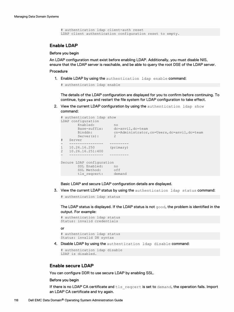
# authentication ldap client-auth resetLDAP client authentication configuration reset to empty.
Enable LDAP
Before you begin
An LDAP configuration must exist before enabling LDAP. Additionally, you must disable NIS,ensure that the LDAP server is reachable, and be able to query the root DSE of the LDAP server.
Procedure
1. Enable LDAP by using the authentication ldap enable command:
# authentication ldap enable
The details of the LDAP configuration are displayed for you to confirm before continuing. Tocontinue, type yes and restart the file system for LDAP configuration to take effect.
2. View the current LDAP configuration by using the authentication ldap showcommand:
# authentication ldap showLDAP configuration Enabled: no Base-suffix: dc=anvil,dc=team Binddn: cn=Administrator,cn=Users,dc=anvil,dc=team Server(s): 2# Server- ---------------- ---------1 10.26.16.250 (primary)2 10.26.16.251:400- ---------------- ---------
Secure LDAP configuration SSL Enabled: no SSL Method: off tls_reqcert: demand
Basic LDAP and secure LDAP configuration details are displayed.
3. View the current LDAP status by using the authentication ldap status command:
# authentication ldap status
The LDAP status is displayed. If the LDAP status is not good, the problem is identified in theoutput. For example:# authentication ldap status Status: invalid credentials
or# authentication ldap status Status: invalid DN syntax
4. Disable LDAP by using the authentication ldap disable command:
# authentication ldap disable LDAP is disabled.
Enable secure LDAP
You can configure DDR to use secure LDAP by enabling SSL.
Before you begin
If there is no LDAP CA certificate and tls_reqcert is set to demand, the operation fails. Importan LDAP CA certificate and try again.
Managing Data Domain Systems
118 Dell EMC Data Domain® Operating System Administration Guide
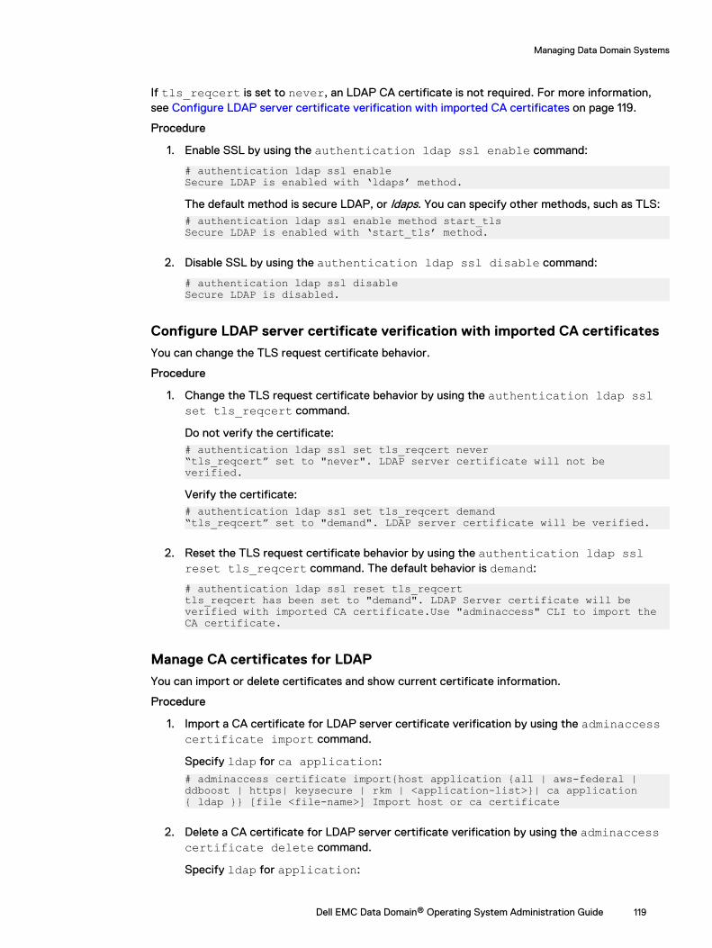
If tls_reqcert is set to never, an LDAP CA certificate is not required. For more information,see Configure LDAP server certificate verification with imported CA certificates on page 119.
Procedure
1. Enable SSL by using the authentication ldap ssl enable command:
# authentication ldap ssl enable Secure LDAP is enabled with ‘ldaps’ method.
The default method is secure LDAP, or ldaps. You can specify other methods, such as TLS:# authentication ldap ssl enable method start_tlsSecure LDAP is enabled with ‘start_tls’ method.
2. Disable SSL by using the authentication ldap ssl disable command:
# authentication ldap ssl disableSecure LDAP is disabled.
Configure LDAP server certificate verification with imported CA certificates
You can change the TLS request certificate behavior.
Procedure
1. Change the TLS request certificate behavior by using the authentication ldap sslset tls_reqcert command.
Do not verify the certificate:# authentication ldap ssl set tls_reqcert never “tls_reqcert” set to "never". LDAP server certificate will not be verified.
Verify the certificate:# authentication ldap ssl set tls_reqcert demand “tls_reqcert” set to "demand". LDAP server certificate will be verified.
2. Reset the TLS request certificate behavior by using the authentication ldap sslreset tls_reqcert command. The default behavior is demand:
# authentication ldap ssl reset tls_reqcerttls_reqcert has been set to "demand". LDAP Server certificate will be verified with imported CA certificate.Use "adminaccess" CLI to import the CA certificate.
Manage CA certificates for LDAP
You can import or delete certificates and show current certificate information.
Procedure
1. Import a CA certificate for LDAP server certificate verification by using the adminaccesscertificate import command.
Specify ldap for ca application:
# adminaccess certificate import{host application {all | aws-federal | ddboost | https| keysecure | rkm | <application-list>}| ca application { ldap }} [file <file-name>] Import host or ca certificate
2. Delete a CA certificate for LDAP server certificate verification by using the adminaccesscertificate delete command.
Specify ldap for application:
Managing Data Domain Systems
Dell EMC Data Domain® Operating System Administration Guide 119
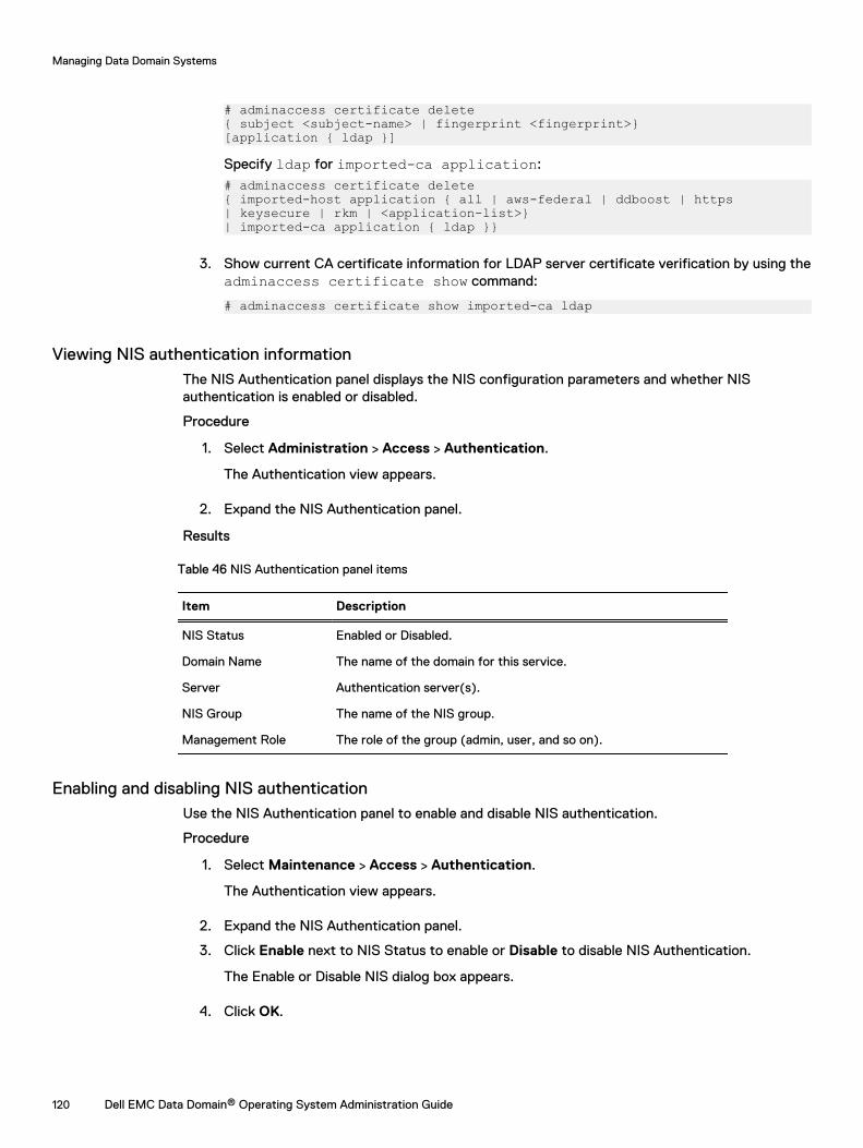
# adminaccess certificate delete{ subject <subject-name> | fingerprint <fingerprint>}[application { ldap }]
Specify ldap for imported-ca application:
# adminaccess certificate delete{ imported-host application { all | aws-federal | ddboost | https| keysecure | rkm | <application-list>}| imported-ca application { ldap }}
3. Show current CA certificate information for LDAP server certificate verification by using theadminaccess certificate show command:
# adminaccess certificate show imported-ca ldap
Viewing NIS authentication informationThe NIS Authentication panel displays the NIS configuration parameters and whether NISauthentication is enabled or disabled.
Procedure
1. Select Administration > Access > Authentication.
The Authentication view appears.
2. Expand the NIS Authentication panel.
Results
Table 46 NIS Authentication panel items
Item Description
NIS Status Enabled or Disabled.
Domain Name The name of the domain for this service.
Server Authentication server(s).
NIS Group The name of the NIS group.
Management Role The role of the group (admin, user, and so on).
Enabling and disabling NIS authenticationUse the NIS Authentication panel to enable and disable NIS authentication.
Procedure
1. Select Maintenance > Access > Authentication.
The Authentication view appears.
2. Expand the NIS Authentication panel.
3. Click Enable next to NIS Status to enable or Disable to disable NIS Authentication.
The Enable or Disable NIS dialog box appears.
4. Click OK.
Managing Data Domain Systems
120 Dell EMC Data Domain® Operating System Administration Guide
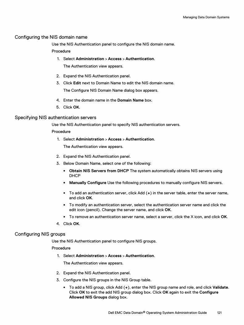
Configuring the NIS domain nameUse the NIS Authentication panel to configure the NIS domain name.
Procedure
1. Select Administration > Access > Authentication.
The Authentication view appears.
2. Expand the NIS Authentication panel.
3. Click Edit next to Domain Name to edit the NIS domain name.
The Configure NIS Domain Name dialog box appears.
4. Enter the domain name in the Domain Name box.
5. Click OK.
Specifying NIS authentication serversUse the NIS Authentication panel to specify NIS authentication servers.
Procedure
1. Select Administration > Access > Authentication.
The Authentication view appears.
2. Expand the NIS Authentication panel.
3. Below Domain Name, select one of the following:
l Obtain NIS Servers from DHCP The system automatically obtains NIS servers usingDHCP
l Manually Configure Use the following procedures to manually configure NIS servers.
l To add an authentication server, click Add (+) in the server table, enter the server name,and click OK.
l To modify an authentication server, select the authentication server name and click theedit icon (pencil). Change the server name, and click OK.
l To remove an authentication server name, select a server, click the X icon, and click OK.
4. Click OK.
Configuring NIS groupsUse the NIS Authentication panel to configure NIS groups.
Procedure
1. Select Administration > Access > Authentication.
The Authentication view appears.
2. Expand the NIS Authentication panel.
3. Configure the NIS groups in the NIS Group table.
l To add a NIS group, click Add (+), enter the NIS group name and role, and click Validate.Click OK to exit the add NIS group dialog box. Click OK again to exit the ConfigureAllowed NIS Groups dialog box.
Managing Data Domain Systems
Dell EMC Data Domain® Operating System Administration Guide 121
l To modify an NIS group, select the checkbox of the NIS group name in the NIS group listand click Edit (pencil). Change the NIS group name, and click OK.
l To remove an NIS group name, select the NIS group in the list and click Delete X.
4. Click OK.
Configuring SSO authenticationThe Single Sign-On (SSO) panel displays the SSO configuration parameters and whether SSO isenabled or disabled. Configuring SSO requires action on both the Data Domain system and theSSO provider. SSO is supported on physical Data Domain systems, and locally installed DD VEinstances. Cloud-based DD VE instances are not supported.
About this task
SSO allows you to register a Data Domain system with a supported SSO provider to use the SSOprovider credentials for system-level user authentication. Logging in using single sign-on (SSO) onpage 32 describes how to log in using SSO after SSO is configured, an SSO user group is created,and SSO is enabled.
Note: Data Protection Central (DPC) is the only supported SSO provider. DPC version 19.1 isrequired to use SSO.
Procedure
1. Select Administration > Access > Authentication.
The Authentication view appears.
2. Expand the Single Sign-On (SSO) panel.
Results
Table 47 Single Sign-On (SSO) panel items
Item Description
Single Sign-On Status Enabled or Disabled.
Provider The name of the SSO provider.
Provider Status Online or Offline.
Client Name The IP address of the SSO client.
Host Name The hostname of the SSO client.
User Group The name of a user group configured to allow SSO provider usersto access the Data Domain system.
Note: At least one user group is required to use SSO.
Domain Name The domain name associated with a user group
Management Role The level of management privileges associated with a user group.
Registering the Data Domain system in Data Protection Central (DPC)
About this task
Complete the following steps to register the Data Domains system in DPC.
Procedure
1. Log in to the DPC and navigate to the System Management.
Managing Data Domain Systems
122 Dell EMC Data Domain® Operating System Administration Guide
2. Add the Data Domain system to DPC.
Note: DPC requires sysadmin credentials for the Data Domain system.
3. Refresh the Single Sign-On (SSO) panel in DD SM to confirm that the Data Domain systemis registered with DPC.
Enabling and disabling SSOUse the Single Sign-On (SSO) panel to enable or disable SSO.
Procedure
1. Select Administration > Access > Authentication.
The Authentication view appears.
2. Expand the Single Sign-On (SSO) panel.
3. Click Enable next to Single Sign-On Status to enable or Disable to disable SSO.
The Enable or Disable SSO dialog box appears.
4. Click OK.
Configuring Single Sign-On (SSO) groupsUse the Single Sign-On (SSO) panel to configure SSO user groups.
About this task
At least one SSO user group is required to use SSO functionality.
Procedure
1. Select Administration > Access > Authentication.
The Authentication view appears.
2. Expand the Single Sign-On (SSO) panel.
3. Configure the SSO user groups in the table.
l To add an SSO user group, click Add (+), enter the SSO user group name and domainname, select the management role, and clickOK.
Note: Admin users can set a group management role to user, admin, backup-operator, or limited-admin. Limited-admin users can set a group management role touser or backup operator.
Note: If a group name belongs to multiple domains, set up the same group name withall domain names on the Data Domain system with the desired role, or make sure thedomain name the user will log in with is configured on Data Domain system with thedesired role. This is important for Active Directory configurations with child or subdomains.
l To modify an SSO user group, select the checkbox of the group name in the SSO grouplist and click Edit (pencil). Change the management role and click OK.
l To remove an SSO user group, select the group in the list and click Delete (X).
Managing Data Domain Systems
Dell EMC Data Domain® Operating System Administration Guide 123
Diagnosing authentication issuesData Domain Operating System provides the ability to diagnose authentication issues for ActiveDirectory from within the Data Domain System Manager interface.
Procedure
1. Select Administration > Access > Authentication
2. Expand the Active Directory/Kerberos Authentication panel.
3. Click Diagnose.
4. Select an issue to investigate, and click Diagnose.
5. Provide the requested information.
To diagnose issues logging in as an Active Directory user, provide:
l Active Directory server IP address
l Active Directory server FQDN
l Active Directory service usernameNote: The Active Directory user account specified here requires the followingprivileges:
n Read-only access to the base DN identified by the domain name.
n Read-only access to query attributes of all users in the base DN.
n Read-only access to query attributes of the machine account for the Data Domainsystem.
l Active Directory service password
l Data Domain username experiencing login failure
To diagnose issues joining the Data Domain system to an active Directory Domain, provide:
l Active Directory server IP address
l Active Directory server FQDN
l Active Directory service username
l Active Directory service password
6. Click Diagnose.
7. View the report.
l Click View Report to view the report online. Each item in the Action Items table can beclicked for additional details.
l Click Download to download a copy of the report.
8. Review and implement the suggested fixes for the issue, and retry the operation.
Change system authentication methodThe Data Domain system supports password-based authentication, or certificate-basedauthentication. Password-based authentication is the default method.
Before you begin
Certificate-based authentication requires SSH keys and CA certificates are imported to allowusers to authenticate with the system when password-based authentication is disabled.
Managing Data Domain Systems
124 Dell EMC Data Domain® Operating System Administration Guide
About this task
Complete the following steps to change the system authentication method from password-basedauthentication to certificate-based authentication.
Procedure
1. Select Administration > Access.
The Access Management view appears.
2. Click Manage CA Certificates.
3. Click Add to create a new certificate.
4. Add the certificate.
l Select I want to upload the certificate as a .pem file and click Choose File to selectthe certificate file and upload it to the system.
l Select I want to copy and paste the certificate text to copy and paste the certificatetext into the text field.
5. Click Add.
6. Select More Tasks > Change Login Options.
7. In the Password Based Login drop-down menu, select Disable.
Note: The drop-down menu is disabled if the required SSH keys and CA certificates arenot configured on the system
8. Click OK.
If a security policy is configured, the system prompts for security officer credentials.Provide the credentials and click OK.
Reset the system authentication method to password-based authentication.
About this task
Complete the following steps to change the system authentication method from certificate-basedauthentication to password-based authentication.
Procedure
1. Select Administration > Access.
The Access Management view appears.
2. Select More Tasks > Change Login Options.
3. In the Password Based Login drop-down menu, select Enable.
4. Click OK.
If a security policy is configured, the system prompts for security officer credentials.Provide the credentials and click OK.
Configuring mail server settingsThe Mail Server tab allows you to specify the mail server to which DD OS sends email reports.
About this task
Procedure
1. Select Administration > Settings > Mail Server.
Managing Data Domain Systems
Dell EMC Data Domain® Operating System Administration Guide 125
2. Select More Tasks > Set Mail Server.
The Set Mail Server dialog box appears.
3. Specify the name of the mail server in the Mail Server field.
4. Use the Credentials button to enable or disable the use of credentials for the mail server.
5. If credentials are enabled, specify the mail server username in the User Name field.
6. If credentials are enabled, specify the mail server password in the Password field.
7. Click Set.
8. Optionally use the CLI to verify and troubleshoot the mail server configuration.
a. Run the config show mailserver command to verify the mail server is configured.
b. Run the net ping <mailserver-hostname> count 4 command to ping the mail server.
c. If the mail server is not configured correctly, run the config set mailserver<mailserver-hostname> command to set the mail server, and attempt to ping it again.
d. Run the net show dns command to verify the DNS server is configured.
e. Run the net ping <DNS-hostname> count 4 command to ping the DNS server.
f. If the DNS server is not configured correctly, run the config set dns <dns-IP>command to set the DNS server, and attempt to ping it again.
g. Optionally run the net hosts add <IP-address> <hostname> command to add themail server IP address and hostname to the Data Domain hosts file for local resolving.
h. Run the net ping <mailserver-hostname> count 4 command to ping the mail server.
Managing time and date settingsThe Time and Date Settings tab allows you to view and configure the system time and date orconfigure the Network Time Protocol to set the time and date.
Procedure
1. To view the current time and date configuration, select Administration > Settings > Timeand Date Settings.
The Time and Date Settings page presents the current system date and time, showswhether NTP is enabled or not, and lists the IP addresses or hostnames of configured NTPservers.
2. To change the configuration, select More Tasks > Configure Time Settings.
The Configure Time Settings dialog appears.
3. In the Time Zone dropdown list, select the time zone where the Data Domain systemresides.
4. To manually set the time and date, select None, type the date in the Date box, and selectthe time in the Time dropdown lists.
5. To use NTP to synchronize the time, select NTP and set how the NTP server is accessed.
l To use DHCP to automatically select a server, select Obtain NTP Servers using DHCP.
l To configure an NTP server IP address, select Manually Configure, add the IP addressof the server, and click OK.
Managing Data Domain Systems
126 Dell EMC Data Domain® Operating System Administration Guide
Note: Using time synchronization from an Active Directory domain controller mightcause excessive time changes on the system if both NTP and the domain controller aremodifying the time.
6. Click OK.
7. If you changed the time zone, you must reboot the system.
a. Select Maintenance > System.
b. From the More Tasks menu, select Reboot System.
c. Click OK to confirm.
Managing system propertiesThe System Properties tab allows you to view and configure system properties that identify themanaged system location, administrator email address, and host name.
Procedure
1. To view the current configuration, select Administration > Settings > System Properties.
The System Properties tab displays the system location, the administrator email address,and the administrator hostname.
2. To change the configuration, select More Tasks > Set System Properties.
The Set System Properties dialog box appears.
3. In the Location box, enter information about where the Data Domain system is located.
4. In the Admin Email box, enter the email address of the system administrator.
5. In the Admin Host box, enter the name of the administration server.
6. Click OK.
SNMP managementThe Simple Network Management Protocol (SNMP) is a standard protocol for exchangingnetwork management information, and is a part of the Transmission Control Protocol/InternetProtocol (TCP/IP) protocol suite. SNMP provides a tool for network administrators to manage andmonitor network-attached devices, such as Data Domain systems, for conditions that warrantadministrator attention.
To monitor Data Domain systems using SNMP, you will need to install the Data Domain MIB in yourSNMP Management system. DD OS also supports the standard MIB-II so you can also query MIB-IIstatistics for general data such as network statistics. For full coverage of available data you shouldutilize both the Data Domain MIB and the standard MIB-II MIB.
The Data Domain system SNMP agent accepts queries for Data Domain-specific information frommanagement systems using SNMP v1, v2c, and v3. SNMP V3 provides a greater degree of securitythan v2c and v1 by replacing cleartext community strings (used for authentication) with user-based authentication using either MD5 or SHA1. Also, SNMP v3 user authentication packets canbe encrypted and their integrity verified with either DES or AES.
Data Domain systems can send SNMP traps (which are alert messages) using SNMP v2c andSNMP v3. Because SNMP v1 traps are not supported, if possible, use SNMP v2c or v3.
The default port that is open when SNMP is enabled is port 161. Traps are sent out through port162.
Managing Data Domain Systems
Dell EMC Data Domain® Operating System Administration Guide 127
l The Data Domain Operating System Initial Configuration Guide describes how to set up the DataDomain system to use SNMP monitoring.
l The Data Domain Operating System MIB Quick Reference describes the full set of MIBparameters included in the Data Domain MIB branch.
Viewing SNMP status and configurationThe SNMP tab displays the current SNMP status and configuration.
Procedure
1. Select Administration > Settings > SNMP.
The SNMP view shows the SNMP status, SNMP properties, SNMP V3 configuration, andSNMP V2C configuration.
SNMP tab labelsThe SNMP tab labels identify the overall SNMP status, SNMP property values, and theconfigurations for SNMPv3 and SNMPv2.
Status
The Status area displays the operational status of the SNMP agent on the system, which is eitherEnabled or Disabled.
SNMP Properties
Table 48 SNMP Properties descriptions
Item Description
SNMP System Location The location of the Data Domain system being monitored.
SNMP System Contact The person designated as the person to contact for the DataDomain system administration.
SNMP System Notes (Optional) Additional SNMP configuration data.
SNMP Engine ID A unique hexadecimal identifier for the Data Domain system.
SNMP V3 Configuration
Table 49 SNMP Users column descriptions
Item Description
Name The name of the user on the SNMP manager with access to theagent for the Data Domain system.
Access The access permissions for the SNMP user, which can be Read-only or Read-write.
Authentication Protocols The Authentication Protocol used to validate the SNMP user,which can be MD5, SHA1, or None.
Privacy Protocol The encryption protocol used during the SNMP userauthentication, which can be AES, DES, or None.
Managing Data Domain Systems
128 Dell EMC Data Domain® Operating System Administration Guide

Table 50 Trap Hosts column descriptions
Item Description
Host The IP address or domain name of the SNMP management host.
Port The port used for SNMP trap communication with the host. Forexample, 162 is the default.
User The user on the trap host authenticated to access the DataDomain SNMP information.
SNMP V2C Configuration
Table 51 Communities column descriptions
Item Description
Community The name of the community. For example, public, private, orlocalCommunity.
Access The access permission assigned, which can be Read-only orRead-write.
Hosts The hosts in this community.
Table 52 Trap Hosts column descriptions
Item Description
Host The systems designated to receive SNMP traps generated bythe Data Domain system. If this parameter is set, systemsreceive alert messages, even if the SNMP agent is disabled.
Port The port used for SNMP trap communication with the host. Forexample, 162 is the default.
Community The name of the community. For example, public, private, orlocalCommunity.
Enabling and disabling SNMPUse the SNMP tab to enable of disable SNMP.
Procedure
1. Select Administration > Settings > SNMP.
2. In the Status area, click Enable or Disable.
Downloading the SNMP MIBUse the SNMP tab to download the SNMP MIB.
Procedure
1. Select Administration > Settings > SNMP.
2. Click Download MIB file.
3. In the Opening DATA_DOMAIN.mib dialog box, select Open.
Managing Data Domain Systems
Dell EMC Data Domain® Operating System Administration Guide 129
4. Click Browse and select a browser to view the MIB in a browser window.
Note: If using the Microsoft Internet Explorer browser, enable Automatic prompting forfile download.
5. Save the MIB or exit the browser.
Configuring SNMP propertiesUse the SNMP tab to configure the text entries for system location and system contact.
Procedure
1. Select Administration > Settings > SNMP.
2. In the SNMP Properties area, click Configure.
The SNMP Configuration dialog box appears.
3. In the text fields, specify the following information: and/or an
l SNMP System Location: A description of where the Data Domain system is located.
l SNMP System Contact: The email address of the system administrator for the DataDomain system.
l SNMP System Notes: (Optional) Additional SNMP configuration information.
l SNMP Engine ID: A unique identifier for the SNMP entity. The engine ID must be 5-34hexadecimal characters (SNMPv3 only).
Note: The system displays an error if the SNMP engine ID does not meet the lengthrequirements, or uses invalid characters.
4. Click OK.
SNMP V3 user managementUse the SNMP tab to create, modify, and delete SNMPv3 users and trap hosts.
Creating SNMP V3 usersWhen you create SNMPv3 users, you define a username, specify either read-only or read-writeaccess, and select an authentication protocol.
Procedure
1. Select Administration > Settings > SNMP.
2. In the SNMP Users area, click Create.
The Create SNMP User dialog box appears.
3. In the Name text field, enter the name of the user for whom you want to grant access to theData Domain system agent. The name must be a minimum of eight characters.
4. Select either read-only or read-write access for this user.
5. To authenticate the user, select Authentication.
a. Select either the MD5 or the SHA1 protocol.
b. Enter the authentication key in the Key text field.
c. To provide encryption to the authentication session, select Privacy.
Managing Data Domain Systems
130 Dell EMC Data Domain® Operating System Administration Guide
d. Select either the AES or the DES protocol.
e. Enter the encryption key in the Key text field.
6. Click OK.
The newly added user account appears in the SNMP Users table.
Modifying SNMP V3 usersYou can modify the access level (read-only or read-write) and authentication protocol for existingSNMPv3 users.
Procedure
1. Select Administration > Settings > SNMP.
2. In the SNMP Users area, select a checkbox for the user and click Modify.
The Modify SNMP User dialog box appears. Add or change any of the following settings.
3. Select either read-only or read-write access for this user.
4. To authenticate the user, select Authentication.
a. Select either the MD5 or the SHA1 protocol.
b. Enter the authentication key in the Key text field.
c. To provide encryption to the authentication session, select Privacy.
d. Select either the AES or the DES protocol.
e. Enter the encryption key in the Key text field.
5. Click OK.
The new settings for this user account appear in the SNMP Users table.
Removing SNMP V3 usersUse the SNMP tab to delete existing SNMPv3 users.
Procedure
1. Select Administration > Settings > SNMP.
2. In the SNMP Users area, select a checkbox for the user and click Delete.
The Delete SNMP User dialog box appears.
Note: If the Delete button is disabled, the selected user is being used by one or moretrap hosts. Delete the trap hosts and then delete the user.
3. Verify the user name to be deleted and click OK.
4. In the Delete SNMP User Status dialog box, click Close.
The user account is removed from the SNMP Users table.
Managing Data Domain Systems
Dell EMC Data Domain® Operating System Administration Guide 131
SNMP V2C community managementDefine SNMP v2c communities (which serve as passwords) to control management system accessto the Data Domain system. To restrict access to specific hosts that use the specified community,assign the hosts to the community.
Note: The SNMP V2c Community string is a sent in cleartext and is very easy to intercept. Ifthis occurs, the interceptor can retrieve information from devices on your network, modifytheir configuration, and possibly shut them down. SNMP V3 provides authentication andencryption features to prevent interception.
Note: SNMP community definitions do not enable the transmission of SNMP traps to amanagement station. You must define trap hosts to enable trap submission to managementstations.
Creating SNMP V2C communitiesCreate communities to restrict access to the DDR system or for use in sending traps to a traphost. You must create a community and assign it to a host before you can select that communityfor use with the trap host.
Procedure
1. Select Administration > Settings > SNMP.
2. In the Communities area, click Create.
The Create SNMP V2C Community dialog box appears.
3. In the Community box, enter the name of a community for whom you want to grant accessto the Data Domain system agent.
4. Select either read-only or read-write access for this community.
5. If you want to associate the community to one or more hosts, add the hosts as follows:
a. Click + to add a host.
The Host dialog box appears.
b. In the Host text field, enter the IP address or domain name of the host.
c. Click OK.
The Host is added to the host list.
6. Click OK.
The new community entry appears in the Communities table and lists the selected hosts.
Modifying SNMP V2C CommunitiesProcedure
1. Select Administration > Settings > SNMP.
2. In the Communities area, select the checkbox for the community and click Modify.
The Modify SNMP V2C Community dialog box appears.
3. To change the access mode for this community, select either read-only or read-writeaccess.
Managing Data Domain Systems
132 Dell EMC Data Domain® Operating System Administration Guide
Note: The Access buttons for the selected community are disabled when a trap host onthe same system is configured as part of that community. To modify the access setting,delete the trap host and add it back after the community is modified.
4. To add one or more hosts to this community, do the following:
a. Click + to add a host.
The Host dialog box appears.
b. In the Host text field, enter the IP address or domain name of the host.
c. Click OK.
The Host is added to the host list.
5. To delete one or more hosts from the host list, do the following:
Note: DD System Manager does not allow you to delete a host when a trap host on thesame system is configured as part of that community. To delete a trap host from acommunity, delete the trap host and add it back after the community is modified.
Note: The Access buttons for the selected community are not disabled when the traphost uses an IPv6 address and the system is managed by an earlier DD OS version thatdoes not support IPv6. If possible, always select a management system that uses thesame or a newer DD OS version than the systems it manages.
a. Select the checkbox for each host or click the Host check box in the table head to selectall listed hosts.
b. Click the delete button (X).
6. To edit a host name, do the following:
a. Select the checkbox for the host.
b. Click the edit button (pencil icon).
c. Edit the host name.
d. Click OK.
7. Click OK.
The modified community entry appears in the Communities table.
Deleting SNMP V2C communitiesUse the SNMP tab to delete existing SNMPv2 communities.
Procedure
1. Select Administration > Settings > SNMP.
2. In the Communities area, select a checkbox for the community and click Delete.
The Delete SNMP V2C Communities dialog box appears.
Note: If the Delete button is disabled, the selected community is being used by one ormore trap hosts. Delete the trap hosts and then delete the community.
3. Verify the community name to be deleted and click OK.
4. In the Delete SNMP V2C Communities Status dialog box, click Close. The community entryis removed from the Communities table.
Managing Data Domain Systems
Dell EMC Data Domain® Operating System Administration Guide 133
SNMP trap host managementTrap host definitions enable Data Domain systems to send alert messages in SNMP trap messagesto an SNMP management station.
Creating SNMP V3 and V2C trap hostsTrap host definitions identify remote hosts that receive SNMP trap messages from the system.
Before you begin
If you plan to assign an existing SNMP v2c community to a trap host, you must first use theCommunities area to assign the trap host to the community.
Procedure
1. Select Administration > Settings > SNMP.
2. In the SNMP V3 Trap Hosts or SNMP V2C Trap Hosts area, click Create.
The Create SNMP [V3 or V2C] Trap Hosts dialog appears.
3. In the Host box, enter the IP address or domain name of the SNMP Host to receive traps.
4. In the Port box, enter the port number for sending traps (port 162 is a common port).
5. Select the user (SNMP V3) or the community (SNMP V2C) from the drop-down menu.
Note: The Community list displays only those communities to which the trap host isalready assigned.
6. To create a new community, do the following:
a. Select Create New Community in the Community drop-down menu.
b. Enter the name for the new community in the Community box.
c. Select the Access type.
d. Click the add (+) button.
e. Enter the trap host name.
f. Click OK.
g. Click OK.
7. Click OK.
Modifying SNMP V3 and V2C trap hostsYou can modify the port number and community selection for existing trap host configurations.
Procedure
1. Select Administration > Settings > SNMP.
2. In the SNMP V3 Trap Hosts or SNMP V2C Trap Hosts area, select a Trap Host entry, andclick Modify.
The Modify SNMP [V3 or V2C] Trap Hosts dialog box appears.
3. To modify the port number, enter a new port number in the Port box (port 162 is a commonport).
4. Select the user (SNMP V3) or the community (SNMP V2C) from the drop-down menu.
Managing Data Domain Systems
134 Dell EMC Data Domain® Operating System Administration Guide
Note: The Community list displays only those communities to which the trap host isalready assigned.
5. To create a new community, do the following:
a. Select Create New Community in the Community drop-down menu.
b. Enter the name for the new community in the Community box.
c. Select the Access type.
d. Click the add (+) button.
e. Enter the trap host name.
f. Click OK.
g. Click OK.
6. Click OK.
Removing SNMP V3 and V2C trap hostsUse the SNMP tab to delete existing trap host configurations.
Procedure
1. Select Administration > Settings > SNMP.
2. In the Trap Hosts area (either for V3 or V2C, select a checkbox for the trap host and clickDelete.
The Delete SNMP [V3 or V2C] Trap Hosts dialog box appears.
3. Verify the host name to be deleted and click OK.
4. In the Delete SNMP [V3 or V2C] Trap Hosts Status dialog box, click Close.
The trap host entry is removed from the Trap Hosts table.
Autosupport report managementThe Autosupport feature generates a report called an ASUP. The ASUP shows systemidentification information, consolidated output from a number of Data Domain system commands,and entries from various log files. Extensive and detailed internal statistics appear at the end of thereport. This report is designed to aid Data Domain Support in debugging system problems.
An ASUP is generated every time the file system is started, which is usually once per day.However, the file system can be started more than once in a day.
You can configure email addresses to receive the daily ASUP reports, and you can enable ordisable sending of these reports to Data Domain. The default time for sending the daily ASUP is06.00 a.m, and it is configurable. When sending ASUPs to Data Domain, you have the option toselect the legacy unsecure method or the ConnectEMC method, which encrypts the informationbefore transmission.
HA system autosupport and support bundle manageabilityConfiguration is done on the active node and mirrored to the standby node; therefore, the sameconfiguration is on both nodes, but there is not a consolidated ASUP and support bundle.
Autosupport and support bundle on the active node also includes filesystem, replication, protocol,and full HA information in addition to local node information. Autosupport and support bundle onthe standby node only have local node information plus some HA information (configuration andstatus), but no filesystem/replication/protocol information. The autosupports and support bundles
Managing Data Domain Systems
Dell EMC Data Domain® Operating System Administration Guide 135
from both the nodes will be needed to debug issues related to HA system status (filesystem,replication, protocols, and HA configuration).
Enabling and disabling autosupport reporting to Data DomainYou can enable or disable autosupport reporting to Data Domain without affecting whether or notalerts are sent to Data Domain.
Procedure
1. To view the autosupport reporting status, select Maintenance > Support > Autosupport.
The autosupport reporting status is highlighted next to the Scheduled autosupport label inthe Support area. Depending on the current configuration, either an Enable or a Disablebutton appears in the Scheduled autosupport row.
2. To enable autosupport reporting to Data Domain, click Enable in the Scheduled autosupportrow.
3. To disable autosupport reporting to Domain, click Disable in the Scheduled autosupportrow.
Reviewing generated autosupport reportsReview autosupport reports to view system statistics and configuration information captured inthe past. The system stores a maximum of 14 autosupport reports.
Procedure
1. Select Maintenance > Support > Autosupport.
The Autosupport Reports page shows the autosupport report file name and file size, and thedate the report was generated. Reports are automatically named. The most current report isautosupport, the previous day is autosupport.1, and the number increments as the reportsmove back in time.
CLI equivalent
# autosupport show history
2. Click the file name link to view the report using a text editor. If doing so is required by yourbrowser, download the file first.
Configuring the autosupport mailing listAutosupport mailing list subscribers receive autosupport messages through email. Use theAutosupport tab to add, modify, and delete subscribers.
About this task
Autosupport emails are sent through the configured mail server to all subscribers in theautosupport email list. After you configure the mail server and autosupport email list, it is a goodpractice to test the setup to ensure that autosupport messages reach the intended destinations.
Procedure
1. Select Maintenance > Support > Autosupport.
2. Click Configure.
The Configure Autosupport Subscribers dialog box appears.
3. To add a subscriber, do the following.
Managing Data Domain Systems
136 Dell EMC Data Domain® Operating System Administration Guide
a. Click Add (+).
The Email dialog box appears.
b. Enter the recipients email address in the Email box.
c. Click OK.
CLI equivalent
# autosupport add asup-detailed emails [email protected]# autosupport add alert-summary emails [email protected]
4. To delete a subscriber, do the following.
a. In the Configure Autosupport Subscribers dialog box, select the subscriber to delete.
b. Click Delete (X).
CLI equivalent
# autosupport del asup-detailed emails [email protected]# autosupport del alert-summary emails [email protected]
5. To modify a subscriber email address, do the following.
a. In the Configure Autosupport Subscribers dialog box, select the subscriber name to edit.
b. Click Modify (pencil icon).
The Email dialog box appears.
c. Modify the email address as needed.
d. Click OK.
6. Click OK to close the Configure Autosupport Subscribers dialog box.
The revised autosupport email list appears in the Autosupport Mailing List area.
Verifying the Data Domain is able to send ASUP and alert emails to externalrecipients
Confirm that external email recipients can receive the autosupport (ASUP) and alert emails yousend from your Data Domain device.
About this task
Verify autosupport (ASUP) is getting relayed by the exchange server.
Procedure
1. Check if ASUPs can be sent to a local email address, an email address on the same MailServer.
# autosupport send [internal-email-addr]
2. Check if ASUPs can be sent to an email address outside the local mail server.
# autosupport send [external email-addr]
Managing Data Domain Systems
Dell EMC Data Domain® Operating System Administration Guide 137
3. If the email does not get to the external email address on the mail server, you may receivean error such as:
**** Unable to send message: (errno 51: Unrecoverable errors from server--giving up)
In this case, it is likely that forwarding will need to be enabled for the Data Domain Systemon the local mail server by using the steps outlined in the KB article Configure Email Relay onMS Exchange, available at https://support.emc.com/kb/181900.
4. If the ASUP can be sent to an external email address, but is not getting to the Data Domain,there may be an issue with the firewall configuration or spam filters.
5. If ASUP alerts are getting to the Data Domain, but they are not causing a case to becreated, it may be due to invalid characters in the subject or body of the alert email. Toverify,
a. Look in a current autosupport and check the HOSTNAME , SYSTEM_ID , and LOCATIONfor single quotes or apostrophes. This is an invalid character and must be removed in DDOS versions 4.9.2.0 and early.
Example:
========== GENERAL INFO ==========GENERATED_ON=Thu Apr 28 06:54:55 PDT 2011
VERSION=Data Domain OS 4.9.2.6-226914SYSTEM_ID=7FP5105000
MODEL_NO=DD510HOSTNAME=system.datadomain.com
LOCATION=123 O Malley Lane
b. Remove any invalid characters from the system HOSTNAME and/or LOCATION. Thecommands are
net set hostname <host>
config set location "location"
c. Test the new setting by simulating an alert. The easiest way is to manually fail a sparedisk drive, verify the alert sent, and immediately unfail the same drive to return it tospare state.
Support bundle managementA support bundle is a file that contains system configuration and operation information. It is a goodpractice to generate a support bundle before a software upgrade or a system topology change(such as a controller upgrade).
Data Domain Support often requests a support bundle when providing assistance.
The KB article How to collect/upload a support bundle (SUB) from a Data Domain Restorer (DDR),available at https://support.emc.com/kb/180563, provides additional information about workingwith support bundles.
Managing Data Domain Systems
138 Dell EMC Data Domain® Operating System Administration Guide
Generating a support bundleWhen troubleshooting problems, Data Domain Customer Support may ask for a support bundle,which is a tar-g-zipped selection of log files with a README file that includes identifyingautosupport headers.
Procedure
1. Select Maintenance > Support > Support Bundles.
2. Click Generate Support Bundle.
Note: The system supports a maximum of five support bundles. If you attempt togenerate an sixth support bundle, the system automatically deletes the oldest supportbundle. You can also delete support bundles using the CLI command support bundledelete.
Also, if you generate a support bundle on a upgraded system that contains a support bundlenamed using the old format, support-bundle.tar.gz, that file is renamed to use thenewer name format.
3. Email the file to customer support at [email protected].
Note: If the bundle is too large to be emailed, use the online support site to upload thebundle. (Go to https://support.emc.com.)
Viewing the support bundles listUse the Support Bundles tab to view the support bundle files on the system.
Procedure
1. Select Maintenance > Support > Support Bundles.
The Support Bundles list appears.
Listed are the support bundle file name, file size, and date the bundle was generated.Bundles are automatically named hostname-support-bundle-datestamp.tar.gz. Anexample filename is localhost-support-bundle-1127103633.tar.gz, whichindicates that the support bundle was created on the localhost system on November 27th at10:36:33.
2. Click the file name link and select a gz/tar decompression tool to view the ASCII contents ofthe bundle.
Coredump managementWhen DD OS crashes due to a coredump, a core file describing the problem is created in the /ddvar/core directory. This file may be large, and difficult to copy off the Data Domain system.
If the core file cannot be copied off the Data Domain system because it is too large, run thesupport coredump split <filename> by <n> {MiB|GiB} command, where:
l <filename> is the name of the core file in the /ddvar/core directory
l <n> is the number of smaller chunks to break the core file intoNote: A single core file can be broken down into a maximum of 20 chunks. The commandwill fail with an error if the specified size would result in more than 20 chunks.
For example, splitting a 42.1 MB core file named cpmdb.core.19297.1517443767 into 10 MBchunks would result in five chunks.
Managing Data Domain Systems
Dell EMC Data Domain® Operating System Administration Guide 139
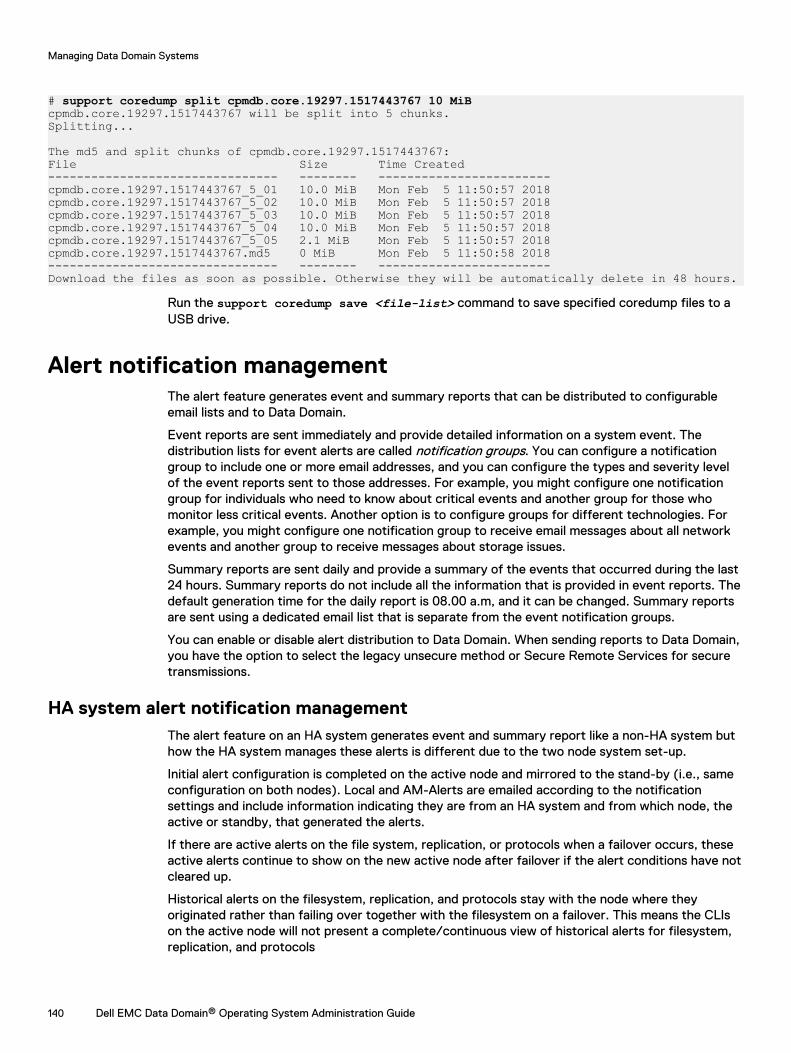
# support coredump split cpmdb.core.19297.1517443767 10 MiBcpmdb.core.19297.1517443767 will be split into 5 chunks.Splitting...
The md5 and split chunks of cpmdb.core.19297.1517443767:File Size Time Created-------------------------------- -------- ------------------------cpmdb.core.19297.1517443767_5_01 10.0 MiB Mon Feb 5 11:50:57 2018cpmdb.core.19297.1517443767_5_02 10.0 MiB Mon Feb 5 11:50:57 2018cpmdb.core.19297.1517443767_5_03 10.0 MiB Mon Feb 5 11:50:57 2018cpmdb.core.19297.1517443767_5_04 10.0 MiB Mon Feb 5 11:50:57 2018cpmdb.core.19297.1517443767_5_05 2.1 MiB Mon Feb 5 11:50:57 2018cpmdb.core.19297.1517443767.md5 0 MiB Mon Feb 5 11:50:58 2018-------------------------------- -------- ------------------------Download the files as soon as possible. Otherwise they will be automatically delete in 48 hours.
Run the support coredump save <file-list> command to save specified coredump files to aUSB drive.
Alert notification managementThe alert feature generates event and summary reports that can be distributed to configurableemail lists and to Data Domain.
Event reports are sent immediately and provide detailed information on a system event. Thedistribution lists for event alerts are called notification groups. You can configure a notificationgroup to include one or more email addresses, and you can configure the types and severity levelof the event reports sent to those addresses. For example, you might configure one notificationgroup for individuals who need to know about critical events and another group for those whomonitor less critical events. Another option is to configure groups for different technologies. Forexample, you might configure one notification group to receive email messages about all networkevents and another group to receive messages about storage issues.
Summary reports are sent daily and provide a summary of the events that occurred during the last24 hours. Summary reports do not include all the information that is provided in event reports. Thedefault generation time for the daily report is 08.00 a.m, and it can be changed. Summary reportsare sent using a dedicated email list that is separate from the event notification groups.
You can enable or disable alert distribution to Data Domain. When sending reports to Data Domain,you have the option to select the legacy unsecure method or Secure Remote Services for securetransmissions.
HA system alert notification managementThe alert feature on an HA system generates event and summary report like a non-HA system buthow the HA system manages these alerts is different due to the two node system set-up.
Initial alert configuration is completed on the active node and mirrored to the stand-by (i.e., sameconfiguration on both nodes). Local and AM-Alerts are emailed according to the notificationsettings and include information indicating they are from an HA system and from which node, theactive or standby, that generated the alerts.
If there are active alerts on the file system, replication, or protocols when a failover occurs, theseactive alerts continue to show on the new active node after failover if the alert conditions have notcleared up.
Historical alerts on the filesystem, replication, and protocols stay with the node where theyoriginated rather than failing over together with the filesystem on a failover. This means the CLIson the active node will not present a complete/continuous view of historical alerts for filesystem,replication, and protocols
Managing Data Domain Systems
140 Dell EMC Data Domain® Operating System Administration Guide
During a failover, local historical alerts stay with the node from which they were generated;however, the historical alerts for the filesystem, replication, and protocols (generally called "logicalalerts") fail over together with the filesystem.
Note: The Health > High Availability panel displays only alerts that are HA-related. Thosealerts can be filtered by major HA component, such as HA Manager, Node, Interconnect,Storage, and SAS connection.
Viewing the notification group listA notification group defines a set of alert types (classes) and a group of email addresses (forsubscribers). Whenever the system generates an alert type selected in a notification list, that alertis sent to the list subscribers.
Procedure
1. Select Health > Alerts > Notification.
CLI equivalent
# alerts notify-list show
2. To limit (filter) the entries in the Group Name list, type a group name in the Group Namebox or a subscriber email in the Alert Email box, and click Update.
Note: Click Reset to display all configured groups.
3. To display detailed information for a group, select the group in the Group Name list.
Notification tabThe Notification tab allows you to configure groups of email address that receive system alerts forthe alert types and severity levels you select.
Table 53 Group Name list, column label descriptions
Item Description
Group Name The configured name for the group.
Classes The number of alert classes that are reported to the group.
Subscribers The number of subscribers who are configured to receivenotifications through email.
Table 54 Detailed Information, label descriptions
Item Description
Class A service or subsystem that can forward alerts. The listed classesare those for which the notification group receives alerts.
Severity The severity level that triggers an email to the notification group. Allalerts at the specified severity level and above are sent to thenotification group.
Subscribers The subscribers area displays a list of all email addresses configuredfor the notification group.
Managing Data Domain Systems
Dell EMC Data Domain® Operating System Administration Guide 141
Table 55 Notification tab controls
Control Description
Add button Click the Add button to begin creating anotification group.
Class Attributes Configure button Click this Configure button to change theclasses and severity levels that generatealerts for the selected notification group.
Delete button Click the Delete button to delete the selectednotification group.
Filter By: Alert Email box Enter text in this box to limit the group namelist entries to groups that include an emailaddress that contains the specified text.
Filter By: Group Name box Enter text in this box to limit the group namelist entries to group names that contain thespecified text.
Modify button Click the Modify button to modify theconfiguration for the selected notificationgroup.
Reset button Click this button to remove any entries in theFilter By boxes and display all group names.
Subscribers Configure button Click this Configure button to change theemail list for the selected notification group.
Update button Click this button to update the group namelist after you enter text in a filter box.
Creating a notification groupUse the Notification tab to add notification groups and select the severity level for each group.
Procedure
1. Select Health > Alerts > Notification.
2. Click Add.
The Add Group dialog box appears.
3. Type the group name in the Group Name box.
4. Select the checkbox of one or more alert classes of which to be notified.
5. To change the default severity level (Warning) for a class, select another level in theassociated list box.
The severity levels are listed in ascending severity level. Emergency is the highest severitylevel.
6. Click OK.
CLI equivalent
# alerts notify-list create eng_grp class hardwareFailure
Managing Data Domain Systems
142 Dell EMC Data Domain® Operating System Administration Guide
Managing the subscriber list for a groupUse the Notification tab to add, modify, or delete email addresses from a notification groupsubscriber list.
Procedure
1. Select Health > Alerts > Notification.
2. Select the checkbox of a group in the Notifications group list, and do one of the following.
l Click Modify and select Subscribers.
l Click Configure in the Subscribers list.
3. To add a subscriber to the group, do the following.
a. Click the + icon.
The Email Address dialog box appears.
b. Enter the email address of a subscriber.
c. Click OK.
CLI equivalent
# alerts notify-list add eng_lab emails [email protected],[email protected]
4. To modify an email address, do the following.
a. Click the checkbox of the email address in the Subscriber Email list.
b. Click the pencil icon.
c. Edit the email address in the Email Address dialog box.
d. Click OK.
5. To delete an email address, click the checkbox of the email address in the Subscriber Emaillist and click the X icon.
CLI equivalent
# alerts notify-list del eng_lab emails [email protected]
6. Click Finish or OK.
Modifying a notification groupUse the Notification table to modify the attribute classes in an existing group.
Procedure
1. Select Health > Alerts > Notification.
2. Select the checkbox of the group to modify in the group list.
3. To modify the class attributes for a group, do the following.
a. Click Configure in the Class Attributes area.
The Edit Group dialog box appears.
b. Select (or clear) the checkbox of one or more class attributes.
Managing Data Domain Systems
Dell EMC Data Domain® Operating System Administration Guide 143
c. To change the severity level for a class attribute, select a level from the correspondinglist box.
d. Click OK.
CLI equivalent
# alerts notify-list add eng_lab class cloud severity warning# alerts notify-list del eng_lab class cloud severity notice
4. To modify the subscriber list for a group, do the following.
a. Click Configure in the Subscribers area.
The Edit Subscribers dialog box appears.
b. To delete subscribers from the group list, select the checkboxes of subscribers to deleteand click the Delete icon (X).
c. To add a subscriber, click the Add icon (+), type a subscriber email address, and clickOK.
d. Click OK.
CLI equivalent
# alerts notify-list add eng_lab emails [email protected],[email protected]# alerts notify-list del eng_lab emails [email protected]
5. Click OK.
Deleting a notification groupUse the Notification tab to delete one or more existing notification groups.
Procedure
1. Select Health > Alerts > Notification.
2. Select one or more checkboxes of groups in the Notifications group list, and click Delete.
The Delete Group dialog box appears.
3. Verify the deletion and click OK.
CLI equivalent
# alerts notify-list destroy eng_grp
Resetting the notification group configurationUse the Notification tab to remove all notification groups added and to remove any changes madeto the Default group.
Procedure
1. Select Health > Alerts > Notification.
2. Select More Tasks > Reset Notification Groups.
3. In the Reset Notification Groups dialog box, click Yes in the verification dialog.
CLI equivalent
Managing Data Domain Systems
144 Dell EMC Data Domain® Operating System Administration Guide
# alerts notify-list reset
Configuring the daily summary schedule and distribution listEvery day, each managed system sends a Daily Alert Summary email to the subscribers configuredfor the alertssummary.list email group. The Daily Alert Summary email contains current andhistorical alerts showing messages about non-critical hardware situations and disk space usagenumbers that you might want to address soon.
About this task
A fan failure is an example of a noncritical issue that you might want to address as soon as isreasonably possible. When Support receives the failure notification, they contact you to arrangefor component replacement.
Procedure
1. Select Health > Alerts > Daily Alert Summary.
2. If the default deliver time of 8 AM is not acceptable, do the following.
a. Click Schedule.
The Schedule Alert Summary dialog box appears.
b. Use the list boxes to select the hour, minute, and either AM or PM for the summaryreport.
c. Click OK.
CLI equivalent
# autosupport set schedule alert-summary daily 1400
3. To configure the daily alert subscriber list, do the following.
a. Click Configure.
The Daily Alert Summary Mailing List dialog box appears.
b. Modify the daily alert subscriber list as follows.
l To add a subscriber, click the + icon, type the email address, and click OK.CLI equivalent
# autosupport add alert-summary emails [email protected] To modify an email address, select the checkbox for the subscriber, click the pencil
icon, edit the email address, and click OK.
l To delete an email address, select the checkbox for the subscriber and click X.CLI equivalent
# autosupport del alert-summary emails [email protected]
c. Click Finish.
Managing Data Domain Systems
Dell EMC Data Domain® Operating System Administration Guide 145
Daily Alert Summary tabThe Daily Alert Summary tab allows you to configure an email list of those who want to receive asummary of all system alerts once each day. The people on this list do not receive individual alertsunless they are also added to a notification group.
Table 56 Daily Alert Summary, label descriptions
Item Description
Delivery Time The delivery time shows the configured time for daily emails.
Email List This list displays the email addresses of those who receive the dailyemails.
Table 57 Daily Alert Summary tab controls
Control Description
Configure button Click the Configure button to edit thesubscriber email list.
Schedule button Click the Schedule button to configure thetime that the daily report is sent.
Enabling and disabling alert notification to Data DomainYou can enable or disable alert notification to Data Domain without affecting whether or notautosupport reports are sent to Data Domain.
Procedure
1. To view the alert reporting status, select Maintenance > Support > Autosupport.
The alert notification status is highlighted in green next to the Real-time alert label in theSupport area. Depending on the current configuration, either an Enable or a Disable buttonappears in the Real-time alert row.
2. To enable alert reporting to Data Domain, click Enable in the Real-time alert row.
3. To disable alert reporting to Data Domain, click Disable in the Real-time alert row.
Testing the alerts email featureUse the Notification tab to send a test email to select notification groups or email addresses. Thisfeature allows you to determine if the system is configured correctly to send alert messages.
Procedure
1. To control whether or not a test alert is sent to Data Domain, do the following.
a. Select Maintenance > Support > Autosupport.
b. In the Alert Support area, click Enable or Disable to control whether or not the testemail is sent .
You cannot change the email address.
2. Select Health > Alerts > Notification.
3. Select More Tasks > Send Test Alert.
The Send Test Alert dialog box appears.
Managing Data Domain Systems
146 Dell EMC Data Domain® Operating System Administration Guide
4. In the Notification Groups list, select groups to receive the test email and click Next.
5. Optionally, add additional email addresses to receive the email.
6. Click Send Now and OK.
CLI equivalent
# alerts notify-list test [email protected]
7. If you disabled sending of the test alert to Data Domain and you want to enable this featurenow, do the following.
a. Select Maintenance > Support > Autosupport.
b. In the Alert Support area, click Enable .
Results
To test newly added alerts emails for mailer problems, enter: autosupport test email email-addr
For example, after adding the email address [email protected] to the list, check theaddress with the command: autosupport test email [email protected]
Support delivery managementDelivery management defines how alerts and autosupport reports are sent to Data Domain. Bydefault, alerts and autosupport reports are sent to Data Domain Customer Support using thestandard (unsecure) email. The ConnectEMC method sends messages in a secure format throughthe Secure Remote Services Virtual Edition (VE) gateway.
When the ConnectEMC method is used with a Secure Remote Services gateway, one benefit isthat one gateway can forward messages from multiple systems, and this allows you to configurenetwork security for only the Secure Remote Services gateway instead of for multiple systems.Also, a usage intelligence report is generated and sent if electronic licenses are adopted.
When configuring a Secure Remote Services gateway, the Data Domain system supportsregistering multiple gateways to provide redundancy.
Selecting standard email delivery to Data DomainWhen you select the standard (non-secure) email delivery method, this method applies to bothalert and autosupport reporting.
Procedure
1. Select Maintenance > Support > Autosupport.
2. Click Configure in the Channel row in the Support area.
The Configure EMC Support Delivery dialog appears. The delivery method is displayed afterthe Channel label in the Support area.
3. In the Channel list box, select Email to datadomain.com.
4. Click OK.
CLI equivalent
# support notification method set email
Managing Data Domain Systems
Dell EMC Data Domain® Operating System Administration Guide 147
Selecting and configuring Secure Remote Services deliverySecure Remote Services Virtual Edition (VE) Gateway provides automated connect home andremote support activities through an IP-based solution that is enhanced by a comprehensivesecurity system.
About this task
An on-premise Secure Remote Services version 3 gateway provides the ability to monitor both on-premise protection systems and DDVE instances, and cloud-based DDVE instances.
Procedure
1. Select Maintenance > Support > Autosupport.
2. Click Configure in the Channel row in the Support area.
The Configure Dell EMC Support Delivery dialog box appears. The delivery method isdisplayed after the Channel label in the Support area.
3. In the Channel list box, select Secure Remote Services.
4. Type the gateway hostname and select the local IP address for the system.
5. Click OK.
6. Type the service link username and password.
7. Click Register.
Secure Remote Services details are displayed in the Autosupport panel.
CLI equivalentProcedure
1. To set up the administrator email, enter:
# config set admin-email [email protected] Admin Email is: [email protected]
2. To register the system to the ESRS-gateway (Secure Remote Services), enter:
# support connectemc device register ipaddr esrs-gateway [host-list] [ha-peer ipaddr]
CAUTION When configuring Secure Remove Services delivery on an HA pair:
l The ha-peer parameter is required when configuring Secure Remote Services onHA pairs to register both nodes.
l The customer must provide Service Link credentials to run the supportconnectemc device register command on an HA pair, because attempting toregister the HA pair as a user will fail and cause the RSA key token to become out ofsynch.
3. To enable the sending of autosupports, enter:
# support notification enable allEnabled sending autosupport and alerts to EMC.
4. To set the notification method to ConnectEMC, enter:
# support notification method set connectemcSupport notification method set to "connectemc".
5. To show the notification setup, enter:
# support notification show allNotification Status Destination
Managing Data Domain Systems
148 Dell EMC Data Domain® Operating System Administration Guide
------------ ------- -----------------------alerts enabled ftp://111.111.11.111:11autosupport enabled ftp://111.111.11.111:11------------ ------- -----------------------
6. To show the notification setup, enter:
# support connectemc config showConnectEMC configuration: ESRS gateway IP/hostname: esrs-gateway.datadomain.com Registered device IP(s) 10.25.246.70
Testing ConnectEMC operationA CLI command allows you to test ConnectEMC operation by sending a test message to Supportthrough the Secure Remote Services gateway.
Procedure
1. To test ConnectEMC operation, use the CLI.
#support connectemc testSending test message through ConnectEMC...Test message successfully sent through ConnectEMC.
Log file managementThe Data Domain system maintains a set of log files, which can be bundled and sent to Support toassist in troubleshooting any system issues that may arise. Log files cannot be modified or deletedby any user with DD System Manager, but they can be copied from the log directory and managedoff of the system.
Note: Log messages on an HA system are preserved on the node where the log file originated.
Log files are rotated weekly. Every Sunday at 0:45 a.m., the system automatically opens new logfiles for the existing logs and renames the previous files with appended numbers. For example,after the first week of operation, the previous week messages file is renamed messages.1, andnew messages are stored in a new messages file. Each numbered file is rolled to the next numbereach week. For example, after the second week, the file messages.1 is rolled to messages.2. Ifa messages.2 file already existed, it rolls to messages.3. At the end of the retention period(shown in the table below, the expired log is deleted. For example, an existing messages.9 file isdeleted when messages.8 rolls to messages.9.
The audit.log does not rotate on a weekly basis. Instead, it rotates when the file reaches 70 MBin size.
Except as noted in this topic, the log files are stored in /ddvar/log.
Note: Files in the /ddvar directory can be deleted using Linux commands if the Linux user isassigned write permission for that directory.
The set of log files on each system is determined by the features configured on the system and theevents that occur. The following table describes the log files that the system can generate.
Table 58 System log files
Log File Description RetentionPeriod
audit.log Messages about user log-in events. 15 weeks
cifs.log Log messages from the CIFS subsystem are logged only indebug/cifs/cifs.log. Size limit of 50 MiB.
10 weeks
Managing Data Domain Systems
Dell EMC Data Domain® Operating System Administration Guide 149
Table 58 System log files (continued)
Log File Description RetentionPeriod
messages Messages about general system events, including commandsexecuted.
9 weeks
secure.log Messages regarding user events such as successful andfailed logins, user additions and deletions, and passwordchanges. Only Admin role users can view this file.
9 weeks
space.log Messages about disk space usage by system components,and messages from the clean process. A space use messageis generated every hour. Each time the clean process runs, itcreates approximately 100 messages. All messages are incomma-separated-value format with tags you can use toseparate the disk space messages from the clean processmessages. You can use third-party software to analyze eitherset of messages. The log file uses the following tags.
l CLEAN for data lines from clean operations.
l CLEAN_HEADER for lines that contain headers for theclean operations data lines.
l SPACE for disk space data lines.
l SPACE_HEADER for lines that contain headers for thedisk space data lines.
A single file iskeptpermanently.There is nolog filerotation forthis log.
Viewing log files in DD System ManagerUse the Logs tab to view and open the system log files in DD System Manager.
Procedure
1. Select Maintenance > Logs.
The Logs list displays log file names and the size and generation date for each log file.
2. Click a log file name to view its contents. You may be prompted to select an application,such as Notepad.exe, to open the file.
Displaying a log file in the CLIUse the log view command to view a log file in the CLI.
Procedure
1. To view a log file in the CLI, use the log view command.
With no argument, the command displays the current messages file.
2. When viewing the log, use the up and down arrows to scroll through the file; use the q keyto quit; and enter a slash character (/) and a pattern to search through the file.
The display of the messages file is similar to the following. The last message in theexample is an hourly system status message that the Data Domain system generatesautomatically. The message reports system uptime, the amount of data stored, NFS
Managing Data Domain Systems
150 Dell EMC Data Domain® Operating System Administration Guide
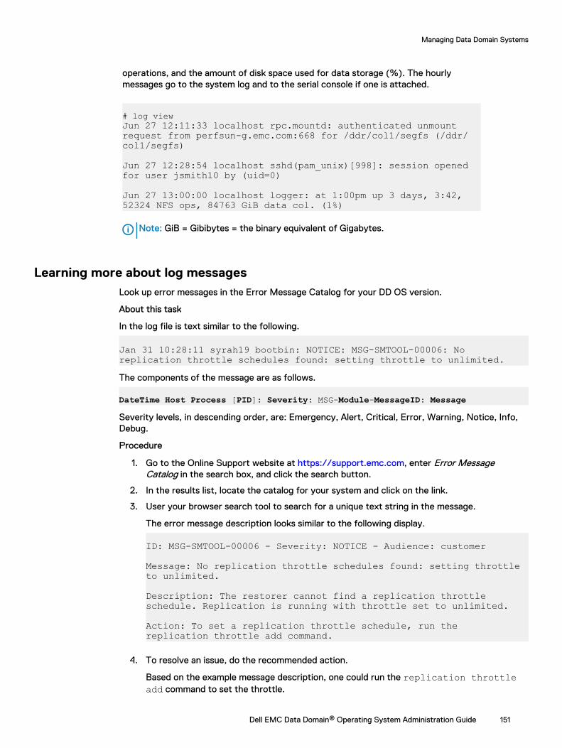
operations, and the amount of disk space used for data storage (%). The hourlymessages go to the system log and to the serial console if one is attached.
# log viewJun 27 12:11:33 localhost rpc.mountd: authenticated unmount request from perfsun-g.emc.com:668 for /ddr/col1/segfs (/ddr/col1/segfs)
Jun 27 12:28:54 localhost sshd(pam_unix)[998]: session opened for user jsmith10 by (uid=0)
Jun 27 13:00:00 localhost logger: at 1:00pm up 3 days, 3:42, 52324 NFS ops, 84763 GiB data col. (1%)
Note: GiB = Gibibytes = the binary equivalent of Gigabytes.
Learning more about log messagesLook up error messages in the Error Message Catalog for your DD OS version.
About this task
In the log file is text similar to the following.
Jan 31 10:28:11 syrah19 bootbin: NOTICE: MSG-SMTOOL-00006: No replication throttle schedules found: setting throttle to unlimited.The components of the message are as follows.
DateTime Host Process [PID]: Severity: MSG-Module-MessageID: Message
Severity levels, in descending order, are: Emergency, Alert, Critical, Error, Warning, Notice, Info,Debug.
Procedure
1. Go to the Online Support website at https://support.emc.com, enter Error MessageCatalog in the search box, and click the search button.
2. In the results list, locate the catalog for your system and click on the link.
3. User your browser search tool to search for a unique text string in the message.
The error message description looks similar to the following display.
ID: MSG-SMTOOL-00006 - Severity: NOTICE - Audience: customer
Message: No replication throttle schedules found: setting throttle to unlimited.
Description: The restorer cannot find a replication throttle schedule. Replication is running with throttle set to unlimited.
Action: To set a replication throttle schedule, run the replication throttle add command.
4. To resolve an issue, do the recommended action.
Based on the example message description, one could run the replication throttleadd command to set the throttle.
Managing Data Domain Systems
Dell EMC Data Domain® Operating System Administration Guide 151
Saving a copy of log filesSave log file copies to another device when you want to archive those files.
About this task
Use NFS, CIFS mount, or FTP to copy the files to another machine. If using CIFS or NFS, mount /ddvar to your desktop and copy the files from the mount point. The following procedure describeshow to use FTP to move files to another machine.
Procedure
1. On the Data Domain system, use the adminaccess show ftp command to see whetherFTP service is enabled. If the service is disabled, use the command adminaccessenable ftp.
2. On the Data Domain system, use the adminaccess show ftp command to see that theFTP access list includes the IP address of your remote machine. If the address is not in thelist, use the command adminaccess add ftp ipaddr.
3. On the remote machine, open a web browser.
4. In the Address box at the top of the web browser, use FTP to access the Data Domainsystem as shown in the following example.
ftp://Data Domain system_name.yourcompany.com/
Note: Some web browsers do not automatically ask for a login if a machine does notaccept anonymous logins. In that case, add a user name and password to the FTP line.For example: ftp://sysadmin:your-pw@Data Domainsystem_name.yourcompany.com/
5. At the login pop-up, log into the Data Domain system as user sysadmin.
6. On the Data Domain system, you are in the directory just above the log directory. Open thelog directory to list the messages files.
7. Copy the file that you want to save. Right-click the file icon and select Copy To Folder fromthe menu. Choose a location for the file copy.
8. If you want the FTP service disabled on the Data Domain system, after completing the filecopy, use SSH to log into the Data Domain system as sysadmin and invoke the commandadminaccess disable ftp.
Log message transmission to remote systemsSome log messages can be sent from the Data Domain system to other systems. DD OS usessyslog to publish log messages to remote systems.
A Data Domain system exports the following facility.priority selectors for log files. For informationon managing the selectors and receiving messages on a third-party system, see your vendor-supplied documentation for the receiving system.
l *.notice—Sends all messages at the notice priority and higher.
l *.alert—Sends all messages at the alert priority and higher (alerts are included in *.notice).
l kern.*—Sends all kernel messages (kern.info log files).
The log host commands manage the process of sending log messages to another system.
Managing Data Domain Systems
152 Dell EMC Data Domain® Operating System Administration Guide
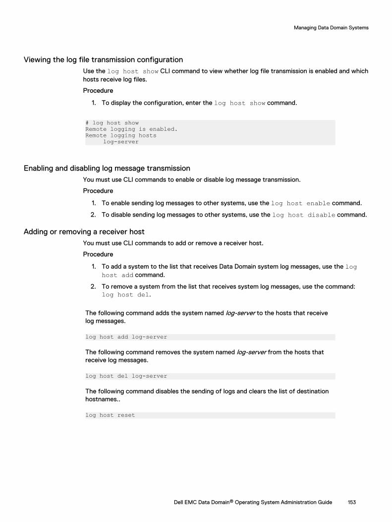
Viewing the log file transmission configurationUse the log host show CLI command to view whether log file transmission is enabled and whichhosts receive log files.
Procedure
1. To display the configuration, enter the log host show command.
# log host showRemote logging is enabled.Remote logging hosts log-server
Enabling and disabling log message transmissionYou must use CLI commands to enable or disable log message transmission.
Procedure
1. To enable sending log messages to other systems, use the log host enable command.
2. To disable sending log messages to other systems, use the log host disable command.
Adding or removing a receiver hostYou must use CLI commands to add or remove a receiver host.
Procedure
1. To add a system to the list that receives Data Domain system log messages, use the loghost add command.
2. To remove a system from the list that receives system log messages, use the command:log host del.
The following command adds the system named log-server to the hosts that receivelog messages.
log host add log-server
The following command removes the system named log-server from the hosts thatreceive log messages.
log host del log-server
The following command disables the sending of logs and clears the list of destinationhostnames..
log host reset
Managing Data Domain Systems
Dell EMC Data Domain® Operating System Administration Guide 153
Remote system power management with IPMISelect DD systems support remote power management using the Intelligent Platform ManagementInterface (IPMI), and they support remote monitoring of the boot sequence using Serial over LAN(SOL).
IPMI power management takes place between an IPMI initiator and an IPMI remote host. The IPMIinitiator is the host that controls power on the remote host. To support remote powermanagement from an initiator, the remote host must be configured with an IPMI username andpassword. The initiator must provide this username and password when attempting to managepower on a remote host.
IPMI runs independently of DD OS and allows an IPMI user to manage system power as long as theremote system is connected to a power source and a network. An IP network connection isrequired between an initiator and a remote system. When properly configured and connected, IPMImanagement eliminates the need to be physically present to power on or power off a remotesystem.
You can use both DD System Manager and the CLI to configure IPMI users on a remote system.After you configure IPMI on a remote system, you can use IPMI initiator features on anothersystem to log in and manage power.
Note: If a system cannot support IPMI due to hardware or software limitations, DD SystemManager displays a notification message when attempting to navigate to a configuration page.
SOL is used to view the boot sequence after a power cycle on a remote system. SOL enables textconsole data that is normally sent to a serial port or to a directly attached console to be sent over aLAN and displayed by a management host.
The DD OS CLI allows you to configure a remote system for SOL and view the remote consoleoutput. This feature is supported only in the CLI.
NOTICE IPMI power removal is provided for emergency situations during which attempts toshut down power using DD OS commands fail. IPMI power removal simply removes power tothe system, it does not perform an orderly shutdown of the DD OS file system. The proper wayto remove and reapply power is to use the DD OS system reboot command. The properway to remove system power is to use the DD OS system poweroff command and wait forthe command to properly shut down the file system.
IPMI and SOL limitationsIPMI and SOL support is limited on some Data Domain systems.
l IPMI is supported on all systems supported by this release except the following systems:DD140, DD610, and DD630.
l IPMI user support varies as follows.
n Model DD990: Maximum user IDs = 15. Three default users (NULL, anonymous, root).Maximum user IDs available = 12.
n Models DD640, DD4200, DD4500, DD7200, and DD9500: Maximum user IDs = 10. Twodefault users (NULL, root). Maximum user IDs available = 8.
l SOL is supported on the following systems: DD160, DD620, DD640, DD670, DD860, DD890,DD990, DD2200, DD2500 (requires DD OS 5.4.0.6 or later), DD4200, DD4500, DD7200, andDD9500.
Note: User root is not supported for IPMI connections on DD160 systems.
Managing Data Domain Systems
154 Dell EMC Data Domain® Operating System Administration Guide
Adding and deleting IPMI users with DD System ManagerEach system contains its own list of configured IPMI users, which is used to control access to localpower management features. Another system operating as an IPMI initiator can manage remotesystem power only after providing a valid username and password.
About this task
To give an IPMI user the authority to manage power on multiple remote systems, you must addthat user to each of the remote systems.
Note: The IPMI user list for each remote system is separate from the DD System Manager listsfor administrator access and local users. Administrators and local users do not inherit anyauthorization for IPMI power management.
Procedure
1. Select Maintenance > IPMI.
2. To add a user, complete the following steps.
a. Above the IPMI Users table, click Add.
b. In the Add User dialog box, type the user name (16 or less characters) and password inthe appropriate boxes (reenter the password in the Verify Password box).
c. Click Create.
The user entry appears in the IPMI Users table.
3. To delete a user, complete the following steps.
a. In the IPMI Users list, select a user and click Delete.
b. In the Delete User dialog box, click OK to verify user deletion.
Changing an IPMI user passwordChange the IPMI user password to prevent use of the old password for power management.
Procedure
1. Select Maintenance > IPMI.
2. In the IPMI Users table, select a user, and click Change Password.
3. In the Change Password dialog box, type the password in the appropriate text box andreenter the password in the Verify Password box.
4. Click Update.
Configuring an IPMI portWhen you configure an IPMI port for a system, you select the port from a network ports list andspecify the IP configuration parameters for that port. The selection of IPMI ports displayed isdetermined by the Data Domain system model.
About this task
Some systems support one or more dedicated ports, which can be used only for IPMI traffic. Othersystems support ports that can be used for both IPMI traffic and all IP traffic supported by thephysical interfaces in the Hardware > Ethernet > Interfaces view. Shared ports are not providedon systems that provide dedicated IPMI ports.
The port names in the IPMI Network Ports list use the prefix bmc, which represents baseboardmanagement controller. To determine if a port is a dedicated port or shared port, compare the rest
Managing Data Domain Systems
Dell EMC Data Domain® Operating System Administration Guide 155
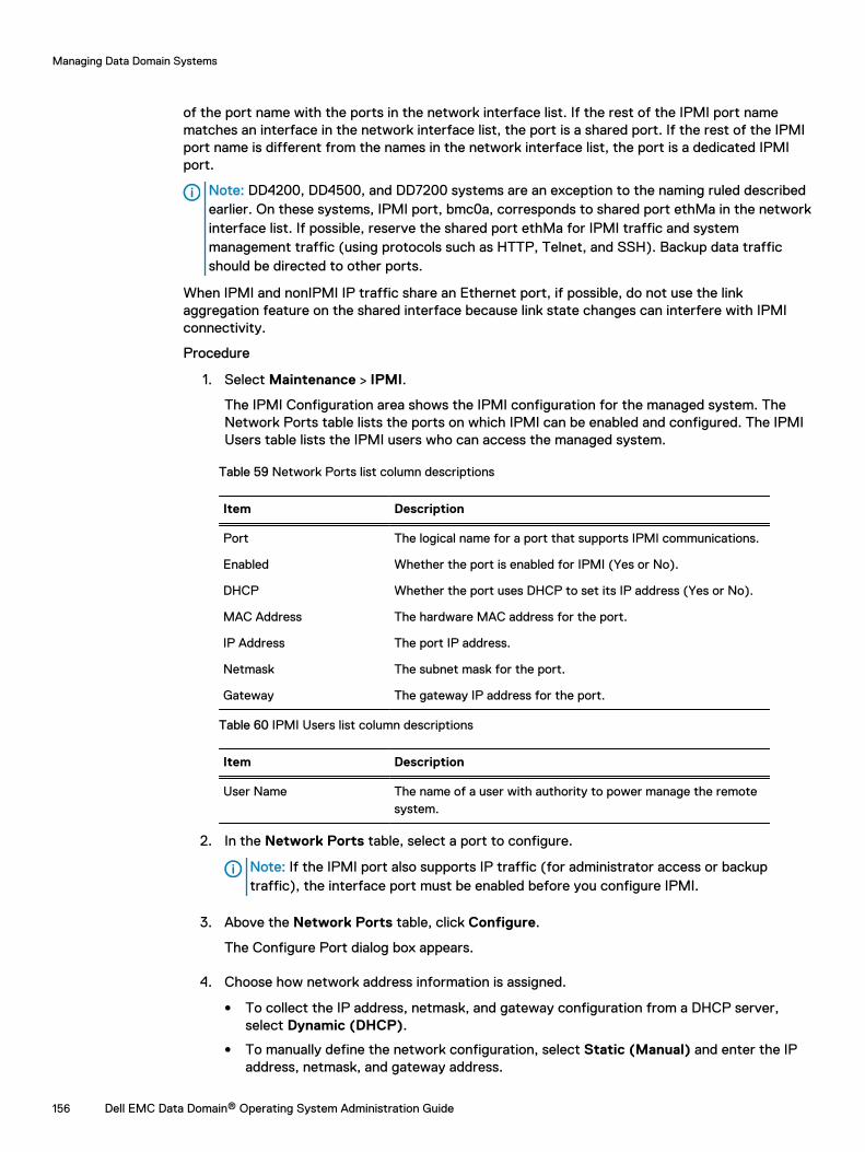
of the port name with the ports in the network interface list. If the rest of the IPMI port namematches an interface in the network interface list, the port is a shared port. If the rest of the IPMIport name is different from the names in the network interface list, the port is a dedicated IPMIport.
Note: DD4200, DD4500, and DD7200 systems are an exception to the naming ruled describedearlier. On these systems, IPMI port, bmc0a, corresponds to shared port ethMa in the networkinterface list. If possible, reserve the shared port ethMa for IPMI traffic and systemmanagement traffic (using protocols such as HTTP, Telnet, and SSH). Backup data trafficshould be directed to other ports.
When IPMI and nonIPMI IP traffic share an Ethernet port, if possible, do not use the linkaggregation feature on the shared interface because link state changes can interfere with IPMIconnectivity.
Procedure
1. Select Maintenance > IPMI.
The IPMI Configuration area shows the IPMI configuration for the managed system. TheNetwork Ports table lists the ports on which IPMI can be enabled and configured. The IPMIUsers table lists the IPMI users who can access the managed system.
Table 59 Network Ports list column descriptions
Item Description
Port The logical name for a port that supports IPMI communications.
Enabled Whether the port is enabled for IPMI (Yes or No).
DHCP Whether the port uses DHCP to set its IP address (Yes or No).
MAC Address The hardware MAC address for the port.
IP Address The port IP address.
Netmask The subnet mask for the port.
Gateway The gateway IP address for the port.
Table 60 IPMI Users list column descriptions
Item Description
User Name The name of a user with authority to power manage the remotesystem.
2. In the Network Ports table, select a port to configure.
Note: If the IPMI port also supports IP traffic (for administrator access or backuptraffic), the interface port must be enabled before you configure IPMI.
3. Above the Network Ports table, click Configure.
The Configure Port dialog box appears.
4. Choose how network address information is assigned.
l To collect the IP address, netmask, and gateway configuration from a DHCP server,select Dynamic (DHCP).
l To manually define the network configuration, select Static (Manual) and enter the IPaddress, netmask, and gateway address.
Managing Data Domain Systems
156 Dell EMC Data Domain® Operating System Administration Guide
5. Enable a disabled IPMI network port by selecting the network port in the Network Portstable, and clicking Enable.
6. Disable a disabled IPMI network port by selecting the network port in the Network Portstable, and clicking Disable.
7. Click Apply.
Preparing for remote power management and console monitoring with the CLIRemote console monitoring uses the Serial Over Lan (SOL) feature to enable viewing of text-based console output without a serial server. You must use the CLI to set up a system for remotepower management and console monitoring.
About this task
Remote console monitoring is typically used in combination with the ipmi remote powercycle command to view the remote system’s boot sequence. This procedure should be used onevery system for which you might want to remotely view the console during the boot sequence.
Procedure
1. Connect the console to the system directly or remotely.
l Use the following connectors for a direct connection.
n DIN-type connectors for a PS/2 keyboard
n USB-A receptacle port for a USB keyboard
n DB15 female connector for a VGA monitor
Note: Systems DD4200, DD4500, and DD7200 do not support direct connection,including KVM.
l For a serial connection, use a standard DB9 male or micro-DB9 female connector.Systems DD4200, DD4500, and DD7200 provide a female micro-DB9 connector. A nullmodem cable with male micro-DB9 and standard female DB9 connectors is included for atypical laptop connection.
l For a remote IPMI/SOL connection, use the appropriate RJ45 receptacle as follows.
n For DD990 systems, use default port eth0d.
n For other systems, use the maintenance or service port. For port locations, refer tothe system documentation, such as a hardware overview or installation and setupguide.
2. To support remote console monitoring, use the default BIOS settings.
3. To display the IPMI port name, enter ipmi show config.
4. To enable IPMI, enter ipmi enable {port | all}.
5. To configure the IPMI port, enter ipmi config port { dhcp | ipaddress ipaddrnetmask mask gateway ipaddr }.
Note: If the IPMI port also supports IP traffic (for administrator access or backuptraffic), the interface port must be enabled with the net enable command before youconfigure IPMI.
6. If this is the first time using IPMI, run ipmi user reset to clear IPMI users that may beout of synch between two ports, and to disable default users.
7. To add a new IPMI user, enter ipmi user add user.
Managing Data Domain Systems
Dell EMC Data Domain® Operating System Administration Guide 157
8. To set up SOL, do the following:
a. Enter system option set console lan.
b. When prompted, enter y to reboot the system.
Managing power with DD System ManagerAfter IPMI is properly set up on a remote system, you can use DD System Manager as an IPMIinitiator to log into the remote system, view the power status, and change the power status.
Procedure
1. Select Maintenance > IPMI.
2. Click Login to Remote System.
The IPMI Power Management dialog box appears.
3. Enter the remote system IPMI IP address or hostname and the IPMI username andpassword, then click Connect.
4. View the IPMI status.
The IPMI Power Management dialog box appears and shows the target system identificationand the current power status. The Status area always shows the current status.
Note: The Refresh icon (the blue arrows) next to the status can be used to refresh theconfiguration status (for example, if the IPMI IP address or user configuration werechanged within the last 15 minutes using the CLI commands).
5. To change the IPMI power status, click the appropriate button.
l Power Up—Appears when the remote system is powered off. Click this button to powerup the remote system.
l Power Down—Appears when the remote system is powered on. Click this button topower down the remote system.
l Power Cycle—Appears when the remote system is powered on. Click this button topower cycle the remote system.
l Manage Another System—Click this button to log into another remote system for IPMIpower management.
l Done—Click to close the IPMI Power Management dialog box.
NOTICE The IPMI Power Down feature does not perform an orderly shutdown of the DDOS. This option can be used if the DD OS hangs and cannot be used to gracefullyshutdown a system.
Managing power with the CLIYou can manage power on a remote system and start remote console monitoring using the CLI.
About this task
Note: The remote system must be properly set up before you can manage power or monitorthe system.
Procedure
1. Establish a CLI session on the system from which you want to monitor a remote system.
2. To manage power on the remote system, enter ipmi remote power {on | off |cycle | status} ipmi-target <ipaddr | hostname> user user.
Managing Data Domain Systems
158 Dell EMC Data Domain® Operating System Administration Guide
3. To begin remote console monitoring, enter ipmi remote console ipmi-target<ipaddr | hostname> user user.
Note: The user name is an IPMI user name defined for IPMI on the remote system. DDOS user names are not automatically supported by IPMI.
4. To disconnect from a remote console monitoring session and return to the command line,enter the at symbol (@).
5. To terminate remote console monitoring, enter the tilde symbol (~).
Managing Data Domain Systems
Dell EMC Data Domain® Operating System Administration Guide 159

Managing Data Domain Systems
160 Dell EMC Data Domain® Operating System Administration Guide
CHAPTER 4
Monitoring Data Domain Systems
This chapter includes:
l Viewing individual system status and identity information....................................................162l Health Alerts panel...............................................................................................................165l Viewing and clearing current alerts...................................................................................... 165l Viewing the alerts history.....................................................................................................166l Viewing hardware component status....................................................................................167l Viewing system statistics......................................................................................................171l Viewing active users.............................................................................................................172l History report management................................................................................................. 172l Viewing the Task Log........................................................................................................... 176l Viewing the system High Availability status..........................................................................177
Dell EMC Data Domain® Operating System Administration Guide 161
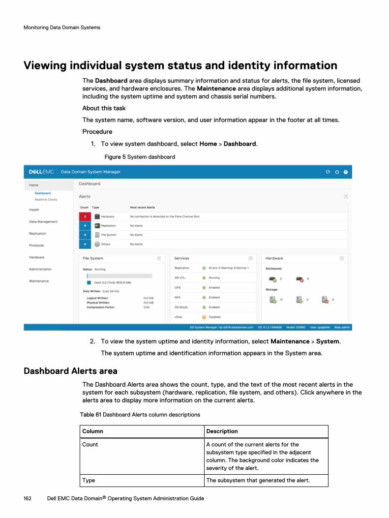
Viewing individual system status and identity informationThe Dashboard area displays summary information and status for alerts, the file system, licensedservices, and hardware enclosures. The Maintenance area displays additional system information,including the system uptime and system and chassis serial numbers.
About this task
The system name, software version, and user information appear in the footer at all times.
Procedure
1. To view system dashboard, select Home > Dashboard.
Figure 5 System dashboard
2. To view the system uptime and identity information, select Maintenance > System.
The system uptime and identification information appears in the System area.
Dashboard Alerts areaThe Dashboard Alerts area shows the count, type, and the text of the most recent alerts in thesystem for each subsystem (hardware, replication, file system, and others). Click anywhere in thealerts area to display more information on the current alerts.
Table 61 Dashboard Alerts column descriptions
Column Description
Count A count of the current alerts for thesubsystem type specified in the adjacentcolumn. The background color indicates theseverity of the alert.
Type The subsystem that generated the alert.
Monitoring Data Domain Systems
162 Dell EMC Data Domain® Operating System Administration Guide
Table 61 Dashboard Alerts column descriptions (continued)
Column Description
Most recent alerts The text of the most recent alert for thesubsystem type specified in the adjacentcolumn
Dashboard File System areaThe Dashboard File System area displays statistics for the entire file system. Click anywhere in theFile System area to display more information.
Table 62 File System area label descriptions
Column Description
Status The current status of the file system.
X.Xx The average compression reduction factor forthe file system.
Used The total file system space being used.
Data Written: Pre-compression The data quantity received by the systemprior to compression.
Data Written: Post-compression The data quantity stored on the system aftercompression.
Dashboard Services areaThe Dashboard Services area displays the status of the replication, DD VTL, CIFS, NFS, DD Boost,and vDisk services. Click on a service to display detailed information about that service.
Table 63 Services area column descriptions
Column Description
Left column The left column lists the services that may beused on the system. These service can includereplication, DD VTL, CIFS, NFS, DD Boost,vDisk.
Right column The right column shows the operational statusof the service. For most services, the status isenabled, disabled, or not licensed. Thereplication service row displays the number ofreplication contexts that are in normal,warning, and error states. A color coded boxdisplays green for normal operation, yellow forwarning situations, or red when errors arepresent).
Monitoring Data Domain Systems
Dell EMC Data Domain® Operating System Administration Guide 163
Dashboard HA Readiness areaIn high-availability (HA) systems, the HA panel indicates whether the system can fail over from theactive node to the standby node if necessary.
You can click on the HA panel to navigate to the High Availability section under HEALTH.
Dashboard Hardware areaThe Dashboard Hardware area displays the status of the system enclosures and drives. Clickanywhere in the Hardware area to display more information on these components.
Table 64 Hardware area label descriptions
Label Description
Enclosures The enclosure icons display the number ofenclosures operating in the normal (greencheckmark) and degraded (red X) states.
Storage The storage icons display the number of diskdrives operating in the normal (greencheckmark), spare (green +), or failed (red X)state.
Maintenance System areaThe Maintenance System area displays the system model number, DD OS version, system uptime,and system and chassis serial numbers.
Table 65 System area label descriptions
Label Description
Model Number The model number is the number assigned tothe Data Domain system.
Version The version is the DD OS version and buildnumber of the software running on thesystem.
System Uptime The system uptime displays how long thesystem has been running since the last systemstart. The time in parenthesis indicates whenthe system uptime was last updated.
System Serial No. The system serial number is the serial numberassigned to the system. On newer systems,such as DD4500 and DD7200, the systemserial number is independent of the chassisserial number and remains the same duringmany types of maintenance events, includingchassis replacements. On legacy systems,such as DD990 and earlier, the system serialnumber is set to the chassis serial number.
Monitoring Data Domain Systems
164 Dell EMC Data Domain® Operating System Administration Guide

Table 65 System area label descriptions (continued)
Label Description
Chassis Serial No. The chassis serial number is the serial numberon the current system chassis.
Health Alerts panelAlerts are messages from system services and subsystems that report system events. The Health> Alerts panel displays tabs that allow you to view current and non-current alerts, the configuredalert notification groups, and the configuration for those who want to receive daily alert summaryreports.
Alerts are also sent as SNMP traps. See the MIB Quick Reference Guide or the SNMP MIB for thefull list of traps.
Viewing and clearing current alertsThe Current Alerts tab displays a list of all the current alerts and can display detailed informationfor a selected alert. An alert is automatically removed from the Current Alerts list when theunderlying situation is corrected or when manually cleared.
Procedure
1. To view all of the current alerts, select Health > Alerts > Current Alerts.
2. To limit the number of entries in the current alert list, do the following.
a. In the Filter By area, select a Severity and Class to expose only alerts that pertain tothose choices.
b. Click Update.
All alerts not matching the Severity and Class are removed from the list.
3. To display additional information for a specific alert in the Details area, click the alert in thelist.
4. To clear an alert, select the alert checkbox in the list and click Clear.
A cleared alert no longer appears in the current alerts list, but it can be found in the alertshistory list.
5. To remove filtering and return to the full listing of current alerts, click Reset.
Current Alerts tabThe Current Alerts tab displays a list of alerts and detailed information about a selected alert.
Table 66 Alerts list, column label descriptions
Item Description
Message The alert message text.
Severity The level of seriousness of the alert. For example, warning, critical,info, or emergency.
Monitoring Data Domain Systems
Dell EMC Data Domain® Operating System Administration Guide 165
Table 66 Alerts list, column label descriptions (continued)
Item Description
Date The time and date the alert occurred.
Class The subsystem where the alert occurred.
Object The physical component where the alert is occurring.
Table 67 Details area, row label descriptions
Item Description
Name A textual identifier for the alert.
Message The alert message text.
Severity The level of seriousness of the alert. For example, warning, critical,info, emergency.
Class The subsystem and device where the alert occurred.
Date The time and date the alert occurred.
Object ID The physical component where the alert is occurring.
Event ID An event identifier.
Tenant Units Lists affected tenant units.
Description More descriptive information about the alert.
Action A suggestion to remedy the alert.
Object Info Additional information about the affected object.
SNMP OID SNMP object ID.
Viewing the alerts historyThe Alerts History tab displays a list of all the cleared alerts and can display detailed informationfor a selected alert.
Procedure
1. To view all of the alerts history, select Health > Alerts > Alerts History.
2. To limit the number of entries in the current alert list, do the following.
a. In the Filter By area, select a Severity and Class to expose only alerts that pertain tothose choices.
b. Click Update.
All alerts not matching the Severity and Class are removed from the list.
3. To display additional information for a specific alert in the Details area, click the alert in thelist.
4. To remove filtering and return to the full listing of cleared alerts, click Reset.
Monitoring Data Domain Systems
166 Dell EMC Data Domain® Operating System Administration Guide
Alerts History tabThe Alerts History tab displays a list of cleared alerts and details about a selected alert.
Table 68 Alerts list, column label descriptions
Item Description
Message The alert message text.
Severity The level of seriousness of the alert. For example, warning, critical,info, or emergency.
Date The time and date the alert occurred.
Class The subsystem where the alert occurred.
Object The physical component where the alert is occurring.
Status Whether the status is posted or cleared. A posted alert is notcleared.
Table 69 Details area, row label descriptions
Item Description
Name A textual identifier for the alert.
Message The alert message text.
Severity The level of seriousness of the alert. For example, warning, critical,info, emergency,
Class The subsystem and device where the alert occurred.
Date The time and date the alert occurred.
Object ID The physical component where the alert is occurring.
Event ID An event identifier.
Tenant Units Lists affected tenant units.
Additional Information More descriptive information about the alert.
Status Whether the status is posted or cleared. A posted alert is notcleared.
Description More descriptive information about the alert.
Action A suggestion to remedy the alert.
Viewing hardware component statusThe Hardware Chassis panel displays a block drawing of each enclosure in a system, including thechassis serial number and the enclosure status. Within each block drawing are the enclosurecomponents, such as disks, fans, power supplies, NVRAM, CPUs, and memory. The componentsthat appear depend upon the system model.
About this task
On systems running DD OS 5.5.1 and later, the system serial number is also displayed. On newersystems, such as DD4500 and DD7200, the system serial number is independent of the chassis
Monitoring Data Domain Systems
Dell EMC Data Domain® Operating System Administration Guide 167

serial number and remains the same during many types of maintenance events, including chassisreplacements. On legacy systems, such as DD990 and earlier, the system serial number is set tothe chassis serial number.
Procedure
1. Select Hardware > Chassis.
The Chassis view shows the system enclosures. Enclosure 1 is the system controller, and therest of the enclosures appear below Enclosure 1.
Components with problems show yellow (warning) or red (error); otherwise, the componentdisplays OK.
2. Hover the cursor over a component to see detailed status.
Fan statusFans are numbered and correspond to their location in the chassis. Hover over a system fan todisplay a tooltip for that device.
Table 70 Fan tooltip, column label descriptions
Item Description
Description The name of the fan.
Level The current operating speed range (Low, Medium, High). Theoperating speed changes depending on the temperature insidethe chassis.
Status The health of the fan.
Temperature statusData Domain systems and some components are configured to operate within a specifictemperature range, which is defined by a temperature profile that is not configurable. Hover overthe Temperature box to display the temperature tooltip.
Table 71 Temperature tooltip, column label descriptions
Item Description
Description The location within the chassis being measured. The componentslisted depend on the model and are often shown as abbreviations.Some examples are:
l CPU 0 Temp (Central Processing Unit)
l MLB Temp 1 (main logic board)
l BP middle temp (backplane)
l LP temp (low profile of I/O riser FRU)
l FHFL temp (full height full length of I/O riser FRU)
l FP temp (front panel)
C/F The C/F column displays temperature in degrees Celsius andFahrenheit. When the description for a CPU specifies relative(CPU n Relative), this column displays the number of degrees
Monitoring Data Domain Systems
168 Dell EMC Data Domain® Operating System Administration Guide

Table 71 Temperature tooltip, column label descriptions (continued)
Item Description
that each CPU is below the maximum allowable temperature andthe actual temperature for the interior of the chassis (chassisambient).
Status Shows the temperature status:
l OK—The temperature is acceptable
l Critical—The temperature is higher than the shutdowntemperature.
l Warning—The temperature is higher than the warningtemperature (but lower than the shutdown temperature).
l Dash (-) —No temperature thresholds are configured for thiscomponent, so there is no status to report.
Management panel statusDD6300, DD6800, and DD9300 systems have a fixed management panel with an Ethernet port forthe management network on the rear of the chassis. Hover over the Ethernet port to display atooltip.
Table 72 Management panel tooltip, column label descriptions
Item Description
Description The type of NIC installed in the management panel.
Vendor The manufacturer of the management NIC.
Ports The name of the management network (Ma).
SSD status (DD6300 only)The DD6300 supports up to two SSDs in slots on the rear of the chassis. The SSD slots arenumbered and correspond to their location in the chassis. Hover over an SSD to display a tooltipfor that device.
Table 73 SSD tooltip, column label descriptions
Item Description
Description The name of the SSD.
Status The state of the SSD.
Life Used The percentage of the rated operating life the SSD has used.
Power supply statusThe tooltip shows the status of the power supply (OK or DEGRADED if a power supply is absent orfailed). You can also look at the back panel of the enclosure and check the LED for each powersupply to identify those that need replacing.
Monitoring Data Domain Systems
Dell EMC Data Domain® Operating System Administration Guide 169
PCI slot statusThe PCI slots shown in the chassis view indicate the number of PCI slots and the numbers of eachslot. Tooltips provide component status for each card in a PCI slot. For example, the tooltip for oneNVRAM card model displays the memory size, temperature data, and battery levels.
NVRAM statusHover over NVRAM to display information about the Non-Volatile RAM, batteries, and othercomponents.
Table 74 NVRAM tooltip, dolumn label descriptions
Item Description
Component The items in the component list depend on the NVRAM installedin the system and can include the following items.
l Firmware version
l Memory size
l Error counts
l Flash controller error counts
l Board temperature
l CPU temperature
l Battery number (The number of batteries depends on thesystem type.)
l Current slot number for NVRAM
C/F Displays the temperature for select components in the Celsius/Fahrenheit format.
Value Values are provided for select components and describe thefollowing.
l Firmware version number
l Memory size value in the displayed units
l Error counts for memory, PCI, and controller
l Flash controller error counts sorted in the following groups:configuration errors (Cfg Err), panic conditions (Panic), BusHang, bad block warnings (Bad Blk Warn), backup errors(Bkup Err), and restore errors (Rstr Err)
l Battery information, such percent charged and status(enabled or disabled)
Monitoring Data Domain Systems
170 Dell EMC Data Domain® Operating System Administration Guide
Viewing system statisticsThe Realtime Charts panel displays up to seven graphs that show real-time subsystemperformance statistics, such as CPU usage and disk traffic.
Procedure
1. Select Home > Realtime Charts.
The Performance Graphs area displays the currently selected graphs.
2. To change the selection of graphs to display, select and clear the checkboxes for graphs inthe list box.
3. To view specific data-point information, hover over a graph point.
4. When a graph contains multiple data, you can use the checkboxes in the upper-right cornerof the graph to select what to display. For example, if Read is not selected in the upper rightof the disk activity graph, only write data is graphed.
Results
Each graph shows usage over the last 200 seconds. Click Pause to temporarily stop the display.Click Resume to restart it and show points missed during the pause.
Performance statistics graphsThe performance statistics graphs display statistics for key system components and features.
DD Boost Active Connections
The DD Boost Active Connections graph displays the number of active DD Boost connectionsfor each of the past 200 seconds. Separate lines within the graph display counts for Read(recovery) connections and Write (backup) connections.
DD Boost Data Throughput
The DD Boost Data Throughput graph displays the bytes/second transferred for each of thepast 200 seconds. Separate lines within the graph display the rates for data read from thesystem by DD Boost clients and data written to the system by DD Boost clients.
Disk
The Disk graph displays the amount of data in the appropriate unit of measurement based onthe data received, such as KiB or MiB per second, going to and from all disks in the system.
File System Operations
The File System Operations graph displays the number of operations per second that occurredfor each of the past 200 seconds. Separate lines within the graph display the NFS and CIFSoperations per second.
Network
The Network graph displays the amount of data in the appropriate unit of measurement basedon the data received, such as KiB or MiB per second, that passes through each Ethernetconnection. One line appears for each Ethernet port.
Recent CPU Usage
The Recent CPU Usage graph displays the percentage of CPU usage for each of the past 200seconds.
Replication (DD Replicator must be licensed)
The Replication graph displays the amount of replication data traveling over the network foreach of the last 200 seconds. Separate lines display the In and Out data as follows:
Monitoring Data Domain Systems
Dell EMC Data Domain® Operating System Administration Guide 171
l In: The total number of units of measurement, such as kilobytes per second, received bythis side from the other side of the DD Replicator pair. For the destination, the valueincludes backup data, replication overhead, and network overhead. For the source, thevalue includes replication overhead and network overhead.
l Out: The total number of units of measurement, such as kilobytes per second, sent by thisside to the other side of the DD Replicator pair. For the source, the value includes backupdata, replication overhead, and network overhead. For the destination, the value includesreplication and network overhead.
Viewing active usersThe Active Users tab displays the names of users who are logged into the system and statisticsabout the current user sessions.
Procedure
1. Select Administration > Access > Active Users.
The Active Users list appears and displays information for each user.
Table 75 Active Users list, column label descriptions
Item Description
Name User name of the logged-in user.
Idle Time since last activity of user.
Last Login From System from which the user logged in.
Last Login Time Datestamp of when user logged in.
TTY Terminal notation for login. GUI appears for DD SystemManager users.
Note: To manage local users, click Go to Local Users.
History report managementDD System Manager enables you to generate reports to track space usage on a Data Domainsystem for up to the previous two years. You can also generate reports to help understandreplication progress, and view daily and cumulative reports on the file system.
The Reports view is divided into two sections. The upper section lets you create the various typesof reports. The lower section lets you view and manage saved reports.
Reports display in a table format, and as charts, depending on the type of report. You can select areport for a specific Data Domain system and provide a specific time period.
The reports display historical data, not real-time data. After the report is generated, the chartsremain static and do not update. Examples of the types of information you can get from thereports include:
l The amount of data that was backed up to the system and the amount of de-duplication thatwas achieved
l Estimates of when the Data Domain system will be full, based on weekly space usage trends
Monitoring Data Domain Systems
172 Dell EMC Data Domain® Operating System Administration Guide
l Backup and compression utilization based on selected intervals
l Historical cleaning performance, including duration of cleaning cycle, amount of space that canbe cleaned, and amount of space that was reclaimed
l Amount of WAN bandwidth used by replication, for source and destination, and if bandwidth issufficient to meet replication requirements
l System performance and resource utilization
Types of reportsThe New Report area lists the types of reports you can generate on your system.
Note: Replication reports can only be created if the system contains a replication license and avalid replication context is configured.
File System Cumulative Space Usage reportThe File System Cumulative Space Usage Report displays 3 charts that detail space usage on thesystem during the specified duration. This report is used to analyze how much data is backed up,the amount of deduplication performed, and how much space is consumed.
Table 76 File System—Usage chart label descriptions
Item Description
Data Written (GiB) The amount of data written before compression. This isindicated by a purple shaded area on the report.
Time The timeline for data that was written. The time displayed onthis report changes based upon the Duration selection whenthe chart was created.
Total Compression Factor The total compression factor reports the compression ratio.
Table 77 File System—Consumption chart label descriptions
Item Description
Used (GiB) The amount of space used after compression.
Time The date the data was written. The time displayed on thisreport changes based upon the Duration selection when thechart was created.
Used (Post Comp) The amount of storage used after compression.
Usage Trend The dotted black line shows the storage usage trend. Whenthe line reaches the red line at the top, the storage is almostfull.
Capacity The total capacity on a Data Domain system.
Cleaning Cleaning is the Cleaning cycle (start and end time for eachcleaning cycle). Administrators can use this information tochoose the best time for space cleaning the best throttlesetting.
Monitoring Data Domain Systems
Dell EMC Data Domain® Operating System Administration Guide 173
Table 78 File System Weekly Cumulative Capacity chart label descriptions
Item Description
Date (or Time for 24 hourreport)
The last day of each week, based on the criteria set for thereport. In reports, a 24-hour period ranges from noon-to-noon.
Data Written (Pre-Comp) The cumulative data written before compression for thespecified time period.
Used (Post-Comp) The cumulative data written after compression for thespecified time period.
Compression Factor The total compression factor. This is indicated by a black lineon the report.
File System Daily Space Usage reportThe File System Daily Space Usage report displays five charts that detail space usage during thespecified duration. This report is used to analyze daily activities.
Table 79 File System Daily Space Usage chart label descriptions
Item Description
Space Used (GiB) The amount of space used. Post-comp is red shaded area.Pre-Comp is purple shaded area.
Time The date the data was written.
Compression Factor The total compression factor. This is indicated by a blacksquare on the report.
Table 80 File System Daily Capacity Utilization chart label descriptions
Item Description
Date The date the data was written.
Data Written (Pre-Comp) The amount of data written pre-compression.
Used (Post-Comp) The amount of storage used after compression.
Total Compression Factor The total compression factor.
Table 81 File System Weekly Capacity Utilization chart label descriptions
Item Description
Start Date The first day of the week for this summary.
End Date The last day of the week for this summary.
Available Total amount of storage available.
Consumed Total amount of storage used.
Data (Post -Comp) The cumulative data written before compression for thespecified time period.
Monitoring Data Domain Systems
174 Dell EMC Data Domain® Operating System Administration Guide
Table 81 File System Weekly Capacity Utilization chart label descriptions (continued)
Item Description
Replication (Post-Comp) The cumulative data written after compression for thespecified time period.
Overhead Extra space used for non-data storage.
Reclaimed by Cleaning The total space reclaimed after cleaning.
Table 82 File System Compression Summary chart label descriptions
Item Description
Time The period of data collection for this report.
Data Written (Pre-Comp) The amount of data written pre-compression.
Used (Post-Comp) The amount of storage used after compression.
Total Compression Factor The total compression factor.
Table 83 File System Cleaning Activity chart label descriptions
Item Description
Start Time The time the cleaning activity started.
End Time The time the cleaning activity finished.
Duration (Hours) The total time required for cleaning in hours.
Space Reclaimed The space reclaimed in Gibibytes (GiB).
Replication Status reportThe Replication Status report displays three charts that provide the status of the currentreplication job running on the system. This report is used to provide a snapshot of what ishappening for all replication contexts to help understand the overall replication status on a DataDomain System.
Table 84 Replication Context Summary chart label descriptions
Item Description
ID The Replication Context identification.
Source Source system name.
Destination Destination system name.
Type Type of replication context: MTree, Directory, Collection, orPool.
Status Replication status types include: Error, Normal.
Sync as of Time Time and date stamp of last sync.
Estimated Completion The estimated time the replication should be complete.
Pre-Comp Remaining The amount of pre-compressed data to be replicated. Thisonly applies to Collection type.
Monitoring Data Domain Systems
Dell EMC Data Domain® Operating System Administration Guide 175
Table 84 Replication Context Summary chart label descriptions (continued)
Item Description
Post-Comp Remaining The amount of post-compressed data to be replicated. Thisonly applies to Directory and Pool types.
Table 85 Replication Context Error Status chart label descriptions
Item Description
ID The Replication Context identification.
Source Source system name.
Destination Destination system name.
Type Replication context type: Directory or Pool.
Status Replication status types include: Error, Normal, and Warning.
Description Description of the error.
Table 86 Replication Destination Space Availability chart label descriptions
Item Description
Destination Destination system name.
Space Availability (GiB) Total amount of storage available.
Replication Summary reportThe Replication Summary report provides performance information about a system’s overallnetwork in-and-out usage for replication, as well as per context levels over a specified duration.You select the contexts to be analyzed from a list.
Table 87 Replication Summary report label descriptions
Item Description
Network In (MiB) The amount of data entering the system. Network In isindicated by a thin green line.
Network Out (MiB) The amount of data sent from the system. Network Out isindicated by a thick orange line.
Time The date on which the data was written.
Pre-Comp Remaining (MiB) The amount of pre-compressed data to be replicated. Pre-Comp Remaining is indicated by a blue line.
Viewing the Task LogThe Task Log displays a list of currently running jobs, such as, replication or system upgrades. DDSystem Manager can manage multiple systems and can initiate tasks on those systems. If a task is
Monitoring Data Domain Systems
176 Dell EMC Data Domain® Operating System Administration Guide
initiated on a remote system, the progress of that task is tracked in the management station tasklog, not in the remote system task log.
Procedure
1. Select Health > Jobs.
The Tasks view appears.
2. Select a filter by which to display the Task Log from the Filter By list box. You can select All,In Progress, Failed, or Completed.
The Tasks view displays the status of all tasks based on the filter you select and refreshesevery 60 seconds.
3. To manually refresh the Tasks list, do either of the following.
l Click Update to update the task log.
l Click Reset to display all tasks and remove any filters that were set.
4. To display detailed information about a task, select the task in the task list.
Table 88 Detailed Information, label descriptions
Item Description
System The system name.
Task Description A description of the task.
Status The status of the task (completed, failed, or in progress).
Start Time The date and time the task started.
End Time The date and time the task ended.
Error Message An applicable error message, if any.
Viewing the system High Availability statusYou can use the High Availability panel to see detailed information about the HA status of thesystem and whether the system can perform failover if necessary.
Procedure
1. Select Health > High Availability on the DD System Manager.
The Health High Availability screen appears.A green check mark indicates the system is operating normally and ready for failover.
The screen shows the active node, which is typically Node 0.
2. Hover the cursor over a node to see its status.
The node is highlighted in blue if it is active.
3. Click the drop-down menu in the banner if you want to change the view from the activenode to the standby node, which is typically Node 1.
Monitoring Data Domain Systems
Dell EMC Data Domain® Operating System Administration Guide 177
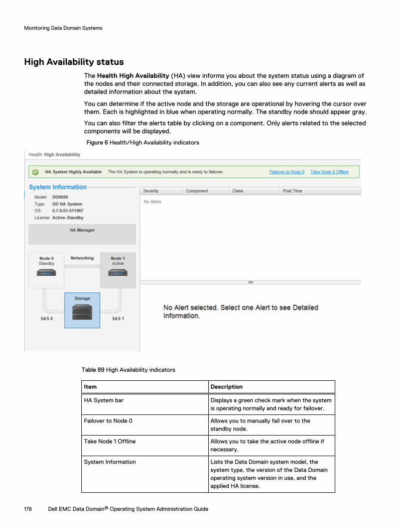
High Availability statusThe Health High Availability (HA) view informs you about the system status using a diagram ofthe nodes and their connected storage. In addition, you can also see any current alerts as well asdetailed information about the system.
You can determine if the active node and the storage are operational by hovering the cursor overthem. Each is highlighted in blue when operating normally. The standby node should appear gray.
You can also filter the alerts table by clicking on a component. Only alerts related to the selectedcomponents will be displayed.
Figure 6 Health/High Availability indicators
Table 89 High Availability indicators
Item Description
HA System bar Displays a green check mark when the systemis operating normally and ready for failover.
Failover to Node 0 Allows you to manually fail over to thestandby node.
Take Node 1 Offline Allows you to take the active node offline ifnecessary.
System Information Lists the Data Domain system model, thesystem type, the version of the Data Domainoperating system version in use, and theapplied HA license.
Monitoring Data Domain Systems
178 Dell EMC Data Domain® Operating System Administration Guide
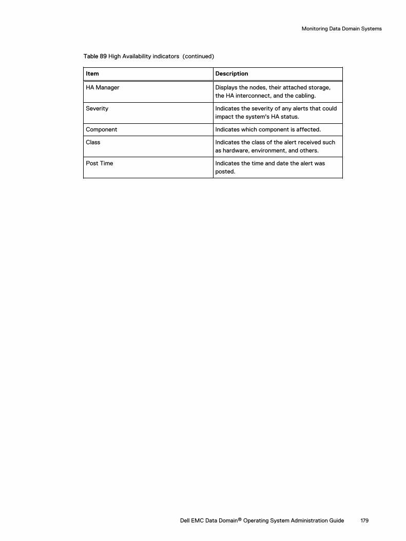
Table 89 High Availability indicators (continued)
Item Description
HA Manager Displays the nodes, their attached storage,the HA interconnect, and the cabling.
Severity Indicates the severity of any alerts that couldimpact the system's HA status.
Component Indicates which component is affected.
Class Indicates the class of the alert received suchas hardware, environment, and others.
Post Time Indicates the time and date the alert wasposted.
Monitoring Data Domain Systems
Dell EMC Data Domain® Operating System Administration Guide 179

Monitoring Data Domain Systems
180 Dell EMC Data Domain® Operating System Administration Guide
CHAPTER 5
File System
This chapter includes:
l File system overview............................................................................................................182l Monitoring file system usage............................................................................................... 189l Managing file system operations..........................................................................................196l Fast copy operations........................................................................................................... 204
Dell EMC Data Domain® Operating System Administration Guide 181
File system overviewLearn how to use the file system.
How the file system stores dataData Domain storage capacity is best managed by keeping multiple backups and 20% empty spaceto accommodate backups until the next cleaning. Space use is primarily affected by the size andcompressibility of data, and the retention period.
A Data Domain system is designed as a very reliable online system for backups and archive data. Asnew backups are added to the system, old backups are aged out. Such removals are normally doneunder the control of backup or archive software based on the configured retention period.
When backup software expires or deletes an old backup from a Data Domain system, the space onthe Data Domain system becomes available only after the Data Domain system cleans the data ofthe expired backups from disk. A good way to manage space on a Data Domain system is to retainas many online backups as possible with some empty space (about 20% of total space available) tocomfortably accommodate backups until the next scheduled cleaning, which runs once a week bydefault.
Some storage capacity is used by Data Domain systems for internal indexes and other metadata.The amount of storage used over time for metadata depends on the type of data stored and thesizes of the stored files. With two otherwise identical systems, one system may, over time, reservemore space for metadata and have less space for actual backup data than the other if differentdata sets are sent to each system.
Space utilization on a Data Domain system is primarily affected by:
l The size and compressibility of the backup data.
l The retention period specified in the backup software.
High levels of compression result when backing up datasets with many duplicates and retainingthem for long periods of time.
How the file system reports space usageAll DD System Manager windows and system commands display storage capacity using base 2calculations. For example, a command that displays 1 GiB of disk space as used reports 230 bytes =1,073,741,824 bytes.
l 1 KiB = 210 = 1024 bytes
l 1 MiB = 220 = 1,048,576 bytes
l 1 GiB = 230 = 1,073,741,824 bytes
l 1 TiB = 240 = 1,099,511,627,776 bytes
How the file system uses compressionThe file system uses compression to optimize available disk space when storing data, so disk spaceis calculated two ways: physical and logical. (See the section regarding types of compression.)Physical space is the actual disk space used on the Data Domain system. Logical space is theamount of uncompressed data written to the system.
The file system space reporting tools (DD System Manager graphs and filesys show spacecommand, or the alias df) show both physical and logical space. These tools also report the sizeand amounts of used and available space.
File System
182 Dell EMC Data Domain® Operating System Administration Guide
When a Data Domain system is mounted, the usual tools for displaying a file system’s physical useof space can be used.
The Data Domain system generates warning messages as the file system reaches 90%, 95%, and100% of capacity. The following information about data compression gives guidelines for disk useover time.
The amount of disk space used over time by a Data Domain system depends on:
l The size of the initial full backup.
l The number of additional backups (incremental and full) retained over time.
l The rate of growth of the backup dataset.
l The change rate of data.
For data sets with typical rates of change and growth, data compression generally matches thefollowing guidelines:
l For the first full backup to a Data Domain system, the compression factor is generally 3:1.
l Each incremental backup to the initial full backup has a compression factor generally in therange of 6:1.
l The next full backup has a compression factor of about 60:1.
Over time, with a schedule of weekly full and daily incremental backups, the aggregatecompression factor for all the data is about 20:1. The compression factor is lower for incremental-only data or for backups with less duplicate data. Compression is higher when all backups are fullbackups.
Types of compressionData Domain compresses data at two levels: global and local. Global compression comparesreceived data to data already stored on disks. Duplicate data does not need to be stored again,while data that is new is locally compressed before being written to disk.
Local Compression
A Data Domain system uses a local compression algorithm developed specifically to maximizethroughput as data is written to disk. The default algorithm (lz) allows shorter backup windows forbackup jobs but uses more space. Two other types of local compression are available, gzfast andgz. Both provide increased compression over lz, but at the cost of additional CPU load. Localcompression options provide a trade-off between slower performance and space usage. It is alsopossible to turn off local compression. To change compression, see Changing local compression onpage 202.
After you change the compression, all new writes use the new compression type. Existing data isconverted to the new compression type during cleaning. It takes several rounds of cleaning torecompress all of the data that existed before the compression change.
The initial cleaning after the compression change might take longer than usual. Whenever youchange the compression type, carefully monitor the system for a week or two to verify that it isworking properly.
How the file system implements data integrityMultiple layers of data verification are performed by the DD OS file system on data received frombackup applications to ensure that data is written correctly to the Data Domain system disks. Thisensures the data can be retrieved without error.
The DD OS is purpose-built for data protection and it is architecturally designed for datainvulnerability. There are four critical areas of focus, described in the following sections.
File System
Dell EMC Data Domain® Operating System Administration Guide 183
End-to-end verificationEnd-to-end checks protect all file system data and metadata. As data comes into the system, astrong checksum is computed. The data is deduplicated and stored in the file system. After all datais flushed to disk, it is read back, and re-checksummed. The checksums are compared to verifythat both the data and the file system metadata are stored correctly.
Fault avoidance and containmentData Domain uses a log-structured file system that never overwrites or updates existing data. Newdata is always written in new containers and appended to existing old containers. The oldcontainers and references remain in place and are safe even in the face of software bugs orhardware faults that may occur when storing new backups.
Continuous fault detection and healingContinuous fault detection and healing protects against storage system faults. The systemperiodically rechecks the integrity of the RAID stripes, and uses the redundancy of the RAIDsystem to heal any faults. During a read, data integrity is re-verified and any errors are healed onthe fly.
File system recoverabilityData is written in a self-describing format. The file system can be re-created, if necessary, byscanning the log and rebuilding it from the metadata stored with the data.
How the file system reclaims storage space with file system cleaningWhen your backup application (such as NetBackup or NetWorker) expires data, the data is markedby the Data Domain system for deletion. However, the data is not deleted immediately; it isremoved during a cleaning operation.
l During the cleaning operation, the file system is available for all normal operations includingbackup (write) and restore (read).
l Although cleaning uses a significant amount of system resources, cleaning is self-throttling andgives up system resources in the presence of user traffic.
l Data Domain recommends running a cleaning operation after the first full backup to a DataDomain system. The initial local compression on a full backup is generally a factor of 1.5 to 2.5.An immediate cleaning operation gives additional compression by another factor of 1.15 to 1.2and reclaims a corresponding amount of disk space.
l When the cleaning operation finishes, a message is sent to the system log giving thepercentage of storage space that was reclaimed.
A default schedule runs the cleaning operation every Tuesday at 6 a.m. (tue 0600). You canchange the schedule or you can run the operation manually (see the section regarding modifying acleaning schedule).
Data Domain recommends running the cleaning operation once a week.
Any operation that disables the file system, or shuts down a Data Domain system during a cleaningoperation (such as a system power-off or reboot) aborts the cleaning operation. The cleaningoperation does not immediately restart when the system restarts. You can manually restart thecleaning operation or wait until the next scheduled cleaning operation.
With collection replication, data in a replication context on the source system that has not beenreplicated cannot be processed for file system cleaning. If file system cleaning is not able tocomplete because the source and destination systems are out of synch, the system reports thestatus of the cleaning operation as partial, and only limited system statistics are available for
File System
184 Dell EMC Data Domain® Operating System Administration Guide
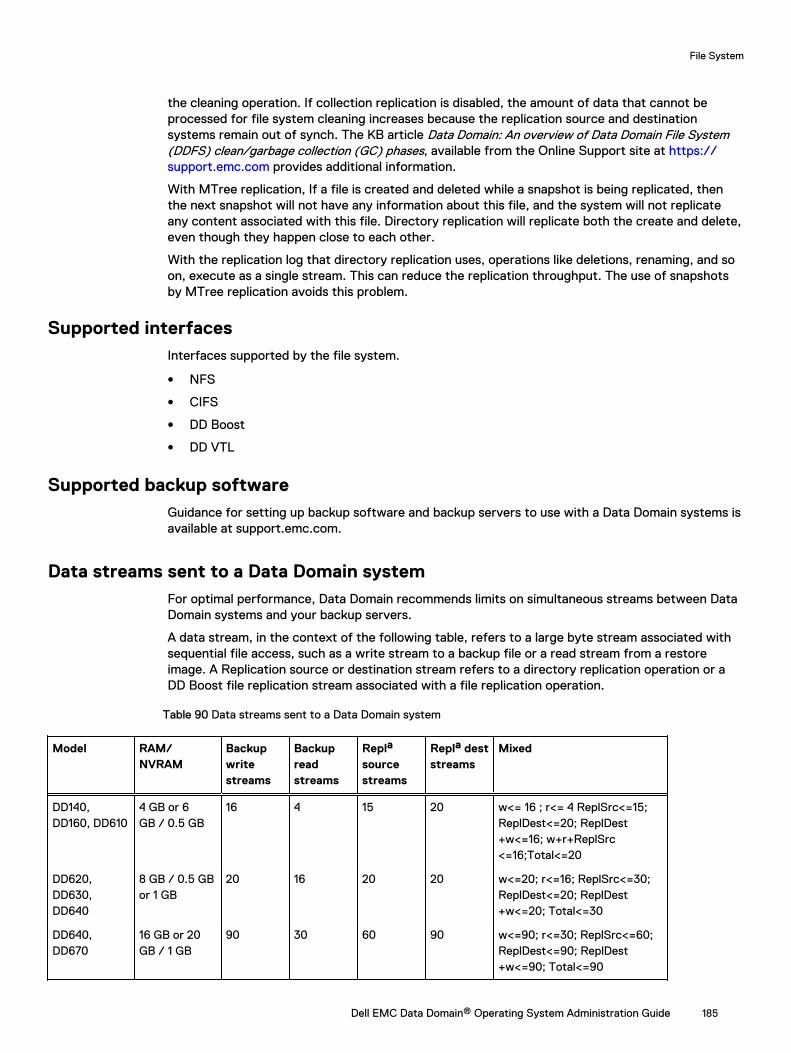
the cleaning operation. If collection replication is disabled, the amount of data that cannot beprocessed for file system cleaning increases because the replication source and destinationsystems remain out of synch. The KB article Data Domain: An overview of Data Domain File System(DDFS) clean/garbage collection (GC) phases, available from the Online Support site at https://support.emc.com provides additional information.
With MTree replication, If a file is created and deleted while a snapshot is being replicated, thenthe next snapshot will not have any information about this file, and the system will not replicateany content associated with this file. Directory replication will replicate both the create and delete,even though they happen close to each other.
With the replication log that directory replication uses, operations like deletions, renaming, and soon, execute as a single stream. This can reduce the replication throughput. The use of snapshotsby MTree replication avoids this problem.
Supported interfacesInterfaces supported by the file system.
l NFS
l CIFS
l DD Boost
l DD VTL
Supported backup softwareGuidance for setting up backup software and backup servers to use with a Data Domain systems isavailable at support.emc.com.
Data streams sent to a Data Domain systemFor optimal performance, Data Domain recommends limits on simultaneous streams between DataDomain systems and your backup servers.
A data stream, in the context of the following table, refers to a large byte stream associated withsequential file access, such as a write stream to a backup file or a read stream from a restoreimage. A Replication source or destination stream refers to a directory replication operation or aDD Boost file replication stream associated with a file replication operation.
Table 90 Data streams sent to a Data Domain system
Model RAM/NVRAM
Backupwritestreams
Backupreadstreams
Repla
sourcestreams
Repla deststreams
Mixed
DD140,DD160, DD610
4 GB or 6GB / 0.5 GB
16 4 15 20 w<= 16 ; r<= 4 ReplSrc<=15;ReplDest<=20; ReplDest+w<=16; w+r+ReplSrc<=16;Total<=20
DD620,DD630,DD640
8 GB / 0.5 GBor 1 GB
20 16 20 20 w<=20; r<=16; ReplSrc<=30;ReplDest<=20; ReplDest+w<=20; Total<=30
DD640,DD670
16 GB or 20GB / 1 GB
90 30 60 90 w<=90; r<=30; ReplSrc<=60;ReplDest<=90; ReplDest+w<=90; Total<=90
File System
Dell EMC Data Domain® Operating System Administration Guide 185
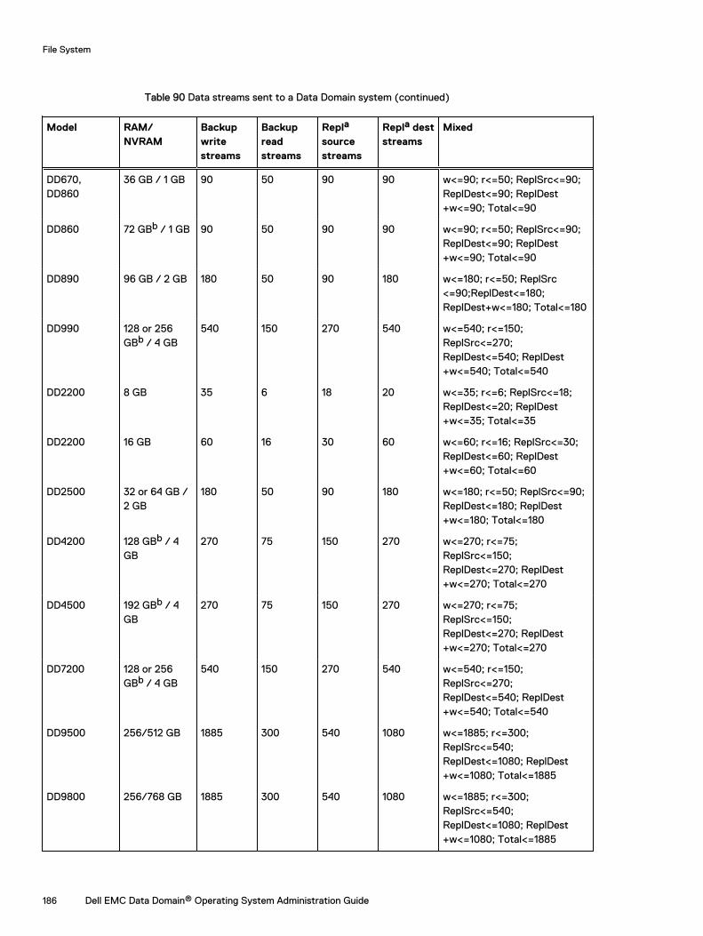
Table 90 Data streams sent to a Data Domain system (continued)
Model RAM/NVRAM
Backupwritestreams
Backupreadstreams
Repla
sourcestreams
Repla deststreams
Mixed
DD670,DD860
36 GB / 1 GB 90 50 90 90 w<=90; r<=50; ReplSrc<=90;ReplDest<=90; ReplDest+w<=90; Total<=90
DD860 72 GBb / 1 GB 90 50 90 90 w<=90; r<=50; ReplSrc<=90;ReplDest<=90; ReplDest+w<=90; Total<=90
DD890 96 GB / 2 GB 180 50 90 180 w<=180; r<=50; ReplSrc<=90;ReplDest<=180;ReplDest+w<=180; Total<=180
DD990 128 or 256GBb / 4 GB
540 150 270 540 w<=540; r<=150;ReplSrc<=270;ReplDest<=540; ReplDest+w<=540; Total<=540
DD2200 8 GB 35 6 18 20 w<=35; r<=6; ReplSrc<=18;ReplDest<=20; ReplDest+w<=35; Total<=35
DD2200 16 GB 60 16 30 60 w<=60; r<=16; ReplSrc<=30;ReplDest<=60; ReplDest+w<=60; Total<=60
DD2500 32 or 64 GB /2 GB
180 50 90 180 w<=180; r<=50; ReplSrc<=90;ReplDest<=180; ReplDest+w<=180; Total<=180
DD4200 128 GBb / 4GB
270 75 150 270 w<=270; r<=75;ReplSrc<=150;ReplDest<=270; ReplDest+w<=270; Total<=270
DD4500 192 GBb / 4GB
270 75 150 270 w<=270; r<=75;ReplSrc<=150;ReplDest<=270; ReplDest+w<=270; Total<=270
DD7200 128 or 256GBb / 4 GB
540 150 270 540 w<=540; r<=150;ReplSrc<=270;ReplDest<=540; ReplDest+w<=540; Total<=540
DD9500 256/512 GB 1885 300 540 1080 w<=1885; r<=300;ReplSrc<=540;ReplDest<=1080; ReplDest+w<=1080; Total<=1885
DD9800 256/768 GB 1885 300 540 1080 w<=1885; r<=300;ReplSrc<=540;ReplDest<=1080; ReplDest+w<=1080; Total<=1885
File System
186 Dell EMC Data Domain® Operating System Administration Guide

Table 90 Data streams sent to a Data Domain system (continued)
Model RAM/NVRAM
Backupwritestreams
Backupreadstreams
Repla
sourcestreams
Repla deststreams
Mixed
DD6300 48/96 GB 270 75 150 270 w<=270; r<=75;ReplSrc<=150;ReplDest<=270; ReplDest+w<=270; Total<=270
DD6800 192 GB 400 110 220 400 w<=400; r<=110;ReplSrc<=220;ReplDest<=400; ReplDest+w<=400; Total<=400
DD9300 192/384 GB 800 220 440 800 w<=800; r<=220;ReplSrc<=440;ReplDest<=800; ReplDest+w<=800; Total<=800
DD VE 8 TB 8 GB / 512MB
20 16 20 20 w<= 20 ; r<= 16 ReplSrc<=20;ReplDest<=20; ReplDest+w<=20; w+r+ReplSrc<=20;Total<=20
DD VE 16 TB 16 GB / 512MB or 24 GB /1 GB
45 30 45 45 w<= 45 ; r<= 30 ReplSrc<=45;ReplDest<=45; ReplDest+w<=45; w+r+ReplSrc<=45;Total<=45
DD VE 32 TB 24 GB / 1 GB 90 50 90 90 w<= 90 ; r<= 50 ReplSrc<=90;ReplDest<=90; ReplDest+w<=90; w+r+ReplSrc<=90;Total<=90
DD VE 48 TB 36 GB / 1 GB 90 50 90 90 w<= 90 ; r<= 50 ReplSrc<=90;ReplDest<=90; ReplDest+w<=90; w+r+ReplSrc<=90;Total<=90
DD VE 64 TB 48 GB / 1 GB 90 50 90 90 w<= 90 ; r<= 50 ReplSrc<=90;ReplDest<=90; ReplDest+w<=90; w+r+ReplSrc<=90;Total<=90
DD VE 96 TB 64 GB / 2 GB 180 50 90 180 w<= 180 ; r<= 50ReplSrc<=90; ReplDest<=180;ReplDest+w<=180; w+r+ReplSrc <=180;Total<=180
DD3300 4 TB 12 GB (virtualmemory) /512 MB
20 16 30 20 w<= 20 ; r<= 16 ReplSrc<=30;ReplDest<=20; ReplDest+w<=20; w+r+ReplSrc<=30;Total<=30
DD3300 8 TB 32 GB (virtualmemory) /1.536 GB
90 50 90 90 w<= 90 ; r<= 50 ReplSrc<=90;ReplDest<=90; ReplDest+w<=90; w+r+ReplSrc<=90;Total<=90
File System
Dell EMC Data Domain® Operating System Administration Guide 187
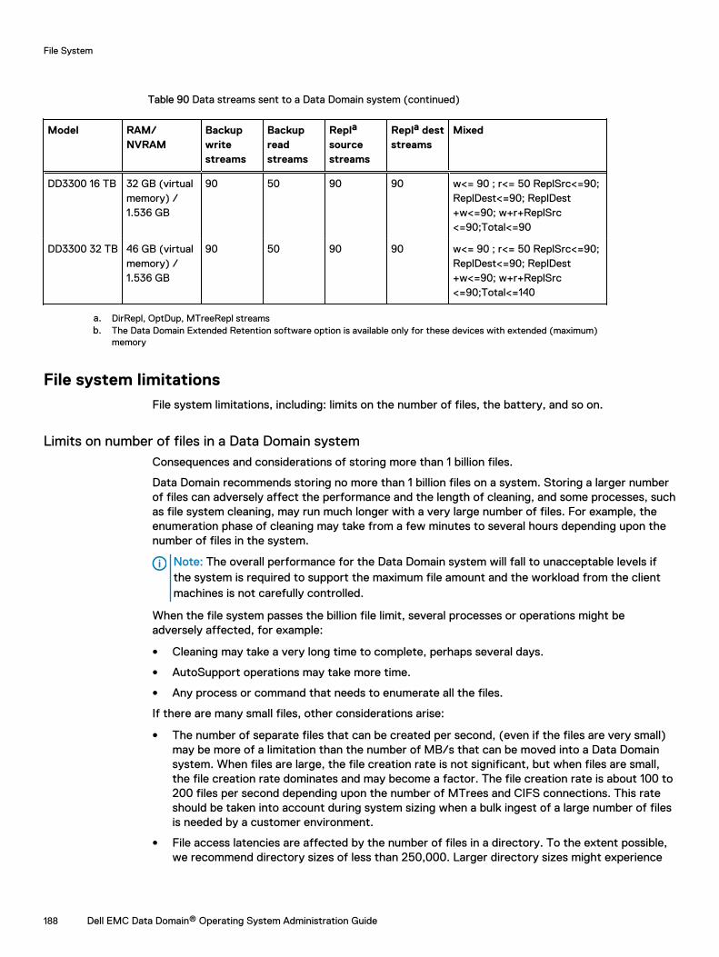
Table 90 Data streams sent to a Data Domain system (continued)
Model RAM/NVRAM
Backupwritestreams
Backupreadstreams
Repla
sourcestreams
Repla deststreams
Mixed
DD3300 16 TB 32 GB (virtualmemory) /1.536 GB
90 50 90 90 w<= 90 ; r<= 50 ReplSrc<=90;ReplDest<=90; ReplDest+w<=90; w+r+ReplSrc<=90;Total<=90
DD3300 32 TB 46 GB (virtualmemory) /1.536 GB
90 50 90 90 w<= 90 ; r<= 50 ReplSrc<=90;ReplDest<=90; ReplDest+w<=90; w+r+ReplSrc<=90;Total<=140
a. DirRepl, OptDup, MTreeRepl streamsb. The Data Domain Extended Retention software option is available only for these devices with extended (maximum)
memory
File system limitationsFile system limitations, including: limits on the number of files, the battery, and so on.
Limits on number of files in a Data Domain systemConsequences and considerations of storing more than 1 billion files.
Data Domain recommends storing no more than 1 billion files on a system. Storing a larger numberof files can adversely affect the performance and the length of cleaning, and some processes, suchas file system cleaning, may run much longer with a very large number of files. For example, theenumeration phase of cleaning may take from a few minutes to several hours depending upon thenumber of files in the system.
Note: The overall performance for the Data Domain system will fall to unacceptable levels ifthe system is required to support the maximum file amount and the workload from the clientmachines is not carefully controlled.
When the file system passes the billion file limit, several processes or operations might beadversely affected, for example:
l Cleaning may take a very long time to complete, perhaps several days.
l AutoSupport operations may take more time.
l Any process or command that needs to enumerate all the files.
If there are many small files, other considerations arise:
l The number of separate files that can be created per second, (even if the files are very small)may be more of a limitation than the number of MB/s that can be moved into a Data Domainsystem. When files are large, the file creation rate is not significant, but when files are small,the file creation rate dominates and may become a factor. The file creation rate is about 100 to200 files per second depending upon the number of MTrees and CIFS connections. This rateshould be taken into account during system sizing when a bulk ingest of a large number of filesis needed by a customer environment.
l File access latencies are affected by the number of files in a directory. To the extent possible,we recommend directory sizes of less than 250,000. Larger directory sizes might experience
File System
188 Dell EMC Data Domain® Operating System Administration Guide
slower responses to metadata operations such as listing the files in the directory and openingor creating a file.
Limits on the batteryFor systems that use NVRAM, the operating system creates a low battery alert if the batterycharge falls below 80% capacity, and the file system is disabled.
NOTICE The Data Domain DD2200 system does not use NVRAM so firmware calculationsdecide whether the battery charge is sufficient to save the data and disable the file system ifthere is a loss of AC power.
Maximum number of supported inodesAn NFS or CIFS client request causes a Data Domain system to report a capacity of about twobillion inodes (files and directories). A Data Domain system can exceed that number, but thereporting on the client may be incorrect.
Maximum path name lengthThe maximum length of a full path name (including the characters in /data/col1/backup) is 61characters. The maximum length of a symbolic link is also 61 characters.
Limited access during HA failoverAccess to files may be interrupted for up to 10 minutes during failover on High Availability systems.(DD Boost and NFS require additional time.)
Monitoring file system usageView real-time data storage statistics.
The File System view has tabs and controls that provide access to real-time data storagestatistics, cloud unit information, encryption information, and graphs of space usage amounts,consumption factors, and data written trends. There are also controls for managing file systemcleaning, expansion, copying, and destruction.
Accessing the file system viewThis section describes the file system functionality.
Procedure
l Select Data Management > File System.
About the File System Status panelDisplay the status of file system services.
To access the File System Status panel, click Data Management > File System > Show Status ofFile System Services.
File System
The File System field contains an Enable/Disable link and shows the working state of the filesystem:
l Enabled and running—and the latest consecutive length of time the file system has beenenabled and running.
l Disabled and shutdown.
File System
Dell EMC Data Domain® Operating System Administration Guide 189
l Enabling and disabling—in the process of becoming enabled or disabled.
l Destroyed—if the file system is deleted.
l Error—if there is an error condition, such as a problem initializing the file system.
Cloud File Recall
The Cloud File Recall field contains a Recall link to initiate a file recall from the Cloud Tier. ADetails link is available if any active recalls are underway. For more information, see the "Recallinga File from the Cloud Tier" topic.
Physical Capacity Measurement
The Physical Capacity Measurement field contains an Enable button when physical capacitymeasurement status is disabled. When enabled, the system displays Disable and View buttons.Click View to see currently running physical capacity measurements: MTree, priority, submit time,start time, and duration.
Data Movement
The Data Movement field contains Start/Stop buttons and shows the date the last datamovement operation finished, the number of files copied, and the amount of data copied. Thesystem displays a Start button when the data movement operation is available, and a Stop when adata movement operation is running.
Active Tier Cleaning
The Active Tier Cleaning field contains a Start/Stop button and shows the date the last cleaningoperation occurred, or the current cleaning status if the cleaning operation is currently running.For example:
Cleaning finished at 2009/01/13 06:00:43or, if the file system is disabled, shows:
UnavailableCloud Tier Cleaning
The Cloud Tier Cleaning field contains a Start/Stop button and shows the date the last cleaningoperation occurred, or the current cleaning status if the cleaning operation is currently running.For example:
Cleaning finished at 2009/01/13 06:00:43or, if the file system is disabled, shows:
Unavailable
About the Summary tabClick the Summary tab to show space usage statistics for the active and cloud tiers and to accesscontrols for viewing file system status, configuring file system settings, performing a Fast Copyoperation, expand capacity, and destroy the file system.
For each tier, space usage statistics include:
l Size—The amount of total physical disk space available for data.
l Used—the actual physical space used for compressed data. Warning messages go to thesystem log and an email alert is generated when the use reaches 90%, 95%, and 100%. At100%, the Data Domain system accepts no more data from backup servers.If the Used amount is always high, check the cleaning schedule to see how often the cleaningoperation runs automatically. Then use the modifying a cleaning schedule procedure to run the
File System
190 Dell EMC Data Domain® Operating System Administration Guide
operation more often. Also consider reducing the data retention period or splitting off a portionof the backup data to another Data Domain system.
l Available (GiB)—The total amount of space available for data storage. This figure can changebecause an internal index may expand as the Data Domain system fills with data. The indexexpansion takes space from the Avail GiB amount.
l Pre-Compression (GiB)—Data written before compression.
l Total Compression Factor (Reduction %)—Pre-Comp / Post-Comp.
l Cleanable (GiB)—The amount of space that could be reclaimed if a cleaning were run.
For Cloud Tier, the Cloud File Recall field contains a Recall link to initiate a file recall from theCloud Tier. A Details link is available if any active recalls are underway. For more information, seethe "Recalling a File from the Cloud Tier" topic.
Separate panels provide the following statistics for the last 24 hours for each tier:
l Pre-Compression (GiB)—Data written before compression.
l Post-Compression (GiB)—Storage used after compression.
l Global Compression Factor—(Pre-Compression / (Size after global compression).
l Local Compression Factor—(Size after global compression) / Post-Compression).
l Total Compression Factor (Reduction %)—[(Pre-Comp - Post-Comp) / Pre-Comp] * 100.
About file system settings
Display and change system options as well as the current cleaning schedule.
To access the File System Settings dialog, click Data Management > File System > Settings.
Table 91 General settings
General settings Description
Local Compression Type The type of local compression in use.
l See the section regarding types of compression for anoverview.
l See the section regarding changing local compression
Cloud Tier Local Comp The type of compression in use for the cloud tier.
l See the section regarding types of compression for anoverview.
l See the section regarding changing local compression
Report Replica as Writable How applications see a replica.
l See the section regarding changing read-only settings
Staging Reserve Manage disk staging.
l See the section regarding working with disk staging
l See the section regarding configuring disk staging
Marker Type Backup software markers (tape markers, tag headers, or othernames are used) in data streams. See the section regardingtape marker settings
Throttle See the section regarding setting the physical capacitymeasurement throttle.
File System
Dell EMC Data Domain® Operating System Administration Guide 191
Table 91 General settings (continued)
General settings Description
Cache Physical Capacity Cache initialization cleans up the caches andenhances the measuring speed.
You can adjust the workload balance of the file system to increase performance based on yourusage.
Table 92 Workload Balance settings
Workload Balance settings Description
Random workloads (%) Instant access and restores perform better using randomworkloads.
Sequential workloads (%) Traditional backups and restores perform better with sequentialworkloads.
Table 93 Data Movement settings
Data movement policysettings
Description
File Age Threshold When data movement starts, all files that have not beenmodified for the specified threshold number of days will bemoved from the active to the retention tier.
Schedule Days and times data is moved.
Throttle The percentage of available resources the system uses for datamovement. A throttle value of 100% is the default throttle andmeans that data movement will not be throttled.
Table 94 Cleaning settings
Cleaning schedule settings Description
Time The date time cleaning operations run.
l See the section regarding modifying a cleaning schedule
Throttle The system resources allocation.
l See the section regarding throttling the cleaning operation
About the Cloud Units tabDisplay summary information for cloud units, add and modify cloud units, and manage certificates.
The Cloud Units tab on the File System page is shown only when the optional DD Cloud Tier licenseis enabled. This view lists summary information (status, network bandwidth, read access, localcompression, data movement and data status) the name of the cloud provider, the used capacity,and the licensed capacity. Controls are provided for editing the cloud unit, managing certificates,and adding a new cloud unit.
File System
192 Dell EMC Data Domain® Operating System Administration Guide
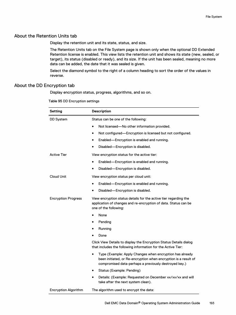
About the Retention Units tabDisplay the retention unit and its state, status, and size.
The Retention Units tab on the File System page is shown only when the optional DD ExtendedRetention license is enabled. This view lists the retention unit and shows its state (new, sealed, ortarget), its status (disabled or ready), and its size. If the unit has been sealed, meaning no moredata can be added, the date that it was sealed is given.
Select the diamond symbol to the right of a column heading to sort the order of the values inreverse.
About the DD Encryption tabDisplay encryption status, progress, algorithms, and so on.
Table 95 DD Encryption settings
Setting Description
DD System Status can be one of the following:
l Not licensed—No other information provided.
l Not configured—Encryption is licensed but not configured.
l Enabled—Encryption is enabled and running.
l Disabled—Encryption is disabled.
Active Tier View encryption status for the active tier:
l Enabled—Encryption is enabled and running.
l Disabled—Encryption is disabled.
Cloud Unit View encryption status per cloud unit:
l Enabled—Encryption is enabled and running.
l Disabled—Encryption is disabled.
Encryption Progress View encryption status details for the active tier regarding theapplication of changes and re-encryption of data. Status can beone of the following:
l None
l Pending
l Running
l Done
Click View Details to display the Encryption Status Details dialogthat includes the following information for the Active Tier:
l Type (Example: Apply Changes when encryption has alreadybeen initiated, or Re-encryption when encryption is a result ofcompromised data-perhaps a previously destroyed key.)
l Status (Example: Pending)
l Details: (Example: Requested on December xx/xx/xx and willtake after the next system clean).
Encryption Algorithm The algorithm used to encrypt the data:
File System
Dell EMC Data Domain® Operating System Administration Guide 193
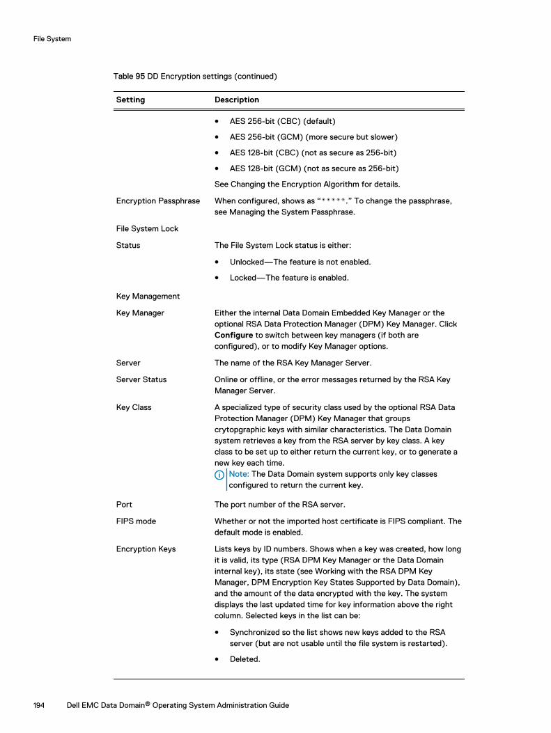
Table 95 DD Encryption settings (continued)
Setting Description
l AES 256-bit (CBC) (default)
l AES 256-bit (GCM) (more secure but slower)
l AES 128-bit (CBC) (not as secure as 256-bit)
l AES 128-bit (GCM) (not as secure as 256-bit)
See Changing the Encryption Algorithm for details.
Encryption Passphrase When configured, shows as “*****.” To change the passphrase,see Managing the System Passphrase.
File System Lock
Status The File System Lock status is either:
l Unlocked—The feature is not enabled.
l Locked—The feature is enabled.
Key Management
Key Manager Either the internal Data Domain Embedded Key Manager or theoptional RSA Data Protection Manager (DPM) Key Manager. ClickConfigure to switch between key managers (if both areconfigured), or to modify Key Manager options.
Server The name of the RSA Key Manager Server.
Server Status Online or offline, or the error messages returned by the RSA KeyManager Server.
Key Class A specialized type of security class used by the optional RSA DataProtection Manager (DPM) Key Manager that groupscrytopgraphic keys with similar characteristics. The Data Domainsystem retrieves a key from the RSA server by key class. A keyclass to be set up to either return the current key, or to generate anew key each time.
Note: The Data Domain system supports only key classesconfigured to return the current key.
Port The port number of the RSA server.
FIPS mode Whether or not the imported host certificate is FIPS compliant. Thedefault mode is enabled.
Encryption Keys Lists keys by ID numbers. Shows when a key was created, how longit is valid, its type (RSA DPM Key Manager or the Data Domaininternal key), its state (see Working with the RSA DPM KeyManager, DPM Encryption Key States Supported by Data Domain),and the amount of the data encrypted with the key. The systemdisplays the last updated time for key information above the rightcolumn. Selected keys in the list can be:
l Synchronized so the list shows new keys added to the RSAserver (but are not usable until the file system is restarted).
l Deleted.
File System
194 Dell EMC Data Domain® Operating System Administration Guide
Table 95 DD Encryption settings (continued)
Setting Description
l Destroyed.
About the space usage view (file system)Display a visual (but static) representation of data use for the file system at certain points in time.
Click Data Management > File System > Charts. Select Space Usage from the Chart drop-downlist.
Click a point on a graph line to display data at that point. The lines of the graph denotemeasurements for:
l Pre-comp Written—The total amount of data sent to the MTree by backup servers. Pre-compressed data on an MTree is what a backup server sees as the total uncompressed dataheld by an MTree-as-storage-unit, shown with the Space Used (left) vertical axis of the graph.
l Post-comp Used—The total amount of disk storage in use on the MTree, shown with theSpace Used (left) vertical axis of the graph.
l Comp Factor—The amount of compression the Data Domain system has performed with thedata it received (compression ratio), shown with the Compression Factor (right) vertical axisof the graph.
Checking Historical Space Usage
On the Space Usage graph, clicking a Date Range (that is, 1w, 1m, 3m,1y, or All) above the graphlets you change the number of days of data shown on the graph, from one week to all.
About the consumption viewDisplay space used over time, in relation to total system capacity.
Click Data Management > File System > Charts. Select Consumption from the Chart drop-downlist.
Click a point on a graph line to display data at that point. The lines of the graph denotemeasurements for:
l Capacity—The total amount of disk storage available for data on the Data Domain system. Theamount is shown with the Space Used (left) vertical axis of the graph. Clicking the Capacitycheckbox toggles this line on and off.
l Post-comp—The total amount of disk storage in use on the Data Domain system. Shown withthe Space Used (left) vertical axis of the graph.
l Comp Factor—The amount of compression the Data Domain system has performed with thedata it received (compression ratio). Shown with the Compression Factor (right) vertical axisof the graph.
l Cleaning—A grey diamond is displayed on the chart each time a file system cleaning operationwas started.
l Data Movement—The amount of disk space moved to the archiving storage area (if theArchive license is enabled).
Checking Historical Consumption Usage
On the Consumption graph, clicking a Date Range (that is, 1w, 1m, 3m,1y, or All) above the graphlets you change the number of days of data shown on the graph, from one week to all.
File System
Dell EMC Data Domain® Operating System Administration Guide 195
About the daily written view (file system)Display the flow of data over time. The data amounts are shown over time for pre- and post-compression amounts.
Click Data Management > File System > Charts. Select Daily Written from the Chart drop-downlist.
Click a point on a graph line to display a box with data at that point. The lines on the graph denotemeasurements for:
l Pre-Comp Written—The total amount of data written to the file system by backup servers.Pre-compressed data on the file system is what a backup server sees as the totaluncompressed data held by the file system.
l Post-Comp Written—The total amount of data written to the file system after compressionhas been performed, as shown in GiBs.
l Total Comp Factor—The total amount of compression the Data Domain system has performedwith the data it received (compression ratio), shown with the Total Compression Factor (right)vertical axis of the graph.
Checking Historical Written Data
On the Daily Written graph, clicking a Date Range (that is, 1w, 1m, 3m,1y, or All) above the graphlets you change the number of days of data shown on the graph, from one week to all.
When the file system is full or nearly fullData Domain systems have three progressive levels of being full. As each level is reached, moreoperations are progressively disallowed. At each level, deleting data and then performing a filesystem cleaning operation makes disk space available.
Note: The process of deleting files and removing snapshots does not immediately reclaim diskspace, the next cleaning operation reclaims the space.
l Level 1—At the first level of fullness, no more new data can be written to the file system. Aninformative out of space alert is generated.Remedy—Delete unneeded datasets, reduce the retention period, delete snapshots, andperform a file system cleaning operation.
l Level 2—At the second level of fullness, files cannot be deleted. This is because deleting filesalso require free space but the system has so little free space available that it cannot evendelete files.Remedy—Expire snapshots and perform a file system cleaning operation.
l Level 3—At the third and final level of fullness, attempts to expire snapshots, delete files, orwrite new data fail.Remedy—Perform a file system cleaning operation to free enough space to at least deletesome files or expire some snapshots and then rerun cleaning.
Monitor the space usage with email alertsAlerts are generated when the file system is at 90%, 95%, and 100% full. To send these alerts, addthe user to the alert emailing list.
Note: To join the alert email list, see Viewing and Clearing Alerts.
Managing file system operationsThis section describes file system cleaning, sanitization, and performing basic operations.
File System
196 Dell EMC Data Domain® Operating System Administration Guide

Performing basic operationsBasic file system operations include enabling and disabling the file system, and in the rareoccasion, destroying a file system.
Creating the file systemCreate a file system from the Data Management > File System page using the Summary tab.
About this task
There are three reasons to create a file system:
l For a new Data Domain system.
l When a system is started after a clean installation.
l After a file system has been destroyed.
To create the file system:
Procedure
1. Verify that storage has been installed and configured (see the section on viewing systemstorage information for more information). If the system does not meet this prerequisite, awarning message is displayed. Install and configure the storage before attempting to createthe file system.
2. Select Data Management > File System > Summary > Create.
The File System Create Wizard is launched. Follow the instructions provided.
Enabling or disabling the file systemThe option to enable or disable the file system is dependent on the current state of the file system—if its enabled, you can disable it and vice versa.
About this task
l Enabling the file system allows Data Domain system operations to begin. This ability is availableto administrative users only.
l Disabling the file system halts all Data Domain system operations, including cleaning. Thisability is available to administrative users only.
CAUTION Disabling the file system when a backup application is sending data to the systemcan cause the backup process to fail. Some backup software applications are able to recoverby restarting where they left off when they are able to successfully resume copying files;others might fail, leaving the user with an incomplete backup.
Procedure
1. Select Data Managment > File System > Summary.
2. For File System, click Enable or Disable.
3. On the confirmation dialog, click Close.
Expanding the file systemYou might need to expand the size of a file system if the suggestions given in "When the FileSystem Is Full or Nearly Full" do not clear enough space for normal operations.
About this task
A file system may not be expandable, however, for these reasons:
File System
Dell EMC Data Domain® Operating System Administration Guide 197
l The file system is not enabled.
l There are no unused disks or enclosures in the Active, Retention, or Cloud tiers.
l An expanded storage license is not installed.
l There are not enough capacity licenses installed.
DD6300 systems support the option to use ES30 enclosures with 4 TB drives ( 43.6 TiB) at 50%utilization (21.8 TiB) in the active tier if the available licensed capacity is exactly 21.8 TiB. Thefollowing guidelines apply to using partial capacity shelves.
l No other enclosure types or drive sizes are supported for use at partial capacity.
l A partial shelf can only exist in the Active tier.
l Only one partial ES30 can exist in the Active tier.
l Once a partial shelf exists in a tier, no additional ES30s can be configured in that tier until thepartial shelf is added at full capacity.
Note: This requires licensing enough additional capacity to use the remaining 21.8 TiB ofthe partial shelf.
l If the available capacity exceeds 21.8 TB, a partial shelf cannot be added.
l Deleting a 21 TiB license will not automatically convert a fully-used shelf to a partial shelf. Theshelf must be removed, and added back as a partial shelf.
To expand the file system:
Procedure
1. Select Data Managment > File System > Summary > Expand Capacity.
The Expand File System Capacity wizard is launched. The Storage Tier drop-down listalways contains Active Tier, and it may contain either Extended Retention Tier or Cloud Tieras a secondary choice. The wizard displays the current capacity of the file system for eachtier as well as how much additional storage space is available for expansion.
Note: File system capacity can be expanded only if the physical disks are installed on thesystem and file system is enabled.
2. From the Storage Tier drop-down list, select a tier.
3. In the Addable Storage area, select the storage devices to use and click Add to Tier.
4. Follow the instructions in the wizard. When the confirmation page is displayed, click Close.
Destroying the file systemDestroying the file system should be done only under the direction of Customer Support. Thisaction deletes all data in the file system, including virtual tapes. Deleted data is not recoverable.This operation also removes Replication configuration settings.
About this task
This operation is used when it is necessary to clean out existing data, to create a new collectionreplication destination, or to replace a collection source, or for security reasons because thesystem is being removed from operation.
CAUTION The optional Write zeros to disk operation writes zeros to all file system disks,effectively removing all traces of data. If the Data Domain system contains a large amount ofdata, this operation can take many hours, or a day, to complete.
Note: As this is a destructive procedure, this operation is available to administrative users only.
File System
198 Dell EMC Data Domain® Operating System Administration Guide
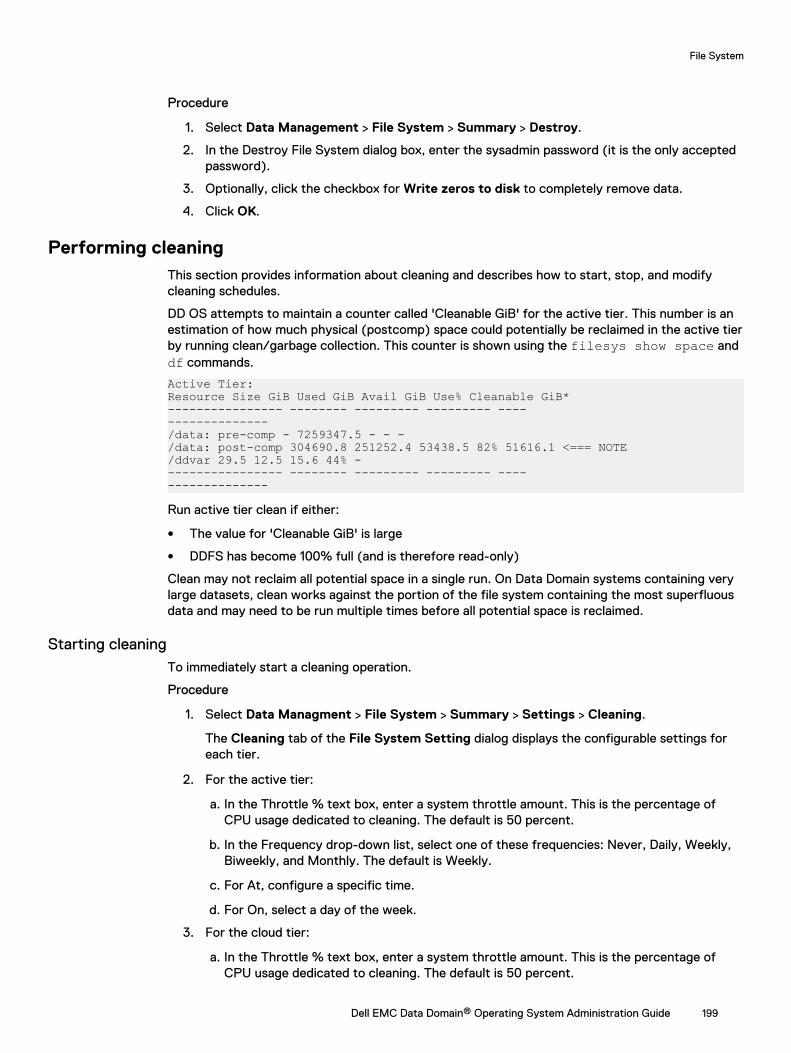
Procedure
1. Select Data Management > File System > Summary > Destroy.
2. In the Destroy File System dialog box, enter the sysadmin password (it is the only acceptedpassword).
3. Optionally, click the checkbox for Write zeros to disk to completely remove data.
4. Click OK.
Performing cleaningThis section provides information about cleaning and describes how to start, stop, and modifycleaning schedules.
DD OS attempts to maintain a counter called 'Cleanable GiB' for the active tier. This number is anestimation of how much physical (postcomp) space could potentially be reclaimed in the active tierby running clean/garbage collection. This counter is shown using the filesys show space anddf commands.
Active Tier:Resource Size GiB Used GiB Avail GiB Use% Cleanable GiB*---------------- -------- --------- --------- ------------------/data: pre-comp - 7259347.5 - - -/data: post-comp 304690.8 251252.4 53438.5 82% 51616.1 <=== NOTE/ddvar 29.5 12.5 15.6 44% ----------------- -------- --------- --------- ------------------
Run active tier clean if either:
l The value for 'Cleanable GiB' is large
l DDFS has become 100% full (and is therefore read-only)
Clean may not reclaim all potential space in a single run. On Data Domain systems containing verylarge datasets, clean works against the portion of the file system containing the most superfluousdata and may need to be run multiple times before all potential space is reclaimed.
Starting cleaningTo immediately start a cleaning operation.
Procedure
1. Select Data Managment > File System > Summary > Settings > Cleaning.
The Cleaning tab of the File System Setting dialog displays the configurable settings foreach tier.
2. For the active tier:
a. In the Throttle % text box, enter a system throttle amount. This is the percentage ofCPU usage dedicated to cleaning. The default is 50 percent.
b. In the Frequency drop-down list, select one of these frequencies: Never, Daily, Weekly,Biweekly, and Monthly. The default is Weekly.
c. For At, configure a specific time.
d. For On, select a day of the week.
3. For the cloud tier:
a. In the Throttle % text box, enter a system throttle amount. This is the percentage ofCPU usage dedicated to cleaning. The default is 50 percent.
File System
Dell EMC Data Domain® Operating System Administration Guide 199
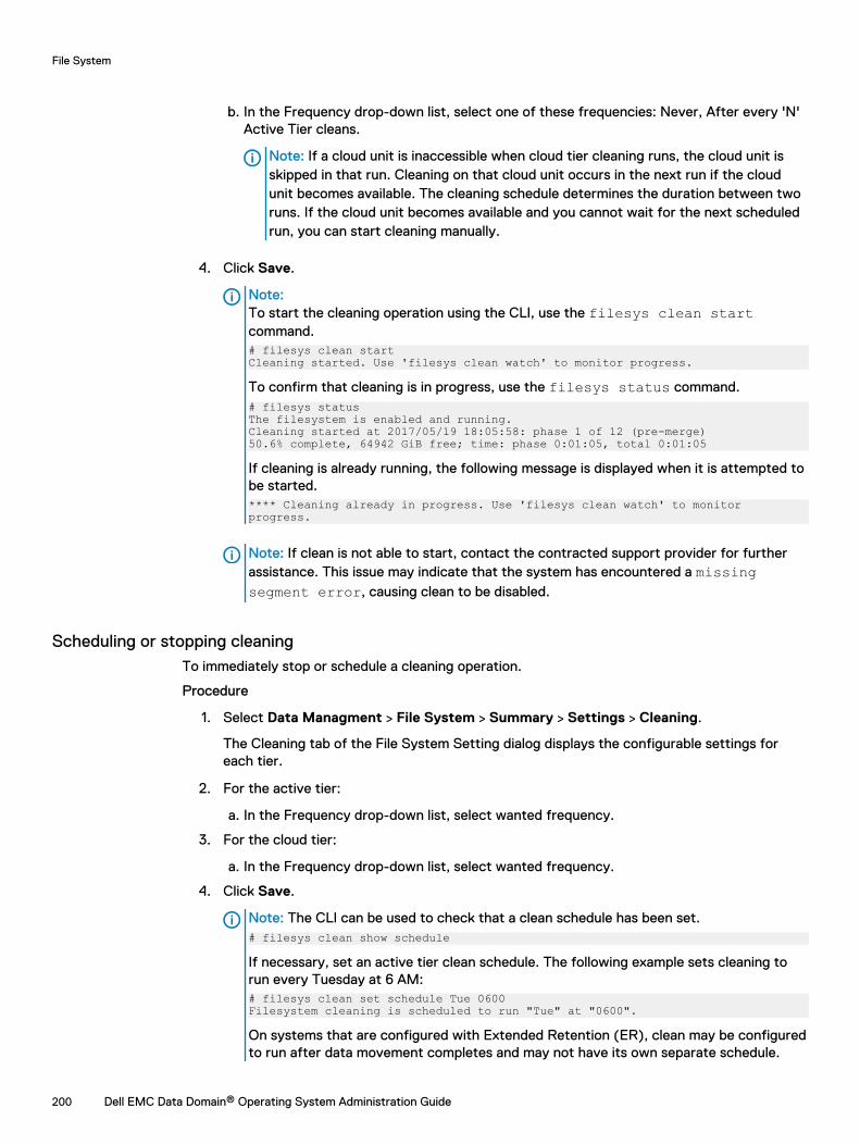
b. In the Frequency drop-down list, select one of these frequencies: Never, After every 'N'Active Tier cleans.
Note: If a cloud unit is inaccessible when cloud tier cleaning runs, the cloud unit isskipped in that run. Cleaning on that cloud unit occurs in the next run if the cloudunit becomes available. The cleaning schedule determines the duration between tworuns. If the cloud unit becomes available and you cannot wait for the next scheduledrun, you can start cleaning manually.
4. Click Save.
Note:To start the cleaning operation using the CLI, use the filesys clean startcommand.# filesys clean startCleaning started. Use 'filesys clean watch' to monitor progress.
To confirm that cleaning is in progress, use the filesys status command.# filesys statusThe filesystem is enabled and running.Cleaning started at 2017/05/19 18:05:58: phase 1 of 12 (pre-merge)50.6% complete, 64942 GiB free; time: phase 0:01:05, total 0:01:05
If cleaning is already running, the following message is displayed when it is attempted tobe started.**** Cleaning already in progress. Use 'filesys clean watch' to monitor progress.
Note: If clean is not able to start, contact the contracted support provider for furtherassistance. This issue may indicate that the system has encountered a missingsegment error, causing clean to be disabled.
Scheduling or stopping cleaningTo immediately stop or schedule a cleaning operation.
Procedure
1. Select Data Managment > File System > Summary > Settings > Cleaning.
The Cleaning tab of the File System Setting dialog displays the configurable settings foreach tier.
2. For the active tier:
a. In the Frequency drop-down list, select wanted frequency.
3. For the cloud tier:
a. In the Frequency drop-down list, select wanted frequency.
4. Click Save.
Note: The CLI can be used to check that a clean schedule has been set.# filesys clean show schedule
If necessary, set an active tier clean schedule. The following example sets cleaning torun every Tuesday at 6 AM:# filesys clean set schedule Tue 0600Filesystem cleaning is scheduled to run "Tue" at "0600".
On systems that are configured with Extended Retention (ER), clean may be configuredto run after data movement completes and may not have its own separate schedule.
File System
200 Dell EMC Data Domain® Operating System Administration Guide
Performing sanitizationTo comply with government guidelines, system sanitization, also called data shredding, must beperformed when classified or sensitive data is written to any system that is not approved to storesuch data.
When an incident occurs, the system administrator must take immediate action to thoroughlyeradicate the data that was accidentally written. The goal is to effectively restore the storagedevice to a state as if the event never occurred. If the data leakage is with sensitive data, theentire storage will need to be sanitized using Data Domain Professional Services' Secure Dataerasure practice.
The Data Domain sanitization command exists to enable the administrator to delete files at thelogical level, whether a backup set or individual files. Deleting a file in most file systems consists ofjust flagging the file or deleting references to the data on disk, freeing up the physical space to beconsumed at a later time. However, this simple action introduces the problem of leaving behind aresidual representation of underlying data physically on disks. Deduplicated storage environmentsare not immune to this problem.
Shredding data in a system implies eliminating the residual representation of that data and thus thepossibility that the file may be accessible after it has been shredded. Data Domain's sanitizationapproach ensures is compliant with the 2007 versions of Department of Defense (DoD) 5220.22 ofthe following specifications:
l US Department of Defense 5220.22-M Clearing and Sanitization Matrix
l National Institute of Systems and Technology (NIST) Special Publication 800-88 Guidelines forMedia Sanitization
Sanitizing deduplicated dataData Domain systems sanitize data in place, in its native deduplicated state.
Deduplication storage systems extract common data patterns from files sent to the system andstore only unique copies of these patterns, referencing all the redundant instances. Because thesedata patterns or segments may potentially be shared among many files in the system, thesanitization process must first determine whether each of the segments of the contaminated fileare shared with a clean file and then erase only those segments that are not shared, along with anycontaminated metadata.
All storage tiers, caches, unused capacity, and free space are cleared so that every copy of everysegment that belongs exclusively to the deleted files is eradicated. The system reclaims andoverwrites all of the storage occupied by these segments to effectively restore the storage deviceto a state as if the contaminated files never existed in that system.
Sanitization level 1: data clearing or shreddingIf the data you need to remove is unclassified, as defined in the "US Department of Defense5220.22-M Clearing and Sanitization Matrix," Level 1 sanitization can be used to overwrite theaffected storage once. This provides the basis for handling most data shredding and systemsanitization cases.
About this task
The Data Domain system sanitization feature ensures that every copy of every segment thatbelongs only to erased files is overwritten using a single-pass zerotization mechanism. Clean datain the system being sanitized is online and available to users.
Procedure
1. Delete the contaminated files or backups through the backup software or correspondingclient. In the case of backups, be sure to manage the backup software appropriately to
File System
Dell EMC Data Domain® Operating System Administration Guide 201

ensure that related files on that image are reconciled, catalog records are managed asrequired, and so forth.
2. Run the system sanitize start command on the contaminated Data Domain systemto cause all previously used space in it to be overwritten once (see the figure below).
3. Wait for the affected system to be sanitized. Sanitization can be monitored by using thesystem sanitize watch command.
If the affected Data Domain system has replication enabled, all the systems containingreplicas need to be processed in a similar manner. Depending on how much data exists in thesystem and how it is distributed, the system sanitize command could take some time.However, during this time, all clean data in the system is available to users.
Sanitization level 2: full system sanitizationIf the data you need to remove is classified, as defined in the "US Department of Defense5220.22-M Clearing and Sanitization Matrix," Level 2 sanitization, or full system sanitization, isnow required.
About this task
Data Domain recommends Blancco for multi-pass overwrites with any overwrite pattern and acertificate. This provides the basis for handling universal Department of Defense requirementswhere complete system sanitization is required. For more information, go to:
https://www.emc.com/auth/rcoll/servicekitdocument/cp_datadomaindataerase_psbasddde.pdf
Modifying basic settingsChange the type of compression used, marker types, Replica write status, and Staging Reservepercentage, as described in this section.
Changing local compressionUse the General tab of the File System Settings dialog to configure the local compression type.
About this task
Note: Do not change the type of local compression unless it is necessary.
Procedure
1. Select Data Managment > File System > Summary > Settings > General.
2. From the Local Compression Type drop-down list, select a compression type.
Table 96 Compression type
Option Description
NONE Do not compress data.
LZ The default algorithm that gives the best throughput. Data Domainrecommends the lz option.
GZFAST A zip-style compression that uses less space for compressed data, but moreCPU cycles (twice as much as lz). Gzfast is the recommended alternativefor sites that want more compression at the cost of lower performance.
GZ A zip-style compression that uses the least amount of space for datastorage (10% to 20% less than lz on average; however, some datasets get
File System
202 Dell EMC Data Domain® Operating System Administration Guide
Table 96 Compression type (continued)
Option Description
much higher compression). This also uses the most CPU cycles (up to fivetimes as much as lz). The gz compression type is commonly used fornearline storage applications in which performance requirements are low.
3. Click Save.
Changing read-only settingsChange the replica to writable. Some backup applications must see the replica as writable to do arestore or vault operation from the replica.
Procedure
1. Select Data Managment > File System > Summary > Settings > General.
2. In the Report Replica as Writable area, toggle between Disabled and Enabled asappropriate.
3. Click Save.
Working with disk stagingDisk staging enables a Data Domain system to serve as a staging device, where the system isviewed as a basic disk via a CIFS share or NFS mount point.
Disk staging can be used in conjunction with your backup software, such as NetWorker andSymantec’s NetBackup (NBU), it does not require a license, and is disabled by default.
Note: The DD VTL feature is not required or supported when the Data Domain system is usedas a Disk Staging device.
The reason that some backup applications use disk staging devices is to enable tape drives tostream continuously. After the data is copied to tape, it is retained on disk for as long as space isavailable. Should a restore be needed from a recent backup, more than likely the data is still on diskand can be restored from it more conveniently than from tape. When the disk fills up, old backupscan be deleted to make space. This delete-on-demand policy maximizes the use of the disk.
In normal operation, the Data Domain System does not reclaim space from deleted files until acleaning operation is done. This is not compatible with backup software that operates in a stagingmode, which expects space to be reclaimed when files are deleted. When you configure diskstaging, you reserve a percentage of the total space—typically 20 to 30 percent—in order toallow the system to simulate the immediate freeing of space.
The amount of available space is reduced by the amount of the staging reserve. When the amountof data stored uses all of the available space, the system is full. However, whenever a file isdeleted, the system estimates the amount of space that will be recovered by cleaning and borrowsfrom the staging reserve to increase the available space by that amount. When a cleaningoperation runs, the space is actually recovered and the reserve restored to its initial size. Since theamount of space made available by deleting files is only an estimate, the actual space reclaimed bycleaning may not match the estimate. The goal of disk staging is to configure enough reserve sothat you do not run out before cleaning is scheduled to run.
Configuring disk stagingEnable disk staging and specify the staging reserve percentage.
Procedure
1. Select Data Managment > File System > Summary > Settings > General.
File System
Dell EMC Data Domain® Operating System Administration Guide 203
2. In the Staging Reserve area, toggle between Disabled and Enabled as appropriate.
3. If Staging Reserve is enabled, enter a value in the % of Total Space box.
This value represents the percentage of the total disk space to be reserved for disk staging,typically 20 to 30%.
4. Click Save.
Tape marker settingsBackup software from some vendors insert markers (tape markers, tag headers, or other namesare used) in all data streams (both file system and DD VTL backups) sent to a Data Domainsystem.
Markers can significantly degrade data compression on a Data Domain system. As such, thedefault marker type auto is set and cannot be changed by the user. If this setting is not compatiblewith your backup software, contact your contracted support provider.
Note: For information about how applications work in a Data Domain environment, see HowEMC Data Domain Systems Integrate into the Storage Environment. You can use these matricesand integration guides to troubleshoot vendor-related issues.
SSD Random workload shareThe value for the threshold at which to cap random I/O on the Data Domain system can beadjusted from the default value to accommodate changing requirements and I/O patterns.
By default, the Data Domain system sets the SSD random workload share at 40%. This value canbe adjusted up or down as needed. Select Data Managment > File System > Summary >Settings > Workload Balance, and adjust the slider.
Click Save.
Fast copy operationsA fast copy operation clones files and directory trees of a source directory to a target directory ona Data Domain system.
The force option allows the destination directory to be overwritten if it exists. Executing the fastcopy operation displays a progress status dialog box.
Note: A fast copy operation makes the destination equal to the source, but not at a specifictime. There are no guarantees that the two are or were ever equal if you change either folderduring this operation.
Performing a fast copy operationCopy a file or directory tree from a Data Domain system source directory to another destination onthe Data Domain system.
Procedure
1. Select Data Managment > File System > Summary > Fast Copy.
The Fast Copy dialog is displayed.
2. In the Source text box, enter the pathname of the directory where the data to be copiedresides. For example, /data/col1/backup/.snapshot/snapshot-name/dir1.
Note: col1 uses a lower case L followed by the number 1.
File System
204 Dell EMC Data Domain® Operating System Administration Guide
3. In the Destination text box, enter the pathname of the directory where the data will becopied to. For example, /data/col1/backup/dir2. This destination directory must beempty, or the operation fails.
l If the Destination directory exists, click the checkbox Overwrite existing destination ifit exists.
4. Click OK.
5. In the progress dialog box that appears, click Close to exit.
File System
Dell EMC Data Domain® Operating System Administration Guide 205

File System
206 Dell EMC Data Domain® Operating System Administration Guide
CHAPTER 6
MTrees
This chapter includes:
l MTrees overview.................................................................................................................208l Monitoring MTree usage......................................................................................................215l Managing MTree operations................................................................................................ 219
Dell EMC Data Domain® Operating System Administration Guide 207

MTrees overviewAn MTree is a logical partition of the file system.
You can use MTrees in the following ways: for DD Boost storage units, DD VTL pools, or an NFS/CIFS share. MTrees allow granular management of snapshots, quotas, and DD Retention Lock. Forsystems that have DD Extended Retention and granular management of data migration policiesfrom Active Tier to Retention Tier, MTree operations can be performed on a specific MTree asopposed to the entire file system.
Note:There can be up to the maximum configurable MTrees designated for MTree replicationcontexts.
Do not place user files in the top-level directory of an MTree.
MTree limitsMTree limits for Data Domain systems
Table 97 Supported MTrees
Data Domain System DD OSVersion
Supportedconfigurable MTrees
Supported concurrentlyactive MTrees
DD9800 6.0 andlater
256 256
DD9500 5.7 and later 256 256
DD6800, DD9300 6.0 andlater
128 128
DD6300 6.0 andlater
100 32
DD990, DD4200,DD4500, DD7200
5.7 and later 128 128
All other DD systems 5.7 and later 100 Up to 32 based on the model
DD9500 5.6 100 64
DD990, DD890 5.3 andlater
100 Up to 32 based on the model
DD7200, DD4500,DD4200
5.4 andlater
100 Up to 32 based on the model
All other DD systems 5.2 andlater
100 Up to 14 based on the model
QuotasMTree quotas apply only to the logical data written to the MTree.
An administrator can set the storage space restriction for an MTree, Storage Unit, or DD VTL poolto prevent it from consuming excess space. There are two kinds of quota limits: hard limits andsoft limits. You can set either a soft or hard limit or both a soft and hard limit. Both values must beintegers, and the soft value must be less than the hard value.
MTrees
208 Dell EMC Data Domain® Operating System Administration Guide
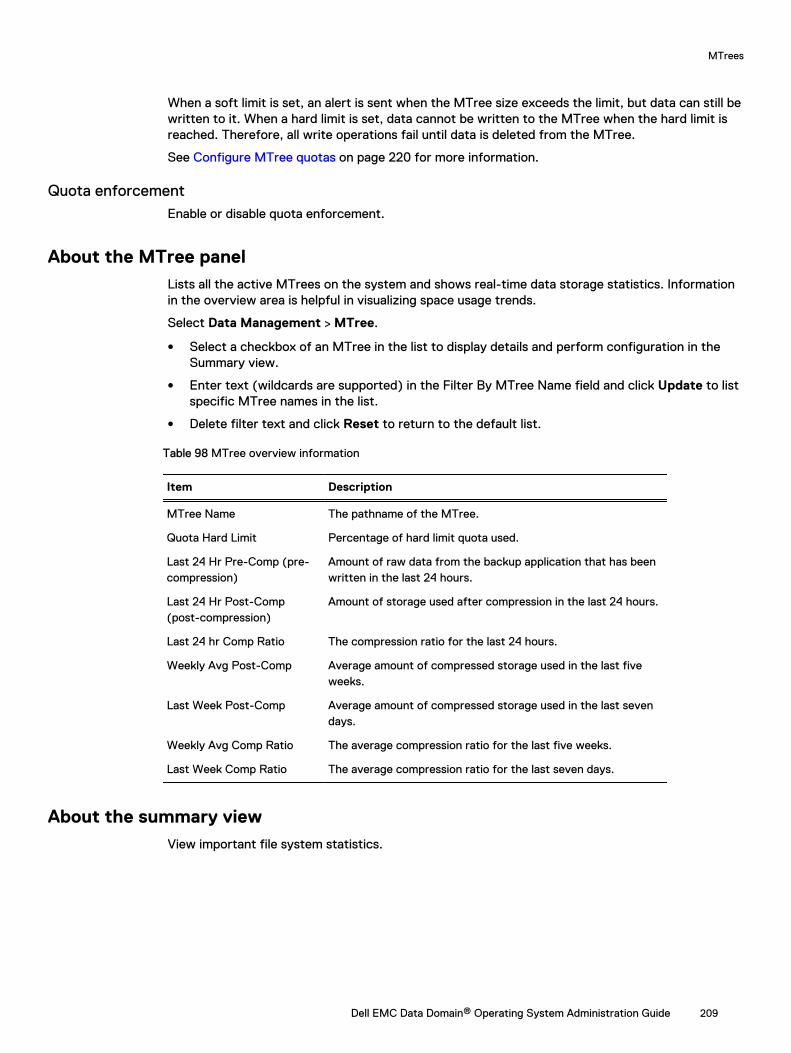
When a soft limit is set, an alert is sent when the MTree size exceeds the limit, but data can still bewritten to it. When a hard limit is set, data cannot be written to the MTree when the hard limit isreached. Therefore, all write operations fail until data is deleted from the MTree.
See Configure MTree quotas on page 220 for more information.
Quota enforcementEnable or disable quota enforcement.
About the MTree panelLists all the active MTrees on the system and shows real-time data storage statistics. Informationin the overview area is helpful in visualizing space usage trends.
Select Data Management > MTree.
l Select a checkbox of an MTree in the list to display details and perform configuration in theSummary view.
l Enter text (wildcards are supported) in the Filter By MTree Name field and click Update to listspecific MTree names in the list.
l Delete filter text and click Reset to return to the default list.
Table 98 MTree overview information
Item Description
MTree Name The pathname of the MTree.
Quota Hard Limit Percentage of hard limit quota used.
Last 24 Hr Pre-Comp (pre-compression)
Amount of raw data from the backup application that has beenwritten in the last 24 hours.
Last 24 Hr Post-Comp(post-compression)
Amount of storage used after compression in the last 24 hours.
Last 24 hr Comp Ratio The compression ratio for the last 24 hours.
Weekly Avg Post-Comp Average amount of compressed storage used in the last fiveweeks.
Last Week Post-Comp Average amount of compressed storage used in the last sevendays.
Weekly Avg Comp Ratio The average compression ratio for the last five weeks.
Last Week Comp Ratio The average compression ratio for the last seven days.
About the summary viewView important file system statistics.
MTrees
Dell EMC Data Domain® Operating System Administration Guide 209

View detail informationSelect an MTree to view information.
Table 99 MTree detail information for a selected MTree
Item Description
Full Path The pathname of the MTree.
Pre-Comp Used The current amount of raw data from the backup applicationthat has been written to the MTree.
Status The status of the MTree (combinations are supported). Statuscan be:
l D: Deleted
l RO: Read-only
l RW: Read/write
l RD: Replication destination
l RLCE: DD Retention Lock Compliance enabled
l RLCD: DD Retention Lock Compliance disabled
l RLGE: DD Retention Lock Governance enabled
l RLGD: DD Retention Lock Governance disabled
Quota
Quota Enforcement Enabled or Disabled.
Pre-Comp Soft Limit Current value. Click Configure to revise the quota limits.
Pre-Comp Hard Limit Current value. Click Configure to revise the quota limits.
Quota Summary Percentage of Hard Limit used.
Protocols
CIFS Shared The CIFS share status. Status can be:
l Yes—The MTree or its parent directory is shared.
l Partial—The subdirectory under this MTree is shared.
l No—This MTree and its parent or subdirectory are notshared.
Click the CIFS link to go to the CIFS view.
NFS Exported The NFS export status. Status can be:
l Yes—The MTree or its parent directory is exported.
l Partial—The subdirectory under this MTree is exported.
l No—This MTree and its parent or subdirectory are notexported.
Click the NFS link to go to the NFS view.
DD Boost Storage Unit The DD Boost export status. Status can be:
l Yes—The MTree is exported.
l No—This MTree is not exported.
MTrees
210 Dell EMC Data Domain® Operating System Administration Guide
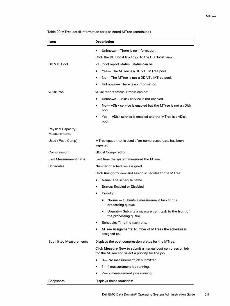
Table 99 MTree detail information for a selected MTree (continued)
Item Description
l Unknown—There is no information.
Click the DD Boost link to go to the DD Boost view.
DD VTL Pool VTL pool report status. Status can be:
l Yes— The MTree is a DD VTL MTree pool.
l No— The MTree is not a DD VTL MTree pool.
l Unknown— There is no information.
vDisk Pool vDisk report status. Status can be:
l Unknown— vDisk service is not enabled.
l No— vDisk service is enabled but the MTree is not a vDiskpool.
l Yes— vDisk service is enabled and the MTree is a vDiskpool.
Physical CapacityMeasurements
Used (Post-Comp) MTree space that is used after compressed data has beeningested.
Compression Global Comp-factor.
Last Measurement Time Last time the system measured the MTree.
Schedules Number of schedules assigned.
Click Assign to view and assign schedules to the MTree.
l Name: The schedule name.
l Status: Enabled or Disabled
l Priority:
n Normal— Submits a measurement task to theprocessing queue.
n Urgent— Submits a measurement task to the front ofthe processing queue.
l Schedule: Time the task runs.
l MTree Assignments: Number of MTrees the schedule isassigned to.
Submitted Measurements Displays the post compression status for the MTree.
Click Measure Now to submit a manual post compression jobfor the MTree and select a priority for the job.
l 0— No measurement job submitted.
l 1— 1 measurement job running.
l 2— 2 measurement jobs running.
Snapshots Displays these statistics:
MTrees
Dell EMC Data Domain® Operating System Administration Guide 211
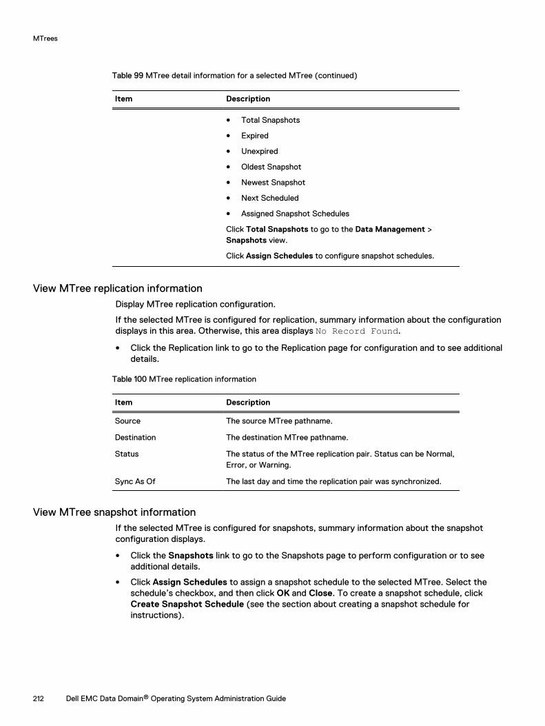
Table 99 MTree detail information for a selected MTree (continued)
Item Description
l Total Snapshots
l Expired
l Unexpired
l Oldest Snapshot
l Newest Snapshot
l Next Scheduled
l Assigned Snapshot Schedules
Click Total Snapshots to go to the Data Management >Snapshots view.
Click Assign Schedules to configure snapshot schedules.
View MTree replication informationDisplay MTree replication configuration.
If the selected MTree is configured for replication, summary information about the configurationdisplays in this area. Otherwise, this area displays No Record Found.
l Click the Replication link to go to the Replication page for configuration and to see additionaldetails.
Table 100 MTree replication information
Item Description
Source The source MTree pathname.
Destination The destination MTree pathname.
Status The status of the MTree replication pair. Status can be Normal,Error, or Warning.
Sync As Of The last day and time the replication pair was synchronized.
View MTree snapshot informationIf the selected MTree is configured for snapshots, summary information about the snapshotconfiguration displays.
l Click the Snapshots link to go to the Snapshots page to perform configuration or to seeadditional details.
l Click Assign Schedules to assign a snapshot schedule to the selected MTree. Select theschedule’s checkbox, and then click OK and Close. To create a snapshot schedule, clickCreate Snapshot Schedule (see the section about creating a snapshot schedule forinstructions).
MTrees
212 Dell EMC Data Domain® Operating System Administration Guide
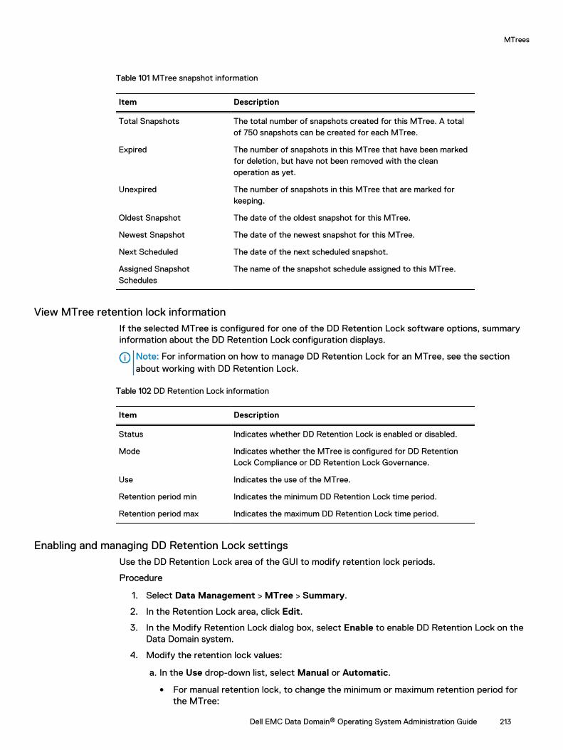
Table 101 MTree snapshot information
Item Description
Total Snapshots The total number of snapshots created for this MTree. A totalof 750 snapshots can be created for each MTree.
Expired The number of snapshots in this MTree that have been markedfor deletion, but have not been removed with the cleanoperation as yet.
Unexpired The number of snapshots in this MTree that are marked forkeeping.
Oldest Snapshot The date of the oldest snapshot for this MTree.
Newest Snapshot The date of the newest snapshot for this MTree.
Next Scheduled The date of the next scheduled snapshot.
Assigned SnapshotSchedules
The name of the snapshot schedule assigned to this MTree.
View MTree retention lock informationIf the selected MTree is configured for one of the DD Retention Lock software options, summaryinformation about the DD Retention Lock configuration displays.
Note: For information on how to manage DD Retention Lock for an MTree, see the sectionabout working with DD Retention Lock.
Table 102 DD Retention Lock information
Item Description
Status Indicates whether DD Retention Lock is enabled or disabled.
Mode Indicates whether the MTree is configured for DD RetentionLock Compliance or DD Retention Lock Governance.
Use Indicates the use of the MTree.
Retention period min Indicates the minimum DD Retention Lock time period.
Retention period max Indicates the maximum DD Retention Lock time period.
Enabling and managing DD Retention Lock settingsUse the DD Retention Lock area of the GUI to modify retention lock periods.
Procedure
1. Select Data Management > MTree > Summary.
2. In the Retention Lock area, click Edit.
3. In the Modify Retention Lock dialog box, select Enable to enable DD Retention Lock on theData Domain system.
4. Modify the retention lock values:
a. In the Use drop-down list, select Manual or Automatic.
l For manual retention lock, to change the minimum or maximum retention period forthe MTree:
MTrees
Dell EMC Data Domain® Operating System Administration Guide 213
a. Type a number for the interval in the text box (for example, 5 or 14).
b. From the drop-down list, select an interval (minutes, hours, days, years).Note: Specifying a minimum retention period of less than 12 hours, or amaximum retention period longer than 70 years, results in an error.
l For automatic retention lock, to change the minimum, maximum, or automaticretention period, or the automatic lock delay for the MTree:
a. Type a number for the interval in the text box (for example, 5 or 14).
b. From the drop-down list, select an interval (minutes, hours, days, years).Note: Specifying a minimum retention period of less than 12 hours, a maximumretention period longer than 70 years, an automatic retention period that doesnot fall between the minimum and maximum values, or an automatic lock delayless than 5 minutes or more than 7 days results in an error.
Note: If a file is modified before the automatic lock delay has elapsed, the lockdelay time starts over when the file modification is complete. For example, ifthe lock delay is 120 minutes and the file is modified after 60 minutes, the lockdelay will start again at 120 minutes after the file is modified.
b. Click OK to save the settings.
Results
After you close the Modify Retention Lock dialog box, updated MTree information is displayed inthe DD Retention Lock summary area.
About the space usage view (MTrees)Display a visual representation of data usage for an MTree at certain points in time.
Select Data Management > MTree > Space Usage.
l Click a point on a graph line to display a box with data at that point.
l Click Print (at the bottom on the graph) to open the standard Print dialog box.
l Click Show in new window to display the graph in a new browser window.
The lines of the graph denote measurement for:
l Pre-comp Written—The total amount of data sent to the MTree by backup servers. Pre-compressed data on an MTree is what a backup server sees as the total uncompressed dataheld by an MTree-as-storage-unit, shown with the Space Used (left) vertical axis of the graph.
l Post-comp Used—The total amount of storage space consumed on the MTree aftercompression, shown with the Space Used (left) vertical axis of the graph.
l Comp Factor—The compression ratio of the data stored on the MTree, shown with the CompFactor (right) vertical axis of the graph.
Note: For the MTrees Space Usage view, the system displays only pre-compressedinformation. Data can be shared between MTrees so compressed usage for a single MTreecannot be provided.
Checking Historical Space Usage
On the Space Usage graph, clicking an interval (that is, 1w, 1m, 3m, or 1y) on the Duration lineabove the graph allows you to change the number of days of data shown on the graph, from 7 to120 days.
To see space usage for intervals over 120 days, issue the following command:
MTrees
214 Dell EMC Data Domain® Operating System Administration Guide
# filesys show compression [summary | daily | daily-detailed] {[last n {hours |days | weeks | months}] | [start date [end date]]}
About the daily written view (MTrees)Display the flow of data over the last 24 hours. Data amounts are shown over time for pre- andpost-compression.
It also provides totals for global and local compression amounts, and pre-compression and post-compression amounts.
l Click a point on a graph line to display a box with data at that point.
l Click Print (at the bottom on the graph) to open the standard Print dialog box.
l Click Show in new window to display the graph in a new browser window.
The lines on the graph denote measurements for:
l Pre-Comp Written—The total amount of data written to the MTree by backup servers. Pre-compressed data on an MTree is what a backup server sees as the total uncompressed dataheld by an MTree -as-storage-unit.
l Post-Comp Written—The total amount of data written to the MTree after compression hasbeen performed, as shown in GiBs.
l Total Comp Factor—The total amount of compression the Data Domain system has performedwith the data it received (compression ratio), shown with the Total Compression Factor (right)vertical axis of the graph.
Checking Historical Written Data
On the Daily Written graph, clicking an interval (that is, 7d, 30d, 60d, or 120d) on the Duration lineabove the graph allows you to change the number of days of data shown on the graph, from 7 to120 days.
Below the Daily Written graph, the following totals display for the current duration value:
l Pre-Comp Written
l Post-Comp Written
l Global-Comp Factor
l Local-Comp Factor
l Total-Comp Factor
Monitoring MTree usageDisplay space usage and data written trends for an MTree.
Procedure
l Select Data Management > MTree.
The MTree view shows a list of configured MTrees, and when selected in the list, details of theMTree are shown in the Summary tab. The Space Usage and Daily Written tabs show graphsthat visually display space usage amounts and data written trends for a selected MTree. Theview also contains options that allow MTree configuration for CIFS, NFS, and DD Boost, as wellas sections for managing snapshots and DD Retention Lock for an MTree.
The MTree view has an MTree overview panel and three tabs which are described in detail inthese sections.
n About the MTree panel on page 209
MTrees
Dell EMC Data Domain® Operating System Administration Guide 215
n About the summary view on page 209
n About the space usage view (MTrees) on page 214
n About the daily written view (MTrees) on page 215
Note: Physical capacity measurement (PCM) provides space usage information forMTrees. For more information about PCM, see the section regarding understandingphysical capacity measurement.
Understanding physical capacity measurementPhysical capacity measurement (PCM) provides space usage information for a sub-set of storagespace. From the DD System Manager, PCM provides space usage information for MTrees, butfrom the command line interface you can view space usage information for MTrees, tenants,tenant units, and pathsets.
Once a path is selected for PCM, all paths underneath it are automatically included. Do not select achild path after its parent path is already selected. For example, if /data/col1/mtree3 isselected, do not select any subdirectories under mtree3.
The Data Domain Operating System Command Reference Guide provides more information aboutusing PCM from the command line.
Enabling, disabling, and viewing physical capacity measurementPhysical capacity measurement provides space usage information for an MTree.
Procedure
1. Select Data Management > File System > Summary.
The system displays the Summary tab in the File System panel.
2. Click ^ in the bottom-right corner to view the status panel.
3. Click Enable to the right of Physical Capacity Measurement Status to enable PCM.
4. Click Details to the right of Physical Capacity Measurement Status to view currentlyrunning PCM jobs.
l MTree: The MTree that PCM is measuring.
l Priority: The priority (normal or urgent) for the task.
l Submit Time: The time the task was requested.
l Duration: The length of time PCM ran to accomplish of the task.
5. Click Disable to the right of Physical Capacity Measurement Status to disable PCM andcancel all currently running PCM jobs.
Initializing physical capacity measurementPhysical capacity measurement (PCM) initialization is a one-time action that can take place only ifPCM is enabled and the cache has not been initialized. It cleans the caches and enhancesmeasuring speed. During the initialization process, you can still manage and run PCM jobs.
Procedure
1. Select Data Management > File System > Configuration.
2. Click Initialize under Physical Capacity Measurement to the right of Cache.
3. Click Yes.
MTrees
216 Dell EMC Data Domain® Operating System Administration Guide
Managing physical capacity measurement schedulesCreate, edit, delete, and view physical capacity measurement schedules. This dialog only displaysschedules created for MTrees and schedules that currently have no assignments.
Procedure
1. Select Data Management > MTree > Manage Schedules.
l Click Add (+) to create a schedule.
l Select a schedule and click Modify (pencil) to edit the schedule.
l Select a schedule and click Delete (X) to delete a schedule.
2. Optionally, click the heading names to sort by schedule: Name, Status (Enabled orDisabled) Priority (Urgent or Normal), Schedule (schedule timing), and MTreeAssignments (the number of MTrees the schedule is assigned to).
Creating physical capacity measurement schedulesCreate physical capacity measurement schedules and assign them to MTrees.
Procedure
1. Select Data Management > MTree > Manage Schedules.
2. Click Add (+) to create a schedule.
3. Enter the name of the schedule.
4. Select the status:
l Normal: Submits a measurement task to the processing queue.
l Urgent: Submits a measurement task to the front of the processing queue.
5. Select how often the schedule triggers a measurement occurrence: every Day, Week, orMonth.
l For Day, select the time.
l For Week, select the time and day of the week.
l For Month, select the time, and days during the month.
6. Select MTree assignments for the schedule (the MTrees that the schedule will apply to):
7. Click Create.
8. Optionally, click on the heading names to sort by schedule: Name, Status (Enabled orDisabled) Priority (Urgent or Normal), Schedule (schedule timing), and MTreeAssignments (the number of MTrees the schedule is assigned to).
Editing physical capacity measurement schedulesEdit a physical capacity measurement schedule.
Procedure
1. Select Data Management > MTree > Manage Schedules.
2. Select a schedule and click Modify (pencil).
3. Modify the schedule and click Save.
Schedule options are described in the Creating physical capacity measurement schedulestopic.
MTrees
Dell EMC Data Domain® Operating System Administration Guide 217
4. Optionally, click the heading names to sort by schedule: Name, Status (Enabled orDisabled) Priority (Urgent or Normal), Schedule (schedule timing), and MTreeAssignments (the number of MTrees the schedule is assigned to).
Assigning physical capacity measurement schedules to an MTreeAttach schedules to an MTree.
Before you begin
Physical capacity measurement (PCM) schedules must be created.
About this task
Note: Administrators can assign up to three PCM schedules to an MTree.
Procedure
1. Select Data Management > MTree > Summary.
2. Select MTrees to assign schedules to.
3. Scroll down to the Physical Capacity Measurements area and click Assign to the right ofSchedules.
4. Select schedules to assign to the MTree and click Assign.
Starting physical capacity measurement immediatelyStart the measurement process as soon as possible.
Procedure
1. Select Data Management > MTree > Summary.
2. Scroll down to the Physical Capacity Measurements area and click Measure Now to theright of Submitted Measurements.
3. Select Normal (Submits a measurement task to the processing queue), or Urgent (Submitsa measurement task to the front of the processing queue).
4. Click Submit.
Setting the physical capacity measurement throttleSet the percentage of system resources that are dedicated to physical capacity measurement.
Procedure
1. Select Data Management > File System > Settings.
2. In the Physical Capacity Measurement area, click Edit to the left of Throttle.
3.Option Description
Click Default Enters the 20% system default.
Type throttle percent The percentage of system resources that are dedicated to physicalcapacity measurement.
4. Click Save.
MTrees
218 Dell EMC Data Domain® Operating System Administration Guide
Managing MTree operationsThis section describes MTree creation, configuration, how to enable and disable MTree quotas,and so on.
Creating an MTreeAn MTree is a logical partition of the file system. Use MTrees in for DD Boost storage units, DDVTL pools, or an NFS/CIFS share.
About this task
MTrees are created in the area /data/col1/mtree_name.
Procedure
1. Select Data Management > MTree.
2. In the MTree overview area, click Create.
3. Enter the name of the MTree in the MTree Name text box. MTree names can be up to 50characters. The following characters are acceptable:
l Upper- and lower-case alphabetical characters: A-Z, a-z
l Numbers: 0-9
l Embedded space
l comma (,)
l period (.), as long as it does not precede the name.
l explanation mark (!)
l number sign (#)
l dollar sign ($)
l per cent sign (%)
l plus sign (+)
l at sign (@)
l equal sign (=)
l ampersand (&)
l semi-colon (;)
l parenthesis [(and)]
l square brackets ([and])
l curly brackets ({and})
l caret (^)
l tilde (~)
l apostrophe (unslanted single quotation mark)
l single slanted quotation mark (‘)
4. Set storage space restrictions for the MTree to prevent it from consuming excessive space.Enter a soft or hard limit quota setting, or both. With a soft limit, an alert is sent when theMTree size exceeds the limit, but data can still be written to the MTree. Data cannot bewritten to the MTree when the hard limit is reached.
MTrees
Dell EMC Data Domain® Operating System Administration Guide 219
Note: The quota limits are pre-compressed values.To set quota limits for the MTree, select Set to Specific value and enter the value.Select the unit of measurement: MiB, GiB, TiB, or PiB.
Note: When setting both soft and hard limits, a quota’s soft limit cannot exceed thequota’s hard limit.
5. Click OK.
The new MTree displays in the MTree table.
Note: You may need to expand the width of the MTree Name column to see the entirepathname.
Configure and enable/disable MTree quotasSet the storage space restriction for an MTree, Storage Unit, or DD VTL pool.
The Data Management > Quota page shows the administrator how many MTrees have no soft orhard quotas set. For MTrees with quotas set, the page shows the percentage of pre-compressedsoft and hard limits used.
Consider the following information when managing quotas.
l MTree quotas apply to ingest operations. These quotas can be applied to data on systems thathave the DD Extended Retention software, regardless of which tier it resides on, as well as DDVTL, DD Boost, CIFS, and NFS.
l Snapshots are not counted.
l Quotas cannot be set on the /data/col1/backup directory.
l The maximum quota value allowed is 4096 PiB.
Configure MTree quotasUse the MTree tab or the Quota tab to configure MTree quotas.
About this task
Procedure
1. Select one of the following menu paths:
l Select Data Management > MTree.
l Select Data Management > Quota.
2. Select only one MTree in the MTree tab, or one or more MTrees in the Quota tab.
Note: Quotas cannot be set on the /data/col1/backup directory.
3. In the MTree tab, click the Summary tab, and then click the Configure button in the Quotaarea.
4. In the Quota tab, click the Configure Quota button.
Configuring MTree quotas
Enter values for hard and soft quotas and select the unit of measurement.
Procedure
1. In the Configure Quota for MTrees dialog box, enter values for hard and soft quotas andselect the unit of measurement: MiB, GiB, TiB, or PiB.
MTrees
220 Dell EMC Data Domain® Operating System Administration Guide
2. Click OK.
Deleting an MTreeRemoves the MTree from the MTree table. The MTree data is deleted at the next cleaning.
About this task
Note: Because the MTree and its associated data are not removed until file cleaning is run, youcannot create a new MTree with the same name as a deleted MTree until the deleted MTree iscompletely removed from the file system by the cleaning operation.
Procedure
1. Select Data Management > MTree.
2. Select an MTree.
3. In the MTree overview area, click Delete.
4. Click OK at the Warning dialog box.
5. Click Close in the Delete MTree Status dialog box after viewing the progress.
Undeleting an MTreeUndelete retrieves a deleted MTree and its data and places it back in the MTree table.
About this task
An undelete of an MTree retrieves a deleted MTree and its data and places it back in the MTreetable.
An undelete is possible only if file cleaning has not been run after the MTree was marked fordeletion.
Note: You can also use this procedure to undelete a storage unit.
Procedure
1. Select Data Management > MTree > More Tasks > Undelete.
2. Select the checkboxes of the MTrees you wish to bring back and click OK.
3. Click Close in the Undelete MTree Status dialog box after viewing the progress.
The recovered MTree displays in the MTree table.
Renaming an MTreeUse the Data Management MTree GUI to rename MTrees.
Procedure
1. Select Data Management > MTree.
2. Select an MTree in the MTree table.
3. Select the Summary tab.
4. In the Detailed Information overview area, click Rename.
5. Enter the name of the MTree in the New MTree Name text box.
See the section about creating an MTree for a list of allowed characters.
6. Click OK.
MTrees
Dell EMC Data Domain® Operating System Administration Guide 221

The renamed MTree displays in the MTree table.
MTrees
222 Dell EMC Data Domain® Operating System Administration Guide
CHAPTER 7
Snapshots
This chapter includes:
l Snapshots overview............................................................................................................ 224l Monitoring snapshots and their schedules...........................................................................224l Managing snapshots............................................................................................................226l Managing snapshot schedules............................................................................................. 227l Recover data from a snapshot.............................................................................................229
Dell EMC Data Domain® Operating System Administration Guide 223
Snapshots overviewThis chapter describes how to use the snapshot feature with MTrees.
A snapshot saves a read-only copy (called a snapshot) of a designated MTree at a specific time.You can use a snapshot as a restore point, and you can manage MTree snapshots and schedulesand display information about the status of existing snapshots.
Note: Snapshots created on the source Data Domain system are replicated to the destinationwith collection and MTree replication. It is not possible to create snapshots on a Data Domainsystem that is a replica for collection replication. It is also not possible to create a snapshot onthe destination MTree of MTree replication. Directory replication does not replicate thesnapshots, and it requires you to create snapshots separately on the destination system.
Snapshots for the MTree named backup are created in the system directory /data/col1/backup/.snapshot. Each directory under /data/col1/backup also has a .snapshotdirectory with the name of each snapshot that includes the directory. Each MTree has the sametype of structure, so an MTree named SantaClara would have a system directory /data/col1/SantaClara/.snapshot, and each subdirectory in /data/col1/SantaClara would havea .snapshot directory as well.
Note: The .snapshot directory is not visible if only /data is mounted. When the MTree itselfis mounted, the .snapshot directory is visible.
An expired snapshot remains available until the next file system cleaning operation.
The maximum number of snapshots allowed per MTree is 750. Warnings are sent when the numberof snapshots per MTree reaches 90% of the maximum allowed number (from 675 to 749snapshots), and an alert is generated when the maximum number is reached. To clear the warning,expire snapshots and then run the file system cleaning operation.
Note: To identify an MTree that is nearing the maximum number of snapshots, check theSnapshots panel of the MTree page regarding viewing MTree snapshot information.
Snapshot retention for an MTree does not take any extra space, but if a snapshot exists and theoriginal file is no longer there, the space cannot be reclaimed.
Note: Snapshots and CIFS Protocol: As of DD OS 5.0, the .snapshot directory is no longervisible in the directory listing in Windows Explorer or DOS CMD shell. You can accessthe .snapshot directory by entering its name in the Windows Explorer address bar or theDOS CMD shell. For example, \\dd\backup\.snapshot or Z:\.snapshot when Z: ismapped as \\dd\backup).
Monitoring snapshots and their schedulesThis section provides detailed and summary information about the status of snapshots andsnapshot schedules.
About the snapshots viewThe topics in this section describe the Snapshot view.
Snapshots
224 Dell EMC Data Domain® Operating System Administration Guide
Snapshots overview panelView the total number of snapshots, the number of expired snapshots, unexpired snapshots, andthe time of the next cleaning.
Select Data Management > Snapshots.
Table 103 Snapshot overview panel information
Field Description
Total Snapshots (Acrossall MTrees)
The total number of snapshots, active and expired, on all MTreesin the system.
Expired The number of snapshots that have been marked for deletion, buthave not been removed with the cleaning operation as yet.
Unexpired The number of snapshots that are marked for keeping.
Next file system cleanscheduled
The date the next scheduled file system cleaning operation will beperformed.
Snapshots viewView snapshot information by name, by MTree, creation time, whether it is active, and when itexpires.
The Snapshots tab displays a list of snapshots and lists the following information.
Table 104 Snapshot information
Field Description
Selected Mtree A drop-down list that selects the MTree the snapshot operates on.
Filter By Items to search for in the list of snapshots that display. Optionsare:
l Name—Name of the snapshot (wildcards are accepted).
l Year—Drop-down list to select the year.
Name The name of the snapshot image.
Creation Time The date the snapshot was created.
Expires On The date the snapshot expires.
Status The status of the snapshot, which can be Expired or blank if thesnapshot is active.
Schedules viewView the days snapshots will be taken, the times, the time they will be retained, and the namingconvention.
Table 105 Snapshot schedule information
Field Description
Name The name of the snapshot schedule.
Snapshots
Dell EMC Data Domain® Operating System Administration Guide 225
Table 105 Snapshot schedule information (continued)
Field Description
Days The days the snapshots will be taken.
Times The time of day the snapshots will be taken.
Retention Period The amount of time the snapshot will be retained.
Snapshot Name Pattern A string of characters and variables that translate into a snapshotname (for example, scheduled-%Y-%m-%d-%H-%M, which
translates to “scheduled-2010-04-12-17-33”).
1. Select a schedule in the Schedules tab. The Detailed Information area appears listing theMTrees that share the same schedule with the selected MTree.
2. Click the Add/Remove button to add or remove MTrees from schedule list.
Managing snapshotsThis section describes how to manage snapshots.
Creating a snapshotCreate a snapshot when an unscheduled snapshot is required.
About this task
Procedure
1. Select Data Management > Snapshots to open the Snapshots view.
2. In the Snapshots view, click Create.
3. In the Name text field, enter the name of the snapshot.
4. In the MTree(s) area, select a checkbox of one or more MTrees in the Available MTreespanel and click Add.
5. In the Expiration area, select one of these expiration options:
a. Never Expire.
b. Enter a number for the In text field, and select Days, Weeks, Month, or Years from thedrop-down list. The snapshot will be retained until the same time of day as when it iscreated.
c. Enter a date (using the formatmm/dd/yyyy) in the On text field, or click Calendar andclick a date. The snapshot will be retained until midnight (00:00, the first minute of theday) of the given date.
6. Click OK and Close.
Modifying a snapshot expiration dateModify snapshot expiration dates to remove them or extent their life for auditing or compliance.
Procedure
1. Select Data ManagementSnapshots to open the Snapshots view.
2. Click the checkbox of the snapshot entry in the list and click Modify Expiration Date.
Snapshots
226 Dell EMC Data Domain® Operating System Administration Guide
Note: More than one snapshot can be selected by clicking additional checkboxes.
3. In the Expiration area, select one of the following for the expiration date:
a. Never Expire.
b. In the In text field, enter a number and select Days, Weeks, Month, or Years from thedrop-down list. The snapshot will be retained until the same time of day as when it iscreated.
c. In the On text field, enter a date (using the format mm/dd/yyyy) or click Calendar andclick a date. The snapshot will be retained until midnight (00:00, the first minute of theday) of the given date.
4. Click OK.
Renaming a snapshotUse the Snapshot tab to rename a snapshot.
Procedure
1. Select Data Management > Snapshots to open the Snapshots view.
2. Select the checkbox of the snapshot entry in the list and click Rename.
3. In the Name text field, enter a new name.
4. Click OK.
Expiring a snapshotSnapshots cannot be deleted. To release disk space, expire snapshots and they will be deleted inthe next cleaning cycle after the expiry date.
Procedure
1. Select Data Management > Snapshots to open the Snapshots view.
2. Click the checkbox next to snapshot entry in the list and click Expire.
Note: More than one snapshot can be selected by selecting additional checkboxes.The snapshot is marked as Expired in the Status column and will be deleted at the nextcleaning operation.
Managing snapshot schedulesSet up and manage a series of snapshots that will be automatically taken at regular intervals (asnapshot schedule).
Multiple snapshot schedules can be active at the same time.
Note: If multiple snapshots with the same name are scheduled to occur at the same time, onlyone is retained. Which one is retained is indeterminate, thus only one of the snapshots withthat name should be scheduled for a given time.
Snapshots
Dell EMC Data Domain® Operating System Administration Guide 227
Creating a snapshot scheduleCreate a weekly or monthly snapshot schedule using the Data Management GUI.
Procedure
1. Select Data Managment > Snapshots > Schedules to open the Schedules view.
2. Click Create.
3. In the Name text field, enter the name of the schedule.
4. In the Snapshot Name Pattern text box, enter a name pattern.
Enter a string of characters and variables that translates to a snapshot name (for example,scheduled-%Y-%m-%d-%H-%m, translates to "scheduled-2012-04-12-17-33"). Use alphabeticcharacters, numbers, _, -, and variables that translate into current values.
5. Click Validate Pattern & Update Sample.
6. Click Next.
7. Select the date when the schedule will be executed:
a. Weekly—Click checkboxes next to the days of the week or select Every Day.
b. Monthly—Click the Selected Days option and click the dates on the calendar, or selectthe Last Day of the Month option.
c. Click Next.
8. Select the time of day when the schedule will be executed:
a. At Specific Times—Click Add and in the Time dialog that appears, enter the time in theformat hh:mm, and click OK.
b. In Intervals—Click the drop-down arrows to select the start and end time hh:mm and AMor PM. Click the Interval drop-down arrows to select a number and then the hours orminutes of the interval.
c. Click Next.
9. In the Retention Period text entry field, enter a number and click the drop-down arrow toselect days, months, or years, and click Next.
Schedules must explicitly specify a retention time.
10. Review the parameters in the schedule summary and click Finish to complete the scheduleor Back to change any entries.
11. If an MTree is not associated with the schedule, a warning dialog box asks if you would liketo add an MTree to the schedule. Click OK to continue (or Cancel to exit).
12. To assign an MTree to the schedule, in the MTree area, click the checkbox of one or moreMTrees in the Available MTrees panel, then click Add and OK.
Naming conventions for snapshots created by a scheduleThe naming convention for scheduled snapshots is the word scheduled followed by the date whenthe snapshot is to occur, in the format scheduled-yyyy-mm-dd-hh-mm. For example,scheduled-2009-04-27-13-30.
The name “mon_thurs” is the name of a snapshot schedule. Snapshots generated by that schedulemight have the names scheduled-2008-03-24-20-00, scheduled-2008-03-25-20-00,etc.
Snapshots
228 Dell EMC Data Domain® Operating System Administration Guide
Modifying a snapshot scheduleChange the snapshot schedule name, date, and retention period.
Procedure
1. In the schedule list, select the schedule and click Modify.
2. In the Name text field, enter the name of the schedule and click Next.
Use alphanumeric characters, and the _ and -.
3. Select the date when the schedule is to be executed:
a. Weekly—Click checkboxes next to the days of the week or select Every Day.
b. Monthly—Click the Selected Days option and click the dates on the calendar, or selectthe Last Day of the Month option.
c. Click Next.
4. Select the time of day when the schedule is to be executed:
a. At Specific Times—Click the checkbox of the scheduled time in the Times list and clickEdit. In the Times dialog that appears, enter a new time in the format hh:mm, and clickOK. Or click Delete to remove the scheduled time.
b. In Intervals—Click the drop-down arrows to select the start and end time hh:mm and AMor PM. Click the Interval drop-down arrows to select a number and then the hours orminutes of the interval.
c. Click Next.
5. In the Retention Period text entry field, enter a number and click the drop-down arrow toselect days, months, or years, and click Next.
6. Review the parameters in the schedule summary and click Finish to complete the scheduleor Back to change any entries.
Deleting a snapshot scheduleDelete a snapshot schedule from the schedule list.
Procedure
1. In the schedule list, click the checkbox to select the schedule and click Delete.
2. In the verification dialog box, click OK and then Close.
Recover data from a snapshotUse the fastcopy operation to retrieve data stored in a snapshot. See the section regarding fastcopy operations.
Snapshots
Dell EMC Data Domain® Operating System Administration Guide 229

Snapshots
230 Dell EMC Data Domain® Operating System Administration Guide

CHAPTER 8
CIFS
This chapter includes:
l CIFS overview..................................................................................................................... 232l Configuring SMB signing..................................................................................................... 232l Performing CIFS setup........................................................................................................ 233l Working with shares............................................................................................................235l Managing access control......................................................................................................241l Monitoring CIFS operation.................................................................................................. 245l Performing CIFS troubleshooting........................................................................................ 248
Dell EMC Data Domain® Operating System Administration Guide 231
CIFS overviewCommon Internet File System (CIFS) clients can have access to the system directories on theData Domain system.
l The /data/col1/backup directory is the destination directory for compressed backupserver data.
l The /ddvar/core directory contains Data Domain System core and log files (remove old logsand core files to free space in this area).
Note: You can also delete core files from the /ddvar or the /ddvar/ext directory if itexists.
Clients, such as backup servers that perform backup and restore operations with a Data DomainSystem, at the least, need access to the /data/col1/backup directory. Clients that haveadministrative access need to be able to access the /ddvar/core directory to retrieve core andlog files.
As part of the initial Data Domain system configuration, CIFS clients were configured to accessthese directories. This chapter describes how to modify these settings and how to manage dataaccess using the Data DD Manager and the cifs command.
Note:
l The DD System Manager Protocols > CIFS page allows you to perform major CIFSoperations such as enabling and disabling CIFS, setting authentication, managing shares,and viewing configuration and share information.
l The cifs command contains all the options to manage CIFS backup and restores betweenWindows clients and Data Domain systems, and to display CIFS statistics and status. Forcomplete information about the cifs command, see the Data Domain Operating SystemCommand Reference Guide.
l For information about the initial system configuration, see the Data Domain OperatingSystem Initial Configuration Guide.
l For information about setting up clients to use the Data Domain system as a server, seethe related tuning guide, such as the CIFS Tuning Guide, which is available from thesupport.emc.com web site. Search for the complete name of the document using theSearch field.
Configuring SMB signingOn a DD OS version that supports it, you can configure the SMB signing feature using the CIFSoption called server signing.
This feature is disabled by default because it degrades performance. When enabled, SMB signingcan cause a 29 percent (reads) to 50 percent (writes) throughput performance drop, althoughindividual system performance will vary. There are three possible values for SMB signing: disabled,auto and mandatory:
l When SMB signing is set to disabled, SMB signing is disabled, this is the default.l When SMB signing is set to required, SMB signing is required, and both computers in the SMB
connection must have SMB signing enabled.
SMB Signing CLI Commands
cifs option set "server-signing" required
CIFS
232 Dell EMC Data Domain® Operating System Administration Guide
Sets server signing to required.
cifs option reset "server-signing"Resets server signing to the default (disabled).
As a best practice, whenever you change the SMB signing options, disable and then enable(restart) CIFS service using the following CLI commands:
cifs disablecifs enableThe DD System Manager interface displays whether the SMB signing option is disabled or set toauto or mandatory. To view this setting in the interface, navigate to: Protocols > CIFS >Configuration tab. In the Options area, the value for the SMB signing option will be disabled, autoor mandatory reflecting the value set using the CLI commands.
Performing CIFS setupThis section contains instructions about enabling CIFS services, naming the CIFS server, and soon.
HA systems and CIFSHA systems are compatible with CIFS; however, if a CIFS job is in progress during a failover, thejob will need to be restarted.
"/ddvar is an ext3 file system, and cannot be shared like a normal MTree-based share. Theinformation in /ddvar will become stale when the active node fails over to the standby nodebecause the filehandles are different on the two nodes. If /ddvar is mounted to access log files orupgrade the system, unmount and remount /ddvar if a failover has occurred since the last time /ddvar was mounted."
Preparing clients for access to Data Domain systemsFind documentation online.
Procedure
1. Log into the Online Support (support.emc.com) web site.
2. In the Search field, enter the name of the document that you are looking for.
3. Select the appropriate document, such as the CIFS and Data Domain Systems Tech Note.
4. Follow the instructions in the document.
Enabling CIFS servicesEnable the client to access the system using the CIFS protocol.
About this task
After configuring a client for access to Data Domain systems, enable CIFS services, which allowsthe client to access the system using the CIFS protocol.
Procedure
1. For the Data Domain system that is selected in the DD System Manager Navigation tree,click Protocols > CIFS.
2. In the CIFS Status area, click Enable.
CIFS
Dell EMC Data Domain® Operating System Administration Guide 233
Naming the CIFS serverThe hostname for the Data Domain system that serves as the CIFS server is set during thesystem’s initial configuration.
To change a CIFS server name, see the procedures in the section regarding setting authenticationparameters.
A Data Domain system’s hostname should match the name assigned to its IP address, oraddresses, in the DNS table. Otherwise authentication, as well as attempts to join a domain, canfail. If you need to change the Data Domain system’s hostname, use the net set hostnamecommand, and also modify the system’s entry in the DNS table.
When the Data Domain system acts as a CIFS server, it takes the hostname of the system. Forcompatibility purposes, it also creates a NetBIOS name. The NetBIOS name is the first componentof the hostname in all uppercase letters. For example, the hostname jp9.oasis.local istruncated to the NetBIOS name JP9. The CIFS server responds to both names.
You can have the CIFS server respond to different names at the NetBIOS levels by changing theNetBIOS hostname.
Changing the NetBIOS hostnameChange the NetBIOS hostname with the CLI.
Procedure
1. Display the current NetBIOS name by entering:
# cifs show config2. Use the
cifs set nb-hostname nb-hostnamecommand.
Setting authentication parametersSet the Data Domain authentication parameters for working with CIFS.
Click the Configure link in to the left of the Authentication label in the Configuration tab. Thesystem will navigate to the Administration > Access > Authentication tab where you canconfigure authentication for Active Directory, Kerberos, Workgroups, and NIS.
Setting CIFS optionsView CIFS configuration, restrict anonymous connections.
Procedure
1. Select Protocols > CIFS > Configuration.
2. In the Options area, click Configure Options.
3. To restrict anonymous connections, click the checkbox of the Enable option in the RestrictAnonymous Connections area.
4. In the Log Level area, click the drop-down list to select the level number.
The level is an integer from 1 (one) to 5 (five). One is the default system level that sends theleast-detailed level of CIFS-related log messages, five results in the most detail. Logmessages are stored in the file /ddvar/log/debug/cifs/cifs.log.
Note: A log level of 5 degrades system performance. Click the Default in the Log Levelarea after debugging an issue. This sets the level back to 1.
CIFS
234 Dell EMC Data Domain® Operating System Administration Guide
5. In the Server Signing area, select:
l Enabled to enable server signing
l Disabled to disable server signing
l Required when server signing is required
Disabling CIFS servicesPrevent clients from accessing the Data Domain system.
Procedure
1. Select Protocols > CIFS.
2. In the Status area, click Disable.
3. Click OK.
Even after disabling CIFS access, CIFS authentication services continue to run on the DataDomain system. This continuation is required to authenticate active directory domain usersfor management access.
Working with sharesTo share data, create shares on the Data Domain system.
Shares are administered on the Data Domain system and the CIFS systems.
Creating shares on the Data Domain systemWhen creating shares, you have to assign client access to each directory separately and removeaccess from each directory separately. For example, a client can be removed from /ddvar andstill have access to /data/col1/backupAbout this task
A Data Domain system supports a maximum number of 3000 CIFS shares,1 and 600 simultaneousconnections are allowed. However, the maximum number of connections that are supported isbased on system memory. See the section regarding setting the maximum open files on aconnection for more information.
Note: If Replication is to be implemented, a Data Domain system can receive backups fromboth CIFS clients and NFS clients as long as separate directories are used for each. Do not mixCIFS and NFS data in the same directory.
Procedure
1. Select Protocols > CIFS tabs to go to the CIFS view.
2. Ensure that authentication has been configured, as described in the section regardingsetting authentication parameters.
3. On the CIFS client, set shared directory permissions or security options.
4. On the CIFS view, click the Shares tab.
5. Click Create.
6. In the Create Shares dialog box, enter the following information:
1. May be affected by hardware limitations.
CIFS
Dell EMC Data Domain® Operating System Administration Guide 235
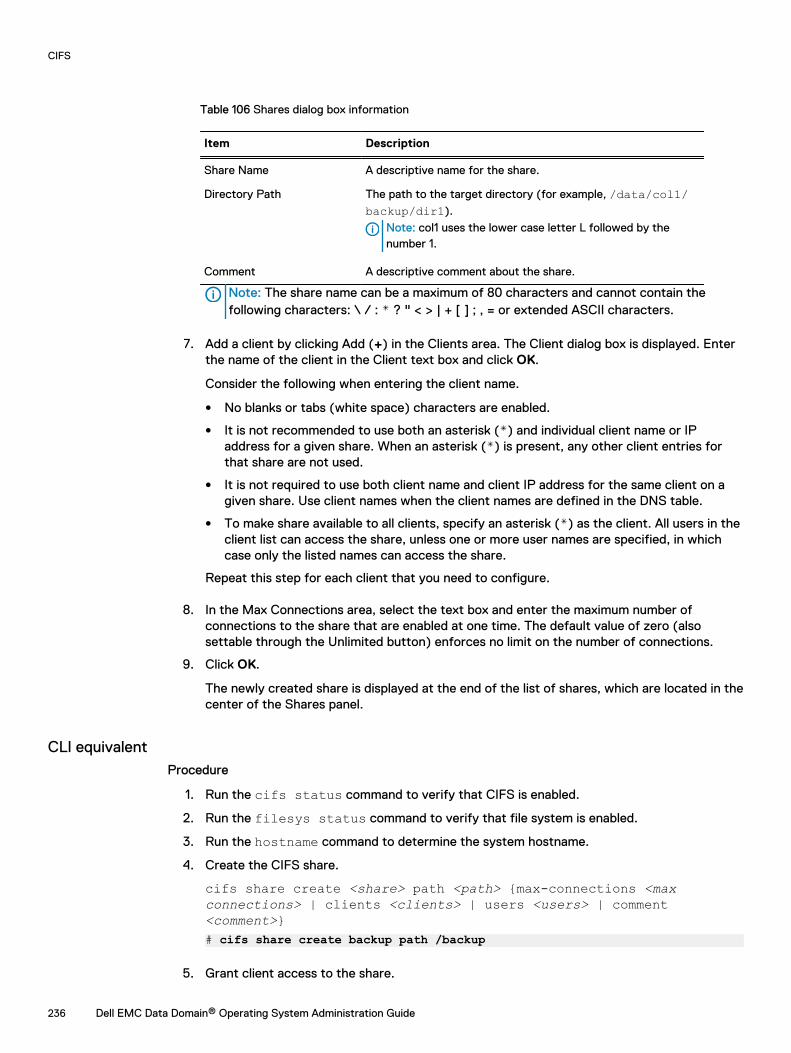
Table 106 Shares dialog box information
Item Description
Share Name A descriptive name for the share.
Directory Path The path to the target directory (for example, /data/col1/backup/dir1).
Note: col1 uses the lower case letter L followed by thenumber 1.
Comment A descriptive comment about the share.
Note: The share name can be a maximum of 80 characters and cannot contain thefollowing characters: \ / : * ? " < > | + [ ] ; , = or extended ASCII characters.
7. Add a client by clicking Add (+) in the Clients area. The Client dialog box is displayed. Enterthe name of the client in the Client text box and click OK.
Consider the following when entering the client name.
l No blanks or tabs (white space) characters are enabled.
l It is not recommended to use both an asterisk (*) and individual client name or IPaddress for a given share. When an asterisk (*) is present, any other client entries forthat share are not used.
l It is not required to use both client name and client IP address for the same client on agiven share. Use client names when the client names are defined in the DNS table.
l To make share available to all clients, specify an asterisk (*) as the client. All users in theclient list can access the share, unless one or more user names are specified, in whichcase only the listed names can access the share.
Repeat this step for each client that you need to configure.
8. In the Max Connections area, select the text box and enter the maximum number ofconnections to the share that are enabled at one time. The default value of zero (alsosettable through the Unlimited button) enforces no limit on the number of connections.
9. Click OK.
The newly created share is displayed at the end of the list of shares, which are located in thecenter of the Shares panel.
CLI equivalentProcedure
1. Run the cifs status command to verify that CIFS is enabled.
2. Run the filesys status command to verify that file system is enabled.
3. Run the hostname command to determine the system hostname.
4. Create the CIFS share.
cifs share create <share> path <path> {max-connections <maxconnections> | clients <clients> | users <users> | comment<comment>}# cifs share create backup path /backup
5. Grant client access to the share.
CIFS
236 Dell EMC Data Domain® Operating System Administration Guide
cifs share modify <share> {max-connections <max connections> |clients <clients> | browsing {enabled | disabled} | writeable{enabled | disabled} | users <users> | comment <comment>}# cifs share modify backup clients "srvr24.yourdomain.com,srvr24,10.24.160.116
6. Optionally make the share visible.
cifs share <share> browsing enabled# cifs share backup browsing enabled
7. Optionally make the share writeable.
cifs share <share> writeable enabled# cifs share backup writeable enabled
8. From the Windows system, select Start > Run, and type the hostname and directory of theCIFS share.
\\<DDhostname>.<DDdomain.com>\<sharename>
9. If there are problems connecting to the CIFS share, run the cifs share show commandto verify the status of the share.
The warning WARNING: The share path does not exist! is displayed if the sharedoes not exist or was misspelled on creation.
# cifs share show--------------- share backup ---------------
enabled: yespath: /backup
10. If the CIFS share is still not accessible, verify that all client information is in the access list,and all network connections are functional.
Modifying a share on a Data Domain systemChange share information and connections.
Procedure
1. Select Protocols > CIFS > Shares to navigate to the CIFS view, Shares tab.
2. Click the checkbox next the share that you wish to modify in the Share Name list.
3. Click Modify.
4. Modify share information:
a. To change the comment, enter new text in the Comment text field.
b. To modify a User or Group names, in the User/Group list, click the checkbox of the useror group and click Edit (pencil icon) or Delete (X). To add a user or group, click (+), andin the User/Group dialog box select the Type for User or Group, and enter the user orgroup name.
c. To modify a client name, in the Client list click the checkbox of the client and click Edit(pencil icon) or Delete (X). To add a client, click the Add (+) and add the name in theClient dialog box.
CIFS
Dell EMC Data Domain® Operating System Administration Guide 237
Note: To make the share available to all clients, specify an asterisk (*) as the client.All users in the client list can access the share, unless one or more user names arespecified, in which case only the listed names can access the share.
d. Click OK.
5. In the Max Connections area, in the text box, change the maximum number of connectionsto the share that are allowed at one time. Or select Unlimited to enforce no limit on thenumber of connections.
6. Click OK.
Creating a share from an existing shareCreate a share from an existing share and modify the new share if necessary.
About this task
Note: User permissions from the existing share are carried over to the new share.
Procedure
1. In the CIFS Shares tab, click the checkbox for the share you wish to use as the source.
2. Click Create From.
3. Modify the share information, as described in the section about modifying a share on a DataDomain system.
Disabling a share on a Data Domain systemDisable one or more existing shares.
Procedure
1. In the Shares tab, click the checkbox of the share you wish to disable in the Share Name list.
2. Click Disable.
3. Click Close.
Enabling a share on a Data Domain systemEnable one or more existing shares.
Procedure
1. In the Shares tab, click the checkbox of the shares you wish to enable in the Share Namelist.
2. Click Enable.
3. Click Close.
Deleting a share on a Data Domain systemDelete one or more existing shares.
Procedure
1. In the Shares tab, click the checkbox of the shares you wish to delete in the Share Namelist.
2. Click Delete.
The Warning dialog box appears.
CIFS
238 Dell EMC Data Domain® Operating System Administration Guide
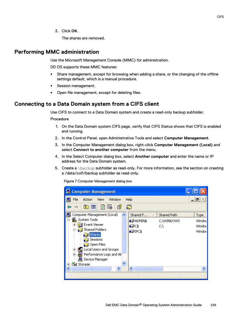
3. Click OK.
The shares are removed.
Performing MMC administrationUse the Microsoft Management Console (MMC) for administration.
DD OS supports these MMC features:
l Share management, except for browsing when adding a share, or the changing of the offlinesettings default, which is a manual procedure.
l Session management.
l Open file management, except for deleting files.
Connecting to a Data Domain system from a CIFS clientUse CIFS to connect to a Data Domain system and create a read-only backup subfolder.
Procedure
1. On the Data Domain system CIFS page, verify that CIFS Status shows that CIFS is enabledand running.
2. In the Control Panel, open Administrative Tools and select Computer Management.
3. In the Computer Management dialog box, right-click Computer Management (Local) andselect Connect to another computer from the menu.
4. In the Select Computer dialog box, select Another computer and enter the name or IPaddress for the Data Domain system.
5. Create a \backup subfolder as read-only. For more information, see the section on creatinga /data/col1/backup subfolder as read-only.
Figure 7 Computer Management dialog box
CIFS
Dell EMC Data Domain® Operating System Administration Guide 239
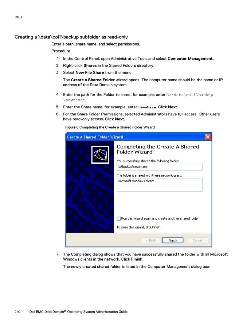
Creating a \data\col1\backup subfolder as read-onlyEnter a path, share name, and select permissions.
Procedure
1. In the Control Panel, open Administrative Tools and select Computer Management.
2. Right-click Shares in the Shared Folders directory.
3. Select New File Share from the menu.
The Create a Shared Folder wizard opens. The computer name should be the name or IPaddress of the Data Domain system.
4. Enter the path for the Folder to share, for example, enter C:\data\col1\backup\newshare.
5. Enter the Share name, for example, enter newshare. Click Next.
6. For the Share Folder Permissions, selected Administrators have full access. Other usershave read-only access. Click Next.
Figure 8 Completing the Create a Shared Folder Wizard
7. The Completing dialog shows that you have successfully shared the folder with all MicrosoftWindows clients in the network. Click Finish.
The newly created shared folder is listed in the Computer Management dialog box.
CIFS
240 Dell EMC Data Domain® Operating System Administration Guide
Displaying CIFS informationDisplay information about shared folders, sessions, and open files.
Procedure
1. In the Control Panel, open Administrative Tools and select Computer Management.
2. Select one of the Shared Folders (Shares, Sessions, or Open Files) in the System Toolsdirectory.
Information about shared folders, sessions, and open files is shown in the right panel.
Managing access controlAccess shared from a Windows client, provide administrative access, and allow access fromtrusted domain users.
Accessing shares from a Windows clientUse the command line to map a share.
Procedure
l From the Windows client use this DOS command:net use drive: backup-location
For example, enter:
# \\dd02\backup /USER:dd02\backup22This command maps the backup share from Data Domain system dd02 to drive H onthe Windows system and gives the user named backup22 access to the \\DD_sys\backup directory.
DD OS supports the SMB Change Notify functionality. This improves CIFSperformance on the Windows client by allowing the CIFS server to automatically notifythe Windows client about changes on the CIFS share, and eliminate the need for theclient to poll the Data Domain system to look for changes to the share.
Providing domain users administrative accessUse the command line to add CIFS and include the domain name in the ssh instruction.
Procedure
l Enter: adminaccess authentication add cifsThe SSH, Telnet, or FTP command that accesses the Data Domain system must include, indouble quotation marks, the domain name, a backslash, and the user name. For example:
C:> ssh "domain2\djones" @dd22
CIFS
Dell EMC Data Domain® Operating System Administration Guide 241
Allowing administrative access to a Data Domain system for domain usersUse the command line to map a DD system default group number, and then enable CIFSadministrative access.
Procedure
1. To map a Data Domain System default group number to a Windows group name that differsfrom the default group name, use thecifs option set "dd admin group2" ["windows grp-name"]command.
The Windows group name is a group (based on one of the user roles—admin, user, or back-up operator) that exists on a Windows domain controller, and you can have up to 50 groups(dd admin group1 to dd admin group50).
Note: For a description of DD OS user roles and Windows groups, see the section aboutmanaging Data Domain systems.
2. Enable CIFS administrative access by entering:
adminaccess authentication add cifsl The default Data Domain System group dd admin group1 is mapped to the Windows
group Domain Admins.
l You can map the default Data Domain System group dd admin group2 to a Windowsgroup named Data Domain that you create on a Windows domain controller.
l Access is available through SSH, Telnet, FTP, HTTP, and HTTPS.
l After setting up administrative access to the Data Domain system from the Windowsgroup Data Domain, you must enable CIFS administrative access using theadminaccess command.
Restricting administrative access from WindowsUse the command line to prohibit access to users without a DD account.
Procedure
l Enter: adminaccess authentication del cifsThis command prohibits Windows users access to the Data Domain system if they do not havean account on the Data Domain system.
File accessThis sections contains information about ACLs, setting DACL and SACL permissions usingWindows Explorer, and so on.
NT access control listsAccess control lists (ACLs) are enabled by default on the Data Domain system.
CAUTION Data Domain recommends that you do not disable NTFS ACLs once they have beenenabled. Contact Data Domain Support prior to disabling NTFS ACLs.
CIFS
242 Dell EMC Data Domain® Operating System Administration Guide
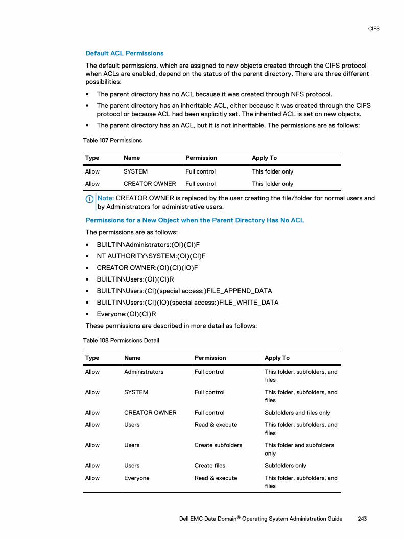
Default ACL Permissions
The default permissions, which are assigned to new objects created through the CIFS protocolwhen ACLs are enabled, depend on the status of the parent directory. There are three differentpossibilities:
l The parent directory has no ACL because it was created through NFS protocol.
l The parent directory has an inheritable ACL, either because it was created through the CIFSprotocol or because ACL had been explicitly set. The inherited ACL is set on new objects.
l The parent directory has an ACL, but it is not inheritable. The permissions are as follows:
Table 107 Permissions
Type Name Permission Apply To
Allow SYSTEM Full control This folder only
Allow CREATOR OWNER Full control This folder only
Note: CREATOR OWNER is replaced by the user creating the file/folder for normal users andby Administrators for administrative users.
Permissions for a New Object when the Parent Directory Has No ACL
The permissions are as follows:
l BUILTIN\Administrators:(OI)(CI)F
l NT AUTHORITY\SYSTEM:(OI)(CI)F
l CREATOR OWNER:(OI)(CI)(IO)F
l BUILTIN\Users:(OI)(CI)R
l BUILTIN\Users:(CI)(special access:)FILE_APPEND_DATA
l BUILTIN\Users:(CI)(IO)(special access:)FILE_WRITE_DATA
l Everyone:(OI)(CI)R
These permissions are described in more detail as follows:
Table 108 Permissions Detail
Type Name Permission Apply To
Allow Administrators Full control This folder, subfolders, andfiles
Allow SYSTEM Full control This folder, subfolders, andfiles
Allow CREATOR OWNER Full control Subfolders and files only
Allow Users Read & execute This folder, subfolders, andfiles
Allow Users Create subfolders This folder and subfoldersonly
Allow Users Create files Subfolders only
Allow Everyone Read & execute This folder, subfolders, andfiles
CIFS
Dell EMC Data Domain® Operating System Administration Guide 243
Setting ACL Permissions and Security
Windows-based backup and restore tools such as NetBackup can be used to back up DACL- andSACL-protected files to the Data Domain system, and to restore them from the Data Domainsystem.
Granular and Complex Permissions (DACL)
You can set granular and complex permissions (DACL) on any file or folder object within the filesystem, either through using Windows commands such as cacls, xcacls, xcopy and scopy, orthrough the CIFS protocol using the Windows Explorer GUI.
Audit ACL (SACL)
You can set audit ACL (SACL) on any object in the file system, either through commands orthrough the CIFS protocol using the Windows Explorer GUI.
Setting DACL permissions using the Windows ExplorerUse Explorer properties settings to select DACL permissions.
Procedure
1. Right-click the file or folder and select Properties.
2. In the Properties dialog box, click the Security tab.
3. Select the group or user name, such as Administrators, from the list. The permissionsappear, in this case for Administrators, Full Control.
4. Click the Advanced button, which enables you to set special permissions.
5. In the Advanced Security Settings for ACL dialog box, click the Permissions tab.
6. Select the permission entry in the list.
7. To view more information about a permission entry, select the entry and click Edit.
8. Select the Inherit from parent option to have the permissions of parent entries inherited bytheir child objects, and click OK.
Setting SACL permissions using the Windows ExplorerUse Explorer properties settings to select SACL permissions.
Procedure
1. Right-click the file or folder and select Properties from the menu.
2. In the Properties dialog box, click the Security tab.
3. Select the group or user name, such as Administrators, from the list, which displays itspermissions, in this case, Full Control.
4. Click the Advanced button, which enables you to set special permissions.
5. In the Advanced Security Settings for ACL dialog box, click the Auditing tab.
6. Select the auditing entry in the list.
7. To view more information about special auditing entries, select the entry and click Edit.
8. Select the Inherit from parent option to have the permissions of parent entries inherited bytheir child objects, and click OK.
CIFS
244 Dell EMC Data Domain® Operating System Administration Guide
Viewing or changing the current owner security ID (owner SID)Use the Advanced Security Settings for ACL dialog box.
Procedure
1. In the Advanced Security Settings for ACL dialog box, click the Owner tab.
2. To change the owner, select a name from the Change owner list, and click OK.
Controlling ID account mappingThe CIFS option idmap-type controls ID account mapping behavior.
This option has two values: rid (the default) and none. When the option is set to rid, the ID-to-idmapping is performed internally. When the option is set to none, all CIFS users are mapped to alocal UNIX user named “cifsuser” belonging to the local UNIX group users.
Consider the following information while managing this option.
l CIFS must be disabled to set this option. If CIFS is running, disable CIFS services.
l The idmap-type can be set to none only when ACL support is enabled.
l Whenever the idmap type is changed, a file system metadata conversion might be required forcorrect file access. Without any conversion, the user might not be able to access the data. Toconvert the metadata, consult your contracted support provider.
Monitoring CIFS operationMonitoring CIFS Operation topics.
Displaying CIFS statusView and enable/disable CIFS status.
Procedure
1. In the DD System Manager, select Protocols > CIFS.
l Status is either enabled and running, or disabled but CIFS authentication is running.To enable CIFS, see the section regarding enabling CIFS services. To disable CIFS, seethe section regarding disabling CIFS services.
l Connections lists the tally of open connections and open files.
Table 109 Connections Details information
Item Description
Open Connections Open CIFS connections
Connection Limit Maximum allowed connections
Open Files Current open files
Max Open Files Maximum number of open files on a Data Domain system
2. Click Connection Details to see more connection information.
CIFS
Dell EMC Data Domain® Operating System Administration Guide 245
Table 110 Connections Details information
Item Description
Sessions Active CIFS sessions
Computer IP address or computer name connected with DDR for thesession
User User operating the computer connected with the DDR
Open Files Number of open files for each session
Connection Time Connection length in minutes
User Domain name of computer
Mode File permissions
Locks Number of locks on the file
Files File location
Display CIFS configurationThis section displays CIFS Configuration.
Authentication configurationThe information in the Authentication panel changes, depending on the type of authentication thatis configured.
Click the Configure link in to the left of the Authentication label in the Configuration tab. Thesystem will navigate to the Administration > Access > Authentication page where you canconfigure authentication for Active Directory, Kerberos, Workgroups, and NIS.
Active directory configuration
Table 111 Active directory configuration information
Item Description
Mode The Active Directory mode displays.
Realm The configured realm displays.
DDNS The status of the DDNS Server displays: either enabled ordisabled.
Domain Controllers The name of the configured domain controllers display or a * ifall controllers are permitted.
Organizational Unit The name of the configured organizational units displays.
CIFS Server Name The name of the configured CIFS server displays.
WINS Server Name The name of the configured WINS server displays.
Short Domain Name The short domain name displays.
CIFS
246 Dell EMC Data Domain® Operating System Administration Guide
Workgroup configuration
Table 112 Workgroup configuration authentication information
Item Description
Mode The Workgroup mode displays.
Workgroup Name The configured workgroup name displays.
DDNS The status of the DDNS Server displays: either enabled ordisabled.
CIFS Server Name The name of the configured CIFS server displays.
WINS Server Name The name of the configured WINS server displays.
Display shares informationThis section displays shares information.
Viewing configured shares
View the list of configured shares.
Table 113 Configured shares information
Item Description
Share Name The name of the share (for example, share1).
Share Status The status of the share: either enabled or disabled.
Directory Path The directory path to the share (for example, /data/col1/backup/dir1).
Note: col1 uses the lower case letter L followed by thenumber 1.
Directory Path Status The status of the directory path.
l To list information about a specific share, enter the share name in the Filter by Share Nametext box and click Update.
l Click Update to return to the default list.
l To page through the list of shares, click the < and > arrows at the bottom right of the view topage forward or backward. To skip to the beginning of the list, click |< and to skip to the end,click >|.
l Click the Items per Page drop-down arrow to change the number of share entries listed on apage. Choices are 15, 30, or 45 entries.
Viewing detailed share information
Display detailed information about a share by clicking a share name in the share list.
Table 114 Share information
Item Description
Share Name The name of the share (for example, share1).
CIFS
Dell EMC Data Domain® Operating System Administration Guide 247
Table 114 Share information (continued)
Item Description
Directory Path The directory path to the share (for example, /data/col1/backup/dir1).
Note: col1 uses the lower case letter L followed by thenumber 1.
Directory Path Status Indicates whether the configured directory path exists on theDDR. Possible values are Path Exists or Path Does Not Exist,the later indicating an incorrect or incomplete CIFSconfiguration.
Max Connections The maximum number of connections allowed to the share atone time. The default value is Unlimited.
Comment The comment that was configured when the share wascreated.
Share Status The status of the share: either enabled or disabled.
l The Clients area lists the clients that are configured to access the share, along with a clienttally beneath the list.
l The User/Groups area lists the names and type of users or groups that are configured toaccess the share, along with a user or group tally beneath the list.
l The Options area lists the name and value of configured options.
Displaying CIFS statisticsUse the command line to display CIFS statistics.
Procedure
l Enter: cifs show detailed-statsThe output shows number of various SMB requests received and the time taken to processthem.
Performing CIFS troubleshootingThis section provides basic troubleshooting procedures.
Note: The cifs troubleshooting commands provide detailed information about CIFSusers and groups.
Displaying clients current activityUse the command line to display CIFS sessions and open files information.
Procedure
l Enter: cifs show active
CIFS
248 Dell EMC Data Domain® Operating System Administration Guide
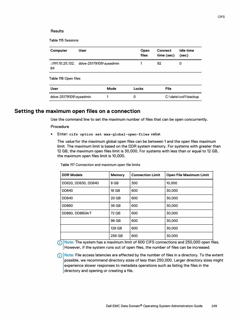
Results
Table 115 Sessions
Computer User Openfiles
Connecttime (sec)
Idle time(sec)
::ffff:10.25.132.84
ddve-25179109\sysadmin 1 92 0
Table 116 Open files
User Mode Locks File
ddve-25179109\sysadmin 1 0 C:\data\col1\backup
Setting the maximum open files on a connectionUse the command line to set the maximum number of files that can be open concurrently.
Procedure
l Enter: cifs option set max-global-open-files value.
The value for the maximum global open files can be between 1 and the open files maximumlimit. The maximum limit is based on the DDR system memory. For systems with greater than12 GB, the maximum open files limit is 30,000. For systems with less than or equal to 12 GB,the maximum open files limit is 10,000.
Table 117 Connection and maximum open file limits
DDR Models Memory Connection Limit Open File Maximum Limit
DD620, DD630, DD640 8 GB 300 10,000
DD640 16 GB 600 30,000
DD640 20 GB 600 30,000
DD860 36 GB 600 30,000
DD860, DD860ArT 72 GB 600 30,000
96 GB 600 30,000
128 GB 600 30,000
256 GB 600 30,000
Note: The system has a maximum limit of 600 CIFS connections and 250,000 open files.However, if the system runs out of open files, the number of files can be increased.
Note: File access latencies are affected by the number of files in a directory. To the extentpossible, we recommend directory sizes of less than 250,000. Larger directory sizes mightexperience slower responses to metadata operations such as listing the files in thedirectory and opening or creating a file.
CIFS
Dell EMC Data Domain® Operating System Administration Guide 249
Data Domain system clockWhen using active directory mode for CIFS access, the Data Domain System clock time can differby no more than five minutes from that of the domain controller.
The DD System Manager, Administration > Settings > Time and Date Settings tab synchronizesthe clock with a time server.
Because the Windows domain controller obtains the time from an external source, NTP must beconfigured. See the Microsoft documentation on how to configure NTP for the Windows operatingsystem version or service pack that is running on your domain controller.
In active directory authentication mode, the Data Domain system periodically synchronizes theclock with a Windows Active Directory Domain Controller.
Synchronizing from a Windows domain controllerUse the command line on a Windows domain controller to synchronize with an NTP server.
About this task
Note: This example is for Windows 2003 SP1; substitute your domain server for the NTPserver’s name (ntpservername).
Procedure
1. On the Windows system, enter commands similar to the following:
C:\>w32tm /config /syncfromflags:manual /manualpeerlist: ntp-server-nameC:\>w32tm /config /update C:\>w32tm /resync
2. After NTP is configured on the domain controller, configure the time server synchronization,as described in the section about working with time and date settings.
Synchronize from an NTP serverConfigure the time server synchronization, as described in the section regarding working with timeand date settings.
CIFS
250 Dell EMC Data Domain® Operating System Administration Guide

CHAPTER 9
NFS
This chapter includes:
l NFS overview......................................................................................................................252l Managing NFS client access to the Data Domain system.................................................... 253l Displaying NFS information................................................................................................. 256l Integrating a DDR into a Kerberos domain........................................................................... 257l Add and delete KDC servers after initial configuration.........................................................258
Dell EMC Data Domain® Operating System Administration Guide 251
NFS overviewNetwork File System (NFS) clients can have access to the system directories or MTrees on theData Domain system.
l The/backup directory is the default destination for non-MTree compressed backup serverdata.
l The /data/col1/backup path is the root destination when using MTrees for compressedbackup server data.
l The /ddvar/core directory contains Data Domain System core and log files (remove old logsand core files to free space in this area).
Note: On Data Domain systems, the /ddvar/core is on a separate partition. If youmount /ddvar only, you will not be able to navigate to /ddvar/core from the /ddvarmountpoint.
Clients, such as backup servers that perform backup and restore operations with a Data DomainSystem, need access to the /backup or /data/col1/backup areas. Clients that haveadministrative access need to be able to access the /ddvar/core directory to retrieve core andlog files.
As part of the initial Data Domain system configuration, NFS clients were configured to accessthese areas. This chapter describes how to modify these settings and how to manage data access.
Note:
l For information about the initial system configuration, see the Data Domain OperatingSystem Initial Configuration Guide.
l The nfs command manages backups and restores between NFS clients and Data Domainsystems, and it displays NFS statistics and status. For complete information about the nfscommand, see the Data Domain Operating System Command Reference Guide.
l For information about setting up third-party clients to use the Data Domain system as aserver, see the related tuning guide, such as the Solaris System Tuning, which is availablefrom the Data Domain support web site. From the Documentation > IntegrationDocumentation page, select the vendor from the list and click OK. Select the tuning guidefrom the list.
HA systems and NFSHA systems are compatible with NFS. If a NFS job is in progress during a failover, the job will notneed to be restarted.
Note: /ddvar is an ext3 file system, and cannot be shared like a normal MTree-based share.The information in /ddvar will become stale when the active node fails over to the standbynode because the filehandles are different on the two nodes. If /ddvar is mounted to accesslog files or upgrade the system, unmount and remount /ddvar if a failover has occurred sincethe last time /ddvar was mounted.
To create valid NFS exports that will failover with HA, the export needs to be created from theActive HA node, and generally shared over the failover network interfaces.
NFS
252 Dell EMC Data Domain® Operating System Administration Guide
Managing NFS client access to the Data Domain systemThe topics in this section describe how to manage NFS client access to a Data Domain System.
The KB article NFS Best Practices for Data Domain and client OS, available at https://support.emc.com/kb/180552, provides additional information about best practices for NFS.
Enabling NFS servicesEnable NFS services to allow the client to access the system using the NFS protocol.
Procedure
1. Select Protocols > NFS.
The NFS view opens displaying the Exports tab.
2. Click Enable.
Disabling NFS servicesDisable NFS services to prevent the client access to the system using the NFS protocol.
Procedure
1. Select the Protocols > NFS tabs.
The NFS view opens displaying the Exports tab.
2. Click Disable.
Creating an exportYou can use Data Domain System Manager’s Create button on the NFS view or use theConfiguration Wizard to specify the NFS clients that can access the /backup, /data/col1/backup,/ddvar, /ddvar/core areas, or the/ddvar/ext area if it exists.
About this task
A Data Domain system supports a maximum of 2048 exports2, with the number of connectionsscaling in accordance with system memory.
Note: You have to assign client access to each export separately and remove access from eachexport separately. For example, a client can be removed from /ddvar and still have accessto /data/col1/backup.
CAUTION If Replication is to be implemented, a single destination Data Domain system canreceive backups from both CIFS clients and NFS clients as long as separate directories orMTrees are used for each. Do not mix CIFS and NFS data in the same area.
Procedure
1. Select ProtocolsNFS.
The NFS view opens displaying the Exports tab.
2. Click Create.
3. Enter the pathname in the Directory Path text box (for example, /data/col1/backup/dir1).
2. May be affected by hardware limitations.
NFS
Dell EMC Data Domain® Operating System Administration Guide 253
Note: col1 uses the lower-case letter L followed by the number 1.
4. In the Clients area, select an existing client or click the + icon to create a client.
The Client dialog box is displayed.
a. Enter a server name in the text box.
Enter fully qualified domain names, hostnames, or IP addresses. A single asterisk (*) as awild card indicates that all backup servers are to be used as clients.
Note: Clients given access to the /data/col1/backup directory have access tothe entire directory. A client given access to a subdirectory of /data/col1/backup has access only to that subdirectory.
l A client can be a fully-qualified domain hostname, an IPv4 or IPv6 IP address, an IPv4address with either a netmask or prefix length, an IPv6 address with prefix length, anNIS netgroup name with the prefix @, or an asterisk (*) wildcard with a domain name,such as *.yourcompany.com.
l A client added to a subdirectory under /data/col1/backup has access only to thatsubdirectory.
l Enter an asterisk (*) as the client list to give access to all clients on the network.
b. Select the checkboxes of the NFS options for the client.
General:
l Read-only permission (ro).
l Allow connections from ports below 1024 (secure) (default).
Anonymous UID/GID:
l Map requests from UID (user identifier) or GID (group identifier) 0 to the anonymousUID/GID (root _squash).
l Map all user requests to the anonymous UID/GID (all _squash).
l Use Default Anonymous UID/GID.
Allowed Kerberos Authentication Modes:
l Unauthenticated connections (sec=sys). Select to not use authentication.
l Authenticated Connections (sec=krb5).
Note: Integrity and Privacy are supported, although they might slow performanceconsiderably.
c. Click OK.
5. Click OK to create the export.
Modifying an exportChange the directory path, domain name, and other options using the GUI.
Procedure
1. SelectProtocols > NFS.
The NFS view opens displaying the Exports tab.
NFS
254 Dell EMC Data Domain® Operating System Administration Guide
2. Click the checkbox of an export in the NFS Exports table.
3. Click Modify.
4. Modify the pathname in the Directory Path text box.
5. In the Clients area, select another client and click the pencil icon (modify), or click the +icon to create a client.
a. Enter a server name in the Client text box.
Enter fully qualified domain names, hostnames, or IP addresses. A single asterisk (*) as awild card indicates that all backup servers are to be used as clients.
Note: Clients given access to the /data/col1/backup directory have access tothe entire directory. A client given access to a subdirectory of /data/col1/backup has access only to that subdirectory.
l A client can be a fully-qualified domain hostname, an IPv4 or IPv6 IP address, an IPv4address with either a netmask or prefix length, an IPv6 address with prefix length, anNIS netgroup name with the prefix @, or an asterisk (*) wildcard with a domain name,such as *.yourcompany.com.A client added to a subdirectory under /data/col1/backup has access only to thatsubdirectory.
l Enter an asterisk (*) as the client list to give access to all clients on the network.
b. Select the checkboxes of the NFS options for the client.
General:
l Read-only permission (ro).
l Allow connections from ports below 1024 (secure) (default).
Anonymous UID/GID:
l Map requests from UID (user identifier) or GID (group identifier) 0 to the anonymousUID/GID (root _squash).
l Map all user requests to the anonymous UID/GID (all _squash).
l Use Default Anonymous UID/GID.
Allowed Kerberos Authentication Modes:
l Unauthenticated connections (sec=sys). Select to not use authentication.
l Authenticated Connections (sec=krb5).
Note: Integrity and Privacy are not supported.
c. Click OK.
6. Click OK to modify the export.
Creating an export from an existing exportCreate an export from an existing export and then modify it as needed.
Procedure
1. In the NFS Exports tab, click the checkbox of the export you wish to use as the source.
2. Click Create From.
NFS
Dell EMC Data Domain® Operating System Administration Guide 255
3. Modify the export information, as described in section about modifying an export.
Deleting an exportDelete an export from the NFS Exports tab.
Procedure
1. In the NFS Exports tab, click the checkbox of the export you wish to delete.
2. Click Delete.
3. Click OK and Close to delete the export.
Displaying NFS informationThe topics in this section describe how to use the DD System Manager to monitor NFS clientstatus and NFS configuration.
Viewing NFS statusDisplay whether NFS is active and Kerberos is enabled.
Procedure
l Click Protocols > NFS.
The top panel shows the operational status of NFS; for example, whether NFS is currentlyactive and running, and whether Kerberos mode is enabled.
Note: Click Configure to view the Administration > Access > Authentication tab whereyou can configure Kerberos authentication.
Viewing NFS exportsSee the list of clients allowed to access the Data Domain System.
Procedure
1. Click Protocols > NFS.
The Exports view shows a table of NFS exports that are configured for Data Domain Systemand the mount path, status, and NFS options for each export.
2. Click an export in the table to populate the Detailed Information area, below the Exportstable.
In addition to the export’s directory path, configured options, and status, the systemdisplays a list of clients.
Use the Filter By text box to sort by mount path.
Click Update for the system to refresh the table and use the filters supplied.
Click Reset for the system to clear the Path and Client filters.
NFS
256 Dell EMC Data Domain® Operating System Administration Guide
Viewing active NFS clientsDisplay all clients that have been connected in the past 15 minutes and their mount path.
Procedure
l Select the Protocols > NFS > Active Clients tab.
The Active Clients view displays, showing all clients that have been connected in the past 15minutes and their mount path.
Use the Filter By text boxes to sort by mount path and client name.
Click Update for the system to refresh the table and use the filters supplied.
Click Reset for the system to clear the Path and Client filters.
Integrating a DDR into a Kerberos domainSet the domain name, the host name, and the DNS server for the DDR.
About this task
Enable the DDR to use the authentication server as a Key Distribution Center (for UNIX) and as aDistribution Center (for Windows Active Directory).
CAUTION The examples provided in this description are specific to the operating system (OS)used to develop this exercise. You must use commands specific to your OS.
Note: For UNIX Kerberos mode, a keytab file must be transferred from the Key DistributionCenter (KDC) server, where it is generated, to the DDR. If you are using more than one DDR,each DDR requires a separate keytab file. The keytab file contains a shared secret between theKDC server and the DDR.
Note: When using a UNIX KDC, the DNS server does not have to be the KDC server, it can bea separate server.
Procedure
1. Set the host name and the domain name for the DDR, using DDR commands.
net set hostname <host>net set {domainname <local-domain-name>}
Note: The host name is the name of the DDR.
2. Configure NFS principal (node) for the DDR on the Key Distribution Center (KDC).
Example:addprinc nfs/hostname@realm
Note: Hostname is the name for the DDR.
3. Verify that there are nfs entries added as principals on the KDC.
Example:listprincsnfs/hostname@realm
4. Add the DDR principal into a keytab file.
Example:
NFS
Dell EMC Data Domain® Operating System Administration Guide 257
ktadd <keytab_file> nfs/hostname@realm
5. Verify that there is an nfs keytab file configured on the KDC.
Example:klist -k <keytab_file>
Note: The <keytab_file> is the keytab file used to configure keys in a previous step.
6. Copy the keytab file from the location where the keys for NFS DDR are generated to theDDR in the /ddvar/ directory.
Table 118 Keytab destination
Copy file from: Copy file to:
<keytab_file> (The keytab file configured in aprevious step.)
/ddvar/
7. Set the realm on the DDR, using the following DDR command:
authentication kerberos set realm <home realm> kdc-type <unix, windows.>kdcs <IP address of server>
8. When the kdc-type is UNIX, import the keytab file from /ddvar/ to /ddr/etc/, where theKerberos configuration file expects it. Use the following DDR command to copy the file:
authentication kerberos keytab importNOTICE This step is required only when the kdc-type is UNIX.
Kerberos setup is now complete.
9. To add a NFS mount point to use Kerberos, use the nfs add command.
See the Data Domain Operating System Command Reference Guide for more information.
10. Add host, NFS and relevant user principals for each NFS client on the Key DistributionCenter (KDC).
Example: listprincshost/hostname@realmnfs/hostname@realmroot/hostname@realm
11. For each NFS client, import all its principals into a keytab file on the client.
Example:ktadd -k <keytab_file> host/hostname@realmktadd -k <keytab_file> nfs/hostname@realm
Add and delete KDC servers after initial configurationAfter you have integrated a DDR into a Kerberos domain, and thereby enabled the DDR to use theauthentication server as a Key Distribution Center (for UNIX) and as a Distribution Center (forWindows Active Directory), you can use the following procedure to add or delete KDC servers.
Procedure
1. Join the DDR to a Windows Active Directory (AD) server or a UNIX Key Distribution Center(KDC).
NFS
258 Dell EMC Data Domain® Operating System Administration Guide
authentication kerberos set realm <home-realm> kdc-type {windows [kdcs<kdc-list>] | unix kdcs <kdc-list>}
Example: authentication kerberos set realm krb5.test kdc-type unix kdcsnfskrb-kdc.krb5.test
This command joins the system to the krb5.test realm and enables Kerberos authenticationfor NFS clients.
Note: A keytab generated on this KDC must exist on the DDR to authenticate usingKerberos.
2. Verify the Kerberos authentication configuration.
authentication kerberos show configHome Realm: krb5.testKDC List: nfskrb-kdc.krb5.testKDC Type: unix
3. Add a second KDC server.
authentication kerberos set realm <home-realm> kdc-type {windows [kdcs<kdc-list>] | unix kdcs <kdc-list>}
Example: authentication kerberos set realm krb5.test kdc-type unix kdcsostqa-sparc2.krb5.test nfskrb-kdc.krb5.test
Note: A keytab generated on this KDC must exist on the DDR to authenticate usingKerberos.
4. Verify that two KDC servers are added.
authentication kerberos show configHome Realm: krb5.testKDC List: ostqa-sparc2.krb5.test, nfskrb-kdc.krb5.testKDC Type: unix
5. Display the value for the Kerberos configuration key.
reg show config.keberosconfig.kerberos.home_realm = krb5.testconfig.kerberos.home_realm.kdc1 = ostqa-sparc2.krb5.testconfig.kerberos.home_realm.kdc2 = nfskrb-kdc.krb5.testconfig.kerberos.kdc_count = 2config.kerberos.kdc_type = unix
6. Delete a KDC server.
Delete a KDC server by using the authentication kerberos set realm <home-realm>kdc-type {windows [kdcs <kdc-list>] | unix kdcs <kdc-list>} command withoutlisting the KDC server that you want to delete. For example, if the existing KDC servers arekdc1, kdc2, and kdc3, and you want to remove kdc2 from the realm, you could use thefollowing example:
authentication kerberos set realm <realm-name> kdc-type <kdc_type> kdcskdc1,kdc3
NFS
Dell EMC Data Domain® Operating System Administration Guide 259

NFS
260 Dell EMC Data Domain® Operating System Administration Guide
CHAPTER 10
NFSv4
This chapter includes:
l Introduction to NFSv4.........................................................................................................262l ID Mapping Overview.......................................................................................................... 263l External formats..................................................................................................................263l Internal Identifier Formats................................................................................................... 264l When ID mapping occurs.....................................................................................................264l NFSv4 and CIFS/SMB Interoperability................................................................................266l NFS Referrals......................................................................................................................267l NFSv4 and High Availability.................................................................................................268l NFSv4 Global Namespaces..................................................................................................268l NFSv4 Configuration...........................................................................................................269l Kerberos and NFSv4............................................................................................................ 271l Enabling Active Directory.................................................................................................... 273
Dell EMC Data Domain® Operating System Administration Guide 261
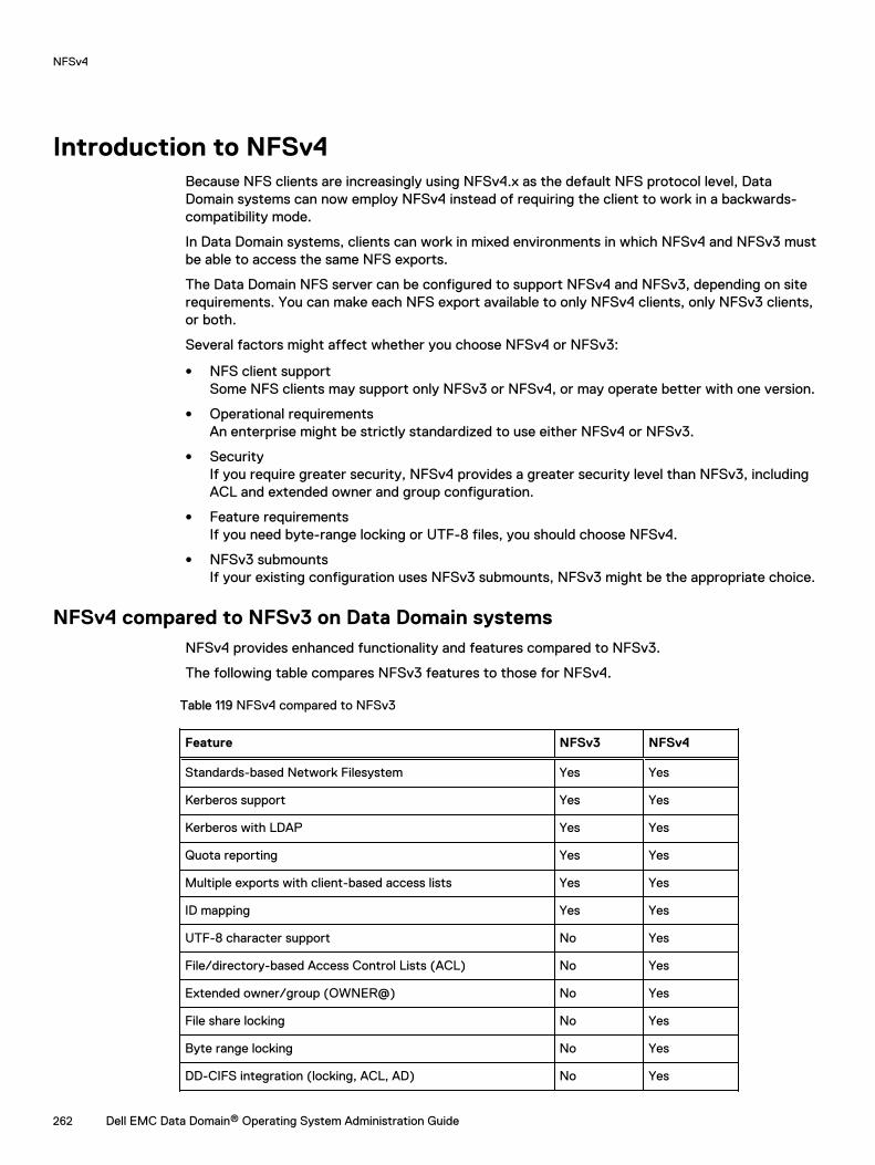
Introduction to NFSv4Because NFS clients are increasingly using NFSv4.x as the default NFS protocol level, DataDomain systems can now employ NFSv4 instead of requiring the client to work in a backwards-compatibility mode.
In Data Domain systems, clients can work in mixed environments in which NFSv4 and NFSv3 mustbe able to access the same NFS exports.
The Data Domain NFS server can be configured to support NFSv4 and NFSv3, depending on siterequirements. You can make each NFS export available to only NFSv4 clients, only NFSv3 clients,or both.
Several factors might affect whether you choose NFSv4 or NFSv3:
l NFS client supportSome NFS clients may support only NFSv3 or NFSv4, or may operate better with one version.
l Operational requirementsAn enterprise might be strictly standardized to use either NFSv4 or NFSv3.
l SecurityIf you require greater security, NFSv4 provides a greater security level than NFSv3, includingACL and extended owner and group configuration.
l Feature requirementsIf you need byte-range locking or UTF-8 files, you should choose NFSv4.
l NFSv3 submountsIf your existing configuration uses NFSv3 submounts, NFSv3 might be the appropriate choice.
NFSv4 compared to NFSv3 on Data Domain systemsNFSv4 provides enhanced functionality and features compared to NFSv3.
The following table compares NFSv3 features to those for NFSv4.
Table 119 NFSv4 compared to NFSv3
Feature NFSv3 NFSv4
Standards-based Network Filesystem Yes Yes
Kerberos support Yes Yes
Kerberos with LDAP Yes Yes
Quota reporting Yes Yes
Multiple exports with client-based access lists Yes Yes
ID mapping Yes Yes
UTF-8 character support No Yes
File/directory-based Access Control Lists (ACL) No Yes
Extended owner/group (OWNER@) No Yes
File share locking No Yes
Byte range locking No Yes
DD-CIFS integration (locking, ACL, AD) No Yes
NFSv4
262 Dell EMC Data Domain® Operating System Administration Guide
Table 119 NFSv4 compared to NFSv3 (continued)
Feature NFSv3 NFSv4
Stateful file opens and recovery No Yes
Global namespace and pseudoFS No Yes
Multi-system namespace using referrals No Yes
NFSv4 portsYou can enable or disable NFSv4 and NFSv3 independently. In addition, you can move NFSversions to different ports; both versions do not need to occupy the same port.
With NFSv4, you do not need to restart the Data Domain file system if you change ports. Only anNFS restart is required in such instances.
Like NFSv3, NFSv4 runs on Port 2049 as the default if it is enabled.
NFSv4 does not use portmapper (Port 111) or mountd (Port 2052).
ID Mapping OverviewNFSv4 identifies owners and groups by a common external format, such as [email protected] common formats are known as identifiers, or IDs.
Identifiers are stored within an NFS server and use internal representations such as ID 12345 or IDS-123-33-667-2. The conversion between internal and external identifiers is known as ID mapping.
Identifiers are associated with the following:
l Owners of files and directories
l Owner groups of files and directories
l Entries in Access Control Lists (ACLs)
Data Domain systems use a common internal format for NFS and CIFS/SMB protocols, whichallows files and directories to be shared between NFS and CIFS/SMB. Each protocol converts theinternal format to its own external format with its own ID mapping.
External formatsThe external format for NFSv4 identifiers follows NFSv4 standards (for example, RFC-7530 forNFSv4.0). In addition, supplemental formats are supported for interoperability.
Standard identifier formatsStandard external identifiers for NFSv4 have the format identifier@domain. This identifier isused for NFSv4 owners, owner-groups, and access control entries (ACEs). The domain mustmatch the configured NFSv4 domain that was set using the nfs option command.
The following CLI example sets the NFSv4 domain to mycorp.com for the Data Domain NFSserver:
nfs option set nfs4-domain mycorp.com
See client-specific documentation you have for setting the client NFS domain. Depending on theoperating system, you might need to update a configuration file (for example, /etc/idmapd.conf) or use a client administrative tool.
NFSv4
Dell EMC Data Domain® Operating System Administration Guide 263
Note: If you do not set the default value, it will follow the DNS name for the Data Domainsystem.
Note: The filesystem must be restarted after changing the DNS domain for the nfs4-domain toautomatically update.
ACE extended identifiersFor ACL ACE entries, Data Domain NFS servers also support the following standard NFSv4 ACEextended identifiers defined by the NFSv4 RFC:
l OWNER@, The current owner of the file or directory
l GROUP@, the current owner group of the file or directory.
l The special identifiers INTERACTIVE@, NETWORK@, DIALUP@, BATCH@, ANONYMOUS@,AUTHENTICATED@, SERVICE@.
Alternative formatsTo allow interoperability, NFSv4 servers on Data Domain systems support some alternativeidentifier formats for input and output.
l Numeric identifiers; for example, “12345”.
l Windows compatible Security identifiers (SIDs) expressed as “S-NNN-NNN-…”
See the sections on input mapping and output mapping for more information about restrictions tothese formats.
Internal Identifier FormatsThe Data Domain filesystem stores identifiers with each object (file or directory) in the filesystem.All objects have a numeric user ID (UID) and group ID (GID). These, along with a set of mode bits,allow for traditional UNIX/Linux identification and access controls.
Objects created by the CIFS/SMB protocol, or by the NFSv4 protocol when NFSv4 ACLs areenabled, also have an extended security descriptor (SD). Each SD contains the following:
l An owner security identifier (SID)
l An owner group SID
l A discretionary ACL (DACL)
l (Optional) A system ACL (SACL)
Each SID contains a relative ID (RID) and a distinct domain in a similar manner to Windows SIDs.See the section on NFSv4 and CIFS interoperability for more information on SIDs and the mappingof SIDs.
When ID mapping occursThe Data Domain NFSv4 server performs mapping in the following circumstances:
l Input mappingThe Data Domain NFS server receives an identifier from an NFSv4 client. See Input mappingon page 265.
l Output mapping:An identifier is sent from the Data Domain NFS server to the NFSv4 client. See Outputmapping on page 265.
NFSv4
264 Dell EMC Data Domain® Operating System Administration Guide
l Credential mappingThe RPC client credentials are mapped to an internal identity for access control and otheroperations. See Credential mapping on page 265.
Input mappingInput mapping occurs when an NFSv4 client sends an identifier to the Data Domain NFSv4 server -setting up the owner or owner-group of a file, for example. Input mapping is distinct fromcredential mapping. For more information on credential mapping, see xxxx
Standard format identifiers such as [email protected] are converted into an internal UID/GIDbased on the configured conversion rules. If NFSv4 ACLs are enabled, a SID will also be generated,based on the configured conversion rules.
Numeric identifiers (for example, “12345”) are directly converted into corresponding UID/GIDs ifthe client is not using Kerberos authentication. If Kerberos is being used, an error will be generatedas recommended by the NFSv4 standard. If NFSv4 ACLs are enabled, a SID will be generatedbased on the conversion rules.
Windows SIDs (for example, “S-NNN-NNN-…”) are validated and directly converted into thecorresponding SIDs. A UID/GID will be generated based on the conversion rules.
Output mappingOutput mapping occurs when the NFSv4 server sends an identifier to the NFSv4 client; forexample, if the server returns the owner or owner-group of a file.
1. If configured, the output might be the numeric ID.This can be useful for NFSv4 clients that are not configured for ID mapping (for example, someLinux clients).
2. Mapping is attempted using the configured mapping services, (for example, NIS or ActiveDirectory).
3. The output is a numeric ID or SID string if mapping fails and the configuration is allowed.
4. Otherwise, nobody is returned.
The nfs option nfs4-idmap-out-numeric configures the mapping on output:
l If nfs option nfs4-idmap-out-numeric is set to map-first, mapping will be attempted. Onerror, a numeric string is output if allowed. This is the default.
l If nfs option nfs4-idmap-out-numeric is set to always, output will always be a numericstring if allowed.
l If nfs option nfs4-idmap-out-numeric is set to never, mapping will be attempted. Onerror, nobody@nfs4-domain is the output.If the RPC connection uses GSS/Kerberos, a numeric string is never allowed andnobody@nfs4-domain is the output.
The following example configures the Data Domain NFS server to always attempt to output anumeric string on output. For Kerberos the name nobody is returned:
nfs option set nfs4-idmap-out-numeric always
Credential mappingThe NFSv4 server provides credentials for the NFSv4 client.
These credentials perform the following functions:
l Determine the access policy for the operation; for example, the ability to read a file.
l Determine the default owner and owner-group for new files and directories.
NFSv4
Dell EMC Data Domain® Operating System Administration Guide 265
Credentials sent from the client may be [email protected], or system credentials such asUID=1000, GID=2000. System credentials specify a UID/GID along with auxiliary group IDs.
If NFSv4 ACLs are disabled, then the UID/GID and auxiliary group IDs are used for the credentials.
If NFSv4 ACLs are enabled, then the configured mapping services are used to build an extendedsecurity descriptor for the credentials:
l SIDs for the owner, owner-group, and auxiliary group mapped and added to the SecurityDescriptor (SD).
l Credential privileges, if any, are added to the SD.
NFSv4 and CIFS/SMB InteroperabilityThe security descriptors used by NFSv4 and CIFS are similar from an ID mapping perspective,although there are differences.
You should be aware of the following to ensure for optimal interoperability:
l Active Directory should be configured for both CIFS and NFSv4, and the NFS ID mappershould be configured to use Active Directory for ID mapping.
l If you are using CIFS ACLs extensively, you can usually improve compatibility by also enablingNFSv4 ACLs.
n Enabling NFSv4 ACLs allows NFSv4 credentials to be mapped to the appropriate SID whenevaluating DACL access.
l The CIFS server receives credentials from the CIFS client, including default ACL and userprivileges.
n In contrast, the NFSv4 server receives a more limited set of credentials, and constructscredentials at runtime using its ID mapper. Because of this, the filesystem might seedifferent credentials.
CIFS/SMB Active Directory IntegrationThe Data Domain NFSv4 server can be configured to use the Windows Active Directoryconfiguration that is set with the Data Domain CIFS server.
The Data Domain system is mapped to use Active Directory if possible. This functionality isdisabled by default, but you can enable it using the following command:nfs option set nfs4-idmap-active-directory enabled
Default DACL for NFSv4NFSv4 sets a different default DACL (discretionary access control list) than the default DACLsupplied by CIFS.
Only OWNER@, GROUP@ and EVERYONE@ are defined in the default NFSv4 DACL. You can useACL inheritance to automatically add CIFS-significant ACEs by default if appropriate.
System Default SIDsFiles and directories created by NFSv3, and NFSv4 without ACLs, use the default system domain,sometimes referred to as the default UNIX domain:
l User SIDs in the system domain have format S-1-22-1-N, where N is the UID.
l Group SIDs in the system domain have format S-1-22-2-N, when N is the GID.
NFSv4
266 Dell EMC Data Domain® Operating System Administration Guide
For example, a user with UID 1234 would have an owner SID of S-1-22-1-1234.
Common identifiers in NFSv4 ACLs and SIDsThe EVERYONE@ identifier and other special identifiers (such as BATCH@, for example) inNFSv4 ACLs use the equivalent CIFS SIDS and are compatible.
The OWNER@ and GROUP@ identifiers have no direct correspondence in CIFS; they appear asthe current owner and current owner-group of the file or directory.
NFS ReferralsThe referral feature allows an NFSv4 client to access an export (or filesystem) in one or multiplelocations. Locations can be on the same NFS server or on different NFS servers, and use eitherthe same or different path to reach the export.
Because referrals are an NFSv4 feature, they apply only to NFSv4 mounts.
Referrals can be made to any server that uses NFSv4 or later, including the following:
l A Data Domain system running NFS with NFSv4 enabled
l Other servers that support NFSv4 including Linux servers, NAS appliances, and VNX systems.
A referral can use an NFS export point with or without a current underlying path in the DataDomain filesystem.
NFS exports with referrals can be mounted through NFSv3, but NFSv3 clients will not beredirected since referrals are a NFSv4 feature. This characteristic is useful in scaleout systems toallow exports to be redirected at a file-management level.
Referral LocationsNFSv4 referrals always have one or more locations.
These locations consist of the following:
l A path on a remote NFS server to the referred filesystem.
l One or more server network addresses that allow the client to reach the remote NFS server.
Typically when multiple server addresses are associated with the same location, those addressesare found on the same NFS server.
Referral location namesYou can name each referral location within an NFS export. You can use the name to access thereferral as well as to modify or delete it.
A referral name can contain a maximum of 80 characters from the following character sets:
l a-z
l A-Z
l 0-9
l "."
l ","
l "_"
l "-"
NFSv4
Dell EMC Data Domain® Operating System Administration Guide 267

Note: You can include spaces as long as those spaces are embedded within the name. If youuse embedded spaces, you must enclose the entire name in double quotes.
Names that begin with "." are reserved for automatic creation by the Data Domain system. Youcan delete these names but you cannot create or modify them using the command line interface(CLI) or system management services (SMS).
Referrals and Scaleout SystemsNFSv4 referrals and locations can better enable access if you are scaling out your Data Domainsystems
Because your Data Domain system might or might not already contain a global namespace, thefollowing two scenarios describe how you might use NFSv4 referrals:
l Your Data Domain system does not contain a global namespace.
n You can use NFSv4 referrals to build that global namespace. System administrators canbuild these global namespaces, or you can use smart system manager (SM) elementbuilding referrals as necessary.
l Your Data Domain system already has a global namespace.
n If your system has a global namespace with MTrees placed in specific nodes, NFS referralscan be created to redirect access to those MTrees to the nodes added to the scaled-outsystem. You can create these referrals or have them performed automatically within NFS ifthe necessary SM or file manager (FM) information is available.See the Data Domain Operating System Administration Guide for more information aboutMTrees.
NFSv4 and High AvailabilityWith NFSv4, protocol exports (for example, /data/col1/<mtree> are mirrored in a HighAvailability (HA) setup. However, configuration exports such as /ddvar are not mirrored.
The /ddvar filesystem is unique to each node of an HA pair. As a result, /ddvar exports and theirassociated client access lists are not mirrored to the standby node in an HA environment.
The information in /ddvar becomes stale when the active node fails over to the standby node.Any client permissions granted to /ddvar on the original active node must be recreated on thenewly active node after a failover occurs.
You must also add any additional /ddvar exports and their clients (for example, /ddvar/core)that were created on the original active node to the newly active node after a failover occurs.
Finally, any desired /ddvar exports must be unmounted from the client and then remounted aftera failover occurs.
NFSv4 Global NamespacesThe NFSv4 server provides a virtual directory tree known as a PseudoFS to connect NFS exportsinto a searchable set of paths.
The use of a PseudoFS distinguishes NFSv4 from NFSv3, which uses the MOUNTD auxiliaryprotocol.
In most configurations, the change from NFSv3 MOUNTD to NFSv4 global namespace istransparent and handled automatically by the NFSv4 client and server.
NFSv4
268 Dell EMC Data Domain® Operating System Administration Guide
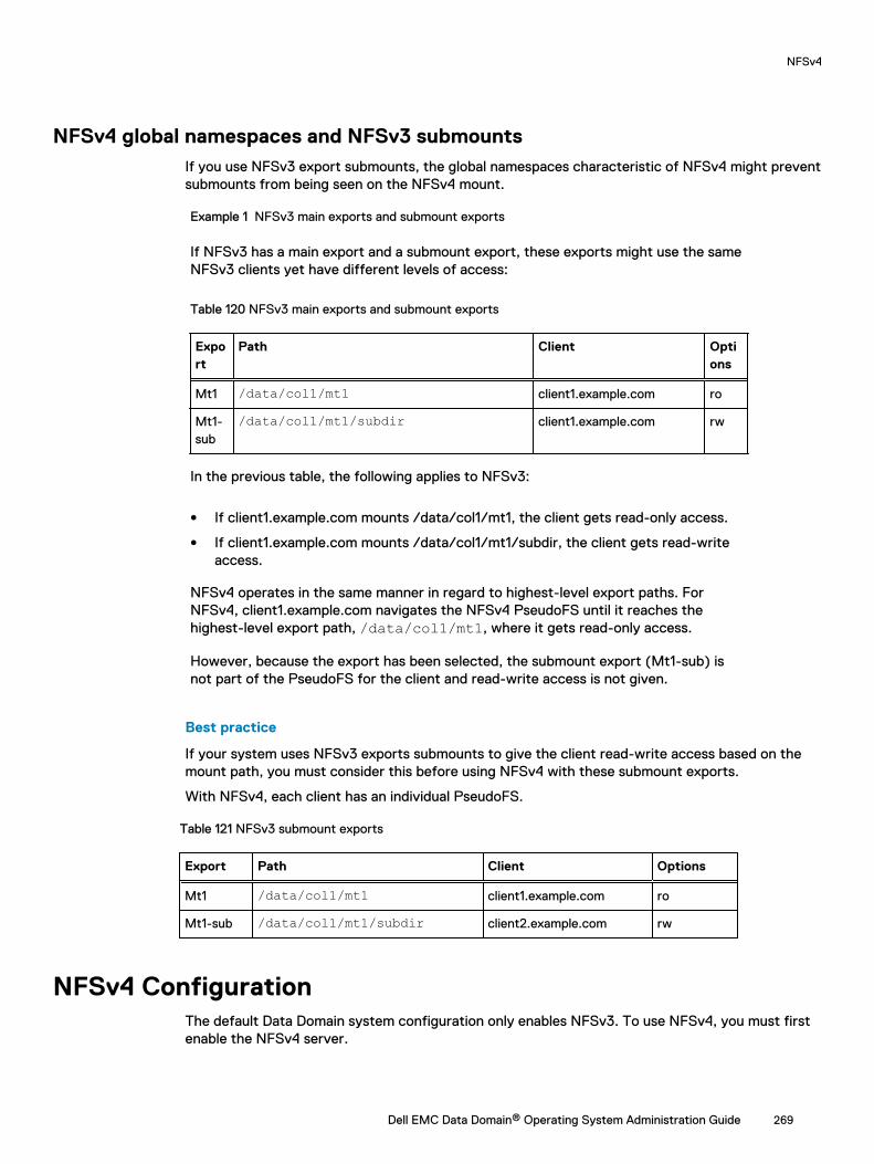
NFSv4 global namespaces and NFSv3 submountsIf you use NFSv3 export submounts, the global namespaces characteristic of NFSv4 might preventsubmounts from being seen on the NFSv4 mount.
Example 1 NFSv3 main exports and submount exports
If NFSv3 has a main export and a submount export, these exports might use the sameNFSv3 clients yet have different levels of access:
Table 120 NFSv3 main exports and submount exports
Export
Path Client Options
Mt1 /data/col1/mt1 client1.example.com ro
Mt1-sub
/data/col1/mt1/subdir client1.example.com rw
In the previous table, the following applies to NFSv3:
l If client1.example.com mounts /data/col1/mt1, the client gets read-only access.
l If client1.example.com mounts /data/col1/mt1/subdir, the client gets read-writeaccess.
NFSv4 operates in the same manner in regard to highest-level export paths. ForNFSv4, client1.example.com navigates the NFSv4 PseudoFS until it reaches thehighest-level export path, /data/col1/mt1, where it gets read-only access.
However, because the export has been selected, the submount export (Mt1-sub) isnot part of the PseudoFS for the client and read-write access is not given.
Best practice
If your system uses NFSv3 exports submounts to give the client read-write access based on themount path, you must consider this before using NFSv4 with these submount exports.
With NFSv4, each client has an individual PseudoFS.
Table 121 NFSv3 submount exports
Export Path Client Options
Mt1 /data/col1/mt1 client1.example.com ro
Mt1-sub /data/col1/mt1/subdir client2.example.com rw
NFSv4 ConfigurationThe default Data Domain system configuration only enables NFSv3. To use NFSv4, you must firstenable the NFSv4 server.
NFSv4
Dell EMC Data Domain® Operating System Administration Guide 269
Enabling the NFSv4 ServerProcedure
1. Enter nfs enable version 4 to enable NFSv4:
# nfs enable version 4 NFS server version(s) 3:4 enabled.
2. (Optional) If you want to disable NFSv3, enter nfs disable version 3.
# nfs disable version 3NFS server version(s) 3 disabled.NFS server version(s) 4 enabled.
After you finish
After the NFSv4 server is enabled, you might need to perform additional NFS configuration tasksspecifically for your site. These tasks can include performing the following actions on the DataDomain system:
l Setting the NFSv4 domain
l Configuring NFSv4 ID mapping
l Configuring ACL (Access Control Lists)
Setting the default server to include NFSv4About this task
The Data Domain NFS command option default-server-version controls which NFS version isenabled when you enter the nfs enable command without specifying a version.
Procedure
1. Enter the nfs option set default-server-version 3:4 command:
# nfs option set default-server-version 3:4NFS option 'default-server-version' set to '3:4'.
Updating existing exportsYou can update existing exports to change the NFS version used by your Data Domain system.
Procedure
1. Enter the nfs export modify all command:
# nfs export modify all clients all options version=version number
To ensure all existing clients have either version 3, 4, or both, you can modify the NFSversion to the appropriate string. The following example shows NFS modified to includeversions 3 and 4:
#nfs export modify all clients all options version=3:4
For more information about the nfs export command, see the Data Domain OperatingSystem Command Reference Guide for more information.
NFSv4
270 Dell EMC Data Domain® Operating System Administration Guide
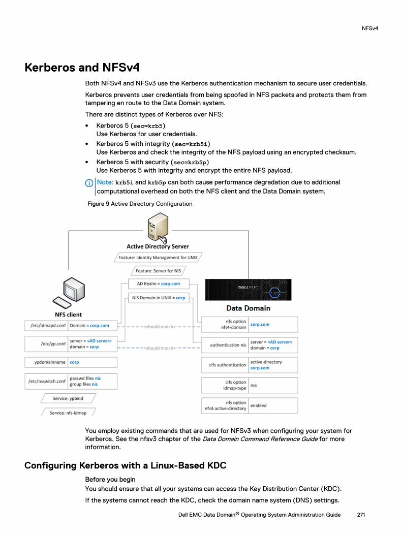
Kerberos and NFSv4Both NFSv4 and NFSv3 use the Kerberos authentication mechanism to secure user credentials.
Kerberos prevents user credentials from being spoofed in NFS packets and protects them fromtampering en route to the Data Domain system.
There are distinct types of Kerberos over NFS:
l Kerberos 5 (sec=krb5)Use Kerberos for user credentials.
l Kerberos 5 with integrity (sec=krb5i)Use Kerberos and check the integrity of the NFS payload using an encrypted checksum.
l Kerberos 5 with security (sec=krb5p)Use Kerberos 5 with integrity and encrypt the entire NFS payload.
Note: krb5i and krb5p can both cause performance degradation due to additionalcomputational overhead on both the NFS client and the Data Domain system.
Figure 9 Active Directory Configuration
You employ existing commands that are used for NFSv3 when configuring your system forKerberos. See the nfsv3 chapter of the Data Domain Command Reference Guide for moreinformation.
Configuring Kerberos with a Linux-Based KDCBefore you beginYou should ensure that all your systems can access the Key Distribution Center (KDC).
If the systems cannot reach the KDC, check the domain name system (DNS) settings.
NFSv4
Dell EMC Data Domain® Operating System Administration Guide 271
About this task
The following steps allow you to create keytab files for the client and the Data Domain system:
l In Steps 1-3, you create the keytab file for the Data Domain system.
l In Steps 4-5, you create the keytab file for the client.
Procedure
1. Create the nfs/<ddr_dns_name>@<realm> service principal.
kadmin.local: addprinc -randkey nfs/ddr12345.<domain-name>@<domain-name>
2. Export nfs/<ddr_dns_name>@<realm> to a keytab file.
kadmin.local: ktadd –k /tmp/ddr.keytab nfs/[email protected]
3. Copy the keytab file to the Data Domain system at the following location:
/ddr/var/krb5.keytab
4. Create one of the following principals for the client and export that principal to the keytabfile:
nfs/<client_dns_name>@<REALM>root/<client_dns_name>@<REALM>
5. Copy the keytab file to the client at the following location:
/etc/krb5.keytab
Note: It is recommended that you use an NTP server to keep the time synchronized onall entities.
Configuring the Data Domain System to Use Kerberos AuthenticationProcedure
1. Configure the KDC and Kerberos realm on the Data Domain system by using theauthentication command:
# authentication kerberos set realm <realm> kdc-type unix kdcs <kdc-server>
2. Import the keytab file:
# authentication kerberos keytab import
3. (Optional) Configure the NIS server by entering the following commands:
# authentication nis servers add <server># authentication nis domain set <domain-name># authentication nis enable# filesys restart
4. (Optional) Make the nfs4-domain the same as the Kerberos realm using the nfs optioncommand:
nfs option set nfs4-domain <kerberos-realm>
NFSv4
272 Dell EMC Data Domain® Operating System Administration Guide
5. Add a client to an existing export by adding sec=krb5 to the nfs export add command:
nfs export add <export-name> clients * options version=4,sec=krb5
Configuring ClientsProcedure
1. Configure the DNS server and verify that forward and reverse lookups are working.
2. Configure the KDC and Kerberos realm by editing the /etc/krb5.conf configuration file.
You might need to perform this step based on the client operating system you are using.
3. Configure NIS or another external name mapping service.
4. (Optional) Edit the /etc/idmapd.conf file to ensure it is the same as the Kerberos realm.
You might need to perform this step based on the client operating system you are using.
5. Verify the keytab file /etc/krb5.keytab contains an entry for the nfs/ service principal orthe root/ principal.
[root@fc22 ~]# klist -kKeytab name: FILE:/etc/krb5.keytabKVNO Principal---- --------------------------------------------------------------------------3 nfs/fc22.domain-name@domain-name
6. Mount the export using the sec=krb5 option.
[root@fc22 ~]# mount ddr12345.<domain-name>:/data/col1/mtree1 /mnt/nfs4 –o sec=krb5,vers=4
Enabling Active DirectoryAbout this task
Configuring Active Directory authentication makes the Data Domain system part of a WindowsActive Directory realm. CIFS clients and NFS clients use Kerberos authentication.
Procedure
1. Join an active directory realm using the cifs set command:
# cifs set authentication active-directory <realm>
Kerberos is automatically set up on the Data Domain system. the required nfs/ serviceprincipal is automatically created on the KDC.
2. Configure NIS using the authentication nis command:
# authentication nis servers add <windows-ad-server># authentication nis domain set <ad-realm># authentication nis enable
3. Configure CIFS to use NSS for ID mapping by using cifs commands:
# cifs disable# cifs option set idmap-type nss# cifs enable# filesys restart
4. Set the nfs4-domain to be the same as the Active Directory realm:
NFSv4
Dell EMC Data Domain® Operating System Administration Guide 273
# nfs option set nfs4-domain <ad-realm>5. Enable Active Directory for NFSv4 id mapping by using the nfs command:
# nfs option set nfs4-idmap-active-directory enabled
Configuring Active DirectoryProcedure
1. Install the Active Directory Domain Services (AD DS) role on the Windows server.
2. Install the Identity Management for UNIX components.
C:\Windows\system32>Dism.exe /online /enable-feature /featurename:adminui /allC:\Windows\system32>Dism.exe /online /enable-feature /featurename:nis /all
3. Verify the NIS domain is configured on the server.
C:\Windows\system32>nisadminThe following are the settings on localhost
Push Interval : 1 daysLogging Mode : Normal
NIS DomainsNIS Domain in AD Master server NIS Domain in UNIX---------------- ------------- ----------------corp win-ad-server corp
4. Assign AD users and groups UNIX UID/GIDs for the NFSv4 server.
a. Go to Server Manager > Tools > Active Directory.
b. Open the Properties for an AD user or group.
c. Under the UNIX Atributes tab, fill in the NIS domain, UID, and Primary GID fields.
Configuring clients on Active DirectoryProcedure
1. Create a new AD user on the AD server to represent the NFS client's service principal.
2. Create the nfs/ service principal for the NFS client.
> ktpass -princ nfs/<client_dns_name>@<REALM> -mapuser nfsuser -pass **** -out nfsclient.keytab /crytp rc4-hmac-nt /ptype KRB5_NT_PRINCIPAL
3. (Optional) Copy the keytab file to /etc/krb5.keytab on the client.
The need to perform this step depends on which client OS you are using.
NFSv4
274 Dell EMC Data Domain® Operating System Administration Guide
CHAPTER 11
Storage Migration
This chapter includes:
l Storage migration overview.................................................................................................276l Migration planning considerations....................................................................................... 276l Viewing migration status..................................................................................................... 278l Evaluating migration readiness............................................................................................ 278l Migrating storage using DD System Manager......................................................................279l Storage migration dialog descriptions..................................................................................279l Migrating storage using the CLI.......................................................................................... 282l CLI storage migration example............................................................................................ 283
Dell EMC Data Domain® Operating System Administration Guide 275
Storage migration overviewStorage migration supports the replacement of existing storage enclosures with new enclosuresthat may offer higher performance, higher capacity, and a smaller footprint.
After new enclosures are installed, you can migrate the data from the older enclosures to the newenclosures while the system continues to support other processes such as data access, expansion,cleaning, and replication. The storage migration does require system resources, but you cancontrol this with throttle settings that give the migration a relatively higher or lower priority. Youcan also suspend a migration to make more resources available to other processes, then resumethe migration when resource demand is lower.
During the migration, the system uses data on the source and destination enclosures. New data iswritten to the new enclosures. Non-migrated data is updated on the source enclosures, andmigrated data is updated on the destination enclosures. If the migration is interrupted, themigration can resume migrating blocks that have not been marked as migrated.
During the migration, each block of data is copied and verified, the source block is freed andmarked as migrated, and the system index is updated to use the new location. New data that wasdestined to land in the source block will now be redirected to destination block. All new data blockallocations that would have been allocated from source are allocated from the destination.
The Migration copy process is done at the shelf level, not the logical data level, so all disk sectorson the source shelf are accessed and copied over regardless of whether there is data on them.Therefore, the Storage Migration Utility cannot be used to shrink a logical data footprint.
Note: Because the data set is divided between the source and destination enclosures duringmigration, you cannot halt a migration and resume use of only the source enclosures. Oncestarted, the migration must complete. If a failure, such as a faulty disk drive, interrupts themigration, address the issue and resume the migration.
Depending on the amount of data to migrate and the throttle settings selected, a storage migrationcan take days or weeks. When all data is migrated, the finalize process, which must be manuallyinitiated using the storage migration finalize command, restarts the filesystem. Duringthe restart, the source enclosures are removed from the system configuration and the destinationenclosures become part of the filesystem. When the finalize process is complete, the sourceenclosures can be removed from the system.
After a storage migration, the disk shelf numbers reported by DD OS might not be sequential. Thisis because shelf numbering is tied to the serial number of each individual disk shelf. KB article499019, Data Domain: Storage enclosure numbering is not sequential, available on https://support.emc.com, provides additional details. In DD OS version 5.7.3.0 and later, the enclosureshow persistent-id command described in the KB article requires administrator access, notSE access.
Migration planning considerationsConsider the following guidelines before starting a storage migration.
l Storage migration requires a single-use license and operates on system models supported byDD OS version 5.7 or later.
Note: Multiple storage migration operations require multiple licenses. However, multiplesource enclosures can be migrated to multiple destination enclosures during a singleoperation.
l Two licenses are required for storage migration:
n The storage migration feature license
Storage Migration
276 Dell EMC Data Domain® Operating System Administration Guide
n The capacity and shelf type license for the destination enclosures
l Storage migration is based on capacity, not enclosure count. Therefore:
n One source enclosure can be migrated to one destination enclosure.
n One source enclosure can be migrated to multiple destination enclosures.
n Multiple source enclosures can be migrated to one destination enclosure.
n Multiple source enclosures can be migrated to multiple destination enclosures.
l The storage migration licensing process consists of:
1. Updating the elicense installed on the system with the storage migration feature license andthe capacity and shelf type license for the destination enclosures before running themigration operation.
2. Updating the elicense installed on the system to remove the original capacity and shelf typelicense and the storage migration feature license after the migration operation is complete.
l The destination enclosures must:
n Be unassigned shelves with the drives in an unused state.
n Be licensed for sufficient capacity to receive the data from the source enclosures, with thelicense installed on the system
n Be supported on the DD system model.
n Contain at least as much usable capacity as the enclosures they are replacing.Note: It is not possible to determine the utilization of the source shelf. The systemperforms all calculations based on the capacity of the shelf.
l The DD system model must have sufficient memory to support the active tier storage capacityof the new enclosures.
l Data migration is not supported for disks in the system controller.
l CAUTION Do not upgrade DD OS until the in-progress storage migration is complete.
l Storage migration cannot start when the file system is disabled or while a DD OS upgrade is inprogress, another migration is in progress, or a RAID reconstruction is in progress.
Note: If a storage migration is in progress, a new storage migration license is required tostart a new storage migration operation after the in-progress migration completes. Thepresence or absence of a storage migration license is reported as part of the upgradeprecheck.
l All specified source enclosures must be in the same tier (active or archive).
l There can be only one disk group in each source enclosure, and all disks in the disk group mustbe installed in within the same enclosure.
l All disks in each destination enclosure must be of the same type (for example, all SATA or allSAS).
l After migration begins, the destination enclosures cannot be removed.
l Source enclosures cannot be removed until migration is complete and finalized.
l The storage migration duration depends on the system resources (which differ for differentsystem models), the availability of system resources, and the data quantity to migrate. Storagemigration can take days or weeks to complete.
DS60 shelf considerationsThe DS60 dense shelf can hold 60 disks, allowing the customer to use the full amount of space inthe rack. The drives are accessed from the top of the shelf, by extending the shelf from the
Storage Migration
Dell EMC Data Domain® Operating System Administration Guide 277
cabinet. Due to the weight of the shelves, approximately 225 lbs when fully loaded, read thissection before proceeding with a storage migration to DS60 shelves.
Be aware of the following considerations when working with the DS60 shelf:
CAUTION
l Loading shelves at the top of the rack may cause the shelf to tip over.
l Validate that the floor can support the total weight of the DS60 shelves.
l Validate that the racks can provide enough power to the DS60 shelves.
l When adding more than five DS60s in the first rack, or more than six DS60s in the secondrack, stabilizer bars and a ladder are required to maintain the DS60 shelves.
Viewing migration statusDD System Manager provides two ways to view storage migration status.
Procedure
1. Select Hardware > Storage.
In the Storage area, review the Storage Migration Status line. If the status is Not Licensed,you must add a license before using any storage migration features. If the storage migrationlicense is installed, the status can be one of the following: None, Starting, Migrating, Pausedby User, Paused by System, Copy Completed - Pending Finalization, Finalizing, Failed duringCopy, or Failed during Finalize.
2. If a storage migration is in progress, click View Storage Migration to view the progressdialogs.
Note: The migration status shows the percentage of blocks transferred. In a systemwith many free blocks, the free blocks are not migrated, but they are included in theprogress indication. In this situation, the progress indication will climb quickly and thenslow when the data migration starts.
3. When a storage migration is in progress, you can also view the status by selecting Health >Jobs.
Evaluating migration readinessYou can use the system to evaluate storage migration readiness without committing to start themigration.
Procedure
1. Install the destination enclosures using the instructions in the product installation guides.
2. Select Administration > Licenses and verify that the storage migration license is installed.
3. If the storage migration license is not installed, click Add Licenses and add the license.
4. Select Hardware > Storage, then click Migrate Data.
5. In the Select a Task dialog, select Estimate, then click Next.
6. In the Select Existing Enclosures dialog, use the checkboxes to select each of the sourceenclosures for the storage migration, then click Next.
7. In the Select New Enclosures dialog, use the checkboxes to select each of the destinationenclosures for the storage migration, then click Next.
Storage Migration
278 Dell EMC Data Domain® Operating System Administration Guide
The Add Licenses button allows you to add storage licenses for the new enclosures asneeded, without interrupting the current task.
8. In the Review Migration Plan dialog, review the estimated migration schedule, then clickNext.
9. Review the precheck results in the Verify Migration Preconditions dialog, then click Close.
Results
If any of the precheck tests fail, resolve the issue before you start the migration.
Migrating storage using DD System ManagerThe storage migration process evaluates system readiness, prompts you to confirm that you wantto start the migration, migrates the data, and then prompts you to finalize the process.
Procedure
1. Install the destination enclosures using the instructions in the product installation guides.
2. Select Administration > Licenses and verify that the storage migration license is installed.
3. If the storage migration license is not installed, click Add Licenses and add the license.
4. Select Hardware > Storage, then click Migrate Data.
5. In the Select a Task dialog, select Migrate, then click Next.
6. In the Select Existing Enclosures dialog, use the checkboxes to select each of the sourceenclosures for the storage migration, then click Next.
7. In the Select New Enclosures dialog, use the checkboxes to select each of the destinationenclosures for the storage migration, then click Next.
The Add Licenses button allows you to add storage licenses for the new enclosures asneeded, without interrupting the current task.
8. In the Review Migration Plan dialog, review the estimated migration schedule, then clickStart.
9. In the Start Migration dialog, click Start.
The Migrate dialog appears and updates during the three phases of the migration: StartingMigration, Migration in Progress, and Copy Complete.
10. When the Migrate dialog title displays Copy Complete and a filesystem restart is acceptable,click Finalize.
Note: This task restarts the filesystem and typically takes 10 to 15 minutes. The systemis unavailable during this time.
Results
When the migration finalize task is complete, the system is using the destination enclosures andthe source enclosures can be removed.
Storage migration dialog descriptionsThe DD System Manager dialog descriptions provide additional information on storage migration.This information is also available by clicking the help icon in the dialogs.
Storage Migration
Dell EMC Data Domain® Operating System Administration Guide 279
Select a Task dialogThe configuration in this dialog determines whether the system will evaluate storage migrationreadiness and stop, or evaluate readiness and begin storage migration.
Select Estimate to evaluate system readiness and stop.
Select Migrate to start migration after the system evaluation. Between the system evaluation andthe start of the migration, a dialog prompts you to confirm or cancel the storage migration.
Select Existing Enclosures dialogThe configuration in this dialog selects either the active or the retention tier and the sourceenclosures for the migration.
If the DD Extended Retention feature is installed, use the list box to select either the Active Tieror Retention Tier. The list box does not appear when DD Extended Retention is not installed.
The Existing Enclosures list displays the enclosures that are eligible for storage migration. Selectthe checkbox for each of the enclosures to migrate. Click Next when you are ready to continue.
Select New Enclosures dialogThe configuration in this dialog selects the destination enclosures for the migration. This dialogalso displays the storage license status and an Add Licenses button.
The Available Enclosures list displays the enclosures that are eligible destinations for storagemigration. Select the checkbox for each of the desired destination enclosures.
The license status bar represents all of the storage licenses installed on the system. The greenportion represents licenses that are in use, and the and clear portion represents the licensedstorage capacity available for destination enclosures. If you need to install additional licenses tosupport the selected destination controllers, click Add Licenses.
Click Next when you are ready to continue.
Review Migration Plan dialogThis dialog presents an estimate of the storage migration duration, organized according to thethree stages of storage migration.
Stage 1 of the storage migration runs a series of tests to verify that the system is ready for themigration. The test results appear in the Verify Migration Preconditions dialog.
During Stage 2, the data is copied from the source enclosures to the destination enclosures. Whena large amount of data is present, the copy can take days or weeks to complete because the copytakes place in the background, while the system continues to serve backup clients. A setting in theMigration in Progress dialog allows you to change the migration priority, which can speed up orslow down the migration.
Stage 3, which is manually initiated from the Copy Complete dialog, updates the systemconfiguration to use the destination enclosures and removes the configuration for the sourcecontrollers. During this stage, the file system is restarted and the system is unavailable to backupclients.
Verify Migration Preconditions dialogThis dialog displays the results of the tests that execute before the migration starts.
The following list shows the test sequence and provides additional information on each of thetests.
Storage Migration
280 Dell EMC Data Domain® Operating System Administration Guide
P1. This system's platform is supported.
Older DD system models do not support storage migration.
P2. A storage migration license is available.
A storage migration license is required.
P3. No other migration is currently running.
A previous storage migration must complete before you can start another.
P4. The current migration request is the same as the interrupted migration request.
Resume and complete the interrupted migration.
P5. Check the disk group layout on the existing enclosures.
Storage migration requires that each source enclosure contain only one disk group, and all thedisks in the group must be in that enclosure.
P6. Verify the final system capacity.
The total system capacity after migration and the removal of the source enclosures must notexceed the capacity supported by the DD system model.
P7. Verify the replacement enclosures' capacity.
The usable capacity of the destination enclosures must be greater than that of the sourceenclosures.
P8. Source enclosures are in the same active tier or retention unit.
The system supports storage migration from either the active tier or the retention tier. It doesnot support migration of data from both tiers at the same time.
P9. Source enclosures are not part of the head unit.
Although the system controller is listed as an enclosure in the CLI, storage migration does notsupport migration from disks installed in the system controller.
P10. Replacement enclosures are addable to storage.
All disks in each destination enclosure must be of the same type (for example, all SATA or allSAS).
P11. No RAID reconstruction is occurring in the source controllers.
Storage migration cannot start while a RAID reconstruction is in progress.
P12. Source shelf belongs to a supported tier.
The source disk enclosure must be part of a tier supported on the migration destination.
Migration progress dialogsThis series of dialogs presents the storage migration status and the controls that apply at eachstage.
Migrate - Starting Migration
During the first stage, the progress is shown on the progress bar and no controls are available.
Migrate - Migration in Progress
During the second stage, data is copied from the source enclosures to the destination enclosuresand the progress is shown on the progress bar. Because the data copy can take days or weeks tocomplete, controls are provided so that you can manage the resources used during migration andsuspend migration when resources are needed for other processes.
Storage Migration
Dell EMC Data Domain® Operating System Administration Guide 281
You can click Pause to suspend the migration and later click Resume to continue the migration.
The Low, Medium, and High buttons define throttle settings for storage migration resourcedemands. A low throttle setting gives storage migration a lower resource priority, which results in aslower migration and requires fewer system resources. Conversely, A high throttle setting givesstorage migration a higher resource priority, which results in a faster migration and requires moresystem resources. The medium setting selects an intermediate priority.
You do not have to leave this dialog open for the duration of the migration. To check the status ofthe migration after closing this dialog, select Hardware > Storage and view the migration status.To return to this dialog from the Hardware/Storage page, click Manage Migration. The migrationprogress can also be viewed by selecting Health > Jobs.
Migrate - Copy Complete
When the copy is complete, the migration process waits for you to click Finalize. During this finalstage, , which takes 10 to 15 minutes, the filesystem is restarted and the system is not available. Itis a good practice to start this stage during a maintenance window or a period of low systemactivity.
Migrating storage using the CLIAbout this task
A migration simply requires moving all of the allocated blocks from the blocksets formatted oversource DGs (e.g., source blocksets) to the blocksets formatted over destination DGs (e.g.,destination blocksets). Once all of the allocated blocks have been moved from the sourceblocksets, those blocksets can be removed from the file system, their disks can be removed fromtheir storage tier, and the physical disks and enclosures can be removed from the DDR.
Note: The preparation of new enclosures for storage migration is managed by the storagemigration process. Do not prepare destination enclosures as you would for an enclosureaddition. For example, use of the filesys expand command is appropriate for an enclosureaddition, but this command prevents enclosures from being used as storage migrationdestinations.
A DS60 disk shelf contains four disk packs, of 15 disks each. When a DS60 shelf is the migrationsource or destination, the disk packs are referenced as enclosure:pack. In this example, thesource is enclosure 7, pack 2 (7:2), and the destination is enclosure 7, pack 4 (7:4).
Procedure
1. Install the destination enclosures using the instructions in the product installation guides.
2. Check to see if the storage migration feature license is installed.
# elicense show3. If the license is not installed, update the elicense to add the storage migration feature
license
# elicense update4. View the disk states for the source and destination disks.
# disk show state
The source disks should be in the active state, and the destination disks should be in theunknown state.
5. Run the storage migration precheck command to determine if the system is ready for themigration.
# storage migration precheck source-enclosures 7:2 destination-enclosures 7:4
Storage Migration
282 Dell EMC Data Domain® Operating System Administration Guide
6. View the migration throttle setting.
storage migration option show throttle
7. When the system is ready, begin the storage migration.
# storage migration start source-enclosures 7:2 destination-enclosures 7:4
8. Optionally, view the disk states for the source and destination disks during the migration.
# disk show state
During the migration, the source disks should be in the migrating state, and the destinationdisks should be in the destination state.
9. Review the migration status as needed.
# storage migration status
10. View the disk states for the source and destination disks.
# disk show state
During the migration, the source disks should be in the migrating state, and the destinationdisks should be in the destination state.
11. When the migration is complete, update the configuration to use the destination enclosures.
Note: This task restarts the file system and typically takes 10 to 15 minutes. The systemis unavailable during this time.
storage migration finalize
12. If you want to remove all data from each of the source enclosures, remove the data now.
storage sanitize start enclosure <enclosure-id>[:<pack-id>]
Note: The storage sanitize command does not produce a certified data erasure. DataDomain offers certified data erasure as a service. For more information, contact yourData Domain representative.
13. View the disk states for the source and destination disks.
# disk show state
After the migration, the source disks should be in the unknown state, and the destinationdisks should be in the active state.
Results
When the migration finalize task is complete, the system is using the destination storage and thesource storage can be removed.
CLI storage migration exampleelicense show
# elicense showFeature licenses:## Feature Count Mode Expiration Date-- ----------- ----- --------------- ---------------1 REPLICATION 1 permanent (int) n/a2 VTL 1 permanent (int) n/a-- ----------- ----- --------------- ---------------
Storage Migration
Dell EMC Data Domain® Operating System Administration Guide 283
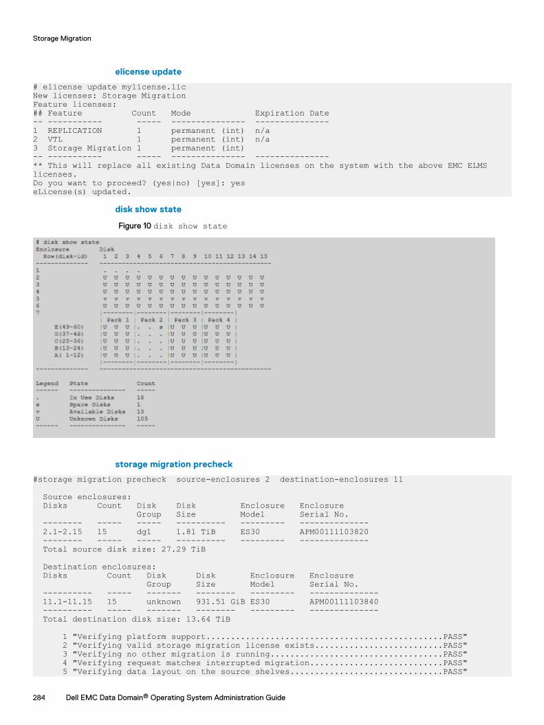
elicense update
# elicense update mylicense.licNew licenses: Storage MigrationFeature licenses:## Feature Count Mode Expiration Date-- ----------- ----- --------------- ---------------1 REPLICATION 1 permanent (int) n/a2 VTL 1 permanent (int) n/a3 Storage Migration 1 permanent (int)-- ----------- ----- --------------- ---------------** This will replace all existing Data Domain licenses on the system with the above EMC ELMS licenses.Do you want to proceed? (yes|no) [yes]: yeseLicense(s) updated.
disk show state
Figure 10 disk show state
storage migration precheck
#storage migration precheck source-enclosures 2 destination-enclosures 11
Source enclosures: Disks Count Disk Disk Enclosure Enclosure Group Size Model Serial No. -------- ----- ----- ---------- --------- -------------- 2.1-2.15 15 dg1 1.81 TiB ES30 APM00111103820 -------- ----- ----- ---------- --------- -------------- Total source disk size: 27.29 TiB Destination enclosures: Disks Count Disk Disk Enclosure Enclosure Group Size Model Serial No. ---------- ----- ------- -------- --------- -------------- 11.1-11.15 15 unknown 931.51 GiB ES30 APM00111103840 ---------- ----- ------- -------- --------- -------------- Total destination disk size: 13.64 TiB
1 "Verifying platform support................................................PASS" 2 "Verifying valid storage migration license exists..........................PASS" 3 "Verifying no other migration is running...................................PASS" 4 "Verifying request matches interrupted migration...........................PASS" 5 "Verifying data layout on the source shelves...............................PASS"
Storage Migration
284 Dell EMC Data Domain® Operating System Administration Guide
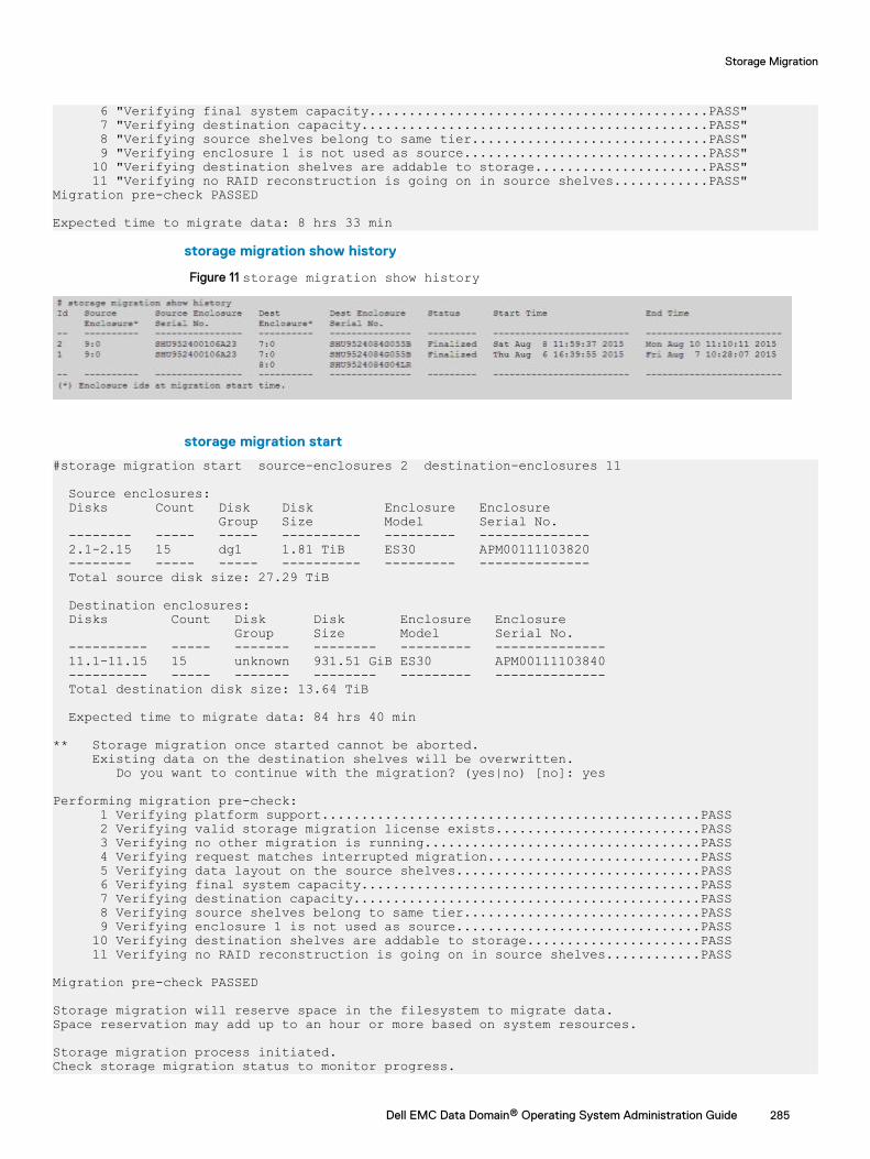
6 "Verifying final system capacity...........................................PASS" 7 "Verifying destination capacity............................................PASS" 8 "Verifying source shelves belong to same tier..............................PASS" 9 "Verifying enclosure 1 is not used as source...............................PASS" 10 "Verifying destination shelves are addable to storage......................PASS" 11 "Verifying no RAID reconstruction is going on in source shelves............PASS"Migration pre-check PASSED
Expected time to migrate data: 8 hrs 33 min
storage migration show history
Figure 11 storage migration show history
storage migration start
#storage migration start source-enclosures 2 destination-enclosures 11
Source enclosures: Disks Count Disk Disk Enclosure Enclosure Group Size Model Serial No. -------- ----- ----- ---------- --------- -------------- 2.1-2.15 15 dg1 1.81 TiB ES30 APM00111103820 -------- ----- ----- ---------- --------- -------------- Total source disk size: 27.29 TiB Destination enclosures: Disks Count Disk Disk Enclosure Enclosure Group Size Model Serial No. ---------- ----- ------- -------- --------- -------------- 11.1-11.15 15 unknown 931.51 GiB ES30 APM00111103840 ---------- ----- ------- -------- --------- -------------- Total destination disk size: 13.64 TiB
Expected time to migrate data: 84 hrs 40 min
** Storage migration once started cannot be aborted. Existing data on the destination shelves will be overwritten. Do you want to continue with the migration? (yes|no) [no]: yes
Performing migration pre-check: 1 Verifying platform support................................................PASS 2 Verifying valid storage migration license exists..........................PASS 3 Verifying no other migration is running...................................PASS 4 Verifying request matches interrupted migration...........................PASS 5 Verifying data layout on the source shelves...............................PASS 6 Verifying final system capacity...........................................PASS 7 Verifying destination capacity............................................PASS 8 Verifying source shelves belong to same tier..............................PASS 9 Verifying enclosure 1 is not used as source...............................PASS 10 Verifying destination shelves are addable to storage......................PASS 11 Verifying no RAID reconstruction is going on in source shelves............PASS
Migration pre-check PASSED
Storage migration will reserve space in the filesystem to migrate data. Space reservation may add up to an hour or more based on system resources.
Storage migration process initiated.Check storage migration status to monitor progress.
Storage Migration
Dell EMC Data Domain® Operating System Administration Guide 285
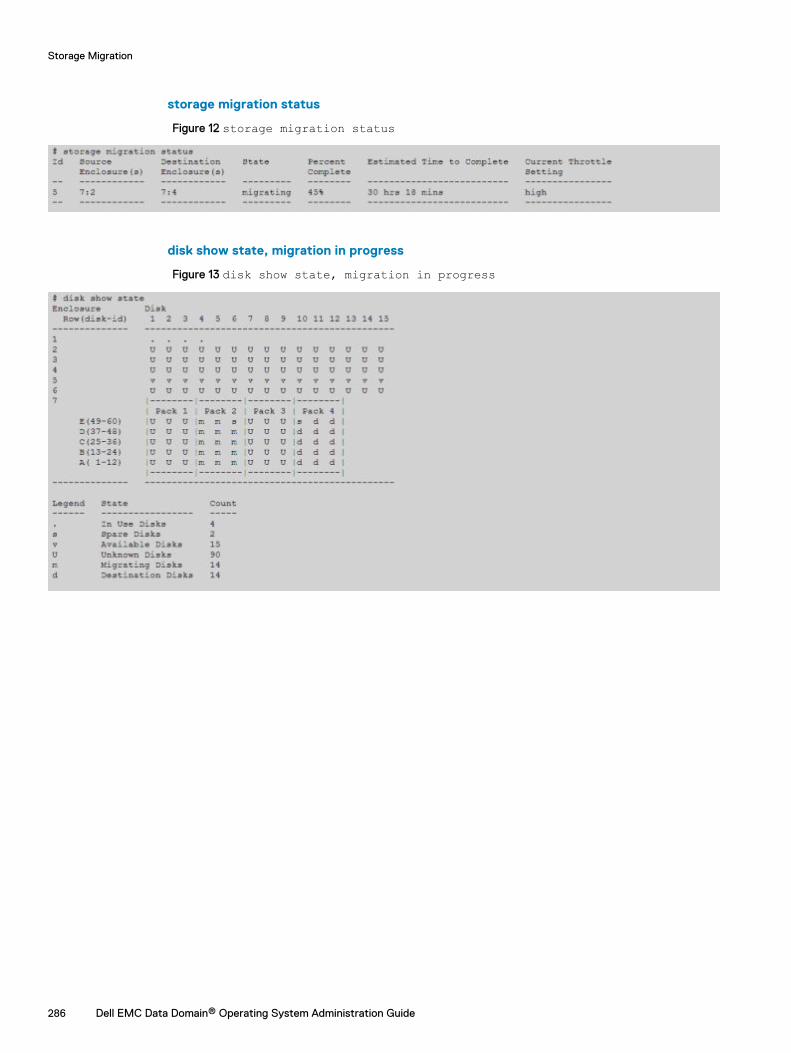
storage migration status
Figure 12 storage migration status
disk show state, migration in progress
Figure 13 disk show state, migration in progress
Storage Migration
286 Dell EMC Data Domain® Operating System Administration Guide
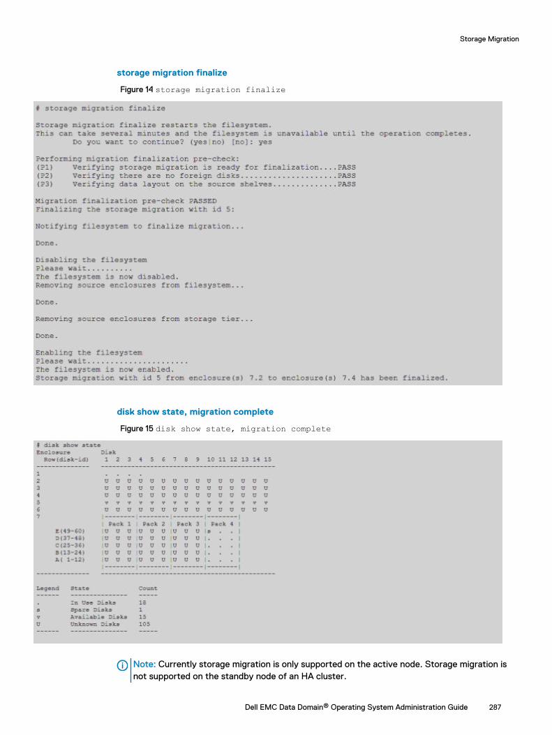
storage migration finalize
Figure 14 storage migration finalize
disk show state, migration complete
Figure 15 disk show state, migration complete
Note: Currently storage migration is only supported on the active node. Storage migration isnot supported on the standby node of an HA cluster.
Storage Migration
Dell EMC Data Domain® Operating System Administration Guide 287

Storage Migration
288 Dell EMC Data Domain® Operating System Administration Guide
CHAPTER 12
Metadata on Flash
This chapter includes:
l Overview of Metadata on Flash (MDoF) ............................................................................ 290l MDoF licensing and capacity............................................................................................... 290l SSD cache tier..................................................................................................................... 291l MDoF SSD cache tier - system management ......................................................................291l SSD alerts........................................................................................................................... 295
Dell EMC Data Domain® Operating System Administration Guide 289
Overview of Metadata on Flash (MDoF)MDoF creates caches for file system metadata using flash technologies. The SSD Cache is a lowlatency, high input/output operations per second (IOPS) cache to accelerate metadata and dataaccess.
Note: The minimum software version required is DD OS 6.0.
Caching the file system metadata on SSDs improves I/O performance for both traditional andrandom workloads.
For traditional workloads, offloading random access to metadata from HDDs to SSDs allows thehard drives to accommodate streaming write and read requests.
For random workloads, SSD cache provides low latency metadata operations, which allows theHDDs to serve data requests instead of cache requests.
Read cache on SSD improves random read performance by caching frequently accessed data.Writing data to NVRAM combined with low latency metadata operations to drain the NVRAMfaster improve random write latency. The absence of cache does not prevent file systemoperation, it only impacts file system performance.
When the cache tier is first created, a file system restart is only required if the cache tier is beingadded after the file system is running. For new systems that come with cache tier disks, no filesystem restart is required if the cache tier is created before enabling the file system for the firsttime. Additional cache can be added to a live system, without the need to disable and enable thefile system.
Note: DD9500 systems that were upgraded from DD OS 5.7 to DD OS 6.0 require a one-timefile system restart after creating the cache tier for the first time.
One specific condition with regard to SSDs is when the number of spare blocks remaining getsclose to zero, the SSD enters a read only condition. When a read only condition occurs, DD OStreats the drive as read-only cache and sends an alert.
MDoF is supported on the following Data Domain systems:
l DD6300
l DD6800
l DD9300
l DD9500
l DD9800
l DD VE instances, including DD3300 systems, in capacity configurations of 16 TB and higher(SSD Cache Tier for DD VE)
MDoF licensing and capacityA license enabled through ELMS is necessary for using the MDoF feature; the SSD Cache licensewill not be enabled by default.
The following table describes the various SSD capacity licenses and the SSD capacities for thegiven system:
Metadata on Flash
290 Dell EMC Data Domain® Operating System Administration Guide
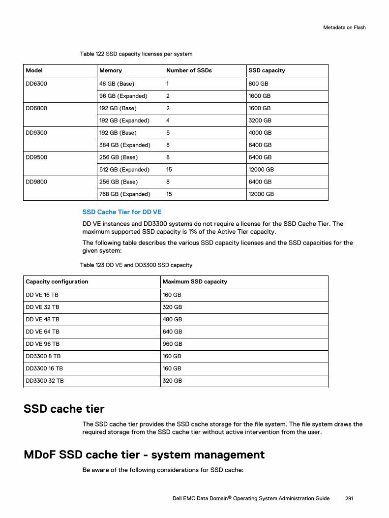
Table 122 SSD capacity licenses per system
Model Memory Number of SSDs SSD capacity
DD6300 48 GB (Base) 1 800 GB
96 GB (Expanded) 2 1600 GB
DD6800 192 GB (Base) 2 1600 GB
192 GB (Expanded) 4 3200 GB
DD9300 192 GB (Base) 5 4000 GB
384 GB (Expanded) 8 6400 GB
DD9500 256 GB (Base) 8 6400 GB
512 GB (Expanded) 15 12000 GB
DD9800 256 GB (Base) 8 6400 GB
768 GB (Expanded) 15 12000 GB
SSD Cache Tier for DD VE
DD VE instances and DD3300 systems do not require a license for the SSD Cache Tier. Themaximum supported SSD capacity is 1% of the Active Tier capacity.
The following table describes the various SSD capacity licenses and the SSD capacities for thegiven system:
Table 123 DD VE and DD3300 SSD capacity
Capacity configuration Maximum SSD capacity
DD VE 16 TB 160 GB
DD VE 32 TB 320 GB
DD VE 48 TB 480 GB
DD VE 64 TB 640 GB
DD VE 96 TB 960 GB
DD3300 8 TB 160 GB
DD3300 16 TB 160 GB
DD3300 32 TB 320 GB
SSD cache tierThe SSD cache tier provides the SSD cache storage for the file system. The file system draws therequired storage from the SSD cache tier without active intervention from the user.
MDoF SSD cache tier - system managementBe aware of the following considerations for SSD cache:
Metadata on Flash
Dell EMC Data Domain® Operating System Administration Guide 291
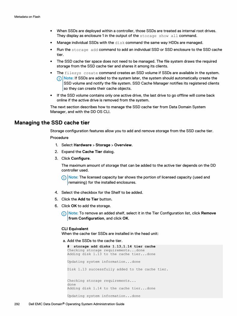
l When SSDs are deployed within a controller, those SSDs are treated as internal root drives.They display as enclosure 1 in the output of the storage show all command.
l Manage individual SSDs with the disk command the same way HDDs are managed.
l Run the storage add command to add an individual SSD or SSD enclosure to the SSD cachetier.
l The SSD cache tier space does not need to be managed. The file system draws the requiredstorage from the SSD cache tier and shares it among its clients.
l The filesys create command creates an SSD volume if SSDs are available in the system.Note: If SSDs are added to the system later, the system should automatically create theSSD volume and notify the file system. SSD Cache Manager notifies its registered clientsso they can create their cache objects.
l If the SSD volume contains only one active drive, the last drive to go offline will come backonline if the active drive is removed from the system.
The next section describes how to manage the SSD cache tier from Data Domain SystemManager, and with the DD OS CLI.
Managing the SSD cache tierStorage configuration features allow you to add and remove storage from the SSD cache tier.
Procedure
1. Select Hardware > Storage > Overview.
2. Expand the Cache Tier dialog.
3. Click Configure.
The maximum amount of storage that can be added to the active tier depends on the DDcontroller used.
Note: The licensed capacity bar shows the portion of licensed capacity (used andremaining) for the installed enclosures.
4. Select the checkbox for the Shelf to be added.
5. Click the Add to Tier button.
6. Click OK to add the storage.
Note: To remove an added shelf, select it in the Tier Configuration list, click Removefrom Configuration, and click OK.
CLI EquivalentWhen the cache tier SSDs are installed in the head unit:
a. Add the SSDs to the cache tier.# storage add disks 1.13,1.14 tier cacheChecking storage requirements...doneAdding disk 1.13 to the cache tier...done
Updating system information...done
Disk 1.13 successfully added to the cache tier.
Checking storage requirements...doneAdding disk 1.14 to the cache tier...done
Updating system information...done
Metadata on Flash
292 Dell EMC Data Domain® Operating System Administration Guide
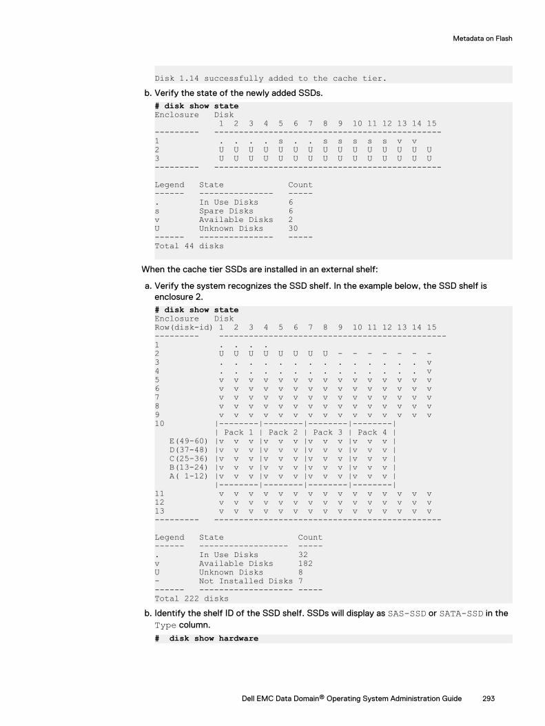
Disk 1.14 successfully added to the cache tier.b. Verify the state of the newly added SSDs.
# disk show state Enclosure Disk 1 2 3 4 5 6 7 8 9 10 11 12 13 14 15--------- ----------------------------------------------1 . . . . s . . s s s s s v v2 U U U U U U U U U U U U U U U3 U U U U U U U U U U U U U U U--------- ----------------------------------------------
Legend State Count------ --------------- -----. In Use Disks 6s Spare Disks 6v Available Disks 2U Unknown Disks 30------ --------------- -----Total 44 disks
When the cache tier SSDs are installed in an external shelf:
a. Verify the system recognizes the SSD shelf. In the example below, the SSD shelf isenclosure 2.# disk show stateEnclosure DiskRow(disk-id) 1 2 3 4 5 6 7 8 9 10 11 12 13 14 15--------- ----------------------------------------------1 . . . . 2 U U U U U U U U - - - - - - -3 . . . . . . . . . . . . . . v4 . . . . . . . . . . . . . . v5 v v v v v v v v v v v v v v v6 v v v v v v v v v v v v v v v7 v v v v v v v v v v v v v v v8 v v v v v v v v v v v v v v v9 v v v v v v v v v v v v v v v10 |--------|--------|--------|--------| | Pack 1 | Pack 2 | Pack 3 | Pack 4 | E(49-60) |v v v |v v v |v v v |v v v | D(37-48) |v v v |v v v |v v v |v v v | C(25-36) |v v v |v v v |v v v |v v v | B(13-24) |v v v |v v v |v v v |v v v | A( 1-12) |v v v |v v v |v v v |v v v | |--------|--------|--------|--------|11 v v v v v v v v v v v v v v v12 v v v v v v v v v v v v v v v13 v v v v v v v v v v v v v v v--------- ----------------------------------------------
Legend State Count------ ------------------ -----. In Use Disks 32v Available Disks 182U Unknown Disks 8- Not Installed Disks 7------ ------------------- -----Total 222 disks
b. Identify the shelf ID of the SSD shelf. SSDs will display as SAS-SSD or SATA-SSD in theType column.
# disk show hardware
Metadata on Flash
Dell EMC Data Domain® Operating System Administration Guide 293
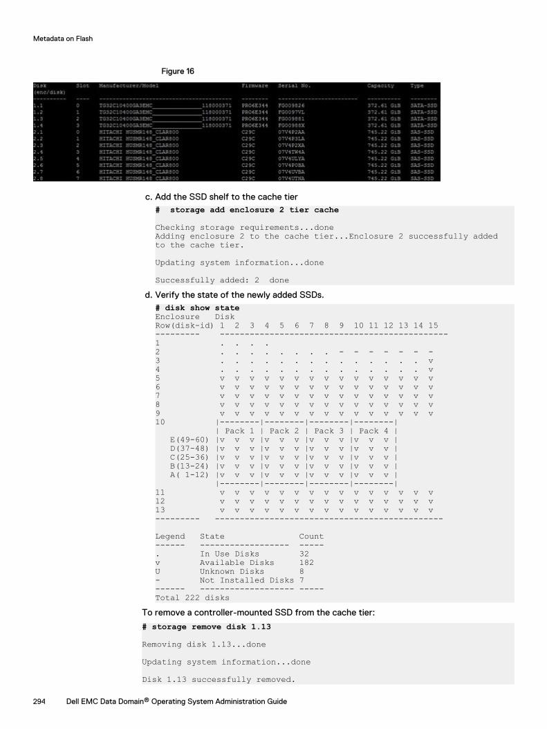
Figure 16
c. Add the SSD shelf to the cache tier# storage add enclosure 2 tier cache
Checking storage requirements...doneAdding enclosure 2 to the cache tier...Enclosure 2 successfully added to the cache tier.
Updating system information...done
Successfully added: 2 doned. Verify the state of the newly added SSDs.
# disk show stateEnclosure DiskRow(disk-id) 1 2 3 4 5 6 7 8 9 10 11 12 13 14 15--------- ----------------------------------------------1 . . . . 2 . . . . . . . . - - - - - - -3 . . . . . . . . . . . . . . v4 . . . . . . . . . . . . . . v5 v v v v v v v v v v v v v v v6 v v v v v v v v v v v v v v v7 v v v v v v v v v v v v v v v8 v v v v v v v v v v v v v v v9 v v v v v v v v v v v v v v v10 |--------|--------|--------|--------| | Pack 1 | Pack 2 | Pack 3 | Pack 4 | E(49-60) |v v v |v v v |v v v |v v v | D(37-48) |v v v |v v v |v v v |v v v | C(25-36) |v v v |v v v |v v v |v v v | B(13-24) |v v v |v v v |v v v |v v v | A( 1-12) |v v v |v v v |v v v |v v v | |--------|--------|--------|--------|11 v v v v v v v v v v v v v v v12 v v v v v v v v v v v v v v v13 v v v v v v v v v v v v v v v--------- ----------------------------------------------
Legend State Count------ ------------------ -----. In Use Disks 32v Available Disks 182U Unknown Disks 8- Not Installed Disks 7------ ------------------- -----Total 222 disks
To remove a controller-mounted SSD from the cache tier:
# storage remove disk 1.13
Removing disk 1.13...done
Updating system information...done
Disk 1.13 successfully removed.
Metadata on Flash
294 Dell EMC Data Domain® Operating System Administration Guide
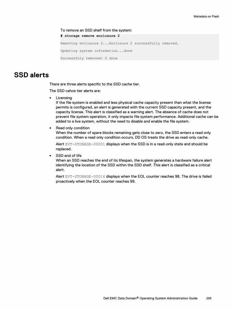
To remove an SSD shelf from the system:# storage remove enclosure 2
Removing enclosure 2...Enclosure 2 successfully removed.
Updating system information...done
Successfuly removed: 2 done
SSD alertsThere are three alerts specific to the SSD cache tier.
The SSD cahce tier alerts are:
l LicensingIf the file system is enabled and less physical cache capacity present than what the licensepermits is configured, an alert is generated with the current SSD capacity present, and thecapacity license. This alert is classified as a warning alert. The absence of cache does notprevent file system operation, it only impacts file system performance. Additional cache can beadded to a live system, without the need to disable and enable the file system.
l Read only conditionWhen the number of spare blocks remaining gets close to zero, the SSD enters a read onlycondition. When a read only condition occurs, DD OS treats the drive as read-only cache.
Alert EVT-STORAGE-00001 displays when the SSD is in a read-only state and should bereplaced.
l SSD end of lifeWhen an SSD reaches the end of its lifespan, the system generates a hardware failure alertidentifying the location of the SSD within the SSD shelf. This alert is classified as a criticalalert.
Alert EVT-STORAGE-00016 displays when the EOL counter reaches 98. The drive is failedproactively when the EOL counter reaches 99.
Metadata on Flash
Dell EMC Data Domain® Operating System Administration Guide 295

Metadata on Flash
296 Dell EMC Data Domain® Operating System Administration Guide
CHAPTER 13
SCSI Target
This chapter includes:
l SCSI Target overview..........................................................................................................298l Fibre Channel view.............................................................................................................. 299l Differences in FC link monitoring among DD OS versions....................................................308
Dell EMC Data Domain® Operating System Administration Guide 297
SCSI Target overviewSCSI (Small Computer System Interface) Target is a unified management daemon for all SCSIservices and transports. SCSI Target supports DD VTL (Virtual Tape Library), DD Boost over FC(Fibre Channel), and vDisk/ProtectPoint Block Services, as well as anything that has a target LUN(logical unit number) on a DD system.
SCSI Target Services and Transports
The SCSI Target daemon starts when FC ports are present or DD VTL is licensed. It providesunified management for all SCSI Target services and transports.
l A service is anything that has a target LUN on a DD system that uses SCSI Target commands,such as DD VTL (tape drives and changers), DD Boost over FC (processor devices), or vDisk(Virtual Disk Device).
l A transport enables devices to become visible to initiators.
l An initiator is a backup client that connects to a system to read and write data using the FCprotocol. A specific initiator can support DD Boost over FC, vDisk, or DD VTL, but not all three.
l Devices are visible on a SAN (storage area network) through physical ports. Host initiatorscommunicate with the DD system through the SAN.
l Access groups manage access between devices and initiators.
l An endpoint is the logical target on a DD system to which an initiator connects. You candisable, enable, and rename endpoints. To delete endpoints, the associated transport hardwaremust no longer exist. Endpoints are automatically discovered and created when a newtransport connection occurs. Endpoints have the following attributes: port topology, FCP2-RETRY status, WWPN, and WWNN.
l NPIV (N_port ID Virtualization) is an FC feature that lets multiple endpoints share a singlephysical port. NPIV eases hardware requirements and provides failover capabilities.
l In DD OS 6.0, users can specify the sequence of secondary system addresses for failover. Forexample, if the system specifies 0a, 0b, 1a, 1b and the user specifies 1b, 1a, 0a, 0b , the user-specified sequence is used for failover. The scsitarget endpoint show detailedcommand displays the user-specified sequence.
Note the following exceptions:
l DD Boost can service both FC and IP clients simultaneously; however, both transports cannotshare the same initiator.
l Only one initiator should be present per access group. Each access group is assigned a type(DD VTL, vDisk/ProtectPoint Block Services, or DD Boost over FC).
SCSI Target Architectures - Supported and Unsupported
SCSI Target supports the following architectures:
l DD VTL plus DD Boost over FC from different initiators: Two different initiators (on thesame or different clients) may access a DD system using DD VTL and DD Boost over FC,through the same or different DD system target endpoints.
l DD VTL plus DD Boost over FC from one initiator to two different DD systems: A singleinitiator may access two different DD systems using any service.
SCSI Target does not support the following architecture:
l DD VTL plus DD Boost over FC from one initiator to the same DD system: A single initiatormay not access the same DD system through different services.
Thin Protocol
SCSI Target
298 Dell EMC Data Domain® Operating System Administration Guide
The thin protocol is a lightweight daemon for VDisk and DD VTL that responds to SCSI commandswhen the primary protocol can't. For Fibre Channel environments with multiple protocols, thinprotocol:
l Prevents initiator hangs
l Prevents unnecessary initiator aborts
l Prevents initiator devices from disappearing
l Supports a standby mode
l Supports fast and early discoverable devices
l Enhances protocol HA behavior
l Doesn't require fast registry access
For More Information about DD Boost and the scscitarget Command (CLI)
For more information about using DD Boost through the DD System Manager, see the relatedchapter in this book. For other types of information about DD Boost, see the Data Domain Boost forOpenStorage Administration Guide.
This chapter focuses on using SCSI Target through the DD System Manager. After you havebecome familiar with basic tasks, the scscitarget command in the Data Domain OperatingSystem Command Reference Guide provides more advanced management tasks.
When there is heavy DD VTL traffic, avoid running the scsitarget group use command,which switches the in-use endpoint lists for one or more SCSI Target or vdisk devices in a groupbetween primary and secondary endpoint lists.
Fibre Channel viewThe Fibre Channel view displays the current status of whether Fibre Channel and/or NPIV isenabled. It also displays two tabs: Resources and Access Groups. Resources include ports,endpoints, and initiators. An access group holds a collection of initiator WWPNs (worldwide portnames) or aliases and the drives and changers they are allowed to access.
Enabling NPIVNPIV (N_Port ID Virtualization), is a Fibre Channel feature in which multiple endpoints can share asingle physical port. NPIV eases hardware requirements and provides endpoint failover/failbackcapabilities. NPIV is not configured by default; you must enable it.
About this task
Note: NPIV is enabled by default in HA configuration.
NPIV provides simplified multiple-system consolidation:
l NPIV is an ANSI T11 standard that allows a single HBA physical port to register with a FibreChannel fabic using multiple WWPNs
l The virtual and physical ports have the same port properties and behave exactly the same.
l There may be m:1 relationships between the endpoints and the port, that is, multiple endpointscan share the same physical port.
Specifically, enabling NPIV enables the following features:
l Multiple endpoints are allowed per physical port, each using a virtual (NPIV) port. The baseport is a placeholder for the physical port and is not associated with an endpoint.
l Endpoint failover/failback is automatically enabled when using NPIV.
SCSI Target
Dell EMC Data Domain® Operating System Administration Guide 299
Note: After NPIV is enabled, the "Secondary System Address" must be specified at eachof the endpoints. If not, endpoint failover will not occur.
l Multiple DD systems can be consolidated into a single DD system, however, the number ofHBAs remains the same on the single DD system.
l The endpoint failover is triggered when FC-SSM detects when a port goes from online tooffline. In the case where the physical port is offline before scsitarget is enabled and the port isstill offline after scsitarget is enabled, a endpoint failover is not possible because FC-SSM doesnot generate a port offline event. If the port comes back online and auto-failback is enabled,any failed over endpoints that use that port as a primary port will fail-back to the primary port.
The Data Domain HA features requires NPIV to move WWNs between the nodes of an HA pairduring the failover process.
Note: Before enabling NPIV, the following conditions must be met:
l The DD system must be running DD OS 5.7.
l All ports must be connected to 4Gb, 8Gb, and 16 Gb Fibre Channel HBA and SLIC.
l The DD system ID must be valid, that is, it must not be 0.
In addition, port topologies and port names will be reviewed and may prevent NPIV from beingenabled:
l NPIV is allowed if the topology for all ports is loop-preferred.
l NPIV is allowed if the topology for some of the ports is loop-preferred; however, NPIVmust be disabled for ports that are loop-only, or you must reconfigure the topology toloop-preferred for proper functionality.
l NPIV is not allowed if none of the ports has a topology of loop-preferred.
l If port names are present in access groups, the port names are replaced with theirassociated endpoint names.
Procedure
1. Select Hardware > Fibre Channel.
2. Next to NPIV: Disabled, select Enable.
3. In the Enable NPIV dialog, you will be warned that all Fibre Channel ports must be disabledbefore NPIV can be enabled. If you are sure that you want to do this, select Yes.
CLI Equivalent
a. Make sure (global) NPIV is enabled.# scsitarget transport option show npivSCSI Target Transport OptionsOption Value------ --------npiv disabled------ --------
b. If NPIV is disabled, then enable it. You must first disable all ports.# scsitarget port disable allAll ports successfully disabled.# scsitarget transport option set npiv enabledEnabling FiberChannel NPIV mode may require SAN zoning tobe changed to configure both base port and NPIV WWPNs.Any FiberChannel port names used in the access groups willbe converted to their corresponding endpoint names in orderto prevent ambiguity. Do you want to continue? (yes|no) [no]:
SCSI Target
300 Dell EMC Data Domain® Operating System Administration Guide
c. Re-enable the disabled ports.# scsitarget port enable allAll ports successfully enabled.
d. Make sure the physical ports have an NPIV setting of “auto”.# scsitarget port show detailed 0aSystem Address: 0aEnabled: YesStatus: OnlineTransport: FibreChannelOperational Status: NormalFC NPIV: Enabled (auto)...
e. Create a new endpoint using the primary and secondary ports you have selected.# scsitarget endpoint add test0a0b system-address 0aprimary-system-address 0a secondary-system-address 0b
Note that the endpoint is disabled by default, so enable it.# scsitarget endpoint enable test0a0b
Then display the endpoint information.
# scsitarget endpoint show detailed test0a0bEndpoint: test0a0bCurrent System Address: 0bPrimary System Address: 0aSecondary System Address: 0bEnabled: YesStatus: OnlineTransport: FibreChannelFC WWNN: 50:02:18:80:08:a0:00:91FC WWPN: 50:02:18:84:08:b6:00:91
f. Zone a host system to the auto-generated WWPN of the newly created endpoint.
g. Create a DD VTL, vDisk, or DD Boost over Fibre Channel (DFC) device, and make thisdevice available on the host system.
h. Ensure that the DD device chosen can be accessed on the host (read and/or written).
i. Test the endpoint failover by using the “secondary” option to move the endpoint to theSSA (secondary system address).# scsitarget endpoint use test0a0b secondary
j. Ensure that the DD device chosen can still be accessed on the host (read and/orwritten). Test the failback by using the “primary” option to move the endpoint back tothe PSA (primary system address).# scsitarget endpoint use test0a0b primary
k. Ensure that the DD device chosen can still be accessed on the host (read and/orwritten).
Disabling NPIVBefore you can disable NPIV, you must not have any ports with multiple endpoints.
About this task
Note: NPIV is required for HA configuration. It is enabled by default and cannot be disabled.
Procedure
1. Select Hardware > Fibre Channel.
SCSI Target
Dell EMC Data Domain® Operating System Administration Guide 301
2. Next to NPIV: Enabled, select Disable.
3. In the Disable NPIV dialog, review any messages about correcting the configuration, andwhen ready, select OK.
Resources tabThe Hardware > Fibre Channel > Resources tab displays information about ports, endpoints, andinitiators.
Table 124 Ports
Item Description
System Address System address for port
WWPN Unique worldwide port name, which is a 64-bit identifier (a60-bit value preceded by a 4-bit Network Address Authorityidentifier), of the Fibre Channel (FC) port.
WWNN Unique worldwide node name, which is a 64-bit identifier (a60-bit value preceded by a 4-bit Network Address Authorityidentifier), of the FC node
Enabled Port operational status; either Enabled or Disabled.
NPIV NPIV status; either Enabled or Disabled.
Link Status Link status: either Online or Offline; that is, whether or notthe port is up and capable of handling traffic.
Operation Status Operation status: either Normal or Marginal.
# of Endpoints Number of endpoints associated with this port.
Table 125 Endpoints
Item Description
Name Name of endpoint.
WWPN Unique worldwide port name, which is a 64-bit identifier (a60-bit value preceded by a 4-bit Network Address Authorityidentifier), of the Fibre Channel (FC) port.
WWNN Unique worldwide node name, which is a 64-bit identifier (a60-bit value preceded by a 4-bit Network Address Authorityidentifier), of the FC node
System Address System address of endpoint.
Enabled Port operational state; either Enabled or Disabled.
Link Status Either Online or Offline; that is, whether or not the port is upand capable of handling traffic.
Table 126 Initiators
Item Description
Name Name of initiator.
SCSI Target
302 Dell EMC Data Domain® Operating System Administration Guide
Table 126 Initiators (continued)
Item Description
Service Service support by the initiator, which is either DD VTL, DDBoost, or vDisk.
WWPN Unique worldwide port name, which is a 64-bit identifier (a60-bit value preceded by a 4-bit Network Address Authorityidentifier), of the Fibre Channel (FC) port.
WWNN Unique worldwide node name, which is a 64-bit identifier (a60-bit value preceded by a 4-bit Network Address Authorityidentifier), of the FC node.
Vendor Name Initiator's model.
Online Endpoints Endpoints seen by this initiator. Displays none or offlineif the initiator is not available.
Configuring a portPorts are discovered, and a single endpoint is automatically created for each port, at startup.
About this task
The properties of the base port depend on whether NPIV is enabled:
l In non-NPIV mode, ports use the same properties as the endpoint, that is, the WWPN for thebase port and the endpoint are the same.
l In NPIV mode, the base port properties are derived from default values, that is, a new WWPNis generated for the base port and is preserved to allow consistent switching between NPIVmodes. Also, NPIV mode provides the ability to support multiple endpoints per port.
Procedure
1. Select Hardware > Fibre Channel > Resources.
2. Under Ports, select an port, and then select Modify (pencil).
3. In the Configure Port dialog, select whether to automatically enable or disable NPIV for thisport.
4. For Topology, select Loop Preferred, Loop Only, Point to Point, or Default.
5. For Speed, select 1, 2, 4, 8, or 16 Gbps, or auto.
6. Select OK.
Enabling a portPorts must be enabled before they can be used.
Procedure
1. Select Hardware > Fibre Channel > Resources.
2. Select More Tasks > Ports > Enable. If all ports are already enabled, a message to thateffect is displayed.
3. In the Enable Ports dialog, select one or more ports from the list, and select Next.
4. After the confirmation, select Next to complete the task.
SCSI Target
Dell EMC Data Domain® Operating System Administration Guide 303
Disabling a portYou can simply disable a port (or ports), or you can chose to failover all endpoints on the port (orports) to another port.
Procedure
1. Select Hardware > Fibre Channel > Resources.
2. Select More Tasks > Ports > Disable.
3. In the Disable Ports dialog, select one or more ports from the list, and select Next.
4. In the confirmation dialog, you can continue with simply disabling the port, or you can choseto failover all endpoints on the ports to another port.
Adding an endpointAn endpoint is a virtual object that is mapped to a underlying virtual port. In non-NPIV mode (notavailable on HA configuration), only a single endpoint is allowed per physical port, and the baseport is used to configure that endpoint to the fabric. When NPIV is enabled, multiple endpoints areallowed per physical port, each using a virtual (NPIV) port, and endpoint failover/failback isenabled.
About this task
Note: Non-NPIV mode is not available on HA configurations. NPIV is enabled by default andcannot be disabled.
Note: In NPIV mode, endpoints:
l have a primary system address.
l may have zero or more secondary system addresses.
l are all candidates for failover to an alternate system address on failure of a port; however,failover to a marginal port is not supported.
l may be failed back to use their primary port when the port comes back up online.
Note: When using NPIV, it is recommended that you use only one protocol (that is, DD VTLFibre Channel, DD Boost-over-Fibre Channel, or vDisk Fibre Channel) per endpoint. Forfailover configurations, secondary endpoints should also be configured to have the sameprotocol as the primary.
Procedure
1. Select Hardware > Fibre Channel > Resources.
2. Under Endpoints, select Add (+ sign).
3. In the Add Endpoint dialog, enter a Name for the endpoint (from 1 to 128 characters). Thefield cannot be empty or be the word “all,” and cannot contain the characters asterisk (*),question mark (?), front or back slashes (/, \), or right or left parentheses [(,)].
4. For Endpoint Status, select Enabled or Disabled.
5. If NPIV is enabled, for Primary system address, select from the drop-down list. The primarysystem address must be different from any secondary system address.
6. If NPIV is enabled, for Fails over to secondary system addresses, check the appropriate boxnext to the secondary system address.
7. Select OK.
SCSI Target
304 Dell EMC Data Domain® Operating System Administration Guide
Configuring an endpointAfter you have added an endpoint, you can modify it using the Configure Endpoint dialog.
About this task
Note: When using NPIV, it is recommended that you use only one protocol (that is, DD VTLFibre Channel, DD Boost-over-Fibre Channel, or vDisk Fibre Channel) per endpoint. Forfailover configurations, secondary endpoints should also be configured to have the sameprotocol as the primary.
Procedure
1. Select Hardware > Fibre Channel > Resources.
2. Under Endpoints, select an endpoint, and then select Modify (pencil).
3. In the Configure Endpoint dialog, enter a Name for the endpoint (from 1 to 128 characters).The field cannot be empty or be the word “all,” and cannot contain the characters asterisk(*), question mark (?), front or back slashes (/, \), or right or left parentheses [(,)].
4. For Endpoint Status, select Enabled or Disabled.
5. For Primary system address, select from the drop-down list. The primary system addressmust be different from any secondary system address.
6. For Fails over to secondary system addresses, check the appropriate box next to thesecondary system address.
7. Select OK.
Modifying an endpoint's system addressYou can modify the active system address for a SCSI Target endpoint using the scsitargetendpoint modify command option. This is useful if the endpoint is associated with a systemaddress that no longer exists, for example after a controller upgrade or when a controller HBA(host bus adapter) has been moved. When the system address for an endpoint is modified, allproperties of the endpoint, including WWPN and WWNN (worldwide port and node names,respectively), if any, are preserved and are used with the new system address.
About this task
In the following example, endpoint ep-1 was assigned to system address 5a, but this systemaddress is no longer valid. A new controller HBA was added at system address 10a. The SCSITarget subsystem automatically created a new endpoint, ep-new, for the newly discovered systemaddress. Because only a single endpoint can be associated with a given system address, ep-newmust be deleted, and then ep-1 must be assigned to system address 10a.
Note: It may take some time for the modified endpoint to come online, depending on the SANenvironment, since the WWPN and WWNN have moved to a different system address. Youmay also need to update SAN zoning to reflect the new configuration.
Procedure
1. Show all endpoints to verify the endpoints to be changed:
# scsitarget endpoint show list2. Disable all endpoints:
# scsitarget endpoint disable all3. Delete the new, unnecessary endpoint, ep-new:
# scsitarget endpoint del ep-new
SCSI Target
Dell EMC Data Domain® Operating System Administration Guide 305
4. Modify the endpoint you want to use, ep-1, by assigning it the new system address 10a:
# scsitarget endpoint modify ep-1 system-address 10a5. Enable all endpoints:
# scsitarget endpoint enable all
Enabling an endpointEnabling an endpoint enables the port only if it is currently disabled, that is, you are in non-NPIVmode.
Procedure
1. Select Hardware > Fibre Channel > Resources.
2. Select More Tasks > Endpoints > Enable. If all endpoints are already enabled, a message tothat effect is displayed.
3. In the Enable Endpoints dialog, select one or more endpoints from the list, and select Next.
4. After the confirmation, select Next to complete the task.
Disabling an endpointDisabling an endpoint does not disable the associated port, unless all endpoints using the port aredisabled, that is, you are in non- NPIV mode.
Procedure
1. Select Hardware > Fibre Channel > Resources.
2. Select More Tasks > Endpoints > Disable.
3. In the Disable Endpoints dialog, select one or more endpoints from the list, and select Next.If an endpoint is in use, you are warned that disabling it might disrupt the system.
4. Select Next to complete the task.
Deleting an endpointYou may want to delete an endpoint if the underlying hardware is no longer available. However, ifthe underlying hardware is still present, or becomes available, a new endpoint for the hardware isdiscovered automatically and configured based on default values.
Procedure
1. Select Hardware > Fibre Channel > Resources.
2. Select More Tasks > Endpoints > Delete.
3. In the Delete Endpoints dialog, select one or more endpoints from the list, and select Next.If an endpoint is in use, you are warned that deleting it might disrupt the system.
4. Select Next to complete the task.
Adding an initiatorAdd initiators to provide backup clients to connect to the system to read and write data using theFC (Fibre Channel) protocol. A specific initiator can support DD Boost over FC, or DD VTL, but notboth. A maximum of 1024 initiators can be configured for a DD system.
Procedure
1. Select Hardware > Fibre Channel > Resources.
2. Under Initiators, select Add (+ sign)
SCSI Target
306 Dell EMC Data Domain® Operating System Administration Guide
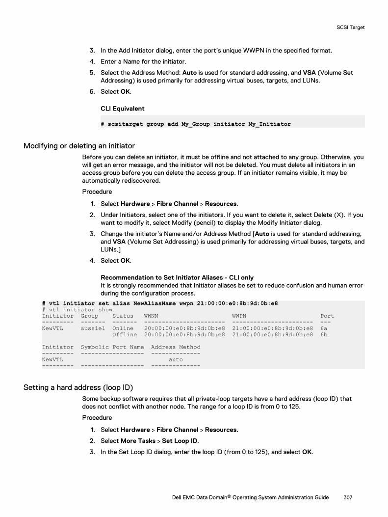
3. In the Add Initiator dialog, enter the port’s unique WWPN in the specified format.
4. Enter a Name for the initiator.
5. Select the Address Method: Auto is used for standard addressing, and VSA (Volume SetAddressing) is used primarily for addressing virtual buses, targets, and LUNs.
6. Select OK.
CLI Equivalent
# scsitarget group add My_Group initiator My_Initiator
Modifying or deleting an initiatorBefore you can delete an initiator, it must be offline and not attached to any group. Otherwise, youwill get an error message, and the initiator will not be deleted. You must delete all initiators in anaccess group before you can delete the access group. If an initiator remains visible, it may beautomatically rediscovered.
Procedure
1. Select Hardware > Fibre Channel > Resources.
2. Under Initiators, select one of the initiators. If you want to delete it, select Delete (X). If youwant to modify it, select Modify (pencil) to display the Modify Initiator dialog.
3. Change the initiator’s Name and/or Address Method [Auto is used for standard addressing,and VSA (Volume Set Addressing) is used primarily for addressing virtual buses, targets, andLUNs.]
4. Select OK.
Recommendation to Set Initiator Aliases - CLI onlyIt is strongly recommended that Initiator aliases be set to reduce confusion and human errorduring the configuration process.
# vtl initiator set alias NewAliasName wwpn 21:00:00:e0:8b:9d:0b:e8# vtl initiator showInitiator Group Status WWNN WWPN Port--------- ------- ------- ----------------------- ----------------------- ---NewVTL aussie1 Online 20:00:00:e0:8b:9d:0b:e8 21:00:00:e0:8b:9d:0b:e8 6a Offline 20:00:00:e0:8b:9d:0b:e8 21:00:00:e0:8b:9d:0b:e8 6b
Initiator Symbolic Port Name Address Method--------- ------------------ --------------NewVTL auto--------- ------------------ --------------
Setting a hard address (loop ID)Some backup software requires that all private-loop targets have a hard address (loop ID) thatdoes not conflict with another node. The range for a loop ID is from 0 to 125.
Procedure
1. Select Hardware > Fibre Channel > Resources.
2. Select More Tasks > Set Loop ID.
3. In the Set Loop ID dialog, enter the loop ID (from 0 to 125), and select OK.
SCSI Target
Dell EMC Data Domain® Operating System Administration Guide 307
Setting failover optionsYou can set options for automatic failover and failback when NPIV is enabled.
About this task
Here is the expected behavior for Fibre Channel port failover, by application:
l DD Boost-over-Fibre Channel operation is expected to continue without user interventionwhen the Fibre Channel endpoints failover.
l DD VTL Fibre Channel operation is expected to be interrupted when the DD VTL Fibre Channelendpoints failover. You may need to perform discovery (that is, operating system discoveryand configuration of DD VTL devices) on the initiators using the affected Fibre Channelendpoint. You should expect to re-start active backup and restore operations.
l vDisk Fibre Channel operation is expected to continue without user intervention when theFibre Channel endpoints failover.
Automatic failback is not guaranteed if all ports are disabled and then subsequently enabled (whichcould be triggered by the administrator), as the order in which ports get enabled is unspecified.
Procedure
1. Select Hardware > Fibre Channel > Resources.
2. Select More Tasks > Set Failover Options.
3. In the Set Failover Options dialog, enter the Failover and Failback Delay (in seconds) andwhether to enable Automatic Failback, and select OK.
Access Groups tabThe Hardware > Fibre Channel > Access Groups tab provides information about DD Boost andDD VTL access groups. Selecting the link to View DD Boost Groups or View VTL Groups takes youto the DD Boost or DD VTL pages.
Table 127 Access Groups
Item Description
Group Name Name of access group.
Service Service for this access group: either DD Boost or DD VTL.
Endpoints Endpoints associated with this access group.
Initiators Initiators associated with this access group.
Number of Devices Number of devices associated with this access group.
Differences in FC link monitoring among DD OS versionsDifferent releases of DD OS handle FC (Fibre Channel) Link Monitoring in different ways.
DD OS 5.3 and later
Port monitoring detects an FC port at system startup and raises an alert if the port is enabled andoffline. To clear the alert, disable an unused port using the scsitarget port commands.
SCSI Target
308 Dell EMC Data Domain® Operating System Administration Guide
DD OS 5.1 up to 5.3
If a port is offline, an alert notifies you that the link is down. This alert is managed, which means itstays active until cleared. This occurs when the DD VTL FC port is online or disabled. If the port isnot in use, disable it unless it needs to be monitored.
DD OS 5.0 up to 5.1
If a port is offline, an alert notifies you that the link is down. The alert is not managed, which meansit does not stay active and does not appear in the current alerts list. When the port is online, analert notifies you that the link is up. If the port is not in use, disable it unless it needs to bemonitored.
DD OS 4.9 up to 5.0
An FC port must be included in a DD VTL group to be monitored.
SCSI Target
Dell EMC Data Domain® Operating System Administration Guide 309

SCSI Target
310 Dell EMC Data Domain® Operating System Administration Guide
CHAPTER 14
Working with DD Boost
This chapter includes:
l About Data Domain Boost.................................................................................................... 312l Managing DD Boost with DD System Manager.................................................................... 312l About interface groups........................................................................................................326l Destroying DD Boost........................................................................................................... 333l Configuring DD Boost-over-Fibre Channel.......................................................................... 333l Using DD Boost on HA systems........................................................................................... 337l About the DD Boost tabs..................................................................................................... 337
Dell EMC Data Domain® Operating System Administration Guide 311
About Data Domain BoostData Domain Boost (DD Boost) provides advanced integration with backup and enterpriseapplications for increased performance and ease of use. DD Boost distributes parts of thededuplication process to the backup server or application clients, enabling client-side deduplicationfor faster, more efficient backup and recovery.
DD Boost is an optional product that requires a separate license to operate on the Data Domainsystem. You can purchase a DD Boost software license key for a Data Domain system directly fromData Domain.
Note: A special license, BLOCK-SERVICES-PROTECTPOINT, is available to enable clientsusing ProtectPoint block services to have DD Boost functionality without a DD Boost license. IfDD Boost is enabled for ProtectPoint clients only—that is, if only the BLOCK-SERVICES-PROTECTPOINT license is installed—the license status indicates that DD Boost is enabled forProtectPoint only.
There are two components to DD Boost: one component that runs on the backup server andanother that runs on the Data Domain system.
l In the context of the NetWorker backup application, Avamar backup application and otherDDBoost partner backup applications, the component that runs on the backup server (DDBoost libraries) is integrated into the particular backup application.
l In the context of Symantec backup applications (NetBackup and Backup Exec) and the OracleRMAN plug-in, you need to download an appropriate version of the DD Boost plugin that isinstalled on each media server. The DD Boost plugin includes the DD Boost libraries forintegrating with the DD Boost server running on the Data Domain system.
The backup application (for example, Avamar, NetWorker, NetBackup, or Backup Exec) setspolicies that control when backups and duplications occur. Administrators manage backup,duplication, and restores from a single console and can use all of the features of DD Boost,including WAN-efficient replicator software. The application manages all files (collections of data)in the catalog, even those created by the Data Domain system.
In the Data Domain system, storage units that you create are exposed to backup applications thatuse the DD Boost protocol. For Symantec applications, storage units are viewed as disk pools. ForNetworker, storage units are viewed as logical storage units (LSUs). A storage unit is an MTree;therefore, it supports MTree quota settings. (Do not create an MTree in place of a storage unit.)
This chapter does not contain installation instructions; refer to the documentation for the productyou want to install. For example, for information about setting up DD Boost with Symantec backupapplications (NetBackup and Backup Exec), see the Data Domain Boost for OpenStorageAdministration Guide. For information on setting up DD Boost with any other application, see theapplication-specific documentation.
Additional information about configuring and managing DD Boost on the Data Domain system canalso be found in the Data Domain Boost for OpenStorage Administration Guide (for NetBackup andBackup Exec) and the Data Domain Boost for Partner Integration Administration Guide (for otherbackup applications).
Managing DD Boost with DD System ManagerAccess the DD Boost view in DD System Manager.
Procedure
1. Select Data Management > File System. Verify that the file system is enabled and runningby checking its state.
Working with DD Boost
312 Dell EMC Data Domain® Operating System Administration Guide
2. Select Protocols > DD Boost.
If you go to the DD Boost page without a license, the Status states that DD Boost is notlicensed. Click Add License and enter a valid license in the Add License Key dialog box.
Note: A special license, BLOCK-SERVICES-PROTECTPOINT, is available to enableclients using ProtectPoint block services to have DD Boost functionality without a DDBoost license. If DD Boost is enabled for ProtectPoint clients only—that is, if only theBLOCK-SERVICES-PROTECTPOINT license is installed—the license status indicatesthat DD Boost is enabled for ProtectPoint only.
Use the DD Boost tabs—Settings, Active Connections, IP Network, Fibre Channel, andStorage Units—to manage DD Boost.
Specifying DD Boost user namesA DD Boost user is also a DD OS user. Specify a DD Boost user either by selecting an existing DDOS user name or by creating a new DD OS user name and making that name a DD Boost user.
About this task
Backup applications use the DD Boost user name and password to connect to the Data Domainsystem. You must configure these credentials on each backup server that connects to this system.The Data Domain system supports multiple DD Boost users. For complete information aboutsetting up DD Boost with Symantec NetBackup and Backup Exec, see the Data Domain Boost forOpenStorage Administration Guide. For information on setting up DD Boost with other applications,see the Data Domain Boost for Partner Integration Administration Guide and the application-specificdocumentation.
Procedure
1. Select Protocols > DD Boost.
2. Select Add (+) above the Users with DD Boost Access list.
The Add User dialog appears.
3. To select an existing user, select the user name in the drop-down list.
If possible, select a user name with management role privileges set to none.
4. To create and select a new user, select Create a new Local User and do the following:
a. Enter the new user name in the User field.
The user must be configured in the backup application to connect to the Data Domainsystem.
b. Enter the password twice in the appropriate fields.
5. Click Add.
Changing DD Boost user passwordsChange a DD Boost user password.
Procedure
1. Select Protocols > DD Boost > Settings.
2. Select a user in the Users with DD Boost Access list.
3. Click the Edit button (pencil icon) above the DD Boost user list.
The Change Password dialog appears.
Working with DD Boost
Dell EMC Data Domain® Operating System Administration Guide 313
4. Enter the password twice in the appropriate boxes.
5. Click Change.
Removing a DD Boost user nameRemove a user from the DD Boost access list.
Procedure
1. Select Protocols > DD Boost > Settings.
2. Select the user in the Users with DD Boost Access list that needs to be removed.
3. Click Remove (X) above the DD Boost user list.
The Remove User dialog appears.
4. Click Remove.
After removal, the user remains in the DD OS access list.
Enabling DD BoostUse the DD Boost Settings tab to enable DD Boost and to select or add a DD Boost user.
Procedure
1. Select Protocols > DD Boost.
2. Click Enable in the DD Boost Status area.
The Enable DD Boost dialog box is displayed.
3. Select an existing user name from the menu, or add a new user by supplying the name,password, and role.
Configuring KerberosYou can configure Kerberos by using the DD Boost Settings tab.
Procedure
1. Select Protocols > DD Boost > Settings.
2. Click Configure in the Kerberos Mode status area.
The Authentication tab under Administration > Access is displayed.Note: You can also enable Kerberos by going directly to Authentication underAdministration > Access in System Manager.
3. Under Active Directory/Kerberos Authentication, click Configure.
The Active Directory/Kerberos Authentication dialog box is displayed.Choose the type of Kerberos Key Distribution Center (KDC) you want to use:
l DisabledNote: If you select Disabled, NFS clients do not use Kerberos authentication. CIFSclients use Workgroup authentication.
l Windows/Active DirectoryNote: Enter the Realm Name, Under Name, and Password for Active Directoryauthentication.
l Unix
Working with DD Boost
314 Dell EMC Data Domain® Operating System Administration Guide
a. Enter the Realm Name, the IP Address/Host Names of one to three KDC servers.
b. Upload the keytab file from one of the KDC servers.
Disabling DD BoostDisabling DD Boost drops all active connections to the backup server. When you disable or destroyDD Boost, the DD Boost FC service is also disabled.
Before you begin
Ensure there are no jobs running from your backup application before disabling.
About this task
Note: File replication started by DD Boost between two Data Domain restores is not canceled.
Procedure
1. Select Protocols > DD Boost.
2. Click Disable in the DD Boost Status area.
3. Click OK in the Disable DD Boost confirmation dialog box.
Viewing DD Boost storage unitsAccess the Storage Units tab to view and manage DD Boost storage units.
The DD Boost Storage Unit tab:
l Lists the storage units and provides the following information for each storage unit:
Table 128 Storage unit information
Item Description
Storage Unit The name of the storage unit.
User The DD Boost user owning the storage unit.
Quota Hard Limit The percentage of hard limit quota used.
Last 24 hr Pre-Comp The amount of raw data from the backup application that hasbeen written in the last 24 hours.
Last 24 hr Post-Comp The amount of storage used after compression in the last 24hours.
Last 24 hr Comp Ratio The compression ratio for the last 24 hours.
Weekly Avg Post-Comp The average amount of compressed storage used in the lastfive weeks.
Last Week Post-Comp The average amount of compressed storage used in the lastseven days.
Weekly Avg Comp Ratio The average compression ratio for the last five weeks.
Last Week Comp Ratio The average compression ratio for the last seven days.
l Allows you to create, modify, and delete storage units.
l Displays four related tabs for a storage unit selected from the list: Storage Unit, Space Usage,Daily Written, and Data Movement.
Working with DD Boost
Dell EMC Data Domain® Operating System Administration Guide 315
Note: The Data Movement tab is available only if an optional Data Domain ExtendedRetention (formerly DD Archiver) or Data Domain Cloud Tier (DD Cloud Tier) license isinstalled.
l Takes you to Replication > On-Demand > File Replication when you click the View DD BoostReplications link.
Note: A DD Replicator license is required for DD Boost to display tabs other than the FileReplication tab.
Creating a storage unitYou must create at least one storage unit on the Data Domain system, and a DD Boost user mustbe assigned to that storage unit. Use the Storage Units tab to create a storage unit.
About this task
Each storage unit is a top-level subdirectory of the /data/col1 directory; there is no hierarchyamong storage units.
Procedure
1. Select Protocols > DD Boost > Storage Units.
2. Click Create (+).
The Create Storage Unit dialog box is displayed.
3. Enter the storage unit name in the Name box.
Each storage unit name must be unique. Storage unit names can be up to 50 characters.The following characters are acceptable:
l upper- and lower-case alphabetical characters: A-Z, a-z
l numbers: 0-9
l embedded spaceNote: The storage-unit name must be enclosed in double quotes (") if the name hasan embedded space.
l comma (,)
l period (.), as long as it does not precede the name
l exclamation mark (!)
l number sign (#)
l dollar sign ($)
l per cent sign (%)
l plus sign (+)
l at sign (@)
l equal sign (=)
l ampersand (&)
l semi-colon (;)
l parenthesis [(and)]
l square brackets ([and])
l curly brackets ({and})
l caret (^)
Working with DD Boost
316 Dell EMC Data Domain® Operating System Administration Guide
l tilde (~)
l apostrophe (unslanted single quotation mark)
l single slanted quotation mark (')
l minus sign (-)
l underscore (_)
4. To select an existing username that will have access to this storage unit, select the username in the dropdown list.
If possible, select a username with management role privileges set to none.
5. To create and select a new username that will have access to this storage unit, selectCreate a new Local User and:
a. Enter the new user name in the User box.
The user must be configured in the backup application to connect to the Data Domainsystem.
b. Enter the password twice in the appropriate boxes.
6. To set storage space restrictions to prevent a storage unit from consuming excess space:enter either a soft or hard limit quota setting, or both a hard and soft limit. With a soft limitan alert is sent when the storage unit size exceeds the limit, but data can still be written toit. Data cannot be written to the storage unit when the hard limit is reached.
Note: Quota limits are pre-compressed values. To set quota limits, select Set toSpecific Value and enter the value. Select the unit of measurement: MiB, GiB, TiB, orPiB.
Note: When setting both soft and hard limits, a quota’s soft limit cannot exceed thequota’s hard limit.
7. Click Create.
8. Repeat the above steps for each Data Domain Boost-enabled system.
Viewing storage unit informationFrom the DD Boost Storage Units tab, you can select a storage unit and access the Storage Unit,Space Usage, Daily Written, and Data Movement tabs for the selected storage unit.
Storage Unit tab
The Storage Unit tab shows detailed information for a selected storage unit in its Summary andQuota panels. The Snapshot panel shows snapshot details, allows you to create new snapshots andschedules, and provides a link to the Data Management > Snapshots tab.
l The Summary panel shows summarized information for the selected storage unit.
Table 129 Summary panel
Summary item Description
Total Files The total number of file images on the storage unit. Forcompression details that you can download to a log file, clickthe Download Compression Details link. The generation can
Working with DD Boost
Dell EMC Data Domain® Operating System Administration Guide 317
Table 129 Summary panel (continued)
Summary item Description
take up to several minutes. After it has completed, clickDownload.
Full Path /data/col1/filenameStatus R: read; W: write; Q: quota defined
Pre-Comp Used The amount of pre-compressed storage already used.
l The Quota panel shows quota information for the selected storage unit.
Table 130 Quota panel
Quota item Description
Quota Enforcement Enabled or disable. Clicking Quota takes you to the DataManagement > Quota tab where you can configure quotas.
Pre-Comp Soft Limit Current value of soft quota set for the storage unit.
Pre-Comp Hard Limit Current value of hard quota set for the storage unit.
Quota Summary Percentage of Hard Limit used.
To modify the pre-comp soft and hard limits shown in the tab:
1. Click the Quota link in the Quota panel.
2. In the Configure Quota dialog box, enter values for hard and soft quotas and select the unitof measurement: MiB, GiB, TiB, or PiB. Click OK.
l SnapshotsThe Snapshots panel shows information about the storage unit’s snapshots.
Table 131 Snapshots panel
Item Description
Total Snapshots The total number of snapshots created for this MTree. A totalof 750 snapshots can be created for each MTree.
Expired The number of snapshots in this MTree that have been markedfor deletion, but have not been removed with the cleanoperation as yet.
Unexpired The number of snapshots in this MTree that are marked forkeeping.
Oldest Snapshot The date of the oldest snapshot for this MTree.
Newest Snapshot The date of the newest snapshot for this MTree.
Next Scheduled The date of the next scheduled snapshot.
Assigned SnapshotSchedules
The name of the snapshot schedule assigned to this MTree.
Using the Snapshots panel, you can:
n Assign a snapshot schedule to a selected storage unit: Click Assign Schedules. Select theschedule’s checkbox; click OK and Close.
Working with DD Boost
318 Dell EMC Data Domain® Operating System Administration Guide
n Create a new schedule: Click Assign Snapshot Schedules > Create Snapshot Schedule.Enter the new schedule’s name.
Note: The snapshot name can be composed only of letters, numbers, _, -, %d (numericday of the month: 01-31), %a (abbreviated weekday name), %m (numeric month of theyear: 01-12), %b (abbreviated month name), %y (year, two digits), %Y (year, four digits),%H (hour: 00-23), and %M (minute: 00-59), following the pattern shown in the dialogbox. Enter the new pattern and click Validate Pattern & Update Sample. Click Next.
– Select when the schedule is to be executed: weekly, every day (or selected days),monthly on specific days that you select by clicking that date in the calendar, or onthe last day of the month. Click Next.
– Enter the times of the day when the schedule is to be executed: Either select AtSpecific Times or In Intervals. If you select a specific time, select the time from thelist. Click Add (+) to add a time (24-hour format). For intervals, select In Intervalsand set the start and end times and how often (Every), such as every eight hours.Click Next.
– Enter the retention period for the snapshots in days, months, or years. Click Next.
– Review the Summary of your configuration. Click Back to edit any of the values.Click Finish to create the schedule.
n Click the Snapshots link to go to the Data Management > Snapshots tab.
Space Usage tab
The Space Usage tab graph displays a visual representation of data usage for the storage unit overtime.
l Click a point on a graph line to display a box with data at that point.
l Click Print (at the bottom on the graph) to open the standard Print dialog box.
l Click Show in new window to display the graph in a new browser window.
There are two types of graph data displayed: Logical Space Used (Pre-Compression) and PhysicalCapacity Used (Post-Compression).
Daily Written tab
The Daily Written view contains a graph that displays a visual representation of data that is writtendaily to the system over a period of time, selectable from 7 to 120 days. The data amounts areshown over time for pre- and post-compression amounts.
Data Movement tab
A graph in the same format as the Daily Written graph that shows the amount of disk space movedto the DD Extended Retention storage area (if the DD Extended Retention license is enabled).
Modifying a storage unitUse the Modify Storage Unit dialog to rename a storage unit, select a different existing user,create and select a new user, and edit quota settings.
About this task
Procedure
1. Select Protocols > DD Boost > Storage Units.
2. In the Storage Unit list, select the storage unit to modify.
3. Click the pencil icon.
The Modify Storage Unit dialog appears.
Working with DD Boost
Dell EMC Data Domain® Operating System Administration Guide 319

4. To rename the storage unit, edit the text in the Name field.
5. To select a different existing user, select the user name in the drop-down list.
If possible, select a username with management role privileges set to none.
6. To create and select a new user, select Create a new Local User and do the following:
a. Enter the new user name in the User box.
The user must be configured in the backup application to connect to the Data Domainsystem.
b. Enter the password twice in the appropriate boxes.
7. Edit the Quota Settings as needed.
To set storage space restrictions to prevent a storage unit from consuming excess space:enter either a soft or hard limit quota setting, or both a hard and soft limit. With a soft limitan alert is sent when the storage unit size exceeds the limit, but data can still be written toit. Data cannot be written to the storage unit when the hard limit is reached.
Note: Quota limits are pre-compressed values. To set quota limits, select Set toSpecific Value and enter the value. Select the unit of measurement: MiB, GiB, TiB, orPiB.
Note: When setting both soft and hard limits, a quota’s soft limit cannot exceed thequota’s hard limit.
8. Click Modify.
Renaming a storage unitUse the Modify Storage Unit dialog to rename a storage unit.
About this task
Renaming a storage unit changes the name of the storage unit while retaining its:
l Username ownership
l Stream limit configuration
l Capacity quota configuration and physical reported size
l AIR association on the local Data Domain system
Procedure
1. Go to Protocols > DD Boost > Storage Units.
2. In the Storage Unit list, select the storage unit to rename.
3. Click the pencil icon.
The Modify Storage Unit dialog appears.
4. Edit the text in the Name field.
5. Click Modify.
Working with DD Boost
320 Dell EMC Data Domain® Operating System Administration Guide
Deleting a storage unitUse the Storage Units tab to delete a storage unit from your Data Domain system. Deleting astorage unit removes the storage unit, as well as any images contained in the storage unit, fromyour Data Domain system.
Procedure
1. Select Protocols > DD Boost > Storage Units.
2. Select the storage unit to be deleted from the list.
3. Click Delete (X).
4. Click OK.
Results
The storage unit is removed from your Data Domain system. You must also manually remove thecorresponding backup application catalog entries.
Undeleting a storage unitUse the Storage Units tab to undelete a storage unit.
About this task
Undeleting a storage unit recovers a previously deleted storage unit, including its:
l Username ownership
l Stream limit configuration
l Capacity quota configuration and physical reported size
l AIR association on the local Data Domain system
Note: Deleted storage units are available until the next filesys clean command is run.
Procedure
1. Select Protocols > DD Boost > Storage Units > More Tasks > Undelete Storage Unit....
2. In the Undelete Storage Units dialog box, select the storage unit(s) that you want toundelete.
3. Click OK.
Selecting DD Boost optionsUse the Set DD Boost Options dialog to specify settings for distributed segment processing, virtualsynthetics, low bandwidth optimization for file replication, file replication encryption, and filereplication network preference (IPv4 or IPv6).
Procedure
1. To display the DD Boost option settings, select Protocols > DD Boost > Settings >Advanced Options.
2. To change the settings, select More Tasks > Set Options.
The Set DD Boost Options dialog appears.
3. Select any option to be enabled.
4. Deselect any option to be disabled.
To deselect a File Replication Network Preference option, select the other option.
Working with DD Boost
Dell EMC Data Domain® Operating System Administration Guide 321
5. Set the DD Boost security options.
a. Select the Authentication Mode:
l None
l Two-way
l Two-way Password
b. Select the Encryption Strength:
l None
l Medium
l High
The Data Domain system compares the global authentication mode and encryption strengthagainst the per-client authentication mode and encryption strength to calculate theeffective authentication mode and authentication encryption strength. The system does notuse the highest authentication mode from one entry, and the highest encryption settingsfrom a different entry. The effective authentication mode and encryption strength comefrom the single entry that provides the highest authentication mode.
6. Click OK.
Note: You can also manage distributed segment processing via the ddboost optioncommands, which are described in detail in the Data Domain Operating System CommandReference Guide.
Distributed segment processingDistributed segment processing increases backup throughput in almost all cases by eliminatingduplicate data transmission between the media server and the Data Domain system.
You can manage distributed segment processing via the ddboost option commands, which aredescribed in detail in the Data Domain Operating System Command Reference Guide.
Note: Distributed segment processing is enabled by default with Data Domain ExtendedRetention (formerly Data Domain Archiver) configurations and cannot be disabled.
Virtual syntheticsA virtual synthetic full backup is the combination of the last full (synthetic or full) backup and allsubsequent incremental backups. Virtual synthetics are enabled by default.
Low-bandwidth optimizationIf you use file replication over a low-bandwidth network (WAN), you can increase replication speedby using low bandwidth optimization. This feature provides additional compression during datatransfer. Low bandwidth compression is available to Data Domain systems with an installedReplication license.
Low-bandwidth optimization, which is disabled by default, is designed for use on networks withless than 6 Mbps aggregate bandwidth. Do not use this option if maximum file system writeperformance is required.
Note: You can also manage low bandwidth optimization via the ddboost file-replication commands, which are described in detail in the Data Domain Operating SystemCommand Reference Guide.
Working with DD Boost
322 Dell EMC Data Domain® Operating System Administration Guide
File replication encryptionYou can encrypt the data replication stream by enabling the DD Boost file replication encryptionoption.
Note: If DD Boost file replication encryption is used on systems without the Data at Restoption, it must be set to on for both the source and destination systems.
Managed file replication TCP port setting
For DD Boost managed file replication, use the same global listen port on both the source andtarget Data Domain systems. To set the listen port, use the replication option command asdescribed in the Data Domain Operating Sysem Command Reference Guide.
File replication network preferenceUse this option to set the preferred network type for DD Boost file replication to either IPv4 orIPv6.
Managing certificates for DD BoostA host certificate allows DD Boost client programs to verify the identity of the system whenestablishing a connection. CA certificates identify certificate authorities that should be trusted bythe system. The topics in this section describe how to manage host and CA certificates for DDBoost.
Adding a host certificate for DD BoostAdd a host certificate to your system. DD OS supports one host certificate for DD Boost.
Procedure
1. If you have not yet requested a host certificate, request one from a trusted CA.
2. When you have received a host certificate, copy or move it to the computer from which yourun DD Service Manager.
3. Start DD System Manager on the system to which you want to add a host certificate.
Note: DD System Manager supports certificate management only on the managementsystem (which is the system running DD System Manager).
4. Select Protocols > DD Boost > More Tasks > Manage Certificates....
Note: If you try to remotely manage certificates on a managed system, DD SystemManager displays an information message at the top of the certificate managementdialog. To manage certificates for a system, you must start DD System Manager on thatsystem.
5. In the Host Certificate area, click Add.
6. To add a host certificate enclosed in a .p12 file, do the following:
a. Select I want to upload the certificate as a .p12 file.
b. Type the password in the Password box.
c. Click Browse and select the host certificate file to upload to the system.
d. Click Add.
7. To add a host certificate enclosed in a .pem file, do the following:
Working with DD Boost
Dell EMC Data Domain® Operating System Administration Guide 323
a. Select I want to upload the public key as a .pem file and use a generated private key.
b. Click Browse and select the host certificate file to upload to the system.
c. Click Add.
Adding CA certificates for DD BoostAdd a certificate for a trusted CA to your system. DD OS supports multiple certificates for trustedCAs.
Procedure
1. Obtain a certificate for the trusted CA.
2. Copy or move the trusted CA certificate to the computer from which you run DD ServiceManager.
3. Start DD System Manager on the system to which you want to add the CA certificate.
Note: DD System Manager supports certificate management only on the managementsystem (which is the system running DD System Manager).
4. Select Protocols > DD Boost > More Tasks > Manage Certificates....
Note: If you try to remotely manage certificates on a managed system, DD SystemManager displays an information message at the top of the certificate managementdialog. To manage certificates for a system, you must start DD System Manager on thatsystem.
5. In the CA Certificates area, click Add.
The Add CA Certificate for DD Boost dialog appears.
6. To add a CA certificate enclosed in a .pem file, do the following:
a. Select I want to upload the certificate as a .pem file.
b. Click Browse, select the host certificate file to upload to the system, and click Open.
c. Click Add.
7. To add a CA certificate using copy and paste, do the following:
a. Copy the certificate text to the clipboard using the controls in your operating system.
b. Select I want to copy and paste the certificate text.
c. Paste the certificate text in the box below the copy and paste selection.
d. Click Add.
Managing DD Boost client access and encryptionUse the DD Boost Settings tab to configure which specific clients, or set of clients, can establish aDD Boost connection with the Data Domain System and whether or not the client will useencryption. By default, the system is configured to allow all clients to have access, with noencryption.
Note: Enabling in-flight encryption will impact system performance.
Note: DD Boost offers global authentication and encryption options to defend your systemagainst man-in-the-middle (MITM) attacks. You specify authentication and encryption settingsusing the GUI, or CLI commands on the Data Domain system. For details, see the Data Domain
Working with DD Boost
324 Dell EMC Data Domain® Operating System Administration Guide
Boost for OpenStorage 3.4 Administration Guide, and Adding a DD Boost client on page 325 orthe Data Domain 6.1 Command Reference Guide.
Adding a DD Boost clientCreate an allowed DD Boost client and specify whether the client will use encryption.
Procedure
1. Select Protocols > DD Boost > Settings.
2. In the Allowed Clients section, click Create (+).
The Add Allowed Client dialog appears.
3. Enter the hostname of the client.
This can be a fully-qualified domain name (e.g. host1.emc.com) or a hostname with awildcard (e.g. *.emc.com).
4. Select the Encryption Strength.
The options are None (no encryption), Medium (AES128-SHA1), or High (AES256-SHA1).
5. Select the Authentication Mode.
The options are One Way, Two Way, Two Way Password, or Anonymous.
6. Click OK.
Modifying a DD Boost clientChange the name, encryption strength, and authentication mode of an allowed DD Boost client.
Procedure
1. Select Protocols > DD Boost > Settings.
2. In the Allowed Clients list, select the client to modify.
3. Click the Edit button, which displays a pencil icon.
The Modify Allowed Client dialog appears.
4. To change the name of a client, edit the Client text.
5. To change the Encryption Strength, select the option.
The options are None (no encryption), Medium (AES128-SHA1), or High (AES256-SHA1).
6. To change the Authentication Mode, select the option.
The options are One Way, Two Way, or Anonymous.
7. Click OK.
Removing a DD Boost clientDelete an allowed DD Boost client.
Procedure
1. Select Protocols > DD Boost > Settings.
2. Select the client from the list.
3. Click Delete (X).
The Delete Allowed Clients dialog appears.
Working with DD Boost
Dell EMC Data Domain® Operating System Administration Guide 325
4. Confirm and select the client name. Click OK.
About interface groupsThis feature lets you combine multiple Ethernet links into a group and register only one interfaceon the Data Domain system with the backup application. The DD Boost Library negotiates with theData Domain system to obtain the best interface to send data. Load balancing provides higherphysical throughput to the Data Domain system.
Configuring an interface group creates a private network within the Data Domain system,comprised of the IP addresses designated as a group. Clients are assigned to a single group, andthe group interface uses load balancing to improve data transfer performance and increasereliability.
For example, in the Symantec NetBackup environment, media server clients use a single publicnetwork IP address to access the Data Domain system. All communication with the Data Domainsystem is initiated via this administered IP connection, which is configured on the NetBackupserver.
If an interface group is configured, when the Data Domain system receives data from the mediaserver clients, the data transfer is load-balanced and distributed on all the interfaces in the group,providing higher input/output throughput, especially for customers who use multiple 1 GigEconnections.
The data transfer is load-balanced based on the number of connections outstanding on theinterfaces. Only connections for backup and restore jobs are load-balanced. Check the ActiveConnections for more information on the number of outstanding connections on the interfaces in agroup.
Should an interface in the group fail, all the in-flight jobs to that interface are automaticallyresumed on healthy operational links (unbeknownst to the backup applications). Any jobs that arestarted subsequent to the failure are also routed to a healthy interface in the group. If the group isdisabled or an attempt to recover on an alternate interface fails, the administered IP is used forrecovery. Failure in one group will not utilize interfaces from another group.
Consider the following information when managing interface groups.
l The IP address must be configured on the Data Domain system, and its interface enabled. Tocheck the interface configuration, select Hardware > Ethernet > Interfaces page, and checkfor free ports. See the net chapter of the Data Domain Operating System Command ReferenceGuide or the Data Domain Operating System Initial Configuration Guide for information aboutconfiguring an IP address for an interface.
l You can use the ifgroup commands to manage interface groups; these commands aredescribed in detail in the Data Domain Operating System Command Reference Guide.
l Interface groups provide full support for static IPv6 addresses, providing the same capabilitiesfor IPv6 as for IPv4. Concurrent IPv4 and IPv6 client connections are allowed. A clientconnected with IPv6 sees IPv6 ifgroup interfaces only. A client connected with IPv4 sees IPv4ifgroup interfaces only. Individual ifgroups include all IPv4 addresses or all IPv6 addresses. Fordetails, see the Data Domain Boost for Partner Integration Administration Guide or the DataDomain Boost for OpenStorage Administration Guide.
l Configured interfaces are listed in Active Connections, on the lower portion of the Activitiespage.
Note: See Using DD Boost on HA systems on page 337 for important information about usinginterface groups with HA systems.
The topics that follow describe how to manage interface groups.
Working with DD Boost
326 Dell EMC Data Domain® Operating System Administration Guide
InterfacesIFGROUP supports physical and virtual interfaces.
An IFGROUP interface is a member of a single IFGROUP <group-name> and may consist of:
l Physical interface such as eth0al Virtual interface, created for link failover or link aggregation, such as veth1l Virtual alias interface such as eth0a:2 or veth1:2l Virtual VLAN interface such as eth0a.1 or veth1.1l Within an IFGROUP <group-name>, all interfaces must be on unique interfaces (Ethernet,
virtual Ethernet) to ensure failover in the event of network error.
IFGROUP provides full support for static IPv6 addresses, providing the same capabilities for IPv6as for IPv4. Concurrent IPv4 and IPv6 client connections are allowed. A client connected with IPv6sees IPv6 IFGROUP interfaces only. A client connected with IPv4 sees IPv4 IFGROUP interfacesonly. Individual IFGROUPs include all IPv4 addresses or all IPv6 addresses.
For more information, see the Data Domain Boost for Partner Integration Administration Guide or theData Domain Boost for OpenStorage Administration Guide.
Interface enforcementIFGROUP lets you enforce private network connectivity, ensuring that a failed job does notreconnect on the public network after network errors.
When interface enforcement is enabled, a failed job can only retry on an alternative privatenetwork IP address. Interface enforcement is only available for clients that use IFGROUPinterfaces.
Interface enforcement is off (FALSE) by default. To enable interface enforcement, you must addthe following setting to the system registry:
system.ENFORCE_IFGROUP_RW=TRUEAfter you've made this entry in the registry, you must do a filesys restart for the setting totake effect.
For more information, see the Data Domain Boost for Partner Integration Administration Guide or theData Domain Boost for OpenStorage Administration Guide.
ClientsIFGROUP supports various naming formats for clients. Client selection is based on a specifiedorder of precedence.
An IFGROUP client is a member of a single ifgroup <group-name> and may consist of:
l A fully qualified domain name (FQDN) such as ddboost.datadomain.com
l A partial host, allowing search on the first n characters of the hostname. For example, whenn=3, valid formats are rtp_.*emc.com and dur_.*emc.com. Five different values of n (1-5)are supported.
l Wild cards such as *.datadomain.com or “*”
l A short name for the client, such as ddboost
l Client public IP range, such as 128.5.20.0/24
Prior to write or read processing, the client requests an IFGROUP IP address from the server. Toselect the client IFGROUP association, the client information is evaluated according to thefollowing order of precedence.
Working with DD Boost
Dell EMC Data Domain® Operating System Administration Guide 327
1. IP address of the connected Data Domain system. If there is already an active connectionbetween the client and the Data Domain system, and the connection exists on the interface inthe IFGROUP, then the IFGROUP interfaces are made available for the client.
2. Connected client IP range. An IP mask check is done against the client source IP; if the client'ssource IP address matches the mask in the IFGROUP clients list, then the IFGROUP interfacesare made available for the client.
l For IPv4, you can select five different range masks, based on network.
l For IPv6, fixed masks /64, /112, and /128 are available.
This host-range check is useful for separate VLANs with many clients where there isn't aunique partial hostname (domain).
3. Client Name: abc-11.d1.com4. Client Domain Name: *.d1.com5. All Clients: *
For more information, see the Data Domain Boost for Partner Integration Administration Guide.
Creating interface groupsUse the IP Network tab to create interface groups and to add interfaces and clients to the groups.
About this task
Multiple interface groups improve the efficiency of DD Boost by allowing you to:
l Configure DD Boost to use specific interfaces configured into groups.
l Assign clients to one of those interface groups.
l Monitor which interfaces are active with DD Boost clients.
Create interface groups first, and then add clients (as new media servers become available) to aninterface group.
Procedure
1. Select Protocols > DD Boost > IP Network.
2. In the Interface Groups section, click Add (+).
3. Enter the interface group name.
4. Select one or more interfaces. A maximum of 32 interfaces can be configured.
Note: Depending upon aliasing configurations, some interfaces may not be selectable ifthey are sharing a physical interface with another interface in the same group. This isbecause each interface within the group must be on a different physical interface toensure fail-over recovery.
5. Click OK.
6. In the Configured Clients section, click Add (+).
7. Enter a fully qualified client name or *.mydomain.com.
Note: The * client is initially available to the default group. The * client may only be amember of one ifgroup.
8. Select a previously configured interface group, and click OK.
Working with DD Boost
328 Dell EMC Data Domain® Operating System Administration Guide
Enabling and disabling interface groupsUse the IP Network tab to enable and disable interface groups.
Procedure
1. Select Protocols > DD Boost > IP Network.
2. In the Interface Groups section, select the interface group in the list.
Note: If the interface group does not have both clients and interfaces assigned, youcannot enable the group.
3. Click Edit (pencil).
4. Click Enabled to enable the interface group; clear the checkbox to disable.
5. Click OK.
Modifying an interface group's name and interfacesUse the IP Network tab to change an interface group's name and the interfaces associated withthe group.
Procedure
1. Select Protocols > DD Boost > IP Network.
2. In the Interface Groups section, select the interface group in the list.
3. Click Edit (pencil).
4. Retype the name to modify the name.
The group name must be one to 24 characters long and contain only letters, numbers,underscores, and dashes. It cannot be the same as any other group name and cannot be“default”, “yes”, “no”, or “all.”
5. Select or deselect client interfaces in the Interfaces list.
Note: If you remove all interfaces from the group, it will be automatically disabled.
6. Click OK.
Deleting an interface groupUse the IP Network tab to delete an interface group. Deleting an interface group deletes allinterfaces and clients associated with the group.
Procedure
1. Select Protocols > DD Boost > IP Network.
2. In the Interface Groups section, select the interface group in the list. The default groupcannot be deleted.
3. Click Delete (X).
4. Confirm the deletion.
Working with DD Boost
Dell EMC Data Domain® Operating System Administration Guide 329
Adding a client to an interface groupUse the IP Network tab to add clients to interface groups.
Procedure
1. Select Protocols > DD Boost > IP Network.
2. In the Configured Clients section, click Add (+).
3. Enter a name for the client.
Client names must be unique and may consist of:
l FQDNl *.domainl Client public IP range:
n For IPv4, xx.xx.xx.0/24 provides a 24-bit mask against the connecting IP.The /24 represents what bits are masked when the client's source IP address isevaluated for access to the IFGROUP.
n For IPv6, xxxx::0/112 provides a 112-bit mask against the connecting IP. The /112represents what bits are masked when the client's source IP address is evaluated foraccess to the IFGROUP.
Client names have a maximum length of 128 characters.
4. Select a previously configured interface group, and click OK.
Modifying a client's name or interface groupUse the IP Network tab to change a client's name or interface group.
Procedure
1. Select Protocols > DD Boost > IP Network.
2. In the Configured Clients section, select the client.
3. Click Edit (pencil).
4. Type a new client name.
Client names must be unique and may consist of:
l FQDNl *.domainl Client public IP range:
n For IPv4, xx.xx.xx.0/24 provides a 24-bit mask against the connecting IP.The /24 represents what bits are masked when the client's source IP address isevaluated for access to the IFGROUP.
n For IPv6, xxxx::0/112 provides a 112-bit mask against the connecting IP. The /112represents what bits are masked when the client's source IP address is evaluated foraccess to the IFGROUP.
Client names have a maximum length of 128 characters.
5. Select a new interface group from the menu.
Note: The old interface group is disabled if it has no clients.
Working with DD Boost
330 Dell EMC Data Domain® Operating System Administration Guide
6. Click OK.
Deleting a client from the interface groupUse the IP Network tab to delete a client from an interface group.
Procedure
1. Select Protocols > DD Boost > IP Network.
2. In the Configured Clients section, select the client.
3. Click Delete (X).
Note: If the interface group to which the client belongs has no other clients, theinterface group is disabled.
4. Confirm the deletion.
Using interface groups for Managed File Replication (MFR)Interface groups can be used to control the interfaces used for DD Boost MFR, to direct thereplication connection over a specific network, and to use multiple network interfaces with highbandwidth and reliability for failover conditions. All Data Domain IP types are supported—IPv4 orIPv6, Alias IP/VLAN IP, and LACP/failover aggregation.
Note: Interface groups used for replication are different from the interface groups previouslyexplained and are supported for DD Boost Managed File Replication (MFR) only. For detailedinformation about using interface groups for MFR, see the Data Domain Boost for PartnerIntegration Administration Guide or the Data Domain Boost for OpenStorage Administration Guide.
Without the use of interface groups, configuration for replication requires several steps:
1. Adding an entry in the /etc/hosts file on the source Data Domain system for the target DataDomain system and hard coding one of the private LAN network interfaces as the destinationIP address.
2. Adding a route on the source Data Domain system to the target Data Domain systemspecifying a physical or virtual port on the source Data Domain system to the remotedestination IP address.
3. Configuring LACP through the network on all switches between the Data Domain systems forload balancing and failover.
4. Requiring different applications to use different names for the target Data Domain system toavoid naming conflicts in the /etc/hosts file.
Using interface groups for replication simplifies this configuration through the use of the DD OSSystem Manager or DD OS CLI commands. Using interface groups to configure the replicationpath lets you:
l Redirect a hostname-resolved IP address away from the public network, using another privateData Domain system IP address.
l Identify an interface group based on configured selection criteria, providing a single interfacegroup where all the interfaces are reachable from the target Data Domain system.
l Select a private network interface from a list of interfaces belonging to a group, ensuring thatthe interface is healthy.
l Provide load balancing across multiple Data Domain interfaces within the same privatenetwork.
l Provide a failover interface for recovery for the interfaces of the interface group.
Working with DD Boost
Dell EMC Data Domain® Operating System Administration Guide 331
l Provide host failover if configured on the source Data Domain system.
l Use Network Address Translation (NAT)
The selection order for determining an interface group match for file replication is:
1. Local MTree (storage-unit) path and a specific remote Data Domain hostname
2. Local MTree (storage-unit) path with any remote Data Domain hostname
3. Any MTree (storage-unit) path with a specific Data Domain hostname
The same MTree can appear in multiple interface groups only if it has a different Data Domainhostname. The same Data Domain hostname can appear in multiple interface groups only if it has adifferent MTree path. The remote hostname is expected to be an FQDN, such asdd890-1.emc.com.
The interface group selection is performed locally on both the source Data Domain system and thetarget Data Domain system, independent of each other. For a WAN replication network, only theremote interface group needs to be configured since the source IP address corresponds to thegateway for the remote IP address.
Adding a replication path to an interface groupUse the IP Network tab to add replication paths to interface groups.
Procedure
1. Select Protocols > DD Boost > IP Network.
2. In the Configured Replication Paths section, click Add (+).
3. Enter values for MTree and/or Remote Host.
4. Select a previously configured interface group, and click OK.
Modifying a replication path for an interface groupUse the IP Network tab to modify replication paths for interface groups.
Procedure
1. Select Protocols > DD Boost > IP Network.
2. In the Configured Replication Paths section, select the replication path.
3. Click Edit (pencil).
4. Modify any or all values for MTree, Remote Host, or Interface Group.
5. Click OK.
Deleting a replication path for an interface groupUse the IP Network tab to delete replication paths for interface groups.
Procedure
1. Select Protocols > DD Boost > IP Network.
2. In the Configured Replication Paths section, select the replication path.
3. Click Delete (X).
4. In the Delete Replication Path(s) dialog, click OK.
Working with DD Boost
332 Dell EMC Data Domain® Operating System Administration Guide
Destroying DD BoostUse this option to permanently remove all of the data (images) contained in the storage units.When you disable or destroy DD Boost, the DD Boost FC service is also disabled. Only anadministrative user can destroy DD Boost.
Procedure
1. Manually remove (expire) the corresponding backup application catalog entries.
Note: If multiple backup applications are using the same Data Domain system, thenremove all entries from each of those applications’ catalogs.
2. Select Protocols > DD Boost > More Tasks > Destroy DD Boost....
3. Enter your administrative credentials when prompted.
4. Click OK.
Configuring DD Boost-over-Fibre ChannelIn earlier versions of DD OS, all communication between the DD Boost Library and any DataDomain system was performed using IP networking. DD OS now offers Fibre Channel as analternative transport mechanism for communication between the DD Boost Library and the DataDomain system.
Note: Windows, Linux, HP-UX (64-bit Itanium architecture), AIX, and Solaris clientenvironments are supported.
Enabling DD Boost usersBefore you can configure the DD Boost-over-FC service on a Data Domain system, you must addone or more DD Boost users and enable DD Boost.
Before you begin
l Log in to DD System Manager. For instructions, see “Logging In and Out of DD SystemManager.”CLI equivalentlogin as: sysadminData Domain OS 5.7.x.x-12345Using keyboard-interactive authentication.Password:
l If you are using the CLI, ensure that the SCSI target daemon is enabled:# scsitarget enablePlease wait ...SCSI Target subsystem is enabled.
Note: If you are using DD System Manager, the SCSI target daemon is automaticallyenabled when you enable the DD Boost-over-FC service (later in this procedure).
l Verify that the DD Boost license is installed. In DD System Manager, select Protocols > DDBoost > Settings. If the Status indicates that DD Boost is not licensed, click Add License andenter a valid license in the Add License Key dialog box.CLI equivalents# license show# license add license-code
Working with DD Boost
Dell EMC Data Domain® Operating System Administration Guide 333
Procedure
1. Select Protocols > DD Boost > Settings.
2. In the Users with DD Boost Access section, specify one or more DD Boost user names.
A DD Boost user is also a DD OS user. When specifying a DD Boost user name, you canselect an existing DD OS user name, or you can create a new DD OS user name and makethat name a DD Boost user. This release supports multiple DD Boost users. For detailedinstructions, see “Specifying DD Boost User Names.”
CLI equivalents
# user add username [password password]
# ddboost set user-name exampleuser
3. Click Enable to enable DD Boost.
CLI equivalent
# ddboost enableStarting DDBOOST, please wait...............DDBOOST is enabled.
Results
You are now ready to configure the DD Boost-over-FC service on the Data Domain system.
Configuring DD BoostAfter you have added user(s) and enabled DD Boost, you need to enable the Fibre Channel optionand specify the DD Boost Fibre Channel server name. Depending on your application, you may alsoneed to create one or more storage units and install the DD Boost API/plug-in on media serversthat will access the Data Domain system.
Procedure
1. Select Protocols > DD Boost > Fibre Channel.
2. Click Enable to enable Fibre Channel transport.
CLI equivalent
# ddboost option set fc enabledPlease wait...DD Boost option "FC" set to enabled.
3. To change the DD Boost Fibre Channel server name from the default (hostname), click Edit,enter a new server name, and click OK.
CLI equivalent
# ddboost fc dfc-server-name set DFC-ddbeta2DDBoost dfc-server-name is set to "DFC-ddbeta2" for DDBoost FC.Configure clients to use "DFC-DFC-ddbeta2" for DDBoost FC.
4. Select Protocols > DD Boost > Storage Units to create a storage unit (if not alreadycreated by the application).
You must create at least one storage unit on the Data Domain system, and a DD Boost usermust be assigned to that storage unit. For detailed instructions, see “Creating a StorageUnit.”
Working with DD Boost
334 Dell EMC Data Domain® Operating System Administration Guide
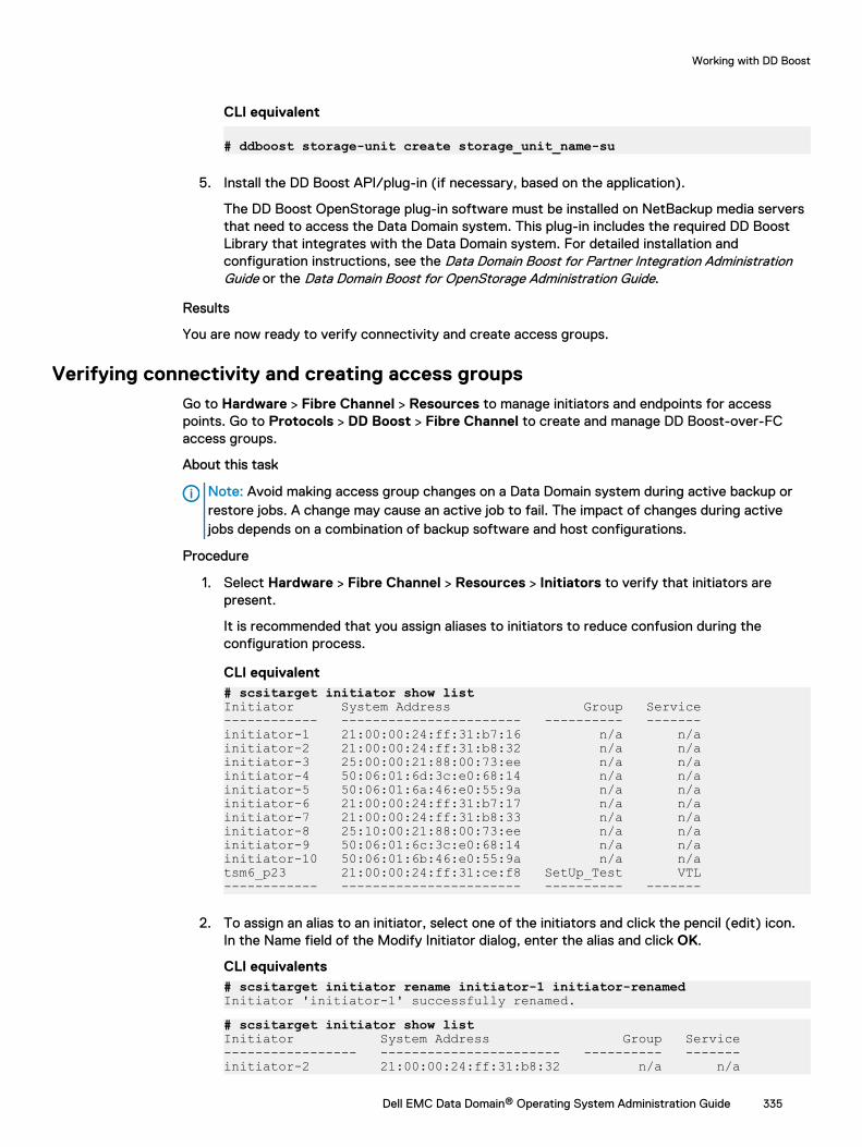
CLI equivalent
# ddboost storage-unit create storage_unit_name-su
5. Install the DD Boost API/plug-in (if necessary, based on the application).
The DD Boost OpenStorage plug-in software must be installed on NetBackup media serversthat need to access the Data Domain system. This plug-in includes the required DD BoostLibrary that integrates with the Data Domain system. For detailed installation andconfiguration instructions, see the Data Domain Boost for Partner Integration AdministrationGuide or the Data Domain Boost for OpenStorage Administration Guide.
Results
You are now ready to verify connectivity and create access groups.
Verifying connectivity and creating access groupsGo to Hardware > Fibre Channel > Resources to manage initiators and endpoints for accesspoints. Go to Protocols > DD Boost > Fibre Channel to create and manage DD Boost-over-FCaccess groups.
About this task
Note: Avoid making access group changes on a Data Domain system during active backup orrestore jobs. A change may cause an active job to fail. The impact of changes during activejobs depends on a combination of backup software and host configurations.
Procedure
1. Select Hardware > Fibre Channel > Resources > Initiators to verify that initiators arepresent.
It is recommended that you assign aliases to initiators to reduce confusion during theconfiguration process.
CLI equivalent# scsitarget initiator show listInitiator System Address Group Service------------ ----------------------- ---------- -------initiator-1 21:00:00:24:ff:31:b7:16 n/a n/ainitiator-2 21:00:00:24:ff:31:b8:32 n/a n/ainitiator-3 25:00:00:21:88:00:73:ee n/a n/ainitiator-4 50:06:01:6d:3c:e0:68:14 n/a n/ainitiator-5 50:06:01:6a:46:e0:55:9a n/a n/ainitiator-6 21:00:00:24:ff:31:b7:17 n/a n/ainitiator-7 21:00:00:24:ff:31:b8:33 n/a n/ainitiator-8 25:10:00:21:88:00:73:ee n/a n/ainitiator-9 50:06:01:6c:3c:e0:68:14 n/a n/ainitiator-10 50:06:01:6b:46:e0:55:9a n/a n/atsm6_p23 21:00:00:24:ff:31:ce:f8 SetUp_Test VTL------------ ----------------------- ---------- -------
2. To assign an alias to an initiator, select one of the initiators and click the pencil (edit) icon.In the Name field of the Modify Initiator dialog, enter the alias and click OK.
CLI equivalents# scsitarget initiator rename initiator-1 initiator-renamedInitiator 'initiator-1' successfully renamed.# scsitarget initiator show listInitiator System Address Group Service----------------- ----------------------- ---------- -------initiator-2 21:00:00:24:ff:31:b8:32 n/a n/a
Working with DD Boost
Dell EMC Data Domain® Operating System Administration Guide 335
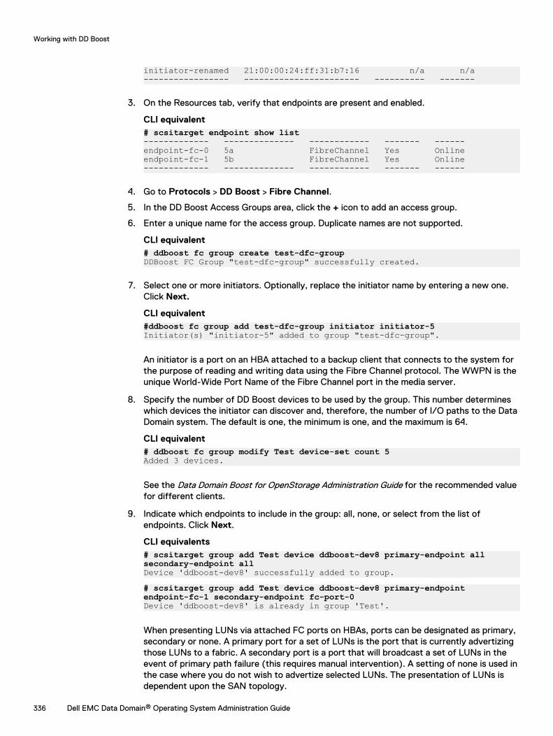
initiator-renamed 21:00:00:24:ff:31:b7:16 n/a n/a----------------- ----------------------- ---------- -------
3. On the Resources tab, verify that endpoints are present and enabled.
CLI equivalent# scsitarget endpoint show list------------- -------------- ------------ ------- ------endpoint-fc-0 5a FibreChannel Yes Onlineendpoint-fc-1 5b FibreChannel Yes Online------------- -------------- ------------ ------- ------
4. Go to Protocols > DD Boost > Fibre Channel.
5. In the DD Boost Access Groups area, click the + icon to add an access group.
6. Enter a unique name for the access group. Duplicate names are not supported.
CLI equivalent# ddboost fc group create test-dfc-groupDDBoost FC Group "test-dfc-group" successfully created.
7. Select one or more initiators. Optionally, replace the initiator name by entering a new one.Click Next.
CLI equivalent#ddboost fc group add test-dfc-group initiator initiator-5Initiator(s) "initiator-5" added to group "test-dfc-group".
An initiator is a port on an HBA attached to a backup client that connects to the system forthe purpose of reading and writing data using the Fibre Channel protocol. The WWPN is theunique World-Wide Port Name of the Fibre Channel port in the media server.
8. Specify the number of DD Boost devices to be used by the group. This number determineswhich devices the initiator can discover and, therefore, the number of I/O paths to the DataDomain system. The default is one, the minimum is one, and the maximum is 64.
CLI equivalent# ddboost fc group modify Test device-set count 5Added 3 devices.
See the Data Domain Boost for OpenStorage Administration Guide for the recommended valuefor different clients.
9. Indicate which endpoints to include in the group: all, none, or select from the list ofendpoints. Click Next.
CLI equivalents# scsitarget group add Test device ddboost-dev8 primary-endpoint allsecondary-endpoint allDevice 'ddboost-dev8' successfully added to group.# scsitarget group add Test device ddboost-dev8 primary-endpointendpoint-fc-1 secondary-endpoint fc-port-0Device 'ddboost-dev8' is already in group 'Test'.
When presenting LUNs via attached FC ports on HBAs, ports can be designated as primary,secondary or none. A primary port for a set of LUNs is the port that is currently advertizingthose LUNs to a fabric. A secondary port is a port that will broadcast a set of LUNs in theevent of primary path failure (this requires manual intervention). A setting of none is used inthe case where you do not wish to advertize selected LUNs. The presentation of LUNs isdependent upon the SAN topology.
Working with DD Boost
336 Dell EMC Data Domain® Operating System Administration Guide
10. Review the Summary and make any modifications. Click Finish to create the access group,which is displayed in the DD Boost Access Groups list.
CLI equivalent# scsitarget group show detailed
Note: To change settings for an existing access group, select it from the list and clickthe pencil icon (Modify).
Deleting access groupsUse the Fibre Channel tab to delete access groups.
Procedure
1. Select Protocols > DD Boost > Fibre Channel.
2. Select the group to be deleted from the DD Boost Access Groups list.
Note: You cannot delete a group that has initiators assigned to it. Edit the group toremove the initiators first.
3. Click Delete (X).
Using DD Boost on HA systemsHA provides seamless failover of any application using DD Boost—that is, any backup or restoreoperation continues with no manual intervention required. All other DD Boost user scenarios aresupported on HA systems as well, including managed file replication (MFR), distributed segmentprocessing (DSP), filecopy, and dynamic interface groups (DIG).
Note these special considerations for using DD Boost on HA systems:
l On HA-enabled Data Domain systems, failovers of the DD server occur in less than 10 minutes.However, recovery of DD Boost applications may take longer than this, because Boostapplication recovery cannot begin until the DD server failover is complete. In addition, Boostapplication recovery cannot start until the application invokes the Boost library.
l DD Boost on HA systems requires that the Boost applications be using Boost HA libraries;applications using non-HA Boost libraries do not see seamless failover.
l MFR will fail over seamlessly when both the source and destination systems are HA-enabled.MFR is also supported on partial HA configurations (that is, when either the source ordestination system is enabled, but not both) when the failure occurs on the HA-enabledsystem. For more information, see the DD Boost for OpenStorage Administration Guide or the DDBoost for Partner Integration Administration Guide.
l Dynamic interface groups should not include IP addresses associated with the directinterconnection between the active and standby Data Domain systems.
l DD Boost clients must be configured to use floating IP addresses.
About the DD Boost tabsLearn to use the DD Boost tabs in DD System Manager.
Working with DD Boost
Dell EMC Data Domain® Operating System Administration Guide 337
SettingsUse the Settings tab to enable or disable DD Boost, select clients and users, and specify advancedoptions.
The Settings tab shows the DD Boost status (Enabled or Disabled). Use the Status button toswitch between Enabled or Disabled.
Under Allowed Clients, select the clients that are to have access to the system. Use the Add,Modify, and Delete buttons to manage the list of clients.
Under Users with DD Boost Access, select the users that are to have DD Boost access. Use theAdd, Change Password, and Remove buttons to manage the list of users.
Expand Advanced Options to see which advanced options are enabled. Go to More Tasks > SetOptions to reset these options.
Active ConnectionsUse the Active Connections tab to see information about clients, interfaces, and outbound files.
Table 132 Connected client information
Item Description
Client The name of the connected client.
Idle Whether the client is idle (Yes) or not (No).
Plug-In Version The DD Boost plug-in version installed, such as 2.2.1.1.
OS Version The operating system version installed, such as Linux 2.6.17-1.2142_FC4smp x86_64.
Application Version The backup application version installed, such as NetBackup6.5.6.
Encrypted Whether the connection is encrypted (Yes) or not (No).
DSP Whether or not the connection is using Distributed SegmentProcessing (DSP) or not.
Transport Type of transport being used, such as IPv4, IPv6 or DFC(Fibre Channel).
Table 133 Configured interface connection information
Item Description
Interface The IP address of the interface.
Interface Group One of the following:
l The name of the interface group.
l None, if not a member of one.
Backup The number of active backup connections.
Restore The number of active restore connections.
Replication The number of active replication connections.
Synthetic The number of synthetic backups.
Working with DD Boost
338 Dell EMC Data Domain® Operating System Administration Guide
Table 133 Configured interface connection information (continued)
Item Description
Total The total number of connections for the interface.
Table 134 Outbound file replication information
Outbound files item Description
File Name The name of the outgoing image file.
Target Host The name of the host receiving the file.
Logical Bytes to Transfer The number of logical bytes to be transferred.
Logical Bytes Transferred The number of logical bytes already transferred.
Low Bandwidth Optimization The number of low-bandwidth bytes already transferred.
IP NetworkThe IP Network tab lists configured interface groups. Details include whether or not a group isenabled and any configured client interfaces. Administrators can use the Interface Group menu toview which clients are associated with an interface group.
Fibre ChannelThe Fibre Channel tab lists configured DD Boost access groups. Use the Fibre Channel tab tocreate and delete access groups and to configure initiators, devices, and endpoints for DD Boostaccess groups.
Storage UnitsUse the Storage Units tab to view, create, modify, and delete storage units.
Table 135 Storage Units tab
Item Description
Storage Units
View DD Boost Replications View DD Boost replication contexts.
Storage Unit The name of the storage unit.
User Username associated with the storage unit.
Quota Hard Limit The hard quota set for the storage unit.
Last 24hr Pre-Comp The amount of data written to the storage unit in the last 24hours, before compression.
Last 24hr Post-Comp The amount of data written to the storage unit in the last 24hours, after compression.
Last 24hr Comp Ratio Compression ratio of the data written to the storage unit inthe last 24 hours.
Working with DD Boost
Dell EMC Data Domain® Operating System Administration Guide 339
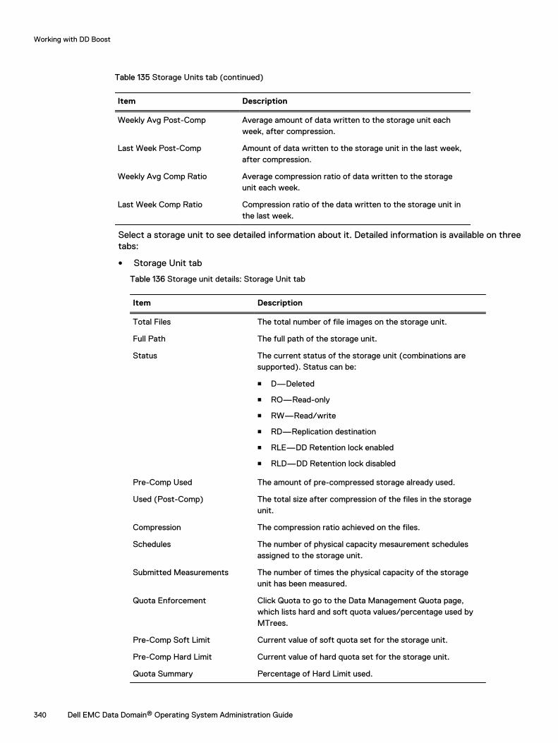
Table 135 Storage Units tab (continued)
Item Description
Weekly Avg Post-Comp Average amount of data written to the storage unit eachweek, after compression.
Last Week Post-Comp Amount of data written to the storage unit in the last week,after compression.
Weekly Avg Comp Ratio Average compression ratio of data written to the storageunit each week.
Last Week Comp Ratio Compression ratio of the data written to the storage unit inthe last week.
Select a storage unit to see detailed information about it. Detailed information is available on threetabs:
l Storage Unit tab
Table 136 Storage unit details: Storage Unit tab
Item Description
Total Files The total number of file images on the storage unit.
Full Path The full path of the storage unit.
Status The current status of the storage unit (combinations aresupported). Status can be:
n D—Deleted
n RO—Read-only
n RW—Read/write
n RD—Replication destination
n RLE—DD Retention lock enabled
n RLD—DD Retention lock disabled
Pre-Comp Used The amount of pre-compressed storage already used.
Used (Post-Comp) The total size after compression of the files in the storageunit.
Compression The compression ratio achieved on the files.
Schedules The number of physical capacity mesaurement schedulesassigned to the storage unit.
Submitted Measurements The number of times the physical capacity of the storageunit has been measured.
Quota Enforcement Click Quota to go to the Data Management Quota page,which lists hard and soft quota values/percentage used byMTrees.
Pre-Comp Soft Limit Current value of soft quota set for the storage unit.
Pre-Comp Hard Limit Current value of hard quota set for the storage unit.
Quota Summary Percentage of Hard Limit used.
Working with DD Boost
340 Dell EMC Data Domain® Operating System Administration Guide
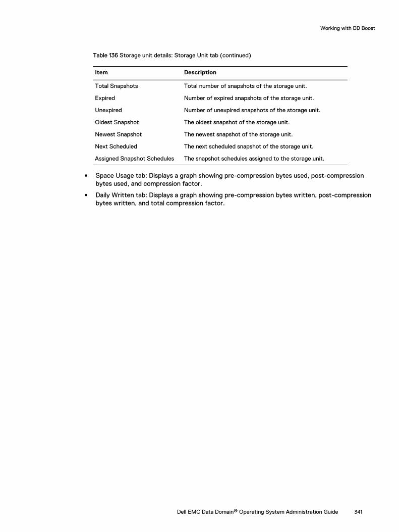
Table 136 Storage unit details: Storage Unit tab (continued)
Item Description
Total Snapshots Total number of snapshots of the storage unit.
Expired Number of expired snapshots of the storage unit.
Unexpired Number of unexpired snapshots of the storage unit.
Oldest Snapshot The oldest snapshot of the storage unit.
Newest Snapshot The newest snapshot of the storage unit.
Next Scheduled The next scheduled snapshot of the storage unit.
Assigned Snapshot Schedules The snapshot schedules assigned to the storage unit.
l Space Usage tab: Displays a graph showing pre-compression bytes used, post-compressionbytes used, and compression factor.
l Daily Written tab: Displays a graph showing pre-compression bytes written, post-compressionbytes written, and total compression factor.
Working with DD Boost
Dell EMC Data Domain® Operating System Administration Guide 341

Working with DD Boost
342 Dell EMC Data Domain® Operating System Administration Guide
CHAPTER 15
DD Virtual Tape Library
This chapter includes:
l DD Virtual Tape Library overview........................................................................................ 344l Planning a DD VTL...............................................................................................................344l Managing a DD VTL............................................................................................................. 351l Working with libraries..........................................................................................................355l Working with a selected library........................................................................................... 358l Viewing changer information............................................................................................... 366l Working with drives.............................................................................................................366l Working with a selected drive..............................................................................................368l Working with tapes............................................................................................................. 369l Working with the vault........................................................................................................ 370l Working with the cloud-based vault..................................................................................... 371l Working with access groups................................................................................................ 377l Working with a selected access group................................................................................. 381l Working with resources.......................................................................................................383l Working with pools..............................................................................................................388l Working with a selected pool...............................................................................................390
Dell EMC Data Domain® Operating System Administration Guide 343
DD Virtual Tape Library overviewData Domain Virtual Tape Library (DD VTL) is a disk-based backup system that emulates the useof physical tapes. It enables backup applications to connect to and manage DD system storageusing functionality almost identical to a physical tape library.
Virtual tape drives are accessible to backup software in the same way as physical tape drives. Afteryou create these drives in a DD VTL, they appear to the backup software as SCSI tape drives. TheDD VTL, itself, appears to the backup software as a SCSI robotic device accessed throughstandard driver interfaces. However, the backup software (not the DD system that is configuredas a DD VTL) manages the movement of the media changer and backup images.
The following terms have special meaning when used with DD VTL:
l Library: A library emulates a physical tape library with drives, changer, CAPs (cartridge accessports), and slots (cartridge slots).
l Tape: A tape is represented as a file. Tapes can be imported from the vault to a library. Tapescan be exported from a library to the vault. Tapes can be moved within a library across drives,slots, and CAPs.
l Pool: A pool is a collection of tapes that maps to a directory on the file system. Pools are usedto replicate tapes to a destination. By default, pools are created as MTree pools unless youspecify them as directory pools when they are created. You can convert directory-based poolsto MTree-based pools to take advantage of the greater functionality of MTrees.
l Vault: The vault holds tapes not being used by any library. Tapes reside in either a library or thevault.
DD VTL has been tested with, and is supported by, specific backup software and hardwareconfigurations. For more information, see the appropriate Backup Compatibility Guide on the OnlineSupport Site.
DD VTL supports simultaneous use of the tape library and file system (NFS/CIFS/DD Boost)interfaces.
When DR (disaster recovery) is needed, pools and tapes can be replicated to a remote DD systemusing the DD Replicator.
To protect data on tapes from modification, tapes can be locked using DD Retention LockGovernance software.
Note: At present, for 16 Gb/s, Data Domain supports fabric and point-to-point topologies.Other topologies will present issues.
The KB article Data Domain: VTL Best Practices Guide, available at https://support.emc.com/kb/180591, provides additional information about best practices for DD VTL.
Planning a DD VTLThe DD VTL (Virtual Tape Library) feature has very specific requirements, such as properlicensing, interface cards, user permissions, etc. These requirements are listed here, complete withdetails and recommendations.
l An appropriate DD VTL license.
n DD VTL is a licensed feature, and you must use NDMP (Network Data ManagementProtocol) over IP (Internet Protocol) or DD VTL directly over FC (Fibre Channel).
n An additional license is required for IBM i systems – the I/OS license.
n Adding a DD VTL license through the DD System Manager automatically disables andenables the DD VTL feature.
DD Virtual Tape Library
344 Dell EMC Data Domain® Operating System Administration Guide
l An installed FC interface card or DD VTL configured to use NDMP.
n If the DD VTL communication between a backup server and a DD system is through an FCinterface, the DD system must have an FC interface card installed. Notice that whenever anFC interface card is removed from (or changed within) a DD system, any DD VTLconfiguration associated with that card must be updated.
n If the DD VTL communication between a backup server and a DD system is through NDMP,no FC interface card is required. However, you must configure the TapeServer accessgroup. Also, when using NDMP, all initiator and port functionality does not apply.
n The net filter must be configured to allow the NDMP client to send information to the DDsystem. Run the net filter add operation allow clients <client-IP-address>command to allow access for the NDMP client.
– For added security, run the net filter add operation allow clients <client-IP-address> interfaces <DD-interface-IP-address> command.
– Add the seq-id 1 option to the command to enforce this rule before any other net filterrules.
l A backup software minimum record (block) size.
n If possible, set backup software to use a minimum record (block) size of 64 KiB or larger.Larger sizes usually give faster performance and better data compression.
n Depending on your backup application, if you change the size after the initial configuration,data written with the original size might become unreadable.
l Appropriate user access to the system.
n For basic tape operations and monitoring, only a user login is required.
n To enable and configure DD VTL services and perform other configuration tasks, asysadmin login is required.
DD VTL limitsBefore setting up or using a DD VTL, review these limits on size, slots, etc.
l I/O Size – The maximum supported I/O size for any DD system using DD VTL is 1 MB.
l Libraries – DD VTL supports a maximum of 64 libraries per DD system (that is, 64 DD VTLinstances on each DD system).
l Initiators – DD VTL supports a maximum of 1024 initiators or WWPNs (world-wide port names)per DD system.
l Tape Drives – Information about tape drives is presented in the next section.
l Data Streams – Information about data streams is presented in the following table.
Table 137 Data streams sent to a Data Domain system
Model RAM/ NVRAM Backupwritestreams
Backupreadstreams
Repla
sourcestreams
Repla deststreams
Mixed
DD140, DD160,DD610
4 GB or 6 GB /0.5 GB
16 4 15 20 w<= 16 ; r<= 4 ReplSrc<=15;ReplDest<=20; ReplDest+w<=16; w+r+ReplSrc<=16;Total<=20
DD620,DD630, DD640
8 GB / 0.5 GBor 1 GB
20 16 20 20 w<=20; r<=16; ReplSrc<=30;ReplDest<=20; ReplDest+w<=20; Total<=30
DD Virtual Tape Library
Dell EMC Data Domain® Operating System Administration Guide 345
Table 137 Data streams sent to a Data Domain system (continued)
Model RAM/ NVRAM Backupwritestreams
Backupreadstreams
Repla
sourcestreams
Repla deststreams
Mixed
DD640, DD670 16 GB or 20GB / 1 GB
90 30 60 90 w<=90; r<=30; ReplSrc<=60;ReplDest<=90; ReplDest+w<=90; Total<=90
DD670, DD860 36 GB / 1 GB 90 50 90 90 w<=90; r<=50; ReplSrc<=90;ReplDest<=90; ReplDest+w<=90; Total<=90
DD860 72 GBb / 1 GB 90 50 90 90 w<=90; r<=50; ReplSrc<=90;ReplDest<=90; ReplDest+w<=90; Total<=90
DD890 96 GB / 2 GB 180 50 90 180 w<=180; r<=50; ReplSrc<=90;ReplDest<=180; ReplDest+w<=180; Total<=180
DD990 128 or 256GBb / 4 GB
540 150 270 540 w<=540; r<=150;ReplSrc<=270; ReplDest<=540;ReplDest+w<=540; Total<=540
DD2200 8 GB 35 6 18 20 w<=35; r<=6; ReplSrc<=18;ReplDest<=20; ReplDest+w<=35; Total<=35
DD2200 16 GB 60 16 30 60 w<=60; r<=16; ReplSrc<=30;ReplDest<=60; ReplDest+w<=60; Total<=60
DD2500 32 or 64 GB /2 GB
180 50 90 180 w<=180; r<=50; ReplSrc<=90;ReplDest<=180; ReplDest+w<=180; Total<=180
DD4200 128 GBb / 4GB
270 75 150 270 w<=270; r<=75; ReplSrc<=150;ReplDest<=270; ReplDest+w<=270; Total<=270
DD4500 192 GBb / 4GB
270 75 150 270 w<=270; r<=75; ReplSrc<=150;ReplDest<=270; ReplDest+w<=270; Total<=270
DD7200 128 or 256GBb / 4 GB
540 150 270 540 w<=540; r<=150;ReplSrc<=270; ReplDest<=540;ReplDest+w<=540; Total<=540
DD9500 256/512 GB 1885 300 540 1080 w<=1885; r<=300;ReplSrc<=540;ReplDest<=1080; ReplDest+w<=1080; Total<=1885
DD9800 256/768 GB 1885 300 540 1080 w<=1885; r<=300;ReplSrc<=540;ReplDest<=1080; ReplDest+w<=1080; Total<=1885
DD Virtual Tape Library
346 Dell EMC Data Domain® Operating System Administration Guide
Table 137 Data streams sent to a Data Domain system (continued)
Model RAM/ NVRAM Backupwritestreams
Backupreadstreams
Repla
sourcestreams
Repla deststreams
Mixed
DD6300 48/96 GB 270 75 150 270 w<=270; r<=75; ReplSrc<=150;ReplDest<=270; ReplDest+w<=270; Total<=270
DD6800 192 GB 400 110 220 400 w<=400; r<=110; ReplSrc<=220;ReplDest<=400; ReplDest+w<=400; Total<=400
DD9300 192/384 GB 800 220 440 800 w<=800; r<=220;ReplSrc<=440; ReplDest<=800;ReplDest+w<=800; Total<=800
DD VE 8 TB 8 GB / 512 MB 20 16 20 20 w<= 20 ; r<= 16 ReplSrc<=20;ReplDest<=20; ReplDest+w<=20; w+r+ReplSrc<=20;Total<=20
DD VE 16 TB 16 GB / 512MB or 24 GB /1 GB
45 30 45 45 w<= 45 ; r<= 30 ReplSrc<=45;ReplDest<=45; ReplDest+w<=45; w+r+ReplSrc<=45;Total<=45
DD VE 32 TB 24 GB / 1 GB 90 50 90 90 w<= 90 ; r<= 50 ReplSrc<=90;ReplDest<=90; ReplDest+w<=90; w+r+ReplSrc<=90;Total<=90
DD VE 48 TB 36 GB / 1 GB 90 50 90 90 w<= 90 ; r<= 50 ReplSrc<=90;ReplDest<=90; ReplDest+w<=90; w+r+ReplSrc<=90;Total<=90
DD VE 64 TB 48 GB / 1 GB 90 50 90 90 w<= 90 ; r<= 50 ReplSrc<=90;ReplDest<=90; ReplDest+w<=90; w+r+ReplSrc<=90;Total<=90
DD VE 96 TB 64 GB / 2 GB 180 50 90 180 w<= 180 ; r<= 50 ReplSrc<=90;ReplDest<=180; ReplDest+w<=180; w+r+ReplSrc<=180;Total<=180
DD3300 4 TB 12 GB (virtualmemory) / 512MB
20 16 30 20 w<= 20 ; r<= 16 ReplSrc<=30;ReplDest<=20; ReplDest+w<=20; w+r+ReplSrc<=30;Total<=30
DD3300 8 TB 32 GB (virtualmemory) /1.536 GB
90 50 90 90 w<= 90 ; r<= 50 ReplSrc<=90;ReplDest<=90; ReplDest+w<=90; w+r+ReplSrc<=90;Total<=90
DD3300 16 TB 32 GB (virtualmemory) /1.536 GB
90 50 90 90 w<= 90 ; r<= 50 ReplSrc<=90;ReplDest<=90; ReplDest
DD Virtual Tape Library
Dell EMC Data Domain® Operating System Administration Guide 347
Table 137 Data streams sent to a Data Domain system (continued)
Model RAM/ NVRAM Backupwritestreams
Backupreadstreams
Repla
sourcestreams
Repla deststreams
Mixed
+w<=90; w+r+ReplSrc<=90;Total<=90
DD3300 32 TB 46 GB (virtualmemory) /1.536 GB
90 50 90 90 w<= 90 ; r<= 50 ReplSrc<=90;ReplDest<=90; ReplDest+w<=90; w+r+ReplSrc<=90;Total<=140
a. DirRepl, OptDup, MTreeRepl streamsb. The Data Domain Extended Retention software option is available only for these devices with extended (maximum)
memory
l Slots – DD VTL supports a maximum of:
n 32,000 slots per library
n 64,000 slots per DD system
The DD system automatically adds slots to keep the number of slots equal to, or greater than,the number of drives.
Note: Some device drivers (for example, IBM AIX atape device drivers) limit libraryconfigurations to specific drive/slot limits, which may be less than what the DD systemsupports. Backup applications, and drives used by those applications, may be affected bythis limitation.
l CAPs (cartridge access ports) – DD VTL supports a maximum of:
n 100 CAPs per library
n 1000 CAPs per DD system
Number of drives supported by a DD VTLThe maximum number of drives supported by a DD VTL depends on the number of CPU cores andthe amount of memory installed (both RAM and NVRAM, if applicable) on a DD system.
Note: There are no references to model numbers in this table because there are manycombinations of CPU cores and memories for each model, and the number of supported drivesdepends only on the CPU cores and memories – not on the particular model, itself.
Table 138 Number of drives supported by a DD VTL
Number of CPUcores
RAM (in GB) NVRAM (inGB)
Maximum number of supporteddrives
Fewer than 32 4 or less NA 64
More than 4, upto 38
NA 128
More than 38, upto 128
NA 256
More than 128 NA 540
DD Virtual Tape Library
348 Dell EMC Data Domain® Operating System Administration Guide
Table 138 Number of drives supported by a DD VTL (continued)
Number of CPUcores
RAM (in GB) NVRAM (inGB)
Maximum number of supporteddrives
32 to 39 Up to 128 Less than 4 270
Up to 128 4 or more 540
More than 128 NA 540
40 to 59 NA NA 540
60 or more NA NA 1080
Tape barcodesWhen you create a tape, you must assign a unique barcode (never duplicate barcodes as this cancause unpredictable behavior). Each barcode consists of eight characters: the first six arenumbers or uppercase letters (0-9, A-Z), and the last two are the tape code for the supportedtape type, as shown in the following table.
Note: Although a DD VTL barcode consists of eight characters, either six or eight charactersmay be transmitted to a backup application, depending on the changer type.
Table 139 Tape Codes by Tape Type
Tape Type Default Capacity (unlessnoted)
Tape Code
LTO-1 100 GiB L1
LTO-1 50 GiB (non-default) LAa
LTO-1 30 GiB (non-default) LB
LTO-1 10 GiB (non-default) LC
LTO-2 200 GiB L2
LTO-3 400 GiB L3
LTO-4 800 GiB L4
LTO-5 (default) 1.5 TiB L5
a. For TSM, use the L2 tape code if the LA code is ignored.
For multiple tape libraries, barcodes are automatically incremented, if the sixth character (justbefore the "L") is a number. If an overflow occurs (9 to 0), numbering moves one position to theleft. If the next character to increment is a letter, incrementation stops. Here are a few samplebarcodes and how each will be incremented:
l 000000L1 creates tapes of 100 GiB capacity and can accept a count of up to 100,000 tapes(from 000000 to 99999).
l AA0000LA creates tapes of 50 GiB capacity and can accept a count of up to 10,000 tapes(from 0000 to 9999).
l AAAA00LB creates tapes of 30GiB capacity and can accept a count of up to 100 tapes (from00 to 99).
l AAAAAALC creates one tape of 10 GiB capacity. Only one tape can be created with this name.
DD Virtual Tape Library
Dell EMC Data Domain® Operating System Administration Guide 349
l AAA350L1 creates tapes of 100 GiB capacity and can accept a count of up to 650 tapes (from350 to 999).
l 000AAALA creates one tape of 50 GiB capacity. Only one tape can be created with this name.
l 5M7Q3KLB creates one tape of 30 GiB capacity. Only one tape can be created with this name.
LTO tape drive compatibilityYou may have different generations of LTO (Linear Tape-Open) technology in your setup; thecompatibility between these generations is presented in tabular form.
In this table:
l RW = read and write compatible
l R = read-only compatible
l — = not compatible
Table 140 LTO tape drive compatibility
tape format LTO-5 drive LTO-4 drive LTO-3 drive LTO-2 drive LTO-1 drive
LTO-5 tape RW — — — —
LTO-4 tape RW RW — — —
LTO-3 tape R RW RW — —
LTO-2 tape — R RW RW —
LTO-1 tape — — R RW RW
Setting up a DD VTLTo set up a simple DD VTL, use the Configuration Wizard, which is described in the GettingStarted chapter.
Similar documentation is available in the Data Domain Operating System Initial Configuration Guide.
Then, continue with the following topics to enable the DD VTL, create libraries, and create andimport tapes.
Note: If the deployment environment includes an AS400 system as a DD VTL client, refer to Configuring DD VTL default options on page 354 to configure the serial number prefix for VTLchangers and drives before configuring the DD VTL relationship between the Data Domainsystem and the AS400 client system.
HA systems and DD VTLHA systems are compatible with DD VTL; however, if a DD VTL job is in progress during a failover,the job will need to be restarted manually after the failover is complete.
The Data Domain Operating System Backup Compatibility Guide provides additional details about theHBA, switch, firmware, and driver requirements for using DD VTL in an HA environment.
DD Virtual Tape Library
350 Dell EMC Data Domain® Operating System Administration Guide
DD VTL tape out to cloudDD VTL supports storing the VTL vault on DD Cloud Tier storage. To use this functionality, theData Domain system must be a supported Cloud Tier configuration, and have a Cloud Tier licensein addition to the VTL license.
Configure and license the DD Cloud Tier storage before configuring DD VTL to use cloud storagefor the vault. DD Cloud Tier on page 455 provides additional information about the requirementsfor DD Cloud Tier, and how to configure DD Cloud Tier.
The FC and network interface requirements for VTL are the same for both cloud-based and localvault storage. DD VTL does not require special configuration to use cloud storage for the vault.When configuring the DD VTL, select the cloud storage as the vault location. However, whenworking with a cloud-based vault, there are some data management options that are unique to thecloud-based vault. Working with the cloud-based vault on page 371 provides more information.
Managing a DD VTLYou can manage a DD VTL using the Data Domain System Manager (DD System Manager) or theData Domain Operating System (DD OS) Command Line Interface (CLI). After you login, you cancheck the status of your DD VTL process, check your license information, and review andconfigure options.
Logging In
To use a graphical user interface (GUI) to manage your DD Virtual Tape Library (DD VTL), log in tothe DD System Manager.
CLI Equivalent
You can also log in at the CLI:
login as: sysadminData Domain OSUsing keyboard-interactive authentication.Password:
Enabling SCSI Target Daemon (CLI only)
If you do log in from the CLI, you must enable the scsitarget daemon (the Fibre Channel service).This daemon is enabled during the DD VTL or DD Boost-FC enable selections in DD SystemManager. In the CLI, these processes need to be enabled separately.
# scsitarget enablePlease wait ...SCSI Target subsystem is enabled.
Accessing DD VTL
From the menu at the left of the DD System Manager, select Protocols > VTL.
Status
In the Virtual Tape Libraries > VTL Service area, you can see the status of your DD VTL processis displayed at the top, for example, Enabled: Running. The first part of the status will be Enabled(on) or Disabled (off). The second part will be one of the following process states.
Table 141 DD VTL process states
State Description
Running DD VTL process is enabled and active (shown in green).
DD Virtual Tape Library
Dell EMC Data Domain® Operating System Administration Guide 351
Table 141 DD VTL process states (continued)
State Description
Starting DD VTL process is starting.
Stopping DD VTL process is being shut down.
Stopped DD VTL process is disabled (shown in red).
Timing out DD VTL process crashed and is attempting an automaticrestart.
Stuck After several failed automatic restarts, the DD VTL process isunable to shut down normally, so an attempt is being made tokill it.
DD VTL License
The VTL License line tells you whether your DD VTL license has been applied. If it says Unlicensed,select Add License. Enter your license key in the Add License Key dialog. Select Next and OK.
Note: All license information should have been populated as part of the factory configurationprocess; however, if DD VTL was purchased later, the DD VTL license key may not have beenavailable at that time.
CLI Equivalent
You can also verify that the DD VTL license has been installed at the CLI:
# elicense show## License Key Feature-- ------------------- -----------1 DEFA-EFCD-FCDE-CDEF Replication2 EFCD-FCDE-CDEF-DEFA VTL -- ------------------- -----------
If the license is not present, each unit comes with documentation – a quick install card – which willshow the licenses that have been purchased. Enter one of the following commands to populate thelicense key.
# license add <license-code># elicense update <license-file>
I/OS License (for IBM i users)
For customers of IBM i, the I/OS License line tells you whether your I/OS license has been applied.If it says Unlicensed, select Add License. You must enter a valid I/OS license in either of theseformats: XXXX-XXXX-XXXX-XXXX or XXXX-XXXX-XXXX-XXXX-XXXX. Your I/OS license must beinstalled before creating a library and drives to be used on an IBM i system. Select Next and OK.
Enabling DD VTLEnabling DD VTL broadcasts the WWN of the Data Domain HBA to customer fabric and enables alllibraries and library drives. If a forwarding plan is required in the form of change control processes,this process should be enabled to facilitate zoning.
Procedure
1. Make sure that you have a DD VTL license and that the file system is enabled.
2. Select Virtual Tape Libraries > VTL Service.
3. To the right of the Status area, select Enable.
DD Virtual Tape Library
352 Dell EMC Data Domain® Operating System Administration Guide
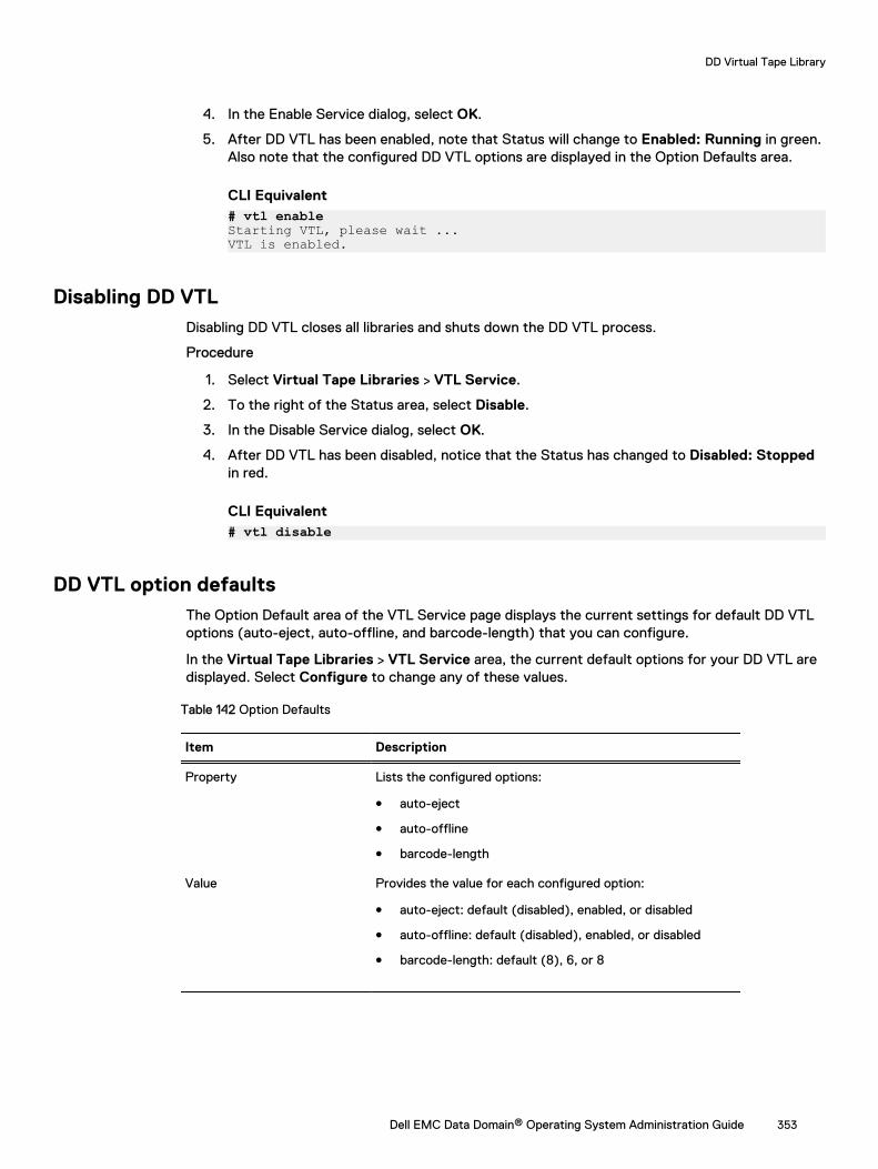
4. In the Enable Service dialog, select OK.
5. After DD VTL has been enabled, note that Status will change to Enabled: Running in green.Also note that the configured DD VTL options are displayed in the Option Defaults area.
CLI Equivalent# vtl enableStarting VTL, please wait ...VTL is enabled.
Disabling DD VTLDisabling DD VTL closes all libraries and shuts down the DD VTL process.
Procedure
1. Select Virtual Tape Libraries > VTL Service.
2. To the right of the Status area, select Disable.
3. In the Disable Service dialog, select OK.
4. After DD VTL has been disabled, notice that the Status has changed to Disabled: Stoppedin red.
CLI Equivalent# vtl disable
DD VTL option defaultsThe Option Default area of the VTL Service page displays the current settings for default DD VTLoptions (auto-eject, auto-offline, and barcode-length) that you can configure.
In the Virtual Tape Libraries > VTL Service area, the current default options for your DD VTL aredisplayed. Select Configure to change any of these values.
Table 142 Option Defaults
Item Description
Property Lists the configured options:
l auto-eject
l auto-offline
l barcode-length
Value Provides the value for each configured option:
l auto-eject: default (disabled), enabled, or disabled
l auto-offline: default (disabled), enabled, or disabled
l barcode-length: default (8), 6, or 8
DD Virtual Tape Library
Dell EMC Data Domain® Operating System Administration Guide 353
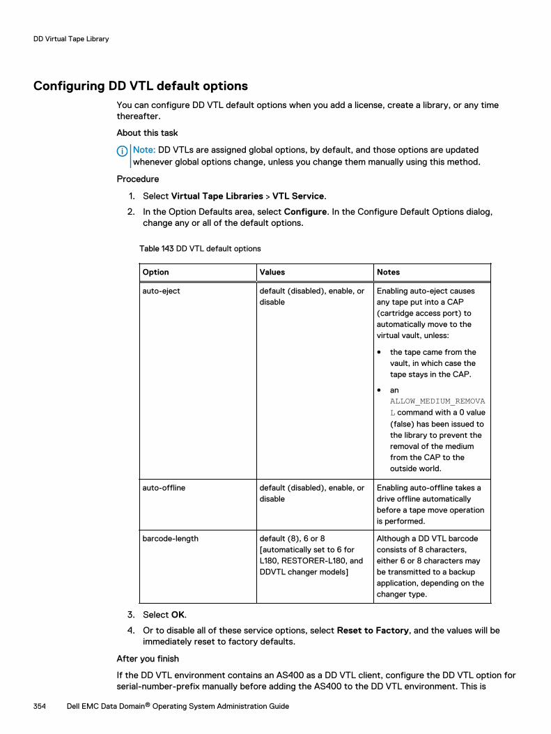
Configuring DD VTL default optionsYou can configure DD VTL default options when you add a license, create a library, or any timethereafter.
About this task
Note: DD VTLs are assigned global options, by default, and those options are updatedwhenever global options change, unless you change them manually using this method.
Procedure
1. Select Virtual Tape Libraries > VTL Service.
2. In the Option Defaults area, select Configure. In the Configure Default Options dialog,change any or all of the default options.
Table 143 DD VTL default options
Option Values Notes
auto-eject default (disabled), enable, ordisable
Enabling auto-eject causesany tape put into a CAP(cartridge access port) toautomatically move to thevirtual vault, unless:
l the tape came from thevault, in which case thetape stays in the CAP.
l anALLOW_MEDIUM_REMOVAL command with a 0 value
(false) has been issued tothe library to prevent theremoval of the mediumfrom the CAP to theoutside world.
auto-offline default (disabled), enable, ordisable
Enabling auto-offline takes adrive offline automaticallybefore a tape move operationis performed.
barcode-length default (8), 6 or 8[automatically set to 6 forL180, RESTORER-L180, andDDVTL changer models]
Although a DD VTL barcodeconsists of 8 characters,either 6 or 8 characters maybe transmitted to a backupapplication, depending on thechanger type.
3. Select OK.
4. Or to disable all of these service options, select Reset to Factory, and the values will beimmediately reset to factory defaults.
After you finish
If the DD VTL environment contains an AS400 as a DD VTL client, configure the DD VTL option forserial-number-prefix manually before adding the AS400 to the DD VTL environment. This is
DD Virtual Tape Library
354 Dell EMC Data Domain® Operating System Administration Guide
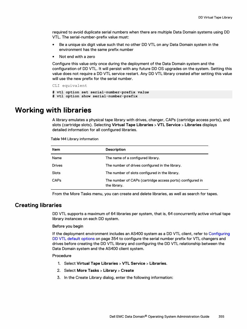
required to avoid duplicate serial numbers when there are multiple Data Domain systems using DDVTL. The serial-number-prefix value must:
l Be a unique six digit value such that no other DD VTL on any Data Domain system in theenvironment has the same prefix number
l Not end with a zero
Configure this value only once during the deployment of the Data Domain system and theconfiguration of DD VTL. It will persist with any future DD OS upgrades on the system. Setting thisvalue does not require a DD VTL service restart. Any DD VTL library created after setting this valuewill use the new prefix for the serial number.
CLI equivalent# vtl option set serial-number-prefix value# vtl option show serial-number-prefix
Working with librariesA library emulates a physical tape library with drives, changer, CAPs (cartridge access ports), andslots (cartridge slots). Selecting Virtual Tape Libraries > VTL Service > Libraries displaysdetailed information for all configured libraries.
Table 144 Library information
Item Description
Name The name of a configured library.
Drives The number of drives configured in the library.
Slots The number of slots configured in the library.
CAPs The number of CAPs (cartridge access ports) configured inthe library.
From the More Tasks menu, you can create and delete libraries, as well as search for tapes.
Creating librariesDD VTL supports a maximum of 64 libraries per system, that is, 64 concurrently active virtual tapelibrary instances on each DD system.
Before you begin
If the deployment environment includes an AS400 system as a DD VTL client, refer to ConfiguringDD VTL default options on page 354 to configure the serial number prefix for VTL changers anddrives before creating the DD VTL library and configuring the DD VTL relationship between theData Domain system and the AS400 client system.
Procedure
1. Select Virtual Tape Libraries > VTL Service > Libraries.
2. Select More Tasks > Library > Create
3. In the Create Library dialog, enter the following information:
DD Virtual Tape Library
Dell EMC Data Domain® Operating System Administration Guide 355
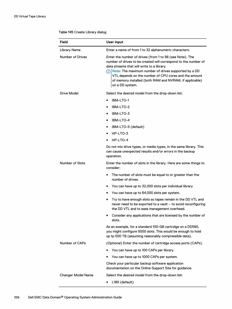
Table 145 Create Library dialog
Field User input
Library Name Enter a name of from 1 to 32 alphanumeric characters.
Number of Drives Enter the number of drives (from 1 to 98 (see Note). Thenumber of drives to be created will correspond to the number ofdata streams that will write to a library.
Note: The maximum number of drives supported by a DDVTL depends on the number of CPU cores and the amountof memory installed (both RAM and NVRAM, if applicable)on a DD system.
Drive Model Select the desired model from the drop-down list:
l IBM-LTO-1
l IBM-LTO-2
l IBM-LTO-3
l IBM-LTO-4
l IBM-LTO-5 (default)
l HP-LTO-3
l HP-LTO-4
Do not mix drive types, or media types, in the same library. Thiscan cause unexpected results and/or errors in the backupoperation.
Number of Slots Enter the number of slots in the library. Here are some things toconsider:
l The number of slots must be equal to or greater than thenumber of drives.
l You can have up to 32,000 slots per individual library
l You can have up to 64,000 slots per system.
l Try to have enough slots so tapes remain in the DD VTL andnever need to be exported to a vault – to avoid reconfiguringthe DD VTL and to ease management overhead.
l Consider any applications that are licensed by the number ofslots.
As an example, for a standard 100-GB cartridge on a DD580,you might configure 5000 slots. This would be enough to holdup tp 500 TB (assuming reasonably compressible data).
Number of CAPs (Optional) Enter the number of cartridge access ports (CAPs).
l You can have up to 100 CAPs per library.
l You can have up to 1000 CAPs per system.
Check your particular backup software applicationdocumentation on the Online Support Site for guidance.
Changer Model Name Select the desired model from the drop-down list:
l L180 (default)
DD Virtual Tape Library
356 Dell EMC Data Domain® Operating System Administration Guide
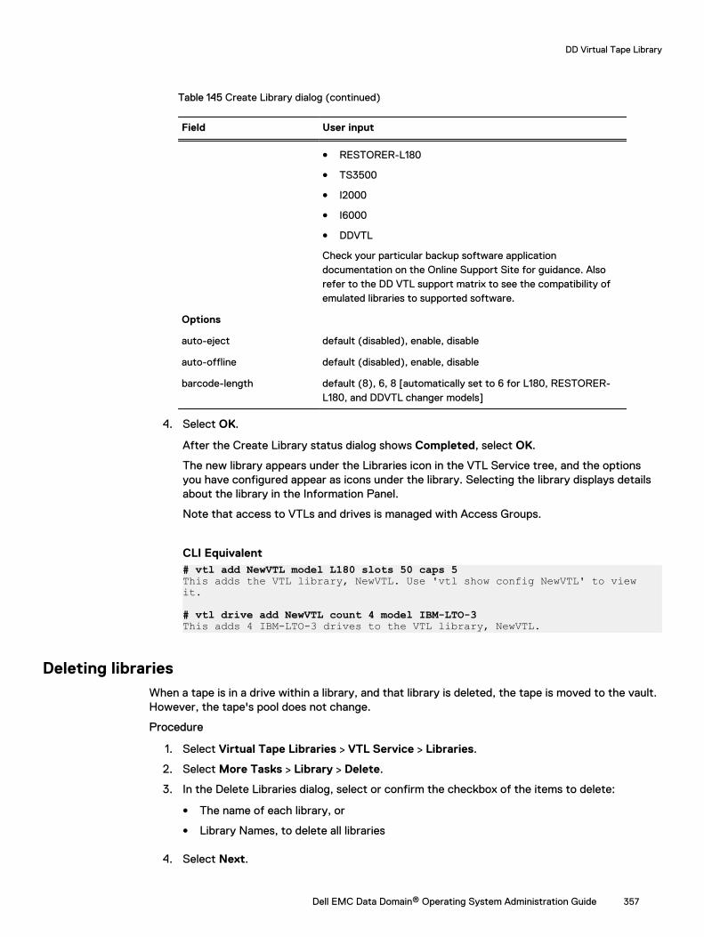
Table 145 Create Library dialog (continued)
Field User input
l RESTORER-L180
l TS3500
l I2000
l I6000
l DDVTL
Check your particular backup software applicationdocumentation on the Online Support Site for guidance. Alsorefer to the DD VTL support matrix to see the compatibility ofemulated libraries to supported software.
Options
auto-eject default (disabled), enable, disable
auto-offline default (disabled), enable, disable
barcode-length default (8), 6, 8 [automatically set to 6 for L180, RESTORER-L180, and DDVTL changer models]
4. Select OK.
After the Create Library status dialog shows Completed, select OK.
The new library appears under the Libraries icon in the VTL Service tree, and the optionsyou have configured appear as icons under the library. Selecting the library displays detailsabout the library in the Information Panel.
Note that access to VTLs and drives is managed with Access Groups.
CLI Equivalent# vtl add NewVTL model L180 slots 50 caps 5This adds the VTL library, NewVTL. Use 'vtl show config NewVTL' to view it.
# vtl drive add NewVTL count 4 model IBM-LTO-3This adds 4 IBM-LTO-3 drives to the VTL library, NewVTL.
Deleting librariesWhen a tape is in a drive within a library, and that library is deleted, the tape is moved to the vault.However, the tape's pool does not change.
Procedure
1. Select Virtual Tape Libraries > VTL Service > Libraries.
2. Select More Tasks > Library > Delete.
3. In the Delete Libraries dialog, select or confirm the checkbox of the items to delete:
l The name of each library, or
l Library Names, to delete all libraries
4. Select Next.
DD Virtual Tape Library
Dell EMC Data Domain® Operating System Administration Guide 357
5. Verify the libraries to delete, and select Submit in the confirmation dialogs.
6. After the Delete Libraries Status dialog shows Completed, select Close. The selectedlibraries are deleted from the DD VTL.
CLI Equivalent# vtl del OldVTL
Searching for tapesYou can use a variety of criteria – location, pool, and/or barcode – to search for a tape.
Procedure
1. Select Virtual Tape Libraries or Pools.
2. Select the area to search (library, vault, pool).
3. Select More Tasks > Tapes > Search.
4. In the Search Tapes dialog, enter information about the tape(s) you want to find.
Table 146 Search Tapes dialog
Field User input
Location Specify a location, or leave the default (All).
Pool Select the name of the pool in which to search for the tape. If no pools havebeen created, use the Default pool.
Barcode Specify a unique barcode. or leave the default (*) to return a group of tapes.Barcode allows the wildcards ? and *, where ? matches any single characterand * matches 0 or more characters.
Count Enter the maximum number of tapes you want to be returned to you. If youleave this blank, the barcode default (*) is used.
5. Select Search.
Working with a selected librarySelecting Virtual Tape Libraries > VTL Service > Libraries > library displays detailed informationfor a selected library.
Table 147 Devices
Item Description
Device The elements in the library, such a drives, slots, and CAPs(cartridge access ports).
Loaded The number of devices with media loaded.
Empty The number of devices with no media loaded.
Total The total number of loaded and empty devices.
DD Virtual Tape Library
358 Dell EMC Data Domain® Operating System Administration Guide
Table 148 Options
Property Value
auto-eject enabled or disabled
auto-offline enabled or disabled
barcode-length 6 or 8
Table 149 Tapes
Item Description
Pool The name of the pool where the tapes are located.
Tape Count The number of tapes in that pool.
Capacity The total configured data capacity of the tapes in that pool, inGiB (Gibibytes, the base-2 equivalent of GB, Gigabytes).
Used The amount of space used on the virtual tapes in that pool.
Average Compression The average amount of compression achieved on the data onthe tapes in that pool.
From the More Tasks menu, you can delete, rename, or set options for a library; create, delete,import, export, or move tapes; and add or delete slots and CAPs.
Creating tapesYou can create tapes in either a library or a pool. If initiated from a pool, the system first createsthe tapes, then imports them to the library.
Procedure
1. Select Virtual Tape Libraries > VTL Service > Libraries > library or Vault or Pools > Pools> pool.
2. Select More Tasks > Tapes > Create.
3. In the Create Tapes dialog, enter the following information about the tape:
Table 150 Create Tapes dialog
Field User input
Library (if initiatedfrom a library)
If a drop-down menu is enabled, select the library or leave the defaultselection.
Pool Name Select the name of the pool in which the tape will reside, from the drop-down list. If no pools have been created, use the Default pool.
Number of Tapes For a library, select from 1 to 20. For a pool, select from 1 to 100,000, orleave the default (20). [Although the number of supported tapes isunlimited, you can create no more than 100,000 tapes at a time.]
Starting Barcode Enter the initial barcode number (using the format A99000LA).
Tape Capacity (optional) Specify the number of GiBs from 1 to 4000 for each tape (thissetting overrides the barcode capacity setting). For efficient use of diskspace, use 100 GiB or fewer.
DD Virtual Tape Library
Dell EMC Data Domain® Operating System Administration Guide 359
4. Select OK and Close.
CLI Equivalent
# vtl tape add A00000L1 capacity 100 count 5 pool VTL_Pool... added 5 tape(s)...
Note: You must auto-increment tape volume names in base10 format.
Deleting tapesYou can delete tapes from either a library or a pool. If initiated from a library, the system firstexports the tapes, then deletes them. The tapes must be in the vault, not in a library. On aReplication destination DD system, deleting a tape is not permitted.
Procedure
1. Select Virtual Tape Libraries > VTL Service > Libraries > library or Vault or Pools > Pools> pool.
2. Select More Tasks > Tapes > Delete.
3. In the Delete Tapes dialog, enter search information about the tapes to delete, and selectSearch:
Table 151 Delete Tapes dialog
Field User input
Location If there is a drop-down list, select a library, or leave the default Vault selection.
Pool Select the name of the pool in which to search for the tape. If no pools havebeen created, use the Default pool.
Barcode Specify a unique barcode, or leave the default (*) to search for a group oftapes. Barcode allows the wildcards ? and *, where ? matches any singlecharacter and * matches 0 or more characters.
Count Enter the maximum number of tapes you want to be returned to you. If youleave this blank, the barcode default (*) is used.
Tapes PerPage
Select the maximum number of tapes to display per page – possible values are15, 30, and 45.
Select allpages
Select the Select All Pages checkbox to select all tapes returned by the searchquery.
ItemsSelected
Shows the number of tapes selected across multiple pages – updatedautomatically for each tape selection.
4. Select the checkbox of the tape that should be deleted or the checkbox on the headingcolumn to delete all tapes, and select Next.
5. Select Submit in the confirmation window, and select Close.
Note: After a tape is removed, the physical disk space used for the tape is not reclaimeduntil after a file system cleaning operation.
CLI Equivalent
# vtl tape del barcode [count count] [pool pool]
For example:
DD Virtual Tape Library
360 Dell EMC Data Domain® Operating System Administration Guide
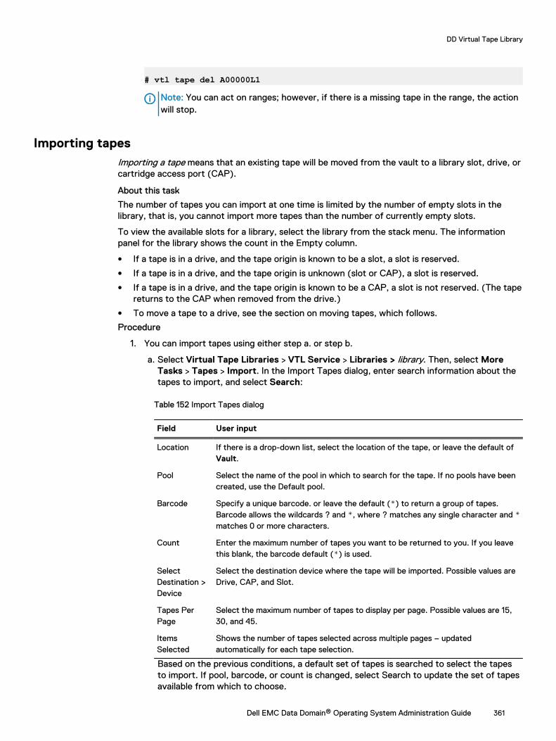
# vtl tape del A00000L1
Note: You can act on ranges; however, if there is a missing tape in the range, the actionwill stop.
Importing tapesImporting a tape means that an existing tape will be moved from the vault to a library slot, drive, orcartridge access port (CAP).
About this task
The number of tapes you can import at one time is limited by the number of empty slots in thelibrary, that is, you cannot import more tapes than the number of currently empty slots.
To view the available slots for a library, select the library from the stack menu. The informationpanel for the library shows the count in the Empty column.
l If a tape is in a drive, and the tape origin is known to be a slot, a slot is reserved.
l If a tape is in a drive, and the tape origin is unknown (slot or CAP), a slot is reserved.
l If a tape is in a drive, and the tape origin is known to be a CAP, a slot is not reserved. (The tapereturns to the CAP when removed from the drive.)
l To move a tape to a drive, see the section on moving tapes, which follows.
Procedure
1. You can import tapes using either step a. or step b.
a. Select Virtual Tape Libraries > VTL Service > Libraries > library. Then, select MoreTasks > Tapes > Import. In the Import Tapes dialog, enter search information about thetapes to import, and select Search:
Table 152 Import Tapes dialog
Field User input
Location If there is a drop-down list, select the location of the tape, or leave the default ofVault.
Pool Select the name of the pool in which to search for the tape. If no pools have beencreated, use the Default pool.
Barcode Specify a unique barcode. or leave the default (*) to return a group of tapes.Barcode allows the wildcards ? and *, where ? matches any single character and *matches 0 or more characters.
Count Enter the maximum number of tapes you want to be returned to you. If you leavethis blank, the barcode default (*) is used.
SelectDestination >Device
Select the destination device where the tape will be imported. Possible values areDrive, CAP, and Slot.
Tapes PerPage
Select the maximum number of tapes to display per page. Possible values are 15,30, and 45.
ItemsSelected
Shows the number of tapes selected across multiple pages – updatedautomatically for each tape selection.
Based on the previous conditions, a default set of tapes is searched to select the tapesto import. If pool, barcode, or count is changed, select Search to update the set of tapesavailable from which to choose.
DD Virtual Tape Library
Dell EMC Data Domain® Operating System Administration Guide 361

b. Select Virtual Tape Libraries > VTL Service > Libraries> library > Changer > Drives >drive > Tapes. Select tapes to import by selecting the checkbox next to:
l An individual tape, or
l The Barcode column to select all tapes on the current page, or
l The Select all pages checkbox to select all tapes returned by the search query.
Only tapes showing Vault in the Location can be imported.
Select Import from Vault. This button is disabled by default and enabled only if all of theselected tapes are from the Vault.
2. From the Import Tapes: library view, verify the summary information and the tape list, andselect OK.
3. Select Close in the status window.
CLI Equivalent
# vtl tape show pool VTL_PoolProcessing tapes....Barcode Pool Location State Size Used (%) Comp ModTime-------- -------- -------- ----- ------- --------------- ---- -------------------A00000L3 VTL_Pool vault RW 100 GiB 0.0 GiB (0.00%) 0x 2010/07/16 09:50:41A00001L3 VTL_Pool vault RW 100 GiB 0.0 GiB (0.00%) 0x 2010/07/16 09:50:41A00002L3 VTL_Pool vault RW 100 GiB 0.0 GiB (0.00%) 0x 2010/07/16 09:50:41A00003L3 VTL_Pool vault RW 100 GiB 0.0 GiB (0.00%) 0x 2010/07/16 09:50:41A00004L3 VTL_Pool vault RW 100 GiB 0.0 GiB (0.00%) 0x 2010/07/16 09:50:41-------- -------- -------- ----- ------- --------------- ---- -------------------VTL Tape Summary----------------Total number of tapes: 5Total pools: 1Total size of tapes: 500 GiBTotal space used by tapes: 0.0 GiBAverage Compression: 0.0x
# vtl import NewVTL barcode A00000L3 count 5 pool VTL_Pool... imported 5 tape(s)...
# vtl tape show pool VTL_PoolProcessing tapes....
VTL Tape Summary----------------Total number of tapes: 5Total pools: 1Total size of tapes: 500 GiBTotal space used by tapes: 0.0 GiBAverage Compression: 0.0x
Exporting tapesExporting a tape removes that tape from a slot, drive, or cartridge-access port (CAP) and sends itto the vault.
Procedure
1. You can export tapes using either step a. or step b.
a. Select Virtual Tape Libraries > VTL Service > Libraries > library. Then, select MoreTasks > Tapes > Export. In the Export Tapes dialog, enter search information about thetapes to export, and select Search:
DD Virtual Tape Library
362 Dell EMC Data Domain® Operating System Administration Guide
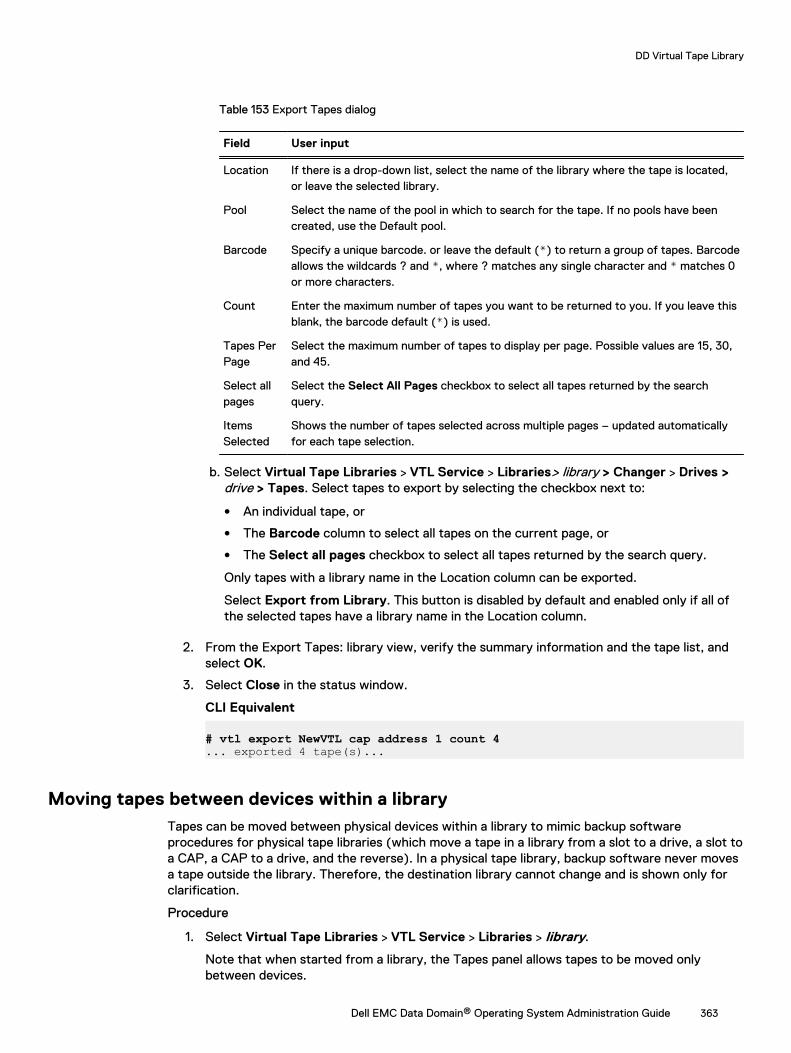
Table 153 Export Tapes dialog
Field User input
Location If there is a drop-down list, select the name of the library where the tape is located,or leave the selected library.
Pool Select the name of the pool in which to search for the tape. If no pools have beencreated, use the Default pool.
Barcode Specify a unique barcode. or leave the default (*) to return a group of tapes. Barcodeallows the wildcards ? and *, where ? matches any single character and * matches 0or more characters.
Count Enter the maximum number of tapes you want to be returned to you. If you leave thisblank, the barcode default (*) is used.
Tapes PerPage
Select the maximum number of tapes to display per page. Possible values are 15, 30,and 45.
Select allpages
Select the Select All Pages checkbox to select all tapes returned by the searchquery.
ItemsSelected
Shows the number of tapes selected across multiple pages – updated automaticallyfor each tape selection.
b. Select Virtual Tape Libraries > VTL Service > Libraries> library > Changer > Drives >drive > Tapes. Select tapes to export by selecting the checkbox next to:
l An individual tape, or
l The Barcode column to select all tapes on the current page, or
l The Select all pages checkbox to select all tapes returned by the search query.
Only tapes with a library name in the Location column can be exported.
Select Export from Library. This button is disabled by default and enabled only if all ofthe selected tapes have a library name in the Location column.
2. From the Export Tapes: library view, verify the summary information and the tape list, andselect OK.
3. Select Close in the status window.
CLI Equivalent
# vtl export NewVTL cap address 1 count 4... exported 4 tape(s)...
Moving tapes between devices within a libraryTapes can be moved between physical devices within a library to mimic backup softwareprocedures for physical tape libraries (which move a tape in a library from a slot to a drive, a slot toa CAP, a CAP to a drive, and the reverse). In a physical tape library, backup software never movesa tape outside the library. Therefore, the destination library cannot change and is shown only forclarification.
Procedure
1. Select Virtual Tape Libraries > VTL Service > Libraries > library.
Note that when started from a library, the Tapes panel allows tapes to be moved onlybetween devices.
DD Virtual Tape Library
Dell EMC Data Domain® Operating System Administration Guide 363
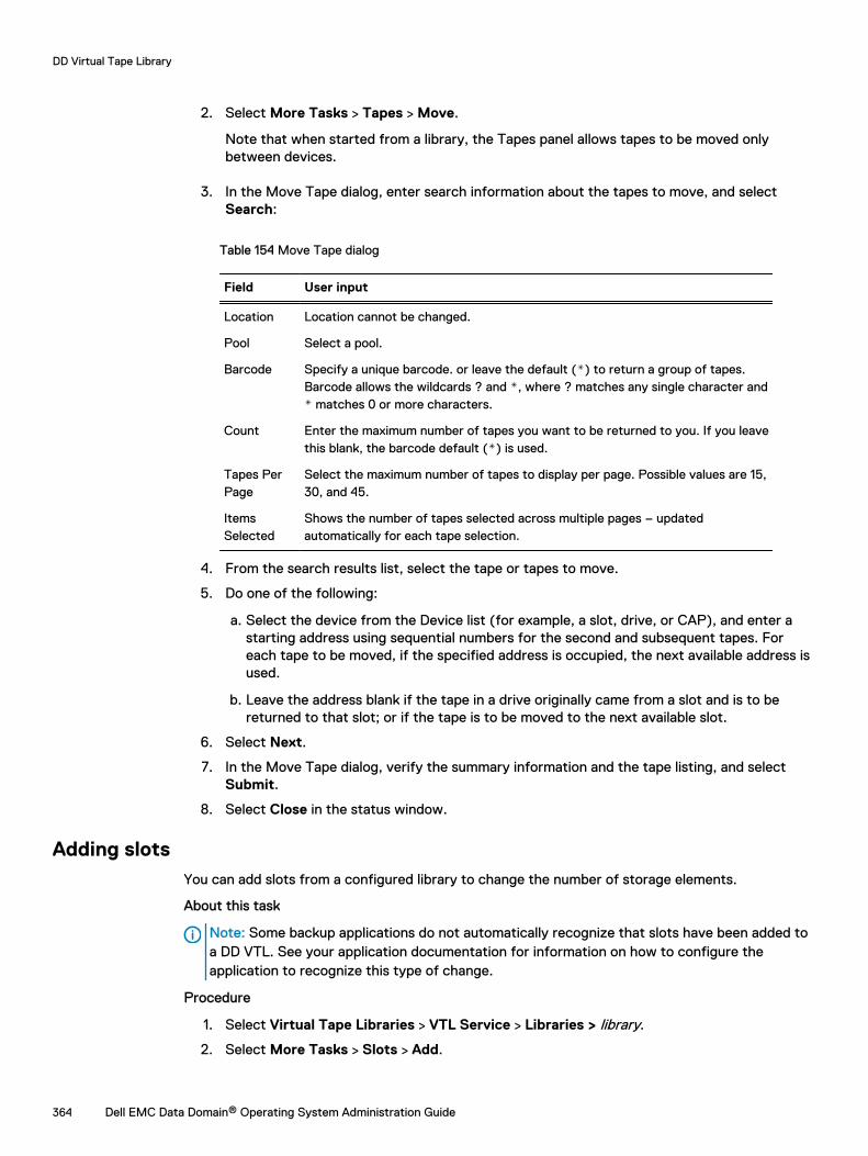
2. Select More Tasks > Tapes > Move.
Note that when started from a library, the Tapes panel allows tapes to be moved onlybetween devices.
3. In the Move Tape dialog, enter search information about the tapes to move, and selectSearch:
Table 154 Move Tape dialog
Field User input
Location Location cannot be changed.
Pool Select a pool.
Barcode Specify a unique barcode. or leave the default (*) to return a group of tapes.Barcode allows the wildcards ? and *, where ? matches any single character and* matches 0 or more characters.
Count Enter the maximum number of tapes you want to be returned to you. If you leavethis blank, the barcode default (*) is used.
Tapes PerPage
Select the maximum number of tapes to display per page. Possible values are 15,30, and 45.
ItemsSelected
Shows the number of tapes selected across multiple pages – updatedautomatically for each tape selection.
4. From the search results list, select the tape or tapes to move.
5. Do one of the following:
a. Select the device from the Device list (for example, a slot, drive, or CAP), and enter astarting address using sequential numbers for the second and subsequent tapes. Foreach tape to be moved, if the specified address is occupied, the next available address isused.
b. Leave the address blank if the tape in a drive originally came from a slot and is to bereturned to that slot; or if the tape is to be moved to the next available slot.
6. Select Next.
7. In the Move Tape dialog, verify the summary information and the tape listing, and selectSubmit.
8. Select Close in the status window.
Adding slotsYou can add slots from a configured library to change the number of storage elements.
About this task
Note: Some backup applications do not automatically recognize that slots have been added toa DD VTL. See your application documentation for information on how to configure theapplication to recognize this type of change.
Procedure
1. Select Virtual Tape Libraries > VTL Service > Libraries > library.
2. Select More Tasks > Slots > Add.
DD Virtual Tape Library
364 Dell EMC Data Domain® Operating System Administration Guide
3. In the Add Slots dialog, enter the Number of Slots to add. The total number of slots in alibrary, or in all libraries on a system, cannot exceed 32,000 for a library and 64,000 for asystem.
4. Select OK and Close when the status shows Completed.
Deleting slotsYou can delete slots from a configured library to change the number of storage elements.
About this task
Note: Some backup applications do not automatically recognize that slots have been deletedfrom a DD VTL. See your application documentation for information on how to configure theapplication to recognize this type of change.
Procedure
1. If the slot that you want to delete contains cartridges, move those cartridges to the vault.The system will delete only empty, uncommitted slots.
2. Select Virtual Tape Libraries > VTL Service > Libraries > library.
3. Select More Tasks > Slots > Delete.
4. In the Delete Slots dialog, enter the Number of Slots to delete.
5. Select OK and Close when the status shows Completed.
Adding CAPsYou can add CAPs (cartridge access ports) from a configured library to change the number ofstorage elements.
About this task
Note: CAPs are used by a limited number of backup applications. See your applicationdocumentation to ensure that CAPs are supported.
Procedure
1. Select Virtual Tape Libraries > VTL Service > Libraries > library.
2. Select More Tasks > CAPs > Add.
3. In the Add CAPs dialog, enter the Number of CAPs to add. You can add from 1 to 100 CAPsper library and from 1 to 1,000 CAPs per system.
4. Select OK and Close when the status shows Completed.
Deleting CAPsYou can delete CAPs (cartridge access ports) from a configured library to change the number ofstorage elements.
About this task
Note: Some backup applications do not automatically recognize that CAPs have been deletedfrom a DD VTL. See your application documentation for information on how to configure theapplication to recognize this type of change.
Procedure
1. If the CAP that you want to delete contains cartridges, move those cartridges to the vault,or this will be done automatically.
DD Virtual Tape Library
Dell EMC Data Domain® Operating System Administration Guide 365
2. Select Virtual Tape Libraries > VTL Service > Libraries > library.
3. Select More Tasks > CAPs > Delete.
4. In the Delete CAPs dialog, enter the Number of CAPs to delete. You can delete a maximumof 100 CAPs per library or 1000 CAPs per system.
5. Select OK and Close when the status shows Completed.
Viewing changer informationThere can be only one changer per DD VTL. The changer model you select depends on yourspecific configuration.
Procedure
1. Select Virtual Tape Libraries > VTL Service > Libraries .
2. Select a specific library.
3. If not expanded, select the plus sign (+) on the left to open the library, and select a Changerelement to display the Changer information panel, which provides the following information.
Table 155 Changer information panel
Item Description
Vendor The name of the vendor who manufactured the changer
Product The model name
Revision The revision level
Serial Number The changer serial number
Working with drivesSelecting Virtual Tape Libraries > VTL Service > Libraries > library > Drives displays detailedinformation for all drives for a selected library.
About this task
Table 156 Drives information panel
Column Description
Drive The list of drives by name, where name is “Drive #” and # is a number between 1and n representing the address or location of the drive in the list of drives.
Vendor The manufacturer or vendor of the drive, for example, IBM.
Product The product name of the drive, for example, ULTRIUM-TD5.
Revision The revision number of the drive product.
SerialNumber
The serial number of the drive product.
Status Whether the drive is Empty, Open, Locked, or Loaded. A tape must be present forthe drive to be locked or loaded.
Tape The barcode of the tape in the drive (if any).
DD Virtual Tape Library
366 Dell EMC Data Domain® Operating System Administration Guide
Table 156 Drives information panel (continued)
Column Description
Pool The pool of the tape in the drive (if any).
Tape and library drivers – To work with drives, you must use the tape and library drivers suppliedby your backup software vendor that support the IBM LTO-1, IBM LTO-2, IBM LTO-3, IBM LTO-4,IBM LTO-5 (default), HP-LTO-3, or HP-LTO-4 drives and the StorageTek L180 (default),RESTORER-L180, IBM TS3500, I2000, I6000, or DDVTL libraries. For more information, see theApplication Compatibility Matrices and Integration Guides for your vendors. When configuring drives,also keep in mind the limits on backup data streams, which are determined by the platform in use.
LTO drive capacities – Because the DD system treats LTO drives as virtual drives, you can set amaximum capacity to 4 TiB (4000 GiB) for each drive type. The default capacities for each LTOdrive type are as follows:
l LTO-1 drive: 100 GiB
l LTO-2 drive: 200 GiB
l LTO-3 drive: 400 GiB
l LTO-4 drive: 800 GiB
l LTO-5 drive: 1.5 TiB
Migrating LTO-1 tapes – You can migrate tapes from existing LTO-1 type VTLs to VTLs thatinclude other supported LTO-type tapes and drives. The migration options are different for eachbackup application, so follow the instructions in the LTO tape migration guide specific to yourapplication. To find the appropriate guide, go to the Online Support Site, and in the search textbox, type in LTO Tape Migration for VTLs.
Tape full: Early warning – You will receive a warning when the remaining tape space is almostcompletely full, that is, greater than 99.9, but less than 100 percent. The application can continuewriting until the end of the tape to reach 100 percent capacity. The last write, however, is notrecoverable.
From the More Tasks menu, you can create or delete a drive.
Creating drivesSee the Number of drives supported by a DD VTL section to determine the maximum number ofdrives supported for your particular DD VTL.
Procedure
1. Select Virtual Tape Libraries > VTL Service > Libraries > library> Changer > Drives.
2. Select More Tasks > Drives > Create.
3. In the Create Drive dialog, enter the following information:
Table 157 Create Drive dialog
Field User input
Location Select a library name, or leave the name selected.
Number ofDrives
See the table in the Number of Drives Supported by a DD VTL section, earlierin this chapter.
DD Virtual Tape Library
Dell EMC Data Domain® Operating System Administration Guide 367
Table 157 Create Drive dialog (continued)
Field User input
Model Name Select the model from the drop-down list. If another drive already exists, thisoption is inactive, and the existing drive type must be used. You cannot mixdrive types in the same library.
l IBM-LTO-1
l IBM-LTO-2
l IBM-LTO-3
l IBM-LTO-4
l IBM-LTO-5 (default)
l HP-LTO-3
l HP-LTO-4
4. Select OK, and when the status shows Completed, select OK.
The added drive appears in the Drives list.
Deleting drivesA drive must be empty before it can be deleted.
Procedure
1. If there is a tape in the drive that you want to delete, remove the tape.
2. Select Virtual Tape Libraries > VTL Service > Libraries > library > Changer > Drives.
3. Select More Tasks > Drives > Delete.
4. In the Delete Drives dialog, select the checkboxes of the drives to delete, or select the Drivecheckbox to delete all drives.
5. Select Next, and after verifying that the correct drive(s) has been selected for deletion,select Submit.
6. When the Delete Drive Status dialog shows Completed, select Close.
The drive will have been removed from the Drives list.
Working with a selected driveSelecting Virtual Tape Libraries > VTL Service > Libraries > library > Drives > drive displaysdetailed information for a selected drive.
Table 158 Drive Tab
Column Description
Drive The list of drives by name, where name is “Drive #” and# is a number between 1 and n representing the addressor location of the drive in the list of drives.
Vendor The manufacturer or vendor of the drive, for example,IBM.
DD Virtual Tape Library
368 Dell EMC Data Domain® Operating System Administration Guide
Table 158 Drive Tab (continued)
Column Description
Product The product name of the drive, for example, ULTRIUM-TD5.
Revision The revision number of the drive product.
Serial Number The serial number of the drive product.
Status Whether the drive is Empty, Open, Locked, or Loaded. Atape must be present for the drive to be locked orloaded.
Tape The barcode of the tape in the drive (if any).
Pool The pool of the tape in the drive (if any).
Table 159 Statistics Tab
Column Description
Endpoint The specific name of the endpoint.
Ops/s The operations per second.
Read KiB/s The speed of reads in KiB per second.
Write KiB/s The speed of writes in KiB per second.
From the More Tasks menu, you can delete the drive or perform a refresh.
Working with tapesA tape is represented as a file. Tapes can be imported from the vault to a library. Tapes can beexported from a library to the vault. Tapes can be moved within a library across drives, slots(cartridge slots), and CAPs (cartridge access ports).
About this task
When tapes are created, they are placed into the vault. After they have been added to the vault,they can be imported, exported, moved, searched, or removed.
Selecting Virtual Tape Libraries > VTL Service > Libraries> library >Tapes displays detailedinformation for all tapes for a selected library.
Table 160 Tape description
Item Description
Barcode The unique barcode for the tape.
Pool The name of the pool that holds the tape. The Default poolholds all tapes unassigned to a user-created pool.
Location The location of the tape - whether in a library (and whichdrive, CAP, or slot number) or in the virtual vault.
State The state of the tape:
l RW – Read-writable
DD Virtual Tape Library
Dell EMC Data Domain® Operating System Administration Guide 369
Table 160 Tape description (continued)
Item Description
l RL – Retention-locked
l RO – Readable only
l WP – Write-protected
l RD – Replication destination
Capacity The total capacity of the tape.
Used The amount of space used on the tape.
Compression The amount of compression performed on the data on a tape.
Last Modified The date of the last change to the tape’s information.Modification times used by the system for age-based policiesmight differ from the last modified time displayed in the tapeinformation sections of the DD System Manager.
Locked Until If a DD Retention Lock deadline has been set, the time set isshown. If no retention lock exists, this value is Notspecified.
From the information panel, you can import a tape from the vault, export a tape to the library, set atape's state, create a tape, or delete a tape.
From the More Tasks menu, you can move a tape.
Changing a tape's write or retention lock stateBefore changing a tape's write or retention lock state, the tape must have been created andimported. DD VTL tapes follow the standard Data Domain Retention Lock policy. After theretention period for a tape has expired, it cannot be written to or changed (however, it can bedeleted).
Procedure
1. Select Virtual Tape Libraries > VTL Service > Libraries > library > Tapes.
2. Select the tape to modify from the list, and select Set State (above the list).
3. In the Set Tape State dialog, select Read-Writeable, Write-Protected, or Retention-Lock.
4. If the state is Retention-Lock, either
l enter the tape’s expiration date in a specified number of days, weeks, months, years, or
l select the calendar icon, and select a date from the calendar. The Retention-Lockexpires at noon on the selected date.
5. Select Next, and select Submit to change the state.
Working with the vaultThe vault holds tapes not being used by any library. Tapes reside in either a library or the vault.
Selecting Virtual Tape Libraries > VTL Service > Vault displays detailed information for theDefault pool and any other existing pools in the vault.
Systems with DD Cloud Tier and DD VTL provide the option of storing the vault on cloud storage.
DD Virtual Tape Library
370 Dell EMC Data Domain® Operating System Administration Guide
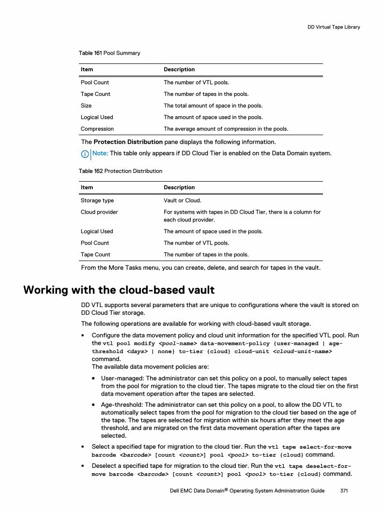
Table 161 Pool Summary
Item Description
Pool Count The number of VTL pools.
Tape Count The number of tapes in the pools.
Size The total amount of space in the pools.
Logical Used The amount of space used in the pools.
Compression The average amount of compression in the pools.
The Protection Distribution pane displays the following information.
Note: This table only appears if DD Cloud Tier is enabled on the Data Domain system.
Table 162 Protection Distribution
Item Description
Storage type Vault or Cloud.
Cloud provider For systems with tapes in DD Cloud Tier, there is a column foreach cloud provider.
Logical Used The amount of space used in the pools.
Pool Count The number of VTL pools.
Tape Count The number of tapes in the pools.
From the More Tasks menu, you can create, delete, and search for tapes in the vault.
Working with the cloud-based vaultDD VTL supports several parameters that are unique to configurations where the vault is stored onDD Cloud Tier storage.
The following operations are available for working with cloud-based vault storage.
l Configure the data movement policy and cloud unit information for the specified VTL pool. Runthe vtl pool modify <pool-name> data-movement-policy {user-managed | age-threshold <days> | none} to-tier {cloud} cloud-unit <cloud-unit-name>command.The available data movement policies are:
n User-managed: The administrator can set this policy on a pool, to manually select tapesfrom the pool for migration to the cloud tier. The tapes migrate to the cloud tier on the firstdata movement operation after the tapes are selected.
n Age-threshold: The administrator can set this policy on a pool, to allow the DD VTL toautomatically select tapes from the pool for migration to the cloud tier based on the age ofthe tape. The tapes are selected for migration within six hours after they meet the agethreshold, and are migrated on the first data movement operation after the tapes areselected.
l Select a specified tape for migration to the cloud tier. Run the vtl tape select-for-movebarcode <barcode> [count <count>] pool <pool> to-tier {cloud} command.
l Deselect a specified tape for migration to the cloud tier. Run the vtl tape deselect-for-move barcode <barcode> [count <count>] pool <pool> to-tier {cloud} command.
DD Virtual Tape Library
Dell EMC Data Domain® Operating System Administration Guide 371
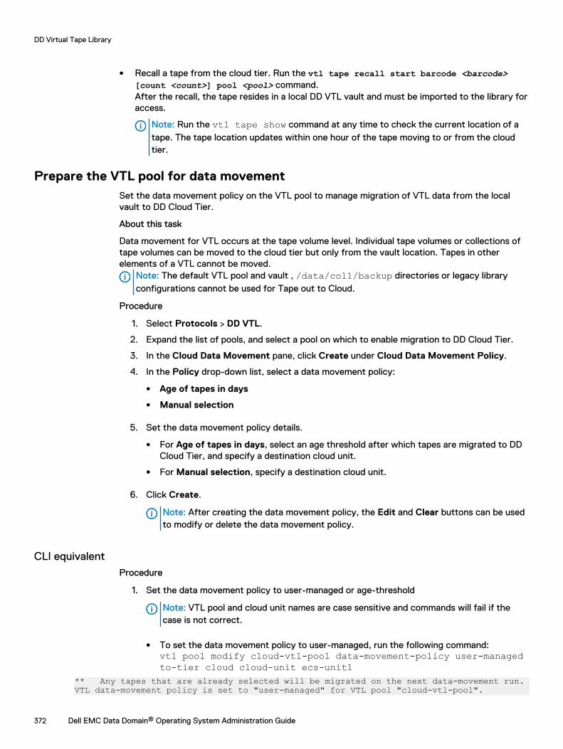
l Recall a tape from the cloud tier. Run the vtl tape recall start barcode <barcode>[count <count>] pool <pool> command.After the recall, the tape resides in a local DD VTL vault and must be imported to the library foraccess.
Note: Run the vtl tape show command at any time to check the current location of atape. The tape location updates within one hour of the tape moving to or from the cloudtier.
Prepare the VTL pool for data movementSet the data movement policy on the VTL pool to manage migration of VTL data from the localvault to DD Cloud Tier.
About this task
Data movement for VTL occurs at the tape volume level. Individual tape volumes or collections oftape volumes can be moved to the cloud tier but only from the vault location. Tapes in otherelements of a VTL cannot be moved.
Note: The default VTL pool and vault , /data/col1/backup directories or legacy libraryconfigurations cannot be used for Tape out to Cloud.
Procedure
1. Select Protocols > DD VTL.
2. Expand the list of pools, and select a pool on which to enable migration to DD Cloud Tier.
3. In the Cloud Data Movement pane, click Create under Cloud Data Movement Policy.
4. In the Policy drop-down list, select a data movement policy:
l Age of tapes in days
l Manual selection
5. Set the data movement policy details.
l For Age of tapes in days, select an age threshold after which tapes are migrated to DDCloud Tier, and specify a destination cloud unit.
l For Manual selection, specify a destination cloud unit.
6. Click Create.
Note: After creating the data movement policy, the Edit and Clear buttons can be usedto modify or delete the data movement policy.
CLI equivalentProcedure
1. Set the data movement policy to user-managed or age-threshold
Note: VTL pool and cloud unit names are case sensitive and commands will fail if thecase is not correct.
l To set the data movement policy to user-managed, run the following command:vtl pool modify cloud-vtl-pool data-movement-policy user-managedto-tier cloud cloud-unit ecs-unit1
** Any tapes that are already selected will be migrated on the next data-movement run.VTL data-movement policy is set to "user-managed" for VTL pool "cloud-vtl-pool".
DD Virtual Tape Library
372 Dell EMC Data Domain® Operating System Administration Guide
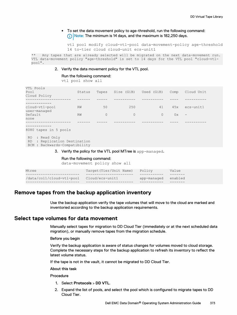
l To set the data movement policy to age-threshold, run the following command:Note: The minimum is 14 days, and the maximum is 182,250 days.
vtl pool modify cloud-vtl-pool data-movement-policy age-threshold14 to-tier cloud cloud-unit ecs-unit1
** Any tapes that are already selected will be migrated on the next data-movement run.VTL data-movement policy "age-threshold" is set to 14 days for the VTL pool "cloud-vtl-pool".
2. Verify the data movement policy for the VTL pool.
Run the following command:vtl pool show all
VTL PoolsPool Status Tapes Size (GiB) Used (GiB) Comp Cloud Unit Cloud Policy--------------------- ------ ----- ---------- ---------- ---- ---------- ------------cloud-vtl-pool RW 50 250 41 45x ecs-unit1 user-managedDefault RW 0 0 0 0x - none --------------------- ------ ----- ---------- ---------- ---- ---------- ------------8080 tapes in 5 pools RO : Read Only RD : Replication Destination BCM : Backwards-Compatibility
3. Verify the policy for the VTL pool MTree is app-managed.
Run the following command:data-movement policy show all
Mtree Target(Tier/Unit Name) Policy Value ------------------------- ---------------------- ----------- -------/data/col1/cloud-vtl-pool Cloud/ecs-unit1 app-managed enabled------------------------- ---------------------- ----------- -------
Remove tapes from the backup application inventory
Use the backup application verify the tape volumes that will move to the cloud are marked andinventoried according to the backup application requirements.
Select tape volumes for data movementManually select tapes for migration to DD Cloud Tier (immediately or at the next scheduled datamigration), or manually remove tapes from the migration schedule.
Before you begin
Verify the backup application is aware of status changes for volumes moved to cloud storage.Complete the necessary steps for the backup application to refresh its inventory to reflect thelatest volume status.
If the tape is not in the vault, it cannot be migrated to DD Cloud Tier.
About this task
Procedure
1. Select Protocols > DD VTL.
2. Expand the list of pools, and select the pool which is configured to migrate tapes to DDCloud Tier.
DD Virtual Tape Library
Dell EMC Data Domain® Operating System Administration Guide 373

3. In the pool pane, click the Tape tab.
4. Select tapes for migration to DD Cloud Tier.
5. Click Select for Cloud Move to migrate the tape at the next scheduled migration, or Moveto Cloud Now to immediately migrate the tape.
Note: If the data movement policy is based on tape ages, the Select for Cloud Move isnot available, as the Data Domain system automatically selects tapes for migration.
6. Click Yes at the confirmation dialog.
Unselect tape volumes for data movement
About this task
Tapes selected for migration to DD Cloud Tier can be removed from the migration schedule.
Procedure
1. Select Protocols > DD VTL.
2. Expand the list of pools, and select the pool which is configured to migrate tapes to DDCloud Tier.
3. In the pool pane, click the Tape tab.
4. Select tapes for migration to DD Cloud Tier.
5. Click Unselect Cloud Move to remove the tape from the migration schedule.
6. Click Yes at the confirmation dialog.
CLI equivalentProcedure
1. Identify the slot location of the tape volume to move.
Run the following command:vtl tape show cloud-vtl
Processing tapes....Barcode Pool Location State Size Used (%) Comp Modification Time -------- -------------- ----------------- ----- ----- ---------------- ---- -------------------T00001L3 cloud-vtl-pool cloud-vtl slot 1 RW 5 GiB 5.0 GiB (99.07%) 205x 2017/05/05 10:43:43T00002L3 cloud-vtl-pool cloud-vtl slot 2 RW 5 GiB 5.0 GiB (99.07%) 36x 2017/05/05 10:45:10T00003L3 cloud-vtl-pool cloud-vtl slot 3 RW 5 GiB 5.0 GiB (99.07%) 73x 2017/05/05 10:45:26
2. Specify the numeric slot value to export the tape from the DD VTL.
Run the following command:vtl export cloud-vtl-pool slot 1 count 1
3. Verify the tape is in the vault.
Run the following command:vtl tape show vault
4. Select the tape for data movement.
Run the following command:vtl tape select-for-move barcode T00001L3 count 1 pool cloud-vtl-pool to-tier cloud
DD Virtual Tape Library
374 Dell EMC Data Domain® Operating System Administration Guide
Note: If the data movement policy is age-threshold, data movement occursautomatically after 15-20 minutes.
5. View the list of tapes scheduled to move to cloud storage during the next data movementoperation. The tapes selected for movement display an (S) in the location column.
Run the following command:vtl tape show vault
Processing tapes.....Barcode Pool Location State Size Used (%) Comp Modification Time -------- ----------------- --------- ------ ------ ---------------- ---- -------------------T00003L3 cloud-vtl-pool vault (S) RW 5 GiB 5.0 GiB (99.07%) 63x 2017/05/05 10:43:43T00006L3 cloud-vtl-pool ecs-unit1 n/a 5 GiB 5.0 GiB (99.07%) 62x 2017/05/05 10:45:49-------- ----------------- --------- ------ ------ ---------------- ---- -------------------* RD : Replication Destination(S) Tape selected for migration to cloud. Selected tapes will move to cloud on the next data-movement run.(R) Recall operation is in progress for the tape.
VTL Tape Summary----------------Total number of tapes: 4024Total pools: 3Total size of tapes: 40175 GiBTotal space used by tapes: 39.6 GiBAverage Compression: 9.7x
6. If the data movement policy is user-managed, initiate the data movement operation.
Run the following command:data-movement start
7. Observe the status of the data movement operation.
Run the following command:data-movement watch
8. Verify the tape volumes successfully move to cloud storage.
Run the following command:vtl tape show all cloud-unit ecs-unit1
Processing tapes.....Barcode Pool Location State Size Used (%) Comp Modification Time-------- -------------- --------- ----- ----- ---------------- ---- -------------------T00001L3 cloud-vtl-pool ecs-unit1 n/a 5 GiB 5.0 GiB (99.07%) 89x 2017/05/05 10:41:41T00006L3 cloud-vtl-pool ecs-unit1 n/a 5 GiB 5.0 GiB (99.07%) 62x 2017/05/05 10:45:49-------- -------------- --------- ----- ----- ---------------- ---- -------------------(S) Tape selected for migration to cloud. Selected tapes will move to cloud on the next data-movement run.(R) Recall operation is in progress for the tape.
VTL Tape Summary----------------Total number of tapes: 4Total pools: 2Total size of tapes: 16 GiBTotal space used by tapes: 14.9 GiBAverage Compression: 59.5x
DD Virtual Tape Library
Dell EMC Data Domain® Operating System Administration Guide 375
Restore data held in the cloud
When a client requests data for restore from the backup application server, the backup applicationshould generate an alert or message requesting the required volumes from the cloud unit.
The volume must be recalled from the cloud and checked into the Data Domain VTL library beforethe backup application must be notified of the presence of the volumes.
Note: Verify the backup application is aware of status changes for volumes moved to cloudstorage. Complete the necessary steps for the backup application to refresh its inventory toreflect the latest volume status.
Manually recall a tape volume from cloud storageRecall a tape from DD Cloud Tier to the local VTL vault.
Procedure
1. Select Protocols > DD VTL.
2. Expand the list of pools, and select the pool which is configured to migrate tapes to DDCloud Tier.
3. In the pool pane, click the Tape tab.
4. Select one or more tapes that are located in a cloud unit.
5. Click Recall Cloud Tapes to recall tapes from DD Cloud Tier.
Results
After the next scheduled data migration, the tapes are recalled from the cloud unit to the vault.From the vault, the tapes can be returned to a library.
CLI equivalentProcedure
1. Identify the volume required to restore data.
2. Recall the tape volume from the vault.
Run the following command:vtl tape recall start barcode T00001L3 count 1 pool cloud-vtl-pool
3. Verify the recall operation started.
Run the following command:data-movement status
4. Verify the recall operation completed successfully.
Run the following command:vtl tape show all barcode T00001L3
Processing tapes....Barcode Pool Location State Size Used (%) Comp Modification Time -------- -------------- ---------------- ----- ----- ---------------- ---- -------------------T00001L3 cloud-vtl-pool cloud-vtl slot 1 RW 5 GiB 5.0 GiB (99.07%) 239x 2017/05/05 10:41:41-------- -------------- ---------------- ----- ----- ---------------- ---- -------------------(S) Tape selected for migration to cloud. Selected tapes will move to cloud on the next data-movement run.(R) Recall operation is in progress for the tape.
DD Virtual Tape Library
376 Dell EMC Data Domain® Operating System Administration Guide
VTL Tape Summary----------------Total number of tapes: 1Total pools: 1Total size of tapes: 5 GiBTotal space used by tapes: 5.0 GiBAverage Compression: 239.1x
5. Validate the file location.
Run the following command:filesys report generate file-location path /data/col1/cloud-vtl-pool
filesys report generate file-location path /data/col1/cloud-vtl-pool-------------------------------- ---------------------------File Name Location(Unit Name)-------------------------------- ---------------------------/data/col1/cloud-vtl-pool/.vtl_pool Active/data/col1/cloud-vtl-pool/.vtc/T00001L3 Active-----------------------------------------------------------------
6. Import the recalled tape to the DD VTL.
Run the following command:vtl import cloud-vtl barcode T00001L3 count 1 pool cloud-vtl-poolelement slot
imported 1 tape(s)...sysadmin@ddbeta70# vtl tape show cloud-vtlProcessing tapes.....7. Check the volume into the backup application inventory.
8. Restore data through the backup application.
9. When restore is completed check the tape volume out of the backup application inventory.
10. Export he tape volume from the Data Domain VTL to the Data Domain Vault.
11. Move the tape back to the cloud unit.
Working with access groupsAccess groups hold a collection of initiator WWPNs (worldwide port names) or aliases and thedrives and changers they are allowed to access. A DD VTL default group named TapeServer letsyou add devices that will support NDMP (Network Data Management Protocol)-based backupapplications.
Access group configuration allows initiators (in general backup applications) to read and write datato devices in the same access group.
Access groups let clients access only selected LUNs (media changers or virtual tape drives) on asystem. A client set up for an access group can access only devices in its access group.
Avoid making access group changes on a DD system during active backup or restore jobs. Achange may cause an active job to fail. The impact of changes during active jobs depends on acombination of backup software and host configurations.
Selecting Access Groups > Groups displays the following information for all access groups.
Table 163 Access group information
Item Description
Group Name Name of group.
Initiators Number of initiators in group.
DD Virtual Tape Library
Dell EMC Data Domain® Operating System Administration Guide 377
Table 163 Access group information (continued)
Item Description
Devices Number of devices in group.
If you select View All Access Groups, you are taken to the Fibre Channel view.
From the More Tasks menu, you can create or delete a group.
Creating an access groupAccess groups manage access between devices and initiators. Do not use the default TapeServeraccess group unless you are using NDMP.
Procedure
1. Select Access Groups > Groups.
2. Select More Tasks > Group > Create
3. In the Create Access Group dialog, enter a name, from 1 to 128 characters, and select Next.
4. Add devices, and select Next.
5. Review the summary, and select Finish or Back, as appropriate.
CLI Equivalent
# vtl group create My_Group
Adding an access group deviceAccess group configuration allows initiators (in general backup applications) to read and write datato devices in the same access group.
Procedure
1. Select Access Groups > Groups. You can also select a specific group.
2. Select More Tasks > Group > Create or Group > Configure.
3. In the Create or Modify Access Group dialog, enter or modify the Group Name if desired.(This field is required.)
4. To configure initiators to the access group, check the box next to the initiator. You can addinitiators to the group later.
5. Select Next.
6. In the Devices display, select Add (+) to display the Add Devices dialog.
a. Verify that the correct library is selected in the Library Name drop-down list, or selectanother library.
b. In the Device area, select the checkboxes of the devices (changer and drives) to beincluded in the group.
c. Optionally, specify a starting LUN in the LUN Start Address text box.
This is the LUN that the DD system returns to the initiator. Each device is uniquelyidentified by the library and the device name. (For example, it is possible to have drive 1in Library 1 and drive 1 in Library 2). Therefore, a LUN is associated with a device, whichis identified by its library and device name.
When presenting LUNs via attached FC ports on FC HBA/SLIC, ports can be designatedas primary, secondary, or none. A Primary port for a set of LUNs is the port that iscurrently advertizing those LUNs to a fabric. A secondary port is a port that will
DD Virtual Tape Library
378 Dell EMC Data Domain® Operating System Administration Guide
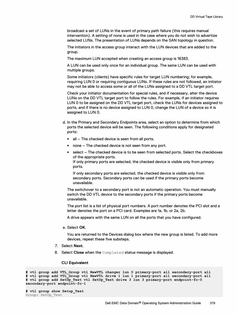
broadcast a set of LUNs in the event of primary path failure (this requires manualintervention). A setting of none is used in the case where you do not wish to advertizeselected LUNs. The presentation of LUNs depends on the SAN topology in question.
The initiators in the access group interact with the LUN devices that are added to thegroup.
The maximum LUN accepted when creating an access group is 16383.
A LUN can be used only once for an individual group. The same LUN can be used withmultiple groups.
Some initiators (clients) have specific rules for target LUN numbering; for example,requiring LUN 0 or requiring contiguous LUNs. If these rules are not followed, an initiatormay not be able to access some or all of the LUNs assigned to a DD VTL target port.
Check your initiator documentation for special rules, and if necessary, alter the deviceLUNs on the DD VTL target port to follow the rules. For example, if an initiator requiresLUN 0 to be assigned on the DD VTL target port, check the LUNs for devices assigned toports, and if there is no device assigned to LUN 0, change the LUN of a device so it isassigned to LUN 0.
d. In the Primary and Secondary Endpoints area, select an option to determine from whichports the selected device will be seen. The following conditions apply for designatedports:
l all – The checked device is seen from all ports.
l none – The checked device is not seen from any port.
l select – The checked device is to be seen from selected ports. Select the checkboxesof the appropriate ports.If only primary ports are selected, the checked device is visible only from primaryports.
If only secondary ports are selected, the checked device is visible only fromsecondary ports. Secondary ports can be used if the primary ports becomeunavailable.
The switchover to a secondary port is not an automatic operation. You must manuallyswitch the DD VTL device to the secondary ports if the primary ports becomeunavailable.
The port list is a list of physical port numbers. A port number denotes the PCI slot and aletter denotes the port on a PCI card. Examples are 1a, 1b, or 2a, 2b.
A drive appears with the same LUN on all the ports that you have configured.
e. Select OK.
You are returned to the Devices dialog box where the new group is listed. To add moredevices, repeat these five substeps.
7. Select Next.
8. Select Close when the Completed status message is displayed.
CLI Equivalent
# vtl group add VTL_Group vtl NewVTL changer lun 0 primary-port all secondary-port all# vtl group add VTL_Group vtl NewVTL drive 1 lun 1 primary-port all secondary-port all# vtl group add SetUp_Test vtl SetUp_Test drive 3 lun 3 primary-port endpoint-fc-0 secondary-port endpoint-fc-1
# vtl group show Setup_TestGroup: SetUp_Test
DD Virtual Tape Library
Dell EMC Data Domain® Operating System Administration Guide 379
Initiators:Initiator Alias Initiator WWPN --------------- -----------------------tsm6_p23 21:00:00:24:ff:31:ce:f8--------------- -----------------------
Devices:Device Name LUN Primary Ports Secondary Ports In-use Ports------------------ --- ------------- --------------- -------------SetUp_Test changer 0 all all allSetUp_Test drive 1 1 all all allSetUp_Test drive 2 2 5a 5b 5aSetUp_Test drive 3 3 endpoint-fc-0 endpoint-fc-1 endpoint-fc-0------------------ --- ------------- --------------- -------------
Modifying or deleting an access group deviceYou may need to modify or delete a device from an access group.
Procedure
1. Select Protocols > VTL > Access Groups > Groups > group.
2. Select More Tasks > Group > Configure.
3. In the Modify Access Group dialog, enter or modify the Group Name. (This field isrequired.)
4. To configure initiators to the access group, check the box next to the initiator. You can addinitiators to the group later.
5. Select Next.
6. Select a device, and select the edit (pencil) icon to display the Modify Devices dialog. Then,follow steps a-e. If you simply want to delete the device, select the delete (X) icon, and skipto step e.
a. Verify that the correct library is selected in the Library drop-down list, or select anotherlibrary.
b. In the Devices to Modify area, select the checkboxes of the devices (Changer anddrives) to be modified.
c. Optionally, modify the starting LUN (logical unit number) in the LUN Start Address box.
This is the LUN that the DD system returns to the initiator. Each device is uniquelyidentified by the library and the device name. (For example, it is possible to have drive 1in Library 1 and drive 1 in Library 2). Therefore, a LUN is associated with a device, whichis identified by its library and device name.
The initiators in the access group interact with the LUN devices that are added to thegroup.
The maximum LUN accepted when creating an access group is 16383.
A LUN can be used only once for an individual group. The same LUN can be used withmultiple groups.
Some initiators (clients) have specific rules for target LUN numbering; for example,requiring LUN 0 or requiring contiguous LUNs. If these rules are not followed, an initiatormay not be able to access some or all of the LUNs assigned to a DD VTL target port.
Check your initiator documentation for special rules, and if necessary, alter the deviceLUNs on the DD VTL target port to follow the rules. For example, if an initiator requiresLUN 0 to be assigned on the DD VTL target port, check the LUNs for devices assigned toports, and if there is no device assigned to LUN 0, change the LUN of a device so it isassigned to LUN 0.
DD Virtual Tape Library
380 Dell EMC Data Domain® Operating System Administration Guide

d. In the Primary and Secondary Ports area, change the option that determines the portsfrom which the selected device is seen. The following conditions apply for designatedports:
l all – The checked device is seen from all ports.
l none – The checked device is not seen from any port.
l select – The checked device is seen from selected ports. Select the checkboxes ofthe ports from which it will be seen.If only primary ports are selected, the checked device is visible only from primaryports.
If only secondary ports are selected, the checked device is visible only fromsecondary ports. Secondary ports can be used if primary ports become unavailable.
The switchover to a secondary port is not an automatic operation. You must manuallyswitch the DD VTL device to the secondary ports if the primary ports becomeunavailable.
The port list is a list of physical port numbers. A port number denotes the PCI slot, and aletter denotes the port on a PCI card. Examples are 1a, 1b, or 2a, 2b.
A drive appears with the same LUN on all ports that you have configured.
e. Select OK.
Deleting an access groupBefore you can delete an access group, you must remove all of its initiators and LUNs.
Procedure
1. Remove all of the initiators and LUNs from the group.
2. Select Access Groups > Groups.
3. Select More Tasks > Group > Delete.
4. In the Delete Group dialog, select the checkbox of the group to be removed, and selectNext.
5. In the groups confirmation dialog, verify the deletion, and select Submit.
6. Select Close when the Delete Groups Status displays Completed.
CLI Equivalent
# scsitarget group destroy My_Group
Working with a selected access groupSelecting Access Groups > Groups > group displays the following information for a selectedaccess group.
Table 164 LUNs tab
Item Description
LUN Device address – maximum number is 16383. A LUN can beused only once within a group, but can be used again within
DD Virtual Tape Library
Dell EMC Data Domain® Operating System Administration Guide 381
Table 164 LUNs tab (continued)
Item Description
another group. DD VTL devices added to a group must usecontiguous LUNs.
Library Name of library associated with LUN.
Device Changers and drives.
In-Use Endpoints Set of endpoints currently being used: primary or secondary.
Primary Endpoints Initial (or default) endpoint used by backup application. In theevent of a failure on this endpoint, the secondary endpointsmay be used, if available.
Secondary Endpoints Set of fail-over endpoints to use if primary endpoint fails.
Table 165 Initiators tab
Item Description
Name Name of initiator, which is either the WWPN or the aliasassigned to the initiator.
WWPN Unique worldwide port name, which is a 64-bit identifier (a60-bit value preceded by a 4-bit Network Address Authorityidentifier), of the Fibre Channel port.
From the More Tasks menu, with a group selected, you can configure that group, or set endpointsin use.
Selecting endpoints for a deviceSince endpoints connect a device to an initiator, use this process to set up the endpoints beforeyou connect the device.
Procedure
1. Select Access Groups > Groups > group.
2. Select More Tasks > Endpoints > Set In-Use.
3. In the Set in-Use Endpoints dialog, select only specific devices, or select Devices to selectall devices in the list.
4. Indicate whether the endpoints are primary or secondary.
5. Select OK.
Configuring the NDMP device TapeServer groupThe DD VTL TapeServer group holds tape drives that interface with NDMP (Network DataManagement Protocol)-based backup applications and that send control information and datastreams over IP (Internet Protocol) instead of Fibre Channel (FC). A device used by the NDMPTapeServer must be in the DD VTL group TapeServer and is available only to the NDMPTapeServer.
Procedure
1. Add tape drives to a new or existing library (in this example, named “dd990-16”).
DD Virtual Tape Library
382 Dell EMC Data Domain® Operating System Administration Guide
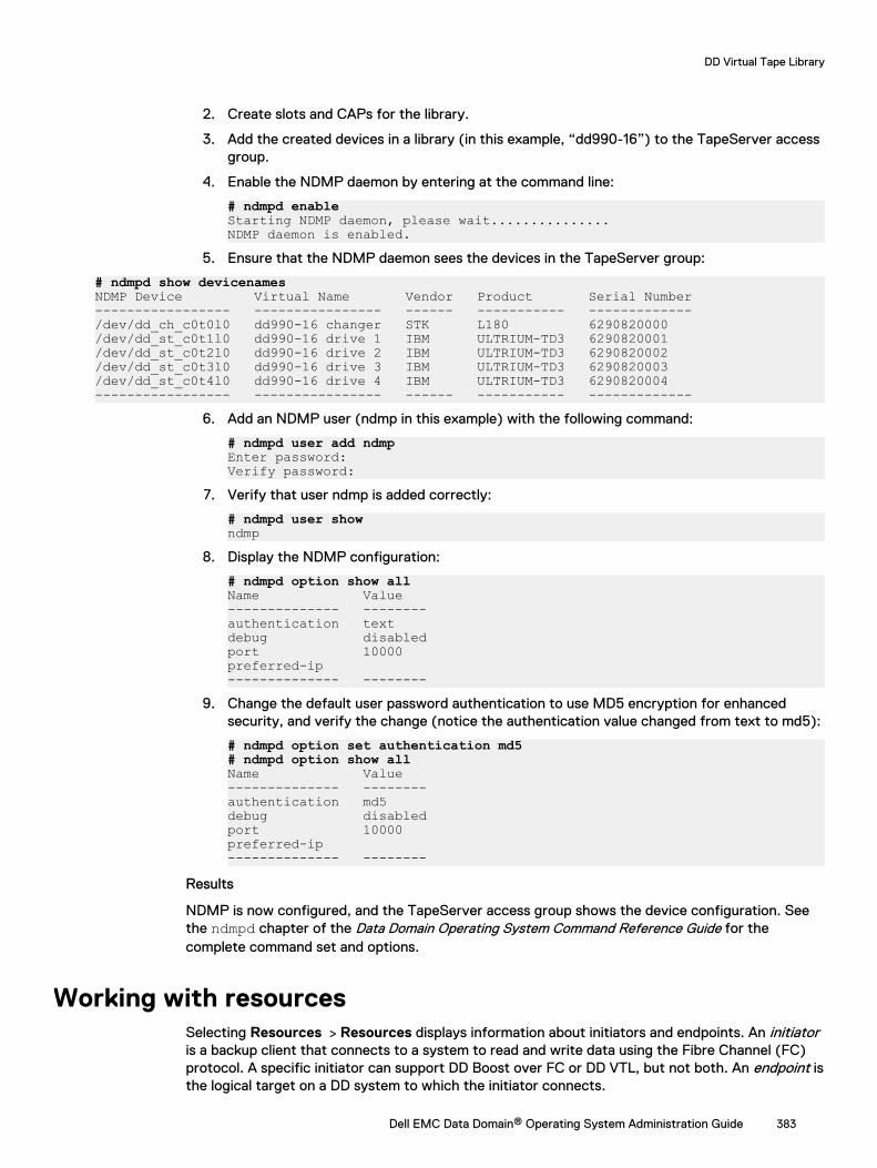
2. Create slots and CAPs for the library.
3. Add the created devices in a library (in this example, “dd990-16”) to the TapeServer accessgroup.
4. Enable the NDMP daemon by entering at the command line:
# ndmpd enableStarting NDMP daemon, please wait...............NDMP daemon is enabled.
5. Ensure that the NDMP daemon sees the devices in the TapeServer group:
# ndmpd show devicenamesNDMP Device Virtual Name Vendor Product Serial Number----------------- ---------------- ------ ----------- -------------/dev/dd_ch_c0t0l0 dd990-16 changer STK L180 6290820000 /dev/dd_st_c0t1l0 dd990-16 drive 1 IBM ULTRIUM-TD3 6290820001 /dev/dd_st_c0t2l0 dd990-16 drive 2 IBM ULTRIUM-TD3 6290820002 /dev/dd_st_c0t3l0 dd990-16 drive 3 IBM ULTRIUM-TD3 6290820003 /dev/dd_st_c0t4l0 dd990-16 drive 4 IBM ULTRIUM-TD3 6290820004 ----------------- ---------------- ------ ----------- -------------
6. Add an NDMP user (ndmp in this example) with the following command:
# ndmpd user add ndmpEnter password: Verify password:
7. Verify that user ndmp is added correctly:
# ndmpd user showndmp
8. Display the NDMP configuration:
# ndmpd option show allName Value -------------- --------authentication text debug disabledport 10000 preferred-ip -------------- --------
9. Change the default user password authentication to use MD5 encryption for enhancedsecurity, and verify the change (notice the authentication value changed from text to md5):
# ndmpd option set authentication md5# ndmpd option show allName Value -------------- --------authentication md5 debug disabledport 10000 preferred-ip -------------- --------
Results
NDMP is now configured, and the TapeServer access group shows the device configuration. Seethe ndmpd chapter of the Data Domain Operating System Command Reference Guide for thecomplete command set and options.
Working with resourcesSelecting Resources > Resources displays information about initiators and endpoints. An initiatoris a backup client that connects to a system to read and write data using the Fibre Channel (FC)protocol. A specific initiator can support DD Boost over FC or DD VTL, but not both. An endpoint isthe logical target on a DD system to which the initiator connects.
DD Virtual Tape Library
Dell EMC Data Domain® Operating System Administration Guide 383
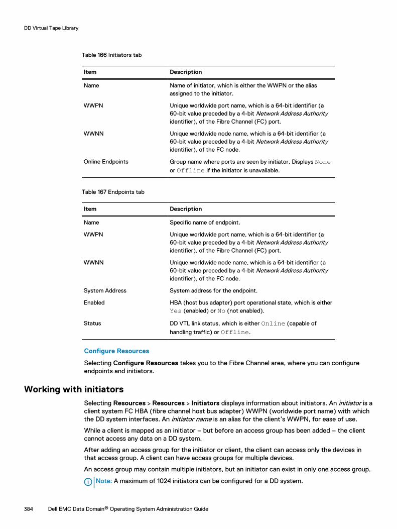
Table 166 Initiators tab
Item Description
Name Name of initiator, which is either the WWPN or the aliasassigned to the initiator.
WWPN Unique worldwide port name, which is a 64-bit identifier (a60-bit value preceded by a 4-bit Network Address Authorityidentifier), of the Fibre Channel (FC) port.
WWNN Unique worldwide node name, which is a 64-bit identifier (a60-bit value preceded by a 4-bit Network Address Authorityidentifier), of the FC node.
Online Endpoints Group name where ports are seen by initiator. Displays Noneor Offline if the initiator is unavailable.
Table 167 Endpoints tab
Item Description
Name Specific name of endpoint.
WWPN Unique worldwide port name, which is a 64-bit identifier (a60-bit value preceded by a 4-bit Network Address Authorityidentifier), of the Fibre Channel (FC) port.
WWNN Unique worldwide node name, which is a 64-bit identifier (a60-bit value preceded by a 4-bit Network Address Authorityidentifier), of the FC node.
System Address System address for the endpoint.
Enabled HBA (host bus adapter) port operational state, which is eitherYes (enabled) or No (not enabled).
Status DD VTL link status, which is either Online (capable of
handling traffic) or Offline.
Configure Resources
Selecting Configure Resources takes you to the Fibre Channel area, where you can configureendpoints and initiators.
Working with initiatorsSelecting Resources > Resources > Initiators displays information about initiators. An initiator is aclient system FC HBA (fibre channel host bus adapter) WWPN (worldwide port name) with whichthe DD system interfaces. An initiator name is an alias for the client’s WWPN, for ease of use.
While a client is mapped as an initiator – but before an access group has been added – the clientcannot access any data on a DD system.
After adding an access group for the initiator or client, the client can access only the devices inthat access group. A client can have access groups for multiple devices.
An access group may contain multiple initiators, but an initiator can exist in only one access group.
Note: A maximum of 1024 initiators can be configured for a DD system.
DD Virtual Tape Library
384 Dell EMC Data Domain® Operating System Administration Guide
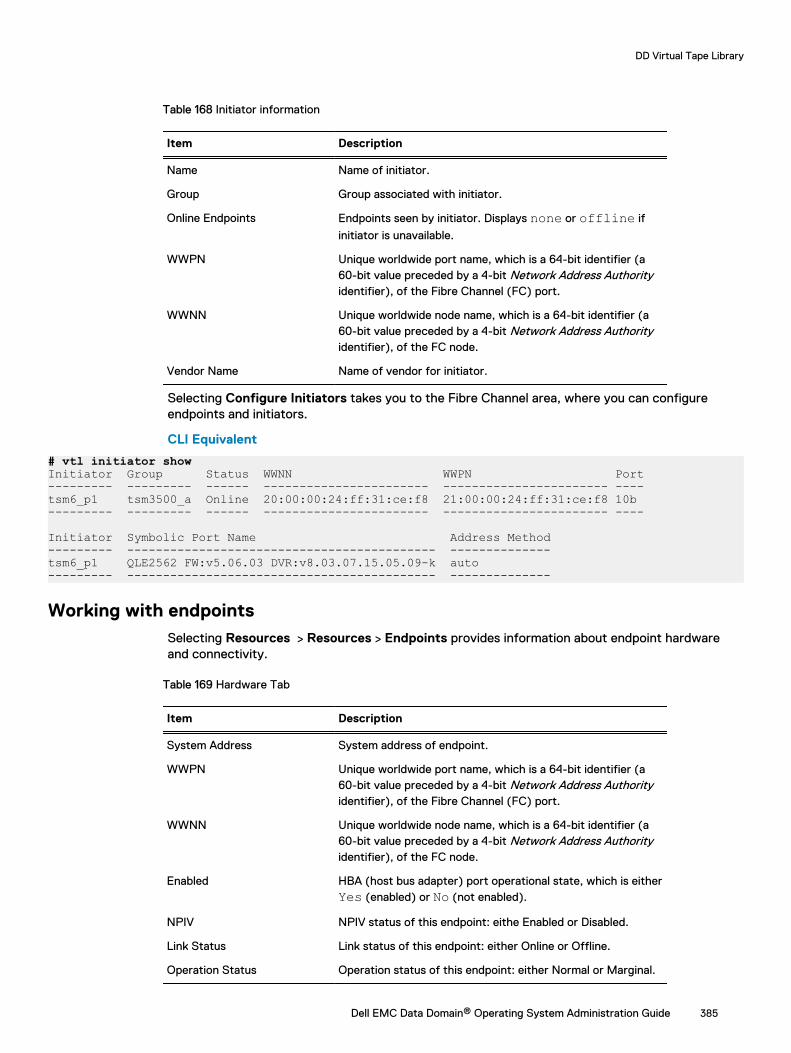
Table 168 Initiator information
Item Description
Name Name of initiator.
Group Group associated with initiator.
Online Endpoints Endpoints seen by initiator. Displays none or offline if
initiator is unavailable.
WWPN Unique worldwide port name, which is a 64-bit identifier (a60-bit value preceded by a 4-bit Network Address Authorityidentifier), of the Fibre Channel (FC) port.
WWNN Unique worldwide node name, which is a 64-bit identifier (a60-bit value preceded by a 4-bit Network Address Authorityidentifier), of the FC node.
Vendor Name Name of vendor for initiator.
Selecting Configure Initiators takes you to the Fibre Channel area, where you can configureendpoints and initiators.
CLI Equivalent
# vtl initiator showInitiator Group Status WWNN WWPN Port--------- --------- ------ ----------------------- ----------------------- ----tsm6_p1 tsm3500_a Online 20:00:00:24:ff:31:ce:f8 21:00:00:24:ff:31:ce:f8 10b --------- --------- ------ ----------------------- ----------------------- ----
Initiator Symbolic Port Name Address Method--------- ------------------------------------------- --------------tsm6_p1 QLE2562 FW:v5.06.03 DVR:v8.03.07.15.05.09-k auto --------- ------------------------------------------- --------------
Working with endpointsSelecting Resources > Resources > Endpoints provides information about endpoint hardwareand connectivity.
Table 169 Hardware Tab
Item Description
System Address System address of endpoint.
WWPN Unique worldwide port name, which is a 64-bit identifier (a60-bit value preceded by a 4-bit Network Address Authorityidentifier), of the Fibre Channel (FC) port.
WWNN Unique worldwide node name, which is a 64-bit identifier (a60-bit value preceded by a 4-bit Network Address Authorityidentifier), of the FC node.
Enabled HBA (host bus adapter) port operational state, which is eitherYes (enabled) or No (not enabled).
NPIV NPIV status of this endpoint: eithe Enabled or Disabled.
Link Status Link status of this endpoint: either Online or Offline.
Operation Status Operation status of this endpoint: either Normal or Marginal.
DD Virtual Tape Library
Dell EMC Data Domain® Operating System Administration Guide 385
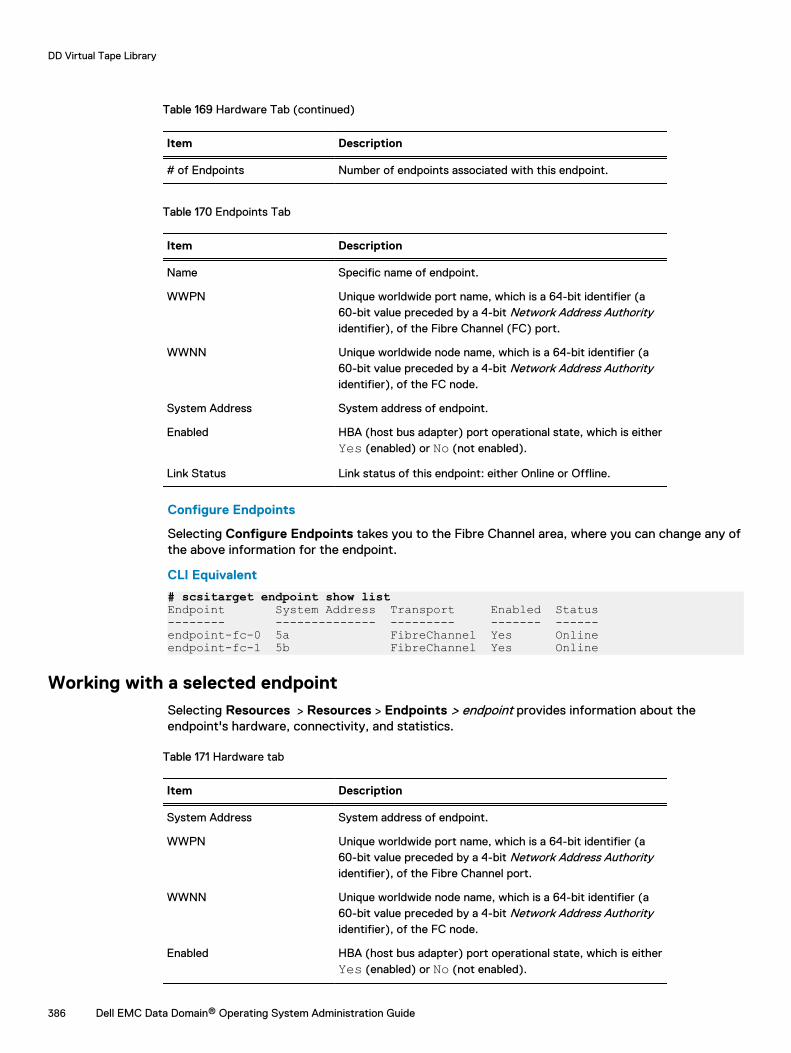
Table 169 Hardware Tab (continued)
Item Description
# of Endpoints Number of endpoints associated with this endpoint.
Table 170 Endpoints Tab
Item Description
Name Specific name of endpoint.
WWPN Unique worldwide port name, which is a 64-bit identifier (a60-bit value preceded by a 4-bit Network Address Authorityidentifier), of the Fibre Channel (FC) port.
WWNN Unique worldwide node name, which is a 64-bit identifier (a60-bit value preceded by a 4-bit Network Address Authorityidentifier), of the FC node.
System Address System address of endpoint.
Enabled HBA (host bus adapter) port operational state, which is eitherYes (enabled) or No (not enabled).
Link Status Link status of this endpoint: either Online or Offline.
Configure Endpoints
Selecting Configure Endpoints takes you to the Fibre Channel area, where you can change any ofthe above information for the endpoint.
CLI Equivalent
# scsitarget endpoint show listEndpoint System Address Transport Enabled Status-------- -------------- --------- ------- ------endpoint-fc-0 5a FibreChannel Yes Onlineendpoint-fc-1 5b FibreChannel Yes Online
Working with a selected endpointSelecting Resources > Resources > Endpoints > endpoint provides information about theendpoint's hardware, connectivity, and statistics.
Table 171 Hardware tab
Item Description
System Address System address of endpoint.
WWPN Unique worldwide port name, which is a 64-bit identifier (a60-bit value preceded by a 4-bit Network Address Authorityidentifier), of the Fibre Channel port.
WWNN Unique worldwide node name, which is a 64-bit identifier (a60-bit value preceded by a 4-bit Network Address Authorityidentifier), of the FC node.
Enabled HBA (host bus adapter) port operational state, which is eitherYes (enabled) or No (not enabled).
DD Virtual Tape Library
386 Dell EMC Data Domain® Operating System Administration Guide
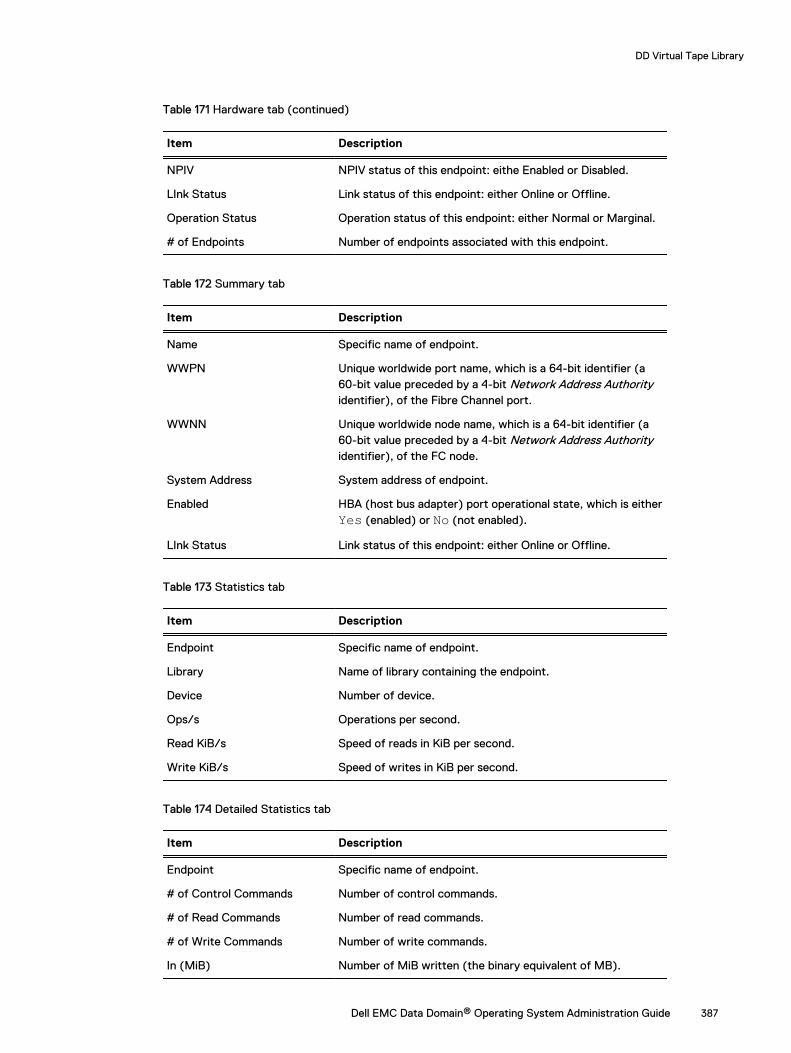
Table 171 Hardware tab (continued)
Item Description
NPIV NPIV status of this endpoint: eithe Enabled or Disabled.
LInk Status Link status of this endpoint: either Online or Offline.
Operation Status Operation status of this endpoint: either Normal or Marginal.
# of Endpoints Number of endpoints associated with this endpoint.
Table 172 Summary tab
Item Description
Name Specific name of endpoint.
WWPN Unique worldwide port name, which is a 64-bit identifier (a60-bit value preceded by a 4-bit Network Address Authorityidentifier), of the Fibre Channel port.
WWNN Unique worldwide node name, which is a 64-bit identifier (a60-bit value preceded by a 4-bit Network Address Authorityidentifier), of the FC node.
System Address System address of endpoint.
Enabled HBA (host bus adapter) port operational state, which is eitherYes (enabled) or No (not enabled).
LInk Status Link status of this endpoint: either Online or Offline.
Table 173 Statistics tab
Item Description
Endpoint Specific name of endpoint.
Library Name of library containing the endpoint.
Device Number of device.
Ops/s Operations per second.
Read KiB/s Speed of reads in KiB per second.
Write KiB/s Speed of writes in KiB per second.
Table 174 Detailed Statistics tab
Item Description
Endpoint Specific name of endpoint.
# of Control Commands Number of control commands.
# of Read Commands Number of read commands.
# of Write Commands Number of write commands.
In (MiB) Number of MiB written (the binary equivalent of MB).
DD Virtual Tape Library
Dell EMC Data Domain® Operating System Administration Guide 387
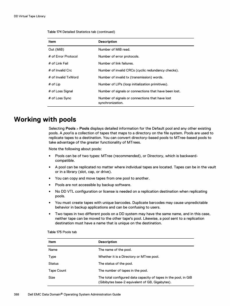
Table 174 Detailed Statistics tab (continued)
Item Description
Out (MiB) Number of MiB read.
# of Error Protocol Number of error protocols.
# of Link Fail Number of link failures.
# of Invalid Crc Number of invalid CRCs (cyclic redundancy checks).
# of Invalid TxWord Number of invalid tx (transmission) words.
# of Lip Number of LIPs (loop initialization primitives).
# of Loss Signal Number of signals or connections that have been lost.
# of Loss Sync Number of signals or connections that have lostsynchronization.
Working with poolsSelecting Pools > Pools displays detailed information for the Default pool and any other existingpools. A pool is a collection of tapes that maps to a directory on the file system. Pools are used toreplicate tapes to a destination. You can convert directory-based pools to MTree-based pools totake advantage of the greater functionality of MTrees.
Note the following about pools:
l Pools can be of two types: MTree (recommended), or Directory, which is backward-compatible.
l A pool can be replicated no matter where individual tapes are located. Tapes can be in the vaultor in a library (slot, cap, or drive).
l You can copy and move tapes from one pool to another.
l Pools are not accessible by backup software.
l No DD VTL configuration or license is needed on a replication destination when replicatingpools.
l You must create tapes with unique barcodes. Duplicate barcodes may cause unpredictablebehavior in backup applications and can be confusing to users.
l Two tapes in two different pools on a DD system may have the same name, and in this case,neither tape can be moved to the other tape's pool. Likewise, a pool sent to a replicationdestination must have a name that is unique on the destination.
Table 175 Pools tab
Item Description
Name The name of the pool.
Type Whether it is a Directory or MTree pool.
Status The status of the pool.
Tape Count The number of tapes in the pool.
Size The total configured data capacity of tapes in the pool, in GiB(Gibibytes base-2 equivalent of GB, Gigabytes).
DD Virtual Tape Library
388 Dell EMC Data Domain® Operating System Administration Guide
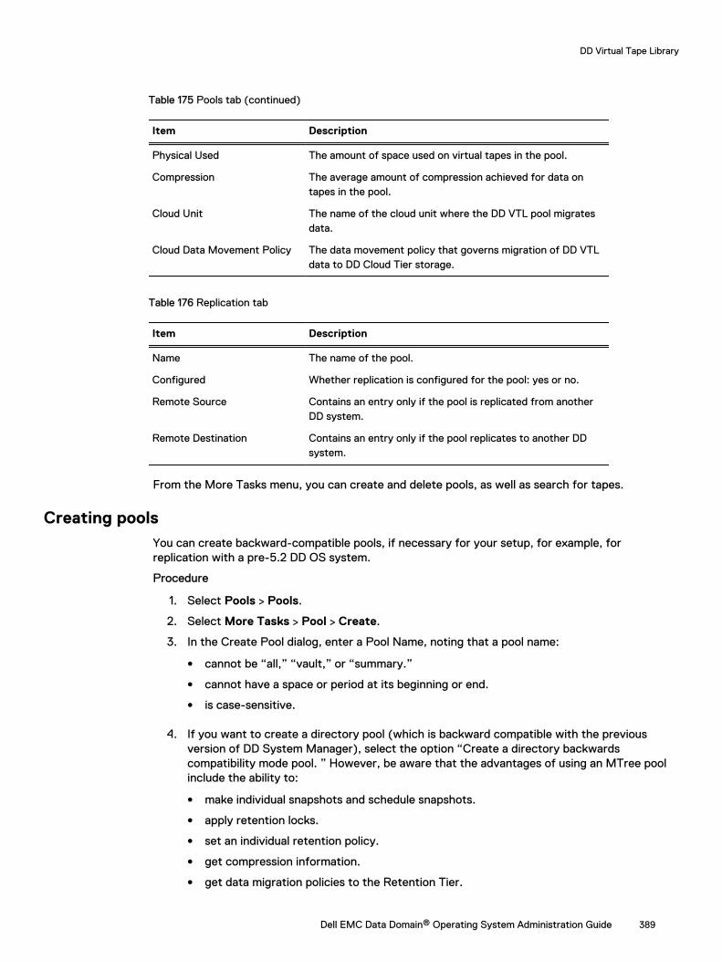
Table 175 Pools tab (continued)
Item Description
Physical Used The amount of space used on virtual tapes in the pool.
Compression The average amount of compression achieved for data ontapes in the pool.
Cloud Unit The name of the cloud unit where the DD VTL pool migratesdata.
Cloud Data Movement Policy The data movement policy that governs migration of DD VTLdata to DD Cloud Tier storage.
Table 176 Replication tab
Item Description
Name The name of the pool.
Configured Whether replication is configured for the pool: yes or no.
Remote Source Contains an entry only if the pool is replicated from anotherDD system.
Remote Destination Contains an entry only if the pool replicates to another DDsystem.
From the More Tasks menu, you can create and delete pools, as well as search for tapes.
Creating poolsYou can create backward-compatible pools, if necessary for your setup, for example, forreplication with a pre-5.2 DD OS system.
Procedure
1. Select Pools > Pools.
2. Select More Tasks > Pool > Create.
3. In the Create Pool dialog, enter a Pool Name, noting that a pool name:
l cannot be “all,” “vault,” or “summary.”
l cannot have a space or period at its beginning or end.
l is case-sensitive.
4. If you want to create a directory pool (which is backward compatible with the previousversion of DD System Manager), select the option “Create a directory backwardscompatibility mode pool. ” However, be aware that the advantages of using an MTree poolinclude the ability to:
l make individual snapshots and schedule snapshots.
l apply retention locks.
l set an individual retention policy.
l get compression information.
l get data migration policies to the Retention Tier.
DD Virtual Tape Library
Dell EMC Data Domain® Operating System Administration Guide 389
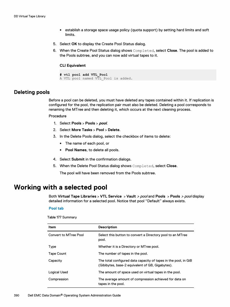
l establish a storage space usage policy (quota support) by setting hard limits and softlimits.
5. Select OK to display the Create Pool Status dialog.
6. When the Create Pool Status dialog shows Completed, select Close. The pool is added tothe Pools subtree, and you can now add virtual tapes to it.
CLI Equivalent
# vtl pool add VTL_PoolA VTL pool named VTL_Pool is added.
Deleting poolsBefore a pool can be deleted, you must have deleted any tapes contained within it. If replication isconfigured for the pool, the replication pair must also be deleted. Deleting a pool corresponds torenaming the MTree and then deleting it, which occurs at the next cleaning process.
Procedure
1. Select Pools > Pools > pool.
2. Select More Tasks > Pool > Delete.
3. In the Delete Pools dialog, select the checkbox of items to delete:
l The name of each pool, or
l Pool Names, to delete all pools.
4. Select Submit in the confirmation dialogs.
5. When the Delete Pool Status dialog shows Completed, select Close.
The pool will have been removed from the Pools subtree.
Working with a selected poolBoth Virtual Tape Libraries > VTL Service > Vault > pool and Pools > Pools > pool displaydetailed information for a selected pool. Notice that pool “Default” always exists.
Pool tab
Table 177 Summary
Item Description
Convert to MTree Pool Select this button to convert a Directory pool to an MTreepool.
Type Whether it is a Directory or MTree pool.
Tape Count The number of tapes in the pool.
Capacity The total configured data capacity of tapes in the pool, in GiB(Gibibytes, base-2 equivalent of GB, Gigabytes).
Logical Used The amount of space used on virtual tapes in the pool.
Compression The average amount of compression achieved for data ontapes in the pool.
DD Virtual Tape Library
390 Dell EMC Data Domain® Operating System Administration Guide
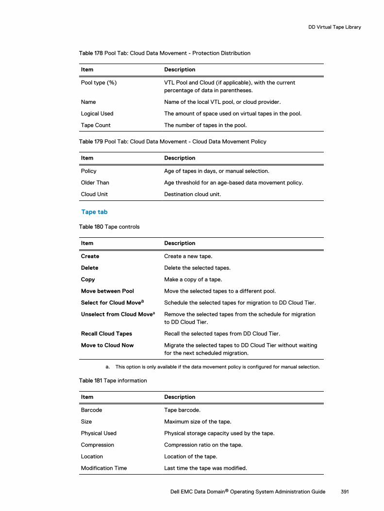
Table 178 Pool Tab: Cloud Data Movement - Protection Distribution
Item Description
Pool type (%) VTL Pool and Cloud (if applicable), with the currentpercentage of data in parentheses.
Name Name of the local VTL pool, or cloud provider.
Logical Used The amount of space used on virtual tapes in the pool.
Tape Count The number of tapes in the pool.
Table 179 Pool Tab: Cloud Data Movement - Cloud Data Movement Policy
Item Description
Policy Age of tapes in days, or manual selection.
Older Than Age threshold for an age-based data movement policy.
Cloud Unit Destination cloud unit.
Tape tab
Table 180 Tape controls
Item Description
Create Create a new tape.
Delete Delete the selected tapes.
Copy Make a copy of a tape.
Move between Pool Move the selected tapes to a different pool.
Select for Cloud Movea Schedule the selected tapes for migration to DD Cloud Tier.
Unselect from Cloud Movea Remove the selected tapes from the schedule for migrationto DD Cloud Tier.
Recall Cloud Tapes Recall the selected tapes from DD Cloud Tier.
Move to Cloud Now Migrate the selected tapes to DD Cloud Tier without waitingfor the next scheduled migration.
a. This option is only available if the data movement policy is configured for manual selection.
Table 181 Tape information
Item Description
Barcode Tape barcode.
Size Maximum size of the tape.
Physical Used Physical storage capacity used by the tape.
Compression Compression ratio on the tape.
Location Location of the tape.
Modification Time Last time the tape was modified.
DD Virtual Tape Library
Dell EMC Data Domain® Operating System Administration Guide 391
Table 181 Tape information (continued)
Item Description
Recall Time Last time the tape was recalled.
Replication tab
Table 182 Replication
Item Description
Name The name of the pool.
Configured Whether replication is configured for this pool: yes or no.
Remote Source Contains an entry only if the pool is replicated from anotherDD system.
Remote Destination Contains an entry only if the pool replicates to another DDsystem.
You can also select the Replication Detail button, at the top right, to go directly to the Replicationinformation panel for the selected pool.
From either the Virtual Tape Libraries or Pools area, from the More Tasks menu, you can create,delete, move, copy, or search for a tape in the pool.
From the Pools area, from the More Tasks menu, you can rename or delete a pool.
Converting a directory pool to an MTree poolMTree pools have many advantages over directory pools. See the Creating pools section for moreinformation.
Procedure
1. Make sure the following prerequisites have been met:
l The source and destination pools must have been synchronized, so that the number oftapes, and the data on each side, remains intact.
l The directory pool must not be a replication source or destination.
l The file system must not be full.
l The file system must not have reached the maximum number of MTrees allowed (100).
l There must not already be an MTree with the same name.
l If the directory pool is being replicated on multiple systems, those replicating systemsmust be known to the managing system.
l If the directory pool is being replicated to an older DD OS (for example, from DD OS 5.5to DD OS 5.4), it cannot be converted. As a workaround:
n Replicate the directory pool to a second DD system.
n Replicate the directory pool from the second DD system to a third DD system.
n Remove the second and third DD systems from the managing DD system's DataDomain network.
n On any of the systems running DD OS 5.5, from the Pools submenu, select Pools anda directory pool. In the Pools tab, select Convert to MTree Pool.
DD Virtual Tape Library
392 Dell EMC Data Domain® Operating System Administration Guide
2. With the directory pool you wish to convert highlighted, choose Convert to MTree Pool.
3. Select OK in the Convert to MTree Pool dialog.
4. Be aware that conversion affects replication in the following ways:
l DD VTL is temporarily disabled on the replicated systems during conversion.
l The destination data is copied to a new pool on the destination system to preserve thedata until the new replication is initialized and synced. Afterward, you may safely deletethis temporarily copied pool, which is named CONVERTED-pool, where pool is the nameof the pool that was upgraded (or the first 18 characters for long pool names). [Thisapplies only to DD OS 5.4.1.0 and later.]
l The target replication directory will be converted to MTree format. [This applies only toDD OS 5.2 and later.]
l Replication pairs are broken before pool conversion and re-established afterward if noerrors occur.
l DD Retention Lock cannot be enabled on systems involved in MTree pool conversion.
Moving tapes between poolsIf they reside in the vault, tapes can be moved between pools to accommodate replicationactivities. For example, pools are needed if all tapes were created in the Default pool, but you laterneed independent groups for replicating groups of tapes. You can create named pools and re-organize the groups of tapes into new pools.
About this task
Note: You cannot move tapes from a tape pool that is a directory replication source. As aworkaround, you can:
l Copy the tape to a new pool, then delete the tape from the old pool.
l Use an MTree pool, which allows you to move tapes from a tape pool that is a directoryreplication source.
Procedure
1. With a pool highlighted, select More Tasks > Tapes > Move.
Note that when started from a pool, the Tapes Panel allows tapes to be moved onlybetween pools.
2. In the Move Tapes dialog, enter information to search for the tapes to move, and selectSearch:
Table 183 Move Tapes dialog
Field User input
Location Location cannot be changed.
Pool Select the name of the pool where the tapes reside. If no pools have beencreated, use the Default pool.
Barcode Specify a unique barcode. or leave the default (*) to import a group of tapes.Barcode allows the wildcards ? and *, where ? matches any single characterand * matches 0 or more characters.
DD Virtual Tape Library
Dell EMC Data Domain® Operating System Administration Guide 393
Table 183 Move Tapes dialog (continued)
Field User input
Count Enter the maximum number of tapes you want to be returned to you. If youleave this blank, the barcode default (*) is used.
Tapes PerPage
Select the maximum number of tapes to display per page. Possible values are15, 30, and 45.
ItemsSelected
Shows the number of tapes selected across multiple pages – updatedautomatically for each tape selection.
3. From the search results list, select the tapes to move.
4. From the Select Destination: Location list, select the location of the pool to which tapes areto be moved. This option is available only when started from the (named) Pool view.
5. Select Next.
6. From the Move Tapes view, verify the summary information and tape list, and selectSubmit.
7. Select Close in the status window.
Copying tapes between poolsTapes can be copied between pools, or from the vault to a pool, to accommodate replicationactivities. This option is available only when started from the (named) Pool view.
Procedure
1. With a pool highlighted, select More Tasks > Tapes > Copy.
2. In the Copy Tapes Between Pools dialog. select the checkboxes of tapes to copy, or enterinformation to search for the tapes to copy, and select Search:
Table 184 Copy Tapes Between Pools dialog
Field User input
Location Select either a library or the Vault for locating the tape. While tapes alwaysshow up in a pool (under the Pools menu), they are technically in either a libraryor the vault, but not both, and they are never in two libraries at the same time.Use the import/export options to move tapes between the vault and a library.
Pool To copy tapes between pools, select the name of the pool where the tapescurrently reside. If no pools have been created, use the Default pool.
Barcode Specify a unique barcode. or leave the default (*) to import a group of tapes.Barcode allows the wildcards ? and *, where ? matches any single character and* matches 0 or more characters.
Count Enter the maximum number of tapes you want to be imported. If you leave thisblank, the barcode default (*) is used.
Tapes PerPage
Select the maximum number of tapes to display per page. Possible values are 15,30, and 45.
ItemsSelected
Shows the number of tapes selected across multiple pages – updatedautomatically for each tape selection.
3. From the search results list, select the tapes to copy.
DD Virtual Tape Library
394 Dell EMC Data Domain® Operating System Administration Guide
4. From the Select Destination: Pool list, select the pool where tapes are to be copied. If a tapewith a matching barcode already resides in the destination pool, an error is displayed, andthe copy aborts.
5. Select Next.
6. From the Copy Tapes Between Pools dialog, verify the summary information and the tapelist, and select Submit.
7. Select Close on the Copy Tapes Between Pools Status window.
Renaming poolsA pool can be renamed only if none of its tapes is in a library.
Procedure
1. Select Pools > Pools > pool.
2. Select More Tasks > Pool > Rename.
3. In the Rename Pool dialog, enter the new Pool Name, with the caveat that this name:
l cannot be “all,” “vault,” or “summary.”
l cannot have a space or period at its beginning or end.
l is case-sensitive.
4. Select OK to display the Rename Pool status dialog.
5. After the Rename Pool status dialog shows Completed, select OK.
The pool will have been renamed in the Pools subtree in both the Pools and the Virtual TapeLibraries areas.
DD Virtual Tape Library
Dell EMC Data Domain® Operating System Administration Guide 395

DD Virtual Tape Library
396 Dell EMC Data Domain® Operating System Administration Guide
CHAPTER 16
DD Replicator
This chapter includes:
l DD Replicator overview....................................................................................................... 398l Prerequisites for replication configuration...........................................................................399l Replication version compatibility......................................................................................... 402l Replication types.................................................................................................................406l Using DD Encryption with DD Replicator.............................................................................. 411l Replication topologies.......................................................................................................... 412l Managing replication............................................................................................................ 417l Monitoring replication .........................................................................................................432l Replication with HA............................................................................................................. 433l Replicating a system with quotas to one without.................................................................434l Replication Scaling Context ................................................................................................434l Directory-to-MTree replication migration............................................................................434l Using collection replication for disaster recovery with SMT................................................ 439
Dell EMC Data Domain® Operating System Administration Guide 397
DD Replicator overviewDD Replicator provides automated, policy-based, network-efficient, and encrypted replication forDR (disaster recovery) and multi-site backup and archive consolidation. DD Replicatorasynchronously replicates only compressed, deduplicated data over a WAN (wide area network).
DD Replicator performs two levels of deduplication to significantly reduce bandwidthrequirements: local and cross-site deduplication. Local deduplication determines the uniquesegments to be replicated over a WAN. Cross-site deduplication further reduces bandwidthrequirements when multiple sites are replicating to the same destination system. With cross-sitededuplication, any redundant segment previously transferred by any other site, or as a result of alocal backup or archive, will not be replicated again. This improves network efficiency across allsites and reduces daily network bandwidth requirements up to 99%, making network-basedreplication fast, reliable, and cost-effective.
In order to meet a broad set of DR requirements, DD Replicator provides flexible replicationtopologies, such as full system mirroring, bi-directional, many-to-one, one-to-many, and cascaded.In addition, you can choose to replicate either all or a subset of the data on your DD system. Forthe highest level of security, DD Replicator can encrypt data being replicated between DD systemsusing the standard SSL (Secure Socket Layer) protocol.
DD Replicator scales performance and supported fan-in ratios to support large enterpriseenvironments.
Before getting started with DD Replicator, note the following general requirements:
l DD Replicator is a licensed product. See your Dell EMC sales representative to purchaselicenses.
l You can usually replicate only between machines that are within two releases of each other, forexample, from 6.0 to 6.2. However, there may be exceptions to this (as a result of atypicalrelease numbering), so review the tables in the Replication version compatibility section, orcheck with your Dell EMC representative.
l If you are unable to manage and monitor DD Replicator from the current version of the DDSystem Manager, use the replication commands described in the DD OS CommandReference Guide.
DD Replicator
398 Dell EMC Data Domain® Operating System Administration Guide
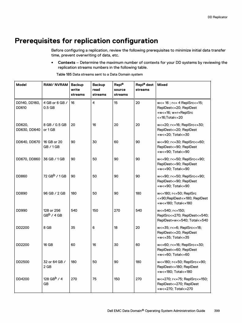
Prerequisites for replication configurationBefore configuring a replication, review the following prerequisites to minimize initial data transfertime, prevent overwriting of data, etc.
l Contexts – Determine the maximum number of contexts for your DD systems by reviewing thereplication streams numbers in the following table.
Table 185 Data streams sent to a Data Domain system
Model RAM/ NVRAM Backupwritestreams
Backupreadstreams
Repla
sourcestreams
Repla deststreams
Mixed
DD140, DD160,DD610
4 GB or 6 GB /0.5 GB
16 4 15 20 w<= 16 ; r<= 4 ReplSrc<=15;ReplDest<=20; ReplDest+w<=16; w+r+ReplSrc<=16;Total<=20
DD620,DD630, DD640
8 GB / 0.5 GBor 1 GB
20 16 20 20 w<=20; r<=16; ReplSrc<=30;ReplDest<=20; ReplDest+w<=20; Total<=30
DD640, DD670 16 GB or 20GB / 1 GB
90 30 60 90 w<=90; r<=30; ReplSrc<=60;ReplDest<=90; ReplDest+w<=90; Total<=90
DD670, DD860 36 GB / 1 GB 90 50 90 90 w<=90; r<=50; ReplSrc<=90;ReplDest<=90; ReplDest+w<=90; Total<=90
DD860 72 GBb / 1 GB 90 50 90 90 w<=90; r<=50; ReplSrc<=90;ReplDest<=90; ReplDest+w<=90; Total<=90
DD890 96 GB / 2 GB 180 50 90 180 w<=180; r<=50; ReplSrc<=90;ReplDest<=180; ReplDest+w<=180; Total<=180
DD990 128 or 256GBb / 4 GB
540 150 270 540 w<=540; r<=150;ReplSrc<=270; ReplDest<=540;ReplDest+w<=540; Total<=540
DD2200 8 GB 35 6 18 20 w<=35; r<=6; ReplSrc<=18;ReplDest<=20; ReplDest+w<=35; Total<=35
DD2200 16 GB 60 16 30 60 w<=60; r<=16; ReplSrc<=30;ReplDest<=60; ReplDest+w<=60; Total<=60
DD2500 32 or 64 GB /2 GB
180 50 90 180 w<=180; r<=50; ReplSrc<=90;ReplDest<=180; ReplDest+w<=180; Total<=180
DD4200 128 GBb / 4GB
270 75 150 270 w<=270; r<=75; ReplSrc<=150;ReplDest<=270; ReplDest+w<=270; Total<=270
DD Replicator
Dell EMC Data Domain® Operating System Administration Guide 399
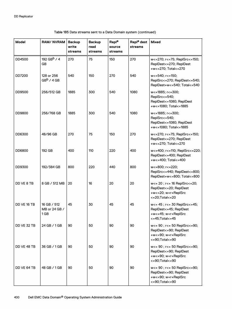
Table 185 Data streams sent to a Data Domain system (continued)
Model RAM/ NVRAM Backupwritestreams
Backupreadstreams
Repla
sourcestreams
Repla deststreams
Mixed
DD4500 192 GBb / 4GB
270 75 150 270 w<=270; r<=75; ReplSrc<=150;ReplDest<=270; ReplDest+w<=270; Total<=270
DD7200 128 or 256GBb / 4 GB
540 150 270 540 w<=540; r<=150;ReplSrc<=270; ReplDest<=540;ReplDest+w<=540; Total<=540
DD9500 256/512 GB 1885 300 540 1080 w<=1885; r<=300;ReplSrc<=540;ReplDest<=1080; ReplDest+w<=1080; Total<=1885
DD9800 256/768 GB 1885 300 540 1080 w<=1885; r<=300;ReplSrc<=540;ReplDest<=1080; ReplDest+w<=1080; Total<=1885
DD6300 48/96 GB 270 75 150 270 w<=270; r<=75; ReplSrc<=150;ReplDest<=270; ReplDest+w<=270; Total<=270
DD6800 192 GB 400 110 220 400 w<=400; r<=110; ReplSrc<=220;ReplDest<=400; ReplDest+w<=400; Total<=400
DD9300 192/384 GB 800 220 440 800 w<=800; r<=220;ReplSrc<=440; ReplDest<=800;ReplDest+w<=800; Total<=800
DD VE 8 TB 8 GB / 512 MB 20 16 20 20 w<= 20 ; r<= 16 ReplSrc<=20;ReplDest<=20; ReplDest+w<=20; w+r+ReplSrc<=20;Total<=20
DD VE 16 TB 16 GB / 512MB or 24 GB /1 GB
45 30 45 45 w<= 45 ; r<= 30 ReplSrc<=45;ReplDest<=45; ReplDest+w<=45; w+r+ReplSrc<=45;Total<=45
DD VE 32 TB 24 GB / 1 GB 90 50 90 90 w<= 90 ; r<= 50 ReplSrc<=90;ReplDest<=90; ReplDest+w<=90; w+r+ReplSrc<=90;Total<=90
DD VE 48 TB 36 GB / 1 GB 90 50 90 90 w<= 90 ; r<= 50 ReplSrc<=90;ReplDest<=90; ReplDest+w<=90; w+r+ReplSrc<=90;Total<=90
DD VE 64 TB 48 GB / 1 GB 90 50 90 90 w<= 90 ; r<= 50 ReplSrc<=90;ReplDest<=90; ReplDest+w<=90; w+r+ReplSrc<=90;Total<=90
DD Replicator
400 Dell EMC Data Domain® Operating System Administration Guide

Table 185 Data streams sent to a Data Domain system (continued)
Model RAM/ NVRAM Backupwritestreams
Backupreadstreams
Repla
sourcestreams
Repla deststreams
Mixed
DD VE 96 TB 64 GB / 2 GB 180 50 90 180 w<= 180 ; r<= 50 ReplSrc<=90;ReplDest<=180; ReplDest+w<=180; w+r+ReplSrc<=180;Total<=180
DD3300 4 TB 12 GB (virtualmemory) / 512MB
20 16 30 20 w<= 20 ; r<= 16 ReplSrc<=30;ReplDest<=20; ReplDest+w<=20; w+r+ReplSrc<=30;Total<=30
DD3300 8 TB 32 GB (virtualmemory) /1.536 GB
90 50 90 90 w<= 90 ; r<= 50 ReplSrc<=90;ReplDest<=90; ReplDest+w<=90; w+r+ReplSrc<=90;Total<=90
DD3300 16 TB 32 GB (virtualmemory) /1.536 GB
90 50 90 90 w<= 90 ; r<= 50 ReplSrc<=90;ReplDest<=90; ReplDest+w<=90; w+r+ReplSrc<=90;Total<=90
DD3300 32 TB 46 GB (virtualmemory) /1.536 GB
90 50 90 90 w<= 90 ; r<= 50 ReplSrc<=90;ReplDest<=90; ReplDest+w<=90; w+r+ReplSrc<=90;Total<=140
a. DirRepl, OptDup, MTreeRepl streamsb. The Data Domain Extended Retention software option is available only for these devices with extended (maximum)
memory
l Compatibility – If you are using DD systems running different versions of DD OS, review thenext section on Replication Version Compatibility.
l Initial Replication – If the source holds a lot of data, the initial replication operation can takemany hours. Consider putting both DD systems in the same location with a high-speed, low-latency link. After the first replication, you can move the systems to their intended locationsbecause only new data will be sent.
l Bandwidth Delay Settings – Both the source and destination must have the same bandwidthdelay settings. These tuning controls benefit replication performance over higher latency linksby controlling the TCP (transmission control protocol) buffer size. The source system can thensend enough data to the destination while waiting for an acknowledgment.
l Only One Context for Directories/Subdirectories – A directory (and its subdirectories) canbe in only one context at a time, so be sure that a subdirectory under a source directory is notused in another directory replication context.
l Adequate Storage – At a minimum, the destination must have the same amount of space asthe source.
l Destination Empty for Directory Replication – The destination directory must be empty fordirectory replication, or its contents no longer needed, because it will be overwritten.
l Security – DD OS requires that port 3009 be open in order to configure secure replicationover an Ethernet connection.
DD Replicator
Dell EMC Data Domain® Operating System Administration Guide 401
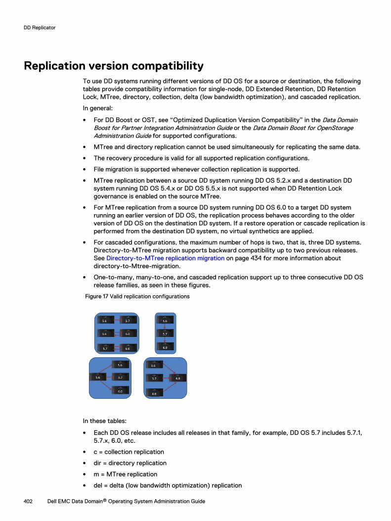
Replication version compatibilityTo use DD systems running different versions of DD OS for a source or destination, the followingtables provide compatibility information for single-node, DD Extended Retention, DD RetentionLock, MTree, directory, collection, delta (low bandwidth optimization), and cascaded replication.
In general:
l For DD Boost or OST, see “Optimized Duplication Version Compatibility” in the Data DomainBoost for Partner Integration Administration Guide or the Data Domain Boost for OpenStorageAdministration Guide for supported configurations.
l MTree and directory replication cannot be used simultaneously for replicating the same data.
l The recovery procedure is valid for all supported replication configurations.
l File migration is supported whenever collection replication is supported.
l MTree replication between a source DD system running DD OS 5.2.x and a destination DDsystem running DD OS 5.4.x or DD OS 5.5.x is not supported when DD Retention Lockgovernance is enabled on the source MTree.
l For MTree replication from a source DD system running DD OS 6.0 to a target DD systemrunning an earlier version of DD OS, the replication process behaves according to the olderversion of DD OS on the destination DD system. If a restore operation or cascade replication isperformed from the destination DD system, no virtual synthetics are applied.
l For cascaded configurations, the maximum number of hops is two, that is, three DD systems.Directory-to-MTree migration supports backward compatibility up to two previous releases.See Directory-to-MTree replication migration on page 434 for more information aboutdirectory-to-Mtree-migration.
l One-to-many, many-to-one, and cascaded replication support up to three consecutive DD OSrelease families, as seen in these figures.
Figure 17 Valid replication configurations
In these tables:
l Each DD OS release includes all releases in that family, for example, DD OS 5.7 includes 5.7.1,5.7.x, 6.0, etc.
l c = collection replication
l dir = directory replication
l m = MTree replication
l del = delta (low bandwidth optimization) replication
DD Replicator
402 Dell EMC Data Domain® Operating System Administration Guide
l dest = destination
l src = source
l NA = not applicable
DD Replicator
Dell EMC Data Domain® Operating System Administration Guide 403
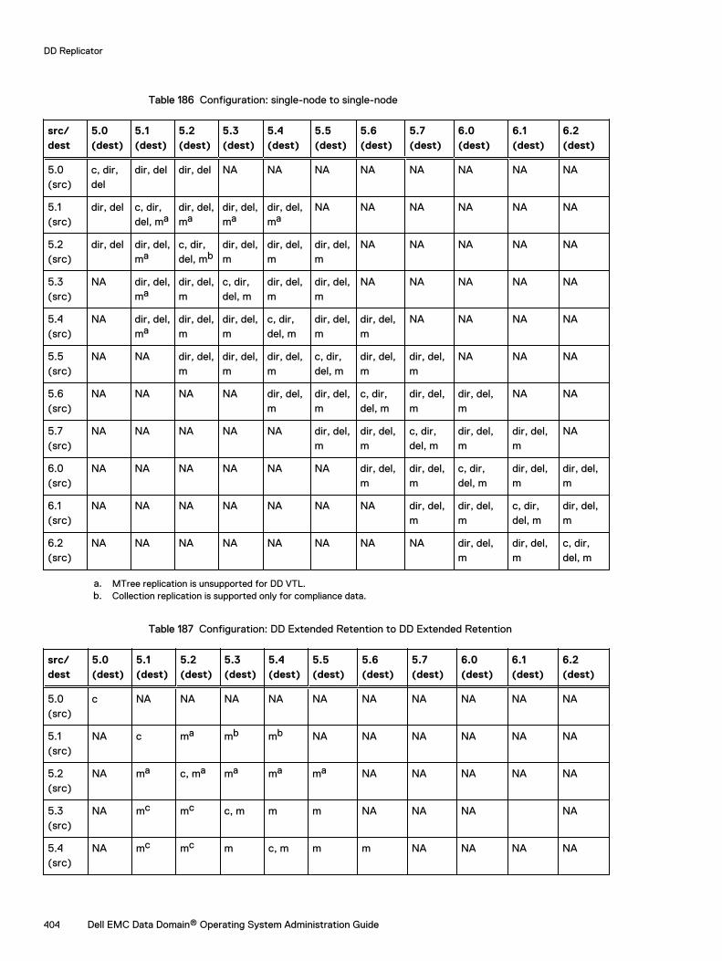
Table 186 Configuration: single-node to single-node
src/dest
5.0(dest)
5.1(dest)
5.2(dest)
5.3(dest)
5.4(dest)
5.5(dest)
5.6(dest)
5.7(dest)
6.0(dest)
6.1(dest)
6.2(dest)
5.0(src)
c, dir,del
dir, del dir, del NA NA NA NA NA NA NA NA
5.1(src)
dir, del c, dir,del, ma
dir, del,ma
dir, del,ma
dir, del,ma
NA NA NA NA NA NA
5.2(src)
dir, del dir, del,ma
c, dir,del, mb
dir, del,m
dir, del,m
dir, del,m
NA NA NA NA NA
5.3(src)
NA dir, del,ma
dir, del,m
c, dir,del, m
dir, del,m
dir, del,m
NA NA NA NA NA
5.4(src)
NA dir, del,ma
dir, del,m
dir, del,m
c, dir,del, m
dir, del,m
dir, del,m
NA NA NA NA
5.5(src)
NA NA dir, del,m
dir, del,m
dir, del,m
c, dir,del, m
dir, del,m
dir, del,m
NA NA NA
5.6(src)
NA NA NA NA dir, del,m
dir, del,m
c, dir,del, m
dir, del,m
dir, del,m
NA NA
5.7(src)
NA NA NA NA NA dir, del,m
dir, del,m
c, dir,del, m
dir, del,m
dir, del,m
NA
6.0(src)
NA NA NA NA NA NA dir, del,m
dir, del,m
c, dir,del, m
dir, del,m
dir, del,m
6.1(src)
NA NA NA NA NA NA NA dir, del,m
dir, del,m
c, dir,del, m
dir, del,m
6.2(src)
NA NA NA NA NA NA NA NA dir, del,m
dir, del,m
c, dir,del, m
a. MTree replication is unsupported for DD VTL.b. Collection replication is supported only for compliance data.
Table 187 Configuration: DD Extended Retention to DD Extended Retention
src/dest
5.0(dest)
5.1(dest)
5.2(dest)
5.3(dest)
5.4(dest)
5.5(dest)
5.6(dest)
5.7(dest)
6.0(dest)
6.1(dest)
6.2(dest)
5.0(src)
c NA NA NA NA NA NA NA NA NA NA
5.1(src)
NA c ma mb mb NA NA NA NA NA NA
5.2(src)
NA ma c, ma ma ma ma NA NA NA NA NA
5.3(src)
NA mc mc c, m m m NA NA NA NA
5.4(src)
NA mc mc m c, m m m NA NA NA NA
DD Replicator
404 Dell EMC Data Domain® Operating System Administration Guide
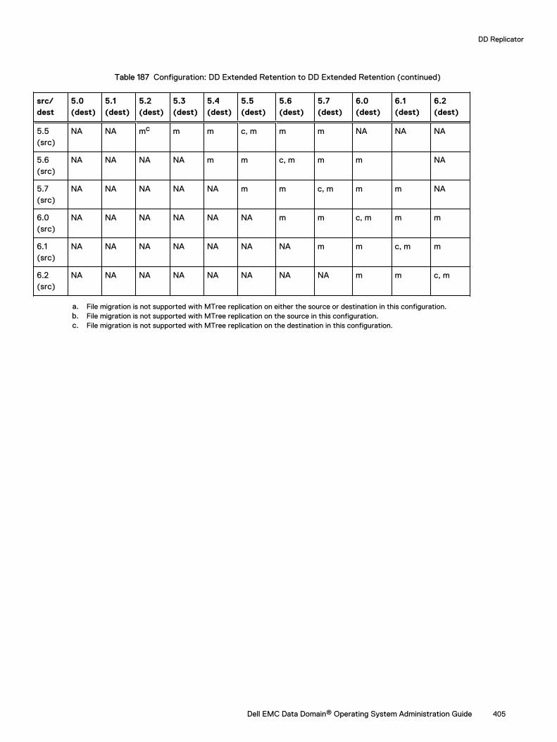
Table 187 Configuration: DD Extended Retention to DD Extended Retention (continued)
src/dest
5.0(dest)
5.1(dest)
5.2(dest)
5.3(dest)
5.4(dest)
5.5(dest)
5.6(dest)
5.7(dest)
6.0(dest)
6.1(dest)
6.2(dest)
5.5(src)
NA NA mc m m c, m m m NA NA NA
5.6(src)
NA NA NA NA m m c, m m m NA
5.7(src)
NA NA NA NA NA m m c, m m m NA
6.0(src)
NA NA NA NA NA NA m m c, m m m
6.1(src)
NA NA NA NA NA NA NA m m c, m m
6.2(src)
NA NA NA NA NA NA NA NA m m c, m
a. File migration is not supported with MTree replication on either the source or destination in this configuration.b. File migration is not supported with MTree replication on the source in this configuration.c. File migration is not supported with MTree replication on the destination in this configuration.
DD Replicator
Dell EMC Data Domain® Operating System Administration Guide 405
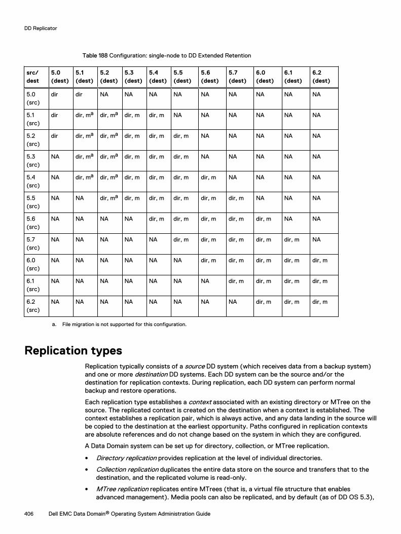
Table 188 Configuration: single-node to DD Extended Retention
src/dest
5.0(dest)
5.1(dest)
5.2(dest)
5.3(dest)
5.4(dest)
5.5(dest)
5.6(dest)
5.7(dest)
6.0(dest)
6.1(dest)
6.2(dest)
5.0(src)
dir dir NA NA NA NA NA NA NA NA NA
5.1(src)
dir dir, ma dir, ma dir, m dir, m NA NA NA NA NA NA
5.2(src)
dir dir, ma dir, ma dir, m dir, m dir, m NA NA NA NA NA
5.3(src)
NA dir, ma dir, ma dir, m dir, m dir, m NA NA NA NA NA
5.4(src)
NA dir, ma dir, ma dir, m dir, m dir, m dir, m NA NA NA NA
5.5(src)
NA NA dir, ma dir, m dir, m dir, m dir, m dir, m NA NA NA
5.6(src)
NA NA NA NA dir, m dir, m dir, m dir, m dir, m NA NA
5.7(src)
NA NA NA NA NA dir, m dir, m dir, m dir, m dir, m NA
6.0(src)
NA NA NA NA NA NA dir, m dir, m dir, m dir, m dir, m
6.1(src)
NA NA NA NA NA NA NA dir, m dir, m dir, m dir, m
6.2(src)
NA NA NA NA NA NA NA NA dir, m dir, m dir, m
a. File migration is not supported for this configuration.
Replication typesReplication typically consists of a source DD system (which receives data from a backup system)and one or more destination DD systems. Each DD system can be the source and/or thedestination for replication contexts. During replication, each DD system can perform normalbackup and restore operations.
Each replication type establishes a context associated with an existing directory or MTree on thesource. The replicated context is created on the destination when a context is established. Thecontext establishes a replication pair, which is always active, and any data landing in the source willbe copied to the destination at the earliest opportunity. Paths configured in replication contextsare absolute references and do not change based on the system in which they are configured.
A Data Domain system can be set up for directory, collection, or MTree replication.
l Directory replication provides replication at the level of individual directories.
l Collection replication duplicates the entire data store on the source and transfers that to thedestination, and the replicated volume is read-only.
l MTree replication replicates entire MTrees (that is, a virtual file structure that enablesadvanced management). Media pools can also be replicated, and by default (as of DD OS 5.3),
DD Replicator
406 Dell EMC Data Domain® Operating System Administration Guide
an MTree is created that will be replicated. (A media pool can also be created in backward-compatibility mode that, when replicated, will be a directory replication context.)
For any replication type, note the following requirements:
l A destination Data Domain system must have available storage capacity that is at least the sizeof the expected maximum size of the source directory. Be sure that the destination DataDomain system has enough network bandwidth and disk space to handle all traffic fromreplication sources.
l The file system must be enabled or, based on the replication type, will be enabled as part of thereplication initialization.
l The source must exist.
l The destination must not exist.
l The destination will be created when a context is built and initialized.
l After replication is initialized, ownership and permissions of the destination are always identicalto those of the source.
l In the replication command options, a specific replication pair is always identified by thedestination.
l Both systems must have an active, visible route through the IP network so that each systemcan resolve its partner's host name.
The choice of replication type depends on your specific needs. The next sections providedescriptions and features of these three types, plus a brief introduction to Managed FileReplication, which is used by DD Boost.
Managed file replicationManaged file replication, which is used by DD Boost, is a type of replication that is managed andcontrolled by backup software.
With managed file replication, backup images are directly transferred from one DD system toanother, one at a time, at the request of the backup software.
The backup software keeps track of all copies, allowing easy monitoring of replication status andrecovery from multiple copies.
Managed file replication offers flexible replication topologies including full system mirroring, bi-directional, many-to-one, one-to-many, and cascaded, enabling efficient cross-site deduplication.
Here are some additional points to consider about managed file replication:
l Replication contexts do not need to be configured.
l Lifecycle polices control replication of information with no intervention from the user.
l DD Boost will build and tear down contexts as needed on the fly.
For more information, see the ddboost file-replication commands in the Data DomainOperating System Command Reference Guide.
Directory replicationDirectory replication transfers deduplicated data within a DD file system directory configured as areplication source to a directory configured as a replication destination on a different system.
With directory replication, a DD system can simultaneously be the source of some replicationcontexts and the destination of other contexts. And that DD system can also receive data frombackup and archive applications while it is replicating data.
Directory replication has the same flexible network deployment topologies and cross-sitededuplication effects as managed file replication (the type used by DD Boost).
DD Replicator
Dell EMC Data Domain® Operating System Administration Guide 407

Here are some additional points to consider when using directory replication:
l Do not mix CIFS and NFS data within the same directory. A single destination DD system canreceive backups from both CIFS clients and NFS clients as long as separate directories areused for CIFS and NFS.
l Any directory can be in only one context at a time. A parent directory may not be used in areplication context if a child directory of that parent is already being replicated.
l Renaming (moving) files or tapes into or out of a directory replication source directory is notpermitted. Renaming files or tapes within a directory replication source directory is permitted.
l A destination DD system must have available storage capacity of at least the post-compressedsize of the expected maximum post-compressed size of the source directory.
l When replication is initialized, a destination directory is created automatically.
l After replication is initialized, ownership and permissions of the destination directory arealways identical to those of the source directory. As long as the context exists, the destinationdirectory is kept in a read-only state and can receive data only from the source directory.
l At any time, due to differences in global compression, the source and destination directory candiffer in size.
Folder Creation Recommendations
Directory replication replicates data at the level of individual subdirectories under /data/col1/backup.
To provide a granular separation of data you must create, from a host system, other directories(DirA, DirB, etc.) within the /backup Mtree. Each directory should be based on your environmentand the desire to replicate those directories to another location. You will not replicate the entire /backup MTree, but instead would set up replication contexts on each subdirectory underneath /data/col1/backup/ (ex. /data/col1/backup/DirC). The purpose of this threefold:
l It allows control of the destination locations as DirA may go to one site and DirB may go toanother.
l This level of granularity allows management, monitoring, and fault isolation. Each replicationcontext can be paused, stopped, destroyed, or reported on.
l Performance is limited on a single context. The creation of multiple contexts can improveaggregate replication performance.
l As a general recommendation, approximately 5 - 10 contexts may be required to distributereplication load across multiple replication streams. This must be validated against the sitedesign and the volume and composition of the data at the location.
Note: Recommending a number of contexts is a design-dependent issue, and in some cases,significant implications are attached to the choices made about segregating data for thepurposes of optimizing replication. Data is usually optimized for the manner in which it will rest– not in manner with which it will replicate. Keep this in mind when altering a backupenvironment.
MTree replicationMTree replication is used to replicate MTrees between DD systems. Periodic snapshots arecreated on the source, and the differences between them are transferred to the destination byleveraging the same cross-site deduplication mechanism used for directory replication. Thisensures that the data on the destination is always a point-in-time copy of the source, with fileconsistency. This also reduces replication of churn in the data, leading to more efficient utilizationof the WAN.
While directory replication must replicate every change to the content of the source directory inorder, the use of snapshots with MTree replication enables some intermediate changes to the
DD Replicator
408 Dell EMC Data Domain® Operating System Administration Guide
source to be skipped. Skipping these changes further reduces the amount of data that is sent overthe network, and therefore reduces replication lag.
With MTree replication, a DD system can be simultaneously the source of some replicationcontexts and the destination of other contexts. And that DD system can also receive data frombackup and archive applications while it is replicating data.
MTree replication has the same flexible network deployment topologies and cross-sitededuplication effects as managed file replication (the type used by DD Boost).
Here are some additional points to consider when using MTree replication:
l When replication is initialized, a destination read-only MTree is created automatically.
l Data can be logically segregated into multiple MTrees to promote greater replicationperformance.
l Snapshots must be created on source contexts.
l Snapshots cannot be created on a replication destination.
l Snapshots are replicated with a fixed retention of one year; however, the retention isadjustable on the destination and must be adjusted there.
l Snapshots are not automatically deleted after breaking a replication context, and must beexpired when they are no longer required to prevent the system from filling up. The followingKB articles provide more information:
n Data Domain - Checking for Snapshots that are No Longer Needed , available at https://support.emc.com/kb/336461.
n Data Domain - Identifying Why a DDR is Filling Up , available at https://support.emc.com/kb/306203.
n Data Domain - Mtree_replication_resync_Snapshot_retention , available at https://support.emc.com/kb/446176.
l Replication contexts must be configured on both the source and the destination.
l Replicating DD VTL tape cartridges (or pools) simply means replicating MTrees or directoriesthat contain DD VTL tape cartridges. Media pools are replicated by MTree replication, as adefault. A media pool can be created in backward-compatibility mode and can then bereplicated via directory-based replication. You cannot use the pool:// syntax to createreplication contexts using the command line. When specifying pool-based replication in DDSystem Manager, either directory or MTree replication will be created, based on the mediapool type.
l Replicating directories under an MTree is not permitted.
l A destination DD system must have available storage capacity of at least the post-compressedsize of the expected maximum post-compressed size of the source MTree.
l After replication is initialized, ownership and permissions of the destination MTree are alwaysidentical to those of the source MTree. If the context is configured, the destination MTree iskept in a read-only state and can receive data only from the source MTree.
l At any time, due to differences in global compression, the source and destination MTree candiffer in size.
l MTree replication is supported from DD Extended Retention systems to non-DD ExtendedRetention systems if both are running DD OS 5.5 or later.
l DD Retention Lock Compliance is supported with MTree replication, by default. If DDRetention Lock is licensed on a source, the destination must also have a DD Retention Locklicense, or replication will fail. (To avoid this situation, you must disable DD Retention Lock.) IfDD Retention Lock is enabled on a replication context, a replicated destination context willalways contain data that is retention locked.
DD Replicator
Dell EMC Data Domain® Operating System Administration Guide 409
MTree replication details
MTree replication involves the following steps:
1. A snapshot is created on the source replication context.
2. This snapshot is compared to the last previous snapshot.
3. Any differences between the two snapshots are sent to the destination replication context.
4. On the destination, the MTree is updated but no files are exposed to the user until all changesare received by the destination system.
These steps are repeated any time a snapshot is created on the source MTree. The followingsituations trigger the creation of a snapshot on the source system:
l System–generated periodic snapshot—When the replication lag is more than 15 minutes andthere is no snapshot being currently replicated.
l User–created snapshot—At a time specified by the user, such as after the completion of abackup job.
For examples showing the interaction of different types of snapshots, see the KB article HowMTree Replication Works, available at https://support.emc.com/kb/180832.
After the snapshot is replicated, the connection to the destination is closed. A new connectionbetween the source and destination is established when the next snapshot is replicated.
Automatic Multi-Streaming (AMS)
Automatic Multi-Streaming (AMS) improves MTree replication performance. It uses multiplestreams to replicate a single large file (32 GB or larger) to improve network bandwidth utilizationduring replication. By increasing the replication speed for individual files, AMS also improves thepipeline efficiency of the replication queue, and provides improved replication throughput andreduced replication lag.
When the workload presents multiple optimization choices, AMS automatically selects the bestoption for the workload. For example, if the workload is a large file with fastcopy attributes, thereplication operation uses fastcopy optimization to avoid the overhead of scanning the file toidentify unique segments between the replication pair. If the workload uses synthetics, replicationuses synthetic replication on top of AMS to leverage local operations on the destination system foreach replication stream to generate the file.
AMS is always enabled, and cannot be disabled.
Collection replicationCollection replication performs whole-system mirroring in a one-to-one topology, continuouslytransferring changes in the underlying collection, including all of the logical directories and files ofthe DD file system.
Collection replication does not have the flexibility of the other types, but it can provide higherthroughput and support more objects with less overhead, which may work better for high-scaleenterprise cases.
Collection replication replicates the entire /data/col1 area from a source DD system to adestination DD system.
Note: Collection replication is not supported for cloud-tier enabled systems.
Here are some additional points to consider when using collection replication:
l No granular replication control is possible. All data is copied from the source to the destinationproducing a read-only copy.
l Collection replication requires that the storage capacity of the destination system be equal to,or greater than, the capacity of the source system. If the destination capacity is less than the
DD Replicator
410 Dell EMC Data Domain® Operating System Administration Guide
source capacity, the available capacity on the source is reduced to the capacity of thedestination.
l The DD system to be used as the collection replication destination must be empty beforeconfiguring replication. After replication is configured, this system is dedicated to receive datafrom the source system.
l With collection replication, all user accounts and passwords are replicated from the source tothe destination. However, as of DD OS 5.5.1.0, other elements of configuration and usersettings of the DD system are not replicated to the destination; you must explicitly reconfigurethem after recovery.
l Collection replication is supported with DD Secure Multitenancy (SMT). Core SMTinformation, contained in the registry namespace, including the tenant and tenant-unitdefinitions with matching UUIDs is automatically transferred during replication operation.However, the following SMT information is not automatically included for replication, and mustbe configured manually on the destination system:
n Alert notification lists for each tenant-unit
n All users assigned to the DD Boost protocol for use by SMT tenants, if DD Boost isconfigured on the system
n The default-tenant-unit associated with each DD Boost user, if any, if DD Boost isconfigured on the system
Using collection replication for disaster recovery with SMT on page 439 describes how tomanually configure these items on the replication destination.
l DD Retention Lock Compliance supports collection replication.
l Collection replication is not supported in cloud tier-enabled systems.
l With collection replication, data in a replication context on the source system that has notbeen replicated cannot be processed for file system cleaning. If file system cleaning cannotcomplete because the source and destination systems are out of sync, the system reports thecleaning operation status as partial, and only limited system statistics are available for thecleaning operation. If collection replication is disabled, the amount of data that cannot beprocessed for file system cleaning increases because the replication source and destinationsystems remain out of sync. The KB article Data Domain: An overview of Data Domain File System(DDFS) clean/garbage collection (GC) phases, available from the Online Support site at https://support.emc.com, provides additional information.
l To enhance throughput in a high bandwidth environment, run the replication modify<destination> crepl-gc-gw-optim command to disable collection replication bandwidthoptimization.
Using DD Encryption with DD ReplicatorDD Replicator can be used with the optional DD Encryption feature, enabling encrypted data to bereplicated using collection, directory, or MTree replication
Replication contexts are always authenticated with a shared secret. That shared secret is used toestablish a session key using a Diffie-Hellman key exchange protocol, and that session key is usedto encrypt and decrypt the Data Domain system encryption key when appropriate.
Each replication type works uniquely with encryption and offers the same level of security.
l Collection replication requires the source and destination to have the same encryptionconfiguration, because the destination data is expected to be an exact replica of the sourcedata. In particular, the encryption feature must be turned on or off at both the source anddestination, and if the feature is turned on, the encryption algorithm and the system
DD Replicator
Dell EMC Data Domain® Operating System Administration Guide 411

passphrases must also match. The parameters are checked during the replication associationphase.During collection replication, the source transmits the data in encrypted form, and alsotransmits the encryption keys to the destination. The data can be recovered at the destinationbecause the destination has the same passphrase and the same system encryption key.
Note: Collection replication is not supported for cloud-tier enabled systems.
l MTree or directory replication does not require encryption configuration to be the same atboth the source and destination. Instead, the source and destination securely exchange thedestination’s encryption key during the replication association phase, and the data is re-encrypted at the source using the destination’s encryption key before transmission to thedestination.If the destination has a different encryption configuration, the data transmitted is preparedappropriately. For example, if the feature is turned off at the destination, the source decryptsthe data, and it is sent to the destination un-encrypted.
l In a cascaded replication topology, a replica is chained among three Data Domain systems. Thelast system in the chain can be configured as a collection, MTree, or directory. If the lastsystem is a collection replication destination, it uses the same encryption keys and encrypteddata as its source. If the last system is an MTree or directory replication destination, it uses itsown key, and the data is encrypted at its source. The encryption key for the destination ateach link is used for encryption. Encryption for systems in the chain works as in a replicationpair.
Replication topologiesDD Replicator supports five replication topologies (one-to-one, one-to-one bidirectional, one-to-many, many-to-one, and cascaded). The tables in this section show (1) how these topologies workwith three types of replication (MTree, directory, and collection) and two types of DD systems[single node (SN) and DD Extended Retention] and (2) how mixed topologies are supported withcascaded replication.
In general:
l Single node (SN) systems support all replication topologies.
l Single node-to-single node (SN -> SN) can be used for all replication types.
l DD Extended Retention systems cannot be the source for directory replication.
l Collection replication cannot be configured from either a single node (SN) system to a DDExtended Retention-enabled system, nor from a DD Extended Retention-enabled system to anSN system.
l Collection replication cannot be configured from either an SN system to a DD high availability-enabled system, nor from a DD high availability-enabled system to an SN system.
l For MTtree and Directory replication, DD high availability systems are treated like SN systems.
l Collection replication cannot be configured if any or both systems have Cloud Tier enabled.
In this table:
l SN = single node DD system (no DD Extended Retention)
l ER = DD Extended Retention system
DD Replicator
412 Dell EMC Data Domain® Operating System Administration Guide
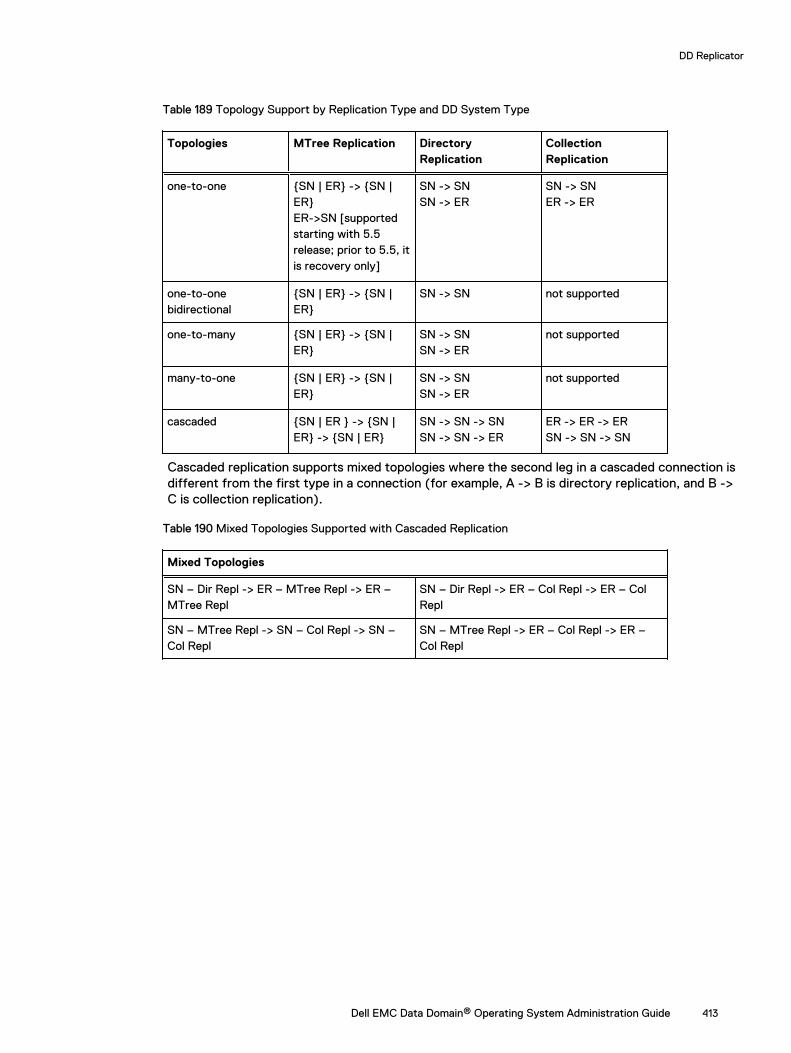
Table 189 Topology Support by Replication Type and DD System Type
Topologies MTree Replication DirectoryReplication
CollectionReplication
one-to-one {SN | ER} -> {SN |ER}ER->SN [supportedstarting with 5.5release; prior to 5.5, itis recovery only]
SN -> SNSN -> ER
SN -> SNER -> ER
one-to-onebidirectional
{SN | ER} -> {SN |ER}
SN -> SN not supported
one-to-many {SN | ER} -> {SN |ER}
SN -> SNSN -> ER
not supported
many-to-one {SN | ER} -> {SN |ER}
SN -> SNSN -> ER
not supported
cascaded {SN | ER } -> {SN |ER} -> {SN | ER}
SN -> SN -> SNSN -> SN -> ER
ER -> ER -> ERSN -> SN -> SN
Cascaded replication supports mixed topologies where the second leg in a cascaded connection isdifferent from the first type in a connection (for example, A -> B is directory replication, and B ->C is collection replication).
Table 190 Mixed Topologies Supported with Cascaded Replication
Mixed Topologies
SN – Dir Repl -> ER – MTree Repl -> ER –MTree Repl
SN – Dir Repl -> ER – Col Repl -> ER – ColRepl
SN – MTree Repl -> SN – Col Repl -> SN –Col Repl
SN – MTree Repl -> ER – Col Repl -> ER –Col Repl
DD Replicator
Dell EMC Data Domain® Operating System Administration Guide 413
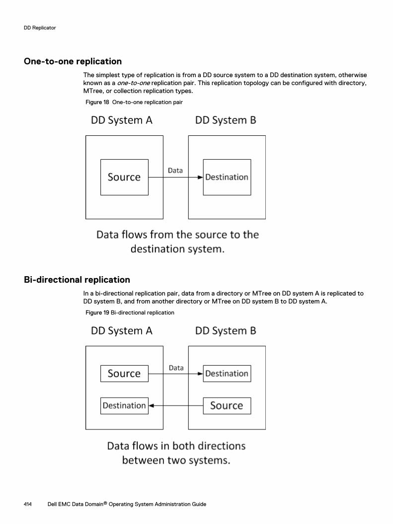
One-to-one replicationThe simplest type of replication is from a DD source system to a DD destination system, otherwiseknown as a one-to-one replication pair. This replication topology can be configured with directory,MTree, or collection replication types.
Figure 18 One-to-one replication pair
Bi-directional replicationIn a bi-directional replication pair, data from a directory or MTree on DD system A is replicated toDD system B, and from another directory or MTree on DD system B to DD system A.
Figure 19 Bi-directional replication
DD Replicator
414 Dell EMC Data Domain® Operating System Administration Guide
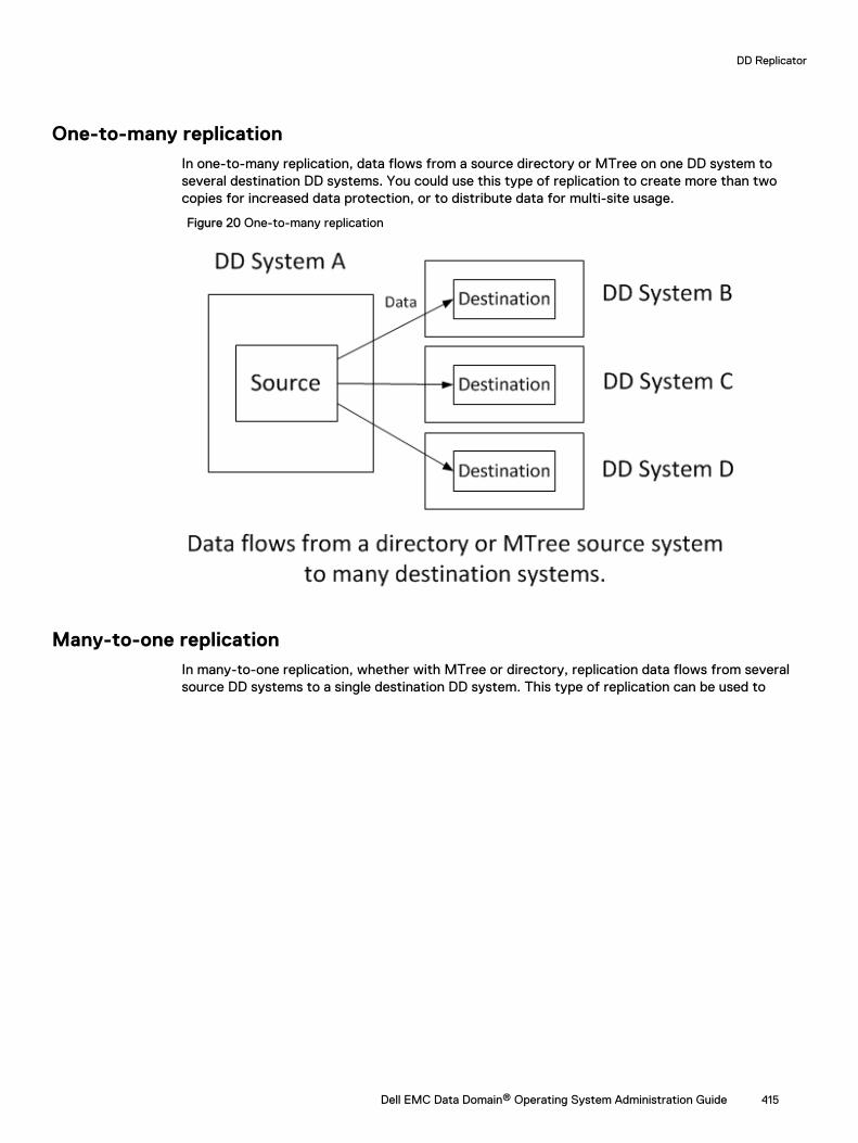
One-to-many replicationIn one-to-many replication, data flows from a source directory or MTree on one DD system toseveral destination DD systems. You could use this type of replication to create more than twocopies for increased data protection, or to distribute data for multi-site usage.
Figure 20 One-to-many replication
Many-to-one replicationIn many-to-one replication, whether with MTree or directory, replication data flows from severalsource DD systems to a single destination DD system. This type of replication can be used to
DD Replicator
Dell EMC Data Domain® Operating System Administration Guide 415
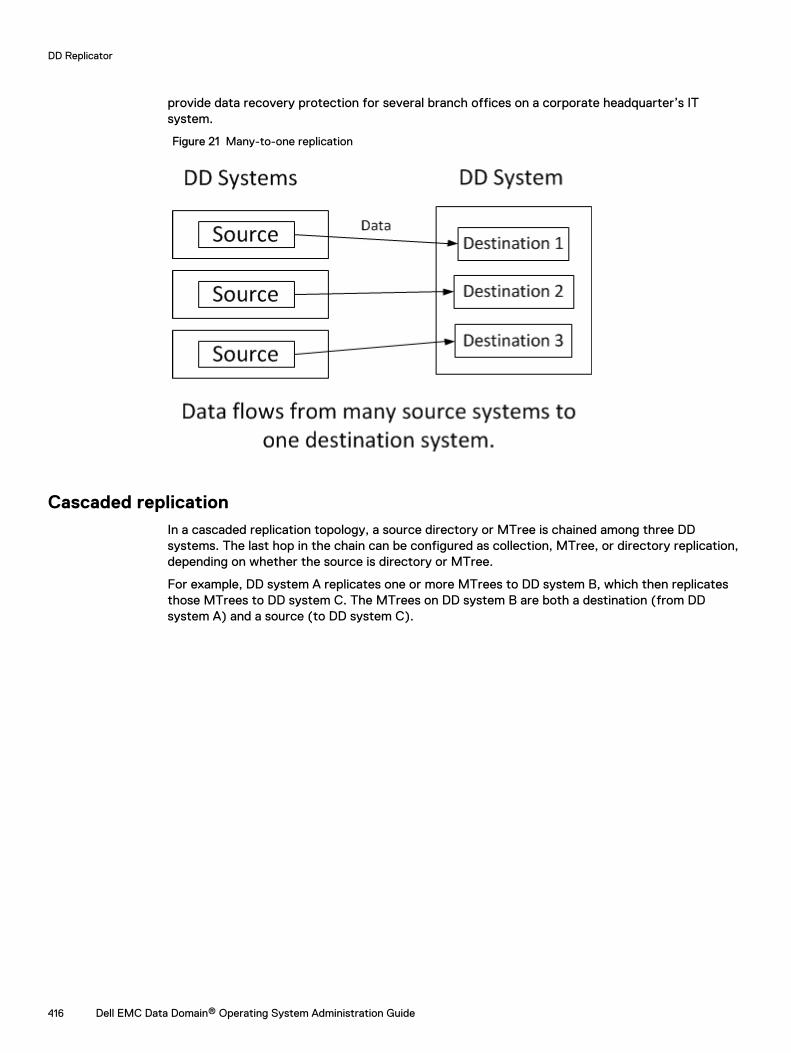
provide data recovery protection for several branch offices on a corporate headquarter’s ITsystem.
Figure 21 Many-to-one replication
Cascaded replicationIn a cascaded replication topology, a source directory or MTree is chained among three DDsystems. The last hop in the chain can be configured as collection, MTree, or directory replication,depending on whether the source is directory or MTree.
For example, DD system A replicates one or more MTrees to DD system B, which then replicatesthose MTrees to DD system C. The MTrees on DD system B are both a destination (from DDsystem A) and a source (to DD system C).
DD Replicator
416 Dell EMC Data Domain® Operating System Administration Guide
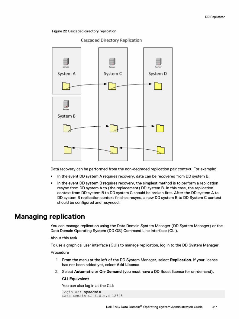
Figure 22 Cascaded directory replication
Data recovery can be performed from the non-degraded replication pair context. For example:
l In the event DD system A requires recovery, data can be recovered from DD system B.
l In the event DD system B requires recovery, the simplest method is to perform a replicationresync from DD system A to (the replacement) DD system B. In this case, the replicationcontext from DD system B to DD system C should be broken first. After the DD system A toDD system B replication context finishes resync, a new DD system B to DD System C contextshould be configured and resynced.
Managing replicationYou can manage replication using the Data Domain System Manager (DD System Manager) or theData Domain Operating System (DD OS) Command Line Interface (CLI).
About this task
To use a graphical user interface (GUI) to manage replication, log in to the DD System Manager.
Procedure
1. From the menu at the left of the DD System Manager, select Replication. If your licensehas not been added yet, select Add License.
2. Select Automatic or On-Demand (you must have a DD Boost license for on-demand).
CLI Equivalent
You can also log in at the CLI:
login as: sysadminData Domain OS 6.0.x.x-12345
DD Replicator
Dell EMC Data Domain® Operating System Administration Guide 417
Using keyboard-interactive authentication.Password:
Replication statusReplication Status shows the system-wide count of replication contexts exhibiting a warning(yellow text) or error (red text) state, or if conditions are normal.
Summary viewThe Summary view lists the configured replication contexts for a DD system, displayingaggregated information about the selected DD system – that is, summary information about theinbound and outbound replication pairs. The focus is the DD system, itself, and the inputs to it andoutputs from it.
The Summary table can be filtered by entering a Source or Destination name, or by selecting aState (Error, Warning, or Normal).
Table 191 Replication Summary view
Item Description
Source System and path name of the source context, with formatsystem.path. For example, for directory dir1 on systemdd120-22, you would see dd120-22.chaos.local/data/col1/dir1.
Destination System and path name of destination context, with formatsystem.path. For example, for MTree MTree1 on systemdd120-44, you would see dd120-44.chaos.local/data/col1/MTree1.
Type Type of context: MTree, directory (Dir), or Pool.
State Possible states of replication pair status include:
l Normal – If the replica is Initializing, Replicating, Recovering,Resyncing, or Migrating.
l Idle – For MTree replication, this state can display if thereplication process is not currently active or for networkerrors (such as the destination system being inaccessible).
l Warning – If there is an unusual delay for the first five states,or for the Uninitialized state.
l Error – Any possible error states, such as Disconnected.
Synced As Of Time Timestamp for last automatic replication sync operationperformed by the source. For MTree replication, this value isupdated when a snapshot is exposed on the destination. Fordirectory replication, it is updated when a sync point inserted bythe source is applied. A value of unknown displays duringreplication initialization.
Pre-Comp Remaining Amount of pre-compressed data remaining to be replicated.
Completion Time (Est.) Value is either Completed, or the estimated amount of time
required to complete the replication data transfer based on thelast 24 hours’ transfer rate.
DD Replicator
418 Dell EMC Data Domain® Operating System Administration Guide
Detailed information for a replication contextSelecting one replication context from the Summary view populates that context’s information inDetailed Information, Performance Graph, Completion Stats, and Completion Predictor.
Table 192 Detailed Information
Item Description
State Description Message about state of replica.
Source System and path name of source context, with formatsystem.path. For example, for directory dir1 on system
dd120-22, you would see dd120-22.chaos.local/data/col1/dir1.
Destination System and path name of destination context, with formatsystem.path. For example, for MTree MTree1 on system
dd120-44, you would see dd120-44.chaos.local/data/col1/MTree1.
Connection Port System name and listen port used for replication connection.
Table 193 Performance Graph
Item Description
Pre-Comp Remaining Pre-compressed data remaining to be replicated.
Pre-Comp Written Pre-compressed data written on the source.
Post-Comp Replicated Post-compressed data that has been replicated.
Table 194 Completion Stats
Item Description
Synced As Of Time Timestamp for last automatic replication sync operationperformed by the source. For MTree replication, this value isupdated when a snapshot is exposed on the destination. Fordirectory replication, it is updated when a sync point inserted bythe source is applied. A value of unknown displays duringreplication initialization.
Completion Time (Est.) Value is either Completed or the estimated amount of time
required to complete the replication data transfer based on thelast 24 hours’ transfer rate.
Pre-Comp Remaining Amount of data remaining to be replicated.
Files Remaining (Directory Replication Only) Number of files that have not yetbeen replicated.
Status For source and destination endpoints, shows status (Enabled,Disabled, Not Licensed, etc.) of major components on the system,such as:
l Replication
l File System
DD Replicator
Dell EMC Data Domain® Operating System Administration Guide 419
Table 194 Completion Stats (continued)
Item Description
l DD Retention Lock
l DD Encryption at Rest
l DD Encryption over Wire
l Available Space
l Low Bandwidth Optimization
l Compression Ratio
l Low Bandwidth Optimization Ratio
Completion Predictor
The Completion Predictor is a widget for tracking a backup job's progress and for predicting whenreplication will complete, for a selected context.
Creating a replication pairBefore creating a replication pair, make sure the destination does not exist, or you will get an error.
Procedure
1. Select Replication > Automatic > Summary tab > Create Pair .
2. In the Create Pair dialog, add information to create an inbound or outbound MTree,directory, collection, or pool replication pair, as described in the next sections.
Adding a DD system for replication
You may need to add a DD system as either a host or a destination before you can create areplication pair.
About this task
Note: Make sure the system being added is running a compatible DD OS version.
Procedure
1. In the Create Pair dialog, select Add System.
2. For System, enter the hostname or IP address of the system to be added.
3. For User Name and Password, enter the sysadmin's user name and password.
4. Optionally, select More Options to enter a proxy IP address (or system name) of a systemthat cannot be reached directly. If configured, enter a custom port instead of the defaultport 3009.
Note: IPv6 addresses are supported only when adding a DD OS 5.5 or later system to amanagement system using DD OS 5.5 or later.
5. Select OK.
Note: If the system is unreachable after adding it to DD System Manager, make surethat there is a route from the managing system to the system being added. If ahostname (either a fully qualified domain name (FQDN) or non-FQDN) is entered, makesure it is resolvable on the managed system. Configure a domain name for the managed
DD Replicator
420 Dell EMC Data Domain® Operating System Administration Guide
system, ensure a DNS entry for the system exists, or ensure an IP address to hostnamemapping is defined.
6. If the system certificate is not verified, the Verify Certificate dialog shows details about thecertificate. Check the system credentials. Select OK if you trust the certificate, or selectCancel.
Creating a collection replication pair
See the Collection replication section for general information about this type of replication.
About this task
Before creating a collection replication pair, make sure:
l The storage capacity of the destination system is equal to, or greater than, that of the sourcesystem. (If the destination capacity is less than that of the source, the available capacity onthe source is reduced to that of the destination.)
l The destination has been destroyed, and subsequently re-created, but not enabled.
l Each destination and each source is in only one context at a time.
l The file system is disabled on the replica, while configuring and enabling encryption on thesource.
l The file system is disabled on the source, while configuring and enabling encryption on thereplica.
Procedure
1. In the Create Pair dialog, select Collection from the Replication Type menu.
2. Select the source system hostname from the Source System menu.
3. Select the destination system hostname from the Destination System menu. The listincludes only those hosts in the DD-Network list.
4. If you want to change any host connection settings, select the Advanced tab.
5. Select OK. Replication from the source to the destination begins.
Results
Test results from Data Domain returned the following performance guidelines for replicationinitialization. These are guidelines only, and actual performance seen in production environmentsmay vary.
l Over a gibibit LAN: With a high enough shelf count to drive maximum input/output and idealconditions, collection replication can saturate a 1GigE link (modulo 10% protocol overhead), aswell as 400-900 MB/sec on 10gigE, depending on the platform.
l Over a WAN, performance is governed by the WAN link line speed, bandwidth, latency, andpacket loss rate.
Creating an MTree, directory, or pool replication pair
See the MTree replication and Directory replication sections for general information about thesetypes of replication.
About this task
When creating an MTree, directory, or pool replication pair:
l Make sure the replication is transiting\exiting the correct interface. When defining areplication context, the host names of the source and destination must resolve with forwardand reverse lookups. To make the data transit alternate interfaces on the system, other thanthe default resolving interface, the replication context must be modified after creation. It may
DD Replicator
Dell EMC Data Domain® Operating System Administration Guide 421
be necessary to set up host files to ensure that contexts are defined on non-resolving (cross-over) interfaces.
l You can “reverse” the context for an MTree replication, that is, you can switch the destinationand the source.
l Subdirectories within an MTree cannot be replicated, because the MTree, in its entirety, isreplicated.
l MTree replication is supported from DD Extended Retention-enabled systems to non-DDExtended Retention-enabled systems, if both are running DD OS 5.5 or later.
l The destination DD system must have available storage capacity of at least the post-compressed size of the expected maximum post-compressed size of the source directory orMTree.
l When replication is initialized, a destination directory is created automatically.
l A DD system can simultaneously be the source for one context and the destination for anothercontext.
Procedure
1. In the Create Pair dialog, select Directory, MTree (default), or Pool from the ReplicationType menu.
2. Select the source system hostname from the Source System menu.
3. Select the destination system hostname from the Destination System menu.
4. Enter the source path in the Source Path text box (notice the first part of the path is aconstant that changes based on the type of replication chosen).
5. Enter the destination path in the Destination Path text box (notice the first part of the pathis a constant that changes based on the type of replication chosen).
6. If you want to change any host connection settings, select the Advanced tab.
7. Select OK.
The Replication from the source to the destination begins.
Test results from Data Domain returned the following guidelines for estimating the timeneeded for replication initialization.
These are guidelines only and may not be accurate in specific production environments.
l Using a T3 connection, 100ms WAN, performance is about 40 MiB/sec of pre-compressed data, which gives data transfer of:40 MiB/sec = 25 seconds/GiB = 3.456 TiB/day
l Using the base-2 equivalent of gigabit LAN, performance is about 80 MiB/sec of pre-compressed data, which gives data transfer of about double the rate for a T3 WAN.
Example 2 CLI Equivalent
Here is an example of creating MTree replication pairs at the CLI. In this example, thesource Data Domain system is dd640 and the destination Data Domain system is dlh5.For details about usage in other scenarios, see the Data Domain Operating SystemCommand Reference Guide.
1. Create an MTree on the source Data Domain system:sysadmin@dd640# mtree create /data/col1/Oracle2MTree "/data/col1/Oracle2" created successfully.
DD Replicator
422 Dell EMC Data Domain® Operating System Administration Guide
Example 2 CLI Equivalent (continued)
2. Create the replication context in the destination Data Domain system, using thefull hostname.
sysadmin@dlh5# replication add source mtree://dd640.chaos.local/data/col1/Oracle2 destination mtree://dlh5.chaos.local/data/col1/Oracle2
3. Create the replication context in the source Data Domain system, using the fullhostname.
sysadmin@dd640# replication add source mtree://dd640.chaos.local/data/col1/Oracle2 destination mtree://dlh5.chaos.local/data/col1/Oracle2
4. To verify that the MTree replication context has been created, use thereplication show config command.The output is horizontally truncated in this example.
sysadmin@dlh5# replication show configCTX Source Destination --- ------------------------------------------- ------------------------------------------1 dir://dd640.chaos.local/backup/Oracle2 dir://dlh5.chaos.local/backup/Oracle2 2 mtree://dd640.chaos.local/data/col1/Oracle2 mtree://dlh5.chaos.local/data/col1/Oracle2--- ------------------------------------------- ------------------------------------------ * Used for recovery only.
5. To start replication between a source and destination, use the replicationinitialize command on the source. This command checks that theconfiguration and connections are correct and returns error messages if anyproblems occur.
sysadmin@dd640# replication initialize mtree://dlh5.chaos.local/data/col1/Oracle2 (00:08) Waiting for initialize to start... (00:10) Intialize started. Use 'replication watch mtree://dlh5.chaos.local/data/col1/Oracle2' to monitor progress.
Configuring bi-directional replicationTo create a bi-directional replication pair, use the directory or MTree replication pair procedure(for example, using mtree2) from host A to host B. Use the same procedure to create a replicationpair (for example, using mtree1) from host B to host A. For this configuration, destinationpathnames cannot be the same.
Configuring one-to-many replicationTo create a one-to-many replication pair, use the directory or MTree replication pair procedure(for example, using mtree1) on host A to: (1) mtree1 on host B, (2) mtree1 on host C, and (3)mtree1 on host D. A replication recovery cannot be done to a source context whose path is thesource path for other contexts; the other contexts must be broken and resynced after therecovery.
Configuring many-to-one replicationTo create a many-to-one replication pair, use the directory or MTree replication pair procedure[for example, (1) mtree1 from host A to mtree1 on host C and (2) mtree2 on host B to mtree2 onhost C.]
Configuring cascaded replicationTo create a cascaded replication pair, use the directory or MTree replication pair procedure: (1)mtree1 on host A to mtree1 on host B, and (2) on host B, create a pair for mtree1 to mtree1 on hostC. The final destination context (on host C in this example, but more than three hops aresupported) can be a collection replica or a directory or MTree replica.
DD Replicator
Dell EMC Data Domain® Operating System Administration Guide 423
Disabling and enabling a replication pairDisabling a replication pair temporarily pauses the active replication of data between a source anda destination. The source stops sending data to the destination, and the destination stops servingas an active connection to the source.
Procedure
1. Select one or more replication pairs in the Summary table, and select Disable Pair.
2. In the Display Pair dialog, select Next and then OK.
3. To resume operation of a disabled replication pair, select one or more replication pairs in theSummary table, and select Enable Pair to display the Enable Pair dialog.
4. Select Next and then OK. Replication of data is resumed.
CLI Equivalent# replication disable {destination | all}
# replication enable {destination | all}
Deleting a replication pairWhen a directory or MTree replication pair is deleted, the destination directory or MTree,respectively, becomes writable. When a collection replication pair is deleted, the destination DDsystem becomes a stand-alone read/write system, and the file system is disabled.
Procedure
1. Select one or more replication pairs in the Summary table, and select Delete Pair.
2. In the Delete Pair dialog, select Next and then OK. The replication pairs are deleted.
CLI EquivalentBefore running this command, always run the filesys disable command. Then,afterward, run the filesys enable command
# replication break {destination | all}
Certain situations may arise in which you must resynchronize replication to resolve an issue.For information about breaking and resynchronizing replication, see the KB article Break andResync Directory Replication, available at https://support.emc.com/kb/180668.
Changing host connection settingsTo direct traffic out of a specific port, modify a current context by altering the connection hostparameter using a host name previously defined in the local hosts file to address the alternatesystem. That host name will correspond to the destination. The host entry will indicate an alternatedestination address for that host. This may be required on both the source and destinationsystems.
Procedure
1. Select the replication pair in the Summary table, and select Modify Settings. You can alsochange these settings when you are performing Create Pair, Start Resync, or Start Recoverby selecting the Advanced tab.
2. In the Modify Connection Settings dialog, modify any or all of these settings:
a. Use Low Bandwidth Optimization – For enterprises with small data sets and 6 Mb/s orless bandwidth networks, DD Replicator can further reduce the amount of data to besent using low bandwidth optimization. This enables remote sites with limited bandwidth
DD Replicator
424 Dell EMC Data Domain® Operating System Administration Guide
to use less bandwidth or to replicate and protect more of their data over existingnetworks. Low bandwidth optimization must be enabled on both the source anddestination DD systems. If the source and destination have incompatible low bandwidthoptimization settings, low bandwidth optimization will be inactive for that context. Afterenabling low bandwidth optimization on the source and destination, both systems mustundergo a full cleaning cycle to prepare the existing data, so run filesys cleanstart on both systems. The duration of the cleaning cycle depends on the amount ofdata on the DD system, but takes longer than a normal cleaning. For more information onthe filesys commands, see the Data Domain Operating System Command ReferenceGuide.
Important: Low bandwidth optimization is not supported if the DD Extended Retentionsoftware option is enabled on either DD system. It is also not supported for CollectionReplication.
b. Enable Encryption Over Wire – DD Replicator supports encryption of data-in-flight byusing standard SSL (Secure Socket Layer) protocol version 1.0.1, which uses the ADH-AES256-GCM-SHA384 and DHE-RSA-AES256-GCM-SHA384 cipher suites to establishsecure replication connections. Both sides of the connection must enable this feature forencryption to proceed.
c. Network Preference – You may choose IPv4 or IPv6. An IPv6-enabled replicationservice can still accept connections from an IPv4 replication client if the service isreachable via IPv4. An IPv6-enabled replication client can still communicate with an IPv4replication service if the service is reachable via IPv4.
d. Use Non-default Connection Host – The source system transmits data to a destinationsystem listen port. Since a source system can have replication configured for manydestination systems (each of which can have a different listen port), each context on thesource can configure the connection port to the corresponding listen port of thedestination.
3. Select Next and then Close.
The replication pair settings are updated, and replication resumes.
CLI Equivalent#replication modify <destination> connection-host <new-host-name> [port <port>]
Managing replication systemsYou can add or delete Data Domain systems to be used for replication using the Manage Systemsdialog.
Procedure
1. Select Manage Systems.
2. In the Manage Systems dialog, add and/or delete Data Domain systems, as required.
3. Select Close.
Recovering data from a replication pairIf source replication data becomes inaccessible, it can be recovered from the replication pairdestination. The source must be empty before recovery can proceed. Recovery can be performedfor all replication topologies, except for MTree replication.
Recovery of data from a directory pool, as well as from directory and collection replication pairs, isdescribed in the next sections.
DD Replicator
Dell EMC Data Domain® Operating System Administration Guide 425
Recovering directory pool data
You can recover data from a directory-based pool, but not from an MTree-based pool.
Procedure
1. Select More > Start Recover.
2. In the Start Recover dialog, select Pool from the Replication Type menu.
3. Select the source system hostname from the System to recover to menu.
4. Select the destination system hostname from the System to recover from menu.
5. Select the context on the destination from which data is recovered.
6. If you want to change any host connection settings, select the Advanced tab.
7. Select OK to start the recovery.
Recovering collection replication pair data
To successfully recover collection replication pair data, the source file system must be in a pristinestate, and the destination context must be fully initialized.
Procedure
1. Select More > Start Recover to display the Start Recover dialog.
2. Select Collection from the Replication Type menu.
3. Select the source system host name from the System to recover to menu.
4. Select the destination system host name from the System to recover from menu.
5. Select the context on the destination from which data is recovered. Only one collection willexist on the destination.
6. To change any host connection settings, select the Advanced tab.
7. Select OK to start the recovery.
Recovering directory replication pair data
To successfully recover directory replication pair data, the same directory used in the originalcontext must be created (but left empty).
Procedure
1. Select More > Start Recover to display the Start Recover dialog.
2. Select Directory from the Replication Type menu.
3. Select the host name of the system to which data needs to be restored from the System torecover to menu.
4. Select the host name of the system that will be the data source from the System torecover from menu.
5. Select the context to restore from the context list.
6. To change any host connection settings, select the Advanced tab.
7. Select OK to start the recovery.
Aborting a replication pair recoveryIf a replication pair recovery fails or must be terminated, you can stop the replication recovery.
Procedure
1. Select the More menu, and select Abort Recover to display the Abort Recover dialog, whichshows the contexts currently performing recovery.
DD Replicator
426 Dell EMC Data Domain® Operating System Administration Guide
2. Select the checkbox of one or more contexts to abort from the list.
3. Select OK.
After you finish
As soon as possible, you should restart recovery on the source.
Resyncing an MTree, directory, or pool replication pairResynchronization is the process of recovering (or bringing back into sync) the data between asource and a destination replication pair after a manual break. The replication pair areresynchronized so both endpoints contain the same data. Resynchronization is available forMTree, directory, and pool replication, but not for collection replication.
About this task
A replication resynchronization can also be used:
l To recreate a context that has been deleted.
l When a destination runs out of space, but the source still has data to replicate.
l To convert a directory replication pair to an MTree replication pair.
Procedure
1. Delete the context on both the replication source and replication destination systems.
2. From either the replication source or replication destination system, select More > StartResync to display the Start Resync dialog.
3. Select the Replication Type to be resynced: Directory, MTree, or Pool.
4. Select the replication source system host name from the Source System menu.
5. Select the replication destination system host name from the Destination System menu.
6. Enter the replication source path in the Source Path text box.
7. Enter the replication destination path in the Destination Path text box.
8. To change any host connection settings, select the Advanced tab.
9. Select OK.
CLI Equivalent# replication resync destination
Aborting a replication pair resynchronizationIf a replication pair resynchronization fails or must be terminated, you can stop theresynchronization.
Procedure
1. From either the replication source or replication destination system, select More > AbortResync to display the Abort Resync dialog, which lists all contexts currently performingresynchronization.
2. Select the checkboxes of one or more contexts to abort their resynchronization.
3. Select OK.
DD Replicator
Dell EMC Data Domain® Operating System Administration Guide 427
DD Boost viewThe DD Boost view provides configuration and troubleshooting information to NetBackupadministrators who have configured DD systems to use DD Boost AIR (Automatic ImageReplication) or any DD Boost application that uses managed file replication.
See the Data Domain Boost for OpenStorage Administration Guide for DD Boost AIR configurationinstructions.
The File Replication tab displays:
l Currently Active File Replication:
n Direction (Out-Going and In-Coming) and the number of files in each.
n Remaining data to be replicated (pre-compressed value in GiB) and the amount of dataalready replicated (pre-compressed value in GiB).
n Total size: The amount of data to be replicated and the already replicated data (pre-compressed value in GiB).
l Most Recent Status: Total file replications and whether completed or failed
n during the last hour
n over the last 24 hours
l Remote Systems:
n Select a replication from the list.
n Select the time period to be covered from the menu.
n Select Show Details for more information about these remote system files.
The Storage Unit Associations tab displays the following information, which you can use for auditpurposes or to check the status of DD Boost AIR events used for the storage unit's imagereplications:
l A list of all storage unit Associations known to the system. The source is on the left, and thedestination is on the right. This information shows the configuration of AIR on the Data Domainsystem.
l The Event Queue is the pending event list. It shows the local storage unit, the event ID, andthe status of the event.
An attempt is made to match both ends of a DD Boost path to form a pair and present this as onepair/record. If the match is impossible, for various reasons, the remote path will be listed asUnresolved.
Remote system filesThe Show Details button provides information for the selected remote file replication system. FileReplications shows starting and ending information, as well as size and data amount, for theselected remote file replication system. The Performance Graph shows performance over time forthe selected remote file replication system.
Table 195 File Replications
Item Description
Start Starting point of time period.
End Ending point of time period.
File Name Name of specific replication file.
DD Replicator
428 Dell EMC Data Domain® Operating System Administration Guide
Table 195 File Replications (continued)
Item Description
Status Most recent status (Success, Failure).
Pre-Comp Size (MiB) Amount of pre-compressed outbound and inbound data, ascompared to network throughput or post-compressed data (inMiB).
Network Bytes (MiB) Amount of network throughput data (in MiB).
Table 196 Performance Graph
Item Description
Duration Duration for replication (either 1d, 7d or 30d).
Interval Interval for replication (either Daily or Weekly).
Pre-Comp Replicated Amount of pre-compressed outbound and inbound data (in GiB).
Post-Comp Replicated Amount of post-compressed data (in GiB).
Network Bytes Amount of network throughput data (in GiB).
Files Succeeded Number of files that were successfully replicated.
Files Failed Number of files that failed to be replicated.
Show in new window Brings up a separate window.
Print Prints the graph.
Performance viewThe Performance view displays a graph that represents the fluctuation of data during replication.These are aggregated statistics of each replication pair for this DD system.
l Duration (x-axis) is 30 days by default.
l Replication Performance (y-axis) is in GibiBytes or MebiBytes (the binary equivalents ofGigaBytes and MegaBytes).
l Network In is the total replication network bytes entering the system (all contexts).
l Network Out is the total replication network bytes leaving the system (all contexts).
l For a reading of a specific point in time, hover the cursor over a place on the graph.
l During times of inactivity (when no data is being transferred), the shape of the graph maydisplay a gradually descending line, instead of an expected sharply descending line.
Advanced Settings viewAdvanced Settings lets you manage throttle and network settings.
Throttle Settings
l Throttle Override – Displays throttle rate if configured, or 0 meaning all replication traffic isstopped.
l Permanent Schedule – Displays the time and days of the week on which scheduled throttlingoccurs.
DD Replicator
Dell EMC Data Domain® Operating System Administration Guide 429
Network Settings
l Bandwidth – Displays the configured data stream rate if bandwidth has been configured, orUnlimited (default) if not. The average data stream to the replication destination is at least98,304 bits per second (12 KiB).
l Delay – Displays the configured network delay setting (in milliseconds) if it has beenconfigured, or None (default) if not.
l Listen Port – Displays the configured listen port value if it has been configured, or 2051(default) if not.
Adding throttle settingsTo modify the amount of bandwidth used by a network for replication, you can set a replicationthrottle for replication traffic.
About this task
There are three types of replication throttle settings:
l Scheduled throttle – The throttle rate is set at a predetermined time or period.
l Current throttle – The throttle rate is set until the next scheduled change, or until a systemreboot.
l Override throttle – The previous two types of throttle are overridden. This persists – eventhrough reboot – until you select Clear Throttle Override or issue the replicationthrottle reset override command.
You can also set a default throttle or a throttle for specific destinations, as follows:
l Default throttle – When configured, all replication contexts are limited to this throttle, exceptfor those destinations specified by destination throttles (see next item).
l Destination throttle – This throttle is used when only a few destinations need to be throttled,or when a destination requires a throttle setting different from the default throttle. When adefault throttle already exists, this throttle takes precedence for the destination specified. Forexample, you can set the default replication throttle to 10 kbps, but – using a destinationthrottle – you can set a single collection replication context to unlimited.
Note: Currently, you can set and modify destination throttle only by using the command-line interface (CLI); this functionality is not available in the DD System Manager. Fordocumentation on this feature, see the replication throttle command in the DataDomain Operating System Command Reference Guide. If the DD System Manager detectsthat you have one or more destination throttles set, you will be given a warning, and youshould use the CLI to continue.
Additional notes about replication throttling:
l Throttles are set only at the source. The only throttle that applies to a destination is the 0 Bps(Disabled) option, which disables all replication traffic.
l The minimum value for a replication throttle is 98,304 bits per second.
Procedure
1. Select Replication > Advanced Settings > Add Throttle Setting to display the AddThrottle Setting dialog.
2. Set the days of the week for which throttling is to be active by selecting Every Day or byselecting checkbox(es) next to individual day(s).
3. Set the time that throttling is to start with the Start Time drop-down selectors for thehour:minute and AM/PM.
4. For Throttle Rate:
DD Replicator
430 Dell EMC Data Domain® Operating System Administration Guide
l Select Unlimited to set no limits.
l Enter a number in the text box (for example, 20000), and select the rate from the menu(bps, Kbps, Bps, or KBps).
l Select the 0 Bps (disabled) option to disable all replication traffic.
5. Select OK to set the schedule. The new schedule is shown under Permanent Schedule.
Results
Replication runs at the given rate until the next scheduled change, or until a new throttle settingforces a change.
Deleting Throttle SettingsYou can delete a single throttle setting or all throttle settings at once.
Procedure
1. Select Replication > Advanced Settings > Delete Throttle Setting to display the DeleteThrottle Setting dialog.
2. Select the checkbox for the throttle setting to delete, or select the heading checkbox todelete all settings. This list can include settings for the “disabled” state.
3. Select OK to remove the setting.
4. In the Delete Throttle Setting Status dialog, select Close.
Temporarily overriding a throttle settingA throttle override temporarily changes a throttle setting. The current setting is listed at the top ofthe window.
Procedure
1. Select Replication > Advanced Settings > Set Throttle Override to display the ThrottleOverride dialog.
2. Either set a new throttle override, or clear a previous override.
a. To set a new throttle override:
l Select Unlimited to revert to the system-set throttle rate (no throttling performed),or
l Set the throttling bit and rate in the text box (for example, 20000) and (bps, Kbps,Bps, or KBps), or
l Select 0 Bps (Disabled) to set the throttle rate to 0, effectively stopping allreplication network traffic.
l To enforce the change temporarily, select Clear at next scheduled throttle event.
b. To clear an override previously set, select Clear Throttle Override.
3. Select OK.
Changing network settingsUsing the bandwidth and network-delay settings together, replication calculates the proper TCP(transmission control protocol) buffer size for replication usage. These network settings are globalto the DD system and should be set only once per system.
About this task
Note the following:
DD Replicator
Dell EMC Data Domain® Operating System Administration Guide 431
l You can determine the actual bandwidth and the actual network delay values for each serverby using the ping command.
l The default network parameters in a restorer work well for replication in low latencyconfigurations, such as a local 100Mbps or 1000Mbps Ethernet network, where the latencyround-trip time (as measured by the ping command) is usually less than 1 millisecond. Thedefaults also work well for replication over low- to moderate-bandwidth WANs, where thelatency may be as high as 50-100 milliseconds. However, for high-bandwidth high-latencynetworks, some tuning of the network parameters is necessary.The key number for tuning is the bandwidth-delay number produced by multiplying thebandwidth and round-trip latency of the network. This number is a measure of how much datacan be transmitted over the network before any acknowledgments can return from the far end.If the bandwidth-delay number of a replication network is more than 100,000, then replicationperformance benefits from setting the network parameters in both restorers.
Procedure
1. Select Replication > Advanced Settings > Change Network Settings to display theNetwork Settings dialog.
2. In the Network Settings area, select Custom Values.
3. Enter Delay and Bandwidth values in the text boxes. The network delay setting is inmilliseconds, and bandwidth is in bytes per second.
4. In the Listen Port area, enter a new value in the text box. The default IP Listen Port for areplication destination for receiving data streams from the replication source is 2051. This isa global setting for the DD system.
5. Select OK. The new settings appear in the Network Settings table.
Monitoring replicationThe DD System Manager provides many ways to track the status of replication – from checkingreplication pair status, to tracking backup jobs, to checking performance, to tracking a replicationprocess.
Viewing estimated completion time for backup jobsYou can use the Completion Predictor to see the estimated time for when a backup replication jobwill be completed.
Procedure
1. Select Replication > Summary.
2. Select a Replication context for which to display Detailed Information.
3. In the Completion Predictor area, select options from the Source Time drop-down list for areplication’s completion time, and select Track.
The estimated time displays, in the Completion Time area, for when a particular backup jobwill finish its replication to the destination. If the replication is finished, the area showsCompleted.
DD Replicator
432 Dell EMC Data Domain® Operating System Administration Guide
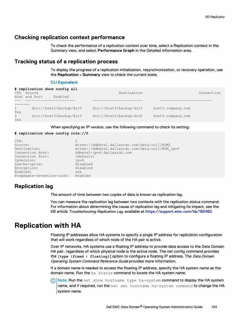
Checking replication context performanceTo check the performance of a replication context over time, select a Replication context in theSummary view, and select Performance Graph in the Detailed Information area.
Tracking status of a replication processTo display the progress of a replication initialization, resynchronization, or recovery operation, usethe Replication > Summary view to check the current state.
CLI Equivalent
# replication show config allCTX Source Destination Connection Host and Port Enabled--- ----------------------- ----------------------- ------------------------ -------1 dir://host2/backup/dir2 dir://host3/backup/dir3 host3.company.com Yes2 dir://host3/backup/dir3 dir://host2/backup/dir2 host3.company.com Yes
When specifying an IP version, use the following command to check its setting:
# replication show config rctx://2
CTX: 2 Source: mtree://ddbeta1.dallasrdc.com/data/col1/EDM1 Destination: mtree://ddbeta2.dallasrdc.com/data/col1/EDM_ipv6Connection Host: ddbeta2-ipv6.dallasrdc.com Connection Port: (default) Ipversion: ipv6 Low-bw-optim: disabled Encryption: disabled Enabled: yes Propagate-retention-lock: enabled
Replication lagThe amount of time between two copies of data is known as replication lag.
You can measure the replication lag between two contexts with the replication status command.For information about determining the cause of replication lag and mitigating its impact, see theKB article Troubleshooting Replication Lag, available at https://support.emc.com/kb/180482.
Replication with HAFloating IP addresses allow HA systems to specify a single IP address for replication configurationthat will work regardless of which node of the HA pair is active.
Over IP networks, HA systems use a floating IP address to provide data access to the Data DomainHA pair, regardless of which physical node is the active node. The net config command providesthe [type {fixed | floating}] option to configure a floating IP address. The Data DomainOperating System Command Reference Guide provides more information.
If a domain name is needed to access the floating IP address, specify the HA system name as thedomain name. Run the ha status command to locate the HA system name.
Note: Run the net show hostname type ha-system command to display the HA systemname, and if required, run the net set hostname ha-system command to change the HAsystem name.
DD Replicator
Dell EMC Data Domain® Operating System Administration Guide 433
All file system access should be through the floating IP address. When configuring backup andreplication operations on an HA pair, always specify the floating IP address as the IP address forthe Data Domain system. Data Domain features such as DD Boost and replication will accept thefloating IP address for the HA pair the same way as they accept the system IP address for a non-HA system.
Replication between HA and non-HA systems
If you want to set up a replication between a high-availability (HA) system and a system runningDD OS 5.7.0.3 or earlier, you must create and manage that replication on the HA system if youwant to use the DD System Manager graphical user interface (GUI).
However, you can perform replications from a non-HA system to an HA system using the CLI aswell as from the HA system to the non-HA system.
Collection replication between HA and non-HA systems is not supported. Directory or MTreereplication is required to replicate data between HA and non-HA systems.
Replicating a system with quotas to one withoutReplicate a Data Domain system with a DD OS that supports quotas, to a system with a DD OSthat does not have quotas.
l A reverse resync, which takes the data from the system without quotas and puts it back in anMTree on the system that has quotas enabled (and which continues to have quotas enabled).
l A reverse initialization from the system without quotas, which takes its data and creates a newMTree on the system that supports quotas, but does not have quotas enabled because it wascreated from data on a system without quotas.
Note: Quotas were introduced as of DD OS 5.2.
Replication Scaling ContextThe Replication Scaling Context feature gives you more flexibility when configuring replicationcontexts.
In environments with more than 299 replication contexts that include both directory and MTreereplication contexts, this feature allows you to configure the contexts in any order. Previously, youhad to configure the directory replication contexts first, followed by the MTree replicationcontexts.
The total number of replication contexts cannot exceed 540.
Note: This feature appears only on Data Domain systems running DD OS version 6.0.
Directory-to-MTree replication migrationThe directory-to-MTree (D2M) replication optimization feature allows you to migrate existingdirectory replication contexts to new replication contexts based on MTrees, which are logicalpartitions of the file system. This feature also lets you monitor the process as it unfolds and verifythat has successfully completed.
The D2M feature is compatible with Data Domain Operating System versions 6.0, 5.7, and 5.6.
The source Data Domain system must be running DD OS 6.0 to use this feature, but thedestination system can be running 6.0, 5.7, or 5.6. However, the performance optimizationbenefits are seen only when both the source and destination systems are also running 6.0.
DD Replicator
434 Dell EMC Data Domain® Operating System Administration Guide
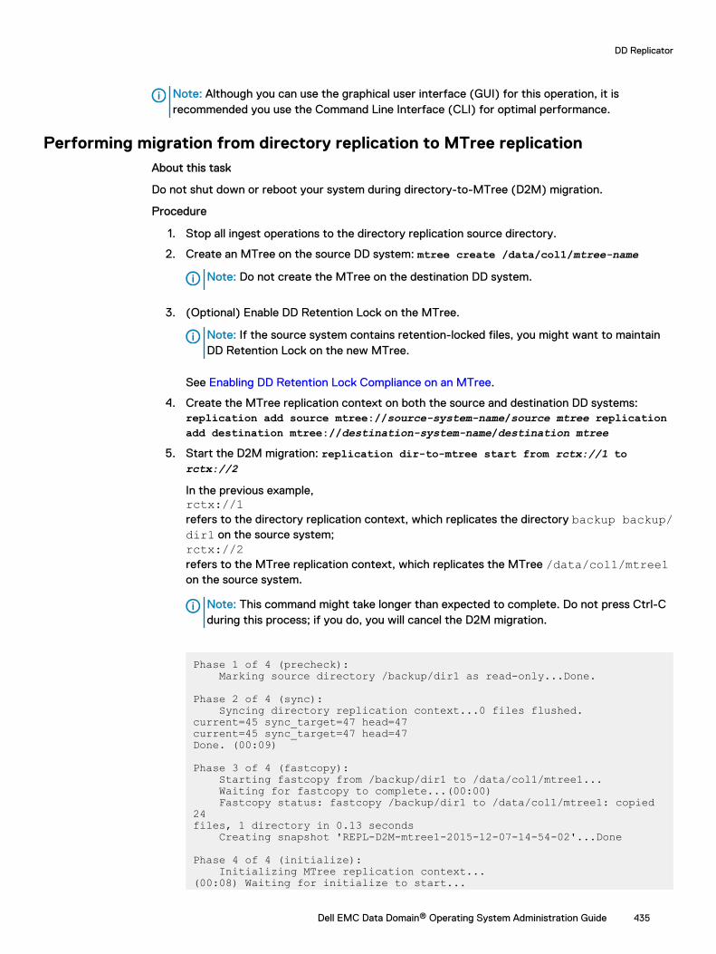
Note: Although you can use the graphical user interface (GUI) for this operation, it isrecommended you use the Command Line Interface (CLI) for optimal performance.
Performing migration from directory replication to MTree replicationAbout this task
Do not shut down or reboot your system during directory-to-MTree (D2M) migration.
Procedure
1. Stop all ingest operations to the directory replication source directory.
2. Create an MTree on the source DD system: mtree create /data/col1/mtree-name
Note: Do not create the MTree on the destination DD system.
3. (Optional) Enable DD Retention Lock on the MTree.
Note: If the source system contains retention-locked files, you might want to maintainDD Retention Lock on the new MTree.
See Enabling DD Retention Lock Compliance on an MTree.
4. Create the MTree replication context on both the source and destination DD systems:replication add source mtree://source-system-name/source mtree replicationadd destination mtree://destination-system-name/destination mtree
5. Start the D2M migration: replication dir-to-mtree start from rctx://1 torctx://2
In the previous example,rctx://1refers to the directory replication context, which replicates the directory backup backup/dir1 on the source system;rctx://2refers to the MTree replication context, which replicates the MTree /data/col1/mtree1on the source system.
Note: This command might take longer than expected to complete. Do not press Ctrl-Cduring this process; if you do, you will cancel the D2M migration.
Phase 1 of 4 (precheck): Marking source directory /backup/dir1 as read-only...Done.
Phase 2 of 4 (sync): Syncing directory replication context...0 files flushed.current=45 sync_target=47 head=47current=45 sync_target=47 head=47Done. (00:09)
Phase 3 of 4 (fastcopy): Starting fastcopy from /backup/dir1 to /data/col1/mtree1... Waiting for fastcopy to complete...(00:00) Fastcopy status: fastcopy /backup/dir1 to /data/col1/mtree1: copied 24files, 1 directory in 0.13 seconds Creating snapshot 'REPL-D2M-mtree1-2015-12-07-14-54-02'...Done
Phase 4 of 4 (initialize): Initializing MTree replication context...(00:08) Waiting for initialize to start...
DD Replicator
Dell EMC Data Domain® Operating System Administration Guide 435
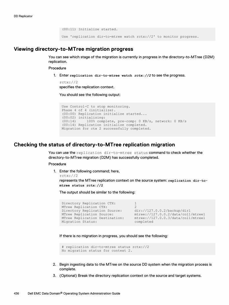
(00:11) Initialize started.
Use 'replication dir-to-mtree watch rctx://2' to monitor progress.
Viewing directory-to-MTree migration progressYou can see which stage of the migration is currently in progress in the directory-to-MTree (D2M)replication.
Procedure
1. Enter replication dir-to-mtree watch rctx://2 to see the progress.
rctx://2specifies the replication context.
You should see the following output:
Use Control-C to stop monitoring.Phase 4 of 4 (initialize).(00:00) Replication initialize started...(00:02) initializing:(00:14) 100% complete, pre-comp: 0 KB/s, network: 0 KB/s (00:14) Replication initialize completed.Migration for ctx 2 successfully completed.
Checking the status of directory-to-MTree replication migrationYou can use the replication dir-to-mtree status command to check whether thedirectory-to-MTree migration (D2M) has successfully completed.
Procedure
1. Enter the following command; here,rctx://2represents the MTree replication context on the source system: replication dir-to-mtree status rctx://2The output should be similar to the following:
Directory Replication CTX: 1MTree Replication CTX: 2Directory Replication Source: dir://127.0.0.2/backup/dir1MTree Replication Source: mtree://127.0.0.2/data/col1/mtree1MTree Replication Destination: mtree://127.0.0.3/data/col1/mtree1Migration Status: completed
If there is no migration in progress, you should see the following:
# replication dir-to-mtree status rctx://2No migration status for context 2.
2. Begin ingesting data to the MTree on the source DD system when the migration process iscomplete.
3. (Optional) Break the directory replication context on the source and target systems.
DD Replicator
436 Dell EMC Data Domain® Operating System Administration Guide
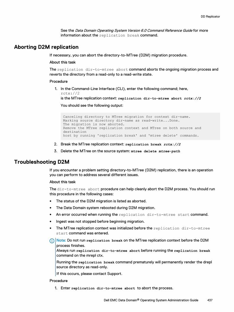
See the Data Domain Operating System Version 6.0 Command Reference Guide for moreinformation about the replication break command.
Aborting D2M replicationIf necessary, you can abort the directory-to-MTree (D2M) migration procedure.
About this task
The replication dir-to-mtree abort command aborts the ongoing migration process andreverts the directory from a read-only to a read-write state.
Procedure
1. In the Command-Line Interface (CLI), enter the following command; here,rctx://2is the MTree replication context: replication dir-to-mtree abort rctx://2You should see the following output:
Canceling directory to MTree migration for context dir-name.Marking source directory dir-name as read-write...Done.The migration is now aborted.Remove the MTree replication context and MTree on both source and destinationhost by running 'replication break' and 'mtree delete' commands.
2. Break the MTree replication context: replication break rctx://23. Delete the MTree on the source system: mtree delete mtree-path
Troubleshooting D2MIf you encounter a problem setting directory-to-MTree (D2M) replication, there is an operationyou can perform to address several different issues.
About this task
The dir-to-mtree abort procedure can help cleanly abort the D2M process. You should runthis procedure in the following cases:
l The status of the D2M migration is listed as aborted.
l The Data Domain system rebooted during D2M migration.
l An error occurred when running the replication dir-to-mtree start command.
l Ingest was not stopped before beginning migration.
l The MTree replication context was initialized before the replication dir-to-mtreestart command was entered.
Note: Do not run replication break on the MTree replication context before the D2Mprocess finishes.Always run replication dir-to-mtree abort before running the replication breakcommand on the mrepl ctx.
Running the replication break command prematurely will permanently render the dreplsource directory as read-only.
If this occurs, please contact Support.
Procedure
1. Enter replication dir-to-mtree abort to abort the process.
DD Replicator
Dell EMC Data Domain® Operating System Administration Guide 437
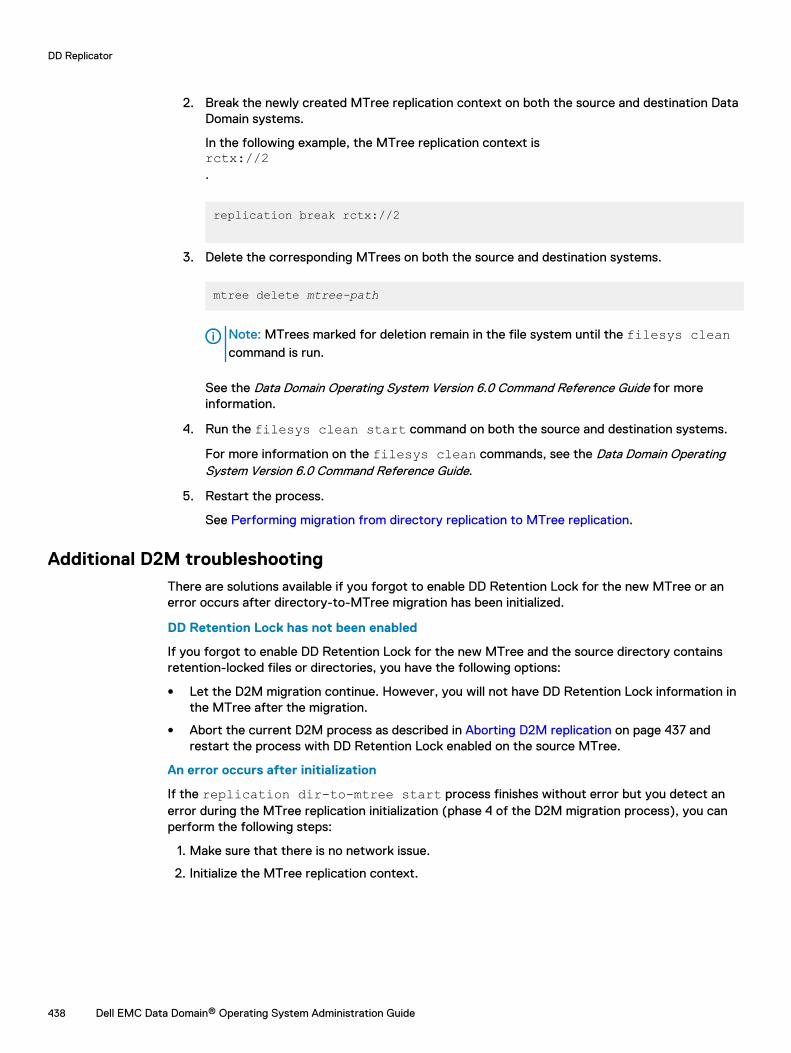
2. Break the newly created MTree replication context on both the source and destination DataDomain systems.
In the following example, the MTree replication context isrctx://2.
replication break rctx://2
3. Delete the corresponding MTrees on both the source and destination systems.
mtree delete mtree-path
Note: MTrees marked for deletion remain in the file system until the filesys cleancommand is run.
See the Data Domain Operating System Version 6.0 Command Reference Guide for moreinformation.
4. Run the filesys clean start command on both the source and destination systems.
For more information on the filesys clean commands, see the Data Domain OperatingSystem Version 6.0 Command Reference Guide.
5. Restart the process.
See Performing migration from directory replication to MTree replication.
Additional D2M troubleshootingThere are solutions available if you forgot to enable DD Retention Lock for the new MTree or anerror occurs after directory-to-MTree migration has been initialized.
DD Retention Lock has not been enabled
If you forgot to enable DD Retention Lock for the new MTree and the source directory containsretention-locked files or directories, you have the following options:
l Let the D2M migration continue. However, you will not have DD Retention Lock information inthe MTree after the migration.
l Abort the current D2M process as described in Aborting D2M replication on page 437 andrestart the process with DD Retention Lock enabled on the source MTree.
An error occurs after initialization
If the replication dir-to-mtree start process finishes without error but you detect anerror during the MTree replication initialization (phase 4 of the D2M migration process), you canperform the following steps:
1. Make sure that there is no network issue.
2. Initialize the MTree replication context.
DD Replicator
438 Dell EMC Data Domain® Operating System Administration Guide
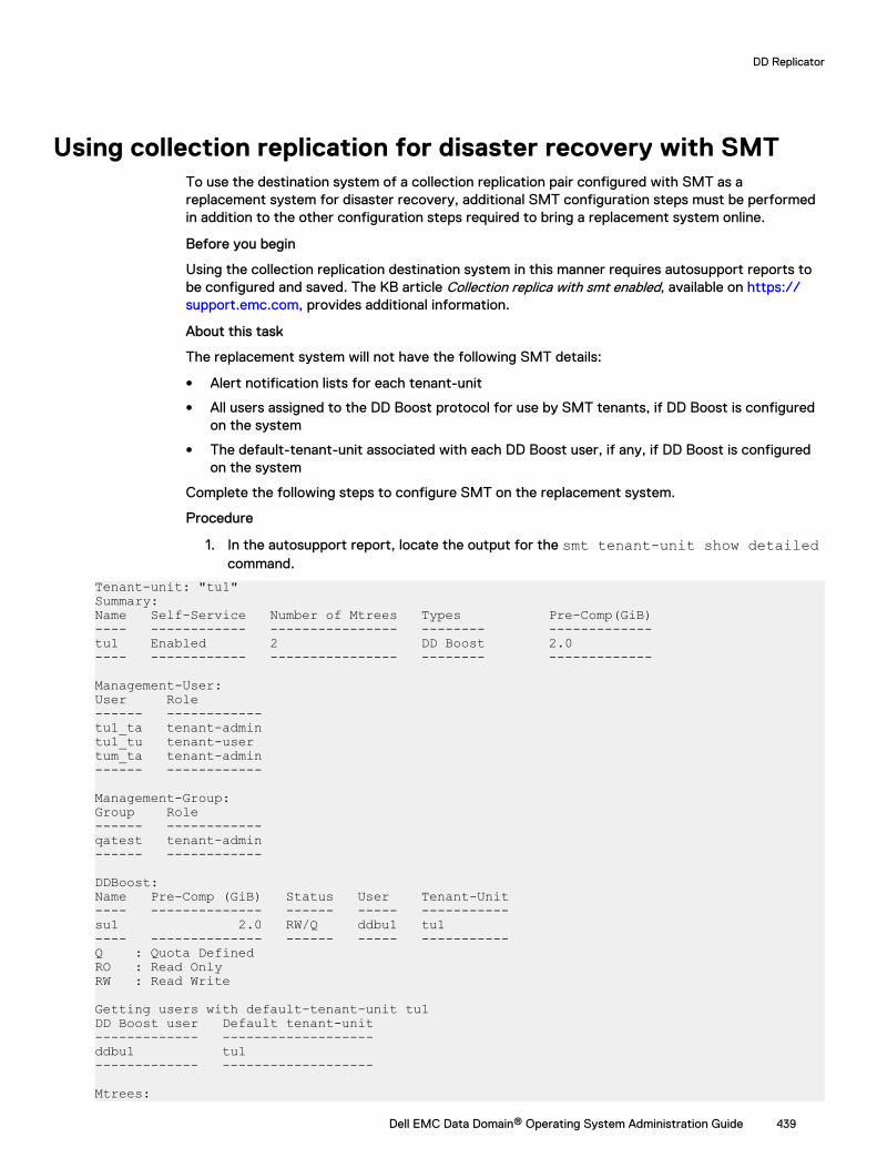
Using collection replication for disaster recovery with SMTTo use the destination system of a collection replication pair configured with SMT as areplacement system for disaster recovery, additional SMT configuration steps must be performedin addition to the other configuration steps required to bring a replacement system online.
Before you begin
Using the collection replication destination system in this manner requires autosupport reports tobe configured and saved. The KB article Collection replica with smt enabled, available on https://support.emc.com, provides additional information.
About this task
The replacement system will not have the following SMT details:
l Alert notification lists for each tenant-unit
l All users assigned to the DD Boost protocol for use by SMT tenants, if DD Boost is configuredon the system
l The default-tenant-unit associated with each DD Boost user, if any, if DD Boost is configuredon the system
Complete the following steps to configure SMT on the replacement system.
Procedure
1. In the autosupport report, locate the output for the smt tenant-unit show detailedcommand.
Tenant-unit: "tu1"Summary:Name Self-Service Number of Mtrees Types Pre-Comp(GiB)---- ------------ ---------------- -------- -------------tu1 Enabled 2 DD Boost 2.0---- ------------ ---------------- -------- -------------
Management-User:User Role------ ------------tu1_ta tenant-admintu1_tu tenant-usertum_ta tenant-admin------ ------------
Management-Group:Group Role------ ------------qatest tenant-admin------ ------------
DDBoost:Name Pre-Comp (GiB) Status User Tenant-Unit---- -------------- ------ ----- -----------su1 2.0 RW/Q ddbu1 tu1---- -------------- ------ ----- -----------Q : Quota DefinedRO : Read OnlyRW : Read Write
Getting users with default-tenant-unit tu1DD Boost user Default tenant-unit------------- -------------------ddbu1 tu1------------- -------------------
Mtrees:
DD Replicator
Dell EMC Data Domain® Operating System Administration Guide 439
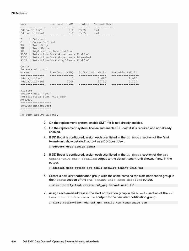
Name Pre-Comp (GiB) Status Tenant-Unit-------------- -------------- ------ -----------/data/col1/m1 0.0 RW/Q tu1/data/col1/su1 2.0 RW/Q tu1-------------- -------------- ------ -----------D : DeletedQ : Quota DefinedRO : Read OnlyRW : Read WriteRD : Replication DestinationRLGE : Retention-Lock Governance EnabledRLGD : Retention-Lock Governance DisabledRLCE : Retention-Lock Compliance Enabled
Quota:Tenant-unit: tu1Mtree Pre-Comp (MiB) Soft-Limit (MiB) Hard-Limit(MiB)-------------- -------------- ---------------- ----------------/data/col1/m1 0 71680 81920/data/col1/su1 2048 30720 51200-------------- -------------- ---------------- ----------------
Alerts:Tenant-unit: "tu1"Notification list "tu1_grp"[email protected]
No such active alerts.
2. On the replacement system, enable SMT if it is not already enabled.
3. On the replacement system, license and enable DD Boost if it is required and not alreadyenabled.
4. If DD Boost is configured, assign each user listed in the DD Boost section of the "smttenant-unit show detailed" output as a DD Boost User.
# ddboost user assign ddbu1
5. If DD Boost is configured, assign each user listed in the DD Boost section of the smttenant-unit show detailed output to the default tenant-unit shown, if any, in theoutput.
# ddboost user option set ddbu1 default-tenant-unit tu1
6. Create a new alert notification group with the same name as the alert notification group inthe Alerts section of the smt tenant-unit show detailed output.
# alert notify-list create tu1_grp tenant-unit tu1
7. Assign each email address in the alert notification group in the Alerts section of the smttenant-unit show detailed output to the new alert notification group.
# alert notify-list add tu1_grp emails [email protected]
DD Replicator
440 Dell EMC Data Domain® Operating System Administration Guide

CHAPTER 17
DD Secure Multitenancy
This chapter includes:
l Data Domain Secure Multi-tenancy overview...................................................................... 442l Provisioning a Tenant Unit.................................................................................................. 445l Enabling Tenant Self-Service mode.....................................................................................449l Data access by protocol...................................................................................................... 449l Data management operations.............................................................................................. 451
Dell EMC Data Domain® Operating System Administration Guide 441
Data Domain Secure Multi-tenancy overviewData Domain Secure Multi-tenancy (SMT) is the simultaneous hosting, by an internal ITdepartment or an external provider, of an IT infrastructure for more than one consumer orworkload (business unit, department, or Tenant).
SMT provides the ability to securely isolate many users and workloads in a shared infrastructure,so that the activities of one Tenant are not apparent or visible to the other Tenants.
A Tenant is a consumer (business unit, department, or customer) who maintains a persistentpresence in a hosted environment.
Within an enterprise, a Tenant may consist of one or more business units or departments on a DataDomain system configured and managed by IT staff.
l For a business unit (BU) use case, the Finance and Human Resources departments of acorporation could share the same Data Domain system, but each department would beunaware of the presence of the other.
l For a service provider (SP) use case, the SP could deploy one or more Data Domain systems toaccommodate different Protection Storage services for multiple end-customers.
Both use cases emphasize the segregation of different customer data on the same physical DataDomain system.
SMT architecture basicsSecure Multitenancy (SMT) provides a simple approach to setting up Tenants and Tenant Units,using MTrees. SMT setup is performed using DD Management Center and/or the DD OS commandline interface. This administration guide provides the theory of SMT and some general commandline instructions.
The basic architecture of SMT is as follows.
l A Tenant is created on the DD Management Center and/or DD system.
l A Tenant Unit is created on a DD system for the Tenant.
l One or more MTrees are created to meet the storage requirements for the Tenant's varioustypes of backups.
l The newly created MTrees are added to the Tenant Unit.
l Backup applications are configured to send each backup to its configured Tenant Unit MTree.
Note: For more information about DD Management Center, see the DD Management CenterUser Guide. For more information about the DD OS command line interface, see the DD OSCommand Reference.
Terminology used in Secure Multi-Tenancy (SMT)Understanding the terminology that is used in SMT will help you better understand this uniqueenvironment.
MTrees
MTrees are logical partitions of the file system and offer the highest degree of managementgranularity, meaning users can perform operations on a specific MTree without affecting the entirefile system. MTrees are assigned to Tenant Units and contain that Tenant Unit's individualizedsettings for managing and monitoring SMT.
DD Secure Multitenancy
442 Dell EMC Data Domain® Operating System Administration Guide
Multi-Tenancy
Multi-Tenancy refers to the hosting of an IT infrastructure by an internal IT department, or anexternal service provider, for more than one consumer/workload (business unit/department/Tenant) simultaneously. Data Domain SMT enables Data Protection-as-a-Service.
RBAC (role-based access control)
RBAC offers multiple roles with different privilege levels, which combine to provide theadministrative isolation on a multi-tenant Data Domain system. (The next section will define theseroles.)
Storage Unit
A Storage Unit is an MTree configured for the DD Boost protocol. Data isolation is achieved bycreating a Storage Unit and assigning it to a DD Boost user. The DD Boost protocol permits accessonly to Storage Units assigned to DD Boost users connected to the Data Domain system.
Tenant
A Tenant is a consumer (business unit/department/customer) who maintains a persistentpresence in a hosted environment.
Tenant Self-Service
Tenant Self-Service is a method of letting a Tenant log in to a Data Domain system to performsome basic services (add, edit, or delete local users, NIS groups, and/or AD groups). This reducesthe bottleneck of always having to go through an administrator for these basic tasks. The Tenantcan access only their assigned Tenant Units. Tenant Users and Tenant Admins will, of course, havedifferent privileges.
Tenant Unit
A Tenant Unit is the partition of a Data Domain system that serves as the unit of administrativeisolation between Tenants. Tenant units that are assigned to a tenant can be on the same ordifferent Data Domain systems and are secured and logically isolated from each other, whichensures security and isolation of the control path when running multiple Tenants simultaneously onthe shared infrastructure. Tenant Units can contain one or more MTrees, which hold allconfiguration elements that are needed in a multi-tenancy setup. Users, management-groups,notification-groups, and other configuration elements are part of a Tenant Unit.
Control path and network isolationControl path isolation is achieved by providing the user roles of tenant-admin and tenant-user for aTenant Unit. Network isolation for data and administrative access is achieved by associating afixed set of data access IP address(es) and management IP address(es) with a Tenant Unit.
The tenant-admin and tenant-user roles are restricted in scope and capability to specific TenantUnits and to a restricted set of operations they can perform on those Tenant Units. To ensure alogically secure and isolated data path, a system administrator must configure one or more TenantUnit MTrees for each protocol in an SMT environment. Supported protocols include DD Boost,NFS, CIFS, and DD VTL. Access is strictly regulated by the native access control mechanisms ofeach protocol.
Tenant-self-service sessions (through ssh) can be restricted to a fixed set of management IPaddress(es) on a DD system. Administrative access sessions (through ssh/http/https) can also berestricted to a fixed set of management IP address(es) on DD systems. By default, however, thereare no management IP address(es) associated with a Tenant Unit, so the only standard restrictionis through the use of the tenant-admin and tenant-user roles. You must use smt tenant-unitmanagement-ip to add and maintain management IP address(es) for Tenant Units.
DD Secure Multitenancy
Dell EMC Data Domain® Operating System Administration Guide 443
Similarly, data access and data flow (into and out of Tenant Units) can be restricted to a fixed setof local or remote data access IP address(es). The use of assigned data access IP address(es)enhances the security of the DD Boost and NFS protocols by adding SMT-related security checks.For example, the list of storage units returned over DD Boost RPC can be limited to those whichbelong to the Tenant Unit with the assigned local data access IP address. For NFS, access andvisibility of exports can be filtered based on the local data access IP address(es) configured. Forexample, using showmount -e from the local data access IP address of a Tenant Unit will onlydisplay NFS exports belonging to that Tenant Unit.
The sysadmin must use smt tenant-unit data-ip to add and maintain data access IPaddress(es) for Tenant Units.
Note: If you attempt to mount an MTree in an SMT using a non-SMT IP address, the operationwill fail.
If multiple Tenant Units are belong to the same tenant, they can share a default gateway.However, if multiple Tenant Units that belong to different tenants are oprevented from using thesame default gateway.
Multiple Tenant Units belonging to the same tenant can share a default gateway. Tenant Units thatbelong to different tenants cannot use the same default gateway.
Understanding RBAC in SMTIn SMT (Secure Multi-Tenancy), permission to perform a task depends on the role that is assignedto a user. DD Management Center uses RBAC (role-based access control) to control thesepermissions.
All DD Management Center users can:
l View all Tenantsl Create, read, update, or delete Tenant Units belonging to any Tenant if the user is an
administrator on the Data Domain system hosting the Tenant Unitl Assign and unassign Tenant Units to and from a Tenant if the user is an administrator on the
Data Domain system hosting the Tenant Unitl View Tenant Units belonging to any Tenant if the user has any assigned role on the Data
Domain system hosting the Tenant Unit
To perform more advanced tasks depends on the role of the user, as follows:
admin role
A user with an admin role can perform all administrative operations on a Data Domain system. Anadmin can also perform all SMT administrative operations on a Data Domain system, includingsetting up SMT, assigning SMT user roles, enabling Tenant self-service mode, creating a Tenant,and so on. In the context of SMT, the admin is typically referred to as the landlord. In DD OS, therole is known as the sysadmin.
To have permission to edit or delete a Tenant, you must be both a DD Management Center adminand a DD OS sysadmin on all Data Domain systems that are associated with the Tenant Units ofthat Tenant. If the Tenant does not have any Tenant Units, you need only to be a DD ManagementCenter admin to edit or delete that Tenant.
limited-admin role
A user with a limited-admin role can perform all administrative operations on a Data Domain systemas the admin. However, users with the limited-admin role cannot delete or destroy MTrees. In DDOS, there is an equivalent limited-admin role.
tenant-admin role
A user with a tenant-admin role can perform certain tasks only when tenant self-service mode isenabled for a specific Tenant Unit. Responsibilities include scheduling and running a backup
DD Secure Multitenancy
444 Dell EMC Data Domain® Operating System Administration Guide
application for the Tenant and monitoring resources and statistics within the assigned Tenant Unit.The tenant-admin can view audit logs, but RBAC ensures that only audit logs from the TenantUnit(s) belonging to the tenant-admin are accessible. In addition, tenant-admins ensureadministrative separation when Tenant self-service mode is enabled. In the context of SMT, thetenant-admin is usually referred to as the backup admin.
tenant-user role
A user with a tenant-user role can monitor the performance and usage of SMT components onlyon Tenant Unit(s) assigned to them and only when Tenant self-service is enabled, but a user withthis role cannot view audit logs for their assigned Tenant Units. In addition, tenant-users may runthe show and list commands.
none role
A user with a role of none is not allowed to perform any operations on a Data Domain system otherthan changing their password and accessing data using DD Boost. However, after SMT is enabled,the admin can select a user with a none role from the Data Domain system and assign them anSMT-specific role of tenant-admin or tenant-user. Then, that user can perform operations on SMTmanagement objects.
management groups
BSPs (backup service providers) can use management groups defined in a single, external AD(active directory) or NIS (network information service) to simplify managing user roles on TenantUnits. Each BSP Tenant may be a separate, external company and may use a name-service such asAD or NIS.
With SMT management groups, the AD and NIS servers are set up and configured by the admin inthe same way as SMT local users. The admin can ask their AD or NIS administrator to create andpopulate the group. The admin then assigns an SMT role to the entire group. Any user within thegroup who logs in to the Data Domain system is logged in with the role that is assigned to thegroup.
When users leave or join a Tenant company, they can be removed or added to the group by the ADor NIS administrator. It is not necessary to modify the RBAC configuration on a Data Domainsystem when users who are part of the group are added or removed.
Provisioning a Tenant UnitLaunching the configuration wizard begins the initial provisioning procedure for SecureMultitenancy (SMT). During the procedure, the wizard creates and provisions a new Tenant Unitbased on Tenant configuration requirements. Information is entered by the administrator, asprompted. After completing the procedure, the administrator proceeds to the next set of tasks,beginning with enabling Tenant Self-Service mode. Following the initial setup, manual proceduresand configuration modifications may be performed as required.
Procedure
1. Start SMT.
# smt enableSMT enabled.
2. Verify that SMT is enabled.
# smt statusSMT is enabled.
3. Launch the SMT configuration wizard.
# smt tenant-unit setupNo tenant-units.
DD Secure Multitenancy
Dell EMC Data Domain® Operating System Administration Guide 445
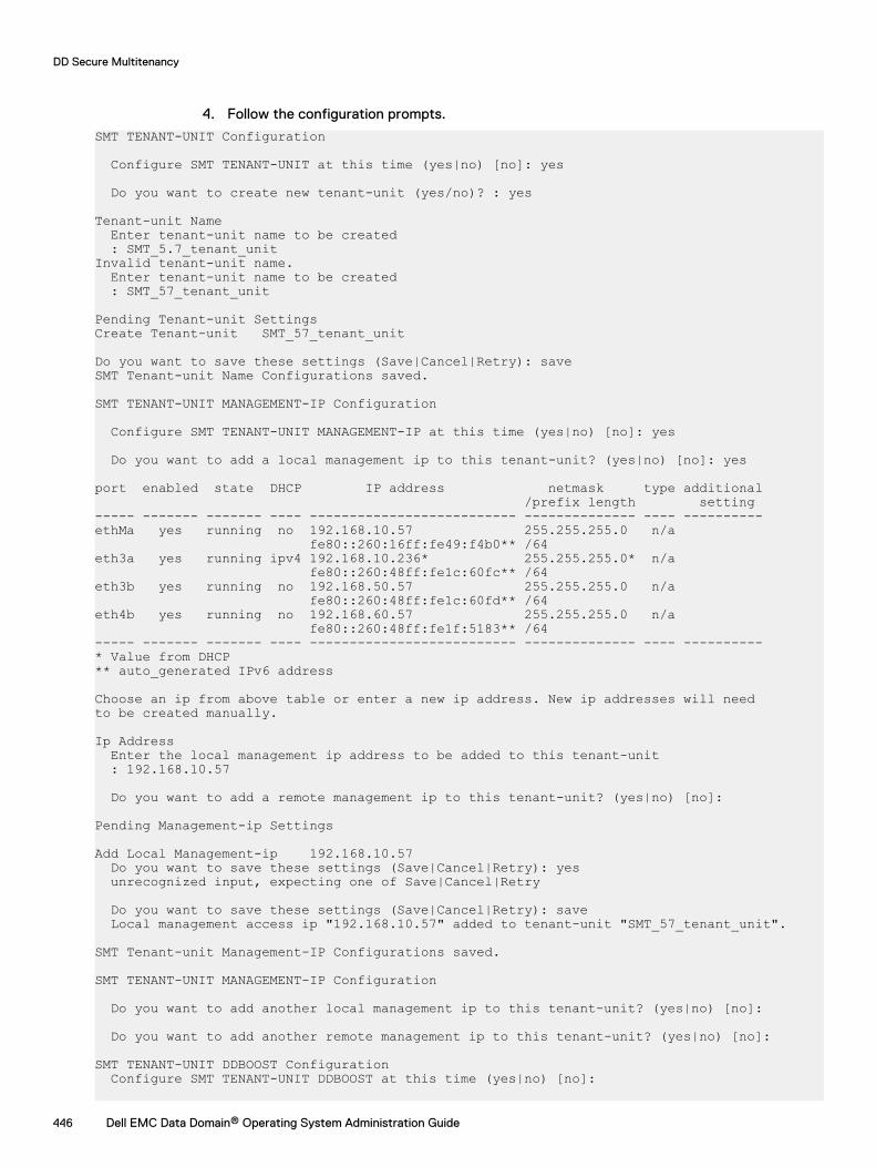
4. Follow the configuration prompts.
SMT TENANT-UNIT Configuration
Configure SMT TENANT-UNIT at this time (yes|no) [no]: yes
Do you want to create new tenant-unit (yes/no)? : yes
Tenant-unit Name Enter tenant-unit name to be created : SMT_5.7_tenant_unitInvalid tenant-unit name. Enter tenant-unit name to be created : SMT_57_tenant_unit
Pending Tenant-unit SettingsCreate Tenant-unit SMT_57_tenant_unit
Do you want to save these settings (Save|Cancel|Retry): saveSMT Tenant-unit Name Configurations saved.
SMT TENANT-UNIT MANAGEMENT-IP Configuration Configure SMT TENANT-UNIT MANAGEMENT-IP at this time (yes|no) [no]: yes
Do you want to add a local management ip to this tenant-unit? (yes|no) [no]: yes
port enabled state DHCP IP address netmask type additional /prefix length setting----- ------- ------- ---- -------------------------- -------------- ---- ----------ethMa yes running no 192.168.10.57 255.255.255.0 n/a fe80::260:16ff:fe49:f4b0** /64eth3a yes running ipv4 192.168.10.236* 255.255.255.0* n/a fe80::260:48ff:fe1c:60fc** /64eth3b yes running no 192.168.50.57 255.255.255.0 n/a fe80::260:48ff:fe1c:60fd** /64eth4b yes running no 192.168.60.57 255.255.255.0 n/a fe80::260:48ff:fe1f:5183** /64----- ------- ------- ---- -------------------------- -------------- ---- ----------* Value from DHCP** auto_generated IPv6 address
Choose an ip from above table or enter a new ip address. New ip addresses will needto be created manually.
Ip Address Enter the local management ip address to be added to this tenant-unit : 192.168.10.57
Do you want to add a remote management ip to this tenant-unit? (yes|no) [no]:
Pending Management-ip Settings
Add Local Management-ip 192.168.10.57 Do you want to save these settings (Save|Cancel|Retry): yes unrecognized input, expecting one of Save|Cancel|Retry
Do you want to save these settings (Save|Cancel|Retry): save Local management access ip "192.168.10.57" added to tenant-unit "SMT_57_tenant_unit".
SMT Tenant-unit Management-IP Configurations saved.
SMT TENANT-UNIT MANAGEMENT-IP Configuration
Do you want to add another local management ip to this tenant-unit? (yes|no) [no]:
Do you want to add another remote management ip to this tenant-unit? (yes|no) [no]:
SMT TENANT-UNIT DDBOOST Configuration Configure SMT TENANT-UNIT DDBOOST at this time (yes|no) [no]:
DD Secure Multitenancy
446 Dell EMC Data Domain® Operating System Administration Guide
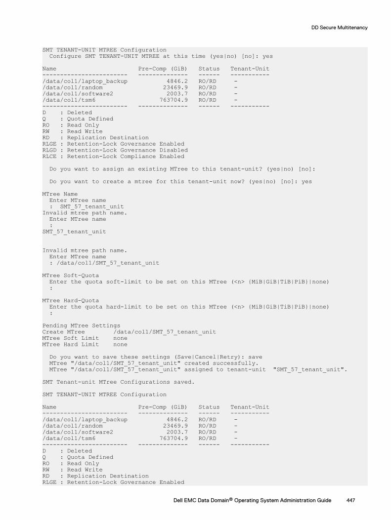
SMT TENANT-UNIT MTREE Configuration Configure SMT TENANT-UNIT MTREE at this time (yes|no) [no]: yes
Name Pre-Comp (GiB) Status Tenant-Unit------------------------ -------------- ------ -----------/data/col1/laptop_backup 4846.2 RO/RD - /data/col1/random 23469.9 RO/RD - /data/col1/software2 2003.7 RO/RD - /data/col1/tsm6 763704.9 RO/RD - ------------------------ -------------- ------ -----------D : Deleted Q : Quota DefinedRO : Read OnlyRW : Read WriteRD : Replication DestinationRLGE : Retention-Lock Governance EnabledRLGD : Retention-Lock Governance DisabledRLCE : Retention-Lock Compliance Enabled
Do you want to assign an existing MTree to this tenant-unit? (yes|no) [no]:
Do you want to create a mtree for this tenant-unit now? (yes|no) [no]: yes
MTree Name Enter MTree name : SMT_57_tenant_unitInvalid mtree path name. Enter MTree name : SMT_57_tenant_unit Invalid mtree path name. Enter MTree name : /data/col1/SMT_57_tenant_unit
MTree Soft-Quota Enter the quota soft-limit to be set on this MTree (<n> {MiB|GiB|TiB|PiB}|none) :
MTree Hard-Quota Enter the quota hard-limit to be set on this MTree (<n> {MiB|GiB|TiB|PiB}|none) :
Pending MTree SettingsCreate MTree /data/col1/SMT_57_tenant_unitMTree Soft Limit none MTree Hard Limit none Do you want to save these settings (Save|Cancel|Retry): save MTree "/data/col1/SMT_57_tenant_unit" created successfully. MTree "/data/col1/SMT_57_tenant_unit" assigned to tenant-unit "SMT_57_tenant_unit".
SMT Tenant-unit MTree Configurations saved.
SMT TENANT-UNIT MTREE Configuration
Name Pre-Comp (GiB) Status Tenant-Unit------------------------ -------------- ------ -----------/data/col1/laptop_backup 4846.2 RO/RD - /data/col1/random 23469.9 RO/RD - /data/col1/software2 2003.7 RO/RD - /data/col1/tsm6 763704.9 RO/RD - ------------------------ -------------- ------ -----------D : Deleted Q : Quota DefinedRO : Read OnlyRW : Read WriteRD : Replication DestinationRLGE : Retention-Lock Governance Enabled
DD Secure Multitenancy
Dell EMC Data Domain® Operating System Administration Guide 447
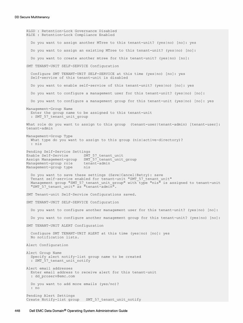
RLGD : Retention-Lock Governance DisabledRLCE : Retention-Lock Compliance Enabled
Do you want to assign another MTree to this tenant-unit? (yes|no) [no]: yes
Do you want to assign an existing MTree to this tenant-unit? (yes|no) [no]:
Do you want to create another mtree for this tenant-unit? (yes|no) [no]:
SMT TENANT-UNIT SELF-SERVICE Configuration
Configure SMT TENANT-UNIT SELF-SERVICE at this time (yes|no) [no]: yes Self-service of this tenant-unit is disabled
Do you want to enable self-service of this tenant-unit? (yes|no) [no]: yes
Do you want to configure a management user for this tenant-unit? (yes|no) [no]:
Do you want to configure a management group for this tenant-unit (yes|no) [no]: yes
Management-Group Name Enter the group name to be assigned to this tenant-unit : SMT_57_tenant_unit_group
What role do you want to assign to this group (tenant-user|tenant-admin) [tenant-user]:tenant-admin
Management-Group Type What type do you want to assign to this group (nis|active-directory)? : nis
Pending Self-Service SettingsEnable Self-Service SMT_57_tenant_unitAssign Management-group SMT_57_tenant_unit_groupManagement-group role tenant-admin Management-group type nis Do you want to save these settings (Save|Cancel|Retry): save Tenant self-service enabled for tenant-unit "SMT_57_tenant_unit" Management group "SMT_57_tenant_unit_group" with type "nis" is assigned to tenant-unit "SMT_57_tenant_unit" as "tenant-admin".
SMT Tenant-unit Self-Service Configurations saved.
SMT TENANT-UNIT SELF-SERVICE Configuration
Do you want to configure another management user for this tenant-unit? (yes|no) [no]:
Do you want to configure another management group for this tenant-unit? (yes|no) [no]:
SMT TENANT-UNIT ALERT Configuration
Configure SMT TENANT-UNIT ALERT at this time (yes|no) [no]: yes No notification lists.
Alert Configuration
Alert Group Name Specify alert notify-list group name to be created : SMT_57_tenant_unit_notify
Alert email addresses Enter email address to receive alert for this tenant-unit : [email protected]
Do you want to add more emails (yes/no)? : no
Pending Alert SettingsCreate Notify-list group SMT_57_tenant_unit_notify
DD Secure Multitenancy
448 Dell EMC Data Domain® Operating System Administration Guide
Add emails [email protected] Do you want to save these settings (Save|Cancel|Retry): save Created notification list "SMT_57_tenant_unit_notify" for tenant "SMT_57_tenant_unit". Added emails to notification list "SMT_57_tenant_unit_notify".
SMT Tenant-unit Alert Configurations saved.
Configuration complete.
Enabling Tenant Self-Service modeFor administrative separation of duties and delegation of administrative/management tasks toimplement Tenant Self-Service, which is required for control path isolation, the systemadministrator can enable this mode on a Tenant Unit and then assign users to manage the unit inthe roles of tenant-admin or tenant-user. These roles allow users other than the administrator toperform specific tasks on the Tenant Unit to which they are assigned. In addition to administrativeseparation, Tenant Self-Service mode helps reduce the management burden on internal IT andservice provider staff.
Procedure
1. View Tenant Self-Service mode status for one or all Tenant Units.# smt tenant-unit option show { tenant-unit | all }
2. Enable Tenant Self-Service mode on the selected Tenant Unit.# smt tenant-unit option set tenant-unit self-service { enabled | disabled }
Data access by protocolSecure data paths, with protocol-specific access controls, enable security and isolation for TenantUnits. In a Secure Multitenancy (SMT) environment, data access protocol management commandsare also enhanced with a Tenant Unit parameter to enable consolidated reporting.
DD systems support multiple data access protocols simultaneously, including DD Boost, NFS,CIFS, and DD VTL. A DD system can present itself as an application-specific interface, such as afile server offering NFS or CIFS access over the Ethernet, a DD VTL device, or a DD Boost device.
The native access control mechanisms of each supported protocol ensure that the data paths foreach Tenant remain separate and isolated. Such mechanisms include access control lists (ACLs)for CIFS, exports for NFS, DD Boost credentials, and Multi-User Boost credential-aware accesscontrol.
Multi-User DD Boost and Storage Units in SMTWhen using Multi-User DD Boost with SMT (Secure Multi-Tenancy), user permissions are set byStorage Unit ownership.
Multi-User DD Boost refers to the use of multiple DD Boost user credentials for DD Boost AccessControl, in which each user has a separate username and password.
A Storage Unit is an MTree configured for the DD Boost protocol. A user can be associated with,or “own,” one or more Storage Units. Storage Units that are owned by one user cannot be ownedby another user. Therefore, only the user owning the Storage Unit can access the Storage Unit forany type of data access, such as backup/restore. The number of DD Boost user names cannotexceed the maximum number of MTrees. (See the “MTrees” chapter in this book for the currentmaximum number of MTrees for each DD model.) Storage Units that are associated with SMTmust have the none role assigned to them.
Each backup application must authenticate using its DD Boost username and password. Afterauthentication, DD Boost verifies the authenticated credentials to confirm ownership of the
DD Secure Multitenancy
Dell EMC Data Domain® Operating System Administration Guide 449
Storage Unit. The backup application is granted access to the Storage Unit only if the usercredentials presented by the backup application match the user names associated with theStorage Unit. If user credentials and user names do not match, the job fails with a permission error.
Configuring access for CIFSCommon Internet File System (CIFS) is a file-sharing protocol for remote file access. In a SecureMultitenancy (SMT) configuration, backup and restores require client access to the CIFS sharesresiding in the MTree of the associated Tenant Unit. Data isolation is achieved using CIFS sharesand CIFS ACLs.
Procedure
1. Create an MTree for CIFS and assign the MTree to the tenant unit.
# mtree create mtree-path tenant-unit tenant-unit2. Set capacity soft and hard quotas for the MTree.
# mtree create mtree-path tenant-unit tenant-unit] [quota-soft-limit n{MiB|GiB|TiB|PiB} ] [quota-hard-limit n {MiB|GiB|TiB|PiB}
3. Create a CIFS share for pathname from the MTree.
# cifs share create share path pathname clients clients
Configuring NFS accessNFS is a UNIX-based, file-sharing protocol for remote file access. In a Secure Multitenancy (SMT)environment, backup and restores require client access to the NFS exports residing in the MTreeof the associated Tenant Unit. Data isolation is achieved using NFS exports and network isolation.NFS determines if an MTree is associated with a network-isolated Tenant Unit. If so, NFS verifiesthe connection properties associated with the Tenant Unit. Connection properties include thedestination IP address and interface or client hostname.
Procedure
1. Create an MTree for NFS and assign the MTree to the tenant unit.
# mtree create mtree-path tenant-unit tenant-unit2. Set capacity soft and hard quotas for the MTree.
# mtree create mtree-path tenant-unit tenant-unit] [quota-soft-limit n{MiB|GiB|TiB|PiB} ] [quota-hard-limit n {MiB|GiB|TiB|PiB}
3. Create an NFS export by adding one or more clients to the MTree.
# nfs add path client-list
Configuring access for DD VTLDD VTL Tenant data isolation is achieved using DD VTL access groups that create a virtual accesspath between a host system and the DD VTL. (The physical Fibre Channel connection between thehost system and DD VTL must already exist.)
Placing tapes in the DD VTL allows them to be written to, and read by, the backup application onthe host system. DD VTL tapes are created in a DD VTL pool, which is an MTree. Because DD VTLpools are MTrees, the pools can be assigned to Tenant Units. This association enables SMTmonitoring and reporting.
For example, if a tenant-admin is assigned a Tenant Unit that contains a DD VTL pool, the tenant-admin can run MTree commands to display read-only information. Commands can run only on theDD VTL pool assigned to the Tenant Unit.
These commands include:
DD Secure Multitenancy
450 Dell EMC Data Domain® Operating System Administration Guide
l mtree list to view a list of MTrees in the Tenant Unit
l mtree show compression to view statistics on MTree compression
l mtree show performance to view statistics on performance
Output from most list and show commands include statistics that enable service providers tomeasure space usage and calculate chargeback fees.
DD VTL operations are unaffected and continue to function normally.
Using DD VTL NDMP TapeServerDD VTL Tenant data isolation is also achieved using NDMP. DD OS implements a NDMP (NetworkData Management Protocol) tape server that allows NDMP-capable systems to send backup datato the DD system via a three-way NDMP backup.
The backup data is written to virtual tapes (which are in a pool) by a DD VTL assigned to thespecial DD VTL group TapeServer.
Because the backup data is written to tapes in a pool, information in the DD VTL topic regardingMTrees also applies to the Data Domain NDMP TapeServer.
Data management operationsSecure Multitenancy (SMT) management operations include monitoring Tenant Units and otherobjects, such as Storage Units and MTrees. For some SMT objects, additional configuration ormodification may also be required.
Collecting performance statisticsEach MTree can be measured for performance or “usage” statistics and other real-timeinformation. Historical consumption rates are available for DD Boost Storage Units. Commandoutput lets the tenant-admin collect usage statistics and compression ratios for an MTreeassociated with a Tenant Unit, or for all MTrees and associated Tenant Units. Output may befiltered to display usage in intervals ranging from minutes to months. Results are passed to theadministrator, who uses the statistics as a chargeback metric. A similar method is used to gatherusage statistics and compression ratios for Storage Units.
Procedure
1. Collect MTree real-time performance statistics.
# mtree show stats 2. Collect performance statistics for MTrees associated with a Tenant Unit.
# mtree show performance3. Collect compression statistics for MTrees associated with a Tenant Unit.
# mtree show compression
Modifying quotasTo meet QoS criteria, a system administrator uses DD OS “knobs” to adjust the settings requiredby the Tenant configuration. For example, the administrator can set “soft” and “hard” quota limitson DD Boost Storage Units. Stream “soft” and “hard” quota limits can be allocated only to DDBoost Storage Units assigned to Tenant Units. After the administrator sets the quotas, the tenant-admin can monitor one or all Tenant Units to ensure no single object exceeds its allocated quotasand deprives others of system resources.
DD Secure Multitenancy
Dell EMC Data Domain® Operating System Administration Guide 451

About this task
Quotas are set initially when prompted by the configuration wizard, but they can be adjusted ormodified later. The example below shows how to modify quotas for DD Boost. (You can also usequota capacity and quota streams to deal with capacity and stream quotas and limits.)
Procedure
1. To modify soft and hard quota limits on DD Boost Storage Unit “su33”:
ddboost storage-unit modify su33 quota-soft-limit 10 Gib quota-hard-limit20 Gib
2. To modify stream soft and hard limits on DD Boost Storage Unit “su33”:
ddboost storage-unit modify su33 write-stream-soft-limit 20 read-stream-soft-limit 6 repl -stream-soft-limit 20 combined-stream-soft-limit 20
3. To report physical size for DD Boost Storage Unit “su33”:
ddboost storage-unit modify su33 report-physical-size 8 GiB
SMT and replicationIn case of disaster, user roles dictate how a user can assist in data recovery operations. Severalreplication types are available in an SMT configuration. (See the DD Replicator chapter for moredetail on how to perform replication.)
Here are some points to consider regarding user roles:
l The admin can recover MTrees from a replicated copy.
l The tenant-admin can replicate MTrees from one system to another, using DD Boost managedfile replication.
l The tenant-admin can recover MTrees from a replicated copy, also by using DD Boostmanaged file replication.
Collection replication
Collection replication replicates core Tenant Unit configuration information.
Secure replication over public internet
To protect against man-in-the-middle (MITM) attacks when replicating over a public internetconnection, authentication includes validating SSL certificate-related information at the replicationsource and destination.
MTree replication (NFS/CIFS) using DD Boost managed file replication
MTree replication is supported on MTrees assigned to Tenant Units, using DD Boost managed filereplication. During MTree replication, an MTree assigned to a Tenant Unit on one system can bereplicated to an MTree assigned to a Tenant Unit on another system. MTree replication is notallowed between two different Tenants on the two DD systems. When security mode is set tostrict, MTree replication is allowed only when the MTrees belong to same Tenants.
For backward compatibility, MTree replication from an MTree assigned to a Tenant Unit to anunassigned MTree is supported, but must be configured manually. Manual configuration ensuresthe destination MTree has the correct settings for the Tenant Unit. Conversely, MTree replicationfrom an unassigned MTree to an MTree assigned to a Tenant Unit is also supported.
When setting up SMT-aware MTree replication, security mode defines how much checking is doneon the Tenant. The default mode checks that the source and destination do not belong to differentTenants. The strict mode makes sure the source and destination belong to the same Tenant.Therefore, when you use strict mode, you must create a Tenant on the destination machine withthe same UUID as the UUID of the Tenant on the source machine that is associated with theMTree being replicated.
DD Secure Multitenancy
452 Dell EMC Data Domain® Operating System Administration Guide
DD Boost managed file replication (also with DD Boost AIR)
DD Boost managed file replication is supported between Storage Units, regardless of whether oneStorage Unit, or both, are assigned to Tenant Units.
During DD Boost managed file replication, Storage Units are not replicated in total. Instead, certainfiles within a Storage Unit are selected by the backup application for replication. The files selectedin a Storage Unit and assigned to a Tenant Unit on one system can be replicated to a Storage Unitassigned to a Tenant Unit on another system.
For backward compatibility, selected files in a Storage Unit assigned to a Tenant Unit can bereplicated to an unassigned Storage Unit. Conversely, selected files in an unassigned Storage Unitcan be replicated to a Storage Unit assigned to a Tenant Unit.
DD Boost managed file replication can also be used in DD Boost AIR deployments.
Replication control for QoS
An upper limit on replication throughput (repl-in) can be specified for an MTree. Since MTreesfor each tenant are assigned to a Tenant Unit, each tenant's replication resource usage can becapped by applying these limits. The relation of this feature to SMT is that MTree Replication issubject to this throughput limit.
SMT Tenant alertsA DD system generates events when it encounters potential problems with software or hardware.When an event is generated, an alert notification is sent immediately via email to membersdesignated in the notification list and to the Data Domain administrator.
SMT alerts are specific to each Tenant Unit and differ from DD system alerts. When Tenant Self-Service mode is enabled, the tenant-admin can choose to receive alerts about the various systemobjects he or she is associated with and any critical events, such as an unexpected systemshutdown. A tenant-admin may only view or modify notification lists to which he or she isassociated.
The example below shows a sample alert. Notice that the two event messages at the bottom ofthe notification are specific to a Multi-Tenant environment (indicated by the word “Tenant”). Forthe entire list of DD OS and SMT alerts, see the Data Domain MIB Quick Reference Guide or theSNMP MIB.
EVT-ENVIRONMENT-00021 – Description: The system has been shutdown by abnormal method; for example, not by one of the following: 1) Via IPMI chassis control command 2) Via power button 3) Via OS shutdown.
Action: This alert is expected after loss of AC (main power) event. If this shutdown is not expected and persists, contact your contracted support provider or visit us online at https://my.datadomain.com.
Tenant description: The system has experienced an unexpected power loss and has restarted.
Tenant action: This alert is generated when the system restarts after a power loss. If this alert repeats, contact your System Administrator.
Managing snapshotsA snapshot is a read-only copy of an MTree captured at a specific point in time. A snapshot can beused for many things, for example, as a restore point in case of a system malfunction. The requiredrole for using snapshot is admin or tenant-admin.
To view snapshot information for an MTree or a Tenant Unit:
# snapshot list mtree mtree-path | tenant-unit tenant-unit
To view a snapshot schedule for an MTree or a Tenant Unit:
DD Secure Multitenancy
Dell EMC Data Domain® Operating System Administration Guide 453
# snapshot schedule show [name | mtrees mtree-listmtree-list | tenant-unit tenant-unit]
Performing a file system Fast CopyA Fast Copy operation clones files and directory trees of a source directory to a target directoryon a DD system. There are special circumstances regarding Fast Copy with Secure Multitenancy(SMT).
Here are some considerations when performing a file system Fast Copy with Tenant Self-Servicemode enabled:
l A tenant-admin can Fast Copy files from one Tenant Unit to another when the tenant-admin isthe tenant-admin for both Tenant Units, and the two Tenant Units belong to the same Tenant.
l A tenant-admin can Fast Copy files within the same Tenant Unit.
l A tenant-admin can Fast Copy files within the Tenant Units at source and destination.
To perform a file system Fast Copy:
# filesys fastcopy source <src> destination <dest>
DD Secure Multitenancy
454 Dell EMC Data Domain® Operating System Administration Guide
CHAPTER 18
DD Cloud Tier
This chapter includes:
l DD Cloud Tier overview.......................................................................................................456l Configuring Cloud Tier........................................................................................................ 459l Configuring cloud units........................................................................................................460l Data movement....................................................................................................................471l Using the Command Line Interface (CLI) to configure DD Cloud Tier..................................475l Configuring encryption for DD cloud units...........................................................................479l Information needed in the event of system loss...................................................................479l Using DD Replicator with Cloud Tier....................................................................................479l Using DD Virtual Tape Library (VTL) with Cloud Tier...........................................................480l Displaying capacity consumption charts for DD Cloud Tier..................................................480l DD Cloud Tier logs............................................................................................................... 481l Using the Command Line Interface (CLI) to remove DD Cloud Tier..................................... 481
Dell EMC Data Domain® Operating System Administration Guide 455
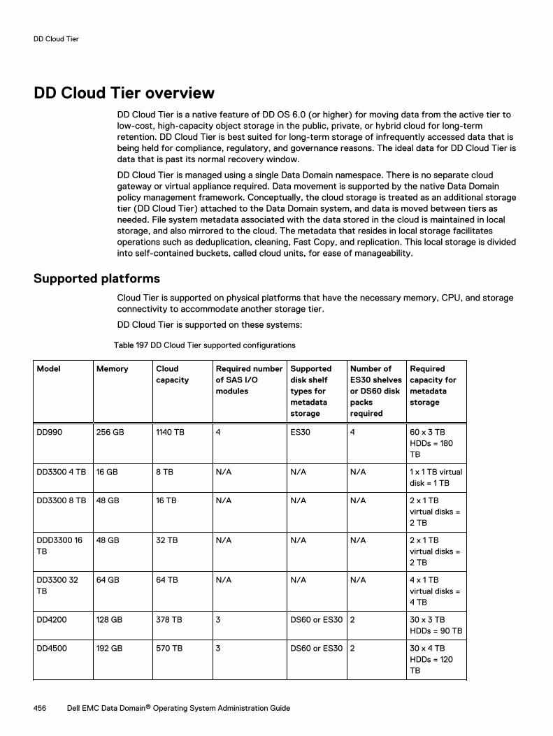
DD Cloud Tier overviewDD Cloud Tier is a native feature of DD OS 6.0 (or higher) for moving data from the active tier tolow-cost, high-capacity object storage in the public, private, or hybrid cloud for long-termretention. DD Cloud Tier is best suited for long-term storage of infrequently accessed data that isbeing held for compliance, regulatory, and governance reasons. The ideal data for DD Cloud Tier isdata that is past its normal recovery window.
DD Cloud Tier is managed using a single Data Domain namespace. There is no separate cloudgateway or virtual appliance required. Data movement is supported by the native Data Domainpolicy management framework. Conceptually, the cloud storage is treated as an additional storagetier (DD Cloud Tier) attached to the Data Domain system, and data is moved between tiers asneeded. File system metadata associated with the data stored in the cloud is maintained in localstorage, and also mirrored to the cloud. The metadata that resides in local storage facilitatesoperations such as deduplication, cleaning, Fast Copy, and replication. This local storage is dividedinto self-contained buckets, called cloud units, for ease of manageability.
Supported platformsCloud Tier is supported on physical platforms that have the necessary memory, CPU, and storageconnectivity to accommodate another storage tier.
DD Cloud Tier is supported on these systems:
Table 197 DD Cloud Tier supported configurations
Model Memory Cloudcapacity
Required numberof SAS I/Omodules
Supporteddisk shelftypes formetadatastorage
Number ofES30 shelvesor DS60 diskpacksrequired
Requiredcapacity formetadatastorage
DD990 256 GB 1140 TB 4 ES30 4 60 x 3 TBHDDs = 180TB
DD3300 4 TB 16 GB 8 TB N/A N/A N/A 1 x 1 TB virtualdisk = 1 TB
DD3300 8 TB 48 GB 16 TB N/A N/A N/A 2 x 1 TBvirtual disks =2 TB
DDD3300 16TB
48 GB 32 TB N/A N/A N/A 2 x 1 TBvirtual disks =2 TB
DD3300 32TB
64 GB 64 TB N/A N/A N/A 4 x 1 TBvirtual disks =4 TB
DD4200 128 GB 378 TB 3 DS60 or ES30 2 30 x 3 TBHDDs = 90 TB
DD4500 192 GB 570 TB 3 DS60 or ES30 2 30 x 4 TBHDDs = 120TB
DD Cloud Tier
456 Dell EMC Data Domain® Operating System Administration Guide
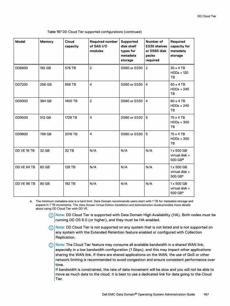
Table 197 DD Cloud Tier supported configurations (continued)
Model Memory Cloudcapacity
Required numberof SAS I/Omodules
Supporteddisk shelftypes formetadatastorage
Number ofES30 shelvesor DS60 diskpacksrequired
Requiredcapacity formetadatastorage
DD6800 192 GB 576 TB 2 DS60 or ES30 2 30 x 4 TBHDDs = 120TB
DD7200 256 GB 856 TB 4 DS60 or ES30 4 60 x 4 TBHDDs = 240TB
DD9300 384 GB 1400 TB 2 DS60 or ES30 4 60 x 4 TBHDDs = 240TB
DD9500 512 GB 1728 TB 4 DS60 or ES30 5 75 x 4 TBHDDs = 300TB
DD9800 768 GB 2016 TB 4 DS60 or ES30 5 75 x 4 TBHDDs = 300TB
DD VE 16 TB 32 GB 32 TB N/A N/A N/A 1 x 500 GBvirtual disk =500 GBa
DD VE 64 TB 60 GB 128 TB N/A N/A N/A 1 x 500 GBvirtual disk =500 GBa
DD VE 96 TB 80 GB 192 TB N/A N/A N/A 1 x 500 GBvirtual disk =500 GBa
a. The minimum metadata size is a hard limit. Data Domain recommends users start with 1 TB for metadata storage andexpand in 1 TB increments. The Data Domain Virtual Edition Installation and Administration Guide provides more detailsabout using DD Cloud Tier with DD VE.
Note: DD Cloud Tier is supported with Data Domain High Availability (HA). Both nodes must berunning DD OS 6.0 (or higher), and they must be HA-enabled.
Note: DD Cloud Tier is not supported on any system that is not listed and is not supported onany system with the Extended Retention feature enabled or configured with CollectionReplication.
Note: The Cloud Tier feature may consume all available bandwidth in a shared WAN link,especially in a low bandwidth configuration (1 Gbps), and this may impact other applicationssharing the WAN link. If there are shared applications on the WAN, the use of QoS or othernetwork limiting is recommended to avoid congestion and ensure consistent performance overtime.If bandwidth is constrained, the rate of data movement will be slow and you will not be able tomove as much data to the cloud. It is best to use a dedicated link for data going to the CloudTier.
DD Cloud Tier
Dell EMC Data Domain® Operating System Administration Guide 457
Note: Do not send traffic over onboard management network interface controllers (ethMxinterfaces).
DD Cloud Tier performanceThe Data Domain system uses internal optimizations to maximize DD Cloud Tier performance.
Cloud seeding
The current migration engine to cloud is filed based and an efficient de-duplication optimizedengine is used for identifying and migrating only unique segments to cloud. This file basedmigration engine's efficiency is high when migrating higher generation data to cloud-tier, whichalready has some data to de-duplicate against. However when cloud-tier is empty or nearly empty- there is no data to de-duplicate against. There is an over-head of compute cycles that areinvested in de-duplication. With Seeding based migration, the de-deduplication filtering ismaintained on active tier itself and only unique data is migrated in bulk to cloud tier. In cloudseeding, the engine migrates the content from local storage to cloud storage without processing itfor de-duplication. When cloud seeding is active, files that are marked for migration to cloudstorage are not cleaned (i.e. space is not freed-up) as part of active tier file system cleaning untilthe migration of all identified files by seeding is completes. Active tier storage must be sized toaccount for this in environments where large amounts of data are migrated to cloud storage. If theDD Cloud Tier storage is less than five percent full and has post-comp data usage of 30 TiB (ormore), as seen in show space command then Data Domain system automatically uses cloudseeding when migrating data to the cloud storage.
After five percent of the DD Cloud Tier capacity is consumed, cloud seeding automaticallydeactivates, and data is processed for deduplication before migration to cloud storage.
Here are additional points to consider when using Seeding migration:
l Migration is supported in Seeding mode only when:
n Active tier postcomp used size is 30 TiB or more as reported in filesys show space output.
n Active tier is less than 70% full, when migration starts as reported in filesys show spaceoutput.
Note: If Active Tier usage during the on-going migration cycle in Seeding mode goesbeyond 90%, migration is aborted and it restarts migration in regular Filecopy mode.
l Migration in Seeding mode is auto-suspended by cleaning on active tier, for the entire durationof cleaning on active tier. Once cleaning completes, Seeding auto-resumes and restartsmigration to cloud.
l Migration in Seeding mode auto-suspends if cloud UNAVAIL event is received on the cloud-unit(cloud-unit is reported as "disconnected") to which it is migrating and only resume, oncecloud-unit is available and reported active.
l Cleaning cannot be started on a cloud-unit that is the destination of an in-progress migrationoperation in Seeding mode.
Note: In two cloud-units system, to force start cleaning on a second cloud-unit, which isnot being seeded, suspend migration in Seeding mode using data-movement suspend CLIand then execute cloud clean start CLI on the second cloud-unit.
l Probabilistic File Verification in cloud, even if scheduled as per default policy gets skipped anddoes not happen for a cloud-unit, on which migration is in-progress in Seeding mode.
l If cleaning is already in progress on cloud tier or active tier and scheduled data-movementstarts in Seeding mode, data-movement auto-suspends for the duration of cleaning activity.
l Migration in Seeding mode skips migration of files, from MTrees, which are replicationdestinations - even though the files are eligible for migration. Files from these MTrees whichare replication destination MTrees (RO/RD), are migrated using filecopy engine, oncemigration in Seeding mode from all eligible MTrees completes.
DD Cloud Tier
458 Dell EMC Data Domain® Operating System Administration Guide
l If physical capacity reporting feature is enabled and is scheduled Seeding mode migrationsuspends capacity reporting feature, for the duration of Seeding based migration.
l Migration in Seeding mode is only supported on all cloud enabled Data Domain systems andconfigurations that have more than 80 Gb of RAM. Seeding based migration is disabled bydefault for DD VEs.
Large object size
DD Cloud Tier uses object sizes of 1 MB or 4 MB (depending on the cloud storage provider) toreduce the metadata overhead, and lower the number of objects to migrate to cloud storage.
Configuring Cloud TierTo configure Cloud Tier, add the license and enclosures, set a system passphrase, and create a filesystem with support for data movement to the cloud.
l For Cloud Tier, the cloud capacity license is required.
l To license Cloud Tier, refer to the applicable Data Domain Operating System Release Notes forthe most up-to-date information on product features, software updates, software compatibilityguides, and information about Data Domain products, licensing, and service.
l To set a system passphrase, use the Administration > Access > Administrator Access tab.If the system passphrase is not set, the Set Passphrase button appears in the Passphrasearea. If a system passphrase is configured, the Change Passphrase button appears, and youronly option is to change the passphrase.
l To configure storage, use the Hardware > Storage tab.
l To create a file system, use the File System Create Wizard.
Configuring storage for DD Cloud TierCloud Tier storage on the DD system is required for the cloud units—it holds the metadata for thefiles, while the data resides in the cloud.
Procedure
1. Select Hardware > Storage.
2. In the Overview tab, expand Cloud Tier.
3. Click Configure.
The Configure Cloud Tier dialog box is displayed.
4. Select the checkbox for the shelf to be added from the Addable Storage section.
CAUTION DD3300 systems require the use of 1 TB storage devices for DD Cloud Tiermetadata storage.
5. Click the Add to Tier button.
6. Click Save to add the storage.
7. Select Data Management > File System and enable the Cloud Tier feature.
8. Click Disable (at the bottom of the screen) to disable the file system.
9. Click OK.
10. After the file system is disabled, select Enable Cloud Tier.
To enable the cloud tier, you must meet the storage requirement for the licensed capacity.Configure the cloud tier of the file system. Click Next.A cloud file system requires a local store for a local copy of the cloud metadata.
DD Cloud Tier
Dell EMC Data Domain® Operating System Administration Guide 459
11. Select Enable file system.
The cloud tier is enabled with the designated storage.
12. Click OK.
You must create cloud units separately, after the file system is created.
Cleanable Space EstimationThe Cleanable Space Estimation tool assesses the amount of space that can be freed up on anactive tier if data-movement moves eligible files to cloud and GC cleans the file system.
This tool can work with or without a cloud/archive license present.
When there is no cloud/active license, provide the age-threshold which should be used to assesstotal cleanable space on the active tier. If there is both an age-threshold along with a policy set onMTrees, the preference is given to the user provided age-threshold.
There are three workflows:
l A system with cloud migration policies set: Files are identified as "eligible" based on the policyset on the respective MTrees and calculates the cleanable space.
l A system with cloud migration policies set but with a user provided age-threshold: Files areidentified based on the user given age-threshold, overriding the system policies.
l A system with no cloud: Mandatory requirement for user to provide an age-threshold whichwould be used to determine total cleanable space.
Some additional points to consider:
l Data-movement cannot run in parallel with data-movement eligibility-check and conversely.
l Cleaning on active tier cannot be started if eligibility-check is running and conversely.
l Cleaning on cloud tier cannot be started if eligibility-check is running and conversely.
l If UNAVAIL event is received, it should not have any impact on eligibility-check operation.
l If filesystem stops or crashes, eligibility-check stops and does not auto-resume once filesystem comes back up again.
Note: There is no provision of initiating eligibility-check from Data Domain System ManagerGUI.
Configuring cloud unitsThe cloud tier consists of a maximum of two cloud units, and each cloud unit is mapped to a cloudprovider, enabling multiple cloud providers per Data Domain system. The Data Domain systemmust be connected to the cloud and have an account with a supported cloud provider.
Configuring cloud units includes these steps:
l Configuring the network, including firewall and proxy settings
l Importing CA certificates
l Adding cloud units
Firewall and proxy settings
Network firewall ports
l Port 443 (HTTPS) and/or Port 80 (HTTP) must be open to the cloud provider networks forboth the endpoint IP and the provider authentication IP for bi-directional traffic.
DD Cloud Tier
460 Dell EMC Data Domain® Operating System Administration Guide
For example, for Amazon S3, both s3-ap-southeast-1.amazonaws.com and s3.amazonaws.commust have port 80 and/or port 443 unblocked and set to allow bi-directional IP traffic.
Note: Several public cloud providers use IP ranges for their endpoint and authenticationaddresses. In this situation, the IP ranges used by the provider need to be unblocked toaccommodate potential IP changes.
l Remote cloud provider destination IP and access authentication IP address ranges must beallowed through the firewall.
l For ECS private cloud, local ECS authentication and web storage (S3) access IP ranges andports 9020 (HTTP) and 9021 (HTTPS) must be allowed through local firewalls.
Note: ECS private cloud load balancer IP access and port rules must also be configured.
Proxy settings
If there are any existing proxy settings that cause data above a certain size to be rejected, thosesettings must be changed to allow object sizes up to 4.5MB.
If customer traffic is being routed through a proxy, the self-signed/CA-signed proxy certificatemust be imported. See "Importing CA certificates" for details.
OpenSSL cipher suites
l Ciphers - ECDHE-RSA-AES256-SHA384, AES256-GCM-SHA384
l TLS Version: 1.2
Note: Default communication with all cloud providers is initiated with strong cipher.
Supported protocols
l HTTP
l HTTPS
Note: Default communication with all public cloud providers occurs on secure HTTP (HTTPS),but you can overwrite the default setting to use HTTP.
Importing CA certificatesBefore you can add cloud units for Alibaba, Amazon Web Services S3 (AWS), Azure, Elastic CloudStorage (ECS), and Google Cloud Provider (GCP), you must import CA certificates.
Before you begin
For AWS and Azure public cloud providers, root CA certificates can be downloaded from https://www.digicert.com/digicert-root-certificates.htm.
l For an AWS cloud provider, download the Baltimore CyberTrust Root certificate.
l For an Azure cloud provider, download the Baltimore CyberTrust Root certificate.
l For ECS, the root certificate authority varies by customer.Implementing cloud storage on ECS requires a load balancer. If an HTTPS endpoint is used asan endpoint in the configuration, be sure to import the root CA certificate. Contact your loadbalancer provider for details.
l For an S3 Flexible provider, import the root CA certificate. Contact your S3 Flexible providerfor details.
If your downloaded certificate has a .crt extension, it is likely that it will need to be converted to aPEM-encoded certificate. If so, use OpenSSL to convert the file from .crt format to .pem (forexample, openssl x509 -inform der -in BaltimoreCyberTrustRoot.crt -outBaltimoreCyberTrustRoot.pem).
DD Cloud Tier
Dell EMC Data Domain® Operating System Administration Guide 461
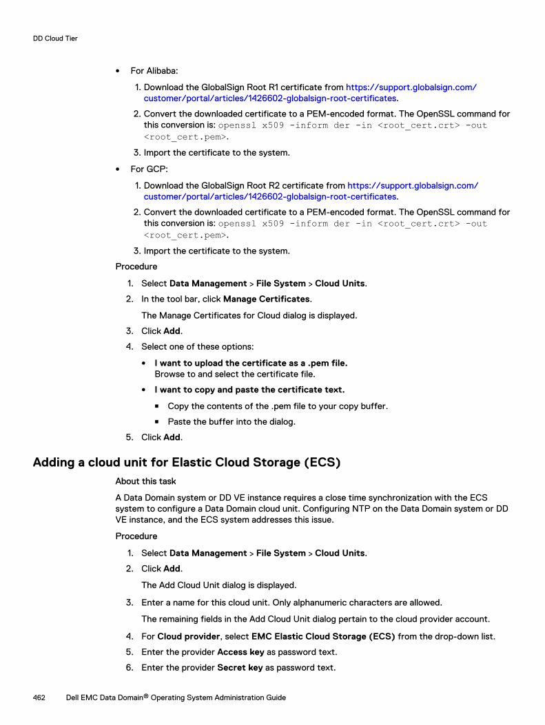
l For Alibaba:
1. Download the GlobalSign Root R1 certificate from https://support.globalsign.com/customer/portal/articles/1426602-globalsign-root-certificates.
2. Convert the downloaded certificate to a PEM-encoded format. The OpenSSL command forthis conversion is: openssl x509 -inform der -in <root_cert.crt> -out<root_cert.pem>.
3. Import the certificate to the system.
l For GCP:
1. Download the GlobalSign Root R2 certificate from https://support.globalsign.com/customer/portal/articles/1426602-globalsign-root-certificates.
2. Convert the downloaded certificate to a PEM-encoded format. The OpenSSL command forthis conversion is: openssl x509 -inform der -in <root_cert.crt> -out<root_cert.pem>.
3. Import the certificate to the system.
Procedure
1. Select Data Management > File System > Cloud Units.
2. In the tool bar, click Manage Certificates.
The Manage Certificates for Cloud dialog is displayed.
3. Click Add.
4. Select one of these options:
l I want to upload the certificate as a .pem file.Browse to and select the certificate file.
l I want to copy and paste the certificate text.
n Copy the contents of the .pem file to your copy buffer.
n Paste the buffer into the dialog.
5. Click Add.
Adding a cloud unit for Elastic Cloud Storage (ECS)About this task
A Data Domain system or DD VE instance requires a close time synchronization with the ECSsystem to configure a Data Domain cloud unit. Configuring NTP on the Data Domain system or DDVE instance, and the ECS system addresses this issue.
Procedure
1. Select Data Management > File System > Cloud Units.
2. Click Add.
The Add Cloud Unit dialog is displayed.
3. Enter a name for this cloud unit. Only alphanumeric characters are allowed.
The remaining fields in the Add Cloud Unit dialog pertain to the cloud provider account.
4. For Cloud provider, select EMC Elastic Cloud Storage (ECS) from the drop-down list.
5. Enter the provider Access key as password text.
6. Enter the provider Secret key as password text.
DD Cloud Tier
462 Dell EMC Data Domain® Operating System Administration Guide
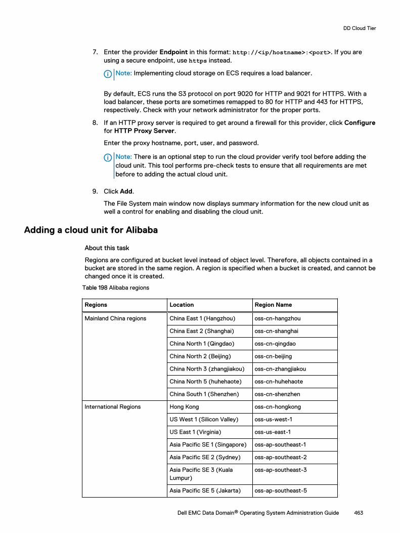
7. Enter the provider Endpoint in this format: http://<ip/hostname>:<port>. If you areusing a secure endpoint, use https instead.
Note: Implementing cloud storage on ECS requires a load balancer.
By default, ECS runs the S3 protocol on port 9020 for HTTP and 9021 for HTTPS. With aload balancer, these ports are sometimes remapped to 80 for HTTP and 443 for HTTPS,respectively. Check with your network administrator for the proper ports.
8. If an HTTP proxy server is required to get around a firewall for this provider, click Configurefor HTTP Proxy Server.
Enter the proxy hostname, port, user, and password.
Note: There is an optional step to run the cloud provider verify tool before adding thecloud unit. This tool performs pre-check tests to ensure that all requirements are metbefore to adding the actual cloud unit.
9. Click Add.
The File System main window now displays summary information for the new cloud unit aswell a control for enabling and disabling the cloud unit.
Adding a cloud unit for Alibaba
About this task
Regions are configured at bucket level instead of object level. Therefore, all objects contained in abucket are stored in the same region. A region is specified when a bucket is created, and cannot bechanged once it is created.
Table 198 Alibaba regions
Regions Location Region Name
Mainland China regions China East 1 (Hangzhou) oss-cn-hangzhou
China East 2 (Shanghai) oss-cn-shanghai
China North 1 (Qingdao) oss-cn-qingdao
China North 2 (Beijing) oss-cn-beijing
China North 3 (zhangjiakou) oss-cn-zhangjiakou
China North 5 (huhehaote) oss-cn-huhehaote
China South 1 (Shenzhen) oss-cn-shenzhen
International Regions Hong Kong oss-cn-hongkong
US West 1 (Silicon Valley) oss-us-west-1
US East 1 (Virginia) oss-us-east-1
Asia Pacific SE 1 (Singapore) oss-ap-southeast-1
Asia Pacific SE 2 (Sydney) oss-ap-southeast-2
Asia Pacific SE 3 (KualaLumpur)
oss-ap-southeast-3
Asia Pacific SE 5 (Jakarta) oss-ap-southeast-5
DD Cloud Tier
Dell EMC Data Domain® Operating System Administration Guide 463
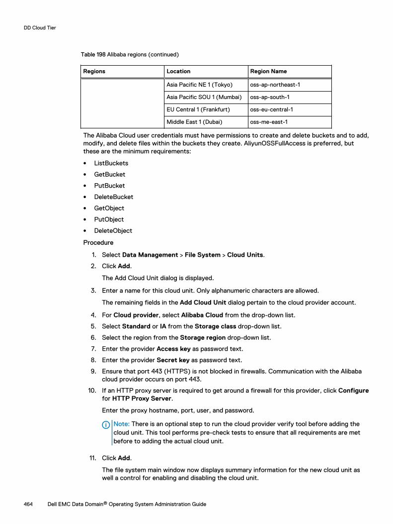
Table 198 Alibaba regions (continued)
Regions Location Region Name
Asia Pacific NE 1 (Tokyo) oss-ap-northeast-1
Asia Pacific SOU 1 (Mumbai) oss-ap-south-1
EU Central 1 (Frankfurt) oss-eu-central-1
Middle East 1 (Dubai) oss-me-east-1
The Alibaba Cloud user credentials must have permissions to create and delete buckets and to add,modify, and delete files within the buckets they create. AliyunOSSFullAccess is preferred, butthese are the minimum requirements:
l ListBuckets
l GetBucket
l PutBucket
l DeleteBucket
l GetObject
l PutObject
l DeleteObject
Procedure
1. Select Data Management > File System > Cloud Units.
2. Click Add.
The Add Cloud Unit dialog is displayed.
3. Enter a name for this cloud unit. Only alphanumeric characters are allowed.
The remaining fields in the Add Cloud Unit dialog pertain to the cloud provider account.
4. For Cloud provider, select Alibaba Cloud from the drop-down list.
5. Select Standard or IA from the Storage class drop-down list.
6. Select the region from the Storage region drop-down list.
7. Enter the provider Access key as password text.
8. Enter the provider Secret key as password text.
9. Ensure that port 443 (HTTPS) is not blocked in firewalls. Communication with the Alibabacloud provider occurs on port 443.
10. If an HTTP proxy server is required to get around a firewall for this provider, click Configurefor HTTP Proxy Server.
Enter the proxy hostname, port, user, and password.
Note: There is an optional step to run the cloud provider verify tool before adding thecloud unit. This tool performs pre-check tests to ensure that all requirements are metbefore to adding the actual cloud unit.
11. Click Add.
The file system main window now displays summary information for the new cloud unit aswell a control for enabling and disabling the cloud unit.
DD Cloud Tier
464 Dell EMC Data Domain® Operating System Administration Guide
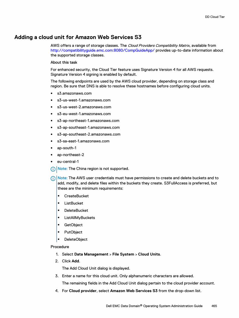
Adding a cloud unit for Amazon Web Services S3AWS offers a range of storage classes. The Cloud Providers Compatibility Matrix, available from http://compatibilityguide.emc.com:8080/CompGuideApp/ provides up-to-date information aboutthe supported storage classes.
About this task
For enhanced security, the Cloud Tier feature uses Signature Version 4 for all AWS requests.Signature Version 4 signing is enabled by default.
The following endpoints are used by the AWS cloud provider, depending on storage class andregion. Be sure that DNS is able to resolve these hostnames before configuring cloud units.
l s3.amazonaws.com
l s3-us-west-1.amazonaws.com
l s3-us-west-2.amazonaws.com
l s3-eu-west-1.amazonaws.com
l s3-ap-northeast-1.amazonaws.com
l s3-ap-southeast-1.amazonaws.com
l s3-ap-southeast-2.amazonaws.com
l s3-sa-east-1.amazonaws.com
l ap-south-1
l ap-northeast-2
l eu-central-1
Note: The China region is not supported.
Note: The AWS user credentials must have permissions to create and delete buckets and toadd, modify, and delete files within the buckets they create. S3FullAccess is preferred, butthese are the minimum requirements:
l CreateBucket
l ListBucket
l DeleteBucket
l ListAllMyBuckets
l GetObject
l PutObject
l DeleteObject
Procedure
1. Select Data Management > File System > Cloud Units.
2. Click Add.
The Add Cloud Unit dialog is displayed.
3. Enter a name for this cloud unit. Only alphanumeric characters are allowed.
The remaining fields in the Add Cloud Unit dialog pertain to the cloud provider account.
4. For Cloud provider, select Amazon Web Services S3 from the drop-down list.
DD Cloud Tier
Dell EMC Data Domain® Operating System Administration Guide 465
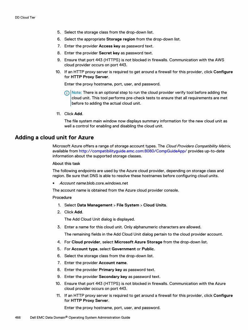
5. Select the storage class from the drop-down list.
6. Select the appropriate Storage region from the drop-down list.
7. Enter the provider Access key as password text.
8. Enter the provider Secret key as password text.
9. Ensure that port 443 (HTTPS) is not blocked in firewalls. Communication with the AWScloud provider occurs on port 443.
10. If an HTTP proxy server is required to get around a firewall for this provider, click Configurefor HTTP Proxy Server.
Enter the proxy hostname, port, user, and password.
Note: There is an optional step to run the cloud provider verify tool before adding thecloud unit. This tool performs pre-check tests to ensure that all requirements are metbefore to adding the actual cloud unit.
11. Click Add.
The file system main window now displays summary information for the new cloud unit aswell a control for enabling and disabling the cloud unit.
Adding a cloud unit for AzureMicrosoft Azure offers a range of storage account types. The Cloud Providers Compatibility Matrix,available from http://compatibilityguide.emc.com:8080/CompGuideApp/ provides up-to-dateinformation about the supported storage classes.
About this task
The following endpoints are used by the Azure cloud provider, depending on storage class andregion. Be sure that DNS is able to resolve these hostnames before configuring cloud units.
l Account name.blob.core.windows.net
The account name is obtained from the Azure cloud provider console.
Procedure
1. Select Data Management > File System > Cloud Units.
2. Click Add.
The Add Cloud Unit dialog is displayed.
3. Enter a name for this cloud unit. Only alphanumeric characters are allowed.
The remaining fields in the Add Cloud Unit dialog pertain to the cloud provider account.
4. For Cloud provider, select Microsoft Azure Storage from the drop-down list.
5. For Account type, select Government or Public.
6. Select the storage class from the drop-down list.
7. Enter the provider Account name.
8. Enter the provider Primary key as password text.
9. Enter the provider Secondary key as password text.
10. Ensure that port 443 (HTTPS) is not blocked in firewalls. Communication with the Azurecloud provider occurs on port 443.
11. If an HTTP proxy server is required to get around a firewall for this provider, click Configurefor HTTP Proxy Server.
Enter the proxy hostname, port, user, and password.
DD Cloud Tier
466 Dell EMC Data Domain® Operating System Administration Guide
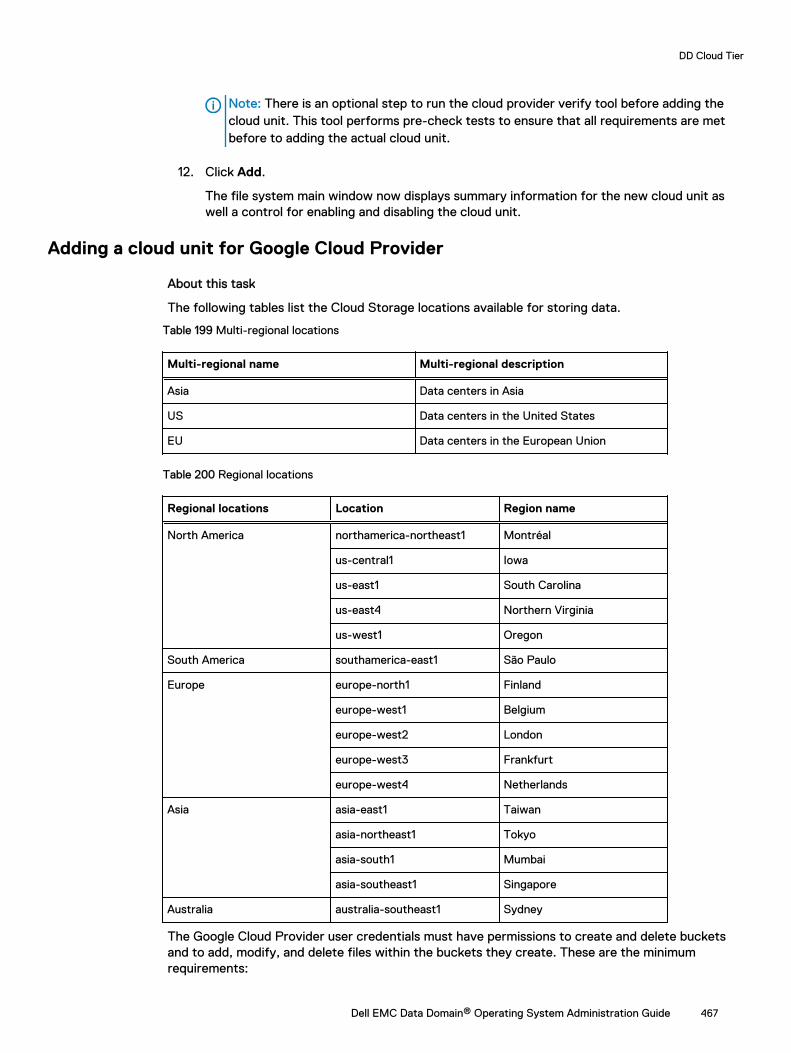
Note: There is an optional step to run the cloud provider verify tool before adding thecloud unit. This tool performs pre-check tests to ensure that all requirements are metbefore to adding the actual cloud unit.
12. Click Add.
The file system main window now displays summary information for the new cloud unit aswell a control for enabling and disabling the cloud unit.
Adding a cloud unit for Google Cloud Provider
About this task
The following tables list the Cloud Storage locations available for storing data.
Table 199 Multi-regional locations
Multi-regional name Multi-regional description
Asia Data centers in Asia
US Data centers in the United States
EU Data centers in the European Union
Table 200 Regional locations
Regional locations Location Region name
North America northamerica-northeast1 Montréal
us-central1 Iowa
us-east1 South Carolina
us-east4 Northern Virginia
us-west1 Oregon
South America southamerica-east1 São Paulo
Europe europe-north1 Finland
europe-west1 Belgium
europe-west2 London
europe-west3 Frankfurt
europe-west4 Netherlands
Asia asia-east1 Taiwan
asia-northeast1 Tokyo
asia-south1 Mumbai
asia-southeast1 Singapore
Australia australia-southeast1 Sydney
The Google Cloud Provider user credentials must have permissions to create and delete bucketsand to add, modify, and delete files within the buckets they create. These are the minimumrequirements:
DD Cloud Tier
Dell EMC Data Domain® Operating System Administration Guide 467
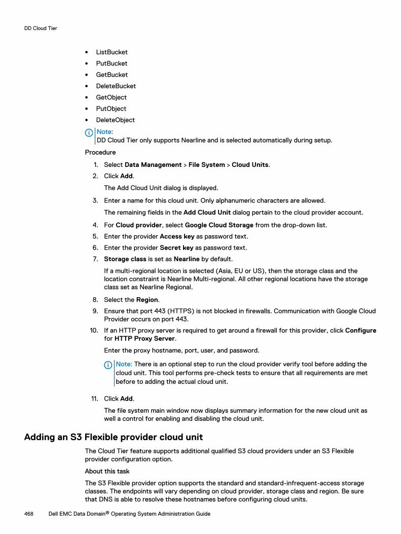
l ListBucket
l PutBucket
l GetBucket
l DeleteBucket
l GetObject
l PutObject
l DeleteObject
Note:DD Cloud Tier only supports Nearline and is selected automatically during setup.
Procedure
1. Select Data Management > File System > Cloud Units.
2. Click Add.
The Add Cloud Unit dialog is displayed.
3. Enter a name for this cloud unit. Only alphanumeric characters are allowed.
The remaining fields in the Add Cloud Unit dialog pertain to the cloud provider account.
4. For Cloud provider, select Google Cloud Storage from the drop-down list.
5. Enter the provider Access key as password text.
6. Enter the provider Secret key as password text.
7. Storage class is set as Nearline by default.
If a multi-regional location is selected (Asia, EU or US), then the storage class and thelocation constraint is Nearline Multi-regional. All other regional locations have the storageclass set as Nearline Regional.
8. Select the Region.
9. Ensure that port 443 (HTTPS) is not blocked in firewalls. Communication with Google CloudProvider occurs on port 443.
10. If an HTTP proxy server is required to get around a firewall for this provider, click Configurefor HTTP Proxy Server.
Enter the proxy hostname, port, user, and password.
Note: There is an optional step to run the cloud provider verify tool before adding thecloud unit. This tool performs pre-check tests to ensure that all requirements are metbefore to adding the actual cloud unit.
11. Click Add.
The file system main window now displays summary information for the new cloud unit aswell a control for enabling and disabling the cloud unit.
Adding an S3 Flexible provider cloud unitThe Cloud Tier feature supports additional qualified S3 cloud providers under an S3 Flexibleprovider configuration option.
About this task
The S3 Flexible provider option supports the standard and standard-infrequent-access storageclasses. The endpoints will vary depending on cloud provider, storage class and region. Be surethat DNS is able to resolve these hostnames before configuring cloud units.
DD Cloud Tier
468 Dell EMC Data Domain® Operating System Administration Guide
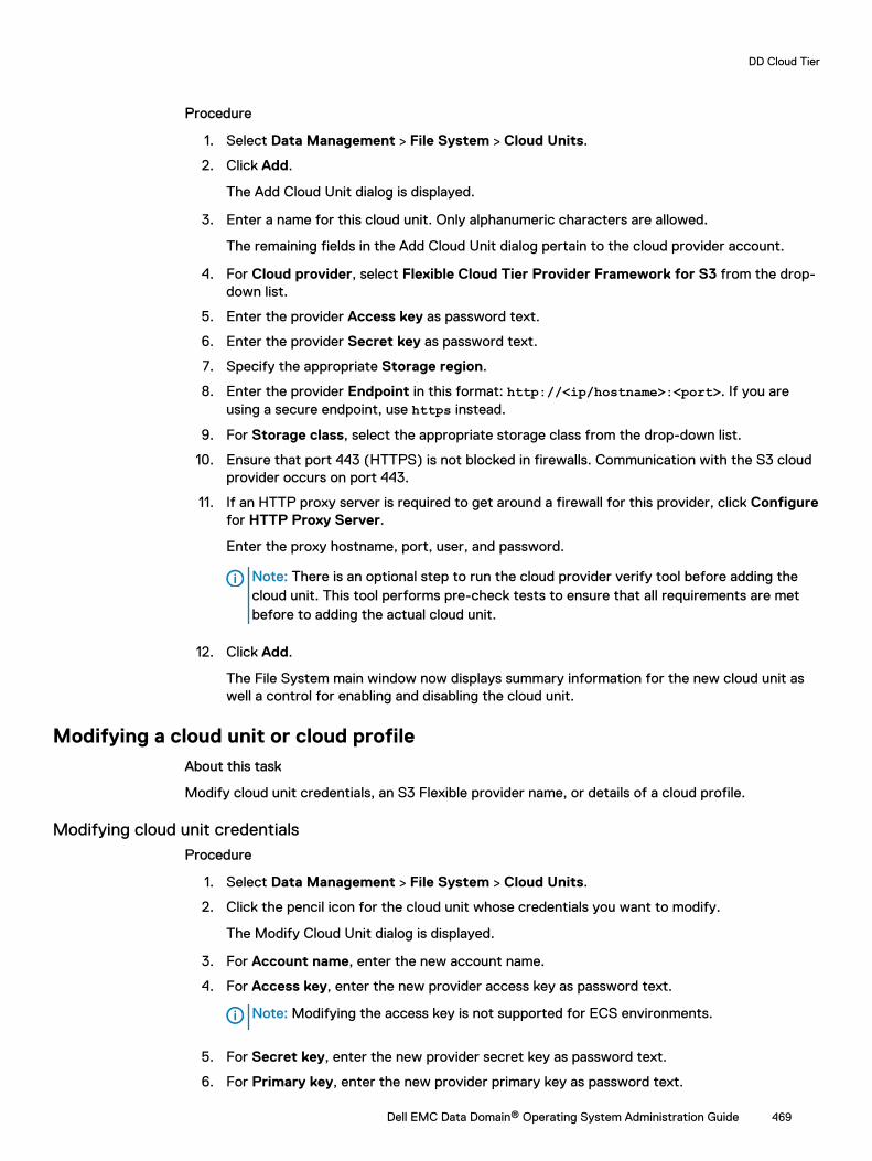
Procedure
1. Select Data Management > File System > Cloud Units.
2. Click Add.
The Add Cloud Unit dialog is displayed.
3. Enter a name for this cloud unit. Only alphanumeric characters are allowed.
The remaining fields in the Add Cloud Unit dialog pertain to the cloud provider account.
4. For Cloud provider, select Flexible Cloud Tier Provider Framework for S3 from the drop-down list.
5. Enter the provider Access key as password text.
6. Enter the provider Secret key as password text.
7. Specify the appropriate Storage region.
8. Enter the provider Endpoint in this format: http://<ip/hostname>:<port>. If you areusing a secure endpoint, use https instead.
9. For Storage class, select the appropriate storage class from the drop-down list.
10. Ensure that port 443 (HTTPS) is not blocked in firewalls. Communication with the S3 cloudprovider occurs on port 443.
11. If an HTTP proxy server is required to get around a firewall for this provider, click Configurefor HTTP Proxy Server.
Enter the proxy hostname, port, user, and password.
Note: There is an optional step to run the cloud provider verify tool before adding thecloud unit. This tool performs pre-check tests to ensure that all requirements are metbefore to adding the actual cloud unit.
12. Click Add.
The File System main window now displays summary information for the new cloud unit aswell a control for enabling and disabling the cloud unit.
Modifying a cloud unit or cloud profileAbout this task
Modify cloud unit credentials, an S3 Flexible provider name, or details of a cloud profile.
Modifying cloud unit credentialsProcedure
1. Select Data Management > File System > Cloud Units.
2. Click the pencil icon for the cloud unit whose credentials you want to modify.
The Modify Cloud Unit dialog is displayed.
3. For Account name, enter the new account name.
4. For Access key, enter the new provider access key as password text.
Note: Modifying the access key is not supported for ECS environments.
5. For Secret key, enter the new provider secret key as password text.
6. For Primary key, enter the new provider primary key as password text.
DD Cloud Tier
Dell EMC Data Domain® Operating System Administration Guide 469
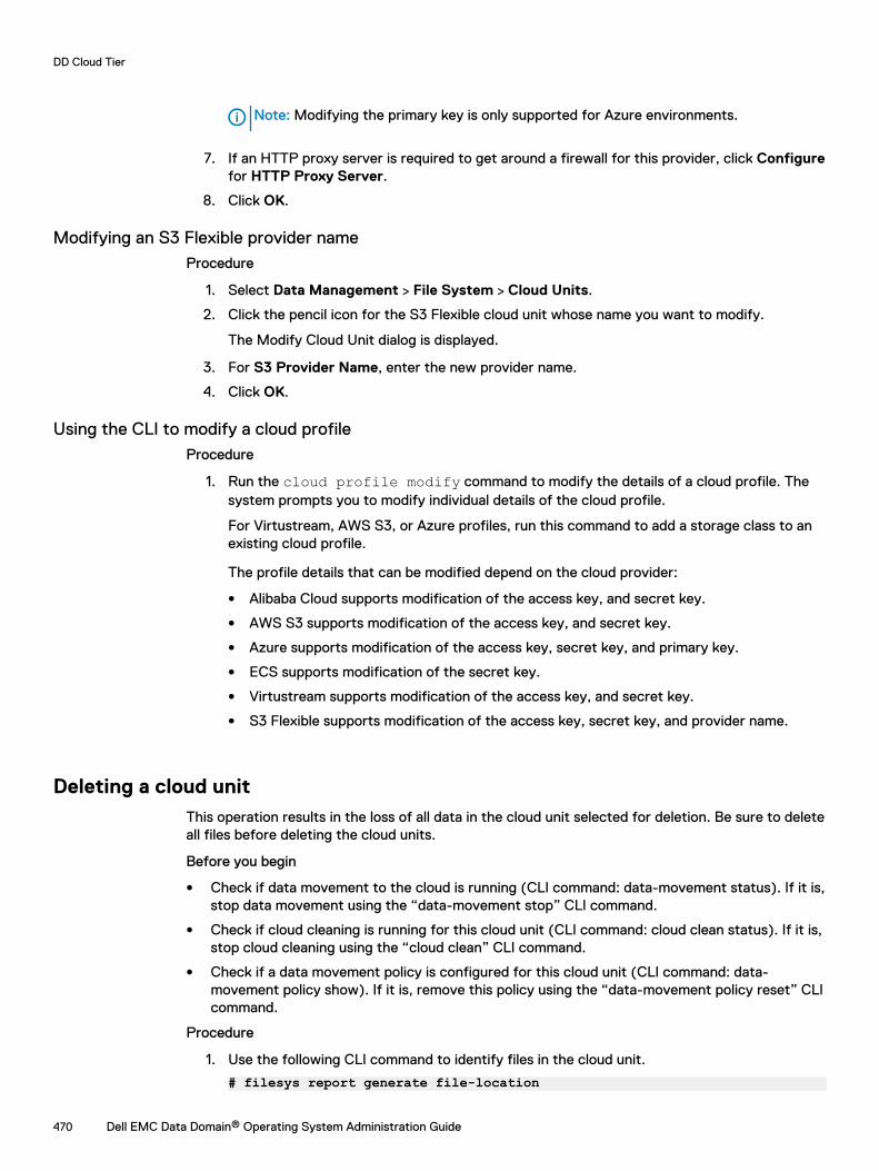
Note: Modifying the primary key is only supported for Azure environments.
7. If an HTTP proxy server is required to get around a firewall for this provider, click Configurefor HTTP Proxy Server.
8. Click OK.
Modifying an S3 Flexible provider nameProcedure
1. Select Data Management > File System > Cloud Units.
2. Click the pencil icon for the S3 Flexible cloud unit whose name you want to modify.
The Modify Cloud Unit dialog is displayed.
3. For S3 Provider Name, enter the new provider name.
4. Click OK.
Using the CLI to modify a cloud profileProcedure
1. Run the cloud profile modify command to modify the details of a cloud profile. Thesystem prompts you to modify individual details of the cloud profile.
For Virtustream, AWS S3, or Azure profiles, run this command to add a storage class to anexisting cloud profile.
The profile details that can be modified depend on the cloud provider:
l Alibaba Cloud supports modification of the access key, and secret key.
l AWS S3 supports modification of the access key, and secret key.
l Azure supports modification of the access key, secret key, and primary key.
l ECS supports modification of the secret key.
l Virtustream supports modification of the access key, and secret key.
l S3 Flexible supports modification of the access key, secret key, and provider name.
Deleting a cloud unitThis operation results in the loss of all data in the cloud unit selected for deletion. Be sure to deleteall files before deleting the cloud units.
Before you begin
l Check if data movement to the cloud is running (CLI command: data-movement status). If it is,stop data movement using the “data-movement stop” CLI command.
l Check if cloud cleaning is running for this cloud unit (CLI command: cloud clean status). If it is,stop cloud cleaning using the “cloud clean” CLI command.
l Check if a data movement policy is configured for this cloud unit (CLI command: data-movement policy show). If it is, remove this policy using the “data-movement policy reset” CLIcommand.
Procedure
1. Use the following CLI command to identify files in the cloud unit.
# filesys report generate file-location
DD Cloud Tier
470 Dell EMC Data Domain® Operating System Administration Guide
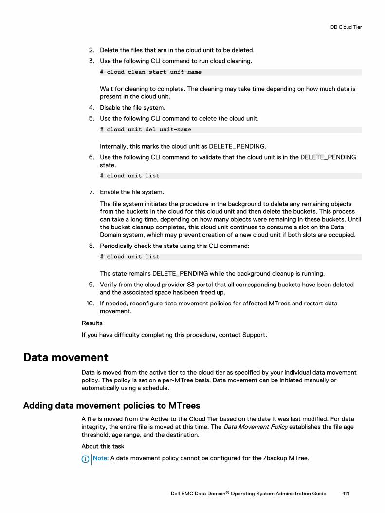
2. Delete the files that are in the cloud unit to be deleted.
3. Use the following CLI command to run cloud cleaning.
# cloud clean start unit-name
Wait for cleaning to complete. The cleaning may take time depending on how much data ispresent in the cloud unit.
4. Disable the file system.
5. Use the following CLI command to delete the cloud unit.
# cloud unit del unit-name
Internally, this marks the cloud unit as DELETE_PENDING.
6. Use the following CLI command to validate that the cloud unit is in the DELETE_PENDINGstate.
# cloud unit list
7. Enable the file system.
The file system initiates the procedure in the background to delete any remaining objectsfrom the buckets in the cloud for this cloud unit and then delete the buckets. This processcan take a long time, depending on how many objects were remaining in these buckets. Untilthe bucket cleanup completes, this cloud unit continues to consume a slot on the DataDomain system, which may prevent creation of a new cloud unit if both slots are occupied.
8. Periodically check the state using this CLI command:
# cloud unit list
The state remains DELETE_PENDING while the background cleanup is running.
9. Verify from the cloud provider S3 portal that all corresponding buckets have been deletedand the associated space has been freed up.
10. If needed, reconfigure data movement policies for affected MTrees and restart datamovement.
Results
If you have difficulty completing this procedure, contact Support.
Data movementData is moved from the active tier to the cloud tier as specified by your individual data movementpolicy. The policy is set on a per-MTree basis. Data movement can be initiated manually orautomatically using a schedule.
Adding data movement policies to MTreesA file is moved from the Active to the Cloud Tier based on the date it was last modified. For dataintegrity, the entire file is moved at this time. The Data Movement Policy establishes the file agethreshold, age range, and the destination.
About this task
Note: A data movement policy cannot be configured for the /backup MTree.
DD Cloud Tier
Dell EMC Data Domain® Operating System Administration Guide 471
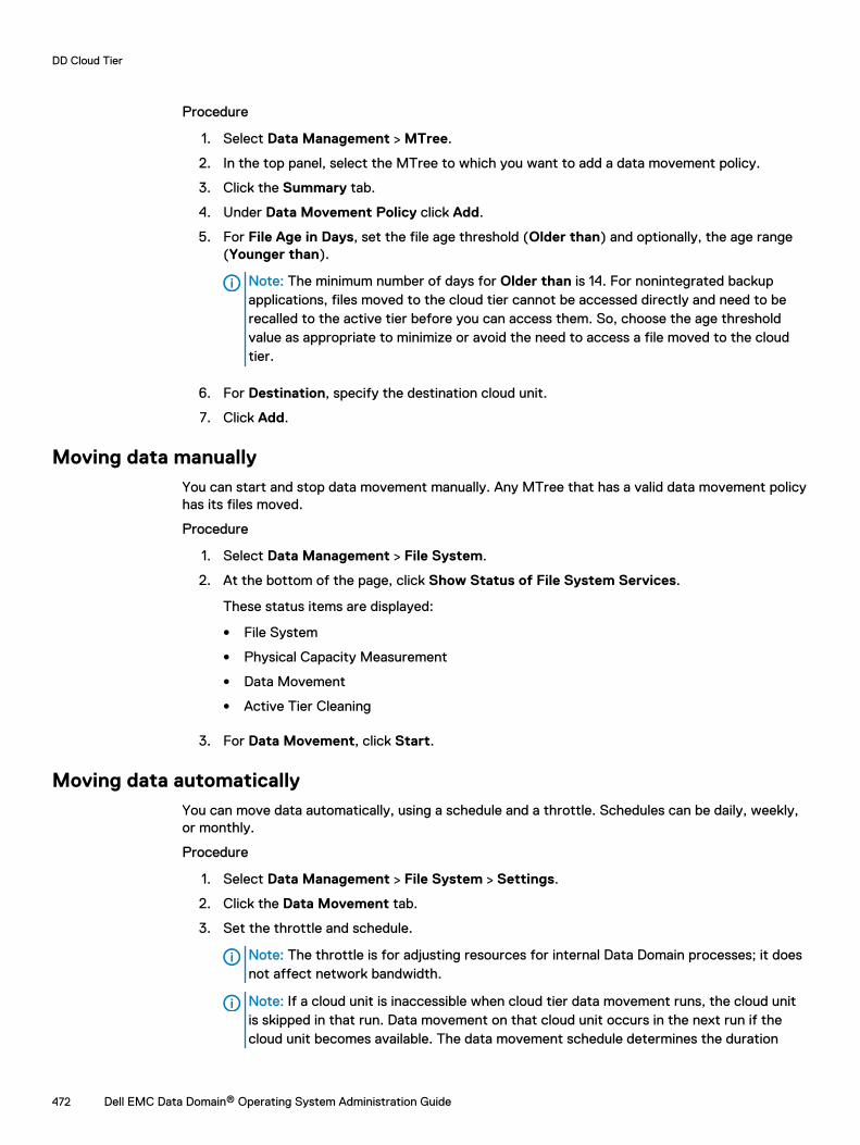
Procedure
1. Select Data Management > MTree.
2. In the top panel, select the MTree to which you want to add a data movement policy.
3. Click the Summary tab.
4. Under Data Movement Policy click Add.
5. For File Age in Days, set the file age threshold (Older than) and optionally, the age range(Younger than).
Note: The minimum number of days for Older than is 14. For nonintegrated backupapplications, files moved to the cloud tier cannot be accessed directly and need to berecalled to the active tier before you can access them. So, choose the age thresholdvalue as appropriate to minimize or avoid the need to access a file moved to the cloudtier.
6. For Destination, specify the destination cloud unit.
7. Click Add.
Moving data manuallyYou can start and stop data movement manually. Any MTree that has a valid data movement policyhas its files moved.
Procedure
1. Select Data Management > File System.
2. At the bottom of the page, click Show Status of File System Services.
These status items are displayed:
l File System
l Physical Capacity Measurement
l Data Movement
l Active Tier Cleaning
3. For Data Movement, click Start.
Moving data automaticallyYou can move data automatically, using a schedule and a throttle. Schedules can be daily, weekly,or monthly.
Procedure
1. Select Data Management > File System > Settings.
2. Click the Data Movement tab.
3. Set the throttle and schedule.
Note: The throttle is for adjusting resources for internal Data Domain processes; it doesnot affect network bandwidth.
Note: If a cloud unit is inaccessible when cloud tier data movement runs, the cloud unitis skipped in that run. Data movement on that cloud unit occurs in the next run if thecloud unit becomes available. The data movement schedule determines the duration
DD Cloud Tier
472 Dell EMC Data Domain® Operating System Administration Guide
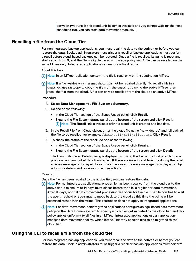
between two runs. If the cloud unit becomes available and you cannot wait for the nextscheduled run, you can start data movement manually.
Recalling a file from the Cloud TierFor nonintegrated backup applications, you must recall the data to the active tier before you canrestore the data. Backup administrators must trigger a recall or backup applications must performa recall before cloud-based backups can be restored. Once a file is recalled, its aging is reset andstarts again from 0, and the file is eligible based on the age policy set. A file can be recalled on thesame MTree only. Integrated applications can restore a file directly.
About this task
Note: In an MTree replication context, the file is read-only on the destination MTree.
Note: If a file resides only in a snapshot, it cannot be recalled directly. To recall a file in asnapshot, use fastcopy to copy the file from the snapshot back to the active MTree, thenrecall the file from the cloud. A file can only be recalled from the cloud to an active MTree.
Procedure
1. Select Data Management > File System > Summary.
2. Do one of the following:
l In the Cloud Tier section of the Space Usage panel, click Recall.
l Expand the File System status panel at the bottom of the screen and click Recall.Note: The Recall link is available only if a cloud unit is created and has data.
3. In the Recall File from Cloud dialog, enter the exact file name (no wildcards) and full path ofthe file to be recalled, for example: /data/col1/mt11/file1.txt. Click Recall.
4. To check the status of the recall, do one of the following:
l In the Cloud Tier section of the Space Usage panel, click Details.
l Expand the File System status panel at the bottom of the screen and click Details.
The Cloud File Recall Details dialog is displayed, showing the file path, cloud provider, recallprogress, and amount of data transferred. If there are unrecoverable errors during the recall,an error message is displayed. Hover the cursor over the error message to display a tool tipwith more details and possible corrective actions.
Results
Once the file has been recalled to the active tier, you can restore the data.Note: For nonintegrated applications, once a file has been recalled from the cloud tier to theactive tier, a minimum of 14 days must elapse before the file is eligible for data movement.After 14 days, normal data movement processing will occur for the file. The file now has to waitthe age-threshold or age-range to move back to the cloud as this time the ptime will beexamined rather than the mtime. This restriction does not apply to integrated applications.
Note: For data-movement, nonintegrated applications configure an age-based data movementpolicy on the Data Domain system to specify which files get migrated to the cloud tier, and thispolicy applies uniformly to all files in an MTree. Integrated applications use an application-managed data movement policy, which lets you identify specific files to be migrated to thecloud tier.
Using the CLI to recall a file from the cloud tierFor nonintegrated backup applications, you must recall the data to the active tier before you canrestore the data. Backup administrators must trigger a recall or backup applications must perform
DD Cloud Tier
Dell EMC Data Domain® Operating System Administration Guide 473
a recall before cloud-based backups can be restored. Once a file is recalled, its aging is reset andwill start again from 0, and the file will be eligible based on the age policy set. A file can be recalledon the source MTree only. Integrated applications can recall a file directly.
About this task
Note: If a file resides only in a snapshot, it cannot be recalled directly. To recall a file in asnapshot, use fastcopy to copy the file from the snapshot back to the active MTree, thenrecall the file from the cloud. A file can only be recalled from the cloud to an active MTree.
Procedure
1. Check the location of the file using:filesys report generate file-location [path {<path-name> | all}][output-file <filename>]The pathname can be a file or directory; if it is a directory, all files in the directory are listed.Filename Location-------- --------/data/col1/mt11/file1.txt Cloud Unit 1
2. Recall the file using:data-movement recall path <path-name>This command is asynchronous, and it starts the recall.data-movement recall path /data/col1/mt11/file1.txtRecall started for "/data/col1/mt11/file1.txt".
3. Monitor the status of the recall usingdata-movement status [path {pathname | all | [queued] [running][completed] [failed]} | to-tier cloud | all]data-movement status path /data/col1/mt11/file1.txtData-movement recall:---------------------Data-movement for “/data/col1/mt11/file1.txt”: phase 2 of 3 (Verifying)80% complete; time: phase XX:XX:XX total XX:XX:XXCopied (post-comp): XX XX, (pre-comp) XX XX
If the status shows that the recall isn't running for a given path, the recall may havefinished, or it may have failed.
4. Verify the location of the file usingfilesys report generate file-location [path {<path-name> | all}][output-file <filename>]Filename Location-------- --------/data/col1/mt11/file1.txt Active
Results
Once the file has been recalled to the active tier, you can restore the data.Note: For nonintegrated applications, once a file has been recalled from the cloud tier to theactive tier, a minimum of 14 days must elapse before the file is eligible for data movement.After 14 days, normal data movement processing will occur for the file. This restriction doesnot apply to integrated applications.
Note: For data-movement, nonintegrated applications configure an age-based data movementpolicy on the Data Domain system to specify which files get migrated to the cloud tier, and thispolicy applies uniformly to all files in an MTree. Integrated applications use an application-
DD Cloud Tier
474 Dell EMC Data Domain® Operating System Administration Guide
managed data movement policy, which lets you identify specific files to be migrated to thecloud tier.
Direct restore from the cloud tierDirect restore lets nonintegrated applications read files directly from the cloud tier without goingthrough the active tier.
Key considerations in choosing to use direct restore include:
l Direct restore does not require an integrated application and is transparent for nonintegratedapplications.
l Reading from the cloud tier does not require copying first into the active tier.
l Histograms and statistics are available for tracking direct reads from the cloud tier.
l Direct restore is supported only for ECS cloud providers.
l Applications do experience cloud tier latency.
l Reading directly from the cloud tier is not bandwidth optimized.
l Direct restore supports a small number of jobs.
Direct restore is useful with nonintegrated applications that do not need to know about the cloudtier and won't need to restore cloud files frequently.
Using the Command Line Interface (CLI) to configure DDCloud Tier
You can use the Data Domain Command Line Interface to configure DD Cloud Tier.
Procedure
1. Configure storage for both active and cloud tier. As a prerequisite, the appropriate capacitylicenses for both the active and cloud tiers must be installed.
a. Ensure licenses for the features CLOUDTIER-CAPACITY and CAPACITY-ACTIVE areinstalled. To check the ELMS license:
# elicense show
If the license is not installed, use the elicense update command to install the license.Enter the command and paste the contents of the license file after this prompt. Afterpasting, ensure there is a carriage return, then press Control-D to save. You areprompted to replace licenses, and after answering yes, the licenses are applied anddisplayed.
# elicense updateEnter the content of license file and then press Control-D, or press Control-C to cancel.
b. Display available storage:
# storage show all# disk show state
c. Add storage to the active tier:
# storage add enclosures <enclosure no> tier active
d. Add storage to the cloud tier:
# storage add enclosures <enclosure no> tier cloud
DD Cloud Tier
Dell EMC Data Domain® Operating System Administration Guide 475
2. Install certificates.
Before you can create a cloud profile, you must install the associated certificates. See Importing the certificates on page 553 for more information.
For AWS, Virtustream, and Azure public cloud providers, root CA certificates can bedownloaded from https://www.digicert.com/digicert-root-certificates.htm.
l For an AWS or Azure cloud provider, download the Baltimore CyberTrust Rootcertificate.
l For Alibaba, Alibaba download the GlobalSign Root R1 certificate from https://support.globalsign.com/customer/portal/articles/1426602-globalsign-rootcertificates.
l For a Virtustream cloud provider, download the DigiCert High Assurance EV Root CAcertificate.
l For ECS, the root certificate authority will vary by customer. Contact your load balancerprovider for details.
Downloaded certificate files have a .crt extension. Use openssl on any Linux or Unix systemwhere it is installed to convert the file from .crt format to .pem.
$openssl x509 -inform der -in DigiCertHighAssuranceEVRootCA.crt -out DigiCertHighAssuranceEVRootCA.pem$openssl x509 -inform der -in BaltimoreCyberTrustRoot.crt -out BaltimoreCyberTrustRoot.pem# adminaccess certificate import ca application cloudEnter the certificate and then press Control-D, or press Control-C to cancel.
3. To configure the Data Domain system for data-movement to the cloud, you must firstenable the “cloud” feature and set the system passphrase if it has not already been set.
# cloud enableCloud feature requires that passphrase be set on the system.Enter new passphrase: Re-enter new passphrase: Passphrases matched.The passphrase is set.Encryption is recommended on the cloud tier. Do you want to enable encryption? (yes|no) [yes]: Encryption feature is enabled on the cloud tier.Cloud feature is enabled.
4. Configure the cloud profile using the cloud provider credentials. The prompts and variablesvary by provider.
# cloud profile add <profilename>
Note: For security reasons, this command does not display the access/secret keys youenter.
Select the provider:
Enter provider name (alibabacloud|aws|azure|ecs|google|s3_flexible|virtustream)l Alibaba Cloud requires access key, secret key, storage class and region.
l AWS S3 requires access key, secret key, storage class, and region.
l Azure requires account name, whether or not the account is an Azure Governmentaccount, primary key, secondary key, and storage class.
l ECS requires entry of access key, secret key and endpoint.
l Google Cloud Platform requires access key, secret key, and region. (Storage class isNearline.)
DD Cloud Tier
476 Dell EMC Data Domain® Operating System Administration Guide
l S3 Flexible providers require the provider name, access key, secret key, region, endpoint,and storage class.
l Virtustream requires access key, secret key, storage class, and region.
At the end of each profile addition you are asked if you want to set up a proxy. If you do,these values are required: proxy hostname, proxy port, proxy username, and proxypassword.
5. Verify the cloud profile configuration:
# cloud profile show
6. Create the active tier file system if it is not already created:
# filesys create
7. Enable the file system:
# filesys enable
8. Configure the cloud unit:
# cloud unit add unitname profile profilename
Use the cloud unit list command to list the cloud units.
9. Optionally, configure encryption for the cloud unit.
a. Verify that the ENCRYPTION license is installed:
# elicense show
b. Enable encryption for the cloud unit:
# filesys encryption enable cloud-unit unitname
c. Check encryption status:
# filesys encryption status
10. Create one or more MTrees:
# mtree create /data/col1/mt11
11. Verify the DD Cloud Tier configuration:
# cloud provider verifyThis operation will perform test data movement after creating a temporary profile and bucket.Do you want to continue? (yes|no) [yes]:Enter provider name (aws|azure|virtustream|ecs|s3_generic): awsEnter the access key:Enter the secret key:Enter the region (us-east-1|us-west-1|us-west-2|eu-west-1|apnortheast-1|ap-southeast-1|ap-southeast-2|sa-east-1|ap-south-1|ap-northeast-2|eu-central-1):
Verifying cloud provider …This process may take a few minutes.Cloud Enablement Check: Checking Cloud feature enabled: PASSED Checking Cloud volume: PASSED
Connectivity Check: Checking firewall access: PASSED Validating certificate PASSED
DD Cloud Tier
Dell EMC Data Domain® Operating System Administration Guide 477
Account Validation: Creating temporary profile: PASSED Creating temporary bucket: PASSED
S3 API Validation: Validating Put Bucket: PASSED Validating List Bucket: PASSED Validating Put Object: PASSED Validating Get Object: PASSED Validating List Object: PASSED Validating Delete Object: PASSED Validating Bulk Delete: PASSED
Cleaning Up: Deleting temporary bucket: PASSED Deleting temporary profile: PASSED
Provider verification passed.
12. Configure the file migration policy for this MTree. You can specify multiple MTrees in thiscommand. The policy can be based on the age threshold or the range.
a. To configure the age-threshold (migrating files older than the specified age to cloud):
# data-movement policy set age-threshold age_in_days to-tier cloud cloud-unit unitname mtrees mtreename
b. To configure the age-range (migrating only those files that are in the specified age-range):
# data-movement policy set age-range min-age age_in_days max-age age_in_days to-tier cloud cloud-unit unitname mtrees mtreename
13. Export the file system, and from the client, mount the file system and ingest data into theactive tier. Change the modification date on the ingested files such that they now qualify fordata migration. (Set the date to older than the age-threshold value specified whenconfiguring the data-movement policy.)
14. Initiate file migration of the aged files. Again, you can specify multiple MTrees with thiscommand.
# data-movement start mtrees mtreename
To check the status of data-movement:
# data-movement status
You can also watch the progress of data-movement:
# data-movement watch
15. Verify that file migration worked and the files are now in the cloud tier:
# filesys report generate file-location path all
16. Once you have migrated a file to the cloud tier, you cannot directly read from the file(attempting to do so results in an error). The file can only be recalled back to the active tier.To recall a file to the active tier:
# data-movement recall path pathname
DD Cloud Tier
478 Dell EMC Data Domain® Operating System Administration Guide
Configuring encryption for DD cloud unitsEncryption can be enabled at three levels: Data Domain system, Active Tier, and cloud unit.Encryption of the Active Tier is only applicable if encryption is enabled for the Data Domainsystem. Cloud units have separate controls for enabling encryption.
Procedure
1. Select Data Management > File System > DD Encryption.
Note: If no encryption license is present on the system, the Add Licenses page isdisplayed.
2. In the DD Encryption panel, do one of the following:
l To enable encryption for Cloud Unit x, click Enable.
l To disable encryption for Cloud Unit x, click Disable.
Note: You are prompted to enter security officer credentials to enable encryption.
3. Enter the security officer Username and Password. Optionally, check Restart file systemnow.
4. Click Enable or Disable, as appropriate.
5. In the File System Lock panel, lock or unlock the file system.
6. In the Key Management panel, click Configure.
7. In the Change Key Manager dialog, configure security officer credentials and the keymanager.
Note: Cloud encryption is allowed only through the Data Domain Embedded KeyManager. External key managers are not supported.
8. Click OK.
9. Use the DD Encryption Keys panel to configure encryption keys.
Information needed in the event of system lossOnce Cloud Tier is configured on the Data Domain system, record the following information aboutthe system and store it in a safe location apart from the Data Domain system. This information willbe needed to recover the Cloud Tier data in case the Data Domain system is lost.
Note: This process is designed for emergency situations only and will involve significant timeand effort from the Data Domain engineering staff.
l Serial number of the original Data Domain system
l System passphrase of the original Data Domain system
l DD OS version number of the original Data Domain system
l Cloud Tier profile and configuration information
Using DD Replicator with Cloud TierCollection replication is not supported on Cloud Tier enabled Data Domain systems.
DD Cloud Tier
Dell EMC Data Domain® Operating System Administration Guide 479
Directory replication only works on the /backup MTree, and this MTree cannot be assigned to theCloud Tier. So, directory replication is not affected by Cloud Tier.
Managed file replication and MTree replication are supported on Cloud Tier enabled Data Domainsystems. One or both systems can have Cloud Tier enabled. If the source system is Cloud Tierenabled, data may need to be read from the cloud if the file was already migrated to the CloudTier. A replicated file is always placed first in the Active Tier on the destination system even whenCloud Tier is enabled. A file can be recalled from the Cloud Tier back to the Active Tier on thesource MTree only. Recall of a file on the destination MTree is not allowed.
Note: If the source system is running DD OS 5.6 or 5.7 and replicating into a Cloud Tierenabled system using MTree replication, the source system must be upgraded to a release thatcan replicate to a Cloud Tier enabled system. Please see the DD OS Release Notes systemrequirements.
Note: Files in the Cloud Tier cannot be used as base files for virtual synthetic operations. Theincremental forever or synthetic full backups need to ensure that the files remain in the ActiveTier if they will be used in virtual synthesis of new backups.
Using DD Virtual Tape Library (VTL) with Cloud TierOn systems configured with Cloud Tier and DD VTL, the cloud storage is supported for use as theVTL vault. To use DD VTL tape out to cloud, license and configure the cloud storage first, and thenselect it as the vault location for the VTL.
DD VTL tape out to cloud on page 351 provides additional information about using VTL with CloudTier.
Displaying capacity consumption charts for DD Cloud TierThree charts are available for displaying Cloud Tier consumption statistics—Space Usage,Consumption, and Daily Written.
Procedure
1. Select Data Management > File System > Charts.
2. For Chart, select one of the following:
l Space Usage
l Consumption
l Daily Written
3. For Scope, select Cloud Tier.
l The Space Usage Tab displays space usage over time, in MiB. You can select a duration(one week, one month, three months, one year, or All). The data is presented (color-coded) as pre-compression used (blue), post-compression used (red), and thecompression factor (green).
l The Consumption Tab displays the amount of post-compression storage used and thecompression ratio over time, which enables you to analyze consumption trends. You canselect a duration (one week, one month, three months, one year, or All). The data ispresented (color-coded) as capacity (blue), post-compression used (red), compressionfactor (green), cleaning (orange) and data movement (violet).
l The Daily Written Tab displays the amount of data written per day. You can select aduration (one week, one month, three months, one year, or All). The data is presented
DD Cloud Tier
480 Dell EMC Data Domain® Operating System Administration Guide
(color-coded) as pre-compression written (blue), post-compression used (red), and thetotal compression factor (green).
DD Cloud Tier logsIf DD Cloud Tier suffers a failure of any kind, in configuration or operation, the systemautomatically creates a folder with a timestamp that is associated with the time of the failure.
Mount the /ddvar/log/debug directory to access the logs.
Note: The output of the log list view command does not list all the detailed log files thatare created for the DD Cloud Tier failure.
Using the Command Line Interface (CLI) to remove DD CloudTier
You can use the Data Domain Command Line Interface to remove the DD Cloud Tier configuration.
Before you begin
Delete all files in the cloud units before removing the DD Cloud Tier configuration from the system.Run the filesys report generate file-location path all output-filefile_loc command to identify the files in the cloud units, and delete them from the NFS mountpoints of the MTrees.
Note: The command above creates the report file_loc in the /ddr/var/ directory.
Procedure
1. Disable the file system.
# filesys disable
This action will disable the file system.Applications may experience interruptionswhile the file system is disabled. Are you sure? (yes|no) [no]: yes
ok, proceeding.
Please wait..............The filesystem is now disabled.
2. List the cloud units on the system.
# cloud unit listName Profile Status------------ ------------ ------cloud_unit-1 cloudProfile Activecloud_unit-2 cloudProfile2 Active------------ ------------ ------
3. Delete the cloud units individually.
# cloud unit del cloud_unit-1
This command irrevocably destroys all data in the cloud unit "cloud_unit-1". Are you sure? (yes|no) [no]: yes
ok, proceeding.
DD Cloud Tier
Dell EMC Data Domain® Operating System Administration Guide 481
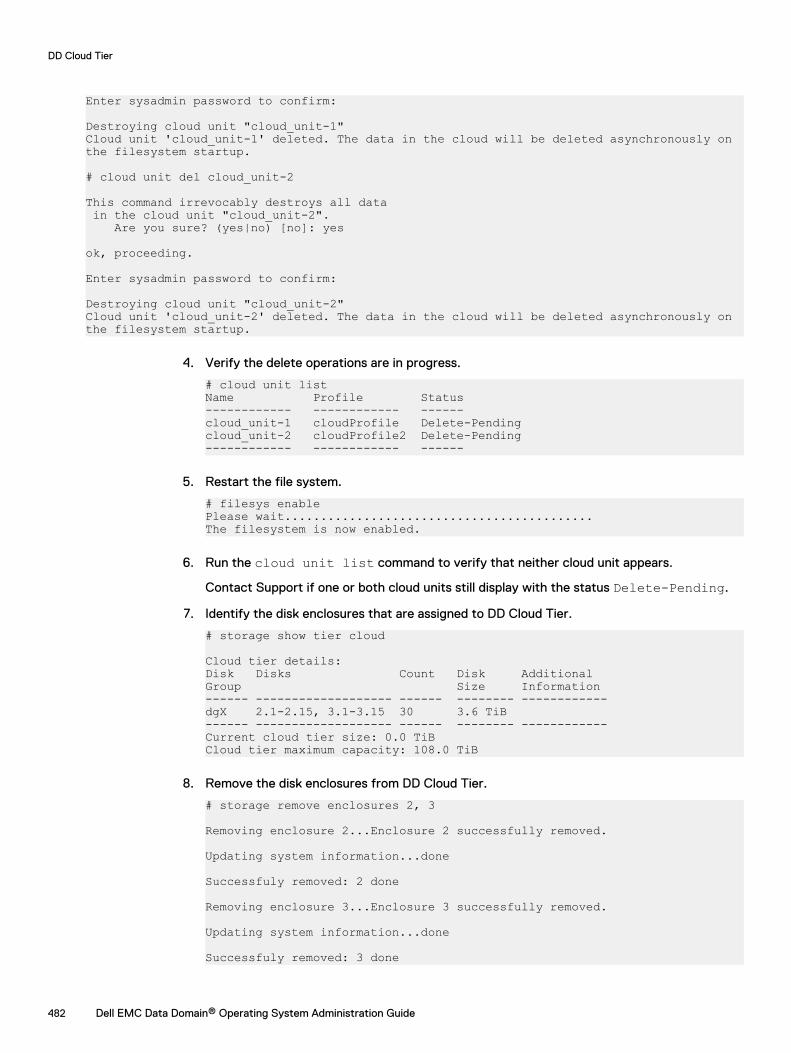
Enter sysadmin password to confirm:
Destroying cloud unit "cloud_unit-1"Cloud unit 'cloud_unit-1' deleted. The data in the cloud will be deleted asynchronously on the filesystem startup.
# cloud unit del cloud_unit-2
This command irrevocably destroys all data in the cloud unit "cloud_unit-2". Are you sure? (yes|no) [no]: yes
ok, proceeding.
Enter sysadmin password to confirm:
Destroying cloud unit "cloud_unit-2"Cloud unit 'cloud_unit-2' deleted. The data in the cloud will be deleted asynchronously on the filesystem startup.
4. Verify the delete operations are in progress.
# cloud unit listName Profile Status------------ ------------ ------cloud_unit-1 cloudProfile Delete-Pendingcloud_unit-2 cloudProfile2 Delete-Pending------------ ------------ ------
5. Restart the file system.
# filesys enablePlease wait...........................................The filesystem is now enabled.
6. Run the cloud unit list command to verify that neither cloud unit appears.
Contact Support if one or both cloud units still display with the status Delete-Pending.
7. Identify the disk enclosures that are assigned to DD Cloud Tier.
# storage show tier cloud
Cloud tier details:Disk Disks Count Disk AdditionalGroup Size Information------ ------------------- ------ -------- ------------dgX 2.1-2.15, 3.1-3.15 30 3.6 TiB------ ------------------- ------ -------- ------------Current cloud tier size: 0.0 TiBCloud tier maximum capacity: 108.0 TiB
8. Remove the disk enclosures from DD Cloud Tier.
# storage remove enclosures 2, 3
Removing enclosure 2...Enclosure 2 successfully removed.
Updating system information...done
Successfuly removed: 2 done
Removing enclosure 3...Enclosure 3 successfully removed.
Updating system information...done
Successfuly removed: 3 done
DD Cloud Tier
482 Dell EMC Data Domain® Operating System Administration Guide
CHAPTER 19
DD Extended Retention
This chapter includes:
l DD Extended Retention overview........................................................................................ 484l Supported protocols in DD Extended Retention.................................................................. 485l High Availability and Extended Retention............................................................................ 486l Using DD Replicator with DD Extended Retention...............................................................486l Hardware and licensing for DD Extended Retention............................................................ 487l Managing DD Extended Retention.......................................................................................492l Upgrades and recovery with DD Extended Retention.......................................................... 501l Migrate data from Archive Tier to DD Cloud Tier................................................................ 502
Dell EMC Data Domain® Operating System Administration Guide 483
DD Extended Retention overviewData Domain Extended Retention (DD Extended Retention) provides an internal tiering approachthat enables cost-effective, long-term retention of backup data on a DD system. DD ExtendedRetention lets you leverage DD systems for long-term backup retention and minimize reliance ontape.
Note: DD Extended Retention was formerly known as Data Domain Archiver.
Two-Tiered File System
The internal two-tiered file system of a DD Extended Retention-enabled DD system consists of anactive tier and a retention tier. The file system, however, appears as a single entity. Incoming datais first placed in the active tier of the file system. The data (in the form of complete files) is latermoved to the retention tier of the file system, as specified by your individual Data MovementPolicy. For example, the active tier might retain weekly full and daily incremental backups for 90days, while the retention tier might retain monthly fulls for seven years.
The retention tier is comprised of one or more retention units, each of which may draw storagefrom one or more shelves.
Note: As of DD OS 5.5.1, only one retention unit per retention tier is allowed. However,systems set up prior to DD OS 5.5.1 may continue to have more than one retention unit, butyou will not be allowed to add any more retention units to them.
Transparency of Operation
DD Extended Retention-enabled DD systems support existing backup applications usingsimultaneous data access methods through NFS and CIFS file service protocols over Ethernet,through DD VTL for open systems and IBMi, or as a disk-based target using application-specificinterfaces, such as DD Boost (for use with Avamar®, NetWorker®, GreenPlum, SymantecOpenStorage, and Oracle RMAN).
DD Extended Retention extends the DD architecture with automatic transparent data movementfrom the active tier to the retention tier. All of the data in the two tiers is accessible, althoughthere might be a slight delay on initial access to data in the retention tier. The namespace of thesystem is global and is not affected by data movement. No partitioning of the file system isnecessary to take advantage of the two-tiered file system.
Data Movement Policy
The Data Movement Policy, which you can customize, is the policy by which files are moved fromthe active to the retention tier. It is based on the time when the file was last modified. You can seta different policy for each different subset of data, because the policy can be set on a per-MTreebasis. Files that may be updated need a policy different from those that never change.
Deduplication within Retention Unit
For fault isolation purposes, deduplication occurs entirely within the retention unit for DDExtended Retention-enabled DD systems. There is no cross-deduplication between active andretention tiers, or between different retention units (if applicable).
Storage Drawn from Each Tier
The concept of tiering extends to the storage level for a DD Extended Retention-enabled DDsystem. The active tier of the file system draws storage from the active tier of storage. Theretention tier of the file system draws storage from the retention tier of storage.
Note: For both active and retention tiers, DD OS 5.2 and later releases support ES20 and ES30shelves, and DD OS 5.7 and later supports DS60 shelves on certain models.. Different Data
DD Extended Retention
484 Dell EMC Data Domain® Operating System Administration Guide

Domain shelf types cannot be mixed in the same shelf set, and the shelf sets must be balancedaccording to the configuration rules specified in the ES30 Expansion Shelf Hardware GuideorDS60 Expansion Shelf Hardware Guide. With DD Extended Retention, youcan attachsignificantly more storage to the same controller. For example, you can attach up to amaximum of 56 ES30 shelves on a DD990 with DD Extended Retention. The active tier mustinclude storage consisting of at least one shelf. For the minimum and maximum shelfconfiguration for the Data Domain controller models, refer to the expansion shelf hardwareguides for ES30 and DS60.
Data Protection
On a DD Extended Retention-enabled DD system, data is protected with built-in fault isolationfeatures, disaster recovery capability, and DIA (Data Invulnerability Architecture). DIA checks fileswhen they are moved from the active to the retention tier. After data is copied into the retentiontier, the container and file system structures are read back and verified. The location of the file isupdated, and the space on the active tier is reclaimed after the file is verified to have beencorrectly written to the retention tier.
When a retention unit is filled up, namespace information and system files are copied into it, so thedata in the retention unit may be recovered even when other parts of the system are lost.
Note: Sanitization and some forms of Replication are not supported for DD ExtendedRetention-enabled DD systems.
Space Reclamation
To reclaim space that has been freed up by data moved to the retention tier, you can use SpaceReclamation (as of DD OS 5.3), which runs in the background as a low-priority activity. It suspendsitself when there are higher priority activities, such as data movement and cleaning.
Encryption of Data at Rest
As of DD OS 5.5.1, you can use the Encryption of Data at Rest feature on DD Extended Retention-enabled DD systems, if you have an encryption license. Encryption is not enabled by default.
This is an extension of the encryption capability already available, prior to DD OS 5.5.1, for systemsnot using DD Extended Retention.
Refer to the Managing Encryption of Data at Rest chapter in this guide for complete instructionson setting up and using the encryption feature.
Supported protocols in DD Extended RetentionDD Extended Retention-enabled DD systems support the protocols NFS, CIFS, and DD Boost.Support for DD VTL was added in DD OS 5.2, and support for NDMP was added in DD OS 5.3.
Note: For a list of applications supported with DD Boost, see the DD Boost Compatibility Liston the Online Support site.
When you are using DD Extended Retention, data first lands in the active tier. Files are moved intheir entirety into the retention unit in the retention tier, as specified by your Data MovementPolicy. All files appear in the same namespace. There is no need to partition data, and you cancontinue to expand the file system as desired.
All data is visible to all users, and all file system metadata is present in the active tier.
The trade-off in moving data from the active to the retention tier is larger capacity versus slightlyslower access time if the unit to be accessed is not currently ready for access.
DD Extended Retention
Dell EMC Data Domain® Operating System Administration Guide 485
High Availability and Extended RetentionData Domain systems with High Availability (HA) enabled do not support DD Extended Retention.DD OS cannot currently support Extended Retention with HA.
Using DD Replicator with DD Extended RetentionSome forms of replication are supported on DD Extended Retention-enabled DD systems.
Supported replication types depend on the data to be protected:
l To protect data on a system as a source, a DD Extended Retention-enabled DD systemsupports collection replication, MTree replication, and DD Boost managed file replication.
l To protect data from other systems as a destination, a DD Extended Retention-enabled DDsystem also supports directory replication, as well as collection replication, MTree replication,and DD Boost managed file replication.
Note: Delta (low bandwidth optimization) replication is not supported with DD ExtendedRetention. You must disable delta replication on all contexts before enabling DD ExtendedRetention on a DD system.
Collection replication with DD Extended RetentionCollection replication takes place between the corresponding active tier and retention unit of thetwo DD systems with DD Extended Retention enabled. If the active tier or retention unit at thesource fails, the data can be copied from the corresponding unit at the remote site onto a newunit, which is shipped to your site as a replacement unit.
Prerequisites for setting up collection replication include:
l Both the source and destination systems must be configured as DD systems with DD ExtendedRetention enabled.
l The file system must not be enabled on the destination until the retention unit has been addedto it, and replication has been configured.
Directory replication with DD Extended RetentionFor directory replication, a DD Extended Retention-enabled DD system serves as a replicationtarget and supports one-to-one and many-to-one topologies from any supported DD system.However, DD Extended Retention-enabled DD systems do not support bi-directional directoryreplication and cannot be a source of directory replication.
About this task
Note: To copy data using directory replication into a DD Extended Retention-enabled DDsystem, the source must be running DD OS 5.0 or later. Therefore, on systems running DD OS5.0 or earlier, you must first import data into an intermediate system running DD OS 5.0 orlater. For example, replication from a DD OS 4.9 Extended Retention-enabled system could bemade into a DD OS 5.2 non-Extended Retention-enabled system. Then, replication could bemade from the DD OS 5.2 system into the DD OS 4.9 system.
MTree replication with DD Extended RetentionYou can set up MTree replication between two DD Extended Retention-enabled DD systems.Replicated data is first placed in the active tier on the destination system. The Data Movement
DD Extended Retention
486 Dell EMC Data Domain® Operating System Administration Guide
Policy on the destination system then determines when the replicated data is moved to theretention tier.
About this task
Note that MTree replication restrictions and policies vary by DD OS release, as follows:
l As of DD OS 5.1, data can be replicated from a non-DD Extended Retention-enabled system toa DD Extended Retention-enabled system with MTree replication.
l As of DD OS 5.2, data can be protected within an active tier by replicating it to the active tierof a DD Extended Retention-enabled system.
l As of DD OS 5.5, MTree replication is supported from a DD Extended Retention-enabledsystem to a non-DD Extended Retention-enabled system if both are running DD OS 5.5 orlater.
l For DD OS 5.3 and 5.4, if you plan to enable DD Extended Retention, do not set up replicationfor the /backup MTree on the source machine. (DD OS 5.5 and later do not have thisrestriction.)
Managed file replication with DD Extended RetentionFor DD Extended Retention-enabled DD systems, the supported topologies for DD Boost managedfile replication are one-to-one, many-to-one, bi-directional, one-to-many, and cascaded.
Note: For DD Boost 2.3 or later, you can specify how multiple copies are to be made andmanaged within the backup application.
Hardware and licensing for DD Extended RetentionCertain hardware configurations are required for DD Extended Retention-enabled DD systems.Licensing, specifically separate shelf capacity licenses, is also specific to this feature.
Hardware supported for DD Extended RetentionThe hardware requirements for DD Extended Retention-enabled DD systems include memoryrequirements, shelves, NIC/FC cards, and so on. For details about the required hardwareconfigurations for DD Extended Retention, see the installation and setup guide for your DDsystem, and the expansion shelf hardware guides for your expansion shelves.
The following DD systems support DD Extended Retention:
DD860
l 72 GB of RAM
l 1 - NVRAM IO module (1 GB)
l 3 - Quad-port SAS IO modules
l 2 - 1 GbE ports on the motherboard
l 0 to 2 - 1/10 GbE NIC IO cards for external connectivity
l 0 to 2 - Dual-Port FC HBA IO cards for external connectivity
l 0 to 2 - Combined NIC and FC cards
l 1 to 24 - ES20 or ES30 shelves (1 TB or 2 TB disks), not to exceed the system maximum usablecapacity of 142 TB
If DD Extended Retention is enabled on a DD860, the maximum usable storage capacity of anactive tier is 142 TB. The retention tier can have a maximum usable capacity of 142 TB. The activeand retention tiers have a total usable storage capacity of 284 TB.
DD Extended Retention
Dell EMC Data Domain® Operating System Administration Guide 487
DD990
l 256 GB of RAM
l 1 - NVRAM IO module (2 GB)
l 4 - Quad-port SAS IO modules
l 2 - 1 GbE ports on the motherboard
l 0 to 4 - 1 GbE NIC IO cards for external connectivity
l 0 to 3 - 10 GbE NIC cards for external connectivity
l 0 to 3 - Dual-Port FC HBA cards for external connectivity
l 0 to 3 - Combined NIC and FC cards, not to exceed three of any one specific IO module
l 1 to 56 - ES20 or ES30 shelves (1, 2, or 3 TB disks), not to exceed the system maximum usablecapacity of 570 TB
If DD Extended Retention is enabled on a DD990, the maximum usable storage capacity of theactive tier is 570 TB. The retention tier can have a maximum usable capacity of 570 TB. The activeand retention tiers have a total usable storage capacity of 1140 TB.
DD4200
l 128 GB of RAM
l 1 - NVRAM IO module (4 GB)
l 4 - Quad-port SAS IO modules
l 1 - 1 GbE port on the motherboard
l 0 to 6 - 1/10 GbE NIC cards for external connectivity
l 0 to 6 - Dual-Port FC HBA cards for external connectivity
l 0 to 6 - Combined NIC and FC cards, not to exceed four of any one specific IO module
l 1 to 16 - ES30 SAS shelves (2 or 3 TB disks), not to exceed the system maximum usablecapacity of 192 TB. ES30 SATA shelves (1, 2, or 3 TB disks) are supported for systemcontroller upgrades.
If DD Extended Retention is enabled on a DD4200, the maximum usable storage capacity of theactive tier is 192 TB. The retention tier can have a maximum usable capacity of 192 TB. The activeand retention tiers have a total usable storage capacity of 384 TB. External connectivity issupported for DD Extended Retention configurations up to 16 shelves.
DD4500
l 192 GB of RAM
l 1 - NVRAM IO module (4 GB)
l 4 - Quad-port SAS IO modules
l 1 - 1 GbE port on the motherboard
l 0 to 6 - 1/10 GbE NIC IO cards for external connectivity
l 0 to 6 - Dual-Port FC HBA cards for external connectivity
l 0 to 5 - Combined NIC and FC cards, not to exceed four of any one specific IO module
l 1 to 20 - ES30 SAS shelves (2 or 3 TB disks), not to exceed the system maximum usablecapacity of 285 TB. ES30 SATA shelves (1 TB, 2 TB, or 3 TB) are supported for systemcontroller upgrades.
If DD Extended Retention is enabled on a DD4500, the maximum usable storage capacity of theactive tier is 285 TB. The retention tier can have a maximum usable capacity of 285 TB. The active
DD Extended Retention
488 Dell EMC Data Domain® Operating System Administration Guide
and retention tiers have a total usable storage capacity of 570 TB. External connectivity issupported for DD Extended Retention configurations up to 24 shelves.
DD6800
l 192 GB of RAM
l 1 - NVRAM IO module (8 GB)
l 3 - Quad-port SAS IO modules
l 1 - 1 GbE port on the motherboard
l 0 to 4 - 1/10 GbE NIC cards for external connectivity
l 0 to 4 - Dual-Port FC HBA cards for external connectivity
l 0 to 4 - Combined NIC and FC cards
l Shelf combinations are documented in the installation and setup guide for your DD system, andthe expansion shelf hardware guides for your expansion shelves.
If DD Extended Retention is enabled on a DD6800, the maximum usable storage capacity of theactive tier is 288 TB. The retention tier can have a maximum usable capacity of 288 TB. The activeand retention tiers have a total usable storage capacity of 0.6 PB. External connectivity issupported for DD Extended Retention configurations up to 28 shelves.
DD7200
l 256 GB of RAM
l 1 - NVRAM IO module (4 GB)
l 4 - Quad-port SAS IO modules
l 1 - 1 GbE port on the motherboard
l 0 to 6 - 1/10 GbE NIC cards for external connectivity
l 0 to 6 - Dual-Port FC HBA cards for external connectivity
l 0 to 5 - Combined NIC and FC cards, not to exceed four of any one specific IO module
l 1 to 20 - ES30 SAS shelves (2 or 3 TB disks), not to exceed the system maximum usablecapacity of 432 TB. ES30 SATA shelves (1 TB, 2 TB, or 3 TB) are supported for systemcontroller upgrades.
If DD Extended Retention is enabled on a DD7200, the maximum usable storage capacity of theactive tier is 432 TB. The retention tier can have a maximum usable capacity of 432 TB. The activeand retention tiers have a total usable storage capacity of 864 TB. External connectivity issupported for DD Extended Retention configurations up to 32 shelves.
DD9300
l 384 GB of RAM
l 1 - NVRAM IO module (8 GB)
l 3 - Quad-port SAS IO modules
l 1 - 1 GbE port on the motherboard
l 0 to 4 - 1/10 GbE NIC cards for external connectivity
l 0 to 4 - Dual-Port FC HBA cards for external connectivity
l 0 to 4 - Combined NIC and FC cards
l Shelf combinations are documented in the installation and setup guide for your DD system, andthe expansion shelf hardware guides for your expansion shelves.
If DD Extended Retention is enabled on a DD9300, the maximum usable storage capacity of theactive tier is 720 TB. The retention tier can have a maximum usable capacity of 720 TB. The active
DD Extended Retention
Dell EMC Data Domain® Operating System Administration Guide 489
and retention tiers have a total usable storage capacity of 1.4 PB. External connectivity issupported for DD Extended Retention configurations up to 28 shelves.
DD9500
l 512 GB of RAM
l 1 - NVRAM IO module (8 GB)
l 4 - Quad-port SAS IO modules
l 1 - Quad 1 GbE ports on the motherboard
l 0 to 4 - 10 GbE NIC cards for external connectivity
l 0 to 4 - Dual-Port 16 Gbe FC HBA cards for external connectivity
l Shelf combinations are documented in the installation and setup guide for your DD system, andthe expansion shelf hardware guides for your expansion shelves.
If DD Extended Retention is enabled on a DD9500, the maximum usable storage capacity of theactive tier is 864 TB. The retention tier can have a maximum usable capacity of 864 TB. The activeand retention tiers have a total usable storage capacity of 1.7 PB. External connectivity issupported for DD Extended Retention configurations up to 56 shelves.
DD9800
l 768 GB of RAM
l 1 - NVRAM IO module (8 GB)
l 4 - Quad-port SAS IO modules
l 1 - Quad 1 GbE ports on the motherboard
l 0 to 4 - 10 GbE NIC cards for external connectivity
l 0 to 4 - Dual-Port 16 Gbe FC HBA cards for external connectivity
l Shelf combinations are documented in the installation and setup guide for your DD system, andthe expansion shelf hardware guides for your expansion shelves.
If DD Extended Retention is enabled on a DD9800, the maximum usable storage capacity of theactive tier is 1008 TB. The retention tier can have a maximum usable capacity of 1008 TB. Theactive and retention tiers have a total usable storage capacity of 2.0 PB. External connectivity issupported for DD Extended Retention configurations up to 56 shelves.
Licensing for DD Extended RetentionDD Extended Retention is a licensed software option installed on a supported DD system.
A separate shelf capacity license is needed for each storage shelf, for shelves installed in both theactive tier and the retention tier. Shelf capacity licenses are specific to either an active orretention tier shelf.
An Expanded-Storage license is required to expand the active tier storage capacity beyond theentry capacity, which varies by Data Domain model. You cannot use the additional storage withoutfirst applying the appropriate licenses.
Adding shelf capacity licenses for DD Extended RetentionEvery shelf in a DD Extended Retention-enabled DD system must have a separate license.
Procedure
1. Select Administration > Licenses.
2. Click Add Licenses.
DD Extended Retention
490 Dell EMC Data Domain® Operating System Administration Guide
3. Enter one or more licenses, one per line, pressing the Enter key after each one. Click Addwhen you have finished. If there are any errors, a summary of the added licenses, and thosenot added because of the error, are listed. Select the erroneous License Key to fix it.
Results
The licenses for the DD system are displayed in two groups:
l Software option licenses, which are required for options such as DD Extended Retention andDD Boost.
l Shelf Capacity Licenses, which display shelf capacity (in TiB), the shelf model (such as ES30),and the shelf’s storage tier (active or retention).
To delete a license, select the license in the Licenses list, and click Delete Selected Licenses. Ifprompted to confirm, read the warning, and click OK to continue.
Configuring storage for DD Extended RetentionAdditional storage for DD Extended Retention requires the appropriate license or licenses andenough installed memory on the DD system to support it. Error messages display if more licensesor memory are needed.
Procedure
1. Select Hardware > Storage tab.
2. In the Overview tab, select Configure Storage.
3. In the Configure Storage tab, select the storage to be added from the Addable Storage list.
4. Select the appropriate Tier Configuration (or Active or Retention) from the menu. Theactive tier is analogous to a standard DD system and should be sized similarly. The maximumamount of storage that can be added to the active tier depends on the DD controller used.
5. Select the checkbox for the Shelf to be added.
6. Click the Add to Tier button.
7. Click OK to add the storage.
8. To remove an added shelf, select it in the Tier Configuration list, select Remove from Tier,and select OK.
Customer-provided infrastructure for DD Extended RetentionBefore enabling DD Extended Retention, your environment and setup must meet certainrequirements.
l Specifications, site requirements, rack space, and interconnect cabling: See the DataDomain Installation and Setup Guide for your DD system model.
l Racking and cabling: It is recommended that you rack your system with future expansion inmind. All shelves are attached to a single DD system.
Note:
n See the Data Domain Expansion Shelf Hardware Guide for your shelf model (ES20, ES30, orDS60).
DD Extended Retention
Dell EMC Data Domain® Operating System Administration Guide 491
Managing DD Extended RetentionTo set up and use DD Extended Retention on your DD system, you can use the DD SystemManager and/or the DD CLI.
l The DD System Manager, formerly known as the Enterprise Manager, is a graphical userinterface (GUI), which is described in this guide.
l The archive commands, entered at the DD Command Line Interface (CLI) are described inthe Data Domain Operating System Command Reference Guide.
The only command not available when you use the DD System Manager is archive report.
Enabling DD systems for DD Extended RetentionBefore using a DD system for DD Extended Retention, you must have the correct license and thecorrect file system setup.
Procedure
1. Ensure that the correct license is applied. Select Administration > Licenses, and check theFeature Licenses list for Extended Retention.
2. Select Data Management > File System > More Tasks > Enable DD Extended Retention.
This option is available only if your Data Domain system supports DD Extended Retentionand the file system has not already been configured for DD Extended Retention. Be awarethat after DD Extended Retention has been enabled, it cannot be disabled withoutdestroying the file system.
a. If the file system is already enabled (as a non-DD Extended Retention system), you areprompted to disable it. Click Disable to do so.
b. If prompted to confirm that you want to convert the file system for use by DD ExtendedRetention, click OK.
After a file system is converted into a DD Extended Retention file system, the file systempage is refreshed to include information about both tiers, and there is a new tab labeledRetention Units.
CLI Equivalent
You can also verify that the Extended Retention license has been installed at the CLI.
To use the legacy licensing method:
# license show## License Key Feature-- ------------------- -----------1 AAAA-BBBB-CCCC-DDDD Replication2 EEEE-FFFF-GGGG-HHHH VTL -- ------------------- -----------
If the license is not present, each unit includes documentation – a quick install card –which shows the licenses that have been purchased. Enter the following command topopulate the license key.
# license add license-code
Then, enable Extended Retention:
# archive enable
To use electronic licensing:
# elicense showFeature licenses:
DD Extended Retention
492 Dell EMC Data Domain® Operating System Administration Guide
## Feature Count Mode Expiration Date-- ----------- ----- --------------- ---------------1 REPLICATION 1 permanent (int) n/a2 VTL 1 permanent (int) n/a-- ----------- ----- --------------- ---------------
If the license is not present, update the license file with the new feature license.
# elicense update mylicense.licNew licenses: Storage MigrationFeature licenses:## Feature Count Mode Expiration Date-- ----------------- ----- --------------- ---------------1 REPLICATION 1 permanent (int) n/a2 VTL 1 permanent (int) n/a3 EXTENDED RETENTION 1 permanent (int) n/a-- ------------------ ----- --------------- ---------------** This will replace all existing Data Domain licenses on the system with the above EMC ELMS licenses.Do you want to proceed? (yes|no) [yes]: yeseLicense(s) updated.
Then, enable Extended Retention:
# archive enable
Creating a two-tiered file system for DD Extended RetentionDD Extended Retention has a two-tiered file system for the active and retention tiers. The DDsystem must have been enabled for DD Extended Retention before enabling this special filesystem.
Procedure
1. Select Data Management > File System.
2. If a file system exists, destroy it.
3. Select More Tasks > Create file system.
4. Select a retention-capable file system and click Next.
5. Click Configure in the File System Create dialog box.
Storage must be configured before the file system is created.
6. Use the Configure Storage dialog box to add and remove available storage from the Activeand Retention Tiers, and click OK when you have finished.
The storage in the active tier is used to create the active file system tier, and the storage inthe retention tier is used to create a retention unit.
Note: As of DD OS 5.5.1, only one retention unit per retention tier is allowed. However,systems set up prior to DD OS 5.5.1 may continue to have more than one retention unit,but you cannot add any more retention units to them.
7. Use the File System Create dialog box to:
a. Select the size of the retention unit from the drop-down list.
b. Select the Enable file system after creation option.
c. Click Next.
A Summary page shows the size of the active and retention tiers in the new file system.
8. Click Finish to create the file system.
The progress of each creation step is shown, and a progress bar monitors overall status.
DD Extended Retention
Dell EMC Data Domain® Operating System Administration Guide 493

9. Click OK after the file system execution has completed.
CLI EquivalentTo add additional shelves, use this command once for each enclosure:
# storage add tier archive enclosure 5
Create an archive unit, and add it to the file system. You are asked to specify the number ofenclosures in the archive unit:
# filesys archive unit add
Verify that the archive unit is created and added to the file system:
# filesys archive unit list all
Check the file system, as seen by the system:
# filesys show space
File system panel for DD Extended RetentionAfter you have enabled a DD system for DD Extended Retention, the Data Management > FileSystem panel will look slightly different (from a non-DD Extended Retention-enabled system).
l State shows that the file system is either enabled or disabled. You can change the state byusing the Disable/Enable button immediately to the right.
l Clean Status shows the time the last cleaning operation finished, or the current cleaningstatus if the cleaning operation is currently running. If cleaning can be run, it shows a StartCleaning button. When cleaning is running, the Start Cleaning button changes to a StopCleaning button.
l Data Movement Status shows the time the last data movement finished. If data movementcan be run, it shows a Start button. When data movement is running, the Start buttonchanges to a Stop button.
l Space Reclamation Status shows the amount of space reclaimed after deleting data in theretention tier. If space reclamation can be run, it shows a Start button. If it is already running,it shows Stop and Suspend buttons. If it was running previously and was suspended, it showsStop and Resume buttons. There is also a More Information button that will display detailedinformation about starting and ending times, completion percentage, units reclaimed, spacefreed, etc.
l Selecting More Tasks > Destroy lets you delete all data in the file system, including virtualtapes. This can be done only by a system administrator.
l Selecting More Tasks > Fast Copy lets you clone files and MTrees of a source directory to adestination directory. Note that for DD Extended Retention-enabled systems, fast copy willnot move data between the active and retention tiers.
l Selecting More Tasks > Expand Capacity lets you expand the active or retention tier.
Expanding the active or retention tierWhen the file system is enabled, you can expand either the active or the retention tier.
About this task
To expand the Active tier:
Procedure
1. Select Data Management > File System > More Tasks > Expand Capacity.
2. In the Expand File System Capacity dialog, select Active Tier, then click Next.
DD Extended Retention
494 Dell EMC Data Domain® Operating System Administration Guide
3. Click Configure.
4. In the Configure Storage dialog, make sure that Active Tier is displayed as the Configureselection, and click OK.
5. After the configuration completes, you are returned to the Expand File System Capacitydialog. Select Finish to complete the active tier expansion.
About this task
To expand the retention tier:
Procedure
1. Select Data Management > File System > More Tasks > Expand Capacity.
2. In the Expand File System Capacity dialog, select Retention Tier, then select Next.
3. If a retention unit is available, you will see the Select Retention Unit dialog. Select theretention unit you want to expand and then Next. If a retention unit is not available, you willsee the Create Retention Unit dialog, and you must create a retention unit beforeproceeding.
Note: To ensure optimal performance of a DD system with DD Extended Retentionenabled, you should always expand the retention tier in at least two-shelf increments.You should also not wait until the retention unit is nearly full before expanding it.
4. Select the size to expand the retention unit, then click Configure.
5. After configuration completes, you are returned to the Expand File System Capacity dialog.Click Finish to complete the retention tier expansion.
Reclaiming space in the retention tierYou can reclaim space from deleted data in the retention tier by running space reclamation(introduced in DD OS 5.3). Space reclamation also occurs during file system cleaning.
Procedure
1. Select Data Management > File System. Just above the tabs, Space Reclamation Statusshows the amount of space that is reclaimed after deleting data in the retention tier.
2. If space reclamation can be run, it shows a Start button. If it is already running, it showsStop and Suspend buttons. If it was running previously and was suspended, it shows Stopand Resume buttons.
3. Click More Information for details about the cycle name, start and end times, effective runtime, percent completed (if in progress), units reclaimed, space freed on target unit, andtotal space freed.
Note: When you use the archive space-reclamation command, the system runsspace-reclamation in the background until it is manually stopped unless you use the one-cycle option. You can also use the archive space-reclamation schedule setcommand to set the starting time for space-reclamation.
CLI EquivalentTo enable space reclamation:
# archive space-reclamation start
To disable space reclamation:
# archive space-reclamation stop
To show the status of space reclamation:
DD Extended Retention
Dell EMC Data Domain® Operating System Administration Guide 495
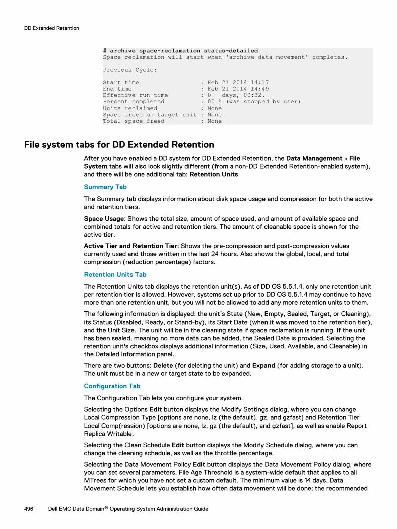
# archive space-reclamation status-detailedSpace-reclamation will start when 'archive data-movement' completes.
Previous Cycle:---------------Start time : Feb 21 2014 14:17End time : Feb 21 2014 14:49Effective run time : 0 days, 00:32.Percent completed : 00 % (was stopped by user)Units reclaimed : NoneSpace freed on target unit : NoneTotal space freed : None
File system tabs for DD Extended RetentionAfter you have enabled a DD system for DD Extended Retention, the Data Management > FileSystem tabs will also look slightly different (from a non-DD Extended Retention-enabled system),and there will be one additional tab: Retention Units
Summary Tab
The Summary tab displays information about disk space usage and compression for both the activeand retention tiers.
Space Usage: Shows the total size, amount of space used, and amount of available space andcombined totals for active and retention tiers. The amount of cleanable space is shown for theactive tier.
Active Tier and Retention Tier: Shows the pre-compression and post-compression valuescurrently used and those written in the last 24 hours. Also shows the global, local, and totalcompression (reduction percentage) factors.
Retention Units Tab
The Retention Units tab displays the retention unit(s). As of DD OS 5.5.1.4, only one retention unitper retention tier is allowed. However, systems set up prior to DD OS 5.5.1.4 may continue to havemore than one retention unit, but you will not be allowed to add any more retention units to them.
The following information is displayed: the unit’s State (New, Empty, Sealed, Target, or Cleaning),its Status (Disabled, Ready, or Stand-by), its Start Date (when it was moved to the retention tier),and the Unit Size. The unit will be in the cleaning state if space reclamation is running. If the unithas been sealed, meaning no more data can be added, the Sealed Date is provided. Selecting theretention unit's checkbox displays additional information (Size, Used, Available, and Cleanable) inthe Detailed Information panel.
There are two buttons: Delete (for deleting the unit) and Expand (for adding storage to a unit).The unit must be in a new or target state to be expanded.
Configuration Tab
The Configuration Tab lets you configure your system.
Selecting the Options Edit button displays the Modify Settings dialog, where you can changeLocal Compression Type [options are none, lz (the default), gz, and gzfast] and Retention TierLocal Comp(ression) [options are none, lz, gz (the default), and gzfast], as well as enable ReportReplica Writable.
Selecting the Clean Schedule Edit button displays the Modify Schedule dialog, where you canchange the cleaning schedule, as well as the throttle percentage.
Selecting the Data Movement Policy Edit button displays the Data Movement Policy dialog, whereyou can set several parameters. File Age Threshold is a system-wide default that applies to allMTrees for which you have not set a custom default. The minimum value is 14 days. DataMovement Schedule lets you establish how often data movement will be done; the recommended
DD Extended Retention
496 Dell EMC Data Domain® Operating System Administration Guide
schedule is every two weeks. File System Cleaning lets you elect not to have a system cleaningafter data movement; however, it is strongly recommended that you leave this option selected.
File Age Threshold per MTree Link
Selecting the File Age Threshold per MTree link will take you from the File System to the MTreearea (also accessible by selecting Data Management > MTree), where you can set a customizedFile Age Threshold for each of your MTrees.
Select the MTree, and then select Edit next to Data Movement Policy. In the Modify AgeThreshold dialog, enter a new value for File Age Threshold, and select OK. As of DD OS 5.5.1, theminimum value is 14 days.
Encryption Tab
The Encryption tab lets you enable or disable Encryption of Data at Rest, which is supported onlyfor systems with a single retention unit. As of 5.5.1, DD Extended Retention supports only a singleretention unit, so systems set up during, or after, 5.5.1 will have no problem complying with thisrestriction. However, systems set up prior to 5.5.1 may have more than one retention unit, butthey will not work with Encryption of Data at Rest until all but one retention unit has beenremoved, or data has been moved or migrated to one retention unit.
Space Usage Tab
The Space Usage Tab lets you select one of three chart types [(entire) File System; Active (tier);Archive (tier)] to view space usage over time in MiB. You can also select a duration value (7, 30,60, or 120 days) at the upper right. The data is presented (color-coded) as pre-compressionwritten (blue), post-compression used (red), and the compression factor (black).
Consumption Tab
The Consumption Tab lets you select one of three chart types [(entire) File System; Active (tier);Archive (tier)] to view the amount of post-compression storage used and the compression ratioover time, which enables you to view consumption trends. You can also select a duration value (7,30, 60, or 120 days) at the upper right. The Capacity checkbox lets you choose whether to displaythe post-compression storage against total system capacity.
Daily Written Tab
The Daily Written Tab lets you select a duration (7, 30, 60, or 120 days) to see the amount of datawritten per day. The data is presented (color-coded) in both graph and table format as pre-compression written (blue), post-compression used (red), and the compression factor (black).
Expanding a retention unitTo ensure optimal performance, do not wait until a retention unit is nearly full before expanding it,and do not expand it in 1-shelf increments. Storage cannot be moved from the active tier to theretention tier after the file system has been created. Only unused enclosures can be added to theretention tier.
Procedure
1. Select Data Management > File System > Retention Units.
2. Select the retention unit.
Note that if cleaning is running, a retention unit cannot be expanded.
3. Click Expand.
The system displays the current retention tier size, an estimated expansion size, and a totalexpanded capacity. If additional storage is available you can click the Configure link.
4. Click Next.
DD Extended Retention
Dell EMC Data Domain® Operating System Administration Guide 497
The system displays a warning telling you that you cannot revert the file system to itsoriginal size after this operation.
5. Click Expand to expand the file system.
Deleting a retention unitIf all of the files on a retention unit are no longer needed, deleting them makes the unit available forreuse. You can generate a file location report to make sure that the retention unit is indeed empty,delete the retention unit, and then add it as a new retention unit.
Procedure
1. Select Data Management > File System and click Disable to disable the file system if it isrunning.
2. Select Data Management > File System > Retention Units.
3. Select the retention unit.
4. Click Delete.
Modifying retention tier local compressionYou can modify the local compression algorithm for subsequent data movement to the retentiontier.
Procedure
1. Select Data Management > File System > Configuration.
2. Click Edit to the right of Options.
3. Select one of the compression options from the Retention Tier Local Comp menu, and clickOK.
The default is gz, which is a zip-style compression that uses the least amount of space fordata storage (10% to 20% less than lz on average; however, some data sets achieve muchhigher compression).
Understanding the Data Movement PolicyA file is moved from the active to the retention tier based on the date it was last modified. For dataintegrity, the entire file is moved at this time. The Data Movement Policy establishes two things: aFile Age Threshold and a Data Movement Schedule. If data has not changed during the period ofdays set by the File Age Threshold, it is moved from the active to the retention tier on the dateestablished by the Data Movement Schedule.
Note: As of DD OS 5.5.1, the File Age Threshold must be a minimum of 14 days.
You can specify different File Age Thresholds for each defined MTree. An MTree is a subtreewithin the namespace that is a logical set of data for management purposes. For example, youmight place financial data, emails, and engineering data in separate MTrees.
To take advantage of the space reclamation feature, introduced in DD OS 5.3, it is recommendedthat you schedule data movement and file system cleaning on a bi-weekly (every 14 days) basis. Bydefault, cleaning is always run after data movement completes. It is highly recommended that youdo not change this default.
Avoid these common sizing errors:
l Setting a Data Movement Policy that is overly aggressive; data will be moved too soon.
l Setting a Data Movement Policy that is too conservative: after the active tier fills up, you willnot be able to write data to the system.
DD Extended Retention
498 Dell EMC Data Domain® Operating System Administration Guide
l Having an undersized active tier and then setting an overly aggressive Data Movement Policyto compensate.
Be aware of the following caveats related to snapshots and file system cleaning:
l Files in snapshots are not cleaned, even after they have been moved to the retention tier.Space cannot be reclaimed until the snapshots have been deleted.
l It is recommended that you set the File Age Threshold for snapshots to the minimum of 14days.
Here are two examples of how to set up a Data Movement Policy.
l You could segregate data with different degrees of change into two different MTrees and setthe File Age Threshold to move data soon after the data stabilizes. Create MTree A for dailyincremental backups and MTree B for weekly fulls. Set the File Age Threshold for MTree A sothat its data is never moved, but set the File Age Threshold for MTree B to 14 days (theminimum threshold).
l For data that cannot be separated into different MTrees, you could do the following. Supposethe retention period of daily incremental backups is eight weeks, and the retention period ofweekly fulls is three years. In this case, it would be best to set the File Age Threshold to nineweeks. If it were set lower, you would be moving daily incremental data that was actually soonto be deleted.
Modifying the Data Movement Policy
You can set different Data Movement Policies for each MTree.
Procedure
1. Select Data Management > File System > Configuration.
2. Click Edit to the right of Data Movement Policy.
3. In the Data Movement Policy dialog, specify the system-wide default File Age Thresholdvalue in number of days. As of DD OS 5.5.1, this value must be greater than or equal to 14days. This value applies to newly created MTrees and MTrees that have not been assigned aper-MTree age threshold value using the File Age Threshold per MTree link (see step 7).When data movement starts, all files that have not been modified for the specified thresholdnumber of days will be moved from the active to the retention tier.
4. Specify a Data Movement Schedule, that is, when data movement should take place; forexample, daily, weekly, bi-weekly (every 14 days), monthly, or on the last day of the month.You can also pick a specific day or days, and a time in hours and minutes. It is highlyrecommended that you schedule data movement and file system cleaning on a bi-weekly(every 14 days) basis, to take advantage of the space reclamation feature (introduced in DDOS 5.3).
5. Specify a Data Movement Throttle, that is, the percentage of available resources thesystem uses for data movement. A value of 100% indicates that data movement will not bethrottled.
6. By default, file system cleaning is always run after data movement completes. It is highlyrecommended that you leave Start file system clean after Data Movement selected.
7. Select OK.
8. Back in the Configuration tab, you can specify age threshold values for individual MTrees byusing the File Age Threshold per MTree link at the lower right corner.
CLI EquivalentTo set the age threshold:
# archive data-movement policy set age-threshold {days|none} mtrees mtree-list
DD Extended Retention
Dell EMC Data Domain® Operating System Administration Guide 499
If necessary, to set the default age threshold:
# archive data-movement policy set default-age-threshold days
To verify the age threshold setting:
# archive data-movement policy show [mtree mtree-list]
To specify the migration schedule:
# archive data-movement schedule set days days time time [no-clean]
Acceptable schedule values include:
l days sun time 00:00
l days mon,tue time 00:00
l days 2 time 10:00
l days 2,15 time 10:00
l days last time 10:00 - last day of the month
To verify the migration schedule:
# archive data-movement schedule show
To disable the file cleaning schedule:
Note: The reason for disabling the cleaning schedule is to eliminate a scheduling conflictbetween cleaning and data movement. At the conclusion of data movement, cleaningwill automatically start. If you disable data movement, you should re-enable file systemcleaning.
# filesys clean set schedule never
Starting or stopping data movement on demand
Even when you have a regular Data Movement Policy, you can also start or stop data movement ondemand.
Procedure
1. Select Data Management > File System.
2. Click Start to the right of Data Movement Status.
3. The Start Data Movement dialog warns that data is to be moved from the active to theretention tier, as defined by your Data Movement Policy, followed by a file system cleaning.Select Start to start the data movement.
If a file system cleaning happens to already be in progress, data movement will occur afterthat cleaning completes. However, another cleaning will be automatically started after thison-demand data movement completes, as well.
4. The Start button will be replaced by a Stop button.
5. At any time, if you want to stop data movement, click Stop and click OK in the Stop DataMovement dialog to confirm.
Using data movement packing
Data is compacted in the target partition after every file migration (as of DD OS 5.2). By default,this feature, which is called data movement packing, is enabled.
When this feature is enabled, the overall compression of the retention tier improves, but there is aslight increase in migration time.
To determine if this feature is enabled, select Data Management > File System > Configuration.
DD Extended Retention
500 Dell EMC Data Domain® Operating System Administration Guide
The current value for Packing data during Retention Tier data movement can be either Enabledor Disabled. Consult with a system engineer to change this setting.
Upgrades and recovery with DD Extended RetentionThe following sections describe how to perform software and hardware upgrades, and how torecover data, for DD Extended Retention-enabled DD systems.
Upgrading to DD OS 5.7 with DD Extended RetentionThe upgrade policy for a DD Extended Retention-enabled DD system is the same as for a standardDD system.
Upgrading from up to two major prior releases is supported. For instructions on how to upgradethe DD OS, refer to the upgrade instructions section of the Release Notes for the target DD OSversion.
When upgrading a DD Extended Retention-enabled DD system to DD OS 5.7, be sure to updateexisting data movement schedules to bi-weekly (14 days) to take advantage of the spacereclamation feature.
DD Extended Retention-enabled DD systems automatically run cleaning after data movementcompletes; therefore, do not schedule cleaning separately using the DD System Manager or CLI(command line interface).
If the active tier is available, the process upgrades the active tier and the retention unit, and putsthe system into a state that the previous upgrade has not been verified to be complete. This stateis cleared by the file system after the file system is enabled and has verified that the retention tierhas been upgraded. A subsequent upgrade is not permitted until this state is cleared.
If the active tier is not available, the upgrade process upgrades the system chassis and places itinto a state where it is ready to create or accept a file system.
If the retention unit becomes available after the upgrade process has finished, the unit isautomatically upgraded when it is plugged into the system, or at the next system start.
Upgrading hardware with DD Extended RetentionYou can upgrade a DD Extended Retention-enabled DD system to a later or higher performance DDExtended Retention-enabled DD system. For example, you could replace a DD ExtendedRetention-enabled DD860 with a DD Extended Retention-enabled DD990
Note: Consult your contracted service provider, and refer to the instructions in the appropriateSystem Controller Upgrade Guide.
This type of upgrade affects DD Extended Retention as follows:
l If the new system has a more recent version of DD OS than the active and retention tiers, theactive and retention tiers are upgraded to the new system's version. Otherwise, the newsystem is upgraded to the version of the active and retention tiers.
l The active and retention tiers that are connected to the new system become owned by thenew system.
l If there is an active tier, the registry in the active tier is installed in the new system. Otherwise,the registry in the retention tier with the most recently updated registry is installed in the newsystem.
DD Extended Retention
Dell EMC Data Domain® Operating System Administration Guide 501
Recovering a DD Extended Retention-enabled systemIf the active tier, and a subset of the retention units are lost, on a DD Extended Retention-enabledDD system, and there is no replica available, Support may be able to reconstitute any remainingsealed retention units into a new DD system.
A DD Extended Retention-enabled DD system is designed to remain available to service read andwrite requests when one or more retention units are lost. The file system may not detect that aretention unit is lost until the file system restarts or tries to access data stored in the retentionunit. The latter circumstance may trigger a file system restart. After the file system has detectedthat a retention unit is lost, it returns an error in response to requests for data stored in that unit.
If the lost data cannot be recovered from a replica, Support might be able to clean up the systemby deleting the lost retention unit and any files that reside fully or partially in it.
Using replication recoveryThe replication recovery procedure for a DD Extended Retention-enabled DD system depends onthe replication type
l Collection replication – The new source must be configured as a DD Extended Retention-enabled DD system with the same number (or more) of retention units as the destination. Thefile system must not be enabled on the new source until the retention units have been added,and replication recovery has been initiated.
Note: If you need to recover only a portion of a system, such as one retention unit, from acollection replica, contact Support.
l MTree replication – See the MTree Replication section in the Working with DD Replicatorchapter.
l DD Boost managed file replication – See the Data Domain Boost for OpenStorage AdministrationGuide.
Recovering from system failuresA DD Extended Retention-enabled DD system is equipped with tools to address failures in differentparts of the system.
Procedure
1. Restore the connection between the system controller and the storage. If the systemcontroller is lost, replace it with a new system controller.
2. If there is loss of data and a replica is available, try to recover the data from the replica. If areplica is not available, limit any loss of data by leveraging the fault isolation features of DDExtended Retention through Support.
Migrate data from Archive Tier to DD Cloud TierThis procedure uses MTree replication to migrate data from the Archive Tier on a Data Domainsystem with Extended Retention to a single node Data Domain system or DD VE instance with DDCloud Tier.
Before you begin
l Licenses for replication and DD Cloud Tier are required.
l The target system must be running Data Domain Operating System version 6.0 or later tosupport DD Cloud Tier.
DD Extended Retention
502 Dell EMC Data Domain® Operating System Administration Guide
l The target system must have enough active tier capacity to hold the data from both the Activeand Archive Tiers on the source system, as data will not be moved to DD Cloud Tier storage onthe target system for at least 14 days.
l Data Domain recommends that any capacity planning include enough Active Tier capacity for aminimum of 14 days of replicated data.
l All backup jobs and other write activities on the source system must be redirected to thetarget system.
l The target system must meet all the same compliance requirements that were met by thesource system.
l The customer must provide all appropriate accounts and credentials for the target and sourceData domain systems.
Additional considerations:
l Contact Dell EMC Support if immediate data migration to DD Cloud Tier storage is required.
l Customer backup applications may not track this data migration.
l This procedure does not cover Managed File Replication (MFR).
l Licensing - Data Domain systems can use:
n Legacy licensing - Use the license show command
n ELMS licensing - Use the elicense show command
Data Domain systems using legacy licensing can add licenses incrementally. Be aware that not allnewer features are supported with legacy licensing.
Data Domain systems installed with DD OS 6.0 or later, converted to or upgraded with featuresrequiring ELMS licensing use the elicense commands when applying and displaying licences, andwhen a new license key file is applied the new set of keys replaces all of the old keys entirely.
CAUTION When updating an ELMS license, be sure that you do not remove existing capacityor features.
About this task
This procedure covers the following uses:
l Customer wants to move data from Archive Tier storage to DD Cloud Tier storage on thetarget system.
l Customer wants to move data from Active and Archive Tier storage on the source system toActive Tier storage on the target system.
l Customer wants to move data from Archive Tier storage on multiple source systems to Activeor DD Cloud Tier storage on the target system.
l Customer wants to re-purpose the source system or its disk enclosures after the migrationoperation is complete.
Capacity planning
Before you begin
The target system must have sufficient Active Tier capacity to store the combined Active andArchive Tiers of the source system.
In addition, the Active Tier of the source system must have enough space to retain all the datafrom scheduled backups from the time when data movement to the archive tier is stopped until themigration from the source system to the target system is complete.
DD Extended Retention
Dell EMC Data Domain® Operating System Administration Guide 503
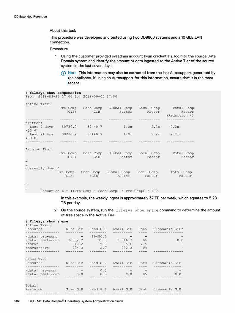
About this task
This procedure was developed and tested using two DD9800 systems and a 10 GbE LANconnection.
Procedure
1. Using the customer provided sysadmin account login credentials, login to the source DataDomain system and identify the amount of data ingested to the Active Tier of the sourcesystem in the last seven days.
Note: This information may also be extracted from the last Autosupport generated bythe appliance. If using an Autosupport for this information, ensure that it is the mostrecent.
# filesys show compressionFrom: 2018-08-29 17:00 To: 2018-09-05 17:00
Active Tier: Pre-Comp Post-Comp Global-Comp Local-Comp Total-Comp (GiB) (GiB) Factor Factor Factor (Reduction %)------------- -------- --------- ----------- ---------- -------------Written: Last 7 days 80730.2 37440.7 1.0x 2.2x 2.2x (53.6) Last 24 hrs 80730.2 37440.7 1.0x 2.2x 2.2x (53.6) ------------- -------- --------- ----------- ---------- -------------
Archive Tier: Pre-Comp Post-Comp Global-Comp Local-Comp Total-Comp (GiB) (GiB) Factor Factor Factor……Currently Used:* Pre-Comp Post-Comp Global-Comp Local-Comp Total-Comp (GiB) (GiB) Factor Factor Factor
…… Reduction % = ((Pre-Comp - Post-Comp) / Pre-Comp) * 100
In this example, the weekly ingest is approximately 37 TB per week, which equates to 5.28TB per day.
2. On the source system, run the filesys show space command to determine the amountof free space in the Active Tier.
# filesys show spaceActive Tier:Resource Size GiB Used GiB Avail GiB Use% Cleanable GiB*---------------- -------- -------- --------- ---- --------------/data: pre-comp - 69480.4 - - -/data: post-comp 30352.2 35.5 30316.7 0% 0.0/ddvar 47.2 9.2 35.6 21% -/ddvar/core 984.3 2.0 932.3 0% ----------------- -------- -------- --------- ---- --------------
Cloud TierResource Size GiB Used GiB Avail GiB Use% Cleanable GiB---------------- -------- -------- --------- ---- -------------/data: pre-comp - 0.0 - - -/data: post-comp 0.0 0.0 0.0 0% 0.0---------------- -------- -------- --------- ---- -------------
Total:Resource Size GiB Used GiB Avail GiB Use% Cleanable GiB---------------- -------- -------- --------- ---- -------------
DD Extended Retention
504 Dell EMC Data Domain® Operating System Administration Guide
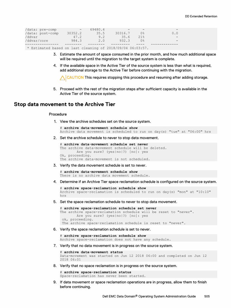
/data: pre-comp - 69480.4 - - -/data: post-comp 30352.2 35.5 30316.7 0% 0.0/ddvar 47.2 9.2 35.6 21% -/ddvar/core 984.3 2.0 932.3 0% ----------------- -------- -------- --------- ---- ------------- * Estimated based on last cleaning of 2018/09/04 06:03:57.
3. Estimate the amount of space consumed in the prior month, and how much additional spacewill be required until the migration to the target system is complete.
4. If the available space in the Active Tier of the source system is less than what is required,add additional storage to the Active Tier before continuing with the migration.
CAUTION This requires stopping this procedure and resuming after adding storage.
5. Proceed with the rest of the migration steps after sufficient capacity is available in theActive Tier of the source system.
Stop data movement to the Archive Tier
Procedure
1. View the archive schedules set on the source system.
# archive data-movement schedule showArchive data movement is scheduled to run on day(s) "tue" at "06:00" hrs
2. Set the archive schedule to never to stop data movement.
# archive data-movement schedule set neverThe archive data-movement schedule will be deleted. Are you sure? (yes|no|?) [no]: yesOk, proceeding.The archive data-movement is not scheduled.
3. Verify the data movement schedule is set to never.
# archive data-movement schedule showThere is no archive data movement schedule.
4. Determine if an Archive Tier space reclamation schedule is configured on the source system.
# archive space-reclamation schedule showArchive space-reclamation is scheduled to run on day(s) "mon" at "10:10" hrs
5. Set the space reclamation schedule to never to stop data movement.
# archive space-reclamation schedule set neverThe archive space-reclamation schedule will be reset to "never". Are you sure? (yes|no|?) [no]: yes ok, proceeding. The archive space-reclamation schedule is reset to "never".
6. Verify the space reclamation schedule is set to never.
# archive space-reclamation schedule showArchive space-reclamation does not have any schedule.
7. Verify that no data movement is in progress on the source system.
# archive data-movement statusData-movement was started on Jun 12 2018 06:00 and completed on Jun 12 2018 06:01
8. Verify that no space reclamation is in progress on the source system.
# archive space-reclamation status Space-reclamation has never been started.
9. If data movement or space reclamation operations are in progress, allow them to finishbefore continuing.
DD Extended Retention
Dell EMC Data Domain® Operating System Administration Guide 505
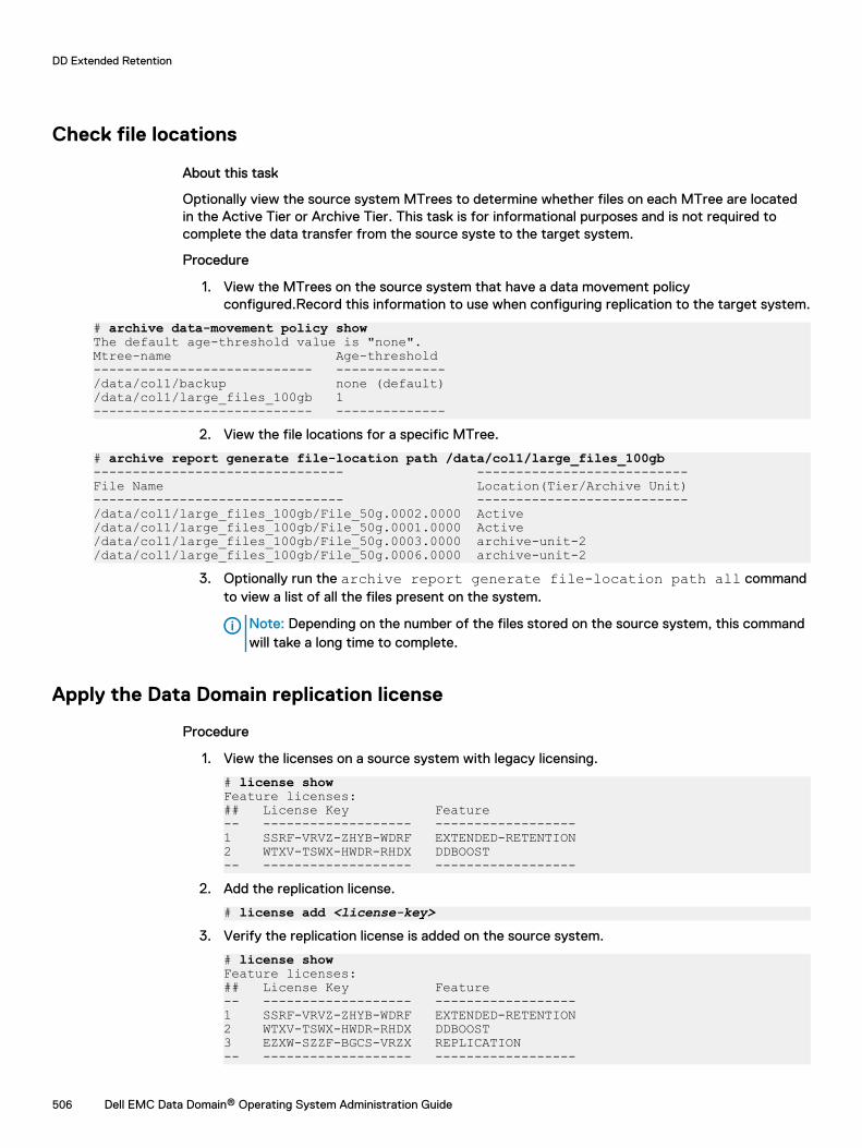
Check file locations
About this task
Optionally view the source system MTrees to determine whether files on each MTree are locatedin the Active Tier or Archive Tier. This task is for informational purposes and is not required tocomplete the data transfer from the source syste to the target system.
Procedure
1. View the MTrees on the source system that have a data movement policyconfigured.Record this information to use when configuring replication to the target system.
# archive data-movement policy showThe default age-threshold value is "none".Mtree-name Age-threshold---------------------------- --------------/data/col1/backup none (default)/data/col1/large_files_100gb 1---------------------------- --------------
2. View the file locations for a specific MTree.
# archive report generate file-location path /data/col1/large_files_100gb-------------------------------- ---------------------------File Name Location(Tier/Archive Unit)-------------------------------- ---------------------------/data/col1/large_files_100gb/File_50g.0002.0000 Active/data/col1/large_files_100gb/File_50g.0001.0000 Active/data/col1/large_files_100gb/File_50g.0003.0000 archive-unit-2/data/col1/large_files_100gb/File_50g.0006.0000 archive-unit-2
3. Optionally run the archive report generate file-location path all commandto view a list of all the files present on the system.
Note: Depending on the number of the files stored on the source system, this commandwill take a long time to complete.
Apply the Data Domain replication license
Procedure
1. View the licenses on a source system with legacy licensing.
# license showFeature licenses:## License Key Feature-- ------------------- ------------------1 SSRF-VRVZ-ZHYB-WDRF EXTENDED-RETENTION2 WTXV-TSWX-HWDR-RHDX DDBOOST-- ------------------- ------------------
2. Add the replication license.
# license add <license-key>3. Verify the replication license is added on the source system.
# license showFeature licenses:## License Key Feature-- ------------------- ------------------1 SSRF-VRVZ-ZHYB-WDRF EXTENDED-RETENTION2 WTXV-TSWX-HWDR-RHDX DDBOOST3 EZXW-SZZF-BGCS-VRZX REPLICATION-- ------------------- ------------------
DD Extended Retention
506 Dell EMC Data Domain® Operating System Administration Guide
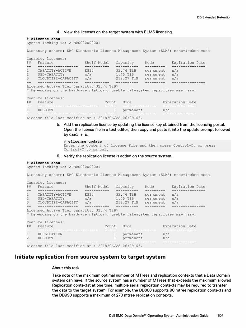
4. View the licenses on the target system with ELMS licensing.
# elicense showSystem locking-id: APM00000000001
Licensing scheme: EMC Electronic License Management System (ELMS) node-locked mode
Capacity licenses:## Feature Shelf Model Capacity Mode Expiration Date-- ------------------ ----------- ---------- --------- ---------------1 CAPACITY-ACTIVE ES30 32.74 TiB permanent n/a 2 SSD-CAPACITY n/a 1.45 TiB permanent n/a 3 CLOUDTIER-CAPACITY n/a 218.27 TiB permanent n/a -- ------------------ ----------- ---------- --------- ---------------Licensed Active Tier capacity: 32.74 TiB** Depending on the hardware platform, usable filesystem capacities may vary. Feature licenses:## Feature Count Mode Expiration Date-- --------------------------- ----- --------------- ---------------1 DDBOOST 1 permanent n/a -- --------------------------- ----- --------------- ---------------License file last modified at : 2018/06/28 06:29:03.
5. Add the replication license by updating the license key obtained from the licensing portal.Open the license file in a text editor, then copy and paste it into the update prompt followedby Ctrl + D.
# elicense updateEnter the content of license file and then press Control-D, or press Control-C to cancel.
6. Verify the replication license is added on the source system.
# elicense showSystem locking-id: APM00000000001
Licensing scheme: EMC Electronic License Management System (ELMS) node-locked mode
Capacity licenses:## Feature Shelf Model Capacity Mode Expiration Date-- ------------------ ----------- ---------- --------- ---------------1 CAPACITY-ACTIVE ES30 32.74 TiB permanent n/a 2 SSD-CAPACITY n/a 1.45 TiB permanent n/a 3 CLOUDTIER-CAPACITY n/a 218.27 TiB permanent n/a -- ------------------ ----------- ---------- --------- ---------------Licensed Active Tier capacity: 32.74 TiB** Depending on the hardware platform, usable filesystem capacities may vary. Feature licenses:## Feature Count Mode Expiration Date-- --------------------------- ----- --------------- ---------------1 REPLICATION 1 permanent n/a 2 DDBOOST 1 permanent n/a -- --------------------------- ----- --------------- ---------------License file last modified at : 2018/06/28 06:29:03.
Initiate replication from source system to target system
About this task
Take note of the maximum optimal number of MTrees and replication contexts that a Data Domainsystem can have. If the source system has a number of MTrees that exceeds the maximum allowedReplication contextst at one time, multiple serial replication contexts may be required to transferthe data to the target system. For example, the DD860 supports 90 mtree replication contexts andthe DD990 supports a maximum of 270 mtree replication contexts.
DD Extended Retention
Dell EMC Data Domain® Operating System Administration Guide 507
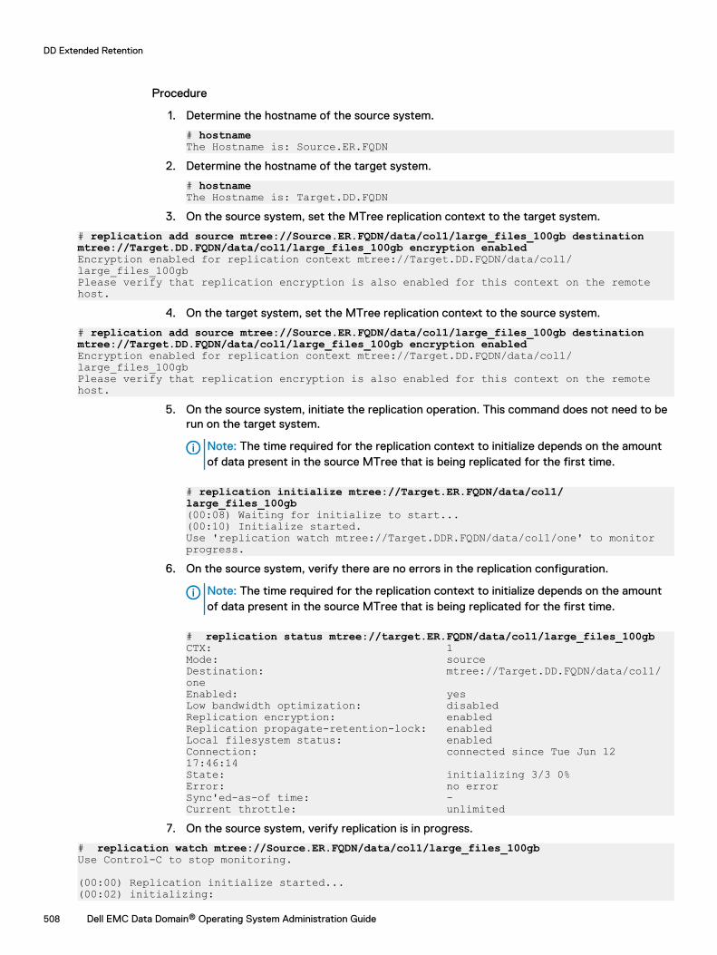
Procedure
1. Determine the hostname of the source system.
# hostnameThe Hostname is: Source.ER.FQDN
2. Determine the hostname of the target system.
# hostnameThe Hostname is: Target.DD.FQDN
3. On the source system, set the MTree replication context to the target system.
# replication add source mtree://Source.ER.FQDN/data/col1/large_files_100gb destination mtree://Target.DD.FQDN/data/col1/large_files_100gb encryption enabledEncryption enabled for replication context mtree://Target.DD.FQDN/data/col1/ large_files_100gbPlease verify that replication encryption is also enabled for this context on the remote host.
4. On the target system, set the MTree replication context to the source system.
# replication add source mtree://Source.ER.FQDN/data/col1/large_files_100gb destination mtree://Target.DD.FQDN/data/col1/large_files_100gb encryption enabledEncryption enabled for replication context mtree://Target.DD.FQDN/data/col1/ large_files_100gbPlease verify that replication encryption is also enabled for this context on the remote host.
5. On the source system, initiate the replication operation. This command does not need to berun on the target system.
Note: The time required for the replication context to initialize depends on the amountof data present in the source MTree that is being replicated for the first time.
# replication initialize mtree://Target.ER.FQDN/data/col1/large_files_100gb(00:08) Waiting for initialize to start...(00:10) Initialize started.Use 'replication watch mtree://Target.DDR.FQDN/data/col1/one' to monitor progress.
6. On the source system, verify there are no errors in the replication configuration.
Note: The time required for the replication context to initialize depends on the amountof data present in the source MTree that is being replicated for the first time.
# replication status mtree://target.ER.FQDN/data/col1/large_files_100gbCTX: 1Mode: sourceDestination: mtree://Target.DD.FQDN/data/col1/oneEnabled: yesLow bandwidth optimization: disabledReplication encryption: enabledReplication propagate-retention-lock: enabledLocal filesystem status: enabledConnection: connected since Tue Jun 12 17:46:14State: initializing 3/3 0%Error: no errorSync'ed-as-of time: -Current throttle: unlimited
7. On the source system, verify replication is in progress.
# replication watch mtree://Source.ER.FQDN/data/col1/large_files_100gbUse Control-C to stop monitoring. (00:00) Replication initialize started...(00:02) initializing:
DD Extended Retention
508 Dell EMC Data Domain® Operating System Administration Guide
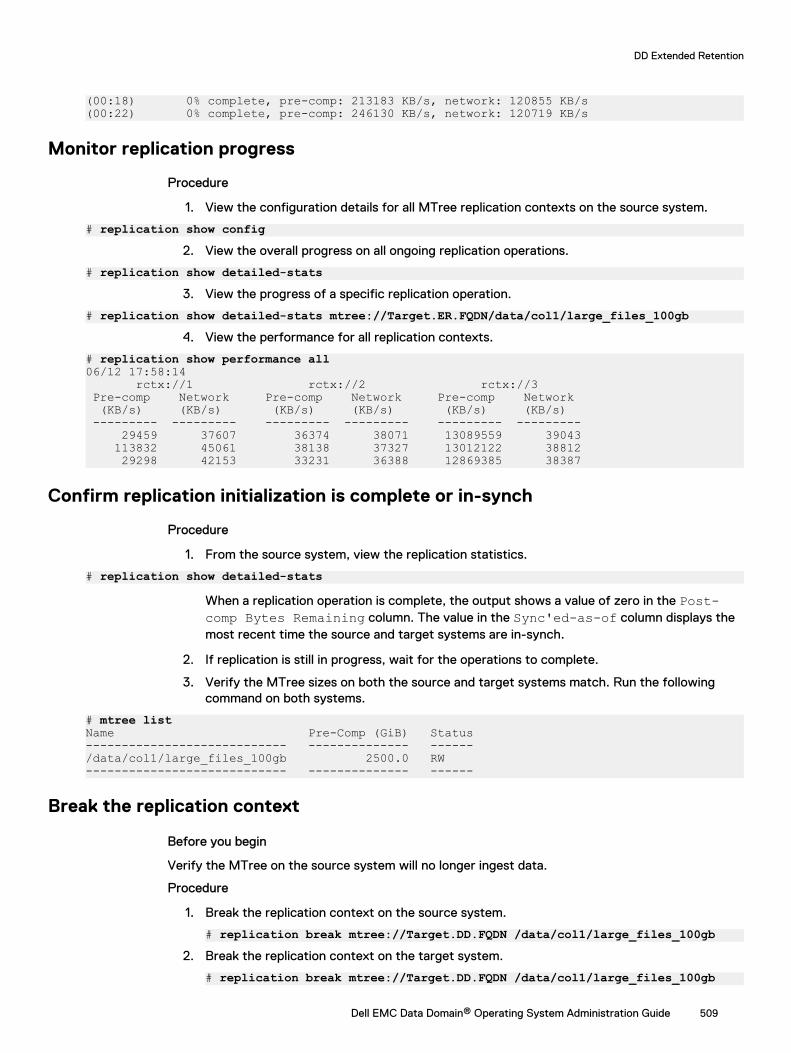
(00:18) 0% complete, pre-comp: 213183 KB/s, network: 120855 KB/s(00:22) 0% complete, pre-comp: 246130 KB/s, network: 120719 KB/s
Monitor replication progress
Procedure
1. View the configuration details for all MTree replication contexts on the source system.
# replication show config2. View the overall progress on all ongoing replication operations.
# replication show detailed-stats3. View the progress of a specific replication operation.
# replication show detailed-stats mtree://Target.ER.FQDN/data/col1/large_files_100gb4. View the performance for all replication contexts.
# replication show performance all06/12 17:58:14 rctx://1 rctx://2 rctx://3 Pre-comp Network Pre-comp Network Pre-comp Network (KB/s) (KB/s) (KB/s) (KB/s) (KB/s) (KB/s) --------- --------- --------- --------- --------- --------- 29459 37607 36374 38071 13089559 39043 113832 45061 38138 37327 13012122 38812 29298 42153 33231 36388 12869385 38387
Confirm replication initialization is complete or in-synch
Procedure
1. From the source system, view the replication statistics.
# replication show detailed-stats
When a replication operation is complete, the output shows a value of zero in the Post-comp Bytes Remaining column. The value in the Sync'ed-as-of column displays themost recent time the source and target systems are in-synch.
2. If replication is still in progress, wait for the operations to complete.
3. Verify the MTree sizes on both the source and target systems match. Run the followingcommand on both systems.
# mtree listName Pre-Comp (GiB) Status---------------------------- -------------- ------/data/col1/large_files_100gb 2500.0 RW---------------------------- -------------- ------
Break the replication context
Before you begin
Verify the MTree on the source system will no longer ingest data.
Procedure
1. Break the replication context on the source system.
# replication break mtree://Target.DD.FQDN /data/col1/large_files_100gb2. Break the replication context on the target system.
# replication break mtree://Target.DD.FQDN /data/col1/large_files_100gb
DD Extended Retention
Dell EMC Data Domain® Operating System Administration Guide 509
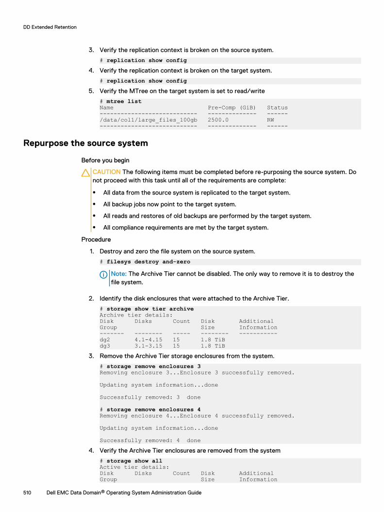
3. Verify the replication context is broken on the source system.
# replication show config4. Verify the replication context is broken on the target system.
# replication show config5. Verify the MTree on the target system is set to read/write
# mtree listName Pre-Comp (GiB) Status---------------------------- -------------- ------/data/col1/large_files_100gb 2500.0 RW---------------------------- -------------- ------
Repurpose the source system
Before you begin
CAUTION The following items must be completed before re-purposing the source system. Donot proceed with this task until all of the requirements are complete:
l All data from the source system is replicated to the target system.
l All backup jobs now point to the target system.
l All reads and restores of old backups are performed by the target system.
l All compliance requirements are met by the target system.
Procedure
1. Destroy and zero the file system on the source system.
# filesys destroy and-zero
Note: The Archive Tier cannot be disabled. The only way to remove it is to destroy thefile system.
2. Identify the disk enclosures that were attached to the Archive Tier.
# storage show tier archiveArchive tier details:Disk Disks Count Disk AdditionalGroup Size Information------- -------- ----- -------- -----------dg2 4.1-4.15 15 1.8 TiBdg3 3.1-3.15 15 1.8 TiB
3. Remove the Archive Tier storage enclosures from the system.
# storage remove enclosures 3 Removing enclosure 3...Enclosure 3 successfully removed.
Updating system information...done
Successfully removed: 3 done
# storage remove enclosures 4Removing enclosure 4...Enclosure 4 successfully removed.
Updating system information...done
Successfully removed: 4 done4. Verify the Archive Tier enclosures are removed from the system
# storage show allActive tier details:Disk Disks Count Disk AdditionalGroup Size Information
DD Extended Retention
510 Dell EMC Data Domain® Operating System Administration Guide
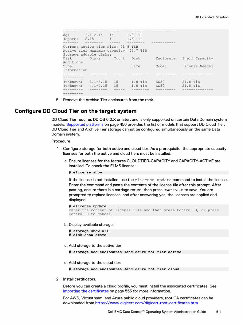
------- -------- ----- -------- -----------dg1 2.1-2.14 14 1.8 TiB(spare) 2.15 1 1.8 TiB------- -------- ----- -------- -----------Current active tier size: 21.8 TiBActive tier maximum capacity: 43.7 TiBStorage addable disks:Disk Disks Count Disk Enclosure Shelf Capacity AdditionalType Size Model License Needed Information--------- -------- ----- -------- --------- -------------- ---------(unknown) 3.1-3.15 15 1.8 TiB ES30 21.8 TiB(unknown) 4.1-4.15 15 1.8 TiB ES30 21.8 TiB--------- -------- ----- -------- --------- -------------- ---------
5. Remove the Archive Tier enclosures from the rack.
Configure DD Cloud Tier on the target systemDD Cloud Tier requires DD OS 6.0.X or later, and is only supported on certain Data Domain systemmodels. Supported platforms on page 456 provides the list of models that support DD Cloud Tier.DD Cloud Tier and Archive Tier storage cannot be configured simultaneously on the same DataDomain system.
Procedure
1. Configure storage for both active and cloud tier. As a prerequisite, the appropriate capacitylicenses for both the active and cloud tiers must be installed.
a. Ensure licenses for the features CLOUDTIER-CAPACITY and CAPACITY-ACTIVE areinstalled. To check the ELMS license:
# elicense show
If the license is not installed, use the elicense update command to install the license.Enter the command and paste the contents of the license file after this prompt. Afterpasting, ensure there is a carriage return, then press Control-D to save. You areprompted to replace licenses, and after answering yes, the licenses are applied anddisplayed.
# elicense updateEnter the content of license file and then press Control-D, or press Control-C to cancel.
b. Display available storage:
# storage show all# disk show state
c. Add storage to the active tier:
# storage add enclosures <enclosure no> tier active
d. Add storage to the cloud tier:
# storage add enclosures <enclosure no> tier cloud
2. Install certificates.
Before you can create a cloud profile, you must install the associated certificates. See Importing the certificates on page 553 for more information.
For AWS, Virtustream, and Azure public cloud providers, root CA certificates can bedownloaded from https://www.digicert.com/digicert-root-certificates.htm.
DD Extended Retention
Dell EMC Data Domain® Operating System Administration Guide 511
l For an AWS or Azure cloud provider, download the Baltimore CyberTrust Rootcertificate.
l For Alibaba, Alibaba download the GlobalSign Root R1 certificate from https://support.globalsign.com/customer/portal/articles/1426602-globalsign-rootcertificates.
l For a Virtustream cloud provider, download the DigiCert High Assurance EV Root CAcertificate.
l For ECS, the root certificate authority will vary by customer. Contact your load balancerprovider for details.
Downloaded certificate files have a .crt extension. Use openssl on any Linux or Unix systemwhere it is installed to convert the file from .crt format to .pem.
$openssl x509 -inform der -in DigiCertHighAssuranceEVRootCA.crt -out DigiCertHighAssuranceEVRootCA.pem$openssl x509 -inform der -in BaltimoreCyberTrustRoot.crt -out BaltimoreCyberTrustRoot.pem# adminaccess certificate import ca application cloudEnter the certificate and then press Control-D, or press Control-C to cancel.
3. To configure the Data Domain system for data-movement to the cloud, you must firstenable the “cloud” feature and set the system passphrase if it has not already been set.
# cloud enableCloud feature requires that passphrase be set on the system.Enter new passphrase: Re-enter new passphrase: Passphrases matched.The passphrase is set.Encryption is recommended on the cloud tier. Do you want to enable encryption? (yes|no) [yes]: Encryption feature is enabled on the cloud tier.Cloud feature is enabled.
4. Configure the cloud profile using the cloud provider credentials. The prompts and variablesvary by provider.
# cloud profile add <profilename>
Note: For security reasons, this command does not display the access/secret keys youenter.
Select the provider:
Enter provider name (alibabacloud|aws|azure|ecs|google|s3_flexible|virtustream)l Alibaba Cloud requires access key, secret key, storage class and region.
l AWS S3 requires access key, secret key, storage class, and region.
l Azure requires account name, whether or not the account is an Azure Governmentaccount, primary key, secondary key, and storage class.
l ECS requires entry of access key, secret key and endpoint.
l Google Cloud Platform requires access key, secret key, and region. (Storage class isNearline.)
l S3 Flexible providers require the provider name, access key, secret key, region, endpoint,and storage class.
l Virtustream requires access key, secret key, storage class, and region.
DD Extended Retention
512 Dell EMC Data Domain® Operating System Administration Guide
At the end of each profile addition you are asked if you want to set up a proxy. If you do,these values are required: proxy hostname, proxy port, proxy username, and proxypassword.
5. Verify the cloud profile configuration:
# cloud profile show
6. Create the active tier file system if it is not already created:
# filesys create
7. Enable the file system:
# filesys enable
8. Configure the cloud unit:
# cloud unit add unitname profile profilename
Use the cloud unit list command to list the cloud units.
9. Optionally, configure encryption for the cloud unit.
a. Verify that the ENCRYPTION license is installed:
# elicense show
b. Enable encryption for the cloud unit:
# filesys encryption enable cloud-unit unitname
c. Check encryption status:
# filesys encryption status
10. Create one or more MTrees:
# mtree create /data/col1/mt11
11. Verify the DD Cloud Tier configuration:
# cloud provider verifyThis operation will perform test data movement after creating a temporary profile and bucket.Do you want to continue? (yes|no) [yes]:Enter provider name (aws|azure|virtustream|ecs|s3_generic): awsEnter the access key:Enter the secret key:Enter the region (us-east-1|us-west-1|us-west-2|eu-west-1|apnortheast-1|ap-southeast-1|ap-southeast-2|sa-east-1|ap-south-1|ap-northeast-2|eu-central-1):
Verifying cloud provider …This process may take a few minutes.Cloud Enablement Check: Checking Cloud feature enabled: PASSED Checking Cloud volume: PASSED
Connectivity Check: Checking firewall access: PASSED Validating certificate PASSED
Account Validation: Creating temporary profile: PASSED Creating temporary bucket: PASSED
S3 API Validation:
DD Extended Retention
Dell EMC Data Domain® Operating System Administration Guide 513
Validating Put Bucket: PASSED Validating List Bucket: PASSED Validating Put Object: PASSED Validating Get Object: PASSED Validating List Object: PASSED Validating Delete Object: PASSED Validating Bulk Delete: PASSED
Cleaning Up: Deleting temporary bucket: PASSED Deleting temporary profile: PASSED
Provider verification passed.
12. Configure the file migration policy for this MTree. You can specify multiple MTrees in thiscommand. The policy can be based on the age threshold or the range.
a. To configure the age-threshold (migrating files older than the specified age to cloud):
# data-movement policy set age-threshold age_in_days to-tier cloud cloud-unit unitname mtrees mtreename
b. To configure the age-range (migrating only those files that are in the specified age-range):
# data-movement policy set age-range min-age age_in_days max-age age_in_days to-tier cloud cloud-unit unitname mtrees mtreename
13. Export the file system, and from the client, mount the file system and ingest data into theactive tier. Change the modification date on the ingested files such that they now qualify fordata migration. (Set the date to older than the age-threshold value specified whenconfiguring the data-movement policy.)
14. Initiate file migration of the aged files. Again, you can specify multiple MTrees with thiscommand.
# data-movement start mtrees mtreename
To check the status of data-movement:
# data-movement status
You can also watch the progress of data-movement:
# data-movement watch
15. Verify that file migration worked and the files are now in the cloud tier:
# filesys report generate file-location path all
16. Once you have migrated a file to the cloud tier, you cannot directly read from the file(attempting to do so results in an error). The file can only be recalled back to the active tier.To recall a file to the active tier:
# data-movement recall path pathname
DD Extended Retention
514 Dell EMC Data Domain® Operating System Administration Guide
CHAPTER 20
DD Retention Lock
This chapter includes:
l DD Retention Lock overview................................................................................................516l Supported data access protocols.........................................................................................518l Enabling DD Retention Lock on an MTree............................................................................519l Client-Side Retention Lock file control................................................................................522l System behavior with DD Retention Lock............................................................................527
Dell EMC Data Domain® Operating System Administration Guide 515
DD Retention Lock overviewWhen data is locked on an MTree that is enabled with DD Retention Lock, DD Retention Lock helpsensure that data integrity is maintained. Any data that is locked cannot be overwritten, modified,or deleted for a user-defined retention period of up to 70 years.
There are two DD Retention Lock editions:
l Data Domain Retention Lock Governance Edition retains the functionality of Data DomainRetention Lock prior to DD OS 5.2. You can use Data Domain Retention Lock Governance todefine retention policies on data that is to be retained for a specific period of time to meetinternal IT governance policies implemented by the system administrator.
l Data Domain Retention Lock Compliance Edition enables you to meet the strictest datapermanence requirements of regulatory standards, such as those of SEC 17a-4(f). The full listof regulatory standards includes:
n CFTC Rule 1.31b
n FDA 21 CFR Part 11
n Sarbanes-Oxley Act
n IRS 98025 and 97-22
n ISO Standard 15489-1
n MoREQ2010
For certification information, see Compliance Assessments - Summary and Conclusions – EMCData Domain Retention Lock Compliance Edition at:
https://www.emc.com/collateral/analyst-reports/cohasset-dd-retention-lock-assoc-comp-assess-summ-ar.pdf
(Login is required.)
Compliance with these standards ensures that files locked on a Data Domain system using DataDomain Retention Lock Compliance Edition software cannot be altered or destroyed before theretention period expires. Data Domain Retention Lock Compliance Edition requires a securityofficer for implementation of policies. An audit log file is accessible by the administrator orsecurity officer.
Each edition requires a separate, add-on license, and either or both can be used on a single DataDomain system.
The retention-locking protocol is the same for both the DD Retention Lock Governance andCompliance Editions. The differences in use stem from the system behavior for the DD RetentionLock Compliance Edition, since it places strict restrictions to meet compliance requirements. Foran overview, see the EMC Data Domain Retention Lock Software – A Detailed Review (a whitepaper) available at:
https://www.emc.com/collateral/hardware/white-papers/h10666-data-domain-retention-lock-wp.pdf
(Login is required.)
The DD Retention Lock Governance Edition does not require a security officer and provides ahigher degree of flexibility for archive data retention on Data Domain systems.
For archive compliance storage requirements, SEC rules require that a separate copy of retention-locked data must be stored with the same retention requirements as the original. Retention-lockedfiles can be replicated using DD Replicator to another Data Domain system. If a retention-lockedfile is replicated, it remains retention locked on the destination system, with the same level ofprotection as the source file.
DD Retention Lock
516 Dell EMC Data Domain® Operating System Administration Guide
DD Retention Lock Governance Edition is supported for on-premises, cloud-based, and DD3300DD VE instances. DD Retention Lock Compliance Edition is not supported for on-premises, cloud-based, or DD3300 DD VE instances.
The topics that follow provide additional information on DD Retention Lock.
DD Retention Lock protocolOnly files that are explicitly committed to be retention-locked files are retention locked on theData Domain system. Files are committed to be retention-locked files through client-side filecommands issued while DD Retention Lock Governance or Compliance is enabled on the MTreecontaining the files.
Note: Linux, Unix, and Windows client environments are supported.
Files that are written to shares or exports that are not committed to be retained (even if DDRetention Lock Governance or Compliance is enabled on the MTree containing the files) can bemodified or deleted at any time.
Retention locking prevents any modification or deletion of files under retention from occurringdirectly from CIFS shares or NFS exports during the retention period specified by a client-sideatime update command. Some archive applications and backup applications can issue thiscommand when appropriately configured. Applications or utilities that do not issue this commandcannot lock files using DD Retention Lock.
Retention-locked files are always protected from modification and premature deletion, even ifretention locking is subsequently disabled or if the retention-lock license is no longer valid.
You cannot rename or delete non-empty folders or directories within an MTree that is retention-lock enabled. However, you can rename or delete empty folders or directories and create newones.
The retention period of a retention-locked file can be extended (but not reduced) by updating thefile’s atime.
For both DD Retention Lock Governance and Compliance, once the retention period for a fileexpires, the file can be deleted using a client-side command, script, or application. However, thefile cannot be modified even after the retention period for the file expires. The Data Domainsystem never automatically deletes a file when its retention period expires.
DD Retention Lock flowThe general flow of activities with DD Retention Lock.
1. Enable MTrees for DD Retention Lock Governance or Compliance retention locking using theDD System Manager or DD OS commands issued from the system console.
2. Commit files to be retention locked on the Data Domain system using client-side commandsissued by an appropriately configured archiving or backup application, manually, or via scripts.
Note: Windows clients may need to download utility programs for DD OS compatibility.
3. Optionally, extend file retention times using client-side commands.
4. Optionally, delete files with expired retention periods using client-side commands.
Automatic retention lockThe automatic retention lock functionality allows you to set automatic values for the retentionperiod, and the lock delay (the time before a file becomes locked) on a per MTree basis. The
DD Retention Lock
Dell EMC Data Domain® Operating System Administration Guide 517
automatic retention lock settings apply to new files created on the MTree after the retention locksettings are configured. Existing files are not impacted.
Set the automatic retention period to ensure that every new file created on the MTree will beautomatically locked and retained for the specified amount of time.
Set the automatic lock delay on the MTree to allow a period of time where a new file can bemodified before it gets locked.
Automatic retention lock is subject to the following limitations:
l Retention lock must be re-applied manually to any files reverted when automatic retention lockis in use.
l MTree replication of an MTree with automatic retention lock enabled to a system with anearlier version of DD OS that does not support automatic retention lock, results in the lockedfiles replicating to the target system as regular files.
l In Automatic Retention Lock, for the files which are being ingested, the mtree retention-lock report generate command may incorrectly report those files as locked as wellreport an incorrect cooling off period.
Supported data access protocolsDD Retention Lock is compatible with industry-standard, NAS-based Write-Once-Read-Many(WORM) protocols, and integration is qualified with archive applications such as SymantecEnterprise Vault, SourceOne, Cloud Tiering Appliance, or DiskXtender. Customers using backupapplications such as CommVault can also develop custom scripts to use Data Domain RetentionLock.
The protocol support of DD Retention Lock is as follows:
l NFS is supported with both DD Retention Lock Governance and Compliance.
l CIFS is supported with both DD Retention Lock Governance and Compliance.
l Automatic retention lock is supported on NFS and CIFS with both Retention Lock Governanceand Compliance.
l DD VTL is supported with DD Retention Lock Governance, but not with DD Retention LockCompliance. Automatic retention lock is not supported on DD VTL.Virtual tapes, here referred to as tapes, are represented as files on the file system.
n When you create a storage pool, a collection of tapes that map to a directory on the filesystem, you are creating an MTree, unless you specifically select to create the older styledirectory pool (for backward compatibility). You can also convert storage pools createdprior to DD OS 5.3 to MTrees. These MTrees can be retention locked and replicated.
n You can retention-lock one or more tapes using the vtl tape modify command,described in the Data Domain Operating System Command Reference Guide.The mtree retention-lock revert path command can be used to revert theretention-locked state of tapes that are locked with the vtl tape modify command.After the tape is unlocked, updates can be made to it. The unlocked state will not be visiblevia the DD System Manager or CLI until the DD VTL service is disabled then enabled.However, updates are applied to the unlocked tape. This capability is only for the DDRetention Lock Governance Edition.
n The retention time for tapes can be displayed using the vtl tape show command withthe time-display retention argument.
n You can retention-lock an individual tape using the DD System Manager.
l DD Boost is supported with both DD Retention Lock Governance and Compliance. Automaticretention lock is not supported on DD Boost.
DD Retention Lock
518 Dell EMC Data Domain® Operating System Administration Guide
If client-side scripts are used to retention-lock backup files or backup images, and if a backupapplication (Veritas NetBackup, for example) is also used on the system via DD Boost, beaware that the backup application may not share the context of the client-side scripts. Thus,when a backup application attempts to expire or delete files that were retention locked via theclient-side scripts, space is not released on the Data Domain system.
Data Domain recommends that administrators change their retention period policy to align withthe retention lock time. This applies to many of the backup applications that are integratedwith DD Boost, including Veritas NetBackup, Veritas Backup Exec, and NetWorker.
Setting retention lock during data ingest to a DD BOOST file in DSP mode is not allowed, andthe client setting the RL receives an error. Retention lock should be set after the data ingest iscomplete.
Setting retention lock during data ingest to a DD BOOST file in OST mode, or to an NFS file isnot allowed and the client writing the data receives error as soon as RL is set. The partial filewritten before RL is set and committed to disk as a worm file.
Enabling DD Retention Lock on an MTreeOnly files within DD Retention Lock Governance or Compliance enabled MTrees can be retention-locked.
MTrees enabled for DD Retention Lock Compliance cannot be converted to DD Retention LockGovernance MTrees and vice versa.
The procedures that follow show how to enable MTrees for either DD Retention Lock Governanceor DD Retention Lock Compliance.
Enabling DD Retention Lock Governance on an MTreeAdd a DD Retention Lock Governance license to a system, and then enable DD Retention LockGovernance on one or more MTrees.
Procedure
1. Add the DD Retention Lock Governance license, if it is not listed under Feature Licenses.
a. Select Administration > Licenses
b. In the Licenses area click Add Licenses.
c. In the License Key text box, type the license key.
Note: License keys are case-insensitive. Include the hyphens when typing keys.
d. Click Add.
2. Select an MTree for retention locking.
a. Select Data Management > MTree.
b. Select the MTree you want to use for retention locking. You can also create an emptyMTree and add files to it later.
3. Click the MTree Summary tab to display information for the selected MTree.
4. Scroll down to Retention Lock area and click Edit to the right of Retention Lock.
5. Enable DD Retention Lock Governance on the MTree and change the default minimum andmaximum retention lock periods for the MTree, if required.
Perform the following actions in the Modify Retention Lock dialog box:
DD Retention Lock
Dell EMC Data Domain® Operating System Administration Guide 519
a. Select Enabled to enable DD Retention Lock Governance on the MTree.
b. In the Use drop-down list, select Manual or Automatic.
l For manual retention lock, to change the minimum or maximum retention period forthe MTree:
a. Type a number for the interval in the text box (for example, 5 or 14).
b. From the drop-down list, select an interval (minutes, hours, days, years).Note: Specifying a minimum retention period of less than 12 hours, or amaximum retention period longer than 70 years, results in an error.
l For automatic retention lock, to change the minimum, maximum, or automaticretention period, or the automatic lock delay for the MTree:
a. Type a number for the interval in the text box (for example, 5 or 14).
b. From the drop-down list, select an interval (minutes, hours, days, years).Note: Specifying a minimum retention period of less than 12 hours, a maximumretention period longer than 70 years, an automatic retention period that doesnot fall between the minimum and maximum values, or an automatic lock delayless than 5 minutes or more than 7 days results in an error.
Note: If a file is modified before the automatic lock delay has elapsed, the lockdelay time starts over when the file modification is complete. For example, ifthe lock delay is 120 minutes and the file is modified after 60 minutes, the lockdelay will start again at 120 minutes after the file is modified.
c. Click OK to save the settings.
After you close the Modify Retention Lock dialog box, which is updated MTreeinformation appears in the Retention Lock area.
6. Check retention lock information for the MTree.
Note the following retention lock fields:
l Top:
n The Status field indicates the read/write access for the MTree, the type of retentionlocking on the MTree, and whether retention locking is enabled or disabled.
l Bottom:
n The Status field indicates whether retention locking is enabled for the MTree.
n The Retention Period field indicates minimum and maximum retention periods for theMTree. The retention period that is specified for a file in the MTree must be equal toor greater than the minimum retention period and equal to or less than the maximumretention period.
n The UUID field is a unique identification number that is generated for the MTree.
Note: To check retention lock configuration settings for any MTree, select the MTree inthe Navigation Panel, then click the Summary tab.
After you finish
Retention-lock files in a retention-lock-enabled MTree.
DD Retention Lock
520 Dell EMC Data Domain® Operating System Administration Guide
Enabling DD Retention Lock Compliance on an MTreeAdd a DD Retention Lock Compliance license to a system, set up a system administrator and oneor more security officers, configure and enable the system to use DD Retention Lock Compliancesoftware, and then enable DD Retention Lock Compliance on one or more MTrees.
Procedure
1. Add the DD Retention Lock Compliance license on the system, if it is not present.
a. First, check whether the license is already installed.
license showb. If the RETENTION-LOCK-COMPLIANCE feature is not displayed, install the license.
license add license-key
Note: License keys are case-insensitive. Include the hyphens when typing keys.
2. Set up one or more security officer users accounts according to Role-Base Access Control(RBAC) rules.
a. In the system administrator role, add a security officer account.
user add user role securityb. Enable the security officer authorization.
authorization policy set security-officer enabled3. Configure and enable the system to use DD Retention Lock Compliance.
Note: Enabling DD Retention Lock Compliance enforces many restrictions on low-levelaccess to system functions used during troubleshooting. Once enabled, the only way todisable DD Retention Lock Compliance is to initialize and reload the system, whichresults in destroying all data on the system.
a. Configure the system to use DD Retention Lock Compliance.
system retention-lock compliance configureThe system automatically reboots.
b. After the restart process is complete, enable DD Retention Lock Compliance on thesystem.
system retention-lock compliance enable4. Enable compliance on an MTree that will contain retention-locked files.
mtree retention-lock enable mode compliance mtree mtree-path
Note: Compliance cannot be enabled on /backup or pool MTrees.
5. To change the default minimum and maximum retention lock periods for a compliance-enabled MTree, type the following commands with security officer authorization.
l mtree retention-lock set min-retention-period period mtree mtree-path
l mtree retention-lock set max-retention-period period mtree mtree-path
DD Retention Lock
Dell EMC Data Domain® Operating System Administration Guide 521
Note: The retention period is specified in the format [number] [unit]. For example: 1 min,1 hr, 1 day, 1 mo, or 1 year. Specifying a minimum retention period of less than 12 hours,or a maximum retention period longer than 70 years, results in an error.
6. To change the automatic retention period and automatic lock delay for a compliance-enabled MTree, type the following commands with security officer authorization.
l mtree retention-lock set automatic-retention-period period mtreemtree-path
Note: The automatic retention period is specified in the format [number] [unit]. Forexample: 1 min, 1 hr, 1 day, 1 mo, or 1 year. The value must be between the minimumand maximum retention periods.
l mtree retention-lock set automatic-lock-delay time mtree mtree-pathNote: The automatic lock delay time is specified in the format [number] [unit]. Forexample: 5 min, 2 hr, or 1 day. The value must be between five minutes and sevendays. The default is 120 minutes. If a file is modified before the automatic lock delayhas elapsed, the lock delay time starts over when the file modification is complete.For example, if the lock delay is 120 minutes and the file is modified after 60 minutes,the lock delay will start again at 120 minutes after the file is modified.
Repeat steps 4 through 6 to enable additional MTrees.
After you finish
Retention lock files reside in a retention-lock-enabled MTree.
Client-Side Retention Lock file controlThis section describes the DD Retention Lock client command interface for locking files stored onData Domain systems. Client commands are the same for DD Retention Lock Governance andCompliance. Linux, Unix, and Windows client environments are supported; however, Windowsclients may need to download utility programs with commands to lock files.
Note: If your application already supports industry-standard WORM, writing a WORM file to aDD Retention Lock Governance or Compliance enabled MTree will lock the file on the DataDomain system. The retention time in the application should agree with the DD Retention Locksettings. You do not need to use the commands described in this section. To check whether anapplication is tested and certified for the DD Retention Lock, refer to the Data Domain ArchiveApplication Compatibility Guide.
Note: Some client machines using NFS, but running a legacy OS, cannot set retention timelater than 2038. The NFS protocol doesn’t impose the 2038 limit and allows to specifyingtimes until 2106. Further, DD OS doesn’t impose the 2038 limit.
Client-side commands are used to manage the retention locking of individual files. Thesecommands apply to all retention-lock-capable Data Domain systems and must be issued in additionto the setup and configuration of DD Retention Lock on the Data Domain system.
Required Tools for Windows Clients
You need the touch.exe command to perform retention-locking from a Windows-based client.
To obtain this command, download and install utilities for Linux/Unix-based applications accordingto your Windows version. These utilities are best recommendations from Data Domain and shouldbe used per customer environment.
l For Windows 8, Windows 7, Windows Server 2008, Windows Vista, Windows Server 2003, andWindows XP:
DD Retention Lock
522 Dell EMC Data Domain® Operating System Administration Guide
http://sourceforge.net/projects/unxutils/files/latest
l For Windows Server 2008, Windows Vista Enterprise, Windows Vista Enterprise 64-bit edition,Windows Vista SP1, Windows Vista Ultimate, and Windows Vista Ultimate 64-bit edition:http://www.microsoft.com/download/en/details.aspx?displaylang=en&id=23754
l For Windows Server 2003 SP1 and Windows Server 2003 R2:http://www.microsoft.com/download/en/details.aspx?displaylang=en&id=20983
Note: The touch command for Windows may have a different format than the Linux examplesin this chapter.
Follow the installation instructions provided and set the search path as needed on the clientmachine.
Client Access to Data Domain System Files
After an MTree is enabled for DD Retention Lock Governance or Compliance, you can:
l Create a CIFS share based on the MTree. This CIFS share can be used on a client machine.
l Create an NFS mount for the MTree and access its files from the NFS mount point on a clientmachine.
Note: The commands listed in this section are to be used only on the client. They cannot beissued through the DD System Manager or CLI. Command syntax may vary slightly, dependingon the utility you are using.
The topics that follow describe how to manage client-side retention lock file control.
Setting Retention Locking on a fileTo perform retention locking on a file, change the last access time (atime) of the file to the desiredretention time of the file, that is, the time when the file can be deleted.
This action is usually performed using the archive application, and all the archive applications thatare qualified on Data Domain systems today (per the Data Domain Archive Application CompatibilityGuide) follow the basic locking protocol outlined here.
The future atime you specify must respect the minimum and maximum retention periods of thefile’s MTree (as offsets from the current time), as shown in the next figure.
DD Retention Lock
Dell EMC Data Domain® Operating System Administration Guide 523
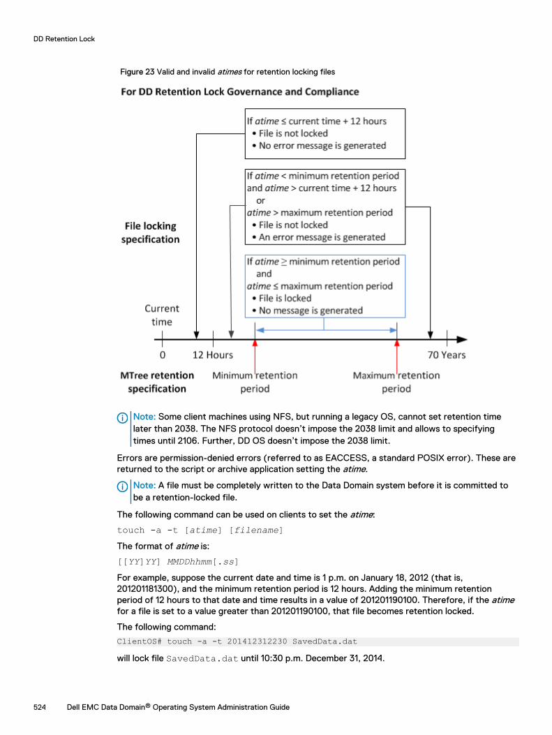
Figure 23 Valid and invalid atimes for retention locking files
Note: Some client machines using NFS, but running a legacy OS, cannot set retention timelater than 2038. The NFS protocol doesn’t impose the 2038 limit and allows to specifyingtimes until 2106. Further, DD OS doesn’t impose the 2038 limit.
Errors are permission-denied errors (referred to as EACCESS, a standard POSIX error). These arereturned to the script or archive application setting the atime.
Note: A file must be completely written to the Data Domain system before it is committed tobe a retention-locked file.
The following command can be used on clients to set the atime:
touch -a -t [atime] [filename]The format of atime is:
[[YY]YY] MMDDhhmm[.ss]For example, suppose the current date and time is 1 p.m. on January 18, 2012 (that is,201201181300), and the minimum retention period is 12 hours. Adding the minimum retentionperiod of 12 hours to that date and time results in a value of 201201190100. Therefore, if the atimefor a file is set to a value greater than 201201190100, that file becomes retention locked.
The following command:
ClientOS# touch -a -t 201412312230 SavedData.dat
will lock file SavedData.dat until 10:30 p.m. December 31, 2014.
DD Retention Lock
524 Dell EMC Data Domain® Operating System Administration Guide
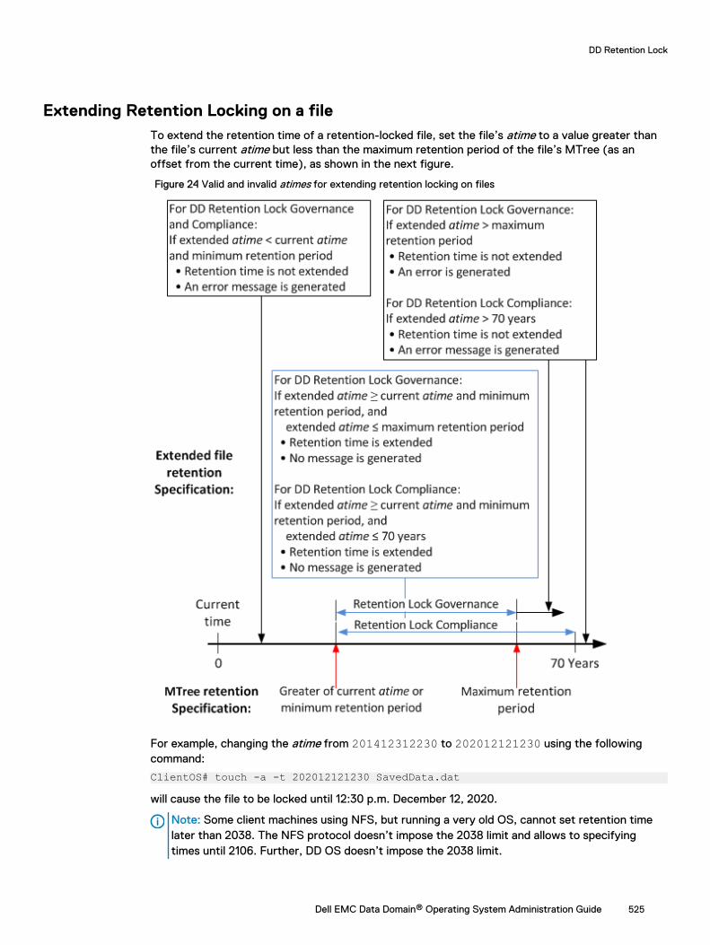
Extending Retention Locking on a fileTo extend the retention time of a retention-locked file, set the file’s atime to a value greater thanthe file’s current atime but less than the maximum retention period of the file’s MTree (as anoffset from the current time), as shown in the next figure.
Figure 24 Valid and invalid atimes for extending retention locking on files
For example, changing the atime from 201412312230 to 202012121230 using the followingcommand:
ClientOS# touch -a -t 202012121230 SavedData.dat
will cause the file to be locked until 12:30 p.m. December 12, 2020.
Note: Some client machines using NFS, but running a very old OS, cannot set retention timelater than 2038. The NFS protocol doesn’t impose the 2038 limit and allows to specifyingtimes until 2106. Further, DD OS doesn’t impose the 2038 limit.
DD Retention Lock
Dell EMC Data Domain® Operating System Administration Guide 525
Errors are permission-denied errors (referred to as EACCESS, a standard POSIX error). These arereturned to the script or archive application setting the atime.
Identifying a Retention-Locked fileThe atime value for a retention-locked file is its retention time. To determine whether a file isretention locked, try to set the atime of the file to a value earlier than its current atime. This actionwill fail with a permission-denied error if and only if the file is a retention-locked file.
First, list the current atime value, and then execute the touch command with an earlier atimeusing these commands:
ls -l --time=atime [filename]touch -a -t [atime] [filename]
The following example shows the command sequence:
ClientOS# ls -l --time=atime SavedData.dat202012121230ClientOS# touch -a -t 202012111230 SavedData.dat
If the atime of SavedData.dat is 202012121230 (12:30 p.m. December 12, 2020) and the touchcommand specifies an earlier atime, 202012111230 (12:30 p.m. December 11, 2020), the touchcommand fails, indicating that SavedData.dat is retention-locked.
Note: The --time=atime option is not supported in all versions of Unix.
Specifying a directory and touching only those filesUse the command line to create a root directory containing the files for which access times willchange.
In this routine, root directory to start from contains the files on which you want to change accesstimes using this client system command:
find [root directory to start from] -exec touch -a -t [expiration time]{} \;For example:
ClientOS# find [/backup/data1/] -exec touch -a -t 202012121230 {} \;
Reading a list of files and touching only those filesIn this routine, name of file list is the name of a text file that contains the names of the files onwhich you want to change access times. Each line contains the name of one file.
Here is the client system command syntax:
touch -a -t [expiration time] 'cat [name of file list]'For example:
ClientOS# touch -a -t 202012121230 ‘cat /backup/data1/filelist.txt‘
Deleting or expiring a fileDelete or expire a file with an expired retention lock using a client application, or delete a file usinga standard file-delete command.
Expiring a file using an application makes the file inaccessible to the application. The file may ormay not actually be removed from the Data Domain system by the expiration operation. If it is notremoved, the application often provides a separate delete operation. You must have theappropriate access rights to delete the file, independent of DD Retention Lock.
DD Retention Lock
526 Dell EMC Data Domain® Operating System Administration Guide
Note: If the retention period of the retention-locked file has not expired, the delete operationresults in a permission-denied error.
Privileged deleteFor DD Retention Lock Governance (only), you can delete retention locked files using this twostep process.
Procedure
1. Use the mtree retention-lock revert path command to revert the retention lockedfile.
2. Delete the file on the client system using the rm filename command.
Using ctime or mtime on Retention-Locked filesctime is the last-metadata-change time of a file.
ctime
ctimegets set to the current time when any of the follow events occur:
l A non-retention-locked file is retention locked.
l The retention time of a retention-locked file is extended.
l A retention-locked file is reverted.
Note: User access permissions for a retention-locked file are updated using the Linuxcommand line tool chmod.
mtime
mtime is the last-modified time of a file. It changes only when the contents of the file change. So,the mtime of a retention-locked file cannot change.
System behavior with DD Retention LockSystem behavior topics are discussed separately for DD Retention Lock Governance and DDRetention Lock Compliance in the sections that follow.
DD Retention Lock governanceCertain DD OS commands behave differently when using DD Retention Lock Governance. Thefollowing sections describe the differences for each.
ReplicationCollection replication, MTree replication, and directory replication replicate the locked or unlockedstate of files.
Files that are governance retention locked on the source are governance retention locked on thedestination and have the same level of protection. For replication, the source system must have aDD Retention Lock Governance license installed—a license is not required on the destinationsystem.
Replication is supported between systems that are:
l Running the same major DD OS version (for example, both systems are running DD OS5.5.x.x).
DD Retention Lock
Dell EMC Data Domain® Operating System Administration Guide 527

l Running DD OS versions within the next two consecutive higher or lower major releases (forexample, 5.3.x.x to 5.5.x.x or 5.5.x.x to 5.3.x.x). Cross-release replication is supported only fordirectory and MTree replication.
Note: MTree replication is not supported for DD OS 5.0 and earlier.
Be aware that:
l Collection replication and MTree replication replicate the minimum and maximum retentionperiods configured on MTrees to the destination system.
l Directory replication does not replicate the minimum and maximum retention periods to thedestination system.
The procedure for configuring and using collection, MTree, and directory replication is the same asfor Data Domain systems that do not have a DD Retention Lock Governance license.
Replication Resync
The replication resync destination command tries to bring the destination into sync with thesource when the MTree or directory replication context is broken between destination and sourcesystems. This command cannot be used with collection replication. Note that:
l If files are migrated to the cloud tier before the context is broken, the MTree replication resyncoverwrites all the data on the destination, so you will need to migrate the files to the cloud tieragain.
l If the destination directory has DD Retention Lock enabled, but the source directory does nothave DD Retention Lock enabled, then a resync of a directory replication will fail.
l With Mtree replication, resync will fail if the source MTree does not have retention lockenabled and the destination MTree has retention lock enabled.
l With Mtree replication, resync will fail if the source and destination MTrees are retention lockenabled but the propagate retention lock option is set to FALSE.
FastcopyWhen the filesys fastcopy [retention-lock] source src destination destcommand is run on a system with a DD Retention Lock Governance enabled MTree, the commandpreserves the retention lock attribute during the fastcopy operation.
Note: If the destination MTree is not retention lock enabled, the retention-lock file attribute isnot preserved.
Filesys destroyEffects of the filesys destroy command when it is run on a system with a DD Retention LockGovernance enabled MTree.
l All data is destroyed, including retention-locked data.
l All filesys options are returned to their defaults. This means that retention locking isdisabled and the minimum and maximum retention periods are set back to their default valueson the newly created file system.
Note: This command is not allowed if DD Retention Lock Compliance is enabled on the system.
DD Retention Lock
528 Dell EMC Data Domain® Operating System Administration Guide
MTree deleteWhen the mtree delete mtree-path command attempts to delete a DD Retention LockGovernance enabled (or previously enabled) MTree that currently contains data, the commandreturns an error.
Note: The behavior of mtree delete is a similar to a command to delete a directory—anMTree with retention lock enabled (or previously enabled) can be deleted only if the MTree isempty.
DD Retention Lock complianceCertain DD OS commands behave differently when using DD Retention Lock Compliance. Thefollowing sections describe the differences for each.
ReplicationAn MTree enabled with DD Retention Lock Compliance can be replicated via MTree and collectionreplication only. Directory replication is not supported.
MTree and collection replication replicate the locked or unlocked state of files. Files that arecompliance retention locked on the source are compliance retention locked on the destination andhave the same level of protection. Minimum and maximum retention periods configured on MTreesare replicated to the destination system.
To perform collection replication, the same security officer user must be present on both thesource and destination systems before starting replication to the destination system and afterwardfor the lifetime of the source/replica pair.
Replication Resync
The replication resync destination command can be used with MTree replication, but notwith collection replication.
l If the destination MTree contains retention-locked files that do not exist on the source, thenresync will fail.
l Both source and destination MTrees must be enabled for DD Retention Lock Compliance, orresync will fail.
Replication proceduresThe topics in this section describe MTree and collection replication procedures supported for DDRetention Lock Compliance.
Note: For full descriptions of the commands referenced in the following topics, see the DataDomain Operating System Command Reference Guide.
Replicating an MTree: One-to-one topology
Replicate a DD Retention Lock Compliance enabled MTree from a source system to a destinationsystem.
Before you begin
Enable DD Retention Lock on an MTree and configure client-side retention lock file control beforereplication.
Procedure
1. Until instructed otherwise, perform the following steps on the destination system only.
DD Retention Lock
Dell EMC Data Domain® Operating System Administration Guide 529

2. Add the DD Retention Lock Compliance license on the system, if it is not present.
a. First, check whether the license is already installed.
license showb. If the RETENTION-LOCK-COMPLIANCE feature is not displayed, install the license.
license add license-key
Note: License keys are case-insensitive. Include the hyphens when typing keys.
3. Set up one or more security officer users accounts according to Role-Base Access Control(RBAC) rules.
a. In the system administrator role, add a security officer account.
user add user role securityb. Enable the security officer authorization.
authorization policy set security-officer enabled4. Configure and enable the system to use DD Retention Lock Compliance.
Note: Enabling DD Retention Lock Compliance enforces many restrictions on low-levelaccess to system functions used during troubleshooting. Once enabled, the only way todisable DD Retention Lock Compliance is to initialize and reload the system, whichresults in destroying all data on the system.
a. Configure the system to use DD Retention Lock Compliance.
system retention-lock compliance configureThe system automatically reboots.
b. After the restart process is complete, enable DD Retention Lock Compliance on thesystem.
system retention-lock compliance enable5. Create a replication context.
replication add source mtree://source-system-name/data/col1/mtree-name destination mtree://destination-system-name/data/col1/mtree-name
6. Perform the following steps on the source system only.
7. Create a replication context.
replication add source mtree://source-system-name/data/col1/mtree-name destination mtree://destination-system-name/data/col1/mtree-name
8. Initialize the replication context.
replication initialize mtree://destination-system-name/data/col1/mtree-name
9. Confirm that replication is complete.
replication status mtree://destination-system-name/data/col1/mtree-name detailedThis command reports 0 pre-compressed bytes remaining when replication is finished.
DD Retention Lock
530 Dell EMC Data Domain® Operating System Administration Guide
Replicating an MTree: One-to-many topology
Replicate a DD Retention Lock Compliance enabled MTree from a source system to multipledestination systems.
Before you begin
Enable DD Retention Lock compliance on an MTree and configure client-side retention lock filecontrol before replication.
Procedure
1. Until instructed otherwise, perform the following steps on the destination system only.
2. Add the DD Retention Lock Compliance license on the system, if it is not present.
a. First, check whether the license is already installed.
license showb. If the RETENTION-LOCK-COMPLIANCE feature is not displayed, install the license.
license add license-key
Note: License keys are case-insensitive. Include the hyphens when typing keys.
3. Set up one or more security officer users accounts according to Role-Base Access Control(RBAC) rules.
a. In the system administrator role, add a security officer account.
user add user role securityb. Enable the security officer authorization.
authorization policy set security-officer enabled4. Configure and enable the system to use DD Retention Lock Compliance.
Note: Enabling DD Retention Lock Compliance enforces many restrictions on low-levelaccess to system functions used during troubleshooting. Once enabled, the only way todisable DD Retention Lock Compliance is to initialize and reload the system, whichresults in destroying all data on the system.
a. Configure the system to use DD Retention Lock Compliance.
system retention-lock compliance configureThe system automatically reboots.
b. After the restart process is complete, enable DD Retention Lock Compliance on thesystem.
system retention-lock compliance enable5. Create a replication context.
replication add source mtree://source-system-name/data/col1/mtree-name destination mtree://destination-system-name/data/col1/mtree-name
6. Perform the following steps on the source system only.
7. Create a replication context for each destination system.
replication add source mtree://source-system-name/data/col1/mtree-name destination mtree://destination-system-name/data/col1/mtree-name
DD Retention Lock
Dell EMC Data Domain® Operating System Administration Guide 531
8. Initialize the replication context for each destination system MTree.
replication initialize mtree://destination-system-name/data/col1/mtree-name
9. Confirm that replication is complete for each destination system.
replication status mtree://destination-system-name/data/col1/mtree-name detailedThis command reports 0 pre-compressed bytes remaining when replication is finished.
Adding DD Retention Lock Compliance protection to an existing MTreereplication pair
Add DD Retention Lock Compliance protection to an existing MTree replication pair that is notenabled for retention locking.
Procedure
1. Until instructed otherwise, perform the following steps on both the source and destinationsystems.
2. Log in to the DD System Manager.
The DD System Manager window appears with DD Network in the Navigation panel.
3. Select a Data Domain system.
In the Navigation panel, expand DD Network and select a system
4. Add the DD Retention Lock Governance license, if it is not listed under Feature Licenses.
a. Select Administration > Licenses
b. In the Licenses area click Add Licenses.
c. In the License Key text box, type the license key.
Note: License keys are case-insensitive. Include the hyphens when typing keys.
d. Click Add.
5. Break the current MTree context on the replication pair.
replication break mtree://destination-system-name/data/col1/mtree-name
6. Create the new replication context.
replication add source mtree://source-system-name/data/col1/mtree-name destination mtree://destination-system-name/data/col1/mtree-name
7. Perform the following steps on the source system only.
8. Select an MTree for retention locking.
Click the Data Management > MTree tab, then the checkbox for the MTree you want touse for retention locking. (You can also create an empty MTree and add files to it later.)
9. Click the MTree Summary tab to display information for the selected MTree.
10. Lock files in the compliance-enabled MTree.
11. Ensure that both source and destination (replica) MTrees are the same.
replication resync mtree://destination-system-name/data/col1/mtree-name
DD Retention Lock
532 Dell EMC Data Domain® Operating System Administration Guide
12. Check the progress of resync.
replication watch mtree://destination-system-name/data/col1/mtree-name
13. Confirm that replication is complete.
replication status mtree://destination-system-name/data/col1/mtree-name detailedThis command reports 0 pre-compressed bytes remaining when replication is finished.
Converting a collection replication pair to MTree replication pairs
A procedure for customers who used collection replication under DD Retention Lock Compliance inDD OS 5.2 and want to convert compliance-enabled MTrees in the collection replication pair toMTree replication pairs.
Procedure
1. On the source system only:
a. Create a snapshot for each DD Retention Lock Compliance enabled MTree.
snapshot create snapshot-name /data/col1/mtree-nameb. Synchronize the collection replication pair.
replication sync col://destination-system-namec. Confirm that replication is complete.
replication status col://destination-system-name detailedThis command reports 0 pre-compressed bytes remaining when replication is finished.
d. View snapshot information for each DD Retention Lock Compliance enabled MTree.
snapshot list mtree /data/col1/mtree-nameNote the snapshot names for use later.
2. On the destination system only:
a. Confirm that the replication is complete.
replication status mtree://destination-system-name/data/col1/mtree-name detailedThis command reports 0 pre-compressed bytes remaining when replication is finished.
b. View each MTree snapshot replicated to the destination system.
snapshot list mtree /data/col1/mtree-namec. Ensure that all DD Retention Lock Compliance MTree snapshots have been replicated by
comparing the snapshot names generated here with those generated on the sourcesystem.
snapshot list mtree /data/col1/mtree-name3. On the both the source and destinations systems:
a. Disable the file system.
filesys disableb. Break the collection replication context.
replication break col://destination-system-namec. Enable the file system. (Security officer authorization may be required.)
filesys enable
DD Retention Lock
Dell EMC Data Domain® Operating System Administration Guide 533
d. Add a replication context for each DD Retention Lock Compliance enabled MTree.
replication add source mtree://source-system-name/data/col1/mtree-name destination mtree://destination-system-name/data/col1/mtree-name
Note: Source and destination MTree names must be the same.
4. On the source system only:
a. Ensure that both source and destination MTrees are the same.
replication resync mtree://destination-system-nameb. Check the progress of resync.
replication watch destinationc. Confirm that replication is complete.
replication status mtree://destination-system-name/data/col1/mtree-name detailedThis command reports 0 pre-compressed bytes remaining when replication is finished.
Performing collection replication
Replicate /data/col1 from a compliance-enabled source system to a compliance-enableddestination system.
About this task
Note: For collection replication the same security officer account must be used on both thesource and destination systems.
Procedure
1. Until instructed to do differently, perform the following steps on the source system only.
2. Log in to the DD System Manager.
The DD System Manager window appears with DD Network in the Navigation Panel.
3. Select a Data Domain system.
In the Navigation Panel, expand DD Network and select a system.
4. Add the DD Retention Lock Governance license, if it is not listed under Feature Licenses.
a. Select Administration > Licenses
b. In the Licenses area click Add Licenses.
c. In the License Key text box, type the license key.
Note: License keys are case-insensitive. Include the hyphens when typing keys.
d. Click Add.
5. Create the replication context.
replication add source col://source-system-name destination col://destination-system-name
6. Until instructed to do differently, perform the following steps on the destination systemonly.
7. Destroy the file system.
filesys destroy
DD Retention Lock
534 Dell EMC Data Domain® Operating System Administration Guide
8. Log in to the DD System Manager.
The DD System Manager window appears with DD Network in the Navigation Panel.
9. Select a Data Domain system.
In the Navigation Panel, expand DD Network and select a system.
10. Create a file system, but do not enable it.
filesys create11. Create the replication context.
replication add source col://source-system-name destination col://destination-system-name
12. Configure and enable the system to use DD Retention Lock Compliance.
system retention-lock compliance configure(The system automatically reboots and executes the system retention-lockcompliance enable command.)
13. Perform the following steps on the source system only.
14. Initialize the replication context.
replication initialize source col://source-system-name destinationcol://destination-system-name
15. Confirm that replication is complete.
replication status col://destination-system-name detailedThis command reports 0 pre-compressed bytes remaining when replication is finished.
Adding DD Retention Lock Compliance protection to an existing collectionreplication pair
Add DD Retention Lock Compliance protection to a collection replication pair that was createdwithout DD Retention Lock Compliance enabled on the source and destination systems.
Procedure
1. Until instructed otherwise, perform the following steps on both the source and destinationsystems.
2. Disable the replication.
replication disable col://destination-system-name3. Log in to the DD System Manager.
The DD System Manager window appears with DD Network in the Navigation Panel.
4. Select a Data Domain system.
In the Navigation Panel, expand DD Network and select a system.
5. Until instructed otherwise, perform the following steps on the source system.
6. Configure and enable the system to use DD Retention Lock Compliance.
system retention-lock compliance configure(The system automatically reboots by executing the system retention-lockcompliance enable command.)
7. Enable the replication context.
replication enable col://destination-system-name
DD Retention Lock
Dell EMC Data Domain® Operating System Administration Guide 535
8. Until instructed otherwise, perform the following steps on the destination system.
9. Configure and enable the system to use DD Retention Lock Compliance.
system retention-lock compliance configure(The system automatically reboots by executing the system retention-lockcompliance enable command.)
10. Enable the replication context.
replication enable col://destination-system-name
FastcopyWhen the filesys fastcopy [retention-lock] source src destination destcommand is run on a system with a DD Retention Lock Compliance enabled MTree, the commandpreserves the retention lock attribute during the fastcopy operation.
Note: If the destination MTree is not retention lock enabled, the retention-lock file attribute isnot preserved.
CLI usageConsiderations for a Data Domain system with DD Retention Lock Compliance.
l Commands that break compliance cannot be run. The following commands are disallowed:
n filesys archive unit del archive-unitn filesys destroyn mtree delete mtree-pathn mtree retention-lock reset {min-retention-period period | max-
retention-period period} mtree mtree-pathn mtree retention-lock disable mtree mtree-pathn mtree retention-lock revertn user reset
l The following command requires security officer authorization if the license being deleted is forDD Retention Lock Compliance:
n license del license-feature [license-feature ...] | license-code[license-code ...]
l The following commands require security officer authorization if DD Retention LockCompliance is enabled on an MTree specified in the command:
n mtree retention-lock set {min-retention-period period | max-retention-period period} mtree mtree-path
n mtree rename mtree-path new-mtree-pathl The following commands require security officer authorization if DD Retention Lock
Compliance is enabled on the system:Note: These commands must be run in interactive mode.
n alerts notify-list resetn config set timezone zonenamen config reset timezone
DD Retention Lock
536 Dell EMC Data Domain® Operating System Administration Guide
n cifs set authentication active-directory realm { [dc1 [dc2 ...]]n license resetn ntp add timeserver time server listn ntp del timeserver time server listn ntp disablen ntp enablen ntp resetn ntp reset timeserversn replication break {destination | all}n replication disable {destination | all}n system set date MMDDhhmm[[CC]YY]
System clockDD Retention Lock Compliance implements an internal security clock to prevent malicioustampering with the system clock.
The security clock closely monitors and records the system clock. If there is an accumulated two-week skew within a year between the security clock and the system clock, the file system isdisabled and can be resumed only by a security officer.
Finding the System Clock Skew
You can run the DD OS command system retention-lock compliance status (securityofficer authorization required) to get system and security clock information, including the lastrecorded security clock value, and the accumulated system clock variance. This value is updatedevery 10 minutes.
Removing the system clock skew
Clock skew is updated every time the security clock records a new value for the system clock.After 1 year, it is reset to 0.
About this task
At any time, you can run the DD OS command system set date MMDDhhmm[[CC]YY] to setthe time of the system clock (security officer authorization required). If the clock skew becomeslarger than the preset value (2 weeks), the file system is disabled. Complete these steps to restartthe file system and remove the skew between security and system clocks.
Procedure
1. At the system console, enable the file system.
filesys enable2. At the prompt, confirm that you want to quit the filesys enable command and check
whether the system date is right.
3. Display the system date.
system show date4. If the system date is not correct, set the correct date (security officer authorization is
required) and confirm it.
system set date MMDDhhmm[[CC]YY]system show date
5. Enable the file system again.
DD Retention Lock
Dell EMC Data Domain® Operating System Administration Guide 537

filesys enable6. At the prompt, continue to the enabling procedure.
7. A security officer prompt appears. Complete the security officer authorization to start thefile system. The security clock will automatically be updated to the current system date.
DD Retention Lock
538 Dell EMC Data Domain® Operating System Administration Guide
CHAPTER 21
DD Encryption
This chapter includes:
l DD encryption overview...................................................................................................... 540l Configuring encryption........................................................................................................540l About key management....................................................................................................... 541l Key manager setup..............................................................................................................552l Changing key managers after setup.................................................................................... 556l Checking settings for encryption of data at rest................................................................. 558l Enabling and disabling encryption of data at rest................................................................ 558l Locking and unlocking the file system................................................................................. 559
Dell EMC Data Domain® Operating System Administration Guide 539
DD encryption overviewData encryption protects user data if the Data Domain system is stolen or if the physical storagemedia is lost during transit, and it eliminates accidental exposure of a failed drive if it is replaced.
When data enters the Data Domain system using any of the supported protocols (NFS, CIFS, DDVTL, DD Boost, and NDMP Tape Server), the stream is segmented, fingerprinted, and de-duplicated (global compression). It is then grouped into multi-segment compression regions, locallycompressed, and encrypted before being stored to disk.
Once enabled, the Encryption at Rest feature encrypts all data entering the Data Domain system.You cannot enable encryption at a more granular level.
CAUTION Data that has been stored before the DD Encryption feature is enabled does notautomatically get encrypted. To protect all of the data on the system, be sure to enable theoption to encrypt existing data when you configure encryption.
Additional Notes:
As of DD OS 5.5.1.0, Encryption of Data at Rest is supported for DD Extended Retention-enabledsystems with a single retention unit. As of 5.5.1.0, DD Extended Retention supports only a singleretention unit, so systems set up during, or after, 5.5.1.0 will have no problem complying with thisrestriction. However, systems set up prior to 5.5.1.0 may have more than one retention unit, butthey will not work with Encryption of Data at Rest until all but one retention unit has beenremoved, or data has been moved or migrated to one retention unit.
The filesys encryption apply-changes command applies any encryption configurationchanges to all data present in the file system during the next cleaning cycle. For more informationabout this command, see the Data Domain Operating System Command Reference Guide.
Encryption of Data at Rest supports all of the currently supported backup applications described inthe Backup Compatibility Guides available through Online Support at http://support.emc.com.
Data Domain Replicator can be used with encryption, enabling encrypted data to be replicatedusing collection, directory, MTree, or application-specific managed file replication with the varioustopologies. Each replication form works uniquely with encryption and offers the same level ofsecurity. For more information, see the section on using encryption of data at rest with replication.
Files locked using Data Domain Retention Lock can be stored, encrypted, and replicated.
The autosupport feature includes information about the state of encryption on the Data Domainsystem:
l Whether or not encryption is enabled
l The Key Manager in effect and which keys are used
l The encryption algorithm that is configured
l The state of the file system
Configuring encryptionThis procedure includes configuring a key manager.
If the Encryption Status on the Data Management > File System > Encryption tab shows NotConfigured, click Configure to set up encryption on the Data Domain system.
Note: The system passphrase must be set in order to enable encryption.
Provide the following information:
DD Encryption
540 Dell EMC Data Domain® Operating System Administration Guide
l Algorithm
n Select an encryption algorithm from the drop-down list or accept the default AES 256-bit(CBC).The AES 256-bit Galois/Counter Mode (GCM) is the most secure algorithm but it issignificantly slower than the Cipher Block Chaining (CBC) mode.
n Determine what data is to be encrypted: existing and new or only new. Existing data will beencrypted during the first cleaning cycle after the file system is restarted. Encryption ofexisting data can take longer than a standard file system cleaning operation.
l Key Manager (select one of the three)
n Embedded Key ManagerBy default, the Data Domain Embedded Key Manager is in effect after you restart the filesystem unless you configure the RSA DPM Key Manager.
You can enable or disable key rotation. If enabled, type a rotation interval between 1-12months.
n RSA DPM Key Manager
n SafeNet KeySecure Key Manager
Note: See the section about key management for an explanation about how the EmbeddedKey Manager, the RSA DPM Key Manager, and SafeNet KeySecure Key Manager work.
The Summary shows the selected configuration values. Review them for correctness. To change avalue, click Back to browse to the page where it was entered and modify it.
A system restart is necessary to enable encryption. To apply the new configuration, select theoption to restart the file system.
Note: Applications may experience an interruption while the file system is restarted.
About key managementEncryption keys determine the output of the cryptographic algorithm. They are protected by apassphrase, which encrypts the encryption key before it is stored in multiple locations on disk. Thepassphrase is generated by the user and requires both an administrator and a security officer tochange it.
A key manager controls the generation, distribution, and lifecycle management of multipleencryption keys. A Data Domain system can use either the Embedded Key Manager or the RSAData Protection Manager (DPM) or SafeNet KeySecure Key Manager. Support for KeyManagement Interoperability Protocol (KMIP) is introduced with DD OS 6.1.
Only one can be in effect at a time. When encryption is enabled on a Data Domain system, theEmbedded Key Manager is in effect by default. If you configure the RSA DPM or SafeNetKeySecure Key Manager, it replaces the Embedded Key Manager and remains in effect until youdisable it. A file system restart is required for a new key manager to be operational.
Both the Embedded and DPM key managers provide multiple keys, although the system uses onlyone key at a time to encrypt data coming into a Data Domain system. If the external Key Manageris configured and enabled, the Data Domain systems use keys that are provided by the RSA DPMKey Manager Server. If the same DPM Key Manager manages multiple Data Domain systems, allsystems have the same active key (if they are using the same key class) when the systems aresynced and the file system has been restarted. The Embedded Key Manager generates its keysinternally.
Both key managers rotate keys and support a maximum of 254 keys. The Embedded Key Managerallows you to specify how many months a key is in effect before being replaced (after the filesystem is restarted). The RSA DPM Key Manager rotates keys on a normal basis, depending on the
DD Encryption
Dell EMC Data Domain® Operating System Administration Guide 541

key class. The Embedded Key Manager key rotation is managed on the Data Domain system. TheKey Manager key rotation is managed on the external Key Manager server.
KeySecure
KeySecure 8.5 and 8.9 supported, which is a KMIP compliant key manager product from SafenetInc/Gemalto Keysecure. To be able to use KMIP key manager, users have to configure both thekey manager and the Data Domain system/DD VE, to trust each other. Users have to pre-createkeys on the key manager. A Data Domain system will retrieve these keys and their states fromKeySecure after establishing a secure TLS connection. See the Data Domain Operating System andGemalto KeySecure Integration Guide for more information on how to create keys and use them on aData Domain system.
Rectifying lost or corrupted keysCreate a file that contains all of your system’s current encryption keys. Your support provider canuse this file to import keys back to your system should they become lost or corrupted. It isrecommended that you create an export file on a regular basis.
You are prompted for the Security Officer's credential to export the keys. For additional key fileprotection, you can use a passphrase that differs from the one used in a Data Domain system.After exporting, it is recommended that you save the key file in a secure file server accessible onlyby authorized users. You must remember the passphrase used for the key file. If the passphrase islost or forgotten, the Data Domain system cannot import and restore the keys. Enter:
# filesys encryption keys export
Key manager supportAll Key Managers support all DD OS file system protocols.
Replication
When configuring Data Domain systems for directory MTree replication, configure each DataDomain system separately. The two systems can use either the same or a different key class, andthe same or different key managers.
For collection replication configuration, the Data Domain system must be configured on thesource. After a replication break, the original replica Data Domain system has to be configured forthe Key Manager. If not, the Data Domain system continues to use the latest known key.
Working with the RSA DPM Key ManagerIf the RSA DPM Key Manager is configured and enabled, the Data Domain systems use keysprovided by the RSA DPM Key Manager Server. If the same DPM Key Manager manages multipleData Domain systems, all systems will have the same active key (if they are using the same keyclass) when the systems are synced and the file system has been restarted. Key rotation ismanaged on the RSA DPM Key Manager server.
If the RSA DPM Key Manager is configured and enabled, the Data Domain systems use keysprovided by the RSA DPM Key Manager Server. If the same DPM Key Manager manages multipleData Domain systems, all systems will have the same active key (if they are using the same keyclass) when the systems are synced and the file system has been restarted. Key rotation ismanaged on the RSA DPM Key Manager server.
Encryption Key States
One Activated-RW key is always in effect. If the active key is compromised, the RSA DPM KeyManager provides a new key. When the Data Domain system detects the new key, it issues an alertfor the administrator to restart the file system.
DD Encryption
542 Dell EMC Data Domain® Operating System Administration Guide
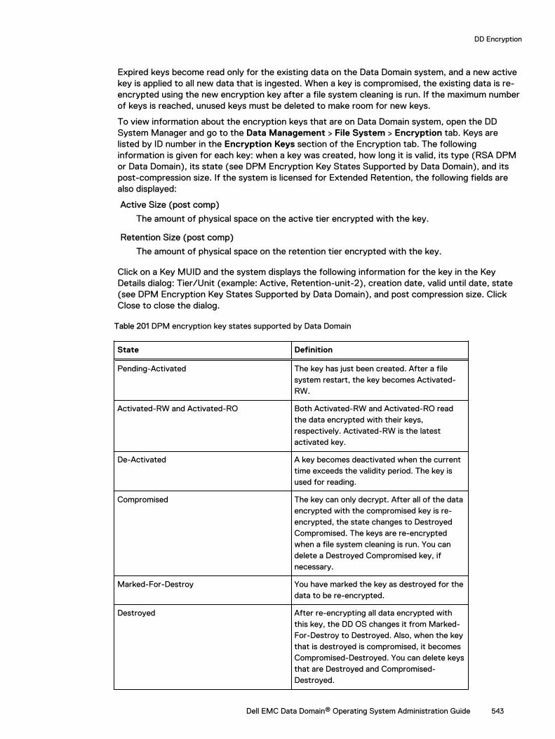
Expired keys become read only for the existing data on the Data Domain system, and a new activekey is applied to all new data that is ingested. When a key is compromised, the existing data is re-encrypted using the new encryption key after a file system cleaning is run. If the maximum numberof keys is reached, unused keys must be deleted to make room for new keys.
To view information about the encryption keys that are on Data Domain system, open the DDSystem Manager and go to the Data Management > File System > Encryption tab. Keys arelisted by ID number in the Encryption Keys section of the Encryption tab. The followinginformation is given for each key: when a key was created, how long it is valid, its type (RSA DPMor Data Domain), its state (see DPM Encryption Key States Supported by Data Domain), and itspost-compression size. If the system is licensed for Extended Retention, the following fields arealso displayed:
Active Size (post comp)
The amount of physical space on the active tier encrypted with the key.
Retention Size (post comp)
The amount of physical space on the retention tier encrypted with the key.
Click on a Key MUID and the system displays the following information for the key in the KeyDetails dialog: Tier/Unit (example: Active, Retention-unit-2), creation date, valid until date, state(see DPM Encryption Key States Supported by Data Domain), and post compression size. ClickClose to close the dialog.
Table 201 DPM encryption key states supported by Data Domain
State Definition
Pending-Activated The key has just been created. After a filesystem restart, the key becomes Activated-RW.
Activated-RW and Activated-RO Both Activated-RW and Activated-RO readthe data encrypted with their keys,respectively. Activated-RW is the latestactivated key.
De-Activated A key becomes deactivated when the currenttime exceeds the validity period. The key isused for reading.
Compromised The key can only decrypt. After all of the dataencrypted with the compromised key is re-encrypted, the state changes to DestroyedCompromised. The keys are re-encryptedwhen a file system cleaning is run. You candelete a Destroyed Compromised key, ifnecessary.
Marked-For-Destroy You have marked the key as destroyed for thedata to be re-encrypted.
Destroyed After re-encrypting all data encrypted withthis key, the DD OS changes it from Marked-For-Destroy to Destroyed. Also, when the keythat is destroyed is compromised, it becomesCompromised-Destroyed. You can delete keysthat are Destroyed and Compromised-Destroyed.
DD Encryption
Dell EMC Data Domain® Operating System Administration Guide 543

Table 201 DPM encryption key states supported by Data Domain (continued)
State Definition
Note: A key is not destroyed in the DataDomain system until a cleaning operationis run and completed.
Keeping keys in sync with the RSA DPM key managerAn automatic key sync is performed every day at midnight. A manual key sync is required only ifyou cannot wait for the scheduled sync. Whenever new keys are synced on the Data Domainsystem, an alert is generated. This alert is cleared after the file system is restarted.
About this task
After the RSA DPM Key Manager Server generates new keys, click the Sync button to have themdisplay in the Encryption Key list on the Data Domain System Manager’s Encryption tab.
Note: A file system restart is necessary if keys have changed since the last sync.
Procedure
1. Using the DD System Manager, select the Data Domain system you are working with in theNavigation panel.
Note: Always perform DD System Manager functions on the system you have selectedin the Navigation panel.
2. Select Data Management > File System > Encryption.
3. In the Encryption Keys section, select the RSA DPM key, and click Sync.
Destroying a key (RSA DPM key manager)Destroy a key if you do not want any data to be encrypted with it. This procedure requires securityofficer credentials.
About this task
Note: For information about the security officer, see the sections regarding creating localusers and enabling security authorization.
To change an RSA DPM key to a state in which it can be destroyed:
Procedure
1. Deactivate the key on the RSA DPM Server.
2. Restart the file system for the key to be deactivated on the Data Domain system.
3. Using the DD System Manager, select Data Management > File System > Encryption.
4. In the Encryption Keys section, select the key in the list to be destroyed.
5. Click Destroy....
The system displays the Destroy dialog that includes the tier and state for the key.
6. Enter your security officer user name and password.
7. Confirm that you want to destroy the key by clicking Destroy.
Note: After a file system clean has run, the key state will change to Destroyed.
DD Encryption
544 Dell EMC Data Domain® Operating System Administration Guide
Deleting a keyYou can delete Key Manager keys that are in the Destroyed or Compromised-Destroyed states.However, you only need to delete a key when the number of keys has reached the maximum 254limit. This procedure requires security officer credentials.
About this task
Note: To reach the Destroyed state, the Destroying a Key procedure (for either the EmbeddedKey Manager or the RSA DPM Key Manager) must be performed on the key and a systemcleaning must be run.
Procedure
1. Select Data Management > File System > Encryption.
2. In the Encryption Keys section, select the key or keys in the list to be deleted.
3. Click Delete....
The system displays the key to be deleted, and the tier and state for the key.
4. Type your security officer user name and password.
5. Confirm that you want to delete the key or keys by clicking Delete.
Working with the Embedded Key ManagerWhen the Embedded Key Manager is selected, the Data Domain System creates its own keys.
After the key rotation policy is configured, a new key is automatically created at the next rotation.An alert informs you of the creation of a new key. You must perform a file system restart toactivate the new key and deactivate the old key. You can disable the key rotation policy by clickingthe disable button associated with the Embedded Key Manager Key’s rotation status.
Creating a key (Embedded Key Manager)Create an encryption key for the Embedded Key Manager.
Procedure
1. Select Data Management > File System > DD Encryption.
2. In the Encryption Keys section, click Create... .
3. Type your security officer user name and password.
4. Click Restart the filesystem now if you want to restart the file system.
A new Data Domain key will be created. After the file system is restarted, the previous keywill become deactivated and the new key will become activated.
5. Click Create.
Destroying a key (Embedded Key Manager)Destroy an encryption key for the Embedded Key Manager.
Procedure
1. Select Data Management > File System > Encryption.
2. In the Encryption Keys section, select the key in the list to be destroyed.
3. Click Destroy....
The system displays the Destroy dialog that includes the tier and state for the key.
DD Encryption
Dell EMC Data Domain® Operating System Administration Guide 545
4. Type your security officer user name and password.
5. Confirm that you want to destroy the key by clicking Destroy.
Note: After a file system clean has run, the key state changes to Destroyed.
Working with KeySecure Key ManagerKeySecure Key Manager supports external key managers by using Key ManagementInteroperability Protocol (KMIP) and centrally manages encryption keys in a single, centralizedplatform.
l Keys will be pre-created on the Key Manager.
l KMIP Key Manager cannot be enabled on systems that have encryption enabled on one ormore cloud units.
Using DD System Manager to set up and manage the KeySecure Key ManagerThis section describes how to use Data Domain System Manager (DD SM) to manage theKeySecure Key Manager.
Creating a key for the KeySecure Key ManagerCreate an encryption key for the KeySecure Key Manager (KMIP).
About this task
Procedure
1. Scroll down to the Key Manager Encryption Keys table.
2. Click Add to create a new Key Manager encryption key.
a. Enter the Security Officer username and password.
b. Click Restart the file system now.
c. Click Create.
3. Click Restart the file system now to make the changes take effect.
A new KIMP key is created. After the file system is restarted, the previous key isdeactivated and the new key is activated.
DD Encryption
546 Dell EMC Data Domain® Operating System Administration Guide
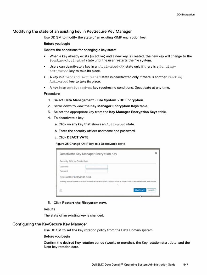
Modifying the state of an existing key in KeySecure Key ManagerUse DD SM to modify the state of an existing KIMP encryption key.
Before you begin
Review the conditions for changing a key state:
l When a key already exists (is active) and a new key is created, the new key will change to thePending-Activated state until the user restarts the file system.
l Users can deactivate a key in an Activated-RW state only if there is a Pending-Activated key to take its place.
l A key in a Pending-Activated state is deactivated only if there is another Pending-Activated key to take its place.
l A key in an Activated-RO key requires no conditions. Deactivate at any time.
Procedure
1. Select Data Management > File System > DD Encryption.
2. Scroll down to view the Key Manager Encryption Keys table.
3. Select the appropriate key from the Key Manager Encryption Keys table.
4. To deactivate a key:
a. Click on any key that shows an Activated state.
b. Enter the security officer username and password.
c. Click DEACTIVATE.
Figure 25 Change KMIP key to a Deactivated state
5. Click Restart the filesystem now.
Results
The state of an existing key is changed.
Configuring the KeySecure Key ManagerUse DD SM to set the key rotation policy from the Data Domain system.
Before you begin
Confirm the desired Key rotation period (weeks or months), the Key rotation start date, and theNext key rotation date.
DD Encryption
Dell EMC Data Domain® Operating System Administration Guide 547
Procedure
1. Select Data Management > File System > DD Encryption.
2. In the Key Management section, click Configure. The Change Key Manager dialog boxopens.
3. Enter your security officer user name and password.
4. Select KeySecure Key Manager from the Key Manager Type drop down menu. TheChange Key Manager information appears.
5. Set the key rotation policy:
Note: The rotation policy is specified in weeks and months. The minimum key rotationpolicy increment is one week, and the maximum key rotation policy increment is 52weeks (or 12 months).
a. Enable the Key Rotation policy. Set the Enable Key rotation policy button to enable.
b. Enter the appropriate dates in the Key rotation schedule field.
c. Select the appropriate number of weeks or months from the Weeks or Months dropdown menu.
d. Click OK.
e. Click Restart the filesystem now if you want to restart the file system to make thechanges take effect immediately. per Fig 3
Results
The key rotation policy is set or changed.
Using the Data Domain CLI to manage the KeySecure Key ManagerThis section describes how to use the CLI to manage the KeySecure Key Manager.
Create a new active key on the KeySecure Key ManagerUse the Data Domain CLI to create a new active key.
Before you begin
Ensure that you have the appropriate user credentials. The security role is required to run thesecommands.
Procedure
1. Log into the Data Domain system using the security role:
Username: <security office user>Password: <security officer password>
2. Create a new active key:
# filesys encryption key-manager keys create
3. Output that is similar to the following appears:
New encryption key was successfully created.The filesystem must be restarted to activate the new key.
DD Encryption
548 Dell EMC Data Domain® Operating System Administration Guide

Results
A new active key is created.
DD Encryption
Dell EMC Data Domain® Operating System Administration Guide 549
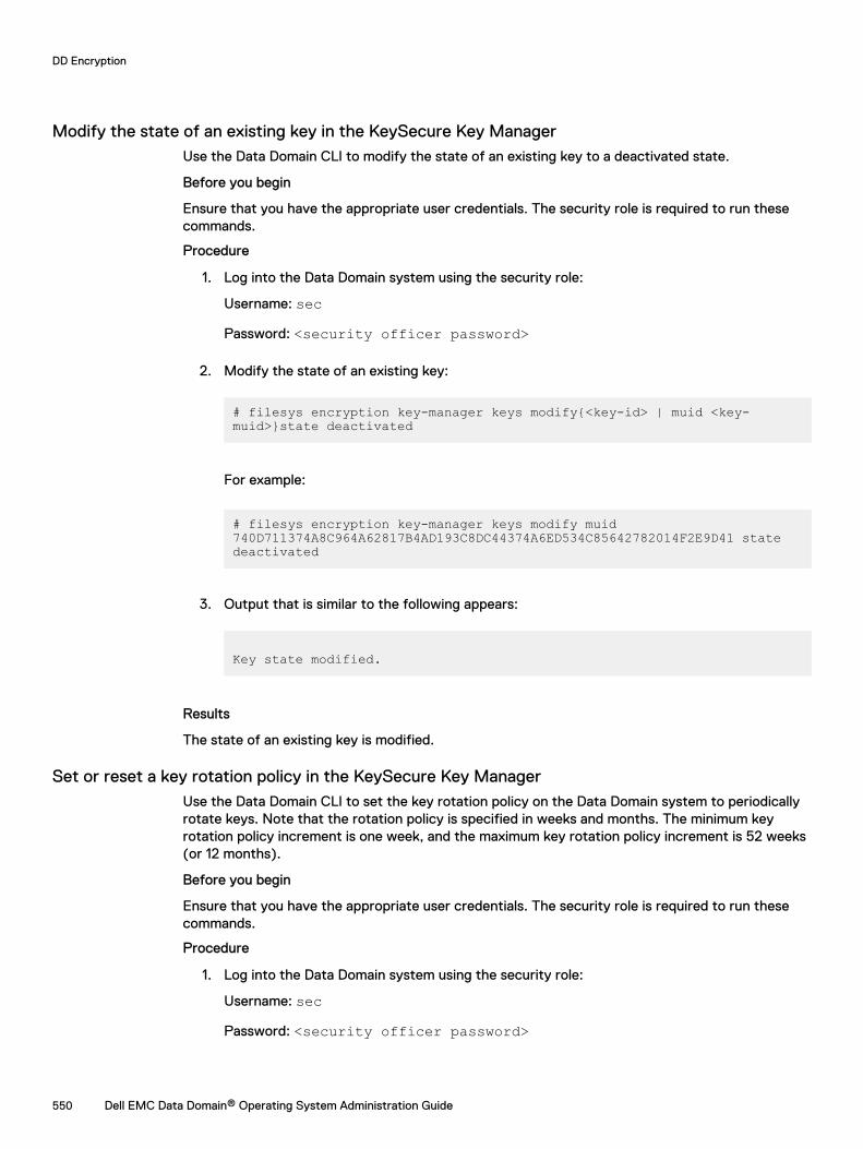
Modify the state of an existing key in the KeySecure Key ManagerUse the Data Domain CLI to modify the state of an existing key to a deactivated state.
Before you begin
Ensure that you have the appropriate user credentials. The security role is required to run thesecommands.
Procedure
1. Log into the Data Domain system using the security role:
Username: secPassword: <security officer password>
2. Modify the state of an existing key:
# filesys encryption key-manager keys modify{<key-id> | muid <key-muid>}state deactivated
For example:
# filesys encryption key-manager keys modify muid 740D711374A8C964A62817B4AD193C8DC44374A6ED534C85642782014F2E9D41 state deactivated
3. Output that is similar to the following appears:
Key state modified.
Results
The state of an existing key is modified.
Set or reset a key rotation policy in the KeySecure Key ManagerUse the Data Domain CLI to set the key rotation policy on the Data Domain system to periodicallyrotate keys. Note that the rotation policy is specified in weeks and months. The minimum keyrotation policy increment is one week, and the maximum key rotation policy increment is 52 weeks(or 12 months).
Before you begin
Ensure that you have the appropriate user credentials. The security role is required to run thesecommands.
Procedure
1. Log into the Data Domain system using the security role:
Username: secPassword: <security officer password>
DD Encryption
550 Dell EMC Data Domain® Operating System Administration Guide

2. Set a key rotation policy for the first time. In our example, we will set the rotation policy tothree weeks:
# filesys encryption key-manager set key-rotation-policy {every <n> {weeks | months} | none}
For example:
# filesys encryption key-manager set key-rotation-policy every 3 weeks
Output that is similar to the following appears:
Key-rotation-policy is set. Encryption key will be rotated every 3 weeks.
3. Subsequently, run this command if you choose to change the existing key rotation policy. Inour example, we will change the rotation policy from three weeks to four months:
Note: Log into the Data Domain system using the security role (where Username is sec,and the password is the <security officer password> ).
# filesys encryption key-manager reset [key-rotation-policy]
For example:
filesys encryption key-manager set key-rotation-policy every 4 months
Output that is similar to the following appears:
Key-rotation-policy is set. Encryption key will be rotated every 4 months.
4. Display the current key rotation policy, or verify that the policy is set correctly:
# filesys encryption key-manager show
Output that is similar to the following appears:
The current key-manager configuration is:Key Manager: EnabledServer Type: KeySecureServer: <IP address of KMIP server>Port: 5696Fips-mode: enabled
DD Encryption
Dell EMC Data Domain® Operating System Administration Guide 551
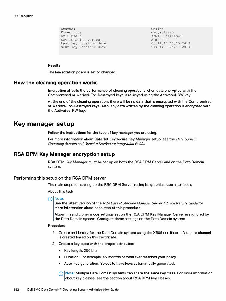
Status: OnlineKey-class: <key-class>KMIP-user: <KMIP username>Key rotation period: 2 monthsLast key rotation date: 03:14:17 03/19 2018Next key rotation date: 01:01:00 05/17 2018
Results
The key rotation policy is set or changed.
How the cleaning operation worksEncryption affects the performance of cleaning operations when data encrypted with theCompromised or Marked-For-Destroyed keys is re-keyed using the Activated-RW key.
At the end of the cleaning operation, there will be no data that is encrypted with the Compromisedor Marked-For-Destroyed keys. Also, any data written by the cleaning operation is encrypted withthe Activated-RW key.
Key manager setupFollow the instructions for the type of key manager you are using.
For more information about SafeNet KeySecure Key Manager setup, see the Data DomainOperating System and Gemalto KeySecure Integration Guide.
RSA DPM Key Manager encryption setupRSA DPM Key Manager must be set up on both the RSA DPM Server and on the Data Domainsystem.
Performing this setup on the RSA DPM serverThe main steps for setting up the RSA DPM Server (using its graphical user interface).
About this task
Note:See the latest version of the RSA Data Protection Manager Server Administrator’s Guide formore information about each step of this procedure.
Algorithm and cipher mode settings set on the RSA DPM Key Manager Server are ignored bythe Data Domain system. Configure these settings on the Data Domain system.
Procedure
1. Create an identity for the Data Domain system using the X509 certificate. A secure channelis created based on this certificate.
2. Create a key class with the proper attributes:
l Key length: 256 bits.
l Duration: For example, six months or whatever matches your policy.
l Auto-key generation: Select to have keys automatically generated.
Note: Multiple Data Domain systems can share the same key class. For more informationabout key classes, see the section about RSA DPM key classes.
DD Encryption
552 Dell EMC Data Domain® Operating System Administration Guide
3. Create an identity using the Data Domain system’s host certificate as its identity certificate.The identity and the key class have to be in the same identity group.
4. Import the certificates. See the section about importing certificates for more information.
About RSA DPM key classesThe Data Domain system retrieves a key from RSA DPM Key Manager by key class. A key class is aspecialized type of security class used by the RSA DPM Key Manager that groups crytopgraphickeys with similar characteristics.
The RSA DPM Key Manager Server allows a key class to be set up to either return the current key,or to generate a new key each time. The Data Domain system supports only the key classesconfigured to return the current key. Do not use a key class that is configured to generate a newkey each time.
Note: If the key length is not 256 bits, the DPM configuration will fail.
Importing the certificatesAfter obtaining certificates, import them to the Data Domain system.
Before you begin
l The Host certificate should be in PKCS12 format.
l The CA certificate should be in PEM format.
l You must obtain CA and Host certificates that are compatible with the RSA DPM KeyManager. You can request these certificates from third-party certificates authorities, or createthem using appropriate SSL utility tools.
l If the system passphrase is not set, you cannot import the host certificate. The passphrase isset when you enable encryption. To change it, see the section regarding changing the systempassphrase in the Managing the Data Domain Systems chapter.
About this task
DD OS supports certificates without any extension and certificates with server and clientextensions for use with both the Data DD Manager and RSA DPM Key Manager. Certificates withclient extensions are supported only by RSA DPM Key Manager, and certificates with serverextensions are supported only by the DD System Manager.
DD OS does not support the RSA DPM Key Manager Server’s Auto Registration Certificatecapability, which uploads an auto registered certificate directly, or imports multiple certificates.This means that you must import the CA and Host certificates for a Data Domain system.
The following information describes how to respond to a couple of alerts that might appear duringcertificate management.
l If HTTPS fails to restart due to corrupted imported certificates, self-signed certificates areused. If this occurs, a managed alert, UnusableHostCertificate, is issued. To clear the alert,delete the corrupted certificates and re-import new certificates.
l If imported certificates are removed, for example during a system headswap and the importedcertificates fail to copy over, a managed alert, MissingHostCertificate, is issued. Re-import thecertificates to clear the alert.
After obtaining the certificates, import them to the Data Domain system as follows:
Procedure
1. Configure the RSA DPM Key Manager Server to use the CA and Host certificates. Forinstructions, see the RSA DPM Key Manager Server Administration Guide.
2. Import the certificates by redirecting the certificate files using ssh command syntax. Seethe Data Domain Operating System Command Reference Guide for details.
DD Encryption
Dell EMC Data Domain® Operating System Administration Guide 553
ssh sysadmin@<Data-Domain-system> adminaccess certificate import {hostpassword password |ca } < path_to_the_certificateFor example, to import the host certificate host.p12 from your personal computer’s desktopover to the Data Domain system DD1 using ssh, enter:
# ssh sysadmin@DD1 adminaccess certificate import host password abc123 <C:\host.p12
3. Import the CA certificate, for example, ca.pem, from your desktop to DD1 via SSH byentering:
# ssh sysadmin@DD1 adminaccess certificate import ca < C:\ca.pem
Performing this setup on the Data Domain systemConfigure encryption on the Data Domain System Manager using the DPM Key Manager.
Procedure
1. Complete the DPM Key Manager setup on the RSA DPM Server.
2. The Data Domain system must be able to resolve its own IP address using its hostname. Ifthis mapping has not been added to the DNS server, use this command line to add the entryto the /etc/hosts file:
# net hosts add ipaddr host-listwhere ipaddr is the IP address of Data Domain system and host-list is the hostname of theData Domain system.
If you are working in a dual stack environment, and the system displays the following errormessage: "RKM is not configured correctly," then use the net hosts add ipaddr host-listcommand to add the IPv4 address of the Data Domain System to the /etc/hosts file.
Note: A DPM server cannot be enabled in an environment using only IPv6 addresses.
Note: By default, the fips-mode is enabled. If the PKCS #12 client credential is notencrypted with the FIPS 140-2 approved algorithm, such as RC2, then you must disablefips-mode. See the Data Domain Operating System Command Reference Guide forinformation about disabling fips-mode.
3. Log into the DD System Manager and select the Data Domain system you are working within the Navigation panel.
Note: Always perform DD System Manager functions on the system you have selectedin the Navigation panel.
4. Click the Data Management > File System > Encryption tab.
5. Follow the instructions in the section regarding configuring encryption and select the DPMKey Manager. If encryption has already been set up, follow the instructions in the sectionregarding changing key managers after setup.
Setting up KMIP key managerWith KMIP support, a Data Domain appliance can retrieve symmetric key objects that are used fordata at rest encryption from KMIP key managers.
Procedure
1. Set up a KeySecure instance with IP address <IP1>.
2. Create and install an SSL server certificate on the KeySecure.
DD Encryption
554 Dell EMC Data Domain® Operating System Administration Guide
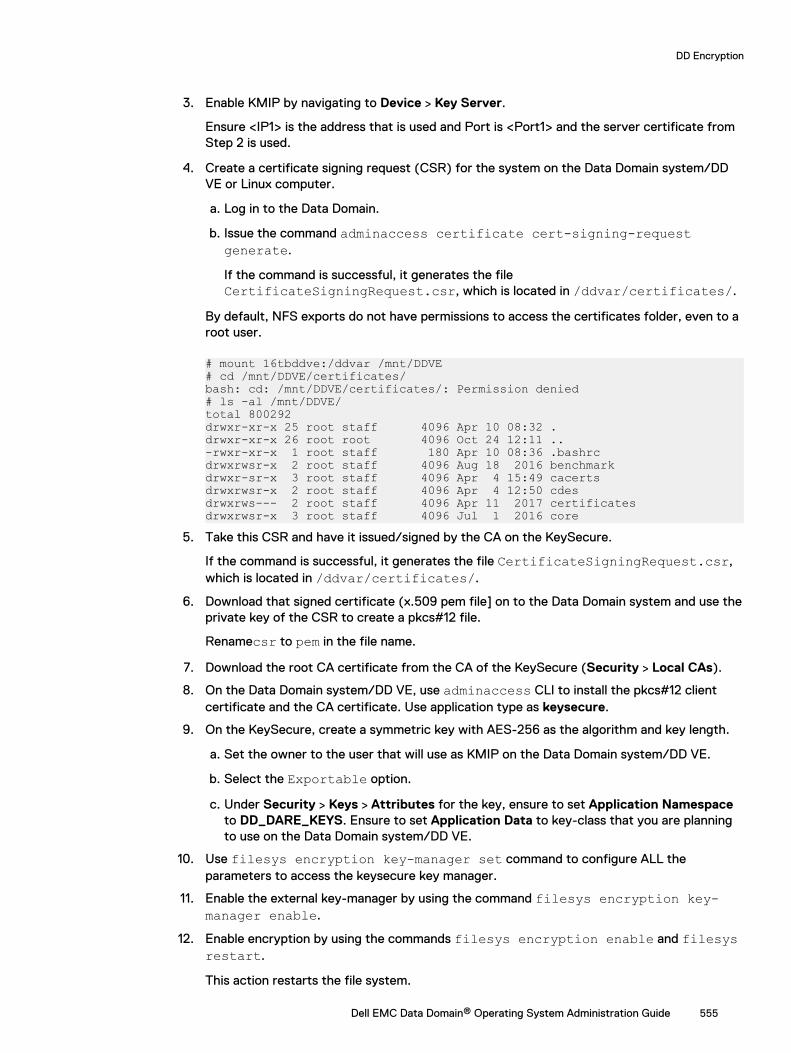
3. Enable KMIP by navigating to Device > Key Server.
Ensure <IP1> is the address that is used and Port is <Port1> and the server certificate fromStep 2 is used.
4. Create a certificate signing request (CSR) for the system on the Data Domain system/DDVE or Linux computer.
a. Log in to the Data Domain.
b. Issue the command adminaccess certificate cert-signing-requestgenerate.
If the command is successful, it generates the fileCertificateSigningRequest.csr, which is located in /ddvar/certificates/.
By default, NFS exports do not have permissions to access the certificates folder, even to aroot user.
# mount 16tbddve:/ddvar /mnt/DDVE# cd /mnt/DDVE/certificates/bash: cd: /mnt/DDVE/certificates/: Permission denied# ls -al /mnt/DDVE/total 800292drwxr-xr-x 25 root staff 4096 Apr 10 08:32 .drwxr-xr-x 26 root root 4096 Oct 24 12:11 ..-rwxr-xr-x 1 root staff 180 Apr 10 08:36 .bashrcdrwxrwsr-x 2 root staff 4096 Aug 18 2016 benchmarkdrwxr-sr-x 3 root staff 4096 Apr 4 15:49 cacertsdrwxrwsr-x 2 root staff 4096 Apr 4 12:50 cdesdrwxrws--- 2 root staff 4096 Apr 11 2017 certificatesdrwxrwsr-x 3 root staff 4096 Jul 1 2016 core
5. Take this CSR and have it issued/signed by the CA on the KeySecure.
If the command is successful, it generates the file CertificateSigningRequest.csr,which is located in /ddvar/certificates/.
6. Download that signed certificate (x.509 pem file] on to the Data Domain system and use theprivate key of the CSR to create a pkcs#12 file.
Renamecsr to pem in the file name.
7. Download the root CA certificate from the CA of the KeySecure (Security > Local CAs).
8. On the Data Domain system/DD VE, use adminaccess CLI to install the pkcs#12 clientcertificate and the CA certificate. Use application type as keysecure.
9. On the KeySecure, create a symmetric key with AES-256 as the algorithm and key length.
a. Set the owner to the user that will use as KMIP on the Data Domain system/DD VE.
b. Select the Exportable option.
c. Under Security > Keys > Attributes for the key, ensure to set Application Namespaceto DD_DARE_KEYS. Ensure to set Application Data to key-class that you are planningto use on the Data Domain system/DD VE.
10. Use filesys encryption key-manager set command to configure ALL theparameters to access the keysecure key manager.
11. Enable the external key-manager by using the command filesys encryption key-manager enable.
12. Enable encryption by using the commands filesys encryption enable and filesysrestart.
This action restarts the file system.
DD Encryption
Dell EMC Data Domain® Operating System Administration Guide 555
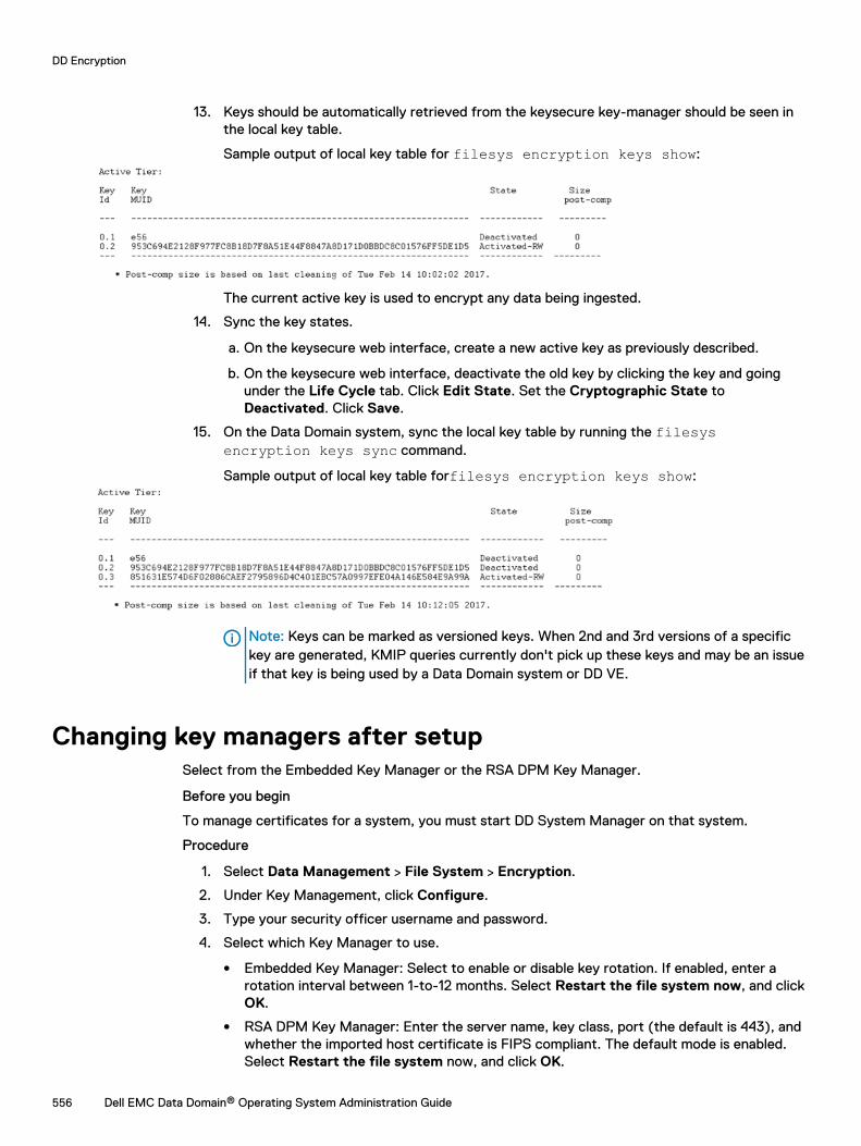
13. Keys should be automatically retrieved from the keysecure key-manager should be seen inthe local key table.
Sample output of local key table for filesys encryption keys show:
The current active key is used to encrypt any data being ingested.
14. Sync the key states.
a. On the keysecure web interface, create a new active key as previously described.
b. On the keysecure web interface, deactivate the old key by clicking the key and goingunder the Life Cycle tab. Click Edit State. Set the Cryptographic State toDeactivated. Click Save.
15. On the Data Domain system, sync the local key table by running the filesysencryption keys sync command.
Sample output of local key table forfilesys encryption keys show:
Note: Keys can be marked as versioned keys. When 2nd and 3rd versions of a specifickey are generated, KMIP queries currently don't pick up these keys and may be an issueif that key is being used by a Data Domain system or DD VE.
Changing key managers after setupSelect from the Embedded Key Manager or the RSA DPM Key Manager.
Before you begin
To manage certificates for a system, you must start DD System Manager on that system.
Procedure
1. Select Data Management > File System > Encryption.
2. Under Key Management, click Configure.
3. Type your security officer username and password.
4. Select which Key Manager to use.
l Embedded Key Manager: Select to enable or disable key rotation. If enabled, enter arotation interval between 1-to-12 months. Select Restart the file system now, and clickOK.
l RSA DPM Key Manager: Enter the server name, key class, port (the default is 443), andwhether the imported host certificate is FIPS compliant. The default mode is enabled.Select Restart the file system now, and click OK.
DD Encryption
556 Dell EMC Data Domain® Operating System Administration Guide
5. Click Manage Certificates to add certificates.
Managing certificates for RSA Key ManagerYou must use both host and CA certificates with RSA Key Manager.
About this task
Note: Certificates are only necessary for RSA Key Manager. Embedded Key Manager does notuse certificates.
Adding CA certificates for RSA Key ManagerUpload or copy and paste CA certificates.
Procedure
1. Select one of the following:
l Select the option to upload a CA certificate as a .pem file and click Browse to find thefile.
l Select the option to copy and paste the CA certificate and paste the certificate contentsinto the field provided.
2. Click Add to add the certificate.
Adding a host certificate for RSA Key ManagerUpload the certificate as a .p12 file, or upload a public key as a .pem file and use a generatedprivate key.
About this task
To start, select the first or second of the following steps:
Procedure
1. Select the option to upload the certificate as a .p12 file.
a. Enter a password.
b. Click Browse to find the .p12 file.
2. Select the option to upload the public key as a .pem file and use a generated private key.
a. Click Browse to find the .pem file.
3. Click Add.
Deleting certificatesSelect a certificate with the correct fingerprint.
Procedure
1. Select a certificate to delete.
2. Click Delete.
The system displays a Delete Certificate dialog with the fingerprint of the certificate to bedeleted.
3. Click OK.
DD Encryption
Dell EMC Data Domain® Operating System Administration Guide 557
Checking settings for encryption of data at restCheck the settings for the DD Encryption feature.
Click the Data Management > File System > Encryption tabs. The currently used Key Manager isshown as Enabled. For a description of the DD Encryption settings, see the section about theencryption view.
Enabling and disabling encryption of data at restAfter configuring DD Encryption, the status is enabled and the Disabled button is active. When DDEncryption is disabled, the Enabled button is active.
Enabling encryption of data at restUse the DD System Manager to enable the DD Encryption feature.
Procedure
1. Using the DD System Manager, select the Data Domain system you are working with in theNavigation panel.
2. In the Encryption view, click the Enable button.
3. Both of the following options are available:
l Select Apply to existing data and click OK. Encryption of existing data will occur duringthe first cleaning cycle after the file system is restarted.
l Select Restart the file system now and click OK. DD Encryption will be enabled afterthe file system is restarted.
After you finish
Note: Applications may experience an interruption while the file system is restarted.
Disabling encryption of data at restUse the DD System Manager to disable the DD Encryption feature.
Procedure
1. Using the DD System Manager, select the Data Domain system you are working with in theNavigation panel.
2. In the Encryption view, click the Disable button.
The Disable Encryption dialog box is displayed.
3. In the Security Officer Credentials area, enter the user name and password of a securityofficer.
4. Select one of the following:
l Select Apply to existing data and click OK. Decryption of existing data will occur duringthe first cleaning cycle after the file system is restarted.
l Select Restart the file system now and click OK. DD Encryption will be disabled afterthe file system is restarted.
DD Encryption
558 Dell EMC Data Domain® Operating System Administration Guide
After you finish
Note: Applications may experience an interruption while the file system is restarted.
Locking and unlocking the file systemUse this procedure when an DD Encryption-enabled Data Domain system (and its external storagedevices) are being transported, or if you want to lock a disk that is being replaced. The procedurerequires two accounts: Security Officer and System Administration roles.
Procedure
1. Select Data Management > File System > Encryption .
In the File System Lock area, the Status shows whether the file system is Locked orUnlocked.
2. Disable the file system by clicking Disabled in the File System status area.
3. Use the procedure to lock or unlock the file system.
Locking the file systemTo lock the file system, DD Encryption must be enabled and the file system must be disabled.
Procedure
1. Select Data Management > File System > Encryption and click Lock File System.
2. In the text fields of the Lock File System dialog box, provide:
l The username and password of a Security Officer account (an authorized user in theSecurity User group on that Data Domain system).
l The current and a new passphrase.
3. Click OK.
This procedure re-encrypts the encryption keys with the new passphrase. This processdestroys the cached copy of the current passphrase (both in-memory and on-disk).
Note: Changing the passphrase requires two-user authentication to protect against thepossibility of a rogue employee‘s shredding the data.
CAUTION Be sure to take care of the passphrase. If the passphrase is lost, you willnever be able to unlock the file system and access the data. The data will be irrevocablylost.
4. Shut down the system:
CAUTION Do not use the chassis power switch to power off the system. Type thefollowing command at the command prompt instead.
# system poweroff The ‘system poweroff’ command shuts down thesystem and turns off the power. Continue? (yes|no|?) [no]:
5. Transport the system or remove the disk being replaced.
6. Power on the system and use the procedure to unlock the file system.
DD Encryption
Dell EMC Data Domain® Operating System Administration Guide 559
Unlocking the file systemThis procedure prepares an encrypted file system for use after it has arrived at its destination.
Procedure
1. Select Data Management > File System > Encryption and click Unlock File System.
2. In the text fields, type the passphrase that was used to lock the file system.
3. Click OK.
4. Click Close to exit.
If the passphrase is incorrect, the file system does not start and the system reports theerror. Type the correct passphrase, as directed in the previous step.
Changing the encryption algorithmReset the encryption algorithm if necessary, or select options to encrypt new and existing data orjust new data.
Procedure
1. Select Data Management > File System > Encryption
2. To change the Encryption Algorithm used to encrypt the Data Domain system, click ChangeAlgorithm.
The Change Algorithm dialog box is displayed. Supported encryption algorithms are:
l AES-128 CBC
l AES-256 CBC
l AES-128 GCM
l AES-256 GCM
3. Select an encryption algorithm from the drop-down list or accept the default AES 256-bit(CBC).
The AES 256-bit Galois/Counter Mode (GCM) is the most secure algorithm but it issignificantly slower than the Cipher Block Chaining (CBC) mode.
Note: To reset the algorithm to the default AES 256-bit (CBC), click Reset to default.
4. Determine what data will be encrypted:
l To encrypt existing and new data on the system, select Apply to Existing data, Restartfile system now, and click OK.Existing data will be encrypted during the first cleaning cycle after the file system isrestarted.
Note: Encryption of existing data can take longer than a standard file system cleanoperation.
l To encrypt only new data, select Restart file system now and click OK.
5. The status is displayed. Click Close when the process is complete.
Note: Applications may experience an interruption while the file system is restarted.
DD Encryption
560 Dell EMC Data Domain® Operating System Administration Guide
Related Documents