Deliverable D4.1 Data collection equipment in the laboratory environment, and plan for field trials Submission date: 27/05/2016

Welcome message from author
This document is posted to help you gain knowledge. Please leave a comment to let me know what you think about it! Share it to your friends and learn new things together.
Transcript

Deliverable D4.1
Data collection equipment in the
laboratory environment, and plan for
field trials
Submission date: 27/05/2016

H2020-MG-2015-2015 GA-636237 PUBLIC Page 2
Lead contractor
AFER
Contributors
ADS, TUD, INTADER
Project Coordinator
University of Sheffield, USFD

D4.1: Data collection equipment inthe laboratory environment, andplan for field trials
NeTIRail-INFRAH2020-MG-2015-2015
GA-6362372016/05/27
NeTIRail-INFRA PUBLIC Page 3
Executive Summary
The deliverable D4.1 represents the first step of achieving the T4.1. It is considered an intermediary
progress report outlining the actions taken to identify the optimized technical elements necessary
for designing and construction of a vibration data acquisition category system, these vibrations being
produced by the interaction between the railroad tracks and wheels rolling units.
In deliverable D4.1 was made a presentation of phenomena in this category, presentation based on
studies and research conducted previously in other projects or individual activities.
In the first part it presented the vibrations of the railway as researching domain; are described the
characteristics of this phenomenon and the factors that may increase the influence of the size and
intensity of the vibration.
Further, are presented an analysis of the mechanism of generating the vibration and noise (this last
is considered a vibration component).
Vibration effects are generated by the static axle loads moving along the track and by the dynamic
forces which arises in the presence of harmonic or non-harmonic wheels and rails irregularities.
From prior researches, most important frequency range of ground vibration, considering human
perception, is approximately 5-80 Hz.
On a given location the vibration amplitudes will be strongly influenced by the properties of the
ground and the vibration presence must be seen as an interaction between vehicle, track and
ground.
Are presented also, the situation of the S&C as special case of vibrations and noise mechanism.
The importance of measuring and analyses of vibrations and rolling noise resides from the
Environmental Noise Directive (END). The END requires European member states to produce and
publish noise maps on a 5 year cycle.
In next chapter are presented the theory of MEMS sensor, used for converting accelerations into
voltage level, and the design of the equipment realized for measuring sessions.
In the last part are described the initial conditions and the ongoing activities on the three sessions of
collecting data: Cristianu Station from RCCF-Brasov; AFER Laboratory; Sabareni Station.
During data collection sessions, were acquired and saved in formats that can be further processed,
large volumes of data. In deliverable are represented some sequences from these volumes of data,
using representation of default interface of portable oscilloscope Pico Scope.
In the next period, these data will be analysed and compared with information already known about
the occurrence of the vibration and the noise in the rail. Also, when necessary, further activities will
be organized for data collection and testing, especially with the optimized and autonomously
equipment, which will be achieved within T4.1.

D4.1: Data collection equipment inthe laboratory environment, andplan for field trials
NeTIRail-INFRAH2020-MG-2015-2015
GA-6362372016/05/27
NeTIRail-INFRA PUBLIC Page 4
Table of contents
Executive Summary.................................................................................................................................3
Table of contents ....................................................................................................................................4
Abbreviations and acronyms ..................................................................................................................6
1 General aspects concerning the phenomenon of vibration and rolling noise. Relevance for
measurement and analysis. ....................................................................................................................7
1.1 Vibrations characteristics as types of trains .............................................................7
1.1.1 Commuter and Inter City Passenger Trains ..........................................................................7
1.1.2 High Speed Passenger Trains................................................................................................8
1.1.3 Freight Trains .......................................................................................................................8
1.2 Vibrations factors of influence ......................................................................................8
1.3 Importance of measuring and analyses of vibrations and rol l ing noise ............9
1.3.1 Rolling noise – part of vibration......................................................................................9
1.3.2 The Environmental Noise Directive (END) & noise mapping........................................10
1.4 Mechanism of generating vibrations and roll ing noise ........................................10
1.4.1 Interaction between wheels, rails and ground .............................................................10
1.4.2 Wheel out-of-roundness and roughness ......................................................................11
1.4.3 Periodic out-of-roundness ............................................................................................11
1.5 Switches & crossings as particular case ....................................................................12
1.5.1 Description of vibrations in S&C area ...........................................................................12
1.5.2 Mechanisms of excitation.............................................................................................13
2 Data collection equipment - description of hardware and functional structure..........................15
2.1 Equipment used for data collecting – into laboratory conditions but also in real field
environment .....................................................................................................................................15
2.1.1 Technical Specifications ................................................................................................15
2.1.2 Terminology used in electronics of MEMS sensors ......................................................18
2.1.3 How the accelerometer works......................................................................................19
2.1.4 NeTIRail-INFRA electronics schema design...................................................................21
3 Test typology for determining the most important features of the rail.......................................22
4 Data collecting activities – planning and work performed ...........................................................27
4.1 Data collecting from RCCF, Cristianu Station........................................................................27

D4.1: Data collection equipment inthe laboratory environment, andplan for field trials
NeTIRail-INFRAH2020-MG-2015-2015
GA-6362372016/05/27
NeTIRail-INFRA PUBLIC Page 5
4.2 Testing equipment and collecting data at AFER Laboratory.................................................27
4.3 Collecting data in real field, at Sabareni ...............................................................................30
5 Results and future planning..........................................................................................................33
5.1 Testing equipment and data collection in the Cristianu Station, from RCCF........................33
5.2 Testing equipment and data collection in the AFER laboratory ...........................................33
5.2.1 Determining the initial, ambient noise, without mechanical loading ..........................34
5.3 Testing equipment and data collection in the Sabareni Station...........................................40
5.3.1 Blue Arrow train; No. 892. Data collecting in real time................................................40
5.3.2 Blue Arrow train; No. 1784. Data collecting in real time ..............................................41
5.4 Measures for reducing vibrations negative effects on railway.............................................42
5.4.1 Optimising the maintenance time interval and quality of procedures.........................42
5.4.2 Inspection as maintenance optimisation......................................................................43
5.5 Next steps and future planning.............................................................................................44
6 Conclusions ...................................................................................................................................46
7 Bibliography ..................................................................................................................................48

D4.1: Data collection equipment inthe laboratory environment, andplan for field trials
NeTIRail-INFRAH2020-MG-2015-2015
GA-6362372016/05/27
NeTIRail-INFRA PUBLIC Page 6
Abbreviations and acronyms
Abbreviation /Acronym
Description
EU European Union
FMEA Failure Modes and Effects Analysis
ICT Information and Communications Technology
IEC International Electro technical Commission
IM Infrastructure Manager
LCA Life-Cycle Assessment
LCC Life-Cycle Costing / Life-Cycle Cost
M&R Maintenance and Renewal
ABC Activity Based Costing
MRT Mean Repair Time
MTTF Mean Time To Failure
RAM Reliability, Availability and Maintainability
RAMS Reliability, Availability, Maintainability and Safety
UIC Union Internationale des Chemins (International Union of Railways)
CM Corrective Maintenance
FME(C)A Failure Mode, Effects (and Criticality) Analysis
IM’s Infrastructure Managers
MGT/MGTPA A measure of traffic in units of million gross tonnes per annum
PM Preventive Maintenance
RCF Rolling Contact Fatigue
SA Safety Analysis
US/UT Ultra-Sonic / Ultra Sonic Testing
DB Deutsche Bahn – German IM
NR Network Rail – British IM
S&C Switches & crossings
TCDD Türkiye Cumhuriyeti Devlet Demiryolları – Turkish IM
TSL Temporary Speed Limitation
END Environmental Noise Directive
OOR Out Of Roundness
MEMS Microelectromechanical Sensors

D4.1: Data collection equipment inthe laboratory environment, andplan for field trials
NeTIRail-INFRAH2020-MG-2015-2015
GA-6362372016/05/27
NeTIRail-INFRA PUBLIC Page 7
1 General aspects concerning the phenomenonof vibration and rolling noise. Relevance formeasurement and analysis.
It is known that trains moving create moving forces on the ground; these are approximately thesame in the same conditions and so forms patterns of generated forces. The force gives rise topropagating waves within the ground and a number of types of wave can exist. The nature of thisforce pattern is dependable by the components between the train and ground as receiver of forcesand vibrations. These element are enumerated: the rail, the rail fastenings, the sleepers; continuousslab, ballast etc.Vibration from trains manifests in two mainly ways for civilians. In some situations the vibrationscould be felt as the effect of the floor resonances inside the buildings. Also, other effects includenoise radiation and disturbance from fixture and fittings.Also, rolling stock has a major contribution of vibrations generated; unsteady components of thevehicle (bouncing, rolling, pitching and yawing, etc.) result in additional fluctuating forces on thetrack structure. In the same way, defects such as eccentricity of the wheels, non-balanced wheelsand flats of wheels, will contribute to transmitting forces, as vibrations, into the ground.The passengers of the trains give importance to higher frequency vibration. This is often perceivedas a rumble in buildings that are in the vicinity of railway. A particular feature of trains tending togive rise to higher vibration is that of axle-hung traction motors. When the train moves the stresspattern will move with it, although modified to a small extent by the finite propagation velocity ofthe stress waves.
1.1 Vibrations characteristics as types of trainsVibrations in the railway operating are distinctive, mainly as type of trains that cause its.As a main rule or condition, the heavier the train the more vibration will be generated. A heavyfreight train with average speed generates significant magnitude of vibration at low frequenciesrange, which travel away in the ground comparing with the high frequencies that suffer a majoramortization in the ground.It has been concluded from tests from other projects that the ground vibration wave’s shapes andmagnitude are affected by many factors:
The ground type and quality; could be considered the most important factor.
The train type.
Railway track and the embankment construction design.
Speed of train.
Distance from the rail way track to the building (receiver).
Building type and the foundation design.
Most analysed cases, as different sources of vibrations, are related to the following paragraphs.
1.1.1 Commuter and Inter City Passenger TrainsThe category includes passenger trains powered by diesel or electric locomotives. In terms ofvibrations effects, the mainly difference between commuter and intercity passenger trains is that

D4.1: Data collection equipment inthe laboratory environment, andplan for field trials
NeTIRail-INFRAH2020-MG-2015-2015
GA-6362372016/05/27
NeTIRail-INFRA PUBLIC Page 8
the latter are on a less frequent schedule. Both often share track with freight trains, which havequite different vibration characteristics. The locomotives of these types create frequently the highvibration amplitude levels. These are considered the vibration problems anytime that newcommuter or intercity passenger service are introduced in an urban or suburban area.
1.1.2 High Speed Passenger TrainsHigh – speed passenger trains, such as the Japanese Shinkansen, the French TGV, the German ICEand the Swedish X2000, have a potential of creating high levels of ground – borne vibration.Ground vibration should be anticipated as one of the major environmental impacts of any highspeed train that is running in an urban or suburban area.
1.1.3 Freight TrainsLocal and long distance freight trains are similar in that they are mostly electric – powered and havethe same types of cars. Differences are in the overall length, number and size of locomotives, andnumber of heavy loaded cars. Moving units with wheels’ irregularities are the sources of the highestvibration levels. (1)
1.2 Vibrations factors of influenceVehicle SuspensionIf the suspension is rigid in the vertical direction, the effective forces will be higher. On transit cars,only the primary suspension affects the vibration levels, the secondary suspension that supports thecar body has no apparent effects.
Wheel Type and ConditionNormal resilient wheels on rail transit system are usually too stiff to provide significant vibrationreduction. Wheel flats and general wheel roughness are the major cause of vibration from steelwheel/steel rail system.
Track/Roadway SurfaceRough track are often the cause of vibration problems. Maintaining a plain and smooth surface willreduce vibration levels.
Track fastening SystemOn rail systems, the track support system is one of the major components in determining the levelsof ground – borne vibration. The highest vibration levels are created by track that is rigidly attachedto a concrete tracked. The vibration levels are much lower when special vibration control tracksystem such as resilient fasteners; ballast mats and floating slabs are used.
SpeedAs default condition, higher speeds means higher vibration levels.
Transit StructureThe general rule is that the heavier the transit structure, the lower the vibration levels. The vibrationlevels from a lightweight capacity tunnel will usually be higher than from a poured concrete subwaytunnel.

D4.1: Data collection equipment inthe laboratory environment, andplan for field trials
NeTIRail-INFRAH2020-MG-2015-2015
GA-6362372016/05/27
NeTIRail-INFRA PUBLIC Page 9
Depth of Vibration SourceThere are significant differences in the vibration characteristics when the source is undergroundcompared to at the ground surface.
According to the studies and the results of experiments, the vertical Z direction is the mostdominating direction compared with the transversal and longitudinal directions (X and Y).
1.3 Importance of measuring and analyses of vibrations androlling noise
1.3.1 Rolling noise – part of vibration
In the category of vibrations, the rolling noise represents an important component. Actually, thenoise of railway represents the vibrations that are in the audible range of frequency.The rolling noise produce at the same time negative influence against life cycle of the wheels andrails but also an immediate effect against buildings and civilians living near railways.
A number of noise sources are associated with the railway operating activities. From these sources,the rolling noise considered to be the most important. Rolling noise is generated by the combinedsurface roughness of the rail and wheels of train. When the train moves, this surface roughnessexcites both the track and wheel which then radiate noise.Even surfaces that apparently are smooth to the touch, have some roughness and will generatenoise. One of the best ways to manage railway noise is to ensure the operation of smooth wheels onsmooth rails.
Rolling noise is a component of vibration phenomenon and is considered the most important noisesource associated with the Great Britain railway network. It is generated by roughness of the wheeland rail. The combined roughness excites both the wheel and track, which then radiate noise. Wheelroughness tends to stabilise at a level determined by the vehicle braking system. Typical GreatBritain rolling stock have relatively smooth wheels due to the preference for composite brake blocksand disc brakes over cast iron brake blocks. Rail roughness tends to increase over time according totonnage supported in time and can be controlled by grinding operations.Noise and vibration could be identified as sources and initial conditions as follows:
Interior noise - the noise inside passenger vehicles has a great effect on the level ofpassenger comfort.
Noise radiated from bridges - the vibration of the track is transmitted into the bridgestructure which in turn radiates low frequency sound. This can raise the overall level of noisenear bridges by up to 20dB. This kind of problem could be greatly reduced throughoptimizing design of bridges.
Impact noise, which are generated at discontinuities in the track or wheel, e.g. points andcrossings, rail joints, irregularities of rail welds and wheels.
Wheel-rail rolling noise - this is a large band of noise and is caused by vibrations of the wheeland rail when are in contact one each other, mainly caused by irregularities of the runningrails. This is the dominant source of noise from railway operational activities. Researches

D4.1: Data collection equipment inthe laboratory environment, andplan for field trials
NeTIRail-INFRAH2020-MG-2015-2015
GA-6362372016/05/27
NeTIRail-INFRA PUBLIC Page 10
have been conducted into Silent Freight and Silent Track projects, searching solutions forrolling noise.
Aerodynamic noise from trains - this is significant compared with rolling noise only at veryhigh speed, typically above 300 km/h.
Squealing as wheels traverse curves of tight radius - this high pitched tonal noise is an acutecause of annoyance to those living adjacent to such a curve. It is of particular concern forurban railways and tramways which often have tight radius curves close to buildings.Mainline freight and passenger railways are also affected at tight curves in depots, sidingsand stations.
Low frequency vibration as major component in the ground - such vibration occurs inlocations of soft soil and propagates parallel to the ground surface with a low rate ofattenuation with distance. This is of particular concern for heavy axle freight operations. Thedominant frequencies are between 4 and 50 Hz. Researches have led to the development ofboth boundary element and analytical models that can be used for analysing thepropagation of vibration through layers of the ground structures.
Rumbling noise from trains in tunnels (ground-borne noise) - this is generated as vibration ofthe track that is transmitted through the ground and radiated as sound within buildings byvibration of their walls. This has components between about 30 Hz and 200 Hz. It can beparticularly annoying as it comes from a source that cannot be predicted and estimated asmagnitude.
Engine noise and other sources of noise at depots and stations - this has characteristicscommon to industrial noise sources.
1.3.2 The Environmental Noise Directive (END) & noise mapping
The END requires European member states to produce and publish noise maps on a 5 year cycle.Separate maps are produced for different noise sources, these include railways, roads, airports andindustry. One of the aims of the END is improve public understanding and engagement withenvironmental noise.For achieving a new version of noise maps as acoustic component of vibrations, for example,Network Rail reassessed the acoustic survey in 2012, which has demonstrated that the improved railmaintenance programme targeted to a reduction in rails vibrations has achieved a significantreduction in rolling noise, through smoother rails across the railway network in Great Britain. (2)
1.4 Mechanism of generating vibrations and rolling noise
1.4.1 Interaction between wheels, rails and ground
Vibration effects from railway traffic is generated either by the static axle loads moving along thetrack or by the dynamic forces which arises in the presence of harmonic or non-harmonic wheelsand rails irregularities. From the prior measurements and experiments, the most importantfrequency range of ground vibration considering human perception, is approximately 5-80 Hz. Theexcitation by the static axle loads primarily leads to low frequency vibrations which are attenuated inthe direction away from the track. The frequency content of the dynamic excitation is determined bythe speed of the vehicle and the wavelength contents of the irregularities exciting the wheel-railcontact patch. On a given location the vibration amplitudes will be strongly influenced by the

D4.1: Data collection equipment inthe laboratory environment, andplan for field trials
NeTIRail-INFRAH2020-MG-2015-2015
GA-6362372016/05/27
NeTIRail-INFRA PUBLIC Page 11
properties of the ground and the vibration presence must be seen as an interaction between vehicle,track and ground. (3)A train running on a surface line will affect its environment by emissions of air-borne and ground-borne noise as well as ground vibration. Among these emissions the perceivable ground-bornevibration have the lowest frequency content ranging from a few Hz up to around 80 Hz (4), (5).The highest frequencies are found in the air-borne noise radiated directly from the wheel and railsurfaces, this is from category of rolling noise with typical frequency range 50-5000 Hz (6). Due tothe very small variations in the air characteristics between different locations, the propagation ofair-borne noise will be essentially the same on all places. As opposite, ground properties will varysignificantly from one site to another and the propagation of ground-borne noise and vibrations willbe specific from one location to the other.The variation of the rigidity of the rail sections is followed by the moving load caused by the discretesleeper support. This will produce a new form of dynamic excitation of the wheel-rail contactsurface. This is commonly referred as parametric excitation and will have a fundamental frequencydetermined by the speed of the vehicle and the spacing between the sleepers. This sleeper passingfrequency is apparent in most ground vibration measurements (7). Commonly in Europe a sleeperspacing of about 60 cm is used which for a vehicle travelling at 100 and 200 km/h would cause aparametric excitation at about 45 and 90 Hz respectively. These frequencies are within the typicalrange of frequencies related to ground-borne noise and vibration. On a given track, the amplitude ofthe excitation is varying with axle load and running speed and in turn also with frequency. Theexcitation increases with speed as the fundamental frequency reaches the vehicle-track resonance.
1.4.2 Wheel out-of-roundness and roughness
Imperfections of the wheels and rails are important when considering the dynamic formation ofvibration in the ground. Limiting the application analyses to the rolling stock, the wheel out-of-roundness (OOR) and roughness should be considered as significant causes and also points ofpossible improvements. Wheel-rail contact forces excited by wheel imperfections are problematicfor several reasons as they give rise to noise and cause wear and damage to both vehicle and track.The differences are represented by the type of imperfection present on the wheel, e.g. wheel flat,roughness, eccentricity or polygon shaping, also together with the speed of the vehicle. Periodic out-of-roundness with one or more wavelengths around the wheel circumference gives a harmonicexcitation while a wheel flat leads to an impulse excitation. The resulting vibration level in theground will be dependent on the track- and ground reacceptances which varies from one site toanother. (3)
1.4.3 Periodic out-of-roundness
Periodic OOR with wavelengths ranging from approximately 14 cm up to one wheel circumference isfound primarily on disc-braked wheels while block-braked wheels hold more corrugation withsmaller wavelengths in the range 3-6 cm. This the latter situation is found to be a result of the heatduring breaking which causes local material expansion of the tread and in wearing. Furthermorealmost all wheels suffer to some extent from eccentricity which is a consequence of misalignmentduring profiling or re-profiling. Taken in consideration the speed of different vehicle types and themost important, the frequency range of vibration in the ground of considered area, it is evident thatthe long wavelength OOR is the primary issue. Corrugation and roughness primarily excites rollingnoise which has been got much more attention compared to ground vibrations.

D4.1: Data collection equipment inthe laboratory environment, andplan for field trials
NeTIRail-INFRAH2020-MG-2015-2015
GA-6362372016/05/27
NeTIRail-INFRA PUBLIC Page 12
The longest wavelength of a periodic wheel OOR is equal to one wheel circumference. This, togetherwith the speed of the vehicle sets the lower frequency limit of the excitation. Lower frequencies inthe spectrum must then be associated with track irregularities or quasi-static excitation. Table 1.1 -gives the wavelength range of the excitation from OOR for vehicles running at different speeds. Theexcited frequencies are assumed to be in the 5-80 Hz range which is pointed out to be the mostimportant one considering human exposure. (3)
Vehicle Freight train Conventionalpassenger train
High-speedpassenger train
Frequency range [Hz] 7-80 18-80 30-80
Speed [km/h] 70 180 300
Wavelengths [m] 0.25-4 0.6-10 1-17
Wheel radius [m] 0.45 0.45 0.45
Wheel orders 1-11 1-5 1-3
Table 1.1 - Wavelengths of wheel OOR important to ground vibration excited by different
vehicle types (3)
Railway induced ground vibration depends on a variety of factors that have influence of dynamic andquasi-static excitation as well as propagation through the track system.The key factors of the vehicle / track system which determine ground vibration are related to thetrack design and the maintenance of wheel and rail as quality and intrinsic characteristics:
Design of the track, more precisely the properties of the track mass/spring/damping systemconsisting of rail, pads, sleeper, ballast, slab, embankment.
Impact excitation from track discontinuities like switches & crossings and insulation joints
Wheel / rail surface quality, roughness including corrugation, out-of-roundness, flats, etc.
1.5 Switches & crossings as particular case
1.5.1 Description of vibrations in S&C area
Switches & crossings (S&Cs, turnouts) contain a switch panel and a crossing panel that areconnected by a closure panel. Dynamic interaction between vehicle and track has more complexitythan on tangent or curved tracks. Wheel - rail impact loads vibrations with large magnitudes andsignificant contributions from high-frequency vehicle–track interaction could be an example; theseare generated when the nominal wheel and rail contact conditions are disturbed at various locationsin the S&C, such as at wheel transfer from wing rail to crossing nose in facing direction. The impactload at the crossing may be a significant source to ground vibration and noise.The switch panel and the crossing panel are the most important for ground vibration as they featurechanges in rail cross-section, track curvature, track irregularities and track stiffness variations.

D4.1: Data collection equipment inthe laboratory environment, andplan for field trials
NeTIRail-INFRAH2020-MG-2015-2015
GA-6362372016/05/27
NeTIRail-INFRA PUBLIC Page 13
Figure 1.1 - Components of an S&C with main (through) and diverging routes. (8)
1.5.2 Mechanisms of excitation
In addition to the wheel and rail unevenness, which is the predominant excitation in straight lines, atrain rolling on a turnout is subjected to track geometrical irregularities (sudden change in trackvertical or lateral alignment, implying changes in contact point location and number), as well as trackstiffness variation (due to rail cross section variation and stiffness variation of the differentcomponents along track e.g. wing rail, crossing nose, sleepers, etc.)These phenomena are combined in the contact force resulting from the wheel - rail interaction.Notice that in Figure 1.1 the wheel and rail unevenness is not represented, but it is also present inturnouts. The repetitive high forces generate rail surface damage which in turn gives rise to higherimpact load.The propagation in the ground will be different depending on the frequency range but also on thenature of the excitation: point or linear sources.The relationship between contact force and ground borne vibration is not very clear for turnouts, asit is more complex than for straight line. More investigations are required in this domain.Measurements of contact force show amplifications in the frequency range [50 - 80] Hz,corresponding to the resonance of the vehicle un-sprung mass on the track stiffness.One objective of INNOTRACK in SP3 was to optimise the transition geometry and stiffness of resilientelements in the crossing panel to reduce material degradation (wear and plastic deformation) of therails.From differences in vibration turnout-amplifications it could be concluded that there are possibilitiesto improve the switching nose as part of a turnout. The wheel transition over a turnout shows thatgeometry is important for optimum and low energy impacts at the crossing nose. There is aninfluence of vertical and horizontal geometries.Researching in this domain established a behaviour for vibration frequency at a high speed (ex. atleast 150Km/h) through creating a low-pass filtering effect.Higher accelerations and vibrations effects are noted when the wheel passes rail joints, but thesepeak values are not importantly influenced by the speed of the train. Higher values around 80 Hzcorrespond to the resonance frequency of the track

D4.1: Data collection equipment inthe laboratory environment, andplan for field trials
NeTIRail-INFRAH2020-MG-2015-2015
GA-6362372016/05/27
NeTIRail-INFRA PUBLIC Page 14
Any modelling process should allow the separate components, considered as sources of noise:wheel, rail, sleeper, etc., to be identified.It is considered that the contribution of the rail is the dominant source; the wheel is a vibrationsource high frequencies and the sleeper is most important at low frequencies.Since the contributions to the total noise from the wheel and the track are of similar magnitude,noise reduction of only one part will have limited effect on the total. In order to make substantialprogress in the long term towards a quieter railway, noise reduction measures must be developedfor both vehicles and track. (8)

D4.1: Data collection equipment inthe laboratory environment, andplan for field trials
NeTIRail-INFRAH2020-MG-2015-2015
GA-6362372016/05/27
NeTIRail-INFRA PUBLIC Page 15
2 Data collection equipment - description ofhardware and functional structure
2.1 Equipment used for data collecting – into laboratory conditionsbut also in real field environment
The equipment platform for data collecting in laboratory conditions, as basic activity, but also in realfield conditions, was using an adapter board surrounding the LIS344ALH integrated circuit core. Thissolution represents a three-axis analogue output linear accelerometer core.
LIS344ALH inertial sensor represents a high performance 3-axis ±2/±6g ultra compact linearaccelerometer.LIS344ALH will be used for this stage of data collection due to the analogue output, providing theacquired data. The simplicity of operation allows easy integration and use in an efficient system forcollection, analysis and modelling.The developed electrical interface allowed the accelerometer connection to a digital oscilloscopewith memory and with integrated spectrum analysis functions.
For the second stage of achieving T4.1, with deliverable D4.2, an optimized model of accelerometerfrom the same family MEMS sensors - Microelectromechanical Sensors will be used.This model will acquire digital data and transmit them to a microcontroller for processing; it will alsoprovide useful functions and events for managing the acquisition process. In this way, through thedecentralization of tasks, it will be possible to develop a system independently of data acquisitionand communication, fully autonomous and optimized for operation in harsh environments.
The main objective of data collection activity, in this stage, is to characterize the phenomenon ofvibration and noise in rail when a train crosses a section of line.Specialized devices placed on the line will sample detect acceleration values and sent it to a dataconcentrator.
To data acquisition correctly is necessary to know the correct values of the resonant frequency ofthe vibration in rail; it will be used to set the correct sampling rate. Maximum sampling rate will bedetermined based on measurements and this parameter will be used in designing the final system.
2.1.1 Technical Specifications
The LIS344ALH is an ultra-compact consumer low-power three-axis linear accelerometer thatincludes a sensing element and an IC interface able to take the information from the sensingelement and to provide an analogic signal to the external world.
Features: 2.4 V to 3.6 V single supply operation; ±2 g / ±6 g user selectable full-scale; Low powerconsumption; Output voltage, offset and sensitivity are ratio metric to the supply voltage; Factorytrimmed device sensitivity and offset; Embedded self-test; RoHS/ECOPACK® compliant; High shocksurvivability (10000 g).

D4.1: Data collection equipment inthe laboratory environment, andplan for field trials
NeTIRail-INFRAH2020-MG-2015-2015
GA-6362372016/05/27
NeTIRail-INFRA PUBLIC Page 16
The sensing element, capable of detecting the acceleration, is manufactured using a dedicatedprocess developed by ST to produce inertial sensors and actuators in silicon.The IC interface is manufactured using an ST proprietary CMOS process with high level ofintegration. The dedicated circuit is trimmed to better match the sensing element characteristics.
The LIS344ALH has a dynamically user selectable full-scale of ±2 g / ±6 g and it is capable ofmeasuring accelerations over a maximum bandwidth of 1.8 kHz sampling rates, for all axes. Thedevice bandwidth may be reduced by using external capacitances. The self-test capability allows theuser to check the functioning of the system.It is guaranteed to operate over an extended temperature range of -40 °C to +85 °C.
Figure 2.1 - Block diagram of the accelerometer chipset - LIS344ALH

D4.1: Data collection equipment inthe laboratory environment, andplan for field trials
NeTIRail-INFRAH2020-MG-2015-2015
GA-6362372016/05/27
NeTIRail-INFRA PUBLIC Page 17
Figure 2.2 – Directions of detectable acceleration and pin connection for LIS344ALH

D4.1: Data collection equipment inthe laboratory environment, andplan for field trials
NeTIRail-INFRAH2020-MG-2015-2015
GA-6362372016/05/27
NeTIRail-INFRA PUBLIC Page 18
Figure 2.3 - Pin connection for LIS344ALH
2.1.2 Terminology used in electronics of MEMS sensors
2.1.2.1 Sensitivity
The sensitivity describes the gain of the sensor and can be determined by applying 1g acceleration toit. As the sensor can measure DC accelerations this can be done easily by pointing the axis of interesttowards the centre of the Earth, note the output value, rotate the sensor by 180 degrees (point tothe sky) and note the output value again thus applying ±1g acceleration to the sensor. Subtractingthe larger output value from the smaller one, and dividing the result by 2, will give the actualsensitivity of the sensor. This value changes very little over temperature and also very little overtime.The Sensitivity tolerance describes the range of sensitivities of a large population of sensors.
2.1.2.2 Zero-g level
This parameter describes the actual output signal if there is no acceleration present. A sensor in asteady state on a horizontal surface will measure 0 g in X axis and 0 g in Y axis whereas the Z axis willmeasure 1g. The output is ideally for a 3.3 V powered sensor Vdd / 2 = 1650 mV. A deviation fromideal 0-g level (1650 mV in this case) is called Zero-g offset. Offset of precise MEMS sensors is tosome extend a result of stress to the sensor and therefore the offset can slightly change after

D4.1: Data collection equipment inthe laboratory environment, andplan for field trials
NeTIRail-INFRAH2020-MG-2015-2015
GA-6362372016/05/27
NeTIRail-INFRA PUBLIC Page 19
mounting the sensor onto a printed circuit board or exposing it to extensive mechanical stress.Offset changes little over temperature and the Zero-g level of an individual sensor is very stable overlifetime.The Zero-g level tolerance describes the range of Zero-g levels of a population of sensors.
2.1.2.3 Self-test
This function allows to test the mechanical and electric part of the sensor, allowing the seismic massto be moved by means of an electrostatic test-force. The Self-Test function is off when the ST pin isconnected to GND. When the ST pin is tied at Vdd an actuation force is applied to the sensor,simulating a definite input acceleration. In this case the sensor outputs will exhibit a voltage changein their DC levels which is related to the selected full-scale and depending on the supply voltagethrough the device sensitivity. When ST is activated, the device output level is given by the algebraicsum of the signals produced by the acceleration acting on the sensor and by the electrostatic test-force. If the output signals change within the amplitude range specified, then the sensor is workingproperly and the parameters of the interface chip are within the defined specification.
2.1.2.4 Output impedance
Output impedance describes the resistor inside the output stage of each channel. This resistor is partof a filter consisting of an external capacitor of at least 1nF and the internal resistor. Due to the highresistor level, only small inexpensive external capacitors are needed to generate low cornerfrequencies. When interfacing with an ADC it is important to use high input impedance inputcircuitries to avoid measurement errors. Note that the minimum load capacitance forms a cornerfrequency close to the resonance frequency of the sensor. In general, the smallest possiblebandwidth for a particular application should be chosen to get the best results.
2.1.3 How the accelerometer works
The LIS344ALH is an ultra-compact low-power, analogue output three-axis linear accelerometer. Thecomplete device includes a sensing element and an IC interface able to take the information fromthe sensing element and to provide an analogue signal to the external world.A proprietary process is used to create a surface micro-machined accelerometer. The technologyallows it to carry suspended silicon structures which are attached to the substrate in a few pointscalled anchors and are free to move in the direction of the sensed acceleration. To be compatiblewith the traditional packaging techniques a cap is placed on top of the sensing element to avoidblocking the moving parts during the moulding phase of the plastic encapsulation.When an acceleration is applied to the sensor the proof mass displaces from its nominal position,causing an imbalance in the capacitive half-bridge. This imbalance is measured using chargeintegration in response to a voltage pulse applied to the sense capacitor. At steady state the nominalvalue of the capacitors are a few pico F.
2.1.3.1 IC interface
The complete signal processing uses a fully differential structure, while the final stage converts thedifferential signal into a single-ended one to be compatible with the external world.

D4.1: Data collection equipment inthe laboratory environment, andplan for field trials
NeTIRail-INFRAH2020-MG-2015-2015
GA-6362372016/05/27
NeTIRail-INFRA PUBLIC Page 20
The first stage is a low-noise capacitive amplifier that implements a Correlated Double Sampling(CDS) at its output to cancel the offset and the 1/f noise. The produced signal is then sent to threedifferent S&Hs, one for each channel, and made available to the outside.All the analogue parameters (output offset voltage and sensitivity) are ratio metric to the voltagesupply. Increasing or decreasing the voltage supply, the sensitivity and the offset will increase ordecrease linearly. This feature provides the cancellation of the error related to the voltage supplyalong an analogue to digital conversion chain.
2.1.3.2 Factory calibration
The IC interface is factory calibrated for sensitivity (S0) and Zero-g level (Voff).The trimming values are stored inside the device by a non-volatile structure. Any time the device isturned on, the trimming parameters are downloaded into the registers to be employed during thenormal operation. This allows the user to employ the device without further calibration.
Figure 2.4 - LIS344ALH electrical connection for generic applications
The LIS344ALH allows to band limit VoutX, VoutY and VoutZ through the use of external capacitors.The recommended frequency range spans from DC up to 1.8 kHz. In particular, capacitors are addedat output VoutX, VoutY, VoutZ pins to implement low-pass filtering for antialiasing and noisereduction. The equation for the cut-off frequency (ft) of the external filters is in this case:
Taking into account that the internal filtering resistor (Rout) has a nominal value equal to

D4.1: Data collection equipment inthe laboratory environment, andplan for field trials
NeTIRail-INFRAH2020-MG-2015-2015
GA-6362372016/05/27
NeTIRail-INFRA PUBLIC Page 21
110 K, the equation for the external filter cut-off frequency may be simplified as follows:
The tolerance of the internal resistor can vary typically of +/-20% within its nominal value of110 KΩ; thus the cut‐off frequency will vary accordingly. A minimum capacitance of 1nF for Cload(x, y, and z) is required.
2.1.4 NeTIRail-INFRA electronics schema design
For our application was realized an electrical platform with following schema design.
Figure 2.5 - Electrical design of the data acquisitioning device
The three outputs of the acquisitioning device are connected through one the shielded cable to adigital Pico Scope unit, which is connected, for data transferring and graphic analyses, to a Laptop,using an USB interface.
C2
1uF
12
Vx (to PicoScope)
Vy (to PicoScope)
VDD
S1JUMPER
213
VDD
VD
D
JP3CAP f ilter
12
VDD
U3
MCP6004
57
41
1
6
U3
MCP6004
1214
41
1
13
6V
U1
LIS344ALH
1234
5 6 7 8
9101112
13
14
15
16
FSSTNCRes
PD
NC
GN
DV
ou
tZ
NCVoutY
NCVoutX
NC
VD
DR
es
NC
VoutX
U3
MCP6004
31
41
1
2
VoutY
VDD
VDD
VDD
VD
D
JP1CAP f ilter
12
VDD
VoutY
U2
LD1117/DD
1
23
GN
D
VOUTVIN
VoutX
JP2CAP f ilter
12
C51nF
12
D1
DIODE
1 2
Vo
utZ
U3
MCP6004
108
41
1
9
C41nF
12
VDDC3
10uF
12
VoutZ
C61nF
12
C11uF
12
Vz (to PicoScope)
VD
D

D4.1: Data collection equipment inthe laboratory environment, andplan for field trials
NeTIRail-INFRAH2020-MG-2015-2015
GA-6362372016/05/27
NeTIRail-INFRA PUBLIC Page 22
3 Test typology for determining the mostimportant features of the rail
In order to further assimilation of the new device, was made a test typology for determining the
most important features of rail. To determine the main features of rail such as, vertical
static/dynamic load which simulates vertical load occurs during the wheel-rail contact and
accelerations that occur during rail vibrations were used two types of rail: common and welded rail.
The test typology was developed in the AFER laboratories.
3.1. Tests performed on a piece of common rail
3.1.1 Static load force on a piece of common rail
In static compression operating mode to continue static vertical load acting on the rail for a period of
50 s was measured.
Figure 3.1 - Static load force applied on a common rail
Figure 3.2 - Values obtained by applying a static load force on a common rail
0
2
4
6
8
10
12
14
1 2 3 4 5 6 7 8 9 10 11 12 13 14
daN
Samples
Static load force

D4.1: Data collection equipment inthe laboratory environment, andplan for field trials
NeTIRail-INFRA
3.1.2. Dynamic load force on a piece of common rail
In dynamic compression operating mode for 5 Hz and 10 Hz working frequencies t
acting on the rail for a total of 1500 cycles for each operating frequency was measured.
Figure 3.
Figure 3.
3.2. Tests performed on a piece of welded rail
Dynamic tests were carried out on a piece of welded rail, measuring the vertical and longaccelerations and loads per rail for a total of 10,000 cycles.
ollection equipment inthe laboratory environment, and
NeTIRailH2020-MG
PUBLIC
3.1.2. Dynamic load force on a piece of common rail
In dynamic compression operating mode for 5 Hz and 10 Hz working frequencies t
acting on the rail for a total of 1500 cycles for each operating frequency was measured.
.3 - Vertical load acting on the common rail - 5 Hz working frequency
.4 - Vertical load acting on the common rail - 10 Hz working frequency
3.2. Tests performed on a piece of welded rail
Dynamic tests were carried out on a piece of welded rail, measuring the vertical and longaccelerations and loads per rail for a total of 10,000 cycles.
NeTIRail-INFRAMG-2015-2015
GA-6362372016/05/27
Page 23
In dynamic compression operating mode for 5 Hz and 10 Hz working frequencies the vertical load
acting on the rail for a total of 1500 cycles for each operating frequency was measured.
5 Hz working frequency
10 Hz working frequency
Dynamic tests were carried out on a piece of welded rail, measuring the vertical and longitudinal

D4.1: Data collection equipment inthe laboratory environment, andplan for field trials
NeTIRail-INFRAH2020-MG-2015-2015
GA-6362372016/05/27
NeTIRail-INFRA PUBLIC Page 24
3.2.1. Description of tools used
For simulating the dynamic vertical load, a press was used, whose features are described in the next
chapter. Also, for measuring acceleration data, were used the following instrumentation: a data
acquisition system HBM - Spider 8, a notebook with a professional software (CATMAN) and two
acceleration transducers type HBM - B12/200, mounted on the direction OX and OZ: vertical and
lateral directions relative to the rail, with following characteristics:
Figure 3.5 - Acceleration transducer type HBM - B12/200
Figure 3.6 - The main characteristics of acceleration transducer HBM - B 12/200
Figure 3.7 - Data acquisition system HBM - Spider 8
D4.1: Data collection equipment inthe laboratory environment, andplan for field trials
NeTIRail-INFRA
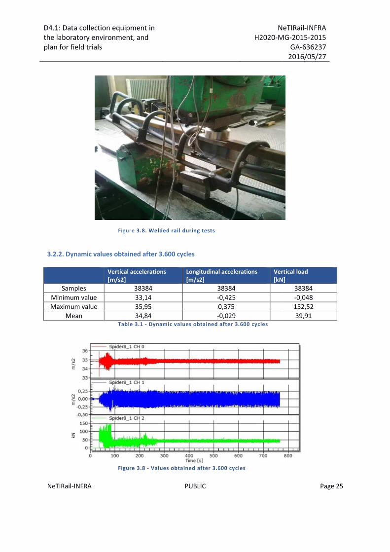
Figure 3.8. Welded rail during tests
3.2.2. Dynamic values obtained after 3.600 cycles
Vertical accelerations[m/s2]
Samples 38384
Minimum value 33,14
Maximum value 35,95
Mean 34,84Table 3.1
Figure 3.
ollection equipment inthe laboratory environment, and
NeTIRailH2020-MG
PUBLIC
3.8. Welded rail during tests
3.2.2. Dynamic values obtained after 3.600 cycles
Vertical accelerations Longitudinal accelerations[m/s2]
Vertical load[kN]
38384 38384
33,14 -0,425
35,95 0,375
34,84 -0,0291 - Dynamic values obtained after 3.600 cycles
.8 - Values obtained after 3.600 cycles
NeTIRail-INFRAMG-2015-2015
GA-6362372016/05/27
Page 25
Vertical load[kN]
38384
-0,048
152,52
39,91

D4.1: Data collection equipment inthe laboratory environment, andplan for field trials
NeTIRail-INFRA
3.2.3. Dynamic values obtained after 10.000 cycles
Vertical accelerations[m/s2]
Samples 59057
Minimum value 34,59
Maximum value 35,09
Mean 34,82Table 3.2
Figure 3.
ollection equipment inthe laboratory environment, and
NeTIRailH2020-MG
PUBLIC
3.2.3. Dynamic values obtained after 10.000 cycles
Vertical accelerations Longitudinal accelerations[m/s2]
Vertical[kN]
59057 59057
34,59 -0,288
35,09 0,263
34,82 -0,0202 - Dynamic values obtained after 10.000 cycles
.9 - Values obtained after 10.000 cycles
NeTIRail-INFRAMG-2015-2015
GA-6362372016/05/27
Page 26
Vertical load[kN]
59057
-0,012
58,87
42,13

D4.1: Data collection equipment inthe laboratory environment, andplan for field trials
NeTIRail-INFRAH2020-MG-2015-2015
GA-6362372016/05/27
NeTIRail-INFRA PUBLIC Page 27
4 Data collecting activities – planning and workperformed
The activities mentioned in the project description represent a basic level requesting for datacollection, in the preliminary stage of T4.1. Making a platform with superior performance, hasenabled the organization of data collection activities in field conditions and the real environment.These results are very close to how the final system should work.
4.1 Data collecting from RCCF, Cristianu Station
First session of data acquisition was performed at partners from RCCF - Brasov, Cristianu station.In this point a measurement system was installed in an area of S&C and data were acquired whenlocomotives are passing through the measurement zone.Data were acquired both in time, to determine the range of amplitudes that vibrations falling butalso in the frequency domain, based on Fourier transform, to determine the frequencies of thesignal that focuses highest-energy signals on which vibrations caused. As a basis, timemeasurements in time domain could be analysed off line in frequency domain, with MatLabapplication.In this area are installed wood sleepers and the rail is from category UIC 54.
Figure 4.1 - Data collecting at Cristianu Station - RCCF
4.2 Testing equipment and collecting data at AFER Laboratory
Second session of collecting data was achieved on the AFER partner, on the Laboratory Testing forMechanical Stress.On this occasion it was made an extensive series of mechanical tests to obtain detailed forms andamplitudes of acceleration of the rail which were subjected to various stresses.Each series of vibration tests was documented with initial conditions for optimal analysis andcomparison.Description and results are presented at Chapter 5.2The subject rail used for testing is described following:

D4.1: Data collection equipment inthe laboratory environment, andplan for field trials
NeTIRail-INFRAH2020-MG-2015-2015
GA-6362372016/05/27
NeTIRail-INFRA PUBLIC Page 28
Figure 4.2 - Rail profile 50E6
Characteristics of the rail:Cross sectional area: 64.84 cm2.Weight per meter: 50.90 kg/m.Dimensions: A = 30.942 mm; B = 43.838 mm.Hardness range (HBW): 260 – 300.The steel mark of the rail is R260, with following alloy composition:

D4.1: Data collection equipment inthe laboratory environment, andplan for field trials
NeTIRail-INFRAH2020-MG-2015-2015
GA-6362372016/05/27
NeTIRail-INFRA PUBLIC Page 29
Figure 4.3 - Detail of mounting data collection device on the subject rail, with protective
EMI shielding housing
Figure 4.4 - Detail of mounting data collection device on the subject rail, without
protective EMI shielding housing

D4.1: Data collection equipment inthe laboratory environment, andplan for field trials
NeTIRail-INFRAH2020-MG-2015-2015
GA-6362372016/05/27
NeTIRail-INFRA PUBLIC Page 30
Figure 4.5 - Complex equipment used to generate test conditions: vibration,
mechanical tension in rail, etc.
For application of the mechanical stress as tension on the testing rail, was used a Static MaterialTesting Machine type: ZD 200 – 400; manufacturer: VEB LEIPZIG - Germany. The machine can applycompression strength in the ranges (20-200) kN, with a resolution of 0.1 kN and (200 – 1600) kN witha resolution of 0.1 kN.
4.3 Collecting data in real field, at Sabareni
A third round of testing was conducted again in the open field, in the real conditions of usability of arailway line. It was chosen as the point of installation for the equipment and data collection, theSabareni railway station. This line is a main line and has intensive circulation and high density oftrains.

D4.1: Data collection equipment inthe laboratory environment, andplan for field trials
NeTIRail-INFRAH2020-MG-2015-2015
GA-6362372016/05/27
NeTIRail-INFRA PUBLIC Page 31
Figure 4.6 - Installation of collecting data equipment; image 1
Figure 4.7 - Installation of collecting data equipment; image 2
Figure 4.8 - Blue Arrow – first train passing

D4.1: Data collection equipment inthe laboratory environment, andplan for field trials
NeTIRail-INFRAH2020-MG-2015-2015
GA-6362372016/05/27
NeTIRail-INFRA PUBLIC Page 32
Figure 4.9 - Blue Arrow – second train passing

D4.1: Data collection equipment inthe laboratory environment, andplan for field trials
NeTIRail-INFRAH2020-MG-2015-2015
GA-6362372016/05/27
NeTIRail-INFRA PUBLIC Page 33
5 Results and future planning
5.1 Testing equipment and data collection in the Cristianu Station,from RCCF
At Cristianu Station were recorded data for two passenger trains. Following is presented a sequence
of registered data for one train, in time domain but also in frequency domain. In the measuring area
there are wooden sleepers which are placed at a distance of 60 cm each. Material loading between
sleepers is type granitic ballast. The rails in this section is from category UIC 54
Figure 5.1 - The sequence of data in the time domain (left) and frequency domain (right)
5.2 Testing equipment and data collection in the AFER laboratory
Acceleration data were acquired from sensors mounted on the direction OX and OZ: vertical and
lateral directions relative to the rail.

D4.1: Data collection equipment inthe laboratory environment, andplan for field trials
NeTIRail-INFRAH2020-MG-2015-2015
GA-6362372016/05/27
NeTIRail-INFRA PUBLIC Page 34
5.2.1 Determining the initial, ambient noise, without mechanical loading
Figure 5.2 - Schematic design with testing rail placed in the stress loading device;
collecting device mounted outside the fixing points
Data was collected from rail mounted device, with and without protective EMI shielding housing. On
the two axes 0X and 0Z were recorded peak to peak values.
5.2.1.1 Device with shielding housing
With shielding housing: 0X = 400uV; OZ = 350uV.
Figure 5.3 - Ambient noise in the time domain (left) and frequency domain (right); device
with shielding housing
5.2.1.2 Device without shielding housing
Without shielding housing: OX = 490uV; OZ = 420uV.
CollectingDevice
Fixing
Point
FixingPoint
Stress
Point
150 cm
40 cm
60 cm

D4.1: Data collection equipment inthe laboratory environment, andplan for field trials
NeTIRail-INFRAH2020-MG-2015-2015
GA-6362372016/05/27
NeTIRail-INFRA PUBLIC Page 35
Figure 5.4 - Ambient noise in the time domain (left) and frequency domain (right);
without shielding device housing
After data collection was found that shielding enclosure improves signal reception by reducing noise
with approx. 20-25%.
5.2.1.3 The initial placement of the device; without mechanical rail loading - Determine the
amplitude of vibration and oscillation frequencies to mechanical stress by striking
with a hammer
Figure 5.5 - Schematic design with testing rail placed in the stress loading device;
collecting device mounted inside the fixing points
CollectingDevice
Fixing
Point
FixingPoint
StressPoint
150 cm
5.5 cm
60 cm

D4.1: Data collection equipment inthe laboratory environment, andplan for field trials
NeTIRail-INFRAH2020-MG-2015-2015
GA-6362372016/05/27
NeTIRail-INFRA PUBLIC Page 36
5.2.1.4 Mechanical stress through vertical striking with a hammer
Figure 5.6 - The sequence of data in the time domain (left) and frequency domain (right)
5.2.1.5 The secondary placement of the device; without mechanical rail loading - Determine
the amplitude of vibration and oscillation frequencies to mechanical stress by striking
with a hammer
Figure 5.7 - Schematic design with testing rail placed in the stress loading device;
collecting device mounted inside the fixing points

D4.1: Data collection equipment inthe laboratory environment, andplan for field trials
NeTIRail-INFRAH2020-MG-2015-2015
GA-6362372016/05/27
NeTIRail-INFRA PUBLIC Page 37
5.2.1.6 Mechanical stress through vertical striking with a hammer
Figure 5.8 - The sequence of data in the time domain (left) and frequency domain (right)
– Registration 1
Figure 5.9 - The sequence of data in the time domain (left) and frequency domain (right)
– Registration 2

D4.1: Data collection equipment inthe laboratory environment, andplan for field trials
NeTIRail-INFRAH2020-MG-2015-2015
GA-6362372016/05/27
NeTIRail-INFRA PUBLIC Page 38
5.2.1.7 The secondary placement of the device; with mechanical rail loading - Determine the
amplitude of vibration and oscillation frequencies to mechanical stress by striking
with a hammer
5.2.1.8 Static and vertical rail loading with 10 tons weight. Dynamic mechanical stress
through vertical striking with a hammer
Figure 5.10 - The sequence of data in the time domain (left) and frequency domain (right)
– Registration 1
Figure 5.11 - The sequence of data in the time domain (left) and frequency domain (right)
– Registration 2

D4.1: Data collection equipment inthe laboratory environment, andplan for field trials
NeTIRail-INFRAH2020-MG-2015-2015
GA-6362372016/05/27
NeTIRail-INFRA PUBLIC Page 39
5.2.1.9 Static and vertical rail loading with 5 tons weight. Dynamic mechanical stress through
vertical striking with a hammer
Figure 5.12 - The sequence of data in the time domain (left) and frequency domain (right)
– Registration 1
Figure 5.13 - The sequence of data in the time domain (left) and frequency domain (right)
– Registration 2

D4.1: Data collection equipment inthe laboratory environment, andplan for field trials
NeTIRail-INFRAH2020-MG-2015-2015
GA-6362372016/05/27
NeTIRail-INFRA PUBLIC Page 40
5.2.1.10 Static and vertical rail loading with 5 tons weight. Dynamic mechanical stress through
lateral striking with a hammer
Figure 5.14 - The sequence of data in the time domain (left) and frequency domain (right)
– Registration 1
Figure 5.15 - The sequence of data in the time domain (left) and frequency domain (right)
– Registration 2
5.3 Testing equipment and data collection in the Sabareni Station
Data were recorded for two dedicated trains of passengers.
Data acquisition was made in time domain.Frequency domain analysis of the recorded data will be done from the time domain by usingconversion functions of the Mat Lab application.
In the measuring area there are concrete sleepers which are placed at a distance of 60cm each.
Material loading between sleepers is type granitic ballast. The rails in this section is from category
UIC 65
5.3.1 Blue Arrow train; No. 892. Data collecting in real time
Initial information:
It is a dedicated passenger train.

D4.1: Data collection equipment inthe laboratory environment, andplan for field trials
NeTIRail-INFRAH2020-MG-2015-2015
GA-6362372016/05/27
NeTIRail-INFRA PUBLIC Page 41
The locomotive is non electrified;
Registering data were started from 30 m distance of the train, before accelerometer fixing
position.
The speed of the train: approx. 40 Km/h;
Figure 5.16 - The sequence of data in the time domain
5.3.2 Blue Arrow train; No. 1784. Data collecting in real time
Initial information:
It is a dedicated passenger train.
The locomotive is non electrified;
Registering data were started from 50 m distance of the train, before accelerometer fixing
position.
The speed of the train: approx. 50 Km/h;

D4.1: Data collection equipment inthe laboratory environment, andplan for field trials
NeTIRail-INFRAH2020-MG-2015-2015
GA-6362372016/05/27
NeTIRail-INFRA PUBLIC Page 42
Figure 5.17 - The sequence of data in the time domain
5.4 Measures for reducing vibrations negative effects on railway
In situations where very long wavelengths predominate, usually associated with heavy freight trains,control of vibration is very difficult. Mitigation measures, which are of benefit for shorterwavelengths, for example creating discontinuities in the ground or using piled foundation forbuildings, are less effective in this situation.
5.4.1 Optimising the maintenance time interval and quality of procedures
The standard EN 15313 is focused on organisational aspects and the management of wheelsmaintenance. It defines maintenance requirements for secure interoperability of wheels and alsothe geometrical limits for safe wheel/rail (wheelset/track) interaction. Based on the experience it is apractice for train operators to turn the wheels at short enough intervals to avoid crack length orcavity length limits being reached. (9)
Accurate function of the axle guidance, the wheel-slide protection system, springs, dampers andother suspension elements are important primarily for vehicle dynamics, safety against derailment,running stability etc. The related maintenance practice and the monitoring methods are thereforewell established.
Depending on application, the wheelset consists of different components. There is a difference if thewheelset is used in a freight wagon, in a coach or in a driven bogie. If additional elements are used(equipment for steering the wheelsets, lubrication, etc.) for the reduction of wear of wheel and rail,these must be considered in the wheelset maintenance. In practice, wheelsets of high-speed trainsrequire regular attention on a wheel to remove tread defects before they reach more than 0.5 mmin depth. On other train types, OOR up to 2.5 mm are removed by the wheel lathe.
A maintenance guideline for freight wagons is very important to be established. With the delivery ofa wagon, the manufacturer has to provide a maintenance plan for all important components of hiswagon.

D4.1: Data collection equipment inthe laboratory environment, andplan for field trials
NeTIRail-INFRAH2020-MG-2015-2015
GA-6362372016/05/27
NeTIRail-INFRA PUBLIC Page 43
For ground-borne vibration, apart from wheels maintenance, the following components of freightwagons have to be kept in good condition:
Brake blocks: periodic control of function, wear and defects.
Axle box bearing: periodic control of bearing lubrication, visual control of removed axle boxbearing.
Damper: periodic control of loss of oil, recording of characteristic diagram.
Primary suspension: periodic control of displacement, visual control of anticorrosive coating,cracks, notches. (10)
Reducing vibrations and noise could be achieved in significant percent through improved trackmaintenance. As example of giving great importance to vibrations and noise produced in rails, recentstudy commissioned by Network Rail has demonstrated that improvements to track maintenancehave achieved a significant reduction in noise associated with the operational railway in GreatBritain. These strategies were needed for noise mapping to be completed in England and Wales tosatisfy the requirements of the Environmental Noise Directive (END).
The most efficient solution for reducing the vibrations caused by rails is the rail maintenancethrough grinding operations.
From 2003 Network Rail implemented an improved rail maintenance programme. This uses a fleet ofengineering trains to periodically grind the railhead with rotating stones. The grinding removes andprevents rail defects resulting in longer rail life and also lower levels of rail roughness, vibrations andnoise. (2)
5.4.2 Inspection as maintenance optimisation
Early detection of the rails and wheels defects and accelerated wear are very important to organisein optimum mode the maintenance activities. Different condition monitoring systems are used todetect out-of-round wheels. Most condition monitoring systems are focused on the wheels andbogies since these are the vehicle components that have the largest impact on the performance andare also the major cost drivers in maintenance. There are track based detection systems andworkshop based detection systems. Track based detection systems are installed in lines and areworking without any speed restriction. By using wheel impact load detectors, structural healthmonitoring trends can be observed based on wheel impact data indicating the actual condition ofthe wheels. Track based detection systems in long-time commercial use are for example DAfuR inGermany and GOTCHA in Netherlands.
Workshop based detection systems allow for the detection of different wheel/wheelset data (cracks,wheel profiles, OOR, wheel diameter, wheel tread defects) but these are situated in the vicinity of aworkshop. The monitoring requires reduced train speed or to be stood still. A sophisticatedworkshop based monitoring system is for example ARGUS. (10)
It is important to share data from the detection systems with the rolling stock owner. A direct datatransfer allows the vehicle owner to take immediate remedial actions. If different levels of alarm areimplemented, it allows the vehicle owner to shift from corrective maintenance to conditionalmaintenance.
Enumerated below are a few options that exist for reducing rolling noise:

D4.1: Data collection equipment inthe laboratory environment, andplan for field trials
NeTIRail-INFRAH2020-MG-2015-2015
GA-6362372016/05/27
NeTIRail-INFRA PUBLIC Page 44
Reduce the amplitude of the irregularities at the wheel and rail running surfaces.It is found, for example, that using disc brakes instead of cast-iron block brakes acting on thewheel running surface leads to smoother wheels and around 10 dB less noise. Alternatives tocast-iron for the brake block material also allow this effect to be achieved.
Reduce the vibration response of the wheel, rail and sleeper to a given excitation.This can be achieved by adding damping treatments or redesigning the wheel or rail cross-sectional shape. The rail fastener stiffness is also an important parameter.
Reduce the sound radiated by the wheel, rail and sleeper for a given vibration level.Smaller wheels or rails lead to reduced sound radiation. Wheels with holes in the web are alsounder investigation as these allow 'acoustic short-circuiting' to occur between the two sides ofthe wheel.
Prevent the noise from reaching the observation position.This can be achieved for example using conventional lineside barriers. Tests have also beencarried out into a combination of bogie-mounted 'shrouds' and low trackside barriers.
Considerable current research is directed at developing technologies based upon these options,
including the recent Silent Freight and Silent Track European projects.
5.5 Next steps and future planning
The intermediary stage represented by deliverable D4.1 of the task T4.1 allowed a staging designand construction of equipment which should be provided in this task. It is a stage that allows testsand data collection as accelerations and vibrations for understanding the phenomena that occur atthe interaction between rolling stock and railway line.
These notions about rails vibrations and rolling noise are a long time concern of the managers ofinfrastructure and rolling stock owners, primarily because this aspect is an important factor thatinfluences the life of rolling stock and wear of rails but, secondly, gain higher importance in relationwith increasing human densities in the vicinity of the rail networks. As it is known, the EnvironmentalNoise Directive (END) requires European member states to produce and publish noise maps on a 5year cycle, especially for this last reason.
The large volume of data acquired from the three sources - Cristianu Station, AFER Laboratory,Sabareni Station - will be further analysed with specialized modelling applications. Vibrationfrequencies will be identified which are important in terms of energy released and as can changingthe operational characteristics, through non-homogeneous wearing, both for rails and wheelset.
The results will be compared to those presented by other research reports from other projects inthis research category.
For example, it will examine the presence of a resonance frequency for vibrations induced in thetrack; this obtained from AFER tests laboratory, it has a value of approx. 1200Hz and not mentionedin the analysis models from similar projects.
In parallel with the analysis of data already collected, the designing and manufacturing of thecomplex and autonomous system proposed in the T4.1 will continue, which has role to characterizethe rails behaviour when dynamic loading and stress produced by rolling stock. Also taken into

D4.1: Data collection equipment inthe laboratory environment, andplan for field trials
NeTIRail-INFRAH2020-MG-2015-2015
GA-6362372016/05/27
NeTIRail-INFRA PUBLIC Page 45
account by the proposed system will be the two usability situations: plain lines and sections of typeof Switch & Crossings.
It will also continue sessions of data collection, whenever they are deemed necessary. Thesesessions will be focused mainly on collecting data in real conditions in the field, on sections ofoperational railway. It will also be considered the necessity of organizing sessions for data collectionsfrom the cases of external partners, to ensure uniformity of the solution to be achieved in the step 2of the T4.1.

D4.1: Data collection equipment inthe laboratory environment, andplan for field trials
NeTIRail-INFRAH2020-MG-2015-2015
GA-6362372016/05/27
NeTIRail-INFRA PUBLIC Page 46
6 Conclusions
Considering dynamic and quasi-static excitation of the wheel-rail contact patch, a number of vehicleparameters could influence the magnitude and frequency content of the excitation. This is true forthe entire range of excitation from lower frequencies important for ground vibrations and ground-borne noise to higher frequencies holding air-borne noise. When considering ground vibrations andalso ground-borne noise the ground properties will become as significant influence for thepropagation and are various from one location to the others. Good ground conditions will constitutea major gain in order to have low vibration levels.
The root cause of the dynamic excitation is the wheel imperfections, the rail imperfections and thestiffness variations along the track which can take the form of long wavelength rail misalignments orwheel out-of-roundness, also discrete discontinuities such as rail joints, switches, wheel flats orother local wheel tread defects. Preventing and mitigating the existence and growth of these wouldbe beneficial from several points of view such as noise and vibration emissions, comfort and wear. Arelationship between using of cast iron block-brakes and wheel corrugation has been established. Itis obvious that there are more connections between the growth of wheel and rail defects andvehicle design; these still to be researched and revealed. Especially if future work proves wheel OORto be a significant cause of ground vibration the mapping of such correlations could constitute amajor mitigation measure for ground vibration emissions.
One important step forward in the assessment of ground vibration emissions would be to relate thevibration levels and frequency content to vehicle speed, axle load and the size and shape of thewheel tread defect. Current limit values on tread defects and contact forces are related to the risk ofwheel and rail damage. These should be assessed for their relevance for ground vibration and new,better suited limits should be proposed.
T4.1 tried to conduct own research in this field of vibration and noise of railway and has achieved aplatform acquisition and data collection.
With the help of partners involved in the project (AFER and RCCF) were identified several categoriesof sources for data collection and, in this regard, were organized testing and collecting dataactivities.
In this acceptation, experimenting sessions were conducted to collect data such as acceleration: inreal and functional railway sections - two sessions in this way at next stations: Cristianu Station fromRCCF and Sabareni Station. The second type of data collection, with initial conditions established,was conducted under controlled laboratory, specialized in mechanical stress, from AFER logistics.
Large volumes of data acquired will be used for analysis in the coming period in order to characterizemore precisely the phenomena of railway vibration and noise, generated by the interaction betweenthe rail and rolling stock wheels. The information obtained will be used primarily to optimize thedesign of equipment to be realized in the second stage. In this regard it would seek a compromisebetween resonance frequency as greatest value that occurs in the interaction between wheels andtires, in relationship with the available speed data communication and storage capacity to theapplication of control centre of the system.

D4.1: Data collection equipment inthe laboratory environment, andplan for field trials
NeTIRail-INFRAH2020-MG-2015-2015
GA-6362372016/05/27
NeTIRail-INFRA PUBLIC Page 47
The acquired data were saved in two useful formats. Application format of the digital oscilloscope'suser interface, from the family Pico Scope, allows to reply and view the off-line recording, withwaveforms and amplitudes but also the frequencies where the signal energy is significant.
In parallel, it is done also data saving in .csv format, a common format for analysis and interpretationfor many specialized applications. These files can be loaded into applications such as Excel or MatLab for detailed analysis, post signal filtering process, etc.
Also, whenever necessary, further activities will be organized for data collecting and testing,especially with the optimized and autonomously equipment, which will be achieved within T4.1.

D4.1: Data collection equipment inthe laboratory environment, andplan for field trials
NeTIRail-INFRAH2020-MG-2015-2015
GA-6362372016/05/27
NeTIRail-INFRA PUBLIC Page 48
7 Bibliography
1. SUHAIRY, SINAN AL. PREDICTION OF GROUND VIBRATION FROM. s.l. : SP Swedish National
Testing and Research Institute, SP REPORT 2000: 25.
2. Network-Rail. Systems Engineering - Reducing noise through improved track maintenance.
3. Railway Induced Vibration Abatement Solutions, RIVAS. D5.1 - Train Induced Ground Vibration –
Influence of Rolling Stock; State-of-the-Art Survey. Submission date: 30/09/2011.
4. Walker, Review J G, Paddan, G S and Griffin, M J. RENVIB II Phase 1 – UIC Railway Vibration
Project, State of the Art. 1997.
5. A theoretical model for ground vibration from trains generated by vertical track irregularities. X.
Sheng, C.J.C. Jones, D.J. Thompson. s.l. : Journal of Sound and Vibration 272(3‐5) ‐ 2004.
6. Thompson, David. Railway noise and vibration – Mechanisms, modeling and means of control.
2009, ISBN‐13: 978‐0‐08‐045147‐3.
7. Structure‐borne Sound and Vibration from Rail Traffic. M. Heckle et al. s.l. : Journal of Sound and
Vibration (1996) 193(1).
8. Railway Induced Vibration Abatement Solutions, RIVAS. D3.6 - Description of the vibration
generation mechanism of turnouts and the development of cost effective mitigation measures.
Submission date: 28/02/2013.
9. EN15313. Railway applications - In-service wheelset operation requirements -. April 2010.
10. Railway Induced Vibration Abatement Solutions, RIVAS. D5.5 - Guideline for Design of Vehicles
Generating Reduced Ground Vibration. Submission Date: 16/12/2013.
11. A study of low level vibrations as a power source for wireless sensor nodes, Journal of Computer
Communications. S. Roundy, P. K. Wright, J. Rabaey. 26/2002.
12. Craven, Nick, et al. Responding to the Environmental Noise Directive by demonstrating. RRUKA
Annual Conference, 7 November 2012.
13. KONOWROCKI, Robert and BAJER, Czesław. VIBRATIONS DUE TO THE PASSAGE OF A RAILWAY
VEHICLE. XXIII SYMPOSIUM – VIBRATIONS IN PHYSICAL SYSTEMS – Poznań – Będlewo 2008.
14. Railway Induced Vibration Abatement Solutions, RIVAS. D3.12 - Ground vibration from
turnouts: numerical and experimental tests for identification of the main influencing sources/factors.
Submission date: 31/12/2013.
15. ST, Microelectronics. http://www2.st.com/content/st_com/en/products/mems-and-
sensors/accelerometers/lis344alh.html. [Online]

D4.1: Data collection equipment inthe laboratory environment, andplan for field trials
NeTIRail-INFRAH2020-MG-2015-2015
GA-6362372016/05/27
NeTIRail-INFRA PUBLIC Page 49
Related Documents