MONROE Measuring Mobile Broadband Networks in Europe H2020-ICT-11-2014 Project number: 644399 Deliverable D2.2 Node Deployment Editor(s): Giacomo Bernini Contributor(s): Pietro G. Giardina, Anna Brunstrom, Audun Fosselie Hansen, Ozgu Alay, Vin- cenzo Mancuso, Thomas Hirsch, Kristian Evensen, Marco Mellia Work Package: 2 / Hardware Design and Node Deployment Revision: 2.0 Date: July 6, 2017 Deliverable type: R (Report) Dissemination level: Confidential, only for members of the consortium (including the Commission Services) Ref. Ares(2017)3396883 - 06/07/2017

Welcome message from author
This document is posted to help you gain knowledge. Please leave a comment to let me know what you think about it! Share it to your friends and learn new things together.
Transcript
MONROEMeasuring Mobile Broadband Networks in Europe
H2020-ICT-11-2014Project number: 644399
Deliverable D2.2Node Deployment
Editor(s): Giacomo BerniniContributor(s): Pietro G. Giardina, Anna Brunstrom, Audun Fosselie Hansen, Ozgu Alay, Vin-
cenzo Mancuso, Thomas Hirsch, Kristian Evensen, Marco Mellia
Work Package: 2 / Hardware Design and Node DeploymentRevision: 2.0Date: July 6, 2017Deliverable type: R (Report)Dissemination level: Confidential, only for members of the consortium
(including the Commission Services)
Ref. Ares(2017)3396883 - 06/07/2017
D2.2Deployment and Logistics
ConfidentialRev. 2.0/ July 6, 2017
Abstract
This report describes the logistic procedures designed to purchase the hardware equipment,
install and configure the software operating system, assemble the MONROE nodes and finally
ship the nodes to the responsible partners for the deployment. Testing procedures for the assess-
ment of the correct functional working of both stationary and mobile nodes are also presented in
the form of test cards. Deployment strategies for selection of hosts and node installations are also
described. The document is an update of the original deliverable D2.2, and reports the upgrade to
the MONROE logistics, assembly and deployment procedures according to the new node design.
Keywords
Participant organisation name Short name
SIMULA RESEARCH LABORATORY AS (Coordinator) SRL
CELERWAY COMMUNICATION AS Celerway
TELENOR ASA Telenor
NEXTWORKS NXW
FUNDACION IMDEA NETWORKS IMDEA
KARLSTADS UNIVERSITET KaU
POLITECNICO DI TORINO POLITO
2 of 32 Project no. 644399
D2.2Deployment and Logistics
ConfidentialRev. 2.0/ July 6, 2017
1 Introduction
The MONROE project aims to build and operate a novel platform to perform measurements and experiments
in the operational mobile networks (MBBs). The main objective of the project is to design and implement
an European transnational open testbed for independent, multi-homed, large-scale monitoring and assess-
ment of performance of MBBs networks in heterogeneous environments.
This document is an upgraded version of the original deliverable D2.2, and provides the needed updates
to the MONROE logistic, assembly and deployment procedures in light of the new dual-APU node design.
Indeed, the upgrade of the MONROE platform to the new node desing has required the engineering of the
new procedures for the realization of a new set of dual-APU nodes. It is important to highlight that the up-
grade of the MONROE platform has been carried out following the principle of re-using as much as possible
available material and components from the old nodes.
This deliverable describes those MONROE logistic procedures which aimed at analyze the hardware re-
quirements of the platform against the components available in the market. The main goal has been the
acquisition of equipment and various material for the MONROE nodes following a principle of best trade
off among several aspects, including availability, delivery time and equipment cost. Based on these, specific
suppliers have been selected for each of the components to fully match the MONROE platform requirements.
As a consequence of the upgrade to the new node design, the total number of nodes for the MONROE plat-
form has been revisited to target a total of 135 nodes (plus 20 for testing) distributed per country as following:
• Norway: 35 deployed nodes (25 mobile and 10 stationary), 5 testing nodes
• Sweden: 45 deployed nodes (30 mobile, 15 stationary), 5 testing nodes
• Italy: 45 deployed nodes (25 in public transport vehicles, 15 in delivery trucks, 5 stationary), 5 testing
nodes
• Spain: 10 deployed nodes (all stationary), 5 testing nodes
Nextworks has been the main responsible for the collection of the spare equipment and materials from
the suppliers. Aiming to simplify and ease the assembly procedures, the Nextworks’ warehouse infrastruc-
ture has been enhanced to store and catalogue in an efficient way all the items in the depot. In this way,
all components have been made accessible during the assembly phases. Moreover, a reference MONROE
courier has been selected for the shipment of the nodes to the partners in Spain, Italy, Sweden and Norway.
The courier has guaranteed a short shipping time together with a competitive price.
The core part of this document focuses on the description of the MONROE node assembly procedures, for
both stationary and mobile nodes. In short, the workflows for APUs software installation and configuration,
as well as interconnection of equipment and components into assembled box, are fully described. Specific
customization required for different partners (in different deployment countries) are also considered. The
description of the MONROE assembly procedures is augmented with a set of test cards which are used by
assembly team to validate the correct functional operation of the nodes.
This document also describes the MONROE node deployment strategies, which basically provide infor-
mation on the selected hosts and locations for the deployed stationary and mobile nodes. The goal here has
been to build a distributed and heterogeneous platform in terms of environmental conditions. The descrip-
tion of the MONROE node deployment included in this document covers a part of the whole set of planned
stationary and mobile nodes. A further update to this document will be released to provide the full informa-
tion on the MONROE deployed nodes.
3 of 32 Project no. 644399
D2.2Deployment and Logistics
ConfidentialRev. 2.0/ July 6, 2017
2 Logistics
This section describes the MONROE logistics procedures, which are composed by a coordinated collection
of complex operations for the management of the flow of node components from the point of origin to the
point of consumption. The point of origin is basically the location of a given individual component at the
moment of the order, i.e. the supplier warehouse. On the other hand, the point of consumption is the final
destination of a MONROE assembled node, i.e. the locatin of a given host (bus or train company, a MONROE
partner, etc.). The logistics procedures include the purchasing of the selected goods, the inventory, the stor-
age in a proper warehouse, the material handling to assemble and realize the MONROE nodes and finally
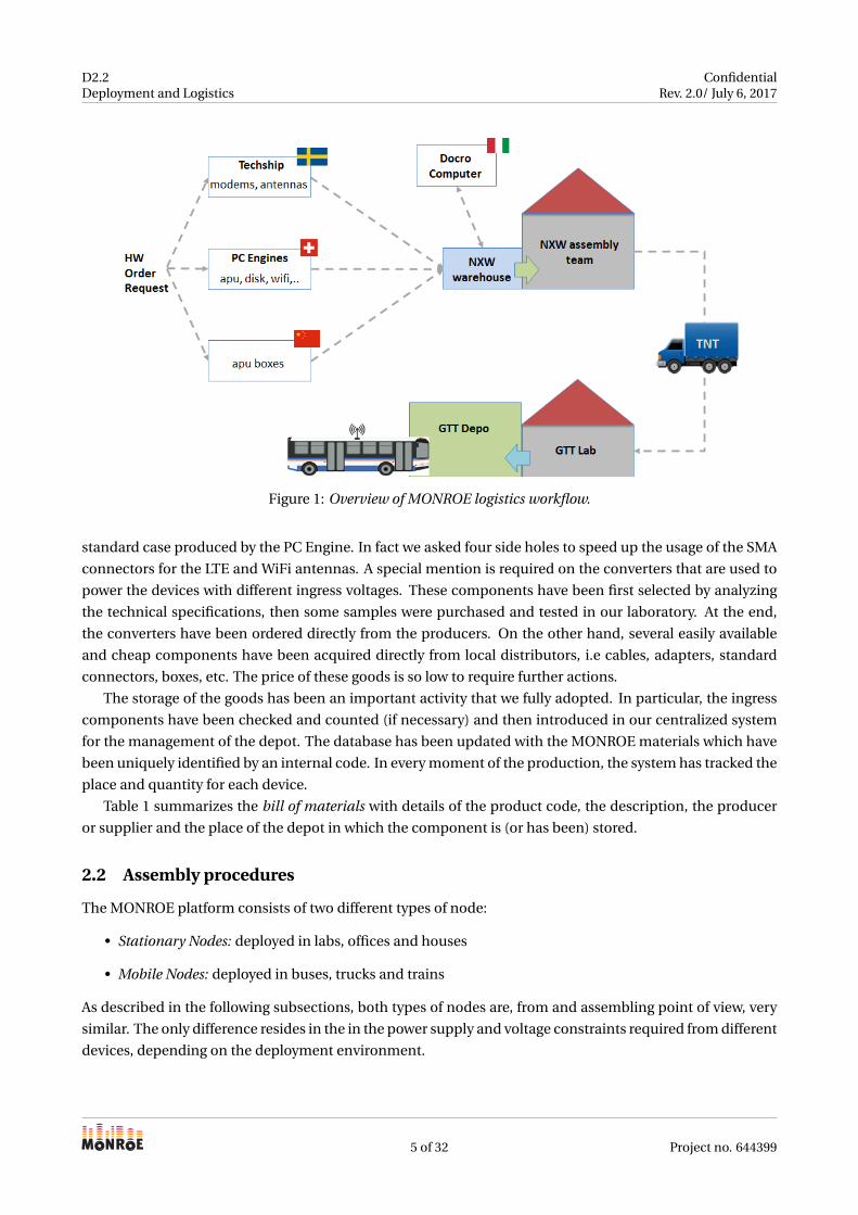
the packaging and shipment to the partners for the final deployment. Figure 1 provides an overview of the
MONROE logistics workflow, in the specific example case of GTT as point of consumption for deployment of
mobile nodes on Turin city buses. The overall workflow can be summarized as follows:
• Nodes hardware components are ordered from the selected suppliers. This phase involve the order of
modems, antennas, APUs, disks, etc, each from the best available supplier, in terms of delivery cost
and time.
• Upon order, the hardware suppliers ship the components to Nextworks (Pisa). Here all the received
material is stored, catalogued in inventories and stored in the warehouse.
• Nextworks takes care of ordering additional assembly material and consumables, needed to produce
MONROE nodes.
• Nextworks assembly team prepares the nodes, which basically includes software installation and con-
figuration for APU nodes, and assembly of the whole node components into a box.
• When ready, a set of assembled MONROE nodes (normally in sets of 10 to 15 units) are shipped with
the reference MONROE outbound courier towards the final destination
• Upon arrival of the nodes at destination, the MONROE nodes can be subject to further tests and vali-
dations from the host deployment team
• The nodes are deployed in the given location (bus, train, etc.) and installed to be used as part of the
MONROE platform.
More details on each of the above MONROE logistics activity are provided in the following sections.
2.1 Inbound: purchase and storage the goods
In the deliverable D2.1, we have introduced the basic prerequisites of the MONROE system and its hardware
components. We have also presented the main devices that form the core of the node, i.e the APU system
board, the internal WiFi modems, the GPS receiver, etc. Moreover the tests to verify their characteristics have
been reported. In short, the bill of materials has been fully defined and this can be considered as the starting
point for the logistic and deployment phase of the project.
One of the first activities carried out in the Task 2.2 was the selection of the best suppliers available in
the market which can guarantee the large amount of materials and a short delivery time. In this context,
we have created relationships directly with the device producers in order to avoid the intermediation of
suppliers or retailers. It is worth noting that these contacts allowed us to have technical discussions to solve
problems or to enhance the final product. For example, the case of the APU board is a customisation of the
4 of 32 Project no. 644399
D2.2Deployment and Logistics
ConfidentialRev. 2.0/ July 6, 2017
Figure 1: Overview of MONROE logistics workflow.
standard case produced by the PC Engine. In fact we asked four side holes to speed up the usage of the SMA
connectors for the LTE and WiFi antennas. A special mention is required on the converters that are used to
power the devices with different ingress voltages. These components have been first selected by analyzing
the technical specifications, then some samples were purchased and tested in our laboratory. At the end,
the converters have been ordered directly from the producers. On the other hand, several easily available
and cheap components have been acquired directly from local distributors, i.e cables, adapters, standard
connectors, boxes, etc. The price of these goods is so low to require further actions.
The storage of the goods has been an important activity that we fully adopted. In particular, the ingress
components have been checked and counted (if necessary) and then introduced in our centralized system
for the management of the depot. The database has been updated with the MONROE materials which have
been uniquely identified by an internal code. In every moment of the production, the system has tracked the
place and quantity for each device.
Table 1 summarizes the bill of materials with details of the product code, the description, the producer
or supplier and the place of the depot in which the component is (or has been) stored.
2.2 Assembly procedures
The MONROE platform consists of two different types of node:
• Stationary Nodes: deployed in labs, offices and houses
• Mobile Nodes: deployed in buses, trucks and trains
As described in the following subsections, both types of nodes are, from and assembling point of view, very
similar. The only difference resides in the in the power supply and voltage constraints required from different
devices, depending on the deployment environment.
5 of 32 Project no. 644399
D2.2Deployment and Logistics
ConfidentialRev. 2.0/ July 6, 2017
Code Description Supplier Storage at warehouse
apu1d4 APU.1D4 system board 4GB PC Engine LABMONROE-0-1apu2d4 APU.2D4 system board 4GB PC Engine LABMONROE-0-1case1d2redu Custom red case PC Engine LABMONROE-0-1ac12veur2 AC adapter 12V 2A euro for IT equipment PC Engine LABMONROE-0-1sma-cable Interface cable SMA/IPEX 15cm PC Engine LABMONROE-0-1msata16d SSD M-Sata 16GB MLC Phison PC Engine LABMONROE-0-2wle600vx Compex WLE600VX miniPCI express card PC Engine LABMONROE-0-2mc7304 Sierra wireless MC7304 data (CAT3) PC Engine LABMONROE-0-2sim7100E SIMCom SIM7100E (CAT3, embedded sim
slot)PC Engine LABMONROE-0-2
mc745504 Sierra wireless MC7455 data (CAT6) PC Engine LABMONROE-0-2wifi-antenna Wifi rubber antenna 2.4-5.8 GHz . LABMONROE-0-2lte-antenna External T-blade LTE antenna . LABMONROE-0-2gps-antenna External passive GPS antenna . LABMONROE-0-2gsm-socket GSM smart plug . LABMONROE-0-4accessories Outlet extensions, fuses, metal clamps,
spare materialsDOCRO Computer LABMONROE-0-4
gewiss-box Gewiss IP55 enclosure Gewiss LABMONROE-1-0k2413 DC-DC converter from 24V to 12V Alcapower LABMONROE-1-1
rsd-100c-12 Railway Single Output DC-DC Converterfrom 48V to 12V
MW mean well LABMONROE-1-1
rsd-100d-12 Railway Single Output DC-DC Converterfrom 110V to 12V
MW mean well LABMONROE-1-1
Table 1: Storage of the MONROE components.
2.2.1 Common assembly procedure
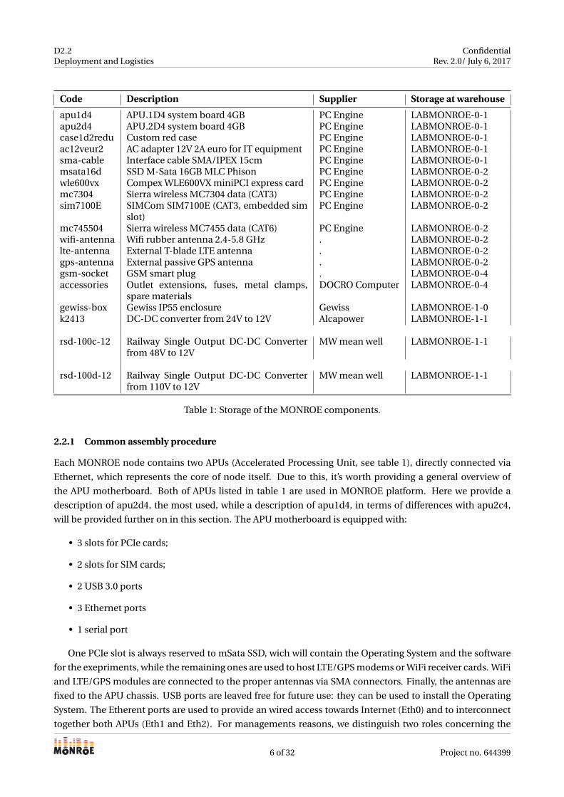
Each MONROE node contains two APUs (Accelerated Processing Unit, see table 1), directly connected via
Ethernet, which represents the core of node itself. Due to this, it’s worth providing a general overview of
the APU motherboard. Both of APUs listed in table 1 are used in MONROE platform. Here we provide a
description of apu2d4, the most used, while a description of apu1d4, in terms of differences with apu2c4,
will be provided further on in this section. The APU motherboard is equipped with:
• 3 slots for PCIe cards;
• 2 slots for SIM cards;
• 2 USB 3.0 ports
• 3 Ethernet ports
• 1 serial port
One PCIe slot is always reserved to mSata SSD, wich will contain the Operating System and the software
for the exepriments, while the remaining ones are used to host LTE/GPS modems or WiFi receiver cards. WiFi
and LTE/GPS modules are connected to the proper antennas via SMA connectors. Finally, the antennas are
fixed to the APU chassis. USB ports are leaved free for future use: they can be used to install the Operating
System. The Etherent ports are used to provide an wired access towards Internet (Eth0) and to interconnect
together both APUs (Eth1 and Eth2). For managements reasons, we distinguish two roles concerning the
6 of 32 Project no. 644399
D2.2Deployment and Logistics
ConfidentialRev. 2.0/ July 6, 2017
single APU in dual-APU system, HEAD or TAIL. As explained below, HEAD and TAIL differ in two aspects:
the PCIe cards and the number of SIMs installed.
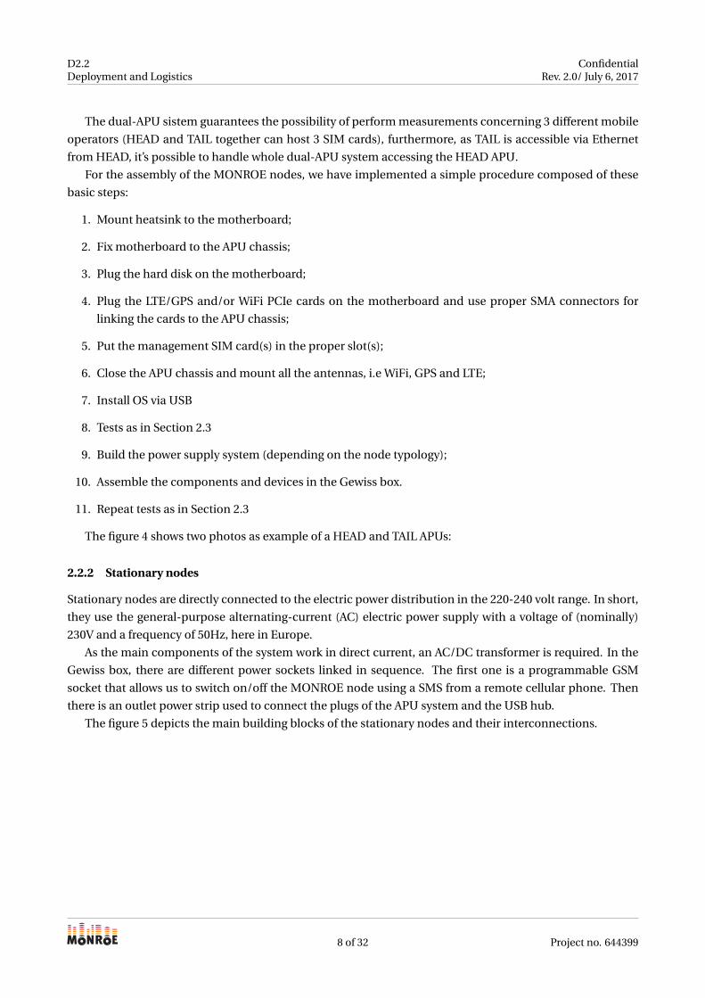
In TAIL APU, the two free PCIe slots host 1 LTE/GPS modem and 1 WiFi receiver respectively. Since only
one LTE/GPS modem is installed, the TAIL APU will contain only one SIM card, which will be inserted in one
of the slots in the motherboard. The figure 2 depicts the main building blocks of the TAIL APU system and
how they are assembled on the motherboard.
Figure 2: Building blocks of TAIL node.
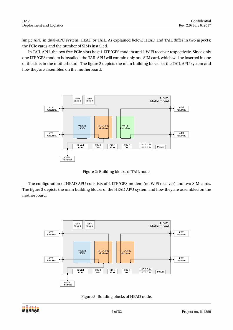
The configuration of HEAD APU constists of 2 LTE/GPS modem (no WiFi receiver) and two SIM cards.
The figure 3 depicts the main building blocks of the HEAD APU system and how they are assembled on the
motherboard.
Figure 3: Building blocks of HEAD node.
7 of 32 Project no. 644399
D2.2Deployment and Logistics
ConfidentialRev. 2.0/ July 6, 2017
The dual-APU sistem guarantees the possibility of perform measurements concerning 3 different mobile
operators (HEAD and TAIL together can host 3 SIM cards), furthermore, as TAIL is accessible via Ethernet
from HEAD, it’s possible to handle whole dual-APU system accessing the HEAD APU.
For the assembly of the MONROE nodes, we have implemented a simple procedure composed of these
basic steps:
1. Mount heatsink to the motherboard;
2. Fix motherboard to the APU chassis;
3. Plug the hard disk on the motherboard;
4. Plug the LTE/GPS and/or WiFi PCIe cards on the motherboard and use proper SMA connectors for
linking the cards to the APU chassis;
5. Put the management SIM card(s) in the proper slot(s);
6. Close the APU chassis and mount all the antennas, i.e WiFi, GPS and LTE;
7. Install OS via USB
8. Tests as in Section 2.3
9. Build the power supply system (depending on the node typology);
10. Assemble the components and devices in the Gewiss box.
11. Repeat tests as in Section 2.3
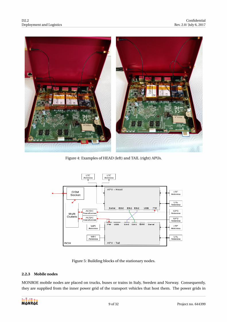
The figure 4 shows two photos as example of a HEAD and TAIL APUs:
2.2.2 Stationary nodes
Stationary nodes are directly connected to the electric power distribution in the 220-240 volt range. In short,
they use the general-purpose alternating-current (AC) electric power supply with a voltage of (nominally)
230V and a frequency of 50Hz, here in Europe.
As the main components of the system work in direct current, an AC/DC transformer is required. In the
Gewiss box, there are different power sockets linked in sequence. The first one is a programmable GSM
socket that allows us to switch on/off the MONROE node using a SMS from a remote cellular phone. Then
there is an outlet power strip used to connect the plugs of the APU system and the USB hub.
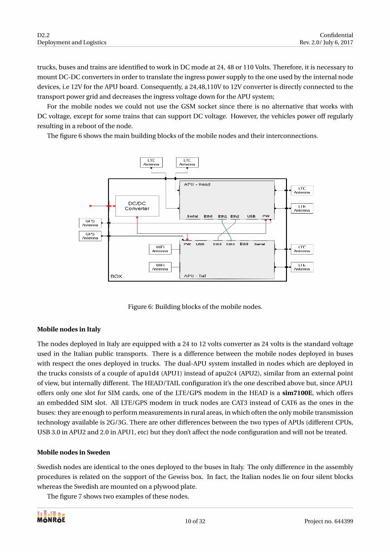
The figure 5 depicts the main building blocks of the stationary nodes and their interconnections.
8 of 32 Project no. 644399
D2.2Deployment and Logistics
ConfidentialRev. 2.0/ July 6, 2017
Figure 4: Examples of HEAD (left) and TAIL (right) APUs.
Figure 5: Building blocks of the stationary nodes.
2.2.3 Mobile nodes
MONROE mobile nodes are placed on trucks, buses or trains in Italy, Sweden and Norway. Consequently,
they are supplied from the inner power grid of the transport vehicles that host them. The power grids in
9 of 32 Project no. 644399
D2.2Deployment and Logistics
ConfidentialRev. 2.0/ July 6, 2017
trucks, buses and trains are identified to work in DC mode at 24, 48 or 110 Volts. Therefore, it is necessary to
mount DC-DC converters in order to translate the ingress power supply to the one used by the internal node
devices, i.e 12V for the APU board. Consequently, a 24,48,110V to 12V converter is directly connected to the
transport power grid and decreases the ingress voltage down for the APU system;
For the mobile nodes we could not use the GSM socket since there is no alternative that works with
DC voltage, except for some trains that can support DC voltage. However, the vehicles power off regularly
resulting in a reboot of the node.
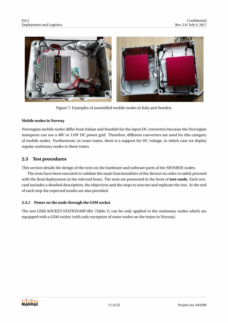
The figure 6 shows the main building blocks of the mobile nodes and their interconnections.
Figure 6: Building blocks of the mobile nodes.
Mobile nodes in Italy
The nodes deployed in Italy are equipped with a 24 to 12 volts converter as 24 volts is the standard voltage
used in the Italian public transports. There is a difference between the mobile nodes deployed in buses
with respect the ones deployed in trucks. The dual-APU system installed in nodes which are deployed in
the trucks consists of a couple of apu1d4 (APU1) instead of apu2c4 (APU2), similar from an external point
of view, but internally different. The HEAD/TAIL configuration it’s the one described above but, since APU1
offers only one slot for SIM cards, one of the LTE/GPS modem in the HEAD is a sim7100E, which offers
an embedded SIM slot. All LTE/GPS modem in truck nodes are CAT3 instead of CAT6 as the ones in the
buses: they are enough to perform measurements in rural areas, in which often the only mobile transmission
technology available is 2G/3G. There are other differences between the two types of APUs (different CPUs,
USB 3.0 in APU2 and 2.0 in APU1, etc) but they don’t affect the node configuration and will not be treated.
Mobile nodes in Sweden
Swedish nodes are identical to the ones deployed to the buses in Italy. The only difference in the assembly
procedures is related on the support of the Gewiss box. In fact, the Italian nodes lie on four silent blocks
whereas the Swedish are mounted on a plywood plate.
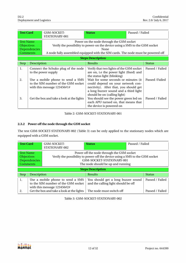
The figure 7 shows two examples of these nodes.
10 of 32 Project no. 644399
D2.2Deployment and Logistics
ConfidentialRev. 2.0/ July 6, 2017
Figure 7: Examples of assembled mobile nodes in Italy and Sweden.
Mobile nodes in Norway
Norwegian mobile nodes differ from Italian and Swedish for the input DC converters because the Norvegian
transports can use a 48V or 110V DC power grid. Therefore, different converters are used for this category
of mobile nodes. Furthermore, in some trains, there is a support for DC voltage, in which case we deploy
regular stationary nodes to these trains.
2.3 Test procedures
This section details the design of the tests on the hardware and software parts of the MONROE nodes.
The tests have been executed to validate the main functionalities of the devices in order to safely proceed
with the final deployment in the selected hosts. The tests are presented in the form of test-cards. Each test-
card includes a detailed description, the objectives and the steps to execute and replicate the test. At the end
of each step the expected results are also provided.
2.3.1 Power on the node through the GSM socket
The test GSM-SOCKET-STATIONARY-001 (Table 2) can be only applied to the stationary nodes which are
equipped with a GSM socket (with only exception of some nodes on the trains in Norway).
11 of 32 Project no. 644399
D2.2Deployment and Logistics
ConfidentialRev. 2.0/ July 6, 2017
Test Card GSM-SOCKET-STATIONARY-001
Status Passed / Failed
Test Name Power on the node through the GSM socketObjectives Verify the possibility to power-on the device using a SMS to the GSM socketDependencies NoneComments A node fully assembled equipped with the SIM cards. The node must be powered off
Steps Description
Step Description Results Status
1. Connect the Schuko plug of the nodeto the power supply
Verify that two lights of the GSM socketare on, i.e the power light (fixed) andthe status light (blinking)
Passed / Failed
2. Use a mobile phone to send a SMSto the SIM number of the GSM socketwith this message 123456#1#
Wait for some seconds or minutes (itcould depend on your network con-nectivity). After that, you should geta long buzzer sound and a third lightshould be on (calling light)
Passed /Failed
3. Get the box and take a look at the lights You should see the power green led oneach APU turned on, that means thatthe device is powered on
Passed / Failed
Table 2: GSM-SOCKET-STATIONARY-001
2.3.2 Power off the node through the GSM socket
The test GSM-SOCKET-STATIONARY-002 (Table 3) can be only applied to the stationary nodes which are
equipped with a GSM socket.
Test Card GSM-SOCKET-STATIONARY-002
Status Passed / Failed
Test Name Power off the node through the GSM socketObjectives Verify the possibility to power-off the device using a SMS to the GSM socketDependencies GSM-SOCKET-STATIONARY-001Comments The node should be up and running
Steps Description
Step Description Results Status
1. Use a mobile phone to send a SMSto the SIM number of the GSM socketwith this message 123456#2#
You should get a long buzzer soundand the calling light should be off
Passed / Failed
2. Get the box and take a look at the lights The node must switch off Passed / Failed
Table 3: GSM-SOCKET-STATIONARY-002
12 of 32 Project no. 644399
D2.2Deployment and Logistics
ConfidentialRev. 2.0/ July 6, 2017
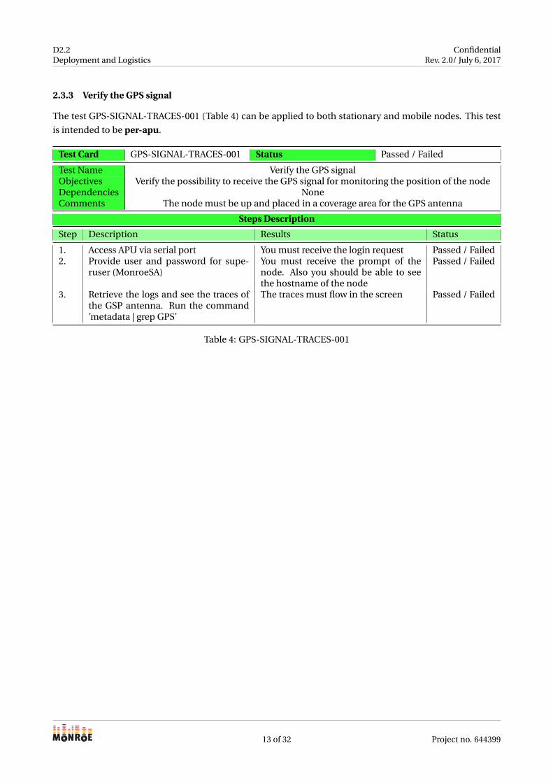
2.3.3 Verify the GPS signal
The test GPS-SIGNAL-TRACES-001 (Table 4) can be applied to both stationary and mobile nodes. This test
is intended to be per-apu.
Test Card GPS-SIGNAL-TRACES-001 Status Passed / Failed
Test Name Verify the GPS signalObjectives Verify the possibility to receive the GPS signal for monitoring the position of the nodeDependencies NoneComments The node must be up and placed in a coverage area for the GPS antenna
Steps Description
Step Description Results Status
1. Access APU via serial port You must receive the login request Passed / Failed2. Provide user and password for supe-
ruser (MonroeSA)You must receive the prompt of thenode. Also you should be able to seethe hostname of the node
Passed / Failed
3. Retrieve the logs and see the traces ofthe GSP antenna. Run the command’metadata | grep GPS’
The traces must flow in the screen Passed / Failed
Table 4: GPS-SIGNAL-TRACES-001
13 of 32 Project no. 644399
D2.2Deployment and Logistics
ConfidentialRev. 2.0/ July 6, 2017
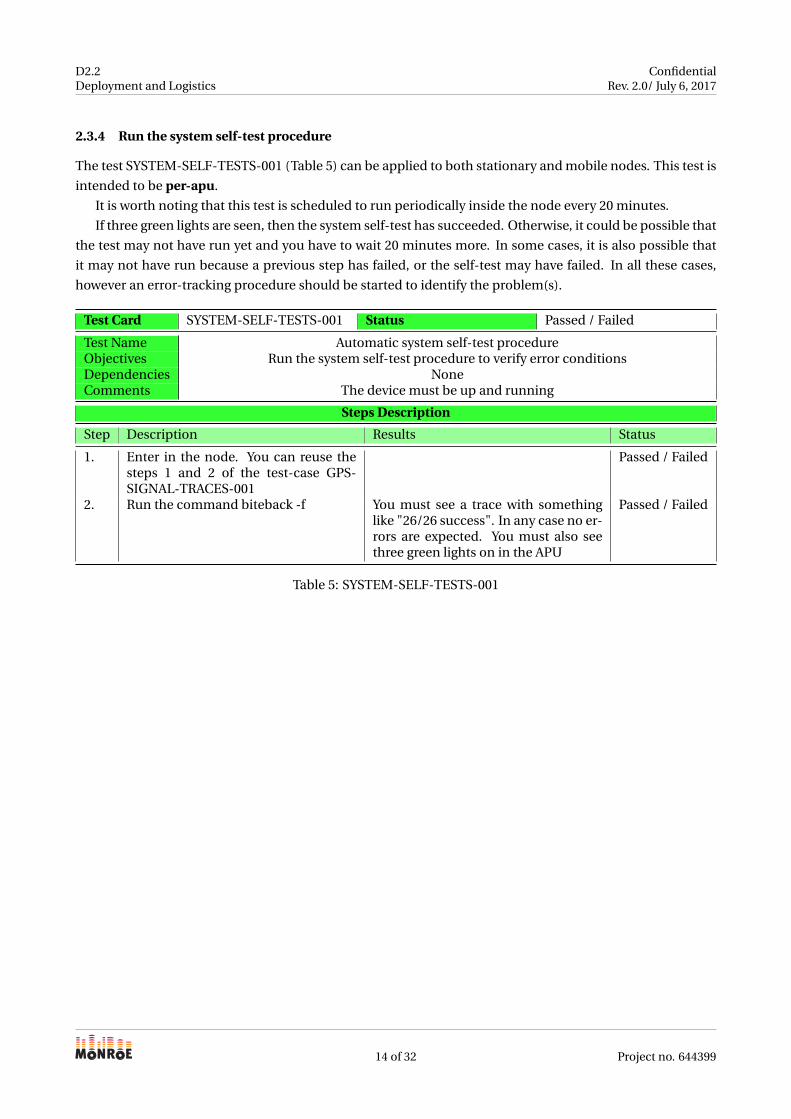
2.3.4 Run the system self-test procedure
The test SYSTEM-SELF-TESTS-001 (Table 5) can be applied to both stationary and mobile nodes. This test is
intended to be per-apu.
It is worth noting that this test is scheduled to run periodically inside the node every 20 minutes.
If three green lights are seen, then the system self-test has succeeded. Otherwise, it could be possible that
the test may not have run yet and you have to wait 20 minutes more. In some cases, it is also possible that
it may not have run because a previous step has failed, or the self-test may have failed. In all these cases,
however an error-tracking procedure should be started to identify the problem(s).
Test Card SYSTEM-SELF-TESTS-001 Status Passed / Failed
Test Name Automatic system self-test procedureObjectives Run the system self-test procedure to verify error conditionsDependencies NoneComments The device must be up and running
Steps Description
Step Description Results Status
1. Enter in the node. You can reuse thesteps 1 and 2 of the test-case GPS-SIGNAL-TRACES-001
Passed / Failed
2. Run the command biteback -f You must see a trace with somethinglike "26/26 success". In any case no er-rors are expected. You must also seethree green lights on in the APU
Passed / Failed
Table 5: SYSTEM-SELF-TESTS-001
14 of 32 Project no. 644399
D2.2Deployment and Logistics
ConfidentialRev. 2.0/ July 6, 2017
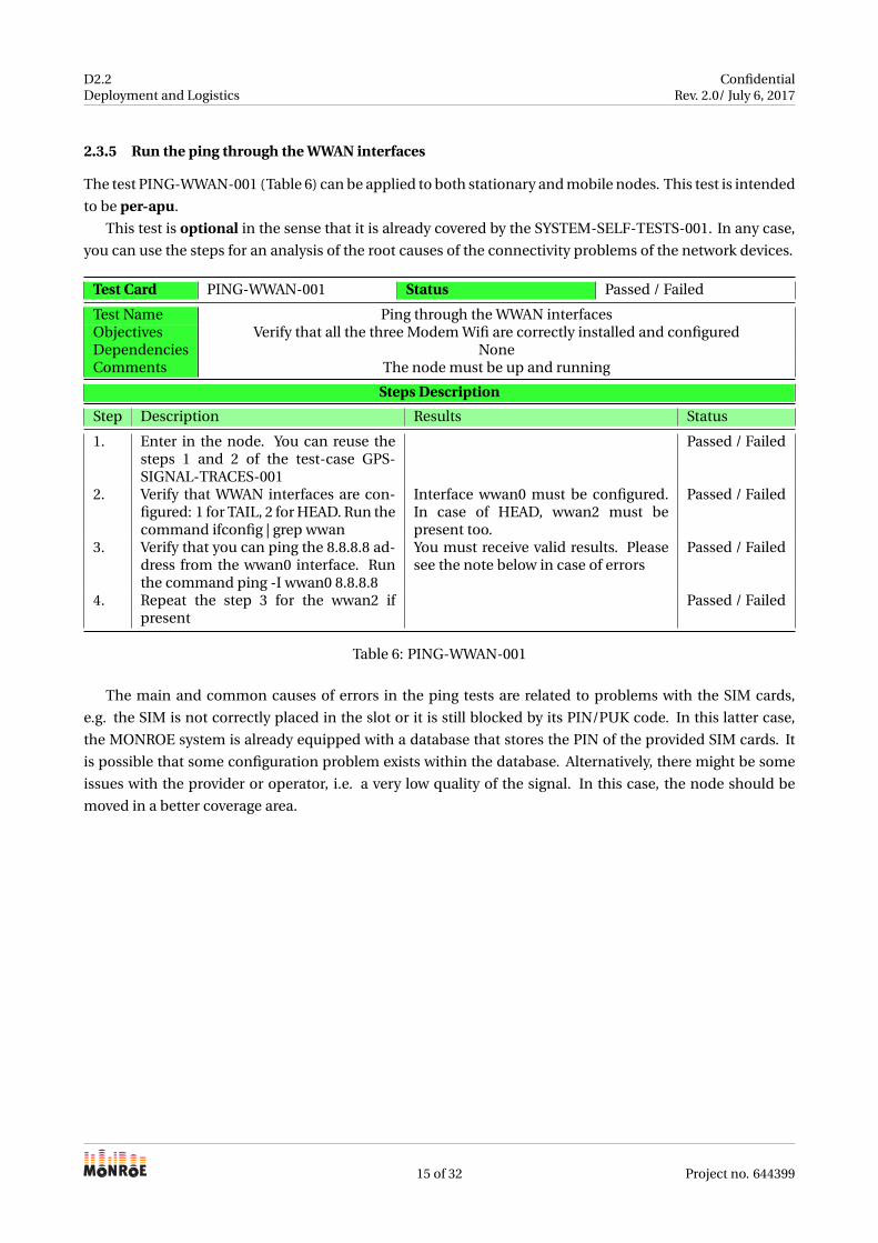
2.3.5 Run the ping through the WWAN interfaces
The test PING-WWAN-001 (Table 6) can be applied to both stationary and mobile nodes. This test is intended
to be per-apu.
This test is optional in the sense that it is already covered by the SYSTEM-SELF-TESTS-001. In any case,
you can use the steps for an analysis of the root causes of the connectivity problems of the network devices.
Test Card PING-WWAN-001 Status Passed / Failed
Test Name Ping through the WWAN interfacesObjectives Verify that all the three Modem Wifi are correctly installed and configuredDependencies NoneComments The node must be up and running
Steps Description
Step Description Results Status
1. Enter in the node. You can reuse thesteps 1 and 2 of the test-case GPS-SIGNAL-TRACES-001
Passed / Failed
2. Verify that WWAN interfaces are con-figured: 1 for TAIL, 2 for HEAD. Run thecommand ifconfig | grep wwan
Interface wwan0 must be configured.In case of HEAD, wwan2 must bepresent too.
Passed / Failed
3. Verify that you can ping the 8.8.8.8 ad-dress from the wwan0 interface. Runthe command ping -I wwan0 8.8.8.8
You must receive valid results. Pleasesee the note below in case of errors
Passed / Failed
4. Repeat the step 3 for the wwan2 ifpresent
Passed / Failed
Table 6: PING-WWAN-001
The main and common causes of errors in the ping tests are related to problems with the SIM cards,
e.g. the SIM is not correctly placed in the slot or it is still blocked by its PIN/PUK code. In this latter case,
the MONROE system is already equipped with a database that stores the PIN of the provided SIM cards. It
is possible that some configuration problem exists within the database. Alternatively, there might be some
issues with the provider or operator, i.e. a very low quality of the signal. In this case, the node should be
moved in a better coverage area.
15 of 32 Project no. 644399
D2.2Deployment and Logistics
ConfidentialRev. 2.0/ July 6, 2017
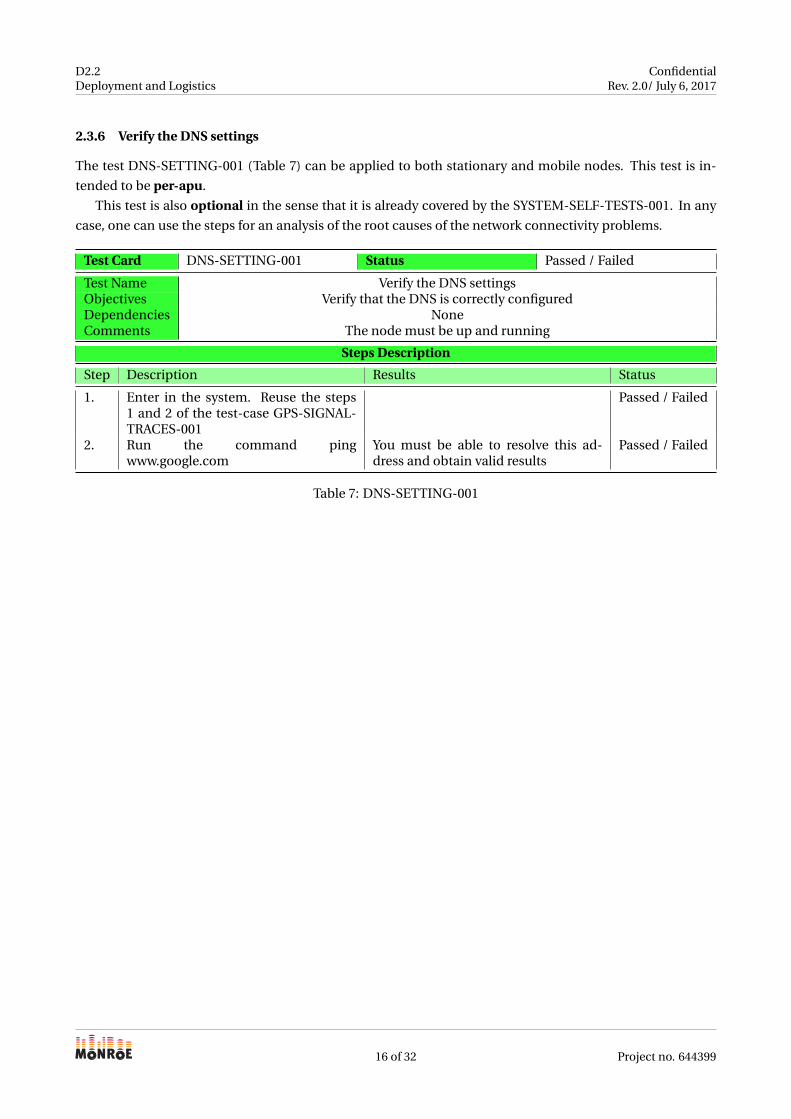
2.3.6 Verify the DNS settings
The test DNS-SETTING-001 (Table 7) can be applied to both stationary and mobile nodes. This test is in-
tended to be per-apu.
This test is also optional in the sense that it is already covered by the SYSTEM-SELF-TESTS-001. In any
case, one can use the steps for an analysis of the root causes of the network connectivity problems.
Test Card DNS-SETTING-001 Status Passed / Failed
Test Name Verify the DNS settingsObjectives Verify that the DNS is correctly configuredDependencies NoneComments The node must be up and running
Steps Description
Step Description Results Status
1. Enter in the system. Reuse the steps1 and 2 of the test-case GPS-SIGNAL-TRACES-001
Passed / Failed
2. Run the command pingwww.google.com
You must be able to resolve this ad-dress and obtain valid results
Passed / Failed
Table 7: DNS-SETTING-001
16 of 32 Project no. 644399
D2.2Deployment and Logistics
ConfidentialRev. 2.0/ July 6, 2017
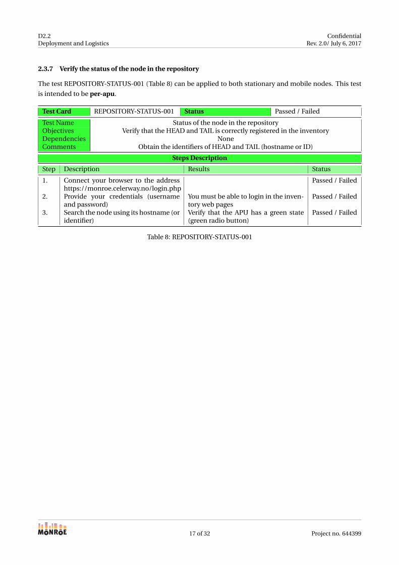
2.3.7 Verify the status of the node in the repository
The test REPOSITORY-STATUS-001 (Table 8) can be applied to both stationary and mobile nodes. This test
is intended to be per-apu.
Test Card REPOSITORY-STATUS-001 Status Passed / Failed
Test Name Status of the node in the repositoryObjectives Verify that the HEAD and TAIL is correctly registered in the inventoryDependencies NoneComments Obtain the identifiers of HEAD and TAIL (hostname or ID)
Steps Description
Step Description Results Status
1. Connect your browser to the addresshttps://monroe.celerway.no/login.php
Passed / Failed
2. Provide your credentials (usernameand password)
You must be able to login in the inven-tory web pages
Passed / Failed
3. Search the node using its hostname (oridentifier)
Verify that the APU has a green state(green radio button)
Passed / Failed
Table 8: REPOSITORY-STATUS-001
17 of 32 Project no. 644399
D2.2Deployment and Logistics
ConfidentialRev. 2.0/ July 6, 2017
2.3.8 Verify the status of the interfaces in the repository
The test REPOSITORY-STATUS-002 (Table 9) can be applied to both stationary and mobile nodes. This test
is intended to be per-apu.
Test Card REPOSITORY-STATUS-002 Status Passed / Failed
Test Name Status of the interfaces of the node in the inventoryObjectives Verify that the interfaces of HEAD and TAIL are correctly workingDependencies REPOSITORY-STATUS-001Comments
Steps Description
Step Description Results Status
1. Click on the (green) radio button You should have a popup with thenode details
Passed / Failed
2. Verify the status of the interfaces The interfaces must be labelled withthe proper operator and the type of thenetwork currently connected (e.g. 3G,4G or LTE). Also, the status must be agreen bar
Passed / Failed
Table 9: REPOSITORY-STATUS-002
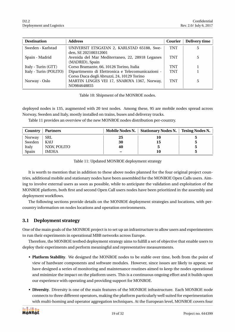
2.4 Outbound: shipment to the partners
When (and if) assembled nodes pass all the planned tests previously described, they are accurately packed
for a safe shipment and to prevent damages or faults during the transportation. The selection of a reference
courier for the MONROE nodes shipment has been carried out in the first months of the project, and had the
main aim to have a unique contanct point for the delivery process, while trying to reduce the overall costs.
Several couriers have been contacted to receive quotations and delivery times for the four countries involved
in the MONROE nodes deployment, i.e. Spain, Norway, Sweden and Italy.
Nextworks, as main responsible for the logistics arrangements, collected best offers from Bartolini, DHL
Express, Macros and TNT couriers. At the end, TNT was selected as it guaranteed the best trade off between
delivery cost and time. TNT offered delivery time for Italy in one business day, and within one week in the rest
of Europe (no more than five working days). Table 10 summarises the main outbound logistics information
related to the shipment process of MONROE nodes, i.e the destination, address, selected courier and the
expected delivery time (in days). Note that since all the nodes have been assembled directly in Nextworks
(Pisa), we have not used any courier for the shipment of stationary and mobile nodes in the Tuscany area.
3 Deployment of the nodes
MONROE has the main objective to build a dedicated infrastructure for measuring and experimenting in
commercial mobile broadband (MBB) and WiFi networks, setting up a platform composed by stationary
and mobile measurement nodes.
As said, this document upgrades the original deliverable D2.2 and provides those updates related to the
new MONROE node design. Concerning the deployment, the upgrade of the MONROE platform to the new
required an update of the target of deployed nodes across Europe. In particular, the new total number of
18 of 32 Project no. 644399
D2.2Deployment and Logistics
ConfidentialRev. 2.0/ July 6, 2017
Destination Address Courier Delivery time
Sweden - Karlstad UNIVERSIT ETSGATAN 2, KARLSTAD 65188, Swe-den, SE 202100312001
TNT 5
Spain - Madrid Avenida del Mar Mediterraneo, 22, 28918 Leganes(MADRID), Spain
TNT 5
Italy - Turin (GTT) Corso Bramante, 66, 10126 Torino, Italia TNT 1Italy - Turin (POLITO) Dipartimento di Elettronica e Telecomunicazioni -
Corso Duca degli Abruzzi, 24, 10129 TorinoTNT 1
Norway - Oslo MARTIN LINGES VEI 17, SNAROYA 1367, Norway,NO984648855
TNT 5
Table 10: Shipment of the MONROE nodes.
deployed nodes is 135, augmented with 20 test nodes. Among these, 95 are mobile nodes spread across
Norway, Sweden and Italy, mostly installed on trains, buses and deliveray trucks.
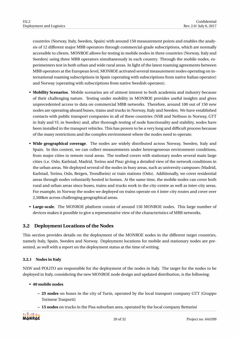
Table 11 provides an overview of the new MONROE nodes distribution per-country.
Country Partners Mobile Nodes N. Stationary Nodes N. Tesing Nodes N.
Norway SRL 25 10 5Sweden KAU 30 15 5Italy NXW, POLITO 40 5 5Spain IMDEA – 10 5
Table 11: Updated MONROE deployment strategy
It is worth to mention that in addition to these above nodes planned for the four original project coun-
tries, additional mobile and stationary nodes have been assembled for the MONROE Open Calls users. Aim-
ing to involve external users as soon as possible, while to anticipate the validation and exploitation of the
MONROE platform, both first and second Open Call users nodes have been prioritized in the assembly and
deployment workflows.
The following sections provide details on the MONROE deployment strategies and locations, with per-
country information on nodes locations and operation environments.
3.1 Deployment strategy
One of the main goals of the MONROE project is to set up an infrastructure to allow users and experimenters
to run their experiments in operational MBB networks across Europe.
Therefore, the MONROE testbed deployment strategy aims to fulfill a set of objective that enable users to
deploy their experiments and perform meaningful and representative measurements.
• Platform Stability. We designed the MONROE nodes to be stable over time, both from the point of
view of hardware components and software modules. However, since issues are likely to appear, we
have designed a series of monitoring and maintenance routines aimed to keep the nodes operational
and minimize the impact on the platform users. This is a continuous ongoing effort and it builds upon
our experience with operating and providing support for MONROE.
• Diversity. Diversity is one of the main features of the MONROE infrastructure. Each MONROE node
connects to three different operators, making the platform particularly well suited for experimentation
with multi-homing and operator aggregation techniques. At the European level, MONROE covers four
19 of 32 Project no. 644399
D2.2Deployment and Logistics
ConfidentialRev. 2.0/ July 6, 2017
countries (Norway, Italy, Sweden, Spain) with around 150 measurement points and enables the analy-
sis of 12 different major MBB operators through commercial-grade subscriptions, which are normally
accessible to clients. MONROE allows for testing in mobile nodes in three countries (Norway, Italy and
Sweden) using three MBB operators simultaneously in each country. Through the mobile nodes, ex-
perimenters test in both urban and wide rural areas. In light of the latest roaming agreements between
MBB operators at the European level, MONROE activated several measurement nodes operating on in-
ternational roaming subscriptions in Spain (operating with subscriptions from native Italian operator)
and Norway (operating with subscriptions from native Swedish operator).
• Mobility Scenarios. Mobile scenarios are of utmost interest to both academia and industry because
of their challenging nature. Testing under mobility in MONROE provides useful insights and gives
unprecedented access to data on commercial MBB networks. Therefore, around 100 out of 150 new
nodes are operating aboard buses, trains and trucks in Norway, Italy and Sweden. We have established
contacts with public transport companies in all of these countries (NSB and Netbuss in Norway, GTT
in Italy and VL in Sweden) and, after thorough testing of node functionality and stability, nodes have
been installed in the transport vehicles. This has proven to be a very long and difficult process because
of the many restrictions and the complex environment where the nodes need to operate.
• Wide geographical coverage. The nodes are widely distributed across Norway, Sweden, Italy and
Spain. In this context, we can collect measurements under heterogeneous environment conditions,
from major cities to remote rural areas. The testbed covers with stationary nodes several main large
cities (i.e. Oslo, Karlstad, Madrid, Torino and Pisa) giving a detailed view of the network conditions in
the urban areas. We deployed several of the nodes in busy areas, such as university campuses (Madrid,
Karlstad, Torino, Oslo, Bergen, Trondheim) or train stations (Oslo). Additionally, we cover residential
areas through nodes voluntarily hosted in homes. At the same time, the mobile nodes can cover both
rural and urban areas since buses, trains and trucks work in the city-centre as well as inter-city areas.
For example, in Norway the nodes we deployed on trains operate on 4 inter-city routes and cover over
2,500km across challenging geographical areas.
• Large-scale. The MONROE platform consist of around 150 MONROE nodes. This large number of
devices makes it possible to give a representative view of the characteristics of MBB networks.
3.2 Deployment Locations of the Nodes
This section provides details on the deployment of the MONROE nodes in the different target countries,
namely Italy, Spain, Sweden and Norway. Deployment locations for mobile and stationary nodes are pre-
sented, as well with a report on the deployment status at the time of writing.
3.2.1 Nodes in Italy
NXW and POLITO are responsible for the deployment of the nodes in Italy. The target for the nodes to be
deployed in Italy, considering the new MONROE node design and updated distribution, is the following:
• 40 mobile nodes
– 25 nodes on buses in the city of Turin, operated by the local transport company GTT (Gruppo
Torinese Trasporti)
– 15 nodes on trucks in the Pisa suburban area, operated by the local company Bettarini
20 of 32 Project no. 644399
D2.2Deployment and Logistics
ConfidentialRev. 2.0/ July 6, 2017
• 5 stationary nodes, all deployed in the Turin city area around the Politecnico di Torino campus
• 5 testing nodes, all deployed in the Politecnico di Torino campus
As said, mobile nodes in Italy are deployed on two different hosts, GTT and Bettarini.
NodeIDs N. Partner Address Notes
(308-309),(310-311),(312-313),(314-315),(316-317),(318-319),(320-321),(326-327),(340-341),(352-353),(342-343),(344-345),(346-347),(348-349),(350-351),(334-335),(336-337),(338-339),(354-355),(388-389),(390-391),(392-393),(398-399),(404-405),(330-331)
25 dual-APUs GTT/NXW GTT, Corso Bramante,Torino (Italy)
Urban buses move aroundthe Turin area
(144-145),(150-151),(146-147),(152-153),(148-149),(266-267),(274-275),(264-265),(258-259),(173-293)
10 dual-APUs NXW Bettarini Group, Via F. Pera,Livorno (Italy)
Trucks move around Tus-cany and center-north ofItaly
(270-271),(268-269),(272-273),(128-129),(136-137)
5 dual-APUs NXW Bettarini Group, Via F. Pera,Livorno (Italy)
Still to be deployed ontrucks at the time of writing
Table 12: Mobile nodes deployment in Italy.
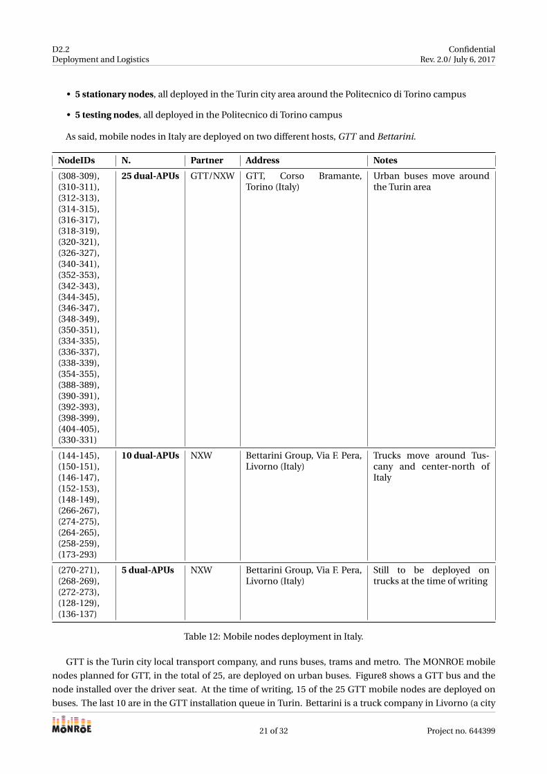
GTT is the Turin city local transport company, and runs buses, trams and metro. The MONROE mobile
nodes planned for GTT, in the total of 25, are deployed on urban buses. Figure8 shows a GTT bus and the
node installed over the driver seat. At the time of writing, 15 of the 25 GTT mobile nodes are deployed on
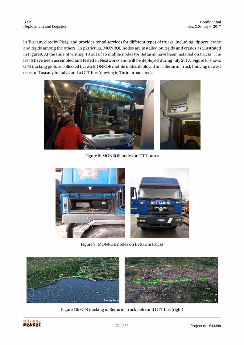
buses. The last 10 are in the GTT installation queue in Turin. Bettarini is a truck company in Livorno (a city
21 of 32 Project no. 644399
D2.2Deployment and Logistics
ConfidentialRev. 2.0/ July 6, 2017
in Tuscany closeby Pisa), and provides rental services for different types of trucks, including, tippers, crane
and rigids among the others. In particular, MONROE nodes are installed on rigids and cranes as illustrated
in Figure9. At the time of writing, 10 out of 15 mobile nodes for Bettarini have been installed on trucks. The
last 5 have been assembled and tested in Nextworks and will be deployed during July 2017. Figure10 shows
GPS tracking plots as collected by two MONROE mobile nodes deployed on a Bettarini truck (moving in west
coast of Tuscany in Italy), and a GTT bus (moving in Turin urban area).
Figure 8: MONROE nodes on GTT buses
Figure 9: MONROE nodes on Bettarini trucks
Figure 10: GPS tracking of Bettarini truck (left) and GTT bus (right)
22 of 32 Project no. 644399
D2.2Deployment and Logistics
ConfidentialRev. 2.0/ July 6, 2017
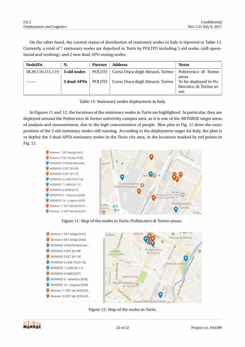
On the other hand, the current status of distribution of stationary nodes in Italy is reported in Table 13.
Currently, a total of 7 stationary nodes are depolyed in Turin by POLITO including 5 old nodes (still opera-
tional and working), and 2 new dual-APU testing nodes.
NodeIDs N. Partner Address Notes
38,39,110,111,119 5 old nodes POLITO Corso Duca degli Abruzzi, Torino Politecnico di Torinoareas
——– 5 dual-APUs POLITO Corso Duca degli Abruzzi, Torino To be deployed in Po-litecnico di Torino ar-eas
Table 13: Stationary nodes deployment in Italy.
In Figures 11 and 12, the locations of the stationary nodes in Turin are highlighted. In particular, they are
deployed around the Politecnico di Torino university campus area, as it is one of the MONROE target areas
of analysis and measurement, due to the high concentration of people. Blue pins in Fig. 12 show the exact
position of the 5 old stationary nodes still running. According to the deployment target for Italy, the plan is
to deploy the 5 dual-APUs stationary nodes in the Turin city area, in the locations marked by red points in
Fig. 12.
Figure 11: Map of the nodes in Turin (Politecnico di Torino areas) .
Figure 12: Map of the nodes in Turin.
23 of 32 Project no. 644399
D2.2Deployment and Logistics
ConfidentialRev. 2.0/ July 6, 2017
3.2.2 Nodes in Spain
IMDEA is responsible for the deployment of the nodes in Spain. We are currently in the process of substi-
tuting the old nodes for 15 new APU2 ones, of which 10 will be deployed for experiments and 5 will be used
as testing nodes for users. At the time of writing, 2 out of 5 dual-APU testing nodes are up and running
in IMDEA premises. The deployment of the rest of stationary nodes is still undergoing and expected to be
completed during September 2017. These new nodes will be deployed in the greater Madrid area, target-
ing specifically the University Carlos III campus in Leganés and Madrid city center. Moreover, 7 of the old
nodes are still operational at the IMDEA Networks lab and usable as additional testing nodes (the rest were
decommissioned after showing failures).
NodeIDs N. Type Partner Address Notes
57, 59, 62, 194, 195, 196, 203 7 old nodes Stationary IMDEA IMDEA (Leganés) APU1
Table 14: Deployment in Spain.
24 of 32 Project no. 644399
D2.2Deployment and Logistics
ConfidentialRev. 2.0/ July 6, 2017
3.2.3 Nodes in Sweden
KAU is responsible for the deployment of the nodes in Sweden. We summarize the ongoing deployment of
the stationary nodes in Sweden in Table 15. In total 15 stationary nodes will be deployed in the new de-
ployment. When finalized, two of the nodes will be on the KAU campus, six nodes will be distributed in the
Karlstad city area, three nodes will be in the Karlstad greater surrounding area, two nodes will be deployed
in Stockholm and two nodes in Västerås. The nodes in Stockholm and Västerås are deployed in collabora-
tion with Swedish Institute of Computer Science (SICS) and Mälardalen University (MDH), respectively. In
addition, five testing nodes will be deployed on the KAU campus. The node IDs of the six already deployed
nodes are indicated in Table 15 and the nodes that are planned to be deployed are marked with −− in the
table. Node deployment on the KAU campus and in Stockholm is complete whereas deployment for the
other locations will be completed in August. However, note that most of the nodes that are not deployed are
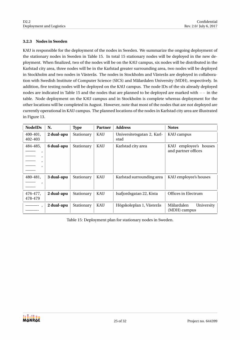
currently operational in KAU campus. The planned locations of the nodes in Karlstad city area are illustrated
in Figure 13.
NodeIDs N. Type Partner Address Notes
400-401,402-403
2 dual-apu Stationary KAU Universitetsgatan 2, Karl-stad
KAU campus
484-485,——– ,——– ,——– ,——– ,——–
6 dual-apu Stationary KAU Karlstad city area KAU employee’s housesand partner offices
480-481,——– ,——–
3 dual-apu Stationary KAU Karlstad surrounding area KAU employee’s houses
476-477,478-479
2 dual-apu Stationary KAU Isafjordsgatan 22, Kista Offices in Electrum
———- ,———-
2 dual-apu Stationary KAU Högskoleplan 1, Västerås Mälardalen University(MDH) campus
Table 15: Deployment plan for stationary nodes in Sweden.
25 of 32 Project no. 644399
D2.2Deployment and Logistics
ConfidentialRev. 2.0/ July 6, 2017
Figure 13: Map of the planned node locations in the Karlstad city area.
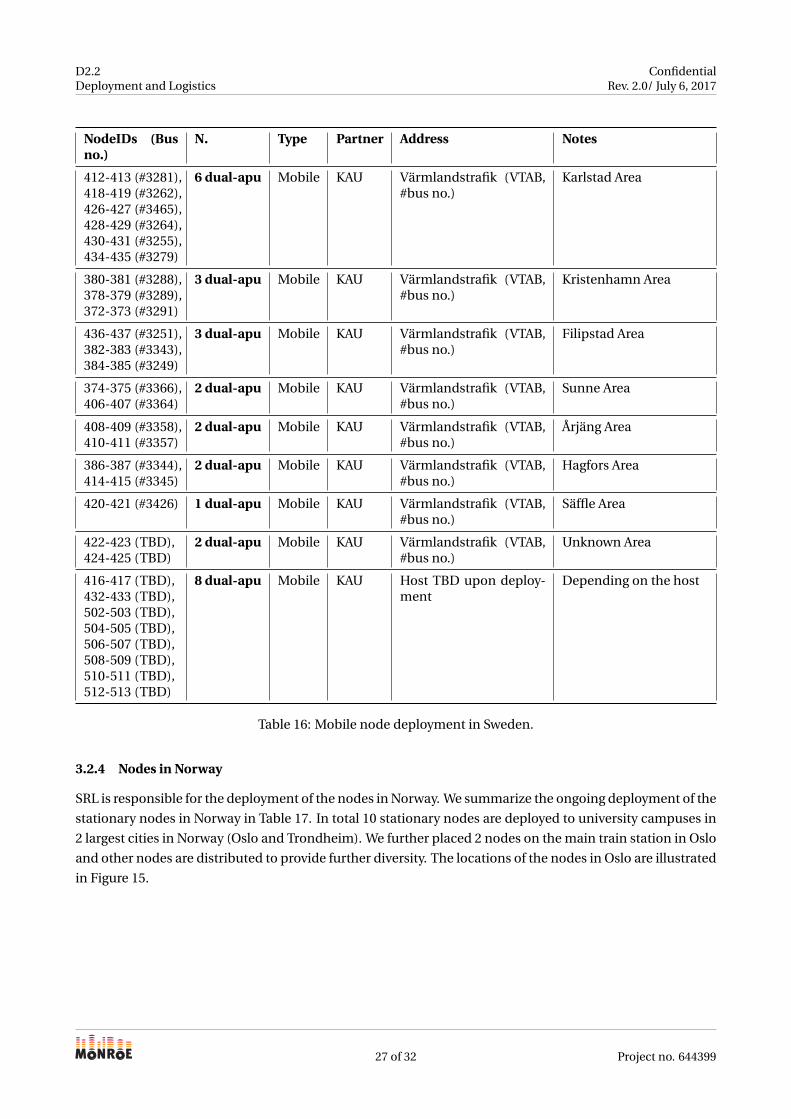
Concerning the mobile nodes, a total of 30 mobile nodes will be deployed in Sweden, 25 of them will be
deployed in buses from Värmlandstrafik and five of them in buses from Karlstadsbuss. Värmlandstrafik is
the regional bus company serving Karlstad and the region of Värmland in which Karlstad is located. Having
nodes deployed in their buses thus gives the possibility to cover both city conditions and rural areas. Karl-
stadbuss provides bus services within the city of Karlstad, and the nodes in their buses will stay within the
city of Karlstad. So far, most of the nodes targeted for the buses from Värmlandstrafik have been deployed. A
summary of the deployment is given in Table 16. The remainder of the mobile nodes will be deployed after
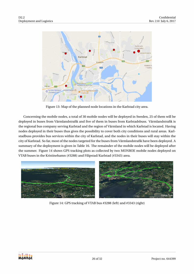
the summer. Figure 14 shows GPS tracking plots as collected by two MONROE mobile nodes deployed on
VTAB buses in the Kristinehamn (#3288) and Filipstad/Karlstad (#3343) area.
Figure 14: GPS tracking of VTAB bus #3288 (left) and #3343 (right)
26 of 32 Project no. 644399
D2.2Deployment and Logistics
ConfidentialRev. 2.0/ July 6, 2017
NodeIDs (Busno.)
N. Type Partner Address Notes
412-413 (#3281),418-419 (#3262),426-427 (#3465),428-429 (#3264),430-431 (#3255),434-435 (#3279)
6 dual-apu Mobile KAU Värmlandstrafik (VTAB,#bus no.)
Karlstad Area
380-381 (#3288),378-379 (#3289),372-373 (#3291)
3 dual-apu Mobile KAU Värmlandstrafik (VTAB,#bus no.)
Kristenhamn Area
436-437 (#3251),382-383 (#3343),384-385 (#3249)
3 dual-apu Mobile KAU Värmlandstrafik (VTAB,#bus no.)
Filipstad Area
374-375 (#3366),406-407 (#3364)
2 dual-apu Mobile KAU Värmlandstrafik (VTAB,#bus no.)
Sunne Area
408-409 (#3358),410-411 (#3357)
2 dual-apu Mobile KAU Värmlandstrafik (VTAB,#bus no.)
Årjäng Area
386-387 (#3344),414-415 (#3345)
2 dual-apu Mobile KAU Värmlandstrafik (VTAB,#bus no.)
Hagfors Area
420-421 (#3426) 1 dual-apu Mobile KAU Värmlandstrafik (VTAB,#bus no.)
Säffle Area
422-423 (TBD),424-425 (TBD)
2 dual-apu Mobile KAU Värmlandstrafik (VTAB,#bus no.)
Unknown Area
416-417 (TBD),432-433 (TBD),502-503 (TBD),504-505 (TBD),506-507 (TBD),508-509 (TBD),510-511 (TBD),512-513 (TBD)
8 dual-apu Mobile KAU Host TBD upon deploy-ment
Depending on the host
Table 16: Mobile node deployment in Sweden.
3.2.4 Nodes in Norway
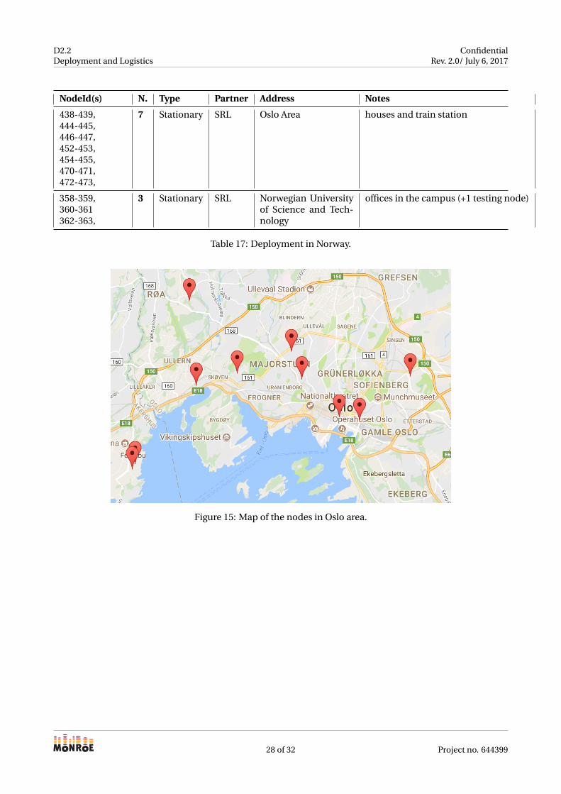
SRL is responsible for the deployment of the nodes in Norway. We summarize the ongoing deployment of the
stationary nodes in Norway in Table 17. In total 10 stationary nodes are deployed to university campuses in
2 largest cities in Norway (Oslo and Trondheim). We further placed 2 nodes on the main train station in Oslo
and other nodes are distributed to provide further diversity. The locations of the nodes in Oslo are illustrated
in Figure 15.
27 of 32 Project no. 644399
D2.2Deployment and Logistics
ConfidentialRev. 2.0/ July 6, 2017
NodeId(s) N. Type Partner Address Notes
438-439,444-445,446-447,452-453,454-455,470-471,472-473,
7 Stationary SRL Oslo Area houses and train station
358-359,360-361362-363,
3 Stationary SRL Norwegian Universityof Science and Tech-nology
offices in the campus (+1 testing node)
Table 17: Deployment in Norway.
Figure 15: Map of the nodes in Oslo area.
28 of 32 Project no. 644399
D2.2Deployment and Logistics
ConfidentialRev. 2.0/ July 6, 2017
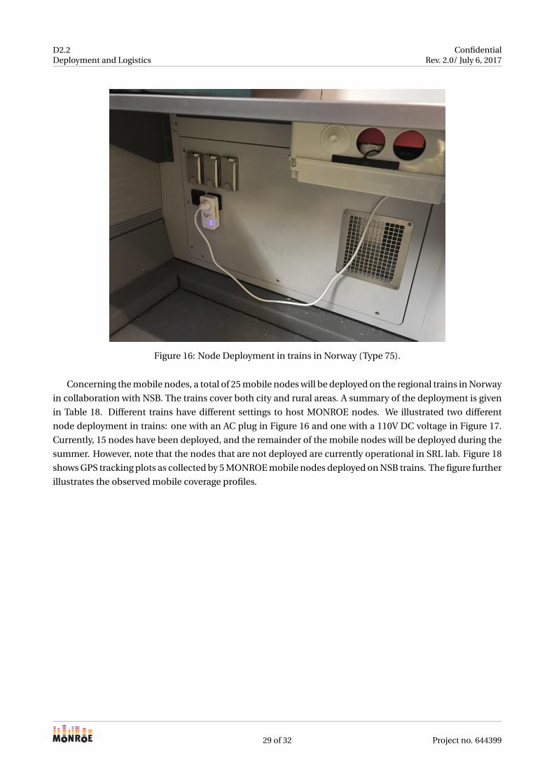
Figure 16: Node Deployment in trains in Norway (Type 75).
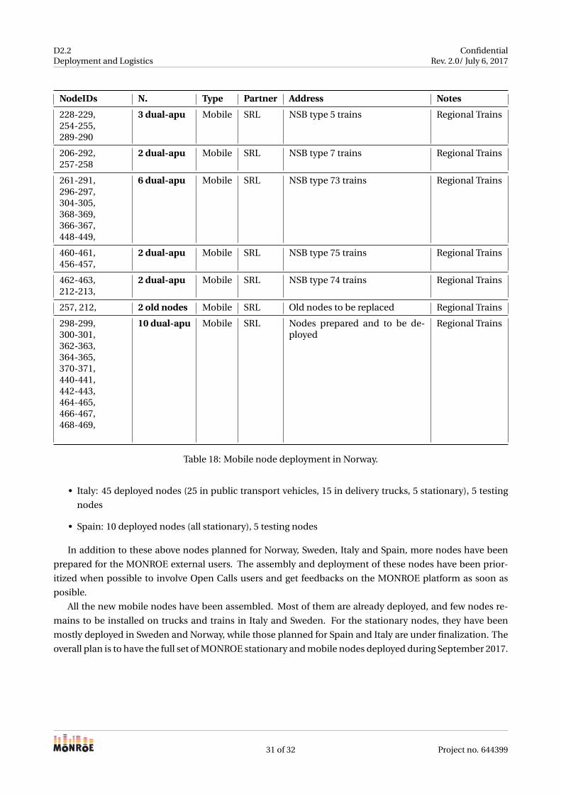
Concerning the mobile nodes, a total of 25 mobile nodes will be deployed on the regional trains in Norway
in collaboration with NSB. The trains cover both city and rural areas. A summary of the deployment is given
in Table 18. Different trains have different settings to host MONROE nodes. We illustrated two different
node deployment in trains: one with an AC plug in Figure 16 and one with a 110V DC voltage in Figure 17.
Currently, 15 nodes have been deployed, and the remainder of the mobile nodes will be deployed during the
summer. However, note that the nodes that are not deployed are currently operational in SRL lab. Figure 18
shows GPS tracking plots as collected by 5 MONROE mobile nodes deployed on NSB trains. The figure further
illustrates the observed mobile coverage profiles.
29 of 32 Project no. 644399
D2.2Deployment and Logistics
ConfidentialRev. 2.0/ July 6, 2017
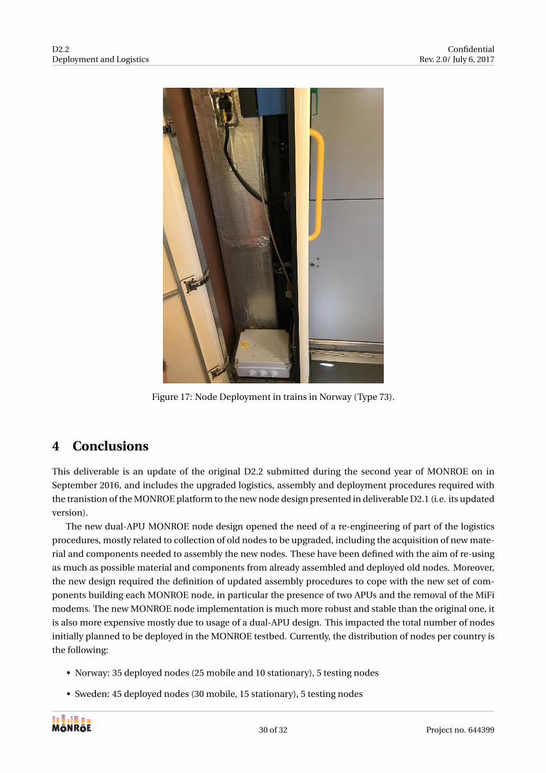
Figure 17: Node Deployment in trains in Norway (Type 73).
4 Conclusions
This deliverable is an update of the original D2.2 submitted during the second year of MONROE on in
September 2016, and includes the upgraded logistics, assembly and deployment procedures required with
the tranistion of the MONROE platform to the new node design presented in deliverable D2.1 (i.e. its updated
version).
The new dual-APU MONROE node design opened the need of a re-engineering of part of the logistics
procedures, mostly related to collection of old nodes to be upgraded, including the acquisition of new mate-
rial and components needed to assembly the new nodes. These have been defined with the aim of re-using
as much as possible material and components from already assembled and deployed old nodes. Moreover,
the new design required the definition of updated assembly procedures to cope with the new set of com-
ponents building each MONROE node, in particular the presence of two APUs and the removal of the MiFi
modems. The new MONROE node implementation is much more robust and stable than the original one, it
is also more expensive mostly due to usage of a dual-APU design. This impacted the total number of nodes
initially planned to be deployed in the MONROE testbed. Currently, the distribution of nodes per country is
the following:
• Norway: 35 deployed nodes (25 mobile and 10 stationary), 5 testing nodes
• Sweden: 45 deployed nodes (30 mobile, 15 stationary), 5 testing nodes
30 of 32 Project no. 644399
D2.2Deployment and Logistics
ConfidentialRev. 2.0/ July 6, 2017
NodeIDs N. Type Partner Address Notes
228-229,254-255,289-290
3 dual-apu Mobile SRL NSB type 5 trains Regional Trains
206-292,257-258
2 dual-apu Mobile SRL NSB type 7 trains Regional Trains
261-291,296-297,304-305,368-369,366-367,448-449,
6 dual-apu Mobile SRL NSB type 73 trains Regional Trains
460-461,456-457,
2 dual-apu Mobile SRL NSB type 75 trains Regional Trains
462-463,212-213,
2 dual-apu Mobile SRL NSB type 74 trains Regional Trains
257, 212, 2 old nodes Mobile SRL Old nodes to be replaced Regional Trains
298-299,300-301,362-363,364-365,370-371,440-441,442-443,464-465,466-467,468-469,
10 dual-apu Mobile SRL Nodes prepared and to be de-ployed
Regional Trains
Table 18: Mobile node deployment in Norway.
• Italy: 45 deployed nodes (25 in public transport vehicles, 15 in delivery trucks, 5 stationary), 5 testing
nodes
• Spain: 10 deployed nodes (all stationary), 5 testing nodes
In addition to these above nodes planned for Norway, Sweden, Italy and Spain, more nodes have been
prepared for the MONROE external users. The assembly and deployment of these nodes have been prior-
itized when possible to involve Open Calls users and get feedbacks on the MONROE platform as soon as
posible.
All the new mobile nodes have been assembled. Most of them are already deployed, and few nodes re-
mains to be installed on trucks and trains in Italy and Sweden. For the stationary nodes, they have been
mostly deployed in Sweden and Norway, while those planned for Spain and Italy are under finalization. The
overall plan is to have the full set of MONROE stationary and mobile nodes deployed during September 2017.
31 of 32 Project no. 644399
D2.2Deployment and Logistics
ConfidentialRev. 2.0/ July 6, 2017
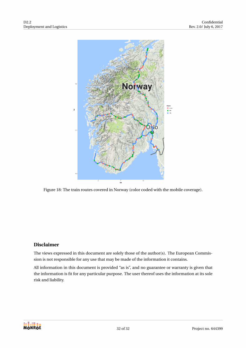
Figure 18: The train routes covered in Norway (color coded with the mobile coverage).
Disclaimer
The views expressed in this document are solely those of the author(s). The European Commis-
sion is not responsible for any use that may be made of the information it contains.
All information in this document is provided “as is”, and no guarantee or warranty is given that
the information is fit for any particular purpose. The user thereof uses the information at its sole
risk and liability.
32 of 32 Project no. 644399
Related Documents