PROMOTioN – Progress on Meshed HVDC Offshore Transmission Networks Mail [email protected] Web www.promotion-offshore.net This result is part of a project that has received funding form the European Union’s Horizon 2020 research and innovation programme under grant agreement No 691714. Publicity reflects the author’s view and the EU is not liable of any use made of the information in this report. Deliverable 3.1: Detailed functional requirements to WPPs Ref. Ares(2016)7126493 - 22/12/2016

Welcome message from author
This document is posted to help you gain knowledge. Please leave a comment to let me know what you think about it! Share it to your friends and learn new things together.
Transcript
PROMOTioN – Progress on Meshed HVDC Offshore Transmission Networks Mail [email protected] Web www.promotion-offshore.net This result is part of a project that has received funding form the European Union’s Horizon 2020 research and innovation programme under grant agreement No 691714. Publicity reflects the author’s view and the EU is not liable of any use made of the information in this report.
Deliverable 3.1: Detailed functional requirements to WPPs
Ref. Ares(2016)7126493 - 22/12/2016
PROJECT REPORT Deliverable 3.1
i
0BDOCUMENT INFO SHEET
Document Name: Deliverable 3.1: Detailed functional requirements to WPPs
Responsible partner: DTU (Technical University of Denmark)
Work Package: WP 3
Work Package leader: Ömer Göksu
Task: 3.1 Functional requirements to WPPs (M03-M12)
Task lead: Ömer Göksu
11BDISTRIBUTION LIST
PROMOTioN partners, European Commission
12BAPPROVALS
Name Company
Validated by: Klaus Wuerflinger Siemens
Sebastian Winter RWTH Aachen
Task leader: Ömer Göksu DTU
WP Leader: Ömer Göksu DTU
13BDOCUMENT HISTORY
Version Date Main modification Author
1.0 21.12.2016
2.0
WP Number WP Title Person months Start month End month
WP3 Wind Turbine – Converter Interaction 269 3 42
Deliverable
Number Deliverable Title Type
Dissemination
level Due Date
D3.1 Detailed functional requirements to WPPs Report Public 12/2016
PROJECT REPORT Deliverable 3.1
ii
1BLIST OF CONTRIBUTORS
Work package 3 and deliverable 3.1 involve a large number of partners and contributors. The names of the
partners, who contributed to the present deliverable, are presented in the following table.
PARTNER NAME
DTU Ömer Göksu, Nicolaos A. Cutululis, Müfit Altin, Oscar Saborío-Romano
UPV Ramon Blasco-Gimenez, Soledad Bernal-Perez, Salvador Añó-Villalba
ADWEN Carmelo Perez, Ryan Motz, Ilir Purellku
DONG Energy Lorenzo Zeni
FGH Oliver Scheufeld, Hendrik Vennegeerts, Andreas Moormann
USTRAT Lie Xu, Rui Li, Stephen Finney
Energinet.dk Walid Ziad El-Khatib, Vladislav Akhmatov, Jakob Glasdam
MVOW Tusitha Abeyasekera, Torsten Lund, Ken Nakayama
RWTH Christina Brantl, Markus Kaiser, Cora Petino, Philipp Ruffing
Siemens Wind Nikolaus Goldenbaum
Siemens DE Slavomir Seman
DNV GL UK Ervin Bossanyi, Andrew Harson
Iberdrola Iñigo Azpiri
ABB Kanstantsin Fadzeyeu, Adil Abdalrahman
Statoil Wei He
CONTENT
0BDocument info sheet .............................................................................................................................................................. i 11BDistribution list ...................................................................................................................................................................... i 12BApprovals ............................................................................................................................................................................. i 13BDocument history ................................................................................................................................................................. i
1BList of Contributors ............................................................................................................................................................... ii
2BList of Definitions .................................................................................................................................................................. 1
3BExecutive Summary .............................................................................................................................................................. 2
1 4BIntroduction.................................................................................................................................................................... 3 1.1. 14BImportant Note on Requirements ............................................................................................................................ 4
2. 5BCase Specifications....................................................................................................................................................... 5 2.1. 15BOffshore AC Interconnected DRU – Focused in WP2 ............................................................................................. 5 2.2. 16BRadial connection with DRU – Focused in WP3 ..................................................................................................... 6 2.3. 17BControl Hierarchy ..................................................................................................................................................... 8
3. 6BOperational Requirements ............................................................................................................................................ 9 3.1. 18BDescription of Events ............................................................................................................................................... 9 3.2. 19BDescription of Operational States – based on configuration of DRU-link ................................................................ 9 3.3. 20BOperational Ranges ............................................................................................................................................... 10
3.3.1 35BUnintended Transmission System Power Interruption Ranges ..................................................................... 11 3.3.2 36BFrequency Ranges ........................................................................................................................................ 12 3.3.3 37BVoltage Ranges ............................................................................................................................................. 14
3.4. 21BActive Power Requirements .................................................................................................................................. 15 3.4.1 38BActive Power Production................................................................................................................................ 15 3.4.2 39BSteady State Active Power Control ................................................................................................................ 15 3.4.3 40BDynamic Active Power Control ...................................................................................................................... 16 3.4.4 41BActive Power Recovery .................................................................................................................................. 16 3.4.5 42BIsland Support (No HVDC or AC Connection) ............................................................................................... 16 3.4.6 43BMinimum Production Limit ............................................................................................................................. 16 3.4.7 44BUnintended Transmission System Limit ........................................................................................................ 16
3.5. 22BHarmonics ............................................................................................................................................................. 17 3.5.1 45BHarmonic requirements for the Offshore Wind Farm ..................................................................................... 17 3.5.2 46BHarmonic requirements for the Offshore HVDC Converter ........................................................................... 17
4. 7BSystem Stability Requirements .................................................................................................................................. 18
PROJECT REPORT Deliverable 3.1
2
4.1. 23BActive Power Control ............................................................................................................................................. 18 4.2. 24BOffshore Frequency Control/Support ..................................................................................................................... 18
4.2.1 47BFrequency Envelope ...................................................................................................................................... 18 4.2.2 48BSteady State Frequency Control.................................................................................................................... 18 4.2.3 49BDynamic Frequency Control .......................................................................................................................... 18 4.2.4 50BLower Abnormal Frequency Support - Offshore ............................................................................................ 18 4.2.5 51BUpper Abnormal Frequency Support - Offshore ............................................................................................ 19 4.2.6 52BProtection Limits ............................................................................................................................................ 19 4.2.7 53BRate of Change of Frequency (ROCOF) Limits ............................................................................................. 19
4.3. 25BOffshore Voltage-/Reactive Power Requirements ................................................................................................. 19 4.3.1 54BVoltage Envelope........................................................................................................................................... 19 4.3.2 55BReactive Power/Current Capabilities ............................................................................................................. 19 4.3.3 56BSteady State Voltage/Reactive power Control ............................................................................................... 20 4.3.4 57BDynamic Voltage Control ............................................................................................................................... 20
4.4. 26BOffshore AC Symmetrical / Asymmetrical Fault Requirements ............................................................................. 20 4.4.1 58BOffshore Fault-Ride-Through ......................................................................................................................... 20 4.4.2 59BOffshore AC Fault Current Injection ............................................................................................................... 21 4.4.3 60BOffshore AC Fault Recovery .......................................................................................................................... 21
4.5. 27BOnshore AC Fault Requirements .......................................................................................................................... 22 4.5.1 61BDetection of Onshore AC Faults by the OWF ................................................................................................ 22 4.5.2 62BActive Power Limitation due to Onshore AC Fault......................................................................................... 22 4.5.3 63BActive Power Recovery after Onshore AC Fault............................................................................................ 22
4.6. 28BDC Fault Requirements ......................................................................................................................................... 22 4.7. 29BOnshore Frequency Support Requirements .......................................................................................................... 23
4.7.1 64BFrequency Response Processing .................................................................................................................. 23 4.7.2 65BFrequency Response Activation .................................................................................................................... 23 4.7.3 66BFrequency Response Parameterisation ........................................................................................................ 23 4.7.4 67BSynthetic Inertia ............................................................................................................................................. 24
4.8. 30BOnshore Power Oscillation Damping Requirements ............................................................................................. 24
5. 8BWT and OWF Modelling .............................................................................................................................................. 25 5.1. 31BType 4 WT models ................................................................................................................................................ 25
5.1.1 68BPitch System Equivalent Model ..................................................................................................................... 26 5.1.2 69BAeroDynamics Model ..................................................................................................................................... 26 5.1.3 70BDriveTrain Model ........................................................................................................................................... 27 5.1.4 71BGenerator and Generator converter Equivalent model .................................................................................. 27 5.1.5 72BDC Link and Chopper Models ........................................................................................................................ 28 5.1.6 73BGrid Side (Front End) Converter Model ......................................................................................................... 29

PROJECT REPORT Deliverable 3.1
3
5.1.7 74BWT Filter and Transformer Models ................................................................................................................ 29 5.2. 32BOWF (400MW) electrical layout ............................................................................................................................. 30
6. 9BBIBLIOGRAPHY ........................................................................................................................................................... 31
7. 10BAnnex............................................................................................................................................................................ 33 7.1. 33BControl Performance Specification ........................................................................................................................ 33 7.2. 34BOWF Collector 66 kV Submarine Cable Parameters ............................................................................................ 34

PROJECT REPORT Deliverable 3.1
4
PROJECT REPORT Deliverable 3.1
1
2BLIST OF DEFINITIONS
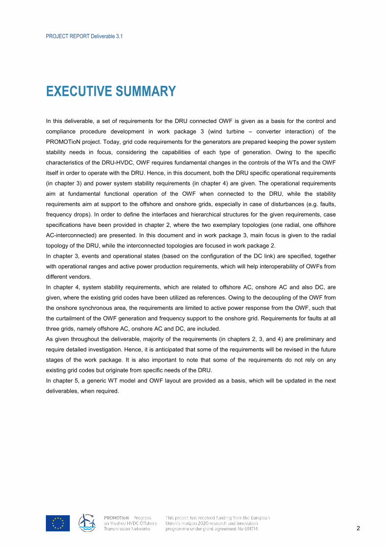
UOffshore Wind Farm (OWF)
The offshore wind farm (OWF) is defined as the connected WTGs and offshore cable system until but not
including the AC side breaker on the DRU transformers and until but not including the breaker connected to an
alternative power source such as the umbilical cableP0F0F
1P. Figure 2.4 can be used as a reference example for OWF
definition. In the given definition the term OWF refers to the sum of turbines (e.g. from the same vendor) with
own overlaying OWF controller. In case all turbines are from the same vendor with a single OWF controller, the
whole (OWF Group) structure can be called as an OWF.
UOffshore Transmission System (OTS)
The offshore transmission system (OTS) is defined as the transmission system (be it AC, HVDC or a
combination of the two) from the OWF interface and until the onshore PCC and if required a MV AC cable,
which is connected to provide auxiliary power for the OWFP1F1F
2P. In this case DC and AC cable would be combined
in one armoured cable. Figure 2.4 can be used as a reference example for OTS definition.
UDiode Rectifier - High Voltage Direct Current (DR-HVDC)
The DR-HVDC implies the HVDC link type, where the offshore HVDC terminal is a DRU (Diode Rectifier Unit).
Hence DR-HVDC means the whole HVDC link, which includes the offshore DRU and the onshore VSC.
UDiode Rectifier Unit - High Voltage Direct Current (DRU-HVDC)
The DRU-HVDC implies the DRU as the offshore HVDC terminal. Hence, DRU-HVDC connection means
connection to the DRU.
UOperational State
The control behaviour of the electrical system defined by the switching configuration and connected assets as
well as the physical state of them (for example diodes conducting or not).
Term Meaning / Shown in
WT Wind Turbine WTG Wind Turbine Generator OWF Offshore Wind Farm WPP Wind Power Plant (replaced by OWF) VSC Voltage Source Converter DRU Diode Rectifier Unit
Radial grid Grid that does not contain a loop Point-to-Point (Inter) connection between two points
OWF Group Figure 2.3 OWF Group Controller Figure 2.5 OWF-OTS Coordinator Figure 2.5
Offshore HVDC Converter Figure 2.5 Onshore HVDC Converter (ONC) Figure 2.5
OWF Controller (OWF C) Figure 2.5
1 Exact definition is considered to be discussed in context with the regulatory framework in WP 7. 2 Legal status of an umbilical cable is considered to be discussed in WP 7.
PROJECT REPORT Deliverable 3.1
2
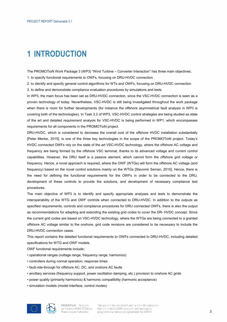
3BEXECUTIVE SUMMARY
In this deliverable, a set of requirements for the DRU connected OWF is given as a basis for the control and
compliance procedure development in work package 3 (wind turbine – converter interaction) of the
PROMOTioN project. Today, grid code requirements for the generators are prepared keeping the power system
stability needs in focus, considering the capabilities of each type of generation. Owing to the specific
characteristics of the DRU-HVDC, OWF requires fundamental changes in the controls of the WTs and the OWF
itself in order to operate with the DRU. Hence, in this document, both the DRU specific operational requirements
(in chapter 3) and power system stability requirements (in chapter 4) are given. The operational requirements
aim at fundamental functional operation of the OWF when connected to the DRU, while the stability
requirements aim at support to the offshore and onshore grids, especially in case of disturbances (e.g. faults,
frequency drops). In order to define the interfaces and hierarchical structures for the given requirements, case
specifications have been provided in chapter 2, where the two exemplary topologies (one radial, one offshore
AC-interconnected) are presented. In this document and in work package 3, main focus is given to the radial
topology of the DRU, while the interconnected topologies are focused in work package 2.
In chapter 3, events and operational states (based on the configuration of the DC link) are specified, together
with operational ranges and active power production requirements, which will help interoperability of OWFs from
different vendors.
In chapter 4, system stability requirements, which are related to offshore AC, onshore AC and also DC, are
given, where the existing grid codes have been utilized as references. Owing to the decoupling of the OWF from
the onshore synchronous area, the requirements are limited to active power response from the OWF, such that
the curtailment of the OWF generation and frequency support to the onshore grid. Requirements for faults at all
three grids, namely offshore AC, onshore AC and DC, are included.
As given throughout the deliverable, majority of the requirements (in chapters 2, 3, and 4) are preliminary and
require detailed investigation. Hence, it is anticipated that some of the requirements will be revised in the future
stages of the work package. It is also important to note that some of the requirements do not rely on any
existing grid codes but originate from specific needs of the DRU.
In chapter 5, a generic WT model and OWF layout are provided as a basis, which will be updated in the next
deliverables, when required.
PROJECT REPORT Deliverable 3.1
3
1 4BINTRODUCTION
The PROMOTioN Work Package 3 (WP3) “Wind Turbine – Converter Interaction” has three main objectives;
1. to specify functional requirements to OWFs, focusing on DRU-HVDC connection
2. to identify and specify general control algorithms for WTs and OWFs, focusing on DRU-HVDC connection
3. to define and demonstrate compliance evaluation procedures by simulations and tests
In WP3, the main focus has been set as DRU-HVDC connection, since the VSC-HVDC connection is seen as a
proven technology of today. Nevertheless, VSC-HVDC is still being investigated throughout the work package
when there is room for further developments (for instance the offshore asymmetrical fault analysis in WP3 is
covering both of the technologies). In Task 3.2 of WP3, VSC-HVDC control strategies are being studied as state
of the art and detailed requirement analysis for VSC-HVDC is being performed in WP1, which encompasses
requirements for all components in the PROMOTioN project.
DRU-HVDC, which is considered to decrease the overall cost of the offshore HVDC installation substantially
[Peter Menke, 2015], is one of the three key technologies in the scope of the PROMOTioN project. Today’s
HVDC connected OWFs rely on the state of the art VSC-HVDC technology, where the offshore AC voltage and
frequency are being formed by the offshore VSC terminal, thanks to its advanced voltage and current control
capabilities. However, the DRU itself is a passive element, which cannot form the offshore grid voltage or
frequency. Hence, a novel approach is required, where the OWF (WTGs) will form the offshore AC voltage (and
frequency) based on the novel control solutions mainly on the WTGs [Slavomir Seman, 2015]. Hence, there is
the need for defining the functional requirements for the OWFs in order to be connected to the DRU,
development of these controls to provide the solutions, and development of necessary compliance test
procedures.
The main objective of WP3 is to identify and specify appropriate analyses and tests to demonstrate the
interoperability of the WTG and OWF controls when connected to DRU-HVDC. In addition to the outputs as
specified requirements, controls and compliance procedures for DRU connected OWFs, there is also the output
as recommendations for adapting and extending the existing grid codes to cover the DR- HVDC concept. Since
the current grid codes are based on VSC-HVDC technology, where the WTGs are being connected to a granted
offshore AC voltage similar to the onshore, grid code revisions are considered to be necessary to include the
DRU-HVDC connection cases.
This report contains the detailed functional requirements to OWFs connected to DRU-HVDC, including detailed
specifications for WTG and OWF models.
OWF functional requirements include;
• operational ranges (voltage range, frequency range, harmonics)
• controllers during normal operation; response times
• fault-ride-through for offshore AC, DC, and onshore AC faults
• ancillary services (frequency support, power oscillation damping, etc.) provision to onshore AC grids
• power quality (primarily harmonics) & harmonic compatibility (harmonic acceptance)
• simulation models (model interface, control modes)

PROJECT REPORT Deliverable 3.1
4
These requirements are defined in this document.
The objectives of this document are;
- To provide fundamental references for controls development in Task 3.2 “General control algorithms”
- To provide interoperability of different wind turbine (models) when connected to the DRU-HVDC; such
that Task 3.2 models, when developed based on hereby specified requirements, will be able to operate
with the DRU-HVDC
- To provide input for test cases (in T3.2) and compliance procedures (in T3.3)
- To help to identify valuable research focus for DRU connection.
1.1. 14BIMPORTANT NOTE ON REQUIREMENTS
The requirements in this document are given to form a common basis in WP3, especially as a starting point for
control development in Task 3.2. Considering the early stage of WP3, requirements have been written mostly
based on the available literature (e.g. network codes), not fully relying on detailed analysis or verification. Based
on the future analysis throughout the WP3 studies, it will be possible to modify the values for the requirements
and to opt out any requirement as well.
These requirements will be reviewed and utilized while preparing the Deliverable 3.8, “List of requirement
recommendations to adapt and extent existing grid codes”, month 42 (June 2019).
PROJECT REPORT Deliverable 3.1
5
2. 5BCASE SPECIFICATIONS
In this section, connection cases for the OWF are specified, such that the requirements in the following chapters
will be built upon. In D3.1, the main focus will be on radial connection of OWF with the DRU. In the next section
an offshore interconnected DRU network is shown, whereas it will be mainly utilized in WP2. Nevertheless, this
interconnected topology is an additional basis while developing the requirements here in D3.1 (and control
solutions in T3.2).
2.1. 15BOffshore AC Interconnected DRU – Focused in WP2
Within WP2 a benchmark network is proposed for first investigations. The grid configuration between these
converters can be changed according to the research aim. These networks are proposed by WP2 (in
cooperation with WP1) but might be different from the roadmap and the final networks. They are intended to
form a common basis for the model set-up and first test simulations, to facilitate comparison. The assumptions
made are not meant to restrict the design of the grid for later studies.
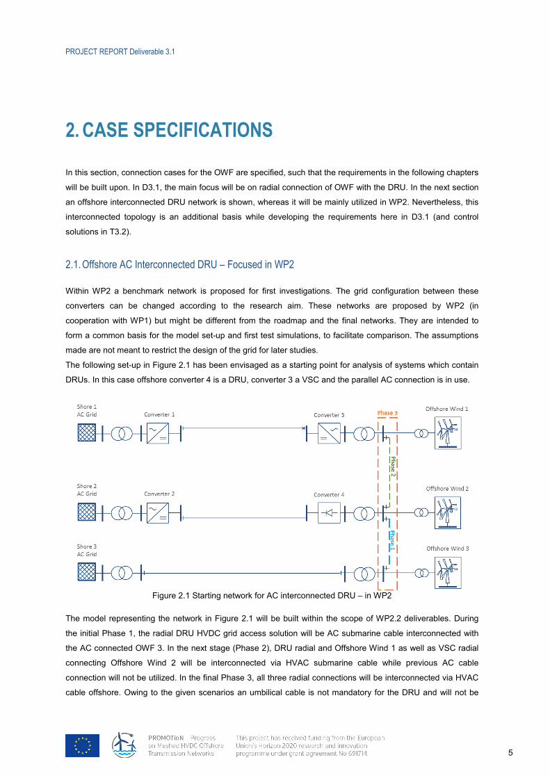
The following set-up in Figure 2.1 has been envisaged as a starting point for analysis of systems which contain
DRUs. In this case offshore converter 4 is a DRU, converter 3 a VSC and the parallel AC connection is in use.
Figure 2.1 Starting network for AC interconnected DRU – in WP2
The model representing the network in Figure 2.1 will be built within the scope of WP2.2 deliverables. During
the initial Phase 1, the radial DRU HVDC grid access solution will be AC submarine cable interconnected with
the AC connected OWF 3. In the next stage (Phase 2), DRU radial and Offshore Wind 1 as well as VSC radial
connecting Offshore Wind 2 will be interconnected via HVAC submarine cable while previous AC cable
connection will not be utilized. In the final Phase 3, all three radial connections will be interconnected via HVAC
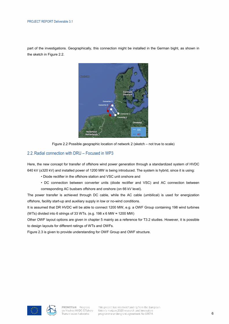
cable offshore. Owing to the given scenarios an umbilical cable is not mandatory for the DRU and will not be
PROJECT REPORT Deliverable 3.1
6
part of the investigations. Geographically, this connection might be installed in the German bight, as shown in
the sketch in Figure 2.2.
Figure 2.2 Possible geographic location of network 2 (sketch – not true to scale)
2.2. 16BRadial connection with DRU – Focused in WP3
Here, the new concept for transfer of offshore wind power generation through a standardized system of HVDC
640 kV (±320 kV) and installed power of 1200 MW is being introduced. The system is hybrid, since it is using:
• Diode rectifier in the offshore station and VSC unit onshore and
• DC connection between converter units (diode rectifier and VSC) and AC connection between
corresponding AC busbars offshore and onshore (on 66 kV level).
The power transfer is achieved through DC cable, while the AC cable (umbilical) is used for energization
offshore, facility start-up and auxiliary supply in low or no-wind conditions.
It is assumed that DR HVDC will be able to connect 1200 MW, e.g. a OWF Group containing 198 wind turbines
(WTs) divided into 6 strings of 33 WTs. (e.g. 198 x 6 MW ≈ 1200 MW)
Other OWF layout options are given in chapter 5 mainly as a reference for T3.2 studies. However, it is possible
to design layouts for different ratings of WTs and OWFs.
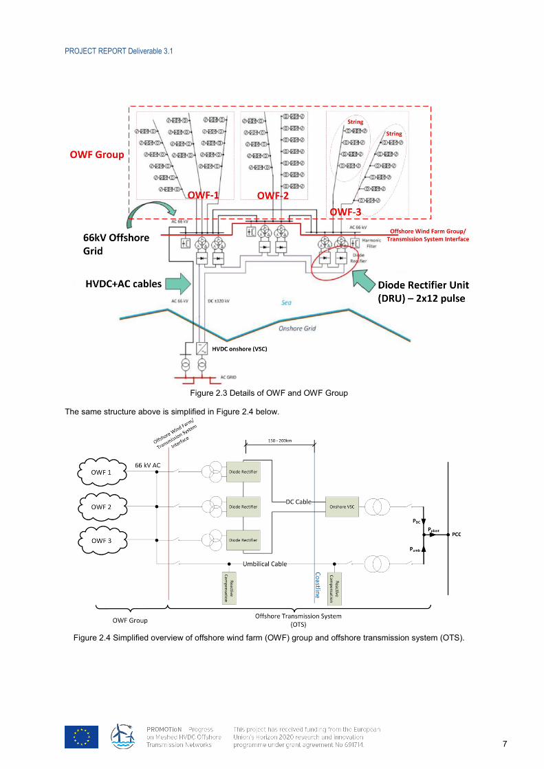
Figure 2.3 is given to provide understanding for OWF Group and OWF structure.
PROJECT REPORT Deliverable 3.1
7
Figure 2.3 Details of OWF and OWF Group
The same structure above is simplified in Figure 2.4 below.
Figure 2.4 Simplified overview of offshore wind farm (OWF) group and offshore transmission system (OTS).
PROJECT REPORT Deliverable 3.1
8
2.3. 17BCONTROL HIERARCHY
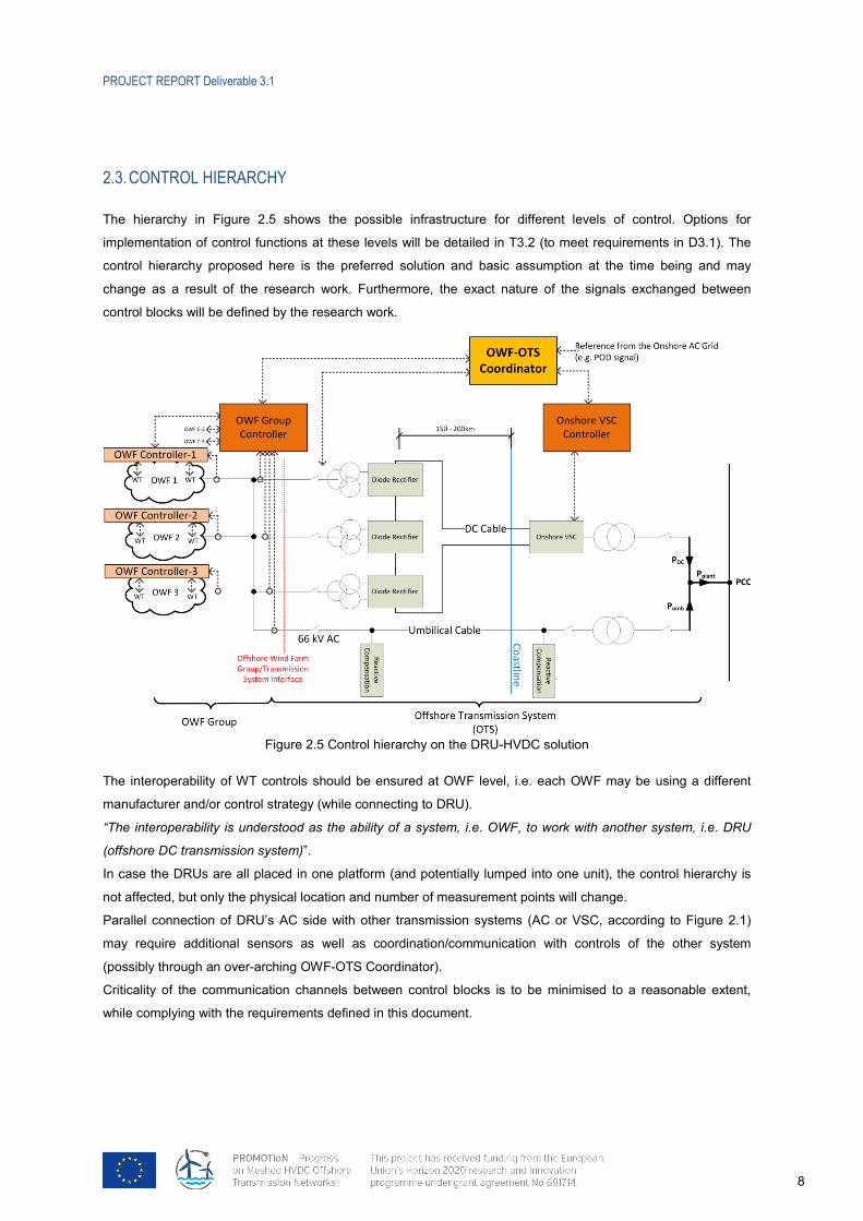
The hierarchy in Figure 2.5 shows the possible infrastructure for different levels of control. Options for
implementation of control functions at these levels will be detailed in T3.2 (to meet requirements in D3.1). The
control hierarchy proposed here is the preferred solution and basic assumption at the time being and may
change as a result of the research work. Furthermore, the exact nature of the signals exchanged between
control blocks will be defined by the research work.
Figure 2.5 Control hierarchy on the DRU-HVDC solution
The interoperability of WT controls should be ensured at OWF level, i.e. each OWF may be using a different
manufacturer and/or control strategy (while connecting to DRU).
“The interoperability is understood as the ability of a system, i.e. OWF, to work with another system, i.e. DRU
(offshore DC transmission system)”.
In case the DRUs are all placed in one platform (and potentially lumped into one unit), the control hierarchy is
not affected, but only the physical location and number of measurement points will change.
Parallel connection of DRU’s AC side with other transmission systems (AC or VSC, according to Figure 2.1)
may require additional sensors as well as coordination/communication with controls of the other system
(possibly through an over-arching OWF-OTS Coordinator).
Criticality of the communication channels between control blocks is to be minimised to a reasonable extent,
while complying with the requirements defined in this document.
PROJECT REPORT Deliverable 3.1
9
3. 6BOPERATIONAL REQUIREMENTS
In this section, operational requirements, which enable the OWF to run stably when connected to the offshore
HVDC terminal (DRU), are specified. Related requirements from D1.1 are also adopted and quantified here.
3.1. 18BDESCRIPTION OF EVENTS
UUnintended Interruption:
Unintended Interruption is an event which is not intended/expected, and which is not communicated to the
relevant system(s). This could be faults in the onshore grid such as onshore LVRT, which temporarily prevents
active power flow into the onshore grid, thus fully- or partially blocking the HVDC power flow without a clear
signal from a central controller to the OWF.
UIntended Interruption:
Intended Interruption is an event which is expected/intended and is communicated to the relevant system(s).
This could be a grid operator requested power limitation, an OTS limit which is caused by e.g. maintenance.
3.2. 19BDESCRIPTION OF OPERATIONAL STATES – BASED ON CONFIGURATION OF DRU-LINK
The following specifies the different configurations, which are defining two main operational states:
1) Initialization (Aux) state – establishing offshore MV busbar stable voltage (SAC)
2) Transmission state – produced active power is transmitted via HVDC line to the onshore connection point
(DR, DRSAC).
In this document, main option for offshore AC network initialization is considered to be the SAC, i.e. the
umbilical cable solution. The other option, UAC, (e.g. connection to a nearby offshore VSC or local source) is
kept as an alternative. The requirements, which are not specifically targeting the umbilical cable, are applicable
for the UAC and DRUAC states as well.
Identifier Description
ISL Island operation: The OWF is neither connected to a DR nor to an alternate AC system (be it synchronised or unsynchronised) i.e. the OWF is completely islanded and has to maintain its own power/frequency balance. (Only temporary islanding is considered in this document in section 3.4.5) Unlimited duration of islanding will be investigated throughout the work package studies.
UAC Unsynchronised AC: The OWF is connected to an alternate AC system such as a local generator or VSC converter, which is not synchronized with the main AC system nor has any other strong frequency control characteristics. (Is being considered as an alternative option to the SAC)
SAC Synchronised AC: The OWF is connected to the main AC system or another AC system with strong frequency control characteristics.
PROJECT REPORT Deliverable 3.1
10
Identifier Description DR Diode Rectifier: The OWF is connected to a diode rectifier only and has to build-up a
stable voltage system via a collective voltage control. If the diodes stop conducting the current due to a low AC voltage the operational state will automatically change to ISL. Any intermediate state where the diodes are in a non-continuously conducting mode should be avoided by means of control.
DRUAC Diode Rectifier and unsynchronised AC: The OWF is connected to a diode rectifier and an alternate AC system, such as a local generator, or a VSC converter, which is not synchronized with the main AC system nor has any other strong frequency control characteristics. The control characteristic of the alternate AC system will differ with the desired solution and influences the requirements for OWF control. In the case of a VSC converter a stable voltage system should be achieved by means of all connected converters (OWF and HVDC). Operational state will change automatically if converters change their control characteristic (for example current limitation activated) or condition for DRU current flow does not hold. DC current flow could be inhibited intentionally by means of control to avoid non-continuously current flow the system would change to UAC mode even with DRU staying physically connected. (Is being considered as an alternative option to the DRSAC)
DRSAC Diode Rectifier and synchronised AC: The OWF is connected to a diode rectifier and another AC system with strong frequency control characteristics. Impedance and rating of the AC connection will be different for the umbilical cable and a parallel AC connected OWF. For the umbilical cable solution maintaining synchronism between onshore and offshore grid may need active control means which might not be possible under all operating conditions. DC current flow could be inhibited intentionally by means of control to avoid non-continuously current flow and the system would change to SAC mode even with DRU staying physically connected.
3.3. 20BOPERATIONAL RANGES
Each system variable (voltage, frequency, etc.) can be split into 5 different ranges confined by an upper and a
lower absolute limit. These ranges will normally also have time dependencies.
Operational ranges are applied to distinguish specific areas of operation where a specific subset of operational
requirements applies.
UNormal Operating Range (NR)
In this range, the WTG’s are expected to be able to operate continuously and deliver all the performance as
required to sustain normal operation of the OWF.
UUpper-/Lower Abnormal Operating Range (UAR/LAR)
In this range, the WTG’s are outside their normal operating range, and the main objective of the WTG is to
remain connected to the AC system. In this range, there can be specific requirements for
PROJECT REPORT Deliverable 3.1
11
performance/capability, which will support the overall system to ride through the abnormal event. Such
requirements need to be specified explicitly for the WTG.
The abnormal range can be split into an upper abnormal range (UAR) where the considered parameter is above
the normal operating range and a lower abnormal range (LAR) where the considered parameter is below the
normal operating range.
UUpper-/Lower Emergency Operating Range (UER/LER)
In this range, the excursion of the considered quantities is considered so severe (in terms of magnitude or time)
that the WTG’s are only expected to take the measures, which are required to protect the WTG equipment, and
are not expected to deliver any services to the remainder system except for potential requirements to trip (could
be within a maximum time).
The emergency range can be split into an upper emergency range (UER) where the considered parameter is
above the abnormal operating range and a lower emergency range (LER) where the considered parameter is
below the abnormal operating range.
UAbsolute Maximum (AM)
This is the absolute maximum boundary. Beyond the boundary, the WTG cannot be guaranteed to protect itself,
and equipment might be damaged.
3.3.1 35BUNINTENDED TRANSMISSION SYSTEM POWER INTERRUPTION RANGES
Unintended interruptions of the active power flow from the OWF into the transmission system have to be
handled by the OWF. Such interruptions can occur due to any onshore grid event or transmission system fault,
which causes a full or partial blocking of the transmission system power flow (e.g. onshore AC fault).
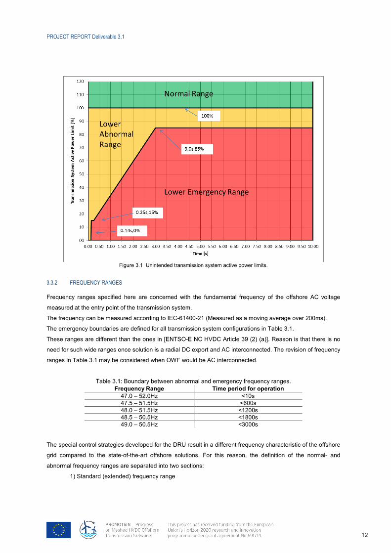
In Figure 3.1, the normal range shows that the transmission system will normally not impose a limit on the active
power which can be exported to shore (the OWF can freely control the active power flow based on prevailing
wind condition, local references and external limitations).
Within the lower abnormal range, the transmission system can – for a limited duration – block active power flow
from the OWF to a value which is less than the “desired” OWF output. Such power limits are considered as
“unintended interruptions” and should be seen as a new type of “high voltage fault” in converter dominated
power grids.
In the lower emergency range, the OWF is not expected to remain connected, and can result in a complete trip
of the plant (OWF + OTS).
The given time profile in Figure 3.1 is an interpretation of the fault-ride-through profile of an HVDC (onshore)
converter station in [ENTSO-E NC HVDC, annex V]; such that the active power transmission capability of the
DR-HVDC link will behave accordingly and the OWF is required to handle this transient in accordingly fast
manner. Required ramp-down rate of the OWF active power will be depending on the OTS characteristics,
which can result in an instantaneous step-down. Temporary active power oscillations with a magnitude of up to
5% of the OWF active power rating and a period of up to 10s can be tolerated as long as the average value is
below the power limit and the signal is well damped. Impact of this overloading on the DRU and DC link will be
investigated throughout the work package studies.
PROJECT REPORT Deliverable 3.1
12
Figure 3.1 Unintended transmission system active power limits.
3.3.2 36BFREQUENCY RANGES
Frequency ranges specified here are concerned with the fundamental frequency of the offshore AC voltage
measured at the entry point of the transmission system.
The frequency can be measured according to IEC-61400-21 (Measured as a moving average over 200ms).
The emergency boundaries are defined for all transmission system configurations in Table 3.1.
These ranges are different than the ones in [ENTSO-E NC HVDC Article 39 (2) (a)]. Reason is that there is no
need for such wide ranges once solution is a radial DC export and AC interconnected. The revision of frequency
ranges in Table 3.1 may be considered when OWF would be AC interconnected.
Table 3.1: Boundary between abnormal and emergency frequency ranges. Frequency Range Time period for operation
47.0 – 52.0Hz <10s 47.5 – 51.5Hz <600s 48.0 – 51.5Hz <1200s 48.5 – 50.5Hz <1800s 49.0 – 50.5Hz <3000s
The special control strategies developed for the DRU result in a different frequency characteristic of the offshore
grid compared to the state-of-the-art offshore solutions. For this reason, the definition of the normal- and
abnormal frequency ranges are separated into two sections:
1) Standard (extended) frequency range
PROJECT REPORT Deliverable 3.1
13
In the operational modes SAC and DRSAC values of the onshore grid have to be applied. In operating
mode UAC and DRUAC values of the standard offshore grid should be used.
2) Optimized (narrow) frequency range
In operational mode DR the operational concept will lead to a narrower frequency band because the
OWF alone is responsible for fast frequency stabilization and high frequency deviations should not
appear for longer times. This is also true in operational mode DRUAC if a common control philosophy
is used for all converters (OWF and HVDC).
Note: The optimized frequency range may not be possible under all operating conditions and frequency
ranges and may change with transitions from one system state to another. Especially changing from
synchronous to asynchronous operation (or vice versa) by opening (closing) the connecting breaker
will need special consideration.
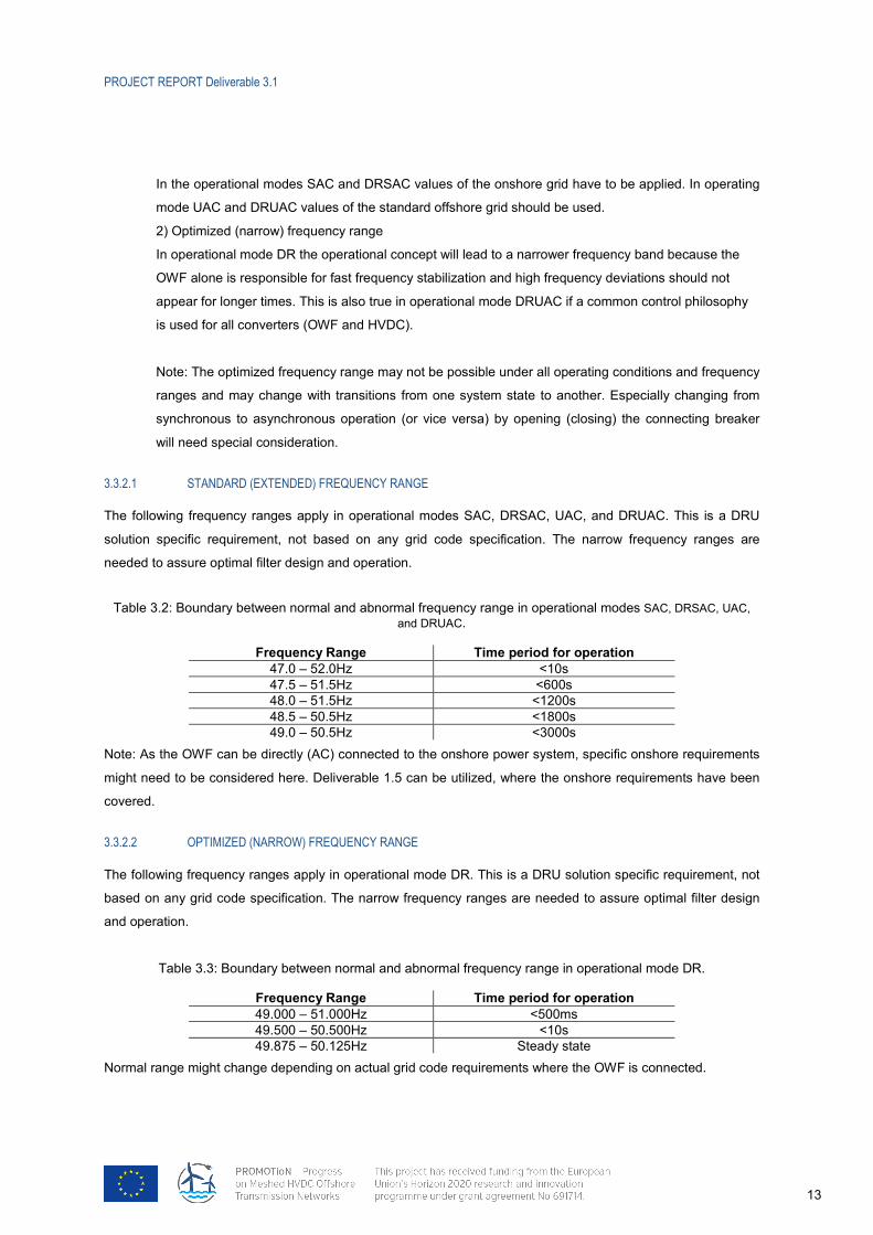
3.3.2.1 75BSTANDARD (EXTENDED) FREQUENCY RANGE
The following frequency ranges apply in operational modes SAC, DRSAC, UAC, and DRUAC. This is a DRU
solution specific requirement, not based on any grid code specification. The narrow frequency ranges are
needed to assure optimal filter design and operation.
Table 3.2: Boundary between normal and abnormal frequency range in operational modes SAC, DRSAC, UAC, and DRUAC.
Frequency Range Time period for operation 47.0 – 52.0Hz <10s 47.5 – 51.5Hz <600s 48.0 – 51.5Hz <1200s 48.5 – 50.5Hz <1800s 49.0 – 50.5Hz <3000s
Note: As the OWF can be directly (AC) connected to the onshore power system, specific onshore requirements
might need to be considered here. Deliverable 1.5 can be utilized, where the onshore requirements have been
covered.
3.3.2.2 76BOPTIMIZED (NARROW) FREQUENCY RANGE
The following frequency ranges apply in operational mode DR. This is a DRU solution specific requirement, not
based on any grid code specification. The narrow frequency ranges are needed to assure optimal filter design
and operation.
Table 3.3: Boundary between normal and abnormal frequency range in operational mode DR.
Frequency Range Time period for operation 49.000 – 51.000Hz <500ms 49.500 – 50.500Hz <10s 49.875 – 50.125Hz Steady state
Normal range might change depending on actual grid code requirements where the OWF is connected.
PROJECT REPORT Deliverable 3.1
14
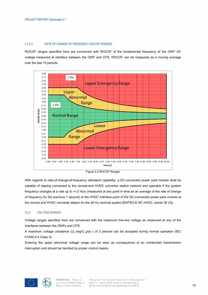
3.3.2.3 77BRATE OF CHANGE OF FREQUENCY (ROCOF) RANGES
ROCOF ranges specified here are concerned with ROCOF of the fundamental frequency of the OWF AC
voltage measured at interface between the OWF and OTS. ROCOF can be measured as a moving average
over the last 10 periods.
Figure 3.2 ROCOF Ranges
With regards to rate-of-change-of-frequency withstand capability, a DC-connected power park module shall be
capable of staying connected to the remote-end HVDC converter station network and operable if the system
frequency changes at a rate up to +/-2 Hz/s (measured at any point in time as an average of the rate of change
of frequency for the previous 1 second) at the HVDC interface point of the DC-connected power park module at
the remote end HVDC converter station for the 50 Hz nominal system [ENTSO-E NC HVDC, article 39 (3)].
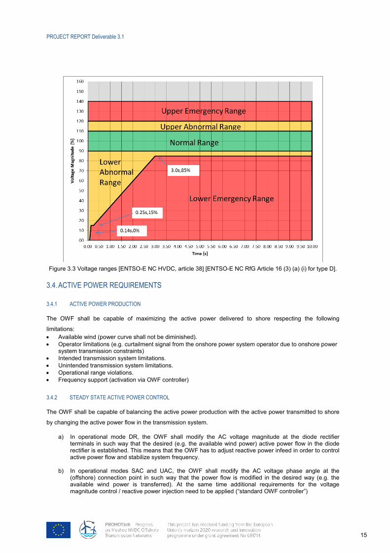
3.3.3 37BVOLTAGE RANGES
Voltage ranges specified here are concerned with the maximum line-line voltage as measured at any of the
interfaces between the OWFs and OTS.
A maximum voltage unbalance (U_neg/U_pos ) of 3 percent can be accepted during normal operation (IEC
61000-2-4 Class 3).
Entering the upper abnormal voltage range can be seen as consequence of an unintended transmission
interruption and should be handled by proper control means.
PROJECT REPORT Deliverable 3.1
15
Figure 3.3 Voltage ranges [ENTSO-E NC HVDC, article 38] [ENTSO-E NC RfG Article 16 (3) (a) (i) for type D].
3.4. 21BACTIVE POWER REQUIREMENTS
3.4.1 38BACTIVE POWER PRODUCTION
The OWF shall be capable of maximizing the active power delivered to shore respecting the following
limitations: • Available wind (power curve shall not be diminished). • Operator limitations (e.g. curtailment signal from the onshore power system operator due to onshore power
system transmission constraints) • Intended transmission system limitations. • Unintended transmission system limitations. • Operational range violations. • Frequency support (activation via OWF controller)
3.4.2 39BSTEADY STATE ACTIVE POWER CONTROL
The OWF shall be capable of balancing the active power production with the active power transmitted to shore
by changing the active power flow in the transmission system.
a) In operational mode DR, the OWF shall modify the AC voltage magnitude at the diode rectifier terminals in such way that the desired (e.g. the available wind power) active power flow in the diode rectifier is established. This means that the OWF has to adjust reactive power infeed in order to control active power flow and stabilize system frequency.
b) In operational modes SAC and UAC, the OWF shall modify the AC voltage phase angle at the (offshore) connection point in such way that the power flow is modified in the desired way (e.g. the available wind power is transferred). At the same time additional requirements for the voltage magnitude control / reactive power injection need to be applied (“standard OWF controller”)
PROJECT REPORT Deliverable 3.1
16
c) In operational modes DRSAC and DRUAC different operational concepts are possible depending on
the concrete system configuration. In any case it is beneficial if the OWF supports active power flow through the DRU and dc line by injection of reactive power. Different secondary control strategies may involve OWF, HVDC onshore station or HVDC offshore station to guarantee proper power sharing between AC and DC lines or OWF and AC sources. The optimization of offshore AC voltage may additionally require active control of tap changers.
d) If the system is in operational mode DRSAC and is operated in parallel with an umbilical cable, coordination must be done much faster in order to keep frequency synchronism and limit thermal stress in the cable. This can be achieved by the onshore HVDC station or OWF. In the latter case a feedback representing the power flow in the AC system/source should be available, and the OWF shall control the feedback towards zero.
3.4.3 40BDYNAMIC ACTIVE POWER CONTROL
To support normal operation, the OWF shall be capable of ramping active power from one set point to another
(considering the limitations as stated in 3.4.1) within 10 seconds.
3.4.4 41BACTIVE POWER RECOVERY
The OWF shall be capable of returning the active power from a limited operating point (see 3.3.1 - Unintended
Transmission System Power Interruption) to the pre-event active power level minus 10% (e.g. 100% -10% =
90%) with a ramp rate of 200%/s (values are similar to the existing UK grid code requirement for post fault
recovery following faults with duration less than 140 ms [National Grid Connection Code, 2016]). Active Power
oscillations shall be acceptable provided that:
(1) the total Active Energy delivered during the period of the oscillations is at least that which would
have been delivered if the Active Power was constant [National Grid Connection Code, 2016],
(2) the oscillations are adequately damped [National Grid Connection Code, 2016],
(3) limitations of the transmission system are regarded.
3.4.5 42BISLAND SUPPORT (NO HVDC OR AC CONNECTION)
Islanding requirement is defined in [ENTSO-E NC RfG 15-5- b- I as referred in NC HVDC Article 38]. The OWF
shall support a temporary islanding of the offshore AC system for minimum 20 seconds. Longer (e.g. unlimited)
duration of islanding will be investigated throughout the work package studies.
Note: It is understood that this can only be achieved as long as there is sufficient energy available (wind,
kinetic, alternative power source at the offshore AC network, etc.).
3.4.6 43BMINIMUM PRODUCTION LIMIT
Due to the non-linear properties of the diode rectifiers, it is permissible to seize production from the OWF at an
agreed minimum production limit (e.g. 2.5%) when connected to a diode rectifier only. This limitation is not
related to the OWF; hence it should be understood as a transmission system limitation.
3.4.7 44BUNINTENDED TRANSMISSION SYSTEM LIMIT
The OWF shall support an unintended limitation of the active power flow. An unintended active power limitation
is understood as a situation where the maximum active power which can be accepted at the offshore end of the

PROJECT REPORT Deliverable 3.1
17
transmission system is less than the available production, operator limits and intended transmission system
limits. Such a power curtailment is to be understood as a transmission system limitation. Required ramp-down
rate of the OWF active power will be depending on the OTS characteristics, which can result in an
instantaneous step-down.
3.5. 22BHARMONICS
The requirements below are given to be informative only for future studies.
3.5.1 45BHARMONIC REQUIREMENTS FOR THE OFFSHORE WIND FARM
OWF shall not adversely interact among one another or with the HVDC controller. The OWF controllers shall not
amplify resonance/harmonics in the offshore grid.
3.5.1.1 78BHARMONIC COMPATIBILITY REQUIREMENTS
The OWF MV collector system shall comply with IEC 61000-2-4 class 3 compatibility requirements.
3.5.1.2 79BHARMONIC EMISSION REQUIREMENTS
Appropriate harmonic emission models shall be available for all relevant equipment which is connected in the
OWF to support the study and design of the electrical infrastructure to comply with IEC 61000-2-4 class 3.
3.5.2 46BHARMONIC REQUIREMENTS FOR THE OFFSHORE HVDC CONVERTER
3.5.2.1 80BHARMONIC COMPATIBILITY REQUIREMENTS
The OWF MV collector system shall comply with IEC 61000-2-4 class 3 compatibility requirements.
3.5.2.2 81BHARMONIC EMISSION REQUIREMENTS
Appropriate harmonic emission models shall be available for all relevant equipment which is connected in the
OWF to support the study and design of the electrical infrastructure to comply with IEC 61000-2-4 class 3.
The specified values refer to percentage of the fundamental and include the harmonic distortion caused by
active injection as well as the modification (amplification) of the existing harmonic background distortion (if any).
The total harmonic voltage distortion THDu from the converter shall be less than 1.0%. The total voltage
distortion is defined by the following equation:
%100max
2
2
1∑−
=
=
n
n
nu U
UTHD
In the calculation of THDu the value of n-max shall be set to 65 as a minimum.
PROJECT REPORT Deliverable 3.1
18
4. 7BSYSTEM STABILITY REQUIREMENTS
In this section, OWF requirements that support the stability of the offshore and onshore systems are specified.
Related requirements from D1.1 are also adopted and quantified here.
4.1. 23BACTIVE POWER CONTROL
To support normal operation, the OWF shall be capable of ramping active power from one set point to another
(considering the active power production limitations as stated in 3.4.1) within 10 seconds. ([ENTSO-E NC RfG]
requires 30 seconds as minimum)
4.2. 24BOFFSHORE FREQUENCY CONTROL/SUPPORT
4.2.1 47BFREQUENCY ENVELOPE
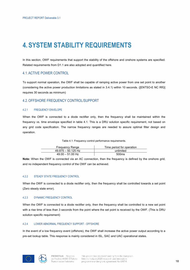
When the OWF is connected to a diode rectifier only, then the frequency shall be maintained within the
frequency vs. time envelope specified in table 4.1. This is a DRU solution specific requirement, not based on
any grid code specification. The narrow frequency ranges are needed to assure optimal filter design and
operation.
Table 4.1: Frequency control performance requirements.
Frequency Range Time period for operation 49.875 – 50.125 Hz unlimited
49.00 – 51.00 Hz 500ms Note: When the OWF is connected via an AC connection, then the frequency is defined by the onshore grid,
and no independent frequency control of the OWF can be achieved.
4.2.2 48BSTEADY STATE FREQUENCY CONTROL
When the OWF is connected to a diode rectifier only, then the frequency shall be controlled towards a set point
(Zero steady state error).
4.2.3 49BDYNAMIC FREQUENCY CONTROL
When the OWF is connected to a diode rectifier only, then the frequency shall be controlled to a new set point
with a rise time of less than 3 seconds from the point where the set point is received by the OWF. (This is DRU
solution specific requirement)
4.2.4 50BLOWER ABNORMAL FREQUENCY SUPPORT - OFFSHORE
In the event of a low frequency event (offshore), the OWF shall increase the active power output according to a
pre-set lookup table. This response is mainly considered in ISL, SAC and UAC operational states.
PROJECT REPORT Deliverable 3.1
19
Note: It is understood that the magnitude and duration of such an active power increase is limited by the
available energy in the OWF (wind, kinetic, alternative power source etc.).
4.2.5 51BUPPER ABNORMAL FREQUENCY SUPPORT - OFFSHORE
In the event of a high frequency event (offshore), the OWF shall reduce the active power output according to a
pre-set lookup table. This response is mainly considered in ISL, SAC and UAC operational states.
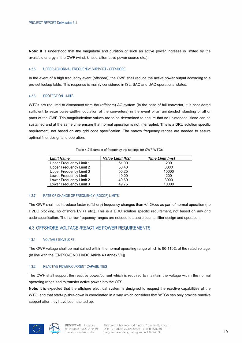
4.2.6 52BPROTECTION LIMITS
WTGs are required to disconnect from the (offshore) AC system (In the case of full converter, it is considered
sufficient to seize pulse-width-modulation of the converters) in the event of an unintended islanding of all or
parts of the OWF. Trip magnitude/time values are to be determined to ensure that no unintended island can be
sustained and at the same time ensure that normal operation is not interrupted. This is a DRU solution specific
requirement, not based on any grid code specification. The narrow frequency ranges are needed to assure
optimal filter design and operation.
Table 4.2:Example of frequency trip settings for OWF WTGs.
Limit Name Value Limit [Hz] Time Limit [ms] Upper Frequency Limit 1 51.00 200 Upper Frequency Limit 2 50.40 3000 Upper Frequency Limit 3 50.25 10000 Lower Frequency Limit 1 49.00 200 Lower Frequency Limit 2 49.60 3000 Lower Frequency Limit 3 49.75 10000
4.2.7 53BRATE OF CHANGE OF FREQUENCY (ROCOF) LIMITS
The OWF shall not introduce faster (offshore) frequency changes than +/- 2Hz/s as part of normal operation (no
HVDC blocking, no offshore LVRT etc.). This is a DRU solution specific requirement, not based on any grid
code specification. The narrow frequency ranges are needed to assure optimal filter design and operation.
4.3. 25BOFFSHORE VOLTAGE-/REACTIVE POWER REQUIREMENTS
4.3.1 54BVOLTAGE ENVELOPE
The OWF voltage shall be maintained within the normal operating range which is 90-110% of the rated voltage.
(In line with the [ENTSO-E NC HVDC Article 40 Annex VII])
4.3.2 55BREACTIVE POWER/CURRENT CAPABILITIES
The OWF shall support the reactive power/current which is required to maintain the voltage within the normal
operating range and to transfer active power into the OTS.
Note: It is expected that the offshore electrical system is designed to respect the reactive capabilities of the
WTG, and that start-up/shut-down is coordinated in a way which considers that WTGs can only provide reactive
support after they have been started up.
PROJECT REPORT Deliverable 3.1
20
4.3.3 56BSTEADY STATE VOLTAGE/REACTIVE POWER CONTROL
When the OWF is not connected via the HVDC (No HVDC power flow), it shall be possible to control the WTG
output voltage/reactive power in such way to: • Support the OTS in controlling the voltage magnitude at the interface between OWF and OTS. • Avoid any unnecessary reactive power flow between WTGs in the OWF to prevent overloading of collector
cabling etc. (This applies in all modes of operation). Note: When power is being transmitted via the HVDC connection, the voltage at the OTS/OWF interface cannot
be controlled independently of the active power flow in the HVDC.
4.3.4 57BDYNAMIC VOLTAGE CONTROL
When the OWF is not connected via the HVDC (No HVDC power flow), it shall be possible to control the WTG
output voltage/Reactive power to a new set point with a rise time of 1 second from the point where the set point
is received by the OWF.
Note: When power is being transmitted via the HVDC connection, the voltage at the OTS/OWF interface cannot
be controlled independently of the active power flow in the HVDC.
4.4. 26BOFFSHORE AC SYMMETRICAL / ASYMMETRICAL FAULT REQUIREMENTS
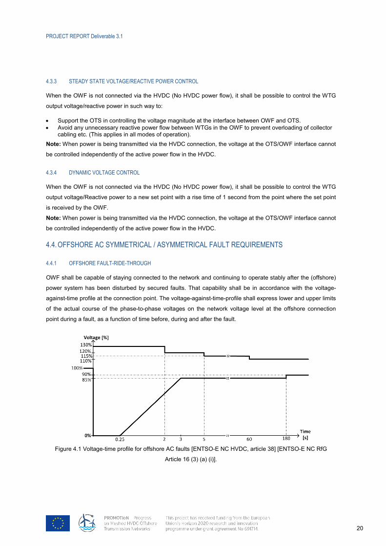
4.4.1 58BOFFSHORE FAULT-RIDE-THROUGH
OWF shall be capable of staying connected to the network and continuing to operate stably after the (offshore)
power system has been disturbed by secured faults. That capability shall be in accordance with the voltage-
against-time profile at the connection point. The voltage-against-time-profile shall express lower and upper limits
of the actual course of the phase-to-phase voltages on the network voltage level at the offshore connection
point during a fault, as a function of time before, during and after the fault.
Figure 4.1 Voltage-time profile for offshore AC faults [ENTSO-E NC HVDC, article 38] [ENTSO-E NC RfG
Article 16 (3) (a) (i)].
PROJECT REPORT Deliverable 3.1
21
Fault current requirements shall cover
- symmetrical (3-phase to ground) and asymmetrical (1-phase to ground fault, phase-phase, phase-phase to
ground) AC offshore faults
- all related system configurations such as; DR (only diode rectifier connection), SAC (e.g. only umbilical cable),
DRSAC (diode rectifier and umbilical cable)
- whole range (e.g. 5%-100%) of power generation level (e.g. including cases with low wind and/or few WTs are
in operation).
It is important to note that the voltage-time profile in Figure 4.1 is originating from classical (onshore) power
system response, where the voltage ramp might take time. This profile is expected to be observed when there is
connection (umbilical cable) to the onshore AC system. For the offshore AC faults, when there is no connection
to the onshore AC (i.e. DR state) the voltage profile will depend on the response of the WTGs. For instance, the
voltage ramp up might be quite faster than the one shown in Figure 4.1 [Soledad Bernal-Perez, 2013, Figure
16]. However, it is also important to note that DRU-connected WTGs would possibly be tested against DRU
connection, rather than a voltage-profile.
4.4.2 59BOFFSHORE AC FAULT CURRENT INJECTION
OWF shall be capable of providing fast fault current at the connection point either by:
— ensuring the supply of the fast fault current at the OWF connection point, or
— measuring voltage deviations at the terminals of the individual WTs of the OWF and providing a fast fault
current at the terminals of WTs. [ENTSO-E NC HVDC, article 38] [ENTSO-E NC RfG Article 20 (2)]
OWF shall be capable of providing active and reactive currents both in positive and negative sequences.
The exact short circuit infeed requirements need to be defined considering the protection strategy and the basic
design (equipment rating) of the OWF and OTS.
4.4.3 60BOFFSHORE AC FAULT RECOVERY
The OWF shall be capable of returning the active power from a limited operating point to the pre-fault active
power level minus 10% (e.g. 100% -10% = 90%) with a ramp rate of 200%/s [National Grid Connection Code,
2016]. Active Power oscillations shall be acceptable provided that:
(1) the total Active Energy delivered during the period of the oscillations is at least that which would
have been delivered if the Active Power was constant,
(2) the oscillations are adequately damped,
(3) limitations of the transmission system are regarded.
It is important to note that the recovery here is defined for post-fault recovery after offshore faults. This
requirement is similar to the requirement in section 3.4.4, active power recovery, where the recovery has been
defined for recovery after unintended transmission system limitation.
PROJECT REPORT Deliverable 3.1
22
4.5. 27BONSHORE AC FAULT REQUIREMENTS
4.5.1 61BDETECTION OF ONSHORE AC FAULTS BY THE OWF
OWF shall be capable of detecting an onshore AC fault via receiving a signal (via communication from the OTS
OWF-OTS Coordinator) and/or observing the disturbance at the offshore terminals (without communication
use). The exact detection scheme will be defined considering the dynamic behaviour of the OTS (onshore VSC
and offshore DRU response) analysing onshore AC faults.
Fault requirements shall cover
- symmetrical (3-phase to ground) and asymmetrical (1-phase to ground fault, phase-phase, phase-phase to
ground) AC onshore faults
- all related system configurations such as; DR (only diode rectifier connection), SAC (e.g. only umbilical cable),
DRSAC (diode rectifier and umbilical cable)
- whole range (e.g. 5%-100%) of power generation level (e.g. including cases with low wind and/or few WTs are
in operation).
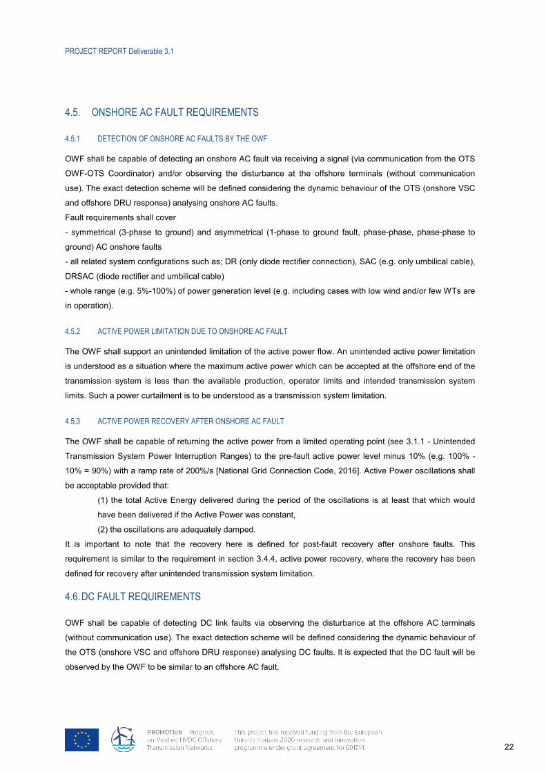
4.5.2 62BACTIVE POWER LIMITATION DUE TO ONSHORE AC FAULT
The OWF shall support an unintended limitation of the active power flow. An unintended active power limitation
is understood as a situation where the maximum active power which can be accepted at the offshore end of the
transmission system is less than the available production, operator limits and intended transmission system
limits. Such a power curtailment is to be understood as a transmission system limitation.
4.5.3 63BACTIVE POWER RECOVERY AFTER ONSHORE AC FAULT
The OWF shall be capable of returning the active power from a limited operating point (see 3.1.1 - Unintended
Transmission System Power Interruption Ranges) to the pre-fault active power level minus 10% (e.g. 100% -
10% = 90%) with a ramp rate of 200%/s [National Grid Connection Code, 2016]. Active Power oscillations shall
be acceptable provided that:
(1) the total Active Energy delivered during the period of the oscillations is at least that which would
have been delivered if the Active Power was constant,
(2) the oscillations are adequately damped.
It is important to note that the recovery here is defined for post-fault recovery after onshore faults. This
requirement is similar to the requirement in section 3.4.4, active power recovery, where the recovery has been
defined for recovery after unintended transmission system limitation.
4.6. 28BDC FAULT REQUIREMENTS
OWF shall be capable of detecting DC link faults via observing the disturbance at the offshore AC terminals
(without communication use). The exact detection scheme will be defined considering the dynamic behaviour of
the OTS (onshore VSC and offshore DRU response) analysing DC faults. It is expected that the DC fault will be
observed by the OWF to be similar to an offshore AC fault.
PROJECT REPORT Deliverable 3.1
23
- In case of a radial connection (such as considered here) OWF shall be capable of performing secure turn-off
(It is assumed that DC faults will be permanent for radial connections)
- In case of a meshed DC connection, OWF shall be capable of performing fault-ride-through for securely
cleared DC faults, same as the response to onshore AC faults.
4.7. 29BONSHORE FREQUENCY SUPPORT REQUIREMENTS
4.7.1 64BFREQUENCY RESPONSE PROCESSING
OWF shall be capable of receiving an onshore frequency signal (measured at the onshore synchronous area
and sent by the onshore converter or OWF-OTS Coordinator).
OWFs connected via HVDC systems which connect to more than one control area should be capable of
delivering coordinated frequency control which will be separately specified.
OWFs that are directly connected to onshore synchronous area (for instance via AC offshore interconnection to
an AC-connected OWF) will respond without need for communication.
4.7.2 65BFREQUENCY RESPONSE ACTIVATION
OWF shall be capable of activating a power frequency response with an initial delay that is shorter than 0.5 s
from receiving the signal (over- or under-frequency) and time for full activation shall be shorter than 30 seconds
[ENTSO-E NC HVDC, article 38] [ENTSO-E NC RfG Article 15 (2) (d) (iii)].
OWF frequency response will take into account: ambient conditions (mainly wind speed) at the time of response
triggering and the operating conditions of the OWF, especially near the maximum capacity at low frequencies;
such that OWF cannot produce more than available (available wind and rotational kinetic energy).
OWF should be capable of providing active power frequency response for minimum 15 minutes [ENTSO-E NC
HVDC, article 38] [ENTSO-E NC RfG Article 15 (2) (d) (v)], while taking the primary energy source of the power-
generating module into account.
4.7.3 66BFREQUENCY RESPONSE PARAMETERISATION
OWF shall be able to respond based on the set of specified parameters, which allow for the calculation of the
active power as a function of the frequency, as shown in Figure 4.2 below. The combination of choice of the
parameters specified should take possible technology-dependent limitations into account.
PROJECT REPORT Deliverable 3.1
24
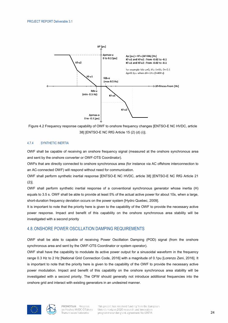
Figure 4.2 Frequency response capability of OWF to onshore frequency changes [ENTSO-E NC HVDC, article
38] [ENTSO-E NC RfG Article 15 (2) (d) (i)].
4.7.4 67BSYNTHETIC INERTIA
OWF shall be capable of receiving an onshore frequency signal (measured at the onshore synchronous area
and sent by the onshore converter or OWF-OTS Coordinator).
OWFs that are directly connected to onshore synchronous area (for instance via AC offshore interconnection to
an AC-connected OWF) will respond without need for communication.
OWF shall perform synthetic inertial response [ENTSO-E NC HVDC, article 38] [ENTSO-E NC RfG Article 21
(2)].
OWF shall perform synthetic inertial response of a conventional synchronous generator whose inertia (H)
equals to 3.5 s. OWF shall be able to provide at least 5% of the actual active power for about 10s, when a large,
short-duration frequency deviation occurs on the power system [Hydro Quebec, 2009].
It is important to note that the priority here is given to the capability of the OWF to provide the necessary active
power response. Impact and benefit of this capability on the onshore synchronous area stability will be
investigated with a second priority
4.8. 30BONSHORE POWER OSCILLATION DAMPING REQUIREMENTS
OWF shall be able to capable of receiving Power Oscillation Damping (POD) signal (from the onshore
synchronous area and sent by the OWF-OTS Coordinator or system operator).
OWF shall have the capability to modulate its active power output for a sinusoidal waveform in the frequency
range 0.3 Hz to 2 Hz [National Grid Connection Code, 2016] with a magnitude of 0.1pu [Lorenzo Zeni, 2016]. It
is important to note that the priority here is given to the capability of the OWF to provide the necessary active
power modulation. Impact and benefit of this capability on the onshore synchronous area stability will be
investigated with a second priority. The OFW should generally not introduce additional frequencies into the
onshore grid and interact with existing generators in an undesired manner.
PROJECT REPORT Deliverable 3.1
25
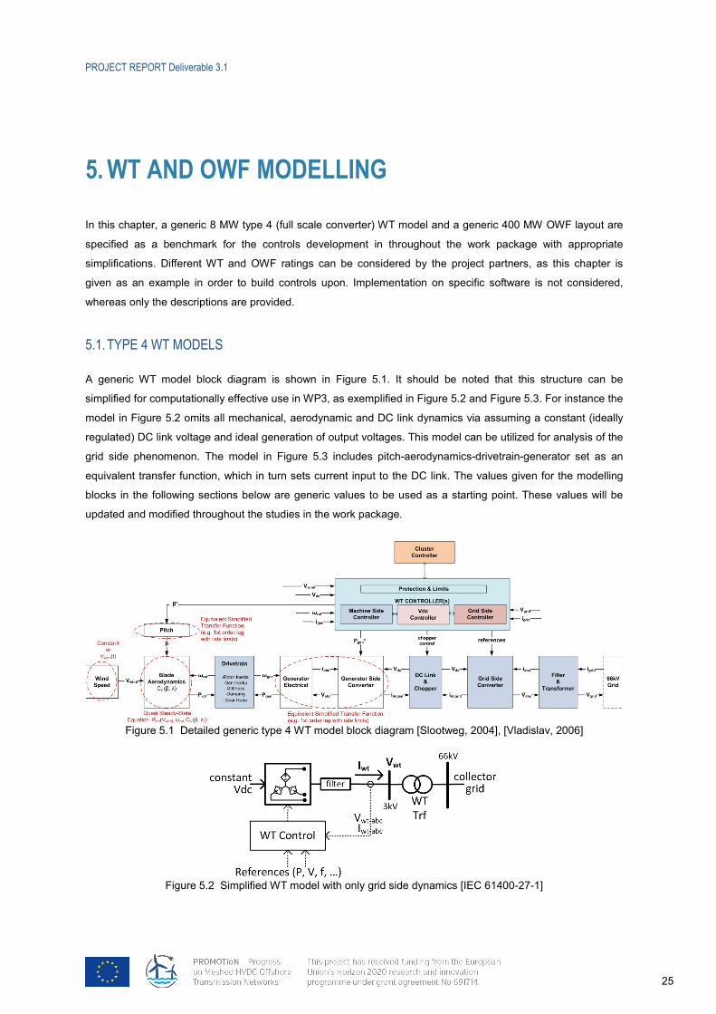
5. 8BWT AND OWF MODELLING
In this chapter, a generic 8 MW type 4 (full scale converter) WT model and a generic 400 MW OWF layout are
specified as a benchmark for the controls development in throughout the work package with appropriate
simplifications. Different WT and OWF ratings can be considered by the project partners, as this chapter is
given as an example in order to build controls upon. Implementation on specific software is not considered,
whereas only the descriptions are provided.
5.1. 31BTYPE 4 WT MODELS
A generic WT model block diagram is shown in Figure 5.1. It should be noted that this structure can be
simplified for computationally effective use in WP3, as exemplified in Figure 5.2 and Figure 5.3. For instance the
model in Figure 5.2 omits all mechanical, aerodynamic and DC link dynamics via assuming a constant (ideally
regulated) DC link voltage and ideal generation of output voltages. This model can be utilized for analysis of the
grid side phenomenon. The model in Figure 5.3 includes pitch-aerodynamics-drivetrain-generator set as an
equivalent transfer function, which in turn sets current input to the DC link. The values given for the modelling
blocks in the following sections below are generic values to be used as a starting point. These values will be
updated and modified throughout the studies in the work package.
Figure 5.1 Detailed generic type 4 WT model block diagram [Slootweg, 2004], [Vladislav, 2006]
Figure 5.2 Simplified WT model with only grid side dynamics [IEC 61400-27-1]
PROJECT REPORT Deliverable 3.1
26
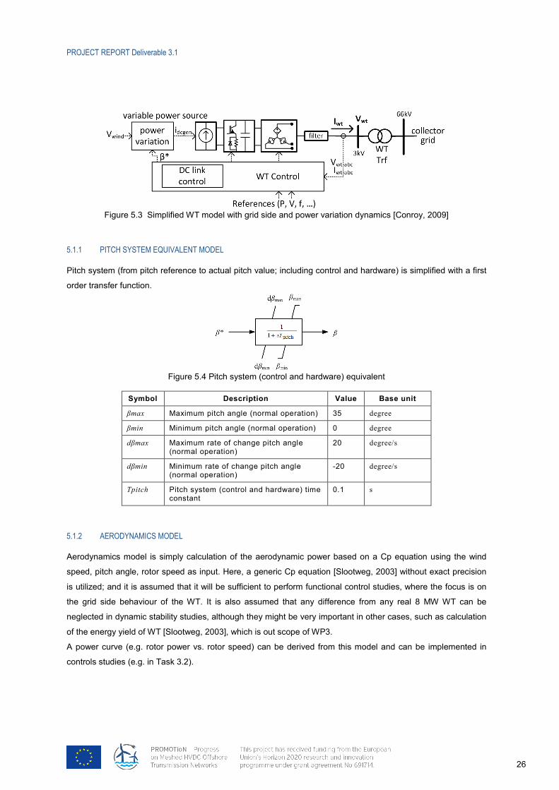
Figure 5.3 Simplified WT model with grid side and power variation dynamics [Conroy, 2009]
5.1.1 68BPITCH SYSTEM EQUIVALENT MODEL
Pitch system (from pitch reference to actual pitch value; including control and hardware) is simplified with a first
order transfer function.
Figure 5.4 Pitch system (control and hardware) equivalent
Symbol Description Value Base unit
βmax Maximum pitch angle (normal operation) 35 degree
βmin Minimum pitch angle (normal operation) 0 degree
dβmax Maximum rate of change pitch angle (normal operation)
20 degree/s
dβmin Minimum rate of change pitch angle (normal operation)
-20 degree/s
Tpitch Pitch system (control and hardware) time constant
0.1 s
5.1.2 69BAERODYNAMICS MODEL
Aerodynamics model is simply calculation of the aerodynamic power based on a Cp equation using the wind
speed, pitch angle, rotor speed as input. Here, a generic Cp equation [Slootweg, 2003] without exact precision
is utilized; and it is assumed that it will be sufficient to perform functional control studies, where the focus is on
the grid side behaviour of the WT. It is also assumed that any difference from any real 8 MW WT can be
neglected in dynamic stability studies, although they might be very important in other cases, such as calculation
of the energy yield of WT [Slootweg, 2003], which is out scope of WP3.
A power curve (e.g. rotor power vs. rotor speed) can be derived from this model and can be implemented in
controls studies (e.g. in Task 3.2).
PROJECT REPORT Deliverable 3.1
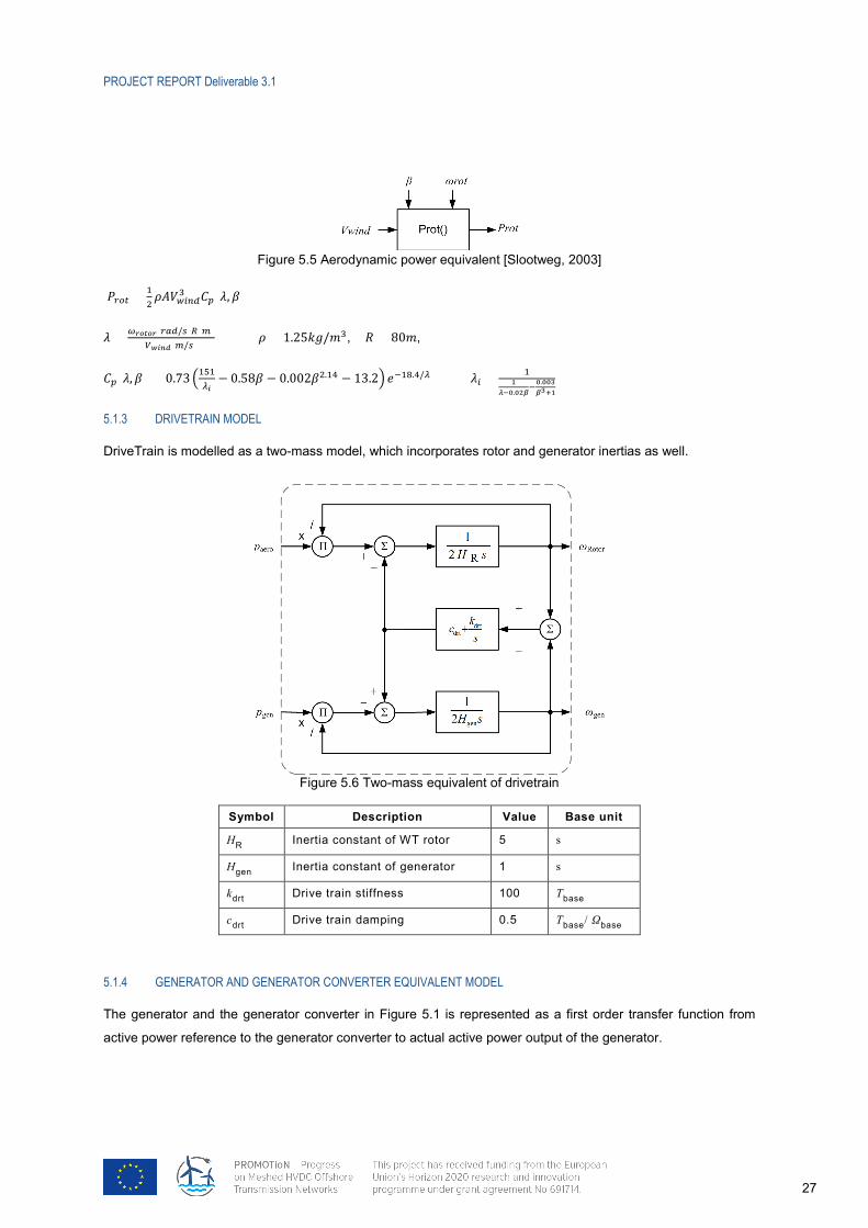
27
Figure 5.5 Aerodynamic power equivalent [Slootweg, 2003]
𝑃𝑃𝑟𝑟𝑟𝑟𝑟𝑟 = 1
2𝜌𝜌𝜌𝜌𝑉𝑉𝑤𝑤𝑤𝑤𝑤𝑤𝑤𝑤3 𝐶𝐶𝑝𝑝(𝜆𝜆,𝛽𝛽)
𝜆𝜆 = 𝜔𝜔𝑟𝑟𝑟𝑟𝑟𝑟𝑟𝑟𝑟𝑟(𝑟𝑟𝑟𝑟𝑤𝑤/𝑠𝑠)𝑅𝑅(𝑚𝑚)𝑉𝑉𝑤𝑤𝑤𝑤𝑤𝑤𝑤𝑤(𝑚𝑚/𝑠𝑠)
𝜌𝜌 = 1.25𝑘𝑘𝑘𝑘/𝑚𝑚3, 𝑅𝑅 = 80𝑚𝑚,
𝐶𝐶𝑝𝑝(𝜆𝜆,𝛽𝛽) = 0.73 �151𝜆𝜆𝑤𝑤− 0.58𝛽𝛽 − 0.002𝛽𝛽2.14 − 13.2� 𝑒𝑒−18.4/𝜆𝜆 𝜆𝜆𝑤𝑤 = 1
1𝜆𝜆−0.02𝛽𝛽
−0.003𝛽𝛽3+1
5.1.3 70BDRIVETRAIN MODEL
DriveTrain is modelled as a two-mass model, which incorporates rotor and generator inertias as well.
Figure 5.6 Two-mass equivalent of drivetrain
Symbol Description Value Base unit
H 50TR Inertia constant of WT rotor 5 s
H 51Tg 50T51Ten Inertia constant of generator 1 s
k 50Tdrt Drive train stiffness 100 T 50Tbase
c 50Tdrt Drive train damping 0.5 T 50Tbase 50T
/ Ω 50Tbase 50T
5.1.4 71BGENERATOR AND GENERATOR CONVERTER EQUIVALENT MODEL
The generator and the generator converter in Figure 5.1 is represented as a first order transfer function from
active power reference to the generator converter to actual active power output of the generator.
PROJECT REPORT Deliverable 3.1
28
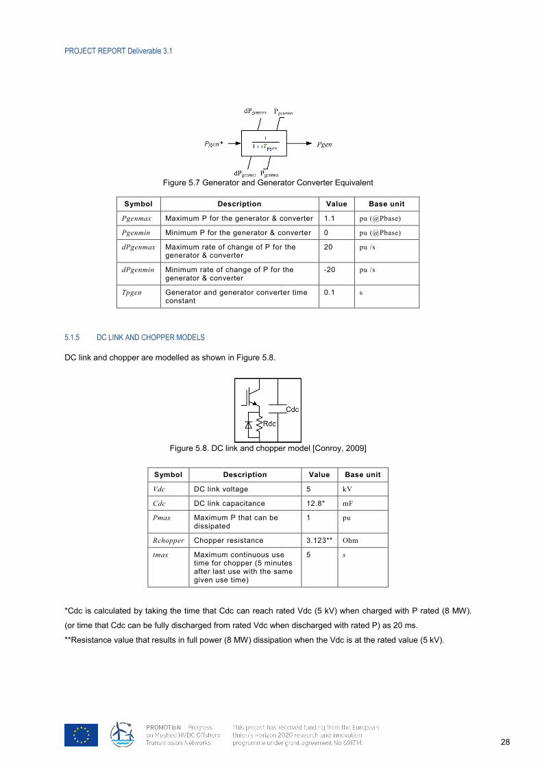
Figure 5.7 Generator and Generator Converter Equivalent
Symbol Description Value Base unit
Pgenmax Maximum P for the generator & converter 1.1 pu (@Pbase)
Pgenmin Minimum P for the generator & converter 0 pu (@Pbase)
dPgenmax Maximum rate of change of P for the generator & converter
20 pu /s
dPgenmin Minimum rate of change of P for the generator & converter
-20 pu /s
Tpgen Generator and generator converter time constant
0.1 s
5.1.5 72BDC LINK AND CHOPPER MODELS
DC link and chopper are modelled as shown in Figure 5.8.
Figure 5.8. DC link and chopper model [Conroy, 2009]
Symbol Description Value Base unit
Vdc DC link voltage 5 kV
Cdc DC link capacitance 12.8* mF
Pmax Maximum P that can be dissipated
1 pu
Rchopper Chopper resistance 3.123** Ohm
tmax Maximum continuous use time for chopper (5 minutes after last use with the same given use time)
5 s
*Cdc is calculated by taking the time that Cdc can reach rated Vdc (5 kV) when charged with P rated (8 MW).
(or time that Cdc can be fully discharged from rated Vdc when discharged with rated P) as 20 ms.
**Resistance value that results in full power (8 MW) dissipation when the Vdc is at the rated value (5 kV).
PROJECT REPORT Deliverable 3.1
29
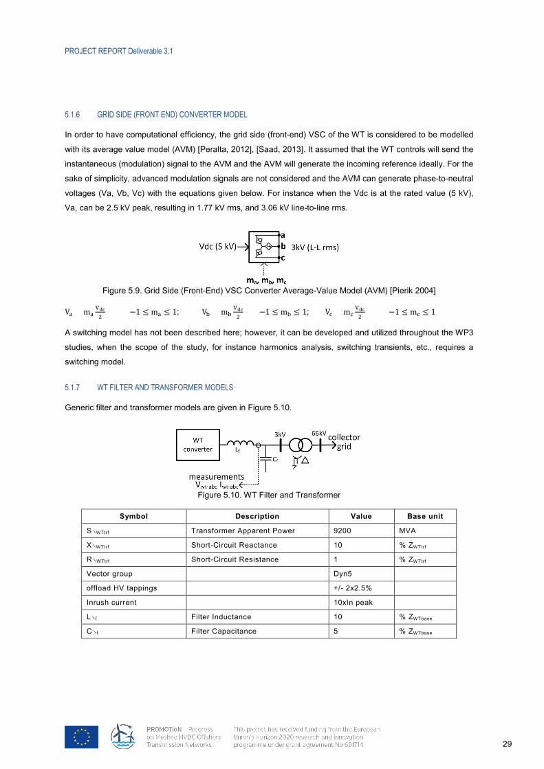
5.1.6 73BGRID SIDE (FRONT END) CONVERTER MODEL
In order to have computational efficiency, the grid side (front-end) VSC of the WT is considered to be modelled
with its average value model (AVM) [Peralta, 2012], [Saad, 2013]. It assumed that the WT controls will send the
instantaneous (modulation) signal to the AVM and the AVM will generate the incoming reference ideally. For the
sake of simplicity, advanced modulation signals are not considered and the AVM can generate phase-to-neutral
voltages (Va, Vb, Vc) with the equations given below. For instance when the Vdc is at the rated value (5 kV),
Va, can be 2.5 kV peak, resulting in 1.77 kV rms, and 3.06 kV line-to-line rms.
Figure 5.9. Grid Side (Front-End) VSC Converter Average-Value Model (AVM) [Pierik 2004]
Va = ma
Vdc2
−1 ≤ ma ≤ 1; Vb = mbVdc2
−1 ≤ mb ≤ 1; Vc = mcVdc2
−1 ≤ mc ≤ 1
A switching model has not been described here; however, it can be developed and utilized throughout the WP3
studies, when the scope of the study, for instance harmonics analysis, switching transients, etc., requires a
switching model.
5.1.7 74BWT FILTER AND TRANSFORMER MODELS
Generic filter and transformer models are given in Figure 5.10.
Figure 5.10. WT Filter and Transformer
Symbol Description Value Base unit
SRWTtrf Transformer Apparent Power 9200 MVA
XRWTtrf Short-Circuit Reactance 10 % ZWTtrf
RRWTtrf Short-Circuit Resistance 1 % ZWTtrf
Vector group Dyn5
offload HV tappings +/- 2x2.5%
Inrush current 10xIn peak
LRf Filter Inductance 10 % ZWTbase
CRf Filter Capacitance 5 % ZWTbase
PROJECT REPORT Deliverable 3.1
30
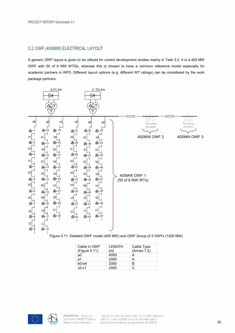
5.2. 32BOWF (400MW) ELECTRICAL LAYOUT
A generic OWF layout is given to be utilized for control development studies mainly in Task 3.2. It is a 400 MW
OWF with 50 of 8 MW WTGs, whereas this is chosen to have a common reference model especially for
academic partners in WP3. Different layout options (e.g. different WT ratings) can be considered by the work
package partners.
Figure 5.11. Detailed OWF model (400 MW) and OWF Group of 3 OWFs (1200 MW)
Cable in OWF (Figure 5.11)
LENGTH [m]
Cable Type (Annex 7.2)
a0 4000 A a1 2000 A b0-b4 2000 B c0-c1 2000 C

PROJECT REPORT Deliverable 3.1
31
6. 9BBIBLIOGRAPHY
[Peter Menke, 2015] P. Menke, “New Grid Access Solutions for Offshore Wind Farms,” in EWEA Offshore,
Copenhagen, 2015.
[Slavomir Seman, 2015] S. Seman, R. Zurowski and T. Christ, “Investigation of DC Converter Nonlinear
Interaction with Offshore Wind Power Park System,” in EWEA Offshore, Copenhagen, 2015
[ENTSO-E NC HVDC] ENTSO-E , Network Code on HVDC connections – Published 26 August 2016,
online
available: 37Thttps://www.entsoe.eu/Documents/Network%20codes%20documents/NC%20HVDC/EC%20Re
gulation%20%28EU%29%202016%201447%20HVDC%20network%20code.pdf
[ENTSO-E, NC RfG] ENTSO-E, Network Code Requirements for Generators – Published 14 April 2016,
online available: http://eur-lex.europa.eu/legal-content/EN/TXT/PDF/?uri=CELEX:32016R0631&from=EN
[National Grid Connection Code, 2016] Issue 5 Revision 17 29 June 2016 online
available: 37Thttp://www2.nationalgrid.com/WorkArea/DownloadAsset.aspx?id=858993528437T
[Hydro Quebec, 2009] Hydro Quebec, "Transmission Provider Technical Requirements for the Connection
of PowerPlants to the Hydro-Quebec Tranmission System," 2009.
[Soledad Bernal-Perez, 2013] S. Bernal-Perez, S. Ano-Villalba, R. Blasco-Gimenez and J. Rodriguez-
D'Derlee, "Efficiency and Fault Ride-Through Performance of a Diode-Rectifier- and VSC-Inverter-Based
HVDC Link for Offshore Wind Farms," in 19TIEEE Transactions on Industrial Electronics19T, vol. 60, no. 6, pp.
2401-2409, June 2013.
doi: 10.1109/TIE.2012.2222855
[Lorenzo Zeni, 2016] L. Zeni 19Tet al19T., "Power Oscillation Damping From VSC–HVDC Connected Offshore
Wind Power Plants," in 19TIEEE Transactions on Power Delivery19T, vol. 31, no. 2, pp. 829-838, April 2016.
doi: 10.1109/TPWRD.2015.2427878
[Slootweg , 2004] Slootweg, J. G., and W. L. Kling. "Modelling wind turbines for power system dynamics
simulations: an overview." Wind Engineering 28.1 (2004): 7-25.
[Vladislav, 2006] Vladislav Akhmatov, "Modelling and ride ‐throu
turbines with permanent magnet generators." Wind Energy 9.4 (2006): 313-326.
[IEC 61400-27-1] Wind Turbines—Part 27-1: Electrical Simulation Models - Wind Turbines, IEC Standard

PROJECT REPORT Deliverable 3.1
32
61400-27-1 ed. 1, Feb. 2015
[Conroy, 2009] Conroy, J., and R. Watson. "Aggregate modelling of wind farms containing full-converter
wind turbine generators with permanent magnet synchronous machines: transient stability studies." IET
Renewable Power Generation 3.1 (2009): 39-52.
[Slootweg, 2003] Slootweg, J. G., et al. "General model for representing variable speed wind turbines in
power system dynamics simulations." IEEE Transactions on power systems 18.1 (2003): 144-151.
[Pierik 2004] Pierik, J., Morren, J.,Wiggelinkhuizen, E., de Haan, S., van Engelen, T., et al.: ‘Electrical and
control aspects of offshore wind farms ii (erao ii) volume 1: dynamic models of wind farms’. Technical
Report, ECN, Petten, Netherlands, 2004, available at http://www.ecn.n1
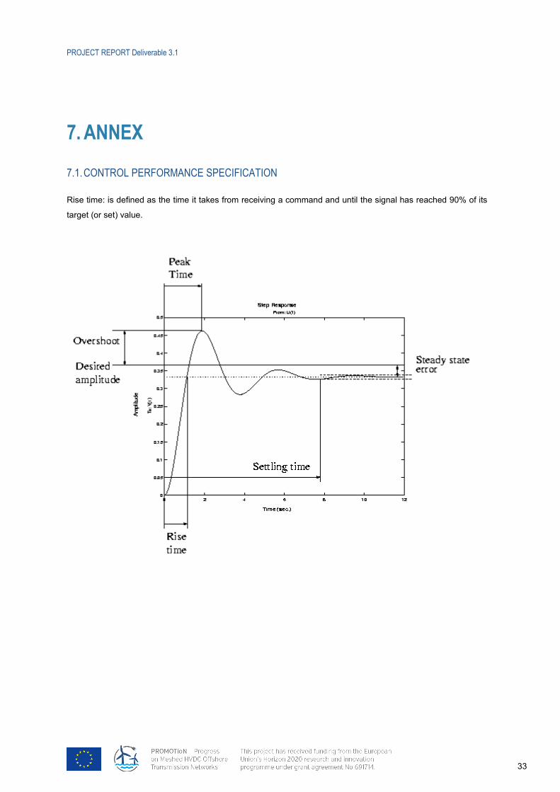
PROJECT REPORT Deliverable 3.1
33
7. 10BANNEX
7.1. 33BCONTROL PERFORMANCE SPECIFICATION
Rise time: is defined as the time it takes from receiving a command and until the signal has reached 90% of its
target (or set) value.
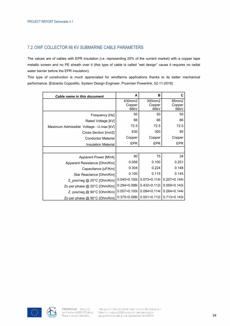
PROJECT REPORT Deliverable 3.1
34
7.2. 34BOWF COLLECTOR 66 KV SUBMARINE CABLE PARAMETERS
The values are of cables with EPR insulation (i.e. representing 25% of the current market) with a copper tape
metallic screen and no PE sheath over it (this type of cable is called “wet design” cause it requires no radial
water barrier before the EPR insulation).
This type of construction is much appreciated for windfarms applications thanks to its better mechanical
performance. [Edoardo Coppolillo, System Design Engineer, Prysmian Powerlink, 02-11-2016]
Cable name in this document A B C
630mm2 Copper
66kV
300mm2 Copper
66kV
95mm2 Copper
66kV Frequency [Hz] 50 50 50
Rated Voltage [kV] 66 66 66 Maximum Admissible Voltage - U.max [kV] 72.5 72.5 72.5
Cross Section [mm2] 630 300 95 Conductor Material Copper Copper Copper
Insulation Material EPR EPR EPR
Apparent Power [MVA] 90 75 34 Apparent Resistance [Ohm/Km] 0.056 0.100 0.251
Capacitance [uF/Km] 0.304 0.224 0.148 Star Reactance [Ohm/Km] 0.100 0.115 0.145
Z_pos/neg @ 20°C [Ohm/Km] 0.045+0.100i 0.073+0.114i 0.207+0.144i Zo per phase @ 20°C [Ohm/Km] 0.294+0.098i 0.432+0.112i 0.559+0.143i
Z_pos/neg @ 90°C [Ohm/Km] 0.057+0.100i 0.094+0.114i 0.264+0.144i
Zo per phase @ 90°C [Ohm/Km] 0.375+0.098i 0.551+0.112i 0.713+0.143i
Related Documents