Delft University of Technology Material-structure integrated design optimization of GFRP bridge deck on steel girder Xin, Haohui; Mosallam, Ayman; Correia, José A.F.O.; Liu, Yuqing; He, Jun; Sun, Yun DOI 10.1016/j.istruc.2020.07.008 Publication date 2020 Document Version Accepted author manuscript Published in Structures Citation (APA) Xin, H., Mosallam, A., Correia, J. A. F. O., Liu, Y., He, J., & Sun, Y. (2020). Material-structure integrated design optimization of GFRP bridge deck on steel girder. Structures, 27, 1222-1230. https://doi.org/10.1016/j.istruc.2020.07.008 Important note To cite this publication, please use the final published version (if applicable). Please check the document version above. Copyright Other than for strictly personal use, it is not permitted to download, forward or distribute the text or part of it, without the consent of the author(s) and/or copyright holder(s), unless the work is under an open content license such as Creative Commons. Takedown policy Please contact us and provide details if you believe this document breaches copyrights. We will remove access to the work immediately and investigate your claim. This work is downloaded from Delft University of Technology. For technical reasons the number of authors shown on this cover page is limited to a maximum of 10.

Welcome message from author
This document is posted to help you gain knowledge. Please leave a comment to let me know what you think about it! Share it to your friends and learn new things together.
Transcript

Delft University of Technology
Material-structure integrated design optimization of GFRP bridge deck on steel girder
Xin, Haohui; Mosallam, Ayman; Correia, José A.F.O.; Liu, Yuqing; He, Jun; Sun, Yun
DOI10.1016/j.istruc.2020.07.008Publication date2020Document VersionAccepted author manuscriptPublished inStructures
Citation (APA)Xin, H., Mosallam, A., Correia, J. A. F. O., Liu, Y., He, J., & Sun, Y. (2020). Material-structure integrateddesign optimization of GFRP bridge deck on steel girder. Structures, 27, 1222-1230.https://doi.org/10.1016/j.istruc.2020.07.008
Important noteTo cite this publication, please use the final published version (if applicable).Please check the document version above.
CopyrightOther than for strictly personal use, it is not permitted to download, forward or distribute the text or part of it, without the consentof the author(s) and/or copyright holder(s), unless the work is under an open content license such as Creative Commons.
Takedown policyPlease contact us and provide details if you believe this document breaches copyrights.We will remove access to the work immediately and investigate your claim.
This work is downloaded from Delft University of Technology.For technical reasons the number of authors shown on this cover page is limited to a maximum of 10.
1
Material-Structure Integrated Design Optimization of GFRP Bridge Deck 1
on Steel Girder 2
Haohui Xina,b, Ayman Mosallamc, José A.F.O. Correiad, Yuqing Liub*, Jun Hee, Yun Sunb 3 aCivil Engineering and Geosciences, Delft University and Technology, Netherlands
bDepartment of Bridge Engineering, Tongji University, Shanghai, China cDepartment of Civil and Environment Engineering, University of California, Irvine, CA, USA 4
d INEGI & CONSTRUCT, Faculty of Engineering, University of Porto, 4200-465 Porto, Portugal 5 eInstitute for Infrastructure and Environment, Heriot-Watt University, Edinburgh, UK 6
fSchool of Civil Engineering, Changsha University of Science and Technology, Changsha, China. 7 8
E-mail: [email protected]
Abstract: 10
Design optimization of fiber-reinforced polymeric (FRP) composite products is essential to facilitate 11
their applications in engineering structures. For bridge structures, the main design optimization goals are 12
the reduction of FRP material consumption and the structure weight, which aim to reduce the initial 13
construction cost and achieve a longer bridge span. Compared with conventional steel-concrete composite 14
bridges, FRP-steel composite bridges possess more design variables and more complex design process, 15
which necessitate the simplified optimization models. This paper aims to propose a two-scale design 16
optimation method for FRP bridge deck on the steel girder. The macro behavior of the pultruded FRP 17
composite bridge deck is analyzed. Regarding the micro level, the equivalent properties of pultruded 18
GFRP lamination are calculated by combining micromechanics and classical lamination theory (CLT). 19
The above-mentioned macro pultruded GFRP bridge level and the micro fiber/resin level were bridged 20
based on the assumption that the micro-component effective homogenized strain equals to the 21
corresponding macro strain. The two-scale lamination optimization of pultruded GFRP bridge deck is 22
finally achieved by finding optimized two-scale design variables that can achieve the minimum bridge 23
weight or the lowest initial construction cost with all listed constraint requirements satisfied. A pultruded 24
FRP deck supported on equally-spaced steel girders was selected as a case study to show how to obtain 25
© 2020 Manuscript version made available under CC-BY-NC-ND 4.0 license https://creativecommons.org/licenses/by-nc-nd/4.0/
2
the optimized two-scale parameters by using this proposed optimization method. The optimized results of 26
the top flange thickness, tu, the bottom flange thickness, tl, the web height, hw, and the web thickness per 27
meter, tw, are 46.02 mm, 45.86 mm, 300.0 mm and 37.42 mm, respectively. Results also showed that the 28
optimized ratio of the 0o-lamina, 45o-lamina, and the 90o-lamina are77.9%, 17.1%, 5.0%. The optimized 29
fiber volume fraction is 65.2%. 30
Keywords: Composite bridge girder; Pultruded GFRP bridge deck; Laminations; Multiscale 31
optimization. 32
33
1. Introduction 34
Fiber-reinforced polymer (FRP) composites have been greatly developed worldwide and have 35
become one of the most popular construction materials for repair and rehabilitation and new construction 36
[1–10]. Pultruded glass fiber reinforced polymer (GFRP) composites are great candidates for newly 37
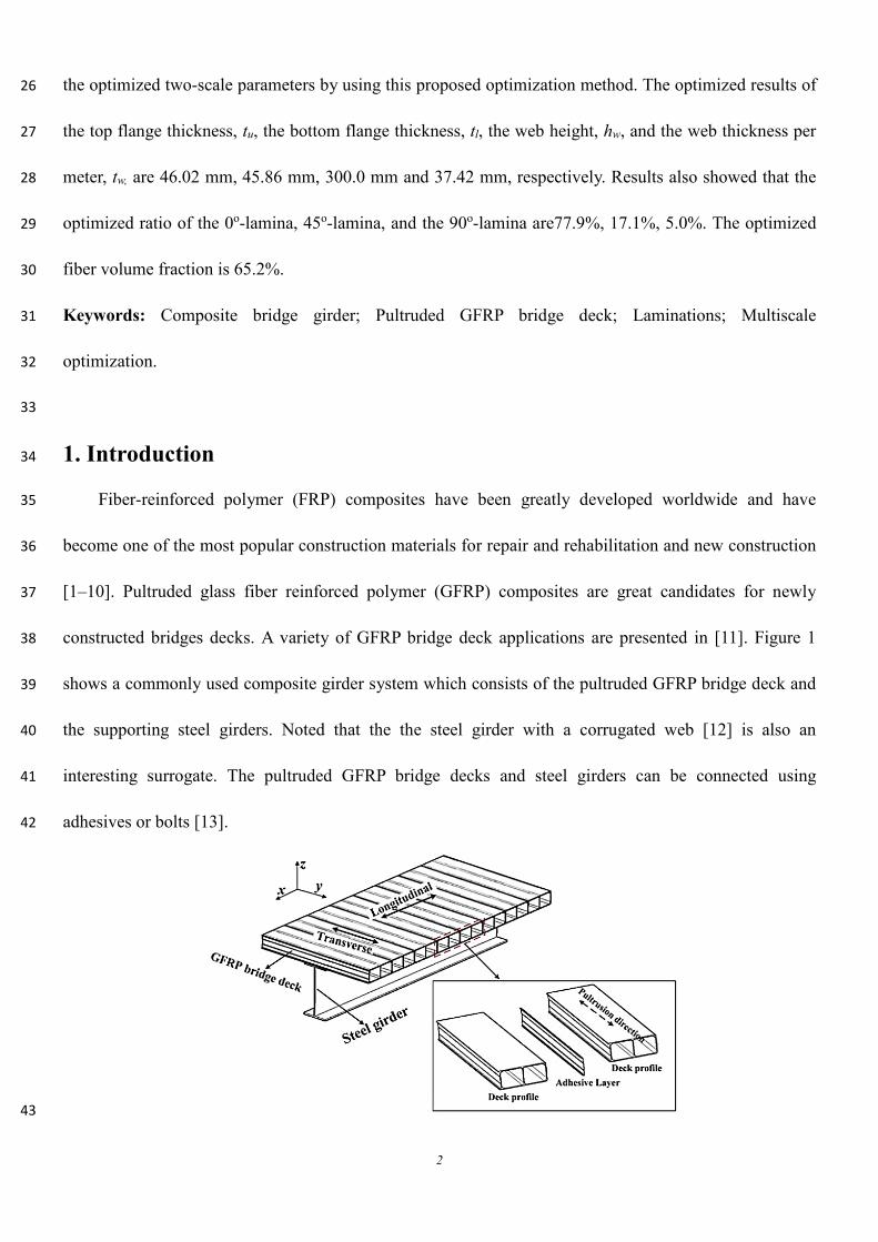
constructed bridges decks. A variety of GFRP bridge deck applications are presented in [11]. Figure 1 38
shows a commonly used composite girder system which consists of the pultruded GFRP bridge deck and 39
the supporting steel girders. Noted that the the steel girder with a corrugated web [12] is also an 40
interesting surrogate. The pultruded GFRP bridge decks and steel girders can be connected using 41
adhesives or bolts [13]. 42
43
3
Figure 1. Pultruded GFRP bridge deck and steel girder system [3] 44
Different from conventional isotropic construction materials like reinforced concrete and steel, 45
GFRP composites are inhomogeneous and anisotropic, which require to be analyzed and designed on 46
different scales, namely, the micro-scale and macro-scale. The importance of multi-scale analysis to 47
determine the mechanical properties of GFRP materials has been pointed out in previous studies[14,15]. 48
During the design stage of a GFRP bridge deck, engineers are not only interested in fulfilling the 49
strength and serviceability requirements, which are the top design priorities, but also in satisfying these 50
requirements with the least possible amount of materials that will result in a weight reduction of the 51
structure and further achieve lower initial construction cost. Thus optimization techniques is very 52
important in obtaining the best use of FRP material in bridge decks. The optimization tasks involve 53
determining the optimal ratio of fiber reinforcements, the optimum fiber volume fractions and geometric 54
variables in order to achieve the best design in both material and structure scales. In addition, the 55
complexity of general pultruded GFRP bridge decks necessitates the development of simplified 56
optimization models. 57
Most of the previous optimization work in the design of composite structures [16–20] focused on 58
aerospace structures, but pultruded GFRP composites, commonly used in bridge decks, are quite different 59
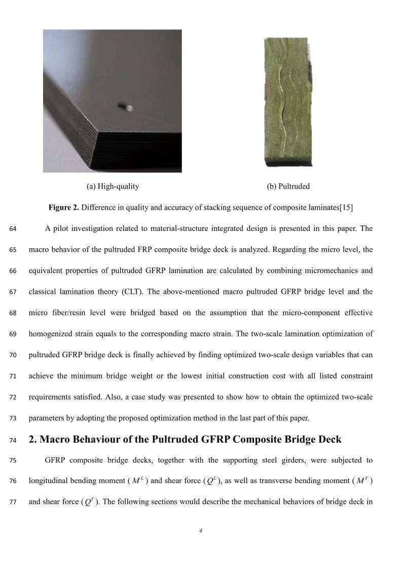
in nature with the composites used in aerospace structures [15], as can be reflected in Figure 2. These 60
differences include: (i) the pultruded FRP laminations have a relatively poor quality, and (ii) the roving 61
content is larger than fabrics, leading to an increase in the thickness of the unidirectional lamina 62
(0°-lamina) of up to 5–15 times the laminas with other orientations. 63
4
(a) High-quality
(b) Pultruded
Figure 2. Difference in quality and accuracy of stacking sequence of composite laminates[15]
A pilot investigation related to material-structure integrated design is presented in this paper. The 64
macro behavior of the pultruded FRP composite bridge deck is analyzed. Regarding the micro level, the 65
equivalent properties of pultruded GFRP lamination are calculated by combining micromechanics and 66
classical lamination theory (CLT). The above-mentioned macro pultruded GFRP bridge level and the 67
micro fiber/resin level were bridged based on the assumption that the micro-component effective 68
homogenized strain equals to the corresponding macro strain. The two-scale lamination optimization of 69
pultruded GFRP bridge deck is finally achieved by finding optimized two-scale design variables that can 70
achieve the minimum bridge weight or the lowest initial construction cost with all listed constraint 71
requirements satisfied. Also, a case study was presented to show how to obtain the optimized two-scale 72
parameters by adopting the proposed optimization method in the last part of this paper. 73
2. Macro Behaviour of the Pultruded GFRP Composite Bridge Deck 74
GFRP composite bridge decks, together with the supporting steel girders, were subjected to 75
longitudinal bending moment ( LM ) and shear force ( LQ ), as well as transverse bending moment ( TM ) 76
and shear force ( TQ ). The following sections would describe the mechanical behaviors of bridge deck in 77
5
both the longitudinal and transverse directions under corresponding bending moment and shear force. 78
2.1 Macro Behavior in the Longitudinal Direction 79
Following assumptions were made to analyze the mechanical behavior of the composite girder along 80
longitudinal direction: (i) the shear connection stiffness is sufficient to ensure a full composite action 81
between the GFRP bridge deck and the supporting steel girder; (ii) the longitudinal shear forces are fully 82
resisted by the steel webs; (iii) the macro longitudinal stresses are uniformly distributed along the flange 83
thickness considering the fact that the laminate thickness dimension is quite small relative to the total 84
height of the steel girder; (iv) the flexural and shear resistances provided by discontinuous web along the 85
longitudinal direction are neglected. 86
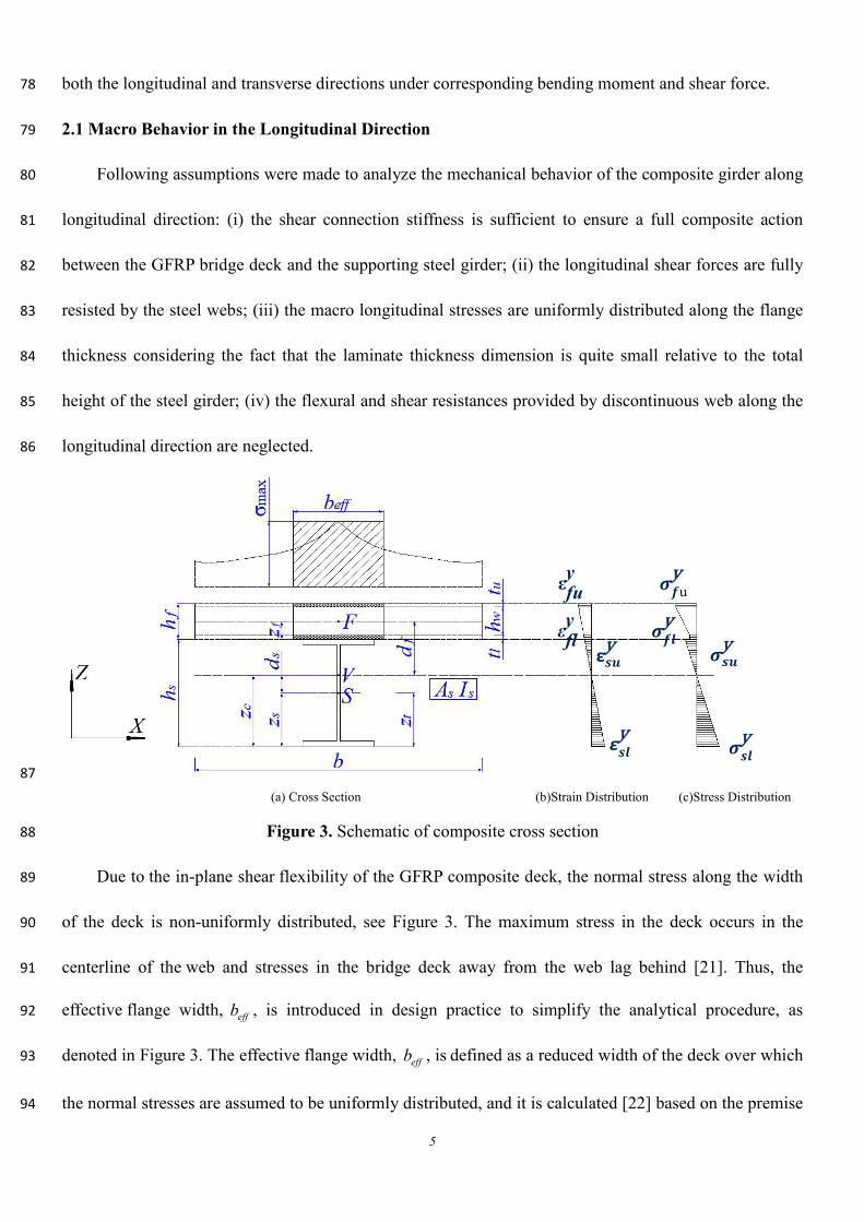
87 (a) Cross Section (b)Strain Distribution (c)Stress Distribution
Figure 3. Schematic of composite cross section 88
Due to the in-plane shear flexibility of the GFRP composite deck, the normal stress along the width 89
of the deck is non-uniformly distributed, see Figure 3. The maximum stress in the deck occurs in the 90
centerline of the web and stresses in the bridge deck away from the web lag behind [21]. Thus, the 91
effective flange width, effb , is introduced in design practice to simplify the analytical procedure, as 92
denoted in Figure 3. The effective flange width, effb , is defined as a reduced width of the deck over which 93
the normal stresses are assumed to be uniformly distributed, and it is calculated [22] based on the premise 94
εfuy
εfly
ε𝒔𝒖y
ε𝒔𝒍y
𝝈𝒔𝒍y
𝝈𝒔𝒖y𝝈𝒇𝒍
y
𝝈𝒇uy
6
that the stress resultant over the effective width should be equal to the stress resultant over the 95
actual flange width, as defined in Eq. (1). 96
( )( )
0
max
xb L
feff L
f
x db
σ
σ= ∫ (1) 97
where: ( )Lf xσ is longitudinal normal stress in the flange of GFRP bridge deck; ( )
max
Lfσ is the maximum 98
longitudinal normal stress in the flange of GFRP bridge deck, and b is the center-to-center spacing of 99
the steel girders. 100
The effective flange width of the GFRP bridge deck supported by the steel girders can be simply 101
predicted [22] by using Eqs. (2) and (3) as follows: 102
,eff eff sb Rb= (2) 103
( )1.025 1 0.0244R ϑ= − (3) 104
where: ,eff sb is the effective width suggested by highway bridges design specifications [30, 31], and ϑ is 105
the degree of composite action between the GFRP composite bridge deck and the main girders. The 106
longitudinal normal stresses at the top flange, yfuσ , and the bottom flange, y
flσ , can be calculated by Eqs. 107
(4) and (5) as follows: 108
L Lfuy
fuv
M znI
σ = − (4) 109
L Lfly
flv
M znI
σ = − (5) 110
where: n is the elastic moduli ratio (modular ratio) between steel modulus ( sE ) and the longitudinal 111
modulus of the GFRP composites deck ( yfE ) and is expressed by Eq. (6): 112
syf
EnE
= (6) 113
Lfuz , and L
flz are the distances from the top and the bottom flanges of the GFRP deck to the neutral axis 114
of the GFRP/steel composite girder, cz , respectively. Thus: 115
7
/ 2Lfu s l w u cz h t h t z= + + + − (7) 116
2L lfl s c
tz h z= + − (8) 117
The distance between the neutral axis of the GFRP/steel composite girder and the bottom fiber of the 118
steel girder, cz , is calculated by the following equation: 119
( )( )
2 22 2 2 2 2
2
ys s s eff f l u u w u l u s s l
c y ys s eff u f eff l f
A E z b E t t t h t t t h h tz
A E b t E b t E
+ + + + + +=
+ + (9) 120
The equivalent moment of inertia of the GFRP/steel composite girder vI could be calculated by Eq. 121
(10). 122
( ) ( ) ( ) ( )( )22 3 3 / 12 /v s s c s eff u l eff u l s f cI I A z z b t t n b t t h z z n= + − + + + + + − (10) 123
( )2 2 2 2z
2l u u w u l
fl u
t t t h t tt t
+ + +=
+ (11) 124
where: sh is the height of the steel beam; lt is the thickness of bottom flange; ut is the thickness of the 125
top flange; wh is the web height of pultruded GFRP bridge deck; sA is the cross-sectional area of the 126
steel beam, and sz is the distance between the neutral axis and the bottom fiber of the steel girder. 127
2.2 Macro Behavior in the Transverse Direction 128
The following assumptions were made to analyze the longitudinal mechanical behavior of the 129
GFRP-steel composite girder: (i) the transverse shear force is fully resisted by the web of GFRP bridge 130
deck; (ii) the transverse normal stress is uniformly distributed along with the top/bottom flange thickness. 131
The transverse normal stress in the top flange xfuσ and bottom flange x
flσ , as denoted in Figure 4, 132
could be calculated based on Eqs. (12)–(13). 133
T Tfux
fu xf
M zI
σ = − (12) 134
T Tflx
fl xf
M zI
σ = (13) 135
where: the transverse moment of inertia xfI of pultruded GFRP bridge deck is: 136
8
( ) ( ) ( ) ( )2 2 23 3 31 1000 1000 1000 100012
x T T Tf u l w w u fu l fl w w fwI t t t h t z t z t h z= + + + + + (14) 137
Note positive and negative signs in Eqs. (12)–(13) represent tensile and compressive stresses, 138
resepectively. 139
The web thickness per meter wt along longitudinal direction is calculated by Eq. (15). 140
( )1000 n
w w ii
t ta
= ∑ (15) 141
where, a is the width of GFPP deck profile, and ( )w it is the thickness of web in each GFRP deck 142
profile. 143
Tfuz in Eq. (11) and T
flz in Eq. (12) respectively refers to the distances between the top/bottom flange of 144
GFRP composite bridge deck and its neutral axis, and can be calculated by Eqs. (16) and (17), 145
respectively: 146
T Tfu l w u fz t h t z= + + − (16) 147
T Tfl fz z= (17) 148
where the height of the GFRP bridge deck neutral axis along the transverse direction, 𝑧𝑧𝑓𝑓𝑇𝑇, is given by Eq. 149
(18): 150
( ) ( ) ( )2 21000 + + / 2 5001000 + +1000
u l u w w w l w l uTf
u w w l
t t t h h t t h t tz
t h t t+ + +
= (18) 151
The shear stress, xyfwτ in the web of the pultruded GFRP bridge deck is calculated by Eqs. (19): 152
Txyfw
w w
Qt h
τ = (19) 153
In order to guarantee a safe design, the GFRP bridge deck is assumed simply supported by steel 154
girder. The transverse deflection of pultruded GFRP bridge deck can be conservatively predicted using 155
Timoshenko beam theory [25]: 156
( )2
max 5=48 4
T Tzf x x xy
f f w w f
M b Q bE I t h G
δ + (20) 157
9
where: xfE and xy
fG are the elastic and in-plane shear moduli of the GFRP composite bridge deck in the 158
transverse direction. 159
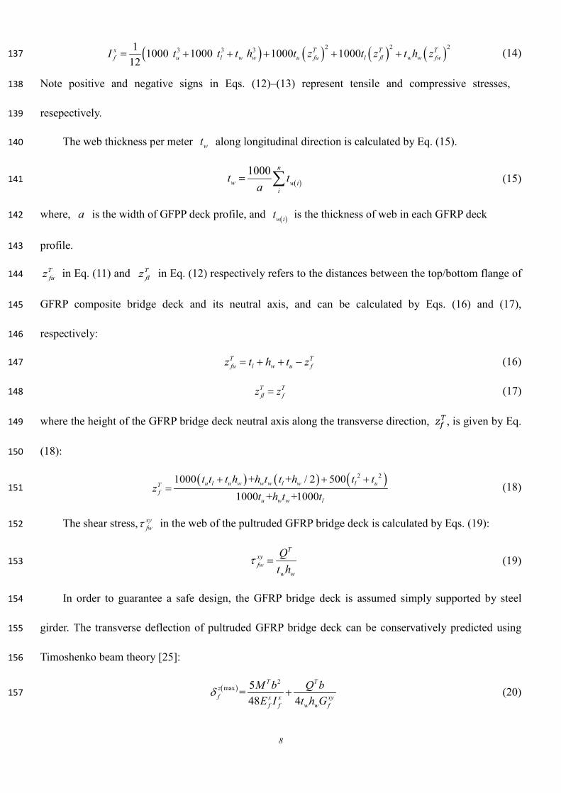
160
(a) Geometry symbols in YZ plane 161
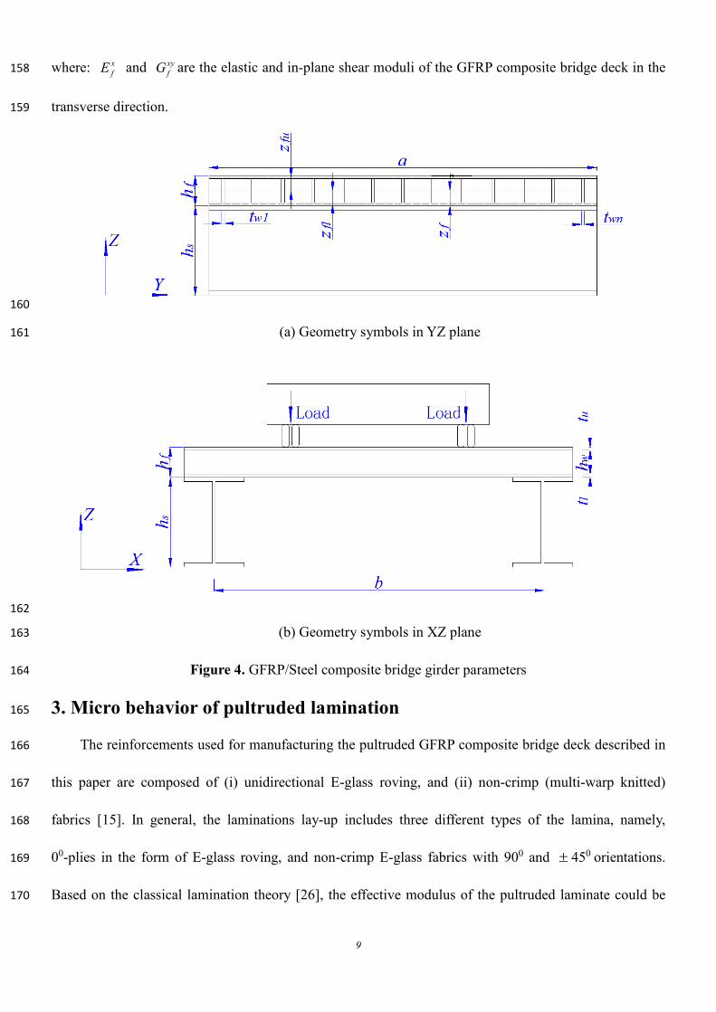
162
(b) Geometry symbols in XZ plane 163
Figure 4. GFRP/Steel composite bridge girder parameters 164
3. Micro behavior of pultruded lamination 165
The reinforcements used for manufacturing the pultruded GFRP composite bridge deck described in 166
this paper are composed of (i) unidirectional E-glass roving, and (ii) non-crimp (multi-warp knitted) 167
fabrics [15]. In general, the laminations lay-up includes three different types of the lamina, namely, 168
00-plies in the form of E-glass roving, and non-crimp E-glass fabrics with 900 and ± 450 orientations. 169
Based on the classical lamination theory [26], the effective modulus of the pultruded laminate could be 170
10
estimated using Eqs. (21)–(23), assuming that the ratio of 0°, 45°, and 90° lamina to the total 171
lamination are 0ξ , 45ξ , and 90ξ , respectively. 172
( )
( )( )( ) ( )
( )
2 2 21 12 2 1 2 12 2
0 9012 21 1 12 21
2 21 2 12 2 12 21 12 12 2
4512 21 1 2 12 2 12 21 12
1 1
2 4 1 -1611 4 2 4 1
xf
E v E E E v EEv v E v v
E E v E v v G v Ev v E E v E v v G
ξ ξ
ξ
− −= + + − −
+ + + −
− + + + −
(21) 173
( )
( )( )( ) ( )
( )
2 2 21 2 12 2 1 12 2
0 901 12 21 12 21
2 21 2 12 2 12 21 12 12 2
4512 21 1 2 12 2 12 21 12
1 1
2 4 1 -1611 4 2 4 1
yf
E E v E E v EEE v v v v
E E v E v v G v Ev v E E v E v v G
ξ ξ
ξ
− −= + + − −
+ + + −
− + + + −
(22) 174
( )1 2 12 2
0 12 90 12 4512 21
+ -24 1
xyf
E E v EG G Gv v
ξ ξ ξ
= + + − (23) 175
where: xfE is the effective elastic modulus of GFRP laminates in the longitudinal direction of the bridge; 176
yfE is the effective elastic modulus of GFRP laminates in the transverse direction of the bridge; xy
fG is 177
the effective in-plane shear modulus of GFRP laminates. 178
The longitudinal modulus, E1, transverse modulus, E2, shear modulus, G12, and Poisson’s ratio, v12 of 179
the lamina can be determined based on the modified mixture formulae [6]: 180
(24) 181
(25) 182
( )21 1
3.50.2= 1.1 1 0.221-
m mf
m f f
E E Vv E E
η
− + +
(26) 183
(27) 184
(28) 185
(29) 186
where: Ef1 is the longitudinal elastic modulus of fiber, Ef2 is the transverse elastic modulus of fiber, Vf is 187
11 f f m mE E V E V= +
2
2
22
2
f m f m
m f f m
E E V VE
E V E V
+ η =+ η
1212
12
( )= f m f m
m f f m
G G V VG
G V G V+η
+ η
12 =0.28+ m
f
EE
η
12 f f m mv V v Vν = +
11
the fiber volume fraction, vf is the fibers’ Poisson’s ratio, Em is the matrix elastic modulus, Vm is the resin 188
volume fraction, vm is the matrix’s Poisson’s ratio, Gf is the shear modulus of fibers, and Gm is the resin 189
shear modulus. 190
The strength-based design method is accepted in many design practices, however, in this study, the 191
variation of elastic moduli and ultimate strength of each lamina complicates the lamination optimization 192
procedures. Thus, the strain-based design method is adopted in this paper. 193
By neglecting the curvature effects, the ultimate strain of each ply in the laminate is deemed to be 194
the same based on First-Ply-Failure (FPF) analytical method [26]. The ultimate strain of each lamina can 195
be obtained based on the micromechanics approach [6] using Eqs. (30)–(34). 196
11 1
ftt u t uTf
f
XXE E
ε ε= = = (30) 197
11 1
fcc u c uCf
f
XXE E
ε ε= = = (31) 198
( )( )
2
2
22
2 2
X m f f mt u mtT
f m f m
E V E VYE SCF E E V V
ηε
η
+= =
+ (32) 199
( )22 2
1 4 / 1c u C mmc f
f
Y EVE E
ε ε π
= = − − (33) 200
( ) ( )( )
1212
12 12
1 1 m f f mu mm f f
f f m f m
G V G VGS S V VG G G G V V
ηγ
η
+ = = + − − +
(34) 201
When applying loads along the pultrusion direction, the ultimate strain of the 00 , 900 ,± 450 lamina is 202
1uε , 2
uε , and uγ , respectively. When the loads are applied perpendicular to the pultrusion direction, the 203
ultimate strain of 00 , 900 , ± 450 lamina is 2uε , 1
uε and uγ , respectively. Based on the “First-Ply-Failure” 204
failure criterion, the ultimate strain of each lamina can be calculated using Eqs. (35)–(37). The ultimate 205
strain variation as related to fiber volume fraction is shown in Fig. 5. These values were calculated using 206
Eqs. (31)–(37) with material properties listed in Tables 1 and 2 [27]. 207
( )1 2 2min , ,t u t u t u u t uε ε ε γ ε= = (35) 208
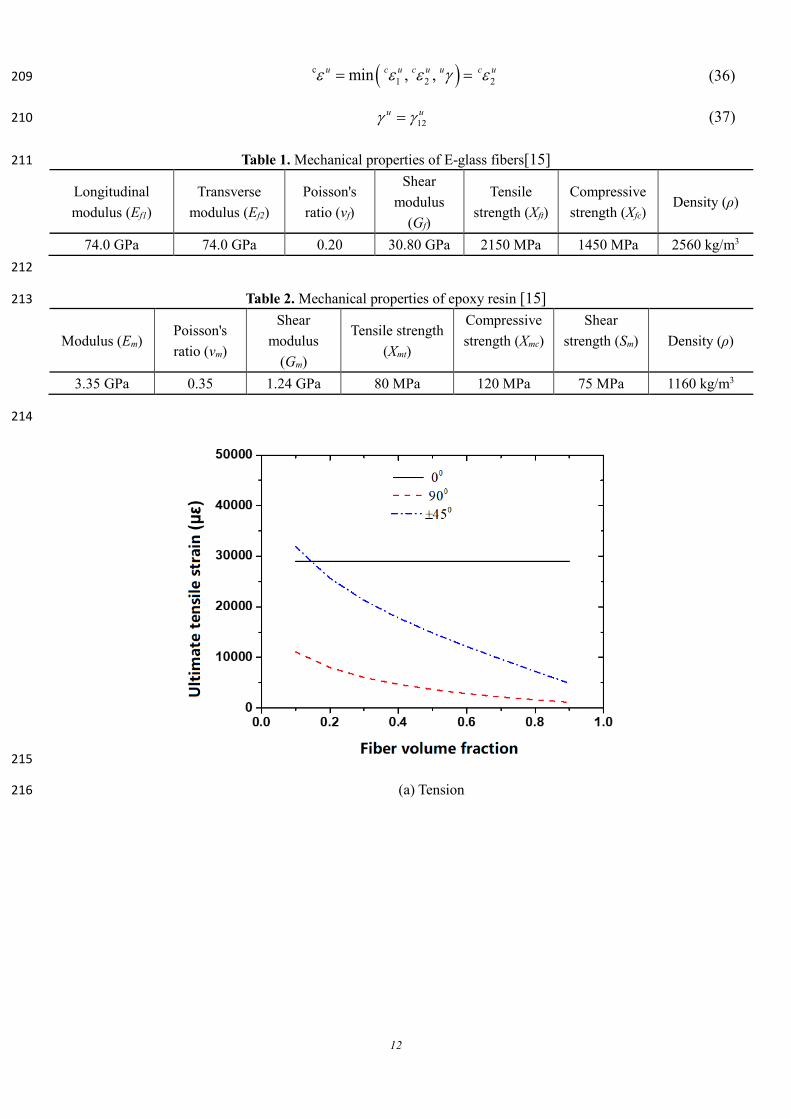
12
( )c1 2 2min , ,u c u c u u c uε ε ε γ ε= = (36) 209
12u uγ γ= (37) 210
Table 1. Mechanical properties of E-glass fibers[15] 211
Longitudinal modulus (Ef1)
Transverse modulus (Ef2)
Poisson's ratio (vf)
Shear modulus
(Gf)
Tensile strength (Xft)
Compressive strength (Xfc)
Density (ρ)
74.0 GPa 74.0 GPa 0.20 30.80 GPa 2150 MPa 1450 MPa 2560 kg/m3 212
Table 2. Mechanical properties of epoxy resin [15] 213
Modulus (Em) Poisson's ratio (vm)
Shear modulus
(Gm)
Tensile strength (Xmt)
Compressive strength (Xmc)
Shear strength (Sm) Density (ρ)
3.35 GPa 0.35 1.24 GPa 80 MPa 120 MPa 75 MPa 1160 kg/m3
214
215
(a) Tension 216
13
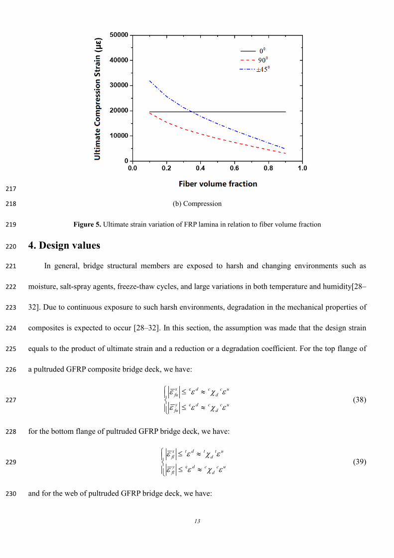
217
(b) Compression 218
Figure 5. Ultimate strain variation of FRP lamina in relation to fiber volume fraction 219
4. Design values 220
In general, bridge structural members are exposed to harsh and changing environments such as 221
moisture, salt-spray agents, freeze-thaw cycles, and large variations in both temperature and humidity[28–222
32]. Due to continuous exposure to such harsh environments, degradation in the mechanical properties of 223
composites is expected to occur [28–32]. In this section, the assumption was made that the design strain 224
equals to the product of ultimate strain and a reduction or a degradation coefficient. For the top flange of 225
a pultruded GFRP composite bridge deck, we have: 226
c
c
x d c c ufu d
y d c c ufu d
ε ε χ ε
ε ε χ ε
≤ ≈
≤ ≈ (38) 227
for the bottom flange of pultruded GFRP bridge deck, we have: 228
c
x t d t t ufl d
y d c c ufl d
ε ε χ ε
ε ε χ ε
≤ ≈
≤ ≈ (39) 229
and for the web of pultruded GFRP bridge deck, we have: 230
14
xy s d s s uw dγ γ χ γ≤ ≈ (40) 231
where: cdχ ,
tdχ ,
sdχ are the reduction (degradation) coefficients for GFRP materials in compression, 232
in tension, and in shear, respectively. 233
The Chinese Technical Code for Infrastructure Application of FRP Composites (GB 50608-2010) 234
[32] suggests that the design values are determined by dividing experimental ultimate strength by 235
appropriate partial safety factors that account for material type, and the surrounding environment. The 236
following equations can be used to calculate the reduction (degradation) coefficient: 237
1.645 1u
d uf e
µ σχµ γ γ
−= (41) 238
where: uµ is the average material strength; σ is the standard derivation of the test number; fγ is the 239
partial safety factor to account for material type; eγ is the partial safety factor to account for 240
environmental exposure. 241
In addition, the transverse deflection of the pultruded GFRP bridge deck should always be smaller 242
than a limiting transverse deflection to ensure the stiffness requirement. 243
( )maxz ufδ δ≤ (42) 244
where: ( )maxzfδ is the maximum transverse deflection of GFRP bridge deck under applied load, uδ is the 245
limited transverse deflection based on the design requirement. 246
5. Bridging fiber/resin level to structure level 247
In this section, the micro fiber/resin scale is bridged to the macro-the GFRP/steel composite girder 248
scale by assuming that the effective homogenized strain obtained from micro-component equals to 249
macro-strain. Linking micro and macro longitudinal and transverse strains at the top flange of a pultruded 250
GFRP bridge deck is achieved by using the following equations: 251
x T Tfu fux
fu x x xf f f
M zE E Iσ
ε = ≈ − (43) 252
15
y L Lfu fuy
fu y yf v f
M zE nI Eσ
ε = ≈ − (44) 253
Similarly, linking both micro and macro longitudinal and transverse strains at the bottom flange of a 254
pultruded GFRP bridge deck is achieved by the following equations: 255
=x T Tfl flx
fl x x xf f f
M zE E Iσ
ε ≈ (45) 256
=L L
flyfl y
v f
M znI E
ε − (46) 257
Eq. (48) shows how to link the micro and macro shear strains at the web of a pultruded GFRP bridge 258
deck: 259
xy
=T
xy ww xy xy
f w w f
QG t h Gτγ = (47) 260
6. Optimization equations for pultruded bridge decks 261
The main goals of multiscale optimization of GFRP bridge decks towards material-structure 262
integrated design are to achieve: (i) the lightest weight to increase the bridge span while satisfying all 263
design and manufacturing requirements, or (ii) the lowest cost for the economy and constructional 264
convenience. Mathematically speaking, the multiscale optimization of GFRP bridge decks is to seek a 265
minimum value of cost or weight by optimizing multiscale design variables within given allowed 266
constrained functions determined by design and manufacturing requirements. In this paper, the multiscale 267
lamination optimization of a pultruded GFRP bridge deck is achieved by finding an optimized two-scale 268
design variable vector, x, that drive the objective weight function, Φ1, or the objective price function, Φ2, 269
to its lowest values while satisfying all constraint functions (Φ1~ Φ6). The design variables, objective 270
functions, and constraint functions will be explained in the following sections. 271
(1) Design Variables: Eq. (48) describes the two-scale optimization design variable vector, x, 272
including the thickness of the top flange, ut , the thickness of the bottom flange, lt , the height of the web,273
16
wh , the thickness per meter of the web, wt , the ratio of 0°, 45°, 90° lamina to the total laminate are 0ξ , 274
45ξ , and 90ξ , respectively, and the fiber volume fraction fV . 275
0 90 45, , , , , , ,T
u l w w fx t t h t Vζ ζ ζ = (48) 276
(2) Objective function: The objective function 1φ related to the optimizing weight is given as 277
follows: 278
( ) ( )1 1000 1000 u l w w f f m mt t h t V Vφ ρ ρ= + + + (49) 279
where: fρ is fiber density, and mρ is the resin density. 280
The objective function, 2φ , related to the optimizing cost is given in Eqn. (50). It should be noted that 281
the manufacturing cost is not included in this expression due to the fact that different manufacturers have 282
different selling prices. 283
( ) ( )2 1000 1000 u l w w f f f m m mt t h t V Vφ η ρ η ρ= + + + (50) 284
where: fη is the price of the fibers, and mη is the price of the matrix. 285
(3) Constraint functions: In this study, a total of six constraint functions were specified as follows. 286
(i) Constraint function Φ1 (strength requirement of the top flange): 287
The longitudinal and transverse normal strains at the top flange of the GFRP deck should be smaller 288
than corresponding design values of normal strains, i.e., 289
1
c
x t dfu
y dfu
ε ε
ε ε
≤Φ = ≤
(51) 290
(ii) Constraint function Φ2 (strength requirement of the bottom flange): 291
The longitudinal and transverse normal strains at the bottom flange of the GFRP deck should be 292
smaller than corresponding allowable maximum normal strains, i.e., 293
2
c
x t dfl
y dfl
ε ε
ε ε
≤Φ = ≤
(52) 294
17
(iii) Constraint function Φ3 (strength requirement of the web): 295
The shear strain at the web of the GFRP deck should be smaller than allowable maximum shear 296
strain, i.e., 297
3 xy s dwγ γΦ = ≤ (53) 298
(iv) Constraint function Φ4 (stiffness requirement): 299
The transverse displacement of the GFRP deck should be smaller than the specified deflection, i.e.: 300
( )max4 z ufδ δΦ = ≤ (54) 301
(v) Constraint function Φ5 (manufacturing requirement): 302
The fractions of different types of laminates should be within the specified ranges, which are 303
determined by the pultrusion manufacture, i.e.: 304
0 0
45 45
90 90
05
45
90
0.25 0.75f
l h
l h
l h
V
ξ ξ ξ
ξ ξ ξ
ξ ξ ξ
≤ ≤
≤ ≤Φ = ≤ ≤
≤ ≤
(55) 305
(vi) Constraint function Φ6 (geometrical requirement): 306
The thickness of the plates should be within the specified ranges to avoid local buckling occurring in 307
the excessive thin plate, and to meet the manufacturing capabilities since each manufacturer can only 308
produce the GFRP plate within the specific range of the thickness, i.e.: 309
( ) ( )( ) ( )( ) ( )( ) ( )
6
l uu u u
l ul l l
l uw w w
l uw w w
t t t
t t t
t t t
h h h
≤ ≤ ≤ ≤Φ =
≤ ≤
≤ ≤
(56) 310
7. Application to composite bridge girder 311
A composite bridge girder with a main span of 20.0 meters was selected for a case study. This bridge 312
girder consists of GFRP bridge decks and I-shaped steel girders with equal center-to-center spacing of 3.0 313
18
meters. The GFRP composite deck is connected to steel girders using the bolted connector, and the degree 314
of composite action between GFRP bridge deck and steel girder, ϑ is specified as 0.72. The total height 315
of the I-shaped steel girder is 1000 mm, the thickness of the top flange, bottom flange, and the web, are, 316
20.0mm, 25.0mm, and 20.0mm, respectively, and the width of both the top and bottom flanges is 400.0 317
mm. According to the Chinese bridge specifications [24], the design load was calculated as: 318
1 11 2
m n
ud Gi Gik Q Q k c Qj Qjki j
S S S Sγ γ ϕ γ= =
= + +∑ ∑ (57) 319
where: Giγ , 1Qγ , Qjγ is the partial safety factor to dead load, vehicle load and live load excluding vehicle 320
load; GikS , 1Q kS , QjkS represent the load effects, resulting from the dead load, vehicle load, and live load 321
excluding vehicle load, respectively; and cϕ is the combination reduction parameter for the load effect 322
resulting from the live load excluding vehicle load. Note that the design load udS can refer to different 323
types of load effects, such as bending moment or shear force. In this study, the design loads include 324
longitudinal bending moment LM , longitudinal shear force, LQ , transverse bending moment, TM , and 325
transverse shear force, TQ , and they were computed based below equation: 326
( ) ( ) ( )21 1 2 1 2 1
1.1 1.2 + 1.4 1+ 1.12 1++
8 4
L Ls f G Q Q QL
q q bq q bq L P LM
µ µ + + + = (58) 327
( ) ( ) ( )1 1 2 1 2 11.1 1.2 1.4 1+ 1.12 1.2 1+
+2 2
L Ls f G Q Q QL
q q bq q bq L PQ
µ µ + + + + = (59) 328
( ) ( )21 2 2 1
1.1 1.2 1000 1120 1.4 1+
8 4
T Tf G Q QT
q q q b P bM
µ + + + = (60) 329
( ) ( )1 2 2 11.1 1.2 1000 1120 1.4 1
+2 2
T Tf G Q QT
q q q b PQ
µ + + + = + (61) 330
Where 1L
fq and 1T
fq is the self-weight of GFRP deck along the longitudinal and transverse direction 331
respectively; 1sq is the self-weight of steel girder; 2Gq is the self-weight of paving, defined as 5 kN/m3; 332
1Qq is the line load of the vehicle, defined as 10.5 kN/m *b/3000; 1QP is the concentration load of the 333
vehicle, defined as 280kN*b/3000; µ is impact coefficient, defined as 0.3. 334
19
The objective function of weight, 1φ , is specified as: 335
( ) ( )5 51 1000 1000 1.28 10 3.25 10 1u l w w f ft t h t V Vφ − − = + + × + × − (62) 336
while the objective function of price, 2φ , is specified as: 337
( ) ( )6 62 1000 1000 2.56 10 1.16 10 1u l w w f ft t h t V Vφ − − = + + × + × − (63) 338
The reduction (degradation) coefficient is specified as 0.43 based on Eqn. (41) as well as on 339
experimental results of several durability tests [28–32]. The constraint functions for strength requirement 340
Φ1~ Φ3 thus can be presented as Eqs. (65)–(67). 341
c
1
c
0.43
0.43
x ufl
y ufl
ε ε
ε ε
≤Φ = ≤
(64) 342
2
c
0.43
0.43
x t ufl
y ufl
ε ε
ε ε
≤Φ = ≤
(65) 343
3 0.43xy s uwγ γΦ = ≤ (66) 344
The Chinese design specifications of highway bridges [24] recommended that the bridge deck 345
transverse deflection should be smaller than the girder’s span (b) divided by 400 (i.e. b/400). The 346
constraint functions for stiffness requirement thus should be expressed as: 347
( )max4 / 400zf bδΦ = ≤ (67) 348
The 0°-lamina of pultruded GFRP laminates is in the form of E-glass roving, while both the 90°- and 349
±45°-laminates are in the form of stitched E-glass fabrics. Due to the limitation of pultrusion 350
manufacturing process, the contents of roving are much larger than fabrics for guaranteeing necessary 351
pultrusion traction, making the content of 0° lamina is much larger than the laminas with other angle 352
orientations[15]. The minimum ratio of 00 lamina is specified as 50% to guarantee necessary pultrusion 353
traction, and the maximum ratio of 90° and ±45° lamina is set as 20% considering manufacture 354
difficulties with larger fabric content. Then constrain functions for pultrusion manufacture requirement is 355
20
specified by Eq. (68). 356
5 0
45
90
0.25 0.700.5 0.950.05 0.20.05 0.2
fVξξξ
≤ ≤
≤ ≤Φ = ≤ ≤
≤ ≤
(68) 357
To avoid local buckling and consider manufacturing capabilities and limitations, a maximum height 358
of the GFRP bridge deck is set to 300 mm, the maximum flange thickness is set as 50 mm, and the 359
maximum web thickness per meter is assumed as 250 mm. The constraint functions for geometry 360
requirements are specified as in Eq. (69) as follow: 361
6
5 505 505 25050 300
u
l
w
w
ttt
h
≤ ≤ ≤ ≤Φ = ≤ ≤ ≤ ≤
(69) 362
The optimization process was achieved by minimizing 1φ or 2φ under the constraint 1Φ - 6Φ using 363
constrained nonlinear minimization (fmincon) function in the MATLAB™ software [33]. The optimized 364
two-scale parameters of this case study are listed in Table 3. It can be seen that the weight objective 365
function 1φ and the price objective function 2φ also calculate the same results. This is mainly because 366
that the stiffness requirement (constrain function Φ4) is most strict based on the specification of steel or 367
concrete deck among all the constrained functions. The optimized top flange thickness tu, bottom flange 368
thickness tl, web height hw, web thickness per meter tw are 46.02 mm, 45.86 mm, 300 mm and 37.42 mm. 369
Also, the optimized ratio of the 00-lamina, the 450-lamina, and the 900-lamina are 77.9%, 17.1%, 5.0%. 370
The optimized fiber volume fraction is 65.2%. The optimized parameters are the same in terms of price 371
and weight optimization because the governing factor is the web height. 372
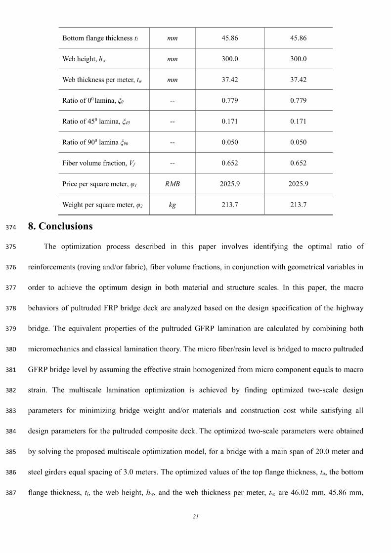
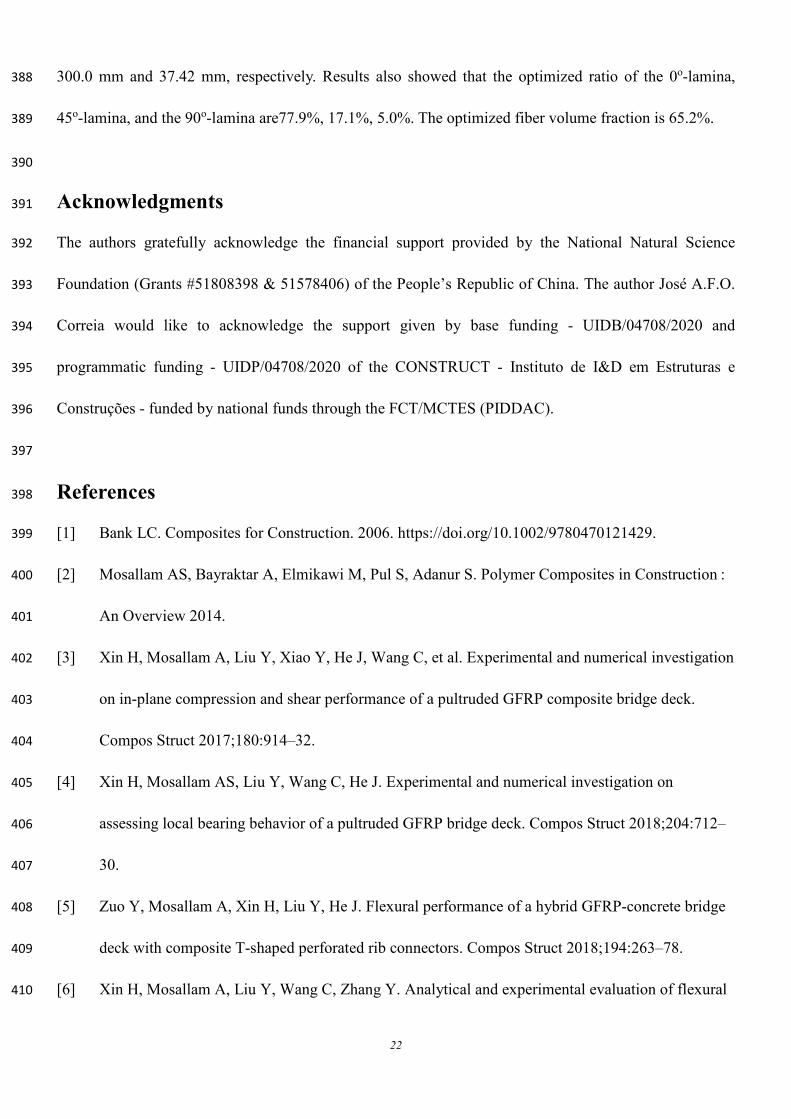
Table 3. Optimized two-scale parameters of case study 373
Item Unit Price Optimization Weight Optimization
Top flange thickness tu mm 46.02 46.02
21
Bottom flange thickness tl mm 45.86 45.86
Web height, hw mm 300.0 300.0
Web thickness per meter, tw mm 37.42 37.42
Ratio of 00 lamina, ξ0 -- 0.779 0.779
Ratio of 450 lamina, ξ45 -- 0.171 0.171
Ratio of 900 lamina ξ90 -- 0.050 0.050
Fiber volume fraction, Vf -- 0.652 0.652
Price per square meter, φ1 RMB 2025.9 2025.9
Weight per square meter, φ2 kg 213.7 213.7
8. Conclusions 374
The optimization process described in this paper involves identifying the optimal ratio of 375
reinforcements (roving and/or fabric), fiber volume fractions, in conjunction with geometrical variables in 376
order to achieve the optimum design in both material and structure scales. In this paper, the macro 377
behaviors of pultruded FRP bridge deck are analyzed based on the design specification of the highway 378
bridge. The equivalent properties of the pultruded GFRP lamination are calculated by combining both 379
micromechanics and classical lamination theory. The micro fiber/resin level is bridged to macro pultruded 380
GFRP bridge level by assuming the effective strain homogenized from micro component equals to macro 381
strain. The multiscale lamination optimization is achieved by finding optimized two-scale design 382
parameters for minimizing bridge weight and/or materials and construction cost while satisfying all 383
design parameters for the pultruded composite deck. The optimized two-scale parameters were obtained 384
by solving the proposed multiscale optimization model, for a bridge with a main span of 20.0 meter and 385
steel girders equal spacing of 3.0 meters. The optimized values of the top flange thickness, tu, the bottom 386
flange thickness, tl, the web height, hw, and the web thickness per meter, tw, are 46.02 mm, 45.86 mm, 387
22
300.0 mm and 37.42 mm, respectively. Results also showed that the optimized ratio of the 0o-lamina, 388
45o-lamina, and the 90o-lamina are77.9%, 17.1%, 5.0%. The optimized fiber volume fraction is 65.2%. 389
390
Acknowledgments 391
The authors gratefully acknowledge the financial support provided by the National Natural Science 392
Foundation (Grants #51808398 & 51578406) of the People’s Republic of China. The author José A.F.O. 393
Correia would like to acknowledge the support given by base funding - UIDB/04708/2020 and 394
programmatic funding - UIDP/04708/2020 of the CONSTRUCT - Instituto de I&D em Estruturas e 395
Construções - funded by national funds through the FCT/MCTES (PIDDAC). 396
397
References 398
[1] Bank LC. Composites for Construction. 2006. https://doi.org/10.1002/9780470121429. 399
[2] Mosallam AS, Bayraktar A, Elmikawi M, Pul S, Adanur S. Polymer Composites in Construction : 400
An Overview 2014. 401
[3] Xin H, Mosallam A, Liu Y, Xiao Y, He J, Wang C, et al. Experimental and numerical investigation 402
on in-plane compression and shear performance of a pultruded GFRP composite bridge deck. 403
Compos Struct 2017;180:914–32. 404
[4] Xin H, Mosallam AS, Liu Y, Wang C, He J. Experimental and numerical investigation on 405
assessing local bearing behavior of a pultruded GFRP bridge deck. Compos Struct 2018;204:712–406
30. 407
[5] Zuo Y, Mosallam A, Xin H, Liu Y, He J. Flexural performance of a hybrid GFRP-concrete bridge 408
deck with composite T-shaped perforated rib connectors. Compos Struct 2018;194:263–78. 409
[6] Xin H, Mosallam A, Liu Y, Wang C, Zhang Y. Analytical and experimental evaluation of flexural 410
23
behavior of FRP pultruded composite profiles for bridge deck structural design. Constr Build 411
Mater 2017;150:123–49. https://doi.org/10.1016/j.conbuildmat.2017.05.212. 412
[7] Zou X, Feng P, Bao Y, Wang J, Xin H. Experimental and analytical studies on shear behaviors of 413
FRP-concrete composite sections. Eng Struct 2020;215:110649. 414
[8] Xiong Z, Liu Y, Zuo Y, Xin H. Experimental evaluation of shear behavior of pultruded GFRP 415
perforated connectors embedded in concrete. Compos Struct 2019;222:110938. 416
[9] Zhang Y, Mosallam A, Liu Y, Sun Y, Xin H, He J. Assessment of Flexural Behavior of Pultruded 417
GFRP Laminates for Bridge Deck Applications. Adv Mater Sci Eng 2019;2019. 418
[10] Xiong Z, Liu Y, Zuo Y, Xin H. Shear performance assessment of sand-coated GFRP perforated 419
connectors embedded in concrete. Materials (Basel) 2019;12:1906. 420
[11] Nijgh MP, Xin H, Veljkovic M. Non-linear hybrid homogenization method for steel-reinforced 421
resin. Constr Build Mater 2018;182:324–33. 422
[12] He J, Wang S, Liu Y, Wang D, Xin H. Shear behavior of steel I-girder with stiffened corrugated 423
web, Part II: Numerical study. Thin-Walled Struct 2020;147. 424
[13] Mosallam A. Design guide for FRP composite connections. 2011. 425
https://doi.org/10.1061/9780784406120. 426
[14] Xin H, Mosallam A, Liu Y, Veljkovic M, He J. Mechanical characterization of a unidirectional 427
pultruded composite lamina using micromechanics and numerical homogenization. Constr Build 428
Mater 2019;216:101–18. 429
[15] Xin H, Liu Y, Mosallam AS, He J, Du A. Evaluation on material behaviors of pultruded glass fiber 430
reinforced polymer (GFRP) laminates. Compos Struct 2017;182:283–300. 431
https://doi.org/10.1016/j.compstruct.2017.09.006. 432
[16] Kathiravan R, Ganguli R. Strength design of composite beam using gradient and particle swarm 433
24
optimization. Compos Struct 2007;81:471–9. 434
[17] Nikbakt S, Kamarian S, Shakeri M. A review on optimization of composite structures Part I: 435
Laminated composites. Compos Struct 2018. 436
[18] Johansen L, Lund E. Optimization of laminated composite structures using delamination criteria 437
and hierarchical models. Struct Multidiscip Optim 2009;38:357–75. 438
[19] Park JH, Hwang JH, Lee CS, Hwang W. Stacking sequence design of composite laminates for 439
maximum strength using genetic algorithms. Compos Struct 2001;52:217–31. 440
[20] Scares CMM, Soares CAM, Correia VMF. Optimization of multilaminated structures using 441
higher-order deformation models. Comput Methods Appl Mech Eng 1997;149:133–52. 442
[21] Zou B, Chen A, Davalos JF, Salim HA. Evaluation of effective flange width by shear lag model for 443
orthotropic FRP bridge decks. Compos Struct 2011;93:474–82. 444
https://doi.org/10.1016/j.compstruct.2010.08.033. 445
[22] Davalos JF, Chen A, Zou B. Performance of a scaled FRP deck-on-steel girder bridge model with 446
partial degree of composite action. Eng Struct 2012;40:51–63. 447
https://doi.org/10.1016/j.engstruct.2012.02.020. 448
[23] Officials T. AASHTO LRFD bridge design guide specifications for GFRP-reinforced concrete 449
bridge decks and traffic railings. AASHTO; 2009. 450
[24] D60 JTG. General Code for Design of Highway Bridges and Culverts 2004. 451
[25] Timoshenko SP. X. On the transverse vibrations of bars of uniform cross-section. London, 452
Edinburgh, Dublin Philos Mag J Sci 1922;43:125–31. 453
[26] Barbero EJ. Introduction to composite materials design. CRC press; 2017. 454
[27] Soden PD, Hinton MJ, Kaddour AS. Lamina properties, lay-up configurations and loading 455
conditions for a range of fibre reinforced composite laminates. Fail Criteria 456
25
Fibre-Reinforced-Polymer Compos 2004;58:30–51. 457
https://doi.org/10.1016/B978-008044475-8/50003-2. 458
[28] Xin H, Mosallam A, Liu Y, Wang C, Zhang Y. Impact of hygrothermal aging on rotational 459
behavior of web-flange junctions of structural pultruded composite members for bridge 460
applications. Compos Part B Eng 2017;110:279–97. 461
https://doi.org/10.1016/j.compositesb.2016.09.105. 462
[29] Xin H, Liu Y, Mosallam A, Zhang Y. Moisture diffusion and hygrothermal aging of pultruded 463
glass fi ber reinforced polymer laminates in bridge application. Compos Part B 2016;100:197–207. 464
https://doi.org/10.1016/j.compositesb.2016.04.085. 465
[30] Xin H, Mosallam A, Liu Y, Wang C. Hygrothermal aging effects on axial behaviour of pultruded 466
web–flange junctions and adhesively bonded build-up bridge members. J Reinf Plast Compos 467
2018;37:13–34. 468
[31] Xin H, Mosallam A, Liu Y, Yang F, Zhang Y. Hygrothermal aging effects on shear behavior of 469
pultruded FRP composite web- fl ange junctions in bridge application. Compos Part B 470
2017;110:213–28. https://doi.org/10.1016/j.compositesb.2016.10.093. 471
[32] Xin H, Liu Y, Mosallam A, Zhang Y, Wang C. Hygrothermal aging effects on flexural behavior of 472
pultruded glass fiber reinforced polymer laminates in bridge applications. Constr Build Mater 473
2016;127:237–47. https://doi.org/10.1016/j.conbuildmat.2016.09.151. 474
[33] Guide MU. The mathworks. Inc, Natick, MA 1998;5:333. 475
476
Related Documents