Journal of Applied and Computational Mechanics, Vol. 2, No. 3, (2016), 174-191 Deformation Characteristics of Composite Structures Theddeus T. Akano 1 , Omotayo A. Fakinlede 2 , Patrick S. Olayiwola 3 1 Department of Systems Engineering, University of Lagos Akoka, Lagos, Nigeria, [email protected], 2 Department of Systems Engineering, University of Lagos Akoka, Lagos, Nigeria, [email protected], 3 Department of Mechanical and Biomedical Engineering, Bells University of Technology Ota, Ogun, Nigeria, [email protected] Abstract Composites provide design flexibility because many of them can be moulded into complex shapes. Carbon fibre-reinforced epoxy composites exhibit excellent fatigue tolerance with high specific strength and stiffness. These properties led to their numerous advanced applications ranging from military and civil aircraft structures to consumer products. The modelling of beams undergoing arbitrarily large displacements and rotations, but small strains, is a common problem in the application of these engineering composite systems. This paper presents a nonlinear finite element model able to estimate the deformations of the fibre-reinforced epoxy composite beam. The governing equations are based on Euler-Bernoulli Beam Theory (EBBT) with a von Kármán type of kinematic nonlinearity. Anisotropic elasticity is employed for the material model of the composite material. Characterization of the mechanical properties of the composite material is achieved through tensile test while simple laboratory experiment is used to validate the model. Results reveal that composite fibre orientation; the type of applied load and boundary condition affect the deformation characteristics of composite structures. Nonlinear consideration is important in the analysis of fibre-reinforced epoxy composites. Keywords: Anisotropic elasticity, composite material, large displacement. 1. Introduction Composite materials are engineered or naturally multi-constituent materials with significantly different physical or chemical properties. These properties remain distinct within the final structure. There are two main elements of a composite material: matrix (e.g. polymer matrix, alloy matrix and ceramic matrix) and filler, which mainly comprises of fibre (e.g. aramid, glass, carbon, wood, paper and asbestos). The synergised new material is preferred for many reasons: Anisotropic Composites provide more design freedom than conventional materials because of their outstanding engineering properties (such as high strength/stiffness-to-weight ratios). Composite beams are likely to play a remarkable role in the design of various engineering-type structures and partially replace conventional isotropic beam structures. These materials are also stronger, lighter or less expensive when compared to traditional materials. For example, fibre-reinforced polymer (epoxy)-matrix composites exhibit high specific strength, high specific stiffness and good fatigue tolerance, which have led to numerous advanced applications ranging from military and civil aircraft structures to recreational consumer products. Composite structures such as beams are widely used in various engineering applications, such as airplane wings and helicopter blades, as well as in the aerospace, mechanical, and civil industries. However, their increased number of design parameters creates some difficulties in structural analysis. One of the important problems in engineering structures is the relationship between load and deflection with or without initial loads. The practical importance and potential benefits of composite beams have inspired continuing research interest. Past decades have witnessed series of research work on composite beams. Received November 19 2016; revised December 29 2016; accepted for publication December 30 2016. Corresponding author: Theddeus T. Akano, [email protected]

Welcome message from author
This document is posted to help you gain knowledge. Please leave a comment to let me know what you think about it! Share it to your friends and learn new things together.
Transcript
Journal of Applied and Computational Mechanics, Vol. 2, No. 3, (2016), 174-191
Deformation Characteristics of Composite Structures
Theddeus T. Akano1, Omotayo A. Fakinlede2, Patrick S. Olayiwola3
1Department of Systems Engineering, University of Lagos
Akoka, Lagos, Nigeria, [email protected], 2Department of Systems Engineering, University of Lagos
Akoka, Lagos, Nigeria, [email protected], 3 Department of Mechanical and Biomedical Engineering, Bells University of Technology
Ota, Ogun, Nigeria, [email protected]
Abstract
Composites provide design flexibility because many of them can be moulded into complex shapes. Carbon fibre-reinforced epoxy composites exhibit excellent fatigue tolerance with high specific strength and stiffness. These properties led to their numerous advanced applications ranging from military and civil aircraft structures to consumer products. The modelling of beams undergoing arbitrarily large displacements and rotations, but small strains, is a common problem in the application of these engineering composite systems. This paper presents a nonlinear finite element model able to estimate the deformations of the fibre-reinforced epoxy composite beam. The governing equations are based on Euler-Bernoulli Beam Theory (EBBT) with a von Kármán type of kinematic nonlinearity. Anisotropic elasticity is employed for the material model of the composite material. Characterization of the mechanical properties of the composite material is achieved through tensile test while simple laboratory experiment is used to validate the model. Results reveal that composite fibre orientation; the type of applied load and boundary condition affect the deformation characteristics of composite structures. Nonlinear consideration is important in the analysis of fibre-reinforced epoxy composites.
Keywords: Anisotropic elasticity, composite material, large displacement.
1. Introduction
Composite materials are engineered or naturally multi-constituent materials with significantly different physical or chemical properties. These properties remain distinct within the final structure. There are two main elements of a composite material: matrix (e.g. polymer matrix, alloy matrix and ceramic matrix) and filler, which mainly comprises of fibre (e.g. aramid, glass, carbon, wood, paper and asbestos). The synergised new material is preferred for many reasons: Anisotropic Composites provide more design freedom than conventional materials because of their outstanding engineering properties (such as high strength/stiffness-to-weight ratios). Composite beams are likely to play a remarkable role in the design of various engineering-type structures and partially replace conventional isotropic beam structures. These materials are also stronger, lighter or less expensive when compared to traditional materials. For example, fibre-reinforced polymer (epoxy)-matrix composites exhibit high specific strength, high specific stiffness and good fatigue tolerance, which have led to numerous advanced applications ranging from military and civil aircraft structures to recreational consumer products.
Composite structures such as beams are widely used in various engineering applications, such as airplane wings and helicopter blades, as well as in the aerospace, mechanical, and civil industries. However, their increased number of design parameters creates some difficulties in structural analysis. One of the important problems in engineering structures is the relationship between load and deflection with or without initial loads. The practical importance and potential benefits of composite beams have inspired continuing research interest. Past decades have witnessed series of research work on composite beams.
Received November 19 2016; revised December 29 2016; accepted for publication December 30 2016. Corresponding author: Theddeus T. Akano, [email protected]
Deformation Characteristics of Composite Structures
Journal of Applied and Computational Mechanics, Vol. 2, No. 3, (2016), 174-191
175 Different models have been proposed for the analysis of composite anisotropic structures. The implementation of normal classical beam theories to anisotropic beam has been discussed in Li and Zhao [1]. Grediac [2] presented an overview of the use of full-field measurement techniques for composite material and structure characterization. The Carrera Unified Formulation (CUF) proposed by Carrera and Guinta [3] was exploited by Carrera et al. [4] [5] to obtain advanced displacement-based theories, where the order of the unknown variables over the cross-section is a free parameter of the formulation. Computational models were developed in the framework of finite element approximations. Pagani, et al. [6] also extended the CUF to the dynamic response of laminated aerospace structures. Filippi et al. [7] equally adopted the CUF to obtain higher-order beam models. They presented a new class of refined beam theories for static and dynamic analysis of composite structures. A compendium of various beam models could be found in Bauchau [8], Luo and Li [9], and Hajianmaleki and Qatu [10] [11]. For simplicity, the Euler-Bernoulli (EBBT) is employed in this work.
Nonlinear analysis, anisotropy and the couplings between in-plane and out-of-plane strains, make the analysis of composite structures complicated in practice. Analytical, closed form solutions are available in very few cases (Li and Zhao [1]; Bauchau [8]; Hodges et al. [12]; Salimi et al. [13]). In most of the practical problems, the solution demand applications of approximated computational methods. Many computational techniques have been developed and applied to composite structures. Vora and Matlock [14] and Panak and Matlock [15] presented a discrete-element method of analysis for anisotropic skew-plate and grid-beam systems. A full mixed 3D finite difference technique was developed by Noor and Rarig [16]. A differential quadrature technique was proposed by Malik [17] and Malik and Bert [18] and applied by Liew et al. [19]. A boundary element formulation has been proposed by Davi and Millazo [20] [21] [22]. A two–phase predictor-corrector computational procedure has also been presented by Noor et al. [23] [24] [25]. Eshelby-Stroh formalism has been used by Vel and Batra [26] [27] to solve 3D problems of anisotropic rectangular plates by giving approximate solutions in terms of infinite series. Machado et al. [28] [29] obtained the natural frequencies and non-linear model for stability of thin-walled composite beams with shear deformation using a variational methodology developed by Filipich and Rosales [30] named WEM (Whole Element Method). The method involves extremizing an appropriate functional after using certain sequences that accomplish essential boundary conditions. The numerical analysis performed to predict the engineering properties of the multi-layered plate and the stress-strain distributions for various lamination angles of continuous fibre composite laminate was described by Vnučec [32]. Morandini et al. [33] solved elastic, anisotropic, non-homogeneous, prismatic beams through a semi-analytical formulation with a finite element discretization over the cross section, leading to a set of Hamiltonian ordinary differential equations along the beam. Kim et al. [34] developed a new anisotropic beam finite element for composite wind turbine blades and implemented into the aeroelastic nonlinear multibody code, HAWC2. The work is to investigate if the use of anisotropic material layups in wind turbine blades can be tailored for improved performance such as reduction of loads and/or increased power capture. Exhaustive overview on several computational techniques and their applications to composite structures can be read in the already mentioned review articles (Reddy and Robbins [35]; Varadan and Bhaskar [36]; Carrera [37]; Battini et al. [38]; Ranzi et al. [39]; Zona and Ranzi [40]. Among the computational techniques implemented for layered plate and composite structures analyses, a predominant role has been played by finite element method. Both research oriented and commercial FEM codes are extensively used as standard tools in academic, research and industrial institutions.
Applications of composite beam structure to shell and nonlinear problems through finite element method are given in Abass and Elshafei [41], Vanegas and Patiño [42], Zhang and Lin [43], Rahman, et al. [44], and Mahmoud [45]. Nonlinear Bending of anisotropic beams has been recently investigated by Li and Ojao [46] [47] who looked at buckling and post-buckling behaviour of shear deformable anisotropic laminated composite beams.
The present work concentrates primarily on the nonlinear bending behaviour of fibre-reinforced epoxy composite beam. It presents a nonlinear finite element model able to estimate the large deformations of composite beam. The governing equations are based on Euler-Bernoulli Beam Theory with von Kármán–type kinematic nonlinearity. For this nonlinear bending problem, three kinds of end boundary conditions are considered: cantilever, double hinged and double fixed. The nonlinear finite element method is employed in the analysis to determine the relationship between the distributed loads and deflections of a beam under distributed and concentrated loading respectively. The numerical illustrations concern the nonlinear bending behaviour of anisotropic straight composite beams with different fibre orientation angles. Mathematica symbolic code is developed in the formulation and solution of the equilibrium equation. Simple laboratory experiment is conducted on a fibre-reinforced epoxy composite cantilever beam to validate the theoretical model. The characterization of the mechanical properties of the fibre-reinforced epoxy composite material is achieved through laboratory testing using the BOSE® Electro Force (ELF) 3200 testing machine in conjunction with the WinTest® control software.
2. Problem Synthesis
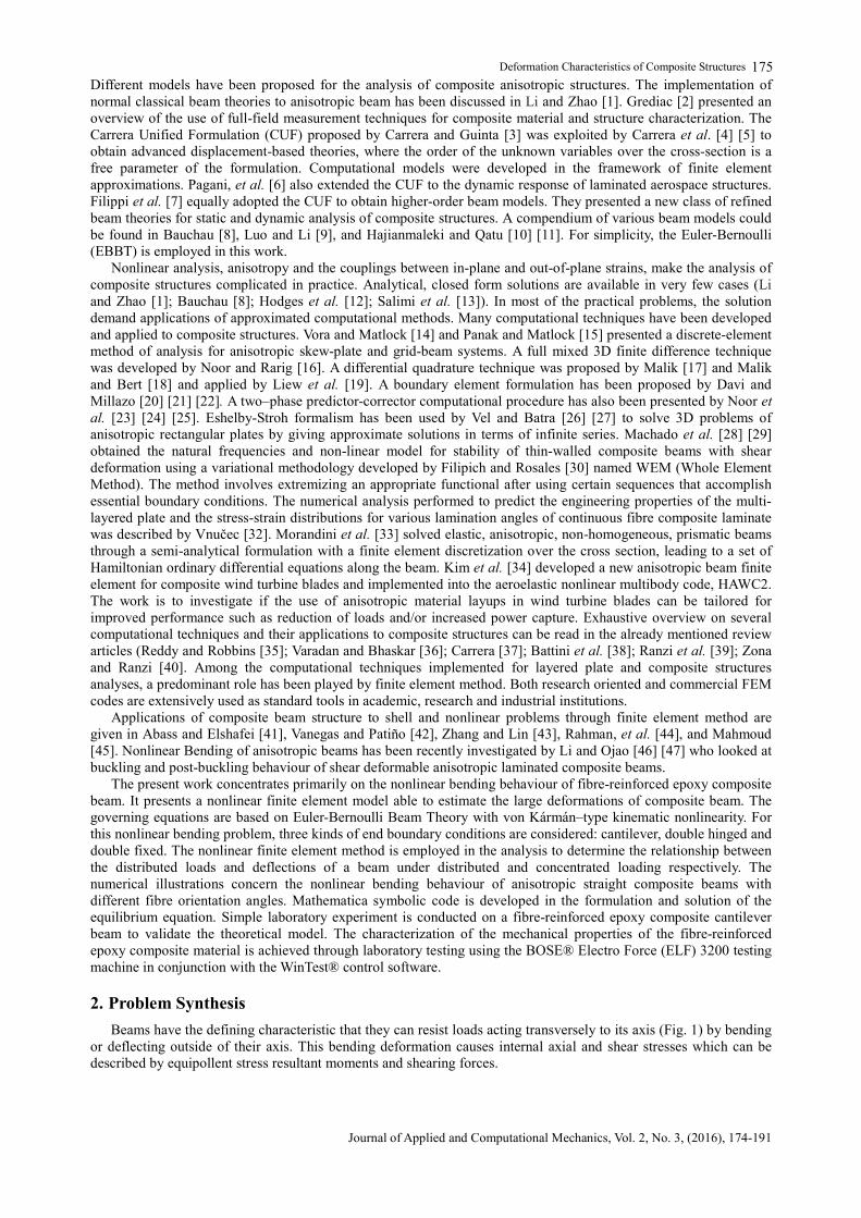
Beams have the defining characteristic that they can resist loads acting transversely to its axis (Fig. 1) by bending or deflecting outside of their axis. This bending deformation causes internal axial and shear stresses which can be described by equipollent stress resultant moments and shearing forces.
Theddeus T. Akano et al., Vol. 2, No. 3, 2016
Journal of Applied and Computational Mechanics, Vol. 2, No. 1, (2016), 174-191
176
Fig. 1. Bending of beam under distributed load
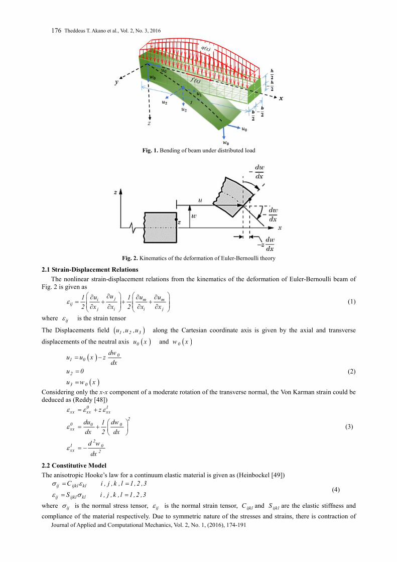
Fig. 2. Kinematics of the deformation of Euler-Bernoulli theory
2.1 Strain-Displacement Relations
The nonlinear strain-displacement relations from the kinematics of the deformation of Euler-Bernoulli beam of Fig. 2 is given as
ji m mij
j i i j
uu u u1 1
2 x x 2 x x
(1)
where ij is the strain tensor
The Displacements field 1 2 3u ,u ,u along the Cartesian coordinate axis is given by the axial and transverse
displacements of the neutral axis 0u x and 0w x
01 0
2
3 0
dwu u x z
dxu 0
u w x
(2)
Considering only the x-x component of a moderate rotation of the transverse normal, the Von Karman strain could be deduced as (Reddy [48])
0 1xx xx xx
20 0 0xx
21 0xx 2
z
du dw1
dx 2 dx
d w
dx
(3)
2.2 Constitutive Model
The anisotropic Hooke’s law for a continuum elastic material is given as (Heinbockel [49])
ij ijkl kl
ij ijkl kl
C i , j , k , l 1 ,2 ,3
S i , j , k , l 1 ,2 ,3
(4)
where ij is the normal stress tensor, ij is the normal strain tensor, ijklC and ijklS are the elastic stiffness and
compliance of the material respectively. Due to symmetric nature of the stresses and strains, there is contraction of
Deformation Characteristics of Composite Structures
Journal of Applied and Computational Mechanics, Vol. 2, No. 3, (2016), 174-191
177 notation. The generalized Hooke’s law can now be written as
i ij kl
i ij kl
C i , j 1 , 2.....6
S i , j 1 , 2.....6
(5)
If the three planes of the composite material are symmetric, it gives rise to orthotropic material model. Thus, the elasticity matrix for the orthotropic case reduces to having only nine independent compliance tensor of Eq. (5). Hence, the stress-strain relation becomes (Heinbockel [49])
1 11 12 13 1
2 22 23 2
3 33 3
4 44 4
5 55 5
6 66 6
S S S 0 0 0
S S 0 0 0
S 0 0 0
S 0 0
sym S 0
S
(6)
On the assumption that the composite material is in a simple two-dimensional state of stress (i.e. plane stress), 3 4 5 0 the planar form of Eq. (6) becomes
1 11 12 1
2 21 22 2
6 66 6
S S 0
S S 0
0 0 S
(7)
The material elastic compliance tensor ijS is related to the engineering constants by the equations (Ronald [50])
12 2111 22 12 21 66
1 2 1 2 12
1 1 1S ; S ; S S ; S
E E E E G
(8)
where 12G is the shear modulus associated with 1 - 2 plane and ij are the Poisson ratios. The composite stresses
in terms of strain tensor are given by
1 11 12 1
2 21 22 2
6 66 6
0
0
0 0
(9)
where ij are the components of the composite stiffness matrix, which are related to the compliances and the
engineering constants by (Ronald [50]))
1 12 2 211 12 21 22 66 12
12 21 12 21 12 21
E E E; ; ; G
1 1 1
(10)
The material constants ijC or ijS for a particular material are usually specified in a basis with coordinate axes
aligned with particular symmetry planes in the material (Bower [51]). When solving problems involving anisotropic materials, it is frequently necessary to transform these values to a coordinate system that is oriented in some convenient way relative to the boundaries of the solid (Bower [51]). Suppose that the components of the stiffness tensor are given in a basis 1 2 3, ,e e e , and we wish to determine its components in a second basis 1 2 3, ,m m m .
The usual transformation tensor is defined, ij with components ij i j. m e . This transformation tensor is an
orthogonal matrix satisfying T T I . The transformation of the stress, strain and elasticity tensors are in
the form (Bower [51])
ik jl ik jl ip jq pqrs kr lsij kl ij kl ijkl; ; C C m e m e m e (11)
In practice, the matrix can be computed in terms of the angles between the basis vectors. The stress-strain relation
of Eq. (11), when transformed to the boundaries of the solid x , y , z relates xx yy xy, , to strains
xx yy xy, , by (Reddy [51])
xx 11 12 16 xx
yy 21 22 26 yy
16 26 66xy xy
(12)
where ij are the components of the transformed composite stiffness matrix which are defined as
Theddeus T. Akano et al., Vol. 2, No. 3, 2016
Journal of Applied and Computational Mechanics, Vol. 2, No. 1, (2016), 174-191
178
4 4 2 211 11 22 12 66
2 2 4 412 11 22 66 12
4 4 2 222 11 22 12 66
2 316 11 22 66 22 12 66
326 11 22 66 22
cos sin 2 2 sin cos
4 sin cos cos sin
sin cos 2 2 sin cos
2 cos sin 2 cos sin
2 cos sin
312 66
2 2 4 466 11 22 12 66 66
2 cos sin
2 2 sin cos cos sin
(13)
For a uniaxial stress, Eq. (13) reduces to
xx 11 xx (14)
2.3 Principle of Virtual Work
The principle of virtual work forms the basis for the finite element method. It states that, if the stress field ij
satisfies
ij ij i i i i
R R
dV b u dV t u dA 0
(15)
for all possible virtual displacement fields and corresponding virtual strains, it will automatically satisfy the equation of stress equilibrium ij i jx b 0 and also the traction boundary condition ij j in t on (Bower
[51]). Where ib and it are the body and contact forces, while is the displacement vector. The first term is the
internal virtual work, int while the second and the third terms are the external virtual work, ext .
Since only contact forces are considered here, Eq. (15) reduces to
ij ij i i
R
dV t u dA 0
(16)
The contact forces acting on the composite beam are the transverse distributed load q x and the axial load f x
respectively. Using Eqs. (3) and (16) the principle of virtual work could be rewritten as
L 0 0 0 1 1 0 1 1xx xx xx xx xx xx xx xx xx xx xx
0 0 0
A B Ddx 0
q( x ) w f ( x ) u
(17)
where the extensional stiffness is xxA , the extensional-bending stiffness is xxB and the bending stiffness is xxD ,
given by
h b
2 2
xx 11 11h b
2 2
h b
2 22
xx 11 11h b
2 2
h b
2 22 3
xx 11 11h b
2 2
A dydz bh
1B z dydz bh
2
1D z dydz bh
3
(18)
Substituting Eq. (18) into Eq. (17), the principle of virtual work statement in normalized form becomes 2 2
0 0 0 0 0 0 02
xx xx 2220 0 00 0 0 0
2
2 20 0
2 2
d u d u dw d w d u dw d w1
d x d x 2 d x d x d x d xd xA B
d w d u dw1d w dw d u dw1d x 2 d xd xd x d x d x 2 d x
d w d w
d x d x
L
0
0 0 0 0
d x 0
q ( x ) w f ( x ) u
(19)
Deformation Characteristics of Composite Structures
Journal of Applied and Computational Mechanics, Vol. 2, No. 3, (2016), 174-191
179 where the dimensionless quantities have been introduced
0 0 0 0 0 0 0 0
3 320 0
xx xx 0 02 3 311 11
x xL ; u u L ; u u L ; w w L ; w w L ;
3q L 3 f L3 L 3 LA ; B ; q ; f
2 hh bh bh
(20)
2.4 Nonlinear Finite Element Formulation
The Galleria method is used to approximate both transverse and axial deformation variables. Hermite polynomials are used to approximate the transverse displacement 0w , while the Lagrange linear interpolation
functions are used to approximate the axial displacement 0u in order to satisfy the various boundary conditions of
the composite beam. The axial deformation 0u is approximated by a shape function given by
2
0 i i
i 1
u ( x ) u x x
(21)
where i is the Lagrange interpolation function and iu are the axial displacements in nodes 1 and 2. Similarly, the
transverse displacement is approximated by third order Hermite polynomials given by
4
0 i i
i 1
w ( x ) x x
(22)
where i is the third order Hermite polynomials and i are the generalized displacements in nodes 1 and 2. To
formulate the finite element system of equations, the expressions from 0u and 0w from Eqs. (21) and (22) are
substituted into the principle of virtual work statement. The shape functions i is substituted for 0u and i
for 0w . By substituting the variations of the two deformation approximations in Eqs. (21) and (22) into Eq. (19)
gives 2 L
jixx j
0i , j 1i i 2 ,J 4 L L 2
0 J Ji ixx xx J2
0 0i 1 ,J 1
L L 2j j0 I I
xx xx 20 0
J
ddA d x u
d x d x
u
dw d dd d1A d x B d x
2 d x d x d x d x d x
d ddw d dA d x B d x
d x d x d x d xd x
I 4 , j 2
j
I 1 , j 1
L L2 20 J JI I
4 xx xx 20 0
JL L 22 20 J JI IJ 1
xx 2 2 20 0
u
dw dd d1A d x B d x
2 d x d x d x d x d x
dw d dd d1B d x d x
2 d x d xd x d x d x
4 2L L
J j
0 0J 1 j 1
q d x f d x
(23) The above equations could be written as
11 12 1ij j iJ J i
21 22 2Ij j IJ J I
K u K F i , j 1 ,2 ; J 1 , 2 ,3 ,4
K u K F I ,J 1 ,2 ,3 ,4 ; j 1 ,2
(24)
Which forms the nonlinear equation
K U U F
with the elements of the stiffness matrix K given as
Theddeus T. Akano et al., Vol. 2, No. 3, 2016
Journal of Applied and Computational Mechanics, Vol. 2, No. 1, (2016), 174-191
180 L
j11 iij xx
0
L L 212 0 J Ji iiJ xx xx 2
0 0
L L 2j j21 0 I I
Ij xx xx 20 0
L L2 222 0 J JI IIJ xx xx 2
0 0
ddK A d x
d x d x
dw d dd d1K A d x B d x
2 d x d x d x d x d x
d ddw d dK A d x B d x
d x d x d x d xd x
dw dd d1K A d x B d x
2 d x d x d x d x d x
1B
2
L L 22 20 J JI I
xx 2 2 20 0
dw d dd dd x d x
d x d xd x d x dx
(25)
and the Residual R given as R K U F (26)
Equation (26) is to be solved with the Newton-Raphson iteration algorithm
1r 1 r r rU U T R (27)
and the tangent stiffness matrix are given as
iij
j
RT , i , j 1 ,......,6
U
(28)
3. Experiment and Test
3.1 Tensile Test
The nonlinear stress-strain behaviour of unidirectional fibre composite was examined by Jones and Morgan [53], Wang and Chung [54], two approaches were adopted. The first approach considers the stress-strain as nonlinear elastic relations, which are derived at through the use of a complementary energy density function and takes into account the material symmetry.
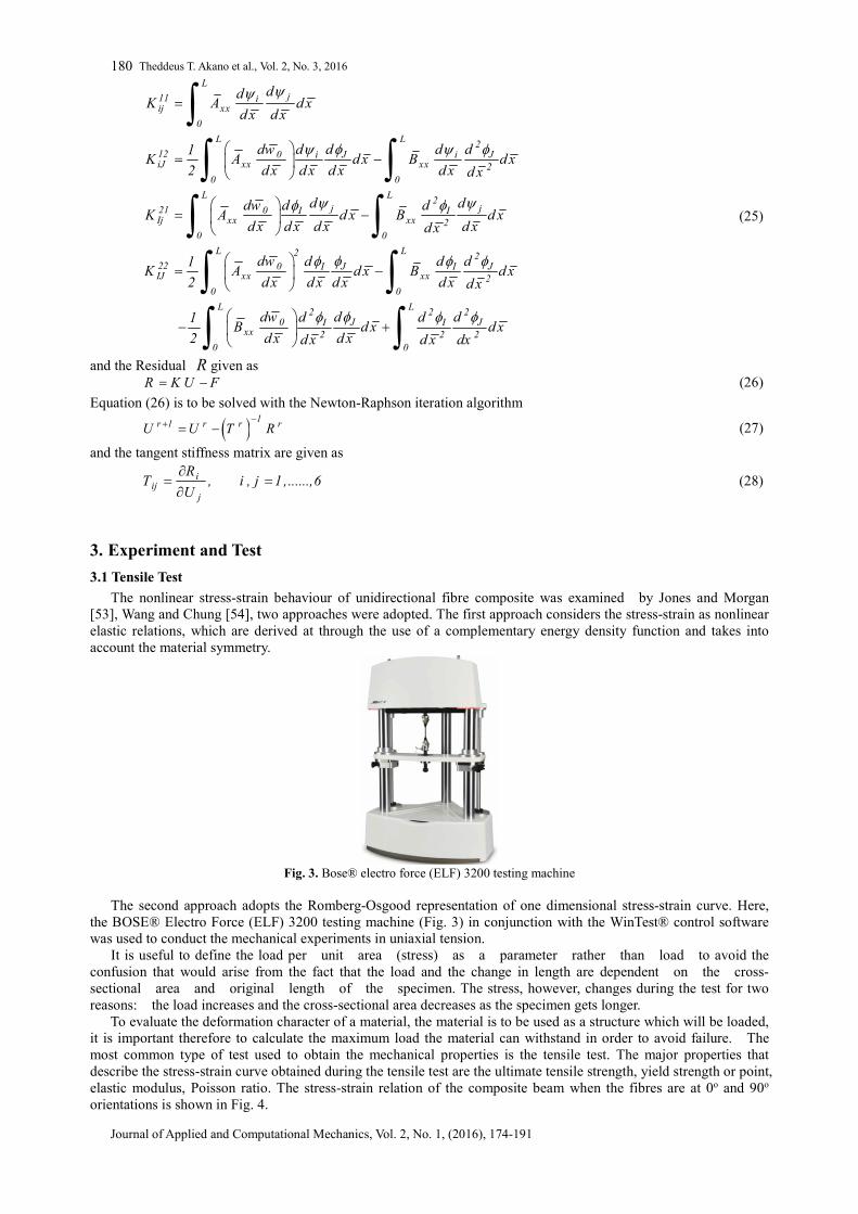
Fig. 3. Bose® electro force (ELF) 3200 testing machine
The second approach adopts the Romberg-Osgood representation of one dimensional stress-strain curve. Here,
the BOSE® Electro Force (ELF) 3200 testing machine (Fig. 3) in conjunction with the WinTest® control software was used to conduct the mechanical experiments in uniaxial tension.
It is useful to define the load per unit area (stress) as a parameter rather than load to avoid the confusion that would arise from the fact that the load and the change in length are dependent on the cross-sectional area and original length of the specimen. The stress, however, changes during the test for two reasons: the load increases and the cross-sectional area decreases as the specimen gets longer.
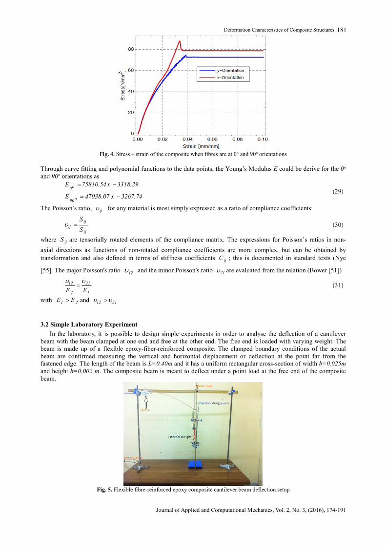
To evaluate the deformation character of a material, the material is to be used as a structure which will be loaded, it is important therefore to calculate the maximum load the material can withstand in order to avoid failure. The most common type of test used to obtain the mechanical properties is the tensile test. The major properties that describe the stress-strain curve obtained during the tensile test are the ultimate tensile strength, yield strength or point, elastic modulus, Poisson ratio. The stress-strain relation of the composite beam when the fibres are at 0o and 90o orientations is shown in Fig. 4.
Deformation Characteristics of Composite Structures
Journal of Applied and Computational Mechanics, Vol. 2, No. 3, (2016), 174-191
181
Fig. 4. Stress – strain of the composite when fibres are at 0o and 90o orientations
Through curve fitting and polynomial functions to the data points, the Young’s Modulus E could be derive for the 0o and 90o orientations as
o0
o90
E 75810.54 x 3318.29
E 47038.07 x 3267.74
(29)
The Poisson’s ratio, ij for any material is most simply expressed as a ratio of compliance coefficients:
ijij
ii
S
S (30)
where ijS are tensorially rotated elements of the compliance matrix. The expressions for Poisson’s ratios in non-
axial directions as functions of non-rotated compliance coefficients are more complex, but can be obtained by transformation and also defined in terms of stiffness coefficients ijC ; this is documented in standard texts (Nye
[55]. The major Poisson's ratio 12 and the minor Poisson's ratio 21 are evaluated from the relation (Bower [51])
12 21
2 1E E
(31)
with 1 2E E and 12 21
3.2 Simple Laboratory Experiment
In the laboratory, it is possible to design simple experiments in order to analyse the deflection of a cantilever beam with the beam clamped at one end and free at the other end. The free end is loaded with varying weight. The beam is made up of a flexible epoxy-fiber-reinforced composite. The clamped boundary conditions of the actual beam are confirmed measuring the vertical and horizontal displacement or deflection at the point far from the fastened edge. The length of the beam is L=0.40m and it has a uniform rectangular cross-section of width b=0.025m and height h=0.002 m. The composite beam is meant to deflect under a point load at the free end of the composite beam.
Fig. 5. Flexible fibre-reinforced epoxy composite cantilever beam deflection setup
Theddeus T. Akano et al., Vol. 2, No. 3, 2016
Journal of Applied and Computational Mechanics, Vol. 2, No. 1, (2016), 174-191
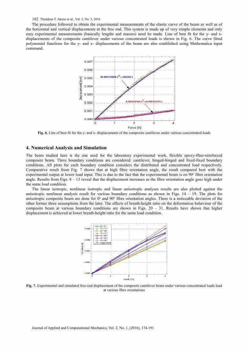
182 The procedure followed to obtain the experimental measurements of the elastic curve of the beam as well as of
the horizontal and vertical displacements at the free end. This system is made up of very simple elements and only easy experimental measurements (basically lengths and masses) need be made. Line of best fit for the y- and x- displacements of the composite cantilever under various concentrated loads is shown in Fig. 6. The curve fitted polynomial functions for the y- and x- displacements of the beam are also established using Mathematica input command.
Fig. 6. Line of best fit for the y- and x- displacements of the composite cantilever under various concentrated loads
4. Numerical Analysis and Simulation
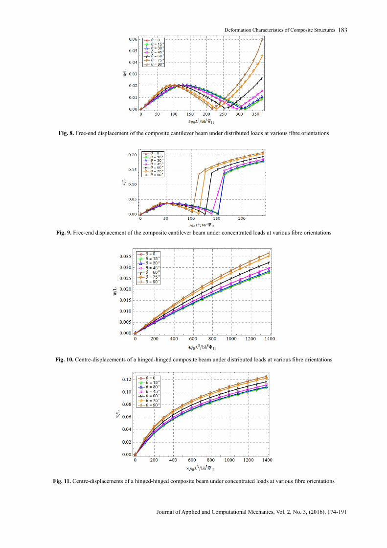
The beam studied here is the one used for the laboratory experimental work, flexible epoxy-fiber-reinforced composite beam. Three boundary conditions are considered: cantilever, hinged-hinged and fixed-fixed boundary conditions. All plots for each boundary condition considers the distributed and concentrated load respectively. Comparative result from Fig. 7 shows that at high fibre orientation angle, the result compared best with the experimental output at lower load input. This is due to the fact that the experimental beam is on 90o fibre orientation angle. Results from Figs. 8 – 13 reveal that the displacement increases as the fibre orientation angle goes high under the same load condition.
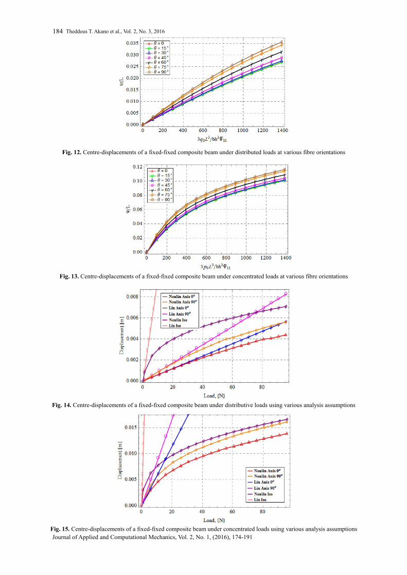
The linear isotropic, nonlinear isotropic and linear anisotropic analyses results are also plotted against the anisotropic nonlinear analysis result for various boundary conditions as shown in Figs. 14 – 19. The plots for anisotropic composite beam are done for 0o and 90o fibre orientation angles. There is a noticeable deviation of the other former three assumptions from the later. The effects of breath-height ratio on the deformation behaviour of the composite beam at various boundary conditions are shown in Figs. 20 – 31. Results have shown that higher displacement is achieved at lower breath-height ratio for the same load condition.
Fig. 7. Experimental and simulated free-end displacement of the composite cantilever beam under various concentrated loads load at various fibre orientations
Deformation Characteristics of Composite Structures
Journal of Applied and Computational Mechanics, Vol. 2, No. 3, (2016), 174-191
183
Fig. 8. Free-end displacement of the composite cantilever beam under distributed loads at various fibre orientations
Fig. 9. Free-end displacement of the composite cantilever beam under concentrated loads at various fibre orientations
Fig. 10. Centre-displacements of a hinged-hinged composite beam under distributed loads at various fibre orientations
Fig. 11. Centre-displacements of a hinged-hinged composite beam under concentrated loads at various fibre orientations
Theddeus T. Akano et al., Vol. 2, No. 3, 2016
Journal of Applied and Computational Mechanics, Vol. 2, No. 1, (2016), 174-191
184
Fig. 12. Centre-displacements of a fixed-fixed composite beam under distributed loads at various fibre orientations
Fig. 13. Centre-displacements of a fixed-fixed composite beam under concentrated loads at various fibre orientations
Fig. 14. Centre-displacements of a fixed-fixed composite beam under distributive loads using various analysis assumptions
Fig. 15. Centre-displacements of a fixed-fixed composite beam under concentrated loads using various analysis assumptions
Deformation Characteristics of Composite Structures
Journal of Applied and Computational Mechanics, Vol. 2, No. 3, (2016), 174-191
185
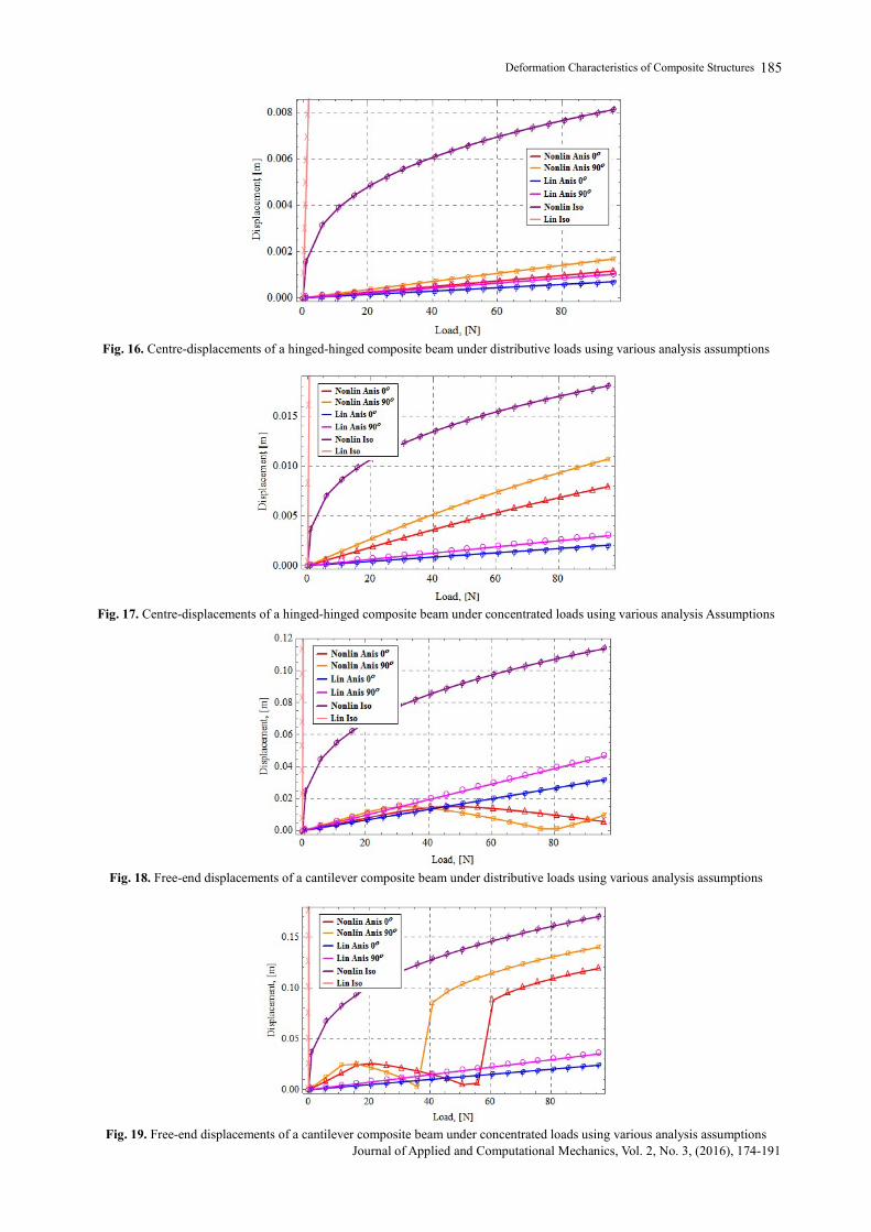
Fig. 16. Centre-displacements of a hinged-hinged composite beam under distributive loads using various analysis assumptions
Fig. 17. Centre-displacements of a hinged-hinged composite beam under concentrated loads using various analysis Assumptions
Fig. 18. Free-end displacements of a cantilever composite beam under distributive loads using various analysis assumptions
Fig. 19. Free-end displacements of a cantilever composite beam under concentrated loads using various analysis assumptions
Theddeus T. Akano et al., Vol. 2, No. 3, 2016
Journal of Applied and Computational Mechanics, Vol. 2, No. 1, (2016), 174-191
186
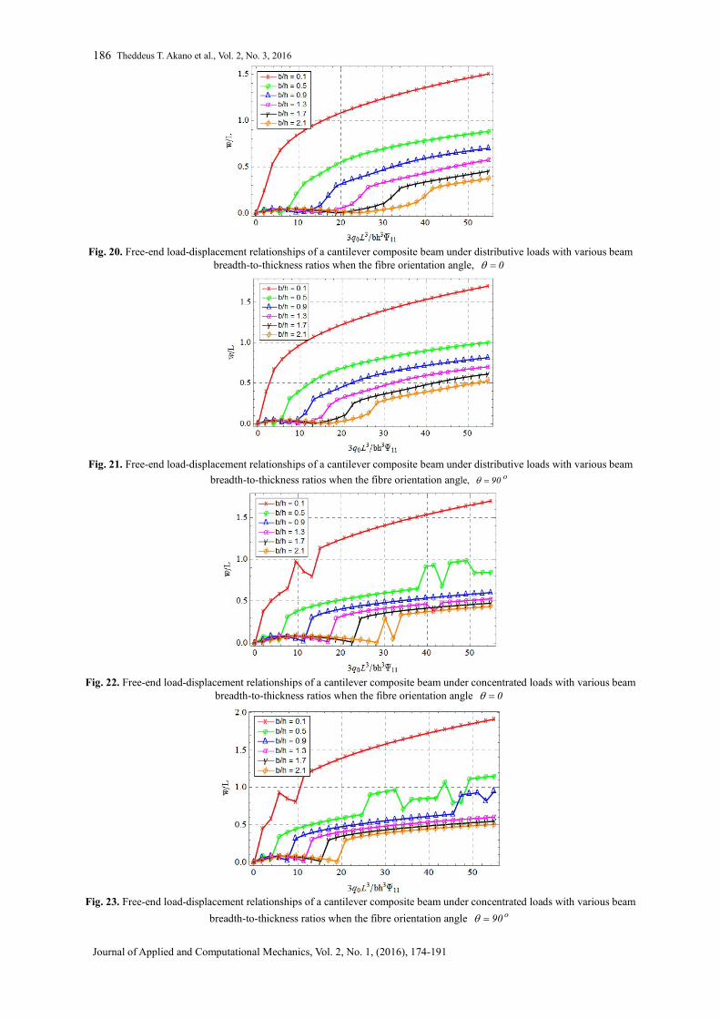
Fig. 20. Free-end load-displacement relationships of a cantilever composite beam under distributive loads with various beam
breadth-to-thickness ratios when the fibre orientation angle, 0
Fig. 21. Free-end load-displacement relationships of a cantilever composite beam under distributive loads with various beam
breadth-to-thickness ratios when the fibre orientation angle, o90
Fig. 22. Free-end load-displacement relationships of a cantilever composite beam under concentrated loads with various beam
breadth-to-thickness ratios when the fibre orientation angle 0
Fig. 23. Free-end load-displacement relationships of a cantilever composite beam under concentrated loads with various beam
breadth-to-thickness ratios when the fibre orientation angle o90
Deformation Characteristics of Composite Structures
Journal of Applied and Computational Mechanics, Vol. 2, No. 3, (2016), 174-191
187
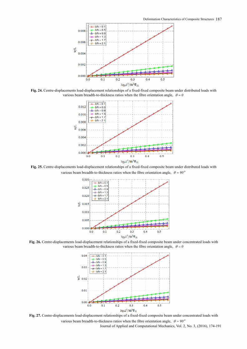
Fig. 24. Centre-displacements load-displacement relationships of a fixed-fixed composite beam under distributed loads with
various beam breadth-to-thickness ratios when the fibre orientation angle, 0
Fig. 25. Centre-displacements load-displacement relationships of a fixed-fixed composite beam under distributed loads with
various beam breadth-to-thickness ratios when the fibre orientation angle, o90
Fig. 26. Centre-displacements load-displacement relationships of a fixed-fixed composite beam under concentrated loads with
various beam breadth-to-thickness ratios when the fibre orientation angle, 0
Fig. 27. Centre-displacements load-displacement relationships of a fixed-fixed composite beam under concentrated loads with
various beam breadth-to-thickness ratios when the fibre orientation angle, o90
Theddeus T. Akano et al., Vol. 2, No. 3, 2016
Journal of Applied and Computational Mechanics, Vol. 2, No. 1, (2016), 174-191
188
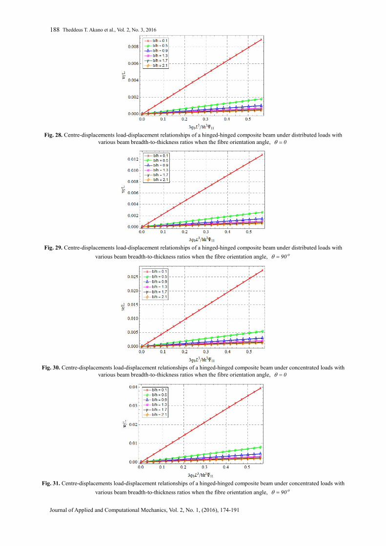
Fig. 28. Centre-displacements load-displacement relationships of a hinged-hinged composite beam under distributed loads with
various beam breadth-to-thickness ratios when the fibre orientation angle, 0
Fig. 29. Centre-displacements load-displacement relationships of a hinged-hinged composite beam under distributed loads with
various beam breadth-to-thickness ratios when the fibre orientation angle, o90
Fig. 30. Centre-displacements load-displacement relationships of a hinged-hinged composite beam under concentrated loads with
various beam breadth-to-thickness ratios when the fibre orientation angle, 0
Fig. 31. Centre-displacements load-displacement relationships of a hinged-hinged composite beam under concentrated loads with
various beam breadth-to-thickness ratios when the fibre orientation angle, o90
Deformation Characteristics of Composite Structures
Journal of Applied and Computational Mechanics, Vol. 2, No. 3, (2016), 174-191
189
4. Discussion
In this paper, the deformation characteristics of composite structures are investigated. The stress-strain characteristics of two types of tested composite bars are shown in Fig. 4. The elastic range of the materials are illustrated to be nonlinear, but after the ultimate stresses (around 0.033 for x-orientation and 0.0375 for the y-orientation), the materials continue straining at slightly dropped constant stress values. In Figs. 6 and 7, parabolic curves are displayed by the displacements against concentrated loads for the x- and y- material orientations. A wide range of turning point in each case produces attainable lines of best fit. However, as various orientations are considered, distinct linear configurations are achieved when compared with the experimental results as described by Fig. 7.
On using distributive loads for various fibre orientations, the free-ends displacements of the composite cantilever beams are parabolic functions of the distributive loads within the observed ranges of loadings in Figs. 8 and 9, though further loading causes geometric increase in the displacements. As the orientation angle increases, the value of the range of loadings forming the parabolas decreases. As demonstrated, the centre-displacement for a hinged composite beam against the distributed load can be approximated to a linear relation than that for concentrated loadings for the same range of loads (Fig. 11). However, as the orientation angles increase, the slope of the curves increases. Figs. 12 and 13 describe similar characteristics. Figure 14 illustrates linear relationship of the distributive loads to displacements for the shown various fibre orientations, except for the case of nonlinear isotropic material which is remarkably parabolic for the loading ranges considered. However, with concentrated loads, all nonlinear fibre orientations relates parabolically while all linear orientations relate linearly.
For the hinge-hinged composite beam illustrated by Figs. 16 and 17, identical characteristics are displayed for both distributive and concentrated loads against displacement. In each case, only nonlinear isotropic materials are parabolic. However, all other materials are linear. The free-end displacement of cantilever composite beam is shown in Fig. 18 under distributive load and Fig. 19 under concentrated load. All nonlinear fibre orientations are displaying parabolic relationships for the shown loading ranges while all linear orientations are linearly related.
Figure 20 demonstrates that with distributive loadings, increasing the breath-to-thickness ratios decreases the
deformation of the material with o0 fibre orientation, and similar profiles are demonstrated by Fig. 21 with o90 fibre orientation. As observed in o0 fibre orientation in Fig. 22 and o90 fibre orientation in Fig. 23, increasing
the values of breath-to-thickness ratios causes decrease in deformation of the material when concentrated loads are applied.
The centre-displacement relations for the various breath-to-thickness ratios are shown with fixed-fixed composite
beam under distributed loads, o0 fibre orientation (Fig. 24) and o90 fibre orientation (Fig. 25); fixed-fixed
composite beam under concentrated loads, o0 fibre orientation (Fig. 26) and o90 fibre orientation (Fig. 27); hinged-
hinged beam under distributed, o0 fibre orientation (Fig. 28) and o90 fibre orientation (Fig. 29); hinged-hinged
beam under concentrated loads, o0 fibre orientation (Fig. 30) and o90 fibre orientation (Fig. 31). All these cases display linear load-deformation characteristics.
5. Conclusion A nonlinear finite element model to estimate the large deformations of composite beams is presented. The constitutive model employed in this work has captured the anisotropic and nonlinear behaviour of fibre-reinforced epoxy composite beam. The nonlinear anisotropic analysis of the composite beam material is much more mechanically realistic. This could be seen from the nonlinear behaviour of the load-displacement graph. To highlight these comparisons, a number of analyses are performed in this study using finite element model. Satisfactory accuracy is achieved when the model and experimental results are compared. Different scenarios are painted. Results reveal that composite fibre orientation; type of applied load and boundary condition affect the deformation characteristics of composite structures.
Nomenclature
ij Strain tensor ij Normal strain tensor
1 2 3u ,u ,u Displacements field
ijklC Material elastic stiffness
ij Normal stress tensor
ijklS Material elastic compliance
ij Poisson ratios
xxB Extensional-bending stiffness
xxA Extensional stiffness
xxD Bending stiffness
Theddeus T. Akano et al., Vol. 2, No. 3, 2016
Journal of Applied and Computational Mechanics, Vol. 2, No. 1, (2016), 174-191
190
References
[1] Li, Zhi-Min, and Yi-Xi Zhao. "Nonlinear Bending of Shear Deformable Anisotropic Laminated Beams Resting on Two-Parameter Elastic Foundations Based on an Exact Bending Curvature Model." Journal of Engineering Mechanics 141.3, 04014125, 2014. [2] Grediac, M., “The use of full-field measurement methods in composite material characterization: interest and limitations”, Composites Part A: applied science and manufacturing, Vol. 5, No. 7, pp. 751-761, 2004. [3] Carrera, E., & Giunta, G., Refined beam theories based on a unified formulation. International Journal of Applied Mechanics, Vol. 2, No. 1, pp. 117-143, 2010. [4] Carrera, E., Maiarú, M., & Petrolo, M., “Component-wise analysis of laminated anisotropic composites”, International Journal of Solids and Structures, Vol. 49, No. 13, pp. 1839-1851, 2012. [5] Carrera, E., Giunta, G., & Petrolo, M., “Carrera Unified Formulation and Refined Beam Theories”, Beam Structures: Classical and Advanced Theories, pp. 45-63, 2011. [6] Pagani, A., Petrolo, M., Colonna, G., & Carrera, E., ” Dynamic response of aerospace structures by means of refined beam theories. Aerospace Science and Technology, Vol. 46, pp. 360-373, 2015. [7] Filippi, M., Pagani, A., Petrolo, M., Colonna, G., & Carrera, E., “Static and free vibration analysis of laminated beams by refined theory based on Chebyshev polynomials”, Composite Structures, Vol. 132, pp. 1248-1259, 2015. [8] Bauchau, O. A., & Hong, C. H., “Nonlinear composite beam theory”, Journal of Applied Mechanics, Vol. 55 No. 1, pp. 156-163, 1988. [9] Luo, J. H., Li, L. J., “Theory of elasticity of an anisotropic body for the bending of beams”, Applied Mathematics and Mechanics, Vol. 13, No. 11, pp. 1031-1037, 1992. [10] Hajianmaleki, M., and Qatu, M. S., “A rigorous beam model for static and vibration analysis of generally laminated composite thick beams and shafts.” Int. J. Veh. Noise Vib., Vol. 8. No. 2, pp. 166–184, 2012. [11] Hajianmaleki, M., and Qatu, M. S., “Vibrations of straight and curved composite beams: A review.” Compos. Struct., 100 (Jun), pp. 218–232, 2013. [12] Hodges, D. H., Atilgan, A. R., Cesnik, C. E., & Fulton, M. V., “On a simplified strain energy function for geometrically nonlinear behaviour of anisotropic beams”, Composites Engineering, Vol. 2, No. 5, pp. 513-526, 1992. [13] Salimi, M., Jamshidian, M., Beheshti, A., & Dolatabadi, A. S., “Bending-Unbending Analysis of Anisotropic Sheet under Plane Strain Condition”, Esteghlal Journal of Engineering, Vol. 26, No. 2, pp. 187-196, 2008. [14] Vora, M. R., Matlock, H., “A discrete-element analysis for anisotropic skew plates and grids”, Ph.D Thesis, University of Texas at Austin, 1970. [15] Panak, J. J., Matlock, H., “A Discrete-Element Method of Analysis for Orthogonal Slab and Grid Bridge Floor Systems, No. 56-25 Res Rpt, Center for Highway Research, University of Texas at Austin, 1972. [16] Noor, A. K., Rarig, P. L., “Three-dimensional solutions of laminated cylinders”, Computer Methods in Applied Mechanics and Engineering, Vol. 3, No. 3, pp. 319-334, 1974. [17] Malik, M., “Differential quadrature method in computational mechanics: new development and applications”, Ph.D. Dissertation, University of Oklahoma, Oklahoma, 1994. [18] Malik, M., Bert, C. W., “Differential quadrature analysis of free vibration of symmetric cross-ply laminates with shear deformation and rotatory inertia”, Shock and Vibration, Vol. 2, No. 4, pp.321-338, 1995. [19] Liew, K. M., Han, J. B., Xiao, Z. M., “Differential quadrature method for thick symmetric cross-ply laminates with first-order shear flexibility”, International Journal of Solids and Structures, Vol. 33, No. 18, pp. 2647-2658, 1996. [20] Davi, G., “Stress fields in general composite laminates”, AIAA journal, Vol. 34, No. 12, pp. 2604-2608, 1996. [21] Davı̀, G., Milazzo, A., “Bending stress fields in composite laminate beams by a boundary integral formulation”, Computers & structures, Vol. 71, No. 3, pp. 267-276, 1999. [22] Milazzo, A., “Interlaminar stresses in laminated composite beam-type structures under shear/bending”, AIAA journal, Vol. 38, No. 4, pp. 687-694, 2000. [23] Noor, A. K., Burton, W. S., “Stress and free vibration analyses of multi-layered composite plates”, Composite Structures, Vol. 11, No. 3, pp. 183-204, 1989. [24] Noor, A. K., Peters, J. M., “A posteriori estimates for the shear correction factors in multi-layered composite cylinders”, Journal of engineering mechanics, Vol. 115, No. 6, pp. 1225-1244, 1989. [25] Noor, A. K., Burton, W. S., Peters, J. M., “Predictor-corrector procedures for stress and free vibration analyses of multilayered composite plates and shells”, Computer Methods in Applied Mechanics and Engineering, Vol. 82, No. 1, pp. 341-363, 1990. [26] Vel, S. S., Batra, R. C., “Analytical solution for rectangular thick laminated plates subjected to arbitrary boundary conditions”, AIAA journal, Vol. 37, No. 11, pp. 1464-1473. 1999. [27] Vel, S. S., Batra, R. C., “The generalized plane strain deformations of thick anisotropic composite laminated plates”, International Journal of Solids and Structures, Vol. 37, No. 5, pp. 715-733, 2000. [28] Machado, S. P., Filipich, C. P. Rosales, M. B., “Plane Anisotropic Beams with Shear Deformation via a Generalized Solution”, Santa Fe-Paraná, Argentina, October 2002, S. R. Idelsohn, V. E. Sonzogni and A. Cardona (Eds.), Mecánica Computational, Vol. 20, pp. 775-785, 2000. [29] Machado, S. P., Cortínez, V. H., “Non-linear model for stability of thin-walled composite beams with shear deformation”, Thin-Walled Structures, Vol. 43, No. 10, pp. 1615-1645. 2005.
Deformation Characteristics of Composite Structures
Journal of Applied and Computational Mechanics, Vol. 2, No. 3, (2016), 174-191
191 [30] Filipich, C. P., Rosales, M. B., “Arbitrary precision frequencies of a free rectangular thin plate”, Journal of Sound and Vibration, Vol. 230, No. 3, pp. 521-539, 2000. [31] Rosales, M. B., Filipich, C. P., “Time integration of non-linear dynamic equations by means of a direct variational method”, Journal of sound and vibration, Vol. 254, No. 4, pp. 763-775, 2002. [32] Vnučec, Z., “Analysis of the Laminated Composite Plate under Combined Loads”, Analysis, Vol. 2, No. 2, 2005. [33] Morandini, M., Chierichetti, M., Mantegazza, P., “Characteristic behaviour of prismatic anisotropic beam via generalized eigenvectors”, International Journal of Solids and Structures, Vol. 47, No. 10, pp. 1327-1337, 2010. [34] Kim, T., Hansen, A. M., Branner, K., “Development of an anisotropic beam finite element for composite wind turbine blades in multibody system”, Renewable Energy, Vol. 59, pp. 172-183, 2013. [35] Reddy, J. N., & Robbins, D. H., “Theories and computational models for composite laminates”, Applied mechanics reviews, Vol. 47, No. 6, pp. 147-169, 1994. [36] Varadan, T. K., Bhaskar, K., “Review of different laminate theories for the analysis of composites”, Journal-Aeronautical Society of India, Vol. 49, pp. 202-208, 1997. [37] Carrera, E., “An assessment of mixed and classical theories for the thermal stress analysis of orthotropic multilayered plates. Journal of Thermal Stresses, Vol. 23, No. 9, pp. 797-831, 2000. [38] Battini, J. M., Nguyen, Q. H., Hjiaj, M., “Non-linear finite element analysis of composite beams with interlayer slips”, Computers and structures, Vol. 87, No. 13, pp. 904-912, 2009. [39] Ranzi, G., Dall’Asta, A., Ragni, L., Zona, A., “A geometric nonlinear model for composite beams with partial interaction”, Engineering Structures, Vol. 32, No. 5, pp. 1384-1396, 2010. [40] Zona, A., Ranzi, G., “Finite element models for nonlinear analysis of steel–concrete composite beams with partial interaction in combined bending and shear”, Finite Elements in Analysis and Design, Vol. 47, No. 2, pp. 98-118, 2011. [41] Abass, M. K., Elshafei, M. A., “Linear and Nonlinear Finite Element Modelling of Advanced Isotropic and Anisotropic Beams Part I: Euler Bernoulli Theory”, 13th International conference on aerospace sciences & aviation technology, Cairo, Egypt, 2009. [42] Vanegas, J. D., Patiño, I. D., “Linear and Non-Linear Finite Element Analysis of Shear-Corrected Composites Box Beams”, Latin American Journal of Solids and Structures, Vol. 10, No. 4, pp. 647-673, 2013. [43] Zhang, Y., and Lin, X., “Nonlinear finite element analyses of steel/FRP-reinforced concrete beams by using a novel composite beam element”, Advances in Structural Engineering, Vol. 16, No. 2, pp. 339-352, 2013. [44] Rahman, M., Aktaruzzaman, F. N. U., Absar, S., Mitra, A., Hossain, A., “Finite Element Analysis of Polyurethane Based Composite Shafts Under Different Boundary Conditions”, In ASME 2014 International Mechanical Engineering Congress and Exposition (pp. V010T13A014-V010T13A014). American Society of Mechanical Engineers, 2014. [45] Mahmoud, A. M., “Finite element modeling of steel concrete beam considering double composite action”, Ain Shams Engineering Journal, 2015. [46] Li, Z. M., Qiao, P., “Buckling and postbuckling behaviour of shear deformable anisotropic laminated beams with initial geometric imperfections subjected to axial compression”, Engineering Structures, Vol. 85, pp. 277-292, 2015. [47] Li, Z. M., Qiao, P., Thermal postbuckling analysis of anisotropic laminated beams with different boundary conditions resting on two-parameter elastic foundations”, European Journal of Mechanics-A/Solids, Vol. 54, pp. 30-43, 2015. [48] Reddy, J. N., “An Introduction to Nonlinear Finite Element Analysis: with applications to heat transfer, fluid mechanics, and solid mechanics”, OUP Oxford, 2014. [49] Heinbockel, J. H., Introduction to tensor calculus and continuum mechanics, Vol. 52. 2001. [50] Gibson, Ronald F., “A simplified analysis of deflections in shear deformable composite sandwich beams”, Journal of sandwich structures and materials, Vol. 13, No. 5, pp. 579-588, 2011. [51] Bower, A. F., Applied mechanics of solids. CRC press, 2010. [52] Reddy, J. N., Mechanics of laminated composite plates and shells: theory and analysis. CRC press, 2004. [53] Jones, R. M., Morgan, H. S., “Analysis of Nonlinear Stress-Strain Behaviour of Fiber-Reinforced Composite Materials”, AIAA Journal, Vol. 15, No. 12, pp. 1669-1676, 1997. [54] Wang, X., Chung, D. D. L., “Continuous carbon fibre epoxy-matrix composite as a sensor of its own strain”, Smart materials and structures, Vol. 5, No. 6, 796, 1996. [55] Nye, J. F., “Physical properties of crystals: their representation by tensors and matrices”, Oxford university press, 1985.
Related Documents