Deflection of Beam Ankit Saxena ([email protected])

Welcome message from author
This document is posted to help you gain knowledge. Please leave a comment to let me know what you think about it! Share it to your friends and learn new things together.
Transcript


Beam Differential Equation
Elastic
Curve PQ
d
R
ds
dx
dyds
Where dx and dy represent the projected lengths of the segment ds along X
and Y axes.
Ankit Saxena ([email protected])

Ankit Saxena ([email protected])
22
2
22
2
3 2
2
32 22
2
.....................................(1)
tan .....................................(2)
. .
sec .
1sec . .
sec
1 tan
ArcAngle
Radius
dsd
R
dy
dx
differenting w r t x
d d y
dx dx
ds d y
R dx dx
d y
R dx
d y
dx R

Ankit Saxena ([email protected])
2
2
2
2
1d y M
dx R EI
d yEI M
dx
Note :-
1) The above equation is the governing differential equation of the beam.
2) we only take the effect of bending moment. The effect of shear on the deflection
is extremely small and usually neglected.
3) EI is an index which is known as flexural strength of an element.
Ankit Saxena ([email protected])
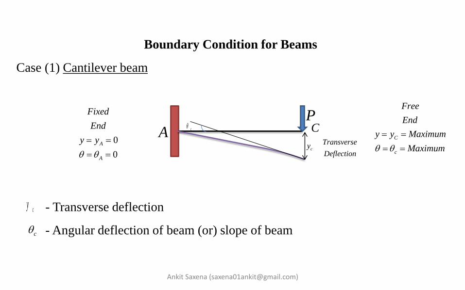
Boundary Condition for Beams
Case (1) Cantilever beam
- Transverse deflection
- Angular deflection of beam (or) slope of beam
AP
c
cyTransverse
Deflection
cy
c CC
c
Free
End
y y Maximum
Maximum
0
0
A
A
Fixed
End
y y

Ankit Saxena ([email protected])
Cantilever beam concentrated load at free end
A
P
C
x
x
x
2
2
2
2
x x
x x
d yEI M
dx
M Px
d yEI Px
dx
Integrating w.r.t 'x' 2
12
,
0
dy PxEI C
dx
at x L
dy
dx
L

Ankit Saxena ([email protected])
2
2
2 2
102
2
2 2
PLC
PLC
dy Px PLEI
dx
Again integrating w.r.t 'x' 3 2
3 3
3
3 2 3
2
2
2
.6 2
,
0
06 2
3
.6 2 3
Px PL xEI y C
at x L
y
PL PLC
PLC
Px PL x PLEI y

Ankit Saxena ([email protected])
Note
3 2 3
.6 2 3
Px PL x PLEI y
1. The magnitude of the slope curve is slope of deflection curve.
2. The slope of slope curve is magnitude of bending moment.
3
max 0
2
max 0
3
2
C x
C xMax
PLy y
EI
dy PL
dx EI


Ankit Saxena ([email protected])
Case (2) Cantilever Beam concentrated Load not at free end
A
P
C
cy
c
cyB
B
CM
By
L
a

Ankit Saxena ([email protected])
Case (3) Cantilever beam subjected to uniformly distributed load on whole span
length
A
L
/W N m
B
4
max 0
3
max 0
8
6
B x
B xMax
WLy y
EI
dy WL
dx EI

Ankit Saxena ([email protected])
Case (4) Cantilever beam subjected to uniformly distributed load on a part of
span length
A
L
/W N m
B
a
4 34 .
8 8 6
W L a W L a aWLy
EI EI EI

Ankit Saxena ([email protected])
Case (5) Cantilever beam subjected to a couple at the free end.
A
L
B
M
2
max 0
max 0
2B x
B xMax
MLy y
EI
dy ML
dx EI
Ankit Saxena ([email protected])
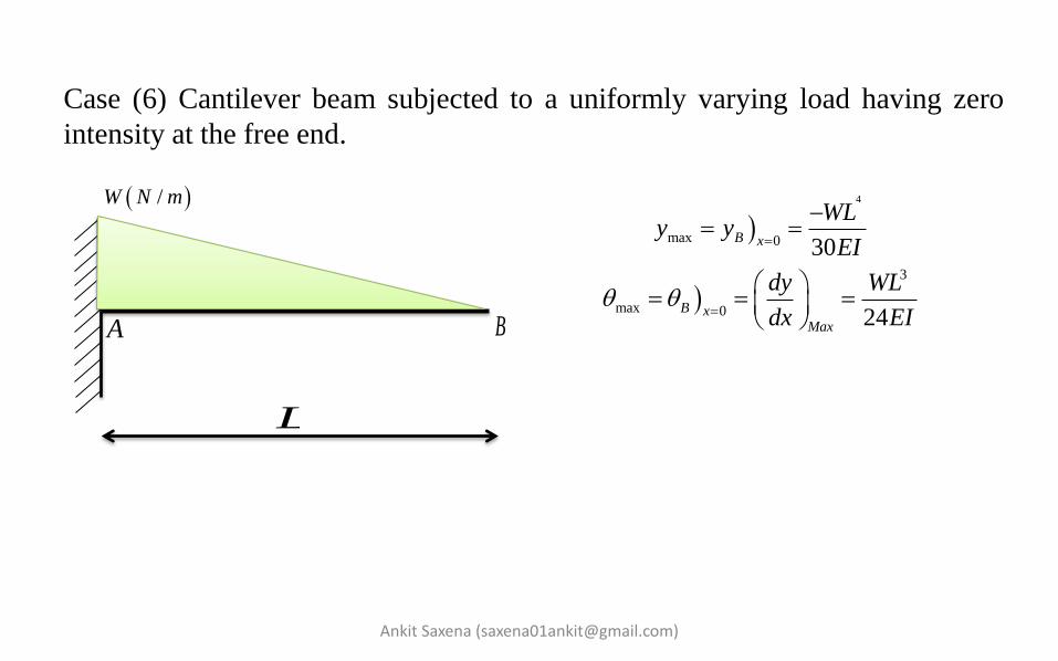
Case (6) Cantilever beam subjected to a uniformly varying load having zero
intensity at the free end.
A
L
B
/W N m
4
max 0
3
max 0
30
24
B x
B xMax
WLy y
EI
dy WL
dx EI

Ankit Saxena ([email protected])
Case (7) Cantilever beam subjected to a uniformly varying load having zero
intensity at the fixed end.
A
L
B
/W N m

Symmetry in Bending moment diagram
1. Maximum deflection occurs at the centre or mid point of the beam axis.
2. At the mid point, point C [slope = 0]
3. At supports (A & B)
Ankit Saxena ([email protected])
2
0
Max
Lx
y y
dy
dx
0
Max
y
dy
dx

No symmetry in Bending moment diagram
1. Maximum deflection occurs in a region between point of application of
load and mid point.
2. The maximum slope is occurred at that support which is nearer to the line
of action of force.
Ankit Saxena ([email protected])

Ankit Saxena ([email protected])
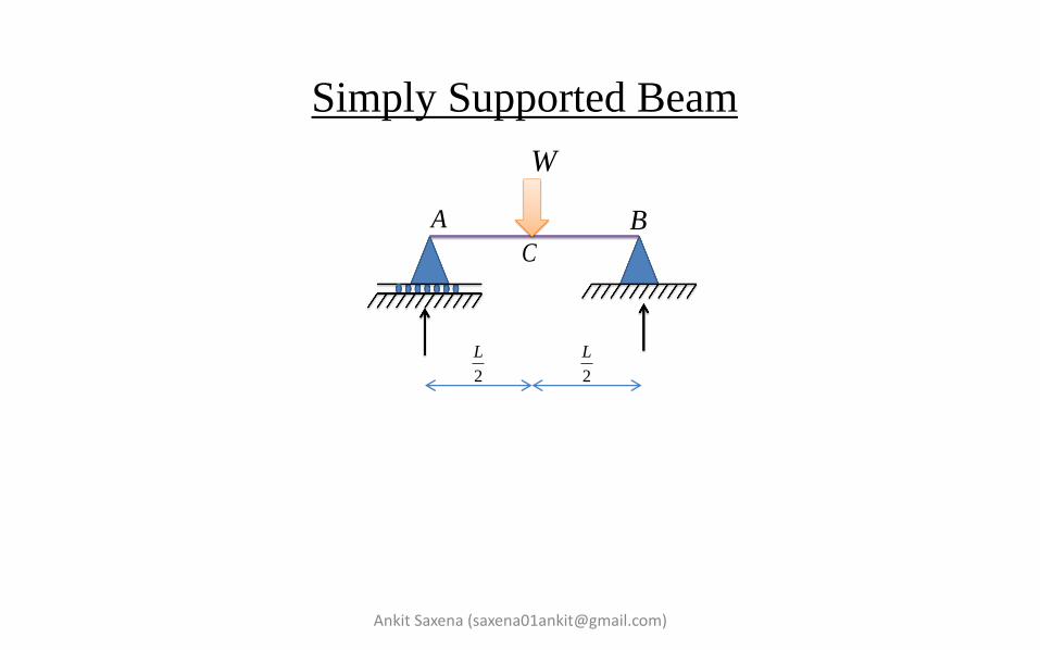
Case 1. Simply Supported beam subjected to a point load at mid span
A B
2
L
2
L
Cx
x2
A
WR
2B
WR
Bending Equation for the section BC On Integration w.r.t 'x' Again integrating w.r.t 'x'
2
2
2
2
x x
WxM
d y WxEI
dx
2
1.....................(1)4
dy WxEI C
dx
3
1 2. .............(2)12
WxEI y C x C
Wx

Ankit Saxena ([email protected])
2
1
3
1 2
.....................(1)4
. .............(2)12
dy WxEI C
dx
WxEI y C x C
Apply boundary condition, At From equation (2) From equation (1) Substitute the value of C1 & C2 in equation (1) & (2)
, 02
&
0 / , 0
L dyx
dx
x L y
2 0C
2
116
WLC

Ankit Saxena ([email protected])
2 2
3 2
.....................(3)4 16
. ...................(4)12 16
dy Wx WLEI
dx
Wx WL xEI y
For maximum deflection and slope
3
max2
2
max 0
48
16
LC x
B Ax x LMax
WLy y
EI
dy WL
dx EI

Ankit Saxena ([email protected])
Home Work
4
max2
3
max 0
5
384
24
LC x
B Ax x LMax
WLy y
EI
dy WL
dx EI
2
max2
max 0
8
2
LC x
B Ax x LMax
MLy y
EI
dy ML
dx EI
Case (1) S.S.B subjected to point moment at its both ends. Case (2) S.S.B subjected to UDL (Uniformly distributed load ) over it length.
L
MM
L
W N/m


Macaulay's Method
1. In Macaulay's method, a single equation is written for the bending
moment for all the portions of the beam.
2. Same integration constants of integration are applicable for all portions.
Ankit Saxena ([email protected])
a b c d1W2W
3W
AB C D
E
AR ER

Ankit Saxena ([email protected])
a b c d1W2W
3W
AB C D
E
AR ERx
x
x
1 2 3. .x x E DE CD BC ABM R x W x d W x c d W x b c d
Note
In the bending moment equation by substituting any value of x, if the form in the
bracket become negative, delete that term completely.

Ankit Saxena ([email protected])
2
1 2 32
2 2 22
1 1 2 3
3 3 33
1 2 1 2 3
. .
. .2 2 2 2
. . .6 6 6 6
E DE CD BC AB
E
DE CD BC AB
E
DE CD BC AB
d yEI R x W x d W x c d W x b c d
dx
x d x c d x b c ddy xEI R C W W W
dx
x d x c d x b c dxEI y R C x C W W W

Ankit Saxena ([email protected])
Q. A simply Supported beam carry 2 point loads 64 KN & 48 KN at B and C points.
Find the deflection under each load.
Given E = 210 GPa and I = 180 * 106 mm4.
A
B CD
64KN 48KN
1m 3m 4m
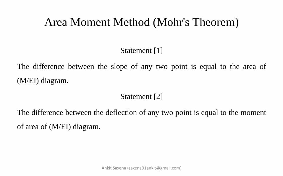
Area Moment Method (Mohr's Theorem)
Statement [1]
The difference between the slope of any two point is equal to the area of
(M/EI) diagram.
Statement [2]
The difference between the deflection of any two point is equal to the moment
of area of (M/EI) diagram.
Ankit Saxena ([email protected])
Ankit Saxena ([email protected])
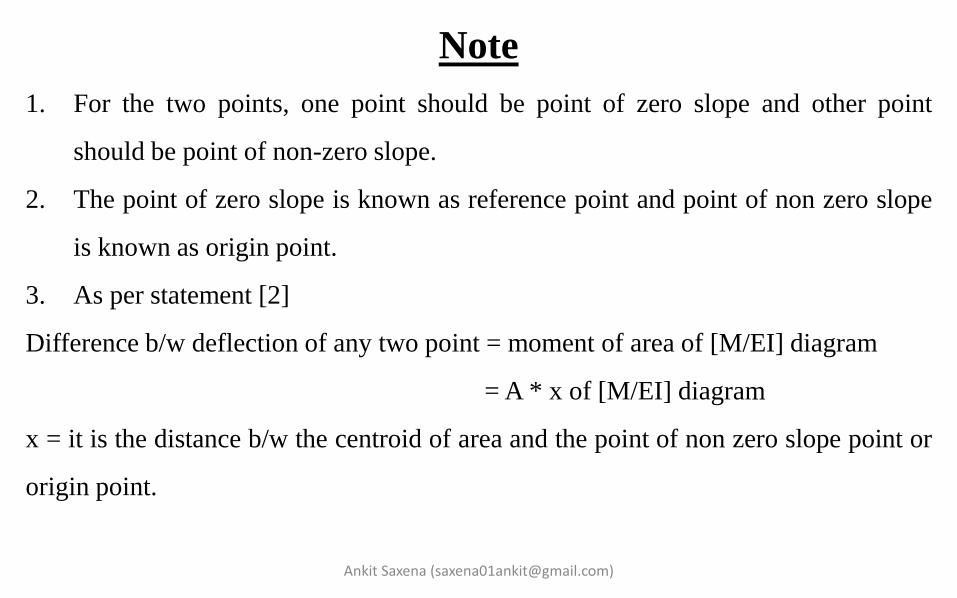
Note
1. For the two points, one point should be point of zero slope and other point
should be point of non-zero slope.
2. The point of zero slope is known as reference point and point of non zero slope
is known as origin point.
3. As per statement [2]
Difference b/w deflection of any two point = moment of area of [M/EI] diagram
= A * x of [M/EI] diagram
x = it is the distance b/w the centroid of area and the point of non zero slope point or
origin point.


Ankit Saxena ([email protected])
Q. For the cantilever beam as known in the figure determine the maximum slope
and deflection. For section AC the flexural rigidity is 2EI and for CB section is
EI.
L L
2EI EI
WA B
C

Ankit Saxena ([email protected])
Q. For the given propped cantilever beam as shown in the figure, determine the support
reaction at the simple support B. W load is acting at mid point of the given beam.
L
W
A B
2
WM
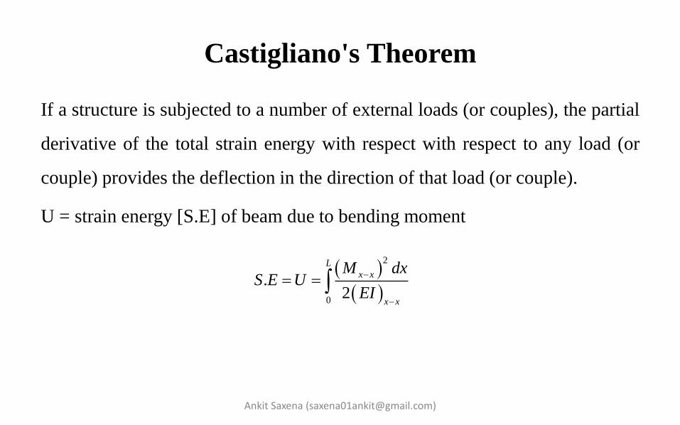
Castigliano's Theorem
If a structure is subjected to a number of external loads (or couples), the partial
derivative of the total strain energy with respect with respect to any load (or
couple) provides the deflection in the direction of that load (or couple).
U = strain energy [S.E] of beam due to bending moment
Ankit Saxena ([email protected])
2
0
.2
L
x x
x x
M dxS E U
EI

Ankit Saxena ([email protected])
L
W
AB
Statement [1]
Statement [2]
Note - W is concentrated point load and M is the concentrated point moment.
M
.B
dy S E
dW
.B
dS E
dM

Ankit Saxena ([email protected])
Note
1. For calculating deflection at a point if there is no point load at that point,
introduce a dummy point load at that point and do the complete
calculation.
2. In the final step, put the dummy load value equal to the zero.

Ankit Saxena ([email protected])
Gate [2014] / 2 Marks
Q. A frame is subjected to a load P as shown in the figure. The frame has a constant
flexural rigidity EI. The effect of axial load is neglected. The deflection at point A
due to the applied load P is -
L W
L
3
3
4
3
1( )
3
2( )
3
( )
4( )
3
PLa
EI
PLb
EI
PLc
EI
PLd
EI


Case 1. Symmetrical loading on fixed beam (A fixed beam having a concentrated point load at mid span)
Step (1) A fixed beam is considered as a simply beam with the given loading
condition.
Ankit Saxena ([email protected])
A B
2
L
2
L
W
12
WR 2
2
WR

Ankit Saxena ([email protected])
Step (2) Draw the free moment diagram.
Step (3) A fixed beam is considered as a simply supported beam having fixing
moments at both the ends. Since it is a case of symmetrical loading so equal fixing
moments are required at both ends.
A BL
4
WL
A B
3 0R 4 0R
MM

Ankit Saxena ([email protected])
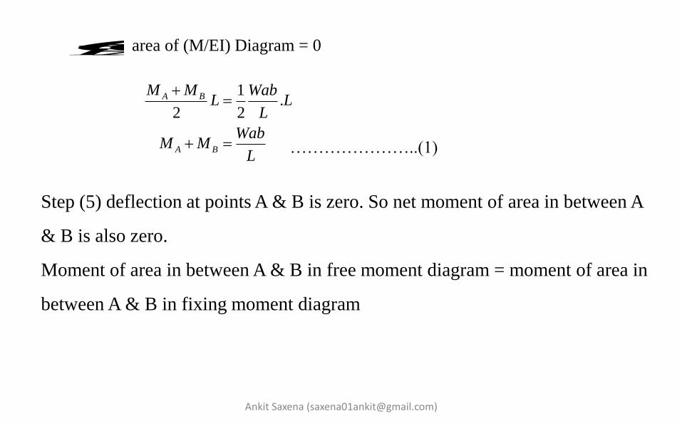
Step (4) Draw the fixing moment diagram.
area of (M/EI) Diagram = 0
Area of free bending moment diagram = area of fixing bending moment diagram
A B
L
-M
B A
. .2 4
8
L WLM L
WLM

Ankit Saxena ([email protected])
Step (5) Maximum deflection will be at point C.
moment of area of (M/EI) diagram about any end support.
{ moment of area of [M/EI] diagram for free moment diagram about any
support} - { moment of area of [M/EI] diagram for fixing moment diagram about any
support.
area between A and C in free moment diagram.
Distance between centroid of area between A and C in free moment diagram to
fixed support A.
area between A and C in fixing moment diagram.
Distance between centroid of area between A and C in fixing moment diagram
to fixed support A.
C Ay y
1A
1x
2A
2x
1 1 2 2C Ay y A x A x
C Ay y

Ankit Saxena ([email protected])
Q. Determine the maximum bending moment and the deflection of a beam of
length L and flexural rigidity EI. The beam is fixed horizontally at both ends and
carries a uniformly distributed load w over the entire length.
L
A B
0
0
A
Ay
0
0
B
By
w
4
384
wLy
EI

Unsymmetrical Loading
Step (1) A fixed beam is considered as a simply beam with the given loading
condition.
Ankit Saxena ([email protected])
L
W
A B
0
0
A
Ay
0
0
B
By
a b
W
a b1
WbR
L 2
WaR
L
A B

Step (2) Draw free moment diagram.
Step (3) A fixed beam is considered as a simply supported beam having fixing
moments at both the ends. Since it is a case of unsymmetrical loading so
unequal fixing moments are required at both ends.
a b2
WaR
L1
WbR
L
A B
a b
A B
3R4R
AM BM
Wab
L

Ankit Saxena ([email protected])
3 4
4
4
3
0
0
0
A
B A
B A
A B
R R
M
M R l M
M MR
L
M MR
L
Step (4) Draw the fixing moment diagram.
Let,
a bA B
AMBM
Ankit Saxena ([email protected])
area of (M/EI) Diagram = 0
…………………..(1)
BA
Step (5) deflection at points A & B is zero. So net moment of area in between A
& B is also zero.
Moment of area in between A & B in free moment diagram = moment of area in
between A & B in fixing moment diagram
1.
2 2
A B
A B
M M WabL L
L
WabM M
L
Ankit Saxena ([email protected])
2
2
2
2
A
B
WabM
L
Wa bM
L
………..(2)
From equation (1) & (2)
1 1 2 2
1 2 1 1. . . . . . . .
2 3 2 3 2 2 3B A B
A x A x
Wab Wab b L La a b a M L L M M
L L

Macaulay's Method
Due to symmetry,
Ankit Saxena ([email protected])
W
A B
0
0
A
Ay
0
0
B
By
2
L
2
L
AM BM
AR BR
A B
A B
R R R
M M M

Q. Determine the maximum bending moment and deflection of a beam of
length L and flexural rigidity is EI. The beam is fixed horizontally at both ends
and carries a concentrated load w at the mid span.
Writing general equation -
On integrating,
Ankit Saxena ([email protected])
W
A B
0
0
A
Ay
0
0
B
By
2
L
2
L
BRAR
C
AM BM
x
x
x
2
2
2
2
. 2
. 2
x x B B CB AC
x x
B B CB AC
M M R x W x L
d yEI M
dx
d yEI M R x W x L
dx
22 2
. .2 2
B B
CB AC
x Ldy xEI M x R A W
dx
Ankit Saxena ([email protected])
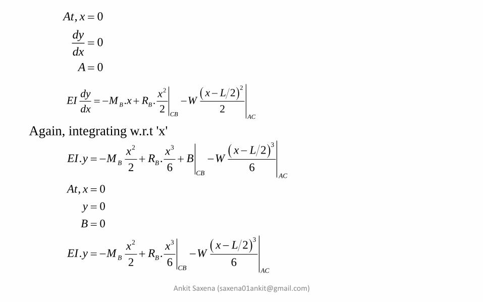
, 0
0
0
At x
dy
dx
A
22 2
. .2 2
B B
CB AC
x Ldy xEI M x R W
dx
Again, integrating w.r.t 'x'
32 3
32 3
2. .
2 6 6
, 0
0
0
2. .
2 6 6
B B
CB AC
B B
CB AC
x Lx xEI y M R B W
At x
y
B
x Lx xEI y M R W
Ankit Saxena ([email protected])
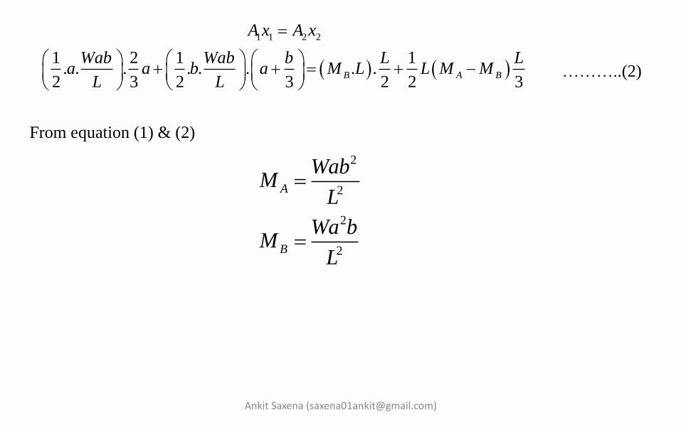
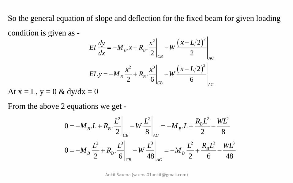
So the general equation of slope and deflection for the fixed beam for given loading
condition is given as -
At x = L, y = 0 & dy/dx = 0
From the above 2 equations we get -
22
32 3
2. .
2 2
2. .
2 6 6
B B
CB AC
B B
CB AC
x Ldy xEI M x R W
dx
x Lx xEI y M R W
22 2 2
32 3 3 2 3
0 . . .2 8 2 8
0 .2 6 48 2 6 48
BB B B
CB AC
BB B B
CB AC
R LL L WLM L R W M L
R LL L L L WLM R W M
Ankit Saxena ([email protected])
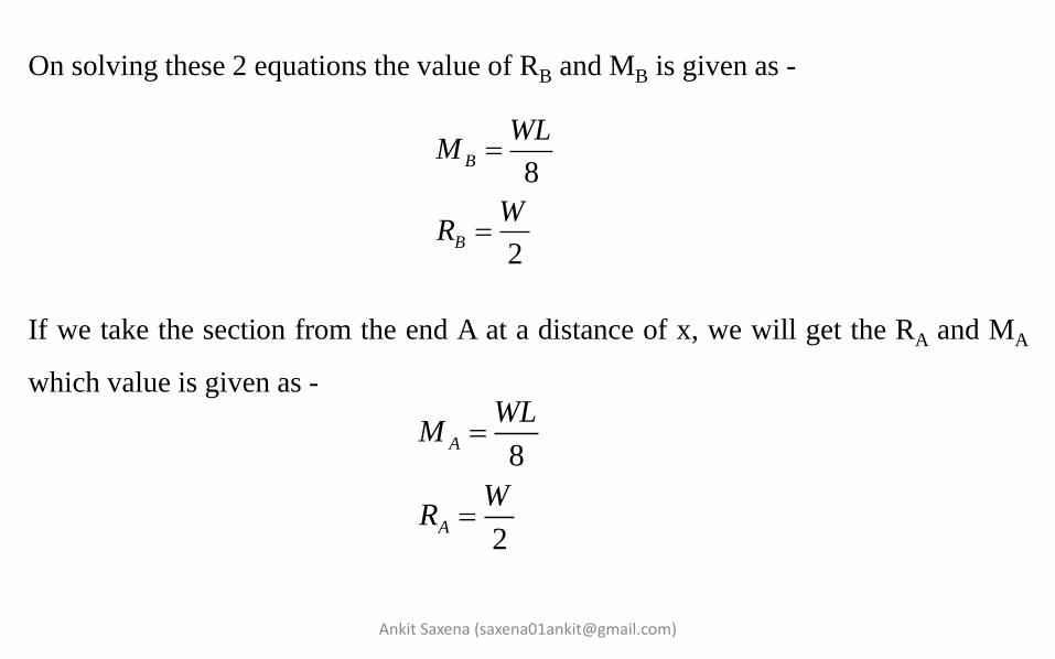
On solving these 2 equations the value of RB and MB is given as -
If we take the section from the end A at a distance of x, we will get the RA and MA
which value is given as -
8
2
B
B
WLM
WR
8
2
A
A
WLM
WR


Continuous Beam
1. In continuous beam we used 3 or more than 3 simple supports.
2. The moment reactions only at the end supports are zero.
Note - [ W1 & W2 are acting at mid point of AB & BC respectively.]
Ankit Saxena ([email protected])
2W1W
1L 2L
AM BMcM
ARBR cR
A B C
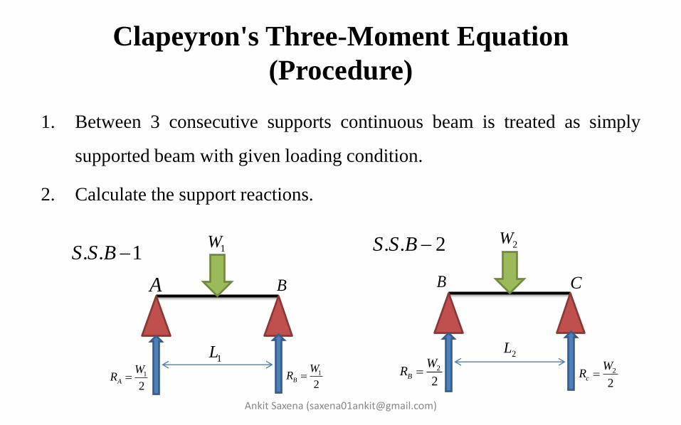
Clapeyron's Three-Moment Equation
(Procedure)
1. Between 3 consecutive supports continuous beam is treated as simply
supported beam with given loading condition.
2. Calculate the support reactions.
Ankit Saxena ([email protected])
1W
1L1
2A
WR
1
2B
WR
. . 1S S B 2W
2L
2
2B
WR 2
2c
WR
A B CB
. . 2S S B

Ankit Saxena ([email protected])
3. Draw the Bending moment diagram for SSB-1 and SSB-2
4. Apply Clapeyron's equation
1L 2LA B CB
. . 1
BMD
S S B . . 2
BMD
S S B
1 1
4
W L 2 2
4
W L
1 1 2 21 1 2 2
1 2
6 62A B C
A x A xM L M L L M L
L L

Ankit Saxena ([email protected])
5. In continuous beam moment reactions at the end support is zero. So moment
reaction at A & C supports are zero.
6. A1 = Area of BMD for SSB-1
A2 = Area of BMD for SSB-2
7. = Distance between centroid of area A1 to the left hand side support in
BMD-1
. = Distance between centroid of area A2 to the right hand side support in
BMD-2
1x
2x
0
0
A
C
M
M

Ankit Saxena ([email protected])
Applying the given conditions to Clapeyron's three moment equation
2
1 1 1 11 1
2
2 2 2 22 2
11
22
2 2
1 1 1 2 2 2
1 2
1 2
2 2
1 1 2 21 2
0
0
1. .
2 4 8
1. .
2 4 8
2
2
6. . 6. .8 2 8 22
3 32 . .
8 8
A
C
B
B
M
M
W L W LA L
W L W LA L
Lx
Lx
W L L W L L
M L LL L
W L W LM L L

Ankit Saxena ([email protected])
Case [1] If,
From the above equation
1 2
1 2
L L L
W W W
2 23 3
2 . .8 8
3.
16
B
B
WL WLM L L
M WL
Ankit Saxena ([email protected])
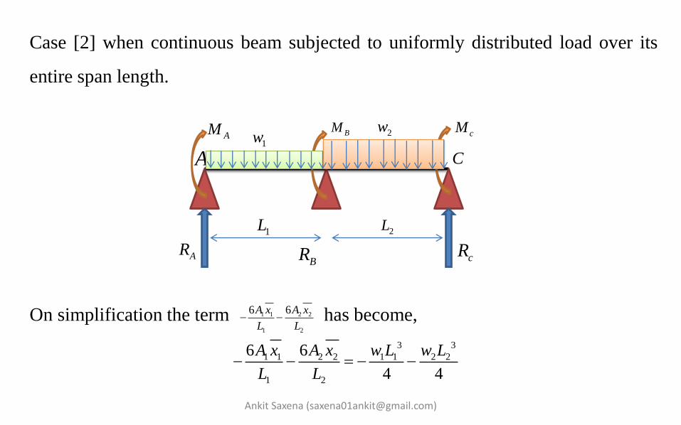
Case [2] when continuous beam subjected to uniformly distributed load over its
entire span length.
On simplification the term has become,
1L 2L
AM BMcM
ARBR cR
A B C1w 2w
1 1 2 2
1 2
6 6A x A x
L L
3 3
1 1 2 2 1 1 2 2
1 2
6 6
4 4
A x A x w L w L
L L


Spring
• Spring is a elastic member which deflect under the action of external load or
couple.
• Due to deflection, spring store the energy and at the required time released
the energy.
Note
Stiffness or spring constant : It is defined as the force required per unit
deflection.
Solid length : It is the length of a spring in the fully compressed state when
the coils touch each other.
Ankit Saxena ([email protected])

Helical Spring
"A helical spring is a piece of wire coil in the form of helix."
Helix- when a right angle triangle is wrapped around the circumference of a cylinder
through its base, a helix profile is generated.
Helix angle - The angle made by plane of coil with the horizontal plane which is
perpendicular to the axis of the spring is known as helix angle.
d = wire diameter (mm)
R = mean coil radius (mm)
D = mean coil diameter (mm)
Ankit Saxena ([email protected])

Ankit Saxena ([email protected])
Spring index:
It is the ratio of mean coil diameter [D] to the wire diameter [d]. It is denoted by
'C'. D
Cd
Types of Helical Spring
Open coil helical spring Closed coil helical spring
1. Coils do not touch each other 1. Coils touch each other.
2. helix angle is generally greater than
10 degree.
2. helix angle generally very small
generally less than 5 degree

Ankit Saxena ([email protected])
Note
1. If there are,
Number of active coil = n
Length of spring = π.D.n

Closed coil helical spring
1. The helix angle is very small.
2. The coils may be assumed to be in a horizontal plane.
3. These spring may be acted upon by axial load or axial toque.
4. Due to axial load, there is axial extension may take place in a spring.
5. Due to axial torque, there is a change in the radius of curvature of the
spring coils.
Note :- Due to axial torque, there is an angular rotation of the free end and the
action is known as wind-up.
Ankit Saxena ([email protected])

Closed coil helical spring under axial load
W = axial load (N)
D = mean coil diameter (mm)
R = mean coil radius (mm)
d = wire diameter (mm)
θ = total angle of twist along wire (radian)
δ = deflection of W along the spring axis (mm)
n = number of coils
L = length of wire
Ankit Saxena ([email protected])

Ankit Saxena ([email protected])
Torsional torque = W. D/2
Assumptions:
1. Neglect the effect of shear force.
2. Neglect the radius of curvature effect.
Torsional shear stress
3
3
3
16
16. .2
8
T
d
DW
d
WD
d
Ankit Saxena ([email protected])
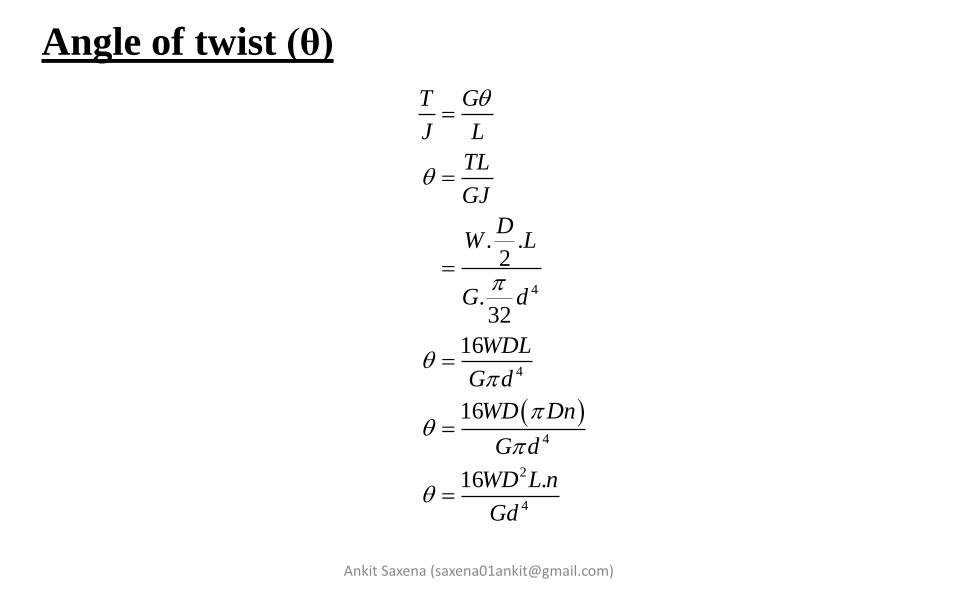
Angle of twist (θ)
4
4
4
2
4
. .2
.32
16
16
16 .
T G
J L
TL
GJ
DW L
G d
WDL
G d
WD Dn
G d
WD L n
Gd

Ankit Saxena ([email protected])
Strain Energy [S.E]
Deflection of W along the shaft axis (mm) [δ]
2
22
4
2 3
4
1. .
2
. .1 4.2
. .32
4 ..
T LS E
GJ
DW Dn
G d
W D nS E
Gd
2 3
4
3
4
.
4 .
8
dS E
dW
d W D n
dW Gd
WD n
Gd

Ankit Saxena ([email protected])
Note
Consider shear stress and radius of curvature effect.
Torsional shear stress is given as-
Where Kw = Wahl's factor
Where C = Spring index, it is given as -
3
8. w
wDK
d
4 1 0.615
4 4w
CK
C C
DC
d
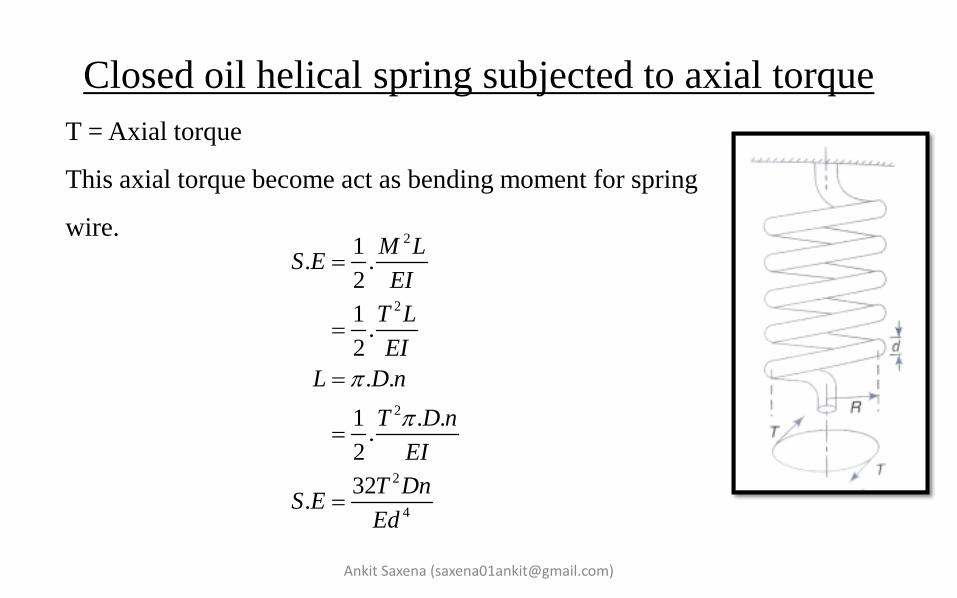
Closed oil helical spring subjected to axial torque
Ankit Saxena ([email protected])
T = Axial torque
This axial torque become act as bending moment for spring
wire.
2
2
2
2
4
1. .
2
1.
2
. .
1 . ..
2
32.
M LS E
EI
T L
EI
L D n
T D n
EI
T DnS E
Ed


Ankit Saxena ([email protected])
A close-coiled helical spring is required to absorb 2.25*103 joules of energy.
Determine the diameter of the wire, the mean diameter of the spring and the number
of coils necessary if
1. The maximum stress is not to exceed 400 MN/m2
2. The maximum compression of the spring is limited to 250 mm
3. the mean diameter of the spring can be assumed to be eight times that of the wire
How would the answers change if appropriate Wahl factors are introduced?
For spring material G = 70 GN/m2.

Ankit Saxena ([email protected])
Q. Show that the ratio of extension per unit axial load to angular rotation per unit
axial torque of a close-coiled helical spring is directly proportional to the square of
the mean diameter, and hence that the constant of proportionality is 1/4 *(1 + ν).
If Poisson's ratio ν = 0.3, determine the angular rotation of a close-coiled helical
spring of mean diameter 80 mm when subjected to a torque of 3 N m, given that
the spring extends 150 mm under an axial load of 250 N.
Springs in Series
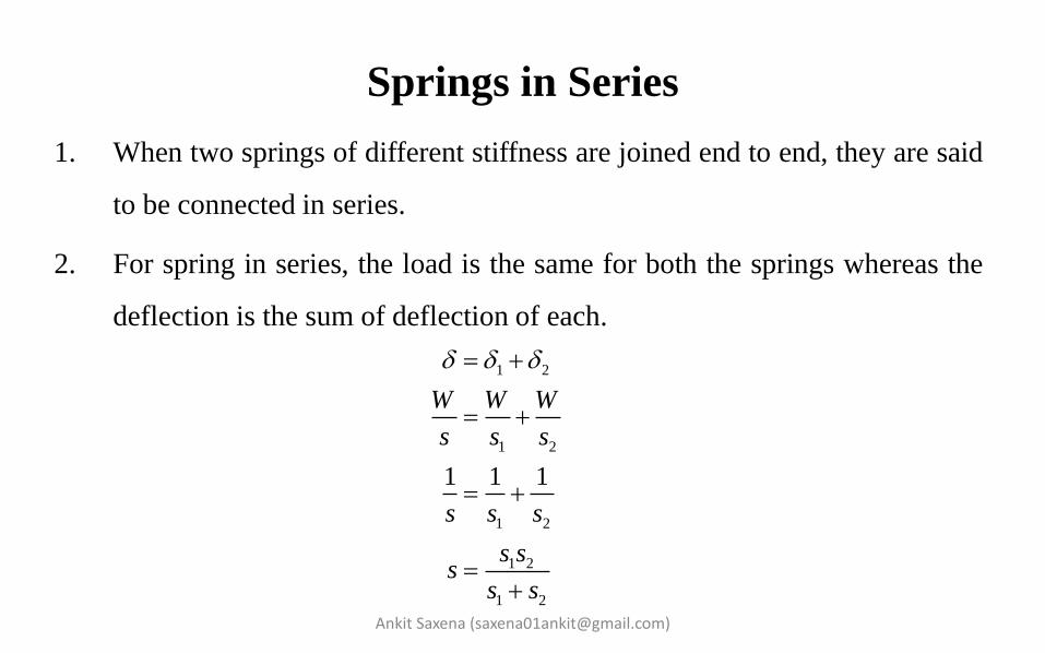
1. When two springs of different stiffness are joined end to end, they are said
to be connected in series.
2. For spring in series, the load is the same for both the springs whereas the
deflection is the sum of deflection of each.
Ankit Saxena ([email protected])
1 2
1 2
1 2
1 2
1 2
1 1 1
W W W
s s s
s s s
s ss
s s
Springs in Parallel
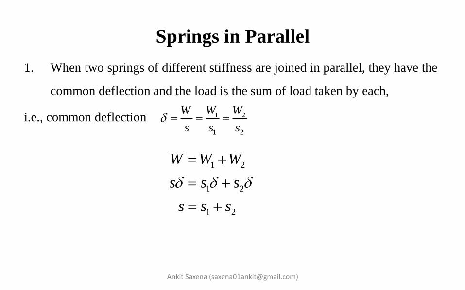
1. When two springs of different stiffness are joined in parallel, they have the
common deflection and the load is the sum of load taken by each,
i.e., common deflection
Ankit Saxena ([email protected])
1 2
1 2
W WW
s s s
1 2
1 2
1 2
W W W
s s s
s s s

Open coiled helical spring subjected to axial load
(W) and axial Torque (T)
Due to this axial load (W) and axial torque (T) both, twisting couple and
bending couple will act in spring wire.
Ankit Saxena ([email protected])

Ankit Saxena ([email protected])
The combined twisting couple is given as,
The combined bending couple is given as,
Length of wire is given as,
' cos sinT WR T
cos sinM T WR
seccos
DnL Dn

Ankit Saxena ([email protected])
Total strain energy (U) is given as -
Axial Deflection
2 2
2 2
2 2
cos sin cos sin
2 2
M L T LU
EI GJ
T WR L WR T LU
EI GJ
2 22
2 cos sin sin 2 cos sin cos
2 2
cos sin 1 1sin cos
dU
dW
L T WR R L WR T R
EI GJ
WR L TRLGJ EI GJ EI

Ankit Saxena ([email protected])
Axial Rotation
2 2
2 cos sin cos 2 cos sin sin
2 2
1 1 sin cossin cos
dU
dT
L T WR L WR T
EI GJ
WRL TLGJ EI GJ EI

Ankit Saxena ([email protected])
Stresses
1. The combined twisting couple is given as,
Torsional shear stress is given as,
2. The combined bending couple is given as,
Bending stress is given as,
'cossinTWRT3
16 'T
d
cossinMTWR3
32b
M
d

Related Documents