Assessment of the impact of new concepts reducing the risk of runway excursions - Definition of the global solution for runway excursion protection and mitigation S. Fleury, F. Barbaresco (TR6), F. Moll (AI-F), J. Atares Rodriguez, S. Lagunas Caballero (AD&S), B. Larrouturou (Zodiac), D. Vechtel (DLR) Programme Manager Michel Piers, NLR Operations Manager Lennaert Speijker, NLR Project Manager (P3) Gerard van Es, NLR Grant Agreement No. 640597 Document Identification D3.11 Status Approved Version 2.0 Classification Public Short abstract: Future Sky Safety is a Joint Research Programme (JRP) on Safety, initiated by EREA, the association of European Research Establishments in Aeronautics. The Programme contains two streams of activities: 1) coordination of the safety research programmes of the EREA institutes and 2) collaborative research projects on European safety priorities. This deliverable is produced by the Project P3 Solutions for Runway Excursions. The main objectives are: Assessment of the impact of new concepts reducing runway excursions Definition of the global solution for runway overrun protection and mitigation

Welcome message from author
This document is posted to help you gain knowledge. Please leave a comment to let me know what you think about it! Share it to your friends and learn new things together.
Transcript

Assessment of the impact of new concepts reducing the risk of runway excursions - Definition of the global solution for runway excursion protection and mitigation
S. Fleury, F. Barbaresco (TR6), F. Moll (AI-F), J. Atares Rodriguez, S. Lagunas Caballero (AD&S), B. Larrouturou (Zodiac), D. Vechtel (DLR)
Programme Manager Michel Piers, NLR
Operations Manager Lennaert Speijker, NLR
Project Manager (P3) Gerard van Es, NLR
Grant Agreement No. 640597
Document Identification D3.11
Status Approved
Version 2.0
Classification Public
Short abstract: Future Sky Safety is a Joint Research Programme (JRP) on Safety, initiated by EREA, the association of
European Research Establishments in Aeronautics. The Programme contains two streams of activities: 1) coordination of the
safety research programmes of the EREA institutes and 2) collaborative research projects on European safety priorities.
This deliverable is produced by the Project P3 Solutions for Runway Excursions. The main objectives are:
Assessment of the impact of new concepts reducing runway excursions
Definition of the global solution for runway overrun protection and mitigation
Project: Reference ID: Classification:
Solutions for runway excursions FSS_P3_TR6_D3.11 Public
TR6 Status: Approved Issue: 2.0 PAGE 2/79 This document is the property of Future Sky Safety and shall not be distributed or reproduced without the formal approval of Coordinator NLR. Future Sky Safety has received funding from the EU’s Horizon 2020 Research and Innovation Programme, under Grant Agreement No. 640597.
This page is intentionally left blank

Project: Reference ID: Classification:
Solutions for runway excursions FSS_P3_TR6_D3.11 Public
TR6 Status: Approved Issue: 2.0 PAGE 3/79 This document is the property of Future Sky Safety and shall not be distributed or reproduced without the formal approval of Coordinator NLR. Future Sky Safety has received funding from the EU’s Horizon 2020 Research and Innovation Programme, under Grant Agreement No. 640597.
Contributing partners
Company Name
Airbus Operations SAS MOLL Fabien
Airbus Defense and Space ATARES RODRIGUEZ Julio / LAGUNAS CABALLERO Sara
Zodiac Aerosafety Systems LARROUTUROU Benoît
DLR VECHTEL Dennis
Thales Air Systems BARBARESCO Frédéric
Thales Avionics FLEURY Stephane
Document Change Log
Version
No.
Issue Date Remarks
1.0 12-09-2018 First formal release
2.0 28-12-2018 Second formal release
Approval status
Prepared by: (name) Company Role Date
Stephane Fleury Thales Avionics Main author 12-09-2018
Checked by: (name) Company Role Date
Frédéric Barbaresco Thales Air Systems WP3.4 leader 12-09-2018
Approved by: (name) Company Role Date
Gerard van Es NLR Project Manager (P3) 12-09-2018
Lennaert Speijker NLR Operations Manager 28-12-2018

Project: Reference ID: Classification:
Solutions for runway excursions FSS_P3_TR6_D3.11 Public
TR6 Status: Approved Issue: 2.0 PAGE 4/79 This document is the property of Future Sky Safety and shall not be distributed or reproduced without the formal approval of Coordinator NLR. Future Sky Safety has received funding from the EU’s Horizon 2020 Research and Innovation Programme, under Grant Agreement No. 640597.
Acronyms
Acronym Definition
ACARS Aircraft Communication Addressing & Reporting System
ADS-B Automatic Dependent Surveillance-Broadcast
AFS Auto Flight System
AGL Above Ground Level
ASDA Accelerate Stop Distance Available
ASPOC Application de Signalisation et Prévision des Orages pour le Contrôle aérien (Thunderstorm forecasting and signaling for ATC)
ATIS / D-ATIS Air Traffic Information System / Digital Air Traffic Information System
ATN Aeronautical Telecommunication Network
ATRA Advanced Technologies Research Aircraft
AVES AirVEhicle Simulator
BD Braking Distance
BTV Brake To Vacate
CAS Calibrated AirSpeed
CFME Continuous Friction Measurement Equipment
CDG Paris Charles de Gaulle Airport
CLAS Crosswind Landing Assistance System
CORSAIR Contaminated Runway State Automatic Identification and Reporting
DGAC/STAC Direction Générale de l’Aviation Civile/Service Technique de l’Aviation Civile
French Civil Aviation Authority technical services EDR Eddy Dissipation Rate
EFB Electronic Flight Bag
EGT Exhaust Gas Temperature
EPR Engine Pressure Ratio
FCS Flight Control System
GNSS Global Navigation Satellite System
GPWS Ground Proximity Warning System

Project: Reference ID: Classification:
Solutions for runway excursions FSS_P3_TR6_D3.11 Public
TR6 Status: Approved Issue: 2.0 PAGE 5/79 This document is the property of Future Sky Safety and shall not be distributed or reproduced without the formal approval of Coordinator NLR. Future Sky Safety has received funding from the EU’s Horizon 2020 Research and Innovation Programme, under Grant Agreement No. 640597.
HTP Horizontal Tail Plane
ILS Instrument Landing System
IFR Instrument Flight Rules
ISA International Standard Atmosphere
MAC Mean Aerodynamic Chord
METAR METeorological Aerodrome Report
ML Machine Learning
MSAW Minimum Safe Altitude Warning
PIREP Pilot REPort
QNH Barometric pressure or reference (used for altimeter calibration)
RAAS Runway Awareness & Advisory System
RECAT 2 Wake turbulence RE-CATegorization phase 2
RESA Runway End Safety Area
RCAM Runway Condition Assessment Matrix
RCR Runway Condition Report
ROPS Runway Overrun Protection System
ROT Runway Occupation Time
ROW Runway Overrun Warning
RWY Runway
RWYCC Runway Condition Code
SARPs Standards and Recommended Practices
SOP Standard Operating Procedure
SPECI SPECIal meteorological report
TAF Terminal Aerodrome Forecast
TAWS Terrain Awareness and Warning System
TOM Take-Off Monitoring
TOS Take-Off Surveillance
TWY Taxiway

Project: Reference ID: Classification:
Solutions for runway excursions FSS_P3_TR6_D3.11 Public
TR6 Status: Approved Issue: 2.0 PAGE 6/79 This document is the property of Future Sky Safety and shall not be distributed or reproduced without the formal approval of Coordinator NLR. Future Sky Safety has received funding from the EU’s Horizon 2020 Research and Innovation Programme, under Grant Agreement No. 640597.
URW Unpaved Runway
USCS Unified Soil Classification System
VFR Visual Flight Rules
XTE Cross Track Error

Project: Reference ID: Classification:
Solutions for runway excursions FSS_P3_TR6_D3.11 Public
TR6 Status: Approved Issue: 2.0 PAGE 7/79 This document is the property of Future Sky Safety and shall not be distributed or reproduced without the formal approval of Coordinator NLR. Future Sky Safety has received funding from the EU’s Horizon 2020 Research and Innovation Programme, under Grant Agreement No. 640597.
EXECUTIVE SUMMARY
Problem Area
The European Action Plan for the Prevention of Runway Excursions (EAPPRE) provides practical
recommendations with guidance material to reduce the probability of runway excursions but does not
address the other part of the equation, damage prevention. EAPPRE also identified areas were research is
needed to further reduce risks. Four areas of research have been identified for which additional research
is needed:
Flight mechanics of runway ground operations on slippery runways under crosswind;
Impact of fluid contaminants of varying depth on aircraft stopping performance;
Advanced methods for analysis flight data for runway excursion risk factors;
New technologies to prevent excursions or the consequences of excursions.
This study explores existing and new concepts for prevention and mitigation of runway excursions. Some
technologies to reduce the risk of excursions, such as Take-Off Performance Monitoring systems and
arresting systems, have been under investigation previously and have yet made it into today’s cockpits
and airports. Other preventive technologies such as on-board 3D active imaging systems for enhanced
crew situation awareness of on ground conditions are still in the exploratory phases of development.
Technologies to reduce the consequences of excursions, such as special pavements in the runway
surroundings or new landing gear designs have seem limited operational use or are still in early
development. Research is required to bring these technologies closer to application, either by removing
technological or regulatory obstacles and improving affordability. In an effort to cover the entire risk
equation, both probability and severity reduction methods are being explored and new technologies to
prevent excursions or the consequences of excursions are to be explored.
Initial assessment shows that improvements can be made through:
Technological means: new systems and/or ways to enhance the decision making of crew towards
performing airport operations (take off or landing) in a safe manner
Airframe infrastructures: further development in the design of landing gears may provide
improvements in the risk of runway excursion, mainly the one of veer off
Mitigation methods: the risk can only be lowered to a certain extent through probability
reduction; additional methods to mitigate the consequences and transform any excursions into a
non-event will be studied. Additions or improvements to the currently existing -yet not widely
installed- Engineered Material Arresting Systems may be found.
Additional analysis and feasibility studies as well as integration of other work packages results, along with
the definition of the R&TD needed to accelerate the implementation will need to be conducted.
Project: Reference ID: Classification:
Solutions for runway excursions FSS_P3_TR6_D3.11 Public
TR6 Status: Approved Issue: 2.0 PAGE 8/79 This document is the property of Future Sky Safety and shall not be distributed or reproduced without the formal approval of Coordinator NLR. Future Sky Safety has received funding from the EU’s Horizon 2020 Research and Innovation Programme, under Grant Agreement No. 640597.
Regarding new concepts and/or technologies, the following tasks are anticipated:
Inventory of current developments and new initiatives;
Feasibility study and definition of R&TD needed for implementation of new concepts;
Assess impact of the new concepts on reducing excursions (no cost-benefit).
Description of Work
This study provides:
an assessment of the impact of new concepts reducing the risk of runway excursions
a definition of the global solution for runway overrun protection and mitigation
Results & Conclusions
The global and collaborative concept takes stand on two families of systems that are already deployed on
some aircraft and/or on some airports:
Existing airborne systems acting as a safety net help the crew detect and respond to a situation of
predicted risk of overrun on final approach and during deceleration phase on the runway.
Existing ground arresting system at the end of the runway and monitoring of the compliance with
current or future regulations limit the consequence of an overrun.
And intends to complete these systems with:
Extension of the overrun prevention at take-off.
Enhance evaluation of the runway contamination status with continuous monitoring that does
not impact the traffic on the runway. The aircraft based braking action measurement combined
with a contamination model for the runway gives the opportunity to obtain a near real -time
estimation of the runway slipperiness.
Enhance evaluation of weather condition in the vicinity of the airport. A more detailed
assessment of the surrounding conditions to support better anticipation of the evolution of the
runway contaminant status and tracking of characteristic weather threats leading to potential
destabilization of the aircraft.
Analysis of the complete risk equation and possible combination of systems to optimize the
overall risk reduction
Every concept proposed for prevention, whether it is on the ground or on -board the aircraft has certain
inter-dependency with each other. For instance, the performance of a ROAAS (Runway Overrun
Awareness and Alerting System) is dependent on correctly reported runway contamination status.
Similarly, an accurate estimation of the runway contamination status is dependent on the aircraft
experienced feedback. Sharing information between the ground and airborne concepts should allow
increased completeness and performance of the prevention. Collaboration between the different

Project: Reference ID: Classification:
Solutions for runway excursions FSS_P3_TR6_D3.11 Public
TR6 Status: Approved Issue: 2.0 PAGE 9/79 This document is the property of Future Sky Safety and shall not be distributed or reproduced without the formal approval of Coordinator NLR. Future Sky Safety has received funding from the EU’s Horizon 2020 Research and Innovation Programme, under Grant Agreement No. 640597.
concepts requires an improvement of the communication between the aircraft and the ground systems to
exchange relevant information on critical factor for runway excursion. Moreover, considering mitigation
measures in addition to the prevention measures is considered a valuable method to address the risk
equation.
Extension of the digital link with system-oriented information needs to be promoted to support an
increased situational awareness both on the airport side and on the aircraft side. Most communications
are led today through voice exchanges which limits the volume of information and the reactivity with fast
evolving runway excursion risk level. Connecting Aircraft and ground systems, as proposed in the
collaborative concept, increases the risk mitigation capacity by simultaneously mixing evaluation obtained
on ground and in the aircraft. Collaboration between the systems forces objecti veness by sharing a
common reporting format among the actors, and is a precursor to development of automation tracking
the evolution of the risk in near real-time. The collaboration between systems and the automation of the
processes induce an increased safety level with a reduction of the workload for the actors.
Beyond the safety net protection, the proposed collaborative concept explores the use of models to
characterize excursion probability factors. The prediction of the weather and runway conditions o pens the
way to a strategic resolution of the likelihood of excursion. Sharing information on prediction of risk
contributing factor allows aircraft operators and flight crew to make an objective assessment in order to
delay an approach that is considered at risk or divert. A strategic assessment would allow airport
operators to optimize airport procedures (decision for change of runway or runway closure and improving
airport capacity).
The proposed collaborative concept is deemed to significantly reduce the probability of runway overrun
but it still needs enhancement to significantly reduce the risk of runway veer -off. The increased
awareness on the veer-off contributing factors is valuable to make the crew aware of the risk of veer off
and optimize their ability to maintain the aircraft on the runway but is not sufficient to guarantee a safe
landing. Because of the nature of the veer-off excursion, new aircraft design and system are researched to
maintain directional control of the aircraft on the runway. The addition of directional main landing gear,
development of limited drift tires or implementation of active assistance still require some intensive
development in order to propose a full protection.
Whilst all efforts should be made through technological means as well as human training to reduce the
probability of excursion, the reduction of risk through the mitigation of the consequences is and remains
the only path to, in conjunction with probability reduction, reduce the risk as much as possible. Also, if
some systems seem to have demonstrated their qualities in reducing severity of overruns, similar
philosophy should be developed to mitigate the consequences of veer offs.
Applicability
This document is the final report of work in Future Sky Safety on defining the collaborative concept for
reduction of risk of runway excursion. This study provides recommendations for implementation of the
collaborative concept, as well as additional necessary research and development activities.

Project: Reference ID: Classification:
Solutions for runway excursions FSS_P3_TR6_D3.11 Public
TR6 Status: Approved Issue: 2.0 PAGE 10/79 This document is the property of Future Sky Safety and shall not be distributed or reproduced without the formal approval of Coordinator NLR. Future Sky Safety has received funding from the EU’s Horizon 2020 Research and Innovation Programme, under Grant Agreement No. 640597.
This page is intentionally left blank

Project: Reference ID: Classification:
Solutions for runway excursions FSS_P3_TR6_D3.11 Public
TR6 Status: Approved Issue: 2.0 PAGE 11/79 This document is the property of Future Sky Safety and shall not be distributed or reproduced without the formal approval of Coordinator NLR. Future Sky Safety has received funding from the EU’s Horizon 2020 Research and Innovation Programme, under Grant Agreement No. 640597.
TABLE OF CONTENTS
Contributing partners 3
Document Change Log 3
Approval status 3
Acronyms 4
Executive Summary 7
Problem Area 7
Description of Work 8
Results & Conclusions 8
Applicability 9
Table of Contents 11
List of Figures 13
1 Introduction 15
1.1. The Programme 15
1.2. Project context 15
1.3. Research objectives 16
1.4. Approach 16
1.5. Structure of the document 16
2 Assessment of the impact of new concepts for reducing THE RISK OF runway
excursions 17
2.1. Description of Operational Concepts 17
2.1.1. Ground Operational Concept 17
2.1.2. Airborne Operational Concept 28
2.2. Safety Benefit Analysis 53
2.2.1. Ground Operational Concept 53
2.2.2. Airborne Operational Concept 59
3 Definition of the global solution for runway overrun protection 69
3.1. Collaborative Operational Concept 69
3.1.1. Collaborative Operational Concept for excursion risk reduction 69
3.1.2. Collaborative Operational Concept for excursion consequence reduction 72
3.2. Safety Enhancement Modules 72
4 Conclusions and recommendations 75
4.1. Conclusions 75
4.2. Recommendations 77

Project: Reference ID: Classification:
Solutions for runway excursions FSS_P3_TR6_D3.11 Public
TR6 Status: Approved Issue: 2.0 PAGE 12/79 This document is the property of Future Sky Safety and shall not be distributed or reproduced without the formal approval of Coordinator NLR. Future Sky Safety has received funding from the EU’s Horizon 2020 Research and Innovation Programme, under Grant Agreement No. 640597.
5 References 79

Project: Reference ID: Classification:
Solutions for runway excursions FSS_P3_TR6_D3.11 Public
TR6 Status: Approved Issue: 2.0 PAGE 13/79 This document is the property of Future Sky Safety and shall not be distributed or reproduced without the formal approval of Coordinator NLR. Future Sky Safety has received funding from the EU’s Horizon 2020 Research and Innovation Programme, under Grant Agreement No. 640597.
LIST OF FIGURES
Figure 1: Rain Rate Prediction by cloud or rain front tracking (Lame d’Eau product at 5mn rate) ..............17
Figure 2: Model to assess Water Depth from Rain intensity ......................................................................18
Figure 3: Wind Monitoring for Low-Level Wind-Shear system on airport ..................................................19
Figure 4: 3D scanning LIDAR and LIDAR Profiler deployment on airport ....................................................20
Figure 5: Ground Runway Excursion Monitoring System ...........................................................................21
Figure 6: ICAO recommendation and distances on airports of code 3 and above .......................................22
Figure 7: Runway excursion over soft, weight sustaining runway strip ......................................................24
Figure 8: ALARP risk as defined by NLR in ASTER .......................................................................................25
Figure 9: AIRBUS concepts to reduce risks of runway excursion ................................................................29
Figure 10: Retarding forces acting on a braked wheel operating on URW .................................................35
Figure 11: Schematic representation of a distance validation calculation ..................................................36
Figure 12: Short-term (quasi-real time) utility of the proposed concept ....................................................37
Figure 13: Database generation (for a certain runway) .............................................................................37
Figure 14: Mid-term (deferred time) utility of the proposed concept ........................................................38
Figure 15: Example of deployment on EFB ................................................................................................39
Figure 16: Required landing distance for current rwycc and rwycc +1 .......................................................40
Figure 17: Example of ASPOC nowcast data from MET provider ................................................................42
Figure 18: Example of thunderstorm nowcast data from MET provider 30 min before landing (measured)
.........................................................................................................................................................43
Figure 19: Example of thunderstorm nowcast data from MET prediction at landing time ..........................44
Figure 20: The AVES A320 simulator .........................................................................................................46
Figure 21: Sample pictures of the outside view and the environmental scenario during the approach ......47
Figure 22: Lateral deviation from runway centerline after touchdown ......................................................48
Figure 23: Maximum lateral deviation from runway centerline as a function of the crosswind component
.........................................................................................................................................................48
Figure 24: Maximum lateral load factor as a function of the crosswind component ..................................49
Figure 25: Main gear side force after touchdown .....................................................................................51
Figure 26: Maximum main gear side force as a function of the crosswind component ..............................51
Figure 27: Risk matrix ...............................................................................................................................57
Figure 28: EMAS arrestments record ........................................................................................................58
Figure 29: Take-off excursion top risk factors (Source Runway Safety initiative – Flight Safety Foundation –
May 2009) ........................................................................................................................................59
Figure 30: Photos of the event occurred in 2009 on A340-500 at Melbourne Airport ................................60
Figure 31: FMGS discrepancy message on T/O speed ................................................................................61
Figure 32: Landing excursion top risk factors (Source Runway Safety initiative – Flight Safety Foundation –
May 2009) ........................................................................................................................................61
Figure 33: Global concept ........................................................................................................................71

Project: Reference ID: Classification:
Solutions for runway excursions FSS_P3_TR6_D3.11 Public
TR6 Status: Approved Issue: 2.0 PAGE 14/79 This document is the property of Future Sky Safety and shall not be distributed or reproduced without the formal approval of Coordinator NLR. Future Sky Safety has received funding from the EU’s Horizon 2020 Research and Innovation Programme, under Grant Agreement No. 640597.
Figure 34: Impact of safety enhancement modules ..................................................................................73
Figure 35: Safety enhancement module for partial and full implementation .............................................74
Figure 36: Estimated availability ...............................................................................................................77

Project: Reference ID: Classification:
Solutions for runway excursions FSS_P3_TR6_D3.11 Public
TR6 Status: Approved Issue: 2.0 PAGE 15/79 This document is the property of Future Sky Safety and shall not be distributed or reproduced without the formal approval of Coordinator NLR. Future Sky Safety has received funding from the EU’s Horizon 2020 Research and Innovation Programme, under Grant Agreement No. 640597.
1 INTRODUCTION
1.1. The Programme
The EC Flight Path 2050 vision aims to achieve the highest levels of safety to ensure that passengers and
freight as well as the air transport system and its infrastructure are protected. However, trends in safety
performance over the last decade indicate that the ACARE Vision 2020 safety goal of an 80% reduction of
the accident rate is not being achieved. A stronger focus on safety is required. There is a need to start a
Joint Research Program (JRP) on Aviation Safety, aiming for Coordinated Safety Research as well as Safety
Research Coordination. The proposed JRP Safety, established under coordination of EREA, is built on
European safety priorities, around four main themes with each theme consisting of a small set of projects.
Theme 1 (New solutions for today’s accidents) aims for breakthrough research with the purpose of
enabling a direct, specific, significant risk reduction in the medium term. Theme 2(Streng thening the
capability to manage risk) conducts research on processes and technologies to enable the aviation system
actors to achieve near-total control over the safety risk in the air transport system. Theme 3 (Building
ultra-resilient systems and operators) conducts research on the improvement of Systems and the Human
Operator with the specific aim to improve safety performance under unanticipated circumstances. Theme
4 (Building ultra-resilient vehicles), aims at reducing the effect of external hazards on the aerial vehicle
integrity, as well as improving the safety of the cabin environment. To really connect and drive
complementary Safety R&D (by EREA) to safety priorities as put forward in the EASA European Aviation
Safety plan (EASp) and the EC ACARE Strategic Research and Innovation (RIA) Agenda, Safety Research
Coordination activities are proposed. Focus on key priorities that impact the safety level most will
significantly increase the leverage effect of the complementary safety Research and Innovat ion actions
planned and performed by EREA.
1.2. Project context
The European Action Plan for the Prevention of Runway Excursions (EAPPRE) provides practical
recommendations with guidance material to reduce the number of runway excursions. EAPPRE also
identified areas were research is needed to further reduce risks. Four areas of research have been
identified for which additional research is needed:
Flight mechanics of runway ground operations on slippery runways under crosswind;
Impact of fluid contaminants of varying depth on aircraft stopping performance;
Advanced methods for analysis of flight data for runway excursion risk factors;
New technologies to prevent excursions or the consequences of excursions.
The main objectives of the Project P3 “Solutions for runway excursions” are:
To identify shortcomings and improve methods and models for analyzing aircraft ground control
under crosswind and on slippery runways
To gain insight into the impact of water/slush covered runways on braking performance for
modern tires and antiskid systems.

Project: Reference ID: Classification:
Solutions for runway excursions FSS_P3_TR6_D3.11 Public
TR6 Status: Approved Issue: 2.0 PAGE 16/79 This document is the property of Future Sky Safety and shall not be distributed or reproduced without the formal approval of Coordinator NLR. Future Sky Safety has received funding from the EU’s Horizon 2020 Research and Innovation Programme, under Grant Agreement No. 640597.
To study and develop algorithms identifying veer-off risk using operational flight data.
To explore new concepts for prevention or mitigation of runway excursions
This study addresses the fourth objective, i.e. explores existing and new concepts for prevention or
mitigation of runway excursions. Some technologies to reduce the risk of excursions, either through
prevention or mitigation, such as Runway Overrun Awareness and Alerting Systems and arresting systems,
have been under investigation previously or have yet made it into today’s cockpits and airports. Other
preventive technologies such as on-board 3D active imaging systems for enhanced crew situation
awareness on ground are still in the exploratory phases of development. Technologies to reduce the
consequences of excursions, such as special pavements in the overrun area or new landing gear designs
have seem limited operational use or are still in early development. Research is required to bring these
technologies closer to application, either by removing technological or regulatory obstacles and improving
affordability. New technologies to prevent excursions or the consequences of excursions are to be
explored. Active enforcement of the current regulation regarding mitigation (distance and bearing
strength of runway strip and Runway End Safety Areas) and innovations to the existing Arresting Systems
could be found, as well new ways to guide pilots in making safe takeoff and landings without a high risk of
running off the runway. Also new airframe technologies, such as new landing gear designs could be
considered.
1.3. Research objectives
The objective of this study is to provide new initiatives to reduce the risk of runway excursions.
1.4. Approach
This study provides:
An assessment of the impact of new concepts for reducing the risk of runway excursions,
A definition of the global solution for runway overrun protection.
1.5. Structure of the document
This report is structured in 4 chapters:
Chapter 1: This chapter presents the context and the objective of the study on collaborative risk
reduction on runway excursion
Chapter 2: This chapter is separated on two subsections
o First section contains the definition of various proposed concepts split into ground and
airborne concepts.
o Second section contains safety evaluation of each presented concept
Chapter 3: Proposes a global concept unifying the various ground and airborne concepts
evaluated in the chapter 2.
Chapter 4: Provides conclusions and recommendations.

Project: Reference ID: Classification:
Solutions for runway excursions FSS_P3_TR6_D3.11 Public
TR6 Status: Approved Issue: 2.0 PAGE 17/79 This document is the property of Future Sky Safety and shall not be distributed or reproduced without the formal approval of Coordinator NLR. Future Sky Safety has received funding from the EU’s Horizon 2020 Research and Innovation Programme, under Grant Agreement No. 640597.
2 ASSESSMENT OF THE IMPACT OF NEW CONCEPTS FOR REDUCING THE RISK OF RUNWAY EXCURSIONS
2.1. Description of Operational Concepts
Potential issues that might influence the overall success of each concept are identified and mitigation
measures are proposed. In this section, the concepts are separated into operational concept implemented
on ground and concept implemented onboard the aircrafts.
2.1.1. Ground Operational Concept
2.1.1.1. Tactical Weather Nowcasting for Runway Excursion probability reduction
2.1.1.1.1. Runway Contaminant Nowcasting for the next 30 minutes by water depth estimation from X-band
weather data
Airports could have direct and short term access to raw X-band Weather Radar data. This X-band Weather
radar data could be used to predict rain rate on runway for the next 30 minutes. For example, the product
“Lame d’Eau” PANTHERE from the French weather office (Météo -France) can be quoted as possibly
delivering rain fallen at ground, using 1km*1kmgrid to determine the movements of precipitations.
Successive images on following figure show the displacement of rain front from North-East towards Paris
CDG airport. Airport is situated into each image (80km*80km). Two parallel white lines border the zone of
interest.
Figure 1: Rain Rate Prediction by cloud or rain front tracking (Lame d’Eau product at 5mn rate)

Project: Reference ID: Classification:
Solutions for runway excursions FSS_P3_TR6_D3.11 Public
TR6 Status: Approved Issue: 2.0 PAGE 18/79 This document is the property of Future Sky Safety and shall not be distributed or reproduced without the formal approval of Coordinator NLR. Future Sky Safety has received funding from the EU’s Horizon 2020 Research and Innovation Programme, under Grant Agreement No. 640597.
The water depth can be predicted to assess the runway contaminant based on a model of water run -off.
The Gallaway formula under estimates water depth compared to Izzard and Ross when water flow
exceeds 2 mm/h. The following formula gave a satisfactory water depth prediction for a wide variety of
surfaces:
ℎ = 0,26 𝐻𝑆𝑐0,4 (𝐼 𝐿)0,4
𝑠0,3+ 0,30 − 𝐻𝑆𝑐 (1)
In the previous equation, HSc represents the macrotexture (measured by sand patch method) in mm; I is
expressed in mm/h, L in m and s in %. This equation has been compared with measurements on real
roads and provides good results for water depth lower than 1,5 mm. Based on this equat ion, DGAC/STAC
has developed a practical tool to predict water depth on runways. The parameters L and p are obtained
from a numerical mapping of the runway based on geometric runway characteristic (longitudinal and
lateral slopes, rutting, and macrotexture). Rain intensity is provided by a local station. This approach is
illustrated in figure below.
Figure 2: Model to assess Water Depth from Rain intensity
The system proposes to mix local airport weather, rain forecast, 80Km arou nd the airport, and water run-
off model of the runways. The system monitors the current contamination status, correlating past and
current airport observations with the runway run-off model. Adding the rain forecast, the contamination
status is estimated for the next 30min.
The limitation of the water depth prediction concept is its built -in estimation model that, as of now, does
not estimate contaminants other than water (snow, ice, slush is excluded).
2.1.1.1.2. Fast & Accurate Wind Nowcasting at low altitude with LIDARs
The new doppler lidar fibered technology is an opportunity to monitor wind on airports at high update
rate compatible with tactical airside operations.

Project: Reference ID: Classification:
Solutions for runway excursions FSS_P3_TR6_D3.11 Public
TR6 Status: Approved Issue: 2.0 PAGE 19/79 This document is the property of Future Sky Safety and shall not be distributed or reproduced without the formal approval of Coordinator NLR. Future Sky Safety has received funding from the EU’s Horizon 2020 Research and Innovation Programme, under Grant Agreement No. 640597.
Wind is an important factor that could increase the risk of runway excursion:
Runway Overrun could be caused by tail wind that will increase the ground speed in final
approach and by cross-wind that will increase the risk of non-stable approach.
Runway Veer-off could be cause by high cross-wind and atmospheric turbulences characterized
by EDR (Eddy Dissipation Rate)
Head/tail/Cross winds can be monitored 4NM before landing in the glide by a combination of Lidar
profilers and Lidar scanner.The Lidar profiler monitors the wind within a cone projected vertically above
the unit. With 3D Lidar scanner, wind can be monitored in an azimuthal sector that is classical used to
predict arrival of wind shear in the vicinity of the glide.
Head/Tail Wind Cross-Wind EDR (Eddy Dissipation
rate)
Runway Overrun 4NM before Threshold
LIDAR Profiler or LIDAR
3D Scanner
4NM before Threshold
LIDAR 3D SCANNER
N.A.
Runway Veer-off N.A. Along First 1/3 of
runway at altitude < 50 m
LIDAR 3D SCANNER
4NM from threshold
to 1/3 of runway
LIDAR 3D SCANNER
A 3D wind Doppler LIDAR scans in real time all potential hazard zones within the airport air space, detects
wind shears to 10kmrange in the glide and around, and sends automatic alerts to air traffic controllers.
Figure 3: Wind Monitoring for Low-Level Wind-Shear system on airport
Different LIDAR Wind sensors deployments on airport can be considered with respect to runway layouts.
We illustrate in the figure 3 above the joint use of 3D scanning LIDAR for cross -wind and EDR monitoring
along first 1/3 of runway, and LIDAR profilers along the glide for the last 4NM to assess head/tail winds.
The scanning rate of a LIDAR could be reduced by adapting different scanning strategies. For a collimated
beam, velocity resolution is less than 0.5m/s for range between 100m and7000m. Focusing the beam at

Project: Reference ID: Classification:
Solutions for runway excursions FSS_P3_TR6_D3.11 Public
TR6 Status: Approved Issue: 2.0 PAGE 20/79 This document is the property of Future Sky Safety and shall not be distributed or reproduced without the formal approval of Coordinator NLR. Future Sky Safety has received funding from the EU’s Horizon 2020 Research and Innovation Programme, under Grant Agreement No. 640597.
shorter distance (800m) leads to high measurement uncertainty at long ranges (>0.5m/s after 3500m) but
increases the precision for low ranges.
Figure 4: 3D scanning LIDAR and LIDAR Profiler deployment on airport
2.1.1.2. Ground Runway Excursion monitoring by Big Data Analytics
New machine learning techniques for Big Data Analytics are able to correlate with braking distance from:
Final approach speed (from Air Traffic Surveillance data)
Aircraft category(Aircraft/Flight Data)
Aircraft Weight (by default 80% of Maximum Landing Weight is considered)
Wind (along the glide for the last 4NM provided by LIDAR)
Runway Contaminant (provided by X-band radar and Water-depth model)
As presented in the study [1], this approach can accurately provide a good assessment of braking distance
assuming all inputs are accurate and available. Although this model is intended primarily to be used for
ROT (Runway Occupancy Time) Prediction as requested for RECAT 2 procedure deployment (this task
could be related to Runway Exits Management Decision Support system), it could also be propo sed for
raising an alert when the estimated landing distance of the incoming aircraft exceeds the landing distance
available on the runway.
3D scanning lidaroutin
the field aside the runway
Lidarprofiler out in the field
below the approach path

Project: Reference ID: Classification:
Solutions for runway excursions FSS_P3_TR6_D3.11 Public
TR6 Status: Approved Issue: 2.0 PAGE 21/79 This document is the property of Future Sky Safety and shall not be distributed or reproduced without the formal approval of Coordinator NLR. Future Sky Safety has received funding from the EU’s Horizon 2020 Research and Innovation Programme, under Grant Agreement No. 640597.
Figure 5: Ground Runway Excursion Monitoring System
The addition of the module dedicated to ground excursion (green module on the previous figure) within
the model for ROT computation would evaluate potential overrun hazard from incoming aircraft and
inform the ATC. The system uses aircraft dynamic information from ground radar and estimate s a risk of
overrun by correlating the dynamic aircraft information with a database of A/C landing on this runway
compiled with analysis of an historic of previous landings and identification of correlation factor to a risk
of overrun.
The objective of the excursion monitoring by the ground-based systems is to complete the on board
safety net in a similar manner as what is today deployed for CFIT prevention. The CFIT prevention is today
performed on board with TAWS safety net and on the ground with MSAW giv ing controller an estimation
of the probability of CFIT for traffic in the vicinity of the airport. This solution explores an alternative
overrun prevention where the ATC would be informed of the potential likelihood of an overrun.
2.1.1.3. Reduction of the consequences of Runway Excursions
In alignment with a practice common in aviation and, more surprisingly, the very recommendation of
EAPPRE, the concept of risk is often mistakenly limited to the probability part. While this is defendable for
air based events such as mid-air collisions or Controlled Flight Into Terrain (CFIT) a different approach is
very logical for runway excursions which, in principle, are survivable given the proper mitigation measures
are in place. Practically, the consequence of this confusion between risk and probability is that most

Project: Reference ID: Classification:
Solutions for runway excursions FSS_P3_TR6_D3.11 Public
TR6 Status: Approved Issue: 2.0 PAGE 22/79 This document is the property of Future Sky Safety and shall not be distributed or reproduced without the formal approval of Coordinator NLR. Future Sky Safety has received funding from the EU’s Horizon 2020 Research and Innovation Programme, under Grant Agreement No. 640597.
efforts that are being made with regards to the risk of runway excursions focus on the reduction of the
numbers and the largest amount of resources are spent with a goal of lowering the probability to as close
to zero as possible. However, if the reduction of the number of runway excursions is of course a noble and
wished exercise, the reduction of human and material damage consecutively to an excursion is and
remains a part of the equation that should be tackled and where the greatest benefits are to be collected.
Reducing the number of excursions seems successful and made aviation one of the safest means of
transportation. Although various studies will show different results based on the type of flights or
operations considered, it is agreed that, as of 2017, the rate of occurrence of runway excursions is
lowered to a level where it is seldom that crew or passengers think it may happen to them. Nevertheless,
data shows that, on average over the last 3 years, overruns keep occurring daily.
2.1.1.3.1. General Mitigation Concepts
The ICAO recently started an activity to re-draft the regulation on runway strips, RESAs and bearing
capability of those. As of today, the standards and recommendations for the length of a RESA are bas ed
on a paper published by the US American Federal Aviation Authority [5]taking into account a very limited
number of occurrences in the second half of the 20th century.
Figure 6: ICAO recommendation and distances on airports of code 3 and above
The mentioned paper reveals that 90% of the 32 overruns considered in the analysis had stopped within
1000FT(~300 meters) which is the base for the length of the recommended 240-meter RESA added to the
60 meter runway strip. It also notes that roughly the same percentage had exited the runway at speeds at
or below 70KT.Because the concept of mitigation was not then in the scope, the condition of those
stopped aircraft are not mentioned in the report nor the cause for which they stopped within the length
mentioned (did the aircraft stop with their full integrity of was the aircraft stopped because of an obstacle

Project: Reference ID: Classification:
Solutions for runway excursions FSS_P3_TR6_D3.11 Public
TR6 Status: Approved Issue: 2.0 PAGE 23/79 This document is the property of Future Sky Safety and shall not be distributed or reproduced without the formal approval of Coordinator NLR. Future Sky Safety has received funding from the EU’s Horizon 2020 Research and Innovation Programme, under Grant Agreement No. 640597.
that incurred damage?). The statistics also involves another 10% of high energy runway excursions when
damage could be catastrophic falling out of the protected range. The American ATSB also concluded based
on the sample considered that 60% of overrunning aircraft would be stopped in the first 150 meters now
the basis of the 90 meter RESA requirement past the 60m runway strip. These figures are all based on an
outdated and very limited research. Those empirical values do not factor nor take into consideration the
measurable limit to the risk of overrunning aircraft or the fact that aircraft got very significantly heavier
over the recent years and carry much more passengers. They also do not take into consideration that air
transport is significantly safer today than it was then and that, consequently, the expect ations of the
flying public as well as the legal liability of the people involved significantly different. It may therefore be
argued that the existing recommendation does not address the severity part of the risk and therefore fails
to follow the ICAO wording "minimize the hazard". A new updated study is therefore strongly
recommended.
Also, in its quest for consensus, the ICAO Annex 14 stipulates that “A runway end shall, as far as
practicable, extend...”. The wording of the text is here open for varying interpretations of what is
practicable. Although recent human achievements have included a 57kmlong tunnel in Switzerland or
164km long bridge in China, improvements of a few dozen of meters are often considered as
"impracticable" by the profit-seeking airport companies and accepted as such by the governments.
Therefore, one may see airports where the recommended 240 meter RESA is in place whilst others have a
90 meter RESA without any apparent reasons of an "impracticable" increase. A significant number of
international airports worldwide offer sub-standard runway strips and RESA as well. Similar variance in
interpretations may be observed with regards to the width of runway strips and to the bearing capability
of the runway surroundings. Aircraft in an excursion situation are commonly damaged, in some cases
beyond repair in the runway strip and/or RESA due to an inadequate bearing capacity. It should be
noticed at this point that the conditions of a runway strip and/or RESA is likely to change along the sam e
parameters as the unpaved runway detailed in part 2.1.2.4.2.2 below. It may also be noted that, although
it is standard practice to report the conditions of the runway and publish it, the bearing capability of the
area is rarely tested and never reported.
It may appear odd that, in aerospace where so little is left to chance, the conditions of the runway strip or
length of RESA are so often without control if ever their dimensions are in compliance with regulations.
The conditions of the runway surroundings are THE determining factors to the severity of an overrun.
Taking into consideration the distance covered by an aircraft on a runway, the conditions of the runway
strip and/or RESAs should not be looked at as uniform. In fact, the inconsistencies, the fluctuation or any
difference in bearing capacity of the area surrounding the runway may create very significant hazard to an
aircraft. The risk attached to runway excursion is therefore directly tied to the dimensions and
conditions of runway surroundings.
If the variation of conditions in space of the runway strip and the other runway areas are problematic, the
variation in times is equally prone to increasing the danger. Prolonged periods of rain or heavy rains as
they happen in various parts of the world may either reduce the deceleration (wet rain on hard soil) or

Project: Reference ID: Classification:
Solutions for runway excursions FSS_P3_TR6_D3.11 Public
TR6 Status: Approved Issue: 2.0 PAGE 24/79 This document is the property of Future Sky Safety and shall not be distributed or reproduced without the formal approval of Coordinator NLR. Future Sky Safety has received funding from the EU’s Horizon 2020 Research and Innovation Programme, under Grant Agreement No. 640597.
improve the deceleration (soft ground), possibly significantly beyond the structural capability the aircraft
can sustain thus generating large human and material damages. Similarly, drought may render the soil
harder thus letting the aircraft roll on it without any braking.
Damages are prevented when excursions occur on an area carrying the weight of the aircraft yet ideally providing some soft braking (source: aviation Herald)
Figure 7: Runway excursion over soft, weight sustaining runway strip
At this point, there is no doubt that the ultimate goal should be to keep all aircraft on the runways.
Getting as close as possible to this goal should be done through training and technological developments.
Nevertheless, the limits of these improvements are nearing and the further reduction of the risk of
runway excursions will go through a better use and therefore better monitoring of the runway
surroundings, possibly through the installation of devices that improve the deceleration of aircraft
regardless of weather conditions. It may be interesting to notice to that other accidents such as collision
(aircraft collision or bird strike) are being addressed because of the risk that they bring to the industry and
the cost that it represents. If the parallel was made, it should be argued that the cost of an overrun is not
incurred as the aircraft leaves the runway. All costs are generated as damage occur because the areas
surrounding the runways offer a support lower than the one required to dissipate the energy of the
aircraft whilst preserving its physical integrity. Although there is no harmonized way to include traffic in
the statistics of runway excursions (what aircraft size, what type of operations etc...), the studies
performed recently in various countries or from many different sources show that, even though runway
excursions happen a very rare frequency, the damages incurred represent a very significant amount eve ry
year. Mitigating the possible consequences on any risky runway must certainly be done in conjunction
with any other equipment aimed at reducing the rate of occurrence to a hypothetical Zero.
A risk based approach including the mitigation
The international texts of law offer the Civilian Aviation Authorities in the countries Standards and
Recommended Practices (SARPs) that should be adhered to. As previously stated, those are not always
followed and, with regards to RESA standards, written based on empirical data from decades ago. The lack
of a uniform application of those standards leads the industry to an avoidable increase of risk, in

Project: Reference ID: Classification:
Solutions for runway excursions FSS_P3_TR6_D3.11 Public
TR6 Status: Approved Issue: 2.0 PAGE 25/79 This document is the property of Future Sky Safety and shall not be distributed or reproduced without the formal approval of Coordinator NLR. Future Sky Safety has received funding from the EU’s Horizon 2020 Research and Innovation Programme, under Grant Agreement No. 640597.
particular when it comes to the number of runways that have sub-standard runway strip or RESAs. As a
general guidance, the ICAO guidance mentions that the risk should be considered and mitigated until it is
"As Low As Reasonably Practicable" (ALARP). EASA defines that this level is reached when any "further
safety enhancement is either impracticable or grossly outweighed by the costs". Various bodies show a
different understanding of what reasonable would be. In 2001, NLR published the "Aviation Safety Targets
for Effective Regulations" (ASTER) and shows the level of risk on the following line:
Figure 8: ALARP risk as defined by NLR in ASTER
It should be concluded here that a financial argument basically determines the ALARP level of risk and
thus requires an insight in the costs associated with runway excursions as well as the mitigation of those.
In an effort to help the airport define then achieve a level of safety that would effectively be "As Low As
Reasonably Practicable" (ALARP), Van Eekeren et al published in 2017 a method to estimate the total cost
of a runway excursion.
Based on this method, every runway excursion may therefore be characterized by a financial amount.
Although the purpose of this report is not to get into details of the methodology used by van Eekeren et al
[11], the data they aggregate include such elements as:
damage to the aircraft
Physical damage on the ground
Country adjusted cost of lives lost
Operational costs of runway closure
...
This method allows the comparison between the cost of an excursion with various scenarii if mitigation
measures had been effective.

Project: Reference ID: Classification:
Solutions for runway excursions FSS_P3_TR6_D3.11 Public
TR6 Status: Approved Issue: 2.0 PAGE 26/79 This document is the property of Future Sky Safety and shall not be distributed or reproduced without the formal approval of Coordinator NLR. Future Sky Safety has received funding from the EU’s Horizon 2020 Research and Innovation Programme, under Grant Agreement No. 640597.
A risk based approach when looking at the mitigation could indeed drive the airport and authorities to
revisit the current regulations. Typically, an airport with a 60m wide runway where good weather
conditions prevail all year long and the approach is a standard 3° glide path straight in could have lower
runway strip requirements than a 30m wide runway where wind shear are frequent on the approach and
turn are needed below 1000FT AGL in the approach path. Similarly, it could seem reasonable for an
airport operating on a former military 5KMlong runway to not require any Runway End safety Areas if only
small to regional traffics where in use. The risk to have any high energy overruns w ould be extremely low.
Generally, the bearing strength requirements should be improved and their application monitored to a
greater degree to include variations that may be generated due to change in weather and/or season. If no
pilot briefing before a standard take off would exclude the preparation for something going wrong and if
emergency vehicles are systematically in standby during all operations, it may also be needed in the
future that the conditions of the areas surrounding the runway are monitored with much more accuracy
so that damage are reduced to a minimum if an excursion was happening.
Because of the very nature of human interaction and technology, situations that are not prevented by
technology and training itself occur and may be expected to continue to occur regardless of all preventing
measures. When those situations occur, the runway surroundings should play their role, mitigation
measures should be in place and guarantee that damages are kept at a minimum.
As we have seen, the risk attached to runway excursion ends up being correlated to two factors only:
The surroundings of the runway should offer enough space so that the energy of an aircraft in an
excursion situation can be dissipated and
The surrounding infrastructure should offer sufficient consistency and adequate structure to
unable the dissipation of energy without causing damage to the plane thus preserving the lives of
the occupants.
Of the use of engineered materials
Engineered materials have existed and are used for two decades at airports worldwide, they are generally
used to target primarily overruns and present the advantage of providing a consistent braking capability
over the distance used. Because they are built over a pavement, the engineered materials systems
actually match very closely the recommendation of ICAO asking for a layer of thin material that the gear
penetrates to obtain the braking over a surface supporting the weight of the aircraft. Also, enginee red
materials are built so that they provide a much more consistent deceleration than soil and/or grass would.
Finally, the performance of Engineered Materials can be predicted under all -weather situations whilst this
cannot be achieved with a conventional runway strip and/or RESA.
Engineered materials normally are built to deliver a given performance for the aircraft modeled.
Therefore a "level of safety" may very clearly and simply be achieved and set at the level that
complementary safety studies would determine as the appropriate based on an option being either
"reasonably practicable". In the case of the long runway mentioned above where small planes operate, it
is possible that the authority moving forward decides that the protection at the end of the runway may be

Project: Reference ID: Classification:
Solutions for runway excursions FSS_P3_TR6_D3.11 Public
TR6 Status: Approved Issue: 2.0 PAGE 27/79 This document is the property of Future Sky Safety and shall not be distributed or reproduced without the formal approval of Coordinator NLR. Future Sky Safety has received funding from the EU’s Horizon 2020 Research and Innovation Programme, under Grant Agreement No. 640597.
lower than it would be at an airport operating heavy airframes using the full length of a runway.
Protection for veer offs on the side of the runway would need to be assessed for an optimal and ALARP
level of safety.
Typically, in the current regulatory environment, engineered materials placed in protection of overruns
are designed to, in the largest number of cases, stop all planes at a speed of 70KT within the dimensions
of the bed without predictable damage. In the recent years, come countries have taken exception to that
and set up significantly lower performance levels (i.e. 40KTentry speed protection).
Using the methodology published by Van Eekeren et al (2017), the outcome of an actual overrun can be
compared with the hypothetical case when arresting systems would not have been installed and the
"value" of the arresting system then inferred.
The Engineered Material Arresting Systems (EMAS) have first been installed in the mid -1990s and have
then been improved and are now installed at nearly 120 runway ends worldwide. Ever since the first
installation, 12 overruns in an EMAS have been accounted for. Those accidents have been studied and at
the same time, the most likely scenario of the accident if the arresting system had not been install ed has
been looked at. Typical factors taken into consideration include among others the energy level (speed and
mass), the characteristics of the runway, runway strips and its surroundings and potential third party risk.
Engineered Materials present the advantage of being totally scalable in the sense that a finite amount of
materials over a finite area can be installed to address a specific risk. Therefore, a scenario when an
excursion would occur prior to the installation of mitigating measures may easil y be compared with the
one that would be with a the cost of installation may easily be compared to the cost that an excursion
could have, thus helping all decision makers to a decision on what a level of safety as low as reasonably
practicable should be. Whenever the cost of a potential overrun would be grossly outweighed by the cost
of installation of such equipment, the airport would be excluded from putting in place the required
mitigating measures.
Using the scale presented by NLR in the
ASTER report defining the level of risk,
the analysis of the 12 EMAS arrestments
concludes that one of them could have
had catastrophic consequences without
an EMAS (KCRW airport, 2010), four
would have turned into disasters, 4
others would have been characterized
as "major" accidents, one as minor and
in 2 cases, the overruns were at such
low speeds that the absence of EMAS
would not have made a difference.

Project: Reference ID: Classification:
Solutions for runway excursions FSS_P3_TR6_D3.11 Public
TR6 Status: Approved Issue: 2.0 PAGE 28/79 This document is the property of Future Sky Safety and shall not be distributed or reproduced without the formal approval of Coordinator NLR. Future Sky Safety has received funding from the EU’s Horizon 2020 Research and Innovation Programme, under Grant Agreement No. 640597.
Study of all 12 EMAS arrestments demonstrates that the nearly 120 EMAS installations to date have been
very effective. In the course of nearly 20 years since the first EMAS installations, runway overruns at
airports where EMAS had been installed saved a significantly larger amount (>$1.1B) of money than all
installations to date in the world.
Database provided by the Swiss aerospace firm SafeRunway GmbH lists the runway accidents over the last
3 years. The data provided has been analyzed and the listed overruns compared to what they could have
been had a hypothetical arresting system been installed at the given runway ends. A larger dataset would
have been warmly accepted. Nevertheless, the covered period already covers 389 overruns in various
parts of the world, most of them offering enough data to make an efficient comparison.
The analysis of those cases highlight further how much the mitigation could have changed the outcome of
those listed accidents and how arresting systems would considerably lower the risk attached to overruns.
Over the last 3 years, more than $500M could have been saved yearly if arresting syste ms had been
installed at airports.
If the importance of arresting systems could be further studied, it can already be agreed that, in most
likelihood, aircraft arresting systems are a very effective method of mitigating the consequences of
runway excursions. Also, in the short term, the dimensions and bearing capacity of both the runway strips
and Runway End Safety Areas (RESA) should be revised and updated in an urgent manner, as much as
possible using manufacturer data and derived from an objective, risk based, accurate and measurable
scheme. The current term of ALARP defines with a certain accuracy the level of risk that could be
acceptable based on financial terms. The cost of potential overruns should be evaluated including all
direct and indirect, airline and airport costs so that a comparison with the cost of mitigating measures
may be done accurately and the decision based on tangible criteria.
Such approach will result in a risk-based assessment built on a straightforward cost-benefit safety
analysis. The anticipation in the mitigation of potential runway excursion is, in combination with the
pursuit of current technology based solution focused on the reduction or likelihood, the most efficient
and effective way to reduce the risk attached to runway excursions.
2.1.2. Airborne Operational Concept
The main objective of the airborne operational concept is to drastically limit the probability of occurren ce
of a runway excursion by providing the crew with better capacity to anticipate this risk from the
preparation of the descent to the vacation of the runway.
Because the contamination of the runway is one of the main factors of excursion, it is also prop ose to use
the aircraft as a sensor to evaluate braking action required to decelerate the aircraft on the runway. Then
by passing this information along to the airport authority, participate in a better real -time assessment of
the state of contamination reported to the incoming traffic. This concept is presented for paved and
unpaved runways.

Project: Reference ID: Classification:
Solutions for runway excursions FSS_P3_TR6_D3.11 Public
TR6 Status: Approved Issue: 2.0 PAGE 29/79 This document is the property of Future Sky Safety and shall not be distributed or reproduced without the formal approval of Coordinator NLR. Future Sky Safety has received funding from the EU’s Horizon 2020 Research and Innovation Programme, under Grant Agreement No. 640597.
The airborne concept studied by the DLR also addresses a landing assistance system to enhance
controllability of the aircraft upon landing with crosswind and limiting occurrence of veer-off.
At take-off, the airborne operational concept main objective is to limit the likelihood of occurrence of a
runway excursion by alerting the pilot in case of a detected abnormal situation.
Figure 9: AIRBUS concepts to reduce risks of runway excursion
2.1.2.1. Alerting & awareness systems at take-off
The AIRBUS concept is to trigger an alert only in case of a detected abnormal situation so as not to
interfere with the standard take-off operational procedure. All these functions are designed to alert the
pilot as soon as possible. It means that alerts shall be triggered far before V1 to minimize operational
consequences and to secure potential rejected takeoffs.
Take-Off Surveillance pack 1 (TOS1)
Take-Off Surveillance 1 (TOS1) function checks that the speeds inserted by the pilot in the FMS are
consistent (V1/VR/V2). The following checks are performed:
o Are speeds inserted the FMS?
If take-off speeds are not inserted by crew in the Flight Management System (FMS) then an ECAM
alert is triggered during Take-Off configuration test procedure and when Take- Off power is set:
“T.O SPEEDS NOT INSERTED”
o Are speeds inserted in the right order (V1 (Decision speed, committed to takeoff) ≤VR (rotation
speed)≤V2 (takeoff safety speed))?
If not, a FMS message is triggered at parameter insertion:
“T.O V1/VR/V2 DISAGREE”

Project: Reference ID: Classification:
Solutions for runway excursions FSS_P3_TR6_D3.11 Public
TR6 Status: Approved Issue: 2.0 PAGE 30/79 This document is the property of Future Sky Safety and shall not be distributed or reproduced without the formal approval of Coordinator NLR. Future Sky Safety has received funding from the EU’s Horizon 2020 Research and Innovation Programme, under Grant Agreement No. 640597.
If necessary the alert is triggered again with an ECAM alert at Take-Off configuration test
procedure and when Take-Off power is set:
“T.O V1/VR/V2 DISAGREE”
o Are speeds consistent with speed envelope (VMu (Velocity of Minimum Unstick, liff -off possible),
VMCA (Velocity of Minimum Control in Air) , VMCG (Velocity of Minimum Control on Ground),
VSR)?
If not, a FMS message is triggered at parameter insertion:
“T.O SPEEDS TOO LOW”
If necessary the alert is triggered later with an ECAM alert at Take-Off configuration test
procedure and when Take-Off power is set:
“T.O SPEEDS TOO LOW”
Take-Of Surveillance pack 2 (TOS2)
As a complement to TOS1, TOS2 is developed so as to check aircraft position at take-off initiation.
Different checks are developed:
o Is the aircraft on a runway when take-off power is applied?
If not, an ECAM alert is triggered at take-off power:
“NAV ON TAXIWAY”
o Is the aircraft on the planned runway when take-off power is applied?
The planned runway is the runway inserted in the FMS. If not, an ECAM alert is triggered at take -
off power:
“NAV NOT ON FMS RUNWAY”
o Is the aircraft capable to lift-off on the runway used?
It means that the aircraft lift-off distance computed for the current conditions is lower than the
current runway length. This check is done in preflight to check that the take-off preparation is
correct and at take-off power to check that for the current aircraft configuration, the predicted
lift-off distance is still compatible with the remaining runway length. If an inconsistency is
detected during preflight phase an ECAM alert is triggered:
“T.O RWY TOO SHORT”
Take-Off Monitoring
TOM performs Real Time Monitoring of aircraft acceleration during roll and can detect a significant lack of
acceleration during Take-Off roll. In this case, an ECAM alert is triggered
2.1.2.2. Runway Overrun Prevention System at Landing
2.1.2.2.1. Definition
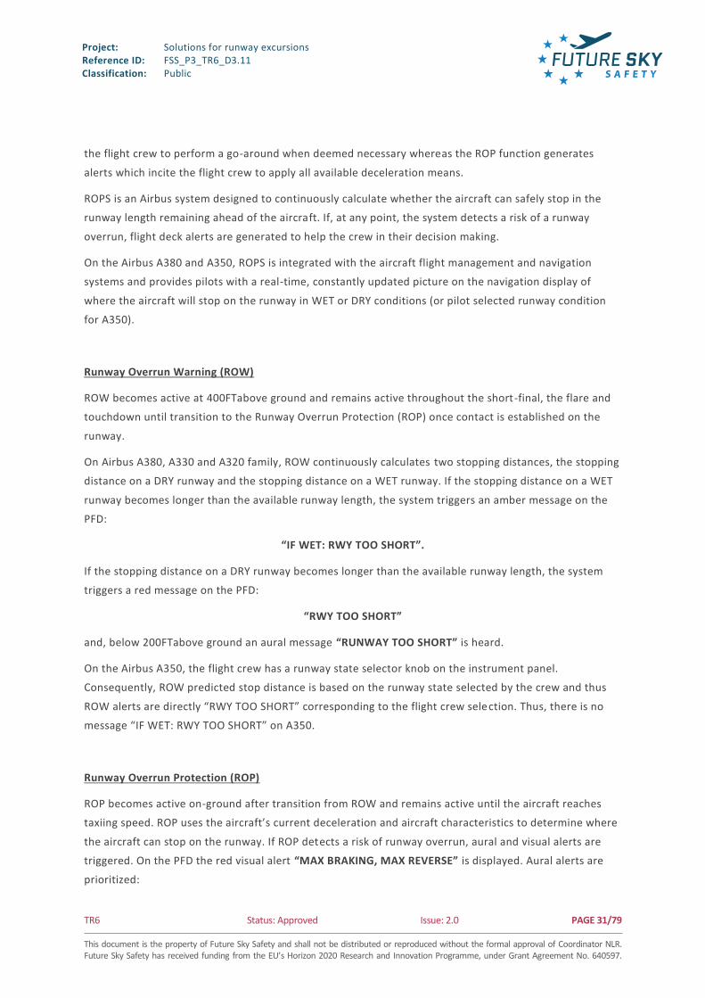
The Runway Overrun Prevention System (ROPS) is made up of two sub-functions, Runway Overrun
Warning (ROW) and Runway Overrun Protection (ROP). The ROW function generates alerts which incite
Project: Reference ID: Classification:
Solutions for runway excursions FSS_P3_TR6_D3.11 Public
TR6 Status: Approved Issue: 2.0 PAGE 31/79 This document is the property of Future Sky Safety and shall not be distributed or reproduced without the formal approval of Coordinator NLR. Future Sky Safety has received funding from the EU’s Horizon 2020 Research and Innovation Programme, under Grant Agreement No. 640597.
the flight crew to perform a go-around when deemed necessary whereas the ROP function generates
alerts which incite the flight crew to apply all available deceleration means.
ROPS is an Airbus system designed to continuously calculate whether the aircraft can safely stop in the
runway length remaining ahead of the aircraft. If, at any point, the system detects a risk of a runway
overrun, flight deck alerts are generated to help the crew in their decision making.
On the Airbus A380 and A350, ROPS is integrated with the aircraft flight management and navigation
systems and provides pilots with a real-time, constantly updated picture on the navigation display of
where the aircraft will stop on the runway in WET or DRY conditions (or pilot selected runway condition
for A350).
Runway Overrun Warning (ROW)
ROW becomes active at 400FTabove ground and remains active throughout the short-final, the flare and
touchdown until transition to the Runway Overrun Protection (ROP) once contact is established on the
runway.
On Airbus A380, A330 and A320 family, ROW continuously calculates two stopping distances, the stopping
distance on a DRY runway and the stopping distance on a WET runway. If the stopping distance on a WET
runway becomes longer than the available runway length, the system triggers an amber message on the
PFD:
“IF WET: RWY TOO SHORT”.
If the stopping distance on a DRY runway becomes longer than the available runway length, the system
triggers a red message on the PFD:
“RWY TOO SHORT”
and, below 200FTabove ground an aural message “RUNWAY TOO SHORT” is heard.
On the Airbus A350, the flight crew has a runway state selector knob on the instrument panel.
Consequently, ROW predicted stop distance is based on the runway state selected by the crew and thus
ROW alerts are directly “RWY TOO SHORT” corresponding to the flight crew selection. Thus, there is no
message “IF WET: RWY TOO SHORT” on A350.
Runway Overrun Protection (ROP)
ROP becomes active on-ground after transition from ROW and remains active until the aircraft reaches
taxiing speed. ROP uses the aircraft’s current deceleration and aircraft characteristics to determine where
the aircraft can stop on the runway. If ROP detects a risk of runway overrun, aural and visual alerts are
triggered. On the PFD the red visual alert “MAX BRAKING, MAX REVERSE” is displayed. Aural alerts are
prioritized:

Project: Reference ID: Classification:
Solutions for runway excursions FSS_P3_TR6_D3.11 Public
TR6 Status: Approved Issue: 2.0 PAGE 32/79 This document is the property of Future Sky Safety and shall not be distributed or reproduced without the formal approval of Coordinator NLR. Future Sky Safety has received funding from the EU’s Horizon 2020 Research and Innovation Programme, under Grant Agreement No. 640597.
“BRAKE, MAX BRAKING, MAX BRAKING” aural alert is triggered until pilot application of pedal braking,
then aural alert “SET MAX REVERSE” if maximum reverse thrust has not been selected. If overrun
condition still exists at 70KT, the aural alert “KEEP MAX REVERSE” will trigger to remind the flight crew to
keep maximum reverse thrust.
ROP is reversible and alerts are cancelled when overrun risk is no longer present.
On the Airbus A380 and A350, if an autobrake mode is engaged, ROP will automatically apply maximum
braking in case of runway overrun risk.
2.1.2.3. Onboard and aircraft based computation of Braking Action
2.1.2.3.1. Recall Definition
The runway slipperiness is assessed on-board the aircraft and then the information is displayed to the
pilot and is disseminated to the ground to two main ground stakeholders: airline operators and airport
operators. The function called Braking Action Computation is developed by Airbus in the frame of the
CORSAIR project.
Pilot
The function will help pilot in addition of his/her experience to decide the braking action to report to ATC
Airline
The concept will provide a mean to the airline to monitor consistently slipperiness of runways covered by
its fleet. It will enable better safety decisions at Airline Operating Center level
Airport
The described system will help airports for strategic and tactical decisions in coordination with the ATC for
runway closures, runway cleaning, and runway condition measurements.
Using the standardized terminology found in the RCAM, the Airbus technology can integrate in the same
way that PIREPs are used today. Within the airport infrastructure, the data will permit users to consult, in
real time, the reports sent by aircraft and the trend of the runway condition. By geo -locating the runway
condition(s) on the runway, the technology allows for increased situational awareness as to wher e runway
contamination may be accumulating on the runway.
Nevertheless, this technology is not designed to replace existing means at the airport, but rather to
complement them.
The advantage is that by adding this data source, which correlates runway con dition to the aircraft
performance and is available in near-real time, the airport can consolidate all available information for
increased awareness of the overall runway condition.

Project: Reference ID: Classification:
Solutions for runway excursions FSS_P3_TR6_D3.11 Public
TR6 Status: Approved Issue: 2.0 PAGE 33/79 This document is the property of Future Sky Safety and shall not be distributed or reproduced without the formal approval of Coordinator NLR. Future Sky Safety has received funding from the EU’s Horizon 2020 Research and Innovation Programme, under Grant Agreement No. 640597.
2.1.2.3.2. Limits
The limits of this technology are that identification can only be made on portions of the runway where the
aircraft was adequately braking (i.e. not discontinuing the braking). Thus the calculated braking action
may not be representative of the entirety of the runway length; there may be portions with worse braking
action, or better.
2.1.2.4. Assessing braking performance on unpaved runway
2.1.2.4.1. Aim and Objectives
Airbus Defense and Space proposal is devoted to developing the capability of aircraft operators to
calculate more accurate braking performance on unpaved runways. The main ta rget is to develop a
software tool capable of estimating the maximum braking capability that a certain unpaved runway is
capable of offering. This may provide substantial benefits in terms of safety enhancement, as will be
discussed later.
A double target is pursued:
In the short term (quasi-real time), the aim is to characterize braking friction capability of an
aircraft on a certain unpaved runway. The objective is to inform incoming aircraft of
expected/achievable braking performance, in terms of RCR (Runway Condition Reading).
In the mid-term, the aim is to relate registered braking capability with encountered runway
conditions. The objective is to predict braking performance beforehand .
2.1.2.4.2. Unpaved Runways (URW): particularities and characterization
2.1.2.4.2.1. Key Concepts
By definition, unpaved runways (URW) are surfaces intended for low-speed operations that are not
established over a stable and well-maintained base. They may have received (or not) some type of
preparation to improve their load-bearing capacity.
URW soils present a wide variability in terms of physical properties. The most relevant physical features
are composition, unevenness, water content and soil density. In particular, composition can be
adequately characterized by means of the United Soil Classification System (USCS), which provides soil
classification criteria in terms of material (gravel, sand, silt, clay, organic) and texture (poor or well
graded, high or low plasticity). The presence of vegetation and its correspondent roots is also a cr ucial
matter.
Another essential feature for URW characterization is the determination of soil load bearing capacity. In
the same manner as it is used for runway surrounding with regards to mitigation, this is generally

Project: Reference ID: Classification:
Solutions for runway excursions FSS_P3_TR6_D3.11 Public
TR6 Status: Approved Issue: 2.0 PAGE 34/79 This document is the property of Future Sky Safety and shall not be distributed or reproduced without the formal approval of Coordinator NLR. Future Sky Safety has received funding from the EU’s Horizon 2020 Research and Innovation Programme, under Grant Agreement No. 640597.
expressed in terms of California Bearing Ratio (CBR), which expresses the relative load bearing capacity of
a given soil section in comparison to that of crushed limestone.
In general, neither physical nor load bearing properties can be expected to remain constant along the
length of a runway. This constitutes one of the main challenges for URW performance evaluation.
In addition to this, changes in physical properties are expected to translate into modifications of load
bearing capacity. Nevertheless, the link between these two items is neither obvious nor quantifiable, and
must normally be estimated by means of adequate soil testing (e.g. material analysis, soaking tests).
2.1.2.4.2.2. Particularities
One of the main challenges of URW performance calculation is the non-negligible differences that this
kind of surfaces presents with respect to paved ones. As previously stated, URWs normally present non -
uniform surface characteristics, including possible roughness and unevenness. Therefore, for a given
aircraft operation, the actual runway conditions may differ from those expected (as provided in the
airfield AIP for example).
In addition to this, URWs may be sensitive to aircraft and maintenance actions, such as aircraft operations
and repair procedures. Although regular maintenance work (rut removal, grading, rolling) is usually
planned after a specified period or a certain number of operations is completed, it rarely returns the
runway to its original state and will require a specific survey to re-characterize the runway surface.
Meteorology also has a non-negligible effect on surface characteristics and, as a result, on braking
capability. For example, runways with low drainage capacity will be highly affected by rain and moisture.
Likewise, runways located in very cold zones may be subjected to seasonal frost, which illustrates the
variability of conditions, in this case with season, that a given unpaved runway may present.
Finally, URW composition cannot be subjected to the same exhaustive control as a paved runway. Paved
runways can be actively controlled from their construction, in terms of materials used and layer thickness.
In contrast, unpaved runways are roughly set over a pre-existing soil, which limits the extent of control on
them. Nevertheless, two sources of secondary control have been found:
Active control means: Addition of new materials (if required).
Passive control means: Composition characterization and analysis (i.e. soaking test results).
As a result of all this, operations repeatability is highly compromised.
2.1.2.4.2.3. Characterization
One of the most comprehensive URW characterization methods is the one provided by Transport Canada.
According to their recommendations, CBR survey should be conducted at least yearly until a trend is
established. After that, they may be repeated every three years or when deemed necessary. Each survey
should comprise at least 20 CBR samples, taken along the runway length in the expected landing gear
path.
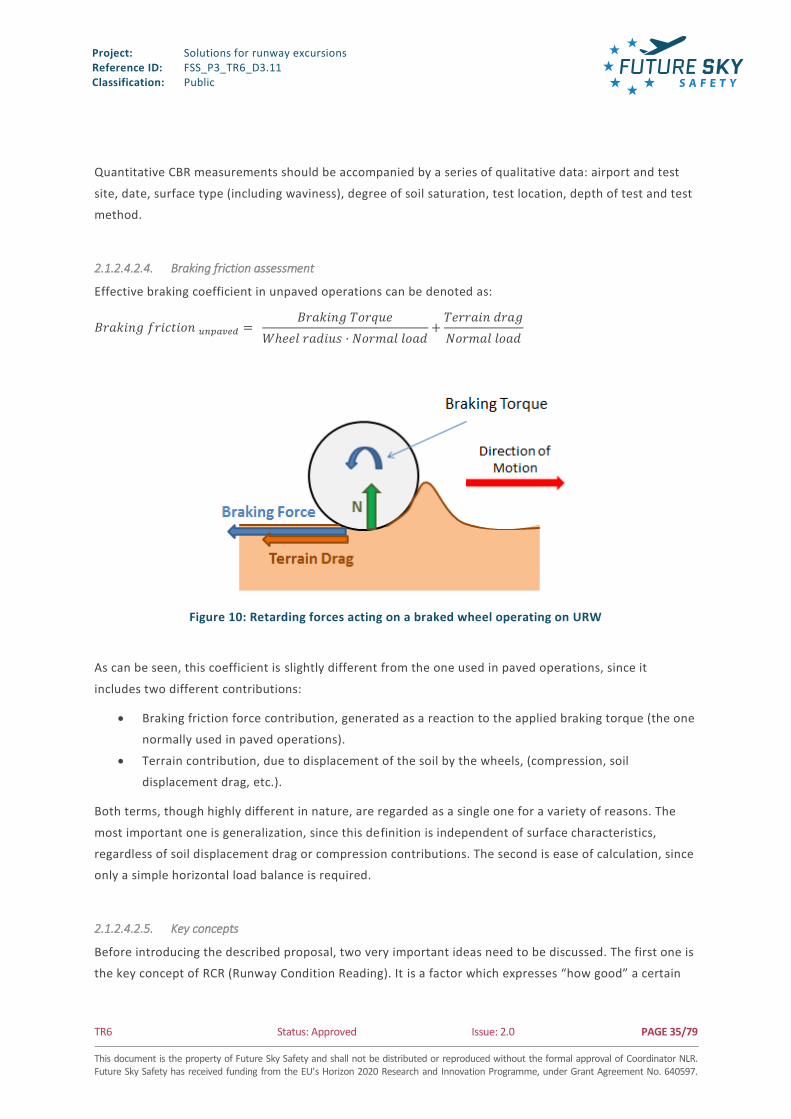
Project: Reference ID: Classification:
Solutions for runway excursions FSS_P3_TR6_D3.11 Public
TR6 Status: Approved Issue: 2.0 PAGE 35/79 This document is the property of Future Sky Safety and shall not be distributed or reproduced without the formal approval of Coordinator NLR. Future Sky Safety has received funding from the EU’s Horizon 2020 Research and Innovation Programme, under Grant Agreement No. 640597.
Quantitative CBR measurements should be accompanied by a series of qualitative data: airport and test
site, date, surface type (including waviness), degree of soil saturation, test location, depth of test and test
method.
2.1.2.4.2.4. Braking friction assessment
Effective braking coefficient in unpaved operations can be denoted as:
𝐵𝑟𝑎𝑘𝑖𝑛𝑔 𝑓𝑟𝑖𝑐𝑡𝑖𝑜𝑛 𝑢𝑛𝑝𝑎𝑣𝑒𝑑 = 𝐵𝑟𝑎𝑘𝑖𝑛𝑔 𝑇𝑜𝑟𝑞𝑢𝑒
𝑊ℎ𝑒𝑒𝑙 𝑟𝑎𝑑𝑖𝑢𝑠 · 𝑁𝑜𝑟𝑚𝑎𝑙 𝑙𝑜𝑎𝑑+
𝑇𝑒𝑟𝑟𝑎𝑖𝑛 𝑑𝑟𝑎𝑔
𝑁𝑜𝑟𝑚𝑎𝑙 𝑙𝑜𝑎𝑑
Figure 10: Retarding forces acting on a braked wheel operating on URW
As can be seen, this coefficient is slightly different from the one used in paved operations, since it
includes two different contributions:
Braking friction force contribution, generated as a reaction to the applied braking torque (the one
normally used in paved operations).
Terrain contribution, due to displacement of the soil by the wheels, (compression, soil
displacement drag, etc.).
Both terms, though highly different in nature, are regarded as a single one for a variety of reasons. The
most important one is generalization, since this definition is independent of surface characteristics,
regardless of soil displacement drag or compression contributions. The second is ease of calculation, since
only a simple horizontal load balance is required.
2.1.2.4.2.5. Key concepts
Before introducing the described proposal, two very important ideas need to be discussed. The first one is
the key concept of RCR (Runway Condition Reading). It is a factor which expresses “how good” a certain

Project: Reference ID: Classification:
Solutions for runway excursions FSS_P3_TR6_D3.11 Public
TR6 Status: Approved Issue: 2.0 PAGE 36/79 This document is the property of Future Sky Safety and shall not be distributed or reproduced without the formal approval of Coordinator NLR. Future Sky Safety has received funding from the EU’s Horizon 2020 Research and Innovation Programme, under Grant Agreement No. 640597.
braking operation is when compared to an analogous operation performed on a paved runway. It can be
defined as:
𝑅𝐶𝑅 = 𝐵𝑟𝑎𝑘𝑖𝑛𝑔 𝑓𝑟𝑖𝑐𝑡𝑖𝑜𝑛𝑢𝑛𝑝𝑎𝑣𝑒𝑑
𝐵𝑟𝑎𝑘𝑖𝑛𝑔 𝑓𝑟𝑖𝑐𝑡𝑖𝑜𝑛𝑝𝑎𝑣𝑒𝑑
𝑥 23
For the sake of simplicity, braking operations are normally characterized in terms of a s ingle, “equivalent”
RCR value. This represents the constant braking friction which would have been necessary in order to
achieve the same braking distance registered on a certain operation.
The calculation of this equivalent RCR is performed by means of the application of distance validation
algorithms. The aim of these calculations is to compare the distance required in a certain braked
operation with the calculated braking distance which would have been required if a certain constant RCR
had been applied. The result is a certain difference between the distance actually used in the operation
and the distance predicted by the model, denoted as Δdist(operation-model).
Figure 11: Schematic representation of a distance validation calculation
As shown in Figure 11, Δdist> 0 means that the distance required for braking is higher than predicted by
the selected RCR (lower safety margin). That is, actual RCR is lower than predicted. On the contrary, if
Δdist< 0, the distance required for braking is lower than predicted by the selected RCR, so the actual RCR
is higher than predicted. In that case the safety margin is increased potentially affecting the operations on
the runway.
If this algorithm is repeatedly launched in an iterative fashion, varying RCR according to the Δdist values
achieved in each iteration, it is possible to reach the RCR value which matches exactly the distance
measured in the braking phase of a landing operation.

Project: Reference ID: Classification:
Solutions for runway excursions FSS_P3_TR6_D3.11 Public
TR6 Status: Approved Issue: 2.0 PAGE 37/79 This document is the property of Future Sky Safety and shall not be distributed or reproduced without the formal approval of Coordinator NLR. Future Sky Safety has received funding from the EU’s Horizon 2020 Research and Innovation Programme, under Grant Agreement No. 640597.
2.1.2.4.2.6. Tool Description
As explained previously, the aim is to find, by means of subsequent automatic analysis, the RCR level that
would yield consistent level of braking performance, on a given unpaved runway under given con ditions.
On a daily basis (short-term objective), this would allow incoming aircraft to be informed of
expected/achievable braking performance, in terms of RCR. This is to be done by applying the previously
described iterative distance validation method, right after a certain braking operation has been
completed. The process is schematically explained in Figure 12 below.
Figure 12: Short-term (quasi-real time) utility of the proposed concept
The calculated RCR values, combined with their corresponding runway conditions, can be used to
generate a series of databases. Each database corresponds to a single, identified runway. The highe r the
number of recorded operations under different runway conditions, the more powerful the database will
be in terms of predicting braking performance. This is shown in Figure 13 and Figure 14 below.
Figure 13: Database generation (for a certain runway)

Project: Reference ID: Classification:
Solutions for runway excursions FSS_P3_TR6_D3.11 Public
TR6 Status: Approved Issue: 2.0 PAGE 38/79 This document is the property of Future Sky Safety and shall not be distributed or reproduced without the formal approval of Coordinator NLR. Future Sky Safety has received funding from the EU’s Horizon 2020 Research and Innovation Programme, under Grant Agreement No. 640597.
Figure 14: Mid-term (deferred time) utility of the proposed concept
2.1.2.4.2.7. Applicability
The concept is to be applied to well characterized and frequently used runways, where:
Systematic control of runway conditions, maintenance actions and meteorology is conducted.
Frequent use of the runway is expected.
Previous knowledge of the runway is important due to all the difficulties and particularities inherent to
URW that have been identified. But it also matters for another reason: the need for achieving the friction
limit of the surface. It is not possible to get to know the maximum friction capability of the runway if the
friction limit is not reached. The easiest way to achieve compliance with this requirement is either by
applying full pedal (in manual braking) or by ordering the maximum deceleration from the automatic
braking system.
2.1.2.4.3. Awareness on landing assessment
The concept consists in assisting the crew at early stage of the approach, i.e. before the top of descent,
for assessing the potential risk of excursion when operating a designated runway. The proposal is to
provide, a tool supporting strategic decision making process of the flight crew. By collecting information
related to the major causes of runway overrun, the tool delivers comprehensive and synthetic level of risk
of overrun for a designated runway.
Among the contributing factors to the runway overrun, the following factors can be mitigated on a
strategic term and are then worth to be processed by the tool and presented to the flight crew.
Weather condition affecting aircraft stabilization on approach,
Tailwind and crosswind near landing
Runway characteristic (short LDA, runway slope)
Runway contamination status
System failure impacting landing distance (failure on one engine, on flap configuration, on ground
spoiler, on brakes…)

Project: Reference ID: Classification:
Solutions for runway excursions FSS_P3_TR6_D3.11 Public
TR6 Status: Approved Issue: 2.0 PAGE 39/79 This document is the property of Future Sky Safety and shall not be distributed or reproduced without the formal approval of Coordinator NLR. Future Sky Safety has received funding from the EU’s Horizon 2020 Research and Innovation Programme, under Grant Agreement No. 640597.
The landing assessment tool monitors the level of risk of overrun from the top of descent down to the
final approach (around 1000FT AGL) where the ROAAS takes over with a tactical overrun risk protection.
Before the top of descent, the crew collects initial information from weather condition on the destination
airport as long as the information on the operated runways and their associated contamination status is
available. The crew then proceeds with performance calculation. The crew crosschecks with runway
characteristics to assess the landing capacity and define the landing and braking strategy.
The landing assessment tool allows manual entry by the flight crew for most parameters in order to
comply with current practice where most of the information is gathered by the flight crew itself. The
integration of such tool in the avionics gives access to automation that relieves the crew from gathering
and entering manually the data.
Figure 15: Example of deployment on EFB
The landing assessment is run with a ROAAS like calculation providing estimated landing distance required
to stop the aircraft. The similar computation method between the assessment tool and the ROAAS
provide additional consistency between the strategic assessment and the tactical assessment. The landing
assessment calculation intends to run ROAAS-like function with estimated parameters characterizing the
external situation (winds, temperature, turbulence on the approach path, runway contamination, runway
geometry) and the internal state (configuration, approach speed, mass, failure of equipment affecting
landing distance). For strategic assessment, unless the failure of critical equipment, the approach
configuration and path are considered nominal, in compliance with prescribed SOP. The major variation

Project: Reference ID: Classification:
Solutions for runway excursions FSS_P3_TR6_D3.11 Public
TR6 Status: Approved Issue: 2.0 PAGE 40/79 This document is the property of Future Sky Safety and shall not be distributed or reproduced without the formal approval of Coordinator NLR. Future Sky Safety has received funding from the EU’s Horizon 2020 Research and Innovation Programme, under Grant Agreement No. 640597.
on the landing assessment would come from evolving external conditions and unpredictable failure of an
equipment affecting landing distance. The impact of the failure of equipment is relevant only when the
failure occurred. In the landing assessment synthesis delivered to the flight crew, the impact of
equipment failure is silenced unless the failure is present.
The impact of degrading weather situation is however retained as useful information to be passed on to
flight crew.
From a flight crew perspective, it is necessary to obtain a landing assessment that is as close as possible to
actual operational landing capacity but it is also important to understand the margin remaining in
anticipation of a degrading situation. For a given runway, the impact of a degrading situation can be given
with impact of degraded component (for instance providing assessment for current situation plus +15KT
tail wind, Delta ISA +10 or degraded runway state +1 in TALPA RWCC or giving degradation level that
would prevent the landing on the runway). The following figure provides a typical view of an EFB interface
delivering landing distance information to the flight crew.
Figure 16: Required landing distance for current rwycc and rwycc +1
On that generic interface, the flight crew can manually interact with the system. Upon selection of the
destination airport and the landing runway, the flight crew inserts in the system the estimated landing

Project: Reference ID: Classification:
Solutions for runway excursions FSS_P3_TR6_D3.11 Public
TR6 Status: Approved Issue: 2.0 PAGE 41/79 This document is the property of Future Sky Safety and shall not be distributed or reproduced without the formal approval of Coordinator NLR. Future Sky Safety has received funding from the EU’s Horizon 2020 Research and Innovation Programme, under Grant Agreement No. 640597.
parameters to compare the landing distance with the available distance on the designated runway. With
the connection to the avionics, all these selections are achieved through retrieval of FMS prediction, wind
and runway status from connection to the ground (D-ATIS from ATC for instance).The limitation for the
automation is the slow deployment of airport status reported information through digital link with format
adapted to simple computer process. The tool intends to propose the capacity to operate with current
procedure (mainly vocal exchange with the ATC) and propose the progressive automation accompanying
development of new FMS interface, access to airport information digital link from equipped airport and
retrieval of weather information from weather providers.
Monitoring weather evolution around the airport
In previous feasibility reports[1], we established that the ATIS/ D-ATIS information were the preferred
channel to collect both weather on approach and runway contamination status to feed into the landing
assessment tool. The information gathered in the ATIS/D-ATIS undergoes the process of collection from
relevant ground key player (MET office, airport authority) and adjustment by ATS with addition of Pilot
REPort information. However, for an on-board tool perspective, the main limitation using the ATIS/D-ATIS
is the format of the data itself. Despite European recommendation for deployment of D -ATIS, very few
airports are equipped and majority of them disseminate information through vocal ATIS frequency. The
machine processing of the vocal ATIS is complex and subjected to error due to vocal recognition
technology over VHF signal. The second limitation is the structuration of the ATIS/D -ATIS information. The
D-ATIS information, even if it is intended to be processed by machine, is oriented towards display of the
message to the flight crew rather than interpretation of the sense of the message by a system. The digital
message is delivered as raw textual format without strict structure which makes interpretation effort still
complex for an on-board tool.
In order to cover the case where D-ATIS is not delivered by the destination airport, it is proposed to
integrate an uplink weather function. The landing assessment tool includes uplink weather function taking
advantage of open- world communication to retrieve updated METAR, TAF and SPECI on any airports. As
an alternative to weather information from D-ATIS, the landing assessment tool collects and decodes
METAR and SPECI to evaluate current information for the airport. With adoption of the amendment 77 of
ICAO annex 3, the exchange of data on the ground segment will comply with structured format of data
(from 2017 to 2020) much more machine oriented than current format. By using an intermediate ground
system it provides the capacity to interrogate automatically (i.e. in lieu of the flight crew) for a given list
of airport (for instance destination and relevant alternates).
Additional weather products are available from the MET providers that introduce short term prediction
(nowcast with a 1-hour prediction) that can provide awareness information for the flight crew on
potential adverse weather on the aircraft path during the descent and the approach to the airport.
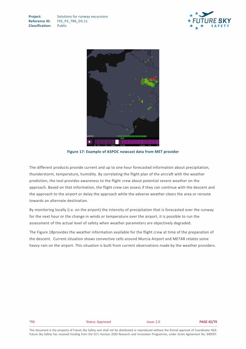
Project: Reference ID: Classification:
Solutions for runway excursions FSS_P3_TR6_D3.11 Public
TR6 Status: Approved Issue: 2.0 PAGE 42/79 This document is the property of Future Sky Safety and shall not be distributed or reproduced without the formal approval of Coordinator NLR. Future Sky Safety has received funding from the EU’s Horizon 2020 Research and Innovation Programme, under Grant Agreement No. 640597.
Figure 17: Example of ASPOC nowcast data from MET provider
The different products provide current and up to one hour forecasted information about precipitation,
thunderstorm, temperature, humidity. By correlating the flight plan of the aircraft with the weather
prediction, the tool provides awareness to the flight crew about potential severe weather on the
approach. Based on that information, the flight crew can assess if they can continue with the descent and
the approach to the airport or delay the approach while the adverse weather clears the area or reroute
towards an alternate destination.
By monitoring locally (i.e. on the airport) the intensity of precipitation that is forecasted over the runway
for the next hour or the change in winds or temperature over the airport, it is possible to run the
assessment of the actual level of safety when weather parameters are objectively degraded.
The Figure 18provides the weather information available for the flight crew at time of the preparation of
the descent. Current situation shows convective cells around Murcia Airport and METAR relates some
heavy rain on the airport. This situation is built from current observations made by the weather providers.

Project: Reference ID: Classification:
Solutions for runway excursions FSS_P3_TR6_D3.11 Public
TR6 Status: Approved Issue: 2.0 PAGE 43/79 This document is the property of Future Sky Safety and shall not be distributed or reproduced without the formal approval of Coordinator NLR. Future Sky Safety has received funding from the EU’s Horizon 2020 Research and Innovation Programme, under Grant Agreement No. 640597.
Figure 18: Example of thunderstorm nowcast data from MET provider 30 min before landing (measured)
The Figure 19represents the anticipated situation as estimated by the weather provider at the time of the
landing. The projection of the weather situation, available over 1 hour ahead of current time is the result
of the mix between current situation and weather model run by the weather provider. The flight crew
accesses this information by scrolling the time line (green bar on bottom of the image) at the time of
landing to get the estimated weather situation for the landing. On the figure, the convective cell heading
towards Murcia is dissipating (severity of the phenomena is requalified from severe to light). This kind of
awareness help the flight crew make its decision on the approach path to adopt for safely landing at
destination.

Project: Reference ID: Classification:
Solutions for runway excursions FSS_P3_TR6_D3.11 Public
TR6 Status: Approved Issue: 2.0 PAGE 44/79 This document is the property of Future Sky Safety and shall not be distributed or reproduced without the formal approval of Coordinator NLR. Future Sky Safety has received funding from the EU’s Horizon 2020 Research and Innovation Programme, under Grant Agreement No. 640597.
Figure 19: Example of thunderstorm nowcast data from MET prediction at landing time
By correlating METAR and the nowcast information, the degradation can be estimated more accurately.
This correlation is particularly relevant for situation with rapidly changing weather condition.
Monitoring of the runway condition
The landing assessment, in order to be accurate, requires the knowledge of the contamination of the
runway. This information is mainly provided by voice either by ATIS or direct communication between the
ATC and the crew. Following TALPA ARC recommendation, ICAO State members are progressively
adopting the new runway contamination evaluation (RCAM) and reporting practice. As described in the
previous feasibility document [1], the ATIS/ D-ATIS integrates this information but with the same access
restriction due to the nature of the ATIS/ D-ATIS.
In a similar way than for weather monitoring, the alternative to ATIS/D-ATIS information consist in
retrieving NOTAM/ SNOWTAM and decode it to extract runway contamination code. With addition of
weather information, it is possible to estimate the runway contamination by cross -referencing NOTAM
and weather information. This alternative can be offered with airport facilities with different level of
ground equipment. The structuration of the ground segment is progressing whereas the limitation
remains on the air-ground transmission of information. NOTAM information becomes accessible from
federated ground systems.
Assisting the crew for the choice of alternates
With the addition of connection to new FMS generation, i.e. interactive FMS or extended FMS, the landing
assessment can also be extended to runway from airports other than the destination airport. By testing

Project: Reference ID: Classification:
Solutions for runway excursions FSS_P3_TR6_D3.11 Public
TR6 Status: Approved Issue: 2.0 PAGE 45/79 This document is the property of Future Sky Safety and shall not be distributed or reproduced without the formal approval of Coordinator NLR. Future Sky Safety has received funding from the EU’s Horizon 2020 Research and Innovation Programme, under Grant Agreement No. 640597.
several alternates, the landing assessment can be run simultaneously on several airports, final
destination, alternates or closest airports and delivers to the crew, over one glimpse, information on risk
of excursion on the surrounding runways. This feature is mostly used upon diversion or in emergency
situations, supporting the crew with already available landing assessments for a list of airports of interest.
When the crew in an emergency situation today would not have enough time to refine the analysis for
each possible alternate and therefore make a decision biased by missing information, the system reduces
the workload and the level of stress by presenting consolidated information about alternatives to pick up.
2.1.2.5. Crosswind Landing Assistance System
In the Future Sky Safety Project P3, the German Aerospace Center DLR Institute of Flight Systems
developed an airborne pilot assistance system for crosswind landings in order to reduce the risk of
crosswind related runway excursions. In the context of crosswind operations, runway excursions are
mostly veer-offs and not runway overruns. During crosswind landings (and take-offs as well), lateral
control of the aircraft on the runway is essential. The developed on-board system shall assist the pilot in
this.
The idea behind the crosswind landing assistance system is the application of a steerable main landing
gear so that, under the presence of crosswind, the aircraft can touchdown in crabbed motion and without
the necessity of a so-called de-crab maneuver. The de-crab maneuver is performed automatically by the
assistance system after touchdown on the runway so that after the roll out the aircraft is able to taxi
conventionally. The design and development of the assistance system is described in detail in P3 project
deliverable report D3.9[1]. Here, only those information on the system design shall be given, which are
necessary for the interpretation of the evaluation results.
The evaluation of simulation results using the autopilot and autoland system in combination with the
crosswind landing assistance system were given in report D3.9[1]. Those simulations showed that the
developed assistance system is able to keep the aircraft safely on the runway centerline with a crosswind
component of up to 50 KT. For the evaluation of the system’s capabilities to also effectively prevent
runway veer-offs under strong crosswinds also in manual flight, the motion-based A320 full-flight-
simulator of the AVES-simulator center, operated by the DLR Institute of Flight Systems [2], was used for
pilot trials. The landing gear model of the AVES-A320-simulation model was adapted in order to allow
main gear steering functionality. The modeling of the steerable main landing gear is given in report D3.9
[1]. The crosswind landing assistance system as described D3.9 [1]was implemented in the flight control /
autoflight system of the AVES-A320-simulation in a way to allow the use of the assistance system both in
manual flight as well as for automatic landings with autopilot engaged. Figure 20 shows an impression of
the outside and inside view of the A320-cockpit of the AVES motion-simulator. In order to allow full
flexibility for scientific purposes the simulator is not certified for pilot training, however the simulation
accuracy fulfils Level-D standard in a wide range [2,3].

Project: Reference ID: Classification:
Solutions for runway excursions FSS_P3_TR6_D3.11 Public
TR6 Status: Approved Issue: 2.0 PAGE 46/79 This document is the property of Future Sky Safety and shall not be distributed or reproduced without the formal approval of Coordinator NLR. Future Sky Safety has received funding from the EU’s Horizon 2020 Research and Innovation Programme, under Grant Agreement No. 640597.
Figure 20: The AVES A320 simulator
In the AVES-A320-simulator a test campaign was conducted with three pilots. All of them are airline pilots
with experience on different aircraft types. However, all pilots were familiar with Airbus aircraft.
The task for the pilots was to perform an ILS approach and a manual landing on Frankfurt/Main runway
25C under different crosswind conditions ranging from 0 KT to 40 KT crosswind at touchdown. Along the
glide path the wind was varied in terms of speed and direction ending up in a pre -defined wind direction
and speed at 10 m above the runway in order to give a realistic feeling of th e wind variation during the
approach to the pilots. For the completeness also the clouds and visibility were adapted in a way to give a
look of a realistic weather scenario with strong winds. The following METAR was given to the pilots during
the briefing representing the exemplary weather conditions:
EDDF 121230Z 17019G29KT 999 -RA FEW006 BKN010 BKN030 5/4 Q988,
meaning a wind direction of 170° with 19KT wind speed and gusts up to 29KT (in the simulation the wind
direction at 10m above the runway was fixed to 170°, whereas the wind speed was varied), good visibility
(set to 10KM in the simulation), light rain, few clouds in 600FT AGL, a broken cloud layer in 1000 FT AGL
and another broken cloud layer in 3000FT AGL., a temperature of 5 degrees Celsius, dew point of 4
degrees Celsius and a QNH of 988hPa. Gusts were not implemented in the simulation. The approaches and
landings were typically simulated without atmospheric turbulence in order to allow the full comparability
of the test runs. This should prevent that a possible degradation of the pilots’ performance is only due to
the high crosswind component and not due to the turbulence, which typically increases with increasing
wind speed. However, in order to also consider the effect of increasing turbulence with increasing wind
speed and to give a more realistic feeling to the pilot, the simulations were also simulated with
atmospheric turbulence. Figure 21 gives two exemplary sketches of the outside view during the approach,
showing the cloudy weather. On the ride hand side photo the airport and the runway is already in sight in
the background.

Project: Reference ID: Classification:
Solutions for runway excursions FSS_P3_TR6_D3.11 Public
TR6 Status: Approved Issue: 2.0 PAGE 47/79 This document is the property of Future Sky Safety and shall not be distributed or reproduced without the formal approval of Coordinator NLR. Future Sky Safety has received funding from the EU’s Horizon 2020 Research and Innovation Programme, under Grant Agreement No. 640597.
Figure 21: Sample pictures of the outside view and the environmental scenario during the approach
As with the previous offline-simulations with autoland engaged as described in [1] the results of the
piloted simulations showed very promising results as well. Altogether, one can conclude that the system
performed well without exception in terms of prevention of runway veer-offs. Figure 22 shows the time
histories of the paths of each simulated landing with different crosswind components. The figure is limited
in the y-axis to +/- 30m matching the 60m runway width of Frankfurt’s runway 25C. One can observe in
Figure 22 that only three landings resulted in veer-offs, and one landing occurred, which was very close to
a veer-off and would have possibly been classified in reality as incident. All other paths varied laterally in
a corridor between roughly 10-15m to either side of the centerline. Generally, the paths show a windward
tendency, which can be explained by the tendency of the aircraft to yaw into the wind on ground under
crosswind operations. This is due to the aircraft acting as a weathervane under the presence of sideslip
angles, such as during crosswind landings on ground. Nevertheless, one can also observe in Figure 22 that
without the assistance system engaged (red lines) the pilots sometimes had difficulties in lateral control,
although they were still able to keep the aircraft near the runway centerline. With the assistance system
engaged (green lines) the lateral deviations from the runway centerline are significantly smaller,
especially during the first time after touchdown, when the aircraft is still at high speeds.

Project: Reference ID: Classification:
Solutions for runway excursions FSS_P3_TR6_D3.11 Public
TR6 Status: Approved Issue: 2.0 PAGE 48/79 This document is the property of Future Sky Safety and shall not be distributed or reproduced without the formal approval of Coordinator NLR. Future Sky Safety has received funding from the EU’s Horizon 2020 Research and Innovation Programme, under Grant Agreement No. 640597.
Figure 22: Lateral deviation from runway centerline after touchdown
Figure 23 shows the maximum absolute lateral deviation from the runway centerline as a function of the
crosswind component.
Figure 23: Maximum lateral deviation from runway centerline as a function of the crosswind component
On Figure 23 one can clearly observe the increasing lateral deviation from the runway centerline with
increasing crosswind component. This result is evident and can be expected due to the increasing later al
control effort with increasing crosswind caused by the weathercock stability of the aircraft. However, with

Project: Reference ID: Classification:
Solutions for runway excursions FSS_P3_TR6_D3.11 Public
TR6 Status: Approved Issue: 2.0 PAGE 49/79 This document is the property of Future Sky Safety and shall not be distributed or reproduced without the formal approval of Coordinator NLR. Future Sky Safety has received funding from the EU’s Horizon 2020 Research and Innovation Programme, under Grant Agreement No. 640597.
the assistance system engaged this increase is marginal and the maximum lateral deviation from the
runway centerline ranges within circa +/- 10m. This range can be considered as typical and uncritical, as
also without any wind (crosswind component of 0KT) the maximum lateral deviation lies within this
margin. Not only can we note that no runway veer-off occurs with the assistance system engaged, we may
also observe that the aircraft stays in close vicinity to the runway centerline, in the same manner as it
does without the presence of wind. These results demonstrate how effectively the crosswind landing
assistance system prevents runway excursions in terms of veer-offs. The simulator trials were solely
performed with a runway friction coefficient representing dry runway. Hence, the results presented here
are not directly transferable to wet or contaminated runways. However, the simulations presented in
report D3.9 [1]were also performed with a runway friction coefficient representing wet runway [7], for
which the assistance system showed satisfying results in terms of directional control up to a crosswind
component of 40KT.
Another issue one has to consider when landing in crabbed motion is the resulting lateral acceleration
during touchdown and deceleration due to the sideward motion of the aircraft on the runway. However,
lateral accelerations also occur during classical landings with de-crab due to the lateral control of the
aircraft on ground. Figure 24 shows the maximum lateral load factor ny as a function of the crosswind
component.
Figure 24: Maximum lateral load factor as a function of the crosswind component
Figure 24 shows that with the assistance system engaged the lateral load factor increases with increasing
crosswind. This effect can be explained with the increasing crab angle with increasing crosswin d, which
leads to a larger lateral component of the acceleration generated by touchdown and deceleration on the
runway due to braking. However, the maximum lateral load factor which occurred during the simulations
with the assistance system engaged was 0.2. Subjectively, this lateral acceleration during the roll out was
not recognized as annoying by the pilots; hence passenger comfort should not be harmed by the

Project: Reference ID: Classification:
Solutions for runway excursions FSS_P3_TR6_D3.11 Public
TR6 Status: Approved Issue: 2.0 PAGE 50/79 This document is the property of Future Sky Safety and shall not be distributed or reproduced without the formal approval of Coordinator NLR. Future Sky Safety has received funding from the EU’s Horizon 2020 Research and Innovation Programme, under Grant Agreement No. 640597.
touchdown in crabbed motion. This subjective impression is strongly supported by the fact that d uring
crosswind landings without the assistance system significantly larger lateral accelerations occurred due to
the more difficult lateral control of the aircraft on ground in those cases (see Figure 24).
It must be emphasized here, that pilots unanimously stated that the ground control in the simulator was
more difficult, hence the precision in controlling the aircraft on ground was degraded in comp arison to
the real aircraft. This fact might increase the resulting lateral accelerations. Nevertheless, based on the
simulation results lateral accelerations can be assumed to have no adverse implications during operations
with the assistance system engaged.
The reduction of lateral accelerations is not only an issue for passenger comfort; it also implies that the
lateral loads on the landing gear can be lowered as well by using the assistance system and steerable main
landing gears. Without such a system and with fixed main landing gears the touchdown always creates
side forces acing on the wheels, struts and tires. Even if the aircraft is perfectly aligned with the runway
by performing a de-crab maneuver the wind drift leads to side forces during touchdown. During roll out
more or less excessive side forces occur due to lateral control of the aircraft on ground and the wind force
acting on the aircraft. Figure 25 shows time histories of the main gear side force after touchdown with
and without assistance system.
One can observe in Figure 25 a distinct peek of the side force for each landing without assistance system
representing the touchdown. As mentioned above without the assistance system the touchdown results in
a peak side force due to the wind drift in sideward direction and/or a residual crab a ngle, if the de-crab is
not performed perfectly. After touchdown the side loads vary depending on the lateral control action of
the pilot. Contrary to those landings without the assistance system, the time histories of landings with the
assistance system engaged show no such distinct peek of side force during touchdown. This result is
clearly evident, as during touchdown, thanks to the assistance system, the wheels of each landing gear are
always aligned with runway, so that no side forces on the wheel can occur. After touchdown, when the
de-crab is performed by the assistance system and the gears are slowly aligned with the aircraft’s
longitudinal axis, side forces occur.

Project: Reference ID: Classification:
Solutions for runway excursions FSS_P3_TR6_D3.11 Public
TR6 Status: Approved Issue: 2.0 PAGE 51/79 This document is the property of Future Sky Safety and shall not be distributed or reproduced without the formal approval of Coordinator NLR. Future Sky Safety has received funding from the EU’s Horizon 2020 Research and Innovation Programme, under Grant Agreement No. 640597.
Figure 25: Main gear side force after touchdown
The maximum side forces, which occur during roll out, independently from whether the loads are due to
the touchdown or lateral control, are depicted in Figure 26.
Figure 26: Maximum main gear side force as a function of the crosswind component
Figure 26 outlines a generally increasing side force on the main gears with increasing crosswind for both
cases with and without the assistance system. This increase in side force is indeed expectable, as the
lateral wind force acting on the aircraft increases with increasing crosswind. However, one can clearly
observe in Figure 26 that the assistance system lowers the side forces acting on the main gear wheel

Project: Reference ID: Classification:
Solutions for runway excursions FSS_P3_TR6_D3.11 Public
TR6 Status: Approved Issue: 2.0 PAGE 52/79 This document is the property of Future Sky Safety and shall not be distributed or reproduced without the formal approval of Coordinator NLR. Future Sky Safety has received funding from the EU’s Horizon 2020 Research and Innovation Programme, under Grant Agreement No. 640597.
significantly. Again, the degraded lateral controllability of the aircraft on ground in the simulator in
comparison to the real aircraft might a reason for higher forces without the assistance system. This is
implied by those landings with no wind, where also larger side forces occurred than with the assistance
system. Nevertheless, the results show that the assistance system inevitably lowers the side forces acting
on the main landing gear. This raises the hope that, due to the reduction of the landing gear side forces by
the usage of the assistance system and steerable main landing gears, the landing gear itself can be built
lighter. By this, at least some of the additional weight of the actuators, which are necessary to steer the
main landing gear, could possibly be saved. Further studies need to be accomplished in order to
investigate the possible weight benefits from the reduction of side forces.
In conclusion, one can say that the simulator trials demonstrated the capabilities of the crosswind landing
assistance system to prevent runway excursions, or, more precisely, from crosswind -related runway veer-
offs in an effective manner. None of the landings simulated in the motion -based A320-simulator with
airline pilots resulted in a runway veer-off when the assistance system was engaged. However, the reader
should keep in mind that the A320 was only used as a platform for the demonstration of the assistance
system. The system does not aim to improve the safety of the current A320. Therefore, the results of the
simulator campaign should not be interpreted in terms of their representativeness regarding the
crosswind-related safety of the A320 but rather be seen as a proof of concept of a system that increases
resilience to runway veer-off conditions without consideration of the specific aircraft used for the
demonstration. The qualitative impression of the pilots on the functionality of the assistance system was
unanimously positive. Also, the simulation results showed that the side forces acting on the main gear
wheels can be reduced significantly by using the assistance system in combination with steerable main
landing gears. This might possibly lead to a lighter design of the landing gear for future aircraft designs,
thus the assistance system bring another positive side-effect besides improvement of flight safety

Project: Reference ID: Classification:
Solutions for runway excursions FSS_P3_TR6_D3.11 Public
TR6 Status: Approved Issue: 2.0 PAGE 53/79 This document is the property of Future Sky Safety and shall not be distributed or reproduced without the formal approval of Coordinator NLR. Future Sky Safety has received funding from the EU’s Horizon 2020 Research and Innovation Programme, under Grant Agreement No. 640597.
2.2. Safety Benefit Analysis
According to the IATA safety report, in 2016, runway excursions contributed to 22% of the accidents.
Runway excursions include landing overruns, take-off overruns, landing veer-offs, take-off veer-offs and
taxiway excursions meeting the IATA definition of an accident.
Over the five year period from 2012 to 2016, 83 percent of runway excursions occurred in the landin g
phase of flight.
There are many factors noted to have contributed to runway excursion runway.
Long, floated or bounced landings were noted in 46 percent of all runway excursion accidents
during this period, while a continued landing after an unstable approach was a factor in 14
percent of the runway excursions.
Poor weather conditions (present in 49 percent of the accidents) and airport facilities (37%) still
represent the largest components for environmental factors, while errors in the manual handling
of the aircraft were noted to have contributed to 48 percent of runway excursions.
Aircraft malfunctions, such as brake or engine malfunction are also a factor that should be noted,
having contributed to 11 percent of all runway excursions.
While the occurrence rates of aircraft flying unstable approaches or landing on contaminated runways are
low, the proportion of runway excursions from those precursors remains high.
While there was a correlation between runway excursions and wet or contaminated runw ays, there is also
need for flight crews to be conscious of the risk of excursion even in favorable conditions, with a high
percentage of the excursions having occurred in good meteorological conditions. This highlights further
the need for crews to be vigilant in the landing phase of flight, regardless of the runway conditions.
It can also be noticed that the IATA safety report does not compute what would be a total cost of the
overruns or the level of damage that could have been mitigated in a standard ru nway strip configuration.
As seen above, such calculation is now made possible thanks to the methodology published by van
Eekeren et al (2017).
2.2.1. Ground Operational Concept
2.2.1.1. Runway Contaminant Nowcasting for the next 30 minutes by water depth estimation from X-band
weather data
The airport authority is responsible for the determination of the operating rules of the runway(s),
including establishing and reporting runway contamination status to the operators. The evaluation of the
contamination of runway generally requires physical measurement conducted in low frequentation
interval as weather conditions are rather steady or forcing the interruption of the traffic when conditions
are rapidly evolving. The runway contamination remains a major factor of excursion, rated third cause by

Project: Reference ID: Classification:
Solutions for runway excursions FSS_P3_TR6_D3.11 Public
TR6 Status: Approved Issue: 2.0 PAGE 54/79 This document is the property of Future Sky Safety and shall not be distributed or reproduced without the formal approval of Coordinator NLR. Future Sky Safety has received funding from the EU’s Horizon 2020 Research and Innovation Programme, under Grant Agreement No. 640597.
runway safety initiative (Flight Safety Foundation – May 2009). The determination of the runway
condition remains a critical factor to pass on to the landing aircraft or aircraft about to takeoff to help
preventing the excursion. The Runway Excursions (RE) analysis [6]conducted by EASA over a period of 5
years from 2011 to 2015 does report 5 cases of excursion (out of 13 reported) where the runway
contamination is either the cause or an aggravating factor. It is to be noted that only 1 case out of the five
is related to a contamination by snow. The 4 other cases are all related to water on the runway due to
rain or standing water patches induced by runway topography.
The system monitors the runway contamination status and anticipates the changes by 30 min increments
and this without interruption of the traffic and independently of any traffic reporting braking action. The
depth of water information is available for the entire runway length, with the capacity to distinguish
standing water patches. The water run-off model is, as previously stated, limited to contamination with
water of the runway. Snow/slush or ice is not taken into account by the system. However, majority of the
airport has a limited exposure to snow condition but experiment rain and heavy rain phenomena that
remains the number one concern in term of contamination. The model used for the trial of the concept
shows satisfactory results but does not account for additional factor as wind above the runway (impacting
drying and water flow) and traffic using the runway blasting water out over the used part of the runway.
As specified in the feasibility study[1], these additions to the model are envisioned and would lead to a
more accurate estimation of the runway contamination.
Many airports in the sub-tropical and tropical area are experimenting monsoon phenomena that make
runway contamination hard to evaluate for the airport authority. The use of the proposed system offers
the airport the capacity to monitor in almost real-time (few minutes delay) the runway condition and to
anticipate the evolution of the condition within the next 30 minutes. The system provides better runway
contamination accuracy for the safety of the runway operation and also helps the airport authority
anticipate closure/re-opening of the runway in case of severe rainfall.
2.2.1.2. Fast & Accurate Wind Nowcasting at low altitude with LIDARs
The wind condition in the vicinity of the airport is often the cause for late destabilization of t he aircraft on
the approach or causes excursions on landing or takeoff. The wind conditions impacts the pilot capacity to
maintain good directional control of the aircraft both on landing and takeoff. The loss of control remains a
serious cause of excursion that needs to be tackled. On several overrun accidents, the tailwind factor was
neither anticipated by the crew nor accurately reported by the airport. On veer off incident, shear of wind
or severe variations of crosswind speed were not reported to the crew. The wind condition are usually
reported through ATIS information and updated by voice call in case of rapidly changing condition and
generally confirmed at the time the landing clearance is given. Most of the time, the airport does not have
an accurate enough information on wind change to evaluate whether shear of wind are collocated with
the approach path or the runway. The reported conditions are based on instantaneous measurement of
wind speed over several points around the airport. From the scarce measurement point, it is difficult to
evaluate wind front, shear of winds and their evolution.

Project: Reference ID: Classification:
Solutions for runway excursions FSS_P3_TR6_D3.11 Public
TR6 Status: Approved Issue: 2.0 PAGE 55/79 This document is the property of Future Sky Safety and shall not be distributed or reproduced without the formal approval of Coordinator NLR. Future Sky Safety has received funding from the EU’s Horizon 2020 Research and Innovation Programme, under Grant Agreement No. 640597.
The proposed system uses new LIDAR technology to scan an entire area over the runway and 4NM out
along the approach area. The LIDAR allows mapping the wind conditions over the scanned area with a
very good accuracy (1m/s). The propose setup allows detecting wind variation over the approach path
after last stabilization point (pilots generally decide of a continue/go around based on the parameters
they have at 1000FT AGL when no outside reference is obtained (or in IFR) or at 500FT AGL in VFR
conditions) and then track late destabilization wind conditions. Once on the runway, the first sector of the
deceleration is also covered by the radar but in order to improve complete coverage of the runway it is
probably wise to move the radar back to a point close to the center of the runway. Using the LIDAR
simultaneously on both runway sides, one can obtain the complete mapping over the runway and both
approach sides. The sensor itself is less than one meter high which allow installation on the side of the
runway. The radar scanning aperture is a limitation in term of anticipation of the incoming phenomena.
Additional sensors would be necessary to extend the scanning area and thus track the turbulences before
they affect the approach path and potentially destabilize approaching aircraft. The mapping information is
useful to the traffic controller for estimation of the risk of destabili zation due to shear of wind or wake
vortex. Detail information on turbulence / wind condition on approach can also be useful for the crew to
visualize area of risk and anticipate piloting techniques. The report of such information is currently limited
by datalink capacity.
As for today, the experimentation of such LIDAR highlighted some necessary improvements:
The limitation of the detection range for the wind analysis in rainy or foggy situation. As per
previous analysis [8], solution mixing 95GHZradar would improve the wind analysis in heavy rain
or fog condition
The current evaluated product need to be modified to allow the installation on safe area around
the runway (work on shifting capacity of the beam to remain at more than 300m from the runway
centerline).
2.2.1.3. Ground Runway Excursion Monitoring System by Big Data Analytics
The system is a support tool for the ATC to detect potential overrun hazard from incoming ai rcraft. It
intends to inform ATC on the capability for the coming aircraft to stop on the runway. The system uses
aircraft dynamic information from ground radar to estimate a risk of overrun by correlating the dynamic
aircraft information with a database of A/C landing on this runway compiled with analysis of an historic of
previous landings and identification of correlation factor to a risk of overrun. As the system is based on
learning techniques applied on all aircraft landing over multiple conditions, i t is agnostic to the aircraft
fine performance and equipment. Installed on an airport, the system provides improvements for ATC
spacing strategy and traffic management optimizing the airport operations. Safety improvement is derived
from the integration of the risk of overrun in the management of the airport capacity. ATC includes
monitoring of the risk for all covered runway and for all incoming aircraft. The potential gain in safety is
the assurance that the optimization of traffic management respects an equivalent level of safety on
overrun while improving the operation. The system could also introduce resilience of the overrun

Project: Reference ID: Classification:
Solutions for runway excursions FSS_P3_TR6_D3.11 Public
TR6 Status: Approved Issue: 2.0 PAGE 56/79 This document is the property of Future Sky Safety and shall not be distributed or reproduced without the formal approval of Coordinator NLR. Future Sky Safety has received funding from the EU’s Horizon 2020 Research and Innovation Programme, under Grant Agreement No. 640597.
prevention by identifying a risk of overrun from the ground independent from the aircraft and its
equipment with ROAAS like system. However these potential gains of safety are limited by :
The accuracy of the overrun risk evaluation by comparison of an on-board system, mainly due to
approximation on the aircraft mass and unknown aircraft limitation due to system failure.
The delay between the detection of the overrun condition and the corrective action taken by the
flight crew. The necessary anticipation to encompass communication delay (voice communication
as of today) would be prone to nuisance alert.
Acceptance of ATC and flight crew to have an additional safety net with partial delegation of
alerting process to the ATC.
2.2.1.4. Arresting System with Engineered Material
Several concepts to lower the risk of runway excursions have been studied within the course of Future Sky
Safety Program. The airborne systems or technologies present the advantages of being integrated in the
aircraft instruments. They are complementary to pilot training and other procedures to make each flight
safer and increase the likelihood of the aircraft staying on the runway. Also, as they are embedded in the
aircraft systems, they offer the improvements on every single flight providing the data that is required is
available. In some cases, the precise coordinates of a runway threshold may be required for the syst ems
to give their full potential, inaccurate or missing information may trigger false alarms or erroneous
response of the systems. Also, the implementation of those systems usually requires significant
investment, both in financial terms but also in training of the crew and maintenance personnel. For this
reason, it is more frequent to see those line fitted on new aircraft fleet rather than retrofitted on the
existing airlines fleet. Moreover, aircraft based systems may require additional crew training or
maintenance, possibly landing gear or structure reinforcement and add weight therefore increasing the
environmental impact. In some cases, they also have proven to trigger false alarms inducing expensive go
arounds. For sure, this interest of embedded system is that risk reduction is applied whatever the airport
infrastructure. No airport based systems allow reducing consequences yet on lateral runway excursion.
The airport arresting systems, using engineered material around the runway for reduction of excu rsion
consequences, have the advantage of not adding to the weight or complexity of the aircraft flying and
offer the possibility of offering a tailor fitted solution to any issue by addressing a particular risk at a given
airport. Typically, if an airport was empirically more prone to excursions or the approach was significantly
different from a standard approach, may it be approach angle, low interception, wind shear etc., tailor -
made solutions could be implemented to address a specific risk. All airports that are not in full compliance
with ICAO SARPs on runway strips and RESAs or when the bearing capability are substandard on adverse
weather conditions should be concerned and tailor made solutions implemented.
However, the main challenge lies with the fact that airport improvements are seen as a cost to the airport
while the main benefiters are and remain the airline and the passengers on board. Consequently, those
options, although beneficial for many reasons are often slow in being implemented.

Project: Reference ID: Classification:
Solutions for runway excursions FSS_P3_TR6_D3.11 Public
TR6 Status: Approved Issue: 2.0 PAGE 57/79 This document is the property of Future Sky Safety and shall not be distributed or reproduced without the formal approval of Coordinator NLR. Future Sky Safety has received funding from the EU’s Horizon 2020 Research and Innovation Programme, under Grant Agreement No. 640597.
The confusion made when using the concept of risk to actually refer to the one of probability is causing
delays in the implementation of truly efficient solutions that are addressing both elements of the risk in
order to target a systemic risk based understanding an apply the most adequate solutions.
Whether one considers that the probability of a runway excursion is unlikely or rare, it is agreed that the
consequences are often major when significant damage is made on the plane if not catastrophic when the
human cost increases. As it may be seen on the risk matrix table below, all efforts should be made to not
only further reduce the likelihood of occurrence but also reduce the level of damage and risks to human
lives and materials if an occurrence was to take place. Nevertheless, a long way still exists towards the
mitigation of those so that any excursion becomes a non-event, all passenger walk away unharmed and
both airport and runway resume operations quickly. It may seem reasonable to focus new efforts on th e
path where the longest way to go lies.
Figure 27: Risk matrix
The arresting systems are used for over two decades on various airports around the world. They are today
used to limit the consequences of an overrun. They are placed beyond the runway end and offer a soft
surface that slows the aircraft down in a controlled and predicted manner while providing sufficient
bearing capacity. As reported by the FAA[4], over the last 18 years, 12 incidents were quoted where an
engineered material arresting system has safely stopped the overrunning aircraft.

Project: Reference ID: Classification:
Solutions for runway excursions FSS_P3_TR6_D3.11 Public
TR6 Status: Approved Issue: 2.0 PAGE 58/79 This document is the property of Future Sky Safety and shall not be distributed or reproduced without the formal approval of Coordinator NLR. Future Sky Safety has received funding from the EU’s Horizon 2020 Research and Innovation Programme, under Grant Agreement No. 640597.
Figure 28: EMAS arrestments record
The use of the engineered material arrestment system is successful in reducing the impact of the overrun.
For runway known to be prone to overrun (because of specific non-standard approach procedure or with
limited extension capability) implementation of such system increases the safety. Although some studies
have been made, such systems have never been installed as a mitigation measure to veer offs. This fact
stresses if need be one more time that, even though solutions exist to mitigate, the proper and accurate
monitoring of the bearing and braking capability of the runway strip are essential so that runway
excursions do not translate into consequential damages.

Project: Reference ID: Classification:
Solutions for runway excursions FSS_P3_TR6_D3.11 Public
TR6 Status: Approved Issue: 2.0 PAGE 59/79 This document is the property of Future Sky Safety and shall not be distributed or reproduced without the formal approval of Coordinator NLR. Future Sky Safety has received funding from the EU’s Horizon 2020 Research and Innovation Programme, under Grant Agreement No. 640597.
2.2.2. Airborne Operational Concept
2.2.2.1. Alerting & awareness systems at take-off (AB)
About 21% of runway excursion occurs at Take-off.
Figure 29: Take-off excursion top risk factors (Source Runway Safety initiative – Flight Safety Foundation – May 2009)
The Take-Off Surveillance TOS1 package is mainly designed to prevent tail -strikes at take-off by avoiding
operational issues during take-off preparation.
Main objective of TOS2 is to decrease risk of runway overrun at take-off.
TOM detects a global lack of aircraft performance resulting from any combination of :
Residual braking
Asymmetric thrust
Aerodynamic degradation
Erroneous ZFW computation used for take-off preparation
Alerting & awareness systems at take-off (TOS1, TOS2 and TOM) would have permitted to avoid events
happened by the past at take-off resulting from operational issues in take-off preparation:
Erroneous take-off speeds leading to tail strikes

Project: Reference ID: Classification:
Solutions for runway excursions FSS_P3_TR6_D3.11 Public
TR6 Status: Approved Issue: 2.0 PAGE 60/79 This document is the property of Future Sky Safety and shall not be distributed or reproduced without the formal approval of Coordinator NLR. Future Sky Safety has received funding from the EU’s Horizon 2020 Research and Innovation Programme, under Grant Agreement No. 640597.
Erroneous aircraft position leading to runway overrun
Erroneous weight used for take-off preparation
For example, the event occurred in 2009 on A340-500 at Melbourne Airport, with following take-off
preparation issues:
100 tons ZFW error at take-off preparation
VR 145KT instead of 161KT
Flex temperature 74°C instead of 43°C
Tail strike, runway overrun
Figure 30: Photos of the event occurred in 2009 on A340-500 at Melbourne Airport
According to ATSB A0-2009-012 report, Airbus provided the ATSB with the results of a simulation of the
TOS function for the A340 using the accident flight take-off performance parameters. The result is shown
below.

Project: Reference ID: Classification:
Solutions for runway excursions FSS_P3_TR6_D3.11 Public
TR6 Status: Approved Issue: 2.0 PAGE 61/79 This document is the property of Future Sky Safety and shall not be distributed or reproduced without the formal approval of Coordinator NLR. Future Sky Safety has received funding from the EU’s Horizon 2020 Research and Innovation Programme, under Grant Agreement No. 640597.
Figure 31: FMGS discrepancy message on T/O speed
2.2.2.2. Runway Overrun Prevention System at Landing
Runway Excursion is the first Air Transportation cause of accident: 22% of A/C accidents over 2010 – 2014
Figure 32: Landing excursion top risk factors (Source Runway Safety initiative – Flight Safety Foundation – May 2009)
Studies demonstrate that the vast majority of these events could be avoided by providing flight crews
with relevant information to make the right decision in a timely manner.
The main factors of Runway Overrun at landing handled by ROPS for Airbus Aircraft:
Landing with Reduced margins on DRY & WET
Stabilization not achieved at 1000/500 FT AGL
Wind shift at low altitude
Approach becoming unstable at low altitude
FMGS discrepancy message

Project: Reference ID: Classification:
Solutions for runway excursions FSS_P3_TR6_D3.11 Public
TR6 Status: Approved Issue: 2.0 PAGE 62/79 This document is the property of Future Sky Safety and shall not be distributed or reproduced without the formal approval of Coordinator NLR. Future Sky Safety has received funding from the EU’s Horizon 2020 Research and Innovation Programme, under Grant Agreement No. 640597.
Long flare
Long derotation
Late selection of thrust reversers, cancellation at 70KT
Late/weak manual braking (w/o or after Autobrake disconnection)
Classic Auto brake setting too low (within physics limits)
Failure affecting the landing distances
For example, the analysis of two separate de-identified events where ROPS alerted the flight crew of the
risk of overrun is presented hereafter. One first event with alert in air and a second event with alert on -
ground.
# In-Service Event 1
As the tail-wind increased, the aircraft ground speed increased and ROW stop distance increased. At
10FTAGLthe system triggered alerts as the safe stop distance was longer than the LDA.
Runway Characteristics
Landing Distance Available ~ 2500m
Runway is DRY
Approach
Vapp ~ 145KTCAS
Strong wind gradient during the approach leading to progressive tailwind (10KTat 50FTAGL)
Event Description
Approach Stable at 1000FTAGL
5KTtail-wind at 500FTAGL
IF “WET RWY TOO SHORT” displayed on PFD below 500FT
Tail-wind increased during final approach 7.5KTwhen crossing threshold
Tail-wind continued to increase during the flare up to 13KT
Aircraft was flaring longer than nominal 7 second air-phase
“RUNWAY TOO SHORT” triggered at 12FTAGL
Immediate pilot reaction to engage Go-Around
Main landing gear briefly touched the runway, Go-Around safely conducted
By monitoring the ground speed and long flare ROW has alerted the flight crew of the overrun risk and
warned the flight crew that more deceleration force was needed.

Project: Reference ID: Classification:
Solutions for runway excursions FSS_P3_TR6_D3.11 Public
TR6 Status: Approved Issue: 2.0 PAGE 63/79 This document is the property of Future Sky Safety and shall not be distributed or reproduced without the formal approval of Coordinator NLR. Future Sky Safety has received funding from the EU’s Horizon 2020 Research and Innovation Programme, under Grant Agreement No. 640597.
# In-Service Event 2
When the crew inadvertently selected FWD idle and the deceleration decreased, the ROP system detected
the estimated stop distance was longer than the remaining runway length and triggered alerts.
Runway Characteristics
Landing Distance Available ~ 3400m
Reported Runway condition:
o From ATIS: 60 % bare and wet, 40 % wet snow
o From PIREP: POOR
Note: ROPS did not take into account contaminated runways
Approach
Vapp = 137KT
Autobrake 3 selected
Landing configuration: CONF Full
Event Description
Normal Flare and Touchdown at 558m
Max Reverse immediately selected
“70KT” called by PNF and PF inadvertently came back to Fwd Idle instead of Idle Rev (2000m
from runway threshold)
Zero deceleration
ROP Alert “SET MAX REVERSE” (2169m from runway threshold). Braking already at max,
therefore no “BRAKE, MAX BRAKING” alert
PF selects max reverse
Vacate at Runway End
By monitoring aircraft deceleration, ROP has alerted the flight crew of risk of runway overrun.
2.2.2.3. Onboard and aircraft based computation of Braking Action
Bad / wrong knowledge of actual runway state at landing is one of the multiple causes of several accidents
that occurred in the past years.
Although the occurrence rate of aircraft landing on contaminated runways remains low, the number of
runway excursions on wet or contaminated runways remains high. IATA 2016 safety report identifies 35%
of runway excursions as occurring on “POOR” or contaminated runways.

Project: Reference ID: Classification:
Solutions for runway excursions FSS_P3_TR6_D3.11 Public
TR6 Status: Approved Issue: 2.0 PAGE 64/79 This document is the property of Future Sky Safety and shall not be distributed or reproduced without the formal approval of Coordinator NLR. Future Sky Safety has received funding from the EU’s Horizon 2020 Research and Innovation Programme, under Grant Agreement No. 640597.
In a Runway Excursions (RE) analysis [6]conducted by EASA over a period of 5 years from 2011 to 2015,
the accidents and serious incidents were reviewed in which at least one of the following conditions had
been fulfilled:
Airplane performance calculation was inadequate to the reported runway condition
Measurement and/or reporting of the runway condition was inaccurate
Runway condition was a causal factor in an occurrence
In the analysis, 13 occurrences were identified, out of which 5 were classified as accidents and 9 as
serious incidents. The majority occurred during landing. There is a balance between the nu mber of
runway overruns and that of side excursions that occurred during landing.
Among the common risk factor for runway excursion, it appears some of the main ones are related to
airports:
Runway not constructed and maintained to maximize effective frict ion and drainage.
Late or inaccurate runway condition report
Inadequate snow or ice control plan
Not closing a runway when conditions dictate
Today the flight crew does not always receive up-to-date information on whether a runway is
contaminated or not. This may arise from three causes:
1. Delays in the making of inspections and measurements by the airport operator
2. Delays in advise to ATC of runway surface status
3. The current absence of methods for the tactical measurement of braking action or other runway
friction indication on runways which are or may be contaminated with water
In addition, when snow or ice contamination exists, different type of friction measuring devices reach
different friction values when used on the same surface. None of the friction measuring devices are
reliable on all types of contaminations which adds another level of uncertainty to the data about runway
surface condition.
The onboard function developed by Airbus in the frame of CORSAIR project will contribute to better
runway condition awareness through the delivery of an objective, timely, non-intrusive and consistent
with aircraft performance means of evaluating the runway slipperiness through a real time braking action
computation.
Correct, timely runway conditions are the key link in the chain for runway safety at landing.
The safety nets for operations at landing rely on having the correct information regarding the runway
state:
The calculation of Airbus in-flight landing distances are based on pilot receiving information on
the runway state and inputting it into the calculation

Project: Reference ID: Classification:
Solutions for runway excursions FSS_P3_TR6_D3.11 Public
TR6 Status: Approved Issue: 2.0 PAGE 65/79 This document is the property of Future Sky Safety and shall not be distributed or reproduced without the formal approval of Coordinator NLR. Future Sky Safety has received funding from the EU’s Horizon 2020 Research and Innovation Programme, under Grant Agreement No. 640597.
ROPS protection is based on pilot knowledge and awareness of the current runway state. The
ROPS step 3 relies on pilot input of the runway state.
Authorities expect safety benefit and are engaged on this concept. 3 recommendations were issued by
NTSB and AAIB (1982, 2005, 2006) to develop onboard solutions.
NTSB Recommendations A-16-23 and A-16-24:
"Continue to develop the technology to outfit transport-category airplanes with equipment and
procedures to routinely calculate, record, and convey the airplane braking ability required and/or
available to slow or stop the airplane during the landing roll”
“Work with operators and the system manufacturers to develop procedures that ensure that
airplane-based braking ability results can be readily conveyed to, and easily interpreted by,
arriving flight crews, airport operators, air traffic control personnel, and others with a safety need
for this information”
2.2.2.4. Awareness on the landing assessment
The landing assessment tool increases safety of the flight by providing to the flight crew an estimation of
the risk of excursion with regards to the airport and weather situation. The addition of the weather
information on the descent and approach profile allows extending the awareness and letting the crew
evaluate hazard on the path.
The review of the Runway Excursions (RE) analysis[6] conducted by EASA over a period of 5 years from
2011 to 2015, shows that 5 out of the 13 reported occurrences of runway excursion were related to
inappropriate crew evaluation of the risk of excursion by either minimizing the impact of the weather
condition on the approach or under evaluating the impact of the runway contaminant (wet runway on
most cases).
The landing assessment tool aggregates information of weather condition from MET services , and the
information of the destination aerodrome, proposing additional awareness for the crew. Capacity of the
tool to deliver detailed information relies on the development of the ground infrastructure for collecting
data and providing it to operators, crews and controller. Major weather center (state agency like Météo-
France or met UK for instance) are proposing information on weather condition with resolution of 1km 2 or
less at a refresh rate of 5 min that allows the crew to follow evolution of severe condition with regards to
their flight path.
The case of accident of the A320-200 at Varna airport (Bulgaria) is symptomatic of the lack of weather
information necessary for the assessment of the risk on the landing. The accident report from the
Bulgarian investigators reports that “series of strong convective cells (were located) west of the aerodrome
at about 06:50Z, which combined into one large powerful cell moving northeast and reaching the

Project: Reference ID: Classification:
Solutions for runway excursions FSS_P3_TR6_D3.11 Public
TR6 Status: Approved Issue: 2.0 PAGE 66/79 This document is the property of Future Sky Safety and shall not be distributed or reproduced without the formal approval of Coordinator NLR. Future Sky Safety has received funding from the EU’s Horizon 2020 Research and Innovation Programme, under Grant Agreement No. 640597.
aerodrome with its "wall" just as the aircraft crossed the runway threshold, also reflected in special
weather reports issued at 07:13Z, 07:16Z and 07:21Z (also seen in the METARs)”
The monitoring of the condition around the airport should provide the crew with information regarding
the presence of the convective cell and the nowcast information (1 hour prediction with increments of 5
min) should have highlighted the risk of encounter with the aircraft predicted path to the runway. The
convective cells were tracked by the airport weather radar 30 minutes before landing. It is expected that
the interference of the front of the convective cells with the approach path be identifiable at least 10
minutes before landing which would give the crew enough time to postpone the landing until the
convective front leaves the final approach segment. The evaluation of the landing distance, using the
METAR information issued 6 minute before landing, should have informed the crew of the margin
reduction for stopping the aircraft as the tailwind component strengthened.
Two of the occurrences cited in the Runway Excursions (RE) analysis conducted by EASA (BAE Jetstream in
Sweden 31/01/2014 and Fokker 27 in Sweden 10/01/2014) highlight the lack of awareness on the runway
contamination status. The runway condition was ignored by the crew, by omission on the Jetstream case
or because ATIS was not understood for the Fokker. The systematic reception of information through D -
ATIS in the cockpit limits risk of omission and reduces workload of the crew who can therefore stay better
focused on the approach procedure. The landing assessment tool automatically retrieving the D -ATIS
adapts the prediction of the risk of overrun accordingly and reports it visually on the runway shown in the
tool interface. In the cases mentioned above, the lack of dynamic aircraft information in the report does
not allow to show whether the stopping marker would have exceeded the runway before the airc raft
overshot the landing zone but, it would have at least informed the crew of the reduced margin for
stopping the aircraft within the runway limits and of the presence of significant wind.
The landing assessment tool intends to increase safety on the landing with improved crew awareness on
the weather condition and the runway condition early in the approach so the crew can proceed with the
approach and the landing knowing the constraints and possible safety margin or decide to postpone the
approach at an early stage during their preparation. The current regulation prevents the use of alerting
system onto an EFB for a tactical use by the flight crew. The tool is expected to be used before 1000ft
AGL, i.e. before the final landing phase where ROAAS system takes over for overrun protection.
In a case of diversion from the destination, the flight crew is re-establishing approach and landing
parameters for the flight within a limited time. In case of emergency diversion (limitation/failure of the
A/C, medical emergency) the workload of the flight crew is significantly increased and the crew is
expecting to take decision rather rapidly. In this case, the tool supports the flight crew by providing
aggregated information related to the situation with regards to the operability of the potential diversion
runway. It supports the flight crew for a safe re-configuration, alleviating part of the workload dedicated
to verify the accessibility to the diversion airport.

Project: Reference ID: Classification:
Solutions for runway excursions FSS_P3_TR6_D3.11 Public
TR6 Status: Approved Issue: 2.0 PAGE 67/79 This document is the property of Future Sky Safety and shall not be distributed or reproduced without the formal approval of Coordinator NLR. Future Sky Safety has received funding from the EU’s Horizon 2020 Research and Innovation Programme, under Grant Agreement No. 640597.
2.2.2.5. Crosswind Landing Assistance System
Accidents or incidents during crosswind landings typically occur due to inappropriate de-crab prior to
touch-down or due to a deficiency in the lateral control once on ground resulting from large aerodynamic
side-forces acting on the aircraft due to large sideslip angles. Both kinds of occurrences can be avoided
with the crosswind landing assistance system developed and demonstrated in the present document.
An example for the first type of accident is the wing strike on the runway at touchdown of a Lufthansa
A320 on 1st March 2008 in Hamburg[9]. The aircraft approached runway 23 of Hamburg Fuhlsbüttel
airport with a reported wind from 280° at 23KT, gusting to 37KT. The actual wind during final approa ch
was 33KT and shortly prior to touchdown, the aircraft encountered a gust of 47KT. During the de -crab
maneuver the aircraft banked rapidly to the left so that the left wingtip touched the pavement of the
runway. A go-around was initiated by the pilots and eventually the aircraft landed safely after a second
approach, this time on runway 33. None of the passengers were injured and the aircraft was only
damaged at the wingtip. However, the event could have easily ended in a catastrophic manner.
An example for the second type of accidents is the veer-off of a Fokker 50 at Ronaldsway, Isle of Man, on
15th January 2009[10]. The aircraft approached the runway 26 with reported winds from 180° at 24KT. At
the time of landing, the airport Automated Weather Observation System (AWOS) showed a two minute
average wind of 170°/25KT, with a maximum gust in the previous ten minutes of 34KT. The maximum gust
recorded in the ten minutes following the incident was 37KT. At about 50FT AGL, the pilot in command
began to de-crab the aircraft. The aircraft touched down, bounced and, as it landed a second time, the
commander applied and held full right rudder. The aircraft immediately began tracking towards the left
side of the runway and thought that the commander selected the engines to ground idle power as well as
applying the wheel brakes. The aircraft continued to deviate from the runway centerline and maximum
reverse power was selected shortly before the aircraft departed the left side of the paved surface. The
aircraft came to a stop with the nose and left main gear off the paved surface. No passenger was injured
and the aircraft received no damage. Nevertheless, the event was rated as serious incident . The accident
investigation outlined that the approach was flown in challenging conditions, with a crosswind which was
close to the aircraft’s recommended limit for landing on a runway with good braking action. The aircraft’s
heading during the initial touchdown was 12° to the left of the runway centerline. Although the aircraft
began to turn to the right, it never achieved the runway heading. The divergence increased slightly during
the bounce, as the rudder was centralized, before correcting sharply to the right as right rudder was
reapplied. This correction appears to show that, at this point, the rudder was effective and was capable of
countering the crosswind. When the reverse power reached a maximum level, the heading decreased over
the following three seconds. This heading change was consistent with the manufacturer’s expected
response of the aircraft in a crosswind, when the use of high levels of reverse power disrupts the air flow
over the rudder.
Both examples show that the most crucial effect of crosswind during landing is the necessary crab angle to
compensate the wind drift in flight, which leads to the necessity of a de-crab maneuver in order to align

Project: Reference ID: Classification:
Solutions for runway excursions FSS_P3_TR6_D3.11 Public
TR6 Status: Approved Issue: 2.0 PAGE 68/79 This document is the property of Future Sky Safety and shall not be distributed or reproduced without the formal approval of Coordinator NLR. Future Sky Safety has received funding from the EU’s Horizon 2020 Research and Innovation Programme, under Grant Agreement No. 640597.
the aircraft with the runway and thus resulting large sideslip angles. All this can lead to sit uations in which
controllability (in the air as well as on ground) is exceeded.
By installing a steerable main landing gear and enabling the pilot to land the aircraft in crabbed motion
the aforementioned effects that occur during crosswind landings are not only prevented but avoided.
Without the necessity to align the aircraft with the runway no sideslip angles occur during landing (at
least not at the most critical high speeds). However, it is not possible to quantify the safety benefit from
such a crosswind landing system for the aforementioned reasons. It must be assumed that, in case that
the assistance system works properly and no malfunction occurs, crosswind-related accidents or incidents
should not occur anymore as the physical effects leading to such events are avoided.
However, the investigation performed in the framework of the P3 project cannot conclude in this absolute
manner. How effectively the assistance landing prevents runway veer-offs could be successfully
demonstrated under the tested circumstances. Effects from contaminated runways with standing water or
ice on the runway and hence varying friction have not been investigated. Nevertheless, it can be expected
that such assistance would still be beneficial in terms of aircraft safety as th e main effect resulting in veer-
off, namely large sideslip angles, can be avoided with such a system.
As the assistance system requires extensive modifications of the aircraft (such as the installation of a
steerable main landing gear) it is not aimed as a retrofit solution for existing aircraft. The resulting costs
due to installation and the increased aircraft weight could not be counterbalanced by the increased
safety. However, for future aircraft the existence of such assistance system can be taken into account
during aircraft design. Many envisaged future aircraft configurations (such as e.g. aircraft with very high
aspect ratio wings) suffer from poor lateral controllability. By making use of steerable main landing gears
and a crosswind landing assistance system, these deficiencies in lateral control can be counteracted and
flight safety can be maintained.

Project: Reference ID: Classification:
Solutions for runway excursions FSS_P3_TR6_D3.11 Public
TR6 Status: Approved Issue: 2.0 PAGE 69/79 This document is the property of Future Sky Safety and shall not be distributed or reproduced without the formal approval of Coordinator NLR. Future Sky Safety has received funding from the EU’s Horizon 2020 Research and Innovation Programme, under Grant Agreement No. 640597.
3 DEFINITION OF THE GLOBAL SOLUTION FOR RUNWAY OVERRUN PROTECTION
3.1. Collaborative Operational Concept
The studied concepts intend to reduce the probability of excursion and the consequences of a runway
excursion. In this section, we propose to demonstrate how the different concepts presented in the
previous sections can interact and provide a globally safer solution.
3.1.1. Collaborative Operational Concept for excursion risk reduction
The weather or runway contamination status is still a cause or an aggravating factor for the likelihood of
excursion. The characterization of the condition on and around the airfield contributes to the reduction of
the risk of excursion
The collaborative concept for excursion risk reduction intends to promote four axis of improvement:
Deployment of safety net on board and on the ground. The purpose is to give support on
detecting unacceptable risk of excursion and give direct guidance to prevent the excursion. It is
suggested to add A/C directional control assistance to prevent the lateral excursion while on the
ground.
Improvement of the data collection on runway contamination, runway surroundings condition
and weather condition.
Improvement of connectivity between the aircraft and the ground systems
Deployment of tools and automation to propose strategic mitigation to the risk of excursion
During the approach and landing phases, the proposed concepts for risk reduction include both strategic
and tactical protection.
The improvement of the landing assessment should start around top of descent. The assessment tool
gives the flight crew capacity to access current and short term nowcast of weather situation around the
airport and evaluates the impact on the expected risk on approach. At this early stage it allows the crew
to delay the landing or divert to possible alternates.
As a safety net protection on short final, the protection offered by ROPS during the landing is due to the
real-time computation of the required landing distance and the generation of alerts directing a go -around
when deemed necessary or directing for application of maximum deceleration means while rolling on the
runway.
Both concepts rely on accurate reported runway condition while the aircraft is flying and cannot evaluate
actual runway slipperiness. In order to facilitate assessment of the runway condition by the airport
authority it is suggested to mix both concepts of water depth prediction and aircraft -based computation
of braking action. The concept of water depth prediction, mixing local weather observation and 30 min
nowcast prediction with water flow model on the runway and the concept of on -board and aircraft based
computation of braking action are both concurring to support aerodrome operators in the assessment of
the runway contamination code without interrupting the traffic on the runway, thus optimizing the

Project: Reference ID: Classification:
Solutions for runway excursions FSS_P3_TR6_D3.11 Public
TR6 Status: Approved Issue: 2.0 PAGE 70/79 This document is the property of Future Sky Safety and shall not be distributed or reproduced without the formal approval of Coordinator NLR. Future Sky Safety has received funding from the EU’s Horizon 2020 Research and Innovation Programme, under Grant Agreement No. 640597.
runway use for the airport. The on-board and aircraft based computation of braking action provides a
systematic, objective assessment of the braking action for the part of the runway used during the landing.
The water depth prediction defines the level of contamination by water for the whole runway. In that
sense, it completes the measurement of the on board system and extend it for case when the situation
degrades between landings (first landing after condition have changed). The two concepts help the airport
to have an objective, near real time estimation of the runway contaminant and a 30 minute f orecast of
the evolution for the area where the contaminant is mainly water.
For the improvement of the complete chain of information, it is necessary to update communication
between the aircraft and the airport / ATC in order to close the loop between the airport and the aircraft.
The airports take benefit of additional information from aircraft landing and, in return, approaching
aircrafts take benefit of the accurate runway condition estimation and forecast. Today braking action is
rarely reported by the crew as Pirep through vocal communication after landing and the airport
retransmits the runway status with voice ATIS (or D-ATIS in certain areas) and direct voice communication
with the flight crew of the incoming aircraft. This scheme can be accommodated with the addition of the
new concepts but the efficiency of the chain will not allow improving much beyond the current situation
because of the delay required to acquire, use and report the information on the ground before the time
taken to transmit it to the aircraft. The optimal gain of safety may be obtained with automation of the
collection of reports from the landing aircraft, automatic correlation with the ground estimation of water
depth prediction for current and 30 minutes prediction. The resulting current runway contamination
status and forecast status can be consolidated by the airport authority and automatically retransmitted to
the approaching aircraft and aircraft about to takeoff. Taking advantage of the improved connectivity
between aircraft and ground systems, given the implementation of the measuring method on the aircraft
and of the monitoring capability on the airport facility, it is expected that airport authority personals will
become rather supervisor of the runway contaminant assessment process, relying on machine processing
of shared information between all operators on the airport. Furthermore, the automation of the process
limits the risk of human error, or lack of objectivity. It also supports the airport staff for providing near
real-time assessment (i.e. at an increased rate than today’s practice).
The other area of improvement is on airport weather condition monitoring and forecasting. It is indeed
crucial to detect as early as possible any weather condition on the airport and in its vicinity that may
present a potential hazard condition that would lead to destabilization of the aircraft while in air or
complicate crew directional control of the aircraft on the ground. The concept of fast & accurate wind
Nowcasting at low altitude with LIDARs provides detailed wind information over an area covering both the
glide path and the runway. Many overruns and veer-offs occur while the aircraft is stabilized on the
approach and get destabilized in the last 200ft of the approach due to wind condition around the airfield.
Installation of such LIDARs would help the MET center to propose a more detailed wind front/shear
detection that supports the airport authority on reporting hazardous condition that could increase the
likelihood of runway excursion.

Project: Reference ID: Classification:
Solutions for runway excursions FSS_P3_TR6_D3.11 Public
TR6 Status: Approved Issue: 2.0 PAGE 71/79 This document is the property of Future Sky Safety and shall not be distributed or reproduced without the formal approval of Coordinator NLR. Future Sky Safety has received funding from the EU’s Horizon 2020 Research and Innovation Programme, under Grant Agreement No. 640597.
It should also be noted that, in line with the collaborative approach of the many systems detailed in this
report, the refined knowledge of wind conditions above the runway also improves the estimation of the
runway contaminant by refining water depth prediction model with accurate wind conditions.
Finally, independent from the others concept, but still contributing to the reduction of the probability of
excursion on landing, the landing assistance system provided by main landing gear orientation c apability
optimize the directional control of the aircraft.
On the takeoff phase, the proposed concepts for probability reduction are based on the cross-reference
of takeoff parameters (speed/configuration, weather…) and available runway distance. These au tomated
checks will reduce significantly the possibility that confusion in the cockpit would lead to set improper
take off configuration or to use the wrong runway entry. Also, the monitoring of the takeoff acceleration
intends to detect as early as possible an anomaly in the takeoff and direct the crew to reject the takeoff
while there is still enough runway distance to stop the aircraft and prevent the overrun from happening.
The concept of fast and accurate wind Nowcasting at low altitude with LIDARs pro viding accurate wind
information in the vicinity of the airport is able to alert on wind conditions that can contribute to
excursions (either overrun or veer-off). Passing this information to the cockpit in real-time improves the
awareness of the crew before takeoff and help either delaying the takeoff or conditioned the crew to
adopt pilot techniques in consequence.
Figure 33: Global concept

Project: Reference ID: Classification:
Solutions for runway excursions FSS_P3_TR6_D3.11 Public
TR6 Status: Approved Issue: 2.0 PAGE 72/79 This document is the property of Future Sky Safety and shall not be distributed or reproduced without the formal approval of Coordinator NLR. Future Sky Safety has received funding from the EU’s Horizon 2020 Research and Innovation Programme, under Grant Agreement No. 640597.
3.1.2. Collaborative Operational Concept for excursion consequence reduction
Most methods described above and studied within the course of FutureSky have focused on the
probability reduction. As mentioned above, the industry as a whole has brought very significant results in
making aviation safer by reducing risks leading to the likelihood of accidents. With that regards, some
systems aiming at reducing the probability of an overrun will also provide mitigation when required. A
system such as ROPS described above will instruct the crew to apply max breaking all the way to a stop if
it detects that a runway excursion is inevitable. Similarly, the collaborative concept is mainly oriented
towards preventing the excursion of the aircraft. The effort for the prevention of the occurrence of
excursion will drastically reduce the risk, but will not narrow it down to zero due to factors such as
dissymmetry of the deployment of solutions, inevitable human errors or unexpected failure. In other
words, regardless of all efforts made to reduce the probability, it is likely that the "zero risk" wil l not be
reached. Therefore, the mitigation of consequences of the excursion remains a challenge. In that case, it
is of the utmost importance that the runway surroundings offer an acceptable level of safety as
recommended in the international regulation and that this performance be maintained at all times,
particularly in weather conditions prone to runway excursion as detailed above.
It may seem illogical that the conditions of the strip are measured in dry conditions although most
excursions occur in poor weather conditions. Similarly, the strategic choice of the requirement that all
airports have trained personals in bird control (all airports are required to have a Bird Control Unit) may
stress further the need to have a monitoring of the runway surroundings since runway excursions are the
cause of much more damage and lives lost than bird hazard. The installation of engineered material as
arresting system at the end of the runway has proved to be extremely efficient for the mitigation of
overruns. As the cost is proportional to the arresting capacity of the engineered material, it is suggested
that the need for reduction of excursion consequence is reevaluated with regards to airport approach
geometry/RESA and deployment of risk mitigation from the collaborative concept.
3.2. Safety Enhancement Modules
In this section, the collaborative concept is presented as the union of the different concepts described in
section 2. These concepts represent several safety enhancement modules. The following table gathers all
safety enhancement modules proposed in the collaborative concept and highlight their impact on the
reduction of the excursion risk factor.

Project: Reference ID: Classification:
Solutions for runway excursions FSS_P3_TR6_D3.11 Public
TR6 Status: Approved Issue: 2.0 PAGE 73/79 This document is the property of Future Sky Safety and shall not be distributed or reproduced without the formal approval of Coordinator NLR. Future Sky Safety has received funding from the EU’s Horizon 2020 Research and Innovation Programme, under Grant Agreement No. 640597.
Figure 34: Impact of safety enhancement modules
Most concepts described in the collaborative approach appear aligned with the safety enhancement
proposed by the Commercial Aviation Safety Team (CAST) in the CAST Runway Excursion Team Study &
Results (RASG-PA Runway Excursion Prevention Seminar, October 2014).
The alerting & awareness system at takeoff is linked to the CAST Safety Enhancement SE 228: Takeoff
Misconfiguration - Airplane Design Features to Facilitate Proper Takeoff Configuration
The Runway Overrun Prevention System at landing is linked to the CAST Safety Enhancement SE 21 8
Runway Excursion – Overrun Awareness and Alerting Systems
The On board and aircraft based computation of braking action and the assessment of braking action for
unpaved runway are linked to CAST Safety Enhancement SE 222 Runway Excursion – Airplane-based
Runway Friction Measurement and Reporting
The EMAS is linked to CAST Safety Enhancement SE 221 Runway Excursion – Policies and Procedures to
Mitigate Consequences and Severity
The Landing assessment awareness is linked to the CAST Safety Enhancement SE 215 Runway Excursion –
Landing distance assessment.
The prediction of water depth on runway and the Fast and accurate wind nowcast concur in completing
coverage of Cast Safety Enhancements SE 222, and improve efficiency of SE 215 and SE 218.
Because the safety modules are aligned with those defined by the CAST in 2014, the impact of safety of
the various safety enhancement module defined by the CAST is summarized in the following figure.
concept description Not
appopriate
take-o
ff c
onfigura
tion
Non c
om
plia
nce t
o S
OP
Degra
ded e
ngin
e p
erf
orm
ance
Weig
ht
calc
ula
tion e
rror
RT
O n
ot
consid
ere
d
Pilo
t te
chniq
ue:
cro
ssw
ind
Go-a
round n
ot
conducte
d
Touchdow
n long
Ineff
ective b
rakin
g:
runw
ay c
onta
min
ate
d
Appro
ach f
ast
Touchdow
n f
ast
Appro
ach h
igh
Pilo
t te
chniq
ue:
altitude h
igh
Pilo
t te
chniq
ue:
speed c
ontr
ol
Pilo
t te
chniq
ue:
cro
ssw
ind
Weath
er
hazard
in a
irport
vic
inity
Alerting & awareness systems at take-off x x x x x
Runway Overrun Prevention system at landing x x x x x x x x
Onboard and aircraft base computation of braking
actionx
EMAS x x x x x x x x x x x x x
Landing assistance for cross wind (x) x
Prediction of water depth on runway x
Fast and accurate wind nowcast x x x x x x
Awareness on landing assessment x x
contribution to risk factor reduction or consequence reduction

Project: Reference ID: Classification:
Solutions for runway excursions FSS_P3_TR6_D3.11 Public
TR6 Status: Approved Issue: 2.0 PAGE 74/79 This document is the property of Future Sky Safety and shall not be distributed or reproduced without the formal approval of Coordinator NLR. Future Sky Safety has received funding from the EU’s Horizon 2020 Research and Innovation Programme, under Grant Agreement No. 640597.
Figure 35: Safety enhancement module for partial and full implementation
The qualitative improvements proposed with the collaborative concept are:
Additional protection due to extension to all type of contaminant and all phases (landing
preparation, landing, takeoff preparation, takeoff),
Additional robustness due to dissimilarity (on board and airport protection), prevention and
mitigation of consequences on high excursion risk airport, introduction of automation (narrowing
human error impact),
Additional anticipation due to forecast model on runway contamination and weather condition.
Capacity to propose strategic assessment of the risk for an increase safety and an improve
efficiency for the operators,
Optimized monitoring, both in terms of compliance and in real time, of the conditions of the
runway surrounding and enhanced use of engineered materials to mitigate remaining risk,
Update of the regulation and increased monitoring, both in terms of compliance and in real time,
of the conditions of the runway surroundings (runway strip/RESA).

Project: Reference ID: Classification:
Solutions for runway excursions FSS_P3_TR6_D3.11 Public
TR6 Status: Approved Issue: 2.0 PAGE 75/79 This document is the property of Future Sky Safety and shall not be distributed or reproduced without the formal approval of Coordinator NLR. Future Sky Safety has received funding from the EU’s Horizon 2020 Research and Innovation Programme, under Grant Agreement No. 640597.
4 CONCLUSIONS AND RECOMMENDATIONS
4.1. Conclusions
Regardless of the options chosen, it is understood that the risk will only be optimized through a
combination of probability reduction (prevention) and mitigation. As soon as the aircraft touches the
ground in an airport, there is a unique opportunity of making certain that it either stays on the runway
and decelerate in an optimal manner, possibly also factoring in operational gains such as Runway
Occupancy Times, or that no (or little) damage occurs should it go out of the runway. All actors will
address the probability reduction through training, procedures and technology and anticipate that the
zero probability might be achieved by anticipating the mitigation. Regulators will accompany those
technology improvements and monitor that the regulations be applied in an unconditional manner. If all
aircraft flying around the world are considered and inspected for their safety, too many airports still fail to
provide a runway strip or RESA meeting the very basic regulation.
ICAO did update the annex 14 to standardize the practice of reporting runway contamination. The
amendment, effective on November 5th, 2020, set the introduction of runway condition code (RWYCC)
with 6 states and the use of the runway condition assessment matrix (RCAM). On the European side, the
Minimum Operational Performance Specification (MOPS) for ROAAS was issued on November 2017. In
accordance with European Action Plan for Prevention of Runway Excursion (recommendation 3.7.11), it is
expected that the ROAAS is mandated around 2021 providing a safety net onboard the aircraft.
The collaborative concept sets an extension of the overrun prevention provided by ROAAS, taking into
account the protection at takeoff phase and explores capacity to operate safe ly on unpaved runway.
The collaborative concept also offers means for the airport to determine accurately the weather condition
in the vicinity of the airport and on the contamination level of the runway. The collaboration between
airborne and on ground system will improve the knowledge of the objective excursion risk without impact
on the traffic. The collaboration will thus offer an increased safety to the flights and, as a side benefit, will
maximize the efficiency of the operations.
Equipping the aircraft is likely to improve the safety for all flights and on all airports. The deployment of
those on board aircraft of previous generations may take some time and the safety gain may be further
slowed down if the information on weather condition around the a irport and the runway conditions are
incorrectly reported to the crew.
Similarly, equipping the airport is likely to improve the safety of all incoming traffic and all departing
traffic on the airport, upon the condition that the crew assesses correctly th e impact of the transmitted
information with regards to well established airline Standard Operating Procedure. It is therefore already
accepted and FSS partners have worked hard towards making sure that the workload of the crew in the
most time and risk sensitive phases of flight be not increased without reason.
For this purpose, automated exchange of safety critical information on airport conditions, excursion risk
assessment and the evaluation of the braking action as well as improvement of the communication

Project: Reference ID: Classification:
Solutions for runway excursions FSS_P3_TR6_D3.11 Public
TR6 Status: Approved Issue: 2.0 PAGE 76/79 This document is the property of Future Sky Safety and shall not be distributed or reproduced without the formal approval of Coordinator NLR. Future Sky Safety has received funding from the EU’s Horizon 2020 Research and Innovation Programme, under Grant Agreement No. 640597.
between the airborne and the ground systems will translate into an improved capacity to obtain detailed
characterization of the excursion risk and its evolution along time. Also, the collaboration between the
various systems will be essential so that the current evaluation of the risk, often based on human
interpretation and subject to the frequency of update is changed into an automated task supporting the
decision-making process of the actors and removing the interruption of traffic currently required to
measure the friction of the runway. The autonomous processing of the collected data and decision
support model help anticipate the evolution of the excursion risk and consequently the organization of
the operations with efficiency.
The maximization of the safety benefit requests both the aircraft and the airp ort to get equipped. Each
system of the collaborative concept provides an incremental safety benefit. The deployment of the
airborne concept improves the capability for the crew to operate within SOP recommendation. The
installation of on-board safety nets such as those presented in this document will provide an additional
protection for the probability of excursion. Moreover, the strict compliance with -ideally- updated
standards on runway strips and RESAs and the installation of system for airport conditi on evaluation
(covering the risk on both the runway for prevention and surroundings for mitigation) is essential to limit
the exposure to the risk of excursion. The augmentation of accuracy of the reports and the reduction of
latency on reported information will improve the assessment of the situation by all the actors.
The deployment of the collaborative concept is incremental and the following table provides estimation of
availability of the each safety module.
Systems availability Main step
Runway Overrun Prevention System Available on some
aircraft with
different
functionality levels
Expecting a mandate for safety
net on overrun prevention
around 2021, covering dry/wet
cases.
Arresting Systems available for overrun
consequence
limitation
Lateral protection to
be defined
Expecting revision on
RESA/runway strip
requirements and arresting
objective to define an
optimized mitigation on
overrun and veer-off
Alerting & awareness systems at take-off Available on some
aircraft with
different
functionality levels.
.
Onboard and aircraft base computation of braking
action
Available on some
aircraft from 2018
2025 for unpaved
runway
Additional validation for
contaminated runway.
Fast and accurate wind nowcast Pending feasibility
analysis
Work on the current product
for permanent installation in
the vicinity of the runway.
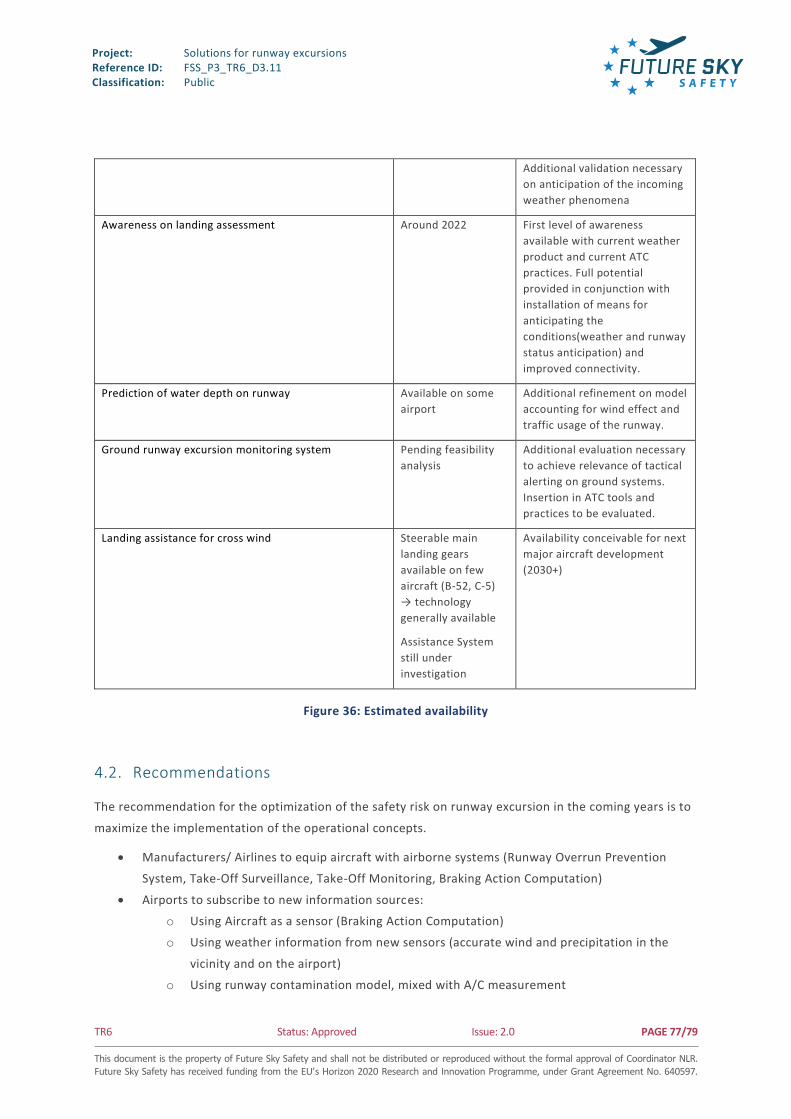
Project: Reference ID: Classification:
Solutions for runway excursions FSS_P3_TR6_D3.11 Public
TR6 Status: Approved Issue: 2.0 PAGE 77/79 This document is the property of Future Sky Safety and shall not be distributed or reproduced without the formal approval of Coordinator NLR. Future Sky Safety has received funding from the EU’s Horizon 2020 Research and Innovation Programme, under Grant Agreement No. 640597.
Additional validation necessary
on anticipation of the incoming
weather phenomena
Awareness on landing assessment Around 2022 First level of awareness
available with current weather
product and current ATC
practices. Full potential
provided in conjunction with
installation of means for
anticipating the
conditions(weather and runway
status anticipation) and
improved connectivity.
Prediction of water depth on runway Available on some
airport
Additional refinement on model
accounting for wind effect and
traffic usage of the runway.
Ground runway excursion monitoring system Pending feasibility
analysis
Additional evaluation necessary
to achieve relevance of tactical
alerting on ground systems.
Insertion in ATC tools and
practices to be evaluated.
Landing assistance for cross wind Steerable main
landing gears
available on few
aircraft (B-52, C-5)
→ technology
generally available
Assistance System
still under
investigation
Availability conceivable for next
major aircraft development
(2030+)
Figure 36: Estimated availability
4.2. Recommendations
The recommendation for the optimization of the safety risk on runway excursion in the coming years is to
maximize the implementation of the operational concepts.
Manufacturers/ Airlines to equip aircraft with airborne systems (Runway Overrun Prevention
System, Take-Off Surveillance, Take-Off Monitoring, Braking Action Computation)
Airports to subscribe to new information sources:
o Using Aircraft as a sensor (Braking Action Computation)
o Using weather information from new sensors (accurate wind and precipitation in the
vicinity and on the airport)
o Using runway contamination model, mixed with A/C measurement

Project: Reference ID: Classification:
Solutions for runway excursions FSS_P3_TR6_D3.11 Public
TR6 Status: Approved Issue: 2.0 PAGE 78/79 This document is the property of Future Sky Safety and shall not be distributed or reproduced without the formal approval of Coordinator NLR. Future Sky Safety has received funding from the EU’s Horizon 2020 Research and Innovation Programme, under Grant Agreement No. 640597.
Authorities to monitor the compliance of airports with current or updated regulation leading to a
strict compliance with standards and optimized mitigation conditions in compliance with the
ALARP principle
Continue research and development (R&D) to prepare and coordinate implementation of new Safety
technologies in Air Traffic Management.
Develop and enlarge use of datalink communication between the aircrafts and the ground
systems.
The effort on the reduction of the probability of excursion will drastically narrow down the probability of
occurrence of overrun. It is however suggested to use improved condition monitoring and reporting as
well as arresting systems around runways to limit the consequences of excursion in an airport.
In the mid-term, to further reduce the risk and consequences, additional research and developments
activities are necessary:
As current concepts do not fully tackle veer-off risks, it is recommended to further investigate
solutions that would reduce the likelihood and consequences of veer-off, and lead feasibility
studies. Airborne solutions, on-board function or aircraft design, have to be further researched.
The reduction of the consequence of the veer-off using engineered materials would require an
assessment of the runway surrounding safety objective to estimate whether the solution could be
viable.
EMAS have shown their efficiency to minimize consequences of runway overrun but its
deployment is limited. For a wider deployment, a recommendation is to re-evaluate the airport
approach geometry/RESA taking into account deployment of risk mitigations deployed. Studies
could determine with better accuracy the dangerous runways and/or dangerous spots around the
runway and find optimal solution. The efforts made by ICAO and EASA to update current
standards on runway should be continued and those standards implemented all across European
airports.

Project: Reference ID: Classification:
Solutions for runway excursions FSS_P3_TR6_D3.11 Public
TR6 Status: Approved Issue: 2.0 PAGE 79/79 This document is the property of Future Sky Safety and shall not be distributed or reproduced without the formal approval of Coordinator NLR. Future Sky Safety has received funding from the EU’s Horizon 2020 Research and Innovation Programme, under Grant Agreement No. 640597.
5 REFERENCES
[1] Feasibility and definition of R&TD needs for implementation of new concepts, project report D3.9,
Future Sky Safety P3, 2017.
[2] Duda, H. et al.: Design of the DLR AVES Research Flight Simulator. AIAA-2013-4737, Boston,
Massachusetts, USA, 19.–22. August 2013. AIAA Modeling and Simulation Technologies
Conference, doi:10.2514/6.2013-4737.
[3] Joint Aviation Requirements, JAR-STD 1A Aeroplane Flight Simulators. JAA, 1999.
[4] Fact sheets on EMAS, FAA, 2017.
[5] Location of Commercial Aircraft Accidents/Incidents Relative to Runways, July 1990, by R.E. David
[6] Runway Excursions (RE) analysis: Annex A: Safety data collection for RMT.0296
[7] A.G. Barnes and T.J. Yager. Enhancement of Aircraft Ground Handling Simulation Capability.
AGARDograph 333, August 1998
[8] UltraFast wind sensOrs for wake-vortex hazards mitigation (UFO) document D3110&D3120
[9] N.N., Aircraft Accident Investigation Report 5X003-0/08, German Federal Bureau of Aircraft
Accident Investigation, March 2010
[10] N.N., AAIB Bulletin 4/2010, Aircraft Accident Investigation Report EW/C2009/01/04, UK Air
Accidents Investigation Branch, April 2010
[11] Estimated Cost-Benefit analysis of runway severity reduction based on actual arrestments, J.N.M.
vanEekeren, January 2016
Related Documents