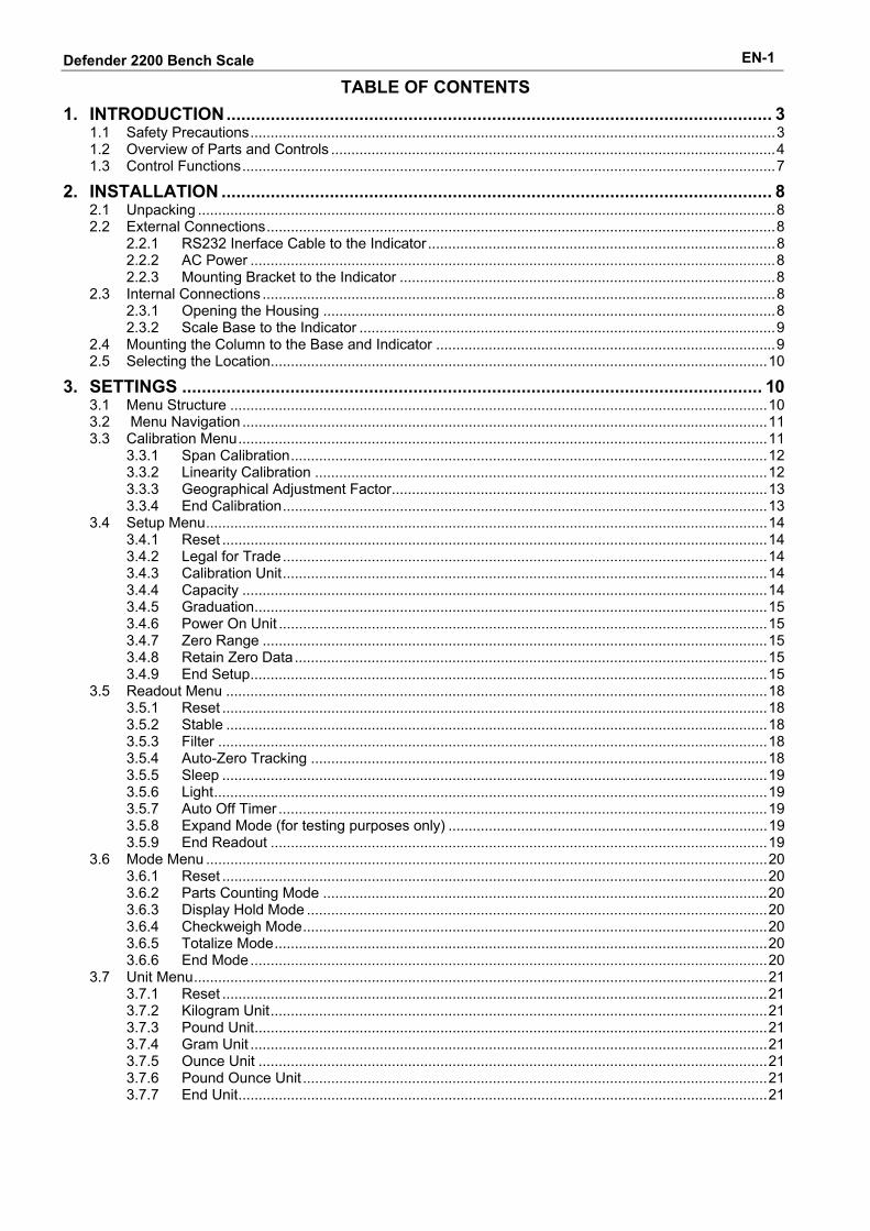
Defender ™ 2200 Bench Scale Instruction Manual

Welcome message from author
This document is posted to help you gain knowledge. Please leave a comment to let me know what you think about it! Share it to your friends and learn new things together.
Transcript
Defender™ 2200 Bench Scale Instruction Manual

Defender 2200 Bench Scale EN-1
TABLE OF CONTENTS
1. INTRODUCTION............................................................................................................... 3 1.1 Safety Precautions..................................................................................................................................3 1.2 Overview of Parts and Controls ..............................................................................................................4 1.3 Control Functions....................................................................................................................................7
2. INSTALLATION ................................................................................................................ 8 2.1 Unpacking ...............................................................................................................................................8 2.2 External Connections..............................................................................................................................8
2.2.1 RS232 Inerface Cable to the Indicator......................................................................................8 2.2.2 AC Power ..................................................................................................................................8 2.2.3 Mounting Bracket to the Indicator .............................................................................................8
2.3 Internal Connections ...............................................................................................................................8 2.3.1 Opening the Housing ................................................................................................................8 2.3.2 Scale Base to the Indicator .......................................................................................................9
2.4 Mounting the Column to the Base and Indicator ....................................................................................9 2.5 Selecting the Location...........................................................................................................................10
3. SETTINGS ...................................................................................................................... 10 3.1 Menu Structure .....................................................................................................................................10 3.2 Menu Navigation ..................................................................................................................................11 3.3 Calibration Menu...................................................................................................................................11
3.3.1 Span Calibration......................................................................................................................12 3.3.2 Linearity Calibration ................................................................................................................12 3.3.3 Geographical Adjustment Factor.............................................................................................13 3.3.4 End Calibration........................................................................................................................13
3.4 Setup Menu...........................................................................................................................................14 3.4.1 Reset .......................................................................................................................................14 3.4.2 Legal for Trade........................................................................................................................14 3.4.3 Calibration Unit........................................................................................................................14 3.4.4 Capacity ..................................................................................................................................14 3.4.5 Graduation...............................................................................................................................15 3.4.6 Power On Unit .........................................................................................................................15 3.4.7 Zero Range .............................................................................................................................15 3.4.8 Retain Zero Data.....................................................................................................................15 3.4.9 End Setup................................................................................................................................15
3.5 Readout Menu ......................................................................................................................................18 3.5.1 Reset .......................................................................................................................................18 3.5.2 Stable ......................................................................................................................................18 3.5.3 Filter ........................................................................................................................................18 3.5.4 Auto-Zero Tracking .................................................................................................................18 3.5.5 Sleep .......................................................................................................................................19 3.5.6 Light.........................................................................................................................................19 3.5.7 Auto Off Timer .........................................................................................................................19 3.5.8 Expand Mode (for testing purposes only) ...............................................................................19 3.5.9 End Readout ...........................................................................................................................19
3.6 Mode Menu ...........................................................................................................................................20 3.6.1 Reset .......................................................................................................................................20 3.6.2 Parts Counting Mode ..............................................................................................................20 3.6.3 Display Hold Mode ..................................................................................................................20 3.6.4 Checkweigh Mode...................................................................................................................20 3.6.5 Totalize Mode..........................................................................................................................20 3.6.6 End Mode................................................................................................................................20
3.7 Unit Menu..............................................................................................................................................21 3.7.1 Reset .......................................................................................................................................21 3.7.2 Kilogram Unit...........................................................................................................................21 3.7.3 Pound Unit...............................................................................................................................21 3.7.4 Gram Unit ................................................................................................................................21 3.7.5 Ounce Unit ..............................................................................................................................21 3.7.6 Pound Ounce Unit ...................................................................................................................21 3.7.7 End Unit...................................................................................................................................21
Defender 2200 Bench Scale EN-2
TABLE OF CONTENTS continued 3.8 Print Menu.............................................................................................................................................22
3.8.1 Reset .......................................................................................................................................22 3.8.2 Baud ........................................................................................................................................22 3.8.3 Parity .......................................................................................................................................22 3.8.4 Stop Bit....................................................................................................................................23 3.8.5 Handshake ..............................................................................................................................23 3.8.6 Print Stable Data Only.............................................................................................................23 3.8.7 Auto Print.................................................................................................................................23 3.8.8 Content....................................................................................................................................23 3.8.9 End Print..................................................................................................................................23
3.9 Lock Menu ............................................................................................................................................24 3.9.1 Reset............................................................................................................................................. 24 3.9.2 Lock Calibration.......................................................................................................................24 3.9.3 Lock Setup ..............................................................................................................................24 3.9.4 Lock Readout ..........................................................................................................................24 3.9.5 Lock Mode...............................................................................................................................24 3.9.6 Lock Unit .................................................................................................................................24 3.9.7 Lock Print ................................................................................................................................25 3.9.8 End Lock .................................................................................................................................25 3.9.9 End Menu................................................................................................................................25 3.9.10 Security Switch........................................................................................................................25
4. OPERATION ................................................................................................................... 25 4.1 Turning Indicator On/Off .......................................................................................................................25 4.2 Zero Operation......................................................................................................................................25 4.3 Manual Tare..........................................................................................................................................25 4.4 Changing Units of Measure ..................................................................................................................26 4.5 Printing Data .........................................................................................................................................26 4.6 Application Modes.................................................................................................................................26
4.6.1 Weighing .................................................................................................................................26 4.6.2 Parts Counting.........................................................................................................................26 4.6.3 Display-Hold ............................................................................................................................28 4.6.4 Check Weighing ......................................................................................................................28 4.6.5 Totalize Weighing....................................................................................................................30
5. SERIAL COMMUNICATION ........................................................................................... 31 5.1 Interface Commands.............................................................................................................................31 5.2 Output Format.......................................................................................................................................32
6. LEGAL FOR TRADE ...................................................................................................... 33 6.1 Settings .................................................................................................................................................33 6.2 Verification ............................................................................................................................................33 6.3 Sealing ..................................................................................................................................................34
6.3.1 Physical Seals .........................................................................................................................34 6.3.2 Audit Trail Seal ........................................................................................................................35
7. MAINTENANCE.............................................................................................................. 36 7.1 Indicator Cleaning .................................................................................................................................36 7.2 Troubleshooting ....................................................................................................................................36 7.3 Service Information ...............................................................................................................................37
8. TECHNICAL DATA......................................................................................................... 38 8.1 Specifications........................................................................................................................................39 8.2 Accessories...........................................................................................................................................39 8.3 Drawings and Dimensions ....................................................................................................................39
8.3.1 Defender 2200 Indicator..........................................................................................................39 8.3.2 Defender 2200 Base ...............................................................................................................40 8.3.3 Defender 2200 Base & Indicator .............................................................................................40
8.4 Compliance ...........................................................................................................................................41
Defender 2200 Bench Scale EN-3 1. INTRODUCTION This manual contains installation, operation and maintenance instructions for the OHAUS Defender TM 2200 Bench Scales. Please read this manual completely before installation and operation. 1.1 Safety Precautions For safe and dependable operation of this product, please comply with the following precautions:
• Verify that the input voltage range printed on the data label matches the local AC power. • Make sure that the power cord does not pose a potential obstacle or tripping hazard. • Use only approved accessories and peripherals. • Disconnect the equipment from the power supply before cleaning. • Operate the equipment only under ambient conditions specified in these instructions • Ensure that the load cell cable does not pose an obstruction or tripping hazard. • Do not operate the equipment in hazardous environments or unstable locations. • Do not drop loads on the base. • Do not lift the base by the top frame; always lift from the bottom frame when moving the base. • Service should only be performed by authorized personnel.
Defender 2200 Bench Scale EN-4
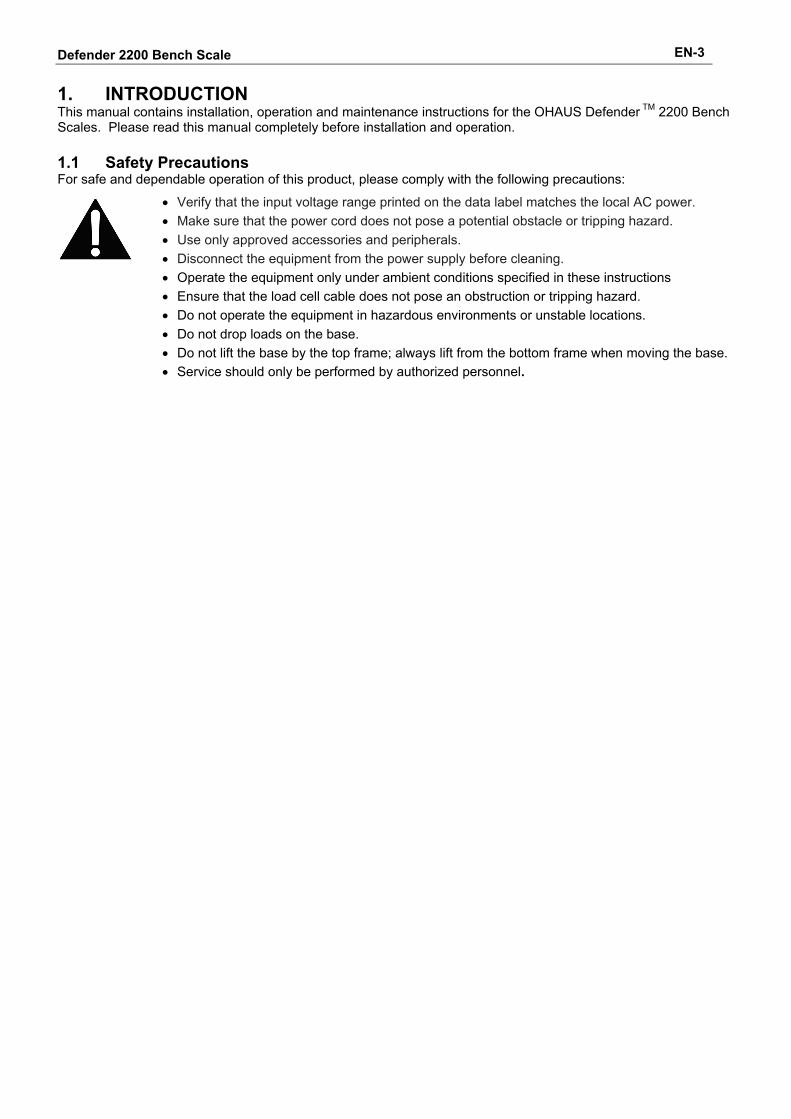
1.2 Overview of Parts and Controls 1 TABLE 1-1. INDICATOR PARTS
1 Data Label
2 Front Housing
3 Adjusting Knob (2)
4 Control Panel
5 Mounting Bracket
6 Screw (4)
7 Rear Housing
8 Data Label
9 Power receptacle
10 Strain Relief for Load Cell Cable
11 RS 232 Connector
Figure 1-1. Defender 2200 Indicator
6
7
8
9 10 11
2
3
4
5
Defender 2200 Bench Scale EN-5
1.2 Overview of Parts and Controls (Cont.)
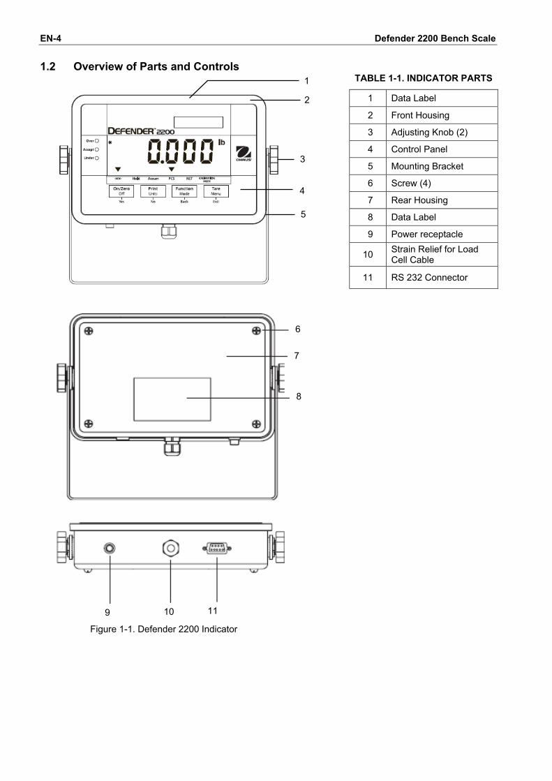
Figure 1-2. Main PC Board
TABLE 1-2. MAIN PC BOARD Item Description
1 Line Power Input J1 2 LFT On / Off Switch 3 RS232 Connector J3 4 Sense Jumper W2 5 Load Cell Terminal Block J7 6 Sense Jumper W1
Defender 2200 Bench Scale EN-6
1.2 Overview of Parts and Controls (Cont.)
lbozkg
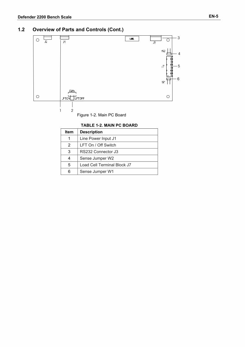
Figure 1-3. Controls and Indicators T22MC
TABLE 1-3. CONTROL PANEL..
No. Designation 1 Capacity Label Window 2 Pound indicator 3 Ounce 4 Kilogram, gram indicator 5 TARE Menu button 6 CALIBRATION MODE indicator 7 FUNCTION Mode button 8 NET indicator 9 PCS indicator 10 PRINT Units button 11 Accumulation indicator 12 Hold indicator 13 ON/ZERO Off button 14 Center of Zero indicator 15 Under LED 16 Accept LED 17 Over LED 18 Stable weight indicator
Defender 2200 Bench Scale EN-7
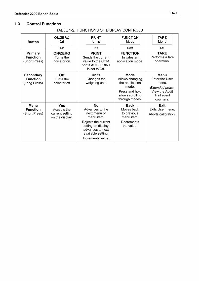
1.3 Control Functions
TABLE 1-2. FUNCTIONS OF DISPLAY CONTROLS
Button
Primary Function
(Short Press)
ON/ZERO Turns the
Indicator on.
PRINT Sends the current value to the COM
port if AUTOPRINT is set to Off.
FUNCTION Initiates an
application mode.
TARE Performs a tare
operation.
Secondary Function
(Long Press)
Off Turns the
Indicator off.
Units Changes the weighing unit.
Mode Allows changing the application
mode. Press and hold allows scrolling through modes.
Menu Enter the User
menu. Extended press: View the Audit
Trail event counters.
Menu Function
(Short Press)
Yes Accepts the
current setting on the display.
No Advances to the
next menu or menu item.
Rejects the current setting on display, advances to next available setting. Increments value.
Back Moves back to previous menu item. Decrements the value.
Exit Exits User menu. Aborts calibration.
Defender 2200 Bench Scale EN-8 2. INSTALLATION
2.1 Unpacking Unpack and inspect the product to make sure that all components have been included. The package includes the following:
• 2200 Series Indicator • Column Assembly • AC Adapter • Mounting Bracket • Knobs (2) • Base and Weighing Pan • Warranty Card • Instruction Manual • LFT Sealing Kit
2.2 External Connections
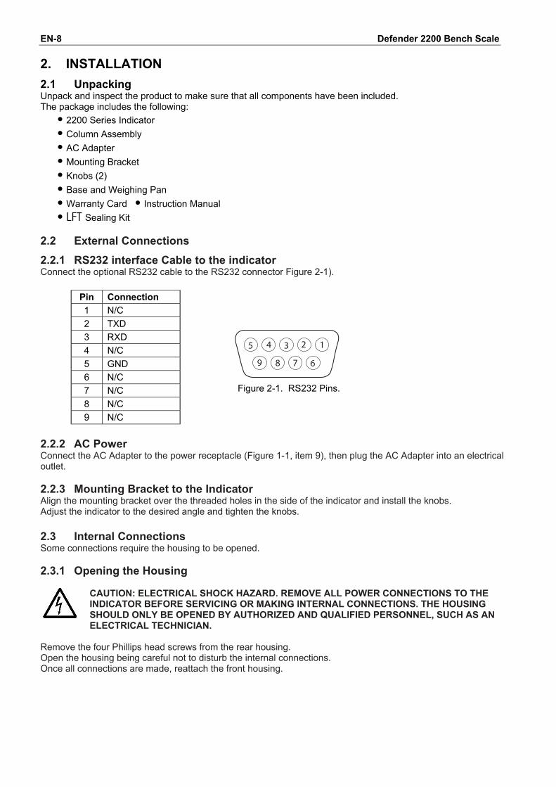
2.2.1 RS232 interface Cable to the indicator Connect the optional RS232 cable to the RS232 connector Figure 2-1). Pin Connection 1 N/C 2 TXD 3 RXD 4 N/C 5 GND 6 N/C 7 N/C 8 N/C 9 N/C
12345
6789
Figure 2-1. RS232 Pins.
2.2.2 AC Power Connect the AC Adapter to the power receptacle (Figure 1-1, item 9), then plug the AC Adapter into an electrical outlet. 2.2.3 Mounting Bracket to the Indicator Align the mounting bracket over the threaded holes in the side of the indicator and install the knobs. Adjust the indicator to the desired angle and tighten the knobs. 2.3 Internal Connections Some connections require the housing to be opened. 2.3.1 Opening the Housing
CAUTION: ELECTRICAL SHOCK HAZARD. REMOVE ALL POWER CONNECTIONS TO THE INDICATOR BEFORE SERVICING OR MAKING INTERNAL CONNECTIONS. THE HOUSING SHOULD ONLY BE OPENED BY AUTHORIZED AND QUALIFIED PERSONNEL, SUCH AS AN ELECTRICAL TECHNICIAN.
Remove the four Phillips head screws from the rear housing. Open the housing being careful not to disturb the internal connections. Once all connections are made, reattach the front housing.
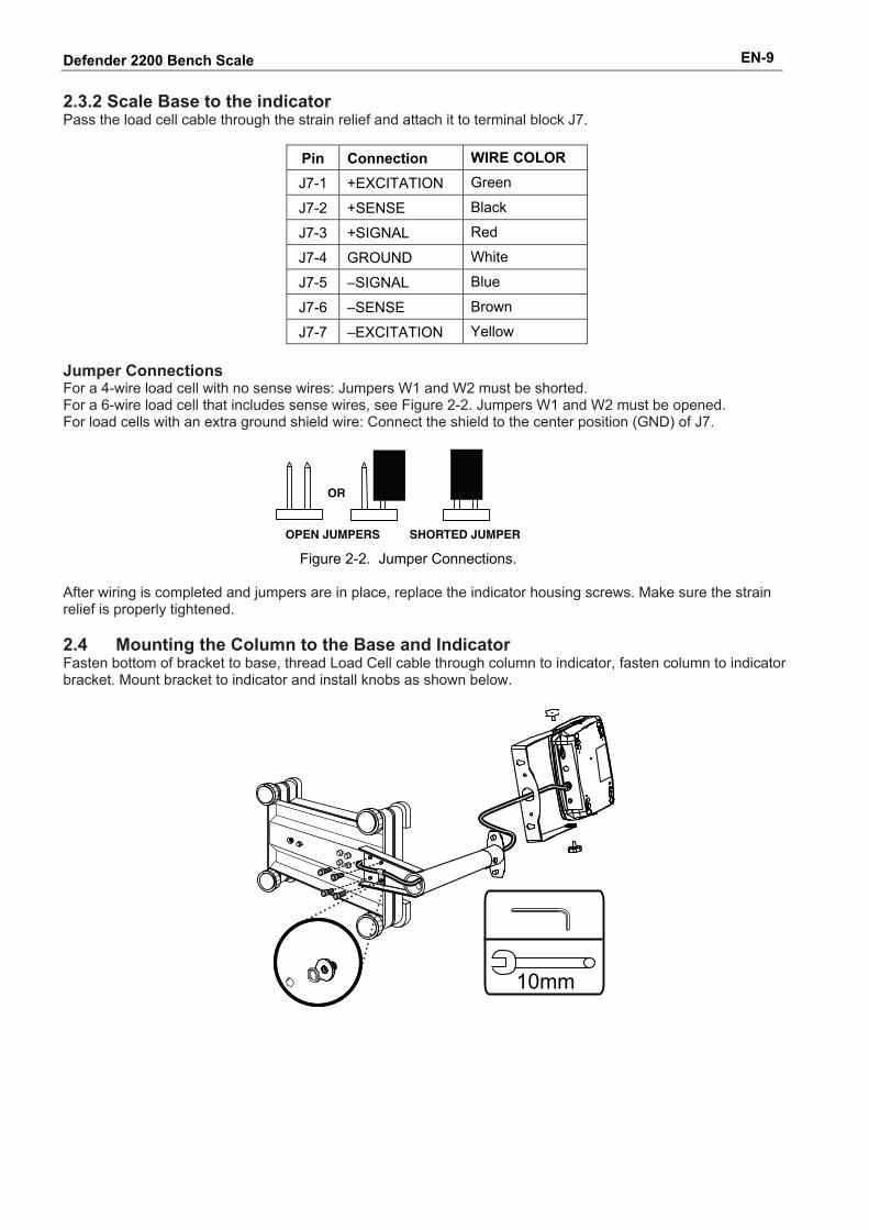
Defender 2200 Bench Scale EN-9 2.3.2 Scale Base to the indicator Pass the load cell cable through the strain relief and attach it to terminal block J7.
Pin Connection WIRE COLOR
J7-1 +EXCITATION Green
J7-2 +SENSE Black
J7-3 +SIGNAL Red
J7-4 GROUND White
J7-5 –SIGNAL Blue
J7-6 –SENSE Brown
J7-7 –EXCITATION Yellow Jumper Connections For a 4-wire load cell with no sense wires: Jumpers W1 and W2 must be shorted. For a 6-wire load cell that includes sense wires, see Figure 2-2. Jumpers W1 and W2 must be opened. For load cells with an extra ground shield wire: Connect the shield to the center position (GND) of J7.
Figure 2-2. Jumper Connections.
After wiring is completed and jumpers are in place, replace the indicator housing screws. Make sure the strain relief is properly tightened. 2.4 Mounting the Column to the Base and Indicator Fasten bottom of bracket to base, thread Load Cell cable through column to indicator, fasten column to indicator bracket. Mount bracket to indicator and install knobs as shown below.
10mm
Defender 2200 Bench Scale EN-10 2.5 Selecting the Location To ensure accuracy, proper performance and safety, locate and operate the base on a stable, level surface. Avoid locations with rapid temperature changes or excessive dust, air currents, vibrations, electromagnetic fields or heat. Level the base by adjusting the four leveling feet until the bubble in the level indicator (located at the rear of the base) is centered. A wrench may be needed to loosen the locking nut above each leveling foot. When the base is level, retighten the locking nuts up against the base to lock each foot into place.
Note: Ensure that the base is level each time its location is changed.
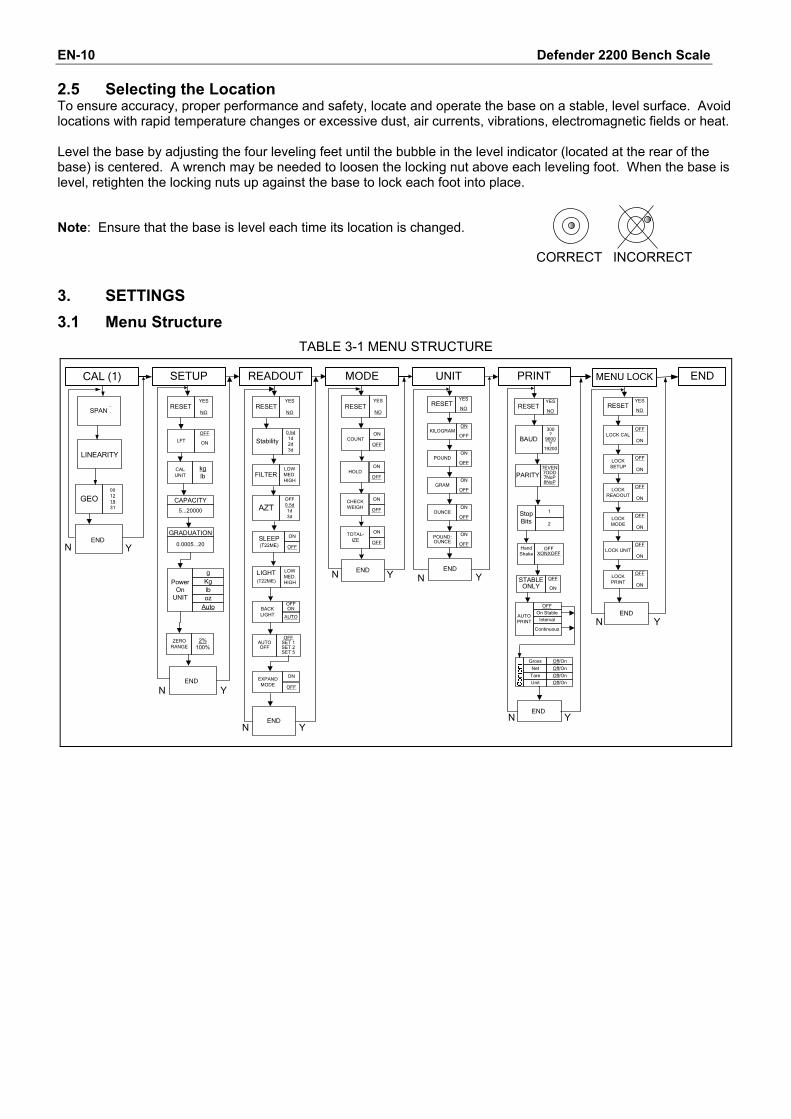
CORRECT INCORRECT 3. SETTINGS 3.1 Menu Structure
TABLE 3-1 MENU STRUCTURE
CAL (1) READOUT
AZTOFF0.5d1d3d
LINEARITY
END
END
SPAN...
YN
Y
UNITMODE
ENDENDN NY Y
RESETYES
NO
CAPACITY
5...20000
GRADUATION
0.0005...20
CALUNIT
kglb
ZERORANGE
2%100%
RESETYES
NORESET
YES
NO
KILOGRAMON
OFF
POUNDON
OFF
GRAMON
OFF
OUNCEON
OFF
POUND:OUNCE
ON
OFF
COUNTON
OFF
SETUP
END
RESETYES
NO
LFTOFF
ON
NEXPAND
MODE
ON
OFF
AUTOOFF
OFFSET 1SET 2SET 5
N
GEO00121931
Y
AUTOPRINT
OFF
ENDN Y
On Stable
Continuous
Gross
Net
Tare
Off/OnOff/On
RESETYES
NO
STABLEONLY
OFF
ON
Off/On
MENU LOCK
LOCK CALOFF
ON
END
N Y
RESETYES
NO
LOCK SETUP
OFF
ON
LOCK READOUT
OFF
ON
LOCK MODE
OFF
ON
LOCK UNITOFF
ON
LOCK PRINT
OFF
ON
BAUD
PARITY
300?
9600?
19200
7EVEN7ODD7NoP8NoP
HandShake
OFFXONXOFF
Unit Off/On
Power On
UNIT
gKglboz
Auto
Stop Bits
1
2
BACKLIGHT
OFFON
AUTO
END
Interval
Stability0.5d1d2d3d
FILTERLOWMED.HIGH
SLEEP(T22ME)
ON
OFF
LIGHT(T22ME)
LOWMED.HIGH
HOLDON
OFF
CHECK WEIGH
ON
OFF
TOTAL-IZE
ON
OFF
Defender 2200 Bench Scale EN-11
3.2 Menu Navigation
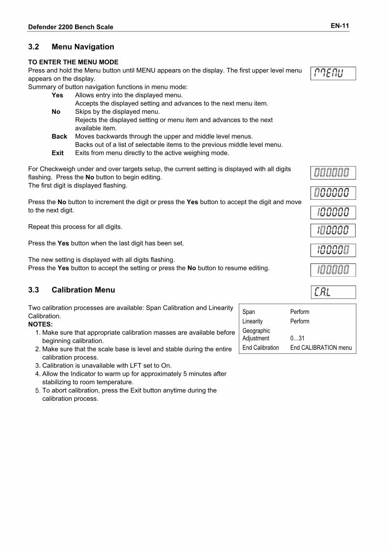
TO ENTER THE MENU MODE Press and hold the Menu button until MENU appears on the display. The first upper level menu appears on the display. Summary of button navigation functions in menu mode: Yes Allows entry into the displayed menu. Accepts the displayed setting and advances to the next menu item. No Skips by the displayed menu. Rejects the displayed setting or menu item and advances to the next available item. Back Moves backwards through the upper and middle level menus. Backs out of a list of selectable items to the previous middle level menu. Exit Exits from menu directly to the active weighing mode.
For Checkweigh under and over targets setup, the current setting is displayed with all digits flashing. Press the No button to begin editing. The first digit is displayed flashing. Press the No button to increment the digit or press the Yes button to accept the digit and move to the next digit. Repeat this process for all digits. Press the Yes button when the last digit has been set. The new setting is displayed with all digits flashing. Press the Yes button to accept the setting or press the No button to resume editing.
3.3 Calibration Menu
Span Linearity Geographic Adjustment End Calibration
Perform Perform 0…31 End CALIBRATION menu
Two calibration processes are available: Span Calibration and Linearity Calibration. NOTES:
1. Make sure that appropriate calibration masses are available before beginning calibration.
2. Make sure that the scale base is level and stable during the entire calibration process.
3. Calibration is unavailable with LFT set to On. 4. Allow the Indicator to warm up for approximately 5 minutes after
stabilizing to room temperature. 5. To abort calibration, press the Exit button anytime during the
calibration process.
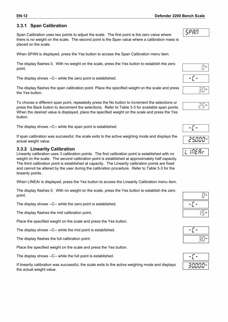
Defender 2200 Bench Scale EN-12 3.3.1 Span Calibration
Span Calibration uses two points to adjust the scale. The first point is the zero value where there is no weight on the scale. The second point is the Span value where a calibration mass is placed on the scale. When SPAN is displayed, press the Yes button to access the Span Calibration menu item. The display flashes 0. With no weight on the scale, press the Yes button to establish the zero point. The display shows --C-- while the zero point is established. The display flashes the span calibration point. Place the specified weight on the scale and press the Yes button. To choose a different span point, repeatedly press the No button to increment the selections or press the Back button to decrement the selections. Refer to Table 3-3 for available span points. When the desired value is displayed, place the specified weight on the scale and press the Yes button. The display shows --C-- while the span point is established. If span calibration was successful, the scale exits to the active weighing mode and displays the actual weight value. 3.3.2 Linearity Calibration Linearity calibration uses 3 calibration points. The first calibration point is established with no weight on the scale. The second calibration point is established at approximately half capacity. The third calibration point is established at capacity. The Linearity calibration points are fixed and cannot be altered by the user during the calibration procedure. Refer to Table 3-3 for the linearity points. When LINEAr is displayed, press the Yes button to access the Linearity Calibration menu item. The display flashes 0. With no weight on the scale, press the Yes button to establish the zero point. The display shows --C-- while the zero point is established. The display flashes the mid calibration point. Place the specified weight on the scale and press the Yes button. The display shows --C-- while the mid point is established. The display flashes the full calibration point. Place the specified weight on the scale and press the Yes button. The display shows --C-- while the full point is established. If linearity calibration was successful, the scale exits to the active weighing mode and displays the actual weight value.
�
Defender 2200 Bench Scale EN-13
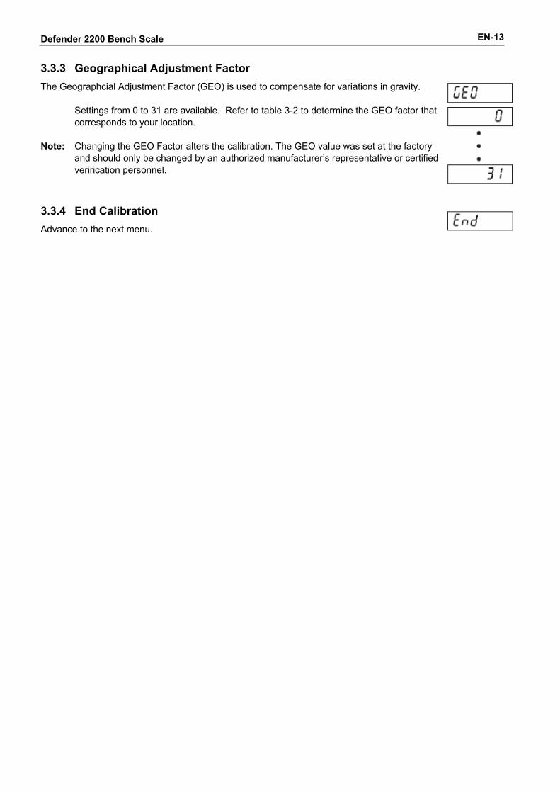
3.3.3 Geographical Adjustment Factor
The Geographcial Adjustment Factor (GEO) is used to compensate for variations in gravity.
Settings from 0 to 31 are available. Refer to table 3-2 to determine the GEO factor that corresponds to your location.
Note: Changing the GEO Factor alters the calibration. The GEO value was set at the factory
and should only be changed by an authorized manufacturer’s representative or certified verirication personnel.
3.3.4 End Calibration
Advance to the next menu.
Defender 2200 Bench Scale EN-14
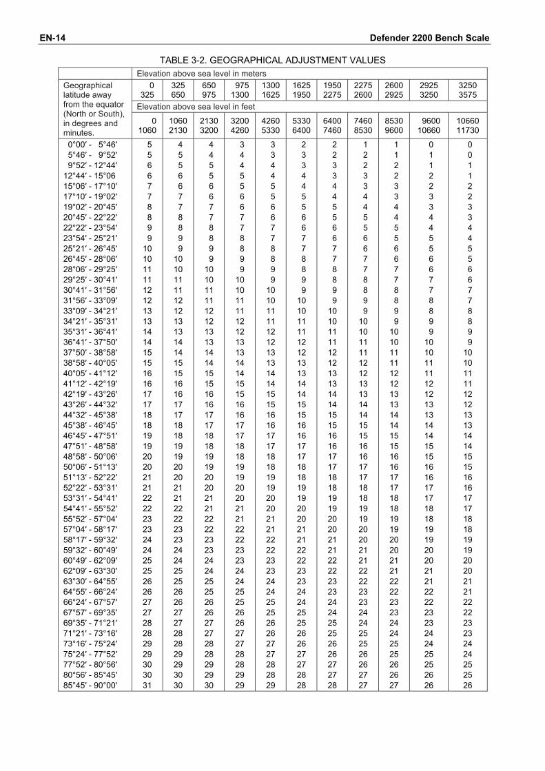
TABLE 3-2. GEOGRAPHICAL ADJUSTMENT VALUES Elevation above sea level in meters
000 325
325 650
650 975
09751300
13001625
16251950
19502275
22752600
2600 2925
2925 3250
3250 3575
Elevation above sea level in feet
Geographical latitude away from the equator (North or South), in degrees and minutes.
0000 1060
1060 2130
2130 3200
32004260
42605330
53306400
64007460
74608530
8530 9600
09600 10660
1066011730
0°00′ - 5°46′ 5°46′ - 9°52′ 9°52′ - 12°44′ 12°44′ - 15°06 15°06′ - 17°10′ 17°10′ - 19°02′ 19°02′ - 20°45′ 20°45′ - 22°22′ 22°22′ - 23°54′ 23°54′ - 25°21′ 25°21′ - 26°45′ 26°45′ - 28°06′ 28°06′ - 29°25′ 29°25′ - 30°41′ 30°41′ - 31°56′ 31°56′ - 33°09′ 33°09′ - 34°21′ 34°21′ - 35°31′ 35°31′ - 36°41′ 36°41′ - 37°50′ 37°50′ - 38°58′ 38°58′ - 40°05′ 40°05′ - 41°12′ 41°12′ - 42°19′ 42°19′ - 43°26′ 43°26′ - 44°32′ 44°32′ - 45°38′ 45°38′ - 46°45′ 46°45′ - 47°51′ 47°51′ - 48°58′ 48°58′ - 50°06′ 50°06′ - 51°13′ 51°13′ - 52°22′ 52°22′ - 53°31′ 53°31′ - 54°41′ 54°41′ - 55°52′ 55°52′ - 57°04′ 57°04′ - 58°17′ 58°17′ - 59°32′ 59°32′ - 60°49′ 60°49′ - 62°09′ 62°09′ - 63°30′ 63°30′ - 64°55′ 64°55′ - 66°24′ 66°24′ - 67°57′ 67°57′ - 69°35′ 69°35′ - 71°21′ 71°21′ - 73°16′ 73°16′ - 75°24′ 75°24′ - 77°52′ 77°52′ - 80°56′ 80°56′ - 85°45′ 85°45′ - 90°00′
05 05 06 06 07 07 08 08 09 09 10 10 11 11 12 12 13 13 14 14 15 15 16 16 17 17 18 18 19 19 20 20 21 21 22 22 23 23 24 24 25 25 26 26 27 27 28 28 29 29 30 30 31
04 05 05 06 06 07 07 08 08 09 09 10 10 11 11 12 12 13 13 14 14 15 15 16 16 17 17 18 18 19 19 20 20 21 21 22 22 23 23 24 24 25 25 26 26 27 27 28 28 29 29 30 30
04 04 05 05 06 06 07 07 08 08 09 09 10 10 11 11 12 12 13 13 14 14 15 15 16 16 17 17 18 18 19 19 20 20 21 21 22 22 23 23 24 24 25 25 26 26 27 27 28 28 29 29 30
03 04 04 05 05 06 06 07 07 08 08 09 09 10 10 11 11 12 12 13 13 14 14 15 15 16 16 17 17 18 18 19 19 20 20 21 21 22 22 23 23 24 24 25 25 26 26 27 27 28 28 29 29
03 03 04 04 05 05 06 06 07 07 08 08 09 09 10 10 11 11 12 12 13 13 14 14 15 15 16 16 17 17 18 18 19 19 20 20 21 21 22 22 23 23 24 24 25 25 26 26 27 27 28 28 29
02 03 03 04 04 05 05 06 06 07 07 08 08 09 09 10 10 11 11 12 12 13 13 14 14 15 15 16 16 17 17 18 18 19 19 20 20 21 21 22 22 23 23 24 24 25 25 26 26 27 27 28 28
02 02 03 03 04 04 05 05 06 06 07 07 08 08 09 09 10 10 11 11 12 12 13 13 14 14 15 15 16 16 17 17 18 18 19 19 20 20 21 21 22 22 23 23 24 24 25 25 26 26 27 27 28
01 02 02 03 03 04 04 05 05 06 06 07 07 08 08 09 09 10 10 11 11 12 12 13 13 14 14 15 15 16 16 17 17 18 18 19 19 20 20 21 21 22 22 23 23 24 24 25 25 26 26 27 27
01 01 02 02 03 03 04 04 05 05 06 06 07 07 08 08 09 09 10 10 11 11 12 12 13 13 14 14 15 15 16 16 17 17 18 18 19 19 20 20 21 21 22 22 23 23 24 24 25 25 26 26 27
00 01 01 02 02 03 03 04 04 05 05 06 06 07 07 08 08 09 09 10 10 11 11 12 12 13 13 14 14 15 15 16 16 17 17 18 18 19 19 20 20 21 21 22 22 23 23 24 24 25 25 26 26
00 00 01 01 02 02 03 03 04 04 05 05 06 06 07 07 08 08 09 09 10 10 11 11 12 12 13 13 14 14 15 15 16 16 17 17 18 18 19 19 20 20 21 21 22 22 23 23 24 24 25 25 26
Defender 2200 Bench Scale EN-15
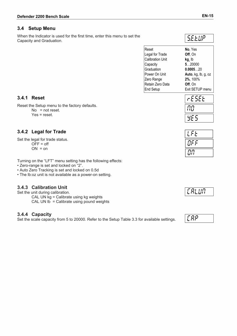
3.4 Setup Menu
When the Indicator is used for the first time, enter this menu to set the Capacity and Graduation.
Reset Legal for Trade Calibration Unit Capacity Graduation Power On Unit Zero Range Retain Zero Data End Setup
No, Yes Off, On kg¸ lb 5…20000 0.0005…20 Auto, kg, lb, g, oz 2%, 100% Off, On Exit SETUP menu
3.4.1 Reset
Reset the Setup menu to the factory defaults. No = not reset. Yes = reset.
3.4.2 Legal for Trade
Set the legal for trade status. OFF = off ON = on
Turning on the “LFT” menu setting has the following effects: • Zero-range is set and locked on “2”. • Auto Zero Tracking is set and locked on 0.5d • The lb:oz unit is not available as a power-on setting.
3.4.3 Calibration Unit Set the unit during calibration.
CAL UN kg = Calibrate using kg weights CAL UN lb = Calibrate using pound weights
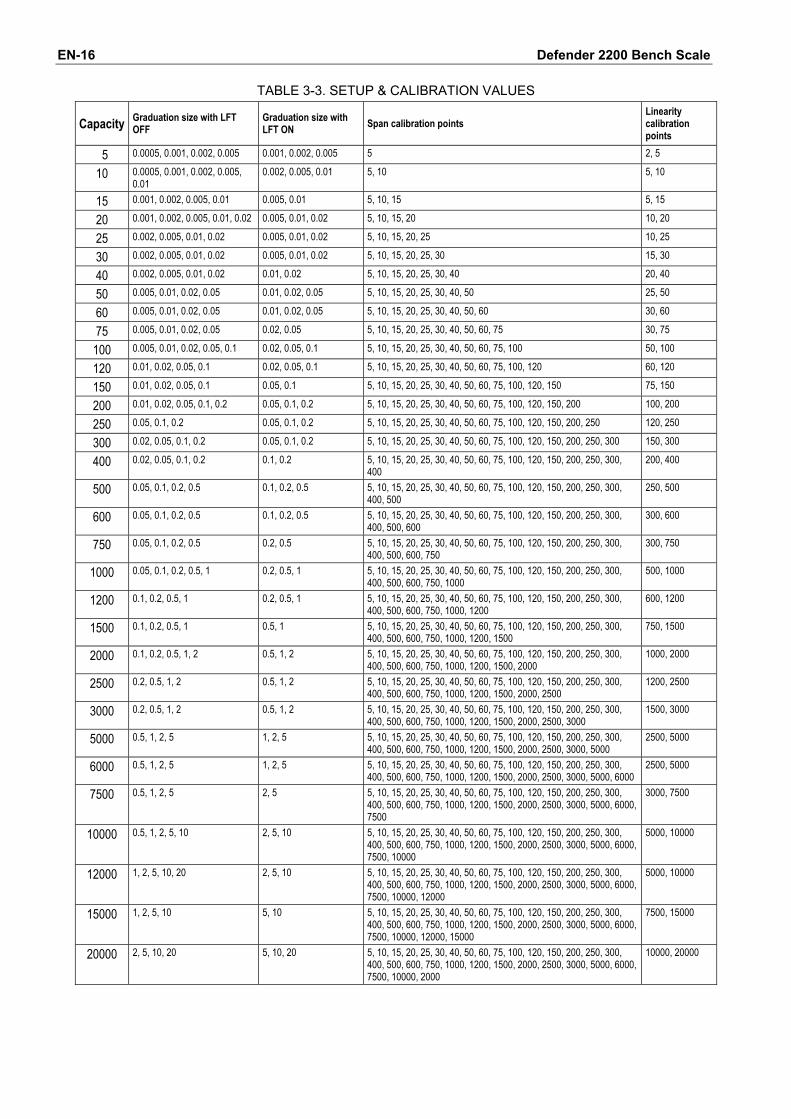
3.4.4 Capacity Set the scale capacity from 5 to 20000. Refer to the Setup Table 3.3 for available settings.
Defender 2200 Bench Scale EN-16
TABLE 3-3. SETUP & CALIBRATION VALUES
Capacity Graduation size with LFT OFF
Graduation size with LFT ON Span calibration points
Linearity calibration points
5 0.0005, 0.001, 0.002, 0.005 0.001, 0.002, 0.005 5 2, 5
10 0.0005, 0.001, 0.002, 0.005, 0.01
0.002, 0.005, 0.01 5, 10 5, 10
15 0.001, 0.002, 0.005, 0.01 0.005, 0.01 5, 10, 15 5, 15
20 0.001, 0.002, 0.005, 0.01, 0.02 0.005, 0.01, 0.02 5, 10, 15, 20 10, 20
25 0.002, 0.005, 0.01, 0.02 0.005, 0.01, 0.02 5, 10, 15, 20, 25 10, 25
30 0.002, 0.005, 0.01, 0.02 0.005, 0.01, 0.02 5, 10, 15, 20, 25, 30 15, 30
40 0.002, 0.005, 0.01, 0.02 0.01, 0.02 5, 10, 15, 20, 25, 30, 40 20, 40
50 0.005, 0.01, 0.02, 0.05 0.01, 0.02, 0.05 5, 10, 15, 20, 25, 30, 40, 50 25, 50
60 0.005, 0.01, 0.02, 0.05 0.01, 0.02, 0.05 5, 10, 15, 20, 25, 30, 40, 50, 60 30, 60
75 0.005, 0.01, 0.02, 0.05 0.02, 0.05 5, 10, 15, 20, 25, 30, 40, 50, 60, 75 30, 75
100 0.005, 0.01, 0.02, 0.05, 0.1 0.02, 0.05, 0.1 5, 10, 15, 20, 25, 30, 40, 50, 60, 75, 100 50, 100
120 0.01, 0.02, 0.05, 0.1 0.02, 0.05, 0.1 5, 10, 15, 20, 25, 30, 40, 50, 60, 75, 100, 120 60, 120
150 0.01, 0.02, 0.05, 0.1 0.05, 0.1 5, 10, 15, 20, 25, 30, 40, 50, 60, 75, 100, 120, 150 75, 150
200 0.01, 0.02, 0.05, 0.1, 0.2 0.05, 0.1, 0.2 5, 10, 15, 20, 25, 30, 40, 50, 60, 75, 100, 120, 150, 200 100, 200
250 0.05, 0.1, 0.2 0.05, 0.1, 0.2 5, 10, 15, 20, 25, 30, 40, 50, 60, 75, 100, 120, 150, 200, 250 120, 250
300 0.02, 0.05, 0.1, 0.2 0.05, 0.1, 0.2 5, 10, 15, 20, 25, 30, 40, 50, 60, 75, 100, 120, 150, 200, 250, 300 150, 300
400 0.02, 0.05, 0.1, 0.2 0.1, 0.2 5, 10, 15, 20, 25, 30, 40, 50, 60, 75, 100, 120, 150, 200, 250, 300, 400
200, 400
500 0.05, 0.1, 0.2, 0.5 0.1, 0.2, 0.5 5, 10, 15, 20, 25, 30, 40, 50, 60, 75, 100, 120, 150, 200, 250, 300, 400, 500
250, 500
600 0.05, 0.1, 0.2, 0.5 0.1, 0.2, 0.5 5, 10, 15, 20, 25, 30, 40, 50, 60, 75, 100, 120, 150, 200, 250, 300, 400, 500, 600
300, 600
750 0.05, 0.1, 0.2, 0.5 0.2, 0.5 5, 10, 15, 20, 25, 30, 40, 50, 60, 75, 100, 120, 150, 200, 250, 300, 400, 500, 600, 750
300, 750
1000 0.05, 0.1, 0.2, 0.5, 1 0.2, 0.5, 1 5, 10, 15, 20, 25, 30, 40, 50, 60, 75, 100, 120, 150, 200, 250, 300, 400, 500, 600, 750, 1000
500, 1000
1200 0.1, 0.2, 0.5, 1 0.2, 0.5, 1 5, 10, 15, 20, 25, 30, 40, 50, 60, 75, 100, 120, 150, 200, 250, 300, 400, 500, 600, 750, 1000, 1200
600, 1200
1500 0.1, 0.2, 0.5, 1 0.5, 1 5, 10, 15, 20, 25, 30, 40, 50, 60, 75, 100, 120, 150, 200, 250, 300, 400, 500, 600, 750, 1000, 1200, 1500
750, 1500
2000 0.1, 0.2, 0.5, 1, 2 0.5, 1, 2 5, 10, 15, 20, 25, 30, 40, 50, 60, 75, 100, 120, 150, 200, 250, 300, 400, 500, 600, 750, 1000, 1200, 1500, 2000
1000, 2000
2500 0.2, 0.5, 1, 2 0.5, 1, 2 5, 10, 15, 20, 25, 30, 40, 50, 60, 75, 100, 120, 150, 200, 250, 300, 400, 500, 600, 750, 1000, 1200, 1500, 2000, 2500
1200, 2500
3000 0.2, 0.5, 1, 2 0.5, 1, 2 5, 10, 15, 20, 25, 30, 40, 50, 60, 75, 100, 120, 150, 200, 250, 300, 400, 500, 600, 750, 1000, 1200, 1500, 2000, 2500, 3000
1500, 3000
5000 0.5, 1, 2, 5 1, 2, 5 5, 10, 15, 20, 25, 30, 40, 50, 60, 75, 100, 120, 150, 200, 250, 300, 400, 500, 600, 750, 1000, 1200, 1500, 2000, 2500, 3000, 5000
2500, 5000
6000 0.5, 1, 2, 5 1, 2, 5 5, 10, 15, 20, 25, 30, 40, 50, 60, 75, 100, 120, 150, 200, 250, 300, 400, 500, 600, 750, 1000, 1200, 1500, 2000, 2500, 3000, 5000, 6000
2500, 5000
7500 0.5, 1, 2, 5 2, 5 5, 10, 15, 20, 25, 30, 40, 50, 60, 75, 100, 120, 150, 200, 250, 300, 400, 500, 600, 750, 1000, 1200, 1500, 2000, 2500, 3000, 5000, 6000, 7500
3000, 7500
10000 0.5, 1, 2, 5, 10 2, 5, 10 5, 10, 15, 20, 25, 30, 40, 50, 60, 75, 100, 120, 150, 200, 250, 300, 400, 500, 600, 750, 1000, 1200, 1500, 2000, 2500, 3000, 5000, 6000, 7500, 10000
5000, 10000
12000 1, 2, 5, 10, 20 2, 5, 10 5, 10, 15, 20, 25, 30, 40, 50, 60, 75, 100, 120, 150, 200, 250, 300, 400, 500, 600, 750, 1000, 1200, 1500, 2000, 2500, 3000, 5000, 6000, 7500, 10000, 12000
5000, 10000
15000 1, 2, 5, 10 5, 10 5, 10, 15, 20, 25, 30, 40, 50, 60, 75, 100, 120, 150, 200, 250, 300, 400, 500, 600, 750, 1000, 1200, 1500, 2000, 2500, 3000, 5000, 6000, 7500, 10000, 12000, 15000
7500, 15000
20000 2, 5, 10, 20 5, 10, 20 5, 10, 15, 20, 25, 30, 40, 50, 60, 75, 100, 120, 150, 200, 250, 300, 400, 500, 600, 750, 1000, 1200, 1500, 2000, 2500, 3000, 5000, 6000, 7500, 10000, 2000
10000, 20000
Defender 2200 Bench Scale EN-17
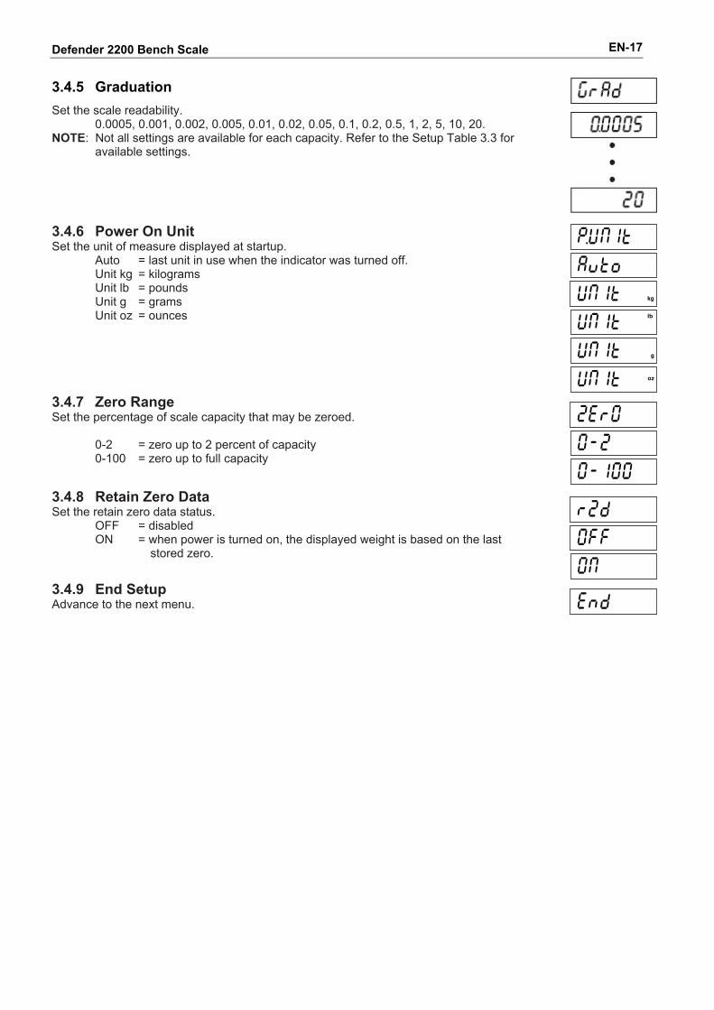
3.4.5 Graduation
Set the scale readability. 0.0005, 0.001, 0.002, 0.005, 0.01, 0.02, 0.05, 0.1, 0.2, 0.5, 1, 2, 5, 10, 20.
NOTE: Not all settings are available for each capacity. Refer to the Setup Table 3.3 for available settings.
3.4.6 Power On Unit Set the unit of measure displayed at startup.
Auto = last unit in use when the indicator was turned off. Unit kg = kilograms Unit lb = pounds Unit g = grams Unit oz = ounces
3.4.7 Zero Range Set the percentage of scale capacity that may be zeroed.
0-2 = zero up to 2 percent of capacity 0-100 = zero up to full capacity
3.4.8 Retain Zero Data Set the retain zero data status.
OFF = disabled ON = when power is turned on, the displayed weight is based on the last stored zero.
3.4.9 End Setup Advance to the next menu.
Defender 2200 Bench Scale EN-18
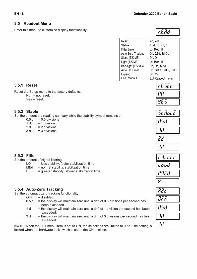
3.5 Readout Menu
Enter this menu to customize display functionality.
Reset Stable Filter Level Auto-Zero Tracking Sleep (T22ME) Light (T22ME) Backlight (T22MC) Auto Off Timer Expand End Readout
No, Yes 0.5d, 1d, 2d, 3d Lo, Med, Hi Off, 0.5d, 1d, 3d Off, On Lo, Med, Hi Off, On, Auto Off, Set 1, Set 2, Set 5 Off, On Exit Readout menu
3.5.1 Reset
Reset the Setup menu to the factory defaults. No = not reset. Yes = reset.
3.5.2 Stable Set the amount the reading can vary while the stability symbol remains on.
0.5 d = 0.5 divisions 1 d = 1 division 2 d = 2 divisions 3 d = 3 divisions
3.5.3 Filter Set the amount of signal filtering.
LO = less stability, faster stabilization time MEd = normal stability, stabilization time HI = greater stability, slower stabilization time
3.5.4 Auto-Zero Tracking Set the automatic zero tracking functionality.
OFF = disabled. 0.5 d = the display will maintain zero until a drift of 0.5 divisions per second has been exceeded. 1 d = the display will maintain zero until a drift of 1 division per second has been exceeded. 3 d = the display will maintain zero until a drift of 3 divisions per second has been exceeded.
NOTE: When the LFT menu item is set to ON, the selections are limited to 0.5d. The setting is locked when the hardware lock switch is set to the ON position.
Defender 2200 Bench Scale EN-19
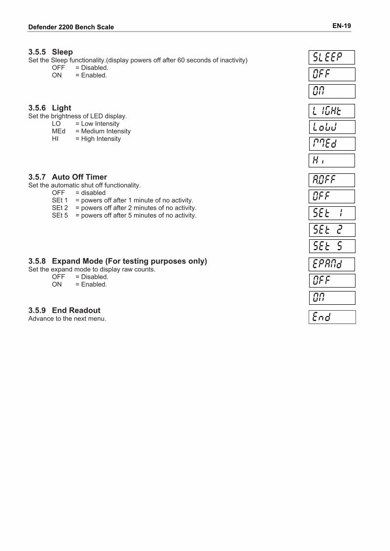
3.5.5 Sleep Set the Sleep functionality.(display powers off after 60 seconds of inactivity)
OFF = Disabled. ON = Enabled.
3.5.6 Light Set the brightness of LED display.
LO = Low Intensity MEd = Medium Intensity HI = High Intensity
3.5.7 Auto Off Timer Set the automatic shut off functionality.
OFF = disabled SEt 1 = powers off after 1 minute of no activity. SEt 2 = powers off after 2 minutes of no activity. SEt 5 = powers off after 5 minutes of no activity.
3.5.8 Expand Mode (For testing purposes only) Set the expand mode to display raw counts.
OFF = Disabled. ON = Enabled.
3.5.9 End Readout Advance to the next menu.
Defender 2200 Bench Scale EN-20
3.6 Mode Menu
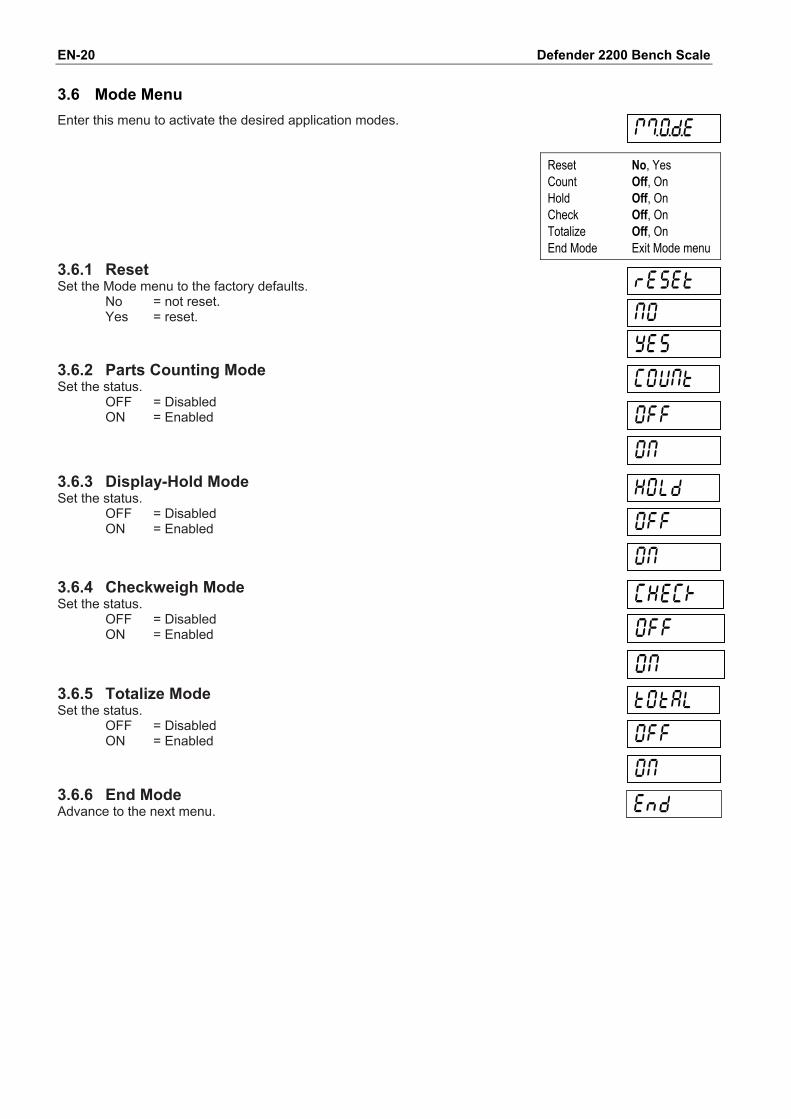
Enter this menu to activate the desired application modes.
Reset Count Hold Check Totalize End Mode
No, Yes Off, On Off, On Off, On Off, On Exit Mode menu
3.6.1 Reset Set the Mode menu to the factory defaults.
No = not reset. Yes = reset.
3.6.2 Parts Counting Mode Set the status.
OFF = Disabled ON = Enabled
3.6.3 Display-Hold Mode Set the status.
OFF = Disabled ON = Enabled
3.6.4 Checkweigh Mode Set the status.
OFF = Disabled ON = Enabled
3.6.5 Totalize Mode Set the status.
OFF = Disabled ON = Enabled
3.6.6 End Mode Advance to the next menu.
Defender 2200 Bench Scale EN-21
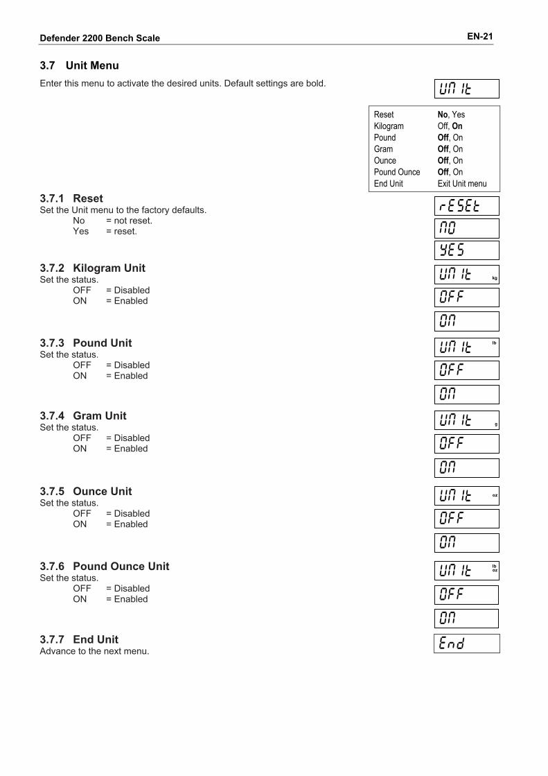
3.7 Unit Menu
Enter this menu to activate the desired units. Default settings are bold.
Reset Kilogram Pound Gram Ounce Pound Ounce End Unit
No, Yes Off, On Off, On Off, On Off, On Off, On Exit Unit menu
3.7.1 Reset Set the Unit menu to the factory defaults.
No = not reset. Yes = reset.
3.7.2 Kilogram Unit Set the status.
OFF = Disabled ON = Enabled
3.7.3 Pound Unit Set the status.
OFF = Disabled ON = Enabled
3.7.4 Gram Unit Set the status.
OFF = Disabled ON = Enabled
3.7.5 Ounce Unit Set the status.
OFF = Disabled ON = Enabled
3.7.6 Pound Ounce Unit Set the status.
OFF = Disabled ON = Enabled
3.7.7 End Unit Advance to the next menu.
Defender 2200 Bench Scale EN-22
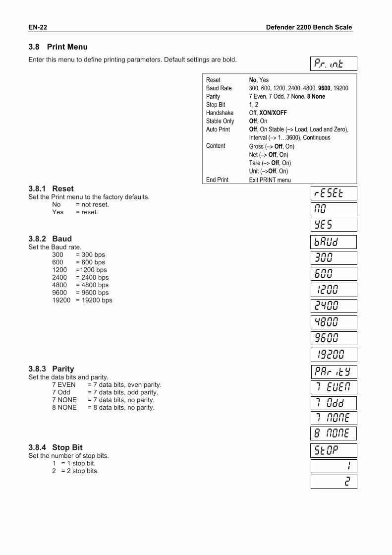
3.8 Print Menu
Enter this menu to define printing parameters. Default settings are bold.
Reset Baud Rate Parity Stop Bit Handshake Stable Only Auto Print Content End Print
No, Yes 300, 600, 1200, 2400, 4800, 9600, 19200 7 Even, 7 Odd, 7 None, 8 None 1, 2 Off, XON/XOFF Off, On Off, On Stable (–> Load, Load and Zero), Interval (–> 1…3600), Continuous Gross (–> Off, On) Net (–> Off, On) Tare (–> Off, On) Unit (–>Off, On) Exit PRINT menu
3.8.1 Reset Set the Print menu to the factory defaults.
No = not reset. Yes = reset.
3.8.2 Baud Set the Baud rate.
300 = 300 bps 600 = 600 bps 1200 =1200 bps 2400 = 2400 bps 4800 = 4800 bps 9600 = 9600 bps 19200 = 19200 bps
3.8.3 Parity Set the data bits and parity.
7 EVEN = 7 data bits, even parity. 7 Odd = 7 data bits, odd parity. 7 NONE = 7 data bits, no parity. 8 NONE = 8 data bits, no parity.
3.8.4 Stop Bit Set the number of stop bits.
1 = 1 stop bit. 2 = 2 stop bits.
Defender 2200 Bench Scale EN-23
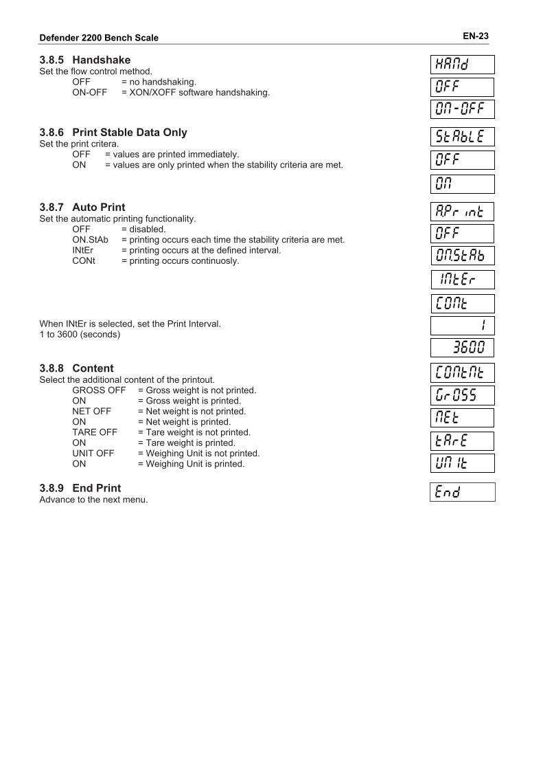
3.8.5 Handshake Set the flow control method.
OFF = no handshaking. ON-OFF = XON/XOFF software handshaking.
3.8.6 Print Stable Data Only Set the print critera.
OFF = values are printed immediately. ON = values are only printed when the stability criteria are met.
3.8.7 Auto Print Set the automatic printing functionality.
OFF = disabled. ON.StAb = printing occurs each time the stability criteria are met. INtEr = printing occurs at the defined interval. CONt = printing occurs continuosly.
When INtEr is selected, set the Print Interval. 1 to 3600 (seconds)
3.8.8 Content Select the additional content of the printout.
GROSS OFF = Gross weight is not printed. ON = Gross weight is printed. NET OFF = Net weight is not printed. ON = Net weight is printed. TARE OFF = Tare weight is not printed. ON = Tare weight is printed. UNIT OFF = Weighing Unit is not printed. ON = Weighing Unit is printed.
3.8.9 End Print Advance to the next menu.
Defender 2200 Bench Scale EN-24
3.9 Lock Menu
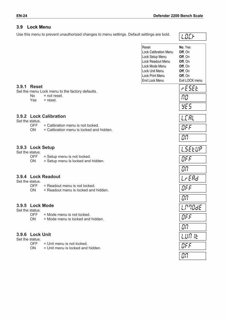
Use this menu to prevent unauthorized changes to menu settings. Default settings are bold.
Reset Lock Calibration Menu Lock Setup Menu Lock Readout Menu Lock Mode Menu Lock Unit Menu Lock Print Menu End Lock Menu
No, Yes Off, On Off, On Off, On Off, On Off, On Off, On Exit LOCK menu
3.9.1 Reset Set the menu Lock menu to the factory defaults.
No = not reset. Yes = reset.
3.9.2 Lock Calibration Set the status.
OFF = Calibration menu is not locked. ON = Calibration menu is locked and hidden.
3.9.3 Lock Setup Set the status.
OFF = Setup menu is not locked. ON = Setup menu is locked and hidden.
3.9.4 Lock Readout Set the status.
OFF = Readout menu is not locked. ON = Readout menu is locked and hidden.
3.9.5 Lock Mode Set the status.
OFF = Mode menu is not locked. ON = Mode menu is locked and hidden.
3.9.6 Lock Unit Set the status.
OFF = Unit menu is not locked. ON = Unit menu is locked and hidden.
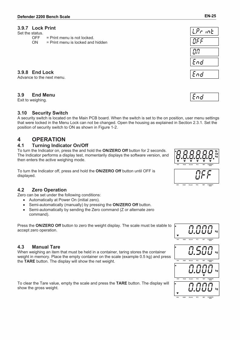
Defender 2200 Bench Scale EN-25 3.9.7 Lock Print Set the status.
OFF = Print menu is not locked. ON = Print menu is locked and hidden
3.9.8 End Lock Advance to the next menu.
3.9 End Menu Exit to weighing.
3.10 Security Switch A security switch is located on the Main PCB board. When the switch is set to the on position, user menu settings that were locked in the Menu Lock can not be changed. Open the housing as explained in Section 2.3.1. Set the position of security switch to ON as shown in Figure 1-2. 4 OPERATION 4.1 Turning Indicator On/Off To turn the Indicator on, press the and hold the ON/ZERO Off button for 2 seconds. The Indicator performs a display test, momentarily displays the software version, and then enters the active weighing mode. To turn the Indicator off, press and hold the ON/ZERO Off button until OFF is displayed.
4.2 Zero Operation Zero can be set under the following conditions:
• Automatically at Power On (initial zero). • Semi-automatically (manually) by pressing the ON/ZERO Off button. • Semi-automatically by sending the Zero command (Z or alternate zero
command).
Press the ON/ZERO Off button to zero the weight display. The scale must be stable to accept zero operation.
4.3 Manual Tare When weighing an item that must be held in a container, taring stores the container weight in memory. Place the empty container on the scale (example 0.5 kg) and press the TARE button. The display will show the net weight.
To clear the Tare value, empty the scale and press the TARE button. The display will show the gross weight.
Defender 2200 Bench Scale EN-26
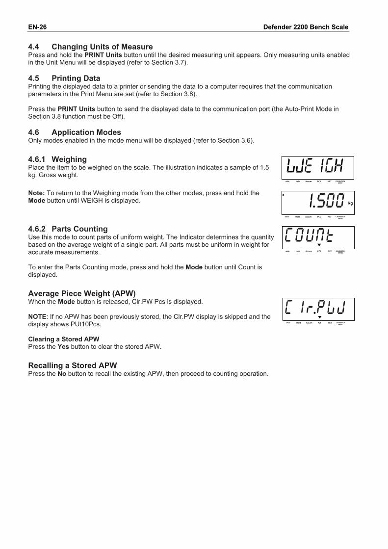
4.4 Changing Units of Measure Press and hold the PRINT Units button until the desired measuring unit appears. Only measuring units enabled in the Unit Menu will be displayed (refer to Section 3.7). 4.5 Printing Data Printing the displayed data to a printer or sending the data to a computer requires that the communication parameters in the Print Menu are set (refer to Section 3.8). Press the PRINT Units button to send the displayed data to the communication port (the Auto-Print Mode in Section 3.8 function must be Off). 4.6 Application Modes Only modes enabled in the mode menu will be displayed (refer to Section 3.6). 4.6.1 Weighing Place the item to be weighed on the scale. The illustration indicates a sample of 1.5 kg, Gross weight. Note: To return to the Weighing mode from the other modes, press and hold the Mode button until WEIGH is displayed.
4.6.2 Parts Counting Use this mode to count parts of uniform weight. The Indicator determines the quantity based on the average weight of a single part. All parts must be uniform in weight for accurate measurements. To enter the Parts Counting mode, press and hold the Mode button until Count is displayed.
Average Piece Weight (APW) When the Mode button is released, Clr.PW Pcs is displayed. NOTE: If no APW has been previously stored, the Clr.PW display is skipped and the display shows PUt10Pcs. Clearing a Stored APW Press the Yes button to clear the stored APW.
Recalling a Stored APW Press the No button to recall the existing APW, then proceed to counting operation.
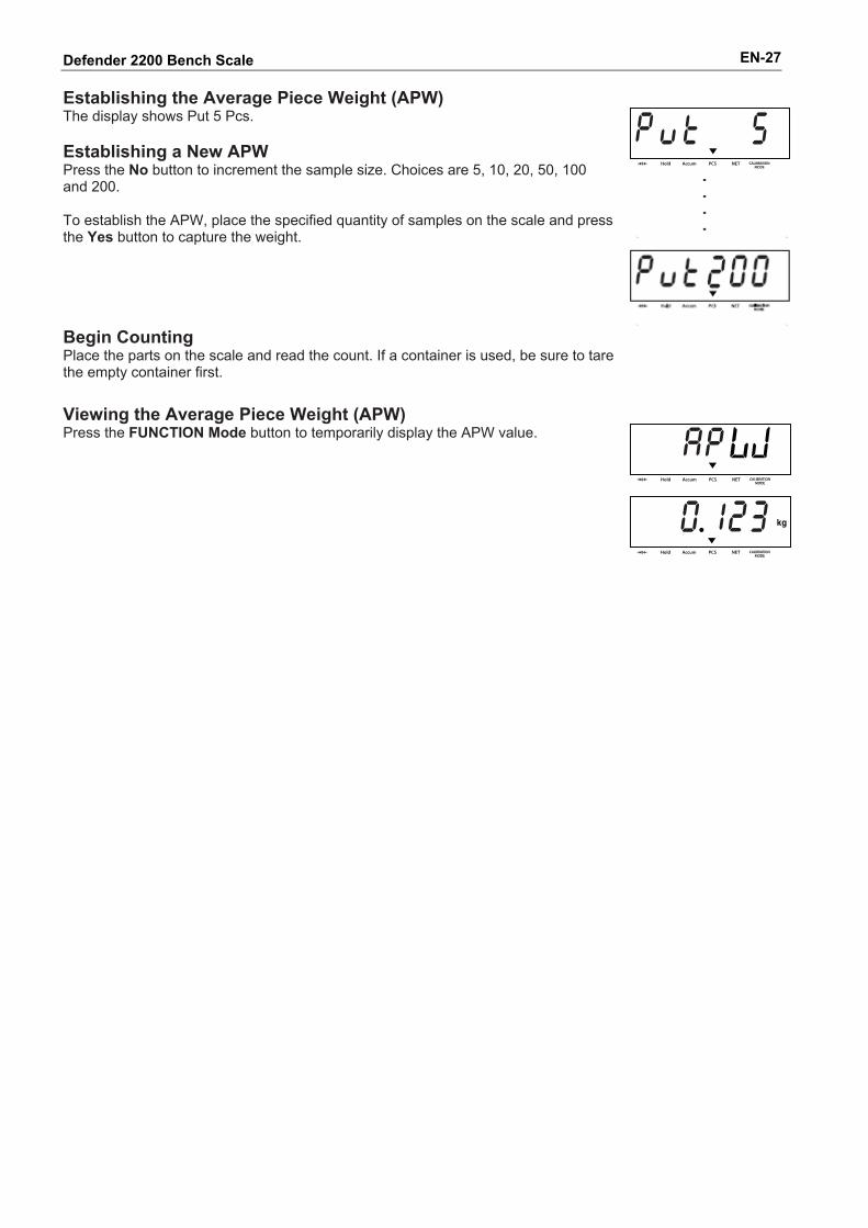
Defender 2200 Bench Scale EN-27 Establishing the Average Piece Weight (APW) The display shows Put 5 Pcs. Establishing a New APW Press the No button to increment the sample size. Choices are 5, 10, 20, 50, 100 and 200. To establish the APW, place the specified quantity of samples on the scale and press the Yes button to capture the weight.
Begin Counting Place the parts on the scale and read the count. If a container is used, be sure to tare the empty container first.
Viewing the Average Piece Weight (APW) Press the FUNCTION Mode button to temporarily display the APW value.
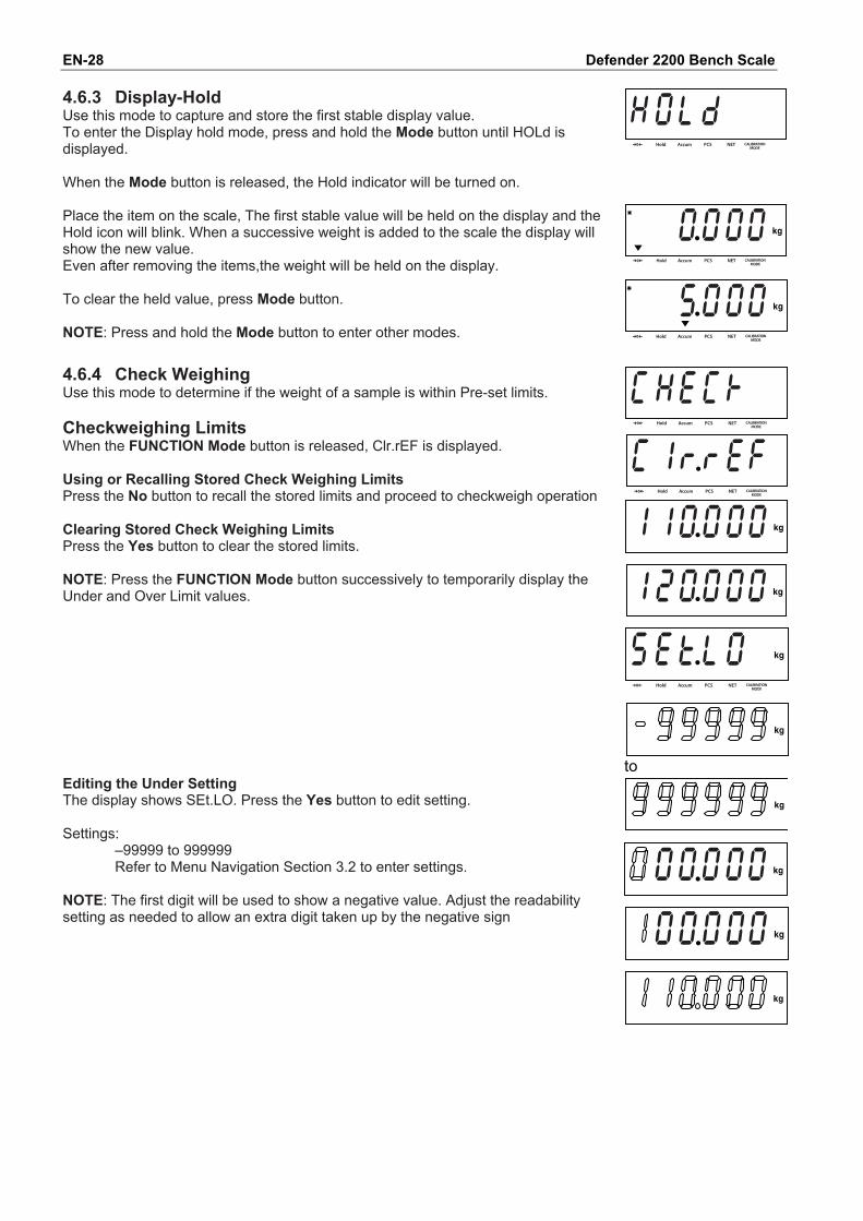
Defender 2200 Bench Scale EN-28 4.6.3 Display-Hold Use this mode to capture and store the first stable display value. To enter the Display hold mode, press and hold the Mode button until HOLd is displayed. When the Mode button is released, the Hold indicator will be turned on. Place the item on the scale, The first stable value will be held on the display and the Hold icon will blink. When a successive weight is added to the scale the display will show the new value. Even after removing the items,the weight will be held on the display. To clear the held value, press Mode button. NOTE: Press and hold the Mode button to enter other modes.
4.6.4 Check Weighing Use this mode to determine if the weight of a sample is within Pre-set limits. Checkweighing Limits When the FUNCTION Mode button is released, Clr.rEF is displayed. Using or Recalling Stored Check Weighing Limits Press the No button to recall the stored limits and proceed to checkweigh operation Clearing Stored Check Weighing Limits Press the Yes button to clear the stored limits. NOTE: Press the FUNCTION Mode button successively to temporarily display the Under and Over Limit values.
to
Editing the Under Setting The display shows SEt.LO. Press the Yes button to edit setting. Settings:
–99999 to 999999 Refer to Menu Navigation Section 3.2 to enter settings.
NOTE: The first digit will be used to show a negative value. Adjust the readability setting as needed to allow an extra digit taken up by the negative sign
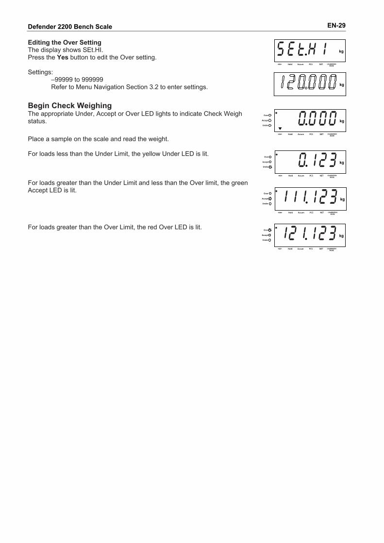
Defender 2200 Bench Scale EN-29 Editing the Over Setting The display shows SEt.HI. Press the Yes button to edit the Over setting. Settings:
–99999 to 999999 Refer to Menu Navigation Section 3.2 to enter settings.
Begin Check Weighing The appropriate Under, Accept or Over LED lights to indicate Check Weigh status. Place a sample on the scale and read the weight.
For loads less than the Under Limit, the yellow Under LED is lit.
For loads greater than the Under Limit and less than the Over limit, the green Accept LED is lit.
For loads greater than the Over Limit, the red Over LED is lit.
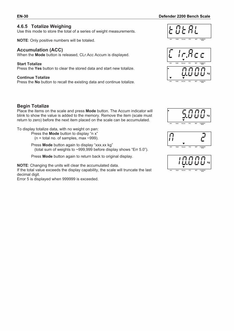
Defender 2200 Bench Scale EN-30 4.6.5 Totalize Weighing Use this mode to store the total of a series of weight measurements. NOTE: Only positive numbers will be totaled. Accumulation (ACC) When the Mode button is released, CLr.Acc Accum is displayed. Start Totalize Press the Yes button to clear the stored data and start new totalize. Continue Totalize Press the No button to recall the existing data and continue totalize.
Begin Totalize Place the items on the scale and press Mode button. The Accum indicator will blink to show the value is added to the memory. Remove the item (scale must return to zero) before the next item placed on the scale can be accumulated. To display totalize data, with no weight on pan:
Press the Mode button to display “n x” (n = total no. of samples, max ~999).
Press Mode button again to display “xxx.xx kg” (total sum of weights to ~999,999 before display shows “Err 5.0”).
Press Mode button again to return back to original display.
NOTE: Changing the units will clear the accumulated data. If the total value exceeds the display capability, the scale will truncate the last decimal digit. Error 5 is displayed when 999999 is exceeded.
Defender 2200 Bench Scale EN-31
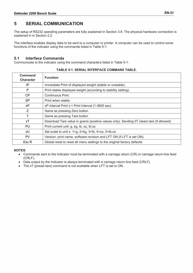
5 SERIAL COMMUNICATION The setup of RS232 operating parameters are fully explained in Section 3.8. The physical hardware connection is explained in in Section 2.2. The interface enables display data to be sent to a computer or printer. A computer can be used to control some functions of the indicator using the commands listed in Table 5-1. 5.1 Interface Commands Communicate to the indicator using the command characters listed in Table 5-1.
TABLE 5-1. SERIAL INTERFACE COMMAND TABLE. Command Character Function
IP Immediate Print of displayed weight (stable or unstable). P Print stable displayed weight (according to stability setting).
CP Continuous Print. SP Print when stable. xP xP Interval Print x = Print Interval (1-3600 sec) Z Same as pressing Zero button T Same as pressing Tare button xT Download Tare value in grams (positive values only). Sending 0T clears tare (if allowed) PU Print current unit: g, kg, lb, oz, lb:oz xU Set scale to unit x: 1=g, 2=kg, 3=lb, 4=oz, 5=lb:oz PV Version: print name, software revision and LFT ON (if LFT is set ON).
Esc R Global reset to reset all menu settings to the original factory defaults NOTES:
• Commands sent to the Indicator must be terminated with a carriage return (CR) or carriage return-line feed (CRLF).
• Data output by the Indicator is always terminated with a carriage return-line feed (CRLF). • The xT (preset tare) command is not available when LFT is set to ON.
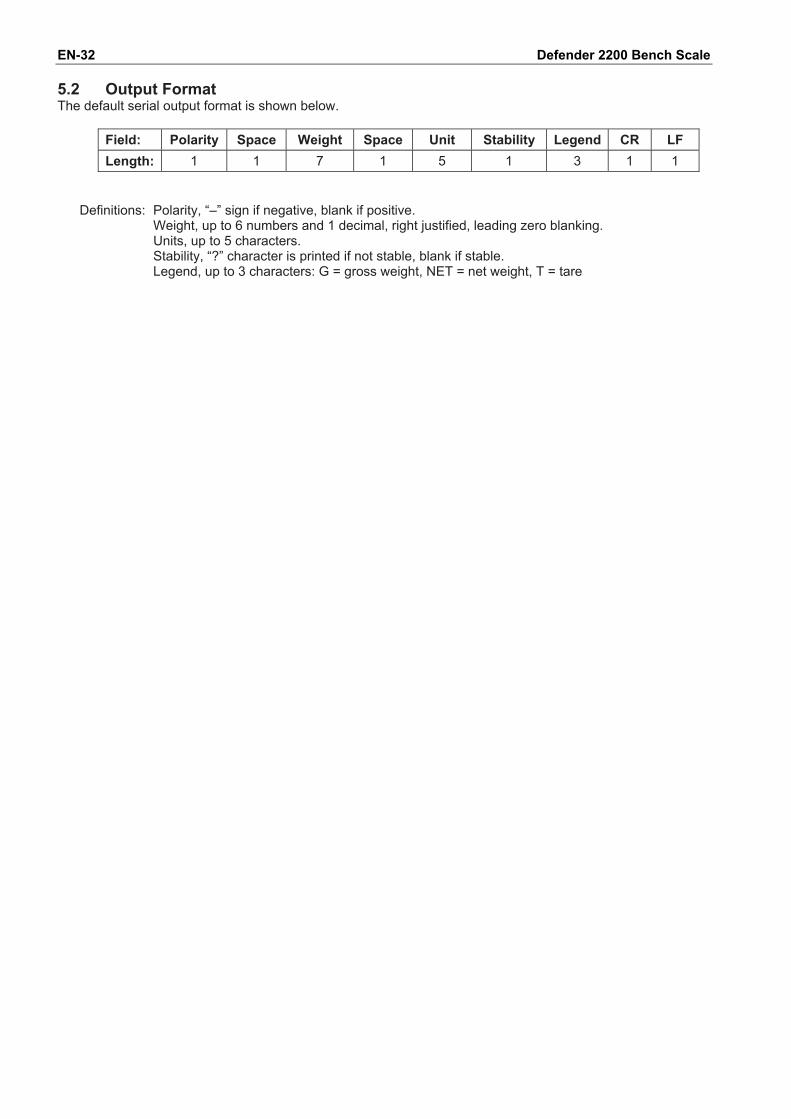
Defender 2200 Bench Scale EN-32 5.2 Output Format The default serial output format is shown below.
Field: Polarity Space Weight Space Unit Stability Legend CR LF Length: 1 1 7 1 5 1 3 1 1
Definitions: Polarity, “–” sign if negative, blank if positive.
Weight, up to 6 numbers and 1 decimal, right justified, leading zero blanking. Units, up to 5 characters. Stability, “?” character is printed if not stable, blank if stable. Legend, up to 3 characters: G = gross weight, NET = net weight, T = tare
Defender 2200 Bench Scale EN-33 6. LEGAL FOR TRADE When the indicator is used in trade or a legally controlled application it must be set up, verified and sealed in accordance with local weights and measures regulations. It is the responsibility of the purchaser to ensure that all pertinent legal requirements are met. 6.1 Settings Before verification and sealing, perform the following steps:
1. Verify that the menu settings meet the local weights and measures regulations. 2. Perform a calibration. 3. Set Legal for Trade to ON in the Setup menu. 4. Exit the menu. 5. Disconnect power from the indicator and open the housing as explained in Section 2.3.1. 6. Set the position of the security switch to ON as shown in Section 1.2, Item 2. 7. Close the housing. 8. Reconnect power and turn the indicator on.
NOTE: For installations that employ the audit trail sealing method, steps 5 to 8 are not required. However, the security switch may be set to ON to safeguard against unintentional changes to configuration and calibration settings. NOTE: When Legal for Trade is set to ON and the security switch is set to ON, the following menu settings cannot be changed: Span Calibration, Linearity Calibration, GEO, LFT, Calibration Unit, Capacity, Graduation, Power On Unit, Zero Range, Auto Zero Tracking, Expanded Mode, Count Mode, Kilogram Unit, Pound Unit, Gram Unit, Ounce Unit, Pound Ounce Unit, Stable Only. To enable editing of these menu settings, return the security switch to the off position and set LFT menu item to off. 6.2 Verification The local weights and measures official or authorized service agent must perform the verification procedure. Please contact your local weights and measures office for further details.
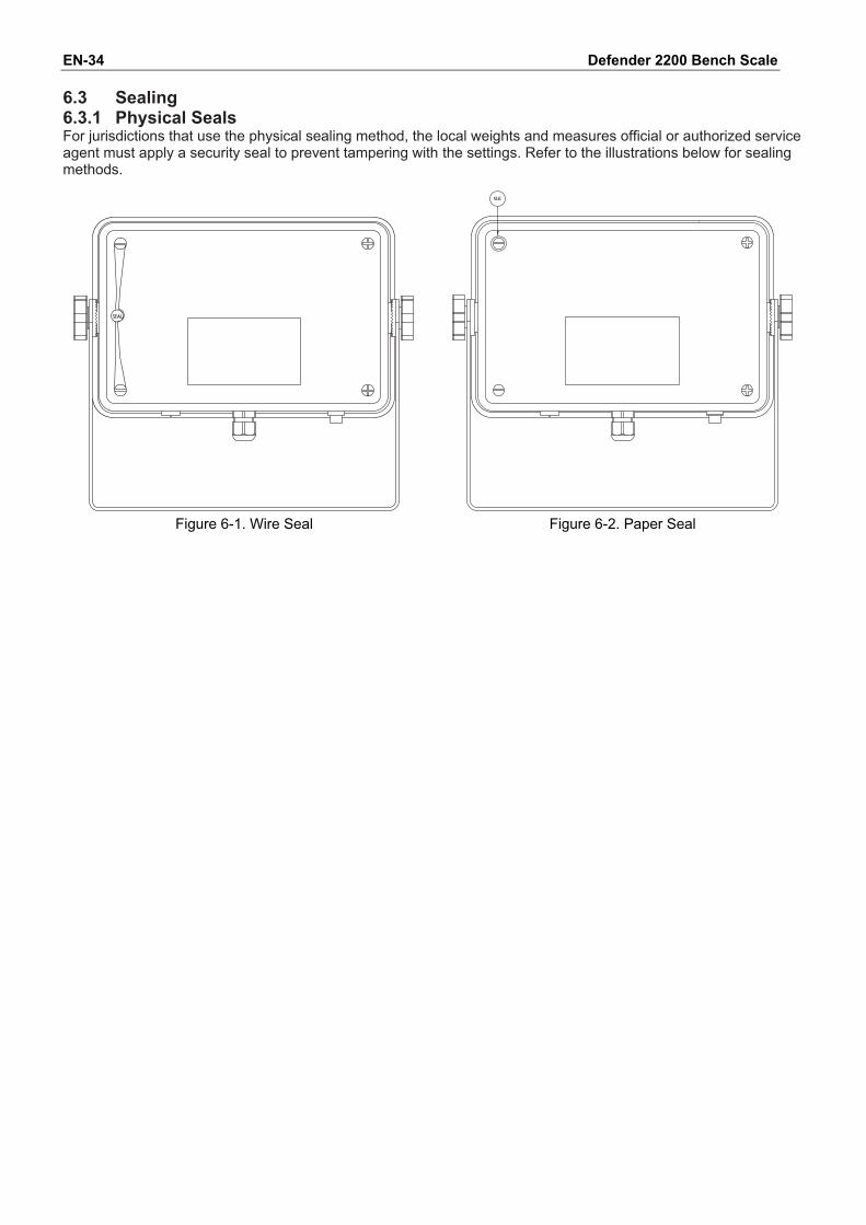
Defender 2200 Bench Scale EN-34 6.3 Sealing 6.3.1 Physical Seals For jurisdictions that use the physical sealing method, the local weights and measures official or authorized service agent must apply a security seal to prevent tampering with the settings. Refer to the illustrations below for sealing methods.
Figure 6-1. Wire Seal Figure 6-2. Paper Seal
Defender 2200 Bench Scale EN-35 6.3.2 Audit Trail Seal For jurisdictions that use the audit trail sealing method, the local weights and measures official or authorized service agent must record the current configuration and calibration event counter values at the time of sealing. These values will be compared to values found during a future inspection. NOTE: A change to an event counter value is equivalent to breaking a physical seal. The audit trail uses two event counters to record changes to configuration and calibration settings.
• The configuration event counter (CFG) will index by 1 when exiting the menu if one or more of the following settings are changed Legal for Trade, Calibration Unit, Capacity, Graduation, Power On Unit, Zero Range, Auto Zero Tracking, Expanded Mode, Count Mode, Kilogram Unit, Pound Unit, Gram Unit, Ounce Unit, Pound Ounce Unit, Stable Only. Note that the counter only indexes once, even if several settings are changed. The configuration event counter values range from CFG000 to CFG999. When the value reaches CFG999, the count starts over at CFG000.
• The calibration event counter (CAL) will index by 1 when exiting the menu if a Span Calibration, Linearity Calibration or GEO setting change is made. Note that the counter only indexes once, even if several settings are changed. The calibration event counter values range from CAL000 to CAL999. When the value reaches CAL999, the count starts over at CAL000.
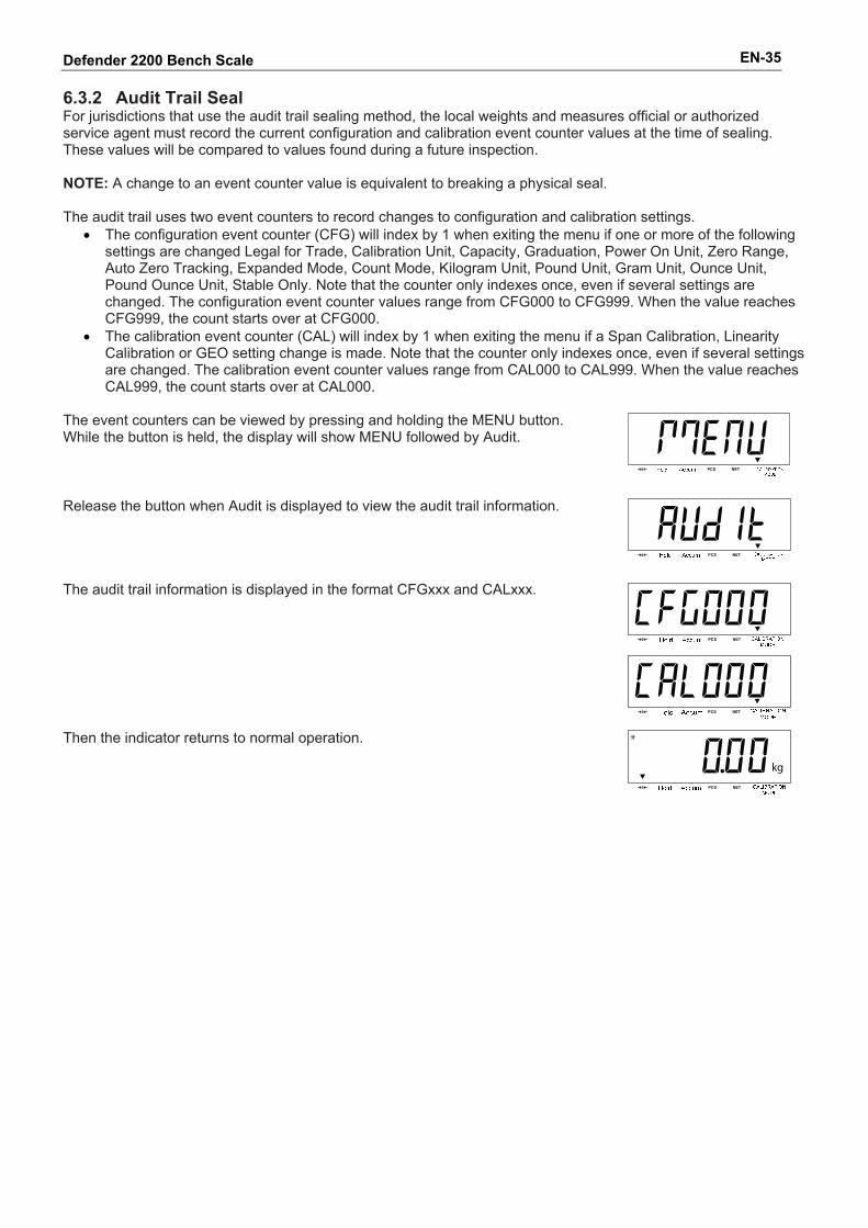
The event counters can be viewed by pressing and holding the MENU button. While the button is held, the display will show MENU followed by Audit.
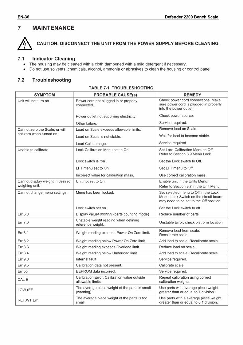
Release the button when Audit is displayed to view the audit trail information.
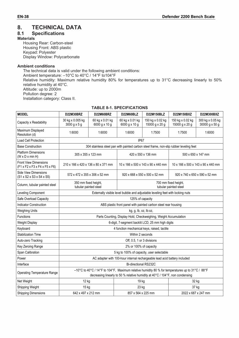
The audit trail information is displayed in the format CFGxxx and CALxxx.
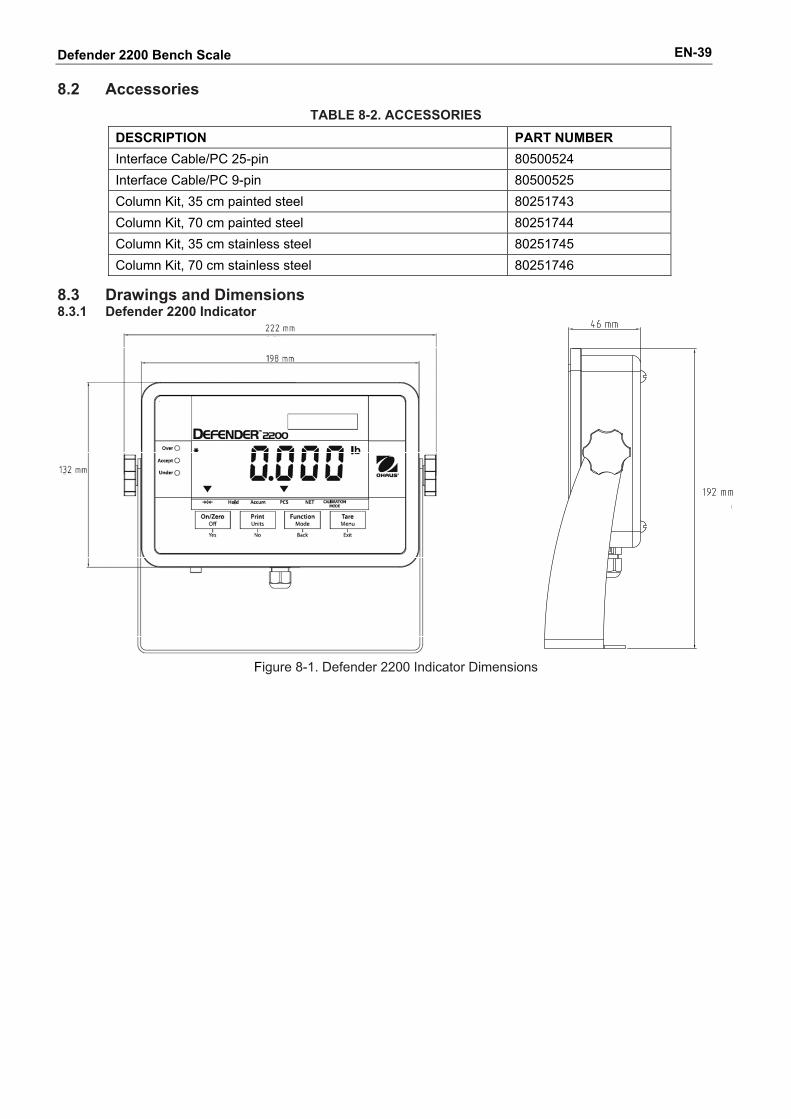
Then the indicator returns to normal operation.
Defender 2200 Bench Scale EN-36 7 MAINTENANCE
CAUTION: DISCONNECT THE UNIT FROM THE POWER SUPPLY BEFORE CLEANING.
7.1 Indicator Cleaning
• The housing may be cleaned with a cloth dampened with a mild detergent if necessary. • Do not use solvents, chemicals, alcohol, ammonia or abrasives to clean the housing or control panel.
7.2 Troubleshooting
TABLE 7-1. TROUBLESHOOTING. SYMPTOM PROBABLE CAUSE(s) REMEDY
Unit will not turn on.
Power cord not plugged in or properly connected. Power outlet not supplying electricity. Other failure.
Check power cord connections. Make sure power cord is plugged in properly into the power outlet. Check power source. Service required.
Cannot zero the Scale, or will not zero when turned on.
Load on Scale exceeds allowable limits. Load on Scale is not stable. Load Cell damage.
Remove load on Scale. Wait for load to become stable. Service required.
Unable to calibrate.
Lock Calibration Menu set to On. Lock switch is “on”. LFT menu set to On. Incorrect value for calibration mass.
Set Lock Calibration Menu to Off. Refer to Section 3.9 Menu Lock. Set the Lock switch to Off. Set LFT menu to Off. Use correct calibration mass.
Cannot display weight in desired weighing unit.
Unit not set to On. Enable unit in the Units Menu. Refer to Section 3.7 in the Unit Menu.
Cannot change menu settings. Menu has been locked. Lock switch set on.
Set selected menu to Off in the Lock Menu. Lock Switch on the circuit board may need to be set to the Off position. Set the Lock switch to off.
Err 5.0 Display value>999999 (parts counting mode) Reduce number of parts
Err 7.0 Unstable weight reading when defining reference weight. Unstable Error, check platform location.
Err 8.1 Weight reading exceeds Power On Zero limit. Remove load from scale. Recalibrate scale.
Err 8.2 Weight reading below Power On Zero limit. Add load to scale. Recalibrate scale. Err 8.3 Weight reading exceeds Overload limit. Reduce load on scale. Err 8.4 Weight reading below Underload limit. Add load to scale. Recalibrate scale. Err 9.0 Internal fault Service required. Err 9.5 Calibration data not present. Calibrate scale. Err 53 EEPROM data incorrect. Service required.
CAL E Calibration Error. Calibration value outside allowable limits.
Repeat calibration using correct calibration weights.
LOW.rEF The average piece weight of the parts is small (warning).
Use parts with average piece weight greater than or equal to 1 division.
REF.WT Err The average piece weight of the parts is too small.
Use parts with a average piece weight greater than or equal to 0.1 division.

Defender 2200 Bench Scale EN-37 7.3 Service Information If the troubleshooting section does not resolve your problem, contact an authorized OHAUS Service Agent. For Service assistance in the United States, call toll-free 1-800-526-0659 between 8:00 AM and 5:00 PM Eastern Standard Time. An OHAUS Product Service Specialist will be available to assist you. Outside the USA, please visit our website www.OHAUS.com to locate the OHAUS office nearest you.
Defender 2200 Bench Scale EN-38 8. TECHNICAL DATA 8.1 Specifications Materials
Housing Rear: Carbon-steel Housing Front: ABS plastic Keypad: Polyester Display Window: Polycarbonate
Ambient conditions The technical data is valid under the following ambient conditions: Ambient temperature: –10°C to 40°C / 14°F to104°F Relative humidity: Maximum relative humidity 80% for temperatures up to 31°C decreasing linearly to 50% relative humidity at 40°C. Altitude: up to 2000m Pollution degree: 2 Installation category: Class II.
TABLE 8-1. SPECIFICATIONS
MODEL D22M30BRZ D22M60BRZ D22M60BLZ D22M150BLZ D22M150BXZ D22M300BXZ
Capacity x Readability 30 kg x 0.005 kg 3000 g x 5 g
60 kg x 0.01 kg 6000 g x 10 g
60 kg x 0.01 kg 6000 g x 10 g
150 kg x 0.02 kg 15000 g x 20 g
150 kg x 0.02 kg 15000 g x 20 g
300 kg x 0.05 kg 30000 g x 50 g
Maximum Displayed Resolution (d) 1:6000 1:6000 1:6000 1:7500 1:7500 1:6000
Load Cell Protection IP67 Base Construction 304 stainless steel pan with painted carbon steel frame, non-slip rubber leveling feet Platform Dimensions (W x D x min H) 305 x 355 x 123 mm 420 x 550 x 136 mm 500 x 650 x 147 mm
Front View Dimensions (F1 x F2 x F3 x F4 x F5 x F6) 210 x 166 x 420 x 136 x 80 x 371 mm 10 x 166 x 500 x 143 x 90 x 440 mm 10 x 166 x 500 x 143 x 90 x 440 mm
Side View Dimensions (S1 x S2 x S3 x S4 x S5) 572 x 472 x 355 x 306 x 52 mm 920 x 668 x 550 x 500 x 52 mm 920 x 740 x 650 x 590 x 52 mm
Column, tubular painted steel 350 mm fixed height, tubular painted steel
700 mm fixed height, tubular painted steel
Leveling Component Externally visible level bubble and adjustable leveling feet with locking nuts Safe Overload Capacity 125% of capacity Indicator Construction ABS plastic front panel with painted carbon steel rear housing Weighing Units kg, g, lb, oz, lb:oz, Functions Parts Counting, Display Hold, Checkweighing, Weight Accumulation Weight Display 6-digit, 7-segment backlit LCD, 25 mm high digits Keyboard 4 function mechanical keys, raised, tactile Stabilization Time Within 2 seconds Auto-zero Tracking Off, 0.5, 1 or 3 divisions Key Zeroing Range 2% or 100% of capacity Span Calibration 5 kg to 100% of capacity, user selectable Power AC adapter with 100-hour internal rechargeable lead acid battery included Interface Bi-directional RS232C
Operating Temperature Range –10°C to 40°C / 14°F to 104°F, Maximum relative humidity 80 % for temperatures up to 31°C / 88°F decreasing linearly to 50 % relative humidity at 40°C / 104°F, non condensing
Net Weight 12 kg 19 kg 32 kg Shipping Weight 15 kg 23 kg 37 kg Shipping Dimensions 642 x 497 x 212 mm 857 x 564 x 225 mm 2022 x 687 x 247 mm
Defender 2200 Bench Scale EN-39 8.2 Accessories
TABLE 8-2. ACCESSORIES
DESCRIPTION PART NUMBER Interface Cable/PC 25-pin 80500524 Interface Cable/PC 9-pin 80500525 Column Kit, 35 cm painted steel 80251743 Column Kit, 70 cm painted steel 80251744 Column Kit, 35 cm stainless steel 80251745 Column Kit, 70 cm stainless steel 80251746
8.3 Drawings and Dimensions 8.3.1 Defender 2200 Indicator
Figure 8-1. Defender 2200 Indicator Dimensions
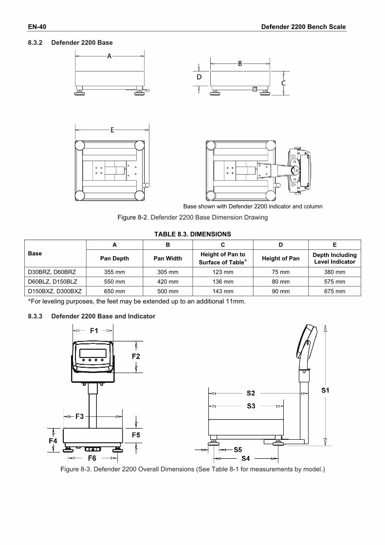
Defender 2200 Bench Scale EN-40 8.3.2 Defender 2200 Base
Base shown with Defender 2200 indicator and column
Figure 8-2. Defender 2200 Base Dimension Drawing
TABLE 8.3. DIMENSIONS A B C D E
Base Pan Depth Pan Width
Height of Pan to Surface of Table* Height of Pan Depth Including
Level Indicator
D30BRZ, D60BRZ 355 mm 305 mm 123 mm 75 mm 380 mm D60BLZ, D150BLZ 550 mm 420 mm 136 mm 80 mm 575 mm D150BXZ, D300BXZ 650 mm 500 mm 143 mm 90 mm 675 mm *For leveling purposes, the feet may be extended up to an additional 11mm. 8.3.3 Defender 2200 Base and Indicator
Figure 8-3. Defender 2200 Overall Dimensions (See Table 8-1 for measurements by model.)
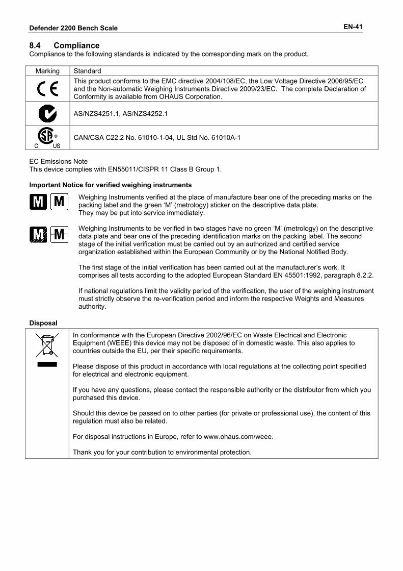
Defender 2200 Bench Scale EN-41 8.4 Compliance Compliance to the following standards is indicated by the corresponding mark on the product.
Marking Standard
This product conforms to the EMC directive 2004/108/EC, the Low Voltage Directive 2006/95/EC and the Non-automatic Weighing Instruments Directive 2009/23/EC. The complete Declaration of Conformity is available from OHAUS Corporation.
AS/NZS4251.1, AS/NZS4252.1
CAN/CSA C22.2 No. 61010-1-04, UL Std No. 61010A-1
EC Emissions Note This device complies with EN55011/CISPR 11 Class B Group 1. Important Notice for verified weighing instruments
Weighing Instruments verified at the place of manufacture bear one of the preceding marks on the packing label and the green ‘M’ (metrology) sticker on the descriptive data plate. They may be put into service immediately. Weighing Instruments to be verified in two stages have no green ‘M’ (metrology) on the descriptive data plate and bear one of the preceding identification marks on the packing label. The second stage of the initial verification must be carried out by an authorized and certified service organization established within the European Community or by the National Notified Body. The first stage of the initial verification has been carried out at the manufacturer’s work. It comprises all tests according to the adopted European Standard EN 45501:1992, paragraph 8.2.2. If national regulations limit the validity period of the verification, the user of the weighing instrument must strictly observe the re-verification period and inform the respective Weights and Measures authority.
Disposal
In conformance with the European Directive 2002/96/EC on Waste Electrical and Electronic Equipment (WEEE) this device may not be disposed of in domestic waste. This also applies to countries outside the EU, per their specific requirements. Please dispose of this product in accordance with local regulations at the collecting point specified for electrical and electronic equipment. If you have any questions, please contact the responsible authority or the distributor from which you purchased this device. Should this device be passed on to other parties (for private or professional use), the content of this regulation must also be related. For disposal instructions in Europe, refer to www.ohaus.com/weee. Thank you for your contribution to environmental protection.
Defender 2200 Bench Scale EN-42 FCC Note This equipment has been tested and found to comply with the limits for a Class B digital device, pursuant to Part 15 of the FCC Rules. These limits are designed to provide reasonable protection against harmful interference when the equipment is operated in a commercial environment. This equipment generates, uses, and can radiate radio frequency energy and, if not installed and used in accordance with the instruction manual, may cause harmful interference to radio communications. Operation of this equipment in a residential area is likely to cause harmful interference in which case the user will be required to correct the interference at his own expense. Industry Canada Note This Class B digital apparatus complies with Canadian ICES-003. ISO 9001 Registration In 1994, OHAUS Corporation, USA, was awarded a certificate of registration to ISO 9001 by Bureau Veritus Quality International (BVQI), confirming that the OHAUS quality management system is compliant with the ISO 9001 standard’s requirements. On May 15, 2003, OHAUS Corporation, USA, was re-registered to the ISO 9001:2000 standard.
LIMITED WARRANTY
OHAUS products are warranted against defects in materials and workmanship from the date of delivery through the duration of the warranty period. During the warranty period OHAUS will repair, or, at its option, replace any component(s) that proves to be defective at no charge, provided that the product is returned, freight prepaid, to OHAUS. This warranty does not appy if the product has been damaged by accident or misuse, exposed to radioactive or corrosive materials, has foreign material penetrating to the inside of the product, or as a result of service or modification by other than OHAUS. In lieu of a properly returned warranty registration card, the warranty period shall begin on the date of shipment to the authorized dealer. No other express or implied warranty is given by OHAUS Corporation. OHAUS Corporation shall not be liable for any consequential damages. As warranty legislation differs from state to state and country to country, please contact OHAUS or your local OHAUS dealer for further details.

Ohaus Corporation 7 Campus Drive Suite 310 Parsippany, NJ 07054 USA Tel: (973) 377-9000 Fax: (973) 944-7177 With offices worldwide www.ohaus.com
*83033841* P/N 83033841 © 2011 Ohaus Corporation, all rights reserved Printed in China
Related Documents