Deep hole drilling Product catalog and application guide METALWORKING PRODUCTS Deep hole drilling In the UNITED STATES call us toll-free 1- 800 - SANDVIK (1-800-726-3845) In CANADA, call us toll-free 1-800-268-0703 4 7 43 109 Introduction Ejector system STS system Application guide DEEP HOLE DRILLING

Welcome message from author
This document is posted to help you gain knowledge. Please leave a comment to let me know what you think about it! Share it to your friends and learn new things together.
Transcript

Deep hole drillingProduct catalog and application guide
METALWORKING PRODUCTS
www.sandvik.com
Your Local Sandvik Coromant Distributor:
In the UNITED STATES,call toll-free for technical and application
assistance, product and ordering information:
1-800-SANDVIK(1-800-726-3845)
In CANADA, call toll-free for product
and ordering information:1-800-268-0703
In MEXICO, call for product
and ordering information:(5) 729 39 00
LIT-CAT DHD 04© AB Sandvik Coromant09/04
Your Productivity Partner™
Printed on recycleable paperPrinted in Sweden by Elanders
Deep hole drilling
2004
Cover uppslag 04-05-11 15.33 Sida 2
In the UNITED STATES call us toll-free1-800- SANDVIK (1-800-726-3845)
In CANADA, call us toll-free1-800-268-0703
4
7
43
109
Introduction
Ejector system
STS system
Application guide
DEEP HOLE DRILLING
003-011 USA 04-04-29 08.38 Sida 3
4 In CANADA, call us toll-free1-800-268-0703
In the UNITED STATES call us toll-free1-800- SANDVIK (1-800-726-3845)
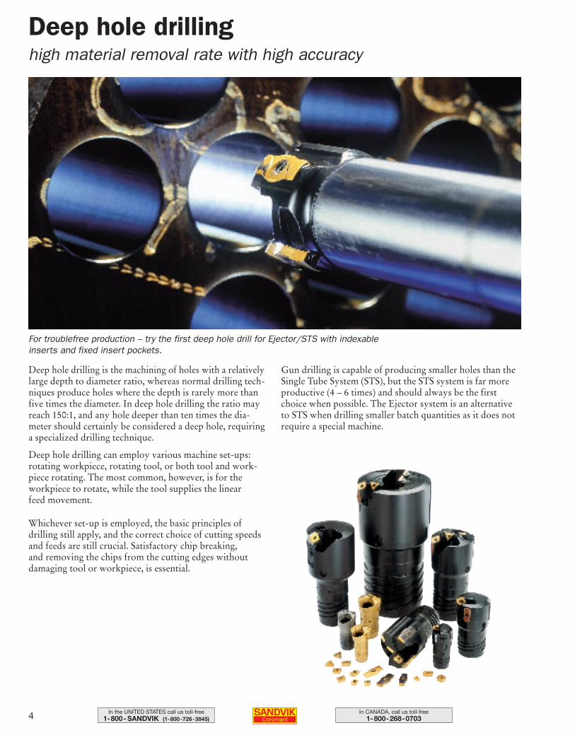
Deep hole drilling is the machining of holes with a relativelylarge depth to diameter ratio, whereas normal drilling tech-niques produce holes where the depth is rarely more thanfive times the diameter. In deep hole drilling the ratio mayreach 150:1, and any hole deeper than ten times the dia-meter should certainly be considered a deep hole, requiringa specialized drilling technique.
Deep hole drilling can employ various machine set-ups:rotating workpiece, rotating tool, or both tool and work-piece rotating. The most common, however, is for the workpiece to rotate, while the tool supplies the linear feed movement.
Whichever set-up is employed, the basic principles ofdrilling still apply, and the correct choice of cutting speedsand feeds are still crucial. Satisfactory chip breaking, and removing the chips from the cutting edges withoutdamaging tool or workpiece, is essential.
Gun drilling is capable of producing smaller holes than theSingle Tube System (STS), but the STS system is far moreproductive (4 – 6 times) and should always be the firstchoice when possible. The Ejector system is an alternativeto STS when drilling smaller batch quantities as it does notrequire a special machine.
Deep hole drillinghigh material removal rate with high accuracy
For troublefree production – try the first deep hole drill for Ejector/STS with indexableinserts and fixed insert pockets.
003-011 USA 04-04-29 08.38 Sida 4
5In the UNITED STATES call us toll-free1-800- SANDVIK (1-800-726-3845)
In CANADA, call us toll-free1-800-268-0703
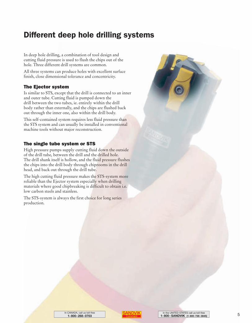
Different deep hole drilling systems
In deep hole drilling, a combination of tool design and cutting fluid pressure is used to flush the chips out of thehole. Three different drill systems are common.
All three systems can produce holes with excellent surfacefinish, close dimensional tolerance and concentricity.
The Ejector systemIs similar to STS, except that the drill is connected to an innerand outer tube. Cutting fluid is pumped down the drill between the two tubes, ie. entirely within the drill body rather than externally, and the chips are flushed backout through the inner one, also within the drill body.
This self-contained system requires less fluid pressure thanthe STS system and can usually be installed in conventionalmachine tools without major reconstruction.
The single tube system or STS High pressure pumps supply cutting fluid down the outsideof the drill tube, between the drill and the drilled hole. The drill shank itself is hollow, and the fluid pressure flushesthe chips into the drill body through chiprooms in the drillhead, and back out through the drill tube.
The high cutting fluid pressure makes the STS-system morereliable than the Ejector system especially when drillingmaterials where good chipbreaking is difficult to obtain i.e.low carbon steels and stainless.
The STS-system is always the first choice for long series production.
003-011 USA 04-04-29 08.38 Sida 5

6 In CANADA, call us toll-free1-800-268-0703
In the UNITED STATES call us toll-free1-800- SANDVIK (1-800-726-3845)
We are dedicated to supply your needs
Sandvik Coromant also recognizes your increasingdemands for environmental concerns and offers a service tocollect used carbide inserts, which are broken down to theiroriginal raw material state – in the most eco-friendly way.
We provide you with quality products suitable for yourbusiness. Add to that our technical service, delivery andcommercial service.
Together, we can strengthen your competitiveness. By working in close partnership with you, we contribute toimprovements in your productivity, production economyand machine utilization.
Our technical staff will help you to reach your objectives in your applications.
003-011 USA 04-04-29 08.38 Sida 6
7In the UNITED STATES call us toll-free1-800- SANDVIK (1-800-726-3845)
In CANADA, call us toll-free1-800-268-0703
8–9
10–11
12–15
16–19
20–24
25
25
26–33
34–35
36
37
38
38
39–41
76
77
78
79-85
86-98
99-108
109
135-136
137-141
142
143
Ejector systemTool selection
Tool mounting – solid drilling and counterboring
Ground drill head 424.6
CoroDrill™ 800.24
T-Max® drill 424.10
Drill tubes manufactured by customer request
Calculation of special length tubes
T-Max® 424.31F and 424.31 counterboring heads
Mounting parts for rotating and non-rotating connectors
Rotating connectors
Non-rotating connectors
Drill mounted connectors non-rotating
Drill tubes suitable for drill mounted connectors
Varilock adapted connector for automatic tool change
Vibration dampers
Adapters converting from external to internal tube threads
Setting the diameter on T-Max® heads
Inserts
Cutting data and graphs
Spare parts
Application guide
Troubleshooting
Material cross reference list
Insert mounting
Safety information
T a b l e o f c o n t e n t s
DEEP HOLE DRILLING
003-011 USA 04-04-29 08.38 Sida 7
8 In CANADA, call us toll-free1-800-268-0703
In the UNITED STATES call us toll-free1-800- SANDVIK (1-800-726-3845)
= FairGood = ✦✦✦
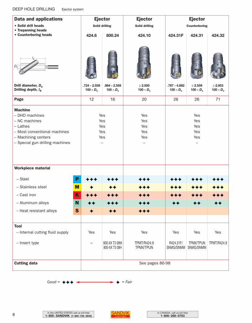
Data and applications• Solid drill heads• Trepanning heads• Counterboring heads
EjectorSolid drilling
424.10
≥ 2.500100 × Dc
Drill diameter, DcDrilling depth, l4
20
EjectorSolid drilling
800.24424.6
.984 - 2.559100 × Dc
.724 - 2.559100 × Dc
Dc
l4
12 16Page
Machine– DHD machines– NC machines– Lathes– Most conventional machines– Machining centers– Special gun drilling machines
YesYesYesYesYes–
YesYesYesYesYes–
Workpiece material
P
M– Stainless steel
– Steel
K– Cast iron
N– Aluminum alloys
S– Heat resistant alloys
Tool
– Internal cutting fluid supply
– Insert type
Yes
TPMT/R424.9TPMX/TPUN
Yes
800-XX T3 08M800-XX T3 08H
Yes
–
Cutting data See pages 86-98
✦
✦✦✦
✦✦✦
✦✦✦
✦✦✦
✦✦✦
✦✦✦
✦✦
✦✦✦
✦✦✦
✦✦
✦✦✦
✦
✦✦✦
✦✦
✦
EjectorCounterboring
424.31F 424.31 424.32
.787 - 4.882100 × Dc
≥ 2.559100 × Dc
≥ 2.953100 × Dc
7126 26
YesYesYesYesYes–
Yes Yes Yes
R424.31F/SNMG/SNMM
TPMX/TPUNSNMG/SNMM
TPMT/R424.9
✦✦✦
✦✦✦
✦✦✦
✦✦
✦✦✦
✦✦✦
✦✦✦
✦✦
✦✦✦
✦✦✦
✦✦✦
✦✦
DEEP HOLE DRILLING Ejector system
003-011 USA 04-04-29 08.38 Sida 8
9In the UNITED STATES call us toll-free1-800- SANDVIK (1-800-726-3845)
In CANADA, call us toll-free1-800-268-0703
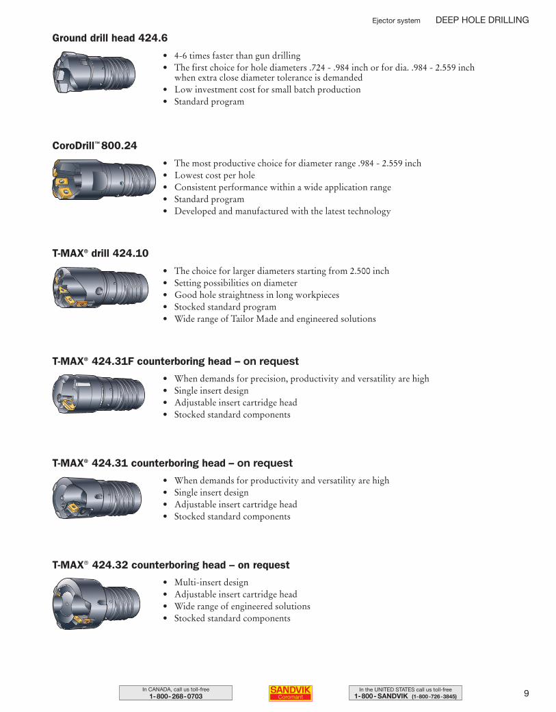
• 4-6 times faster than gun drilling• The first choice for hole diameters .724 - .984 inch or for dia. .984 - 2.559 inch
when extra close diameter tolerance is demanded• Low investment cost for small batch production• Standard program
• The most productive choice for diameter range .984 - 2.559 inch• Lowest cost per hole• Consistent performance within a wide application range• Standard program• Developed and manufactured with the latest technology
• The choice for larger diameters starting from 2.500 inch• Setting possibilities on diameter• Good hole straightness in long workpieces• Stocked standard program• Wide range of Tailor Made and engineered solutions
• When demands for precision, productivity and versatility are high• Single insert design• Adjustable insert cartridge head• Stocked standard components
• When demands for productivity and versatility are high• Single insert design• Adjustable insert cartridge head• Stocked standard components
• Multi-insert design• Adjustable insert cartridge head• Wide range of engineered solutions• Stocked standard components
Ejector system DEEP HOLE DRILLING
Ground drill head 424.6
CoroDrill™ 800.24
T-MAX® drill 424.10
T-MAX® 424.31F counterboring head – on request
T-MAX® 424.31 counterboring head – on request
T-MAX® 424.32 counterboring head – on request
003-011 USA 04-04-29 08.38 Sida 9
10 In CANADA, call us toll-free1-800-268-0703
In the UNITED STATES call us toll-free1-800- SANDVIK (1-800-726-3845)
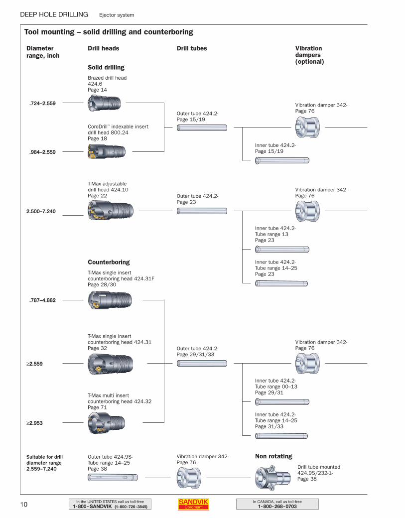
Drill tubes
Outer tube 424.2-Page 15/19
CoroDrill™ indexable insert drill head 800.24Page 18
Brazed drill head 424.6Page 14
T-Max adjustable drill head 424.10Page 22
T-Max single insert counterboring head 424.31FPage 28/30
T-Max single insert counterboring head 424.31Page 32
T-Max multi insert counterboring head 424.32Page 71
Vibration damper 342-Page 76
Inner tube 424.2-Page 15/19
Inner tube 424.2-Tube range 14–25Page 23
Vibration dampers(optional)
Drill headsDiameter range, inch
Solid drilling
Counterboring
2.500–7.240
.787–4.882
≥2.559
≥2.953
.984–2.559
.724–2.559
Outer tube 424.2-Page 23
Inner tube 424.2-Tube range 13Page 23
Tool mounting – solid drilling and counterboring
DEEP HOLE DRILLING Ejector system
Vibration damper 342-Page 76
Outer tube 424.2-Page 29/31/33
Inner tube 424.2-Tube range 14–25Page 31/33
Inner tube 424.2-Tube range 00–13Page 29/31
Vibration damper 342-Page 76
Outer tube 424.9S-Tube range 14–25Page 38
Vibration damper 342-Page 76
Drill tube mounted424.9S/232-1-Page 38
Suitable for drilldiameter range2.559–7.240
Non rotating
003-011 USA 04-04-29 08.38 Sida 10
11In the UNITED STATES call us toll-free1-800- SANDVIK (1-800-726-3845)
In CANADA, call us toll-free1-800-268-0703
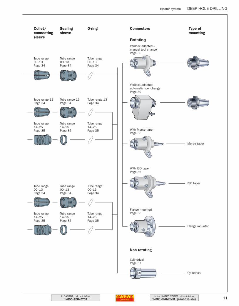
Tube range 00–13Page 34
Tube range 00–13Page 34
Tube range 00–13Page 34
ConnectorsCollet/connectingsleeve
Sealingsleeve
O-ring Type of mounting
Rotating
Non rotating
Varilock adapted – automatic tool changePage 39
With Morse taper Page 36
With ISO taper Page 36
Flange mounted Page 36
Cylindrical Page 37
Varilock adapted – manual tool changePage 36
Morse taper
ISO taper
Flange mounted
Cylindrical
Tube range 14–25Page 35
Tube range 14–25Page 35
Tube range 14–25Page 35
Tube range 13Page 34
Tube range 13Page 34
Tube range 13Page 34
Tube range 14–25Page 35
Tube range 14–25Page 35
Tube range 14–25Page 35
Tube range 00–13Page 34
Tube range 00–13Page 34
Tube range 00–13Page 34
Ejector system DEEP HOLE DRILLING
003-011 USA 04-04-29 08.38 Sida 11

12 In CANADA, call us toll-free1-800-268-0703
In the UNITED STATES call us toll-free1-800- SANDVIK (1-800-726-3845)
DEEP HOLE DRILLING Ejector system
Ground drill head 424.6“The original” precision drill
Diameter range .724–2.559 inch
Easy to use• No pre-setting
• No need for tool roomservice
Excellent holestraightness andsurface finish
Customer specified diameter• Finish ground within
.001 inch increments
Reliable performance• Robust design enables high feed rates
• Sintered insert geometries ensure consistanttroublefree chip control in most materials
Wide application area• Optimized grade- and geometry
combinations for most workpiecematerials
012-033 USA 04-04-29 08.18 Sida 12
13In the UNITED STATES call us toll-free1-800- SANDVIK (1-800-726-3845)
In CANADA, call us toll-free1-800-268-0703
Ejector system DEEP HOLE DRILLING
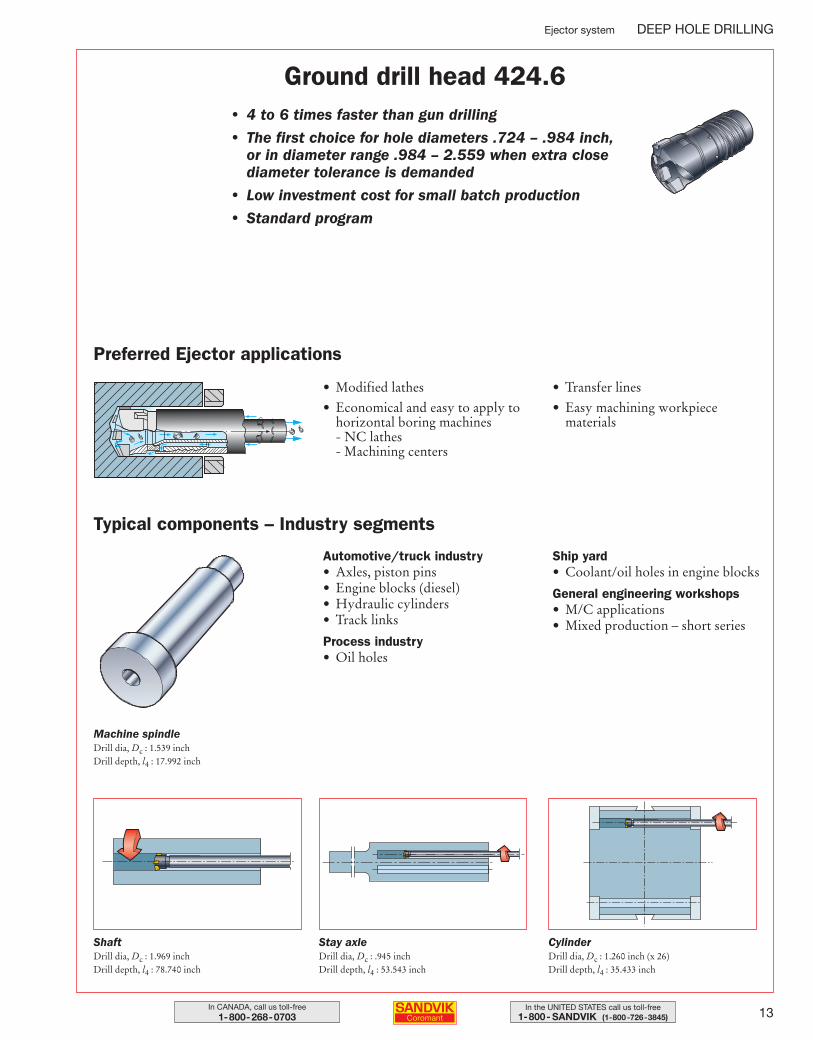
Ground drill head 424.6• 4 to 6 times faster than gun drilling
• The first choice for hole diameters .724 – .984 inch, or in diameter range .984 – 2.559 when extra closediameter tolerance is demanded
• Low investment cost for small batch production
• Standard program
Preferred Ejector applications
• Modified lathes
• Economical and easy to apply tohorizontal boring machines - NC lathes- Machining centers
• Transfer lines
• Easy machining workpiece materials
Typical components – Industry segments
Automotive/truck industry• Axles, piston pins• Engine blocks (diesel)• Hydraulic cylinders• Track links
Process industry• Oil holes
Ship yard• Coolant/oil holes in engine blocks
General engineering workshops• M/C applications• Mixed production – short series
Machine spindleDrill dia, Dc : 1.539 inchDrill depth, l4 : 17.992 inch
ShaftDrill dia, Dc : 1.969 inchDrill depth, l4 : 78.740 inch
Stay axleDrill dia, Dc : .945 inchDrill depth, l4 : 53.543 inch
CylinderDrill dia, Dc : 1.260 inch (x 26)Drill depth, l4 : 35.433 inch
012-033 USA 04-04-29 08.18 Sida 13
14 In CANADA, call us toll-free1-800-268-0703
In the UNITED STATES call us toll-free1-800- SANDVIK (1-800-726-3845)
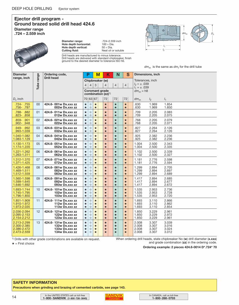
1) Drills with other grade combinations are available on request.★ = First choice
SAFETY INFORMATIONPrecautions when grinding and brazing of cemented carbide, see page 143.
DEEP HOLE DRILLING Ejector system
Ejector drill program - Ground brazed solid drill head 424.6Diameter range .724 – 2.559 inch
Diameter range: .724–2.559 inchHole depth horizontal: 100 × Dia.Hole depth vertical: 50 × Dia.Cutting fluid: Neat oil or soluble
dmm is the same as dmt for the drill tube
Diameterrange, inch
Coromant gradecombination (zz)1)
Drill heads are manufactured to minus tolerance.Drill heads are delivered with standard chipbreaker, finishground to the desired diameter to tolerance ISO h6.
Ordering code, Drill head
Chipbreaker (w)
P
4 4 3 4 4 4
M K N S
70 63 67 72 72 72Dc inch
Dimensions, inch
Tolerances, inchl2 = ± .039l1 = ± .039dmm = h8
dmm l2 l1
l1l2
Dcdmm
.724- .755 00 424.6- 001w Dx.xxx zz ★ ✩ ★ ★ ★ ★ .630 1.969 1.854
.756- .787 002w Dx.xxx zz ★ ✩ ★ ★ ★ ★ .630 1.969 1.850
.788- .882 01 424.6- 011w Dx.xxx zz ★ ✩ ★ ★ ★ ★ .709 2.205 2.083
.823- .858 012w Dx.xxx zz ★ ✩ ★ ★ ★ ★ .709 2.205 2.075
.859- .901 02 424.6- 021w Dx.xxx zz ★ ✩ ★ ★ ★ ★ .768 2.205 2.079
.902- .948 022w Dx.xxx zz ★ ✩ ★ ★ ★ ★ .768 2.205 2.071
.949- .992 03 424.6- 031w Dx.xxx zz ★ ✩ ★ ★ ★ ★ .827 2.264 2.126
.993-1.039 032w Dx.xxx zz ★ ✩ ★ ★ ★ ★ .827 2.264 2.126
1.040-1.082 04 424.6- 041w Dx.xxx zz ★ ✩ ★ ★ ★ ★ .925 2.382 2.2361.083-1.129 042w Dx.xxx zz ★ ✩ ★ ★ ★ ★ .925 2.382 2.236
1.130-1.173 05 424.6- 051w Dx.xxx zz ★ ✩ ★ ★ ★ ★ 1.004 2.500 2.3431.174-1.220 052w Dx.xxx zz ★ ✩ ★ ★ ★ ★ 1.004 2.500 2.335
1.221-1.262 06 424.6- 061w Dx.xxx zz ★ ✩ ★ ★ ★ ★ 1.102 2.500 2.3391.263-1.311 062w Dx.xxx zz ★ ✩ ★ ★ ★ ★ 1.102 2.500 2.327
1.312-1.370 07 424.6- 071w Dx.xxx zz ★ ✩ ★ ★ ★ ★ 1.181 2.776 2.5981.371-1.425 072w Dx.xxx zz ★ ✩ ★ ★ ★ ★ 1.181 2.776 2.594
1.426-1.468 08 424.6- 081w Dx.xxx zz ★ ✩ ★ ★ ★ ★ 1.299 2.894 2.7051.469-1.511 082w Dx.xxx zz ★ ✩ ★ ★ ★ ★ 1.299 2.894 2.6971.512-1.559 083w Dx.xxx zz ★ ✩ ★ ★ ★ ★ 1.299 2.894 2.689
1.560-1.598 09 424.6- 091w Dx.xxx zz ★ ✩ ★ ★ ★ ★ 1.417 2.894 2.6851.599-1.645 092w Dx.xxx zz ★ ✩ ★ ★ ★ ★ 1.417 2.894 2.6771.646-1.692 093w Dx.xxx zz ★ ✩ ★ ★ ★ ★ 1.417 2.894 2.672
1.693-1.744 10 424.6- 101w Dx.xxx zz ★ ✩ ★ ★ ★ ★ 1.535 2.953 2.7361.745-1.795 102w Dx.xxx zz ★ ✩ ★ ★ ★ ★ 1.535 2.953 2.7281.796-1.850 103w Dx.xxx zz ★ ✩ ★ ★ ★ ★ 1.535 2.953 2.720
1.851-1.909 11 424.6- 111w Dx.xxx zz ★ ✩ ★ ★ ★ ★ 1.693 3.110 2.8661.910-1.972 112w Dx.xxx zz ★ ✩ ★ ★ ★ ★ 1.693 3.110 2.8621.973-2.035 113w Dx.xxx zz ★ ✩ ★ ★ ★ ★ 1.693 3.110 2.854
2.036-2.094 12 424.6- 121w Dx.xxx zz ★ ✩ ★ ★ ★ ★ 1.850 3.229 2.9612.095-2.153 122w Dx.xxx zz ★ ✩ ★ ★ ★ ★ 1.850 3.229 2.9722.154-2.212 123w Dx.xxx zz ★ ✩ ★ ★ ★ ★ 1.850 3.229 2.961
2.213-2.299 13 424.6- 131w Dx.xxx zz ★ ✩ ★ ★ ★ ★ 2.008 3.307 3.0392.300-2.385 132w Dx.xxx zz ★ ✩ ★ ★ ★ ★ 2.008 3.307 3.0162.386-2.472 133w Dx.xxx zz ★ ✩ ★ ★ ★ ★ 2.008 3.307 3.0242.473-2.559 134w Dx.xxx zz ★ ✩ ★ ★ ★ ★ 2.008 3.307 3.012
When ordering drill heads, state chipbreaker No (w) drill diameter (x.xxx)and grade combination (zz) in the ordering code.
Ordering example: 2 pieces 424.6-0014 D*.724* 70
Tub
e ra
nge
012-033 USA 04-04-29 08.18 Sida 14
15In the UNITED STATES call us toll-free1-800- SANDVIK (1-800-726-3845)
In CANADA, call us toll-free1-800-268-0703
Ejector system DEEP HOLE DRILLING
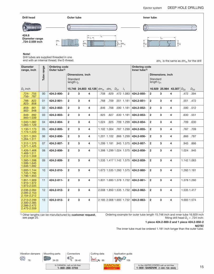
Ordering codeOuter tube1)
Dimensions, inch
dmm dmt D21 l115.748 24.803 42.126
Standard length l2
Outer tubeDrill head Inner tube
424.6Diameter range .724-2.559 inch
l1l2
D21dmmdmt
dmt
dmt is the same as dmm for the drill
l21
D22 D23
Ordering codeInner tube1)
Dimensions, inch
D22 D2316.929 25.984 43.307
Standard length l21
.724- .755 00 424.2-800- 2 3 4 .708 .629 .472 1.083 424.2-850- 2 3 4 .472 .394
.756- .787
.788- .822 01 424.2-801- 2 3 4 .768 .709 .551 1.181 424.2-851- 2 3 4 .551 .472
.823- .858
.859- .901 02 424.2-802- 2 3 4 .846 .768 .590 1.181 424.2-852- 2 3 4 .590 .512
.902- .948
.949- .992 03 424.2-803- 2 3 4 .925 .827 .630 1.181 424.2-853- 2 3 4 .630 .551
.993-1.039
1.040-1.082 04 424.2-804- 2 3 4 1.024 .925 .709 1.299 424.2-854- 2 3 4 .709 .6301.083-1.129
1.130-1.173 05 424.2-805- 2 3 4 1.102 1.004 .787 1.299 424.2-855- 2 3 4 .787 .7091.174-1.220
1.221-1.263 06 424.2-806- 2 3 4 1.201 1.102 .866 1.299 424.2-856- 2 3 4 .866 .7871.264-1.311
1.312-1.370 07 424.2-807- 2 3 4 1.299 1.181 .945 1.575 424.2-857- 2 3 4 .945 .8661.371-1.425
1.426-1.468 08 424.2-808- 2 3 4 1.398 1.299 1.024 1.575 424.2-858- 2 3 4 1.024 .9451.469-1.5111.512-1.559
1.560-1.598 09 424.2-809- 2 3 4 1.535 1.417 1.142 1.575 424.2-859- 2 3 4 1.142 1.0631.599-1.6451.646-1.692
1.693-1.744 10 424.2-810- 2 3 4 1.673 1.535 1.260 1.575 424.2-860- 2 3 4 1.260 1.1811.745-1.7951.796-1.850
1.851-1.909 11 424.2-811- 2 3 4 1.831 1.693 1.378 1.732 424.2-861- 2 3 4 1.378 1.2601.910-1.9721.973-2.035
2.036-2.094 12 424.2-812- 2 3 4 2.008 1.850 1.535 1.732 424.2-862- 2 3 4 1.535 1.4172.095-2.1532.154-2.212
2.213-2.299 13 424.2-813- 2 3 4 2.185 2.008 1.693 1.732 424.2-863- 2 3 4 1.693 1.5742.300-2.3852.386-2.4722.473-2.559
Ordering example for outer tube length 15.748 inch and inner tube 16.929 inch fitting drill head Dc = .724 inch:
1 piece 424.2-800-2 and 1 piece 424.2-850-2NOTE!
The inner tube must be ordered 1.181 inch longer than the outer tube.
1) Other lengths can be manufactured by customer request, see page 25.
34-35 36-40 86 109
Mounting parts Connectors Cutting data Application guide
76
Vibration dampers
Tub
e ra
ngeDiameter
range, inch
Dc inch
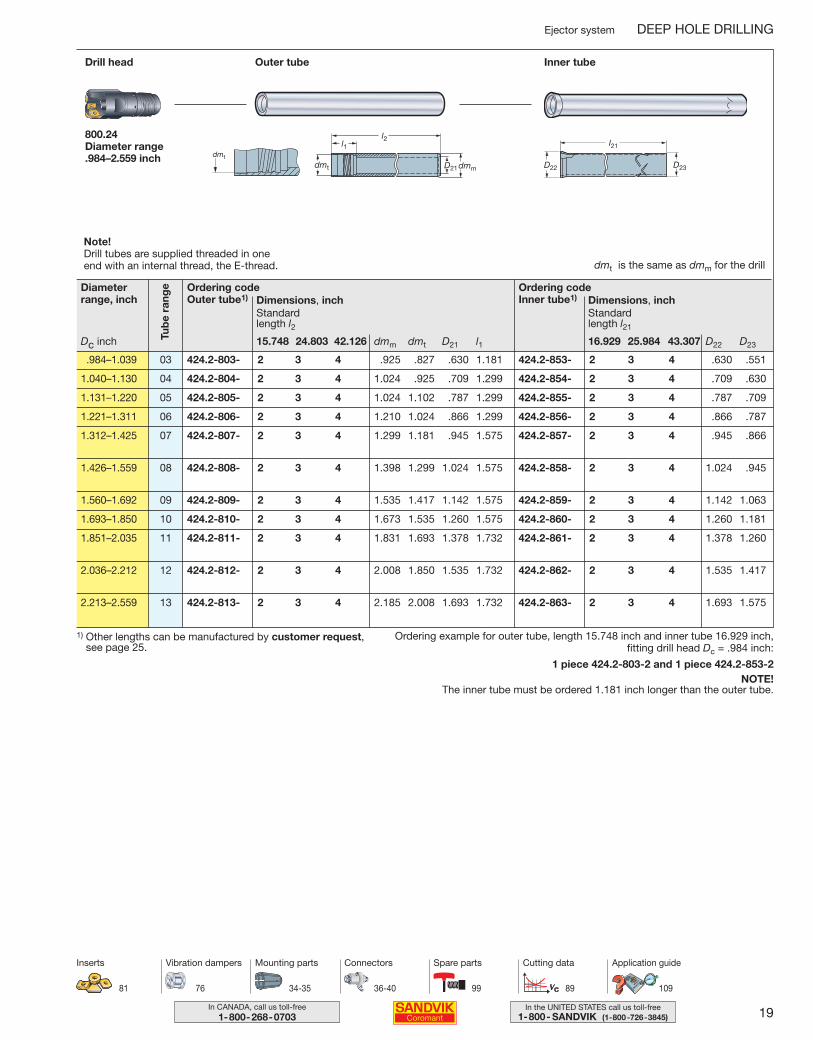
Note!Drill tubes are supplied threaded in one end with an internal thread, the E-thread.
012-033 USA 04-04-29 08.18 Sida 15

16 In CANADA, call us toll-free1-800-268-0703
In the UNITED STATES call us toll-free1-800- SANDVIK (1-800-726-3845)
DEEP HOLE DRILLING Ejector system
Reliable performance• Robust design – high
feed per rev. – produc-tivity
• Wear resistant drillbody manufactured inhardened steel
• Customer specified diameters
• Close tolerances
Easy to identify• Lasermarking of code, dimension and
tube range
Easy to use and handle• Fixed insert seats. No pre-setting – no need for tool room
services
• Few spare parts – low inventory costs
“Coolant accelerator”• Patent pending design
• Ensures outstanding chip evacuation
• No chip clogging – no production stops
Unique support pad design• Indexable economy – two pads
in one drill head
• Higher cutting speed – productivity
• Excellent surface finish
• Improves cutting fluid supply
Productivity in a wide application range• Modern grade and geometry program covers most workpiece
materials
• Few inserts and support pad sizes cover the whole diameter range
• Excellent chip control in both low and high feeds
Patent pending design.
Excellent holestraightness andsurface finish
CoroDrill™ 800.24The productivity drill
Diameter range .984 – 2.559 inch
012-033 USA 04-04-29 08.18 Sida 16
17In the UNITED STATES call us toll-free1-800- SANDVIK (1-800-726-3845)
In CANADA, call us toll-free1-800-268-0703
Ejector system DEEP HOLE DRILLING
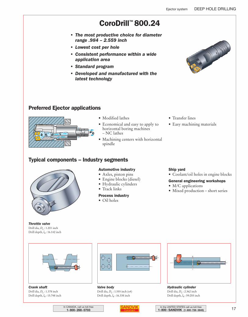
CoroDrill™ 800.24• The most productive choice for diameter
range .984 – 2.559 inch
• Lowest cost per hole
• Consistent performance within a wide application area
• Standard program
• Developed and manufactured with the latest technology
Preferred Ejector applications
• Modified lathes
• Economical and easy to apply tohorizontal boring machines – NC lathes
• Machining centers with horizontalspindle
• Transfer lines
• Easy machining materials
Typical components – Industry segments
Automotive industry• Axles, piston pins• Engine blocks (diesel)• Hydraulic cylinders• Track links
Process industry• Oil holes
Ship yard• Coolant/oil holes in engine blocks
General engineering workshops• M/C applications• Mixed production – short series
Throttle valveDrill dia, Dc : 1.201 inchDrill depth, l4 : 16.142 inch
Crank shaftDrill dia, Dc : 1.378 inchDrill depth, l4 : 15.748 inch
Valve bodyDrill dia, Dc : 1.555 inch (x4)Drill depth, l4 : 16.338 inch
Hydraulic cylinderDrill dia, Dc : 2.362 inchDrill depth, l4 : 59.055 inch
012-033 USA 04-04-29 08.18 Sida 17
18 In CANADA, call us toll-free1-800-268-0703
In the UNITED STATES call us toll-free1-800- SANDVIK (1-800-726-3845)
DEEP HOLE DRILLING Ejector system
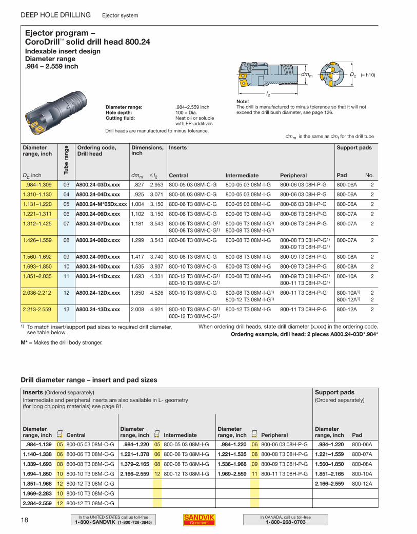
1) To match insert/support pad sizes to required drill diameter, see table below.
When ordering drill heads, state drill diameter (x.xxx) in the ordering code.Ordering example, drill head: 2 pieces A800.24-03D*.984*
Ejector program – CoroDrill™ solid drill head 800.24Indexable insert design Diameter range .984 – 2.559 inch
Diameter range: .984–2.559 inchHole depth: 100 × Dia.Cutting fluid: Neat oil or soluble
with EP-additives
l2
Dcdmm (≈ h10)
dmm is the same as dmt for the drill tube
.984–1.309 03 A800.24-03Dx.xxx .827 2.953 800-05 03 08M-C-G 800-05 03 08M-I-G 800-06 03 08H-P-G 800-06A 2
1.310–1.130 04 A800.24-04Dx.xxx .925 3.071 800-05 03 08M-C-G 800-05 03 08M-I-G 800-06 03 08H-P-G 800-06A 2
1.131–1.220 05 A800.24-M*05Dx.xxx 1.004 3.150 800-06 T3 08M-C-G 800-05 03 08M-I-G 800-06 03 08H-P-G 800-06A 2
1.221–1.311 06 A800.24-06Dx.xxx 1.102 3.150 800-06 T3 08M-C-G 800-06 T3 08M-I-G 800-08 T3 08H-P-G 800-07A 2
1.312–1.425 07 A800.24-07Dx.xxx 1.181 3.543 800-06 T3 08M-C-G1) 800-06 T3 08M-I-G1) 800-08 T3 08H-P-G 800-07A 2800-08 T3 08M-C-G1) 800-08 T3 08M-I-G1)
1.426–1.559 08 A800.24-08Dx.xxx 1.299 3.543 800-08 T3 08M-C-G 800-08 T3 08M-I-G 800-08 T3 08H-P-G1) 800-07A 2800-09 T3 08H-P-G1)
1.560–1.692 09 A800.24-09Dx.xxx 1.417 3.740 800-08 T3 08M-C-G 800-08 T3 08M-I-G 800-09 T3 08H-P-G 800-08A 2
1.693–1.850 10 A800.24-10Dx.xxx 1.535 3.937 800-10 T3 08M-C-G 800-08 T3 08M-I-G 800-09 T3 08H-P-G 800-08A 2
1.851–2.035 11 A800.24-11Dx.xxx 1.693 4.331 800-12 T3 08M-C-G1) 800-08 T3 08M-I-G 800-09 T3 08H-P-G1) 800-10A 2800-10 T3 08M-C-G1) 800-11 T3 08H-P-G1)
2.036-2.212 12 A800.24-12Dx.xxx 1.850 4.526 800-10 T3 08M-C-G 800-08 T3 08M-I-G1) 800-11 T3 08H-P-G 800-10A1) 2800-12 T3 08M-I-G1) 800-12A1) 2
2.213-2.559 13 A800.24-13Dx.xxx 2.008 4.921 800-10 T3 08M-C-G1) 800-12 T3 08M-I-G 800-11 T3 08H-P-G 800-12A 2800-12 T3 08M-C-G1)
Ordering code, Drill head
Diameterrange, inch
Dc inch
Support padsInserts
Central Intermediate Peripheral
Dimensions, inch
Tub
e ra
nge
dmm ≤ l2 Pad No.
Drill diameter range – insert and pad sizes
Inserts (Ordered separately)Intermediate and peripheral inserts are also available in L- geometry (for long chipping materials) see page 81.
.984–1.139 05 800-05 03 08M-C-G .984–1.220 05 800-05 03 08M-I-G .984–1.220 06 800-06 03 08H-P-G .984–1.220 800-06A
1.140–1.338 06 800-06 T3 08M-C-G 1.221–1.378 06 800-06 T3 08M-I-G 1.221–1.535 08 800-08 T3 08H-P-G 1.221–1.559 800-07A
1.339–1.693 08 800-08 T3 08M-C-G 1.379–2.165 08 800-08 T3 08M-I-G 1.536–1.968 09 800-09 T3 08H-P-G 1.560–1.850 800-08A
1.694–1.850 10 800-10 T3 08M-C-G 2.166–2.559 12 800-12 T3 08M-I-G 1.969–2.559 11 800-11 T3 08H-P-G 1.851–2.165 800-10A
1.851–1.968 12 800-12 T3 08M-C-G 2.166–2.559 800-12A
1.969–2.283 10 800-10 T3 08M-C-G
2.284–2.559 12 800-12 T3 08M-C-G
Diameterrange, inch Central Intermediate Peripheral Pad
Support pads(Ordered separately)
Diameterrange, inch
Diameterrange, inch
Diameterrange, inch
Note!The drill is manufactured to minus tolerance so that it will not exceed the drill bush diameter, see page 126.
Drill heads are manufactured to minus tolerance.
M* = Makes the drill body stronger.
012-033 USA 04-04-29 08.18 Sida 18
19In the UNITED STATES call us toll-free1-800- SANDVIK (1-800-726-3845)
In CANADA, call us toll-free1-800-268-0703
Ejector system DEEP HOLE DRILLING
Ordering codeOuter tube1) Dimensions, inch
dmm dmt D21 l115.748 24.803 42.126
Standard length l2
Outer tubeDrill head Inner tube
800.24Diameter range .984–2.559 inch
l1l2
D21dmmdmt
dmt
dmt is the same as dmm for the drill
l21
D22 D23
Ordering codeInner tube1) Dimensions, inch
D22 D2316.929 25.984 43.307
Standard length l21
.984–1.039 03 424.2-803- 2 3 4 .925 .827 .630 1.181 424.2-853- 2 3 4 .630 .551
1.040–1.130 04 424.2-804- 2 3 4 1.024 .925 .709 1.299 424.2-854- 2 3 4 .709 .630
1.131–1.220 05 424.2-805- 2 3 4 1.024 1.102 .787 1.299 424.2-855- 2 3 4 .787 .709
1.221–1.311 06 424.2-806- 2 3 4 1.210 1.024 .866 1.299 424.2-856- 2 3 4 .866 .787
1.312–1.425 07 424.2-807- 2 3 4 1.299 1.181 .945 1.575 424.2-857- 2 3 4 .945 .866
1.426–1.559 08 424.2-808- 2 3 4 1.398 1.299 1.024 1.575 424.2-858- 2 3 4 1.024 .945
1.560–1.692 09 424.2-809- 2 3 4 1.535 1.417 1.142 1.575 424.2-859- 2 3 4 1.142 1.063
1.693–1.850 10 424.2-810- 2 3 4 1.673 1.535 1.260 1.575 424.2-860- 2 3 4 1.260 1.181
1.851–2.035 11 424.2-811- 2 3 4 1.831 1.693 1.378 1.732 424.2-861- 2 3 4 1.378 1.260
2.036–2.212 12 424.2-812- 2 3 4 2.008 1.850 1.535 1.732 424.2-862- 2 3 4 1.535 1.417
2.213–2.559 13 424.2-813- 2 3 4 2.185 2.008 1.693 1.732 424.2-863- 2 3 4 1.693 1.575
Ordering example for outer tube, length 15.748 inch and inner tube 16.929 inch, fitting drill head Dc = .984 inch:
1 piece 424.2-803-2 and 1 piece 424.2-853-2NOTE!
The inner tube must be ordered 1.181 inch longer than the outer tube.
1) Other lengths can be manufactured by customer request, see page 25.
Tub
e ra
ngeDiameter
range, inch
Dc inch
34-35 36-40 89 109
Mounting parts Connectors Cutting data Application guide
76
Vibration dampers
81
Inserts
99
Spare parts
Note!Drill tubes are supplied threaded in one end with an internal thread, the E-thread.
012-033 USA 04-04-29 08.18 Sida 19
20 In CANADA, call us toll-free1-800-268-0703
In the UNITED STATES call us toll-free1-800- SANDVIK (1-800-726-3845)
DEEP HOLE DRILLING Ejector system
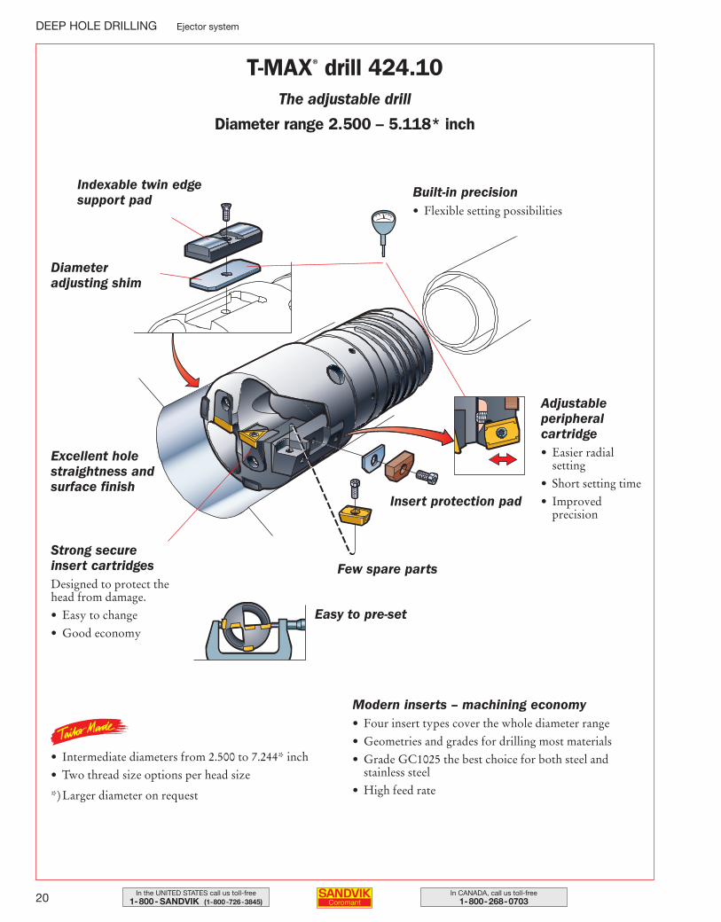
Indexable twin edge support pad
Diameter adjusting shim
Excellent holestraightness andsurface finish
Strong secure insert cartridgesDesigned to protect thehead from damage.
• Easy to change
• Good economy
• Intermediate diameters from 2.500 to 7.244* inch
• Two thread size options per head size
*) Larger diameter on request
Modern inserts – machining economy• Four insert types cover the whole diameter range
• Geometries and grades for drilling most materials
• Grade GC1025 the best choice for both steel and stainless steel
• High feed rate
Easy to pre-set
Few spare parts
Insert protection pad
Adjustable peripheral cartridge• Easier radial
setting
• Short setting time
• Improved precision
Built-in precision• Flexible setting possibilities
T-MAX® drill 424.10The adjustable drill
Diameter range 2.500 – 5.118* inch
012-033 USA 04-04-29 08.18 Sida 20
21In the UNITED STATES call us toll-free1-800- SANDVIK (1-800-726-3845)
In CANADA, call us toll-free1-800-268-0703
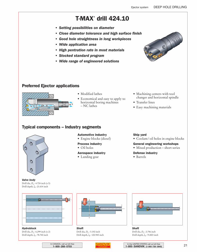
Ejector system DEEP HOLE DRILLING
T-MAX® drill 424.10• Setting possibilities on diameter
• Close diameter tolerance and high surface finish
• Good hole straightness in long workpieces
• Wide application area
• High pentration rate in most materials
• Stocked standard program
• Wide range of engineered solutions
Preferred Ejector applications
Automotive industry• Engine blocks (diesel)
Process industry• Oil holes
Aerospace industry• Landing gear
Ship yard• Coolant/ oil holes in engine blocks
General engineering workshops• Mixed production – short series
Defense industry• Barrels
Typical components – Industry segments
Valve bodyDrill dia, Dc : 4.724 inch (x 5)Drill depth, l4 : 21.614 inch
HydroblockDrill dia, Dc : 6.299 inch (x 2)Drill depth, l4 : 78.740 inch
ShaftDrill dia, Dc : 3.150 inchDrill depth, l4 : 120.945 inch
ShaftDrill dia, Dc : 2.756 inchDrill depth, l4 : 74.803 inch
• Modified lathes
• Economical and easy to apply tohorizontal boring machines – NC lathes
• Machining centers with toolchanger and horizontal spindle
• Transfer lines
• Easy machining materials
012-033 USA 04-04-29 08.18 Sida 21
22 In CANADA, call us toll-free1-800-268-0703
In the UNITED STATES call us toll-free1-800- SANDVIK (1-800-726-3845)
DEEP HOLE DRILLING Ejector system
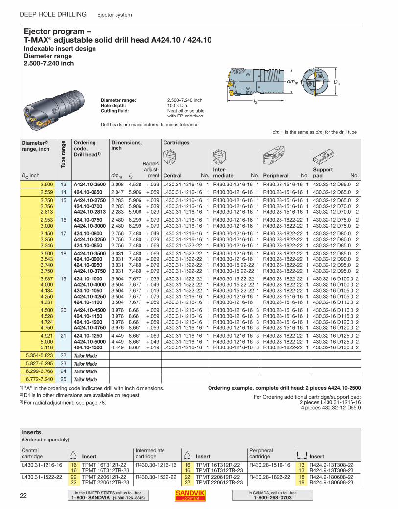
1) "A" in the ordering code indicates drill with inch dimensions.2) Drills in other dimensions are available on request.3) For radial adjustment, see page 78.
Ordering example, complete drill head: 2 pieces A424.10-2500
For Ordering additional cartridge/support pad:2 pieces L430.31-1216-164 pieces 430.32-12 D65.0
Ejector program – T-MAX® adjustable solid drill head A424.10 / 424.10Indexable insert design Diameter range 2.500-7.240 inch
Diameter range: 2.500–7.240 inchHole depth: 100 × Dia.Cutting fluid: Neat oil or soluble
with EP-additives
l2
Dcdmm
dmm is the same as dmt for the drill tube
2.500 13 A424.10-2500 2.008 4.528 +.039 L430.31-1216-16 1 R430.30-1216-16 1 R430.28-1516-16 1 430.32-12 D65.0 2
2.559 14 424.10-0650 2.047 5.906 +.059 L430.31-1216-16 1 R430.30-1216-16 1 R430.28-1516-16 1 430.32-12 D65.0 2
2.750 15 A424.10-2750 2.283 5.906 +.039 L430.31-1216-16 1 R430.30-1216-16 1 R430.28-1516-16 1 430.32-12 D65.0 22.756 424.10-0700 2.283 5.906 +.039 L430.31-1216-16 1 R430.30-1216-16 1 R430.28-1516-16 1 430.32-12 D70.0 22.813 A424.10-2813 2.283 5.906 +.029 L430.31-1216-16 1 R430.30-1216-16 1 R430.28-1516-16 1 430.32-12 D70.0 2
2.953 16 424.10-0750 2.480 6.299 +.079 L430.31-1216-16 1 R430.30-1216-16 1 R430.28-1822-22 1 430.32-12 D75.0 23.000 A424.10-3000 2.480 6.299 +.079 L430.31-1216-16 1 R430.30-1216-16 1 R430.28-1822-22 1 430.32-12 D75.0 2
3.150 17 424.10-0800 2.756 7.480 +.049 L430.31-1216-16 1 R430.30-1216-16 1 R430.28-1822-22 1 430.32-12 D80.0 23.250 A424.10-3250 2.756 7.480 +.029 L430.31-1216-16 1 R430.30-1216-16 1 R430.28-1822-22 1 430.32-12 D80.0 23.346 424.10-0850 2.756 7.480 +.069 L430.31-1522-22 1 R430.30-1216-16 1 R430.28-1822-22 1 430.32-12 D85.0 2
3.500 18 A424.10-3500 3.031 7.480 +.069 L430.31-1522-22 1 R430.30-1216-16 1 R430.28-1822-22 1 430.32-12 D85.0 23.543 424.10-0900 3.031 7.480 +.069 L430.31-1522-22 1 R430.30-1216-16 1 R430.28-1822-22 1 430.32-12 D90.0 23.740 424.10-0950 3.031 7.480 +.079 L430.31-1522-22 1 R430.30-15 22-22 1 R430.28-1822-22 1 430.32-12 D95.0 23.750 A424.10-3750 3.031 7.480 +.079 L430.31-1522-22 1 R430.30-15 22-22 1 R430.28-1822-22 1 430.32-12 D95.0 2
3.937 19 424.10-1000 3.504 7.677 +.039 L430.31-1522-22 1 R430.30-15 22-22 1 R430.28-1822-22 1 430.32-16 D100.0 24.000 A424.10-4000 3.504 7.677 +.049 L430.31-1522-22 1 R430.30-15 22-22 1 R430.28-1822-22 1 430.32-16 D100.0 24.134 424.10-1050 3.504 7.677 +.019 L430.31-1522-22 1 R430.30-15 22-22 1 R430.28-1822-22 1 430.32-16 D105.0 24.250 A424.10-4250 3.504 7.677 +.079 L430.31-1216-16 1 R430.30-1216-16 1 R430.28-1516-16 1 430.32-16 D105.0 24.331 424.10-1100 3.504 7.677 +.059 L430.31-1216-16 1 R430.30-1216-16 1 R430.28-1516-16 1 430.32-16 D110.0 2
4.500 20 A424.10-4500 3.976 8.661 +.069 L430.31-1216-16 1 R430.30-1216-16 3 R430.28-1516-16 1 430.32-16 D110.0 24.528 424.10-1150 3.976 8.661 +.059 L430.31-1216-16 1 R430.30-1216-16 3 R430.28-1516-16 1 430.32-16 D115.0 24.724 424.10-1200 3.976 8.661 +.059 L430.31-1216-16 1 R430.30-1216-16 3 R430.28-1516-16 1 430.32-16 D120.0 24.750 A424.10-4750 3.976 8.661 +.059 L430.31-1216-16 1 R430.30-1216-16 3 R430.28-1516-16 1 430.32-16 D120.0 2
4.921 21 424.10-1250 4.449 8.661 +.069 L430.31-1216-16 1 R430.30-1216-16 3 R430.28-1822-22 1 430.32-16 D125.0 25.000 A424.10-5000 4.449 8.661 +.049 L430.31-1216-16 1 R430.30-1216-16 3 R430.28-1822-22 1 430.32-16 D125.0 25.118 424.10-1300 4.449 8.661 +.019 L430.31-1216-16 1 R430.30-1216-16 3 R430.28-1822-22 1 430.32-16 D130.0 2
5.354-5.823 22
5.827-6.295 23
6.299-6.768 24
6.772-7.240 25
Orderingcode, Drill head1)
Diameter2)
range, inch
Dc inch
Cartridges
CentralInter-mediate Peripheral
Dimensions, inch
Tub
e ra
nge
dmm l2 No.Support pad
Radial3)
adjust-ment No.No.No.
Tailor Made
Tailor Made
Tailor Made
Tailor Made
Inserts(Ordered separately)
L430.31-1216-16 16 TPMT 16T312R-22 R430.30-1216-16 16 TPMT 16T312R-22 R430.28-1516-16 13 R424.9-13T308-2216 TPMT 16T312TR-23 16 TPMT 16T312TR-23 13 R424.9-13T308-23
L430.31-1522-22 22 TPMT 220612R-22 R430.30-1522-22 22 TPMT 220612R-22 R430.28-1822-22 18 R424.9-180608-2222 TPMT 220612TR-23 22 TPMT 220612TR-23 18 R424.9-180608-23
Central cartridge
Intermediate cartridge
Peripheral cartridgeInsert Insert Insert
Drill heads are manufactured to minus tolerance.
012-033 USA 04-04-29 08.18 Sida 22
23In the UNITED STATES call us toll-free1-800- SANDVIK (1-800-726-3845)
In CANADA, call us toll-free1-800-268-0703
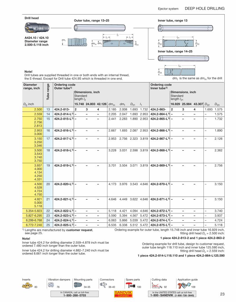
Ejector system DEEP HOLE DRILLING
Ordering codeOuter tube1)
Dimensions, inch
dmm dmt D21 l115.748 24.803 42.126
Standard length l2
Outer tube, range 13–25Drill head
Inner tube, range 13
A424.10 / 424.10Diameter range 2.500-5.118 inch
l1l1l2
D21dmm dmt
dmt
l21
D22 D23
Ordering codeInner tube1)
Dimensions, inch
D22 D2316.929 25.984 43.307
Standard length l21
2.500 13 424.2-813- 2 3 4 2.185 2.008 1.693 1.732 424.2-863- 2 3 4 1.693 1.575
2.559 14 424.2-814-L1) – – – 2.205 2.047 1.693 2.953 424.2-864-L1) – – – – 1.575
2.750 15 424.2-815-L1) – – – 2.441 2.283 1.890 2.953 424.2-865-L1) – – – – 1.7322.7562.813
2.953 16 424.2-816-L1) – – – 2.667 1.693 2.087 2.953 424.2-866-L1) – – – – 1.8903.000
3.150 17 424.2-817-L1) – – – 2.953 2.756 2.323 3.819 424.2-867-L1) – – – – 2.1263.2503.346
3.500 18 424.2-818-L1) – – – 3.228 3.031 2.598 3.819 424.2-868-L1) – – – – 2.3623.5433.7403.750
3.937 19 424.2-819-L1) – – – 3.701 3.504 3.071 3.819 424.2-869-L1) – – – – 2.7564.0004.1344.2504.331
4.500 20 424.2-820-L1) – – – 4.173 3.976 3.543 4.646 424.2-870-L1) – – – – 3.1504.5284.7244.750
4.921 21 424.2-821-L1) – – – 4.646 4.449 3.622 4.646 424.2-871-L1) – – – – 3.1505.0005.118
5.354-5.823 22 424.2-822-L1) – – – 5.118 4.421 4.094 4.646 424.2-872-L1) – – – – 3.740
5.827-6.295 23 424.2-823-L1) – – – 5.590 5.394 4.567 5.472 424.2-873-L1) – – – – 3.937
6.299-6.768 24 424.2-824-L1) – – – 6.063 5.866 5.039 5.472 424.2-874-L1) – – – – 4.724
6.772-7.240 25 424.2-825-L1) – – – 6.535 6.338 5.512 5.472 424.2-875-L1) – – – – 5.118
Ordering example for outer tube, length 15.748 inch and inner tube 16.929 inch, fitting drill head Dc = 2.500 inch:
1 piece 424.2-813-2 and 1 piece 424.2-863-2
Ordering example for drill tube, design to customer request, outer tube length 118.110 inch and inner tube 125.590 inch,
fitting drill head Dc = 2.559 inch:
1 piece 424.2-814-L118.110 and 1 piece 424.2-864-L125.590
1) Lengths are manufactured by customer request, see page 25.
Note!Inner tube 424.2 for drilling diameter 2.559–4.878 inch must be ordered 7.480 inch longer than the outer tube.
Inner tube 424.2 for drilling diameter 4.882–7.240 inch must be ordered 8.661 inch longer than the outer tube.
Tub
e ra
ngeDiameter
range, inch
Dc inch
34-35 36-40 92 109
Mounting parts Connectors Cutting data Application guide
76
Vibration dampers
83
Inserts
100
Spare parts
l21
D23
Inner tube, range 14–25
dmt is the same as dmm for the drill
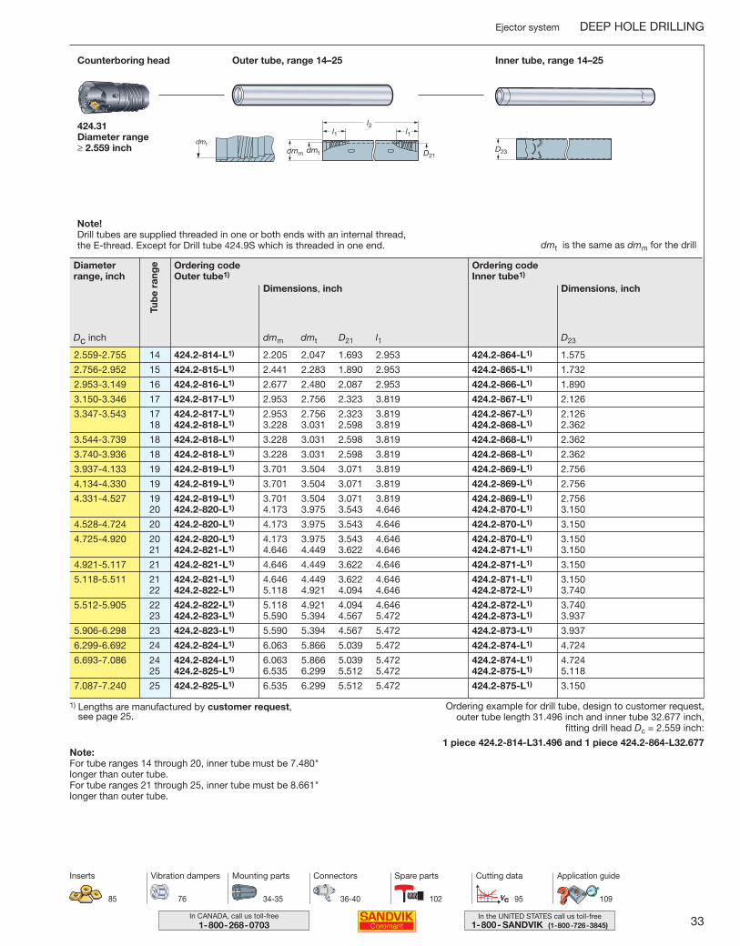
Note!Drill tubes are supplied threaded in one or both ends with an internal thread, the E-thread. Except for Drill tube 424.9S which is threaded in one end.
012-033 USA 04-04-29 08.18 Sida 23

24 In CANADA, call us toll-free1-800-268-0703
In the UNITED STATES call us toll-free1-800- SANDVIK (1-800-726-3845)
DEEP HOLE DRILLING Ejector system
Even more possibilities thanks to tailored design!If you do not find what you need in our comprehensive standardprogram, choose the tool shape you require and we will tailor itfor you to your dimensions.– Quick quotation
– Easy to order– Competitive delivery
T-Max adjustable solid drill head 424.10
Dc = 2.500-7.244 inch, with E-thread
Dc dmm
2.500 - 2.558 2.008 132.559 - 2.637 2.008 / 2.047 13 / 142.638 - 2.874 2.047 / 2.283 14 / 152.875 - 3.149 2.283 / 2.480 15 / 163.150 - 3.425 2.480 / 2.756 16 / 173.426 - 3.937 2.756 / 3.031 17 / 183.938 - 4.409 3.031 / 3.504 18 / 194.410 - 4.881 3.504 / 3.976 19 / 204.882 - 5.354 3.976 / 4.449 20 / 215.355 - 5.826 4.449 / 4.921 21 / 225.827 - 6.299 4.921 / 5.394 22 / 236.300 - 6.771 5.394 / 5.866 23 / 246.772 - 7.244 5.866 / 6.339 24 / 25
1) Compare with drill tube (424.2 – 8xx Ejector / 420.5 – 8xx STS)
E-thread range1)
Options
Dc Diameter – 2.500-7.244 inch
dmm Thread size – 2.008-6.339
Note For specific details regarding the options, contact your Coromant sales representative.
012-033 USA 04-04-29 08.18 Sida 24
25In the UNITED STATES call us toll-free1-800- SANDVIK (1-800-726-3845)
In CANADA, call us toll-free1-800-268-0703
l2
l21l22
l23
l24
lcWorkpiece
Drill head
Connector
Tube
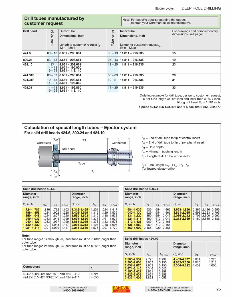
l24 = End of drill tube to tip of central Insert
l23 = End of drill tube to tip of peripheral insert
l21 = Hole depth
l22 = Minimum bushing length
lc = Length of drill tube in connector
l2 = Tube Length = l21 + l22 + lc – l24(for brazed ejector drills)
Calculation of special length tubes – Ejector systemFor solid drill heads 424.6, 800.24 and 424.10
Ejector system DEEP HOLE DRILLING
Connectors lc
.724- .787 .886 .772 1.102
.788- .858 1.024 .902 1.220
.859- .948 1.024 .897 1.220
.949-1.039 1.083 .945 1.2991.040-1.129 1.083 .937 1.2991.130-1.220 1.201 1.043 1.4171.221-1.311 1.201 1.039 1.417
Dc inch l24 l23 l22 min
Solid drill heads 424.6
Diameterrange, inch
1.312-1.425 1.201 1.024 1.4171.426-1.559 1.319 1.129 1.5351.560-1.693 1.319 1.110 1.5351.694-1.850 1.378 1.161 1.5751.851-2.035 1.378 1.133 1.5752.036-2.212 1.496 1.240 1.6932.213-2.559 1.575 1.307 1.772
Dc inch l24 l23 l22 min
Diameterrange, inch
.984-1.039 1.929 1.654 1.9691.040-1.130 1.929 1.654 1.9691.131-1.220 1.850 1.654 2.0471.221-1.311 1.850 1.673 2.0471.312-1.425 1.969 1.772 2.1651.426-1.559 1.969 1.772 2.1651.560-1.692 2.165 1.929 2.365
Dc inch l24 l23 l22 min
Solid drill heads 800.24
Diameterrange, inch
1.693-1.850 2.362 2.126 2.5591.851-2.035 2.598 2.323 2.7952.036-2.212 2.795 2.500 2.9922.213-2.559 3.189 2.835 3.386
Dc inch l24 l23 l22 min
Diameterrange, inch
424.2-400M 424.9S/170-1 and 424.2-410424.2-401M 424.9S/231-1 and 424.2-411
4.7244.055
Drill head
Length to customer request l2(Min – Max)
Inner tube
Dimensions, inch
Length to customer request l21(Min – Max)
424.6 00 – 13 8.661 – 208.661 00 – 13 11.811 – 216.535 15
800.24 03 – 13 8.661 – 208.661 03 – 13 11.811 – 216.535 19
424.10 13 8.661 – 208.661 13 – 25 11.811 – 216.535 2314 – 18 8.661 – 196.85019 – 25 8.661 – 118.110
424.31F 00 – 09 8.661 – 208.661 00 – 09 11.811 – 216.535 29
424.31F 10 – 13 8.661 – 208.661 10 – 21 11.811 – 216.535 3114 – 21 8.661 – 196.850
424.31 14 – 18 8.661 – 196.850 14 – 25 11.811 – 216.535 3319 – 25 8.661 – 118.110
Tub
e ra
nge
Drill tubes manufactured by customer request
Outer tube
Dimensions, inch
For drawings and complementarydimensions, see page:
Tub
e ra
nge
Note! For specific details regarding the options, contact your Coromant sales representative.
Ordering example for drill tube, design to customer request, outer tube length 31.496 inch and inner tube 32.677 inch,
fitting drill head Dc = 1.161 inch:
1 piece 424.2-805-L31.496 and 1 piece 424.2-855-L32.677
2.500-2.559 2.795 2.9922.500-2.633 2.953 3.1502.638-2.870 2.953 3.1502.874-3.145 3.346 3.5433.150-3.421 3.661 3.8583.425-3.933 3.661 3.8583.937-4.405 3.858 4.055
Dc inch l24 l22 min
Solid drill heads 424.10
Diameterrange, inch
4.409-4.877 3.031 3.2284.882-5.350 4.016 4.2135.354-5.822 4.409 4.606
Dc inch l24 l22 min
Diameterrange, inch
Note:For tube ranges 14 through 20, inner tube must be 7.480" longer thanouter tube.For tube ranges 21 through 25, inner tube must be 8.661" longer thanouter tube.
012-033 USA 04-04-29 08.18 Sida 25
26 In CANADA, call us toll-free1-800-268-0703
In the UNITED STATES call us toll-free1-800- SANDVIK (1-800-726-3845)
DEEP HOLE DRILLING Ejector system
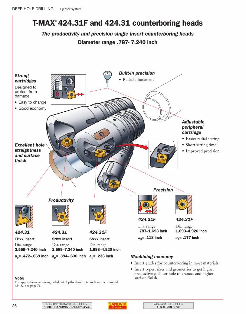
Adjustable peripheral cartridge• Easier radial setting
• Short setting time
• Improved precision
Built-in precision• Radial adjustment
Machining economy• Insert grades for counterboring in most materials.
• Insert types, sizes and geometries to get higherproductivity, closer hole tolerances and highersurface finish.
Strong cartridgesDesigned to protect from damage.
• Easy to change
• Good economy
424.31TPxx insertDia. range 2.559–7.240 inch
ap= .472–.669 inch
Excellent holestraightnessand surfacefinish
Precision
Productivity
T-MAX® 424.31F and 424.31 counterboring headsThe productivity and precision single insert counterboring heads
Diameter range .787- 7.240 inch
424.31SNxx insertDia. range 2.559–7.240 inch
ap= .394–.630 inch
424.31FSNxx insertDia. range 1.693–4.920 inch
ap= .236 inch
424.31FDia. range .787–1.693 inch
ap= .118 inch
424.31FDia. range 1.693–4.920 inch
ap= .177 inch
Note!For applications requiring radial cut depths above .669 inch we recommend424.32, see page 71.
012-033 USA 04-04-29 08.18 Sida 26
27In the UNITED STATES call us toll-free1-800- SANDVIK (1-800-726-3845)
In CANADA, call us toll-free1-800-268-0703
Ejector system DEEP HOLE DRILLING
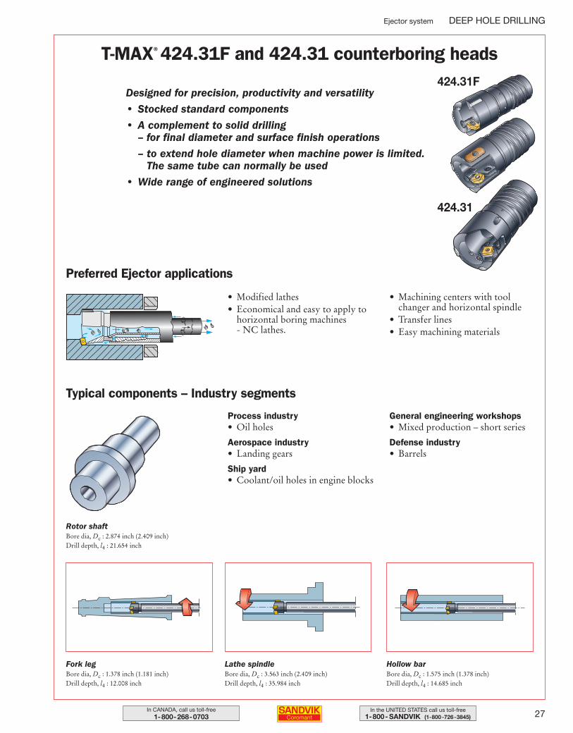
T-MAX® 424.31F and 424.31 counterboring heads
Designed for precision, productivity and versatility
• Stocked standard components
• A complement to solid drilling– for final diameter and surface finish operations
– to extend hole diameter when machine power is limited.The same tube can normally be used
• Wide range of engineered solutions
• Modified lathes• Economical and easy to apply to
horizontal boring machines - NC lathes.
• Machining centers with toolchanger and horizontal spindle
• Transfer lines• Easy machining materials
Preferred Ejector applications
Process industry• Oil holes
Aerospace industry• Landing gears
Ship yard• Coolant/oil holes in engine blocks
General engineering workshops• Mixed production – short series
Defense industry• Barrels
Typical components – Industry segments
424.31F
424.31
Rotor shaftBore dia, Dc : 2.874 inch (2.409 inch)Drill depth, l4 : 21.654 inch
Fork legBore dia, Dc : 1.378 inch (1.181 inch)Drill depth, l4 : 12.008 inch
Lathe spindleBore dia, Dc : 3.563 inch (2.409 inch)Drill depth, l4 : 35.984 inch
Hollow barBore dia, Dc : 1.575 inch (1.378 inch)Drill depth, l4 : 14.685 inch
012-033 USA 04-04-29 08.18 Sida 27

28 In CANADA, call us toll-free1-800-268-0703
In the UNITED STATES call us toll-free1-800- SANDVIK (1-800-726-3845)
DEEP HOLE DRILLING Ejector system
OrderingWhen ordering counterboring heads the following must be stated:• Drill diameter, Dc.• Depth of cut or pre-bored size.• Cartridges to be used – cartridge for close tolerances or for normal tolerances.• Drilling system to be used – Ejector or STS.• Drill tubes to be used and size dmt.
For more information and advice, please contact your nearest Sandvik Coromant representative.
Ordering example: 2 pieces 430.21-06 D20.01) Inserts are ordered separately.
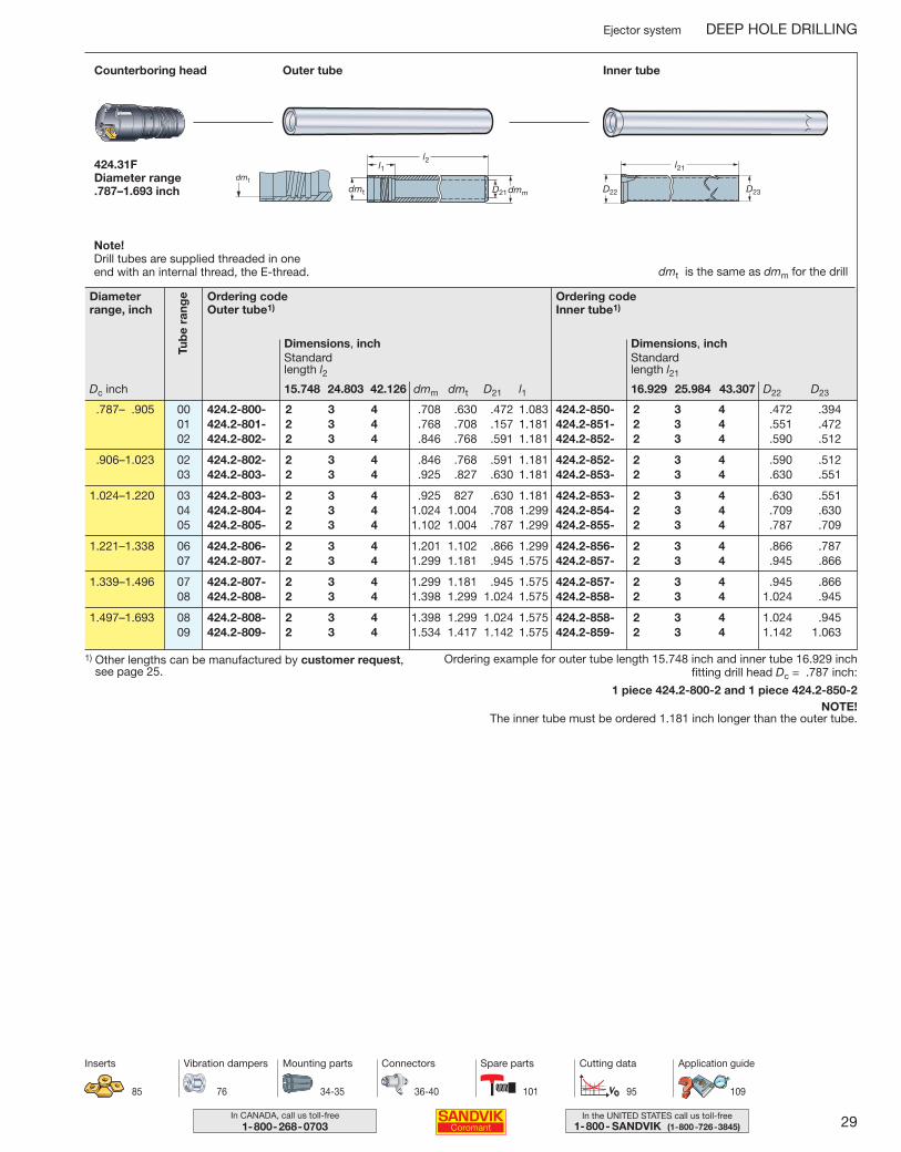
T-MAX® counterboring head 424.31F – manufactured by customer requestSingle indexable insert design – close toleranceDiameter range .787–1.693 inch
Diameter range: .787-1.693 inchHole depth: 100 × diameterCutting fluid: Neat oil or emulsion
with EP-additives
dmm is the same as dmt for the drill tube
Diameterrange, inch
Support pad set Pressure pad set
.787– .905 .118 04 430.21-06 D20.0 2 5636 010-011 1
.906–1.023 .118 04 430.21-06 D23.0 2 5636 010-011 1
1.024–1.220 .118 04 430.21-06 D26.0 2 5636 010-011 1
1.221–1.338 .118 04 430.21-08 D31.0 2 5636 010-021 1
1.339–1.496 .118 04 430.21-08 D34.0 2 5636 010-021 1
1.497–1.693 .118 04 430.21-08 D38.0 2 5636 010-021 1
No.No.
Max. cutting depth
apinch
Inserts1)
R424.31F
Dc inch
Drill heads are manufactured to minus tolerance.
012-033 USA 04-04-29 08.18 Sida 28
29In the UNITED STATES call us toll-free1-800- SANDVIK (1-800-726-3845)
In CANADA, call us toll-free1-800-268-0703
Ejector system DEEP HOLE DRILLING
Ordering codeOuter tube1)
Dimensions, inch
dmm dmt D21 l115.748 24.803 42.126
Standard length l2
Outer tubeCounterboring head Inner tube
424.31FDiameter range .787–1.693 inch
l1l2
D21dmmdmt
dmt
dmt is the same as dmm for the drill
l21
D22 D23
Ordering codeInner tube1)
Dimensions, inch
D22 D2316.929 25.984 43.307
Standard length l21
.787– .905 00 424.2-800- 2 3 4 .708 .630 .472 1.083 424.2-850- 2 3 4 .472 .39401 424.2-801- 2 3 4 .768 .708 .157 1.181 424.2-851- 2 3 4 .551 .47202 424.2-802- 2 3 4 .846 .768 .591 1.181 424.2-852- 2 3 4 .590 .512
.906–1.023 02 424.2-802- 2 3 4 .846 .768 .591 1.181 424.2-852- 2 3 4 .590 .51203 424.2-803- 2 3 4 .925 .827 .630 1.181 424.2-853- 2 3 4 .630 .551
1.024–1.220 03 424.2-803- 2 3 4 .925 827 .630 1.181 424.2-853- 2 3 4 .630 .55104 424.2-804- 2 3 4 1.024 1.004 .708 1.299 424.2-854- 2 3 4 .709 .63005 424.2-805- 2 3 4 1.102 1.004 .787 1.299 424.2-855- 2 3 4 .787 .709
1.221–1.338 06 424.2-806- 2 3 4 1.201 1.102 .866 1.299 424.2-856- 2 3 4 .866 .78707 424.2-807- 2 3 4 1.299 1.181 .945 1.575 424.2-857- 2 3 4 .945 .866
1.339–1.496 07 424.2-807- 2 3 4 1.299 1.181 .945 1.575 424.2-857- 2 3 4 .945 .86608 424.2-808- 2 3 4 1.398 1.299 1.024 1.575 424.2-858- 2 3 4 1.024 .945
1.497–1.693 08 424.2-808- 2 3 4 1.398 1.299 1.024 1.575 424.2-858- 2 3 4 1.024 .94509 424.2-809- 2 3 4 1.534 1.417 1.142 1.575 424.2-859- 2 3 4 1.142 1.063
Ordering example for outer tube length 15.748 inch and inner tube 16.929 inch fitting drill head Dc = .787 inch:
1 piece 424.2-800-2 and 1 piece 424.2-850-2NOTE!
The inner tube must be ordered 1.181 inch longer than the outer tube.
1) Other lengths can be manufactured by customer request, see page 25.
Tub
e ra
ngeDiameter
range, inch
Dc inch
34-35 36-40 95 109
Mounting parts Connectors Cutting data Application guide
76
Vibration dampers
85
Inserts
101
Spare parts
Note!Drill tubes are supplied threaded in one end with an internal thread, the E-thread.
012-033 USA 04-04-29 08.19 Sida 29
30 In CANADA, call us toll-free1-800-268-0703
In the UNITED STATES call us toll-free1-800- SANDVIK (1-800-726-3845)
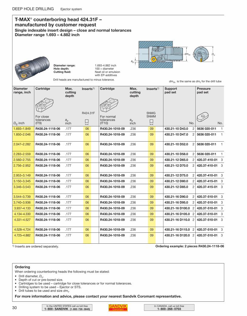
Ordering example: 2 pieces R430.24-1118-061) Inserts are ordered separately.
T-MAX® counterboring head 424.31F – manufactured by customer requestSingle indexable insert design – close and normal tolerancesDiameter range 1.693 – 4.882 inch
Diameter range: 1.693-4.882 inchHole depth: 100 × diameterCutting fluid: Neat oil or emulsion
with EP-additives
dmm is the same as dmt for the drill tube
Diameterrange, inch
Cartridge
For normaltolerances (IT10)
Max.cuttingdepth
apinch
Inserts1)
SNMGSNMM
Support pad set
Pressure pad set
1.693–1.849 R430.24-1118-06 .177 06 R430.24-1018-09 .236 09 430.21-10 D43.0 2 5636 020-011 1
1.850–2.046 R430.24-1118-06 .177 06 R430.24-1018-09 .236 09 430.21-10 D47.0 2 5636 020-011 1
2.047–2.282 R430.24-1118-06 .177 06 R430.24-1018-09 .236 09 430.21-10 D52.0 2 5636 020-011 1
2.283–2.559 R430.24-1118-06 .177 06 R430.24-1018-09 .236 09 430.21-10 D58.0 2 5636 020-011 1
2.560–2.755 R430.24-1118-06 .177 06 R430.24-1018-09 .236 09 430.21-12 D65.0 2 420.37-410-01 3
2.756–2.952 R430.24-1118-06 .177 06 R430.24-1018-09 .236 09 430.21-12 D70.0 2 420.37-410-01 3
2.953–3.149 R430.24-1118-06 .177 06 R430.24-1018-09 .236 09 430.21-12 D75.0 2 420.37-410-01 3
3.150–3.345 R430.24-1118-06 .177 06 R430.24-1018-09 .236 09 430.21-12 D80.0 2 420.37-415-01 3
3.346–3.543 R430.24-1118-06 .177 06 R430.24-1018-09 .236 09 430.21-12 D85.0 2 420.37-415-01 3
3.544–3.739 R430.24-1118-06 .177 06 R430.24-1018-09 .236 09 430.21-16 D90.0 2 420.37-510-01 3
3.740–3.936 R430.24-1118-06 .177 06 R430.24-1018-09 .236 09 430.21-16 D95.0 2 420.37-510-01 3
3.937–4.133 R430.24-1118-06 .177 06 R430.24-1018-09 .236 09 430.21-16 D100.0 2 420.37-510-01 3
4.134–4.330 R430.24-1118-06 .177 06 R430.24-1018-09 .236 09 430.21-16 D105.0 2 420.37-510-01 3
4.331–4.527 R430.24-1118-06 .177 06 R430.24-1018-09 .236 09 430.21-16 D110.0 2 420.37-510-01 3
4.528–4.724 R430.24-1118-06 .177 06 R430.24-1018-09 .236 09 430.21-16 D115.0 2 420.37-510-01 3
4.725–4.882 R430.24-1118-06 .177 06 R430.24-1018-09 .236 09 430.21-16 D120.0 2 420.37-510-01 3
No.No.
Cartridge
For closetolerances (IT9)
Max.cuttingdepth
apinch
Inserts1)
R424.31F
Dc inch
DEEP HOLE DRILLING Ejector system
OrderingWhen ordering counterboring heads the following must be stated:• Drill diameter, Dc.• Depth of cut or pre-bored size.• Cartridges to be used – cartridge for close tolerances or for normal tolerances.• Drilling system to be used – Ejector or STS.• Drill tubes to be used and size dmt.
For more information and advice, please contact your nearest Sandvik Coromant representative.
Drill heads are manufactured to minus tolerance.
012-033 USA 04-04-29 08.19 Sida 30
31In the UNITED STATES call us toll-free1-800- SANDVIK (1-800-726-3845)
In CANADA, call us toll-free1-800-268-0703
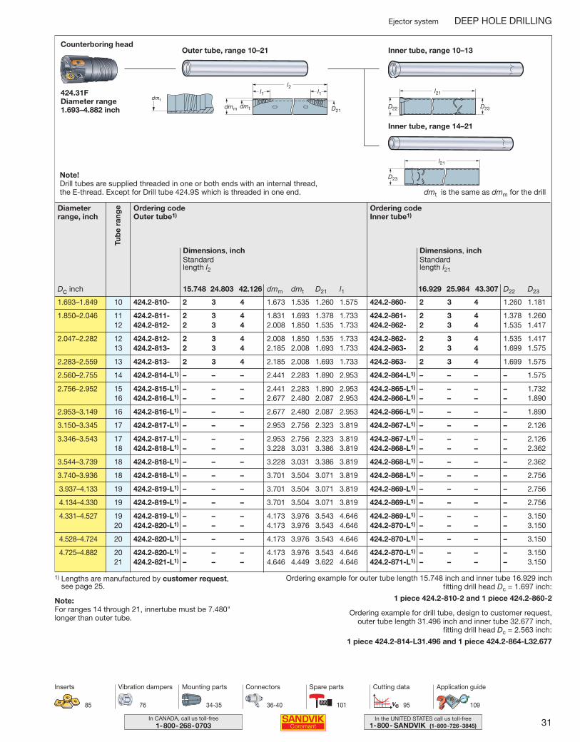
Ejector system DEEP HOLE DRILLING
Ordering codeOuter tube1)
Dimensions, inch
dmm dmt D21 l115.748 24.803 42.126
Standard length l2
Outer tube, range 10–21Counterboring head
Inner tube, range 10–13
424.31FDiameter range 1.693–4.882 inch
l1l1l2
D21dmm dmt
dmt
l21
D22 D23
Ordering codeInner tube1)
Dimensions, inch
D22 D2316.929 25.984 43.307
Standard length l21
1.693–1.849 10 424.2-810- 2 3 4 1.673 1.535 1.260 1.575 424.2-860- 2 3 4 1.260 1.181
1.850–2.046 11 424.2-811- 2 3 4 1.831 1.693 1.378 1.733 424.2-861- 2 3 4 1.378 1.26012 424.2-812- 2 3 4 2.008 1.850 1.535 1.733 424.2-862- 2 3 4 1.535 1.417
2.047–2.282 12 424.2-812- 2 3 4 2.008 1.850 1.535 1.733 424.2-862- 2 3 4 1.535 1.41713 424.2-813- 2 3 4 2.185 2.008 1.693 1.733 424.2-863- 2 3 4 1.699 1.575
2.283–2.559 13 424.2-813- 2 3 4 2.185 2.008 1.693 1.733 424.2-863- 2 3 4 1.699 1.575
2.560–2.755 14 424.2-814-L1) – – – 2.441 2.283 1.890 2.953 424.2-864-L1) – – – – 1.575
2.756–2.952 15 424.2-815-L1) – – – 2.441 2.283 1.890 2.953 424.2-865-L1) – – – – 1.73216 424.2-816-L1) – – – 2.677 2.480 2.087 2.953 424.2-866-L1) – – – – 1.890
2.953–3.149 16 424.2-816-L1) – – – 2.677 2.480 2.087 2.953 424.2-866-L1) – – – – 1.890
3.150–3.345 17 424.2-817-L1) – – – 2.953 2.756 2.323 3.819 424.2-867-L1) – – – – 2.126
3.346–3.543 17 424.2-817-L1) – – – 2.953 2.756 2.323 3.819 424.2-867-L1) – – – – 2.12618 424.2-818-L1) – – – 3.228 3.031 3.386 3.819 424.2-868-L1) – – – – 2.362
3.544–3.739 18 424.2-818-L1) – – – 3.228 3.031 3.386 3.819 424.2-868-L1) – – – – 2.362
3.740–3.936 18 424.2-818-L1) – – – 3.701 3.504 3.071 3.819 424.2-868-L1) – – – – 2.756
3.937–4.133 19 424.2-819-L1) – – – 3.701 3.504 3.071 3.819 424.2-869-L1) – – – – 2.756
4.134–4.330 19 424.2-819-L1) – – – 3.701 3.504 3.071 3.819 424.2-869-L1) – – – – 2.756
4.331–4.527 19 424.2-819-L1) – – – 4.173 3.976 3.543 4.646 424.2-869-L1) – – – – 3.15020 424.2-820-L1) – – – 4.173 3.976 3.543 4.646 424.2-870-L1) – – – – 3.150
4.528–4.724 20 424.2-820-L1) – – – 4.173 3.976 3.543 4.646 424.2-870-L1) – – – – 3.150
4.725–4.882 20 424.2-820-L1) – – – 4.173 3.976 3.543 4.646 424.2-870-L1) – – – – 3.15021 424.2-821-L1) – – – 4.646 4.449 3.622 4.646 424.2-871-L1) – – – – 3.150
Tub
e ra
ngeDiameter
range, inch
Dc inch
l21
D23
Inner tube, range 14–21
34-35 36-40 95 109
Mounting parts Connectors Cutting data Application guide
76
Vibration dampers
85
Inserts
101
Spare parts
Ordering example for outer tube length 15.748 inch and inner tube 16.929 inch fitting drill head Dc = 1.697 inch:
1 piece 424.2-810-2 and 1 piece 424.2-860-2
Ordering example for drill tube, design to customer request, outer tube length 31.496 inch and inner tube 32.677 inch,
fitting drill head Dc = 2.563 inch:
1 piece 424.2-814-L31.496 and 1 piece 424.2-864-L32.677
1) Lengths are manufactured by customer request, see page 25.
Note:For ranges 14 through 21, innertube must be 7.480" longer than outer tube.
dmt is the same as dmm for the drill
Note!Drill tubes are supplied threaded in one or both ends with an internal thread, the E-thread. Except for Drill tube 424.9S which is threaded in one end.
012-033 USA 04-04-29 08.19 Sida 31
32 In CANADA, call us toll-free1-800-268-0703
In the UNITED STATES call us toll-free1-800- SANDVIK (1-800-726-3845)
DEEP HOLE DRILLING Ejector system
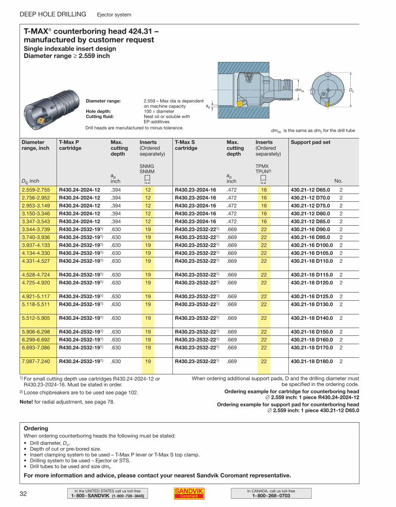
OrderingWhen ordering counterboring heads the following must be stated:• Drill diameter, Dc.• Depth of cut or pre-bored size.• Insert clamping system to be used – T-Max P lever or T-Max S top clamp.• Drilling system to be used – Ejector or STS.• Drill tubes to be used and size dmt.
For more information and advice, please contact your nearest Sandvik Coromant representative.
When ordering additional support pads, D and the drilling diameter mustbe specified in the ordering code.
Ordering example for cartridge for counterboring head ∅ 2.559 inch: 1 piece R430.24-2024-12
Ordering example for support pad for counterboring head ∅ 2.559 inch: 1 piece 430.21-12 D65.0
1) For small cutting depth use cartridges R430.24-2024-12 or R430.23-2024-16. Must be stated in order.
2) Loose chipbreakers are to be used see page 102.
Note! for radial adjustment, see page 78.
T-MAX® counterboring head 424.31 – manufactured by customer requestSingle indexable insert designDiameter range ≥ 2.559 inch
Diameter range: 2.559 – Max dia is dependenton machine capacity
Hole depth: 100 × diameterCutting fluid: Neat oil or soluble with
EP-additives
dmm is the same as dmt for the drill tube
Diameterrange, inch
T-Max S cartridge
Max.cuttingdepth
apinch
Inserts(Orderedseparately)
TPMXTPUN2)
Support pad set
2.559-2.755 R430.24-2024-12 .394 12 R430.23-2024-16 .472 16 430.21-12 D65.0 2
2.756-2.952 R430.24-2024-12 .394 12 R430.23-2024-16 .472 16 430.21-12 D70.0 2
2.953-3.149 R430.24-2024-12 .394 12 R430.23-2024-16 .472 16 430.21-12 D75.0 2
3.150-3.346 R430.24-2024-12 .394 12 R430.23-2024-16 .472 16 430.21-12 D80.0 2
3.347-3.543 R430.24-2024-12 .394 12 R430.23-2024-16 .472 16 430.21-12 D85.0 2
3.544-3.739 R430.24-2532-191) .630 19 R430.23-2532-221) .669 22 430.21-16 D90.0 2
3.740-3.936 R430.24-2532-191) .630 19 R430.23-2532-221) .669 22 430.21-16 D95.0 2
3.937-4.133 R430.24-2532-191) .630 19 R430.23-2532-221) .669 22 430.21-16 D100.0 2
4.134-4.330 R430.24-2532-191) .630 19 R430.23-2532-221) .669 22 430.21-16 D105.0 2
4.331-4.527 R430.24-2532-191) .630 19 R430.23-2532-221) .669 22 430.21-18 D110.0 2
4.528-4.724 R430.24-2532-191) .630 19 R430.23-2532-221) .669 22 430.21-18 D115.0 2
4.725-4.920 R430.24-2532-191) .630 19 R430.23-2532-221) .669 22 430.21-18 D120.0 2
4.921-5.117 R430.24-2532-191) .630 19 R430.23-2532-221) .669 22 430.21-18 D125.0 2
5.118-5.511 R430.24-2532-191) .630 19 R430.23-2532-221) .669 22 430.21-18 D130.0 2
5.512-5.905 R430.24-2532-191) .630 19 R430.23-2532-221) .669 22 430.21-18 D140.0 2
5.906-6.298 R430.24-2532-191) .630 19 R430.23-2532-221) .669 22 430.21-18 D150.0 2
6.299-6.692 R430.24-2532-191) .630 19 R430.23-2532-221) .669 22 430.21-18 D160.0 2
6.693-7.086 R430.24-2532-191) .630 19 R430.23-2532-221) .669 22 430.21-18 D170.0 2
7.087-7.240 R430.24-2532-191) .630 19 R430.23-2532-221) .669 22 430.21-18 D180.0 2
No.
T-Max P cartridge
Max.cuttingdepth
apinch
Inserts(Orderedseparately)
SNMGSNMM
Dc inch
Drill heads are manufactured to minus tolerance.
012-033 USA 04-04-29 08.19 Sida 32
33In the UNITED STATES call us toll-free1-800- SANDVIK (1-800-726-3845)
In CANADA, call us toll-free1-800-268-0703
Ejector system DEEP HOLE DRILLING
Ordering codeOuter tube1)
Dimensions, inch
dmm dmt D21 l1
Outer tube, range 14–25Counterboring head Inner tube, range 14–25
424.31Diameter range ≥ 2.559 inch
l1l1l2
D21dmm dmt
dmt
Ordering codeInner tube1)
Dimensions, inch
D23
2.559-2.755 14 424.2-814-L1) 2.205 2.047 1.693 2.953 424.2-864-L1) 1.575
2.756-2.952 15 424.2-815-L1) 2.441 2.283 1.890 2.953 424.2-865-L1) 1.732
2.953-3.149 16 424.2-816-L1) 2.677 2.480 2.087 2.953 424.2-866-L1) 1.890
3.150-3.346 17 424.2-817-L1) 2.953 2.756 2.323 3.819 424.2-867-L1) 2.126
3.347-3.543 17 424.2-817-L1) 2.953 2.756 2.323 3.819 424.2-867-L1) 2.12618 424.2-818-L1) 3.228 3.031 2.598 3.819 424.2-868-L1) 2.362
3.544-3.739 18 424.2-818-L1) 3.228 3.031 2.598 3.819 424.2-868-L1) 2.362
3.740-3.936 18 424.2-818-L1) 3.228 3.031 2.598 3.819 424.2-868-L1) 2.362
3.937-4.133 19 424.2-819-L1) 3.701 3.504 3.071 3.819 424.2-869-L1) 2.756
4.134-4.330 19 424.2-819-L1) 3.701 3.504 3.071 3.819 424.2-869-L1) 2.756
4.331-4.527 19 424.2-819-L1) 3.701 3.504 3.071 3.819 424.2-869-L1) 2.75620 424.2-820-L1) 4.173 3.975 3.543 4.646 424.2-870-L1) 3.150
4.528-4.724 20 424.2-820-L1) 4.173 3.975 3.543 4.646 424.2-870-L1) 3.150
4.725-4.920 20 424.2-820-L1) 4.173 3.975 3.543 4.646 424.2-870-L1) 3.15021 424.2-821-L1) 4.646 4.449 3.622 4.646 424.2-871-L1) 3.150
4.921-5.117 21 424.2-821-L1) 4.646 4.449 3.622 4.646 424.2-871-L1) 3.150
5.118-5.511 21 424.2-821-L1) 4.646 4.449 3.622 4.646 424.2-871-L1) 3.15022 424.2-822-L1) 5.118 4.921 4.094 4.646 424.2-872-L1) 3.740
5.512-5.905 22 424.2-822-L1) 5.118 4.921 4.094 4.646 424.2-872-L1) 3.74023 424.2-823-L1) 5.590 5.394 4.567 5.472 424.2-873-L1) 3.937
5.906-6.298 23 424.2-823-L1) 5.590 5.394 4.567 5.472 424.2-873-L1) 3.937
6.299-6.692 24 424.2-824-L1) 6.063 5.866 5.039 5.472 424.2-874-L1) 4.724
6.693-7.086 24 424.2-824-L1) 6.063 5.866 5.039 5.472 424.2-874-L1) 4.72425 424.2-825-L1) 6.535 6.299 5.512 5.472 424.2-875-L1) 5.118
7.087-7.240 25 424.2-825-L1) 6.535 6.299 5.512 5.472 424.2-875-L1) 3.150
Tub
e ra
ngeDiameter
range, inch
Dc inch
34-35 36-40 95 109
Mounting parts Connectors Cutting data Application guide
76
Vibration dampers
85
Inserts
102
Spare parts
Ordering example for drill tube, design to customer request, outer tube length 31.496 inch and inner tube 32.677 inch,
fitting drill head Dc = 2.559 inch:
1 piece 424.2-814-L31.496 and 1 piece 424.2-864-L32.677
1) Lengths are manufactured by customer request, see page 25.
Note:For tube ranges 14 through 20, inner tube must be 7.480" longer than outer tube.For tube ranges 21 through 25, inner tube must be 8.661" longer than outer tube.
dmt is the same as dmm for the drill
Note!Drill tubes are supplied threaded in one or both ends with an internal thread, the E-thread. Except for Drill tube 424.9S which is threaded in one end.
012-033 USA 04-04-29 08.19 Sida 33
34 In CANADA, call us toll-free1-800-268-0703
In the UNITED STATES call us toll-free1-800- SANDVIK (1-800-726-3845)
Non- rotating
DEEP HOLE DRILLING Ejector system
Diameterrange, inch
Mounting parts Connectors
Rotating
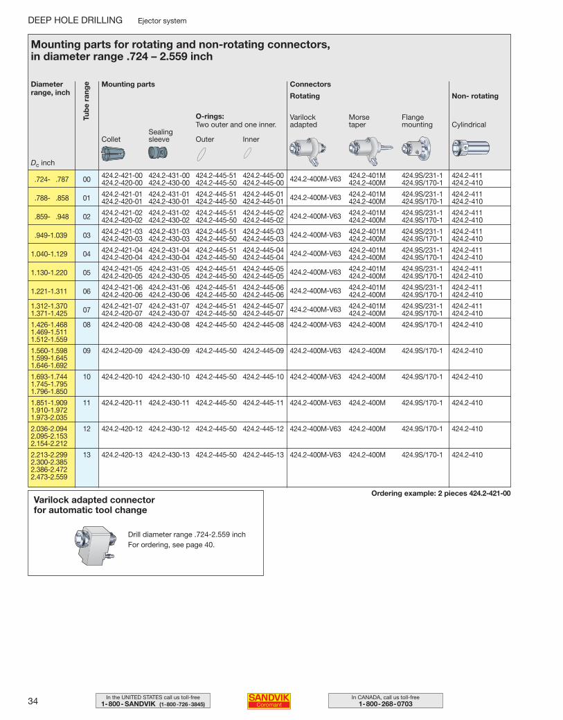
Mounting parts for rotating and non-rotating connectors, in diameter range .724 – 2.559 inch
.724- .787 00 424.2-421-00 424.2-431-00 424.2-445-51 424.2-445-00 424.2-401M 424.9S/231-1 424.2-411424.2-420-00 424.2-430-00 424.2-445-50 424.2-445-00 424.2-400M-V63 424.2-400M 424.9S/170-1 424.2-410
.788- .858 01 424.2-421-01 424.2-431-01 424.2-445-51 424.2-445-01 424.2-401M 424.9S/231-1 424.2-411424.2-420-01 424.2-430-01 424.2-445-50 424.2-445-01 424.2-400M-V63 424.2-400M 424.9S/170-1 424.2-410
.859- .948 02 424.2-421-02 424.2-431-02 424.2-445-51 424.2-445-02 424.2-401M 424.9S/231-1 424.2-411424.2-420-02 424.2-430-02 424.2-445-50 424.2-445-02 424.2-400M-V63 424.2-400M 424.9S/170-1 424.2-410
.949-1.039 03 424.2-421-03 424.2-431-03 424.2-445-51 424.2-445-03 424.2-401M 424.9S/231-1 424.2-411424.2-420-03 424.2-430-03 424.2-445-50 424.2-445-03 424.2-400M-V63 424.2-400M 424.9S/170-1 424.2-410
1.040-1.129 04 424.2-421-04 424.2-431-04 424.2-445-51 424.2-445-04 424.2-401M 424.9S/231-1 424.2-411424.2-420-04 424.2-430-04 424.2-445-50 424.2-445-04 424.2-400M-V63 424.2-400M 424.9S/170-1 424.2-410
1.130-1.220 05 424.2-421-05 424.2-431-05 424.2-445-51 424.2-445-05 424.2-401M 424.9S/231-1 424.2-411424.2-420-05 424.2-430-05 424.2-445-50 424.2-445-05 424.2-400M-V63 424.2-400M 424.9S/170-1 424.2-410
1.221-1.311 06 424.2-421-06 424.2-431-06 424.2-445-51 424.2-445-06 424.2-401M 424.9S/231-1 424.2-411424.2-420-06 424.2-430-06 424.2-445-50 424.2-445-06 424.2-400M-V63 424.2-400M 424.9S/170-1 424.2-410
1.312-1.370 07 424.2-421-07 424.2-431-07 424.2-445-51 424.2-445-07 424.2-401M 424.9S/231-1 424.2-4111.371-1.425 424.2-420-07 424.2-430-07 424.2-445-50 424.2-445-07 424.2-400M-V63 424.2-400M 424.9S/170-1 424.2-410
1.426-1.468 08 424.2-420-08 424.2-430-08 424.2-445-50 424.2-445-08 424.2-400M-V63 424.2-400M 424.9S/170-1 424.2-4101.469-1.5111.512-1.559
1.560-1.598 09 424.2-420-09 424.2-430-09 424.2-445-50 424.2-445-09 424.2-400M-V63 424.2-400M 424.9S/170-1 424.2-4101.599-1.6451.646-1.692
1.693-1.744 10 424.2-420-10 424.2-430-10 424.2-445-50 424.2-445-10 424.2-400M-V63 424.2-400M 424.9S/170-1 424.2-4101.745-1.7951.796-1.850
1.851-1.909 11 424.2-420-11 424.2-430-11 424.2-445-50 424.2-445-11 424.2-400M-V63 424.2-400M 424.9S/170-1 424.2-4101.910-1.9721.973-2.035
2.036-2.094 12 424.2-420-12 424.2-430-12 424.2-445-50 424.2-445-12 424.2-400M-V63 424.2-400M 424.9S/170-1 424.2-4102.095-2.1532.154-2.212
2.213-2.299 13 424.2-420-13 424.2-430-13 424.2-445-50 424.2-445-13 424.2-400M-V63 424.2-400M 424.9S/170-1 424.2-4102.300-2.3852.386-2.4722.473-2.559
Tub
e ra
nge
ColletSealing sleeve Outer Inner
Dc inch
O-rings: Two outer and one inner.
Varilock adapted
Morse taper
Flange mounting Cylindrical
Ordering example: 2 pieces 424.2-421-00Varilock adapted connector for automatic tool change
Drill diameter range .724-2.559 inchFor ordering, see page 40.
034-043 USA 04-05-07 08.43 Sida 34
35In the UNITED STATES call us toll-free1-800- SANDVIK (1-800-726-3845)
In CANADA, call us toll-free1-800-268-0703
Non- rotating
Diameterrange, inch
Mounting parts Connectors
Rotating
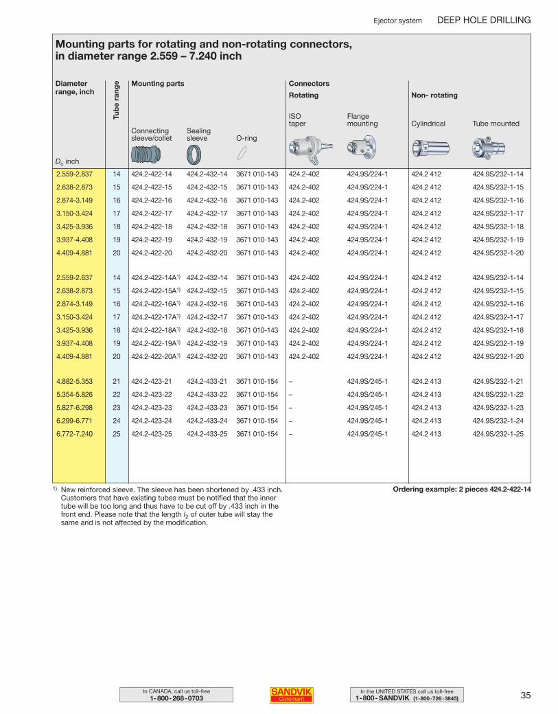
Mounting parts for rotating and non-rotating connectors, in diameter range 2.559 – 7.240 inch
2.559-2.637 14 424.2-422-14 424.2-432-14 3671 010-143 424.2-402 424.9S/224-1 424.2 412 424.9S/232-1-14
2.638-2.873 15 424.2-422-15 424.2-432-15 3671 010-143 424.2-402 424.9S/224-1 424.2 412 424.9S/232-1-15
2.874-3.149 16 424.2-422-16 424.2-432-16 3671 010-143 424.2-402 424.9S/224-1 424.2 412 424.9S/232-1-16
3.150-3.424 17 424.2-422-17 424.2-432-17 3671 010-143 424.2-402 424.9S/224-1 424.2 412 424.9S/232-1-17
3.425-3.936 18 424.2-422-18 424.2-432-18 3671 010-143 424.2-402 424.9S/224-1 424.2 412 424.9S/232-1-18
3.937-4.408 19 424.2-422-19 424.2-432-19 3671 010-143 424.2-402 424.9S/224-1 424.2 412 424.9S/232-1-19
4.409-4.881 20 424.2-422-20 424.2-432-20 3671 010-143 424.2-402 424.9S/224-1 424.2 412 424.9S/232-1-20
2.559-2.637 14 424.2-422-14A1) 424.2-432-14 3671 010-143 424.2-402 424.9S/224-1 424.2 412 424.9S/232-1-14
2.638-2.873 15 424.2-422-15A1) 424.2-432-15 3671 010-143 424.2-402 424.9S/224-1 424.2 412 424.9S/232-1-15
2.874-3.149 16 424.2-422-16A1) 424.2-432-16 3671 010-143 424.2-402 424.9S/224-1 424.2 412 424.9S/232-1-16
3.150-3.424 17 424.2-422-17A1) 424.2-432-17 3671 010-143 424.2-402 424.9S/224-1 424.2 412 424.9S/232-1-17
3.425-3.936 18 424.2-422-18A1) 424.2-432-18 3671 010-143 424.2-402 424.9S/224-1 424.2 412 424.9S/232-1-18
3.937-4.408 19 424.2-422-19A1) 424.2-432-19 3671 010-143 424.2-402 424.9S/224-1 424.2 412 424.9S/232-1-19
4.409-4.881 20 424.2-422-20A1) 424.2-432-20 3671 010-143 424.2-402 424.9S/224-1 424.2 412 424.9S/232-1-20
4.882-5.353 21 424.2-423-21 424.2-433-21 3671 010-154 – 424.9S/245-1 424.2 413 424.9S/232-1-21
5.354-5.826 22 424.2-423-22 424.2-433-22 3671 010-154 – 424.9S/245-1 424.2 413 424.9S/232-1-22
5.827-6.298 23 424.2-423-23 424.2-433-23 3671 010-154 – 424.9S/245-1 424.2 413 424.9S/232-1-23
6.299-6.771 24 424.2-423-24 424.2-433-24 3671 010-154 – 424.9S/245-1 424.2 413 424.9S/232-1-24
6.772-7.240 25 424.2-423-25 424.2-433-25 3671 010-154 – 424.9S/245-1 424.2 413 424.9S/232-1-25
Tub
e ra
nge
Connectingsleeve/collet
Sealing sleeve O-ring
Dc inch
ISO taper
Flange mounting Cylindrical Tube mounted
Ordering example: 2 pieces 424.2-422-14
Ejector system DEEP HOLE DRILLING
1) New reinforced sleeve. The sleeve has been shortened by .433 inch. Customers that have existing tubes must be notified that the innertube will be too long and thus have to be cut off by .433 inch in thefront end. Please note that the length l2 of outer tube will stay thesame and is not affected by the modification.
034-043 USA 04-04-29 09.52 Sida 35
36 In CANADA, call us toll-free1-800-268-0703
In the UNITED STATES call us toll-free1-800- SANDVIK (1-800-726-3845)
DEEP HOLE DRILLING Ejector system
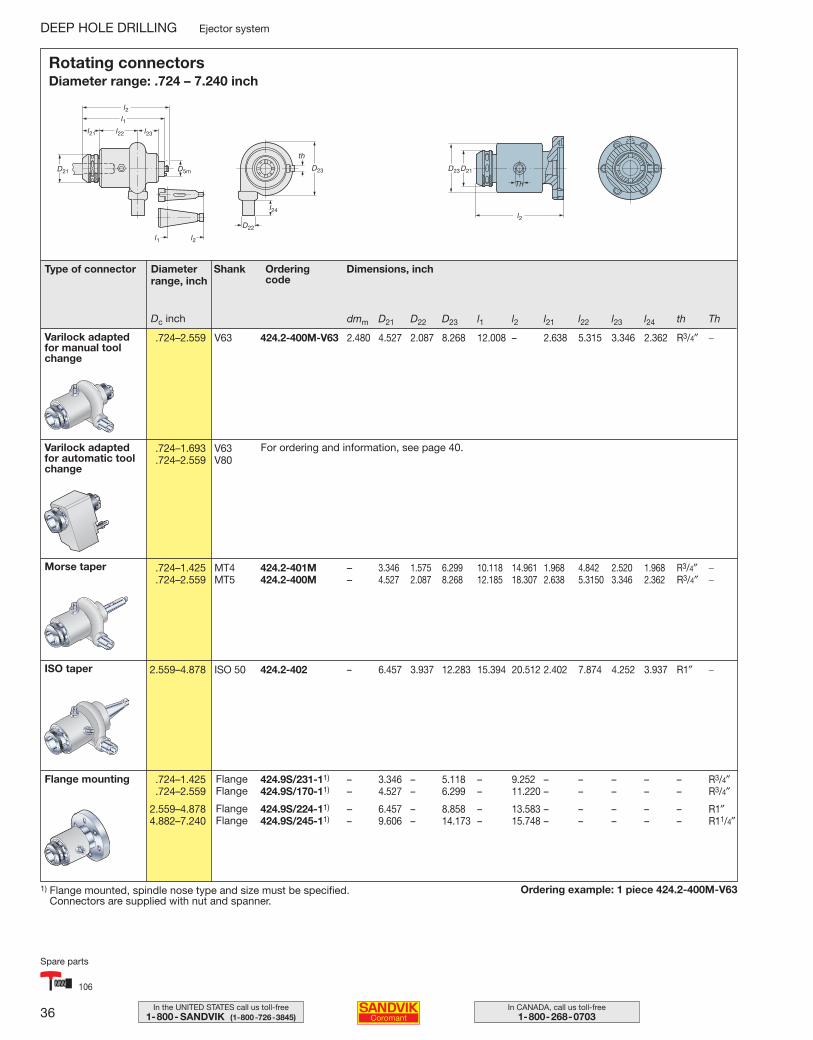
dmm D21 D22 D23 l1 l2 l21 l22 l23 l24 th Th
.724–2.559 V63 424.2-400M-V63 2.480 4.527 2.087 8.268 12.008 – 2.638 5.315 3.346 2.362 R3/4″ −
.724–1.693 V63
.724–2.559 V80
.724–1.425 MT4 424.2-401M – 3.346 1.575 6.299 10.118 14.961 1.968 4.842 2.520 1.968 R3/4″ −
.724–2.559 MT5 424.2-400M – 4.527 2.087 8.268 12.185 18.307 2.638 5.3150 3.346 2.362 R3/4″ −
2.559–4.878 ISO 50 424.2-402 – 6.457 3.937 12.283 15.394 20.512 2.402 7.874 4.252 3.937 R1″ −
.724–1.425 424.9S/231-11) – 3.346 – 5.118 – 9.252 – – – – – R3/4″
.724–2.559 424.9S/170-11) – 4.527 – 6.299 – 11.220 – – – – – R3/4″
2.559–4.878 424.9S/224-11) – 6.457 – 8.858 – 13.583 – – – – – R1″4.882–7.240 424.9S/245-11) – 9.606 – 14.173 – 15.748 – – – – – R11/4″
Type of connector Diameterrange, inch
Shank Ordering code
Dimensions, inch
1) Flange mounted, spindle nose type and size must be specified. Connectors are supplied with nut and spanner.
Ordering example: 1 piece 424.2-400M-V63
Varilock adaptedfor manual toolchange
Varilock adaptedfor automatic toolchange
Morse taper
ISO taper
Flange mounting
l1
l1 l2
l2
l21 l22 l23
l24
D21 D23
D22
D5m
th
FlangeFlange
FlangeFlange
For ordering and information, see page 40.
Rotating connectorsDiameter range: .724 – 7.240 inch
Dc inch
106
Spare parts
034-043 USA 04-04-29 09.52 Sida 36
37In the UNITED STATES call us toll-free1-800- SANDVIK (1-800-726-3845)
In CANADA, call us toll-free1-800-268-0703
Ejector system DEEP HOLE DRILLING
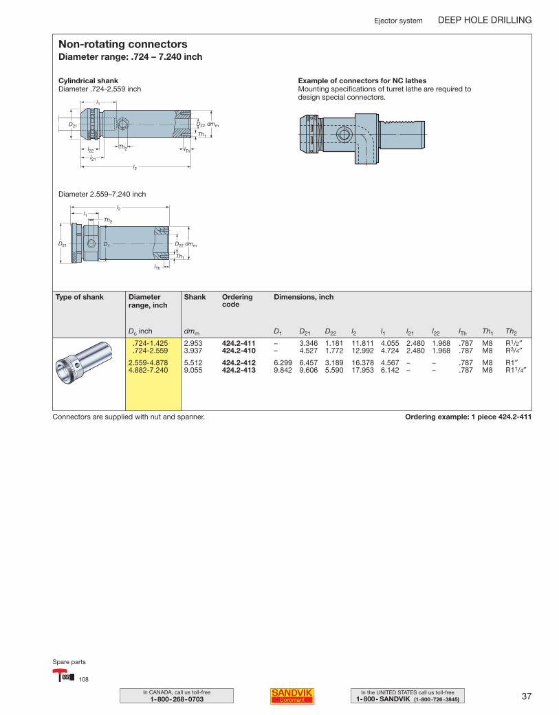
Connectors are supplied with nut and spanner. Ordering example: 1 piece 424.2-411
Non-rotating connectorsDiameter range: .724 – 7.240 inch
Cylindrical shankDiameter .724-2.559 inch
l1
l2
l21
l22
D21 D22 dmm
Th1
Th2 lTh
l1l2
D1D21 D22 dmm
Th1
Th2
lTh
Example of connectors for NC lathesMounting specifications of turret lathe are required to design special connectors.
Diameter 2.559–7.240 inch
Type of shank Diameterrange, inch
Dc inch
Shank Ordering code
Dimensions, inch
dmm D1 D21 D22 l2 l1 l21 l22 lTh Th1 Th2
.724-1.425 2.953 424.2-411 – 3.346 1.181 11.811 4.055 2.480 1.968 .787 M8 R1/2″
.724-2.559 3.937 424.2-410 – 4.527 1.772 12.992 4.724 2.480 1.968 .787 M8 R3/4″
2.559-4.878 5.512 424.2-412 6.299 6.457 3.189 16.378 4.567 – – .787 M8 R1″4.882-7.240 9.055 424.2-413 9.842 9.606 5.590 17.953 6.142 – – .787 M8 R11/4″
108
Spare parts
034-043 USA 04-04-29 09.52 Sida 37
38 In CANADA, call us toll-free1-800-268-0703
In the UNITED STATES call us toll-free1-800- SANDVIK (1-800-726-3845)
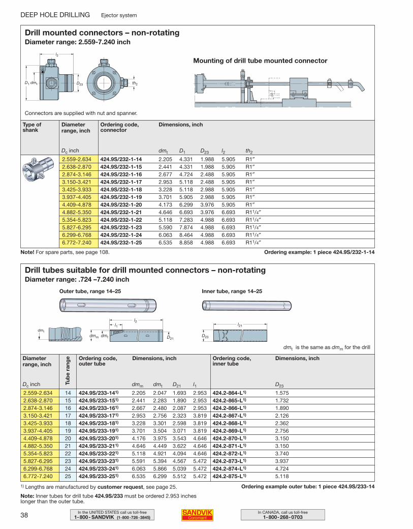
Ordering example: 1 piece 424.9S/232-1-14
Drill mounted connectors – non-rotating Diameter range: 2.559-7.240 inch
l2
D1 D23dmt th2
dmt D1 D23 l2 th2
2.559-2.634 424.9S/232-1-14 2.205 4.331 1.988 5.905 R1″2.638-2.870 424.9S/232-1-15 2.441 4.331 1.988 5.905 R1″2.874-3.146 424.9S/232-1-16 2.677 4.724 2.488 5.905 R1″3.150-3.421 424.9S/232-1-17 2.953 5.118 2.488 5.905 R1″3.425-3.933 424.9S/232-1-18 3.228 5.118 2.988 5.905 R1″3.937-4.405 424.9S/232-1-19 3.701 5.905 2.988 5.905 R1″4.409-4.878 424.9S/232-1-20 4.173 6.299 3.976 5.905 R1″4.882-5.350 424.9S/232-1-21 4.646 6.693 3.976 6.693 R11/4″5.354-5.823 424.9S/232-1-22 5.118 7.283 4.988 6.693 R11/4″5.827-6.295 424.9S/232-1-23 5.590 7.874 4.988 6.693 R11/4″6.299-6.768 424.9S/232-1-24 6.063 8.464 4.988 6.693 R11/4″6.772-7.240 424.9S/232-1-25 6.535 8.858 4.988 6.693 R11/4″
DEEP HOLE DRILLING Ejector system
Type ofshank
Diameterrange, inch
Ordering code,connector
Dimensions, inch
Dc inch
Connectors are supplied with nut and spanner.
Mounting of drill tube mounted connector
Ordering example outer tube: 1 piece 424.9S/233-14
Drill tubes suitable for drill mounted connectors – non-rotating Diameter range: .724 –7.240 inch
dmm dmt D21 l1 D23
2.559-2.634 14 424.9S/233-141) 2.205 2.047 1.693 2.953 424.2-864-L1) 1.5752.638-2.870 15 424.9S/233-151) 2.441 2.283 1.890 2.953 424.2-865-L1) 1.7322.874-3.146 16 424.9S/233-161) 2.667 2.480 2.087 2.953 424.2-866-L1) 1.8903.150-3.421 17 424.9S/233-171) 2.953 2.756 2.323 3.819 424.2-867-L1) 2.1263.425-3.933 18 424.9S/233-181) 3.228 3.301 2.598 3.819 424.2-868-L1) 2.3623.937-4.405 19 424.9S/233-191) 3.701 3.504 3.071 3.819 424.2-869-L1) 2.7564.409-4.878 20 424.9S/233-201) 4.176 3.975 3.543 4.646 424.2-870-L1) 3.1504.882-5.350 21 424.9S/233-211) 4.646 4.449 3.622 4.646 424.2-871-L1) 3.1505.354-5.823 22 424.9S/233-221) 5.118 4.921 4.094 4.646 424.2-872-L1) 3.7405.827-6.295 23 424.9S/233-231) 5.591 5.394 4.567 5.472 424.2-873-L1) 3.9376.299-6.768 24 424.9S/233-241) 6.063 5.866 5.039 5.472 424.2-874-L1) 4.7246.772-7.240 25 424.9S/233-251) 6.535 6.299 5.512 5.472 424.2-875-L1) 5.118
Diameterrange, inch
Ordering code, outer tube
Dimensions, inch
Dc inch Tub
e ra
nge Ordering code,
inner tubeDimensions, inch
dmt
l1l2
D21dmm dmt
Outer tube, range 14–25
l21
D23
dmt is the same as dmm for the drill
Inner tube, range 14–25
1) Lengths are manufactured by customer request, see page 25.
Note: Inner tubes for drill tube 424.9S/233 must be ordered 2.953 inches longer than the outer tube.
Note! For spare parts, see page 108.
034-043 USA 04-04-29 09.52 Sida 38
39In the UNITED STATES call us toll-free1-800- SANDVIK (1-800-726-3845)
In CANADA, call us toll-free1-800-268-0703
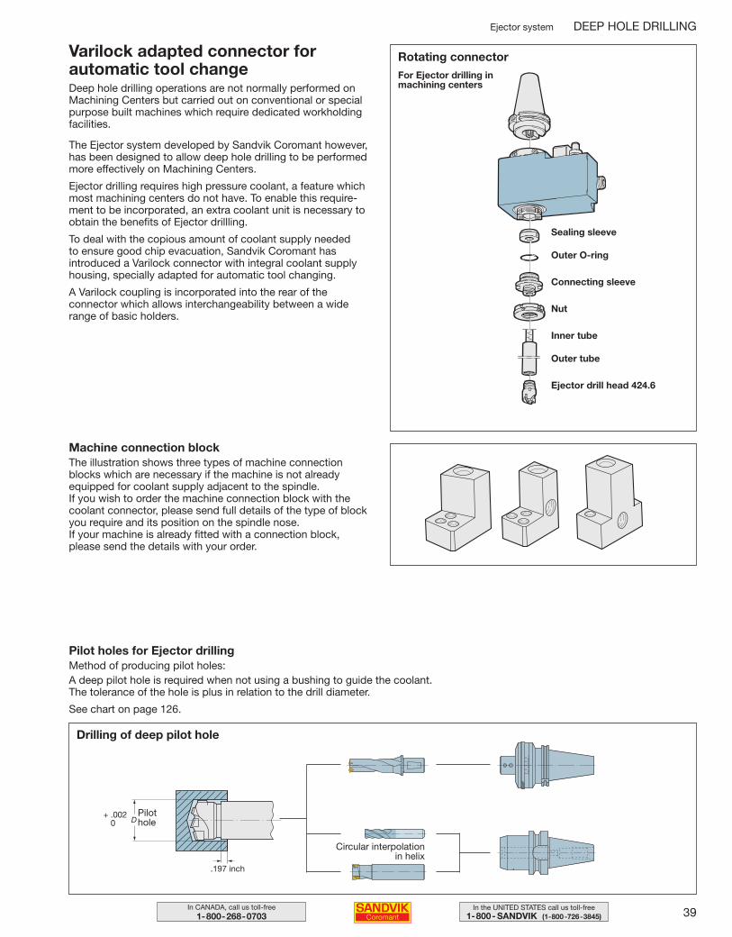
Varilock adapted connector forautomatic tool changeDeep hole drilling operations are not normally performed onMachining Centers but carried out on conventional or specialpurpose built machines which require dedicated workholdingfacilities.
The Ejector system developed by Sandvik Coromant however,has been designed to allow deep hole drilling to be performedmore effectively on Machining Centers.
Ejector drilling requires high pressure coolant, a feature whichmost machining centers do not have. To enable this require-ment to be incorporated, an extra coolant unit is necessary toobtain the benefits of Ejector drillling.
To deal with the copious amount of coolant supply needed to ensure good chip evacuation, Sandvik Coromant has introduced a Varilock connector with integral coolant supplyhousing, specially adapted for automatic tool changing.
A Varilock coupling is incorporated into the rear of the connector which allows interchangeability between a widerange of basic holders.
Rotating connector
Sealing sleeve
Outer O-ring
Connecting sleeve
Nut
Inner tube
Outer tube
Ejector drill head 424.6
Machine connection blockThe illustration shows three types of machine connectionblocks which are necessary if the machine is not already equipped for coolant supply adjacent to the spindle.If you wish to order the machine connection block with thecoolant connector, please send full details of the type of blockyou require and its position on the spindle nose.If your machine is already fitted with a connection block, please send the details with your order.
Pilot holes for Ejector drillingMethod of producing pilot holes:A deep pilot hole is required when not using a bushing to guide the coolant. The tolerance of the hole is plus in relation to the drill diameter.
See chart on page 126.
For Ejector drilling inmachining centers
Ejector system DEEP HOLE DRILLING
Drilling of deep pilot hole
+ .0020
.197 inch
22
04
4
Circular interpolation in helix
Pilot hole
034-043 USA 04-05-07 08.44 Sida 39
40 In CANADA, call us toll-free1-800-268-0703
In the UNITED STATES call us toll-free1-800- SANDVIK (1-800-726-3845)
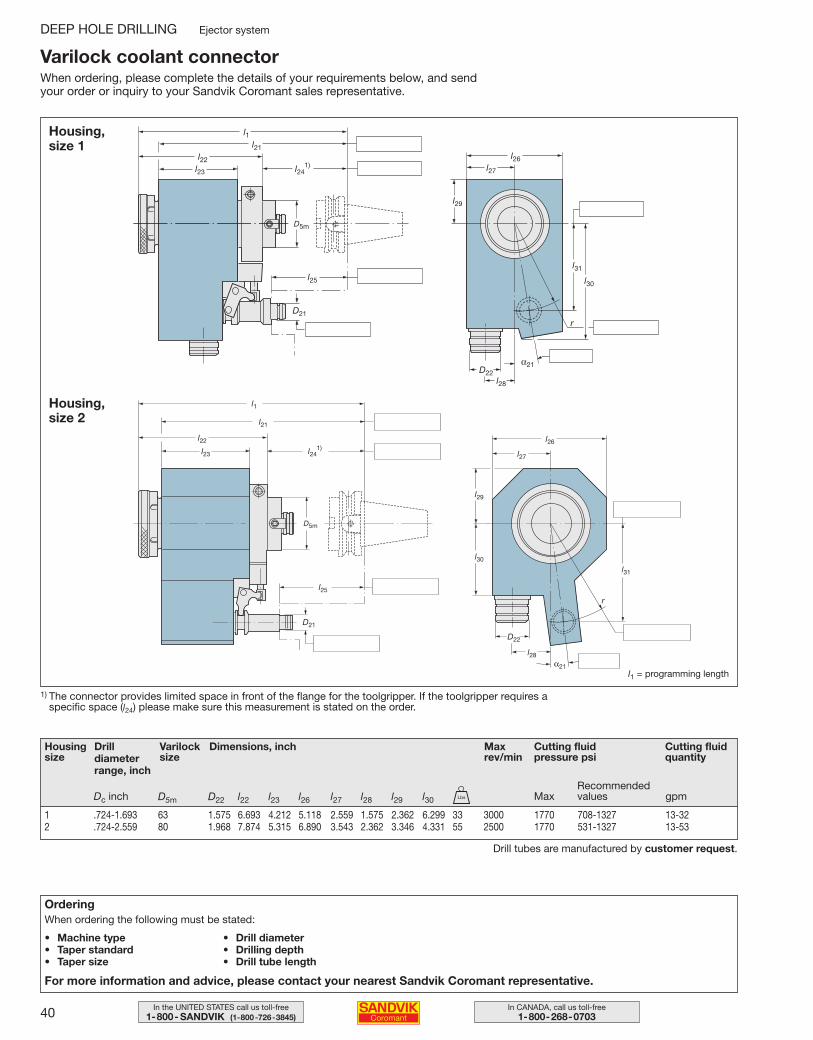
Housing size
Drill diameterrange, inch
Varilock size
Dimensions, inch Max rev/min
Cutting fluid pressure psi
Cutting fluidquantity
MaxRecommendedvalues gpm
Varilock coolant connectorWhen ordering, please complete the details of your requirements below, and sendyour order or inquiry to your Sandvik Coromant sales representative.
Housing, size 1
Housing,size 2
1) The connector provides limited space in front of the flange for the toolgripper. If the toolgripper requires aspecific space (l24) please make sure this measurement is stated on the order.
Drill tubes are manufactured by customer request.
l1
l21
l22
l23
l25
D21
l241)
D5m
r
l26
D22
l27
l28
l29
l30
l31
α21l1 = programming length
l1l21
l22
l23
l25
D21
l241)
D5m
r
l26
D22
l27
l28
l29
l30
l31
α21
D5m D22 l22 l23 l26 l27 l28 l29 l30
1 .724-1.693 63 1.575 6.693 4.212 5.118 2.559 1.575 2.362 6.299 33 3000 1770 708-1327 13-322 .724-2.559 80 1.968 7.874 5.315 6.890 3.543 2.362 3.346 4.331 55 2500 1770 531-1327 13-53
Dc inch Lbs
OrderingWhen ordering the following must be stated:
• Machine type• Taper standard• Taper size
• Drill diameter• Drilling depth• Drill tube length
For more information and advice, please contact your nearest Sandvik Coromant representative.
DEEP HOLE DRILLING Ejector system
034-043 USA 04-04-29 09.52 Sida 40
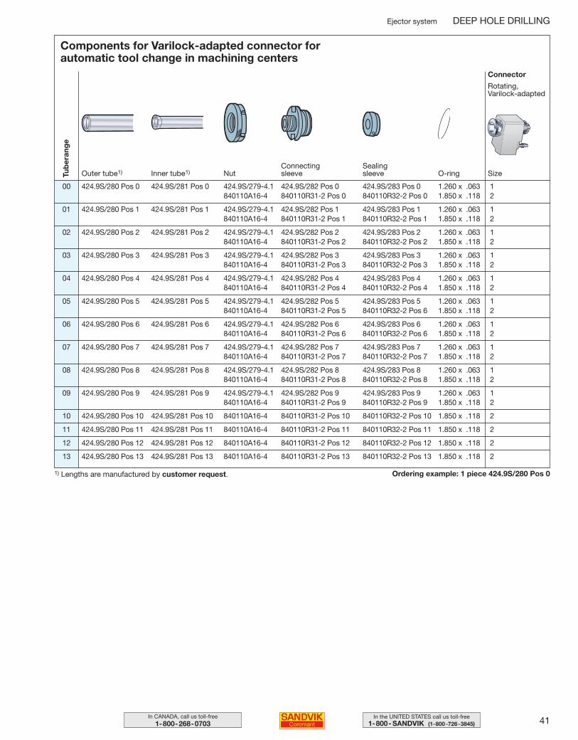
41In the UNITED STATES call us toll-free1-800- SANDVIK (1-800-726-3845)
In CANADA, call us toll-free1-800-268-0703
Components for Varilock-adapted connector for automatic tool change in machining centers
Tub
eran
ge
Connector
Rotating, Varilock-adapted
SizeNutInner tube1)Outer tube1)Connectingsleeve O-ring
Sealing sleeve
Ordering example: 1 piece 424.9S/280 Pos 0
Ejector system DEEP HOLE DRILLING
00 424.9S/280 Pos 0 424.9S/281 Pos 0 424.9S/279-4.1 424.9S/282 Pos 0 424.9S/283 Pos 0 1.260 x .063 1840110A16-4 840110R31-2 Pos 0 840110R32-2 Pos 0 1.850 x .118 2
01 424.9S/280 Pos 1 424.9S/281 Pos 1 424.9S/279-4.1 424.9S/282 Pos 1 424.9S/283 Pos 1 1.260 x .063 1840110A16-4 840110R31-2 Pos 1 840110R32-2 Pos 1 1.850 x .118 2
02 424.9S/280 Pos 2 424.9S/281 Pos 2 424.9S/279-4.1 424.9S/282 Pos 2 424.9S/283 Pos 2 1.260 x .063 1840110A16-4 840110R31-2 Pos 2 840110R32-2 Pos 2 1.850 x .118 2
03 424.9S/280 Pos 3 424.9S/281 Pos 3 424.9S/279-4.1 424.9S/282 Pos 3 424.9S/283 Pos 3 1.260 x .063 1840110A16-4 840110R31-2 Pos 3 840110R32-2 Pos 3 1.850 x .118 2
04 424.9S/280 Pos 4 424.9S/281 Pos 4 424.9S/279-4.1 424.9S/282 Pos 4 424.9S/283 Pos 4 1.260 x .063 1840110A16-4 840110R31-2 Pos 4 840110R32-2 Pos 4 1.850 x .118 2
05 424.9S/280 Pos 5 424.9S/281 Pos 5 424.9S/279-4.1 424.9S/282 Pos 5 424.9S/283 Pos 5 1.260 x .063 1840110A16-4 840110R31-2 Pos 5 840110R32-2 Pos 6 1.850 x .118 2
06 424.9S/280 Pos 6 424.9S/281 Pos 6 424.9S/279-4.1 424.9S/282 Pos 6 424.9S/283 Pos 6 1.260 x .063 1840110A16-4 840110R31-2 Pos 6 840110R32-2 Pos 6 1.850 x .118 2
07 424.9S/280 Pos 7 424.9S/281 Pos 7 424.9S/279-4.1 424.9S/282 Pos 7 424.9S/283 Pos 7 1.260 x .063 1840110A16-4 840110R31-2 Pos 7 840110R32-2 Pos 7 1.850 x .118 2
08 424.9S/280 Pos 8 424.9S/281 Pos 8 424.9S/279-4.1 424.9S/282 Pos 8 424.9S/283 Pos 8 1.260 x .063 1840110A16-4 840110R31-2 Pos 8 840110R32-2 Pos 8 1.850 x .118 2
09 424.9S/280 Pos 9 424.9S/281 Pos 9 424.9S/279-4.1 424.9S/282 Pos 9 424.9S/283 Pos 9 1.260 x .063 1840110A16-4 840110R31-2 Pos 9 840110R32-2 Pos 9 1.850 x .118 2
10 424.9S/280 Pos 10 424.9S/281 Pos 10 840110A16-4 840110R31-2 Pos 10 840110R32-2 Pos 10 1.850 x .118 2
11 424.9S/280 Pos 11 424.9S/281 Pos 11 840110A16-4 840110R31-2 Pos 11 840110R32-2 Pos 11 1.850 x .118 2
12 424.9S/280 Pos 12 424.9S/281 Pos 12 840110A16-4 840110R31-2 Pos 12 840110R32-2 Pos 12 1.850 x .118 2
13 424.9S/280 Pos 13 424.9S/281 Pos 13 840110A16-4 840110R31-2 Pos 13 840110R32-2 Pos 13 1.850 x .118 2
1) Lengths are manufactured by customer request.
034-043 USA 04-04-29 09.52 Sida 41

42 In CANADA, call us toll-free1-800-268-0703
In the UNITED STATES call us toll-free1-800- SANDVIK (1-800-726-3845)
✍034-043 USA 04-04-29 09.52 Sida 42
43In the UNITED STATES call us toll-free1-800- SANDVIK (1-800-726-3845)
In CANADA, call us toll-free1-800-268-0703
44–45
46–47
48–51
52–55
56–60
61
61
62–69
70
71
72
73-74
75
76
77
78
79-85
86-98
99-108
109
135-136
137-141
142
143
STS systemTool selection
Tool mounting – solid drilling and counterboring
Ground drill head 420.6
CoroDrill™ 800.20
T-Max® drill 424.10
Drill tubes manufactured by customer request
Calculation of special length tubes
T-Max® 424.31F and 424.31 counterboring heads
T-Max® 420.7 trepanning head
Special T-Max® counterboring heads 424.32
Mounting parts for connectors
STS oil pressure heads
STS connecting chucks
Vibration dampers
Adapters converting from external to internal tube threads
Setting the diameters on T-Max® drills
Inserts
Cutting data and graphs
Spare parts
Application guide
Troubleshooting
Material cross reference list
Insert mounting
Safety information
T a b l e o f c o n t e n t s
DEEP HOLE DRILLING
034-043 USA 04-04-29 09.52 Sida 43
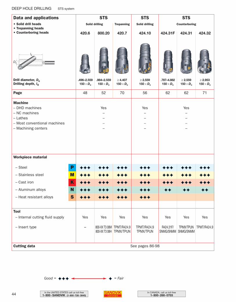
44 In CANADA, call us toll-free1-800-268-0703
In the UNITED STATES call us toll-free1-800- SANDVIK (1-800-726-3845)
= FairGood = ✦✦✦
Data and applications• Solid drill heads• Trepanning heads• Counterboring heads
STSSolid drilling
424.10
≥ 2.559150 × Dc
Drill diameter, DcDrilling depth, l4
56
STSSolid drilling
800.20420.6
.984–2.559150 × Dc
.496–2.559150 × Dc
Dc
l4
48 52Page
Machine– DHD machines– NC machines– Lathes– Most conventional machines– Machining centers
Yes––––
Yes––––
Workpiece material
P
M– Stainless steel
– Steel
K– Cast iron
N– Aluminum alloys
S– Heat resistant alloys
Tool
– Internal cutting fluid supply
– Insert type
Yes
TPMT/R424.9TPMX/TPUN
Yes
800-XX T3 08M800-XX T3 08H
Yes
–
Cutting data See pages 86-98
✦
✦✦✦
✦✦✦
✦✦✦
✦✦✦
✦✦✦
✦✦✦
✦✦✦
✦✦✦
✦✦✦
✦✦✦
✦✦✦
✦✦✦
✦✦✦
✦✦✦
✦✦✦
STSCounterboring
424.31F 424.31 424.32
.787–4.882150 × Dc
≥ 2.559150 × Dc
≥ 2.953150 × Dc
7162 62
Yes––––
Yes Yes Yes
R424.31F/SNMG/SNMM
TPMX/TPUNSNMG/SNMM
TPMT/R424.9
✦✦✦
✦✦✦
✦✦✦
✦✦
✦✦✦
✦✦✦
✦✦✦
✦✦
✦✦✦
✦✦✦
✦✦✦
✦✦
DEEP HOLE DRILLING STS system
Trepanning
420.7
≥ 4.407150 × Dc
70
Yes
TPMT/R424.9TPMX/TPUN
✦✦✦
✦✦✦
✦✦✦
✦✦✦
✦✦✦
044-071 USA 04-04-29 10.00 Sida 44
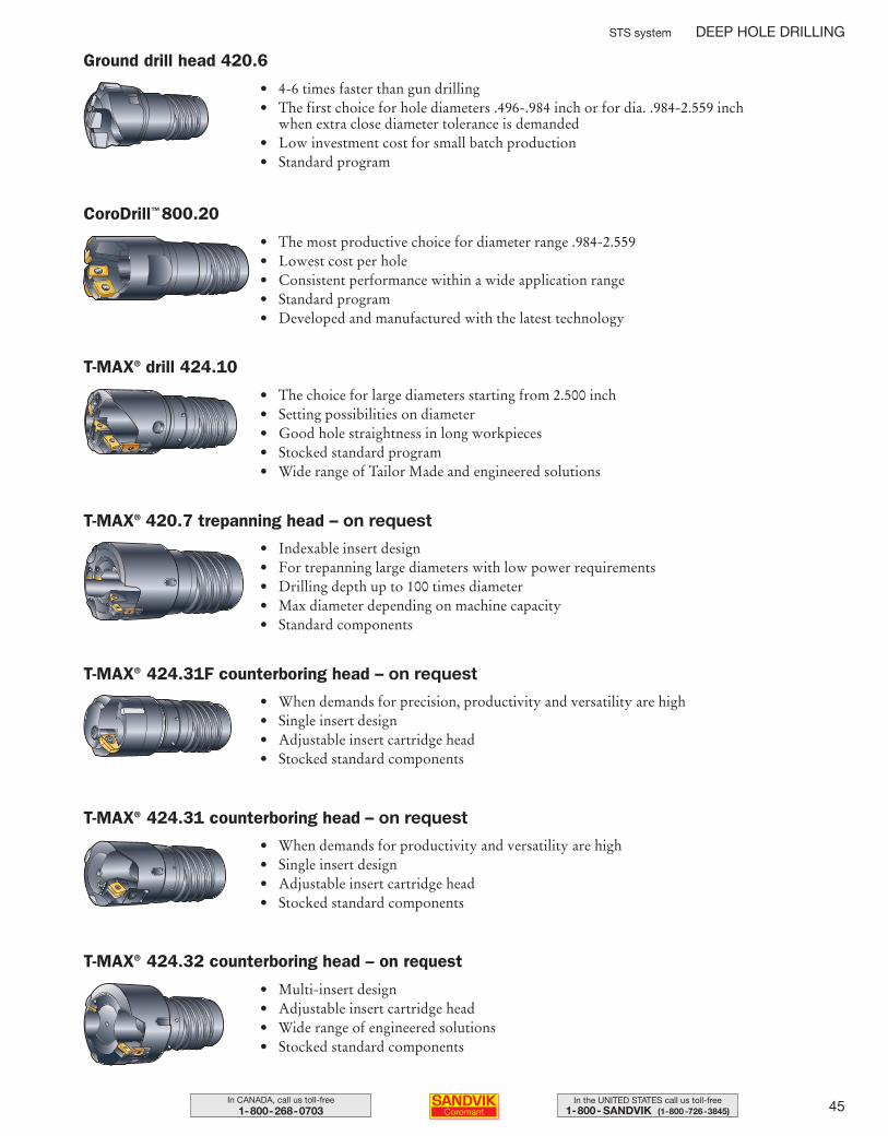
45In the UNITED STATES call us toll-free1-800- SANDVIK (1-800-726-3845)
In CANADA, call us toll-free1-800-268-0703
• 4-6 times faster than gun drilling• The first choice for hole diameters .496-.984 inch or for dia. .984-2.559 inch
when extra close diameter tolerance is demanded• Low investment cost for small batch production• Standard program
• The most productive choice for diameter range .984-2.559• Lowest cost per hole• Consistent performance within a wide application range• Standard program• Developed and manufactured with the latest technology
• The choice for large diameters starting from 2.500 inch• Setting possibilities on diameter• Good hole straightness in long workpieces• Stocked standard program • Wide range of Tailor Made and engineered solutions
• When demands for precision, productivity and versatility are high• Single insert design• Adjustable insert cartridge head• Stocked standard components
• When demands for productivity and versatility are high• Single insert design• Adjustable insert cartridge head• Stocked standard components
• Multi-insert design• Adjustable insert cartridge head• Wide range of engineered solutions• Stocked standard components
STS system DEEP HOLE DRILLING
Ground drill head 420.6
CoroDrill™ 800.20
T-MAX® drill 424.10
T-MAX® 424.31F counterboring head – on request
T-MAX® 424.31 counterboring head – on request
T-MAX® 424.32 counterboring head – on request
• Indexable insert design• For trepanning large diameters with low power requirements• Drilling depth up to 100 times diameter• Max diameter depending on machine capacity• Standard components
T-MAX® 420.7 trepanning head – on request
044-071 USA 04-04-29 10.00 Sida 45
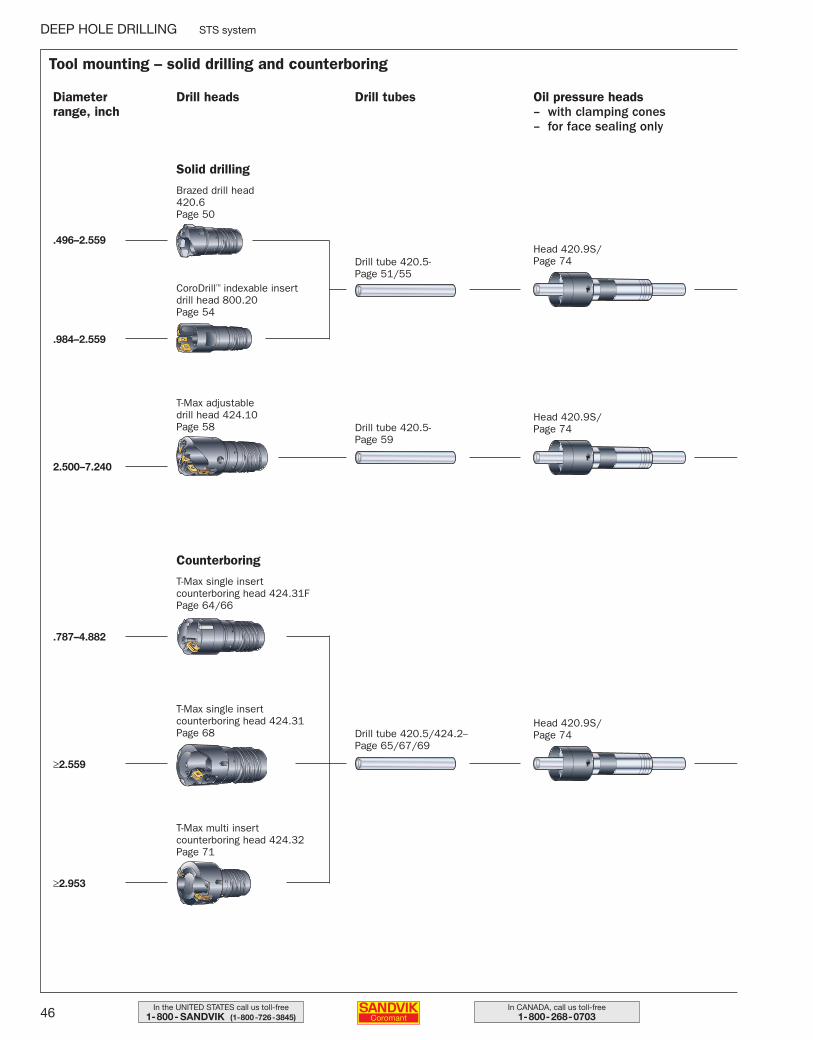
46 In CANADA, call us toll-free1-800-268-0703
In the UNITED STATES call us toll-free1-800- SANDVIK (1-800-726-3845)
Drill tubes
Drill tube 420.5-Page 51/55
CoroDrill™ indexable insert drill head 800.20Page 54
Brazed drill head 420.6Page 50
T-Max adjustable drill head 424.10Page 58
T-Max single insert counterboring head 424.31FPage 64/66
T-Max single insert counterboring head 424.31Page 68
T-Max multi insert counterboring head 424.32Page 71
Drill headsDiameter range, inch
Solid drilling
Counterboring
2.500–7.240
.787–4.882
≥2.559
≥2.953
.984–2.559
.496–2.559
Drill tube 420.5-Page 59
Tool mounting – solid drilling and counterboring
DEEP HOLE DRILLING STS system
Drill tube 420.5/424.2--Page 65/67/69
Head 420.9S/Page 74
Head 420.9S/Page 74
Head 420.9S/Page 74
Oil pressure heads– with clamping cones– for face sealing only
044-071 USA 04-04-29 10.00 Sida 46
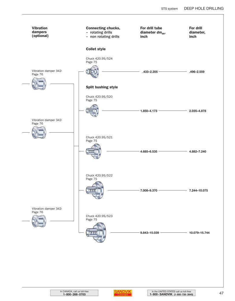
47In the UNITED STATES call us toll-free1-800- SANDVIK (1-800-726-3845)
In CANADA, call us toll-free1-800-268-0703
Connecting chucks,– rotating drills– non rotating drills
For drill tube diameter dmm, inch
Chuck 420.9S/520Page 75
Chuck 420.9S/521Page 75
Chuck 420.9S/522Page 75
Chuck 420.9S/523Page 75
Chuck 420.9S/524Page 75
Vibration damper 342-Page 76
Vibration dampers(optional)
Vibration damper 342-Page 76
Vibration damper 342-Page 76
STS system DEEP HOLE DRILLING
Collet style
Split bushing style
For drill diameter, inch
.433–2.205 .496–2.559
1.850–4.173 2.035–4.878
4.685–6.535 4.882–7.240
7.008–9.370 7.244–10.075
9.843–15.039 10.079–15.744
044-071 USA 04-04-29 10.00 Sida 47
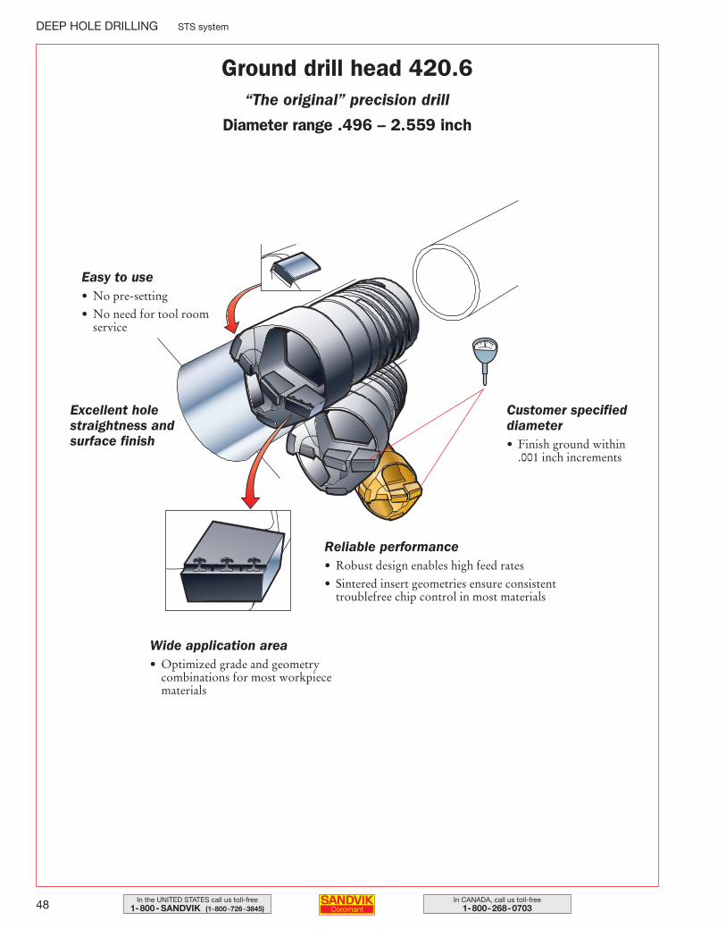
48 In CANADA, call us toll-free1-800-268-0703
In the UNITED STATES call us toll-free1-800- SANDVIK (1-800-726-3845)
DEEP HOLE DRILLING STS system
Ground drill head 420.6“The original” precision drill
Diameter range .496 – 2.559 inch
Easy to use• No pre-setting
• No need for tool roomservice
Excellent holestraightness andsurface finish
Customer specified diameter• Finish ground within
.001 inch increments
Reliable performance• Robust design enables high feed rates
• Sintered insert geometries ensure consistenttroublefree chip control in most materials
Wide application area• Optimized grade and geometry
combinations for most workpiecematerials
044-071 USA 04-04-29 10.00 Sida 48
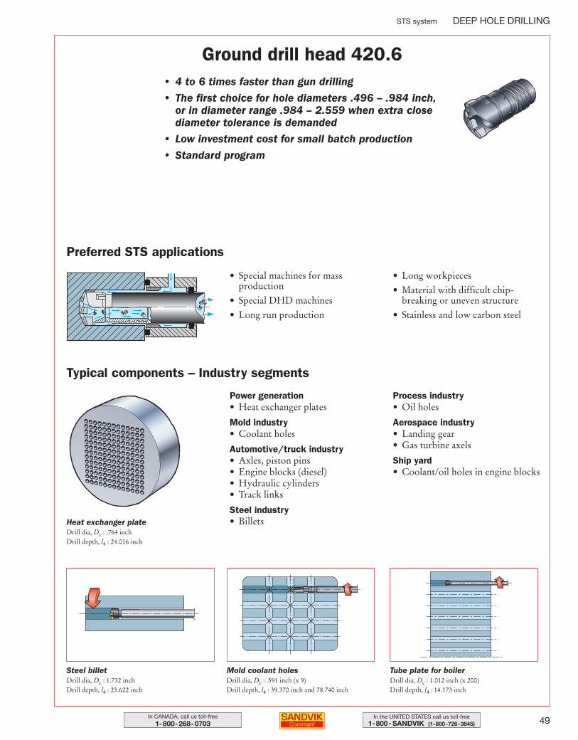
49In the UNITED STATES call us toll-free1-800- SANDVIK (1-800-726-3845)
In CANADA, call us toll-free1-800-268-0703
STS system DEEP HOLE DRILLING
Ground drill head 420.6• 4 to 6 times faster than gun drilling
• The first choice for hole diameters .496 – .984 inch, or in diameter range .984 – 2.559 when extra closediameter tolerance is demanded
• Low investment cost for small batch production
• Standard program
Preferred STS applications
• Special machines for massproduction
• Special DHD machines
• Long run production
• Long workpieces
• Material with difficult chip-breaking or uneven structure
• Stainless and low carbon steel
Typical components – Industry segments
Power generation• Heat exchanger plates
Mold industry• Coolant holes
Automotive/truck industry• Axles, piston pins• Engine blocks (diesel)• Hydraulic cylinders• Track links
Steel industry• Billets
Process industry• Oil holes
Aerospace industry• Landing gear• Gas turbine axels
Ship yard• Coolant/oil holes in engine blocks
Heat exchanger plateDrill dia, Dc : .764 inchDrill depth, l4 : 24.016 inch
Steel billetDrill dia, Dc : 1.732 inchDrill depth, l4 : 23.622 inch
Mold coolant holesDrill dia, Dc : .591 inch (x 9)Drill depth, l4 : 39.370 inch and 78.740 inch
Tube plate for boilerDrill dia, Dc : 1.012 inch (x 200)Drill depth, l4 : 14.173 inch
044-071 USA 04-04-29 10.00 Sida 49
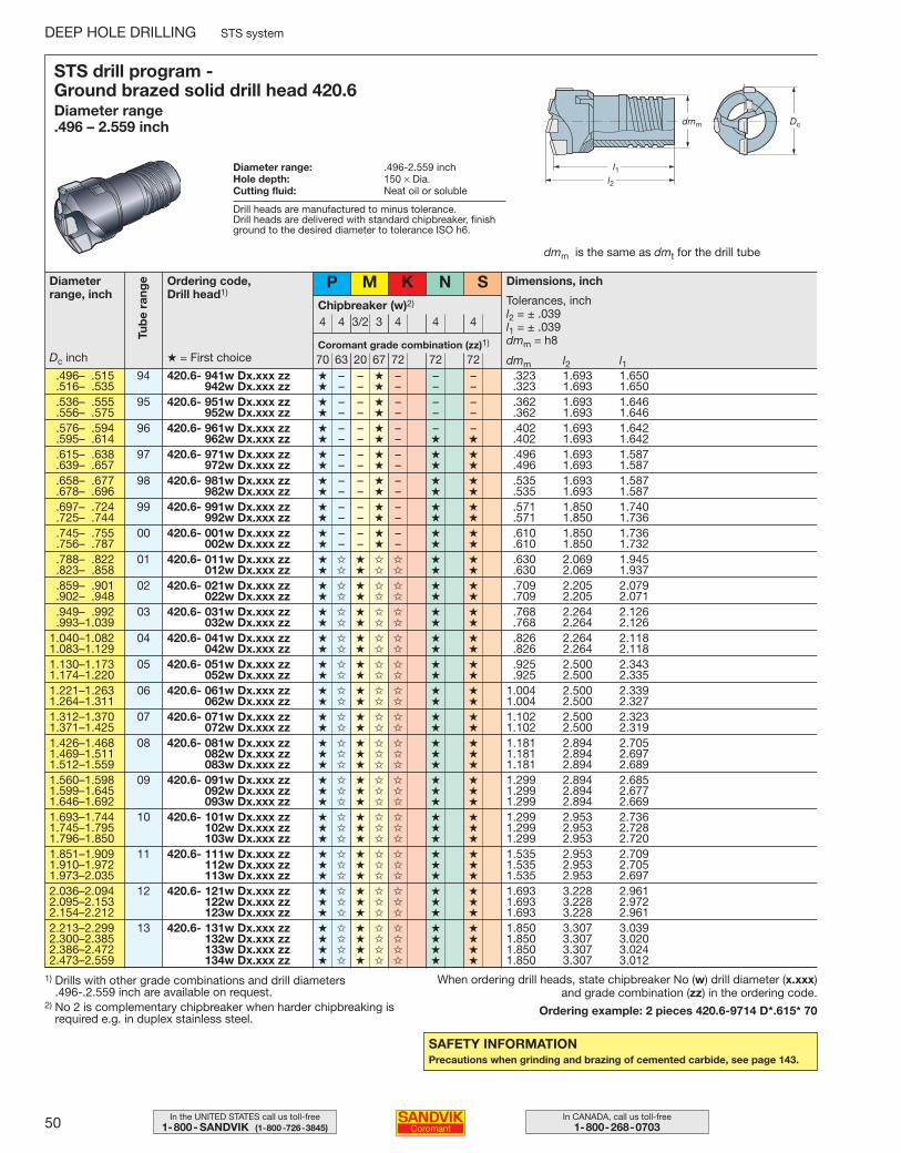
50 In CANADA, call us toll-free1-800-268-0703
In the UNITED STATES call us toll-free1-800- SANDVIK (1-800-726-3845)
DEEP HOLE DRILLING STS system
SAFETY INFORMATIONPrecautions when grinding and brazing of cemented carbide, see page 143.
STS drill program - Ground brazed solid drill head 420.6Diameter range .496 – 2.559 inch
Diameter range: .496-2.559 inchHole depth: 150 × Dia.Cutting fluid: Neat oil or soluble
dmm is the same as dmt for the drill tube
Diameterrange, inch
Coromant grade combination (zz)1)
Drill heads are manufactured to minus tolerance.Drill heads are delivered with standard chipbreaker, finishground to the desired diameter to tolerance ISO h6.
Ordering code, Drill head1)
Chipbreaker (w)2)
P
4 4 3/2 3 4 4 4
M K N S
70 63 20 67 72 72 72Dc inch
Dimensions, inch
Tolerances, inchl2 = ± .039l1 = ± .039dmm = h8
dmm l2 l1.496– .515 94 420.6- 941w Dx.xxx zz ★ – – ★ – – – .323 1.693 1.650.516– .535 942w Dx.xxx zz ★ – – ★ – – – .323 1.693 1.650.536– .555 95 420.6- 951w Dx.xxx zz ★ – – ★ – – – .362 1.693 1.646.556– .575 952w Dx.xxx zz ★ – – ★ – – – .362 1.693 1.646.576– .594 96 420.6- 961w Dx.xxx zz ★ – – ★ – – – .402 1.693 1.642.595– .614 962w Dx.xxx zz ★ – – ★ – ★ ★ .402 1.693 1.642.615– .638 97 420.6- 971w Dx.xxx zz ★ – – ★ – ★ ★ .496 1.693 1.587.639– .657 972w Dx.xxx zz ★ – – ★ – ★ ★ .496 1.693 1.587.658– .677 98 420.6- 981w Dx.xxx zz ★ – – ★ – ★ ★ .535 1.693 1.587.678– .696 982w Dx.xxx zz ★ – – ★ – ★ ★ .535 1.693 1.587.697– .724 99 420.6- 991w Dx.xxx zz ★ – – ★ – ★ ★ .571 1.850 1.740.725– .744 992w Dx.xxx zz ★ – – ★ – ★ ★ .571 1.850 1.736.745– .755 00 420.6- 001w Dx.xxx zz ★ – – ★ – ★ ★ .610 1.850 1.736.756– .787 002w Dx.xxx zz ★ – – ★ – ★ ★ .610 1.850 1.732.788– .822 01 420.6- 011w Dx.xxx zz ★ ✩ ★ ✩ ✩ ★ ★ .630 2.069 1.945.823– .858 012w Dx.xxx zz ★ ✩ ★ ✩ ✩ ★ ★ .630 2.069 1.937.859– .901 02 420.6- 021w Dx.xxx zz ★ ✩ ★ ✩ ✩ ★ ★ .709 2.205 2.079.902– .948 022w Dx.xxx zz ★ ✩ ★ ✩ ✩ ★ ★ .709 2.205 2.071.949– .992 03 420.6- 031w Dx.xxx zz ★ ✩ ★ ✩ ✩ ★ ★ .768 2.264 2.126.993–1.039 032w Dx.xxx zz ★ ✩ ★ ✩ ✩ ★ ★ .768 2.264 2.126
1.040–1.082 04 420.6- 041w Dx.xxx zz ★ ✩ ★ ✩ ✩ ★ ★ .826 2.264 2.1181.083–1.129 042w Dx.xxx zz ★ ✩ ★ ✩ ✩ ★ ★ .826 2.264 2.1181.130–1.173 05 420.6- 051w Dx.xxx zz ★ ✩ ★ ✩ ✩ ★ ★ .925 2.500 2.3431.174–1.220 052w Dx.xxx zz ★ ✩ ★ ✩ ✩ ★ ★ .925 2.500 2.3351.221–1.263 06 420.6- 061w Dx.xxx zz ★ ✩ ★ ✩ ✩ ★ ★ 1.004 2.500 2.3391.264–1.311 062w Dx.xxx zz ★ ✩ ★ ✩ ✩ ★ ★ 1.004 2.500 2.3271.312–1.370 07 420.6- 071w Dx.xxx zz ★ ✩ ★ ✩ ✩ ★ ★ 1.102 2.500 2.3231.371–1.425 072w Dx.xxx zz ★ ✩ ★ ✩ ✩ ★ ★ 1.102 2.500 2.3191.426–1.468 08 420.6- 081w Dx.xxx zz ★ ✩ ★ ✩ ✩ ★ ★ 1.181 2.894 2.7051.469–1.511 082w Dx.xxx zz ★ ✩ ★ ✩ ✩ ★ ★ 1.181 2.894 2.6971.512–1.559 083w Dx.xxx zz ★ ✩ ★ ✩ ✩ ★ ★ 1.181 2.894 2.6891.560–1.598 09 420.6- 091w Dx.xxx zz ★ ✩ ★ ✩ ✩ ★ ★ 1.299 2.894 2.6851.599–1.645 092w Dx.xxx zz ★ ✩ ★ ✩ ✩ ★ ★ 1.299 2.894 2.6771.646–1.692 093w Dx.xxx zz ★ ✩ ★ ✩ ✩ ★ ★ 1.299 2.894 2.6691.693–1.744 10 420.6- 101w Dx.xxx zz ★ ✩ ★ ✩ ✩ ★ ★ 1.299 2.953 2.7361.745–1.795 102w Dx.xxx zz ★ ✩ ★ ✩ ✩ ★ ★ 1.299 2.953 2.7281.796–1.850 103w Dx.xxx zz ★ ✩ ★ ✩ ✩ ★ ★ 1.299 2.953 2.7201.851–1.909 11 420.6- 111w Dx.xxx zz ★ ✩ ★ ✩ ✩ ★ ★ 1.535 2.953 2.7091.910–1.972 112w Dx.xxx zz ★ ✩ ★ ✩ ✩ ★ ★ 1.535 2.953 2.7051.973–2.035 113w Dx.xxx zz ★ ✩ ★ ✩ ✩ ★ ★ 1.535 2.953 2.6972.036–2.094 12 420.6- 121w Dx.xxx zz ★ ✩ ★ ✩ ✩ ★ ★ 1.693 3.228 2.9612.095–2.153 122w Dx.xxx zz ★ ✩ ★ ✩ ✩ ★ ★ 1.693 3.228 2.9722.154–2.212 123w Dx.xxx zz ★ ✩ ★ ✩ ✩ ★ ★ 1.693 3.228 2.9612.213–2.299 13 420.6- 131w Dx.xxx zz ★ ✩ ★ ✩ ✩ ★ ★ 1.850 3.307 3.0392.300–2.385 132w Dx.xxx zz ★ ✩ ★ ✩ ✩ ★ ★ 1.850 3.307 3.0202.386–2.472 133w Dx.xxx zz ★ ✩ ★ ✩ ✩ ★ ★ 1.850 3.307 3.0242.473–2.559 134w Dx.xxx zz ★ ✩ ★ ✩ ✩ ★ ★ 1.850 3.307 3.012
When ordering drill heads, state chipbreaker No (w) drill diameter (x.xxx)and grade combination (zz) in the ordering code.
Ordering example: 2 pieces 420.6-9714 D*.615* 70
Tub
e ra
nge
1) Drills with other grade combinations and drill diameters .496-.2.559 inch are available on request.
2) No 2 is complementary chipbreaker when harder chipbreaking isrequired e.g. in duplex stainless steel.
★ = First choice
044-071 USA 04-04-29 10.00 Sida 50
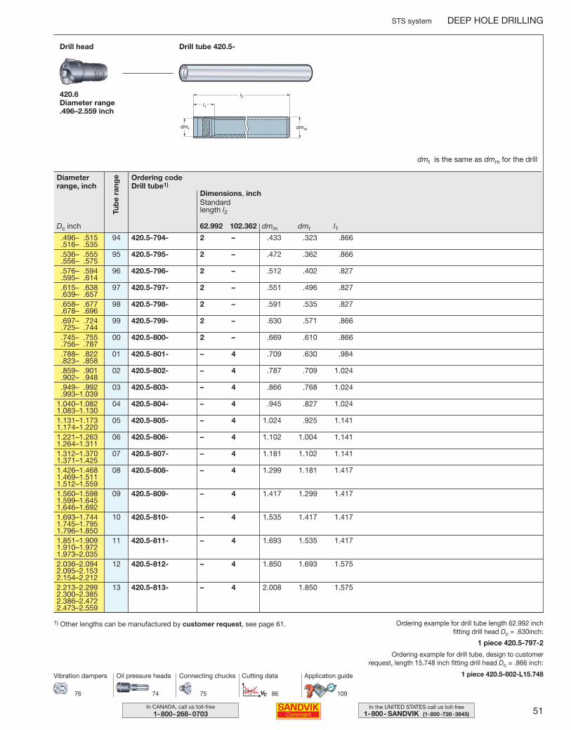
51In the UNITED STATES call us toll-free1-800- SANDVIK (1-800-726-3845)
In CANADA, call us toll-free1-800-268-0703
STS system DEEP HOLE DRILLING
Ordering codeDrill tube1)
Dimensions, inch
dmm dmt l162.992 102.362
Standard length l2
Drill tube 420.5-Drill head
420.6Diameter range .496–2.559 inch
dmt is the same as dmm for the drill
.496– .515 94 420.5-794- 2 – .433 .323 .866
.516– .535
.536– .555 95 420.5-795- 2 – .472 .362 .866
.556– .575
.576– .594 96 420.5-796- 2 – .512 .402 .827
.595– .614
.615– .638 97 420.5-797- 2 – .551 .496 .827
.639– .657
.658– .677 98 420.5-798- 2 – .591 .535 .827
.678– .696
.697– .724 99 420.5-799- 2 – .630 .571 .866
.725– .744
.745– .755 00 420.5-800- 2 – .669 .610 .866
.756– .787
.788– .822 01 420.5-801- – 4 .709 .630 .984
.823– .858
.859– .901 02 420.5-802- – 4 .787 .709 1.024
.902– .948
.949– .992 03 420.5-803- – 4 .866 .768 1.024
.993–1.0391.040–1.082 04 420.5-804- – 4 .945 .827 1.0241.083–1.1301.131–1.173 05 420.5-805- – 4 1.024 .925 1.1411.174–1.2201.221–1.263 06 420.5-806- – 4 1.102 1.004 1.1411.264–1.3111.312–1.370 07 420.5-807- – 4 1.181 1.102 1.1411.371–1.4251.426–1.468 08 420.5-808- – 4 1.299 1.181 1.4171.469–1.5111.512–1.5591.560–1.598 09 420.5-809- – 4 1.417 1.299 1.4171.599–1.6451.646–1.6921.693–1.744 10 420.5-810- – 4 1.535 1.417 1.4171.745–1.7951.796–1.8501.851–1.909 11 420.5-811- – 4 1.693 1.535 1.4171.910–1.9721.973–2.0352.036–2.094 12 420.5-812- – 4 1.850 1.693 1.5752.095–2.1532.154–2.2122.213–2.299 13 420.5-813- – 4 2.008 1.850 1.5752.300–2.3852.386–2.4722.473–2.559
Ordering example for drill tube length 62.992 inch fitting drill head Dc = .630inch:
1 piece 420.5-797-2
Ordering example for drill tube, design to customer request, length 15.748 inch fitting drill head Dc = .866 inch:
1 piece 420.5-802-L15.748
1) Other lengths can be manufactured by customer request, see page 61.
74 75 86 109
Oil pressure heads Connecting chucks Cutting data Application guide
76
Vibration dampers
Tub
e ra
ngeDiameter
range, inch
Dc inch
044-071 USA 04-04-29 10.00 Sida 51
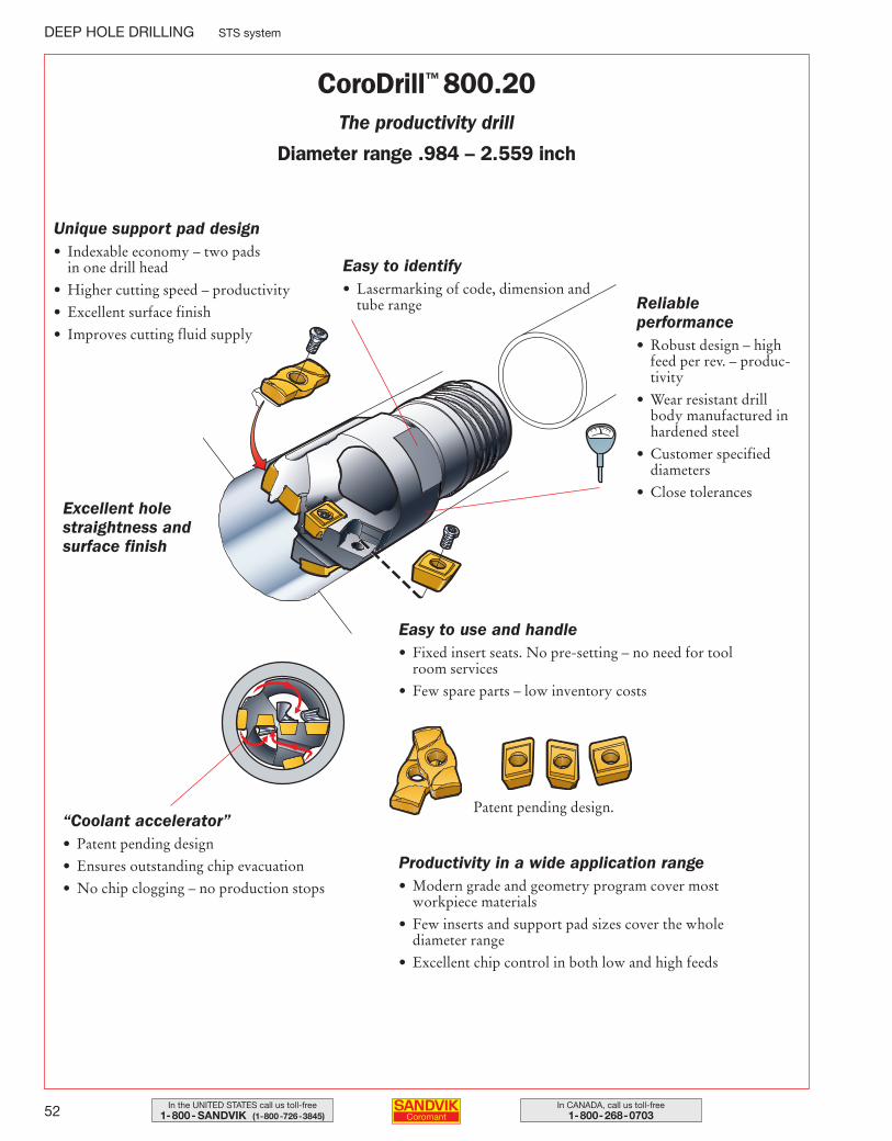
52 In CANADA, call us toll-free1-800-268-0703
In the UNITED STATES call us toll-free1-800- SANDVIK (1-800-726-3845)
DEEP HOLE DRILLING STS system
Reliable performance• Robust design – high
feed per rev. – produc-tivity
• Wear resistant drillbody manufactured inhardened steel
• Customer specified diameters
• Close tolerances
Easy to identify• Lasermarking of code, dimension and
tube range
Easy to use and handle• Fixed insert seats. No pre-setting – no need for tool
room services
• Few spare parts – low inventory costs
“Coolant accelerator”• Patent pending design
• Ensures outstanding chip evacuation
• No chip clogging – no production stops
Unique support pad design• Indexable economy – two pads
in one drill head
• Higher cutting speed – productivity
• Excellent surface finish
• Improves cutting fluid supply
Productivity in a wide application range• Modern grade and geometry program cover most
workpiece materials
• Few inserts and support pad sizes cover the whole diameter range
• Excellent chip control in both low and high feeds
Patent pending design.
Excellent holestraightness andsurface finish
CoroDrill™ 800.20The productivity drill
Diameter range .984 – 2.559 inch
044-071 USA 04-04-29 10.00 Sida 52
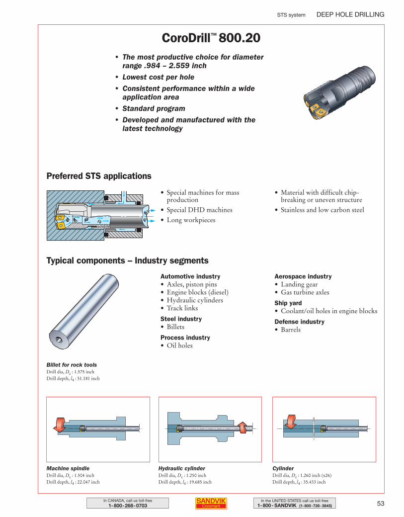
53In the UNITED STATES call us toll-free1-800- SANDVIK (1-800-726-3845)
In CANADA, call us toll-free1-800-268-0703
STS system DEEP HOLE DRILLING
CoroDrill™ 800.20• The most productive choice for diameter
range .984 – 2.559 inch
• Lowest cost per hole
• Consistent performance within a wide application area
• Standard program
• Developed and manufactured with the latest technology
Preferred STS applications
• Special machines for massproduction
• Special DHD machines
• Long workpieces
• Material with difficult chip-breaking or uneven structure
• Stainless and low carbon steel
Typical components – Industry segments
Automotive industry• Axles, piston pins• Engine blocks (diesel)• Hydraulic cylinders• Track links
Steel industry• Billets
Process industry• Oil holes
Aerospace industry• Landing gear• Gas turbine axles
Ship yard• Coolant/oil holes in engine blocks
Defense industry• Barrels
Billet for rock toolsDrill dia, Dc : 1.575 inchDrill depth, l4 : 51.181 inch
Machine spindleDrill dia, Dc : 1.504 inchDrill depth, l4 : 22.047 inch
Hydraulic cylinderDrill dia, Dc : 1.250 inchDrill depth, l4 : 19.685 inch
CylinderDrill dia, Dc : 1.260 inch (x26)Drill depth, l4 : 35.433 inch
044-071 USA 04-04-29 10.00 Sida 53
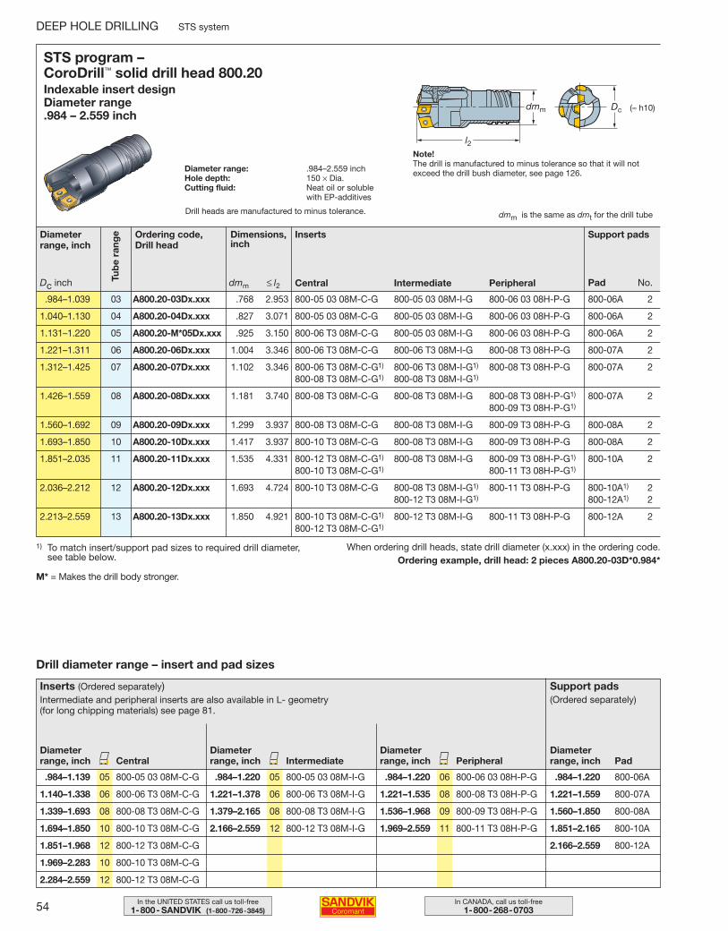
54 In CANADA, call us toll-free1-800-268-0703
In the UNITED STATES call us toll-free1-800- SANDVIK (1-800-726-3845)
1) To match insert/support pad sizes to required drill diameter, see table below.
When ordering drill heads, state drill diameter (x.xxx) in the ordering code.Ordering example, drill head: 2 pieces A800.20-03D*0.984*
STS program – CoroDrill™ solid drill head 800.20Indexable insert design Diameter range .984 – 2.559 inch
Diameter range: .984–2.559 inchHole depth: 150 × Dia.Cutting fluid: Neat oil or soluble
with EP-additives
l2
Dcdmm (≈ h10)
dmm is the same as dmt for the drill tube
.984–1.039 03 A800.20-03Dx.xxx .768 2.953 800-05 03 08M-C-G 800-05 03 08M-I-G 800-06 03 08H-P-G 800-06A 2
1.040–1.130 04 A800.20-04Dx.xxx .827 3.071 800-05 03 08M-C-G 800-05 03 08M-I-G 800-06 03 08H-P-G 800-06A 2
1.131–1.220 05 A800.20-M*05Dx.xxx .925 3.150 800-06 T3 08M-C-G 800-05 03 08M-I-G 800-06 03 08H-P-G 800-06A 2
1.221–1.311 06 A800.20-06Dx.xxx 1.004 3.346 800-06 T3 08M-C-G 800-06 T3 08M-I-G 800-08 T3 08H-P-G 800-07A 2
1.312–1.425 07 A800.20-07Dx.xxx 1.102 3.346 800-06 T3 08M-C-G1) 800-06 T3 08M-I-G1) 800-08 T3 08H-P-G 800-07A 2800-08 T3 08M-C-G1) 800-08 T3 08M-I-G1)
1.426–1.559 08 A800.20-08Dx.xxx 1.181 3.740 800-08 T3 08M-C-G 800-08 T3 08M-I-G 800-08 T3 08H-P-G1) 800-07A 2800-09 T3 08H-P-G1)
1.560–1.692 09 A800.20-09Dx.xxx 1.299 3.937 800-08 T3 08M-C-G 800-08 T3 08M-I-G 800-09 T3 08H-P-G 800-08A 2
1.693–1.850 10 A800.20-10Dx.xxx 1.417 3.937 800-10 T3 08M-C-G 800-08 T3 08M-I-G 800-09 T3 08H-P-G 800-08A 2
1.851–2.035 11 A800.20-11Dx.xxx 1.535 4.331 800-12 T3 08M-C-G1) 800-08 T3 08M-I-G 800-09 T3 08H-P-G1) 800-10A 2800-10 T3 08M-C-G1) 800-11 T3 08H-P-G1)
2.036–2.212 12 A800.20-12Dx.xxx 1.693 4.724 800-10 T3 08M-C-G 800-08 T3 08M-I-G1) 800-11 T3 08H-P-G 800-10A1) 2800-12 T3 08M-I-G1) 800-12A1) 2
2.213–2.559 13 A800.20-13Dx.xxx 1.850 4.921 800-10 T3 08M-C-G1) 800-12 T3 08M-I-G 800-11 T3 08H-P-G 800-12A 2800-12 T3 08M-C-G1)
Ordering code, Drill head
Diameterrange, inch
Dc inch
Support padsInserts
Central Intermediate Peripheral
Dimensions, inch
Tub
e ra
nge
dmm ≤ l2 Pad No.
DEEP HOLE DRILLING STS system
Drill diameter range – insert and pad sizes
Inserts (Ordered separately)Intermediate and peripheral inserts are also available in L- geometry (for long chipping materials) see page 81.
.984–1.139 05 800-05 03 08M-C-G .984–1.220 05 800-05 03 08M-I-G .984–1.220 06 800-06 03 08H-P-G .984–1.220 800-06A
1.140–1.338 06 800-06 T3 08M-C-G 1.221–1.378 06 800-06 T3 08M-I-G 1.221–1.535 08 800-08 T3 08H-P-G 1.221–1.559 800-07A
1.339–1.693 08 800-08 T3 08M-C-G 1.379–2.165 08 800-08 T3 08M-I-G 1.536–1.968 09 800-09 T3 08H-P-G 1.560–1.850 800-08A
1.694–1.850 10 800-10 T3 08M-C-G 2.166–2.559 12 800-12 T3 08M-I-G 1.969–2.559 11 800-11 T3 08H-P-G 1.851–2.165 800-10A
1.851–1.968 12 800-12 T3 08M-C-G 2.166–2.559 800-12A
1.969–2.283 10 800-10 T3 08M-C-G
2.284–2.559 12 800-12 T3 08M-C-G
Diameterrange, inch Central Intermediate Peripheral Pad
Support pads(Ordered separately)
Diameterrange, inch
Diameterrange, inch
Diameterrange, inch
Note!The drill is manufactured to minus tolerance so that it will not exceed the drill bush diameter, see page 126.
Drill heads are manufactured to minus tolerance.
M* = Makes the drill body stronger.
044-071 USA 04-04-29 10.00 Sida 54
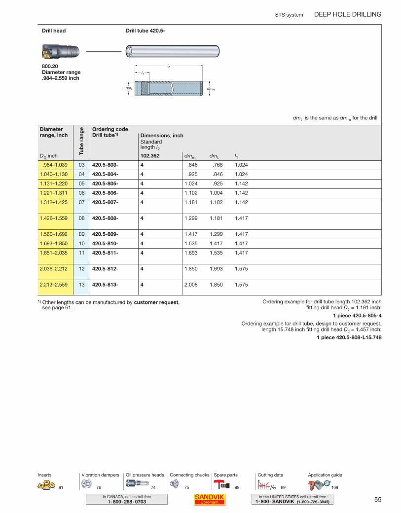
55In the UNITED STATES call us toll-free1-800- SANDVIK (1-800-726-3845)
In CANADA, call us toll-free1-800-268-0703
STS system DEEP HOLE DRILLING
Ordering codeDrill tube1) Dimensions, inch
Standard length l2
Drill tube 420.5-Drill head
800.20Diameter range .984–2.559 inch
dmt is the same as dmm for the drill
.984–1.039 03 420.5-803- 4 .846 .768 1.024
1.040–1.130 04 420.5-804- 4 .925 .846 1.024
1.131–1.220 05 420.5-805- 4 1.024 .925 1.142
1.221–1.311 06 420.5-806- 4 1.102 1.004 1.142
1.312–1.425 07 420.5-807- 4 1.181 1.102 1.142
1.426–1.559 08 420.5-808- 4 1.299 1.181 1.417
1.560–1.692 09 420.5-809- 4 1.417 1.299 1.417
1.693–1.850 10 420.5-810- 4 1.535 1.417 1.417
1.851–2.035 11 420.5-811- 4 1.693 1.535 1.417
2.036–2.212 12 420.5-812- 4 1.850 1.693 1.575
2.213–2.559 13 420.5-813- 4 2.008 1.850 1.575
Ordering example for drill tube length 102.362 inch fitting drill head Dc = 1.181 inch:
1 piece 420.5-805-4
Ordering example for drill tube, design to customer request, length 15.748 inch fitting drill head Dc = 1.457 inch:
1 piece 420.5-808-L15.748
1) Other lengths can be manufactured by customer request, see page 61.
Tub
e ra
ngeDiameter
range, inch
Dc inch
81
Inserts
dmm dmt l1102.362
74 75 99 89
Oil pressure heads Connecting chucks Spare parts Cutting data
76
Vibration dampers
109
Application guide
044-071 USA 04-04-29 10.00 Sida 55
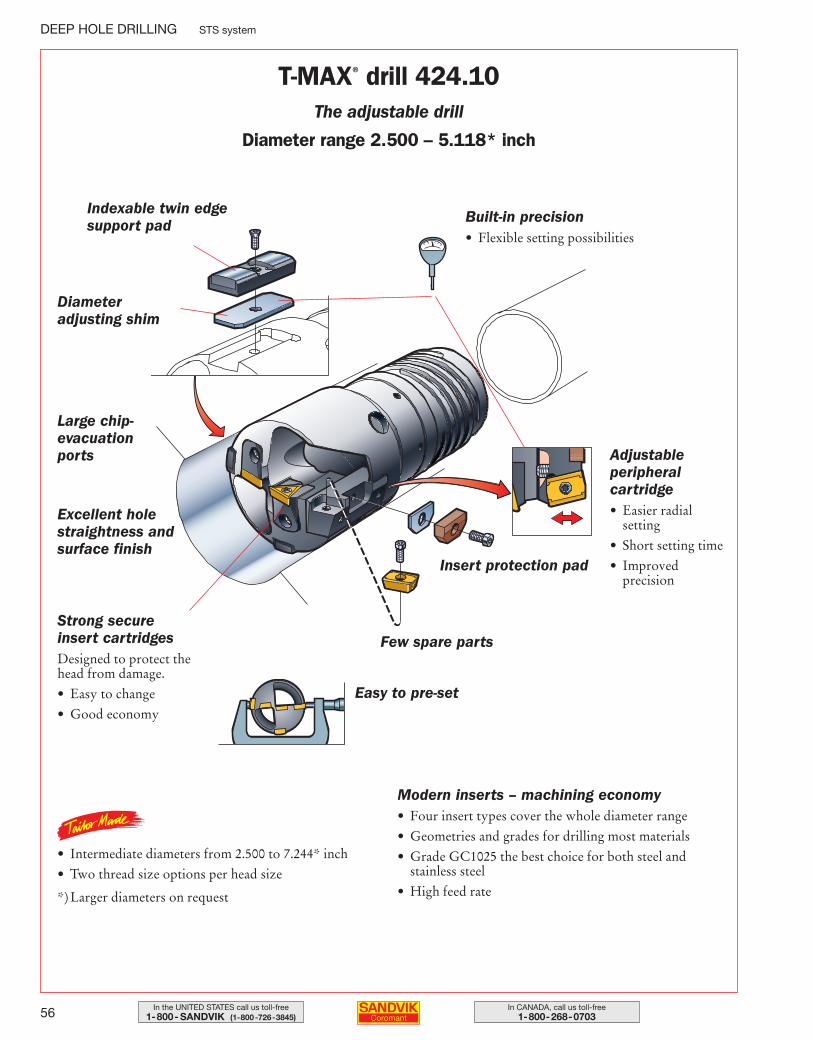
56 In CANADA, call us toll-free1-800-268-0703
In the UNITED STATES call us toll-free1-800- SANDVIK (1-800-726-3845)
DEEP HOLE DRILLING STS system
Indexable twin edge support pad
Diameter adjusting shim
Excellent holestraightness andsurface finish
Strong secure insert cartridgesDesigned to protect thehead from damage.
• Easy to change
• Good economy
• Intermediate diameters from 2.500 to 7.244* inch
• Two thread size options per head size
*) Larger diameters on request
Modern inserts – machining economy• Four insert types cover the whole diameter range
• Geometries and grades for drilling most materials
• Grade GC1025 the best choice for both steel and stainless steel
• High feed rate
Easy to pre-set
Few spare parts
Insert protection pad
Adjustable peripheral cartridge• Easier radial
setting
• Short setting time
• Improved precision
Built-in precision• Flexible setting possibilities
T-MAX® drill 424.10The adjustable drill
Diameter range 2.500 – 5.118* inch
Large chip-evacuationports
044-071 USA 04-04-29 10.00 Sida 56
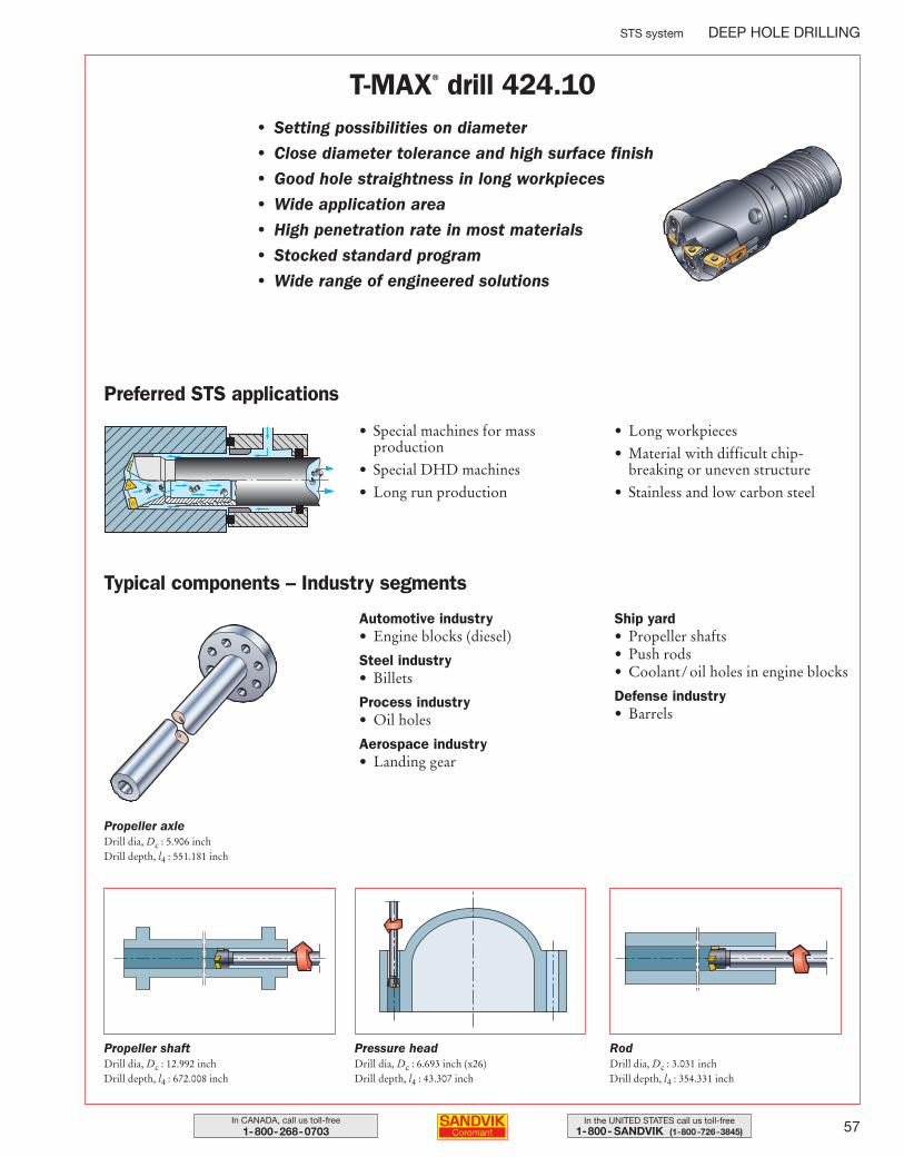
57In the UNITED STATES call us toll-free1-800- SANDVIK (1-800-726-3845)
In CANADA, call us toll-free1-800-268-0703
STS system DEEP HOLE DRILLING
T-MAX® drill 424.10• Setting possibilities on diameter
• Close diameter tolerance and high surface finish
• Good hole straightness in long workpieces
• Wide application area
• High penetration rate in most materials
• Stocked standard program
• Wide range of engineered solutions
Preferred STS applications
Automotive industry• Engine blocks (diesel)
Steel industry• Billets
Process industry• Oil holes
Aerospace industry• Landing gear
Ship yard• Propeller shafts• Push rods• Coolant/ oil holes in engine blocks
Defense industry• Barrels
Typical components – Industry segments
Propeller axleDrill dia, Dc : 5.906 inchDrill depth, l4 : 551.181 inch
Propeller shaftDrill dia, Dc : 12.992 inchDrill depth, l4 : 672.008 inch
Pressure headDrill dia, Dc : 6.693 inch (x26)Drill depth, l4 : 43.307 inch
RodDrill dia, Dc : 3.031 inchDrill depth, l4 : 354.331 inch
• Special machines for massproduction
• Special DHD machines
• Long run production
• Long workpieces
• Material with difficult chip-breaking or uneven structure
• Stainless and low carbon steel
044-071 USA 04-04-29 10.00 Sida 57
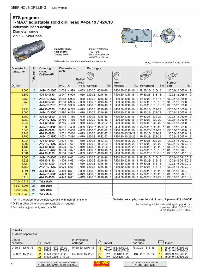
58 In CANADA, call us toll-free1-800-268-0703
In the UNITED STATES call us toll-free1-800- SANDVIK (1-800-726-3845)
DEEP HOLE DRILLING STS system
1) "A" in the ordering code indicates drill with inch dimensions.2) Drills in other dimensions are available on request.3) For radial adjustment, see page 78.
Ordering example, complete drill head: 2 pieces 424.10-0650
For ordering additional cartridge/support pad:2 pieces L430.31-1216-164 pieces 430.32-12 D65.0
STS program – T-MAX® adjustable solid drill head A424.10 / 424.10Indexable insert design Diameter range 2.500 – 7.240 inch
Diameter range: 2.500–7.240 inchHole depth: 100 × Dia.Cutting fluid: Neat oil or soluble
with EP-additives
l2
Dcdmm
dmm is the same as dmt for the drill tube
2.500 13 A424.10-2500 2.008 4.528 +.039 L430.31-1216-16 1 R430.30-1216-16 1 R430.28-1516-16 1 430.32-12 D65.0 2
2.559 14 424.10-0650 2.047 5.906 +.059 L430.31-1216-16 1 R430.30-1216-16 1 R430.28-1516-16 1 430.32-12 D65.0 2
2.750 15 A424.10-2750 2.283 5.906 +.039 L430.31-1216-16 1 R430.30-1216-16 1 R430.28-1516-16 1 430.32-12 D65.0 22.756 424.10-0700 2.283 5.906 +.039 L430.31-1216-16 1 R430.30-1216-16 1 R430.28-1516-16 1 430.32-12 D70.0 22.813 A424.10-2813 2.283 5.906 +.029 L430.31-1216-16 1 R430.30-1216-16 1 R430.28-1516-16 1 430.32-12 D70.0 2
2.953 16 424.10-0750 2.480 6.299 +.079 L430.31-1216-16 1 R430.30-1216-16 1 R430.28-1822-22 1 430.32-12 D75.0 23.000 A424.10-3000 2.480 6.299 +.079 L430.31-1216-16 1 R430.30-1216-16 1 R430.28-1822-22 1 430.32-12 D75.0 2
3.150 17 424.10-0800 2.756 7.480 +.049 L430.31-1216-16 1 R430.30-1216-16 1 R430.28-1822-22 1 430.32-12 D80.0 23.250 A424.10-3250 2.756 7.480 +.029 L430.31-1216-16 1 R430.30-1216-16 1 R430.28-1822-22 1 430.32-12 D80.0 23.346 424.10-0850 2.756 7.480 +.069 L430.31-1522-22 1 R430.30-1216-16 1 R430.28-1822-22 1 430.32-12 D85.0 2
3.500 18 A424.10-3500 3.031 7.480 +.069 L430.31-1522-22 1 R430.30-1216-16 1 R430.28-1822-22 1 430.32-12 D85.0 23.543 424.10-0900 3.031 7.480 +.069 L430.31-1522-22 1 R430.30-1216-16 1 R430.28-1822-22 1 430.32-12 D90.0 23.740 424.10-0950 3.031 7.480 +.079 L430.31-1522-22 1 R430.30-15 22-22 1 R430.28-1822-22 1 430.32-12 D95.0 23.750 A424.10-3750 3.031 7.480 +.079 L430.31-1522-22 1 R430.30-15 22-22 1 R430.28-1822-22 1 430.32-12 D95.0 2
3.937 19 424.10-1000 3.504 7.677 +.039 L430.31-1522-22 1 R430.30-15 22-22 1 R430.28-1822-22 1 430.32-16 D100.0 24.000 A424.10-4000 3.504 7.677 +.049 L430.31-1522-22 1 R430.30-15 22-22 1 R430.28-1822-22 1 430.32-16 D100.0 24.134 424.10-1050 3.504 7.677 +.019 L430.31-1522-22 1 R430.30-15 22-22 1 R430.28-1822-22 1 430.32-16 D105.0 24.250 A424.10-4250 3.504 7.677 +.079 L430.31-1216-16 1 R430.30-1216-16 1 R430.28-1516-16 1 430.32-16 D105.0 24.331 424.10-1100 3.504 7.677 +.059 L430.31-1216-16 1 R430.30-1216-16 1 R430.28-1516-16 1 430.32-16 D110.0 2
4.500 20 A424.10-4500 3.976 8.661 +.069 L430.31-1216-16 1 R430.30-1216-16 3 R430.28-1516-16 1 430.32-16 D110.0 24.528 424.10-1150 3.976 8.661 +.059 L430.31-1216-16 1 R430.30-1216-16 3 R430.28-1516-16 1 430.32-16 D115.0 24.724 424.10-1200 3.976 8.661 +.059 L430.31-1216-16 1 R430.30-1216-16 3 R430.28-1516-16 1 430.32-16 D120.0 24.750 A424.10-4750 3.976 8.661 +.059 L430.31-1216-16 1 R430.30-1216-16 3 R430.28-1516-16 1 430.32-16 D120.0 2
4.921 21 424.10-1250 4.449 8.661 +.069 L430.31-1216-16 1 R430.30-1216-16 3 R430.28-1822-22 1 430.32-16 D125.0 25.000 A424.10-5000 4.449 8.661 +.049 L430.31-1216-16 1 R430.30-1216-16 3 R430.28-1822-22 1 430.32-16 D125.0 25.118 424.10-1300 4.449 8.661 +.019 L430.31-1216-16 1 R430.30-1216-16 3 R430.28-1822-22 1 430.32-16 D130.0 2
5.354-5.823 22
5.827-6.295 23
6.299-6.768 24
6.772-7.240 25
Orderingcode, Drill head1)
Diameter2)
range, inch
Dc inch
Cartridges
CentralInter-mediate Peripheral
Dimensions, inch
Tub
e ra
nge
dmm l2 No.Support padNo.No.No.
Tailor Made
Tailor Made
Tailor Made
Tailor Made
Inserts(Ordered separately)
L430.31-1216-16 16 TPMT 16T312R-22 R430.30-1216-16 16 TPMT 16T312R-22 R430.28-1516-16 13 R424.9-13T308-2216 TPMT 16T312TR-23 16 TPMT 16T312TR-23 13 R424.9-13T308-23
L430.31-1522-22 22 TPMT 220612R-22 R430.30-1522-22 22 TPMT 220612R-22 R430.28-1822-22 18 R424.9-180608-2222 TPMT 220612TR-23 22 TPMT 220612TR-23 18 R424.9-180608-23
Central cartridge
Intermediate cartridge
Peripheral cartridgeInsert Insert Insert
Radial3)
adjust-ment
Drill heads are manufactured to minus tolerance.
044-071 USA 04-04-29 10.00 Sida 58
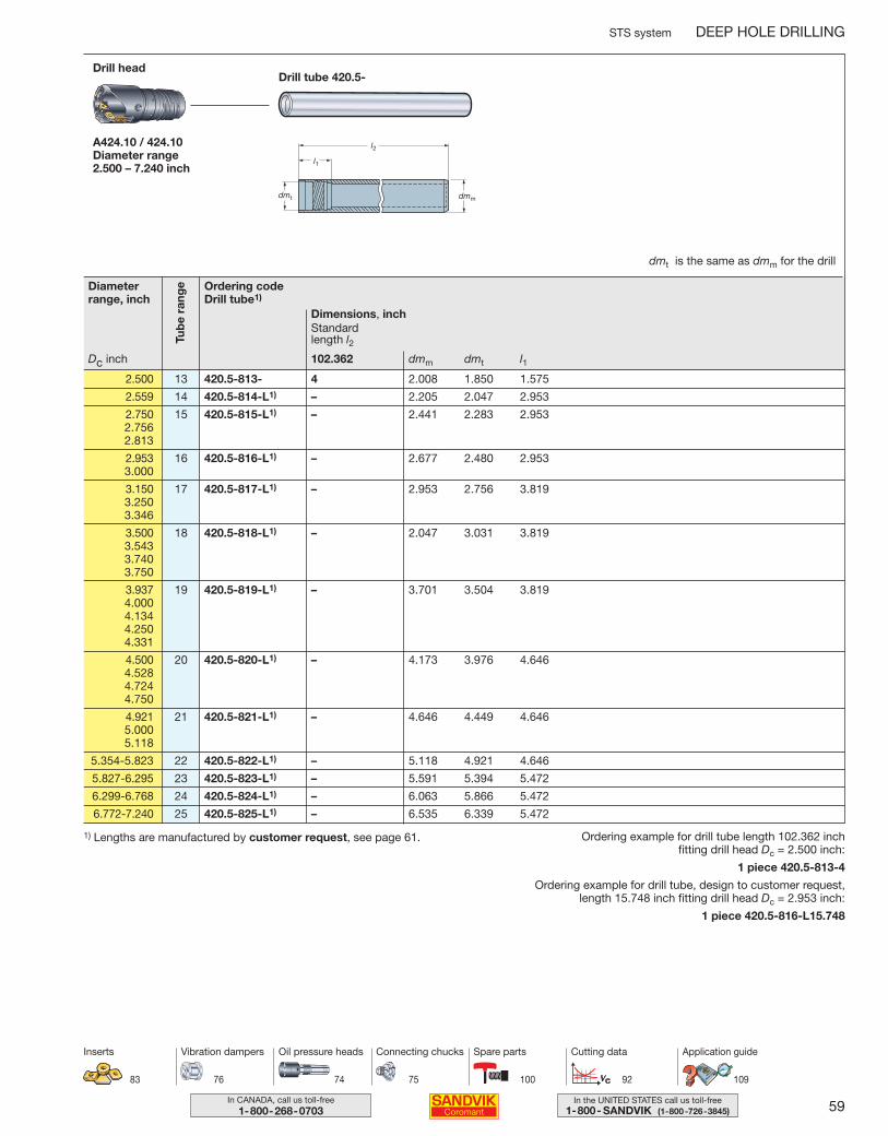
59In the UNITED STATES call us toll-free1-800- SANDVIK (1-800-726-3845)
In CANADA, call us toll-free1-800-268-0703
STS system DEEP HOLE DRILLING
Ordering codeDrill tube1)
Dimensions, inch
dmm dmt l1
Standard length l2
Drill tube 420.5-Drill head
A424.10 / 424.10Diameter range 2.500 – 7.240 inch
2.500 13 420.5-813- 4 2.008 1.850 1.575
2.559 14 420.5-814-L1) – 2.205 2.047 2.953
2.750 15 420.5-815-L1) – 2.441 2.283 2.9532.7562.813
2.953 16 420.5-816-L1) – 2.677 2.480 2.9533.000
3.150 17 420.5-817-L1) – 2.953 2.756 3.8193.2503.346
3.500 18 420.5-818-L1) – 2.047 3.031 3.8193.5433.7403.750
3.937 19 420.5-819-L1) – 3.701 3.504 3.8194.0004.1344.2504.331
4.500 20 420.5-820-L1) – 4.173 3.976 4.6464.5284.7244.750
4.921 21 420.5-821-L1) – 4.646 4.449 4.6465.0005.118
5.354-5.823 22 420.5-822-L1) – 5.118 4.921 4.646
5.827-6.295 23 420.5-823-L1) – 5.591 5.394 5.472
6.299-6.768 24 420.5-824-L1) – 6.063 5.866 5.472
6.772-7.240 25 420.5-825-L1) – 6.535 6.339 5.472
Ordering example for drill tube length 102.362 inch fitting drill head Dc = 2.500 inch:
1 piece 420.5-813-4
Ordering example for drill tube, design to customer request, length 15.748 inch fitting drill head Dc = 2.953 inch:
1 piece 420.5-816-L15.748
1) Lengths are manufactured by customer request, see page 61.
Tub
e ra
ngeDiameter
range, inch
Dc inch
dmt is the same as dmm for the drill
102.362
83
Inserts
74 75 100 92
Oil pressure heads Connecting chucks Spare parts Cutting data
76
Vibration dampers
109
Application guide
044-071 USA 04-04-29 10.00 Sida 59
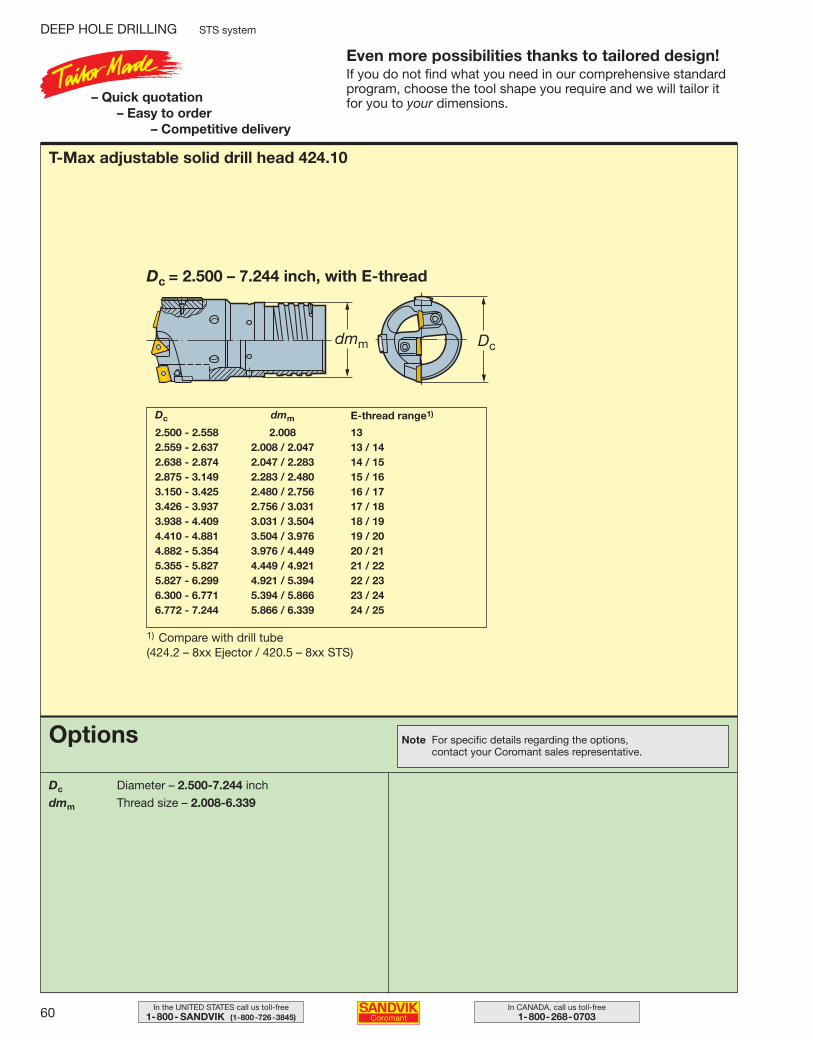
60 In CANADA, call us toll-free1-800-268-0703
In the UNITED STATES call us toll-free1-800- SANDVIK (1-800-726-3845)
DEEP HOLE DRILLING STS system
Even more possibilities thanks to tailored design!If you do not find what you need in our comprehensive standardprogram, choose the tool shape you require and we will tailor itfor you to your dimensions.– Quick quotation
– Easy to order– Competitive delivery
T-Max adjustable solid drill head 424.10
Dc = 2.500 – 7.244 inch, with E-thread
Dc dmm
2.500 - 2.558 2.008 132.559 - 2.637 2.008 / 2.047 13 / 142.638 - 2.874 2.047 / 2.283 14 / 152.875 - 3.149 2.283 / 2.480 15 / 163.150 - 3.425 2.480 / 2.756 16 / 173.426 - 3.937 2.756 / 3.031 17 / 183.938 - 4.409 3.031 / 3.504 18 / 194.410 - 4.881 3.504 / 3.976 19 / 204.882 - 5.354 3.976 / 4.449 20 / 215.355 - 5.827 4.449 / 4.921 21 / 225.827 - 6.299 4.921 / 5.394 22 / 236.300 - 6.771 5.394 / 5.866 23 / 246.772 - 7.244 5.866 / 6.339 24 / 25
1) Compare with drill tube (424.2 – 8xx Ejector / 420.5 – 8xx STS)
E-thread range1)
Options
Dc Diameter – 2.500-7.244 inch
dmm Thread size – 2.008-6.339
Note For specific details regarding the options, contact your Coromant sales representative.
044-071 USA 04-04-29 10.00 Sida 60
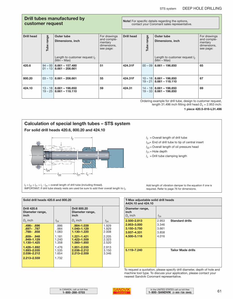
61In the UNITED STATES call us toll-free1-800- SANDVIK (1-800-726-3845)
In CANADA, call us toll-free1-800-268-0703
STS system DEEP HOLE DRILLING
.496– .696 .886
.697– .787 .984
.788– .858 1.083
.859– .948 1.181
.949–1.129 1.2401.130–1.425 1.358
1.426–1.692 1.4761.693–2.035 1.5352.036–2.212 1.654
2.213–2.559 1.732
Dc inch l24
Solid drill heads 420.6 and 800.20
Drill 420.6Diameter range,inch
Drill head
Length to customer request l2(Min – Max)
Tub
e ra
nge
Drill tubes manufactured by customer request
Outer tube
Dimensions, inch
For drawingsand comple-mentarydimensions,see page:
Note! For specific details regarding the options, contact your Coromant sales representative.
Ordering example for drill tube, design to customer request, length 31.496 inch fitting drill head Dc = 2.953 inch:
1 piece 420.5-816-L31.496
420.6 94 – 00 8.661 – 157.480 51 424.31F 00 – 09 8.661 – 196.850 6501 – 13 8.661 – 208.661
800.20 03 – 13 8.661 – 208.661 55 424.31F 10 – 18 8.661 – 196.850 6719 – 21 8.661 – 118.110
424.10 13 – 18 8.661 – 196.850 59 424.31 14 – 18 8.661 – 196.850 6919 – 25 8.661 – 118.110 19 – 33 8.661 – 196.850
Drill head
Length to customer request l2(Min – Max)
Tub
e ra
nge Outer tube
Dimensions, inch
For drawingsand comple-mentarydimensions,see page:
To request a quotation, please specify drill diameter, depth of hole andmachine tool type. To discuss your application, please contact yournearest Sandvik Coromant representative.
l2 = l22 + l21 + lc - l24 = overall length of drill tube (including thread).IMPORTANT: If drill tube steady rests are used be sure to add their overall length to l2.
Add length of vibration damper to the equation if one isrequired. Refer to page 76 for dimensions.
l2 = Overall length of drill tube
l24= End of drill tube to tip of central insert
l22 = Overall length of oil pressure head
l21 = Hole depth
lc = Drill tube clamping length
2.500–2.813 2.9532.953–3.000 3.3463.150–3.750 3.6613.937–4.331 3.8584.500–5.118 4.016
Dc inch l24
T-Max adjustable solid drill heads A424.10 and 424.10
Diameter range,inch
Standard drills
Tailor Made drills
Calculation of special length tubes – STS systemFor solid drill heads 420.6, 800.20 and 424.10
Dc inch l24
Drill 800.20Diameter range,inch
.984–1.039 1.9291.040–1.129 1.9291.130–1.220 2.008
1.221–1.421 2.2051.422–1.559 2.3231.560–1.850 2.520
1.851–2.035 2.9132.036–2.212 3.1502.213–2.559 3.346
5.119–7.240
044-071 USA 04-04-29 10.00 Sida 61
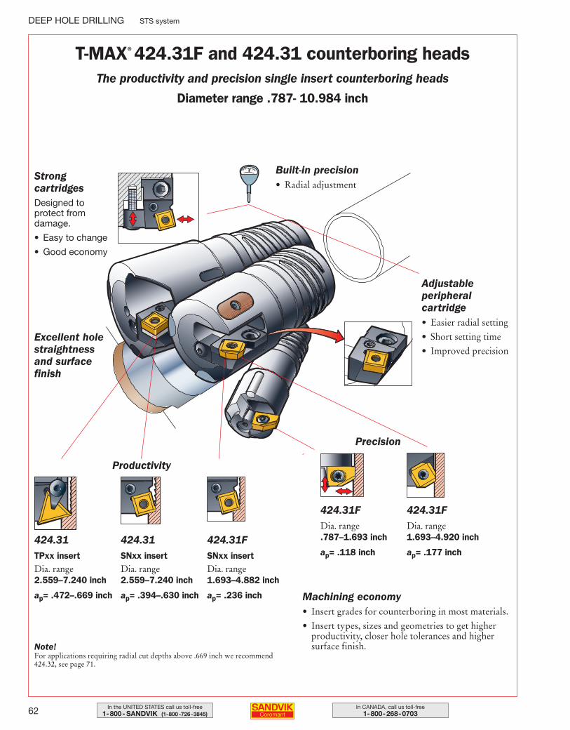
62 In CANADA, call us toll-free1-800-268-0703
In the UNITED STATES call us toll-free1-800- SANDVIK (1-800-726-3845)
DEEP HOLE DRILLING STS system
Adjustable peripheral cartridge• Easier radial setting
• Short setting time
• Improved precision
Built-in precision• Radial adjustment
Machining economy• Insert grades for counterboring in most materials.
• Insert types, sizes and geometries to get higherproductivity, closer hole tolerances and highersurface finish.
Strong cartridgesDesigned to protect from damage.
• Easy to change
• Good economy
424.31TPxx insertDia. range 2.559–7.240 inch
ap= .472–.669 inch
Excellent holestraightnessand surfacefinish
Precision
Productivity
T-MAX® 424.31F and 424.31 counterboring headsThe productivity and precision single insert counterboring heads
Diameter range .787- 10.984 inch
424.31SNxx insertDia. range 2.559–7.240 inch
ap= .394–.630 inch
424.31FSNxx insertDia. range 1.693–4.882 inch
ap= .236 inch
424.31FDia. range .787–1.693 inch
ap= .118 inch
424.31FDia. range 1.693–4.920 inch
ap= .177 inch
Note!For applications requiring radial cut depths above .669 inch we recommend424.32, see page 71.
044-071 USA 04-04-29 10.00 Sida 62
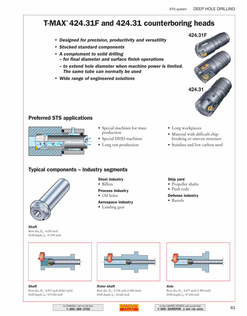
63In the UNITED STATES call us toll-free1-800- SANDVIK (1-800-726-3845)
In CANADA, call us toll-free1-800-268-0703
STS system DEEP HOLE DRILLING
T-MAX® 424.31F and 424.31 counterboring heads
• Designed for precision, productivity and versatility
• Stocked standard components
• A complement to solid drilling– for final diameter and surface finish operations
– to extend hole diameter when machine power is limited.The same tube can normally be used
• Wide range of engineered solutions
• Special machines for massproduction
• Special DHD machines
• Long run production
• Long workpieces
• Material with difficult chip-breaking or uneven structure
• Stainless and low carbon steel
Preferred STS applications
Steel industry• Billets
Process industry• Oil holes
Aerospace industry• Landing gear
Ship yard• Propeller shafts• Push rods
Defense industry• Barrels
Typical components – Industry segments
424.31F
424.31
ShaftBore dia, Dc : 4.035 inchDrill depth, l4 : 47.244 inch
ShaftBore dia, Dc : 8.937 inch (8.661 inch)Drill depth, l4 : 473.425 inch
Rotor shaftBore dia, Dc : 2.756 inch (1.969 inch)Drill depth, l4 : 23.622 inch
AxleBore dia, Dc : 2.677 inch (1.969 inch)Drill depth, l4 : 47.244 inch
044-071 USA 04-04-29 10.00 Sida 63
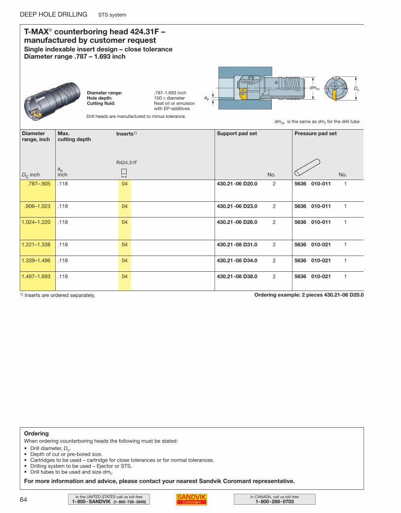
64 In CANADA, call us toll-free1-800-268-0703
In the UNITED STATES call us toll-free1-800- SANDVIK (1-800-726-3845)
DEEP HOLE DRILLING STS system
OrderingWhen ordering counterboring heads the following must be stated:• Drill diameter, Dc.• Depth of cut or pre-bored size.• Cartridges to be used – cartridge for close tolerances or for normal tolerances.• Drilling system to be used – Ejector or STS.• Drill tubes to be used and size dmt.
For more information and advice, please contact your nearest Sandvik Coromant representative.
Ordering example: 2 pieces 430.21-06 D20.01) Inserts are ordered separately.
T-MAX® counterboring head 424.31F – manufactured by customer requestSingle indexable insert design – close toleranceDiameter range .787 – 1.693 inch
Diameter range: .787-1.693 inchHole depth: 150 × diameterCutting fluid: Neat oil or emulsion
with EP-additives
dmm is the same as dmt for the drill tube
Diameterrange, inch
Support pad set Pressure pad set
.787–.905 .118 04 430.21-06 D20.0 2 5636 010-011 1
.906–1.023 .118 04 430.21-06 D23.0 2 5636 010-011 1
1.024–1.220 .118 04 430.21-06 D26.0 2 5636 010-011 1
1.221–1.338 .118 04 430.21-08 D31.0 2 5636 010-021 1
1.339–1.496 .118 04 430.21-08 D34.0 2 5636 010-021 1
1.497–1.693 .118 04 430.21-08 D38.0 2 5636 010-021 1
No.No.
Max. cutting depth
apinch
Inserts1)
R424.31F
Dc inch
Drill heads are manufactured to minus tolerance.
044-071 USA 04-04-29 10.00 Sida 64
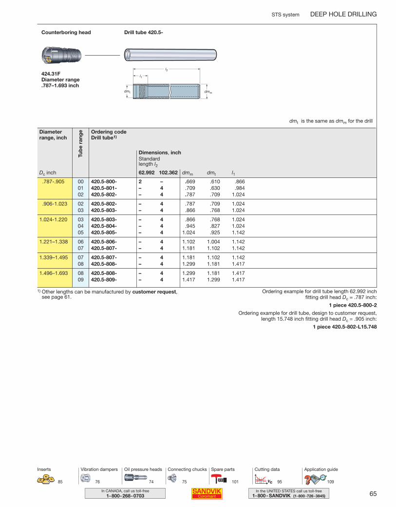
65In the UNITED STATES call us toll-free1-800- SANDVIK (1-800-726-3845)
In CANADA, call us toll-free1-800-268-0703
STS system DEEP HOLE DRILLING
Ordering codeDrill tube1)
Dimensions, inch
dmm dmt l162.992 102.362
Standard length l2
Drill tube 420.5-Counterboring head
424.31FDiameter range .787–1.693 inch
dmt is the same as dmm for the drill
.787-.905 00 420.5-800- 2 – .669 .610 .86601 420.5-801- – 4 .709 .630 .98402 420.5-802- – 4 .787 .709 1.024
.906-1.023 02 420.5-802- – 4 .787 .709 1.02403 420.5-803- – 4 .866 .768 1.024
1.024-1.220 03 420.5-803- – 4 .866 .768 1.02404 420.5-804- – 4 .945 .827 1.02405 420.5-805- – 4 1.024 .925 1.142
1.221–1.338 06 420.5-806- – 4 1.102 1.004 1.14207 420.5-807- – 4 1.181 1.102 1.142
1.339–1.495 07 420.5-807- – 4 1.181 1.102 1.14208 420.5-808- – 4 1.299 1.181 1.417
1.496–1.693 08 420.5-808- – 4 1.299 1.181 1.41709 420.5-809- – 4 1.417 1.299 1.417
Ordering example for drill tube length 62.992 inch fitting drill head Dc = .787 inch:
1 piece 420.5-800-2
Ordering example for drill tube, design to customer request, length 15.748 inch fitting drill head Dc = .905 inch:
1 piece 420.5-802-L15.748
1) Other lengths can be manufactured by customer request, see page 61.
Tub
e ra
ngeDiameter
range, inch
Dc inch
85
Inserts
74 75 101 95
Oil pressure heads Connecting chucks Spare parts Cutting data
76
Vibration dampers
109
Application guide
044-071 USA 04-04-29 10.00 Sida 65
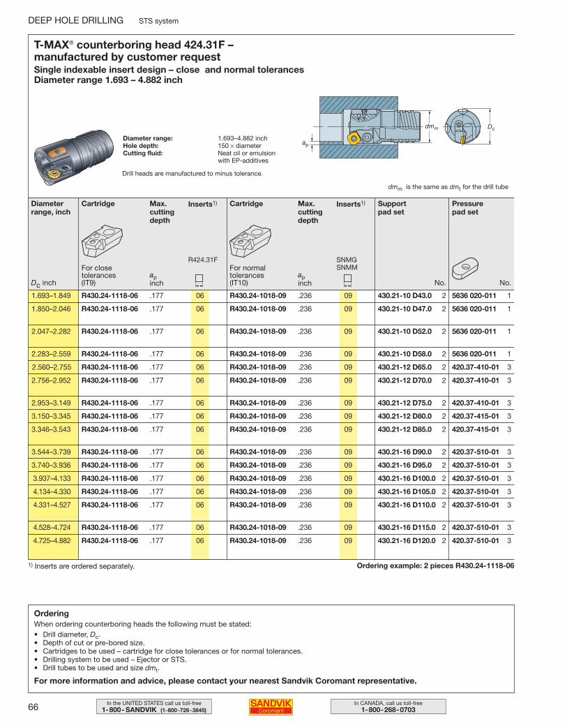
66 In CANADA, call us toll-free1-800-268-0703
In the UNITED STATES call us toll-free1-800- SANDVIK (1-800-726-3845)
DEEP HOLE DRILLING STS system
Ordering example: 2 pieces R430.24-1118-061) Inserts are ordered separately.
T-MAX® counterboring head 424.31F – manufactured by customer requestSingle indexable insert design – close and normal tolerancesDiameter range 1.693 – 4.882 inch
Diameter range: 1.693–4.882 inchHole depth: 150 × diameterCutting fluid: Neat oil or emulsion
with EP-additives
dmm is the same as dmt for the drill tube
Diameterrange, inch
Cartridge
For normaltolerances (IT10)
Max.cuttingdepth
apinch
Inserts1)
SNMGSNMM
Support pad set
Pressure pad set
1.693–1.849 R430.24-1118-06 .177 06 R430.24-1018-09 .236 09 430.21-10 D43.0 2 5636 020-011 1
1.850–2.046 R430.24-1118-06 .177 06 R430.24-1018-09 .236 09 430.21-10 D47.0 2 5636 020-011 1
2.047–2.282 R430.24-1118-06 .177 06 R430.24-1018-09 .236 09 430.21-10 D52.0 2 5636 020-011 1
2.283–2.559 R430.24-1118-06 .177 06 R430.24-1018-09 .236 09 430.21-10 D58.0 2 5636 020-011 1
2.560–2.755 R430.24-1118-06 .177 06 R430.24-1018-09 .236 09 430.21-12 D65.0 2 420.37-410-01 3
2.756–2.952 R430.24-1118-06 .177 06 R430.24-1018-09 .236 09 430.21-12 D70.0 2 420.37-410-01 3
2.953–3.149 R430.24-1118-06 .177 06 R430.24-1018-09 .236 09 430.21-12 D75.0 2 420.37-410-01 3
3.150–3.345 R430.24-1118-06 .177 06 R430.24-1018-09 .236 09 430.21-12 D80.0 2 420.37-415-01 3
3.346–3.543 R430.24-1118-06 .177 06 R430.24-1018-09 .236 09 430.21-12 D85.0 2 420.37-415-01 3
3.544–3.739 R430.24-1118-06 .177 06 R430.24-1018-09 .236 09 430.21-16 D90.0 2 420.37-510-01 3
3.740–3.936 R430.24-1118-06 .177 06 R430.24-1018-09 .236 09 430.21-16 D95.0 2 420.37-510-01 3
3.937–4.133 R430.24-1118-06 .177 06 R430.24-1018-09 .236 09 430.21-16 D100.0 2 420.37-510-01 3
4.134–4.330 R430.24-1118-06 .177 06 R430.24-1018-09 .236 09 430.21-16 D105.0 2 420.37-510-01 3
4.331–4.527 R430.24-1118-06 .177 06 R430.24-1018-09 .236 09 430.21-16 D110.0 2 420.37-510-01 3
4.528–4.724 R430.24-1118-06 .177 06 R430.24-1018-09 .236 09 430.21-16 D115.0 2 420.37-510-01 3
4.725–4.882 R430.24-1118-06 .177 06 R430.24-1018-09 .236 09 430.21-16 D120.0 2 420.37-510-01 3
No.No.
Cartridge
For closetolerances (IT9)
Max.cuttingdepth
apinch
Inserts1)
R424.31F
Dc inch
OrderingWhen ordering counterboring heads the following must be stated:• Drill diameter, Dc.• Depth of cut or pre-bored size.• Cartridges to be used – cartridge for close tolerances or for normal tolerances.• Drilling system to be used – Ejector or STS.• Drill tubes to be used and size dmt.
For more information and advice, please contact your nearest Sandvik Coromant representative.
Drill heads are manufactured to minus tolerance.
044-071 USA 04-04-29 10.00 Sida 66
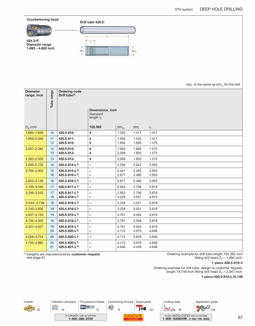
67In the UNITED STATES call us toll-free1-800- SANDVIK (1-800-726-3845)
In CANADA, call us toll-free1-800-268-0703
STS system DEEP HOLE DRILLING
Ordering codeDrill tube1)
Dimensions, inch
dmm dmt l1102.362
Standard length l2
Drill tube 420.5-Counterboring head
424.31FDiameter range 1.693 – 4.882 inch
1.693–1.849 10 420.5-810- 4 1.535 1.417 1.417
1.850–2.046 11 420.5-811- 4 1.693 1.535 1.41712 420.5-812- 4 1.850 1.693 1.575
2.047–2.282 12 420.5-812- 4 1.850 1.693 1.575 13 420.5-813- 4 2,008 1.850 1.575
2.283–2.559 13 420.5-813- 4 2,008 1.850 1.575
2.560–2.755 14 420.5-814-L1) – 2.205 2.047 2.953
2.756–2.952 15 420.5-815-L1) – 2.441 2.283 2.95316 420.5-816-L1) – 2.677 2.480 2.953
2.953–3.149 16 420.5-816-L1) – 2.677 2.480 2.953
3.150–3.345 17 420.5-817-L1) – 2.953 2.756 3.819
3.346–3.543 17 420.5-817-L1) – 2.953 2.756 3.81918 420.5-818-L1) – 3.228 3.031 3.819
3.544– 3.739 18 420.5-818-L1) – 3.228 3.031 3.819
3.740–3.936 18 420.5-818-L1) – 3.228 3.031 3.819
3.937–4.133 19 420.5-819-L1) – 3.701 3.504 3.819
4.134–4.330 19 420.5-819-L1) – 3.701 3.504 3.819
4.331–4.527 19 420.5-819-L1) – 3.701 3.504 3.81920 420.5-820-L1) – 4.173 3.976 4.646
4.528–4.724 20 420.5-820-L1) – 4.173 3.976 4.646
4.725–4.882 20 420.5-820-L1) – 4.173 3.976 4.64621 420.5-821-L1) – 4.646 4.449 4.646
Tub
e ra
ngeDiameter
range, inch
Dc inch
Ordering example for drill tube length 102.362 inch fitting drill head Dc = 1.694 inch:
1 piece 420.5-810-4
Ordering example for drill tube, design to customer request, length 15.748 inch fitting drill head Dc = 2.047 inch:
1 piece 420.5-812-L15.748
1) Lengths are manufactured by customer request, see page 61.
dmt is the same as dmm for the drill
85
Inserts
74 75 101 95
Oil pressure heads Connecting chucks Spare parts Cutting data
76
Vibration dampers
109
Application guide
044-071 USA 04-04-29 10.00 Sida 67
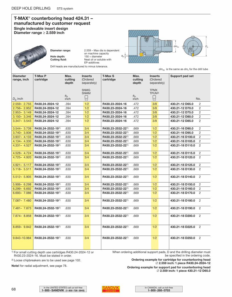
68 In CANADA, call us toll-free1-800-268-0703
In the UNITED STATES call us toll-free1-800- SANDVIK (1-800-726-3845)
DEEP HOLE DRILLING STS system
T-MAX® counterboring head 424.31 – manufactured by customer requestSingle indexable insert designDiameter range ≥ 2.559 inch
Diameter range: 2.559 – Max dia is dependenton machine capacity
Hole depth: 150 × diameterCutting fluid: Neat oil or soluble with
EP-additives
dmm is the same as dmt for the drill tube
Diameterrange, inch
T-Max S cartridge
Max.cuttingdepth
apinch
Inserts(Orderedseparately)
TPMXTPUN2)
Support pad set
2.559– 2.755 R430.24-2024-12 .394 1/2 R430.23-2024-16 .472 3/8 430.21-12 D65.0 22.756– 2.952 R430.24-2024-12 .394 1/2 R430.23-2024-16 .472 3/8 430.21-12 D70.0 22.953– 3.149 R430.24-2024-12 .394 1/2 R430.23-2024-16 .472 3/8 430.21-12 D75.0 23.150– 3.346 R430.24-2024-12 .394 1/2 R430.23-2024-16 .472 3/8 430.21-12 D80.0 23.347– 3.543 R430.24-2024-12 .394 1/2 R430.23-2024-16 .472 3/8 430.21-12 D85.0 2
3.544– 3.739 R430.24-2532-191) .630 3/4 R430.23-2532-221) .669 1/2 430.21-16 D90.0 23.740– 3.936 R430.24-2532-191) .630 3/4 R430.23-2532-221) .669 1/2 430.21-16 D95.0 23.937– 4.133 R430.24-2532-191) .630 3/4 R430.23-2532-221) .669 1/2 430.21-16 D100.0 24.134– 4.330 R430.24-2532-191) .630 3/4 R430.23-2532-221) .669 1/2 430.21-16 D105.0 24.331– 4.527 R430.24-2532-191) .630 3/4 R430.23-2532-221) .669 1/2 430.21-18 D110.0 2
4.528– 4.724 R430.24-2532-191) .630 3/4 R430.23-2532-221) .669 1/2 430.21-18 D115.0 24.725– 4.920 R430.24-2532-191) .630 3/4 R430.23-2532-221) .669 1/2 430.21-18 D120.0 2
4.921– 5.117 R430.24-2532-191) .630 3/4 R430.23-2532-221) .669 1/2 430.21-18 D125.0 25.118– 5.511 R430.24-2532-191) .630 3/4 R430.23-2532-221) .669 1/2 430.21-18 D130.0 2
5.512– 5.905 R430.24-2532-191) .630 3/4 R430.23-2532-221) .669 1/2 430.21-18 D140.0 2
5.906– 6.298 R430.24-2532-191) .630 3/4 R430.23-2532-221) .669 1/2 430.21-18 D150.0 26.299– 6.692 R430.24-2532-191) .630 3/4 R430.23-2532-221) .669 1/2 430.21-18 D160.0 26.693– 7.086 R430.24-2532-191) .630 3/4 R430.23-2532-221) .669 1/2 430.21-18 D170.0 2
7.087– 7.480 R430.24-2532-191) .630 3/4 R430.23-2532-221) .669 1/2 430.21-18 D180.0 2
7.481– 7.873 R430.24-2532-191) .630 3/4 R430.23-2532-221) .669 1/2 430.21-18 D190.0 2
7.874– 8.858 R430.24-2532-191) .630 3/4 R430.23-2532-221) .669 1/2 430.21-18 D200.0 2
8.859– 9.842 R430.24-2532-191) .630 3/4 R430.23-2532-221) .669 1/2 430.21-18 D225.0 2
9.843–10.984 R430.24-2532-191) .630 3/4 R430.23-2532-221) .669 1/2 430.21-18 D250.0 2
No.
T-Max P cartridge
Max.cuttingdepth
apinch
Inserts(Orderedseparately)
SNMGSNMM
Dc inch
When ordering additional support pads, D and the drilling diameter mustbe specified in the ordering code.
Ordering example for cartridge for counterboring head ∅ 2.559 inch: 1 piece R430.24-2024-12
Ordering example for support pad for counterboring head ∅ 2.559 inch: 1 piece 430.21-12 D65.0
1) For small cutting depth use cartridges R430.24-2024-12 or R430.23-2024-16. Must be stated in order.
2) Loose chipbreakers are to be used see page 102.
Note! for radial adjustment, see page 78.
Drill heads are manufactured to minus tolerance.
044-071 USA 04-04-29 10.00 Sida 68
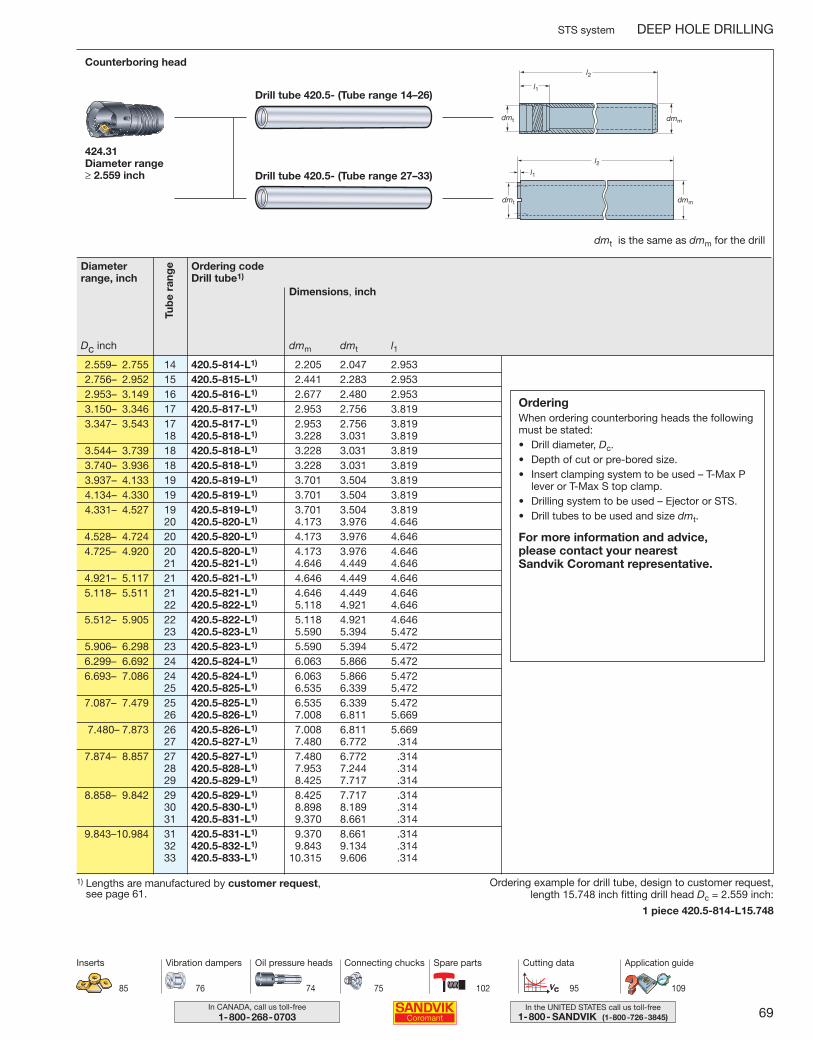
69In the UNITED STATES call us toll-free1-800- SANDVIK (1-800-726-3845)
In CANADA, call us toll-free1-800-268-0703
STS system DEEP HOLE DRILLING
Dimensions, inch
dmm dmt l1
Counterboring head
424.31Diameter range ≥ 2.559 inch
2.559– 2.755 14 420.5-814-L1) 2.205 2.047 2.9532.756– 2.952 15 420.5-815-L1) 2.441 2.283 2.9532.953– 3.149 16 420.5-816-L1) 2.677 2.480 2.9533.150– 3.346 17 420.5-817-L1) 2.953 2.756 3.8193.347– 3.543 17 420.5-817-L1) 2.953 2.756 3.819
18 420.5-818-L1) 3.228 3.031 3.8193.544– 3.739 18 420.5-818-L1) 3.228 3.031 3.8193.740– 3.936 18 420.5-818-L1) 3.228 3.031 3.8193.937– 4.133 19 420.5-819-L1) 3.701 3.504 3.8194.134– 4.330 19 420.5-819-L1) 3.701 3.504 3.8194.331– 4.527 19 420.5-819-L1) 3.701 3.504 3.819
20 420.5-820-L1) 4.173 3.976 4.6464.528– 4.724 20 420.5-820-L1) 4.173 3.976 4.6464.725– 4.920 20 420.5-820-L1) 4.173 3.976 4.646
21 420.5-821-L1) 4.646 4.449 4.6464.921– 5.117 21 420.5-821-L1) 4.646 4.449 4.6465.118– 5.511 21 420.5-821-L1) 4.646 4.449 4.646
22 420.5-822-L1) 5.118 4.921 4.6465.512– 5.905 22 420.5-822-L1) 5.118 4.921 4.646
23 420.5-823-L1) 5.590 5.394 5.4725.906– 6.298 23 420.5-823-L1) 5.590 5.394 5.4726.299– 6.692 24 420.5-824-L1) 6.063 5.866 5.4726.693– 7.086 24 420.5-824-L1) 6.063 5.866 5.472
25 420.5-825-L1) 6.535 6.339 5.4727.087– 7.479 25 420.5-825-L1) 6.535 6.339 5.472
26 420.5-826-L1) 7.008 6.811 5.6697.480– 7.873 26 420.5-826-L1) 7.008 6.811 5.669
27 420.5-827-L1) 7.480 6.772 .3147.874– 8.857 27 420.5-827-L1) 7.480 6.772 .314
28 420.5-828-L1) 7.953 7.244 .31429 420.5-829-L1) 8.425 7.717 .314
8.858– 9.842 29 420.5-829-L1) 8.425 7.717 .31430 420.5-830-L1) 8.898 8.189 .31431 420.5-831-L1) 9.370 8.661 .314
9.843–10.984 31 420.5-831-L1) 9.370 8.661 .31432 420.5-832-L1) 9.843 9.134 .31433 420.5-833-L1) 10.315 9.606 .314
Tub
e ra
ngeDiameter
range, inch
Dc inch
dmt is the same as dmm for the drill
Ordering codeDrill tube1)
85
Inserts
74 75 102 95
Oil pressure heads Connecting chucks Spare parts Cutting data
76
Vibration dampers
1) Lengths are manufactured by customer request, see page 61.
Ordering example for drill tube, design to customer request, length 15.748 inch fitting drill head Dc = 2.559 inch:
1 piece 420.5-814-L15.748
OrderingWhen ordering counterboring heads the followingmust be stated:• Drill diameter, Dc.• Depth of cut or pre-bored size.• Insert clamping system to be used – T-Max P
lever or T-Max S top clamp.• Drilling system to be used – Ejector or STS.• Drill tubes to be used and size dmt.
For more information and advice, please contact your nearest Sandvik Coromant representative.
Drill tube 420.5- (Tube range 27–33)
Drill tube 420.5- (Tube range 14–26)
109
Application guide
044-071 USA 04-04-29 10.00 Sida 69

70 In CANADA, call us toll-free1-800-268-0703
In the UNITED STATES call us toll-free1-800- SANDVIK (1-800-726-3845)
DEEP HOLE DRILLING STS system
T-MAX® trepanning head 420.7 – manufactured by customer requestIndexable insert design Diameter range 4.407 – 9.843 inch
Diameter range: 4.407–9.843 inchHole depth: 150 × Dia.Cutting fluid: Neat oil or soluble
dmm is the same as dmt for the drill tube
4.407–4.724 L430.27-1216-16 3 R430.28-1516-16 1 2 1.722
4.725–4.920 L430.27-1216-16 3 R430.28-1516-16 1 430.21-18D120.0 2 1.722
4.921–5.117 L430.27-1216-16 3 R430.28-1516-16 1 430.21-18D125.0 2 1.722
5.118–5.511 L430.27-1216-16 3 R430.28-1516-16 1 430.21-18D130.0 2 1.722
5.512–5.905 L430.27-1216-16 3 R430.28-1516-16 1 430.21-18D140.0 2 1.722
5.906–6.298 L430.27-1216-16 3 R430.28-1516-16 1 430.21-18D150.0 2 1.722
6.299–7.086 L430.27-1216-16 3 R430.28-1516-16 1 430.21-18D160.0 2 1.722
7.087–7.873 L430.27-1216-16 3 R430.28-1516-16 1 430.21-18D180.0 2 1.722
7.874–8.857 L430.27-1216-16 4 R430.28-1516-16 1 430.21-18D200.0 2 2.116
8.858–9.842 L430.27-1216-16 4 R430.28-1516-16 1 430.21-18D225.0 2 2.116
9.843 L430.27-1216-16 4 R430.28-1516-16 1 430.21-18D250.0 2 2.116
Diameter range, inch
Dc inch
Cartridges
Central Peripheral No.Support padNo.No.
OrderingWhen ordering trepanning heads the following must be stated:• Drill diameter, Dc.
For more information and advice, please contact your nearest Sandvik Coromant representative.
83, 85
Inserts
74 75 103 97
Oil pressure heads Connecting chucks Spare parts Cutting data
76
Vibration dampers
Inserts(Ordered separately)
L430.27-1216-16 16 TPMT 16T312R-22 R430.28-1516-16 13 R424.9-13T308-2216 TPMT 16T312TR-23 13 R424.9-13T308-23
Central cartridge
Peripheral cartridgeInsert Insert
(on request)
Note! for radial adjustment, see page 78.
109
Application guide
Drill heads are manufactured to minus tolerance.
apinch
044-071 USA 04-04-29 10.00 Sida 70
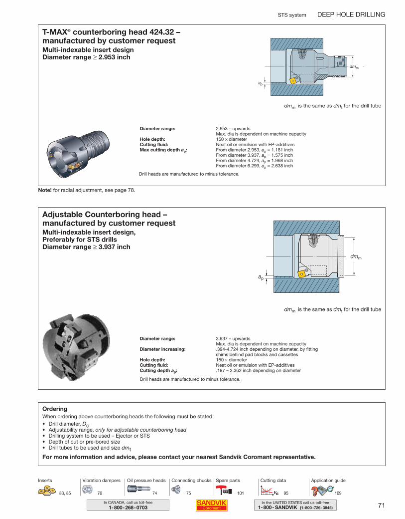
71In the UNITED STATES call us toll-free1-800- SANDVIK (1-800-726-3845)
In CANADA, call us toll-free1-800-268-0703
STS system DEEP HOLE DRILLING
T-MAX® counterboring head 424.32 – manufactured by customer requestMulti-indexable insert design Diameter range ≥ 2.953 inch
Diameter range: 2.953 – upwardsMax. dia is dependent on machine capacity
Hole depth: 150 × diameterCutting fluid: Neat oil or emulsion with EP-additivesMax cutting depth ap: From diameter 2.953, ap = 1.181 inch
From diameter 3.937, ap = 1.575 inchFrom diameter 4.724, ap = 1.968 inchFrom diameter 6.299, ap = 2.638 inch
Adjustable Counterboring head – manufactured by customer requestMulti-indexable insert design, Preferably for STS drills Diameter range ≥ 3.937 inch
Diameter range: 3.937 – upwardsMax. dia is dependent on machine capacity
Diameter increasing: .394-4.724 inch depending on diameter, by fittingshims behind pad blocks and cassettes
Hole depth: 150 × diameterCutting fluid: Neat oil or emulsion with EP-additivesCutting depth ap: .197 – 2.362 inch depending on diameter
dmm is the same as dmt for the drill tube
OrderingWhen ordering above counterboring heads the following must be stated:• Drill diameter, Dc• Adjustability range, only for adjustable counterboring head• Drilling system to be used – Ejector or STS• Depth of cut or pre-bored size• Drill tubes to be used and size dmtFor more information and advice, please contact your nearest Sandvik Coromant representative.
dmm is the same as dmt for the drill tube
83, 85
Inserts
74 75 101 95
Oil pressure heads Connecting chucks Spare parts Cutting data
76
Vibration dampers
dmm
Note! for radial adjustment, see page 78.
109
Application guide
Drill heads are manufactured to minus tolerance.
Drill heads are manufactured to minus tolerance.
044-071 USA 04-04-29 10.00 Sida 71
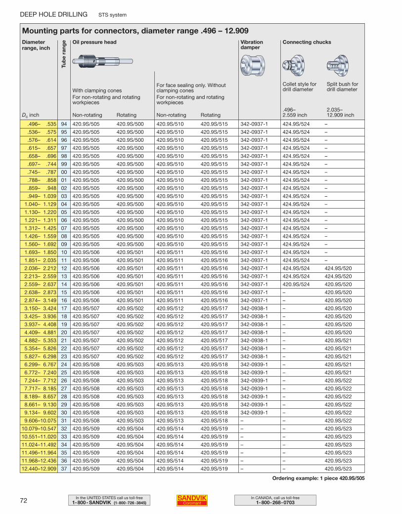
72 In CANADA, call us toll-free1-800-268-0703
In the UNITED STATES call us toll-free1-800- SANDVIK (1-800-726-3845)
DEEP HOLE DRILLING STS system
Diameterrange, inch
Oil pressure head
Mounting parts for connectors, diameter range .496 – 12.909
.496– .535 94 420.9S/505 420.9S/500 420.9S/510 420.9S/515 342-0937-1 424.9S/524 –
.536– .575 95 420.9S/505 420.9S/500 420.9S/510 420.9S/515 342-0937-1 424.9S/524 –
.576– .614 96 420.9S/505 420.9S/500 420.9S/510 420.9S/515 342-0937-1 424.9S/524 –
.615– .657 97 420.9S/505 420.9S/500 420.9S/510 420.9S/515 342-0937-1 424.9S/524 –
.658– .696 98 420.9S/505 420.9S/500 420.9S/510 420.9S/515 342-0937-1 424.9S/524 –
.697– .744 99 420.9S/505 420.9S/500 420.9S/510 420.9S/515 342-0937-1 424.9S/524 –
.745– .787 00 420.9S/505 420.9S/500 420.9S/510 420.9S/515 342-0937-1 424.9S/524 –
.788– .858 01 420.9S/505 420.9S/500 420.9S/510 420.9S/515 342-0937-1 424.9S/524 –
.859– .948 02 420.9S/505 420.9S/500 420.9S/510 420.9S/515 342-0937-1 424.9S/524 –
.949– 1.039 03 420.9S/505 420.9S/500 420.9S/510 420.9S/515 342-0937-1 424.9S/524 –
1.040– 1.129 04 420.9S/505 420.9S/500 420.9S/510 420.9S/515 342-0937-1 424.9S/524 –
1.130– 1.220 05 420.9S/505 420.9S/500 420.9S/510 420.9S/515 342-0937-1 424.9S/524 –
1.221– 1.311 06 420.9S/505 420.9S/500 420.9S/510 420.9S/515 342-0937-1 424.9S/524 –
1.312– 1.425 07 420.9S/505 420.9S/500 420.9S/510 420.9S/515 342-0937-1 424.9S/524 –
1.426– 1.559 08 420.9S/505 420.9S/500 420.9S/510 420.9S/515 342-0937-1 424.9S/524 –
1.560– 1.692 09 420.9S/505 420.9S/500 420.9S/510 420.9S/515 342-0937-1 424.9S/524 –
1.693– 1.850 10 420.9S/506 420.9S/501 420.9S/511 420.9S/516 342-0937-1 424.9S/524 –
1.851– 2.035 11 420.9S/506 420.9S/501 420.9S/511 420.9S/516 342-0937-1 424.9S/524 –
2.036– 2.212 12 420.9S/506 420.9S/501 420.9S/511 420.9S/516 342-0937-1 424.9S/524 424.9S/520
2.213– 2.559 13 420.9S/506 420.9S/501 420.9S/511 420.9S/516 342-0937-1 424.9S/524 424.9S/520
2.559– 2.637 14 420.9S/506 420.9S/501 420.9S/511 420.9S/516 342-0937-1 420.9S/524 420.9S/520
2.638– 2.873 15 420.9S/506 420.9S/501 420.9S/511 420.9S/516 342-0937-1 – 420.9S/520
2.874– 3.149 16 420.9S/506 420.9S/501 420.9S/511 420.9S/516 342-0937-1 – 420.9S/520
3.150– 3.424 17 420.9S/507 420.9S/502 420.9S/512 420.9S/517 342-0938-1 – 420.9S/520
3.425– 3.936 18 420.9S/507 420.9S/502 420.9S/512 420.9S/517 342-0938-1 – 420.9S/520
3.937– 4.408 19 420.9S/507 420.9S/502 420.9S/512 420.9S/517 342-0938-1 – 420.9S/520
4.409– 4.881 20 420.9S/507 420.9S/502 420.9S/512 420.9S/517 342-0938-1 – 420.9S/520
4.882– 5.353 21 420.9S/507 420.9S/502 420.9S/512 420.9S/517 342-0938-1 – 420.9S/521
5.354– 5.826 22 420.9S/507 420.9S/502 420.9S/512 420.9S/517 342-0938-1 – 420.9S/521
5.827– 6.298 23 420.9S/507 420.9S/502 420.9S/512 420.9S/517 342-0938-1 – 420.9S/521
6.299– 6.767 24 420.9S/508 420.9S/503 420.9S/513 420.9S/518 342-0939-1 – 420.9S/521
6.772– 7.240 25 420.9S/508 420.9S/503 420.9S/513 420.9S/518 342-0939-1 – 420.9S/521
7.244– 7.712 26 420.9S/508 420.9S/503 420.9S/513 420.9S/518 342-0939-1 – 420.9S/522
7.717– 8.185 27 420.9S/508 420.9S/503 420.9S/513 420.9S/518 342-0939-1 – 420.9S/522
8.189– 8.657 28 420.9S/508 420.9S/503 420.9S/513 420.9S/518 342-0939-1 – 420.9S/522
8.661– 9.130 29 420.9S/508 420.9S/503 420.9S/513 420.9S/518 342-0939-1 – 420.9S/522
9.134– 9.602 30 420.9S/508 420.9S/503 420.9S/513 420.9S/518 342-0939-1 – 420.9S/522
9.606–10.075 31 420.9S/508 420.9S/503 420.9S/513 420.9S/518 – – 420.9S/522
10.079–10.547 32 420.9S/509 420.9S/504 420.9S/514 420.9S/519 – – 420.9S/523
10.551–11.020 33 420.9S/509 420.9S/504 420.9S/514 420.9S/519 – – 420.9S/523
11.024–11.492 34 420.9S/509 420.9S/504 420.9S/514 420.9S/519 – – 420.9S/523
11.496–11.964 35 420.9S/509 420.9S/504 420.9S/514 420.9S/519 – – 420.9S/523
11.968–12.436 36 420.9S/509 420.9S/504 420.9S/514 420.9S/519 – – 420.9S/523
12.440–12.909 37 420.9S/509 420.9S/504 420.9S/514 420.9S/519 – – 420.9S/523
Tub
e ra
nge
Dc inch
Ordering example: 1 piece 420.9S/505
With clamping conesFor non-rotating and rotatingworkpieces
Non-rotating Rotating
For face sealing only. Withoutclamping conesFor non-rotating and rotatingworkpieces
Non-rotating Rotating
Vibrationdamper
Collet style fordrill diameter
.496–2.559 inch
2.035–12.909 inch
Split bush fordrill diameter
Connecting chucks
072-078 USA 04-04-29 10.05 Sida 72
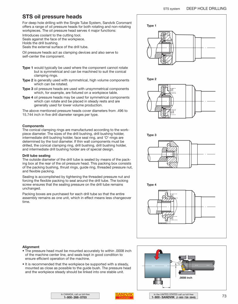
73In the UNITED STATES call us toll-free1-800- SANDVIK (1-800-726-3845)
In CANADA, call us toll-free1-800-268-0703
STS system DEEP HOLE DRILLING
STS oil pressure headsFor deep hole drilling with the Single Tube System, Sandvik Coromantoffers a range of oil pressure heads for both rotating and non-rotatingworkpieces. The oil pressure head serves 4 major functions:Introduces coolant to the cutting tool.Seals against the face of the workpiece.Holds the drill bushing.Seals the external surface of the drill tube.
Oil pressure heads act as clamping devices and also serve to self-center the component.
Type 1 would typically be used where the component cannot rotatebut is symmetrical and can be machined to suit the conicalclamping rings.
Type 2 is generally used with symmetrical, high volume componentswhich can be rotated.
Type 3 oil pressure heads are used with unsymmetrical componentswhich, for example, are fixtured on a workpiece table.
Type 4 oil pressure heads may be used for symmetrical componentswhich can rotate and be placed in steady rests and aregenerally used for lower volume production.
The above mentioned pressure heads cover diameters from .496 to15.744 inch in five drill diameter ranges per type.
ComponentsThe conical clamping rings are manufactured according to the work-piece diameter. The sizes of the drill bushing, drill bushing holder, intermediate drill bushing holder, face seal ring, and ‘O’-rings are determined by the tool diameter. If thin wall components must bedrilled, the conical clamping ring, drill bushing, drill bushing holder,and intermediate drill bushing holder are of special design.
Drill tube sealingThe outside diameter of the drill tube is sealed by means of the pack-ing box at the rear of the oil pressure head. This packing box consistsof the packing bushing, thrust rings, guide ring, threaded pressure nut,and flexible packing.
Sealing is accomplished by tightening the threaded pressure nut andforcing the flexible packing to seal around the drill tube. The lockingscrew ensures that the sealing pressure on the drill tube remains unchanged.
Packing boxes are purchased for each drill tube so that the entire assembly remains as one unit, which in effect means less changeovertime.
Type 1
Type 2
Type 4
Type 3
Alignment• The pressure head must be mounted accurately to within .0008 inch
of the machine center line, and seals kept in good condition to ensure efficient operation of the machine.
• It is recommended that the workpiece be supported with a steady,mounted as close as possible to the guide bush. The pressure headand the workpiece steady should be linked into one stable unit.
.0008 inch
072-078 USA 04-05-07 08.50 Sida 73
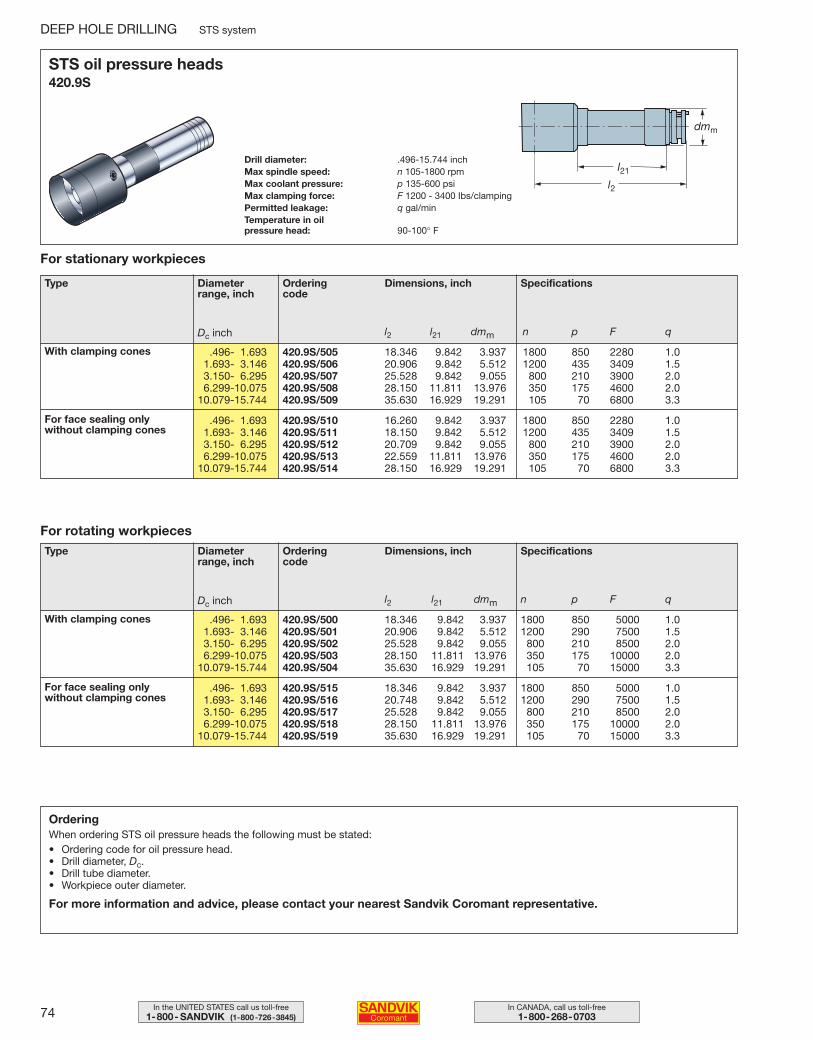
74 In CANADA, call us toll-free1-800-268-0703
In the UNITED STATES call us toll-free1-800- SANDVIK (1-800-726-3845)
STS oil pressure heads420.9S
Drill diameter: .496-15.744 inchMax spindle speed: n 105-1800 rpmMax coolant pressure: p 135-600 psiMax clamping force: F 1200 - 3400 Ibs/clampingPermitted leakage: q gal/minTemperature in oilpressure head: 90-100° F
For stationary workpieces
Type Diameterrange, inch
Ordering code
Dimensions, inch Specifications
l2 l21 dmm n p F q
.496- 1.693 420.9S/505 18.346 9.842 3.937 1800 850 2280 1.01.693- 3.146 420.9S/506 20.906 9.842 5.512 1200 435 3409 1.53.150- 6.295 420.9S/507 25.528 9.842 9.055 800 210 3900 2.06.299-10.075 420.9S/508 28.150 11.811 13.976 350 175 4600 2.0
10.079-15.744 420.9S/509 35.630 16.929 19.291 105 70 6800 3.3
.496- 1.693 420.9S/510 16.260 9.842 3.937 1800 850 2280 1.01.693- 3.146 420.9S/511 18.150 9.842 5.512 1200 435 3409 1.53.150- 6.295 420.9S/512 20.709 9.842 9.055 800 210 3900 2.06.299-10.075 420.9S/513 22.559 11.811 13.976 350 175 4600 2.0
10.079-15.744 420.9S/514 28.150 16.929 19.291 105 70 6800 3.3
For rotating workpieces
l2 l21 dmm n p F q
.496- 1.693 420.9S/500 18.346 9.842 3.937 1800 850 5000 1.01.693- 3.146 420.9S/501 20.906 9.842 5.512 1200 290 7500 1.53.150- 6.295 420.9S/502 25.528 9.842 9.055 800 210 8500 2.06.299-10.075 420.9S/503 28.150 11.811 13.976 350 175 10000 2.0
10.079-15.744 420.9S/504 35.630 16.929 19.291 105 70 15000 3.3
.496- 1.693 420.9S/515 18.346 9.842 3.937 1800 850 5000 1.01.693- 3.146 420.9S/516 20.748 9.842 5.512 1200 290 7500 1.53.150- 6.295 420.9S/517 25.528 9.842 9.055 800 210 8500 2.06.299-10.075 420.9S/518 28.150 11.811 13.976 350 175 10000 2.0
10.079-15.744 420.9S/519 35.630 16.929 19.291 105 70 15000 3.3
Dc inch
DEEP HOLE DRILLING STS system
With clamping cones
For face sealing only without clamping cones
Type Diameterrange, inch
Ordering code
Dimensions, inch Specifications
Dc inch
With clamping cones
For face sealing only without clamping cones
OrderingWhen ordering STS oil pressure heads the following must be stated:• Ordering code for oil pressure head.• Drill diameter, Dc.• Drill tube diameter.• Workpiece outer diameter.
For more information and advice, please contact your nearest Sandvik Coromant representative.
072-078 USA 04-04-29 10.05 Sida 74
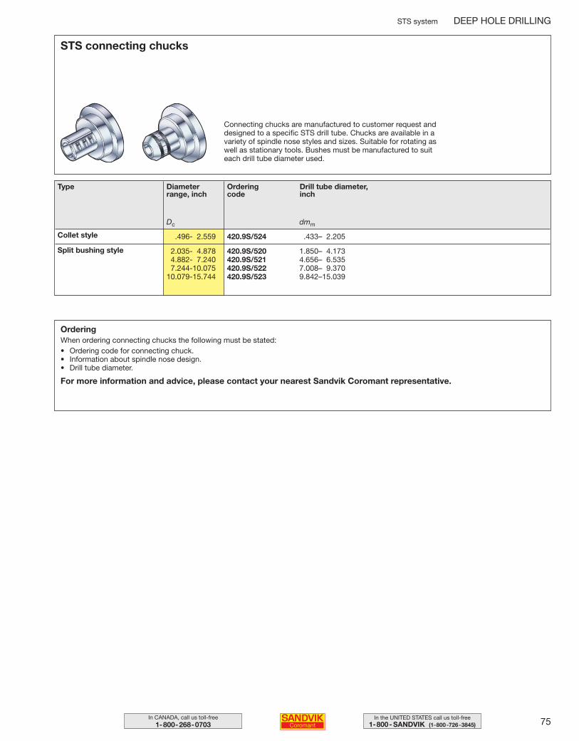
75In the UNITED STATES call us toll-free1-800- SANDVIK (1-800-726-3845)
In CANADA, call us toll-free1-800-268-0703
STS connecting chucks
Connecting chucks are manufactured to customer request and designed to a specific STS drill tube. Chucks are available in a variety of spindle nose styles and sizes. Suitable for rotating as well as stationary tools. Bushes must be manufactured to suit each drill tube diameter used.
Type Diameterrange, inch
Ordering code
Drill tube diameter,inch
Dc dmm
.496- 2.559 420.9S/524 .433– 2.205
2.035- 4.878 420.9S/520 1.850– 4.1734.882- 7.240 420.9S/521 4.656– 6.5357.244-10.075 420.9S/522 7.008– 9.370
10.079-15.744 420.9S/523 9.842–15.039
Collet style
Split bushing style
OrderingWhen ordering connecting chucks the following must be stated:• Ordering code for connecting chuck.• Information about spindle nose design.• Drill tube diameter.
For more information and advice, please contact your nearest Sandvik Coromant representative.
STS system DEEP HOLE DRILLING
072-078 USA 04-04-29 10.05 Sida 75
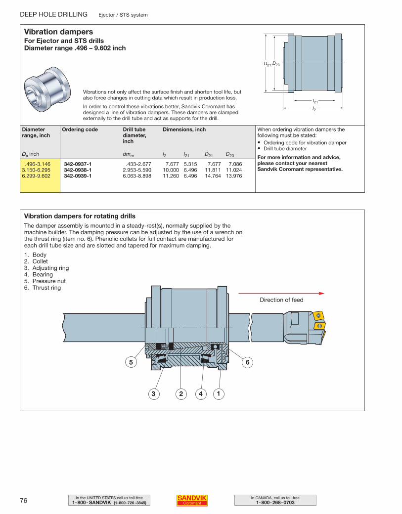
76 In CANADA, call us toll-free1-800-268-0703
In the UNITED STATES call us toll-free1-800- SANDVIK (1-800-726-3845)
Vibration dampers for rotating drillsThe damper assembly is mounted in a steady-rest(s), normally supplied by the machine builder. The damping pressure can be adjusted by the use of a wrench onthe thrust ring (item no. 6). Phenolic collets for full contact are manufactured for each drill tube size and are slotted and tapered for maximum damping.
1. Body2. Collet3. Adjusting ring4. Bearing5. Pressure nut6. Thrust ring
Vibration dampersFor Ejector and STS drillsDiameter range .496 – 9.602 inch
Vibrations not only affect the surface finish and shorten tool life, butalso force changes in cutting data which result in production loss.
In order to control these vibrations better, Sandvik Coromant hasdesigned a line of vibration dampers. These dampers are clampedexternally to the drill tube and act as supports for the drill.
Diameterrange, inch
Dc inch
Ordering code Drill tube diameter, inch
Dimensions, inch
Dc dmm l2 l21 D21 D23
.496-3.146 342-0937-1 .433-2.677 7.677 5.315 7.677 7.0863.150-6.295 342-0938-1 2.953-5.590 10.000 6.496 11.811 11.0246.299-9.602 342-0939-1 6.063-8.898 11.260 6.496 14.764 13.976
When ordering vibration dampers the following must be stated:• Ordering code for vibration damper• Drill tube diameter
For more information and advice, please contact your nearest Sandvik Coromant representative.
5
43 2 1
6
DEEP HOLE DRILLING Ejector / STS system
Direction of feed
072-078 USA 04-04-29 10.05 Sida 76
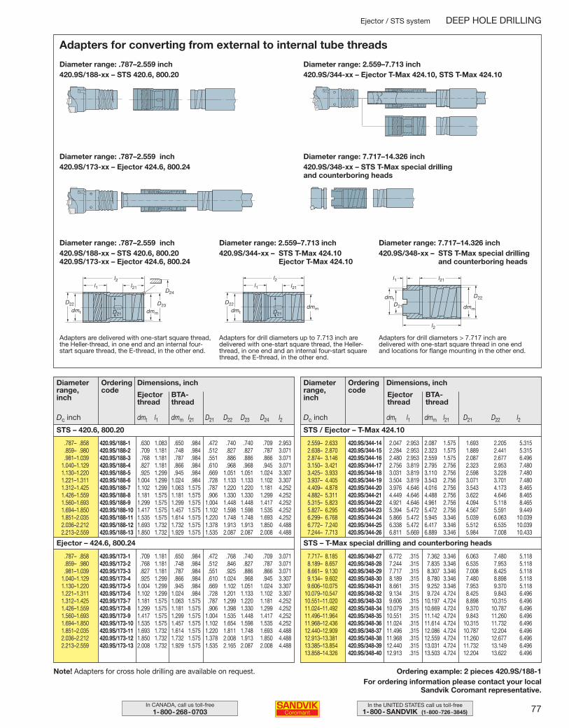
77In the UNITED STATES call us toll-free1-800- SANDVIK (1-800-726-3845)
In CANADA, call us toll-free1-800-268-0703
Ejector / STS system DEEP HOLE DRILLING
Diameter range: .787–2.559 inch420.9S/188-xx – STS 420.6, 800.20420.9S/173-xx – Ejector 424.6, 800.24
Diameter range: 2.559–7.713 inch420.9S/344-xx – STS T-Max 424.10
Ejector T-Max 424.10
Diameter range: 7.717–14.326 inch420.9S/348-xx – STS T-Max special drilling
and counterboring heads
Diameter range: 2.559–7.713 inch420.9S/344-xx – Ejector T-Max 424.10, STS T-Max 424.10
Adapters are delivered with one-start square thread,the Heller-thread, in one end and an internal four-start square thread, the E-thread, in the other end.
Adapters for drill diameters up to 7.713 inch are delivered with one-start square thread, the Heller-thread, in one end and an internal four-start squarethread, the E-thread, in the other end.
Adapters for drill diameters > 7.717 inch aredelivered with one-start square thread in one endand locations for flange mounting in the other end.
Ordering example: 2 pieces 420.9S/188-1For ordering information please contact your local
Sandvik Coromant representative.
Adapters for converting from external to internal tube threads
Dimensions, inch
BTA- thread
Diameter range: .787–2.559 inch420.9S/188-xx – STS 420.6, 800.20
Diameter range: .787–2.559 inch420.9S/173-xx – Ejector 424.6, 800.24
Diameter range: 7.717–14.326 inch420.9S/348-xx – STS T-Max special drilling and counterboring heads
Diameterrange,inch
Orderingcode
Ejectorthread
Dc inch
STS – 420.6, 800.20
Ejector – 424.6, 800.24
dmt l1 dmm l21 D21 D22 D23 D24 l2
.787– .858 420.9S/188-1 .630 1.083 .650 .984 .472 .740 .740 .709 2.953
.859– .980 420.9S/188-2 .709 1.181 .748 .984 .512 .827 .827 .787 3.071
.981–1.039 420.9S/188-3 .768 1.181 .787 .984 .551 .886 .886 .866 3.0711.040–1.129 420.9S/188-4 .827 1.181 .866 .984 .610 .968 .968 .945 3.0711.130–1.220 420.9S/188-5 .925 1.299 .945 .984 .669 1.051 1.051 1.024 3.3071.221–1.311 420.9S/188-6 1.004 1.299 1.024 .984 .728 1.133 1.133 1.102 3.3071.312–1.425 420.9S/188-7 1.102 1.299 1.063 1.575 .787 1.220 1.220 1.181 4.2521.426–1.559 420.9S/188-8 1.181 1.575 1.181 1.575 .906 1.330 1.330 1.299 4.2521.560–1.693 420.9S/188-9 1.299 1.575 1.299 1.575 1.004 1.448 1.448 1.417 4.2521.694–1.850 420.9S/188-10 1.417 1.575 1.457 1.575 1.102 1.598 1.598 1.535 4.2521.851–2.035 420.9S/188-11 1.535 1.575 1.614 1.575 1.220 1.748 1.748 1.693 4.2522.036–2.212 420.9S/188-12 1.693 1.732 1.732 1.575 1.378 1.913 1.913 1.850 4.4882.213–2.559 420.9S/188-13 1.850 1.732 1.929 1.575 1.535 2.087 2.087 2.008 4.488
.787– .858 420.9S/173-1 .709 1.181 .650 .984 .472 .768 .740 .709 3.071
.859– .980 420.9S/173-2 .768 1.181 .748 .984 .512 .846 .827 .787 3.071
.981–1.039 420.9S/173-3 .827 1.181 .787 .984 .551 .925 .886 .866 3.0711.040–1.129 420.9S/173-4 .925 1.299 .866 .984 .610 1.024 .968 .945 3.3071.130–1.220 420.9S/173-5 1.004 1.299 .945 .984 .669 1.102 1.051 1.024 3.3071.221–1.311 420.9S/173-6 1.102 1.299 1.024 .984 .728 1.201 1.133 1.102 3.3071.312–1.425 420.9S/173-7 1.181 1.575 1.063 1.575 .787 1.299 1.220 1.181 4.2521.426–1.559 420.9S/173-8 1.299 1.575 1.181 1.575 .906 1.398 1.330 1.299 4.2521.560–1.693 420.9S/173-9 1.417 1.575 1.299 1.575 1.004 1.535 1.448 1.417 4.2521.694–1.850 420.9S/173-10 1.535 1.575 1.457 1.575 1.102 1.654 1.598 1.535 4.2521.851–2.035 420.9S/173-11 1.693 1.732 1.614 1.575 1.220 1.811 1.748 1.693 4.4882.036–2.212 420.9S/173-12 1.850 1.732 1.732 1.575 1.378 2.008 1.913 1.850 4.4882.213–2.559 420.9S/173-13 2.008 1.732 1.929 1.575 1.535 2.165 2.087 2.008 4.488
Dimensions, inch
BTA- thread
Diameterrange,inch
Orderingcode
Ejectorthread
Dc inch
STS / Ejector – T-Max 424.10
STS – T-Max special drilling and counterboring heads
dmt l1 dmm l21 D21 D22 l2
2.559– 2.633 420.9S/344-14 2.047 2.953 2.087 1.575 1.693 2.205 5.3152.638– 2.870 420.9S/344-15 2.284 2.953 2.323 1.575 1.889 2.441 5.3152.874– 3.146 420.9S/344-16 2.480 2.953 2.559 1.575 2.087 2.677 6.4963.150– 3.421 420.9S/344-17 2.756 3.819 2.795 2.756 2.323 2.953 7.4803.425– 3.933 420.9S/344-18 3.031 3.819 3.110 2.756 2.598 3.228 7.4803.937– 4.405 420.9S/344-19 3.504 3.819 3.543 2.756 3.071 3.701 7.4804.409– 4.878 420.9S/344-20 3.976 4.646 4.016 2.756 3.543 4.173 8.4654.882– 5.311 420.9S/344-21 4.449 4.646 4.488 2.756 3.622 4.646 8.4655.315– 5.823 420.9S/344-22 4.921 4.646 4.961 2.756 4.094 5.118 8.4655.827– 6.295 420.9S/344-23 5.394 5.472 5.472 2.756 4.567 5.591 9.4496.299– 6.768 420.9S/344-24 5.866 5.472 5.945 3.346 5.039 6.063 10.0396.772– 7.240 420.9S/344-25 6.338 5.472 6.417 3.346 5.512 6.535 10.0397.244– 7.713 420.9S/344-26 6.811 5.669 6.889 3.346 5.984 7.008 10.433
7.717– 8.185 420.9S/348-27 6.772 .315 7.362 3.346 6.063 7.480 5.1188.189– 8.657 420.9S/348-28 7.244 .315 7.835 3.346 6.535 7.953 5.1188.661– 9.130 420.9S/348-29 7.717 .315 8.307 3.346 7.008 8.425 5.1189.134– 9.602 420.9S/348-30 8.189 .315 8.780 3.346 7.480 8.898 5.1189.606–10.075 420.9S/348-31 8.661 .315 9.252 3.346 7.953 9.370 5.118
10.079–10.547 420.9S/348-32 9.134 .315 9.724 4.724 8.425 9.843 6.49610.551–11.020 420.9S/348-33 9.606 .315 10.197 4.724 8.898 10.315 6.49611.024–11.492 420.9S/348-34 10.079 .315 10.669 4.724 9.370 10.787 6.49611.496–11.964 420.9S/348-35 10.551 .315 11.142 4.724 9.843 11.260 6.49611.968–12.436 420.9S/348-36 11.024 .315 11.614 4.724 10.315 11.732 6.49612.440–12.909 420.9S/348-37 11.496 .315 12.086 4.724 10.787 12.204 6.49612.913–13.381 420.9S/348-38 11.968 .315 12.559 4.724 11.260 12.677 6.49613.385–13.854 420.9S/348-39 12.440 .315 13.031 4.724 11.732 13.149 6.49613.858–14.326 420.9S/348-40 12.913 .315 13.503 4.724 12.204 13.622 6.496
Note! Adapters for cross hole drilling are available on request.
072-078 USA 04-04-29 10.05 Sida 77
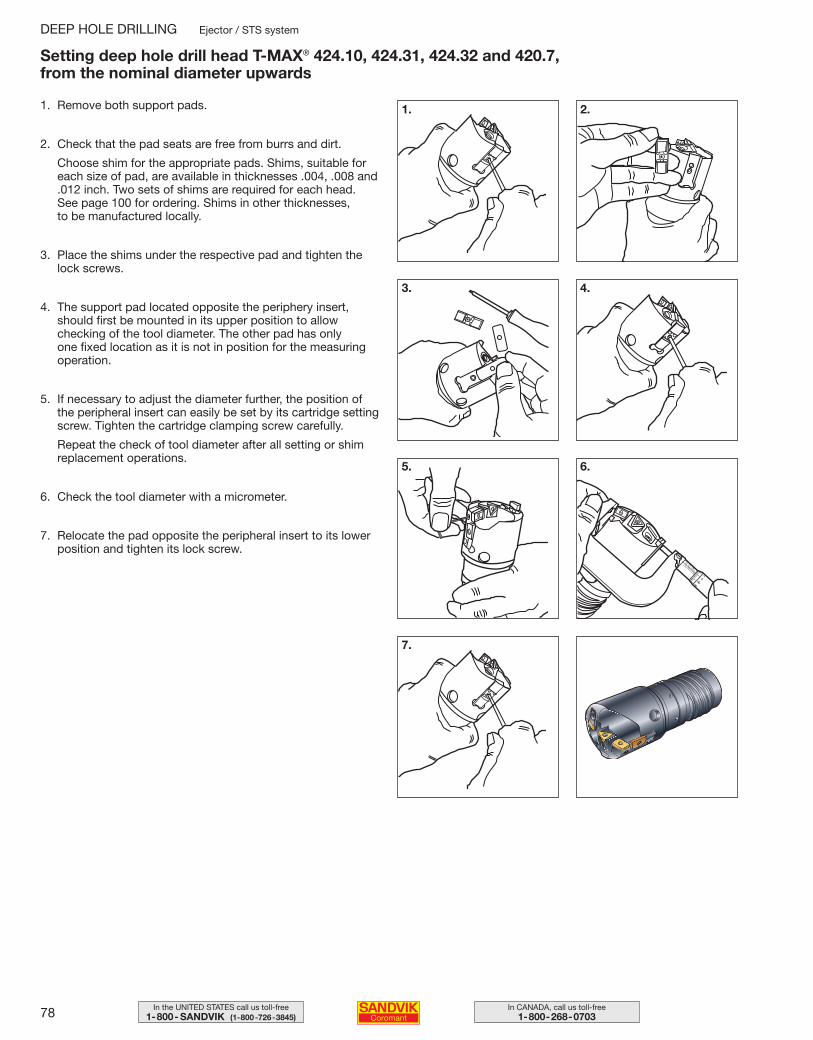
78 In CANADA, call us toll-free1-800-268-0703
In the UNITED STATES call us toll-free1-800- SANDVIK (1-800-726-3845)
1. Remove both support pads.
2. Check that the pad seats are free from burrs and dirt.
Choose shim for the appropriate pads. Shims, suitable foreach size of pad, are available in thicknesses .004, .008 and.012 inch. Two sets of shims are required for each head. See page 100 for ordering. Shims in other thicknesses, to be manufactured locally.
3. Place the shims under the respective pad and tighten thelock screws.
4. The support pad located opposite the periphery insert,should first be mounted in its upper position to allow checking of the tool diameter. The other pad has only one fixed location as it is not in position for the measuringoperation.
5. If necessary to adjust the diameter further, the position ofthe peripheral insert can easily be set by its cartridge settingscrew. Tighten the cartridge clamping screw carefully.
Repeat the check of tool diameter after all setting or shimreplacement operations.
6. Check the tool diameter with a micrometer.
7. Relocate the pad opposite the peripheral insert to its lowerposition and tighten its lock screw.
Setting deep hole drill head T-MAX® 424.10, 424.31, 424.32 and 420.7, from the nominal diameter upwards
1. 2.
3. 4.
5. 6.
7.
DEEP HOLE DRILLING Ejector / STS system
072-078 USA 04-04-29 10.05 Sida 78
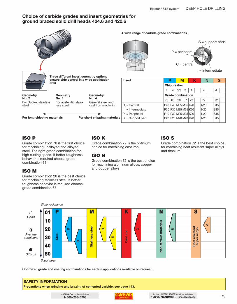
79In the UNITED STATES call us toll-free1-800- SANDVIK (1-800-726-3845)
In CANADA, call us toll-free1-800-268-0703
ISO PGrade combination 70 is the first choicefor machining unalloyed and alloyedsteel. The right grade combination forhigh cutting speed. If better toughnessbehavior is required choose gradecombination 63.
ISO MGrade combination 20 is the best choicefor machining stainless steel. If bettertoughness behavior is required choosegrade combination 67.
ISO KGrade combination 72 is the optimumchoice for machining cast iron.
ISO NGrade combination 72 is the best choicefor machining aluminum alloys, copperand copper alloys.
ISO SGrade combination 72 is the best choicefor machining heat resistant super alloysand titanium.
Optimized grade and coating combinations for certain applications available on request.
Ejector / STS system DEEP HOLE DRILLING
P
Ste
el
M
Sta
inle
ss s
teel
01
10
20
30
40
50
Wear resistance
Toughness
Good
Averageconditions
Difficult
K
Cas
t ir
on
N
No
n-fe
rro
us m
ater
ials
S
Hea
t re
sist
ant
sup
er a
lloys70
63
67
72 7272
SAFETY INFORMATIONPrecautions when grinding and brazing of cemented carbide, see page 143.
Choice of carbide grades and insert geometries for ground brazed solid drill heads 424.6 and 420.6
20
A wide range of carbide grade combinations
Three different insert geometry optionsensure chip control in a wide applicationarea
Insert
Grade combination
C = CentralI = IntermediateP = PeripheralS = Support pad
70 63 20 67 72 72 72
P M K N S
P40 P40 M35 M35 K20 N20 S15P30 P30 M35 M35 K20 N20 S15P10 P30 M25 M35 K20 N20 S15P20 P20 M20 M20 K20 N20 S15
P = peripheral
C = central
I = intermediate
S = support pads
GeometryNo. 2For Duplex stainlesssteel
GeometryNo. 3For austenitic stain-less steel
GeometryNo. 4General steel andcast iron machining
For long chipping materials For short chipping materials
Chipbreaker
4 4 3/2 3 4 4 4
079-085 USA 04-04-29 10.09 Sida 79
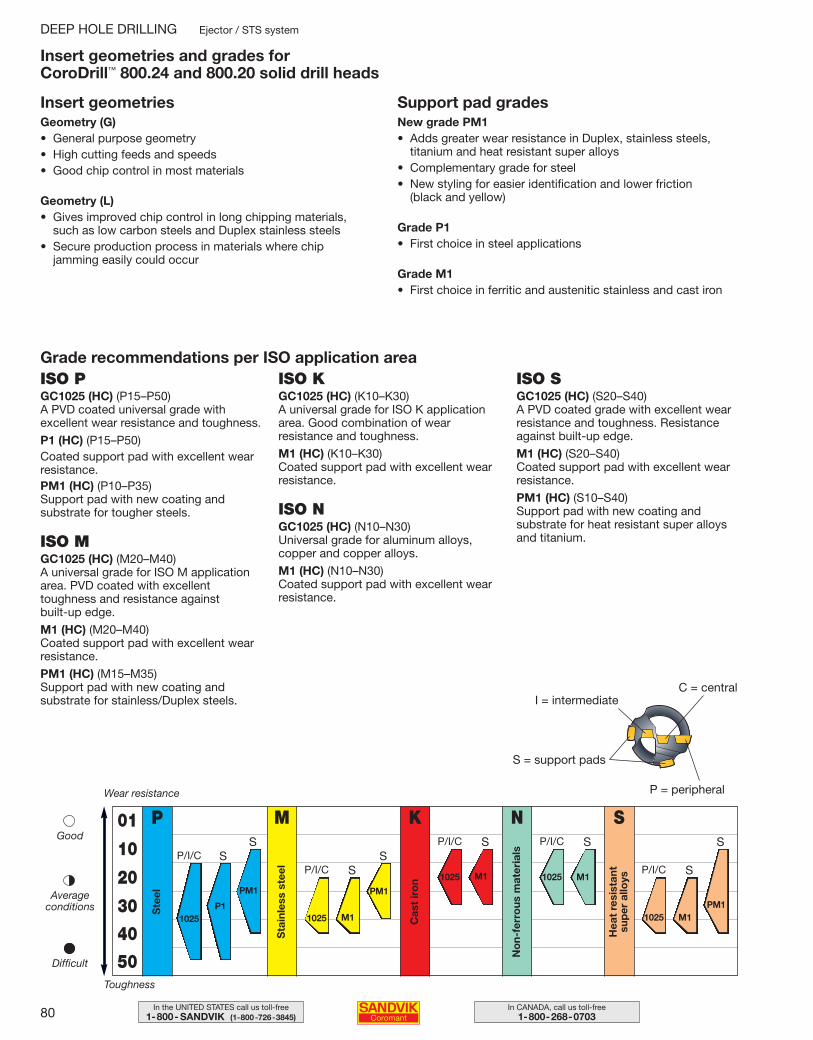
80 In CANADA, call us toll-free1-800-268-0703
In the UNITED STATES call us toll-free1-800- SANDVIK (1-800-726-3845)
ISO PGC1025 (HC) (P15–P50)A PVD coated universal grade withexcellent wear resistance and toughness.
P1 (HC) (P15–P50)Coated support pad with excellent wearresistance.PM1 (HC) (P10–P35)Support pad with new coating and substrate for tougher steels.
ISO MGC1025 (HC) (M20–M40)A universal grade for ISO M applicationarea. PVD coated with excellenttoughness and resistance against built-up edge.
M1 (HC) (M20–M40)Coated support pad with excellent wearresistance.
PM1 (HC) (M15–M35)Support pad with new coating and substrate for stainless/Duplex steels.
ISO KGC1025 (HC) (K10–K30)A universal grade for ISO K applicationarea. Good combination of wearresistance and toughness.
M1 (HC) (K10–K30)Coated support pad with excellent wearresistance.
ISO NGC1025 (HC) (N10–N30)Universal grade for aluminum alloys,copper and copper alloys.
M1 (HC) (N10–N30)Coated support pad with excellent wearresistance.
ISO SGC1025 (HC) (S20–S40)A PVD coated grade with excellent wearresistance and toughness. Resistanceagainst built-up edge.
M1 (HC) (S20–S40)Coated support pad with excellent wearresistance.
PM1 (HC) (S10–S40)Support pad with new coating and substrate for heat resistant super alloysand titanium.
Geometry (G)• General purpose geometry• High cutting feeds and speeds• Good chip control in most materials
Geometry (L)• Gives improved chip control in long chipping materials,
such as low carbon steels and Duplex stainless steels• Secure production process in materials where chip
jamming easily could occur
New grade PM1• Adds greater wear resistance in Duplex, stainless steels,
titanium and heat resistant super alloys• Complementary grade for steel• New styling for easier identification and lower friction
(black and yellow)
Grade P1• First choice in steel applications
Grade M1• First choice in ferritic and austenitic stainless and cast iron
Insert geometries and grades for CoroDrill™ 800.24 and 800.20 solid drill heads
I = intermediate
S = support pads
P = peripheral
C = central
Grade recommendations per ISO application area
Insert geometries
DEEP HOLE DRILLING Ejector / STS system
P
Ste
el
M
Sta
inle
ss s
teel
01
10
20
30
40
50
Wear resistance
Toughness
Good
Averageconditions
Difficult
K
Cas
t ir
on
N
No
n-fe
rro
us m
ater
ials
S
Hea
t re
sist
ant
sup
er a
lloys
1025
SP/I/C
SP/I/CSP/I/C
SP/I/CSP/I/C S
1025P1
M1
PM1
1025 M1 1025 M1
1025 M1
S
PM1
S
PM1
Support pad grades
079-085 USA 04-04-29 10.09 Sida 80
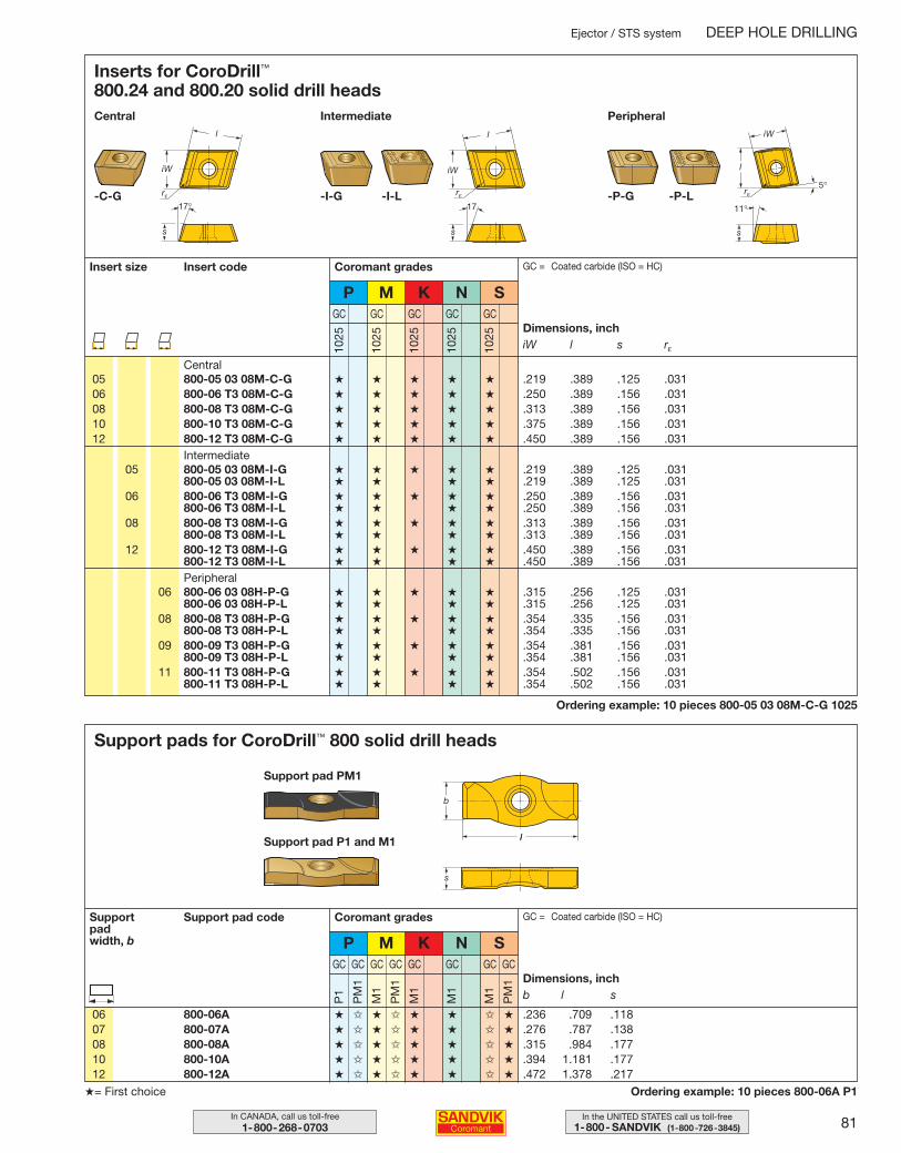
81In the UNITED STATES call us toll-free1-800- SANDVIK (1-800-726-3845)
In CANADA, call us toll-free1-800-268-0703
Ordering example: 10 pieces 800-05 03 08M-C-G 1025
Inserts for CoroDrill™
800.24 and 800.20 solid drill headsCentral Intermediate Peripheral
Insert size Insert code
1025
1025
1025
1025
1025
GC GC GC GC GC
Coromant grades
P M K N S
Central
Intermediate
GC = Coated carbide (ISO = HC)
Dimensions, inchiW l s rε
05 800-05 03 08M-C-G ★ ★ ★ ★ ★ .219 .389 .125 .03106 800-06 T3 08M-C-G ★ ★ ★ ★ ★ .250 .389 .156 .03108 800-08 T3 08M-C-G ★ ★ ★ ★ ★ .313 .389 .156 .03110 800-10 T3 08M-C-G ★ ★ ★ ★ ★ .375 .389 .156 .03112 800-12 T3 08M-C-G ★ ★ ★ ★ ★ .450 .389 .156 .031
05 800-05 03 08M-I-G ★ ★ ★ ★ ★ .219 .389 .125 .031800-05 03 08M-I-L ★ ★ ★ ★ .219 .389 .125 .031
06 800-06 T3 08M-I-G ★ ★ ★ ★ ★ .250 .389 .156 .031800-06 T3 08M-I-L ★ ★ ★ ★ .250 .389 .156 .031
08 800-08 T3 08M-I-G ★ ★ ★ ★ ★ .313 .389 .156 .031800-08 T3 08M-I-L ★ ★ ★ ★ .313 .389 .156 .031
12 800-12 T3 08M-I-G ★ ★ ★ ★ ★ .450 .389 .156 .031800-12 T3 08M-I-L ★ ★ ★ ★ .450 .389 .156 .031
06 800-06 03 08H-P-G ★ ★ ★ ★ ★ .315 .256 .125 .031800-06 03 08H-P-L ★ ★ ★ ★ .315 .256 .125 .031
08 800-08 T3 08H-P-G ★ ★ ★ ★ ★ .354 .335 .156 .031800-08 T3 08H-P-L ★ ★ ★ ★ .354 .335 .156 .031
09 800-09 T3 08H-P-G ★ ★ ★ ★ ★ .354 .381 .156 .031800-09 T3 08H-P-L ★ ★ ★ ★ .354 .381 .156 .031
11 800-11 T3 08H-P-G ★ ★ ★ ★ ★ .354 .502 .156 .031800-11 T3 08H-P-L ★ ★ ★ ★ .354 .502 .156 .031
Peripheral
-C-G -I-L -P-L-I-G -P-G
Ejector / STS system DEEP HOLE DRILLING
Ordering example: 10 pieces 800-06A P1
Support pads for CoroDrill™ 800 solid drill heads
Support padwidth, b
Support pad code
P1
PM
1
M1
PM
1
M1
M1
M1
PM
1
GC GC GC GC GC GC GC GC
Coromant grades
P M K N S
GC = Coated carbide (ISO = HC)
Dimensions, inchb l s
06 800-06A ★ ✩ ★ ✩ ★ ★ ✩ ★ .236 .709 .11807 800-07A ★ ✩ ★ ✩ ★ ★ ✩ ★ .276 .787 .13808 800-08A ★ ✩ ★ ✩ ★ ★ ✩ ★ .315 .984 .17710 800-10A ★ ✩ ★ ✩ ★ ★ ✩ ★ .394 1.181 .17712 800-12A ★ ✩ ★ ✩ ★ ★ ✩ ★ .472 1.378 .217
★= First choice
Support pad PM1
Support pad P1 and M1
079-085 USA 04-04-29 10.09 Sida 81
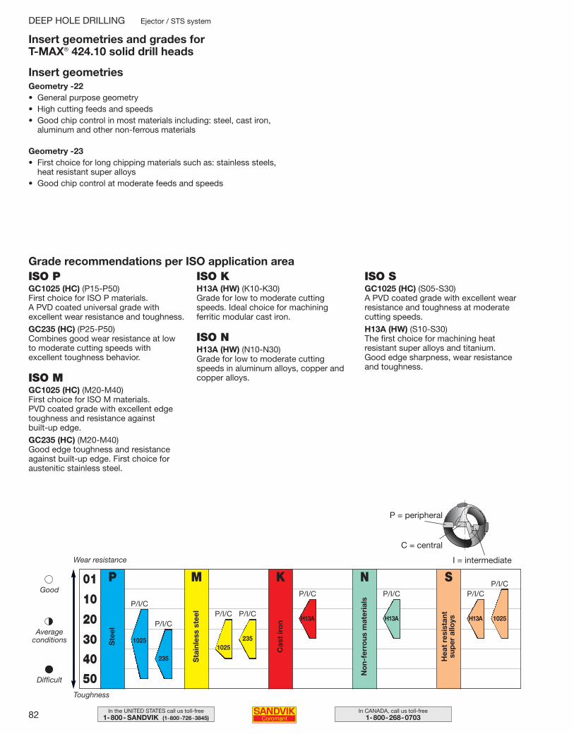
82 In CANADA, call us toll-free1-800-268-0703
In the UNITED STATES call us toll-free1-800- SANDVIK (1-800-726-3845)
Insert geometries and grades for T-MAX® 424.10 solid drill heads
ISO PGC1025 (HC) (P15-P50)First choice for ISO P materials.A PVD coated universal grade withexcellent wear resistance and toughness.
GC235 (HC) (P25-P50)Combines good wear resistance at lowto moderate cutting speeds withexcellent toughness behavior.
ISO MGC1025 (HC) (M20-M40)First choice for ISO M materials.PVD coated grade with excellent edgetoughness and resistance against built-up edge.
GC235 (HC) (M20-M40)Good edge toughness and resistanceagainst built-up edge. First choice foraustenitic stainless steel.
ISO KH13A (HW) (K10-K30)Grade for low to moderate cuttingspeeds. Ideal choice for machiningferritic modular cast iron.
ISO NH13A (HW) (N10-N30)Grade for low to moderate cuttingspeeds in aluminum alloys, copper andcopper alloys.
ISO SGC1025 (HC) (S05-S30)A PVD coated grade with excellent wearresistance and toughness at moderatecutting speeds.
H13A (HW) (S10-S30)The first choice for machining heatresistant super alloys and titanium. Good edge sharpness, wear resistanceand toughness.
Geometry -22• General purpose geometry• High cutting feeds and speeds• Good chip control in most materials including: steel, cast iron,
aluminum and other non-ferrous materials
Geometry -23• First choice for long chipping materials such as: stainless steels,
heat resistant super alloys• Good chip control at moderate feeds and speeds
Grade recommendations per ISO application area
DEEP HOLE DRILLING Ejector / STS system
Insert geometries
P
Ste
el
M
Sta
inle
ss s
teel
01
10
20
30
40
50
Wear resistance
Toughness
Good
Averageconditions
Difficult
K
Cas
t ir
on
N
No
n-fe
rro
us m
ater
ials
S
Hea
t re
sist
ant
sup
er a
lloys
P = peripheral
C = central
I = intermediate
P/I/CP/I/CP/I/C
P/I/CP/I/C
1025
235
P/I/CP/I/C
1025235
H13A H13A
P/I/C
H13A 1025
079-085 USA 04-04-29 10.09 Sida 82
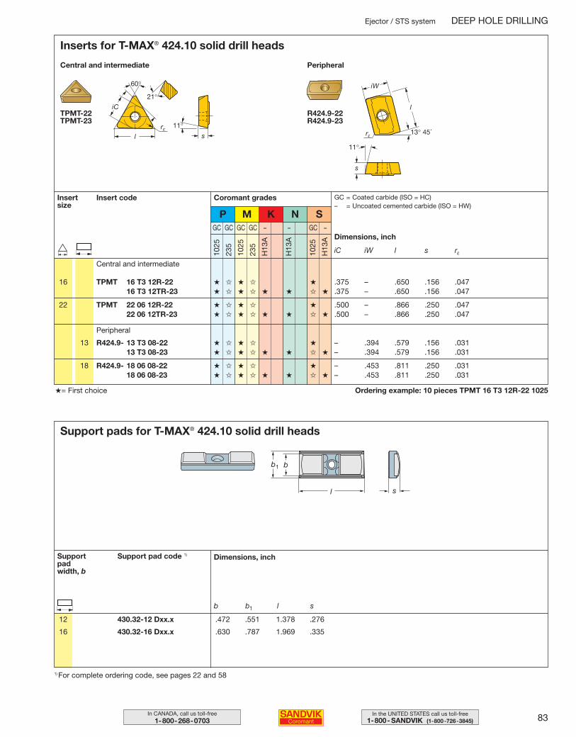
83In the UNITED STATES call us toll-free1-800- SANDVIK (1-800-726-3845)
In CANADA, call us toll-free1-800-268-0703
Ordering example: 10 pieces TPMT 16 T3 12R-22 1025★= First choice
Ejector / STS system DEEP HOLE DRILLING
Inserts for T-MAX® 424.10 solid drill heads
TPMT-22TPMT-23
Central and intermediate Peripheral
R424.9-22R424.9-23
Insert size
Insert code Coromant grades
P M K N S
16 TPMT 16 T3 12R-22 ★ ✩ ★ ✩ ★ .375 – .650 .156 .04716 T3 12TR-23 ★ ✩ ★ ✩ ★ ★ ✩ ★ .375 – .650 .156 .047
22 TPMT 22 06 12R-22 ★ ✩ ★ ✩ ★ .500 – .866 .250 .04722 06 12TR-23 ★ ✩ ★ ✩ ★ ★ ✩ ★ .500 – .866 .250 .047
13 R424.9- 13 T3 08-22 ★ ✩ ★ ✩ ★ – .394 .579 .156 .03113 T3 08-23 ★ ✩ ★ ✩ ★ ★ ✩ ★ – .394 .579 .156 .031
18 R424.9- 18 06 08-22 ★ ✩ ★ ✩ ★ – .453 .811 .250 .03118 06 08-23 ★ ✩ ★ ✩ ★ ★ ✩ ★ – .453 .811 .250 .031
1025
235
1025
235
H13
A
H13
A
1025
H13
A
GC GC GC GC – – GC –
GC = Coated carbide (ISO = HC)– = Uncoated cemented carbide (ISO = HW)
Dimensions, inch
iC iW l s rε
Central and intermediate
Peripheral
Support pads for T-MAX® 424.10 solid drill heads
Support padwidth, b
Support pad code 1) Dimensions, inch
b b1 l s
12 430.32-12 Dxx.x .472 .551 1.378 .276
16 430.32-16 Dxx.x .630 .787 1.969 .335
1) For complete ordering code, see pages 22 and 58
079-085 USA 04-04-29 10.09 Sida 83
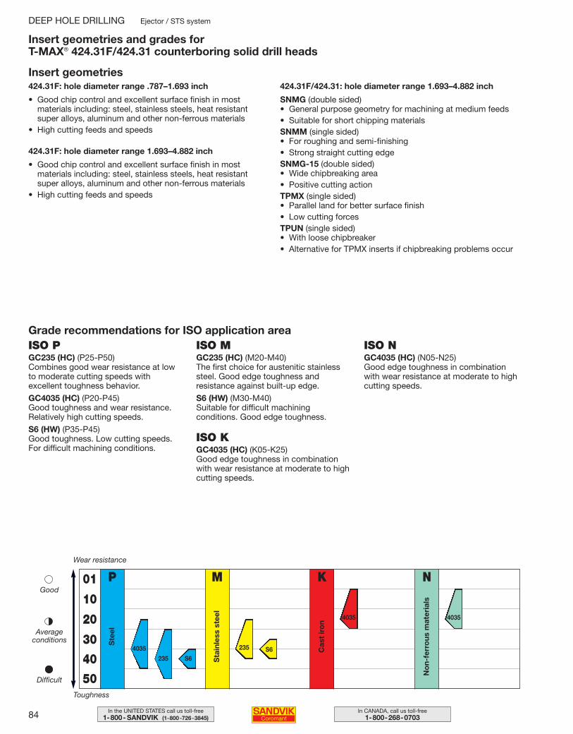
84 In CANADA, call us toll-free1-800-268-0703
In the UNITED STATES call us toll-free1-800- SANDVIK (1-800-726-3845)
DEEP HOLE DRILLING Ejector / STS system
ISO PGC235 (HC) (P25-P50)Combines good wear resistance at lowto moderate cutting speeds withexcellent toughness behavior.
GC4035 (HC) (P20-P45)Good toughness and wear resistance.Relatively high cutting speeds.
S6 (HW) (P35-P45)Good toughness. Low cutting speeds.For difficult machining conditions.
ISO MGC235 (HC) (M20-M40)The first choice for austenitic stainlesssteel. Good edge toughness andresistance against built-up edge.
S6 (HW) (M30-M40)Suitable for difficult machiningconditions. Good edge toughness.
ISO KGC4035 (HC) (K05-K25)Good edge toughness in combinationwith wear resistance at moderate to highcutting speeds.
ISO NGC4035 (HC) (N05-N25)Good edge toughness in combinationwith wear resistance at moderate to highcutting speeds.
424.31F: hole diameter range .787–1.693 inch
• Good chip control and excellent surface finish in mostmaterials including: steel, stainless steels, heat resistantsuper alloys, aluminum and other non-ferrous materials
• High cutting feeds and speeds
424.31F: hole diameter range 1.693–4.882 inch
• Good chip control and excellent surface finish in mostmaterials including: steel, stainless steels, heat resistantsuper alloys, aluminum and other non-ferrous materials
• High cutting feeds and speeds
424.31F/424.31: hole diameter range 1.693–4.882 inch
SNMG (double sided)• General purpose geometry for machining at medium feeds• Suitable for short chipping materialsSNMM (single sided)• For roughing and semi-finishing• Strong straight cutting edgeSNMG-15 (double sided)• Wide chipbreaking area• Positive cutting actionTPMX (single sided)• Parallel land for better surface finish• Low cutting forcesTPUN (single sided)• With loose chipbreaker• Alternative for TPMX inserts if chipbreaking problems occur
Insert geometries and grades for T-MAX® 424.31F/424.31 counterboring solid drill heads
Insert geometries
P
Ste
el
M
Sta
inle
ss s
teel
01
10
20
30
40
50
Wear resistance
Toughness
Good
Averageconditions
Difficult
K
Cas
t ir
on
N
No
n-fe
rro
us m
ater
ials
4035
235 S6
235 S6
4035 4035
Grade recommendations for ISO application area
079-085 USA 04-04-29 10.09 Sida 84
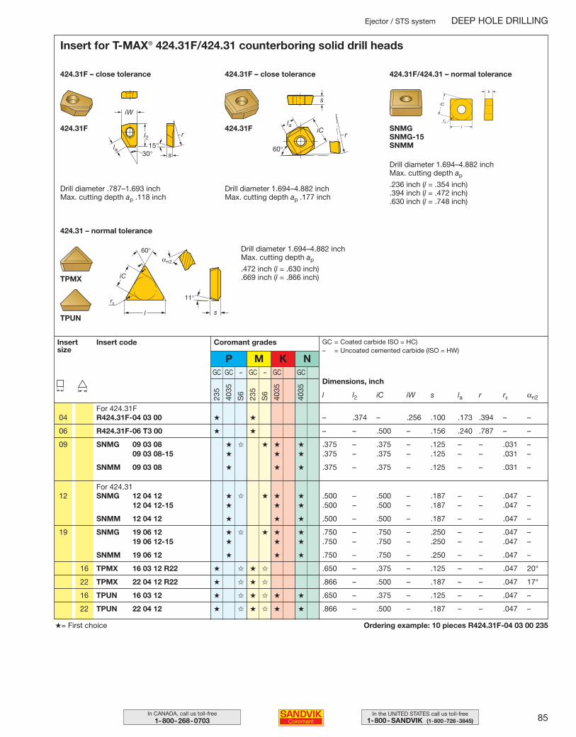
85In the UNITED STATES call us toll-free1-800- SANDVIK (1-800-726-3845)
In CANADA, call us toll-free1-800-268-0703
Ejector / STS system DEEP HOLE DRILLING
Ordering example: 10 pieces R424.31F-04 03 00 235★= First choice
424.31F
Insert for T-MAX® 424.31F/424.31 counterboring solid drill heads
424.31F – close tolerance
TPUN
11°
60°
rε
sl
iC
αn2
424.31F – close tolerance
424.31F SNMGSNMG-15SNMM
424.31F/424.31 – normal tolerance
Drill diameter .787–1.693 inchMax. cutting depth ap .118 inch
Drill diameter 1.694–4.882 inchMax. cutting depth ap .177 inch
Drill diameter 1.694–4.882 inchMax. cutting depth ap
.236 inch (l = .354 inch)
.394 inch (l = .472 inch)
.630 inch (l = .748 inch)
424.31 – normal tolerance
TPMX
Drill diameter 1.694–4.882 inchMax. cutting depth ap
.472 inch (l = .630 inch)
.669 inch (l = .866 inch)
Coromant gradesInsert size
Insert code
P M K N
235
4035
S6
235
S6
4035
4035
GC GC – GC – GC GCDimensions, inch
l l2 iC iW s la r rε αn2
04 R424.31F-04 03 00 ★ ★ – .374 – .256 .100 .173 .394 – –
06 R424.31F-06 T3 00 ★ ★ – – .500 – .156 .240 .787 – –
09 SNMG 09 03 08 ★ ✩ ★ ★ ★ .375 – .375 – .125 – – .031 –09 03 08-15 ★ ★ ★ .375 – .375 – .125 – – .031 –
SNMM 09 03 08 ★ ★ ★ .375 – .375 – .125 – – .031 –
For 424.31
For 424.31F
12 SNMG 12 04 12 ★ ✩ ★ ★ ★ .500 – .500 – .187 – – .047 –12 04 12-15 ★ ★ ★ .500 – .500 – .187 – – .047 –
SNMM 12 04 12 ★ ★ ★ .500 – .500 – .187 – – .047 –
19 SNMG 19 06 12 ★ ✩ ★ ★ ★ .750 – .750 – .250 – – .047 –19 06 12-15 ★ ★ ★ .750 – .750 – .250 – – .047 –
SNMM 19 06 12 ★ ★ ★ .750 – .750 – .250 – – .047 –
16 TPMX 16 03 12 R22 ★ ✩ ★ ✩ .650 – .375 – .125 – – .047 20°
22 TPMX 22 04 12 R22 ★ ✩ ★ ✩ .866 – .500 – .187 – – .047 17°
16 TPUN 16 03 12 ★ ✩ ★ ✩ ★ ★ .650 – .375 – .125 – – .047 –
22 TPUN 22 04 12 ★ ✩ ★ ✩ ★ ★ .866 – .500 – .187 – – .047 –
GC = Coated carbide ISO = HC)– = Uncoated cemented carbide (ISO = HW)
079-085 USA 04-04-29 10.09 Sida 85
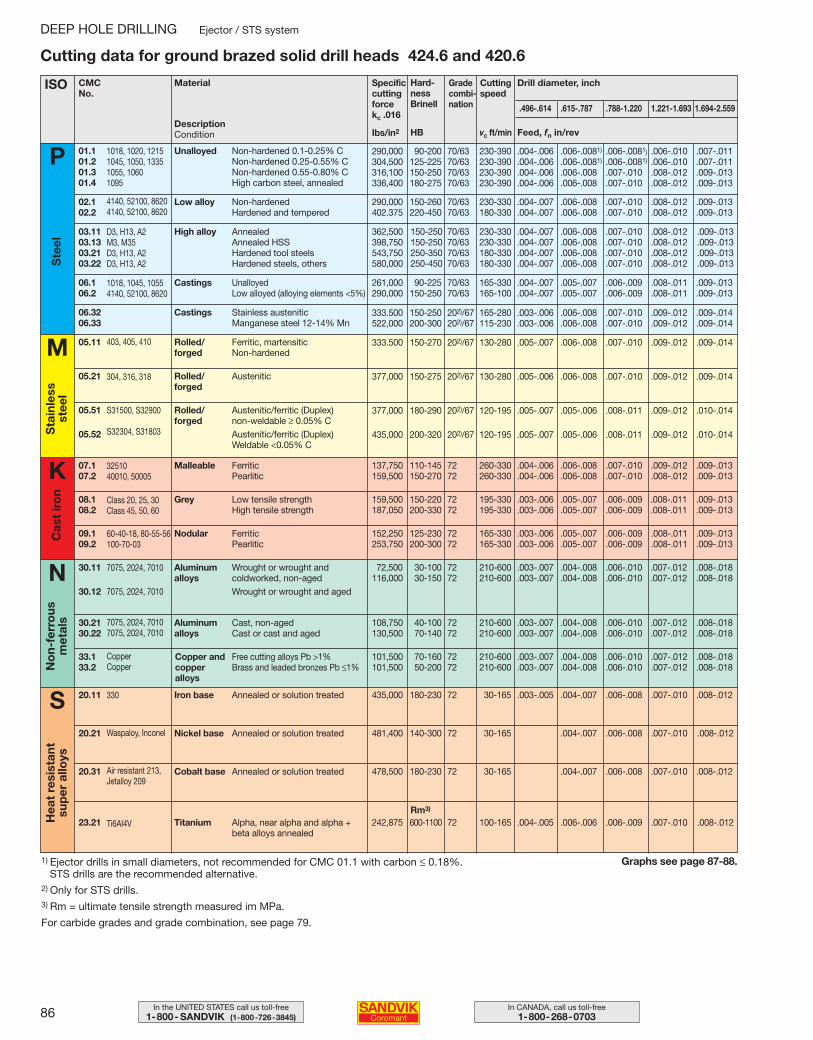
86 In CANADA, call us toll-free1-800-268-0703
In the UNITED STATES call us toll-free1-800- SANDVIK (1-800-726-3845)
DEEP HOLE DRILLING Ejector / STS system
1) Ejector drills in small diameters, not recommended for CMC 01.1 with carbon ≤ 0.18%.STS drills are the recommended alternative.
2) Only for STS drills.3) Rm = ultimate tensile strength measured im MPa.
For carbide grades and grade combination, see page 79.
Graphs see page 87-88.
Cutting data for ground brazed solid drill heads 424.6 and 420.6
ISO CMCNo.
Specificcuttingforcekc .016
Hard-ness Brinell
Ibs/in2
Grade combi-nation
vc ft/min
Cuttingspeed
.496-.614 .615-.787 .788-1.220 1.221-1.693 1.694-2.559
Feed, fn in/rev
Unalloyed 01.101.201.301.4
Non-hardened 0.1-0.25% CNon-hardened 0.25-0.55% CNon-hardened 0.55-0.80% CHigh carbon steel, annealed
Ste
el
P
M
Sta
inle
ss
stee
l
S
Drill diameter, inchMaterial
HB
Low alloy 02.102.2
Non-hardenedHardened and tempered
High alloy03.1103.1303.2103.22
AnnealedAnnealed HSSHardened tool steelsHardened steels, others
Castings06.106.2
UnalloyedLow alloyed (alloying elements <5%)
Castings06.3206.33
Stainless austeniticManganese steel 12-14% Mn
290,000 90-200 70/63 230-390 .004-.006 .006-.0081) .006-.0081) .006-.010 .007-.011304,500 125-225 70/63 230-390 .004-.006 .006-.0081) .006-.0081) .006-.010 .007-.011316,100 150-250 70/63 230-390 .004-.006 .006-.008 .007-.010 .008-.012 .009-.013336,400 180-275 70/63 230-390 .004-.006 .006-.008 .007-.010 .008-.012 .009-.013
290,000 150-260 70/63 230-330 .004-.007 .006-.008 .007-.010 .008-.012 .009-.013402.375 220-450 70/63 180-330 .004-.007 .006-.008 .007-.010 .008-.012 .009-.013
362,500 150-250 70/63 230-330 .004-.007 .006-.008 .007-.010 .008-.012 .009-.013398,750 150-250 70/63 230-330 .004-.007 .006-.008 .007-.010 .008-.012 .009-.013543,750 250-350 70/63 180-330 .004-.007 .006-.008 .007-.010 .008-.012 .009-.013580,000 250-450 70/63 180-330 .004-.007 .006-.008 .007-.010 .008-.012 .009-.013
261,000 90-225 70/63 165-330 .004-.007 .005-.007 .006-.009 .008-.011 .009-.013290,000 150-250 70/63 165-100 .004-.007 .005-.007 .006-.009 .008-.011 .009-.013
333.500 150-250 202)/67 165-280 .003-.006 .006-.008 .007-.010 .009-.012 .009-.014522,000 200-300 202)/67 115-230 .003-.006 .006-.008 .007-.010 .009-.012 .009-.014
Rolled/forged
05.11 Ferritic, martensitic Non-hardened
333.500 150-270 202)/67 130-280 .005-.007 .006-.008 .007-.010 .009-.012 .009-.014
Rolled/forged
05.21 Austenitic 377,000 150-275 202)/67 130-280 .005-.006 .006-.008 .007-.010 .009-.012 .009-.014
Rolled/forged
05.51
05.52
Austenitic/ferritic (Duplex) non-weldable ≥ 0.05% CAustenitic/ferritic (Duplex) Weldable <0.05% C
377,000 180-290 202)/67 120-195 .005-.007 .005-.006 .008-.011 .009-.012 .010-.014
435,000 200-320 202)/67 120-195 .005-.007 .005-.006 .008-.011 .009-.012 .010-.014
K Malleable07.107.2
FerriticPearlitic
137,750 110-145 72 260-330 .004-.006 .006-.008 .007-.010 .009-.012 .009-.013159,500 150-270 72 260-330 .004-.006 .006-.008 .007-.010 .008-.012 .009-.013
Grey08.108.2
Low tensile strengthHigh tensile strength
159,500 150-220 72 195-330 .003-.006 .005-.007 .006-.009 .008-.011 .009-.013187,050 200-330 72 195-330 .003-.006 .005-.007 .006-.009 .008-.011 .009-.013
Nodular09.109.2
FerriticPearlitic
152,250 125-230 72 165-330 .003-.006 .005-.007 .006-.009 .008-.011 .009-.013253,750 200-300 72 165-330 .003-.006 .005-.007 .006-.009 .008-.011 .009-.013
Aluminum alloys
30.11
30.12
Wrought or wrought and coldworked, non-agedWrought or wrought and aged
72,500 30-100 72 210-600 .003-.007 .004-.008 .006-.010 .007-.012 .008-.018116,000 30-150 72 210-600 .003-.007 .004-.008 .006-.010 .007-.012 .008-.018
Aluminum alloys
30.2130.22
Cast, non-agedCast or cast and aged
108,750 40-100 72 210-600 .003-.007 .004-.008 .006-.010 .007-.012 .008-.018130,500 70-140 72 210-600 .003-.007 .004-.008 .006-.010 .007-.012 .008-.018
Copper andcopperalloys
33.133.2
Free cutting alloys Pb >1%Brass and leaded bronzes Pb ≤1%
101,500 70-160 72 210-600 .003-.007 .004-.008 .006-.010 .007-.012 .008-.018101,500 50-200 72 210-600 .003-.007 .004-.008 .006-.010 .007-.012 .008-.018
Cas
t ir
on
Iron base20.11 Annealed or solution treated 435,000 180-230 72 30-165 .003-.005 .004-.007 .006-.008 .007-.010 .008-.012
No
n-fe
rro
us
met
als
Hea
t re
sist
ant
sup
er a
lloys
Nickel base20.21 Annealed or solution treated 481,400 140-300 72 30-165 .004-.007 .006-.008 .007-.010 .008-.012
Cobalt base20.31 Annealed or solution treated 478,500 180-230 72 30-165 .004-.007 .006-.008 .007-.010 .008-.012
Titanium23.21 Alpha, near alpha and alpha + beta alloys annealed
242,875 600-1100 72 100-165 .004-.005 .006-.006 .006-.009 .007-.010 .008-.012
N
Rm3)
1018, 1020, 12151045, 1050, 13351055, 10601095
4140, 52100, 86204140, 52100, 8620
D3, H13, A2M3, M35D3, H13, A2D3, H13, A2
1018, 1045, 10554140, 52100, 8620
403, 405, 410
304, 316, 318
S31500, S32900
S32304, S31803
3251040010, 50005
Class 20, 25, 30Class 45, 50, 60
60-40-18, 80-55-56100-70-03
7075, 2024, 7010
7075, 2024, 7010
7075, 2024, 70107075, 2024, 7010
CopperCopper
330
Waspaloy, Inconel
Air resistant 213,Jetalloy 209
Ti6AI4V
DescriptionCondition
086-098 USA 04-04-29 10.26 Sida 86
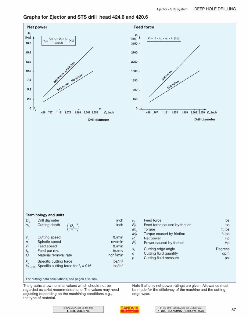
87In the UNITED STATES call us toll-free1-800- SANDVIK (1-800-726-3845)
In CANADA, call us toll-free1-800-268-0703
Ejector / STS system DEEP HOLE DRILLING
Graphs for Ejector and STS drill head 424.6 and 420.6
The graphs show nominal values which should not be regarded as strict recommendations. The values may need adjusting depending on the machining conditions e.g., the type of material.
Note that only net power ratings are given. Allowance must be made for the efficiency of the machine and the cutting edge wear.
For cutting data calculations, see pages 133-134.
Terminology and unitsDc Drill diameter inchap Cutting depth inch
vc Cutting speed ft./minn Spindle speed rev/minvf Feed speed ft./minfn Feed per rev. in./revQ Material removal rate inch3/min
kc Specific cutting force Ibs/in2
kc .016 Specific cutting force for fz =.016 Ibs/in2
Ff Feed force IbsFµ Feed force caused by friction IbsMc Torque ft.IbsMµ Torque caused by friction ft.lbsPc Net power HpPµ Power caused by friction Hp
κr Cutting edge angle Degreesq Cutting fluid quantity gpmp Cutting fluid pressure psi
18.2
15.6
13.0
10.2
7.8
5.2
2.6
0.496 . 787 1.181 1.575 1.969 2.362 2.559 Dc inch
245 ft/min .0
06 in/re
v
245 f
t/min
.010
in/re
v
.006 in/re
v.010
in/re
v
Net power
Drill diameter
Pc[Hp]
Feed force
Drill diameter
Ff[lbs.]
3150
2700
2250
1800
1350
900
450
0.496 .787 1.181 1.575 1.969 2.362 2.559 Dc inch
(Hp)Pc = fn × vc × Dc × kc
132000
Ff = .5 × kc × ap × fn (lbs)
Dc2( )
086-098 USA 04-04-29 10.14 Sida 87
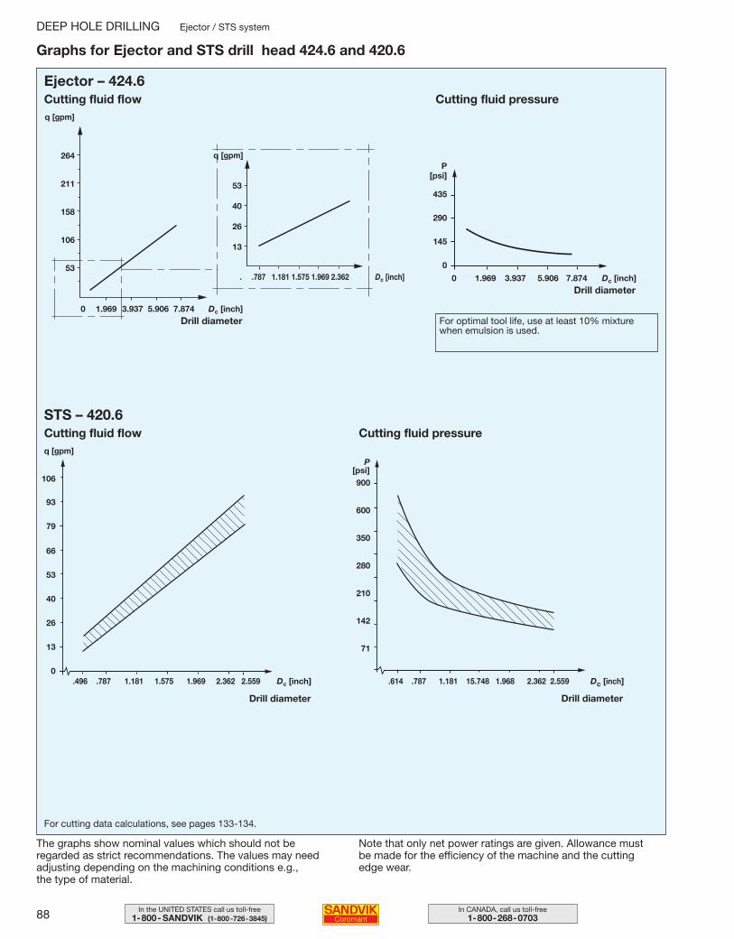
88 In CANADA, call us toll-free1-800-268-0703
In the UNITED STATES call us toll-free1-800- SANDVIK (1-800-726-3845)
DEEP HOLE DRILLING Ejector / STS system
Graphs for Ejector and STS drill head 424.6 and 420.6
The graphs show nominal values which should not be regarded as strict recommendations. The values may need adjusting depending on the machining conditions e.g., the type of material.
Note that only net power ratings are given. Allowance must be made for the efficiency of the machine and the cutting edge wear.
900
600
350
280
210
142
71
.614 .787 1.181 15.748 1.968 2.362 2.559 Dc [inch]
106
93
79
66
53
40
26
13
0.496 .787 1.181 1.575 1.969 2.362 2.559 Dc [inch]
Cutting fluid flowq [gpm]
Drill diameter Drill diameter
Cutting fluid pressure
For cutting data calculations, see pages 133-134.
Cutting fluid pressure
P[psi]
435
290
145
0
0 1.969 3.937 5.906 7.874 Dc [inch]
0 1.969 3.937 5.906 7.874 Dc [inch]
264
211
158
106
53. .787 1.181 1.575 1.969 2.362 Dc [inch]
Cutting fluid flow
Drill diameter
q [gpm]
Drill diameter For optimal tool life, use at least 10% mixturewhen emulsion is used.
53
40
26
13
q [gpm]
Ejector – 424.6
STS – 420.6
P[psi]
086-098 USA 04-04-29 10.14 Sida 88
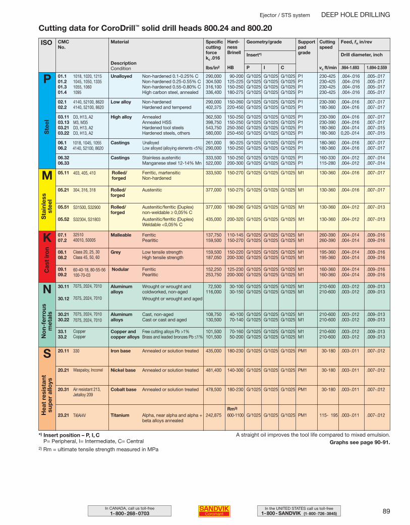
89In the UNITED STATES call us toll-free1-800- SANDVIK (1-800-726-3845)
In CANADA, call us toll-free1-800-268-0703
*) Insert position – P, I, CP= Peripheral, I= Intermediate, C= Central
2) Rm = ultimate tensile strength measured in MPa
A straight oil improves the tool life compared to mixed emulsion.Graphs see page 90-91.
Cutting data for CoroDrill™ solid drill heads 800.24 and 800.20
Ejector / STS system DEEP HOLE DRILLING
ISO CMCNo.
Specificcuttingforcekc .016
Hard-ness Brinell
Ibs/in2
Geometry/grade
vc ft/min
Cuttingspeed
.984-1.693 1.694-2.559
Feed, fn in/rev
Unalloyed 01.101.201.301.4
Non-hardened 0.1-0.25% CNon-hardened 0.25-0.55% CNon-hardened 0.55-0.80% CHigh carbon steel, annealed
Ste
el
P
M
Sta
inle
ss
stee
l
S
Drill diameter, inch
Material
HB
Low alloy 02.102.2
Non-hardenedHardened and tempered
High alloy03.1103.1303.2103.22
AnnealedAnnealed HSSHardened tool steelsHardened steels, others
Castings06.106.2
UnalloyedLow alloyed (alloying elements <5%)
Castings06.3206.33
Stainless austeniticManganese steel 12-14% Mn
290,000 90-200 G/1025 G/1025 G/1025 P1 230-425 .004-.016 .005-.017304.500 125-225 G/1025 G/1025 G/1025 P1 230-425 .004-.016 .005-.017316,100 150-250 G/1025 G/1025 G/1025 P1 230-425 .004-.016 .005-.017336,400 180-275 G/1025 G/1025 G/1025 P1 230-425 .004-.016 .005-.017
290,000 150-260 G/1025 G/1025 G/1025 P1 230-390 .004-.016 .007-.017402,375 220-450 G/1025 G/1025 G/1025 P1 180-360 .004-.016 .007-.017
362,500 150-250 G/1025 G/1025 G/1025 P1 230-390 .004-.016 .007-.017398,750 150-250 G/1025 G/1025 G/1025 P1 230-390 .004-.016 .007-.017543,750 250-350 G/1025 G/1025 G/1025 P1 180-360 .004-.014 .007-.015580,000 250-450 G/1025 G/1025 G/1025 P1 180-360 0,20-.014 .007-.015
261,000 90-225 G/1025 G/1025 G/1025 P1 180-360 .004-.016 .007-.017290,000 150-250 G/1025 G/1025 G/1025 P1 180-360 .004-.016 .007-.017
333,500 150-250 G/1025 G/1025 G/1025 P1 160-330 .004-.012 .007-.014522,000 200-300 G/1025 G/1025 G/1025 P1 115-280 .004-.012 .007-.014
Rolled/forged
05.11 Ferritic, martensitic Non-hardened
333,500 150-270 G/1025 G/1025 G/1025 M1 130-360 .004-.016 .007-.017
Rolled/forged
05.21 Austenitic 377,000 150-275 G/1025 G/1025 G/1025 M1 130-360 .004-.016 .007-.017
Rolled/forged
05.51
05.52
Austenitic/ferritic (Duplex) non-weldable ≥ 0,05% CAustenitic/ferritic (Duplex) Weldable <0,05% C
377,000 180-290 G/1025 G/1025 G/1025 M1 130-360 .004-.012 .007-.013
435,000 200-320 G/1025 G/1025 G/1025 M1 130-360 .004-.012 .007-.013
K Malleable07.107.2
FerriticPearlitic
137,750 110-145 G/1025 G/1025 G/1025 M1 260-390 .004-.014 .009-.016159,500 150-270 G/1025 G/1025 G/1025 M1 260-390 .004-.014 .009-.016
Grey08.108.2
Low tensile strengthHigh tensile strength
159,500 150-220 G/1025 G/1025 G/1025 M1 195-360 .004-.014 .009-.016187,050 200-330 G/1025 G/1025 G/1025 M1 195-360 .004-.014 .009-.016
Nodular09.109.2
FerriticPearlitic
152,250 125-230 G/1025 G/1025 G/1025 M1 160-360 .004-.014 .009-.016253,750 200-300 G/1025 G/1025 G/1025 M1 160-360 .004-.014 .009-.016
Aluminum alloys
30.11
30.12
Wrought or wrought and coldworked, non-agedWrought or wrought and aged
72,500 30-100 G/1025 G/1025 G/1025 M1 210-600 .003-.012 .009-.013116,000 30-150 G/1025 G/1025 G/1025 M1 210-600 .003-.012 .009-.013
Aluminum alloys
30.2130.22
Cast, non-agedCast or cast and aged
108,750 40-100 G/1025 G/1025 G/1025 M1 210-600 .003-.012 .009-.013130,500 70-140 G/1025 G/1025 G/1025 M1 210-600 .003-.012 .009-.013
Copper andcopper alloys
33.133.2
Free cutting alloys Pb >1%Brass and leaded bronzes Pb ≤1%
101,500 70-160 G/1025 G/1025 G/1025 M1 210-600 .003-.012 .009-.013101,500 50-200 G/1025 G/1025 G/1025 M1 210-600 .003-.012 .009-.013
Cas
t ir
on
Iron base20.11 Annealed or solution treated 435,000 180-230 G/1025 G/1025 G/1025 PM1 30-180 .003-.011 .007-.012
No
n-fe
rro
us
met
als
Hea
t re
sist
ant
sup
er a
lloys
Nickel base20.21 Annealed or solution treated 481,400 140-300 G/1025 G/1025 G/1025 PM1 30-180 .003-.011 .007-.012
Cobalt base20.31 Annealed or solution treated 478,500 180-230 G/1025 G/1025 G/1025 PM1 30-180 .003-.011 .007-.012
Titanium23.21 Alpha, near alpha and alpha + beta alloys annealed
242,875 600-1100 G/1025 G/1025 G/1025 PM1 115- 195 .003-.011 .007-.012
N
Rm3)
SupportpadgradeInsert*)
P I C
1018, 1020, 12151045, 1050, 13351055, 10601095
4140, 52100, 86204140, 52100, 8620
D3, H13, A2M3, M35D3, H13, A2D3, H13, A2
1018, 1045, 10554140, 52100, 8620
403, 405, 410
304, 316, 318
S31500, S32900
S32304, S31803
3251040010, 50005
Class 20, 25, 30Class 45, 50, 60
60-40-18, 80-55-56100-70-03
7075, 2024, 7010
7075, 2024, 7010
7075, 2024, 70107075, 2024, 7010
CopperCopper
330
Waspaloy, Inconel
Air resistant 213,Jetalloy 209
Ti6AI4V
DescriptionCondition
086-098 USA 04-04-29 10.14 Sida 89
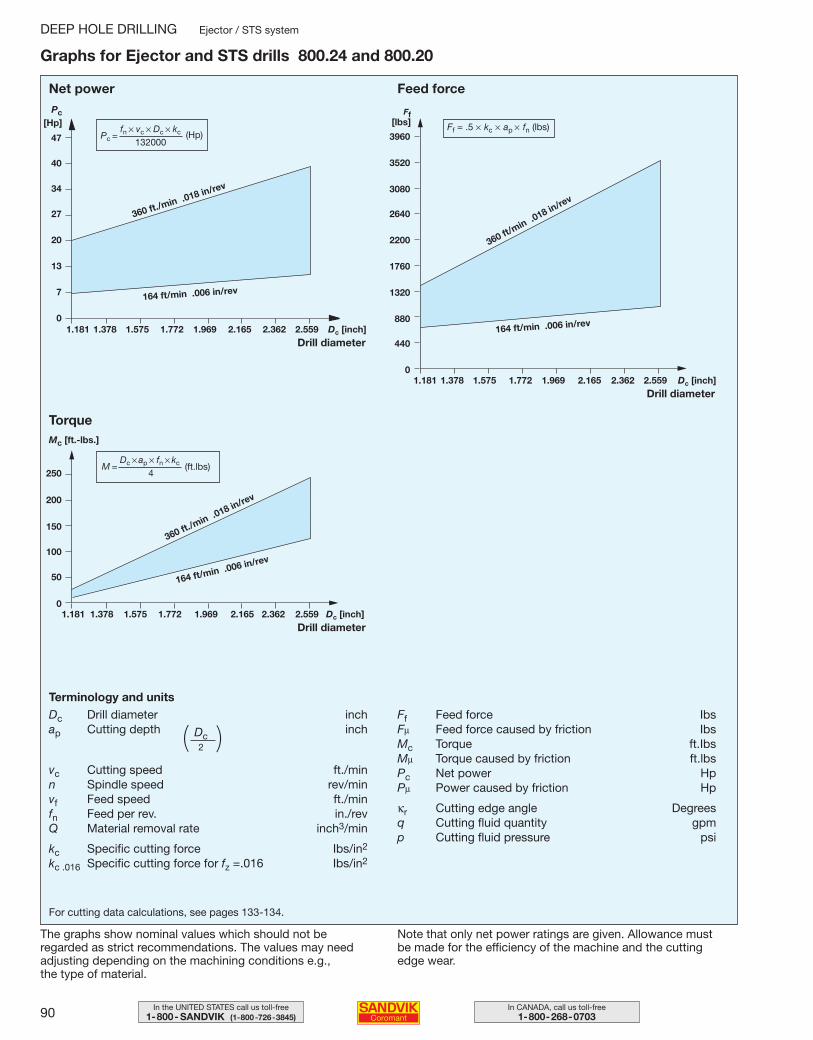
90 In CANADA, call us toll-free1-800-268-0703
In the UNITED STATES call us toll-free1-800- SANDVIK (1-800-726-3845)
DEEP HOLE DRILLING Ejector / STS system
Graphs for Ejector and STS drills 800.24 and 800.20
47
40
34
27
20
13
7
01.181 1.378 1.575 1.772 1.969 2.165 2.362 2.559 Dc [inch]
1.181 1.378 1.575 1.772 1.969 2.165 2.362 2.559 Dc [inch]
1.181 1.378 1.575 1.772 1.969 2.165 2.362 2.559 Dc [inch]
164 ft/min .006 in/rev
360 ft./min .018 in/rev
The graphs show nominal values which should not be regarded as strict recommendations. The values may need adjusting depending on the machining conditions e.g., the type of material.
Note that only net power ratings are given. Allowance must be made for the efficiency of the machine and the cutting edge wear.
3960
3520
3080
2640
2200
1760
1320
880
440
0
164 ft/min .006 in/rev
360 ft/min .0
18 in/rev
250
200
150
100
50
0
Net power
Drill diameter
Pc[Hp]
Feed force
Ff[lbs]
Drill diameter
TorqueMc [ft.-lbs.]
360 ft./min .018 in/rev
164 ft/min .006 in/rev
Drill diameter
For cutting data calculations, see pages 133-134.
Terminology and unitsDc Drill diameter inchap Cutting depth inch
vc Cutting speed ft./minn Spindle speed rev/minvf Feed speed ft./minfn Feed per rev. in./revQ Material removal rate inch3/min
kc Specific cutting force Ibs/in2
kc .016 Specific cutting force for fz =.016 Ibs/in2
Ff Feed force IbsFµ Feed force caused by friction IbsMc Torque ft.IbsMµ Torque caused by friction ft.lbsPc Net power HpPµ Power caused by friction Hp
κr Cutting edge angle Degreesq Cutting fluid quantity gpmp Cutting fluid pressure psi
(Hp)Pc = fn × vc × Dc × kc
132000
Ff = .5 × kc × ap × fn (lbs)
M = Dc × ap × fn × kc
4(ft.lbs)
Dc2( )
086-098 USA 04-04-29 10.14 Sida 90
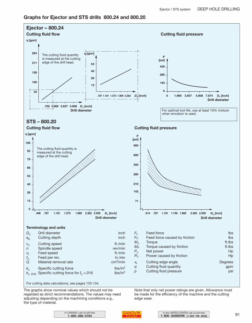
91In the UNITED STATES call us toll-free1-800- SANDVIK (1-800-726-3845)
In CANADA, call us toll-free1-800-268-0703
Ejector / STS system DEEP HOLE DRILLING
Graphs for Ejector and STS drills 800.24 and 800.20
The graphs show nominal values which should not be regarded as strict recommendations. The values may need adjusting depending on the machining conditions e.g., the type of material.
Note that only net power ratings are given. Allowance must be made for the efficiency of the machine and the cutting edge wear.
Ejector – 800.24
STS – 800.20
.750 1.969 3.937 5.906 Dc [inch]
264
211
158
106
53
Cutting fluid flow
q [gpm]
53
40
26
13
q [gpm]
Drill diameter
.787 1.181 1.575 1.969 2.362 Dc [inch]
P[psi]
435
290
145
0
0 1.969 3.937 5.906 7.874 Dc [inch]Drill diameter
Cutting fluid pressure
For optimal tool life, use at least 10% mixturewhen emulsion is used.
900
600
350
280
210
142
71
.614 .787 1.181 1.748 1.968 2.362 2.559 Dc [inch]
106
93
79
66
53
40
26
13
0.496 .787 1.181 1.575 1.969 2.362 2.559 Dc [inch]
Cutting fluid flowq [gpm]
Drill diameter Drill diameter
Cutting fluid pressure
P [psi]
The cutting fluid quantityis measured at the cuttingedge of the drill head.
The cutting fluid quantity ismeasured at the cuttingedge of the drill head.
For cutting data calculations, see pages 133-134.
Terminology and unitsDc Drill diameter inchap Cutting depth inch
vc Cutting speed ft./minn Spindle speed rev/minvf Feed speed ft./minfn Feed per rev. in./revQ Material removal rate cm3/min
kc Specific cutting force Ibs/in2
kc .016 Specific cutting force for fz =.016 Ibs/in2
Ff Feed force IbsFµ Feed force caused by friction IbsMc Torque ft.IbsMµ Torque caused by friction ft.IbsPc Net power HpPµ Power caused by friction Hp
κr Cutting edge angle Degreesq Cutting fluid quantity gpmp Cutting fluid pressure psi
086-098 USA 04-04-29 10.14 Sida 91
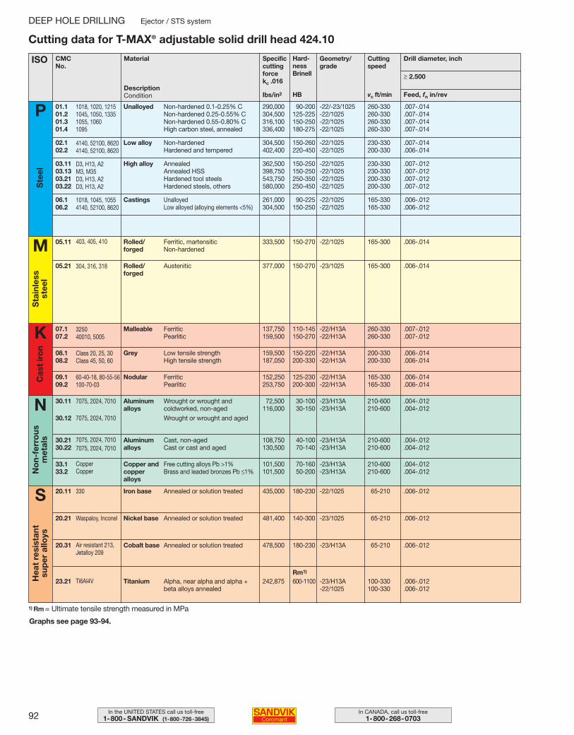
92 In CANADA, call us toll-free1-800-268-0703
In the UNITED STATES call us toll-free1-800- SANDVIK (1-800-726-3845)
DEEP HOLE DRILLING Ejector / STS system
1) Rm = Ultimate tensile strength measured in MPa
Graphs see page 93-94.
Cutting data for T-MAX® adjustable solid drill head 424.10
ISO CMCNo.
Specificcuttingforcekc .016
Hard-ness Brinell
Ibs/in2
Geometry/grade
vc ft/min
Cuttingspeed
Feed, fn in/rev
Drill diameter, inch
Unalloyed 01.101.201.301.4
Non-hardened 0.1-0.25% CNon-hardened 0.25-0.55% CNon-hardened 0.55-0.80% CHigh carbon steel, annealed
Ste
el
P
M
Sta
inle
ss
stee
l
S
≥ 2.500
Material
HB
Low alloy 02.102.2
Non-hardenedHardened and tempered
High alloy03.1103.1303.2103.22
AnnealedAnnealed HSSHardened tool steelsHardened steels, others
Castings06.106.2
UnalloyedLow alloyed (alloying elements <5%)
290,000 90-200 -22/-23/1025 260-330 .007-.014304,500 125-225 -22/1025 260-330 .007-.014316,100 150-250 -22/1025 260-330 .007-.014336,400 180-275 -22/1025 260-330 .007-.014
304,500 150-260 -22/1025 230-330 .007-.014402,400 220-450 -22/1025 200-330 .006-.014
362,500 150-250 -22/1025 230-330 .007-.012398,750 150-250 -22/1025 230-330 .007-.012543,750 250-350 -22/1025 200-330 .007-.012580,000 250-450 -22/1025 200-330 .007-.012
261,000 90-225 -22/1025 165-330 .006-.012304,500 150-250 -22/1025 165-330 .006-.012
Rolled/forged
05.11 Ferritic, martensitic Non-hardened
333,500 150-270 -22/1025 165-300 .006-.014
Rolled/forged
05.21 Austenitic 377,000 150-270 -23/1025 165-300 .006-.014
K Malleable07.107.2
FerriticPearlitic
137,750 110-145 -22/H13A 260-330 .007-.012159,500 150-270 -22/H13A 260-330 .007-.012
Grey08.108.2
Low tensile strengthHigh tensile strength
159,500 150-220 -22/H13A 200-330 .006-.014187,050 200-330 -22/H13A 200-330 .006-.014
Nodular09.109.2
FerriticPearlitic
152,250 125-230 -22/H13A 165-330 .006-.014253,750 200-300 -22/H13A 165-330 .006-.014
Aluminum alloys
30.11
30.12
Wrought or wrought and coldworked, non-agedWrought or wrought and aged
72,500 30-100 -23/H13A 210-600 .004-.012116,000 30-150 -23/H13A 210-600 .004-.012
Aluminum alloys
30.2130.22
Cast, non-agedCast or cast and aged
108,750 40-100 -23/H13A 210-600 .004-.012130,500 70-140 -23/H13A 210-600 .004-.012
Copper and copperalloys
33.133.2
Free cutting alloys Pb >1%Brass and leaded bronzes Pb ≤1%
101,500 70-160 -23/H13A 210-600 .004-.012101,500 50-200 -23/H13A 210-600 .004-.012
Cas
t ir
on
Iron base20.11 Annealed or solution treated 435,000 180-230 -22/1025 65-210 .006-.012
No
n-fe
rro
us
met
als
Hea
t re
sist
ant
sup
er a
lloys
Nickel base20.21 Annealed or solution treated 481,400 140-300 -23/1025 65-210 .006-.012
Cobalt base20.31 Annealed or solution treated 478,500 180-230 -23/H13A 65-210 .006-.012
Titanium23.21 Alpha, near alpha and alpha + beta alloys annealed
242,875 600-1100 -23/H13A 100-330 .006-.012-22/1025 100-330 .006-.012
N
Rm1)
1018, 1020, 12151045, 1050, 13351055, 10601095
4140, 52100, 86204140, 52100, 8620
D3, H13, A2M3, M35D3, H13, A2D3, H13, A2
1018, 1045, 10554140, 52100, 8620
403, 405, 410
304, 316, 318
325040010, 5005
Class 20, 25, 30Class 45, 50, 60
60-40-18, 80-55-56100-70-03
7075, 2024, 7010
7075, 2024, 7010
7075, 2024, 70107075, 2024, 7010
CopperCopper
330
Waspaloy, Inconel
Ti6AI4V
Air resistant 213,Jetalloy 209
DescriptionCondition
086-098 USA 04-04-29 10.14 Sida 92
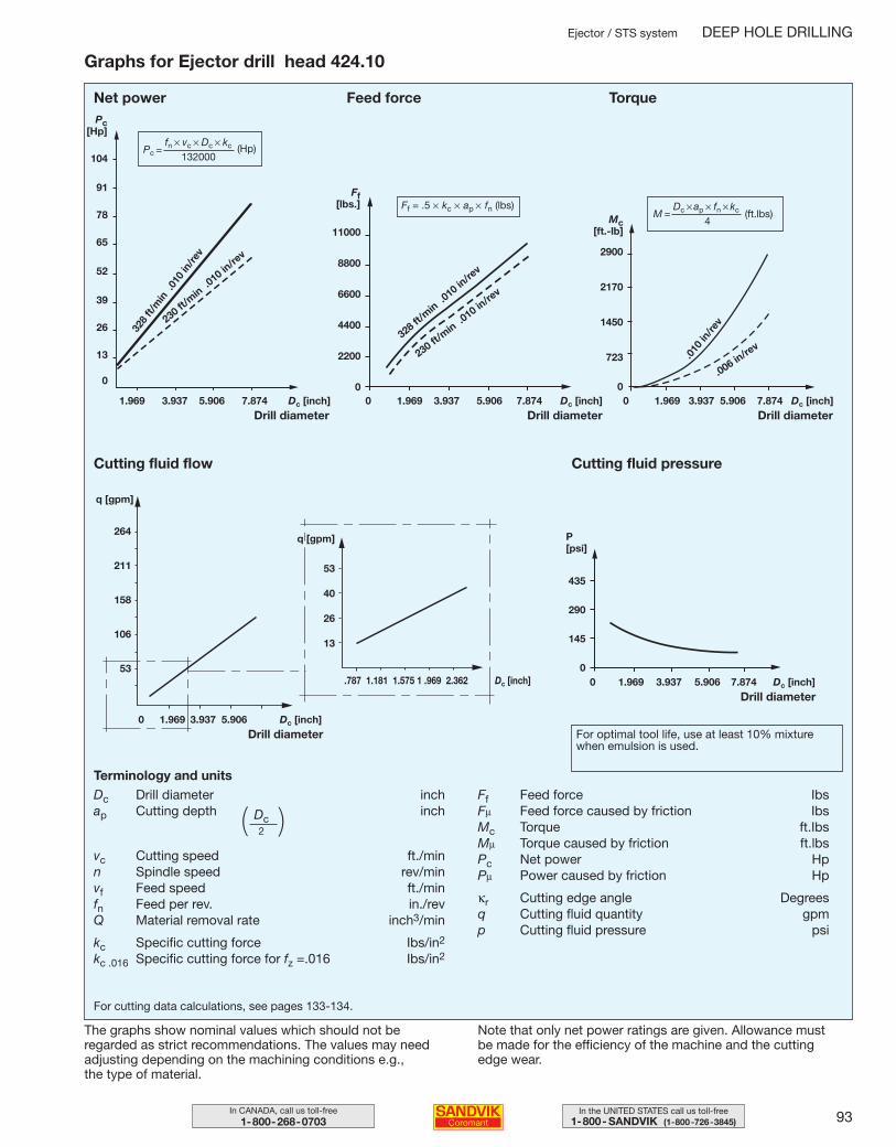
93In the UNITED STATES call us toll-free1-800- SANDVIK (1-800-726-3845)
In CANADA, call us toll-free1-800-268-0703
Ejector / STS system DEEP HOLE DRILLING
Graphs for Ejector drill head 424.10
104
91
78
65
52
39
26
13
0
1.969 3.937 5.906 7.874 Dc [inch]
The graphs show nominal values which should not be regarded as strict recommendations. The values may need adjusting depending on the machining conditions e.g., the type of material.
Note that only net power ratings are given. Allowance must be made for the efficiency of the machine and the cutting edge wear.
11000
8800
6600
4400
2200
00 1.969 3.937 5.906 7.874 Dc [inch]
435
290
145
00 1.969 3.937 5.906 7.874 Dc [inch]
2900
2170
1450
723
00 1.969 3.937 5.906 7.874 Dc [inch]
0 1.969 3.937 5.906 Dc [inch]
264
211
158
106
53
53
40
26
13
.787 1.181 1.575 1 .969 2.362 Dc [inch]
Net power Feed force Torque
.010
in/re
v
.006 in/re
v
Drill diameterDrill diameterDrill diameter
Cutting fluid flow
Drill diameter
Cutting fluid pressure
q [gpm]
q [gpm]
Pc[Hp]
328
ft/m
in .
010
in/re
v
230 ft/m
in .010 in
/rev
Ff [lbs.]
328 ft/m
in .010 in
/rev
230 ft/min .0
10 in/re
v
Mc[ft.-lb]
Drill diameter
P[psi]
For optimal tool life, use at least 10% mixturewhen emulsion is used.
For cutting data calculations, see pages 133-134.
Terminology and unitsDc Drill diameter inchap Cutting depth inch
vc Cutting speed ft./minn Spindle speed rev/minvf Feed speed ft./minfn Feed per rev. in./revQ Material removal rate inch3/min
kc Specific cutting force Ibs/in2
kc .016 Specific cutting force for fz =.016 Ibs/in2
Ff Feed force IbsFµ Feed force caused by friction IbsMc Torque ft.IbsMµ Torque caused by friction ft.lbsPc Net power HpPµ Power caused by friction Hp
κr Cutting edge angle Degreesq Cutting fluid quantity gpmp Cutting fluid pressure psi
(Hp)Pc = fn × vc × Dc × kc
132000
Ff = .5 × kc × ap × fn (lbs)M =
Dc × ap × fn × kc
4(ft.lbs)
Dc2( )
086-098 USA 04-04-29 10.14 Sida 93
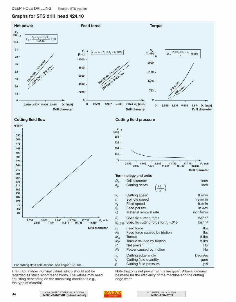
94 In CANADA, call us toll-free1-800-268-0703
In the UNITED STATES call us toll-free1-800- SANDVIK (1-800-726-3845)
DEEP HOLE DRILLING Ejector / STS system
Graphs for STS drill head 424.10
The graphs show nominal values which should not be regarded as strict recommendations. The values may need adjusting depending on the machining conditions e.g., the type of material.
Note that only net power ratings are given. Allowance must be made for the efficiency of the machine and the cutting edge wear.
P[psi]
568
426
284
142
0
2.559 5.906 9.843 13.780 17.717 Dc inch3.937 7.874 11.811 15.748 19.685
2.559 5.906 9.843 13.780 17.717 Dc inch3.937 7.874 11.811 15.748 19.685
530
502
476
449
423
396
370
344
317
291264238211
185159132106
795326
104
91
78
65
52
39
26
13
0
2.559 3.937 5.906 7.874 Dc [inch]
Net power
Drill diameter
Pc[Hp]
328
ft/m
in .
010
in/re
v
230 ft/m
in .010 in
/rev
Ff[lbs.]
11000
8800
6600
4400
2200
00 2.559 3.937 5.906 7.874 Dc [inch]
Feed force
Drill diameter
328 ft/m
in .010 in
/rev
230 ft/min .0
10 in/re
v
Mc[ft.-lb]
2900
2170
1450
723
0
0 2.559 3.937 5.906 7.874 Dc [inch]
Torque
.010
in/re
v
.006 in/re
v
Drill diameter
Cutting fluid flowq [gpm]
Drill diameter
Drill diameter
Cutting fluid pressure
Terminology and unitsDc Drill diameter inchap Cutting depth inch
vc Cutting speed ft./minn Spindle speed rev/minvf Feed speed ft./minfn Feed per rev. in./revQ Material removal rate inch3/min
kc Specific cutting force Ibs/in2
kc .016 Specific cutting force for fz =.016 Ibs/in2
Ff Feed force IbsFµ Feed force caused by friction IbsMc Torque ft.IbsMµ Torque caused by friction ft.lbsPc Net power HpPµ Power caused by friction Hp
κr Cutting edge angle Degreesq Cutting fluid quantity gpmp Cutting fluid pressure psiFor cutting data calculations, see pages 133-134.
(Hp)Pc = fn × vc × Dc × kc
132000
Ff = .5 × kc × ap × fn (lbs)M =
Dc × ap × fn × kc
4(ft.lbs)
Dc2( )
086-098 USA 04-04-29 10.14 Sida 94
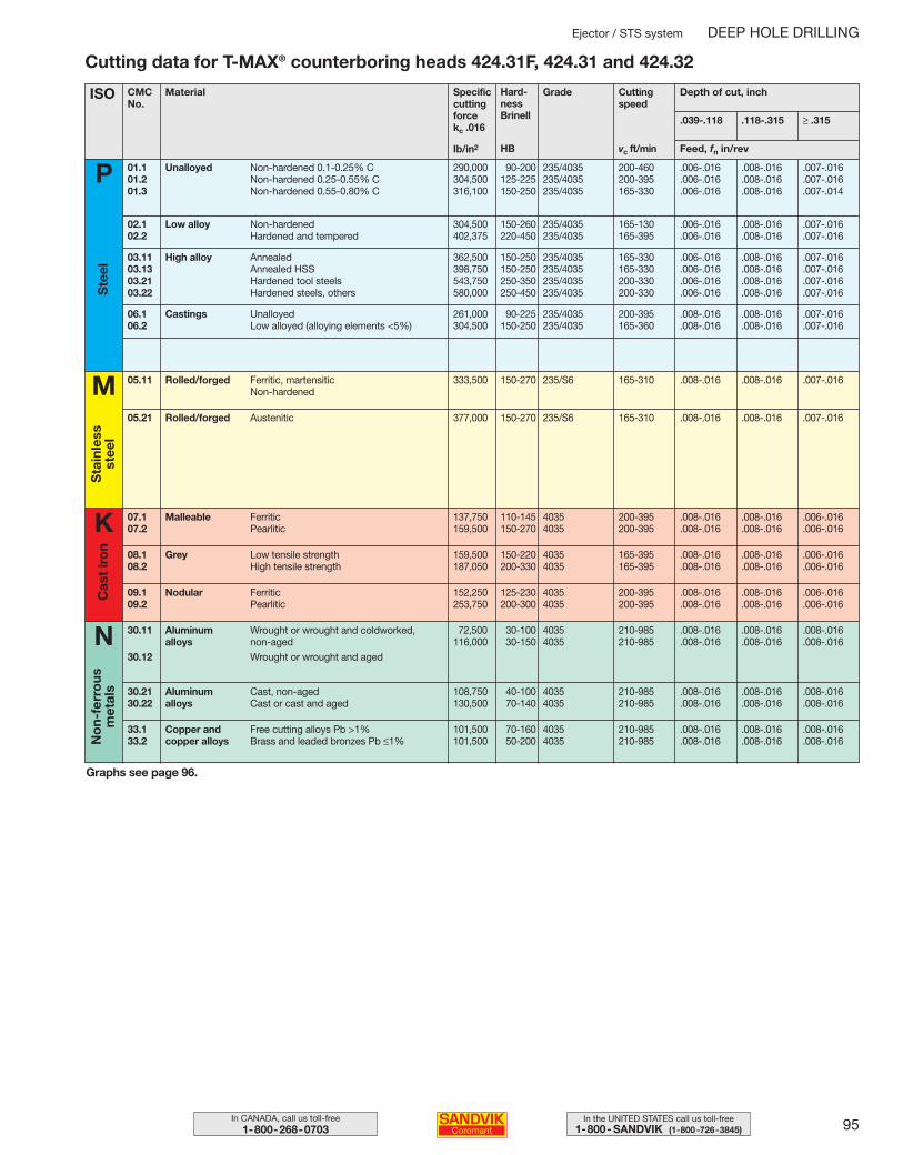
95In the UNITED STATES call us toll-free1-800- SANDVIK (1-800-726-3845)
In CANADA, call us toll-free1-800-268-0703
Ejector / STS system DEEP HOLE DRILLING
Cutting data for T-MAX® counterboring heads 424.31F, 424.31 and 424.32
Graphs see page 96.
ISO CMCNo.
Specificcuttingforcekc .016
Hard-ness Brinell
Ib/in2
Grade
vc ft/min
Cuttingspeed
Feed, fn in/rev
Depth of cut, inch
Unalloyed 01.101.201.3
Non-hardened 0.1-0.25% CNon-hardened 0.25-0.55% CNon-hardened 0.55-0.80% C
Ste
el
P
M
Sta
inle
ss
stee
lMaterial
HB
Low alloy 02.102.2
Non-hardenedHardened and tempered
High alloy03.1103.1303.2103.22
AnnealedAnnealed HSSHardened tool steelsHardened steels, others
Castings06.106.2
UnalloyedLow alloyed (alloying elements <5%)
290,000 90-200 235/4035 200-460 .006-.016 .008-.016 .007-.016304,500 125-225 235/4035 200-395 .006-.016 .008-.016 .007-.016316,100 150-250 235/4035 165-330 .006-.016 .008-.016 .007-.014
304,500 150-260 235/4035 165-130 .006-.016 .008-.016 .007-.016402,375 220-450 235/4035 165-395 .006-.016 .008-.016 .007-.016
362,500 150-250 235/4035 165-330 .006-.016 .008-.016 .007-.016398,750 150-250 235/4035 165-330 .006-.016 .008-.016 .007-.016543,750 250-350 235/4035 200-330 .006-.016 .008-.016 .007-.016580,000 250-450 235/4035 200-330 .006-.016 .008-.016 .007-.016
261,000 90-225 235/4035 200-395 .008-.016 .008-.016 .007-.016304,500 150-250 235/4035 165-360 .008-.016 .008-.016 .007-.016
Rolled/forged05.11 Ferritic, martensitic Non-hardened
333,500 150-270 235/S6 165-310 .008-.016 .008-.016 .007-.016
Rolled/forged05.21 Austenitic 377,000 150-270 235/S6 165-310 .008-.016 .008-.016 .007-.016
K Malleable07.107.2
FerriticPearlitic
137,750 110-145 4035 200-395 .008-.016 .008-.016 .006-.016159,500 150-270 4035 200-395 .008-.016 .008-.016 .006-.016
Grey08.108.2
Low tensile strengthHigh tensile strength
159,500 150-220 4035 165-395 .008-.016 .008-.016 .006-.016187,050 200-330 4035 165-395 .008-.016 .008-.016 .006-.016
Nodular09.109.2
FerriticPearlitic
152,250 125-230 4035 200-395 .008-.016 .008-.016 .006-.016253,750 200-300 4035 200-395 .008-.016 .008-.016 .006-.016
Aluminum alloys
30.11
30.12
Wrought or wrought and coldworked, non-agedWrought or wrought and aged
72,500 30-100 4035 210-985 .008-.016 .008-.016 .008-.016116,000 30-150 4035 210-985 .008-.016 .008-.016 .008-.016
Aluminum alloys
30.2130.22
Cast, non-agedCast or cast and aged
108,750 40-100 4035 210-985 .008-.016 .008-.016 .008-.016130,500 70-140 4035 210-985 .008-.016 .008-.016 .008-.016
Copper and copper alloys
33.133.2
Free cutting alloys Pb >1%Brass and leaded bronzes Pb ≤1%
101,500 70-160 4035 210-985 .008-.016 .008-.016 .008-.016101,500 50-200 4035 210-985 .008-.016 .008-.016 .008-.016
Cas
t ir
on
No
n-fe
rro
us
met
als
N
.039-.118 .118-.315 ≥ .315
086-098 USA 04-04-29 10.14 Sida 95
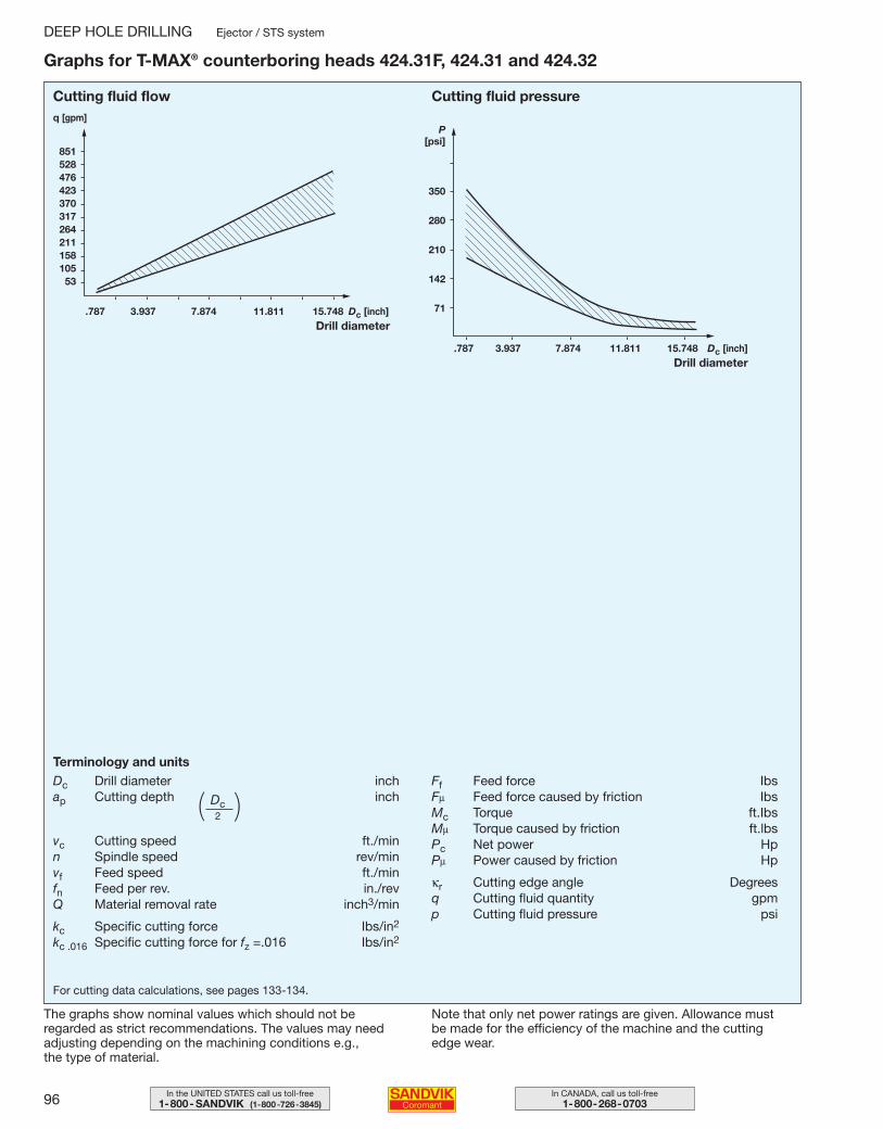
96 In CANADA, call us toll-free1-800-268-0703
In the UNITED STATES call us toll-free1-800- SANDVIK (1-800-726-3845)
DEEP HOLE DRILLING Ejector / STS system
Graphs for T-MAX® counterboring heads 424.31F, 424.31 and 424.32
85152847642337031726421115810553
.787 3.937 7.874 11.811 15.748 Dc [inch]
Cutting fluid flowq [gpm]
Drill diameter
P[psi]
350
280
210
142
71
.787 3.937 7.874 11.811 15.748 Dc [inch]Drill diameter
Cutting fluid pressure
For cutting data calculations, see pages 133-134.
Terminology and unitsDc Drill diameter inchap Cutting depth inch
vc Cutting speed ft./minn Spindle speed rev/minvf Feed speed ft./minfn Feed per rev. in./revQ Material removal rate inch3/min
kc Specific cutting force Ibs/in2
kc .016 Specific cutting force for fz =.016 Ibs/in2
Ff Feed force IbsFµ Feed force caused by friction IbsMc Torque ft.IbsMµ Torque caused by friction ft.lbsPc Net power HpPµ Power caused by friction Hp
κr Cutting edge angle Degreesq Cutting fluid quantity gpmp Cutting fluid pressure psi
The graphs show nominal values which should not be regarded as strict recommendations. The values may need adjusting depending on the machining conditions e.g., the type of material.
Note that only net power ratings are given. Allowance must be made for the efficiency of the machine and the cutting edge wear.
Dc2( )
086-098 USA 04-04-29 10.14 Sida 96
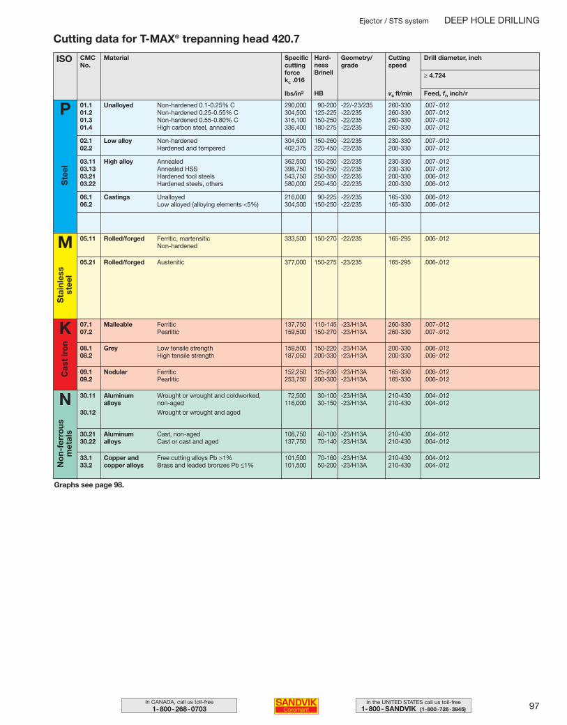
97In the UNITED STATES call us toll-free1-800- SANDVIK (1-800-726-3845)
In CANADA, call us toll-free1-800-268-0703
Ejector / STS system DEEP HOLE DRILLING
Cutting data for T-MAX® trepanning head 420.7
Graphs see page 98.
ISO CMCNo.
Specificcuttingforcekc .016
Hard-ness Brinell
Ibs/in2
Geometry/grade
vc ft/min
Cuttingspeed
Feed, fn inch/r
Drill diameter, inch
Unalloyed 01.101.201.301.4
Non-hardened 0.1-0.25% CNon-hardened 0.25-0.55% CNon-hardened 0.55-0.80% CHigh carbon steel, annealed
Ste
el
P
M
Sta
inle
ss
stee
l≥ 4.724
Material
HB
Low alloy 02.102.2
Non-hardenedHardened and tempered
High alloy03.1103.1303.2103.22
AnnealedAnnealed HSSHardened tool steelsHardened steels, others
Castings06.106.2
UnalloyedLow alloyed (alloying elements <5%)
290,000 90-200 -22/-23/235 260-330 .007-.012304,500 125-225 -22/235 260-330 .007-.012316,100 150-250 -22/235 260-330 .007-.012336,400 180-275 -22/235 260-330 .007-.012
304,500 150-260 -22/235 230-330 .007-.012402,375 220-450 -22/235 200-330 .007-.012
362,500 150-250 -22/235 230-330 .007-.012398,750 150-250 -22/235 230-330 .007-.012543,750 250-350 -22/235 200-330 .006-.012580,000 250-450 -22/235 200-330 .006-.012
216,000 90-225 -22/235 165-330 .006-.012304,500 150-250 -22/235 165-330 .006-.012
Rolled/forged05.11 Ferritic, martensitic Non-hardened
333,500 150-270 -22/235 165-295 .006-.012
Rolled/forged05.21 Austenitic 377,000 150-275 -23/235 165-295 .006-.012
K Malleable07.107.2
FerriticPearlitic
137,750 110-145 -23/H13A 260-330 .007-.012159,500 150-270 -23/H13A 260-330 .007-.012
Grey08.108.2
Low tensile strengthHigh tensile strength
159,500 150-220 -23/H13A 200-330 .006-.012187,050 200-330 -23/H13A 200-330 .006-.012
Nodular09.109.2
FerriticPearlitic
152,250 125-230 -23/H13A 165-330 .006-.012253,750 200-300 -23/H13A 165-330 .006-.012
Aluminum alloys
30.11
30.12
Wrought or wrought and coldworked, non-agedWrought or wrought and aged
72,500 30-100 -23/H13A 210-430 .004-.012116,000 30-150 -23/H13A 210-430 .004-.012
Aluminum alloys
30.2130.22
Cast, non-agedCast or cast and aged
108,750 40-100 -23/H13A 210-430 .004-.012137,750 70-140 -23/H13A 210-430 .004-.012
Copper and copper alloys
33.133.2
Free cutting alloys Pb >1%Brass and leaded bronzes Pb ≤1%
101,500 70-160 -23/H13A 210-430 .004-.012101,500 50-200 -23/H13A 210-430 .004-.012
Cas
t ir
on
No
n-fe
rro
us
met
als
N
086-098 USA 04-04-29 10.14 Sida 97
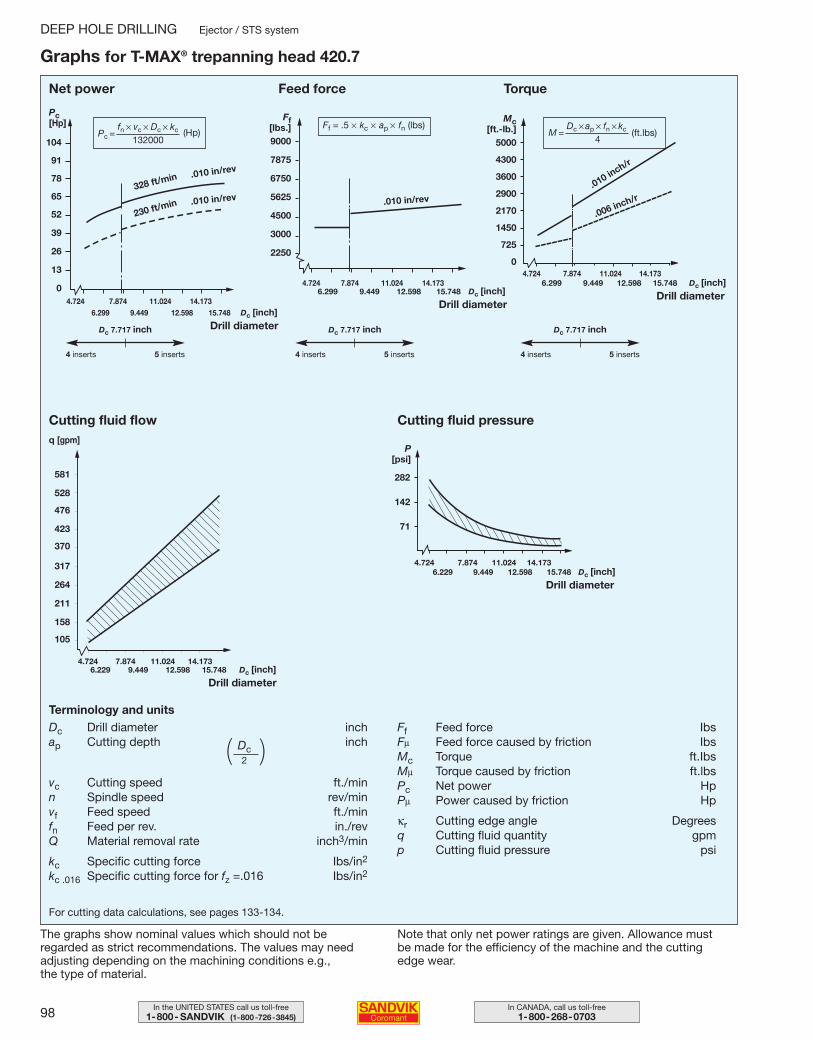
98 In CANADA, call us toll-free1-800-268-0703
In the UNITED STATES call us toll-free1-800- SANDVIK (1-800-726-3845)
DEEP HOLE DRILLING Ejector / STS system
Graphs for T-MAX® trepanning head 420.7
The graphs show nominal values which should not be regarded as strict recommendations. The values may need adjusting depending on the machining conditions e.g., the type of material.
Note that only net power ratings are given. Allowance must be made for the efficiency of the machine and the cutting edge wear.
Mc[ft.-lb.]
5000
4300
3600
2900
2170
1450
725
0
Ff[lbs.]9000
7875
6750
5625
4500
3000
2250
104
91
78
65
52
39
26
13
0
Dc 7.717 inch
4.724 7.874 11.024 14.1736.299 9.449 12.598 15.748 Dc [inch]
282
142
71
581
528
476
423
370
317
264
211
158
105
.010 in/rev
.010 in/rev
.010 inch/r
.006 inch/r.010 in/rev
230 ft/min
328 ft/min
5 inserts4 inserts
Net power
Drill diameter
Pc[Hp]
Feed force
Drill diameter
Torque
Drill diameter
Dc 7.717 inch
5 inserts4 inserts
Dc 7.717 inch
5 inserts4 inserts
4.724 7.874 11.024 14.1736.299 9.449 12.598 15.748 Dc [inch]
4.724 7.874 11.024 14.1736.299 9.449 12.598 15.748 Dc [inch]
Cutting fluid flowq [gpm]
Drill diameter
4.724 7.874 11.024 14.1736.229 9.449 12.598 15.748 Dc [inch]
Drill diameter
Cutting fluid pressure
P[psi]
4.724 7.874 11.024 14.173 6.229 9.449 12.598 15.748 Dc [inch]
For cutting data calculations, see pages 133-134.
Terminology and unitsDc Drill diameter inchap Cutting depth inch
vc Cutting speed ft./minn Spindle speed rev/minvf Feed speed ft./minfn Feed per rev. in./revQ Material removal rate inch3/min
kc Specific cutting force Ibs/in2
kc .016 Specific cutting force for fz =.016 Ibs/in2
Ff Feed force IbsFµ Feed force caused by friction IbsMc Torque ft.IbsMµ Torque caused by friction ft.lbsPc Net power HpPµ Power caused by friction Hp
κr Cutting edge angle Degreesq Cutting fluid quantity gpmp Cutting fluid pressure psi
(Hp)Pc = fn × vc × Dc × kc
132000
Ff = .5 × kc × ap × fn (lbs)M =
Dc × ap × fn × kc
4(ft.lbs)
Dc2( )
086-098 USA 04-04-29 10.14 Sida 98
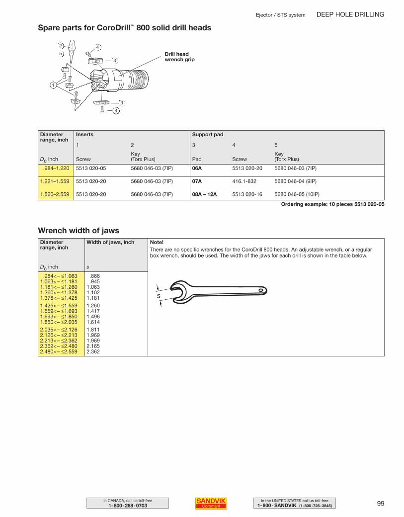
99In the UNITED STATES call us toll-free1-800- SANDVIK (1-800-726-3845)
In CANADA, call us toll-free1-800-268-0703
Spare parts for CoroDrill™ 800 solid drill heads
Ordering example: 10 pieces 5513 020-05
Drill headwrench grip
Wrench width of jaws
2
1
3
45
3
4
Note!There are no specific wrenches for the CoroDrill 800 heads. An adjustable wrench, or a regularbox wrench, should be used. The width of the jaws for each drill is shown in the table below.
Diameter range, inch
Inserts
.984–1.220 5513 020-05 5680 046-03 (7IP) 06A 5513 020-20 5680 046-03 (7IP)
1.221–1.559 5513 020-20 5680 046-03 (7IP) 07A 416.1-832 5680 046-04 (9IP)
1.560–2.559 5513 020-20 5680 046-03 (7IP) 08A – 12A 5513 020-16 5680 046-05 (10IP)
Dc inch Screw
1 2 3 4 5
Key (Torx Plus)
Support pad
Pad ScrewKey (Torx Plus)
Diameter range, inch
Dc inch
Width of jaws, inch
.984<– ≤1.063 .8661.063<– ≤1.181 .9451.181<– ≤1.260 1.0631.260<– ≤1.378 1.1021.378<– ≤1.425 1.1811.425<– ≤1.559 1.2601.559<– ≤1.693 1.4171.693<– ≤1.850 1.4961.850<– ≤2.035 1.6142.035<– ≤2.126 1.8112.126<– ≤2.213 1.9692.213<– ≤2.362 1.9692.362<– ≤2.480 2.1652.480<– ≤2.559 2.362
s
Ejector / STS system DEEP HOLE DRILLING
099-108 USA 04-04-29 10.17 Sida 99
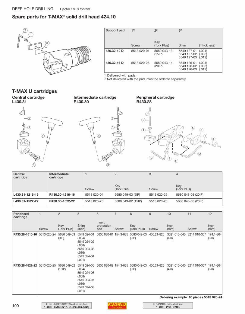
100 In CANADA, call us toll-free1-800-268-0703
In the UNITED STATES call us toll-free1-800- SANDVIK (1-800-726-3845)
T-MAX U cartridgesCentral cartridgeL430.31
Intermediate cartridgeR430.30
Central cartridge
Intermediate cartridge
1 2 3 4
Screw
L430.31-1216-16 R430.30-1216-16 5513 020-04 5680 049-03 (9IP) 5513 020-26 5680 048-03 (20IP)
L430.31-1522-22 R430.30-1522-22 5513 020-25 5680 049-02 (15IP) 5513 020-26 5680 048-03 (20IP)
Peripheral cartridge
1 2 5 6 7 8 9 10 11 12
R430.28-1516-16 5513 020-24 5680 049-03 5549 024-01 5636 030-01 154.3-835 5680 049-03 430.21-825 3021 010-040 3214 010-357 174.1-864(9IP) (.004) (9IP) (4.0) (3.0)
5549 024-02(.008)5549 024-03(.016)5549 024-04(.031)
R430.28-1822-22 5513 020-25 5680 049-02 5549 024-05 5636 030-02 154.3-835 5680 049-03 430.21-825 3021 010-040 3214 010-357 174.1-864(15IP) (.004) (9IP) (4.0) (3.0)
5549 024-06(.008)5549 024-07(.016)5549 024-08(.031)
Ordering example: 10 pieces 5513 020-24
ScrewKey (Torx Plus)
Shim(inch)
Insert protectionpad Screw
Key (Torx Plus) Screw
Key(mm) Screw
Key(mm)
Spare parts for T-MAX® solid drill head 424.10
1) Delivered with pads.2) Not delivered with the pad, must be ordered separately.
Support pad 11) 22) 32)
ScrewKey (Torx Plus) Shim
430.32-12 D 5513 020-01 5680 043-13 5549 127-01 (.004)(15IP) 5549 127-02 (.008)
5549 127-03 (.012)
430.32-16 D 5513 020-26 5680 043-14 5549 126-01 (.004)(20IP) 5549 126-02 (.008)
5549 126-03 (.012)
Peripheral cartridgeR430.28
DEEP HOLE DRILLING Ejector / STS system
2
1
3(Thickness)
Key (Torx Plus)
Key (Torx Plus)Screw
1
2
4
3
2
1
10 911
12
87
65
2
1
4
3
099-108 USA 04-04-29 10.17 Sida 100
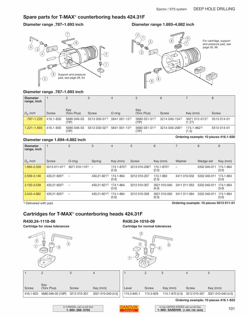
101In the UNITED STATES call us toll-free1-800- SANDVIK (1-800-726-3845)
In CANADA, call us toll-free1-800-268-0703
Spare parts for T-MAX® counterboring heads 424.31FDiameter range .787–1.693 inch Diameter range 1.693–4.882 inch
Support and pressurepad, see page 28, 64
Diameter range .787–1.693 inch
ScrewKey (Torx Plus) Screw O-ring
Key (Torx Plus) Screw Key (mm) Screw
1 2 3 4 5 6 7 8
.787–1.220 416.1-830 5680 046-03 5513 030-011) 5641 001-131) 5680 051-011) 3214 040-1541) 3021 012-0131) 5513 014-01(7IP) (7IP) (1.27)
1.221–1.693 416.1-830 5680 046-03 5513 030-021) 5641 001-131) 5680 051-011) 3214 040-2061) 174.1-8621) 5513 014-01(7IP) (7IP) (1.5)
Diameter range 1.694–4.882 inch
Screw O-ring Spring Key (mm) Screw Key (mm) Washer Wedge set Key (mm)
1 2 3 4 5 6 7 8 9
1.694–2.559 5513 011-011) 3671 010-1101) – 174.1-8701) 3213 010-2061) 174.1-8701) – 5332 040-011 174.1-864(2.0) (2.0) (3.0)
2.559–3.146 430.21-8201) – 430.21-8211) 174.1-864 3212 010-207 174.1-863 3411 010-032 5332 040-011 174.1-864(3.0) (2.5) (3.0)
3.150–3.539 430.21-8201) – 430.21-8211) 174.1-864 3212 010-307 3021 010-040 3411 011-053 5332 040-011 174.1-864(3.0) (4.0) (3.0)
3.543–4.882 430.21-8201) – 430.21-8211) 174.1-864 3212 010-358 3021 010-050 3411 011-064 5332 040-011 174.1-864(3.0) (5.0) (3.0)
1) Delivered with pad. Ordering example: 10 pieces 5513 011-01
Cartridges for T-MAX® counterboring heads 424.31FR430.24-1118-06 R430.24-1018-09
1 2 3 4
Key (Torx Plus) Key (mm)ScrewScrew
416.1-833 5680 046-05 (10IP) 3212 010-307 3021 010-040 (4.0)
1 2 3 4 5
Screw Screw Key (mm)Key (mm)Lever
174.3-845-1 174.3-829 174.1-870 (2.0) 3212 010-307 3021 010-040 (4.0)
Ordering example: 10 pieces 416.1-833
Cartridge for close tolerances Cartridge for normal tolerances
Ejector / STS system DEEP HOLE DRILLING
1
2
6
7
53
4
8
2
41
3
2
98
67
5For cartridge, supportand pressure pad, seepage 30, 66
Diameter range, inch
Dc inch
Diameter range, inch
Dc inch
2
1 34
3
2
1
54
Ordering example: 10 pieces 416.1-830
099-108 USA 04-04-29 10.17 Sida 101
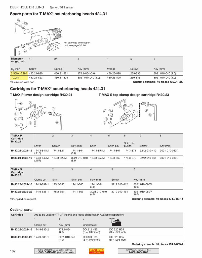
102 In CANADA, call us toll-free1-800-268-0703
In the UNITED STATES call us toll-free1-800- SANDVIK (1-800-726-3845)
Spare parts for T-MAX® counterboring heads 424.31
Screw Spring Key (mm) Wedge Screw Key (mm)
11) 21) 3 4 5 6
2.559–10.984 430.21-820 430.21-821 174.1-864 (3.0) 430.23-820 269-833 3021 010-040 (4.0)
10.984– 430.21-823 430.21-824 3021 010-040 (4.0) 430.23-820 269-833 3021 010-040 (4.0)
Ordering example: 10 pieces 430.21-8201) Delivered with pad.
T-MAX PCartridgeR430.24
Lever Screw Key (mm) Shim Shim pinShim pinpunch Screw Key (mm)
1 2 3 4 5 6 7 8
R430.24-2024-12 174.3-841M 174.3-821 174.1-864 174.3-851M 174.3-861 174.3-871 3212 010-412 3021 010-0601)
(.118) (6.0)
R430.24-2532-19 174.3-842M 174.3-822M 3021 010-040 174.3-852M 174.3-862 174.3-872 3212 010-464 3021 010-0801)
(.157) (8.0)
Cartridges for T-MAX® counterboring heads 424.31T-MAX P lever design cartridge R430.24 T-MAX S top clamp design cartridge R430.23
T-MAX SCartridgeR430.23
Clamp set Shim Shim pin Key (mm) Screw Key (mm)
1 2 3 4 5 6
R430.23-2024-16 174.9-837-1 175.2-850 174.1-865 174.1-864 3212 010-412 3021 010-0601)
(3.0) (6.0)
R430.23-2532-22 174.9-838-1 175.2-851 174.1-866 3021 010-040 3212 010-464 3021 010-0801)
(4.0) (8.0)
Ordering example: 10 pieces 174.9-837-11) Supplied on request
Cartridge
Clamp set Key (mm) Chipbreaker
1 4 7
R430.23-2024-16 174.9-833-2 174.1-864 DO 212 H35 DO 220 H35(3.0) (B = .047 inch) (B = .079 inch)
R430.23-2532-22 174.9-835-1 3021 010-040 DO 320 H35 DO 325 H35(4.0) (B = .079 inch) (B = .098 inch)
Ordering example: 10 pieces 174.9-833-2
Optional partsAre to be used for TPUN inserts and loose chipbreaker. Available separately.
DEEP HOLE DRILLING Ejector / STS system
For cartridge and supportpad, see page 32, 68
31
2
64
5
Diameter range, inch
Dc inch
6 3
7
82
5
4
1
6
5
14
7
3
2
099-108 USA 04-05-07 08.52 Sida 102
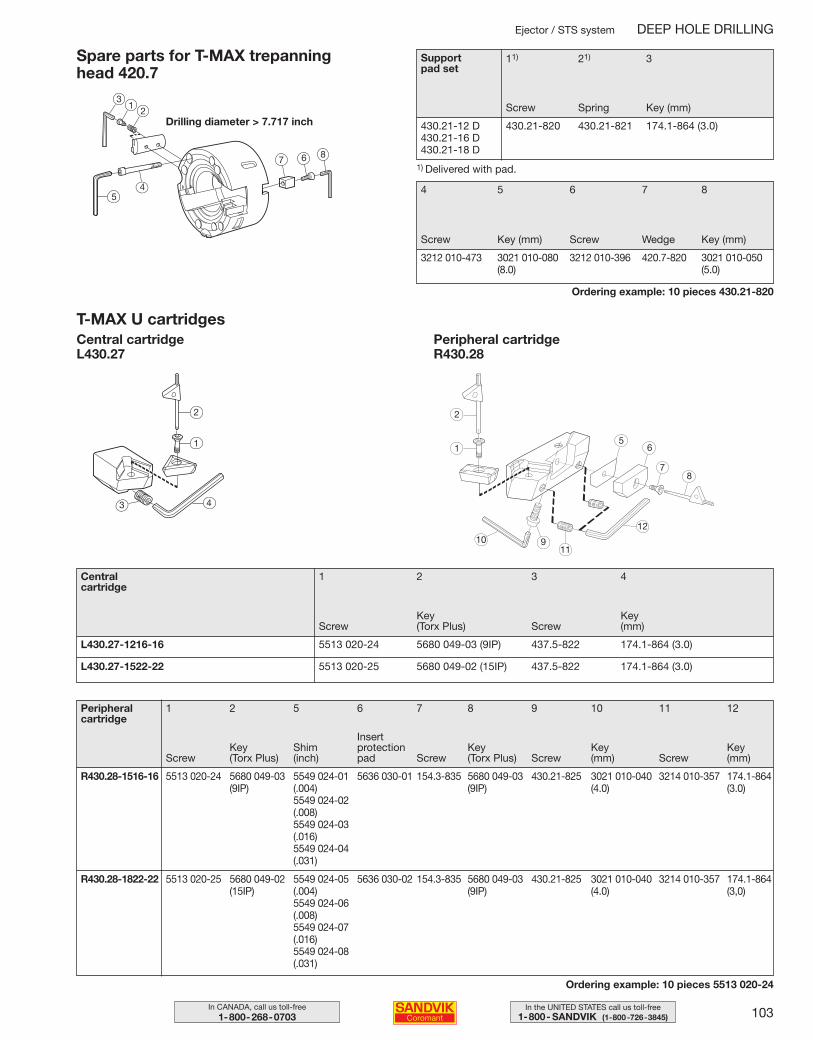
103In the UNITED STATES call us toll-free1-800- SANDVIK (1-800-726-3845)
In CANADA, call us toll-free1-800-268-0703
Spare parts for T-MAX trepanning head 420.7
Drilling diameter > 7.717 inch
Ordering example: 10 pieces 430.21-820
4 5 6 7 8
Screw Key (mm) Screw Wedge Key (mm)
3212 010-473 3021 010-080 3212 010-396 420.7-820 3021 010-050(8.0) (5.0)
11) 21) 3
Screw Spring Key (mm)
430.21-12 D 430.21-820 430.21-821 174.1-864 (3.0)430.21-16 D430.21-18 D
Supportpad set
1) Delivered with pad.
Ejector / STS system DEEP HOLE DRILLING
31
2
54
7 6 8
Central cartridge
1 2 3 4
Screw
L430.27-1216-16 5513 020-24 5680 049-03 (9IP) 437.5-822 174.1-864 (3.0)
L430.27-1522-22 5513 020-25 5680 049-02 (15IP) 437.5-822 174.1-864 (3.0)
Peripheral cartridge
1 2 5 6 7 8 9 10 11 12
R430.28-1516-16 5513 020-24 5680 049-03 5549 024-01 5636 030-01 154.3-835 5680 049-03 430.21-825 3021 010-040 3214 010-357 174.1-864(9IP) (.004) (9IP) (4.0) (3.0)
5549 024-02(.008)5549 024-03(.016)5549 024-04(.031)
R430.28-1822-22 5513 020-25 5680 049-02 5549 024-05 5636 030-02 154.3-835 5680 049-03 430.21-825 3021 010-040 3214 010-357 174.1-864(15IP) (.004) (9IP) (4.0) (3,0)
5549 024-06(.008)5549 024-07(.016)5549 024-08(.031)
Ordering example: 10 pieces 5513 020-24
ScrewKey (Torx Plus)
Shim(inch)
Insert protectionpad Screw
Key (Torx Plus) Screw
Key(mm) Screw
Key(mm)
Key (Torx Plus)
Key (mm)Screw
Peripheral cartridgeR430.28
2
1
10 911
12
87
65
T-MAX U cartridgesCentral cartridgeL430.27
2
1
43
099-108 USA 04-04-29 10.17 Sida 103
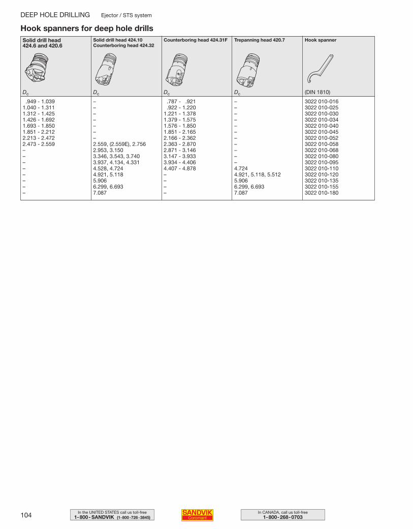
104 In CANADA, call us toll-free1-800-268-0703
In the UNITED STATES call us toll-free1-800- SANDVIK (1-800-726-3845)
Hook spanners for deep hole drillsSolid drill head 424.6 and 420.6
Solid drill head 424.10 Counterboring head 424.32
Counterboring head 424.31F Trepanning head 420.7 Hook spanner
DEEP HOLE DRILLING Ejector / STS system
Dc Dc Dc Dc (DIN 1810)
.949 - 1.039 – .787 - .921 – 3022 010-0161.040 - 1.311 – .922 - 1.220 – 3022 010-0251.312 - 1.425 – 1.221 - 1.378 – 3022 010-0301.426 - 1.692 – 1.379 - 1.575 – 3022 010-0341.693 - 1.850 – 1.576 - 1.850 – 3022 010-0401.851 - 2.212 – 1.851 - 2.165 – 3022 010-0452.213 - 2.472 – 2.166 - 2.362 – 3022 010-0522.473 - 2.559 2.559, (2.559E), 2.756 2.363 - 2.870 – 3022 010-058– 2.953, 3.150 2.871 - 3.146 – 3022 010-068– 3.346, 3.543, 3.740 3.147 - 3.933 – 3022 010-080– 3.937, 4.134, 4.331 3.934 - 4.406 – 3022 010-095– 4.528, 4.724 4.407 - 4.878 4.724 3022 010-110– 4.921, 5.118 – 4.921, 5.118, 5.512 3022 010-120– 5.906 – 5.906 3022 010-135– 6.299, 6.693 – 6.299, 6.693 3022 010-155– 7.087 – 7.087 3022 010-180
099-108 USA 04-04-29 10.17 Sida 104
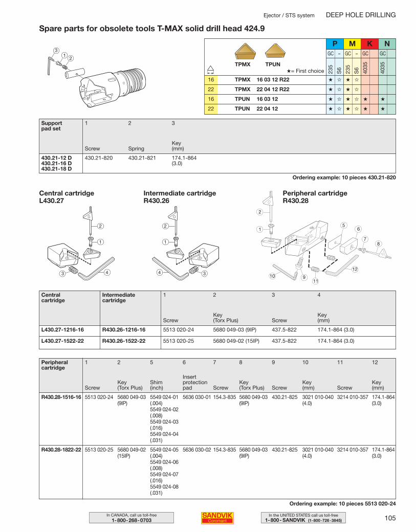
105In the UNITED STATES call us toll-free1-800- SANDVIK (1-800-726-3845)
In CANADA, call us toll-free1-800-268-0703
Intermediate cartridgeR430.26
Spare parts for obsolete tools T-MAX solid drill head 424.9
Ordering example: 10 pieces 430.21-820
Support pad set
1 2 3
430.21-12 D 430.21-820 430.21-821 174.1-864430.21-16 D (3.0)430.21-18 D
M KP
Ejector / STS system DEEP HOLE DRILLING
Central cartridge
Intermediate cartridge
1 2 3 4
Screw
L430.27-1216-16 R430.26-1216-16 5513 020-24 5680 049-03 (9IP) 437.5-822 174.1-864 (3.0)
L430.27-1522-22 R430.26-1522-22 5513 020-25 5680 049-02 (15IP) 437.5-822 174.1-864 (3.0)
Peripheral cartridge
1 2 5 6 7 8 9 10 11 12
R430.28-1516-16 5513 020-24 5680 049-03 5549 024-01 5636 030-01 154.3-835 5680 049-03 430.21-825 3021 010-040 3214 010-357 174.1-864(9IP) (.004) (9IP) (4.0) (3.0)
5549 024-02(.008)5549 024-03(.016)5549 024-04(.031)
R430.28-1822-22 5513 020-25 5680 049-02 5549 024-05 5636 030-02 154.3-835 5680 049-03 430.21-825 3021 010-040 3214 010-357 174.1-864(15IP) (.004) (9IP) (4.0) (3.0)
5549 024-06(.008)5549 024-07(.016)5549 024-08(.031)
Ordering example: 10 pieces 5513 020-24
ScrewKey (Torx Plus)
Shim(inch)
Insert protectionpad Screw
Key (Torx Plus) Screw
Key(mm) Screw
Key(mm)
Key (Torx Plus)
Key(mm)Screw
31
2
235
S6
235
S6
4035
4035
GC – GC – GC GC
N
TPUNTPMX
16 TPMX 16 03 12 R22 ★ ✩ ★ ✩
22 TPMX 22 04 12 R22 ★ ✩ ★ ✩
16 TPUN 16 03 12 ★ ✩ ★ ✩ ★ ★
22 TPUN 22 04 12 ★ ✩ ★ ✩ ★ ★
★= First choice
Screw SpringKey(mm)
Peripheral cartridgeR430.28
2
1
10 911
12
87
65
Central cartridgeL430.27
2
1
43
2
1
4 3
099-108 USA 04-04-29 10.17 Sida 105
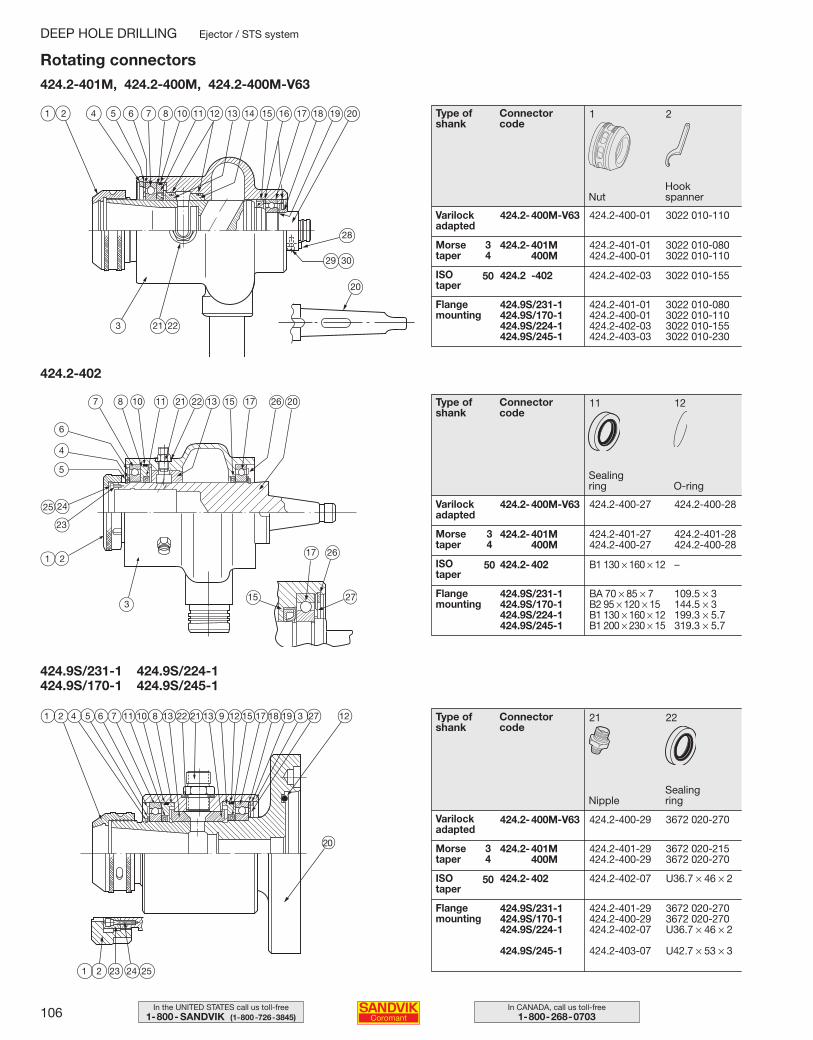
106 In CANADA, call us toll-free1-800-268-0703
In the UNITED STATES call us toll-free1-800- SANDVIK (1-800-726-3845)
21 22
424.2-400M-V63 424.2-400-29 3672 020-270
424.2-401M 424.2-401-29 3672 020-215400M 424.2-400-29 3672 020-270
424.2-402 424.2-402-07 U36.7 × 46 × 2
424.9S/231-1 424.2-401-29 3672 020-270424.9S/170-1 424.2-400-29 3672 020-270424.9S/224-1 424.2-402-07 U36.7 × 46 × 2
424.9S/245-1 424.2-403-07 U42.7 × 53 × 3
11 12
424.2-400M-V63 424.2-400-27 424.2-400-28
424.2-401M 424.2-401-27 424.2-401-28400M 424.2-400-27 424.2-400-28
424.2-402 B1 130 × 160 × 12 –
424.9S/231-1 BA 70 × 85 × 7 109.5 × 3424.9S/170-1 B2 95 × 120 × 15 144.5 × 3424.9S/224-1 B1 130 × 160 × 12 199.3 × 5.7424.9S/245-1 B1 200 × 230 × 15 319.3 × 5.7
1 2
424.2-400M-V63 424.2-400-01 3022 010-110
424.2-401M 424.2-401-01 3022 010-080400M 424.2-400-01 3022 010-110
424.2 -402 424.2-402-03 3022 010-155
424.9S/231-1 424.2-401-01 3022 010-080424.9S/170-1 424.2-400-01 3022 010-110424.9S/224-1 424.2-402-03 3022 010-155424.9S/245-1 424.2-403-03 3022 010-230
Type of shank
Connector code
Nut
Sealingring
Rotating connectors424.2-401M, 424.2-400M, 424.2-400M-V63
424.2-402
424.9S/231-1 424.9S/224-1424.9S/170-1 424.9S/245-1
20
DEEP HOLE DRILLING Ejector / STS system
3
1 2 4 5 6 7 8 10 11 12 13 14 15 16 17 18 19 20
28
29 30
20
21 22
7 8 10 11 21 1322 15 17 26 20
17 26
27153
6
4
5
25 24
23
1 2
1 2 4 5 6 7 81011 2213 21 9 12 15 17 18 1913 3 27
1 2 23 24 25
12
Hookspanner
Varilock adapted
Flange mounting
Morse taper
ISO taper
Type of shank
Connector code
Varilock adapted
Flange mounting
Morse taper
ISO taper
O-ring
Type of shank
Connector code
Varilock adapted
Flange mounting
Morse taper
ISO taper
NippleSealing ring
34
50
34
50
34
50
099-108 USA 04-05-07 09.21 Sida 106
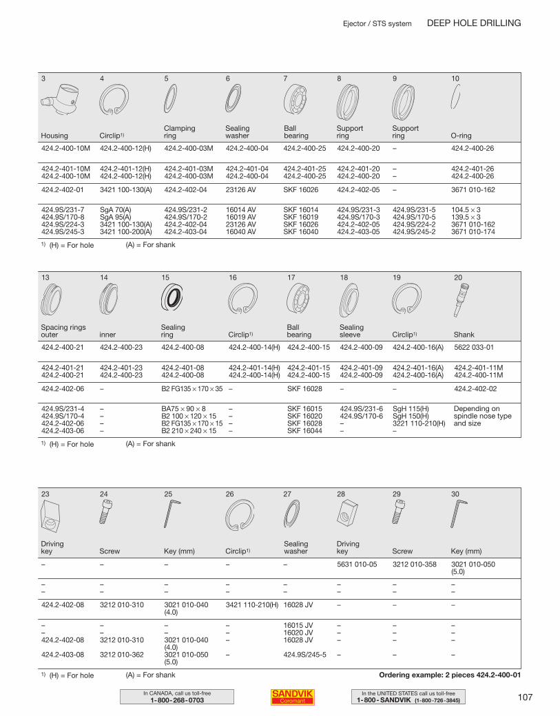
107In the UNITED STATES call us toll-free1-800- SANDVIK (1-800-726-3845)
In CANADA, call us toll-free1-800-268-0703
1) (H) = For hole
Ordering example: 2 pieces 424.2-400-01
23 24 25 26 27 28 29 30
– – – – – 5631 010-05 3212 010-358 3021 010-050(5.0)
– – – – – – – –– – – – – – – –
424.2-402-08 3212 010-310 3021 010-040 3421 110-210(H) 16028 JV – – –(4.0)
– – – – 16015 JV – – –– – – – 16020 JV – – –424.2-402-08 3212 010-310 3021 010-040 – 16028 JV – – –
(4.0)424.2-403-08 3212 010-362 3021 010-050 – 424.9S/245-5 – – –
(5.0)
13 14 15 16 17 18 19 20
424.2-400-21 424.2-400-23 424.2-400-08 424.2-400-14(H) 424.2-400-15 424.2-400-09 424.2-400-16(A) 5622 033-01
424.2-401-21 424.2-401-23 424.2-401-08 424.2-401-14(H) 424.2-401-15 424.2-401-09 424.2-401-16(A) 424.2-401-11M424.2-400-21 424.2-400-23 424.2-400-08 424.2-400-14(H) 424.2-400-15 424.2-400-09 424.2-400-16(A) 424.2-400-11M
424.2-402-06 – B2 FG135 × 170 × 35 – SKF 16028 – – 424.2-402-02
424.9S/231-4 – BA75 × 90 × 8 – SKF 16015 424.9S/231-6 SgH 115(H)424.9S/170-4 – B2 100 × 120 × 15 – SKF 16020 424.9S/170-6 SgH 150(H)424.2-402-06 – B2 FG135 × 170 × 15 – SKF 16028 – 3221 110-210(H)424.2-403-06 – B2 210 × 240 × 15 – SKF 16044 – –
3 4 5 6 7 8 9 10
424.2-400-10M 424.2-400-12(H) 424.2-400-03M 424.2-400-04 424.2-400-25 424.2-400-20 – 424.2-400-26
424.2-401-10M 424.2-401-12(H) 424.2-401-03M 424.2-401-04 424.2-401-25 424.2-401-20 – 424.2-401-26424.2-400-10M 424.2-400-12(H) 424.2-400-03M 424.2-400-04 424.2-400-25 424.2-400-20 – 424.2-400-26
424.2-402-01 3421 100-130(A) 424.2-402-04 23126 AV SKF 16026 424.2-402-05 – 3671 010-162
424.9S/231-7 SgA 70(A) 424.9S/231-2 16014 AV SKF 16014 424.9S/231-3 424.9S/231-5 104.5 × 3424.9S/170-8 SgA 95(A) 424.9S/170-2 16019 AV SKF 16019 424.9S/170-3 424.9S/170-5 139.5 × 3424.9S/224-3 3421 100-130(A) 424.2-402-04 23126 AV SKF 16026 424.2-402-05 424.9S/224-2 3671 010-162424.9S/245-3 3421 100-200(A) 424.2-403-04 16040 AV SKF 16040 424.2-403-05 424.9S/245-2 3671 010-174
Depending on spindle nose typeand size
Ejector / STS system DEEP HOLE DRILLING
(A) = For shank
Housing Circlip1)Clamping ring
Sealing washer
Ball bearing
Support ring
Support ring O-ring
1) (H) = For hole (A) = For shank
Spacing ringsouter inner
Sealing ring Circlip1) ShankCirclip1)
Sealing sleeve
Ball bearing
1) (H) = For hole (A) = For shank
Driving key Screw Key (mm) Circlip1)
Sealing washer
Driving key Screw Key (mm)
099-108 USA 04-04-29 10.17 Sida 107
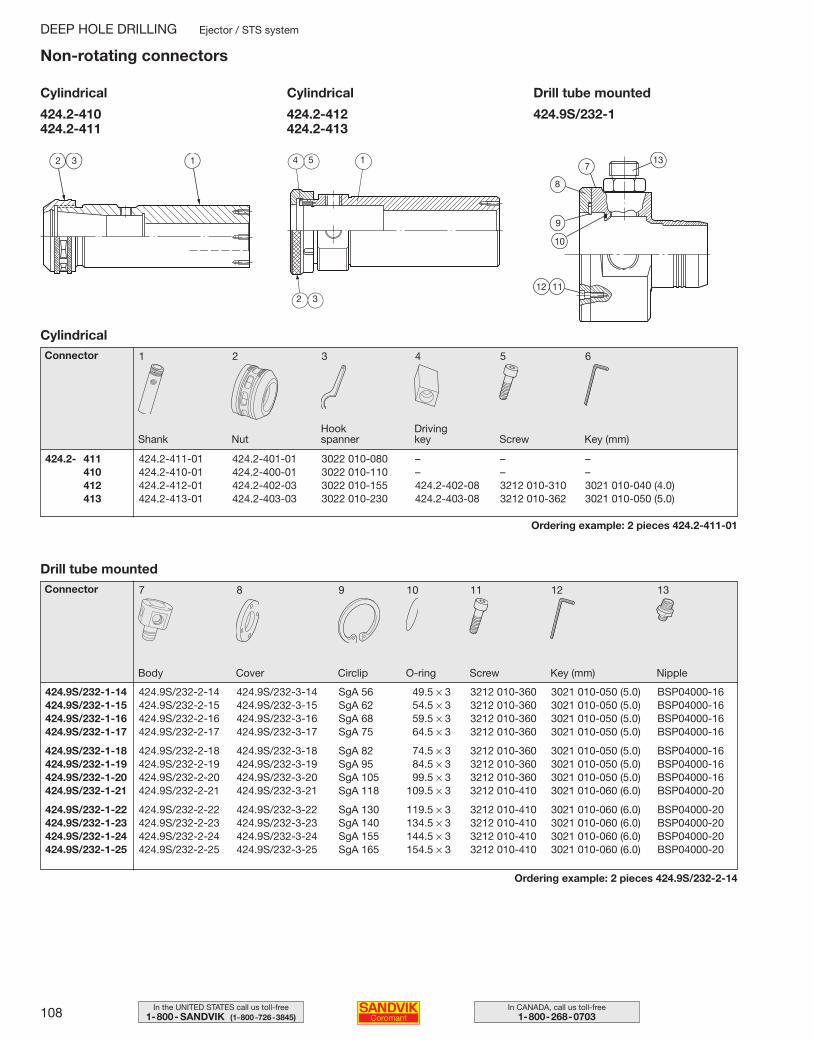
108 In CANADA, call us toll-free1-800-268-0703
In the UNITED STATES call us toll-free1-800- SANDVIK (1-800-726-3845)
7 8 9 10 11 12 13
424.9S/232-1-14 424.9S/232-2-14 424.9S/232-3-14 SgA 56 49.5 × 3 3212 010-360 3021 010-050 (5.0) BSP04000-16424.9S/232-1-15 424.9S/232-2-15 424.9S/232-3-15 SgA 62 54.5 × 3 3212 010-360 3021 010-050 (5.0) BSP04000-16424.9S/232-1-16 424.9S/232-2-16 424.9S/232-3-16 SgA 68 59.5 × 3 3212 010-360 3021 010-050 (5.0) BSP04000-16424.9S/232-1-17 424.9S/232-2-17 424.9S/232-3-17 SgA 75 64.5 × 3 3212 010-360 3021 010-050 (5.0) BSP04000-16
424.9S/232-1-18 424.9S/232-2-18 424.9S/232-3-18 SgA 82 74.5 × 3 3212 010-360 3021 010-050 (5.0) BSP04000-16424.9S/232-1-19 424.9S/232-2-19 424.9S/232-3-19 SgA 95 84.5 × 3 3212 010-360 3021 010-050 (5.0) BSP04000-16424.9S/232-1-20 424.9S/232-2-20 424.9S/232-3-20 SgA 105 99.5 × 3 3212 010-360 3021 010-050 (5.0) BSP04000-16424.9S/232-1-21 424.9S/232-2-21 424.9S/232-3-21 SgA 118 109.5 × 3 3212 010-410 3021 010-060 (6.0) BSP04000-20
424.9S/232-1-22 424.9S/232-2-22 424.9S/232-3-22 SgA 130 119.5 × 3 3212 010-410 3021 010-060 (6.0) BSP04000-20424.9S/232-1-23 424.9S/232-2-23 424.9S/232-3-23 SgA 140 134.5 × 3 3212 010-410 3021 010-060 (6.0) BSP04000-20424.9S/232-1-24 424.9S/232-2-24 424.9S/232-3-24 SgA 155 144.5 × 3 3212 010-410 3021 010-060 (6.0) BSP04000-20424.9S/232-1-25 424.9S/232-2-25 424.9S/232-3-25 SgA 165 154.5 × 3 3212 010-410 3021 010-060 (6.0) BSP04000-20
1 2 3 4 5 6
424.2- 411 424.2-411-01 424.2-401-01 3022 010-080 – – –410 424.2-410-01 424.2-400-01 3022 010-110 – – –412 424.2-412-01 424.2-402-03 3022 010-155 424.2-402-08 3212 010-310 3021 010-040 (4.0)413 424.2-413-01 424.2-403-03 3022 010-230 424.2-403-08 3212 010-362 3021 010-050 (5.0)
NutHookspanner
Drivingkey Screw Key (mm)
Connector
Shank
Non-rotating connectors
Ordering example: 2 pieces 424.2-411-01
Cylindrical
424.2-410424.2-411
424.2-412424.2-413
424.9S/232-1
Cover Circlip O-ring Screw Key (mm)Body
Ordering example: 2 pieces 424.9S/232-2-14
Drill tube mounted
Nipple
DEEP HOLE DRILLING Ejector / STS system
Cylindrical Cylindrical Drill tube mounted
Connector
132 4 5 1
2 3
713
8
9
10
12 11
099-108 USA 04-05-07 09.22 Sida 108
109In the UNITED STATES call us toll-free1-800- SANDVIK (1-800-726-3845)
In CANADA, call us toll-free1-800-268-0703
110-113
114
115
116
117–119
120–123
124–125
126–127
128–129
130–131
132
133
134
135–136
137–141
142
143
Application guideDrilling system and methods
Hole quality
Center alignment
Special application cases
Cutting fluid
The Ejector system
The Single Tube System – STS
Drill bush and set up
Machining recommendations
Choice of cutting data
Balanced and unbalanced drills
Cutting data calculations
Cutting forces
Troubleshooting
Material cross reference list
Insert mounting
Safety information
T a b l e o f c o n t e n t s
DEEP HOLE DRILLING
109-146 USA 04-04-29 10.23 Sida 109
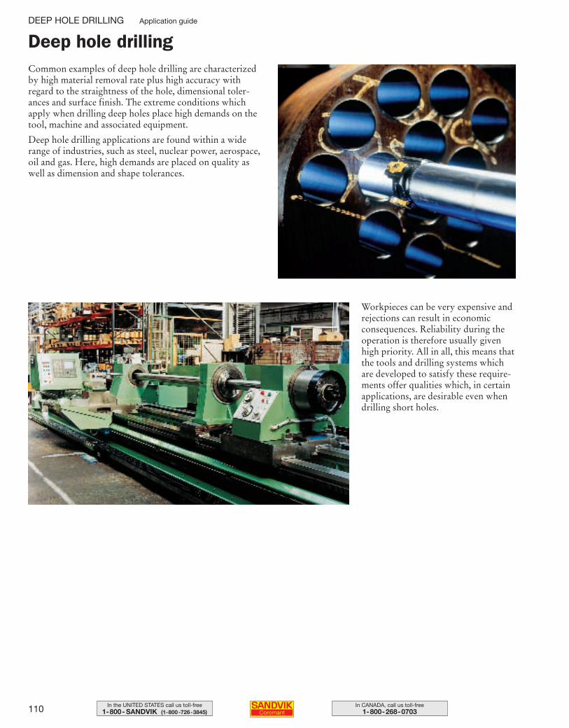
110 In CANADA, call us toll-free1-800-268-0703
In the UNITED STATES call us toll-free1-800- SANDVIK (1-800-726-3845)
Deep hole drillingCommon examples of deep hole drilling are characterizedby high material removal rate plus high accuracy with regard to the straightness of the hole, dimensional toler-ances and surface finish. The extreme conditions which apply when drilling deep holes place high demands on thetool, machine and associated equipment.
Deep hole drilling applications are found within a widerange of industries, such as steel, nuclear power, aerospace,oil and gas. Here, high demands are placed on quality aswell as dimension and shape tolerances.
Workpieces can be very expensive andrejections can result in economicconsequences. Reliability during theoperation is therefore usually givenhigh priority. All in all, this means thatthe tools and drilling systems whichare developed to satisfy these require-ments offer qualities which, in certainapplications, are desirable even whendrilling short holes.
DEEP HOLE DRILLING Application guide
109-146 USA 04-04-29 10.23 Sida 110
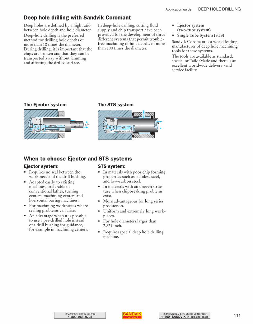
111In the UNITED STATES call us toll-free1-800- SANDVIK (1-800-726-3845)
In CANADA, call us toll-free1-800-268-0703
The Ejector system The STS system
Deep holes are defined by a high ratiobetween hole depth and hole diameter. Deep-hole drilling is the preferredmethod for drilling hole depths ofmore than 10 times the diameter.During drilling, it is important that thechips are broken and that they can betransported away without jammingand affecting the drilled surface.
In deep-hole drilling, cutting fluidsupply and chip transport have beenprovided for the development of threedifferent systems that permit trouble-free machining of hole depths of morethan 100 times the diameter.
• Ejector system (two-tube system)
• Single Tube System (STS)Sandvik Coromant is a world leadingmanufacturer of deep hole machiningtools for these systems. The tools are available as standard,special or TailorMade and there is anexcellent worldwide delivery -and service facility.
Deep hole drilling with Sandvik Coromant
Ejector system:• Requires no seal between the
workpiece and the drill bushing.• Adapted easily to existing
machines, preferable in conventional lathes, turning centers, machining centers and horizontal boring machines.
• For machining workpieces wheresealing problems can arise.
• An advantage when it is possible to use a pre-drilled hole instead of a drill bushing for guidance, for example in machining centers.
STS system:• In materals with poor chip forming
properties such as stainless steel,and low-carbon steel.
• In materials with an uneven struc-ture when chipbreaking problemsexist.
• More advantageous for long seriesproduction.
• Uniform and extremely long work-pieces.
• For hole diameters larger than 7.874 inch.
• Requires special deep hole drillingmachine.
When to choose Ejector and STS systems
Application guide DEEP HOLE DRILLING
109-146 USA 04-04-29 10.23 Sida 111
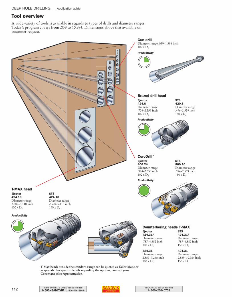
112 In CANADA, call us toll-free1-800-268-0703
In the UNITED STATES call us toll-free1-800- SANDVIK (1-800-726-3845)
A wide variety of tools is available in regards to types of drills and diameter ranges.Today’s program covers from .039 to 10.984. Dimensions above that available on customer request.
Tool overview
Gun drillDiameter range .039–1.594 inch100 x Dc
Brazed drill headEjector424.6Diameter range .724–2.559 inch100 x Dc
STS420.6Diameter range .496–2.559 inch150 x Dc
CoroDrill™
Ejector800.24Diameter range .984–2.559 inch100 x Dc
STS800.20Diameter range .984–2.559 inch150 x Dc
T-MAX headEjector424.10Diameter range 2.500–5.118 inch100 x Dc
STS424.10Diameter range 2.500–5.118 inch150 x Dc
Counterboring heads T-MAXEjector 424.31FDiameter range .787–4.882 inch100 x Dc
424.31Diameter range 2.559–7.240 inch100 x Dc
STS 424.31FDiameter range .787–4.882 inch150 x Dc
424.31Diameter range 2.559–10.984 inch150 x Dc
T-Max heads outside the standard range can be quoted as Tailor Made oras specials. For specific details regarding the options, contact yourCoromant sales representative.
Productivity
Productivity
Productivity
Productivity
DEEP HOLE DRILLING Application guide
109-146 USA 04-04-29 10.23 Sida 112
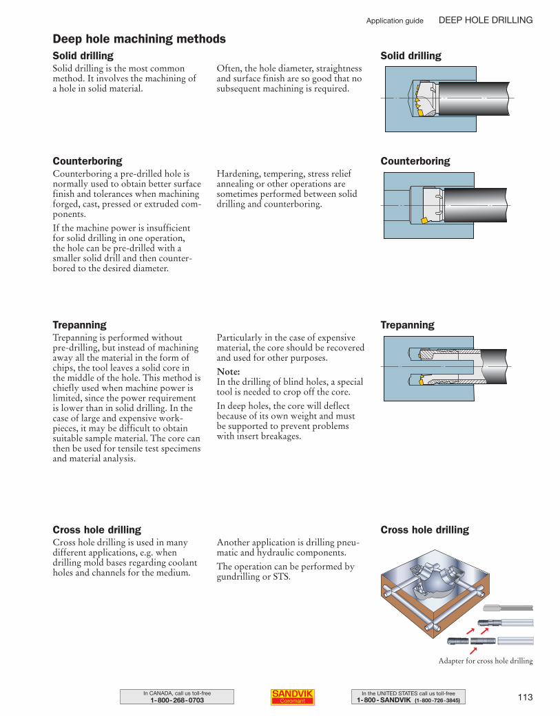
113In the UNITED STATES call us toll-free1-800- SANDVIK (1-800-726-3845)
In CANADA, call us toll-free1-800-268-0703
Solid drillingSolid drilling is the most common method. It involves the machining of a hole in solid material.
Often, the hole diameter, straightnessand surface finish are so good that nosubsequent machining is required.
TrepanningTrepanning is performed without pre-drilling, but instead of machiningaway all the material in the form ofchips, the tool leaves a solid core in the middle of the hole. This method ischiefly used when machine power islimited, since the power requirement is lower than in solid drilling. In thecase of large and expensive work-pieces, it may be difficult to obtainsuitable sample material. The core canthen be used for tensile test specimensand material analysis.
Particularly in the case of expensivematerial, the core should be recoveredand used for other purposes.
Note: In the drilling of blind holes, a specialtool is needed to crop off the core.
In deep holes, the core will deflect because of its own weight and must be supported to prevent problemswith insert breakages.
CounterboringCounterboring a pre-drilled hole isnormally used to obtain better surfacefinish and tolerances when machiningforged, cast, pressed or extruded com-ponents.
If the machine power is insufficient for solid drilling in one operation, the hole can be pre-drilled with asmaller solid drill and then counter-bored to the desired diameter.
Hardening, tempering, stress relief annealing or other operations aresometimes performed between soliddrilling and counterboring.
Deep hole machining methodsSolid drilling
Trepanning
Counterboring
Cross hole drillingCross hole drilling is used in many different applications, e.g. whendrilling mold bases regarding coolantholes and channels for the medium.
Another application is drilling pneu-matic and hydraulic components.
The operation can be performed bygundrilling or STS.
Cross hole drilling
➞Adapter for cross hole drilling
➞ ➞
Application guide DEEP HOLE DRILLING
109-146 USA 04-05-07 09.23 Sida 113
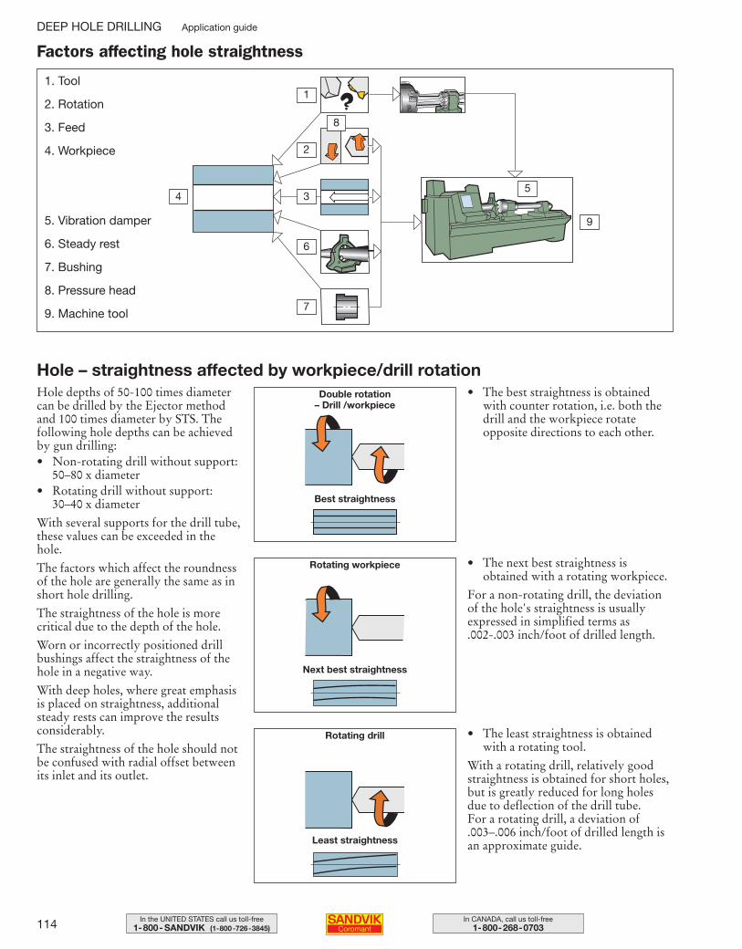
114 In CANADA, call us toll-free1-800-268-0703
In the UNITED STATES call us toll-free1-800- SANDVIK (1-800-726-3845)
1. Tool
2. Rotation
3. Feed
4. Workpiece
6. Steady rest
7. Bushing
8. Pressure head
9. Machine tool
8
Factors affecting hole straightness
Hole – straightness affected by workpiece/drill rotationDouble rotation
– Drill /workpiece
Rotating workpiece
Rotating drill
Best straightness
Next best straightness
Least straightness
9
4
1
2
3
6
7
Hole depths of 50-100 times diametercan be drilled by the Ejector methodand 100 times diameter by STS. Thefollowing hole depths can be achievedby gun drilling:• Non-rotating drill without support:
50–80 x diameter• Rotating drill without support:
30–40 x diameter
With several supports for the drill tube,these values can be exceeded in thehole.
The factors which affect the roundnessof the hole are generally the same as inshort hole drilling.
The straightness of the hole is morecritical due to the depth of the hole.
Worn or incorrectly positioned drillbushings affect the straightness of thehole in a negative way.
With deep holes, where great emphasisis placed on straightness, additionalsteady rests can improve the resultsconsiderably.
The straightness of the hole should notbe confused with radial offset betweenits inlet and its outlet.
• The best straightness is obtainedwith counter rotation, i.e. both thedrill and the workpiece rotate opposite directions to each other.
• The next best straightness is obtained with a rotating workpiece.
For a non-rotating drill, the deviationof the hole's straightness is usually expressed in simplified terms as .002-.003 inch/foot of drilled length.
• The least straightness is obtainedwith a rotating tool.
With a rotating drill, relatively goodstraightness is obtained for short holes,but is greatly reduced for long holesdue to deflection of the drill tube. For a rotating drill, a deviation of.003–.006 inch/foot of drilled length isan approximate guide.
5. Vibration damper
5
DEEP HOLE DRILLING Application guide
109-146 USA 04-04-29 10.23 Sida 114
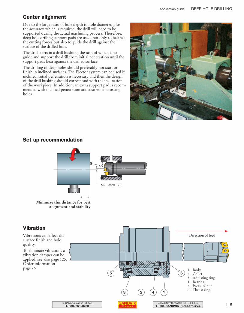
115In the UNITED STATES call us toll-free1-800- SANDVIK (1-800-726-3845)
In CANADA, call us toll-free1-800-268-0703
Center alignmentDue to the large ratio of hole depth to hole diameter, plusthe accuracy which is required, the drill will need to be supported during the actual machining process. Therefore,deep hole drilling support pads are used, not only to balancethe cutting forces but also to guide the drill against thesurface of the drilled hole.
The drill starts in a drill bushing, the task of which is toguide and support the drill from initial penetration until thesupport pads bear against the drilled surface.
The drilling of deep holes should preferably not start or finish in inclined surfaces. The Ejector system can be used ifinclined initial penetration is necessary and then the designof the drill bushing should correspond with the inclinationof the workpiece. In addition, an extra support pad is recom-mended with inclined penetration and also when crossingholes.
VibrationVibrations can affect thesurface finish and holequality.
To eliminate vibrations avibration damper can beapplied, see also page 125.Order information page 76.
Set up recommendation
Max .0008 inch
Minimize this distance for best alignment and stability
5
43 2 1
6
Direction of feed
1. Body2. Collet3. Adjusting ring4. Bearing5. Pressure nut6. Thrust ring
Application guide DEEP HOLE DRILLING
109-146 USA 04-04-29 10.23 Sida 115
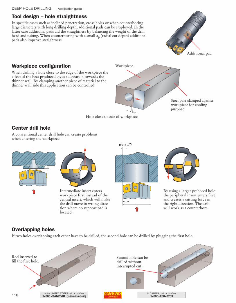
116 In CANADA, call us toll-free1-800-268-0703
In the UNITED STATES call us toll-free1-800- SANDVIK (1-800-726-3845)
Tool design – hole straightnessIn specific cases such as inclined penetration, cross holes or when counterboring large diameters with long drilling depth, additional pads can be employed. In the latter case additional pads aid the straightness by balancing the weight of the drill head and tubing. When counterboring with a small ap (radial cut depth) additional pads also improve straightness.
Workpiece configurationWhen drilling a hole close to the edge of the workpiece theeffect of the heat produced gives a deviation towards thethinner wall. By clamping another piece of material to thethinner wall side this application can be controlled.
Center drill holeA conventional center drill hole can create problems when entering the workpiece.
Overlapping holesIf two holes overlapping each other have to be drilled, the second hole can be drilled by plugging the first hole.
Steel part clamped againstworkpiece for coolingpurpose
Hole close to side of workpiece
Intermediate insert entersworkpiece first instead of thecentral insert, which will makethe drill move in wrong direc-tion where no support pad islocated.
By using a larger prebored holethe peripheral insert enters firstand creates a cutting force inthe right direction. The drillwill work as a counterbore.
Rod inserted tofill the first hole.
Second hole can bedrilled without interrupted cut.
Workpiece
max l/2
DEEP HOLE DRILLING Application guide
Additional pad
109-146 USA 04-04-29 10.23 Sida 116
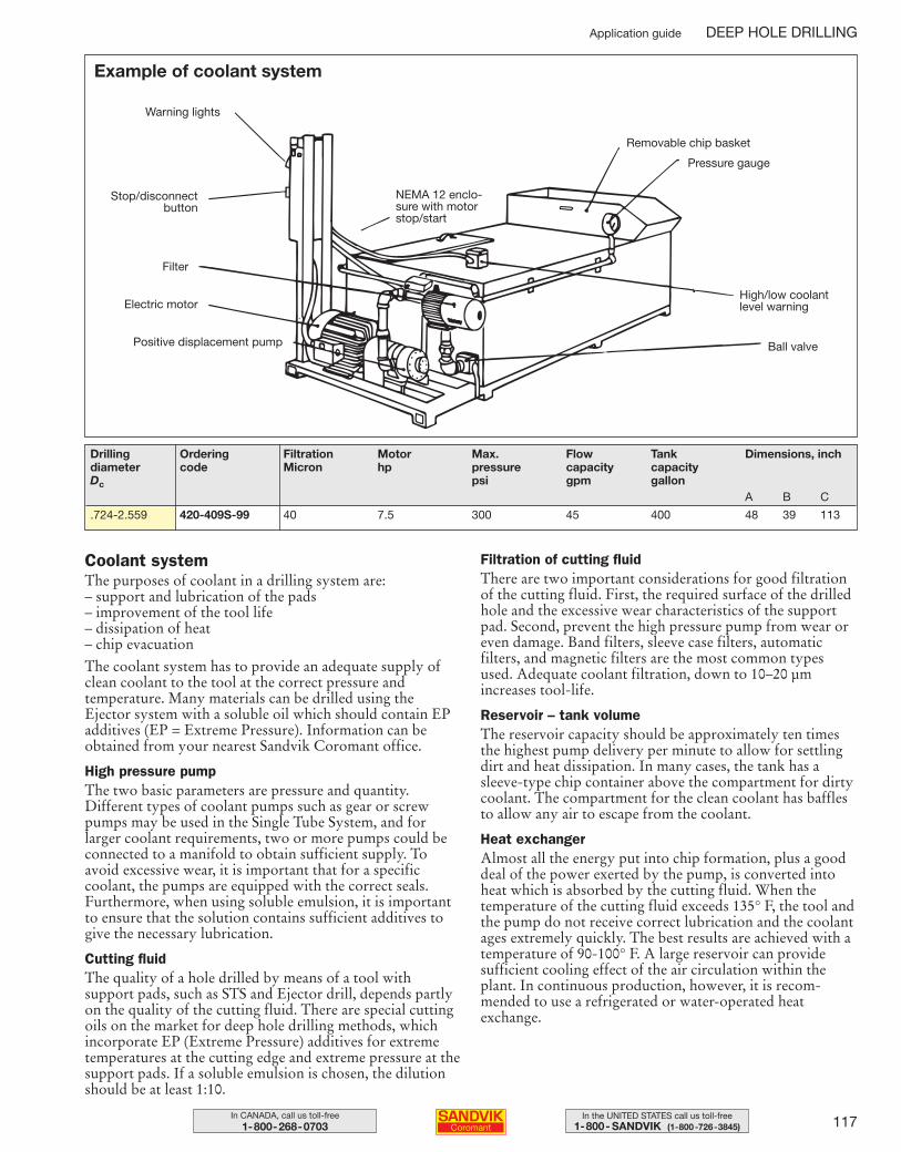
117In the UNITED STATES call us toll-free1-800- SANDVIK (1-800-726-3845)
In CANADA, call us toll-free1-800-268-0703
Example of coolant system
Warning lights
NEMA 12 enclo-sure with motorstop/start
Filter
Electric motor
Positive displacement pump
Removable chip basket
Pressure gauge
Ball valve
High/low coolantlevel warning
Stop/disconnectbutton
Coolant systemThe purposes of coolant in a drilling system are: – support and lubrication of the pads– improvement of the tool life– dissipation of heat– chip evacuationThe coolant system has to provide an adequate supply ofclean coolant to the tool at the correct pressure andtemperature. Many materials can be drilled using theEjector system with a soluble oil which should contain EPadditives (EP = Extreme Pressure). Information can beobtained from your nearest Sandvik Coromant office.
High pressure pumpThe two basic parameters are pressure and quantity.Different types of coolant pumps such as gear or screwpumps may be used in the Single Tube System, and forlarger coolant requirements, two or more pumps could beconnected to a manifold to obtain sufficient supply. Toavoid excessive wear, it is important that for a specificcoolant, the pumps are equipped with the correct seals.Furthermore, when using soluble emulsion, it is importantto ensure that the solution contains sufficient additives togive the necessary lubrication.
Cutting fluidThe quality of a hole drilled by means of a tool withsupport pads, such as STS and Ejector drill, depends partlyon the quality of the cutting fluid. There are special cuttingoils on the market for deep hole drilling methods, whichincorporate EP (Extreme Pressure) additives for extremetemperatures at the cutting edge and extreme pressure at thesupport pads. If a soluble emulsion is chosen, the dilutionshould be at least 1:10.
Filtration of cutting fluidThere are two important considerations for good filtrationof the cutting fluid. First, the required surface of the drilledhole and the excessive wear characteristics of the supportpad. Second, prevent the high pressure pump from wear oreven damage. Band filters, sleeve case filters, automaticfilters, and magnetic filters are the most common typesused. Adequate coolant filtration, down to 10–20 µmincreases tool-life.
Reservoir – tank volumeThe reservoir capacity should be approximately ten timesthe highest pump delivery per minute to allow for settlingdirt and heat dissipation. In many cases, the tank has asleeve-type chip container above the compartment for dirtycoolant. The compartment for the clean coolant has bafflesto allow any air to escape from the coolant.
Heat exchangerAlmost all the energy put into chip formation, plus a gooddeal of the power exerted by the pump, is converted intoheat which is absorbed by the cutting fluid. When thetemperature of the cutting fluid exceeds 135° F, the tool andthe pump do not receive correct lubrication and the coolantages extremely quickly. The best results are achieved with atemperature of 90-100° F. A large reservoir can providesufficient cooling effect of the air circulation within theplant. In continuous production, however, it is recom-mended to use a refrigerated or water-operated heatexchange.
Application guide DEEP HOLE DRILLING
Drilling Ordering Filtration Motor Max. Flow Tank Dimensions, inchdiameter code Micron hp pressure capacity capacityDc psi gpm gallon
A B C
.724-2.559 420-409S-99 40 7.5 300 45 400 48 39 113
109-146 USA 04-05-07 09.25 Sida 117
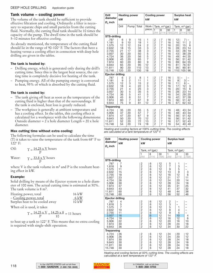
118 In CANADA, call us toll-free1-800-268-0703
In the UNITED STATES call us toll-free1-800- SANDVIK (1-800-726-3845)
Tank volume – cooling powerThe volume of the tank should be sufficient to provideeffective filtration and cooling. Ordinarily a filter is neces-sary to separate chips and small particles from the cuttingfluid. Normally, the cutting fluid tank should be 10 times thecapacity of the pump. The dwell time in the tank should be5–10 minutes for effective cooling.
As already mentioned, the temperature of the cutting fluidshould lie in the range of 90-100° F. The factors that have aheating versus a cooling effect in connection with deep holedrilling are given in the tables.
The tank is heated by:– Drilling energy, which is generated only during the drill’s
cutting time. Since this is the largest heat source, the cut-ting time is completely decisive for heating of the tank.
– Pumping energy. All of the pumping energy is convertedto heat, 95% of which is absorbed by the cutting fluid.
The tank is cooled by:– The tank giving off heat as soon as the temperature of the
cutting fluid is higher than that of the surroundings. Ifthe tank is enclosed, heat loss is greatly reduced.
– The workpiece is generally at ambient temperature andhas a cooling effect. In the tables, this cooling effect is calculated for a workpiece with the following dimensions:Outside diameter = 2 x hole diameter Length = 20 x holediameter.
Max cutting time without extra cooling:The following formulas can be used to calculate the time (T) it takes to raise the temperature of the tank from 68° F to122° F:
Oil: T = 14.25 x V hours P
Water: T = 33.8 x V hours P
where V is the tank volume in m3 and P is the resultant heat-ing effect in kW.
Example:Solid drilling by means of the Ejector system to a hole diam-eter of 100 mm. The actual cutting time is estimated at 50%.The tank volume is 8 m3.Heating power, total 16 kW– Cooling power, total 6 kWSurplus heat to be cooled away 10 kW
When oil is used, it takes
T = 14.25 x V = 14.25 x 8 = 11 hours P 10
to heat up a tank to 122° F. This means that no extra coolingis required with single-shift operation.
Drill diameter
Dc inch
Heating power
kW
Drill Pump Total Work-piece
Tank, m3 (gal.) Tank, m3 (gal.)
Cooling power
kW
Surplus heat
kW
1 8 30(264) (2114) (7926)
1 8 30(264) (2114) (7926)
STS-drilling
1 8 30(264) (2114) (7926)
1 8 30(264) (2114) (7926)
STS-drilling
Heating and cooling factors at 100% cutting time. The cooling effectsare calculated at a tank temperature of 122° F.
Heating and cooling factors at 50% cutting time. The cooling effects arecalculated at a tank temperature of 122° F.
.787 7 2 6 12 5 1 –1.818 9 2 6 12 7 3 –1.575 11 2 6 12 9 5 –2.632 15 2 6 12 13 9 32.755 18 2 6 12 16 12 63.937 23 2 6 12 21 17 114.724 26 2 6 12 24 20 145.906 30 2 6 12 28 24 187.874 37 2 6 12 35 31 259.843 43 2 6 12 41 37 32
11.811 60 2 6 12 48 44 3815.748 60 2 6 12 56 52 46
.787 4 2 6 12 2 – –1.818 5 2 6 12 3 – –1.575 7 2 6 12 5 1 –2.632 10 2 6 12 8 4 –2.755 11 2 6 12 9 5 –3.937 16 2 6 12 14 10 44.724 18 2 6 12 16 12 65.906 22 2 6 12 20 16 107.874 30 2 6 12 28 24 189.843 36 2 6 12 34 30 22
4.724 26 2 6 12 24 20 125.906 26 2 6 12 24 20 127.874 30 2 6 12 28 24 189.843 30 2 6 12 28 24 18
11.811 30 2 6 12 28 24 1815.748 30 2 6 12 28 24 18
.787 6 9 15 1 2 7 16 12 7 –1.181 9 10 19 1 2 7 16 16 11 21.575 12 12 24 2 2 7 16 20 15 62.632 18 15 33 3 2 7 16 28 23 142.755 21 17 38 3 2 7 16 33 28 193.937 30 20 50 5 2 7 16 43 38 294.724 36 20 56 5 2 7 16 49 44 355.906 45 20 65 7 2 7 16 56 51 427.874 60 20 80 9 2 7 16 69 64 559.843 65 20 95 12 2 7 16 81 76 67
11.811 90 20 110 13 2 7 16 95 90 8115.748 120 20 130 18 2 7 16 110 105 96
.787 6 2 8 1 2 7 16 5 – –1.181 9 2 11 1 2 7 16 8 3 –1.575 12 3 15 2 2 7 16 11 6 –2.632 18 4 22 3 2 7 16 17 12 32.755 21 4 25 3 2 7 16 20 15 63.937 30 5 35 5 2 7 16 28 23 144.724 36 5 41 5 2 7 16 34 29 205.906 45 6 51 7 2 7 16 42 37 287.874 60 7 67 9 2 7 16 56 51 429.843 75 9 81 12 2 7 16 67 62 53
4.724 35 20 55 5 2 7 16 48 43 345.906 37 20 57 7 2 7 16 48 43 347.874 47 20 67 9 2 7 16 56 51 429.843 50 20 70 12 2 7 16 56 51 42
11.811 52 20 72 13 2 7 16 57 52 4315.748 54 20 74 18 2 7 16 54 40 40
Trepanning
Ejector drilling
Ejector drilling
Trepanning
Drill diameter
Dc inch
Heating power
kW
Tank, m3 (gal.)Tank, m3 (gal.)
Cooling power
kW
Surplus heat
kW
DEEP HOLE DRILLING Application guide
109-146 USA 04-04-29 10.23 Sida 118
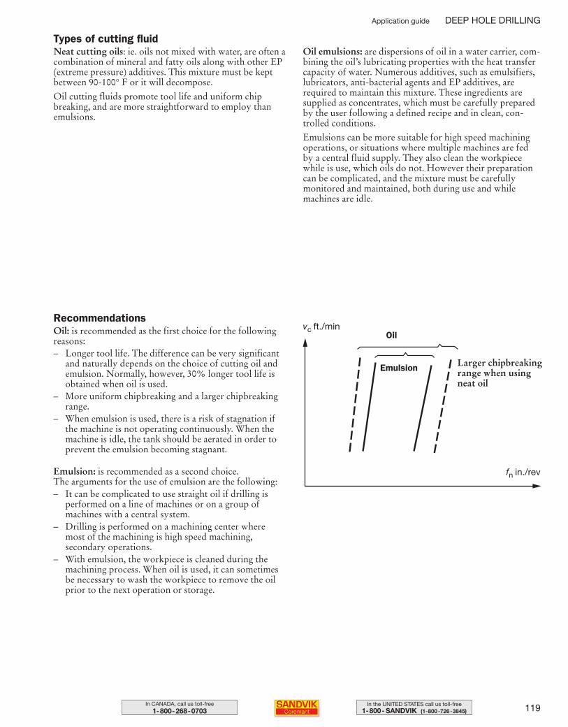
119In the UNITED STATES call us toll-free1-800- SANDVIK (1-800-726-3845)
In CANADA, call us toll-free1-800-268-0703
RecommendationsOil: is recommended as the first choice for the followingreasons:– Longer tool life. The difference can be very significant
and naturally depends on the choice of cutting oil andemulsion. Normally, however, 30% longer tool life is obtained when oil is used.
– More uniform chipbreaking and a larger chipbreakingrange.
– When emulsion is used, there is a risk of stagnation if the machine is not operating continuously. When the machine is idle, the tank should be aerated in order toprevent the emulsion becoming stagnant.
Emulsion: is recommended as a second choice. The arguments for the use of emulsion are the following:– It can be complicated to use straight oil if drilling is
performed on a line of machines or on a group of machines with a central system.
– Drilling is performed on a machining center where most of the machining is high speed machining, secondary operations.
– With emulsion, the workpiece is cleaned during the machining process. When oil is used, it can sometimes be necessary to wash the workpiece to remove the oilprior to the next operation or storage.
Types of cutting fluidNeat cutting oils: ie. oils not mixed with water, are often acombination of mineral and fatty oils along with other EP(extreme pressure) additives. This mixture must be kept between 90-100° F or it will decompose.
Oil cutting fluids promote tool life and uniform chip breaking, and are more straightforward to employ thanemulsions.
Oil emulsions: are dispersions of oil in a water carrier, com-bining the oil’s lubricating properties with the heat transfercapacity of water. Numerous additives, such as emulsifiers,lubricators, anti-bacterial agents and EP additives, are required to maintain this mixture. These ingredients aresupplied as concentrates, which must be carefully preparedby the user following a defined recipe and in clean, con-trolled conditions.
Emulsions can be more suitable for high speed machiningoperations, or situations where multiple machines are fedby a central fluid supply. They also clean the workpiecewhile is use, which oils do not. However their preparationcan be complicated, and the mixture must be carefully monitored and maintained, both during use and while machines are idle.
vc ft./min
Emulsion
fn in./rev
Oil
Larger chipbreakingrange when usingneat oil
Application guide DEEP HOLE DRILLING
109-146 USA 04-04-29 10.23 Sida 119
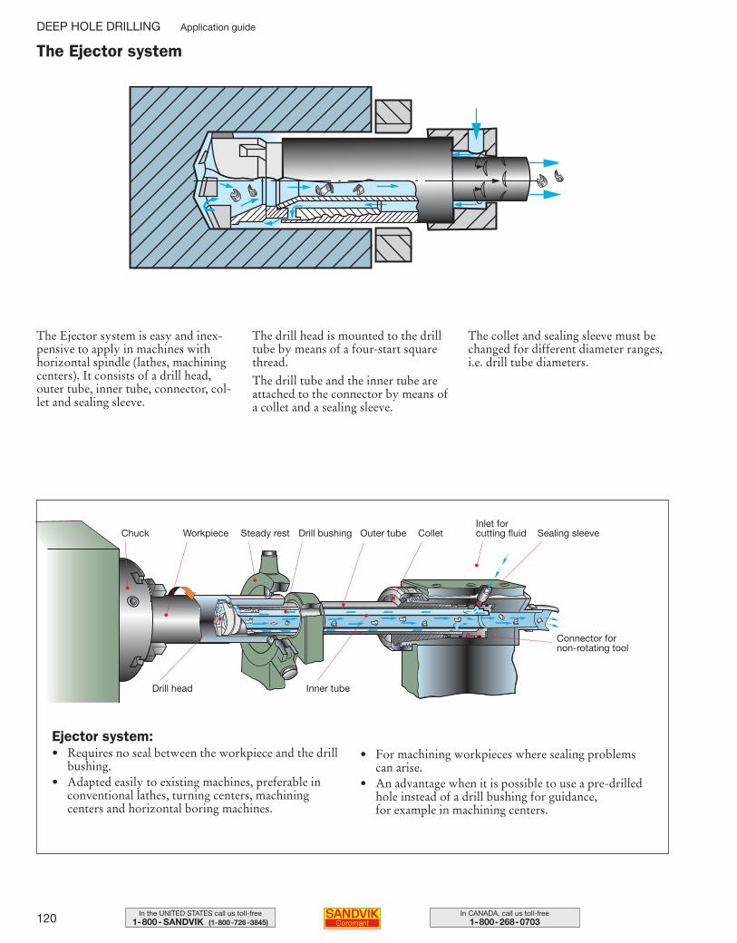
120 In CANADA, call us toll-free1-800-268-0703
In the UNITED STATES call us toll-free1-800- SANDVIK (1-800-726-3845)
The Ejector system is easy and inex-pensive to apply in machines with horizontal spindle (lathes, machining centers). It consists of a drill head,outer tube, inner tube, connector, col-let and sealing sleeve.
The drill head is mounted to the drilltube by means of a four-start squarethread.
The drill tube and the inner tube areattached to the connector by means ofa collet and a sealing sleeve.
The collet and sealing sleeve must bechanged for different diameter ranges,i.e. drill tube diameters.
Drill bushing
•
Outer tube
•
Collet
•
Steady restWorkpieceChuck
•
•
•
Inlet for cutting fluid
•
Sealing sleeve
•
Connector for non-rotating tool
•
Inner tube
•
Drill head
•
Ejector system:• Requires no seal between the workpiece and the drill
bushing.• Adapted easily to existing machines, preferable in
conventional lathes, turning centers, machining centers and horizontal boring machines.
• For machining workpieces where sealing problemscan arise.
• An advantage when it is possible to use a pre-drilledhole instead of a drill bushing for guidance, for example in machining centers.
The Ejector system
DEEP HOLE DRILLING Application guide
109-146 USA 04-04-29 10.23 Sida 120
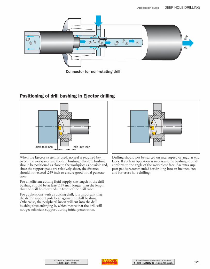
121In the UNITED STATES call us toll-free1-800- SANDVIK (1-800-726-3845)
In CANADA, call us toll-free1-800-268-0703
Connector for non-rotating drill
When the Ejector system is used, no seal is required be-tween the workpiece and the drill bushing. The drill bushingshould be positioned as close to the workpiece as possible and,since the support pads are relatively short, the distanceshould not exceed .039 inch to ensure good initial penetra-tion.
For an efficient cutting fluid supply, the length of the drillbushing should be at least .197 inch longer than the lengththat the drill head extends in front of the drill tube.
For applications with a rotating drill, it is important that the drill's support pads bear against the drill bushing.Otherwise, the peripheral insert will cut into the drill bushing thus enlarging it, which means that the drill will not get sufficient support during initial penetration.
Drilling should not be started on interrupted or angular endfaces. If such an operation is necessary, the bushing shouldconform to the angle of the workpiece face. An extra sup-port pad is recommended for drilling into an inclined faceand for cross hole drilling.
min .197 inchmax .039 inch
Positioning of drill bushing in Ejector drilling
Application guide DEEP HOLE DRILLING
109-146 USA 04-04-29 10.23 Sida 121
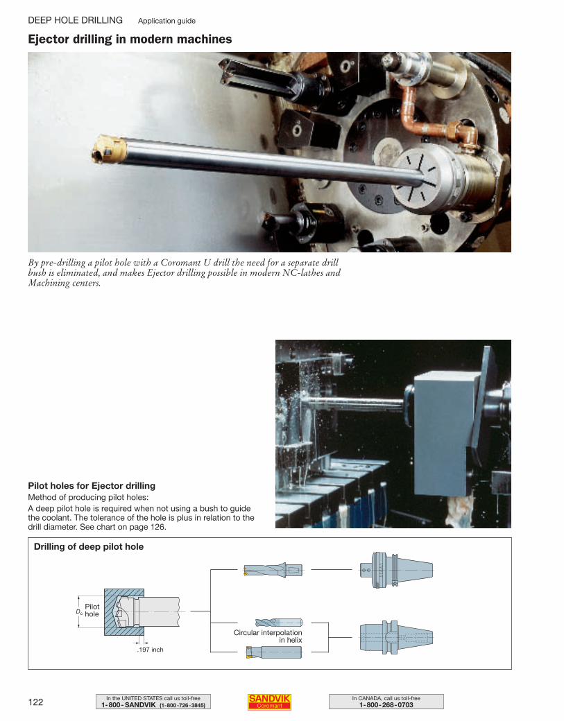
122 In CANADA, call us toll-free1-800-268-0703
In the UNITED STATES call us toll-free1-800- SANDVIK (1-800-726-3845)
Ejector drilling in modern machines
By pre-drilling a pilot hole with a Coromant U drill the need for a separate drillbush is eliminated, and makes Ejector drilling possible in modern NC-lathes andMachining centers.
Pilot holes for Ejector drillingMethod of producing pilot holes:A deep pilot hole is required when not using a bush to guidethe coolant. The tolerance of the hole is plus in relation to thedrill diameter. See chart on page 126.
Drilling of deep pilot hole
.197 inch
22
04
4
Dc
Circular interpolation in helix
Pilot hole
DEEP HOLE DRILLING Application guide
109-146 USA 04-04-29 10.23 Sida 122
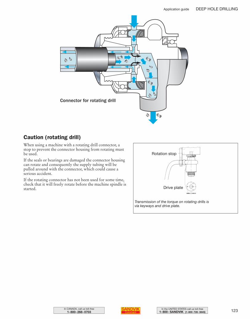
123In the UNITED STATES call us toll-free1-800- SANDVIK (1-800-726-3845)
In CANADA, call us toll-free1-800-268-0703
When using a machine with a rotating drill connector, astop to prevent the connector housing from rotating mustbe used.
If the seals or bearings are damaged the connector housingcan rotate and consequently the supply tubing will bepulled around with the connector, which could cause a serious accident.
If the rotating connector has not been used for some time,check that it will freely rotate before the machine spindle isstarted.
Rotation stop
Drive plate
Transmission of the torque on rotating drills is via keyways and drive plate.
Caution (rotating drill)
Connector for rotating drill
Application guide DEEP HOLE DRILLING
109-146 USA 04-04-29 10.23 Sida 123
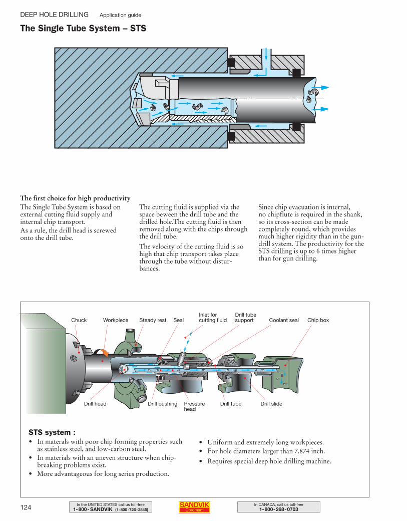
124 In CANADA, call us toll-free1-800-268-0703
In the UNITED STATES call us toll-free1-800- SANDVIK (1-800-726-3845)
The first choice for high productivity The Single Tube System is based onexternal cutting fluid supply and internal chip transport. As a rule, the drill head is screwedonto the drill tube.
The cutting fluid is supplied via thespace beween the drill tube and thedrilled hole.The cutting fluid is thenremoved along with the chips throughthe drill tube.
The velocity of the cutting fluid is sohigh that chip transport takes placethrough the tube without distur-bances.
Since chip evacuation is internal, no chipflute is required in the shank,so its cross-section can be made completely round, which providesmuch higher rigidity than in the gun-drill system. The productivity for theSTS drilling is up to 6 times higherthan for gun drilling.
Steady restWorkpieceChuck
•
Seal
•
Drill tube support
•
Chip box
•
Coolant seal
••
•
Inlet for cutting fluid
•
Drill slide
•
Drill tube
•
Pressurehead
•
Drill bushing
•
Drill head
•
STS system :• In materals with poor chip forming properties such
as stainless steel, and low-carbon steel.• In materials with an uneven structure when chip-
breaking problems exist.• More advantageous for long series production.
• Uniform and extremely long workpieces.• For hole diameters larger than 7.874 inch.
• Requires special deep hole drilling machine.
The Single Tube System – STS
DEEP HOLE DRILLING Application guide
109-146 USA 04-04-29 10.23 Sida 124
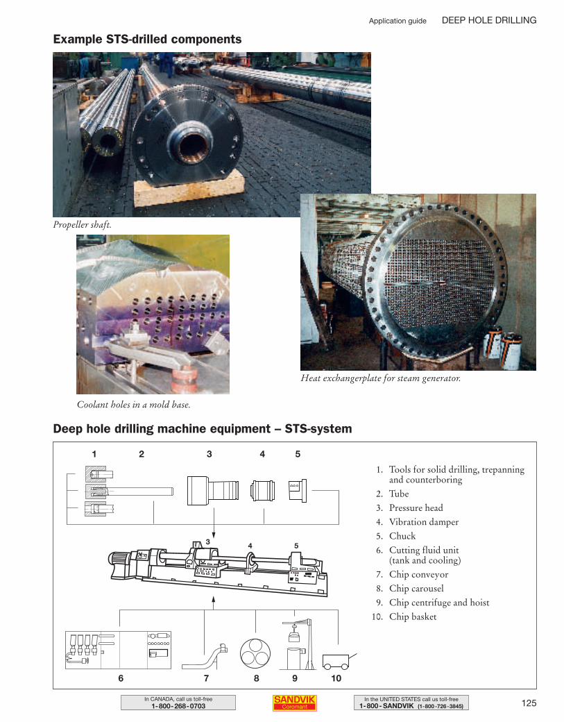
125In the UNITED STATES call us toll-free1-800- SANDVIK (1-800-726-3845)
In CANADA, call us toll-free1-800-268-0703
1. Tools for solid drilling, trepanningand counterboring
2. Tube
3. Pressure head
4. Vibration damper
5. Chuck
6. Cutting fluid unit (tank and cooling)
7. Chip conveyor
8. Chip carousel
9. Chip centrifuge and hoist
10. Chip basket
Propeller shaft.
Coolant holes in a mold base.
Heat exchangerplate for steam generator.
1
6
2 3 4 5
7 8 9 10
Example STS-drilled components
Deep hole drilling machine equipment – STS-system
Application guide DEEP HOLE DRILLING
3 4 5
109-146 USA 04-04-29 10.23 Sida 125
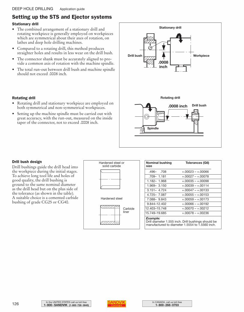
126 In CANADA, call us toll-free1-800-268-0703
In the UNITED STATES call us toll-free1-800- SANDVIK (1-800-726-3845)
Setting up the STS and Ejector systems
.0008 inch
Stationary drill• The combined arrangement of a stationary drill and
rotating workpiece is generally employed on workpieceswhich are symmetrical about their axes of rotation, onlathes and deep hole drilling machines.
• Compared to a rotating drill, this method producesstraighter holes and results in less wear on the drill bush.
• The connector shank must be accurately aligned to pro-vide a common axis of rotation with the machine spindle.
• The total run-out between drill bush and machine spindleshould not exceed .0008 inch.
Nominal bushingsize
Tolerances (G6)
Example:Drill diameter 1.555 inch. Drill bushings should bemanufactured to diameter 1.5554 to 1.5560 inch.
Drill bush designDrill bushings guide the drill head intothe workpiece during the initial stages.To achieve long tool life and holes ofgood quality, the drill bushing isground to the same nominal diameteras the drill head but on the plus side ofthe tolerance (as shown in the table). A suitable choice is a cemented carbidebushing of grade CG25 or CG40.
Hardened steel or solid carbide
Hardened steel
Carbideliner
.0008 inch
Stationary drill
Rotating drill
.496– .708 +.00023 – +.00066
.709– 1.181 +.00027 – +.000781.182– 1.968 +.00035 – +.000981.969– 3.150 +.00039 – +.001143.151– 4.724 +.00047 – +.001334.725– 7.087 +.00055 – +.001537.088– 9.843 +.00059 – +.001739.844–12.402 +.00066 – +.00192
12.403–15.748 +.00070 – +.0021215.749–19.685 +.00078 – +.00236
WorkpieceDrill bush
Drill bush
Spindle
Rotating drill• Rotating drill and stationary workpiece are employed on
both symmetrical and non-symmetrical workpieces.
• Setting up the machine spindle must be carried out withgreat accuracy, with the run-out, measured on the insidetaper of the connector, not to exceed .0008 inch.
DEEP HOLE DRILLING Application guide
109-146 USA 04-04-29 10.23 Sida 126
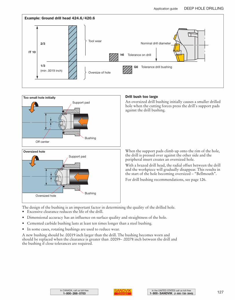
127In the UNITED STATES call us toll-free1-800- SANDVIK (1-800-726-3845)
In CANADA, call us toll-free1-800-268-0703
Tolerance drill bushing
Tolerance on drill
Nominal drill diameter
Oversize of hole
Tool wear
G6
h6IT 10
1/3
2/3
(min .0019 inch)
When the support pads climb up onto the rim of the hole,the drill is pressed over against the other side and the peripheral insert creates an oversized hole.
With a brazed drill head, the radial offset between the drilland the workpiece will gradually disappear. This results inthe start of the hole becoming oversized – “Bellmouth”.
For drill bushing recommendations, see page 126.
Oversized hole
Support pad
BushingOff center
The design of the bushing is an important factor in determining the quality of the drilled hole.• Excessive clearance reduces the life of the drill.
• Dimensional accuracy has an influence on surface quality and straightness of the hole.
• Cemented carbide bushing lasts at least ten times longer than a steel bushing.
• In some cases, rotating bushings are used to reduce wear.
A new bushing should be .00019 inch larger than the drill. The bushing becomes worn and should be replaced when the clearance is greater than .00059– .00078 inch between the drill and the bushing if close tolerances are required.
Drill bush too largeAn oversized drill bushing initially causes a smaller drilledhole when the cutting forces press the drill's support padsagainst the drill bushing.
Too small hole initially
Oversized hole
Support pad
Bushing
Application guide DEEP HOLE DRILLING
Example: Ground drill head 424.6/420.6
109-146 USA 04-04-29 10.23 Sida 127
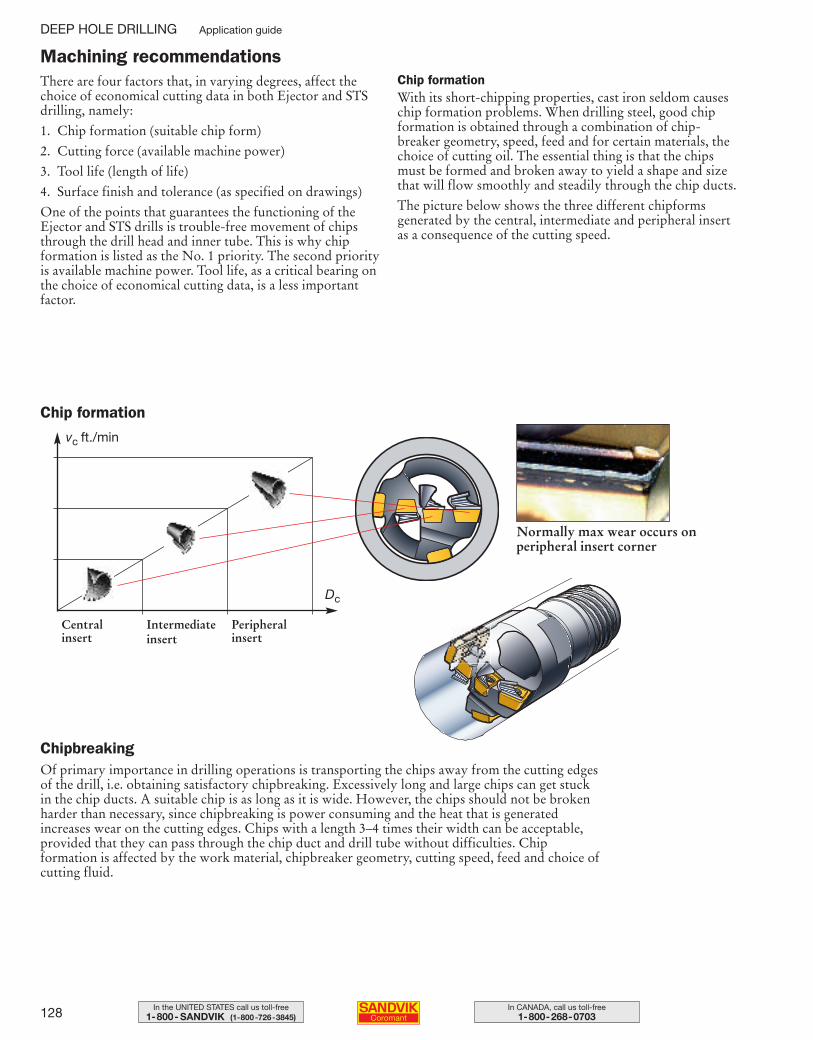
128 In CANADA, call us toll-free1-800-268-0703
In the UNITED STATES call us toll-free1-800- SANDVIK (1-800-726-3845)
There are four factors that, in varying degrees, affect thechoice of economical cutting data in both Ejector and STSdrilling, namely:
1. Chip formation (suitable chip form)
2. Cutting force (available machine power)
3. Tool life (length of life)
4. Surface finish and tolerance (as specified on drawings)
One of the points that guarantees the functioning of theEjector and STS drills is trouble-free movement of chipsthrough the drill head and inner tube. This is why chip formation is listed as the No. 1 priority. The second priorityis available machine power. Tool life, as a critical bearing onthe choice of economical cutting data, is a less importantfactor.
Chip formationWith its short-chipping properties, cast iron seldom causeschip formation problems. When drilling steel, good chipformation is obtained through a combination of chip-breaker geometry, speed, feed and for certain materials, thechoice of cutting oil. The essential thing is that the chipsmust be formed and broken away to yield a shape and sizethat will flow smoothly and steadily through the chip ducts.
The picture below shows the three different chipforms generated by the central, intermediate and peripheral insertas a consequence of the cutting speed.
Of primary importance in drilling operations is transporting the chips away from the cutting edgesof the drill, i.e. obtaining satisfactory chipbreaking. Excessively long and large chips can get stuckin the chip ducts. A suitable chip is as long as it is wide. However, the chips should not be brokenharder than necessary, since chipbreaking is power consuming and the heat that is generatedincreases wear on the cutting edges. Chips with a length 3–4 times their width can be acceptable,provided that they can pass through the chip duct and drill tube without difficulties. Chipformation is affected by the work material, chipbreaker geometry, cutting speed, feed and choice of cutting fluid.
Chipbreaking
Chip formation
Central insert
Intermediate insert
Peripheral insert
Normally max wear occurs on peripheral insert corner
vc ft./min
Dc
Machining recommendations
DEEP HOLE DRILLING Application guide
109-146 USA 04-04-29 10.23 Sida 128
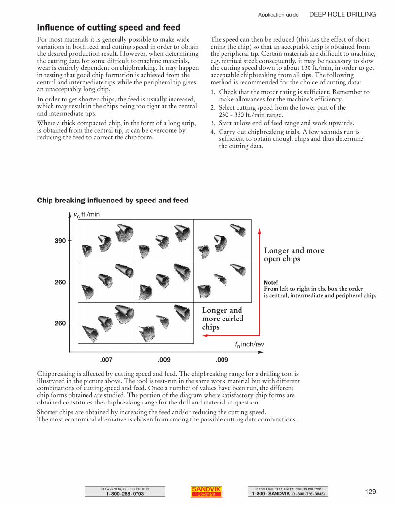
129In the UNITED STATES call us toll-free1-800- SANDVIK (1-800-726-3845)
In CANADA, call us toll-free1-800-268-0703
For most materials it is generally possible to make widevariations in both feed and cutting speed in order to obtainthe desired production result. However, when determiningthe cutting data for some difficult to machine materials,wear is entirely dependent on chipbreaking. It may happenin testing that good chip formation is achieved from thecentral and intermediate tips while the peripheral tip givesan unacceptably long chip.
In order to get shorter chips, the feed is usually increased,which may result in the chips being too tight at the centraland intermediate tips.
Where a thick compacted chip, in the form of a long strip, is obtained from the central tip, it can be overcome by reducing the feed to correct the chip form.
The speed can then be reduced (this has the effect of short-ening the chip) so that an acceptable chip is obtained fromthe peripheral tip. Certain materials are difficult to machine,e.g. nitrited steel; consequently, it may be necessary to slowthe cutting speed down to about 130 ft./min, in order to getacceptable chipbreaking from all tips. The followingmethod is recommended for the choice of cutting data:
1. Check that the motor rating is sufficient. Remember tomake allowances for the machine’s efficiency.
2. Select cutting speed from the lower part of the 230 - 330 ft./min range.
3. Start at low end of feed range and work upwards.4. Carry out chipbreaking trials. A few seconds run is
sufficient to obtain enough chips and thus determine the cutting data.
Chip breaking influenced by speed and feed
Longer and moreopen chips
Longer andmore curledchips
vc ft./min
fn inch/rev
390
260
260
.007 .009 .009
Note!From left to right in the box the order is central, intermediate and peripheral chip.
Chipbreaking is affected by cutting speed and feed. The chipbreaking range for a drilling tool isillustrated in the picture above. The tool is test-run in the same work material but with differentcombinations of cutting speed and feed. Once a number of values have been run, the differentchip forms obtained are studied. The portion of the diagram where satisfactory chip forms areobtained constitutes the chipbreaking range for the drill and material in question.
Shorter chips are obtained by increasing the feed and/or reducing the cutting speed. The most economical alternative is chosen from among the possible cutting data combinations.
Influence of cutting speed and feed
Application guide DEEP HOLE DRILLING
109-146 USA 04-04-29 10.23 Sida 129
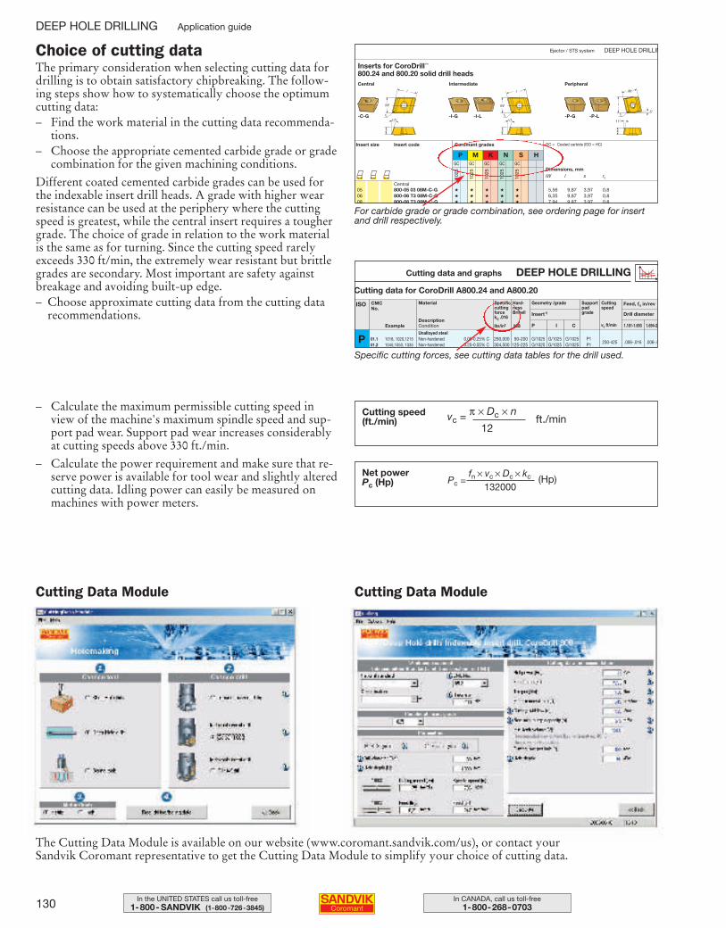
130 In CANADA, call us toll-free1-800-268-0703
In the UNITED STATES call us toll-free1-800- SANDVIK (1-800-726-3845)
Inserts for CoroDrill™
800.24 and 800.20 solid drill headsCentral Intermediate Peripheral
Insert size Insert code
1025
1025
1025
1025
1025
GC GC GC GC GC
Coromant grades
P M K N S H
Central
GC = Coated carbide (ISO = HC)
Dimensions, mmiW l s rε
05 800-05 03 08M-C-G ★ ★ ★ ★ ★ 5,56 9,87 3,97 0,806 800-06 T3 08M-C-G ★ ★ ★ ★ ★ 6,35 9,87 3,97 0,808 800-08 T3 08M-C-G ★ ★ ★ ★ ★ 7,94 9,87 3,97 0,8
-C-G -I-L -P-L-I-G -P-G
Ejector / STS system DEEP HOLE DRILLINChoice of cutting dataThe primary consideration when selecting cutting data fordrilling is to obtain satisfactory chipbreaking. The follow-ing steps show how to systematically choose the optimumcutting data: – Find the work material in the cutting data recommenda-
tions.– Choose the appropriate cemented carbide grade or grade
combination for the given machining conditions.
Different coated cemented carbide grades can be used forthe indexable insert drill heads. A grade with higher wearresistance can be used at the periphery where the cuttingspeed is greatest, while the central insert requires a toughergrade. The choice of grade in relation to the work materialis the same as for turning. Since the cutting speed rarely exceeds 330 ft/min, the extremely wear resistant but brittlegrades are secondary. Most important are safety againstbreakage and avoiding built-up edge.– Choose approximate cutting data from the cutting data
recommendations.
– Calculate the maximum permissible cutting speed inview of the machine's maximum spindle speed and sup-port pad wear. Support pad wear increases considerablyat cutting speeds above 330 ft./min.
– Calculate the power requirement and make sure that re-serve power is available for tool wear and slightly alteredcutting data. Idling power can easily be measured on machines with power meters.
For carbide grade or grade combination, see ordering page for insertand drill respectively.
Specific cutting forces, see cutting data tables for the drill used.
Cutting data and graphs DEEP HOLE DRILLING
Cutting data for CoroDrill A800.24 and A800.20
ISO
1.181-1.693 1.694-2.P I C
P G/1025 G/1025 G/1025 P1230-425 .006-.016 .006-.0G/1025 G/1025 G/1025 P1
CMCNo.
Cuttingspeed
Supportpadgrade Drill diameterInsert1)
Feed, fn in/revGeometry /grade
vc ft/min
Specificcuttingforcekc .016
Hard-nessBrinell
290,000 90-200304,500 125-225
lbs/in2 HB
Unalloyed steelNon-hardened 0.05-0.25% CNon-hardened 0.25-0.55% C
01.1 1018, 1020,121501.2 1045,1050, 1335
DescriptionCondition
Material
Example
Cutting speed (ft./min)
Net power Pc (Hp)
Cutting Data Module Cutting Data Module
The Cutting Data Module is available on our website (www.coromant.sandvik.com/us), or contact your Sandvik Coromant representative to get the Cutting Data Module to simplify your choice of cutting data.
DEEP HOLE DRILLING Application guide
vc = π × Dc × n
12ft./min
(Hp)Pc = fn × vc × Dc × kc
132000
109-146 USA 04-04-29 10.23 Sida 130
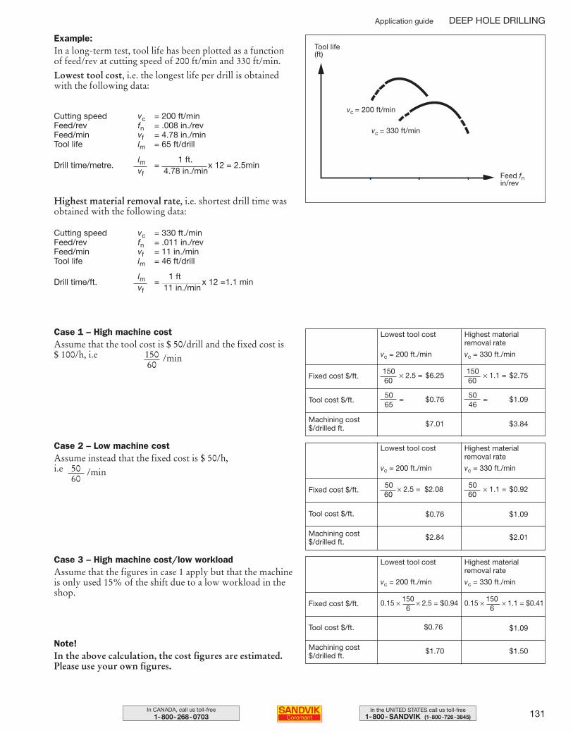
131In the UNITED STATES call us toll-free1-800- SANDVIK (1-800-726-3845)
In CANADA, call us toll-free1-800-268-0703
Lowest tool cost
vc = 200 ft./min
Highest materialremoval rate
vc = 330 ft./min
Tool cost $/ft.
Machining cost $/drilled ft.
Case 3 – High machine cost/low workload Assume that the figures in case 1 apply but that the machineis only used 15% of the shift due to a low workload in theshop.
Example:In a long-term test, tool life has been plotted as a functionof feed/rev at cutting speed of 200 ft/min and 330 ft/min.
Lowest tool cost, i.e. the longest life per drill is obtainedwith the following data:
Tool life(ft)
vc = 200 ft/min
vc = 330 ft/min
Feed fnin/rev
$7.01
Fixed cost $/ft.150 × 2.5 = $6.2560
$3.84
Note!In the above calculation, the cost figures are estimated.Please use your own figures.
Highest material removal rate, i.e. shortest drill time wasobtained with the following data:
Cutting speed vc = 200 ft/minFeed/rev fn = .008 in./revFeed/min vf = 4.78 in./minTool life lm = 65 ft/drill
Drill time/metre.lm =
1 ft.x 12 = 2.5min
vf 4.78 in./min
Cutting speed vc = 330 ft./minFeed/rev fn = .011 in./revFeed/min vf = 11 in./minTool life lm = 46 ft/drill
Drill time/ft.lm =
1 ftx 12 =1.1 min
vf 11 in./min
50 = $0.7665
150 × 1.1 = $2.7560
50 = $1.0946
Lowest tool cost
vc = 200 ft./min
Highest materialremoval rate
vc = 330 ft./min
Tool cost $/ft.
Machining cost $/drilled ft.
$2.84
Fixed cost $/ft.50 × 2.5 = $2.0860
$2.01
$0.76
50 × 1.1 = $0.9260
$1.09
Lowest tool cost
vc = 200 ft./min
Highest materialremoval rate
vc = 330 ft./min
Tool cost $/ft.
Machining cost $/drilled ft.
$1.70
Fixed cost $/ft.
$1.50
$0.76 $1.09
0.15 × 150 × 2.5 = $0.946
0.15 × 150 × 1.1 = $0.416
Case 1 – High machine cost Assume that the tool cost is $ 50/drill and the fixed cost is $ 100/h, i.e 150 /min
60
50 /min60
Case 2 – Low machine cost Assume instead that the fixed cost is $ 50/h, i.e
Application guide DEEP HOLE DRILLING
109-146 USA 04-04-29 10.23 Sida 131
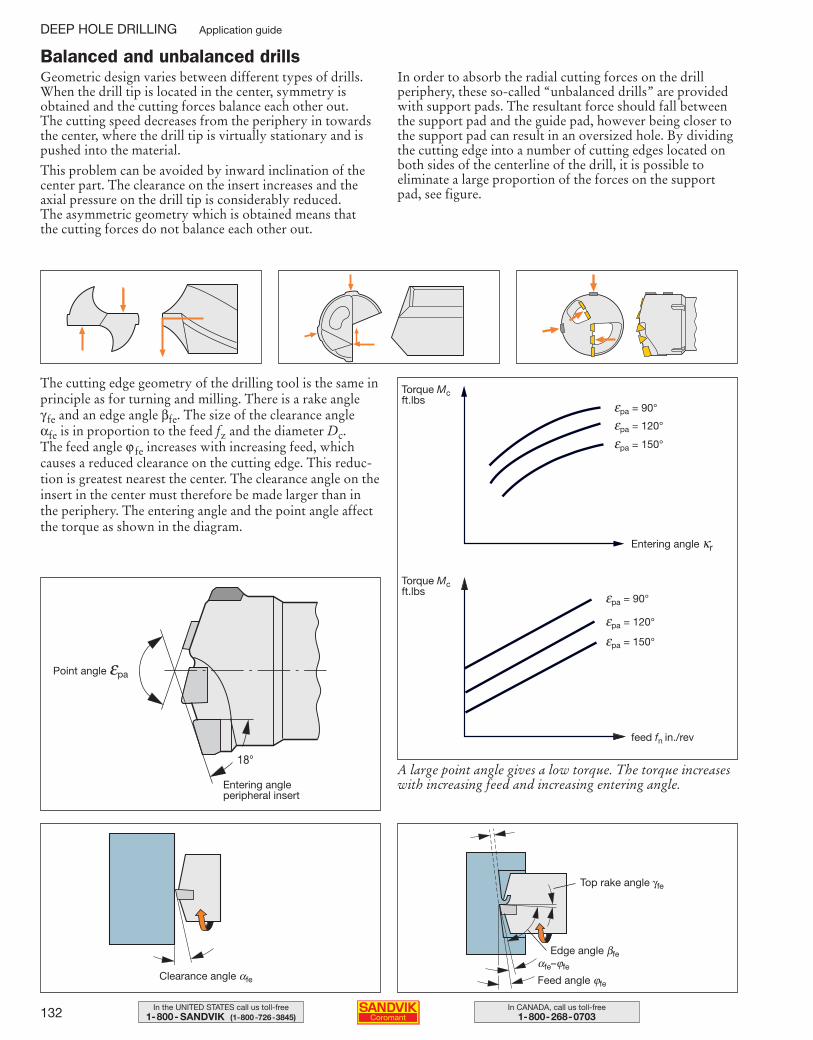
132 In CANADA, call us toll-free1-800-268-0703
In the UNITED STATES call us toll-free1-800- SANDVIK (1-800-726-3845)
Geometric design varies between different types of drills.When the drill tip is located in the center, symmetry is obtained and the cutting forces balance each other out. The cutting speed decreases from the periphery in towardsthe center, where the drill tip is virtually stationary and ispushed into the material.
This problem can be avoided by inward inclination of thecenter part. The clearance on the insert increases and the axial pressure on the drill tip is considerably reduced. The asymmetric geometry which is obtained means that the cutting forces do not balance each other out.
In order to absorb the radial cutting forces on the drill periphery, these so-called “unbalanced drills” are providedwith support pads. The resultant force should fall betweenthe support pad and the guide pad, however being closer tothe support pad can result in an oversized hole. By dividingthe cutting edge into a number of cutting edges located onboth sides of the centerline of the drill, it is possible toeliminate a large proportion of the forces on the supportpad, see figure.
Balanced and unbalanced drills
The cutting edge geometry of the drilling tool is the same inprinciple as for turning and milling. There is a rake angle γ fe and an edge angle βfe. The size of the clearance angle αfe is in proportion to the feed fz and the diameter Dc. The feed angle ϕ fe increases with increasing feed, whichcauses a reduced clearance on the cutting edge. This reduc-tion is greatest nearest the center. The clearance angle on theinsert in the center must therefore be made larger than in the periphery. The entering angle and the point angle affectthe torque as shown in the diagram.
A large point angle gives a low torque. The torque increaseswith increasing feed and increasing entering angle.
feed fn in./rev
Entering angle κr
εpa = 90°
εpa = 120°
εpa = 150°
εpa = 90°
εpa = 120°
εpa = 150°
Torque Mcft.lbs
Torque Mcft.lbs
Point angle εpa
Entering angle peripheral insert
18°
Clearance angle αfe
αfe–ϕfe
Feed angle ϕfe
Edge angle βfe
Top rake angle γfe
DEEP HOLE DRILLING Application guide
109-146 USA 04-04-29 10.23 Sida 132
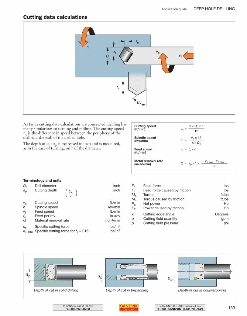
133In the UNITED STATES call us toll-free1-800- SANDVIK (1-800-726-3845)
In CANADA, call us toll-free1-800-268-0703
As far as cutting data calculations are concerned, drilling hasmany similarities to turning and milling. The cutting speedvc is the difference in speed between the periphery of thedrill and the wall of the drilled hole.
The depth of cut ap is expressed in inch and is measured, as in the case of turning, on half the diameter.
Depth of cut in solid drilling Depth of cut in trepanning Depth of cut in counterboring
ap ap ap
Terminology and unitsDc Drill diameter inchap Cutting depth inch
vc Cutting speed ft./minn Spindle speed rev/minvf Feed speed ft./minfn Feed per rev. in./revQ Material removal rate inch3/min
kc Specific cutting force Ibs/in2
kc .016 Specific cutting force for fz =.016 Ibs/in2
Ff Feed force IbsFµ Feed force caused by friction IbsMc Torque ft.lbsMµ Torque caused by friction ft.lbsPc Net power HpPµ Power caused by friction Hp
κr Cutting edge angle Degreesq Cutting fluid quantity gpmp Cutting fluid pressure psi
Cutting data calculations
Cutting speed (ft/min) vc =
π × Dc × n
12
Spindle speed (rev/min)
Feed speed (ft./min)
Metal removal rate (inch3/min)
n =vc × 12
π × Dc
vf = fn × n
Q = ap × fn ×vc max - vc min
2
Application guide DEEP HOLE DRILLING
Dc2( )
109-146 USA 04-04-29 10.23 Sida 133
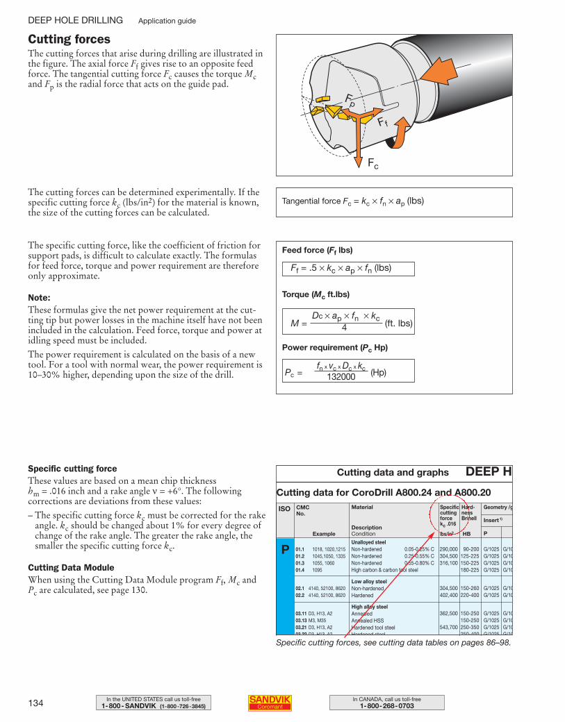
134 In CANADA, call us toll-free1-800-268-0703
In the UNITED STATES call us toll-free1-800- SANDVIK (1-800-726-3845)
The cutting forces that arise during drilling are illustrated inthe figure. The axial force Ff gives rise to an opposite feedforce. The tangential cutting force Fc causes the torque Mcand Fp is the radial force that acts on the guide pad.
The cutting forces can be determined experimentally. If thespecific cutting force kc (lbs/in2) for the material is known,the size of the cutting forces can be calculated.
The specific cutting force, like the coefficient of friction forsupport pads, is difficult to calculate exactly. The formulasfor feed force, torque and power requirement are thereforeonly approximate.
Note:These formulas give the net power requirement at the cut-ting tip but power losses in the machine itself have not beenincluded in the calculation. Feed force, torque and power atidling speed must be included.
The power requirement is calculated on the basis of a newtool. For a tool with normal wear, the power requirement is10–30% higher, depending upon the size of the drill.
Cutting data and graphs DEEP H
Cutting data for CoroDrill A800.24 and A800.20
ISO
P I
P G/1025 G/10G/1025 G/10G/1025 G/10G/1025 G/10
G/1025 G/10G/1025 G/10
G/1025 G/10G/1025 G/10G/1025 G/10G/1025 G/10
CMCNo.
Insert1)
Geometry /gSpecificcuttingforcekc .016
Hard-nessBrinell
290,000 90-200304,500 125-225316,100 150-225
180-225
304,500 150-260402,400 220-400
362,500 150-250150-250
543,700 250-350250-400
lbs/in2 HB
Unalloyed steelNon-hardened 0.05-0.25% CNon-hardened 0.25-0.55% CNon-hardened 0.55-0.80% CHigh carbon & carbon tool steel
High alloy steelAnnealedAnnealed HSSHardened tool steelHardened steel
Low alloy steelNon-hardenedHardened
01.1 1018, 1020,121501.2 1045,1050, 133501.3 1055, 106001.4 1095
02.1 4140, 52100, 862002.2 4140, 52100, 8620
03.11 D3, H13, A203.13 M3, M3503.21 D3, H13, A203 22 D3 H13 A2
DescriptionCondition
Material
Example
Specific cutting forceThese values are based on a mean chip thicknesshm = .016 inch and a rake angle ν = +6°. The followingcorrections are deviations from these values:
– The specific cutting force kc must be corrected for the rakeangle. kc should be changed about 1% for every degree ofchange of the rake angle. The greater the rake angle, thesmaller the specific cutting force kc.
Cutting Data ModuleWhen using the Cutting Data Module program Ff, Mc andPc are calculated, see page 130.
Specific cutting forces, see cutting data tables on pages 86–98.
Fp
Fc
Ff
Feed force (Ff lbs)
Torque (Mc ft.lbs)
Power requirement (Pc Hp)
Cutting forces
Pc =fn x vc x Dc x kc (Hp)132000
Ff = .5 × kc × ap × fn (lbs)
Tangential force Fc = kc × fn × ap (lbs)
DEEP HOLE DRILLING Application guide
M = Dc × ap × fn × kc
(ft. lbs)4
109-146 USA 04-04-29 10.23 Sida 134
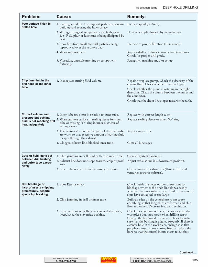
135In the UNITED STATES call us toll-free1-800- SANDVIK (1-800-726-3845)
In CANADA, call us toll-free1-800-268-0703
Poor surface finish indrilled hole
1. Cutting speed too low, support pads experiencingbuild up and scoring the hole surface.
2. Wrong cutting oil, temperature too high, over 135° F. Sulphur or lubricant is being dissipated byheat.
3. Poor filtration, small material particles being reproduced over the support pads.
4. Worn support pads.
5. Vibration, unstable machine or component fixturing.
Increase speed (rev/min).
Have oil sample checked by manufacturer.
Increase to proper filtration (40 microns).
Replace drill and check cutting speed (rev/min).Check for proper drill grade.
Strengthen machine and / or set up.
Chip jamming in the drill head or the innertube
1. Inadequate cutting fluid volume. Repair or replace pump. Check the viscosity of thecutting fluid. Check whether filter is clogged.
Check whether the pump is rotating in the right direction. Check the plumb between the pump andthe connector.
Check that the drain line slopes towards the tank.
Correct volume andpressure but cuttingfluid is not reaching drillhead adequately
1. Inner tube too short in relation to outer tube.
2. Worn support surface in sealing sleeve for innertube or missing "O" ring in inner diameter of sealing sleeve.
3. The venturi slots in the rear part of the inner tubeare worn so that excessive amount of cutting fluidescapes through the exhaust.
4. Clogged exhaust line, blocked inner tube.
Replace with correct length tube.
Replace sealing sleeve or inner "O" ring.
Replace inner tube.
Clear all blockages.
Drill breakage or insert/inserts chippingprematurely, despitegood chip breaking
1. Poor Ejector effect
2. Chip jamming in drill or inner tube.
3. Incorrect start of drilling i.e. center drilled hole, irregular surface, oversize bushing.
Check inside diameter of the connections for blockage, whether the drain line slopes evenly,whether the inner tube is constricted or the venturislots have collapsed or too large.
Built-up edge on the central insert can cause crumbling so that long chips are formed and chipflow is blocked. Decrease feed per revolution.
Check the clamping of the workpiece so that theworkpiece does not move when drilling starts.Change the bushing if it is worn. Check to make sure that the bushing is aligned properly. If there is a center hole in the workpiece, enlarge it so that peripheral insert starts cutting first, or reduce thebore so that the central inserts starts to cut first.
Cutting fluid leaks outbetween drill bushingand outer tube exces-sively
1. Chip jamming in drill head or flare in inner tube.
2. Exhaust line does not slope towards chip disposalarea.
3. Inner tube is inverted in the wrong direction.
Clear all system blockages.
Adjust exhaust line in a downward position.
Correct inner tube direction (flare to drill and venturies towards exhaust).
Continued…
Problem: Cause: Remedy:
Application guide DEEP HOLE DRILLING
109-146 USA 04-04-29 10.23 Sida 135
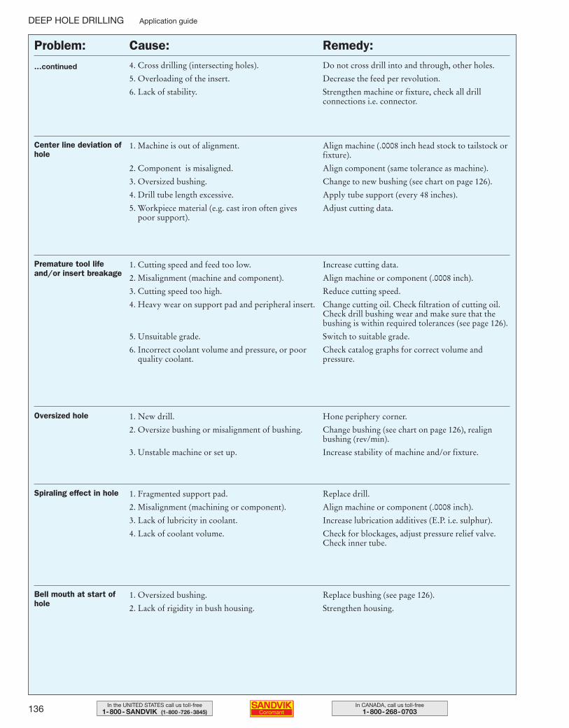
136 In CANADA, call us toll-free1-800-268-0703
In the UNITED STATES call us toll-free1-800- SANDVIK (1-800-726-3845)
4. Cross drilling (intersecting holes).
5. Overloading of the insert.
6. Lack of stability.
Do not cross drill into and through, other holes.
Decrease the feed per revolution.
Strengthen machine or fixture, check all drill connections i.e. connector.
Center line deviation ofhole
1. Machine is out of alignment.
2. Component is misaligned.
3. Oversized bushing.
4. Drill tube length excessive.
5. Workpiece material (e.g. cast iron often gives poor support).
Align machine (.0008 inch head stock to tailstock orfixture).
Align component (same tolerance as machine).
Change to new bushing (see chart on page 126).
Apply tube support (every 48 inches).Adjust cutting data.
Premature tool lifeand/or insert breakage
1. Cutting speed and feed too low.
2. Misalignment (machine and component).
3. Cutting speed too high.
4. Heavy wear on support pad and peripheral insert.
5. Unsuitable grade.
6. Incorrect coolant volume and pressure, or poorquality coolant.
Increase cutting data.
Align machine or component (.0008 inch).
Reduce cutting speed.
Change cutting oil. Check filtration of cutting oil.Check drill bushing wear and make sure that thebushing is within required tolerances (see page 126).
Switch to suitable grade.
Check catalog graphs for correct volume and pressure.
Oversized hole 1. New drill.
2. Oversize bushing or misalignment of bushing.
3. Unstable machine or set up.
Hone periphery corner.
Change bushing (see chart on page 126), realignbushing (rev/min).
Increase stability of machine and/or fixture.
Spiraling effect in hole 1. Fragmented support pad.
2. Misalignment (machining or component).
3. Lack of lubricity in coolant.
4. Lack of coolant volume.
Replace drill.
Align machine or component (.0008 inch).
Increase lubrication additives (E.P. i.e. sulphur).
Check for blockages, adjust pressure relief valve.Check inner tube.
Bell mouth at start ofhole
1. Oversized bushing.
2. Lack of rigidity in bush housing.
Replace bushing (see page 126).
Strengthen housing.
…continued
Problem: Cause: Remedy:
DEEP HOLE DRILLING Application guide
109-146 USA 04-04-29 10.23 Sida 136
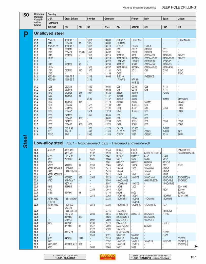
137In the UNITED STATES call us toll-free1-800- SANDVIK (1-800-726-3845)
In CANADA, call us toll-free1-800-268-0703
Material cross reference list DEEP HOLE DRILLING
ISO CoromantMaterialClassifi-cation(CMC)
Country
Standard
Germany France Italy Spain Japan
PAISI/SAE BS EN SS W.-nr. DIN AFNOR UNI UNE JIS
01.1 A570.36 4360 40 C 1311 1.0038 RSt.37-2 E 24-2 Ne STKM 12A;C01.1 1115 030A04 1A 1325 1.0038 GS-CK16 - - - -01.1 A573-81 65 4360 40 B 1312 1.0116 St.37-3 E 24-U Fe37-301.1 1015 080M15 - 1350 1.0401 C15 CC12 C15C16 F.111 -01.1 1020 050A20 2C/2D 1450 1.0402 C22 CC20 C20C21 F.112 -01.1 1213 230M07 - 1912 1.0715 9SMn28 S250 CF9SMn28 11SMn28 SUM2201.1 12L13 - - 1914 1.0718 9SMnPb28 S250Pb CF9SMnPb28 11SMnPb28 SUM22L01.1 - - - - 1.0722 10SPb20 10PbF2 CF10SPb20 10SPb20 -01.1 1215 240M07 1B - 1.0736 9SMn36 S 300 CF9SMn36 12SMn35 -01.1 12L14 - - 1926 1.0737 9SMnPb36 S300Pb CF9SMnPb36 12SMnP35 -01.1 1015 080M15 32C 1370 1.1141 Ck15 XC12 C16 C15K S15C01.1 1025 - - - 1.1158 Ck25 - - - S25C01.1 A572-60 4360 55 E 2145 1.8900 StE 380 - FeE390KG01.1 A572-60 4360 55 E 2142 - 17 MnV 6 NFA 35- - -
501 E 36
01.2 1035 060A35 - 1550 1.0501 C35 CC35 C35 F.113 -01.2 1045 080M46 - 1650 1.0503 C45 CC45 C45 F.114 -01.2 1140 212M36 8M 1957 1.0726 35S20 35MF4 - F210G -01.2 1039 150M36 15 - 1.1157 40Mn4 35M5 - - -01.2 1335 - - 2120 1.1167 36MN5 40M5 - 36Mn5 SMn438(H)01.2 1330 150M28 14A - 1.1170 28Mn6 20M5 C28Mn - SCMn101.2 1035 060A35 - 1572 1.1183 Cf35 XC38TS C36 - S35C01.2 1045 080M46 - 1672 1.1191 Ck45 XC42 C45 C45K S45C01.2 1050 060A52 - 1674 1.1213 Cf53 XC48TS C53 - S50C
01.3 1055 070M55 - 1655 1.0535 C55 - C55 - -01.3 1060 080A62 43D - 1.0601 C60 CC55 C60 - -01.3 1055 070M55 - - 1.1203 Ck55 XC55 C50 C55K S55C01.3 1060 080A62 43D 1678 1.1221 Ck60 XC60 C60 - S58C
01.4 1095 060 A 96 1870 1.1274 Ck 101 XC 100 - F-511701.4 W 1 BW 1A 1880 1.1545 C 105 W1 Y105 C36KU F-5118 SK 301.4 W210 BW2 - 2900 1.1545 C105W1 Y120 C120KU F.515 SUP4
Unalloyed steel
Low-alloy steel (02.1 = Non-hardened, 02.2 = Hardened and tempered)
➤
02.1 A573-81 4360 43C 1412 1.0144 St.44-2 E 28-3 - - SM 400A;B;C02.1 - 4360 50B 2132 1.0570 St.52-3 E36-3 Fe52BFN/Fe52CFN - SM490A;B;C;YA;YB02.1 5120 150 M 19 2172 1.0841 St.52-3 20 MC 5 Fe52 F-43102.1 9255 250A53 45 2085 1.0904 55Si7 55S7 55Si8 56Si7 -02.1 9262 - - - 1.0961 60SiCr7 60SC7 60SiCr8 60SiCr8 -02.1 52100 534A99 31 2258 1.3505 100Cr6 100C6 100Cr6 F.131 SUJ202.1 ASTM A204Gr.A 1501-240 - 2912 1.5415 15Mo3 15D3 16Mo3KW 16Mo3 -02.1 4520 1503-245-420 - - 1.5423 16Mo5 - 16Mo5 16Mo5 -02.1 ASTM A350LF5 - - - 1.5622 14Ni6 16N6 14Ni6 15Ni6 -02.1 8620 805M20 362 2506 1.6523 21NiCrMo2 20NCD2 20NiCrMo2 20NiCrMo2 SNCM220(H)02.1 8740 311-Type 7 - - 1.6546 40NiCrMo22 - 40NiCrMo2(KB) 40NiCrMo2 SNCM24002.1 - 820A16 - - 1.6587 17CrNiMo6 18NCD6 - 14NiCrMo13 -02.1 5015 523M15 - - 1.7015 15Cr3 12C3 - - SCr415(H)02.1 5140 - - 2245 1.7045 42Cr4 - - 42Cr4 SCr44002.1 5155 527A60 48 - 1.7176 55Cr3 55C3 - - SUP9(A)02.1 - - - 2216 1.7262 15CrMo5 12CD4 - 12CrMo4 SCM415(H)02.1 ASTM A182 1501-620Gr27 - - 1.7335 13CrMo4 4 15CD3.5 14CrMo4 5 14CrMo45 -
F11;F12 15CD4.502.1 ASTM A182 1501-622 - 2218 1.7380 10CrMo9 10 12CD9, 10 12CrMo9, 10 TU.H -
F.22 Gr.31;45 - - - -02.1 - 1503-660-440 - - 1.7715 14MoV6 3 - - 13MoCrV6 -02.1 - 722 M 24 2240 1.8515 31 CeMo 12 30 CD 12 30CrMo12 F-171202.1 - 897M39 40C - 1.8523 39CrMoV13 9 - 36CrMoV12 - -02.1 L1 524A14 - 2092 1.7039 34MoCrS4 G - 105WCR 5 - -02.1 8620 605A32 - 2108 1.5419 20MoCrS4 - - F520.S -02.1 - 823M30 33 2512 1.7228 55NiCrMoV6G - 653M31 - -02.1 - - - 2127 1.7139 16MnCr5 - - - -02.1 - 830 M 31 2534 - 31NiCrMo134 - - F-127002.1 L6 - 2550 1.2721 50NiCr13 55NCV6 - F-52802.2 3135 640A35 111A - 1.5710 36NiCr6 35NC6 - - SNC23602.2 3415 - - - 1.5732 14NiCr10 14NC11 16NiCr11 15NiCr11 SNC415(H)02.2 3415;3310 655M13; A12 36A - 1.5752 14NiCr14 12NC15 - - SNC815(H)02.2 9255 - - 2090 1.0904 55Si7 55S7 - - -
Great BritainUSA Sweden
Ste
el
109-146 USA 04-05-07 09.54 Sida 137
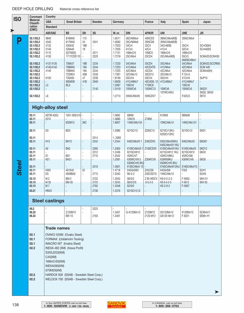
138 In CANADA, call us toll-free1-800-268-0703
In the UNITED STATES call us toll-free1-800- SANDVIK (1-800-726-3845)
DEEP HOLE DRILLING Material cross reference list
ISO CoromantMaterialClassifi-cation(CMC)
Country
USA Great Britain Germany France Italy Spain Japan
Standard
P➤ AISI/SAE BS EN SS W.-nr. DIN AFNOR UNI UNE JIS
02.1/02.2 9840 816M40 110 - 1.6511 36CrNiMo4 40NCD3 38NiCrMo4(KB) 35NiCrMo4 -02.1/02.2 4340 817M40 24 2541 1.6582 35CrNiMo6 35NCD6 35NiCrMo6(KB) - -02.1/02.2 5132 530A32 18B - 1.7033 34Cr4 32C4 34Cr4(KB) 35Cr4 SCr430(H)02.1/02.2 5140 530A40 18 - 1.7035 41Cr4 42C4 41Cr4 42Cr4 SCr440(H)02.1/02.2 5115 (527M20) - 2511 1.7131 16MnCr5 16MC5 16MnCr5 16MnCr5 -02.1/02.2 4130 1717CDS110 - 2225 1.7218 25CrMo4 25CD4 25CrMo4(KB) 55Cr3 SCM420;SCM430
AM26CrMo402.1/02.2 4137;4135 708A37 19B 2234 1.7220 34CrMo4 35CD4 35CrMo4 34CrMo4 SCM432;SCCRM302.1/02.2 4140;4142 708M40 19A 2244 1.7223 41CrMo4 42CD4TS 41CrMo4 42CrMo4 SCM 44002.1/02.2 4140 708M40 19A 2244 1.7225 42CrMo4 42CD4 42CrMo4 42CrMo4 SCM440(H)02.1/02.2 - 722M24 40B 2240 1.7361 32CrMo12 30CD12 32CrMo12 F.124.A -02.1/02.2 6150 735A50 47 2230 1.8159 50CrV4 50CV4 50CrV4 51CrV4 SUP1002.1/02.2 - 905M39 41B 2940 1.8509 41CrAlMo7 40CAD6, 12 41CrAlMo7 41CrAlMo7 -02.1/02.2 L3 BL3 - - 1.2067 100Cr6 Y100C6 - 100Cr6 -02.1/02.2 - - - 2140 1.2419 105WCr6 105WC13 10WCr6 105WCr5 SKS31
107WCr5KU SKS2, SKS302.1/02.2 L6 - - - 1.2713 55NiCrMoV6 55NCDV7 - F.520.S SKT4
High-alloy steel
Steel castings
03.11 ASTM A353 1501-509;510 - - 1.5662 X8Ni9 - X10Ni9 XBNi09 -03.11 2515 - - - 1.5680 12Ni19 Z18N5 - - -03.11 - 832M13 36C - 1.6657 14NiCrMo134 - 15NiCrMo13 14NiCrMo131 -
03.11 D3 BD3 - - 1.2080 X210Cr12 Z200C12 X210Cr13KU X210Cr12 SKD1X250Cr12KU
03.11 2314 1..208303.11 H13 BH13 - 2242 1.2344 X40CrMoV5 1 Z40CDV5 X35CrMoV05KU X40CrMoV5 SKD61
X40CrMoV511KU03.11 A2 BA2 - 2260 1.2363 X100CrMoV5 1 Z100CDV5 X100CrMoV51KU X100CrMoV5 SKD1203.11 - - - 2312 1.2436 X210CrW12 - X215CrW12 1KU X210CrW12 SKD203.11 S1 BS1 - 2710 1.2542 45WCrV7 - 45WCrV8KU 45WCrSi8 -03.11 H21 BH21 - - 1.2581 X30WCrV9 3 Z30WCV9 X28W09KU X30WCrV9 SKD5
X30WCrV9 3KU X30WCrV9 3KU03.11 - - - 2310 1.2601 X165CrMoV 12 - X165CrMoW12KU X160CrMoV12 -03.11 HW3 401S45 52 - 1.4718 X45GrSi93 Z45CS9 X45GrSi8 F322 SUH103.11 D3 4959BA2 - 2715 1.3343 S6-5-2 Z40CSD10 15NiCrMo13 - SUH3
03.13 M 2 BM 2 2722 1.3343 S6/5/2 Z 85 WDCV HS 6-5-2-2 F-5603. SKH 5103.13 M 35 BM 35 2723 1.3243 S6/5/2/5 6-5-2-5 HS 6-5-2-5 F-5613 SKH 5503.13 M 7 - 2782 1.3348 S2/9/2 - HS 2-9-2 F-5607 -
03.21 HNV3 - - 2736 1.2379 X210Cr12 G - - - -
06.2 - - - 2223 - - -06.33 - Z120M12 - - 1.3401 G-X120Mn12 Z120M12 XG120Mn12 X120Mn12 SCMnH/106.33 BW 10 2183 1.3401 2120 M12 GX120 Mn12 F-8251 SEMn H1
02.1 OVAKO 520M (Ovako Steel)02.1 FORMAX (Uddeholm Tooling)02.1 IMACRO NIT (Imatra Steel)02.2 INEXA 482 (XM) (Inexa Profil)
S355J2G3(XM)C45(XM)16MnCrS5(XM)INEXA280(XM)070M20(XM)
02.2 HARDOX 500 (SSAB - Swedish Steel Corp.)02.2 WELDOX 700 (SSAB - Swedish Steel Corp.)
Trade names
➤
SwedenS
teel
109-146 USA 04-05-07 09.45 Sida 138
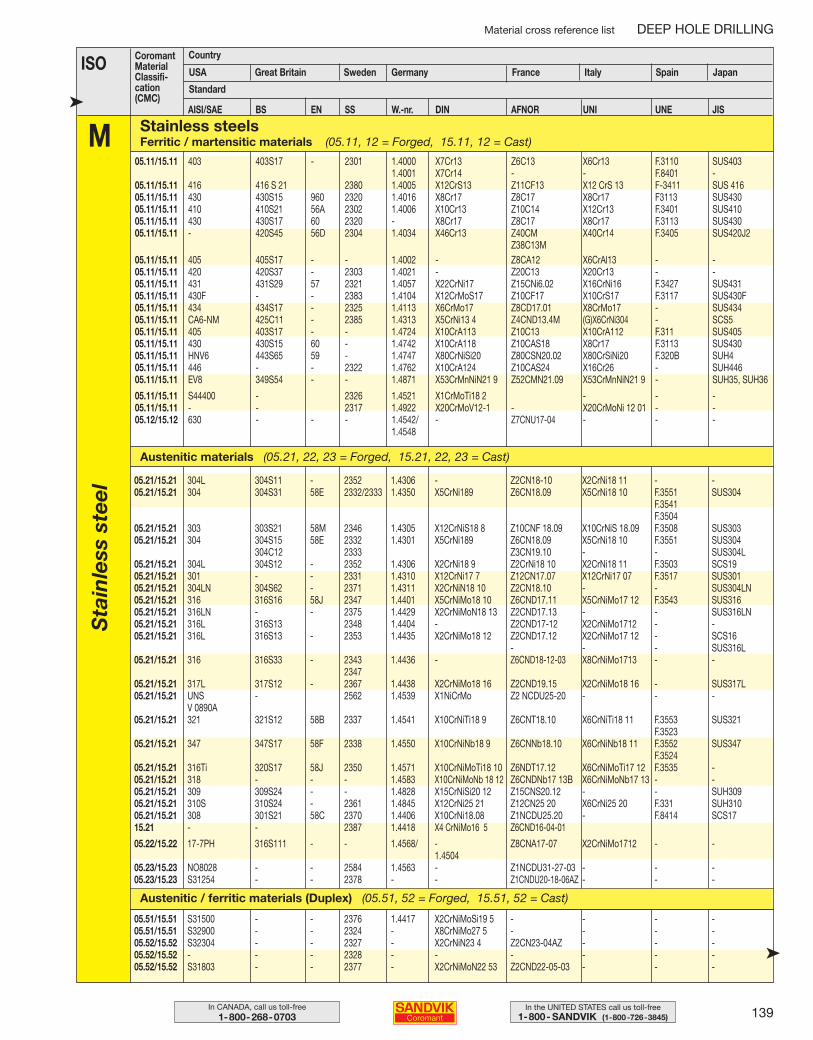
139In the UNITED STATES call us toll-free1-800- SANDVIK (1-800-726-3845)
In CANADA, call us toll-free1-800-268-0703
Material cross reference list DEEP HOLE DRILLING
ISO CoromantMaterialClassifi-cation(CMC)
Country
Germany France Italy Spain Japan
Standard
MAISI/SAE BS EN SS W.-nr. DIN AFNOR UNI UNE JIS
05.11/15.11 403 403S17 - 2301 1.4000 X7Cr13 Z6C13 X6Cr13 F.3110 SUS4031.4001 X7Cr14 - - F.8401 -
05.11/15.11 416 416 S 21 2380 1.4005 X12CrS13 Z11CF13 X12 CrS 13 F-3411 SUS 41605.11/15.11 430 430S15 960 2320 1.4016 X8Cr17 Z8C17 X8Cr17 F3113 SUS43005.11/15.11 410 410S21 56A 2302 1.4006 X10Cr13 Z10C14 X12Cr13 F.3401 SUS41005.11/15.11 430 430S17 60 2320 - X8Cr17 Z8C17 X8Cr17 F.3113 SUS43005.11/15.11 - 420S45 56D 2304 1.4034 X46Cr13 Z40CM X40Cr14 F.3405 SUS420J2
Z38C13M05.11/15.11 405 405S17 - - 1.4002 - Z8CA12 X6CrAl13 - -05.11/15.11 420 420S37 - 2303 1.4021 - Z20C13 X20Cr13 - -05.11/15.11 431 431S29 57 2321 1.4057 X22CrNi17 Z15CNi6.02 X16CrNi16 F.3427 SUS43105.11/15.11 430F - - 2383 1.4104 X12CrMoS17 Z10CF17 X10CrS17 F.3117 SUS430F05.11/15.11 434 434S17 - 2325 1.4113 X6CrMo17 Z8CD17.01 X8CrMo17 - SUS43405.11/15.11 CA6-NM 425C11 - 2385 1.4313 X5CrNi13 4 Z4CND13.4M (G)X6CrNi304 - SCS505.11/15.11 405 403S17 - - 1.4724 X10CrA113 Z10C13 X10CrA112 F.311 SUS40505.11/15.11 430 430S15 60 - 1.4742 X10CrA118 Z10CAS18 X8Cr17 F.3113 SUS43005.11/15.11 HNV6 443S65 59 - 1.4747 X80CrNiSi20 Z80CSN20.02 X80CrSiNi20 F.320B SUH405.11/15.11 446 - - 2322 1.4762 X10CrA124 Z10CAS24 X16Cr26 - SUH44605.11/15.11 EV8 349S54 - - 1.4871 X53CrMnNiN21 9 Z52CMN21.09 X53CrMnNiN21 9 - SUH35, SUH36
05.11/15.11 S44400 - 2326 1.4521 X1CrMoTi18 2 - - -05.11/15.11 - - 2317 1.4922 X20CrMoV12-1 - X20CrMoNi 12 01 - -05.12/15.12 630 - - - 1.4542/ - Z7CNU17-04 - - -
1.4548
05.51/15.51 S31500 - - 2376 1.4417 X2CrNiMoSi19 5 - - - -05.51/15.51 S32900 - - 2324 - X8CrNiMo27 5 - - - -05.52/15.52 S32304 - - 2327 - X2CrNiN23 4 Z2CN23-04AZ - - -05.52/15.52 - - - 2328 - - - - - -05.52/15.52 S31803 - - 2377 - X2CrNiMoN22 53 Z2CND22-05-03 - - -
05.21/15.21 304L 304S11 - 2352 1.4306 - Z2CN18-10 X2CrNi18 11 - -05.21/15.21 304 304S31 58E 2332/2333 1.4350 X5CrNi189 Z6CN18.09 X5CrNi18 10 F.3551 SUS304
F.3541F.3504
05.21/15.21 303 303S21 58M 2346 1.4305 X12CrNiS18 8 Z10CNF 18.09 X10CrNiS 18.09 F.3508 SUS30305.21/15.21 304 304S15 58E 2332 1.4301 X5CrNi189 Z6CN18.09 X5CrNi18 10 F.3551 SUS304
304C12 2333 Z3CN19.10 - - SUS304L05.21/15.21 304L 304S12 - 2352 1.4306 X2CrNi18 9 Z2CrNi18 10 X2CrNi18 11 F.3503 SCS1905.21/15.21 301 - - 2331 1.4310 X12CrNi17 7 Z12CN17.07 X12CrNi17 07 F.3517 SUS30105.21/15.21 304LN 304S62 - 2371 1.4311 X2CrNiN18 10 Z2CN18.10 - - SUS304LN05.21/15.21 316 316S16 58J 2347 1.4401 X5CrNiMo18 10 Z6CND17.11 X5CrNiMo17 12 F.3543 SUS31605.21/15.21 316LN - - 2375 1.4429 X2CrNiMoN18 13 Z2CND17.13 - - SUS316LN05.21/15.21 316L 316S13 2348 1.4404 - Z2CND17-12 X2CrNiMo1712 - -05.21/15.21 316L 316S13 - 2353 1.4435 X2CrNiMo18 12 Z2CND17.12 X2CrNiMo17 12 - SCS16
- - - SUS316L05.21/15.21 316 316S33 - 2343 1.4436 - Z6CND18-12-03 X8CrNiMo1713 - -
234705.21/15.21 317L 317S12 - 2367 1.4438 X2CrNiMo18 16 Z2CND19.15 X2CrNiMo18 16 - SUS317L05.21/15.21 UNS - 2562 1.4539 X1NiCrMo Z2 NCDU25-20 - - -
V 0890A05.21/15.21 321 321S12 58B 2337 1.4541 X10CrNiTi18 9 Z6CNT18.10 X6CrNiTi18 11 F.3553 SUS321
F.352305.21/15.21 347 347S17 58F 2338 1.4550 X10CrNiNb18 9 Z6CNNb18.10 X6CrNiNb18 11 F.3552 SUS347
F.352405.21/15.21 316Ti 320S17 58J 2350 1.4571 X10CrNiMoTi18 10 Z6NDT17.12 X6CrNiMoTi17 12 F.3535 -05.21/15.21 318 - - - 1.4583 X10CrNiMoNb 18 12 Z6CNDNb17 13B X6CrNiMoNb17 13 - -05.21/15.21 309 309S24 - - 1.4828 X15CrNiSi20 12 Z15CNS20.12 - - SUH30905.21/15.21 310S 310S24 - 2361 1.4845 X12CrNi25 21 Z12CN25 20 X6CrNi25 20 F.331 SUH31005.21/15.21 308 301S21 58C 2370 1.4406 X10CrNi18.08 Z1NCDU25.20 - F.8414 SCS1715.21 - - 2387 1.4418 X4 CrNiMo16 5 Z6CND16-04-01
05.22/15.22 17-7PH 316S111 - - 1.4568/ - Z8CNA17-07 X2CrNiMo1712 - -1.4504
05.23/15.23 NO8028 - - 2584 1.4563 - Z1NCDU31-27-03 - - -05.23/15.23 S31254 - - 2378 - - Z1CNDU20-18-06AZ - - -
➤
Sta
inle
ss s
teel
Stainless steels Ferritic / martensitic materials (05.11, 12 = Forged, 15.11, 12 = Cast)
Austenitic / ferritic materials (Duplex) (05.51, 52 = Forged, 15.51, 52 = Cast)
Austenitic materials (05.21, 22, 23 = Forged, 15.21, 22, 23 = Cast)
USA Great Britain Sweden
➤
109-146 USA 04-05-07 09.45 Sida 139
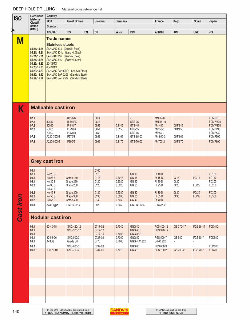
140 In CANADA, call us toll-free1-800-268-0703
In the UNITED STATES call us toll-free1-800- SANDVIK (1-800-726-3845)
DEEP HOLE DRILLING Material cross reference list
ISO Germany France Italy Spain Japan
Standard
M➤
CoromantMaterialClassifi-cation(CMC)
Country
USA Great Britain Sweden
Trade namesStainless steels
05.21/15.21 SANMAC 304 (Sandvik Steel)05.21/15.21 SANMAC 304L (Sandvik Steel)05.21/15.21 SANMAC 316 (Sandvik Steel)05.21/15.21 SANMAC 316L (Sandvik Steel)05.23/15.23 254 SMO05.23/15.23 654 SMO05.23/15.23 SANMAC SANICRO (Sandvik Steel)05.52/15.52 SANMAC SAF 2205 (Sandvik Steel)05.52/15.52 SANMAC SAF 2507 (Sandvik Steel)
K
Nodular cast iron
Grey cast iron
Malleable cast iron
07.1 8 290/6 0814 - MN 32-8 FCMB31007.1 32510 B 340/12 0815 GTS-35 MN 35-10 FCMW33007.2 40010 P 440/7 0852 0.8145 GTS-45 Mn 450 GMN 45 FCMW37007.2 50005 P 510/4 0854 0.8155 GTS-55 MP 50-5 GMN 55 FCMP490
70003 P 570/3 0858 GTS-65 MP 60-3 FCMP54007.2 A220-70003 P570/3 0856 0.8165 GTS-65-02 Mn 650-3 GMN 65 - FCMP590
07.3 A220-80002 P690/2 0862 0.8170 GTS-70-02 Mn700-2 GMN 70 FCMP690
08.1 010008.1 No 20 B 0110 GG 10 Ft 10 D FC10008.1 No 25 B Grade 150 0115 0.6015 GG 15 Ft 15 D G 15 FG 15 FC15008.1 No 30 B Grade 220 0120 0.6020 GG 20 Ft 20 D G 20 FC20008.2 No 35 B Grade 260 0125 0.6025 GG 25 Ft 25 D G 25 FG 25 FC250
No 40 B08.2 No 45 B Grade 300 0130 0.6030 GG 30 Ft 30 D G 30 FG 30 FC30008.2 No 50 B Grade 350 0135 0.6035 GG 35 Ft 35 D G 35 FG 35 FC35008.2 No 55 B Grade 400 0140 0.6040 GG 40 Ft 40 D
08.3 A436 Type 2 L-NiCuCr202 0523 0.6660 GGL-NiCr202 L-NC 202 - -
09.1 60-40-18 SNG 420/12 0717-02 0.7040 GGG 40 FCS 400-12 GS 370-17 FGE 38-17 FCD40009.1 - SNG 370/17 0717-12 GGG 40.3 FGS 370-1709.1 - - 0717-15 0.7033 GGG 35.3 -09.1 80-55-06 SNG 500/7 0727-02 0.7050 GGG 50 FGS 500-7 GS 500 FGE 50-7 FCD50009.1 A43D2 Grade S6 0776 0.7660 GGG-NiCr202 S-NC 202 - -
09.2 - SNG 600/3 0732-03 GGG 60 FGS 600-3 FCD60009.2 100-70-03 SNG 700/2 0737-01 0.7070 GGG 70 FGS 700-2 GS 700-2 FGS 70-2 FCD700
AISI/SAE BS EN SS W.-nr. DIN AFNOR UNI UNE JIS
Cas
t ir
on
109-146 USA 04-05-07 09.45 Sida 140
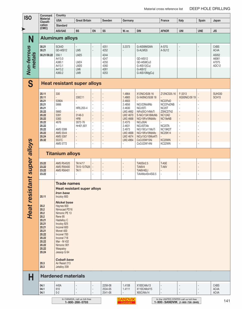
AISI/SAE BS EN SS W.-nr. DIN AFNOR UNI UNE JIS
141In the UNITED STATES call us toll-free1-800- SANDVIK (1-800-726-3845)
In CANADA, call us toll-free1-800-268-0703
Material cross reference list DEEP HOLE DRILLING
ISO Germany France Italy Spain Japan
Standard➤
CoromantMaterialClassifi-cation(CMC)
Country
USA Great Britain Sweden
N30.21 SC64D - - 4251 3.2373 G-AISI9MGWA A-S7G - - C4BS30.21 GD-AISI12 LM5 - 4252 - G-ALMG5 A-SU12 - - AC4A
30.21/30.22 356.1 LM25 4244 A5052A413.0 4247 GD-AlSi12 A6061A380.1 LM24 4250 GD-AlSi8Cu3 A7075A413.1 LM20 4260 G-AlSi12(Cu) ADC12A413.2 LM6 4261 G-AlSi12A360.2 LM9 4253 G-AlSi10Mg(Cu)
23.22 AMS R54520 TA14/17 - - - TiAl5Sn2.5 T-A5E - -23.22 AMS R56400 TA10-13/TA28 - - - TiAl6V4 T-A6V - -23.22 AMS R56401 TA11 - - - TiAl6V4ELI - - -23.22 - - - - - TiAl4Mo4Sn4Si0.5 - - -
20.2 Haynes 60020.2 Nimocast PD1620.2 Nimonic PE 1320.2 Rene 9520.21 Hastelloy C20.21 Incoloy 82520.21 Inconel 60020.21 Monet 40020.22 Inconel 70020.22 Inconel 71820.22 Mar - M 43220.22 Nimonic 90120.22 Waspaloy20.24 Jessop G 64
Iron base20.11 Incoloy 800
Heat resistant super alloys
Nickel base
Cobalt base20.3 Air Resist 21320.3 Jetalloy 209
S
Trade names
H04.1 440A - - 2258-08 1.4108 X100CrMo13 - - - C4BS04.1 610 - - 2534-05 1.4111 X110CrMoV15 - - - AC4A04.1 0-2 - - 2541-06 - X65CrMo14 - - - AC4A
20.11 330 - - - 1.4864 X12NiCrSi36 16 Z12NCS35.16 F-3313 - SUH33020.11 - 330C11 - - 1.4865 G-X40NiCrSi38 18 - XG50NiCr39 19 - SCH1520.21 5390A - - - 2.4603 - NC22FeD - -20.21 5666 - - - 2.4856 NiCr22Mo9Nb NC22FeDNB - -20.21 - HR5,203-4 - - 2.4630 NiCr20Ti NC20T - -20.22 5660 - - - LW2.4662 NiFe35Cr14MoTi ZSNCDT42 - -20.22 5391 3146-3 - - LW2 4670 S-NiCr13A16MoNb NC12AD - -20.22 5383 HR8 - - LW2.4668 NiCr19Fe19NbMo NC19eNB - -20.22 4676 3072-76 - - 2.4375 NiCu30Al - - -20.22 - Hr401,601 - - 2.4631 NiCr20TiAk NC20TA - -20.22 AMS 5399 - - - 2.4973 NiCr19Co11MoTi NC19KDT - -20.22 AMS 5544 - - - LW2.4668 NiCr19Fe19NbMo NC20K14 - -20.24 AMS 5397 - - - LW2 4674 NiCo15Cr10MoAlTi - - -20.32 5537C - - - LW2.4964 CoCr20W15Ni KC20WN - -
AMS 5772 - - - - CoCr22W14Ni KC22WN - -
Aluminum alloys
Heat resistant super alloys
Titanium alloys
Hardened materials
Hea
t re
sist
ant
sup
er a
lloys
Non
-fer
rou
sm
etal
s
109-146 USA 04-05-07 09.45 Sida 141
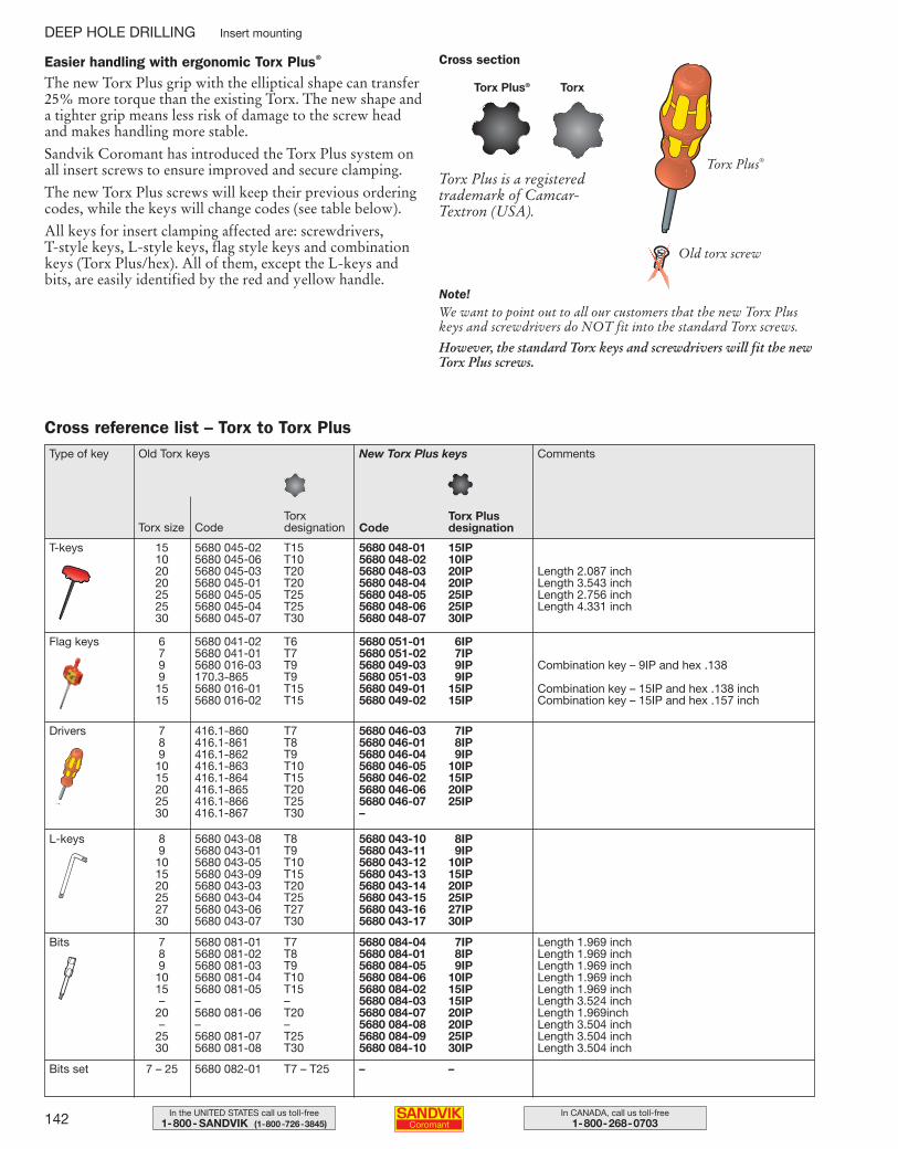
142 In CANADA, call us toll-free1-800-268-0703
In the UNITED STATES call us toll-free1-800- SANDVIK (1-800-726-3845)
DEEP HOLE DRILLING Insert mounting
Easier handling with ergonomic Torx Plus®
The new Torx Plus grip with the elliptical shape can transfer25% more torque than the existing Torx. The new shape anda tighter grip means less risk of damage to the screw headand makes handling more stable.
Sandvik Coromant has introduced the Torx Plus system onall insert screws to ensure improved and secure clamping.
The new Torx Plus screws will keep their previous orderingcodes, while the keys will change codes (see table below).
All keys for insert clamping affected are: screwdrivers, T-style keys, L-style keys, flag style keys and combinationkeys (Torx Plus/hex). All of them, except the L-keys andbits, are easily identified by the red and yellow handle.
Torx Plus® Torx
Cross section
Cross reference list – Torx to Torx Plus
TorxdesignationCode
Torx PlusdesignationCode
Type of key Old Torx keys
Torx size
New Torx Plus keys Comments
T-keys 15 5680 045-02 T15 5680 048-01 15IP10 5680 045-06 T10 5680 048-02 10IP20 5680 045-03 T20 5680 048-03 20IP20 5680 045-01 T20 5680 048-04 20IP25 5680 045-05 T25 5680 048-05 25IP25 5680 045-04 T25 5680 048-06 25IP30 5680 045-07 T30 5680 048-07 30IP
Flag keys 6 5680 041-02 T6 5680 051-01 6IP7 5680 041-01 T7 5680 051-02 7IP9 5680 016-03 T9 5680 049-03 9IP9 170.3-865 T9 5680 051-03 9IP15 5680 016-01 T15 5680 049-01 15IP 15 5680 016-02 T15 5680 049-02 15IP
Drivers 7 416.1-860 T7 5680 046-03 7IP8 416.1-861 T8 5680 046-01 8IP9 416.1-862 T9 5680 046-04 9IP10 416.1-863 T10 5680 046-05 10IP15 416.1-864 T15 5680 046-02 15IP20 416.1-865 T20 5680 046-06 20IP25 416.1-866 T25 5680 046-07 25IP30 416.1-867 T30 –
L-keys 8 5680 043-08 T8 5680 043-10 8IP9 5680 043-01 T9 5680 043-11 9IP10 5680 043-05 T10 5680 043-12 10IP15 5680 043-09 T15 5680 043-13 15IP20 5680 043-03 T20 5680 043-14 20IP25 5680 043-04 T25 5680 043-15 25IP27 5680 043-06 T27 5680 043-16 27IP30 5680 043-07 T30 5680 043-17 30IP
Bits 7 5680 081-01 T7 5680 084-04 7IP8 5680 081-02 T8 5680 084-01 8IP9 5680 081-03 T9 5680 084-05 9IP10 5680 081-04 T10 5680 084-06 10IP15 5680 081-05 T15 5680 084-02 15IP– – – 5680 084-03 15IP
20 5680 081-06 T20 5680 084-07 20IP– – – 5680 084-08 20IP
25 5680 081-07 T25 5680 084-09 25IP30 5680 081-08 T30 5680 084-10 30IP
Length 1.969 inchLength 1.969 inchLength 1.969 inchLength 1.969 inchLength 1.969 inchLength 3.524 inchLength 1.969inchLength 3.504 inchLength 3.504 inchLength 3.504 inch
Bits set 7 – 25 5680 082-01 T7 – T25 – –
Torx Plus is a registeredtrademark of Camcar-Textron (USA).
Note!We want to point out to all our customers that the new Torx Pluskeys and screwdrivers do NOT fit into the standard Torx screws.
However, the standard Torx keys and screwdrivers will fit the newTorx Plus screws.
Length 2.087 inchLength 3.543 inchLength 2.756 inchLength 4.331 inch
Combination key – 9IP and hex .138
Combination key – 15IP and hex .138 inch Combination key – 15IP and hex .157 inch
Torx Plus®
Old torx screw
109-146 USA 04-04-29 10.23 Sida 142
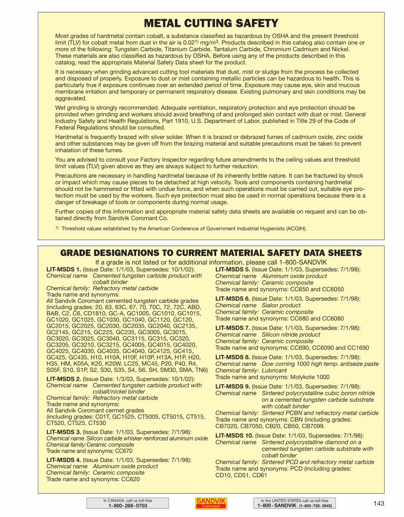
143In the UNITED STATES call us toll-free1-800- SANDVIK (1-800-726-3845)
In CANADA, call us toll-free1-800-268-0703
METAL CUTTING SAFETYMost grades of hardmetal contain cobalt, a substance classified as hazardous by OSHA and the present thresholdlimit (TLV) for cobalt metal from dust in the air is 0.021) mg/m3. Products described in this catalog also contain one ormore of the following: Tungsten Carbide, Titanium Carbide, Tantalum Carbide, Chromium Cadmium and Nickel.These materials are also classified as hazardous by OSHA. Before using any of the products described in this catalog, read the appropriate Material Safety Data sheet for the product.
It is necessary when grinding advanced cutting tool materials that dust, mist or sludge from the process be collectedand disposed of properly. Exposure to dust or mist containing metallic particles can be hazardous to health. This isparticularly true if exposure continues over an extended period of time. Exposure may cause eye, skin and mucousmembrane irritation and temporary or permanent respiratory disease. Existing pulmonary and skin conditions may beaggravated.
Wet grinding is strongly recommended. Adequate ventilation, respiratory protection and eye protection should beprovided when grinding and workers should avoid breathing of and prolonged skin contact with dust or mist. GeneralIndustry Safety and Health Regulations, Part 1910, U.S. Department of Labor, published in Title 29 of the Code ofFederal Regulations should be consulted.
Hardmetal is frequently brazed with silver solder. When it is brazed or debrazed fumes of cadmium oxide, zinc oxideand other substances may be given off from the brazing material and suitable precautions must be taken to preventinhalation of these fumes.
You are advised to consult your Factory Inspector regarding future amendments to the ceiling values and thresholdlimit values (TLV) given above as they are always subject to further reduction.
Precautions are necessary in handling hardmetal because of its inherently brittle nature. It can be fractured by shockor impact which may cause pieces to be detached at high velocity. Tools and components containing hardmetalshould not be hammered or fitted with undue force, and when such operations must be carried out, suitable eye pro-tection must be used by the workers. Such eye protection must also be used in normal operations because there is adanger of breakage of tools or components during normal usage.
Further copies of this information and appropriate material safety data sheets are available on request and can be ob-tained directly from Sandvik Coromant Co.
1) Threshold values established by the American Conference of Government Industrial Hygienists (ACGIH).
LIT-MSDS 1. (Issue Date: 1/1/03, Supersedes: 10/1/02):Chemical name Cemented tungsten carbide product with
cobalt binderChemical family: Refractory metal carbideTrade name and synonyms: All Sandvik Coromant cemented tungsten carbide grades(including grades: 20, 63, 63C, 67, 70, 70C, 72, 72C, ABD,BAB, C2, C6, CD1810, GC-A, GC1005, GC1010, GC1015,GC1020, GC1025, GC1030, GC1040, GC1120, GC120,GC2015, GC2025, GC2030, GC2035, GC2040, GC2135,GC2145, GC215, GC225, GC235, GC3005, GC3015,GC3020, GC3025, GC3040, GC3115, GC315, GC320,GC3205, GC3210, GC3215, GC4005, GC4015, GC4020,GC4025, GC4030, GC4035, GC4040, GC4125, GC415,GC425, GC435, H10, H10A, H10F, H10P, H13A, H1P, H20,H35, HM, K05A, K20, K20W, LC25, MC45, P20, P40, R4,S05F, S10, S1P, S2, S30, S35, S4, S6, SH, SM30, SMA, TN6)
LIT-MSDS 2. (Issue Date: 1/3/03, Supersedes: 10/1/02):Chemical name Cemented tungsten carbide product with
cobalt/nickel binderChemical family: Refractory metal carbideTrade name and synonyms: All Sandvik Coromant cermet grades(including grades: C01T, GC1525, CT5005, CT5015, CT515,CT520, CT525, CT530
LIT-MSDS 3. (Issue Date: 1/1/03, Supersedes: 7/1/98):Chemical name Silicon carbide whisker reinforced aluminum oxideChemical family:Ceramic compositeTrade name and synonyms: CC670
LIT-MSDS 4. (Issue Date: 1/1/03, Supersedes: 7/1/98):Chemical name Aluminum oxide productChemical family: Ceramic compositeTrade name and synonyms: CC620
LIT-MSDS 5. (Issue Date: 1/1/03, Supersedes: 7/1/98):Chemical name Aluminum oxide product Chemical family: Ceramic compositeTrade name and synonyms: CC650 and CC6050
LIT-MSDS 6. (Issue Date: 1/1/03, Supersedes: 7/1/98):Chemical name Sialon product Chemical family: Ceramic compositeTrade name and synonyms: CC680 and CC6080
LIT-MSDS 7. (Issue Date: 1/1/03, Supersedes: 7/1/98):Chemical name Silicon nitride productChemical family: Ceramic compositeTrade name and synonyms: CC690, CC6090 and CC1690
LIT-MSDS 8. (Issue Date: 1/1/03, Supersedes: 7/1/98):Chemical name Dow corning 1000 high temp. antiseize pasteChemical family: LubricantTrade name and synonyms: Molykote 1000
LIT-MSDS 9. (Issue Date: 1/1/03, Supersedes: 7/1/98):Chemical name Sintered polycrystalline cubic boron nitride
on a cemented tungsten carbide substratewith cobalt binder
Chemical family: Sintered PCBN and refractory metal carbideTrade name and synonyms: CBN (including grades: CB7020, CB7050, CB20, CB50, CB7099.
LIT-MSDS 10. (Issue Date: 1/1/03, Supersedes: 7/1/98):Chemical name Sintered polycrystalline diamond on a
cemented tungsten carbide substrate withcobalt binder
Chemical family: Sintered PCD and refractory metal carbideTrade name and synonyms: PCD (including grades: CD10, CD51, CD61
GRADE DESIGNATIONS TO CURRENT MATERIAL SAFETY DATA SHEETSIf a grade is not listed or for additional information, please call 1-800-SANDVIK
109-146 USA 04-04-29 10.23 Sida 143

144 In CANADA, call us toll-free1-800-268-0703
In the UNITED STATES call us toll-free1-800- SANDVIK (1-800-726-3845)
✍109-146 USA 04-04-29 10.23 Sida 144

145In the UNITED STATES call us toll-free1-800- SANDVIK (1-800-726-3845)
In CANADA, call us toll-free1-800-268-0703
✍109-146 USA 04-04-29 10.23 Sida 145

146 In CANADA, call us toll-free1-800-268-0703
In the UNITED STATES call us toll-free1-800- SANDVIK (1-800-726-3845)
Sandvik Coromant recognizes today’s increasing demands forenvironmental concerns. Current recycling methods allowused carbide products to be broken down to their original rawmaterial states.
Sandvik Coromant is proud to offer a service to recycle usedcarbide inserts.
Recycling through Sandvik Coromant is Simple and Easy1. Call 1-800-SANDVIK and ask the Regional Customer ServiceCenter to have a Recycling Kit sent to you today.
2. Use the collection boxes at each machine or cell. Then, fill thetransportation boxes with inserts collected from each machine orcell.
3. Call 1-800-SANDVIK to get a Recycle Return Authorization(RRA) number and current price per pound. Then, ship thetransportation boxes using the shipping label included in theRecycling Kit.
The service is easy for customers to use. Sandvik Coromantwill provide a recycling kit, free of charge, to customers interested in using the service. The kit includes instructions, a recycling form, a plastic collection box and a transportationbox.
A refund check, based on current price per pound of carbidetimes the weight of the returned inserts, will be forwarded tothe customer within 2-3 weeks after the receipt of the shipment.
Any customers wishing to take advantage of this service canobtain a recycling kit by calling a Sandvik Coromant regionalcustomer service center at 1-800-SANDVIK.
CARBIDE INSERT RECYCLINGOrdering code: LIT-LABEL-RECYCLE-INFO Max Size: 2 in. × 2 in × 1/2 in.
109-146 USA 04-04-29 10.23 Sida 146
Related Documents


