DEECo – an Ensemble-Based Component System Tomas Bures 1,2 , Ilias Gerostathopoulos 1 , Petr Hnetynka 1 , Jaroslav Keznikl 1,2 , Michal Kit 1 , Frantisek Plasil 1 Technical report No. D3S-TR-2013-02, February 2013 Version 1.0, February 2013 1 Distributed Systems Research Group, Department of Software Engineering Faculty of Mathematics and Physics, Charles University Malostranské nám. 25, 118 00 Prague, Czech Republic phone +420-221914267, fax +420-221914323 2 Institute of Computer Science, Academy of Sciences of the Czech Republic Pod Vodárenskou věží 2, 182 07 Prague, Czech Republic phone +420-266053831

Welcome message from author
This document is posted to help you gain knowledge. Please leave a comment to let me know what you think about it! Share it to your friends and learn new things together.
Transcript

DEECo – an Ensemble-Based Component System
Tomas Bures1,2, Ilias Gerostathopoulos1, Petr Hnetynka1, Jaroslav Keznikl1,2, Michal Kit1, Frantisek Plasil1
Technical report No. D3S-TR-2013-02, February 2013 Version 1.0, February 2013
1 Distributed Systems Research Group, Department of Software Engineering
Faculty of Mathematics and Physics, Charles University Malostranské nám. 25, 118 00 Prague, Czech Republic
phone +420-221914267, fax +420-221914323
2 Institute of Computer Science, Academy of Sciences of the Czech Republic Pod Vodárenskou věží 2, 182 07 Prague, Czech Republic
phone +420-266053831

DEECo – an Ensemble-Based Component System
Tomas Bures1,2
[email protected] Ilias Gerostathopoulos1
[email protected] Petr Hnetynka1
Jaroslav Keznikl1,2
[email protected] Michal Kit1
[email protected] Frantisek Plasil1
1Faculty of Mathematics and Physics Charles University in Prague
Prague, Czech Republic
2Institute of Computer Science Academy of Sciences of the Czech Republic
Prague, Czech Republic ABSTRACT The recent increase in the ubiquity and connectivity of computing devices allows forming large-scale distributed systems that respond to and influence the activities in their environment. Engineering of such systems is very complex because of their inherent dynamicity, open-endedness, and autonomicity. In this paper we propose a new class of component systems (Ensemble-Based Component Systems – EBCS) which bind autonomic components with cyclic execution via dynamic component ensembles controlling data exchange. EBCS combine the key ideas of agents, ensemble-oriented systems and control systems into software engineering concepts based on autonomic components. In particular, we present an instantiation of EBCS – the DEECo component model. In addition to DEECo main concepts, we also describe its computation model and mapping to Java. Further, we outline the basic principles EBCS/DEECo development process.
Keywords Component model, emergent architecture, component ensembles, autonomic systems, development process, runtime framework
1. INTRODUCTION The significant increase in the ubiquity and connectivity of computing devices has opened new possibilities for addressing social and environmental challenges (e.g., ambient assisted living, smart city infrastructures, emergency coordination, environmental monitoring) by providing hardware and infrastructures necessary for building large-scale Resilient Distributed Systems (RDS) that respond to and influence activities in the real world. As RDS have to cope with very dynamic and open-ended environments, they exhibit a high degree of adaptivity and autonomicity.
Although developing RDS has become relatively feasible from the perspective of hardware and network infrastructures, there still remain significant challenges in developing software for RDS. In particular, the problem is to feature the appropriate computation models and development processes which would address the requirements of scalability, distribution and well-defined architecture, while, at the same time, would deal with the requirements of dynamicity, open-endedness, robustness, and autonomicity.
1.1 Towards EBCS In this paper, we advocate using components for engineering RDS. The use of components has been a proven means for
efficient design and development of large-scale systems with well-defined architectures. However, due to the dynamic and autonomic nature of RDS, classical approaches to component architectures [37] as well as existing component models ([6] [7][29][30][31]) do not scale. Therefore, inspired by the work in the field of formal coordination languages [14], in this paper we address this issue by identifying a new class of component-based systems – Ensemble-Based Component Systems (EBCS) – specifically tailored for designing RDS. Moreover, we present the DEECo (Distributed Emergent Ensembles of Components) component model as our instantiation of EBCS. The characteristic of EBCS is that the “traditional” explicit component architecture is replaced by composition of components into so-called ensembles [14][20], each of which is an implicit, inherently dynamic group of components mutually cooperating to achieve a particular goal. To cope with the dynamism, the components in EBCS become autonomic entities, building on agent-oriented concepts [38], while featuring execution model based on feedback loops (e.g., MAPE-K [23], soft real-time control systems [32]) in order to achieve (self-) adaptive and resilient operation.
In this view, the EBCS can be defined as “Distributed systems composed of components that feature autonomic and (self-) adaptive behaviors and are organized into emergent ensembles to achieve cooperation.” EBCS thus naturally combine relevant concepts from a number of research areas (Figure 1). Namely: From component-based software engineering [11] EBCS adopt the software engineering concepts of the system architecture based on components (which themselves are seen as well-encapsulated, reusable, and substitutable entities) and the component-based development process.
From agent-oriented computing [38] EBCS derive the autonomous aspects, where the individuals maintain only a partial view on the whole system in order to guide their decisions – the belief, and self-* behavior [10]. This way, the overall behavior of EBCS is an emergent result of the behaviors of the individual components, enabling thus for efficient decentralized execution.
Building on the ensemble-oriented systems [14][20] EBCS rely on the attribute-based communication, which models the communication as best-effort and localized to dynamically changing ensembles of components; as opposed to existing agent-based systems [4] which at the deployment level resemble

service-oriented architectures employing explicit communication channels. This helps to effectively cope with the assumption that the deployment (and thus also architecture) of EBCS changes very dynamically.
From control system engineering [32] EBCS adopt the idea of achieving robustness by employing (soft real-time) control feedback loops [23] that maintain the operational normalcy of a component. Here, operational normalcy expresses the property of being within certain limits that define the range of normal functioning of the component. The required level of robustness is achieved by adjusting the periods of the loops. As extreme dynamism is assumed, the core attribute of EBCS is employing the concept of feedback loops both at the level of individual components and ensembles. Thus, an EBCS system can be understood as a distributed system of conditionally interacting feedback loops. As a result, EBCS provide the following key features important for development of RDS:
• System architecture (represented by components and their bindings) emerges at runtime. The system architecture is however not arbitrary – it complies with explicit interaction patterns of ensembles specified at design time.
• Components maintain a belief about the rest of the system and the environment. The belief is managed outside the component behavior by the underlying runtime framework.
• Component execution is performed in isolation based solely on the component’s belief. This strengthens the autonomicity of components (e.g., in the context of unreliable communication and/or rapid architecture changes).
1.2 Goals and Structure of the Text The goal of the paper is to describe our instance of EBCS – the DEECo (Distributed Emergent Ensembles of Components) component model [24][8] and its framework and share with the reader experience with its application. In particular, after describing a running example (Section 2), we present: (i) the core DEECo concepts along with its abstract execution model (Section 3), (ii) a Java-based DEECo framework, which allows engineering DEECo components and ensembles in a Java environment (Section 4), and (iii) an outline of a design process, which drives the architecture design of EBCS (DEECo-based systems in particular) from high-level requirements (Section 0). Finally, we share with the reader our experience with an industrial case study (Section 6). After presenting a survey of related work (Section 7), the paper is concluded by a summary and a brief overview of our intentions in future work (Section 8).
2. RUNNING EXAMPLE We illustrate the main concepts of EBCS/DEECo with the help of the electrical vehicle navigation case study featured by the ASCENS project [36]. We describe the fundamentals of the case
study in this section and articulate the running example that we use in the rest of the paper.
The objective of the e-mobility case study is to coordinate the planning of journeys in compliance with parking and charging strategies in a highly dynamic and heterogeneous traffic environment, where information is distributed. The case study consists of drivers, navigating around a city in their electric vehicles (e-vehicles). Drivers have to reach particular Points Of Interest (POIs) within time constraints, specified as the expected POI arrival and departure times. Every driver possesses his/her daily meetings schedule (calendar), where POIs and their respective constraints are listed. Vehicles are equipped with sensors of basic capabilities, e.g., monitoring the battery level and energy consumption of the car, but also more sophisticated ones, e.g., monitoring the traffic level along the route. Vehicles can only park and recharge in designated parking spaces and charging lots, organized into parking/charging stations. They also communicate with each other and with relevant parking/charging stations, e.g. those that are close to their respective POIs. Such communication is necessary, e.g., in order for a vehicle to obtain the availability of the parking station and potentially reserve a place there. It is important that in this setting no central coordination point is assumed; there is no global control or global planning. Instead, every e-vehicle plans and executes its route individually, based on the data available.
The whole system can be seen a set of (distributed) nodes, which form ensembles (dynamic communication groups) in order to allow drivers to arrive at their POIs in time while leveraging the available resources in a close-to-optimal way. This is illustrated in Figure 2 – each vehicle forms an ensemble with available parking stations close to their respective POIs. Figure 2.b further shows an evolution of the scenario, where vehicles moved along the route and a parking station became unavailable leading to dynamic changes of the ensembles.
As our running example, we consider a simplified version of the case study by making the following assumptions: i) car sharing is not allowed, so drivers are bound to the vehicles they drive, ii) parking and charging stations are modeled together as Parking Lot/Charging Station (PLCS) elements, iii) drivers do not reserve a place in the PLCSs, but only obtain their availability information in order to plan accordingly, and iv) vehicles as relevant the PLCSs that are within a fixed distance to one of their POIs.
Although simplified, the running example features a number of important challenges targeted by EBCS. In particular, the physical
Figure 1: Areas combined into Ensemble-Based Component Systems and their strong points.
Figure 2: E-mobility: Potential ensembles and their dynamic changes (available parking stations close to respective POIs).
Component-‐based engineering (software engineering concepts)
Agent-‐oriented Computing(autonomy)
Control system engineering(operational normalcy)
Ensemble-‐oriented systems(attribute-‐based communication)
EBCS

architecture of the system constantly changes as the cars move around the city; cars and PLCSs maintain a partial view over the whole system, according to the information they obtain from components they interact with; trip planning and decision making in general is localized to the drivers (cars), as no central coordination is assumed.
3. DEECo COMPONENT MODEL To refine the principles of EBCS into a systematic approach for building software for RDS, we have proposed a new component model called DEECo [24]. DEECo embodies the main concepts of EBCS, while giving them a suitable semantics in order to turn them into proper software engineering constructs that can be employed in the real-life development of RDS.
3.1 General Concepts DEECo is built on top of two first-class concepts: component and ensemble. A component is an independent and self-sustained unit of development, deployment and computation. An ensemble acts as a dynamic binding mechanism, which links a set of components together and manages their interaction. A grounding idea in DEECo is that the only way components bind and communicate with one another is through ensembles. The two first-class DEECo concepts are in detail elaborated below. An integral part of the component model is also the runtime framework providing the necessary management services for both components and ensembles.
3.1.1 Component A component in DEECo comprises knowledge, exposed via a set of interfaces, and processes (illustrated in Figure 3).
Knowledge reflects the state and available functionality of the component (lines 8-16). It is organized as a hierarchical data structure (resembling a tuple space [15]), which maps knowledge identifiers to values. Specifically, values may be either (potentially structured) data or executable functions. Technically, we use structured identifiers to refer to internal parts of the structured values (e.g., plan.isFeasible in line 18).
A component’s knowledge is exposed to the other components and environment via a set of interfaces (lines 7, 29). An interface (e.g., lines 1-2) thus represents a partial view on the component’s knowledge. Specifically, interfaces of a single component can overlap and multiple components can provide the same interface, thus allowing for polymorphism of components. Component processes are essentially soft real-time tasks that manipulate the knowledge of the component. A process is characterized as a function (lines 19-21) associated with a list of input and output knowledge fields (line 18). Operation of the process is managed by the runtime framework and consists of atomically retrieving all input knowledge fields, computing the process function (with the input knowledge fields as function parameters) and atomically writing all output knowledge fields (retrieved as the return value(s) of the process function). A process may have side effects in terms of sensing and actuating, however it is not supposed to explicitly communicate with other components or other processes of the same component in any other way than via knowledge.
Being active entities of computation, component processes are subject to scheduling, which is again managed by the runtime framework. A process can be scheduled either periodically (line 27), i.e., repeatedly executed once within a given period, or as triggered (line 22), i.e., executed when a trigger condition is met
(for brevity, we assume the change of input knowledge value as the only trigger condition).
Referring to the e-mobility running example, the components are the Vehicle and the PLCS (Figure 3). A Vehicle maintains a belief over the availability of the relevant PLCSs (availabilities, line 9). It uses a Planner library to (re-) compute its journey plan according to the availability belief and its calendar (line 17) every time the availability belief or plan feasibility changes (line 22). The Vehicle also periodically checks if its plan remains feasible, with respect to its battery level and its current position (line 23). A PLCS just keeps track of its available timeslots for vehicle parking and charging (availability, line 33).
3.1.2 Ensemble An ensemble embodies a dynamic binding among a set of components and thus determines their composition and interaction. In DEECo, composition is flat, expressed implicitly via a dynamic involvement in an ensemble. Among the components involved in an ensemble, one always plays the role of the ensemble’s coordinator while others play the role of the members. This is determined dynamically (the task of the runtime framework) according to the membership condition of the ensemble. As to interaction, the individual components in an ensemble are not capable of explicit communication with the others. Instead, the interaction among the components forming the ensemble takes the form of knowledge exchange, carried out implicitly (by the runtime framework). Specifically, definition of an ensemble (Figure 4) consists of:
1. interface AvailabilityAggregator: 2. calendar, availabilities 3. 4. interface AvailabilityAwareParkingLot: 5. position, availability 6. 7. component Vehicle features AvailabilityAggregator: 8. knowledge: 9. batteryLevel = 90%, 10. position = GPS(…), 11. calendar = [ POI(WORKPLACE, 9AM-‐1PM), POI(MALL, 2PM-‐3PM), … ], 12. availabilities = [ ], 13. plan = { 14. route = ROUTE(…), 15. isFeasible = TRUE 16. } 17. process computePlan: 18. in plan.isFeasible, in availabilities, in calendar, inout plan.route 19. function: 20. if (!plan.isFeasible) 21. plan.route ← Planner.computePlan(calendar, availabilities) 22. scheduling: triggered( changed(plan.isFeasible) ∨ changed(availabilities) ) 23. process checkPlanFeasibility: 24. in plan.route, in batteryLevel, in position, out plan.isFeasible 25. function: 26. plan.isFeasible ← Planner.isFeasible(plan.route, batteryLevel, position) 27. scheduling: periodic( 5s ) 28. 29. component PLCS features AvailabilityAwareParkingLot: 30. knowledge: 31. position = GPS(…) , 32. availability = … 33. process observeAvailability: 34. out availability 35. function: 36. availability← Sensors.getCurrentAvailability() 37. scheduling: periodic( 2000ms ) Figure 3: Examples of DEECo component definitions in a DSL.

• Membership condition. Definition of a membership condition comprises the definition of the interface specific for the coordinator role – coordinator interface (line 2), as well as the interface specific for the member role (and thus featured by each member component) – member interface (line 3), and the definition of membership predicate (lines 4-7). A membership predicate declaratively expresses the condition under which two components represent a pair coordinator-member of the associated ensemble. The predicate is defined upon the knowledge exposed via the coordinator/member interfaces and is evaluated by the runtime framework when necessary. In general, as illustrated in Figure 5, a single component can be member/coordinator of multiple ensembles, so that ensembles form overlapping composition layers upon the components.
• Knowledge exchange. Knowledge exchange embodies the interaction between the coordinator and all the members of the ensemble (lines 8-10); i.e., it is a one-to-many interaction (in contrast to the one-to-one form of the membership predicate). Being limited to coordinator-member interaction, knowledge exchange allows the coordinator to apply various interaction policies. In principle, knowledge exchange is carried out by the runtime framework; thus, it is up to the runtime framework when/how often it is performed. Similarly to component processes, knowledge exchange can be carried out either periodically or when triggered (line 10).
Based on the ensemble definition, a new ensemble is dynamically formed for each group of components that together satisfy the membership condition.
In summary, components operate only upon their own local knowledge, which gets implicitly updated by the runtime framework (via knowledge exchange) whenever the component is part of an ensemble. This supports component encapsulation and independence. The sole ensemble of the running example is the UpdateAvailabilityInformation ensemble listed in Figure 4. Its purpose is to aggregate the availability information of the members, i.e. PLCSs, on the side of the coordinator, i.e., Vehicle (line 9). The ensemble is formed only when a PLCS is close enough to at least one of the POIs of the Vehicle (line 6) and there is an available slot in the PLCS, which can accommodate the respective POI arrival and departure time (line 7).
3.2 Computational Model To allow for formal reasoning about DEECo applications, we have defined the operational semantics of DEECo, which models a DEECo application as a label transition system (LTS) with knowledge manipulation actions on transitions. The semantics further associates time with the LTS run and defines periodic and triggered processes and ensembles in terms of time constraints over traces generated by the LTS.
We also define a subset relation over a set of traces of observable changes in the components’ knowledge. This allows us to build different implementations of DEECo (such as the tuple-space based implementation described in Section 4) while accommodating for and benefiting from specifics of the communication middleware used.
Due to space constraints we do not include the definition of the semantics in this paper, rather we refer the reader to the technical report [2], which describes it in full extent.
4. DEECo REALIZATION IN JAVA In order to bring DEECo abstractions to the practical use during the development of real-life EBCS we provide a framework called jDEECo [13], which is a Java-based realization of DEECo component model. jDEECo delivers the necessary programming abstractions and the runtime environment to deploy and run DEECo-based applications.
In this section, we describe how jDEECo maps definitions of DEECo components and ensembles to Java language primitives. In particular, we follow the developer’s perspective and show how the running example gets implemented using the jDEECo constructs. Further, we briefly discuss interesting aspects of the jDEECo runtime framework and supporting tools and the in-memory representation of the DEECo concepts.
4.1 Mapping of DEECo Concepts to Java By building on Java annotations, the mapping of DEECo concepts relies on standard Java language primitives and does not require any language extensions or external tools.
4.1.1 Component A component definition has the form of a Java class (Figure 6). Such a class is marked by the @DEECoComponent annotation and extends the ComponentKnowledge class. The initial knowledge structure of the component is captured by means of the public, non-static fields of the class (the id knowledge field, which is used for unique identification of a component, is inherited from the ComponentKnowledge class). As knowledge can be hierarchically structured, these fields represent the first level of this hierarchy, where each can take the form of a knowledge tree (recursively), map, or list. As for the knowledge tree form, the non-leaf nodes of this tree need to be instances of a class inheriting from Knowledge (lines 36-39). The non-structured knowledge values are represented as serializeable Java objects. At runtime, this initial knowledge structure is initialized either via static initializers or via the constructor of the class (lines 10-12).
1. ensemble UpdateAvailabilityInformation: 2. coordinator: AvailabilityAggregator 3. member: AvailabilityAwareParkingLot 4. membership: 5. ∃ poi ∈ coordinator.calendar: 6. distance(member.position, poi.position) ≤ TRESHOLD && 7. isAvailable(poi, member.availability) 8. knowledge exchange: 9. coordinator.availabilities ← { (m.id, m.availability) | m ∈ members } 10. scheduling: periodic( 5000ms )
Figure 4: An example of an ensemble definition in a DSL.
Figure 5: Composition of components into multiple overlapping ensembles in DEECo.
Component level
Component 1Component 2
Component 4Component 3
Coordinator
MemberMember
Ensemble 1
Ensemble 2Member
Member
Coordinator

In contrast to the conceptual description of a component (Section 3.1.1), the Java definition of a component does not comprise interfaces. Instead, the set of supported interfaces is implicit; i.e., all interfaces that structurally match the component’s knowledge are assumed to be featured by the component (similar to duck typing in dynamic languages). The component processes are defined as public static methods of the class, annotated with @DEECoProcess. The requirement of the static modifier stems from the semantics of component process execution (Section 3.1.1). In particular, except for reading the input knowledge and writing the output knowledge (which is anyway managed by the runtime framework), a component process executes in isolation, without access to the knowledge. Thus, declaring the method as static prevents it from directly accessing the knowledge represented by the class fields (which are non-static).
The input and output knowledge of the process is represented by the methods’ parameters. The parameters are marked with one of the annotations @DEECoIn, @DEECoOut or @DEECoInOut, in order to distinguish between input and output knowledge fields of the process. Each annotation also includes an identifier of the knowledge field that the associated method parameter represents. As the input/output knowledge can consist of a knowledge field that is an internal node of a knowledge tree, the identifier of such a knowledge field is a dot-separated representation of the path to the node in the tree (e.g., line 16). When a non-structured knowledge field constitutes an inout/out knowledge of a process, the associated method parameter is for technical reasons (related
to Java immutable types) passed inside an OutWrapper object (e.g., line 30).
Periodic scheduling of the process is defined via the @DEECoPeriodicScheduling annotation of the process’s method, which takes the period expressed in milliseconds in its parameter (line 25). Triggered scheduling is defined via @DEECoTriggered annotation of the method’s parameter, change of which should trigger execution of the process (line 16).
4.1.2 Ensemble The ensemble definition takes also the form of a Java class. In particular, the class is marked with the @DEECoEnsemble annotation and extends the Ensemble class (Figure 7).
Both the membership predicate and the knowledge exchange are defined as specifically-annotated static methods of this class. While the method representing the membership predicate is annotated by @DEECoEnsembleMembership (line 5), the method representing knowledge exchange is annotated by @DEECoEnsembleKnowledgeExchange (line 19). Note that in jDEECo we assume knowledge exchange between the coordinator and a single member (applied for each member separately); this is a simplification of the one-to-many knowledge exchange (one coordinator vs. many members) as introduced in Section 3.1.2. Thus, in the Java implementation we use a timestamp to distinguish current elements of the availabilities collection (line 27), instead of refreshing the whole collection (Figure 4, line 9).
In contrast to the conceptual description of an ensemble (Section 3.1.2), Java definition of an ensemble does not comprise explicit definition of the member and coordinator interfaces. Instead, these interfaces are defined implicitly as a union of the knowledge fields represented by parameters of the methods representing membership predicate and knowledge exchange. Since these parameters are annotated in the same way as parameters of component processes, the parameters relevant to member/coordinator interface are distinguished by identifier prefixes (i.e., identifiers of knowledge of a coordinator/member interface are prefixed with “coord”/“member”).
1. @DEECoComponent 2. public class Vehicle extends ComponentKnowledge { 3. 4. public List<CalendarEvent> calendar; 5. public Plan plan; 6. public EnergyLevel batteryLevel; 7. public Map<ID, Availability> availabilities; 8. public Position position; 9. 10. public Vehicle() { 11. // initialize the initial knowledge structure reflected by the class fields 12. } 13. 14. @DEECoProcess 15. public static void computePlan( 16. @DEECoIn("plan.isFeasible") @DEECoTriggered Boolean isPlanFeasible, 17. @DEECoIn("availabilities ") @DEECoTriggered Map<…> availabilities, 18. @DEECoIn("calendar") List<CalendarEvent> calendar, 19. @DEECoInOut("plan.route") Route plannedRoute 20. ) { 21. // re-‐compute the vehicle’s plan if it’s infeasible 22. } 23. 24. @DEECoProcess 25. @DEECoPeriodicScheduling(5000) 26. public static void checkPlanFeasibility( 27. @DEECoIn("plan.route") Route plannedRoute, 28. @DEECoIn("batteryLevel") EnergyLevel batteryLevel, 29. @DEECoIn("position") Position position, 30. @DEECoOut("plan.isFeasible") OutWrapper<Boolean> isPlanFeasible 31. ) { 32. // determine feasibility of the plan 33. } 34. ... 35. } 36. public class Plan extends Knowledge { 37. public Route route; 38. public Boolean isFeasible; 39. }
Figure 6: Example of a component definition in Java.
1. @DEECoEnsemble 2. @DEECoPeriodicScheduling(4000) 3. public class AvailabilityAggregation extends Ensemble { 4. 5. @DEECoEnsembleMembership 6. public static boolean membership ( 7. @DEECoIn("coord.calendar ") List<CalendarEvent> calendar, 8. @DEECoIn("member.position ") Position plcsPosition, 9. @DEECoIn("member.availability ") Availability availability 10. ) { 11. for (CalendarEvent ce : eventsCalendar) { 12. if (isClose(ce.poi.position, plcsPosition, DISTANCE_THRESHOLD) 13. && isAvailable(ce.poi, availability)) 14. return true; 15. } 16. return false; 17. } 18. 19. @DEECoEnsembleKnowledgeExchange 20. public static void knowledgeExchange ( 21. @DEECoIn("coord.calendar") List<CalendarEvent> calendar, 22. @DEECoInOut("coord. availabilities") Map<…> availabilities, 23. @DEECoIn("member.id]") ID memberID, 24. @DEECoIn("member.position") Position plcsPosition, 25. @DEECoIn("member.availability") Availability availability 26. ) { 27. availabilities.put (memberID, availability.clone(currentTimestamp())); 28. } 29. }
Figure 7: Example of an ensemble definition in Java.

Scheduling of the knowledge exchange is defined similarly to component processes. The only difference is that the @DEECoPeriodicScheduling is applied to the whole class defining the ensemble, while the @DEECoTriggered is applied to a particular parameter of the membership method.
4.2 Runtime framework The jDEECo runtime framework is primarily responsible for scheduling component processes, forming ensembles, and performing knowledge exchange. It also allows for distribution of components.
As illustrated in Figure 8, it is internally composed of the management part and knowledge repository. The management part is further composed of two modules. One is responsible for scheduling and execution of component processes and knowledge exchange of ensembles. The other is responsible for managing access to the knowledge repository. Exploiting the fact that all modules of the runtime framework implementation are loosely coupled, we are able to introduce implementation variants for each of them. As a result, different variants can be selected in order to reflect specific requirements imposed to the whole platform.
The role of the knowledge repository is to store the component’s knowledge (e.g., CK1 – knowledge of component C1 – in Figure 8). Its responsibility is also to provide component processes and knowledge exchange of ensembles with access to this knowledge. In fact, we provide a local and a distributed implementation of the knowledge repository; the former is employed for simulation and verification of the code (Section 0) while the latter is used in case the runtime framework needs to run in a distributed setting (i.e., the distribution is achieved at the level of knowledge repository). Specifically, the distributed implementation of the knowledge repository allows each component to run in a different Java virtual machine (as illustrated in Figure 8). The distribution is achieved by employing the JavaSpaces1 middleware. JavaSpaces is a reification of the LINDA [15] paradigm, which aligns well with the way DEECo represents knowledge. For the time being, jDEECo relies on the ApacheRiver2 implementation of JavaSpaces.
1 The JavaSpaces Service Specification is available at
http://river.apache.org/doc/specs/html/js-spec.html 2 http://river.apache.org
As to the scheduling module, each component process (e.g., C1P1 – process P1 of component C1 – in Figure 8) is executed by the runtime framework within a regular Java thread. Thus, threads executing triggered processes are blocked till their triggering condition holds true, while threads executing periodic processes are between two subsequent runs blocked for the duration of their period. Concerning knowledge exchange of ensembles (e.g., E1 in Figure 8), the scheduling and execution is similar to component processes. In addition, the membership predicate is evaluated before each run of the knowledge exchange, so that it is applied only to valid coordinator-member pairs of components.
Further, to enable dynamic deployment, Java classes with component/ensemble definitions can be provided to the runtime framework both during deployment and runtime.
4.3 Tool support In addition to providing the runtime framework, jDEECo supports the development of DEECo-based applications via ASCENS tool workbench (called SDE), featuring modeling and analysis tools for RDS.
Since SDE is based on Eclipse, the integration with jDEECo comprises deploying jDEECo as an Eclipse plugin and providing additional Eclipse-specific features. Most importantly, these include the possibility of packaging and deploying DEECo components and ensembles as OSGi [17] bundles. This is complemented by a graphical packaging tool and a discovery mechanism based on OSGi service discovery.
Furthermore, the tool palette is enhanced by the integration of jDEECo and Java PathFinder3 [18] which supports verification of properties related to knowledge. Currently, we are focusing on verification of reachability properties, encoded via assertions and exceptions in the component/ensemble code. Technically, we perform model-checking on a compound consisting of code of components and ensembles, and of the jDEECo runtime framework. The latter is included to represent the DEECo computational model. To minimize model-checking complexity, we perform the verification on a special configuration of the jDEECo runtime framework (its JPF-optimized variant); in particular, this concerns the local knowledge repository and scheduling module.
5. SOFTWARE ENGINEERING PROCESS INTEGRATION To build EBCS applications (DEECo applications in particular) and reason about their properties in a systematic way, a high-level view of the target system is required. Such view should trace the (latent) system architecture, which will naturally comprise a number of DEECo components and ensembles, back to system requirements.
To enable that, we have proposed a requirements-driven method for designing EBCS, called Invariant Refinement Method – IRM. In this section, we build on the existing description of the method [9][16] and outline the way it can be integrated with traditional component-based development (CBD) process.
5.1 Basic Concepts of IRM IRM builds on the idea of iterative refinement of system goals, employed in goal-oriented requirements engineering. Contrary to classic goal-oriented approaches though, like KAOS [26] and 3 http://babelfish.arc.nasa.gov/trac/jpf/
Figure 8: jDEECo runtime framework architecture
jDEECo InstancejDEECo Instance
Scheduling . . .
CK1
C1P1
CK2
C2P1 . . . E1 C3P1 . . .
CK4
C4P1 . . .
Component processes & Ensemble knowledge exchange
Knowledge Repository
C4P2
Knowledge access . . .
Scheduling
Knowledge access
Scheduling
Knowledge access
Java VM Java VM . . . Java VM
jDEECo Instance
CK3
Management
Runtime framework
Tropos/i* [5], IRM is tailored to the domain of EBCS. In particular, EBCS feature emergent system architectures, which cannot be systematically derived from system requirements using classic approaches.
The main goal of IRM is identification of EBCS concepts of components and ensembles based on system requirements. This subsequently brings correct-by-construction guarantees of important system properties, such as compliance with system requirements, and the possibility of automated preparation of EBCS artifacts (component skeletons, ensemble code) in the programming language of choice.
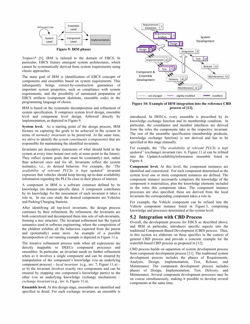
IRM is based on the systematic decomposition and refinement of system specification. It comprises system level design, ensemble level and component level design, followed directly by implementation, as depicted in Figure 9.
System level. As a starting point of the design process, IRM focuses on capturing the goals to be achieved in the system in terms of normalcy invariants to be preserved. At the same time, we strive to identify the system constituents (components) that are responsible for maintaining the identified invariants. Invariants are descriptive statements of what should hold in the system at every time instant (not only at some point in the future). They reflect system goals that must be (constantly) met, rather than achieved once and for all. Invariants reflect the system normalcy, i.e., its desired behavior. For example, the “The availability of relevant PLCSs is kept updated” invariant expresses that vehicles should keep having up-to-date availability information regarding the PLCSs close to their places of interest.
A component in IRM is a software construct defined by its knowledge (its domain-specific data). A component contributes by its knowledge for the assessment of each invariant it takes a role in. In our case study the desired components are Vehicles and Parking/Charging Stations. After identifying all top-level invariants, the design process continues by their refinement. By refinement, the invariants are both concretized and decomposed them into sets of sub-invariants, forming a tree structure. The invariant refinement has the typical semantics used in software engineering, where the composition of the children exhibits all the behaviors expected from the parent and (potentially) some more. An example of a possible decomposition of our running example is depicted in Figure 11.a.
The iterative refinement process ends when all expressions are directly mappable to DEECo component processes and ensembles. In particular, an invariant needs no further refinement when a) it involves a single component and can be ensured by manipulation of the component’s knowledge (via an underlying component process) – local invariant (e.g., inv. 7, Figure 11.a) – or b) the invariant involves exactly two components and can be ensured by mapping one component’s knowledge part(s) to the other (via an underlying knowledge exchange mechanism) – exchange invariant (e.g., inv. 6, Figure 11.a).
Ensemble level. At this design stage, ensembles are identified and specified in detail. For each exchange invariant, an ensemble is
introduced. In DEECo, every ensemble is prescribed by its knowledge exchange function and its membership condition. In particular, the coordinator and member interfaces are derived from the roles the components take in the respective invariant. The rest of the ensemble specification (membership predicate, knowledge exchange function) is not derived and has to be specified at this stage manually. For example, the “The availability of relevant PLCSs is kept updated” (exchange) invariant (inv. 6, Figure 11.a) can be refined into the UpdateAvailabilityInformation ensemble listed in Figure 4. Component level. At this level, the component instances are identified and concretized. For each component determined at the system level one or more component instances are defined. The component instance necessarily comprises the knowledge of the component it materializes, plus the knowledge elements included in the roles this component takes. The component instance processes are also specified; these are derived from the local invariants the corresponding component takes a role in.
For example, the Vehicle component can be refined into the Vehicle component instance listed in Figure 3, comprising knowledge and processes determined at the system level.
5.2 Integration with CBD Process Overall, the development process for EBCS as described above, and IRM in particular, introduces specific aspects into the traditional Component-Based Development (CBD) process. Thus, in this section we elaborate on these specifics in the context of general CBD process and provide a concrete example for the waterfall-based CBD process as proposed in [12].
CBD process builds on separation of system development process from component development process [11]. The traditional system development process includes the phases of Requirements, Analysis, Design, Implementation, Test, Release, and Maintenance. The component development process includes phases of Design, Implementation, Test, Delivery, and Maintenance. Several component development processes may be on course simultaneously, making it possible to develop several components at the same time.
Figure 9: IRM phases
Figure 10: Example of IRM integration into the reference CBD
process of [12].
System Level
Ensemble Level
Component Level Implementation
Refinement step
MaintenanceMaintenance
Component & Ensemble
Development
System Development
Requirements Elicitation 1
Design 3
Design 5
Implementation 6
Test 7
Delivery 8
8
Integration 9
Release 11
RequirementsAnalysis 2
Test 10
Maintenance 12
Maintenance 12
not changed slightly modified modified

By employing IRM in design, we couple component development (exemplified on the reference CBD process of [12] in Figure 10) with ensemble development. To do so, we extend several phases of CBD to accommodate IRM (Table 1). Since the extensions do not rely on any specifics of CBD (they only assume requirements analysis and architectural/system design, traditional parts of development processes in general), we believe that they are applicable to any development process which involves components (e.g. agile variations of CBD).
5.3 System Evolution Since EBCS are inherently open-ended and evolving systems, the aforementioned development process has to accommodate additional requirements that arise after the initial development cycle has been completed. A new requirement can arise when a new or modified functionality is required from the system. IRM provides an easy and effective way to deal with such evolution by introducing new invariants into corresponding branches of the IRM tree.
For illustration, we consider that the e-mobility system from the running example has been originally designed and implemented without considering traffic level information (Figure 11.a). In this case, the IRM design captures just the necessity to keep the vehicle’s plan updated (inv. 4, Figure 11.a) and to check whether the current plan remains feasible with respect to measured energy level (inv. 5, Figure 11.a). Together with the Vehicle component, the PLCS component is identified. This component provides the availability information, which is used during the Vehicle’s planning procedure. As a possible evolution scenario we consider that the Traffic Information Provider component is added to the system, to represent the traffic monitoring stations scattered around roads. These stations provide information to the vehicles about traffic congestions in their vicinity. In that case, the IRM tree is modified
as follows (Figure 11.b): i) the new component is added, ii) the invariant (5) is modified to account for traffic level, iii) three new invariants (i.e., (9), (10), (11)) are added. Out of these, one is an exchange invariant (10) and one is a local invariant (11), prescribing the addition of a new ensemble and a new process to the Vehicle component.
To account for such kind of system evolution, the whole development process needs to follow an iterative approach, where, by integrating newly identified requirements, software is incrementally built, tested, and released.
6. EXPERIENCE We have evaluated the DEECo approach (together with IRM) by developing a prototype of the e-mobility case study within the ASCENS project. As this case study has been conceived in cooperation with Volkswagen, the detailed designs and implementation are proprietary. For a concise description of the case study we refer the reader to [35]. Along with the case study, we have also implemented a number of example applications and a tutorial, which are all available at jDEECo GitHub site [13]. Our experience shows that DEECo concepts well combine the encapsulation and modularity brought by components with the needs of autonomic behavior and highly dynamic architecture. IRM process well complements the DEECo concepts in providing an overall system-level view that can be easily translated to components and ensembles. The mapping to Java (by jDEECo) proved to be relatively straightforward.
Our experience also indicated that although there is a strong conceptual difference between a component and an ensemble (in the sense that a component is state-full while an ensemble is stateless), the developers of the case-study had problems with differentiating between responsibilities of a component process
Req
. A
naly
sis
[2]
By applying the IRM method, the requirements are captured in terms of invariants and elaborated by iterative refinement.
Syst
em D
esig
n [3
]
The system architecture, in terms of (DEECo) ensembles and components, is identified. The analysis is both structural (which architectural entities should be present in the system) and behavioral (what should be their behavior, e.g., in terms of process & ensemble scheduling). It is important to distinguish between the components’ internal and external interfaces. An external interface comprises a part of the knowledge that can be exchanged (read or written) by ensembles. This knowledge must not be violated during implementation, as this would harm the system-wide contractual design. On the contrary, an internal interface, comprises a part of the knowledge that must be present in the component, for in the purpose of an internal computation.
Com
p.
Des
ign
[5]
Components & ensembles are designed in detail. This step can include elaboration of representation of the knowledge belonging to internal interfaces.
Com
p.
Test
ing
[7
]
Components & ensembles are tested in isolation. The leaf invariants of the IRM tree can serve as a specification for unit testing.
Syst
em
Test
ing
[10]
System-wide tests are performed. The non-leaf invariants of the IRM tree can serve as a specification for integration testing.
Table 1: IRM injection points into the CBD process.
(a)
(b)
Figure 11: Capturing system evolution in IRM.
(2) Vehicle has an up-‐to-‐date and feasible plan
(1) Vehicle meets its calendar
(4) Plan is kept updated
(3) Driver follows the route of the plan
L
(6) Availability of relevant PLCSs is kept updated
X
(5) Plan feasibility w.r.t. battery level is checked
(7) Plan is kept computed w.r.t. availability & feasibility
L
(8) Battery sufficiency w.r.t plan is checked
L
1{ plannedRoute}
Vehicle
positionplannedRouteplanFeasibilityavailabilitiesbatteryLevel
PLCS
positionavailability
1{ batteryLevel,planFeasibility}
1{ plannedRoute,planFeasibility,availabilities,position}
*{position, availability}
1{availabilities}
(2) Vehicle has an up-‐to-‐date and feasible plan
(4) Plan is kept updated (5) Plan feasibility w.r.t. battery level, traffic level is checked
(8) Battery sufficiency w.r.t plan is checked
L
(11) Time constraints w.r.t. traffic level are checked
L
(9) Traffic level assuptions w.r.t. plan are checked
(10) Traffic level information is kept updated
X
Traffic Information Provider
trafficLevel *{trafficLevel}
1{trafficLevel}
1{ trafficLevel,planFeasibility}
Vehicle
positionplannedRouteplanFeasibilityavailabilitiesbatteryLeveltrafficLevel
agent invariant AND-‐decomposition
x{k} role with knowledge k
exchange invariant
Xlocal invariant
L
Parking/Charging Station
positionavailability
and knowledge exchange. In particular, they incorrectly tended to reduce autonomy of components by pushing some of their functionality to ensembles (by employing complex knowledge transformations in the knowledge exchange). As a remedy, we adopted the following rule as a design guideline: The knowledge exchange should be ideally 1:1 knowledge assignment; complex knowledge transformations may be employed only in well justified cases (typically when integrating third-party components).
Finally, our experiments with verification of jDEECo applications via JPF (performed on the example applications) indicate that the relatively strict DEECo computational model can be effectively exploited for increasing the performance of explicit model checking.
7. RELATED WORK Since EBCS are a relatively new class of systems, we are currently not aware of any other approach that would be directly related to IRM and DEECo. However, as EBCS is a software engineering concept for developing Resilient Distributed Systems (RDS), in this section we survey approaches that deal with specific aspects of RDS.
At the computational level, control engineering methodologies have been identified as a promising solution to implement self-adaptive software systems [10] in a variety of application domains and with different performance requirements and control objectives [32]. In the domain of distributed systems, decentralized solutions based on feedback loops, ranging from cloud performance management [40] to embedded real-time systems [39], have been proposed to keep the system in the required steady state, while avoiding scalability issues and points of failure. EBCS employ similar idea of cyclic execution of component processes and ensembles to maintain the operational normalcy of the system. At the architectural level, attempts have been made to instantiate the generic MAPE-K loop [23] to feature adaptation at a larger scale. Self-managing architectures [25], component-based approaches [3][33], and solutions that apply architectural models at runtime [28] are examples of this. The common denominator of these approaches is that they rely on explicit bindings among the system components, which get re-organized in response to runtime stimuli. EBCS, on the other hand, do not consider explicit architecture, but let the architecture “emerge” during runtime, fitting better the dynamic, constantly–changing system landscapes.
Agent-oriented approaches provide useful notions (e.g., goals, plans), models (e.g., Belief-Desire-Intention [34]) and algorithms (e.g., DCOPs [21]) for reasoning in complex dynamic systems. In a distributed setting, multi-agent analysis is based on the conceptual autonomy and social ability of the parts constituting the system. A problem is that current agent implementation platforms [4] and methodologies [5] rely on guaranteed communication and explicit bindings among the agents, which typically take the form of messaging. In this view, EBCS/DEECo stands as an agent engineering platform which handles the communication in an implicit and automatic way, making it possible for agents to operate in opportunistic environments where no guarantees are available.
The concept of service-component ensembles has been recently proposed in order to allow for communication over unreliable communication channels and at massive scale [20]. Ensembles rely on attribute-based communication [14] to model a best-effort,
dynamic coordination of components. An attempt to formally define this concept can be found in [19].
At the requirements phase, well-established methods and models exist for capturing and analyzing early requirements in terms of goals delegated to system agents. However, these models either do not map effectively to the later development phases [26], or do not support mapping to emergent architectures [5], which are typical in EBCS. Recent attempts in the area of EBCS have centered around a model termed Statement of the Affairs (SOTA), which provides the means to capture and analyze the early requirements of different component cooperation schemes, along with the architectural patterns that satisfy them by construction [1]. IRM stands as the intermediate method which guides the transition from early (high-level) requirements to system architecture in terms of components and ensemble.
8. CONCLUSIONS AND FUTURE WORK In this paper, we have focused on resilient distributed systems (RDS). We argued that classic component-based approaches in design do not scale well in the area of RDS – mainly because RDS exhibit very high degree of dynamicity, adaptivity, and autonomy.
For component-based development of RDS, we have introduced EBCS, a new class of component-based systems, which combine concepts from agent-oriented, ensemble-oriented and control systems. In particular, we have presented an instance of EBCS – the DEECo component model and its framework.
Overall, DEECo provides a comprehensive software engineering solution comprising (i) component and ensemble paradigms with well-defined formal semantics, (ii) mapping to Java, (iii) distributed Java-based runtime framework (jDEECo), (iv) integration with analysis tools (SDE, JPF), (v) design method (IRM) for deriving components and ensembles from high-level requirements, and (vi) integration of the design method to traditional component-based development processes. We have successfully evaluated DEECo along with IRM on the e-mobility case-study of the ASCENS project.
The experience with DEECo (and consequently EBCS) puts forward several research directions. In particular we would like to evaluate the robustness of DEECo in environments with highly unreliable communication and heterogeneous network infrastructure (e.g. MANETs [27]). Although this will most likely require employing some communication middleware for such networks (e.g. EgoSpaces [22]) at the implementation level, it is well aligned with the general DEECo computational model. Also, we are currently investigating the possibility of using formalized IRM invariants as the basis for monitoring the correctness and performance of a DEECo-based system and for guiding component adaptations.
9. ACKNOWLEDGMENTS The authors would like to thank Pavel Parizek and Pavel Jancik for their input concerning JPF. This work was partially supported by the EU project ASCENS 257414 and the Grant Agency of the Czech Republic project P202/11/0312. The work was also partially supported by Charles University institutional funding SVV-2013-267312.
10. REFERENCES [1] D. B. Abeywickrama, N. Bicocchi, and F. Zambonelli.
SOTA: Towards a General Model for Self-Adaptive Systems. In Proc. of WETICE ’12, 48 – 53, 2012.

[2] R. Al Ali, T. Bures, I. Gerostathopoulos, P. Hnetynka, J. Keznikl, M. Kit, and F. Plasil. DEECo computational model – I. Technical Report no. D3S-TR-2013-01. D3S, Charles University in Prague. Available at: http://d3s.mff.cuni.cz/publications, 2013.
[3] L. Baresi, S. Guinea, and G. Tamburrelli. Towards decentralized self-adaptive component-based systems. In Proc. of SEAMS ’08, 57–64, 2008.
[4] F. Bellifemine, G. Caire, and D. Greenwood. Developing Multi-Agent Systems with JADE. John Wiley, 2007.
[5] P. Bresciani, P. Giorgini, F. Giunchiglia, J. Mylopoulos, and A. Perini. Tropos: An Agent-Oriented Software Development Methodology. Autonomous Agents and Multi-Agent Systems. 8, 3, 203–236, 2004.
[6] E. Bruneton, T. Coupaye, M. Leclercq, V. Quema, and J. Stefani. The Fractal component model and its support in Java. Software: Practice & Experience. 36, 11-12, 1257–1284, 2006.
[7] T. Bures, P. Hnetynka, and F. Plasil. SOFA 2.0 : Balancing Advanced Features in a Hierarchical Component Model. In Proc. of SERA ’06, 40–48, 2006.
[8] T. Bures, I. Gerostathopoulos, P. Hnetynka, J. Keznikl, M. Kit, and F. Plasil. Autonomous components in dynamic environments. Awareness Magazine. Online: http://www.awareness-mag.eu, 2012
[9] T. Bures, I. Gerostathopoulos, V. Horky, J. Keznikl, J. Kofron, M. Loreti, and F. Plasil. Language Extensions for Implementation-Level Conformance Checking. ASCENS Deliverable 1.5. Available at: http://www.ascens-ist.eu/deliverables, 2012.
[10] B. Cheng et al. Software Engineering for Self-Adaptive Systems: A Research Roadmap. Software Engineering for Self-Adaptive Systems. 1–26. Springer–Verlag, 2009.
[11] I. Crnkovic. Building Reliable Component-Based Software Systems. Artech House, Inc., Norwood, MA, USA, 2002.
[12] I. Crnkovic, M. Chaudron, and S. Larsson. Component-based development process and component lifecycle. Software Engineering Advances, 44, 2006.
[13] D3S, Charles University in Prague. jDEECo. Accessed February 20, 2013. https://github.com/d3scomp/JDEECo, 2012.
[14] R. De Nicola, G. Ferrari, M. Loreti, and R. Pugliese. A Language-based Approach to Autonomic Computing. In Proc. of FMCO ’11, 1–24, 2012.
[15] D. Gelernter. Generative communication in Linda. Toplas. 7, 1, 80–112, 1985.
[16] I. Gerostathopoulos, T. Bures, and P. Hnetynka. Position Paper: Toward s a requirements-driven design of ensemble-based component systems. To appear in Proc. of International Workshop on Hot Topics in Cloud Services, ICPE ’13. Preliminary version available at: http://d3s.mff.cuni.cz/publications, 2013.
[17] R. Hall, K. Pauls, S. McCulloch, and D. Savage. OSGi in Action: Creating Modular Applications in Java. Manning Pubs Co Series. Manning Publications, 2011.
[18] K. Havelund, and T. Pressburger. Model Checking Java Programs Using Java PathFinder. Software Tools for Technology Trasfer. 2, 4, 2000.
[19] M. Holz, and M. Wirsing. Towards a System Model for Ensembles. Formal modeling. 241–261, 2012.
[20] M. Holzl, A. Rauschmayer, and M. Wirsing. Engineering of software-intensive systems: State of the art and research challenges. In Software-Intensive Systems and New Computing Paradigms. Ser. LNCS, Springer Berlin, Heidelberg, vol. 5380, 1–44, 2008.
[21] M. Jain, M. Taylor, M. Tambe, and M. Yokoo. DCOPs meet the real world: Exploring unknown reward matrices with applications to mobile sensor networks. In Proc. of IJCAI ‘09, 181–186, 2009.
[22] C. Julien, and G.-C. Roman. EgoSpaces: Facilitating Rapid Development of Context-Aware Mobile Applications. Software Engineering, IEEE Transactions on. 32, 5, 281–298, 2006.
[23] J. Kephart, and D. Chess. The Vision of Autonomic Computing. Computer. 36, 1, 41–50, 2003.
[24] J. Keznikl, T. Bures, F. Plasil, and M. Kit. Towards Dependable Emergent Ensembles of Components: The DEECo Component Model. In Proc. of WICSA/ECSA 2012. IEEE CS, 2012.
[25] J. Kramer, and J. Magee. Self-managed systems: an architectural challenge. In Proc. of FOSE ’07, 259–268, 2007.
[26] A. Lamsweerde. Requirements engineering: from craft to discipline. In Proc. of SIGSOFT ’08/FSE-16, 238–249, 2008.
[27] M. Mauve, A. Widmer and H. Hartenstein. A Survey on Position-Based Routing in Mobile Ad Hoc Networks. Network, IEEE. 15, 6, 30–39, 2001.
[28] B. Morin, O. Barais, J.-M. Jezequel, F. Fleurey, and A. Solberg. Models at Runtime to Support Dynamic Adaptation. Computer. 42, 10 (2009), 44–51, 2009.
[29] OMG. Unified Modeling Language 2.0: Superstructure. Available online: http://www.omg.org/spec/UML/2.0/, 2005.
[30] OMG. CORBA Component Model Specification v4.0. Available online: http://www.omg.org/spec/CCM/4.0/, 2006.
[31] OSGi Alliance. OSGi service platform core specification, release 4. Available online: http://www.osgi.org/Specifications/HomePage, 2012.
[32] T. Patikirikorala, A. Coman, H. Jun, and W. Liuping . A systematic survey on the design of self-adaptive software systems using control engineering approaches. In Proc. of SEAMS ’12, 33–42, 2012.
[33] C. Peper, and D. Schneider. Component engineering for adaptive ad-hoc systems. In Proc. of SEAMS ’08, 49-56, 2008.
[34] A. Rao; and M.P. Georgeff. BDI agents: From theory to practice. In Proc. of ICMAS ’95 1995.
[35] N. Serbedzija et al. Ensemble Model Syntheses with Robot, Cloud Computing and e-Mobility. ASCENS Deliverable 7.2. Available at: http://www.ascens-ist.eu/deliverables, 2012.
[36] N. Serbedzija, S. Reiter, M. Ahrens, J. Velasco, C. Pinciroli, N. Hoch, and B.Werther. Requirement Specification and Scenario Description of the ASCENS Case Studies. ASCENS Deliverable 7.1. Available at: http://www.ascens-ist.eu/deliverables, 2011.
[37] M. Shaw, and D. Garlan. Software Architecture: Perspectives on an Emerging Discipline, Prentice-Hall, Englewood Cliffs, NJ, 1996.
[38] Y. Shoham, and K. Leyton-Brown. Multiagent Systems: Algorithmic, GameTheoretic, and Logical Foundations, Cambridge University Press, 2008.

[39] J. A. Stankovic , T. He , T. Abdelzaher , M. Marley , G. Tao , S. Son , and C. Lu. Feedback control scheduling in distributed real-time systems. In Proc. of RTSS ‘01, 59–70, 2002.
[40] R. Wang, and N. Kandasamy. A distributed control framework for performance management of virtualized computing environments. In Proc. of ICAC ’10, 89–98, 2009.
Related Documents