Abstract—There is a need to develop new control strategies for interconnecting Renewable Energy Sources (RES) to the power grid due to the continuously increasing penetration of RES. The control strategies are typically based on a fast and accurate detection of the phase angle of the grid voltage which may be estimated by using a Phase-Locked Loop (PLL) control circuit. The performance of the PLL under normal and abnormal operational conditions is a crucial aspect, since the RES is desired to operate accurately to support the power system under grid fault conditions. This paper investigates the performance of three different PLLs: a synchronous reference frame PLL (dqPLL), a stationary reference frame PLL (αβPLL), and a decoupled double synchronous reference frame PLL (DDSRF PLL). The results of this investigation motivate the development of a decoupled stationary reference frame PLL which is a combination of the abovementioned PLLs and uses the advantages of each PLL. The proposed decoupled stationary reference frame PLL(dαβPLL) may be an appropriate solution to use in an interconnected RES with Fault Ride Through (FRT) capability, since it prevails the other PLLs with regards to its accuracy under unbalanced faults. The performance of the dαβPLL is verified through simulations and experiments. Further the dαβPLL is used in an interconnected RES through experiments under normal and FRT operation. Index Terms— Fault ride through operation, grid side converter, interconnected renewable energy systems, Phase Locked-Loop(PLL), unbalanced grid faults. I. INTRODUCTION The use of fossil fuels for electric power generation has imposed several problems on the environment including global warming and greenhouse effect. This has led to an era in which the increasing power demand will be met by Distributed Generation (DG) system which are based on renewable energy sources such as solar power, wind power, small hydro power etc. The DG systems are distributed near the user's facility. These systems are mainly small scale generations having capacity less than 20MW. These DG systems need to be controlled properly in order to ensure sinusoidal current injection into the grid. However, They have a poor controllability due to their intermittent characteristics .Grid connected inverter is the key element to maintain voltage at the point of common coupling (PCC) constant and to ensure power quality improvements. For safe and reliable operation of power system based on DG system, usually power plant operators should satisfy the grid code requirements such as grid stability, fault ride through, power quality improvement, grid synchronization and power control etc. The major issue associated with DG system is their synchronization with utility voltage vector. The information about the phase angle of utility voltage vector is accurately tracked in order to control the flow of active and reactive power and to turn on and off power devices. Renewable Energy Systems (RES), such as wind power and solar power systems, use power electronic converters in order to inject the produced energy to the power grid. The Grid Side Converter (GSC) is the one which is responsible for the grid synchronization, so the control for the GSC should be designed very carefully in order to meet the specifications and the regulations for interconnected distributed generation under normal operation. Moreover, the RES should have Fault Ride Through (FRT) capability in order to provide voltage and frequency support to the power system when disturbances and faults occur. The control system of the GSC may be based on a synchronous reference frame with proportional-integral (PI) controllers. In case that the control system is based on a synchronous reference frame with PI controllers, the most important synchronization variable is the phase of the grid voltage at the PCC. Therefore a Phase-Locked Loop (PLL) algorithm is recommended to be used in order to obtain the synchronization and the appropriate operation from the GSC. This paper focuses on the performance of the PLL on a synchronous reference frame control system. Three PLLs are considered in this investigation: the dqPLL, the αβPLL and the DDSRF PLL. The dqPLL and αβPLL have difficulties in tracking the phase angle when an unbalanced fault occurs. The DDSRF PLL overcomes this problem by decoupling the positive and the negative sequence of the voltage at the PCC. The main drawback of the DDSRF PLL is the high overshoot on the phase angle tracking error when a fault occurs. Decoupled Stationary Reference Frame PLL for Interconnecting Renewable Energy Systems to the Grid G. Sivasankar Instrumentation and control systems Dr M. Sailaja Jawaharlal Nehru Technological University rofessor, ECE Department Jawaharlal Nehru Technological University Kakinada, India Kakinada, India Kakinada P International Journal of Engineering Research & Technology (IJERT) Vol. 3 Issue 8, August - 2014 ISSN: 2278-0181 www.ijert.org IJERTV3IS080473 (This work is licensed under a Creative Commons Attribution 4.0 International License.) 447

Welcome message from author
This document is posted to help you gain knowledge. Please leave a comment to let me know what you think about it! Share it to your friends and learn new things together.
Transcript

Abstract—There is a need to develop new control strategies for
interconnecting Renewable Energy Sources (RES) to the power
grid due to the continuously increasing penetration of RES. The
control strategies are typically based on a fast and accurate
detection of the phase angle of the grid voltage which may be
estimated by using a Phase-Locked Loop (PLL) control circuit.
The performance of the PLL
under normal and abnormal
operational conditions is a crucial aspect, since the RES is desired
to operate accurately to support the power system under grid fault
conditions. This paper investigates the performance of three
different PLLs: a synchronous reference frame PLL (dqPLL), a
stationary reference frame PLL (αβPLL), and a decoupled double
synchronous reference frame PLL (DDSRF PLL). The results of
this investigation
motivate the development of a decoupled
stationary reference frame PLL which is a combination of the
abovementioned PLLs and uses the advantages of each PLL. The
proposed decoupled stationary reference frame PLL(dαβPLL)
may be an appropriate solution to use in an interconnected RES
with Fault Ride Through (FRT) capability, since it prevails the
other PLLs with regards to its accuracy under unbalanced faults.
The performance of the dαβPLL is verified through simulations
and experiments. Further the dαβPLL is
used in an
interconnected RES through experiments under normal and FRT
operation. Index Terms—
Fault ride through operation, grid side converter,
interconnected renewable energy systems, Phase
Locked-Loop(PLL), unbalanced grid faults.
I.
INTRODUCTION
The use of fossil fuels for electric power generation has
imposed several problems on the environment including global
warming and greenhouse effect. This has led to an era in which
the increasing power demand will be met by Distributed
Generation (DG) system which are based on renewable energy
sources such as solar power, wind power, small hydro power
etc. The DG systems are distributed near the user's facility.
These systems are mainly small scale generations having
capacity less than 20MW. These DG systems need to be
controlled properly in order to ensure sinusoidal current
injection into the grid. However, They have a poor
controllability due to their intermittent characteristics .Grid
connected inverter is the key element to maintain voltage at the
point of common coupling (PCC) constant and to ensure power
quality improvements. For safe and reliable operation of power
system based on DG system, usually power plant operators
should satisfy the grid code requirements such as grid stability,
fault ride through, power quality improvement, grid
synchronization and power control etc. The major issue
associated with DG system is their synchronization with utility
voltage vector. The information about the phase angle of utility
voltage vector is accurately tracked in order to control the flow
of active and reactive power and to turn on and off power
devices.
Renewable Energy Systems (RES), such as wind power
and solar power systems, use power electronic converters in
order to inject the produced energy to the power grid. The Grid
Side Converter (GSC) is the one which is responsible for the
grid synchronization, so the control for the GSC should be
designed very carefully in order to meet the specifications and
the regulations for interconnected distributed generation under
normal operation. Moreover, the RES should have Fault Ride
Through (FRT) capability in order to provide voltage and
frequency support to the power system when disturbances and
faults occur. The control system of the GSC may be based on a
synchronous reference frame with proportional-integral (PI)
controllers. In case that the control system is based on a
synchronous reference frame with PI controllers, the most
important synchronization variable is the phase of the grid
voltage at the PCC. Therefore a Phase-Locked Loop (PLL)
algorithm is recommended to be used in order to obtain the
synchronization and the appropriate operation from the GSC.
This paper focuses on the performance of the PLL on a
synchronous reference frame control system. Three PLLs are
considered in this investigation: the dqPLL, the αβPLL and the
DDSRF PLL. The dqPLL and αβPLL have difficulties in
tracking the phase angle when an unbalanced fault occurs. The
DDSRF PLL overcomes this problem by decoupling the
positive and the negative sequence of the voltage at the PCC.
The main drawback of the DDSRF PLL is the high overshoot
on the phase angle tracking error when a fault occurs.
Decoupled Stationary Reference Frame PLL
for Interconnecting Renewable Energy
Systems to the Grid
G. Sivasankar
Instrumentation and control systems Dr M. Sailaja
Jawaharlal Nehru Technological University
rofessor, ECE Department
Jawaharlal Nehru Technological University
Kakinada, India
Kakinada, India
Kakinada
P
International Journal of Engineering Research & Technology (IJERT)
Vol. 3 Issue 8, August - 2014
IJERT
IJERT
ISSN: 2278-0181
www.ijert.orgIJERTV3IS080473
(This work is licensed under a Creative Commons Attribution 4.0 International License.)
447

II. DESIGN APPROACH
A. Synchronous Reference Frame PLL (dqPLL)
The basic configuration is shown in the figure below. The
dqPLL uses the equations of the Park’s transformation, as
shown below, to translate the abc natural frame (SRF).
In this PLL either direct axis component or quadrature axis
component of voltage rotating reference frame into the
dq-synchronous reference can be considered for the estimation
of frequency or hence phase angle. A crucial aspect of the
transformation is that the voltage of the d-axis (Vd) has to lie on
the voltage of phase a. This is achieved by having the voltage of
the q-axis (Vq) to track zero through a proportional-integral
(PI) controller and therefore frequency, ωdq PLL and phase,
θdqPLL could be estimated as illustrated in the Fig.1. In this
PLL, the PI controller performs the function of Loop filter in
the basic PLL. The angle θdqPLL is found integrating the
output ωdq PLL which uses the error signal Vq- Vqref in the dq
frame.
When a balanced fault occurs, the dqPLL is operating well and
can track the phase angle. However, when an unbalanced fault
occurs, then the dqPLL fails to track accurately the phase angle
because Vd does not perfectly match with the positive sequence
voltage V+1 due to the oscillation which appears because of the
existence of the negative sequence voltage V-1 under
unbalanced disturbances.
B. Stationary Reference Frame PLL (αβPLL)
The basic configuration of a Stationary reference frame
PLL is shown below. The αβPLL sets θ=0 in that of dqPLL, in
order to translate the abc natural rotating reference frame into
the αβ-stationary reference frame. Trigonometric equations are
used in order to estimate the phase angle θαβ PLL as shown
below. It should be noticed that the below expression is valid if
Δθ is small.
The objective of the closed loop control of αβPLL is to
induce the difference Δθ to be controlled to zero by using a PI
controller, where θgr is the actual phase angle of the voltage.
The αβPLL in unbalanced operation has similar problems to
those mentioned for the dqPLL. The structure of αβPLL is
shown in Fig.2.
Fig.2 The structure of αβPLL
C. Decoupled Double Synchronous Reference Frame PLL
(DDSRF PLL)
The DDSRF-PLL stems from improving the conventional
SRF-PLL. It consists of a decoupling network and phase locked
loop operating on synchronous reference frame (SRFPLL). The
decoupling network provides positive and negative sequence
components from the input voltage vector. The synchronization
to the positive sequence component of the grid voltage is
achieved when the voltage positive sequence q-component is
controlled to zero. This is done using SRF-PLL. Fig.3. shows
the structure of DDSRF PLL.
Fig.3. The structure of DDSRF PLL
When the three phase grid voltage is unbalanced, the
fundamental positive-sequence voltage vector appears as a DC
voltage on the dq+1 axes of the positive sequence SRF and as
ac voltages at twice the fundamental utility frequency on the
dq-1 axes of the negative sequence SRF. On the contrary, the
negative sequence voltage vector will cause a dc component on
the negative sequence SRF and an ac oscillation on the positive
sequence SRF. Since the amplitude of the oscillation on the
positive sequence SRF matches to the DC level on the negative
sequence SRF and vice versa, a decoupling network is applied
to signals on the dq positive/negative SRF axes in order to
cancel out such ac oscillations. Low pass filters are in charge of
extracting DC component from the signal on the decoupled
SRF axes. These DC components collect the information about
the amplitude and phase angle of the positive and negative
sequence components of the grid voltage vector.
The loop controller of the DDSRF-PLL works on the
decoupled q-axis signal of the positive sequence SRF (Uq+1).
The signal is free of ac components due to the effect of the
decoupling cells and the band width of the loop controller can
be consequently increased.
International Journal of Engineering Research & Technology (IJERT)
Vol. 3 Issue 8, August - 2014
IJERT
IJERT
ISSN: 2278-0181
www.ijert.orgIJERTV3IS080473
(This work is licensed under a Creative Commons Attribution 4.0 International License.)
448

D. Decoupled Stationary Reference frame PLL
The proposed dαβ PLL combines the decoupling of
the voltage sequence of the DDSRF PLL and the algorithm to
estimate the phase angle use by αβPLL. The novel dαβ PLL
inherits the advantage of a lower frequency overshoot of the
αβPLL in comparison to the dqPLL and the accurate estimation
of the DDSRF PLL under unbalanced operation. This could
lead to a faster operation without violating the frequency limits
of the grid code when a disturbance occurs. Simulation and
experimental results are shown under balanced and unbalanced
disturbances, where it is clear that the dαβ PLL outperforms the
other PLLs under investigation. The proposed dαβ PLL is also
experimentally demonstrated in an interconnected RES under
normal and FRT operations.
The effect of the time response of each PLL on the
overshoot of the estimated phase angle is investigated and show
below in Fig. A
Fig. A
The effect of changing the time response of the three PLLs
in terms of overshoots of the estimation frequency during a
symmetrical fault.
The simulation results in Fig. A show how the changing of
the time response settings of each PLL affects the overshoot of
the frequency estimation (fdqPLL, fαβPLL and fDDSRF PLL)
when a 50% balanced voltage sag occurs. Clearly the desired
faster operation of a PLL causes undesirably higher overshoots
in the frequency. An important conclusion from Fig. A is that
the overshoot of αβPLL is always lower (18% lower overshoot
on average) in comparison to the other two PLLs and also that
dqPLL and DDSRF PLL have very similar responses since the
structure of the DDSRF PLL is based on the dqPLL and on two
decoupling cells.
The results in Fig. A show that the αβPLL has lower
overshoot on the frequency estimation when a fault occurs
compared to the two other PLLs under investigation. In
addition, the αβPLL faces a problem under unbalanced
conditions, in contrast to the DDSRF PLL, where the
decoupling of the voltage sequence makes it very accurate
under balanced and unbalanced conditions. The proposed dαβ
PLL is a combination of the decoupling cells that are used in
DDSRF PLL to decouple the voltage sequence and the αβPLL
algorithm to estimate the phase angle of the grid voltage, which
offers lower estimation overshoot instead of the algorithm that
is used in dqPLL. The dαβ PLL aims at operating very
accurately under balanced and unbalanced disturbances and
also at having a lower phase angle and frequency overshoot
than the DDSRF PLL. Therefore, the desired faster operation
could be achieved by the suggested dαβ PLL within the same
frequency limits. The structure of the proposed dαβ PLL is
illustrated in Fig.4.
Fig.4.The structure of dαβ PLL
III. SIMULATION RESULTS
A comparison of the new proposed dαβ PLL to the other
PLLs is necessary in order to demonstrate its advantages. The
comparison focuses especially on dαβ PLL and DDSRF PLL,
which are the only ones that are able to operate accurately under
unbalanced disturbances.
A. Simulink Model Of a Synchronous Reference Frame
PLL:
The Simulink Model of a Synchronous Reference Frame
PLL is shown below. The tuning parameters of a PI controller
are selected as kp==180 ki=3200 calculated using
Ziegler-Nichols method.
Voltage and Phase Angle Tracked by SRF PLL:
The output voltage Vd is obtained as 264.7v for an input
voltage of 325.26v is shown below in Fig.5.2.
International Journal of Engineering Research & Technology (IJERT)
Vol. 3 Issue 8, August - 2014
IJERT
IJERT
ISSN: 2278-0181
www.ijert.orgIJERTV3IS080473
(This work is licensed under a Creative Commons Attribution 4.0 International License.)
449

Simulink Model of Synchronous Reference Frame PLL during
Unbalanced fault:
The Simulink Model of a Synchronous Reference
Frame PLL during Unbalanced fault is shown below in Fig.5.3.
Here an unbalanced fault is applied where there is a line to
ground fault in two of the three phases
Voltage and Phase Angle Tracked by SRF PLL
during an unbalanced fault:
B. Simulink Model of a αβ PLL:
The Simulink Model of an αβ Frame PLL is shown below
in Fig.5.5.The tuning parameters of a PI controller are selected
as kp==180 ki=3200 calculated using Ziegler-Nichols method.
Voltage and Phase Angle Tracked by αβ PLL:
The voltage obtained by the PLL in αβ frame is
shown below. The input voltage to the PLL is 325.26v
Simulink Model of a αβ PLL during Unbalanced fault:
International Journal of Engineering Research & Technology (IJERT)
Vol. 3 Issue 8, August - 2014
IJERT
IJERT
ISSN: 2278-0181
www.ijert.orgIJERTV3IS080473
(This work is licensed under a Creative Commons Attribution 4.0 International License.)
450

The Simulink Model of a αβ PLL during Unbalanced fault is
shown below. Here an unbalanced fault is applied where there
is a line to ground fault in two of the three phases
The phase angle tracked by αβ PLL during an unbalanced
fault is shown below.
C. Simulink Model Of A Decoupled Double Synchronous
Reference Frame PLL(DDSRF PLL):
The Simulink Model of a Decoupled Double
Synchronous Reference Frame PLL(DDSRF PLL) is shown
below in Fig.5.9. The tuning parameters of a PI controller are
selected as kp==2.2214 ki=246.74 calculated using
Ziegler-Nichols method.
Voltage and Phase Angle Tracked by DDSRF PLL:
The output voltage Vd is obtained as 423.3v for an
input voltage of 415v is shown below in Fig.5.10
Simulink Model of a DDSRF PLL during an unbalanced fault:
Voltage and Phase Angle Tracked by DDSRF PLL during an
unbalanced fault:
The Voltage and Phase Angle Tracked by DDSRF
PLL during an unbalanced fault are shown below in Fig.5.12.
International Journal of Engineering Research & Technology (IJERT)
Vol. 3 Issue 8, August - 2014
IJERT
IJERT
ISSN: 2278-0181
www.ijert.orgIJERTV3IS080473
(This work is licensed under a Creative Commons Attribution 4.0 International License.)
451
D. Simulink Model of a Decoupled αβPLL(dαβ PLL):
The Simulink Model of a Decoupled αβ PLL(dαβ
PLL) is shown below in Fig.5.13. The tuning parameters of a PI
controller are selected as kp==180 ki=3200 calculated using
Ziegler-Nichols method.
Voltage and Phase angle tracked using dαβ PLL:
The Voltage and Phase angle tracked using dαβ
PLL is shown below in Fig.5.14. The output voltage Vd is
423.3v for an input voltage of 415v.
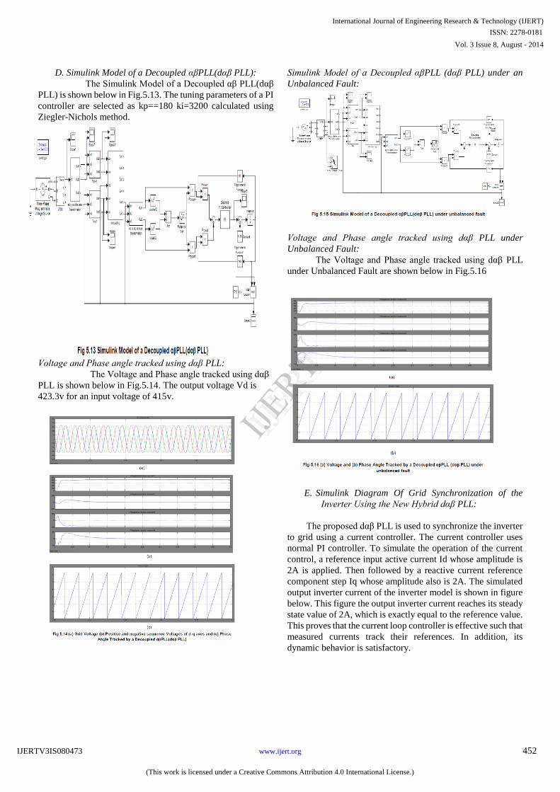
Simulink Model of a Decoupled αβPLL (dαβ PLL) under an
Unbalanced Fault:
Voltage and Phase angle tracked using dαβ PLL under
Unbalanced Fault:
The Voltage and Phase angle tracked using dαβ PLL
under Unbalanced Fault are shown below in Fig.5.16
E.
Simulink Diagram Of Grid Synchronization of the
Inverter Using the New Hybrid dαβ PLL:
The proposed dαβ PLL
is used to synchronize the inverter
to grid using a current controller. The current controller uses
normal PI controller. To simulate the operation of the current
control, a reference input active current Id whose amplitude is
2A is applied. Then followed by a reactive current reference
component step Iq whose amplitude also is 2A. The simulated
output inverter current of the inverter model is shown in figure
below. This figure the output inverter current reaches its steady
state value of 2A, which is exactly equal to the reference value.
This
proves that the current loop controller is effective such that
measured currents track their references. In addition, its
dynamic behavior is satisfactory.
International Journal of Engineering Research & Technology (IJERT)
Vol. 3 Issue 8, August - 2014
IJERT
IJERT
ISSN: 2278-0181
www.ijert.orgIJERTV3IS080473
(This work is licensed under a Creative Commons Attribution 4.0 International License.)
452

The Simulink diagram is shown below
―Phase-locked loop for grid-connected three-phase power
conversion systems. The synchronized inverter output current
is shown below. The current magnitude is almost near to that of
the reference value 2A
IV. CONCLUSION
In this paper, A benchmarking study of the effect of the
time response on the overshoot of the estimated frequency and
phase angle for three different PLLs is performed in this paper.
The investigation of dqPLL, αβ PLL and DDSRF PLL
motivates the proposal for a new PLL, which inherits the
advantages of each PLL. The new hybrid dαβ PLL is the most
beneficial solution for grid synchronization compared to the
other three PLLs under investigation, since it operates
accurately under balanced and unbalanced conditions and also
reduces the overshoot on the estimation of the phase angle and
frequency, which is the main drawback of DDSRF PLL. The
lower frequency overshoot of dαβ PLL leads to a faster time
response without any violation of the frequency limits of the
grid codes. The proposed dαβ PLL could be very useful in
synchronizing the inverter to the grid. The performance of the
dαβ PLL in DGS is verified through results and its use is
illustrated.
REFERENCES
[1] F. Blaabjerg, R. Teodorescu, M. Liserre, and A. V. Timbus, ―Overview of
Control and Grid Synchronization for Distributed Power Generation
Systems,‖ IEEE Trans. Industrial Electronics, vol. 53, no. 5, pp. 1398–
1409, Oct. 2006.
[2] P. Rodriguez, A. Luna, R. S. Munoz-Aguilar, I. Etxeberria-Otadui, R.
Teodorescu, and F. Blaabjerg, ―A stationary reference frame grid
synchronization system for three-phase gridconnected power converters
under adverse grid conditions,‖ IEEE Trans. Power Electronics, vol. 27,
no. 1, pp. 99–111, Jan. 2012.
[3] S.-K. Chung, ―Phase-locked loop for grid-connected three-phase power
conversion systems,‖ Proc. Inst. Elect. Eng., vol. 147, no. 3, pp. 213–
219, May 2000.
[4] P. Rodriguez, J. Pou, J. Bergas, J. I. Candela, R. P. Burgos, and D.
Boroyevich, ―Decoupled double synchronous reference frame PLL for
power converters control,‖ IEEE Trans. PowerElectronics, vol. 22, no.
2, pp. 584–592, Mar. 2007.
[5] Marian P. Kazmierkowski, Luigi Malesani. Current Control Techniques
for Three-Phase Voltage-Source PWM Converters: A Survey. s.l. : IEEE
Transactions On Industrial Electronics, October 1998. pp. VOL. 45, NO.
5.
[6] G.-C. Hsich and J. Hung, ―Phase-locked loop techniques—A survey,‖
IEEE Trans. Industrial Electronics, vol. 43, pp. 609–615, Dec. 1996.
[7] A. Abobakr , A. Zekry. Three phase grid connected inverter, PhD thesis.
Cairo, Eygpt : Ain-Shams university, 2008.
International Journal of Engineering Research & Technology (IJERT)
Vol. 3 Issue 8, August - 2014
IJERT
IJERT
ISSN: 2278-0181
www.ijert.orgIJERTV3IS080473
(This work is licensed under a Creative Commons Attribution 4.0 International License.)
453
Related Documents