CONTENTS SCIENTIFIC AND TECHNICAL Kharlamov M.Yu., Krivtsun I.V., Korzhik V.N. and Petrov S.V. Formation of liquid metal film at the tip of wire-anode in plasma-arc spraying .......................................... 2 Rymar S.V., Zhernosekov A.M. and Sidorets V.N. Effect of single-phase power sources of welding arc on electric mains ......................................................................... 7 Shlepakov V.N. and Kotelchuk A.S. Investigation of thermochemical characteristics of mixtures of dispersed materials by differential thermal analysis methods ................................................................................. 13 Rimsky S.T. Control of properties of the weld metal by regulating the level of oxidation of the weld pool in gas-shielded welding .............................................................. 16 Moravetsky S.I. Hygroscopicity of high-basicity synthetic flux .......................................................................... 20 INDUSTRIAL Paton B.E., Lobanov L.M. and Volkov V.S. Transformable structures (Review) .......................................... 25 Bogdanovsky V.A., Gavva V.M., Makhlin N.M., Cherednik A.D., Tkachenko A.V., Kudryashev V.B., Kulikov A.P. and Kovalyuk A.V. Application of automatic orbital welding to fabricate absorbing inserts for spent nuclear fuel storage containers ............................................... 34 Yushchenko K.A., Borisov Yu.S., Vojnarovich S.G., Kislitsa A.N. and Kuzmich-Yanchuk E.K. Two-layer bio-cermet titanium—hydroxyapatite coating ............................. 38 Makovetskaya O.K. Organization and topics of R&D in the field of joining technologies conducted by TWI and DVS Association of Researchers (Review) ................................ 41 Index of articles for TPWJ’2011, Nos. 1—12 .............................. 45 List of authors ........................................................................ 49 © PWI, International Association «Welding», 2011 English translation of the monthly «Avtomaticheskaya Svarka» (Automatic Welding) journal published in Russian since 1948 International Scientific-Technical and Production Journal Founders: E.O. Paton Electric Welding Institute of the NAS of Ukraine Publisher: International Association «Welding» International Association «Welding» Editor-in-Chief B.E.Paton Editorial board: Yu.S.Borisov V.F.Khorunov A.Ya.Ishchenko I.V.Krivtsun B.V.Khitrovskaya L.M.Lobanov V.I.Kyrian A.A.Mazur S.I.Kuchuk-Yatsenko Yu.N.Lankin I.K.Pokhodnya V.N.Lipodaev V.D.Poznyakov V.I.Makhnenko K.A.Yushchenko O.K.Nazarenko A.T.Zelnichenko I.A.Ryabtsev International editorial council: N.P.Alyoshin (Russia) U.Diltey (Germany) Guan Qiao (China) D. von Hofe (Germany) V.I.Lysak (Russia) N.I.Nikiforov (Russia) B.E.Paton (Ukraine) Ya.Pilarczyk (Poland) G.A.Turichin (Russia) Zhang Yanmin (China) A.S.Zubchenko (Russia) Promotion group: V.N.Lipodaev, V.I.Lokteva A.T.Zelnichenko (exec. director) Translators: A.A.Fomin, O.S.Kurochko, I.N.Kutianova, T.K.Vasilenko Editor: N.A.Dmitrieva Electron galley: D.I.Sereda, T.Yu.Snegiryova Address: E.O. Paton Electric Welding Institute, International Association «Welding», 11, Bozhenko str., 03680, Kyiv, Ukraine Tel.: (38044) 200 82 77 Fax: (38044) 200 81 45 E-mail: [email protected] http://www.nas.gov.ua/pwj URL: www.rucont.ru State Registration Certificate KV 4790 of 09.01.2001 Subscriptions: $324, 12 issues per year, postage and packaging included. Back issues available. All rights reserved. This publication and each of the articles contained herein are protected by copyright. Permission to reproduce material contained in this journal must be obtained in writing from the Publisher. Copies of individual articles may be obtained from the Publisher. December 2011 # 12

Welcome message from author
This document is posted to help you gain knowledge. Please leave a comment to let me know what you think about it! Share it to your friends and learn new things together.
Transcript

CONTENTS
SCIENTIFIC AND TECHNICAL
Kharlamov M.Yu., Krivtsun I.V., Korzhik V.N. and PetrovS.V. Formation of liquid metal film at the tip ofwire-anode in plasma-arc spraying .......................................... 2
Rymar S.V., Zhernosekov A.M. and Sidorets V.N. Effectof single-phase power sources of welding arc onelectric mains ......................................................................... 7
Shlepakov V.N. and Kotelchuk A.S. Investigation ofthermochemical characteristics of mixtures ofdispersed materials by differential thermal analysismethods ................................................................................. 13
Rimsky S.T. Control of properties of the weld metal byregulating the level of oxidation of the weld pool ingas-shielded welding .............................................................. 16
Moravetsky S.I. Hygroscopicity of high-basicitysynthetic flux .......................................................................... 20
INDUSTRIAL
Paton B.E., Lobanov L.M. and Volkov V.S.Transformable structures (Review) .......................................... 25
Bogdanovsky V.A., Gavva V.M., Makhlin N.M.,Cherednik A.D., Tkachenko A.V., Kudryashev V.B.,Kulikov A.P. and Kovalyuk A.V. Application of automaticorbital welding to fabricate absorbing inserts for spentnuclear fuel storage containers ............................................... 34
Yushchenko K.A., Borisov Yu.S., Vojnarovich S.G.,Kislitsa A.N. and Kuzmich-Yanchuk E.K. Two-layerbio-cermet titanium—hydroxyapatite coating ............................. 38
Makovetskaya O.K. Organization and topics of R&D inthe field of joining technologies conducted by TWI andDVS Association of Researchers (Review) ................................ 41
Index of articles for TPWJ’2011, Nos. 1—12 .............................. 45
List of authors ........................................................................ 49
© PWI, International Association «Welding», 2011
English translation of the monthly «Avtomaticheskaya Svarka» (Automatic Welding) journal published in Russian since 1948
International Scientific-Technical and Production Journal
Founders: E.O. Paton Electric Welding Institute of the NAS of Ukraine Publisher: International Association «Welding» International Association «Welding»
Editor-in-Chief B.E.Paton
Editorial board:Yu.S.Borisov V.F.Khorunov
A.Ya.Ishchenko I.V.KrivtsunB.V.Khitrovskaya L.M.Lobanov
V.I.Kyrian A.A.MazurS.I.Kuchuk-Yatsenko
Yu.N.Lankin I.K.PokhodnyaV.N.Lipodaev V.D.Poznyakov
V.I.Makhnenko K.A.YushchenkoO.K.Nazarenko A.T.Zelnichenko
I.A.Ryabtsev
International editorial council:N.P.Alyoshin (Russia)
U.Diltey (Germany)Guan Qiao (China)
D. von Hofe (Germany)V.I.Lysak (Russia)
N.I.Nikiforov (Russia)B.E.Paton (Ukraine)
Ya.Pilarczyk (Poland)G.A.Turichin (Russia)
Zhang Yanmin (China)A.S.Zubchenko (Russia)
Promotion group:V.N.Lipodaev, V.I.Lokteva
A.T.Zelnichenko (exec. director)Translators:
A.A.Fomin, O.S.Kurochko,I.N.Kutianova, T.K.Vasilenko
Editor:N.A.Dmitrieva
Electron galley:D.I.Sereda, T.Yu.Snegiryova
Address:E.O. Paton Electric Welding Institute,International Association «Welding»,
11, Bozhenko str., 03680, Kyiv, UkraineTel.: (38044) 200 82 77Fax: (38044) 200 81 45
E-mail: [email protected]://www.nas.gov.ua/pwj
URL: www.rucont.ru
State Registration CertificateKV 4790 of 09.01.2001
Subscriptions:$324, 12 issues per year,
postage and packaging included.Back issues available.
All rights reserved.This publication and each of the articles
contained herein are protected by copyright.Permission to reproduce material contained inthis journal must be obtained in writing from
the Publisher.Copies of individual articles may be obtained
from the Publisher.
December2011# 12
FORMATION OF LIQUID METAL FILM AT THE TIPOF WIRE-ANODE IN PLASMA-ARC SPRAYING
M.Yu. KHARLAMOV1, I.V. KRIVTSUN2, V.N. KORZHIK2 and S.V. PETROV2
1V. Dal East-Ukrainian National University, Lugansk, Ukraine2E.O. Paton Electric Welding Institute, NASU, Kiev, Ukraine
A mathematical model is proposed, describing formation of a molten metal film at the tip of sprayed anode-wire underthe conditions of plasma-arc spraying of coatings. Numerical analysis of the influence of spraying mode parameters onthe position of molten wire tip relative to plasma jet axis, thickness of liquid interlayer contained on the wire tip,temperature and velocity of metal flow in it was performed.
Keywo rd s : plasma-arc spraying, coatings, wire-anode,spraying modes, thermal condition, molten metal film, mathe-matical model
Stability of the process of plasma-arc wire spraying,as well as formation of specified quality characteristicsof coatings, are largely determined by the conditions,under which the concentrated flow of spraying mate-rial particles is formed. Parameters of the formed dis-persed particles depend chiefly on the intensity of theprocesses of thermal and gas-dynamic interaction ofmelting wire-anode with arc plasma flow movingaround it. Therefore, detailed study of the above proc-esses, including development of the appropriatemathematical models, is highly important for furtherprogress of plasma-arc spraying technology.
Spraying of wire consumables is not given enoughattention in scientific-technical publications, theavailable work being devoted, mainly to the processof electric-arc metallizing [1—3]. Results obtained inthe above studies are not applicable to the process ofplasma-arc spraying, as it differs by the location ofsprayed wire relative to the arc (the latter form anangle of 70—90°), as well as high values of temperature(up to 30,000 K) and velocity (up to 4000 m/s) ofplasma, flowing around the wire [4].
For the conditions of plasma-arc spraying a modelwas earlier proposed for thermal processes in solidmetal wire-anode, fed into the plasma arc behind theplasmatron nozzle tip [5]. This model allows forecast-ing the temperature field and calculating the moltenmetal volume depending on the parameters of plas-matron operation mode, wire feed rate and diameter,as well as its position in space relative to the tip ofplasma-shaping nozzle and distance from molten wiretip to plasma jet axis. However, the melt zone thick-ness obtained within this model can differ consider-ably from that observed in the experiments. The reasonfor that is the molten metal at the wire tip being undera considerable dynamic impact of the plasma flow thatresults in just part of the melt being contained at thewire tip, forming a liquid interlayer, and part beingcarried off into a thin jet – so-called tongue [1].
Here, the molten wire tip takes up such a positionrelative to plasma jet axis that corresponds to thethickness of liquid interlayer, ensuring a balance ofthermal and dynamic impact of plasma on the moltenmetal. In other words, for a correct determination ofthe parameters of liquid metal interlayer contained onthe sprayed wire tip, as well as distance from themolten wire tip to the plasma jet axis, it is necessaryto coordinate the calculations within the thermalmodel [5] with calculations of gas-dynamic impact ofthe transverse plasma flow on the molten metal. De-velopment of such a self-consistent model is exactlythe objective of this study.
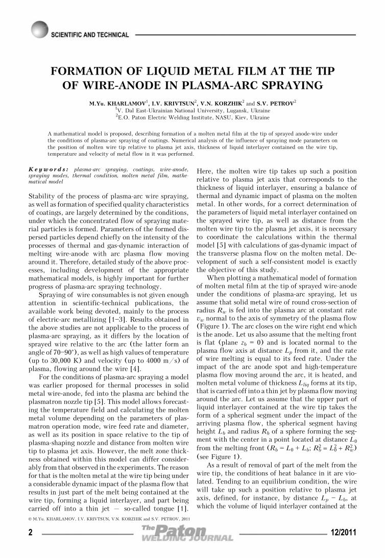
When plotting a mathematical model of formationof molten metal film at the tip of sprayed wire-anodeunder the conditions of plasma-arc spraying, let usassume that solid metal wire of round cross-section ofradius Rw is fed into the plasma arc at constant ratevw normal to the axis of symmetry of the plasma flow(Figure 1). The arc closes on the wire right end whichis the anode. Let us also assume that the melting frontis flat (plane zb = 0) and is located normal to theplasma flow axis at distance Lp from it, and the rateof wire melting is equal to its feed rate. Under theimpact of the arc anode spot and high-temperatureplasma flow moving around the arc, it is heated, andmolten metal volume of thickness Lliq forms at its tip,that is carried off into a thin jet by plasma flow movingaround the arc. Let us assume that the upper part ofliquid interlayer contained at the wire tip takes theform of a spherical segment under the impact of thearriving plasma flow, the spherical segment havingheight Lb and radius Rb of a sphere forming the seg-ment with the center in a point located at distance L0
from the melting front (Rb = L0 + Lb; Rb2 = L0
2 + Rw2 )
(see Figure 1).As a result of removal of part of the melt from the
wire tip, the conditions of heat balance in it are vio-lated. Tending to an equilibrium condition, the wirewill take up such a position relative to plasma jetaxis, defined, for instance, by distance Lp — Lb, atwhich the volume of liquid interlayer contained at the
© M.Yu. KHARLAMOV, I.V. KRIVTSUN, V.N. KORZHIK and S.V. PETROV, 2011
2 12/2011

wire tip Vb will correspond to the volume of wire moltenmetal Vliq = πRw
2 Lliq, i.e. condition Vb = Vliq will befulfilled. A problem is posed to determine wire position,at which the above condition is satisfied at specifiedparameters of the spraying mode, and the volume ofliquid interlayer contained at the wire tip, temperature,as well as molten metal flow, are calculated.
Let us move over to construction of the model ofliquid interlayer formation at the wire tip. ThicknessLliq and volume Vliq of molten metal layer, respec-tively, depending on the distance from molten wiretip to plasma jet axis Lp — Lliq at other assigned spray-ing mode parameters being equal can be determinedfrom the model of wire thermal condition [5].
To assess the thickness of liquid interlayer con-tained on the wire tip, let us consider the interactionof two flows – viscous outflow of incompressibleliquid (molten metal) along the boundary of wiremelting and turbulent flow of arc plasma along thesurface of liquid metal boundary with the mediumintephase at z0 = Lb (see Figure 1). Let us assumethat the main force, acting on the melt from the sideof the plasma flow, is the viscous force. Consideringthat the melt flow occurs in the following plasmaflow, viscous forces on the medium interphase prevail,so that such an approximation can be regarded as quitejustified.
A boundary layer [6] forms in the plasma flow inthe immediate vicinity of the liquid metal boundary,which is characterized by an abrupt change of themain parameters of the flow in the transverse direc-tion. In particular, plasma velocity changes from itsvalue in the outer flow to the value of the velocity offlowing of liquid wire material on the medium inter-phase (satisfying the «sticking» condition is as-sumed).
In view of the turbulent nature of plasma flow [4],several subregions can be singled out in the consideredboundary layer [7]. The outer layer is a region of fullydeveloped turbulent flow, its properties being depend-ent on the flow prehistory. The inner region of theturbulent boundary layer in the general case consistsof a viscous underlayer, transition region and regionof logarithmic profile of velocity. Universal nature ofvelocity distribution corresponds to flowing in theinner region, that is the basis for plotting special near-wall functions, connecting the flow parameters withthe distance from medium interphase [6, 7].
Considering the smallness of liquid interlayerthickness, flowing of liquid metal in it can be consid-ered to be practically laminar, and a linear dependenceof tangential component of velocity can be assumedhere [6, 7]:
vliq(zb) = zb
Lb vm, (1)
where vm is the melt flow velocity on the mediuminterphase (at zb = Lb). Value vm can be connected
with parameters of plasma flow moving around thearc, proceeding from the assumption that tangentialstresses in the plasma and melt on the medium inter-phase are equal:
ηliq ∂vliq
∂zb
⎪⎪Lb
= ηp ∂vp
∂zb
⎪⎪Lb
, (2)
where ηp, ηliq are the coefficients of dynamic viscosityof plasma and molten metal of the wire, respectively;vp(zp) is the distribution of tangential (relative tomelt surface) plasma velocity along axis zb. To findvp(zp) we will apply the logarithmic near-wall func-tion, which is often used at description of flow pa-rameters in near-wall regions [7, 8]. For the flowingaround conditions considered by us, this function canbe written as follows:
v+ = 1
Kar ln (Ey+). (3)
Here v+ = v__
p/v∗ is the dimensionless tangential ve-locity of plasma; v
__p(zb) = vp(zb) — vm is the velocity of
plasma flow relative to the melt flow velocity; v* isthe dynamic velocity determined as
v∗ = √⎯⎯⎯⎯⎯τp/ρp , (4)
where τp = ⎛⎜⎝ηp
∂u
∂r
⎞⎟⎠Lb
is the friction stress in the plasma
on the flowing surface; ρp is the plasma density; Kar ≈≈ 0.41 is Karman constant; E is the constant deter-mining the degree of wall roughness (for smooth wallE = 8.8 [7]); y+ is the dimensionless distance from
the interface, determined as y+ = ρp(zb — Lb)
ηp v∗.
Figure 1. Schematic of liquid interlayer formation at the tip ofcurrent-carrying wire in plasma-arc spraying: 1 – current-carryingwire; 2 – fusion boundary; 3 – molten metal jet («tongue»);4 – sprayed particles; 5 – plasma flow
12/2011 3

We will assume that the transition from the meltflowing velocity («sticking» condition) to the velocityof undisturbed plasma flow, which can be determined,for instance, by model [4], occurs in region 0 ≤ y+ << 400 [8]. Then, based on expression (3) tangentialstress in the plasma can be presented as follows:
τp(vm) = v__
ext2 (vm)
⎛⎜⎝
1Kar
ln (Ey+)⎞⎟⎠
2 ρp =
v__
ext2 (vm)ρp
396.71, (5)
where v__
ext(vm) = vext — vm is the flowing velocity of un-disturbed plasma flow near the wire tip vext relative tothe melt flowing velocity vm.
As a result, in order to determine the thickness ofliquid interlayer Lb, it is necessary to consider thebalance of the weight of molten wire material. Con-sidering the made assumption that the molten metalin the upper part of the wire tip takes the shape of asegment of a sphere, consumption of liquid wire ma-terial passing through axis zb normal to the axis ofthe plasma jet can be determined as
G2 = 2ρw ∫ 0
Lb
vliq(zb) ∫ 0
y(zb)
dydzb, (6)
where y(zb) = √⎯⎯⎯⎯⎯⎯⎯⎯⎯⎯⎯⎯⎯⎯⎯⎯⎯⎯⎯⎯⎯⎯⎯⎯⎯⎯Rw2 — 2((Rw
2 — Lb2)/(2Lb))zb — zb
2 is thecurve of crossing of the segment of a sphere with theabove plane; ρw is the density of the metal wire. Inits turn, proceeding from the conditions of the con-stancy of the velocities of wire feed and melting, quan-tity of wire material, melting in a unit of time, and,therefore, crossing section zb = 0, is given by the ex-pression
G1 = ρwvwSw, (7)
where Sw = πRw2 is the wire cross-sectional area.
Then considering that half of the molten wire ma-terial comes to the considered half of the segment ofa sphere, we will come to the following relationship:
G1/2 = G2. (8)
Substituting expressions (6) and (7) into (8), andconsidering assumption (1), we obtain the dependenceof maximum melt flowing velocity on its interlayerthickness at the wire tip:
vm(Lb) = Sw
4
vwLb
∫ 0
Lb
zb ∫ 0
y(zb)
dydzb
. (9)
Now condition (8) can be rewritten as follows:
vwSw
2 = 2
τp(vm(Lb))ηliq
∫ 0
Lb
zb ∫ 0
y(zb)
dydz b, (10)
whence thickness Lb of liquid interlayer on the wiretip can now be determined. Equation (10) closed byrelationships (5) and (9) can be solved by one of thenumerical methods of solution of nonlinear equations[9]. This can be done using the simplest method ofdichotomy or, considering that the antiderivative ofthe integrand in (5) and (9) is expressed analytically,Newton iteration method can be applied.
Using the model of thermal processes in the wire[5] for determination of the volume of its molten partVliq, as well as expression (10), on the basis of whichthe volume of liquid interlayer contained at the wiretip is found:
Vb = π ∫ 0
Lb
[y(zb)]2dzb, (11)
it is possible to determine what position of the moltenwire tip relative to plasma jet axis is set at the specifiedspraying mode. For this purpose, fixing the mode pa-rameters and varying just value Lb, based on model[5] we obtain dependence Vliq = Vliq(Lp — Lliq), andbased on expressions (10), (11) – dependence Vb == Vb(Lb), and find such a position of the wire atwhich their equality is achieved. This condition, es-sentially, is the connecting link between the modelsof thermal [5] and gas-dynamic interaction of wirewith plasma flow moving laterally around it, and itallows determination of the distance, to which themolten wire tip is removed from the plasma flow axis,depending on the values of spraying mode parameters.In its turn, this value is the basis, which can be usedto determine using expressions (1), (9), (11) andmodel [5], the characteristics of the liquid metal con-tained at the wire tip, including its flowing velocityand temperature. The above characteristics will havea direct influence on the dimensions and temperatureof drops separating from the wire tip, and will deter-mine the point of their entering the plasma flow.
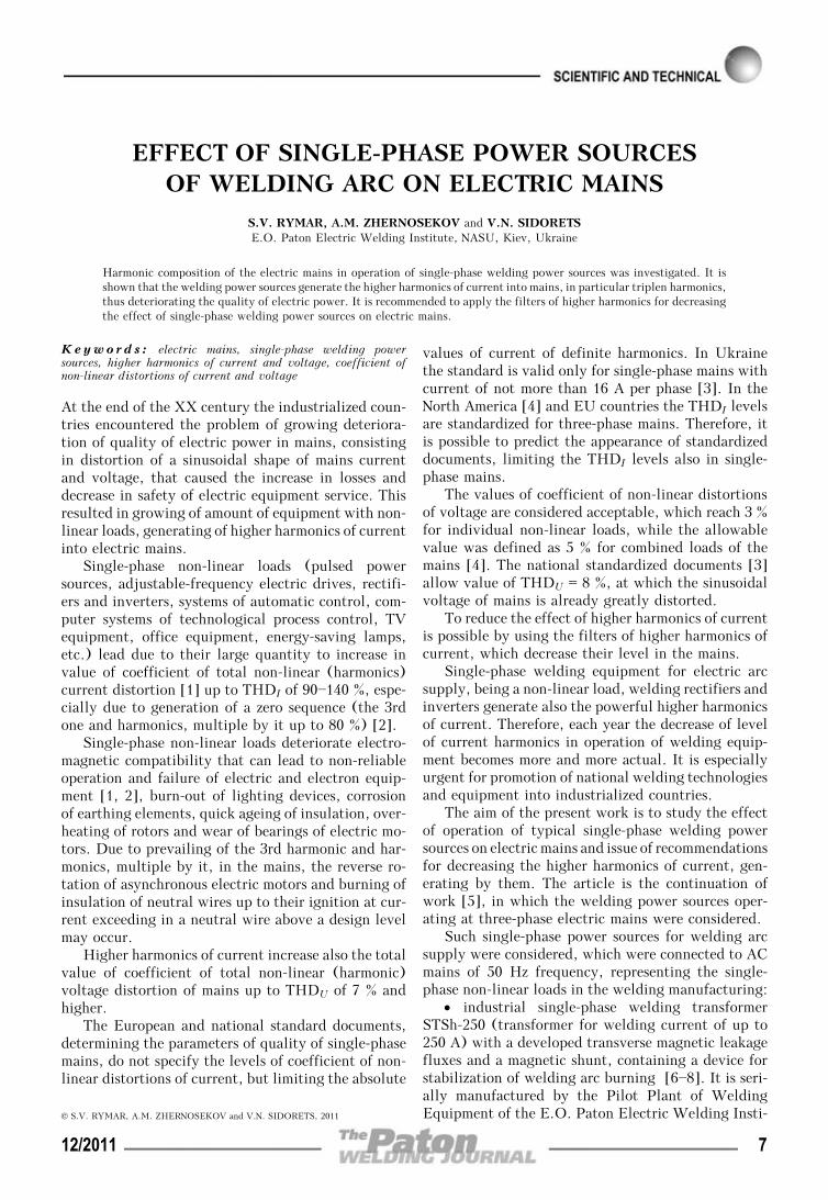
Let us conduct numerical analysis of the influenceof spraying mode parameters on the characteristics ofliquid interlayer, contained at the tip of sprayed wire-anode, as well as spatial position of the latter. Cal-culations were performed for the conditions of plasma-arc spraying of steel wire, the thermo-physical char-acteristics of which are taken from [10]. The followingparameters of the spraying mode were selected [4]:arc current I = 160—240 A, plasma gas (argon) flowrate GAr = 1.0—1.5 m3/h, wire feed rate 6—15 m/min,wire diameter 1.2—1.6 mm. It was assumed that theanode-wire is located at 6.3 mm distance from theplasmatron nozzle tip, normal to the axis of the plasmaflow. Distributions of velocity and temperature ofundisturbed plasma flow along the wire-anode forvarious modes of plasmatron operation were calculatedin advance based on model [4] and are given in Fi-gure 2.
4 12/2011

As is seen from Figure 2, values of plasma velocityand temperature change quite abruptly in the trans-verse direction relative to plasma jet axis. Therefore,the conditions of viscous and thermal interaction ofthe plasma flow with wire essentially depend on theposition of the molten wire tip relative to the plasmaflow axis. The closer to the jet axis, the larger is thethermal flow into the wire, and the more increasedare the viscous forces acting on the melt surface, car-rying the liquid metal off the wire tip. Therefore, itshould be noted that in spraying modes, at which heatpropagation in the wire is difficult, its molten tip islocated closer to the plasma jet axis. For instance, atincrease of the feed rate the region of wire heatingand melting become smaller, and the wire comes tothe plasma jet axis until the molten metal volume canbe contained at its tip. The same situation should beobserved also when larger diameter wire is used.
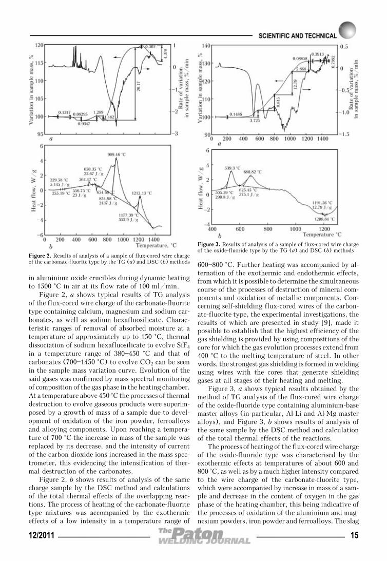
Influence of plasmatron operation mode on theposition of the molten wire tip relative to plasma jetaxis, as well as thickness of the liquid interlayer con-tained at the wire tip, can be illustrated in Figure 3.For all the considered modes, the molten wire tip islocated at distance 0.1—1.4 mm from the jet axis atinterlayer thickness of 0.10—0.15 mm. Increase of arccurrent leads to increase of plasma velocity and tem-perature (see Figure 2), convective-conductive andradiation-thermal flows into the wire increasing, aswell as the intensity of viscous force acting on liquidmetal at the wire tip. As a result, the increased meltvolume cannot be contained at the wire tip, and partof it is carried off by the plasma flow, and the wiretip will take a new equilibrium position, farther fromthe plasma flow axis. At increase of the plasma gasflow rate, the flow velocity rises, temperature profile,however, being more compressed towards the jet axis(see Figure 2, curves 2 and 4). Here, wire meltingoccurs at wire tip location in near-axis regions of theplasma jet, and increase of the intensity of dynamicinteraction of the plasma flow will lead to reductionof the volume of liquid interlayer, contained at thewire tip, and, therefore, also its thickness (see Fi-gure 3).
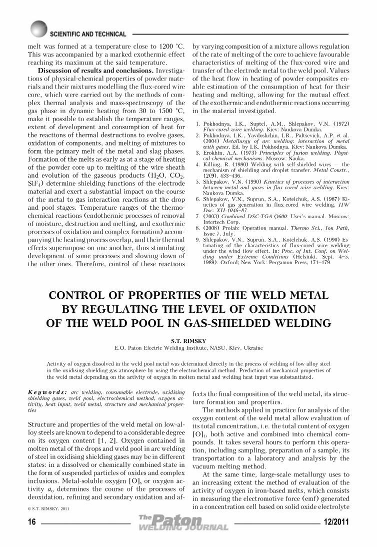
Molten material of the wire is entrained by theplasma flow, forming a liquid metal jet, which atfurther flowing separates into individual drops – dis-persed particles of the spraying material – under theimpact of external and inner disturbing factors. Here,transverse dimensions of the liquid interlayer and meltflowing velocity determine the characteristics of theabove jet flowing, and, therefore, also the conditionsof drop formation. In its turn, the melt flowing ve-locity is connected to the quantity of wire materialmolten in a unit of time, as well as the set thickness
Figure 2. Distribution of axial component of velocity (a) and temperature (b) of arc plasma along anode-wire: 1 – I = 160; 2 – 200;3 – 240 A at GAr = 1.0 m3/h; 4 – GAr = 1.5 m3/h at I = 200 A
Figure 3. Influence of wire feed rate on distance from wire meltingplane Lp (1—6) and distance from molten wire tip Lp — Lb (1′—6′)to plasma jet axis at different parameters of the spraying mode:2Rw = 1.2 (1; 1′), 1.4 (2; 2′), 1.6 (3; 3′) mm at I = 200 A, GAr == 1.0 m3/h; I = 160 (4; 4′), 240 (5; 5′) А at 2Rw = 1.4 mm, GAr == 1.0 m3/h; GAr = 1.5 m3/h (6; 6′) at 2Rw = 1.4 mm, I = 200 А
12/2011 5

of the liquid interlayer, that is illustrated, for in-stance, by dependencies in Figure 4.
Liquid interlayer parameters at plasma-arc spray-ing are given in the Table. As is seen, for most of themodes, overheating of liquid metal above the meltingtemperature does not exceed 20 K, as the molten ma-terial does not have enough time for any significantoverheating and is immediately carried off by the flowfrom the wire tip. Metal overheating in the liquidinterlayer by 200—250 K above the melting point is,as a rule, characteristic for melting modes with lowwire feed rates, at which the heat conductivity mecha-nism has a significant role in heat propagation in thewire.
CONCLUSIONS
1. Mathematical model of thermal condition of wire-anode at plasma-arc spraying of coatings was improvedby allowing for gas-dynamic impact on the wire ofplasma flow moving around it. Such a self-consistentmodel allows determination of wire position relative
to plasmatron axis, as well as characteristics of liquidinterlayer contained at the wire tip, including itsthickness and melt flowing velocity, depending on thespraying mode parameters.
2. Distance, to which the molten wire tip is re-moved from the plasma flow axis, is determined bythe condition of equality of the wire molten part tothe volume of liquid metal interlayer that can be con-tained at the wire tip at plasma flow moving laterallyaround it, and is equal to 0.1—1.4 mm under the con-sidered conditions at interlayer thickness of 0.10—0.15 mm, depending on the spraying mode parameters.
3. At plasma-arc spraying of coatings metal tem-perature at the molten wire tip reaches 1780—2100 K,here for most of the spraying modes liquid metal over-heating above melting temperature (1773 K) is insig-nificant, and is not higher than 20 K, as the formingmelt is carried by the plasma flow out of the interactionzone, and the total heat content of the wire is notdecreased.
1. Korobov, Yu.S. (2004) Estimation of forces affecting thespray metal in electric arc metallizing. The Paton WeldingJ., 7, 21—25.
2. Korobov, Yu.S., Boronenkov, V.N. (2003) Kinetics of inter-action of sprayed metal with oxygen in electric arc metalliz-ing. Svarochn. Proizvodstvo, 7, 30—36.
3. Vakhalin, V.A., Maslenkov, S.B., Kudinov, V.V. et al.(1981) Process of melting and spraying of electrode materialin electric arc metallizing. Fizika i Khimiya Obrab. Materi-alov, 3, 58—63.
4. Kharlamov, M.Yu., Krivtsun, I.V., Korzhik, V.N. et al.(2007) Mathematical model of arc plasma generated by plas-matron with anode wire. The Paton Welding J., 12, 9—14.
5. Kharlamov, M.Yu., Krivtsun, I.V., Korzhik, V.N. et al.(2011) Heating and melting of anode wire in plasma arcspraying. Ibid., 5, 2—7.
6. Lojtsyansky, L.G. (1973) Mechanics of fluid and gas. Mos-cow: Nauka.
7. Volkov, K.N. (2006) Boundary conditions on the wall andmesh dependence of the solution in turbulent flow calcula-tion on unstructured meshes. Vychislit. Metody i Program-mirovanie, 7(1), 211—223.
8. Wilcox, D.C. (1994) Turbulence modeling for CFD. LaCanada: DCW Industries.
9. Kalitkin, N.N. (1978) Numerical methods: Manual. Mos-cow: Nauka.
10. Hu, J., Tsai, H.L. (2007) Heat and mass transfer in gasmetal arc welding. Pt 2: The metal. Int. J. Heat and MassTransfer, 50, 808—820.
Figure 4. Dependence of melt flow rate in liquid interlayer at thewire tip on its feed rate at different diameters of wire-anode andplasmatron operation modes: 2Rw = 1.2 (1), 1.4 (2), 1.6 (3) mmat I = 200 А, GAr = 1.0 m3/h; I = 160 (4), 240 (5) А at 2Rw == 1.4 mm, GAr = 1.0 m3/h; GAr = 1.5 m3/h (6) at 2Rw = 1.4 mm,I = 200 А
Parameters of liquid interlayer contained at the tip of sprayed wire-anode at plasma-arc spraying of coatings
I, А GAr, m3/h 2Rw, mm vw, m/min Lp — Lb, mm Lb, mm vm, m/s T, K
200 1.0 1.4 5 1.054 0.113 1.81 2070
6 0.893 0.117 2.05 1931
7 0.798 0.127 2.42 1774
9 0.686 0.129 2.64 1773
12 0.550 0.133 3.07 1774
15 0.428 0.141 3.61 1774
1.2 9 0.811 0.125 2.10 1775
1.6 9 0.604 0.131 2.68 1774
160 1.0 1.4 9 0.526 0.140 2.18 1776
240 1.0 1.4 9 0.829 0.118 2.61 1773
200 1.5 1.4 9 0.684 0.109 2.83 1774
6 12/2011
EFFECT OF SINGLE-PHASE POWER SOURCESOF WELDING ARC ON ELECTRIC MAINS
S.V. RYMAR, A.M. ZHERNOSEKOV and V.N. SIDORETSE.O. Paton Electric Welding Institute, NASU, Kiev, Ukraine
Harmonic composition of the electric mains in operation of single-phase welding power sources was investigated. It isshown that the welding power sources generate the higher harmonics of current into mains, in particular triplen harmonics,thus deteriorating the quality of electric power. It is recommended to apply the filters of higher harmonics for decreasingthe effect of single-phase welding power sources on electric mains.
Keywo rd s : electric mains, single-phase welding powersources, higher harmonics of current and voltage, coefficient ofnon-linear distortions of current and voltage
At the end of the XX century the industrialized coun-tries encountered the problem of growing deteriora-tion of quality of electric power in mains, consistingin distortion of a sinusoidal shape of mains currentand voltage, that caused the increase in losses anddecrease in safety of electric equipment service. Thisresulted in growing of amount of equipment with non-linear loads, generating of higher harmonics of currentinto electric mains.
Single-phase non-linear loads (pulsed powersources, adjustable-frequency electric drives, rectifi-ers and inverters, systems of automatic control, com-puter systems of technological process control, TVequipment, office equipment, energy-saving lamps,etc.) lead due to their large quantity to increase invalue of coefficient of total non-linear (harmonics)current distortion [1] up to THDI of 90—140 %, espe-cially due to generation of a zero sequence (the 3rdone and harmonics, multiple by it up to 80 %) [2].
Single-phase non-linear loads deteriorate electro-magnetic compatibility that can lead to non-reliableoperation and failure of electric and electron equip-ment [1, 2], burn-out of lighting devices, corrosionof earthing elements, quick ageing of insulation, over-heating of rotors and wear of bearings of electric mo-tors. Due to prevailing of the 3rd harmonic and har-monics, multiple by it, in the mains, the reverse ro-tation of asynchronous electric motors and burning ofinsulation of neutral wires up to their ignition at cur-rent exceeding in a neutral wire above a design levelmay occur.
Higher harmonics of current increase also the totalvalue of coefficient of total non-linear (harmonic)voltage distortion of mains up to THDU of 7 % andhigher.
The European and national standard documents,determining the parameters of quality of single-phasemains, do not specify the levels of coefficient of non-linear distortions of current, but limiting the absolute
values of current of definite harmonics. In Ukrainethe standard is valid only for single-phase mains withcurrent of not more than 16 A per phase [3]. In theNorth America [4] and EU countries the THDI levelsare standardized for three-phase mains. Therefore, itis possible to predict the appearance of standardizeddocuments, limiting the THDI levels also in single-phase mains.
The values of coefficient of non-linear distortionsof voltage are considered acceptable, which reach 3 %for individual non-linear loads, while the allowablevalue was defined as 5 % for combined loads of themains [4]. The national standardized documents [3]allow value of THDU = 8 %, at which the sinusoidalvoltage of mains is already greatly distorted.
To reduce the effect of higher harmonics of currentis possible by using the filters of higher harmonics ofcurrent, which decrease their level in the mains.
Single-phase welding equipment for electric arcsupply, being a non-linear load, welding rectifiers andinverters generate also the powerful higher harmonicsof current. Therefore, each year the decrease of levelof current harmonics in operation of welding equip-ment becomes more and more actual. It is especiallyurgent for promotion of national welding technologiesand equipment into industrialized countries.
The aim of the present work is to study the effectof operation of typical single-phase welding powersources on electric mains and issue of recommendationsfor decreasing the higher harmonics of current, gen-erating by them. The article is the continuation ofwork [5], in which the welding power sources oper-ating at three-phase electric mains were considered.
Such single-phase power sources for welding arcsupply were considered, which were connected to ACmains of 50 Hz frequency, representing the single-phase non-linear loads in the welding manufacturing:
• industrial single-phase welding transformerSTSh-250 (transformer for welding current of up to250 A) with a developed transverse magnetic leakagefluxes and a magnetic shunt, containing a device forstabilization of welding arc burning [6—8]. It is seri-ally manufactured by the Pilot Plant of WeldingEquipment of the E.O. Paton Electric Welding Insti-© S.V. RYMAR, A.M. ZHERNOSEKOV and V.N. SIDORETS, 2011
12/2011 7

tute and designed for manual arc welding with ACstick electrodes. The presence of device for stabiliza-tion of welding arc burning allows also realizing weld-ing with DC electrodes;
• single-phase welding power source VDU-125with a capacitor voltage multiplier (universal arc rec-tifier for welding current of up to 125 A). It consistsof a welding transformer with developed yoke mag-netic leakage fluxes and capacitor voltage multiplierwith a bridge diode circuit of rectification [9, 10].The voltage multiplier provides the improved initialignition of welding arc, ignition in transition of cur-rent through zero and stability of its burning. It wasdesigned and manufactured at the E.O. Paton ElectricWelding Institute and also at the Institute of Elec-trodynamics of the NASU in small batches. The powersource has a discrete adjustment of welding currentand designed for manual arc welding with AC stickelectrodes;
• single-phase welding power source VDU-201with a capacitor voltage multiplier and thyristor ad-justment of welding current (for welding current ofup to 200 A). It consists of a welding transformerwith yoke magnetic leakage fluxes with a bridgethyristor circuit of rectification, parallel-connectedauxiliary diode bridge rectifier and phase-shifting re-actor to provide the continuous welding current inoperation of thyristors. It was designed at the E.O.Paton Electric Welding Institute and manufacturedby the Lithuanian enterprise «Relema» (Vilnius) anddesigned for manual arc welding with AC and DCstick electrodes;
• industrial single-phase thyristor inverter powersource VDI-200, manufactured by the Pilot Plant ofWelding Equipment of the E.O. Paton Electric Weld-ing Institute and designed for manual arc welding oflow-carbon and alloyed steels with AC and DC stickelectrodes.
As a measuring unit, an analyzer of quality ofelectric mains (single phase) Chauvin Arnoux C.A.8230 (France) was used, allowing obtaining time de-pendencies of current and voltage with their typicalvalues (maximum and minimum; full, active and re-active power, etc.), as well as spectra of harmonicsup to maximum number of harmonic hmax = 50.
Let us consider the operation with mains of weldingtransformer STSh-250, containing a device for stabi-lization of welding arc burning.
Figure 1, a shows dependencies of relative instan-taneous values of current i* and voltage u* in mainson time t in operation of welding transformer, ob-tained in welding of stainless steel 12Kh18N10T withstick electrode OZL-8 of 3 mm diameter at 90 A weld-ing current. Values i* and u* refer to their highestamplitude values: i* = i/|Im| and u* = u/|Um|, whereIm = 80.8 A, Um = —313.2 V, selected from technicalcharacteristic, where highest «+» and lowest «—» are
the amplitude values of voltage and current for periodsIm+, Im—, Um+, Um—, obtained during experiment.
Shape of curves of current and voltage is negligiblydiffered from sinusoidal one. The superposition of ashort-time pulse, corresponding to a stabilizer pulse,and also a small bend of current curve during transi-tion through zero were noted.
Figure 1, b shows diagram of harmonic componentsh of current Ih% and voltage Uh% from effective valueof current and voltage of the 1st main harmonic, takenas 100 %: Ih% = Ih%/I1⋅100 %, Uh% = Uh%/U1⋅100 %.Values of numbers of harmonics are limited by number27 for improving the diagram visualization.
It is seen from diagram that during the weldingtransformer operation the 3rd harmonic of current,equal to 15.3 % of the 1st one, and the 5th, being2.3 %, are clearly seen in mains, while the rest unevenharmonics of current do not exceed 1 %. Uneven num-bers of harmonics of voltage, reaching more than 1 %of the 1st harmonic, have the following values: the3rd – 2.5, the 5th – 1.3, the 9th – 1 %. There isalso a constant component of current of 10.9 % andeven harmonics of current (the 2nd – 2.8, the 4th –2.4 %). The constant component and even harmonicsof voltage are negligibly expressed.
Coefficients of non-linear distortions of currentand voltage of transformer STSh-250 [1] are THDI == 15.9 and THDU = 3.1 %.
K-factor, determining how much the incrementallosses in electric equipment and conductors of electricmains are increased as compared with the fact if onlythe 1st main harmonic of current was passing in equip-ment and mains, is equal to 1.38.
Incremental losses are caused by eddy currents,passing in current-carrying parts and conductors ofelectric mains. The eddy currents themselves are dueto magnetic leakage fluxes, passing through the cur-rent-carrying parts and conductors.
Thus, the incremental losses in mains and equip-ment during operation of welding transformer beingconsidered at the given type of its load are increasedby 1.38 times. The Table gives the main parametersof operation of the welding transformer at the typeof load being considered.
When varying the welding conditions, these valuescan vary within the range of 13—24 %, and the coef-ficient THDU – within 2.5—3.5 %. These results con-firm the theoretical analysis of harmonic compositionof alternating current of arc [11], which is suppliedfrom the welding transformer.
The welding transformer STSh-250 generates notvery high harmonic components of current into supplymains, though they can show negative effect on op-eration of equipment connected to the mains. Valueof THDU is also not high. The shown characteristicsare also typical to other types of single-phase weldingtransformers.
8 12/2011

Figure 2, a shows time dependencies of relativevalues of current and voltage in mains during opera-tion of welding power source VDU-125. Charac-teristics were recorded during welding with 3 mmdiameter stick electrodes ANO-22 at 120 A weldingcurrent. The highest amplitude values of current andvoltage during experiment were the following: Im == —33.3 A, Um = 304.5 V. After current transitionthrough zero a low disturbance is superposed onsinusoidal current, caused by operation of voltage mul-tiplier. The shape of voltage is very close to sinusoidal.
Figure 2, b shows diagram of harmonic componentsof effective value of current and voltage. It is seenfrom this diagram that during operation of powersource the 3rd harmonic of current, equal to 15.6 %of the 1st harmonic, and the 5th, equal to 4.6 %, arewell expressed in supply mains. The rest uneven har-monics of current do not exceed 1 %. The unevennumbers of harmonics of voltage, having more than1 % of the 1st harmonic, have the following values:the 3rd – 1.6, the 5th – 1.1 %. The constant com-ponent of current is equal to 3.7 %. Even harmonicsof current are as follows: the 2nd – 4.0, the 4th –1.1 %. The constant component and even harmonicsof voltage are negligibly expressed.
The coefficients are equal to THDI = 16.9, THDU == 2.2 %. K-factor reaches 1.31.
Welding power source VDU-125 has acceptablevalues of THDI and THDU. Incremental losses in
mains and equipment during operation of power sourceat the mentioned type of load are 1.3 times increased.
When varying the welding conditions, the valuesgiven in the Table, are changed, here THDI will be8.7—20.8, THDU – 2.2—2.8 %.
These characteristics are typical of all types ofwelding power sources with a capacitor multiplier ofvoltage, different of types of welding transformers,manufactured as VDU-140, VDU-160 and VDU-180and designed at the E.O. Paton Electric Welding In-stitute.
Figure 3, a shows time dependencies of relativevalues of current and voltage in supply mains duringoperation of welding power source VDU-201. Thehighest amplitude values of current and voltage areas follows: Im = 61.2 A, Um = —315.1 V. Experimentswere performed in welding with 3 mm diameter stickelectrode ANO-22 at 90 A welding current. A currentpulse of high amplitude at commutation of thyristorswas superposed on a basic sinusoidal current of lowamplitude, which was provided by a phase-shiftingreactor. Sinusoid of voltage had only a negligible dis-tortion just after maximum value.
Figure 3, b shows harmonic composition of currentand voltage at the input of welding power source. In
Figure 1. Dependence of current and voltage on time in supplymains of industrial single-phase welding transformer STSh-250 withdevice for stabilization of welding arc burning (a), and harmoniccomposition of mains current and voltage (b)
Main parameters of mains in operation of welding arc powersources
Parameter STSh-250 VDU-125 VDU-201 VDU-200
Im+, А 80.8 30.2 61.2 59.5
Um+, V 310.6 304.5 312.2 312.9
Im—, А —74.3 —33.3 —54.7 —59.6
Um—, V —313.2 —304.3 —315.1 —313.1
I, А 41.0 23.8 26.1 36.8
U, V 221.0 210.6 220.1 221.5
S, V⋅А 9895.9 5008.3 5202.2 8282.5
P, W 2787.2 3701.6 2543.6 6130.1
Q, var 9495.2 3373.6 4537.9 5569.6
kP 0.282 0.739 0.489 0.740
cos ϕ 0.280 0.764 0.530 0.980
tg ϕ 3.376 0.816 1.573 —0.129
THDI, % 15.983 16.879 41.165 86.366
THDU, % 3.110 2.256 3.624 5.957
K 1.383 1.309 3.233 7.259
Notes. 1. Here I, U – effective values of current and voltage; S,P, Q – full, active and reactive (can include distortion power inthe presence of harmonics) powers; kP – coefficient of power,equal to ratio of active and full power P/S; cos ϕ – coefficient ofphase shifting between current and voltage. 2. Formulae forcalculation of parameters are given in work [5].
12/2011 9

the power source mains the 3rd harmonic of current,equal to 37.7 % of the 1st harmonic, the 5th – 6.8,the 7th – 6.1, the 9th – 2.5, the 11th – 1.1, the13th – 1.0 and 19th – 1.1 % are expressed, the restuneven harmonics of current did not exceed 1 %. Un-even numbers of harmonics of voltage of more than1 % of the 1st harmonic had the following values: the3rd – 2.5, the 5th – 1.6 and the 13th – 1.4 %.Expressed are the constant component of current(6.8 %) and its even harmonics (the 2nd – 4.5, the4th – 7.7, the 6th – 7.9, the 8th – 5.0 and the10th – 2.4 %). The constant component and evenharmonics of voltage are negligibly expressed.
The coefficients of non-linear distortions of currentand voltage of power source VDU-201 have the fol-lowing values: THDI = 41.2, THDU = 3.6 %, K = 3.2.In this power source the value of coefficient THDI ishigh. In addition, high harmonic components of cur-rent, which are also important, generate into mains.
Incremental losses in mains and equipment duringthe operation of power source at the mentioned typeof load are increased by more than 3 times.
The Table shows main parameters of power sourceoperation at the given type of load. In case of varyingthe welding condition these values are changed, here
the coefficient THDI will be 9.5—46.5 %, and thecoefficient THDU – 1.8—3.9 %.
Figure 4, a shows time dependencies of relativevalues of current and voltage in mains during opera-tion of welding inverter VDI-200. The highest ampli-tude values of current and voltage in experiment wereequal to Im = —59.6 A, Um = —313.1 V.
Figure 4, b shows harmonic composition of currentin mains line and linear voltage at the input of weldingpower source during welding of low-alloy steel St3with 5 mm diameter electrodes UONI-13/55 at 200 Awelding current.
In mains of power source almost all uneven har-monics of current are expressed, in particular the 3rdcurrent harmonic, equal to 75.1 % of the 1st harmonic,the 5th – 39.5, the 7th – 10.5, the 9th – 8.3, the11th – 7.4, the 13th – 1.2, the 15th – 3.1, the17th – 2.4, the 21st – 1.9, the 27th – 1.1 %. Theuneven numbers of harmonics of voltage of more than1 % of the 1st harmonic have the following values:the 3rd – 5.2, the 5th – 2.2, the 7th – 1.4 %. Theconstant component of current and voltage is absent.Even harmonics of current are negligibly expressed.
The coefficients of non-linear distortions of currentand voltage of power source VDI-200 are as follows:THDI = 86.4 %, THDU = 5.9 %, K = 7.2.
Figure 2. Dependence of current and voltage on time in supplymains of single-phase welding power source VDU-125 with capaci-tor multiplier of voltage (a), and harmonic composition of mainscurrent and voltage (b)
Figure 3. Dependence of current and voltage on time in supplymains of single-phase welding power source VDU-201 with capaci-tor multiplier of voltage (a), and harmonic composition of mainscurrent and voltage (b)
10 12/2011

The curve of current represents the clearly ex-pressed pulse on the background of almost zero valuesat the rest extension of a semi-period, the value ofcoefficient THDI is rather high for power source VDI-200. Moreover, very wide spectrum of harmonic com-ponents of current generates into mains. The curve ofvoltage, though being like a sinusoid, has cuts in theregion of extremums, therefore, the amplitudes of har-monic components of voltage are also high. This shapeof curve of voltage can lead to false operation of de-vices of continuous supply, connected to the samemains, which are connected in case of lowering theamplitude value of mains voltage.
Incremental losses in mains and equipment duringoperation of power sources at the given type of loadare increased by more than 7 times. The Table showsmain parameters of operation of power source VDI-200at the given type of load. Negative value tg ϕ provesthat inverter power source is an active-capacitive loadfor the mains.
When varying the welding condition these valuesare changed, here the coefficient THDI = 82.0—121.5 %, and the coefficient THDU = 2.8—6.7 %.
By analyzing the given data, it is possible to makea conclusion that to improve the quality of electricpower and to reduce the level of higher harmonics ofcurrent and voltage, generated by welding equipment,it is rational in a number of cases to apply filters ofhigher harmonics of current. Here, the welding powersources, except providing the required technologicalcharacteristics, will have a good electromagnetic com-patibility, and also reduce the incremental losses inmains wires and equipment connected to the mains.
It is necessary to note the positive properties oftransformer power sources of arc, which except tech-nological effectiveness, safety and low cost, have anegligible effect on the mains. Welding transformersand power sources, manufactured on their base, pro-vide the adjustment of welding current by transformeritself [12] (without electron unit of current adjust-ment). This is due to the fact that the welding trans-former has an increased leakage inductance to providea steep-falling external characteristic [12, 13], andthis promotes the decrease in higher harmonics of cur-rent. The capacitors of voltage multiplier and weldingtransformer with developed magnetic leakage fluxesform something like an inner filter of higher harmonicsof current of power source. However, the higher har-monics of current themselves (in absolute values) arerather high, therefore, the application of filters ofhigher harmonics is desirable for the single-phasewelding transformers and power sources manufacturedon their base. In this connection, the transformerpower sources of welding arc are characterized, inspite of their increased mass, by many positive prop-erties. They should be also developed and improvedin future, for example, together with capacitor mul-tipliers of voltage, which greatly decrease the mass of
transformer and consumed power in mains, or withdevices of stabilization of welding arc burning, whoseapplication gives an opportunity to use DC electrodesin welding.
Unlike the welding transformers, the power sources,comprising the electron control circuits, generate muchmore harmonics of current, it particularly concerns thewelding inverters. In spite of advantages (small mass,guarantee of preset shape of external characteristic, highvalue of cos ϕ, etc.) the welding inverters generate thewidest spectrum of harmonic components of current intomains and distort greatly the sinusoidal curve of currentand voltage, therefore, in this case the obligatory appli-cation of filters of higher harmonics of current is re-quired. The similar conclusions were made also by theChinese researchers [14].
The single-phase welding power sources for mains,unlike the three-phase ones, load significantly the neu-tral wire, not designed for high loads, with higherharmonics of current of zero sequence. Therefore, ex-cept the resonance inductive-capacitive filters ofhigher harmonics of current [15], it is necessary toapply the autotransformer filters of currents of zerosequence [16, 17], used for three-phase four-wiremains. In addition these filters are balancing themains. They can be connected in parallel with mains
Figure 4. Depence of current and voltage on time in supply mainsof single-phase transformer inverter power source VDI-200 (a), andharmonic composition of mains current and voltage (b)
12/2011 11

at the entrance into enterprise or building or severalfilters can be used along the length of the mains. Insome cases it is rational to apply devices of compen-sation of reactive power simultaneously with single-phase welding power sources, in which the decreasedvalue of power factor cos ϕ was observed. In our casethese are power sources STSh-250 and VDU-201.
Recommended filters do not almost generate thereactive power, which affects negatively the operationof mains, into the mains and are characterized by im-proved safety in operation in «non-quality» mains,thus providing the reduction of coefficient THDI downto 5—15 % in single-phase mains.
The E.O. Paton Electric Welding Institute has alarge experience in development of methods of calcu-lation of mains parameters and devices for suppressionof higher harmonics of current required for their fil-tering.
CONCLUSIONS
1. It is shown that the single-phase welding powersources generate higher harmonics of current into themains, thus deteriorating the quality of electric power.Generation of the 3rd harmonic and harmonics, mul-tiple by it, present a particular hazard.
2. Total value of coefficient THDI during operationof power sources is 8.7—121.5 %, and coefficient THDU
is equal to 2.2—6.7 %, that proves a poor electromag-netic comparability of single-phase welding supplysources.
3. It was found that the coefficient, accounting forthe increase in incremental losses from eddy currentsin equipment and mains (K-factor), was equal to 1.3—7.3, that gives no opportunity to refer adequately allthe single-phase power sources to the category of en-ergy-saving ones.
4. Rationality and in some cases the necessity weredefined for application of filters of higher harmonicsof current and filters of current of zero sequence to-gether with single-phase sources of arc supply, reduc-ing the coefficient THDI to 5—15 %. The applicationof devices for compensation of reactive power are re-quired for some power sources.
5. It was established that the single-phase trans-former power sources (welding transformers with de-veloped magnetic leakage fluxes) and welding powersources (without electron adjustment of current),
manufactured on their base, require the obligatoryapplying of filters of higher harmonics of current.
6. It is shown that the widest spectrum of higherharmonics of current is generated by single-phasewelding inverters, distorting most of all the sinusoidalshape of current and voltage of the mains, thereforethe obligatory application of filters of higher harmon-ics of current is required.
1. Paice, D.A. (1995) Power electronic converter harmonics.Multipulse methods for clean power. New York: IEEEPress.
2. Pentegov, I.V., Volkov, I.V., Levin, M. (2002) Devices ofattenuation of higher harmonics of current. In: Technicalelectrodynamics: Subject Issue on Problems of Current Elec-trical Engineering. Pt 1. Kyiv: IED.
3. DSTU IEZ 61000-3-2:2004: Electromagnetic compatibility.Pt 3-2: Norms. Norms for emission of harmonics of current(at input current force of equipment of not more than 16 Aper phase). Kyiv: Derzhspozhyvstandart Ukrainy.
4. (1992) IEEE Recommended practices and requirements forharmonic control in electrical power systems: IEEE Stand-ard 519—1992. New York: IEEE Standard Board.
5. Rymar, S.V., Zhernosekov, A.M., Sydorets, V.N. (2011) In-fluence of welding power supplies on three-phase mains. ThePaton Welding J., 10, 40—45.
6. Zaruba, I.I., Dymenko, V.V. (1992) Multioperator powersupplies for AC welding. In: Transact. on New WeldingPower Supplies. Kiev: PWI.
7. Pentegov, I.V., Dymenko, V.V., Sklifos, V.V. (1994) Wel-ding power supplies with pulse ignition of arc. Avtomatich.Svarka, 7/8, 36—39.
8. Paton, B.E., Zaruba, I.I., Dymenko, V.V. et al. (2007)Welding power supplies with pulse stabilization of arc bur-ning. Kiev: Ekotekhnologiya.
9. Pentegov, I.V., Latansky, V.P., Sklifos, V.V. (1992) Small-size power supplies with improved energy data. In: Tran-sact. on New Welding Power Supplies. Kiev: PWI.
10. Pentegov, I.V., Rymar, S.V., Latansky, V.P. (2000) Pros-pects of development of new types of transformers for manu-al arc welding. Visnyk PryazovDTU, 10, 217—223.
11. Sidorets, V.N., Kunkin, D.D., Moskovich, G.N. (2011)Harmonic analysis of alternative current of electric weldingarc. In: Technical electrodynamics: Subject Issue on PowerElectronics and Power Efficiency. Pt 1. Kyiv: IED.
12. Paton, B.E., Lebedev, V.K. (1966) Electric equipment forarc and slag welding. Moscow: Mashinostroenie.
13. (1974) Technology of fusion electric arc welding of metalsand alloys. Ed. by B.E. Paton. Moscow: Mashinostroenie.
14. Xiao, J.-G., Xing, M.-Z., Xiong, G. et al. (2009) Suppressi-on technology of electromagnetic disturbance for IGBT in-verter welder. Electric Welding Machine, 39(12), 39—42.
15. Volkov, I.V., Kurilchuk, M.N., Pentegov, I.V. et al. (2005)Improvement in quality of industrial enterprises mains usingfilters of higher harmonics of current. Visnyk PryazovDTU,2(15), 15—19.
16. Shidlovsky, A.K., Kuznetsov, V.G. (1985) Improvement inquality of energy in electric mains. Kiev: Naukova Dumka.
17. Pentegov, I.V., Volkov, I.V., Rymar, S.V. et al. Three-phase filter of harmonics of current of zero sequence ofautotransformer type. Pat. 88912 C2 Ukraine. Int. Cl.H01F27/24. Publ. 10.12.2009.
12 12/2011

INVESTIGATION OF THERMOCHEMICALCHARACTERISTICS OF MIXTURES
OF DISPERSED MATERIALSBY DIFFERENTIAL THERMAL ANALYSIS METHODS*
V.N. SHLEPAKOV and A.S. KOTELCHUKE.O. Paton Electric Welding Institute, NASU, Kiev, Ukraine
It is shown that formation of melts as early as at a stage of heating of the powder core up to melting of the sheath of aflux-cored wire and evolution of the gaseous products (H2O, CO2, SiF4) determine shielding functions of an electrodematerial and exert a substantial effect on the course of metal to gas interaction reactions at the drop and pool stages.Temperature ranges of thermochemical reactions accompanying the heating process overlap, and their thermal effectssuperimpose on one another, thus stimulating development of some processes and slowing down the other ones. Controlof these reactions by varying composition of a mixture allows regulation of the rate of melting of the core to achievefavourable characteristics of melting of the flux-cored wire and transfer of the electrode metal into the weld pool.
Keywo rd s : electric arc welding, flux-cored wire, core com-position, thermochemical processes, thermal analysis, thermo-gravimetry, differential scanning calorimetry
The flux-cored wire sheath or electrode rod is heatedduring welding primarily due to the heat released bythe electric current flow and heat of the active spotof the welding arc. In this case a temperature fieldclose to the quasi-steady one is formed at the extension(region of the wire ranging from the contact tube orholder to the arc) [1—3]. As shown by the earliercalculations [3], the electrode rod or flux-cored wiresheath can be heated at the extension to a temperatureabove 1000 °C. The powder composite of the wire coreor electrode covering at a high melting rate is heatedmostly due to the heat transferred from the arc and,to a lesser degree, from the rod or sheath. As thermalconductivity of the powder composite is dozens oftimes lower than that of metal, at high melting ratesthe heat transferred to the electrode wire tip from thearc propagates to a considerably smaller distance [3].This allows the flux-cored wire core or electrode cov-ering to be modelled as an infinite-length cylinder(solid or hollow) heated from the surface (externalor internal) and tip to make corresponding calcula-tions [1, 3]. However, practical application of thecalculations for estimation of the extent of the reac-tions developing in the powder composite is hamperedby the need to find relationships and coefficients thatare also determined by the extent of development ofthe reactions. Therefore, physical modelling is a welljustified approach for experimental estimation of de-velopment of the processes of evaporation, dissocia-
tion, thermal destruction and oxidation of componentsof the flux-cored wire core or electrode covering,which accompany heating and melting of the powdercomposites during welding [4—6].
The above processes can be successfully studied bythe methods and procedures of thermal analysis ofpowder materials and composites: differential thermalanalysis, thermogravimetric (TG) analysis, differen-tial thermogravimetric analysis and differential scan-ning calorimetry (DSC) [1, 2, 5, 6]. These methodsof thermal analysis are supplemented by mass-spectralanalysis of the gas phase formed in heating and meltingof the materials investigated.
Investigation procedure. Complex thermal analy-sis for the solid, liquid and gas phases allows inves-tigation of reactions of the following types (the«prime» mark means allotropic transformation):
As ↔ A′s; As → Al; As → Ag, (1)
As + Bg ↔ Cs; As + Bg ↔ Cg, (2)
As → Bs + Cg; Al → Bl + Cg, (3)
As + Bs ↔ Cs + Dg; As + Bg → Cs + Dg. (4)
Equations (1) through (4) are well suited to de-scribe the processes of evaporation, oxidation, disso-ciation and reduction, as well as other phase transfor-mations characteristic of the welding processes [1, 2].Investigations of such processes were carried out byusing thermoanalyser TGA/DSC Q600 STD (TA In-struments, USA) combined with mass-spectrometerVG Prolab (Thermo Scientific Fisher, Great Britain)(Figure 1). Thermoanalyser TGA/DSC Q600 STDis an analytical instrument allowing simultaneous in-vestigations by the DSC and TG methods. It is usedto measure the heat flow and mass variations thataccompany phase transformations and reactions in the© V.N. SHLEPAKOV and A.S. KOTELCHUK, 2011
*Based on the paper presented at the VI International Conferenceon Welding Consumables of the CIS Countries «Welding Consu-mables. Development. Technology. Production. Quality. Compe-titiveness» (Krasnodar, 2011), P. 91—97.
12/2011 13

materials investigated. The data obtained enable dis-tinguishing the endothermic and exothermic processesthat do not lead to changes in mass (e.g. melting andsolidification) from the processes of interaction withthe gas phase that cause a change in mass of a sample(e.g. dissociation or oxidation). Simultaneous cal-orimetric and thermogravimetric analyses of the samesample make it possible to decrease the experimentaland sampling errors.
Specifications of thermoanalyser TGA/DSC Q600STD, as well as of the employed crucibles, scales,heating chamber and purging gases are given below[7]:
Thermocouples ........... platinum-platinum + 13 % rhodium, type RTemperature range for investigations, °C ............... 5—1500Heating rate, °C/min ................... up to 100 (to 1000 °C) up to 25 (to 1500 °C)Type of crucibles ..................... platinum, ceramic (Al2O3)Capacity of crucibles ................... platinum: 40 and 110 μl aluminium oxide: 40 and 90 μlAccuracy of measurements of heat flow (DSC)for pure metals, % .................................................. ≤ ±2Frequency of measurements of heat flow (DSC)for pure metals, %................................................... ≤ ±2Accuracy of measurements of temperaturefor pure metals, °C ................................................... ±1Frequency of measurements of temperaturefor pure metals, °C ................................................. ±0.5Sensitivity to temperature difference(DTA), % .......................................... 0.001 (200—1300)Sensitivity in determination of mass, μg ..................... 0.1Mass measurement accuracy, % .................................. ±1Primary purging gases ............................. He, N2, air, ArPrimary purging gas flow rate, ml/min .............. 20—1000Secondary purging gases ............................... O2, air, CO, CO2, N2, He, ArSecondary purging gas flow rate, ml/min .............. 10—100
The secondary purging system is intended to pro-vide the low concentration of a reagent gas fed to thechamber with a sample. The gas flow rate is set bythe control computer and adjusted by the flow meter,which also provides a switch-over of gases [7].
Experimental investigations by using the ther-moanalyser are carried out by one common scheme,which includes selection of modes and signals for reg-istration, setting of gas flow rates for primary andsecondary purging, setting of temperature conditions
for an experiment, selection and mounting of emptycrucibles on arms of microscales, calibration of a masssignal, weighing of the required amount of a sample,closing of the heating chamber, starting up of theexperiment, removal of the sample remainders afterthe experiment, and processing and analysis of thedata obtained. Most of the operations are performedby using control software of the external control com-puter. To achieve the required accuracy, the instru-ment is preliminarily calibrated by the signals of mass,temperature, heat flow and difference in temperaturesof the sample and standard.
Composition of the gas phase in the thermoanalyserheating chamber is monitored by using quadrupolemass-spectrometer VG Prolab, the system of which isdesigned to analyse gases under a pressure close tothe atmospheric one (from 100 to 1500 mbar) and alow flow rate (not higher than 20 ml/min) [8]. Sam-pling of gas is done by using a quartz capillary linewith heating. The frequency of analysis of samples isup to 1 ms, the mass of fixed ions being up to 300 amu.The mass-spectrometer comprises a closed contamina-tion-resistant ion source, the sensitivity of which isnot lower than 5⋅10—5 A/Torr (for nitrogen using theFaraday detector). The limit of detection by using theFaraday detector is not lower than 10—5, and that byusing the electronic multiplier is not lower than 10—6
[8]. The software package for control of the mass-spectrometer and processing of its data contains thelibrary of spectra to ensure quality analysis of an un-known composition of the gas phase.
Investigation of thermochemical processes inheating and melting of mixtures by an example ofcompositions of flux-cored wire cores. Objects forour investigations were powder composites, the com-positions of which corresponded to two types of self-shielding flux-cored wires: having cores of the fluo-ride-oxide (system MgO—BaF2—LiF) and carbonate-fluorite (CaCO3—CaF2—Li2O⋅TiO2—CaO⋅SiO2) typeswith the oxidising and alloying system on the Al—Mn—Ni—Zr base. Properties of such composites werestudied on samples with a mass of 20.0±0.2 mg placed
Figure 1. Thermoanalyser TGA/DSC Q600 STD (to the right) combined with mass-spectrometer VG Prolab (to the left) for monitoringand analysis of gas phase composition in heating chamber
14 12/2011
in aluminium oxide crucibles during dynamic heatingto 1500 °C in air at its flow rate of 100 ml/min.
Figure 2, a shows typical results of TG analysisof the flux-cored wire charge of the carbonate-fluoritetype containing calcium, magnesium and sodium car-bonates, as well as sodium hexafluosilicate. Charac-teristic ranges of removal of absorbed moisture at atemperature of approximately up to 150 °C, thermaldissociation of sodium hexafluosilicate to evolve SiF4
in a temperature range of 380—450 °C and that ofcarbonates (700—1450 °C) to evolve CO2 can be seenin the sample mass variation curve. Evolution of thesaid gases was confirmed by mass-spectral monitoringof composition of the gas phase in the heating chamber.At a temperature above 450 °C the processes of thermaldestruction to evolve gaseous products were superim-posed by a growth of mass of a sample due to devel-opment of oxidation of the iron powder, ferroalloysand alloying components. Upon reaching a tempera-ture of 700 °C the increase in mass of the sample wasreplaced by its decrease, and the intensity of currentof the carbon dioxide ions increased in the mass spec-trometer, this evidencing the intensification of ther-mal destruction of the carbonates.
Figure 2, b shows results of analysis of the samecharge sample by the DSC method and calculationsof the total thermal effects of the overlapping reac-tions. The process of heating of the carbonate-fluoritetype mixtures was accompanied by the exothermiceffects of a low intensity in a temperature range of
600—800 °C. Further heating was accompanied by al-ternation of the exothermic and endothermic effects,from which it is possible to determine the simultaneouscourse of the processes of destruction of mineral com-ponents and oxidation of metallic components. Con-cerning self-shielding flux-cored wires of the carbon-ate-fluorite type, the experimental investigations, theresults of which are presented in study [9], made itpossible to establish that the highest efficiency of thegas shielding is provided by using compositions of thecore for which the gas evolution processes extend from400 °C to the melting temperature of steel. In otherwords, the strongest gas shielding is formed in weldingusing wires with the cores that generate shieldinggases at all stages of their heating and melting.
Figure 3, a shows typical results obtained by themethod of TG analysis of the flux-cored wire chargeof the oxide-fluoride type containing aluminium-basemaster alloys (in particular, Al⋅Li and Al⋅Mg masteralloys), and Figure 3, b shows results of analysis ofthe same sample by the DSC method and calculationof the total thermal effects of the reactions.
The process of heating of the flux-cored wire chargeof the oxide-fluoride type was characterised by theexothermic effects at temperatures of about 600 and800 °C, as well as by a much higher intensity comparedto the wire charge of the carbonate-fluorite type,which were accompanied by increase in mass of a sam-ple and decrease in the content of oxygen in the gasphase of the heating chamber, this being indicative ofthe processes of oxidation of the aluminium and mag-nesium powders, iron powder and ferroalloys. The slag
Figure 2. Results of analysis of a sample of flux-cored wire chargeof the carbonate-fluorite type by the TG (a) and DSC (b) methods
Figure 3. Results of analysis of a sample of flux-cored wire chargeof the oxide-fluoride type by the TG (a) and DSC (b) methods
12/2011 15
melt was formed at a temperature close to 1200 °C.This was accompanied by a marked exothermic effectreaching its maximum at the said temperature.
Discussion of results and conclusions. Investiga-tions of physical-chemical properties of powder mate-rials and their mixtures modelling the flux-cored wirecore, which were carried out by the methods of com-plex thermal analysis and mass-spectroscopy of thegas phase in dynamic heating from 30 to 1500 °C,make it possible to establish the temperature ranges,extent of development and consumption of heat forthe reactions of thermal destructions to evolve gases,oxidation of components, and melting of mixtures toform the primary melt of the metal and slag phases.Formation of the melts as early as at a stage of heatingof the powder core up to melting of the wire sheathand evolution of the gaseous products (H2O, CO2,SiF4) determine shielding functions of the electrodematerial and exert a substantial impact on the courseof the metal to gas interaction reactions at the dropand pool stages. Temperature ranges of the thermo-chemical reactions (endothermic processes of removalof moisture, destruction and melting, and exothermicprocesses of oxidation and complex formation) accom-panying the heating process overlap, and their thermaleffects superimpose on one another, thus stimulatingdevelopment of some processes and slowing down ofthe other ones. Therefore, control of these reactions
by varying composition of a mixture allows regulationof the rate of melting of the core to achieve favourablecharacteristics of melting of the flux-cored wire andtransfer of the electrode metal to the weld pool. Valuesof the heat flow in heating of powder composites en-able estimation of the consumption of heat for theirheating and melting, allowing for the mutual effectof the exothermic and endothermic reactions occurringin the material investigated.
1. Pokhodnya, I.K., Suptel, A.M., Shlepakov, V.N. (1972)Flux-cored wire welding. Kiev: Naukova Dumka.
2. Pokhodnya, I.K., Yavdoshchin, I.R., Paltsevich, A.P. et al.(2004) Metallurgy of arc welding: interaction of metalwith gases. Ed. by I.K. Pokhodnya. Kiev: Naukova Dumka.
3. Erokhin, A.A. (1973) Principles of fusion welding. Physi-cal-chemical mechanisms. Moscow: Nauka.
4. Killing, R. (1980) Welding with self-shielded wires – themechanism of shielding and droplet transfer. Metal Constr.,12(9), 433—436.
5. Shlepakov, V.N. (1990) Kinetics of processes of interactionbetween metal and gases in flux-cored wire welding. Kiev:Naukova Dumka.
6. Shlepakov, V.N., Suprun, S.A., Kotelchuk, A.S. (1987) Ki-netics of gas generation in flux-cored wire welding. IIWDoc. XII-1046—87.
7. (2003) Combined DSC-TGA Q600: User’s manual. Moscow:Intertech Corp.
8. (2008) Prolab: Operation manual. Thermo Sci., Ion Path,Issue 7, July.
9. Shlepakov, V.N., Suprun, S.A., Kotelchuk, A.S. (1990) Es-timating of the characteristics of flux-cored wire weldingunder the wind flow effect. In: Proc. of Int. Conf. on Wel-ding under Extreme Conditions (Helsinki, Sept. 4—5,1989). Oxford; New York: Pergamon Press, 171—179.
CONTROL OF PROPERTIES OF THE WELD METALBY REGULATING THE LEVEL OF OXIDATION
OF THE WELD POOL IN GAS-SHIELDED WELDING
S.T. RIMSKYE.O. Paton Electric Welding Institute, NASU, Kiev, Ukraine
Activity of oxygen dissolved in the weld pool metal was determined directly in the process of welding of low-alloy steelin the oxidising shielding gas atmosphere by using the electrochemical method. Prediction of mechanical properties ofthe weld metal depending on the activity of oxygen in molten metal and welding heat input was substantiated.
Keywo rd s : arc welding, consumable electrode, oxidisingshielding gases, weld pool, electrochemical method, oxygen ac-tivity, heat input, weld metal, structure and mechanical proper-ties
Structure and properties of the weld metal on low-al-loy steels are known to depend to a considerable degreeon its oxygen content [1, 2]. Oxygen contained inmolten metal of the drops and weld pool in arc weldingof steel in oxidising shielding gases may be in differentstates: in a dissolved or chemically combined state inthe form of suspended particles of oxides and complexinclusions. Metal-soluble oxygen [O]s or oxygen ac-tivity ao determines the course of the processes ofdeoxidation, refining and secondary oxidation and af-
fects the final composition of the weld metal, its struc-ture formation and properties.
The methods applied in practice for analysis of theoxygen content of the weld metal allow evaluation ofits total concentration, i.e. the total content of oxygen[O]t, both active and combined into chemical com-pounds. It takes several hours to perform this opera-tion, including sampling, preparation of a sample, itstransportation to a laboratory and analysis by thevacuum melting method.
At the same time, large-scale metallurgy uses toan increasing extent the method of evaluation of theactivity of oxygen in iron-based melts, which consistsin measuring the electromotive force (emf) generatedin a concentration cell based on solid oxide electrolyte© S.T. RIMSKY, 2011
16 12/2011
[3]. An important feature of this method is that theoxide phase forming in molten metal as a result of itsoxidation does not affect the level of the generatedemf and, hence, the activity of oxygen in metal. There-fore, the measurements can be performed without anypreliminary holding of sensor in the melt, which isusually applied to stabilise processes occurring in thegalvanic cell circuit, this being of high importance forinvestigation of short-time fast processes taking placein the weld pool. The measured values of the oxygenactivity range from 0.0001 to 0.2 wt.% [4].
The soluble oxygen content can be determined bythe electrochemical method within 15—20 s by immers-ing the oxygen galvanic cell into the weld pool [5,6]. Oxygen activity ao (this directly measurable valueis taken as a criterion of oxidation of the weld poolmetal) and total oxygen content [O]t of the weld arethe mutually complementary values, as their differenceΔ[O] = [O]t — ao characterises the content of oxygencombined into chemical compounds, i.e. the content ofoxide and complex inclusions in the metal [6].
Participating in metallurgical reactions during fu-sion welding, oxygen may have both positive and nega-tive effect on the technological strength [7, 8], sen-sitivity to formation of pores [8] and mechanical prop-erties of the welds [9], depending on its concentrationin the melt.
The purpose of this study was to analyse mechanicalproperties and structure of the weld metal dependingon the variations of the activity of oxygen in the weldpool metal directly in the process of welding of low-carbon steel in the oxidising shielding gas atmosphere.
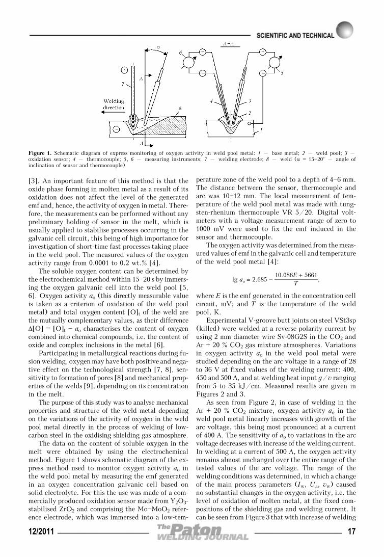
The data on the content of soluble oxygen in themelt were obtained by using the electrochemicalmethod. Figure 1 shows schematic diagram of the ex-press method used to monitor oxygen activity ao inthe weld pool metal by measuring the emf generatedin an oxygen concentration galvanic cell based onsolid electrolyte. For this the use was made of a com-mercially produced oxidation sensor made from Y2O3-stabilised ZrO2 and comprising the Mo—MoO2 refer-ence electrode, which was immersed into a low-tem-
perature zone of the weld pool to a depth of 4—6 mm.The distance between the sensor, thermocouple andarc was 10—12 mm. The local measurement of tem-perature of the weld pool metal was made with tung-sten-rhenium thermocouple VR 5/20. Digital volt-meters with a voltage measurement range of zero to1000 mV were used to fix the emf induced in thesensor and thermocouple.
The oxygen activity was determined from the meas-ured values of emf in the galvanic cell and temperatureof the weld pool metal [4]:
lg ao = 2.685 — 10.086E + 5661
T,
where E is the emf generated in the concentration cellcircuit, mV; and T is the temperature of the weldpool, K.
Experimental V-groove butt joints on steel VSt3sp(killed) were welded at a reverse polarity current byusing 2 mm diameter wire Sv-08G2S in the CO2 andAr + 20 % CO2 gas mixture atmospheres. Variationsin oxygen activity ao in the weld pool metal werestudied depending on the arc voltage in a range of 28to 36 V at fixed values of the welding current: 400,450 and 500 A, and at welding heat input g/v rangingfrom 5 to 35 kJ/cm. Measured results are given inFigures 2 and 3.
As seen from Figure 2, in case of welding in theAr + 20 % CO2 mixture, oxygen activity ao in theweld pool metal linearly increases with growth of thearc voltage, this being most pronounced at a currentof 400 A. The sensitivity of ao to variations in the arcvoltage decreases with increase of the welding current.In welding at a current of 500 A, the oxygen activityremains almost unchanged over the entire range of thetested values of the arc voltage. The range of thewelding conditions was determined, in which a changeof the main process parameters (Iw, Ua, vw) causedno substantial changes in the oxygen activity, i.e. thelevel of oxidation of molten metal, at the fixed com-positions of the shielding gas and welding current. Itcan be seen from Figure 3 that with increase of welding
Figure 1. Schematic diagram of express monitoring of oxygen activity in weld pool metal: 1 – base metal; 2 – weld pool; 3 –oxidation sensor; 4 – thermocouple; 5, 6 – measuring instruments; 7 – welding electrode; 8 – weld (α = 15—20° – angle ofinclination of sensor and thermocouple)
12/2011 17

heat input g/v the level of oxidation of the weld poolmetal first grows almost linearly, then this growthslows down, and in a range of welding conditions witha heat input above 20 kJ/cm the value of ao remainsalmost constant. This regularity shows up when weld-ing is performed in the CO2 and Ar + 20 % CO2 gasmixture atmospheres having a different oxidising abil-ity. This character of dependence of the oxygen ac-tivity on the welding parameters is attributable, firstof all, to increase in the base metal content of theweld pool, as well as to increase in the content of ironvapours in the arc atmosphere causing decrease in apartial pressure of the oxidising gases and, hence,absorption of oxygen by the electrode metal drops.
Further investigations allowed evaluation of theeffect of welding heat input on the oxygen activity inthe melt, as well as of mechanical properties of thewelds made on steel VSt3sp in the CO2 and Ar +20 % CO2 gas mixture atmospheres (Table). The dataof the Table show that the ao values grow with increasein the oxidising ability of the shielding atmosphere.However, they are an order of magnitude lower thantotal oxygen content [O]t of the weld metal deter-mined by the vacuum melting method.
Structure of metal of the experimental welds wasexamined by using the optical and electron micro-scopes, and character of the γ → α transformation of
this metal under conditions of continuous cooling wasstudied by using the high-sensitivity dilatometry in-struments combined with the «Ala-Too» unit for high-temperature metallography. The Pt-Pt—10 % Rh ther-mocouple was employed for precise measurement oftemperature. The dilatometer was evacuated to a pres-sure of 2⋅10—4 Torr and then filled up with high-purityargon to prevent oxidation or decarburisation of sam-ples. To investigate the effect of oxygen on peculiari-ties of decomposition of austenite in the weld metal,the samples were heated to a temperature of 1250 °Cand held for 2 min at this temperature providing theidentical grain sizes. Cooling from 800 to 500 °C wasperformed at a rate of 5 °C/s. The temperature versustime of elongation of a sample was recorded duringthis thermal cycle simulating the welding conditionsby using a specially calibrated potentiometer KSP-4.
It was established that high values of impact tough-ness of the weld metal and a maximal amount of acicularferrite in structure of the weld metal can be achieved atthe content of combined oxygen Δ[O] in the weld rang-ing from 0.015 to 0.045 % (Figure 4, a) and at thefollowing contents of alloying elements and impurities,wt.%: 0.08—0.11 C, 0.40—0.55 Si, 1.2—1.5 Mn, 0.015—
Mechanical properties of metal of the welds made in oxidising shielding gases on steel VSt3sp depending on the welding heat inputand oxygen activity in the weld pool
Shielding gasg/v,
kJ/cm[O]t,wt.%
ao, wt.%Δ[O],wt.%
σ0.2, MPa σt, MPA δ5, % ψ, %KCV, J/cm2, at T, °С
+20 —20 —40
CO2 18.4 0.054 0.0056 0.0484 350 420 26.5 55.2 120 60 32
28.8 0.061 0.0063 0.0547 335 380 25.2 53.4 98 42 16
Ar + 20 % CO2 18.4 0.035 0.0034 0.0316 384 530 33.0 66.0 165 115 55
28.8 0.046 0.0040 0.0420 353 465 29.3 58.6 136 91 43
Note. Given are the values averaged over the results of tests of three to five specimens.
Figure 3. Variations in oxygen activity ao in weld pool metal de-pending on the heat input in welding of steel in oxidising shieldinggases: 1 – CO2; 2 – Ar + 20 % CO2
Figure 2. Variations in oxygen activity ao in weld pool metal de-pending on the arc voltage in welding of steel in Ar + 20 % CO2gas mixture: 1 – Iw = 400; 2 – 450; 3 – 500 A
18 12/2011

0.020 S and P. Deviations of the oxygen concentrationto higher or lower values from the said ranges wereaccompanied by decrease in the amount of acicularferrite in structure of the weld metal.
The γ → α transformation in the weld metal witha high oxygen content (0.06—0.07 %) occurred athigher temperatures of 720 to 680 °C, this being 20—30 °C higher than in the welds with the 0.045 % orlower oxygen content. Lowering of the transformationbeginning temperature decelerated diffusion processesin the pearlitic transformation region. As a result, themajor portion of austenite undergoes transformationsby the shear mechanism to form finely dispersed acicu-lar ferrite. It was found out that at an oxygen contentof 0.015 to 0.045 % the structure of the weld metalcontained 75—80 % of acicular ferrite (Figure 4, b).Electron microscopic examinations showed that theformed acicular phase was not bainite, as there wereno characteristic precipitates of the carbide phase atthe needle edges (Figure 5). The matrix surroundinga growing ferrite needle featured an increased densityof dislocations.
Fine oxide particles with a size of less than 0.1 μmpresent in metal were nuclei of the ferrite phase inthe bulk of austenitic grains, which was confirmed bythe results of electron microscopic examinations (see
Figure 5). Decrease in the acicular ferrite content ofthe welds with an oxygen concentration of less than0.015 % (see Figure 4, a) can be explained by decreasein the quantity of the oxide particles, i.e. quantity ofthe ferritic phase nucleation centres. Depending ontheir quantity and size, such particles favour formationof this or other morphology of the ferritic phase [1]affecting the fine metal structure and, hence, its sen-sitivity to brittle fracture.
Therefore, the quantitative data on the activity ofoxygen in molten metal of the weld pool do not onlymake it possible to explain the phenomena taking placeduring welding, but also, which is more important,allow the scientifically substantiated planning of thisor other effect. In particular, such data are extremelyimportant for development of the schemes of alloyingof new welding wires, selection of the optimal shield-ing gas—wire combinations, development of the tech-nologies for welding of steels, and more reliable pre-diction of mechanical properties of the welds.
Figure 5. Microstructure (×13,200) of acicular ferrite in metal ofthe welds made in Ar + 20 % CO2 mixture (arrows indicate to oxideinclusions connected to edge regions of ferrite needles)
Figure 4. Effect of oxygen combined into chemical compounds,Δ[O], on impact toughness and microstructure (×200) of metal ofthe welds made in oxidising shielding gases: a – structure ofacicular ferrite with bainite regions; b – structure with predomi-nant acicular ferrite; c – grain-boundary ferrite and lamellar pre-cipitates of Widmanstatten ferrite
1. Cochrane, R.C., Kirkwood, P.R. (1979) The effect of ox-ygen on weld metal microstructure. In: Proc. of Int. Conf.on Trends in Steels and Consumables for Welding (London,14—16 Nov. 1978). Cambridge: TWI, 103—122.
2. Kulikov, I.S. (1975) Deoxidation of metals. Moscow: Me-tallurgiya.
3. Yavojsky, V.I., Vishkarev, A.F., Luzgin, V.P. et al. (1975)Express analysis of oxygen content of steel. Moscow: Metal-lurgiya.
4. Luzgin, V.P., Yavojsky, V.I. (1983) Gases in steel and qua-lity of metal. Moscow: Metallurgiya.
5. Rimsky, S.T., Svetsinsky, V.G., Bondarenko, T.P. et al.Method of determination of activity of elements in melt.USSR author’s cert. 1491161. Int. Cl. G 01 N 27/46. Prior.22.12.1986. Publ. 1988.
6. Svetsinsky, V.G., Bondarenko, T.P., Rimsky, S.T. et al.(1988) Determination of activity of oxygen in molten metalin gas-shielded welding of steel. Avtomatich. Svarka, 2, 73.
7. Rimsky, S.T., Svetsinsky, V.G. (1977) Effect of compositi-on of oxidizing argon mixture on solidification crack resis-tance of weld on steel VSt3sp. Ibid., 10, 48—52, 54.
8. Pidgaetsky, V.V. (1970) Pores, inclusions and cracks inwelds. Kyiv: Tekhnika.
9. Svetsinsky, V.G., Rimsky, S.T., Petrov, Yu.N. (1974) Pecu-liarities of fine structure of gas-shielded welds. Avtomatich.Svarka, 8, 5—8.
12/2011 19

HYGROSCOPICITY OF HIGH-BASICITY SYNTHETIC FLUX
S.I. MORAVETSKYE.O. Paton Electric Welding Institute, NASU, Kiev, Ukraine
It was experimentally found that hygroscopicity of synthetic acid fluxes is at the same that of standard fused fluxes.Hygroscopicity of the synthetic fluxes grows not less than 10 times with increase in their basicity from 0.8 to 2.4. Thisprobably is caused by the presence of a free lime which forms in the synthetic flux as a result of the solid-phase reactionbetween magnesium oxide and calcium fluoride in flux sintering. The thermodynamic calculation results and experimentaldata confirm the above assumption.
Keywo rd s : welding flux, oxide-fluoride system, basicity,hygroscopicity, phase composition, solid-phase chemical reaction
Development of welding fluxes obtained by meansof a solid-phase synthesis of initial charge componentsand mechanical refinement of fused product per gran-ules [1] is an important result of investigations, carriedout in the E.O. Paton Electric Welding Institute.
Deterioration of welding-technological propertiesof the fluxes can be caused by increase of their basicity.Indicated tendency was also noted for a synthetic flux.Thus, some degradation of forming capability of theflux, tarnish of a weld surface, and in some cases,appearance of single pores were found after relativelyshort soaking of SFT-6 flux (TU PWI 839—93) withBIIW = 2.4 basicity under humid atmospheric condi-tions during surfacing of low alloy heat-resistant steel.These drawbacks were eliminated after repeated bak-ing of such a flux at 550—600 °C for 2 h. Soaking inhumid atmosphere of the low-basicity synthetic fluxes,for example, pilot flux SF-1 (BIIW = 0.8) does notresult in notable degradation of welding-technologicalproperties. It can be assumed, therefore, that the syn-thetic fluxes, like others, obtain higher hygroscopicitywith increase of basicity.
The aim of the present work lies in experimentaldetermination of hygroscopicity of SFT-6 type syn-
thetic fluxes of MgO—CaF2—Al2O3—SiO2 system andreasons of its increase at basicity rise. Hygroscopicityof the standard fluxes of other types (agglomerated,fused vitreous fluxes and fused honeycombed ones),as well as low basicity of the synthetic flux, wasdetermined for comparative assessment.
The charge components from Table 1 were selectedfor manufacture of the synthetic fluxes (objects of in-vestigation of this study). A gravimetric method wasused for determination of hygroscopicity of the fluxes.
Several forms of moisture differing by type andenergy of bonding between the atoms of hydrogen,oxygen and flux material [2] can be, symbolically,distinguished in the fluxes. Temperature of thermaldesorbtion of the moisture from the flux is determinedby value of indicated energy. Most of chemicallybound moisture (around 80 %) in the fused fluxesgranulated by pouring of a melt in a water refers tohigh-temperature form and is removed at temperaturevalues of 800—1000 °C [2]. There is no high-tempera-ture form of the moisture in the fluxes having noexposure of «wet» granulation.
Content of moisture in the fluxes is determined bystandard method [3] allowing setting general (gross)moisture emission from the flux in the temperatureinterval from 20 to 1000 °C. However, the hygro-scopicity of fluxes is to be evaluated considering the
© S.I. MORAVETSKY, 2011
Table 1. Some charge materials used for production of the synthetic fluxes
Charge materialsMain component of
the materialGrade
Normative document(GOST)
Periclase fused powder for steel-making production (magnesite) MgO PPK-88 24862—81
Fluor-spar lump concentrate (fluorite) CaF2 FKS-95A 4421—73
Alumina Al2O3 GK 6912—87
Feldspar for electrode coatings NaK[AlSi3O8] PShM 4422—73
Glass breakage* Na2O⋅CaO⋅6SiO2 — —
Quartz sand SiO2 PB-150-1 22551—77
Manganese ore concentrate for electrode coating MnО — 4418—75
Metallic manganese Mn Mn95 6008—90
Calcium quicklime CaО Grade 1 9179—77
Crystalline foundry graphite С GL-1 5279—74*Powder material, product of soda-lime glass milling being a spoilage and wastes of production of houseware and ornamental glass productsaccording to GOST 24315—80 and(or) flat glass according to GOST 111—2001.
20 12/2011
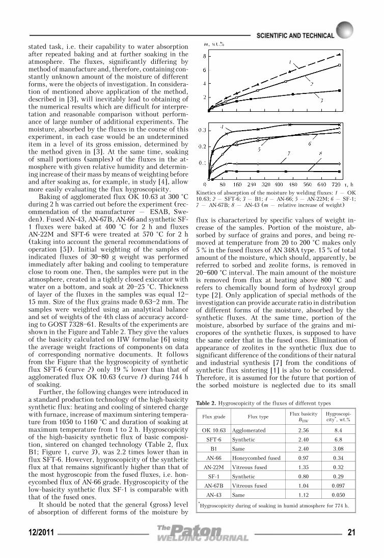
stated task, i.e. their capability to water absorptionafter repeated baking and at further soaking in theatmosphere. The fluxes, significantly differing bymethod of manufacture and, therefore, containing con-stantly unknown amount of the moisture of differentforms, were the objects of investigation. In considera-tion of mentioned above application of the method,described in [3], will inevitably lead to obtaining ofthe numerical results which are difficult for interpre-tation and reasonable comparison without perform-ance of large number of additional experiments. Themoisture, absorbed by the fluxes in the course of thisexperiment, in each case would be an undetermineditem in a level of its gross emission, determined bythe method given in [3]. At the same time, soakingof small portions (samples) of the fluxes in the at-mosphere with given relative humidity and determin-ing increase of their mass by means of weighting beforeand after soaking as, for example, in study [4], allowmore easily evaluating the flux hygroscopicity.
Baking of agglomerated flux OK 10.63 at 300 °Cduring 2 h was carried out before the experiment (rec-ommendation of the manufacturer – ESAB, Swe-den). Fused AN-43, AN-67B, AN-66 and synthetic SF-1 fluxes were baked at 400 °C for 2 h and fluxesAN-22M and SFT-6 were treated at 570 °C for 2 h(taking into account the general recommendations ofoperation [5]). Initial weighting of the samples ofindicated fluxes of 30—80 g weight was performedimmediately after baking and cooling to temperatureclose to room one. Then, the samples were put in theatmosphere, created in a tightly closed exiccator withwater on a bottom, and soak at 20—25 °C. Thicknessof layer of the fluxes in the samples was equal 12—15 mm. Size of the flux grains made 0.63—2 mm. Thesamples were weighted using an analytical balanceand set of weights of the 4th class of accuracy accord-ing to GOST 7328—61. Results of the experiments areshown in the Figure and Table 2. They give the valuesof the basicity calculated on IIW formulae [6] usingthe average weight fractions of components on dataof corresponding normative documents. It followsfrom the Figure that the hygroscopicity of syntheticflux SFT-6 (curve 2) only 19 % lower than that ofagglomerated flux OK 10.63 (curve 1) during 744 hof soaking.
Further, the following changes were introduced ina standard production technology of the high-basicitysynthetic flux: heating and cooling of sintered chargewith furnace, increase of maximum sintering tempera-ture from 1050 to 1160 °C and duration of soaking atmaximum temperature from 1 to 2 h. Hygroscopicityof the high-basicity synthetic flux of basic composi-tion, sintered on changed technology (Table 2, fluxB1; Figure 1, curve 3), was 2.2 times lower than influx SFT-6. However, hygroscopicity of the syntheticflux at that remains significantly higher than that ofthe most hygroscopic from the fused fluxes, i.e. hon-eycombed flux of AN-66 grade. Hygroscopicity of thelow-basicity synthetic flux SF-1 is comparable withthat of the fused ones.
It should be noted that the general (gross) levelof absorption of different forms of the moisture by
flux is characterized by specific values of weight in-crease of the samples. Portion of the moisture, ab-sorbed by surface of grains and pores, and being re-moved at temperature from 20 to 200 °C makes only5 % in the fused fluxes of AN 348A type. 15 % of totalamount of the moisture, which should, apparently, bereferred to sorbed and zeolite forms, is removed in20—600 °C interval. The main amount of the moistureis removed from flux at heating above 800 °C andrefers to chemically bound form of hydroxyl grouptype [2]. Only application of special methods of theinvestigation can provide accurate ratio in distributionof different forms of the moisture, absorbed by thesynthetic fluxes. At the same time, portion of themoisture, absorbed by surface of the grains and mi-cropores of the synthetic fluxes, is supposed to havethe same order that in the fused ones. Elimination ofappearance of zeolites in the synthetic flux due tosignificant difference of the conditions of their naturaland industrial synthesis [7] from the conditions ofsynthetic flux sintering [1] is also to be considered.Therefore, it is assumed for the future that portion ofthe sorbed moisture is neglected due to its small
Kinetics of absorption of the moisture by welding fluxes: 1 – OK10.63; 2 – SFT-6; 3 – B1; 4 – AN-66; 5 – AN-22M; 6 – SF-1;7 – AN-67B; 8 – AN-43 (m – relative increase of weight)
Table 2. Hygroscopicity of the fluxes of different types
Flux grade Flux typeFlux basicity
BIIW
Hygroscopi-city*, wt.%
OK 10.63 Agglomerated 2.56 8.4
SFT-6 Synthetic 2.40 6.8
B1 Same 2.40 3.08
AN-66 Honeycombed fused 0.97 0.34
AN-22М Vitreous fused 1.35 0.32
SF-1 Synthetic 0.80 0.29
AN-67B Vitreous fused 1.04 0.097
AN-43 Same 1.12 0.050*Hygroscopicity during of soaking in humid atmosphere for 774 h.
12/2011 21

amount and all moisture, absorbed by the syntheticflux, is referred to chemically-bound form.
Thus, rapid (10—23 times) increase of hygroscopic-ity of the synthetic flux was promoted by a change ofcomponent composition and basicity, represented inTable 3. It was supposed based on these data andtaking into account specified remarks that appearanceof the compounds having tendency to hydration in afinished flux and causing a rise of the flux suscepti-bility to moisture absorption (similar to silicate-lumpin the agglomerated fluxes) was contributed by sucha change of component composition. In this connectionan investigation of phase composition of SFT-6 fluxwas of interest.
X-ray phase analysis of SFT-6 flux carried usingDRON-UM1 diffractometer in monochromatic CuKαirradiation by step-by-step scanning method (acceler-ating voltage 35 kV, current 25 mA) allowed deter-mining the main components of its phase composition,i.e. fluorite CaF2, alumomagnesite spinel MgO⋅Al2O3,forsterite 2MgO⋅SiO2, cuspidine 3CaO⋅2SiO2⋅CaF2and free MgO. Small and trace amounts of diopsideCaO⋅MgO⋅2SiO2, pseudo-wollastonite α-CaO⋅SiO2and other compounds are present in the flux. Nomen-clature of the main components in SF-1 flux compo-sition (for which the same analysis was performed[1]) does not correspond with the given one and in-cludes nepheline β-Na2O⋅Al2O3⋅2SiO2, enstatiteMgO⋅SiO2, andalusite Al2O3⋅SiO2, brauniteMnO⋅SiO2, wollastonite β-CaO⋅SiO2 and diopside.
Study of the compounds of SFT-6 flux being re-sponsible for its high hygroscopicity will be carriedout in the experimental way. For this a sintering ofthe simplified model charges consisting of fluoridesand oxides is to be performed. The latter are taken ina compatible mole proportion corresponding to knownminerals. Ratio of weight fraction of the fluoride tosum weight fraction of the oxides made 2:3 in thecharge that is typical for the fluxes with high contentof CaF2. An output of the investigated compound issupposed to be maximum at such ratios and presence
of the necessary thermodynamic conditions. At thesame time a reproduction of all peculiarities of solid-phase reactions between the components, which arestipulated by the presence of large amount of CaF2,will be possible. Table 4 shows component composi-tion of the charge. Charge materials given in Table 1were used.
Granulated material with the same grain size as inearlier tested fluxes was obtained from the sinteredcharges by means of mechanical refinement and siev-ing. Further, hygroscopicity of the obtained granu-lated products was evaluated using indicated gravi-metric method. Limit of the maximum soaking in hu-mid atmosphere for all the samples made 336 h. Hy-groscopicity of the separate charge components aftertheir heat treatment using mode of sintering of modelcharges (maximum temperature 1125 °C; time of heat-ing up to maximum temperature – 2 h; duration ofsoaking at maximum temperature – 2 h, heating andcooling with the furnace) was also determined takinginto account the possibility of existence of real com-pounds of the unreacted components in a free state(for example, MgO, CaF2) in the fluxes.
Table 4 shows a relative increase of weight of thesamples characterizing hygroscopicity of the sinteredproducts. It was stated that hygroscopicity of phasesof SFT-6 flux lies in the ranges from 0.07 for fluoriteup to 0.50 wt.% for sintered mixture of fluorite +forsterite. It was noted that the hygroscopicity of apure MgO (superpure according TU 6-09-2807—78) isan order higher than of fired magnesite. However, iftheoretically decide that all magnesite in SFT-6 fluxcharge was chemically inert during sintering as wellas obtained properties of pure MgO then its contri-bution in the increase of flux weight would make0.31⋅2.6 = 0.81 %. This is significantly lower of par-ticularly registered hygroscopicity of SFT-6 flux underany conditions of sintering (2.0—3.5 wt.% during336 h). It followed from these data that the sum con-tribution of mineral components of the SFT-6 syn-thetic flux cannot be an explanation of its increased
Table 3. Influence of component composition, basicity and parameters of sintering of the synthetic fluxes on their hygroscopicity*
Fluxgrade
Weight fraction of components, %
Peculiarities of sintering BIIW
Hygrosco-picity,wt.%
Magne-site
Fluo-rite
Alu-mina
Felds-par
Glassbreakage
Manga-nese ore
Metallicmanga-nese
Graphite
SF-1 5 15 20 — 50 10 — — Setting of a charge in thefurnace, heated up to950 °C, soaking at thattemperature for 1 h, aircooling
0.8 0.29
SFT-6 31 26.25 16 23 — — 1.75 2 Setting of a charge in thefurnace, heated up to1050 °C, soaking at thattemperature for 1 h, aircooling
2.4 6.80
B1 31 26.25 16 23 — — 1.75 2 Soaking of a charge atmaximum temperature1160 °C during 2 h, heatingand cooling with furnace
2.4 3.08
*Compared are the values of the hygroscopicity during soaking in humid atmosphere for 744 h.
22 12/2011

hygroscopicity. However, experimental data of [8]allowed assuming that a contribution of free lime CaOin composition of the finished flux creates the in-creased hygroscopicity of SFT-6 flux.
As shown in [8], free lime can be an intermediateproduct of chemical reaction between the CaF2, oxidesand silicate-lump with formation and decay of com-plex oxyfluoride due to effect of anion redistributionmechanism between the calcium and magnesium dur-ing heating of a multicomponent charge of the ag-glomerated flux with excessive content of the acidoxides. Further, the lime appeared in such a flux isconsumed for formation of anorthite mineral.
If possible intermediate reactions for formation ofthe magnesium and calcium oxyfluorides are omittedthen a process of lime formation can be representedby more simple reaction
MgO(s) + CaF2(s) ←→ CaО(s) + MgF2(s). (1)
An equilibrium constant of such a reaction can beinterpreted as
keq = (aCaO⋅aMgF2)/(aCaF2
⋅aMgO), (2)
where a is an activity of agents, indicated in the in-dices.
Temperature dependence of the equilibrium constantof this reaction can be calculated using an exact methodof L.P. Vladimirov and reference value of variables [9].Taking into account formulae (2) the obtained calcu-lated values lg keq from —3.027 up to —2.414 at tempera-tures from 800 to 1127 °C, respectively, indicate theappearance of several percents of products of reaction(1) in MgO(s)—CaF2(s) system after its continuous soak-ing at 1125 °C. Specified reaction has a tendency tointensify with temperature rise.
A model charge consisting of MgO and CaF2 in1:1 mole ratio was sintered for checking the possibilityof formation of the free lime in reaction (1). Hygro-scopicity of the sintered product made 1.46 wt.% dur-ing 336 h of soaking that, respectively, 7 and 21 timeshigher than in magnesite and fluorite, sintered indi-vidually (see Table 3). Obtained result indicates thata phase appears in the process of sintering in MgO(s)—
Table 4. Composition and hygroscopicity of the sintered model charges
Chargegrade
Fraction of components, wt.%
m*, wt.%Fluorite
Manganeseoxide
Magnesite Alumina Lime Feldspar Quartz sand Other components
Flux basic composition
SFT-6 26.25 — 31.0 16.0 — 23.0 — Graphite 2.0; Mn 1.75 3.50
B1 26.25 — 31.0 16.0 — 23.0 — Same 2.05
Charge with fluorite + alumomagnesite spinel MgO⋅Al2O3
FSh 41.0 — 18.0 41.0 — — — — 0.22
FSh-1** 36.9 — 16.2 36.9 — 10.0 — — 0.21
Fluorite + forsterite 2MgO⋅SiO2
FF 39.77 — 35.28 — — — 24.95 — 0.50
Fluorite + diopside CaO⋅MgO⋅2SiO2
FD 39.0 — 12.0 — 17.0 — 32.0 — 0.47
Fluorite + wollastonite CaO⋅SiO2
FV 40.0 — — — 29.0 — 31.0 — 0.13
Cuspidine 3CaО⋅2SiO2⋅CaF2
K 21.3 — — — 45.9 — 32.8 — 0.17
Fluosilicates with excessive and insufficient content of feldspar
FS1 31.0 — — — — 69.0 — — 0.11
FS2 43.0 7.4 — — — 49.6 — — 0.04
Fluorite + magnezite CaF2⋅MgO
FM 65.0 — 35.0 — — — — — 1.46
Charge components (lime, chemically pure MgO, alumina, magnesite, fluorite, feldspar)
I — — — — 100 — — — 30.10
MgO — 100 — — — — — — 2.60
G — — — 100 — — — — 0.83
M — — 100 — — — — — 0.21
F 100 — — — — — — — 0.07
PSh — — — — — 100 — — 0.04*Relative increase in weight of the granulated product samples for the period of soaking in humid atmosphere for 336 h. **Charge withfeldspar addition for improvement of sintering.
12/2011 23

CaF2(s) system, the hygroscopicity of which signifi-cantly higher than in the initial components. Hygro-scopicity of the lime after heat treatment in the modeof sintering of model charge was also evaluated andmade 30.1 % during 336 h of soaking in the exiccator.This result has a good agreement with theoretical ratioof the molar masses of quicklime (CaO) and slakedlime (Ca(OH)2). The latter is higher of the first by32.12 %.
Content of the free lime in the product can beapproximately evaluated taking into account additiv-ity of the hygroscopicity mΣ of the sintered productof MgO(s)—CaF2(s) system as a result of contributionof all phases of this product and allowing that indi-cated sintered product has no other agents except forthe initial chemical agents and products of reaction(1). For this it is also assumed that the hygroscopici-ties of fluorite mf and manganese fluoride mMgF2
areequal. Union of magnesite, fluorite and MgF2 in thesintered product is considered as one agent the hygro-scopicity m0 of which consists of contributions of mag-nesite mm and fluorite mf accepted considering theirweight fractions in the initial charge:
m0 = 0.65mf + 0.35mm =
= 0.65⋅0.07 + 0.35⋅0.21 = 0.119 %.
If hygroscopicity of the lime ml is known than itsmass fraction xl in the sintered product of MgO(s)—CaF2(s) system can be easily determined from the fol-lowing equation relatively to xl:
mΣ = хlml + (1 — хl)m0. (3)
The calculation using expression (3) showed thatcontent of the free lime in the sintered product ofMgO(s)—CaF2(s) system makes 4.47 wt.%.
Such minerals as alumina spinel MgO⋅Al2O3, cal-cium aluminate CaO⋅Al2O3 and CaO⋅2Al2O3 etc. arethermodynamically very stable compounds in a widetemperature interval. Therefore, increase of tempera-ture provides beginning of their formation at achieve-ment of sufficient diffusion mobility of the atoms ofthe initial components. Many factors (lattice defec-tiveness, presence of additions and moisture of con-stitution in the components, appearance of liquid andgas phases in salt—oxide systems) promote mineralformation under real conditions reducing temperatureof beginning of the solid-phase reactions. For example,formation of spinel from commercially pure and natu-rally humid components becomes already apparent at700—800 °C and that for forsterite makes 900 °C [10].As a result the basic oxides and fluorite dominate overthe acid oxides in the charge of sintered flux and thelatter, probably, completely or mostly will be con-sumed for formation of complex oxides and oxy-fluorides to the moment when the oxide systemachieves its maximum temperature. On the contrarythe fluorite and magnesite will remain in excess. Thelime formed according to reaction (1) at temperature,approximately, 700—1000 °C, under these conditionsreacts with, for example, Al2O3 forming the calciumaluminates. However, after free Al2O3 has been ex-hausted the lime, appearing during soaking at maxi-
mum temperature, cannot be quickly bound in theminerals.
Hygroscopicity of the high-basicity synthetic flux(see the Figure and Table 1) is reduced with the in-crease of temperature of sintering and duration of soak-ing at maximum temperature. Reduction of a contentof the free lime due to processes of mutual dissolutionof the components at high temperatures, as well asreaction of CaO with the initial chemical compoundswith formation of more complex secondary minerals[10], can, probably, explain such dependence. How-ever, speed of these processes, apparently, is notenough for complete binding of the lime, formed ac-cording to reaction (1). Therefore, increased hygro-scopicity of the finished high-basicity synthetic fluxof MgO—CaF2—Al2O3—SiO2 system is caused by re-mains of some amount of the free CaO.
CONCLUSIONS
1. It was shown that hygroscopicity of the flux in-creases 10—23 times and become comparable with hy-groscopicity of the agglomerated flux with rise ofbasicity of the synthetic flux from 0.8 to 2.4 times.The latter is provided by simultaneous rise of weightfractions of magnesite and fluorite in its composition.
2. It was determined that the presence of the freelime, forming as a result of chemical reaction betweenCaF2 and MgO taking place in MgO—CaF2—Al2O3—SiO2 system at high (approximately 1100 °C) tem-perature and absence of the acid oxides in a free formwhich could effectively bound the lime in the minerals,in composition of the synthetic flux can be the reasonof high hygroscopicity of the synthetic fluxes of MgO—CaF2—Al2O3—SiO2 system.
3. It was stated that hygroscopicity of the high-basicity synthetic fluxes can be significantly increasedby rise of sintering temperature and duration of soak-ing at this temperature. However, their hygroscopicityis significantly higher than in fused ones.
1. Kasatkin, B.S., Tsaryuk, A.K., Vakhnin, Yu.N. et al.(1994) Synthetic welding fluxes, fabrication and fields ofapplication. Avtomatich. Svarka, 3, 62—66.
2. Goncharov, I.A., Paltsevich, A.P., Tokarev, V.S. et al.(2001) About the form of hydrogen existence in weldingfused fluxes. The Paton Welding J., 4, 27—30.
3. GOST 22974.14—90: Welding fused fluxes. Procedure fordetermination of humidity content. Moscow: Standart.
4. Kuzmenko, V.G., Guzej, V.I. (2004) Hydration of fluxeswith a locally changed chemical composition of grains. ThePaton Welding J., 6, 41—43.
5. Potapov, N.N. (1979) Principles of flux selection in weldingof steels. Moscow: Mashinostroenie.
6. Galinich, V.I., Sokolsky, V.E., Kazimirov, V.P. et al.(1991) Basicity of fused fluxes and possibility of its experi-mental determination. Avtomatich. Svarka, 5, 35—37.
7. Eremin, N.I. Nonmetallic mineral products. http:web.ru/db/msg.html?mid==1172887&uri=glava10.htm
8. Sokolsky, V.E., Roik, A.I., Davidenko, A.O. et al. (2010)On phase transformations in agglomerated flux of salt-oxideslag system at heating. The Paton Welding J., 12, 9—14.
9. Vladimirov, L.P. (1970) Thermodynamic calculations ofequilibrium of metallurgical reactions. Moscow: Metallur-giya.
10. Budnikov, P.P., Ginstling, A.M. (1965) Reactions in mix-tures of solids. Moscow: Gosstrojizdat.
24 12/2011

TRANSFORMABLE STRUCTURES (Review)
B.E. PATON, L.M. LOBANOV and V.S. VOLKOVE.O. Paton Electric Welding Institute, NASU, Kiev, Ukraine
The paper deals with the main classes of transformable structures, which are shells of soft and rigid type. The mainproblems are outlined, which greatly reduce the range of application of such structures in modern engineering. Technicalsolutions, allowing optimization of functional properties of transformable shell structures, are suggested.
Keywo rd s : transformable structures, load-carrying shells,transformable shells
Searching for a compromise between the need to createshell-type structures with the required parameters andpossibility of their further transportation to the op-eration site involves addressing a wide range of engi-neering tasks, accompanied by upgrading of the cur-rently available technologies and work performancein difficult-of-access places. The main problem con-sists in the complexity of realization in the intendedstructure operation site of the time- and labour-con-suming process of its fabrication. On the other hand,development of engineering determines the need forshells of ever greater volume and overall dimensions,range of application of which is limited either by theabsence of the respective transportation means, ortheir extremely high cost. The above conditions re-quire application of special class of structures, capableof changing their geometrical dimensions in a broadrange at practically unchanged mechanical propertiesof the material of the shell – transformable structures(TS).
The urgency of the work on TS development is duenot only to appearance of new non-standard engineer-ing tasks, requiring a search for new decisions of therespective level. A common case is that of «shell-in-shell», when upgrading or replacement of large-sizedtanks in limited technological space (for instance, acompartment of an all-welded ship hull) is required.
Known is a number of TS applications, in whichthe transformation process is applied to solve an in-dependent engineering task or obtain new physicalproperties of the object, namely excess buoyancy, ri-gidity, reflectivity, etc., that can be achieved in thecase, when TS functional and technological charac-teristics meet the requirements made of its prototype.
Experience of practical application of engineeringfacilities of this class allows outlining the main prob-lems, elimination of which is capable of essentiallywidening the sphere of TS application in engineering.Solution of these problems is reduced to ensuring mul-tiple reproducibility of geometrical parameters, leak-proofness and stability of strength characteristics ofthe transformed shell.
Load-carrying shells taking the load at sufficientrigidity have the greatest applied importance. Theircapability of considerable elastic displacements canbe regarded as undesirable consequence of the smallthickness and flatness of the shell, associated withgeometrical non-linearity and loss of stability. This isexactly the property, however, which is the basis forthe technology of changing the form of the shells,combining the advantages of enclosing and load-car-rying structures.
In most of the cases the known TS can be condi-tionally regarded as bodies of shell type, which aredivided into three main classes: load-carrying soft;based on transformable frame; and rigid. By the typeof transformation TS are divided into structures trans-formed by application of excess pressure in the innervolume, and through mechanical transformation ofthe load-carrying frame, in particular with applicationof shape-memory materials. By their functional char-acteristics TS can be also conditionally divided intoleak-proof and non leak-proof.
PWI developed a separate class of TS, which be-long to hard shells and which are capable of combiningthe characteristics inherent to different types of trans-formable shells [1]. Technology of changing the formof thin-walled metal shells, to which V.M. Balitskycontributed greatly, was developed on the basis of themethod of isometric bending of surfaces and combinesthe main advantages of the considered TS classes:
• possibility of continuous transformation of struc-tures without application of auxiliary technologicaloperations;
• absence of the need to maintain in the innervolume the excess pressure, used only during trans-formation;
• leak-proofness of the transformable shells,achieved by application of the technology of buttwelding;
• absence of the need for a load-carrying frame;• high values of transformation coefficient Kt;• structure compactness before form change.Developed methods of shell structure form change
with preservation of topologically equivalent surfaceallowed creating a wide range of TS based on spatialbodies of revolution – spheres, ellipsoid, etc. Theirfabrication technology is based on the methods of com-
© B.E. PATON, L.M. LOBANOV and V.S. VOLKOV, 2011
12/2011 25
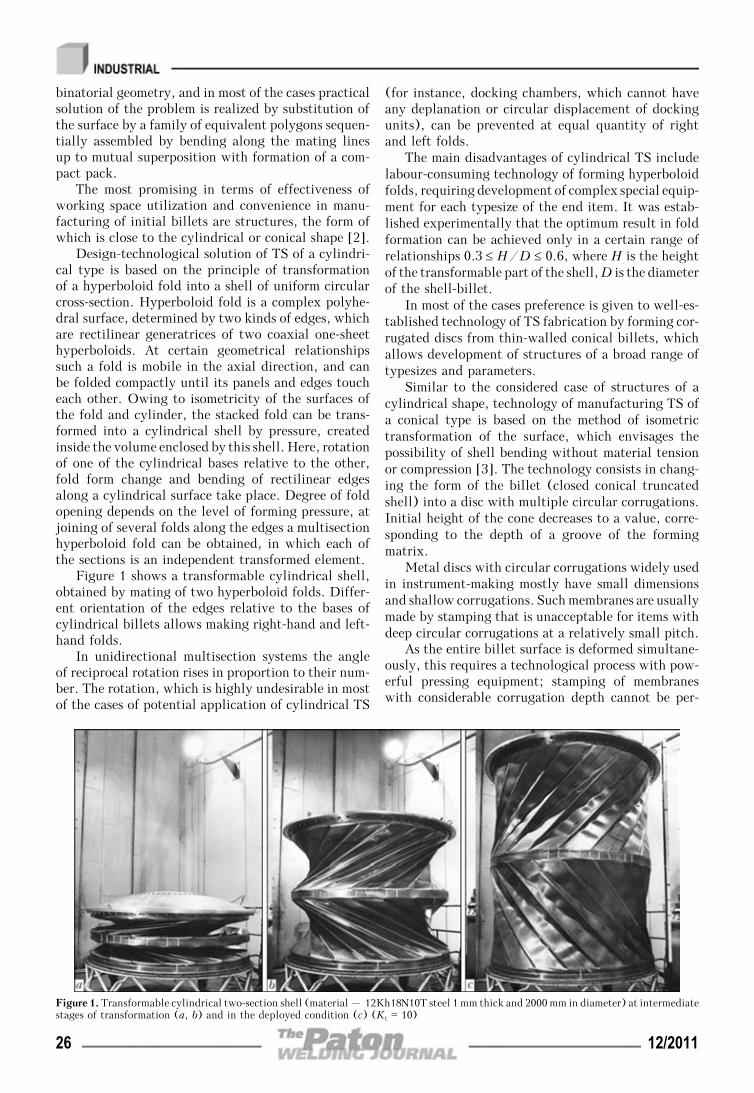
binatorial geometry, and in most of the cases practicalsolution of the problem is realized by substitution ofthe surface by a family of equivalent polygons sequen-tially assembled by bending along the mating linesup to mutual superposition with formation of a com-pact pack.
The most promising in terms of effectiveness ofworking space utilization and convenience in manu-facturing of initial billets are structures, the form ofwhich is close to the cylindrical or conical shape [2].
Design-technological solution of TS of a cylindri-cal type is based on the principle of transformationof a hyperboloid fold into a shell of uniform circularcross-section. Hyperboloid fold is a complex polyhe-dral surface, determined by two kinds of edges, whichare rectilinear generatrices of two coaxial one-sheethyperboloids. At certain geometrical relationshipssuch a fold is mobile in the axial direction, and canbe folded compactly until its panels and edges toucheach other. Owing to isometricity of the surfaces ofthe fold and cylinder, the stacked fold can be trans-formed into a cylindrical shell by pressure, createdinside the volume enclosed by this shell. Here, rotationof one of the cylindrical bases relative to the other,fold form change and bending of rectilinear edgesalong a cylindrical surface take place. Degree of foldopening depends on the level of forming pressure, atjoining of several folds along the edges a multisectionhyperboloid fold can be obtained, in which each ofthe sections is an independent transformed element.
Figure 1 shows a transformable cylindrical shell,obtained by mating of two hyperboloid folds. Differ-ent orientation of the edges relative to the bases ofcylindrical billets allows making right-hand and left-hand folds.
In unidirectional multisection systems the angleof reciprocal rotation rises in proportion to their num-ber. The rotation, which is highly undesirable in mostof the cases of potential application of cylindrical TS
(for instance, docking chambers, which cannot haveany deplanation or circular displacement of dockingunits), can be prevented at equal quantity of rightand left folds.
The main disadvantages of cylindrical TS includelabour-consuming technology of forming hyperboloidfolds, requiring development of complex special equip-ment for each typesize of the end item. It was estab-lished experimentally that the optimum result in foldformation can be achieved only in a certain range ofrelationships 0.3 ≤ H/D ≤ 0.6, where H is the heightof the transformable part of the shell, D is the diameterof the shell-billet.
In most of the cases preference is given to well-es-tablished technology of TS fabrication by forming cor-rugated discs from thin-walled conical billets, whichallows development of structures of a broad range oftypesizes and parameters.
Similar to the considered case of structures of acylindrical shape, technology of manufacturing TS ofa conical type is based on the method of isometrictransformation of the surface, which envisages thepossibility of shell bending without material tensionor compression [3]. The technology consists in chang-ing the form of the billet (closed conical truncatedshell) into a disc with multiple circular corrugations.Initial height of the cone decreases to a value, corre-sponding to the depth of a groove of the formingmatrix.
Metal discs with circular corrugations widely usedin instrument-making mostly have small dimensionsand shallow corrugations. Such membranes are usuallymade by stamping that is unacceptable for items withdeep circular corrugations at a relatively small pitch.
As the entire billet surface is deformed simultane-ously, this requires a technological process with pow-erful pressing equipment; stamping of membraneswith considerable corrugation depth cannot be per-
Figure 1. Transformable cylindrical two-section shell (material – 12Kh18N10T steel 1 mm thick and 2000 mm in diameter) at intermediatestages of transformation (a, b) and in the deployed condition (c) (Kt = 10)
26 12/2011
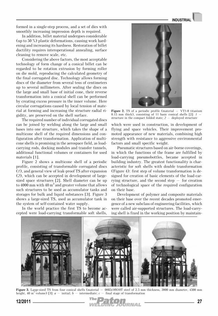
formed in a single-step process, and a set of dies withsmoothly increasing impression depth is required.
In addition, billet material undergoes considerable(up to 50 %) plastic deformations, causing work hard-ening and increasing its hardness. Restoration of billetductility requires interoperational annealing, surfacecleaning to remove scale, etc.
Considering the above factors, the most acceptabletechnology of form change of a conical billet can beregarded to be rotation extrusion by forming rolleron die mold, reproducing the calculated geometry ofthe final corrugated disc. Technology allows formingdiscs of the diameter from several tens of centimetersup to several millimeters. After sealing the discs onthe large and small base of initial cone, their reversetransformation into a conical shell can be performedby creating excess pressure in the inner volume. Herecircular corrugations caused by local tension of mate-rial at forming and increasing the structure radial ri-gidity, are preserved on the shell surface.
The required number of individual corrugated discscan be joined by welding along the large and smallbases into one structure, which takes the shape of amulticone shell of the required dimensions and con-figuration after transformation. Application of multi-cone shells is promising in the aerospace field, as load-carrying rods, docking modules and transfer tunnels,additional functional volumes or containers for usedmaterials [1].
Figure 2 shows a multicone shell of a periodicprofile, consisting of transformable corrugated discs(1), and general view of leak-proof TS after expansion(2), which can be accepted in development of large-sized space structures [2]. Shell diameter can be upto 4000 mm with 40 m3 and greater volume that allowssuch structures to be used as accumulator tanks andstorages for bulk and liquid substances [3]. Figure 3shows a large-sized TS, used as accumulator tank inthe system of self-contained water supply.
In the world practice the first TS to become ac-cepted were load-carrying transformable soft shells,
which were used in construction, in development offlying and space vehicles. Their improvement pro-moted appearance of new materials, combining highstrength with resistance to aggressive environmentalfactors and small specific weight.
Pneumatic structures based on air-borne coverings,in which the functions of the frame are fulfilled byload-carrying pneumobottles, became accepted inbuilding industry. The greatest functionality is char-acteristic for soft shells with double transformation(Figure 4): first step of volume transformation is de-signed for creation of basic elements of the load-car-rying structure, and the second step – for creationof technological space of the required configurationon their base.
Development of polymer and composite materialson their base over the recent decades promoted emer-gence of a new subclass of engineering facilities, whichwere called air-supported structures. The load-carry-ing shell is fixed in the working position by maintain-
Figure 3. Large-sized TS from four conical shells (material – 08Kh18N10T steel of 2.5 mm thickness, 3800 mm diameter, 4500 mmheight, 40 m3 volume) [3]: a – initial; b – intermediate; c – final stage of transformation
Figure 2. TS of a periodic profile (material – VT1-0 titanium0.15 mm thick), consisting of 11 basic conical shells [2]: 1 –structure in the compact folded state; 2 – deployed structure
12/2011 27

ing in the service volume a slight excess pressure, notexceeding the level of normal barometric fluctuations.Soft shell from reinforced light-tight PVC fabric ishermetically fastened on the strip footing, the perime-ter of which can be equal to hundreds of meters (Fi-gure 5).
Variant of air-supported structure of radar stationradome [6], made from reinforcing material of vectrantype, is shown in Figure 6. Shell of 36 m diameter,39 m height and about 8 t weight is capable of opposingwind loads, corresponding to wind velocities of morethan 200 km/h without impairing the radar perform-ance.
Application of load-carrying soft shells became oneof the first successful solutions on lowering the weightof artificial Earth satellites. In particular, the USAimplemented the projects of launching to near-earth
orbit three research satellites and a series of commer-cial satellites, which represent various types of softtransformable shells. The US Naval Research Labo-ratory is planning the launch of a spherical researchsatellite, constructed on the base of a transformableframe [7]. Because of special features of the consideredstructures operation under the conditions of openspace highly important is development of shell mate-rials, characterized by specified properties.
Figure 7 gives the general view of a satellite witha spherical shell from synthetic polyether fibre –(mylar) – with metalized coating.
In 2009 NASA Langley Research Center (NASALaRC) conducted a successful experiment on launch-ing and retrieval of a lander built by ILC Dover on
Figure 4. Air-borne structures of hangar type based on pneumobottles, designed for application as mobile living quarters and storagepremises (a: arrows show direction of reverse transformation) and for sheltering airplanes in Swedish Airforce (b) [4]
Figure 5. Variants of configuration of air-supported structures of Vingida Company, Finland-Lithania [5]
Figure 6. Air-supported structure of radome on ILC Dover testingplatform in the Gulf of Mexico [6]
Figure 7. PAGEOS observation satellite with 56 kg mass and 31 mdiameter of the shell [8]
28 12/2011

the base of elastic transformable shell. The vehiclewas designed as a pneumatic structure with airbornecovering and frame from load-carrying pneumobottles(Figure 8).
At the altitude of 211 km a kevlar shell laid intoa cylindrical pack of 0.4 m diameter expanded at excesspressure up to 3 m diameter and returned to denseatmospheric layers. The experiment demonstrated theability of structures of this class to resist pressuresand temperatures, arising at passage through atmos-pheric layers at hypersonic velocities, while preservingthe structural integrity and aerodynamic stability ofthe shell [9].
Joint efforts of ILC Dover and NASA on designinghabitable long-term lunar outposts resulted in devel-opment of a prototype of a Toroidal Lunar Habitat,which is a transformable air-supported structure fromvectran, reinforced by kevlar fibres, and rigid cylinderbase for accommodation of power equipment (Fi-gure 9).
Within NASA «Constellation» program ILCDover developed new X-Hab Lunar Habitats, whichare hybrid structures based on two metal semi-spheri-cal shells, connected by soft cylindrical transfer tunnelof variable length with transformation coefficient, i.e.
ratio of determining parameters in the initial andtransformed conditions, Kt = 10—12 [6]. Figure 10gives the stages of transformation of the structure atNASA LaRC.
In all probability, wide acceptance of load-carryingsoft shells in space environment may be prevented bya rising contamination of the near – Earth space.The above structures operated in low orbits, practi-cally free from the remnants of used space vehicles,
Figure 8. Schematic of a transformable lander (a: 1 – protective Kevlar shell; 2 – rigid central part of the structure with boostingsystem; 3 – torroidal load-carrying pneumbottles), and general view of the vehicle (b) [9]
Figure 9. Torroidal Lunar Habitat: a – folded condition; b – completely deployed condition; c – project of NASA manned lunaroutpost, constructed on the base of Torroidal Lunar Habitat [6]
Figure 10. Stages of X-Hab module transformation [6]
Figure 11. Schematic of a collapsible structure [10]: 1 – sphericalstructure; 2, 3 – pinning points; 4 – folding direction
12/2011 29
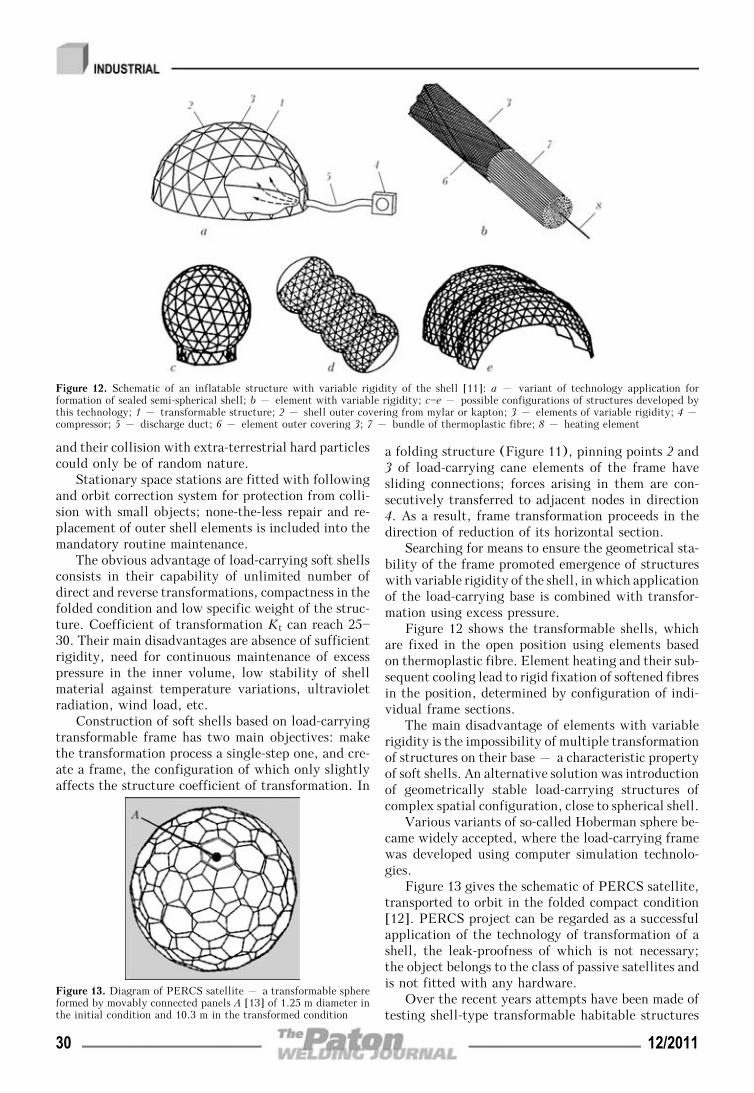
and their collision with extra-terrestrial hard particlescould only be of random nature.
Stationary space stations are fitted with followingand orbit correction system for protection from colli-sion with small objects; none-the-less repair and re-placement of outer shell elements is included into themandatory routine maintenance.
The obvious advantage of load-carrying soft shellsconsists in their capability of unlimited number ofdirect and reverse transformations, compactness in thefolded condition and low specific weight of the struc-ture. Coefficient of transformation Kt can reach 25—30. Their main disadvantages are absence of sufficientrigidity, need for continuous maintenance of excesspressure in the inner volume, low stability of shellmaterial against temperature variations, ultravioletradiation, wind load, etc.
Construction of soft shells based on load-carryingtransformable frame has two main objectives: makethe transformation process a single-step one, and cre-ate a frame, the configuration of which only slightlyaffects the structure coefficient of transformation. In
a folding structure (Figure 11), pinning points 2 and3 of load-carrying cane elements of the frame havesliding connections; forces arising in them are con-secutively transferred to adjacent nodes in direction4. As a result, frame transformation proceeds in thedirection of reduction of its horizontal section.
Searching for means to ensure the geometrical sta-bility of the frame promoted emergence of structureswith variable rigidity of the shell, in which applicationof the load-carrying base is combined with transfor-mation using excess pressure.
Figure 12 shows the transformable shells, whichare fixed in the open position using elements basedon thermoplastic fibre. Element heating and their sub-sequent cooling lead to rigid fixation of softened fibresin the position, determined by configuration of indi-vidual frame sections.
The main disadvantage of elements with variablerigidity is the impossibility of multiple transformationof structures on their base – a characteristic propertyof soft shells. An alternative solution was introductionof geometrically stable load-carrying structures ofcomplex spatial configuration, close to spherical shell.
Various variants of so-called Hoberman sphere be-came widely accepted, where the load-carrying framewas developed using computer simulation technolo-gies.
Figure 13 gives the schematic of PERCS satellite,transported to orbit in the folded compact condition[12]. PERCS project can be regarded as a successfulapplication of the technology of transformation of ashell, the leak-proofness of which is not necessary;the object belongs to the class of passive satellites andis not fitted with any hardware.
Over the recent years attempts have been made oftesting shell-type transformable habitable structures
Figure 12. Schematic of an inflatable structure with variable rigidity of the shell [11]: a – variant of technology application forformation of sealed semi-spherical shell; b – element with variable rigidity; c—e – possible configurations of structures developed bythis technology; 1 – transformable structure; 2 – shell outer covering from mylar or kapton; 3 – elements of variable rigidity; 4 –compressor; 5 – discharge duct; 6 – element outer covering 3; 7 – bundle of thermoplastic fibre; 8 – heating element
Figure 13. Diagram of PERCS satellite – a transformable sphereformed by movably connected panels A [13] of 1.25 m diameter inthe initial condition and 10.3 m in the transformed condition
30 12/2011

out of terrestrial atmosphere. None of the announcedprojects, however, has been so far realized in it is fullscope. In 2006—2007 Bigelow Aerospace, USA,launched to 500 km orbit the first two prototypes ofhabitable space stations, which are soft leak-proofmultilayer shells of 150 mm thickness supported on aframe (Figure 14). After transformation by inducingexcess pressure in the inner volume, module diameterincreases up to 2.54 m at unchanged length [14]. Atconsiderable specific weight of the rigid metal frameand low coefficient of transformation, the modulestructures lack the main advantages of flexible shells,but have the decisive advantages when being launchedby rocket-carriers with a relatively small section ofthe transportation compartment.
Modern materials with new properties allow cre-ating space TS, in which the transformation coefficientKt can reach 10. However, the problem of combiningthese parameters with sufficient strength and leak-proofness of the shells is still unsolved. In particular,the structures of vacuum-tight shells of Genesis mod-ules are capable of providing transformation coeffi-cients Kt ≈ 1.6, which under the terrestrial conditionsare acceptable only at transformation of the volumeof some laboratory and measuring devices, or futurestructures, in which parallel problems of optimizationof weight-dimensional and strength characteristics aresolved.
Transformation of the volume of individual ele-ments of instruments is widely used in laboratory andmeasuring instrumentation, in components of pipingsystems, and in special stop valves, in particular tu-bular condensers – torroidal shells with a circularor close to circular shape of the meridian, capable ofundergoing slight elastic deformations. Bellows –thin-walled tubes with circular corrugations, in mostof the cases made from nonferrous metal alloys andalloyed steels, became widely accepted.
In bellows structures Kt is determined by the fea-tures of shell profile, capable of compression onlywithin the intercorrugation spaces. Bellows are leak-proof, and can be subjected to multiple shape changesunder the impact of varying pressure, but they havea special feature – loss of axial stability at innerpressure, while not having sufficient bending rigidity.
Comparative analysis of currently-available TSclasses leads to the conclusion that combination oftechnologically acceptable strength characteristics ofthe shell with considerable transformation coefficientsat simultaneous leak-proofness is only achievable inrigid load-carrying shells, among which conical andmulticone transformable structures are the optimumvariant owing to simplicity of technology. None-the-less, functional qualities of this class of TS are limitedby lack of well-established algorithm of multiple formchange, while absence of invariance of embodimentsrequires development of a versatile calculation proce-dure of determination of basic geometrical parameters.
One of the main approaches to optimization of rigidtransformable shell design, allowing an essential ex-pansion of their applications, is creation of a two-layerstructure, in which the consequences of possible de-pressurizing can be prevented owing to duplication ofthe outer wall.
It was experimentally established that the processrealized mainly at the expense of material bendingdeformation also allows performing simultaneous formchange of several billets of equal geometry. Furtherassembly and welding of basic elements in TS areperformed on circumferential load-carrying elements(frame-rings), fulfilling the functions of a jig at align-ment of basic element edges, of backing during thewelding process and of load-carrying element takingtechnological and service loads (Figure 15, b). Tight-ness of contact of two-layer shell edges is ensured bya specially developed device, which allows tying basicelements along TS axis.
After sealing the produced discs around the largeand small base of initial cone, their reverse transfor-mation into a conical shell is performed by inducingexcess pressure in the inner volume. After final trans-formation the shell surface preserves the characteristiccircumferential corrugations, caused by local tensionof material in the tips of technological edges at formchange and increasing the radial rigidity of the pro-duced structure.
The purpose of the experiment with test two-layershell consisted in determination of the influence ofduplicating wall on the nature of transformation anddegree of increase of excess pressure, required forstructure transformation. Figure 15 gives the modelof two-stage shell structure in the compact and de-ployed condition. The shell was fitted with a pressuregage with 0.01⋅104 Pa division value. At smooth in-crease of pressure opening of a two-layer corrugateddisc proceeded in stages, starting with larger diametercorrugations and ending by smaller ones, inner shelldeformation causing increase of excess pressure in theinterwall space, and, consequently – opening of theouter shell.
Figure 14. Genesis space module I/II [14] (1363 kg weight, 4.4 mlength in the transformation condition, diameter before transfor-mation 1.6, after transformation – 2.54 m): 1 – rigid metal frame,carrying life support systems of the module; 2 – transformableshell; 3 – docking assembly
12/2011 31

After achievement of maximum pressure value forthe current diameter, the corrugation deployed jum-plike, pressure decreasing abruptly, because of in-crease of the shell inner volume; the process was re-peated right up to complete transformation of TS tothe calculated dimensions. Pressure required for com-plete transformation of the two-layer shell was equalto P2 = 22.1⋅104 Pa, and for single-layer shell withsimilar parameters P1 = (9.32—9.51)⋅104 Pa. Thus, the
duplicating wall required more than two times in-crease of technological pressure of transformation.
During transformation of the truncated cone intoa corrugated disc and subsequent reverse transforma-tion precise geometrical dependencies between the an-gle of conicity, length of cone generatrix and corru-gated disc parameters are ensured, that allows simu-lation of the technological operations and double-shellTS components with high precision. Results obtainedduring the experiment allow making the conclusionabout the possibility of development of extended two-stage structures, similar to the currently availablemulticone TS of periodical profile.
Future tasks of application of multicone TS asextendable systems and case parts of orbital spacemodule are related to the need for their subsequentrecovery, requiring optimization of the mechanism ofreverse transformation with preservation of initial ge-ometry. The capability of transformable rigid shellsfor multiple reproducibility of stable geometrical di-mensions is in keeping with the bases of the methodof regular isometric transformation. However, the realmetal shell after the first repeated cycle of transfor-mation develops wave-like deformations in the inter-corrugation spaces, which are indicative of the localloss of stability (Figure 16).
During the conducted experiment a rarefaction ofapproximately P = —9.32⋅104 Pa was induced in themodel inner cavity by a vacuum pump, that corre-sponds to reverse value of pressure that is requiredfor deployment of the initial corrugated disc. Withinthe complete transformation cycle of 33 s duration, acomplete restoration of the initial shape of a two-stageshell with local deformations in the vicinity of edgetip was noted. At subsequent cycles an increase oflocal deformation and combining of their localizationzones was noted, which leads to overall loss of struc-ture stability.
One of the possible variants of the change of trans-formation technology for realization of multiple formchange of the shell can be reduction of the rounding-offradius of matrix edge tips, increasing the rigidity ofresidual circumferential corrugations. Here, the zonesof maximum elasto-plastic deformations are localized
Figure 16. Reverse transformation of conical shell with sinusoidalprofile of the generatrix (material – titanium VT1-0 0.15 mmthick): a – intermediate stage of transformation; b – full reversetransformation of the shell; c – shell appearance after completereverse transformation
Figure 15. Model of a two-stage transformable conical shell (material – VT1-0 titanium 0.15 mm thick): a – compact condition; b –deployed condition; c – axial sections of load-carrying elements (frame rings) I and II; C, D – load-carrying and auxiliary framerings; F – shell bottom; G – transformable conical shells
32 12/2011

in the vicinities of the corrugation tips, and thesinusoidal profile of the conical generatrix becomesclose to the shape of piecewise-broken curve, corre-sponding to the initial mathematical model of mirrorreflection of a truncated conical surface.
Figure 17, a and b, shows the stages of reversetransformation of a model of conical TS withpiecewise-broken profile of the generatrix, and con-figuration, corresponding to the shell, shown in Fi-gure 16. After complete restoration of the initial shapeno deformations were noted, and no zones of local lossof stability were found at three subsequent cycles.Figures 16, c and 17, c show the appearance of conicalTS with sinusoidal and piecewise-broken profiles ofthe generatrix after complete reverse transformation.In Figure 16, c one can see an abrupt distortion of theshell surface in the form of multiple fractures of in-tercorrugation spaces, and the shell in Figure 17, chas completely preserved its initial geometrical di-mensions.
Conducted experiments on model samples are in-dicative of the possibility of repeated transformationof TS with structural elements of conical type anddevelopment of two-stage TS.
Analysis of various TS classes showed that theyare becoming ever wider accepted in building industryand aerospace engineering. TS developed at PWI onthe base of rigid load-carrying shells are promisingfor application under various conditions of mountingand service, including extreme conditions.
1. (2003) Space: technologies, materials, structures. Ed. byB.E. Paton. Taylor&Francis, 447—495.
2. Paton, B.E., Lapchinsky, V.F. (1997) Welding and relatedtechnologies in space. Cambridge Int. Sci. Publ., 88—105.
3. Paton, B.E., Lobanov, L.M., Samilov, V.N. et al. (2006)Design and features of fabrication technology of a large-sized transformable shell structure. The Paton Welding J.,7, 2—10.
4. Inflatable structures. www.lindstrandusa.com5. Air-supported structures. www.vingida.ru6. Air-supported installations for military purposes. www.
ilcdover.com7. Bernhardt, A., Siefring, C.L., Thomason, J.F. et al. (2008)
The design and applications of a versatile HF radar calibra-tion target in low-earth orbit. Radio Sci., 8, 11—21.
8. Description of PAGEOS project. www.nssdc.gsfs.nasa.gov
9. Hughes, S.J., Dillman, R.A., Starr, B.R. et al. (2010) In-flatable Re-entry vehicle experiment (IRVE) design overvi-ew. In: Proc. of 18th AIAA Conf. and Seminar on Aerody-namic Decelerator Systems Technology (Munich, Germany,May 23—26, 2010), 52—58.
10. Zeigler, Th.R. Collapsible self-supporting structures a pa-nels and nud therefor. Pat. 4290244 USA. Int. Cl. E04B1/32. Publ. 22.09.1981.
11. Sallee, B.T. Rigidizable inflatable structure. Pat. 5579609USA. Int. Cl. B64699/00. Publ. 12.03.1996.
12. Self-opening satellite PERCS. www.hoberman.com13. Hoberman, C. Folding covering panels for expanding struc-
tures. Pat. 6834465 USA. Int. Cl. E04 B1/344. Publ.28.12.2004.
14. Module Genesis II. www.bigelowaerospace. com
Figure 17. Reverse transformation of conical shell with piecewise-broken profile of the generatrix (material – titanium VT1-00.15 mm thick): a – intermediate stage of transformation; b –full reverse transformation of the shell; c – appearance of the shellafter full reverse transformation
12/2011 33

APPLICATION OF AUTOMATIC ORBITAL WELDINGTO FABRICATE ABSORBING INSERTS
FOR SPENT NUCLEAR FUEL STORAGE CONTAINERS
V.A. BOGDANOVSKY1, V.M. GAVVA1, N.M. MAKHLIN1, A.D. CHEREDNIK1, A.V. TKACHENKO1,V.B. KUDRYASHEV2, A.P. KULIKOV2 and A.V. KOVALYUK2
1E.O. Paton Electric Welding Institute, NASU, Kiev, Ukraine2Separated Structural Unit «Atomenergomash» of State Enterprise
«National Nuclear Energy Generating Company ENERGOATOM», Kiev, Ukraine
Considered is application of automatic orbital TIG welding for production of tight butt-lock joints on absorbing elements,which are the base of absorbing inserts of spent nuclear fuel storage containers. Results of optimisation of the TIGwelding technology and ranges of optimal parameters for making of such joints are presented. The commercial unitdesigned for welding of the lock joints on the absorbing elements and the results of its test operation are described.
Keywo rd s : automatic orbital welding, absorbing inserts,nuclear power plants, butt-lock joints, technological rig, nuclearsafety
In compliance with requirements for nuclear safety ofwater-moderated reactors (WWER type) of powergenerating units operating at nuclear power plants(NPP), to maintain the required level of subcriticalitythe fuel assemblies (FA) are fitted with absorbingrods of the control and protection system (AR CPS).The same principle of securing the nuclear safety isused for storage of the spent nuclear fuel. Accordingto this principle, under conditions of normal operationand in design accidents the value of the neutron mul-tiplication factor should not exceed 0.95 [1—3].
One of the methods for securing the nuclear safetyof charges of ventilated storing containers for dry stor-age of the spent nuclear fuel (VSC DSSNF) is fittingup of spent FA with absorbing inserts (AI), whichare used along with spent AR CPS and compensatefor deficit of the latter.
The absorbing insert used in VSC DSSNF of theZaporozhie NPP, which was developed by the NationalScience Centre «Karkov Institute of Physics and Tech-nology» (NSC KhIPT), consists of a cross-arm and18 absorbing elements (AE). The AI cross-arm servesfor simultaneous transportation of the AEs and theirranging during transportation and technological op-erations. The AEs are intended for placement of anabsorbing material in guide channels of spent FA. AE
is analogue of AR CPS in design, shape, overall andsetting-out dimensions.
AE consists of a shell (Figure 1) filled up withvibrocompacted boron carbide powder, weighting ma-terial, tip, cone (cap) and plugs. The shell is manu-factured from a pipe with a diameter of 8.2 mm andwall thickness of 0.6 mm made from austenitic chrome-nickel steel 08Kh18N10T or 12Kh18N10T, tip andcone (rod of the same steel).
According to the AI manufacture technology de-veloped and applied by NSC KhIPT, the sealing butt-lock joints between the shell of AE and its tip andcone are made by the roll butt TIG welding method,in which the workpiece is rotated about its axis at awelding speed, while the torch with tungsten electrodeis in a fixed spatial position. The shell is welded tothe cone in argon, and to the tip – in a controlledatmosphere (helium) [4]. Specialised units ASTE-7and SA-281 developed by the Research and Develop-ment Institute of Construction Technology (NIKIMT)(Moscow) are used for the welding process [5].
This technology provides the required quality ofthe welded joints on AE, which is proved by the ex-perience of manufacture of the AIs and their applica-tion in VSC DSSNF of the Zaporozhie NPP. At thesame time, increase in output of AE caused by theemerging growth of the demand for AI is limited toa certain degree by peculiarities of operation of thedurable roll butt welding units, their functional pos-sibilities and level of the end productivity, difficultiesin upgrading of this equipment or its replacement bythe new one. Also, the noted peculiarities of the equip-ment employed hamper upgrading of some componentsof the AE technological manufacture cycle.
One of the possible ways of improving the existingAI manufacturing technology is the technology forsealing of the butt-lock joints on AE by the methodof orbital position butt TIG welding, as well as the
Figure 1. Schematic of absorbing element: 1 – cone (cap); 2 –filling material (boron carbide powder); 3 – shell; 4, 5 – plugs;6 – weighing material; 7 – tip
© V.A. BOGDANOVSKY, V.M. GAVVA, N.M. MAKHLIN, A.D. CHEREDNIK, A.V. TKACHENKO, V.B. KUDRYASHEV, A.P. KULIKOV and A.V. KOVALYUK, 2011
34 12/2011
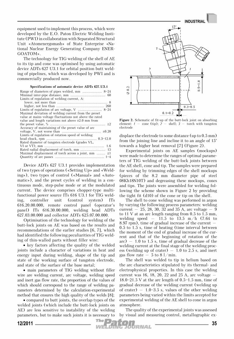
equipment used to implement this process, which weredeveloped by the E.O. Paton Electric Welding Insti-tute (PWI) in collaboration with Separated StructuralUnit «Atomenergomash» of State Enterprise «Na-tional Nuclear Energy Generating Company ENER-GOATOM».
The technology for TIG welding of the shell of AEto its tip and cone was optimised by using automaticdevice ADTs 627 U3.1 for orbital position butt weld-ing of pipelines, which was developed by PWI and iscommercially produced now.
Specifications of automatic device ADTs 627.U3.1Range of diameters of pipes welded, mm .................. 8—24Minimal inter-pipe distance, mm ................................ 60Limits of regulation of welding current, A:
lower, not more than .............................................. 8higher, not less than ............................................ 260
Limits of regulation of arc voltage, V ...................... 8—24Maximal deviation of welding current from the presetvalue at mains voltage fluctuations not above the ratedvalue and length variations not above ±2.0 mm fromthe preset value, % ................................................... ±2Accuracy of maintaining of the preset value of arcvoltage, V, not worse than .................................... ±0.20Limits of regulation of rotation speed of weldinghead chuck, rpm .............................................. 0.3—12.0Rated diameter of tungsten electrode (grades VL,VI or VT), mm ....................................................... 1.6Rated radial displacement of torch, mm ....................... 15Maximal displacement of torch across a joint, mm ........ ±1Quantity of arc passes ............................................. 1—4
Device ADTs 627 U3.1 provides implementationof two types of operations («Setting Up» and «Weld-ing»), two types of control («Manual» and «Auto-matic»), and the preset cycles of welding in a con-tinuous mode, step-pulse mode or at the modulatedcurrent. The device comprises chopper-type multi-functional power source ITs 616 U3.1 for TIG weld-ing, controller unit (control system) ITs616.20.00.000, remote control panel (operator’spanel) ITs 616.30.00.000, welding head ADTs627.03.00.000 and collector ADTs 625.07.00.000.
Optimisation of the technology for welding of thebutt-lock joints on AE was based on the results andrecommendations of the earlier studies [6, 7], whichhad identified the following peculiarities of TIG weld-ing of thin-walled parts without filler wire:
• key factors affecting the quality of the weldedjoints include a character of variations in heat andenergy input during welding, shape of the tip andstate of the working surface of tungsten electrode,and state of the surface of the base metal;
• main parameters of TIG welding without fillerwire are welding current, arc voltage, welding speedand inert gas flow rate, the proportion of the values ofwhich should correspond to the range of welding pa-rameters determined by the calculation-experimentalmethod that ensures the high quality of the welds [8];
• compared to butt joints, the overlap types of thewelded joints (which include the butt-lock joints onAE) are less sensitive to instability of the weldingparameters, but to make such joints it is necessary to
displace the electrode to some distance (up to 0.5 mm)from the joining line and incline it to an angle of 15°towards a higher heat removal [7] (Figure 2).
Experimental joints on AE samples (mockups)were made to determine the ranges of optimal parame-ters of TIG welding of the butt-lock joints betweenthe AE shell, cone and tip. The samples were preparedfor welding by trimming edges of the shell mockups(pieces of the 8.2 mm diameter pipe of steel08Kh18N10T) and degreasing these mockups, conesand tips. The joints were assembled for welding fol-lowing the scheme shown in Figure 2 by providingthe tight fit (d10) of the cone or tip on the shell.
The shell to cone welding was performed in argonby varying the following process parameters: weldingcurrent – 25, 28, 30, 32 and 35 A, arc voltage – 9to 11 V at an arc length ranging from 0.5 to 1.5 mm,welding speed – 11.5 to 13.5 m/h (7.64 to8.97 rpm), time of gradual increase of the current –0.5 to 1.5 s, time of heating (time interval betweenthe moment of the end of gradual increase of the cur-rent and that of the beginning of rotation of thearc) – 1.0 to 1.5 s, time of gradual decrease of thewelding current at the final stage of the welding proc-ess (welding up of crater) – 1.0 to 2.5 s, and inertgas flow rate – 5 to 8 l/min.
The shell was welded to tip in helium based onthe arc characteristics stipulated by its thermal- andelectrophysical properties. In this case the weldingcurrent was 16, 18, 20, 22 and 25 A, arc voltage –18.0—21.5 V at the arc length of 0.5—1.5 mm, time ofgradual decrease of the welding current (welding upof crater) – 1.0—3.5 s, values of the other weldingparameters being varied within the limits accepted forexperimental welding of the AE shell to cone in argonatmosphere.
The quality of the experimental joints was assessedby visual and measuring control, metallographic ex-
Figure 2. Schematic of fit-up of the butt-lock joint on absorbingelement: 1 – cone (tip); 2 – shell; 3 – torch with tungstenelectrode
12/2011 35

aminations, intercrystalline corrosion (ICC) resis-tance tests and leakage tests. The visual and measuringcontrol was carried out in compliance with require-ments of the standards in force in the industry [9] byusing a micrometer, as well as a magnifying glass andbinocular microscope (e.g. MVS-9) with the ×(8—10)magnification. The metallography was done on themacrosections cut out from the resulting welded jointsby using a metallurgical microscope with the ×(50—100) magnification to determine the penetrationdepth, defects in the weld metal (non-metallic inclu-sions, pores, wormholes and lacks of fusion), structureof the weld and HAZ metal, and austenite grain sizes.The ICC resistance tests of the weld and HAZ metalwere conducted by the AMU method according toGOST 6032—89. The leakage tests were conducted byusing a mass-spectrometer and helium leak detectorPTI-10 by the vacuum chamber method in compliance
with the requirements and procedures specified in theoperating regulatory-technical documents [10].
Welding of several series of the experimental jointsbetween the AE shell, cone and tip, comprehensiveinspection of the quality of these joints and analysisof the obtained results allowed a conclusion that toensure the consistent high quality of the butt-lockjoints on AE the main TIG welding parameters shouldcorrespond to those indicated in the Table.
Results of the experimental and technological de-velopment efforts made by PWI for optimisation ofthe technology for TIG welding of the sealing butt-lock joints on EA proved the expediency of commercialapplication of this technology for mass production ofboth AI for VSC DSSNF and (in the future) AR CPSfor FA of the WWER type reactors.
The special technological rig, the schematic ofwhich is shown in Figure 3, was developed and manu-factured to implement TIG welding of sealing joints
Main parameters of TIG welding of joints on absorbing elements
Parameter Shell-cone Shell-tip
Grade of 1.6 mm diameter tungsten electrode EVI-1, EVI-2, EVI-3, EVI-15 and EVI-20 acc. to GOST23949—80, or «Abicor Binzel» WT-20, WR-2 and WR-2D
Shielding gas Argon acc.to GOST 10157—79
Helium acc.to TU 51-940—80
Welding current, A 30.0±1.2 20.0±1.0
Arc voltage, V 9—10 19—20
Arc length, mm 0.5—1.0
Welding speed (rotation speed of welding head chuck), m/h (rpm) 12.0±0.4 (7.98±0.27) 13.0±0.45 (8.63±0.30)
Time of gradual increase of welding current, s 1.0±0.1
Heating time interval, s 0.75±0.05
Time of gradual decrease of welding current (welding up of crater), s 2.0±0.1 3.0±0.1
Shielding gas flow rate, l/min 5.9—7.1 4.9—6.1
Time of preliminary purging of welding zone with shielding gas (timeinterval «gas before welding»), s, not less than
5—10
Time of purging of welding zone with shielding gas at final stage ofwelding cycle (time interval «gas after welding»), s, not less than
10—20
Figure 3. Schematic of the rig for TIG welding of butt-lock joints on AE: 1 – gas bottle rack; 2 – welding chamber; 3 – weldinghead ADTs 627.03.00.000; 4 – collector ADTs 625.07.00.000; 5 – remote control panel ITs 616.30.00.000; 6 – power source ITs616.U3.1; 7 – controller unit ITs 616.20.00.000; 8 – cradle; 9 – vacuum valve unit
36 12/2011

on AE and similar parts commercially fabricated by«Atomenergomash».
The rig comprises all components of ADTs 627U3.1 for orbital position butt TIG welding, a weldingchamber, vacuum valve unit, guide cradle and gasbottle rack.
The chamber (see Figure 3) with the welding headrigidly fixed inside it provides:
• repeatability and, if necessary, adjustment, fixa-tion of the spatial position and alignment of the butt-lock joints on AE prepared for welding with respectto tungsten electrode of the torch mounted on thewelding head chuck;
• free access to the welding head and adjustors ofspatial position of the torch with the tungsten elec-trode, thus facilitating maintenance of the head with-out its removal from the chamber;
• electric insulation of the current and gas supplylines of the welding torch and control circuits of itsrotator with respect to the chamber casing, weldmentand other non-current-conducting components of the rig;
• meeting the leak tightness requirements in evacu-ation of the internal volume of the chamber for sub-sequent creation of the controlled atmosphere in it byfilling it with helium and maintaining the excess pres-sure at a level of (1.96±0.2) kPa;
• possibility of observation of the course of thewelding process through a viewing window.
The general view of the chamber is shown in Fi-gure 4.
The valve unit (see Figure 3) is intended for evacu-ation of the internal volume of the chamber with rare-fication to a level of not less than 1.33 Pa.
The cradle is a guide support for placement of anabsorbing element to be welded in the rig. It protectsthe AE shell from deformation and mechanical damageduring preparatory and final operations, and duringwelding of the sealing joints on AE.
Testing of the PWI technology for TIG weldingof sealing joints on AEs under industrial conditionsof «Atomenergomash» showed that the use of the rig(see Figure 3) does not only provide the consistenthigh quality of the welded joints on AEs, but alsoleads to some decrease in labour intensiveness and toreduction of duration of the setting up operations pre-ceding the welding process (compared to the existingroll butt welding technology), and simplifies trainingof welders and attending personnel. The test resultsserved as forcible arguments in favour of arrangementof the specialised sector for commercial fabrication ofabsorbing elements at «Atomenergomash». Techno-logical fitting of this sector and its productivity withone rig used for welding allow producing up to 1200AEs a year. The equipment of the sector was used tofabricate an experimental batch of AEs, the samplesof which were subjected to comprehensive tests (in-cluding by the destructive testing methods) at NSCKhIPT. These tests proved a full correspondence ofthe quality of the joints on AEs made by the orbitalTIG welding technology to the requirements of thestandards. Also, it was established that the butt-lockjoints on AEs made by the orbital TIG welding tech-nology are identical in their penetration depth, struc-
ture of the weld and HAZ metal, austenite grain sizesand mechanical strength to those made by the existingroll butt welding technology.
CONCLUSIONS
1. The developed technology for TIG welding of over-lap joints on different-thickness small-diameter bodiesof revolution by using automatic orbital welding de-vices of the ADTs 627 U3.1 type provides the high-quality butt-lock joints on AEs and similar parts.
2. Commercial application of the developed TIGwelding technology and corresponding technologicalequipment will allow manufacturing AIs, AR CPSand similar parts in volumes that meet the nuclearpower generation needs.
1. PN AE G-14-029—91: Safety rules in storage and transporta-tion of nuclear fuel at nuclear power objects (Gosatom-nadzor SSSR). Moscow: Energoatomizdat.
2. NP 306.2.105—2004: Principles of securing safety of interme-diate dry type storages. Kyiv: Derzhatomregulyuvannya.
3. (2007) Technical regulations concerning containers for stor-age and burial of radioactive wastes: Resolution of theCabinet of Ministry of Ukraine 939 of 18.07.2007.
4. (1999) Studies of the technology for fabrication and devel-opment of the program for mastering and production of ARCPS in Ukraine: Report of NTK YaTTs NNTs KhFTI.Kharkov.
5. (1985) Welding equipment: Catalogue. Ed. by A.A.Kurkumeli. Moscow: TsNIIatominform.
6. Ishchenko, Yu.S. (2002) Physico-technological principles ofweld formation in arc welding. In: Welding in nuclear in-dustry and power engineering: Transact. of NIKIMT,Vol. 2. Moscow: IzdAT.
7. Bukarov, V.A. (2002) Technology of automatic gas-shieldedarc welding. Ibid., Vol. 1.
8. Poloskov, S.I., Bukarov, V.A., Ishchenko, Yu.S. (2000) In-fluence of deviations of parameter of position butt argon-arcwelding on the quality of welded joints. In: Proc. of All-Un-ion Sci.-Techn. Conf. on Welding and Related Technologies(Moscow, Sept. 2000). Moscow: MEI, 22—25.
9. (1989) Unified procedure for control of base materials(semi-finished products), welded joints and surfacing ofNPP equipment and pipelines. Visual and measuring con-trol of PN AE G-7-016—89 (Goskomnadzor SSSR). Moscow:Energoatomizdat.
10. (1989) Unified procedure for control of base materials(semi-finished products), welded joints and surfacing ofNPP equipment and pipelines. Leakage test. Gas and liq-uid methods of PN AE G-7-019—89 (Goskomnadzor SSSR).Moscow: Energoatomizdat.
Figure 4. General view of chamber (1) and welding head ADTs627.03.00.000 (2)
12/2011 37

TWO-LAYER BIO-CERMETTITANIUM—HYDROXYAPATITE COATING
K.A. YUSHCHENKO, Yu.S. BORISOV, S.G. VOJNAROVICH, A.N. KISLITSA and E.K. KUZMICH-YANCHUKE.O. Paton Electric Welding Institute, NASU, Kiev, Ukraine
It is suggested using two-layer bio-cermet (titanium—hydroxyapatite) coatings for titanium alloy endoprostheses. Acombination of porous titanium with an external hydroxyapatite (HA) layer provides high strength of adhesion of suchcoatings to the surfaces of endoprostheses (24—25 MPa) and subsequent active growth of bone tissue into them. Themicroplasma spraying technology allows formation of the HA layer with the 88—98 % content of the crystalline phase,thus providing a high degree of utilisation of the powder (up to 90 %) in spraying and increasing the cost effectivenessof the process.
Keywo rd s : microplasma spraying, medical-applicationcoatings, bio-compatible coatings, porous titanium, hydroxyapa-tite, endoprosthetics, hip joint
Metal implants with bio-active ceramic coatings arewidely applied now in medical practice. These im-plants are characterised by a triple positive effect:increased rate of formation of the bone tissue, possi-bility of formation of bond with the bone (osteointe-gration), and decrease in formation of metal corrosionproducts. This allows substantial reduction of the timeof implantation of an endoprosthesis, provides the re-liable bond with the bone and improves reliability ofthe implants. The most extensively used bio-activeceramics are ceramics based on calcium phosphate, i.e.hydroxyapatite (HA), or other calcium phosphatesclose to it in composition [1, 2].
Bio-ceramic coatings of HA are deposited by usingdifferent methods (magnetron sputtering, electro-phoretic deposition, sol gel method, etc.), includingplasma spraying, which has received a real practicalapplication in production of coated endoprostheses[2—5].
The following main requirements to quality of thebio-ceramic coatings were worked out on the basis ofclinical application of endoprostheses with such coat-ings: sufficiently high strength of adhesion to the endo-prosthesis surface (15 MPa or more, according to stan-dard ISO 13779—2), high content of the crystalline phase(not less than 70 %), and presence of developed porosityproviding ingrowth of the bone tissue.
Phase composition of a coating (degree of crystal-linity) has a considerable effect on the osteointegra-tion process. During this process the amorphous HAphase has a higher rate of dissolution, thus reducingthe time of recovery of a patient but, at the same time,decreasing reliability of fixation of an endoprosthesisin the bone.
A drawback of the conventional plasma sprayingmethod is formation of coatings with a high contentof the amorphous phase, which is caused by conditionsof both heating of the HA particles (because of the
need to use working gases with increased thermal con-ductivity, i.e. Ar + H2 and Ar + He mixtures) andtheir solidification on the substrate surface [6].
In the last years the E.O. Paton Electric WeldingInstitute has developed the microplasma sprayingmethod and equipment, allowing spraying of ceramiccoatings by using the laminar jet of argon plasma [7].A low thermal conductivity of argon decreases theintensity of heating of the particles, thus decreasingthe temperature gradient across their sections. Inspraying of the HA coatings this allows avoidance ofoverheating of the melt of HA and formation of toxicproducts of its decomposition (CaO). Low velocitiesof the HA particles under conditions of the laminarjet lead to formation of coatings from the particleswith a lower deformation degree and, hence, lowerrate of hardening on the substrate, which provides thehigh content of the crystalline phase (up to 95—98 %).
In this connection, the E.O. Paton Electric Weld-ing Institute completed a package of work on devel-opment of the compositions and technology for depo-sition of bio-ceramic coatings on endoprostheses byusing microplasma spraying [8—10].
The technology for microplasma spraying of two-layer bio-cermet (Ti + HA) coatings on implant sur-faces was developed to increase strength of adhesionof the coatings to the bone implant surfaces. Thistechnology allows deposition of a titanium coatingwith regulated porosity by microplasma spraying us-ing a variant of wire spraying.
The two-layer bio-cermet coatings are depositedby using microplasma spraying system MPN-004 (Fi-gure 1), which comprises a power source with a coolingunit, control unit, plasmatron, as well as the inter-changeable wire feed mechanism and powder feederMPD-004 (Figure 2).
The spraying materials for the two-layer bio-cer-met coatings are the 0.3 mm diameter titanium wireof the VT1-00 grade used for deposition of the titaniumcoating with developed porosity, as well as the HApowder used for deposition of the bio-active upper
© K.A. YUSHCHENKO, Yu.S. BORISOV, S.G. VOJNAROVICH, A.N. KISLITSA and E.K. KUZMICH-YANCHUK, 2011
38 12/2011

layer, the phase composition of the HA powder pro-duced by Scientific-and-Technical Service Centre«RAPID» being fully crystalline Ca10(PO4)6(OH)2
with the Ca/P-1.67 ratio.Appearance of the surface and structure of the bio-
cermet coating are shown in Figure 3.The costs of the HA coating deposition process
depend on the consumption of the HA spraying pow-der, the price of the latter being very high. Experi-mental studies of the material utilisation factor(MUF) for HA in deposition of the two-layer bio-cer-met coating show that in the case of microplasmaspraying it is 1.5—2 times higher than in traditionalplasma spraying. For instance, according to literaturedata, the maximal values of MUF in plasma sprayingof HA on a plate are 50—62 %, whereas in microplasmaspraying the maximal value of MUF amounts to 90 %[10]. Under conditions of microplasma spraying thespraying spot has a form of ellipse with an axes ratioof 1.1—1.3 and size of 8—15 mm (instead of 30—40 mmin conventional plasma spraying), depending on thespraying process parameters. The calculations of lossesof the HA powder show that the total losses of thematerial (for recoil and spattering, and losses causedby geometric factor) in microplasma spraying on im-plants 8—10 mm in size (dental, intervertebral cages)are 20—40 %, whereas in traditional plasma sprayingthey amount to 85—90 %.
The investigations conducted resulted in estab-lishing the quantitative dependence of phase compo-sition of the HA coating on such microplasma sprayingparameters as current, plasma gas flow rate, sprayingdistance and powder consumption. Thus, the contentof the crystalline phase of HA in a coating, as wellas the content of the amorphous phase in it are moststrongly affected by the spraying distance. The amountof tricalcium phosphate (β-TCP) in the coating greatlydepends on the plasma gas flow rate and sprayingdistance. Therefore, by varying the microplasma
Figure 1. Appearance of microplasma spraying system MPN-004
Figure 3. Appearance of surface (a) and microstructure (b – ×140) of bio-cermet coating
Figure 2. Appearance of powder feeder MPD-004 (a) and wire feed device MPP-04 (b)
12/2011 39

spraying parameters (current, plasma gas flow rate,spraying distance and powder consumption) it is pos-sible to control phase composition of the HA coatingsat a content of the HA crystalline phase ranging from88 to 98 %, degree of amorphism in a range of 0 to7 % and TCP content (degree of decomposition ofHA) in a range of 0 to 6 %. Hence, it is possible tocontrol formation of the HA coatings with the speci-fied phase composition.
Strength properties of the two-layer bio-cermetcoatings should provide their integrity and long-timereliable functioning in an organism. According tostandard ISO 13779—2, sufficient strength of adhesionof the coatings to the substrate should be not less than15 MPa. Spraying of the two-layer bio-cermet coatingsby using a titanium coating with developed porosity(pores with a size of 100—150 μm) provides the adhe-sion strength equal to 25.2 ± 0.85 MPa.
Toxic-hygienic estimation of the bio-cermet coat-ings was carried out by the Institute of Macromolecu-lar Chemistry of the NAS of Ukraine*. According tostandard ISO 10993—2, samples of the coatings wereimplanted to white rats. Histological investigationsof such tissues around the implanted coatings showedthat the bio-cermet coatings of HA and titanium (Ti +HA) are non-toxic, bio-compatible with live tissues,and exert no irritating and sensitising effect.
The bio-medical investigations allowed a conclu-sion on the safety and bio-compatibility of endopros-theses with the microplasma bio-cermet coatings (Ti +HA). Recommendations on deposition of the bio-cer-met coatings by the microplasma spraying methodwere worked out on the basis the investigation results.
The developed microplasma spraying technologywas applied for deposition of coatings on hip jointendoprostheses, implants for interbody vertebral spon-dylosyndesis [11] and dental implants (Figure 4).
CONCLUSIONS
1. Microplasma spraying of bio-ceramic HA coatingis characterised by the possibility of producing layers
with a high degree of crystallinity (88—98 %), whichcan be controlled by varying the spraying process pa-rameters. Small size of the spraying spot (3—8 mm)provides substantial decrease (2—3 times) in powderconsumption during spraying on small-size implants,compared to conventional plasma spraying.
2. The two-layer bio-cermet coating (porous tita-nium + HA) provides the strength of adhesion to en-doprosthesis equal to 24—25 MPa and intensificationof growth of the bone into the coating surface.
3. Toxic-hygienic examinations of the microplasmabio-cermet coatings proved their being non-toxic andbio-compatible with live tissues.
4. The bio-cermet coatings (Ti + HA) and tech-nology for their microplasma spraying were used forcoating of hip joint endoprostheses, dental implants,intervertebral cages etc.
Figure 4. Examples of items with bio-cermet coatings produced by microplasma spraying: a – hip joint endoprostheses; b – cermetimplant for interbody vertebral spondylosyndesis; c – dental implant
*The study was carried out under the leadership of Prof. N.A.Galatenko, Doctor of Biological Sciences.
1. Kanazawa, T. (1998) Inorganic phosphate materials. Kiev:Nauka.
2. Shpak, A.P., Karbovsky, V.L., Grachevsky, V.V. (2002)Apatites. Kiev: Akademperiodika.
3. Kalita, V.I. (2000) Physics and chemistry of formation ofbio-inert and bio-active surfaces on implants (Review). Fizi-ka i Khimiya Obrab. Materialov, 5, 28—45.
4. http://www.biomet.co.uk5. http://www.stryker.com6. Yang, C.Y., Wang, B.C., Chang, E. et al. (1995) The influ-
ences of plasma spraying parameters on the characteristics ofhydroxyapatite coatings: a quantitative study. J. MaterialsSci.: Materials in Medicine, 6, 249—257.
7. Borisov, Yu.S., Vojnarovich, S.G., Fomakin, O.O. et al.Plasmatron for spraying of coatings. Pat. 2002076032 Ukra-ine. Int. Cl. B 23 K 10/00. Fil. 19.07.2002. Publ.16.06.2003.
8. Borisov, Yu.S., Vojnarovich, S.G., Bobrik, V.G. et al.(2000) Microplasma spraying of bio-ceramic coatings. ThePaton Welding J., 12, 62—66.
9. Borisov, Yu.S., Vojnarovich, S.G., Ulianchich, N.V. et al.(2002) Investigation of bio-ceramic coatings produced bymicroplasma spraying. Ibid., 9, 4—6.
10. Vojnarovich, S.G. (2010) Effect of microplasma sprayingparameters on material utilisation factor in spraying of bio-ceramic coating. Zbirka Nauk. Pr. Nats. Un-tu Korablebu-duvannya, 433(4), 58—61.
11. Brekhov, O.M., Eliseev, S.L., Ulianchich, N.V. et al. Cer-met implant for interbody vertebral spondylosyndesis. Pat.200112870 Ukraine. Int. Cl. B 23 K 10/10. Fil. 03.12.2001.Publ. 15.03.2002.
40 12/2011

ORGANIZATION AND TOPICS OF R&D IN THE FIELDOF JOINING TECHNOLOGIES CONDUCTED BY TWIAND DVS ASSOCIATION OF RESEARCHERS (Review)
O.K. MAKOVETSKAYAE.O. Paton Electric Welding Institute, NASU, Kiev, Ukraine
The paper gives information on organization and topics of investigations in the filed of joining technologies conductedby TWI and DVS Association of Researchers.
Keywo rd s : joining technologies, topics of R&D, TWI,DVS Association of Researchers
Practice of «openness» of the investigation topics ac-quires a wide-accepted character under conditions ofglobalization of world economic development. The top-ics of planned scientific projects and programs of fun-damental and applied investigations are published in thenational editions as well as on the pages of web-sites byleading welding institutes, centers and welding societiesof many countries, thus inviting to cooperation and mu-tual exchange of the scientific information.
The Institute Welding (TWI, Great Britain) andDVS Association of Researchers (DVS AR, Germany)are the leading European and world scientific centersin the field of joining technologies. Solution of specificand relevant tasks of the industry, i.e. developmentof new joining technologies, investigation of weld-ability of new structural materials, cut of industrialexpenses in welding engineering, quality and safetyof welding operations, increase of safety of weldedstructures, obtaining of scientific and experimentalgrounds to norm and standards etc. is the main direc-tion of the investigation topics conducted in thesescientific centers. High level of maturity of the de-velopments sharply reducing time for technologytransfer is provided for in the research programs ofTWI and DVS.
TWI has been significantly growing its scientific-and-technical potential in the recent years. Numberof researchers working in the Institute increased 1.3times from 500 to 640 persons for the period from2005 to 2010. A total gain from different areas ofactivities exceeded 53 mln GBP in 2010.
Researches on a plan of topics of Basic Investiga-tion Program (CRP) make a basis of fundamental andapplied scientific investigations in area of welding andrelated technologies of TWI. The budget of CRP Pro-gram made around 3.3 mln GBP for 2010—2012, andTWI income from results of the performed R&D wasaround 10 mln GBP in 2010.
TWI conducts significant volume of works ontraining, retraining and attestation of welding per-sonnel, engineering and scientific stuff. A general fundfor financing of this area of activity exceeded 14 mlnGBP per year.
Membership fees from enterprises and individual per-sons from Great Britain as well as other countries of theworld are the main source of financing of TWI scientificand production activities. Significant increase of a num-ber of TWI members is observed in recent years. Thus,110 companies became joint members in 2010 that al-lowed additionally obtaining around 1 mln GBP andthe total gain from membership fees made around 7 mlnGBP. Number of organizations and enterprises-jointmembers of TWI achieved 660 in 2010.
Industrial enterprises and firms (members of TWI)provide financial support at conductance of the spe-cific topics and influence on direction of the performedinvestigations and developments. As a rule, the rep-resentatives of branches of industry reckon on obtain-ing of maximum benefit from the results of CRP Pro-gram for providing competitiveness of their productionin the world market. Only commercial members ofTWI which also can obtain additional information onCRP projects, including during the process of theirexecution, are provided with the final reports on re-sults of R&D, performed in the range of CRP Program.
Organization of performance of the investigationsin TWI is carried out on target projects. A scientificlaboratory or department is organized for performanceof works on that or another scientific direction for thetime of conductance of R&D project and stops itsexistence after work on specific direction is finished.
TWI CRP Program for 2009—2012 includes 57R&D projects which are grouped by five subject di-rections (strength of welded structures; metals andweldability; laser, arc and resistance welding; surfacetreatment; electron beam technologies and technolo-gies of friction welding; plastics; glues, ceramics andelectronics). Each research project is clearly orientedto one or several specific sectors of commercial pro-duction (airspace; motor car construction; weldedstructures and design; war industry; oil-, gas- andchemical industry; power engineering; railway trans-port; sensors and medicine; shipbuilding), where re-alization of obtained R&D results is supposed or whichis a customer of given topic.
17 projects the topics of which can be divided ontwo main groups, i.e. mathematical modelling andvisualization of physico-chemical and mechanicalprocesses (6 projects) and methods for control of qual-ity of welded joints (11 projects), have been per-formed/is performed in «Strength of Welded Struc-© O.K. MAKOVETSKAYA, 2011
12/2011 41

tures» direction. The mathematical modelling andvisualization find wider application in the investiga-tions of welding processes replacing performance ofmultiple expensive experiments. A model for accurateforecasting of the residual stresses in circumferentialwelds of the pipelines is supposed to be developed andgrounded in «Development of Progressive Methodsfor Evaluation of Circumferential Welds of the Pipe-lines» project. The project includes an investigationof changing of circumferential weld metal propertiesin the stress-strain state using stain-based failure as-sessment diagram, development and grounding of amodel for accurate forecasting of the residual stressesin circumferential welds of the pipelines, developmentof a procedure for determination of influence of theresidual stresses on crack formation for evaluation ofcrack resistance of circumferential weld. Developmentof a model for direct metal laser deposition using lasertechnologies that allows determining of the depend-ence between process parameters, material propertiesand resultant quality is the aim of «Progressive Meth-ods of Modelling» project.
Large group of the projects is dedicated to devel-opment of methods of non-destructive testing ofwelded metal structures which, in particular, dealwith evaluation of corrosion damage of steels in acidmedia, development of phased array ultrasonic testing,detection of small fatigue cracks. Computer X-ray to-mography is interesting in application for testing andevaluation of porosity and undulation of black-rein-forced plastic fiber.
Topics of the investigations in «Metals and Weld-ability» direction include 15 projects, aimed at inves-tigation of weldability of structural, heat-resistant,stainless steels, nickel alloys and dissimilar materialsusing different welding technologies, i.e. electronbeam, arc and TIG welding. In particular, the inves-tigations are conducted on following R&D projects:
• Improvement of technology for welding of dis-similar materials – topic is relevant for nuclear-powerengineering;
• Evaluation of weldability of ultrasupercriticalmaterials for power units/power stations – for de-velopment of new structural materials designed formanufacture of turbogenerators of TPP with ultrasu-percritical parameters of vapor;
• Repair of welded structures from heat-resistantsteels with 9 % Cr without heat treatment – appli-cable to repair of turbosets and boiler units underconditions of TPP and NPP.
12 projects refer to the investigations in direction«Laser, Arc and Resistance Welding and Surface Engi-neering». They represent studies the topics of which aredirected on development of new technologies, i.e.MIG/MAG, laser, hybrid laser-arc, welding of partsfrom carbon steel, corrosion-resistant alloys, dissimilarmaterials (steel and copper, steel and aluminum), heat-resistant steels, nickel, titanium and aluminum alloys.
The projects «Welding and Cutting Using NewGeneration Superpower Fiber Lasers and Single andMultipass Hybrid Laser Welding with Adaptive Con-trol» are directly related with study of a peculiarityof interaction of laser and arc heating sources in hybrid
process; selection of alternative combinations of laserwith arc or plasma heating sources, providing highefficiency of welding and quality of the joint; inves-tigation and development of hybrid laser-arc technol-ogy of welding of thin sheets from aluminum alloysand combination of dissimilar materials.
Such investigation topics as «High-EfficiencyLayer-by-layer Laser Surfacing of Metal and LaserSpraying and Cladding» reflect direction of TWI in-vestigation in the field of creation and developmentof processes of surfacing and deposition of special andprotective coatings as well as development of consu-mables of improved quality with special physico-me-chanical and tribological properties designed for coat-ing deposition.
There are seven projects on investigation topicsdirected to «Technologies of Electron Beam and Fric-tion Welding». The projects connected with develop-ment of new technologies of EBW and FSW of ferriteand austenite steels and high-strength aluminum al-loys were represented in the program.
Number of serious research investigations in thefield of development of new types of FSW tool andtechnique has not been reduced in TWI regardlessthat the FSW process was developed and realized backin the 1990s including by means of selling of a licensefor technology and equipment. Thus, a technology ofmicroFSW of aluminum alloys from 0.2—0.3 to 1.5—2.0 mm applicable to performance of the longitudinaland spot welds were developed and has been alreadywidely implemented following the TWI plans.
Additive technologies find greater application incommercial production, in particular, replacing cast-ing techniques in ferrous metallurgy. Possibility ofapplication of this technology for the friction weldingprocess, especially, for development of tool, is sup-posed to be investigated in «Additive TechnologiesApplicable to Friction Welding» project.
There are 9 projects in topic of the investigationsin «Plastics, Glues, Ceramics and Electronics» direc-tion. The projects aimed at investigation and devel-opment of a technology of welding (laser welding,fusion butt welding) and deposition of coatings onthe parts from plastics and composites are representedin the Program, in particular:
• Investigation of polymeric materials reinforcedby carbon nanotubes and designed for operation underextreme environment conditions;
• Improvement of quality of welding for fiber-re-inforced thermoplastics;
• Technologies of joining in medicine [1].DVS – federal society (association), realizing
management and coordination of scientific and tech-nical, industrial and educational activity of differententerprises of Germany, dealing with the problems ofwelding and related technologies. DVS is includedinto Otto von Herike Association of Industrial Re-search Associations (AiF) and includes 14 land and94 regional departments, 9 welding training-experi-mental centers (SLV institutes) and more than 12training-welding centers (SL).
Number of DVS members (collective and individual)in 2010 was 18456, including 597 collective members.
42 12/2011

According to the basic functions of DVS the fol-lowing organizations were formed in its composition:
• DVS Association of Researchers;• DVS Publishing house;• Certification center DVS-ZERT;• Commission on professional training AfB and
independent body DVS-PersZert;• Technical committee on standardization TC;• National delegation in IIW and EWF.To activate engineering research and to increase
the efficiency of professional education the Associationof institutes of welding technology (GSI) is function-ing in DVS since 1999, which combines the weldingeducational-experimental centers (institutes): SLVDuisburg, SLV Berlin-Brandenburg, SLV Halle, SLVMunchen, SLV Felbach, SLV Hannover, SLVSaabrucken, SLV Bilefeld.
The of DVS AR forms program of topics of DVSresearch works, meeting the interests of industry andgeneral strategy of development of research directions;realizes the annual distribution of funds for their per-formance, coordinates the integral developments. Theselection of projects for inclusion into the plan ofR&D of DVS AR is performed within the frames of15 expert commissions (committees): FA1 – metal-lurgy and metals science; FA2 – thermal sprayingand autogenous technology; FA3 –arc welding;FA4 – resistance welding; FA5 – special weldingmethods; FA6 – beam processes; FA7 – brazing;FA8 – adhesion bonding; FA9 – designing and cal-culation; FA10 – microbonding technology; FA11 –joining of plastics; FA12 – modeling of welding proc-esses; FA Q6 – safety instructions and environmentprotection; FA V4 – underwater welding; FA13 –manufacturing methods, production technology.
In 2010 the DVS AR performed R&D on 160 pro-jects, with the total volume of financing of11.5 mln Euro. The bulk of R&D projects is financedby AiF. In 2010 AiF financed 124 research projectsat the sum of 8.8 mln Euro.
The Figure shows data on the number of R&Dprojects, performed by the DVS AR within the framesof financing of AiF in the period of 1999—2009 andtheir cost.
In 2009 the topics of DVS research works were dis-tributed as follows: 86 % – research in the field ofjoining technologies and each 7 % – in the field oftechnology for spraying coatings and cutting technology.
The topics of DVS research works in the field ofjoining technology for different years are given inTable 1.
In the structure of topics of DVS research worksthe main part belongs to the research in the field ofwelding technologies, however their volume in theperiod of 2002—2009 decreased by 10 %. At the sameperiod the volume of research on technologies of braz-ing joining increased practically by 3 times. The Ger-man scientists pay considerable attention to adhesion
bonding technology, which is one of the most chal-lenged at the technology market. It is predicted thatalong with the technology of laser welding the adhe-sion bonding will have the biggest growth. For ex-ample, in 2007 in EU countries more than 30 % ofvolume of production in the structure of productionof welding equipment and rendering services belongedto adhesives and bonding equipment (about 6500 mlnEuro).
The topics of DVS research works in the field ofwelding technology for different years are given inTable 2. As is seen from the Table, the arc fusionwelding preserves the positions of basic welding tech-nology. The volume of topics of research works in thisfield is high and amounts nearly 40 %. In the structureof DVS research works the volume of laser and hybridtechnologies is growing.
The main material for welded structures remainssteel (Table 3). After growth of volume of researchworks in the field of technologies of aluminium weld-ing in 2002, 2007, 2009 the decrease of works in thisdirection is observed. In connection with increasingapplication of new materials, such as ceramics, com-posites in many fields of industry (transport, aircraftindustry, etc.) and also increase in need in joining ofdissimilar materials the volume of research works inthese directions is increased.
Number (a) and total cost (b) of carried out DVS AR R&D projects
Table 1. Topics of DVS research works in the field of joiningtechnology, %
Type of joint 2002 2007 2009
Welding 73 62 64
Microjoints 11 14 12
Adhesion bonding 11 16 8
Brazing 5 8 16
12/2011 43

Quantitatively the topics of DVS research workson basic directions of R&D was divided in the follow-ing way: joining technologies, respectively, in2007 – 42; 2009 – 38; materials – 27 and 17; cal-culation, designing, modeling – 13 and 28; automat-ion – 10 and 7; safety regulations – 8 and 10 %.
The development of new technologies of joiningoccupies the major part (about 40 %) in the topics ofDVS research works. However ever more attention ispaid to studying of visualization of welding processes,including calculations, designing and computer mod-eling. The volume of research works, connected withsafety regulations and environment protection, is in-creased (Table 4).
In conclusion it is necessary to note that famili-arization with topics of R&D works carried out byleading world welding institutes, its analysis allowsdetermination of scientific priorities in research works,clear out the problems at which the scientists are work-ing by the orders of industry, personify the topics ofresearch works, find possible partners, etc. The trans-parency of research topics gives possibility to realizethe international coordination in the development ofactual scientific trends [2].
1. Core research programme 2010—2012: Project summaries.TWI world centre for materials joining technology. www.twi.co.uk
2. Geschaeftsbericht 2010. Innovationen fur die Wirtschaft.Forschung in der Fuegetechnik. DVS. www.dvs-ev.de
Table 2. Distribution of DVS research directions in the field ofwelding technology, %
Joining technology 2002 2007 2009
Arc welding in shielding gas 45 37 38
Resistance welding 18 12 13
Electron beam welding 7 5 5
Hybrid welding 8 13 13
Laser welding 17 22 19
Other 5 11 12
Table 3. Structure of research works in the field of joining ofweldable materials, %
Material 2002 2007 2009
Steel 40 28 34
Aluminium 28 36 21
Plastics 6 7 14
Glass/ceramics 5 5 7
Dissimilar materials 14 16 10
Magnesium 5 5 —
Other 2 2 14
Table 4. DVS R&D projects on separate topic directions
Topic direction Name of the project
Metallurgy and materi-als science
Systems of alloying of flux-cored wires for shielded-gas welding of wrought aluminium alloys and alloysproduced using die castingImprovement of weldability of aluminium by grain refiningInvestigation of prevention of hot cracks in austenite Cr—Ni steels and Ni-based alloys using optimizationof temperature field
Thermal spraying andautogenous technology
Development of express-methods of NDT for measuring mechanic characteristics and porosity of thermal-sprayed coatingsThermographic methods of NDT for evaluation of thermal-sprayed coatingsImprovement of quality of coatings deposited using arc method applying modified autogenous technologyand high-velocity gas flows
Arc welding Increase of stability of welding process in shielding gas using modified shielding gas flowDevelopment of system of control of welding torch for automatic welding of steel and aluminium alloysin shielding gasEvaluation of efficiency of welding in shielding gas
Special weldingmethods
Investigation of FSW of steel and aluminiumDevelopment of conception of evaluation of fitness of installations for FSW and also determination ofwelding parametersDevelopment of on-line control for FSW on the basis of sensors integrated into the tool
Beam welding methods Application of multi-beam technology for decrease of internal stresses in the EB- and laser-welded partsHybrid laser-arc welding of thick-wall precision pipesHybrid laser-arc welding using low power arc methods
Designing and calcula-tion
Experimental research and numerical modeling of deformation process of aluminium welded jointssubjected to impactCalculation of micromagnetic characteristics of internal stresses in steels welded
Joining of plastics Welding of plastics with heating by infrared radiationLaser welding of optically transparent plastics without using of absorberAutomatic optimization and providing of quality on the basis of a new concept of machines for weldingusing a heating element
Modeling of weldingprocesses
Rapid automatic reproduction of temperature field for modeling of welding deformationsDigital diagnostics of cold cracks of parts of laser-welded high-strength steelsApplying of modeling welding for calculation of load-carrying capacity of light steel structures ofirregular shape
44 12/2011

INDEX OF ARTICLES FOR TPWJ’2011, Nos. 1—12Unique technology developed by Ukrainian scientists forelimination of underwater accidents in oil and gas pipelines 1
BRIEF INFORMATIONAbstracts of works on innovation projects of the NAS ofUkraine 3
Developed at PWI 3
Development of the methods for elimination of deformationof crankshafts in wide-layer hardfacing (Krivchikov S.Yu.) 8
Development of versatile transport ships and ocean engi-neering facilities (Ryzhkov S.S., Blintsov V.S., EgorovG.V., Zhukov Yu.D., Kvasnitsky V.F., Koshkin K.V.,Krivtsun I.V., Nekrasov V.A., Sevryukov V.V. and Solo-nichenko Yu.V.) 9
Experience of application of S355 J2 steel in metal struc-tures of the roofing over NSC «Olimpijsky» (Kiev) (Poz-nyakov V.D., Zhdanov S.L., Sineok A.G. and MaksimenkoA.A.) 6
Information-calculation system for hygienic characteristicsof welding electrodes (Levchenko O.G., Savitsky V.V. andLukianenko A.O.) 2
International Scientific-Practical Seminar in Kiev 5
New Book 5
New information on «old» electrodes (Yavdoshchin I.R.and Folbort O.I.) 1
News 3
System of video observation of the process of TIG weldingof titanium structures (Kolyada V.A.) 11
Theses for a scientific degree 2
Upgrading of electric circuit of A-1150 machine for verticalwelding (Stepakhno V.I., Kopylov L.N. and ZelenchenokG.S.) 4
INDUSTRIALAll-purpose power source for arc welding and plasma cut-ting (Vladimirov A.V., Khabuzov V.A., Lebedev V.A.,Maksimov S.Yu. and Galyshev A.A.) 1
Application of automatic orbital welding to fabricate ab-sorbing inserts for spent nuclear fuel storage containers(Bogdanovsky V.A., Gavva V.M., Makhlin N.M., Chered-nik A.D., Tkachenko A.V., Kudryashev V.B., Kulikov A.P.and Kovalyuk A.V.) 12
Assessment of the effectiveness of composite bands for re-conditioning of defective sections of pipelines (Garf E.F.,Nekhotyashchy V.A., Dmitrienko R.I., BanakhevichYu.V., Savenko A.V. and Olejnik I.N.) 7
Automatic control drive of electrode movement trajectoryfor the arc surfacing machines (Gulakov S.V. and BurlakaV.V.) 2
Capabilities of application of high-strength low-alloy pipesteels for manufacture of high-pressure vessels (Kulik V.M.,Savitsky M.M., Elagin V.P. and Demchenko E.L.) 2
Chambers for explosion welding of metals (Review) (Shlen-sky P.S., Dobrushin L.D., Fadeenko Yu.I. and VentsevS.D.) 5
Control of arc ignition during excitation of electroslag proc-ess (Lankin Yu.N., Moskalenko A.A., Tyukalov V.G. andSemikin V.F.) 3
Current consumables and methods of fusion arc welding(Review) (Shlepakov V.N.) 10
Development of a sensor for estimation of the rate of cor-rosion of welded metal structure under atmospheric condi-tions (Osadchuk S.A., Nyrkova L.I., Polyakov S.G., Mel-nichuk S.L. and Gapula N.A.) 7
Devices for impact treatment of a weld in the process ofresistance spot welding (Pismenny A.S., Pentegov I.V.,Kislitsyn V.M., Stemkovsky E.M. and Shejkovsky D.A.) 1
Efficiency of melting of electrode wire in submerged-arcsurfacing with influence of transverse magnetic field(Razmyshlyaev A.D., Mironova M.V., Kuzmenko K.G. andVydmysh P.A.) 5
Electron beam welding in production of steel-aluminiumjoints of transition pieces of dissimilar metals (BondarevA.A., Nesterenkov V.M. and Arkhangelsky Yu.A.) 7
Electron beam welding of bodies of drill bits with modifyingof weld metal by zirconium (Nesterenkov V.M., BondarevA.A., Arkhangelsky Yu.A. and Zagornikov V.I.) 9
Electron beam welding of measuring chamber of magneticpneumatic gas analyser (Nesterenkov V.M. and KravchukL.A.) 10
Electron beam welding of thin-sheet three-dimensionalstructures of aluminium alloys (Bondarev A.A. and Neste-renkov V.M.) 6
Evaluation of stability of the flashing process in flash buttwelding (Skachkov I.O. and Chvertko E.P.) 3
Experience of manufacture and application of seamless flux-cored wire for electric arc welding (Shlepakov V.N. andKotelchuk A.S.) 2
Flux-cored wires of FMI series for coating deposition byelectric arc spraying (Review) (Pokhmursky V.I., StudentM.M., Gvozdetsky V.M. and Pokhmurskaya A.V.) 9
Improvement of the quality of welded assembly for branch-pipe cutting into the wall of oil storage tank (BarvinkoA.Yu. and Barvinko Yu.P.) 3
Influence of preliminary cyclic loading on effectiveness ofwelded joint strengthening by high-frequency peening(Knysh V.V., Solovej S.A. and Kuzmenko A.Z.) 10
Influence of surface strengthening and argon-arc treatmenton fatigue of welded joints of structures of metallurgicalproduction (Kolomijtsev E.V. and Serenko A.N.) 4
Influence of welding power sources on three-phase mains(Rymar S.V., Zhernosekov A.M. and Sydorets V.N.) 10
Laser based girth welding technologies for pipeline con-struction (Keitel S. and Neubert J.) 2
Laser welding of thin-sheet stainless steel (Shelyagin V.D.,Lukashenko A.G., Lukashenko D.A., Bernatsky A.V.,Garashchuk V.P. and Lutsenko V.I.) 4
12/2011 45

Level of effect of preparation and assembly for welding onquality of welded joints for industrial pipelines (ZankovetsP.V.) 6
Limitation of overvoltages in high-voltage circuits afterdischarges in welding gun (Nazarenko O.K. and Matvej-chuk V.A.) 10
Manufacture of outstanding thick-walled constructions(Engindeniz E., Kaplan E., Ganioglu E., Yuksel F.,Bayezid N. and Rosert R.) 5
Method for estimation of welding properties of powersources for arc welding (Shevchenko N.V., Skachkov I.O.and Ponomarev V.E.) 4
Modern market of welding equipment and materials (Ma-kovetskaya O.K.) 6
Organization and topics of R&D in the field of joiningtechnologies conducted by TWI and DVS Association ofResearchers (Review) (Makovetskaya O.K.) 12
Selection of the groove shape for repair of through cracksby multilayer electroslag welding (Kozulin S.M.) 3
Shielding materials and personal gear for welder protectionfrom magnetic fields (Levchenko O.G., Levchuk V.K. andTimoshenko O.N.) 3
Single- and multioperator systems for automatic weldingof position butt joints of nuclear power plant piping(Makhlin N.M., Korotynsky A.E., Bogdanovsky V.A.,Omelchenko I.A. and Sviridenko A.A.) 11
State-of-the-art and prospects of market of steel and weld-ing equipment in China (Review) (Makovetskaya O.K.) 11
State-of-the-art of development and manufacture of low-hydrogen electrodes with double-layer coating in CIS coun-tries (Review) (Marchenko A.E., Skorina N.V. andKostyuchenko V.P.) 1
System for automatic regulation of position of tungstenelectrode in narrow-gap magnetically controlled arc weld-ing of titanium (Belous V.Yu. and Akhonin S.V.) 7
Transformable structures (Review) (Paton B.E., LobanovL.M. and Volkov V.S.) 12
Technological capabilities for improvement of reliability ofwelded joints on aluminium-lithium alloys (Labur T.M.) 4
Technological peculiarities of cladding of high alloys(Bartenev I.A.) 5
To 130th anniversary of the first method of arc electricwelding 5
Two-layer bio-cermet titanium—hydroxyapatite coating(Yushchenko K.A., Borisov Yu.S., Vojnarovich S.G., Kis-litsa A.N. and Kuzmich-Yanchuk E.K.) 12
Welded electric contacts of dissimilar conductors (PatonB.E., Lakomsky V.I. and Braginets V.I.) 9
Welding fume – factors of influence, physical propertiesand methods of analysis (Review) (Pokhodnya I.K.,Yavdoshchin I.R. and Gubenya I.P.) 6
Ways of increasing the technological efficiency of rectifiersfor mechanized welding and surfacing (Review) (ZarubaI.I., Andreev V.V., Stepakhno V.I. and Koritsky V.A.) 11
INFORMATIONAbstracts of works on innovation projects of the NAS ofUkraine 2
Flash-butt welding of rod reinforcement in reconstructionof Olympic NSC (Kiev) 2
NEWSBranch meeting-conference «Status and Main Directions ofDevelopment of Welding Production in OJSC «Gazprom» 1
5th International Seminar «New research areas in the fieldof welding live soft tissues» 1
First Meeting of Council of Chinese-Ukrainian E.O. PatonWelding Institute 10
Foundation of the E.O. Paton Chinese-Ukrainian WeldingInstitute 9
Industrial Exhibition «Paton Expo-2011» 6
International Conference «Surface Engineering and Reno-vation of Parts» 7
International Conference «Titanium-2011 in CIS» 6
International Specialized Exhibition «Welding, Cutting,Surfacing» 7
Laser Technology Conference in Ukraine 7
News 10
Plasma-arc welding of large-sized products from carbonmaterials to metals 6
Report-and-Election Conference of the Ukrainian WeldingSociety 1
Seminar of the Society of Welders of Ukraine 8
Technical Seminar on Welding Consumables 6
The 3rd Paton Readings-2010 1
Ukrainian-Polish Scientific-Technical Conference 8
SCIENTIFIC AND TECHNICALAdmissible pressure for filler of sealed sleeves used to repairmain pipelines (Makhnenko V.I., Velikoivanenko E.A.,Milenin A.S., Olejnik O.I., Rozynka G.F. and PivtorakN.I.) 8
Analysis of spectrum of the welding arc light for monitoringof arc welding (Review) (Lazorenko Ya.P., ShapovalovE.V. and Kolyada V.A.) 11
Application of nanopowders of metals in diffusion weldingof dissimilar materials (Lyushinsky A.V.) 5
Application of nanostructured interlayers in joints of diffi-cult-to-weld aluminium-base materials (Review) (IshchenkoD.A.) 4
Assessment of deformability of pipe steel joints made byautomatic continuous flash-butt welding (Kuchuk-Yatsen-ko S.I., Kyrian V.I., Kazymov B.I. and Khomenko V.I.)
2
Cause of secondary hardening in Cr—Mo—V weld metalduring long-term heat exposure (Mohyla P., Hlavaty I.and Tomcik P.) 2137Cs and 90Sr phase transitions in surfacing of radioac-tively contaminated metal structures (Ennan A.A., KiroS.A., Oprya M.V., Khan V.E., Ogorodnikov B.I., KrasnovV.A., A. de Meyer-Vorobets, Darchuk L. and HoremenceB.) 7
Comparative evaluation of sensitivity of welded joints onalloy Inconel 690 to hot cracking (Yushchenko K.A.,Savchenko V.S., Chervyakov N.O., Zvyagintseva A.V.,Monko G.G. and Pestov V.A.) 11
46 12/2011

Concentrations of carbon oxide and nitrogen dioxide in airof a working zone in covered-electrode welding (LevchenkoO.G., Lukianenko A.O. and Polukarov Yu.O.) 1
Conditions for formation of defect-free welds in narrow-gapmagnetically controlled arc welding of low titanium alloys(Belous V.Yu.) 3
Conditions of propagation of the SHS reaction front innanolayered foils in contact with heat-conducting material(Zaporozhets T.V., Gusak A.M. and Ustinov A.I.) 8
Control of properties of the weld metal by regulating thelevel of oxidation of the weld pool in gas-shielded welding(Rimsky S.T.) 12
Damping of welding current fluctuations in robotic arcwelding (Tsybulkin G.A.) 7
Deformations of welded joints in multilayer electroslagwelding (Kozulin S.M. and Lychko I.I.) 1
Deposition of titanium-based graded coatings by laser clad-ding (Narva V.K. and Marants A.V.) 4
Detachability of slag crust in arc welding (Review). Part 1.Mechanism of chemical adhesion of slag crust to weld metal(Moravetsky S.I.) 1
Detachability of slag crust in arc welding (Review). Part 2.Character of the effect of main factors on detachability ofslag crust (Moravetsky S.I.) 2
Development of a procedure for selection of parameters ofstrip electrode surfacing with mechanical forced transfer ofliquid metal (Nosovsky B.I. and Lavrova E.V.) 3
Development of flux-cored wire for arc welding of high-strength steel of bainite class (Shlepakov V.N., GavrilyukYu.A. and Naumejko S.M.) 11
Development of the technology and equipment for laserand laser-arc welding of aluminium alloys (Turichin G.A.,Tsybulsky I.A., Zemlyakov E.V., Valdajtseva E.A. andKuznetsov M.V.) 9
Diffusion bonding of γ-TiAl base alloy in vacuum by usingnanolayered interlayers (Kharchenko G.K., Ustinov A.I.,Falchenko Yu.V., Muravejnik A.N., Melnichenko T.V. andPetrushinets L.V.) 3
Effect of alloying of the welds on structure and propertiesof welded joints on steel 17Kh2M (Markashova L.I., Poz-nyakov V.D., Alekseenko T.A., Berdnikova E.N., ZhdanovS.L., Kushnaryova O.S. and Maksimenko A.A.) 4
Effect of ductile sub-layer on heat resistance of multilayerdeposited metal (Ryabtsev I.A., Babinets A.A. and Ryab-tsev I.I.) 10
Effect of low-frequency resonance oscillations on structureand crack resistance of deposited high-chromium cast iron(Tyurin Yu.N., Kuskov Yu.M., Markashova L.I., ChernyakYa.P., Berdnikova E.N., Popko V.I., Kashnaryova O.S.and Alekseenko T.A.) 2
Effect of single-phase power sources of welding arc on elec-tric mains (Rymar S.V., Zhernosekov A.M. and SidoretsV.N.) 12
Electric arc spraying of cermet and metal-glass coatings(Karpechenko A.A.) 4
Electron beam welding of heat exchangers with single ordouble refraction of the electron beam (Kravchuk L.A.,Zagornikov V.I. and Kuleshov I.A.) 1
Experimental evaluation of δ1c-curve temperature shift andbrittle-tough transition of structural steels and weldedjoints by the results of standard tests (Dyadin V.P. andYurko L.Ya.) 2
Experimental investigation of hot cracking susceptibilityof wrought aluminum alloys (Kah P., Hiltunen E. andMartikainen J.) 9
Features of formation of dissimilar metal joints in hot rollwelding in vacuum (Neklyudov I.M., Bortz B.V. andTkachenko V.I.) 8
Flash-butt welding of high-temperature nickel alloy usingnano-structured foils (Kuchuk-Yatsenko V.S.) 11
Force effect on welded surfaces initiated by running of SHSreaction in nanolayered interlayer (Velikoivanenko E.A.,Ustinov A.I., Kharchenko G.K., Falchenko Yu.V.,Petrushinets L.V. and Rozynka G.F.) 7
Forecasting the content of σ-phase in the HAZ of weldedjoints of duplex steels in arc welding (Makhnenko V.I.,Kozlitina S.S. and Dzyubak L.I.) 6
Formation of liquid metal film at the tip of wire-anode inplasma-arc spraying (Kharlamov M.Yu., Krivtsun I.V.,Korzhik V.N. and Petrov S.V.) 12
Formation of narrow-gap welded joints on titanium usingthe controlling magnetic field (Belous V.Yu. and AkhoninS.V.) 4
Fracture surface morphology at fatigue of MIG-weldedjoints of AMg6 alloy (Labur T.M., Shonin V.A., TaranovaT.G., Kostin V.A., Mashin V.S. and Klochkov I.N.) 3
Friction stir welding of composite, granulated and quasi-crystalline aluminium alloys (Poklyatsky A.G., IshchenkoA.Ya. and Fedorchuk V.E.) 7
Heating and melting of anode wire in plasma arc spraying(Kharlamov M.Yu., Krivtsun I.V., Korzhik V.N. andPetrov S.V.) 5
Hydrogen behaviour in repair welding of the main pipelinesunder pressure (Makhnenko V.I., Olejnik O.I. and PaltsevichA.P.) 9
Hygroscopicity of high-basicity synthetic flux (MoravetskyS.I.) 12
Indicators of stability of the GMAW process (LankinYu.N.) 1
Induction system for local treatment of surfaces by liquidmetal flows (Pismenny A.S., Baglaj V.M., Pismenny A.A.and Rymar S.V.) 6
Influence of repeated loading on the efficiency of electro-dynamic treatment of aluminium alloy AMg6 and its weldedjoints (Lobanov L.M., Pashchin N.A., Loginov V.P. andMikhoduj O.L.) 4
Influence of technological factors on resistance to delayedfracture of butt joints of rail steel in arc welding (Poznya-kov V.D., Kiriakov V.M., Gajvoronsky A.A., KasatkinS.B., Klapatyuk A.V., Taranenko S.D. and ProshchenkoV.A.) 11
In-process quality control of welded panels of alloy VT20using method of electron shearography (Lobanov L.M.,Pivtorak V.A., Savitskaya E.M., Kiyanets I.V. and LysakV.V.) 11
Investigation of thermochemical characteristics of mixturesof dispersed materials by differential thermal analysis meth-ods (Shlepakov V.N. and Kotelchuk A.S.) 12
12/2011 47

Methods for assessment of strengthening of HSLA steelweld metal (Kostin V.A., Golovko V.V. and GrigorenkoG.M.) 10
Monitoring of corrosion of pipelines of cooling system ofautomobile gas-filling compressor stations (Osadchuk S.A.,Kotlyar O.V., Nyrkova L.I. and Polyakov S.G.) 3
On the subject of electric submerged-arc welding(Kuzmenko V.G.) 5
Optimization of conditions of reduction heat treatment ofblades of alloy KhN65VMTYu after long-term service(Tarasenko Yu.P., Berdnik O.B. and Tsaryova I.N.) 9
Optimisation of the process of strengthening of weldedjoints of 09G2S steel by high-frequency mechanical peening(Knysh V.V., Solovej S.A. and Bogajchuk I.L.) 5
Particle dispersity and manganese valence in welding aero-sol (Pokhodnya I.K., Karmanov V.I., Yavdoshchin I.R.,Gubenya I.P., Khizhun O.Yu. and Khobta I.V.) 9
Peculiarities of formation of structure in the transition zoneof the Cu—Ta joint made by explosion welding (GrinbergB.A., Elkina O.A., Antonova O.V., Inozemtsev A.V.,Ivanov M.A., Rybin V.V. and Kozhevnikov V.E.) 7
Peculiarities of influence of defects in cast billets of steel110G13L on mechanical properties of joints during flash-butt welding (Kuchuk-Yatsenko S.I., Shvets Yu.V., Ka-vunichenko A.V., Shvets V.I., Taranenko S.D. and Pro-shchenko V.A.) 6
Peculiarities of intergranular mass transfer of gallium inaluminium alloy during solid phase activation of surfacesbeing joined (Khokhlova Yu.A., Fedorchuk V.E. and Kho-khlov M.A.) 3
Peculiarities of resistance welding of copper with alu-minium alloys using nanostructured foil of Al—Cu system(Kuchuk-Yatsenko V.S.) 5
Peculiarities of temperature distribution in thin-sheet alu-minium alloy AMg5M in friction stir welding (PoklyatskyA.G.) 8
Peculiarities of the influence of complex alloying on struc-ture formation and mechanical properties of welds on low-alloyed high-strength steels (Golovko V.V., Kostin V.A.and Grigorenko G.M.) 7
Peculiarities of thermal spraying of coatings using flux-cored wire (Review) (Wielage B., Rupprecht C. andPokhmurska H.) 10
Prediction of thermodynamic properties of melts of MgO—Al2O3—SiO2—CaF2 system (Goncharov I.A., Galinich V.I.,Mishchenko D.D., Shevchenko M.A. and Sudavtsova V.S.) 10
Properties and structure of circumferential joints of tubesmade by orbital electron beam welding (Ternovoj E.G.,Shulym V.F., Bulatsev A.R., Solomijchuk T.G. and KostinV.A.) 1
Properties of iron-base alloys for plasma powder hard-facingof sealing surfaces of fittings (Pereplyotchikov E.F. andRyabtsev I.A.) 9
Resistance of welds on thin-sheet aluminium alloys to in-itiation and propagation of service cracks (PoklyatskyA.G.) 10
Role of non-metallic inclusions in cracking during arc clad-ding (Kuskov Yu.M., Novikova D.P. and Bogajchuk I.L.)
10
Simulation of electric circuit as a stage in development ofpower source with controllable shape of alternating current(Andreev V.V., Efremenko E.M. and Moskovich G.N.) 2
Simulation of the effect of high-voltage cables on currentripple in welding guns with automatic bias (NazarenkoO.K., Matvejchuk V.A. and Galushka V.V.) 5
Strength and features of fracture of welded joints on high-strength aluminium alloys at low temperature (LaburT.M.) 5
Studying the features of mass transfer in the process offriction stir welding using physical modelling (PoklyatskyA.G.) 6
Wear- and heat resistance of deposited metal of graphitizedsteel type (Ryabtsev I.A., Kondratiev I.A., Osin V.V. andGordan G.N.) 8
WELDING FACULTY of PSTU is 40Effect of manganese on structure and wear resistance ofdeposited metal of the low-carbon steel type (MalinovV.L.) 8
Influence of hardfacing technology and heat treatment onstructure and properties of metal deposited on carbon steelby LN-02Kh25N22AG4M2 strip electrode (Ivanov V.P. andIvashchenko V.Yu.) 8
Modification of medium-chromium deposited metal (Step-nov K.K., Matvienko V.N. and Oldakovsky A.I.) 8
Specialist training at PSTU Welding Faculty (GulakovS.V. and Shaferovsky V.A.) 8
Structure and properties of deposited wear-resistant Fe—Cr—Mn steel with a controllable content of metastableaustenite (Chejlyakh Ya.A. and Chigarev V.V.) 8
To the 65th Anniversary of the welding equipment andtechnology chair of the Priazovsky State Technical Univer-sity (Royanov V.A.) 8
Index of articles for TPWJ’2011, Nos. 1—12 12
List of authors 12
48 12/2011

LIST OF AUTHORS
Akhonin S.V. No.4, 6, 7Alekseenko T.A. No.2, 4Andreev V.V. No.2, 6, 11Antonova O.V. No.7Arkhangelsky Yu.A. No.7, 9
Babinets A.A. No.10Baglaj V.M. No.6Bakumtsev N.I. No.1Banakhevich Yu.V. No.7Bartenev I.A. No.5Barvinko A.Yu. No.3Barvinko Yu.P. No.3Bayezid N. No.5Belous V.Yu. No.3, 4, 7Berdnik O.B. No.9Berdnikova E.N. No.2, 4Bernatsky A.V. No.4Blintsov V.S. No.9Bogajchuk I.L. No.5, 10Bogdanovsky V.A. No.11, 12Bondarev A.A. No.6, 7, 9Borisov Yu.S. No.12Bortz B.V. No.8Braginets V.I. No.9Burlaka V.V. No.2Bulatsev A.R. No.1
Chejlyakh Ya.A. No.8Cherednik A.D. No.12Chernyak Ya.P. No.2Chervyakov N.O. No.11Chigarev V.V. No.8Chvertko E.P. No.3
Darchuk L. No.7Demchenko E.L. No.2Didkovsky A.V. No.8Dmitrienko R.I. No.7Dobrushin L.D. No.5Dyadin V.P. No.2Dzyubak L.I. No.6
Efremenko E.M. No.2Egorov G.V. No.9Elagin V.P. No.2Elkina O.A. No.7Engindeniz E. No.5Ennan A.A. No.7
Fadeenko Yu.I. No.5Falchenko Yu.V. No.3, 7Fedorchuk V.E. No.3, 7Folbort O.I. No.1
Gajvoronsky A.A. No.11Galinich V.I. No.10
Galushka V.V. No.5Galyshev A.A. No.1
Ganioglu E. No.5Gapula N.A. No.7Garashchuk V.P. No.4Garf E.F. No.7Gavrilyuk Yu.A. No.11Gavva V.M. No.12Golovko V.V. No.7, 10Goncharov I.A. No.10
Gordan G.N. No.8Grigorenko G.M. No.7, 10Grinberg B.A. No.7Gubenya I.P. No.6, 9Gulakov S.V. No.2, 8Gusak A.M. No.8Gvozdetsky V.M. No.9
Hiltunen E. No.9Hlavaty I. No.2Horemence B. No.7
Ilyushenko V.M. No.1
Inozemtsev A.V. No.7Ishchenko A.Ya. No.7
Ishchenko D.A. No.4Ivanov M.A. No.7Ivanov V.P. No.8Ivanova O.N. No.1Ivashchenko V.Yu. No.8
Kah P. No.9Kajdalov A.A. No.8 Kaplan E. No.5Karmanov V.I. No.9Karpechenko A.A. No.4
Kasatkin S.B. No.11Kashnaryova O.S. No.2
Kavunichenko A.V. No.6Kazymov B.I. No.2Keitel S. No.2Khabuzov V.A. No.1Khan V.E. No.7Kharchenko G.K. No.3, 7
Kharlamov M.Yu. No.5, 12Khizhun O.Yu. No.9
Khobta I.V. No.9Khokhlov M.A. No.3Khokhlova Yu.A. No.3Khomenko V.I. No.2Kiriakov V.M. No.11Kiro S.A. No.7
Kislitsa A.N. No.12Kislitsyn V.M. No.1
Kiyanets I.V. No.11Klapatyuk A.V. No.11
12/2011 49

Klimenko S.A. No.7Klochkov I.N. No.3Knysh V.V. No.5, 10Kolomijtsev E.V. No.4Kolyada V.A. No.11(2)Kondratiev I.A. No.8Kopeikina M.Yu. No.7Kopylov L.N. No.4Koritsky A.V. No.6Koritsky V.A. No.11Kornienko A.N. No.5Korotynsky A.E. No.11Korzhik V.N. No.5, 9(2), 12Koshkin K.V. No.9Kostin V.A. No.1, 3, 7, 10Kostyuchenko V.P. No.1Kotelchuk A.S. No.2, 12Kotlyar O.V. No.3Kovalenko V.S. No.7Kovalyuk A.V. No.12Kozhevnikov V.E. No.7Kozlitina S.S. No.6Kozulin S.M. No.1, 3Krasnov V.A. No.7Kravchuk L.A. No.1, 10Krivchikov S.Yu. No.8Krivtsun I.V. No.5, 9, 12Kuchuk-Yatsenko S.I. No.2, 6Kuchuk-Yatsenko V.S. No.5, 11Kudryashev V.B. No.12Kuleshov I.A. No.1Kulik V.M. No.2Kulikov A.P. No.12Kunkin D.D. No.1Kushnaryova O.S. No.4Kuskov Yu.M. No.2, 10Kuzmenko A.Z. No.10Kuzmenko K.G. No.5Kuzmenko V.G. No.5Kuzmich-Yanchuk E.K. No.12Kuznetsov M.V. No.9Kvasnitsky V.F. No.9Kyrian V.I. No.1, 2
Labur T.M. No.3, 4, 5Lakomsky V.I. No.9Lankin Yu.N. No.1, 3Lavrova E.V. No.3Lazorenko Ya.P. No.11Lebedev V.A. No.1Levchenko O.G. No.1, 2, 3Levchuk V.K. No.3Lipodaev V.N. No.6(2), 7, 8Lobanov L.M. No.4, 11, 12Loginov V.P. No.4Lukashenko A.G. No.4Lukashenko D.A. No.4Lukianenko A.O. No.1, 2Lutsenko V.I. No.4Lychko I.I. No.1Lysak V.V. No.11
Lyushinsky A.V. No.5
Makhlin N.M. No.11, 12Makhnenko V.I. No.6, 8, 9Makovetskaya O.K. No.6, 11, 12Maksimenko A.A. No.4, 6Maksimov S.Yu. No.1Malinov V.L. No.8Marants A.V. No.4Marchenko A.E. No.1Markashova L.I. No.2, 4Martikainen J. No.9Mashin V.S. No.3Matvejchuk V.A. No.5, 10Matvienko V.N. No.8Melnichenko T.V. No.3Melnichuk S.L. No.7de Meyer-Vorobets A. No.7Mikhoduj O.L. No.4Mikitin Ya.M. No.8Milenin A.S. No.8Mironova M.V. No.5Mishchenko D.D. No.10Mohyla P. No.2Monko G.G. No.11Moravetsky S.I. No.1, 2, 12Moskalenko A.A. No.3Moskovich G.N. No.2Muravejnik A.N. No.3
Narva V.K. No.4Naumejko S.M. No.11Nazarenko O.K. No.5, 10Nekhotyashchy V.A. No.7Neklyudov I.M. No.8Nekrasov V.A. No.9Nesterenkov V.M. No.6, 7, 9, 10Neubert J. No.2Nosovsky B.I. No.3Novikova D.P. No.10Nyrkova L.I. No.3, 7
Ogorodnikov B.I. No.7Oldakovsky A.I. No.8Olejnik I.N. No.7Olejnik O.I. No.8, 9Omelchenko I.A. No.11Oprya M.V. No.7Osadchuk S.A. No.3, 7Osin V.V. No.8
Paltsevich A.P. No.9Pashchin N.A. No.4Paton B.E. No.9, 12Pentegov I.V. No.1Pereplyotchikov E.F. No.9Pestov V.A. No.11Petrov S.V. No.5, 12Petrushinets L.V. No.3, 7Pismenny A.A. No.6Pismenny A.S. No.1, 6Pivtorak N.I. No.8
50 12/2011
Pivtorak V.A. No.11Pokhmurska H. No.10Pokhmurskaya A.V. No.9Pokhmursky V.I. No.9Pokhodnya I.K. No.6, 9Poklyatsky A.G. No.6, 7, 8, 10Polukarov Yu.O. No.1Polyakov S.G. No.3, 7Ponomarev V.E. No.4Popko V.I. No.2Poznyakov V.D. No.4, 6, 11Proshchenko V.A. No.6, 11
Razmyshlyaev A.D. No.5Rimsky S.T. No.12Rosert R. No.5Royanov V.A. No.8Rozynka G.F. No.7, 8Rupprecht C. No.10Ryabtsev I.A. No.8(2), 9, 10Ryabtsev I.I. No.10Rybin V.V. No.7Rymar S.V. No.6, 10, 12Ryzhkov S.S. No.9
Savchenko V.S. No.11Savenko A.V. No.7Savitskaya E.M. No.11Savitsky M.M. No.2Savitsky V.V. No.2Semikin V.F. No.3Serenko A.N. No.4Sevryukov V.V. No.9Shaferovsky V.A. No.8Shapovalov E.V. No.11Shejkovsky D.A. No.1Shelyagin V.D. No.4Shevchenko M.A. No.10Shevchenko N.V. No.4Shlensky P.S. No.5Shlepakov V.N. No.2, 10, 11, 12Shonin V.A. No.3Shulym V.F. No.1Shvets V.I. No.6Shvets Yu.V. No.6Sidorets V.N. No.12Sineok A.G. No.6Skachkov I.O. No.3, 4Skorina N.V. No.1Solomijchuk T.G. No.1Solonichenko Yu.V. No.9
Solovej S.A. No.5, 10Stemkovsky E.M. No.1Stepakhno V.I. No.4, 11Stepnov K.K. No.8Student M.M. No.9Sudavtsova V.S. No.10Sviridenko A.A. No.11Sydorets V.N. No.10
Taranenko S.D. No.6, 11Taranova T.G. No.3Tarasenko Yu.P. No.9Ternovoj E.G. No.1Timoshenko O.N. No.3Tkachenko A.V. No.12Tkachenko V.I. No.8Tomcik P. No.2Tsaryova I.N. No.9Tsybulkin G.A. No.7Tsybulsky I.A. No.9Turichin G.A. No.9Tyukalov V.G. No.3Tyurin Yu.N. No.2
Ustinov A.I. No.3, 7, 8
Valdajtseva E.A. No.9Velikoivanenko E.A. No.7, 8Ventsev S.D. No.5Vladimirov A.V. No.1Vojnarovich S.G. No.12Volkov V.S. No.12Vydmysh P.A. No.5
Wielage B. No.10
Yavdoshchin I.R. No.1, 6, 9Yuksel F. No.5Yurko L.Ya. No.2Yushchenko K.A. No.11, 12
Zagornikov V.I. No.1, 9Zankovets P.V. No.6Zaporozhets T.V. No.8Zaruba I.I. No.11Zelenchenok G.S. No.4Zemlyakov E.V. No.9Zhdanov S.L. No.4, 6Zhernosekov A.M. No.10, 12Zhukov Yu.D. No.9Zvyagintseva A.V. No.11Zyakhor I.V. No.5
12/2011 51

52 12/2011
Related Documents