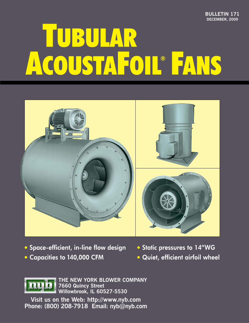
BULLETIN 171 DECEMBER, 2009 THE NEW YORK BLOWER COMPANY 7660 Quincy Street Willowbrook, IL 60527-5530 Visit us on the Web: http://www.nyb.com Phone: (800) 208-7918 Email: [email protected] • Space-efficient, in-line flow design • Capacities to 140,000 CFM • Static pressures to 14”WG • Quiet, efficient airfoil wheel ACOUSTAFOIL ® F ANS TUBULAR

Welcome message from author
This document is posted to help you gain knowledge. Please leave a comment to let me know what you think about it! Share it to your friends and learn new things together.
Transcript
BULLETIN 171DECEMBER, 2009
THE NEW YORK BLOWER COMPANY7660 Quincy StreetWillowbrook, IL 60527-5530
Visit us on the Web: http://www.nyb.comPhone: (800) 208-7918 Email: [email protected]
• Space-efficient, in-line flow design
• Capacities to 140,000 CFM• Static pressures to 14”WG
• Quiet, efficient airfoil wheel
ACOUSTAFOIL® FANSTUBULAR

PAGE 2
DESIGN FEATURES
• Complete AMCA Class I, II, III performance.
• Capacities to 140,000 CFM.
• Pressures to 14”WG.
• Efficiencies beyond 75%.
• Sixteen sizes: 12” through 73” wheel diameters.
• Choice of direct-drive or belt-drive arrangements ina variety of mounting positions [see page 6].
• Unique inlet cone with dual-airflow divertersimprove fan efficiency.
• Precisely formed and positioned vanes convertangular airflow to axial flow in the housing, mini-mizing turbulence while maximizing efficiency.
CONSTRUCTION FEATURES
• AcoustaFoil wheel–airfoil blades provide highlyefficient, quiet operation for clean-air applications.Sizes 12 and 15 available in welded aluminumconstruction only; Sizes 18 through 73 are weldedsteel.
• Heavy-gauge welded components provide structuralstrength, durability, and minimal leakage.
• Adjustable motor mount–features positive screwadjustment for ease in adjusting belt tension.
• Bearings are selected to provide long servicelife…50,000 hours average minimum L-10 on Class I,750,000 hours average minimum on Classes IIand III. External lubrication fittings are standard.
• Standard finish is a medium-green enamel.
• Shafting is straightened to close tolerance to minimize “run out” and ensure smooth operation.
• Lifting eyes are standard.
• All Tubular AcoustaFoil wheels are dynamically balanced. Fans with motors and drives mounted bynyb are checked at the specified running speed.
• Inner-tube construction–isolates bearings anddrive from airstream. Removable end cover allowsaccess to bearings and drive.
TUBULAR ACOUSTAFOIL® FANS
The New York BlowerCompany certifies thatthe Arrangement 9Tubular AcoustaFoilFans shown herein arelicensed to bear theAMCA Seal. The ratingsshown are based ontests and proceduresperformed in accord-ance with AMCA Publi-cation 211 and complywith the requirementsof the AMCA CertifiedRatings Program.
Copyright © 2009 by The New York Blower Company. ®AcoustaFoil is a registered trademark of The New York Blower Company.
Arrangement 9-M with optionalinternal inlet-vane damper, motor and drive.
The New York Blower Company’s Tubular AcoustaFoilFans combine the efficient performance of its airfoilwheels with the versatility and compactness of axialflow fan design. This combination is suited to in-
dustrial supply and exhaust systems as well as heating, ventilating, and air-conditioning applications.A wide range of accessories is available to tailorTubular AcoustaFoil Fans to each unique application.

PAGE 3
WITH ACOUSTAFOIL® WHEELS
Airfoil-blade design is the most efficient and quiet selection for clean-air environments due to aerodynamic superiority.
Stable performance—completely stable pressurecurve from wide-open to closed-off…ideal for variable air volume systems.Non-overloading horsepower curve—horsepowerreaches a peak and then decreases as flow increases…allows calculation of the maximum brake horse-power at a given fan speed so a motor can be selectedthat will not overload if system pressure changes.Efficiency—the mechanical efficiency curve offers a broad selection range with little horsepower variation.Sound—the superior efficiency of the AcoustaFoilwheel provides a low sound level over a wide performance range.
APPLICATION ADVANTAGESNew York Blower’s Tubular AcoustaFoil Fan combinesthe system simplicity and installed cost savings of axial-flow designs with the superior performance of airfoilcentrifugal fans.
In applications where equipment space is at a premium,the compact Tubular AcoustaFoil Fan can reduce systemspace requirements by as much as 50% over conven-tional centrifugal fans. The straight, in-line design eliminates the need for space consuming and costlytransition, elbows, and inlet boxes. In addition, becauseof its superior design, the Tubular AcoustaFoil Fan islighter than comparable centrifugal systems furtherreducing structural requirements and system costs.
Sound is becoming increasingly important in the indus-trial and the commercial environments. Because theTubular AcoustaFoil Fan is based on centrifugal fan prin-ciples and utilizes the highly efficient AcoustaFoil airfoilwheel, it is ideally suited to applications where sound isa concern. The Tubular AcoustaFoil Fan is significantlyquieter than other axial fan alternatives. Sound levelsare further reduced because of generally larger fan out-lets and lower outlet velocities as compared to standardcentrifugal fans.
0 10 20 30 40 50 60 70 80 90 1000
20
40
60
80
100
120
TYPICAL ACOUSTAFOILPERFORMANCE
Tinted area provides quietest,most efficient performance.
% CFM
% S
P, B
HP
, M
E
SP
BHP
ME
Arrangement 9-M Tubular Acoustafoil Fan.

PAGE 4
1. INTERNAL INLET-VANE DAMPERCompact damper/cone assembly provides smoothcontrol in systems that require efficient damperingof airflow…electric and pneumatic damper opera-tors also available. Available on Sizes 18 and larger.
2. VIBRATION ISOLATIONRubber-in-shear or spring-type isolation mounts areavailable to prevent the transmission of vibration tothe mounting structure.
3. SAFETY EQUIPMENT/WEATHER COVERBelt guards, inlet guards, and weather covers areavailable. Selection of appropriate safety acces-sories is the responsibility of the system designerfamiliar with the specific installation.
4. FLANGESRolled rings welded flush with fan inlet and outletprovided with holes…companion flanges with matching hole pattern also available.
5. STACK HOODStack hood with built-in back draft dampers avail-able for outdoor exhaust applications.
6. CURB CAPGussetted cover with nailer holes on perimeterincludes flange for fan mounting.
7. DRAINS3-way for horizontal fans, 2-way for vertical UpBlast units…provides positive drainage of inner-tube and housing.
8. ACCESS DOORGasketed, latch-type door swings open on hingesafter turning cam levers. Provides easy access towheel. Available in Sizes 18 and larger. Inspectionhand hole with cover plate available on smallersizes.
9. SHAFT SEAL [not shown]Ceramic-felt seal elements encased between metalbacking plate and retaining disc…elements can beeasily split for field installation and maintenance.Lubricated lip seals are also available.
ACCESSORIES AND MODIFICATIONS
Protective coatings and special alloys are available tocombat corrosion problems.Special coatings [5 to 10 mil thickness]—specialpaints and spray coatings are available under a variety of trade names. nyb works with experiencedcoating applicators who can apply coatings to meet awide range of requirements.Alternate material construction—Tubular AcoustaFoilFans can be constructed of aluminum or stainlesssteel.PLR wheel—single thickness blades handleairstreams not suited to the AcoustaFoil wheel’s hollow airfoil shape.
ARRANGEMENT4-M
ARRANGEMENT9-R
ARRANGEMENT9-M
2
5
3
7
6
4
8
3
1
PAGE 5
VARIABLE AIRFLOW APPLICATIONS
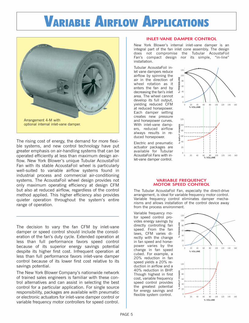
The rising cost of energy, the demand for more flexi-ble systems, and new control technology have putgreater emphasis on air-handling systems that can beoperated efficiently at less than maximum design air-flow. New York Blower’s unique Tubular AcoustaFoilFan with its stable AcoustaFoil wheel is particularlywell-suited to variable airflow systems found inindustrial process and commercial air-conditioningsystems. The AcoustaFoil wheel design provides notonly maximum operating efficiency at design CFMbut also at reduced airflow, regardless of the controlmethod applied. This higher efficiency also providesquieter operation throughout the system’s entirerange of operation.
INLET-VANE DAMPER CONTROL
New York Blower’s internal inlet-vane damper is an integral part of the fan inlet cone assembly. The designdoes not compromise the Tubular AcoustaFoil Fan’s compact design nor its simple, “in-line” installation.
Tubular AcoustaFoil in-let vane dampers reduceairflow by spinning theair in the direction ofwheel rotation as itenters the fan and bydecreasing the fan’s inletarea. The wheel cannotdevelop its full output,yielding reduced CFMat reduced horsepower.Each damper settingcreates new pressureand horsepower curves.With inlet-vane damp-ers, reduced airflowalways results in re-duced horsepower.
Electric and pneumaticactuator packages areavailable for TubularAcoustaFoil Fans with in-let-vane damper control.
VARIABLE FREQUENCY MOTOR SPEED CONTROL
The Tubular AcoustaFoil Fan, especially the direct-drivearrangement, is ideal for variable frequency motor control.Variable frequency control eliminates damper mecha-nisms and allows installation of the control device awayfrom the process environment.
Variable frequency mo-tor speed control pro-vides energy savings bydirectly controlling fanspeed. From the fanlaws, CFM varies di-rectly with the changein fan speed and horse-power varies by thechange in fan speedcubed. For example, a20% reduction in fanspeed yields a 20% re-duction in airflow and a40% reduction in BHP.Though highest in firstcost, variable frequencyspeed control providesthe greatest potentialfor energy savings andflexible system control.
The decision to vary the fan CFM by inlet-vanedamper or speed control should include the consid-eration of the fan’s duty cycle. Extended operation atless than full performance favors speed controlbecause of its superior energy savings potentialdespite its higher first cost. Infrequent operation atless than full performance favors inlet-vane dampercontrol because of its lower first cost relative to itssavings potential.
The New York Blower Company’s nationwide networkof trained sales engineers is familiar with these con-trol alternatives and can assist in selecting the bestcontrol for a particular application. For single sourceresponsibility, packages are available with pneumaticor electronic actuators for inlet-vane damper control orvariable frequency motor controllers for speed control.
0 20 40 60 80 100 120 140 1600
20
40
60
80
100
120
% P
RE
SS
UR
E
0 20 40 60 80 100 120 140 1600
20
40
60
80
100
120
% VOLUME
% IN
PU
T P
OW
ER
% VOLUME
0 20 40 60 80 100 120 140 1600
20
40
60
80
100
120
% VOLUME
% P
RE
SS
UR
E
0 20 40 60 80 100 120 140 1600
20
40
60
80
100
120
% VOLUME
% IN
PU
T P
OW
ER
Arrangement 4-M with optional internal inlet-vane damper.

PAGE 6
ARRANGEMENTS
4-R AND9-RFOR
ROOFMOUNTING
ARRANGEMENTS
4-D AND9-DFORDUCT
MOUNTING
ARRANGEMENTS
4-S AND9-SFOR
SUSPENDEDMOUNTING
ARRANGEMENTS
4-V AND9-VFOR
VERTICALMOUNTING
ARRANGEMENTS
4-M AND9-MWITH
MOUNTINGLEGS
Fabricated mounting legs facilitate fanmounting on the floor, ceiling, or in a vertical position on a wall. Slip connec-tions are standard; optional flanges areavailable.
Fans are equipped with four mountingbrackets suitable for floor, platform, orceiling mounting. Motor is located oncenterline between two of the four brack-ets on Arrangement 9. Slip connectionopposite end from brackets is standard.Bracketed end has flanged connection.
Fans for suspended mounting areequipped with side angle supports suit-able for attachment to rods hung from the ceiling structure. Slip duct connec-tions are standard; optional flanges areavailable.
Units feature drilled flanges on inlet and discharge for mounting to the duct work.
Tubular AcoustaFoil Fans are available packaged with stack hoodsand curb caps for outdoor applications. Arrangement 9 units also feature weather covers. Roof-mounted units have round collarsextending below the curb caps for easy connection to the duct system.
2 3
5 64
1
1211
AIR
FLO
W
7 8
9 10
FLO
W
AIR
FLO
W
AIR
FLO
W
AIR
Mounting Positions
9-S Mounting Positions
9-M Mounting Positionsviewed from discharge end
MOUNTING ARRANGEMENTS
Arrangement 9-M with optional flanged inlet and outlet and access door [motor mounting position 3].
Arrangement 9-S with optional motor,
drive, and spring isolation.

PAGE 7
DIRECT-CONNECTED TUBULAR ACOUSTAFOIL FANS
SAFETY EQUIPMENTSafety accessories are available from nyb,but selection of the appropriate devices is theresponsibility of the system-designer who isfamiliar with the particular installation, orapplication, and can provide for guards for allexposed moving parts as well as protection from access to high-velocityairstreams. Neither nyb nor its sales repre-sentatives is in a position to make such adetermination. Users and/or installers shouldread “Recommended Safety Practices for AirMoving Devices” as published by the AirMovement and Control AssociationInternational, Arlington Heights, Illinois.
The Direct-Connected Tubular AcoustaFoil fan is ideally suited for clean-air applications at tempera-tures to 105° F. Available in Sizes 12 through 36, itis the most compact tubular arrangement, reducingfan length by as much as 15% over belt-drive con-figurations. Elimination of external motor mountingstructure permits installation in extremely tight locations and reduction in overall unit weight. TheArrangement 4 configuration virtually eliminates allregularly scheduled maintenance.
Direct-Connected Tubular AcoustaFoil Fan performanceis maximized by modifying wheel width to match specific performance requirements. By tailoring wheelwidth, the direct-connected Tubular AcoustaFoil Fan isselected and designed at its most efficient full loadpoint of operation. The advent of economical, morecapable variable frequency speed controls meansdirect-connected fan performance can now be easilymodified when system requirements change or when used in variable airflow ventilation or processapplications.
VANEAXIAL FANSCast-aluminum wheels with airfoil blades for quiet operation at most operating points…available in horizontal, vertical, androof-mounted.
DIRECT DRIVECapacities to 100,000 CFM4” static pressureAvailable in multiple-blade angles to provide maximum airflow at specific motor horsepower and speed ratings.
BELT DRIVECapacities to 92,000 CFM5” static pressureAllows flexibility of selection at widevariety of systems requirements.
Arrangement 4-M with optional internal inlet-vane damper.
Arrangement 4-M with optional flanged
inlet and outlet.

PAGE 8
SELECTING DIRECT-DRIVE FANS
The curves above provide a means of quick selection of fan size, approximate width, and, using the capacity tables on pages 10-12, approximate brake horsepower. For more precise direct-drive capacity information, see separate Engineering Supplement. Tubular AcoustaFoil Fan wheels can be narrowed. Minimum blade-width requirements limit Size 12 fans to 47% of full width, Size 15 to 38%. All other sizes are available to 30% of full width.
Fan performance with narrow-width Tubular Acousta-Foil wheels can be determined as follows. If conditionsare at other than 70° F., sea level, or standard density[0.075 pounds per cubic foot], correction factors mustbe applied to SP and BHP. See chart III on page 9.
Plot the desired CFM and SP on the direct-drive chartabove and draw a horizontal line through the plottedpoint to the fan curve to the right.
Draw a vertical line from where the horizontal lineintersects the fan curve and read the CFM.
The approximate blade-width percentage is the desiredCFM divided by the full-width CFM from step 2.
Turn to the appropriate capacity table, pages 10-12,and determine the BHP required by a full-width fan at the full-width CFM and desired SP.
The narrow-width fan will require the BHP from Step 4times the percent width from Step 3.
The complete fan description includes fan size, class,arrangement, percent width, motor speed, CFM, SP,and BHP.
The fan is a Size 33 Class III Arrangement 4-D, 83%width, at 1770 RPM for 20,000 CFM at 8”WG atapproximately 40.9 BHP.
83% of 49.3 BHP is 40.9 BHP.
From page 11, a Size 33 Fan would require approximately 49.3 BHP for 24,000 CFM at 8”WG.
% width = 20,000 CFM ÷ 24,000 CFM = 83%.
Approximately 24,000 CFM.
The Size 33 at 1770 RPM is the most economical.
EXAMPLE: Select a duct-mounted Tubular AcoustaFoilfan for 20,000 CFM at 8”WG at 70°F. and sea level.
1123456
STEPS
DIRECT
DRIVE
SELECTION
CURVES
SIZES
12-36
0 5,000 10,000 15,000 20,000 25,000 30,000 35,000 40,000
CFM
ST
AT
IC P
RE
SS
UR
E [IN
CH
ES
WA
TE
R G
AU
GE
]
0
2
4
6
8
10
12
14
Size 12 @ 3500
Size 15 @ 3500
Size 18 @ 3500
Size 22 @ 1750
Size 24 @ 1750
Size 27 @ 1750
Size 30 @ 1750
Size 33 @ 1770
Size 36 @ 1770

PAGE 9
HOW TO USE CAPACITY TABLES
Check maximum safe speed of fan at operating temper-atures as shown in Charts I and II.
Select size, RPM, and BHP of fan from capacity table.
If conditions other than standard are involved, correct static pressure for actual altitude and temperature usingChart III.
Determine actual performance at operating conditionsby correcting SP and BHP.
In capacity tables, pages 10-13, Class I is to left of outline area, Class II is outline area, Class III is to right of outline area.
Chart III gives a 1.33 factor for 100°F. and 6000’.Corrected SP is 3”WG x 1.33 = 4”WG at 70°F. Select fanfrom capacity tables for 14,000 CFM at 4”WG.
A Size 27 fan is selected for 14,000 CFM at 4”WG at 1763 RPM and 16.1 BHP.
From Charts I and II, the maximum safe speed of a Size 27 fan, Class II construction, at 100°F. is 2019 RPM[2060 x .98]. Fan is satisfactory for operation at 100°F.
Actual performance: 14,000 CFM at 3”WG [4” ÷ 1.33] at 1763 RPM at 12.1 BHP [16.1 ÷ 1.33] at 100°F. and 6000’.
PROCEDURES STEPS EXAMPLE: A fan is required for 14,00 0 CFM at 3”WGat 100°F. and 6000’ elevation.
For a given fan size, CFM, and static pressure, capacity tables can be used to obtain outlet velocity, fan RPM, and BHP.If capacities are at conditions other than 70° F., sea level, or standard density [.075 lb./cu. ft.], correction factors mustbe applied to static pressure and BHP.
MAXIMUMSAFE SPEEDINFORMATION
Chart I details maximum safe speed ofstandard wheels at 70°F. When alloyconstruction is specified or when tem-peratures are involved, multiply theappropriate safe operating speedshown in Chart I by the factor shown inChart II. Maximum operating tempera-ture for standard Arrangement 4 fans is105°F. and for standard Arrangement 9fans is 120°F. For temperatures above120°F. as indicated by tinted areas inCharts II and III, consult nyb.
12* 3840 5010 NA15* 3140 4100 NA18 2320 3025 380022 2090 2725 3185
24 1730 2260 283027 1580 2060 259530 1425 1855 233533 1293 1685 2120
36 1140 1490 187040 1027 1343 168544 935 1222 153449 849 1110 1393
54 753 985 123560 694 906 113866 630 824 103473 570 745 935
Size Class I Class II Class IIICHART IMAXIMUM
SAFE SPEEDS†OF TUBULARACOUSTAFOILFANS AT 70°F.
†Maximum safe speedsapply only to wheelsoperated at or belowstated temperature andfree of material build-up, corrosion, or wear.*Sizes 12 and 15AcoustaFoil wheels arealuminum.NA–Not Available
–50 1.00 1.0070 1.00 1.00
120 .98 .98200 .97 .98
–50 .77 .79 .80 .82 .83 .86 .89 .92 .96 1.00 1.04 1.08 1.12–25 .82 .84 .85 .87 ,89 .92 .95 .98 1.03 1.07 1.11 1.15 1.19
0 .87 .89 .91 .92 .94 .97 1.01 1.04 1.09 1.13 1.18 1.22 1.2620 .91 .93 .95 .97 .98 1.02 1.06 1.09 1.14 1.18 1.23 1.27 1.3240 .94 .96 .98 1.00 1.02 1.05 1.09 1.13 1.18 1.22 1.27 1.32 1.3660 .98 1.00 1.02 1.04 1.06 1.10 1.14 1.18 1.23 1.27 1.32 1.37 1.4270 1.00 1.02 1.04 1.06 1.08 1.12 1.16 1.20 1.25 1.30 1.35 1.40 1.4580 1.02 1.04 1.06 1.08 1.10 1.14 1.18 1.22 1.28 1.33 1.38 1.43 1.48
100 1.06 1.08 1.10 1.12 1.15 1.19 1.23 1.27 1.33 1.38 1.43 1.48 1.54120 1.09 1.11 1.13 1.16 1.18 1.22 1.26 1.31 1.36 1.42 1.47 1.53 1.58140 1.13 1.15 1.18 1.20 1.22 1.27 1.31 1.36 1.41 1.47 1.53 1.58 1.64160 1.17 1.19 1.22 1.24 1.26 1.31 1.36 1.40 1.46 1.52 1.58 1.64 1.70180 1.21 1.23 1.26 1.28 1.31 1.36 1.40 1.45 1.51 1.57 1.63 1.69 1.75200 1.25 1.28 1.30 1.33 1.35 1.40 1.45 1.50 1.56 1.63 1.69 1.75 1.81
CHART IITEMPERATURECORRECTION
FACTORSFOR WHEEL
SAFE SPEEDS
Temp. °F.
Temperature °F.Altitude–feet above sea level
0 500 1000 1500 2000 3000 4000 5000 6000 7000 8000 9000 10000
Wheel material
Steel Aluminum
CHART III CORRECTION FACTORS FOR TEMPERATURE AND ALTITUDE

SIZE 12RPM BHP
1"SP
900 588 1665 0.60 2231 0.66 2693 1.14 3078 1.43 3430 1.74 3768 2.08 4057 2.40 4336 2.79 4598 3.20 4824 3.581200 784 1937 0.72 2333 0.99 2746 1.30 3137 1.66 3478 2.00 3797 2.37 4078 2.77 4345 3.22 4608 3.69 4855 4.171500 980 2224 0.88 2586 1.19 2878 1.53 3207 1.89 3543 2.29 3848 2.74 4126 3.22 4397 3.71 4639 4.19 4874 4.69
1800 1176 2533 1.09 2832 1.44 3110 1.81 3370 2.20 3632 2.62 3912 3.12 4189 3.85 4462 4.24 4693 4.78 4933 5.352000 1307 2751 1.26 3023 1.64 3287 2.05 3530 2.46 3756 2.93 3998 3.45 4239 3.97 4492 4.54 4756 5.18 4980 5.782200 1438 2972 1.46 3222 1.86 3463 2.29 3700 2.78 3909 3.28 4130 3.83 4331 4.35 4552 4.92 4798 5.57
2400 1569 3196 1.69 3431 2.12 3653 2.59 3875 3.13 4080 3.67 4283 4.25 4479 4.84 4664 5.40 4865 6.012600 1699 3420 1.98 3644 2.41 3851 2.95 4055 3.52 4255 4.10 4447 4.70 4632 5.32 4512 5.95 4993 6.592800 1830 3647 2.26 3860 2.78 4058 3.38 4247 3.96 4437 4.57 4623 5.21 4798 5.85 4961 6.483000 1961 3876 2.52 4079 3.19 4267 3.81 4448 4.45 4619 5.07 4803 5.78 4972 6.43
PAGE 10
Performance certified is for installation Type B: Free inlet, Ducted outlet. Power rating [BHP] does not include transmission losses.Performance ratings do not include the effects of appurtenances [accessories].
CFM OVRPM BHP RPM BHP RPM BHP RPM BHP RPM BHP RPM BHP RPM BHP RPM BHP RPM BHP
2"SP 3"SP 4"SP 5"SP 6"SP 7"SP 8"SP 9"SP 10"SP
Wheel diameter: 121⁄4" Fan outlet area: 1.53 sq. ft.
Wheel circumference: 3.21' Maximum BHP = .076 (RPM)3
1000
Class I = 3840 RPMClass II = 5010 RPM
SIZE 15RPM BHP
1"SP
1900 829 1912 1.11 2188 1.57 2411 2.05 2623 2.56 2851 3.21 3123 4.00 3372 4.77 3611 5.60 3829 6.44 4026 7.292200 960 2115 1.33 2383 1.86 2597 2.39 2784 2.99 2970 3.66 3159 4.37 3365 5.15 3599 6.05 3821 6.95 4045 7.942500 1091 2322 1.60 2579 2.20 2791 2.83 2975 3.53 3137 4.21 3297 4.94 3465 5.74 3634 6.56 3820 7.46 4026 8.48
2800 1222 2531 1.90 2779 2.60 2989 3.36 3165 4.10 3325 4.87 3475 5.65 3624 6.48 3762 7.29 3911 8.18 4054 9.053100 1353 2745 2.27 2984 3.11 3183 3.93 3362 4.77 3520 5.60 3668 6.46 3801 7.30 3929 8.16 4067 9.123400 1483 2960 2.73 3187 3.66 3384 4.60 3560 5.51 3716 6.41 3856 7.30 3994 8.26
3700 1614 3178 3.29 3397 4.31 3587 5.33 3755 6.31 3913 7.31 4057 8.304000 1745 3397 3.95 3610 5.04 3793 6.14 3957 7.224300 1876 3617 4.69 3822 5.84 4000 7.034600 2007 3840 5.53 4037 6.75
CFM OVRPM BHP RPM BHP RPM BHP RPM BHP RPM BHP RPM BHP RPM BHP RPM BHP RPM BHP
2"SP 3"SP 4"SP 5"SP 6"SP 7"SP 8"SP 9"SP 10"SP
Wheel diameter: 15" Fan outlet area: 2.29 sq. ft.
Wheel circumference: 3.93' Maximum BHP = .169 (RPM)3
1000
Class I = 3140 RPMClass II = 4100 RPM
SIZE 18RPM BHP
1"SP
2000 590 1136 0.82 1478 1.32 1799 1.87 2056 2.48 2296 3.24 2525 4.06 2741 4.95 2937 5.86 3271 7.71 3583 9.762800 826 1346 1.09 1601 1.66 1830 2.30 2087 3.09 2347 3.99 2543 4.85 2727 5.78 2914 6.81 3254 8.92 3582 11.23600 1062 1586 1.48 1801 2.17 1999 2.93 2183 3.81 2360 4.76 2560 5.82 2771 6.87 2968 8.00 3292 10.3 3574 12.7
4400 1298 1835 1.99 2034 2.84 2203 3.81 2367 4.79 2524 5.81 2672 6.89 2817 8.04 2963 9.22 3316 11.9 3633 14.55200 1534 2098 2.69 2275 3.76 2436 4.86 2574 5.97 2714 7.12 2853 8.30 2983 9.49 3111 10.8 3356 13.5 3607 16.36000 1770 2369 3.68 2525 4.90 2675 6.14 2813 7.42 2932 8.68 3051 9.98 3180 11.4 3297 12.7 3516 15.5 3735 18.5
6800 2006 2643 4.94 2784 6.28 2917 7.65 3049 9.06 3171 10.5 3280 12.0 3385 13.4 3492 14.9 3708 18.07600 2242 2920 6.49 3051 7.94 3171 9.46 3294 11.1 3411 12.6 3517 14.2 3616 15.8 3710 17.48400 2478 3200 8.36 3321 9.94 3434 11.6 3541 13.3 3651 15.0 3755 16.79200 2714 3483 10.6 3594 12.3 3700 14.1
CFM OVRPM BHP RPM BHP RPM BHP RPM BHP RPM BHP RPM BHP RPM BHP RPM BHP RPM BHP
2"SP 3"SP 4"SP 5"SP 6"SP 7"SP 8"SP 10"SP 12"SP
Wheel diameter: 181⁄4" Fan outlet area: 3.39 sq. ft.
Wheel circumference: 4.78' Maximum BHP = .422 (RPM)3
1000
Class I = 2320 RPMClass II = 3025 RPMClass III = 3800 RPM
SIZE 22RPM BHP
1"SP
4000 789 1031 1.29 1242 2.07 1464 3.02 1684 4.11 1873 5.28 2034 6.43 2342 9.03 2614 11.9 2864 15.1 3091 18.45000 986 1180 1.67 1368 2.60 1534 3.71 1699 4.89 1886 6.19 2059 7.53 2359 10.4 2624 13.4 2870 16.6 3098 20.16000 1183 1335 2.15 1508 3.31 1660 4.58 1795 5.86 1928 7.25 2082 8.79 2383 11.9 2652 15.2 2895 18.8 3118 22.4
7000 1381 1499 2.82 1656 4.16 1798 5.62 1923 7.05 2044 8.55 2158 10.1 2405 13.5 2667 17.1 2913 20.9 3141 24.98000 1578 1668 3.71 1810 5.19 1944 6.80 2062 8.43 2173 10.1 2281 11.8 2486 15.4 2696 19.2 2929 23.3 3157 27.59000 1775 1843 4.81 1971 6.44 2096 8.20 2209 9.98 2316 11.9 2416 13.7 2604 17.5 2785 21.6 2973 25.9 3171 30.3
10000 1972 2022 6.13 2136 7.92 2249 9.76 2360 11.8 2461 13.8 2557 15.9 2737 20.0 2902 24.2 3063 28.611000 2170 2202 7.69 2306 9.67 2411 11.7 2513 13.8 2612 16.0 2701 18.1 2869 22.6 3032 27.212000 2367 2383 9.50 2479 11.7 2576 13.9 2670 16.1 2763 18.4 2854 20.8 3017 25.6 3167 30.513000 2564 2566 11.6 2655 14.0 2744 16.4 2831 18.7 2919 21.1 3003 23.6 3165 28.8
CFM OVRPM BHP RPM BHP RPM BHP RPM BHP RPM BHP RPM BHP RPM BHP RPM BHP RPM BHP
2"SP 3"SP 4"SP 5"SP 6"SP 8"SP 10"SP 12"SP 14"SP
Wheel diameter: 221⁄4" Fan outlet area: 5.07 sq. ft.
Wheel circumference: 5.83' Maximum BHP = 1.10 (RPM)3
1000
Class I = 2090 RPMClass II = 2725 RPMClass III = 3185 RPM

PAGE 11
SIZE 24RPM BHP
1"SP
5000 810 953 1.52 1141 2.48 1330 3.68 1530 5.03 1698 6.41 1857 7.94 2132 11.1 2375 14.5 2598 18.3 2698 20.26200 1005 1088 1.99 1257 3.20 1402 4.52 1548 5.98 1718 7.61 1874 9.25 2145 12.7 2385 16.3 2606 20.3 2711 22.47400 1199 1228 2.59 1383 4.06 1517 5.58 1642 7.18 1764 8.93 1891 10.7 2164 14.5 2408 18.5 2629 22.8 2727 24.9
8600 1394 1376 3.47 1518 5.10 1644 6.85 1760 8.66 1868 10.5 1970 12.4 2186 16.5 2419 20.8 2645 25.4 2755 27.99800 1588 1528 4.55 1658 6.36 1777 8.31 1884 10.3 1984 12.3 2080 14.4 2266 18.8 2455 23.5 2664 28.4 2758 30.7
11000 1783 1686 5.88 1800 7.84 1913 9.97 2015 12.2 2112 14.5 2201 16.7 2373 21.3 2532 26.2 2694 31.2 2790 34.1
12200 1977 1846 7.46 1950 9.67 2053 11.9 2151 14.3 2242 16.7 2329 19.3 2490 24.2 2641 29.3 2792 35.013400 2172 2008 9.33 2103 11.8 2197 14.2 2289 16.7 2379 19.4 2464 22.2 2616 27.6 2760 33.114600 2366 2171 11.5 2258 14.2 2345 16.8 2430 19.4 2515 22.3 2595 25.1 2746 31.115800 2561 2336 14.1 2417 17.0 2496 19.8 2575 22.6 2656 25.6 2734 28.7
Performance certified is for installation Type B: Free inlet, Ducted outlet. Power rating [BHP] does not include transmission losses.Performance ratings do not include the effects of appurtenances [accessories].
CFM OVRPM BHP RPM BHP RPM BHP RPM BHP RPM BHP RPM BHP RPM BHP RPM BHP RPM BHP
2"SP 3"SP 4"SP 5"SP 6"SP 8"SP 10"SP 12"SP 13"SP
Wheel diameter: 241⁄2" Fan outlet area: 6.17 sq. ft.
Wheel circumference: 6.41' Maximum BHP = 1.75 (RPM)3
1000
Class I = 1730 RPMClass II = 2260 RPMClass III = 2830 RPM
SIZE 27RPM BHP
1"SP
6000 793 805 1.75 970 2.90 1146 4.34 1341 6.22 1487 7.95 1622 9.79 1856 13.7 2065 17.9 2257 22.3 2452 27.27600 1004 930 2.40 1077 3.93 1206 5.53 1329 7.15 1485 9.19 1644 11.6 1881 16.0 2094 20.7 2276 25.5 2453 30.89200 1215 1062 3.35 1191 5.12 1312 7.05 1420 8.96 1521 11.0 1628 13.0 1889 18.2 2112 23.6 2306 29.1 2470 34.4
10800 1427 1198 4.53 1320 6.69 1423 8.77 1527 11.0 1622 13.3 1709 15.6 1887 20.3 2099 25.9 2316 32.5 2497 38.812400 1638 1341 6.04 1451 8.56 1548 10.9 1640 13.4 1729 16.0 1812 18.5 1969 23.8 2120 29.1 2298 35.1 2492 42.214000 1849 1487 7.91 1585 10.7 1678 13.5 1763 16.1 1843 18.9 1919 21.7 2073 27.6 2210 33.6 2344 39.6 2481 45.5
15600 2061 1636 10.3 1724 13.3 1812 16.5 1891 19.4 1968 22.4 2039 25.5 2179 31.8 2315 38.4 2436 44.9 2552 51.417200 2272 1788 13.1 1865 16.2 1946 19.7 2023 23.2 2094 26.4 2164 29.7 2293 36.6 2420 43.6 2545 50.918800 2483 1940 16.5 2012 19.7 2084 23.4 2158 27.3 2227 31.0 2293 34.6 2416 41.8 2534 49.520400 2695 2094 20.5 2159 23.8 2226 27.7 2294 31.9 2359 36.0 2425 40.1 2542 47.8
CFM OVRPM BHP RPM BHP RPM BHP RPM BHP RPM BHP RPM BHP RPM BHP RPM BHP RPM BHP
2"SP 3"SP 4"SP 5"SP 6"SP 8"SP 10"SP 12"SP 14"SP
Wheel diameter: 27" Fan outlet area: 7.57 sq. ft.
Wheel circumference: 7.07' Maximum BHP = 3.34 (RPM)3
1000
Class I = 1580 RPMClass II = 2060 RPMClass III = 2595 RPM
SIZE 30RPM BHP
1"SP
7000 759 704 1.94 858 3.35 1041 5.22 1203 7.32 1333 9.34 1456 11.6 1665 16.2 1855 21.2 2033 26.5 2216 32.49100 987 820 2.77 955 4.61 1070 6.50 1195 8.57 1342 11.2 1478 14.0 1688 19.1 1880 24.9 2046 30.8 2200 36.9
11200 1215 946 4.01 1063 6.15 1172 8.46 1271 10.8 1360 13.2 1464 15.7 1701 22.2 1903 28.8 2066 35.1 2228 42.2
13300 1443 1077 5.53 1186 8.18 1278 10.7 1371 13.5 1459 16.3 1535 19.0 1693 24.7 1888 31.7 2089 40.1 2248 47.615400 1670 1212 7.48 1310 10.6 1399 13.5 1481 16.6 1560 19.8 1636 22.9 1772 29.2 1907 35.8 2063 43.1 2247 52.317500 1898 1353 9.99 1440 13.5 1524 16.9 1599 20.2 1670 23.7 1740 27.2 1875 34.4 1997 41.7 2114 49.2 2241 56.9
19600 2126 1496 13.1 1573 16.8 1650 20.8 1722 24.6 1789 28.3 1855 32.2 1978 40.1 2100 48.3 2206 56.2 2313 64.721700 2354 1641 17.0 1710 20.8 1780 25.2 1848 29.5 1913 33.7 1975 37.9 2088 46.3 2201 55.2 2308 64.023800 2581 1788 21.6 1849 25.6 1913 30.2 1978 35.2 2040 39.9 2096 44.3 2208 53.6 2311 63.025900 2809 1935 27.1 1991 31.3 2049 36.1 2109 41.4 2168 46.7 2225 51.9 2328 61.5
CFM OVRPM BHP RPM BHP RPM BHP RPM BHP RPM BHP RPM BHP RPM BHP RPM BHP RPM BHP
2"SP 3"SP 4"SP 5"SP 6"SP 8"SP 10"SP 12"SP 14"SP
Wheel diameter: 36" Fan outlet area: 9.22 sq. ft.
Wheel circumference: 7.85' Maximum BHP = 5.62 (RPM)3
1000
Class I = 1425 RPMClass II = 1855 RPMClass III = 2335 RPM
SIZE 33RPM BHP
1"SP
9000 804 659 2.42 795 4.29 939 6.44 1097 9.22 1214 11.7 1326 14.5 1517 20.2 1684 26.3 1843 32.9 2005 40.211500 1027 767 3.58 887 5.89 992 8.30 1092 10.8 1213 13.7 1340 17.2 1542 24.0 1711 30.8 1862 38.0 2007 45.914000 1250 881 5.10 986 7.80 1081 10.6 1172 13.6 1250 16.5 1336 19.6 1542 27.2 1733 35.7 1886 43.6 2031 52.2
16500 1473 998 7.00 1095 10.3 1181 13.5 1261 16.8 1338 20.2 1411 23.8 1548 30.7 1715 38.9 1894 48.9 2052 59.019000 1696 1120 9.40 1209 13.3 1288 16.9 1360 20.5 1430 24.4 1500 28.3 1625 36.2 1745 44.3 1883 53.2 2038 63.721500 1920 1246 12.5 1325 16.7 1400 21.0 1469 25.1 1532 29.3 1594 33.6 1719 42.6 1829 51.5 1933 60.6 2044 69.9
24000 2143 1375 16.3 1443 20.8 1513 25.7 1579 30.4 1641 35.0 1696 39.4 1810 49.3 1920 59.3 2019 69.2 2114 79.426500 2366 1505 21.0 1566 25.6 1630 31.0 1692 36.4 1750 41.4 1805 46.4 1907 56.6 2010 67.5 2109 78.629000 2589 1636 26.6 1691 31.4 1749 37.0 1808 43.1 1865 48.9 1916 54.4 2015 65.3 2107 76.631500 2812 1768 33.1 1818 38.2 1871 44.0 1926 50.6 1979 57.0 2029 63.1
CFM OVRPM BHP RPM BHP RPM BHP RPM BHP RPM BHP RPM BHP RPM BHP RPM BHP RPM BHP
2"SP 3"SP 4"SP 5"SP 6"SP 8"SP 10"SP 12"SP 14"SP
Wheel diameter: 33" Fan outlet area: 11.2 sq. ft.
Wheel circumference: 8.64' Maximum BHP = 8.98 (RPM)3
1000
Class I = 1293 RPMClass II = 1685 RPMClass III = 2120 RPM

PAGE 12
SIZE 36RPM BHP
1"SP
11000 807 605 2.95 735 5.23 872 7.93 1010 11.2 1122 14.4 1230 18.0 1424 25.7 1603 34.3 1754 42.4 1826 46.614200 1041 703 4.39 817 7.25 918 10.2 1014 13.3 1128 17.1 1237 21.1 1423 29.5 1585 38.3 1739 48.2 1818 53.717400 1276 805 6.30 909 9.70 1001 13.3 1085 16.9 1163 20.6 1242 24.4 1432 34.0 1597 43.9 1742 54.1 1813 59.6
20600 1511 917 8.84 1010 12.9 1092 16.9 1170 21.1 1245 25.5 1312 29.7 1443 38.5 1589 48.5 1748 60.4 1827 67.023800 1746 1034 12.2 1113 16.7 1192 21.3 1262 26.0 1329 30.8 1396 35.9 1513 45.6 1628 55.7 1751 66.9 1817 73.027000 1980 1154 16.4 1221 21.3 1294 26.6 1363 31.9 1423 37.2 1483 42.6 1599 53.9 1704 65.1 1804 76.4 1854 82.1
30200 2215 1275 21.6 1335 26.8 1396 32.5 1465 38.8 1523 44.5 1575 50.1 1685 62.6 1786 75.133400 2450 1397 27.9 1453 33.6 1506 39.7 1565 46.3 1626 53.0 1679 59.4 1777 72.536600 2684 1520 35.4 1573 41.6 1620 48.1 1671 55.0 1728 62.5 1781 69.639800 2919 1643 44.4 1694 51.0 1739 58.0 1782 65.0 1831 72.8
Performance certified is for installation Type B: Free inlet, Ducted outlet. Power rating [BHP] does not include transmission losses.Performance ratings do not include the effects of appurtenances [accessories].
CFM OVRPM BHP RPM BHP RPM BHP RPM BHP RPM BHP RPM BHP RPM BHP RPM BHP RPM BHP
2"SP 3"SP 4"SP 5"SP 6"SP 8"SP 10"SP 12"SP 13"SP
Wheel diameter: 361⁄2" Fan outlet area: 13.6 sq. ft.
Wheel circumference: 9.56' Maximum BHP = 14.0 (RPM)3
1000
Class I = 1140 RPMClass II = 1490 RPMClass III = 1870 RPM
SIZE 40RPM BHP
1"SP
12000 723 514 2.93 635 5.12 772 7.74 893 10.8 998 13.9 1088 16.9 1249 23.3 1398 30.3 1542 37.9 1675 46.116000 964 601 4.42 707 7.59 798 10.8 887 13.1 993 16.8 1092 20.9 1258 28.9 1405 37.2 1536 45.7 1651 54.120000 1205 699 6.56 792 10.3 874 14.3 950 18.6 1022 22.0 1092 24.8 1258 33.7 1411 44.1 1547 54.3 1669 64.5
24000 1446 804 9.46 881 13.7 959 18.3 1028 23.1 1093 28.1 1154 33.1 1271 40.5 1404 49.0 1545 61.5 1670 73.728000 1687 911 13.2 982 18.1 1047 23.1 1112 28.6 1176 34.3 1232 39.9 1338 51.6 1440 61.0 1543 68.9 1657 79.832000 1928 1018 17.8 1086 23.6 1144 29.2 1201 35.0 1259 41.2 1316 47.8 1416 60.7 1508 74.0 1600 86.1 1684 94.9
36000 2169 1129 23.7 1192 30.1 1248 36.6 1296 42.6 1347 49.2 1400 56.3 1497 70.5 1586 85.1 1670 10040000 2410 1241 30.9 1298 37.8 1351 45.0 1398 52.0 1444 59.0 1489 66.2 1582 81.8 1669 97.744000 2651 1354 39.6 1406 47.1 1457 55.0 1503 62.9 1545 70.4 1586 78.0 1669 94.248000 2892 1467 50.0 1516 57.9 1563 66.3 1608 75.0 1649 83.5
CFM OVRPM BHP RPM BHP RPM BHP RPM BHP RPM BHP RPM BHP RPM BHP RPM BHP RPM BHP
2"SP 3"SP 4"SP 5"SP 6"SP 8"SP 10"SP 12"SP 14"SP
Wheel diameter: 401⁄4" Fan outlet area: 16.5 sq. ft.
Wheel circumference: 10.54' Maximum BHP = 22.7 (RPM)3
1000
Class I = 1027 RPMClass II = 1343 RPMClass III = 1685 RPM
SIZE 44RPM BHP
1"SP
14000 690 455 3.36 569 5.78 699 9.16 807 12.7 899 16.2 982 19.9 1128 27.5 1271 36.2 1399 45.3 1521 55.618400 906 524 4.89 624 8.67 709 11.9 802 15.0 903 19.9 987 24.4 1139 33.8 1269 43.3 1383 53.0 1490 63.122800 1123 601 7.00 690 11.4 768 16.1 837 20.5 907 23.9 984 27.9 1144 39.9 1275 51.0 1395 62.6 1504 74.3
27200 1340 686 9.88 759 14.7 834 20.1 898 25.6 959 31.4 1016 36.1 1135 44.1 1275 57.6 1401 71.8 1507 84.731600 1557 772 13.5 838 19.0 904 25.0 967 31.3 1021 37.4 1075 44.3 1176 56.2 1277 65.2 1392 77.8 1506 93.936000 1773 859 18.0 923 24.4 977 30.6 1035 37.6 1091 44.9 1142 52.1 1235 67.1 1323 80.8 1411 91.4 1502 102
40400 1990 948 23.5 1007 30.7 1059 37.8 1107 44.8 1160 52.9 1210 61.0 1299 76.8 1383 94.1 1462 11044800 2207 1038 30.3 1094 38.2 1143 46.2 1187 53.8 1232 61.9 1279 70.7 1369 88.8 1448 107 1521 12549200 2424 1128 38.3 1181 46.9 1229 55.9 1271 64.2 1311 72.8 1352 81.7 1435 101 1516 12153600 2640 1220 47.9 1269 57.1 1314 66.7 1356 76.2 1395 85.6 1431 94.6 1507 115
CFM OVRPM BHP RPM BHP RPM BHP RPM BHP RPM BHP RPM BHP RPM BHP RPM BHP RPM BHP
2"SP 3"SP 4"SP 5"SP 6"SP 8"SP 10"SP 12"SP 14"SP
Wheel diameter: 441⁄2" Fan outlet area: 20.3 sq. ft.
Wheel circumference: 11.65' Maximum BHP = 37.5 (RPM)3
1000
Class I = 935 RPMClass II = 1222 RPMClass III = 1534 RPM
SIZE 49RPM BHP
1"SP
16000 650 402 3.78 516 6.56 634 10.6 733 14.7 815 18.7 890 23.0 1026 31.9 1161 42.4 1276 53.3 1383 65.622000 894 472 5.80 562 10.3 641 14.0 729 18.0 819 23.8 898 29.3 1034 40.3 1152 51.6 1258 63.5 1357 75.828000 1138 551 8.69 630 14.0 699 19.6 764 25.3 826 29.4 892 34.0 1037 48.3 1159 62.3 1268 76.3 1370 91.0
34000 1382 638 12.7 703 18.6 770 25.4 826 32.0 881 39.4 933 45.9 1034 55.5 1155 70.4 1271 88.2 1370 10540000 1626 725 17.8 786 24.9 841 32.2 897 40.1 947 47.8 994 56.0 1085 72.6 1169 84.3 1262 96.9 1367 11646000 1870 815 24.4 872 32.7 919 40.5 969 49.2 1018 58.3 1064 67.5 1147 86.1 1226 106 1298 120 1374 133
52000 2114 907 32.8 959 42.0 1004 51.0 1046 60.0 1090 69.7 1133 79.8 1214 100 1287 122 1359 14458000 2358 999 43.1 1048 53.3 1091 63.5 1131 73.7 1168 83.5 1207 94.2 1287 118 1356 14064000 2602 1093 55.6 1137 66.4 1179 77.9 1217 89.3 1252 100 1286 111 1358 13670000 2846 1187 70.5 1228 82.1 1267 94.5 1305 107 1338 119 1370 131
CFM OVRPM BHP RPM BHP RPM BHP RPM BHP RPM BHP RPM BHP RPM BHP RPM BHP RPM BHP
2"SP 3"SP 4"SP 5"SP 6"SP 8"SP 10"SP 12"SP 14"SP
Wheel diameter: 49" Fan outlet area: 24.6 sq. ft.
Wheel circumference: 12.83' Maximum BHP = 60.9 (RPM)3
1000
Class I = 849 RPMClass II = 1110 RPMClass III = 1393 RPM

PAGE 13
SIZE 54RPM BHP
1"SP
20000 662 366 4.70 465 8.10 574 13.2 662 18.2 737 23.3 804 28.4 866 33.8 928 39.7 984 45.4 1043 51.926000 861 418 6.74 501 12.0 575 16.2 660 21.7 740 28.4 810 34.9 875 41.4 934 48.1 989 54.8 1037 61.332000 1060 474 9.32 550 15.6 615 22.3 674 27.6 734 32.2 807 39.7 877 48.4 934 56.0 991 64.0 1045 72.1
38000 1258 536 12.9 602 19.9 663 27.4 717 35.2 769 42.6 818 48.1 871 53.7 931 62.1 993 72.3 1045 81.744000 1457 601 17.4 658 25.0 715 33.6 767 42.4 813 51.1 860 60.6 904 68.4 946 74.5 990 80.6 1042 89.150000 1656 666 22.8 719 31.5 769 40.6 820 50.6 865 60.4 905 70.2 948 81.3 986 91.0 1023 99.6 1061 107
56000 1854 732 29.4 783 39.5 827 49.1 871 59.4 916 70.5 958 82.0 995 92.6 1031 104 1068 116 1104 12862000 2053 799 37.5 848 48.6 889 59.3 928 70.2 969 82.0 1009 94.2 1047 107 1083 119 1116 131 1148 14468000 2252 867 47.2 913 59.1 953 71.4 989 82.9 1024 94.7 1061 108 1099 121 1135 135 1167 148 1198 16274000 2450 936 58.5 978 71.3 1017 84.4 1051 97.1 1085 110 1117 123 1152 138 1185 152 1220 167
Performance certified is for installation Type B: Free inlet, Ducted outlet. Power rating [BHP] does not include transmission losses.Performance ratings do not include the effects of appurtenances [accessories].
CFM OVRPM BHP RPM BHP RPM BHP RPM BHP RPM BHP RPM BHP RPM BHP RPM BHP RPM BHP
2"SP 3"SP 4"SP 5"SP 6"SP 7"SP 8"SP 9"SP 10"SP
Wheel diameter: 541⁄4" Fan outlet area: 30.2 sq. ft.
Wheel circumference: 14.20' Maximum BHP = 101 (RPM)3
1000
Class I = 753 RPMClass II = 985 RPMClass III = 1235 RPM
SIZE 60RPM BHP
1"SP
24000 650 328 5.61 420 9.72 519 15.9 598 21.9 664 27.8 728 34.4 783 40.8 840 48.0 893 55.1 944 62.832000 867 379 8.28 454 14.9 520 19.9 596 26.6 669 34.8 732 42.8 792 51.1 844 59.0 893 67.2 937 75.040000 1084 435 11.8 503 19.6 560 27.8 613 35.0 668 40.7 730 49.3 792 59.9 847 70.0 898 79.8 946 89.8
48000 1301 497 16.8 554 25.4 609 35.0 657 44.6 703 54.6 748 62.3 793 69.0 840 77.4 894 89.4 948 10356000 1518 561 23.1 610 32.6 661 43.4 707 54.5 749 65.7 789 77.5 828 88.8 864 97.2 903 105 942 11364000 1734 625 30.8 673 42.1 714 53.2 759 66.0 800 78.7 837 91.2 873 105 907 118 941 131 975 142
72000 1951 691 40.5 736 53.4 774 65.6 811 78.4 850 92.5 889 107 922 121 955 136 986 151 1018 16780000 2168 757 52.3 799 66.3 837 80.7 870 94.2 904 109 938 124 974 141 1004 156 1034 171 1063 18788000 2385 825 66.5 864 81.7 900 97.6 931 113 962 128 993 144 1026 162 1056 178 1086 196 1114 21396000 2602 893 83.3 929 99.5 963 117 995 134 1023 150 1051 167 1079 185 1107 202 1137 221
CFM OVRPM BHP RPM BHP RPM BHP RPM BHP RPM BHP RPM BHP RPM BHP RPM BHP RPM BHP
2"SP 3"SP 4"SP 5"SP 6"SP 7"SP 8"SP 9"SP 10"SP
Wheel diameter: 60" Fan outlet area: 36.9 sq. ft.
Wheel circumference: 15.71' Maximum BHP = 166 (RPM)3
1000
Class I = 694 RPMClass II = 906 RPMClass III = 1138 RPM
SIZE 66RPM BHP
1"SP
30000 673 304 7.09 383 12.1 472 19.7 544 27.1 606 34.6 662 42.5 712 50.5 760 58.8 809 67.8 858 77.540000 897 351 10.4 417 18.5 477 25.5 541 32.6 609 43.2 666 52.9 718 62.9 768 73.1 811 82.9 854 93.450000 1121 405 15.2 464 24.7 517 35.1 565 44.9 610 51.8 661 60.4 718 73.4 770 86.4 818 99.3 860 111
60000 1345 463 21.6 514 32.4 563 44.2 606 56.3 647 68.8 687 79.7 725 87.9 765 96.8 813 110 860 12670000 1570 523 29.9 568 41.9 611 55.0 654 69.1 692 83.1 727 97.4 763 112 795 124 828 134 860 14480000 1794 584 40.1 626 54.3 663 68.1 703 83.7 739 99.1 772 115 805 132 836 149 867 166 896 180
90000 2018 646 52.9 686 68.9 720 84.4 753 100 787 118 821 136 852 153 882 172 910 190 937 209100000 2242 709 68.5 746 86.2 779 104 809 121 838 138 870 158 900 178 930 198 955 217 982 237110000 2466 772 87.3 807 106 839 126 867 145 894 164 921 183 949 205 977 226 1004 248 1030 270120000 2691 836 110 868 130 899 151 927 173 953 194 977 214 1001 235 1027 258
CFM OVRPM BHP RPM BHP RPM BHP RPM BHP RPM BHP RPM BHP RPM BHP RPM BHP RPM BHP
2"SP 3"SP 4"SP 5"SP 6"SP 7"SP 8"SP 9"SP 10"SP
Wheel diameter: 66" Fan outlet area: 44.6 sq. ft.
Wheel circumference: 17.28' Maximum BHP = 267 (RPM)3
1000
Class I = 630 RPMClass II = 824 RPMClass III = 1034 RPM
SIZE 73RPM BHP
1"SP
40000 734 285 9.62 352 17.0 426 25.3 492 35.3 551 45.6 601 55.6 645 65.6 689 76.6 730 87.5 772 99.751000 936 325 13.6 385 23.9 436 38.3 489 41.1 550 54.2 602 66.6 651 79.6 694 92.0 735 105 773 11862000 1138 369 19.0 423 30.9 470 43.4 513 56.0 554 64.9 600 75.3 649 90.4 695 106 738 122 779 138
73000 1339 417 26.1 463 39.2 508 53.7 547 68.5 584 83.8 619 96.3 654 106 690 117 734 134 777 15384000 1541 466 34.9 507 49.6 546 65.2 585 82.1 620 99.1 651 116 684 134 714 147 744 159 777 17195000 1743 515 45.9 554 62.5 588 79.3 625 98.0 658 116 689 135 719 155 747 176 774 194 802 210
106000 1945 565 59.0 602 78.1 634 96.3 665 116 697 136 727 157 755 177 783 200 809 222 834 244117000 2147 616 75.0 651 95.8 681 116 709 136 737 158 766 180 796 205 822 228 845 249 869 274128000 2349 667 94.0 700 116 730 139 756 161 780 183 807 207 834 232 861 259 884 283 909 309139000 2569 724 119 754 142 782 167 808 192 832 216 855 241 879 267 903 293 928 322
CFM OVRPM BHP RPM BHP RPM BHP RPM BHP RPM BHP RPM BHP RPM BHP RPM BHP RPM BHP
2"SP 3"SP 4"SP 5"SP 6"SP 7"SP 8"SP 9"SP 10"SP
Wheel diameter: 73" Fan outlet area: 54.5 sq. ft.
Wheel circumference: 19.11' Maximum BHP = 442 (RPM)3
1000
Class I = 570 RPMClass II = 745 RPMClass III = 935 RPM

PAGE 14
MATERIAL SPECIFICATIONSDimensions in inches. Weights in pounds. WR² in lb.-ft.².
SizeShaft diameter Bearings Wheel weight Wheel WR2
Class I Class II Class III Class I Class II Class III Class I Class II Class III Class I Class II Class III
12151822242730333640444954606673
113⁄1613⁄1617⁄16
111⁄16111⁄16111⁄16115⁄16
23⁄1623⁄1623⁄1627⁄16
27⁄1627⁄16211⁄16215⁄16
13⁄1613⁄1617⁄16111⁄16
111⁄16111⁄16115⁄1623⁄16
23⁄1623⁄1627⁄16211⁄16
211⁄16215⁄1637⁄1637⁄16
––
111⁄16111⁄16
115⁄16115⁄1623⁄1623⁄16
27⁄1627⁄16211⁄16215⁄16
37⁄1637⁄1637⁄16315⁄16
AAACCEEEDDDDDDDD
FFFFFFFFFFFFFFFF
––FFFFFFFFFFFFFF
8133246617290
118158188248344411523814
1036
8133246617290
118158188259349418539851
1069
––476090
102134155234287334477653804984
1178
23
1124385587
130219321523843
1252192637155872
23
1124385587
130219321523867
1291198638075997
––14284969
119170273430628949
1799285042716310
Bearing types: A–Link-Belt P3-U200. C–Sealmaster SPM. D–Sealmaster MPD. E–Link-Belt P-U300. F–Link-Belt P-B22400. nyb reserves the right to substitute bearings of equal ratings.
Size
Class I Class II Class III
Arr.9-M
Arr. 9-S,9-V, 9-D
Arr.9Roof-
mountedArr.9-M
Arr. 9-S,9-V, 9-D
Arr.9Roof-
mountedArr.9-M
Arr. 9-S,9-V, 9-D
Arr.9Roof-
mounted
Arr.4-M
Arr. 4-S,4-V, 4-D
Arr.4Roof-
mounted
12151822242730333640444954606673
134183259361484604757936
11581470191523723077372246515746
124170248349464575711883
10911390181822572928355544365466
148208302425564698887
110213671721236628133667447155436819
140187271385493611769953
11731461193123953104377547625836
130174260373473582723900
11061381183422802955360845475556
154212314449573705899
111913821712238228363694452456546909
––280390503623804978
12091542200624123311406548145953
––269378483594758925
11421462190922973162389845995673
––323454583717934
114414181793245728533901481457067026
112148227331453570750914
1082–––––––
102135216319433541704861
1015–––––––
126173270395533664880
10181291
–––––––
APPROXIMATE BARE-FAN WEIGHT
Size
Arrangement 9Frame size Frame size
Arrangement 4
Max.C-NW Min. Min.Max. Max.
12151822242730333640444954606673
16.8316.8323.6925.9525.9527.9327.9334.1534.1534.1534.1534.1534.1534.1535.3835.38
56565656
143T145T184T213T215T254T256T286T324T326T404T444T
213T†215T284T324T326T364T365T405T405T405T405T405T405T405T445T445T
56143T143T143T143T145T184T213T215T
–––––––
182T184T215T256T286T326T365T405T405T
–––––––
MOTOR SIZE CAPABILITY
† 184T max. explosion proof frame with weather cover. *Holes spaced equally straddling centerline. All flanges are 1⁄4” thick.
Tolerance: ±1⁄8”
Size ID BC OD
Holes*
Dia.No.
12151822242730333640444954606673
17203⁄4251⁄4303⁄4337⁄8371⁄4411⁄2455⁄8503⁄8551⁄2613⁄8671⁄2743⁄4825⁄8903⁄4
1003⁄8
183⁄4221⁄227321⁄2361⁄8391⁄2433⁄4477⁄8525⁄8573⁄4635⁄8693⁄477847⁄893
1025⁄8
20233⁄4281⁄4333⁄4377⁄8411⁄4451⁄2495⁄8543⁄8591⁄2653⁄8711⁄2783⁄4865⁄8943⁄4
1043⁄8
8161616161616242424243232323232
9⁄169⁄169⁄169⁄169⁄169⁄169⁄169⁄169⁄169⁄169⁄169⁄169⁄169⁄169⁄169⁄16
FLANGE OPTION

PAGE 15
DIMENSIONSDimensions should not be usedfor construction unless certi-fied. See page 6 for availablemounting positions. Note motorsize capability on page 14.Tolerance: ±1⁄8”.
The New York Blower Company has a policy of continual product improvement and reserves the right to change designs and specifications without notice.
ARRANGEMENTS4-M AND 9-M, 4-S AND 9-S, 4-D AND 9-D
ARRANGEMENTS4-R AND 9-R[roof-mounted]
with exhaust-typestack hood.
ARRANGEMENTS4-V AND 9-V
Size A BArr. 4 Arr. 9
E F FFC
Arr. 4 Arr. 9J L M P R S T TT
HG GG
[max.]
12151822242730333640444954606673
11131517192224262932353841454954
21⁄221⁄221⁄221⁄2333333334444
27281⁄8331⁄8393⁄4443⁄8491⁄2551⁄8611⁄4631⁄2
–––––––
303⁄4333⁄4363⁄4441⁄447
521⁄2563⁄4621⁄4671⁄2753⁄4805⁄8877⁄897
1071163⁄41293⁄8
31⁄233⁄433⁄433⁄441⁄441⁄441⁄441⁄441⁄441⁄456
51⁄453⁄453⁄465⁄8
56
61⁄281⁄29
1011121314
151⁄21719
201⁄2221⁄225
2-9⁄162-9⁄162-9⁄162-9⁄16
2-9⁄162-9⁄163-3⁄43-3⁄43-3⁄43-3⁄43-3⁄43-3⁄44-14-14-14-1
28323⁄435
401⁄4411⁄2491⁄2521⁄4577⁄8607⁄8637⁄8573⁄8621⁄4665⁄8711⁄8793⁄485
253⁄8311⁄2335⁄8375⁄8401⁄44345
491⁄8517⁄8541⁄8591⁄8621⁄2653⁄4693⁄4733⁄479
483⁄4517⁄8587⁄8681⁄2855⁄8883⁄4
1003⁄81101⁄21083⁄4
–––––––
497⁄8553⁄8607⁄8701⁄4861⁄8891⁄2993⁄4
1087⁄81101⁄21223⁄81307⁄81421⁄81551⁄41691⁄4183
2005⁄8
Arr. 4 Arr. 9W WW Y
U
20205⁄8255⁄8321⁄4357⁄841
465⁄8523⁄455–––––––
233⁄4261⁄4291⁄4363⁄4381⁄244
481⁄4533⁄459
663⁄4705⁄8757⁄8861⁄2951⁄2
1051⁄41161⁄8
891⁄4
101⁄4113⁄4131⁄2147⁄8161⁄8171⁄419
201⁄8221⁄2241⁄227
281⁄2311⁄236
123⁄4145⁄8167⁄8195⁄8221⁄424
261⁄8281⁄8301⁄2331⁄836
391⁄8433⁄8471⁄4513⁄8561⁄8
11⁄1611⁄1611⁄1611⁄16
7⁄87⁄87⁄87⁄87⁄87⁄87⁄87⁄8
11⁄211⁄211⁄211⁄2
2222333333333333
185⁄8223⁄8273⁄8327⁄836
393⁄8447⁄849
533⁄4587⁄8643⁄4707⁄8791⁄887
951⁄81043⁄4
167⁄8205⁄8251⁄8305⁄8337⁄8371⁄4413⁄8451⁄2501⁄4553⁄8611⁄4673⁄8745⁄8821⁄2905⁄8
1001⁄4
41⁄241⁄241⁄241⁄2555555556666
261⁄2301⁄4343⁄4401⁄4433⁄8463⁄451
551⁄8597⁄865
707⁄877
841⁄4921⁄8
1001⁄41095⁄8
14161821232526293134364043475156
261⁄4301⁄4341⁄240
431⁄4471⁄4501⁄4523⁄8591⁄8645⁄8705⁄8765⁄884
917⁄8100
1095⁄8
71⁄883⁄893⁄8
107⁄8121⁄4135⁄8147⁄816
171⁄219212325
261⁄229
331⁄2
111⁄2131⁄2155⁄8183⁄8207⁄8221⁄2245⁄8265⁄829
315⁄8341⁄2375⁄8417⁄8453⁄4493⁄4545⁄8
DIMENSIONS [INCHES]
Z
L[O.D] 2"
C
GG
WW
TT
Y-size ofholes
4 supportbracketsper unit
AIRFLOW
J
GG
A
TTWW
On Arr.4-S, 9-S
onlyOn Arr.
4-M, 9-Monly
2" 2"
C
L[O.D.]
For suspendedunits only.Length andholes same asmounting legs.
On Arr.4-D and 9-D,flanges flushwith fan ends
2" 2"FFno. and size of equallyspaced holes per side
UE E
AIRFLOW
Mounting flangeCover Collar
M8" recommended
6" minimum
LineRoof
4 34[inside]
"
AIRFLOW
S
R
H
Z
B
916" dia. holes
1 14"
2"
P inside square
L [O.D.]
FFFF

COMPLETE SELECTION OFAIR-MOVING EQUIPMENTThe New York Blower Company offers thousands of different types, models, andsizes of air-moving equipment. Contact your nyb representative for assistance inidentifying the best fan for your application.
Leading the industry forward since 1889
DUST/MATERIALHANDLING
Wide range of duty available with unique fan lines capable of handling light dust to heavymaterial. Typical applicationsinclude dust-collection and high-pressure process along with material-conveying.
ROOF VENTILATORSIncluding both hooded and upblast ventilators, propeller fans, and centrifugal roof exhausters. These units are ideal for industrial, commercial,and institutional applications.
PROCESS/FANCOMPONENTSPlug fans, plenum fans, wheels, inlet cones, and housings for a wide variety of OEM applications. Process/fan components are used in air-handling units, ovens, dryers, freezer tunnels, and filtration systems.
HEATINGPRODUCTSIndustrial-duty steam unit heaters with steam heating coils are availablefor facility heating andprocess-heat transfer.
AIR-HANDLING[CENTRIFUGAL]
Designed for clean to moderatelydirty gas streams. Commercial and industrial HVAC, process cooling, light material-conveying,heat removal, and dryer exhaustare just a few of the numeroussample applications
AIR-HANDLING[AXIAL]
For the ideal handling of cleanto moderately dirty airstreams.Commercial and industrial HVAC,drying and cooling systems, fumeextraction, and process-heatremoval are typical applications.
FIBERGLASSREINFORCED
PLASTIC [FRP]Choice of performance and duty forcorrosive gas streams. Applicationsinclude chemical process, wastewatertreatment, laboratory hood exhaust,and tank aeration.
CUSTOM PRODUCTSDesigned for unique applications. Variety of configurations, temperatures, flows, and pressures. Wide range of modifications and accessories are available to meet the most demanding specifications.
Related Documents


