Deca XP Getting Started Revision A 97144-97002

Welcome message from author
This document is posted to help you gain knowledge. Please leave a comment to let me know what you think about it! Share it to your friends and learn new things together.
Transcript

Deca XP
Getting Started
Revision A
97144-97002

Technical information contained in this publication is for reference purposes only and is subject to change without notice. Every effort has been made to supply complete and accurate information; however, Thermo Finnigan assumes no responsibility and will not be liable for any errors, omissions, damage, or loss that might result from any use of this manual or the information contained therein (even if this information is properly followed and problems still arise).
This publication is not part of the Agreement of Sale between Thermo Finnigan and the purchaser of an LC/MS system. In the event of any conflict between the provisions of this document and those contained in Thermo Finnigan’s Terms and Conditions, the provisions of the Terms and Conditions shall govern.
System Configurations and Specifications supersede all previous information and are subject to change without notice.
Printing History: Revision A printed in March 2001.
The products of the Thermo Finnigan LC and LC/MS Division are produced under ISO 9001 accredited quality management systems.
Australia: Thermo Finnigan • P.O. Box 239 Rydalmere• Unit 14, Metro Centre • 38 – 46 South Street • Rydalmere, N.S.W. 2116 • [61] (02) 9898-9000 Austria: ThermoQuest GmbH • Wehlistrasse 27b • A-1200 Wein • [43] (01) 333 50 34-0 Belgium: Thermo Finnigan BVBA • Groenenborgerlaan 84 • B-2610 Wilrijk (Antwerpen) • [32] (03) 825 06 70 Canada: Thermo Finnigan Canada • 5716 Coopers Avenue, Unit 1 • Mississauga, Ontario • L4Z 2E8 • [1] (905) 712-2258 France: Thermo Finnigan France SA • Parc Hightec Sud • 12 avenue des Tropiques • Z.A. de Courtaboeuf BP141 • F-91944 Les Ulis Cédex •
[33] (01) 69 18 88 10 Germany: Thermo Finnigan Analytische Systeme GmbH • Boschring 12 • D-63329 Egelsbach • [49] (06103) 408 0 Italy: Thermo Finnigan Italia S.p.A. • Strada Rivoltana • I-20090 Rodano (Milano) • [39] (02) 95 059 1 Japan: ThermoQuest K.K. • Nishi-Shinjuku Toyokuni Building, 3rd Floor • 2-5-8 Hatsudai, Shibuya-ku • Tokyo 151-0061 • [81] (03) 3372-3001 Japan: ThermoQuest K.K. • Esaka Grand Building • 2-3-1 Esaka-cho, Suita City • Osaka 564-0063 • [81] (06) 6387-6681 Netherlands: Thermo Finnigan BV • Druivenstraat 33 • NL – 4816 KB Breda • [31] (076) 587 8722 P.R. China: Thermo Finnigan China • Room 912-916, Ping-an Mansion • No. 23, Jin Rong Street • Xi Cheng District • Beijing 100032 •
[86] (010) 6621 0839 Spain: ThermoQuest SA • Avenida de Valdelaparra 27 • Edificio Alcor – Planta 2a • ES-28108 Alcobendas (Madrid) • [34] (091) 657 4930 Spain: ThermoQuest SA • Acer 30 – 32 • Edificio Sertram – Planta 2, Modulo 3 • ES-08038 Barcelona • [34] (093) 223 0918 Sweden: Thermo Finnigan AB • Pyramidbacken 3 • S-141 75 Kungens Kurva (Stockholm) • [46] (08) 680 01 01 United Kingdom: Thermo Finnigan Ltd. • Paradise • Hemel Hempstead • Herts HP2 4TG • [44] (01442) 233 555 U.S.A.: Thermo Finnigan LC and LC/MS Division • 355 River Oaks Parkway • San Jose, CA 95134-1991 • [1] (408) 965-6800 Notes: The country code is enclosed in square brackets [ ]. The city code or area code is enclosed in parenthesis ( ). For countries other than the U.S.A., when you are dialing from within the specified country, dial the 0 of the city code. For countries other than Italy, when you are dialing from outside the country, do not dial the 0 of the city code. Published by Technical Publications, Thermo Finnigan, LC and LC/MS Division, San Jose, California. Copyright© 2001 Thermo Finnigan, a Thermo Electron business. All rights reserved. Printed in the United States of America.
Data Dependent , Ion Mapping , LCQ , Xcalibur , and ZoomScan are trademarks of Thermo Finnigan. Microsoft and Windows NT are registered trademarks of Microsoft Corporation. Teflon and Tefzel are registered trademarks of E.I. du Pont de Nemours & Company. Unimetrics is a registered trademark of Unimetrics Company.

READER SURVEY LCQ Deca XP Getting Started
Revision A P/N 97144-97002
Please help us improve the quality of our documentation by completing and returning this survey. Circle one number for each of the statements below.
Strongly Agree
Agree
Neutral
Disagree
Strongly Disagree
The manual is well organized. 1 2 3 4 5 The manual is clearly written. 1 2 3 4 5 The manual contains all the information I need. 1 2 3 4 5 The instructions are easy to follow. 1 2 3 4 5 The instructions are complete. 1 2 3 4 5 The technical information is easy to understand. 1 2 3 4 5 Examples of operation are clear and useful. 1 2 3 4 5 The figures are helpful. 1 2 3 4 5 I was able to operate the system by using this manual. (If not, please comment below.)
1 2 3 4 5
If you would like to make additional comments, please do. (Attach additional sheets if necessary.)
___________________________________________________________________________________
___________________________________________________________________________________
Customer Registration Card
Register now…and receive all the privileges associated with being a Thermo Finnigan product user including customer support, application reports, technical reports, and the Thermo Finnigan publication, Analytical News.
MY ORGANIZATION IS: (Check one only) MY PRIMARY APPLICATION IS: (Check one only) Commercial (for profit) lab Analytical Government lab Biomedical Hospital / Clinic Clinical / Toxicology Industrial Lab Energy Research Institute Environmental University / College Food / Agriculture Veterinary Forensic / Toxicology Other ___________________________________ Pharmaceutical Research / Education JOB FUNCTION: (Check one only) Other __________________________________ Administration Lab Management Operator Other ___________________________________
Name ______________________________________________________
Title _______________________________________________________
Company ___________________________________________________
Address ____________________________________________________________________________________
City/State/Postal Code _________________________________________________________________________
Country ____________________________________________________________________________________
Telephone ______________________________________________ Ext. _______________________________
LCQ Deca XP Serial # __________________________ Date purchased _________________________________
Please fold this sheet closed, stamp it, and drop it in the mail.
fold
fold
Thank You!

EDITOR, TECHNICAL PUBLICATIONS THERMO FINNIGAN, LC AND LC/MS DIVISION 355 RIVER OAKS PARKWAY SAN JOSE, CA 95134-1991 U.S.A.
Regulatory Compliance
Thermo Finnigan performs complete testing and evaluation of its products to ensure full compliance with applicable domestic and international regulations. When your system is delivered to you, it meets all pertinent electromagnetic compatibility (EMC) and safety standards as follows:
EMC Certification
EN 55011 (1991)
EN 50082-1 (1992)
EN 61000-4-2 (1995)
EN 61000-4-3 (1996)
ENV 50204 (1995)
EN 61000-4-4 (1995)
EN 61000-4-5 (1995)
FCC Class A
EMC issues have been evaluated by EMC TECHNOLOGY SERVICES, A Subsidiary of UNDERWRITERS LABORATORY, INC (UL)
Safety Compliance
Low Voltage Directive EN 61010-1 1993/A2
Please be aware that any changes that you make to your system may void compliance with one or more of these EMC and/or safety standards.
Making changes to your system includes replacing a part. Thus, to ensure continued compliance with EMC and safety standards, replacement parts should be ordered from Thermo Finnigan or one of its authorized representatives.
FCC Compliance Statement
Note: This equipment has been tested and found to comply with the limits for a Class A digital device, pursuant to part 15 of the FCC rules. These limits are designed to provide reasonable protection against harmful interference when the equipment is operated in a commercial environment. This equipment generates, uses, and can radiate radio frequency energy. If it is not installed and used in accordance with the instruction manual, it may cause harmful interference to radio communications. Operation of this equipment in a residential area is likely to cause harmful interference. In this case, the user will be required to correct the interference at his/her own expense.

97033 / 97133 / 97044 / 97144 / 70111 TF SJ - 1 March 2001
Notice on Lifting and Handling of Thermo Finnigan LC and LC/MS Division Instruments
For your safety, and in compliance with international regulations, the physical handling of this Thermo Finnigan instrument requires a team effort for lifting and/or moving the instrument. This instrument is too heavy and/or bulky for one person alone to handle safely.
Notice on the Proper Use of Thermo Finnigan LC and LC/MS Division Instruments
In compliance with international regulations: If this instrument is used in a manner not specified by Thermo Finnigan, the protection provided by the instrument could be impaired.

Contents _____________________________________________________________________________
____________________ LCQ Deca XP Getting Started ________________________ i
Contents
Read This First .............................................................................................................................v
Changes to the Manual and Online Help............................................................................................... vi
Abbreviations ....................................................................................................................................... vii
Typographical Conventions .................................................................................................................. xi Data Input ............................................................................................................................ xi Notes, Cautions, and CAUTIONS...................................................................................... xii Topic Headings..................................................................................................................xiii
Reply Cards......................................................................................................................................... xiv
1. Introduction .............................................................................................................................. 1-1
1.1 Why Use the LCQ Deca XP MS Detector? ............................................................................. 1-2
1.2 Which MS Detector Technique — ESI or APCI — Is Better for Analyzing My Samples? .................................................................................................................................. 1-4
Using ESI/MS.................................................................................................................... 1-4 Using APCI/MS ................................................................................................................ 1-5
1.3 How Can I Introduce My Samples into the MS Detector? ...................................................... 1-7
1.4 What Types of Buffers Should I Use? What Types Should I Avoid? .................................... 1-9
1.5 How Should I Set Up the MS Detector for Various LC Flow Rates?.................................... 1-10
1.6 What is Tuning and Calibration of the MS Detector All About? .......................................... 1-12
1.7 What Types of Experiments Can I Perform with LCQ Deca XP?......................................... 1-15 General MS or MSn Experiments.................................................................................... 1-16 Data-Dependent Experiments.......................................................................................... 1-18 Ion Mapping Experiments ............................................................................................... 1-20 Ion Tree Experiments ...................................................................................................... 1-22
2. Setting Up for Tuning and Calibrating the MS Detector in ESI/MS Mode ....................... 2-1
2.1 Removing the APCI Probe Assembly...................................................................................... 2-2
2.2 Connecting the PEEK Safety Sleeve and a New Fused-Silica Sample Tube to the ESI Probe ........................................................................................................................................ 2-6

Contents _____________________________________________________________________________
ii________________________LCQ Deca XP Getting Started_____________________
2.3 Installing the ESI Probe Assembly...........................................................................................2-8
2.4 Setting Up the Syringe Pump for Tuning and Calibrating .....................................................2-10
3. Tuning and Calibrating Automatically in the ESI/MS Mode .............................................. 3-1
3.1 Setting Up the MS Detector in Xcalibur for Tuning and Calibrating.......................................3-2
3.2 Testing the Operation of the MS Detector in the ESI/MS Mode .............................................3-7
3.3 Tuning the MS Detector Automatically in the ESI/MS Mode ...............................................3-10
3.4 Saving Your ESI/MS Tune Method .......................................................................................3-14
3.5 Calibrating the MS Detector Automatically...........................................................................3-16
3.6 Cleaning the MS Detector after Tuning and Calibrating........................................................3-19
4. Tuning with Your Analyte in LC/ESI/MS Mode .................................................................. 4-1
4.1 Setting Up to Introduce Sample by Syringe Pump into Solvent Flow from an LC..................4-3
4.2 Setting Up to Tune the MS Detector with Your Analyte .........................................................4-6
4.3 Optimizing the MS Detector Tune Automatically with Your Analyte.....................................4-9
4.4 Saving the ESI/MS Tune Method...........................................................................................4-11
5. Acquiring ESI Sample Data Using the Tune Plus Window ................................................. 5-1
5.1 Setting Up to Acquire MS/MS Data in the Full Scan Type .....................................................5-2 Optimizing the Isolation Width and Setting Up to Optimize the Collision Energy...........5-2 Optimizing the Collision Energy Automatically for an MS/MS Experiment....................5-7
5.2 Setting Up to Introduce Sample by Loop Injection into Solvent Flow from an LC.................5-9
5.3 Acquiring MS Data in the SIM Scan Type.............................................................................5-12
6. Setting Up to Acquire Data in the APCI/MS Mode .............................................................. 6-1
6.1 Removing the ESI Probe Assembly .........................................................................................6-2
6.2 Installing the APCI Probe Assembly........................................................................................6-3
6.3 Setting Up the Inlet for Tuning Using High-Flow Infusion .....................................................6-5

Contents _____________________________________________________________________________
____________________ LCQ Deca XP Getting Started _______________________ iii
6.4 Setting Up the MS Detector for APCI/MS Operation ............................................................. 6-8
7. Optimizing the MS Detector with Your Analyte in APCI/MS Mode.................................. 7-1
7.1 Optimizing the Tune of the MS Detector Automatically in APCI/MS Mode ......................... 7-2
7.2 Saving the APCI/MS Tune Method......................................................................................... 7-4
7.3 Cleaning the MS Detector after Tuning in APCI Mode .......................................................... 7-6
8. Acquiring APCI Sample Data Using the Tune Plus Window .............................................. 8-1
8.1 Setting Up to Introduce Sample by Loop Injection into Solvent Flow from an LC ................ 8-2
8.2 Acquiring APCI Data in the SIM Scan Mode.......................................................................... 8-4
A. Sample Formulations .............................................................................................................. A-1
A.1 Caffeine, MRFA, and Ultramark 1621 Stock Solutions ......................................................... A-2 Stock Solution: Caffeine ................................................................................................. A-3 Stock Solution: MRFA.................................................................................................... A-3 Stock Solution: Ultramark 1621...................................................................................... A-3
A.2 ESI Calibration Solution: Caffeine, MRFA, Ultramark 1621................................................ A-4
A.3 Reserpine ................................................................................................................................ A-5 Stock Solution: Reserpine ............................................................................................... A-5 ESI / APCI Sample Solution: Reserpine ......................................................................... A-5

____________________ LCQ Deca XP Getting Started ________________________v
Read This First
Welcome to the Thermo Finnigan LCQ™ Deca XP system!
This LCQ Deca XP Getting Started manual provides you with information on how to set up, calibrate, and tune the LCQ Deca XP, and how to acquire LC/MS data. All of these procedures can be performed from the Xcalibur™ Tune Plus window.
LCQ Deca XP Getting Started includes the following chapters:
Chapter 1: Introduction answers typical questions about the LCQ Deca XP and lists LC/MS instrument parameters for typical analyses.
Chapter 2: Setting Up the Hardware for Tuning and Calibrating the MS Detector in ESI/MS Mode gives instructions to set up the ESI probe assembly.
Chapter 3: Tuning and Calibrating Automatically in the ESI/MS Mode provides procedures to tune and calibrate your LCQ Deca XP using calibration solution.
Chapter 4: Tuning with Your Analyte in LC/ESI/MS Mode describes how to optimize the LCQ Deca XP in ESI mode using your compound of interest.
Chapter 5: Acquiring ESI Sample Data Using the Tune Plus Window describes how to set up the LCQ Deca XP for acquiring MS/MS data, and then describes a simple procedure for acquiring ESI sample data on your LCQ Deca XP system.
Chapter 6: Setting Up to Acquire Data in the APCI/MS Mode gives instructions to set up the APCI probe assembly.
Chapter 7: Optimizing the MS Detector with Your Analyte in APCI/MS Mode describes how to optimize the LCQ Deca XP in APCI mode using your compound of interest.
Chapter 8: Acquiring APCI Sample Data Using the Tune Plus Window describes a simple procedure for acquiring APCI sample data on your LCQ Deca XP system.
Appendix A: Sample Formulations gives instructions about preparing solutions you can use to acquire data with your LCQ Deca XP.
If you want to perform analyses in ESI mode, read Chapters 2, 3, 4, and 5. If you want to perform analyses in APCI mode, go to Chapters 2, 3, 6, 7, and 8.

Read This First Changes to the Manual and Online Help _____________________________________________
vi _______________________LCQ Deca XP Getting Started_____________________
Changes to the Manual and Online Help
To suggest changes to this manual or the online Help, please send your comments to:
Editor, Technical Publications Thermo Finnigan, LC and LC/MS Division 355 River Oaks Parkway San Jose, CA 95134-1991 U.S.A.
You are encouraged to report errors or omissions in the text or index. Thank you.

Read This First __________________________________________________________________ Abbreviations
____________________ LCQ Deca XP Getting Started _______________________vii
Abbreviations
The following abbreviations are used in this and other LCQ Deca XP manuals and in the online Help.
A ampere
ac alternating current
ADC analog-to-digital converter
AP acquisition processor
APCI atmospheric pressure chemical ionization
API atmospheric pressure ionization
ASCII American Standard Code for Information Interchange
b bit
B byte (8 b)
baud rate data transmission speed in events per second
°C degrees Celsius
CD compact disc
CD-ROM compact disc read-only memory
cfm cubic feet per minute
CI chemical ionization
CIP carriage and insurance paid to
cm centimeter
cm3 cubic centimeter
CPU central processing unit (of a computer)
CRM consecutive reaction monitoring
<Ctrl> control key on the terminal keyboard
d depth
Da dalton
DAC digital-to-analog converter
dc direct current
DDS direct digital synthesizer
DEP direct exposure probe
DS data system
DSP digital signal processor
EI electron ionization
<Enter> enter key on the terminal keyboard

Read This First Abbreviations __________________________________________________________________
viii ______________________LCQ Deca XP Getting Started_____________________
ESD electrostatic discharge
ESI electrospray ionization
eV electron volt
f femto (10-15)
°F degrees Fahrenheit
.fasta file extension of a SEQUEST search database file
FOB free on board
ft foot
FTP file transfer protocol
g gram
G giga (109)
GC gas chromatograph; gas chromatography
GC/MS gas chromatograph / mass spectrometer
GND electrical ground
GPIB general-purpose interface bus
GUI graphical user interface
h hour
h height
HPLC high-performance liquid chromatograph
HV high voltage
Hz hertz (cycles per second)
ICIS Interactive Chemical Information System
ICL Instrument Control Language
IEC International Electrotechnical Commission
IEEE Institute of Electrical and Electronics Engineers
in. inch
I/O input/output
k kilo (103, 1000)
K kilo (210, 1024)
kg kilogram
l length
L liter
LAN local area network
lb pound

Read This First __________________________________________________________________ Abbreviations
____________________ LCQ Deca XP Getting Started _______________________ ix
LC liquid chromatograph; liquid chromatography
LC/MS liquid chromatograph / mass spectrometer
LED light-emitting diode
µ micro (10-6)
m meter
m milli (10-3)
M mega (106)
M+ molecular ion
MH+ protonated molecular ion
min minute
mL milliliter
mm millimeter
MS mass spectrometer; mass spectrometry
MS MSn power: where n = 1
MS/MS MSn power: where n = 2
MSn MSn power: where n = 1 through 10
m/z mass-to-charge ratio
n nano (10-9)
NCBI National Center for Biotechnology Information (USA)
NIST National Institute of Standards and Technology (USA)
Ω ohm
p pico (10-12)
Pa pascal
PCB printed circuit board
PID proportional / integral / differential
P/N part number
P/P peak-to-peak voltage
ppm parts per million
psig pounds per square inch, gauge
RAM random access memory
RF radio frequency
RMS root mean square
ROM read-only memory
RS-232 industry standard for serial communications

Read This First Abbreviations __________________________________________________________________
x________________________LCQ Deca XP Getting Started_____________________
s second
SIM selected ion monitoring
solids probe direct insertion probe
SRM selected reaction monitoring
SSQ single stage quadrupole
TCP/IP transmission control protocol / Internet protocol
TIC total ion current
Torr torr
TSQ triple stage quadrupole
u atomic mass unit
URL uniform resource locator
V volt
V ac volts alternating current
V dc volts direct current
vol volume
w width
W watt
WWW World Wide Web
Note. Exponents are written as superscripts. In the corresponding online Help, exponents are written with a caret (^) or with e notation because of design constraints in the online Help. For example:
MSn (in this manual) MS^n (in the online Help)
105 (in this manual) 10^5 (in the online Help)

Read This First _______________________________________________________ Typographical Conventions
____________________ LCQ Deca XP Getting Started _______________________ xi
Typographical Conventions
Typographical conventions have been established for Thermo Finnigan LC and LC/MS Division manuals for the following:
• Data input
• Notes, Cautions, and CAUTIONS
• Topic headings
Data Input
Throughout this manual, the following conventions indicate data input and output via the computer:
• Prompts and messages displayed on the screen are represented in this manual by capitalizing the initial letter of each word and italicizing each word.
• Input that is to be entered by keyboard or buttons that are to be clicked on by the mouse is represented in bold face letters. (Titles of topics, chapters, and manuals also appear in bold face letters.)
• For brevity, expressions such as “choose File | Directories” are used rather than “pull down the File menu and choose Directories.”
• Any command enclosed in angle brackets < > represents a single keystroke. For example, “press <F1>” means press the key labeled F1.
• Any command that requires pressing two or more keys simultaneously is shown with a hyphen connecting the keys. For example, “press <Shift>-<F1>” means depress and hold the <Shift> key and then press the <F1> key.
Read This First Typographical Conventions _______________________________________________________
xii_______________________LCQ Deca XP Getting Started_____________________
Notes, Cautions, and CAUTIONS
Notes, Cautions, and CAUTIONS are displayed in boxes such as the one below.
Note. Boxes such as this are used to display Notes, Cautions, and CAUTIONS.
A Note contains information that can affect the quality of your data. In addition, notes often contain information that you may need if you are having trouble.
A Caution contains information necessary to protect your instrument from damage.
A CAUTION describes hazards to human beings. Each CAUTION is accompanied by a CAUTION symbol. Each hardware manual has a blue CAUTION sheet that lists the CAUTION symbols and their meanings.

Read This First _______________________________________________________ Typographical Conventions
____________________ LCQ Deca XP Getting Started ______________________ xiii
Topic Headings
The following headings are used to show the organization of topics within a chapter:
Chapter 1
Chapter Name
1.2 Second Level Topics
Third Level Topics
Fourth Level Topics
Fifth Level Topics

Read This First Reply Cards ___________________________________________________________________
xiv ______________________LCQ Deca XP Getting Started_____________________
Reply Cards
Thermo Finnigan manuals contain one or two reply cards. All Thermo Finnigan manuals contain a Reader Survey card and some contain a Change of Location card. These cards are located at the front of each manual.
A message on the Reader Survey card asks you to please fill out and return the card after you have had an opportunity to use the manual. The Reader Survey card has two functions. First, it allows you to tell the Thermo Finnigan LC and LC/MS Division what you like and do not like about the manual. Second, when you return the card, you are placed on the Thermo Finnigan mailing list. Thus, you will receive Thermo Finnigan’s newsletter Analytical News and will be notified of events of interest, such as user meetings.
A message on the Change of Location card asks you to please fill out and return the card only if you move the instrument to another site within your company or if you sell the instrument. The purpose of the Change of Location card is to allow the Thermo Finnigan LC and LC/MS Division to track the whereabouts of the instrument. Occasionally, we need to notify owners of our products about safety or other issues.

_____________________ LCQ Deca XP Getting Started ____________________ 1-1
Chapter 1
1. Introduction
The Thermo Finnigan LCQ Deca XP is an advanced analytical instrument that includes a syringe pump, a divert/inject valve, an atmospheric pressure ionization (API) source, a mass spectrometer (MS) detector, and the Xcalibur data system. In a typical analysis, a sample can be introduced in any of the following ways:
• Using the syringe pump (direct infusion)
• Using the inject valve fitted with a loop and an LC (flow injection analysis)
• Using a divert valve and LC fitted with a column (LC/MS)
In analysis by LC/MS, a sample is injected onto an LC column. The sample is then separated into its various components. The components elute from the LC column and pass into the MS detector where they are analyzed. Analysis by direct infusion or flow injection provides no chromatographic separation of components in the sample before it passes into the MS detector. The data from the MS detector are then stored and processed by the Xcalibur data system.
This introduction answers the following questions:
• Why use the LCQ Deca XP MS detector?
• Which MS detector technique — ESI or APCI — is better for analyzing my samples?
• How can I introduce my samples into the MS detector?
• What types of buffers should I use? What types should I avoid?
• How should I set up the MS detector for various LC flow rates?
• What is tuning and calibration of the MS detector all about?
• What types of experiments can I perform with LCQ Deca XP?

Introduction Why Use the LCQ Deca XP MS Detector? ____________________________________________
1-2 _____________________LCQ Deca XP Getting Started_____________________
1.1 Why Use the LCQ Deca XP MS Detector?
The attribute that sets the LCQ Deca XP MS detector apart from other LC detectors is the high level of analytical specificity that it provides. The LCQ Deca XP can provide multiple levels of analysis. Each level of analysis adds a new dimension of specificity for positive compound identification. The various levels of analysis are as follows:
• Chromatographic separation and compound detection (retention time)
• Mass analysis (molecular weight information)
• Two-stage mass analysis, MS/MS (structural information)
• Multi-stage mass analysis, MSn (structural information)
• Wideband Activation (structural information)
• ZoomScan™ analysis (charge state information)
Chromatographic separation and compound detection can be obtained by all LC/detector systems. Retention time alone, however, does not positively identify a compound because many compounds can have the same retention time under the same experimental conditions. In addition, even if a compound is identified correctly by retention time, quantitation results can be in error because other compounds in the sample might coelute with the compound of interest.
Mass analysis allows for the identification of analytes of interest. Atmospheric pressure ionization typically produces mass spectra that provide molecular weight information, either directly for relatively non-polar small molecules or after a mathematical manipulation for proteins or peptides.
Two-stage mass analysis allows for even more positive compound identification. MS/MS analysis monitors a reaction path: the production of a specific product ion from a specific parent ion [called selective reaction monitoring (SRM)]. Using SRM analysis, you can easily quantitate target analytes in complex matrices such as plant or animal tissue, plasma, urine, groundwater, or soil. Because of the specificity of MS/MS measurements and the ability to eliminate interferences by an initial mass selection stage, quantitative target compound analysis is easily accomplished using the LCQ Deca XP MS detector.
Multi-stage mass analysis provides a unique capability to obtain structural information that can be useful in structure elucidation of metabolites, natural products, and sugars. MSn techniques on the LCQ Deca XP allow for stepwise fragmentation pathways, making interpretation of MSn spectra relatively straightforward. LCQ Deca XP has several advanced features that make its MSn capabilities extremely powerful for qualitative analysis. (Refer to the topic What Types of Experiments Can I Perform with LCQ Deca XP?, below.)
Introduction _____________________________________________Why Use the LCQ Deca XP MS Detector?
_____________________ LCQ Deca XP Getting Started ____________________ 1-3
The Wideband Activation option allows LCQ Deca XP to apply collision energy to ions during MS/MS fragmentation over a fixed mass range of 20 u. The option allows LCQ Deca XP to apply collision energy first to the parent ion, which might fragment with a non-specific loss of water (18 u) or ammonia (17 u), for example. Then, the LCQ Deca XP applies collision energy to the product ion that is formed from the loss of fragments less than 20 u. When you want enhanced structural information and you do not want to perform MS3 analysis with the LCQ Deca XP, choose the Wideband Activation option for qualitative MS/MS. Because the collision energy is applied to a broad mass range, signal sensitivity is somewhat reduced when you choose this option. Therefore, increase the value of the collision energy (Activation Amplitude) to compensate somewhat for the reduction of sensitivity.
ZoomScan analysis provides information about the charge state of one or more mass ions of interest. ZoomScan data are collected by using slower scans in a narrow range at higher resolution. This can improve the resolution of the 12C / 13C isotopes of the analyte ion, which allows for unambiguous determination of charge state, which in turn allows for the correct determination of molecular weight.

Introduction Which MS Detector Technique — ESI or APCI — Is Better for Analyzing My Samples?__________
1-4 _____________________LCQ Deca XP Getting Started_____________________
1.2 Which MS Detector Technique — ESI or APCI — Is Better for Analyzing My Samples?
You can operate the MS detector in either of two atmospheric pressure ionization modes:
• Electrospray ionization (ESI)
• Atmospheric pressure chemical ionization (APCI)
Typically, more polar compounds such as amines, peptides, and proteins are best analyzed by ESI, and non-polar compounds such as steroids are best analyzed by APCI.
Sample ions can carry a single charge or multiple charges. The number of charges carried by the sample ions depends on the structure of the analyte of interest, the mobile phase, and the ionization mode.
Using ESI/MS
The ESI mode typically produces mass spectra consisting of multiply charged ions (for proteins and peptides) depending on the structure of the analyte and the solvent. For example, the resulting mass spectrum of a higher molecular weight protein or peptide typically consists of a distribution of multiply charged analyte ions. The resulting mass spectrum can be mathematically manipulated to determine the molecular weight of the sample.
The ESI mode transfers ions in solution into the gas phase. Many samples that previously were not suitable for mass analysis (for example, heat-labile compounds or high molecular weight compounds) can be analyzed by ESI. ESI can be used to analyze any polar compound that makes a preformed ion in solution. The term preformed ion can include adduct ions. For example, polyethylene glycols can be analyzed from a solution containing ammonium acetate, because of adduct formation between the NH4
+ ions in the solution and oxygen atoms in the polymer. With ESI, the range of molecular weights that can be analyzed by the LCQ Deca XP is greater than 100,000 u, due to multiple charging. ESI is especially useful for the mass analysis of polar compounds, which include: biological polymers (for example, proteins, peptides, glycoproteins, and nucleotides); pharmaceuticals and their metabolites; and industrial polymers.
You can use the ESI mode in either positive or negative ion polarity mode. The ion polarity mode is determined by the polarity of the preformed ions in solution: Acidic molecules form negative ions in high pH solution, and basic molecules form positive ions in low pH solution. A positively charged ESI needle is used to generate positive ions and a negatively charged needle is used to generate negative ions.

Introduction __________Which MS Detector Technique — ESI or APCI — Is Better for Analyzing My Samples?
_____________________ LCQ Deca XP Getting Started ____________________ 1-5
You can vary the flow rate from the LC into the MS detector over a range from 1 L/min. Refer to Table 1-2. (In ESI, the buffer and the buffer strength both have a noticeable effect on sensitivity. Therefore, it is important to choose these variables correctly.) In the case of higher molecular weight proteins or peptides, the resulting mass spectrum consists typically of a series of peaks corresponding to a distribution of multiply charged analyte ions.
The ESI process is affected by droplet size, surface charge, liquid surface tension, solvent volatility, and ion solvation strength. Large droplets with high surface tension, low volatility, strong ion solvation, low surface charge, and high conductivity prevent good electrospray.
Mixed organic/aqueous solvent systems that include organic solvents such as methanol, acetonitrile, and isopropyl alcohol are superior to water alone for ESI. Volatile acids and bases are good, but salts above 10 mM are not recommended. Strong mineral acids and bases are extremely detrimental to the instrument.
The rules for a good electrospray are as follows:
• Keep non-volatile salts and buffers out of the solvent system. For example, avoid the use of salts containing sodium or potassium and avoid the use of phosphates. If necessary, use ammonium salts instead.
• Use organic/aqueous solvent systems and volatile acids and bases.
• If possible, optimize the pH of the solvent system for your analyte of interest. For example, if your analyte of interest contains a primary or secondary amine, your mobile phase should be slightly acidic (pH 2 to 5). The acid pH tends to keep positive ions in solution.
Using APCI/MS
Like ESI, APCI is a soft ionization technique. APCI provides molecular weight information for compounds of medium polarity that have some volatility. APCI is typically used to analyze small molecules with molecular weights up to about 2000 u.
APCI is a gas phase ionization technique. Therefore, the gas phase acidities and basicities of the analyte and solvent vapor play an important role in the APCI process.
APCI is a very robust ionization technique. It is not affected by minor changes in most variables such as changes in buffer or buffer strength. The rate of solvent flowing from the LC into the MS detector in APCI mode is typically high (between 0.2 and 2 mL/min). Refer to Table 1-3.
You can use APCI in positive or negative ion polarity mode. For most molecules, the positive-ion mode produces a stronger ion current. This is especially true for molecules with one or more basic nitrogen (or other basic) atoms. Molecules which generally produce strong negative ions, with acidic sites such as carboxylic acids and acid alcohols, are an exception to this general rule.

Introduction Which MS Detector Technique — ESI or APCI — Is Better for Analyzing My Samples?__________
1-6 _____________________LCQ Deca XP Getting Started_____________________
Although, in general, fewer negative ions are produced than positive ions, negative ion polarity can be more specific. This is because the negative ion polarity mode sometimes generates less chemical noise than does the positive mode. Thus, the signal-to-noise ratio might be better in the negative ion mode than in the positive ion mode.
Introduction __________________________________How Can I Introduce My Samples into the MS Detector?
_____________________ LCQ Deca XP Getting Started ____________________ 1-7
1.3 How Can I Introduce My Samples into the MS Detector?
You can introduce your samples into the MS detector in a variety of ways. Refer to Table 1-1.
The syringe pump is often used to introduce calibration solution for automatic tuning and calibrating in ESI mode. You can also use this technique to introduce a solution of pure analyte at a steady rate in ESI mode, for example, for determining the structure of an unknown compound.
You can also use a Tee union to direct samples from the syringe pump into an LC flow (without a column), which then enters the MS detector. This technique is used to introduce sample at a steady rate and at higher solvent flow rates; it is used especially for tuning in ESI or APCI on an analyte of interest. You can also use this technique to introduce a solution of pure analyte at a steady rate in ESI or APCI.
You can introduce samples from a syringe into the loop of the injector valve. You can then use the divert valve to introduce the sample into an LC flow, which then enters the MS detector. This technique is used in ESI or APCI to introduce pure analytes into the MS detector in a slug. It is useful when you have a limited quantity of pure analyte.
You can also use an LC autosampler to introduce samples into an LC flow. This technique is also used in ESI or APCI to introduce a solution of pure analyte into the MS detector in a slug.
Finally, you can use an LC autosampler to introduce a mixture onto an LC column. This technique is used with ESI or APCI to separate the analytes before they are introduced sequentially into the MS detector.
You can refer to subsequent chapters in this manual and to LCQ Deca XP Getting Connected for plumbing diagrams for methods of sample introduction.

Introduction How Can I Introduce My Samples into the MS Detector? _________________________________
1-8 _____________________LCQ Deca XP Getting Started_____________________
Table 1-1. Sample introduction techniques
Sample Introduction Technique
Analytical Technique
Figure Reference
Syringe Pump Flow (no LC Flow)
Syringe pump* ESI automatic tuning and calibrating
ESI analysis of a pure analyte solution
LCQ Deca XP Getting Started Figure 2-5
LC Flow Without Chromatographic Separation (no column)
Syringe pump into LC flow (connected by Tee union)*
ESI or APCI automatic optimization of tuning on analyte of interest
ESI or APCI analysis of a pure analyte solution
LCQ Deca XP Getting Started Figure 4-1 (ESI) Figure 6-1 (APCI)
Loop injection into LC flow
ESI or APCI analysis of a pure analyte solution
LCQ Deca XP Getting Started Figure 5-6 (ESI) Figure 8-1 (APCI)
Autosampler injection into LC flow (one or multiple injections)
ESI or APCI analysis of a pure analyte solution
LC Flow With Chromatographic Separation
Autosampler injections into LC column via LC flow (one or multiple injections)
ESI or APCI analysis of mixtures
LCQ Deca XP Getting Connected Figure 11-5 (ESI) Figure 11-8 (APCI)
*Provides steady state introduction of sample (direct infusion)

Introduction _________________________ What Types of Buffers Should I Use? What Types Should I Avoid?
_____________________ LCQ Deca XP Getting Started ____________________ 1-9
1.4 What Types of Buffers Should I Use? What Types Should I Avoid?
Many LC applications use nonvolatile buffers such as phosphate and borate buffers. Avoid the use of nonvolatile buffers with the MS detector because they can cause the following problems:
• Blocking the capillary in the probe
• Causing salt buildup on the spray head and thus compromising the integrity of the spray
Use volatile buffers when you use the MS detector. Many volatile buffer solutions are available that can be used instead of nonvolatile ones. Volatile buffer solutions can include the following:
• Acetic acid
• Ammonium acetate
• Ammonium formate
• Ammonium hydroxide
• Triethylamine (TEA)
• Trifluoroacetic acid

Introduction How Should I Set Up the MS Detector for Various LC Flow Rates?__________________________
1-10 ____________________LCQ Deca XP Getting Started_____________________
1.5 How Should I Set Up the MS Detector for Various LC Flow Rates?
The ESI probe can generate ions from liquid flows1 of 1 µL/min to 1.0 mL/min. This flow rate range allows you to use a wide range of separation techniques: CE, CEC, capillary LC, microbore LC, and analytical LC.
The APCI probe can generate ions from liquid flows2 of 50 µL/min to 2.0 mL/min. This flow range allows you to use microbore LC, analytical LC, and semi-preparative LC.
As you change the rate of flow of solvents entering the MS detector, you need to adjust several of the MS detector parameters, as follows:
• For ESI, you need to adjust the temperature of the ion transfer capillary and adjust the gas flow rates for the sheath gas and auxiliary gas.
• For APCI, you need to adjust the ion transfer capillary temperature and vaporizer temperature and adjust the gas flow rates for the sheath gas and auxiliary gas.
In general, the higher the rate of liquid flowing into the MS detector, the higher the temperature of the ion transfer capillary (and vaporizer) and the higher the gas flows.
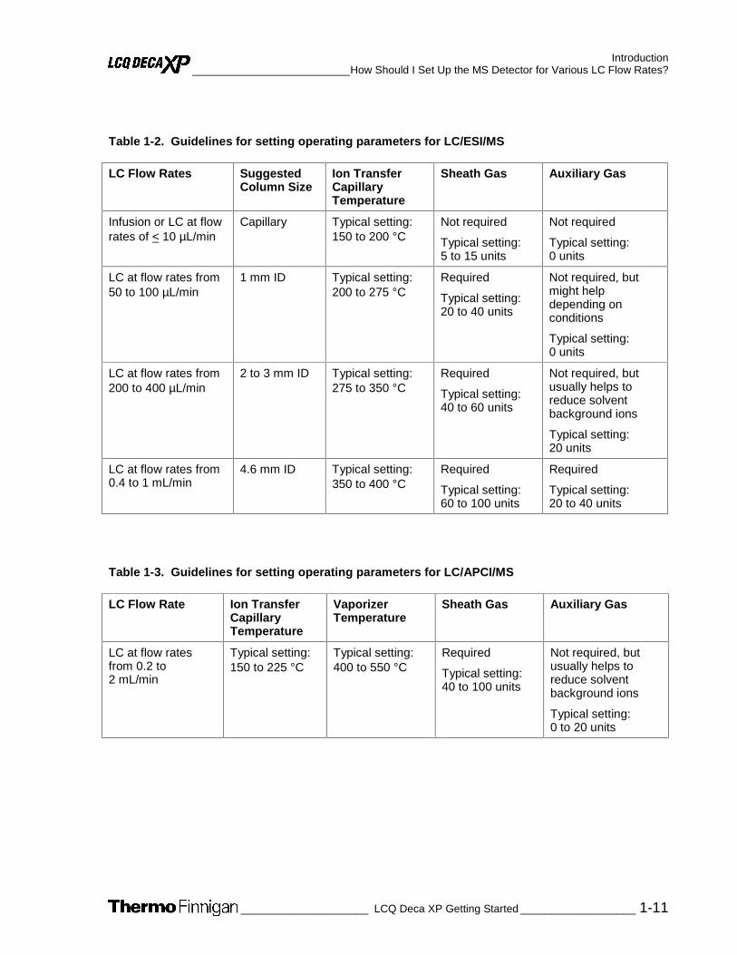
Table 1-2 provides guidelines for ESI operation for ion transfer capillary temperatures and gas flow rates for various LC solvent flow rates.
Table 1-3 provides guidelines for APCI operation for the ion transfer capillary temperature, vaporizer temperature, and gas flow rate for a range of LC solvent flow rates.
1 The ESI probe can generate ions from liquid flows of as low as 1 µL/min. However, flows below 5 µL/min require more care, especially with the position of the fused silica sample tube within the ESI probe.
2 For the APCI probe, flows below 200 µL/min require more care to maintain a stable spray.
Introduction __________________________How Should I Set Up the MS Detector for Various LC Flow Rates?
_____________________ LCQ Deca XP Getting Started ___________________ 1-11
Table 1-2. Guidelines for setting operating parameters for LC/ESI/MS
LC Flow Rates Suggested Column Size
Ion Transfer Capillary Temperature
Sheath Gas Auxiliary Gas
Infusion or LC at flow rates of < 10 µL/min
Capillary Typical setting: 150 to 200 °C
Not required
Typical setting: 5 to 15 units
Not required
Typical setting: 0 units
LC at flow rates from 50 to 100 µL/min
1 mm ID Typical setting: 200 to 275 °C
Required
Typical setting: 20 to 40 units
Not required, but might help depending on conditions
Typical setting: 0 units
LC at flow rates from 200 to 400 µL/min
2 to 3 mm ID Typical setting: 275 to 350 °C
Required
Typical setting: 40 to 60 units
Not required, but usually helps to reduce solvent background ions
Typical setting: 20 units
LC at flow rates from 0.4 to 1 mL/min
4.6 mm ID Typical setting: 350 to 400 °C
Required
Typical setting: 60 to 100 units
Required
Typical setting: 20 to 40 units
Table 1-3. Guidelines for setting operating parameters for LC/APCI/MS
LC Flow Rate Ion Transfer Capillary Temperature
Vaporizer Temperature
Sheath Gas Auxiliary Gas
LC at flow rates from 0.2 to 2 mL/min
Typical setting: 150 to 225 °C
Typical setting: 400 to 550 °C
Required
Typical setting: 40 to 100 units
Not required, but usually helps to reduce solvent background ions
Typical setting: 0 to 20 units

Introduction What is Tuning and Calibration of the MS Detector All About? _____________________________
1-12 ____________________LCQ Deca XP Getting Started_____________________
1.6 What is Tuning and Calibration of the MS Detector All About?
To optimize the performance of data acquisition on the LCQ Deca XP, you tune and calibrate in three steps:
• First, you tune the MS detector in ESI mode by infusing calibration solution. In this step, you use the automatic tuning procedure in Tune Plus to establish a stable spray of ions into the MS detector and to demonstrate that the transmission of ions into the MS detector is optimum. You infuse a calibration solution into the MS detector at a steady rate m/z 195, the mass-to-charge ratio of caffeine in the calibration solution. You observe the Tune Plus window as Xcalibur tunes your LCQ Deca XP automatically.
• Second, you calibrate the MS detector in the ESI mode with calibration solution to automatically optimize its performance. In this step, you want to ensure that the calibration parameters complete automatic calibration successfully. The Calibrate dialog box in Tune Plus provides a readback of the status of the calibration parameters, both during the automatic calibration and when calibration is complete.
• Third, if you want to maximize the detection of one or more particular ions, you can optimize the tune of the MS detector with your analyte of interest in either the ESI or APCI mode. You choose a mass-to-charge ratio of your analyte of interest. Alternatively, you can choose an ion in the calibration solution that is closest to the mass-to-charge ratio for your ion of interest. (It is sometimes possible to acquire qualitative data without optimizing the parameters, but detection sensitivity might be compromised.)
Calibration parameters are instrument parameters whose values do not vary with the type of experiment. It is recommended that you calibrate the MS detector at least once every three months and that you check the calibration about once a week.
Automatic and semi-automatic calibration (including checking the calibration) require that you introduce calibration solution into the MS detector at a steady flow rate while the procedure is running. You introduce the solution directly from the syringe pump into the MS detector in the ESI/MS mode.
Tune parameters are instrument parameters whose values can vary with the type of experiment. For example, if your experiment requires quantitative data on one or more particular ions, you need to tune the MS detector with your analyte if you change any one of the parameters specific to the experiment or analyte.
Automatic and semi-automatic tuning procedures (including optimizing the collision energy) require that you introduce calibration solution, or a tuning solution of your analyte of interest, into the MS detector at a steady rate in either of two ways:

Introduction _____________________________ What is Tuning and Calibration of the MS Detector All About?
_____________________ LCQ Deca XP Getting Started ___________________ 1-13
• Introduce the solution directly from the syringe pump. Refer to the topic: Setting Up the Syringe Pump for Tuning and Calibrating in chapter 2.
• Introduce the sample from the syringe pump into the effluent of the LC by using a Tee union. Refer to the topic: Setting Up to Introduce Sample by Syringe Pump into Solvent Flow from an LC in chapter 4.
The first method is good for tuning if you intend to use an experiment type at a low flow rate involving the syringe pump. The second method is useful if you intend to use an experiment type at a higher flow rate involving the LC. However, the second method of introduction puts a comparatively large amount of analyte into the MS detector. Therefore, before you can perform an analytical run to analyze for the analyte, you might need to clean the API spray shield.
Caution. Ultramark 1621 can contaminate your system at high concentrations.
In most cases, you can use the tune you obtain from the automatic or semi-automatic tuning procedures for your analytical experiments. However, for some applications, you might need to tune several MS detector parameters. In that case, you would tune manually. With the manual tuning process, you introduce a tuning solution at a steady flow rate.
Note. The most important parameters that affect the signal quality during ESI/MS operation are the ion transfer capillary temperature, capillary voltage, tube lens offset voltage, gases, and solution flow rate. For optimum sensitivity, tune with the instrument in the same operational mode as the mode you use for the analytical experiment.
Table 1-4 summarizes methods of sample introduction for each of the calibration and tuning procedures.

Introduction What is Tuning and Calibration of the MS Detector All About? _____________________________
1-14 ____________________LCQ Deca XP Getting Started_____________________
Table 1-4. Summary of methods of sample introduction for calibration and tuning
Calibrating Tuning
Sample/ Sample Intro
Check Auto Semi-auto
Auto Semi-auto
Manual Collision Energy
Calibration solution/ Syringe pump
Your tune solution/ Syringe pump
Your tune solution/ Syringe pump into LC flow by using Tee union

Introduction ____________________________ What Types of Experiments Can I Perform with LCQ Deca XP?
_____________________ LCQ Deca XP Getting Started ___________________ 1-15
1.7 What Types of Experiments Can I Perform with LCQ Deca XP?
This topic describes several types of experiments that you can perform with LCQ Deca XP. The experiments can be grouped into the following categories:
• General MS or MSn
• Data-Dependent™
• Ion Mapping™
• Ion Tree
You can specify which type of experiment you want to perform in the Instrument Setup window, and then save it in an Instrument Method (.meth) file.
Note. Procedures for these experiments are beyond the scope of this LCQ Deca XP Getting Started manual. If you need more information, refer to online Help.

Introduction What Types of Experiments Can I Perform with LCQ Deca XP? ____________________________
1-16 ____________________LCQ Deca XP Getting Started_____________________
General MS or MSn Experiments
A General MS or MSn experiment is best used for the quantitative analysis of known compounds. However, you can also use a General experiment to collect qualitative data for structural analysis. Xcalibur includes an Instrument Method template in Instrument Setup so you can get started with a General MS or MSn experiment. See Figure 1-1 for an example of a General MS or MSn experiment template.
In a General MS quantitation experiment, you need to specify the mass range of your analyte(s) of interest. In a General MS/MS quantitation experiment, you need to specify a parent (precursor ion) that fragments into distinctive product ions. In a General MSn quantitation experiment, you need to specify the mass-to-charge ratios of all the parent ions of interest. LCQ Deca XP can then collect data on the ions in the range or on the product ions of the parent ion(s) that you specify.
If you use a General experiment to collect data for qualitative (structural) analysis, you specify the scan mode (MS through MSn) for which you want data in the Scan Event Settings group box. If you specify MS/MS or MSn, you then choose the parent ion(s) for which you want data in the Set Parent List dialog box. LCQ Deca XP can then collect distinct qualitative information for structural analysis or for spectral reference.
The LCQ Deca XP can generate reproducible, product-specific spectra, even from laboratory to laboratory. Consequently, reference spectra that are generated with the LCQ Deca XP can be used to confirm structures of compounds generated with other LCQ Deca XP systems.

Introduction ____________________________ What Types of Experiments Can I Perform with LCQ Deca XP?
_____________________ LCQ Deca XP Getting Started ___________________ 1-17
Figure 1-1. MS Detector Setup page in Instrument Setup, showing a template for a General MS experiment
Introduction What Types of Experiments Can I Perform with LCQ Deca XP? ____________________________
1-18 ____________________LCQ Deca XP Getting Started_____________________
Data-Dependent Experiments
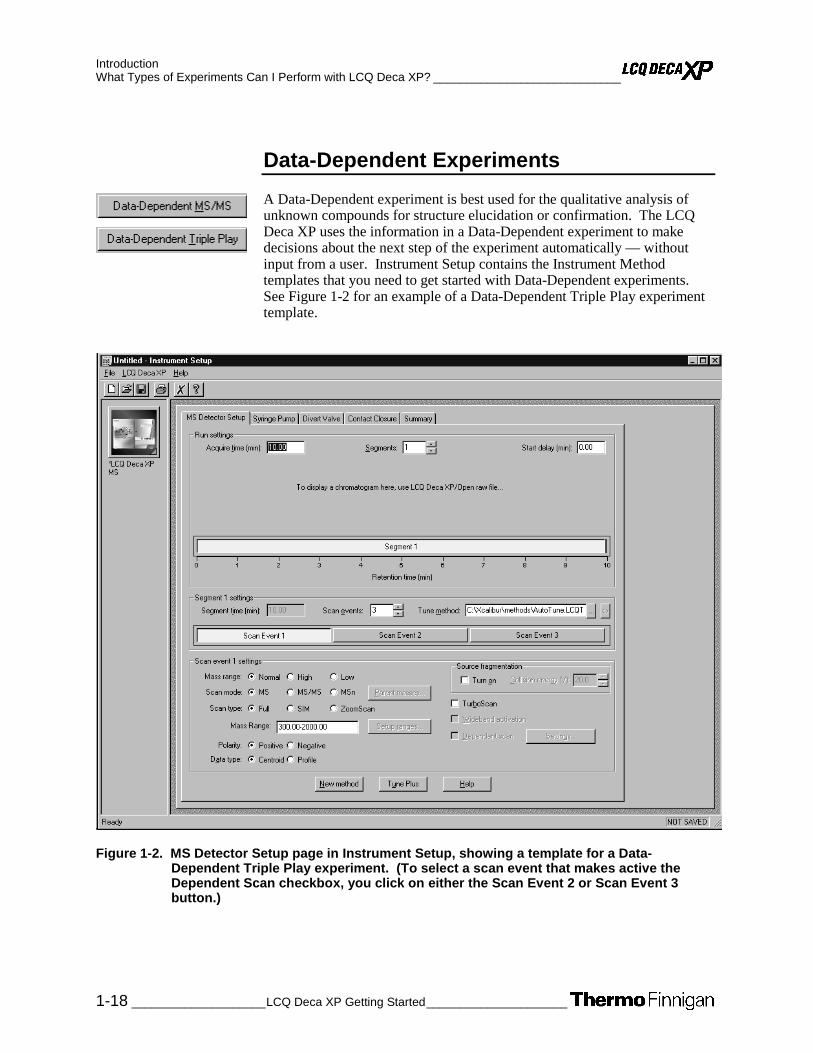
A Data-Dependent experiment is best used for the qualitative analysis of unknown compounds for structure elucidation or confirmation. The LCQ Deca XP uses the information in a Data-Dependent experiment to make decisions about the next step of the experiment automatically — without input from a user. Instrument Setup contains the Instrument Method templates that you need to get started with Data-Dependent experiments. See Figure 1-2 for an example of a Data-Dependent Triple Play experiment template.
Figure 1-2. MS Detector Setup page in Instrument Setup, showing a template for a Data-Dependent Triple Play experiment. (To select a scan event that makes active the Dependent Scan checkbox, you click on either the Scan Event 2 or Scan Event 3 button.)

Introduction ____________________________ What Types of Experiments Can I Perform with LCQ Deca XP?
_____________________ LCQ Deca XP Getting Started ___________________ 1-19
A Data-Dependent experiment produces a great deal of data from a single sample analysis. You can run a Data-Dependent experiment even if you know very little about your sample, and even if you are unfamiliar with the variables of mass spectroscopy. In a Data-Dependent experiment, you can specify parent ions for fragmentation or you can let LCQ Deca XP automatically select the ions for fragmentation. LCQ Deca XP can collect the structural information for every parent ion in the sample automatically, even if the sample is a mixture of compounds.
A Data-Dependent experiment requires minimal input from a user about how the experiment should best proceed. The user specifies that one or more scan events of an experiment segment are to be run as Data-Dependent. Then, LCQ Deca XP collects MS/MS or MSn data and makes decisions about what the next step in the experiment should be to collect even more data. For example, in a Data-Dependent Triple Play experiment for a mixture of compounds, LCQ Deca XP can decide which parent ion to isolate, the charge state of the parent ion, and the molecular weight of the compound.
Ion Mapping experiments can be Data-Dependent. (The Total Ion Map, Neutral Loss Ion Map, and Parent Ion Map experiments are not Data-Dependent.) The Data-Dependent Zoom Map experiment collects ZoomScan data on every scan interval in a specified mass range.
Ion Tree experiments are types of Data-Dependent experiments. These experiments provide methods for automatically interpreting MSn data and arranging the data in formats that are easy to manipulate.
You can approach the setup of Data-Dependent experiments in either of two ways:
• If you have some idea of the parent ion, or if you expect a certain kind of parent, you can set up a list of possible parent ions. Then, when one of the parent ions you specified is detected, you can acquire product spectra and analyze the information. Conversely, you can also set up a list of ions that you do not want to be selected for fragmentation.
• If you have little information about your compound, you can set up the parameters of a Data-Dependent experiment so that if the intensity of the ion signal is above a specified threshold, LCQ Deca XP generates product spectra. Later, you decide if the information is useful. Parameters that you might specify, for example, include threshold values for the intensity of the MS or MSn ion signal. Whatever threshold values you choose should accomplish the isolation of your parent ions of interest.
You can find useful structural information about your compound automatically with the simplest Data-Dependent experiment, Data-Dependent MS/MS. You specify the MS scan range, and you do not even need to specify a parent ion. LCQ Deca XP can then collect full scan MS data, pick the most intense parent ion in the spectrum, and fragment the ion to generate product ions.

Introduction What Types of Experiments Can I Perform with LCQ Deca XP? ____________________________
1-20 ____________________LCQ Deca XP Getting Started_____________________
A Data-Dependent Triple-Play experiment is the same as Data-Dependent MS/MS, but includes the identification of the charge state of the parent with the LCQ Deca XP ZoomScan feature. A Data-Dependent Triple-Play experiment collects full scan MS data, and then uses ZoomScan to determine the charge state of the parent ion and calculate the molecular weight. The parent ion is then fragmented into product ions (MS/MS). For example, if LCQ Deca XP determines a charge state equal to 2, and if the mass-to-charge ratio of the parent ion is m/z 500, then the mass-to-charge ratios of the product ions can be up to m/z 1000 (or 2 × 500).
You can use a Data-Dependent experiment (from templates in Instrument Setup) to do the following:
• Identify low-level impurities in high-purity compounds (Data-Dependent MS/MS)
• Identify metabolites in a complex mixture (Chromatographic Separation with Data-Dependent MS/MS)
• Build a custom library of composite MSn spectra (Ion Tree)
You can use a Data-Dependent MSn experiment to identify process impurities. In the quality assurance process for aspirin, for example, the LCQ Deca XP can identify impurities of 0.1%.
A Data-Dependent MS/MS experiment of a complex mixture of drug metabolites can provide highly specific structural information. Characteristic masses along the metabolic pathways of a drug, for example, can produce MS/MS spectra that are specific to the structure of the drug. These spectra are essential in metabolite identification.
A Data-Dependent experiment can produce a composite spectrum of, for example, MS2, MS3, and MS4 data. The LCQ Deca XP can store the MSn fingerprint data in a custom MSn library spectrum. The data is valuable for use in process control, quality assurance, or research.
Ion Mapping Experiments
An Ion Mapping experiment is best used to get full structural characterization of unknown molecules in complex mixtures. In an Ion Mapping experiment, you can get product ion scans on every parent ion over a specified mass range. An Ion Mapping experiment can help to identify automatically which parent ions were fragmented to yield a specified product ion. The experiment “maps” one or more parent ions by using the information from product ion scans.
LCQ Deca XP includes the following Ion Mapping templates in Instrument Setup so you can get started with an Ion Mapping experiment:
• Total (or full scan) Ion Map
• Neutral Loss Ion Map
• Parent Ion Map
Introduction ____________________________ What Types of Experiments Can I Perform with LCQ Deca XP?
_____________________ LCQ Deca XP Getting Started ___________________ 1-21
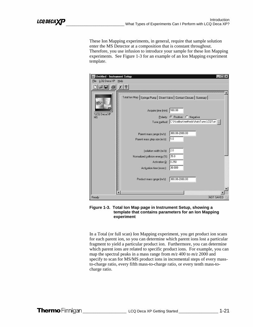
These Ion Mapping experiments, in general, require that sample solution enter the MS Detector at a composition that is constant throughout. Therefore, you use infusion to introduce your sample for these Ion Mapping experiments. See Figure 1-3 for an example of an Ion Mapping experiment template.
Figure 1-3. Total Ion Map page in Instrument Setup, showing a template that contains parameters for an Ion Mapping experiment
In a Total (or full scan) Ion Mapping experiment, you get product ion scans for each parent ion, so you can determine which parent ions lost a particular fragment to yield a particular product ion. Furthermore, you can determine which parent ions are related to specific product ions. For example, you can map the spectral peaks in a mass range from m/z 400 to m/z 2000 and specify to scan for MS/MS product ions in incremental steps of every mass-to-charge ratio, every fifth mass-to-charge ratio, or every tenth mass-to-charge ratio.

Introduction What Types of Experiments Can I Perform with LCQ Deca XP? ____________________________
1-22 ____________________LCQ Deca XP Getting Started_____________________
A Neutral Loss Ion Mapping experiment collects scans for masses that have lost neutral fragments. As with full scan Ion Mapping, you can get product ion scans on every parent ion. However, a Neutral Loss Ion Map identifies which parent ions lost a neutral fragment of a particular mass. For example, you can specify a neutral loss of 80 u (as in the case of a phosphorylated peptide in a tryptic digest). A Neutral Loss Ion Mapping experiment can step through each product mass in the mixture. The experiment searches for evidence of the loss of a neutral moiety of mass 80 u.
A Parent Ion Mapping experiment identifies all the ions that produce a particular molecular ion that you specify. For example, if you specify a product ion mass of m/z 50, a Parent Ion Map includes all the parent ions that yielded the specified product ion, m/z 50.
A Data-Dependent Zoom Map is an Ion Mapping experiment that collects ZoomScan data on every scan interval in a mass range that you specify, as well as Data-Dependent MS/MS product spectra on every mass above an intensity threshold.
The results of any of the Ion Mapping experiments can be viewed in the Xcalibur Qual Browser window.
Ion Tree Experiments
In an Ion Tree experiment, LCQ Deca XP can collect MSn data automatically. You can specify a particular parent ion for fragmentation, or you can let LCQ Deca XP find the parent ions automatically and fragment them to any level between MS2 and MS10. LCQ Deca XP automates the collection of data by deciding what actions need to occur next for the experiment to progress. See Figure 1-4 for an example of an Ion Tree experiment template.

Introduction ____________________________ What Types of Experiments Can I Perform with LCQ Deca XP?
_____________________ LCQ Deca XP Getting Started ___________________ 1-23
Figure 1-4. Data-Dependent Ion Tree page in Instrument Setup, showing a template for an Ion Tree experiment
In an Ion Tree experiment, you can specify either of two options that prioritize how LCQ Deca XP gathers information: Depth Focus and Breadth Focus.
• Depth Focus characterizes an ion by performing a series of MSn-level fragmentations (for example, MS/MS, MS3, MS4, etc.) before characterizing the next most intense ion in the MSn series.
• Breadth Focus characterizes all ions to the same MSn level before advancing to the next MSn level.
For example, if you specify a Maximum Depth of 3 and a Maximum Breadth of 2 in an Ion Tree experiment, the following occurs.

Introduction What Types of Experiments Can I Perform with LCQ Deca XP? ____________________________
1-24 ____________________LCQ Deca XP Getting Started_____________________
First, with either Depth or Breadth Focus, LCQ Deca XP scans for parent ions (MS) over the specified mass range. The most intense ion of the MS spectrum is selected for fragmentation (MS/MS).
• Second, if you chose the Depth Focus, after the most intense ion of the MS spectrum is fragmented — producing an MS/MS spectrum — LCQ Deca XP selects and fragments the most intense ion of the MS/MS spectrum. This results in an MS3 spectrum, the level specified as the maximum depth for this example. LCQ Deca XP then backs up one level and fragments the second most intense ion of the MS/MS spectrum, creating more product ions on the level of MS3 from this parent ion. This process is then repeated for the second most intense ion in the MS spectrum.
• If you chose the Breadth Focus, after the most intense ion of the MS spectrum is fragmented — producing an MS/MS spectrum — LCQ Deca XP selects and fragments the second-most intense ion of the same MS spectrum. The fragmentation of parent ions continues to the Max Breadth level that you specified (2, for this example). After the two most intense peaks on the MS level are fragmented, LCQ Deca XP scans the first MS/MS spectrum to select and fragment the two most intense ions. This results in product ions on the level of MS3, the level specified as the maximum depth for this example. This process is then repeated for the second most intense ion in the MS spectrum.
The results of a Data-Dependent Ion Tree experiment can be viewed in the Xcalibur Qual Browser window. The results are displayed as a structure tree that originates from a particular parent ion.
_____________________ LCQ Deca XP Getting Started ____________________ 2-1
Chapter 2
2. Setting Up the Hardware for Tuning and Calibrating the MS Detector in
ESI/MS Mode
This chapter provides information on setting up the hardware for tuning and calibrating your LCQ Deca XP. You tune and calibrate in ESI mode before you acquire data in either the ESI or the APCI mode.
This chapter contains the following topics:
• Removing the APCI Probe Assembly
• Connecting the PEEK Safety Sleeve and a New Fused-Silica Sample Tube to the ESI Probe
• Installing the ESI Probe Assembly
• Setting Up the Syringe Pump for Tuning and Calibrating
If the ESI probe and the PEEK safety sleeve are installed on the API source, go to the topic: Setting Up the Syringe Pump for Tuning and Calibrating.
If no probe is installed, or if the ESI probe is installed without the PEEK safety sleeve, go to the topic: Connecting the PEEK Safety Sleeve and New Fused-Silica Sample Tube to the ESI Probe.
If the APCI probe is installed on the API source, go on to the next topic: Removing the APCI Probe Assembly.

Setting Up the Hardware for Tuning and Calibrating the MS Detector in ESI/MS Mode Removing the APCI Probe Assembly_________________________________________________
2-2 _____________________LCQ Deca XP Getting Started_____________________
2.1 Removing the APCI Probe Assembly
To remove the APCI probe assembly and ensure that the MS detector is in Standby mode, proceed as follows.
Note. The following procedures assume that you are familiar with your LCQ Deca XP instrument. If you need assistance, refer to LCQ Deca XP MS online Help, LCQ Deca XP Getting Connected and/or LCQ Deca XP Hardware Manual.
Ensure that the MS detector is in Standby mode before removing the APCI probe assembly, as follows:
1. Open the Tune Plus window from the Start button on your Windows NT® Desktop, as follows:
a. Choose Start | Programs | Xcalibur | Xcalibur to display the Xcalibur Home Page — Roadmap view.
b. Click on the Instrument Setup button to display the window.
c. Click on the LCQ Deca XP MS button to display the New Method page.
d. Click on the Tune Plus button to display the window. See Figure 2-1.
Setting Up the Hardware for Tuning and Calibrating the MS Detector in ESI/MS Mode _________________________________________________Removing the APCI Probe Assembly
_____________________ LCQ Deca XP Getting Started ____________________ 2-3
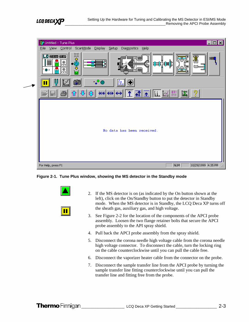
Figure 2-1. Tune Plus window, showing the MS detector in the Standby mode
2. If the MS detector is on (as indicated by the On button shown at the left), click on the On/Standby button to put the detector in Standby mode. When the MS detector is in Standby, the LCQ Deca XP turns off the sheath gas, auxiliary gas, and high voltage.
3. See Figure 2-2 for the location of the components of the APCI probe assembly. Loosen the two flange retainer bolts that secure the APCI probe assembly to the API spray shield.
4. Pull back the APCI probe assembly from the spray shield.
5. Disconnect the corona needle high voltage cable from the corona needle high voltage connector. To disconnect the cable, turn the locking ring on the cable counterclockwise until you can pull the cable free.
6. Disconnect the vaporizer heater cable from the connector on the probe.
7. Disconnect the sample transfer line from the APCI probe by turning the sample transfer line fitting counterclockwise until you can pull the transfer line and fitting free from the probe.

Setting Up the Hardware for Tuning and Calibrating the MS Detector in ESI/MS Mode Removing the APCI Probe Assembly_________________________________________________
2-4 _____________________LCQ Deca XP Getting Started_____________________
Figure 2-2. APCI probe assembly
8. Disconnect the sheath gas line from the APCI probe by turning the sheath gas line fitting counterclockwise until you can pull the sheath gas line and fitting free from the probe.
9. Disconnect the auxiliary gas line from the APCI probe by turning the auxiliary gas line fitting counterclockwise until you can pull the auxiliary gas line and fitting free from the probe.
CAUTION. AVOID BURNS. The APCI vaporizer heater can reach temperatures of 600 °C. Always allow the APCI probe to cool to ambient temperature, for approximately 20 min, before handling or removing the APCI probe from the APCI flange.
10. With one hand holding the APCI flange, loosen the knurled fastener that secures the APCI flange to the probe slide adapter.
FLANGE RETAINER BOLT
(2 X)
PROBE RETAINER
BOLT
VAPORIZER HEATER CABLE
AUXILIARY GAS LINE FITTING
(GREEN)
SAMPLE TRANSFER
LINE FITTING (RED)
PROBE SLIDE ADAPTER
FASTENER (UNDERSIDE)
CORONA NEEDLE HIGH VOLTAGE
CONNECTOR
SHEATH GAS LINE FITTING
(BLUE)
PROBE POSITION
ADJUSTMENT SCREW

Setting Up the Hardware for Tuning and Calibrating the MS Detector in ESI/MS Mode _________________________________________________Removing the APCI Probe Assembly
_____________________ LCQ Deca XP Getting Started ____________________ 2-5
11. Remove the APCI probe assembly from the probe slide adapter by sliding the probe off the slide adapter. Place the APCI probe assembly on a lint-free tissue and allow it to cool to ambient temperature (approximately 20 min).
CAUTION. AVOID INJURY. The corona discharge needle is very sharp and can puncture your skin if you handle it without caution.
12. Remove the corona discharge needle from the APCI probe assembly by pulling it free from the corona discharge needle assembly. Store the corona discharge needle by inserting it into one of the foam walls of the APCI probe assembly storage container.
13. Store the APCI probe assembly in its foam storage container. (Make sure that the APCI probe assembly is at ambient temperature before you place it in its storage container.)

Setting Up the Hardware for Tuning and Calibrating the MS Detector in ESI/MS Mode Connecting the PEEK Safety Sleeve and a New Fused-Silica Sample Tube to the ESI Probe _____
2-6 _____________________LCQ Deca XP Getting Started_____________________
2.2 Connecting the PEEK Safety Sleeve and a New Fused-Silica Sample Tube to the ESI Probe
Before you operate your LCQ Deca XP, connect the PEEK safety sleeve and sample tube to the ESI probe.
CAUTION. AVOID ELECTRICAL SHOCK. When you are operating your instrument in the ESI mode, there are two situations in which you could receive an electrical shock unless you install the safety kit discussed below. When you are using the optional Metal Needle Kit (P/N 70001-62217 or 70005-62013), you might receive an electrical shock if you touch the fused-silica capillary tube. You could also receive an electrical shock if the fused-silica capillary tube breaks during ESI operation, with or without the metal needle installed. Therefore, for your safety and in compliance with international safety standards, you must cover the fused-silica capillary tube with the PEEK safety sleeve (P/N 00301-22806) and associated PEEK ferrules (P/N 00101-18119) provided in the Safety Sleeve Kit (P/N 70005-62015) before you operate the instrument. Installation instructions (P/N 70005-97009) are included in the kit. Operation of the instrument without the safety sleeve impairs the safety protection provided by the instrument and, thus, could lead to serious injury.
Connect the PEEK safety sleeve and sample tube to the ESI probe, as follows. See Figure 2-3.
1. Use a fused-silica cutting tool to cut a 12-in. (30 cm) piece of sample tube (P/N 00106-10499). Ensure that you squarely cut the ends of the sample tube.
2. Insert the sample tube through the exit end of the ESI needle and into the ESI probe.
3. Push the sample tube through the ESI probe until approximately 3.5 cm (1.5-in.) is left protruding from the exit end of the ESI needle. The remaining length of sample tube should exit the ESI probe sample inlet.
4. Slide the (brown) 10-32 × 1/4-28 PEEK fitting adapter over the sample tube and tighten the fitting in the ESI probe sample inlet.
5. Slide the 25.4 cm (10.0-in.) precut (brown) PEEK safety sleeve over the sample tube.
6. Slide a (brown) ferrule (P/N 00101-18119), narrow end first, over the PEEK safety sleeve and up to the 10-32 × 1/4-28 PEEK fitting.

Setting Up the Hardware for Tuning and Calibrating the MS Detector in ESI/MS Mode _____ Connecting the PEEK Safety Sleeve and a New Fused-Silica Sample Tube to the ESI Probe
_____________________ LCQ Deca XP Getting Started ____________________ 2-7
PEEK SAFETY SLEEVE(00301-22806)
FERRULE(00101-18119)
SAMPLE TUBEFUSED-SILICA CAPILLARY
(00106-10499)
FINGERTIGHT FITTING(00101-18081)
FERRULE(00101-18119)
GROUNDED FITTING(00101-18182)
FINGERTIGHT FITTING(00101-18195)
10-32 x 1/4-28 FITTING(00101-18080)
Figure 2-3. ESI/MS plumbing connections for the PEEK safety sleeve and sample tube
7. Slide a (red) fingertight fitting onto the PEEK safety sleeve and push it
to the 10-32 × 1/4-28 PEEK fitting. Tighten the fingertight fitting slightly, but not completely.
8. Push the PEEK safety sleeve over the sample tube and into the ESI probe until it stops against the Teflon® needle seal inside the ESI probe.
9. Pull the sample tube (from the ESI needle end) until the sample tube is flush with the precut square end of the PEEK safety sleeve.
10. Slide a (brown) fingertight fitting and (brown) ferrule (P/N 00101-18119), wide end first, over the free end of the PEEK safety sleeve.
11. Connect the PEEK safety sleeve and ferrule to the grounded fitting by tightening the fingertight fitting. Ensure that the fingertight fitting is securely tightened around the PEEK safety sleeve, otherwise the sample stream might enter between the sample tube and the PEEK safety sleeve.
12. Ensure the sample tube is held tightly in the grounded fitting; check by pulling the sample tube from the exit end of the ESI needle.
13. Use a fused-silica cutting tool to cut the sample tube at the ESI needle so that only 2.5 cm (1-in.) remains protruding from the exit end of ESI needle.
14. From the ESI sample inlet carefully pull the PEEK safety sleeve back until the exit end of the sample tube is recessed inside the ESI needle (approximately 1 mm).
15. Tighten the (red) fingertight fitting to securely hold the PEEK safety sleeve and sample tube in place in the ESI sample inlet.
ESI PROBE

Setting Up the Hardware for Tuning and Calibrating the MS Detector in ESI/MS Mode Installing the ESI Probe Assembly ___________________________________________________
2-8 _____________________LCQ Deca XP Getting Started_____________________
2.3 Installing the ESI Probe Assembly
To install the ESI probe assembly, proceed as follows. See Figure 2-4 for the location of the components of the ESI probe assembly.
1. If your ESI probe assembly does not already contain a sample tube (fused-silica capillary), you need to follow the procedure for installing a sample tube that is outlined in the previous topic: Connecting the PEEK Safety Sleeve and a New Fused-Silica Sample Tube to the ESI Probe.
Figure 2-4. ESI probe assembly
PROBE SLIDE ADAPTER
AUXILIARY GAS INLET (GREEN)
SHEATH GAS INLET
(BLUE)
SAMPLE INLET (RED)
PROBE POSITION
ADJUSMENT SCREW
PROBE RETAINER
BOLT
FLANGE RETAINER BOLT (2 X)
ESI PROBE
GROUNDED FITTING HOLDER
ESI NEEDLE HIGH VOLTAGE
CONNECTOR

Setting Up the Hardware for Tuning and Calibrating the MS Detector in ESI/MS Mode ___________________________________________________ Installing the ESI Probe Assembly
_____________________ LCQ Deca XP Getting Started ____________________ 2-9
2. With one hand holding the ESI flange, align the ESI flange with the probe slide adapter, and place it onto the guide rails.
3. Slide the ESI probe assembly onto the probe slide adapter. Secure the ESI probe assembly to the probe slide adapter with the knurled fastener that is located on the underside of the probe slide adapter.
4. Remove the Teflon coated septum from the entrance end of the ion transfer capillary.
5. With one hand, hold the ESI probe on the nozzle side of the probe to keep it from moving in the flange. With the other hand, connect the high voltage power cable to the connector labeled HV on the ESI probe. Turn the locking-ring on the cable clockwise to secure the cable.
6. Push the ESI probe assembly against the spray shield.
7. Secure the ESI flange to the spray shield with the two (black) flange retainer bolts.
8. Set the probe position to 3B for a 5-µL/min experiment, as follows:
a. Loosen the probe retainer bolt to free the ESI probe. Refer to Figure 2-4.
b. Grasp the probe firmly, and gently pull the probe ¼ in. away from the rest of the assembly. Notice the numbered position markers on top of the probe.
c. Gently move the probe in and out so that the metal sleeve around the probe aligns with position 3 on the probe.
d. Turn the probe position adjustment screw to align the mark on the metal sleeve with position B (the second mark from the right) on the instrument.
e. Tighten the probe retainer bolt to stabilize the probe on position 3B.
9. Connect the sheath gas line and (blue) fitting to the inlet labeled Sheath Gas on the ESI probe.
10. Connect the auxiliary gas line and (green) fitting to the inlet labeled Aux Gas on the ESI probe.
11. Connect the sample transfer line (coming from the syringe) to the grounded fitting.
Note. The ESI needle inside the ESI probe is positioned on a Teflon needle seat to prevent the loss of gas from inside the probe. Ensure that the ESI needle is seated properly when you reassemble the probe. Over time, the needle seat becomes compressed and needs to be replaced.
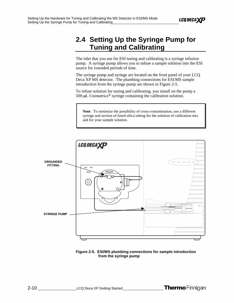
Setting Up the Hardware for Tuning and Calibrating the MS Detector in ESI/MS Mode Setting Up the Syringe Pump for Tuning and Calibrating__________________________________
2-10 ____________________LCQ Deca XP Getting Started_____________________
2.4 Setting Up the Syringe Pump for Tuning and Calibrating
The inlet that you use for ESI tuning and calibrating is a syringe infusion pump. A syringe pump allows you to infuse a sample solution into the ESI source for extended periods of time.
The syringe pump and syringe are located on the front panel of your LCQ Deca XP MS detector. The plumbing connections for ESI/MS sample introduction from the syringe pump are shown in Figure 2-5.
To infuse solution for tuning and calibrating, you install on the pump a 500- ® syringe containing the calibration solution.
Note. To minimize the possibility of cross-contamination, use a different syringe and section of fused silica tubing for the solution of calibration mix and for your sample solution.
Figure 2-5. ESI/MS plumbing connections for sample introduction from the syringe pump
GROUNDED FITTING
SYRINGE PUMP

Setting Up the Hardware for Tuning and Calibrating the MS Detector in ESI/MS Mode __________________________________ Setting Up the Syringe Pump for Tuning and Calibrating
_____________________ LCQ Deca XP Getting Started ___________________ 2-11
Use the following procedure to set up the syringe pump for infusion.
1. Connect a 4 cm (1.5 in.) segment of Teflon tube (00301-22803) with a (brown) Fingertight fitting and a (brown) ferrule to the (black) LC union. See Figure 2-6.
2. Load a clean, 500- -19012) with 420 Appendix A: Sample Formulations for a procedure for making the calibration solution.)
Figure 2-6. Plumbing connections for the syringe
3. Insert the syringe needle into the segment of Teflon tube.
4. Place the syringe into one of the syringe holders of the syringe pump.
5. While squeezing the blue release button on the syringe pump handle, push the handle forward until it just contacts the syringe plunger.
6. Connect a fused-silica infusion line from the LC union to the (stainless steel) grounded fitting, as follows. See Figure 2-7.
a. Connect the infusion line (P/N 00106-10504) with a (brown) Fingertight fitting and a (brown) ferrule to the free end of the LC union.
b. Connect the other end of the infusion line with a (red) Fingertight fitting and a (brown) ferrule to the grounded fitting.
Caution. Prevent solvent waste from backing up into the API ion source and MS detector. Always ensure that the PVC drain hose is above the level of liquid in the waste container.
7. Connect an appropriate length of (clear) 3/8 in. ID PVC hose to the ESI probe outlet drain. Insert the end of the hose into a suitable container (such as a gallon jug). Ideally, the container should be vented to a fume exhaust system.
LC UNION(00101-18202)
FERRULE(00101-18196)
TEFLON TUBE(00301-22803)
FINGERTIGHT FITTING(00101-18081)

Setting Up the Hardware for Tuning and Calibrating the MS Detector in ESI/MS Mode Setting Up the Syringe Pump for Tuning and Calibrating__________________________________
2-12 ____________________LCQ Deca XP Getting Started_____________________
GROUNDED FITTING(00101-18182)
FINGERTIGHT FITTING(00101-18081)
INFUSION LINEFUSED-SILICA CAPILLARY
(00106-10504)
FINGERTIGHT FITTING(00101-18195)
LC UNION(00101-18202)
FERRULE(00101-18120)
Figure 2-7. ESI/MS plumbing connections for the fused-silica infusion line

_____________________ LCQ Deca XP Getting Started ____________________ 3-1
Chapter 3
3. Tuning and Calibrating Automatically in the ESI/MS Mode
This chapter provides information on how to tune and calibrate the LCQ Deca XP MS detector in the ESI/MS mode. For most applications, you tune and calibrate in the ESI mode through automatic procedures. The procedures use a calibration solution, which is introduced into the MS detector in low flow mode. The procedures properly tune and calibrate the MS detector for ESI operation. (Refer to Table 1-2.) You need to calibrate the MS detector every one to three months for optimum performance over the entire mass range of the detector.
To tune and calibrate your MS detector automatically in the ESI/MS mode, you do the following:
• Infuse a low concentration calibration solution containing caffeine, MRFA, and Ultramark 1621 into the ESI source by using the syringe pump. (Refer to the topic: Setting Up the Syringe Pump for Tuning and Calibrating.)
• Test the efficiency and stability of the spray of calibration solution into the MS detector. You can observe the following singly-charged, positive ions for caffeine, MRFA, and Ultramark 1621 in the Tune Plus window: m/z 195, 524, 1222, 1522, and 1822.
• Tune the MS detector from the Tune Plus window to optimize automatically the lenses.
• Calibrate the MS detector to adjust automatically the voltages of the endcaps and the ring electrode.
This chapter contains the following topics:
• Setting Up the MS Detector in Xcalibur for Tuning and Calibrating
• Testing the Operation of the MS Detector in the ESI/MS Mode
• Tuning the MS Detector Automatically in the ESI/MS Mode
• Saving Your ESI/MS Tune Method
• Calibrating the MS Detector Automatically
• Cleaning the MS Detector after Tuning and Calibrating

Tuning and Calibrating Automatically in the ESI/MS Mode Setting Up the MS Detector in Xcalibur for Tuning and Calibrating __________________________
3-2 _____________________LCQ Deca XP Getting Started_____________________
3.1 Setting Up the MS Detector in Xcalibur for Tuning and Calibrating
Use the following procedure to set up the MS detector in Xcalibur for tuning and calibrating in the ESI/MS mode.
You first tune manually with calibration solution to establish a stable spray of solution and to ensure that enough ions are detected to calibrate the MS detector. You then calibrate the MS detector automatically to optimize the parameters that affect ion detection. With the optimized MS detector, Xcalibur can isolate and fragment ions and determine their mass-to-charge ratios. Perform calibration with calibration solution periodically, every one to three months, for optimum performance of the MS detector.
Note. The following procedures assume that you are familiar with your LCQ Deca XP instrument and the Tune Plus window. If you need assistance, refer to: LCQ Deca XP online Help, LCQ Deca XP Getting Connected, and/or LCQ Deca XP Hardware Manual.
CAUTION. Before you begin normal operation each day, ensure that you have sufficient nitrogen for your API source. If you run out of nitrogen, LCQ Deca XP automatically turns the MS detector Off to prevent the possibility of atmospheric oxygen from entering the ion source. The presence of oxygen in the ion source when the MS detector is ON could be unsafe. (In addition, if LCQ Deca XP turns Off the MS detector during an analytical run, you could lose data.)
1. If you have not already done so, open the Tune Plus window from the Start button on your Windows NT Desktop, as follows:
a. Choose Start | Programs | Xcalibur | Xcalibur to display the Xcalibur Home Page – Roadmap view.
b. Click on the Instrument Setup button to display the window.
c. Click on the LCQ Deca XP MS button to display the New Method page.
d. Click on the Tune Plus button to display the window. See Figure 3-1.

Tuning and Calibrating Automatically in the ESI/MS Mode __________________________ Setting Up the MS Detector in Xcalibur for Tuning and Calibrating
_____________________ LCQ Deca XP Getting Started ____________________ 3-3
Figure 3-1. Tune Plus window, showing the MS detector in the Standby mode
2. In the Tune Plus window, on the Control/Scan Mode toolbar, click on the On/Standby button to take the MS detector out of the Standby mode and turn it On. When you turn the MS detector to On, you initiate the following events:
• The MS detector begins scanning.
• Nitrogen flows into the ESI probe.
• The LCQ Deca XP applies high voltage to the probe.
• Xcalibur shows a real-time display in the Spectrum view.
Note. The Xcalibur data system on the LCQ Deca XP contains customized tune files for different applications in the folder C:\Xcalibur\methods, including one for low flow LC/ESI/MS.
STANDBY
ON
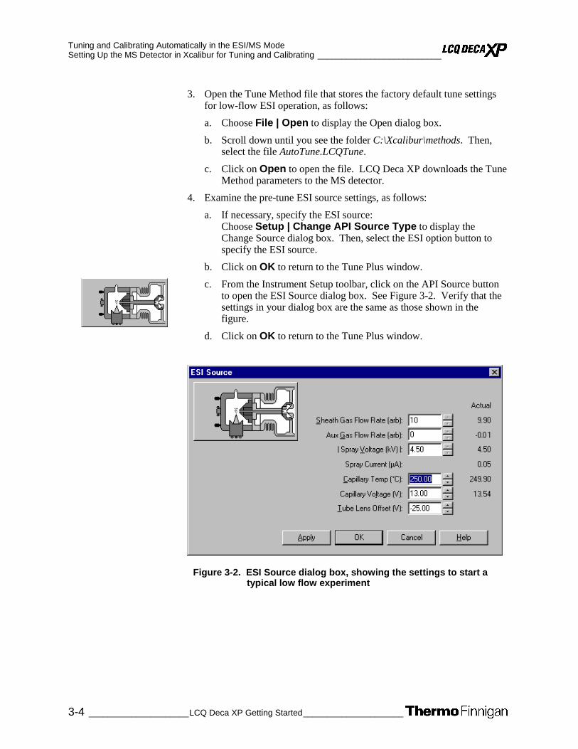
Tuning and Calibrating Automatically in the ESI/MS Mode Setting Up the MS Detector in Xcalibur for Tuning and Calibrating __________________________
3-4 _____________________LCQ Deca XP Getting Started_____________________
3. Open the Tune Method file that stores the factory default tune settings for low-flow ESI operation, as follows:
a. Choose File | Open to display the Open dialog box.
b. Scroll down until you see the folder C:\Xcalibur\methods. Then, select the file AutoTune.LCQTune.
c. Click on Open to open the file. LCQ Deca XP downloads the Tune Method parameters to the MS detector.
4. Examine the pre-tune ESI source settings, as follows:
a. If necessary, specify the ESI source: Choose Setup | Change API Source Type to display the Change Source dialog box. Then, select the ESI option button to specify the ESI source.
b. Click on OK to return to the Tune Plus window.
c. From the Instrument Setup toolbar, click on the API Source button to open the ESI Source dialog box. See Figure 3-2. Verify that the settings in your dialog box are the same as those shown in the figure.
d. Click on OK to return to the Tune Plus window.
Figure 3-2. ESI Source dialog box, showing the settings to start a typical low flow experiment

Tuning and Calibrating Automatically in the ESI/MS Mode __________________________ Setting Up the MS Detector in Xcalibur for Tuning and Calibrating
_____________________ LCQ Deca XP Getting Started ____________________ 3-5
5. Set the scan parameters for tuning and calibration, as follows:
a. On the Control/Scan Mode toolbar, click on the Define Scan button to open the dialog box. See Figure 3-3. (If your dialog box appears different from the one shown in the figure, it is probably because the advanced settings are not displayed. You can turn on the advanced settings, as follows: In Tune Plus, choose ScanMode, and then click on Advanced Scan Features to check the command.)
b. In the Scan Description group box, click on the Mass Range: Normal option button to select a mass range of m/z 50 to 2000.
c. Click on the Scan Mode: MS option button to select the MS scan mode. Note that LCQ Deca XP sets the MSn power to 1.
d. Click on the Scan Type: Full option button to select the Full scan type.
e. In the Scan Time group box, in the Total Microscans spin box, enter 3 to set the total number of microscans to 3.
Note. If the Maximum Inject Time spin box is not displayed in your Define Scan dialog box, the AGC (Automatic Gain Control) is turned off. To turn the AGC on, do the following: Click on OK in the Define Scan dialog box to return to the Tune Plus window. Choose Setup Injection | Control to display the Injection Control dialog box. Then, in the AGC group box, click on the On option button. Finally, click on OK. Reopen the Define Scan dialog box as described in step 5a above, and continue the procedure.
Figure 3-3. Define Scan dialog box, showing the typical settings for ESI/MS operation

Tuning and Calibrating Automatically in the ESI/MS Mode Setting Up the MS Detector in Xcalibur for Tuning and Calibrating __________________________
3-6 _____________________LCQ Deca XP Getting Started_____________________
f. In the Maximum Inject Time spin box, enter 200 to set the maximum injection time to 200 ms.
g. In the Input Method group box, click on the First/Last option button to make available the First Mass and Last Mass text boxes in the Scan Ranges group box. (Refer to steps 5i and 5j, below.)
h. In the [Ion] Source Fragmentation group box, confirm that the Turn On check box is not selected ( ) to specify that the ion source fragmentation option is turned off.
i. In the Scan Ranges group box, in the First Mass text box, enter 150 to set the first mass for the scan range to m/z 150.
j. In the Last Mass text box, enter 2000 to set the last mass for the scan range to m/z 2000.
k. Ensure that the settings in your Define Scan dialog box are the same as those shown in Figure 3-3.
l. Click on OK to save the MS detector scan parameters, and return to the Tune Plus window.
6. On the Control/Scan Mode toolbar, click on the Centroid/Profile button to toggle the data type to profile. (The picture on the button should be the same as that shown here.)
7. Click on the Positive/Negative button to toggle the ion polarity mode to positive. (The picture on the button should be the same as that shown here).

Tuning and Calibrating Automatically in the ESI/MS Mode _____________________________ Testing the Operation of the MS Detector in the ESI/MS Mode
_____________________ LCQ Deca XP Getting Started ____________________ 3-7
3.2 Testing the Operation of the MS Detector in the ESI/MS Mode
You are now ready to test if your MS detector is operating properly. To test for proper operation, you infuse the calibration solution into the ESI source, and then you monitor the real-time display of the mass spectrum of calibration solution. You want to ensure that a stable spray of solution enters the MS detector.
Test the operation of the MS detector in the ESI/MS mode, as follows:
1. Click on the Syringe Pump button to display the dialog box. See Figure 3-4.
Figure 3-4. Syringe Pump dialog box
2. Turn on the syringe pump and set an infusion flow rate of 5 µL/min, as
follows:
a. In the Flow Control group box, click on the On option button to turn on the flow from the syringe pump and to make active the Flow Rate spin box.
b. Enter 5 in the Flow Rate spin box to specify a rate of 5 µL/min.
Note. This procedure assumes that you are using the 500-µL Unimetrics syringe that is provided with your LCQ Deca XP system. If you are using another type of syringe, select the option button corresponding to your syringe.
Tuning and Calibrating Automatically in the ESI/MS Mode Testing the Operation of the MS Detector in the ESI/MS Mode _____________________________
3-8 _____________________LCQ Deca XP Getting Started_____________________
c. In the Type group box, click on the Unimetrics option button to specify a Unimetrics syringe.
d. Click on the Volume list box arrow to display the list of available volumes, and then select 500 from the list to set the syringe volume to 500 µL. Note that, if you are using a Unimetrics syringe, the LCQ Deca XP automatically sets the syringe ID to its proper value of 3.260 mm.
e. If you are not using a Unimetrics (or Hamilton) syringe, enter the inner diameter of your syringe in the Syringe ID spin box.
f. Click on OK to apply the parameters and return to the Tune Plus window.
3. On the File/Display toolbar, click on the Display Spectrum View button to ensure that the Spectrum view is displayed.
4. Monitor the data for the calibration solution, as follows:
a. In the Spectrum view of the Tune Plus window, observe the mass spectra of the singly-charged ions of calibration solution. The ions are as follows. See Figure 3-5.
• Caffeine: m/z 195
• MRFA: m/z 524
• Ultramark 1621: m/z 1022, 1122, 1222, 1322, 1422, 1522, 1622, 1722, 1822
Note. Based on the LC flow rate of your experiment, you can specify the value of each of the following tuning parameters on the LCQ Deca XP: sheath gas pressure, auxiliary gas pressure, ESI needle (or “spray”) voltage, ion transfer capillary temperature, and probe position, Refer to Finnigan LCQ Deca XP Operational Tips for guidelines about which values to use for each of these parameters at a particular LC flow rate. Automatic tuning sets the values of the other parameters.
b. At the top of the Spectrum view, notice the values for the normalization level (NL) and the ionization time (IT).
c. Click on the API Source button to open the ESI Source dialog box. (See the Spray Current readback shown in Figure 3-2.)
d. Observe the value for the Spray Current readback and the values for NL and IT in the Spectrum view. As calibration solution infuses, and the readback values fluctuate, ask yourself the following questions about the ion current signal:
• Is the signal present?
• Is the signal stable, varying by less than about 15% from scan to scan?

Tuning and Calibrating Automatically in the ESI/MS Mode _____________________________ Testing the Operation of the MS Detector in the ESI/MS Mode
_____________________ LCQ Deca XP Getting Started ____________________ 3-9
Figure 3-5. Spectrum view of the Tune Plus window, showing a real-time display of calibration solution
If you answered “yes” to the questions in step 4d, then your MS detector is operating properly.
If you answered “no” to either of these questions, try the following troubleshooting measures:
• Ensure that the fused-silica sample tube does not extend beyond the tip of the ESI needle.
• Ensure that the entrance to the ion transfer capillary is clean, and is not covered with a piece of septum.
• Ensure that the automatic gain control feature is on, and the Full MS Target is set to 5e+007 (5 × 10⁷). Verify the setting by choosing Setup | Injection Control from the Tune Plus window.
• Ensure that the ESI probe is in position 3B (corresponding to a flow rate of <10µL/min).
• Ensure that the solution entering the probe is free of air bubbles and that the tubing and connectors are free of leaks.
Congratulations! You have demonstrated that your MS detector is operating properly in the ESI mode. You are now ready to tune and calibrate the MS detector. Leave your LCQ Deca XP as it is, and go to the next topic: Tuning the MS Detector Automatically in the ESI/MS Mode.
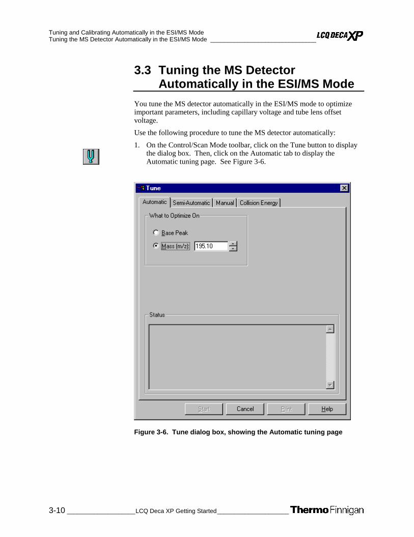
Tuning and Calibrating Automatically in the ESI/MS Mode Tuning the MS Detector Automatically in the ESI/MS Mode _______________________________
3-10 ____________________LCQ Deca XP Getting Started_____________________
3.3 Tuning the MS Detector Automatically in the ESI/MS Mode
You tune the MS detector automatically in the ESI/MS mode to optimize important parameters, including capillary voltage and tube lens offset voltage.
Use the following procedure to tune the MS detector automatically:
1. On the Control/Scan Mode toolbar, click on the Tune button to display the dialog box. Then, click on the Automatic tab to display the Automatic tuning page. See Figure 3-6.
Figure 3-6. Tune dialog box, showing the Automatic tuning page

Tuning and Calibrating Automatically in the ESI/MS Mode ________________________________Tuning the MS Detector Automatically in the ESI/MS Mode
_____________________ LCQ Deca XP Getting Started ___________________ 3-11
2. In the Mass spin box, enter 195.1 to specify that LCQ Deca XP optimize your tune on the peak at m/z 195.1.
Note. In this example, you use the mass peak at m/z 195.1 to optimize the tune. However, you can optimize the tune on any mass peak of the calibration solution.
3. Start the automatic tuning procedure, as follows:
a. Click on Start. A message box displays the following message:
Please ensure that the 500 microliter syringe is full.
Ensure the syringe contains at least 420 µL calibration solution.
b. Click on OK to close the message box, and return to the Tune dialog box.
4. On the File/Display toolbar, click on the Graph View button to display the Graph view. See Figure 3-7.
5. Observe the Tune Plus window and the Tune dialog box. While automatic tuning is in progress, LCQ Deca XP displays various tests in the Spectrum and Graph views in Tune Plus and displays various messages in the Status group box in the Tune dialog box. Your Tune Plus window should now look similar to the one shown in Figure 3-7.
6. Click on the ESI Source dialog box to examine the ESI source parameters after tuning. Compare the settings shown in Figure 3-8 with the pre-tune settings shown in Figure 3-2.
7. Click on the Ion Optics toolbar button to display the dialog box. The parameters in the Ion Optics dialog box are optimized automatically by the LCQ Deca XP. See Figure 3-9.

Tuning and Calibrating Automatically in the ESI/MS Mode Tuning the MS Detector Automatically in the ESI/MS Mode _______________________________
3-12 ____________________LCQ Deca XP Getting Started_____________________
Figure 3-7. Tune Plus window, showing the results of a typical automatic tune procedure
Figure 3-8. ESI Source dialog box, showing typical parameters after automatic tuning

Tuning and Calibrating Automatically in the ESI/MS Mode ________________________________Tuning the MS Detector Automatically in the ESI/MS Mode
_____________________ LCQ Deca XP Getting Started ___________________ 3-13
Figure 3-9. Ion Optics dialog box, showing examples of voltages of lenses and octapoles, which are optimized by the LCQ Deca XP automatic tuning procedure
You have now successfully tuned the MS detector in ESI/MS mode using the calibration solution. Go on to the next topic: Saving Your ESI/MS Tune Method.

Tuning and Calibrating Automatically in the ESI/MS Mode Saving Your ESI/MS Tune Method___________________________________________________
3-14 ____________________LCQ Deca XP Getting Started_____________________
3.4 Saving Your ESI/MS Tune Method
You can save the parameters you just set in a tune method specific to your particular analyte and solvent flow rate. (In this case, you save settings obtained using calibration solution.) You can recall the tune method and use it as a starting point for optimizing the MS detector on a different analyte of interest or at a different flow rate.
Note. You must save the Tune Method while the MS detector is On.
Save your ESI/MS tune method (for low-flow operation) when automatic tuning is complete, as follows:
1. Choose File | Save As to display the Save As dialog box. See Figure 3-10.
Figure 3-10. Save As dialog box, showing files in the folder C:\Xcalibur\methods

Tuning and Calibrating Automatically in the ESI/MS Mode ___________________________________________________Saving Your ESI/MS Tune Method
_____________________ LCQ Deca XP Getting Started ___________________ 3-15
2. Select the C:\Xcalibur\methods folder.
3. Click on the File Name text box, and then enter ESImyTune to name the Tune Method ESImyTune.LCQTune.
4. Click on Save to save the Tune Method, and return to the Tune Plus window. Note that the Tune Method is named ESImyTune.LCQTune.
Once you have tuned the MS detector, you are ready to calibrate. Go on to the next topic: Calibrating the MS Detector Automatically.

Tuning and Calibrating Automatically in the ESI/MS Mode Calibrating the MS Detector Automatically _____________________________________________
3-16 ____________________LCQ Deca XP Getting Started_____________________
3.5 Calibrating the MS Detector Automatically
Use the following procedure to calibrate the MS detector automatically from the Tune Plus window:
1. Choose Control | Calibrate to display the Calibrate dialog box.
2. Click on the Automatic tab to display the page. See Figure 3-11.
Figure 3-11. Calibrate dialog box, showing the Automatic page

Tuning and Calibrating Automatically in the ESI/MS Mode _____________________________________________ Calibrating the MS Detector Automatically
_____________________ LCQ Deca XP Getting Started ___________________ 3-17
3. Start the automatic calibration procedure, as follows:
a. Click on Start. A message box displays the following message:
Please ensure that the 500 microliter syringe is full.
Ensure the syringe contains at least 420 µL calibration solution.
b. Click on OK to close the message box, and return to the Calibrate dialog box.
4. Observe the Tune Plus window and the Calibrate dialog box. While the automatic calibration is in progress, LCQ Deca XP displays a variety of test results in the Spectrum and Graph views and displays a variety of messages in the Status box of the Calibrate dialog box.
The automatic calibration procedure typically takes about 40 min.
When LCQ Deca XP completes the calibration procedure, LCQ Deca XP restores the full scan ESI mass spectrum in the Spectrum view. The Instrument Messages dialog box is displayed, which indicates whether or not the calibration procedure for an item is successful.
• If a calibration item is successful, LCQ Deca XP saves the new calibration parameter automatically to the hard disk.
• If a calibration item fails, you can try calibrating on that item again after you ensure the following: the spray is stable, the solution flow rate is sufficient, and all the ions in the calibration solution are present with adequate signal-to-noise ratios. If the sensitivity of the ions is low, increase the solution flow rate somewhat, and then use the semi-automatic calibration procedure to calibrate the specific parameter that failed. See Figure 3-12. Consider unselecting the ZoomScan Mode option if repeated failures occur.
When all calibration items are successful, your MS detector is properly tuned and calibrated for low-flow experiments. A successful calibration exhibits adequate intensities of the following calibrant ions: m/z 195, 524, 1222, 1522, and 1822. In many cases, fine tuning on your particular analyte is not necessary if the intensity of these ions is sufficient.
You are ready to analyze samples if you do not need to maximize the intensity of the ion signals for your analyte.
In Chapter 4: Tuning with Your Analyte in LC/ESI/MS Mode, you change the solution flow rate and optimize the MS detector parameters on reserpine or on your particular analyte.
Before you tune with your analyte, go to the next topic: Cleaning the MS Detector after Tuning and Calibrating.

Tuning and Calibrating Automatically in the ESI/MS Mode Calibrating the MS Detector Automatically _____________________________________________
3-18 ____________________LCQ Deca XP Getting Started_____________________
Figure 3-12. Tune Plus window with Calibrate dialog box, showing the results of a successful semi-automatic calibration procedure
Tuning and Calibrating Automatically in the ESI/MS Mode ___________________________________ Cleaning the MS Detector after Tuning and Calibrating
_____________________ LCQ Deca XP Getting Started ___________________ 3-19
3.6 Cleaning the MS Detector after Tuning and Calibrating
Use the following procedure to clean the MS detector after calibrating. This procedure describes how to clean your MS detector after using the calibration solution, in preparation for acquiring data on your analyte of interest.
1. Click on the On/Standby button to put the MS detector in Standby mode. When the MS detector is in Standby, LCQ Deca XP turns off the sheath gas, auxiliary gas, ESI high voltage, and syringe pump. The MS detector stops scanning, and the LCQ Deca XP freezes the displays for the Spectrum and Graph views.
CAUTION. Always place the MS detector in Standby (or Off) before you open the API source to atmospheric oxygen. The presence of oxygen in the ion source when the MS detector is On could be unsafe. (LCQ Deca XP automatically turns the MS detector Off when you open the API source, however, it is best to take this added precaution.)
2. Remove the syringe from the syringe pump holder, as follows:
a. Squeeze the blue buttons, and pull back on the syringe pump handle to free the syringe.
b. Remove the syringe from the holder.
c. Disconnect the tip of the syringe needle from the Teflon tubing.
3. Clean the syringe thoroughly, as follows: First, clean the syringe with a solution of 5% acetic acid in water. Then, rinse the syringe with a solution of 50:50 methanol:water. Finally, use acetone to rinse the syringe. Repeat this step several times.
4. Loosen completely the two ESI flange retainer bolts.
5. Slide the ESI flange out, away from the MS detector chassis, on the slide rails.
CAUTION. AVOID BURNS. At operating temperatures, the ion transfer capillary can severely burn you! The ion transfer capillary typically operates between 200 and 300 °C. Always allow the ion transfer capillary to cool to room temperature, for approximately 20 min, before you touch or remove this component. Always be careful not to touch the entrance end of the ion transfer capillary when it is exposed.
STANDBY
ON

Tuning and Calibrating Automatically in the ESI/MS Mode Cleaning the MS Detector after Tuning and Calibrating ___________________________________
3-20 ____________________LCQ Deca XP Getting Started_____________________
6. Clean the ion transfer capillary as follows:
a. Remove the ion transfer capillary by using the custom tool provided.
b. Place the capillary tube in a beaker of 50:50 methanol/water. Sonicate for 15 min.
c. Reinstall the ion transfer capillary.
7. Place a small Teflon coated septum over the entrance end of the ion transfer capillary to seal the vacuum chamber of the MS detector.
8. Flush the sample transfer line, sample tube, and ESI probe thoroughly with a solution of 5% acetic acid in water (or with another appropriate solvent), as follows:
Note. The solvent that you use to flush the sample transfer line, sample tube, and ESI probe assembly depends on the solvent system you use to dissolve your samples. For example, if you are using a buffered solution of a high concentration, an acidic solution is appropriate.
a. Fill a clean, 250 µL Unimetrics syringe with a solution an appropriate solvent.
b. While holding the plunger of the syringe in place, carefully insert the needle of the syringe into the free end of the Teflon tube.
c. Flush the sample transfer line, sample tube, and ESI probe with the solution by slowly depressing the syringe plunger. Visually check that the solution is exiting the tip of the ESI probe on the inside of the probe assembly. Use a lint-free tissue to gently remove the excess solution as it exits the probe.
d. Remove the needle of the syringe from the Teflon tube.
9. Repeat step 8 with a solution of 50:50 methanol:water.
10. Repeat step 8 with acetone.
11. Clean the spray shield as follows:
a. Fill a spray bottle with solvent solution.
b. Temporarily place a large Kimwipe (or other lint-free tissue) on the bottom of the spray shield. (The Kimwipe is required to absorb the solution used to flush the ion transfer capillary and spray shield.)
c. Use the spray bottle to flush contaminants from the interior surface of the spray shield.
d. Remove the Kimwipe you used to absorb the solution. Swab the surface of the spray shield with a dry Kimwipe.
e. Repeat steps 11 a through d with acetone to remove the (high molecular weight) Ultramark 1621.

Tuning and Calibrating Automatically in the ESI/MS Mode ___________________________________ Cleaning the MS Detector after Tuning and Calibrating
_____________________ LCQ Deca XP Getting Started ___________________ 3-21
12. Being careful not to touch the ion transfer capillary with your hand, remove the septum from the entrance end of the ion transfer capillary.
13. Slide the ESI flange forward along the slide rails and into the ion source housing.
14. Secure the ESI flange with the two flange retainer bolts.
If you plan to run analytical samples in high-flow ESI mode (using flow the procedures in the next chapter: Tuning with Your Analyte in LC/ESI/MS Mode.

_____________________ LCQ Deca XP Getting Started ____________________ 4-1
Chapter 4
4. Tuning with Your Analyte in LC/ESI/MS Mode
This chapter provides information on tuning the MS detector in the LC/ESI/MS mode using your analyte. You optimize the sensitivity of your analyte in the MS detector through an automatic procedure.
The customized Tune Methods contained in your LCQ Deca XP data system are optimized for a wide range of applications, and they can often be used without further tuning of your MS detector. However, for certain applications you might need to tune and optimize several MS detector parameters.
For instance, the most important parameters that interact with the ESI interface and signal quality are as follows:
• Electrospray voltage
• Ion transfer capillary temperature
• Tube lens offset voltage
• Capillary voltage
• Sheath gas flow rate
• Auxiliary gas flow rate
The settings for these parameters depend on the solvent flow rate and target analyte composition. In general, you should fine tune your MS detector whenever you change the solvent flow rate conditions of your particular application. In this procedure, you use the ESI low-flow Tune Method ESImyTune.LCQTune as a starting point, and then further optimize the MS detector parameters using an automatic procedure. The automatic procedure adjusts the tube lens offset voltage, capillary voltage, and voltages applied to the ion optics until the ion transmission of your analyte is maximized.
The capillary is heated to maximize the ion transmission to the MS detector. For ESI only, you set the ion transfer capillary temperature proportional to the flow rate of your solution. Refer to Table 1-2 for guidelines for setting operating parameters for LC/ESI/MS. For this procedure, the ion transfer capillary temperature is set to 350 °C, and the sheath gas is set to 30.

Tuning with Your Analyte in LC/ESI/MS Mode ______________________________________________________________________________
4-2 _____________________LCQ Deca XP Getting Started_____________________
Note the results you want can be obtained without optimizing the MS detector on your particular analyte, you can go to Chapter 5: Acquiring ESI Sample Data Using the Tune Plus Window to acquire sample data.
Note. Before you optimize the tune for your analyte of interest, ensure that the LCQ Deca XP has been calibrated within the previous three months. If the system needs to be calibrated, refer to the procedures in the chapter: Tuning and Calibrating Automatically in the ESI/MS Mode.
To tune the MS detector in the ESI/MS (high-flow) mode using your analyte, you do the following:
• Set up the MS detector for your specific analyte from the Tune Plus window.
• Infuse your analyte into the MS detector using a syringe pump connected to the LC with a Tee union.
• Optimize the MS detector parameters for your analyte while the solution flows into the MS detector.
This chapter contains the following topics:
• Setting Up to Introduce Sample by Syringe Pump into Solvent Flow from an LC
• Setting Up to Tune the MS Detector with Your Analyte
• Optimizing the MS Detector Tune Automatically with Your Analyte
• Saving the ESI/MS Tune Method

Tuning with Your Analyte in LC/ESI/MS Mode ________________Setting Up to Introduce Sample by Syringe Pump into Solvent Flow from an LC
_____________________ LCQ Deca XP Getting Started ____________________ 4-3
4.1 Setting Up to Introduce Sample by Syringe Pump into Solvent Flow from an LC
Set up to introduce your analyte by syringe pump into solvent flow from an LC. The plumbing connections for ESI/MS sample introduction from the syringe pump into solvent flow from an LC are shown in Figure 4-1.
To make the plumbing connections for ESI/MS sample introduction from the syringe pump into solvent flow from an LC, do the following.
1. Connect a 4 cm (1.5 in.) segment of Teflon tubing with a (brown) Fingertight fitting and a (brown) ferrule to the (black) LC union. (See Figure 2-7.)
2. Fill a clean, 500- 00301-19012) with the 1 !Appendix A: Sample Formulations for a procedure for making the reserpine tuning solution.)
3. Insert the needle of a syringe into the segment of Teflon tube. Check that the needle tip of the syringe fits readily into the opening in the free end of the Teflon tubing. If necessary, you can enlarge the opening in the end of the tubing slightly.
132
Figure 4-1. ESI/MS plumbing connections for sample introduction
from the syringe pump into solvent flow from an LC
TO WASTE
FROM LC
LC TEE UNION
SYRINGE PUMP
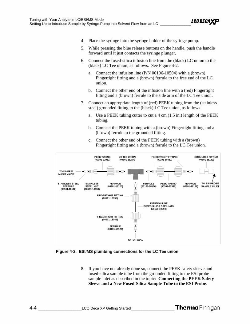
Tuning with Your Analyte in LC/ESI/MS Mode Setting Up to Introduce Sample by Syringe Pump into Solvent Flow from an LC _______________
4-4 _____________________LCQ Deca XP Getting Started_____________________
4. Place the syringe into the syringe holder of the syringe pump.
5. While pressing the blue release buttons on the handle, push the handle forward until it just contacts the syringe plunger.
6. Connect the fused-silica infusion line from the (black) LC union to the (black) LC Tee union, as follows. See Figure 4-2.
a. Connect the infusion line (P/N 00106-10504) with a (brown) Fingertight fitting and a (brown) ferrule to the free end of the LC union.
b. Connect the other end of the infusion line with a (red) Fingertight fitting and a (brown) ferrule to the side arm of the LC Tee union.
7. Connect an appropriate length of (red) PEEK tubing from the (stainless steel) grounded fitting to the (black) LC Tee union, as follows.
a. Use a PEEK tubing cutter to cut a 4 cm (1.5 in.) length of the PEEK tubing.
b. Connect the PEEK tubing with a (brown) Fingertight fitting and a (brown) ferrule to the grounded fitting.
c. Connect the other end of the PEEK tubing with a (brown) Fingertight fitting and a (brown) ferrule to the LC Tee union.
Figure 4-2. ESI/MS plumbing connections for the LC Tee union
8. If you have not already done so, connect the PEEK safety sleeve and fused-silica sample tube from the grounded fitting to the ESI probe sample inlet as described in the topic: Connecting the PEEK Safety Sleeve and a New Fused-Silica Sample Tube to the ESI Probe.
LC TEE UNION(00101-18204)
TO LC UNION
FINGERTIGHT FITTING(00101-18081)
FERRULE(00101-18196)
FERRULE(00101-18120)
STAINLESSSTEEL NUT
(00101-16008)
STAINLESS STEELFERRULE
(00101-18122)
FINGERTIGHT FITTING(00101-18195)
PEEK TUBING(00301-22912)
INFUSION LINEFUSED-SILICA CAPILLARY
(00106-10504)
PEEK TUBING(00301-22912)
TO DIVERT/INJECT VALVE
FERRULE(00101-18196)
FINGERTIGHT FITTING(00101-18081)
FERRULE(00101-18120)
GROUNDED FITTING(00101-18182)
TO ESI PROBE SAMPLE INLET
Tuning with Your Analyte in LC/ESI/MS Mode ________________Setting Up to Introduce Sample by Syringe Pump into Solvent Flow from an LC
_____________________ LCQ Deca XP Getting Started ____________________ 4-5
If you have installed the stainless steel needle in the ESI probe, connect the PEEK safety sleeve and fused-silica capillary tube from the grounded fitting to the ESI probe sample inlet as described in the topic: Installing the Stainless Steel Needle and Connecting the PEEK Safety Sleeve and Fused-Silica Capillary Tube to the ESI Probe in LCQ Deca XP Getting Connected.
9. Connect an appropriate length of PEEK tubing (transfer line from the divert/inject valve) from the divert/inject valve to the free end of the (black) LC Tee union, as follows. (See Figure 4-2.)
a. Connect a length of PEEK tubing with a (stainless steel) nut and a (stainless steel) ferrule to port 3 of the divert/inject valve.
b. Connect the other end of the PEEK tubing with a (brown) Fingertight fitting and a (brown) ferrule to the free end of the LC Tee union.
10. Connect an appropriate length of PEEK tubing (transfer line from the LC) from the divert/inject valve to the LC, as follows:
a. Connect a length of PEEK tubing with a (stainless steel) nut and a (stainless steel) ferrule to port 2 of the divert/inject valve.
b. Connect the other end of the PEEK tubing with a proper fitting and a ferrule to the outlet of the LC.
11. Connect an appropriate length of PEEK tubing (waste line) from the divert/inject valve to a waste container, as follows:
a. Connect a length of PEEK tubing with a (stainless steel) nut and a (stainless steel) ferrule to port 1 of the divert/inject valve.
b. Insert the other end of the PEEK tubing in a suitable waste container.
Caution. Prevent solvent waste from backing up into the API ion source and MS detector. Always ensure that the PVC drain hose is above the level of liquid in the waste container.
12. Connect an appropriate length of (clear) 3/8 in. ID PVC hose to the ESI probe outlet drain. Insert the other end of the hose into a suitable container (such as a gallon jug). Ideally, the waste container should be vented to a fume exhaust system.

Tuning with Your Analyte in LC/ESI/MS Mode Setting Up to Tune the MS Detector with Your Analyte ___________________________________
4-6 _____________________LCQ Deca XP Getting Started_____________________
4.2 Setting Up to Tune the MS Detector with Your Analyte
Use the following procedure to set up the MS detector to tune automatically on your analyte in ESI/MS mode. (In this example, you can use the reserpine solution described in Appendix A: Sample Formulations, or you can use a solution of your analyte of interest.)
Caution"# Ultramark 1621 can contaminate your system at high concentrations.
Note. The following procedures assume that you are familiar with your LCQ Deca XP instrument and the Tune Plus window. If you need assistance, refer to: LCQ Deca XP online Help and/or LCQ Deca XP Hardware Manual.
1. If you have not already done so, open the Tune Plus window from the Start button on your Windows NT Desktop, as follows:
a. Choose Start | Programs | Xcalibur | Xcalibur to display the Xcalibur Home Page – Roadmap view.
b. Click on the Instrument Setup button to display the window.
c. Click on the LCQ Deca XP MS button to display the New Method page.
d. Click on the Tune Plus button to display the window.
2. In Tune Plus, click on the On/Standby button to take the MS detector out of Standby mode and turn it On. The MS detector begins scanning, LCQ Deca XP applies high voltage to the ESI probe, and LCQ Deca XP shows a real-time display in the Spectrum view.
ON
STANDBY

Tuning with Your Analyte in LC/ESI/MS Mode ___________________________________ Setting Up to Tune the MS Detector with Your Analyte
_____________________ LCQ Deca XP Getting Started ____________________ 4-7
3. Open the ESImyTune.LCQTune Tune Method, the Tune Method you saved in Chapter 3, as follows:
a. On the File/Display toolbar, click on the Open File icon to display the Open dialog box.
b. Scroll down until you see the folder C:\Xcalibur\methods. Then, select the file ESImyTune.LCQTune.
c. Click on Open to open the file. LCQ Deca XP downloads the Tune Method parameters to the MS detector, and the title bar in the Tune Plus window should read as follows:
C:\Xcalibur\methods\ESImyTune.LCQTune – Tune Plus
4. Define the scan parameters for tuning with your analyte in the ESI/MS mode, as follows:
a. In the Instrument Control toolbar, click on the Define Scan button to open the dialog box. See Figure 4-3.
b. In the Scan Description group box, click on the Mass Range: Normal option button to select a mass range of m/z 50 to 2000.
c. Click on the Scan Mode: MS option button to select the MS scan mode. Note that LCQ Deca XP sets the MSn power to 1.
d. Click on the Scan Type: SIM option button to select the SIM scan type. Note that LCQ Deca XP sets the Total Scan Ranges to 1.
e. In the Scan Time group box, in the Total Microscans spin box, enter 3 to set the total number of microscans to 3.
f. In the Maximum Inject Time spin box, enter 200 to set the maximum injection time to 200 ms.
g. In the Input Method group box, click on the Center/Width option button to make available the Center Mass and Width text boxes in the Scan Ranges group box. (Refer to steps 4i and 4j, below.)
h. In the Source Fragmentation group box, confirm that the Turn On check box is not selected ( ) to specify that the ion source fragmentation option is turned off.
i. In the Scan Ranges group box, in the Center Mass text box, enter 609.2 to set the center mass for the scan range to m/z 609.2 (for reserpine).
j. In the Width text box, enter 2 to set the width of the scan range to m/z 2.
k. Ensure that the settings in your Define Scan dialog box are the same as those shown in Figure 4-3.

Tuning with Your Analyte in LC/ESI/MS Mode Setting Up to Tune the MS Detector with Your Analyte ___________________________________
4-8 _____________________LCQ Deca XP Getting Started_____________________
Figure 4-3. Define Scan dialog box, showing typical settings for acquiring reserpine data of the SIM type
l. Click on OK to save the MS detector scan parameters, and close the Define Scan dialog box.
5. On the Control/Scan Mode toolbar, click on the Centroid/Profile button to toggle the data type to profile. (The picture on the button should be the same as that shown here.)
6. Click on the Positive/Negative button to toggle the ion polarity mode to positive. (The picture on the button should be the same as that shown here).
You have completed setting up to tune your MS detector with your analyte in ESI/MS mode. Go to the next topic: Optimizing the MS Detector Tune Automatically with Your Analyte.

Tuning with Your Analyte in LC/ESI/MS Mode __________________________ Optimizing the MS Detector Tune Automatically with Your Analyte
_____________________ LCQ Deca XP Getting Started ____________________ 4-9
4.3 Optimizing the MS Detector Tune Automatically with Your Analyte
Optimize the MS detector tune automatically to maximize the ion transmission of reserpine (or your analyte of interest) for a high-flow experiment. It is recommended that you begin optimizing after you have successfully passed an automatic tuning procedure and an automatic calibration procedure with the calibration solution infused at 5 µL/min.
Use the following procedure to tune the MS detector automatically on the reserpine m/z 609.2 at your particular flow rate, for example, 1 mL/min. (Refer to Table 1-2 for guidelines about setting flow rates and temperatures.)
1. On the Control/Scan Mode toolbar, click on the Tune button to display the dialog box. Then, click on the Automatic tab to display the Automatic tuning page.
2. In the Mass spin box, enter 609.2 to specify that LCQ Deca XP use the peak at m/z 609.2 to optimize your tune.
3. Ensure that the Divert/Inject valve is in the Detector position, as follows:
a. Click on the Divert/Inject button to open the Divert/Inject Valve dialog box. See Figure 4-4.
b. Select the Detector option button.
c. Click on Close.
Figure 4-4. Divert/Inject Valve dialog box
4. Start the automatic tuning procedure from the Tune dialog box, as
follows:
a. Click on Start. A message box displays the following message:
Please ensure that the 500 microliter syringe is full.
Ensure the syringe pump contains at least 420 µL of the 1 ng/µL reserpine tuning solution.
b. Click on OK to close the message box, and return to the Tune Plus window.

Tuning with Your Analyte in LC/ESI/MS Mode Optimizing the MS Detector Tune Automatically with Your Analyte __________________________
4-10 ____________________LCQ Deca XP Getting Started_____________________
5. In the File/Display toolbar, click on the Graph View button to display the Graph view.
6. Observe the Tune Plus window and the Tune dialog box. While automatic tuning is in progress, LCQ Deca XP displays various tests in the Spectrum and Graph views in the Tune Plus window and displays various messages in the Status group box in the Tune dialog box. Your Tune Plus window should now look similar to the one shown in Figure 4-5.
Note. The most important parameters that affect the signal quality during ESI/MS operation are the electrospray voltage, ion transfer capillary temperature, capillary voltage, tube lens offset voltage, gases, and solution flow rate. If any one of these parameters is changed, you need to reoptimize MS detector parameters. You can use the Semi-Automatic tune procedure to tune the MS detector on individual parameters.
You have now successfully tuned the MS detector in ESI/MS mode for the compound reserpine (or your analyte of interest). Go on to the next topic: Saving the ESI/MS Tune Method.
Figure 4-5. Tune Plus window with the Tune dialog box, showing the Automatic page

Tuning with Your Analyte in LC/ESI/MS Mode ____________________________________________________ Saving the ESI/MS Tune Method
_____________________ LCQ Deca XP Getting Started ___________________ 4-11
4.4 Saving the ESI/MS Tune Method
Save your ESI/MS tune method (for a high-flow experiment using your analyte) when automatic tuning is complete, as follows:
Note. Save the Tune Method while the MS detector is On, if any of the ion source parameters are different from those with which you started.
1. Choose File | Save As to display the Save As dialog box. See Figure 4-6.
Figure 4-6. Save As dialog box, showing files in the folder C:\Xcalibur\methods

Tuning with Your Analyte in LC/ESI/MS Mode Saving the ESI/MS Tune Method ____________________________________________________
4-12 ____________________LCQ Deca XP Getting Started_____________________
2. Select the C:\Xcalibur\methods folder.
3. Click on the File Name text box, and enter reserpine (or the name of your analyte of interest).
4. Click on Save to save the Tune Method, and return to the Tune Plus window. Note that the Tune Method is named reserpine.LCQTune.
Go on to the next chapter: Acquiring ESI Sample Data using the Tune Plus Window.
_____________________ LCQ Deca XP Getting Started ____________________ 5-1
Chapter 5
5. Acquiring ESI Sample Data Using the Tune Plus Window
This chapter provides information on acquiring LC/ESI/MS sample data using the Tune Plus window. This experiment uses reserpine but you can follow the same procedure with your analyte of interest.
Note. The following procedures assume that you are familiar with your LCQ Deca XP instrument and the Tune Plus window. If you need information, refer to the LCQ Deca XP online Help, LCQ Deca XP
Getting Connected, and/or LCQ Deca XP Hardware Manual. Ensure that you have completed the procedures in the topics Tuning and Calibrating Automatically in the ESI/MS Mode and Tuning with Your Analyte in LC/ESI/MS Mode.
This chapter contains the following topics:
• Setting Up to Acquire MS/MS Data in the Full Scan Type
• Setting Up to Introduce Sample by Loop Injection into Solvent Flow from an LC
• Acquiring MS Data in the SIM Scan Type

Acquiring ESI Sample Data Using the Tune Plus Window Setting Up to Acquire MS/MS Data in the Full Scan Type _________________________________
5-2 _____________________LCQ Deca XP Getting Started_____________________
5.1 Setting Up to Acquire MS/MS Data in the Full Scan Type
Prepare to acquire MS/MS data in the Full scan type on reserpine (or on your analyte of interest). You need to optimize the isolation width and the relative collision energy parameters before you acquire MS/MS data.
You first optimize the isolation width to ensure that the ion of interest is isolated effectively, and then you optimize the collision energy to ensure that fragmentation of the parent ion is efficient. The relative collision energy for a particular analysis depends on the type of sample you are analyzing.
The information in this topic applies to operation of the LCQ Deca XP in either the ESI or the APCI mode.
This topic contains the following topics:
• Optimizing the Isolation Width and Setting Up to Optimize the Collision Energy
• Optimizing the Collision Energy Automatically for an MS/MS Experiment
Optimizing the Isolation Width and Setting Up to Optimize the Collision Energy
Optimize the isolation width and set up to optimize the collision energy for an MS/MS experiment, as follows:
Note. The collision energy is optimized on the LCQ Deca XP by changing the values for the parameter Activation Amplitude in the MSn Settings group box of the Define Scan dialog box. For this experiment, and for most applications, leave the parameters Activation Q and Activation Time set to their default values. For more information about these parameters, refer to the online Help.
1. If you have not already done so, from the Tune Plus window, click on the On/Standby button to take the MS detector out of Standby mode and turn it On.
STANDBY
ON

Acquiring ESI Sample Data Using the Tune Plus Window _________________________________ Setting Up to Acquire MS/MS Data in the Full Scan Type
_____________________ LCQ Deca XP Getting Started ____________________ 5-3
2. Ensure that the Centroid data type is selected. (The picture on the button should be the same as that shown here.)
3. Ensure that the scan parameters are defined to acquire MS/MS Full scan data for reserpine (or your analyte of interest), as follows:
a. Click on the Define Scan button to open the dialog box. See Figure 5-1.
b. Ensure that the values in your dialog box are the same as those shown in Figure 5-1. Start with a relatively wide Isolation Width. Leave the Define Scan dialog box open.
Figure 5-1. Define Scan dialog box, showing initial settings to optimize the isolation width of an MS/MS experiment for reserpine
4. At this time you may wish to turn on your LC pump and specify a flow rate of 0.4 mL/min, for example, to ensure that your system is free of leaks.
5. Click on the Syringe Pump icon to display the dialog box. Then, select reserpine solution. Finally, move the Syringe Pump dialog box to the top of the monitor screen.
6. In the Tune Plus window, observe the mass spectrum of reserpine (or your analyte of interest). Also observe the values for NL and IT (Normalization Level and Ion Time), while you optimize the value of the Isolation Width in the Define Scan dialog box, as follows:
a. In the Define Scan dialog box, in the Isolation Width spin box, enter 5 to specify an isolation width of m/z 5. Then, click on Apply.

Acquiring ESI Sample Data Using the Tune Plus Window Setting Up to Acquire MS/MS Data in the Full Scan Type _________________________________
5-4 _____________________LCQ Deca XP Getting Started_____________________
b. In the Tune Plus window, observe the mass spectrum for the parent ion of reserpine, m/z 609.2. Ensure that the readback values for NL and IT are relatively stable.
c. Again, in the Define Scan dialog box, in the Isolation Width spin box, enter 3 to specify an isolation width of m/z 3. Then, click on Apply.
Note. The optimum value for Isolation Width is one that is the smallest (to a minimum width of m/z 0.4), but which results in a mass spectrum of maximum intensity for only the ions of interest. The Isolation Width is optimized when the values for NL and IT are stable and when the mass peak for the parent ion is of maximum intensity and appears symmetrical.
If you specify a value for Isolation Width that is less than the optimum value, the readback for NL drops substantially. A significant drop in sensitivity indicates that your ions of interest are not effectively isolated.
d. Repeat steps b and c above, entering successively smaller values for Isolation Width. Continue to observe the intensity of the mass chromatogram of the parent ion, and ensure that the values for NL and IT are stable with each change you make to the Isolation Width.
Note. After the Isolation Width is optimized, you might compensate for minor changes in tune stability by increasing the value by up to m/z 1.
7. In the Define Scan dialog box, enter 20 in the Activation Amplitude spin box to specify an initial value of 20 for the collision energy. Then, click on Apply.
8. In the Tune Plus window, observe the mass spectrum of the product ions of reserpine (or your analyte of interest). If necessary, increase the value for the Activation Amplitude in increments of 5% to cause the clear display of product ion mass spectrum. (After each change in value, click on Apply to implement the change.) See Figure 5-2.

Acquiring ESI Sample Data Using the Tune Plus Window _________________________________ Setting Up to Acquire MS/MS Data in the Full Scan Type
_____________________ LCQ Deca XP Getting Started ____________________ 5-5
Figure 5-2. Define Scan dialog box, showing typical settings for acquiring MS/MS data in the Full scan type on reserpine
9. When you have clearly identified a product ion mass-to-charge ratio for reserpine (or your analyte of interest), click on the Tune button to display the dialog box.
10. In the Tune dialog box, click on the Collision Energy tab to display the page. See Figure 5-3.

Acquiring ESI Sample Data Using the Tune Plus Window Setting Up to Acquire MS/MS Data in the Full Scan Type _________________________________
5-6 _____________________LCQ Deca XP Getting Started_____________________
Figure 5-3. Tune dialog box, showing the Collision Energy page
11. Click on the Product Ion Mass option button to make active the spin box. Then, enter 397.2 to specify the product ion at m/z 397.2 for reserpine. The LCQ Deca XP can optimize collision energy automatically by using this product ion of reserpine.
Go on to the next topic: Optimizing the Collision Energy Automatically for an MS/MS Experiment.

Acquiring ESI Sample Data Using the Tune Plus Window _________________________________ Setting Up to Acquire MS/MS Data in the Full Scan Type
_____________________ LCQ Deca XP Getting Started ____________________ 5-7
Optimizing the Collision Energy Automatically for an MS/MS Experiment
The optimum relative collision energy is the one that produces the maximum product ion intensity. Optimize the relative collision energy automatically for the ESI/MS/MS analysis of reserpine (or your analyte of interest), as follows:
1. In the Tune dialog box, on the Collision Energy page (Figure 5-3), click on Start to start the optimization procedure. A message box displays the following message:
Please ensure that the 500 microliter syringe is full.
Ensure the syringe contains at least 420 µL of the 1 ng/µL reserpine solution.
2. Click on OK to close the message box, and leave the Tune dialog box open. Your Tune Plus window should now look similar to the one shown in Figure 5-4.
Figure 5-4. Tune Plus window, showing MS/MS product ions of reserpine in the Spectrum view

Acquiring ESI Sample Data Using the Tune Plus Window Setting Up to Acquire MS/MS Data in the Full Scan Type _________________________________
5-8 _____________________LCQ Deca XP Getting Started_____________________
3. In the Spectrum view of Tune Plus, observe the MS/MS Full scan spectrum of reserpine (or that of your analyte of interest).
4. When the collision energy is optimized, the Accept Optimized Value dialog box appears. See Figure 5-5.
Figure 5-5. Accept Optimized Value dialog box
5. Click on the Accept button to accept the new collision energy value, and
return to Tune Plus. The new value is displayed in the Define Scan dialog box.
6. In the Syringe Pump dialog box, select the Off option button to turn off the syringe pump. Then, click on Close to close the Syringe Pump dialog box.
7. Click on Cancel to close the Tune dialog box.
After you optimize the relative collision energy, the LCQ Deca XP is ready to acquire MS/MS data on your analyte of interest.

Acquiring ESI Sample Data Using the Tune Plus Window ________________Setting Up to Introduce Sample by Loop Injection into Solvent Flow from an LC
_____________________ LCQ Deca XP Getting Started ____________________ 5-9
5.2 Setting Up to Introduce Sample by Loop Injection into Solvent Flow from an LC
Set up to introduce sample by loop injection into solvent flow from an LC. The plumbing connections for ESI/MS sample introduction by loop injection are shown in Figure 5-6.
To make the plumbing connections for ESI/MS sample introduction by loop injection into solvent flow from an LC, do the following:
1. If you have not already done so, connect the PEEK safety sleeve and fused-silica sample tube from the grounded fitting to the ESI probe sample inlet as described in the topic: Connecting the PEEK Safety Sleeve and Fused-Silica Sample Tube to the ESI Probe.
If you have installed the stainless steel needle in the ESI probe, connect the PEEK safety sleeve and fused-silica capillary tube from the grounded fitting to the ESI probe sample inlet as described in the topic: Installing the Stainless Steel Needle and Connecting the PEEK Safety Sleeve and Fused-Silica Capillary Tube to the ESI Probe in LCQ Deca XP Getting Connected.
1
6
3
4
2
Figure 5-6. ESI/MS plumbing connections for sample introduction by loop injection into solvent flow from an LC
TO WASTE
FROM LC
INJECTION PORT (CENTER, POSITION 5)

Acquiring ESI Sample Data Using the Tune Plus Window Setting Up to Introduce Sample by Loop Injection into Solvent Flow from an LC________________
5-10 ____________________LCQ Deca XP Getting Started_____________________
2. Connect an appropriate length of (red) PEEK tubing (transfer line from the divert/inject valve) from the divert/inject valve to the (stainless steel) grounded fitting, as follows. See Figure 5-7.
a. Connect a length of PEEK tubing fitted with a (stainless steel) nut and a (stainless steel) ferrule to port 3 of the divert/inject valve.
b. Connect the other end of the PEEK tubing with a (brown) Fingertight fitting and a (brown) ferrule to the free end of the grounded fitting.
FINGERTIGHT FITTING(00101-18081)
VALCO NUT(00101-16008)
PEEK TUBING(00301-22912)
FERRULE(00101-18122)
FERRULE(00101-18196)
TO DIVERT/INJECT VALVE
TO GROUNDED FITTING
Figure 5-7. ESI/MS plumbing connections for the divert/inject valve and grounded fitting
3. Connect a 5 µL sample loop (P/N 00110-16010) with (stainless steel) nuts and (stainless steel) ferrules to ports 1 and 4 of the divert/inject valve.
4. Connect an appropriate length of PEEK tubing (transfer line from the LC) from the divert/inject valve to the LC, as follows:
a. Connect a length of the PEEK tubing with a (stainless steel) nut and (stainless steel) ferrule to port 2 of the divert/inject valve.
b. Connect the other end of the PEEK tubing with a proper fitting and a ferrule to the outlet of the LC.
5. Connect an appropriate length of PEEK tubing (waste line) from the divert/inject valve to a waste container, as follows:
a. Connect a length of PEEK tubing with a (stainless steel) nut and (stainless steel) ferrule to port 6 of the divert/inject valve.
b. Insert the other end of the PEEK tubing into a suitable waste container.

Acquiring ESI Sample Data Using the Tune Plus Window ________________Setting Up to Introduce Sample by Loop Injection into Solvent Flow from an LC
_____________________ LCQ Deca XP Getting Started ___________________ 5-11
Caution. Prevent solvent waste from backing up into the API ion source and MS detector. Always ensure that the PVC drain hose is above the level of liquid in the waste container.
6. Connect an appropriate length of (clear) 3/8 in. ID PVC hose to the ESI
probe outlet drain. Insert the end of the hose into a suitable waste container (such as a gallon jug). Ideally, the container should be vented to a fume exhaust system.

Acquiring ESI Sample Data Using the Tune Plus Window Acquiring MS Data in the SIM Scan Type _____________________________________________
5-12 ____________________LCQ Deca XP Getting Started_____________________
5.3 Acquiring MS Data in the SIM Scan Type
Use the following procedure to acquire a file of reserpine data in the single ion monitoring (SIM) type from the Tune Plus window. LCQ Deca XP automatically saves the data you acquire on your hard disk.
1. On the Control/Scan Mode toolbar, click on the On/Standby button to take the MS detector out of Standby mode and turn it On. The MS detector begins scanning, LCQ Deca XP applies high voltage to the ESI probe, and a real-time display shows in the Spectrum view.
2. Ensure that the Centroid data type is selected. (The picture on the button should be the same as that shown here.)
3. Ensure that the scan parameters are defined to acquire SIM data for reserpine (or your analyte of interest), as follows:
a. Click on the Define Scan button to open the dialog box. See Figure 5-8.
b. Compare the values in your dialog box to those in Figure 5-8. Then, click on OK.
Figure 5-8. Define Scan dialog box, showing typical settings for acquiring reserpine data in the SIM scan type
STANDBY
ON

Acquiring ESI Sample Data Using the Tune Plus Window _____________________________________________ Acquiring MS Data in the SIM Scan Type
_____________________ LCQ Deca XP Getting Started ___________________ 5-13
4. Turn on the LC pump, and specify your flow rate of 1 mL/min, for example. Ensure that your system is free of leaks.
5. On the Control/Scan Mode toolbar, click on the Acquire Data button to open the dialog box. See Figure 5-9.
Figure 5-9. Acquire Data dialog box, showing the acquisition status of the raw data file
6. Specify the acquisition parameters, as follows:
a. In the Filename text box, enter C:\Xcalibur\Data\reserpine1.raw to specify a filename.
b. In the Sample Name text box, enter reserpine to specify the sample identity. If you are not using reserpine, type the name of your particular analyte.
c. Enter a comment about your experiment. (For example, describe the scan mode, scan type, ionization mode, sample amount, or method of sample introduction.). Xcalibur includes the comment on hard copies of your data.
d. In the Acquire Time group box, select the Continuously option button to acquire data continuously (until you stop the acquisition).
7. Leave the Acquire Data dialog box open during data acquisition, but move it to a corner of the Tune Plus window.
8. Click on Start in the Acquire Data dialog box to begin acquiring data to the file reserpine1.raw. The Acquisition Status group box displays the following message.
State: Acquiring
Time (min):
9. Click on the Divert/Inject Valve button to open the dialog box. See Figure 5-10.
10. Select the Load option button, and overfill the 5-µL injector loop with the 10 pg/µL solution of reserpine (or a solution of your analyte of interest).

Acquiring ESI Sample Data Using the Tune Plus Window Acquiring MS Data in the SIM Scan Type _____________________________________________
5-14 ____________________LCQ Deca XP Getting Started_____________________
Figure 5-10. Divert/Inject Valve dialog box
11. Select the Inject option button to inject the reserpine solution into the
ESI source. Leave the Divert/Inject Valve dialog box open.
12. Observe the reserpine peak (m/z 609.2), or that of your analyte of interest, in the Spectrum view. See Figure 5-11. Wait about 1 min before you inject again (step 13b, below).
Figure 5-11. Tune Plus window, showing the SIM spectrum of reserpine during analysis by loop injection
Acquiring ESI Sample Data Using the Tune Plus Window _____________________________________________ Acquiring MS Data in the SIM Scan Type
_____________________ LCQ Deca XP Getting Started ___________________ 5-15
13. Perform the following repetitive sequence to obtain a total of four consecutive loop injections of reserpine.
a. Select the Load option button, and overfill the injector loop with the 10 pg/µL solution of reserpine.
b. Select the Inject option button to inject the reserpine solution into the ESI source, and then observe the Spectrum view.
c. Wait 1 min before performing the next injection.
d. Perform steps 13 a through 13 c three more times.
14. Click on Close in the Divert/Inject Valve dialog box to return to the Tune Plus window.
15. Click on Stop in the Acquire Data dialog box to end the data acquisition. Then, click on Cancel to close the Acquire Data dialog box.
Review the mass spectrum and chromatogram in the Xcalibur Qual Browser window. See Figure 5-12.
For more information about reviewing the data you acquired using LCQ Deca XP with Xcalibur, refer to the manual: Xcalibur Getting Productive: Qualitative Analysis.

Acquiring ESI Sample Data Using the Tune Plus Window Acquiring MS Data in the SIM Scan Type _____________________________________________
5-16 ____________________LCQ Deca XP Getting Started_____________________
Figure 5-12. Qual Browser window, showing loop injections of reserpine in the Chromatogram view (left) and showing m/z 609 in the Spectrum view. Note that the injections occur at intervals of approximately 1 min

_____________________ LCQ Deca XP Getting Started ____________________ 6-1
Chapter 6
6. Setting Up to Acquire Data in the APCI/MS Mode
To set up the LCQ Deca XP to acquire data in the APCI/MS mode, you do the following:
• Install the APCI probe assembly
• Set up to infuse your analyte into the MS detector using a syringe pump connected to the LC with Tee union
• Set up the MS detector for APCI/MS operation from the Tune Plus window
This chapter contains the following topics:
• Removing the ESI probe assembly
• Installing the APCI probe assembly
• Setting Up the Inlet for High-Flow Infusion
• Setting Up the MS Detector for APCI/MS Operation
If the APCI probe is already installed on the API source, go to the topic: Setting Up the Inlet for High-Flow Infusion.
If the ESI probe is installed on the API source, go on to the next topic Removing the ESI Probe Assembly.

Setting Up to Acquire Data in the APCI/MS Mode Removing the ESI Probe Assembly __________________________________________________
6-2 _____________________LCQ Deca XP Getting Started_____________________
6.1 Removing the ESI Probe Assembly
To remove the ESI probe assembly, proceed as follows. See Figure 2-4 for the location of the components of the ESI probe assembly.
1. Stop the flow of sample solution (from the LC or syringe pump) into the ESI probe.
2. Click on the On/Standby button to put the MS Detector in Standby mode. When the MS detector is in Standby, the LCQ Deca XP turns off the sheath gas, auxiliary gas, and high voltage.
3. Disconnect the high voltage cable from the connector labeled HV on the ESI probe. To disconnect the cable, turn the locking ring on the cable counterclockwise until you can pull the cable free.
4. Disconnect the sample transfer line from the grounded transfer line fitting on the ESI flange. (The sample transfer line is the line that comes from the LC, divert/injector valve, or syringe pump. It is not the fused silica capillary that enters the ESI probe.)
5. Disconnect the sheath gas line and fitting from the inlet labeled Sheath Gas on the ESI probe by turning the sheath gas line fitting (blue) counterclockwise until you can pull the sheath gas line and fitting free from the probe.
6. Disconnect the auxiliary gas line and fitting from the inlet labeled Aux Gas on the ESI probe by turning the auxiliary gas line fitting (green) counterclockwise until you can pull the auxiliary gas line and fitting free from the probe.
7. Loosen the two flange retainer bolts that secure the ESI probe assembly to the spray shield.
8. Pull back the ESI probe assembly from the spray shield.
9. With one hand holding the ESI flange, loosen the knurled fastener that secures the ESI flange to the probe slide adapter.
10. Slide the ESI probe assembly off the probe slide adapter. Store the ESI probe assembly in its foam storage container.
STANDBY ON

Setting Up to Acquire Data in the APCI/MS Mode __________________________________________________Installing the APCI Probe Assembly
_____________________ LCQ Deca XP Getting Started ____________________ 6-3
6.2 Installing the APCI Probe Assembly
To install the APCI probe assembly, remove the ESI probe assembly using the procedure in the previous section; then proceed as follows. See Figure 2-2 for the location of the components of the APCI probe assembly.
1. Remove the APCI probe assembly and corona discharge needle from the storage container.
CAUTION. AVOID INJURY. The corona discharge needle is very sharp and can puncture your skin if you handle it without caution.
2. Insert the corona discharge needle into its socket in the corona discharge needle assembly.
3. If your APCI probe assembly does not already contain a sample tube (fused-silica capillary), you need to follow the procedure for installing a sample tube that is outlined in the topic: Maintaining the APCI Probe in the MS Detector Maintenance chapter of the LCQ Deca XP Hardware Manual. Ensure that the probe retainer bolt is tight and the APCI probe is secured to the APCI flange.
Caution. Inspect the APCI probe. Make sure that the green ground wire is not touching the vaporizer casing. Reposition the ground wire if necessary.
4. Slide the APCI probe assembly onto the probe slide adapter. Secure the APCI probe assembly to the probe slide adapter with the knurled fastener.
5. Connect the sample transfer line and fitting to the inlet labeled LC on the APCI probe.
6. Connect the auxiliary gas line and (green) fitting to the inlet labeled A on the APCI probe.
7. Connect the sheath gas line and (blue) fitting to the inlet labeled S on the APCI probe.
8. Connect the high voltage cable to the connector on the APCI probe assembly. Turn the locking-ring on the cable clockwise to secure the cable.

Setting Up to Acquire Data in the APCI/MS Mode Installing the APCI Probe Assembly__________________________________________________
6-4 _____________________LCQ Deca XP Getting Started_____________________
9. Connect the vaporizer heater cable to the connector on the front panel of the MS detector (beneath the APCI probe assembly). Make sure that the red dot on the cable is aligned with the red mark on the connector.
10. Push the APCI probe assembly against the spray shield.
11. Secure the APCI flange to the spray shield with the two flange retainer bolts.
12. In the Tune Plus window, choose Setup | Change to APCI to configure the software for APCI operation.

Setting Up to Acquire Data in the APCI/MS Mode __________________________________ Setting Up the Inlet for Tuning Using High-Flow Infusion
_____________________ LCQ Deca XP Getting Started ____________________ 6-5
6.3 Setting Up the Inlet for Tuning Using High-Flow Infusion
The plumbing connections for the APCI/MS sample introduction from the syringe pump are shown in Figure 6-1.
To make the plumbing connections for APCI/MS sample introduction from the syringe pump into solvent flow from an LC, proceed as follows:
1. Connect a 4 cm (1.5 in) segment of Teflon tubing with a (brown) Fingertight fitting and a (brown) ferrule to the (black) LC union. (See Figure 6-2.)
2. Load a clean, 500- -19012) with 420 (Refer to Appendix A: Sample Formulations for a procedure for making the reserpine tuning solution.)
3. Insert the needle of a syringe into the segment of Teflon tubing, and place the syringe in the syringe holder of the syringe pump.
132
Figure 6-1. APCI/MS plumbing connections for sample introduction from the syringe pump into solvent flow from an LC
TO WASTE
LC TEE UNION
FROM LC
SYRINGE PUMP

Setting Up to Acquire Data in the APCI/MS Mode Setting Up the Inlet for Tuning Using High-Flow Infusion__________________________________
6-6 _____________________LCQ Deca XP Getting Started_____________________
4. Connect a fused-silica infusion line from the (black) LC union to the (black) LC Tee union, as follows. See Figure 6-3.
a. Connect the infusion line (P/N 00106-10504) with a (brown) Fingertight fitting and a (brown) ferrule to the free end of the LC union.
b. Connect the other end of the infusion line with a (red) Fingertight fitting and a (brown) ferrule to the side arm of the LC Tee union.
Figure 6-2. APCI/MS plumbing connections for the syringe pump
Note. To cut the PEEK tubing used to connect your LC to the divert/inject valve and the divert/inject valve to the APCI source, use a PEEK tubing cutter. This ensures that the tubing is cut straight. In addition, make sure your LC fittings, ferrules, and PEEK tubing are installed properly. By using these precautions, you prevent void (dead) volumes. The exclusion of void volumes is critical to microbore LC. Also, void volumes affect the quality of the MS detector signal.
Figure 6-3. APCI/MS plumbing connections for the LC Tee union
LC UNION(00101-18202)
FERRULE(00101-18196)
TEFLON TUBE(00301-22803)
FINGERTIGHT FITTING(00101-18081)
LC TEE UNION(00101-18204)
TO LC UNION
FINGERTIGHT FITTING(00101-18081)
FERRULE(00101-18196)
FERRULE(00101-18120)
STAINLESSSTEEL NUT
(00101-16008)
STAINLESS STEELFERRULE
(00101-18122)
FINGERTIGHT FITTING(00101-18195)
PEEK TUBING(00301-22912)
INFUSION LINEFUSED-SILICA CAPILLARY
(00106-10504)
PEEK TUBING(00301-22912)
TO DIVERT/INJECT VALVE
FINGERTIGHT FITTING(00101-18195)
TO APCI PROBELC INLET
FERRULE(00101-18196)
FINGERTIGHT FITTING(00101-18081)
FERRULE(00101-18120)

Setting Up to Acquire Data in the APCI/MS Mode __________________________________ Setting Up the Inlet for Tuning Using High-Flow Infusion
_____________________ LCQ Deca XP Getting Started ____________________ 6-7
5. Connect a segment of PEEK tubing from the (black) LC Tee union to the APCI LC inlet, as follows. (See Figure 6-3.)
a. Use a PEEK tubing cutter to cut a 4 cm (1.5 in.) length of the PEEK tubing.
b. Connect the PEEK tubing with a (brown) Fingertight fitting and a (brown) ferrule to a free end of the (black) LC Tee union.
c. Connect the other end of the PEEK tubing with a (red) Fingertight fitting and a (brown) ferrule to the LC inlet located on the APCI probe.
6. Connect an appropriate length of PEEK tubing (transfer line from the divert/inject valve) from the divert/inject valve to the LC Tee union, as follows. (See Figure 6-3.)
a. Connect a length of PEEK tubing with a (stainless steel) nut and a (stainless steel) ferrule to port 3 of the divert/inject valve.
b. Connect the other end of the PEEK tubing with a (brown) Fingertight fitting and a (brown) ferrule to the free end of the LC Tee union.
7. Connect an appropriate length of PEEK tubing (transfer line from the LC) from the divert/inject valve to the LC, as follows:
a. Connect a length of PEEK tubing with a (stainless steel) nut and a (stainless steel) ferrule to port 2 of the divert/inject valve.
b. Connect the other end of the PEEK tubing with a proper fitting and a ferrule to the outlet of the LC.
8. Connect an appropriate length of PEEK tubing (waste line) from the divert/inject valve to a waste container, as follows:
a. Connect a length of PEEK tubing with a (stainless steel) nut and a (stainless steel) ferrule to port 1 of the divert/inject valve.
b. Insert the other end of the PEEK tubing in a suitable waste container.
Caution. Prevent solvent waste from backing up into the API ion source and MS detector. Always ensure that the PVC drain hose is above the level of liquid in the waste container.
9. Connect an appropriate length of (clear) 3/8 in. ID PVC hose to the ESI probe outlet drain. Insert the other end of the hose into a suitable waste container (such as a gallon jug). Ideally, the waste container should be vented to a fume exhaust system.
Setting Up to Acquire Data in the APCI/MS Mode Setting Up the MS Detector for APCI/MS Operation _____________________________________
6-8 _____________________LCQ Deca XP Getting Started_____________________
6.4 Setting Up the MS Detector for APCI/MS Operation
Use the following procedure to set up the MS detector for APCI/MS operation on the LCQ Deca XP.
1. In Tune Plus, click on the On/Standby button to take the MS detector out of Standby mode and turn it On. The MS detector begins scanning, and the LCQ Deca XP applies high voltage to the corona needle and shows a real-time display in the Spectrum view.
2. Open the APCITune.LCQTune Tune Method, the Tune Method for high-flow APCI operation, as follows:
a. Choose File | Open to display the Open dialog box.
b. Scroll down until you see the folder C:\Xcalibur\methods. Then, select the file APCITune.LCQTune.
c. Click on OK to open the file. LCQ Deca XP downloads the Tune Method parameters to the MS detector.
3. Verify that LCQ Deca XP opened the Tune Method, as follows:
a. Choose Setup | Change API Source Type to specify the APCI source. Then, in the Change Source Type dialog box, which appears, select the APCI option button.
b. Click on OK to return to the Tune Plus window.
c. On the Instrument Setup toolbar, click on the API Source button to open the APCI Source dialog box. See Figure 6-4.
d. Verify that the settings in your dialog box are similar to those shown in Figure 6-4.
e. Click on OK to close the dialog box.
STANDBY
ON

Setting Up to Acquire Data in the APCI/MS Mode _____________________________________ Setting Up the MS Detector for APCI/MS Operation
_____________________ LCQ Deca XP Getting Started ____________________ 6-9
Figure 6-4. APCI Source dialog box, showing the proper settings for a
typical high flow experiment
4. Define the scan parameters for tuning the MS detector in the APCI/MS mode, as follows:
a. On the Control/Scan Mode toolbar, click on the Define Scan button to open the dialog box. See Figure 6-5.
b. In the Scan Description group box, click on the Mass Range: Normal option button to select a mass range of m/z 50 to 2000.
c. Click on the Scan Mode: MS option button to select the MS scan mode. Note that LCQ Deca XP sets the MSn power to 1.
d. Click on the Scan Type: SIM option button to select the SIM data type. Note that LCQ Deca XP sets the Total Scan Ranges to 1.
e. In the Scan Time group box, in the Total Microscans spin box, enter 1 to set the total number of microscans to 1.
f. In the Maximum Inject Time spin box, enter 200 to set the maximum injection time to 200 ms.
g. In the Input Method group box, click on the Center/Width option button to make available the Center Mass and Width text boxes in the Scan Ranges group box. (Refer to steps 4i and 4j, below.)
h. In the [Ion] Source Fragmentation group box, confirm that the Turn On check box is not selected ( ) to specify that the ion source fragmentation option is turned off.
i. In the Scan Ranges group box, in the Center Mass text box, enter 609.2 to set the center mass for the scan range to m/z 609.2.
j. In the Width text box, enter 2 to set the width of the scan range to m/z 2.

Setting Up to Acquire Data in the APCI/MS Mode Setting Up the MS Detector for APCI/MS Operation _____________________________________
6-10 ____________________LCQ Deca XP Getting Started_____________________
k. Ensure that the settings in your Define Scan dialog box are the same as those shown in Figure 6-5.
l. Click on OK to save the MS detector scan parameters, and return to the Tune Plus window.
5. On the Control/Scan Mode toolbar, click on the Centroid/Profile button to toggle the data type to centroid. (The picture on the button should be the same as that shown here).
6. Click on the Positive/Negative button to toggle the ion polarity mode to positive. (The picture on the button should be the same as that shown here).
You have now completed setting up your MS detector for APCI/MS operation. Go to the next chapter: Optimizing the MS Detector with Your Analyte in APCI/MS Mode.
Figure 6-5. Define Scan dialog box, showing typical settings for APCI/MS operation

_____________________ LCQ Deca XP Getting Started ____________________ 7-1
Chapter 7
7. Optimizing the MS Detector with Your Analyte in APCI/MS Mode
This chapter provides information on optimizing the tune of your MS detector in the APCI/MS high flow mode. It is not necessary to recalibrate the MS detector when you switch to APCI/MS operation. You can use the calibration settings you obtained from the successful automatic calibration procedure you performed in the ESI/MS mode.
For APCI/MS operation you simply open a default tune method located in your C:\Xcalibur\methods folder, in this case APCIhighflow.LCQTune. From this starting point, you optimize automatically the tube lens offset voltage, capillary voltage, and ion transfer capillary temperature for your particular analyte.
Note. The following procedures assume that you are familiar with your LCQ Deca XP instrument and the Tune Plus window. If you need information, refer to the LCQ Deca XP online Help, LCQ Deca XP Getting Connected, and/or LCQ Deca XP Hardware Manual.
Ensure that you have completed the procedures in the topics Tuning and Calibrating Automatically in the ESI/MS Mode and Setting Up to Acquire Data in the APCI/MS Mode.
This chapter includes the following topics:
• Optimizing the Tune of the MS Detector Automatically in APCI/MS Mode
• Saving the APCI/MS Tune Method
• Cleaning the Spray Shield after Optimization

Optimizing the MS Detector with Your Analyte in APCI/MS Mode Optimizing the Tune of the MS Detector Automatically in APCI/MS Mode_____________________
7-2 _____________________LCQ Deca XP Getting Started_____________________
7.1 Optimizing the Tune of the MS Detector Automatically in APCI/MS Mode
You can optimize the tune of the MS detector automatically for APCI operation.
The most important parameters that affect the signal quality during APCI/MS operation are the vaporizer temperature, ion transfer capillary temperature, capillary voltage, tube lens offset voltage, gases, and solution flow rate. If any one of these parameters is changed, you need to re-optimize MS detector parameters. (You can use the Semi-Automatic tune procedure to tune the MS detector on individual parameters.)
Use the following procedure to optimize the MS detector automatically on the reserpine peak at m/z 609.2 at your particular flow rate, for example, 1 mL/min. (Refer to Table 1-2 for guidelines about flow rates and temperatures.)
1. On the Control/Scan Mode toolbar, click on the Tune button to display the Automatic tuning page in the Tune dialog box.
2. In the Mass spin box, enter 609.2 to specify that you want to tune on the peak at m/z 609.2.
3. Ensure that the Divert/Inject valve is in the Detector position, as follows:
a. Click on the Divert/Inject Valve button to open the dialog box.
b. Select the Detector option button, and then click on Close to return to Tune Plus.
4. Start the automatic tuning procedure from the Tune dialog box, as follows:
a. Click on Start. A message box displays the following message:
Please ensure that the 500 microliter syringe is full.
Ensure the syringe pump contains at least 420 µL of the 1 ng/µL reserpine tuning solution.
b. Click on OK to close the message box, and return to the Tune Plus window.
5. On the File/Display toolbar, click on the Graph View button to display the view.

Optimizing the MS Detector with Your Analyte in APCI/MS Mode _____________________Optimizing the Tune of the MS Detector Automatically in APCI/MS Mode
_____________________ LCQ Deca XP Getting Started ____________________ 7-3
6. Observe the Tune Plus window and the Tune dialog box. While automatic tuning is in progress, LCQ Deca XP displays various tests in the Spectrum and Graph views in the Tune Plus window and displays various messages in the Status group box in the Tune dialog box. Your Tune Plus window should now look similar to the one shown in Figure 7-1.
You have now successfully tuned the MS detector in APCI/MS mode for the compound reserpine (or your analyte of interest). Leave the LC pumps on (with a flow rate of approximately 1 mL/min), and leave the Tune Plus window open with APCIhighflow.LCQTune to complete the next topic: Saving the APCI/MS Tune Method.
Figure 7-1. Tune Plus window with the Tune dialog box, showing the Automatic page

Optimizing the MS Detector with Your Analyte in APCI/MS Mode Saving the APCI/MS Tune Method___________________________________________________
7-4 _____________________LCQ Deca XP Getting Started_____________________
7.2 Saving the APCI/MS Tune Method
You can save the settings you just obtained in a tune method specific to your particular analyte and solvent flow rate. (In this case, you save settings obtained using reserpine.) You can recall the tune method and use it as a starting point for optimizing the MS detector on reserpine at a different flow rate.
Note. Save the Tune Method while the MS detector is On.
Save your APCI/MS tune method, as follows:
1. Choose File | Save As to display the Save As dialog box. See Figure 7-2.
Figure 7-2. Save As dialog box, showing files in the folder C:\Xcalibur\methods

Optimizing the MS Detector with Your Analyte in APCI/MS Mode ___________________________________________________Saving the APCI/MS Tune Method
_____________________ LCQ Deca XP Getting Started ____________________ 7-5
2. Select the C:\Xcalibur\methods folder.
3. Click on the File Name text box, and then enter APCImyTune to name the Tune Method APCImyTune.LCQTune.
4. Click on Save to save the Tune Method, and return to the Tune Plus window. Note that the Tune Method is named APCImyTune.LCQTune.
Before you acquire data, go to the next topic: Cleaning the MS Detector after Tuning in APCI Mode.

Optimizing the MS Detector with Your Analyte in APCI/MS Mode Cleaning the MS Detector after Tuning in APCI Mode ____________________________________
7-6 _____________________LCQ Deca XP Getting Started_____________________
7.3 Cleaning the MS Detector after Tuning in APCI Mode
Use the following procedure to clean the MS detector after tuning on your analyte of interest.
1. Click on the On/Standby button to put the MS detector in Standby mode. When the MS detector is in Standby, LCQ Deca XP turns off the vaporizer heater, corona discharge voltage, and syringe pump. The MS detector stops scanning, and the LCQ Deca XP freezes the displays for the Spectrum and Graph views.
CAUTION. Always place the MS detector in Standby (or Off) before you open the API source to atmospheric oxygen. The presence of oxygen in the ion source when the MS detector is ON could be unsafe. (LCQ Deca XP automatically turns the MS detector Off when you open the API source, however, it is best to take this added precaution.)
2. Remove the syringe from the syringe pump holder, as follows:
a. Squeeze the blue buttons, and pull back on the syringe pump handle to free the syringe.
b. Remove the syringe from the holder.
c. Disconnect the tip of the syringe needle from the Teflon tubing.
3. Clean the syringe thoroughly, as follows: First, clean the syringe with a solution of 5% acetic acid in water. Then, rinse the syringe with a solution of 50:50 methanol:water. Finally, rinse the syringe with acetone.
4. Loosen completely the two APCI flange retainer bolts.
CAUTION. AVOID BURNS. The APCI vaporizer heater can reach temperatures of 600 °C. Always allow the APCI probe to cool to ambient temperature, for approximately 20 min, before handling or removing the APCI probe from the APCI flange.
STANDBY
ON

Optimizing the MS Detector with Your Analyte in APCI/MS Mode ____________________________________ Cleaning the MS Detector after Tuning in APCI Mode
_____________________ LCQ Deca XP Getting Started ____________________ 7-7
CAUTION. AVOID INJURY. The corona discharge needle is very sharp and can puncture your skin if you handle it without caution.
5. Slide the APCI flange out, away from the MS detector chassis, on the slide rails.
6. Flush the sample transfer line, sample tube, and APCI probe thoroughly with a solution of 5% acetic acid in water (or with another appropriate solvent), as follows:
Note. The solvent that you use to flush the sample transfer line, sample tube, and APCI probe assembly depends on the solvent system you use to dissolve your samples. For example, if you are using a buffered solution of a high concentration, an acidic solution is appropriate.
a. Fill a clean, 250 µL Unimetrics syringe with an appropriate solvent.
b. While holding the plunger of the syringe in place, carefully insert the needle of the syringe into the free end of the Teflon tube.
c. Flush the sample transfer line, sample tube, and APCI probe with the solution by slowly depressing the syringe plunger. Visually check that the solution is exiting the tip of the APCI probe on the inside of the probe assembly. Use a lint-free tissue to gently remove the excess solution as it exits the probe.
d. Remove the needle of the syringe from the Teflon tube.
7. Repeat step 6 with a solution of 50:50 methanol:water.
8. Slide the APCI flange forward along the slide rails and into the ion source housing.
9. Secure the APCI flange with the two flange retainer bolts.
If you plan to run analytical samples in APCI mode, go to the next chapter: Acquiring APCI Sample Data Using the Tune Plus Window.


_____________________ LCQ Deca XP Getting Started ____________________ 8-1
Chapter 8
8. Acquiring APCI Sample Data Using the Tune Plus Window
This chapter provides information on acquiring LC/APCI/MS sample data using the Tune Plus window. This experiment uses reserpine but you can follow the same procedure with your analyte of interest.
Note. The following procedures assume that you are familiar with your LCQ Deca XP instrument and the Tune Plus window. If you need information, refer to the LCQ Deca XP online Help, LCQ Deca XP
Getting Connected, and/or LCQ Deca XP Hardware Manual. Ensure that you have completed the procedures in the chapters Tuning and Calibrating Automatically in the ESI/MS Mode and Optimizing the MS Detector with Your Analyte in APCI/MS Mode.
This chapter contains the following topics:
• Setting Up to Introduce Sample by Loop Injection into Solvent Flow from an LC
• Acquiring APCI Data in the SIM Scan Mode
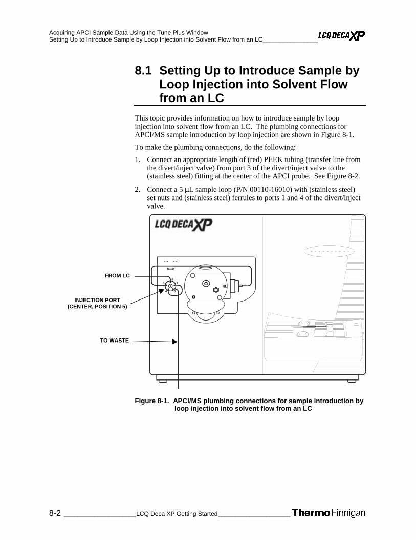
Acquiring APCI Sample Data Using the Tune Plus Window Setting Up to Introduce Sample by Loop Injection into Solvent Flow from an LC________________
8-2 _____________________LCQ Deca XP Getting Started_____________________
8.1 Setting Up to Introduce Sample by Loop Injection into Solvent Flow from an LC
This topic provides information on how to introduce sample by loop injection into solvent flow from an LC. The plumbing connections for APCI/MS sample introduction by loop injection are shown in Figure 8-1.
To make the plumbing connections, do the following:
1. Connect an appropriate length of (red) PEEK tubing (transfer line from the divert/inject valve) from port 3 of the divert/inject valve to the (stainless steel) fitting at the center of the APCI probe. See Figure 8-2.
2. Connect a 5 µL sample loop (P/N 00110-16010) with (stainless steel) set nuts and (stainless steel) ferrules to ports 1 and 4 of the divert/inject valve.
Figure 8-1. APCI/MS plumbing connections for sample introduction by loop injection into solvent flow from an LC
FROM LC
INJECTION PORT (CENTER, POSITION 5)
TO WASTE

Acquiring APCI Sample Data Using the Tune Plus Window ________________Setting Up to Introduce Sample by Loop Injection into Solvent Flow from an LC
_____________________ LCQ Deca XP Getting Started ____________________ 8-3
3. Connect an appropriate length of PEEK tubing (transfer line from the LC) from the divert/inject valve to the LC, as follows:
a. Connect a length of the PEEK tubing with a (stainless steel) nut and (stainless steel) ferrule to port 2 of the divert/inject valve.
b. Connect the other end of the PEEK tubing with a proper fitting and a ferrule to the outlet of the LC.
4. Connect an appropriate length of PEEK tubing (waste line) from the divert/inject valve to a waste container, as follows:
a. Connect a length of PEEK tubing with a (stainless steel) nut and (stainless steel) ferrule to port 6 of the divert/inject valve.
b. Insert the other end of the PEEK tubing into a suitable waste container.
Caution. Prevent solvent waste from backing up into the API ion source and MS detector. Always ensure that the PVC drain hose is above the level of liquid in the waste container.
5. Connect an appropriate length of (clear) 3/8 in. ID PVC hose to the
APCI probe outlet drain. Insert the end of the hose into a suitable waste container (such as a gallon jug). Ideally, the container should be vented to a fume exhaust system.
Figure 8-2. Divert/Inject (Valco injector) Valve, showing the correct set up for analysis by loop injection and showing the flow of liquid through the valve in the LOAD and INJECT positions
4/)/.3/52#%
4/)/.3/52#%

Acquiring APCI Sample Data Using the Tune Plus Window Acquiring APCI Data in the SIM Scan Mode ___________________________________________
8-4 _____________________LCQ Deca XP Getting Started_____________________
8.2 Acquiring APCI Data in the SIM Scan Mode
Use the following procedure to acquire a file of reserpine data in the single ion monitoring (SIM) mode. LCQ Deca XP automatically saves the data you acquire on your hard disk.
1. If you have not already done so, in Tune Plus, click on the On/Standby button to take the MS detector out of Standby mode and turn it On. The MS detector begins scanning, and the LCQ Deca XP applies high voltage to the corona needle and shows a real-time display in the Spectrum view.
2. Ensure that the Centroid data type is selected. (The picture on the button should be the same as that shown here.)
3. Ensure that the scan parameters are defined to acquire SIM data for reserpine (or your analyte of interest), as follows:
a. Click on the Define Scan button to open the dialog box. See Figure 8-3.
b. Ensure that the values in your dialog box are the same as those in Figure 8-3. Then, click on OK.
Figure 8-3. Define Scan dialog box, showing typical settings for acquiring data in the SIM scan mode
STANDBY
ON

Acquiring APCI Sample Data Using the Tune Plus Window ___________________________________________ Acquiring APCI Data in the SIM Scan Mode
_____________________ LCQ Deca XP Getting Started ____________________ 8-5
4. Turn on your LC pump, and specify an appropriate flow rate of
1 mL/min, for example. Ensure that your system is free of leaks.
5. On the Control/Scan Mode toolbar, click on the Acquire Data button to open the dialog box. See Figure 8-4.
Figure 8-4. Acquire Data dialog box, showing the acquisition status of the raw data file
6. Specify the acquisition parameters, as follows:
a. In the File Name text box, enter C:\Xcalibur\Data\reserpine3.raw to specify a path and filename.
b. In the Sample Name text box, enter reserpine to specify the sample identity. If you are not using reserpine, type the name of your particular analyte.
c. In the Comment text box, enter a comment about your experiment. For example, enter SIM, APCI, 50 pg, loop to specify the scan mode, ionization mode, sample amount, and/or method of sample introduction. Xcalibur includes the comment on hard copies of your data.
d. In the Acquire Time group box, select the Continuously option button to specify the continuous acquisition of data (until you stop the acquisition).
7. Leave the Acquire Data dialog box open during data acquisition, but move it to a corner of the Tune Plus window.
8. Click on Start in the Acquire Data dialog box to begin acquiring data to the file reserpine3.raw. See Figure 8-5. The Acquisition Status group box displays the following message.
State: Acquiring
Time (min):
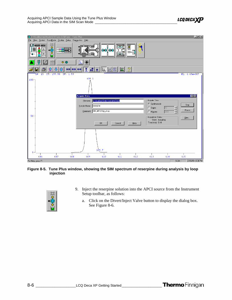
Acquiring APCI Sample Data Using the Tune Plus Window Acquiring APCI Data in the SIM Scan Mode ___________________________________________
8-6 _____________________LCQ Deca XP Getting Started_____________________
Figure 8-5. Tune Plus window, showing the SIM spectrum of reserpine during analysis by loop injection
9. Inject the reserpine solution into the APCI source from the Instrument Setup toolbar, as follows:
a. Click on the Divert/Inject Valve button to display the dialog box. See Figure 8-6.

Acquiring APCI Sample Data Using the Tune Plus Window ___________________________________________ Acquiring APCI Data in the SIM Scan Mode
_____________________ LCQ Deca XP Getting Started ____________________ 8-7
Figure 8-6. Divert/Inject Valve dialog box
b. Select the Load option button, and overfill the 5-µL injector loop
with the 10 pg/µL solution of reserpine (or a solution of your analyte of interest).
c. Select the Inject option button.
10. Observe the reserpine peak (m/z 609.2), or that of your analyte of interest, in the Spectrum view.
11. Perform the following repetitive sequence to obtain a total of four consecutive loop injections of reserpine in the SIM scan mode. Wait about 1 min between injections.
a. Select the Load option button to put the divert/inject valve in the Load position. Overfill the injector loop with the 10 pg/µL solution of reserpine.
b. Select the Inject option button to inject the reserpine solution into the APCI source. Then, observe the Spectrum view.
c. Wait 1 min before the next injection.
d. Repeat steps 11a through 11c three times
12. Click on Stop in the Acquire Data dialog box to end the data acquisition.

Acquiring APCI Sample Data Using the Tune Plus Window Acquiring APCI Data in the SIM Scan Mode ___________________________________________
8-8 _____________________LCQ Deca XP Getting Started_____________________
Review the mass spectrum and chromatogram in the raw file you just acquired using the Xcalibur Qual Browser window. See Figure 8-7.
For more information about reviewing the data you acquire using LCQ Deca XP with Xcalibur, refer to the manual: Xcalibur Getting Productive: Qualitative Analysis.
Note. If you want to acquire MS/MS Full scan data in APCI mode, refer to the following topic for information about setting up the LCQ Deca XP: Setting Up to Acquire MS/MS Data in the Full Scan Type.
Figure 8-7. Qual Browser window, showing loop injections of reserpine in the Chromatogram view (left) and m/z 609 in the Spectrum view

_____________________ LCQ Deca XP Getting Started ____________________ A-1
Appendix A
A. Sample Formulations
This appendix provides instructions for the preparation of several stock solutions. These solutions are used for tuning, calibrating, and demonstrating applications of the APCI / ESI system. Formulations for sample solutions in this appendix are as follows:
• Caffeine, MRFA, and Ultramark 1621 stock solutions
• ESI Calibration Solution: Caffeine, MRFA, Ultramark 1621
• Reserpine
Always take safety precautions when you handle chemicals and unknown samples. ENSURE THAT YOU READ AND UNDERSTAND THE HAZARDS OF THE CHEMICALS USED IN THE FOLLOWING PREPARATIONS. Dispose of all laboratory reagents by the appropriate method for a specific reagent or solvent.
Material Safety Data Sheets (MSDS) provide summarized information on the hazard and toxicity of specific chemical compounds. MSDSs also provides information on the proper handling of compounds, first aid for accidental exposure, and procedures for the remedy of spills or leaks. Producers and suppliers of chemical compounds are required by law to provide their customers with the most current health and safety information in the form of an MSDS. Read the material safety data sheets for each chemical you use. Examples of potentially hazardous chemicals used in procedures throughout this manual are as follows:
• Acetic acid
• Acetonitrile
• Methanol
• Reserpine
Sample Formulations Caffeine, MRFA, and Ultramark 1621 Stock Solutions____________________________________
A-2 _____________________LCQ Deca XP Getting Started_____________________
A.1 Caffeine, MRFA, and Ultramark 1621 Stock Solutions
For tuning and calibrating the ESI system, you use a solution of caffeine, MRFA, and Ultramark 1621 in an acetonitrile:methanol:water solution containing 1% acetic acid. You prepare the calibration solution from each of the following:
• Caffeine stock solution
• MRFA stock solution
• Ultramark 1621 stock solution
Note. Vials of caffeine, MRFA, and Ultramark 1621 are included in the API accessory kit. To order more of these compounds, write or call:
Sigma Chemical Company P. O. Box 14508 St. Louis, Missouri, USA 63178-9916 (800) 325-3010 (in the USA or Canada) (314) 771-3750 (outside the USA or Canada)
CAUTION. AVOID EXPOSURE TO POTENTIALLY HARMFUL MATERIALS. Always wear protective gloves and safety glasses when you use solvents or corrosives. Also contain waste streams, and use proper ventilation. Refer to your supplier’s Material Safety Data Sheet (MSDS) for the proper handling of a particular solvent.

Sample Formulations ____________________________________Caffeine, MRFA, and Ultramark 1621 Stock Solutions
_____________________ LCQ Deca XP Getting Started ____________________ A-3
Stock Solution: Caffeine
A 1 mg/mL stock solution of caffeine in 100% methanol is provided with your LCQ system.
Stock Solution: MRFA
Prepare a 1 mL stock solution of 5 nmol/µL MRFA in 50:50 methanol:water as follows:
1. Obtain the vial of L-methionyl-arginyl-phenylalanyl-alanine acetate•H20 (MRFA) in your accessory kit. In this form, the MRFA sample has an average molecular weight of 523.6 u. Carefully weigh 3.0 mg of the MRFA sample.
2. Dissolve the MRFA sample in a total volume of 1 mL of 50:50 methanol:water. Mix the solution thoroughly.
3. Label the vial MRFA stock solution.
Stock Solution: Ultramark 1621
Prepare a 10 mL stock solution of 0.1% Ultramark 1621 in acetonitrile as follows:
1. Obtain the vial of Ultramark 1621 in your accessory kit.
2. Using a syringe, measure out 10 µL of Ultramark 1621, and dissolve it in 10 mL of acetonitrile. Mix the solution thoroughly.
3. Label the vial Ultramark 1621 stock solution.
Go to the next topic: ESI Calibration Solution: Caffeine, MRFA, Ultramark 1621.

Sample Formulations ESI Calibration Solution: Caffeine, MRFA, Ultramark 1621________________________________
A-4 _____________________LCQ Deca XP Getting Started_____________________
A.2 ESI Calibration Solution: Caffeine, MRFA, Ultramark 1621
Prepare 5 mL of the calibration solution, as follows:
1. Pipet 100 µL of the stock solution of caffeine into a clean, dry vial.
2. Pipet 5 µL of the stock solution of MRFA into the vial.
3. Pipet 2.5 mL of the stock solution of Ultramark 1621 into the vial.
Note. Use only glass pipets or stainless steel syringes when measuring glacial acetic acid. Using plastic pipet tips causes contamination of acid stock solutions, which can introduce contaminants in the calibration solution.
4. Pipet 50 µL of glacial acetic acid into the vial.
5. Pipet 2.34 mL of 50:50 methanol:water into the vial, and then mix the solution thoroughly.
6. Label the vial and store it in a refrigerator until it is needed.

Sample Formulations ______________________________________________________________________Reserpine
_____________________ LCQ Deca XP Getting Started ____________________ A-5
A.3 Reserpine
Follow the directions given below to prepare a stock solution of reserpine. Then, use serial dilutions of the stock solution to make either an APCI or ESI sample solution as described in: ESI / APCI Sample Solution: Reserpine.
Stock Solution: Reserpine
Prepare a stock solution of 1 µg/µL reserpine in 50:50 isopropanol:water (or n-propanol:water):
1. Obtain the 1 gram vial of reserpine in your accessory kit. (The average molecular weight of resperine is 608.7 u). Weigh out 1 mg of reserpine and transfer the sample to a polypropylene microcentrifuge tube.
2. Dissolve the reserpine sample in a total volume of 1 mL of 50:50 isopropanol:water (or n-propanol:water).
3. Ensure the sample is thoroughly dissolved in solution.
ESI / APCI Sample Solution: Reserpine
Prepare 1 mL of the sample solution of 10 pg/µL (82 fmol/µL) in 50:50 isopropanol:water (or n-propanol:water), as follows:
1. Pipet 100 µL of the stock solution (1µg/µL) of reserpine into a clean polypropylene microcentrifuge tube.
2. Add 900 µL of 50:50 isopropanol:water (or n-propanol:water) to the tube.
3. Mix this solution (100 ng/µL) thoroughly.
4. Transfer 10 µL of the 100 ng/µL solution into a clean polypropylene tube.
5. Add 990 µL of 50:50 isopropanol:water (or n-propanol:water) to the tube.
6. Mix this solution (1 ng/µL) thoroughly.
7. Transfer 10 µL of the 1 ng/µL solution into a clean polypropylene tube.
8. Add 990 µL of 50:50 isopropanol:water (or n-propanol:water) to the tube.
9. Mix this solution (10 pg/µL) thoroughly.
10. Store the ESI / APCI sample solution (10 pg/µL) in a refrigerator until it is needed.


Index ______________________________________________________________________________
_____________________ LCQ Deca XP Getting Started _______________________ I
Index
Note. Dialog box is abbreviated d.b.
A Accept Optimized Value d.b.
figure, 5-8 Acquire Data d.b.
figure, 5-13, 8-5 acquiring data
prerequisites for, in MS/MS mode, 5-2 SIM scan type, 5-12, 8-4 using Tune Plus, 5-1, 8-1
Activation Amplitude. See collision energy APCI
plumbing for sample input loop injection (figure), 8-2 Tee to LC (figure), 6-5
probe assembly CAUTION, 2-5 figure, 2-4 installing, 6-3 removing, 2-2
tuning procedure, 6-5 APCI Source d.b.
figure, 6-9 APCI/MS
operational guidelines table, 1-11
setting up MS detector for, 6-8 using, discussion, 1-5
API source discussion, 1-4 ensure nitrogen flow (CAUTION), 3-2
AutoTune file, 3-4
B Breadth Focus
in Ion Tree experiment, discussion, 1-23 buffers, LC
discussion, 1-9
C caffeine
stock solution, preparing, A-3 vial of sample formulation (note), A-2
Calibrate d.b. (figure), 3-16
calibration discussion, 1-12 ions, 3-8 MS detector setup, 3-2 procedure, 3-16
results (figure), 3-18 solutions
Caution, 4-6 preparing, A-4 spectrum results (figure), 3-9 table, 1-14
syringe pump setup for, 2-10 capillary, ion transfer
CAUTION, 3-21 temperature
note, 4-10 setting (figure), 3-4
voltage note, 4-10 setting (figure), 3-4
Cautions avoid contamination of system, 1-13 calibration solution
flow rate limit, 4-6 solvent waste backing into API2 source housing,
2-11, 4-5, 5-11, 6-7, 8-3 CAUTIONS
avoid burns from APCI vaporizer heater, 2-4, 7-6 avoid burns from ion transfer capillary, 3-21 avoid contact with chemicals, A-2 avoid electrical shock if fused silica transfer line
breaks, 2-6 avoid sharp needle, 2-5, 6-3 ensure nitrogen flow for API source, 3-2 exposing ion source to oxygen, 3-19, 7-6 position ground wire, 6-3
cleaning MS detector, 3-19, 7-6 collision energy
optimizing, 5-7 setting, in Define Scan d.b. (note), 5-2
computer terms directories, 3-15, 4-12, 7-5 files, 3-15, 4-12, 7-5
contamination Caution, 1-13
corona discharge needle CAUTION, 2-5
D data
acquiring, in SIM scan type, 5-12, 8-4 reviewing, in Qual Browser window (figure), 5-16,
8-8 Data-Dependent Ion Tree page
figure, 1-23

Index ______________________________________________________________________________
II________________________LCQ Deca XP Getting Started_____________________
Define Scan d.b. figure, 3-5, 4-8, 5-12, 6-10, 8-4 MS/MS settings for reserpine (figure), 5-5
Depth Focus in Ion Tree experiment, discussion, 1-23
dialog boxes Accept Optimized Value, 5-8 Acquire Data, 5-13, 8-5 APCI Source, 6-9 Calibrate, 3-16 Define Scan, 3-5, 4-8, 5-12, 6-10, 8-4 Define Scan, 5-3 Divert/Inject Valve, 4-9, 5-14, 8-7 ESI Source, 3-4, 3-12 Ion Optics, 3-13 Save As, 3-14, 4-11, 7-4 Syringe Pump, 3-7 Tune, 3-10, 4-10, 7-3 Tune, Collision Energy page, 5-6
Divert/Inject valve loop injection (figure), 8-3
Divert/Inject Valve d.b., 4-9, 5-14, 8-7
E ESI
plumbing for sample input loop injection (figure), 5-9 syringe pump infusion (figure), 2-10 Tee to LC (figure), 4-3
probe assembly figure, 2-8 installing, 2-8 needle seat (note), 2-9 removing, 6-2
tuning procedure, 3-7 ESI Source d.b.
figure, 3-4, 3-12 ESI/MS
defining scan parameters, 3-5 discussion, 1-4 operational guidelines
table, 1-11 optimizing MS detector, 4-1 preparing calibration solution for, A-4 setting up MS detector for, 4-6 testing MS detector, 3-7
experiment types Data-Dependent, 1-18 discussion, 1-15 General MS, 1-16 Ion Mapping, 1-20 Ion Tree, 1-22
F Figures
Accept Optimized Value d.b., 5-8 Acquire Data d.b., 5-13, 8-5
APCI plumbing for Tee, 6-6 APCI probe assembly, 2-4 APCI Source d.b., 6-9 Calibrate d.b., 3-16 calibration solution, 3-9 connecting PEEK safety sleeve, 2-7 Define Scan d.b., 3-5, 4-8, 5-12, 8-4
MS/MS Full scan settings, 5-3 MS/MS settings for reserpine, 5-5
Define Scan d.b., APCI settings, 6-10 Divert/Inject valve
positions for loop injection, 8-3 Divert/Inject Valve d.b., 4-9, 5-14, 8-7 ESI probe assembly, 2-8 ESI Source d.b., 3-4, 3-12 experiment templates
General MS, 1-17 Ion Tree, 1-23 Total Ion Map, 1-21 Triple Play, 1-18
Ion Optics d.b., 3-13 loop injection of reserpine, 5-14 MS/MS spectrum of reserpine, 5-7 plumbing
loop injection, 5-10 loop injection, APCI, 8-2 loop injection, ESI, 5-9 syringe pump, 2-11, 2-12 Tee union, 4-4 Tee union, APCI, 6-5 Tee union, ESI, 4-3
Qual Browser window, 5-16, 8-8 results of loop injection, 8-6 Save As d.b., 3-14, 4-11, 7-4 Syringe Pump d.b., 3-7 syringe pump infusion, ESI, 2-10 Tune d.b.
Collision Energy page, 5-6 settings for automatic tuning, 3-10
Tune Plus window, 2-3 automatic calibration results, 3-18 Automatic page, Tune d.b., 4-10, 7-3 results of automatic tune, 3-12
Wideband Activation checkbox, 5-3 flow rates
discussion, 1-10 effects of (note), 3-8 note, 4-10 using LCQ Deca XP syringe pump (note), 2-10
G Graph view
displaying, 3-11 guidelines
LCQ Deca XP operation (table), 1-11

Index ______________________________________________________________________________
_____________________ LCQ Deca XP Getting Started ______________________ III
H Home Page, Xcalibur
displaying, 3-2, 4-6
I Instrument Setup window
displaying, 3-2, 4-6 introducing samples into LCQ Deca XP
discussion, 1-7 Ion Optics d.b.
optimized tune (figure), 3-13 ion source
exposing to atmosphere CAUTION, 3-19, 7-6
Ion Tree experiment Breadth Focus, 1-23 Depth Focus, 1-23
isolation width optimizing, 5-2
note, 5-4
L LC
using buffers, discussion, 1-9 LCQ Deca XP
discussion, 1-2 flow rates, discussion, 1-10 introducing sample
discussion, 1-7 table, 1-8
operational guidelines table, 1-11
loop injection reserpine results (figure), 5-14, 8-6 setup for, 5-9, 8-2
M methods, Tune
opening predefined, 4-7, 6-8 opening predefined, 3-4 saving (note), 3-14, 4-11, 7-4
MRFA preparing stock solution, A-3 vial of sample formulation (note), A-2
MS detector calibrating, 3-16 cleaning for normal operation, 3-19, 7-6 ESI/MS mode, testing, 3-7 optimizing tune, LC/ESI/MS operation, 4-1 setting up for APCI/MS operation, 6-8 setting up for ESI/MS operation, 4-6
MS Detector Setup page General MS experiment
figure, 1-17
Triple Play experiment figure, 1-18
MS/MS acquiring, data, 5-2 discussion, 1-3
N nitrogen
ensure flow for API source (CAUTION), 3-2 Notes
acquire data without optimizing, 4-2 collision energy, 5-2 cutting PEEK tubing, 6-6 effect of flow rates, 3-8 ensuring that MS detector is set up, tuned, and
calibrated, 4-2 ESI needle seat, 2-9 ESI signal quality, 1-13 ESI tune files, 3-3 ion transfer capillary temperature, 4-10 optimizing isolation width, 5-4 optimizing MS detector tune, 3-11 refer to LCQ Deca XP Getting Connected, 2-2, 3-2 refer to LCQ Deca XP Hardware Manual, 2-2, 3-2,
4-6 refer to LCQ Deca XP online Help, 2-2, 3-2, 4-6, 5-
1 saving Tune Method, 3-14, 4-11, 7-4 solution flow rate, 4-10 solvents, 3-20, 3-21, 7-7 syringe pump speed, 2-10 tube lens voltage, 4-10 Unimetrics syringe, 3-7 use glass pipettes or stainless steel syringes with
glacial acetic acid, A-4 vials of sample formulations, A-2
O optimizing
collision energy, 5-7 MS detector for LC/ESI/MS operation, 4-1 tune, automatically (figure), 3-12
P PEEK safety sleeve
connecting to ESI probe, 2-6 PEEK tubing
cutting (note), 6-6 pipettes
use glass, with glacial acetic acid (note), A-4 plumbing
divert/inject valve (figure), 5-10 ESI, for syringe pump infusion (figure), 2-10 loop injection (figure), 5-10 loop injection, APCI (figure), 8-2

Index ______________________________________________________________________________
IV_______________________LCQ Deca XP Getting Started_____________________
loop injection, ESI (figure), 5-9 syringe pump (figure), 2-11, 2-12 syringe pump, Tee to LC (figure), 4-4 syringe pump, Tee to LC, APCI (figure), 6-5 syringe pump, Tee to LC, ESI (figure), 4-3
procedures acquiring data using Tune Plus, 5-1, 8-1 acquiring data, SIM scan type, 5-12, 8-4 calibrating MS detector automatically, 3-16 cleaning MS detector after tuning, calibrating, 3-
19, 7-6 connecting PEEK safety sleeve to ESI probe, 2-6 installing ESI probe, 2-8 optimizing
APCI tune, 7-2 collision energy, 5-7 ESI tune, 4-9 isolation width, 5-2
preparing a stock solution of reserpine, A-5 preparing an ESI sample solution of reserpine, A-5 preparing ESI calibration solution, A-4 preparing stock solutions, A-2 removing APCI probe, 2-2 saving Tune Method, 3-14, 4-11, 7-4 setting up inlet for APCI tuning, 6-5 setting up loop injection, 5-9, 8-2 setting up MS detector for APCI/MS operation, 6-8 setting up MS detector for tuning, calibrating, 2-1 setting up syringe pump, 4-3 setting up syringe pump for tuning, calibrating, 2-
10 setting up to tune MS detector with your analyte, 4-
6 testing MS detector in ESI/MS mode, 3-7 tuning and calibrating
MS detector setup, 3-2 tuning and calibrating automatically, ESI mode, 3-1 tuning MS detector automatically with your analyte,
4-1 tuning MS detector automatically, APCI/MS mode,
7-2 tuning MS detector automatically, ESI/MS mode,
3-10 Purge checkbox, 3-8
Q Qual Browser window
figure, 5-16, 8-8 quantitation experiments, 1-16
R reserpine
acquiring, data, loop injection, 5-1, 8-1 MS/MS settings for, in Define Scan d.b. (figure), 5-
5 MS/MS spectrum (figure), 5-7 preparing ESI sample solution, A-5
preparing solutions, A-5
S safety sleeve, PEEK
connecting (figure), 2-7 sample solutions
ESI, reserpine, A-5 sample tube, 2-6 Save As d.b.
figure, 3-14, 4-11, 7-4 saving
files (figure), 3-14, 4-11, 7-4 saving Tune Method
note, 3-14, 4-11, 7-4 scan parameters
defining (figure), 3-5 sheath gas flow rate
figure, 3-4 signal quality
ESI (note), 1-13 SIM scan type
acquiring data in, 5-12, 8-4 solutions, preparing
caffeine, stock, A-3 calibrating, ESI, A-4 ESI sample, reserpine, A-5 MRFA, stock, A-3 reserpine, stock, A-5 Ultramark 1621, stock, A-3
solvents (note), 3-20, 3-21, 7-7
syringe pump setting up for tuning, calibrating, 2-10 speed (note), 2-10
Syringe Pump d.b. figure, 3-7
syringes note, 3-7 use stainless steel, with glacial acetic acid (note),
A-4
T Tables
APCI operational guidelines, 1-11 ESI operational guidelines, 1-11 introducing sample for calibrating, tuning, 1-14 sample introduction techniques, 1-8
Tee union plumbing (figure), 4-4
Total Ion Map page figure, 1-21
tube lens setting (figure), 3-4 voltage (note), 4-10
Tune d.b. Automatic page, 4-10 Collision Energy page (figure), 5-6

Index ______________________________________________________________________________
_____________________ LCQ Deca XP Getting Started ______________________ V
figure, 3-10 showing settings for automatic tuning (figure), 3-10
Tune Methods opening predefined, 3-4, 4-7, 6-8 saving (note), 3-14, 4-11, 7-4
Tune Plus window figure, 2-3, 3-18 loop injection (figure), 5-14, 8-6 MS/MS spectrum (figure), 5-7 opening, 2-2, 3-2, 4-6 showing automatic tune optimization (figure), 3-12 tuning (figure), 4-10, 7-3 tuning results (figure), 3-12 using, to acquire data, 5-1, 8-1
tuning automatically, 3-10 discussion, 1-12 ESI tune files (note), 3-3 MS detector
optimizing (note), 3-11 MS detector for LC/ESI/MS operation, 4-1 MS detector setup for, 3-2 set up for, 4-6 syringe pump setup for, 2-10 voltages, 3-10
U Ultramark 1621
preparing stock solution, A-3 vial of sample formulation (note), A-2
V voltages
optimized tune (figure), 3-13
W Wideband Activation
discussion, 1-3 option (figure), 5-3
X Xcalibur
displaying Home Page, 3-2, 4-6 displaying Roadmap view, 2-2
Z ZoomScan
discussion, 1-3, 1-20

Related Documents