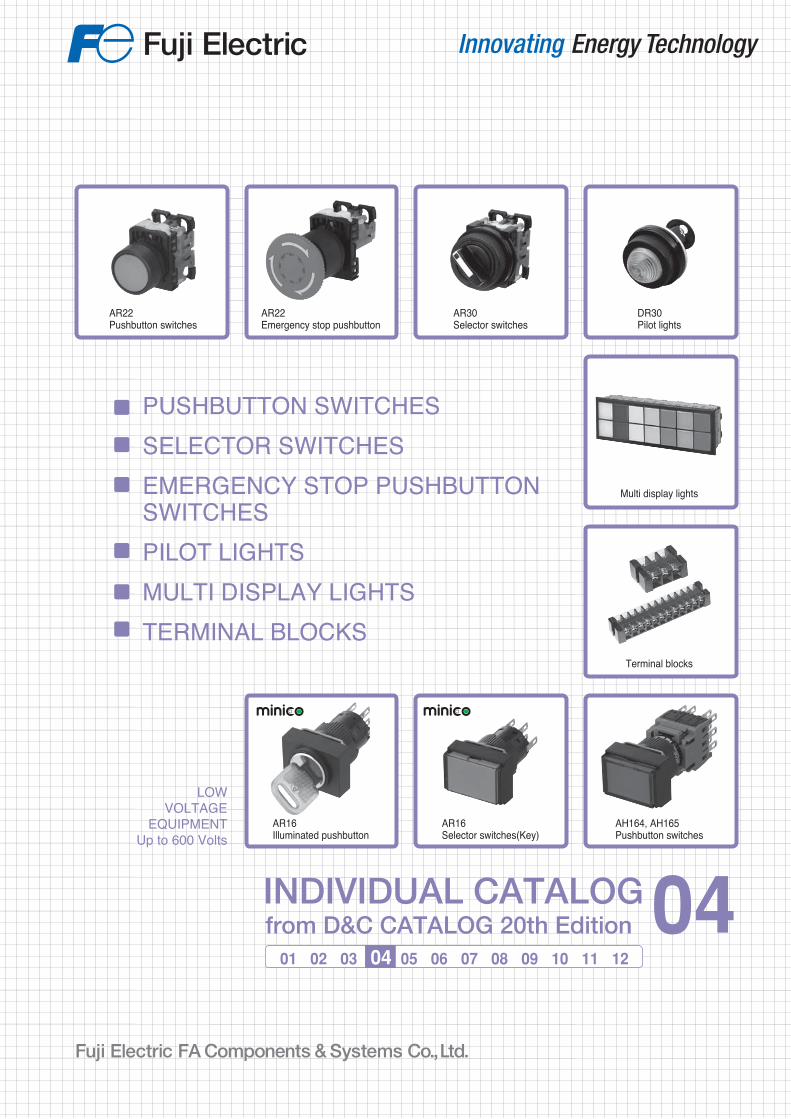
PUSHBUTTON SWITCHES SELECTOR SWITCHES EMERGENCY STOP PUSHBUTTON SWITCHES PILOT LIGHTS MULTI DISPLAY LIGHTS TERMINAL BLOCKS 01 02 03 04 05 06 07 08 09 10 11 12 LOW VOLTAGE EQUIPMENT Up to 600 Volts INDIVIDUAL CATALOG from D&C CATALOG 20th Edition 04 AR22 Pushbutton switches Terminal blocks AR22 Emergency stop pushbutton AR30 Selector switches DR30 Pilot lights Multi display lights AH164, AH165 Pushbutton switches AR16 Illuminated pushbutton AR16 Selector switches(Key)

Welcome message from author
This document is posted to help you gain knowledge. Please leave a comment to let me know what you think about it! Share it to your friends and learn new things together.
Transcript
Information in this catalog is subject to change without notice.
5-7, Nihonbashi Odemma-cho, Chuo-ku, Tokyo, 103-0011, Japan URL http://www.fujielectric.co.jp/fcs/eng
IND
IVID
UA
L CA
TA
LOG
from
D&
C C
AT
ALO
G 20th E
ditio
n
04
PUSHBUTTON SWITCHESSELECTOR SWITCHESEMERGENCY STOP PUSHBUTTON SWITCHESPILOT LIGHTSMULTI DISPLAY LIGHTSTERMINAL BLOCKS
01 02 03 04 05 06 07 08 09 10 11 12
LOWVOLTAGE
EQUIPMENTUp to 600 Volts
INDIVIDUAL CATALOGfrom D&C CATALOG 20th Edition 04INDIVIDUAL CATALOG
from D&C CATALOG 20th Edition 04
LOW VOLTAGE PRODUCTS Up to 600 VoltsIndividualcatalog No.
01 Magnetic Contactors and StartersThermal Overload Relays, Solid-state Contactors
02
Industrial Relays, Industrial Control RelaysAnnunciator Relay Unit, Time Delay Relays
Manual Motor Starters and Contactors Combination Starters
Pushbuttons, Selector Switches, Pilot LightsRotary Switches, Cam Type Selector SwitchesPanel Switches, Terminal Blocks, Testing Terminals
Molded Case Circuit BreakersAir Circuit Breakers
Earth Leakage Circuit BreakersEarth Leakage Protective Relays
Measuring Instruments, Arresters, TransducersPower Factor ControllersPower Monitoring Equipment (F-MPC)
Circuit ProtectorsLow Voltage Current-Limiting Fuses
03
04
05
06
07
08
09
10
HIGH VOLTAGE PRODUCTS Up to 36kV
11Disconnecting Switches, Power FusesAir Load Break SwitchesInstrument Transformers — VT, CT
D&C CATALOG DIGEST INDEX
AC Power RegulatorsNoise Suppression FiltersControl Power Transformers
12 Vacuum Circuit Breakers, Vacuum Magnetic ContactorsProtective Relays
Limit Switches, Proximity SwitchesPhotoelectric Switches
AR22Pushbutton switches
Terminal blocks
AR22Emergency stop pushbutton
AR30Selector switches
DR30Pilot lights
Multi display lights
AH164, AH165Pushbutton switches
AR16Illuminated pushbutton
AR16Selector switches(Key)
2010-09 PDF FOLS DEC2004
28.4
mm
42.5
mm
2
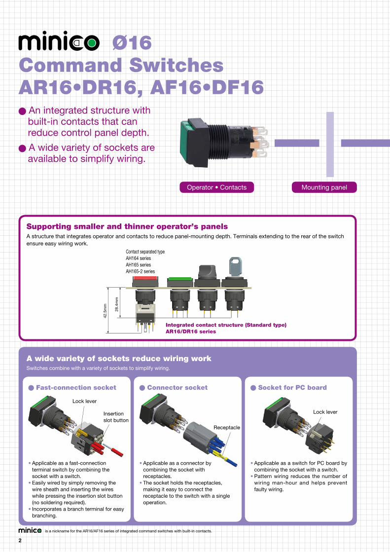
Ø16
An integrated structure with built-in contacts that can reduce control panel depth.
A wide variety of sockets are available to simplify wiring.
Command SwitchesAR16•DR16, AF16•DF16
Supporting smaller and thinner operator’s panelsA structure that integrates operator and contacts to reduce panel-mounting depth. Terminals extending to the rear of the switch ensure easy wiring work.
A wide variety of sockets reduce wiring workSwitches combine with a variety of sockets to simplify wiring.
• Applicable as a fast-connection terminal switch by combining the socket with a switch.
• Easily wired by simply removing the wire sheath and inserting the wires while pressing the insertion slot button (no soldering required).
• Incorporates a branch terminal for easy branching.
• Applicable as a connector by combining the socket with receptacles.
• The socket holds the receptacles, making it easy to connect the receptacle to the switch with a single operation.
• Applicable as a switch for PC board by combining the socket with a switch.
• Pattern wiring reduces the number of wiring man-hour and helps prevent faulty wiring.
Fast-connection socket Connector socket Socket for PC board
is a nickname for the AR16/AF16 series of integrated command switches with built-in contacts.
Operator • Contacts Mounting panel
Integrated contact structure (Standard type) AR16/DR16 series
Contact separated typeAH164 seriesAH165 seriesAH165-2 series
Lock lever
Insertion slot button
Receptacle
Lock lever
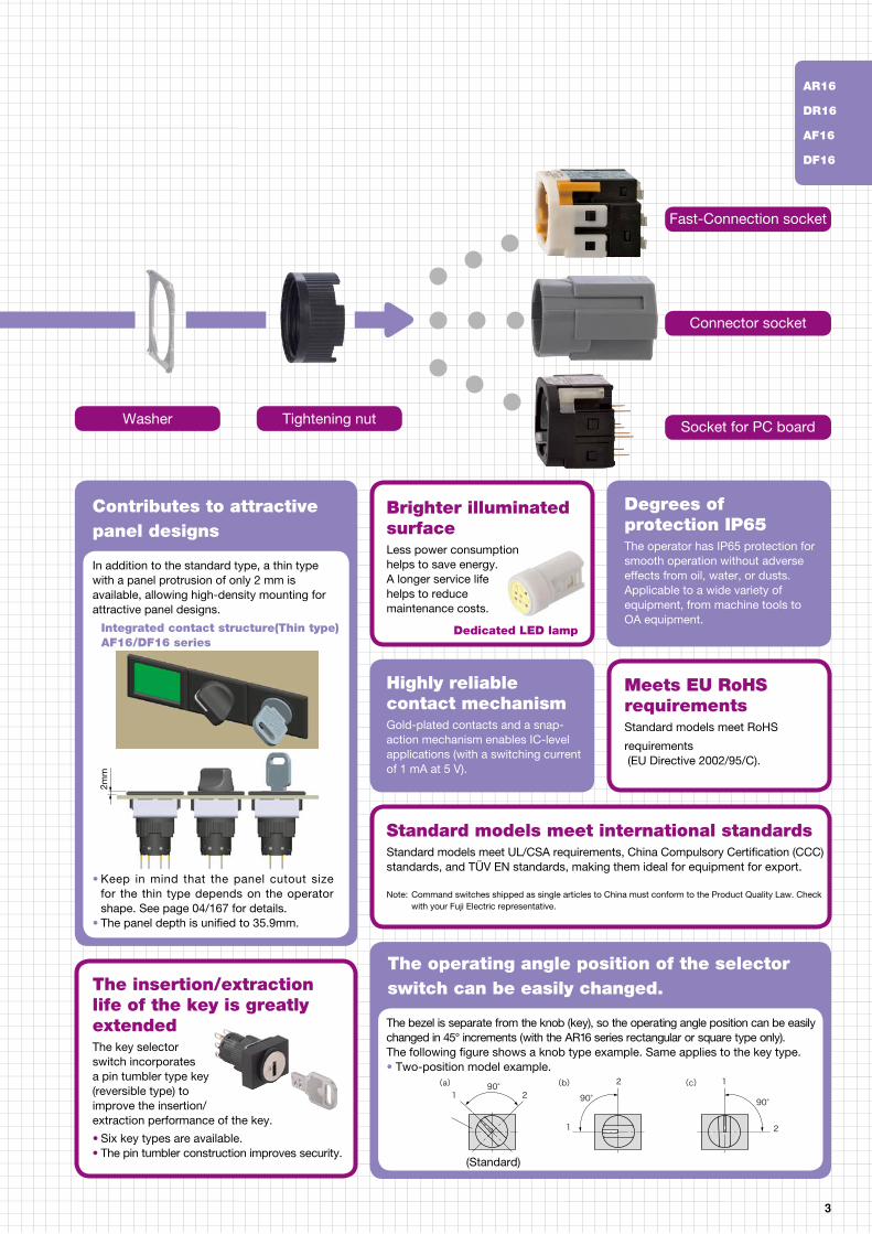
Contributes to attractivepanel designs
Highly reliable contact mechanismGold-plated contacts and a snap-action mechanism enables IC-level applications (with a switching current of 1 mA at 5 V).
3
2mm
Bezel
(Standard)
Dedicated LED lamp
• Keep in mind that the panel cutout size for the thin type depends on the operator shape. See page 04/167 for details.
• The panel depth is unified to 35.9mm.
The insertion/extraction life of the key is greatly extendedThe key selectorswitch incorporates a pin tumbler type key(reversible type) toimprove the insertion/extraction performance of the key.
Washer Tightening nut
• Six key types are available.• The pin tumbler construction improves security.
In addition to the standard type, a thin type with a panel protrusion of only 2 mm is available, allowing high-density mounting for attractive panel designs.
Integrated contact structure(Thin type)AF16/DF16 series
The operating angle position of the selectorswitch can be easily changed.
The bezel is separate from the knob (key), so the operating angle position can be easily changed in 45° increments (with the AR16 series rectangular or square type only).The following figure shows a knob type example. Same applies to the key type.• Two-position model example.
(a) 90° 90° 90°
1
1
1 2
2
2
(b) (c)
Brighter illuminated surfaceLess power consumption helps to save energy.A longer service life helps to reduce maintenance costs.
Standard models meet international standardsStandard models meet UL/CSA requirements, China Compulsory Certification (CCC) standards, and TÜV EN standards, making them ideal for equipment for export.
Note: Command switches shipped as single articles to China must conform to the Product Quality Law. Check with your Fuji Electric representative.
Degrees of protection IP65The operator has IP65 protection for smooth operation without adverse effects from oil, water, or dusts.Applicable to a wide variety ofequipment, from machine tools to OA equipment.
Meets EU RoHS requirementsStandard models meet RoHS
requirements (EU Directive 2002/95/C).
Fast-Connection socket
Connector socket
Socket for PC board
AR16
DR16
AF16
DF16
(Standard)
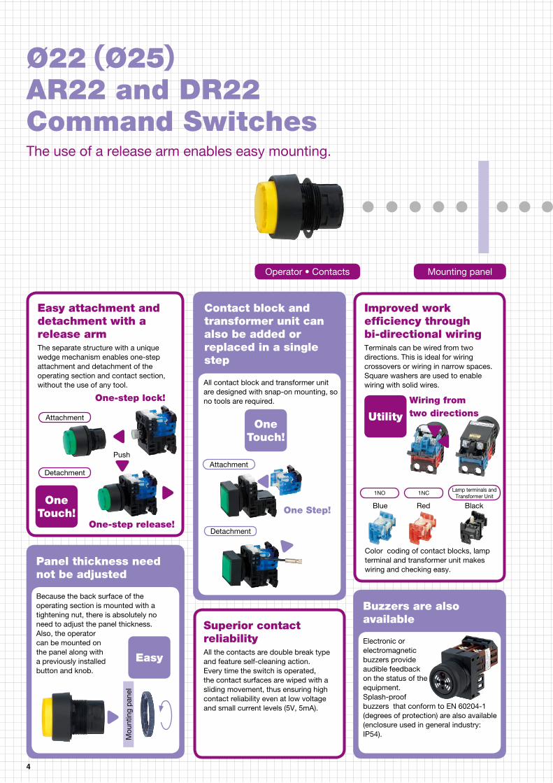
Easy attachment and detachment with a release armThe separate structure with a unique wedge mechanism enables one-step attachment and detachment of the operating section and contact section, without the use of any tool.
Improved work efficiency through bi-directional wiringTerminals can be wired from two directions. This is ideal for wiring crossovers or wiring in narrow spaces. Square washers are used to enable wiring with solid wires.
Panel thickness need not be adjusted
Buzzers are also available
Because the back surface of the operating section is mounted with a tightening nut, there is absolutely no need to adjust the panel thickness.Also, the operator can be mounted on the panel along with a previously installed button and knob.
Electronic or electromagnetic buzzers provide audible feedback on the status of the equipment.Splash-proof buzzers that conform to EN 60204-1 (degrees of protection) are also available (enclosure used in general industry: IP54).
4
Blue RedOne
Touch!
Utility
1NO 1NC Lamp terminals and Transformer Unit
Detachment
The use of a release arm enables easy mounting.
Ø22(Ø25)AR22 and DR22Command Switches
Wiring from two directions
Color coding of contact blocks, lamp terminal and transformer unit makes wiring and checking easy.
Push
One-step release!
One-step lock!
Mou
ntin
g p
anel
Contact block and transformer unit can also be added or replaced in a single step
All contact block and transformer unit are designed with snap-on mounting, so no tools are required.
One Step!
Superior contact reliabilityAll the contacts are double break type and feature self-cleaning action.Every time the switch is operated, the contact surfaces are wiped with a sliding movement, thus ensuring high contact reliability even at low voltage and small current levels (5V, 5mA).
Easy
One Touch!
Attachment
Attachment
Detachment
Operator • Contacts Mounting panel
Black

Switches with IP2X -compliant terminals are also availableSwitches with IP2X-compliant terminals with a finger protection structure conforming to EN 60204-1 (Protection against electric shock) are available. (A test finger that simulates a human finger does not come into contact with live parts.)
High brightness LED illuminated model, “PIKARI-KUN”1. Standard models feature (1) higher equipment grade, (2) enhanced safety that enables easy
identification of the status, and (3) adoption of pure green illumination
color through a major improvement in visibility (Luminance) through the adoption of four elements LED.
2. Along with a significant improvement in Luminance, energy is saved through a reduction in power consumption.
3. The maintenance cost is also reduced by increasing the service life.
Features 30 × 50 mm tight mounting
Depth of the short body
A short design enables full use of the available depth of the equipment.
Short
Lamp base shape facilitates easy replacementThe same lamp base shape of BA9s/13 for both high brightness LED lamps and incandescent lamps facilitates application.
5
Safety
Units can be mounted on a 25.5-mm diameter hole simply by turning over the tightening nut.
30mm
50m
m
Note: Not applicable to all models.
Selector Switch (1NO+1NC)
Pilot light (models for full voltages)
Illuminated PuchbuttonSwitch (1NO+1NC with transformer)
❶ The Short-body Pilot light is 21.5mm long.
41mm
37mm ❶
61mm
Note: For details, refer to AR22 and DR22-series Special Products.
Ø 22.3 + 0.4 mm
0 Ø 25.5 + 0.5 mm
0
Panel cutout dimensions of 22.3 mm and 25.5 mm diameterBy providing a projection on the tightening nut, one switch can be mounted on two different panel cutout dimensions. Therefore, switches do not need to be purchased to match the panel cutout dimensions.
Standard models meet international standards
Standard models meet UL/CSA requirements and TÜV EN standards, making them ideal for equipment for export.Chinese CCC-compliant models are also available.Note: For details, refer to List of Models.
See page 04/3 to 04/6
GlobalStandardization
Terminal cover for charged parts provided as a standard accessoryA terminal cover that covers the terminals is provided as a standard accessory to help prevent electric shock by reducing exposure to charged parts.Note: Not provided on all models.
Tightening nut
Release arm
Contact section
Contacts Transformer unit
Lamp terminal for pilot light
AR22
DR22
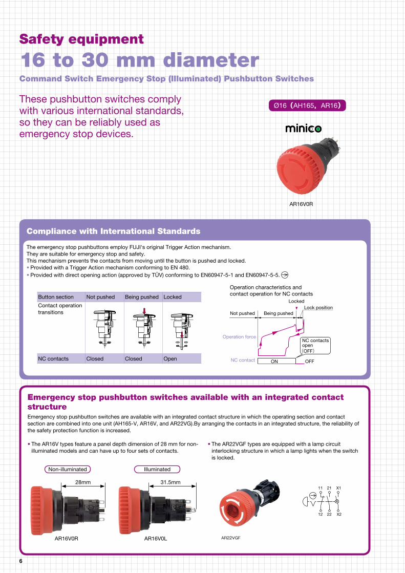
Emergency stop pushbutton switches available with an integrated contact structureEmergency stop pushbutton switches are available with an integrated contact structure in which the operating section and contact section are combined into one unit (AH165-V, AR16V, and AR22VG).By arranging the contacts in an integrated structure, the reliability of the safety protection function is increased.
Compliance with International Standards
The emergency stop pushbuttons employ FUJI's original Trigger Action mechanism.They are suitable for emergency stop and safety.This mechanism prevents the contacts from moving until the button is pushed and locked.• Provided with a Trigger Action mechanism conforming to EN 480.• Provided with direct opening action (approved by TÜV) conforming to EN60947-5-1 and EN60947-5-5.
6
AR22VGF
• The AR16V types feature a panel depth dimension of 28 mm for non-illuminated models and can have up to four sets of contacts.
• The AR22VGF types are equipped with a lamp circuit interlocking structure in which a lamp lights when the switch is locked.
12 22 X2
11 21 X1
AR16V0R AR16V0L
Button section Not pushed Being pushed Locked
Contact operation transitions
NC contacts Closed Closed Open
AR16V0R
Safety equipment
Operation characteristics and contact operation for NC contacts
Locked
Being pushedLock position
Not pushed
Operation force
NC contact ON OFF
NC contacts open(OFF)
These pushbutton switches comply with various international standards, so they can be reliably used as emergency stop devices.
Command Switch Emergency Stop (Illuminated) Pushbutton Switches
16 to 30 mm diameter
Ø16(AH165,AR16)
Non-illuminated Illuminated
28mm 31.5mm
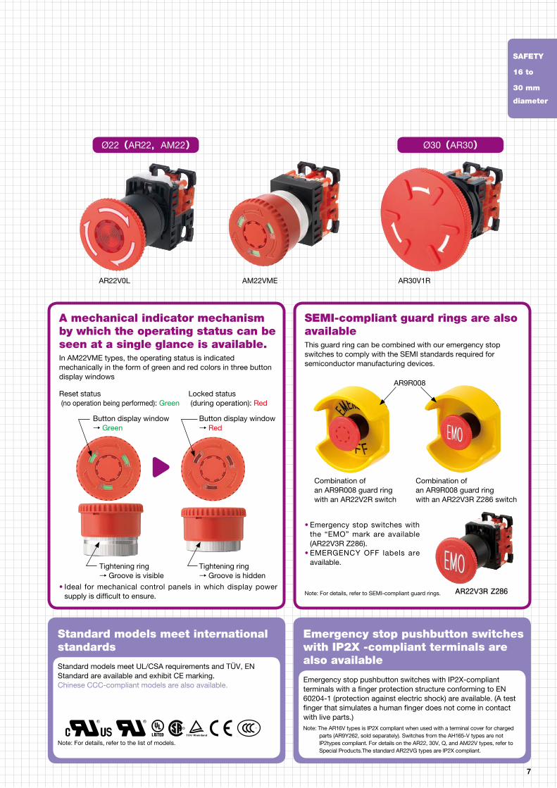
A mechanical indicator mechanism by which the operating status can be seen at a single glance is available. In AM22VME types, the operating status is indicated mechanically in the form of green and red colors in three button display windows
SEMI-compliant guard rings are also availableThis guard ring can be combined with our emergency stop switches to comply with the SEMI standards required for semiconductor manufacturing devices.
Standard models meet international standards
Emergency stop pushbutton switches with IP2X -compliant terminals are also available
Standard models meet UL/CSA requirements and TÜV, EN Standard are available and exhibit CE marking.Chinese CCC-compliant models are also available.
Emergency stop pushbutton switches with IP2X-compliant terminals with a finger protection structure conforming to EN 60204-1 (protection against electric shock) are available. (A test finger that simulates a human finger does not come in contact with live parts.)Note: The AR16V types is IP2X compliant when used with a terminal cover for charged
parts (AR9Y262, sold separately). Switches from the AH165-V types are not IP2types compliant. For details on the AR22, 30V, Q, and AM22V types, refer to Special Products.The standard AR22VG types are IP2X compliant.
7
Note: For details, refer to SEMI-compliant guard rings.
• Emergency stop switches with the “EMO” mark are available (AR22V3R Z286).
• EMERGENCY OFF labels are available.
Combination of an AR9R008 guard ring with an AR22V2R switch
Combination of an AR9R008 guard ring with an AR22V3R Z286 switch
AR22V3R Z286• Ideal for mechanical control panels in which display power supply is difficult to ensure.
Note: For details, refer to the list of models.
S
AR22V0L AM22VME AR30V1R
AR9R008Reset status (no operation being performed): Green
Locked status (during operation): Red
Ø22(AR22,AM22) Ø30(AR30)
Button display window→ Green
Button display window→ Red
Tightening ring→ Groove is visible
Tightening ring→ Groove is hidden
SAFETY
16 to
30 mm
diameter

Series Type Features Page
Command Series AR22 and DR22 • Standard models feature illumination with high brightness LEDs.• No adjusting of panel thickness is necessary.• The button and lens can be mounted on a panel while the operator is engaged.• Easy replacing contact block and transformer.• Wiring from two directions is possible.• The shortest among industrial pushbuttons. The transformer now occupies far less
space.• A terminal cover are provided, assuring safety and security.• The emergency stop pushbuttons employ FUJI’s original Trigger Action mechanism.
They are suitable for emergency stop and safety.• Mountable even on panel cutout 25mm diameter.• AR22 and DR22 series of the ø22 Command Switches are approved by UL/CSA
CCC and TÜV (EN standard).• Bearing CE markings.
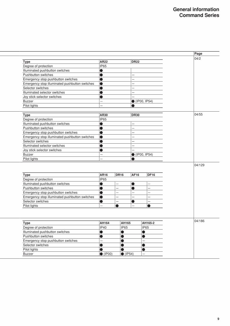
Type AR22 DR22Degree of protection IP65Illuminated pushbutton switchesPushbutton switches -Emergency stop pushbutton switches -Emergency stop illuminated pushbutton switches -Selector switches -Illuminated selector switches -Joy stick selector switches -Buzzer - (IP00, IP54)Pilot lights -
04/2
AR30 and DR30 • Standard models feature illumination with high brightness LEDs.• Easy replacing contact block and transformer.• The shortest among industrial pushbuttons. The transformer now occupies far less
space.• A terminal cover are provided, assuring safety and security.• The emergency stop pushbuttons employ FUJI’s original Trigger Action mechanism.
They are suitable for emergency stop and safety.• AR30 and DR30 series of the ø30 Command Switches are approved by UL/CSA,
CCC and TÜV (EN standard).• Bearing CE markings.
Type AR30 DR30Degree of protection IP65Illuminated pushbutton switches -Pushbutton switches -Emergency stop pushbutton switches -Emergency stop illuminated pushbutton switches -Selector switches -Illuminated selector switches -Joy stick selector switches -Buzzer - (IP00, IP54)Pilot lights -
04/55
AR16 and AF16 • An integrated operator component and contact mechanism that reduces control panel’s depth. A unified depth of 28.4mm for the Standard type and 35.9mm for the Thin type.
• Thin type and Standard types available for your control panel design. Select an optimum one to match your control panel design.
• A wide variety of sockets help to reduce wiring.• Incorporating a gold-flashed SPDT or 2PDT contact mechanism with a snap-action
structure that makes and breaks 1mA at 5V.• A key selector switch with a pin tumbler key and reversible type mechanism
provides improved key insertion and removal (extraction) performance.• Complies with RoHS (EU Directive 2002/95/EC).• The standard AR16 and DR16, AF16 and DF16 series of the ø16 Command
Switches are approved by UL/CSA, CCC and TÜV (EN standard).• Bearing CE markings.
Type AR16 DR16 AF16 DF16
Degree of protection IP65Illuminated pushbutton switches - -Pushbutton switches - -Emergency stop pushbutton switches - - -Emergency stop illuminated pushbutton switches - - -Selector switches - -Pilot lights - -
04/129
AH164 and AH165 AH165-2
• Standard models feature illumination with high brightness LEDs.• Unified depth dimension of 24 mm for type with indicator and 42.5 mm for other
types.• Application possible at 1 mA, 5 V due to gold-plated contacts and sliding structure.• Incandescent, neon and LED lamps are available.• Easy replacing contact block.• AH165-2 series are about twice as large as the AH165 series.• AH164 and AH165, AH165-2 series of the ø16 Command Switches are approved
by UL/CSA, CCC and TÜV (EN standard).• Bearing CE markings.
Type AH164 AH165 AH165-2
Degree of protection IP40 IP65 IP65Illuminated pushbutton switchesPushbutton switchesEmergency stop pushbutton switches - -Selector switchesPilot lightsBuzzer (IP00) (IP54) -
04/186
8
General informationCommand Series
Series Type Features Page
Command Series AR22 and DR22 • Standard models feature illumination with high brightness LEDs.• No adjusting of panel thickness is necessary.• The button and lens can be mounted on a panel while the operator is engaged.• Easy replacing contact block and transformer.• Wiring from two directions is possible.• The shortest among industrial pushbuttons. The transformer now occupies far less
space.• A terminal cover are provided, assuring safety and security.• The emergency stop pushbuttons employ FUJI’s original Trigger Action mechanism.
They are suitable for emergency stop and safety.• Mountable even on panel cutout 25mm diameter.• AR22 and DR22 series of the ø22 Command Switches are approved by UL/CSA
CCC and TÜV (EN standard).• Bearing CE markings.
Type AR22 DR22Degree of protection IP65Illuminated pushbutton switchesPushbutton switches -Emergency stop pushbutton switches -Emergency stop illuminated pushbutton switches -Selector switches -Illuminated selector switches -Joy stick selector switches -Buzzer - (IP00, IP54)Pilot lights -
04/2
AR30 and DR30 • Standard models feature illumination with high brightness LEDs.• Easy replacing contact block and transformer.• The shortest among industrial pushbuttons. The transformer now occupies far less
space.• A terminal cover are provided, assuring safety and security.• The emergency stop pushbuttons employ FUJI’s original Trigger Action mechanism.
They are suitable for emergency stop and safety.• AR30 and DR30 series of the ø30 Command Switches are approved by UL/CSA,
CCC and TÜV (EN standard).• Bearing CE markings.
Type AR30 DR30Degree of protection IP65Illuminated pushbutton switches -Pushbutton switches -Emergency stop pushbutton switches -Emergency stop illuminated pushbutton switches -Selector switches -Illuminated selector switches -Joy stick selector switches -Buzzer - (IP00, IP54)Pilot lights -
04/55
AR16 and AF16 • An integrated operator component and contact mechanism that reduces control panel’s depth. A unified depth of 28.4mm for the Standard type and 35.9mm for the Thin type.
• Thin type and Standard types available for your control panel design. Select an optimum one to match your control panel design.
• A wide variety of sockets help to reduce wiring.• Incorporating a gold-flashed SPDT or 2PDT contact mechanism with a snap-action
structure that makes and breaks 1mA at 5V.• A key selector switch with a pin tumbler key and reversible type mechanism
provides improved key insertion and removal (extraction) performance.• Complies with RoHS (EU Directive 2002/95/EC).• The standard AR16 and DR16, AF16 and DF16 series of the ø16 Command
Switches are approved by UL/CSA, CCC and TÜV (EN standard).• Bearing CE markings.
Type AR16 DR16 AF16 DF16
Degree of protection IP65Illuminated pushbutton switches - -Pushbutton switches - -Emergency stop pushbutton switches - - -Emergency stop illuminated pushbutton switches - - -Selector switches - -Pilot lights - -
04/129
AH164 and AH165 AH165-2
• Standard models feature illumination with high brightness LEDs.• Unified depth dimension of 24 mm for type with indicator and 42.5 mm for other
types.• Application possible at 1 mA, 5 V due to gold-plated contacts and sliding structure.• Incandescent, neon and LED lamps are available.• Easy replacing contact block.• AH165-2 series are about twice as large as the AH165 series.• AH164 and AH165, AH165-2 series of the ø16 Command Switches are approved
by UL/CSA, CCC and TÜV (EN standard).• Bearing CE markings.
Type AH164 AH165 AH165-2
Degree of protection IP40 IP65 IP65Illuminated pushbutton switchesPushbutton switchesEmergency stop pushbutton switches - -Selector switchesPilot lightsBuzzer (IP00) (IP54) -
04/186
9
General informationCommand Series

Series Type Features Page
Multi Display AP30F and AP40F • High brightness for more vivid colors• Newly added blue and pure white LEDs improve visibility.• Transformer-free design for lighter structure and shorter depth (for 100-V and 200-
V models)• Easy color and voltage changes.• Wide window size selection. A wide selection, including half-size windows.• UL/CSA-compliant models also available.
Type Illuminated face Face size Type Illuminated face Face sizeAP30F Half size (H) 15×30 AP40F Half size (H) 20×40
Square (S) 30×30 Square (S) 40×40Rectangular horizontally long (T)
30×60Rectangular horizontally long (T)
40×80
Rectangular vertical long (V)
60×30Rectangular vertical long (V)
80×40
Mixtture of S, T, V (X) - Mixtture of S, T, V (X) -
04/235
Rotary Switches AC09, AC16 and AC32 • Rotary switches with code output.• Three types of code output are available.• Select either soldered or connector connections. Type Type of code
Real binary code Complementary binary code Real gray codeAC09AC16AC32
04/256
Cam Type RC310 • A wide range of models available for control, instrumentation, and motor starting and with bifurcated contacts, keys, and indicators.
Type Mounting Rated insulation voltage
Rated thermal current
Remarks
RC310-1 40 x 40, mounted with 4 screws
600V 10A The following are also available: Keys, indicators, bifurcated contacts, case covers, etc.
04/263
Panel Switches NS387 • Ideal for switching all types of electric circuits.
Type Rated thermal current ApplicationNS387 15A Voltmeter changeover switches
Ammeter changeover switchesIndustrial control switches
04/270
Terminal Blocks • FUJI can supply a variety of terminal blocks for switchboard or switchgear use. Type Rated insulation voltage Rated thermal current ApplicationAYBN 600V 15 to 600A General purpose terminal blocksAYBS 600V 49 to 115A High quality terminal blocksLT4D 660V 20A Rail mounted terminal blocks with isolating switchSKT 600V 50 to 200A Terminal block with pressure solderless box lug type connector
on one side and screw type connector on the otherLT2E 600V 22 to 600A Rail mounted terminal blocks LT5 250V 30A Testing terminal and link for VT and CT circuit
04/276
10
General informationCommand Series

Series Type Features Page
Multi Display AP30F and AP40F • High brightness for more vivid colors• Newly added blue and pure white LEDs improve visibility.• Transformer-free design for lighter structure and shorter depth (for 100-V and 200-
V models)• Easy color and voltage changes.• Wide window size selection. A wide selection, including half-size windows.• UL/CSA-compliant models also available.
Type Illuminated face Face size Type Illuminated face Face sizeAP30F Half size (H) 15×30 AP40F Half size (H) 20×40
Square (S) 30×30 Square (S) 40×40Rectangular horizontally long (T)
30×60Rectangular horizontally long (T)
40×80
Rectangular vertical long (V)
60×30Rectangular vertical long (V)
80×40
Mixtture of S, T, V (X) - Mixtture of S, T, V (X) -
04/235
Rotary Switches AC09, AC16 and AC32 • Rotary switches with code output.• Three types of code output are available.• Select either soldered or connector connections. Type Type of code
Real binary code Complementary binary code Real gray codeAC09AC16AC32
04/256
Cam Type RC310 • A wide range of models available for control, instrumentation, and motor starting and with bifurcated contacts, keys, and indicators.
Type Mounting Rated insulation voltage
Rated thermal current
Remarks
RC310-1 40 x 40, mounted with 4 screws
600V 10A The following are also available: Keys, indicators, bifurcated contacts, case covers, etc.
04/263
Panel Switches NS387 • Ideal for switching all types of electric circuits.
Type Rated thermal current ApplicationNS387 15A Voltmeter changeover switches
Ammeter changeover switchesIndustrial control switches
04/270
Terminal Blocks • FUJI can supply a variety of terminal blocks for switchboard or switchgear use. Type Rated insulation voltage Rated thermal current ApplicationAYBN 600V 15 to 600A General purpose terminal blocksAYBS 600V 49 to 115A High quality terminal blocksLT4D 660V 20A Rail mounted terminal blocks with isolating switchSKT 600V 50 to 200A Terminal block with pressure solderless box lug type connector
on one side and screw type connector on the otherLT2E 600V 22 to 600A Rail mounted terminal blocks LT5 250V 30A Testing terminal and link for VT and CT circuit
04/276
11
General informationCommand Series
Discontinued

Page
04 Pushbuttons, Selector SwitchesPilot Lights, Control Selector SwitchesPanel Switches, Terminal Blocks
Command Series AR22 and DR22 General information ........................................................................................04/2Quick reference guide ....................................................................................04/3Type number nomenclature ...........................................................................04/7Ratings and specifications .............................................................................04/12Pushbuttons, selectors, pilot lights and buzzers............................................ 04/17Dimensions .....................................................................................................04/40Notes on use ..................................................................................................04/50
AR30 and DR30 General information ........................................................................................04/55Quick reference guide ....................................................................................04/56Type number nomenclature ...........................................................................04/60Ratings and specifications .............................................................................04/65Pushbuttons, selectors, pilot lights and buzzers............................................ 04/71Dimensions .....................................................................................................04/94Notes on use ..................................................................................................04/105Accessories for AR22/DR22 and AR30/DR30............................................... 04/108Special products .............................................................................................04/122Mass (AR22/DR22 and AR30/DR30).............................................................04/125
AR16, DR16 and General information ........................................................................................04/129AF16, DF16 Quick reference guide ....................................................................................04/130
Ratings and specifications .............................................................................04/136Type number nomenclature ...........................................................................04/139Type numbers and dimensions (AR16 and DR16) ........................................ 04/143Type numbers and dimensions (AF16 and DF16)......................................... 04/154Panel cutout and mounting ............................................................................04/167Notes on use ..................................................................................................04/169Accessories ....................................................................................................04/175Integrated contact structure AR16V series ....................................................04/180
AH164 and AH165 General information ........................................................................................04/186Quick reference guide ....................................................................................04/187Type number nomenclature ...........................................................................04/191Ratings and specifications .............................................................................04/193Pushbuttons, selectors, pilot lights and buzzers............................................ 04/195Mounting space ..............................................................................................04/209
AH165-2 General information ........................................................................................04/186Quick reference guide ....................................................................................04/187Type number nomenclature ...........................................................................04/191Ratings and specifications .............................................................................04/212Pushbuttons, selectors and pilot lights ..........................................................04/213Mounting space ..............................................................................................04/223Notes on use (AH164, AH165 and AH165-2) ................................................04/224Accessories for AH164, AH165 and AH165-2 ............................................... 04/227Mass (AH164, AH165 and AH165-2) .............................................................04/233
Multi Display AP30F and AP40F General information ........................................................................................04/235Lights Type number nomenclature ...........................................................................04/236
Specifications and performance.....................................................................04/237Dimensions .....................................................................................................04/239Notes on use ..................................................................................................04/243Accessories ....................................................................................................04/247Window layout sheet ......................................................................................04/254
Rotary Switches AC09, AC16 and AC32 Digital code output type..................................................................................04/256
Cam Type RC310 Control selector switches ...............................................................................04/263
Panel Switches NS387 and RC310 Instrument switches........................................................................................04/270Control switches .............................................................................................04/272
Terminal Blocks General information ........................................................................................04/276AYBN General purpose terminal blocks ...................................................................04/278AYBS High quality terminal blocks ...........................................................................04/279LT4D Channel mounted type terminal blocks with islating switch .......................... 04/280SKT Power terminal blocks ....................................................................................04/281LT2E Rail mounted terminal blocks .........................................................................04/283Testing Terminal TT Testing terminals for VT and CT circuits........................................................04/288
Command Series CCC approved ................................................................................................04/289
Discontinued

Page
Command Series AG22 and AG23 General information ................................................................................04CD/1/1Quick reference guide ............................................................................04CD/1/2Type number nomenclature ...................................................................04CD/1/4Ratings and specifications .....................................................................04CD/1/6Pushbuttons, pilot lights, lever switches and rocker switches............... 04CD/1/8Dimensions .............................................................................................04CD/1/12Notes on use ..........................................................................................04CD/1/13Accessories ............................................................................................04CD/1/17Mass .......................................................................................................04CD/1/19
AM22 and DM22 General information ................................................................................04CD/2/1Quick reference guide ............................................................................04CD/2/2Type number nomenclature ...................................................................04CD/2/4Ratings and specifications .....................................................................04CD/2/8Pushbuttons, selectors and pilot lights ..................................................04CD/2/13Dimensions .............................................................................................04CD/2/29Notes on use ..........................................................................................04CD/2/36Accessories ............................................................................................04CD/2/39Special products .....................................................................................04CD/2/46Mass .......................................................................................................04CD/2/49CCC approved ........................................................................................04CD/2/50
AH25 General information ................................................................................04CD/3/1Quick reference guide ............................................................................04CD/3/2Type number nomenclature ...................................................................04CD/3/5Ratings and specifications .....................................................................04CD/3/7Pushbuttons, selectors and pilot lights ..................................................04CD/3/10Notes on use ..........................................................................................04CD/3/27Accessories ............................................................................................04CD/3/30Mass .......................................................................................................04CD/3/34
Command box AHX9 ......................................................................................................04CD/4/1
MINIMUM ORDERS
Orders amounting to less than ¥10,000 net per order willbe charged as ¥10,000 net per order plus freight andother charges.
WEIGHTS AND DIMENSIONS
Weights and dimensions appearing in this catalog are thebest information available at the time of going to press.FUJI ELECTRIC FA has a policy of continuous productimprovement, and design changes may make thisinformation out of date.Please confirm such details before planning actualconstruction.
INFORMATION IN THIS CATALOG IS SUBJECT TO
CHANGE WITHOUT NOTICE.

04/1Fuji Electric FA Components & Systems Co., Ltd./D & C CatalogInformation subject to change without notice
04
AH164, 165
SK-1103
• 16mm diameter hole, finger-sizedbutton
• Incandescent, neon and LEDlamps are available.
• Block type contact• AH165 series is oil-tight• UL, CSA, TÜV and CCCapproved
SK-1138
Command SeriesGeneral information
Command series
AR30/DR30• 30mm diameter hole• Provided with terminal cover forsafety and security
• UL, CSA, TÜV and CCCapproved
AR22/DR22• 22mm diameter hole• Mountable even on panel cutout25mm in diameter.
• Provided with newly developedrelease arm
• Provided with terminal cover forsafety and security
• UL, CSA, TÜV and CCCapproved
AF94-320
AF95-4
AF95-6
AF98-88
AF98-195
AF94-310
AH165-2
AF87-211
• 16mm diameter hole• AH165-2 series are about twiceas large as the AH165 series
• Incandescent, neon and LEDlamps are available.
• Block type contact• AH165-2 series is oil-tight• UL, CSA, TÜV and CCCapproved
AF87-208
AR16/DR16, AF16/DF16• 16mm diameter hole,finger-sized button
• Integrated contact structure• AR16 series is standard type.• AF16 series is thin type.• UL, CSA, TÜV and CCCapproved
KKD07-171 KKD07-183
KKD07-157
04/2Fuji Electric FA Components & Systems Co., Ltd./D & C Catalog
Information subject to change without notice
Pushbuttons/Selectors/Pilot Lights/BuzzersAR22 and DR22General information
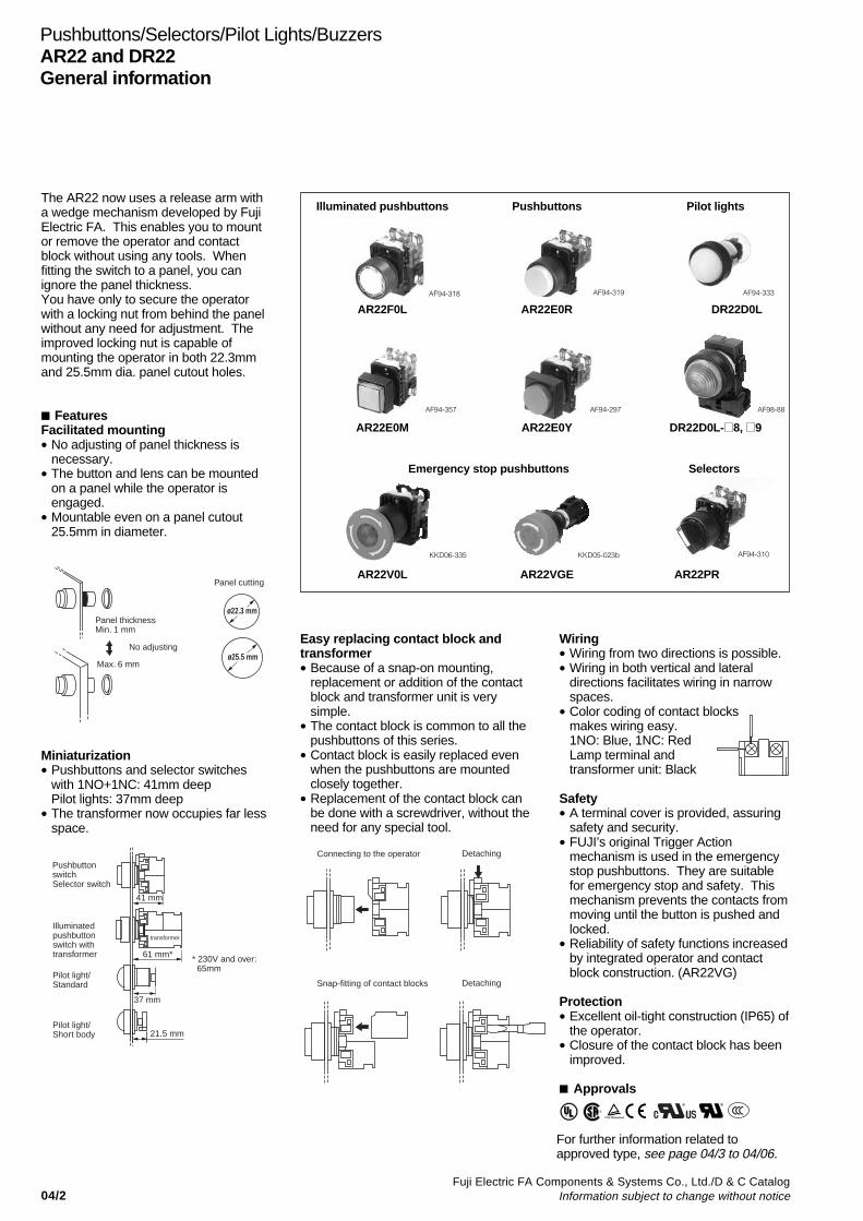
The AR22 now uses a release arm witha wedge mechanism developed by FujiElectric FA. This enables you to mountor remove the operator and contactblock without using any tools. Whenfitting the switch to a panel, you canignore the panel thickness.You have only to secure the operatorwith a locking nut from behind the panelwithout any need for adjustment. Theimproved locking nut is capable ofmounting the operator in both 22.3mmand 25.5mm dia. panel cutout holes.
FeaturesFacilitated mounting• No adjusting of panel thickness is
necessary.• The button and lens can be mounted
on a panel while the operator isengaged.
• Mountable even on a panel cutout25.5mm in diameter.
Miniaturization• Pushbuttons and selector switches
with 1NO+1NC: 41mm deepPilot lights: 37mm deep
• The transformer now occupies far lessspace.
Illuminated pushbuttons Pushbuttons Pilot lights
AR22F0L AR22E0R DR22D0L
AR22E0M AR22E0Y DR22D0L- 8, 9
AF94-318 AF94-319 AF94-333
AF94-357 AF94-297
Easy replacing contact block andtransformer• Because of a snap-on mounting,
replacement or addition of the contactblock and transformer unit is verysimple.
• The contact block is common to all thepushbuttons of this series.
• Contact block is easily replaced evenwhen the pushbuttons are mountedclosely together.
• Replacement of the contact block canbe done with a screwdriver, without theneed for any special tool.
Wiring• Wiring from two directions is possible.• Wiring in both vertical and lateral
directions facilitates wiring in narrowspaces.
• Color coding of contact blocksmakes wiring easy.1NO: Blue, 1NC: RedLamp terminal andtransformer unit: Black
Safety• A terminal cover is provided, assuring
safety and security.• FUJI’s original Trigger Action
mechanism is used in the emergencystop pushbuttons. They are suitablefor emergency stop and safety. Thismechanism prevents the contacts frommoving until the button is pushed andlocked.
• Reliability of safety functions increasedby integrated operator and contactblock construction. (AR22VG)
Protection• Excellent oil-tight construction (IP65) of
the operator.• Closure of the contact block has been
improved.
Approvals
AF98-88
Selectors
AR22V0L AR22VGE AR22PR
KKD06-335
Panel thicknessMin. 1 mm
No adjusting
Max. 6 mm
ø22.3 mm
Panel cutting
ø25.5 mm
41 mm
PushbuttonswitchSelector switch
Illuminatedpushbuttonswitch withtransformer
Pilot light/Standard
Pilot light/Short body
61 mm*
37 mm
21.5 mm
transformer
* 230V and over: 65mm
Connecting to the operator Detaching
Snap-fitting of contact blocks Detaching
S
KKD05-023b AF94-310
Emergency stop pushbuttons
For further information related toapproved type, see page 04/3 to 04/06.
04/3Fuji Electric FA Components & Systems Co., Ltd./D & C CatalogInformation subject to change without notice
04
Pushbuttons/Selectors/Pilot Lights/BuzzersAR22 and DR22
Quick reference guide
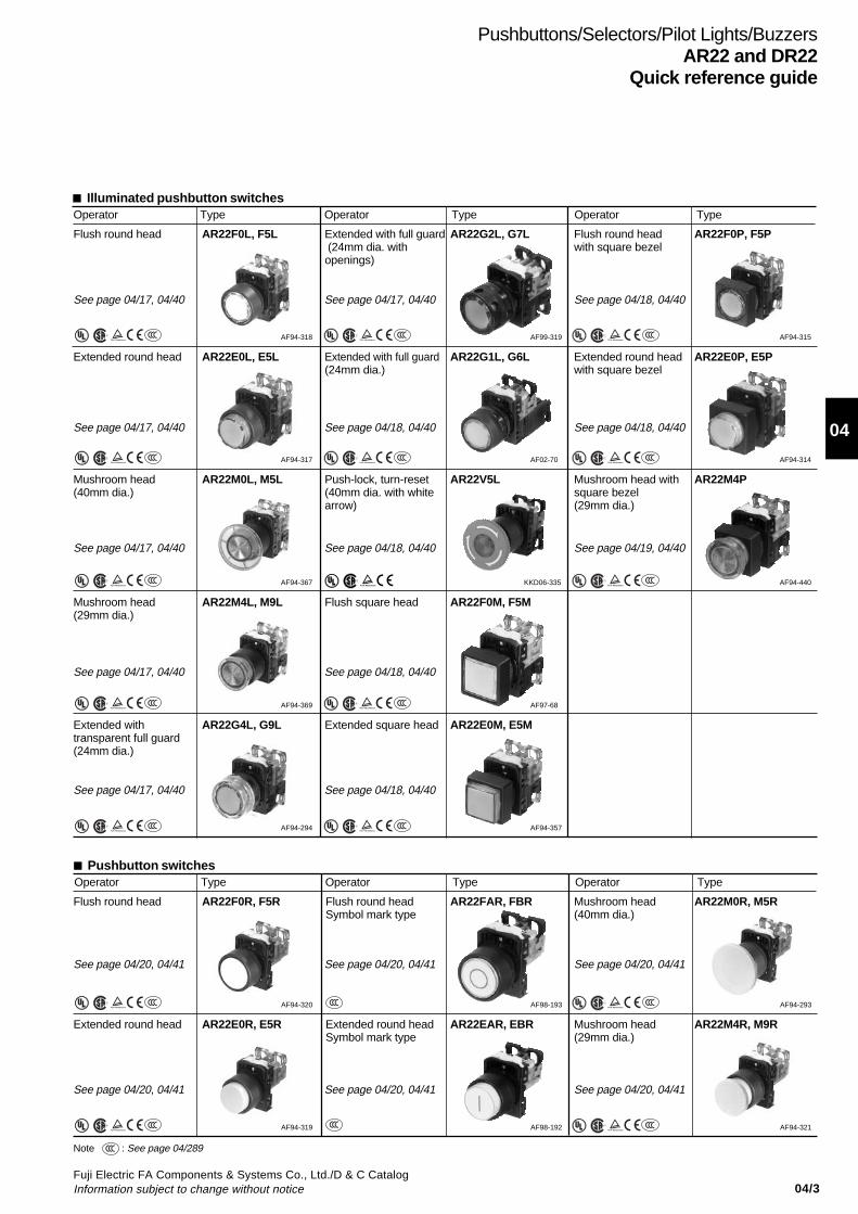
Illuminated pushbutton switchesOperator Type Operator Type Operator Type
Pushbutton switchesOperator Type Operator Type Operator Type
Flush round head AR22F0L, F5L
S
Extended round head AR22E0L, E5L
S
Mushroom head(40mm dia.)
AR22M0L, M5L
S
Mushroom head(29mm dia.)
AR22M4L, M9L
S
Extended withtransparent full guard(24mm dia.)
AR22G4L, G9L
S
Extended with full guard (24mm dia. withopenings)
AR22G2L, G7L
S
Flush round headwith square bezel
AR22F0P, F5P
S
Extended with full guard(24mm dia.)
AR22G1L, G6L
S
Extended round headwith square bezel
AR22E0P, E5P
S
Push-lock, turn-reset(40mm dia. with whitearrow)
AR22V5L Mushroom head withsquare bezel(29mm dia.)
AR22M4P
S
Flush square head AR22F0M, F5M
S
Extended square head AR22E0M, E5M
S
Flush round head AR22F0R, F5R
S
Flush round headSymbol mark type
AR22FAR, FBR Mushroom head(40mm dia.)
AR22M0R, M5R
S
Extended round head AR22E0R, E5R
S
Extended round headSymbol mark type
AR22EAR, EBR Mushroom head(29mm dia.)
AR22M4R, M9R
S
AF94-318 AF99-319 AF94-315
AF94-317 AF02-70 AF94-314
AF94-367 KKD06-335 AF94-440
AF94-369 AF97-68
AF94-294 AF94-357
AF94-320 AF98-193 AF94-293
AF94-319 AF98-192 AF94-321
See page 04/17, 04/40 See page 04/17, 04/40 See page 04/18, 04/40
See page 04/17, 04/40 See page 04/18, 04/40 See page 04/18, 04/40
See page 04/17, 04/40 See page 04/18, 04/40 See page 04/19, 04/40
See page 04/17, 04/40 See page 04/18, 04/40
See page 04/17, 04/40 See page 04/18, 04/40
See page 04/20, 04/41 See page 04/20, 04/41 See page 04/20, 04/41
See page 04/20, 04/41 See page 04/20, 04/41 See page 04/20, 04/41
Note : See page 04/289S
S
S

04/4Fuji Electric FA Components & Systems Co., Ltd./D & C Catalog
Information subject to change without notice
Pushbuttons/Selectors/Pilot Lights/BuzzersAR22 and DR22Quick reference guide
Pushbutton switchesOperator Type Operator Type Operator Type
Emergency stop pushbutton switches (conform to EN418)Operator Type Operator Type Operator Type
Extended with full guard(24mm dia.)
AR22G3R, G8R
S
Flush with full guard(24mm dia.)
AR22G2R, G7R
S
Extended withhalf guard
AR22G0R, G5R
S
Flush round headwith square bezel
AR22F0Y, F5Y
S
Extended roundhead with squarebezel
AR22E0Y, E5Y
S
Flush square head AR22F0S, F5S
S
Mushroom head withsquare bezel(29mm dia.)
AR22M4Y
S
Extended square head AR22E0S, E5S
S
Push-lock, turn-reset(Soft-touch 40mm dia.with white arrow)
AR22V0R
S
Push-lock, turn-reset(29mm dia.)
AR22V4R Unibody push-lock,turn-reset(Soft-touch 40mm dia.with white arrow)
AR22VGE
Push-lock, turn-reset(40mm dia.)
AR22V2R Key release push-lock,turn-reset(40mm dia.)
AR22V7R
S
AF94-292 AF94-295
AF02-68 AF94-297
AF94-316 AF94-298AF96-236
AF94-296
KKD08-042 KKD06-339 KKD05-023b
KKD05-020b KKD09-020
Push-lock, turn-reset(Soft-touch 29mm dia.with white arrow)
AR22VSR
S
Push-lock, pull-reset(35mm dia.)
AR22Q2R
S
KKD06-346 KKD06-334
See page 04/20, 04/41 See page 04/22, 04/41 See page 04/20, 04/41
See page 04/20, 04/41 See page 04/20, 04/41 See page 04/21, 04/41
See page 04/20, 04/41 See page 04/20, 04/41 See page 04/21, 04/41
See page 04/20, 04/41 See page 04/20, 04/41
See page 04/23, 04/42 See page 04/23, 04/42 See page 04/23, 04/42
See page 04/23, 04/42 See page 04/23, 04/42
See page 04/23, 04/42 See page 04/23, 04/42
Pushbutton withselector ring (2-position)
AR22S1R, S2R, S3R,S6R
S
AF97-507
Push-lock, turn-reset(40mm dia. with whitearrow)
AR22V5R
S
KKD08-042
Mushroom head withfull guard (40mm dia.)
AR22M3R, M8R
S
AF94-372
Note: AR22M8R: Not approved standard
Notes: Provided with the (Direct opening action) : See page 04/289S
S
Push-lock, turn-reset(40mm dia. with "EMO" charactor)
AR22V3R- RZ286
KKD05-261
See page 04/120
S
S
04/5Fuji Electric FA Components & Systems Co., Ltd./D & C CatalogInformation subject to change without notice
04
KKD09-018
Pushbuttons/Selectors/Pilot Lights/BuzzersAR22 and DR22
Quick reference guide
Key with square bezel AR22JY, JCY
S
KKD09-019
Cylindrical knobwith square bezel
AR22RY, RCY
S
AF94-362
Lever with square bezel AR22WY, WCY
S
AF94-323
Lever AR22WR, WCR
S
AF94-324
Cylindrical knob AR22RR, RCR
S
AF94-308
Knob with square bezel AR22PY, PCY
S
AF94-309
Key (Long durability) AR22JAR
S
KKD09-015
Illuminated selector switchesOperator Type Operator Type
Knob AR22PL
S
Knob with square bezel AR22PP
S
AF94-306 AF94-318
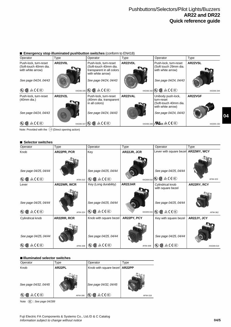
Emergency stop illuminated pushbutton switches (conform to EN418)Operator Type Operator Type Operator Type
Push-lock, turn-reset(Soft-touch 40mm dia.with white arrow)
AR22V0L
S
Push-lock, turn-reset(Soft-touch 40mm dia.transparent in all colorswith white arrow)
AR22VDL
S
Push-lock, turn-reset(Soft touch 29mm dia.with white arrow)
AR22VSL
S
Push-lock, turn-reset(40mm dia.)
AR22V2L
S
Push-lock, turn-reset(40mm dia. transparentin all colors)
AR22VAL
S
Unibody push-lock,turn-reset(Soft-touch 40mm dia.with white arrow)
AR22VGF
KKD06-335 KKD06-342 KKD06-344
KKD06-337 KKD06-340 KKD05-150
Selector switchesOperator Type Operator Type Operator Type
Knob AR22PR, PCR
S
AF94-310
See page 04/24, 04/43 See page 04/24, 04/43 See page 04/24, 04/43
See page 04/24, 04/43 See page 04/24, 04/43 See page 04/24, 04/43
Note: Provided with the (Direct opening action)
See page 04/25, 04/44 See page 04/25, 04/44 See page 04/25, 04/44
See page 04/25, 04/44 See page 04/25, 04/44 See page 04/25, 04/44
See page 04/25, 04/44 See page 04/25, 04/44 See page 04/25, 04/44
See page 04/32, 04/45 See page 04/32, 04/45
Note : See page 04/289S
S
Key AR22JR, JCR
S

04/6Fuji Electric FA Components & Systems Co., Ltd./D & C Catalog
Information subject to change without notice
Pushbuttons/Selectors/Pilot Lights/BuzzersAR22 and DR22Quick reference guide
Pilot lightsLens Type Lens Type Lens Type
Dome DR22D0L
S
Flush square DR22F3M
S
Extended square DR22E3M
S
Extended round DR22E3L
S
Flush square(Transparent lens)
DR22F4M
S
AF94-333 AF94-330 AF94-380
AF94-332 AF94-443
Faceted DR22K0L
S
Flush square(12mm high frame)
DR22F5M
S
AF96-189 AF95-658
Flush rectangular DR22E3N
S
AF96-237
Extended roundwith square bezel
DR22E3P
S
AF94-331
Joy stick selector switchesHandle Type Handle Type Handle Type
Ball type AR22A0, A5
AF97-49
BuzzersSound Type Sound Type Sound Type
Electronic sound DR22B5 * Magnetic sound DR22B3 Electronic sound(IP54)
DR22B8 *
KKD08-053 AF96-376 AF96-244
Note: With resistor unit type: Not approved standard
Rubber cap type AR22A2, A7
AF97-56
Ball type with lock AR22A1, A6
AF97-45
Note: * 6V AC, 110V DC types: Not approved standard
See page 04/34, 04/45 See page 04/34, 04/47 See page 04/34, 04/46
See page 04/34, 04/46 See page 04/34, 04/47 See page 04/34, 04/48
See page 04/34, 04/46 See page 04/34, 04/47 See page 04/34, 04/46
See page 04/38, 04/48 See page 04/38, 04/48 See page 04/38, 04/49
See page 04/39, 04/49 See page 04/39, 04/49 See page 04/39, 04/49
Note : See page 04/289S
04/7Fuji Electric FA Components & Systems Co., Ltd./D & C CatalogInformation subject to change without notice
04
Pushbuttons/Selectors/Pilot Lights/BuzzersAR22 and DR22
Type number nomenclature
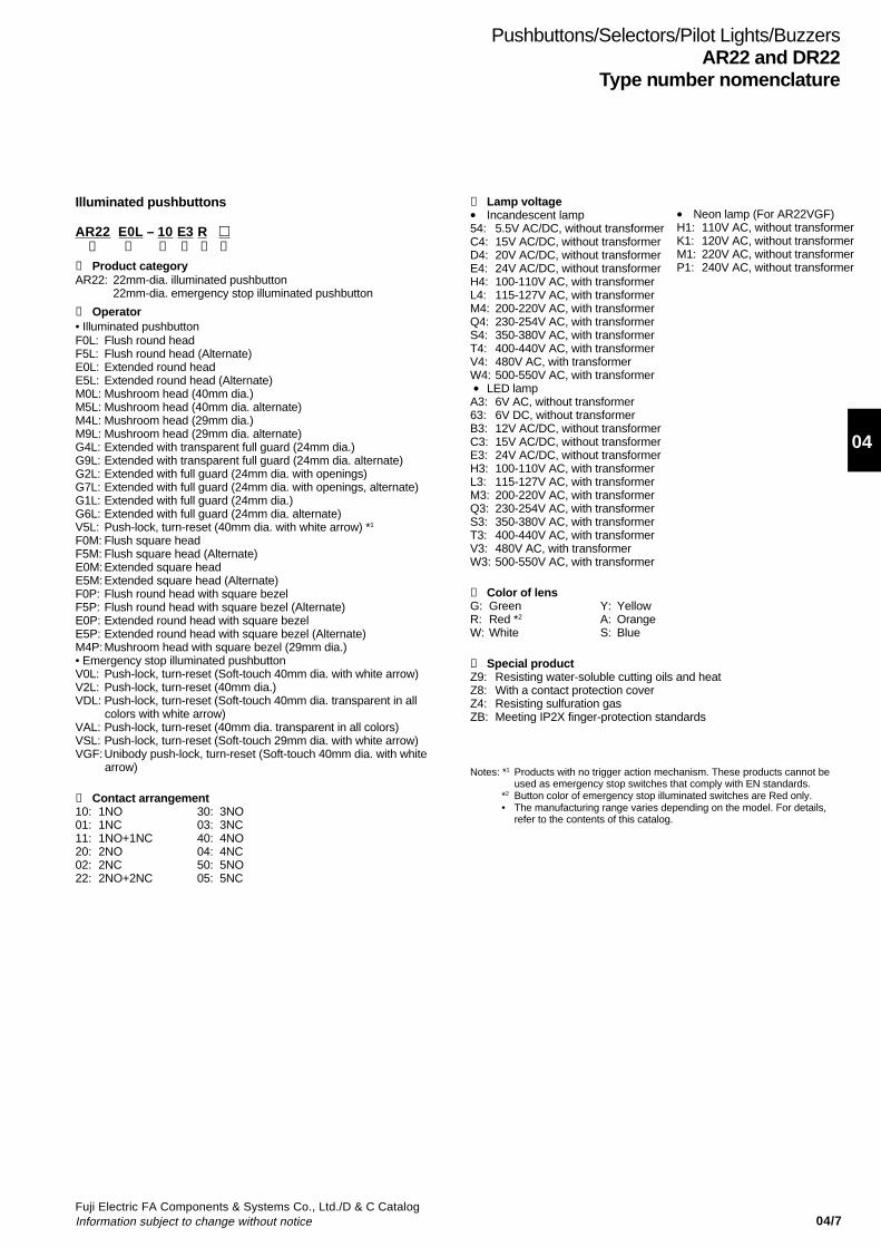
Illuminated pushbuttons
AR22 E0L – 10 E3 R ➀ ➁ ➂ ➃ ➄ ➅
➀ Product categoryAR22: 22mm-dia. illuminated pushbutton
22mm-dia. emergency stop illuminated pushbutton
➁ Operator• Illuminated pushbuttonF0L: Flush round headF5L: Flush round head (Alternate)E0L: Extended round headE5L: Extended round head (Alternate)M0L: Mushroom head (40mm dia.)M5L: Mushroom head (40mm dia. alternate)M4L: Mushroom head (29mm dia.)M9L: Mushroom head (29mm dia. alternate)G4L: Extended with transparent full guard (24mm dia.)G9L: Extended with transparent full guard (24mm dia. alternate)G2L: Extended with full guard (24mm dia. with openings)G7L: Extended with full guard (24mm dia. with openings, alternate)G1L: Extended with full guard (24mm dia.)G6L: Extended with full guard (24mm dia. alternate)V5L: Push-lock, turn-reset (40mm dia. with white arrow) *1
F0M: Flush square headF5M: Flush square head (Alternate)E0M:Extended square headE5M:Extended square head (Alternate)F0P: Flush round head with square bezelF5P: Flush round head with square bezel (Alternate)E0P: Extended round head with square bezelE5P: Extended round head with square bezel (Alternate)M4P:Mushroom head with square bezel (29mm dia.)• Emergency stop illuminated pushbuttonV0L: Push-lock, turn-reset (Soft-touch 40mm dia. with white arrow)V2L: Push-lock, turn-reset (40mm dia.)VDL: Push-lock, turn-reset (Soft-touch 40mm dia. transparent in all
colors with white arrow)VAL: Push-lock, turn-reset (40mm dia. transparent in all colors)VSL: Push-lock, turn-reset (Soft-touch 29mm dia. with white arrow)VGF:Unibody push-lock, turn-reset (Soft-touch 40mm dia. with white
arrow)
➂ Contact arrangement10: 1NO 30: 3NO01: 1NC 03: 3NC11: 1NO+1NC 40: 4NO20: 2NO 04: 4NC02: 2NC 50: 5NO22: 2NO+2NC 05: 5NC
➃ Lamp voltage• Incandescent lamp54: 5.5V AC/DC, without transformerC4: 15V AC/DC, without transformerD4: 20V AC/DC, without transformerE4: 24V AC/DC, without transformerH4: 100-110V AC, with transformerL4: 115-127V AC, with transformerM4: 200-220V AC, with transformerQ4: 230-254V AC, with transformerS4: 350-380V AC, with transformerT4: 400-440V AC, with transformerV4: 480V AC, with transformerW4: 500-550V AC, with transformer • LED lampA3: 6V AC, without transformer63: 6V DC, without transformerB3: 12V AC/DC, without transformerC3: 15V AC/DC, without transformerE3: 24V AC/DC, without transformerH3: 100-110V AC, with transformerL3: 115-127V AC, with transformerM3: 200-220V AC, with transformerQ3: 230-254V AC, with transformerS3: 350-380V AC, with transformerT3: 400-440V AC, with transformerV3: 480V AC, with transformerW3: 500-550V AC, with transformer
➄ Color of lensG: Green Y: YellowR: Red *2 A: OrangeW: White S: Blue
➅ Special productZ9: Resisting water-soluble cutting oils and heatZ8: With a contact protection coverZ4: Resisting sulfuration gasZB: Meeting IP2X finger-protection standards
• Neon lamp (For AR22VGF)H1: 110V AC, without transformerK1: 120V AC, without transformerM1: 220V AC, without transformerP1: 240V AC, without transformer
Notes: *1 Products with no trigger action mechanism. These products cannot beused as emergency stop switches that comply with EN standards.
*2 Button color of emergency stop illuminated switches are Red only.• The manufacturing range varies depending on the model. For details,
refer to the contents of this catalog.

04/8Fuji Electric FA Components & Systems Co., Ltd./D & C Catalog
Information subject to change without notice
Pushbuttons/Selectors/Pilot Lights/BuzzersAR22 and DR22Type number nomenclature
Pushbuttons
AR22 E0R – 10 R ➀ ➁ ➂ ➃ ➄ ➅
➀ Product categoryAR22: 22mm-dia. pushbutton
22mm-dia. emergency stop pushbutton
➁ Operator • Pushbutton switchF0R: Flush round headF5R: Flush round head (Alternate)E0R: Extended round headE5R: Extended round head (Alternate)FAR: Flush round head (Symbol mark type)FBR: Flush round head (Symbol mark type, alternate)EAR:Extended round head (Symbol mark type)EBR:Extended round head (Symbol mark type, alternate)M0R: Mushroom head (40mm dia.)M5R: Mushroom head (40mm dia. Alternate)M4R: Mushroom head (29mm dia.)M9R: Mushroom head (29mm dia. Alternate)G3R:Extended with full guard (24mm dia.)G8R:Extended with full guard (24mm dia. Alternate)G2R:Flush with full guard (24mm dia.)G7R:Flush with full guard (24mm dia. Alternate)G0R:Extended with half guardG5R:Extended with half guard (Alternate)M3R:Mushroom head with full guard (40mm dia.)M8R:Mushroom head with full guard (40mm dia. Alternate)S1R: Push-button with selector ring (2-position)S2R: Push-button with selector ring (2-position)S3R: Push-button with selector ring (2-position)S6R: Push-button with selector ring (2-position)V5R: Push-lock, turn-reset (40mm dia. with white arrow) *1
F0S: Flush square headF5S: Flush square head (Alternate)E0S: Extended square headE5S: Extended square head (Alternate)F0Y: Flush round head with square bezelF5Y: Flush round head with square bezel (Alternate)E0Y: Extended round head with square bezelE5Y: Extended round head with square bezel (Alternate)M4Y:Mushroom head with square bezel (29mm dia.) • Emergency stop pushbutton switchV0R: Push-lock, turn-reset (Soft-touch 40mm dia. with white arrow)V2R: Push-lock, turn-reset (40mm dia.)VSR:Push-lock, turn-reset (Soft-touch 29mm dia. with white arrow)V4R: Push-lock, turn-reset (29mm dia.)V7R: Key-release push-lock, turn-reset (40mm dia.)Q2R:Push-lock, pull-reset (35mm dia.)VGE:Unibody push-lock, turn-reset (Soft-touch 40mm dia. with white
arrow)
➂ Contact arrangement10: 1NO 30: 3NO01: 1NC 03: 3NC11: 1NO+1NC 33: 3NO+3NC20: 2NO 40: 4NO02: 2NC 04: 4NC22: 2NO+2NC 50: 5NO
05: 5NC
➃ Color of buttonG: Green Y: YellowR: Red*2 A: OrangeB: Black S: BlueW: White C: ClearT: Green, Red, Black (For AR22F0R) (For AR22FAR, FBR,
EAR, EBR)
➄ Symbol mark (For AR22FAR, FBR, EAR, EBR)Symbol mark I T I T
Color of button White Black White Black White Black ClearColor of mark Red Green Green BlackCode 01 02 03 04 11 12 02B 04B 12B
➅ Special productZ9: Resisting water-soluble cutting oils and heatZ8: With a contact protection coverZ4: Resisting sulfuration gasZB: Meeting IP2X finger-protection standards
Notes: *1 Products with no trigger action mechanism. These products cannot beused as emergency stop switches that comply with EN standards.
*2 Button color of emergency stop switches are Red only.• The manufacturing range varies depending on the model. For details,
refer to the contents of this catalog.
04/9Fuji Electric FA Components & Systems Co., Ltd./D & C CatalogInformation subject to change without notice
04
Pushbuttons/Selectors/Pilot Lights/BuzzersAR22 and DR22
Type number nomenclature
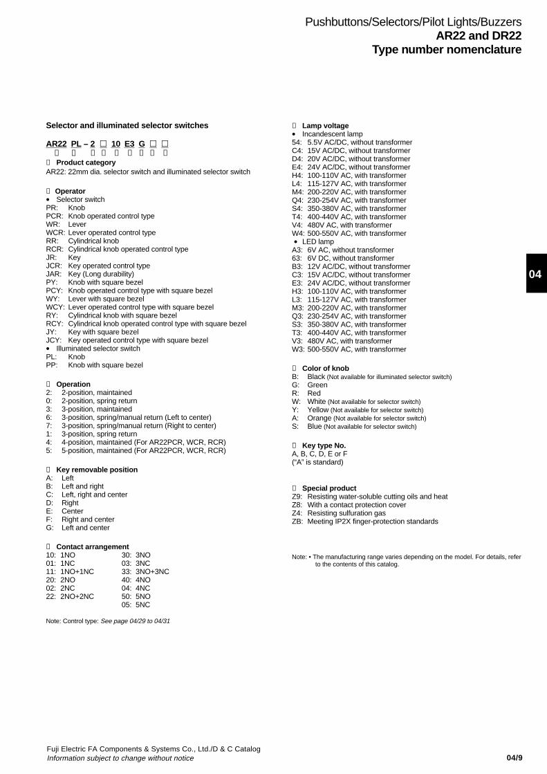
Selector and illuminated selector switches
AR22 PL – 2 10 E3 G ➀ ➁ ➂ ➃ ➄ ➅ ➆ ➇ ➈
➀ Product categoryAR22: 22mm dia. selector switch and illuminated selector switch
➁ Operator• Selector switchPR: KnobPCR: Knob operated control typeWR: LeverWCR: Lever operated control typeRR: Cylindrical knobRCR: Cylindrical knob operated control typeJR: KeyJCR: Key operated control typeJAR: Key (Long durability)PY: Knob with square bezelPCY: Knob operated control type with square bezelWY: Lever with square bezelWCY: Lever operated control type with square bezelRY: Cylindrical knob with square bezelRCY: Cylindrical knob operated control type with square bezelJY: Key with square bezelJCY: Key operated control type with square bezel• Illuminated selector switchPL: KnobPP: Knob with square bezel
➂ Operation2: 2-position, maintained0: 2-position, spring return3: 3-position, maintained6: 3-position, spring/manual return (Left to center)7: 3-position, spring/manual return (Right to center)1: 3-position, spring return4: 4-position, maintained (For AR22PCR, WCR, RCR)5: 5-position, maintained (For AR22PCR, WCR, RCR)
➃ Key removable positionA: LeftB: Left and rightC: Left, right and centerD: RightE: CenterF: Right and centerG: Left and center
➄ Contact arrangement10: 1NO 30: 3NO01: 1NC 03: 3NC11: 1NO+1NC 33: 3NO+3NC20: 2NO 40: 4NO02: 2NC 04: 4NC22: 2NO+2NC 50: 5NO
05: 5NC
Note: Control type: See page 04/29 to 04/31
➅ Lamp voltage• Incandescent lamp54: 5.5V AC/DC, without transformerC4: 15V AC/DC, without transformerD4: 20V AC/DC, without transformerE4: 24V AC/DC, without transformerH4: 100-110V AC, with transformerL4: 115-127V AC, with transformerM4: 200-220V AC, with transformerQ4: 230-254V AC, with transformerS4: 350-380V AC, with transformerT4: 400-440V AC, with transformerV4: 480V AC, with transformerW4: 500-550V AC, with transformer • LED lampA3: 6V AC, without transformer63: 6V DC, without transformerB3: 12V AC/DC, without transformerC3: 15V AC/DC, without transformerE3: 24V AC/DC, without transformerH3: 100-110V AC, with transformerL3: 115-127V AC, with transformerM3: 200-220V AC, with transformerQ3: 230-254V AC, with transformerS3: 350-380V AC, with transformerT3: 400-440V AC, with transformerV3: 480V AC, with transformerW3: 500-550V AC, with transformer
➆ Color of knobB: Black (Not available for illuminated selector switch)G: GreenR: RedW: White (Not available for selector switch)Y: Yellow (Not available for selector switch)A: Orange (Not available for selector switch)S: Blue (Not available for selector switch)
➇ Key type No.A, B, C, D, E or F(“A” is standard)
➈ Special productZ9: Resisting water-soluble cutting oils and heatZ8: With a contact protection coverZ4: Resisting sulfuration gasZB: Meeting IP2X finger-protection standards
Note: • The manufacturing range varies depending on the model. For details, referto the contents of this catalog.
04/10Fuji Electric FA Components & Systems Co., Ltd./D & C Catalog
Information subject to change without notice
Pushbuttons/Selectors/Pilot Lights/BuzzersAR22 and DR22Type number nomenclature
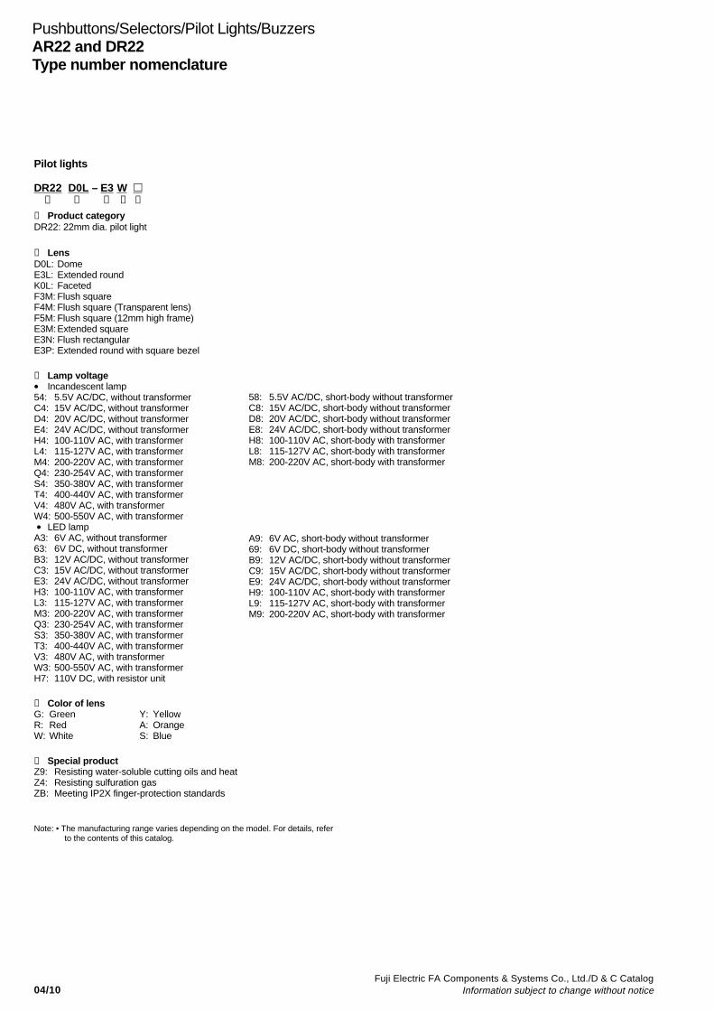
Pilot lights
DR22 D0L – E3 W ➀ ➁ ➂ ➃ ➄
➀ Product categoryDR22: 22mm dia. pilot light
➁ LensD0L: DomeE3L: Extended roundK0L: FacetedF3M: Flush squareF4M: Flush square (Transparent lens)F5M: Flush square (12mm high frame)E3M:Extended squareE3N: Flush rectangularE3P: Extended round with square bezel
➂ Lamp voltage• Incandescent lamp54: 5.5V AC/DC, without transformerC4: 15V AC/DC, without transformerD4: 20V AC/DC, without transformerE4: 24V AC/DC, without transformerH4: 100-110V AC, with transformerL4: 115-127V AC, with transformerM4: 200-220V AC, with transformerQ4: 230-254V AC, with transformerS4: 350-380V AC, with transformerT4: 400-440V AC, with transformerV4: 480V AC, with transformerW4: 500-550V AC, with transformer • LED lampA3: 6V AC, without transformer63: 6V DC, without transformerB3: 12V AC/DC, without transformerC3: 15V AC/DC, without transformerE3: 24V AC/DC, without transformerH3: 100-110V AC, with transformerL3: 115-127V AC, with transformerM3: 200-220V AC, with transformerQ3: 230-254V AC, with transformerS3: 350-380V AC, with transformerT3: 400-440V AC, with transformerV3: 480V AC, with transformerW3: 500-550V AC, with transformerH7: 110V DC, with resistor unit
➃ Color of lensG: Green Y: YellowR: Red A: OrangeW: White S: Blue
➄ Special productZ9: Resisting water-soluble cutting oils and heatZ4: Resisting sulfuration gasZB: Meeting IP2X finger-protection standards
Note: • The manufacturing range varies depending on the model. For details, referto the contents of this catalog.
58: 5.5V AC/DC, short-body without transformerC8: 15V AC/DC, short-body without transformerD8: 20V AC/DC, short-body without transformerE8: 24V AC/DC, short-body without transformerH8: 100-110V AC, short-body with transformerL8: 115-127V AC, short-body with transformerM8: 200-220V AC, short-body with transformer
A9: 6V AC, short-body without transformer69: 6V DC, short-body without transformerB9: 12V AC/DC, short-body without transformerC9: 15V AC/DC, short-body without transformerE9: 24V AC/DC, short-body without transformerH9: 100-110V AC, short-body with transformerL9: 115-127V AC, short-body with transformerM9: 200-220V AC, short-body with transformer

04/11Fuji Electric FA Components & Systems Co., Ltd./D & C CatalogInformation subject to change without notice
04
Pushbuttons/Selectors/Pilot Lights/BuzzersAR22 and DR22
Type number nomenclature
Buzzers
DR22B 5 – E B➀ ➁ ➂ ➃
➀ Product categoryDR22B: 22mm-dia. buzzer
➁ Sound5: Electronic sound3: Magnetic sound8: Electronic sound (IP54)
➂ Operating voltageA: 6V AC (Type “5”, “8”)6: 6V DC (Type “5”, “8”)E: 12-24V AC/DC (Type “3” : 24V AC/DC)F: 35-48V AC/DC (Type “5”, “8”)H: 100-110V ACM: 200-220V AC1: 100-110V DC (Type “5”, “8”)
➃ Color of headB: Black
Joy stick selector switches
AR22A 0 N – A0A0 B ➀ ➁➂ ➃ ➄
➀ Product categoryAR22A: 22mm-dia. Joy stick selector switch
➁ Handle0: Ball type (without lock, manual return)1: Ball type with lock (manual return)2: Rubber cap type (without lock, manual return)5: Ball type (without lock, spring return)6: Ball type with lock (spring return)7: Rubber cap type (without lock, spring return)
➂ TerminalN: ScrewH: Solder/tab
➃ Contact arrangement
Contact arrangement Blank 1NO 1NC 1NO+1NC 2NO 2NC 2NO+2NC
Code Screw 0 A B 1 D E –
Solder/tab 0 – – 1 – – 2
Operating direction code of contacts
1
2
34
1: Upper 2: Right3: Lower 4: Left
Locked position Ex. AR22A0N-A 0 A 0 B1 2 3 4
➄ Handle colorB: Black
Ordering informationSpecify the following:1. Type number
For the CCC approved product, add the suffix (CCC) to the type number
Example: Pushbutton switch AR22F0R-11B(CCC)
Discontinued
Discontinued
DiscontinuedDiscontinued
Discontinued

04/12Fuji Electric FA Components & Systems Co., Ltd./D & C Catalog
Information subject to change without notice
Pushbuttons/Selectors/Pilot Lights/BuzzersAR22 and DR22Ratings and specifications
Specifications (Indoor use)
Description Pushbutton switch Illuminated pushbutton switchEmergency stop pushbutton switchEmergency stop illuminated pushbutton switchSelector switchIlluminated selector switch
Joy stick selector(Lever switch)
Pilot light
Rated insulation voltageMechanical durability Electrical durability
Operating frequency
Dielectric strengthInsulation resistanceRated impulse dielectric strengthConditional short-circuit currentShort-circuit protective devicePollution degreeVibration
Shock
Ambient temperature(No condensation or no icing)Storage temperatureHumidityDegree of protection
600V AC/DC *1
See page 04/13500,000 operations at 220V AC 6A1 million operations at 220V AC 3A(AR22VG type: 100,000 operations)1200 operations/hour (On-load factor: 40%)AR22VG type: 1800 operations/hour (On-load factor: 40%)2500V AC, 1 minute *3
100MΩ or more (500V DC megger)6kV (AR22VG type: 4kV)1000AFuse 15A3Resonance: 10 to 55Hz, double amplitude 0.1mm *5
Constant: 16.7Hz, double amplitude 3mmMalfunction durability: 100m/s2 *6
Mechanical durability: 500m/s2
-20 to +70°C *7
-40 to +80°C45 to 85% RH (within -5 to +40°C)IP65
250V AC/DC250,000 operations100,000 operationsat 220V AC 1A (Res. load)
2000V AC, 1 minute *4
–1000AFuse 1A
-5 to +70°C
250V AC/DC *2
––
–
6kV––
Mechanical durability: 500m/s2
-20 to +50°C
Notes: *1 Illuminated type without transformer and AR22VG type: 250V AC/DC *2 Pilot light with transformer: 600V AC *3 Illuminated type without transformer: 2000V AC, 1 minute (except AR22VGF type) *4 Pilot light with transformer: 2500V AC, 1 minute *5 Emergency stop type: 10 to 500Hz, double amplitude 0.7mm (acceleration 50m/s2), according to the test condition of EN60947-5-5 (1997) *6 Emergency stop type: 150m/s2
*7 AR22VGE type: -20 to +60°C, illuminated type: -20 to +50°C
Standards approved
UL508CSA C22.2 No.14
TÜV: EN60947-5-1
TÜV: EN60947-5-1 EN60947-5-5
File No. E44592File No. LR20479cUL File No. E44592 (For AR22VG)Pushbutton, Illuminated pushbutton: R9551062, Selector, Illuminated selector: R9551060Pilot lights: R9551061Joy stick selector switch: R2050803(Lever switch)Buzzer: J9950091Emergency stop pushbuttonEmergency stop illuminated pushbutton: R50028146, R50028137 (For AR22VG)

04/13Fuji Electric FA Components & Systems Co., Ltd./D & C CatalogInformation subject to change without notice
04
Pushbuttons/Selectors/Pilot Lights/BuzzersAR22 and DR22
Ratings and specifications
BuzzersItem DR22B5 DR22B3 DR22B8
Rated insulation voltage Without transformer: 60V AC/DC With transformer: 250V AC
Sound level 90dB (0.1m) 80 to 90dB (0.1m) 80dB (0.1m)70dB (1m) 60 to 70dB (1m) 60dB (1.0m)
Durability 1000h 200h 1000h
Frequency 2.4 to 3.3kHz
Intermittent cycle Approx. 170-cycle/min
Current consumption See the table below
Dielectric strength Without transformer: 1000V AC 1 minute With transformer: 2000V AC 1 minute
Insulation resistance 100MΩ or more (500V DC megger)
Pollution degree 3
Vibration Resonance: 10 to 55Hz, double amplitude 0.1mmConstant: 16.7Hz, double amplitude 3.0mm
Shock Mechanical durability: 500m/s2
Ambient temperature –20 to +60˚C (No condensation or no icing)(with resistor unit: –20 to +40˚C)
Storage temperature –30 to +70˚C
Humidity 45 to 85%RH (within –5 to 40˚C)
Degree of protection IP00 IP54
Mechanical durabilityDescription Operations
Pushbutton switch Momentary action 5 millionIlluminated pushbutton switch Alternate action 1 millionEmergency stop pushbutton switch With selector ring 100,000Emergency stop illuminated pushbutton Push-lock, turn-reset 100,000
Push-lock, pull-reset 30,000
Selector switch Maintained 1, 2, 3, 4-contact 1 millionMaintained 5, 6-contact 500,000Control type, spring return, spring/manual return 200,000
Illuminated selector switch Maintained Without transformer 1, 2, 3-contact 1 million
4-contact 500,000 With transformer 1, 2-contact 1 million
3-contact 500,000
Spring return, spring/manual return 200,000
Note: Key insertion/removal durability for selector switch key types• Key type 10,000• Key (Long durability) type 20,000
• Current consumptionOperational voltage
6V AC6V DC24V AC/DC48V AC/DC110V AC110V DC220V AC
Current consumptionDR22B5, DR22B870mA AC35mA DC40mA AC, 25mA DC65mA AC, 20mA DC30mA AC30mA DC15mA AC
DR22B3––30mA AC, 20mA DC–30mA AC –15mA AC
Discontinued
Discontinued
Discontinued
Discontinued Discontinued

04/14Fuji Electric FA Components & Systems Co., Ltd./D & C Catalog
Information subject to change without notice
Pushbuttons/Selectors/Pilot Lights/BuzzersAR22 and DR22Ratings and specifications
EN standard/TÜV approved
Rated operational currentDescription
Rated thermal Rated operational AC15 (Ind. load) DC13 (Ind. load)current voltage Rated operational current Rated operational current
Illuminated pushbutton switch 10A 24V 6.0A 4.0A (AR22VG: 1.5A)
Pushbutton (Except the selector ring type) 120V 6.0A (AR22VG: 3A) –
Emergency stop pushbutton switch 125V – 1.3A (AR22VG: 0.3A)
Emergency stop illuminated pushbutton switch 240V 6.0A (AR22VG: 3A) –
Selector switch (2-position) 250V – 0.45A(AR22VG: 0.15A)
Illuminated selector switch (2-position) 480V 2.5A (AR22VG: –) –
600V 2.0A (AR22VG: –) –
Selector switch (3, 4, 5-position) 10A 24V 6.0A 2.0A
Illuminated selector switch (3-position) 120V 6.0A –
Pushbutton with selector ring 125V – 0.65A
240V 6.0A –
250V – 0.23A
480V 2.5A –
600V 2.0A –
Joy stick selector switch (Lever switch) 5A 24V – 0.7A
120V 0.3A –
125V – 0.15A
240V 0.3A –
DC T0.95= 6P (Max. 300ms)
Description Contact rated Making current · Breaking currentcode
125V 250V 301V–600V
Illuminated pushbutton switch P600 1.1A 0.55A 0.2APushbutton(Ring type selector switch: AR22S2R only)Emergency stop pushbutton switch
Emergency stop illuminated pushbutton switch Q300 0.55A 0.27A –(Except the overlap contact types) (AR22VG)
Overlap contact types of products shown above Q600 0.55A 0.27A 0.1APushbutton(Ring type selector switch: AR22S1R, S6R only)Selector switch (2-position only, except the overlap contact types)Illuminated selector switch(2-position only, except the overlap contact types)
Pushbutton R300 0.22A 0.11A –(Ring type selector switch: AR22S3R only)Selector switch (2-pos./overlap contact type, 3-, 4-, 5-pos. type)Illuminated selector switch (2-pos./overlap contact type, 3-pos. type)
Lamp rated voltage UL/CSA standards, TÜV approved
LED lamp Incandescent lamp Neon lamp
Full-voltage (without transformer) Max. 24V AC/DC Max. 30V AC/DC Max. 240V AC
With transformer Max. 550V AC (Short-body type: Max. 220V AC) –
Contact ratings UL/CSA standardsAC (COS ø=0.35)
Contact rated code 120V 240V 480V 600V
Making Breaking Making Breaking Making Breaking Making Breakingcurrent current current current current current current current
A600 60A 6.0A 30A 3.0A 15A 1.5A 12A 1.2A
B300 (AR22VG) 30A 3.0A 15A 1.5A – – – –
Note: Joy stick selector switches (Lever switches): 250V AC, 5A (Res. load) 125V DC, 0.2A 24V DC, 1A (Res. load)

04/15Fuji Electric FA Components & Systems Co., Ltd./D & C CatalogInformation subject to change without notice
04
Pushbuttons/Selectors/Pilot Lights/BuzzersAR22 and DR22
Ratings and specifications
Operating characteristic (1NO+1NC)
Description PushbuttonIlluminated pushbutton
Ave. required operating forceOperating travel
Required return force
9N (Push-lock type: 20N)
Approx. 6mm
(Push-lock type: Approx. 9mm, operation angle: Approx. 45°)
–(Push-lock type: 0.6N•m)
Emergency stop pushbutton Emergency stop illuminated pushbuttonPush-lock type
Selector *2
Illuminated selectorMaintained Spring/manual return Spring returnPush-pull type
30N (AR22VG: 22N)*1
Approx. 9mm
(AR22VG: Approx. 10mm, operation angle: Approx. 45°)
0.6N•m(AR22VG: 0.2N•m)
0.15N•m
2-position: Approx. 90°
3-position: Approx. 45°
4-position: Approx. 40°
5-position: Approx. 30°
0.15N•m
0.13N•m
3-position: Approx. 45°
0.13N•m
0.1N•m
2-position: Approx. 60°
3-position: Approx. 45°
–
45N
Approx. 9mm
30N (pull)
Notes: *1 AR22V2R, V4R, V7R, VAL types: 45N *2 4-position, 5-position: 2NO+2NC
Lamp ratings• Illuminated pushbuttons, illuminated selectors, pilot lights
Transformer
Without transformer
With transformer(Standard type: AR9T511)
With resistor unit(AR9T519-H)
Lamp voltage
5.5V AC/DC6V AC
6V DC
12V AC/DC
15V AC/DC
20V AC/DC24V AC/DC110V AC127V AC220V AC254V AC380V AC440V AC480V AC550V AC110V DC
LED Type–APX510-6
APX510-D6
APX510-12
APX510-15
–APX510-24APX510-6
APX510-6
APX510-24
Rated voltage–6V AC
6V DC
12V AC/DC
15V AC/DC
–24V AC/DC6V AC
6V AC
24V AC/DC
Consumption–Green, red, orange, amber, blue: 7mA ACYellow: 50mA ACGreen, red, orange, amber, blue: 11mA DCYellow: 33mA DCGreen, red, orange, amber, blue: 14mA AC,11mA DCYellow: 28mA AC, 22mA DCGreen, red, orange, amber, blue: 13mA AC,11mA DCYellow: 26mA AC, 22mA DC–12mA AC, 11mA DC1.5VA
2.5VA
1.2W
IncandescentTypeAHX135–
–
–
AHX279
AHX144AHX129AHX135
AHX135
–
Rated voltage6.3V AC/DC–
–
–
18V AC/DC
24V AC/DC30V AC/DC6.3V AC/DC
6.3V AC/DC
–
Consumption0.9W–
–
–
0.8W
0.9W0.8W2VA2VA2VA2.5VA2.5VA2.5VA2.5VA2.5VA–
Notes: • Short body pilot lights: 110V AC, 127V AC, 220V AC only• Replace the mark by the lamp luminous color code, see page 04/16• Except AR22VGF type
• Emergency stop illuminated pushbuttons (AR22VGF type)
TransformerWithout transformer
Lamp LED
Neon
Voltage 24V AC/DC
110V AC120V AC220V AC240V AC
TypeAR9L002-ER
AR9N001-HAAR9N001-KAAR9N001-MAAR9N001-PA
Rated voltage24V AC/DC
110V AC120V AC220V AC240V AC
Consumption12mA AC11mA DC0.19VA0.21VA0.30VA0.30VA
Notes: Lamp base: BA9S/13
04/16Fuji Electric FA Components & Systems Co., Ltd./D & C Catalog
Information subject to change without notice
Pushbuttons/Selectors/Pilot Lights/BuzzersAR22 and DR22Ratings and specifications
Combination of lens color and LED or neon lamp luminous color
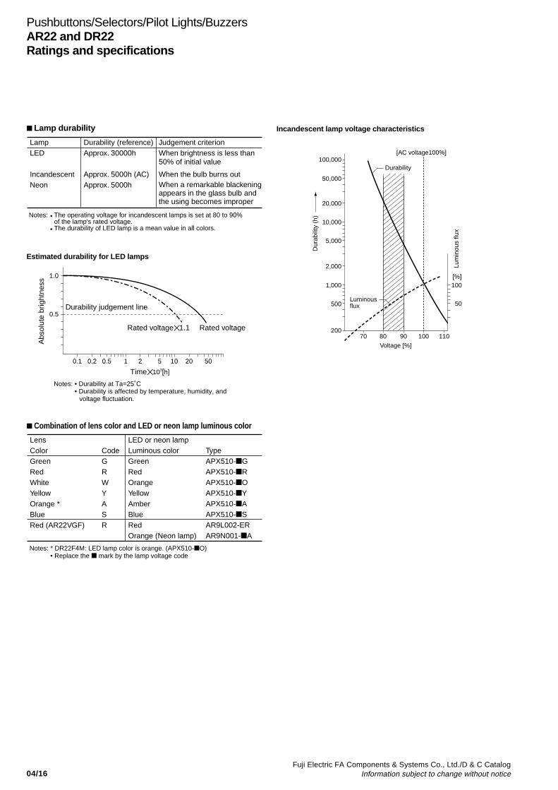
LampLED
IncandescentNeon
Durability (reference)Approx. 30000h
Approx. 5000h (AC)Approx. 5000h
Judgement criterionWhen brightness is less than 50% of initial value
When the bulb burns outWhen a remarkable blackening appears in the glass bulb and the using becomes improper
Notes: • The operating voltage for incandescent lamps is set at 80 to 90% of the lamp's rated voltage.
• The durability of LED lamp is a mean value in all colors.
Estimated durability for LED lamps
1.0
0.5
0.1 0.2 0.5 1 2 5 10 20 50
Time 103[h]
Abs
olut
e br
ight
ness
Durability judgement line
Rated voltage1.1 Rated voltage
Notes: • Durability at Ta=25˚C• Durability is affected by temperature, humidity, and
voltage fluctuation.
[AC voltage100%]100,000
50,000
20,000
10,000
5,000
2,000
1,000
500
20070 80
Voltage [%]
90 100 110
100
50
Durability
Luminous flux
Dur
abili
ty (
h)
Lum
inou
s flu
x
[%]
Incandescent lamp voltage characteristics Lamp durability
LensColorGreenRedWhiteYellowOrange *BlueRed (AR22VGF)
CodeGRWYASR
LED or neon lampLuminous colorGreenRedOrangeYellowAmberBlueRedOrange (Neon lamp)
TypeAPX510-GAPX510-RAPX510-OAPX510-YAPX510-AAPX510-SAR9L002-ERAR9N001-A
Notes: * DR22F4M: LED lamp color is orange. (APX510-O)• Replace the mark by the lamp voltage code
04/17Fuji Electric FA Components & Systems Co., Ltd./D & C CatalogInformation subject to change without notice
04
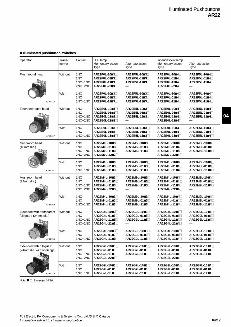
Illuminated PushbuttonsAR22
Operator Trans- Contact LED lamp Incandescent lampformer Momentary action Alternate action Momentary action Alternate action
Type Type Type Type
Flush round head Without 1NO AR22F0L-10 3 AR22F5L-103 AR22F0L-104 AR22F5L-1041NC AR22F0L-01 3 AR22F5L-013 AR22F0L-014 AR22F5L-0141NO+1NC AR22F0L-11 3 AR22F5L-113 AR22F0L-114 AR22F5L-1142NO+2NC AR22F0L-22 3 — AR22F0L-224 —
With 1NO AR22F0L-10 3 AR22F5L-103 AR22F0L-104 AR22F5L-1041NC AR22F0L-01 3 AR22F5L-013 AR22F0L-014 AR22F5L-014
AF94-318 1NO+1NC AR22F0L-11 3 AR22F5L-113 AR22F0L-114 AR22F5L-114
Extended round head Without 1NO AR22E0L-10 3 AR22E5L-10 3 AR22E0L-10 4 AR22E5L-10 41NC AR22E0L-01 3 AR22E5L-01 3 AR22E0L-01 4 AR22E5L-01 41NO+1NC AR22E0L-11 3 AR22E5L-11 3 AR22E0L-11 4 AR22E5L-11 42NO+2NC AR22E0L-22 3 — AR22E0L-22 4 —
With 1NO AR22E0L-10 3 AR22E5L-10 3 AR22E0L-10 4 AR22E5L-10 41NC AR22E0L-01 3 AR22E5L-01 3 AR22E0L-01 4 AR22E5L-01 4
AF94-317 1NO+1NC AR22E0L-11 3 AR22E5L-11 3 AR22E0L-11 4 AR22E5L-11 4
Mushroom head Without 1NO AR22M0L-10 3 AR22M5L-103 AR22M0L-104 AR22M5L-104(40mm dia.) 1NC AR22M0L-01 3 AR22M5L-013 AR22M0L-014 AR22M5L-014
1NO+1NC AR22M0L-11 3 AR22M5L-113 AR22M0L-114 AR22M5L-1142NO+2NC AR22M0L-22 3 — AR22M0L-224 —
With 1NO AR22M0L-10 3 AR22M5L-103 AR22M0L-104 AR22M5L-1041NC AR22M0L-01 3 AR22M5L-013 AR22M0L-014 AR22M5L-014
AF94-367 1NO+1NC AR22M0L-11 3 AR22M5L-113 AR22M0L-114 AR22M5L-114
Mushroom head Without 1NO AR22M4L-10 3 AR22M9L-103 AR22M4L-104 AR22M9L-104(29mm dia.) 1NC AR22M4L-01 3 AR22M9L-013 AR22M4L-014 AR22M9L-014
1NO+1NC AR22M4L-11 3 AR22M9L-113 AR22M4L-114 AR22M9L-1142NO+2NC AR22M4L-22 3 — AR22M4L-224 —
With 1NO AR22M4L-10 3 AR22M9L-103 AR22M4L-104 AR22M9L-1041NC AR22M4L-01 3 AR22M9L-013 AR22M4L-014 AR22M9L-014
AF94-369 1NO+1NC AR22M4L-11 3 AR22M9L-113 AR22M4L-114 AR22M9L-114
Extended with transparent Without 1NO AR22G4L-10 3 AR22G9L-10 3 AR22G4L-10 4 AR22G9L-10 4full guard (24mm dia.) 1NC AR22G4L-01 3 AR22G9L-01 3 AR22G4L-01 4 AR22G9L-01 4
1NO+1NC AR22G4L-11 3 AR22G9L-11 3 AR22G4L-11 4 AR22G9L-11 42NO+2NC AR22G4L-22 3 — AR22G4L-22 4 —
With 1NO AR22G4L-10 3 AR22G9L-10 3 AR22G4L-10 4 AR22G9L-10 41NC AR22G4L-01 3 AR22G9L-01 3 AR22G4L-01 4 AR22G9L-01 4
AF94-294 1NO+1NC AR22G4L-11 3 AR22G9L-11 3 AR22G4L-11 4 AR22G9L-11 4
Extended with full guard Without 1NO AR22G2L-10 3 AR22G7L-10 3 AR22G2L-10 4 AR22G7L-10 4(24mm dia. with openings) 1NC AR22G2L-01 3 AR22G7L-01 3 AR22G2L-01 4 AR22G7L-01 4
1NO+1NC AR22G2L-11 3 AR22G7L-11 3 AR22G2L-11 4 AR22G7L-11 42NO+2NC AR22G2L-22 3 — AR22G2L-22 4 —
With 1NO AR22G2L-10 3 AR22G7L-10 3 AR22G2L-10 4 AR22G7L-10 41NC AR22G2L-01 3 AR22G7L-01 3 AR22G2L-01 4 AR22G7L-01 4
AF99-319 1NO+1NC AR22G2L-11 3 AR22G7L-11 3 AR22G2L-11 4 AR22G7L-11 4
Illuminated pushbutton switches
Note: See page 04/19
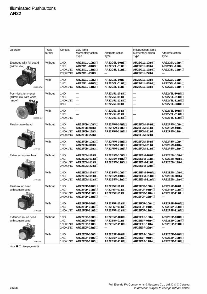
04/18Fuji Electric FA Components & Systems Co., Ltd./D & C Catalog
Information subject to change without notice
Illuminated PushbuttonsAR22
Operator Trans- Contact LED lamp Incandescent lampformer Momentary action Alternate action Momentary action Alternate action
Type Type Type Type
Extended with full guard Without 1NO AR22G1L-10 3 AR22G6L-10 3 AR22G1L-10 4 AR22G6L-10 4(24mm dia.) 1NC AR22G1L-01 3 AR22G6L-01 3 AR22G1L-01 4 AR22G6L-01 4
1NO+1NC AR22G1L-11 3 AR22G6L-11 3 AR22G1L-11 4 AR22G6L-11 42NO+2NC AR22G1L-22 3 — AR22G1L-22 4 —
With 1NO AR22G1L-10 3 AR22G6L-10 3 AR22G1L-10 4 AR22G6L-10 41NC AR22G1L-01 3 AR22G6L-01 3 AR22G1L-01 4 AR22G6L-01 4
KK02-127A 1NO+1NC AR22G1L-11 3 AR22G6L-11 3 AR22G1L-11 4 AR22G6L-11 4
Push-lock, turn-reset Without 1NO — AR22V5L-10 3 — AR22V5L-10 4(40mm dia. with white 1NC — AR22V5L-01 3 — AR22V5L-01 4 arrow) 1NO+1NC — AR22V5L-11 3 — AR22V5L-11 4
3NC — AR22V5L-03 3 — AR22V5L-03 4
With 1NO — AR22V5L-10 3 — AR22V5L-10 41NC — AR22V5L-01 3 — AR22V5L-01 4
KKD06-335 1NO+1NC — AR22V5L-11 3 — AR22V5L-11 4
Flush square head Without 1NO AR22F0M-103 AR22F5M-10 3 AR22F0M-10 4 AR22F5M-10 41NC AR22F0M-013 AR22F5M-01 3 AR22F0M-01 4 AR22F5M-01 41NO+1NC AR22F0M-113 AR22F5M-11 3 AR22F0M-11 4 AR22F5M-11 42NO+2NC AR22F0M-223 — AR22F0M-22 4 —
With 1NO AR22F0M-103 AR22F5M-10 3 AR22F0M-10 4 AR22F5M-10 41NC AR22F0M-013 AR22F5M-01 3 AR22F0M-01 4 AR22F5M-01 4
AF97-68 1NO+1NC AR22F0M-113 AR22F5M-11 3 AR22F0M-11 4 AR22F5M-11 4
Extended square head Without 1NO AR22E0M-10 3 AR22E5M-10 3 AR22E0M-10 4 AR22E5M-10 41NC AR22E0M-01 3 AR22E5M-01 3 AR22E0M-01 4 AR22E5M-01 41NO+1NC AR22E0M-11 3 AR22E5M-11 3 AR22E0M-11 4 AR22E5M-11 42NO+2NC AR22E0M-22 3 — AR22E0M-22 4 —
With 1NO AR22E0M-10 3 AR22E5M-10 3 AR22E0M-10 4 AR22E5M-10 41NC AR22E0M-01 3 AR22E5M-01 3 AR22E0M-01 4 AR22E5M-01 4
AF94-357 1NO+1NC AR22E0M-11 3 AR22E5M-11 3 AR22E0M-11 4 AR22E5M-11 4
Flush round head Without 1NO AR22F0P-10 3 AR22F5P-10 3 AR22F0P-10 4 AR22F5P-10 4with square bezel 1NC AR22F0P-01 3 AR22F5P-01 3 AR22F0P-01 4 AR22F5P-01 4
1NO+1NC AR22F0P-11 3 AR22F5P-11 3 AR22F0P-11 4 AR22F5P-11 42NO+2NC AR22F0P-22 3 — AR22F0P-22 4 —
With 1NO AR22F0P-10 3 AR22F5P-10 3 AR22F0P-10 4 AR22F5P-10 41NC AR22F0P-01 3 AR22F5P-01 3 AR22F0P-01 4 AR22F5P-01 4
AF94-315 1NO+1NC AR22F0P-11 3 AR22F5P-11 3 AR22F0P-11 4 AR22F5P-11 4
Extended round head Without 1NO AR22E0P-10 3 AR22E5P-103 AR22E0P-104 AR22E5P-104with square bezel 1NC AR22E0P-01 3 AR22E5P-013 AR22E0P-014 AR22E5P-014
1NO+1NC AR22E0P-11 3 AR22E5P-113 AR22E0P-114 AR22E5P-1142NO+2NC AR22E0P-22 3 — AR22E0P-224 —
With 1NO AR22E0P-10 3 AR22E5P-103 AR22E0P-104 AR22E5P-1041NC AR22E0P-01 3 AR22E5P-013 AR22E0P-014 AR22E5P-014
AF94-314 1NO+1NC AR22E0P-11 3 AR22E5P-113 AR22E0P-114 AR22E5P-114
Note: See page 04/19
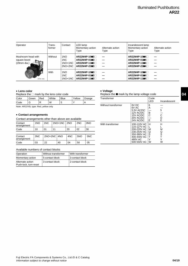
04/19Fuji Electric FA Components & Systems Co., Ltd./D & C CatalogInformation subject to change without notice
04
Illuminated PushbuttonsAR22
Operator Trans- Contact LED lamp Incandescent lampformer Momentary action Alternate action Momentary action Alternate action
Type Type Type Type
Mushroom head with Without 1NO AR22M4P-10 3 — AR22M4P-10 4 —square bezel 1NC AR22M4P-01 3 — AR22M4P-01 4 —(29mm dia.) 1NO+1NC AR22M4P-11 3 — AR22M4P-11 4 —
2NO+2NC AR22M4P-22 3 — AR22M4P-22 4 —
With 1NO AR22M4P-10 3 — AR22M4P-10 4 —1NC AR22M4P-01 3 — AR22M4P-01 4 —
AF94-440 1NO+1NC AR22M4P-11 3 — AR22M4P-11 4 —
• Lens colorReplace the mark by the lens color codeColor Green Red White Blue Yellow Orange
Code G R W S Y A
• VoltageReplace the mark by the lamp voltage codeTransformer Code
LED Incandescent
Without transformer 6V DC 6 —6V AC A —5.5V AC/DC — 512V AC/DC B —15V AC/DC C C20V AC/DC — D24V AC/DC E E
With transformer 100-110V AC H H115-127V AC L L200-220V AC M M230-254V AC Q Q350-380V AC S S400-440V AC T T480V AC V V500-550V AC W W
• Contact arrangementsContact arrangements other than above are availableContact 1NO 1NC 1NO+1NC 2NO 2NC 3NOarrangement
Code 10 01 11 20 02 30
Contact 3NC 2NO+2NC 4NO 4NC 5NO 5NCarrangement
Code 03 22 40 04 50 05
Available numbers of contact blocksOperation Without transformer With transformer
Momentary action 5-contact block 3-contact block
Alternate action 3-contact block 2-contact blockPush-lock, turn-reset
Note: AR22V5L type: Red, yellow only
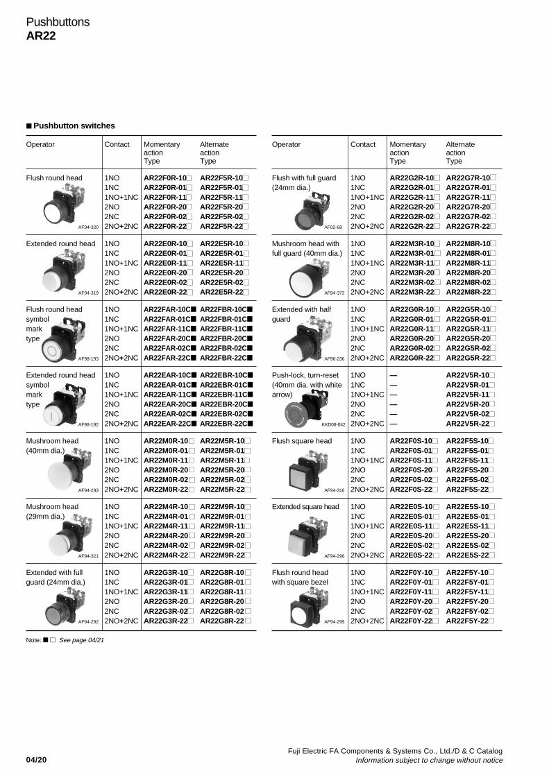
04/20Fuji Electric FA Components & Systems Co., Ltd./D & C Catalog
Information subject to change without notice
PushbuttonsAR22
Operator Contact Momentary Alternateaction actionType Type
Flush round head 1NO AR22F0R-10 AR22F5R-101NC AR22F0R-01 AR22F5R-011NO+1NC AR22F0R-11 AR22F5R-112NO AR22F0R-20 AR22F5R-202NC AR22F0R-02 AR22F5R-02
AF94-320 2NO+2NC AR22F0R-22 AR22F5R-22
Extended round head 1NO AR22E0R-10 AR22E5R-101NC AR22E0R-01 AR22E5R-011NO+1NC AR22E0R-11 AR22E5R-112NO AR22E0R-20 AR22E5R-202NC AR22E0R-02 AR22E5R-02
AF94-319 2NO+2NC AR22E0R-22 AR22E5R-22
Flush round head 1NO AR22FAR-10C AR22FBR-10C
symbol 1NC AR22FAR-01C AR22FBR-01C
mark 1NO+1NC AR22FAR-11C AR22FBR-11C
type 2NO AR22FAR-20C AR22FBR-20C
2NC AR22FAR-02C AR22FBR-02C
AF98-193 2NO+2NC AR22FAR-22C AR22FBR-22C
Extended round head 1NO AR22EAR-10C AR22EBR-10C
symbol 1NC AR22EAR-01C AR22EBR-01C
mark 1NO+1NC AR22EAR-11C AR22EBR-11C
type 2NO AR22EAR-20C AR22EBR-20C
2NC AR22EAR-02C AR22EBR-02C
AF98-192 2NO+2NC AR22EAR-22C AR22EBR-22C
Mushroom head 1NO AR22M0R-10 AR22M5R-10(40mm dia.) 1NC AR22M0R-01 AR22M5R-01
1NO+1NC AR22M0R-11 AR22M5R-112NO AR22M0R-20 AR22M5R-202NC AR22M0R-02 AR22M5R-02
AF94-293 2NO+2NC AR22M0R-22 AR22M5R-22
Mushroom head 1NO AR22M4R-10 AR22M9R-10(29mm dia.) 1NC AR22M4R-01 AR22M9R-01
1NO+1NC AR22M4R-11 AR22M9R-112NO AR22M4R-20 AR22M9R-202NC AR22M4R-02 AR22M9R-02
AF94-321 2NO+2NC AR22M4R-22 AR22M9R-22
Extended with full 1NO AR22G3R-10 AR22G8R-10guard (24mm dia.) 1NC AR22G3R-01 AR22G8R-01
1NO+1NC AR22G3R-11 AR22G8R-112NO AR22G3R-20 AR22G8R-202NC AR22G3R-02 AR22G8R-02
AF94-292 2NO+2NC AR22G3R-22 AR22G8R-22
Operator Contact Momentary Alternateaction actionType Type
Flush with full guard 1NO AR22G2R-10 AR22G7R-10(24mm dia.) 1NC AR22G2R-01 AR22G7R-01
1NO+1NC AR22G2R-11 AR22G7R-112NO AR22G2R-20 AR22G7R-202NC AR22G2R-02 AR22G7R-02
AF02-68 2NO+2NC AR22G2R-22 AR22G7R-22
Mushroom head with 1NO AR22M3R-10 AR22M8R-10full guard (40mm dia.) 1NC AR22M3R-01 AR22M8R-01
1NO+1NC AR22M3R-11 AR22M8R-112NO AR22M3R-20 AR22M8R-202NC AR22M3R-02 AR22M8R-02
AF94-372 2NO+2NC AR22M3R-22 AR22M8R-22
Extended with half 1NO AR22G0R-10 AR22G5R-10guard 1NC AR22G0R-01 AR22G5R-01
1NO+1NC AR22G0R-11 AR22G5R-112NO AR22G0R-20 AR22G5R-202NC AR22G0R-02 AR22G5R-02
AF96-236 2NO+2NC AR22G0R-22 AR22G5R-22
Push-lock, turn-reset 1NO — AR22V5R-10(40mm dia. with white 1NC — AR22V5R-01arrow) 1NO+1NC — AR22V5R-11
2NO — AR22V5R-202NC — AR22V5R-02
KKD08-042 2NO+2NC — AR22V5R-22
Flush square head 1NO AR22F0S-10 AR22F5S-101NC AR22F0S-01 AR22F5S-011NO+1NC AR22F0S-11 AR22F5S-112NO AR22F0S-20 AR22F5S-202NC AR22F0S-02 AR22F5S-02
AF94-316 2NO+2NC AR22F0S-22 AR22F5S-22
Extended square head 1NO AR22E0S-10 AR22E5S-101NC AR22E0S-01 AR22E5S-011NO+1NC AR22E0S-11 AR22E5S-112NO AR22E0S-20 AR22E5S-202NC AR22E0S-02 AR22E5S-02
AF94-296 2NO+2NC AR22E0S-22 AR22E5S-22
Flush round head 1NO AR22F0Y-10 AR22F5Y-10with square bezel 1NC AR22F0Y-01 AR22F5Y-01
1NO+1NC AR22F0Y-11 AR22F5Y-112NO AR22F0Y-20 AR22F5Y-202NC AR22F0Y-02 AR22F5Y-02
AF94-295 2NO+2NC AR22F0Y-22 AR22F5Y-22
Pushbutton switches
Note: See page 04/21

04/21Fuji Electric FA Components & Systems Co., Ltd./D & C CatalogInformation subject to change without notice
04
• Available numbers of contact blocksMomentary action Alternate action
Push-lock, turn-reset
6-contact block 4-contact block
• Button colorReplace the mark by the button color codeColor Green Red White Blue Yellow Orange Black
Code G R W S Y A B
Operator Contact Momentary Alternateaction actionType Type
Extended round head 1NO AR22E0Y-10 AR22E5Y-10with square bezel 1NC AR22E0Y-01 AR22E5Y-01
1NO+1NC AR22E0Y-11 AR22E5Y-112NO AR22E0Y-20 AR22E5Y-202NC AR22E0Y-02 AR22E5Y-02
AF94-297 2NO+2NC AR22E0Y-22 AR22E5Y-22
Operator Contact Momentary Alternateaction actionType Type
Mushroom head 1NO AR22M4Y-10 —with square bezel 1NC AR22M4Y-01 —(29mm dia.) 1NO+1NC AR22M4Y-11 —
2NO AR22M4Y-20 —2NC AR22M4Y-02 —
AF94-298 2NO+2NC AR22M4Y-22 —
• Contact arrangementsContact arrangements other than above are available
Contact 1NO 1NC 1NO+1NC 2NO 2NC 3NO 3NCarrangement
Code 10 01 11 20 02 30 03
Contact 2NO+2NC 4NO 4NC 5NO 5NC 3NO+3NCarrangement
Code 22 40 04 50 05 33
Symbol mark I T I T
Color of button White Black White Black White Black ClearColor of mark Red Green Green BlackCode 01 02 03 04 11 12 02B 04B 12B
• Symbol mark (For AR22FAR, FBR, EAR, EBR)Replace the mark by the symbol mark code
PushbuttonsAR22
Note: AR22V5R type: Red, yellow, black only

04/22Fuji Electric FA Components & Systems Co., Ltd./D & C Catalog
Information subject to change without notice
PushbuttonsAR22
Operator Contact Button Type Contact operationcolor
Contact block Left Right
Mounting Type Free Depressed Free Depressedposition
Pushbutton with 2NO+2NC Green AR22S1R-22G (1) NC — — —selector ring Red AR22S1R-22R(2-position) Black AR22S1R-22B (2) NC — — —
White AR22S1R-22WYellow AR22S1R-22Y (3) NO — —
Orange AR22S1R-22ABlue AR22S1R-22S (4) NO — —
2NO Green AR22S2R-20G (1) NO — — —Red AR22S2R-20RBlack AR22S2R-20B (2) NO — — —
White AR22S2R-20WYellow AR22S2R-20YOrange AR22S2R-20ABlue AR22S2R-20S
2NO+2NC Green AR22S2R-22G (1) NC —Red AR22S2R-22RBlack AR22S2R-22B (2) NC —White AR22S2R-22WYellow AR22S2R-22Y (3) NO — — —Orange AR22S2R-22ABlue AR22S2R-22S (4) NO — — —
2NO+2NC Green AR22S3R-22G (1) NC — —Red AR22S3R-22RBlack AR22S3R-22B (2) NC — —White AR22S3R-22WYellow AR22S3R-22Y (3) NO — — —Orange AR22S3R-22ABlue AR22S3R-22S (4) NO — — —
2NO+2NC Green AR22S6R-22G (1) NC — —Red AR22S6R-22RBlack AR22S6R-22B (2) NC — —White AR22S6R-22W LockedYellow AR22S6R-22Y (3) NO —
Orange AR22S6R-22ABlue AR22S6R-22S (4) NO —
• Position of contact block
Contact closed— Contact open
Note: (1) to (4): Contact block mounting position
AF94-355
(The followingcontact is onlyavailable.)
Release arm
Operator
Contact block
(1)(3)
(2)(4)
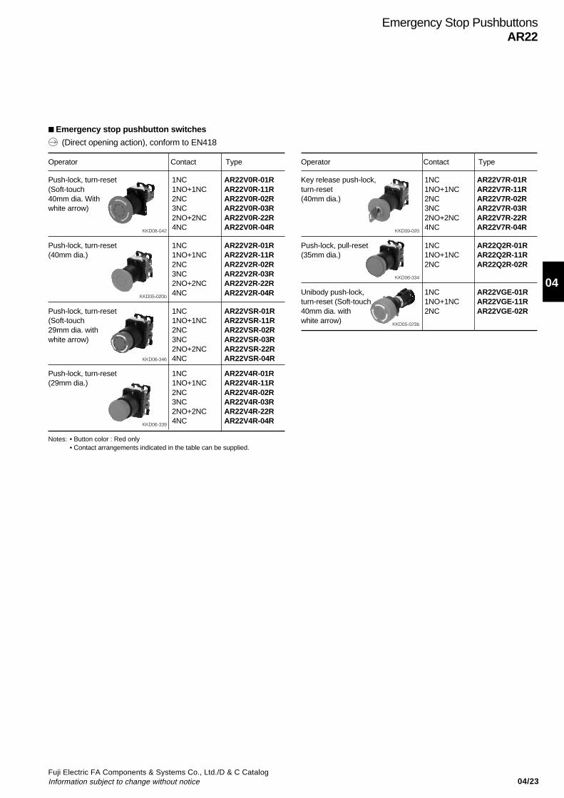
04/23Fuji Electric FA Components & Systems Co., Ltd./D & C CatalogInformation subject to change without notice
04
Operator Contact Type
Key release push-lock, 1NC AR22V7R-01Rturn-reset 1NO+1NC AR22V7R-11R(40mm dia.) 2NC AR22V7R-02R
3NC AR22V7R-03R2NO+2NC AR22V7R-22R
KKD09-020 4NC AR22V7R-04R
Push-lock, pull-reset 1NC AR22Q2R-01R(35mm dia.) 1NO+1NC AR22Q2R-11R
2NC AR22Q2R-02R
KKD06-334
Unibody push-lock, 1NC AR22VGE-01Rturn-reset (Soft-touch 1NO+1NC AR22VGE-11R40mm dia. with 2NC AR22VGE-02Rwhite arrow) KKD05-023b
Emergency Stop PushbuttonsAR22
Emergency stop pushbutton switches
(Direct opening action), conform to EN418
Operator Contact Type
Push-lock, turn-reset 1NC AR22V0R-01R(Soft-touch 1NO+1NC AR22V0R-11R40mm dia. With 2NC AR22V0R-02Rwhite arrow) 3NC AR22V0R-03R
2NO+2NC AR22V0R-22R
KKD08-042 4NC AR22V0R-04R
Push-lock, turn-reset 1NC AR22V2R-01R(40mm dia.) 1NO+1NC AR22V2R-11R
2NC AR22V2R-02R3NC AR22V2R-03R2NO+2NC AR22V2R-22R
KKD05-020b 4NC AR22V2R-04R
Push-lock, turn-reset 1NC AR22VSR-01R(Soft-touch 1NO+1NC AR22VSR-11R29mm dia. with 2NC AR22VSR-02Rwhite arrow) 3NC AR22VSR-03R
2NO+2NC AR22VSR-22RKKD06-346 4NC AR22VSR-04R
Push-lock, turn-reset 1NC AR22V4R-01R(29mm dia.) 1NO+1NC AR22V4R-11R
2NC AR22V4R-02R3NC AR22V4R-03R2NO+2NC AR22V4R-22R
KKD06-339 4NC AR22V4R-04R
Notes: • Button color : Red only• Contact arrangements indicated in the table can be supplied.
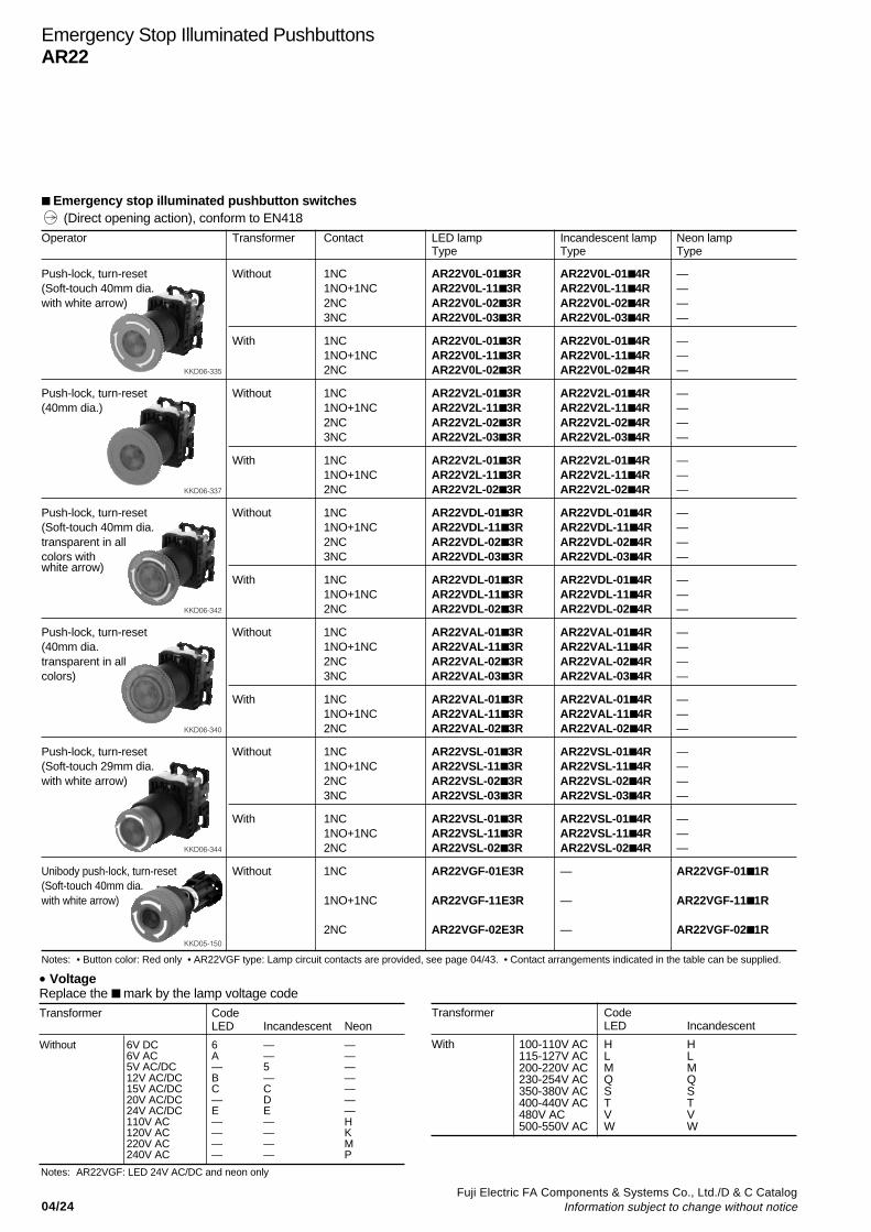
04/24Fuji Electric FA Components & Systems Co., Ltd./D & C Catalog
Information subject to change without notice
Operator Transformer Contact LED lamp Incandescent lamp Neon lampType Type Type
Push-lock, turn-reset Without 1NC AR22V0L-01 3R AR22V0L-01 4R —(Soft-touch 40mm dia. 1NO+1NC AR22V0L-11 3R AR22V0L-11 4R —with white arrow) 2NC AR22V0L-02 3R AR22V0L-02 4R —
3NC AR22V0L-03 3R AR22V0L-03 4R —
With 1NC AR22V0L-01 3R AR22V0L-01 4R —1NO+1NC AR22V0L-11 3R AR22V0L-11 4R —
KKD06-335 2NC AR22V0L-02 3R AR22V0L-02 4R —
Push-lock, turn-reset Without 1NC AR22V2L-01 3R AR22V2L-01 4R —(40mm dia.) 1NO+1NC AR22V2L-11 3R AR22V2L-11 4R —
2NC AR22V2L-02 3R AR22V2L-02 4R —3NC AR22V2L-03 3R AR22V2L-03 4R —
With 1NC AR22V2L-01 3R AR22V2L-01 4R —1NO+1NC AR22V2L-11 3R AR22V2L-11 4R —
KKD06-337 2NC AR22V2L-02 3R AR22V2L-02 4R —
Push-lock, turn-reset Without 1NC AR22VDL-013R AR22VDL-01 4R —(Soft-touch 40mm dia. 1NO+1NC AR22VDL-113R AR22VDL-11 4R —transparent in all 2NC AR22VDL-023R AR22VDL-02 4R —colors with 3NC AR22VDL-033R AR22VDL-03 4R —white arrow)
With 1NC AR22VDL-013R AR22VDL-01 4R —1NO+1NC AR22VDL-113R AR22VDL-11 4R —
KKD06-342 2NC AR22VDL-023R AR22VDL-02 4R —
Push-lock, turn-reset Without 1NC AR22VAL-013R AR22VAL-01 4R —(40mm dia. 1NO+1NC AR22VAL-113R AR22VAL-11 4R —transparent in all 2NC AR22VAL-023R AR22VAL-02 4R —colors) 3NC AR22VAL-033R AR22VAL-03 4R —
With 1NC AR22VAL-013R AR22VAL-01 4R —1NO+1NC AR22VAL-113R AR22VAL-11 4R —
KKD06-340 2NC AR22VAL-023R AR22VAL-02 4R —
Push-lock, turn-reset Without 1NC AR22VSL-01 3R AR22VSL-01 4R —(Soft-touch 29mm dia. 1NO+1NC AR22VSL-11 3R AR22VSL-11 4R —with white arrow) 2NC AR22VSL-02 3R AR22VSL-02 4R —
3NC AR22VSL-03 3R AR22VSL-03 4R —
With 1NC AR22VSL-01 3R AR22VSL-01 4R —1NO+1NC AR22VSL-11 3R AR22VSL-11 4R —
KKD06-344 2NC AR22VSL-02 3R AR22VSL-02 4R —
Unibody push-lock, turn-reset Without 1NC AR22VGF-01E3R — AR22VGF-01 1R(Soft-touch 40mm dia.with white arrow) 1NO+1NC AR22VGF-11E3R — AR22VGF-11 1R
KKD05-150
2NC AR22VGF-02E3R — AR22VGF-02 1R
Emergency Stop Illuminated PushbuttonsAR22
Emergency stop illuminated pushbutton switches
• VoltageReplace the mark by the lamp voltage code
Transformer CodeLED Incandescent Neon
Without 6V DC 6 — —6V AC A — —5V AC/DC — 5 —12V AC/DC B — —15V AC/DC C C —20V AC/DC — D —24V AC/DC E E —110V AC — — H120V AC — — K220V AC — — M240V AC — — P
Notes: • Button color: Red only • AR22VGF type: Lamp circuit contacts are provided, see page 04/43. • Contact arrangements indicated in the table can be supplied.
Transformer CodeLED Incandescent
With 100-110V AC H H115-127V AC L L200-220V AC M M230-254V AC Q Q350-380V AC S S400-440V AC T T480V AC V V500-550V AC W W
(Direct opening action), conform to EN418
Notes: AR22VGF: LED 24V AC/DC and neon only
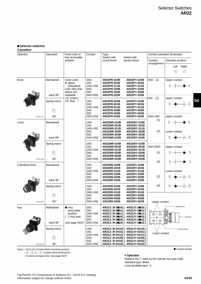
04/25Fuji Electric FA Components & Systems Co., Ltd./D & C CatalogInformation subject to change without notice
04
2-positionOperator Operation Knob color or Contact Type Contact operation (Example)
key removable Switch with Switch withposition round bezel square bezel Contact Operator position
arrangement Left Right
Knob Maintained Color code: 1NO AR22PR-210B AR22PY-210B 1NO (1) Upper contactB: Black 1NC AR22PR-201B AR22PY-201B
(Standard) 1NO+1NC AR22PR-211B AR22PY-211B ➂ ➃Color other than 2NO AR22PR-220B AR22PY-220Babove are 2NC AR22PR-202B AR22PY-202B
each 90° available 2NO+2NC AR22PR-222B AR22PY-222B G: Green 1NC (1) Upper contact
Spring return R: Red 1NO AR22PR-010B AR22PY-010B1NC AR22PR-001B AR22PY-001B ➀ ➁1NO+1NC AR22PR-011B AR22PY-011B2NO AR22PR-020B AR22PY-020B2NC AR22PR-002B AR22PY-002B
AF94-310 60° 2NO+2NC AR22PR-022B AR22PY-022B 1NO+1NC Upper contact
Lever Maintained 1NO AR22WR-210B AR22WY-210B ➂ ➃1NC AR22WR-201B AR22WY-201B1NO+1NC AR22WR-211B AR22WY-211B2NO AR22WR-220B AR22WY-220B Lower contact2NC AR22WR-202B AR22WY-202B
each 90° 2NO+2NC AR22WR-222B AR22WY-222B ➀ ➁
Spring return 1NO AR22WR-010B AR22WY-010B1NC AR22WR-001B AR22WY-001B 2NO+2NC Upper contact1NO+1NC AR22WR-011B AR22WY-011B2NO AR22WR-020B AR22WY-020B ➂ ➃2NC AR22WR-002B AR22WY-002B
AF94-324 60° 2NO+2NC AR22WR-022B AR22WY-022B ➂ ➃
Cylindrical knob Maintained 1NO AR22RR-210B AR22RY-210B1NC AR22RR-201B AR22RY-201B1NO+1NC AR22RR-211B AR22RY-211B Lower contact2NO AR22RR-220B AR22RY-220B2NC AR22RR-202B AR22RY-202B ➀ ➁
each 90° 2NO+2NC AR22RR-222B AR22RY-222B
Spring return 1NO AR22RR-010B AR22RY-010B ➀ ➁1NC AR22RR-001B AR22RY-001B1NO+1NC AR22RR-011B AR22RY-011B2NO AR22RR-020B AR22RY-020B2NC AR22RR-002B AR22RY-002B
AF94-308 60° 2NO+2NC AR22RR-022B AR22RY-022B
Key Maintained : Key 1NO AR22JR-2 10( ) AR22JY-210( ) removable 1NC AR22JR-2 01( ) AR22JY-201( ) position 1NO+1NC AR22JR-2 11( ) AR22JY-211( )
( ): Key type 2NO AR22JR-2 20( ) AR22JY-220( )2NC AR22JR-2 02( ) AR22JY-202( )
each 90° See page 04/27 2NO+2NC AR22JR-2 22( ) AR22JY-222( )
Spring return 1NO AR22JR-0A10( ) AR22JY-0A10( )1NC AR22JR-0A01( ) AR22JY-0A01( )1NO+1NC AR22JR-0A11( ) AR22JY-0A11( )2NO AR22JR-0A20( ) AR22JY-0A20( )2NC AR22JR-0A02( ) AR22JY-0A02( )
KKD09-018 60° 2NO+2NC AR22JR-0A22( ) AR22JY-0A22( )
Selector SwitchesAR22
(1)
(2)
(1)
(3)
(2)
(4)
Notes: • (1) to (4): Contact block mounting position• ➀ – ➁ , ➂ – ➃ : Contact block terminal No.• Contact arrangements: See page 04/27
Release arm
Upper contact
Lower contact
Operator
Contact block
(1)
(2)
(3)
(4)
Selector switches
• OperatorReplace the mark by the cylinder key type codeStandard type: BlankLong durability type: A
Contact closed
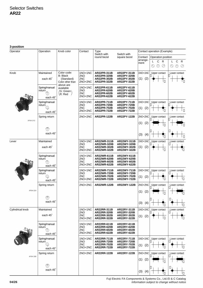
04/26Fuji Electric FA Components & Systems Co., Ltd./D & C Catalog
Information subject to change without notice
Selector SwitchesAR22
3-positionOperator Operation Knob color Contact Type Contact operation (Example)
Switch with Switch withround bezel square bezel Contact Operation position
arrange-ment L C R L C R
Knob Maintained 1NO+1NC AR22PR-311B AR22PY-311B 1NO+1NC Upper contact Lower contact2NO AR22PR-320B AR22PY-320B ➂ ➀2NC AR22PR-302B AR22PY-302B 2NO+2NC AR22PR-322B AR22PY-322B ➃ ➁
Spring/manual 1NO+1NC AR22PR-611B AR22PY-611Breturn 2NO AR22PR-620B AR22PY-620B
2NC AR22PR-602B AR22PY-602B2NO+2NC AR22PR-622B AR22PY-622B
Spring/manual 1NO+1NC AR22PR-711B AR22PY-711B 1NO+1NC Upper contact Lower contactreturn 2NO AR22PR-720B AR22PY-720B ➂ ➀
2NC AR22PR-702B AR22PY-702B 2NO+2NC AR22PR-722B AR22PY-722B ➃ ➁
Spring return 2NO+2NC AR22PR-122B AR22PY-122B 2NO+2NC Upper contact Lower contact➀ ➀
➁ ➁
➂ ➂ ➃ ➃
Lever Maintained 1NO+1NC AR22WR-311B AR22WY-311B 1NO+1NC Upper contact Lower contact2NO AR22WR-320B AR22WY-320B ➂ ➀2NC AR22WR-302B AR22WY-302B 2NO+2NC AR22WR-322B AR22WY-322B ➃ ➁
Spring/manual 1NO+1NC AR22WR-611B AR22WY-611Breturn 2NO AR22WR-620B AR22WY-620B
2NC AR22WR-602B AR22WY-602B2NO+2NC AR22WR-622B AR22WY-622B
Spring/manual 1NO+1NC AR22WR-711B AR22WY-711B 1NO+1NC Upper contact Lower contactreturn 2NO AR22WR-720B AR22WY-720B ➂ ➀
2NC AR22WR-702B AR22WY-702B 2NO+2NC AR22WR-722B AR22WY-722B ➃ ➁
Spring return 2NO+2NC AR22WR-122B AR22WY-122B 2NO+2NC Upper contact Lower contact➀ ➀
➁ ➁
➂ ➂ ➃ ➃
Cylindrical knob Maintained 1NO+1NC AR22RR-311B AR22RY-311B 1NO+1NC Upper contact Lower contact2NO AR22RR-320B AR22RY-320B ➂ ➀2NC AR22RR-302B AR22RY-302B 2NO+2NC AR22RR-322B AR22RY-322B ➃ ➁
Spring/manual 1NO+1NC AR22RR-611B AR22RY-611Breturn 2NO AR22RR-620B AR22RY-620B
2NC AR22RR-602B AR22RY-602B2NO+2NC AR22RR-622B AR22RY-622B
Spring/manual 1NO+1NC AR22RR-711B AR22RY-711B 1NO+1NC Upper contact Lower contactreturn 2NO AR22RR-720B AR22RY-720B ➂ ➀
2NC AR22RR-702B AR22RY-702B 2NO+2NC AR22RR-722B AR22RY-722B ➃ ➁
Spring return 2NO+2NC AR22RR-122B AR22RY-122B 2NO+2NC Upper contact Lower contact➀ ➀
➁ ➁
➂ ➂ ➃ ➃
(1) (2)
(1) (2)
(1) (2)
(1) (2)
(1) (2)
(3) (4)
(3) (4)
(1) (2)
(1) (2)
(3) (4)
(1) (2)
(1) (2)
Color code:B: Black
(Standard)Color other thanabove areavailable G: Green R: Red
each 45˚
each 45˚
each 45˚
each 45˚
each 45˚
each 45˚
each 45˚
each 45˚
each 45˚
each 45˚
each 45˚
each 45˚
AF94-310
AF94-324
AF94-308
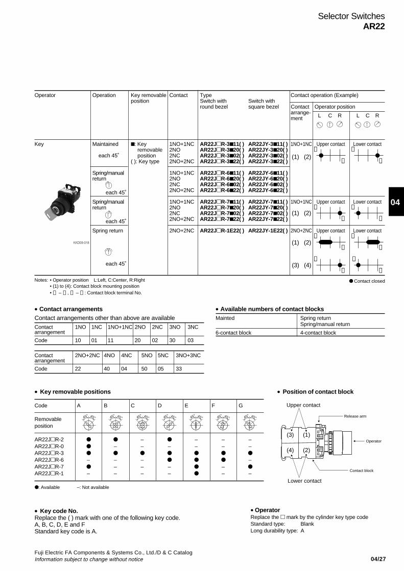
04/27Fuji Electric FA Components & Systems Co., Ltd./D & C CatalogInformation subject to change without notice
04
Selector SwitchesAR22
Operator Operation Key removable Contact Type Contact operation (Example)position Switch with Switch with
round bezel square bezel Contact Operator positionarrange-ment L C R L C R
Key Maintained : Key 1NO+1NC AR22JR-3 11( ) AR22JY-3 11( ) 1NO+1NC Upper contact Lower contact removable 2NO AR22JR-3 20( ) AR22JY-3 20( ) ➂ ➀ position 2NC AR22JR-3 02( ) AR22JY-3 02( )
( ): Key type 2NO+2NC AR22JR-3 22( ) AR22JY-3 22( ) ➃ ➁
Spring/manual 1NO+1NC AR22JR-6 11( ) AR22JY-6 11( )return 2NO AR22JR-6 20( ) AR22JY-6 20( )
2NC AR22JR-6 02( ) AR22JY-6 02( )2NO+2NC AR22JR-6 22( ) AR22JY-6 22( )
Spring/manual 1NO+1NC AR22JR-7 11( ) AR22JY-7 11( ) 1NO+1NC Upper contact Lower contactreturn 2NO AR22JR-7 20( ) AR22JY-7 20( ) ➂ ➀
2NC AR22JR-7 02( ) AR22JY-7 02( ) 2NO+2NC AR22JR-7 22( ) AR22JY-7 22( ) ➃ ➁
Spring return 2NO+2NC AR22JR-1E22( ) AR22JY-1E22( ) 2NO+2NC Upper contact Lower contact➀ ➀
➁ ➁
➂ ➂ ➃ ➃
Notes: • Operator position L:Left, C:Center, R:Right• (1) to (4): Contact block mounting position• ➀ – ➁ , ➂ – ➃ : Contact block terminal No.
• Key removable positions
Code A B C D E F G
Removableposition
AR22JR-2 – – – –AR22JR-0 – – – – – –AR22JR-3
AR22JR-6 – – – –AR22JR-7 – – – –
AR22JR-1 – – – – – –
: Available –: Not available
• Position of contact block
• Key code No.Replace the ( ) mark with one of the following key code.A, B, C, D, E and FStandard key code is A.
(3) (4)
(1) (2)
(1) (2)
(1) (2)
each 45˚
each 45˚
each 45˚
each 45˚
45° 45° 45° 45° 45° 45° 45° 45° 45° 45°45° 45° 45° 45°
KKD09-018
• OperatorReplace the mark by the cylinder key type codeStandard type: BlankLong durability type: A
Contact closed
Release arm
Upper contact
Lower contact
Operator
Contact block
(1)
(2)
(3)
(4)
• Contact arrangementsContact arrangements other than above are available
Contact 1NO 1NC 1NO+1NC 2NO 2NC 3NO 3NCarrangement
Code 10 01 11 20 02 30 03
Contact 2NO+2NC 4NO 4NC 5NO 5NC 3NO+3NCarrangement
Code 22 40 04 50 05 33
• Available numbers of contact blocksMainted Spring return
Spring/manual return
6-contact block 4-contact block

04/28Fuji Electric FA Components & Systems Co., Ltd./D & C Catalog
Information subject to change without notice
3-positionOperator Operation Knob color or Contact Type
key removable arrangement Switch with Switch withposition round bezel square bezel
Knob Maintained Replace the AR22PCR-3 B AR22PCY-3 Bmark by the contactarrangement code
Spring/manual (shown on next page). AR22PCR-6 B AR22PCY-6 Breturn
Spring/manual AR22PCR-7 B AR22PCY-7 Breturn
Spring return AR22PCR-1 B AR22PCY-1 B
Lever Maintained Replace the AR22WCR-3 B AR22WCY-3 Bmark by the contactarrangement code
Spring/manual (shown on next page). AR22WCR-6 B AR22WCY-6 Breturn
Spring/manual AR22WCR-7 B AR22WCY-7 Breturn
Spring return AR22WCR-1 B AR22WCY-1 B
Cylindrical knob Maintained Replace the AR22RCR-3 B AR22RCY-3 Bmark by the contactarrangement code
Spring/manual (shown on next page). AR22RCR-6 B AR22RCY-6 Breturn
Spring/manual AR22RCR-7 B AR22RCY-7 Breturn
Spring return AR22RCR-1 B AR22RCY-1 B
Key Maintained Replace the Replace the AR22JCR-3 ( ) AR22JCY-3 ( )mark by the mark by the contactkey removable arrangement code
Spring/manual position code: (shown on next page). AR22JCR-6 ( ) AR22JCY-6 ( )return A, B, C, D, E
F or GSpring/manual AR22JCR-7 ( ) AR22JCY-7 ( )return
Spring return AR22JCR-1E ( ) AR22JCY-1E ( )
Selector SwitchesAR22
• Key removable positions
Code A B C D E F G
Removableposition
AR22JCR-3 AR22JCR-6 – – – –AR22JCR-7 – – – – AR22JCR-1 – – – – – –
: Available –: Not available
• Key code No.Replace the ( ) mark with one of the following key code.A, B, C, D, E and FStandard key code is A.
Color code:B: Black
(Standard)Color other thanabove areavailable G: Green R: Red
each 45˚
each 45˚
each 45˚
each 45˚
each 45˚
each 45˚
each 45˚
each 45˚
each 45˚
each 45˚
each 45˚
each 45˚
each 45˚
each 45˚
each 45˚
each 45˚
45° 45° 45° 45° 45° 45° 45° 45° 45° 45°45° 45° 45° 45°
Selector switches (control type)
AF94-435
AF94-436
AF94-433
KKD09-016
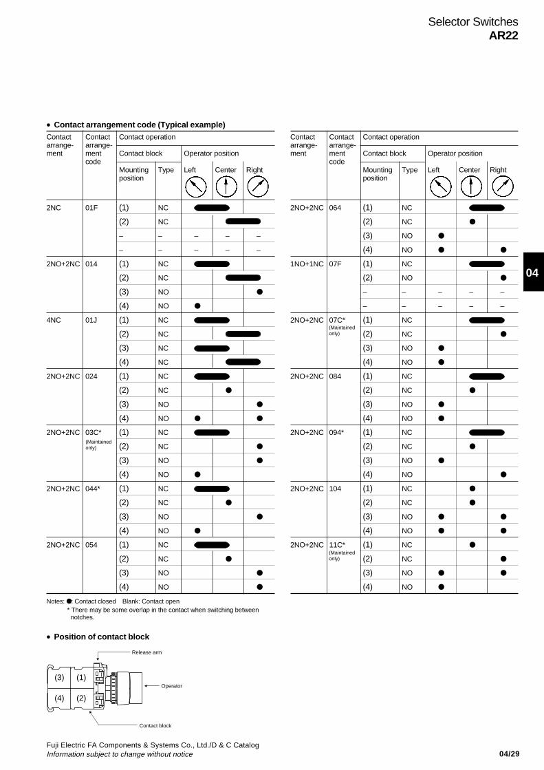
04/29Fuji Electric FA Components & Systems Co., Ltd./D & C CatalogInformation subject to change without notice
04
Selector SwitchesAR22
Contact Contact Contact operationarrange- arrange-ment ment Contact block Operator position
codeMounting Type Left Center Rightposition
2NO+2NC 064 (1) NC
(2) NC
(3) NO
(4) NO
1NO+1NC 07F (1) NC
(2) NO
– – – – –
– – – – –
2NO+2NC 07C* (1) NC
(2) NC
(3) NO
(4) NO
2NO+2NC 084 (1) NC
(2) NC
(3) NO
(4) NO
2NO+2NC 094* (1) NC
(2) NC
(3) NO
(4) NO
2NO+2NC 104 (1) NC
(2) NC
(3) NO
(4) NO
2NO+2NC 11C* (1) NC
(2) NC
(3) NO
(4) NO
Contact Contact Contact operationarrange- arrange-ment ment Contact block Operator position
codeMounting Type Left Center Rightposition
2NC 01F (1) NC
(2) NC
– – – – –
– – – – –
2NO+2NC 014 (1) NC
(2) NC
(3) NO
(4) NO
4NC 01J (1) NC
(2) NC
(3) NC
(4) NC
2NO+2NC 024 (1) NC
(2) NC
(3) NO
(4) NO
2NO+2NC 03C* (1) NC
(2) NC
(3) NO
(4) NO
2NO+2NC 044* (1) NC
(2) NC
(3) NO
(4) NO
2NO+2NC 054 (1) NC
(2) NC
(3) NO
(4) NO
Notes: : Contact closed Blank: Contact open* There may be some overlap in the contact when switching between notches.
• Position of contact block
(Maintainedonly)
(Maintainedonly)
(Maintainedonly)
• Contact arrangement code (Typical example)
Release arm
Operator
Contact block
(1)
(2)
(3)
(4)
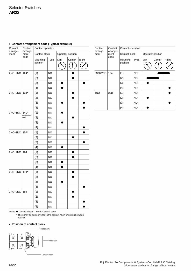
04/30Fuji Electric FA Components & Systems Co., Ltd./D & C Catalog
Information subject to change without notice
Selector SwitchesAR22
• Contact arrangement code (Typical example)Contact Contact Contact operationarrange- arrange-ment ment Contact block Operator position
codeMounting Type Left Center Rightposition
2NO+2NC 124* (1) NC
(2) NC
(3) NO
(4) NO
2NO+2NC 134* (1) NC
(2) NC
(3) NO
(4) NO
3NO+1NC 14D* (1) NO
(2) NC
(3) NO
(4) NO
3NO+1NC 15A* (1) NO
(2) NC
(3) NO
(4) NO
2NO+2NC 164 (1) NC
(2) NC
(3) NO
(4) NO
2NO+2NC 174* (1) NC
(2) NC
(3) NO
(4) NO
2NO+2NC 184 (1) NC
(2) NC
(3) NO
(4) NO
Notes: : Contact closed Blank: Contact open* There may be some overlap in the contact when switching between notches.
• Position of contact block
Contact Contact Contact operationarrange- arrange-ment ment Contact block Operator position
codeMounting Type Left Center Rightposition
2NO+2NC 194 (1) NC
(2) NC
(3) NO
(4) NO
4NO 20B (1) NO
(2) NO
(3) NO
(4) NO
(Maintainedonly)
Release arm
Operator
Contact block
(1)
(2)
(3)
(4)

04/31Fuji Electric FA Components & Systems Co., Ltd./D & C CatalogInformation subject to change without notice
04
Selector SwitchesAR22
4, 5-positionOperator Contact Operation Knob color Contact Type
arrangement Switch with Switch withround bezel square bezel
Knob 2NO+2NC 4-position Replace the AR22PCR-4 B AR22PCY-4 Bmaintained mark by the contact
arrangement code(shown below)
5-position AR22PCR-5 B AR22PCY-5 Bmaintained
Lever 2NO+2NC 4-position AR22WCR-4 B AR22WCY-4Bmaintained
5-position AR22WCR-5 B AR22WCY-5Bmaintained
Cylindrical knob 2NO+2NC 4-position AR22RCR-4 B AR22RCY-4Bmaintained
5-position AR22RCR-5 B AR22RCY-5Bmaintained
Contact arrangement codePosition Contact Contact Contact operation
arrange- arrange-ment ment Contact block Operator position
codeMounting Typeposition 1 2 3 4 5
4-position 2NO+2NC 41C*(1) NC
(2) NC
(3) NO
(4) NO
5-position 2NO+2NC 51C*(1) NC
(2) NC
(3) NO
(4) NO
• Position of contact block
Operator position4-position 5-position
Color code:B: Black
(Standard)Color other thanabove areavailable G: Green R: Red
(The followingcontact is onlyavailable.)
(Main-tained only)
(Main-tained only)
40° 30°
AF94-435
AF94-436
AF94-433
Release arm
Operator
Contact block
(1)
(2)
(3)
(4)
Notes: : Contact closed* There may be some overlap in the contact when switching between notches.
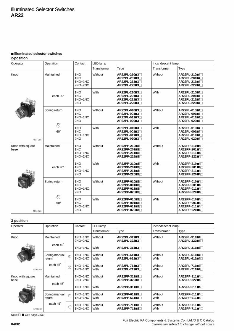
04/32Fuji Electric FA Components & Systems Co., Ltd./D & C Catalog
Information subject to change without notice
Illuminated Selector SwitchesAR22
2-positionOperator Operation Contact LED lamp Incandescent lamp
Transformer Type Transformer Type
Knob Maintained 1NO Without AR22PL-210 3 Without AR22PL-210 41NC AR22PL-201 3 AR22PL-201 41NO+1NC AR22PL-211 3 AR22PL-211 42NO+2NC AR22PL-222 3 AR22PL-222 4
1NO With AR22PL-210 3 With AR22PL-210 4 each 90° 1NC AR22PL-201 3 AR22PL-201 4
1NO+1NC AR22PL-211 3 AR22PL-211 42NO AR22PL-220 3 AR22PL-220 4
Spring return 1NO Without AR22PL-010 3 Without AR22PL-010 41NC AR22PL-001 3 AR22PL-001 41NO+1NC AR22PL-011 3 AR22PL-011 42NO AR22PL-020 3 AR22PL-020 4
1NO With AR22PL-010 3 With AR22PL-010 4 60° 1NC AR22PL-001 3 AR22PL-001 4
1NO+1NC AR22PL-011 3 AR22PL-011 42NO AR22PL-020 3 AR22PL-020 4
Knob with square Maintained 1NO Without AR22PP-210 3 Without AR22PP-210 4bezel 1NC AR22PP-201 3 AR22PP-201 4
1NO+1NC AR22PP-211 3 AR22PP-211 42NO+2NC AR22PP-222 3 AR22PP-222 4
1NO With AR22PP-210 3 With AR22PP-210 4 each 90° 1NC AR22PP-201 3 AR22PP-201 4
1NO+1NC AR22PP-211 3 AR22PP-211 42NO AR22PP-220 3 AR22PP-220 4
Spring return 1NO Without AR22PP-010 3 Without AR22PP-010 41NC AR22PP-001 3 AR22PP-001 41NO+1NC AR22PP-011 3 AR22PP-011 42NO AR22PP-020 3 AR22PP-020 4
1NO With AR22PP-010 3 With AR22PP-010 4 60° 1NC AR22PP-001 3 AR22PP-001 4
1NO+1NC AR22PP-011 3 AR22PP-011 42NO AR22PP-020 3 AR22PP-020 4
Illuminated selector switches
AF94-306
AF94-360
3-positionOperator Operation Contact LED lamp Incandescent lamp
Transformer Type Transformer Type
Knob Maintained 1NO+1NC Without AR22PL-311 3 Without AR22PL-311 42NO+2NC AR22PL-322 3 AR22PL-322 4
1NO+1NC With AR22PL-311 3 AR22PL-311 4
Spring/manual 1NO+1NC Without AR22PL-611 3 Without AR22PL-611 4return 1NO+1NC With AR22PL-611 3 With AR22PL-611 4
1NO+1NC Without AR22PL-711 3 Without AR22PL-711 41NO+1NC With AR22PL-711 3 With AR22PL-711 4
Knob with square Maintained 1NO+1NC Without AR22PP-311 3 Without AR22PP-311 4bezel 2NO+2NC AR22PP-322 3 AR22PP-322 4
1NO+1NC With AR22PP-311 3 AR22PP-311 4
Spring/manual 1NO+1NC Without AR22PP-611 3 Without AR22PP-611 4return 1NO+1NC With AR22PP-611 3 With AR22PP-611 4
1NO+1NC Without AR22PP-711 3 Without AR22PP-711 41NO+1NC With AR22PP-711 3 With AR22PP-711 4
each 45˚
each 45˚
each 45˚
each 45˚
AF94-306
AF94-360
Note: , See page 04/33
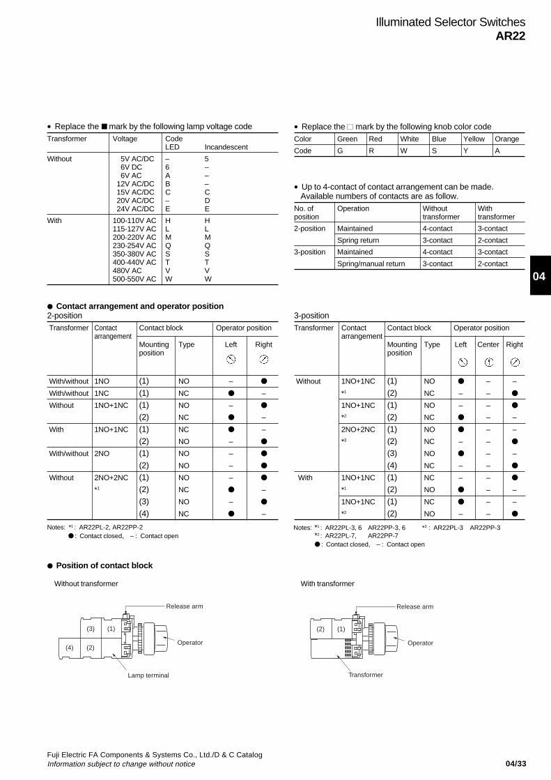
04/33Fuji Electric FA Components & Systems Co., Ltd./D & C CatalogInformation subject to change without notice
04
Illuminated Selector SwitchesAR22
• Replace the mark by the following lamp voltage codeTransformer Voltage Code
LED Incandescent
Without 5V AC/DC – 5 6V DC 6 – 6V AC A – 12V AC/DC B – 15V AC/DC C C 20V AC/DC – D 24V AC/DC E E
With 100-110V AC H H115-127V AC L L200-220V AC M M230-254V AC Q Q350-380V AC S S400-440V AC T T480V AC V V500-550V AC W W
• Replace the mark by the following knob color codeColor Green Red White Blue Yellow Orange
Code G R W S Y A
• Up to 4-contact of contact arrangement can be made.Available numbers of contacts are as follow.
No. of Operation Without Withposition transformer transformer
2-position Maintained 4-contact 3-contact
Spring return 3-contact 2-contact
3-position Maintained 4-contact 3-contact
Spring/manual return 3-contact 2-contact
Contact arrangement and operator position2-position Transformer Contact Contact block Operator position
arrangementMounting Type Left Rightposition
With/without 1NO (1) NO –
With/without 1NC (1) NC –
Without 1NO+1NC (1) NO –
(2) NC –
With 1NO+1NC (1) NC –
(2) NO –
With/without 2NO (1) NO –
(2) NO –
Without 2NO+2NC (1) NO –
*1 (2) NC –
(3) NO –
(4) NC –
Position of contact block
Without transformer
3-positionTransformer Contact Contact block Operator position
arrangementMounting Type Left Center Rightposition
Without 1NO+1NC (1) NO – –
*1 (2) NC – –
1NO+1NC (1) NO – –
*2 (2) NC – –
2NO+2NC (1) NO – –
*3 (2) NC – –
(3) NO – –
(4) NC – –
With 1NO+1NC (1) NC – –
*1 (2) NO – –
1NO+1NC (1) NC – –
*2 (2) NO – –
Notes: *1 : AR22PL-3, 6 AR22PP-3, 6 *3 : AR22PL-3 AR22PP-3*2 : AR22PL-7, AR22PP-7 : Contact closed, – : Contact open
With transformer
Release arm
Operator
Lamp terminal
(1)(3)
(2)(4)
Release arm
Operator
Transformer
(1)(2)
Notes: *1 : AR22PL-2, AR22PP-2 : Contact closed, – : Contact open
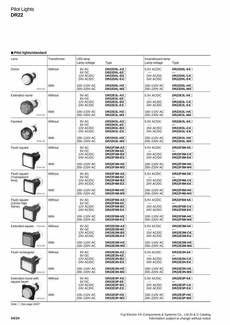
04/34Fuji Electric FA Components & Systems Co., Ltd./D & C Catalog
Information subject to change without notice
Lens Transformer LED lamp Incandescent lampLamp voltage Type Lamp voltage Type
Dome Without 6V AC DR22D0L-A3 5.5V AC/DC DR22D0L-54 6V DC DR22D0L-63 — — 12V AC/DC DR22D0L-B3 15V AC/DC DR22D0L-C4 24V AC/DC DR22D0L-E3 24V AC/DC DR22D0L-E4
With 100–110V AC DR22D0L-H3 100–110V AC DR22D0L-H4200–220V AC DR22D0L-M3 200–220V AC DR22D0L-M4
Extended round Without 6V AC DR22E3L-A3 5.5V AC/DC DR22E3L-54 6V DC DR22E3L-63 — — 12V AC/DC DR22E3L-B3 15V AC/DC DR22E3L-C4 24V AC/DC DR22E3L-E3 24V AC/DC DR22E3L-E4
With 100–110V AC DR22E3L-H3 100–110V AC DR22E3L-H4200–220V AC DR22E3L-M3 200–220V AC DR22E3L-M4
Faceted Without 6V AC DR22K0L-A3 5.5V AC/DC DR22K0L-54 6V DC DR22K0L-63 — — 12V AC/DC DR22K0L-B3 15V AC/DC DR22K0L-C4 24V AC/DC DR22K0L-E3 24V AC/DC DR22K0L-E4
With 100–110V AC DR22K0L-H3 100–110V AC DR22K0L-H4200–220V AC DR22K0L-M3 200–220V AC DR22K0L-M4
Flush square Without 6V AC DR22F3M-A3 5.5V AC/DC DR22F3M-54 6V DC DR22F3M-63 — — 12V AC/DC DR22F3M-B3 15V AC/DC DR22F3M-C4 24V AC/DC DR22F3M-E3 24V AC/DC DR22F3M-E4
With 100–110V AC DR22F3M-H3 100–110V AC DR22F3M-H4200–220V AC DR22F3M-M3 200–220V AC DR22F3M-M4
Flush square Without 6V AC DR22F4M-A3 5.5V AC/DC DR22F4M-54(Transparent 6V DC DR22F4M-63 — —lens) 12V AC/DC DR22F4M-B3 15V AC/DC DR22F4M-C4
24V AC/DC DR22F4M-E3 24V AC/DC DR22F4M-E4
With 100–110V AC DR22F4M-H3 100–110V AC DR22F4M-H4200–220V AC DR22F4M-M3 200–220V AC DR22F4M-M4
Flush square Without 6V AC DR22F5M-A3 5.5V AC/DC DR22F5M-54(12mm high 6V DC DR22F5M-63 — —frame) 12V AC/DC DR22F5M-B3 15V AC/DC DR22F5M-C4
24V AC/DC DR22F5M-E3 24V AC/DC DR22F5M-E4
With 100–110V AC DR22F5M-H3 100–110V AC DR22F5M-H4200–220V AC DR22F5M-E3 200–220V AC DR22F5M-M4
Extended square Without 6V AC DR22E3M-A3 5.5V AC/DC DR22E3M-54 6V DC DR22E3M-63 — — 12V AC/DC DR22E3M-B3 15V AC/DC DR22E3M-C4 24V AC/DC DR22E3M-E3 24V AC/DC DR22E3M-E4
With 100–110V AC DR22E3M-H3 100–110V AC DR22E3M-H4200–220V AC DR22E3M-M3 200–220V AC DR22E3M-M4
Flush rectangular Without 6V AC DR22E3N-A3 5.5V AC/DC DR22E3N-54 6V DC DR22E3N-63 — — 12V AC/DC DR22E3N-B3 15V AC/DC DR22E3N-C4 24V AC/DC DR22E3N-E3 24V AC/DC DR22E3N-E4
With 100–110V AC DR22E3N-H3 100–110V AC DR22E3N-H4200–220V AC DR22E3N-M3 200–220V AC DR22E3N-M4
Extended round with Without 6V AC DR22E3P-A3 5.5V AC/DC DR22E3P-54square bezel 6V DC DR22E3P-63 — —
12V AC/DC DR22E3P-B3 15V AC/DC DR22E3P-C4 24V AC/DC DR22E3P-E3 24V AC/DC DR22E3P-E4
With 100–110V AC DR22E3P-H3 100–110V AC DR22E3P-H4200–220V AC DR22E3P-M3 200–220V AC DR22E3P-M4
Pilot LightsDR22
Pilot lights/standard
AF94-333
AF94-332
AF96-189
AF94-330
AF94-443
AF95-685
AF94-380
AF96-237
AF94-331
Note: See page 04/37
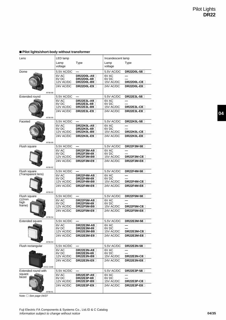
04/35Fuji Electric FA Components & Systems Co., Ltd./D & C CatalogInformation subject to change without notice
04
Pilot LightsDR22
Lens LED lamp Incandescent lamp
Lamp Type Lamp Typevoltage voltage
Dome 5.5V AC/DC — 5.5V AC/DC DR22D0L-586V AC DR22D0L-A9 6V AC —6V DC DR22D0L-69 6V DC —12V AC/DC DR22D0L-B9 15V AC/DC DR22D0L-C824V AC/DC DR22D0L-E9 24V AC/DC DR22D0L-E8
AF98-88
Extended round 5.5V AC/DC — 5.5V AC/DC DR22E3L-586V AC DR22E3L-A9 6V AC —6V DC DR22E3L-69 6V DC —12V AC/DC DR22E3L-B9 15V AC/DC DR22E3L-C824V AC/DC DR22E3L-E9 24V AC/DC DR22E3L-E8
AF98-90
Faceted 5.5V AC/DC — 5.5V AC/DC DR22K0L-586V AC DR22K0L-A9 6V AC —6V DC DR22K0L-69 6V DC —12V AC/DC DR22K0L-B9 15V AC/DC DR22K0L-C824V AC/DC DR22K0L-E9 24V AC/DC DR22K0L-E8
AF98-89
Flush square 5.5V AC/DC — 5.5V AC/DC DR22F3M-586V AC DR22F3M-A9 6V AC —6V DC DR22F3M-69 6V DC —12V AC/DC DR22F3M-B9 15V AC/DC DR22F3M-C824V AC/DC DR22F3M-E9 24V AC/DC DR22F3M-E8
AF98-92
Flush square 5.5V AC/DC — 5.5V AC/DC DR22F4M-58(Transparent lens) 6V AC DR22F4M-A9 6V AC —
6V DC DR22F4M-69 6V DC —12V AC/DC DR22F4M-B9 15V AC/DC DR22F4M-C824V AC/DC DR22F4M-E9 24V AC/DC DR22F4M-E8
AF98-92
Flush square 5.5V AC/DC — 5.5V AC/DC DR22F5M-58(12mm 6V AC DR22F5M-A9 6V AC —high 6V DC DR22F5M-69 6V DC —frame) 12V AC/DC DR22F5M-B9 15V AC/DC DR22F5M-C8
24V AC/DC DR22F5M-E9 24V AC/DC DR22F5M-E8
AF98-94
Extended square 5.5V AC/DC — 5.5V AC/DC DR22E3M-586V AC DR22E3M-A9 6V AC —6V DC DR22E3M-69 6V DC —12V AC/DC DR22E3M-B9 15V AC/DC DR22E3M-C824V AC/DC DR22E3M-E9 24V AC/DC DR22E3M-E8
AF98-93
Flush rectangular 5.5V AC/DC — 5.5V AC/DC DR22E3N-586V AC DR22E3N-A9 6V AC —6V DC DR22E3N-69 6V DC —12V AC/DC DR22E3N-B9 15V AC/DC DR22E3N-C824V AC/DC DR22E3N-E9 24V AC/DC DR22E3N-E8
KK02-234B
Extended round with 5.5V AC/DC — 5.5V AC/DC DR22E3P-58square 6V AC DR22E3P-A9 6V AC —bezel 6V DC DR22E3P-69 6V DC —
12V AC/DC DR22E3P-B9 15V AC/DC DR22E3P-C824V AC/DC DR22E3P-E9 24V AC/DC DR22E3P-E8
AF98-91
Pilot lights/short-body without transformer
Note: See page 04/37

04/36Fuji Electric FA Components & Systems Co., Ltd./D & C Catalog
Information subject to change without notice
Pilot LightsDR22
Pilot lights/short-body with transformer
Lens LED lamp Incandescent lampLamp voltage Type Lamp voltage Type
Dome 100–110V AC DR22D0L-H9 100–110V AC DR22D0L-H8200–220V AC DR22D0L-M9 200–220V AC DR22D0L-M8
Extended round 100–110V AC DR22E3L-H9 100–110V AC DR22E3L-H8200–220V AC DR22E3L-M9 200–220V AC DR22E3L-M8
Faceted 100–110V AC DR22K0L-H9 100–110V AC DR22K0L-H8200–220V AC DR22K0L-M9 200–220V AC DR22K0L-M8
Flush square 100–110V AC DR22F3M-H9 100–110V AC DR22F3M-H8200–220V AC DR22F3M-M9 200–220V AC DR22F3M-M8
Flush square 100–110V AC DR22F4M-H9 100–110V AC DR22F4M-H8(Transparent lens) 200–220V AC DR22F4M-M9 200–220V AC DR22F4M-M8
Flush square 100–110V AC DR22F5M-H9 100–110V AC DR22F5M-H8(12mm high 200–220V AC DR22F5M-M9 200–220V AC DR22F5M-M8frame)
Extended square 100–110V AC DR22E3M-H9 100–110V AC DR22E3M-H8200–220V AC DR22E3M-M9 200–220V AC DR22E3M-M8
Flush rectangular 100–110V AC DR22E3N-H9 100–110V AC DR22E3N-H8200–220V AC DR22E3N-M9 200–220V AC DR22E3N-M8
Extended round with 100–110V AC DR22E3P-H9 100–110V AC DR22E3P-H8square bezel 200–220V AC DR22E3P-M9 200–220V AC DR22E3P-M8
AF97-137
AF97-138
AF97-134
AF97-133
AF97-136
AF97-135
KK02-130A
KK02-134A
KK02-235B
Note: See page 04/37

04/37Fuji Electric FA Components & Systems Co., Ltd./D & C CatalogInformation subject to change without notice
04
Pilot LightsDR22
ColorCode
GreenG
RedR
WhiteW
BlueS
YellowY
OrangeA
Replace the mark by the following lens color code• Lens color
• Lamp voltageAvailable lamp voltage are as follow.
Description
Without transformer
With transformer
With resistor unit
Voltage
5.5V AC/DC6V AC6V DC12V AC/DC15V AC/DC20V AC/DC24V AC/DC100-110V AC115-127V AC200-220V AC230-254V AC350-380V AC 400-440V AC480V AC 500-550V AC110V DC
CodeStandard typeLED–A363B3C3–E3H3L3M3Q3S3T3V3W3H7
Incandescent54–––C4D4E4H4L4M4Q4S4T4V4W4–
Short-body typeLED–A969B9C9–E9H9L9M9––––––
Incandescent58–––C8D8E8H8L8M8––––––
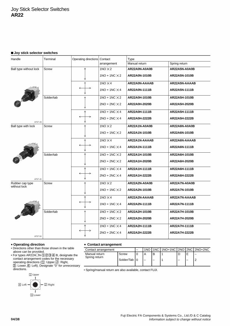
04/38Fuji Electric FA Components & Systems Co., Ltd./D & C Catalog
Information subject to change without notice
Joy stick selector switches
Handle Terminal Operating directions Contact Typearrangement Manual return Spring return
Ball type without lock Screw 1NO 2 AR22A0N-A0A0B AR22A5N-A0A0B
1NO + 1NC 2 AR22A0N-1010B AR22A5N-1010B
1NO 4 AR22A0N-AAAAB AR22A5N-AAAAB
1NO + 1NC 4 AR22A0N-1111B AR22A5N-1111B
Solder/tab 1NO + 1NC 2 AR22A0H-1010B AR22A5H-1010B
2NO + 2NC 2 AR22A0H-2020B AR22A5H-2020B
1NO + 1NC 4 AR22A0H-1111B AR22A5H-1111B
2NO + 2NC 4 AR22A0H-2222B AR22A5H-2222BAF97-49
Ball type with lock Screw 1NO 2 AR22A1N-A0A0B AR22A6N-A0A0B
1NO + 1NC 2 AR22A1N-1010B AR22A6N-1010B
1NO 4 AR22A1N-AAAAB AR22A6N-AAAAB
1NO + 1NC 4 AR22A1N-1111B AR22A6N-1111B
Solder/tab 1NO + 1NC 2 AR22A1H-1010B AR22A6H-1010B
2NO + 2NC 2 AR22A1H-2020B AR22A6H-2020B
1NO + 1NC 4 AR22A1H-1111B AR22A6H-1111B
2NO + 2NC 4 AR22A1H-2222B AR22A6H-2222BAF97-45
Rubber cap type Screw 1NO 2 AR22A2N-A0A0B AR22A7N-A0A0Bwithout lock
1NO + 1NC 2 AR22A2N-1010B AR22A7N-1010B
1NO 4 AR22A2N-AAAAB AR22A7N-AAAAB
1NO + 1NC 4 AR22A2N-1111B AR22A7N-1111B
Solder/tab 1NO + 1NC 2 AR22A2H-1010B AR22A7H-1010B
2NO + 2NC 2 AR22A2H-2020B AR22A7H-2020B
1NO + 1NC 4 AR22A2H-1111B AR22A7H-1111B
2NO + 2NC 4 AR22A2H-2222B AR22A7H-2222BAF97-56
Joy Stick Selector SwitchesAR22
• Operating direction• Directions other than those shown in the table
above can be provided.• For types AR22AN- 1 2 3 4 B, designate the
contact arrangement codes for the necessaryoperating directions ( 1 : Upper, 2 : Right,
3 : Lower, 4 : Left). Designate "0" for unnecessarydirections.
• Contact arrangementContact arrangementManual returnSpring return
Screw
Solder/Tab
1NO– 1NC 1NO+1NC 2NO 2NC 2NO+2NCA
–
0
0
B
–
1
1
D
–
E
–
–
2
1 Upper
3 Lower
2 Right4 Left
• Spring/manual return are also available, contact FUJI.
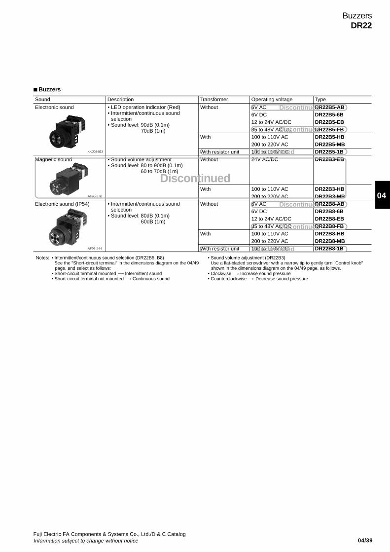
04/39Fuji Electric FA Components & Systems Co., Ltd./D & C CatalogInformation subject to change without notice
04
Sound Description
Electronic sound
Magnetic sound
Electronic sound (IP54)
Transformer
Without
With
With resistor unitWithout
With
Without
With
With resistor unit
Operating voltage
6V AC6V DC12 to 24V AC/DC35 to 48V AC/DC100 to 110V AC200 to 220V AC100 to 110V DC24V AC/DC
100 to 110V AC200 to 220V AC6V AC6V DC12 to 24V AC/DC35 to 48V AC/DC100 to 110V AC200 to 220V AC100 to 110V DC
Type
DR22B5-ABDR22B5-6BDR22B5-EBDR22B5-FBDR22B5-HBDR22B5-MBDR22B5-1BDR22B3-EB
DR22B3-HBDR22B3-MBDR22B8-ABDR22B8-6BDR22B8-EBDR22B8-FBDR22B8-HBDR22B8-MBDR22B8-1B
• Intermittent/continuous sound selection (DR22B5, B8) See the "Short-circuit terminal" in the dimensions diagram on the 04/49
page, and select as follows:• Short-circuit terminal mounted Intermittent sound• Short-circuit terminal not mounted Continuous sound
Notes: • Sound volume adjustment (DR22B3) Use a flat-bladed screwdriver with a narrow tip to gently turn "Control knob"
shown in the dimensions diagram on the 04/49 page, as follows.• Clockwise Increase sound pressure• Counterclockwise Decrease sound pressure
• LED operation indicator (Red)• Intermittent/continuous sound
selection• Sound level: 90dB (0.1m)
70dB (1m)
• Intermittent/continuous sound selection
• Sound level: 80dB (0.1m) 60dB (1m)
• Sound volume adjustment• Sound level: 80 to 90dB (0.1m)
60 to 70dB (1m)
KKD08-053
AF96-376
AF96-244
Buzzers
BuzzersDR22
Discontinued
Discontinued
Discontinued
Discontinued
Discontinued
Discontinued
Discontinued

04/40Fuji Electric FA Components & Systems Co., Ltd./D & C Catalog
Information subject to change without notice
Pushbuttons/Selectors/Pilot Lights/BuzzersAR22 and DR22Dimensions
Dimensions, mm• Illuminated pushbutton switches
AR22F0M, F5MAR22E0M, E5M
AR22F0P, F5PAR22E0P, E5P
AR22F0L, F5LAR22E0L, E5L
With transformer
Without transformer Mushroom (40mm dia.)
Mushroom (29mm dia.)
Flush/Extended
Extended with full guard
Push-lock, turn-reset
Extended with full guard (with openings)AR22G4L, G9LAR22G1L, G6L
AR22G2L, G7L
AR22M0L, M5L
AR22V5L
AR22M4L, M9L AR22M4P
1 80 17.5 (Extended)
12 (Flush)
3744
ø30
NutPackingTransformer
Terminal screw M3.5
Release armTerminal cover
Panel thickness 1 to 6
Note: *230V and over64*
22.5
37
ø24
30
22.5
37
24sq.
30sq.
22.5
37
ø24
30sq.
22.5
37
30
ø40
1 80
44 37
Terminal screw M3.5 Lamp terminal
40
60
NutPacking
Panel thickness 1 to 6
ø30
Terminal cover Release arm
251 80 17.5 (Extended)
12 (Flush)
ø30
Release armTerminal cover
NutPacking
Panel thickness 1 to 6
Terminal screw M3.5
3744
40
60
Lamp terminal
801
Terminal cover
44 37
Terminal screw M3.5 Lamp terminal
40
NutPacking
Packing
60
Panel thickness 1 to 6
ø30
Release arm
25
22.5
37
30
ø29
22.5
30sq.
ø29
37
22.5
ø24
30
37
80
Release arm
17.5
ø30
Panel thickness 1 to 6
Nut
40
60
Lamp terminal
44 37
1
Terminal cover
Terminal screw M3.5
ø30
17.5
22.5
ø24
30
37
Release arm
1
Terminal cover
44 37
Terminal screw M3.5
60
Lamp terminal
40
NutPacking
Packing
Panel thickness 1 to 6
80
40
Panel thickness 1 to 6
NutTerminal screw M3.5 Lamp
terminal
Release armTerminal cover
44 37
60 311
22.5
37
ø18
30
ø40
601
24.5
*

04/41Fuji Electric FA Components & Systems Co., Ltd./D & C CatalogInformation subject to change without notice
04
Pushbuttons/Selectors/Pilot Lights/BuzzersAR22 and DR22
Dimensions
Dimensions, mm• Pushbutton switches
AR22F0R, F5RAR22E0R, E5RAR22FAR, FBRAR22EAR, EBR
AR22F0S, F5SAR22E0S, E5S
AR22F0Y, F5YAR22E0Y, E5Y
AR22M4R, M9R AR22M4Y
AR22M3R, M8R
AR22V5R
AR22M0R, M5R AR22G3R, G8RAR22G2R, G7R
AR22S1R, S2RAR22S3R, S6R
AR22G0R, G5R
Ui 600V
Ith 10AJIS
Ui 600V
Ith 10AJIS
80 17.5 (Extended)
12 (Flush)
12 (Flush)
ø30
40
60
44 37
Panel thickness 1 to 6Packing
Nut
Panel thickness 1 to 6Packing
Nut
Terminal screw M3.5
Terminal cover Release arm
1
22.5
37
30
ø24
22.5
37
24sq.
30sq.
22.5
37
ø24
30sq.
3744
60
40
Terminal screw M3.5
Release arm
801
Terminal cover
ø30
25
22.5
30
ø40
37
60
80
Terminal cover
1
Terminal screw M3.5
44 37
40
NutPacking
Panel thickness 1 to 6
17.5 (Extended)
Release arm
44
60
801
37
40
25
ø30
Release armTerminal cover
Terminal screw M3.5NutPacking
Packing
Panel thickness 1 to 6
22.5
37
30
ø29
30sq.
37
22.5
ø29
Release arm
Terminal screw M3.5
Terminal cover
Nut Panel thickness 1 to 6
60
80
37
1
44
17.5
ø30
40
22.5
ø24
37
30
60
Release arm
80
37
1
44
Terminal cover
Terminal screw M3.5Nut
Packing
40
Panel thickness 1 to 6
25
ø40
ø47
37
1
44
Terminal cover Release arm
Terminal screw M3.5NutPacking
Panel thickness 1 to 6
40
60 31
22.5
37
ø18
30
ø40
Release arm
Panel thickness 1 to 6Packing
Nut
ø28
ø30
1
44
Terminal cover
Terminal screw M3.5
60
37
22.5
30
37
40
Flush/Extended
Mushroom (40mm dia.)
Mushroom (29mm dia.)
Extended with half guard Mushroom with full guard (40mm dia.)
Pushbutton with selector ring Push-lock, turn-reset
Flush/Extended with full guard
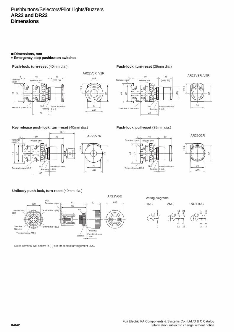
04/42Fuji Electric FA Components & Systems Co., Ltd./D & C Catalog
Information subject to change without notice
Pushbuttons/Selectors/Pilot Lights/BuzzersAR22 and DR22Dimensions
Dimensions, mm• Emergency stop pushbutton switches
AR22Q2R
AR22VGE
AR22V0R, V2R
AR22V7R
AR22VSR, V4R
1 3111 21
2 412 222
43
Push-lock, turn-reset (40mm dia.) Push-lock, turn-reset (29mm dia.)
Key release push-lock, turn-reset (40mm dia.)
Unibody push-lock, turn-reset (40mm dia.)
Wiring diagrams
1NC 2NC 1NO+1NC
Push-lock, pull-reset (35mm dia.)
60 31
Panel thickness 1 to 6Packing
Nut
Terminal cover
Terminal cover
1
40
Terminal screw M3.5
Release arm
44 37
30
ø40
22.5
37
ø18
22.5
30
37
Release arm
60Terminal cover
44 37
Terminal screw M3.5Nut Panel thickness
1 to 6
31
ø29
Packing
1
40
Release arm
60
37
1
44
Terminal screw M3.5 Terminal screw M3.5Nut Panel thickness
1 to 6
55.4
32
Packing
40
22.5
37
30
ø40
22.5
30
37
ø35
ø40ø30
Terminal cover
IP2XTerminal cover
1
44 37
Nut
Nut
Packing
Packing
Washer
Panel thickness 1 to 6
Panel thickness 1 to 6
40 30
Release arm
57 32
55
Terminal No.2(12)
Terminal No.3 (21)
Terminal No.4 (22)Terminal No.1(11)
Terminal screw M3.5
Note: Terminal No. shown in ( ) are for contact arrangement 2NC.
(V2R: 30) (V4R: 30)

04/43Fuji Electric FA Components & Systems Co., Ltd./D & C CatalogInformation subject to change without notice
04
Pushbuttons/Selectors/Pilot Lights/BuzzersAR22 and DR22
Dimensions
Dimensions, mm• Emergency stop illuminated pushbutton switches
AR22V0L, V2LAR22VDL, VAL
AR22VSL
2 4 X2
1 3 X111 21 X11 X1
12 22 X22 X2
Push-lock, turn-reset (40mm dia.)
With transformer
Push-lock, turn-reset (29mm dia.)
Without transformer
Unibody push-lock, turn-reset (40mm dia.)
Without transformer
Without transformer
43
Terminal No. 2 (12)
Terminal No. 1 (11)
Terminal screw M3.5
Note: Terminal No. shown in ( ) are for contact arrangement 2NC.
Note: *1 230V and over*2 AR22V2L and VAL types only
Lamp terminal screw M3.5
Terminal No. 3 (21)
ø30
ø4057 32
55
Terminal No. 4 (22)
IP2XTerminal cover
Terminal No. X2
Washer
Packing
Panel thickness1 to 6
NutTerminal No. X1
Wiring diagrams
1NC 2NC 1NO+1NC
Terminal cover
31
30*2
Panel thickness 1 to 6
NutTransformerTerminal screw M3.5
44 37
24.5
*1
Packing
64*1
601
ø18
ø40
30
37
22.5
Release arm
60
Terminal cover
44
1
37
NutPacking
Panel thickness 1 to 6
31
Terminal screw M3.5
Terminal screw M3.5
Lamp terminal 40
30*2
601 31ø18
37
22.5
30
Release arm
3744
Terminal cover
NutPacking
Lamp terminal
Panel thickness 1 to 6
ø29
40
AR22VGF

04/44Fuji Electric FA Components & Systems Co., Ltd./D & C Catalog
Information subject to change without notice
Dimensions, mm• Selector switches
Pushbuttons/Selectors/Pilot Lights/BuzzersAR22 and DR22Dimensions
40
Release armø
30
23
Terminal screw M3.5
80
Terminal cover
44 37
60
PackingNut Panel thickness
1 to 6
1
ø24
30
37
22.5
22.5
37
ø24
30sq.
Packing
40
Nut
80
60
3744
1
Terminal cover
Terminal screw M3.5
Release arm
Panel thickness 1 to 6
23
ø30 37
22.5
ø24
30
2722
.5
30sq.
ø2437
27
Packing
40
80
60
Release arm
Terminal screw M3.5
Terminal cover
1
44 37
Nut
23
ø30
Panel thickness 1 to 6
ø24
30
37
22.5
22.5
30sq.
ø24
37
Packing
40
80
60
Nut
3744
1
Terminal cover
Terminal screw M3.5
Release arm
Panel thickness 1 to 6
ø30
20 24
22.5
30
37
22.5
37
30sq.
ø24 ø24
AR22PR, PCR AR22PY, PCY
AR22WR, WCR AR22WY, WCY
AR22RR, RCR AR22RY, RCY
AR22JR, JCRAR22JAR
AR22JY, JCY
Knob
Lever
Cylindrical knob
Key
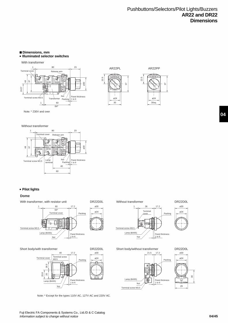
04/45Fuji Electric FA Components & Systems Co., Ltd./D & C CatalogInformation subject to change without notice
04
Dimensions, mm• Illuminated selector switches
Pushbuttons/Selectors/Pilot Lights/BuzzersAR22 and DR22
Dimensions
Nut
60
801
1
3744
24.5
*
TransformerTerminal screw M3.5
Terminal cover
64*
Panel thickness 1 to 6Packing
23
ø30
Release arm
22.5
30
ø24
37
22.5
37
ø24
30sq.
60
40
Packing
Release arm
NutTerminal screw M3.5 Lamp
terminalPanel thickness 1 to 6
Terminal cover
801
3744
23
ø30
With transformer
AR22PL AR22PP
Without transformer
Note: * 230V and over
• Pilot lights
60
64*
1
Terminal cover
Terminal screw M3.5
17.2
Packing
Panel thickness 1 to 6
Panel thickness 1 to 6
Panel thickness 1 to 6
Panel thickness 1 to 6
Nut
Lamp (BA9S)
ø30
ø24
17.2
Packing
Nut
Lamp (BA9S)
Terminal cover
Terminal screw M3.5
361 ø30
ø24
17.2
Packing
40
Terminal screw M3.5
Terminal cover
18.3
20.8
Lamp (BA9S)
Nut
20
ø24
ø30 17.2
Packing
Nut
Lamp (BA9S)
21.5
Terminal screw M3.5
ø24
ø30
30
29
Note: * Except for the types 110V AC, 127V AC and 220V AC.
With transformer, with resistor unit Without transformer
Short body/with transformer Short body/without transformer
Dome
DR22D0L DR22D0L
DR22D0L DR22D0L
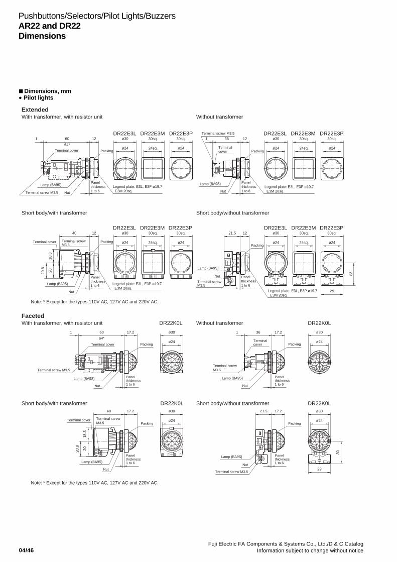
04/46Fuji Electric FA Components & Systems Co., Ltd./D & C Catalog
Information subject to change without notice
Pushbuttons/Selectors/Pilot Lights/BuzzersAR22 and DR22Dimensions
Dimensions, mm• Pilot lights
60
64*
1
Terminal screw M3.5
Lamp (BA9S)Panel thickness 1 to 6
Panel thickness 1 to 6
Panel thickness 1 to 6
Panel thickness 1 to 6
Panel thickness 1 to 6
Panel thickness 1 to 6
Panel thickness 1 to 6
Packing
12 ø30
ø24 24sq.
30sq.
ø24
30sq.DR22E3L DR22E3M DR22E3P
Legend plate: E3L, E3P ø19.7 E3M 20sq.
12
Packing
Legend plate: E3L, E3P ø19.7 E3M 20sq.
Lamp (BA9S)
361Terminal screw M3.5
Terminal cover
30sq.
ø24
30sq.
24sq.
ø30
ø24
DR22E3L DR22E3M DR22E3P
Legend plate: E3L, E3P ø19.7 E3M 20sq.
12
Nut
Lamp (BA9S)
40
Terminal screw M3.5
Terminal cover
18.3
2020.8
Packing
ø30
ø24
30sq.
24sq. ø24
30sq.DR22E3L DR22E3M DR22E3P
12
Packing
Legend plate: E3L, E3P ø19.7 E3M 20sq.
Lamp (BA9S)
Nut
Terminal screw M3.5
21.5 ø30
ø24 24sq.
30sq. 30sq.
ø24
DR22E3L DR22E3M DR22E3P
30
29
60
64*
1
Terminal cover
17.2
Packing
Terminal screw M3.5
Lamp (BA9S)
Nut
ø24
ø30 17.2361
Terminal screw M3.5
Terminal cover Packing
Nut
Lamp (BA9S)
ø30
ø24
40 17.2
Packing Packing
Nut
Lamp (BA9S)
20.8
2018
.3
Terminal cover Terminal screw M3.5
ø30
ø24
17.221.5
Lamp (BA9S)
Nut
Terminal screw M3.5
ø30
ø24
30
29
ExtendedWith transformer, with resistor unit Without transformer
FacetedWith transformer, with resistor unit DR22K0L DR22K0LWithout transformer
Short body/with transformer Short body/without transformer
Short body/with transformer DR22K0L DR22K0LShort body/without transformer
Terminal cover
Nut Nut
Panel thickness 1 to 6
Note: * Except for the types 110V AC, 127V AC and 220V AC.
Note: * Except for the types 110V AC, 127V AC and 220V AC.
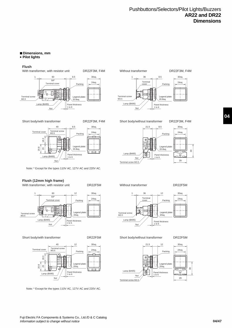
04/47Fuji Electric FA Components & Systems Co., Ltd./D & C CatalogInformation subject to change without notice
04
Pushbuttons/Selectors/Pilot Lights/BuzzersAR22 and DR22
Dimensions
Dimensions, mm• Pilot lights
60
64*
Lamp (BA9S)
Lamp (BA9S)
Lamp (BA9S)
Terminal screw M3.5
Terminal screw M3.5
Terminal screw M3.5
Terminal screw M3.5
1 8.5
24sq.
30sq. 30sq.
24sq.
8.5361
30sq.
24sq.
8.5
18.3
20.8
20
40
24sq.
30sq.8.5
30
29
21.5
Lamp (BA9S)
Packing
60
64*
1
Terminal screw M3.5
Terminal screw M3.5
Terminal cover
Lamp (BA9S)
Nut
Panel thickness 1 to 6
Panel thickness 1 to 6
Panel thickness 1 to 6
Panel thickness 1 to 6
24sq.
30sq.12 30sq.
24sq.
12
PackingTerminal cover
361
Terminal screw M3.5
Terminal screw M3.5
Lamp (BA9S)
Nut
30sq.
24sq.
12
Packing
40
Terminal cover
18.3
2020.8
Lamp (BA9S)
NutNut
30sq.
24sq.
12
Packing
21.5
Lamp (BA9S)
29
30
FlushWith transformer, with resistor unit DR22F3M, F4M DR22F3M, F4MWithout transformer
Flush (12mm high frame)With transformer, with resistor unit DR22F5M DR22F5MWithout transformer
Short body/with transformer DR22F3M, F4M DR22F3M, F4MShort body/without transformer
Short body/with transformer DR22F5M DR22F5MShort body/without transformer
Terminal cover
Terminal cover
Terminal cover
Nut
Nut
Nut
Nut
Packing
Packing Packing
Packing
Panel thickness 1 to 6
Panel thickness 1 to 6
Panel thickness 1 to 6
Panel thickness 1 to 6
Legend plate: 20.8sq.
Legend plate: 20.8sq.
Legend plate: 20.8sq.
Legend plate: 20.8sq.
Legend plate: 20sq.
Legend plate: 20sq.
Legend plate: 20sq.
Legend plate: 20sq.
Note: * Except for the types 110V AC, 127V AC and 220V AC.
Note: * Except for the types 110V AC, 127V AC and 220V AC.
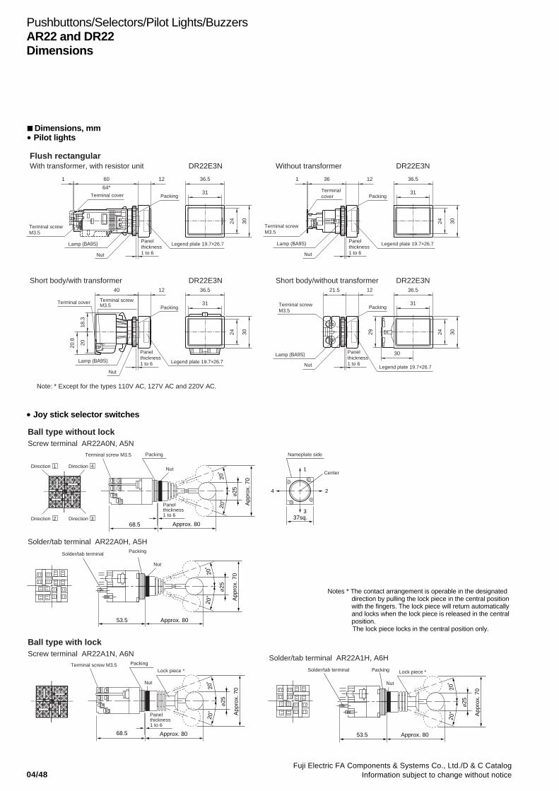
04/48Fuji Electric FA Components & Systems Co., Ltd./D & C Catalog
Information subject to change without notice
Pushbuttons/Selectors/Pilot Lights/BuzzersAR22 and DR22Dimensions
Dimensions, mm• Pilot lights
Packing
60
64*
1
Terminal screw M3.5
Lamp (BA9S)
Nut
Legend plate 19.7×26.7
Legend plate 19.7×26.7
31
36.5
24 30
12 36.5
31
24 30
12
Legend plate 19.7×26.7
PackingTerminal cover
361
Terminal screw M3.5
Lamp (BA9S)
Nut
Packing
Nut
Lamp (BA9S)
36.5
31
24 30
12
20.8
2018
.3
Terminal cover Terminal screw M3.5
40 36.5
31
24 30
12
Legend plate 19.7×26.7
21.5
Nut
Lamp (BA9S)
Terminal screw M3.5
30
29
Packing
Flush rectangularWith transformer, with resistor unit DR22E3N DR22E3N
DR22E3N DR22E3N
Without transformer
Short body/with transformer Short body/without transformer
Terminal cover
Panel thickness 1 to 6
Panel thickness 1 to 6
Panel thickness 1 to 6
Panel thickness 1 to 6
Note: * Except for the types 110V AC, 127V AC and 220V AC.
• Joy stick selector switches
37sq.
Terminal screw M3.5 Packing
PackingSolder/tab terminal
Nameplate side
Center
20˚
20˚
ø25
App
rox.
70
68.5 Approx. 80
4 2
1
3
53.5
20˚
20˚
ø25
App
rox.
70
Approx. 80
Terminal screw M3.5
20˚
20˚
ø25
App
rox.
70
68.5 Approx. 80
Lock piece * Solder/tab terminal
53.5
Packing
20˚
20˚
ø25
App
rox.
70
Approx. 80
Lock piece *
Ball type without lock
Ball type with lock
Screw terminal AR22A0N, A5N
Solder/tab terminal AR22A0H, A5H
Screw terminal AR22A1N, A6N Solder/tab terminal AR22A1H, A6H
Nut Nut
Nut
Nut
Packing
Panel thickness 1 to 6
Panel thickness 1 to 6
Direction 2
Direction 1
Direction 3
Direction 4
Notes * The contact arrangement is operable in the designateddirection by pulling the lock piece in the central positionwith the fingers. The lock piece will return automaticallyand locks when the lock piece is released in the centralposition.
The lock piece locks in the central position only.

04/49Fuji Electric FA Components & Systems Co., Ltd./D & C CatalogInformation subject to change without notice
04
Pushbuttons/Selectors/Pilot Lights/BuzzersAR22 and DR22
Dimensions
Dimensions, mm• Joy stick selector switches
• Buzzers
PackingTerminal screw M3.5
20˚
20˚
Panel thickness 1 to 6
Approx. 7668.5
ø10
ø10
App
rox.
60
37sq.
Nameplate side
4 2
1
3
Nut
Solder/tab terminal
53.5
Packing
20˚
20˚
Approx. 76
App
rox.
60
Nut
Rubber cap type without lockScrew terminal AR22A2N, A7N
Electronic sound
Solder/tab terminal AR22A2H, A7H
With transformer DR22B5 DR22B5
DR22B3 DR22B3
DR22B8 DR22B8
Without transformer
Magnetic soundWith transformer Without transformer
Electronic sound (IP54)With transformer Without transformer
65 13ø20.5 ø20.5
ø29
.5
Transformer
Terminal screw M3.5 Terminal screw M3.5
Short-circuit terminal Short-circuit terminal
24.5
LED lamp(Red)
LED lamp(Red)
30
37
ø29
.5
23.5
Nut
1350.51.5
37
30
Lamp terminalNut
Packing PackingPanel thickness 1 to 6
Panel thickness 1 to 6
ø20.5 ø20.513
ø29
.5
Packing
Nut Control knob Control knob85
24.5
Transformer
Terminal screw M3.5
37
30
23.5
13
Nut
Packing
ø29
.5
70.51.5
Terminal screw M3.5
Lamp terminal
37
30Panel thickness 1 to 6
Panel thickness 1 to 6
23.5
Transformer 65
Nut
Packing
24.5
Terminal screw M3.5
18.5
ø24
ø30 37
30
Lamp terminal
50.51.5
Nut
Terminal screw M3.5
Packing
18.5
ø24
ø30
30
37
Panel thickness 1 to 6
Panel thickness 1 to 6Short-circuit terminal Short-circuit terminal
Discontinued

04/50Fuji Electric FA Components & Systems Co., Ltd./D & C Catalog
Information subject to change without notice
Pushbuttons/Selectors/Pilot Lights/BuzzersAR22 and DR22Notes on use
Notes on use
Fit two sizes of panel cutout holes
* The unique nut with a step allows switch to be mounted ineither 22.3mm- or 25.5mm-dia. holes as shown in Fig. 1 withoutany extra adapter.
Fig. 1 Panel cutout
➁ In a 25.5mm-dia. panel cutout holeAs shown in Fig. 4, with the nut step-out side oriented to thepanel, use the wrench to tighten the nut and secure theoperator.
Fig. 4 Mounting a operator in a 25.5mm-dia. hole
Note: 1. Recommended tightening torque is from 1 to 1.5N•m2. Ensure that the step-out portion of the nut is correctly fitted in the
cutout hole.
For easier mounting in the 25.5mm-dia. hole, the AR9Y718adapter is also available separately.
Fig. 5 Mounting with an adapter and locking nut
Mounting contact block to the operator
As shown in Fig. 6, align the protruding part of the contact blockrelease arm with the operator groove at the mark. Then,insert the contact block into the operator until it clicks.
Fig. 6 Mounting the contact block to the operator
The switch mounted as aφ25mm diameter unit.
The switch mounted as aφ22mm diameter unit.
Note: * If key-washer or legend plate are not used, 3.2mm-wide location holesneed not be cutout.
Detaching contact block from the operator
While keeping the white release arm pressed with one finger,pull-out the contact block in the direction by the arrow.
Fig. 2 Detaching contact block from the operator
Mounting operator to panel
➀ In a 22.3mm-dia. panel cutout holeInsert the operator into the cutout hole from the panel front asshown in the Fig. 3.Then, fit section “A” of the AR9A004 wrench from behind thepanel and secure the operator with nut. (See page 04/108 forthe wrench)
Fig. 3 Mounting an operator in a 22.3mm-dia. hole
Note: Recommended tightening torque is from 1 to 1.5N•m
ø25.5+0.5mm0
rmax=0.8mm* 3.2+0.2mm
ø22.3+0.4mm0
0
24.1+0.4mm0
Operator Contact block
Release arm Pressed
Pull-out
Wrench (AR9A004, Section A)
Panel
Operator
Packing Nut
Wrench (AR9A004, Section A)Panel
Operator
Packing Nut
Panel
Adapter for 25.5mm-dia.
Nut
Operator
Correct Incorrect
Panel Panel
View from above
Release arm
Contact block
Operator
Groove with mark
Groove with mark
Packing
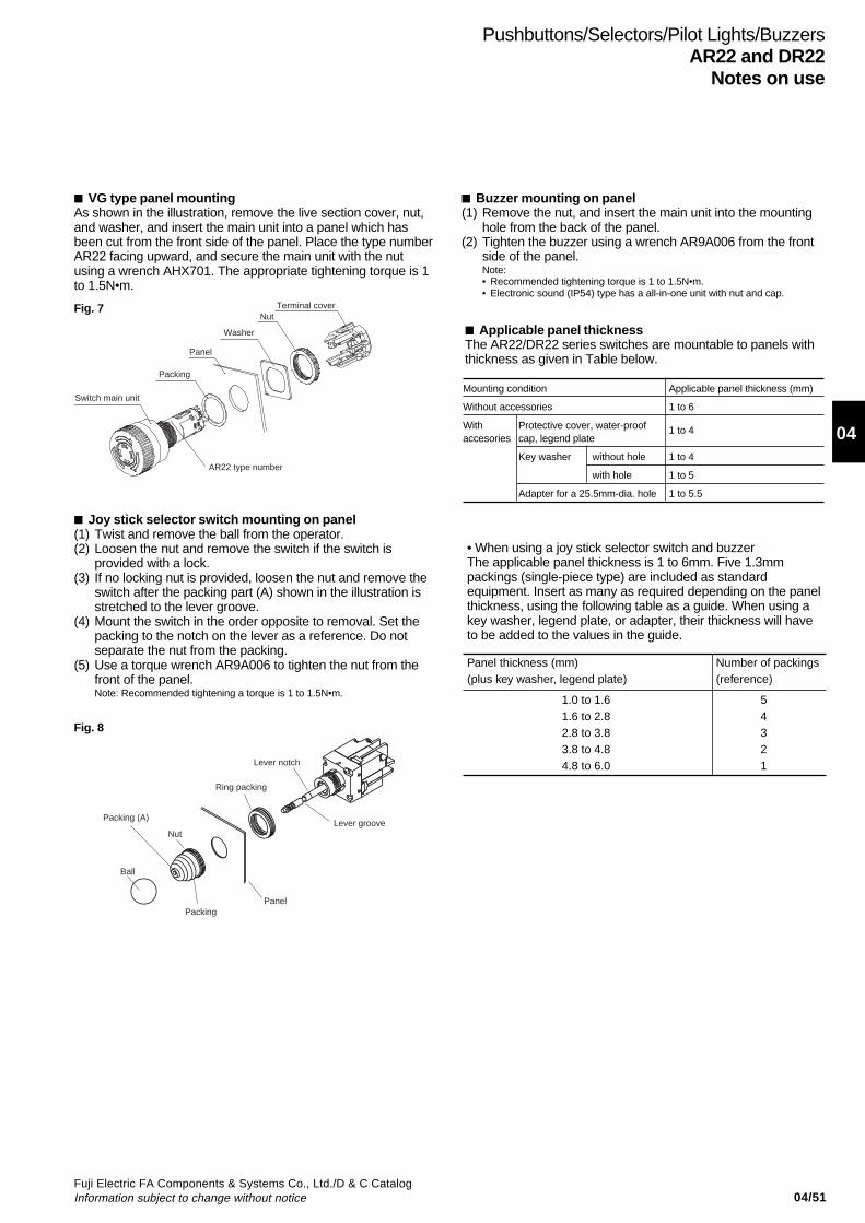
04/51Fuji Electric FA Components & Systems Co., Ltd./D & C CatalogInformation subject to change without notice
04
Applicable panel thicknessThe AR22/DR22 series switches are mountable to panels withthickness as given in Table below.
Mounting condition Applicable panel thickness (mm)
Without accessories 1 to 6
With Protective cover, water-proofaccesories cap, legend plate
1 to 4
Key washer without hole 1 to 4
with hole 1 to 5
Adapter for a 25.5mm-dia. hole 1 to 5.5
Pushbuttons/Selectors/Pilot Lights/BuzzersAR22 and DR22
Notes on use
VG type panel mountingAs shown in the illustration, remove the live section cover, nut,and washer, and insert the main unit into a panel which hasbeen cut from the front side of the panel. Place the type numberAR22 facing upward, and secure the main unit with the nutusing a wrench AHX701. The appropriate tightening torque is 1to 1.5N•m.
Joy stick selector switch mounting on panel(1) Twist and remove the ball from the operator.(2) Loosen the nut and remove the switch if the switch is
provided with a lock.(3) If no locking nut is provided, loosen the nut and remove the
switch after the packing part (A) shown in the illustration isstretched to the lever groove.
(4) Mount the switch in the order opposite to removal. Set thepacking to the notch on the lever as a reference. Do notseparate the nut from the packing.
(5) Use a torque wrench AR9A006 to tighten the nut from thefront of the panel.Note: Recommended tightening a torque is 1 to 1.5N•m.
Buzzer mounting on panel(1) Remove the nut, and insert the main unit into the mounting
hole from the back of the panel.(2) Tighten the buzzer using a wrench AR9A006 from the front
side of the panel.Note:• Recommended tightening torque is 1 to 1.5N•m.• Electronic sound (IP54) type has a all-in-one unit with nut and cap.
Terminal coverNut
Washer
Panel
Packing
Switch main unit
AR22 type number
Ball
Lever notch
Lever groove
Ring packing
Panel
Packing (A)
Nut
Packing
Fig. 7
Fig. 8
• When using a joy stick selector switch and buzzerThe applicable panel thickness is 1 to 6mm. Five 1.3mmpackings (single-piece type) are included as standardequipment. Insert as many as required depending on the panelthickness, using the following table as a guide. When using akey washer, legend plate, or adapter, their thickness will haveto be added to the values in the guide.
Panel thickness (mm)(plus key washer, legend plate)
Number of packings (reference)
1.0 to 1.61.6 to 2.82.8 to 3.83.8 to 4.84.8 to 6.0
54321

04/52Fuji Electric FA Components & Systems Co., Ltd./D & C Catalog
Information subject to change without notice
Minimum mounting space, mm(1) Minimum mounting space
Illuminated pushbuttons,Pushbutton Selectors
Pilot Light
Notes: *1 AR22M0 , M5 , V5 , V0 , V2 , V7R, VG : 42mmAR22M3R, M8R: 49mmAR22Q2R, WR, W0R, WY, WCY: 40mm
*2 When mounting contact blocks at 30mm pitch, use it circuit of380V or less.
*3 Short body with transformer types: 50mm.*4 Rectangular types: 36.5mm (except for short body without
transformer types).*5 Short body without transformer types: 60mm.*6 Rectangular short body without transformer types: 60mm.*7 This dimension applies when transformer units or contact blocks
face each other.*8 This dimension applies when transformer unit or contact block is
mounted on only one side.
When mounting operators on a panel, orient all marks on theoperator upwards.(The operator release arms are oriented upwards.) This alignsthe terminals of all contact blocks, thus making wiring easy.
(2) Detaching contact blocks from operatorsAs shown in Fig. 10, insert a flat-head screw driver into thegroove of the white release arm on the contact block. Then,while inserting the driver in hole A of the operator base, lowerthe driver grip and take out the contact block.
Note: Use a flat head screwdriver as shownat the right.
6mm or less
Pushbuttons/Selectors/Pilot Lights/BuzzersAR22 and DR22Notes on use
30*2
50*7 42*1 *8
42*1 30*4 *6
30*3
*5
Release arm
Hole A on theoperator base
Pull-out
Contact blockOperator
Products with blue and green LEDsThe LED devices on products with high-brightness (blue andgreen) LEDs are very sensitive to static electricity. Whenreplacing LED lamps do not allow static electricity to come intodirect contact with the metal frame on the upper side of the LEDlamp. The LED device may be damaged if this part is subjectedto static electricity. When installing or removing an LED lamp, itis recommended that you use the lamp changer (AHX790).
Fig. 9
Fig. 10
Wiring(1) The terminal screws are M3.5 pan head screws. Solid wires,
stranded wires, or crimp terminals can be connected.
(2) Two crimp terminals can be used by putting one of them ontop of the other. If fork-type crimp terminals are used in thehorizontal direction, however, use ones as shown in thefigure below. (i.e., Toei Tanshi's F2-3.5S or an equivalent).
(3) The terminal washers are a self-lifting type.(4) Tighten the terminal screws to a tightening torque of 0.8 to
1N•m.(5) Keep the terminals free of external force while wiring or after
wiring, or operational failures may result.(6) Do not use screws other than the provided terminal screws.
Notes:• If solid wires are connected to the lamp terminals in the horizontal direction
(on the side), be sure to insert the solid wires into the square washers.• Terminal layout., see page 04/54• See page 04/53 for the wiring of the joy stick selector switch and VG type.
LED Indicator(1) LED Lamp MalfunctioningThe LED lamp is lit by a very small level of current.Therefore, it may be erroneously lit by a leaking current from thesurge absorption circuit or semiconductor circuit or due to straycapacitance between cables. In that case, provide acountermeasure (e.g., connect a resistor in parallel with the LEDlamp).• Countermeasure for MalfunctioningThe LED lamp malfunctions can be prevented by connecting ashunt resistor (R) or CR elements (a capacitor and resistor) inparallel with the LED lamp terminal. The resistance and CRvalues vary depending on the model and the operatingconditions.
8mm
1.6mm dia. max.8mm max.
Flat plate width: 11.1mm max.
Width: 6.4mm max.
Lamp
Shunt resistor
X1 X2 X1 X2
Transformer
CR RC: CapacitorR: Resistor
Example 1 Example 2
• 24V DC R: 10kΩ (0.5W)• 24V AC R: 2kΩ (2W)
• 100V AC C: 0.33µF (250V AC) R: 120Ω (0.25W)• 220V AC C: 0.1µF (250V AC) R: 120Ω (0.25W)
X1 X2
Resistor unit
C RC: CapacitorR: Resistor
Example 3
• 110V DC C: 4700pF (250V DC) R: 100Ω (0.5W)
Metal frame
LED lamp
Fig. 12
Fig. 13
Fig. 14
Fig. 11(2) Incoming surgeHigh luminance LED products use an element sensitive to staticelectricity. They may not be lit by an abnormal voltage likesurge. Please note it.
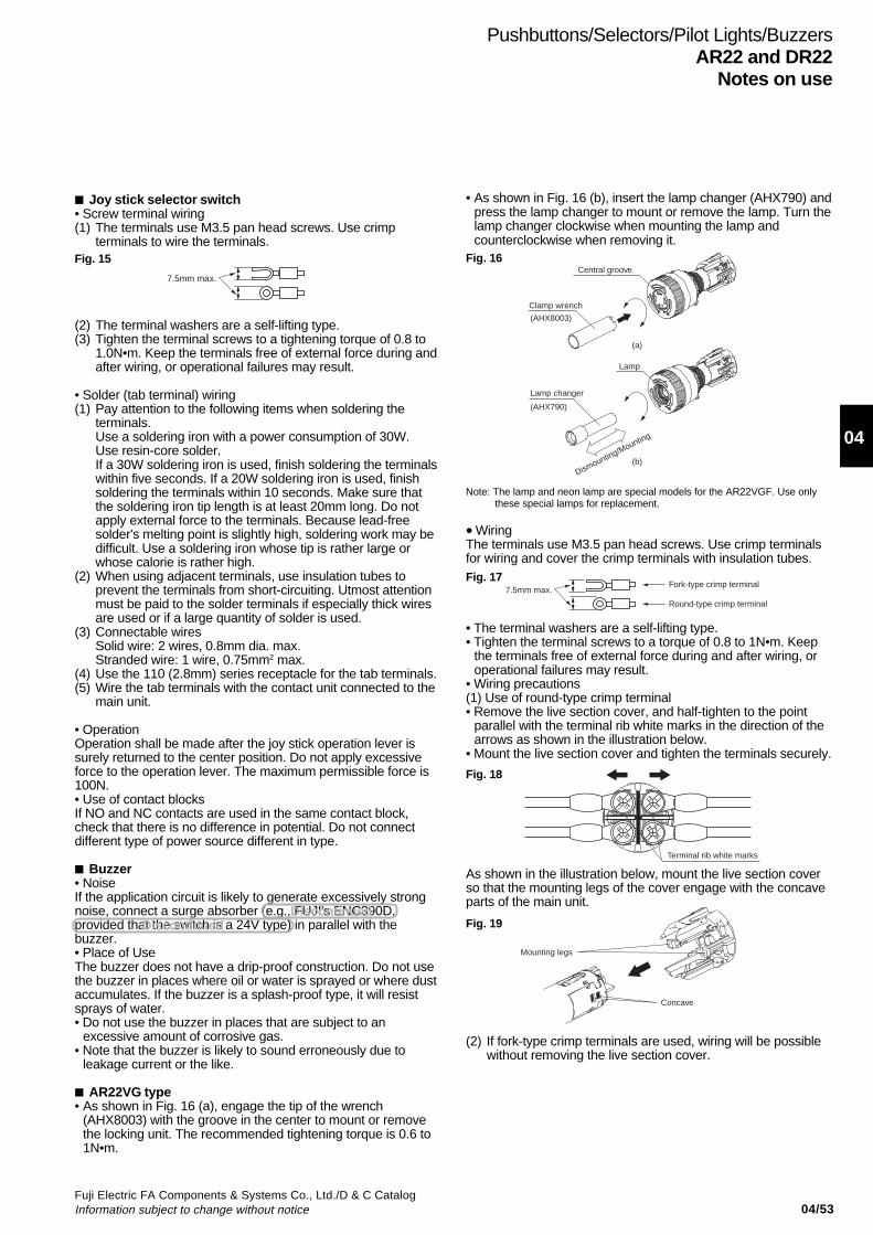
04/53Fuji Electric FA Components & Systems Co., Ltd./D & C CatalogInformation subject to change without notice
04
Pushbuttons/Selectors/Pilot Lights/BuzzersAR22 and DR22
Notes on use
Joy stick selector switch• Screw terminal wiring(1) The terminals use M3.5 pan head screws. Use crimp
terminals to wire the terminals.
(2) The terminal washers are a self-lifting type.(3) Tighten the terminal screws to a tightening torque of 0.8 to
1.0N•m. Keep the terminals free of external force during andafter wiring, or operational failures may result.
• Solder (tab terminal) wiring(1) Pay attention to the following items when soldering the
terminals.Use a soldering iron with a power consumption of 30W.Use resin-core solder.If a 30W soldering iron is used, finish soldering the terminalswithin five seconds. If a 20W soldering iron is used, finishsoldering the terminals within 10 seconds. Make sure thatthe soldering iron tip length is at least 20mm long. Do notapply external force to the terminals. Because lead-freesolder's melting point is slightly high, soldering work may bedifficult. Use a soldering iron whose tip is rather large orwhose calorie is rather high.
(2) When using adjacent terminals, use insulation tubes toprevent the terminals from short-circuiting. Utmost attentionmust be paid to the solder terminals if especially thick wiresare used or if a large quantity of solder is used.
(3) Connectable wiresSolid wire: 2 wires, 0.8mm dia. max.Stranded wire: 1 wire, 0.75mm2 max.
(4) Use the 110 (2.8mm) series receptacle for the tab terminals.(5) Wire the tab terminals with the contact unit connected to the
main unit.
• OperationOperation shall be made after the joy stick operation lever issurely returned to the center position. Do not apply excessiveforce to the operation lever. The maximum permissible force is100N.• Use of contact blocksIf NO and NC contacts are used in the same contact block,check that there is no difference in potential. Do not connectdifferent type of power source different in type.
Buzzer• NoiseIf the application circuit is likely to generate excessively strongnoise, connect a surge absorber (e.g., FUJI's ENC390D,provided that the switch is a 24V type) in parallel with thebuzzer.• Place of UseThe buzzer does not have a drip-proof construction. Do not usethe buzzer in places where oil or water is sprayed or where dustaccumulates. If the buzzer is a splash-proof type, it will resistsprays of water.• Do not use the buzzer in places that are subject to an
excessive amount of corrosive gas.• Note that the buzzer is likely to sound erroneously due to
leakage current or the like.
AR22VG type• As shown in Fig. 16 (a), engage the tip of the wrench
(AHX8003) with the groove in the center to mount or removethe locking unit. The recommended tightening torque is 0.6 to1N•m.
7.5mm max.
• As shown in Fig. 16 (b), insert the lamp changer (AHX790) andpress the lamp changer to mount or remove the lamp. Turn thelamp changer clockwise when mounting the lamp andcounterclockwise when removing it.
Note: The lamp and neon lamp are special models for the AR22VGF. Use onlythese special lamps for replacement.
• WiringThe terminals use M3.5 pan head screws. Use crimp terminalsfor wiring and cover the crimp terminals with insulation tubes.
• The terminal washers are a self-lifting type.• Tighten the terminal screws to a torque of 0.8 to 1N•m. Keep
the terminals free of external force during and after wiring, oroperational failures may result.
• Wiring precautions(1) Use of round-type crimp terminal• Remove the live section cover, and half-tighten to the point
parallel with the terminal rib white marks in the direction of thearrows as shown in the illustration below.
• Mount the live section cover and tighten the terminals securely.
As shown in the illustration below, mount the live section coverso that the mounting legs of the cover engage with the concaveparts of the main unit.
(2) If fork-type crimp terminals are used, wiring will be possiblewithout removing the live section cover.
(a)
(b)
(AHX8003)
(AHX790)
Central groove
Clamp wrench
Lamp
Lamp changer
Dismounting/Mounting
7.5mm max.Fork-type crimp terminal
Round-type crimp terminal
Terminal rib white marks
Mounting legs
Concave
Fig. 15 Fig. 16
Fig. 17
Fig. 18
Fig. 19DiscontinuedDiscontinued
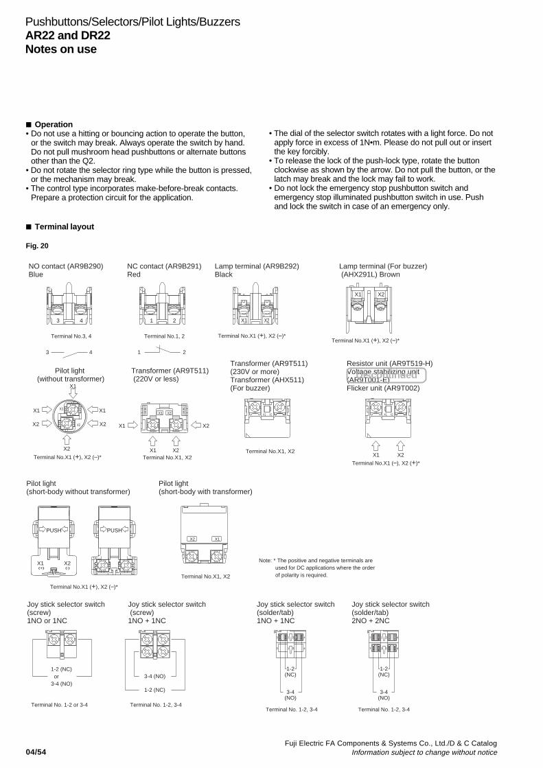
04/54Fuji Electric FA Components & Systems Co., Ltd./D & C Catalog
Information subject to change without notice
Operation• Do not use a hitting or bouncing action to operate the button,
or the switch may break. Always operate the switch by hand.Do not pull mushroom head pushbuttons or alternate buttonsother than the Q2.
• Do not rotate the selector ring type while the button is pressed,or the mechanism may break.
• The control type incorporates make-before-break contacts.Prepare a protection circuit for the application.
• The dial of the selector switch rotates with a light force. Do notapply force in excess of 1N•m. Please do not pull out or insertthe key forcibly.
• To release the lock of the push-lock type, rotate the buttonclockwise as shown by the arrow. Do not pull the button, or thelatch may break and the lock may fail to work.
• Do not lock the emergency stop pushbutton switch andemergency stop illuminated pushbutton switch in use. Pushand lock the switch in case of an emergency only.
X1 X2
(-) (+)
X2X1
(-) (+)
2
2
21
Terminal No.3, 4
3 1 24
NO contact (AR9B290) Blue
43
Lamp terminal (AR9B292) Black
Terminal No.X1 (+), X2 (–)*
NC contact (AR9B291) Red
Terminal No.1, 2
1 2
Lamp terminal (For buzzer) (AHX291L) Brown
Terminal No.X1 (+), X2 (–)*
X2X1
X2
X1
X1X2 X2
X2
X1
X1X1
Terminal No.X1 (–), X2 (+)*
Resistor unit (AR9T519-H) Voltage stabilizing unit (AR9T001-E) Flicker unit (AR9T002)
Terminal No.X1 (+), X2 (–)*
Pilot light (short-body without transformer)
Pilot light (short-body with transformer)
Terminal No.X1, X2
Transformer (AR9T511) (230V or more) Transformer (AHX511) (For buzzer)
Transformer (AR9T511) (220V or less)
Terminal No.X1 (+), X2 (–)*
Pilot light (without transformer)
Terminal No.X1, X2
1-2 (NC) or3-4 (NO)
Joy stick selector switch (screw)1NO or 1NC
Terminal No. 1-2 or 3-4
1-2 (NC)
3-4 (NO)
1-2 (NC)
3-4 (NO)
Joy stick selector switch (solder/tab)1NO + 1NC
Terminal No. 1-2, 3-4Terminal No. 1-2, 3-4
Joy stick selector switch (screw)1NO + 1NC
1-2 (NC)
3-4 (NO)
Terminal No. 1-2, 3-4
Joy stick selector switch (solder/tab)2NO + 2NC
X2X1
Terminal No.X1, X2X2
X2X1
X2
X1
X2X1
PUSH PUSH
X1X2
3 41
413 3 1 2 4
43
Note: * The positive and negative terminals are used for DC applications where the order of polarity is required.
X1 X2
Terminal layout
Pushbuttons/Selectors/Pilot Lights/BuzzersAR22 and DR22Notes on use
Fig. 20
Discontinued

04/55Fuji Electric FA Components & Systems Co., Ltd./D & C CatalogInformation subject to change without notice
04
Pushbuttons/Selectors/Pilot Lights/BuzzersAR30 and DR30
General information
The full range of the contact blocks andtransformer units suitable for the AR22and DR22 series may also be fitted tothe AR30 and DR30 series.
FeaturesQuick-replacement contact blocksand transformer unitsThe snap-on construction makesreplacement and addition of contactblocks and transformer units very simpleand straightforward.
Oil-and dust-proof operator moduleconstructionThe protection level of the AR30/DR30operator modules conforms to IECStandard IP65. The special sealsprotect the operator modules and switchmechanisms against oil, dust, and grime,thus ensuring high performance in dustyand moist environments.
Miniaturization• Selector switches with 1NO+1NC:
41mm deepPilot lights: 34mm deep
• The transformer now occupies far lessspace.
Metal nutSafer model with metal nut is alsoavailable
Wiring• Wiring from two directions is possible.• Wiring in both vertical and lateral
directions facilitates wiring in narrowspaces.
• Color coding of contact blocksmakes wiring easy.1NO: Blue, 1NC: RedLamp terminal andtransformer unit: Black
Safety• A terminal cover is provided, assuring
safety and security.• FUJI’s original Trigger Action
mechanism is used in the emergencystop pushbuttons. They are suitablefor emergency stop and safety. Thismechanism prevents the contacts frommoving until the button is pushed andlocked.
Protection• Excellent oil-tight construction (IP65) of
the operator.• Closure of the contact block has been
improved.
Approvals
AR30V0L AR30V0R AR30V1R
KKD06-348KKD08-051
KKD06-052
Emergency stop pushbuttons
For further information related toapproved type, see page 04/56 to 04/59.
Illuminated pushbuttons Pushbuttons Pilot lights
AR30E0L AR30E0R DR30D0L
AR30G3L AR30M0R AR30PR
AF95-4 AF95-10 AF95-18
AF95-6 AF95-12 AF95-13
41mm
Selector switch
Illuminatedpushbuttonswitch withtransformer
Pilot light/Standard
62.5mm*
34mm
transformer
* 230V and over: 66.5mm
Self-cleaning contactsAll the contacts are double break typeand feature self-cleaning action.Every time the switch is operated, thecontact surfaces are wiped with asliding movement, thus ensuring highcontact reliability even at low voltageand small current levels (5V, 5mA).
Stationarycontact
Returnspring
Movablecontact
S
Selectors
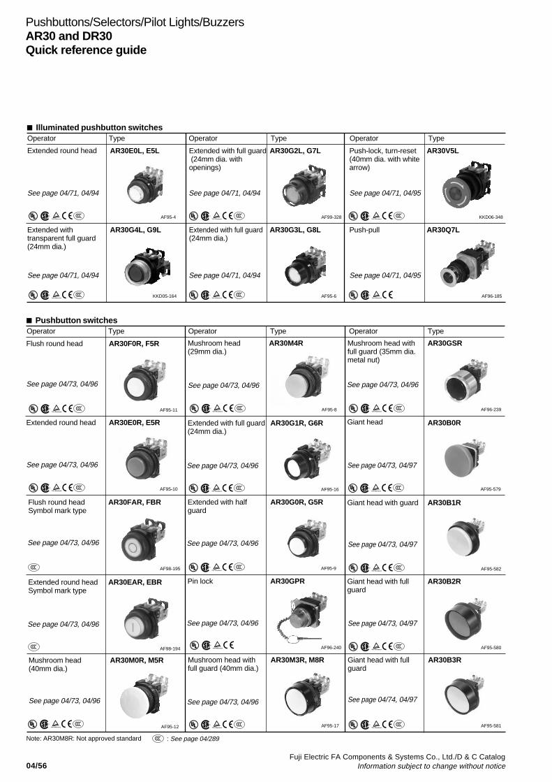
04/56Fuji Electric FA Components & Systems Co., Ltd./D & C Catalog
Information subject to change without notice
Pushbuttons/Selectors/Pilot Lights/BuzzersAR30 and DR30Quick reference guide
Illuminated pushbutton switchesOperator Type Operator Type Operator Type
Pushbutton switchesOperator Type Operator Type Operator Type
AR30E0L, E5L
S
Extended withtransparent full guard(24mm dia.)
AR30G4L, G9L
S
Extended with full guard (24mm dia. withopenings)
AR30G2L, G7L
S
Push-lock, turn-reset(40mm dia. with whitearrow)
AR30V5L
S
Extended with full guard(24mm dia.)
AR30G3L, G8L
S
Push-pull AR30Q7L
Flush round head AR30F0R, F5R
S
Flush round headSymbol mark type
AR30FAR, FBR
Mushroom head(40mm dia.)
AR30M0R, M5R
S
Extended round head AR30E0R, E5R
S
Extended round headSymbol mark type
AR30EAR, EBR
Mushroom head(29mm dia.)
AR30M4R
S
AF95-4 AF99-328 KKD06-348
KKD05-164 AF95-6 AF96-185
AF95-11
AF98-195
AF95-12
AF95-10
AF98-194
AF95-8
See page 04/71, 04/94 See page 04/71, 04/94 See page 04/71, 04/95
See page 04/71, 04/94 See page 04/71, 04/94 See page 04/71, 04/95
See page 04/73, 04/96
See page 04/73, 04/96
See page 04/73, 04/96
See page 04/73, 04/96
See page 04/73, 04/96
See page 04/73, 04/96
: See page 04/289S
S
S
Extended round head
Giant head with fullguard
AR30B2R
S
AF95-580
See page 04/73, 04/97
See page 04/73, 04/97
See page 04/73, 04/97
Giant head AR30B0R
S
AF95-579
Giant head with guard AR30B1R
S
AF95-582
Extended with full guard(24mm dia.)
AR30G1R, G6R
S
AF95-16
See page 04/73, 04/96
Extended with halfguard
AR30G0R, G5R
S
AF95-9
See page 04/73, 04/96
Pin lock AR30GPR
AF96-240
See page 04/73, 04/96
Mushroom head withfull guard (40mm dia.)
AR30M3R, M8R
S
AF95-17
See page 04/73, 04/96
Mushroom head withfull guard (35mm dia.metal nut)
AR30GSR
S
AF96-239
See page 04/73, 04/96
Giant head with fullguard
AR30B3R
S
AF95-581
See page 04/74, 04/97
Note: AR30M8R: Not approved standard
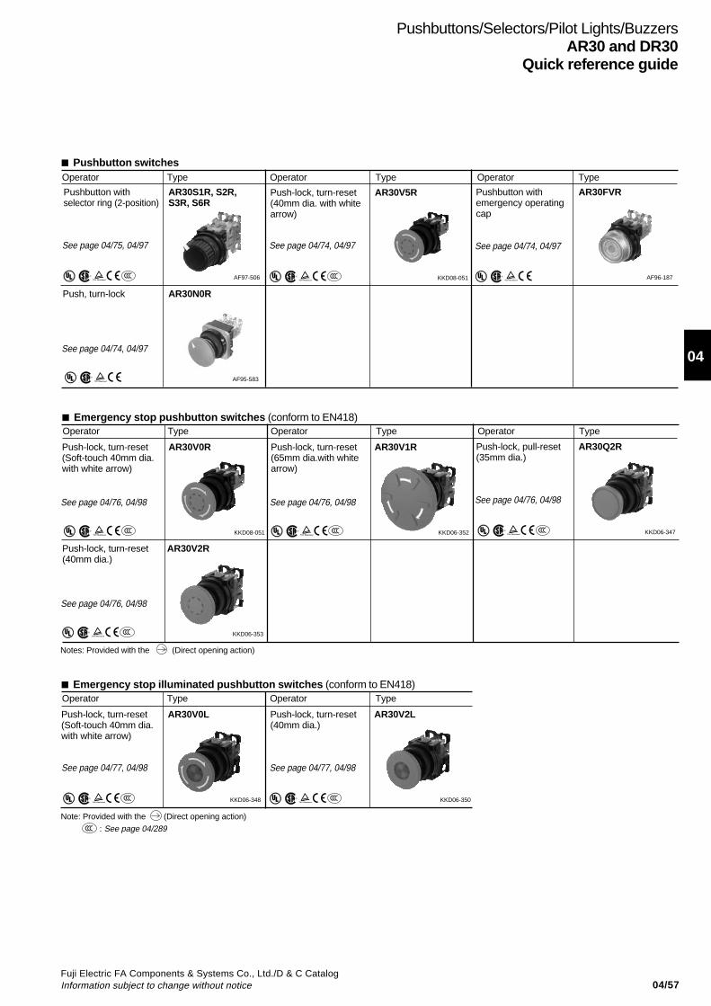
04/57Fuji Electric FA Components & Systems Co., Ltd./D & C CatalogInformation subject to change without notice
04
Pushbuttons/Selectors/Pilot Lights/BuzzersAR30 and DR30
Quick reference guide
Pushbutton switchesOperator Type Operator Type Operator Type
Emergency stop pushbutton switches (conform to EN418)Operator Type Operator Type Operator Type
Push-lock, turn-reset(Soft-touch 40mm dia.with white arrow)
AR30V0R
S
Push-lock, turn-reset(40mm dia.)
AR30V2R
S
Push-lock, turn-reset(65mm dia.with whitearrow)
AR30V1R Push-lock, pull-reset(35mm dia.)
AR30Q2R
S
KKD08-051
KKD06-353
KKD06-352 KKD06-347
Emergency stop illuminated pushbutton switches (conform to EN418)Operator Type Operator Type
Push-lock, turn-reset(Soft-touch 40mm dia.with white arrow)
AR30V0L
S
Push-lock, turn-reset(40mm dia.)
AR30V2L
S
KKD06-348 KKD06-350
See page 04/76, 04/98
See page 04/76, 04/98
See page 04/76, 04/98 See page 04/76, 04/98
See page 04/77, 04/98 See page 04/77, 04/98
Notes: Provided with the (Direct opening action)
Note: Provided with the (Direct opening action)
: See page 04/289S
Pushbutton withselector ring (2-position)
AR30S1R, S2R,S3R, S6R
S
AF97-506
See page 04/75, 04/97
Push, turn-lock AR30N0R
Push-lock, turn-reset(40mm dia. with whitearrow)
AR30V5R
S
Pushbutton withemergency operatingcap
AR30FVR
AF95-583
KKD08-051 AF96-187
See page 04/74, 04/97
See page 04/74, 04/97 See page 04/74, 04/97
S
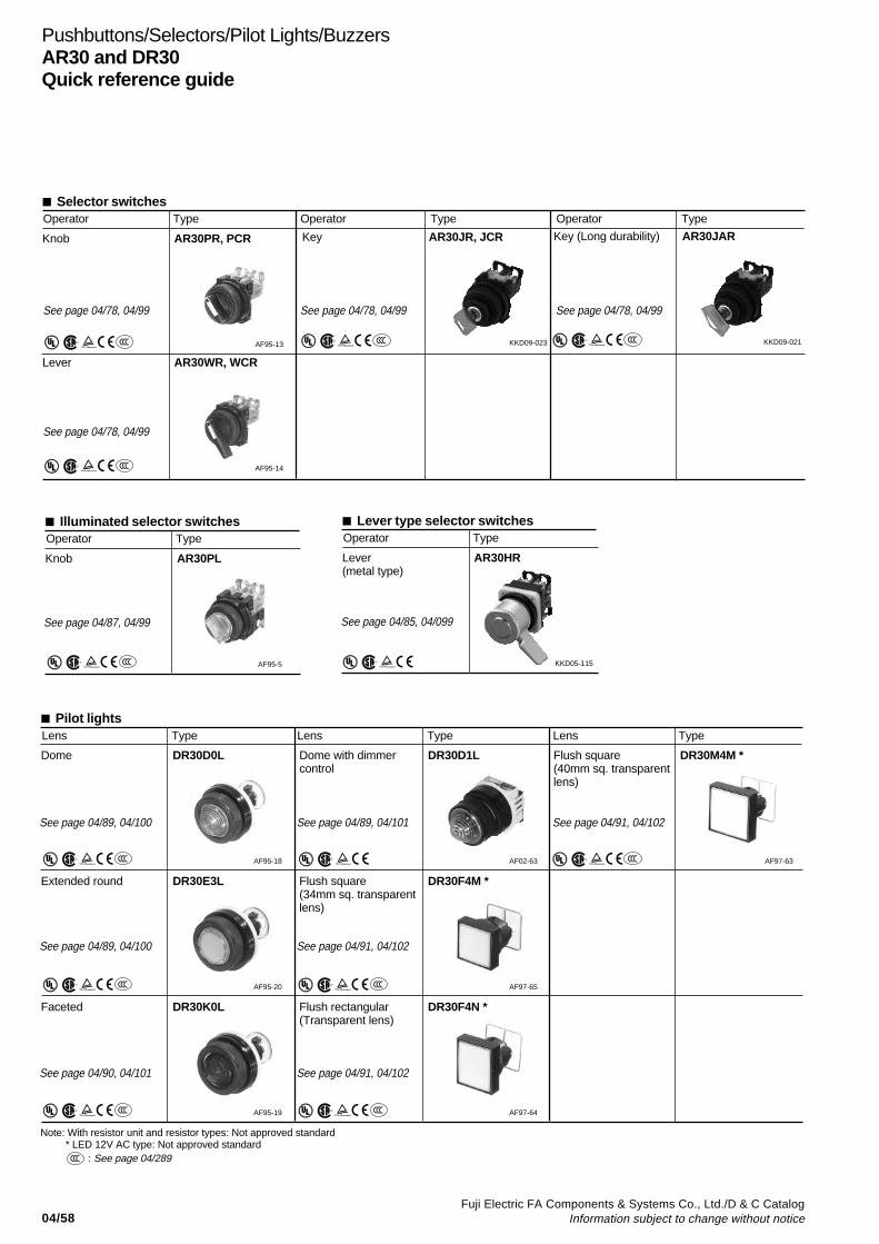
04/58Fuji Electric FA Components & Systems Co., Ltd./D & C Catalog
Information subject to change without notice
Key (Long durability) AR30JAR
S
KKD09-021
Lever AR30WR, WCR
S
AF95-14
Key AR30JR, JCR
S
KKD09-023
Pushbuttons/Selectors/Pilot Lights/BuzzersAR30 and DR30Quick reference guide
Illuminated selector switchesOperator Type
Knob AR30PL
S
AF95-5
Selector switchesOperator Type Operator Type Operator Type
Knob AR30PR, PCR
S
AF95-13
See page 04/78, 04/99 See page 04/78, 04/99 See page 04/78, 04/99
See page 04/78, 04/99
See page 04/87, 04/99
: See page 04/289S
Pilot lightsLens Type Lens Type Lens Type
Dome DR30D0L
S
Dome with dimmercontrol
DR30D1L Flush square(40mm sq. transparentlens)
DR30M4M *
S
Extended round DR30E3L
S
Flush square(34mm sq. transparentlens)
DR30F4M *
S
AF95-18 AF02-63 AF97-63
AF95-20 AF97-65
Faceted DR30K0L
S
Flush rectangular(Transparent lens)
DR30F4N *
S
AF95-19 AF97-64
Note: With resistor unit and resistor types: Not approved standard * LED 12V AC type: Not approved standard
See page 04/89, 04/100 See page 04/89, 04/101 See page 04/91, 04/102
See page 04/89, 04/100 See page 04/91, 04/102
See page 04/90, 04/101 See page 04/91, 04/102
Lever type selector switchesOperator Type
Lever(metal type)
AR30HR
KKD05-115
See page 04/85, 04/099
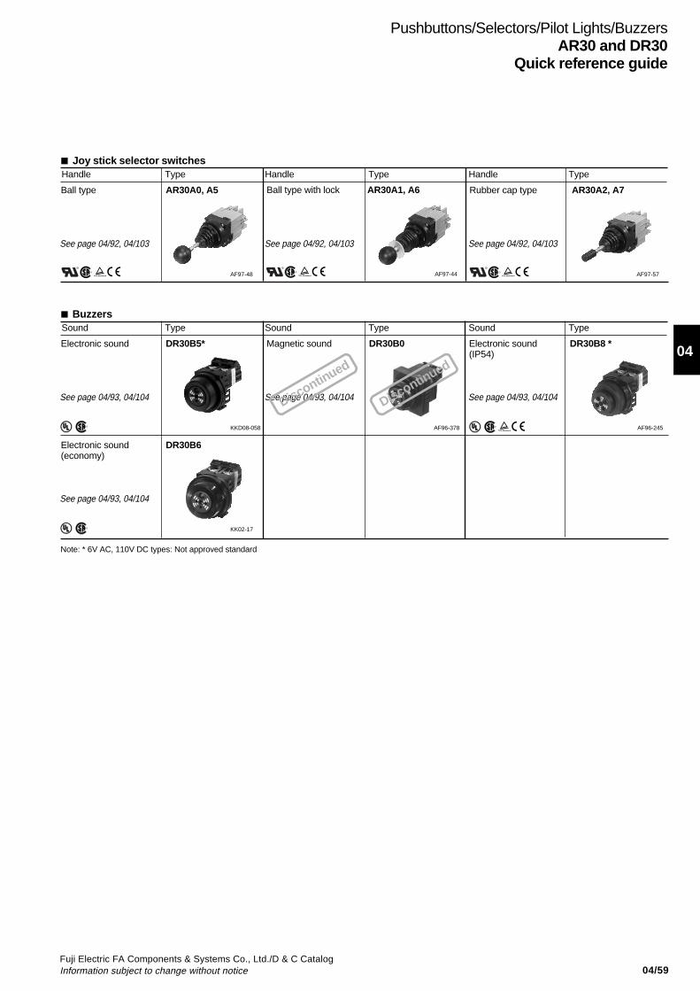
04/59Fuji Electric FA Components & Systems Co., Ltd./D & C CatalogInformation subject to change without notice
04
Pushbuttons/Selectors/Pilot Lights/BuzzersAR30 and DR30
Quick reference guide
Joy stick selector switchesHandle Type Handle Type Handle Type
Ball type AR30A0, A5
AF97-48
BuzzersSound Type Sound Type Sound Type
Electronic sound DR30B5* Magnetic sound DR30B0 Electronic sound(IP54)
DR30B8 *
KKD08-058 AF96-378 AF96-245
Rubber cap type AR30A2, A7
AF97-57
Ball type with lock AR30A1, A6
AF97-44
Note: * 6V AC, 110V DC types: Not approved standard
See page 04/92, 04/103 See page 04/92, 04/103 See page 04/92, 04/103
See page 04/93, 04/104 See page 04/93, 04/104 See page 04/93, 04/104
Electronic sound(economy)
DR30B6
KK02-17
See page 04/93, 04/104
Discontinued
Discontinued
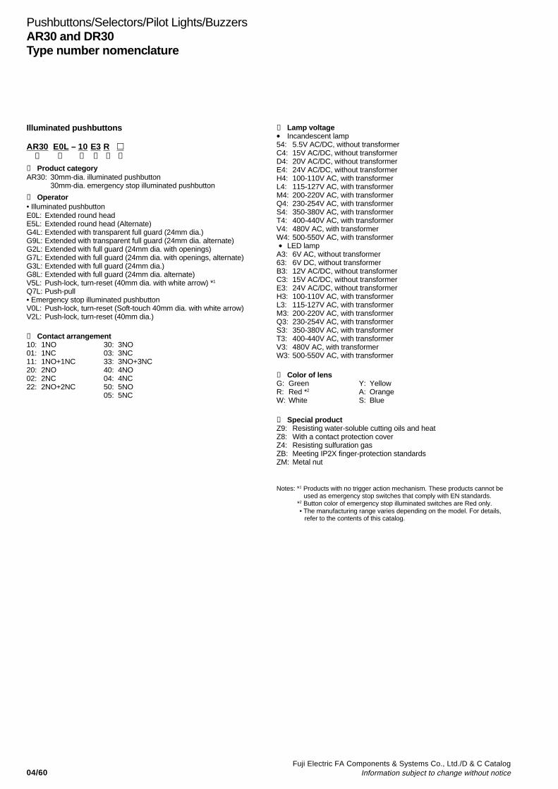
04/60Fuji Electric FA Components & Systems Co., Ltd./D & C Catalog
Information subject to change without notice
Pushbuttons/Selectors/Pilot Lights/BuzzersAR30 and DR30Type number nomenclature
Illuminated pushbuttons
AR30 E0L – 10 E3 R ➀ ➁ ➂ ➃ ➄ ➅
➀ Product categoryAR30: 30mm-dia. illuminated pushbutton
30mm-dia. emergency stop illuminated pushbutton
➁ Operator• Illuminated pushbuttonE0L: Extended round headE5L: Extended round head (Alternate)G4L: Extended with transparent full guard (24mm dia.)G9L: Extended with transparent full guard (24mm dia. alternate)G2L: Extended with full guard (24mm dia. with openings)G7L: Extended with full guard (24mm dia. with openings, alternate)G3L: Extended with full guard (24mm dia.)G8L: Extended with full guard (24mm dia. alternate)V5L: Push-lock, turn-reset (40mm dia. with white arrow) *1
Q7L: Push-pull• Emergency stop illuminated pushbuttonV0L: Push-lock, turn-reset (Soft-touch 40mm dia. with white arrow)V2L: Push-lock, turn-reset (40mm dia.)
➂ Contact arrangement10: 1NO 30: 3NO01: 1NC 03: 3NC11: 1NO+1NC 33: 3NO+3NC20: 2NO 40: 4NO02: 2NC 04: 4NC22: 2NO+2NC 50: 5NO
05: 5NC
➃ Lamp voltage• Incandescent lamp54: 5.5V AC/DC, without transformerC4: 15V AC/DC, without transformerD4: 20V AC/DC, without transformerE4: 24V AC/DC, without transformerH4: 100-110V AC, with transformerL4: 115-127V AC, with transformerM4: 200-220V AC, with transformerQ4: 230-254V AC, with transformerS4: 350-380V AC, with transformerT4: 400-440V AC, with transformerV4: 480V AC, with transformerW4: 500-550V AC, with transformer • LED lampA3: 6V AC, without transformer63: 6V DC, without transformerB3: 12V AC/DC, without transformerC3: 15V AC/DC, without transformerE3: 24V AC/DC, without transformerH3: 100-110V AC, with transformerL3: 115-127V AC, with transformerM3: 200-220V AC, with transformerQ3: 230-254V AC, with transformerS3: 350-380V AC, with transformerT3: 400-440V AC, with transformerV3: 480V AC, with transformerW3: 500-550V AC, with transformer
➄ Color of lensG: Green Y: YellowR: Red *2 A: OrangeW: White S: Blue
➅ Special productZ9: Resisting water-soluble cutting oils and heatZ8: With a contact protection coverZ4: Resisting sulfuration gasZB: Meeting IP2X finger-protection standardsZM: Metal nut
Notes: *1 Products with no trigger action mechanism. These products cannot beused as emergency stop switches that comply with EN standards.
*2 Button color of emergency stop illuminated switches are Red only. • The manufacturing range varies depending on the model. For details,
refer to the contents of this catalog.

04/61Fuji Electric FA Components & Systems Co., Ltd./D & C CatalogInformation subject to change without notice
04
Pushbuttons/Selectors/Pilot Lights/BuzzersAR30 and DR30
Type number nomenclature
Pushbuttons
AR30 E0R – 10 R ➀ ➁ ➂ ➃ ➄ ➅
➀ Product categoryAR30: 30mm-dia. pushbutton
30mm-dia. emergency stop pushbutton
➁ Operator • Pushbutton switchF0R: Flush round headF5R: Flush round head (Alternate)E0R: Extended round headE5R: Extended round head (Alternate)FAR: Flush round head (Symbol mark type)FBR: Flush round head (Symbol mark type, alternate)EAR:Extended round head (Symbol mark type)EBR:Extended round head (Symbol mark type, alternate)M0R: Mushroom head (40mm dia.)M5R: Mushroom head (40mm dia. Alternate)M4R: Mushroom head (29mm dia.)G1R:Extended with full guard (24mm dia.)G6R:Extended with full guard (24mm dia. Alternate)GPR:Pin lockG0R:Extended with half guardG5R:Extended with half guard (Alternate)M3R:Mushroom head with full guard (40mm dia.)M8R:Mushroom head with full guard (40mm dia. Alternate)GSR:Mushroom head with full guard (35mm dia. metal nut)B0R: Giant headB1R: Giant head with guardB2R: Giant head with full guardB3R: Giant head with full guardS1R: Pushbutton with selector ring (2-position)S2R: Pushbutton with selector ring (2-position)S3R: Pushbutton with selector ring (2-position)S6R: Pushbutton with selector ring (2-position)N0R: Push, turn-lockV5R: Push-lock, turn-reset (40mm dia. with white arrow) *1
FVR: Pushbutton with emergency operating cap • Emergency stop pushbutton switchV0R: Push-lock, turn-reset (Soft-touch 40mm dia. with white arrow)V2R: Push-lock, turn-reset (40mm dia.)V1R: Push-lock, turn-reset (Soft-touch 65mm dia. with white arrow)Q2R:Push-lock, pull-reset (35mm dia.)
➂ Contact arrangement10: 1NO 30: 3NO01: 1NC 03: 3NC11: 1NO+1NC 33: 3NO+3NC20: 2NO 40: 4NO02: 2NC 04: 4NC22: 2NO+2NC 44: 4NO+4NC
50: 5NO05: 5NC
➃ Color of buttonG: Green Y: YellowR: Red*2 A: OrangeB: Black S: BlueW: White C: ClearT: Green, Red, Black (For AR30F0R) (For AR30FAR, FBR,
EAR, EBR)
➄ Symbol mark (For AR30FAR, FBR, EAR, EBR)Symbol mark I T I T
Color of button White Black White Black White Black ClearColor of mark Red Green Green BlackCode 01 02 03 04 11 12 02B 04B 12B
➅ Special productZ9: Resisting water-soluble cutting oils and heatZ8: With a contact protection coverZ4: Resisting sulfuration gasZB: Meeting IP2X finger-protection standardsZM: Metal nut
Notes: *1 Products with no trigger action mechanism. These products cannot beused as emergency stop switches that comply with EN standards.
*2Button color of emergency stop switches are Red only.• The manufacturing range varies depending on the model. For details,
refer to the contents of this catalog.
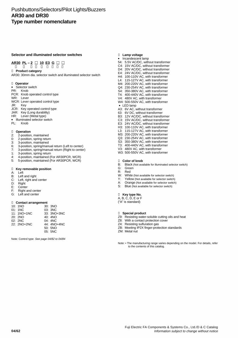
04/62Fuji Electric FA Components & Systems Co., Ltd./D & C Catalog
Information subject to change without notice
Pushbuttons/Selectors/Pilot Lights/BuzzersAR30 and DR30Type number nomenclature
Selector and illuminated selector switches
AR30 PL – 2 10 E3 G ➀ ➁ ➂ ➃ ➄ ➅ ➆ ➇ ➈
➀ Product categoryAR30: 30mm dia. selector switch and illuminated selector switch
➁ Operator• Selector switchPR: KnobPCR: Knob operated control typeWR: LeverWCR: Lever operated control typeJR: KeyJCR: Key operated control typeJAR: Key (Long durability)HR: Lever (Metal type)• Illuminated selector switchPL: Knob
➂ Operation2: 2-position, maintained0: 2-position, spring return3: 3-position, maintained6: 3-position, spring/manual return (Left to center)7: 3-position, spring/manual return (Right to center)1: 3-position, spring return4: 4-position, maintained (For AR30PCR, WCR)5: 5-position, maintained (For AR30PCR, WCR)
➃ Key removable positionA: LeftB: Left and rightC: Left, right and centerD: RightE: CenterF: Right and centerG: Left and center
➄ Contact arrangement10: 1NO 30: 3NO01: 1NC 03: 3NC11: 1NO+1NC 33: 3NO+3NC20: 2NO 40: 4NO02: 2NC 04: 4NC22: 2NO+2NC 44: 4NO+4NC
50: 5NO05: 5NC
Note: Control type: See page 04/82 to 04/84
➅ Lamp voltage• Incandescent lamp54: 5.5V AC/DC, without transformerC4: 15V AC/DC, without transformerD4: 20V AC/DC, without transformerE4: 24V AC/DC, without transformerH4: 100-110V AC, with transformerL4: 115-127V AC, with transformerM4: 200-220V AC, with transformerQ4: 230-254V AC, with transformerS4: 350-380V AC, with transformerT4: 400-440V AC, with transformerV4: 480V AC, with transformerW4: 500-550V AC, with transformer • LED lampA3: 6V AC, without transformer63: 6V DC, without transformerB3: 12V AC/DC, without transformerC3: 15V AC/DC, without transformerE3: 24V AC/DC, without transformerH3: 100-110V AC, with transformerL3: 115-127V AC, with transformerM3: 200-220V AC, with transformerQ3: 230-254V AC, with transformerS3: 350-380V AC, with transformerT3: 400-440V AC, with transformerV3: 480V AC, with transformerW3: 500-550V AC, with transformer
➆ Color of knobB: Black (Not available for illuminated selector switch)G: GreenR: RedW: White (Not available for selector switch)Y: Yellow (Not available for selector switch)A: Orange (Not available for selector switch)S: Blue (Not available for selector switch)
➇ Key type No.A, B, C, D, E or F(“A” is standard)
➈ Special productZ9: Resisting water-soluble cutting oils and heatZ8: With a contact protection coverZ4: Resisting sulfuration gasZB: Meeting IP2X finger-protection standardsZM: Metal nut
Note: • The manufacturing range varies depending on the model. For details, referto the contents of this catalog.

04/63Fuji Electric FA Components & Systems Co., Ltd./D & C CatalogInformation subject to change without notice
04
Pushbuttons/Selectors/Pilot Lights/BuzzersAR30 and DR30
Type number nomenclature
Pilot lights
DR30 D0L – E3 W ➀ ➁ ➂ ➃ ➄
➀ Product categoryDR30: 30mm dia. pilot light
➁ LensD0L: DomeE3L: Extended roundK0L: FacetedD1L: Dome with dimmer controlF4M: Flush square (34mm sq. transparent lens)F4N: Flush rectangular (Transparent lens)M4M: Flush square (40mm sq. transparent lens)
➂ Lamp voltage• Incandescent lamp54: 5.5V AC/DC, without transformerC4: 15V AC/DC, without transformerD4: 20V AC/DC, without transformerE4: 24V AC/DC, without transformerH4: 100-110V AC, with transformerL4: 115-127V AC, with transformerM4: 200-220V AC, with transformerQ4: 230-254V AC, with transformerS4: 350-380V AC, with transformerT4: 400-440V AC, with transformerV4: 480V AC, with transformerW4: 500-550V AC, with transformerFQ: 50V DC, with resistor*HQ: 110V DC, with resistor*MQ: 220V DC, with resistor* • LED lampA3: 6V AC, without transformer63: 6V DC, without transformerB3: 12V AC/DC, without transformerC3: 15V AC/DC, without transformerE3: 24V AC/DC, without transformerH3: 100-110V AC, with transformerL3: 115-127V AC, with transformerM3: 200-220V AC, with transformerQ3: 230-254V AC, with transformerS3: 350-380V AC, with transformerT3: 400-440V AC, with transformerV3: 480V AC, with transformerW3: 500-550V AC, with transformerH7: 110V DC, with resistor unitFR: 50V DC, with resistor*HR: 110V DC, with resistor*MR: 220V DC, with resistor* • LED unit(For DR30F4M, F4N, M4M type)65: 6V DC, without transformer25: 12V AC, without transformerB5: 12V AC/DC, without transformerE5: 24V AC/DC, without transformerH5: 100-110V AC, with transformerL5: 115-127V AC, with transformerM5: 200-220V AC, with transformerQ5: 230-254V AC, with transformerS5: 350-380V AC, with transformerT5: 400-440V AC, with transformerV5: 480V AC, with transformerW5: 500-550V AC, with transformerHE: 110V DC, with resistor unit
Note: * DR30D0L, K0L type only
Note: • The manufacturing range varies depending on the model. For details, referto the contents of this catalog.
H8: 100-110V AC, short-body with transformerL8: 115-127V AC, short-body with transformerM8: 200-220V AC, short-body with transformer
H9: 100-110V AC, short-body with transformerL9: 115-127V AC, short-body with transformerM9: 200-220V AC, short-body with transformer
➃ Color of lens or color plateG: Green Y: YellowR: Red A: OrangeW: White S: Blue
➄ Special productZ9: Resisting water-soluble cutting oils and heatZ4: Resisting sulfuration gasZB: Meeting IP2X finger-protection standardsZM: Metal nut
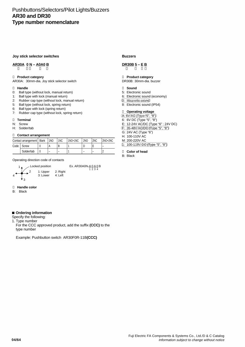
04/64Fuji Electric FA Components & Systems Co., Ltd./D & C Catalog
Information subject to change without notice
Pushbuttons/Selectors/Pilot Lights/BuzzersAR30 and DR30Type number nomenclature
Buzzers
DR30B 5 – E B➀ ➁ ➂ ➃
➀ Product categoryDR30B: 30mm-dia. buzzer
➁ Sound5: Electronic sound6: Electronic sound (economy)0: Magnetic sound8: Electronic sound (IP54)
➂ Operating voltageA: 6V AC (Type “5”, “8”)6: 6V DC (Type “5”, “8”)E: 12-24V AC/DC (Type “6” : 24V DC)F: 35-48V AC/DC (Type “5”, “8”)G: 24V AC (Type “6”)H: 100-110V ACM: 200-220V AC1: 100-110V DC (Type “5”, “8”)
➃ Color of headB: Black
Joy stick selector switches
AR30A 0 N – A0A0 B ➀ ➁➂ ➃ ➄
➀ Product categoryAR30A: 30mm-dia. Joy stick selector switch
➁ Handle0: Ball type (without lock, manual return)1: Ball type with lock (manual return)2: Rubber cap type (without lock, manual return)5: Ball type (without lock, spring return)6: Ball type with lock (spring return)7: Rubber cap type (without lock, spring return)
➂ TerminalN: ScrewH: Solder/tab
➃ Contact arrangement
Contact arrangement Blank 1NO 1NC 1NO+1NC 2NO 2NC 2NO+2NC
Code Screw 0 A B 1 D E –
Solder/tab 0 – – 1 – – 2
Operating direction code of contacts
1
2
34
1: Upper 2: Right3: Lower 4: Left
Locked position Ex. AR30A0N-A 0 A 0 B1 2 3 4
➄ Handle colorB: Black
Ordering informationSpecify the following:1. Type number
For the CCC approved product, add the suffix (CCC) to the type number
Example: Pushbutton switch AR30F0R-11B(CCC)
Discontinued
Discontinued
Discontinued
Discontinued
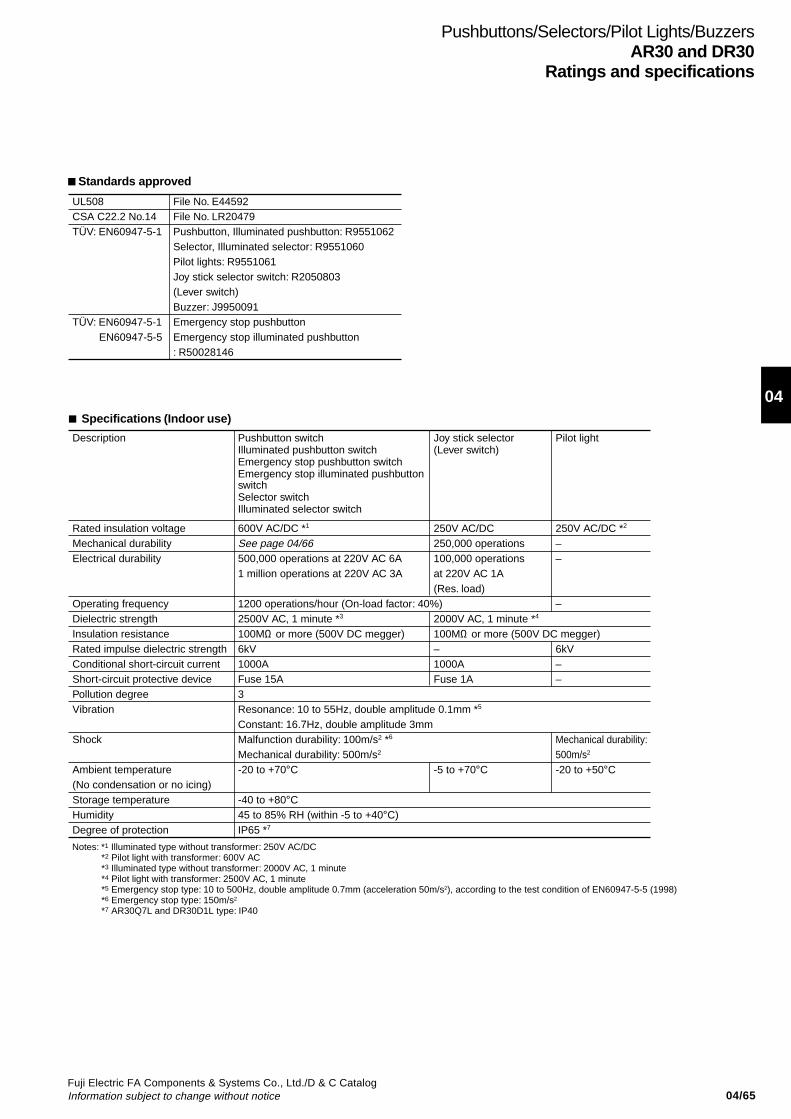
04/65Fuji Electric FA Components & Systems Co., Ltd./D & C CatalogInformation subject to change without notice
04
Pushbuttons/Selectors/Pilot Lights/BuzzersAR30 and DR30
Ratings and specifications
Specifications (Indoor use)
Description Pushbutton switch Illuminated pushbutton switchEmergency stop pushbutton switchEmergency stop illuminated pushbutton switchSelector switchIlluminated selector switch
Joy stick selector(Lever switch)
Pilot light
Rated insulation voltageMechanical durability Electrical durability
Operating frequencyDielectric strengthInsulation resistanceRated impulse dielectric strengthConditional short-circuit currentShort-circuit protective devicePollution degreeVibration
Shock
Ambient temperature(No condensation or no icing)Storage temperatureHumidityDegree of protection
600V AC/DC *1
See page 04/66500,000 operations at 220V AC 6A1 million operations at 220V AC 3A
1200 operations/hour (On-load factor: 40%)2500V AC, 1 minute *3
100MΩ or more (500V DC megger)6kV1000AFuse 15A3Resonance: 10 to 55Hz, double amplitude 0.1mm *5
Constant: 16.7Hz, double amplitude 3mmMalfunction durability: 100m/s2 *6
Mechanical durability: 500m/s2
-20 to +70°C
-40 to +80°C45 to 85% RH (within -5 to +40°C)IP65 *7
250V AC/DC250,000 operations100,000 operationsat 220V AC 1A (Res. load)
2000V AC, 1 minute *4
100MΩ or more (500V DC megger)–1000AFuse 1A
-5 to +70°C
250V AC/DC *2
––
–
6kV––
Mechanical durability: 500m/s2
-20 to +50°C
Notes: *1 Illuminated type without transformer: 250V AC/DC *2 Pilot light with transformer: 600V AC *3 Illuminated type without transformer: 2000V AC, 1 minute *4 Pilot light with transformer: 2500V AC, 1 minute *5 Emergency stop type: 10 to 500Hz, double amplitude 0.7mm (acceleration 50m/s2), according to the test condition of EN60947-5-5 (1998) *6 Emergency stop type: 150m/s2
*7 AR30Q7L and DR30D1L type: IP40
Standards approved
UL508CSA C22.2 No.14TÜV: EN60947-5-1
TÜV: EN60947-5-1 EN60947-5-5
File No. E44592File No. LR20479Pushbutton, Illuminated pushbutton: R9551062 Selector, Illuminated selector: R9551060Pilot lights: R9551061Joy stick selector switch: R2050803(Lever switch)Buzzer: J9950091Emergency stop pushbuttonEmergency stop illuminated pushbutton: R50028146
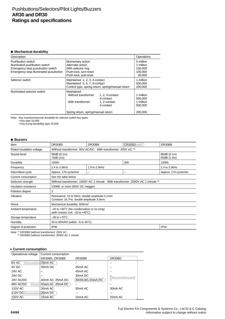
04/66Fuji Electric FA Components & Systems Co., Ltd./D & C Catalog
Information subject to change without notice
Pushbuttons/Selectors/Pilot Lights/BuzzersAR30 and DR30Ratings and specifications
BuzzersItem DR30B5 DR30B6 DR30B0 DR30B8
Rated insulation voltage Without transformer: 60V AC/DC With transformer: 250V AC *1
Sound level 90dB (0.1m) 80dB (0.1m)70dB (1m) 60dB (1.0m)
Durability 1000h 80h 1000h
Frequency 2.4 to 3.3kHz 1.9 to 2.5kHz 2.4 to 3.3kHz
Intermittent cycle Approx. 170-cycle/min – – Approx. 170-cycle/min
Current consumption See the table below
Dielectric strength Without transformer: 1000V AC 1 minute With transformer: 2000V AC 1 minute *2
Insulation resistance 100MΩ or more (500V DC megger)
Pollution degree 3
Vibration Resonance: 10 to 55Hz, double amplitude 0.1mmConstant: 16.7Hz, double amplitude 3.0mm
Shock Mechanical durability: 500m/s2
Ambient temperature –20 to +60˚C (No condensation or no icing)(with resistor unit: –20 to +40˚C)
Storage temperature –30 to +70˚C
Humidity 45 to 85%RH (within –5 to 40˚C)
Degree of protection IP00 IP54
Note: *1 DR30B0 (without transformer): 250V AC*2 DR30B0 (without transformer): 2000V AC 1 minute
Mechanical durabilityDescription Operations
Pushbutton switch Momentary action 5 millionIlluminated pushbutton switch Alternate action 1 millionEmergency stop pusubutton switch With selector ring 100,000Emergency stop illuminated pusubutton Push-lock, turn-reset 100,000
Push-lock, pull-reset 30,000
Selector switch Maintained 1, 2, 3, 4-contact 1 millionMaintained 5, 6, 7, 8-contact 500,000Control type, spring return, spring/manual return 200,000
Illuminated selector switch Maintained Without transformer 1, 2, 3-contact 1 million
4-contact 500,000 With transformer 1, 2-contact 1 million
3-contact 500,000
Spring return, spring/manual return 200,000
Note: Key insertion/removal durability for selector switch key types• Key type 10,000• Key (Long durability) type 20,000
• Current consumptionOperational voltage
6V AC6V DC24V AC24V DC24V AC/DC48V AC/DC110V AC110V DC220V AC
Current consumptionDR30B5, DR30B870mA AC35mA DC––40mA AC, 25mA DC65mA AC, 20mA DC30mA AC30mA DC15mA AC
DR30B6–25mA AC45mA AC30mA DC30mA AC, 20mA DC–30mA AC –15mA AC
DR30B0––––––30mA AC –20mA AC
Discontinued
Discontinued
Discontinued
DiscontinuedDiscontinued Discontinued
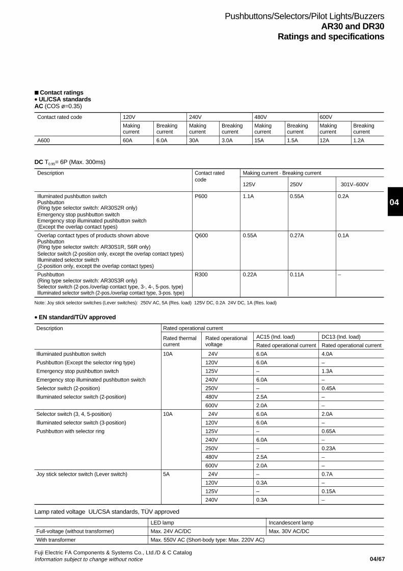
04/67Fuji Electric FA Components & Systems Co., Ltd./D & C CatalogInformation subject to change without notice
04
Pushbuttons/Selectors/Pilot Lights/BuzzersAR30 and DR30
Ratings and specifications
• EN standard/TÜV approved
Rated operational currentDescription
Rated thermal Rated operational AC15 (Ind. load) DC13 (Ind. load)current voltage Rated operational current Rated operational current
Illuminated pushbutton switch 10A 24V 6.0A 4.0A
Pushbutton (Except the selector ring type) 120V 6.0A –
Emergency stop pushbutton switch 125V – 1.3A
Emergency stop illuminated pushbutton switch 240V 6.0A –
Selector switch (2-position) 250V – 0.45A
Illuminated selector switch (2-position) 480V 2.5A –
600V 2.0A –
Selector switch (3, 4, 5-position) 10A 24V 6.0A 2.0A
Illuminated selector switch (3-position) 120V 6.0A –
Pushbutton with selector ring 125V – 0.65A
240V 6.0A –
250V – 0.23A
480V 2.5A –
600V 2.0A –
Joy stick selector switch (Lever switch) 5A 24V – 0.7A
120V 0.3A –
125V – 0.15A
240V 0.3A –
DC T0.95= 6P (Max. 300ms)
Description Contact rated Making current · Breaking currentcode
125V 250V 301V–600V
Illuminated pushbutton switch P600 1.1A 0.55A 0.2APushbutton(Ring type selector switch: AR30S2R only)Emergency stop pushbutton switchEmergency stop illuminated pushbutton switch(Except the overlap contact types)
Overlap contact types of products shown above Q600 0.55A 0.27A 0.1APushbutton(Ring type selector switch: AR30S1R, S6R only)Selector switch (2-position only, except the overlap contact types)Illuminated selector switch(2-position only, except the overlap contact types)
Pushbutton R300 0.22A 0.11A –(Ring type selector switch: AR30S3R only)Selector switch (2-pos./overlap contact type, 3-, 4-, 5-pos. type)Illuminated selector switch (2-pos./overlap contact type, 3-pos. type)
Lamp rated voltage UL/CSA standards, TÜV approved
LED lamp Incandescent lamp
Full-voltage (without transformer) Max. 24V AC/DC Max. 30V AC/DC
With transformer Max. 550V AC (Short-body type: Max. 220V AC)
Contact ratings• UL/CSA standardsAC (COS ø=0.35)
Contact rated code 120V 240V 480V 600V
Making Breaking Making Breaking Making Breaking Making Breakingcurrent current current current current current current current
A600 60A 6.0A 30A 3.0A 15A 1.5A 12A 1.2A
Note: Joy stick selector switches (Lever switches): 250V AC, 5A (Res. load) 125V DC, 0.2A 24V DC, 1A (Res. load)
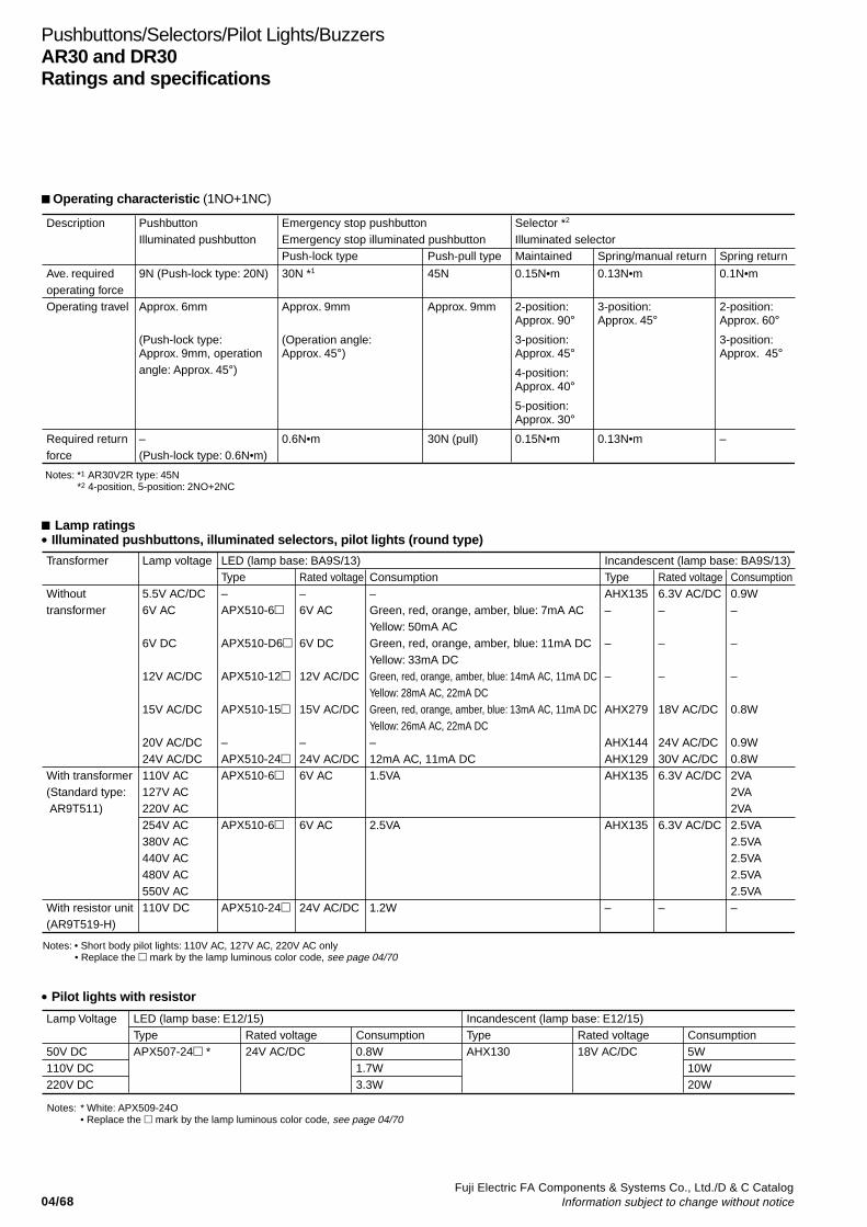
04/68Fuji Electric FA Components & Systems Co., Ltd./D & C Catalog
Information subject to change without notice
Pushbuttons/Selectors/Pilot Lights/BuzzersAR30 and DR30Ratings and specifications
Operating characteristic (1NO+1NC)
Description PushbuttonIlluminated pushbutton
Ave. required operating forceOperating travel
Required return force
9N (Push-lock type: 20N)
Approx. 6mm
(Push-lock type: Approx. 9mm, operation angle: Approx. 45°)
–(Push-lock type: 0.6N•m)
Emergency stop pushbutton Emergency stop illuminated pushbuttonPush-lock type
Selector *2
Illuminated selectorMaintained Spring/manual return Spring returnPush-pull type
30N *1
Approx. 9mm
(Operation angle: Approx. 45°)
0.6N•m
0.15N•m
2-position: Approx. 90°
3-position: Approx. 45°
4-position: Approx. 40°
5-position: Approx. 30°
0.15N•m
0.13N•m
3-position: Approx. 45°
0.13N•m
0.1N•m
2-position: Approx. 60°
3-position: Approx. 45°
–
45N
Approx. 9mm
30N (pull)
Notes: *1 AR30V2R type: 45N *2 4-position, 5-position: 2NO+2NC
Lamp ratings• Illuminated pushbuttons, illuminated selectors, pilot lights (round type)
Transformer
Without transformer
With transformer(Standard type: AR9T511)
With resistor unit(AR9T519-H)
Lamp voltage
5.5V AC/DC6V AC
6V DC
12V AC/DC
15V AC/DC
20V AC/DC24V AC/DC110V AC127V AC220V AC254V AC380V AC440V AC480V AC550V AC110V DC
LED (lamp base: BA9S/13)Type–APX510-6
APX510-D6
APX510-12
APX510-15
–APX510-24APX510-6
APX510-6
APX510-24
Rated voltage–6V AC
6V DC
12V AC/DC
15V AC/DC
–24V AC/DC6V AC
6V AC
24V AC/DC
Consumption–Green, red, orange, amber, blue: 7mA ACYellow: 50mA ACGreen, red, orange, amber, blue: 11mA DCYellow: 33mA DCGreen, red, orange, amber, blue: 14mA AC, 11mA DCYellow: 28mA AC, 22mA DCGreen, red, orange, amber, blue: 13mA AC, 11mA DCYellow: 26mA AC, 22mA DC–12mA AC, 11mA DC1.5VA
2.5VA
1.2W
Incandescent (lamp base: BA9S/13)TypeAHX135–
–
–
AHX279
AHX144AHX129AHX135
AHX135
–
Rated voltage6.3V AC/DC–
–
–
18V AC/DC
24V AC/DC30V AC/DC6.3V AC/DC
6.3V AC/DC
–
Consumption0.9W–
–
–
0.8W
0.9W0.8W2VA2VA2VA2.5VA2.5VA2.5VA2.5VA2.5VA–
Notes: • Short body pilot lights: 110V AC, 127V AC, 220V AC only• Replace the mark by the lamp luminous color code, see page 04/70
• Pilot lights with resistor
Lamp Voltage
50V DC110V DC220V DC
LED (lamp base: E12/15)TypeAPX507-24 *
Rated voltage 24V AC/DC
Consumption0.8W1.7W3.3W
Rated voltage 18V AC/DC
Consumption5W10W20W
Incandescent (lamp base: E12/15)TypeAHX130
Notes: * White: APX509-24O• Replace the mark by the lamp luminous color code, see page 04/70
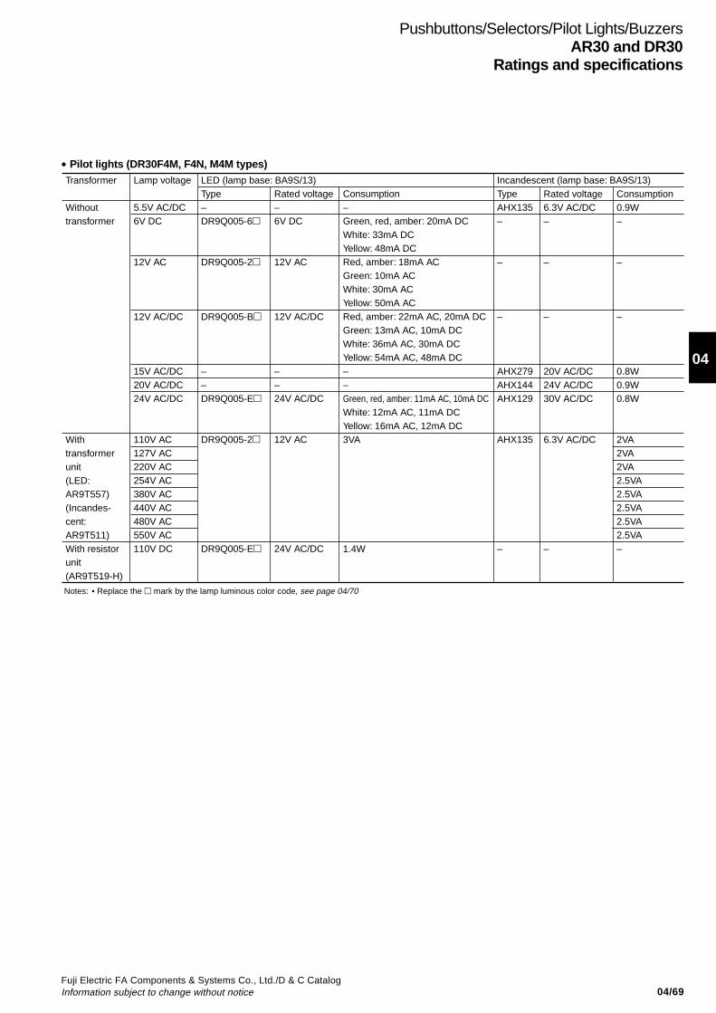
04/69Fuji Electric FA Components & Systems Co., Ltd./D & C CatalogInformation subject to change without notice
04
Pushbuttons/Selectors/Pilot Lights/BuzzersAR30 and DR30
Ratings and specifications
Transformer
Withouttransformer
Withtransformerunit (LED: AR9T557)(Incandes-cent: AR9T511)With resistorunit(AR9T519-H)
LED (lamp base: BA9S/13)Type–DR9Q005-6
DR9Q005-2
DR9Q005-B
––DR9Q005-E
DR9Q005-2
DR9Q005-E
Lamp voltage
5.5V AC/DC6V DC
12V AC
12V AC/DC
15V AC/DC20V AC/DC24V AC/DC
110V AC127V AC220V AC254V AC380V AC440V AC480V AC550V AC110V DC
Rated voltage –6V DC
12V AC
12V AC/DC
––24V AC/DC
12V AC
24V AC/DC
Consumption–Green, red, amber: 20mA DCWhite: 33mA DCYellow: 48mA DCRed, amber: 18mA ACGreen: 10mA ACWhite: 30mA ACYellow: 50mA ACRed, amber: 22mA AC, 20mA DCGreen: 13mA AC, 10mA DCWhite: 36mA AC, 30mA DCYellow: 54mA AC, 48mA DC––Green, red, amber: 11mA AC, 10mA DCWhite: 12mA AC, 11mA DCYellow: 16mA AC, 12mA DC3VA
1.4W
Rated voltage 6.3V AC/DC–
–
–
20V AC/DC24V AC/DC30V AC/DC
6.3V AC/DC
–
Consumption0.9W–
–
–
0.8W0.9W0.8W
2VA2VA2VA2.5VA2.5VA2.5VA2.5VA2.5VA–
Incandescent (lamp base: BA9S/13)TypeAHX135–
–
–
AHX279AHX144AHX129
AHX135
–
Notes: • Replace the mark by the lamp luminous color code, see page 04/70
• Pilot lights (DR30F4M, F4N, M4M types)
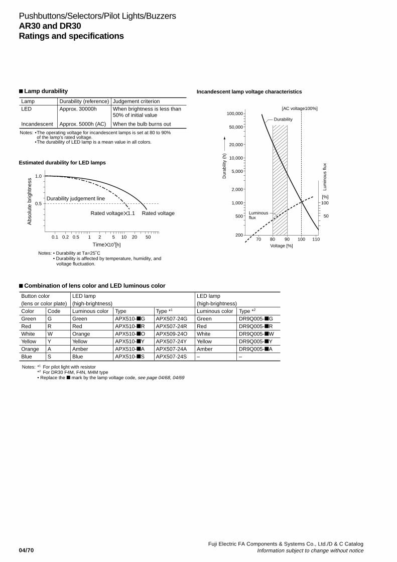
04/70Fuji Electric FA Components & Systems Co., Ltd./D & C Catalog
Information subject to change without notice
Pushbuttons/Selectors/Pilot Lights/BuzzersAR30 and DR30Ratings and specifications
Combination of lens color and LED luminous color
LampLED
Incandescent
Durability (reference)Approx. 30000h
Approx. 5000h (AC)
Judgement criterionWhen brightness is less than 50% of initial value
When the bulb burns out
Notes: •The operating voltage for incandescent lamps is set at 80 to 90%of the lamp's rated voltage.
•The durability of LED lamp is a mean value in all colors.
Estimated durability for LED lamps
1.0
0.5
0.1 0.2 0.5 1 2 5 10 20 50
Time 103[h]
Abs
olut
e br
ight
ness
Durability judgement line
Rated voltage1.1 Rated voltage
Notes: • Durability at Ta=25˚C• Durability is affected by temperature, humidity, and
voltage fluctuation.
[AC voltage100%]100,000
50,000
20,000
10,000
5,000
2,000
1,000
500
20070 80
Voltage [%]
90 100 110
100
50
Durability
Luminous flux
Dur
abili
ty (
h)
Lum
inou
s flu
x
[%]
Incandescent lamp voltage characteristics Lamp durability
Button color (lens or color plate)ColorGreenRedWhiteYellowOrangeBlue
LED lamp (high-brightness)Luminous colorGreenRedOrangeYellowAmberBlue
TypeAPX510-GAPX510-RAPX510-OAPX510-YAPX510-AAPX510-S
Type *1
APX507-24GAPX507-24RAPX509-24OAPX507-24YAPX507-24AAPX507-24S
CodeGRWYAS
Type *2
DR9Q005-GDR9Q005-RDR9Q005-WDR9Q005-YDR9Q005-A–
LED lamp(high-brightness)Luminous colorGreenRedWhiteYellowAmber–
Notes: *1 For pilot light with resistor*2 For DR30 F4M, F4N, M4M type• Replace the mark by the lamp voltage code, see page 04/68, 04/69

04/71Fuji Electric FA Components & Systems Co., Ltd./D & C CatalogInformation subject to change without notice
04
Illuminated PushbuttonsAR30
Operator Trans- Contact LED lamp Incandescent lampformer Momentary action Alternate action Momentary action Alternate action
Type Type Type Type
Extended round head Without 1NO AR30E0L-10 3 AR30E5L-10 3 AR30E0L-10 4 AR30E5L-10 41NC AR30E0L-01 3 AR30E5L-01 3 AR30E0L-01 4 AR30E5L-01 41NO+1NC AR30E0L-11 3 AR30E5L-11 3 AR30E0L-11 4 AR30E5L-11 42NO+2NC AR30E0L-22 3 — AR30E0L-22 4 —
With 1NO AR30E0L-10 3 AR30E5L-10 3 AR30E0L-10 4 AR30E5L-10 41NC AR30E0L-01 3 AR30E5L-01 3 AR30E0L-01 4 AR30E5L-01 4
AF95-4 1NO+1NC AR30E0L-11 3 AR30E5L-11 3 AR30E0L-11 4 AR30E5L-11 4
Extended with transparent Without 1NO AR30G4L-10 3 AR30G9L-10 3 AR30G4L-10 4 AR30G9L-10 4full guard (24mm dia.) 1NC AR30G4L-01 3 AR30G9L-01 3 AR30G4L-01 4 AR30G9L-01 4
1NO+1NC AR30G4L-11 3 AR30G9L-11 3 AR30G4L-11 4 AR30G9L-11 42NO+2NC AR30G4L-22 3 — AR30G4L-22 4 —
With 1NO AR30G4L-10 3 AR30G9L-10 3 AR30G4L-10 4 AR30G9L-10 41NC AR30G4L-01 3 AR30G9L-01 3 AR30G4L-01 4 AR30G9L-01 4
KKD05-164 1NO+1NC AR30G4L-11 3 AR30G9L-11 3 AR30G4L-11 4 AR30G9L-11 4
Extended with full guard Without 1NO AR30G2L-10 3 AR30G7L-10 3 AR30G2L-10 4 AR30G7L-10 4(24mm dia. with openings) 1NC AR30G2L-01 3 AR30G7L-01 3 AR30G2L-01 4 AR30G7L-01 4
1NO+1NC AR30G2L-11 3 AR30G7L-11 3 AR30G2L-11 4 AR30G7L-11 42NO+2NC AR30G2L-22 3 — AR30G2L-22 4 —
With 1NO AR30G2L-10 3 AR30G7L-10 3 AR30G2L-10 4 AR30G7L-10 41NC AR30G2L-01 3 AR30G7L-01 3 AR30G2L-01 4 AR30G7L-01 4
AF99-328 1NO+1NC AR30G2L-11 3 AR30G7L-11 3 AR30G2L-11 4 AR30G7L-11 4
Extended with full guard Without 1NO AR30G3L-10 3 AR30G8L-10 3 AR30G3L-10 4 AR30G8L-10 4(24mm dia.) 1NC AR30G3L-01 3 AR30G8L-01 3 AR30G3L-01 4 AR30G8L-01 4
1NO+1NC AR30G3L-11 3 AR30G8L-11 3 AR30G3L-11 4 AR30G8L-11 42NO+2NC AR30G3L-22 3 — AR30G3L-22 4 —
With 1NO AR30G3L-10 3 AR30G8L-10 3 AR30G3L-10 4 AR30G8L-10 41NC AR30G3L-01 3 AR30G8L-01 3 AR30G3L-01 4 AR30G8L-01 4
AF95-6 1NO+1NC AR30G3L-11 3 AR30G8L-11 3 AR30G3L-11 4 AR30G8L-11 4
Push-lock, turn-reset Without 1NO — AR30V5L-10 3 — AR30V5L-10 4(40mm dia. with white 1NC — AR30V5L-01 3 — AR30V5L-01 4 arrow) 1NO+1NC — AR30V5L-11 3 — AR30V5L-11 4
3NC — AR30V5L-03 3 — AR30V5L-03 4
With 1NO — AR30V5L-10 3 — AR30V5L-10 41NC — AR30V5L-01 3 — AR30V5L-01 4
KKD06-348 1NO+1NC — AR30V5L-11 3 — AR30V5L-11 4
Push-pull Without 1NO+1NC AR30Q7L-11 3 — AR30Q7L-11 4 —(35mm dia.)
With 1NO+1NC AR30Q7L-11 3 — AR30Q7L-11 4 —
AF96-185
Illuminated pushbutton switches
Note: See page 04/72
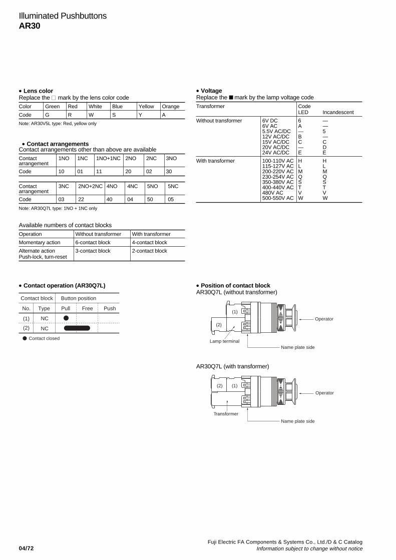
04/72Fuji Electric FA Components & Systems Co., Ltd./D & C Catalog
Information subject to change without notice
Illuminated PushbuttonsAR30
• Lens colorReplace the mark by the lens color codeColor Green Red White Blue Yellow Orange
Code G R W S Y A
• VoltageReplace the mark by the lamp voltage code
Transformer CodeLED Incandescent
Without transformer 6V DC 6 —6V AC A —5.5V AC/DC — 512V AC/DC B —15V AC/DC C C20V AC/DC — D24V AC/DC E E
With transformer 100-110V AC H H115-127V AC L L200-220V AC M M230-254V AC Q Q350-380V AC S S400-440V AC T T480V AC V V500-550V AC W W
• Contact operation (AR30Q7L)
Contact arrangements other than above are availableContact 1NO 1NC 1NO+1NC 2NO 2NC 3NOarrangement
Code 10 01 11 20 02 30
Contact 3NC 2NO+2NC 4NO 4NC 5NO 5NCarrangement
Code 03 22 40 04 50 05
Available numbers of contact blocks
Operation Without transformer With transformer
Momentary action 6-contact block 4-contact block
Alternate action 3-contact block 2-contact blockPush-lock, turn-reset
Note: AR30V5L type: Red, yellow only
Button positionContact block
TypeNo. Pull Free
NC
NC
Contact closed
Push
(1)
(2)
• Contact arrangements
• Position of contact blockAR30Q7L (without transformer)
(1)
(2)
Lamp terminal
Transformer
(1)(2)
Operator
Name plate side
Operator
Name plate side
AR30Q7L (with transformer)
Note: AR30Q7L type: 1NO + 1NC only

04/73Fuji Electric FA Components & Systems Co., Ltd./D & C CatalogInformation subject to change without notice
04
PushbuttonsAR30
Operator Contact Momentary Alternateaction actionType Type
Flush round head 1NO AR30F0R-10 AR30F5R-101NC AR30F0R-01 AR30F5R-011NO+1NC AR30F0R-11 AR30F5R-112NO AR30F0R-20 AR30F5R-202NC AR30F0R-02 AR30F5R-02
AF95-11 2NO+2NC AR30F0R-22 AR30F5R-22
Extended round head 1NO AR30E0R-10 AR30E5R-101NC AR30E0R-01 AR30E5R-011NO+1NC AR30E0R-11 AR30E5R-112NO AR30E0R-20 AR30E5R-202NC AR30E0R-02 AR30E5R-02
AF95-10 2NO+2NC AR30E0R-22 AR30E5R-22
Flush round head 1NO AR30FAR-10C AR30FBR-10C
symbol 1NC AR30FAR-01C AR30FBR-01C
mark 1NO+1NC AR30FAR-11C AR30FBR-11C
type 2NO AR30FAR-20C AR30FBR-20C
2NC AR30FAR-02C AR30FBR-02C
AF98-195 2NO+2NC AR30FAR-22C AR30FBR-22C
Extended round head 1NO AR30EAR-10C AR30EBR-10C
symbol 1NC AR30EAR-01C AR30EBR-01C
mark 1NO+1NC AR30EAR-11C AR30EBR-11C
type 2NO AR30EAR-20C AR30EBR-20C
2NC AR30EAR-02C AR30EBR-02C
AF98-194 2NO+2NC AR30EAR-22C AR30EBR-22C
Mushroom head 1NO AR30M0R-10 AR30M5R-10(40mm dia.) 1NC AR30M0R-01 AR30M5R-01
1NO+1NC AR30M0R-11 AR30M5R-112NO AR30M0R-20 AR30M5R-202NC AR30M0R-02 AR30M5R-02
AF95-12 2NO+2NC AR30M0R-22 AR30M5R-22
Mushroom head 1NO AR30M4R-10 —(29mm dia.) 1NC AR30M4R-01 —
1NO+1NC AR30M4R-11 —2NO AR30M4R-20 —2NC AR30M4R-02 —
AF95-8 2NO+2NC AR30M4R-22 —
Extended with full 1NO AR30G1R-10 AR30G6R-10guard (24mm dia.) 1NC AR30G1R-01 AR30G6R-01
1NO+1NC AR30G1R-11 AR30G6R-112NO AR30G1R-20 AR30G6R-202NC AR30G1R-02 AR30G6R-02
AF95-16 2NO+2NC AR30G1R-22 AR30G8R-22
Operator Contact Momentary Alternateaction actionType Type
Extended with half 1NO AR30G0R-10 AR30G5R-10guard 1NC AR30G0R-01 AR30G5R-01
1NO+1NC AR30G0R-11 AR30G5R-112NO AR30G0R-20 AR30G5R-202NC AR30G0R-02 AR30G5R-02
AF95-9 2NO+2NC AR30G0R-22 AR30G5R-22
Pin lock 1NO AR30GPR-10 —1NC AR30GPR-01 —1NO+1NC AR30GPR-11 —2NO AR30GPR-20 —2NC AR30GPR-02 —
AF96-240 2NO+2NC AR30GPR-22 —
Mushroom head with 1NO AR30M3R-10 AR30M8R-10full guard (40mm dia.) 1NC AR30M3R-01 AR30M8R-01
1NO+1NC AR30M3R-11 AR30M8R-112NO AR30M3R-20 AR30M8R-202NC AR30M3R-02 AR30M8R-02
AF95-17 2NO+2NC AR30M3R-22 AR30M8R-22
Mushroom head with 1NO AR30GSR-10 —full guard (35mm dia. 1NC AR30GSR-01 —metal nut) 1NO+1NC AR30GSR-11 —
2NO AR30GSR-20 —2NC AR30GSR-02 —
AF96-239 2NO+2NC AR30GSR-22 —
Giant head 1NO AR30B0R-10 —1NC AR30B0R-01 —1NO+1NC AR30B0R-11 —2NO AR30B0R-20 —2NC AR30B0R-02 —
AF95-579 2NO+2NC AR30B0R-22 —
Giant head with guard 1NO AR30B1R-10 —1NC AR30B1R-01 —1NO+1NC AR30B1R-11 —2NO AR30B1R-20 —2NC AR30B1R-02 —
AF95-582 2NO+2NC AR30B1R-22 —
Giant head with full 1NO AR30B2R-10 —guard 1NC AR30B2R-01 —
1NO+1NC AR30B2R-11 —2NO AR30B2R-20 —2NC AR30B2R-02 —
AF95-580 2NO+2NC AR30B2R-22 —
Pushbutton switches
Note: See page 04/74
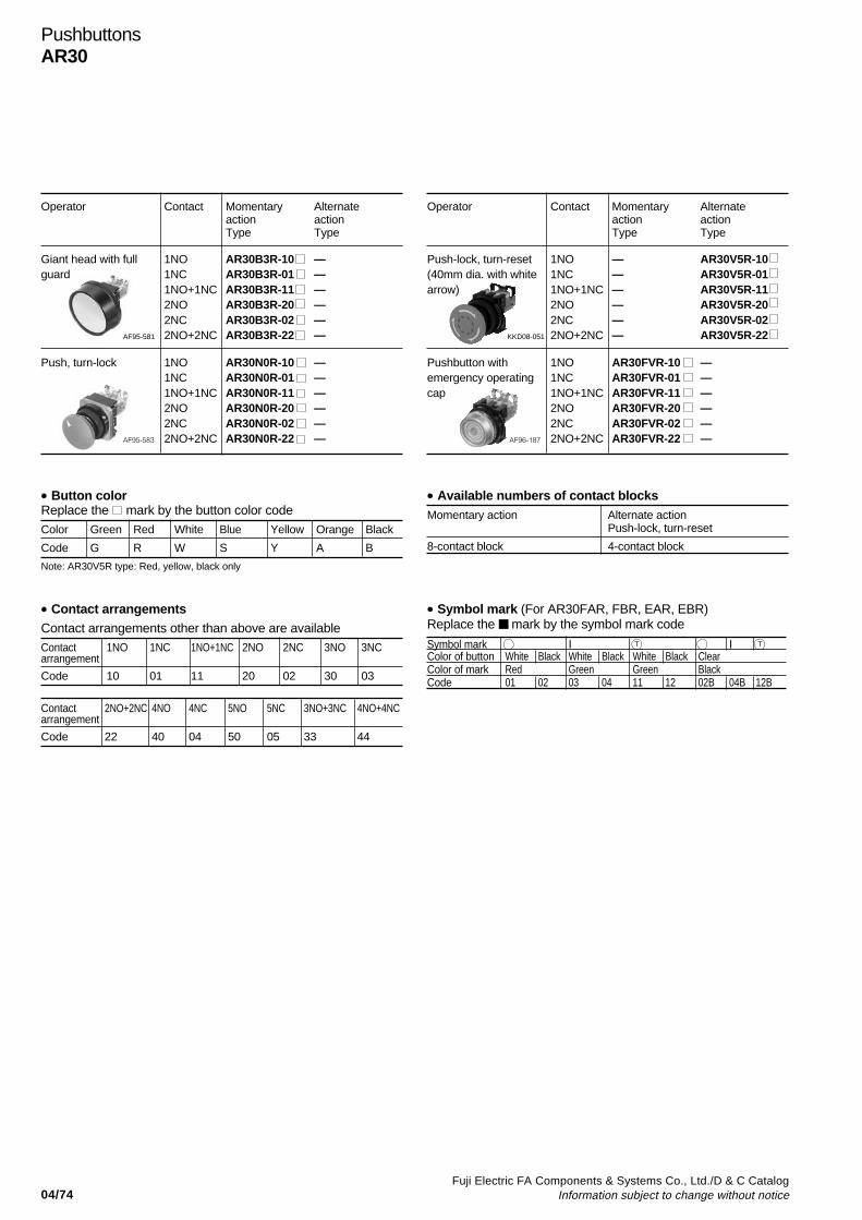
04/74Fuji Electric FA Components & Systems Co., Ltd./D & C Catalog
Information subject to change without notice
Operator Contact Momentary Alternateaction actionType Type
Push-lock, turn-reset 1NO — AR30V5R-10(40mm dia. with white 1NC — AR30V5R-01arrow) 1NO+1NC — AR30V5R-11
2NO — AR30V5R-202NC — AR30V5R-02
KKD08-051 2NO+2NC — AR30V5R-22
Pushbutton with 1NO AR30FVR-10 —emergency operating 1NC AR30FVR-01 —cap 1NO+1NC AR30FVR-11 —
2NO AR30FVR-20 —2NC AR30FVR-02 —
AF96-187 2NO+2NC AR30FVR-22 —
• Available numbers of contact blocksMomentary action Alternate action
Push-lock, turn-reset
8-contact block 4-contact block
• Button colorReplace the mark by the button color codeColor Green Red White Blue Yellow Orange Black
Code G R W S Y A B
Operator Contact Momentary Alternateaction actionType Type
Giant head with full 1NO AR30B3R-10 —guard 1NC AR30B3R-01 —
1NO+1NC AR30B3R-11 —2NO AR30B3R-20 —2NC AR30B3R-02 —
AF95-581 2NO+2NC AR30B3R-22 —
Push, turn-lock 1NO AR30N0R-10 —1NC AR30N0R-01 —1NO+1NC AR30N0R-11 —2NO AR30N0R-20 —2NC AR30N0R-02 —
AF95-583 2NO+2NC AR30N0R-22 —
• Contact arrangementsContact arrangements other than above are availableContact 1NO 1NC 1NO+1NC 2NO 2NC 3NO 3NCarrangement
Code 10 01 11 20 02 30 03
Contact 2NO+2NC 4NO 4NC 5NO 5NC 3NO+3NC 4NO+4NCarrangement
Code 22 40 04 50 05 33 44
Symbol mark I T I T
Color of button White Black White Black White Black ClearColor of mark Red Green Green BlackCode 01 02 03 04 11 12 02B 04B 12B
• Symbol mark (For AR30FAR, FBR, EAR, EBR)Replace the mark by the symbol mark code
PushbuttonsAR30
Note: AR30V5R type: Red, yellow, black only
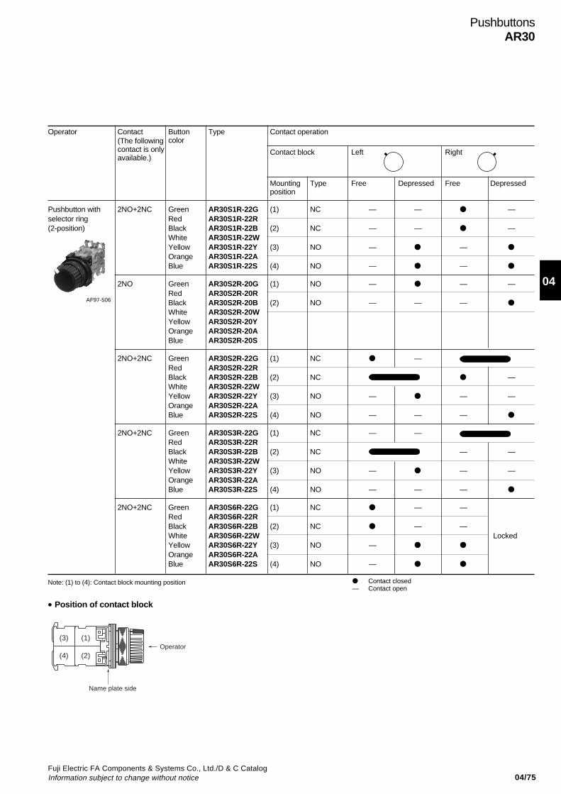
04/75Fuji Electric FA Components & Systems Co., Ltd./D & C CatalogInformation subject to change without notice
04
PushbuttonsAR30
Operator Contact Button Type Contact operationcolor
Contact block Left Right
Mounting Type Free Depressed Free Depressedposition
Pushbutton with 2NO+2NC Green AR30S1R-22G (1) NC — — —selector ring Red AR30S1R-22R(2-position) Black AR30S1R-22B (2) NC — — —
White AR30S1R-22WYellow AR30S1R-22Y (3) NO — —
Orange AR30S1R-22ABlue AR30S1R-22S (4) NO — —
2NO Green AR30S2R-20G (1) NO — — —Red AR30S2R-20RBlack AR30S2R-20B (2) NO — — —
White AR30S2R-20WYellow AR30S2R-20YOrange AR30S2R-20ABlue AR30S2R-20S
2NO+2NC Green AR30S2R-22G (1) NC —Red AR30S2R-22RBlack AR30S2R-22B (2) NC —White AR30S2R-22WYellow AR30S2R-22Y (3) NO — — —Orange AR30S2R-22ABlue AR30S2R-22S (4) NO — — —
2NO+2NC Green AR30S3R-22G (1) NC — —Red AR30S3R-22RBlack AR30S3R-22B (2) NC — —White AR30S3R-22WYellow AR30S3R-22Y (3) NO — — —Orange AR30S3R-22ABlue AR30S3R-22S (4) NO — — —
2NO+2NC Green AR30S6R-22G (1) NC — —Red AR30S6R-22RBlack AR30S6R-22B (2) NC — —White AR30S6R-22W LockedYellow AR30S6R-22Y (3) NO —
Orange AR30S6R-22ABlue AR30S6R-22S (4) NO —
• Position of contact block
Contact closed— Contact open
Note: (1) to (4): Contact block mounting position
AF97-506
(The followingcontact is onlyavailable.)
(1)
(2)
(3)
(4)
Name plate side
Operator
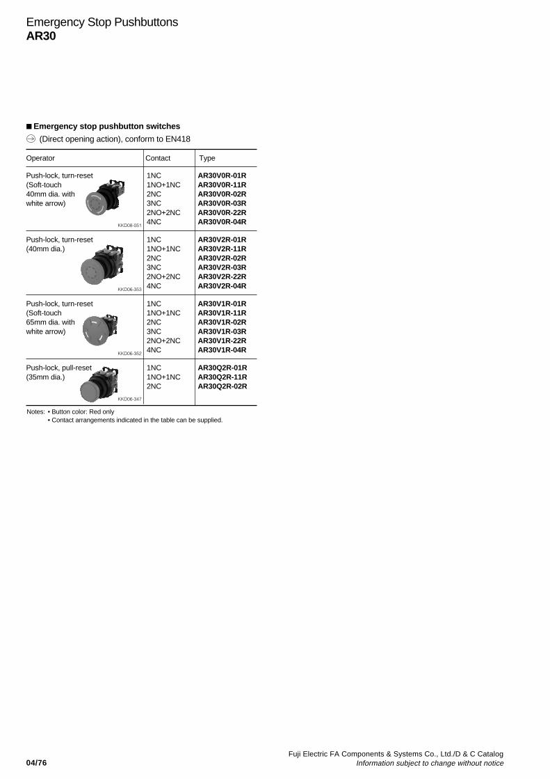
04/76Fuji Electric FA Components & Systems Co., Ltd./D & C Catalog
Information subject to change without notice
Operator Contact Type
Push-lock, turn-reset 1NC AR30V0R-01R(Soft-touch 1NO+1NC AR30V0R-11R40mm dia. with 2NC AR30V0R-02Rwhite arrow) 3NC AR30V0R-03R
2NO+2NC AR30V0R-22R
KKD08-051 4NC AR30V0R-04R
Push-lock, turn-reset 1NC AR30V2R-01R(40mm dia.) 1NO+1NC AR30V2R-11R
2NC AR30V2R-02R3NC AR30V2R-03R2NO+2NC AR30V2R-22R
KKD06-353 4NC AR30V2R-04R
Push-lock, turn-reset 1NC AR30V1R-01R(Soft-touch 1NO+1NC AR30V1R-11R65mm dia. with 2NC AR30V1R-02Rwhite arrow) 3NC AR30V1R-03R
2NO+2NC AR30V1R-22R
KKD06-352 4NC AR30V1R-04R
Push-lock, pull-reset 1NC AR30Q2R-01R(35mm dia.) 1NO+1NC AR30Q2R-11R
2NC AR30Q2R-02R
KKD06-347
Emergency Stop PushbuttonsAR30
Emergency stop pushbutton switches
(Direct opening action), conform to EN418
Notes: • Button color: Red only• Contact arrangements indicated in the table can be supplied.
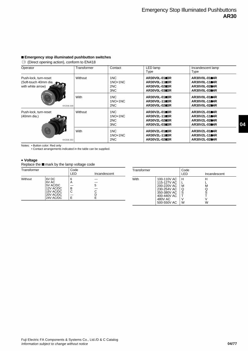
04/77Fuji Electric FA Components & Systems Co., Ltd./D & C CatalogInformation subject to change without notice
04
Operator Transformer Contact LED lamp Incandescent lampType Type
Push-lock, turn-reset Without 1NC AR30V0L-013R AR30V0L-01 4R(Soft-touch 40mm dia. 1NO+1NC AR30V0L-113R AR30V0L-11 4Rwith white arrow) 2NC AR30V0L-023R AR30V0L-02 4R
3NC AR30V0L-033R AR30V0L-03 4R
With 1NC AR30V0L-013R AR30V0L-01 4R1NO+1NC AR30V0L-113R AR30V0L-11 4R
KKD06-348 2NC AR30V0L-023R AR30V0L-02 4R
Push-lock, turn-reset Without 1NC AR30V2L-013R AR30V2L-01 4R(40mm dia.) 1NO+1NC AR30V2L-113R AR30V2L-11 4R
2NC AR30V2L-023R AR30V2L-02 4R3NC AR30V2L-033R AR30V2L-03 4R
With 1NC AR30V2L-013R AR30V2L-01 4R1NO+1NC AR30V2L-113R AR30V2L-11 4R
KKD06-350 2NC AR30V2L-023R AR30V2L-02 4R
Emergency Stop Illuminated PushbuttonsAR30
Emergency stop illuminated pushbutton switches
• VoltageReplace the mark by the lamp voltage codeTransformer Code
LED Incandescent
Without 6V DC 6 —6V AC A —5V AC/DC — 512V AC/DC B —15V AC/DC C C20V AC/DC — D24V AC/DC E E
Notes: • Button color: Red only• Contact arrangements indicated in the table can be supplied.
Transformer CodeLED Incandescent
With 100-110V AC H H115-127V AC L L200-220V AC M M230-254V AC Q Q350-380V AC S S400-440V AC T T480V AC V V500-550V AC W W
(Direct opening action), conform to EN418
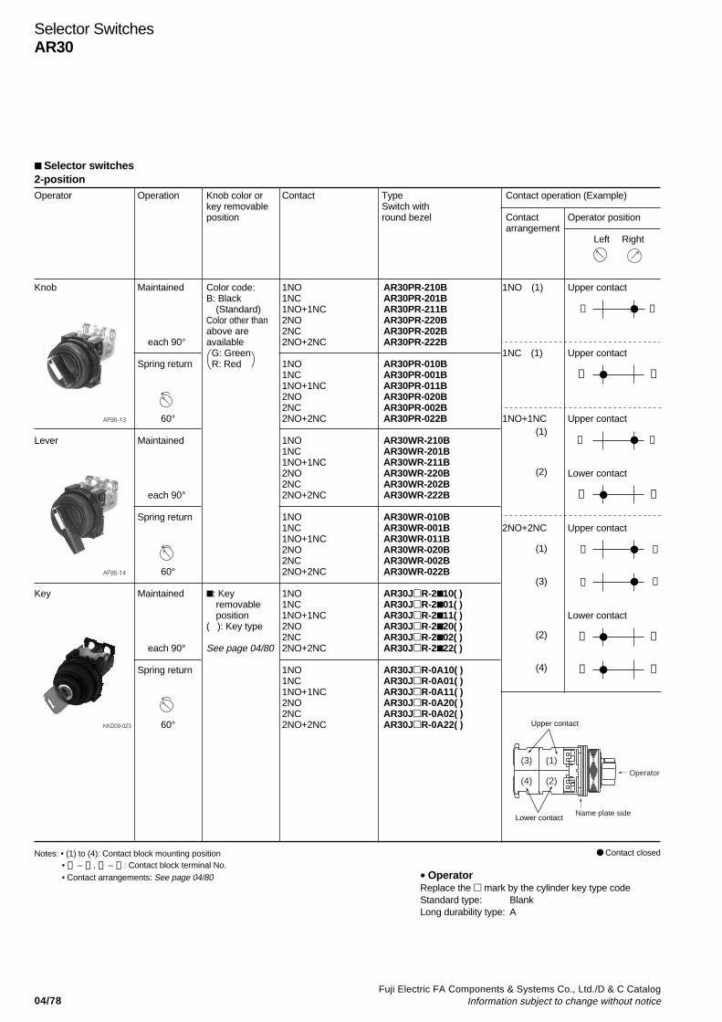
04/78Fuji Electric FA Components & Systems Co., Ltd./D & C Catalog
Information subject to change without notice
Selector SwitchesAR30
2-positionOperator Operation Knob color or Contact Type Contact operation (Example)
key removable Switch withposition round bezel Contact Operator position
arrangement Left Right
Knob Maintained Color code: 1NO AR30PR-210B 1NO (1) Upper contactB: Black 1NC AR30PR-201B
(Standard) 1NO+1NC AR30PR-211B ➂ ➃Color other than 2NO AR30PR-220Babove are 2NC AR30PR-202B
each 90° available 2NO+2NC AR30PR-222B G: Green 1NC (1) Upper contact
Spring return R: Red 1NO AR30PR-010B1NC AR30PR-001B ➀ ➁1NO+1NC AR30PR-011B2NO AR30PR-020B2NC AR30PR-002B
AF95-13 60° 2NO+2NC AR30PR-022B 1NO+1NC Upper contact
Lever Maintained 1NO AR30WR-210B ➂ ➃1NC AR30WR-201B1NO+1NC AR30WR-211B2NO AR30WR-220B Lower contact2NC AR30WR-202B
each 90° 2NO+2NC AR30WR-222B ➀ ➁
Spring return 1NO AR30WR-010B1NC AR30WR-001B 2NO+2NC Upper contact1NO+1NC AR30WR-011B2NO AR30WR-020B ➂ ➃2NC AR30WR-002B
AF95-14 60° 2NO+2NC AR30WR-022B ➂
➃
Key Maintained : Key 1NO AR30JR-2 10( ) removable 1NC AR30JR-2 01( ) position 1NO+1NC AR30JR-2 11( ) Lower contact
( ): Key type 2NO AR30JR-2 20( )2NC AR30JR-2 02( ) ➀ ➁
each 90° See page 04/80 2NO+2NC AR30JR-2 22( )
Spring return 1NO AR30JR-0A10( ) ➀ ➁1NC AR30JR-0A01( )1NO+1NC AR30JR-0A11( )2NO AR30JR-0A20( )2NC AR30JR-0A02( )
KKD09-023 60° 2NO+2NC AR30JR-0A22( )
(1)
(2)
(1)
(3)
(2)
(4)
Notes: • (1) to (4): Contact block mounting position• ➀ – ➁ , ➂ – ➃ : Contact block terminal No.• Contact arrangements: See page 04/80
Selector switches
• OperatorReplace the mark by the cylinder key type codeStandard type: BlankLong durability type: A
Contact closed
Name plate side
(1)
(2)
(3)
(4)Operator
Upper contact
Lower contact
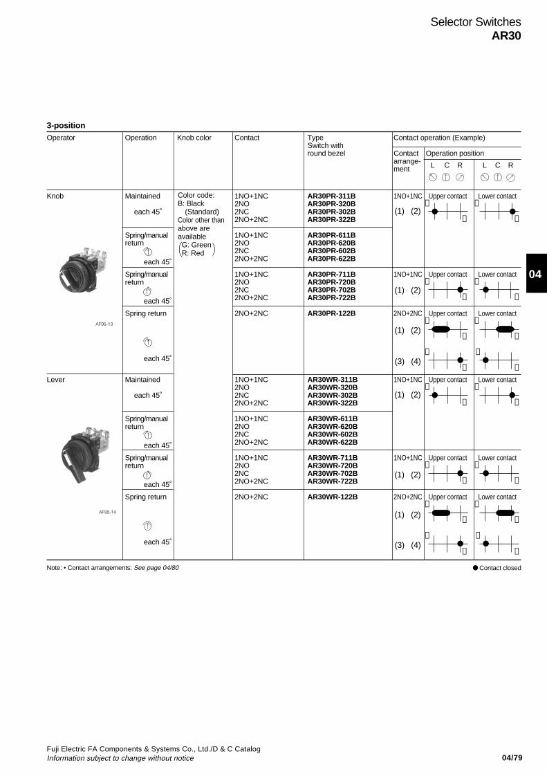
04/79Fuji Electric FA Components & Systems Co., Ltd./D & C CatalogInformation subject to change without notice
04
3-positionOperator Operation Knob color Contact Type Contact operation (Example)
Switch withround bezel Contact Operation position
arrange-ment L C R L C R
Knob Maintained 1NO+1NC AR30PR-311B 1NO+1NC Upper contact Lower contact2NO AR30PR-320B ➂ ➀2NC AR30PR-302B 2NO+2NC AR30PR-322B ➃ ➁
Spring/manual 1NO+1NC AR30PR-611Breturn 2NO AR30PR-620B
2NC AR30PR-602B2NO+2NC AR30PR-622B
Spring/manual 1NO+1NC AR30PR-711B 1NO+1NC Upper contact Lower contactreturn 2NO AR30PR-720B ➂ ➀
2NC AR30PR-702B 2NO+2NC AR30PR-722B ➃ ➁
Spring return 2NO+2NC AR30PR-122B 2NO+2NC Upper contact Lower contact➀ ➀
➁ ➁
➂ ➂ ➃ ➃
Lever Maintained 1NO+1NC AR30WR-311B 1NO+1NC Upper contact Lower contact2NO AR30WR-320B ➂ ➀2NC AR30WR-302B 2NO+2NC AR30WR-322B ➃ ➁
Spring/manual 1NO+1NC AR30WR-611Breturn 2NO AR30WR-620B
2NC AR30WR-602B2NO+2NC AR30WR-622B
Spring/manual 1NO+1NC AR30WR-711B 1NO+1NC Upper contact Lower contactreturn 2NO AR30WR-720B ➂ ➀
2NC AR30WR-702B 2NO+2NC AR30WR-722B ➃ ➁
Spring return 2NO+2NC AR30WR-122B 2NO+2NC Upper contact Lower contact➀ ➀
➁ ➁
➂ ➂ ➃ ➃
(1) (2)
(1) (2)
(1) (2)
(1) (2)
(1) (2)
(3) (4)
(3) (4)
(1) (2)
Color code:B: Black
(Standard)Color other thanabove areavailable G: Green R: Red
each 45˚
each 45˚
each 45˚
each 45˚
each 45˚
each 45˚
each 45˚
each 45˚
AF95-13
AF95-14
Contact closedNote: • Contact arrangements: See page 04/80
Selector SwitchesAR30
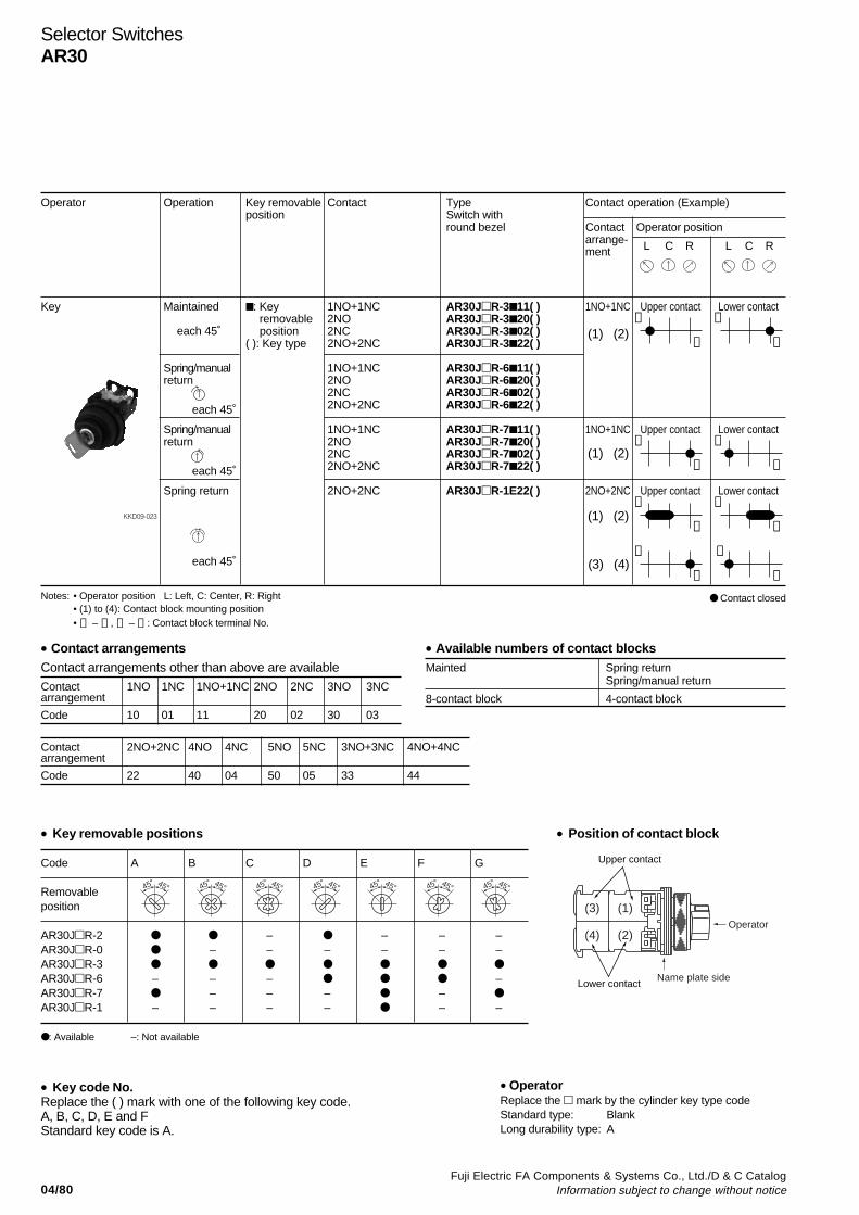
04/80Fuji Electric FA Components & Systems Co., Ltd./D & C Catalog
Information subject to change without notice
Selector SwitchesAR30
Operator Operation Key removable Contact Type Contact operation (Example)position Switch with
round bezel Contact Operator positionarrange-ment L C R L C R
Key Maintained : Key 1NO+1NC AR30JR-3 11( ) 1NO+1NC Upper contact Lower contact removable 2NO AR30JR-3 20( ) ➂ ➀ position 2NC AR30JR-3 02( )
( ): Key type 2NO+2NC AR30JR-3 22( ) ➃ ➁
Spring/manual 1NO+1NC AR30JR-6 11( )return 2NO AR30JR-6 20( )
2NC AR30JR-6 02( )2NO+2NC AR30JR-6 22( )
Spring/manual 1NO+1NC AR30JR-7 11( ) 1NO+1NC Upper contact Lower contactreturn 2NO AR30JR-7 20( ) ➂ ➀
2NC AR30JR-7 02( ) 2NO+2NC AR30JR-7 22( ) ➃ ➁
Spring return 2NO+2NC AR30JR-1E22( ) 2NO+2NC Upper contact Lower contact➀ ➀
➁ ➁
➂ ➂ ➃ ➃
Notes: • Operator position L: Left, C: Center, R: Right• (1) to (4): Contact block mounting position• ➀ – ➁ , ➂ – ➃ : Contact block terminal No.
• Key removable positions
Code A B C D E F G
Removableposition
AR30JR-2 – – – –AR30JR-0 – – – – – –AR30JR-3
AR30JR-6 – – – –AR30JR-7 – – – –
AR30JR-1 – – – – – –
: Available –: Not available
• Position of contact block
• Key code No.Replace the ( ) mark with one of the following key code.A, B, C, D, E and FStandard key code is A.
(3) (4)
(1) (2)
(1) (2)
(1) (2)
each 45˚
each 45˚
each 45˚
each 45˚
45° 45° 45° 45° 45° 45° 45° 45° 45° 45°45° 45° 45° 45°
KKD09-023
• OperatorReplace the mark by the cylinder key type codeStandard type: BlankLong durability type: A
Contact closed
• Contact arrangementsContact arrangements other than above are availableContact 1NO 1NC 1NO+1NC 2NO 2NC 3NO 3NCarrangement
Code 10 01 11 20 02 30 03
Contact 2NO+2NC 4NO 4NC 5NO 5NC 3NO+3NC 4NO+4NCarrangement
Code 22 40 04 50 05 33 44
• Available numbers of contact blocksMainted Spring return
Spring/manual return
8-contact block 4-contact block
Name plate side
(1)
(2)
(3)
(4)Operator
Upper contact
Lower contact

04/81Fuji Electric FA Components & Systems Co., Ltd./D & C CatalogInformation subject to change without notice
04
3-positionOperator Operation Knob color or Contact Type
key removable arrangement Switch withposition round bezel
Knob Maintained Replace the AR30PCR-3 Bmark by the contactarrangement code
Spring/manual (shown on next page). AR30PCR-6 Breturn
Spring/manual AR30PCR-7 Breturn
Spring return AR30PCR-1 B
Lever Maintained Replace the AR30WCR-3 Bmark by the contactarrangement code
Spring/manual (shown on next page). AR30WCR-6 Breturn
Spring/manual AR30WCR-7 Breturn
Spring return AR30WCR-1 B
Key Maintained Replace the Replace the AR30JCR-3 ( )mark by the mark by the contactkey removable arrangement code
Spring/manual position code: (shown on next page). AR30JCR-6 ( )return A, B, C, D, E
F or GSpring/manual AR30JCR-7 ( )return
Spring return AR30JCR-1E ( )
• Key removable positions
Code A B C D E F G
Removableposition
AR30JCR-3 AR30JCR-6 – – – –AR30JCR-7 – – – – AR30JCR-1 – – – – – –
: Available –: Not available
• Key code No.Replace the ( ) mark with one of the following key code.A, B, C, D, E and FStandard key code is A.
Color code:B: Black
(Standard)Color other thanabove areavailable G: Green R: Red
each 45˚
each 45˚
each 45˚
each 45˚
each 45˚
each 45˚
each 45˚
each 45˚
each 45˚
each 45˚
each 45˚
each 45˚
45° 45° 45° 45° 45° 45° 45° 45° 45° 45°45° 45° 45° 45°
Selector switches (control type)
AF95-475
KK02-140A
KKD09-022
Selector SwitchesAR30
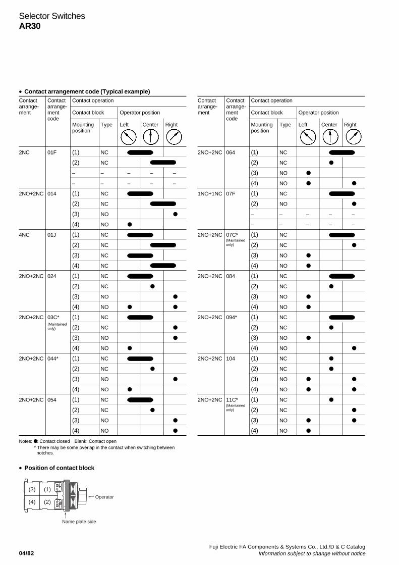
04/82Fuji Electric FA Components & Systems Co., Ltd./D & C Catalog
Information subject to change without notice
Selector SwitchesAR30
Contact Contact Contact operationarrange- arrange-ment ment Contact block Operator position
codeMounting Type Left Center Rightposition
2NO+2NC 064 (1) NC
(2) NC
(3) NO
(4) NO
1NO+1NC 07F (1) NC
(2) NO
– – – – –
– – – – –
2NO+2NC 07C* (1) NC
(2) NC
(3) NO
(4) NO
2NO+2NC 084 (1) NC
(2) NC
(3) NO
(4) NO
2NO+2NC 094* (1) NC
(2) NC
(3) NO
(4) NO
2NO+2NC 104 (1) NC
(2) NC
(3) NO
(4) NO
2NO+2NC 11C* (1) NC
(2) NC
(3) NO
(4) NO
Contact Contact Contact operationarrange- arrange-ment ment Contact block Operator position
codeMounting Type Left Center Rightposition
2NC 01F (1) NC
(2) NC
– – – – –
– – – – –
2NO+2NC 014 (1) NC
(2) NC
(3) NO
(4) NO
4NC 01J (1) NC
(2) NC
(3) NC
(4) NC
2NO+2NC 024 (1) NC
(2) NC
(3) NO
(4) NO
2NO+2NC 03C* (1) NC
(2) NC
(3) NO
(4) NO
2NO+2NC 044* (1) NC
(2) NC
(3) NO
(4) NO
2NO+2NC 054 (1) NC
(2) NC
(3) NO
(4) NO
Notes: : Contact closed Blank: Contact open* There may be some overlap in the contact when switching between notches.
• Position of contact block
(Maintainedonly)
(Maintainedonly)
(Maintainedonly)
• Contact arrangement code (Typical example)
Name plate side
(1)
(2)
(3)
(4)Operator
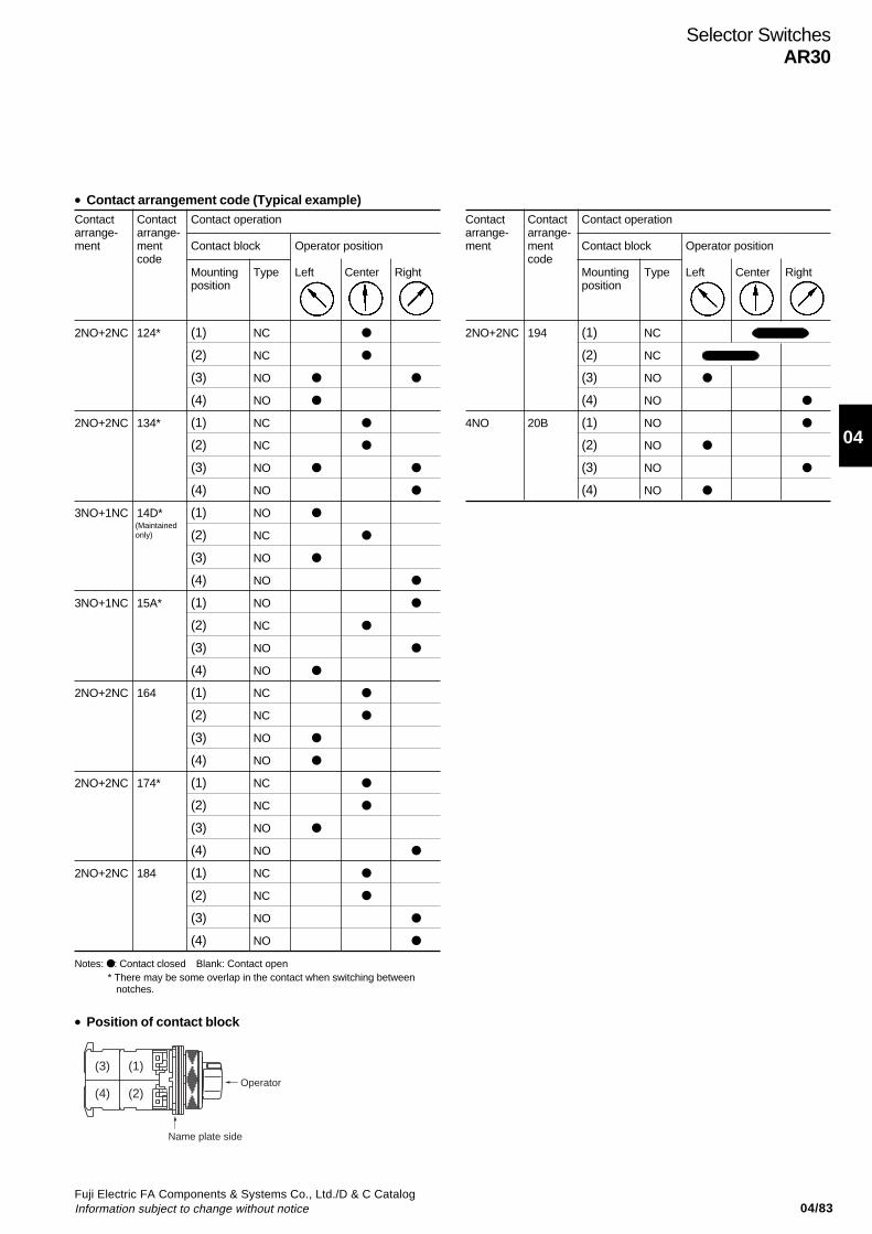
04/83Fuji Electric FA Components & Systems Co., Ltd./D & C CatalogInformation subject to change without notice
04
• Contact arrangement code (Typical example)Contact Contact Contact operationarrange- arrange-ment ment Contact block Operator position
codeMounting Type Left Center Rightposition
2NO+2NC 124* (1) NC
(2) NC
(3) NO
(4) NO
2NO+2NC 134* (1) NC
(2) NC
(3) NO
(4) NO
3NO+1NC 14D* (1) NO
(2) NC
(3) NO
(4) NO
3NO+1NC 15A* (1) NO
(2) NC
(3) NO
(4) NO
2NO+2NC 164 (1) NC
(2) NC
(3) NO
(4) NO
2NO+2NC 174* (1) NC
(2) NC
(3) NO
(4) NO
2NO+2NC 184 (1) NC
(2) NC
(3) NO
(4) NO
Notes: : Contact closed Blank: Contact open* There may be some overlap in the contact when switching between
notches.
• Position of contact block
Contact Contact Contact operationarrange- arrange-ment ment Contact block Operator position
codeMounting Type Left Center Rightposition
2NO+2NC 194 (1) NC
(2) NC
(3) NO
(4) NO
4NO 20B (1) NO
(2) NO
(3) NO
(4) NO
(Maintainedonly)
Name plate side
(1)
(2)
(3)
(4)Operator
Selector SwitchesAR30

04/84Fuji Electric FA Components & Systems Co., Ltd./D & C Catalog
Information subject to change without notice
Selector SwitchesAR30
4, 5-positionOperator Contact Operation Knob color Contact Type
arrangement Switch withround bezel
Knob 2NO+2NC 4-position Replace the AR30PCR-4 Bmaintained mark by the contact
arrangement code(shown below)
5-position AR30PCR-5 Bmaintained
Lever 2NO+2NC 4-position AR30WCR-4 Bmaintained
5-position AR30WCR-5 Bmaintained
Contact arrangement codePosition Contact Contact Contact operation
arrange- arrange-ment ment Contact block Operator position
codeMounting Typeposition 1 2 3 4 5
4-position 2NO+2NC 41C*(1) NC
(2) NC
(3) NO
(4) NO
5-position 2NO+2NC 51C*(1) NC
(2) NC
(3) NO
(4) NO
• Position of contact block
Operator position4-position 5-position
Color code:B: Black
(Standard)Color other thanabove areavailable G: Green R: Red
(The followingcontact is onlyavailable.)
(Main-tained only)
(Main-tained only)
40° 30°
AF95-475
KK02-140A
Notes: : Contact closed* There may be some overlap in the contact when switching between notches.
Name plate side
(1)
(2)
(3)
(4)Operator

04/85Fuji Electric FA Components & Systems Co., Ltd./D & C CatalogInformation subject to change without notice
04
2-positionOperator Operation Contact Type Contact operation
Contact Operator positionarrangement
Left Right
Lever (metal type) Maintained 1NO AR30HR-210 1NO (1) Upper contact
each 90° 1NC AR30HR-201 1NC (1) Upper contact
1NO+1NC AR30HR-211 1NO (1) Upper contact
1NC (2) Lower contact
2NO AR30HR-220 1NO (1) Upper contact
1NO (2) Lower contact
2NC AR30HR-202 1NC (1) Upper contact
1NC (2) Lower contact
2NO+2NC AR30HR-222 1NO (1) Upper contact
1NO (3)
1NC (2) Lower contact
1NC (4)
Notes: • Contact arrangements in the table can be supplied.
Lever type selector switches
• Position of contact block
Contact closed
➂ ➃
➀ ➁
➂ ➃
➀ ➁
➂ ➃
➂ ➃
➀ ➁
➀ ➁
➂ ➃
➂ ➃
➀ ➁
➀ ➁
KKD05-115
Selector SwitchesAR30
(1)
(2)
(3)
(4)Operator
Upper contact
Lower contact
Name plate side

04/86Fuji Electric FA Components & Systems Co., Ltd./D & C Catalog
Information subject to change without notice
3-positionOperator Operation Contact Type Contact operation
Contact Operator positionarrangement
Left Center Right
Lever (metal type) Maintained 1NO+1NC AR30HR-311 1NO (1) Upper contact
each 45° 1NC (2) Lower contact
2NO+2NC AR30HR-322 1NO (1) Upper contact
1NO (3)
1NC (2) Lower contact
1NC (4)
Spring 2NO+2NC AR30HR-122 1NC (1) Upper contactreturn
each 60° 1NO (3)
1NC (2) Lower contact
1NO (4)
Notes: • Contact arrangements in the table can be supplied. • Contact arrangements. The NO contacts at (1) and (2) use special parts. Do not interchange these parts.
• Position of contact block
Contact closed
➂ ➃
➀ ➁
➂ ➃
➂ ➃
➀ ➁
➀ ➁
➁
➂ ➃
➀ ➁
➂ ➃
➀
KKD05-114
Illuminated Selector SwitchesAR30
(1)
(2)
(3)
(4)Operator
Upper contact
Lower contact
Name plate side
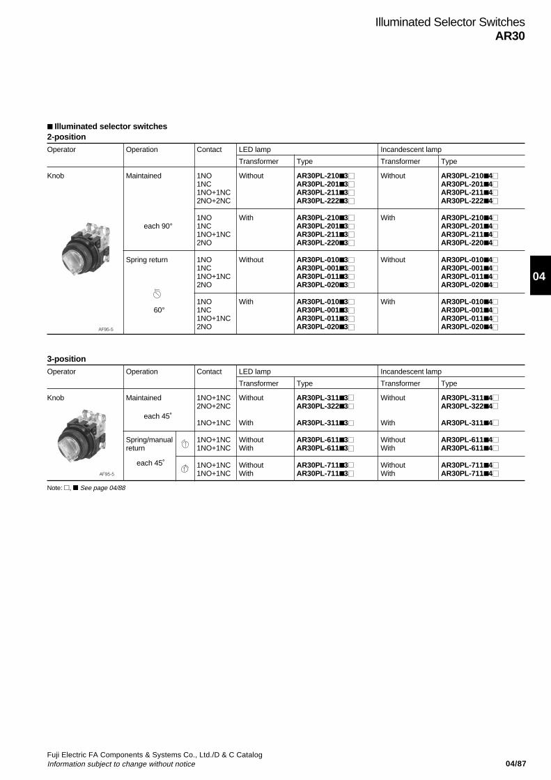
04/87Fuji Electric FA Components & Systems Co., Ltd./D & C CatalogInformation subject to change without notice
04
Illuminated Selector SwitchesAR30
2-positionOperator Operation Contact LED lamp Incandescent lamp
Transformer Type Transformer Type
Knob Maintained 1NO Without AR30PL-2103 Without AR30PL-21041NC AR30PL-2013 AR30PL-20141NO+1NC AR30PL-2113 AR30PL-21142NO+2NC AR30PL-2223 AR30PL-2224
1NO With AR30PL-2103 With AR30PL-2104 each 90° 1NC AR30PL-2013 AR30PL-2014
1NO+1NC AR30PL-2113 AR30PL-21142NO AR30PL-2203 AR30PL-2204
Spring return 1NO Without AR30PL-0103 Without AR30PL-01041NC AR30PL-0013 AR30PL-00141NO+1NC AR30PL-0113 AR30PL-01142NO AR30PL-0203 AR30PL-0204
1NO With AR30PL-0103 With AR30PL-0104 60° 1NC AR30PL-0013 AR30PL-0014
1NO+1NC AR30PL-0113 AR30PL-01142NO AR30PL-0203 AR30PL-0204
Illuminated selector switches
AF95-5
3-positionOperator Operation Contact LED lamp Incandescent lamp
Transformer Type Transformer Type
Knob Maintained 1NO+1NC Without AR30PL-3113 Without AR30PL-31142NO+2NC AR30PL-3223 AR30PL-3224
1NO+1NC With AR30PL-3113 With AR30PL-3114
Spring/manual 1NO+1NC Without AR30PL-6113 Without AR30PL-6114return 1NO+1NC With AR30PL-6113 With AR30PL-6114
1NO+1NC Without AR30PL-7113 Without AR30PL-71141NO+1NC With AR30PL-7113 With AR30PL-7114
each 45˚
each 45˚AF95-5
Note: , See page 04/88
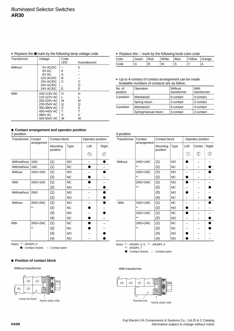
04/88Fuji Electric FA Components & Systems Co., Ltd./D & C Catalog
Information subject to change without notice
Illuminated Selector SwitchesAR30
• Replace the mark by the following lamp voltage codeTransformer Voltage Code
LED Incandescent
Without 5V AC/DC – 5 6V DC 6 – 6V AC A – 12V AC/DC B – 15V AC/DC C C 20V AC/DC – D 24V AC/DC E E
With 100-110V AC H H115-127V AC L L200-220V AC M M230-254V AC Q Q350-380V AC S S400-440V AC T T480V AC V V500-550V AC W W
• Replace the mark by the following knob color codeColor Green Red White Blue Yellow Orange
Code G R W S Y A
• Up to 4-contact of contact arrangement can be made.Available numbers of contacts are as follow.
No. of Operation Without Withposition transformer transformer
2-position Maintained 6-contact 4-contact
Spring return 3-contact 2-contact
3-position Maintained 6-contact 4-contact
Spring/manual return 3-contact 2-contact
Contact arrangement and operator position2-position Transformer Contact Contact block Operator position
arrangementMounting Type Left Rightposition
With/without 1NO (1) NO –
With/without 1NC (1) NC –
Without 1NO+1NC (1) NO –
(2) NC –
With 1NO+1NC (1) NC –
(2) NO –
With/without 2NO (1) NO –
(2) NO –
Without 2NO+2NC (1) NO –
*1 (2) NC –
(3) NO –
(4) NC –
With 2NO+2NC (1) NC –
*1 (2) NC –
(3) NO –
(4) NO –
Notes: *1 : AR30PL-2 : Contact closed, – : Contact open
Position of contact block
Without transformer
3-position Transformer Contact Contact block Operator position
arrangementMounting Type Left Center Rightposition
Without 1NO+1NC (1) NO – –
*1 (2) NC – –
1NO+1NC (1) NO – –
*2 (2) NC – –
2NO+2NC (1) NO – –
*3 (2) NC – –
(3) NO – –
(4) NC – –
With 1NO+1NC (1) NC – –
*1 (2) NO – –
1NO+1NC (1) NC – –
*2 (2) NO – –
2NO+2NC (1) NC – –
*3 (2) NC – –
(3) NO – –
(4) NO – –
Notes: *1 : AR30PL-3, 6 *3 : AR30PL-3*2 : AR30PL-7 : Contact closed, – : Contact open
With transformer
Lamp terminalName plate side
(1)(3)
(2)(4)
TransformerName plate side
(1)(2)(3)(4)

04/89Fuji Electric FA Components & Systems Co., Ltd./D & C CatalogInformation subject to change without notice
04
Lens Transformer LED lamp Incandescent lampLamp voltage Type Lamp voltage Type
Dome Without 6V AC DR30D0L-A3 5.5V AC/DC DR30D0L-54 6V DC DR30D0L-63 — — 12V AC/DC DR30D0L-B3 15V AC/DC DR30D0L-C4 24V AC/DC DR30D0L-E3 24V AC/DC DR30D0L-E4
With 100–110V AC DR30D0L-H3 100–110V AC DR30D0L-H4200–220V AC DR30D0L-M3 200–220V AC DR30D0L-M4
Dome With resistor 50V DC DR30D0L-FR 50V DC DR30D0L-FQ110V DC DR30D0L-HR — —220V DC DR30D0L-MR — —
Dome With resistor — — 110V DC DR30D0L-HQ — — 220V DC DR30D0L-MQ
Extended round Without 6V AC DR30E3L-A3 5.5V AC/DC DR30E3L-54 6V DC DR30E3L-63 — — 12V AC/DC DR30E3L-B3 15V AC/DC DR30E3L-C4 24V AC/DC DR30E3L-E3 24V AC/DC DR30E3L-E4
With 100–110V AC DR30E3L-H3 100–110V AC DR30E3L-H4200–220V AC DR30E3L-M3 200–220V AC DR30E3L-M4
Faceted Without 6V AC DR30K0L-A3 5.5V AC/DC DR30K0L-54 6V DC DR30K0L-63 — — 12V AC/DC DR30K0L-B3 15V AC/DC DR30K0L-C4 24V AC/DC DR30K0L-E3 24V AC/DC DR30K0L-E4
With 100–110V AC DR30K0L-H3 100–110V AC DR30K0L-H4200–220V AC DR30K0L-M3 200–220V AC DR30K0L-M4
Faceted With resistor 50V DC DR30K0L-FR 50V DC DR30K0L-FQ 110V DC DR30K0L-HR — — 220V DC DR30K0L-MR — —
Faceted With resistor — — 110V DC DR30K0L-HQ — — 220V DC DR30K0L-MQ
Dome with dimmer control Without 6V AC DR30D1L-A3 5.5V AC/DC DR30D1L-54 6V DC DR30D1L-63 — — 12V AC/DC DR30D1L-B3 — — 15V AC/DC DR30D1L-C3 15V AC/DC DR30D1L-C4 24V AC/DC DR30D1L-E3 24V AC/DC DR30D1L-E4
With 100V–110V AC DR30D1L-H3 100V–110V AC DR30D1L-H4200V–220V AC DR30D1L-M3 200V–220V AC DR30D1L-M4
Pilot LightsDR30
Pilot lights/standard
AF95-18
AF97-674
AF97-672
AF95-20
AF95-19
AF97-673
AF97-671
KK02-144A
Note: See page 04/90
Discontinued
Discontinued
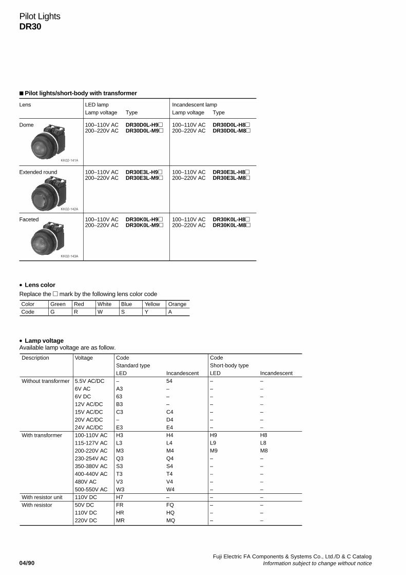
04/90Fuji Electric FA Components & Systems Co., Ltd./D & C Catalog
Information subject to change without notice
Pilot LightsDR30
Pilot lights/short-body with transformer
Lens LED lamp Incandescent lampLamp voltage Type Lamp voltage Type
Dome 100–110V AC DR30D0L-H9 100–110V AC DR30D0L-H8200–220V AC DR30D0L-M9 200–220V AC DR30D0L-M8
Extended round 100–110V AC DR30E3L-H9 100–110V AC DR30E3L-H8200–220V AC DR30E3L-M9 200–220V AC DR30E3L-M8
Faceted 100–110V AC DR30K0L-H9 100–110V AC DR30K0L-H8200–220V AC DR30K0L-M9 200–220V AC DR30K0L-M8
KK02-141A
KK02-142A
KK02-143A
ColorCode
GreenG
RedR
WhiteW
BlueS
YellowY
OrangeA
Replace the mark by the following lens color code• Lens color
• Lamp voltageAvailable lamp voltage are as follow.
Description
Without transformer
With transformer
With resistor unitWith resistor
Voltage
5.5V AC/DC6V AC6V DC12V AC/DC15V AC/DC20V AC/DC24V AC/DC100-110V AC115-127V AC200-220V AC230-254V AC350-380V AC 400-440V AC480V AC 500-550V AC110V DC50V DC110V DC220V DC
CodeStandard typeLED–A363B3C3–E3H3L3M3Q3S3T3V3W3H7FRHRMR
Incandescent54–––C4D4E4H4L4M4Q4S4T4V4W4–FQHQMQ
CodeShort-body typeLED–––––––H9L9M9–––––––––
Incandescent–––––––H8L8M8–––––––––
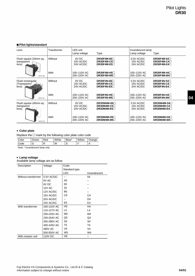
04/91Fuji Electric FA Components & Systems Co., Ltd./D & C CatalogInformation subject to change without notice
04
Pilot LightsDR30
Lens Transformer LED unit Incandescent lampLamp voltage Type Lamp voltage Type
Flush square (34mm sq. Without 6V DC DR30F4M-65 5.5V AC/DC DR30F4M-54transparent 15V AC/DC DR30F4M-C5 15V AC/DC DR30F4M-C4lens) 24V AC/DC DR30F4M-E5 24V AC/DC DR30F4M-E4
With 100–110V AC DR30F4M-H5 100–110V AC DR30F4M-H4200–220V AC DR30F4M-M5 200–220V AC DR30F4M-M4
Flush rectangular Without 6V DC DR30F4N-65 5.5V AC/DC DR30F4N-54(Transparent 15V AC/DC DR30F4N-C5 15V AC/DC DR30F4N-C4lens) 24V AC/DC DR30F4N-E5 24V AC/DC DR30F4N-E4
With 100–110V AC DR30F4N-H5 100–110V AC DR30F4N-H4200–220V AC DR30F4N-M5 200–220V AC DR30F4N-M4
Flush square (40mm sq. Without 6V DC DR30M4M-65 5.5V AC/DC DR30M4M-54transparent 15V AC/DC DR30M4M-C5 15V AC/DC DR30M4M-C4lens) 24V AC/DC DR30M4M-E5 24V AC/DC DR30M4M-E4
With 100–110V AC DR30M4M-H5 100–110V AC DR30M4M-H4200–220V AC DR30M4M-M5 200–220V AC DR30M4M-M4
Pilot lights/standard
AF97-65
AF97-61
AF97-63
Replace the mark by the following color plate color code• Color plate
• Lamp voltageAvailable lamp voltage are as follow.
ColorCode
Note: * Incandescent lamp only
GreenG
RedR
WhiteW
Blue*S
YellowY
OrangeA
Description
Without transformer
With transformer
With resistor unit
Voltage
5.5V AC/DC6V AC6V DC12V AC12V AC/DC15V AC/DC20V AC/DC24V AC/DC100-110V AC115-127V AC200-220V AC230-254V AC350-380V AC 400-440V AC480V AC 500-550V AC110V DC
CodeStandard typeLED–A56525B5C5–E5H5L5M5Q5S5T5V5W5HE
Incandescent54––––C4D4E4H4L4M4Q4S4T4V4W4–
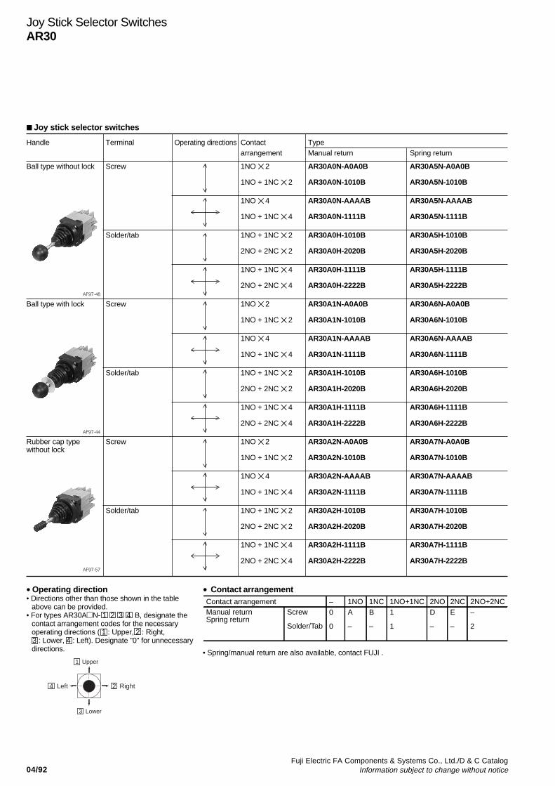
04/92Fuji Electric FA Components & Systems Co., Ltd./D & C Catalog
Information subject to change without notice
Joy stick selector switches
Handle Terminal Operating directions Contact Typearrangement Manual return Spring return
Ball type without lock Screw 1NO 2 AR30A0N-A0A0B AR30A5N-A0A0B
1NO + 1NC 2 AR30A0N-1010B AR30A5N-1010B
1NO 4 AR30A0N-AAAAB AR30A5N-AAAAB
1NO + 1NC 4 AR30A0N-1111B AR30A5N-1111B
Solder/tab 1NO + 1NC 2 AR30A0H-1010B AR30A5H-1010B
2NO + 2NC 2 AR30A0H-2020B AR30A5H-2020B
1NO + 1NC 4 AR30A0H-1111B AR30A5H-1111B
2NO + 2NC 4 AR30A0H-2222B AR30A5H-2222BAF97-48
Ball type with lock Screw 1NO 2 AR30A1N-A0A0B AR30A6N-A0A0B
1NO + 1NC 2 AR30A1N-1010B AR30A6N-1010B
1NO 4 AR30A1N-AAAAB AR30A6N-AAAAB
1NO + 1NC 4 AR30A1N-1111B AR30A6N-1111B
Solder/tab 1NO + 1NC 2 AR30A1H-1010B AR30A6H-1010B
2NO + 2NC 2 AR30A1H-2020B AR30A6H-2020B
1NO + 1NC 4 AR30A1H-1111B AR30A6H-1111B
2NO + 2NC 4 AR30A1H-2222B AR30A6H-2222BAF97-44
Rubber cap type Screw 1NO 2 AR30A2N-A0A0B AR30A7N-A0A0Bwithout lock
1NO + 1NC 2 AR30A2N-1010B AR30A7N-1010B
1NO 4 AR30A2N-AAAAB AR30A7N-AAAAB
1NO + 1NC 4 AR30A2N-1111B AR30A7N-1111B
Solder/tab 1NO + 1NC 2 AR30A2H-1010B AR30A7H-1010B
2NO + 2NC 2 AR30A2H-2020B AR30A7H-2020B
1NO + 1NC 4 AR30A2H-1111B AR30A7H-1111B
2NO + 2NC 4 AR30A2H-2222B AR30A7H-2222BAF97-57
Joy Stick Selector SwitchesAR30
• Operating direction• Directions other than those shown in the table
above can be provided.• For types AR30AN- 1 2 3 4 B, designate the
contact arrangement codes for the necessaryoperating directions ( 1 : Upper, 2 : Right,
3 : Lower, 4 : Left). Designate "0" for unnecessarydirections.
• Contact arrangementContact arrangementManual returnSpring return
Screw
Solder/Tab
1NO– 1NC 1NO+1NC 2NO 2NC 2NO+2NCA
–
0
0
B
–
1
1
D
–
E
–
–
2
1 Upper
3 Lower
2 Right4 Left
• Spring/manual return are also available, contact FUJI .
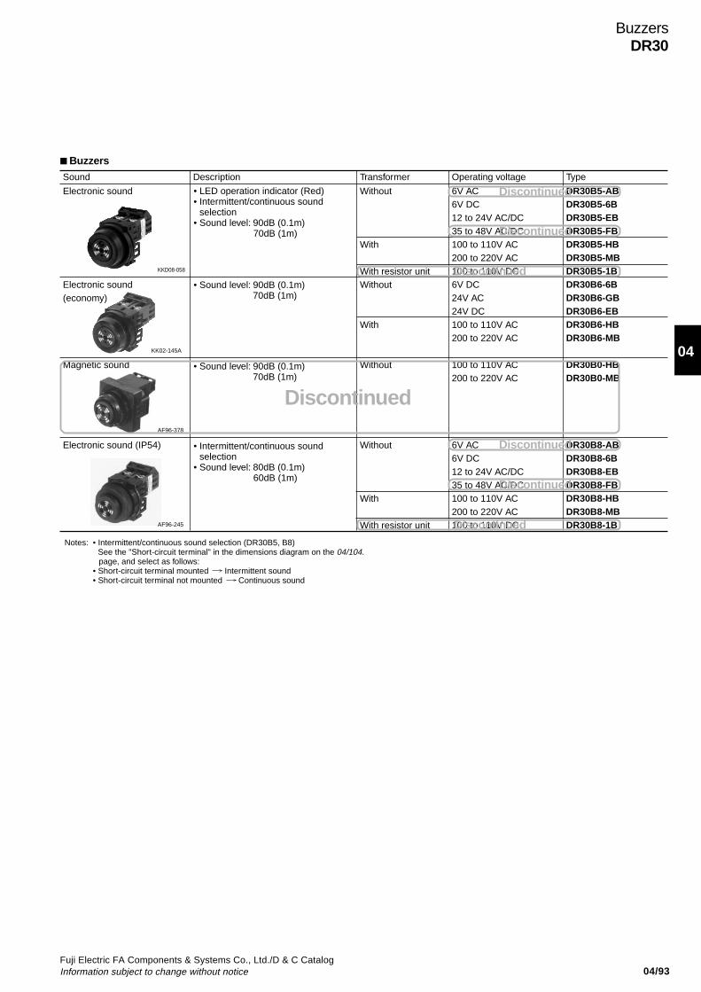
04/93Fuji Electric FA Components & Systems Co., Ltd./D & C CatalogInformation subject to change without notice
04
Buzzers
BuzzersDR30
Sound Description
Electronic sound
Electronic sound(economy)
Magnetic sound
Electronic sound (IP54)
Transformer
Without
With
With resistor unitWithout
With
Without
Without
With
With resistor unit
Operating voltage
6V AC6V DC12 to 24V AC/DC35 to 48V AC/DC100 to 110V AC200 to 220V AC100 to 110V DC6V DC24V AC24V DC100 to 110V AC200 to 220V AC
100 to 110V AC200 to 220V AC
6V AC6V DC12 to 24V AC/DC35 to 48V AC/DC100 to 110V AC200 to 220V AC100 to 110V DC
Type
DR30B5-ABDR30B5-6BDR30B5-EBDR30B5-FBDR30B5-HBDR30B5-MBDR30B5-1BDR30B6-6BDR30B6-GBDR30B6-EBDR30B6-HBDR30B6-MB
DR30B0-HBDR30B0-MB
DR30B8-ABDR30B8-6BDR30B8-EBDR30B8-FBDR30B8-HBDR30B8-MBDR30B8-1B
• Intermittent/continuous sound selection (DR30B5, B8) See the "Short-circuit terminal" in the dimensions diagram on the 04/104.
page, and select as follows:• Short-circuit terminal mounted Intermittent sound• Short-circuit terminal not mounted Continuous sound
Notes:
• LED operation indicator (Red)• Intermittent/continuous sound
selection• Sound level: 90dB (0.1m)
70dB (1m)
• Intermittent/continuous sound selection
• Sound level: 80dB (0.1m) 60dB (1m)
• Sound level: 90dB (0.1m) 70dB (1m)
• Sound level: 90dB (0.1m) 70dB (1m)
KKD08-058
AF96-378
KK02-145A
AF96-245
Discontinued
Discontinued
Discontinued
Discontinued
Discontinued
Discontinued
Discontinued
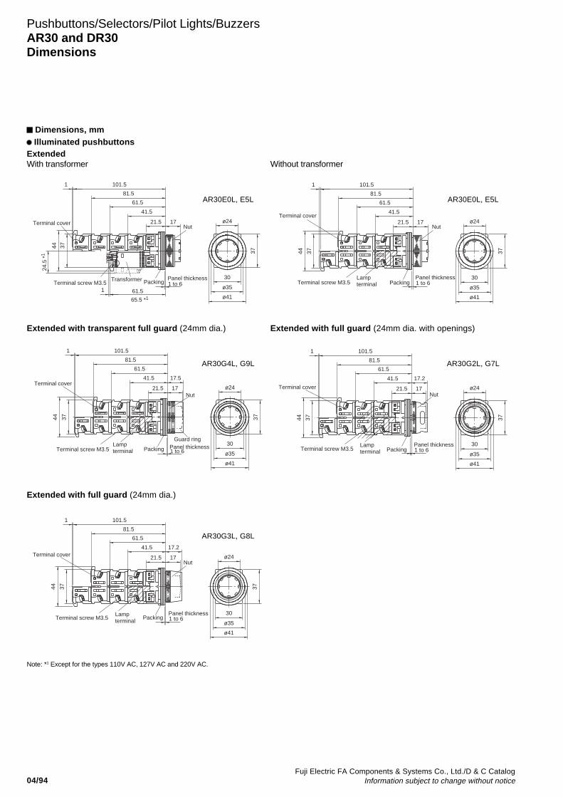
04/94Fuji Electric FA Components & Systems Co., Ltd./D & C Catalog
Information subject to change without notice
Pushbuttons/Selectors/Pilot Lights/BuzzersAR30 and DR30Dimensions
Dimensions, mm Illuminated pushbuttons
ExtendedWith transformer Without transformer
30
ø35
ø41
37
1 101.5
81.5
61.5
41.5
21.5 17
24.5
*1
Transformer
3744
61.51
65.5 *1
ø24
Panel thickness1 to 6
Nut
PackingTerminal screw M3.5
Terminal cover
30
ø35
ø41
37
ø24Nut
Panel thickness1 to 6PackingTerminal screw M3.5
81.5
41.5
1721.5
101.5
3744
Lampterminal
1
61.5
Terminal cover
Extended with transparent full guard (24mm dia.)
ø24
37
30
ø35
ø41
81.5
61.5
41.5
21.5
101.51
44 37
17
Lampterminal
Guard ring
17.5
Panel thickness1 to 6
Nut
PackingTerminal screw M3.5
Terminal cover
Extended with full guard (24mm dia. with openings)
ø24
37
30
ø35
ø41
61.5
41.5
21.5
44 37
1
17.2
17
81.5
101.5
Panel thickness1 to 6
Nut
PackingTerminal screw M3.5Lampterminal
Terminal cover
Extended with full guard (24mm dia.)
ø24
37
30
ø35
ø41
81.5
61.5
41.5
21.5
101.51
3744
17
17.2
Panel thickness1 to 6
Nut
PackingTerminal screw M3.5Lampterminal
Terminal cover
Note: *1 Except for the types 110V AC, 127V AC and 220V AC.
AR30E0L, E5L AR30E0L, E5L
AR30G4L, G9L AR30G2L, G7L
AR30G3L, G8L
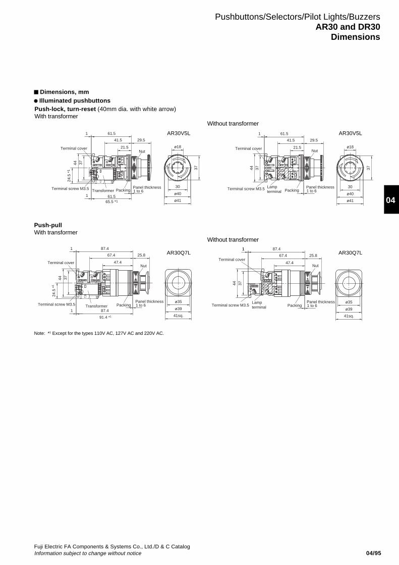
04/95Fuji Electric FA Components & Systems Co., Ltd./D & C CatalogInformation subject to change without notice
04
Pushbuttons/Selectors/Pilot Lights/BuzzersAR30 and DR30
Dimensions
Dimensions, mm Illuminated pushbuttons
Push-pullWith transformer
Without transformer
ø35
ø39
41sq.
24.5
*1
44 37
1
91.4 *1
1
47.4
67.4
87.4
87.4
25.8
Panel thickness1 to 6
Nut
PackingTerminal screw M3.5 Transformer
Terminal cover
ø35
ø39
41sq.
47.4
67.4
87.4
3744
25.8
11
Panel thickness1 to 6
Nut
PackingTerminal screw M3.5Lampterminal
Terminal cover
Push-lock, turn-reset (40mm dia. with white arrow)With transformer
37
ø18
30
ø41
ø40
1 61.5
41.5
21.5
61.565.5 *1
3744
24.5
*1
29.5
1
Panel thickness1 to 6
Nut
PackingTerminal screw M3.5 Transformer
Terminal cover
30
ø40
ø41
37
ø18
61.5
41.5
21.5
1
3744
29.5
Panel thickness1 to 6
Nut
PackingTerminal screw M3.5 Lampterminal
Terminal cover
Without transformer
Note: *1 Except for the types 110V AC, 127V AC and 220V AC.
AR30V5L AR30V5L
AR30Q7L AR30Q7L

04/96Fuji Electric FA Components & Systems Co., Ltd./D & C Catalog
Information subject to change without notice
Pushbuttons/Selectors/Pilot Lights/BuzzersAR30 and DR30Dimensions
Dimensions, mm Pushbuttons
17(Extended)11.5(Flush)
NutPackingTerminal screw M3.5
Terminal cover
Panel thickness
1 101.5
37
ø24
ø41ø3530
44 37
81.561.5
41.521.5
1 to 6
Flush/Extended Mushroom (40mm dia.)
Panel thickness1 to 6 ø40
22.5
3744
41.521.5
1 101.581.5
61.5
37
ø41
30Nut
PackingTerminal screw M3.5
Terminal cover
Mushroom (29mm dia.)
ø29
37
ø41ø3530
Panel thickness1 to 6
3744
22.541.521.5
61.5
1 101.581.5
NutPackingTerminal screw M3.5
Terminal cover
Extended with full guard (24mm dia.)
ø24
37
ø41ø3530
17
Panel thickness1 to 6
3744
41.521.5
1 101.581.5
61.5
NutPackingTerminal screw M3.5
Terminal cover 17.2
Extended with half guard
Panel thickness1 to 6
NutPackingTerminal screw M3.5
17.517
3744
41.521.5
101.581.5
61.5
ø24
37
ø41ø3530
1
Terminal cover
Pin lock
Panel thickness1 to 6
NutPacking
Pin
Terminal screw M3.5
7.323.6
44 37
1 107.387.3
67.3
27.3
30
ø23.4
41sq
.
ø35
47.3
Terminal cover
Note:The enclosed pin can be inserted to lock the pushbutton in a pushed or not pushed state.
Mushroom with full guard (40mm dia.)
30
3744
1
22.3
Guard ring
ø50ø40
101.581.5
61.541.5
21.522
37
Panel thickness1 to 6
PackingTerminal screw M3.5
Terminal cover
Mushroom with full guard (35mm dia. metal nut)
ø3530
1
Guard ring
44 37
25
101.581.5
61.541.5
21.5
ø44.5
37
Panel thickness1 to 6
PackingTerminal screw M3.5
Terminal cover
AR30F0R, F5R, FAR,FBR, E0R, E5R,EAR, EBR AR30M0R, M5R
AR30M4R AR30G1R, G6R
AR30G0R, G5R AR30GPR
AR30M3R, M8R AR30GSR
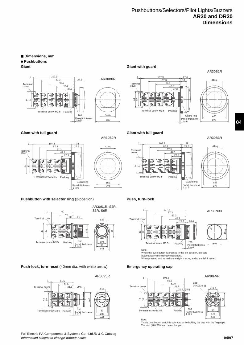
04/97Fuji Electric FA Components & Systems Co., Ltd./D & C CatalogInformation subject to change without notice
04
Pushbuttons/Selectors/Pilot Lights/BuzzersAR30 and DR30
Dimensions
Giant
Dimensions, mm Pushbuttons
44 37
27.61 107.3
87.367.3
47.327.3
Panel thickness1 to 6
NutPackingTerminal screw M3.5
Terminal cover
41sq.
ø65
Giant with guard
18
Guard ring
27.347.3
27.6
67.387.3
107.31
3744
Panel thickness1 to 6
PackingTerminal screw M3.5
Terminal cover
41sq.
ø65ø75
Giant with full guard
Guard ring
27.633
27.347.3
67.387.3
107.3
37
1
44
Panel thickness1 to 6
PackingTerminal screw M3.5
Terminal cover
41sq.
ø65ø75
Giant with full guard
Guard ring
29
27.347.3
27.667.3
87.3107.31
3744
Panel thickness1 to 6
PackingTerminal screw M3.5
Terminal cover
41sq.
ø65ø75
Pushbutton with selector ring (2-position)
ø32
37
ø41
ø24
ø3544 37
1
23
6040
30
20
Panel thickness1 to 6
NutPackingTerminal screw M3.5
Terminal cover
Push, turn-lock
107.387.3
67.347.3
27.341
sq.
ø40
1
28.4
3744
Panel thickness1 to 6
NutPackingTerminal screw M3.5
Terminal cover
Note: When the push button is pressed in the left position, it resets automatically (momentary operation). When pressed and turned to the right it locks, and to the left it resets.
Push-lock, turn-reset (40mm dia. with white arrow)
1
ø18
ø40
ø41ø3530
61.541.5
21.5 29.5
44 37
Panel thickness1 to 6
NutPackingTerminal screw M3.5
Terminal cover
Emergency operating cap
37
ø41ø3530
1 101.581.5
61.541.5
21.5
Cap(AHX539-1)
ø24.515.5
44 37
NutPackingTerminal screw M3.5
Panel thickness1 to 6
Terminal cover
Note:This is pushbutton switch is operated while holding the cap with the fingertips. The cap (AHX539) can be exchanged.
AR30B0R
AR30B1R
AR30B2R AR30B3R
AR30S1R, S2R,S3R, S6R AR30N0R
AR30V5R AR30FVR
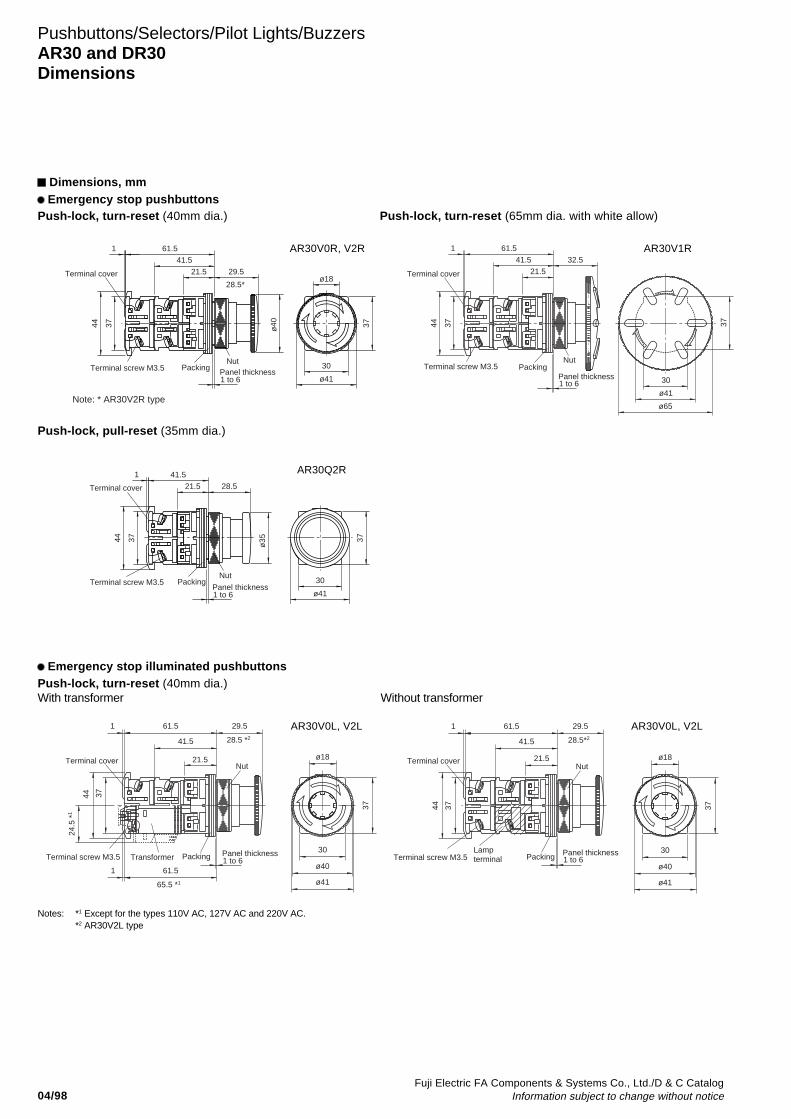
04/98Fuji Electric FA Components & Systems Co., Ltd./D & C Catalog
Information subject to change without notice
Pushbuttons/Selectors/Pilot Lights/BuzzersAR30 and DR30Dimensions
Dimensions, mm Emergency stop pushbuttons
Push-lock, turn-reset (40mm dia.)
1
3744
29.521.5
41.5
61.5
30
ø41
37ø40
ø1828.5*
Panel thickness1 to 6
NutPackingTerminal screw M3.5
Terminal cover
Note: * AR30V2R type
Push-lock, turn-reset (65mm dia. with white allow)
32.5
ø65
30
ø41
61.5
41.5
21.5
44 37
1
37
Panel thickness1 to 6
NutPackingTerminal screw M3.5
Terminal cover
Push-lock, pull-reset (35mm dia.)
37
ø41
30
41.5
21.5 28.5
44 37
1
ø35
Panel thickness1 to 6
NutPackingTerminal screw M3.5
Terminal cover
Push-lock, turn-reset (40mm dia.)With transformer Without transformer
28.5 *2
37
30
ø41
ø18
ø40
1 61.5
41.5
21.5
61.5
65.5 *1
1
3744
24.5
*1
29.5
Panel thickness1 to 6
Nut
PackingTerminal screw M3.5 Transformer
Terminal cover
29.5
44 37
1
21.5
41.5
61.5
28.5*2
37
30
ø41
ø18
ø40
Panel thickness1 to 6
Nut
PackingTerminal screw M3.5Lampterminal
Terminal cover
Notes: *1 Except for the types 110V AC, 127V AC and 220V AC.*2 AR30V2L type
Emergency stop illuminated pushbuttons
AR30V0R, V2R AR30V1R
AR30V0L, V2L AR30V0L, V2L
AR30Q2R
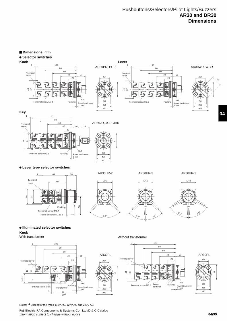
04/99Fuji Electric FA Components & Systems Co., Ltd./D & C CatalogInformation subject to change without notice
04
Pushbuttons/Selectors/Pilot Lights/BuzzersAR30 and DR30
Dimensions
Knob
Dimensions, mm Selector switches
1
44 37
ø41
ø35
30
37
ø2420
40
60
80
100
23
Panel thickness1 to 6
NutPackingTerminal screw M3.5
Terminal cover
Lever1
44 37
20
40
60
80
100
23ø24
27
37
30
ø35
ø41
Panel thickness1 to 6
NutPackingTerminal screw M3.5
Terminal cover
Key
Illuminated selector switchesKnobWith transformer
Panel thickness1 to 6
NutPackingTerminal screw M3.5
100
80
73
44
1
73
ø35
30
ø41
60
40
20
20 24 Terminalcover
24.5
*1
3744
1
64*1
1
ø24
37
ø35
ø41
30
20
40
60
80
100
60
23
Panel thickness1 to 6
NutPackingTerminal screw M3.5 Transformer
Terminal cover
1
3744
ø24
37
ø35
ø41
30
40
60
80
100
23
20
Panel thickness1 to 6
NutPackingTerminal screw M3.5 Lamp
terminal
Terminal cover
Without transformer
Notes: *1 Except for the types 110V AC, 127V AC and 220V AC.
AR30PR, PCR AR30WR, WCR
AR30JR, JCR, JAR
AR30PL AR30PL
Lever type selector switches
1 69
49
50
44 37
41 41 41
9 0° 4 5° 4 5°6 0° 6 0°Terminal screw M3.5
Packing
28 AR30HR-2 AR30HR-3 AR30HR-1
Terminalcover
Panel thickness 1 to 6
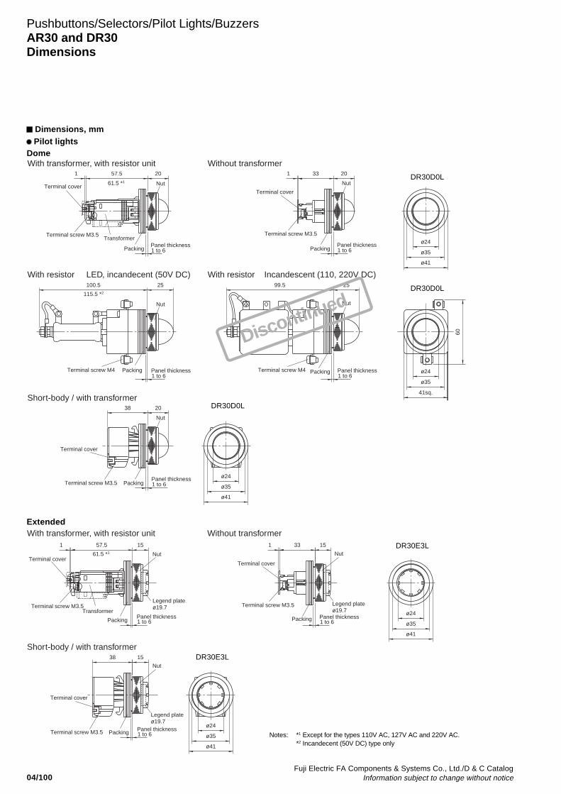
04/100Fuji Electric FA Components & Systems Co., Ltd./D & C Catalog
Information subject to change without notice
Pushbuttons/Selectors/Pilot Lights/BuzzersAR30 and DR30Dimensions
Dimensions, mm Pilot lights
Dome
ø24
ø41
61.5 *1
20331
ø35
100.5 25
ø24
ø35
41sq.
60
2599.5
115.5 *2
2038
ø35
ø41
ø24
2057.51
Panel thickness1 to 6
Panel thickness1 to 6
Nut Nut
Nut Nut
Packing Packing
Panel thickness1 to 6
Panel thickness1 to 6
Packing Packing
Terminal screw M3.5 Terminal screw M3.5
Panel thickness1 to 6
Nut
PackingTerminal screw M3.5
Terminal screw M4 Terminal screw M4
Transformer
Terminal cover
Terminal cover
Terminal cover
With transformer, with resistor unit
With resistor LED, incandecent (50V DC)
Short-body / with transformer
With resistor Incandescent (110, 220V DC)
Without transformer
Extended
ø35
61.5 *1
1 57.5
ø41
ø24
15
Legend plateø19.7
1 33 15
Legend plateø19.7
ø24
ø41
ø35
38 15
Legend plateø19.7
Panel thickness1 to 6
Panel thickness1 to 6
Panel thickness1 to 6
Nut
Nut
Packing
Packing
Terminal screw M3.5
Nut
Packing
Terminal screw M3.5
Terminal screw M3.5
Transformer
Terminal coverTerminal cover
Terminal cover
With transformer, with resistor unit
Short-body / with transformer
Without transformer
Notes: *1 Except for the types 110V AC, 127V AC and 220V AC.*2 Incandecent (50V DC) type only
DR30D0L
DR30D0L
DR30D0L
DR30E3L
DR30E3L
Discontinued
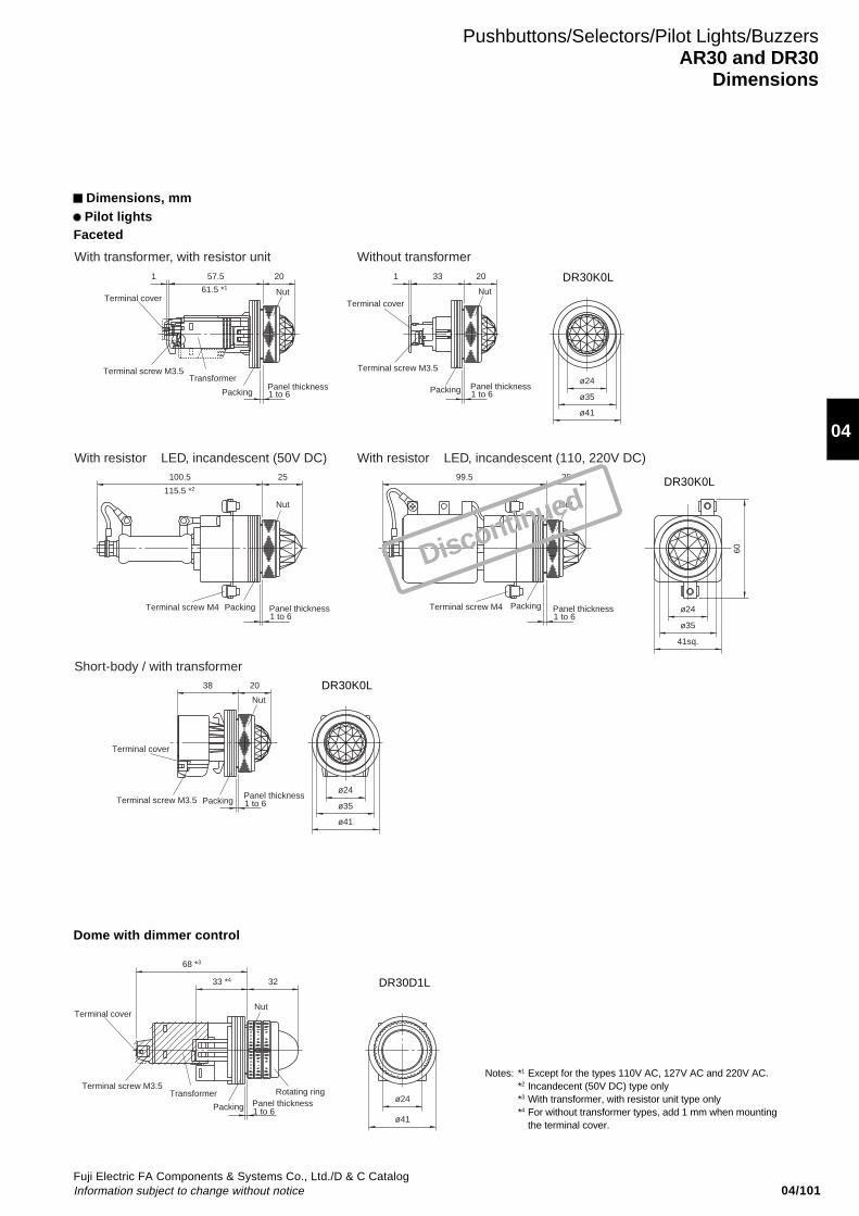
04/101Fuji Electric FA Components & Systems Co., Ltd./D & C CatalogInformation subject to change without notice
04
Pushbuttons/Selectors/Pilot Lights/BuzzersAR30 and DR30
Dimensions
Dimensions, mm Pilot lights
Faceted
ø24
ø41
57.51
61.5 *1
331
100.5 25
ø24
ø35
ø35
41sq.
60
2599.5
2038
ø35
ø41
ø24
115.5 *2
20 20
Panel thickness1 to 6
Nut
Packing
Terminal screw M3.5
Panel thickness1 to 6
Nut
PackingTerminal screw M3.5
Panel thickness1 to 6
Nut Nut
PackingTerminal screw M4 Panel thickness1 to 6
PackingTerminal screw M4
Panel thickness1 to 6
Nut
Packing
Terminal screw M3.5Transformer
Terminal coverTerminal cover
Terminal cover
With transformer, with resistor unit Without transformer
With resistor LED, incandescent (50V DC)
Short-body / with transformer
With resistor LED, incandescent (110, 220V DC)
Dome with dimmer control
ø24
ø41
3233 *4
68 *3
Rotating ringPanel thickness1 to 6
Nut
Packing
Terminal screw M3.5Transformer
Terminal cover
Notes: *1 Except for the types 110V AC, 127V AC and 220V AC.*2 Incandecent (50V DC) type only*3 With transformer, with resistor unit type only*4 For without transformer types, add 1 mm when mounting
the terminal cover.
DR30K0L
DR30K0L
DR30K0L
DR30D1L
Discontinued

04/102Fuji Electric FA Components & Systems Co., Ltd./D & C Catalog
Information subject to change without notice
Pushbuttons/Selectors/Pilot Lights/BuzzersAR30 and DR30Dimensions
Dimensions, mm Pilot lights
Flush square (34mm sq. transparent lens)
61
61
61
12
12
12
65 *1
65 *1
65 *1
Legend plate
Legend plate
Legend plate
1
1
1
30 sq.
34 sq.
30
34
36 sq.
40 sq.
36 40
12
12
12
Legend plate
Legend plate
Legend plate
32
32
32
1
1
1
Panel thickness
Panel thickness
Panel thickness
1 to 6
1 to 6
1 to 6
Panel thickness
Panel thickness
Panel thickness
1 to 6
1 to 6
1 to 6
Nut
Nut
Nut
Nut
Nut
Nut
Packing
Packing
Packing
Packing
Packing
Packing
Terminal screw M3.5
Terminal screw M3.5
Terminal screw M3.5
Terminal screw M3.5
Terminal screw M3.5
Terminal screw M3.5
Transformer
Transformer
Transformer
Terminal cover
Terminal cover
Terminal cover
Terminal cover
Terminal cover
Terminal cover
With transformer, with resistor unit
With transformer, with resistor unit
With transformer, with resistor unit
Without transformer
Without transformer
Without transformer
Note: *1 Except for the types 110V AC, 127V AC and 220V AC.
Flush rectangular (Transparent lens)
Flush square (40mm sq. transparent lens)
DR30F4M
DR30F4N
DR30M4M
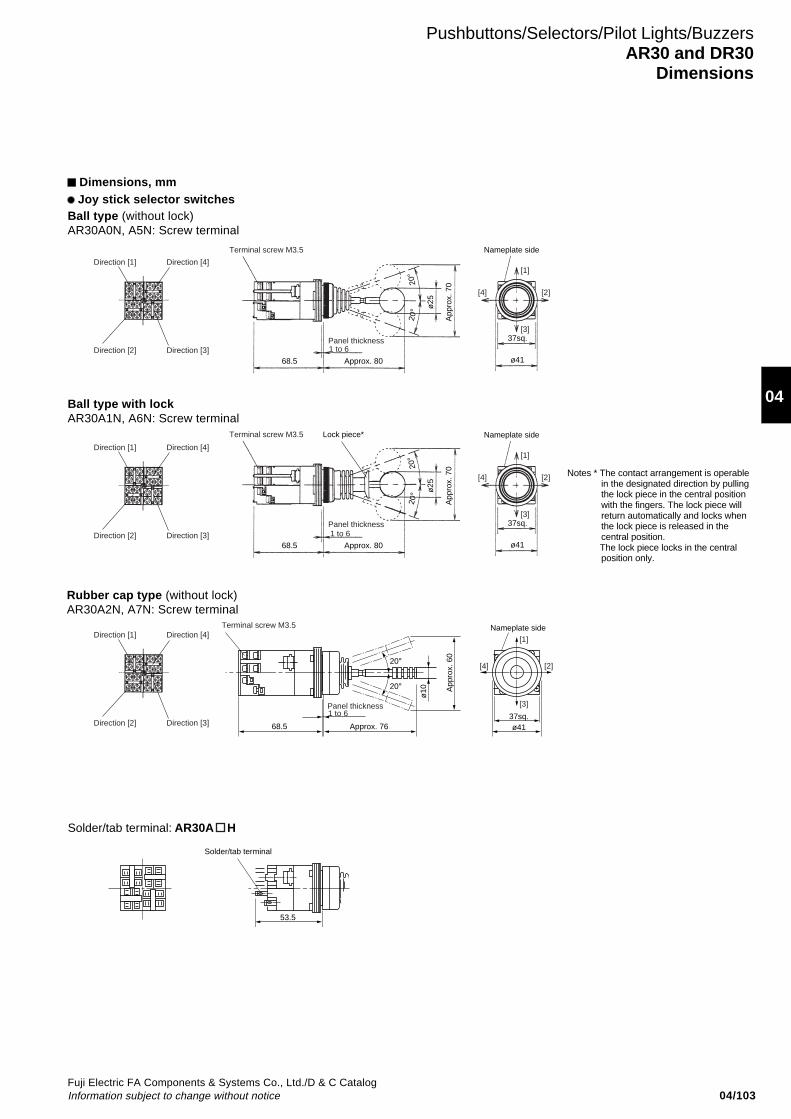
04/103Fuji Electric FA Components & Systems Co., Ltd./D & C CatalogInformation subject to change without notice
04
Pushbuttons/Selectors/Pilot Lights/BuzzersAR30 and DR30
Dimensions
Dimensions, mm Joy stick selector switches
Ball type with lockAR30A1N, A6N: Screw terminal
Nameplate side
Solder/tab terminal
20°
20°
Approx. 7668.5
ø10
ø41
App
rox.
60
37sq.
[4]
[1]
[3]
[2]
53.5
Panel thickness1 to 6
Terminal screw M3.5
Nameplate sideLock piece*
[4]
[1]
[2]
37sq.
ø41
[3]
Nameplate side
[4]
[1]
[2]
37sq.
ø41
[3]
20°
20°
ø25
App
rox.
70
68.5 Approx. 80
Panel thickness1 to 6
Terminal screw M3.5
Direction [4]
Direction [3]
Direction [1]
Direction [2]
Direction [4]
Direction [3]
Direction [1]
Direction [2]
Direction [4]
Direction [3]
Direction [1]
Direction [2]
20°
20°
ø25
App
rox.
70
68.5 Approx. 80
Panel thickness1 to 6
Terminal screw M3.5
Solder/tab terminal: AR30A H
Rubber cap type (without lock)AR30A2N, A7N: Screw terminal
Ball type (without lock)AR30A0N, A5N: Screw terminal
Notes * The contact arrangement is operablein the designated direction by pullingthe lock piece in the central positionwith the fingers. The lock piece willreturn automatically and locks whenthe lock piece is released in thecentral position.
The lock piece locks in the centralposition only.
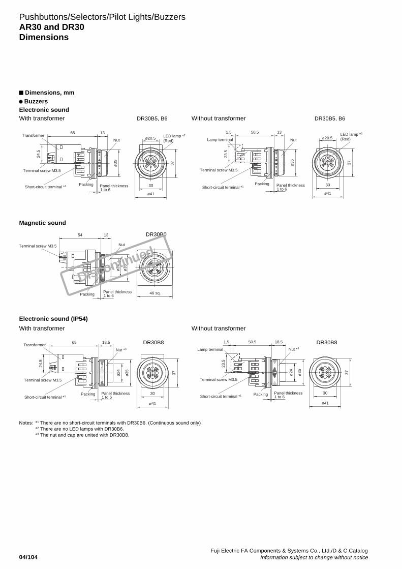
04/104Fuji Electric FA Components & Systems Co., Ltd./D & C Catalog
Information subject to change without notice
Pushbuttons/Selectors/Pilot Lights/BuzzersAR30 and DR30Dimensions
Dimensions, mm Buzzers
Electronic soundWith transformer Without transformer
ø20.5 LED lamp *2
(Red)
Short-circuit terminal *1
ø35
30
37
ø41
65
24.5
13
Panel thickness1 to 6
Nut
Packing
Terminal screw M3.5
Transformerø20.5
50.51.5
ø35
23.5
ø41
37
30Short-circuit terminal *1
LED lamp *2
(Red)
13
Nut
Panel thickness1 to 6
Packing
Terminal screw M3.5
Lamp terminal
Magnetic sound
46 sq.
1354
ø24
ø35
Panel thickness1 to 6
Nut
Packing
Terminal screw M3.5
Electronic sound (IP54)
Short-circuit terminal *1
ø24
18.5
ø35
30
ø41
37
24.5
65
Panel thickness1 to 6
Nut *3
Terminal screw M3.5
Packing
Transformer
Short-circuit terminal *1
23.5
18.5
ø35
ø24
50.51.537
ø41
30
Nut *3
Terminal screw M3.5
Panel thickness1 to 6
Packing
Lamp terminal
With transformer Without transformer
Notes: *1 There are no short-circuit terminals with DR30B6. (Continuous sound only)*2 There are no LED lamps with DR30B6.*3 The nut and cap are united with DR30B8.
DR30B5, B6 DR30B5, B6
DR30B0
DR30B8 DR30B8
Discontinued

04/105Fuji Electric FA Components & Systems Co., Ltd./D & C CatalogInformation subject to change without notice
04
OperatorPanel
Nut
Wrench (AHX001)
Pushbuttons/Selectors/Pilot LightsAR30 and DR30
Notes on use
Panel cutout hole
Fig. 1 Panel cutout hole dimensions, mm
Note : If key-washer or legend plate are not used, 4.8mm-wide. location holesshown in Fig. 1 need not be cutout.
Mounting operator to panel1. Pushbutton with a round bezel (ordinary mounting)Insert the operator into the cutout hole from the back of thepanel, and tighten the nut with the AHX001 wrench from thefront of the panel to secure the operator as shown in Fig.2.
Fig. 2 Pushbutton with a round bezel
AF95-465
Note : Recommended tightening torque is from 1.5 to 2N·m.
2. AR30V0R, V0L, V2R, V2L, V5R, V5L(1) The button is removed after loosening the center button by
inserting the end of the AR9A002 tightening wrench or theAR9A005 wrench (enclosed with pushbutton) into the holes in thecenter button and turning counterclockwise, as shown in Fig.3.
(2) Attach the operator in the same manner as described in step 1.
Insert the operator into the cutout hole from the back of thepanel, and as shown in Fig.4, insert the pushbutton into theoperator cylinder while aligning the grooves inside thepushbutton with the protrusions on the operator.
Fig. 4 Setting pushbutton to operator cylinder
AF95-414
Cylinder inside protrusionPushbutton inside groove Settingrmax=0.8mm
4.8+0.5mm
ø30.5+0.5mm0
0
33+0.5mm0
3. AR30WR, WCR(1) As shown in the following figure, insert the tip of a flathead
screwdriver into the selector tip groove. Rotate thescrewdriver in the direction indicated by the arrow until theselector tip rises, and draw out the knob.
(2) Attach the operator in the same manner as described in step 1.(3) Insert the knob, with the selector tip in the floated state, into
the original position of the rotation tube, and push theselector tip into place.
Fig. 5
4. AR30M0R, M4R, M5R, B0R, Q7L(1) Loosen the button by hand.(2) Attach the operator in the same manner as
described in step 1.(3) Screw in the button by hand, making
sure that the button is screwed in all theway. (Recommended tightening torque:0.3 to 0.5 N•m)
Small flathead screwdriver (I-shaped, 4mm wide)
Selector tip groove
Button
Fig. 6
Notes on use
C
Wrench (AR9A005)
Wrench (AR9A002)
Wrench (AR9A004)
The center button can be attached or removed using the C portion of the AR9A004 tightening wrench as well.
Loosen
Tighten
Holes in center buttonButton
Fig. 3
5. AR30M3R, M8R, B1R, B2R and B3RThe outer circumference of the nut is threaded, so be careful notto cut your hand on it.(1) Loosen and remove the guard ring by hand.(2) Loosen and remove the button and nut by hand.(3) Insert the operator into the cutout hole from the back of the
panel, and tighten the nut to secure it in place.(Recommended tightening torque: 0.3 to 0.5 N•m)
(4) Screw in the button by hand, making sure that it is screwedin all the way.(Recommended tightening torque: 0.3 to 0.5 N•m)
(5) Loosen and remove the guard ring by hand. (Recommendedtightening torque: 1.5 to 2.5 N•m)
Fig. 7
Guard ringButton
Nut
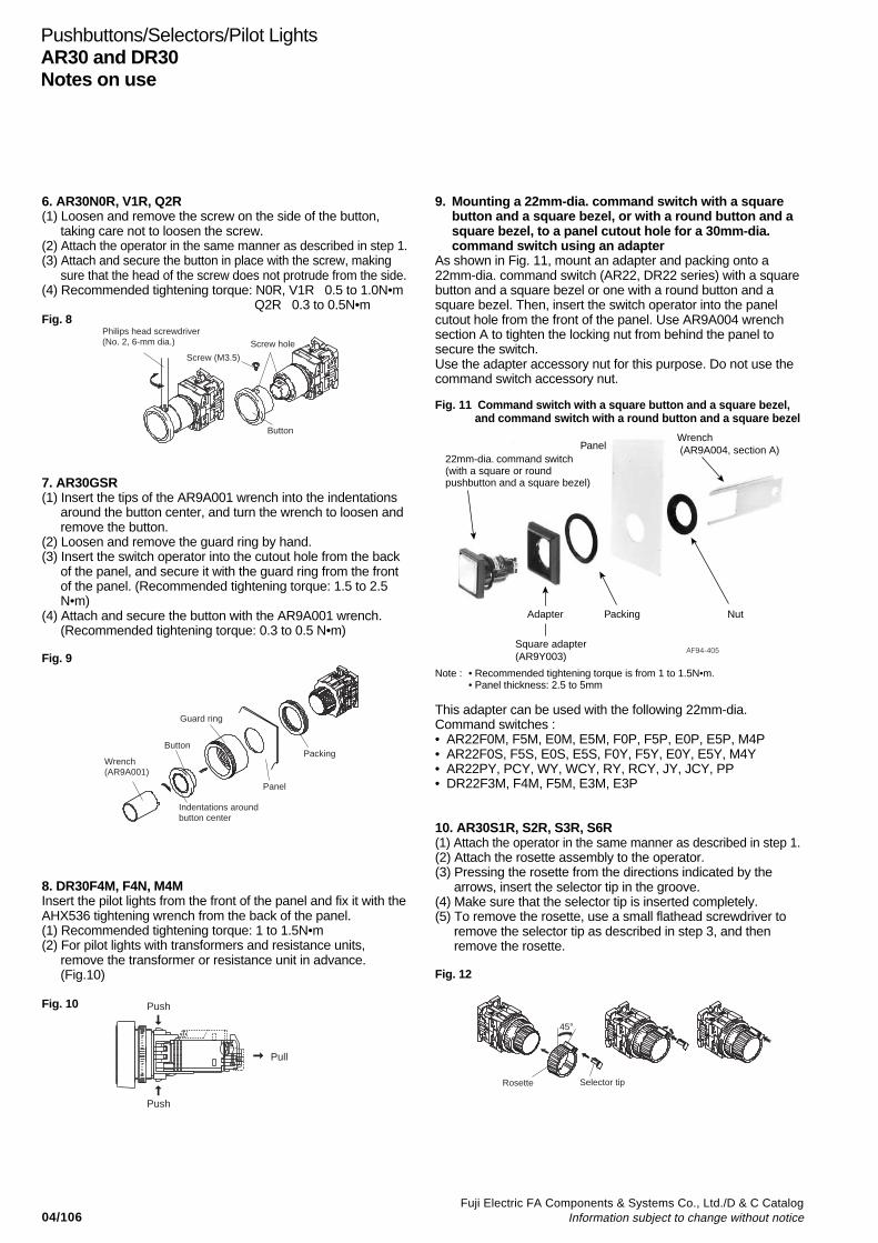
04/106Fuji Electric FA Components & Systems Co., Ltd./D & C Catalog
Information subject to change without notice
Pushbuttons/Selectors/Pilot LightsAR30 and DR30Notes on use
6. AR30N0R, V1R, Q2R(1) Loosen and remove the screw on the side of the button,
taking care not to loosen the screw.(2) Attach the operator in the same manner as described in step 1.(3) Attach and secure the button in place with the screw, making
sure that the head of the screw does not protrude from the side.(4) Recommended tightening torque: N0R, V1R 0.5 to 1.0N•m
Q2R 0.3 to 0.5N•mFig. 8
7. AR30GSR(1) Insert the tips of the AR9A001 wrench into the indentations
around the button center, and turn the wrench to loosen andremove the button.
(2) Loosen and remove the guard ring by hand.(3) Insert the switch operator into the cutout hole from the back
of the panel, and secure it with the guard ring from the frontof the panel. (Recommended tightening torque: 1.5 to 2.5N•m)
(4) Attach and secure the button with the AR9A001 wrench.(Recommended tightening torque: 0.3 to 0.5 N•m)
Fig. 9
Button
Screw hole
Screw (M3.5)
Philips head screwdriver (No. 2, 6-mm dia.)
Guard ring
Button
Indentations around button center
Wrench (AR9A001)
Panel
Packing
9. Mounting a 22mm-dia. command switch with a squarebutton and a square bezel, or with a round button and asquare bezel, to a panel cutout hole for a 30mm-dia.command switch using an adapter
As shown in Fig. 11, mount an adapter and packing onto a22mm-dia. command switch (AR22, DR22 series) with a squarebutton and a square bezel or one with a round button and asquare bezel. Then, insert the switch operator into the panelcutout hole from the front of the panel. Use AR9A004 wrenchsection A to tighten the locking nut from behind the panel tosecure the switch.Use the adapter accessory nut for this purpose. Do not use thecommand switch accessory nut.
Fig. 11 Command switch with a square button and a square bezel, and command switch with a round button and a square bezel
Note : • Recommended tightening torque is from 1 to 1.5N•m.• Panel thickness: 2.5 to 5mm
This adapter can be used with the following 22mm-dia.Command switches :• AR22F0M, F5M, E0M, E5M, F0P, F5P, E0P, E5P, M4P• AR22F0S, F5S, E0S, E5S, F0Y, F5Y, E0Y, E5Y, M4Y• AR22PY, PCY, WY, WCY, RY, RCY, JY, JCY, PP• DR22F3M, F4M, F5M, E3M, E3P
10. AR30S1R, S2R, S3R, S6R(1) Attach the operator in the same manner as described in step 1.(2) Attach the rosette assembly to the operator.(3) Pressing the rosette from the directions indicated by the
arrows, insert the selector tip in the groove.(4) Make sure that the selector tip is inserted completely.(5) To remove the rosette, use a small flathead screwdriver to
remove the selector tip as described in step 3, and thenremove the rosette.
Fig. 12
AF94-405
22mm-dia. command switch (with a square or round pushbutton and a square bezel)
Wrench (AR9A004, section A)
Nut
Panel
PackingAdapter
Square adapter (AR9Y003)
Rosette Selector tip
45°
8. DR30F4M, F4N, M4MInsert the pilot lights from the front of the panel and fix it with theAHX536 tightening wrench from the back of the panel.(1) Recommended tightening torque: 1 to 1.5N•m(2) For pilot lights with transformers and resistance units,
remove the transformer or resistance unit in advance.(Fig.10)
Fig. 10
Pull
Push
Push
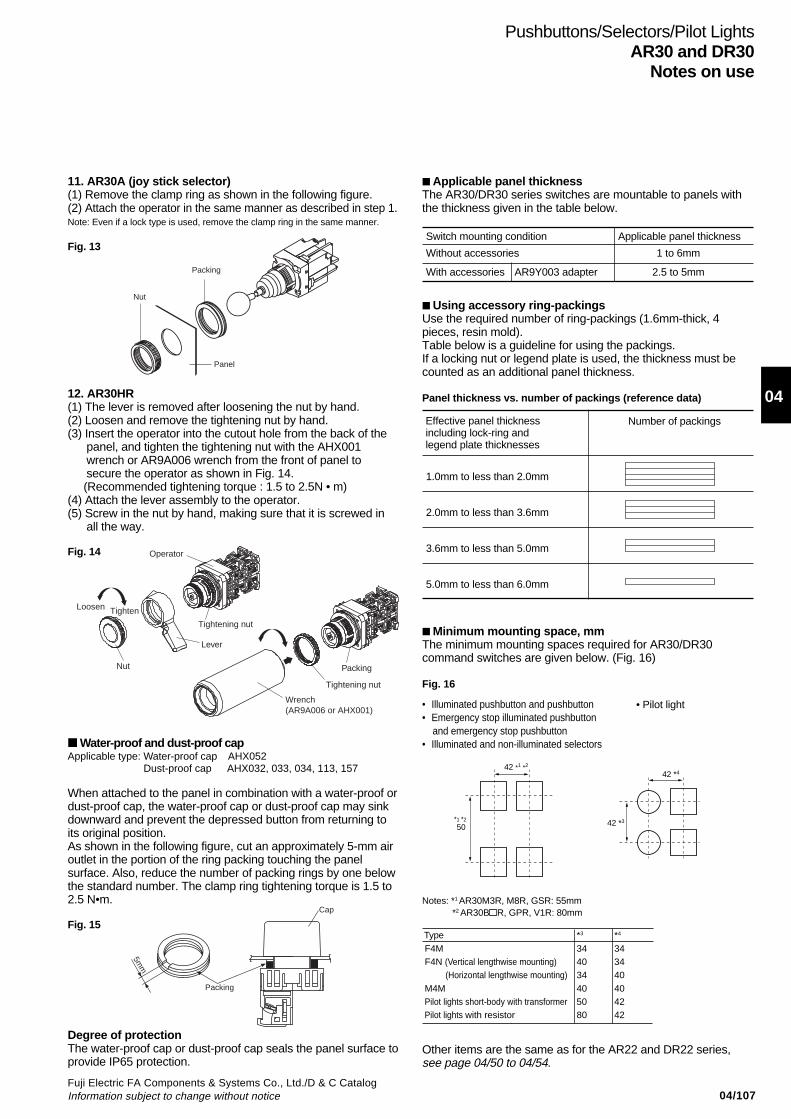
04/107Fuji Electric FA Components & Systems Co., Ltd./D & C CatalogInformation subject to change without notice
04
Applicable panel thicknessThe AR30/DR30 series switches are mountable to panels withthe thickness given in the table below.
Switch mounting condition Applicable panel thickness
Without accessories 1 to 6mm
With accessories AR9Y003 adapter 2.5 to 5mm
Using accessory ring-packingsUse the required number of ring-packings (1.6mm-thick, 4pieces, resin mold).Table below is a guideline for using the packings.If a locking nut or legend plate is used, the thickness must becounted as an additional panel thickness.
Panel thickness vs. number of packings (reference data)
Number of packings
1.0mm to less than 2.0mm
2.0mm to less than 3.6mm
3.6mm to less than 5.0mm
5.0mm to less than 6.0mm
Minimum mounting space, mmThe minimum mounting spaces required for AR30/DR30command switches are given below. (Fig. 16)
Fig. 16
• Illuminated pushbutton and pushbutton• Emergency stop illuminated pushbutton and emergency stop pushbutton• Illuminated and non-illuminated selectors
Notes: *1 AR30M3R, M8R, GSR: 55mm *2 AR30B R, GPR, V1R: 80mm
Pushbuttons/Selectors/Pilot LightsAR30 and DR30
Notes on use
Effective panel thicknessincluding lock-ring andlegend plate thicknesses
• Pilot light
42 *1 *2
50
42 *4
42 *3*1 *2
11. AR30A (joy stick selector)(1) Remove the clamp ring as shown in the following figure.(2) Attach the operator in the same manner as described in step 1.Note: Even if a lock type is used, remove the clamp ring in the same manner.
Fig. 13
12. AR30HR(1) The lever is removed after loosening the nut by hand.(2) Loosen and remove the tightening nut by hand.(3) Insert the operator into the cutout hole from the back of the
panel, and tighten the tightening nut with the AHX001wrench or AR9A006 wrench from the front of panel tosecure the operator as shown in Fig. 14.
(Recommended tightening torque : 1.5 to 2.5N • m)(4) Attach the lever assembly to the operator.(5) Screw in the nut by hand, making sure that it is screwed in
all the way.
Fig. 14
Nut
Panel
Packing
Type *3 *4
F4M 34 34 F4N (Vertical lengthwise mounting) 40 34 (Horizontal lengthwise mounting) 34 40 M4M 40 40 Pilot lights short-body with transformer 50 42 Pilot lights with resistor 80 42
Water-proof and dust-proof capApplicable type: Water-proof cap AHX052
Dust-proof cap AHX032, 033, 034, 113, 157
When attached to the panel in combination with a water-proof ordust-proof cap, the water-proof cap or dust-proof cap may sinkdownward and prevent the depressed button from returning toits original position.As shown in the following figure, cut an approximately 5-mm airoutlet in the portion of the ring packing touching the panelsurface. Also, reduce the number of packing rings by one belowthe standard number. The clamp ring tightening torque is 1.5 to2.5 N•m.
Fig. 15
Degree of protectionThe water-proof cap or dust-proof cap seals the panel surface toprovide IP65 protection.
Packing
5mm
Cap
Other items are the same as for the AR22 and DR22 series,see page 04/50 to 04/54.
Operator
PackingNut
Lever
Tighten
Tightening nut
Tightening nut
Wrench(AR9A006 or AHX001)
Loosen
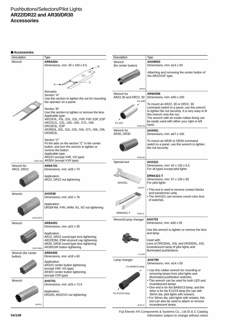
04/108Fuji Electric FA Components & Systems Co., Ltd./D & C Catalog
Information subject to change without notice
Pushbuttons/Selectors/Pilot LightsAR22/DR22 and AR30/DR30Accessories
Description
Wrench
KK02-261
Wrench forAR22, DR22
AR9A701Dimensions, mm: ø28 x 70
Application:AR22, DR22 nut tightening
Wrench
KK02-098A
Wrench forAR22,30 and DR22, 30
SG-873
AF95-21
AF96-241
Wrench forAR30, DR30
AF95-467
Wrench/Lamp changer
SI-1030
AF95-22
For ø30
AF03-5
AF93-6
Attaching and removing the center button ofthe AR22VGF type.
Wrench(for center button)
Type
AR9A004Dimensions, mm: 30 x 100 x 6.5
RemarksSection “A”Use this section to tighten the nut for mountingthe operator on a panel.
Section “B”Use this section to tighten or remove the lens.Applicable type:AR22F0L, F5L, E0L, E5L, F0P, F5P, E0P, E5PAR22G1L, G2L, G4L, G6L, G7L, G9LDR22E3L, E3PAR30E0L, E5L, G2L, G3L, G4L, G7L, G8L, G9LDR30E3L
Section “C”Fit the tabs on the section “C” in the centerbutton, and turn the wrench to tighten orremove the button.Applicable type:AR22V (except V4R, VG type)AR30V (except V1R type)
AR9A001Dimensions, mm: ø22 x 35
Application:AR22, DR22 round-type lens tighteningAR22E0M, E5M oil-proof cap tighteningAR30, DR30 round-type lens tighteningAR30GSR button tightening
Wrench (for centerbutton)
AR9A002Dimensions, mm: ø18 x 60
Application:AR22V center button tightening(except V4R, VG type)AR30V center button tightening(except V1R type)
Wrench AHX701Dimensions, mm: ø25 x 72.5
Application:DR22N, AR22VG nut tightening
Description Type
AHX8003Dimensions, mm: ø14 x 50
AR9A006Dimensions, mm: ø40 x 100
To mount an AR22, 30 or DR22, 30command switch to a panel, use this wrenchto tighten the nut securely. It is very easy to fitthis wrench onto the nut.The wrench with an inside rubber-lining canbe easily used with either your right or lefthand.
For ø22
AHX001Dimensions, mm: ø47 x 100
To mount an AR30 or DR30 commandswitch to a panel, use this wrench to tightenthe nut securely.
AHX321Dimensions, mm: 42 x 130 x 6.5For all types except pilot lights
DR9A321-TDimensions, mm: 57 x 130 x 30For pilot lights
• This tool is used to remove contact blocks and transformer units.• The AHX321 can remove round color lens of switches.
Special tool
AHX702Dimensions, mm: ø36 x 55
Use this wrench to tighten or remove the lensand lamp.
Used with:Lens of DR22D0L, K0L and DR30D0L, K0LIncandescent lamp of pilot lights andilluminated pushbuttons
Lamp changer AHX790Dimensions, mm: ø14 x 55
• Use this rubber wrench for mounting orremoving lamps from pilot lights andilluminated pushbutton switches.
• This wrench can be used for both LED andincandescent lamps.
• One end is for the BA9S/13 lamp, and theother is for the E12/15 lamp (for use with30mm dia. pilot lights with resistor).
• For 30mm dia. pilot lights with resistor, thistool can also be used to attach or removeincandescent lamps.
Accessories
Wrench
KK02-097A
AHX536Dimensions, mm: ø32 x 76
Application:DR30F4M, F4N, M4M, N1, N2 nut tightening
AHX321
DR9A321-T
For BA9S/13 lamp
For E12/15 lamp
B
CA

04/109Fuji Electric FA Components & Systems Co., Ltd./D & C CatalogInformation subject to change without notice
04
Pushbuttons/Selectors/Pilot LightsAR22/DR22 and AR30/DR30
Accessories
Protection cover
AF95-29
Cover for preventingoperating errors with30mm dia. types
AF91-671
Key washerfor AR22, DR22
AR9Y715Use this metal washer when securing aoperator in a 22.3mm dia. panel cutout hole.
Dimensions, mm:
AF95-25
Key washer for ø30 AHX082Use this metal washer when securing anoperator in a 30.5mm dia. panel cutout hole.
Dimension, mm:
SC-1016
Operator base cover
AF95-26
Adapter forAR22, DR22
AR9Y718Use this resin adapter to mount the AR22/DR22 (switch/pilot light) in a 25.5mm dia.cutout hole on a panel.
Dimensions, mm:
.AF95-28
20.8
51.8
34
32
Cover for preventingoperating errors with30mm dia. types
AHX408This is a metallic cover for preventinginadvertent operation.
Used with: AR30F0R, F5R
Dimensions, mm:
ø30.5ø35
ø35
25
50.5
16.2
A
Stopper
When attaching the cover to a vertical panel, if you attach it so that the portion indicated by an "A" is at the upper right, the stopper causes the cover to stop above the push button to halt further rotation.
Description Type Description Type
AR9E760
This cover protects against accidentaloperation.The cover lid is returned home with a springforce. (Packing is provided)
Used with:AR22F0L, F5L, E0L, E5L, F0M, F5M, E0M, E5M,F0P, F5P, E0P, E5PAR22F0R, F5R, E0R, E5R, F0S, F5S, E0S, E5S,E0Y, E5Y, F0Y, F5Y, FAR, FBR, EAR, EBR
Dimensions, mm:
AR9E538Inadvertent operation can be prevented byfitting a transparent cover with chain in theclamp ring.
Used with:AR30F0R, F5R, E0R, E5R, E0L, E5L
Dimensions, mm:ø37.7
ø34.7
24.5
Ring: ø10
Length:Approx. 45mm
30
28
26.5
ø30.2ø37
Thickness: 1mm
Clamp ring mounting portion
Cover
.AF93-420 The material is steel (zinc plated).
12.6
1 1
ø22.130 sq.
20.5
2.9
A B
• When the periphery of the panel cutouthas a hole to stop rotation, use with side Acontacting the panel (except for Joy stickselector types).
• Even when the periphery of the panelcutout does not have a hole to stoprotation, if used with side B contacting thepanel it can serve as a washer foreliminating play (except for Joy stickselector types).
AR9Y002Attach this cover to the operator base of apushbutton switch with only one contactblock (1NO or 1NC) to protect against dust.
ø22.3ø24.9ø29.5
0.5
1.5
1ø30.2 1.2
ø37
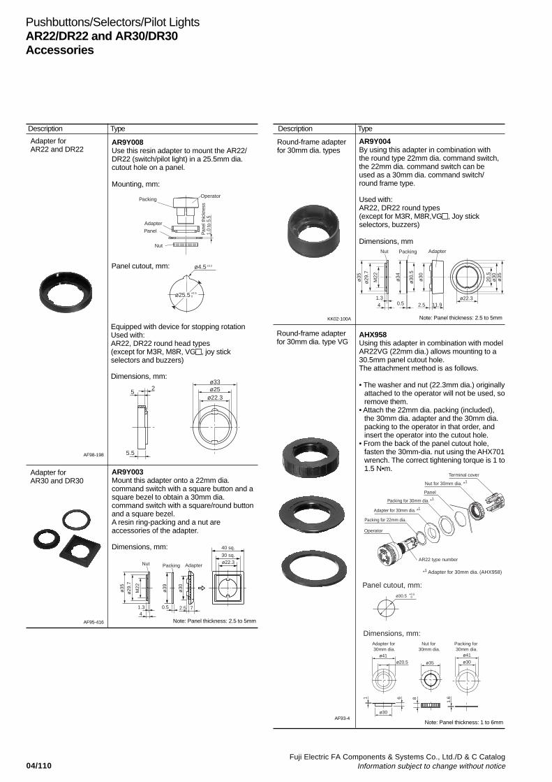
04/110Fuji Electric FA Components & Systems Co., Ltd./D & C Catalog
Information subject to change without notice
Pushbuttons/Selectors/Pilot LightsAR22/DR22 and AR30/DR30Accessories
Adapter forAR22 and DR22
AF98-198
AR9Y008Use this resin adapter to mount the AR22/DR22 (switch/pilot light) in a 25.5mm dia.cutout hole on a panel.
Mounting, mm:
Adapter forAR30 and DR30
AR9Y003Mount this adapter onto a 22mm dia.command switch with a square button and asquare bezel to obtain a 30mm dia.command switch with a square/round buttonand a square bezel.A resin ring-packing and a nut areaccessories of the adapter.
Dimensions, mm:
AF95-416
Round-frame adapterfor 30mm dia. types
AR9Y004By using this adapter in combination withthe round type 22mm dia. command switch,the 22mm dia. command switch can beused as a 30mm dia. command switch/round frame type.
Used with:AR22, DR22 round types(except for M3R, M8R,VG , Joy stickselectors, buzzers)
Dimensions, mm
KK02-100A
Round-frame adapterfor 30mm dia. type VG
AF93-4
Description Type Description Type
Equipped with device for stopping rotationUsed with:AR22, DR22 round head types(except for M3R, M8R, VG , joy stickselectors and buzzers)
Dimensions, mm:
Panel cutout, mm:
AHX958Using this adapter in combination with modelAR22VG (22mm dia.) allows mounting to a30.5mm panel cutout hole.The attachment method is as follows.
• The washer and nut (22.3mm dia.) originallyattached to the operator will not be used, soremove them.
• Attach the 22mm dia. packing (included),the 30mm dia. adapter and the 30mm dia.packing to the operator in that order, andinsert the operator into the cutout hole.
• From the back of the panel cutout hole,fasten the 30mm-dia. nut using the AHX701wrench. The correct tightening torque is 1 to1.5 N•m.
Note: Panel thickness: 2.5 to 5mm
Note: Panel thickness: 2.5 to 5mm
Note: Panel thickness: 1 to 6mm
Adapter
OperatorPacking
Panel
Nut
Pane
l thi
ckne
ss1.
0 to
5.5
ø4.5 ±0.2
ø25.5 +0.50
ø22.3ø25ø33
25
5.5
Packing Adapter
ø39
ø30
ø22.330 sq.
40 sq.
41.3 0.5 2.5 7
ø35
ø29
.7
M22
Nut
ø35
ø30
20.5
ø22.32.5 11.90.54
1.3
ø35
ø29
.7
M22
ø34
ø30
.5
ø30
Nut Packing Adapter
Dimensions, mm:
ø41
1 6 8
1.6
ø30
Adapter for 30mm dia.
Nut for 30mm dia.
Packing for 30mm dia.
ø20.5 ø35
ø41
ø30
Panel
Operator
Nut for 30mm dia. *1
Adapter for 30mm dia. *1
Packing for 22mm dia.
Terminal cover
Panel cutout, mm:ø30.5 +0.5
0
*1 Adapter for 30mm dia. (AHX958)
Packing for 30mm dia. *1
AR22 type number
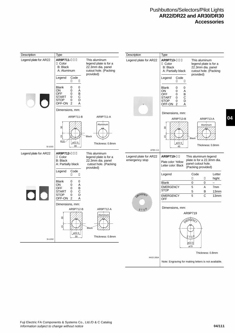
04/111Fuji Electric FA Components & Systems Co., Ltd./D & C CatalogInformation subject to change without notice
04
Pushbuttons/Selectors/Pilot LightsAR22/DR22 and AR30/DR30
Accessories
AR9P719
Thickness: 0.8mm
Description Type
Legend plate for AR22 AR9P711-➀➁➂ This aluminum➀ Color legend plate is for aB: Black 22.3mm dia. panelA: Aluminum cutout hole. (Packing
provided)Legend Code
➁ ➂
Blank 0 0ON 0 AOFF 0 BSTART 0 CSTOP 0 DOFF-ON 2 A
Legend plate for AR22 AR9P712-➀➁➂ This aluminum➀ Color legend plate is for aB: Black 22.3mm dia. panelA: Partially black cutout hole. (Packing
provided)Legend Code
➁ ➂
Blank 0 0ON 0 AOFF 0 BSTART 0 CSTOP 0 DOFF-ON 2 A
Legend plate for AR22 AR9P713-➀➁➂ This aluminum➀ Color legend plate is for aB: Black 22.3mm dia. panelA: Partially black cutout hole. (Packing
provided)Legend Code
➁ ➂
Blank 0 0ON 0 AOFF 0 BSTART 0 CSTOP 0 DOFF-ON 2 A
SI-1033
Dimensions, mm:
SI-1032Thickness: 0.8mm
Dimensions, mm:
AF95-114
Thickness: 0.8mm
Dimensions, mm:
Description Type
Legend plate for AR22 AR9P719-➀➁ This aluminum legend emergency stop plate is for a 22.3mm dia.
panel cutout hole. (Packing provided)
Legend Code Letter➀ ➁ hight
Blank 0 0 –EMERGENCY 5 A 7mmSTOP 5 B 13mmEMERGENCY 5 C 13mmOFF
Dimensions, mm:
Thickness: 0.8mm
AR9P713-B AR9P713-AAR9P711-B AR9P711-A
AR9P712-B AR9P712-A
KK02-265A
Plate color: YellowLetter color: Black
Note: Engraving for making letters is not available.
ø22.5
Aluminum
Black
30
R15
1530
ø22.5
Aluminum
Black
30
1530
ø22.5
Aluminum
Black
45
1530
ø22.5
ø70
S T O P
EMERGENCY
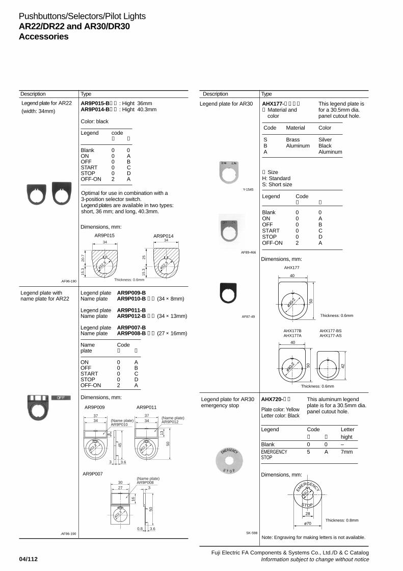
04/112Fuji Electric FA Components & Systems Co., Ltd./D & C Catalog
Information subject to change without notice
Pushbuttons/Selectors/Pilot LightsAR22/DR22 and AR30/DR30Accessories
Legend plate for AR30 AHX177-➀➁➂➃ This legend plate is➀ Material and for a 30.5mm dia. color panel cutout hole.
Code Material Color
S Brass Silver B Aluminum Black A Aluminum
➁ SizeH: StandardS: Short size
Legend Code➂ ➃
Blank 0 0ON 0 AOFF 0 BSTART 0 CSTOP 0 DOFF-ON 2 A
Legend plate for AR22
(width: 34mm)AR9P015-B➀➁ : Hight 36mmAR9P014-B➀➁ : Hight 40.3mm
Color: black
Legend code➀ ➁
Blank 0 0ON 0 AOFF 0 BSTART 0 CSTOP 0 DOFF-ON 2 A
.AF96-190
Optimal for use in combination with a3-position selector switch.Legend plates are available in two types:short, 36 mm; and long, 40.3mm.
AR9P015 AR9P014
AR9P009 AR9P011
AR9P007
Y-1545
AF89-466
SK-598
Description Type Description Type
Dimensions, mm:
Legend plate with Legend plate AR9P009-B name plate for AR22 Name plate AR9P010-B ➀➁ (34 × 8mm)
Legend plate AR9P011-BName plate AR9P012-B ➀➁ (34 × 13mm)
Legend plate AR9P007-BName plate AR9P008-B ➀➁ (27 × 16mm)
Name Codeplate ➀ ➁
ON 0 AOFF 0 BSTART 0 CSTOP 0 DOFF-ON 2 A
Dimensions, mm:
.AF96-190
Legend plate for AR30 AHX720-➀➁ This aluminum legend emergency stop plate is for a 30.5mm dia.
panel cutout hole.
Legend Code Letter➀ ➁ hight
Blank 0 0 –EMERGENCY 5 A 7mmSTOP
AF87-49
Dimensions, mm:
Dimensions, mm:
Plate color: YellowLetter color: Black
Note: Engraving for making letters is not available.
34
ø22.5
ø22.5
Thickness: 0.6mm
34
25
20.7
15.3
15.3
3734
3.63
45 50
(Name plate)AR9P010
(Name plate)AR9P012
138
3734
ø22.3
ø22.3
(Name plate)AR9P008
50
16
3
3.60.8
3027
ø22.3
40
50
ø30.
2
40
50
ø30.
2
42
AHX177
AHX177BAHX177A
AHX177-BSAHX177-AS
Thickness: 0.6mm
Thickness: 0.6mm
EM
ERGENCY
ø30.2
28
ø70
ST OP
Thickness: 0.8mm

04/113Fuji Electric FA Components & Systems Co., Ltd./D & C CatalogInformation subject to change without notice
04
Pushbuttons/Selectors/Pilot LightsAR22/DR22 and AR30/DR30
Accessories
Panel plug for AR22and DR22
SI-1027
T-1993
Panel plug for AR30and DR30
Group panel for22mm dia. type
AF95-153
AF97-233
Dimensions, mm:
Jumper
AF95-27
Description Type Description Type
Round:AHX725-B BlackAHX725-H Gray
Square:AHX726-B BlackAHX726-H Gray
Dimensions, mm: ø29.5 x 17 (AHX725)29.5 sq. x 17 (AHX726)
Use this plug to cover up unused panelcutout holes.For oil proof usage, use together withpacking (AR9Y730) and a nut (AR9R744).
AHX004
Color: Silver (metal)This plug is used to cover up unused panelcutout hole.
Dimensions, mm:
DR9Y004These new 22mm dia. command switch/square types can be neatly aligned side byside on this group panel at a 30mm pitch toform a uniform panel face with nomisalignment between mounted switches.Depending on the number of switches to begrouped (maximum 12), the panel can bedivided (by cutting at the portion indicated byan asterisk (*)).
Mounting, mm:(example showing a group of three)
APCX029 (For pilot light without transformer)DR9Y001 (For pilot light with transformer)
Use this jumper to connect terminalsallocated in a 30mm pich.Rated current is 3A
Dimensions, mm:
ø42
ø35
M5
3
20
1.6
Panel plugPacking
Nut
Panel thickness1 to 5.5
Operator
Grouppanel
Panel
Nut 1 2 1 21 2
30 12-ø22.1
30
30 x 11=330
360
Thickness: 0.8mm
29.5
*
7.5
30
37.5
37.5
30
Thickness: 0.5mm
9
7.5APCX029
DR9Y001
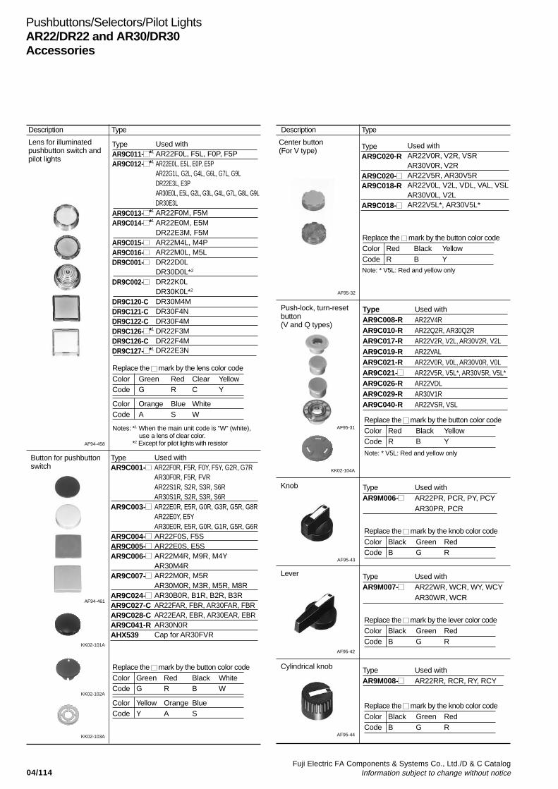
04/114Fuji Electric FA Components & Systems Co., Ltd./D & C Catalog
Information subject to change without notice
Pushbuttons/Selectors/Pilot LightsAR22/DR22 and AR30/DR30Accessories
Lens for illuminatedpushbutton switch andpilot lights
AF94-458
Notes: *1 When the main unit code is “W” (white),use a lens of clear color.
*2 Except for pilot lights with resistor
Button for pushbuttonswitch
TypeAR9C001-
AR9C003-
AR9C004-AR9C005-AR9C006-
AR9C007-
AR9C024-AR9C027-CAR9C028-CAR9C041-RAHX539
AF94-461
AF95-31
TypeAR9C020-R
AR9C020-AR9C018-R
AR9C018-
Used withAR22V0R, V2R, VSRAR30V0R, V2RAR22V5R, AR30V5RAR22V0L, V2L, VDL, VAL, VSLAR30V0L, V2LAR22V5L*, AR30V5L*
AF95-42
AF95-32
Push-lock, turn-resetbutton(V and Q types)
TypeAR9C008-RAR9C010-RAR9C017-RAR9C019-RAR9C021-RAR9C021-AR9C026-RAR9C029-RAR9C040-R
Used withAR22V4RAR22Q2R, AR30Q2RAR22V2R, V2L, AR30V2R, V2LAR22VALAR22V0R, V0L, AR30V0R, V0LAR22V5R, V5L*, AR30V5R, V5L*AR22VDLAR30V1RAR22VSR, VSL
Knob
AF95-43
Lever
Cylindrical knob
KK02-101A
KK02-102A
KK02-104A
Description Type Description Type
TypeAR9C011- *1
AR9C012- *1
AR9C013- *1
AR9C014- *1
AR9C015-AR9C016-DR9C001-
DR9C002-
DR9C120-CDR9C121-CDR9C122-CDR9C126- *1
DR9C126-CDR9C127- *1
Used withAR22F0L, F5L, F0P, F5PAR22E0L, E5L, E0P, E5PAR22G1L, G2L, G4L, G6L, G7L, G9LDR22E3L, E3PAR30E0L, E5L, G2L, G3L, G4L, G7L, G8L, G9LDR30E3LAR22F0M, F5MAR22E0M, E5MDR22E3M, F5MAR22M4L, M4PAR22M0L, M5LDR22D0LDR30D0L*2
DR22K0LDR30K0L*2
DR30M4MDR30F4NDR30F4MDR22F3MDR22F4MDR22E3N
Replace the mark by the lens color code
Color Green Red Clear YellowCode G R C Y
Color Orange Blue WhiteCode A S W
Used withAR22F0R, F5R, F0Y, F5Y, G2R, G7RAR30F0R, F5R, FVRAR22S1R, S2R, S3R, S6RAR30S1R, S2R, S3R, S6RAR22E0R, E5R, G0R, G3R, G5R, G8RAR22E0Y, E5YAR30E0R, E5R, G0R, G1R, G5R, G6RAR22F0S, F5SAR22E0S, E5SAR22M4R, M9R, M4YAR30M4RAR22M0R, M5RAR30M0R, M3R, M5R, M8RAR30B0R, B1R, B2R, B3RAR22FAR, FBR, AR30FAR, FBRAR22EAR, EBR, AR30EAR, EBRAR30N0RCap for AR30FVR
KK02-103A
Center button(For V type)
Replace the mark by the button color codeColor Green Red Black WhiteCode G R B W
Color Yellow Orange BlueCode Y A S
Replace the mark by the button color codeColor Red Black YellowCode R B Y
Replace the mark by the button color codeColor Red Black YellowCode R B Y
Replace the mark by the knob color code
Color Black Green RedCode B G R
TypeAR9M006-
Used withAR22PR, PCR, PY, PCYAR30PR, PCR
Replace the mark by the lever color codeColor Black Green RedCode B G R
TypeAR9M007-
Used withAR22WR, WCR, WY, WCYAR30WR, WCR
AF95-44
Replace the mark by the knob color codeColor Black Green RedCode B G R
TypeAR9M008-
Used withAR22RR, RCR, RY, RCY
Note: * V5L: Red and yellow only
Note: * V5L: Red and yellow only
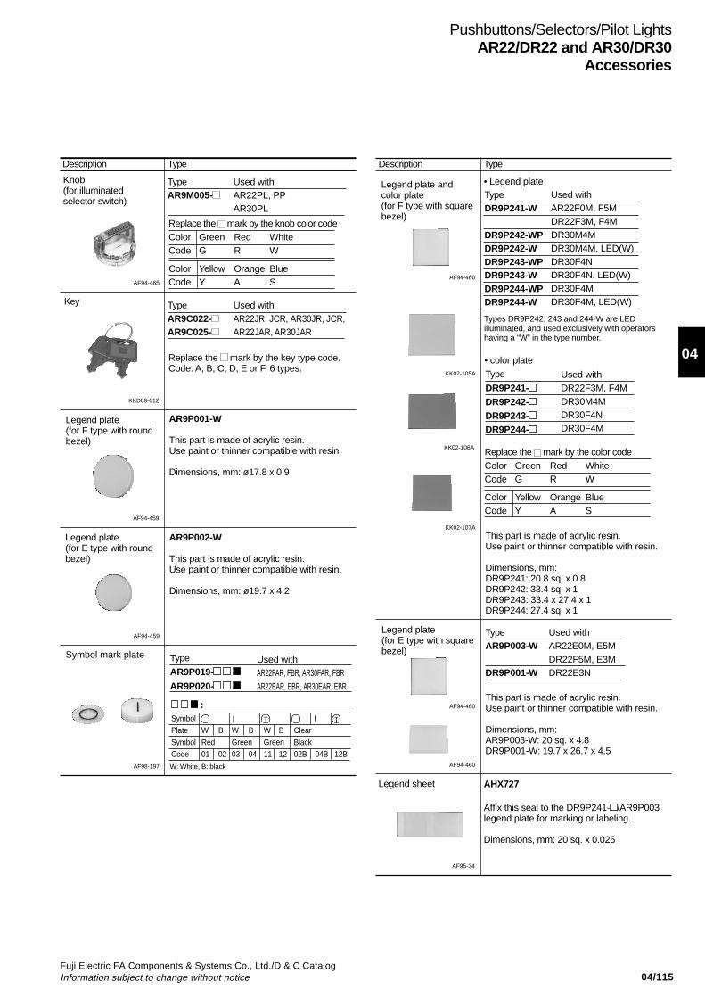
04/115Fuji Electric FA Components & Systems Co., Ltd./D & C CatalogInformation subject to change without notice
04
Pushbuttons/Selectors/Pilot LightsAR22/DR22 and AR30/DR30
Accessories
AF98-197
AF94-465
Key
Legend plate(for F type with roundbezel)
AF94-459
Symbol mark plate
:
Type
AR9P019-
AR9P020-
Used withAR22FAR, FBR, AR30FAR, FBRAR22EAR, EBR, AR30EAR, EBR
Symbol IPlate W B W B W B ClearSymbol Red Green Green BlackCode 01 02 03 04 11 12 02B 04B 12B
Knob(for illuminatedselector switch)
KKD09-012
AF94-459
Legend plate(for E type with roundbezel)
Legend plate andcolor plate(for F type with squarebezel)
AF94-460
TypeDR9P241-W
DR9P242-WPDR9P242-WDR9P243-WPDR9P243-WDR9P244-WPDR9P244-W
Used withAR22F0M, F5MDR22F3M, F4MDR30M4MDR30M4M, LED(W)DR30F4NDR30F4N, LED(W)DR30F4MDR30F4M, LED(W)
TypeAR9P003-W
DR9P001-W
Used withAR22E0M, E5MDR22F5M, E3MDR22E3N
Type
DR9P241-DR9P242-DR9P243-DR9P244-
Used withDR22F3M, F4MDR30M4MDR30F4NDR30F4M
Legend plate(for E type with squarebezel)
AF94-460
• color plate
AF95-34
KK02-105A
KK02-106A
KK02-107A
AF94-460
Types DR9P242, 243 and 244-W are LEDilluminated, and used exclusively with operatorshaving a “W” in the type number.
Description Type Description Type
TypeAR9M005-
Used withAR22PL, PPAR30PL
Replace the mark by the knob color codeColor Green Red WhiteCode G R W
Color Yellow Orange BlueCode Y A S
TypeAR9C022-AR9C025-
Used withAR22JR, JCR, AR30JR, JCR,AR22JAR, AR30JAR
Replace the mark by the key type code.Code: A, B, C, D, E or F, 6 types.
AR9P001-W
This part is made of acrylic resin.Use paint or thinner compatible with resin.
Dimensions, mm: ø17.8 x 0.9
AR9P002-W
This part is made of acrylic resin.Use paint or thinner compatible with resin.
Dimensions, mm: ø19.7 x 4.2
I T T
W: White, B: black
• Legend plate
Replace the mark by the color codeColor Green Red WhiteCode G R W
Color Yellow Orange BlueCode Y A S
This part is made of acrylic resin.Use paint or thinner compatible with resin.
Dimensions, mm:DR9P241: 20.8 sq. x 0.8DR9P242: 33.4 sq. x 1DR9P243: 33.4 x 27.4 x 1DR9P244: 27.4 sq. x 1
This part is made of acrylic resin.Use paint or thinner compatible with resin.
Dimensions, mm:AR9P003-W: 20 sq. x 4.8DR9P001-W: 19.7 x 26.7 x 4.5
AHX727
Affix this seal to the DR9P241- /AR9P003legend plate for marking or labeling.
Dimensions, mm: 20 sq. x 0.025
Legend sheet
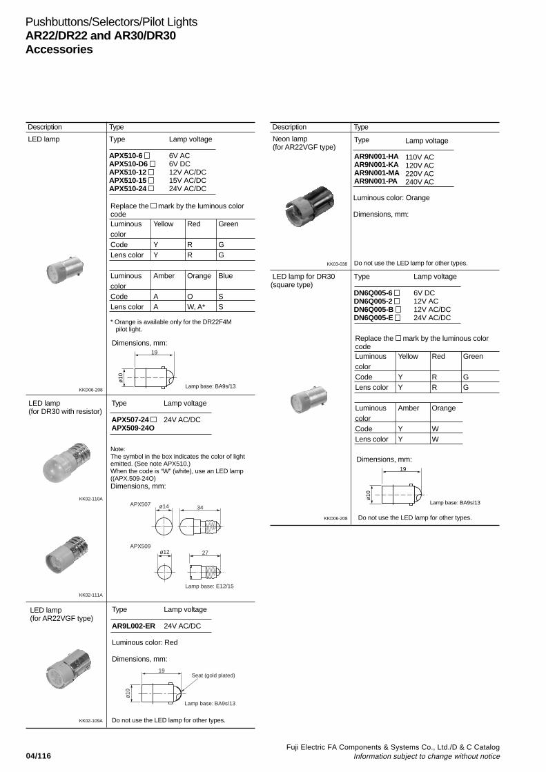
04/116Fuji Electric FA Components & Systems Co., Ltd./D & C Catalog
Information subject to change without notice
Pushbuttons/Selectors/Pilot LightsAR22/DR22 and AR30/DR30Accessories
Replace the mark by the luminous colorcodeLuminous Yellow Red GreencolorCode Y R GLens color Y R G
Luminous Amber OrangecolorCode Y WLens color Y W
KKD06-208
KK02-110A
LED lamp(for DR30 with resistor)
Type Lamp voltage
APX507-24 24V AC/DCAPX509-24O
Note:The symbol in the box indicates the color of lightemitted. (See note APX510.)When the code is “W” (white), use an LED lamp((APX.509-24O)Dimensions, mm:
Lamp base: BA9s/13
KKD06-208
KK02-111A
LED lamp(for AR22VGF type)
Neon lamp(for AR22VGF type)
KK03-038
Description Type Description Type
LED lamp Type Lamp voltage
APX510-6 6V ACAPX510-D6 6V DCAPX510-12 12V AC/DCAPX510-15 15V AC/DCAPX510-24 24V AC/DC
Dimensions, mm:
Replace the mark by the luminous colorcodeLuminous Yellow Red GreencolorCode Y R GLens color Y R G
Luminous Amber Orange BluecolorCode A O SLens color A W, A* S
* Orange is available only for the DR22F4M pilot light.
Type Lamp voltage
AR9L002-ER 24V AC/DC
Luminous color: Red
Dimensions, mm:
KK02-109A
Type
AR9N001-HAAR9N001-KAAR9N001-MAAR9N001-PA
Lamp voltage
110V AC120V AC220V AC240V AC
Luminous color: Orange
Dimensions, mm:
Do not use the LED lamp for other types.
Do not use the LED lamp for other types.
19
ø10
ø14 34
ø12 27
Lamp base: E12/15
APX507
APX509
19
ø10
Lamp base: BA9s/13
Seat (gold plated)
LED lamp for DR30 Type Lamp voltage(square type)
DN6Q005-6 6V DCDN6Q005-2 12V ACDN6Q005-B 12V AC/DCDN6Q005-E 24V AC/DC
Lamp base: BA9s/13
Dimensions, mm:19
ø10
Do not use the LED lamp for other types.
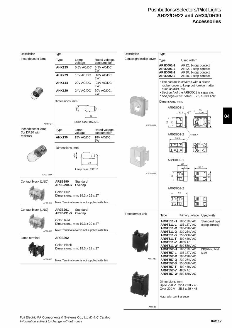
04/117Fuji Electric FA Components & Systems Co., Ltd./D & C CatalogInformation subject to change without notice
04
Pushbuttons/Selectors/Pilot LightsAR22/DR22 and AR30/DR30
Accessories
Incandescent lamp
AF89-427
Type Lamp Rated voltage,voltage consumption
AHX135 5.5V AC/DC 6.3V AC/DC,1W
AHX279 15V AC/DC 18V AC/DC,1W
AHX144 20V AC/DC 24V AC/DC,1W
AHX129 24V AC/DC 30V AC/DC,1W
Dimensions, mm:
Lamp base: BA9s/13
Dimensions, mm:
Lamp base: E12/15
KK02-115A
KK02-117A
Type
AR9T511-HAR9T511-LAR9T511-MAR9T511-QAR9T511-SAR9T511-TAR9T511-VAR9T511-WAR9T557-HAR9T557-LAR9T557-MAR9T557-QAR9T557-SAR9T557-TAR9T557-VAR9T557-W
Primary voltage
100-110V AC115-127V AC200-220V AC230-254V AC350-380V AC400-440V AC480V AC500-550V AC100-110V AC115-127V AC200-220V AC230-254V AC350-380V AC400-440V AC480V AC500-550V AC
Transformer unit
• The contact is covered with a siliconrubber cover to keep out foreign mattersuch as dust, etc.
• Section A of the AR9D001 is separate.* See page 04/122, “AR22 Z8, AR30 Z8”
Dimensions, mm:Up to 220 V 22.4 x 30 x 45Over 220 V 25.3 x 29 x 48
KK02-118A
AF94-457
AF95-33
Description Type Description Type
Incandescent lamp(for DR30 withresistor)
Type Lamp Rated voltage,voltage consumption
AHX130 15V AC/DC 18V AC/DC,2W
Contact block (1NO) AR9B290 StandardAR9B290-S Overlap
Color: BlueDimensions, mm: 19.3 x 29 x 27
AF94-455
Contact block (1NC) AR9B291 StandardAR9B291-S Overlap
Color: RedDimensions, mm: 19.3 x 29 x 27
AF94-455
Lamp terminal AR9B292
Color: BlackDimensions, mm: 19.3 x 29 x 27
AF94-456
Contact protection cover Type Used with *
AR9D001-1 AR22, 1-step contactAR9D001-2 AR22, 2-step contactAR9D002-1 AR30, 1-step contactAR9D002-2 AR30, 2-step contact
Dimensions, mm:
Used with
Standard type(except buzzers)
DR30F4N, F4M,M4M
Note: Terminal cover is not supplied with this.
Note: Terminal cover is not supplied with this.
Note: Terminal cover is not supplied with this.
Note: With terminal cover
20
ø10
ø14
34 32
12
30.5 42.645
50.5
52
39.5
35.6
32.5
30
33 30
4.7
Part A
AR9D001-1
AR9D001-2
AR9D002-1
AR9D002-2
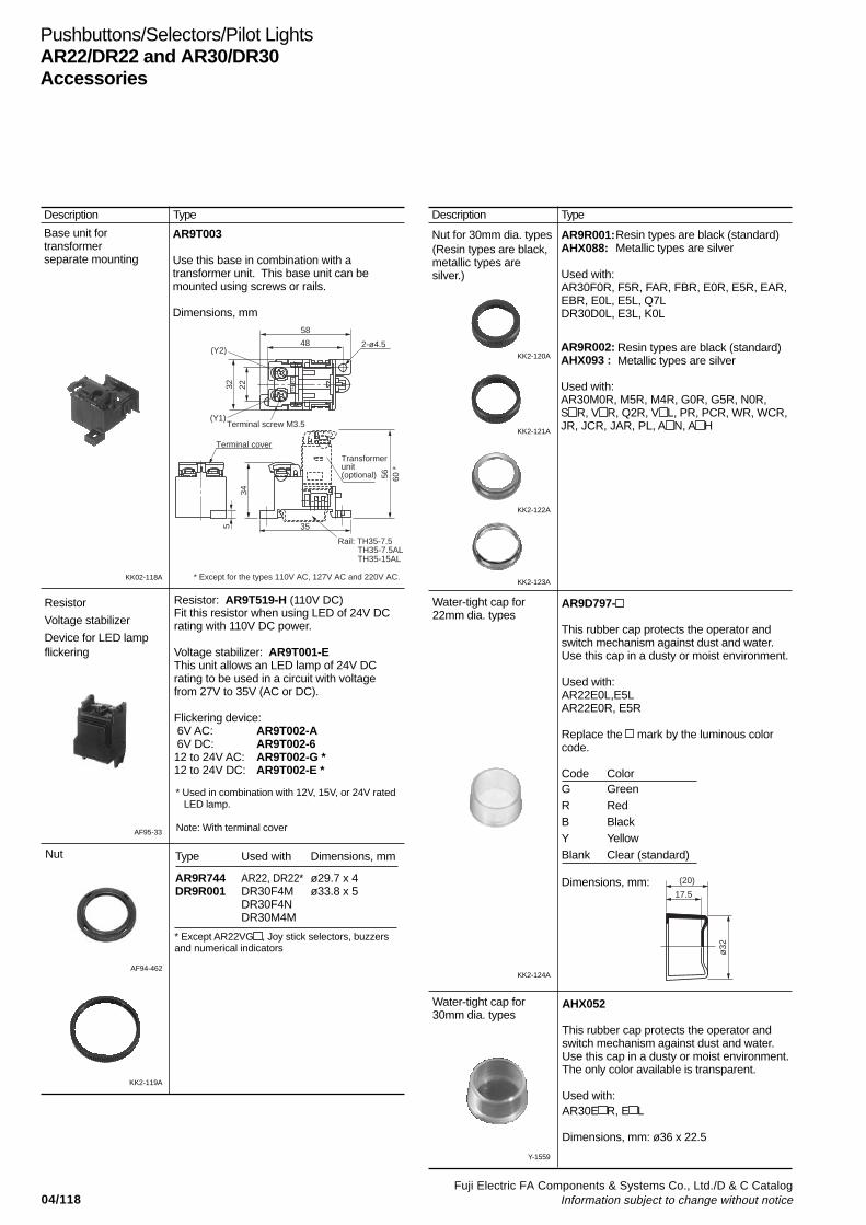
04/118Fuji Electric FA Components & Systems Co., Ltd./D & C Catalog
Information subject to change without notice
Pushbuttons/Selectors/Pilot LightsAR22/DR22 and AR30/DR30Accessories
Resistor
Voltage stabilizer
Device for LED lampflickering
AF95-33
Nut
AF94-462
KK02-118A
* Used in combination with 12V, 15V, or 24V rated LED lamp.
Type
AR9R744DR9R001
Used with
AR22, DR22*DR30F4MDR30F4NDR30M4M
Dimensions, mm
ø29.7 x 4ø33.8 x 5
* Except AR22VG , Joy stick selectors, buzzersand numerical indicators
AR9R001:AHX088:
Used with:AR30F0R, F5R, FAR, FBR, E0R, E5R, EAR,EBR, E0L, E5L, Q7LDR30D0L, E3L, K0L
Resin types are black (standard)Metallic types are silver
KK2-120A
(Resin types are black,metallic types aresilver.)
KK2-124A
KK2-121A
KK2-122A
KK2-123A
Description Type Description Type
AR9T003
Use this base in combination with atransformer unit. This base unit can bemounted using screws or rails.
Dimensions, mm
Base unit fortransformerseparate mounting
Resistor: AR9T519-H (110V DC)Fit this resistor when using LED of 24V DCrating with 110V DC power.
Voltage stabilizer: AR9T001-EThis unit allows an LED lamp of 24V DCrating to be used in a circuit with voltagefrom 27V to 35V (AC or DC).
Flickering device: 6V AC: AR9T002-A 6V DC: AR9T002-612 to 24V AC: AR9T002-G *12 to 24V DC: AR9T002-E *
KK2-119A
Nut for 30mm dia. types
AR9R002:AHX093 :
Used with:AR30M0R, M5R, M4R, G0R, G5R, N0R,S R, V R, Q2R, V L, PR, PCR, WR, WCR,JR, JCR, JAR, PL, A N, A H
AR9D797-
This rubber cap protects the operator andswitch mechanism against dust and water.Use this cap in a dusty or moist environment.
Used with:AR22E0L,E5LAR22E0R, E5R
Replace the mark by the luminous colorcode.
Code ColorG GreenR RedB BlackY YellowBlank Clear (standard)
Dimensions, mm:
Water-tight cap for22mm dia. types
Y-1559
Water-tight cap for30mm dia. types
AHX052
This rubber cap protects the operator andswitch mechanism against dust and water.Use this cap in a dusty or moist environment.The only color available is transparent.
Used with:AR30E R, E L
Dimensions, mm: ø36 x 22.5
Resin types are black (standard)Metallic types are silver
Note: With terminal cover
5
58
48
32 22
2-ø4.5
34
56 60 *
35
Rail: TH35-7.5 TH35-7.5AL TH35-15AL
Terminal screw M3.5
Terminal cover
Transformer unit(optional)
Y2
Y1
(Y2)
(Y1)
* Except for the types 110V AC, 127V AC and 220V AC.
ø32
(20)
17.5
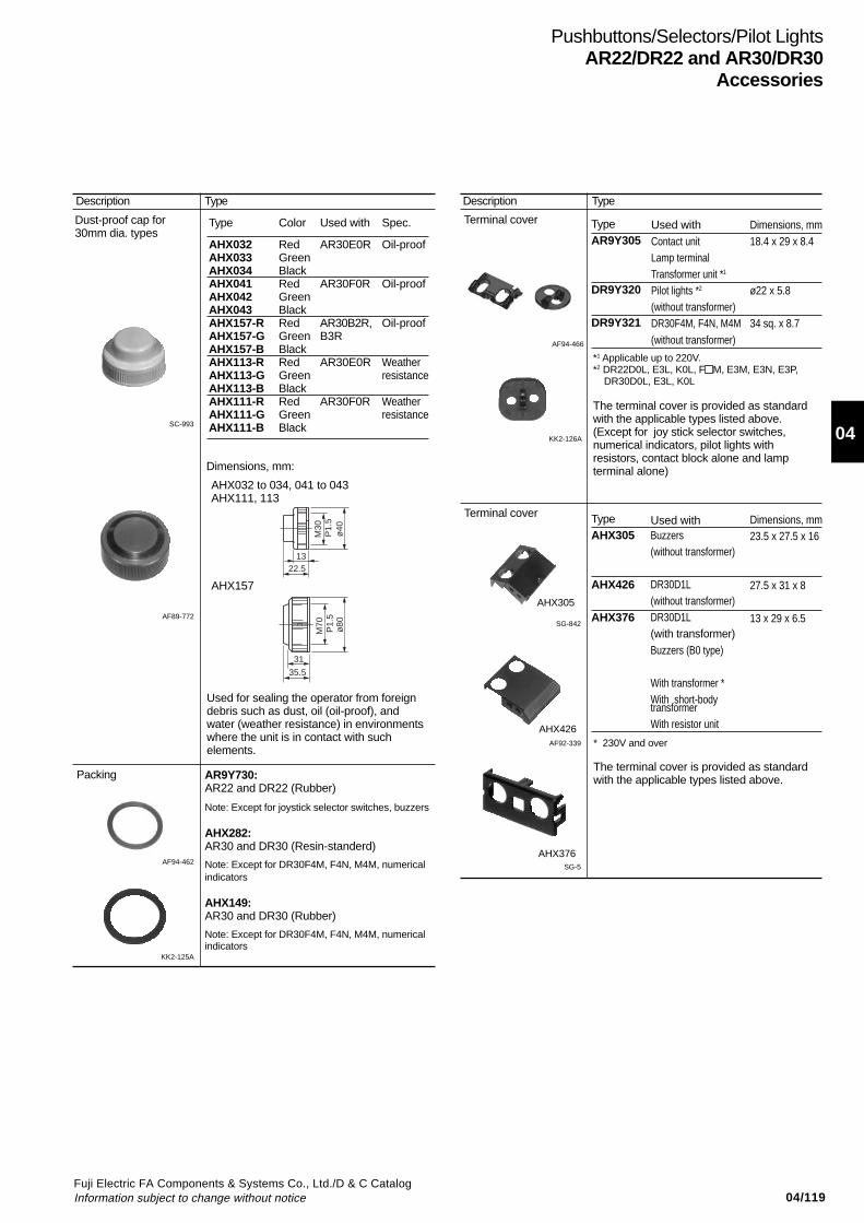
04/119Fuji Electric FA Components & Systems Co., Ltd./D & C CatalogInformation subject to change without notice
04
Pushbuttons/Selectors/Pilot LightsAR22/DR22 and AR30/DR30
Accessories
Packing
SC-993
Dust-proof cap for30mm dia. types
Terminal cover
AF94-466
AF89-772
AF94-462
TypeAR9Y305
DR9Y320
DR9Y321
*1 Applicable up to 220V.*2 DR22D0L, E3L, K0L, F M, E3M, E3N, E3P, DR30D0L, E3L, K0L
The terminal cover is provided as standardwith the applicable types listed above.(Except for joy stick selector switches,numerical indicators, pilot lights withresistors, contact block alone and lampterminal alone)
KK2-126A
AHX032 to 034, 041 to 043AHX111, 113
AHX157
SG-842
Terminal cover
* 230V and over
The terminal cover is provided as standardwith the applicable types listed above.
AF92-339
SG-5
AHX305
AHX426
AHX376
Used for sealing the operator from foreigndebris such as dust, oil (oil-proof), andwater (weather resistance) in environmentswhere the unit is in contact with suchelements.
Description Type Description Type
Type
AHX032AHX033AHX034AHX041AHX042AHX043AHX157-RAHX157-GAHX157-BAHX113-RAHX113-GAHX113-BAHX111-RAHX111-GAHX111-B
Color
RedGreenBlackRedGreenBlackRedGreenBlackRedGreenBlackRedGreenBlack
Used with
AR30E0R
AR30F0R
AR30B2R,B3R
AR30E0R
AR30F0R
Spec.
Oil-proof
Oil-proof
Oil-proof
Weatherresistance
Weatherresistance
Dimensions, mm:
AR9Y730:AR22 and DR22 (Rubber)
Note: Except for joystick selector switches, buzzers
AHX282:AR30 and DR30 (Resin-standerd)
Note: Except for DR30F4M, F4N, M4M, numericalindicators
AHX149:AR30 and DR30 (Rubber)
Note: Except for DR30F4M, F4N, M4M, numericalindicators
KK2-125A
Used withContact unitLamp terminalTransformer unit *1
Pilot lights *2
(without transformer)DR30F4M, F4N, M4M(without transformer)
Dimensions, mm18.4 x 29 x 8.4
ø22 x 5.8
34 sq. x 8.7
TypeAHX305
AHX426
AHX376
Used withBuzzers(without transformer)
DR30D1L(without transformer)DR30D1L(with transformer)Buzzers (B0 type)
With transformer *With short-bodytransformerWith resistor unit
Dimensions, mm23.5 x 27.5 x 16
27.5 x 31 x 8
13 x 29 x 6.5
ø40
M30
P1.
5
1322.5
ø80
M70
P
1.5
31
35.5
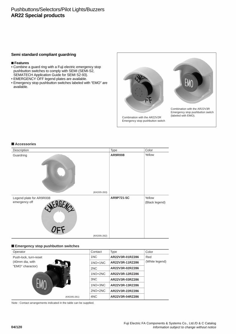
04/120Fuji Electric FA Components & Systems Co., Ltd./D & C Catalog
Information subject to change without notice
Pushbuttons/Selectors/Pilot Lights/BuzzersAR22 Special products
AR9R008
AR9P721-5C
AR22V3R-01RZ286
AR22V3R-11RZ286
AR22V3R-02RZ286
AR22V3R-13RZ286
1NC
1NO+1NC
2NC
1NO+3NC
AR22V3R-12RZ2861NO+2NC
AR22V3R-03RZ2863NC
AR22V3R-04RZ2864NC
AR22V3R-22RZ2862NO+2NC
Combination with the AR22V2R Emergency stop pushbutton switch
Combination with the AR22V3R Emergency stop pushbutton switch (labeled with EMO).
Accessories
Emergency stop pushbutton switches
Description
Operator
Note : Contact arrangements indicated in the table can be supplied.
Contact Type
Push-lock, turn-reset(40mm dia, with "EMO" charactor)
Type Color
Color
Yellow
Yellow(Black legend)
Red(White legend)
Guardring
Legend plate for AR9R008emergency off
(KKD05-263)
(KKD05-262)
(KKD05-261)
Semi standard compliant guardring
Features• Combine a guard ring with a Fuji electric emergency stop
pushbutton switches to comply with SEMI (SEMI-S2,SEMATECH Application Guide for SEMI S2-93).
• EMERGENCY OFF legend plates are available.• Emergency stop pushbutton switches labeled with “EMO” are
available.
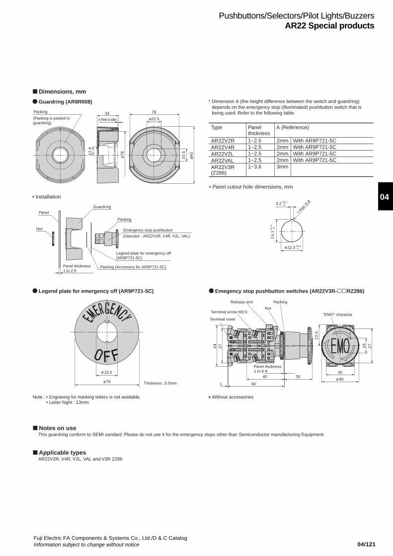
04/121Fuji Electric FA Components & Systems Co., Ltd./D & C CatalogInformation subject to change without notice
04
Pushbuttons/Selectors/Pilot Lights/BuzzersAR22 Special products
Type Panelthickness
A (Reference)
AR22V2RAR22V4RAR22V2LAR22VALAR22V3R(Z286)
1~2.51~2.51~2.51~2.51~3.6
2mm With AR9P721-5CWith AR9P721-5CWith AR9P721-5CWith AR9P721-5C
2mm2mm2mm3mm
5.
22
6
1
7
3
40
30 40 30
60
44
73
1
3.2 +0.2 0
22.3 +0.4 0
1.
42
4.
0+
0
8.0 xam r
78 34 ø22.3
0
ø9ø76
9.
21
5.
02
Legend plate for emergency off (AR9P721-5C)
(Operator : AR22V2R, V4R, V2L, VAL)
22.5
70
ø
ø
ø
ø
Dimensions, mm
Applicable types
Notes on use
Guardring (AR9R008)
Legend plate for emergency off (AR9P721-5C) Emegency stop pushbutton switches (AR22V3R-RZ286)
• Installation
• Panel cutout hole dimensions, mm
Packing
Panel
Panel thickness 1 to 2.5
Guardring
Packing
Packing (Accessory for AR9P721-5C)
Emergency stop pushbuttonNut
Thickness : 0.5mm
Terminal cover
Terminal screw M3.5
Release arm
Nut
Panel thickness1 to 6 *
Packing
"EMO" charactor
A (Refar to table)(Packing is pasted to guardring)
Note : • Engraving for marking letters is not available.• Letter hight : 13mm
* Without accessories
This guardring conform to SEMI sandard. Please do not use it for the emergency stops other than Semiconductor manufacturing Equipment.
AR22V2R, V4R, V2L, VAL and V3R Z286
* Dimension A (the height difference between the switch and guardring) depends on the emergency stop (Illuminated) pushbutton switch that is being used. Refer to the following table.

04/122Fuji Electric FA Components & Systems Co., Ltd./D & C Catalog
Information subject to change without notice
Pushbuttons/Selectors/Pilot Lights/BuzzersAR22/DR22 and AR30/DR30Special products
Products equipped with contact protection cover
FeaturesA silicon rubber cover is provided for the contact block to keepout foreign matter such as dust, etc.Other ratings and specifications are the same as those of thestandard type.
TypeAR22 Z8AR30 Z8Specify “Z8” at the end of the type number of the standard type.
DimensionsThe only thing different from the standard product is the additionof a 1-mm thick silicon rubber cover around the contact block.
Applicable types
Type• Pushbuttons *1
• Emergency stop pushbuttons *2
• Selectors *3
• Illuminated pushbuttons *4
(without transformer)• Emergency stop illuminated pushbuttons*2 (without transformer)• Illuminated selectors (without transformer)
Contact arrangement1NO+1NC,2NO*5, 2NC1NO+3NC, 2NO+2NC,3NO+1NC, 4NO*5, 4NC1NO*6, 1NC
1NO+2NC, 2NO+1NC,3NO*6, 3NC
RemarksFor use with a1-step contact
For use with a2-step contact
For use with a1-step contact
For use with a2-step contact
Notes: *1 Except for AR30B0R, B1R, B2R, B3R, N0R, and GPR.*2 Except for unibody (VG types)*3 Except for AR30HR*4 Except for AR30Q7L*5 Except for emergency stop pushbutton switch*6 Except for emergency stop illuminated pushbutton switch
Resisting water-soluble cutting oils and heat
FeaturesSafer operation in environments exposed to water-misciblecutting fluids, machining oils, lubricating oils, cleaning oils andhigh humidity (up to 95%) is made possible by using materialsthat protect against rust and corrosion of components.Other ratings and specifications are the same as those of thestandard type.
TypeAR22 Z9, DR22 Z9AR30 Z9, DR30 Z9Specify “Z9” at the end of the type number of the standard type.
DimensionsSame as those of the standard type
Applicable types• AR22, DR22 seriesAR 22 (Except for joy stick selectors, FAR, FBR, EAR, EBRtypes and VG types)DR22 (Except for pilot lights with resistor unit and buzzers)
• AR30, DR30 seriesAR30 (Except for Q7L, FAR, FBR, EAR, EBR, HR types and joystick selectors)DR30 (Except for D1L, F4M, F4N, M4M types, pilot lights withresistor/resistor unit and buzzers)
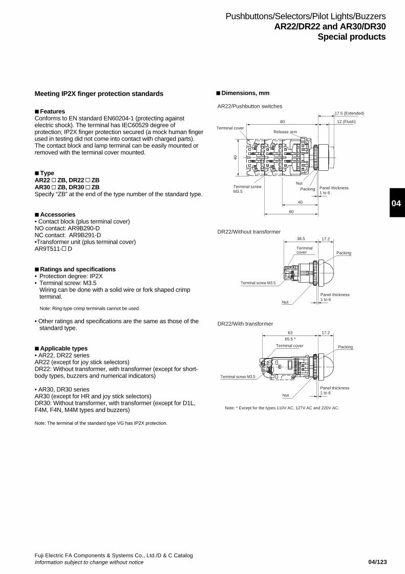
04/123Fuji Electric FA Components & Systems Co., Ltd./D & C CatalogInformation subject to change without notice
04
Pushbuttons/Selectors/Pilot Lights/BuzzersAR22/DR22 and AR30/DR30
Special products
Terminal cover
40
Terminal screwM3.5
NutPacking Panel thickness
1 to 6
40
60
17.5 (Extended)
12 (Flush)
38.5 17.2
17.2
Terminal cover
Terminal cover
Terminal screw M3.5
Terminal screw M3.5
Nut
Nut
Panel thickness1 to 6
Panel thickness1 to 6
Packing
Packing
63
65.5 *
80
Release arm
AR22/Pushbutton switches
DR22/Without transformer
DR22/With transformer
Note: * Except for the types 110V AC, 127V AC and 220V AC.
Meeting IP2X finger protection standards
FeaturesConforms to EN standard EN60204-1 (protecting againstelectric shock). The terminal has IEC60529 degree ofprotection; IP2X finger protection secured (a mock human fingerused in testing did not come into contact with charged parts).The contact block and lamp terminal can be easily mounted orremoved with the terminal cover mounted.
TypeAR22 ZB, DR22 ZBAR30 ZB, DR30 ZBSpecify “ZB” at the end of the type number of the standard type.
Accessories• Contact block (plus terminal cover)NO contact: AR9B290-DNC contact: AR9B291-D•Transformer unit (plus terminal cover)AR9T511- D
Ratings and specifications• Protection degree: IP2X• Terminal screw: M3.5
Wiring can be done with a solid wire or fork shaped crimpterminal.
Note: Ring-type crimp terminals cannot be used.
• Other ratings and specifications are the same as those of thestandard type.
Applicable types• AR22, DR22 seriesAR22 (except for joy stick selectors)DR22: Without transformer, with transformer (except for short-body types, buzzers and numerical indicators)
• AR30, DR30 seriesAR30 (except for HR and joy stick selectors)DR30: Without transformer, with transformer (except for D1L,F4M, F4N, M4M types and buzzers)
Note: The terminal of the standard type VG has IP2X protection.
Dimensions, mm

04/124Fuji Electric FA Components & Systems Co., Ltd./D & C Catalog
Information subject to change without notice
Pushbuttons/Selectors/Pilot Lights/BuzzersAR22/DR22 and AR30/DR30Special products
Metal nut (chrome plated) types
FeaturesThe nut is a metallic ring (chrome plated).Other ratings and specifications are the same as those of thestandard model.
TypeAR30 ZMDR30 ZMSpecify “ZM” at the end of the type number of the standard type.
Dimensions, mmSame as those of the standard types.
Applicable types• AR30, DR30 seriesAR30 (except for G4L, G9L, GSR*1, GPR*1, BOR*1,and HR*1
types)DR30 with round bezel (except for IP54 buzzer type B8)*2
Notes: *1 Standard type is a metallic ring (chrome plated). *2 The nut of types DR30B0, B5 and B6 buzzers are resin (chrome plated).
Resisting sulfuration gas
FeaturesThese products can be used in environments having aconcentration of hydrogen sulfide gas of 0.5 ppm or less.The metallic parts have been subjected to an anti-corrosiontreatment (see note).The contacts of the AR series are gold plated.
Note: The body is made of resin and cannot be used with gases that affectresins (plastics).
TypeAR22 Z4, DR22 Z4AR30 Z4, DR30 Z4Specify “Z4” at the end of the type number of the standard type.
Notes on use• This product is resistant to light corrosive gas exposure.• Other measures, such as covering the entire switch with a box,
and the degree of protection of the panel should be taken intoconsideration.
Ratings and specificationsHydrogen sulfide gas concentration of 0.5 ppm max.Ambient storage temperature: 8 to 37°CHumidity: 62 to 81%Other ratings and specifications are the same as those of thestandard type.
Dimensions, mmSame as those of the standard types.
Applicable types• AR22, DR22 seriesAR22 (except for Joy stick selectors and VG type)DR22 (except for pilot lights with resistor unit and buzzers)
• AR30, DR30 seriesAR30 (except for HR and Joy stick selectors)DR30 (except for F4M, F4N, M4M types, pilot lights withresistor/resistor unit and buzzers)
AR30PR ZM DR30D0L ZMAR30E0R ZM
KKD08-048KK02-148A KK02-149A
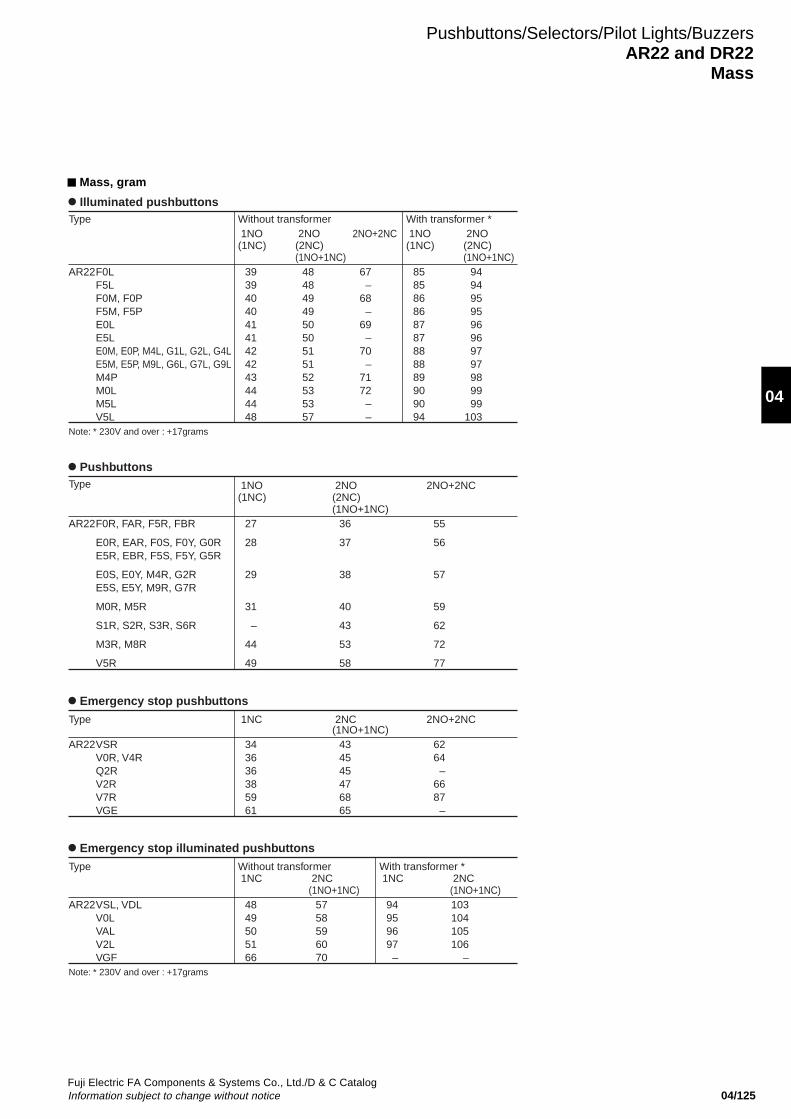
04/125Fuji Electric FA Components & Systems Co., Ltd./D & C CatalogInformation subject to change without notice
04
Mass, gram
Pushbuttons/Selectors/Pilot Lights/BuzzersAR22 and DR22
Mass
Illuminated pushbuttonsType
AR22F0LF5LF0M, F0PF5M, F5PE0LE5LE0M, E0P, M4L, G1L, G2L, G4LE5M, E5P, M9L, G6L, G7L, G9LM4PM0LM5LV5L
Without transformer 1NO(1NC)
393940404141424243444448
With transformer * 1NO(1NC)
858586868787888889909094
2NO(2NC)(1NO+1NC)
484849495050515152535357
2NO(2NC)(1NO+1NC)
9494959596969797989999
103
2NO+2NC
67–
68–
69–
70–
7172––
Note: * 230V and over : +17grams
PushbuttonsType
AR22F0R, FAR, F5R, FBR
E0R, EAR, F0S, F0Y, G0RE5R, EBR, F5S, F5Y, G5R
E0S, E0Y, M4R, G2RE5S, E5Y, M9R, G7R
M0R, M5R
S1R, S2R, S3R, S6R
M3R, M8R
V5R
1NO(1NC)
27
28
29
31
–
44
49
2NO(2NC)(1NO+1NC)
36
37
38
40
43
53
58
2NO+2NC
55
56
57
59
62
72
77
Type
AR22VSL, VDLV0LVALV2LVGF
Without transformer 1NC
4849505166
With transformer * 1NC
94959697–
2NC(1NO+1NC)
5758596070
2NC(1NO+1NC)103104105106
–
Emergency stop illuminated pushbuttons
Note: * 230V and over : +17grams
Emergency stop pushbuttons
Type
AR22VSRV0R, V4RQ2RV2RV7RVGE
1NC
343636385961
2NC(1NO+1NC)
434545476865
2NO+2NC
6264–
6687–
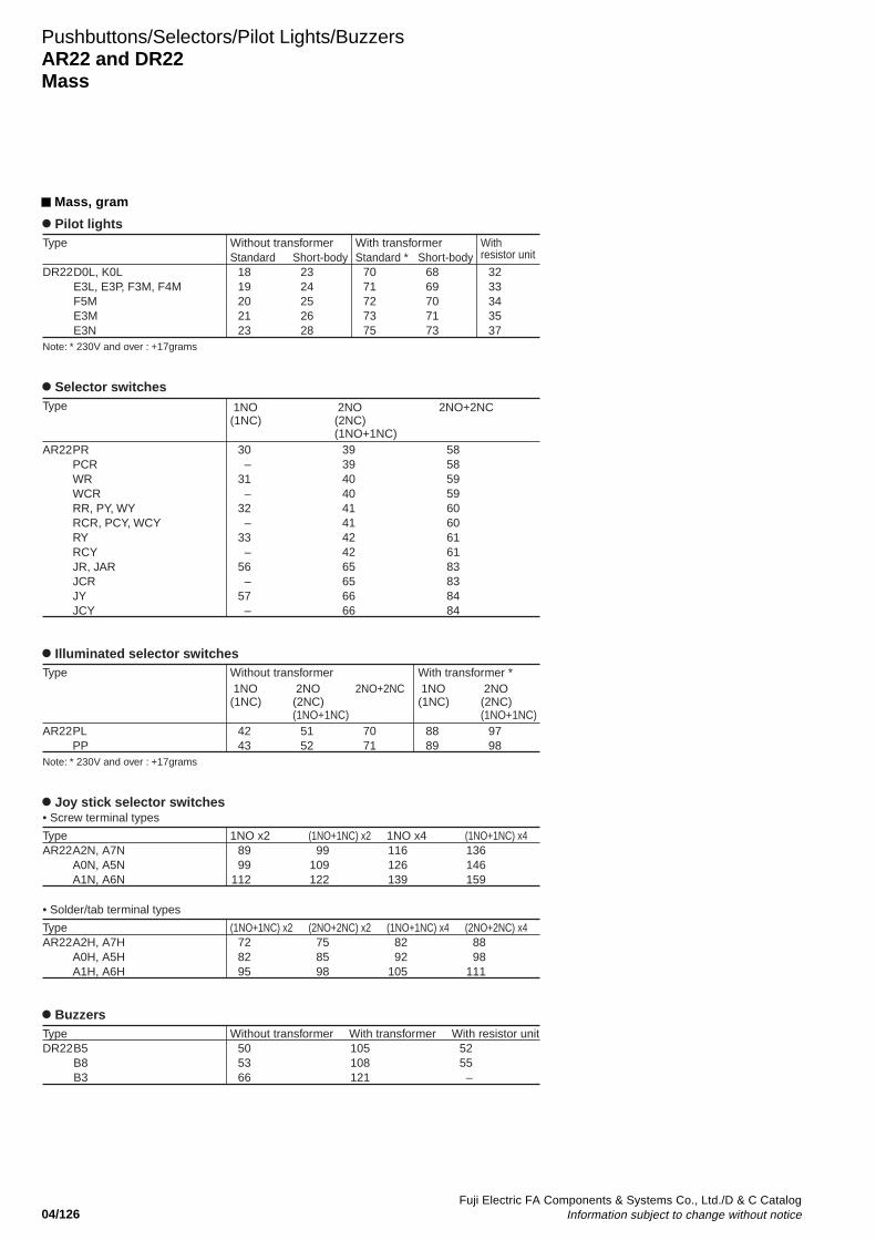
04/126Fuji Electric FA Components & Systems Co., Ltd./D & C Catalog
Information subject to change without notice
Pushbuttons/Selectors/Pilot Lights/BuzzersAR22 and DR22Mass
Mass, gram
Pilot lightsType
DR22D0L, K0LE3L, E3P, F3M, F4MF5ME3ME3N
Without transformerStandard
1819202123
Short-body2324252628
Short-body6869707173
With transformerStandard *
7071727375
With resistor unit
3233343537
Note: * 230V and over : +17grams
Selector switchesType
AR22PRPCRWRWCRRR, PY, WYRCR, PCY, WCYRYRCYJR, JARJCRJYJCY
1NO(1NC)
30–
31–
32–
33–
56–
57–
2NO(2NC)(1NO+1NC)
393940404141424265656666
2NO+2NC
585859596060616183838484
Illuminated selector switchesType
AR22PLPP
Without transformer 1NO(1NC)
4243
With transformer * 1NO(1NC)
8889
2NO(2NC)(1NO+1NC)
5152
2NO+2NC
7071
2NO(2NC)(1NO+1NC)
9798
Note: * 230V and over : +17grams
Joy stick selector switches
TypeAR22A2N, A7N
A0N, A5NA1N, A6N
1NO x28999
112
(1NO+1NC) x299
109122
(1NO+1NC) x4136146159
1NO x4116126139
TypeAR22A2H, A7H
A0H, A5HA1H, A6H
(1NO+1NC) x2728295
(2NO+2NC) x2758598
(2NO+2NC) x48898
111
(1NO+1NC) x48292
105
• Screw terminal types
• Solder/tab terminal types
BuzzersTypeDR22B5
B8B3
Without transformer505366
With transformer105108121
With resistor unit5255–
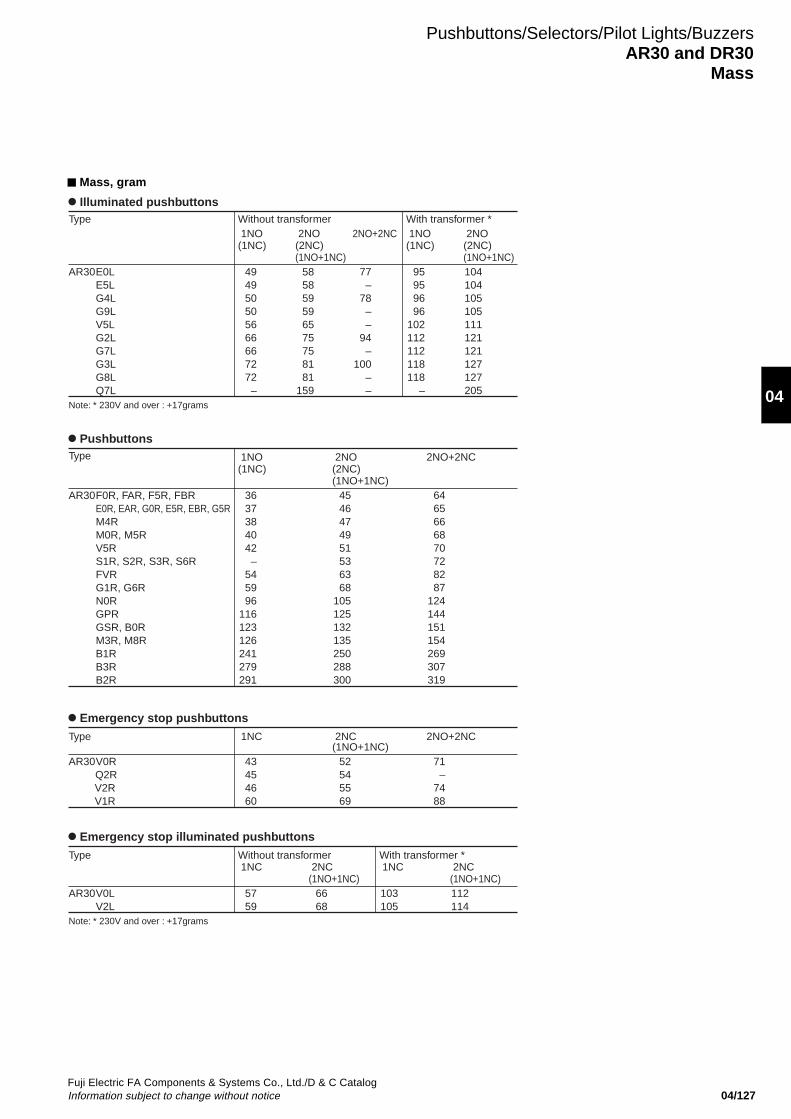
04/127Fuji Electric FA Components & Systems Co., Ltd./D & C CatalogInformation subject to change without notice
04
Mass, gram
Pushbuttons/Selectors/Pilot Lights/BuzzersAR30 and DR30
Mass
Illuminated pushbuttonsType
AR30E0LE5LG4LG9LV5LG2LG7LG3LG8LQ7L
Without transformer 1NO(1NC)
494950505666667272–
With transformer * 1NO(1NC)
95959696
102112112118118
–
2NO(2NC)(1NO+1NC)
585859596575758181
159
2NO(2NC)(1NO+1NC)104104105105111121121127127205
2NO+2NC
77–
78––
94–
100––
Note: * 230V and over : +17grams
PushbuttonsType
AR30F0R, FAR, F5R, FBRE0R, EAR, G0R, E5R, EBR, G5RM4RM0R, M5RV5RS1R, S2R, S3R, S6RFVRG1R, G6RN0RGPRGSR, B0RM3R, M8RB1RB3RB2R
1NO(1NC)
3637384042–
545996
116123126241279291
2NO(2NC)(1NO+1NC)
4546474951536368
105125132135250288300
2NO+2NC
6465666870728287
124144151154269307319
Type
AR30V0LV2L
Without transformer 1NC
5759
With transformer * 1NC
103105
2NC(1NO+1NC)
6668
2NC(1NO+1NC)112114
Emergency stop illuminated pushbuttons
Note: * 230V and over : +17grams
Emergency stop pushbuttons
Type
AR30V0R Q2R V2R V1R
1NC
43454660
2NC(1NO+1NC)
52545569
2NO+2NC
71–
7488
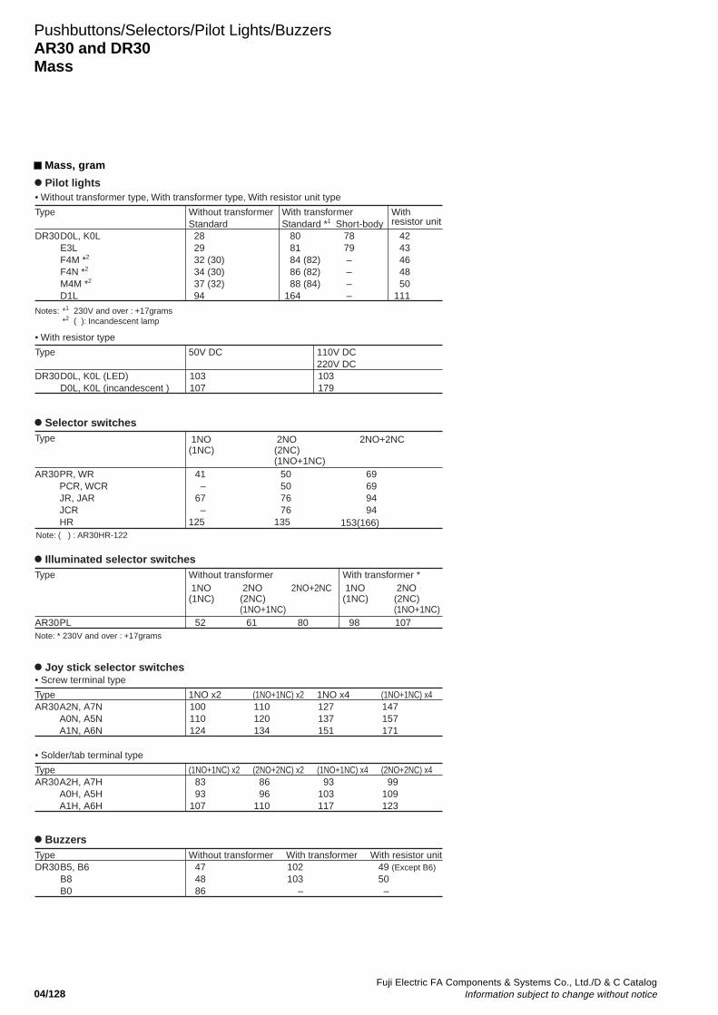
04/128Fuji Electric FA Components & Systems Co., Ltd./D & C Catalog
Information subject to change without notice
Pushbuttons/Selectors/Pilot Lights/BuzzersAR30 and DR30Mass
Mass, gram
Pilot lights
Type
DR30D0L, K0LE3LF4M *2
F4N *2
M4M *2
D1L
Without transformerStandard 28 29 32 (30) 34 (30) 37 (32) 94
Short-body 78 79 – – – –
With transformerStandard *1
80 81 84 (82) 86 (82) 88 (84) 164
With resistor unit
42 43 46 48 50 111
Notes: *1 230V and over : +17grams*2 ( ): Incandescent lamp
• Without transformer type, With transformer type, With resistor unit type
Type
DR30D0L, K0L (LED)D0L, K0L (incandescent )
50V DC
103107
110V DC220V DC103179
• With resistor type
Selector switchesType
AR30PR, WRPCR, WCRJR, JARJCRHR
1NO(1NC)
41–
67–
125
2NO(2NC)(1NO+1NC)
50507676
135
2NO+2NC
69699494
153(166)Note: ( ) : AR30HR-122
Illuminated selector switchesType
AR30PL
Without transformer 1NO(1NC)
52
With transformer * 1NO(1NC)
98
2NO(2NC)(1NO+1NC)
61
2NO+2NC
80
2NO(2NC)(1NO+1NC)107
Note: * 230V and over : +17grams
Joy stick selector switches
TypeAR30A2N, A7N
A0N, A5NA1N, A6N
1NO x2100110124
(1NO+1NC) x2110120134
(1NO+1NC) x4147157171
1NO x4127137151
TypeAR30A2H, A7H
A0H, A5HA1H, A6H
(1NO+1NC) x28393
107
(2NO+2NC) x28696
110
(2NO+2NC) x499
109123
(1NO+1NC) x493
103117
• Screw terminal type
• Solder/tab terminal type
BuzzersTypeDR30B5, B6
B8B0
Without transformer474886
With transformer102103
–
With resistor unit 49 (Except B6) 50 –
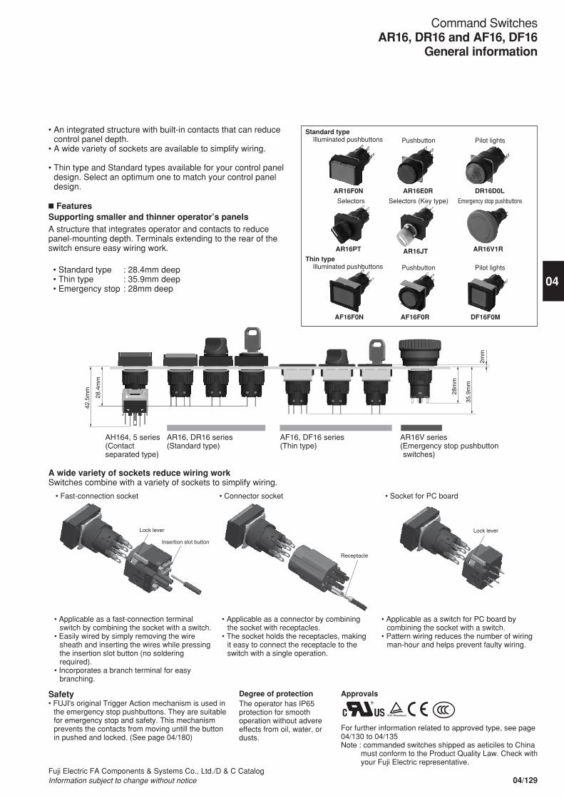
Lock lever
Approvals
For further information related to approved type, see page 04/130 to 04/135Note : commanded switches shipped as aeticiles to China
must conform to the Product Quality Law. Check with your Fuji Electric representative.
• An integrated structure with built-in contacts that can reduce control panel depth.
• A wide variety of sockets are available to simplify wiring.
• Thin type and Standard types available for your control panel design. Select an optimum one to match your control panel design.
n FeaturesSupporting smaller and thinner operator’s panelsA structure that integrates operator and contacts to reduce panel-mounting depth. Terminals extending to the rear of the switch ensure easy wiring work.
• Standard type : 28.4mm deep • Thin type : 35.9mm deep • Emergency stop : 28mm deep
28m
m
35.9
mm
2mm
28.4
mm
42.5
mm
AH164, 5 series(Contact separated type)
AR16, DR16 series(Standard type)
AF16, DF16 series(Thin type)
AR16V series(Emergency stop pushbutton switches)
Receptacle
Insertion slot button
Lock lever
A wide variety of sockets reduce wiring workSwitches combine with a variety of sockets to simplify wiring.
• Applicable as a fast-connection terminal switch by combining the socket with a switch.
• Easily wired by simply removing the wire sheath and inserting the wires while pressing the insertion slot button (no soldering required).
• Incorporates a branch terminal for easy branching.
Safety• FUJI's original Trigger Action mechanism is used in
the emergency stop pushbuttons. They are suitable for emergency stop and safety. This mechanism prevents the contacts from moving untill the button in pushed and locked. (See page 04/180)
• Applicable as a connector by combining the socket with receptacles.
• The socket holds the receptacles, making it easy to connect the receptacle to the switch with a single operation.
• Applicable as a switch for PC board by combining the socket with a switch.
• Pattern wiring reduces the number of wiring man-hour and helps prevent faulty wiring.
• Connector socket • Socket for PC board• Fast-connection socket
Degree of protectionThe operator has IP65 protection for smooth operation without advere effects from oil, water, or dusts.
S
Standard type Illuminated pushbuttons
Thin type Illuminated pushbuttons
AR16F0N
AF16F0N
AR16PT
AR16E0R
AF16F0R
AR16JT
DR16D0L
DF16F0M
AR16V1R
Pushbutton
Selectors (Key type)Selectors
Pushbutton
Pilot lights
Emergency stop pushbuttons
Pilot lights
04/129Fuji Electric FA Components & Systems Co., Ltd./D & C CatalogInformation subject to change without notice
Command SwitchesAR16, DR16 and AF16, DF16
General information
04
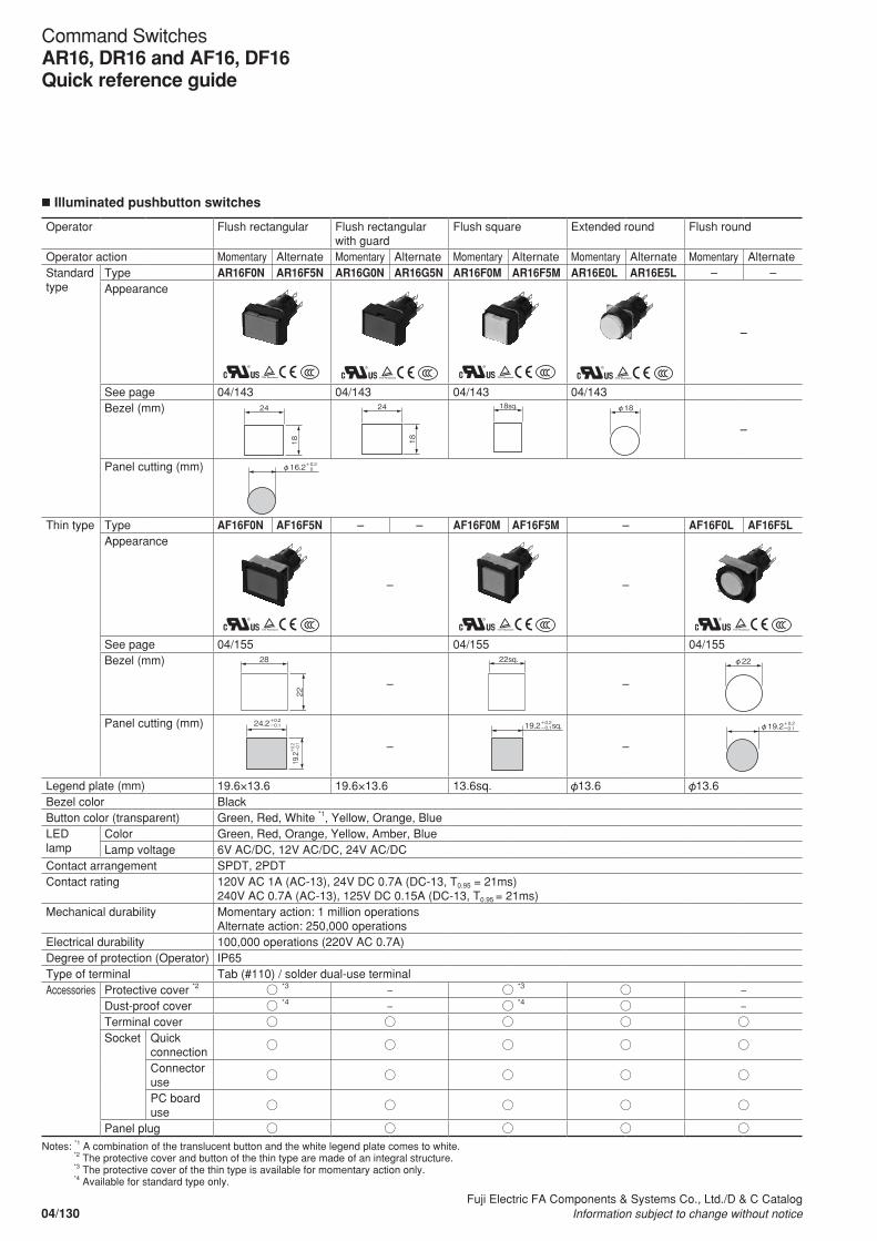
n Illuminated pushbutton switches
Operator Flush rectangular Flush rectangular with guard
Flush square Extended round Flush round
Operator action Momentary Alternate Momentary Alternate Momentary Alternate Momentary Alternate Momentary AlternateStandard type
Type AR16F0N AR16F5N AR16G0N AR16G5N AR16F0M AR16F5M AR16E0L AR16E5L – –Appearance
S S SS
–
See page 04/143 04/143 04/143 04/143Bezel (mm) 24
18
2418
18sq. φ18
–
Panel cutting (mm) φ16.2+0.2 0
Thin type Type AF16F0N AF16F5N – – AF16F0M AF16F5M – AF16F0L AF16F5LAppearance
S
–
S
–
S
See page 04/155 04/155 04/155Bezel (mm)
22
28
–
22sq.
–
φ22
Panel cutting (mm) 24.2+0.2-0.1
19.2+0.2
-0.1 –
19.2+0.2 sq. -0.1
–
φ19.2+0.2 -0.1
Legend plate (mm) 19.6×13.6 19.6×13.6 13.6sq. 13.6 13.6Bezel color BlackButton color (transparent) Green, Red, White *1, Yellow, Orange, BlueLED lamp
Color Green, Red, Orange, Yellow, Amber, BlueLamp voltage 6V AC/DC, 12V AC/DC, 24V AC/DC
Contact arrangement SPDT, 2PDTContact rating 120V AC 1A (AC-13), 24V DC 0.7A (DC-13, T0.95 = 21ms)
240V AC 0.7A (AC-13), 125V DC 0.15A (DC-13, T0.95 = 21ms)Mechanical durability Momentary action: 1 million operations
Alternate action: 250,000 operations Electrical durability 100,000 operations (220V AC 0.7A)Degree of protection (Operator) IP65Type of terminal Tab (#110) / solder dual-use terminalAccessories Protective cover *2 *3 – *3 –
Dust-proof cover *4 – *4 –Terminal cover Socket Quick
connection
Connector use
PC board use
Panel plug Notes: *1 A combination of the translucent button and the white legend plate comes to white.
*2 The protective cover and button of the thin type are made of an integral structure. *3 The protective cover of the thin type is available for momentary action only. *4 Available for standard type only.
04/130Fuji Electric FA Components & Systems Co., Ltd./D & C Catalog
Information subject to change without notice
Command SwitchesAR16, DR16 and AF16, DF16Quick reference guide

n Pushbutton switches
Operator Flush rectangular Flush rectangular with guard
Flush square Extended round Flush round
Operator action Momentary Alternate Momentary Alternate Momentary Alternate Momentary Alternate Momentary AlternateStandard type
Type AR16F0T AR16F5T AR16G0T AR16G5T AR16F0S AR16F5S AR16E0R AR16E5R – –Appearance
S S S S
–
See page 04/145 04/145 04/145 04/145Bezel (mm) 24
18
24
18
18sq. φ18
–
Panel cutting (mm) φ16.2+0.2 0
Thin type Type AF16F0T AF16F5T – – AF16F0S AF16F5S – AF16F0R AF16F5RAppearance
S
–
S
–
S
See page 04/157 04/157 04/157Bezel (mm)
22
28
–
22sq.
–
φ22
Panel cutting (mm) 24.2+0.2-0.1
19.2+0.2
-0.1 –
19.2+0.2 sq. -0.1
–
φ19.2+0.2 -0.1
Legend plate (mm) 19.6×13.6 19.6×13.6 13.6sq 13.6 13.6Button color (transparent) BlackButton color Green, Red, Black *1, White *2, Yellow, Orange, BlueContact arrangement SPDT, 2PDTContact rating 120V AC 1A (AC-13), 24V DC 0.7A (DC-13, T0.95 = 21ms)
240V AC 0.7A (AC-13), 125V DC 0.15A (DC-13, T0.95 = 21ms)Mechanical durability Momentary action: 1 million operations
Alternate action: 250,000 operations Electrical durability 100,000 operations (220V AC 0.7A)Degree of protection (Operator) IP65Type of terminal Tab (#110) / solder dual-use terminalAccessories Protective cover *3 *4 – *4 –
Dust-proof cover *5 – *5 –Terminal cover Socket Quick
connection
Connector use
PC board use
Panel plug Notes: *1 A combination of the translucent button and the black legend plate comes to black button.
*2 A combination of the translucent button and the white legend plate comes to white button. *3 The protective cover and button of the thin type are made of an integral structure.
*4 The protective cover of the thin type is available for momentary action only.*5 Available for standard type only.
04/131Fuji Electric FA Components & Systems Co., Ltd./D & C CatalogInformation subject to change without notice
Command SwitchesAR16, DR16 and AF16, DF16
Quick reference guide
04
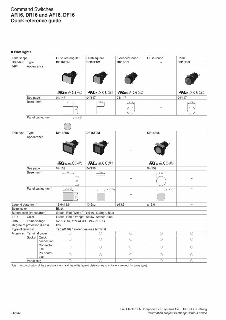
n Pilot lights
Lens shape Flush rectangular Flush square Extended round Flush round DomeStandard type
Type DR16F0N DR16F0M DR16E0L – DR16D0LAppearance
S S S
–
S
See page 04/147 04/147 04/147 04/147Bezel (mm) 24
18
18sq. φ18
–
φ18
Panel cutting (mm)
φ16.2+0.2 0
Thin type Type DF16F0N DF16F0M – DF16F0L –Appearance
S S
–
S
–
See page 04/159 04/159 04/159Bezel (mm)
22
28 22sq.
–
φ22
–
Panel cutting (mm) 24.2+0.2-0.1
19.2+0.2
-0.1
19.2+0.2 sq. -0.1
–
φ19.2+0.2 -0.1 –
Legend plate (mm) 19.6×13.6 13.6sq 13.6 13.6 –Bezel color BlackButton color (transparent) Green, Red, White *1, Yellow, Orange, BlueLED lamp
Color Green, Red, Orange, Yellow, Amber, BlueLamp voltage 6V AC/DC, 12V AC/DC, 24V AC/DC
Degree of protection (Lens) IP65Type of terminal Tab (#110) / solder dual-use terminalAccessories Terminal cover
Socket Quick connection
Connector use
PC board use
Panel plug Note: *1 A combination of the translucent lens and the white legend plate comes to white lens (except for dome type).
04/132Fuji Electric FA Components & Systems Co., Ltd./D & C Catalog
Information subject to change without notice
Command SwitchesAR16, DR16 and AF16, DF16Quick reference guide
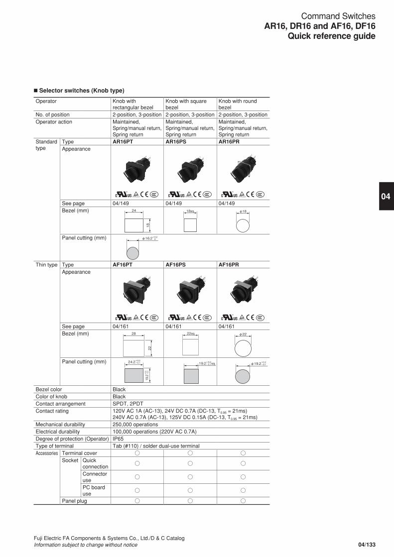
n Selector switches (Knob type)
Operator Knob with rectangular bezel
Knob with square bezel
Knob with round bezel
No. of position 2-position, 3-position 2-position, 3-position 2-position, 3-position Operator action Maintained,
Spring/manual return,Spring return
Maintained, Spring/manual return,Spring return
Maintained, Spring/manual return,Spring return
Standard type
Type AR16PT AR16PS AR16PRAppearance
S S S
See page 04/149 04/149 04/149Bezel (mm) 24
18
18sq. φ18
Panel cutting (mm)
φ16.2+0.2 0
Thin type Type AF16PT AF16PS AF16PRAppearance
S S S
See page 04/161 04/161 04/161Bezel (mm)
22
28 22sq. φ22
Panel cutting (mm) 24.2+0.2-0.1
19.2+0.2
-0.1
19.2+0.2 sq. -0.1 φ19.2+0.2 -0.1
Bezel color BlackColor of knob BlackContact arrangement SPDT, 2PDTContact rating 120V AC 1A (AC-13), 24V DC 0.7A (DC-13, T0.95 = 21ms)
240V AC 0.7A (AC-13), 125V DC 0.15A (DC-13, T0.95 = 21ms)Mechanical durability 250,000 operationsElectrical durability 100,000 operations (220V AC 0.7A)Degree of protection (Operator) IP65Type of terminal Tab (#110) / solder dual-use terminalAccessories Terminal cover
Socket Quick connection
Connector use
PC board use
Panel plug
04/133Fuji Electric FA Components & Systems Co., Ltd./D & C CatalogInformation subject to change without notice
Command SwitchesAR16, DR16 and AF16, DF16
Quick reference guide
04
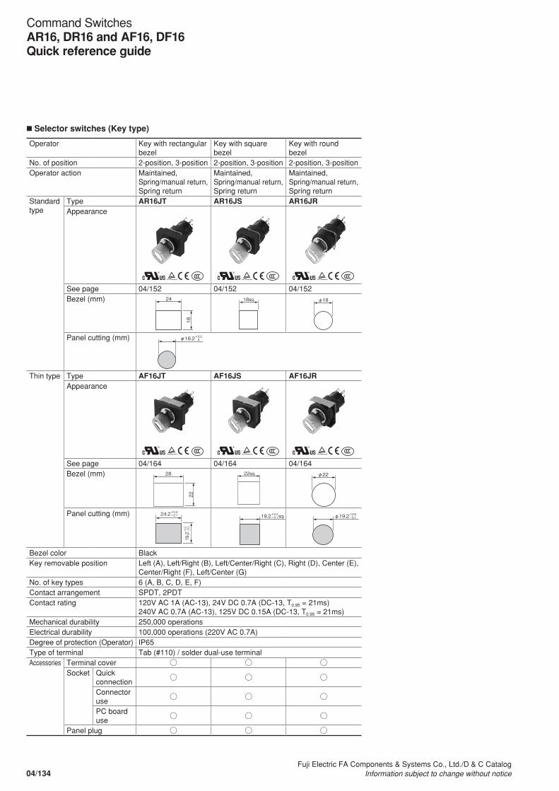
n Selector switches (Key type)
Operator Key with rectangular bezel
Key with square bezel
Key with round bezel
No. of position 2-position, 3-position 2-position, 3-position 2-position, 3-position Operator action Maintained,
Spring/manual return,Spring return
Maintained, Spring/manual return,Spring return
Maintained, Spring/manual return,Spring return
Standard type
Type AR16JT AR16JS AR16JRAppearance
S S S
See page 04/152 04/152 04/152Bezel (mm) 24
18
18sq. φ18
Panel cutting (mm)
φ16.2+0.2 0
Thin type Type AF16JT AF16JS AF16JRAppearance
S S S
See page 04/164 04/164 04/164Bezel (mm)
22
28 22sq. φ22
Panel cutting (mm) 24.2+0.2-0.1
19.2+0.2
-0.1
19.2+0.2 sq. -0.1 φ19.2+0.2 -0.1
Bezel color BlackKey removable position Left (A), Left/Right (B), Left/Center/Right (C), Right (D), Center (E),
Center/Right (F), Left/Center (G)No. of key types 6 (A, B, C, D, E, F)Contact arrangement SPDT, 2PDTContact rating 120V AC 1A (AC-13), 24V DC 0.7A (DC-13, T0.95 = 21ms)
240V AC 0.7A (AC-13), 125V DC 0.15A (DC-13, T0.95 = 21ms)Mechanical durability 250,000 operationsElectrical durability 100,000 operations (220V AC 0.7A)Degree of protection (Operator) IP65Type of terminal Tab (#110) / solder dual-use terminalAccessories Terminal cover
Socket Quick connection
Connector use
PC board use
Panel plug
04/134Fuji Electric FA Components & Systems Co., Ltd./D & C Catalog
Information subject to change without notice
Command SwitchesAR16, DR16 and AF16, DF16Quick reference guide

n Emergency stop pushbutton switches
Operator Illuminated push-lock (32mm dia)
Illuminated push-lock (40mm dia)
Push-lock(32mm dia)
Push-lock(40mm dia)
Operator action Turn reset or pull-reset Turn reset or pull-resetType AR16V0L AR16V1L AR16V0R AR16V1RAppearance
See page 04/182 04/182 04/182 04/182Button size (mm)
Panel cutting (mm)
Button color RedLED lamp Color Red -
Lamp voltage 6V AC/DC, 12V AC/DC, 24V AC/DC -Contact arrangement 1NC, 1NO+1NC, 2NC, 1NO+2NC, 3NC, 1NO+3NC, 4NCContact ratings 120V AC 0.3A (AC-15), 24V DC 0.7A (DC-13),
240V AC 0.3A (AC-15), 125V DC 0.15A (DC-13)Mechanical durability 100,000 operationsElectrical durability 100,000 operations (AC-15, AC-13, AC-12, DC-13, DC-12)Degree of protection (Operator) IP65Type of terminal Solder use terminalAccessories Terminal cover
Name plate(Emergency stop)
S SS S
φ32 φ40φ40φ32
r max=0.8mm
1.7+0.2mm
φ16.2+0.2mm0
0
17.9+0.2mm0
04/135Fuji Electric FA Components & Systems Co., Ltd./D & C CatalogInformation subject to change without notice
Command SwitchesAR16, DR16 and AF16, DF16
Quick reference guide
04
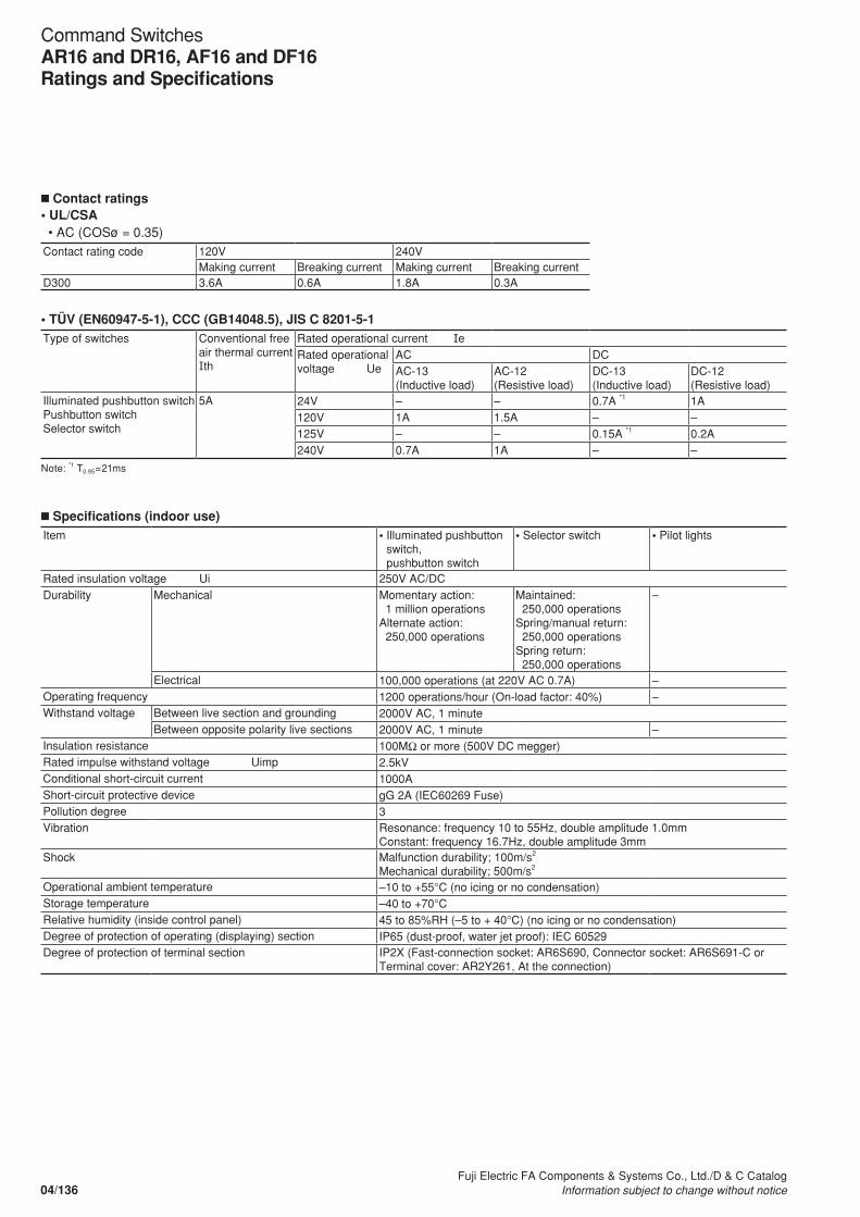
n Specifications (indoor use)Item • Illuminated pushbutton
switch, pushbutton switch
• Selector switch • Pilot lights
Rated insulation voltage Ui 250V AC/DCDurability Mechanical Momentary action:
1 million operations Alternate action: 250,000 operations
Maintained: 250,000 operationsSpring/manual return: 250,000 operationsSpring return: 250,000 operations
–
Electrical 100,000 operations (at 220V AC 0.7A) –Operating frequency 1200 operations/hour (On-load factor: 40%) –Withstand voltage Between live section and grounding 2000V AC, 1 minute
Between opposite polarity live sections 2000V AC, 1 minute –Insulation resistance 100MΩ or more (500V DC megger)Rated impulse withstand voltage Uimp 2.5kVConditional short-circuit current 1000AShort-circuit protective device gG 2A (IEC60269 Fuse)Pollution degree 3Vibration Resonance: frequency 10 to 55Hz, double amplitude 1.0mm
Constant: frequency 16.7Hz, double amplitude 3mmShock Malfunction durability; 100m/s2
Mechanical durability; 500m/s2
Operational ambient temperature –10 to +55°C (no icing or no condensation)Storage temperature –40 to +70°CRelative humidity (inside control panel) 45 to 85%RH (–5 to + 40°C) (no icing or no condensation)Degree of protection of operating (displaying) section IP65 (dust-proof, water jet proof): IEC 60529 Degree of protection of terminal section IP2X (Fast-connection socket: AR6S690, Connector socket: AR6S691-C or
Terminal cover: AR2Y261, At the connection)
n Contact ratings• UL/CSA • AC (COSø = 0.35)Contact rating code 120V 240V
Making current Breaking current Making current Breaking currentD300 3.6A 0.6A 1.8A 0.3A
• TÜV (EN60947-5-1), CCC (GB14048.5), JIS C 8201-5-1Type of switches Conventional free
air thermal current Ith
Rated operational current IeRated operational voltage Ue
AC DCAC-13(Inductive load)
AC-12(Resistive load)
DC-13(Inductive load)
DC-12(Resistive load)
Illuminated pushbutton switchPushbutton switchSelector switch
5A 24V – – 0.7A *1 1A120V 1A 1.5A – –125V – – 0.15A *1 0.2A240V 0.7A 1A – –
Note: *1 T0.95=21ms
04/136Fuji Electric FA Components & Systems Co., Ltd./D & C Catalog
Information subject to change without notice
Command SwitchesAR16 and DR16, AF16 and DF16Ratings and Specifications
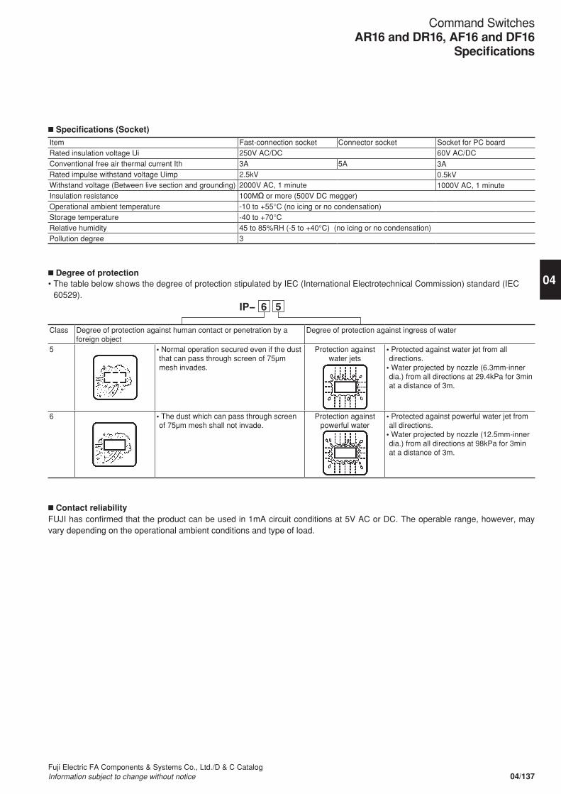
n Specifications (Socket)
Item Fast-connection socket Connector socket Socket for PC boardRated insulation voltage Ui 250V AC/DC 60V AC/DCConventional free air thermal current Ith 3A 5A 3ARated impulse withstand voltage Uimp 2.5kV 0.5kVWithstand voltage (Between live section and grounding) 2000V AC, 1 minute 1000V AC, 1 minuteInsulation resistance 100MΩ or more (500V DC megger) Operational ambient temperature -10 to +55°C (no icing or no condensation)Storage temperature -40 to +70°CRelative humidity 45 to 85%RH (-5 to +40°C) (no icing or no condensation)Pollution degree 3
n Degree of protection• The table below shows the degree of protection stipulated by IEC (International Electrotechnical Commission) standard (IEC
60529).
Class Degree of protection against human contact or penetration by a foreign object
Degree of protection against ingress of water
5 • Normal operation secured even if the dust that can pass through screen of 75μm mesh invades.
Protection against water jets
• Protected against water jet from all directions.
• Water projected by nozzle (6.3mm-inner dia.) from all directions at 29.4kPa for 3min at a distance of 3m.
6 • The dust which can pass through screen of 75μm mesh shall not invade.
Protection against powerful water
• Protected against powerful water jet from all directions.
• Water projected by nozzle (12.5mm-inner dia.) from all directions at 98kPa for 3min at a distance of 3m.
n Contact reliabilityFUJI has confirmed that the product can be used in 1mA circuit conditions at 5V AC or DC. The operable range, however, may vary depending on the operational ambient conditions and type of load.
04/137Fuji Electric FA Components & Systems Co., Ltd./D & C CatalogInformation subject to change without notice
04
Command SwitchesAR16 and DR16, AF16 and DF16
Specifications
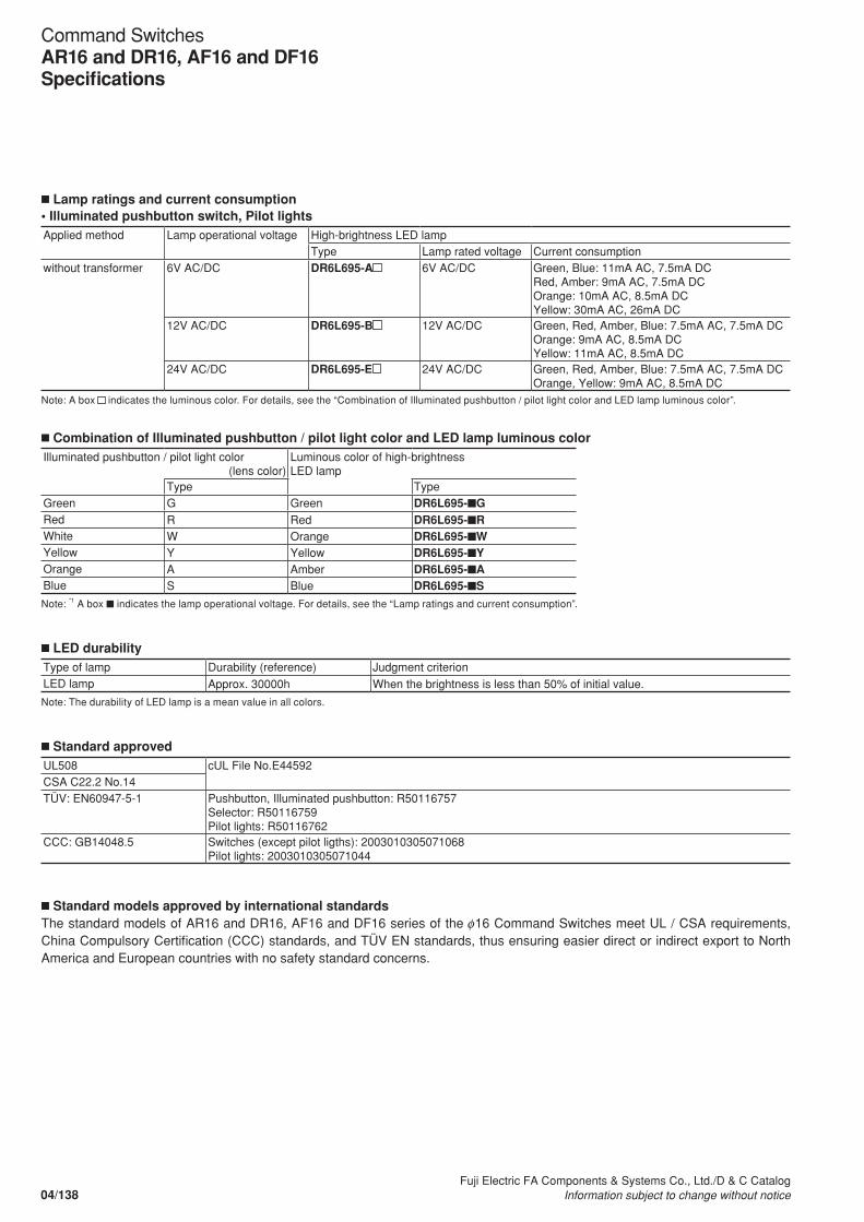
n Lamp ratings and current consumption• Illuminated pushbutton switch, Pilot lightsApplied method Lamp operational voltage High-brightness LED lamp
Type Lamp rated voltage Current consumptionwithout transformer 6V AC/DC DR6L695-A 6V AC/DC Green, Blue: 11mA AC, 7.5mA DC
Red, Amber: 9mA AC, 7.5mA DCOrange: 10mA AC, 8.5mA DCYellow: 30mA AC, 26mA DC
12V AC/DC DR6L695-B 12V AC/DC Green, Red, Amber, Blue: 7.5mA AC, 7.5mA DCOrange: 9mA AC, 8.5mA DCYellow: 11mA AC, 8.5mA DC
24V AC/DC DR6L695-E 24V AC/DC Green, Red, Amber, Blue: 7.5mA AC, 7.5mA DCOrange, Yellow: 9mA AC, 8.5mA DC
Note: A box indicates the luminous color. For details, see the “Combination of Illuminated pushbutton / pilot light color and LED lamp luminous color”.
n Combination of Illuminated pushbutton / pilot light color and LED lamp luminous colorIlluminated pushbutton / pilot light color (lens color)
Luminous color of high-brightnessLED lamp
Type TypeGreen G Green DR6L695-nGRed R Red DR6L695-nRWhite W Orange DR6L695-nWYellow Y Yellow DR6L695-nYOrange A Amber DR6L695-nABlue S Blue DR6L695-nS
Note: *1 A box n indicates the lamp operational voltage. For details, see the “Lamp ratings and current consumption”.
n LED durabilityType of lamp Durability (reference) Judgment criterionLED lamp Approx. 30000h When the brightness is less than 50% of initial value.
Note: The durability of LED lamp is a mean value in all colors.
n Standard approvedUL508 cUL File No.E44592CSA C22.2 No.14TÜV: EN60947-5-1 Pushbutton, Illuminated pushbutton: R50116757
Selector: R50116759Pilot lights: R50116762
CCC: GB14048.5 Switches (except pilot ligths): 2003010305071068Pilot lights: 2003010305071044
n Standard models approved by international standardsThe standard models of AR16 and DR16, AF16 and DF16 series of the φ16 Command Switches meet UL / CSA requirements, China Compulsory Certification (CCC) standards, and TÜV EN standards, thus ensuring easier direct or indirect export to North America and European countries with no safety standard concerns.
04/138Fuji Electric FA Components & Systems Co., Ltd./D & C Catalog
Information subject to change without notice
Command SwitchesAR16 and DR16, AF16 and DF16Specifications

• Illuminated pushbutton switches
AR16 F0N-C2 E3 G
Product category
Operator shape and action
Contact arrangement and terminal
Category Standard type Thin type
Color of button
Color Green Red White *1
Yellow Orange Blue
LED color Green Red Orange Yellow Amber Blue
CodeGRWYASOperator shape
Flush rectangular Flush rectangular with guard Flush square Extended round Flush round
Contact arrangement SPDT 2PDT
Code
C1C2
Type of terminal Tab (#110) and solder dual-use terminal
CodeStandard typeMomentaryF0NG0NF0ME0L–
AlternateF5NG5NF5ME5L–
AlternateF5N–F5M–F5L
Thin typeMomentaryF0N–F0M–F0L
CodeAR16AF16
Note: ・The button is transparent in color. *1: A combination of the transparent lens
and the white legend plate comes to white.
Lamp operational voltage and light source
Applied method Without transformer
Voltage 6V AC/DC 12V AC/DC 24V AC/DC
CodeLEDA3B3E3
• Pushbutton switches
AR16 F0T-C2 R
Product category
Operator shape and action
Contact arrangement and terminal
Category Standard type Thin type
Color of button
Color Green Red Black *1
White *2
Yellow Orange Blue
CodeGRBWYAS
Operator shape Flush rectangular Flush rectangular with guard Flush square Extended round Flush round
Contact arrangement SPDT 2PDT
Code
C1C2
Type of terminal Tab (#110) and solder dual-use terminal
CodeStandard typeMomentaryF0TG0TF0SE0R–
AlternateF5TG5TF5SE5R–
AlternateF5T–F5S–F5R
Thin typeMomentaryF0T–F0S–F0R
CodeAR16AF16
Notes: ・The button is transparent in color. *1: A combination of the transparent button
and the black legend plate comes to black.
*2: A combination of the transparent button and the white legend plate comes to white.
Note: The manufacturing range varies depending on the model. For details, see “Types and dimensions” of this catalog.
04/139Fuji Electric FA Components & Systems Co., Ltd./D & C CatalogInformation subject to change without notice
04
Command SwitchesAR16 and DR16, AF16 and DF16
Type number nomenclature
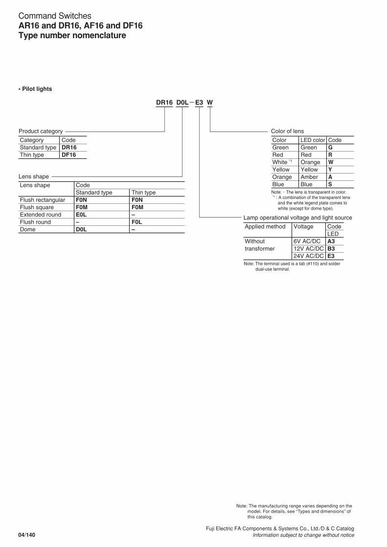
• Pilot lights
DR16 D0L-E3 W
Product category
Lens shape
Category Standard type Thin type
Color of lens
Color Green Red White *1
Yellow Orange Blue
LED color Green Red Orange Yellow Amber Blue
CodeGRWYASLens shape
Flush rectangular Flush square Extended round Flush round Dome
CodeStandard typeF0NF0ME0L–D0L
Thin typeF0NF0M–F0L–
CodeDR16DF16
Note: ・The lens is transparent in color. *1 : A combination of the transparent lens
and the white legend plate comes to white (except for dome type).
Note: The terminal used is a tab (#110) and solder dual-use terminal.
Lamp operational voltage and light source
Applied method Without transformer
Voltage 6V AC/DC 12V AC/DC 24V AC/DC
CodeLEDA3B3E3
Note: The manufacturing range varies depending on the model. For details, see “Types and dimensions” of this catalog.
04/140Fuji Electric FA Components & Systems Co., Ltd./D & C Catalog
Information subject to change without notice
Command SwitchesAR16 and DR16, AF16 and DF16Type number nomenclature

AR16 PT-2 C1 B
Product category
Contact arrangement and terminal
Category Standard type Thin type
Contact arrangement SPDT *1
2PDT
Code
C1C2
Type of terminal Tab (#110) and solder dual-use terminal
CodeAR16AF16
Operator shape
Operator shape Knob with rectangular bezel Knob with square bezel Knob with round bezel
CodePTPSPR
Color of knob
Color Black
CodeB
Note: *1 2-position model only available
No. of positions and operator action
No. of positions 2-position (90°) 3-position (45°)
Operator action Maintained Spring return (Right to left) Maintained Spring/manual return (Left to center) Spring/manual return (Right to center) Spring return (Left or right to center)
Code
20
36
7
1
• Selector switches (Knob type)
Operator action (View form the front) Contact arrangement
Contact unit Operator position *2
2 0 1 2
1 2
Maintained/90°
1 2
Spring return/90°
SPDTLeft COM
NC
NO
2PDTLeft COM
NC
NO
Right COMNC
NO
3-positionOperator action (View form the front) Contact
arrangementContact unit Operator position *2
3 6 7 1 1 2 3
1 3 2
Maintained/each 45°
1 3 2
Spring/manual return/each 45°
1 3 2
Spring/manual return/each 45°
1 3 2
Spring return/each 45°
2PDTLeft COM
NC
NO
Right COMNC
NO
Note: *2 •, : means the contact closed (ON).
• Key position and contact operation2-position
NC NO
COM
Left contact Right contact
Terminal arrangementView from the terminal side (the back)
04/141Fuji Electric FA Components & Systems Co., Ltd./D & C CatalogInformation subject to change without notice
04
Command SwitchesAR16 and DR16, AF16 and DF16
Type number nomenclature
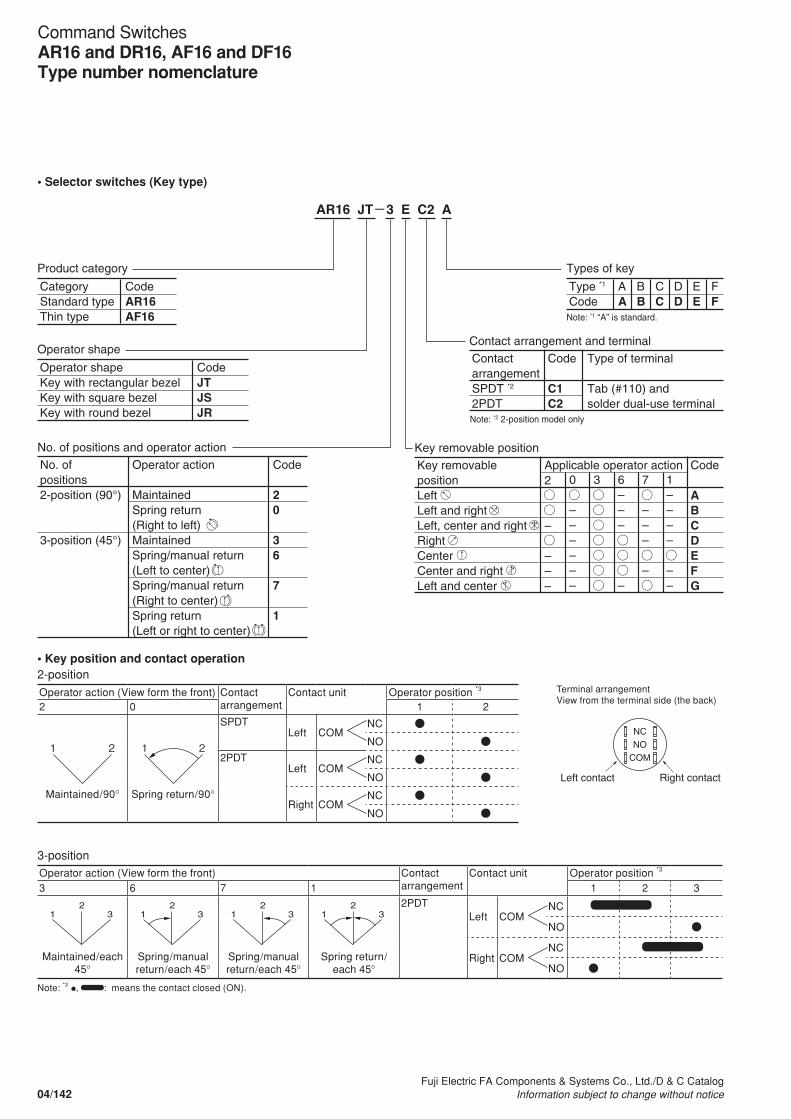
AR16 JT-3 E C2 A
Product category
Contact arrangement and terminal
Category Standard type Thin type
Contact arrangement SPDT *2
2PDT
Code
C1C2
Type of terminal Tab (#110) and solder dual-use terminal
CodeAR16AF16
Operator shape
Operator shape Key with rectangular bezel Key with square bezel Key with round bezel
CodeJTJSJR
Types of key
Type *1
Code AA
BB
CC
DD
EE
FF
Note: *2 2-position model only
Key removable position
Key removable position Left Left and right Left, center and right Right Center Center and right Left and center
Applicable operator action 2 – – – –
0 – – – – – –
3 6 – – – –
7 – – – –
1 – – – – – –
Code
ABCDEFG
Note: *1 “A” is standard.
No. of positions and operator action
No. of positions 2-position (90°) 3-position (45°)
Operator action Maintained Spring return (Right to left) Maintained Spring/manual return (Left to center) Spring/manual return (Right to center) Spring return (Left or right to center)
Code
20
36
7
1
• Selector switches (Key type)
Operator action (View form the front) Contact arrangement
Contact unit Operator position *3
2 0 1 2
1 2
Maintained/90°
1 2
Spring return/90°
SPDTLeft COM
NC
NO
2PDTLeft COM
NC
NO
Right COMNC
NO
3-positionOperator action (View form the front) Contact
arrangementContact unit Operator position *3
3 6 7 1 1 2 3
1 3 2
Maintained/each 45°
1 3 2
Spring/manual return/each 45°
1 3 2
Spring/manual return/each 45°
1 3 2
Spring return/each 45°
2PDTLeft COM
NC
NO
Right COMNC
NO
Note: *3 •, : means the contact closed (ON).
• Key position and contact operation2-position
NC NO
COM
Left contact Right contact
Terminal arrangementView from the terminal side (the back)
04/142Fuji Electric FA Components & Systems Co., Ltd./D & C Catalog
Information subject to change without notice
Command SwitchesAR16 and DR16, AF16 and DF16Type number nomenclature
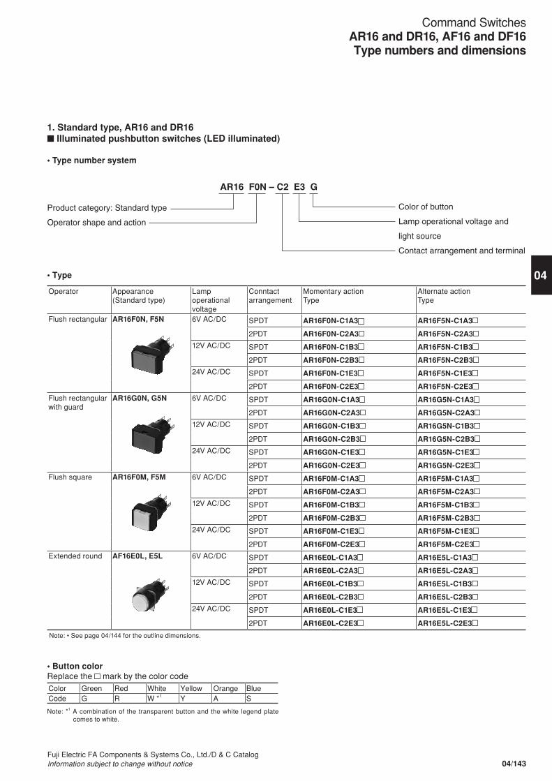
1. Standard type, AR16 and DR16n Illuminated pushbutton switches (LED illuminated)
• Type number system
AR16 F0N – C2 E3 G
Product category: Standard type
Operator shape and action
Color of button
Lamp operational voltage and
light source
Contact arrangement and terminal
• Type
Operator Appearance(Standard type)
Lamp operational voltage
Conntact arrangement
Momentary actionType
Alternate actionType
Flush rectangular AR16F0N, F5N 6V AC/DC SPDT AR16F0N-C1A3 AR16F5N-C1A3
2PDT AR16F0N-C2A3 AR16F5N-C2A3
12V AC/DC SPDT AR16F0N-C1B3 AR16F5N-C1B3
2PDT AR16F0N-C2B3 AR16F5N-C2B3
24V AC/DC SPDT AR16F0N-C1E3 AR16F5N-C1E3
2PDT AR16F0N-C2E3 AR16F5N-C2E3
Flush rectangular with guard
AR16G0N, G5N 6V AC/DC SPDT AR16G0N-C1A3 AR16G5N-C1A3
2PDT AR16G0N-C2A3 AR16G5N-C2A3
12V AC/DC SPDT AR16G0N-C1B3 AR16G5N-C1B3
2PDT AR16G0N-C2B3 AR16G5N-C2B3
24V AC/DC SPDT AR16G0N-C1E3 AR16G5N-C1E3
2PDT AR16G0N-C2E3 AR16G5N-C2E3
Flush square AR16F0M, F5M 6V AC/DC SPDT AR16F0M-C1A3 AR16F5M-C1A3
2PDT AR16F0M-C2A3 AR16F5M-C2A3
12V AC/DC SPDT AR16F0M-C1B3 AR16F5M-C1B3
2PDT AR16F0M-C2B3 AR16F5M-C2B3
24V AC/DC SPDT AR16F0M-C1E3 AR16F5M-C1E3
2PDT AR16F0M-C2E3 AR16F5M-C2E3
Extended round AF16E0L, E5L 6V AC/DC SPDT AR16E0L-C1A3 AR16E5L-C1A3
2PDT AR16E0L-C2A3 AR16E5L-C2A3
12V AC/DC SPDT AR16E0L-C1B3 AR16E5L-C1B3
2PDT AR16E0L-C2B3 AR16E5L-C2B3
24V AC/DC SPDT AR16E0L-C1E3 AR16E5L-C1E3
2PDT AR16E0L-C2E3 AR16E5L-C2E3
Note: • See page 04/144 for the outline dimensions.
• Button colorReplace the mark by the color codeColor Green Red White Yellow Orange BlueCode G R W *1 Y A S
Note: *1 A combination of the transparent button and the white legend plate comes to white.
04/143Fuji Electric FA Components & Systems Co., Ltd./D & C CatalogInformation subject to change without notice
04
Command SwitchesAR16 and DR16, AF16 and DF16Type numbers and dimensions
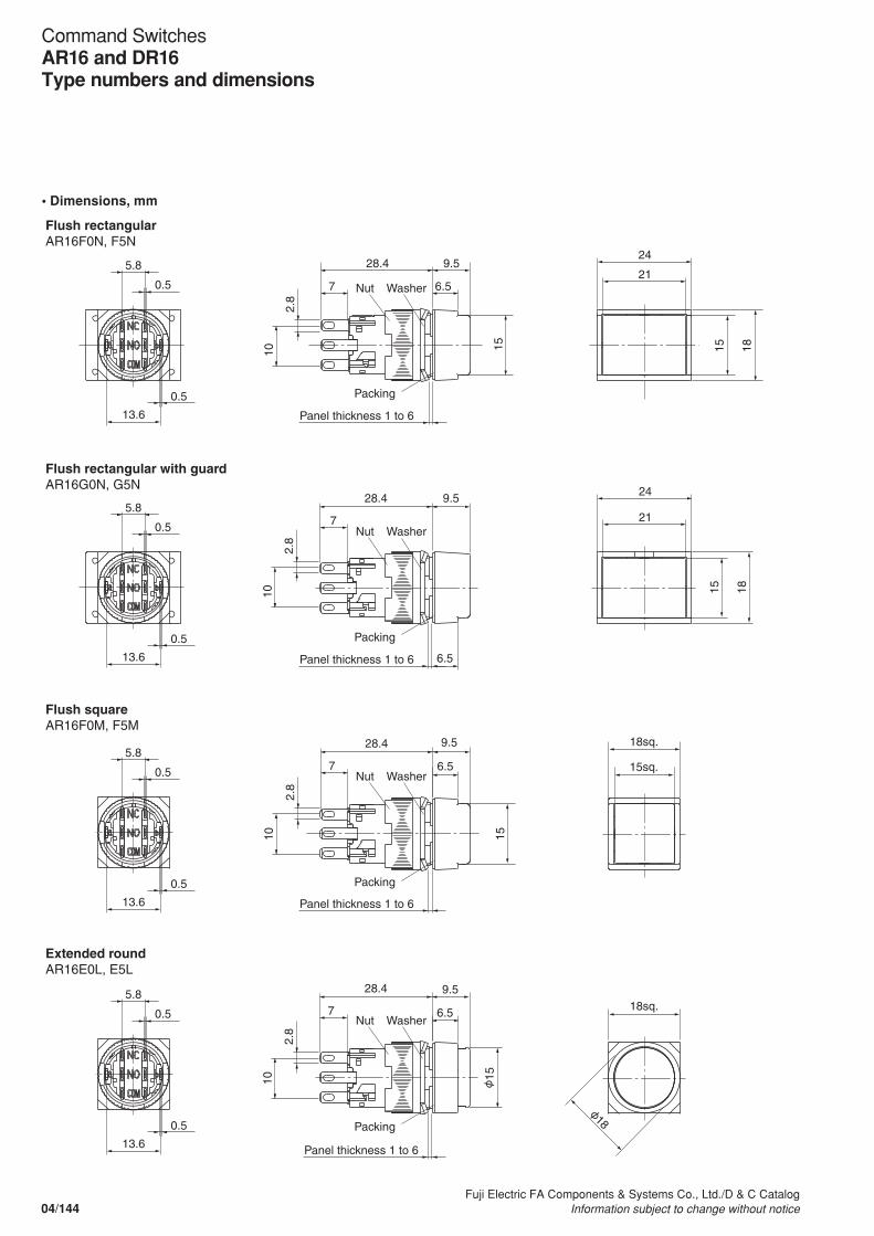
• Dimensions, mm
24
21
1815
18sq.
15sq.
18sq.
24
21
1815
6.57
9.5
Panel thickness 1 to 6
28.4
7
28.4
7
28.4
7
28.415
15
9.5
6.5
6.5
9.5
159.5
6.5
2.8
10
2.8
10
2.8
10
2.8
105.8
0.5
13.6
0.5
5.8
0.5
13.6
0.5
5.8
0.5
13.6
0.5
5.8
0.5
13.6
0.5
Flush rectangularAR16F0N, F5N
Flush squareAR16F0M, F5M
Extended roundAR16E0L, E5L
Flush rectangular with guardAR16G0N, G5N
Nut Washer
Nut Washer
Nut Washer
Nut Washer
Packing
Panel thickness 1 to 6
Packing
Panel thickness 1 to 6
Packing
Panel thickness 1 to 6
Packing18
04/144Fuji Electric FA Components & Systems Co., Ltd./D & C Catalog
Information subject to change without notice
Command SwitchesAR16 and DR16Type numbers and dimensions
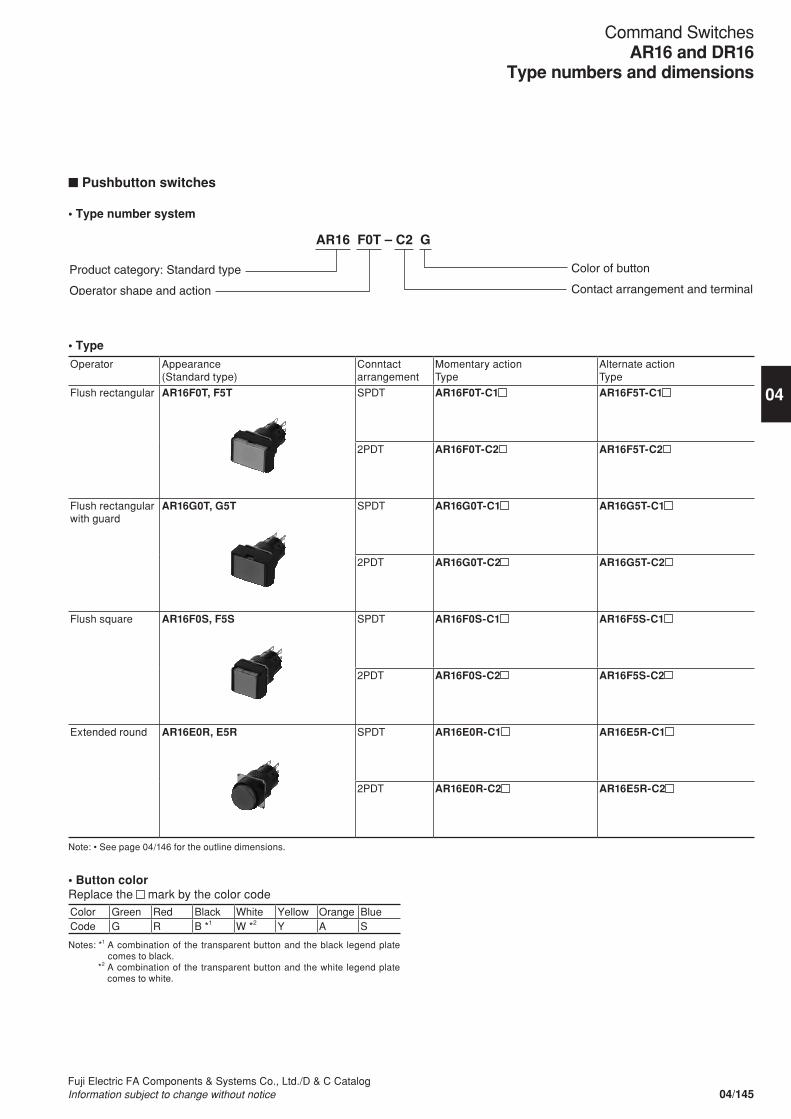
n Pushbutton switches
• Type number system
AR16 F0T – C2 G
Product category: Standard type
Operator shape and action
Color of button
Contact arrangement and terminal
• Button colorReplace the mark by the color codeColor Green Red Black White Yellow Orange BlueCode G R B *1 W *2 Y A S
Notes: *1 A combination of the transparent button and the black legend plate comes to black.
*2 A combination of the transparent button and the white legend plate comes to white.
• Type
Operator Appearance(Standard type)
Conntact arrangement
Momentary actionType
Alternate actionType
Flush rectangular AR16F0T, F5T SPDT AR16F0T-C1 AR16F5T-C1
2PDT AR16F0T-C2 AR16F5T-C2
Flush rectangular with guard
AR16G0T, G5T SPDT AR16G0T-C1 AR16G5T-C1
2PDT AR16G0T-C2 AR16G5T-C2
Flush square AR16F0S, F5S SPDT AR16F0S-C1 AR16F5S-C1
2PDT AR16F0S-C2 AR16F5S-C2
Extended round AR16E0R, E5R SPDT AR16E0R-C1 AR16E5R-C1
2PDT AR16E0R-C2 AR16E5R-C2
Note: • See page 04/146 for the outline dimensions.
04/145Fuji Electric FA Components & Systems Co., Ltd./D & C CatalogInformation subject to change without notice
04
Command SwitchesAR16 and DR16
Type numbers and dimensions
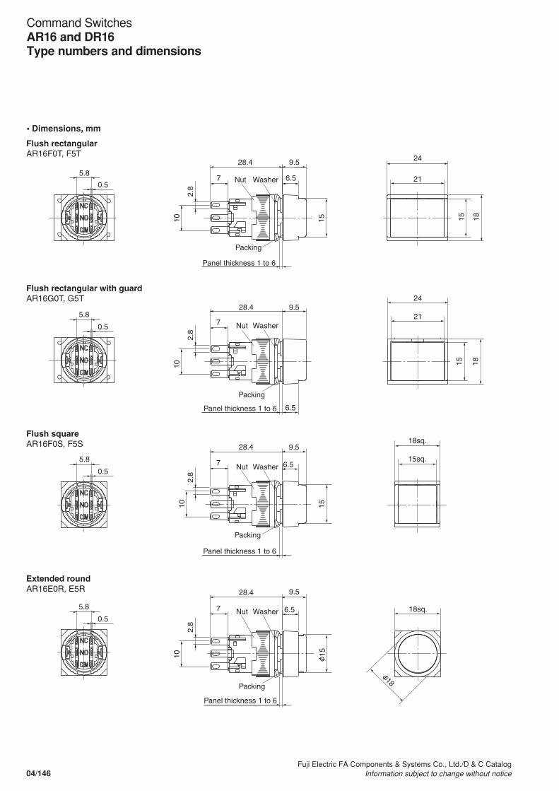
• Dimensions, mm
24
1815
21
18sq.
15sq.
18sq.
24
21
1815
9.5
6.57
15
2.8
10
2.8
102.
8
10
2.8
10
28.4
7
28.4
7
28.4
7
28.4
5.8
0.5
5.8
0.5
5.8
0.5
5.8
0.5
6.5
6.5
9.5
9.5
6.5
9.5
15
Flush rectangularAR16F0T, F5T
Flush squareAR16F0S, F5S
Extended roundAR16E0R, E5R
Flush rectangular with guardAR16G0T, G5T
Panel thickness 1 to 6
Nut Washer
Nut Washer
Nut Washer
Nut Washer
Packing
Panel thickness 1 to 6
Packing
Panel thickness 1 to 6
Packing
Panel thickness 1 to 6
Packing
15
18
04/146Fuji Electric FA Components & Systems Co., Ltd./D & C Catalog
Information subject to change without notice
Command SwitchesAR16 and DR16Type numbers and dimensions
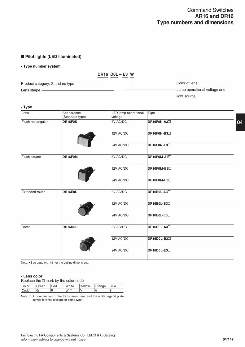
n Pilot lights (LED illuminated)
• Type number system
DR16 D0L – E3 W
Product category: Standard type
Lens shape
Color of lens
Lamp operational voltage and
light source
• Type
Lens Appearance(Standard type)
LED lamp operational voltage
Type
Flush rectangular DR16F0N 6V AC/DC DR16F0N-A3
12V AC/DC DR16F0N-B3
24V AC/DC DR16F0N-E3
Flush square DR16F0M 6V AC/DC DR16F0M-A3
12V AC/DC DR16F0M-B3
24V AC/DC DR16F0M-E3
Extended round DR16E0L 6V AC/DC DR16E0L-A3
12V AC/DC DR16E0L-B3
24V AC/DC DR16E0L-E3
Dome DR16D0L 6V AC/DC DR16D0L-A3
12V AC/DC DR16D0L-B3
24V AC/DC DR16D0L-E3
Note: • See page 04/148 for the outline dimensions.
• Lens colorReplace the mark by the color codeColor Green Red White Yellow Orange BlueCode G R W *1 Y A S
Note: *1 A combination of the transparent lens and the white legend plate comes to white (except for dome type).
04/147Fuji Electric FA Components & Systems Co., Ltd./D & C CatalogInformation subject to change without notice
04
Command SwitchesAR16 and DR16
Type numbers and dimensions
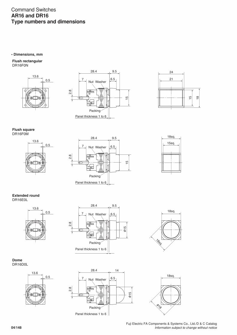
• Dimensions, mm
18sq.
Flush rectangular DR16F0N
Extended roundDR16E0L
DomeDR16D0L
Flush squareDR16F0M
24
21
1815
18sq.
15sq.
18sq.
18sq.
6.5
9.5
15
28.4
6.5
9.5
15
6.5
9.5
6.5
14
2.8
2.8
2.8
2.8
7
28.4
7
28.4
7
28.4
7
13.6 0.5
13.60.5
13.60.5
13.60.5
Panel thickness 1 to 6
Nut Washer
Nut Washer
Nut Washer
Nut Washer
Packing
Panel thickness 1 to 6
Packing
Panel thickness 1 to 6
Packing
Panel thickness 1 to 6
Packing
15
18
15
04/148Fuji Electric FA Components & Systems Co., Ltd./D & C Catalog
Information subject to change without notice
Command SwitchesAR16 and DR16Type numbers and dimensions
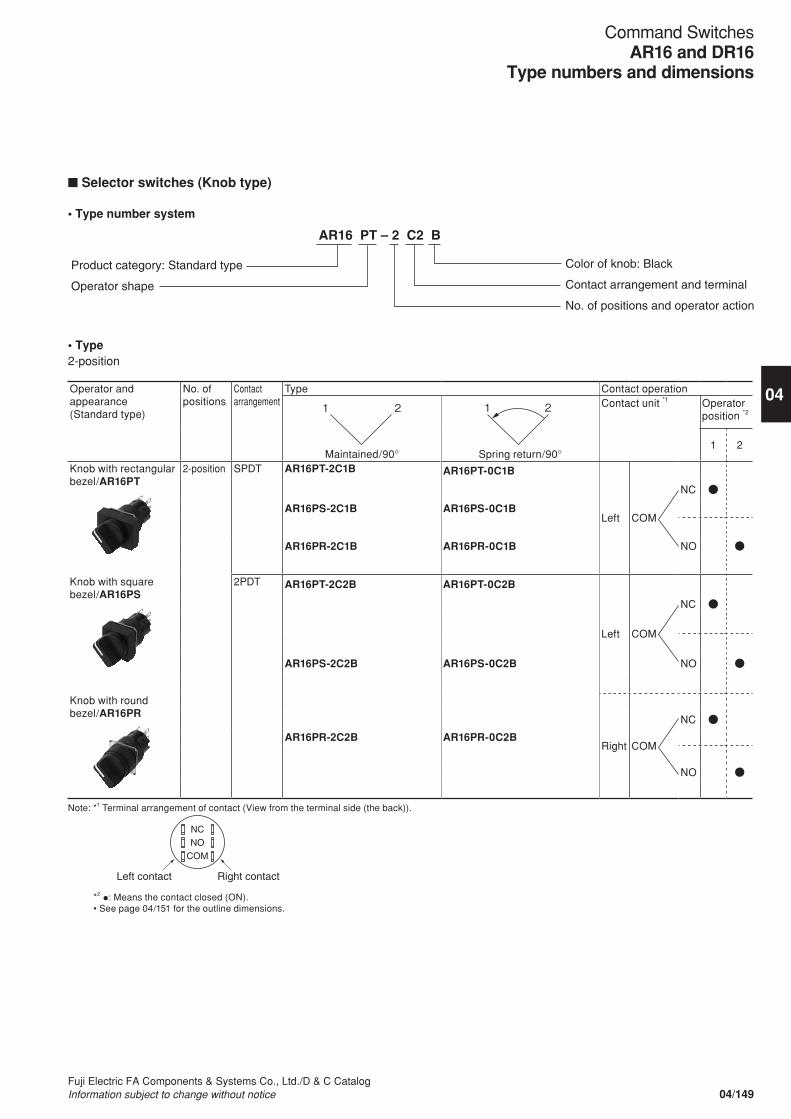
n Selector switches (Knob type)
• Type number system
AR16 PT – 2 C2 B
Product category: Standard type
Operator shape
Color of knob: Black
Contact arrangement and terminal
No. of positions and operator action
• Type2-position
Operator and appearance(Standard type)
No. ofpositions
Contact arrangement
Type Contact operation
Maintained/90° Spring return/90°
Contact unit *1 Operator position *2
1 2
Knob with rectangular bezel/AR16PT
2-position SPDT AR16PT-2C1B AR16PT-0C1B
Left COM
NC
AR16PS-2C1B AR16PS-0C1B
NOAR16PR-2C1B AR16PR-0C1B
Knob with square bezel/AR16PS
2PDT AR16PT-2C2B AR16PT-0C2B
Left COM
NC
NOAR16PS-2C2B AR16PS-0C2B
Knob with round bezel/AR16PR
Right COM
NC
AR16PR-2C2B AR16PR-0C2B
NO
Note: *1 Terminal arrangement of contact (View from the terminal side (the back)).
NC NO
COM
Left contact Right contact
*2 •: Means the contact closed (ON).• See page 04/151 for the outline dimensions.
1 2 1 2
04/149Fuji Electric FA Components & Systems Co., Ltd./D & C CatalogInformation subject to change without notice
04
Command SwitchesAR16 and DR16
Type numbers and dimensions
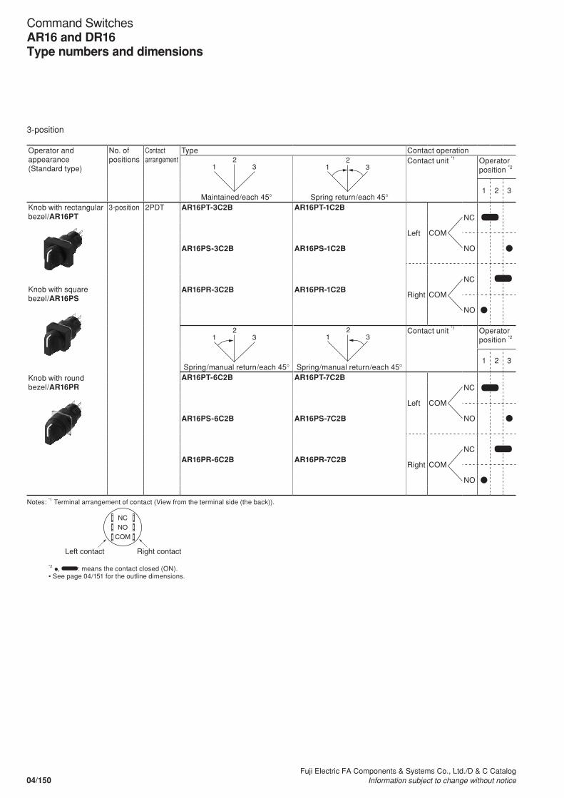
3-position
Operator and appearance(Standard type)
No. ofpositions
Contact arrangement
Type Contact operation
Maintained/each 45° Spring return/each 45°
Contact unit *1 Operator position *2
1 2 3
Knob with rectangular bezel/AR16PT
Knob with square bezel/AR16PS
Knob with round bezel/AR16PR
3-position 2PDT AR16PT-3C2B AR16PT-1C2B
Left COM
NC
NOAR16PS-3C2B AR16PS-1C2B
Right COM
NCAR16PR-3C2B AR16PR-1C2B
NO
Spring/manual return/each 45° Spring/manual return/each 45°
Contact unit *1 Operator position *2
1 2 3
AR16PT-6C2B AR16PT-7C2B
Left COM
NC
NOAR16PS-6C2B AR16PS-7C2B
Right COM
NCAR16PR-6C2B AR16PR-7C2B
NO
Notes: *1 Terminal arrangement of contact (View from the terminal side (the back)).
NC NO
COM
Left contact Right contact
*2 •, : means the contact closed (ON).• See page 04/151 for the outline dimensions.
1 3 2
1 3 2
1 3 2
1 3 2
04/150Fuji Electric FA Components & Systems Co., Ltd./D & C Catalog
Information subject to change without notice
Command SwitchesAR16 and DR16Type numbers and dimensions
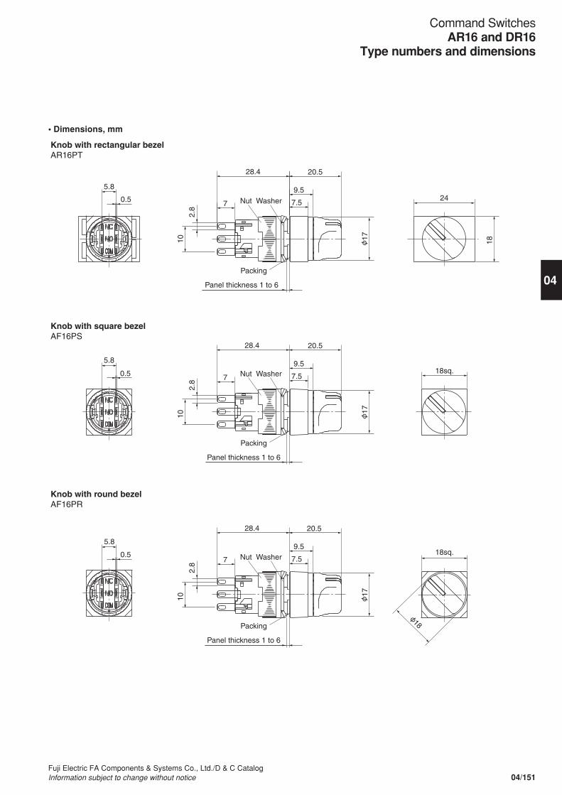
• Dimensions, mm
Knob with square bezel AF16PS
Knob with round bezel AF16PR
Knob with rectangular bezel AR16PT
24
18
20.5 28.4
7.5
9.5
20.5 28.4
7.5
9.5
20.5 28.4
7.5
9.5
18sq.
18sq.
2.8
10
2.8
10
2.8
10
7
7
7
0.5
5.8
0.5
5.8
0.5
5.8
Panel thickness 1 to 6
Nut Washer
Nut Washer
Nut Washer
Packing
Panel thickness 1 to 6
Packing
Panel thickness 1 to 6
Packing 18
17
17
17
04/151Fuji Electric FA Components & Systems Co., Ltd./D & C CatalogInformation subject to change without notice
04
Command SwitchesAR16 and DR16
Type numbers and dimensions
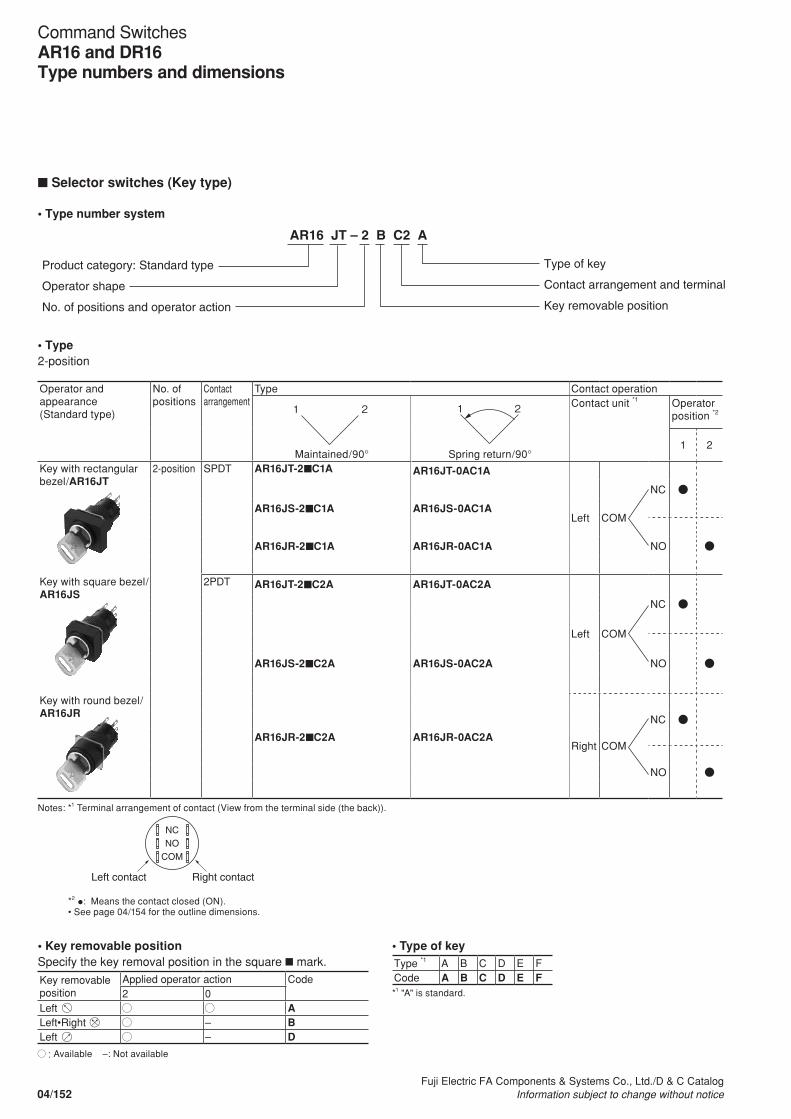
n Selector switches (Key type)
• Type number system
AR16 JT – 2 B C2 A
Product category: Standard type
Operator shape
No. of positions and operator action
Type of key
Contact arrangement and terminal
Key removable position
• Type 2-position
Operator and appearance(Standard type)
No. ofpositions
Contact arrangement
Type Contact operation
Maintained/90° Spring return/90°
Contact unit *1 Operator position *2
1 2
Key with rectangular bezel/AR16JT
2-position SPDT AR16JT-2nC1A AR16JT-0AC1A
Left COM
NC
AR16JS-2nC1A AR16JS-0AC1A
NOAR16JR-2nC1A AR16JR-0AC1A
Key with square bezel/AR16JS
2PDT AR16JT-2nC2A AR16JT-0AC2A
Left COM
NC
NOAR16JS-2nC2A AR16JS-0AC2A
Key with round bezel/AR16JR
Right COM
NC
AR16JR-2nC2A AR16JR-0AC2A
NO
Notes: *1 Terminal arrangement of contact (View from the terminal side (the back)).
NC NO
COM
Left contact Right contact
*2 •: Means the contact closed (ON).• See page 04/154 for the outline dimensions.
1 2 1 2
• Key removable positionSpecify the key removal position in the square n mark.
Key removable position
Applied operator action Code2 0
Left ALeft•Right – BLeft – D
: Available –: Not available
• Type of keyType *1 A B C D E FCode A B C D E F*1 "A" is standard.
04/152Fuji Electric FA Components & Systems Co., Ltd./D & C Catalog
Information subject to change without notice
Command SwitchesAR16 and DR16Type numbers and dimensions

3-position
Operator and appearance(Standard type)
No. ofpositions
Contact arrangement
Type Contact operation
Maintained/each 45° Spring return/each 45°
Contact unit *1 Operator position *2
1 2 3
Key with rectangular bezel/AR16JT
Key with square bezel/AR16JS
Key with round bezel/AR16JR
3-position 2PDT AR16JT-3nC2A AR16JT-1EC2A
Left COM
NC
NOAR16JS-3nC2A AR16JS-1EC2A
Right COM
NCAR16JR-3nC2A AR16JR-1EC2A
NO
Spring/manual return/each 45° Spring/manual return/each 45°
Contact unit *1 Operator position *2
1 2 3
AR16JT-6nC2A AR16JT-7nC2A
Left COM
NC
NOAR16JS-6nC2A AR16JS-7nC2A
Right COM
NCAR16JR-6nC2A AR16JR-7nC2A
NO
Notes: *1 Terminal arrangement of contact (View form the terminal side (the back)).
NC NO
COM
Left contact Right contact
*2 •, : Means the contact closed (ON).• See page 04/154 for the outline dimensions.
1 3 2
1 3 2
1 3 2
1 3 2
• Key removal positionSpecify the key removal position in the square n mark.
Key removable position
Applied operator action Code3 6 7 1
Left – – ALeft•Right – – – BLeft•Center•Right
– – – C
Right – – DCenter ECenter•Right – – FLeft•Center – – G
: Available –: Not available
• Type of keyType *1 A B C D E FCode A B C D E F*1 "A" is standard.
04/153Fuji Electric FA Components & Systems Co., Ltd./D & C CatalogInformation subject to change without notice
04
Command SwitchesAR16 and DR16
Type numbers and dimensions
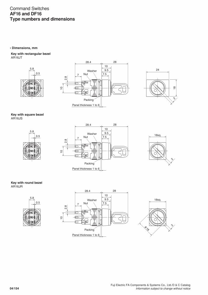
• Dimensions, mm
Key with square bezel AR16JS
Key with round bezel AR16JR
7.5
10 9.5
28 28.4
28 28.4
28 28.4
24
18
18sq.
18sq.
Key with rectangular bezel AR16JT
Panel thickness 1 to 6
Nut Washer
7.5
10 9.5
Nut Washer
7.5
10 9.5
Nut Washer
2.8
10
7
2.8
10
2.8
10
7
7
0.5
5.8
0.5
5.8
0.5
5.8
2
2
2 Packing
Panel thickness 1 to 6
Packing
Panel thickness 1 to 6
Packing
18
04/154Fuji Electric FA Components & Systems Co., Ltd./D & C Catalog
Information subject to change without notice
Command SwitchesAF16 and DF16Type numbers and dimensions
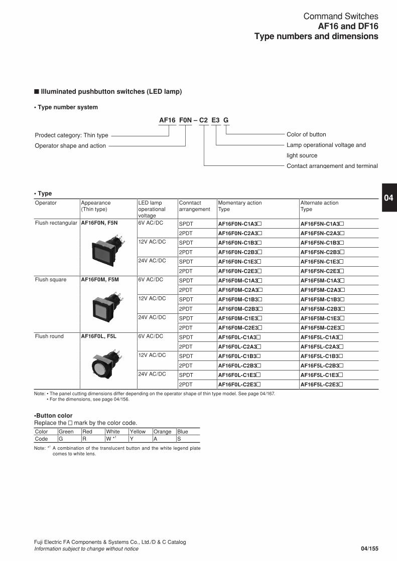
n Illuminated pushbutton switches (LED lamp)
• Type number system
AF16 F0N – C2 E3 G
Prodect category: Thin type
Operator shape and action
Color of button
Lamp operational voltage and
light source
Contact arrangement and terminal
• Type
Operator Appearance(Thin type)
LED lamp operational voltage
Conntact arrangement
Momentary actionType
Alternate actionType
Flush rectangular AF16F0N, F5N 6V AC/DC SPDT AF16F0N-C1A3 AF16F5N-C1A3
2PDT AF16F0N-C2A3 AF16F5N-C2A3
12V AC/DC SPDT AF16F0N-C1B3 AF16F5N-C1B3
2PDT AF16F0N-C2B3 AF16F5N-C2B3
24V AC/DC SPDT AF16F0N-C1E3 AF16F5N-C1E3
2PDT AF16F0N-C2E3 AF16F5N-C2E3
Flush square AF16F0M, F5M 6V AC/DC SPDT AF16F0M-C1A3 AF16F5M-C1A3
2PDT AF16F0M-C2A3 AF16F5M-C2A3
12V AC/DC SPDT AF16F0M-C1B3 AF16F5M-C1B3
2PDT AF16F0M-C2B3 AF16F5M-C2B3
24V AC/DC SPDT AF16F0M-C1E3 AF16F5M-C1E3
2PDT AF16F0M-C2E3 AF16F5M-C2E3
Flush round AF16F0L, F5L 6V AC/DC SPDT AF16F0L-C1A3 AF16F5L-C1A3
2PDT AF16F0L-C2A3 AF16F5L-C2A3
12V AC/DC SPDT AF16F0L-C1B3 AF16F5L-C1B3
2PDT AF16F0L-C2B3 AF16F5L-C2B3
24V AC/DC SPDT AF16F0L-C1E3 AF16F5L-C1E3
2PDT AF16F0L-C2E3 AF16F5L-C2E3
Note: • The panel cutting dimensions differ depending on the operator shape of thin type model. See page 04/167. • For the dimensions, see page 04/156.
•Button colorReplace the mark by the color code.Color Green Red White Yellow Orange BlueCode G R W *1 Y A S
Note: *1 A combination of the translucent button and the white legend plate comes to white lens.
04/155Fuji Electric FA Components & Systems Co., Ltd./D & C CatalogInformation subject to change without notice
04
Command SwitchesAF16 and DF16
Type numbers and dimensions

• Dimensions, mm
5.8
0.5
13.6
0.5
5.8
0.5
13.6
0.5
5.8
0.5
13.6
0.5
28
21
2215
22sq.
15sq.
22
15
2 35.9
Panel thickness: 1 to 6
Panel thickness: 1 to 6
Panel thickness: 1 to 6
Nut Panel retainer
Nut Panel retainer
Nut Panel retainer
7
2 35.9
7
2 35.9
7
2.8
10
2.8
10
2.8
10
Flush rectangular AF16F0N, F5N
Flush square AF16F0M, F5M
Flush round AF16F0L, F5L
Packing
Packing
Packing
04/156Fuji Electric FA Components & Systems Co., Ltd./D & C Catalog
Information subject to change without notice
Command SwitchesAF16 and DF16Type numbers and dimensions
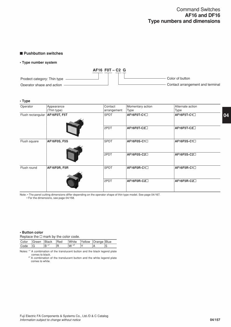
n Pushbutton switches
• Type number system
AF16 F0T – C2 G
Prodect category: Thin type
Operator shape and action
Color of button
Contact arrangement and terminal
• Type
Operator Appearance(Thin type)
Contact arrangement
Momentary actionType
Alternate actionType
Flush rectangular AF16F0T, F5T SPDT AF16F0T-C1 AF16F5T-C1
2PDT AF16F0T-C2 AF16F5T-C2
Flush square AF16F0S, F5S SPDT AF16F0S-C1 AF16F5S-C1
2PDT AF16F0S-C2 AF16F5S-C2
Flush round AF16F0R, F5R SPDT AF16F0R-C1 AF16F5R-C1
2PDT AF16F0R-C2 AF16F5R-C2
Note: • The panel cutting dimensions differ depending on the operator shape of thin type model. See page 04/167. • For the dimensions, see page 04/158.
• Button colorReplace the mark by the color code.Color Green Black Red White Yellow Orange BlueCode G B *1 R W *2 Y A S
Notes: *1 A combination of the translucent button and the black legend plate comes to black.
*2 A combination of the translucent button and the white legend plate comes to white.
04/157Fuji Electric FA Components & Systems Co., Ltd./D & C CatalogInformation subject to change without notice
04
Command SwitchesAF16 and DF16
Type numbers and dimensions

• Dimensions, mm
Flush rectangular AF16F0T, F5T
Flush square AF16F0S, F5S
Flush round AF16F0R, F5R
28
21
22
15
22sq.
15sq.
22
2 35.9
15
Panel thickness: 1 to 6
Panel thickness: 1 to 6
Panel thickness: 1 to 6
2.8
10
2.8
10
2.8
10
Nut Panel retainer
2 35.9
Nut Panel retainer
2 35.9
Nut Panel retainer
7
7
7
5.8
0.5
5.8
0.5
5.8
0.5
Packing
Packing
Packing
04/158Fuji Electric FA Components & Systems Co., Ltd./D & C Catalog
Information subject to change without notice
Command SwitchesAF16 and DF16Type numbers and dimensions
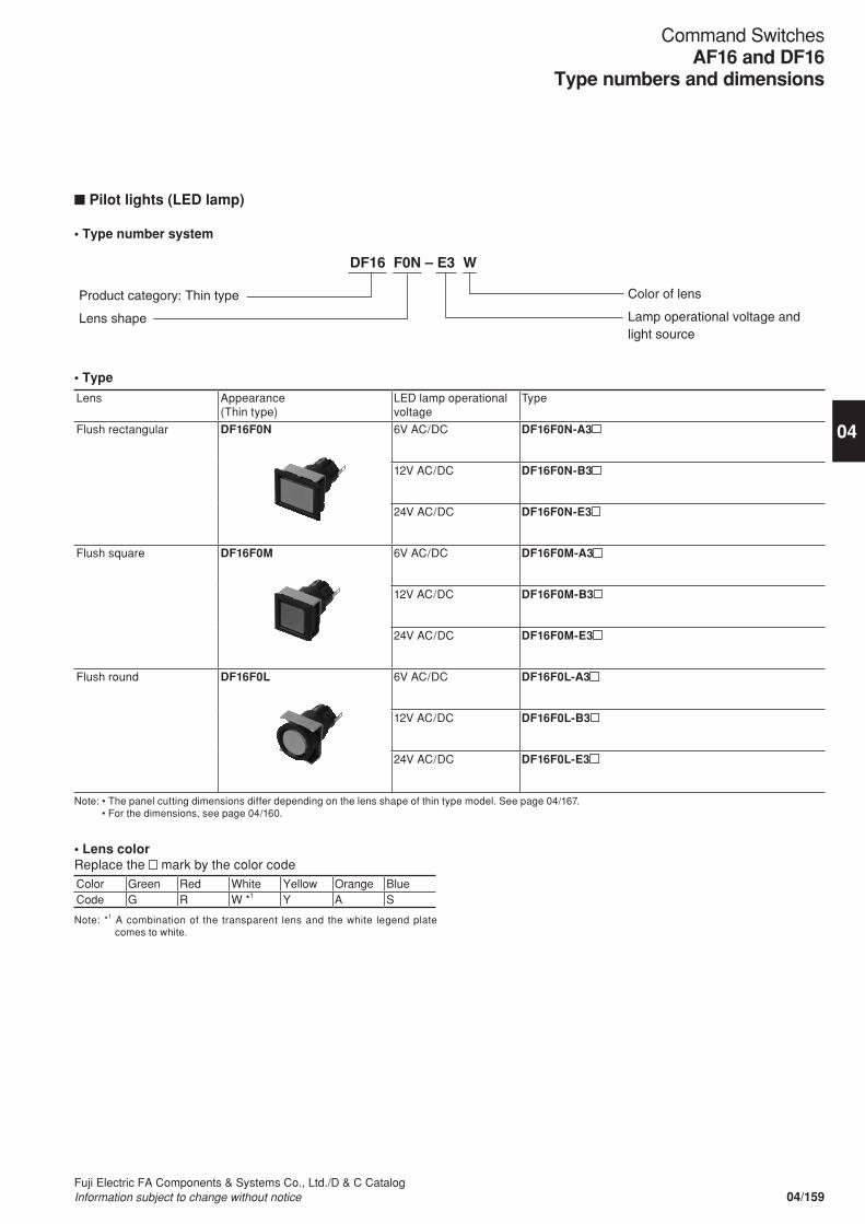
n Pilot lights (LED lamp)
• Type number system
DF16 F0N – E3 W
Product category: Thin type
Lens shape
Color of lens
Lamp operational voltage and light source
• Type
Lens Appearance(Thin type)
LED lamp operational voltage
Type
Flush rectangular DF16F0N 6V AC/DC DF16F0N-A3
12V AC/DC DF16F0N-B3
24V AC/DC DF16F0N-E3
Flush square DF16F0M 6V AC/DC DF16F0M-A3
12V AC/DC DF16F0M-B3
24V AC/DC DF16F0M-E3
Flush round DF16F0L 6V AC/DC DF16F0L-A3
12V AC/DC DF16F0L-B3
24V AC/DC DF16F0L-E3
Note: • The panel cutting dimensions differ depending on the lens shape of thin type model. See page 04/167. • For the dimensions, see page 04/160.
• Lens colorReplace the mark by the color codeColor Green Red White Yellow Orange BlueCode G R W *1 Y A S
Note: *1 A combination of the transparent lens and the white legend plate comes to white.
04/159Fuji Electric FA Components & Systems Co., Ltd./D & C CatalogInformation subject to change without notice
04
Command SwitchesAF16 and DF16
Type numbers and dimensions
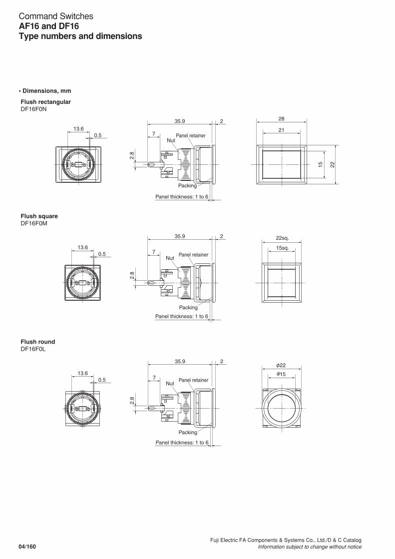
• Dimensions, mm
28
21
22
15
22sq.
15sq.
22
15
2 35.9
2 35.9
2 35.9
Panel thickness: 1 to 6
Panel thickness: 1 to 6
Panel thickness: 1 to 6
2.8
2.8
2.8
7
7
7
Nut Panel retainer
Nut Panel retainer
13.6 0.5
13.6 0.5
13.6 0.5
Packing
Packing
Nut Panel retainer
Packing
Flush rectangular DF16F0N
Flush square DF16F0M
Flush round DF16F0L
04/160Fuji Electric FA Components & Systems Co., Ltd./D & C Catalog
Information subject to change without notice
Command SwitchesAF16 and DF16Type numbers and dimensions

AF16 PT – 2 C2 B
Product category: Thin type
Operator shape
Color of knob: Black
Contact arrangement and terminal
No. of positions and operator action
• Type2-position
Operator(Thin type)
Conntact arrangement
Type Contact operation
Maintained/90° Spring return/90°
Contact unit *1 Operator position *2
1 2
Knob with rectangular bezel/AF16PT
SPDT AF16PT-2C1B AF16PT-0C1B
Left COM
NC
AF16PS-2C1B AF16PS-0C1B
NOAF16PR-2C1B AF16PR-0C1B
Knob with square bezel/AF16PS
2PDT AF16PT-2C2B AF16PT-0C2B
Left COM
NC
NOAF16PS-2C2B AF16PS-0C2B
Knob with round bezel/AF16PR
Right COM
NC
AF16PR-2C2B AF16PR-0C2B
NO
Notes: *1 Terminal arrangement of contact (view from terminal side).
NC NO
COM
Left contact Right contact
*2 •: Contact closed.• The panel cutting dimensions differ depending on the operator shape of thin type model. See page 04/167. • For the dimensions, see page 04/163.
1 2 1 2
n Selector switches (Knob type)
• Type number system
04/161Fuji Electric FA Components & Systems Co., Ltd./D & C CatalogInformation subject to change without notice
04
Command SwitchesAF16 and DF16
Type numbers and dimensions

3-position
Operator(Thin type)
Contact arrangement
Type Contact operation
Maintained/each 45° Spring return/each 45°
Contact unit *1 Operator position *2
1 2 3
Knob with flush square/AF16PT
Knob with square bezel/AF16PS
Knob with round bezel/AF16PR
2PDT AF16PT-3C2B AF16PT-1C2B
Left COM
NC
NOAF16PS-3C2B AF16PS-1C2B
Right COM
NCAF16PR-3C2B AF16PR-1C2B
NO
Spring/manual return/each 45° Spring/manual return/each 45°
Contact unit *1 Operator position *2
1 2 3
AF16PT-6C2B AF16PT-7C2B
Left COM
NC
NOAF16PS-6C2B AF16PS-7C2B
Right COM
NCAF16PR-6C2B AF16PR-7C2B
NO
Notes: *1 Terminal arrangement of contact (view from terminal side).
NC NO
COM
Left contact Right contact
*2 •, : Contact closed.• The panel cutting dimensions differ depending on the operator shape of thin type model. See page 04/167. • For the dimensions, see page 04/163.
1 3 2
1 3 2
1 3 2
1 3 2
04/162Fuji Electric FA Components & Systems Co., Ltd./D & C Catalog
Information subject to change without notice
Command SwitchesAF16 and DF16Type numbers and dimensions

• Dimensions, mm
Knob with square bezel AF16PS
Knob AF16PR
Panel thickness: 1 to 6
Panel thickness: 1 to 6
Panel thickness: 1 to 6
28
22
17
17
17
2
13 35.9
2
13 35.9
2
13 35.9
22
22sq.
Knob with rectangular bezel AF16PT
Nut Panel retainer
Nut Panel retainer
Nut Panel retainer
7
7
2.8
10
2.8
10
7
2.8
10
0.5
5.8
0.5
5.8
0.5
5.8
Packing
Packing
Packing
04/163Fuji Electric FA Components & Systems Co., Ltd./D & C CatalogInformation subject to change without notice
04
Command SwitchesAF16 and DF16
Type numbers and dimensions
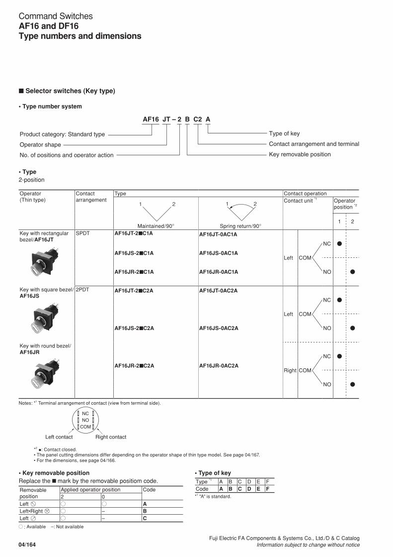
n Selector switches (Key type)
• Type number system
AF16 JT – 2 B C2 A
Product category: Standard type
Operator shape
No. of positions and operator action
Type of key
Contact arrangement and terminal
Key removable position
• Type 2-position
Operator(Thin type)
Contact arrangement
Type Contact operation
Maintained/90° Spring return/90°
Contact unit *1 Operator position *2
1 2
Key with rectangular bezel/AF16JT
SPDT AF16JT-2nC1A AF16JT-0AC1A
Left COM
NC
AF16JS-2nC1A AF16JS-0AC1A
NOAF16JR-2nC1A AF16JR-0AC1A
Key with square bezel/AF16JS
2PDT AF16JT-2nC2A AF16JT-0AC2A
Left COM
NC
NOAF16JS-2nC2A AF16JS-0AC2A
Key with round bezel/AF16JR
Right COM
NC
AF16JR-2nC2A AF16JR-0AC2A
NO
Notes: *1 Terminal arrangement of contact (view from terminal side).
NC NO
COM
Left contact Right contact
*2 •: Contact closed.• The panel cutting dimensions differ depending on the operator shape of thin type model. See page 04/167. • For the dimensions, see page 04/166.
1 2 1 2
• Key removable positionReplace the n mark by the removable positiom code.
Removable position
Applied operatior position Code2 0
Left ALeft•Right – BLeft – C
: Available –: Not available
• Type of keyType *1 A B C D E FCode A B C D E F*1 "A" is standard.
04/164Fuji Electric FA Components & Systems Co., Ltd./D & C Catalog
Information subject to change without notice
Command SwitchesAF16 and DF16Type numbers and dimensions

3-position
Operator(Thin type)
Contact arrangement
Type Contact operation
Maintained/each 45° Spring return/each 45°
Contact unit *1 Operator position *2
1 2 3
Key with Flush square/AF16JT
Key with square bezel/AF16JS
Key with round bezel/AF16JR
2PDT AF16JT-3nC2A AF16JT-1EC2A
Left COM
NC
NOAF16JS-3nC2A AF16JS-1EC2A
Right COM
NCAF16JR-3nC2A AF16JR-1EC2A
NO
Spring/manual return/each 45° Spring/manual return/each 45°
Contact unit *1 Operator position *2
1 2 3
AF16JT-6nC2A AF16JT-7nC2A
Left COM
NC
NOAF16JS-6nC2A AF16JS-7nC2A
Right COM
NCAF16JR-6nC2A AF16JR-7nC2A
NO
Notes: *1 Terminal arrangement of contact (view from terminal side).
NC NO
COM
Left contact Right contact
*2 •, : Contact closed.• The panel cutting dimensions differ depending on the operator shape of thin type model. See page 04/167. • For the dimensions, see page 04/166.
1 3 2
1 3 2
1 3 2
1 3 2
• Key removable positionReplace the n mark by the removable positiom code.
Removable position
Applied operatior position Code3 6 7 1
Left – – ALeft•Right – – – BLeft•Center•Right
– – – C
Right – – DCenter ECenter•Right – – FLeft•Center – – G
: Available –: Not available
• Type of keyType *1 A B C D E FCode A B C D E F*1 "A" is standard.
04/165Fuji Electric FA Components & Systems Co., Ltd./D & C CatalogInformation subject to change without notice
04
Command SwitchesAF16 and DF16
Type numbers and dimensions

• Dimensions, mm
Key with square bezel AF16JS
Key with round bezel AF16JR
Key with recrangular bezel AF16JT
20.5
2 2.5
35.9
20.5 35.9
20.5 35.9
28
22
22sq.
22
Panel thickness: 1 to 6
Nut Panel retainer
7
7
7
2.8
10
2.8
10
2.8
10
2
2
2
5.8
0.5
5.8
0.5
5.8
0.5
Packing
Panel thickness: 1 to 6
Nut Panel retainer
Packing
Panel thickness: 1 to 6
Nut Panel retainer
Packing
2 2.5
2 2.5
04/166Fuji Electric FA Components & Systems Co., Ltd./D & C Catalog
Information subject to change without notice
Command SwitchesAF16 and DF16Type numbers and dimensions
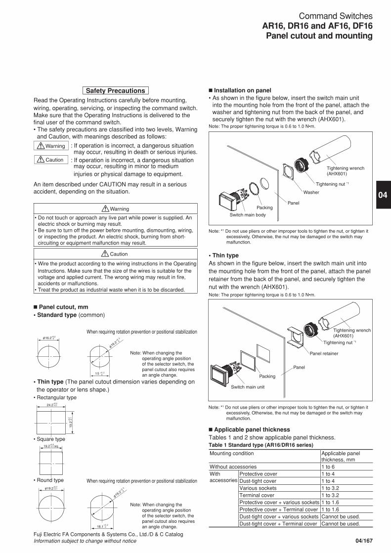
Safety PrecautionsRead the Operating Instructions carefully before mounting, wiring, operating, servicing, or inspecting the command switch. Make sure that the Operating Instructions is delivered to the final user of the command switch. • The safety precautions are classified into two levels, Warning
and Caution, with meanings described as follows:
Warning : If operation is incorrect, a dangerous situation may occur, resulting in death or serious injuries.
Caution : If operation is incorrect, a dangerous situation may occur, resulting in minor to medium injuries or physical damage to equipment.
An item described under CAUTION may result in a serious accident, depending on the situation.
Warning
• Do not touch or approach any live part while power is supplied. An electric shock or burning may result.
• Be sure to turn off the power before mounting, dismounting, wiring, or inspecting the product. An electric shock, burning from short-circuiting or equipment malfunction may result.
Caution
• Wire the product according to the wiring instructions in the Operating Instructions. Make sure that the size of the wires is suitable for the voltage and applied current. The wrong wiring may result in fire, accidents or malfunctions.
• Treat the product as industrial waste when it is to be discarded.
n Panel cutout, mm• Standard type (common)
• Thin type (The panel cutout dimension varies depending on the operator or lens shape.)
• Rectangular type
• Square type
• Round type
16.2
15 +0.2 0
+0.2
0 16.2+0.2
0
Note: When changing the operating angle position of the selector switch, the panel cutout also requires an angle change.
18.1+0.2 0
19.2+0.2
019.2
sq.
+0.2 -0.1
24.2+0.2 -0.1
19.2+0.2 -0.1
19.2
+0.
2 -
0.1
Note: When changing the operating angle position of the selector switch, the panel cutout also requires an angle change.
n Installation on panel• As shown in the figure below, insert the switch main unit
into the mounting hole from the front of the panel, attach the washer and tightening nut from the back of the panel, and securely tighten the nut with the wrench (AHX601).
Note: The proper tightening torque is 0.6 to 1.0 N•m.
Note: *1 Do not use pliers or other improper tools to tighten the nut, or tighten it excessively, Otherwise, the nut may be damaged or the switch may malfunction.
Switch main body
Packing Panel
Washer
Tightening nut *1
Tightening wrench (AHX601)
• Thin typeAs shown in the figure below, insert the switch main unit into the mounting hole from the front of the panel, attach the panel retainer from the back of the panel, and securely tighten the nut with the wrench (AHX601).Note: The proper tightening torque is 0.6 to 1.0 N•m.
Switch main unit
Packing
Panel
Panel retainer
Tightening nut *1
Tightening wrench (AHX601)
Note: *1 Do not use pliers or other improper tools to tighten the nut, or tighten it excessively, Otherwise, the nut may be damaged or the switch may malfunction.
n Applicable panel thicknessTables 1 and 2 show applicable panel thickness.Table 1 Standard type (AR16/DR16 series)
Mounting condition Applicable panelthickness, mm
Without accessories 1 to 6With accessories
Protective cover 1 to 4Dust-tight cover 1 to 4Various sockets 1 to 3.2Terminal cover 1 to 3.2Protective cover + various sockets 1 to 1.6Protective cover + Terminal cover 1 to 1.6Dust-tight cover + various sockets Cannot be used.Dust-tight cover + Terminal cover Cannot be used.
When requiring rotation prevention or positional stabilization
When requiring rotation prevention or positional stabilization
04/167Fuji Electric FA Components & Systems Co., Ltd./D & C CatalogInformation subject to change without notice
04
Command SwitchesAR16, DR16 and AF16, DF16Panel cutout and mounting
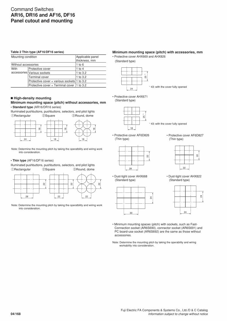
n High-density mountingMinimum mounting space (pitch) without accessories, mm• Standard type (AR16/DR16 series)Illuminated pushbuttons, pushbuttons, selectors, and pilot lights
Table 2 Thin type (AF16/DF16 series)
Mounting condition Applicable panelthickness, mm
Without accessories 1 to 6With accessories
Protective cover 1 to 4Various sockets 1 to 3.2Terminal cover 1 to 3.2Protective cover + various sockets 1 to 3.2Protective cover + Terminal cover 1 to 3.2
①Rectangular ②Square ③Round, dome
①Rectangular ②Square ③Round, dome
Note: Determine the mounting pitch by taking the operatbility and wiring work into consideration.
Note: Determine the mounting pitch by taking the operatbility and wiring work into consideration.
24 18 18
18
18
18
28 22 22
22
22
22
• Thin type (AF16/DF16 series)
Illuminated pushbuttons, pushbuttons, selectors, and pilot lights
Minimum mounting space (pitch) with accessories, mm• Protective cover AHX669 and AHX826
(Standard type)
24 *1 43: with the cover fully opened
*1 43: with the cover fully opened
25 *1
28
22
22
30
22
24
24
24
18
25 *1
• Protective cover AHX671 (Standard type)
• Protective cover AF6D826 (Thin type)
• Protective cover AF6D827 (Thin type)
• Dust-tight cover AHX668 (Standard type)
• Dust-tight cover AHX822 (Standard type)
• Minimum mounting spaces (pitch) with sockets, such as Fast-Connection socket (AR6S690), connector socket (AR6S691) and PC board-use socket (AR6S692) are the same as those without accessories.
Note: Determine the mounting pitch by taking the operability and wiring workability into consideration.
24 *1 43: with the cover fully opened
*1 43: with the cover fully opened
25 *1
28
22
22
30
22
24
24
24
18
25 *1
24 *1 43: with the cover fully opened
*1 43: with the cover fully opened
25 *1
28
22
22
30
22
24
24
24
18
25 *1
24 *1 43: with the cover fully opened
*1 43: with the cover fully opened
25 *1
28
22
22
30
22
24
24
24
18
25 *1
04/168Fuji Electric FA Components & Systems Co., Ltd./D & C Catalog
Information subject to change without notice
Command SwitchesAR16, DR16 and AF16, DF16Panel cutout and mounting
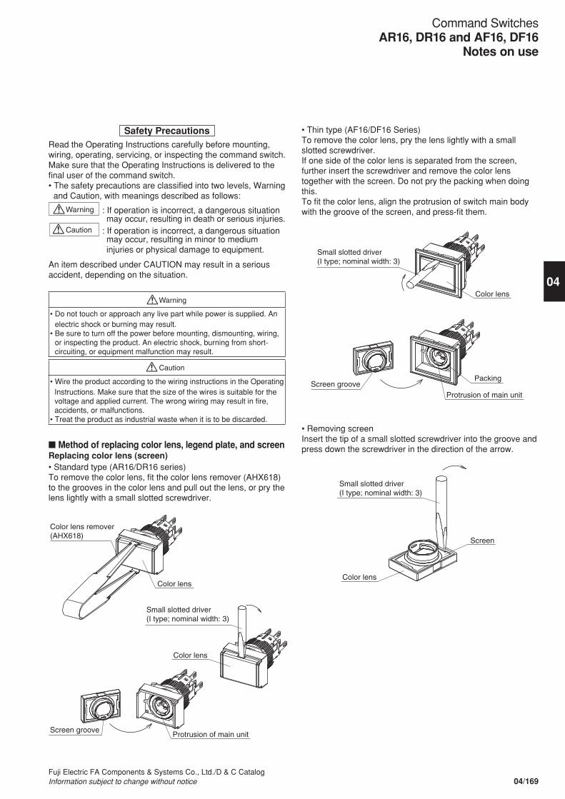
Safety PrecautionsRead the Operating Instructions carefully before mounting, wiring, operating, servicing, or inspecting the command switch. Make sure that the Operating Instructions is delivered to the final user of the command switch. • The safety precautions are classified into two levels, Warning
and Caution, with meanings described as follows:
Warning : If operation is incorrect, a dangerous situation may occur, resulting in death or serious injuries.
Caution : If operation is incorrect, a dangerous situation may occur, resulting in minor to medium injuries or physical damage to equipment.
An item described under CAUTION may result in a serious accident, depending on the situation.
Warning
• Do not touch or approach any live part while power is supplied. An electric shock or burning may result.
• Be sure to turn off the power before mounting, dismounting, wiring, or inspecting the product. An electric shock, burning from short-circuiting, or equipment malfunction may result.
Caution
• Wire the product according to the wiring instructions in the Operating Instructions. Make sure that the size of the wires is suitable for the voltage and applied current. The wrong wiring may result in fire, accidents, or malfunctions.
• Treat the product as industrial waste when it is to be discarded.
n Method of replacing color lens, legend plate, and screenReplacing color lens (screen)• Standard type (AR16/DR16 series)To remove the color lens, fit the color lens remover (AHX618) to the grooves in the color lens and pull out the lens, or pry the lens lightly with a small slotted screwdriver.
• Thin type (AF16/DF16 Series)To remove the color lens, pry the lens lightly with a small slotted screwdriver.If one side of the color lens is separated from the screen, further insert the screwdriver and remove the color lens together with the screen. Do not pry the packing when doing this.To fit the color lens, align the protrusion of switch main body with the groove of the screen, and press-fit them.
Color lens remover (AHX618)
Color lens
Small slotted driver (I type; nominal width: 3)
Color lens
Screen groove Protrusion of main unit
Small slotted driver (I type; nominal width: 3)
Color lens
Screen groove Protrusion of main unit
Packing
• Removing screen Insert the tip of a small slotted screwdriver into the groove and press down the screwdriver in the direction of the arrow.
Small slotted driver (I type; nominal width: 3)
Color lens
Screen
04/169Fuji Electric FA Components & Systems Co., Ltd./D & C CatalogInformation subject to change without notice
04
Command SwitchesAR16, DR16 and AF16, DF16
Notes on use
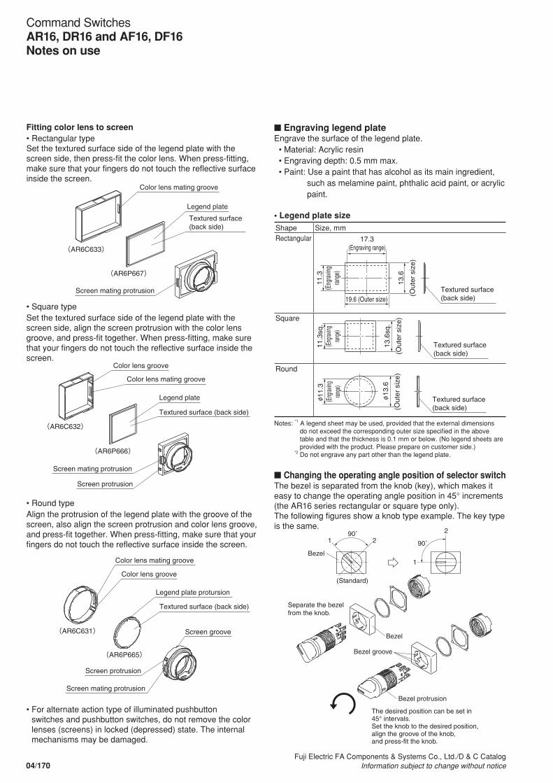
Fitting color lens to screen• Rectangular typeSet the textured surface side of the legend plate with the screen side, then press-fit the color lens. When press-fitting, make sure that your fingers do not touch the reflective surface inside the screen.
(AR6C633)
(AR6P667)
Color lens mating groove
Screen mating protrusion
Legend plate
Textured surface (back side)
(AR6C632)
(AR6P666)
Color lens groove
Legend plate
Screen mating protrusion
Screen protrusion
Textured surface (back side)
Color lens mating groove
(AR6C631)
(AR6P665)
Color lens mating groove
Color lens groove
Legend plate protursion
Textured surface (back side)
Screen protrusion
Screen mating protrusion
Screen groove
• Square typeSet the textured surface side of the legend plate with the screen side, align the screen protrusion with the color lens groove, and press-fit together. When press-fitting, make sure that your fingers do not touch the reflective surface inside the screen.
• Round typeAlign the protrusion of the legend plate with the groove of the screen, also align the screen protrusion and color lens groove, and press-fit together. When press-fitting, make sure that your fingers do not touch the reflective surface inside the screen.
• For alternate action type of illuminated pushbutton switches and pushbutton switches, do not remove the color lenses (screens) in locked (depressed) state. The internal mechanisms may be damaged.
n Engraving legend plate Engrave the surface of the legend plate. • Material: Acrylic resin • Engraving depth: 0.5 mm max. • Paint: Use a paint that has alcohol as its main ingredient,
such as melamine paint, phthalic acid paint, or acrylic paint.
• Legend plate size
Shape Size, mmRectangular 17.3
(Engraving range)
Textured surface (back side)
11.3
(E
ngra
ving
rang
e)
13.6
(Out
er s
ize)
19.6 (Outer size)
Square
Textured surface (back side)
13.6
sq.
(Out
er s
ize)
11.3
sq.
(Eng
raving
ran
ge)
Round
Textured surface (back side)
13
.6
(Out
er s
ize)
11.3
(E
ngrav
ing
range
)
Notes: *1 A legend sheet may be used, provided that the external dimensions do not exceed the corresponding outer size specified in the above table and that the thickness is 0.1 mm or below. (No legend sheets are provided with the product. Please prepare on customer side.)
*2 Do not engrave any part other than the legend plate.
n Changing the operating angle position of selector switch The bezel is separated from the knob (key), which makes it easy to change the operating angle position in 45° increments (the AR16 series rectangular or square type only). The following figures show a knob type example. The key type is the same.
Bezel
Bezel
Bezel protrusion
Bezel groove
1
1
2290˚
(Standard)
90˚
Separate the bezel from the knob.
The desired position can be set in 45° intervals.Set the knob to the desired position,align the groove of the knob,and press-fit the knob.
04/170Fuji Electric FA Components & Systems Co., Ltd./D & C Catalog
Information subject to change without notice
Command SwitchesAR16, DR16 and AF16, DF16Notes on use
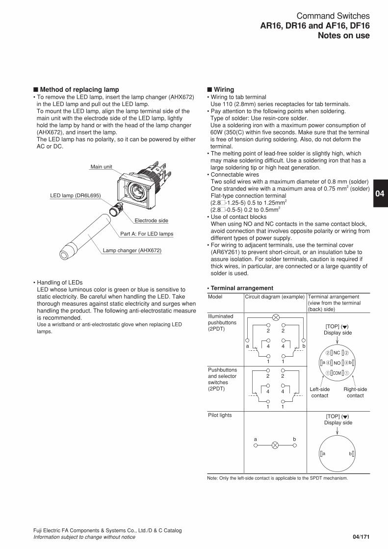
n Method of replacing lamp• To remove the LED lamp, insert the lamp changer (AHX672)
in the LED lamp and pull out the LED lamp. To mount the LED lamp, align the lamp terminal side of the main unit with the electrode side of the LED lamp, lightly hold the lamp by hand or with the head of the lamp changer (AHX672), and insert the lamp. The LED lamp has no polarity, so it can be powered by either AC or DC.
Main unit
LED lamp (DR6L695)
Electrode side
Lamp changer (AHX672)
Part A: For LED lamps
• Handling of LEDs LED whose luminous color is green or blue is sensitive to static electricity. Be careful when handling the LED. Take thorough measures against static electricity and surges when handling the product. The following anti-electrostatic measure is recommended. Use a wristband or anti-electrostatic glove when replacing LED lamps.
n Wiring• Wiring to tab terminal
Use 110 (2.8mm) series receptacles for tab terminals.• Pay attention to the following points when soldering. Type of solder: Use resin-core solder. Use a soldering iron with a maximum power consumption of 60W (350(C) within five seconds. Make sure that the terminal is free of tension during soldering. Also, do not deform the terminal.
• The melting point of lead-free solder is slightly high, which may make soldering difficult. Use a soldering iron that has a large soldering tip or high heat generation.
• Connectable wires Two solid wires with a maximum diameter of 0.8 mm (solder) One stranded wire with a maximum area of 0.75 mm2 (solder)Flat-type connection terminal
(2.8 -1.25-5) 0.5 to 1.25mm2
(2.8 -0.5-5) 0.2 to 0.5mm2
• Use of contact blocks When using NO and NC contacts in the same contact block, avoid connection that involves opposite polarity or wiring from different types of power supply.
• For wiring to adjacent terminals, use the terminal cover (AR6Y261) to prevent short-circuit, or an insulation tube to assure isolation. For solder terminals, caution is required if thick wires, in particular, are connected or a large quantity of solder is used.
• Terminal arrangementModel Circuit diagram (example) Terminal arrangement
(view from the terminal (back) side)
Illuminated pushbuttons(2PDT)
a b
2 2
4 4
1 1 a b
NC
NO
COM
[TOP] ( ) Display side
Left-side contact
Right-side contact
Pushbuttons and selector switches(2PDT)
2 2
4 4
1 1
Pilot lights
a b
[TOP] ( ) Display side
a b
Note: Only the left-side contact is applicable to the SPDT mechanism.
04/171Fuji Electric FA Components & Systems Co., Ltd./D & C CatalogInformation subject to change without notice
04
Command SwitchesAR16, DR16 and AF16, DF16
Notes on use
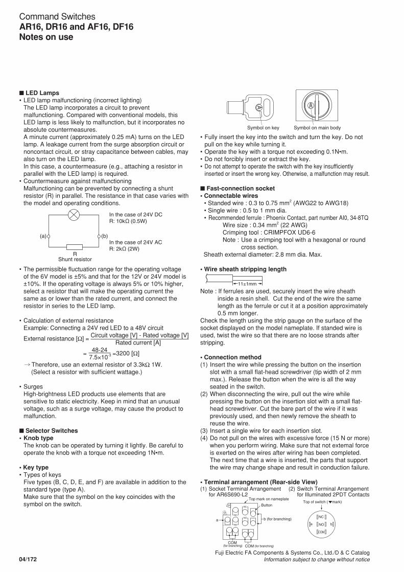
•• Fully insert the key into the switch and turn the key. Do not pull on the key while turning it.
•• Operate the key with a torque not exceeding 0.1N•m.•• Do not forcibly insert or extract the key.•• Do not attempt to operate the switch with the key insufficiently
inserted or insert the wrong key. Otherwise, a malfunction may result.
n Fast-connection socket• Connectable wires
• Standed wire : 0.3 to 0.75 mm2 (AWG22 to AWG18)• Single wire : 0.5 to 1 mm dia.•• Recommended ferrule : Phoenix Contact, part number AI0, 34-8TQ Wire size : 0.34 mm2 (22 AWG) Crimping tool : CRIMPFOX UD6-6 Note :• Use a crimping tool with a hexagonal or round
cross section. Sheath external diameter: 2.8 mm dia. Max.
• Wire sheath stripping length
11±1mm
Note : If ferrules are used, securely insert the wire sheath inside a resin shell. Cut the end of the wire the same length as the ferrule or cut it at a position approximately 0.5 mm longer.
Check the length using the strip gauge on the surface of the socket displayed on the model nameplate. If standed wire is used, twist the wire so that there are no loose strands after stripping.
• Connection method(1)• Insert the wire while pressing the button on the insertion
slot with a small flat-head screwdriver (tip width of 2 mm max.). Release the button when the wire is all the way seated in the switch.
(2)• When disconnecting the wire, pull out the wire while pressing the button on the insertion slot with a small flat-head screwdriver. Cut the bare part of the wire if it was previously used, and then newly remove the sheath to reuse the wire.
(3)• Insert a single wire for each insertion slot.(4)• Do not pull on the wires with excessive force (15 N or more)
when you perform wiring. Make sure that not extemal force is exerted on the wires after wiring has been completed. The next time that a wire is inserted, the parts that support the wire may change shape and result in conduction failure.
• Terminal arrangement (Rear-side View)
n LED Lamps•• LED lamp malfunctioning (incorrect lighting)
The LED lamp incorporates a circuit to prevent malfunctioning. Compared with conventional models, this LED lamp is less likely to malfunction, but it incorporates no absolute countermeasures. A minute current (approximately 0.25 mA) turns on the LED lamp. A leakage current from the surge absorption circuit or noncontact circuit, or stray capacitance between cables, may also turn on the LED lamp. In this case, a countermeasure (e.g., attaching a resistor in parallel with the LED lamp) is required.
•• Countermeasure against malfunctioningMalfunctioning can be prevented by connecting a shunt resistor (R) in parallel. The resistance in that case varies with the model and operating conditions.
•• The permissible fluctuation range for the operating voltage of the 6V model is ±5% and that for the 12V or 24V model is ±10%. If the operating voltage is always 5% or 10% higher, select a resistor that will make the operating current the same as or lower than the rated current, and connect the resistor in series to the LED lamp.
•• Calculation of external resistanceExample: Connecting a 24V red LED to a 48V circuit
External resistance [Ω] = Circuit voltage [V] - Rated voltage [V] Rated current [A] = 48-24 =3200 [Ω] 7.5×10⁻³
Therefore, use an external resistor of 3.3kΩ 1W. (Select a resistor with sufficient wattage.)
•• SurgesHigh-brightness LED products use elements that are sensitive to static electricity. Keep in mind that an unusual voltage, such as a surge voltage, may cause the product to malfunction.
n Selector Switches•• Knob type
The knob can be operated by turning it lightly. Be careful to operate the knob with a torque not exceeding 1N•m.
• Key type•• Types of keys
Five types (B, C, D, E, and F) are available in addition to the standard type (type A). Make sure that the symbol on the key coincides with the symbol on the switch.
In the case of 24V DC R: 10k (0.5W)
Shunt resistor R
(a) (b) In the case of 24V AC R: 2k (2W)
Symbol on key Symbol on main body
(1)• Socket Terminal Arrangement for AR6S690-L2
(2)• Switch Terminal Arrangement for Illuminated 2PDT Contacts
a b
NC
NO
COM
Top of switch ( mark)
NC
NO
NC
NOa
Top mark on nameplate
b (for branching)
Button
COM (for branching) COM (for branching)
04/172Fuji Electric FA Components & Systems Co., Ltd./D & C Catalog
Information subject to change without notice
Command SwitchesAR16, DR16 and AF16, DF16Notes on use
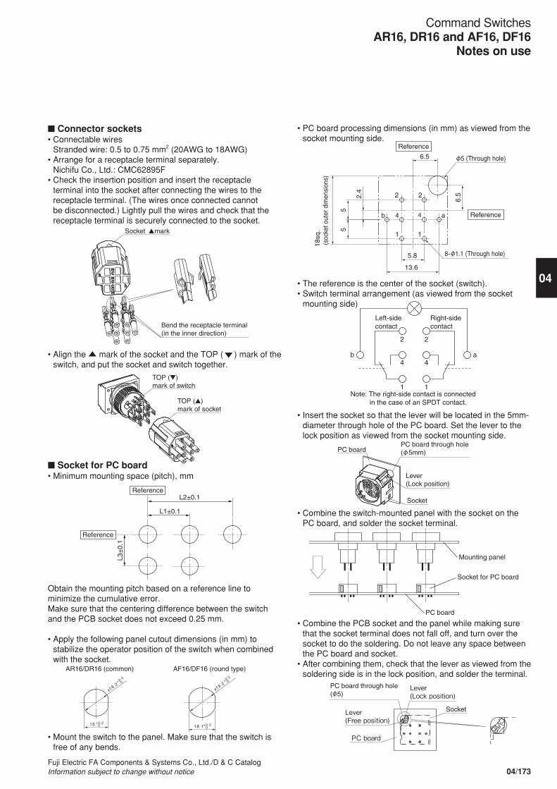
n Connector sockets• Connectable wires Stranded wire: 0.5 to 0.75 mm2 (20AWG to 18AWG)
• Arrange for a receptacle terminal separately. Nichifu Co., Ltd.: CMC62895F
• Check the insertion position and insert the receptacle terminal into the socket after connecting the wires to the receptacle terminal. (The wires once connected cannot be disconnected.) Lightly pull the wires and check that the receptacle terminal is securely connected to the socket.
• Align the mark of the socket and the TOP ( ) mark of the switch, and put the socket and switch together.
n Socket for PC board• Minimum mounting space (pitch), mm
Obtain the mounting pitch based on a reference line to minimize the cumulative error. Make sure that the centering difference between the switch and the PCB socket does not exceed 0.25 mm.
• Apply the following panel cutout dimensions (in mm) to stabilize the operator position of the switch when combined with the socket.
• Mount the switch to the panel. Make sure that the switch is free of any bends.
• PC board processing dimensions (in mm) as viewed from the socket mounting side.
• The reference is the center of the socket (switch).• Switch terminal arrangement (as viewed from the socket
mounting side)
• Insert the socket so that the lever will be located in the 5mm-diameter through hole of the PC board. Set the lever to the lock position as viewed from the socket mounting side.
• Combine the switch-mounted panel with the socket on the PC board, and solder the socket terminal.
• Combine the PCB socket and the panel while making sure that the socket terminal does not fall off, and turn over the socket to do the soldering. Do not leave any space between the PC board and socket.
• After combining them, check that the lever as viewed from the soldering side is in the lock position, and solder the terminal.
16.2
15 +0.2 0
+0.2
0
18.1 +0.2 0
AR16/DR16 (common) AF16/DF16 (round type)
19.2
+0.2
0
L2±0.1
L1±0.1
L3±
0.1
Reference
Reference
Socket mark
Bend the receptacle terminal (in the inner direction)
TOP ( ) mark of switch
TOP ( ) mark of socket
6.5
2 2
4 4
1 1
ab
6.5
55
2.4
5.8
13.6
Reference
Reference
18sq
. (s
ocke
t out
er d
imen
sion
s)
8- 1.1 (Through hole)
5 (Through hole)
2
4b a
2
4
1 1
Left-side contact
Note: The right-side contact is connected in the case of an SPDT contact.
Right-side contact
Mounting panel
Socket for PC board
PC board
PC board PC board through hole ( 5mm)
Lever (Lock position)
Socket
PC board
Lever (Free position)
Lever (Lock position)
PC board through hole ( 5)
Socket
04/173Fuji Electric FA Components & Systems Co., Ltd./D & C CatalogInformation subject to change without notice
04
Command SwitchesAR16, DR16 and AF16, DF16
Notes on use
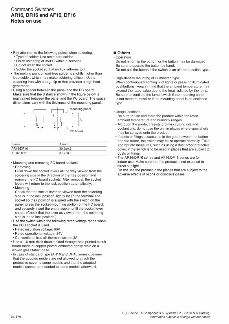
n Others• Operation
Do not hit or flip the button, or the button may be damaged. Be sure to operate the button by hand. Do not pull the button if the switch is an alternate action type.
• High-density mounting of illuminated type When continuously lighting pilot lights or pressing illuminated pushbuttons, keep in mind that the ambient temperature may exceed the rated value due to the heat radiated by the lamp. Be sure to ventilate the lamp /switch if the mounting panel is not made of metal or if the mounting panel is an enclosed type.
• Usage locations • Be sure to use and store the product within the rated
ambient temperature and humidity ranges. • Although the product resists ordinary cutting oils and
coolant oils, do not use the unit in places where special oils may be sprayed onto the product.
• If dusts or filings accumulate in the gap between the button and the frame, the switch may fail to operate normally. Take appropriate measures, such as using a dust-proof protective cover, if the switch is to be used in places that are subject to dusts or filings.
• The AR16/DR16 series and AF16/DF16 series are for indoor use. Make sure that the product is not exposed to direct sunlight.
• Do not use the product in the places that are subject to the adverse effects of ozone or corrosive gases.
• Pay attention to the following points when soldering. • Type of solder: Use resin-core solder. • Finish soldering at 350°C within 5 seconds. • Do not wash the socket. • Solder the socket so that no flux adheres to it.• The melting point of lead-free solder is slightly higher than
lead solder, which may make soldering difficult. Use a soldering iron with a large tip or that provides a high heat generation.
• Using a spacer between the panel and the PC board Make sure that the distance shown in the figure below is maintained between the panel and the PC board. The spacer dimensions vary with the thickness of the mounting panel.
Series A (mm)AR16/DR16 30.2±0.2AF16/DF16 37.7±0.2
• Mounting and removing PC board sockets • Removing
Push down the socket levers all the way viewed from the soldering side in the direction of the free position and remove the PC board sockets. After removal, the socket levers will return to the lock position automatically.
• Mounting Check that the socket lever as viewed from the soldering side is in the lock position, lightly insert the terminal and socket so their position is aligned with the switch on the panel, press the socket-mounting portion of the PC board, and securely insert the entire socket until the socket lever snaps. (Check that the lever as viewed from the soldering side is in the lock position.)
• Use the switch within the following rated voltage range when the PCB socket is used.
• Rated insulation voltage: 60V • Rated operational voltage: 24V • Conventional free air thermal current: 3A• Use a 1.6-mm-thick double-sided through-hole printed circuit board made of copper-plated laminated epoxy resin on a woven glass fabric base.
• In case of standard type (AR16 and DR16 series), beware that the adopted models are not allowed to attach the protective cover to some models and that the adopted models cannot be mounted to some models afterward.
Mounting panel
A
PC board
04/174Fuji Electric FA Components & Systems Co., Ltd./D & C Catalog
Information subject to change without notice
Command SwitchesAR16, DR16 and AF16, DF16Notes on use
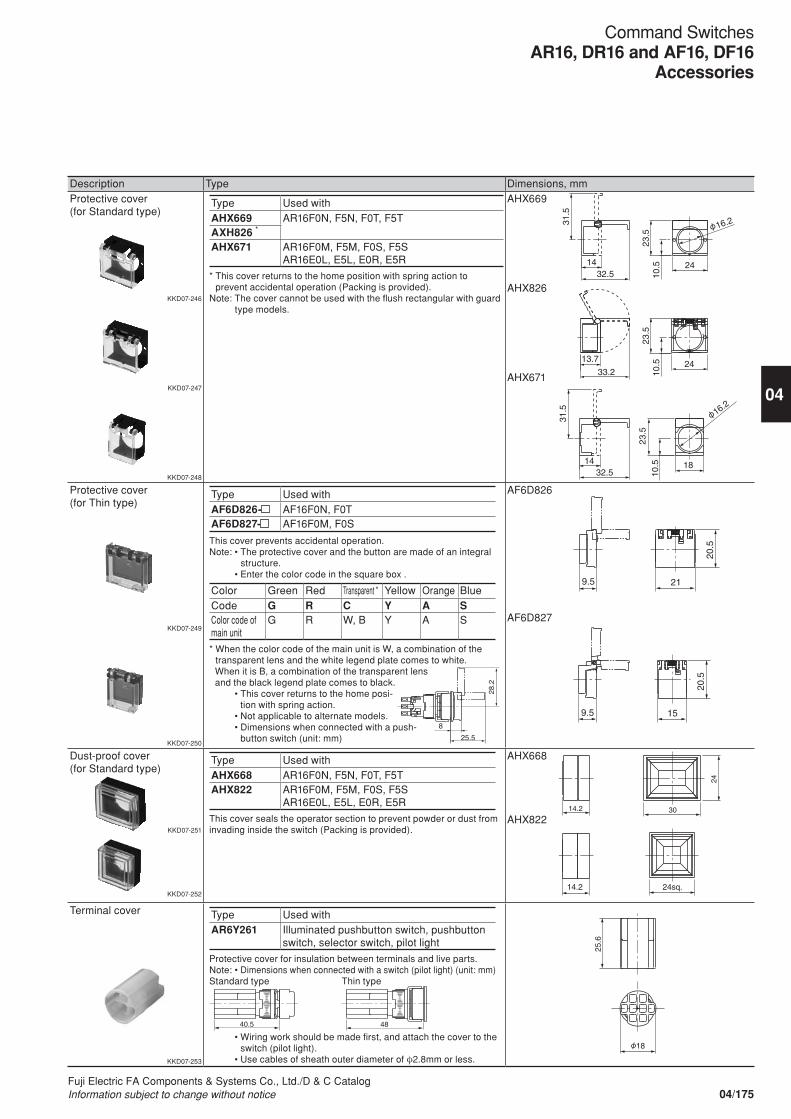
Description Type Dimensions, mmProtective cover(for Standard type)
KKD07-246
KKD07-247
KKD07-248
Type Used withAHX669 AR16F0N, F5N, F0T, F5TAXH826 *
AHX671 AR16F0M, F5M, F0S, F5SAR16E0L, E5L, E0R, E5R
* This cover returns to the home position with spring action to prevent accidental operation (Packing is provided).
Note: The cover cannot be used with the flush rectangular with guard type models.
AHX669
AHX826
AHX671
Protective cover(for Thin type)
KKD07-249
KKD07-250
Type Used withAF6D826- AF16F0N, F0TAF6D827- AF16F0M, F0S
This cover prevents accidental operation.Note: • The protective cover and the button are made of an integral
structure. • Enter the color code in the square box .
Color Green Red Transparent * Yellow Orange BlueCode G R C Y A SColor code of main unit
G R W, B Y A S
* When the color code of the main unit is W, a combination of the transparent lens and the white legend plate comes to white.
When it is B, a combination of the transparent lens and the black legend plate comes to black.
• This cover returns to the home posi-tion with spring action.
• Not applicable to alternate models. • Dimensions when connected with a push-
button switch (unit: mm)
AF6D826
AF6D827
Dust-proof cover(for Standard type)
KKD07-251
KKD07-252
Type Used withAHX668 AR16F0N, F5N, F0T, F5TAHX822 AR16F0M, F5M, F0S, F5S
AR16E0L, E5L, E0R, E5R
This cover seals the operator section to prevent powder or dust from invading inside the switch (Packing is provided).
AHX668
AHX822
Terminal cover
KKD07-253
Type Used withAR6Y261 Illuminated pushbutton switch, pushbutton
switch, selector switch, pilot light
Protective cover for insulation between terminals and live parts.Note: • Dimensions when connected with a switch (pilot light) (unit: mm)Standard type Thin type
• Wiring work should be made first, and attach the cover to the switch (pilot light).
• Use cables of sheath outer diameter of φ2.8mm or less.
9.5 21
20.5
9.5 15
20.5
8
25.5
28.2
31.5
24 14 32.5 10
.5
23.5
10
.5
23.5
33.2
13.7 24
31.5
14 32.5
16.2
18
10.5
23
.5
16.2
24
14.2 30
14.2 24sq.
9.5 21
20.5
9.5 15
20.5
40.5 48 40.5 48
25.6
18
04/175Fuji Electric FA Components & Systems Co., Ltd./D & C CatalogInformation subject to change without notice
04
Command SwitchesAR16, DR16 and AF16, DF16
Accessories
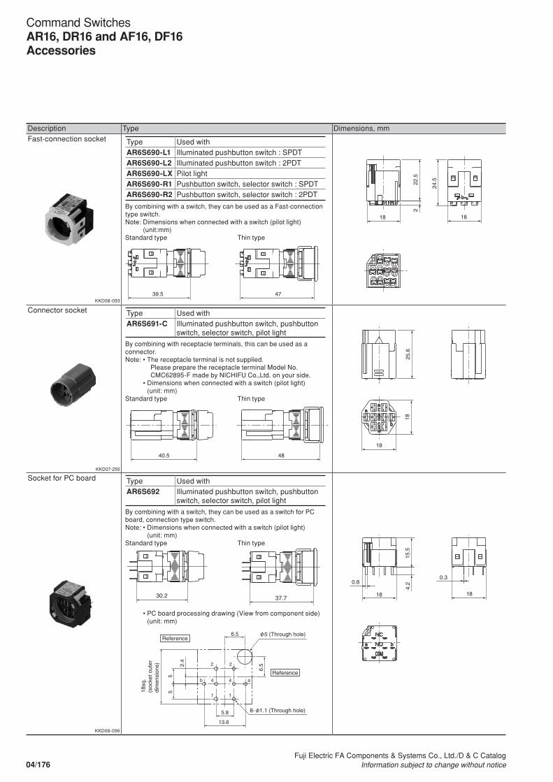
Description Type Dimensions, mmFast-connection socket
KKD08-093
Type Used withAR6S690-L1 Illuminated pushbutton switch : SPDTAR6S690-L2 Illuminated pushbutton switch : 2PDTAR6S690-LX Pilot lightAR6S690-R1 Pushbutton switch, selector switch : SPDTAR6S690-R2 Pushbutton switch, selector switch : 2PDT
By combining with a switch, they can be used as a Fast-connection type switch.Note: Dimensions when connected with a switch (pilot light)
(unit:mm)Standard type Thin type
Connector socket
KKD07-255
Type Used withAR6S691-C Illuminated pushbutton switch, pushbutton
switch, selector switch, pilot light
By combining with receptacle terminals, this can be used as a connector.Note: • The receptacle terminal is not supplied. Please prepare the receptacle terminal Model No.
CMC62895-F made by NICHIFU Co.,Ltd. on your side. • Dimensions when connected with a switch (pilot light)
(unit: mm)Standard type Thin type
Socket for PC board
KKD08-096
Type Used withAR6S692 Illuminated pushbutton switch, pushbutton
switch, selector switch, pilot light
By combining with a switch, they can be used as a switch for PC board, connection type switch.Note: • Dimensions when connected with a switch (pilot light)
(unit: mm)Standard type Thin type
• PC board processing drawing (View from component side) (unit: mm)
30.2 37.7
15.5
4.
2
18
0.8
18
0.3
4840.5
18
18
25.6
6.5
2 2
4 4
1 1
ab
6.5
55
2.4
5.8
13.6
Reference
Reference
5 (Through hole)
18sq
. (s
ocke
t out
erdi
men
sion
s)
8- 1.1 (Through hole)
4739.5
22.5
24.5
2
18 18
04/176Fuji Electric FA Components & Systems Co., Ltd./D & C Catalog
Information subject to change without notice
Command SwitchesAR16, DR16 and AF16, DF16Accessories
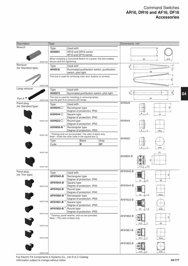
Description Type Dimensions, mmWrench
KKD07-257
Type Used withAHX601 AR16 and DR16 series
AF16 and DF16 series
When installing a Command Switch on a panel, this tool enables secure and firm tightening.
Remover(for Standard type)
KKD07-258
Type Used withAHX618 Illuminated pushbutton switch, pushbutton
switch, pilot light
This tool is used for removing color lens, buttons or screens.
Lamp remover
KKD07-259
Type Used withAHX672 Illuminated pushbutton switch, pilot light
This tool is used for installing or removing lamps.Use the part A to remove LED lamps.
Panel plug(for Standard type)
KKD07-260
KKD07-261
KKD07-262
KKD07-267
Type Used withAXH645- Rectangular type
Degree of protection: IP40AXH644- Square type
Degree of protection: IP40AXH622- Round type
Degree of protection: IP40AXH850-B *1 Rectangular type
Degree of protection: IP65*1 Packing and nut are provided. The color is black only.Note: • Enter the color code in the square box .
Type Black GrayCode B GY
AHX645
AHX644
AHX622
AHX850-B
Panel plug(for Thin type)
KKD07-264
KKD07-266
KKD07-265
KKD07-263
KKD07-268
KKD07-269
Type Used withAF6Y645-B Rectangular type
Degree of protection: IP40AF6Y644-B Square type
Degree of protection: IP40AF6Y622-B Round type
Degree of protection: IP40AF6Y850-B *1 Rectangular type
Degree of protection: IP65AF6Y851-B *1 Square type
Degree of protection: IP65AF6Y852-B *1 Round type
Degree of protection: IP65*1 Packing, panel retainer, and nut are provided.Note: • The color is black only.
AF6Y645-B
AF6Y644-B
AF6Y622-B
AF6Y850-B
AF6Y851-B
AF6Y852-B
18 60
204
10
69
18
24 8
18sq. 8
18 8 3
3
3
3.5 12.5
24 18
7
56
8
24 1.5 28
22
24 1.5 22sq.
24 1.5 22
28
22
22sq.
φ
22 φ
23.5 2
23.5 2
23.5 2
Part A
04/177Fuji Electric FA Components & Systems Co., Ltd./D & C CatalogInformation subject to change without notice
04
Command SwitchesAR16, DR16 and AF16, DF16
Accessories
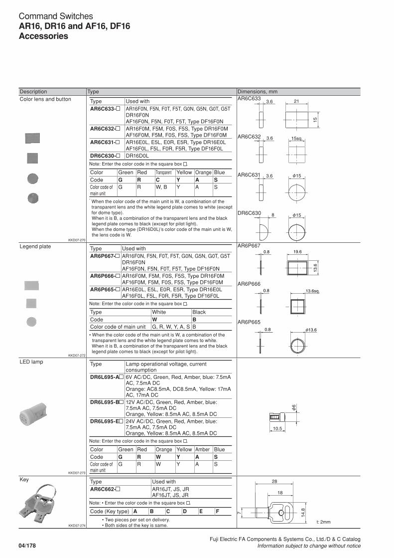
Description Type Dimensions, mmColor lens and button
KKD07-270
Type Used withAR6C633- AR16F0N, F5N, F0T, F5T, G0N, G5N, G0T, G5T
DR16F0NAF16F0N, F5N, F0T, F5T, Type DF16F0N
AR6C632- AR16F0M, F5M, F0S, F5S, Type DR16F0MAF16F0M, F5M, F0S, F5S, Type DF16F0M
AR6C631- AR16E0L, E5L, E0R, E5R, Type DR16E0LAF16F0L, F5L, F0R, F5R, Type DF16F0L
DR6C630- DR16D0L
Note: Enter the color code in the square box .
Color Green Red Transparent * Yellow Orange BlueCode G R C Y A SColor code of main unit
G R W, B Y A S
* When the color code of the main unit is W, a combination of the transparent lens and the white legend plate comes to white (except for dome type).
When it is B, a combination of the transparent lens and the black legend plate comes to black (except for pilot light).
When the dome type (DR16D0L)’s color code of the main unit is W, the lens code is W.
AR6C633
AR6C632
AR6C631
DR6C630
Legend plate
KKD07-272
Type Used withAR6P667- AR16F0N, F5N, F0T, F5T, G0N, G5N, G0T, G5T
DR16F0NAF16F0N, F5N, F0T, F5T, Type DF16F0N
AR6P666- AR16F0M, F5M, F0S, F5S, Type DR16F0MAF16F0M, F5M, F0S, F5S, Type DF16F0M
AR6P665- AR16E0L, E5L, E0R, E5R, Type DR16E0LAF16F0L, F5L, F0R, F5R, Type DF16F0L
Note: Enter the color code in the square box .
Type White BlackCode W BColor code of main unit G, R, W, Y, A, S B
• When the color code of the main unit is W, a combination of the transparent lens and the white legend plate comes to white.
When it is B, a combination of the transparent lens and the black legend plate comes to black (except for pilot light).
AR6P667
AR6P666
AR6P665
LED lamp
KKD07-273
Type Lamp operational voltage, current consumption
DR6L695-A 6V AC/DC, Green, Red, Amber, blue: 7.5mA AC, 7.5mA DCOrange: AC8.5mA, DC8.5mA, Yellow: 17mA AC, 17mA DC
DR6L695-B 12V AC/DC, Green, Red, Amber, blue: 7.5mA AC, 7.5mA DCOrange, Yellow: 8.5mA AC, 8.5mA DC
DR6L695-E 24V AC/DC, Green, Red, Amber, blue: 7.5mA AC, 7.5mA DCOrange, Yellow: 8.5mA AC, 8.5mA DC
Note: Enter the color code in the square box .
Color Green Red Orange Yellow Amber BlueCode G R W Y A SColor code of main unit
G R W Y A S
Key
KKD07-274
Type Used withAR6C662- AR16JT, JS, JR
AF16JT, JS, JRNote: • Enter the color code in the square box .
Code (Key type) A B C D E F
• Two pieces per set on delivery. • Both sides of the key is same.
21
15
15sq.
15
3.6
3.6
3.6
8 15
21
15
15sq.
15
3.6
3.6
3.6
8 15
21
15
15sq.
15
3.6
3.6
3.6
8 15
21
15
15sq.
15
3.6
3.6
3.6
8 15
13.6sq.
13.6
19.6
13.6
0.8
0.8
0.8
13.6sq.
13.6
19.6
13.6
0.8
0.8
0.8
13.6sq.
13.6
19.6
13.6
0.8
0.8
0.8
6
10.5
t: 2mm
28
14.8
18
7
04/178Fuji Electric FA Components & Systems Co., Ltd./D & C Catalog
Information subject to change without notice
Command SwitchesAR16, DR16 and AF16, DF16Accessories
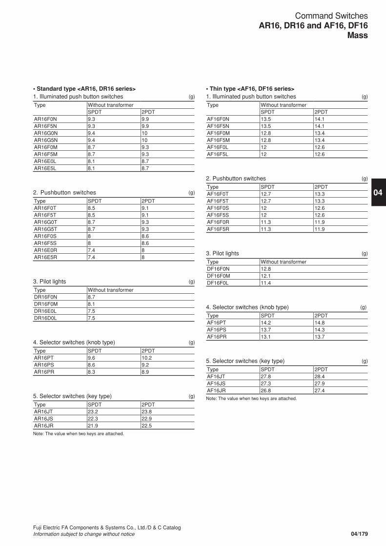
• Standard type <AR16, DR16 series>1. Illuminated push button switches (g)
Type Without transformerSPDT 2PDT
AR16F0N 9.3 9.9AR16F5N 9.3 9.9AR16G0N 9.4 10AR16G5N 9.4 10AR16F0M 8.7 9.3AR16F5M 8.7 9.3AR16E0L 8.1 8.7AR16E5L 8.1 8.7
2. Pushbutton switches (g)
Type SPDT 2PDTAR16F0T 8.5 9.1AR16F5T 8.5 9.1AR16G0T 8.7 9.3AR16G5T 8.7 9.3AR16F0S 8 8.6AR16F5S 8 8.6AR16E0R 7.4 8AR16E5R 7.4 8
3. Pilot lights (g)
Type Without transformerDR16F0N 8.7DR16F0M 8.1DR16E0L 7.5DR16D0L 7.5
4. Selector switches (knob type) (g)
Type SPDT 2PDTAR16PT 9.6 10.2AR16PS 8.6 9.2AR16PR 8.3 8.9
5. Selector switches (key type) (g)
Type SPDT 2PDTAR16JT 23.2 23.8AR16JS 22.3 22.9AR16JR 21.9 22.5
Note: The value when two keys are attached.
• Thin type <AF16, DF16 series>1. Illuminated push button switches (g)
Type Without transformerSPDT 2PDT
AF16F0N 13.5 14.1AF16F5N 13.5 14.1AF16F0M 12.8 13.4AF16F5M 12.8 13.4AF16F0L 12 12.6AF16F5L 12 12.6
2. Pushbutton switches (g)
Type SPDT 2PDTAF16F0T 12.7 13.3AF16F5T 12.7 13.3AF16F0S 12 12.6AF16F5S 12 12.6AF16F0R 11.3 11.9AF16F5R 11.3 11.9
3. Pilot lights (g)
Type Without transformerDF16F0N 12.8DF16F0M 12.1DF16F0L 11.4
4. Selector switches (knob type) (g)
Type SPDT 2PDTAF16PT 14.2 14.8AF16PS 13.7 14.3AF16PR 13.1 13.7
5. Selector switches (key type) (g)
Type SPDT 2PDTAF16JT 27.8 28.4AF16JS 27.3 27.9AF16JR 26.8 27.4
Note: The value when two keys are attached.
04/179Fuji Electric FA Components & Systems Co., Ltd./D & C CatalogInformation subject to change without notice
04
Command SwitchesAR16, DR16 and AF16, DF16
Mass
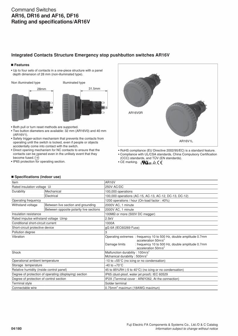
n Specifications (indoor use)
Item AR16VRated insulation voltage Ui 250V AC/DCDurability Mechanical 100,000 operations
Electrical 100,000 operations (AC-15, AC-13, AC-12, DC-13, DC-12)Operating frequency 1200 operations / hour (On-load factor : 40%)Withstand voltage Between live section and grounding 2000V AC, 1 minute
Between opposite polarity live sections 2000V AC, 1 minuteInsulation resistance 100MΩ or more (500V DC megger)Rated impulse withstand voltage Uimp 2.5kVConditional short-circuit current 1000AShort-circuit protective device gG 6A (IEC60269 Fuse)Pollution degree 3Vibration Operating extremes : frequency 10 to 500 Hz, double amplitude 0.7mm
acceleration 50m/s2
Damage limits : frequency 10 to 500 Hz, double amplitude 0.7mm acceleration 50m/s2
Shock Malfunction durability : 100m/s2
Mchanical durability : 500m/s2
Operational ambient temperature -10 to +55°C (no icing or no condensation)Storage temperature -40 to +70°CRelative humidity (inside control panel) 45 to 85%RH (-5 to 40°C) (no icing or no condensation)Degree of protection of operating (displaying) section IP65 (dust-ploof, water jet proof): IEC 60529Degree of protection of control section IP2X (Terminal cover : AR6Y262, At the connection)Terminal style Solder terminalConnectable wire 0.75mm2 maximun (18AWG maximun)
• Both pull or turn reset methods are supported.• Two button diameters are available: 32 mm (AR16V0) and 40 mm
(AR16V1).• Safety trigger-action mechanism that prevents the contacts from
operating until the switch is locked, even if people or objects accidentally come into contact with the switch.
• Direct opening mechanism for NC contacts to ensure that the contacts can be opened even in the unlikely event that they become fused.
• IP65 protection for operating section.
28mm
AR16V0R
AR16V1L
Features
• Up to four sets of contacts in a one-piece structure with a panel depth dimension of 28 mm (non-illuminated type).
Non illuminated type Illuminated type
31.5mm
• RoHS compliance (EU Directive 2002/95/EC) is a standard feature. • Compliance with UL/CSA standards, China Compulsory Certification
(CCC) standards, and TÜV (EN standards). • CE marking.
Integrated Contacts Structure Emergency stop pushbutton switches AR16V
04/180Fuji Electric FA Components & Systems Co., Ltd./D & C Catalog
Information subject to change without notice
Command SwitchesAR16, DR16 and AF16, DF16Rating and specifications/AR16V
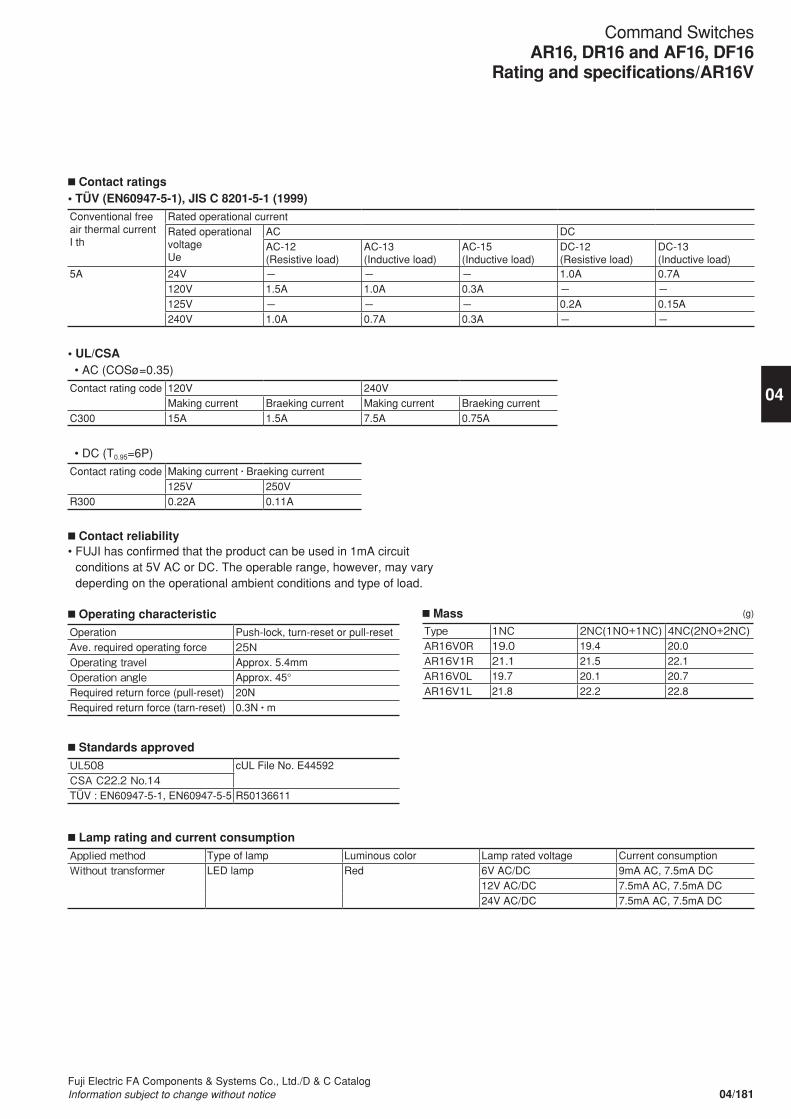
n Contact ratings• TÜV (EN60947-5-1), JIS C 8201-5-1 (1999)
Conventional free air thermal currentI th
Rated operational currentRated operational voltageUe
AC DCAC-12(Resistive load)
AC-13(Inductive load)
AC-15(Inductive load)
DC-12(Resistive load)
DC-13(Inductive load)
5A 24V - - - 1.0A 0.7A120V 1.5A 1.0A 0.3A - -125V - - - 0.2A 0.15A240V 1.0A 0.7A 0.3A - -
• UL/CSA • AC (COSø=0.35)
Contact rating code 120V 240VMaking current Braeking current Making current Braeking current
C300 15A 1.5A 7.5A 0.75A
• DC (T0.95=6P)
Contact rating code Making current • Braeking current125V 250V
R300 0.22A 0.11A
n Contact reliability• FUJI has confirmed that the product can be used in 1mA circuit
conditions at 5V AC or DC. The operable range, however, may vary deperding on the operational ambient conditions and type of load.
n Operating characteristic
Operation Push-lock, turn-reset or pull-resetAve. required operating force 25NOperating travel Approx. 5.4mmOperation angle Approx. 45°Required return force (pull-reset) 20NRequired return force (tarn-reset) 0.3N • m
n Standards approved
UL508 cUL File No. E44592CSA C22.2 No.14TÜV : EN60947-5-1, EN60947-5-5 R50136611
n Lamp rating and current consumption
Applied method Type of lamp Luminous color Lamp rated voltage Current consumptionWithout transformer LED lamp Red 6V AC/DC 9mA AC, 7.5mA DC
12V AC/DC 7.5mA AC, 7.5mA DC24V AC/DC 7.5mA AC, 7.5mA DC
n Mass (g)
Type 1NC 2NC(1NO+1NC) 4NC(2NO+2NC)AR16V0R 19.0 19.4 20.0AR16V1R 21.1 21.5 22.1AR16V0L 19.7 20.1 20.7AR16V1L 21.8 22.2 22.8
04/181Fuji Electric FA Components & Systems Co., Ltd./D & C CatalogInformation subject to change without notice
04
Command SwitchesAR16, DR16 and AF16, DF16
Rating and specifications/AR16V

n Type• Emergency stop pushbutton switches
Operator Contact TypeUnibody push-lock, pull or turn-reset (32mm dia.) 1NC AR16V0R-01R
1NO+1NC AR16V0R-11R2NC AR16V0R-02R1NO+2NC AR16V0R-12R3NC AR16V0R-03R1NO+3NC AR16V0R-13R4NC AR16V0R-04R
Unibody push-lock, pull or turn-reset (40mm dia.) 1NC AR16V1R-01R1NO+1NC AR16V1R-11R2NC AR16V1R-02R1NO+2NC AR16V1R-12R3NC AR16V1R-03R1NO+3NC AR16V1R-13R4NC AR16V1R-04R
• Emergency stop illuminated pushbutton switches
Operator Contact LED Lamp TypeUnibody push-lock, pull or turn-reset (32mm dia.) 1NC AR16V0L-01nR
1NO+1NC AR16V0L-11nR2NC AR16V0L-02nR1NO+2NC AR16V0L-12nR3NC AR16V0L-03nR1NO+3NC AR16V0L-13nR
(KKD08-087) 4NC AR16V0L-04nRUnibody push-lock, pull or turn-reset (40mm dia.) 1NC AR16V1L-01nR
1NO+1NC AR16V1L-11nR2NC AR16V1L-02nR1NO+2NC AR16V1L-12nR3NC AR16V1L-03nR1NO+3NC AR16V1L-13nR
(KKD08-091) 4NC AR16V1L-04nR
• Voltage Replace the nmark by the lamp voltage code
Lamp voltage Code6V AC/DC A312V AC/DC B324V AC/DC E3
(KKD08-090)
(KKD08-092)
04/182Fuji Electric FA Components & Systems Co., Ltd./D & C Catalog
Information subject to change without notice
Command SwitchesAR16, DR16 and AF16, DF16Type numbers/AR16V

n Accessories
Description Type Dimensions, mmWrench AHX601 (AH9A601)
When installing a command switch on a panel, this tool is useful for tightening the switch firmly and efficiently.
(KKD07-257)
Terminal cover AR6Y262Protective cover for insulation between terminals and live parts.Note : Dimensions when connected with a switch (unit : mm)
• Wiring work should be made first , and attach the cover to the switch.
Legend plate for AR16V emergency stop
AR6P719-*1,2
Legend code (*1, 2) Letter hightBlack 00 -EMERGENCY STOP 5A 7mm
• Plate color : Yellow• Letter color : Black
ø4020.620.628 ø32
• Emergency stop pushbutton switches
• AR16V0R • AR16V1R
• Emergency stop illuminated pushbutton switches
• AR16V0L • AR16V1L
Dimensions, mm
4Washer
Washer
Nut
Nut
Packing
Packing
Panel thickness 1 to 6
Panel thickness 1 to 6
0.5
3.8
2.2
11.5
ø4020.6
0.5
3.8
2.2
11.5
0.8
31.5
20.628
4
ø32
4
1 2
34
12 1
2
60 ø18
20.4
20
20
11.2
Thickness : 0.35mm
ø17
ø65
60 ø18
20.4
20
20
11.2
Thickness : 0.35mm
ø17
ø65
60 ø18
20.4
20
20
11.2
Thickness : 0.35mm
ø17
ø65
36
04/183Fuji Electric FA Components & Systems Co., Ltd./D & C CatalogInformation subject to change without notice
04
Command SwitchesAR16, DR16 and AF16, DF16
Dimensions and Accessories/AR16V
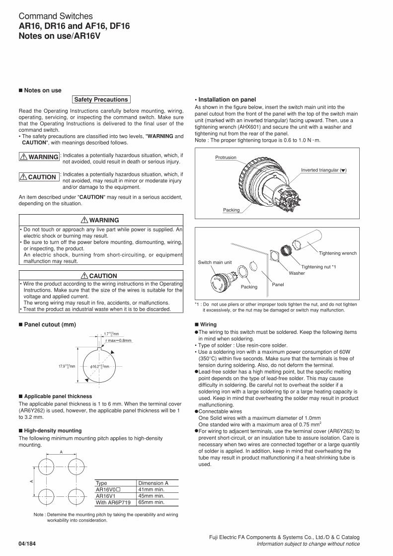
n Notes on use
Safety Precautions
Read the Operating Instructions carefully before mounting, wiring, operating, servicing, or inspecting the command switch. Make sure that the Operating Instructions is delivered to the final user of the command switch.• The safety precautions are classified into two levels, "WARNING and CAUTION", with meanings described follows.
: Indicates a potentially hazardous situation, which, if not avoided, could resuit in death or serious injury.
: Indicates a potentially hazardous situation, which, if not avoided, may result in minor or moderate injury and/or damage to the equipment.
An item described under "CAUTION" may resuit in a serious accident, depending on the situation.
WARNING
CAUTION• Do not touch or approach any live part while power is supplied. An
electric shock or burning may result.• Be sure to turn off the power before mounting, dismounting, wiring,
or inspecting, the product.An electric shock, burning from short-circuiting, or equipment malfunction may result. WARNING
CAUTION• Wire the product according to the wiring instructions in the Operating
Instructions. Make sure that the size of the wires is suitable for the voltage and applied current.The wrong wiring may result in fire, accidents, or malfunctions.
• Treat the product as industrial waste when it is to be discarded.
• Installation on panelAs shown in the figure below, insert the switch main unit into the panel cutout from the front of the panel with the top of the switch main unit (marked with an inverted triangular) facing upward. Then, use a tightening wrench (AHX601) and secure the unit with a washer and tightening nut from the rear of the panel.Note : The proper tightening torque is 0.6 to 1.0 N • m.
n Applicable panel thicknessThe applicable panel thickness is 1 to 6 mm. When the terminal cover (AR6Y262) is used, however, the applicable panel thickness will be 1 to 3.2 mm.
n High-density mountingThe following minimum mounting pitch applies to high-density mounting.
n WiringThe wiring to this switch must be soldered. Keep the following items in mind when soldering.
• Type of solder : Use resin-core solder.• Use a soldering iron with a maximum power consumption of 60W
(350°C) within five seconds. Make sure that the terminals is free of tension during soldering. Also, do not deform the terminal. Lead-free solder has a high melting point, but the specific melting point depends on the type of lead-free solder. This may cause difficulty in soldering. Be careful not to overheat the solder if a soldering iron with a large soldering tip or a large heating capacity is used. Keep in mind that overheating the solder may resuit in product malfunctioning.Connectable wiresOne Solid wires with a maximum diameter of 1.0mmOne standed wire with a maximum area of 0.75 mm2
For wiring to adjacent terminals, use the terminal cover (AR6Y262) to prevent short-circuit, or an insulation tube to assure isolation. Care is necessary when two wires are connected together or a large quantily of solder is applied. In addition, keep in mind that overheating the tube may result in product malfunctioning if a heat-shrinking tube is used.
WARNING
CAUTIONWARNING
CAUTION
*1 : Do not use pliers or other improper tools tighten the nut, and do not tighten it excessively, or the nut may be damaged or switch may malfunction.
n Panel cutout (mm)
Protrusion
Packing
Switch main unit
Packing Panel
WasherTightening nut *1
Tightening wrench
Inverted triangular ( )
Protrusion
Packing
Switch main unit
Packing Panel
WasherTightening nut *1
Tightening wrench
Inverted triangular ( )
r max=0.8mm
1.7+0.2mm
φ16.2+0.2mm0
0
17.9+0.2mm0
A
A
Note : Detemine the mounting pitch by taking the operability and wiring workability into consideration.
TypeAR16V0AR16V1With AR6P719
Dimension A41mm min.45mm min.65mm min.
04/184Fuji Electric FA Components & Systems Co., Ltd./D & C Catalog
Information subject to change without notice
Command SwitchesAR16, DR16 and AF16, DF16Notes on use/AR16V

• Terminal arrangement
Model Circuit diagram (example) Terminal arrangement(view from the terminal (back) side)
Emergency stop pushbutton switches
Emergency stop illuminated pushbutton switches
Note : If NO contacts are uesd in the contact configuration, they will be on the top of the unit (marked with the inverted triangular) and on the opposite side, regardless of the number of contacts.
n Terminal caver (AR6Y262)• CombinationThe terminal cover must be attached in the correct direction. Make sure that the triangular on the terminal cover is aligned with the inverted triangular on the top of the unit. Also, when wiring the switch, check the alignment of these triangles and insert the wires correctly through the corresponding holes in the terminal cover.
n Nameplate (AR6P719)• PrecautionsThe nameplate must be attached. Attach the nameplate to an appropriate part, such as the panel, after removing the paper from the back of the nameplate.Before attaching the nameplate, claen the surface to which the nameplate will be attached with alcohol.The nameplate may come off if the surface is dirty or oily.• Attachment Procedure (Example)Remove portions ① and ② from the center of the nameplate, aligh the nameplate with the panel cutout, and lightly press on the front surface of the nameplate to attach it to the panel. Then remove portions ③and ④ , and press on the entire front surface of the nameplate to complate attaching it to the panel.
n OthersOperation• Do not hit or flip the button, or the button may be damaged. Be sure
to operate the button by hand.• To unlock the switch, turn the button approximately 45° clockwise (in
the direction of the arrow) or pull out the button. Do not operate or handle the button with excessive force.
• Do not lock the emergency stop pushbutton switch during normal use. Push and lock the switch only in an emergency.
Storage and Usage Locations• Be sure to use and store the product within the rated ambient
temperature and humidity ranges.• Although the product resists ordinary cutting oils and coolant oils, do
not use the unit in places where special oils may be sprayed onto the product.
• If dusts or filings accumulate in the gap between the button and the frame, the switch may fail to operate normally.
• This switch are for indoor use. Make sure that the product is not exposed to direct sunlight.
• Do not use the product in the places thet are subject to the adverse effects of ozone or corrosive gases.
①
②
③ ④
1
a
2
4 3
4 3
b 12
12
1 2 Top (marked with inverted triangular)
Terminals 1-2 : b (NC) contact terminalsTerminals 3-4 : a (NO) contact terminalsTerminals a-b : Lamp terminals
12
12
a
1 2
34
b
12
12
1
a
2
4 3
4 3
b 12
12
1 2 Top (marked with inverted triangular)
Terminals 1-2 : b (NC) contact terminalsTerminals 3-4 : a (NO) contact terminalsTerminals a-b : Lamp terminals
12
12
a
1 2
34
b
12
12
Inverted triangular ( )
Wires
Triangular on terminal cover mark
04/185Fuji Electric FA Components & Systems Co., Ltd./D & C CatalogInformation subject to change without notice
04
Command SwitchesAR16, DR16 and AF16, DF16
Notes on use/AR16V

04/186Fuji Electric FA Components & Systems Co., Ltd./D & C Catalog
Information subject to change without notice
FeaturesDesign basisThe 16mm dia. series of compact sizepushbuttons are 'finger-size', andconsequently take up little panel space.AH165-2 series operators are about twiceas large as the AH164 and AH165 seriesoperators for easier operation. With manytypes of operator available, the mostsuitable switch can be identified by color,shape and legend, and have a smooth,quality "snap-action". In spite of their smallsize they have a highly reliablemechanism, and are eminently suited forsolid state and other electroniccircuits. AH164, AH165 and AH165-2series contact block holders can easily beremoved manually. Moreover, the contactblock can be easily attached or detachedwithout using any special tools, thusfacilitating addition or replacement ofcontact.
Selector switchesSelector switches can also be suppliedin either knob-handle operated or keyoperated types.
Strong constructionThe operator and contact blocks aremolded from an excellent thermalresistance resin and can withstand theheat at the time of soldering.Since these pushbuttons aremanufactured to industrial standardsthey can withstand vibration or shockthus eliminating lamp failure due tosuch causes as loose bases.With regard to the degree of protection,standard types which met therequirements of IP40 of IEC 60529,and oil tight types which meet therequirements of IP65 of the said,are available. This permits the applicationto various fields, from machine tools to OA(Office Automation) facilities.
Quality feel toughBoth the operator and contact block areprecisely engineered. There is no fearof the switch malfunction even afterlong use and it continues to operatesmoothly for its service life of about1,000,000 operations.
Easy color changeColor lenses fit over the inner button.The lens can easily be removed using asmall screwdriver
Visible inscriptionButton legends are printed on legendsheet, which is stuck to the legend plateon the inner button.The lettering is back lit by the switchlamp and the inscription is highly visiblethrough the color lens.Contact FUJI for your letteringrequirements.
Excellent switch reliabilityThe switch uses a snap-actionmechanism. The pushbuttons areavailable with either momentary oralternative actions. The snap-actionswitch has a double break movementwhich operates independently of thespeed of switching. The contacts aremade from gold-flashed silver. Highcontact reliability of 1mA at 5V AC/DC isassured. Contact blocks are available in1NO+1NC to 3NO+3NC arrangement.
Large terminalsSolder/tab terminal is provided as standard.Wire-wrap terminal is available on reguest.
Alternate actionIn the case of alternate action whenthe button is depressed the contacts aremaintained and remain so even if thefinger is removed. The button will notreturn to its free position. In order toremove the lock, the button mustbe given a second pressure before thebutton will return to its free position. Thismakes it most suitable as the switch for apower source.
Pushbutton with finger guardsFinger guards are provided for square orrectangular type pushbuttons (SF, TF, SLand TL types) in order to preventoperational error of adjacent buttons.
Pushbuttons/Selectors/Pilot Lights/BuzzersAH164, AH165 and AH165-2General information
Color lens
Screw driver
Legend plate
Legend sheet(film)
Lampterminal
Contact terminal
Maintain
SafetyFUJI’s original Trigger Action mechanismis used in the emergency stoppushbuttons. They are suitable foremergency stop and safety. Thismechanism prevents the contacts frommoving until the button is pushed andlocked.• Provided with a trigger action mechanism conforming to EN418.• Provided with direct opening action (approved by TÜV) conforming to EN60947-5-1 and EN60947-5-5.
Note: The luminous color of LEDs and neon illumination types varies with the body color of the product.
Approvals
For further information related to approvedtype, see page 04/187 to 04/190 .
R S
Pushbuttons Illuminated pushbuttons Pilot lights
AH164-E AH164-TL AH164-Z
Selectors
AH165-2ML AH165-2P
KKD07-209 KKD07-202
AF87-221 KKD07-232
KKD07-212
KKD07-222
AH165-V6
Emergency stop pushbuttons

04/187Fuji Electric FA Components & Systems Co., Ltd./D & C CatalogInformation subject to change without notice
04
Emergency stop pushbutton switches (Direct opening action), conform to EN418
Operator Type Operator Type
Push-lock, turn-reset AH165-V5R Push-lock, turn-reset AH165-V6R(32mm dia.) (40mm dia.)
See page 04/200 See page 04/200
KKD07-221 KKD07-222
Illuminated pushbutton switchesOperator Type Operator Type Operator Type
Extended round head AH164-L, L5 Flush square head AH164-SL, SL5 Flush rectangular head AH164-TL, TL5AH165-L, L5 AH165-SL, SL5 AH165-TL, TL5
See page 04/195 See page 04/195 See page 04/195
KKD07-205 KKD07-204 KKD07-202
Flush rectangular head AH164-TGL, TGL5 Flush square head AH164-SGL, SGL5with guard AH165-TGL, TGL5 with guard AH165-SGL, SGL5
See page 04/196 See page 04/196
KKD07-203 KKD05-075b
Pushbutton switchesOperator Type Operator Type Operator Type
Extended round head AH164-E, E5 Mushroom head AH164-M, M5 Flush square head AH164-SF, SF5AH165-E, E5 AH165-M, M5 AH165-SF, SF5
See page 04/199 See page 04/199 See page 04/199
KKD07-209 KKD07-210 KKD07-208
Flush rectangular head AH164-TF, TF5 Flush rectangular head AH164-TGF, TGF5 Flush square head AH164-SGF, SGF5AH165-TF, TF5 with guard AH165-TGF, TGF5 with guard AH165-SGF, SGF5
See page 04/199 See page 04/199 See page 04/199
KKD07-206 KKD05-176 KKD05-075b
Convex square head AH164-SM, SM5 Convex rectangular head AH164-TM, TM5 Push-lock, turn-reset AH165-VRAH165-SM, SM5 AH165-TM, TM5 (32mm dia.)
See page 04/199 See page 04/199 See page 04/200
KKD05-081b KKD05-082b AF91-584
Push-lock, turn-reset AH165-V1R(40mm dia.)
See page 04/200
AF91-583
Pushbuttons/Selectors/Pilot Lights/BuzzersAH164, AH165 and AH165-2
Quick reference guide
R R R
R
R
R
R
R
R
R
R
R
R
R R
AH164 (standard) / AH165 (oil-tight)
Note: : See page 04/292
S S S
S S
S
S
S
S
S
S
S
S
S
S
S S
S
Note: Spot LED and red/green LED types: Not approved standard
(Direct opening action)
(Direct opening action)

04/188Fuji Electric FA Components & Systems Co., Ltd./D & C Catalog
Information subject to change without notice
Selector switchesOperator Type Operator Type Operator Type
Knob with rectangular AH164-P Knob with square bezel AH164-SP Key with rectangular AH164-Jbezel AH165-P AH165-SP bezel AH165-J
See page 04/201 See page 04/201 See page 04/201
KKD07-213 KKD07-215 KKD09-001L
Key with square bezel AH164-SJ Key with rectangular AH165-JM Key AH165-RJMAH165-SJ bezel
See page 04/201, 04/204 See page 04/202 See page 04/202
KKD09-001R KKD09-006 KKD09-007
Pilot lightsLens Type Lens Type Lens Type
Extended round AH164-Z Flush square AH164-ZS Flush rectangular AH164-ZTAH165-Z AH165-ZS AH165-ZT
See page 04/206 See page 04/206 See page 04/206
KKD07-212 KKD05-094b KKD07-211
Dome AH165-ZM
See page 04/206
AF87-45
BuzzersSound Type Sound Type Sound Type
Standard AH164-TX Loud sound AH164-TX1 Loud sound with AH164-TX2Bvolume control
See page 04/208 See page 04/208 See page 04/208
AF87-317 AF87-44 KKD07-223
Standard sound with AH165-Xvolume control (IP54)
See page 04/208
KKD05-096b
Pushbuttons/Selectors/Pilot Lights/BuzzersAH164, AH165 and AH165-2Quick reference guide
R
R
R R
R R
R
R
R R
R
R
S
S
S
S
S
S
S S S
(Direct opening action) (Direct opening action)
Note: : See page 04/292S
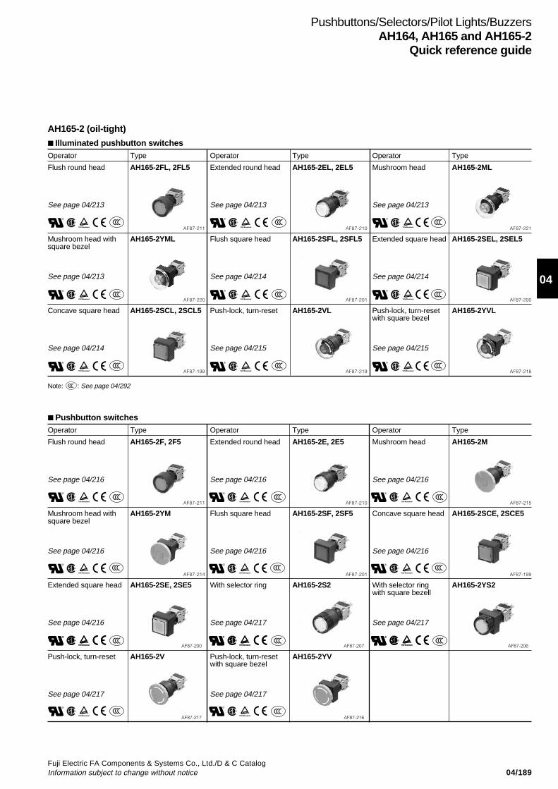
04/189Fuji Electric FA Components & Systems Co., Ltd./D & C CatalogInformation subject to change without notice
04
Pushbuttons/Selectors/Pilot Lights/BuzzersAH164, AH165 and AH165-2
Quick reference guide
AH165-2 (oil-tight)
R
R
R
R
R
R
R
R
R
S
S
S
S
S
S
S
S
S
Note: : See page 04/292S
Pushbutton switchesOperator Type Operator Type Operator Type
Flush round head AH165-2F, 2F5 Extended round head AH165-2E, 2E5 Mushroom head AH165-2M
See page 04/216 See page 04/216 See page 04/216
AF87-211 AF87-210 AF87-215
Mushroom head with AH165-2YM Flush square head AH165-2SF, 2SF5 Concave square head AH165-2SCE, 2SCE5square bezel
See page 04/216 See page 04/216 See page 04/216
AF87-214 AF87-201 AF87-199
Extended square head AH165-2SE, 2SE5 With selector ring AH165-2S2 With selector ring AH165-2YS2with square bezell
See page 04/216 See page 04/217 See page 04/217
AF87-200 AF87-207 AF87-206
Push-lock, turn-reset AH165-2V Push-lock, turn-reset AH165-2YVwith square bezel
See page 04/217 See page 04/217
AF87-217 AF87-216
R
R
RR
R
R
R
RR
R
R
RR
S
S
S
S
S
S
S
S
S
S
R S
Illuminated pushbutton switchesOperator Type Operator Type Operator Type
Flush round head AH165-2FL, 2FL5 Extended round head AH165-2EL, 2EL5 Mushroom head AH165-2ML
See page 04/213 See page 04/213 See page 04/213
AF87-211 AF87-210 AF87-221
Mushroom head with AH165-2YML Flush square head AH165-2SFL, 2SFL5 Extended square head AH165-2SEL, 2SEL5square bezel
See page 04/213 See page 04/214 See page 04/214
AF87-220 AF87-201 AF87-200
Concave square head AH165-2SCL, 2SCL5 Push-lock, turn-reset AH165-2VL Push-lock, turn-reset AH165-2YVLwith square bezel
See page 04/214 See page 04/215 See page 04/215
AF87-199 AF87-219 AF87-218

04/190Fuji Electric FA Components & Systems Co., Ltd./D & C Catalog
Information subject to change without notice
Pushbuttons/Selectors/Pilot Lights/BuzzersAH164, AH165 and AH165-2Quick reference guide
R
R
R
R
R
R
S
S
S S
R S
R
R
R RS
S
S S
Note: : See page 04/292S
Selector switchesOperator Type Operator Type Operator Type
Knob AH165-2P Knob with square bezel AH165-2YP Key AH165-2J
See page 04/218 See page 04/218 See page 04/218
KKD07-232 KKD07-234 KKD09-003L
Key with square bezel AH165-2YJ Lever AH165-2H Lever with square bezel AH165-2SH
See page 04/218 See page 04/219 See page 04/219
KKD09-003R AF87-209 AF87-203
Illuminated selector switchesOperator Type
Knob AH165-2PL
See page 04/221
KKD07-240
Pilot lightsLens Type Lens Type Lens Type
Flush round AH165-2Z Extended round AH165-2ZE Flush square AH165-2SZ
See page 04/222 See page 04/222 See page 04/222
AF87-213 AF87-212 AF87-205
Extended square AH165-2SZE
See page 04/222
AF87-204
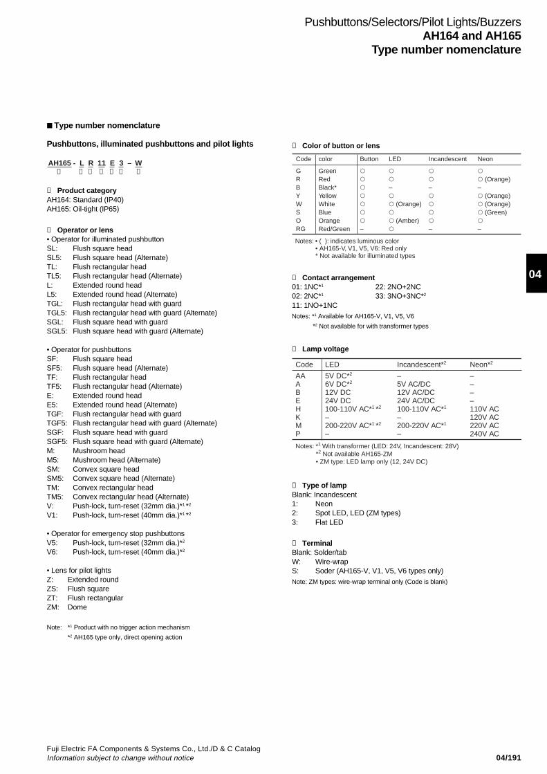
04/191Fuji Electric FA Components & Systems Co., Ltd./D & C CatalogInformation subject to change without notice
04
Pushbuttons/Selectors/Pilot Lights/BuzzersAH164 and AH165
Type number nomenclature
➀ Product categoryAH164: Standard (IP40)AH165: Oil-tight (IP65)
➁ Operator or lens• Operator for illuminated pushbuttonSL: Flush square headSL5: Flush square head (Alternate)TL: Flush rectangular headTL5: Flush rectangular head (Alternate)L: Extended round headL5: Extended round head (Alternate)TGL: Flush rectangular head with guardTGL5: Flush rectangular head with guard (Alternate)SGL: Flush square head with guardSGL5: Flush square head with guard (Alternate)
• Operator for pushbuttonsSF: Flush square headSF5: Flush square head (Alternate)TF: Flush rectangular headTF5: Flush rectangular head (Alternate)E: Extended round headE5: Extended round head (Alternate)TGF: Flush rectangular head with guardTGF5: Flush rectangular head with guard (Alternate)SGF: Flush square head with guardSGF5: Flush square head with guard (Alternate)M: Mushroom headM5: Mushroom head (Alternate)SM: Convex square headSM5: Convex square head (Alternate)TM: Convex rectangular headTM5: Convex rectangular head (Alternate)V: Push-lock, turn-reset (32mm dia.)*1 *2
V1: Push-lock, turn-reset (40mm dia.)*1 *2
• Operator for emergency stop pushbuttonsV5: Push-lock, turn-reset (32mm dia.)*2
V6: Push-lock, turn-reset (40mm dia.)*2
• Lens for pilot lightsZ: Extended roundZS: Flush squareZT: Flush rectangularZM: Dome
Note: *1 Product with no trigger action mechanism
*2 AH165 type only, direct opening action
➃ Contact arrangement01: 1NC*1 22: 2NO+2NC02: 2NC*1 33: 3NO+3NC*2
11: 1NO+1NCNotes: *1 Available for AH165-V, V1, V5, V6
*2 Not available for with transformer types
➄ Lamp voltage
Type number nomenclature
Pushbuttons, illuminated pushbuttons and pilot lights
AH165 - L R 11 E 3 – W➀ ➄➁ ➅➂ ➆➃
➂ Color of button or lens
Code
Notes: • ( ): indicates luminous color• AH165-V, V1, V5, V6: Red only* Not available for illuminated types
Button
GRBYWSORG
–
LED
– (Orange) (Amber)
Incandescent
––
Neon
(Orange)– (Orange) (Orange) (Green)–
color
GreenRedBlack*YellowWhiteBlueOrangeRed/Green
➅ Type of lampBlank: Incandescent1: Neon2: Spot LED, LED (ZM types)3: Flat LED
➆ TerminalBlank: Solder/tabW: Wire-wrapS: Soder (AH165-V, V1, V5, V6 types only)Note: ZM types: wire-wrap terminal only (Code is blank)
Code
Notes: *1 With transformer (LED: 24V, Incandescent: 28V)*2 Not available AH165-ZM• ZM type: LED lamp only (12, 24V DC)
LED Incandescent*2 Neon*2
AAABEHKMP
5V DC*2
6V DC*2
12V DC24V DC100-110V AC*1 *2
–200-220V AC*1 *2
–
–5V AC/DC12V AC/DC24V AC/DC100-110V AC*1
–200-220V AC*1
–
––––110V AC120V AC220V AC240V AC
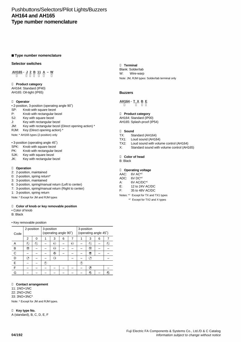
04/192Fuji Electric FA Components & Systems Co., Ltd./D & C Catalog
Information subject to change without notice
Pushbuttons/Selectors/Pilot Lights/BuzzersAH164 and AH165Type number nomenclature
➀ Product categoryAH164: Standard (IP40)AH165: Oil-tight (IP65)
➁ Operator• 2-position, 3-position (operating angle 90˚)SP: Knob with square bezelP: Knob with rectangular bezelSJ: Key with square bezelJ: Key with rectangular bezelJM: Key with rectangular bezel (Direct opening action) *RJM: Key (Direct opening action) *Note: * AH165 types (2-position) only
• 3-position (operating angle 45˚)SPK: Knob with square bezelPK: Knob with rectangular bezelSJK: Key with square bezelJK: Key with rectangular bezel
➂ Operation2: 2-position, maintained0: 2-position, spring return*3: 3-position, maintained6: 3-position, spring/manual return (Left to center)7: 3-position, spring/manual return (Right to center)1: 3-position, spring returnNote: * Except for JM and RJM types
➃ Color of knob or key removable position• Color of knobB: Black
• Key removable position
Type number nomenclature
Selector switches
AH165 - J 2 B 11 A – W➀ ➄➁ ➅➂ ➆➃
Code
2-position
2 0
3-position (operating angle 90˚)
3-position (operating angle 45˚)
1 3 6 7 1 3 6 7
–
–
–
–
–
–
–
–
–
–
–
–
–
–
–
–
–
–
–
–
–
–
–
–
–
–
–
–
–
–
–
–
–
–
–
–
–
–
–
–
–
–
A
B
C
D
E
F
G
➄ Contact arrangement11: 1NO+1NC22: 2NO+2NC33: 3NO+3NC*
Note: * Except for JM and RJM types.
➅ Key type No.A (standard), B, C, D, E, F
➆ TerminalBlank: Solder/tabW: Wire-warpNote: JM, RJM types: Solder/tab terminal only
Buzzers
➀ Product categoryAH164: Standard (IP00)AH165: Splash-proof (IP54)
➁ SoundTX: Standard (AH164)TX1: Loud sound (AH164)TX2: Loud sound with volume control (AH164)X: Standard sound with volume control (AH165)
➂ Color of headB: Black
➃ Operating voltageAAC: 6V AC*2
ADC: 6V DC*2
A: 6V AC/DC*1
E: 12 to 24V AC/DCF: 35 to 48V AC/DCNotes: *1 Except for TX and TX1 types
*2 Except for TX2 and X types
AH164 - T X B E➀ ➁ ➂ ➃
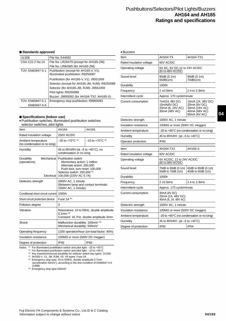
04/193Fuji Electric FA Components & Systems Co., Ltd./D & C CatalogInformation subject to change without notice
04
Pushbuttons/Selectors/Pilot Lights/BuzzersAH164 and AH165
Ratings and specifications
Specifications (Indoor use)•Pushbutton switches, illuminated pushbutton switches
selector switches, pilot lightsItem AH164 AH165
Rated insulation voltage 250V AC/DC
Ambient temperature –20 to +70°C *1 –10 to +70°C *2
(no condensation or no icing)
Humidity 45 to 85%RH (at –5 to +40°C), nocondensation or no icing
Durability Mechanical Pushbutton switch(operations) Momentary action: 1 million
Alternate action: 250,000Push-lock, turn-reset: 100,000
Selector switch: 250,000 *3
Electrical 100,000 (220V AC 0.7A)
Dielectric strength 2000V AC, 1 minute(Between lamp and contact terminals:1500V AC, 1 minute)
Conditional short-circuit current 1000A
Short-circuit protective device Fuse 1A *4
Pollution degree 3
Vibration Resonance: 10 to 55Hz, double amplitude0.1mm *5
Constant: 16.7Hz, double amplitude 3mm
Shock Malfunction durability: 100m/s2 *6
Mechanical durability: 500m/s2
Operating frequency 1200 operation/hour (on-load factor: 40%)
Insulation resistance 100MΩ or more (500V DC megger)
Degree of protection IP40 IP65
Notes: *1 For illuminated pushbutton switch and pilot light: –20 to +55°C*2 For illuminated pushbutton switch and pilot light: –10 to +55°C*3 Key insertion/removal durability for selector switch key types: 10,000*4 AH165-V, V1, JM, RJM, V5, V6 types: Fuse 5A*5 Emergency stop type: 10 to 500Hz, double amplitude 0.7mm
(acceleration 50m/s2), according to the test condition of EN60947-5-5(1998)
*6 Emergency stop type:150m/s2
• Buzzers
Item AH164-TX AH164-TX1
Rated insulation voltage 60V AC/DC
Operating voltage 6V AC, 6V DC,12 to 24V AC/DC35 to 48V AC/DC
Sound level 80dB (0.1m) 90dB (0.1m)60dB(1m) 70dB(1m)
Durability 1000h
Frequency 2 ±0.5kHz 2.4 to 3.3kHz
Intermittent cycle Approx. 170 cycle/minute
Current consumption 7mA(24, 48V DC) 15mA (24, 48V DC)15mA(6V DC) 25mA (6V DC)20mA (6, 24V AC) 30mA (24V AC)30mA (48V AC) 40mA (48V AC)
50mA (6V AC)
Dielectric strength 1000V AC, 1 minute
Insulation resistance 100MΩ or more (500V DC megger)
Ambient temperature –20 to +60°C (no condensation or no icing)
Humidity 45 to 85%RH (at –5 to +40˚C)
Operator protection IP00
Item AH164-TX2 AH165-X
Rated insulation voltage 60V AC/DC
Operating voltage 6V AC/DC, 12 to 24V AC/DC35 to 48V AC/DC
Sound level 70dB to 90dB (0.1m) 60dB to 80dB (0.1m)50dB to 70dB (1m) 40dB to 60dB (1m)
Durability 1000h
Frequency 2 ±0.5kHz 2.4 to 3.3kHz
Intermittent cycle Approx. 170 cycle/minute
Current consumption 30mA (6V DC)20mA (24, 48V DC)40mA (6, 24, 48V AC)
Dielectric strength 1000V AC, 1 minute
Insulation resistance 100MΩ or more (500V DC megger)
Ambient temperature –20 to +60°C (no condensation or no icing)
Humidity 45 to 85%RH (at –5 to +40˚C)
Degree of protection IP00 IP54
Standards approved
UL508CSA C22.2 No.14
TÜV: EN60947-5-1
TÜV: EN60947-5-1 EN60947-5-5
File No. E44592File No. LR20479 (except for AH165-ZM)File No. LR84365 (for AH165-ZM)Pushbutton (except for AH165-V, V1), Illuminated pushbutton: R9250087
Pushbutton (for AH165-V, V1): J9551059Selector (except for AH165-JM, RJM): R9250088Selector (for AH165-JM, RJM): J9551059Pilot lights: R9250089Buzzer: J9950092 (for AH164-TX2, AH165-X)Emergency stop pushbutton: R9950093
Discontinued
Discontinued
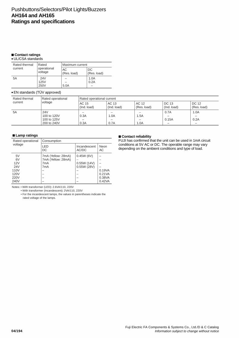
04/194Fuji Electric FA Components & Systems Co., Ltd./D & C Catalog
Information subject to change without notice
Pushbuttons/Selectors/Pilot Lights/BuzzersAH164 and AH165Ratings and specifications
Contact reliabilityFUJI has confirmed that the unit can be used in 1mA circuitconditions at 5V AC or DC. The operable range may varydepending on the ambient conditions and type of load.
Rated operationalvoltage
Notes: • With transformer (LED): 2.6VA/110, 220V• With transformer (Incandescent): 2VA/110, 220V• For the incandescent lamps, the values in parentheses indicate the
rated voltage of the lamps.
Consumption
LEDDC
IncandescentAC/DC
NeonAC
5V6V
12V24V
110V120V220V240V
7mA (Yellow: 28mA)7mA (Yellow: 28mA)7mA7mA––––
0.45W (6V)–0.55W (14V)0.55W (28V)––––
––––0.19VA0.21VA0.38VA0.42VA
Lamp ratings
Contact ratings•UL/CSA standards
Rated thermalcurrent
Ratedoperationalvoltage
Maximum current
AC(Res. load)
DC(Res. load)
5A 24V125V250V
––
5.0A
1.0A0.2A
–
•EN standards (TÜV approved)
Rated thermalcurrent
Rated operationalvoltage
Rated operational current
AC 15(Ind. load)
AC 13(Ind. load)
5A 24V100 to 120V100 to 125V200 to 240V
–0.3A
–0.3A
–1.0A
–0.7A
AC 12(Res. load)
–1.5A
–1.0A
DC 13(Ind. load)
0.7A –0.15A –
DC 12(Res. load)
1.0A–
0.2A–

04/195Fuji Electric FA Components & Systems Co., Ltd./D & C CatalogInformation subject to change without notice
04
Illuminated PushbuttonsAH164 and AH165
Operator Lamp Voltage Contact Momentary action Alternate action
AH164 type AH165 (Oil-tight) type AH164 type AH165 (Oil-tight) type
Extended round head Flat LED 24V DC 1NO+1NC AH164-L11E3 AH165-L11E3 AH164-L511E3 AH165-L511E32NO+2NC AH164-L22E3 AH165-L22E3 AH164-L522E3 AH165-L522E33NO+3NC AH164-L33E3 AH165-L33E3 AH164-L533E3 AH165-L533E3
Spot LED 24V DC 1NO+1NC AH164-L11E2 AH165-L11E2 AH164-L511E2 AH165-L511E22NO+2NC AH164-L22E2 AH165-L22E2 AH164-L522E2 AH165-L522E23NO+3NC AH164-L33E2 AH165-L33E2 AH164-L533E2 AH165-L533E2
Incandes- 24V 1NO+1NC AH164-L11E AH165-L11E AH164-L511E AH165-L511Ecent AC/DC 2NO+2NC AH164-L22E AH165-L22E AH164-L522E AH165-L522E
3NO+3NC AH164-L33E AH165-L33E AH164-L533E AH165-L533E
Neon 110V AC 1NO+1NC AH164-L11H1 AH165-L11H1 AH164-L511H1 AH165-L511H12NO+2NC AH164-L22H1 AH165-L22H1 AH164-L522H1 AH165-L522H13NO+3NC AH164-L33H1 AH165-L33H1 AH164-L533H1 AH165-L533H1
220V AC 1NO+1NC AH164-L11M1 AH165-L11M1 AH164-L511M1 AH165-L511M12NO+2NC AH164-L22M1 AH165-L22M1 AH164-L522M1 AH165-L522M13NO+3NC AH164-L33M1 AH165-L33M1 AH164-L533M1 AH165-L533M1
Flush square head Flat LED 24V DC 1NO+1NC AH164-SL11E3 AH165-SL11E3 AH164-SL511E3 AH165-SL511E32NO+2NC AH164-SL22E3 AH165-SL22E3 AH164-SL522E3 AH165-SL522E33NO+3NC AH164-SL33E3 AH165-SL33E3 AH164-SL533E3 AH165-SL533E3
Spot LED 24V DC 1NO+1NC AH164-SL11E2 AH165-SL11E2 AH164-SL511E2 AH165-SL511E22NO+2NC AH164-SL22E2 AH165-SL22E2 AH164-SL522E2 AH165-SL522E23NO+3NC AH164-SL33E2 AH165-SL33E2 AH164-SL533E2 AH165-SL533E2
Incandes- 24V 1NO+1NC AH164-SL11E AH165-SL11E AH164-SL511E AH165-SL511Ecent AC/DC 2NO+2NC AH164-SL22E AH165-SL22E AH164-SL522E AH165-SL522E
3NO+3NC AH164-SL33E AH165-SL33E AH164-SL533E AH165-SL533E
Neon 110V AC 1NO+1NC AH164-SL11H1 AH165-SL11H1 AH164-SL511H1 AH165-SL511H12NO+2NC AH164-SL22H1 AH165-SL22H1 AH164-SL522H1 AH165-SL522H13NO+3NC AH164-SL33H1 AH165-SL33H1 AH164-SL533H1 AH165-SL533H1
220V AC 1NO+1NC AH164-SL11M1 AH165-SL11M1 AH164-SL511M1 AH165-SL511M12NO+2NC AH164-SL22M1 AH165-SL22M1 AH164-SL522M1 AH165-SL522M13NO+3NC AH164-SL33M1 AH165-SL33M1 AH164-SL533M1 AH165-SL533M1
Flush rectangular head Flat LED 24V DC 1NO+1NC AH164-TL11E3 AH165-TL11E3 AH164-TL511E3 AH165-TL511E32NO+2NC AH164-TL22E3 AH165-TL22E3 AH164-TL522E3 AH165-TL522E33NO+3NC AH164-TL33E3 AH165-TL33E3 AH164-TL533E3 AH165-TL533E3
Spot LED 24V DC 1NO+1NC AH164-TL11E2 AH165-TL11E2 AH164-TL511E2 AH165-TL511E22NO+2NC AH164-TL22E2 AH165-TL22E2 AH164-TL522E2 AH165-TL522E23NO+3NC AH164-TL33E2 AH165-TL33E2 AH164-TL533E2 AH165-TL533E2
Incandes- 24V 1NO+1NC AH164-TL11E AH165-TL11E AH164-TL511E AH165-TL511Ecent AC/DC 2NO+2NC AH164-TL22E AH165-TL22E AH164-TL522E AH165-TL522E
3NO+3NC AH164-TL33E AH165-TL33E AH164-TL533E AH165-TL533E
Neon 110V AC 1NO+1NC AH164-TL11H1 AH165-TL11H1 AH164-TL511H1 AH165-TL511H12NO+2NC AH164-TL22H1 AH165-TL22H1 AH164-TL522H1 AH165-TL522H13NO+3NC AH164-TL33H1 AH165-TL33H1 AH164-TL533H1 AH165-TL533H1
220V AC 1NO+1NC AH164-TL11M1 AH165-TL11M1 AH164-TL511M1 AH165-TL511M12NO+2NC AH164-TL22M1 AH165-TL22M1 AH164-TL522M1 AH165-TL522M13NO+3NC AH164-TL33M1 AH165-TL33M1 AH164-TL533M1 AH165-TL533M1
Note: Replace the mark by the button color code, see page 04/196.
KKD07-205
KKD07-204
KKD07-202
Illuminated pushbutton switches/without transformer

04/196Fuji Electric FA Components & Systems Co., Ltd./D & C Catalog
Information subject to change without notice
Operator Lamp Voltage Contact Momentary action Alternate action
AH164 type AH165 (oil-tight) type AH164 type AH165 (oil-tight) type
Flush rectangular head Flat LED 24V DC 1NO+1NC AH164-TGL11E3 AH165-TGL11E3 AH164-TGL511E3 AH165-TGL511E3with guard 2NO+2NC AH164-TGL22E3 AH165-TGL22E3 AH164-TGL522E3 AH165-TGL522E3
3NO+3NC AH164-TGL33E3 AH165-TGL33E3 AH164-TGL533E3 AH165-TGL533E3
Incandes- 24V 1NO+1NC AH164-TGL11E AH165-TGL11E AH164-TGL511E AH165-TGL511Ecent AC/DC 2NO+2NC AH164-TGL22E AH165-TGL22E AH164-TGL522E AH165-TGL522E
3NO+3NC AH164-TGL33E AH165-TGL33E AH164-TGL533E AH165-TGL533E
Neon 110V AC 1NO+1NC AH164-TGL11H1 AH165-TGL11H1 AH164-TGL511H1 AH165-TGL511H12NO+2NC AH164-TGL22H1 AH165-TGL22H1 AH164-TGL522H1 AH165-TGL522H13NO+3NC AH164-TGL33H1 AH165-TGL33H1 AH164-TGL533H1 AH165-TGL533H1
220V AC 1NO+1NC AH164-TGL11M1 AH165-TGL11M1 AH164-TGL511M1 AH165-TGL511M12NO+2NC AH164-TGL22M1 AH165-TGL22M1 AH164-TGL522M1 AH165-TGL522M13NO+3NC AH164-TGL33M1 AH165-TGL33M1 AH164-TGL533M1 AH165-TGL533M1
Flush square head Flat LED 24V DC 1NO+1NC AH164-SGL11E3 AH165-SGL11E3 AH164-SGL511E3 AH165-SGL511E3with guard 2NO+2NC AH164-SGL22E3 AH165-SGL22E3 AH164-SGL522E3 AH165-SGL522E3
3NO+3NC AH164-SGL33E3 AH165-SGL33E3 AH164-SGL533E3 AH165-SGL533E3
Incandes- 24V 1NO+1NC AH164-SGL11E AH165-SGL11E AH164-SGL511E AH165-SGL511Ecent AC/DC 2NO+2NC AH164-SGL22E AH165-SGL22E AH164-SGL522E AH165-SGL522E
3NO+3NC AH164-SGL33E AH165-SGL33E AH164-SGL533E AH165-SGL533E
Neon 110V AC 1NO+1NC AH164-SGL11H1 AH165-SGL11H1 AH164-SGL511H1 AH165-SGL511H12NO+2NC AH164-SGL22H1 AH165-SGL22H1 AH164-SGL522H1 AH165-SGL522H13NO+3NC AH164-SGL33H1 AH165-SGL33H1 AH164-SGL533H1 AH165-SGL533H1
220V AC 1NO+1NC AH164-SGL11M1 AH165-SGL11M1 AH164-SGL511M1 AH165-SGL511M12NO+2NC AH164-SGL22M1 AH165-SGL22M1 AH164-SGL522M1 AH165-SGL522M13NO+3NC AH164-SGL33M1 AH165-SGL33M1 AH164-SGL533M1 AH165-SGL533M1
Illuminated PushbuttonsAH164 and AH165
Dimensions, mm
L, L5 SL, SL5
TL, TL5 TGL, TGL5 SGL, SGL5
• Button color
KKD07-203
KKD05-075b
Color Green Red White Yellow Blue OrangeCode G R W Y S O
Lamp terminal
WasherNut
Panel thickness4 (max.)
42.5 10
7
ø15 ø18
18sq. Lamp terminal
WasherNut
Panel thickness4 (max.)
15 18
15sq.18sq.42.5 10
7
42.5 10
7Lamp terminal
WasherNut
Panel thickness4 (max.)
15 18
21
24
15 18
42.5 10
7Lamp terminal
WasherNut
Panel thickness4 (max.)
21
24
15 18
15sq.18sq.
• The color lens is made of a tinted transparent material.• A white illuminated pushbutton is fitted with a transparent color
lens.(Except the neon lamp)• With wire-wrap pin terminals have a depth of 47mm.
• Lamp voltageVoltages other than above are available
Code LED Incandescent
AAABKP
5V DC6V DC12V DC––
–5V AC/DC12V AC/DC––
Neon
–––120V AC240V AC

04/197Fuji Electric FA Components & Systems Co., Ltd./D & C CatalogInformation subject to change without notice
04
Illuminated PushbuttonsAH164 and AH165
Operator Lamp Voltage Contact Momentary action Alternate action
AH164 type AH165 (oil-tight) type AH164 type AH165 (oil-tight) type
Extended round head Flat LED Voltage 1NO+1NC AH164-L113 AH165-L113 AH164-L5113 AH165-L5113
code
2NO+2NC AH164-L223 AH165-L223 AH164-L5223 AH165-L5223
Incandes- 1NO+1NC AH164-L11 AH165-L11 AH164-L511 AH165-L511cent
2NO+2NC AH164-L22 AH165-L22 AH164-L522 AH165-L522
Flush square head Flat LED Voltage 1NO+1NC AH164-SL113 AH165-SL113 AH164-SL5113 AH165-SL5113
code
2NO+2NC AH164-SL223 AH165-SL223 AH164-SL5223 AH165-SL5223
Incandes- 1NO+1NC AH164-SL11 AH165-SL11 AH164-SL511 AH165-SL511cent
2NO+2NC AH164-SL22 AH165-SL22 AH164-SL522 AH165-SL522
Flush rectangular head Flat LED Voltage 1NO+1NC AH164-TL113 AH165-TL113 AH164-TL5113 AH165-TL5113
code
2NO+2NC AH164-TL223 AH165-TL223 AH164-TL5223 AH165-TL5223
Incandes- 1NO+1NC AH164-TL11 AH165-TL11 AH164-TL511 AH165-TL511cent
2NO+2NC AH164-TL22 AH165-TL22 AH164-TL522 AH165-TL522
Flush rectangular head Flat LED Voltage 1NO+1NC AH164-TGL113 AH165-TGL113 AH164-TGL5113 AH165-TGL5113with guard code
2NO+2NC AH164-TGL223 AH165-TGL223 AH164-TGL5223 AH165-TGL5223
Incandes- 1NO+1NC AH164-TGL11 AH165-TGL11 AH164-TGL511 AH165-TGL511cent
2NO+2NC AH164-TGL22 AH165-TGL22 AH164-TGL522 AH165-TGL522
Flush square head Flat LED Voltage 1NO+1NC AH164-SGL113 AH165-SGL113 AH164-SGL5113 AH165-SGL5113with guard code
2NO+2NC AH164-SGL223 AH165-SGL223 AH164-SGL5223 AH165-SGL5223
Incandes- 1NO+1NC AH164-SGL11 AH165-SGL11 AH164-SGL511 AH165-SGL511cent
2NO+2NC AH164-SGL22 AH165-SGL22 AH164-SGL522 AH165-SGL522
Note: Replace the mark by the button color code, see page 04/198.
AF90-946
AF90-947
Illuminated pushbutton switches/with transformer
AF90-941
AF90-948
H:100-110VAC
M:200-220VAC
H:100-110VAC
M:200-220VAC
H:100-110VAC
M:200-220VAC
H:100-110VAC
M:200-220VAC
H:100-110VAC
M:200-220VAC
AF90-945
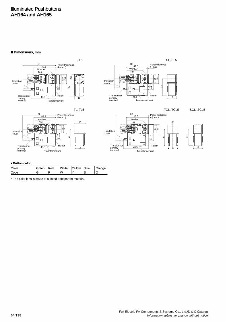
04/198Fuji Electric FA Components & Systems Co., Ltd./D & C Catalog
Information subject to change without notice
Dimensions, mm
L, L5 SL, SL5
TL, TL5 TGL, TGL5 SGL, SGL5
• Button color
Color Green Red White Yellow Blue OrangeCode G R W Y S O
62 Panel thickness4 (max.)
Holder
Transformer unit
Transformer primary terminal
Insulationcover
WasherNut
42.5
48.5
710
ø15
ø18
3218
18
(–)b(+
)a
Panel thickness4 (max.)
Holder
Transformer unit
Transformer primary terminal
Insulationcover
WasherNut
42.562
48.5
710
15 18
32
18
(–)b(+
)a
Panel thickness4 (max.)
Holder
Transformer unit
Transformer primary terminal
Insulationcover
WasherNut
42.562
48.5
710
15 18
32
18
24
(–)b(+
)a
Panel thickness4 (max.)
Holder
Transformer unit
Transformer primary terminal
Insulationcover
WasherNut
42.562
48.5
710
15 18
32
18
24
(+)a
32
18
Illuminated PushbuttonsAH164 and AH165
• The color lens is made of a tinted transparent material.
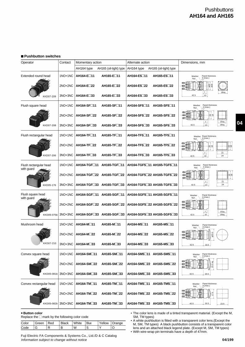
04/199Fuji Electric FA Components & Systems Co., Ltd./D & C CatalogInformation subject to change without notice
04
Extended round head 1NO+1NC AH164-E11 AH165-E11 AH164-E511 AH165-E511
2NO+2NC AH164-E22 AH165-E22 AH164-E522 AH165-E522
3NO+3NC AH164-E33 AH165-E33 AH164-E533 AH165-E533
Flush square head 1NO+1NC AH164-SF11 AH165-SF11 AH164-SF511 AH165-SF511
2NO+2NC AH164-SF22 AH165-SF22 AH164-SF522 AH165-SF522
3NO+3NC AH164-SF33 AH165-SF33 AH164-SF533 AH165-SF533
Flush rectangular head 1NO+1NC AH164-TF11 AH165-TF11 AH164-TF511 AH165-TF511
2NO+2NC AH164-TF22 AH165-TF22 AH164-TF522 AH165-TF522
3NO+3NC AH164-TF33 AH165-TF33 AH164-TF533 AH165-TF533
1NO+1NC AH164-TGF11 AH165-TGF11 AH164-TGF511 AH165-TGF511
2NO+2NC AH164-TGF22 AH165-TGF22 AH164-TGF522 AH165-TGF522
3NO+3NC AH164-TGF33 AH165-TGF33 AH164-TGF533 AH165-TGF533
1NO+1NC AH164-SGF11 AH165-SGF11 AH164-SGF511 AH165-SGF511
2NO+2NC AH164-SGF22 AH165-SGF22 AH164-SGF522 AH165-SGF522
3NO+3NC AH164-SGF33 AH165-SGF33 AH164-SGF533 AH165-SGF533
Mushroom head 1NO+1NC AH164-M11 AH165-M11 AH164-M511 AH165-M511
2NO+2NC AH164-M22 AH165-M22 AH164-M522 AH165-M522
3NO+3NC AH164-M33 AH165-M33 AH164-M533 AH165-M533
Convex square head 1NO+1NC AH164-SM11 AH165-SM11 AH164-SM511 AH165-SM511
2NO+2NC AH164-SM22 AH165-SM22 AH164-SM522 AH165-SM522
3NO+3NC AH164-SM33 AH165-SM33 AH164-SM533 AH165-SM533
Convex rectangular head 1NO+1NC AH164-TM11 AH165-TM11 AH164-TM511 AH165-TM511
2NO+2NC AH164-TM22 AH165-TM22 AH164-TM522 AH165-TM522
3NO+3NC AH164-TM33 AH165-TM33 AH164-TM533 AH165-TM533
PushbuttonsAH164 and AH165
Operator Contact Momentary action Alternate action Dimensions, mm
AH164 type AH165 (oil-tight) type AH164 type AH165 (oil-tight) type
• Button colorReplace the mark by the following color code
• The color lens is made of a tinted transparent material. (Except the M,SM, TM types)
• A white pushbutton is fitted with a transparent color lens.(Except theM, SM, TM types) A black pushbutton consists of a transparent colorlens and an attached black legend plate. (Except M, SM, TM types)
• With wire-wrap pin terminals have a depth of 47mm.
Color Green Red Black White Blue Yellow OrangeCode G R B W S Y O
Flush rectangular headwith guard
KKD07-209
KKD07-208
KKD07-206
KKD05-176
KKD05-075b
KKD07-210
KKD05-081b
KKD05-082b
10
7
WasherNut
Panel thickness4 (max.)
φ φ15 18
18sq.
42.5
10
742.5
WasherNut
Panel thickness4 (max.)
15 18
15sq.
18sq.
10
7
42.5
WasherNut
Panel thickness4 (max.)
15 18
21
24
15 18
10
742.5
WasherNut
Panel thickness4 (max.)
21
24
15 18
10
7
42.5
WasherNut
Panel thickness4 (max.)
15sq.18sq.
42.5 16.5
WasherNut
Panel thickness4 (max.)
φ23
.5
42.5 16.5
WasherNut
Panel thickness4 (max.)
23.5
sq.
42.5 16.5 23.5
WasherNut
Panel thickness4 (max.)
17.5
Pushbutton switches
Flush square headwith guard

04/200Fuji Electric FA Components & Systems Co., Ltd./D & C Catalog
Information subject to change without notice
Operator Button Contact Terminal AH165 (oil-tight) type Dimensions, mmcolor
Push-lock, turn-reset Red 1NC Solder/Tab AH165-V5R01(32mm dia.) Solder (AH165-V5R01-S)
2NC AH165-V5R02
KKD07-221(AH165-V5R02-S)
Push-lock, turn-reset 1NC AH165-V6R01(40mm dia.) (AH165-V6R01-S)
2NC AH165-V6R02
KKD07-222(AH165-V6R02-S)
Notes: * ( ) For switch with solder terminal.• Contact arrangements indicated in the table can be supplied.
Operator Button Contact Terminal AH165 (oil-tight) type Dimensions, mmcolor
Push-lock, turn-reset Red 1NC Solder/Tab AH165-VR01(32mm dia.) Solder (AH165-VR01-S)
2NC AH165-VR02
AF91-584(AH165-VR02-S)
Push-lock, turn-reset 1NC AH165-V1R01(40mm dia.) (AH165-V1R01-S)
2NC AH165-V1R02
AF91-583(AH165-V1R02-S)
Notes: * ( ) For switch with solder terminal.• Contact arrangements indicated in the table can be supplied.• Product with no trigger action mechanism.
PushbuttonsAH165
Washer
Nut
Panel thickness4 (max.)
24.5
15.5 15
ø32
*(20)
Washer
Nut
24.5
15.5 15
Panel thickness4 (max.)
ø40
*(20)
Pushbutton switches (Direct opening action)
Emergency stop pushbutton switches (Direct opening action), conform to EN418
3342 24.5
Washer Panel thickness6 (max.)
Nut
ø32
* (37.5)
3324.5
ø40
42
Washer Panel thickness6 (max.)
Nut
* (37.5)
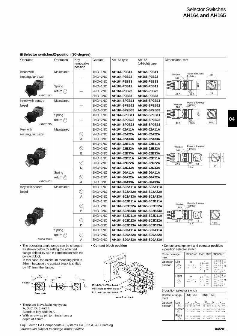
04/201Fuji Electric FA Components & Systems Co., Ltd./D & C CatalogInformation subject to change without notice
04
Operator Operation Key Contact AH164 type AH165 Dimensions, mmremovable (oil-tight) typeposition
Knob with Maintained 1NO+1NC AH164-P2B11 AH165-P2B11
rectangular bezel — 2NO+2NC AH164-P2B22 AH165-P2B22
3NO+3NC AH164-P2B33 AH165-P2B33
Spring 1NO+1NC AH164-P0B11 AH165-P0B11
return — 2NO+2NC AH164-P0B22 AH165-P0B22
3NO+3NC AH164-P0B33 AH165-P0B33
Knob with square Maintained 1NO+1NC AH164-SP2B11 AH165-SP2B11
bezel — 2NO+2NC AH164-SP2B22 AH165-SP2B22
3NO+3NC AH164-SP2B33 AH165-SP2B33
Spring 1NO+1NC AH164-SP0B11 AH165-SP0B11
return — 2NO+2NC AH164-SP0B22 AH165-SP0B22
3NO+3NC AH164-SP0B33 AH165-SP0B33
Key with Maintained 1NO+1NC AH164-J2A11A AH165-J2A11A
rectangular bezel 2NO+2NC AH164-J2A22A AH165-J2A22A
A 3NO+3NC AH164-J2A33A AH165-J2A33A
1NO+1NC AH164-J2B11A AH165-J2B11A
2NO+2NC AH164-J2B22A AH165-J2B22A
B 3NO+3NC AH164-J2B33A AH165-J2B33A
1NO+1NC AH164-J2D11A AH165-J2D11A
2NO+2NC AH164-J2D22A AH165-J2D22A
D 3NO+3NC AH164-J2D33A AH165-J2D33A
Spring 1NO+1NC AH164-J0A11A AH165-J0A11A
return 2NO+2NC AH164-J0A22A AH165-J0A22A
A 3NO+3NC AH164-J0A33A AH165-J0A33A
Key with square Maintained 1NO+1NC AH164-SJ2A11A AH165-SJ2A11A
bezel 2NO+2NC AH164-SJ2A22A AH165-SJ2A22A
A 3NO+3NC AH164-SJ2A33A AH165-SJ2A33A
1NO+1NC AH164-SJ2B11A AH165-SJ2B11A
2NO+2NC AH164-SJ2B22A AH165-SJ2B22A
B 3NO+3NC AH164-SJ2B33A AH165-SJ2B33A
1NO+1NC AH164-SJ2D11A AH165-SJ2D11A
2NO+2NC AH164-SJ2D22A AH165-SJ2D22A
D 3NO+3NC AH164-SJ2D33A AH165-SJ2D33A
Spring 1NO+1NC AH164-SJ0A11A AH165-SJ0A11A
return 2NO+2NC AH164-SJ0A22A AH165-SJ0A22A
A 3NO+3NC AH164-SJ0A33A AH165-SJ0A33A
Selector switches/2-position (90-degree)
Selector SwitchesAH164 and AH165
3-position selector switchContact arrange- 2NO+2NC 3NO+3NCment
Operator Left U L U M L
positionCenter
Right
Contact arrange- 1NO+1NC 2NO+2NC 3NO+3NCment
Operator Leftposition
Right
1 23 4
1 23 41 23 4
1 23 41 23 4
1 23 4
1 23 4
1 23 41 23 4
1 23 41 23 4
1 23 4
1 23 4
1 23 4
1 23 4
1 23 4
1 23 4
1 23 4
1 23 4
1 23 4
1 23 4
1 23 4
1 23 4
1 23 4
1 23 4
1 23 4
1 23 4
KKD07-213
KKD07-215
KKD09-001L
KKD09-001R
• Contact block position
• There are 6 available key types; A, B, C, D, E and F.
Standard key code is A.• With wire-wrap pin terminals have a
depth of 47mm.
• The operating angle range can be changedas shown below by setting the attachedflange shifted by 45° in combination with thecontact block.In this case, the minimum mounting pitch is26mm because the contact block is shiftedby 45° from the flange.
42.5 18.510.58.5
18 18
24
WasherNut
Panel thickness4 (max.)
φ
18φ
42.5 18.510.58.5
18sq.
18
WasherNut
Panel thickness4 (max.)
φ
42.510.5
188.5
18
24
WasherNut
Panel thickness4 (max.)
42.510.5
188.5
18sq.
WasherNut
Panel thickness4 (max.)
• Contact arrangement and operator position:2-position selector switch
M
M
U
L
U
L
U
L
M
U
L
M

04/202Fuji Electric FA Components & Systems Co., Ltd./D & C Catalog
Information subject to change without notice
Operator Operation Key Contact AH165 (oil-tight) type Dimensions, mmremovableposition
Key with rectangular Maintained A 1NO+1NC AH165-JM2A11A
bezel
B AH165-JM2B11A
D AH165-JM2D11A
A 2NO+2NC AH165-JM2A22A
B AH165-JM2B22A
D AH165-JM2D22A
Key with round bezel Maintained A 1NO+1NC AH165-RJM2A11A
B AH165-RJM2B11A
D AH165-RJM2D11A
A 2NO+2NC AH165-RJM2A22A
B AH165-RJM2B22A
D AH165-RJM2D22A
Selector SwitchesAH165
WasherNut
Panel thickness4 (max.)
9.8
ø20
18s
q.
32.510.8 1841.5
Panel thickness4(max.)
WasherNut
9.818
18sq
.27
.5
37.510.8 1846.5
ø20
Panel thickness4(max.)
Washer
Nut
Selector switches/2-position (90-degree) (Direct opening action)
Contactarrangement
1NO+1NC
Operatorposition
Left
Right
21 2211 12
21 2211 12
• Contact arrangement and operator positions:2-position selector switch
Contactarrangement
2NO+2NC
Operatorposition
Left U L
Right
11 1211 12
11 1211 12
21 2221 22
21 2221 22
• Terminal number
1211
2221
U: Upper contact block
1NO+1NC 2NO+2NC
L: Lower contact block
18
24
8.832.5
Washer Panel thickness4 (max.)Nut
41.5 10.8 18
• There are 6 available key types; A, B, C, D, E and F.Standard key code is A.
KKD09-005R
KKD09-007R
KKD09-005L
KKD09-005L

04/203Fuji Electric FA Components & Systems Co., Ltd./D & C CatalogInformation subject to change without notice
04
Operator Operation Key Contact AH164 type AH165 Dimensions, mmremovable (oil-tight) typeposition
Knob with Maintained 2NO+2NC AH164-P3B22 AH165-P3B22rectangular bezel 3NO+3NC AH164-P3B33 AH165-P3B33
Spring/ 2NO+2NC AH164-P6B22 AH165-P6B22manual return 3NO+3NC AH164-P6B33 AH165-P6B33Spring/ 2NO+2NC AH164-P7B22 AH165-P7B22manual return 3NO+3NC AH164-P7B33 AH165-P7B33Spring return 2NO+2NC AH164-P1B22 AH165-P1B22
3NO+3NC AH164-P1B33 AH165-P1B33Knob with square Maintained 2NO+2NC AH164-SP3B22 AH165-SP3B22bezel 3NO+3NC AH164-SP3B33 AH165-SP3B33
Spring/ 2NO+2NC AH164-SP6B22 AH165-SP6B22manual return 3NO+3NC AH164-SP6B33 AH165-SP6B33Spring/ 2NO+2NC AH164-SP7B22 AH165-SP7B22manual return 3NO+3NC AH164-SP7B33 AH165-SP7B33Spring return 2NO+2NC AH164-SP1B22 AH165-SP1B22
3NO+3NC AH164-SP1B33 AH165-SP1B33Key with Maintained* 2NO+2NC AH164-J3A22A AH165-J3A22Arectangular bezel 3NO+3NC AH164-J3A33A AH165-J3A33A
2NO+2NC AH164-J3E22A AH165-J3E22A3NO+3NC AH164-J3E33A AH165-J3E33A2NO+2NC AH164-J3D22A AH165-J3D22A3NO+3NC AH164-J3D33A AH165-J3D33A2NO+2NC AH164-J3C22A AH165-J3C22A3NO+3NC AH164-J3C33A AH165-J3C33A
Spring/ 2NO+2NC AH164-J6E22A AH165-J6E22Amanual return 3NO+3NC AH164-J6E33A AH165-J6E33A
2NO+2NC AH164-J6D22A AH165-J6D22A3NO+3NC AH164-J6D33A AH165-J6D33A
Spring/ 2NO+2NC AH164-J7A22A AH165-J7A22Amanual return 3NO+3NC AH164-J7A33A AH165-J7A33A
2NO+2NC AH164-J7E22A AH165-J7E22A3NO+3NC AH164-J7E33A AH165-J7E33A
Spring 2NO+2NC AH164-J1E22A AH165-J1E22Areturn 3NO+3NC AH164-J1E33A AH165-J1E33A
Key with square Maintained* 2NO+2NC AH164-SJ3A22A AH165-SJ3A22Abezel 3NO+3NC AH164-SJ3A33A AH165-SJ3A33A
2NO+2NC AH164-SJ3E22A AH165-SJ3E22A3NO+3NC AH164-SJ3E33A AH165-SJ3E33A2NO+2NC AH164-SJ3D22A AH165-SJ3D22A3NO+3NC AH164-SJ3D33A AH165-SJ3D33A2NO+2NC AH164-SJ3C22A AH165-SJ3C22A3NO+3NC AH164-SJ3C33A AH165-SJ3C33A
Spring/ 2NO+2NC AH164-SJ6E22A AH165-SJ6E22Amanual return 3NO+3NC AH164-SJ6E33A AH165-SJ6E33A
2NO+2NC AH164-SJ6D22A AH165-SJ6D22A3NO+3NC AH164-SJ6D33A AH165-SJ6D33A
Spring/ 2NO+2NC AH164-SJ7A22A AH165-SJ7A22Amanual return 3NO+3NC AH164-SJ7A33A AH165-SJ7A33A
2NO+2NC AH164-SJ7E22A AH165-SJ7E22A3NO+3NC AH164-SJ7E33A AH165-SJ7E33A
Spring 2NO+2NC AH164-SJ1E22A AH165-SJ1E22Areturn 3NO+3NC AH164-SJ1E33A AH165-SJ1E33A
—
—
—
—
—
—
—
—
A
E
D
C
E
D
A
E
E
A
E
D
C
E
D
A
E
E
Selector SwitchesAH164 and AH165
• There are 6 available key types; A, B, C, D, E and F.Standard key code is A.
• Contact arrangement and operator position: See page 04/201.• Spring return, spring/manual return (spring return):
Operation angle 70-degree
42.5 18.510.58.5
18 18
24
WasherNut
Panel thickness4 (max.)
φ
42.5 18.510.58.5
18sq.
18
WasherNut
Panel thickness4 (max.)
φ
42.510.5
188.5
18
24
WasherNut
Panel thickness4 (max.)
42.510.5
188.5
18sq.
WasherNut
Panel thickness4 (max.)
Selector switches/3-position (90-degree)
• * Available key removable position: Code B• With wire-wrap pin terminals have a depth of 47mm.
KKD07-214
KKD07-216
KKD09-002L
KKD09-002R
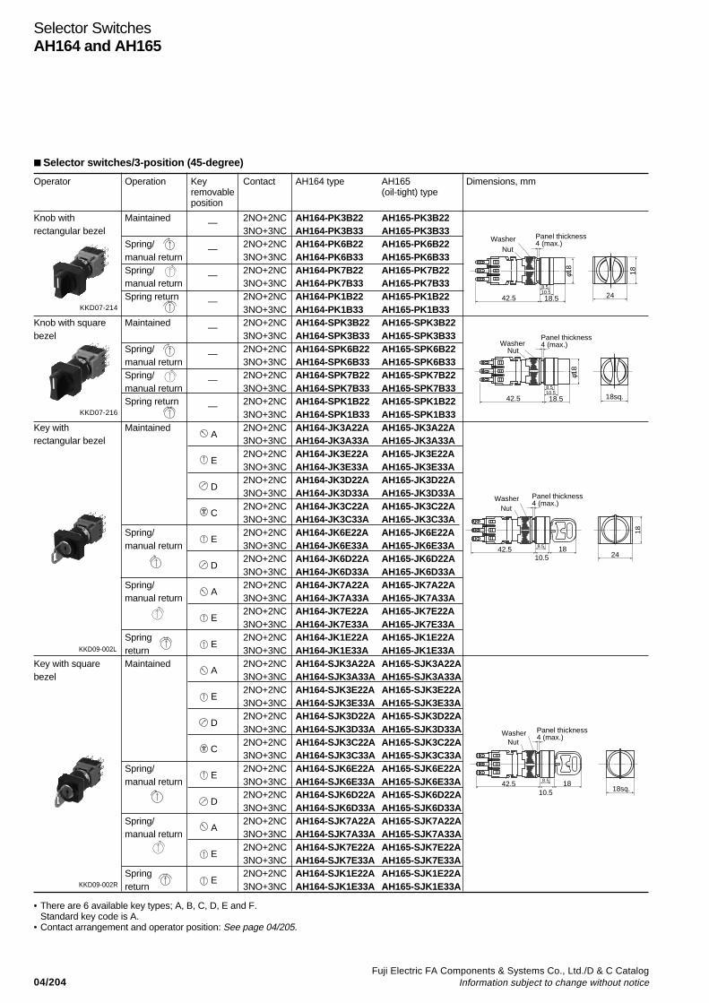
04/204Fuji Electric FA Components & Systems Co., Ltd./D & C Catalog
Information subject to change without notice
Operator Operation Key Contact AH164 type AH165 Dimensions, mmremovable (oil-tight) typeposition
Knob with Maintained 2NO+2NC AH164-PK3B22 AH165-PK3B22rectangular bezel 3NO+3NC AH164-PK3B33 AH165-PK3B33
Spring/ 2NO+2NC AH164-PK6B22 AH165-PK6B22manual return 3NO+3NC AH164-PK6B33 AH165-PK6B33Spring/ 2NO+2NC AH164-PK7B22 AH165-PK7B22manual return 3NO+3NC AH164-PK7B33 AH165-PK7B33Spring return 2NO+2NC AH164-PK1B22 AH165-PK1B22
3NO+3NC AH164-PK1B33 AH165-PK1B33Knob with square Maintained 2NO+2NC AH164-SPK3B22 AH165-SPK3B22bezel 3NO+3NC AH164-SPK3B33 AH165-SPK3B33
Spring/ 2NO+2NC AH164-SPK6B22 AH165-SPK6B22manual return 3NO+3NC AH164-SPK6B33 AH165-SPK6B33Spring/ 2NO+2NC AH164-SPK7B22 AH165-SPK7B22manual return 3NO+3NC AH164-SPK7B33 AH165-SPK7B33Spring return 2NO+2NC AH164-SPK1B22 AH165-SPK1B22
3NO+3NC AH164-SPK1B33 AH165-SPK1B33Key with Maintained 2NO+2NC AH164-JK3A22A AH165-JK3A22Arectangular bezel 3NO+3NC AH164-JK3A33A AH165-JK3A33A
2NO+2NC AH164-JK3E22A AH165-JK3E22A3NO+3NC AH164-JK3E33A AH165-JK3E33A2NO+2NC AH164-JK3D22A AH165-JK3D22A3NO+3NC AH164-JK3D33A AH165-JK3D33A2NO+2NC AH164-JK3C22A AH165-JK3C22A3NO+3NC AH164-JK3C33A AH165-JK3C33A
Spring/ 2NO+2NC AH164-JK6E22A AH165-JK6E22Amanual return 3NO+3NC AH164-JK6E33A AH165-JK6E33A
2NO+2NC AH164-JK6D22A AH165-JK6D22A3NO+3NC AH164-JK6D33A AH165-JK6D33A
Spring/ 2NO+2NC AH164-JK7A22A AH165-JK7A22Amanual return 3NO+3NC AH164-JK7A33A AH165-JK7A33A
2NO+2NC AH164-JK7E22A AH165-JK7E22A3NO+3NC AH164-JK7E33A AH165-JK7E33A
Spring 2NO+2NC AH164-JK1E22A AH165-JK1E22Areturn 3NO+3NC AH164-JK1E33A AH165-JK1E33A
Key with square Maintained 2NO+2NC AH164-SJK3A22A AH165-SJK3A22Abezel 3NO+3NC AH164-SJK3A33A AH165-SJK3A33A
2NO+2NC AH164-SJK3E22A AH165-SJK3E22A3NO+3NC AH164-SJK3E33A AH165-SJK3E33A2NO+2NC AH164-SJK3D22A AH165-SJK3D22A3NO+3NC AH164-SJK3D33A AH165-SJK3D33A2NO+2NC AH164-SJK3C22A AH165-SJK3C22A3NO+3NC AH164-SJK3C33A AH165-SJK3C33A
Spring/ 2NO+2NC AH164-SJK6E22A AH165-SJK6E22Amanual return 3NO+3NC AH164-SJK6E33A AH165-SJK6E33A
2NO+2NC AH164-SJK6D22A AH165-SJK6D22A3NO+3NC AH164-SJK6D33A AH165-SJK6D33A
Spring/ 2NO+2NC AH164-SJK7A22A AH165-SJK7A22Amanual return 3NO+3NC AH164-SJK7A33A AH165-SJK7A33A
2NO+2NC AH164-SJK7E22A AH165-SJK7E22A3NO+3NC AH164-SJK7E33A AH165-SJK7E33A
Spring 2NO+2NC AH164-SJK1E22A AH165-SJK1E22Areturn 3NO+3NC AH164-SJK1E33A AH165-SJK1E33A
Selector SwitchesAH164 and AH165
—
—
—
—
—
—
—
—
A
E
D
C
E
D
A
E
E
A
E
D
C
E
D
A
E
E
• There are 6 available key types; A, B, C, D, E and F.Standard key code is A.
• Contact arrangement and operator position: See page 04/205.
42.5 18.510.58.5
18 18
24
WasherNut
Panel thickness4 (max.)
φ
42.5 18.510.58.5
18sq.
18
WasherNut
Panel thickness4 (max.)
φ
42.510.5
188.5
18
24
WasherNut
Panel thickness4 (max.)
42.510.5
188.5
18sq.
WasherNut
Panel thickness4 (max.)
Selector switches/3-position (45-degree)
KKD07-214
KKD07-216
KKD09-002L
KKD09-002R
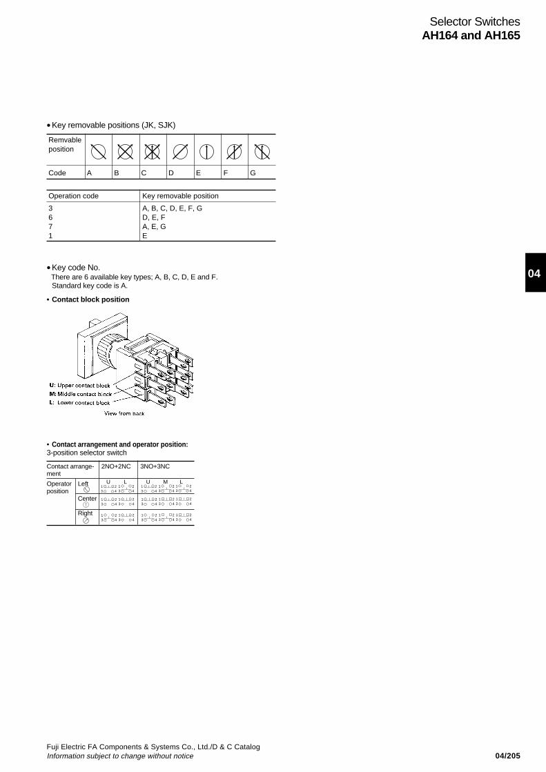
04/205Fuji Electric FA Components & Systems Co., Ltd./D & C CatalogInformation subject to change without notice
04
Selector SwitchesAH164 and AH165
•Key removable positions (JK, SJK)
•Key code No. There are 6 available key types; A, B, C, D, E and F.
Standard key code is A.
Remvableposition
Code A B C D E F G
Operation code Key removable position
3671
A, B, C, D, E, F, GD, E, FA, E, GE
• Contact block position
Contact arrange- 2NO+2NC 3NO+3NCment
Operator Left U L U M L
positionCenter
Right
1 23 4
1 23 4
1 23 4
1 23 4
1 23 4
1 23 4
1 23 4
1 23 4
1 23 4
1 23 4
1 23 4
1 23 4
1 23 4
1 23 4
1 23 4
• Contact arrangement and operator position:3-position selector switch
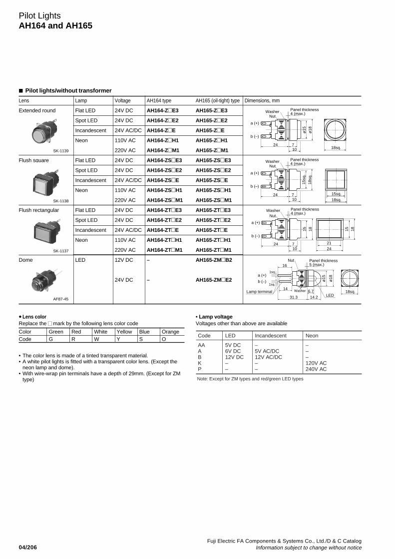
04/206Fuji Electric FA Components & Systems Co., Ltd./D & C Catalog
Information subject to change without notice
Lens Lamp Voltage AH164 type AH165 (oil-tight) type Dimensions, mm
Extended round Flat LED 24V DC AH164-ZE3 AH165-ZE3
Spot LED 24V DC AH164-ZE2 AH165-ZE2
Incandescent 24V AC/DC AH164-ZE AH165-ZE
Neon 110V AC AH164-ZH1 AH165-ZH1
220V AC AH164-ZM1 AH165-ZM1
Flush square Flat LED 24V DC AH164-ZSE3 AH165-ZSE3
Spot LED 24V DC AH164-ZSE2 AH165-ZSE2
Incandescent 24V AC/DC AH164-ZSE AH165-ZSE
Neon 110V AC AH164-ZSH1 AH165-ZSH1
220V AC AH164-ZSM1 AH165-ZSM1
Flat LED 24V DC AH164-ZTE3 AH165-ZTE3
Spot LED 24V DC AH164-ZTE2 AH165-ZTE2
Incandescent 24V AC/DC AH164-ZTE AH165-ZTE
Neon 110V AC AH164-ZTH1 AH165-ZTH1
220V AC AH164-ZTM1 AH165-ZTM1
Dome LED 12V DC – AH165-ZMB2
24V DC – AH165-ZME2
Pilot LightsAH164 and AH165
Flush rectangular
• Lens colorReplace the mark by the following lens color code
• The color lens is made of a tinted transparent material.• A white pilot lights is fitted with a transparent color lens. (Except the
neon lamp and dome).• With wire-wrap pin terminals have a depth of 29mm. (Except for ZM
type)
Color Green Red White Yellow Blue OrangeCode G R W Y S O
Pilot lights/without transformer
• Lamp voltageVoltages other than above are available
Code LED Incandescent
AAABKP
5V DC6V DC12V DC––
Note: Except for ZM types and red/green LED types
–5V AC/DC12V AC/DC––
Neon
–––120V AC240V AC
SK-1139
SK-1138
SK-1137
AF87-45
24 710
ø15
ø18
18sq.
WasherNut
a (+)
b (–)
Panel thickness 4 (max.)
24 710 18sq.
15sq.
18sq
.
15sq
.a (+)
b (–)
Panel thickness 4 (max.)Washer
Nut
24 710
15 18 15 18
2124
a (+)
b (–)
WasherNut
Panel thickness 4 (max.)
ø15
ø18
Panel thickness 5 (max.)
14
16
6.7
31.3 14.2 LED
Nut
Lamp terminal
a (+)
b (–)
Washer
1sq.
1sq.
18sq.
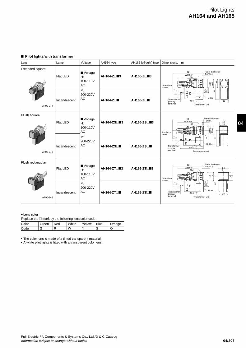
04/207Fuji Electric FA Components & Systems Co., Ltd./D & C CatalogInformation subject to change without notice
04
Lens Lamp Voltage AH164 type AH165 (oil-tight) type Dimensions, mm
Flat LED AH164-Z3 AH165-Z3
Incandescent AH164-Z AH165-Z
Flat LED AH164-ZS3 AH165-ZS3
Incandescent AH164-ZS AH165-ZS
Flat LED AH164-ZT3 AH165-ZT3
Incandescent AH164-ZT AH165-ZT
Flush rectangular
• Lens colorReplace the mark by the following lens color code
• The color lens is made of a tinted transparent material.• A white pilot lights is fitted with a transparent color lens.
Color Green Red White Yellow Blue OrangeCode G R W Y S O
AF90-944
Pilot lights/with transformer
Pilot LightsAH164 and AH165
48.5
710
ø15
ø18
WasherPanel thickness4 (max.)
Insulationcover
Transformerprimaryterminal Transformer unit
Holder
3218
18
Nut
(–)b(+
)a
62
Holder
Transformer unit
Transformerprimaryterminal
Insulationcover
Panel thickness4 (max.)
48.5
710
15sq
.18
sq.
Nut
32
(–)b(+
)a
Washer62
1815
Holder
Transformer unit
Transformerprimaryterminal
Insulationcover
Panel thickness4 (max.)
48.5
710
15 18
Nut
32
18
(–)b(+
)a
Washer62
1815
2421
VoltageH:100-110VAC
M:200-220VAC
VoltageH:100-110VAC
M:200-220VAC
VoltageH:100-110VAC
M:200-220VAC
AF90-943
AF90-942
Flush square
Extended square
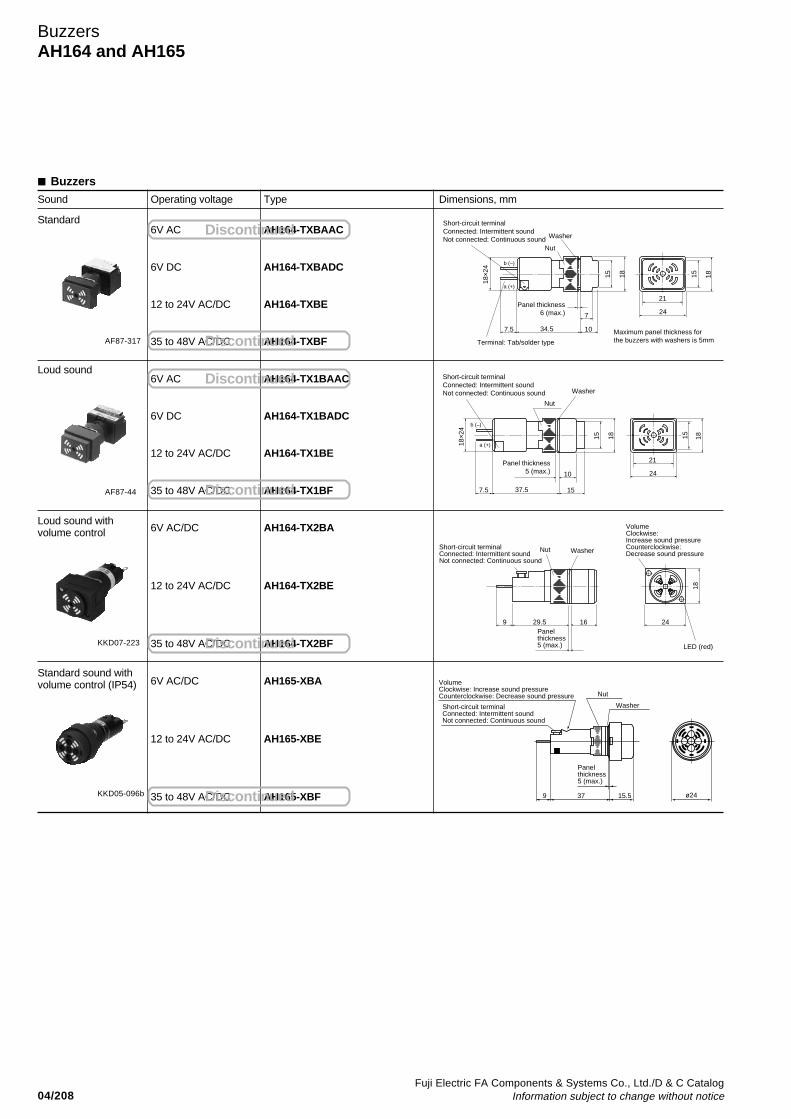
04/208Fuji Electric FA Components & Systems Co., Ltd./D & C Catalog
Information subject to change without notice
Sound Operating voltage Type Dimensions, mm
6V AC AH164-TXBAAC
6V DC AH164-TXBADC
12 to 24V AC/DC AH164-TXBE
35 to 48V AC/DC AH164-TXBF
6V AC AH164-TX1BAAC
6V DC AH164-TX1BADC
12 to 24V AC/DC AH164-TX1BE
35 to 48V AC/DC AH164-TX1BF
6V AC/DC AH164-TX2BA
12 to 24V AC/DC AH164-TX2BE
35 to 48V AC/DC AH164-TX2BF
6V AC/DC AH165-XBA
12 to 24V AC/DC AH165-XBE
35 to 48V AC/DC AH165-XBF
AF87-317
AF87-44
Washer
Nut
a (+)
b (–)
7
1034.5
15 18
7.5
Short-circuit terminalConnected: Intermittent soundNot connected: Continuous sound
Terminal: Tab/solder type
Maximum panel thickness forthe buzzers with washers is 5mm
24
21
15 18
18×2
4
Panel thickness6 (max.)
15 18
37.57.5
24
21
15 18
15
10
Washer
Nut
Short-circuit terminalConnected: Intermittent soundNot connected: Continuous sound
Panel thickness5 (max.)
18×2
4
a (+)
b (–)
Buzzers
KKD07-223
KKD05-096b ø24
Washer
Panelthickness5 (max.)
9 37
VolumeClockwise: Increase sound pressureCounterclockwise: Decrease sound pressure Nut
Short-circuit terminalConnected: Intermittent soundNot connected: Continuous sound
15.5
9 29.5 16 24
LED (red)
18
Washer
Panelthickness5 (max.)
VolumeClockwise: Increase sound pressureCounterclockwise: Decrease sound pressure
NutShort-circuit terminalConnected: Intermittent soundNot connected: Continuous sound
BuzzersAH164 and AH165
Loud sound withvolume control
Standard
Loud sound
Standard sound withvolume control (IP54)
Discontinued
Discontinued
Discontinued
Discontinued
Discontinued
Discontinued

04/209Fuji Electric FA Components & Systems Co., Ltd./D & C CatalogInformation subject to change without notice
04
Mounting space, mm• Pushbuttons and pilot lightsExtended round head or lens Flush square head or lens Flush rectangular head or lens
Mushroom head Convex square head Convex rectangular head
• Selector switches•When mounting the selector switches near the pilot light
Pushbuttons/Selectors/Pilot Lights/BuzzersAH164 and AH165
Mounting space
• When mounting the selectorswitches near each other
• With transformer
Note: *( ) For switch with flush rectangular head
Terminal number• AH164, 165
18 18
20
20
18 18
20
20
24
24
21.5(24)*
42
24
24
24
2424
24
24
24
24
20
Panel cut t ingø16.2 +0.2
0
Panel cut t ingø16.2 +0.2
0
Panel cut t ingø16.2 +0.2
0
Panel cut t ingø16.2 +0.2
0
Panel cut t ingø16.2 +0.2
0
Panel cut t ingø16.2 +0.2
0
Panel cut t ingø16.2 +0.2
0
Panel cut t ingø16.2 +0.2
0
24
30
24
25*
Note: * Mushroom, convex square, convex rectangular: 27
• When mounting the JM or RJM selector switches near each other (2NO+2NC only)
• When mounting the JM or RJM selector switches near the other selector switch, pushbutton switch and pilot lights
• AH165-V, V1, V5, V6 • AH165-JM, RJM
7.7±0.1
ø16.2+0.2
0
ø2+0.1 0
ø16.2+0.2
0
15
+0
.2
0
a(+)
a(+)
b(-)
a(+)
b(-)
b(-)
ab
Type number display side
Type number display side
Wiring Terminal positionType
Illuminated pushbuttons
PushbuttonsSelector switches(except for JM, RJM types)
Pilot lights(without transformer)
1
3
2
4
13
13
131
3
2 4
2 4
2 42
4

04/210Fuji Electric FA Components & Systems Co., Ltd./D & C Catalog
Information subject to change without notice
Pushbuttons/Selectors/Pilot LightsAH165-2Type number nomenclature
➀ Product categoryAH165-2: Oil-tight (Large operator)
➁ Operator or lens• Operator for illuminated pushbuttonFL: Flush round headFL5: Flush round head (Alternate)SFL: Flush square headSFL5: Flush square head (Alternate)EL: Extended round headEL5: Extended round head (Alternate)SEL: Extended square headSEL5: Extended square head (Alternate)SCL: Concave square headSCL5: Concave square head (Alternate)ML: Mushroom headYML: Mushroom head with square bezelVL: Push-lock, turn-resetYVL: Push-lock, turn-reset with square bezel
• Operator for pushbuttonsF: Flush round headF5: Flush round head (Alternate)SF: Flush square headSF5: Flush square head (Alternate)E: Extended round headE5: Extended round head (Alternate)SE: Extended square headSE5: Extended square head (Alternate)SCE: Concave square headSCE5: Concave square head (Alternate)M: Mushroom headYM: Mushroom head with square bezelV: Push-lock, turn-resetYV: Push-lock, turn-reset with square bezelS2: With selector ringYS2: With selector ring with square bezel
• Lens for pilot lightsZ: Flush roundSZ: Flush squareZE: Extended roundSEZ: Extended square
➃ Contact arrangement (except pilot lights)11: 1NO+1NC22: 2NO+2NC33: 3NO+3NC
➄ Lamp voltage
Type number nomenclature
Pushbuttons, illuminated pushbuttons and pilot lights ➂ Color of button or lens
➅ Type of lampBlank: Incandescent1: Neon3: Flat LED
➆ TerminalBlank: Solder/tabW: Wire-wrap
AH165-2 FL R 11 E 3 – W➀ ➄➁ ➅➂ ➆➃
Code
Notes: • ( ): indicates luminous color* Not available for illuminated types
Button
GRBYWSO
LED
– (Orange) (Amber)
Incandescent
–
Neon
(Orange)– (Orange) (Orange) (Green)
Color
GreenRedBlack*YellowWhiteBlueOrange
Code LED Incandescent Neon
AAABEHKMP
5V DC6V DC12V DC24V DC––––
–5V AC/DC12V AC/DC24V AC/DC––––
––––110V AC120V AC220V AC240V AC

04/211Fuji Electric FA Components & Systems Co., Ltd./D & C CatalogInformation subject to change without notice
04
Pushbuttons/Selectors/Pilot LightsAH165-2
Type number nomenclature
➀ Product categoryAH165-2: Oil-tight (Large operator)
➁ Operator• Knob and key type2-position (operating angle 90˚)P: KnobYP: Knob with square bezelJ: KeyYJ: Key with square bezel
3-position (operating angle 45˚)P: KnobYP: Knob with square bezelJ: KeyYJ: Key with square bezel
• Lever type2-position (operating angle 45˚)H: LeverSH: Lever with square bezelNote: The operation angle is 45˚ on the upper and lower side.
➂ Operation2: 2-position, maintained0: 2-position, spring return*3: 3-position, maintained6: 3-position, spring/manual return (Left to center)7: 3-position, spring/manual return (Right to center)1: 3-position, spring returnNote: * Except for H and SH types
➃ Color of knob, lever or key removable position• Color of knob or leverB: Black
• Key removable position
Type number nomenclature
Selector switches
➄ Contact arrangement11: 1NO+1NC*22: 2NO+2NC33: 3NO+3NCNote: * Except for 3-position
➅ Key type No.A (standard), B, C, D, E, F
AH165-2 J 2 B 11 A – W➀ ➄➁ ➅➂ ➆➃
Code 2-position 3-position
A
B
C
D
E
F
G
2 0 1 3 6 7
–
–
–
–
–
–
–
–
–
–
–
–
–
–
–
–
–
–
–
–
–
–
–
–
➆ TerminalBlank: Solder/tabW: Wire-wrap
➀ Product categoryAH165-2: Oil-tight (Large operator)
➁ Operator• 2-position (operating angle 90˚)PL: Knob
• 3-position (operating angle 45˚)PL: Knob
➂ Operation2: 2-position, maintained3: 3-position, maintained
➃ Color of knob
Illuminated selector switches
AH165-2 PL 2 G 11 E 3➀ ➄➁ ➅➂ ➆➃
Code
Notes: • ( ): indicates luminous color• The part other than the arrow of the knob is black.
GRYWSO
LED
(Orange) (Amber)
Incandescent
Neon
(Orange) (Orange) (Orange) (Green)
Color
GreenRedYellowWhiteBlueOrange
➄ Contact arrangement11: 1NO+1NC*22: 2NO+2NCNote: * Except for 3-position
➅ Lamp voltage
Code LED Incandescent Neon
AAABEHKMP
5V DC6V DC12V DC24V DC––––
–5V AC/DC12V AC/DC24V AC/DC––––
––––110V AC120V AC220V AC240V AC
➆ Type of lampBlank: Incandescent1: Neon3: Flat LEDNote: Terminal with solder/tab only
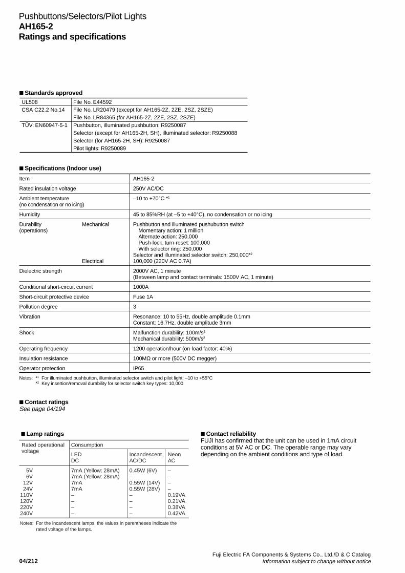
04/212Fuji Electric FA Components & Systems Co., Ltd./D & C Catalog
Information subject to change without notice
Pushbuttons/Selectors/Pilot LightsAH165-2Ratings and specifications
Specifications (Indoor use)
Item AH165-2
Rated insulation voltage 250V AC/DC
Ambient temperature –10 to +70°C *1
(no condensation or no icing)
Humidity 45 to 85%RH (at –5 to +40°C), no condensation or no icing
Durability Mechanical Pushbutton and illuminated pushubutton switch(operations) Momentary action: 1 million
Alternate action: 250,000Push-lock, turn-reset: 100,000With selector ring: 250,000
Selector and illuminated selector switch: 250,000*2
Electrical 100,000 (220V AC 0.7A)
Dielectric strength 2000V AC, 1 minute(Between lamp and contact terminals: 1500V AC, 1 minute)
Conditional short-circuit current 1000A
Short-circuit protective device Fuse 1A
Pollution degree 3
Vibration Resonance: 10 to 55Hz, double amplitude 0.1mmConstant: 16.7Hz, double amplitude 3mm
Shock Malfunction durability: 100m/s2
Mechanical durability: 500m/s2
Operating frequency 1200 operation/hour (on-load factor: 40%)
Insulation resistance 100MΩ or more (500V DC megger)
Operator protection IP65
Notes: *1 For illuminated pushbutton, illuminated selector switch and pilot light: –10 to +55°C*2 Key insertion/removal durability for selector switch key types: 10,000
Contact reliabilityFUJI has confirmed that the unit can be used in 1mA circuitconditions at 5V AC or DC. The operable range may varydepending on the ambient conditions and type of load.
Lamp ratings
Rated operationalvoltage
Notes: For the incandescent lamps, the values in parentheses indicate the rated voltage of the lamps.
Consumption
LEDDC
IncandescentAC/DC
NeonAC
5V6V
12V24V
110V120V220V240V
7mA (Yellow: 28mA)7mA (Yellow: 28mA)7mA7mA––––
0.45W (6V)–0.55W (14V)0.55W (28V)––––
––––0.19VA0.21VA0.38VA0.42VA
Standards approvedUL508CSA C22.2 No.14
TÜV: EN60947-5-1
File No. E44592File No. LR20479 (except for AH165-2Z, 2ZE, 2SZ, 2SZE)File No. LR84365 (for AH165-2Z, 2ZE, 2SZ, 2SZE)Pushbutton, illuminated pushbutton: R9250087Selector (except for AH165-2H, SH), illuminated selector: R9250088Selector (for AH165-2H, SH): R9250087Pilot lights: R9250089
Contact ratingsSee page 04/194

04/213Fuji Electric FA Components & Systems Co., Ltd./D & C CatalogInformation subject to change without notice
04
Flush round head
Extended round head
Mushroom head
Mushroom headwith square bezel
Flat LED
Incandescent
Neon
Flat LED
Incandescent
Neon
Flat LED
Incandescent
Neon
Flat LED
Incandescent
Neon
24V DC
24V AC/DC
110V AC
220V AC
24V DC
24V AC/DC
110V AC
220V AC
24V DC
24V AC/DC
110V AC
220V AC
24V DC
24V AC/DC
110V AC
220V AC
1NO+1NC2NO+2NC3NO+3NC1NO+1NC2NO+2NC3NO+3NC1NO+1NC2NO+2NC3NO+3NC1NO+1NC2NO+2NC3NO+3NC1NO+1NC2NO+2NC3NO+3NC1NO+1NC2NO+2NC3NO+3NC1NO+1NC2NO+2NC3NO+3NC1NO+1NC2NO+2NC3NO+3NC1NO+1NC2NO+2NC3NO+3NC1NO+1NC2NO+2NC3NO+3NC1NO+1NC2NO+2NC3NO+3NC1NO+1NC2NO+2NC3NO+3NC1NO+1NC2NO+2NC3NO+3NC1NO+1NC2NO+2NC3NO+3NC1NO+1NC2NO+2NC3NO+3NC1NO+1NC2NO+2NC3NO+3NC
AH165-2FL11E3AH165-2FL22E3AH165-2FL33E3AH165-2FL11EAH165-2FL22EAH165-2FL33EAH165-2FL11H1AH165-2FL22H1AH165-2FL33H1AH165-2FL11M1AH165-2FL22M1AH165-2FL33M1AH165-2EL11E3AH165-2EL22E3AH165-2EL33E3AH165-2EL11EAH165-2EL22EAH165-2EL33EAH165-2EL11H1AH165-2EL22H1AH165-2EL33H1AH165-2EL11M1AH165-2EL22M1AH165-2EL33M1AH165-2ML11E3AH165-2ML22E3AH165-2ML33E3AH165-2ML11EAH165-2ML22EAH165-2ML33EAH165-2ML11H1AH165-2ML22H1AH165-2ML33H1AH165-2ML11M1AH165-2ML22M1AH165-2ML33M1AH165-2YML11E3AH165-2YML22E3AH165-2YML33E3AH165-2YML11EAH165-2YML22EAH165-2YML33EAH165-2YML11H1AH165-2YML22H1AH165-2YML33H1AH165-2YML11M1AH165-2YML22M1AH165-2YML33M1
AH165-2FL511E3AH165-2FL522E3AH165-2FL533E3AH165-2FL511EAH165-2FL522EAH165-2FL533EAH165-2FL511H1AH165-2FL522H1AH165-2FL533H1AH165-2FL511M1AH165-2FL522M1AH165-2FL533M1AH165-2EL511E3AH165-2EL522E3AH165-2EL533E3AH165-2EL511EAH165-2EL522EAH165-2EL533EAH165-2EL511H1AH165-2EL522H1AH165-2EL533H1AH165-2EL511M1AH165-2EL522M1AH165-2EL533M1––––––––––––––––––––––––
Operator Lamp Voltage Contact Momentary actionType
Alternate actionType
Dimensions, mm
Note: Replace the mark by the following color code, see page 04/215.
AF87-211
AF87-210
AF87-221
AF87-220
42.5 11.5 ø20ø25
Panel thickness 1 to 5
42.511.5 ø20
ø25
Panel thickness 1 to 5
15
42.511.5
Panel thickness 1 to 5
22
ø32
42.511.5
Panel thickness 1 to 5
22
ø32
25sq.
Illuminated Pushbutton SwitchesAH165-2
Illuminated pushbutton switches
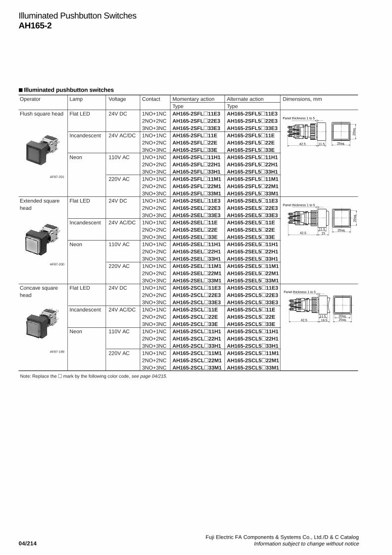
04/214Fuji Electric FA Components & Systems Co., Ltd./D & C Catalog
Information subject to change without notice
Illuminated Pushbutton SwitchesAH165-2
Flush square head
Extended square head
Concave square head
Flat LED
Incandescent
Neon
Flat LED
Incandescent
Neon
Flat LED
Incandescent
Neon
24V DC
24V AC/DC
110V AC
220V AC
24V DC
24V AC/DC
110V AC
220V AC
24V DC
24V AC/DC
110V AC
220V AC
1NO+1NC2NO+2NC3NO+3NC1NO+1NC2NO+2NC3NO+3NC1NO+1NC2NO+2NC3NO+3NC1NO+1NC2NO+2NC3NO+3NC1NO+1NC2NO+2NC3NO+3NC1NO+1NC2NO+2NC3NO+3NC1NO+1NC2NO+2NC3NO+3NC1NO+1NC2NO+2NC3NO+3NC1NO+1NC2NO+2NC3NO+3NC1NO+1NC2NO+2NC3NO+3NC1NO+1NC2NO+2NC3NO+3NC1NO+1NC2NO+2NC3NO+3NC
AH165-2SFL11E3AH165-2SFL22E3AH165-2SFL33E3AH165-2SFL11EAH165-2SFL22EAH165-2SFL33EAH165-2SFL11H1AH165-2SFL22H1AH165-2SFL33H1AH165-2SFL11M1AH165-2SFL22M1AH165-2SFL33M1AH165-2SEL11E3AH165-2SEL22E3AH165-2SEL33E3AH165-2SEL11EAH165-2SEL22EAH165-2SEL33EAH165-2SEL11H1AH165-2SEL22H1AH165-2SEL33H1AH165-2SEL11M1AH165-2SEL22M1AH165-2SEL33M1AH165-2SCL11E3AH165-2SCL22E3AH165-2SCL33E3AH165-2SCL11EAH165-2SCL22EAH165-2SCL33EAH165-2SCL11H1AH165-2SCL22H1AH165-2SCL33H1AH165-2SCL11M1AH165-2SCL22M1AH165-2SCL33M1
AH165-2SFL511E3AH165-2SFL522E3AH165-2SFL533E3AH165-2SFL511EAH165-2SFL522EAH165-2SFL533EAH165-2SFL511H1AH165-2SFL522H1AH165-2SFL533H1AH165-2SFL511M1AH165-2SFL522M1AH165-2SFL533M1AH165-2SEL511E3AH165-2SEL522E3AH165-2SEL533E3AH165-2SEL511EAH165-2SEL522EAH165-2SEL533EAH165-2SEL511H1AH165-2SEL522H1AH165-2SEL533H1AH165-2SEL511M1AH165-2SEL522M1AH165-2SEL533M1AH165-2SCL511E3AH165-2SCL522E3AH165-2SCL533E3AH165-2SCL511EAH165-2SCL522EAH165-2SCL533EAH165-2SCL511H1AH165-2SCL522H1AH165-2SCL533H1AH165-2SCL511M1AH165-2SCL522M1AH165-2SCL533M1
Operator Lamp Voltage Contact Momentary actionType
Alternate actionType
Dimensions, mm
AF87-201
AF87-200
AF87-199
42.5 11.5 25sq.
20sq
.
Panel thickness 1 to 5
42.511.5
20sq
.
25sq.
Panel thickness 1 to 5
15
42.511.5 20sq.
25sq.
Panel thickness 1 to 5
16.5
Note: Replace the mark by the following color code, see page 04/215.
Illuminated pushbutton switches
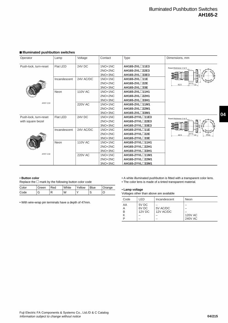
04/215Fuji Electric FA Components & Systems Co., Ltd./D & C CatalogInformation subject to change without notice
04
Illuminated Pushbutton SwitchesAH165-2
Illuminated pushbutton switches
Push-lock, turn-reset
Push-lock, turn-resetwith square bezel
Flat LED
Incandescent
Neon
Flat LED
Incandescent
Neon
24V DC
24V AC/DC
110V AC
220V AC
24V DC
24V AC/DC
110V AC
220V AC
1NO+1NC2NO+2NC3NO+3NC1NO+1NC2NO+2NC3NO+3NC1NO+1NC2NO+2NC3NO+3NC1NO+1NC2NO+2NC3NO+3NC1NO+1NC2NO+2NC3NO+3NC1NO+1NC2NO+2NC3NO+3NC1NO+1NC2NO+2NC3NO+3NC1NO+1NC2NO+2NC3NO+3NC
AH165-2VL11E3AH165-2VL22E3AH165-2VL33E3AH165-2VL11EAH165-2VL22EAH165-2VL33EAH165-2VL11H1AH165-2VL22H1AH165-2VL33H1AH165-2VL11M1AH165-2VL22M1AH165-2VL33M1AH165-2YVL11E3AH165-2YVL22E3AH165-2YVL33E3AH165-2YVL11EAH165-2YVL22EAH165-2YVL33EAH165-2YVL11H1AH165-2YVL22H1AH165-2YVL33H1AH165-2YVL11M1AH165-2YVL22M1AH165-2YVL33M1
Operator Lamp Voltage Contact Type Dimensions, mm
AF87-219
AF87-218
42.511.5
22
ø32
Panel thickness 1 to 5
42.511.5
22
ø32
25sq.
Panel thickness 1 to 5
• Button colorReplace the mark by the following button color code
• With wire-wrap pin terminals have a depth of 47mm.
Color Green Red White Yellow Blue Orange
Code G R W Y S O
• A white illuminated pushbutton is fitted with a transparent color lens.• The color lens is made of a tinted transparent material.
• Lamp voltageVoltages other than above are available
Code LED Incandescent
AAABKP
5V DC6V DC12V DC––
–5V AC/DC12V AC/DC––
Neon
–––120V AC240V AC
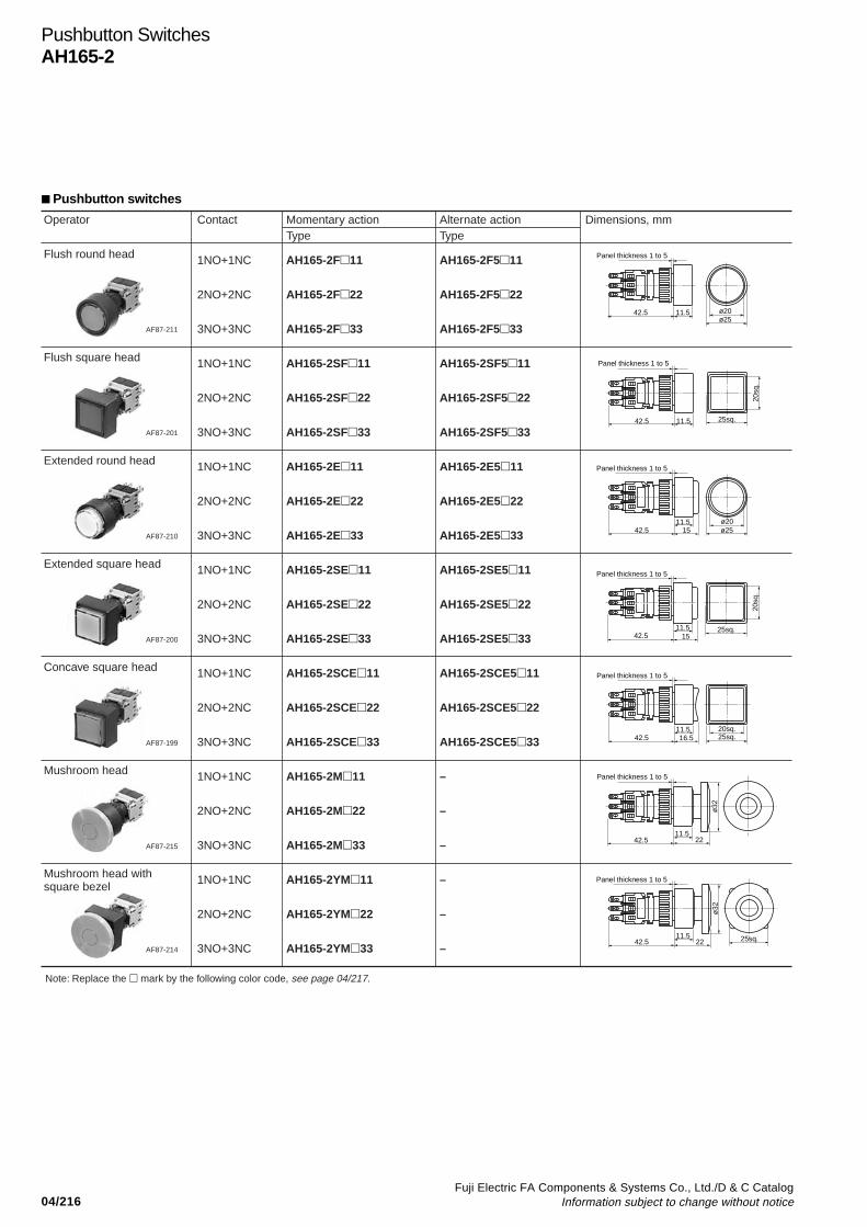
04/216Fuji Electric FA Components & Systems Co., Ltd./D & C Catalog
Information subject to change without notice
Pushbutton SwitchesAH165-2
Pushbutton switches
Flush round head
Flush square head
Extended round head
Extended square head
Concave square head
Mushroom head
Mushroom head with square bezel
1NO+1NC
2NO+2NC
3NO+3NC
1NO+1NC
2NO+2NC
3NO+3NC
1NO+1NC
2NO+2NC
3NO+3NC
1NO+1NC
2NO+2NC
3NO+3NC
1NO+1NC
2NO+2NC
3NO+3NC
1NO+1NC
2NO+2NC
3NO+3NC
1NO+1NC
2NO+2NC
3NO+3NC
AH165-2F11
AH165-2F22
AH165-2F33
AH165-2SF11
AH165-2SF22
AH165-2SF33
AH165-2E11
AH165-2E22
AH165-2E33
AH165-2SE11
AH165-2SE22
AH165-2SE33
AH165-2SCE11
AH165-2SCE22
AH165-2SCE33
AH165-2M11
AH165-2M22
AH165-2M33
AH165-2YM11
AH165-2YM22
AH165-2YM33
AH165-2F511
AH165-2F522
AH165-2F533
AH165-2SF511
AH165-2SF522
AH165-2SF533
AH165-2E511
AH165-2E522
AH165-2E533
AH165-2SE511
AH165-2SE522
AH165-2SE533
AH165-2SCE511
AH165-2SCE522
AH165-2SCE533
–
–
–
–
–
–
Operator Contact Momentary actionType
Alternate actionType
Dimensions, mm
Note: Replace the mark by the following color code, see page 04/217.
AF87-211
AF87-201
AF87-210
AF87-200
AF87-199
AF87-215
AF87-214
42.5 11.5 ø20ø25
Panel thickness 1 to 5
42.5 11.5 25sq.
20sq
.
Panel thickness 1 to 5
42.511.5 ø20
ø25
Panel thickness 1 to 5
15
42.511.5 20sq.
25sq.
Panel thickness 1 to 5
16.5
42.511.5
20sq
.
25sq.
Panel thickness 1 to 5
15
42.511.5
Panel thickness 1 to 5
22
ø32
42.511.5
Panel thickness 1 to 5
22
ø32
25sq.

04/217Fuji Electric FA Components & Systems Co., Ltd./D & C CatalogInformation subject to change without notice
04
Pushbutton SwitchesAH165-2
Pushbutton switches
With selector ring
With selector ring with square bezel
Push-lock, turn-reset
Push-lock, turn-reset with square bezel
2NO+2NC
2NO+2NC
1NO+1NC
2NO+2NC
3NO+3NC
1NO+1NC
2NO+2NC
3NO+3NC
AH165-2S222
AH165-2YS222
AH165-2V11
AH165-2V22
AH165-2V33
AH165-2YV11
AH165-2YV22
AH165-2YV33
Operator Contact Type Dimensions, mm
AF87-207
AF87-206
AF87-210
AF87-200
42.511.5 ø20
Panel thickness 1 to 5
22
ø25
90˚
42.511.5 ø20
25sq.
Panel thickness 1 to 5
22
ø25
90˚
42.511.5
22
ø32
Panel thickness 1 to 5
42.511.5
22
ø32
25sq.
Panel thickness 1 to 5
• Button colorReplace the mark by the following button color code
• The color lens is made of a tinted transparent material. (Except for M,YM, V, YV, types)
• A white pushbutton is fitted with a transparent color lens. A blackpushbutton consists of a transparent color lens and an attached blacklegend plate. (Except for M, YM, V, YV, types)
• With wire-wrap pin terminals have a depth of 47mm.
ColorCode
GreenG
RedR
WhiteW
BlackB
BlueS
YellowY
OrangeO
• Contact arrangement and operator positionAH165-2S, 2YS
Button
Ring Left
U L U L
Right
Free
U: Upper contact blockL: Lower contact block
Depressed
1 2
3 4
1 2
3 4
1 2
3 4
1 2
3 4
1 2
3 4
1 2
3 4
1 2
3 4
1 2
3 4
• Terminal number and contact block position
NCNO
Upper
Lower
➀ ➁➃➂
Type number display side

04/218Fuji Electric FA Components & Systems Co., Ltd./D & C Catalog
Information subject to change without notice
Selector SwitchesAH165-2
Selector switches/2-position (90-degree)
• The key can be removed only at the following positions:
A: B: D:
• For spring-return selector switches, the key can be removed atposition A.
• There are 6 available key types; A, B, C, D, E and F.Standard key code is A.
• With wire-wrap pin terminals have a depth of 47mm.
• Contact arrangement and operator positions:2-position
Contactarrangement
1NO+1NC 2NO+2NC 3NO+3NC
Operatorposition
Left
Right
1 23 41 23 41 23 4
1 23 41 23 41 2
1 23 41 23 4
1 23 41 23 4
1 23 4
1 23 4
3 4
U: Upper contact blockM: Middle contact blockL: Lower contact block
M U U
M
L
U
M
L
L
U
L
M
• Terminal number and contact block position
NCNO
Upper
Middle
Lower
Contact arrangement (terminal No.: common)1NO+1NC: Middle2NO+2NC: Upper, lower3NO+3NC: Upper, middle, lower
➀ ➁➃➂
Type number display side
Knob
Knob
Key
Key with square bezel
Maintained
Spring return
Maintained
Spring return
Maintained
Spring return
Maintained
Spring return
–
–
–
–
A
B
D
A
A
B
D
A
1NO+1NC2NO+2NC3NO+3NC1NO+1NC2NO+2NC3NO+3NC1NO+1NC2NO+2NC3NO+3NC1NO+1NC2NO+2NC3NO+3NC1NO+1NC2NO+2NC3NO+3NC1NO+1NC2NO+2NC3NO+3NC1NO+1NC2NO+2NC3NO+3NC1NO+1NC2NO+2NC3NO+3NC1NO+1NC2NO+2NC3NO+3NC1NO+1NC2NO+2NC3NO+3NC1NO+1NC2NO+2NC3NO+3NC1NO+1NC2NO+2NC3NO+3NC
AH165-2P2B11AH165-2P2B22AH165-2P2B33AH165-2P0B11AH165-2P0B22AH165-2P0B33AH165-2YP2B11AH165-2YP2B22AH165-2YP2B33AH165-2YP0B11AH165-2YP0B22AH165-2YP0B33AH165-2J2A11AAH165-2J2A22AAH165-2J2A33AAH165-2J2B11AAH165-2J2B22AAH165-2J2B33AAH165-2J2D11AAH165-2J2D22AAH165-2J2D33AAH165-2J0A11AAH165-2J0A22AAH165-2J0A33AAH165-2YJ2A11AAH165-2YJ2A22AAH165-2YJ2A33AAH165-2YJ2B11AAH165-2YJ2B22AAH165-2YJ2B33AAH165-2YJ2D11AAH165-2YJ2D22AAH165-2YJ2D33AAH165-2YJ0A11AAH165-2YJ0A22AAH165-2YJ0A33A
Operator Operation Key removableposition
Contact Type Dimensions, mm
KKD07-232
KKD07-234
KKD09-003L
KKD09-003R
11.52442.5
Panel thickness 1 to 5
ø25
25
11.52442.5
Panel thickness 1 to 5
25sq.
25
11.5
3742.5ø2513.5
Panel thickness 1 to 5
11.5
3742.525sq.13.5
Panel thickness 1 to 5

04/219Fuji Electric FA Components & Systems Co., Ltd./D & C CatalogInformation subject to change without notice
04
Lever
Lever with square bezel
Black
Black
Maintained
Maintained
1NO+1NC
2NO+2NC
3NO+3NC
1NO+1NC
2NO+2NC
3NO+3NC
AH165-2H2B11
AH165-2H2B22
AH165-2H2B33
AH165-2SH2B11
AH165-2SH2B22
AH165-2SH2B33
Operator Levercolor
Operation Contact Type Dimensions, mm
AF87-209
AF87-203
11.52442.5
Panel thickness 1 to 5
45˚
ø25
Panel thickness 1 to 5
11.52442.5
45˚
25sq.
Selector SwitchesAH165-2
Selector switches/2-position
• Contact arrangement and operator position
• With wire-wrap pin terminals have a depth of 47mm.
AH165-2H, 2SH
Contactblock
Lever Up Down
1NO+1NC
2NO+2NC
3NO+3NC
1 2
3 4
1 2
3 4
1 2
3 4
1 2
3 4
1 2
3 4
1 2
3 4
1 2
3 4
1 2
3 4
1 2
3 4
1 2
3 4
1 2
3 4
1 2
3 4
L
M M
U
LU M LU M
LU
• Terminal number and contact block position
NCNO
Upper
Middle
Lower
Contact arrangement (terminal No.: common)1NO+1NC: Middle2NO+2NC: Upper, lower3NO+3NC: Upper, middle, lower
➀ ➁➃➂
Type number display side
U: Upper contact blockM: Middle contact blockL: Lower contact block
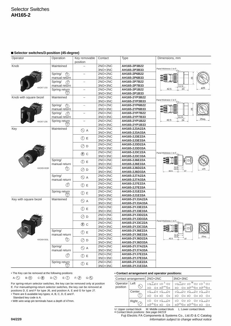
04/220Fuji Electric FA Components & Systems Co., Ltd./D & C Catalog
Information subject to change without notice
Selector SwitchesAH165-2
Selector switches/3-position (45-degree)
• The Key can be removed at the following positions:
For spring-return selector switches, the key can be removed only at positionE. For manual/spring-return selector switches, the key can be removed atpositions D, E and F for type J6, and position A, E and G for type J7.• There are 6 available key types; A, B, C, D, E and F.
Standard key code is A.• With wire-wrap pin terminals have a depth of 47mm.
• Contact arrangement and operator positions:
Contact arrangement 2NO+2NC 3NO+3NC
Operatorposition
Left
Center
Right
1 2
3 4
1 2
3
U L LMU
4
1 2
3 4
1 2
3 4
1 2
3 4
1 2
3 4
1 2
3 4
1 2
3 4
1 2
3 4
1 2
3 4
1 2
3 4
1 2
3 4
1 2
3 4
1 2
3 4
1 2
3 4
A: B: C: F: G:D: E:
U: Upper contact block M: Middle contact block L: Lower contact block• Contact block positions: See page 04/219
Knob
Knob with square bezel
Key
Key with square bezel
Mainteined
Spring/manual returnSpring/manual returnSpring return
Mainteined
Spring/manual returnSpring/manual returnSpring return
Mainteined
Spring/manual return
Spring/manual return
Spring return
Mainteined
Spring/manual return
Spring/manual return
Spring return
–
–
–
–
–
–
–
–
A
E
D
C
E
D
A
E
E
A
E
D
C
E
D
A
E
E
2NO+2NC3NO+3NC2NO+2NC3NO+3NC2NO+2NC3NO+3NC2NO+2NC3NO+3NC2NO+2NC3NO+3NC2NO+2NC3NO+3NC2NO+2NC3NO+3NC2NO+2NC3NO+3NC2NO+2NC3NO+3NC2NO+2NC3NO+3NC2NO+2NC3NO+3NC2NO+2NC3NO+3NC2NO+2NC3NO+3NC2NO+2NC3NO+3NC2NO+2NC3NO+3NC2NO+2NC3NO+3NC2NO+2NC3NO+3NC2NO+2NC3NO+3NC2NO+2NC3NO+3NC2NO+2NC3NO+3NC2NO+2NC3NO+3NC2NO+2NC3NO+3NC2NO+2NC3NO+3NC2NO+2NC3NO+3NC2NO+2NC3NO+3NC2NO+2NC3NO+3NC
AH165-2P3B22AH165-2P3B33AH165-2P6B22AH165-2P6B33AH165-2P7B22AH165-2P7B33AH165-2P1B22AH165-2P1B33AH165-2YP3B22AH165-2YP3B33AH165-2YP6B22AH165-2YP6B33AH165-2YP7B22AH165-2YP7B33AH165-2YP1B22AH165-2YP1B33AH165-2J3A22AAH165-2J3A33AAH165-2J3E22AAH165-2J3E33AAH165-2J3D22AAH165-2J3D33AAH165-2J3C22AAH165-2J3C33AAH165-2J6E22AAH165-2J6E33AAH165-2J6D22AAH165-2J6D33AAH165-2J7A22AAH165-2J7A33AAH165-2J7E22AAH165-2J7E33AAH165-2J1E22AAH165-2J1E33AAH165-2YJ3A22AAH165-2YJ3A33AAH165-2YJ3E22AAH165-2YJ3E33AAH165-2YJ3D22AAH165-2YJ3D33AAH165-2YJ3C22AAH165-2YJ3C33AAH165-2YJ6E22AAH165-2YJ6E33AAH165-2YJ6D22AAH165-2YJ6D33AAH165-2YJ7A22AAH165-2YJ7A33AAH165-2YJ7E22AAH165-2YJ7E33AAH165-2YJ1E22AAH165-2YJ1E33A
Operator Operation Key removableposition
Contact Type Dimensions, mm
KKD07-233
KKD07-235
KKD09-003R
KKD09-003L
11.52442.5 ø25
25
Panel thickness 1 to 5
11.52442.5 25sq.
25
Panel thickness 1 to 5
11.5
3742.5ø2513.5
Panel thickness 1 to 5
11.5
3742.525sq.13.5
Panel thickness 1 to 5
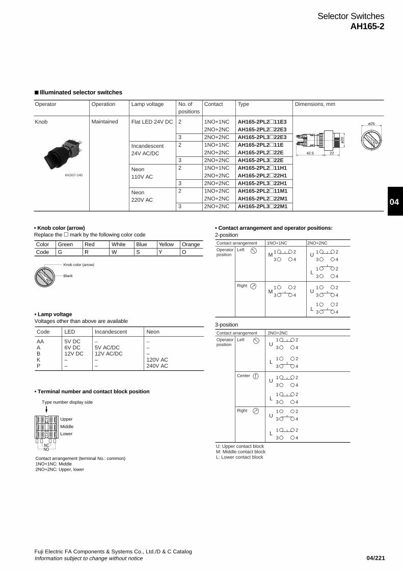
04/221Fuji Electric FA Components & Systems Co., Ltd./D & C CatalogInformation subject to change without notice
04
Selector SwitchesAH165-2
Illuminated selector switches
Knob Flat LED 24V DC
Incandescent24V AC/DC
Neon110V AC
Neon220V AC
AH165-2PL211E3AH165-2PL222E3AH165-2PL322E3AH165-2PL211EAH165-2PL222EAH165-2PL322EAH165-2PL211H1AH165-2PL222H1AH165-2PL322H1AH165-2PL211M1AH165-2PL222M1AH165-2PL322M1
Operator Lamp voltageOperation
Maintained 1NO+1NC2NO+2NC2NO+2NC1NO+1NC2NO+2NC2NO+2NC1NO+1NC2NO+2NC2NO+2NC1NO+2NC2NO+2NC2NO+2NC
Contact
2
32
32
32
3
No. ofpositions
Type Dimensions, mm
KKD07-240
2242.5
ø20
ø25
• Knob color (arrow)Replace the mark by the following color code
ColorCode
GreenG
RedR
WhiteW
BlueS
YellowY
OrangeO
Knob color (arrow)
Black
Code LED Incandescent
AAABKP
5V DC6V DC12V DC––
–5V AC/DC12V AC/DC––
Neon
–––120V AC240V AC
• Lamp voltageVoltages other than above are available
• Contact arrangement and operator positions:
Contact arrangement 1NO+1NC 2NO+2NC
Operatorposition
Left
Right
Contact arrangement 2NO+2NC
Operatorposition
Left
Right
Center
1 2
3 4
1 2
3 4
1 2
3 4
1 2
3 4
1 2
3 4
1 2
3 4
1 2
3 4
1 2
3 4
1 2
3 4
1 2
3 4
1 2
3 4
1 2
3 4
M U
L
U
L
U
L
U
L
U
L
M
U: Upper contact blockM: Middle contact blockL: Lower contact block
2-position
3-position
• Terminal number and contact block position
NCNO
Upper
Middle
Lower
Contact arrangement (terminal No.: common)1NO+1NC: Middle2NO+2NC: Upper, lower
➀ ➁➃➂
Type number display side
b(-)
a(+)

04/222Fuji Electric FA Components & Systems Co., Ltd./D & C Catalog
Information subject to change without notice
Pilot LightsAH165-2
Flush round
Flush square
Extended round
Extended square
Flat LED
Incandescent
Neon
Flat LED
Incandescent
Neon
Flat LED
Incandescent
Neon
Flat LED
Incandescent
Neon
24V DC
24V AC/DC
110V AC
220V AC
24V DC
24V AC/DC
110V AC
220V AC
24V DC
24V AC/DC
110V AC
220V AC
24V DC
24V AC/DC
110V AC
220V AC
AH165-2ZE3
AH165-2ZE
AH165-2ZH1
AH165-2ZM1
AH165-2SZE3
AH165-2SZE
AH165-2SZH1
AH165-2SZM1
AH165-2ZEE3
AH165-2ZEE
AH165-2ZEH1
AH165-2ZEM1
AH165-2SZEE3
AH165-2SZEE
AH165-2SZEH1
AH165-2SZEM1
Lens Lamp Voltage Type Dimensions, mm
AF87-213
AF87-205
AF87-212
AF87-204
24 11.5 ø20ø25
Panel thickness 1 to 5
24 11.515
15
ø20ø25
Panel thickness 1 to 5
24 11.525sq.
20sq
.
Panel thickness 1 to 5
24 11.525sq.
20sq
.
Panel thickness 1 to 5
a (+)
b (-)
a (+)
b (-)
a (+)
b (-)
a (+)
b (-)
Pilot lights
• Lens colorReplace the mark by the following lens color code
ColorCode
GreenG
RedR
WhiteW
BlueS
YellowY
OrangeO
• Lamp voltageVoltage other than above is available
• The color lens is made of a tinted transparent material.• A white lens is fitted with a transparent color lens.• With wire-wrap pin terminals have a depth of 29mm.
Code LED Incandescent
AAABKP
5V DC6V DC12V DC––
–5V AC/DC12V AC/DC––
Neon
–––120V AC240V AC

04/223Fuji Electric FA Components & Systems Co., Ltd./D & C CatalogInformation subject to change without notice
04
Pushbuttons/Selectors/Pilot LightsAH165-2
Mounting space
Mounting space, mm• Illuminated pushbuttons, pushbuttons, selector switches, illuminated selector switches and pilot lights
Round head Square head Mushroom headPush-lock, turn-reset
25 25
25
25 25
25
33
33
ø16.2
Panelcutt ing
+0.20 ø16.2
Panelcutt ing
+0.20 ø16.2
Panelcutt ing
+0.20
a(+)
a(+)
b(-)
a(+)
b(-)
b(-)
ab
Type number display side
Type number display side
Wiring Terminal positionType
Illuminated pushbuttons,Illuminated selectorswitches
PushbuttonsSelector swiches
Pilot lights(without transformer)
1
3
2
4
13
13
131
3
2 4
2 4
2 42
4
Terminal number
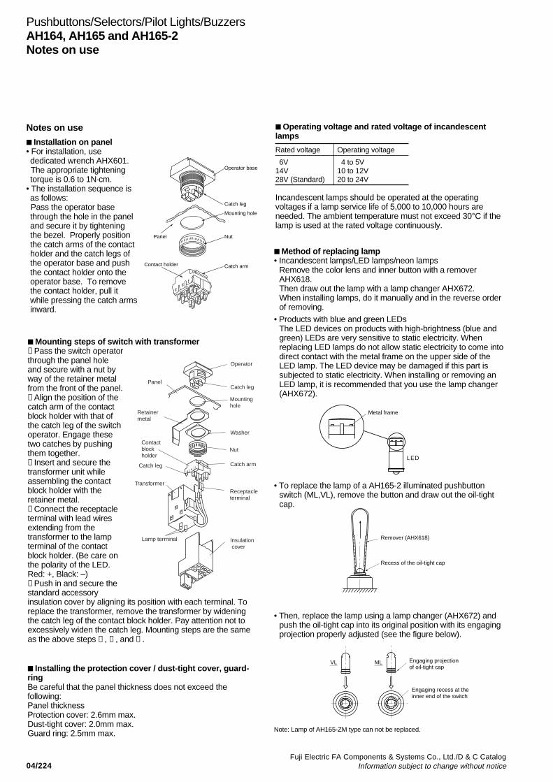
04/224Fuji Electric FA Components & Systems Co., Ltd./D & C Catalog
Information subject to change without notice
Installation on panel• For installation, usededicated wrench AHX601.
The appropriate tighteningtorque is 0.6 to 1N·cm.
• The installation sequence isas follows:
Pass the operator basethrough the hole in the paneland secure it by tighteningthe bezel. Properly positionthe catch arms of the contactholder and the catch legs ofthe operator base and pushthe contact holder onto theoperator base. To removethe contact holder, pull itwhile pressing the catch armsinward.
Operator base
Catch leg
Mounting hole
Panel Nut
Catch armContact holder
Notes on use
Mounting steps of switch with transformer➀ Pass the switch operatorthrough the panel holeand secure with a nut byway of the retainer metalfrom the front of the panel.➁ Align the position of thecatch arm of the contactblock holder with that ofthe catch leg of the switchoperator. Engage thesetwo catches by pushingthem together.➂ Insert and secure thetransformer unit whileassembling the contactblock holder with theretainer metal.➃ Connect the receptacleterminal with lead wiresextending from thetransformer to the lampterminal of the contactblock holder. (Be care onthe polarity of the LED.Red: +, Black: –)➄ Push in and secure thestandard accessoryinsulation cover by aligning its position with each terminal. Toreplace the transformer, remove the transformer by wideningthe catch leg of the contact block holder. Pay attention not toexcessively widen the catch leg. Mounting steps are the sameas the above steps ➂ , ➃ , and ➄ .
Operator
Catch leg
Catch leg
Mountinghole
Washer
Nut
Catch arm
Panel
Retainermetal
Contactblockholder
Transformer
Lamp terminal
Receptacleterminal
Insulation cover
Installing the protection cover / dust-tight cover, guard-ringBe careful that the panel thickness does not exceed thefollowing:Panel thicknessProtection cover: 2.6mm max.Dust-tight cover: 2.0mm max.Guard ring: 2.5mm max.
Operating voltage and rated voltage of incandescentlamps
Rated voltage Operating voltage
6V 4 to 5V14V 10 to 12V28V (Standard) 20 to 24V
Incandescent lamps should be operated at the operatingvoltages if a lamp service life of 5,000 to 10,000 hours areneeded. The ambient temperature must not exceed 30°C if thelamp is used at the rated voltage continuously.
Method of replacing lamp• Incandescent lamps/LED lamps/neon lamps
Remove the color lens and inner button with a removerAHX618.Then draw out the lamp with a lamp changer AHX672.When installing lamps, do it manually and in the reverse orderof removing.
• To replace the lamp of a AH165-2 illuminated pushbuttonswitch (ML,VL), remove the button and draw out the oil-tightcap.
• Then, replace the lamp using a lamp changer (AHX672) andpush the oil-tight cap into its original position with its engagingprojection properly adjusted (see the figure below).
Remover (AHX618)
Recess of the oil-tight cap
Engaging projection of oil-tight cap
Engaging recess at theinner end of the switch
MLVL
Note: Lamp of AH165-ZM type can not be replaced.
• Products with blue and green LEDsThe LED devices on products with high-brightness (blue andgreen) LEDs are very sensitive to static electricity. Whenreplacing LED lamps do not allow static electricity to come intodirect contact with the metal frame on the upper side of theLED lamp. The LED device may be damaged if this part issubjected to static electricity. When installing or removing anLED lamp, it is recommended that you use the lamp changer(AHX672).
Metal frame
LED
Pushbuttons/Selectors/Pilot Lights/BuzzersAH164, AH165 and AH165-2Notes on use

04/225Fuji Electric FA Components & Systems Co., Ltd./D & C CatalogInformation subject to change without notice
04
Method of replacing color lens• To remove the color lens , insert a small screwdriver into the
color lens and twist in direction of the arrow.
• For an AH165-2, use a smallstandard screwdriver or a similar toolwith a flat end. If one side of thecolor lens is removed from thescreen, insert the screwdriver or asimilar tool deeper and remove thecolor lens together with the screen.
Screen
Color lens
Screen
Recess Projection
Legend plateColor lens
Color lens
Replacing pushbuttonsIn the case of alternative action type pushbutton switches andilluminated pushbutton switches, be sure not to replace thepushbuttons in their locked state. This could result in internaldamage to the mechanism.
Description sheetThe Fuji description sheet is 25µm thick. If preparing customdescription sheets, make sure that the thickness is 0.1mm orless.
Contact blockTo replace a contact block, use removing tool AGX012. Ifexcessive force is applied when attempting to open the supportlegs for the contact block holder, deformation or damage mayoccur.
Handling precautions• Do not apply torque in excess of 1.0 N•m to operate theselectors switch (Type “P”). Required operating force ofswitches is less than 0.1 N•m.• Do not tap on a pushbutton to turn it ON or OFF, such handlingmay damage it. Be sure to operate the pushbutton by hand.
Symbol on the key Symbol on the main unit
Installing lamps in close orderWhen continuously lighting pilot lights or pressing illuminatedpushbuttons installed in close order, care must be taken that theambient temperature does not exceed the rated value.
Wiring connections• Use a soldering iron with a wattage of not more than 30W and
a tip length of more than 20mm.Use a rosin-core solderWith a 30W iron complete soldering within 5 seconds, or 10seconds with a 20W iron. Do not apply external force to theterminals. Do not deform the terminals.Because lead-free solder's melting point is slightly high,soldering work may be difficult. Use a soldering iron whose tipis rather large or whose calorie is rather high.
• Wires that can be connectedTwo solid wires with a maximum diameter of 0.8mm (solder)One stranded wire with a maximum area of 0.75mm2 (solder)Flat connection terminal(2.8 -1.25-5) 0.5 to 1.25mm2
(2.8 -0.5-5) 0.2 to 0.5mm2
• Using contact blocksWhen using NO and NC contacts in the same contact block,avoid connection that involves opposite polarity or wiring fromdifferent types of power supply.
• For wiring to adjacent terminals, use insulated tubing toprevent short-circuit and to assure isolation. For solderterminals, be careful when connecting thick wires. Do not usetoo much solder.
• Wiring to wire-wrap pin terminalsSelect the appropriate wire sizes and tools from the tablebelow.
Wire size Bit Sleeve Number of effective wraps 0.4mm dia. 3-A 1-B About 8 0.5mm dia. 1-A 1-B About 6 (0.65mm dia.) (2-A) (2-B) (About 6)
Use ordinary wrapping for connection.Wires of 0.65mm dia. must not be used on adjacent terminals.However, 0.65mm dia. wire can be mixed with 0.4 and 0.5mmdia. wires.
• Wiring to tab terminalsUse receptacles, No. 110.
Key type selector switch• Five key types (Type B toType F) are availablebesides Type A, which isthe standard key type.Be sure to use a key witha symbol which is matchedwith the symbol on the main unit.• Fully insert the key into the main unit before turning the key.• The key turning force should not exceed 0.1 N•m.• Do not pull out or insert the key forcibly.
Pushbuttons/Selectors/Pilot Lights/BuzzersAH164, AH165 and AH165-2
Notes on use
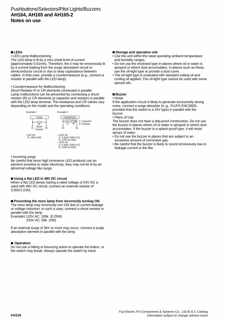
04/226Fuji Electric FA Components & Systems Co., Ltd./D & C Catalog
Information subject to change without notice
Using a flat LED in 48V DC circuitWhen a flat LED lamps having a rated voltage of 24V DC isused with 48V DC circuit, connect an external resistor of3,500Ω (1W).
Preventing the neon lamp from incorrectly turning ONThe neon lamp may incorrectly turn ON due to current leakageor voltage induction. In such a case, connect a shunt resistor inparallel with the lamp.Example) 110V AC: 100k (0.25W) 220V AC: 50k (2W)
If an external surge of 3kV or more may occur, connect a surgeabsorption element in parallel with the lamp.
OperationDo not use a hitting or bouncing action to operate the button, orthe switch may break. Always operate the switch by hand.
Storage and operation site• Use the unit within the rated operating ambient temperature and humidity ranges.• Do not use the enclosed type in places where oil or water is sprayed or where dust accumulates. In places such as these, use the oil-tight type or provide a dust cover.• The oil-tight type is evaluated with standard cutting oil and cooling oil applied. The oil-tight type cannot be used with some special oils.
Buzzer• NoiseIf the application circuit is likely to generate excessively strongnoise, connect a surge absorber (e.,g., FUJI'S ENC390D,provided that the switch is a 24V type) in parallel with thebuzzer.• Place of UseThe buzzer does not have a drip-proof construction. Do not usethe buzzer in places where oil or water is sprayed or where dustaccumulates. If the buzzer is a splash-proof type, it will resistsprays of water.• Do not use the buzzer in places that are subject to an
excessive amount of corronsive gas.• Be careful that the buzzer is likely to sound erroneously due to
leakage current or the like.
LEDs• LED Lamp MalfunctioningThe LED lamp is lit by a very small level of current(approximately 0.01mA). Therefore, the it may be erroneously litby a current leaking from the surge absorption circuit orsemiconductor circuit or due to stray capacitance betweencables. In that case, provide a countermeasure (e.g., connect aresistor in parallel with the LED lamp).
• Countermeasure for MalfunctioningShunt Resistor R or CR elements connected in parallelLamp malfunctions can be prevented by connecting a shuntresistor (R) or CR elements (a capacitor and resistor) in parallelwith the LED lamp terminal. The resistance and CR values varydepending on the model and the operating conditions.
Example 1 Example 2
Lamp
R
X1 X2Shunt
resistor
• 24V DC R: 10kΩ (1W)
• 110V AC C: 0.33µF (250V AC) R: 120Ω (0.25W)• 220V AC C: 0.33µF (250V AC) R: 120Ω (0.25W)
Transformer
RC
X1 X2
R: ResistorC: Capacitor
Pushbuttons/Selectors/Pilot Lights/BuzzersAH164, AH165 and AH165-2Notes on use
• Incoming surgeBe careful that since high luminance LED products use anelement sensitive to static electricity, they may not be lit by anabnormal voltage like surge.
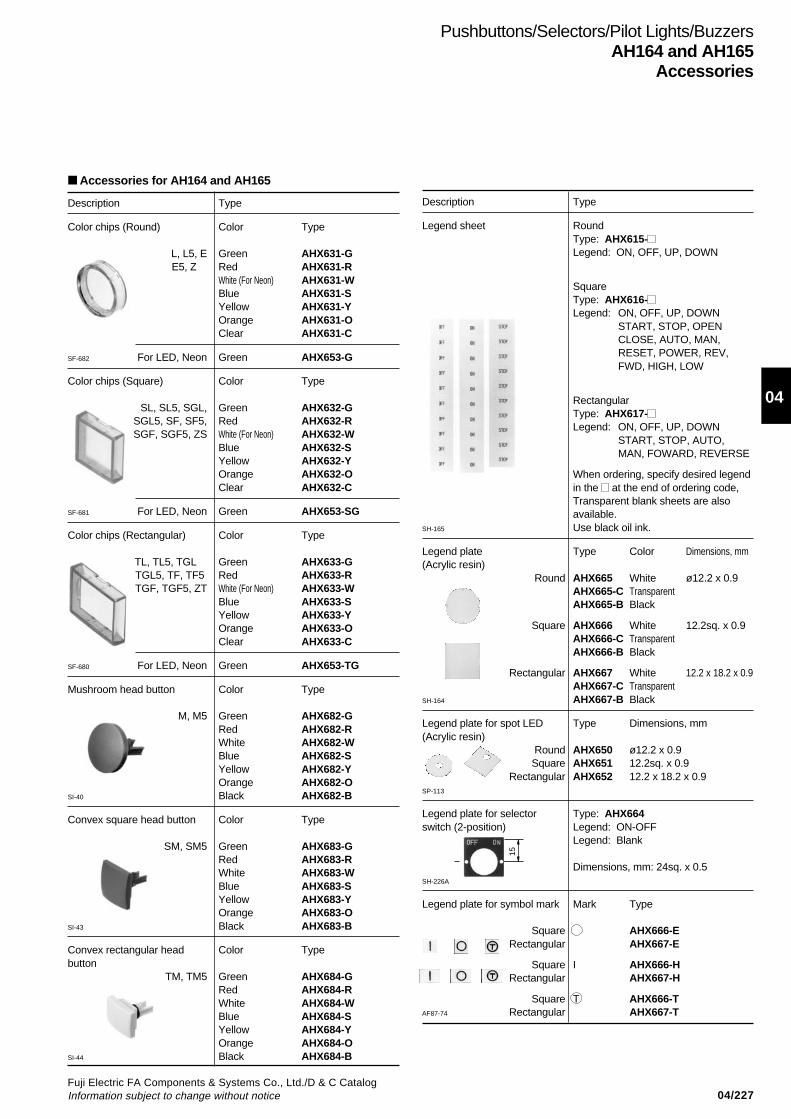
04/227Fuji Electric FA Components & Systems Co., Ltd./D & C CatalogInformation subject to change without notice
04
Pushbuttons/Selectors/Pilot Lights/BuzzersAH164 and AH165
Accessories
Description Type
Color chips (Round) Color Type
L, L5, E Green AHX631-GE5, Z Red AHX631-R
White (For Neon) AHX631-WBlue AHX631-SYellow AHX631-YOrange AHX631-OClear AHX631-C
SF-682 For LED, Neon Green AHX653-G
Color chips (Square) Color Type
SL, SL5, SGL, Green AHX632-GSGL5, SF, SF5, Red AHX632-RSGF, SGF5, ZS White (For Neon) AHX632-W
Blue AHX632-SYellow AHX632-YOrange AHX632-OClear AHX632-C
SF-681 For LED, Neon Green AHX653-SG
Color chips (Rectangular) Color Type
TL, TL5, TGL Green AHX633-GTGL5, TF, TF5 Red AHX633-RTGF, TGF5, ZT White (For Neon) AHX633-W
Blue AHX633-SYellow AHX633-YOrange AHX633-OClear AHX633-C
SF-680 For LED, Neon Green AHX653-TG
Mushroom head button Color Type
M, M5 Green AHX682-GRed AHX682-RWhite AHX682-WBlue AHX682-SYellow AHX682-YOrange AHX682-O
SI-40 Black AHX682-B
Convex square head button Color Type
SM, SM5 Green AHX683-GRed AHX683-RWhite AHX683-WBlue AHX683-SYellow AHX683-YOrange AHX683-O
SI-43 Black AHX683-B
Convex rectangular head Color Typebutton
TM, TM5 Green AHX684-GRed AHX684-RWhite AHX684-WBlue AHX684-SYellow AHX684-YOrange AHX684-O
SI-44 Black AHX684-B
Description Type
Legend sheet RoundType: AHX615-Legend: ON, OFF, UP, DOWN
SquareType: AHX616-Legend: ON, OFF, UP, DOWN
START, STOP, OPENCLOSE, AUTO, MAN,RESET, POWER, REV,FWD, HIGH, LOW
RectangularType: AHX617-Legend: ON, OFF, UP, DOWN
START, STOP, AUTO,MAN, FOWARD, REVERSE
When ordering, specify desired legendin the at the end of ordering code,Transparent blank sheets are alsoavailable.
SH-165 Use black oil ink.
Legend plate Type Color Dimensions, mm(Acrylic resin)
Round AHX665 White ø12.2 x 0.9AHX665-C TransparentAHX665-B Black
Square AHX666 White 12.2sq. x 0.9AHX666-C TransparentAHX666-B Black
Rectangular AHX667 White 12.2 x 18.2 x 0.9AHX667-C Transparent
SH-164 AHX667-B Black
Legend plate for spot LED Type Dimensions, mm(Acrylic resin)
Round AHX650 ø12.2 x 0.9Square AHX651 12.2sq. x 0.9
Rectangular AHX652 12.2 x 18.2 x 0.9SP-113
Legend plate for selector Type: AHX664switch (2-position) Legend: ON-OFF
Legend: Blank
Dimensions, mm: 24sq. x 0.5SH-226A
Legend plate for symbol mark Mark Type
Square AHX666-ERectangular AHX667-E
Square I AHX666-HRectangular AHX667-H
Square T AHX666-TAF87-74 Rectangular AHX667-T
15
Accessories for AH164 and AH165

04/228Fuji Electric FA Components & Systems Co., Ltd./D & C Catalog
Information subject to change without notice
Description Type
Protection cover For round and square head buttonType: AHX671
For rectangular head buttonType: AHX669 AHX826
This cover protect against accidental operation.
Dimensions, mm
Dust-tight cover For round and square head buttonType: AHX822Dimensions, mm: 24sq. x 14.2
For rectangular head buttonType: AHX668Dimensions, mm: 24 x 30 x 14.2
For mushroom head buttonType: AHX649Dimensions, mm: ø30 x 18
These covers protect against dust.
Guard ring Type Color Dimensions, mm
AHX676-B Black ø21 x 12AHX676-GY Gray
This guard ring is used in combination with anextended round head pushbutton (L or E).
Transformer Voltage Type Lamp
100 to 110V AC AHX805-H LED200 to 220V AC AHX805-M
100 to 110V AC AHX806-H Incandescent200 to 220V AC AHX806-M
Pushbuttons/Selectors/Pilot Lights/BuzzersAH164 and AH165Accessories
SI-42
AF90-949
AF91-123, SI-41
ø16.2
AHX671
33.2
23.5
31.5
10.5
ø16.2
AHX669
14 18 24
24
13.7
33.2
23.5
AHX826
Note: Not used for illuminated pushbuttons with guard.Applicable panel thickness is 2.6mm max.
Note: Applicable panel thickness is 2.0mm max.
Note: Applicable panel thickness is 2.5mm max. Pleaseplace an order for a packing (AHX685) separatelywhen you intend to use for AH165 series.
KKD07-246
KKD07-247
KKD07-248
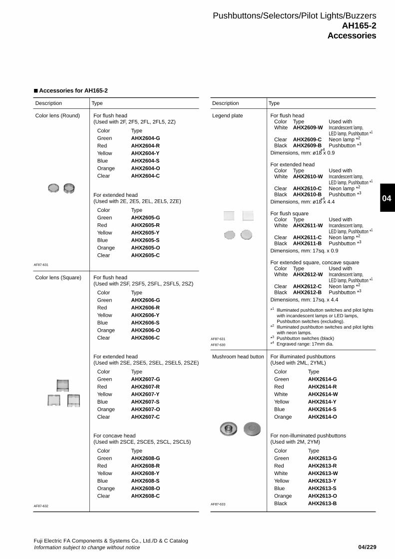
04/229Fuji Electric FA Components & Systems Co., Ltd./D & C CatalogInformation subject to change without notice
04
Pushbuttons/Selectors/Pilot Lights/BuzzersAH165-2
Accessories
Description Type Description Type
Color lens (Round) Legend plate
Mushroom head button
Color lens (Square)
For flush head(Used with 2F, 2F5, 2FL, 2FL5, 2Z)
Color TypeGreen AHX2604-GRed AHX2604-RYellow AHX2604-YBlue AHX2604-SOrange AHX2604-OClear AHX2604-C
For flush headColor Type Used withWhite AHX2609-W Incandescent lamp,
LED lamp, Pushbutton *1
Clear AHX2609-C Neon lamp *2
Black AHX2609-B Pushbutton *3
Dimensions, mm: ø18 x 0.9
For extended headColor Type Used withWhite AHX2610-W Incandescent lamp,
LED lamp, Pushbutton *1
Clear AHX2610-C Neon lamp *2
Black AHX2610-B Pushbutton *3
Dimensions, mm: ø18 x 4.4
For flush squareColor Type Used withWhite AHX2611-W Incandescent lamp,
LED lamp, Pushbutton *1
Clear AHX2611-C Neon lamp *2
Black AHX2611-B Pushbutton *3
Dimensions, mm: 17sq. x 0.9
For extended square, concave squareColor Type Used withWhite AHX2612-W Incandescent lamp,
LED lamp, Pushbutton *1
Clear AHX2612-C Neon lamp *2
Black AHX2612-B Pushbutton *3
Dimensions, mm: 17sq. x 4.4
For extended head(Used with 2E, 2E5, 2EL, 2EL5, 2ZE)
Color TypeGreen AHX2605-GRed AHX2605-RYellow AHX2605-YBlue AHX2605-SOrange AHX2605-OClear AHX2605-C
For flush head(Used with 2SF, 2SF5, 2SFL, 2SFL5, 2SZ)
Color TypeGreen AHX2606-GRed AHX2606-RYellow AHX2606-YBlue AHX2606-SOrange AHX2606-OClear AHX2606-C
For extended head(Used with 2SE, 2SE5, 2SEL, 2SEL5, 2SZE)
Color TypeGreen AHX2607-GRed AHX2607-RYellow AHX2607-YBlue AHX2607-SOrange AHX2607-OClear AHX2607-C
For concave head(Used with 2SCE, 2SCE5, 2SCL, 2SCL5)
Color TypeGreen AHX2608-GRed AHX2608-RYellow AHX2608-YBlue AHX2608-SOrange AHX2608-OClear AHX2608-C
For illuminated pushbuttons(Used with 2ML, 2YML)
Color TypeGreen AHX2614-GRed AHX2614-RWhite AHX2614-WYellow AHX2614-YBlue AHX2614-SOrange AHX2614-O
For non-illuminated pushbuttons(Used with 2M, 2YM)
Color TypeGreen AHX2613-GRed AHX2613-RWhite AHX2613-WYellow AHX2613-YBlue AHX2613-SOrange AHX2613-OBlack AHX2613-B
*1 Illuminated pushbutton switches and pilot lights with incandescent lamps or LED lamps, Pushbutton switches (excluding).*2 Illuminated pushbutton switches and pilot lights with neon lamps.*3 Pushbutton switches (black)*4 Engraved range: 17mm dia.
*4
*4
Accessories for AH165-2
AF87-631
AF87-632
AF87-631
AF87-630
AF87-633
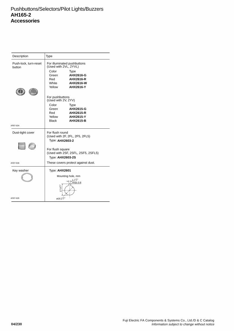
04/230Fuji Electric FA Components & Systems Co., Ltd./D & C Catalog
Information subject to change without notice
Pushbuttons/Selectors/Pilot Lights/BuzzersAH165-2Accessories
Mounting hole, mm
rmax.0.8
ø16.2+0.2 0
17.9
+0.
2 0
1.7+0.2 0
Description Type
Push-lock, turn-resetbutton
Dust-tight cover
Key washer
For illuminated pushbuttons(Used with 2VL, 2YVL)
Color TypeGreen AHX2616-GRed AHX2616-RWhite AHX2616-WYellow AHX2616-Y
For pushbuttons(Used with 2V, 2YV)
Color TypeGreen AHX2615-GRed AHX2615-RYellow AHX2615-YBlack AHX2615-B
For flush round(Used with 2F, 2FL, 2F5, 2FL5)
Type: AHX2603-2
For flush square(Used with 2SF, 2SFL, 2SF5, 2SFL5)
Type: AHX2603-2S
These covers protect against dust.
Type: AHX2601
AF87-634
AF87-636
AF87-635
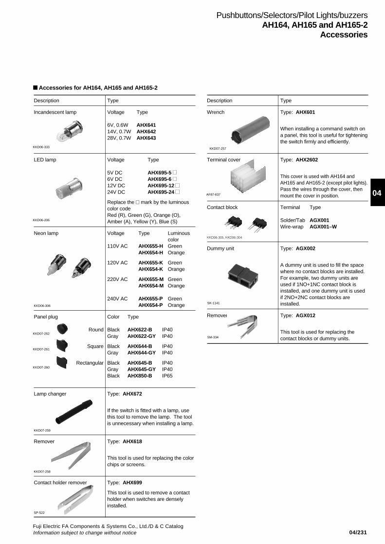
04/231Fuji Electric FA Components & Systems Co., Ltd./D & C CatalogInformation subject to change without notice
04
Description Type
Wrench Type: AHX601
When installing a command switch ona panel, this tool is useful for tighteningthe switch firmly and efficiently.
Terminal cover Type: AHX2602
This cover is used with AH164 andAH165 and AH165-2 (except pilot lights).Pass the wires through the cover, thenmount the cover in position.
Contact block Terminal Type
Solder/Tab AGX001Wire-wrap AGX001–W
KKD06-305, KKD06-304
Dummy unit Type: AGX002
A dummy unit is used to fill the spacewhere no contact blocks are installed.For example, two dummy units areused if 1NO+1NC contact block isinstalled, and one dummy unit is usedif 2NO+2NC contact blocks areinstalled.
Remover Type: AGX012
This tool is used for replacing thecontact blocks or dummy units.
Pushbuttons/Selectors/Pilot Lights/buzzersAH164, AH165 and AH165-2
Accessories
AF87-637
Accessories for AH164, AH165 and AH165-2
SK-1141
SM-334
KKD06-333
KKD06-206
KKD07-262
KKD07-261
KKD07-260
KKD07-257
Description Type
Incandescent lamp Voltage Type
6V, 0.6W AHX64114V, 0.7W AHX64228V, 0.7W AHX643
LED lamp Voltage Type
5V DC AHX695-5 6V DC AHX695-6 12V DC AHX695-12 24V DC AHX695-24
Replace the mark by the luminouscolor codeRed (R), Green (G), Orange (O),Amber (A), Yellow (Y), Blue (S)
Neon lamp Voltage Type Luminouscolor
110V AC AHX655-H GreenAHX654-H Orange
120V AC AHX655-K GreenAHX654-K Orange
220V AC AHX655-M GreenAHX654-M Orange
240V AC AHX655-P GreenKKD06-306 AHX654-P Orange
Panel plug Color Type
Round Black AHX622-B IP40Gray AHX622-GY IP40
Square Black AHX644-B IP40Gray AHX644-GY IP40
Rectangular Black AHX645-B IP40Gray AHX645-GY IP40Black AHX850-B IP65
Lamp changer Type: AHX672
If the switch is fitted with a lamp, usethis tool to remove the lamp. The toolis unnecessary when installing a lamp.
KKD07-259
Remover Type: AHX618
This tool is used for replacing the colorchips or screens.
KKD07-258
Contact holder remover Type: AHX699
This tool is used to remove a contactholder when switches are denselyinstalled.
SP-522
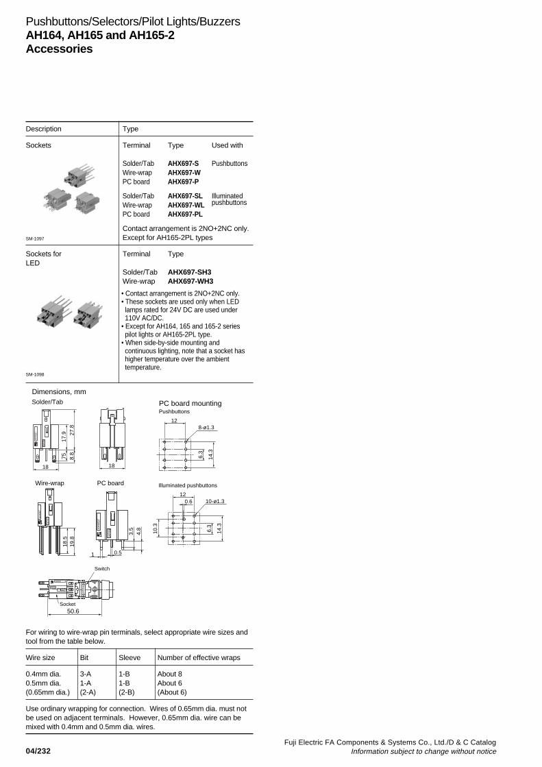
04/232Fuji Electric FA Components & Systems Co., Ltd./D & C Catalog
Information subject to change without notice
Description Type
Sockets Terminal Type Used with
Solder/Tab AHX697-S PushbuttonsWire-wrap AHX697-WPC board AHX697-P
Solder/Tab AHX697-SL IlluminatedWire-wrap AHX697-WL pushbuttons
PC board AHX697-PL
Contact arrangement is 2NO+2NC only.Except for AH165-2PL types
Sockets for Terminal TypeLED
Solder/Tab AHX697-SH3Wire-wrap AHX697-WH3
For wiring to wire-wrap pin terminals, select appropriate wire sizes andtool from the table below.
Wire size Bit Sleeve Number of effective wraps
0.4mm dia. 3-A 1-B About 80.5mm dia. 1-A 1-B About 6(0.65mm dia.) (2-A) (2-B) (About 6)
Use ordinary wrapping for connection. Wires of 0.65mm dia. must notbe used on adjacent terminals. However, 0.65mm dia. wire can bemixed with 0.4mm and 0.5mm dia. wires.
Pushbuttons/Selectors/Pilot Lights/BuzzersAH164, AH165 and AH165-2Accessories
SM-1097
AHX6
97
JAPA
N
AH
X69
7
JAPA
N
18.5
19.8
AH
X69
7
JAPA
N
0.5
0.612
10-ø1.3
3.5
4.8
10.3
6.3
14.3
1
128-ø1.3
6.3
14.3
18
Wire-wrap
Solder/Tab PC board mountingPushbuttons
Illuminated pushbuttonsPC board
18
7517
.9
8.8
27.8
Dimensions, mm
Switch
Socket50.6
AHX697
JAPAN
PU
SH
• Contact arrangement is 2NO+2NC only.• These sockets are used only when LED lamps rated for 24V DC are used under 110V AC/DC.• Except for AH164, 165 and 165-2 series pilot lights or AH165-2PL type.• When side-by-side mounting and continuous lighting, note that a socket has higher temperature over the ambient temperature.
SM-1098
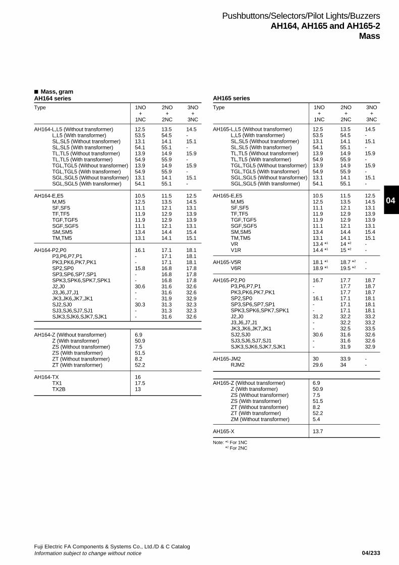
04/233Fuji Electric FA Components & Systems Co., Ltd./D & C CatalogInformation subject to change without notice
04
Mass, gramAH164 seriesType 1NO 2NO 3NO
+ + +1NC 2NC 3NC
AH164-L,L5 (Without transformer) 12.5 13.5 14.5L,L5 (With transformer) 53.5 54.5 -SL,SL5 (Without transformer) 13.1 14.1 15.1SL,SL5 (With transformer) 54.1 55.1 -TL,TL5 (Without transformer) 13.9 14.9 15.9TL,TL5 (With transformer) 54.9 55.9 -TGL,TGL5 (Without transformer) 13.9 14.9 15.9TGL,TGL5 (With transformer) 54.9 55.9 -SGL,SGL5 (Without transformer) 13.1 14.1 15.1SGL,SGL5 (With transformer) 54.1 55.1 -
AH164-E,E5 10.5 11.5 12.5M,M5 12.5 13.5 14.5SF,SF5 11.1 12.1 13.1TF,TF5 11.9 12.9 13.9TGF,TGF5 11.9 12.9 13.9SGF,SGF5 11.1 12.1 13.1SM,SM5 13.4 14.4 15.4TM,TM5 13.1 14.1 15.1
AH164-P2,P0 16.1 17.1 18.1P3,P6,P7,P1 - 17.1 18.1PK3,PK6,PK7,PK1 - 17.1 18.1SP2,SP0 15.8 16.8 17.8SP3,SP6,SP7,SP1 - 16.8 17.8SPK3,SPK6,SPK7,SPK1 - 16.8 17.8J2,J0 30.6 31.6 32.6J3,J6,J7,J1 - 31.6 32.6JK3,JK6,JK7,JK1 - 31.9 32.9SJ2,SJ0 30.3 31.3 32.3SJ3,SJ6,SJ7,SJ1 - 31.3 32.3SJK3,SJK6,SJK7,SJK1 - 31.6 32.6
AH164-Z (Without transformer) 6.9Z (With transformer) 50.9ZS (Without transformer) 7.5ZS (With transformer) 51.5ZT (Without transformer) 8.2ZT (With transformer) 52.2
AH164-TX 16TX1 17.5TX2B 13
Pushbuttons/Selectors/Pilot Lights/BuzzersAH164, AH165 and AH165-2
Mass
AH165 seriesType 1NO 2NO 3NO
+ + +1NC 2NC 3NC
AH165-L,L5 (Without transformer) 12.5 13.5 14.5L,L5 (With transformer) 53.5 54.5 -SL,SL5 (Without transformer) 13.1 14.1 15.1SL,SL5 (With transformer) 54.1 55.1 -TL,TL5 (Without transformer) 13.9 14.9 15.9TL,TL5 (With transformer) 54.9 55.9 -TGL,TGL5 (Without transformer) 13.9 14.9 15.9TGL,TGL5 (With transformer) 54.9 55.9 -SGL,SGL5 (Without transformer) 13.1 14.1 15.1SGL,SGL5 (With transformer) 54.1 55.1 -
AH165-E,E5 10.5 11.5 12.5M,M5 12.5 13.5 14.5SF,SF5 11.1 12.1 13.1TF,TF5 11.9 12.9 13.9TGF,TGF5 11.9 12.9 13.9SGF,SGF5 11.1 12.1 13.1SM,SM5 13.4 14.4 15.4TM,TM5 13.1 14.1 15.1VR 13.4 *1 14 *2 -V1R 14.4 *1 15 *2 -
AH165-V5R 18.1 *1 18.7 *2 -V6R 18.9 *1 19.5 *2 -
AH165-P2,P0 16.7 17.7 18.7P3,P6,P7,P1 - 17.7 18.7PK3,PK6,PK7,PK1 - 17.7 18.7SP2,SP0 16.1 17.1 18.1SP3,SP6,SP7,SP1 - 17.1 18.1SPK3,SPK6,SPK7,SPK1 - 17.1 18.1J2,J0 31.2 32.2 33.2J3,J6,J7,J1 - 32.2 33.2JK3,JK6,JK7,JK1 - 32.5 33.5SJ2,SJ0 30.6 31.6 32.6SJ3,SJ6,SJ7,SJ1 - 31.6 32.6SJK3,SJK6,SJK7,SJK1 - 31.9 32.9
AH165-JM2 30 33.9 -RJM2 29.6 34 -
AH165-Z (Without transformer) 6.9Z (With transformer) 50.9ZS (Without transformer) 7.5ZS (With transformer) 51.5ZT (Without transformer) 8.2ZT (With transformer) 52.2ZM (Without transformer) 5.4
AH165-X 13.7
Note: *1 For 1NC*2 For 2NC
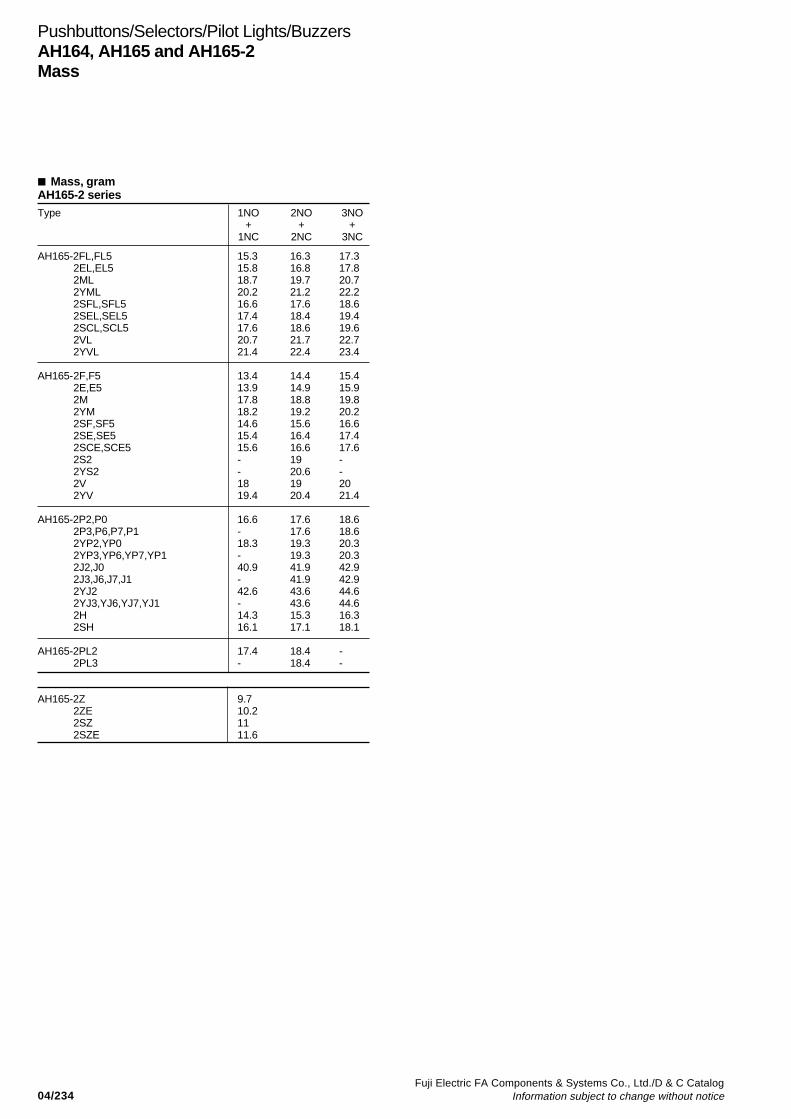
04/234Fuji Electric FA Components & Systems Co., Ltd./D & C Catalog
Information subject to change without notice
Mass, gramAH165-2 seriesType 1NO 2NO 3NO
+ + +1NC 2NC 3NC
AH165-2FL,FL5 15.3 16.3 17.32EL,EL5 15.8 16.8 17.82ML 18.7 19.7 20.72YML 20.2 21.2 22.22SFL,SFL5 16.6 17.6 18.62SEL,SEL5 17.4 18.4 19.42SCL,SCL5 17.6 18.6 19.62VL 20.7 21.7 22.72YVL 21.4 22.4 23.4
AH165-2F,F5 13.4 14.4 15.42E,E5 13.9 14.9 15.92M 17.8 18.8 19.82YM 18.2 19.2 20.22SF,SF5 14.6 15.6 16.62SE,SE5 15.4 16.4 17.42SCE,SCE5 15.6 16.6 17.62S2 - 19 -2YS2 - 20.6 -2V 18 19 202YV 19.4 20.4 21.4
AH165-2P2,P0 16.6 17.6 18.62P3,P6,P7,P1 - 17.6 18.62YP2,YP0 18.3 19.3 20.32YP3,YP6,YP7,YP1 - 19.3 20.32J2,J0 40.9 41.9 42.92J3,J6,J7,J1 - 41.9 42.92YJ2 42.6 43.6 44.62YJ3,YJ6,YJ7,YJ1 - 43.6 44.62H 14.3 15.3 16.32SH 16.1 17.1 18.1
AH165-2PL2 17.4 18.4 -2PL3 - 18.4 -
AH165-2Z 9.72ZE 10.22SZ 112SZE 11.6
Pushbuttons/Selectors/Pilot Lights/BuzzersAH164, AH165 and AH165-2Mass
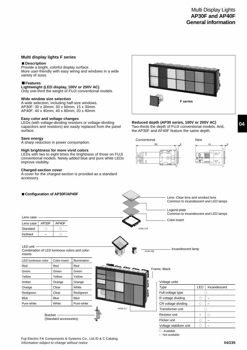
04/235Fuji Electric FA Components & Systems Co., Ltd./D & C CatalogInformation subject to change without notice
04
DescriptionProvide a bright, colorful display surface.More user-friendly with easy wiring and windows in a widevariety of sizes.
FeaturesLightweight (LED display, 100V or 200V AC)Only one-third the weight of FUJI conventional models.
Wide window size selectionA wide selection, including half-size windows.AP30F: 30 x 30mm, 30 x 60mm, 15 x 30mmAP40F: 40 x 40mm, 40 x 80mm, 20 x 40mm
Easy color and voltage changesLEDs (with voltage-dividing resistors or voltage-dividingcapacitors and resistors) are easily replaced from the panelsurface.
Save energyA sharp reduction in power consumption.
High brightness for more vivid colorsLEDs with two to eight times the brightness of those on FUJIconventional models. Newly added blue and pure white LEDsimprove visibility.
Charged-section coverA cover for the charged section is provided as a standardaccessory.
Configuration of AP30F/AP40FLens: Clear lens and smoked lensCommon to incandescent and LED lamps
Legend plateCommon to incandescent and LED lamps
Color-insert
Incandescent lamp
Bracket(Standard accessories)
LED luminous color Color-insert Illumination
Red Red Red
Green Green Green
Yellow Yellow Yellow
Amber Orange Orange
Orange Clear White
Red/green Clear Red/green
Blue Blue Blue
Pure-white White Pure-white
AF88-217
Frame, Black
Voltage units
Type LED Incandescent
Full-voltage type
R voltage dividing –
CR voltage dividing –
Transformer unit
Resistor unit –
Flicker unit –
Voltage stabilizer unit –
: Available– : Not available
LED unitCombination of LED luminous colors and color-inserts
Lens case
Lens case AP30F AP40F
Standard
Inclined –
Multi Display LightsAP30F and AP40F
General information
AF88-218
AF89-398
Multi display lights F series
F series
61 6
NewConventional90 6
Reduced depth (AP30 series, 100V or 200V AC)Two-thirds the depth of FUJI conventional models. And,the AP30F and AF40F feature the same depth.

04/236Fuji Electric FA Components & Systems Co., Ltd./D & C Catalog
Information subject to change without notice
Type number nomenclature
AP30F– 04 05 E3–S 4 –SR (20) Z1
➀ Basic typeAP30F: 30 × 30, 30 × 60, 60 × 30, 15 × 30mm (Window size)AP40F: 40 × 40, 40 × 80, 80 × 40, 20 × 40mm
➁ Number of windows(=Row × Column)
➄ Shape of illuminated faceAP30F seriesS: Square (30 × 30)T: Rectangular, horizontally long (30 × 60)V: Rectangular, vertically long (60 × 30)H: Half-size (15 × 30) × 2X: Mixture of S, T, and V
AP40F seriesS: Square (40 × 40)T: Rectangular, horizontally long (40 × 80)V: Rectangular, vertically long (80 × 40)H: Half-size (20 × 40) × 2X: Mixture of S, T, and V
➅ Illumination methodBlank: Single color, entire surface illumination
4: 2-color, entire surface illumination (for 24V AC/DC LEDs only)2: 2-way rectangular-split illumination
➆ Illuminated colorUsing clear lens Color plate (White) Using smoked lens
R: Red CR: Red SR: RedG: Green CG: Green SG: GreenY: Yellow CY: Yellow SY: YellowO: Orange CO: Orange SO: OrangeW: White CS: Blue SW: WhiteS: Blue RG: Red/green SS: BlueP: Pure-white*
• Two-color illumination face is only available for 24V AC/DC type.• The flicker unit is available in square design only (S-type).
Ordering informationSpecify the following:1. Type number
➀ ➁ ➂ ➃ ➄ ➅ ➆ ➇
01,02,03,04,05,06,07,08,09,10 01,02,03,04,05,06,07,08,09,1011,12,13,14,15,16,17,18,19,20 11,12,13,14,15,16,17,18,19,2001,02,03,04,05,06,07 01,02,03,04,05,06,07,08,09,10,
11,12,13,14,15Max.105
Max.400
AP40F
AP30F
• Convert one rectangular window to two square windows.• The number of windows is limited to 80 when transformer units are mounted.
ColumnRow
Incandescent LED unit
Full-voltage type A: 5.5V AC/DC C: 15.5V AC/DC A3: 6V DC B3: 12V ACDCD: 20V AC/DC E: 24V AC/DC C3: 15V AC/DC E3: 24V AC/DC
ES: 24V AC/DC * F3: 48V AC/DCH3: 100-110V AC/DC L3: 115-127V AC/DCM3: 200-220V AC
Transformer unit H: 100-110V AC L:115-127V AC Q3: 230-254V AC S3: 350-380V ACM: 200-220V AC Q:230-254V AC T3: 400-440V AC V3: 480V ACS: 350-380V AC T:400-440V ACV: 480V AC
Resistor unit H6:110V DC L6: 125V DC –(Electric bulb 48V 1W)
Mixed type X: Combination of the above X3: Combination of the above three three types plus flicker and voltage
stabilizer unit
AP40F seriesIncandescent LED unit
Full-voltage type C: 15.5V AC/DC D: 20V AC/DC A3: 6V DC B3: 12V AC/DCE: 24V AC/DC C3: 15V AC/DC E3: 24V AC/DC
ES: 24V AC/DC * F3: 48V AC/DCH3: 100-110V AC/DC L3: 115-127V AC/DCM3: 200-220V AC
Transformer unit H: 100-110V AC L: 115-127V AC Q3: 230-254V AC S3: 350-380V ACM: 200-220V AC Q: 230-254V AC T3: 400-440V AC V3: 480V ACS: 350-380V AC T: 400-440V ACV: 480V AC
Resistor unit H6: 110V DC L6: 127V DC –(Electric bulb 48V 2W)
Mixed type X: Combination of the above X3: Combination of the above three three types plus flicker and voltage
stabilizer unit
➃ Voltage unit and input voltageAP30F series
Notes:The combination of LED units and voltage units is limited as follows:
Code Voltage unit LED unit
E3FA Flicker unit For 24V AC
E3FD For 24V DC
E3C Voltage stabilizer unit 27-35V AC/DC 24V (short body type)
24V (short body type)
Using window layout sheet
Use the copies of the window layout sheet (See page 04/255) andspecify for each of the window when ordering the following types.• Types with letters on legend plate• Types with symbol X for ➃ voltage unit and input voltage• Types with symbol X for ➄ shape of illuminated face• When two or more illuminated colors are specified for LED
unit in ➆ .
Multi Display LightsAP30F and AP40FType number nomenclature
• Specify the number of windows in ( ).• If two or more colors are specified using LED unit, the illuminated
color ➆ here should be blank.* Not available for incandescent lamp
➂ Check terminalC: withBlank: without
* Short body type
* Short body type
➇ UL, CSA Approved (Option)
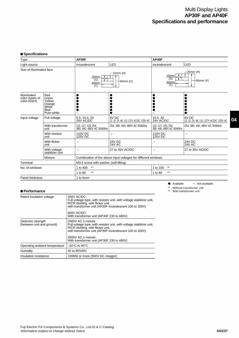
04/237Fuji Electric FA Components & Systems Co., Ltd./D & C CatalogInformation subject to change without notice
04
Specifications
Type AP30F AP40F
Light source Incandescent LED Incandescent LED
Size of illuminated face
Illuminated Red color (types of Green color-insert) Yellow
Orange White Blue Pure-white – –
Input voltage Full voltage 5.5, 15.5, 20 6V DC 15.5, 20 6V DC24V AC/DC 12, 15, 24, 48, 110, 127V AC/DC 220V AC 24V AC/DC 12, 15, 24, 48, 110, 127V AC/DC 220V AC
With transformer 110, 127, 220, 254, 254, 380, 440, 480V AC 50/60Hz 110, 127, 220, 254, 254, 380, 440, 480V AC 50/60Hzunit 380, 440, 480V AC 50/60Hz 380, 440, 480V AC 50/60Hz
With resistor 110V DC – 110V DC –unit 125V DC 125V DC
With flicker – 24V DC – 24V DCunit 24V AC 24V AC
With voltage – 27 to 35V AC/DC – 27 to 35V AC/DCstabilizer unit
Mixture Combination of the above input voltages for different windows.
Terminal M3.5 screw with washer (self-lifting)
No. of windows 1 to 400 *1 1 to 105 *1
1 to 80 *2 1 to 80 *2
Panel thickness 1 to 6mm
60mm (V)
15mm (H)30mm
(S)60mm
(T)
80mm (V)80mm
(T)
40mm(S)
20mm (H)
Performance
Rated insulation voltage 250V AC/DC:Full voltage type, with resistor unit, with voltage stabilizer unit,R/CR dividing, with flicker unit,with transformer unit (AP30F incandescent 100 to 200V)
600V AC/DC:With transformer unit (AP30F 230 to 480V)
Dielectric strength 2000V AC 1-minute:(between unit and ground) Full voltage type, with resistor unit, with voltage stabilizer unit,
R/CR dividing, with flicker unit,with transformer unit (AP30F incandescent 100 to 200V)
2500V AC 1-minute:With transformer unit (AP30F 230 to 480V)
Operating ambient temperature –20°C to 40°C
Humidity 45 to 85%RH
Insulation resistance 100MΩ or more (500V DC megger)
: Available –: Not available
Multi Display LightsAP30F and AP40F
Specifications and performance
*1 : Without transformer unit*2 : With transformer unit
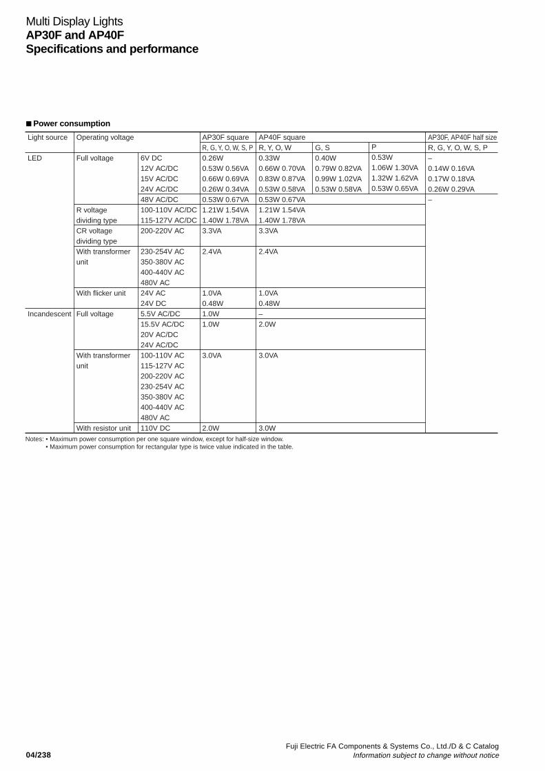
04/238Fuji Electric FA Components & Systems Co., Ltd./D & C Catalog
Information subject to change without notice
Multi Display LightsAP30F and AP40FSpecifications and performance
Power consumption
Light source
LED
Incandescent
Operating voltage
Full voltage
R voltagedividing typeCR voltagedividing typeWith transformerunit
With flicker unit
Full voltage
With transformerunit
With resistor unit
AP30F squareR, G, Y, O, W, S, P0.26W0.53W 0.56VA0.66W 0.69VA0.26W 0.34VA0.53W 0.67VA1.21W 1.54VA1.40W 1.78VA3.3VA
2.4VA
1.0VA0.48W1.0W1.0W
3.0VA
2.0W
AP40F squareR, Y, O, W0.33W0.66W 0.70VA0.83W 0.87VA0.53W 0.58VA0.53W 0.67VA1.21W 1.54VA1.40W 1.78VA3.3VA
2.4VA
1.0VA0.48W–2.0W
3.0VA
3.0W
AP30F, AP40F half sizeR, G, Y, O, W, S, P–0.14W 0.16VA0.17W 0.18VA0.26W 0.29VA–
G, S0.40W0.79W 0.82VA0.99W 1.02VA0.53W 0.58VA
P0.53W1.06W 1.30VA1.32W 1.62VA0.53W 0.65VA
6V DC12V AC/DC15V AC/DC24V AC/DC48V AC/DC100-110V AC/DC115-127V AC/DC200-220V AC
230-254V AC350-380V AC400-440V AC480V AC24V AC24V DC5.5V AC/DC15.5V AC/DC20V AC/DC24V AC/DC100-110V AC115-127V AC200-220V AC230-254V AC350-380V AC400-440V AC480V AC110V DC
Notes: • Maximum power consumption per one square window, except for half-size window.• Maximum power consumption for rectangular type is twice value indicated in the table.

04/239Fuji Electric FA Components & Systems Co., Ltd./D & C CatalogInformation subject to change without notice
04
Multi Display LightsAP30F
Dimensions
AP30F Dimensions, mm
V-type T-typeFront view S-type H-type
21 30 30
2130
30
30sq
.
Dimension D (30n+12)
Dim
ensi
on C
(30
n+12
)
21 30 30
3660
60
30
Dimension D (30n+12)
Dim
ensi
on C
(30
n+12
)
21 30 30
1415
1515
1515
15
30
Dimension D (30n+12)
Dim
ensi
on C
(30
n+12
)
With transformer unit (230V to 480V LED and incandescent) With resistor unit, with flicker unit, with voltage stabilizer unit
Back view Full-voltage type (LED)
655
60.5 (With terminal cover)
Panel thickness 1~6
Terminal screw M3.5(Slotted and Phillips head, self–lifting)
1630
3016
.9
689 (With terminal cover)84
Panel thickness 1~6
Terminal screw M3.5(Slotted and Phillips head, self–lifting)
Full-voltage type (LED, short body type)
47
52 (With terminal cover)6
Panel thickness 1~6
Terminal screw M3.5(Slotted and Phillips head, self–lifting)
With transformer (Incandescent, 100V to 220V) Full-voltage type (Incandescent)
486
54 (With terminal cover)
Panel thickness 1~6
Terminal screw M3.5(Slotted and Phillips head, self–lifting)
71676 (With terminal cover)
Panel thickness 1~6
Terminal screw M3.5(Slotted and Phillips head, self–lifting)
Half size (Illuminated face)With check terminal Full-voltage type
657
60 (With terminal cover)
Panel thickness 1~6
Terminal screw M3.5(Slotted and Phillips head, self–lifting)
1730
12
30
13
13
30
30
8
12.8
30
30
13
13
30
30
13
13
30
30
36 60
2130
30
30
60
Dimension D (60n+12)
Dim
ensi
on C
(30
n+12
)
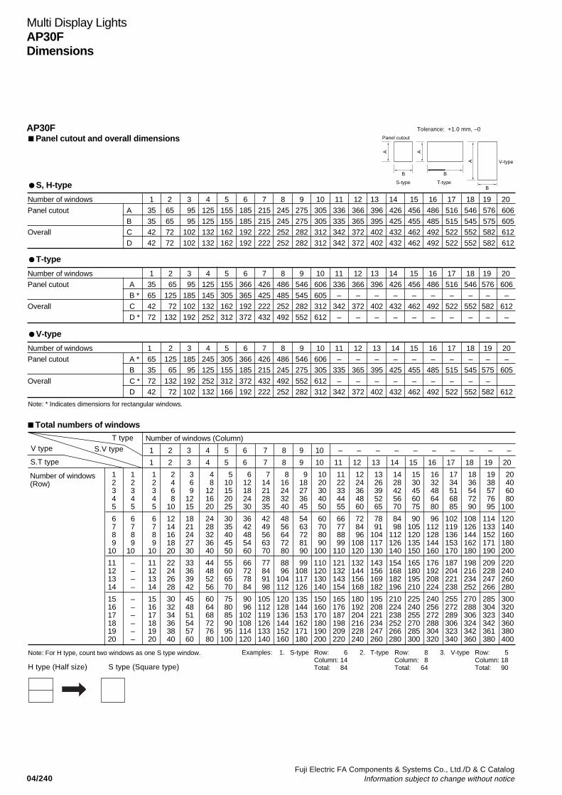
04/240Fuji Electric FA Components & Systems Co., Ltd./D & C Catalog
Information subject to change without notice
Number of windows 1 2 3 4 5 6 7 8 9 10 11 12 13 14 15 16 17 18 19 20
Panel cutout A 35 65 95 125 155 185 215 245 275 305 336 366 396 426 456 486 516 546 576 606B 35 65 95 125 155 185 215 245 275 305 335 365 395 425 455 485 515 545 575 605
Overall C 42 72 102 132 162 192 222 252 282 312 342 372 402 432 462 492 522 552 582 612D 42 72 102 132 162 192 222 252 282 312 342 372 402 432 462 492 522 552 582 612
V-type
T-type
Panel cutout and overall dimensions
S, H-type
Multi Display LightsAP30FDimensions
Number of windows 1 2 3 4 5 6 7 8 9 10 11 12 13 14 15 16 17 18 19 20Panel cutout A * 65 125 185 245 305 366 426 486 546 606 – – – – – – – – – –
B 35 65 95 125 155 185 215 245 275 305 335 365 395 425 455 485 515 545 575 605
Overall C * 72 132 192 252 312 372 432 492 552 612 – – – – – – – – –D 42 72 102 132 166 192 222 252 282 312 342 372 402 432 462 492 522 552 582 612
Number of windows 1 2 3 4 5 6 7 8 9 10 11 12 13 14 15 16 17 18 19 20Panel cutout A 35 65 95 125 155 366 426 486 546 606 336 366 396 426 456 486 516 546 576 606
B * 65 125 185 145 305 365 425 485 545 605 – – – – – – – – – –Overall C 42 72 102 132 162 192 222 252 282 312 342 372 402 432 462 492 522 552 582 612
D * 72 132 192 252 312 372 432 492 552 612 – – – – – – – – – –
AP30F
Examples: 1. S-type Row: 6 2. T-type Row: 8 3. V-type Row: 5Column: 14 Column: 8 Column: 18Total: 84 Total: 64 Total: 90
V type
S.T type
Total numbers of windows
Number of windows (Column)
1 2 3 4 5 6 7 8 9 10 – – – – – – – – – –
1 2 3 4 5 6 7 8 9 10 11 12 13 14 15 16 17 18 19 20
1 1 1 2 3 4 5 6 7 8 9 10 11 12 13 14 15 16 17 18 19 202 2 2 4 6 8 10 12 14 16 18 20 22 24 26 28 30 32 34 36 38 403 3 3 6 9 12 15 18 21 24 27 30 33 36 39 42 45 48 51 54 57 604 4 4 8 12 16 20 24 28 32 36 40 44 48 52 56 60 64 68 72 76 805 5 5 10 15 20 25 30 35 40 45 50 55 60 65 70 75 80 85 90 95 100
6 6 6 12 18 24 30 36 42 48 54 60 66 72 78 84 90 96 102 108 114 1207 7 7 14 21 28 35 42 49 56 63 70 77 84 91 98 105 112 119 126 133 1408 8 8 16 24 32 40 48 56 64 72 80 88 96 104 112 120 128 136 144 152 1609 9 9 18 27 36 45 54 63 72 81 90 99 108 117 126 135 144 153 162 171 180
10 10 10 20 30 40 50 60 70 80 90 100 110 120 130 140 150 160 170 180 190 200
11 – 11 22 33 44 55 66 77 88 99 110 121 132 143 154 165 176 187 198 209 22012 – 12 24 36 48 60 72 84 96 108 120 132 144 156 168 180 192 204 216 228 24013 – 13 26 39 52 65 78 91 104 117 130 143 156 169 182 195 208 221 234 247 26014 – 14 28 42 56 70 84 98 112 126 140 154 168 182 196 210 224 238 252 266 280
15 – 15 30 45 60 75 90 105 120 135 150 165 180 195 210 225 240 255 270 285 30016 – 16 32 48 64 80 96 112 128 144 160 176 192 208 224 240 256 272 288 304 32017 – 17 34 51 68 85 102 119 136 153 170 187 204 221 238 255 272 289 306 323 34018 – 18 36 54 72 90 108 126 144 162 180 198 216 234 252 270 288 306 324 342 36019 – 19 38 57 76 95 114 133 152 171 190 209 228 247 266 285 304 323 342 361 38020 – 20 40 60 80 100 120 140 160 180 200 220 240 260 280 300 320 340 360 380 400
V-type
A
B
S-type
Panel cutout
A
B
T-type
A
B
T type
S.V type
Number of windows(Row)
Note: For H type, count two windows as one S type window.
H type (Half size) S type (Square type)
Tolerance: +1.0 mm, –0
Note: * Indicates dimensions for rectangular windows.
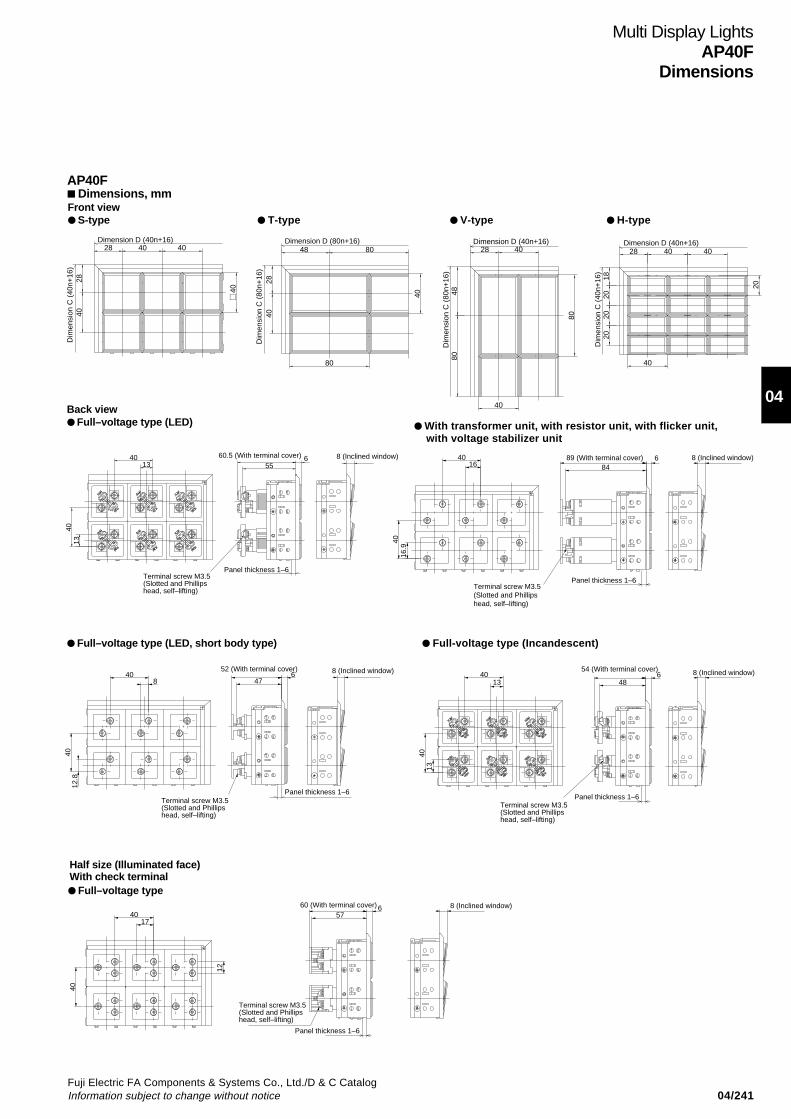
04/241Fuji Electric FA Components & Systems Co., Ltd./D & C CatalogInformation subject to change without notice
04
Multi Display LightsAP40F
Dimensions
AP40F Dimensions, mm
V-type T-typeFront view S-type H-type
40
40 4028
4028
Dimension D (40n+16)
Dim
ensi
on C
(40
n+16
)
8048
2840
80
40
Dimension D (80n+16)
Dim
ensi
on C
(80
n+16
)
80
40
4028
8048
Dimension D (40n+16)
Dim
ensi
on C
(80
n+16
)
40 4028
2020
2018
20
40
Dimension D (40n+16)
Dim
ensi
on C
(40
n+16
)
With transformer unit, with resistor unit, with flicker unit, with voltage stabilizer unit
Back view Full–voltage type (LED)
6 8 (Inclined window)55
60.5 (With terminal cover)
Panel thickness 1–6Terminal screw M3.5(Slotted and Phillips head, self–lifting)
4013
1340
4016
4016
.9
8489 (With terminal cover) 6 8 (Inclined window)
Panel thickness 1–6Terminal screw M3.5(Slotted and Phillips head, self–lifting)
Full–voltage type (LED, short body type)
57660 (With terminal cover) 8 (Inclined window)
Panel thickness 1–6
Terminal screw M3.5(Slotted and Phillips head, self–lifting)
840
12.8
40
47
52 (With terminal cover)6 8 (Inclined window)
Panel thickness 1–6Terminal screw M3.5(Slotted and Phillips head, self–lifting)
648
54 (With terminal cover) 8 (Inclined window)
Panel thickness 1–6Terminal screw M3.5(Slotted and Phillips head, self–lifting)
1340
1340
12
1740
40
Full-voltage type (Incandescent)
Full–voltage type
Half size (Illuminated face)With check terminal

04/242Fuji Electric FA Components & Systems Co., Ltd./D & C Catalog
Information subject to change without notice
A A
B
A
BS-type T-type
V-type
Panel cutout
B
Number of windows 1 2 3 4 5 6 7 8 9 10 11 12 13 14 15
Panel cutout A 45 85 125 165 205 245 285 – – – – – – – –
B 45 85 125 165 205 245 285 325 365 405 445 485 525 565 605
Overall C 56 96 136 176 216 256 296 – – – – – – – –
D 56 96 136 176 216 256 296 336 376 416 456 496 536 576 616
Total numbers of windows
Number of windows (Column)
1 2 3 4 5 6 7 8 9 10 11 12 13 14 15
1 2 3 4 5 6 7 –
1 1 1 2 3 4 5 6 7 8 9 10 11 12 13 14 152 2 2 4 6 8 10 12 14 16 18 20 22 24 26 28 303 3 3 6 9 12 15 18 21 24 27 30 33 36 39 42 45
4 4 8 12 16 20 24 28 32 36 40 44 48 52 56 605 – 5 10 15 20 25 30 35 40 45 50 55 60 65 70 756 6 12 18 24 30 36 42 48 54 60 66 72 78 84 907 7 14 21 28 35 42 49 56 63 70 77 84 91 98 105
V-type
Number of windows 1 2 3 4 5 6 7 8 9 10 11 12 13 14 15
Panel cutout A * 85 165 245 – – – – – – – – – – – –
B 45 85 125 165 205 245 285 325 365 405 445 485 525 565 605
Overall C * 96 176 256 – – – – – – – – – – – –
D 56 96 136 176 216 256 296 336 376 416 456 496 536 576 616
S, H-type
T-type
Number of windows 1 2 3 4 5 6 7Panel cutout A 45 85 125 165 205 245 285
B * 85 165 245 325 405 485 565Overall C 56 96 136 176 216 256 296
D * 96 176 256 336 416 496 576
Numberofwindows(Row)
S, V type
T type
S, T type
V type
Tolerance: +1.0 mm, –0
Multi Display LightsAP40FDimensions
AP40F Panel cutout and overall dimensions
Note: * Indicates dimensions for rectangular windows.
H type (Half size) S type (Square type)
Note: For H Type, count two-windows as one S-type window.

04/243Fuji Electric FA Components & Systems Co., Ltd./D & C CatalogInformation subject to change without notice
04
Description Mass (g)
Voltage Incandescent Full-voltage type 29unit With transformer (short) 79
With transformer 107
With resistor unit 52
LED Full-voltage type 29
With transformer 109
Short body type 33
With R/CR voltage dividing type 32
2-color all surface illumination 38with check terminal half size
With flicker unit 54
With voltage stabilizer unit 54
Side plate 27
Multi Display LightsAP30F and AP40F
Notes on use
InstallationMounting panel• Panel thickness: 1 to 6mm• The panel thickness must be able to support the weight of theproducts and wiring cables. Take particular care in deciding thepanel thickness when the products are heavy.
Panel cutoutCut the mounting panel according to the numbers of rows andcolumns of windows. (See the dimensions on page04/240 and 242.)
How to install• Insert the product into the panel cutout from the front of themounting panel. Make sure the product top and bottom arecorrectly oriented. The product nameplate is stuck to the top ofthe product.• Fix the brackets into the side-plate slots at the back of thepanel, as shown in the figure below, and clamp the product withthe bracket screws. (Tightening torque : 0.4 to 0.6N•m)
WiringTerminal sizeThe M3.5 terminal screw is suitable for both phillips and slottedscrewdrivers. The terminal washers are the self-lifting type. Usecrimp terminals. (Tightening torque : 0.8 to 1.0N•m). Doublecrimp terminals can be connected.
Staggered terminalsBecause the terminals are staggered, jumper connection issimple. Jumpers are supplied with products as standard.Rated current of jumper : 3A
The number of brackets required depends on the type as follows
Full-voltage type and transformer type with 1 to 20 lamps
Transformer type with 21 to 50 lamps
Rows orcolumns
Bracketsrequired
1–2 3–4 5 6–8 9 10–12 13 14–16 17 18–20
1 2 3 4 5 6 7 8 9 10
Mass (g)Mass of multi display light = Voltage unit × (rows × columns) + Side plate × (rows + columns)AP30F AP40F
The transformer type with over 20 lamps is very heavy and extrabrackets are required. Fit brackets at equal intervals.
Transformer type with 51 to 80 lampsFit brackets in all slots.
ColumnRow
01~02
01~02AP30F
03~06
03~08
07~10
09~15 16~2001~02AP40F 03~06 07~11 12~15
11~15
16~20
01~02AP30F AP40F
03~04
05~07
–
–
Description Mass (g)
Voltage Incandescent Full-voltage type 32unit With transformer 110
With resistor unit 64
LED Full-voltage type 38
With transformer 121
Short body type 33
With R/CR voltage dividing type 32
2-color all surface illumination 38with check terminal half size
With flicker unit 67
With voltage stabilizer unit 67
Side plate 28
Bracket
Side-plate slot
Jumper
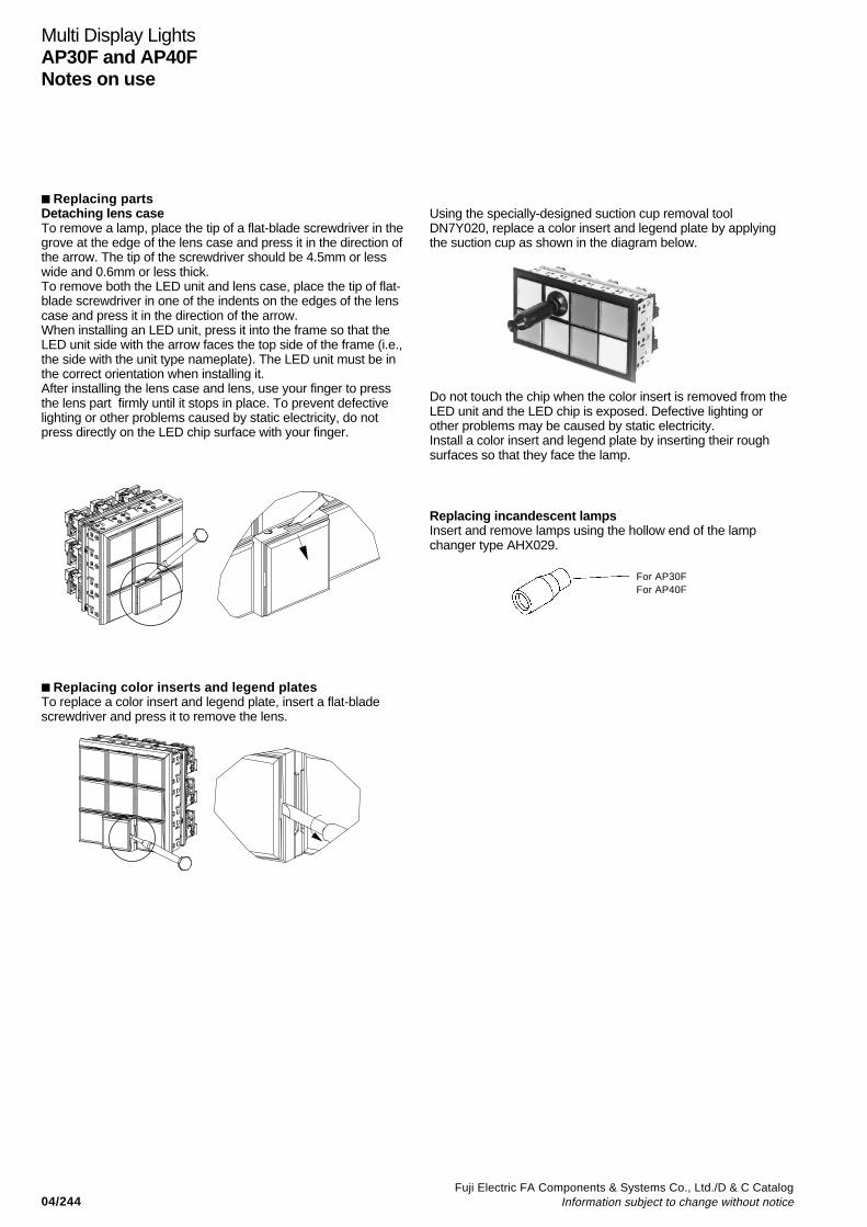
04/244Fuji Electric FA Components & Systems Co., Ltd./D & C Catalog
Information subject to change without notice
Replacing partsDetaching lens caseTo remove a lamp, place the tip of a flat-blade screwdriver in thegrove at the edge of the lens case and press it in the direction ofthe arrow. The tip of the screwdriver should be 4.5mm or lesswide and 0.6mm or less thick.To remove both the LED unit and lens case, place the tip of flat-blade screwdriver in one of the indents on the edges of the lenscase and press it in the direction of the arrow.When installing an LED unit, press it into the frame so that theLED unit side with the arrow faces the top side of the frame (i.e.,the side with the unit type nameplate). The LED unit must be inthe correct orientation when installing it.After installing the lens case and lens, use your finger to pressthe lens part firmly until it stops in place. To prevent defectivelighting or other problems caused by static electricity, do notpress directly on the LED chip surface with your finger.
Multi Display LightsAP30F and AP40FNotes on use
Replacing incandescent lampsInsert and remove lamps using the hollow end of the lampchanger type AHX029.
Replacing color inserts and legend platesTo replace a color insert and legend plate, insert a flat-bladescrewdriver and press it to remove the lens.
For AP30FFor AP40F
Using the specially-designed suction cup removal toolDN7Y020, replace a color insert and legend plate by applyingthe suction cup as shown in the diagram below.
Do not touch the chip when the color insert is removed from theLED unit and the LED chip is exposed. Defective lighting orother problems may be caused by static electricity.Install a color insert and legend plate by inserting their roughsurfaces so that they face the lamp.
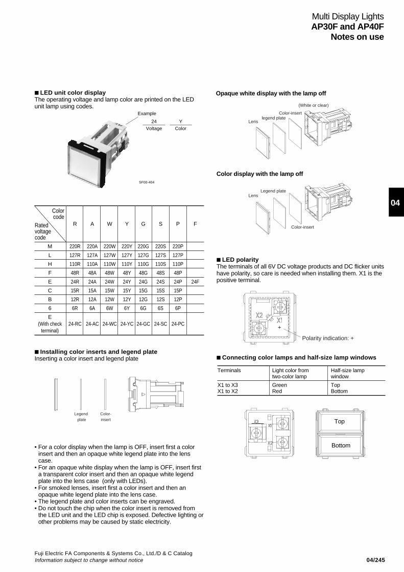
04/245Fuji Electric FA Components & Systems Co., Ltd./D & C CatalogInformation subject to change without notice
04
LED unit color displayThe operating voltage and lamp color are printed on the LEDunit lamp using codes.
Multi Display LightsAP30F and AP40F
Notes on use
• For a color display when the lamp is OFF, insert first a colorinsert and then an opaque white legend plate into the lenscase.
• For an opaque white display when the lamp is OFF, insert firsta transparent color insert and then an opaque white legendplate into the lens case (only with LEDs).
• For smoked lenses, insert first a color insert and then anopaque white legend plate into the lens case.
• The legend plate and color inserts can be engraved.• Do not touch the chip when the color insert is removed from
the LED unit and the LED chip is exposed. Defective lighting orother problems may be caused by static electricity.
SF00-404
Lenslegend plate
(White or clear)
Color-insert
LensLegend plate
Color-insert
Opaque white display with the lamp off
Color display with the lamp off
LED polarityThe terminals of all 6V DC voltage products and DC flicker unitshave polarity, so care is needed when installing them. X1 is thepositive terminal.
+
Polarity indication: +
Connecting color lamps and half-size lamp windows
Example
24
Voltage
Y
Color
Terminals Light color from Half-size lamptwo-color lamp window
X1 to X3 Green TopX1 to X2 Red Bottom
R A W Y G S P F
M 220R 220A 220W 220Y 220G 220S 220P
L 127R 127A 127W 127Y 127G 127S 127P
H 110R 110A 110W 110Y 110G 110S 110P
F 48R 48A 48W 48Y 48G 48S 48P
E 24R 24A 24W 24Y 24G 24S 24P 24F
C 15R 15A 15W 15Y 15G 15S 15P
B 12R 12A 12W 12Y 12G 12S 12P
6 6R 6A 6W 6Y 6G 6S 6P
E(With check 24-RC 24-AC 24-WC 24-YC 24-GC 24-SC 24-PC
terminal)
Installing color inserts and legend plateInserting a color insert and legend plate
Legend plate
Color-insert
Colorcode
Ratedvoltagecode
Top
Bottom
04/246Fuji Electric FA Components & Systems Co., Ltd./D & C Catalog
Information subject to change without notice
Assembling lens and lens caseAssemble the lens with lens case by mating lens projectionswith lens case indents.
Other precautions1. Transformer units• A maximum of 80 windows can function for a unit with
transformers when the windows are square.• Transformers are designed for a load of one incandescent
lamp and one LED unit. It is not possible to connect additionalloads.
2. Operating voltage and the rated voltage of incandescent lamp• Incandescent lamps can be used within the lamp’s rated voltage.If you need 5,000 to 10,000 hours of service life for incandescentlamp (at AC circuit), use the lamp within the standard operatingvoltage. Using incandescent lamps in DC circuit greatly reducesthe lamp service life due to notching phenomenon. Use LED unitsin DC circuit instead.
3. Flicker units• When two or more flicker units are used in a Multi Display
Light, they may not illuminate simultaneously because ofvariations in flicker unit circuits.
• Flicker units can be used only with square Multi Display Lights.They cannot be used with rectangular lights.
4. Continuous lighting• For continuous light, the duty cycle should be 50% or less. If
densely packed LEDs are lit continuously with a high dutycycle, LED life will be reduced.
• With 2-color lighting on the entire surface, do not usecontinuous lighting when lighting 2 colors simultaneously.
5. Store and operate these units within the temperature andhumidity specifications on page 04/237.
6. Do not use these units at outdoor.
7. Do not use these units in places where dust or cuttings willaccumulate. The lights may not turn ON if dust or cuttingspenetrate into the units.
Multi Display LightsAP30F and AP40FNotes on use
Lamp rated voltage Standard operating voltage (V AC) (V AC) 6.3 4 to 5.518 12 to 1524 16 to 2030 20 to 24
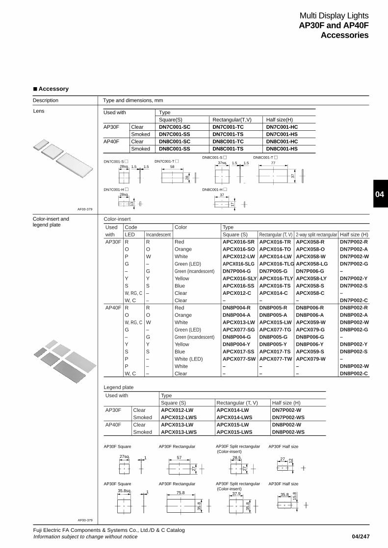
04/247Fuji Electric FA Components & Systems Co., Ltd./D & C CatalogInformation subject to change without notice
04
Multi Display LightsAP30F and AP40F
Accessories
Accessory
Description Type and dimensions, mm
28sq. 1.5 1.5 58
28
28sq.
13
37sq. 1.5 1.5 77
37
17
37
DN7C001-S DN7C001-T
DN7C001-H
DN8C001-S DN8C001-T
DN8C001-H
27sq. 1 57
27
27
12
35.8sq. 1 75.8
35.8
35.8
15.8
28.5
27
37.9
35.8
AP30F Square AP30F Rectangular AP30F Half sizeAP30F Split rectangular (Color-insert)
AP30F Square AP30F Rectangular AP30F Half sizeAP30F Split rectangular (Color-insert)
AF00-379
Color-insert andlegend plate
Used with TypeSquare(S) Rectangular(T,V) Half size(H)
AP30F Clear DN7C001-SC DN7C001-TC DN7C001-HCSmoked DN7C001-SS DN7C001-TS DN7C001-HS
AP40F Clear DN8C001-SC DN8C001-TC DN8C001-HCSmoked DN8C001-SS DN8C001-TS DN8C001-HS
AF00-379
Lens
Color-insert
Legend plate
TypeSquare (S)APCX012-LWAPCX012-LWSAPCX013-LWAPCX013-LWS
Rectangular (T, V)APCX014-LWAPCX014-LWSAPCX015-LWAPCX015-LWS
Half size (H)DN7P002-WDN7P002-WSDN8P002-WDN8P002-WS
ClearSmokedClearSmoked
Used with
AP30F
AP40F
TypeSquare (S)APCX016-SRAPCX016-SOAPCX012-LWAPCX016-SLGDN7P004-GAPCX016-SLYAPCX016-SSAPCX012-C–DN8P004-RDN8P004-AAPCX013-LWAPCX077-SGDN8P004-GDN8P004-YAPCX017-SSAPCX077-SW––
Rectangular (T, V)APCX016-TRAPCX016-TOAPCX014-LWAPCX016-TLGDN7P005-GAPCX016-TLYAPCX016-TSAPCX014-C–DN8P005-RDN8P005-AAPCX015-LWAPCX077-TGDN8P005-GDN8P005-YAPCX017-TSAPCX077-TW––
2-way split rectangularAPCX058-RAPCX058-OAPCX058-WAPCX058-LGDN7P006-GAPCX058-LYAPCX058-SAPCX058-C–DN8P006-RDN8P006-AAPCX059-WAPCX079-GDN8P006-GDN8P006-YAPCX059-SAPCX079-W––
Half size (H)DN7P002-RDN7P002-ADN7P002-WDN7P002-G–DN7P002-YDN7P002-S–DN7P002-CDN8P002-RDN8P002-ADN8P002-WDN8P002-G–DN8P002-YDN8P002-S–DN8P002-WDN8P002-C
Color
RedOrangeWhiteGreen (LED)Green (incandescent)YellowBlueClearClearRedOrangeWhiteGreen (LED)Green (incandescent)YellowBlueWhite (LED)WhiteClear
UsedwithAP30F
AP40F
CodeLEDROPG–YSW, RG, CW, CROW, RG, CG–YSPPW, C
IncandescentROW–GYS––ROW–GYS–––

04/248Fuji Electric FA Components & Systems Co., Ltd./D & C Catalog
Information subject to change without notice
Multi Display LightsAP30F and AP40FAccessories
Description Type and dimensions, mm
Jumper
AF00-379
Incandescent lamp
AF00-380
Used with Type2 poles 3 poles 4 poles 5 poles 6 poles
AP30F APCX029 DN7Y001-03 DN7Y001-04 DN7Y001-05 DN7Y001-06AP40F APCX030 DN8Y001-03 DN8Y001-04 DN8Y001-05 DN8Y001-06
Used with Dimension A Dimension B2 poles 3 poles 4 poles 5 poles 6 poles
AP30F series 30 37.6 67.6 97.6 127.6 157.6AP40F series 40 47.6 87.6 127.6 167.6 207.6
Jumper dimensions
7.5
Dimension B (for 6 poles)
Dimension B (for 5 poles)Dimension B (for 4 poles)
Dimension B (for 3 poles)Dimension B (for 2 poles)
Dimension A Dimension A Dimension A Dimension A Dimension A
AF00-383
Used with Socket type Voltage/capacity Type RemarksAP30F BA9s/13 bayonet type 6.3V 1W AHX135 Lamp with built-in transformer
18V 1W AHX279 –24V 1W AHX144 –30V 1W AHX129 –48V 1W AHX407 Lamp with built-in resistor unit
AP40F 18V 2W AHX141 Lamp with built-in transformer24V 2W AHX142 –30V 2W AHX143 –48V 2W DN7H001 Lamp with built-in resistor unit
23 28
ø10
ø10
For AP30F (except 48V 1W) For AP40F, AP30F (48V 1W)
Lamp changer
Color-insert and legend platechanger
Used with TypeAP30F, AP40F AHX029 For incandescent lamp
T-1990
AA
35
ø16
ø12
ø12
.5
ø9
Cross section A-A
60
15
ø22
ø11
ø5
Type DN7Y020

04/249Fuji Electric FA Components & Systems Co., Ltd./D & C CatalogInformation subject to change without notice
04
Multi Display LightsAP30F and AP40F
Accessories
Description Type and dimensions, mm
LED unit
AF00-374
Used with Emitted Color-insert Typecolor specification
Square(S) Horizontal Vertical Half size(H)rectangular (T) rectangular (V)
AP30F Red DN7Q001-S1 R DN7Q001-T1 R DN7Q001-V1 R DN7Q001-H1 ROrange DN7Q001-S1 A DN7Q001-T1 A DN7Q001-V1 A DN7Q001-H1 AWhite DN7Q001-S1 W DN7Q001-T1 W DN7Q001-V1 W DN7Q001-H1 WGreen DN7Q001-S1 G DN7Q001-T1 G DN7Q001-V1 G DN7Q001-H1 GYellow DN7Q001-S1 Y DN7Q001-T1 Y DN7Q001-V1 Y DN7Q001-H1 YBlue DN7Q001-S1 S DN7Q001-T1 S DN7Q001-V1 S DN7Q001-H1 SPure-white DN7Q001-S1 P DN7Q001-T1 P DN7Q001-V1 P DN7Q001-H1 PRed DN7Q001-S3 R DN7Q001-T3 R DN7Q001-V3 R DN7Q001-H3 ROrange DN7Q001-S3 A DN7Q001-T3 A DN7Q001-V3 A DN7Q001-H3 AGreen DN7Q001-S3 G DN7Q001-T3 G DN7Q001-V3 G DN7Q001-H3 GYellow DN7Q001-S3 Y DN7Q001-T3 Y DN7Q001-V3 Y DN7Q001-H3 YBlue DN7Q001-S3 S DN7Q001-T3 S DN7Q001-V3 S DN7Q001-H3 S
AP40F Red DN8Q001-S1 R DN8Q001-T1 R DN8Q001-V1 R DN8Q001-H1 ROrange DN8Q001-S1 A DN8Q001-T1 A DN8Q001-V1 A DN8Q001-H1 AWhite DN8Q001-S1 W DN8Q001-T1 W DN8Q001-V1 W DN8Q001-H1 WGreen DN8Q001-S1 G DN8Q001-T1 G DN8Q001-V1 G DN8Q001-H1 GYellow DN8Q001-S1 Y DN8Q001-T1 Y DN8Q001-V1 Y DN8Q001-H1 YBlue DN8Q001-S1 S DN8Q001-T1 S DN8Q001-V1 S DN8Q001-H1 SPure-white DN8Q001-S1 P DN8Q001-T1 P DN8Q001-V1 P DN8Q001-H1 PRed DN8Q001-S3 R DN8Q001-T3 R DN8Q001-V3 R DN8Q001-H3 ROrange DN8Q001-S3 A DN8Q001-T3 A DN8Q001-V3 A DN8Q001-H3 AGreen DN8Q001-S3 G DN8Q001-T3 G DN8Q001-V3 G DN8Q001-H3 GYellow DN8Q001-S3 Y DN8Q001-T3 Y DN8Q001-V3 Y DN8Q001-H3 YBlue DN8Q001-S3 S DN8Q001-T3 S DN8Q001-V3 S DN8Q001-H3 S
Notes: The LED unit is provided with a lens case and a color-insert.
Single color
All surfaceillumination
Full voltage
Single color
All surfaceillumination
Full voltage
Color-insert(color when lightturned OFF)
Color (transparent)-insert (white whenlight turned OFF)
Color-insert(color when lightturned OFF)
Color (transparent)-insert (white whenlight turned OFF)
Replace the in the type number with one of the following voltage code.
Voltage Code Square, horizontal/ Half sizevertical rectangular
6V DC 6 –12V AC/DC B15V AC/DC C24V AC/DC E48V AC/DC F –110V AC/DC H –127V AC/DC L –220V AC M –
AP30F Square
AP30F Rectangular
AP30F Half size
AP40F Square
AP40F Rectangular
AP40F Half size
30sq.
48
60
3048
30
1538
40sq.
48
80
4048
40
2038
DN7Q001-S DN7Q001-T,V DN7Q001-H DN8Q001-S DN8Q001-T,V DN8Q001-H
AF00-373
: Available – :Not available
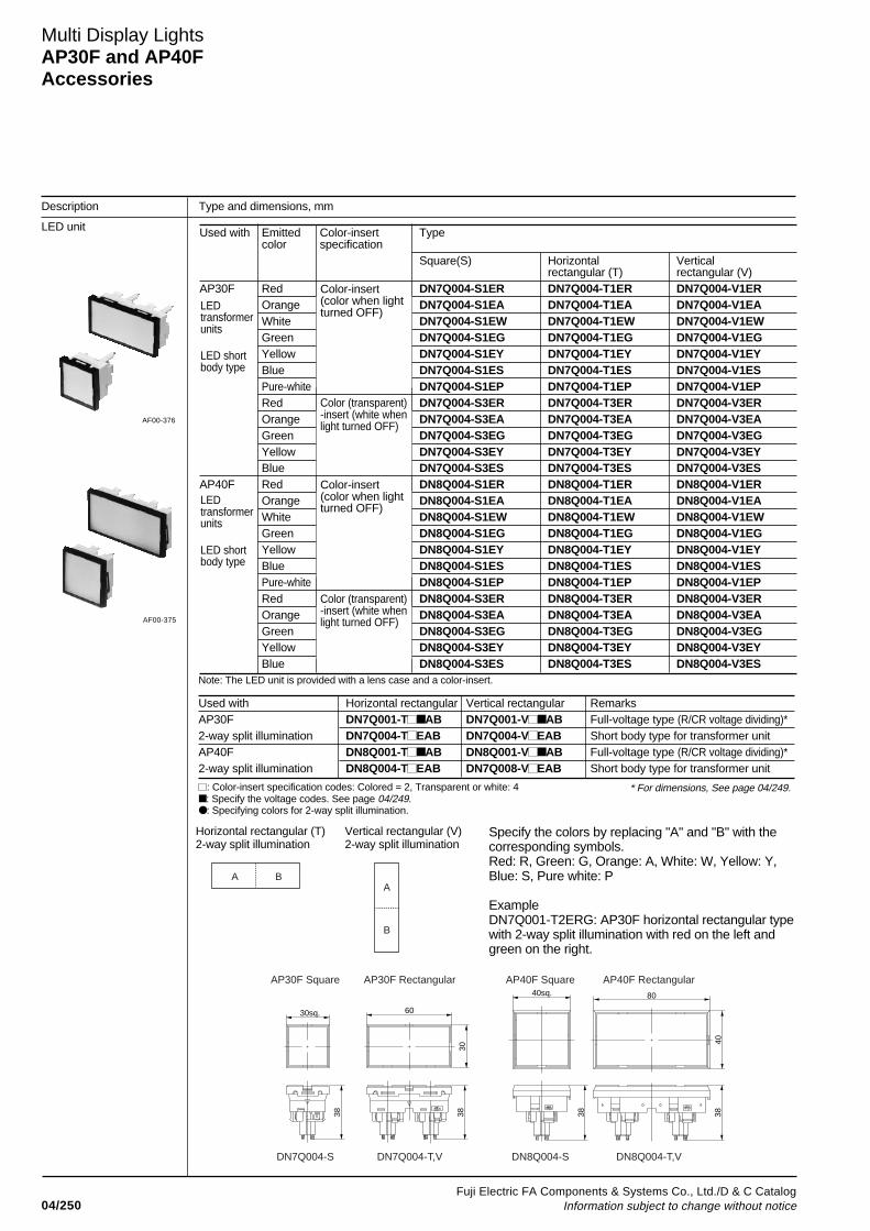
04/250Fuji Electric FA Components & Systems Co., Ltd./D & C Catalog
Information subject to change without notice
Used with Emitted Color-insert Typecolor specification
Square(S) Horizontal Verticalrectangular (T) rectangular (V)
AP30F Red DN7Q004-S1ER DN7Q004-T1ER DN7Q004-V1EROrange DN7Q004-S1EA DN7Q004-T1EA DN7Q004-V1EAWhite DN7Q004-S1EW DN7Q004-T1EW DN7Q004-V1EWGreen DN7Q004-S1EG DN7Q004-T1EG DN7Q004-V1EGYellow DN7Q004-S1EY DN7Q004-T1EY DN7Q004-V1EYBlue DN7Q004-S1ES DN7Q004-T1ES DN7Q004-V1ESPure-white DN7Q004-S1EP DN7Q004-T1EP DN7Q004-V1EPRed DN7Q004-S3ER DN7Q004-T3ER DN7Q004-V3EROrange DN7Q004-S3EA DN7Q004-T3EA DN7Q004-V3EAGreen DN7Q004-S3EG DN7Q004-T3EG DN7Q004-V3EGYellow DN7Q004-S3EY DN7Q004-T3EY DN7Q004-V3EYBlue DN7Q004-S3ES DN7Q004-T3ES DN7Q004-V3ES
AP40F Red DN8Q004-S1ER DN8Q004-T1ER DN8Q004-V1EROrange DN8Q004-S1EA DN8Q004-T1EA DN8Q004-V1EAWhite DN8Q004-S1EW DN8Q004-T1EW DN8Q004-V1EWGreen DN8Q004-S1EG DN8Q004-T1EG DN8Q004-V1EGYellow DN8Q004-S1EY DN8Q004-T1EY DN8Q004-V1EYBlue DN8Q004-S1ES DN8Q004-T1ES DN8Q004-V1ESPure-white DN8Q004-S1EP DN8Q004-T1EP DN8Q004-V1EPRed DN8Q004-S3ER DN8Q004-T3ER DN8Q004-V3EROrange DN8Q004-S3EA DN8Q004-T3EA DN8Q004-V3EAGreen DN8Q004-S3EG DN8Q004-T3EG DN8Q004-V3EGYellow DN8Q004-S3EY DN8Q004-T3EY DN8Q004-V3EYBlue DN8Q004-S3ES DN8Q004-T3ES DN8Q004-V3ES
Multi Display LightsAP30F and AP40FAccessories
Description Type and dimensions, mm
LED unit
AF00-376
Note: The LED unit is provided with a lens case and a color-insert.
LEDtransformerunits
LED shortbody type
LEDtransformerunits
LED shortbody type
Color-insert(color when lightturned OFF)
Color (transparent)-insert (white whenlight turned OFF)
Color-insert(color when lightturned OFF)
Color (transparent)-insert (white whenlight turned OFF)AF00-375
A BA
B
Horizontal rectangular (T)2-way split illumination
Vertical rectangular (V)2-way split illumination
Specify the colors by replacing "A" and "B" with thecorresponding symbols.Red: R, Green: G, Orange: A, White: W, Yellow: Y,Blue: S, Pure white: P
ExampleDN7Q001-T2ERG: AP30F horizontal rectangular typewith 2-way split illumination with red on the left andgreen on the right.
30sq.
38
60
3038
AP30F Square AP30F Rectangular AP40F Square AP40F Rectangular
DN7Q004-S DN7Q004-T,V DN8Q004-S DN8Q004-T,V
40sq.
38
80
4038
: Color-insert specification codes: Colored = 2, Transparent or white: 4 : Specify the voltage codes. See page 04/249. : Specifying colors for 2-way split illumination.
Used with Horizontal rectangular Vertical rectangular RemarksAP30F DN7Q001-T AB DN7Q001-V AB Full-voltage type (R/CR voltage dividing)*2-way split illumination DN7Q004-T EAB DN7Q004-V EAB Short body type for transformer unitAP40F DN8Q001-T AB DN8Q001-V AB Full-voltage type (R/CR voltage dividing)*2-way split illumination DN8Q004-T EAB DN7Q008-V EAB Short body type for transformer unit
* For dimensions, See page 04/249.
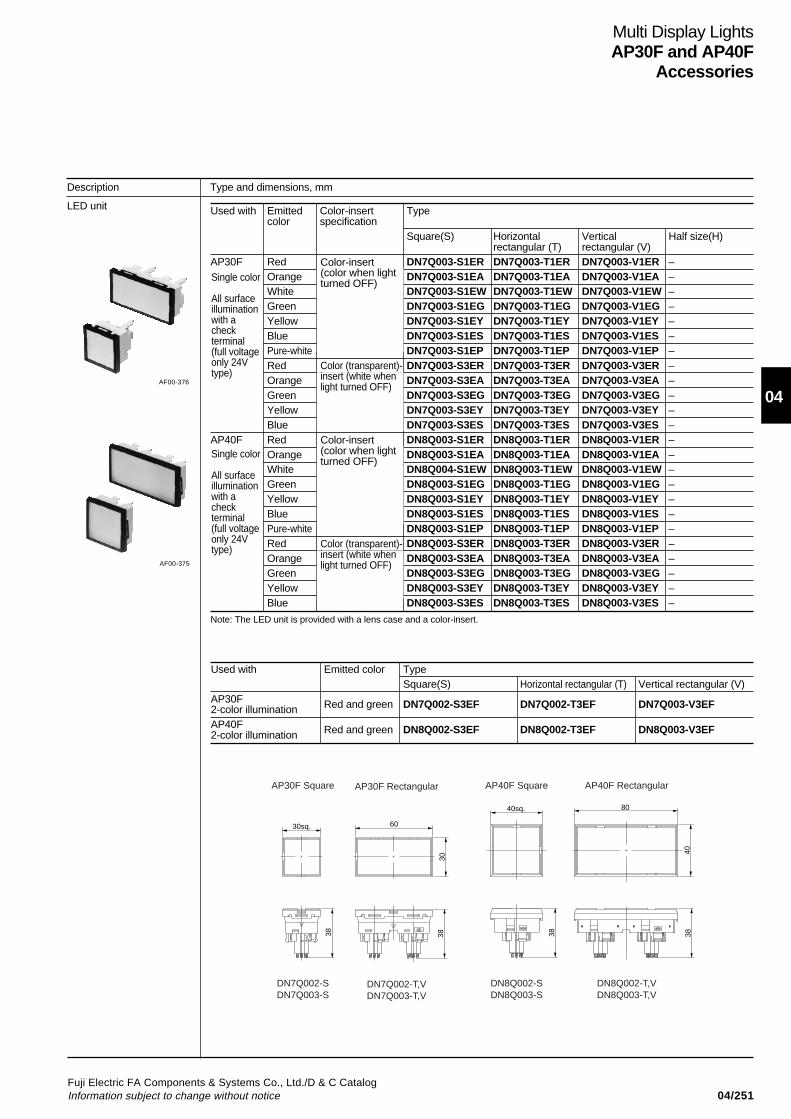
04/251Fuji Electric FA Components & Systems Co., Ltd./D & C CatalogInformation subject to change without notice
04
Multi Display LightsAP30F and AP40F
Accessories
Description Type and dimensions, mm
LED unit Used with Emitted Color-insert Typecolor specification
Square(S) Horizontal Vertical Half size(H)rectangular (T) rectangular (V)
AP30F Red DN7Q003-S1ER DN7Q003-T1ER DN7Q003-V1ER –Orange DN7Q003-S1EA DN7Q003-T1EA DN7Q003-V1EA –White DN7Q003-S1EW DN7Q003-T1EW DN7Q003-V1EW –Green DN7Q003-S1EG DN7Q003-T1EG DN7Q003-V1EG –Yellow DN7Q003-S1EY DN7Q003-T1EY DN7Q003-V1EY –Blue DN7Q003-S1ES DN7Q003-T1ES DN7Q003-V1ES –Pure-white DN7Q003-S1EP DN7Q003-T1EP DN7Q003-V1EP –Red DN7Q003-S3ER DN7Q003-T3ER DN7Q003-V3ER –Orange DN7Q003-S3EA DN7Q003-T3EA DN7Q003-V3EA –Green DN7Q003-S3EG DN7Q003-T3EG DN7Q003-V3EG –Yellow DN7Q003-S3EY DN7Q003-T3EY DN7Q003-V3EY –Blue DN7Q003-S3ES DN7Q003-T3ES DN7Q003-V3ES –
AP40F Red DN8Q003-S1ER DN8Q003-T1ER DN8Q003-V1ER –Orange DN8Q003-S1EA DN8Q003-T1EA DN8Q003-V1EA –White DN8Q004-S1EW DN8Q003-T1EW DN8Q003-V1EW –Green DN8Q003-S1EG DN8Q003-T1EG DN8Q003-V1EG –Yellow DN8Q003-S1EY DN8Q003-T1EY DN8Q003-V1EY –Blue DN8Q003-S1ES DN8Q003-T1ES DN8Q003-V1ES –Pure-white DN8Q003-S1EP DN8Q003-T1EP DN8Q003-V1EP –Red DN8Q003-S3ER DN8Q003-T3ER DN8Q003-V3ER –Orange DN8Q003-S3EA DN8Q003-T3EA DN8Q003-V3EA –Green DN8Q003-S3EG DN8Q003-T3EG DN8Q003-V3EG –Yellow DN8Q003-S3EY DN8Q003-T3EY DN8Q003-V3EY –Blue DN8Q003-S3ES DN8Q003-T3ES DN8Q003-V3ES –
Note: The LED unit is provided with a lens case and a color-insert.
Single color
All surfaceilluminationwith acheckterminal(full voltageonly 24Vtype)
Single color
All surfaceilluminationwith acheckterminal(full voltageonly 24Vtype)
Color-insert(color when lightturned OFF)
Color (transparent)-insert (white whenlight turned OFF)
Color-insert(color when lightturned OFF)
Color (transparent)-insert (white whenlight turned OFF)
AF00-376
AF00-375
Used with Emitted color TypeSquare(S) Horizontal rectangular (T) Vertical rectangular (V)
AP30F Red and green DN7Q002-S3EF DN7Q002-T3EF DN7Q003-V3EF2-color illuminationAP40F Red and green DN8Q002-S3EF DN8Q002-T3EF DN8Q003-V3EF2-color illumination
30sq.
38
60
3038
AP30F Square AP30F Rectangular AP40F Square AP40F Rectangular
DN7Q002-SDN7Q003-S
DN7Q002-T,VDN7Q003-T,V
DN8Q002-SDN8Q003-S
DN8Q002-T,VDN8Q003-T,V
40sq.
38
80
4038
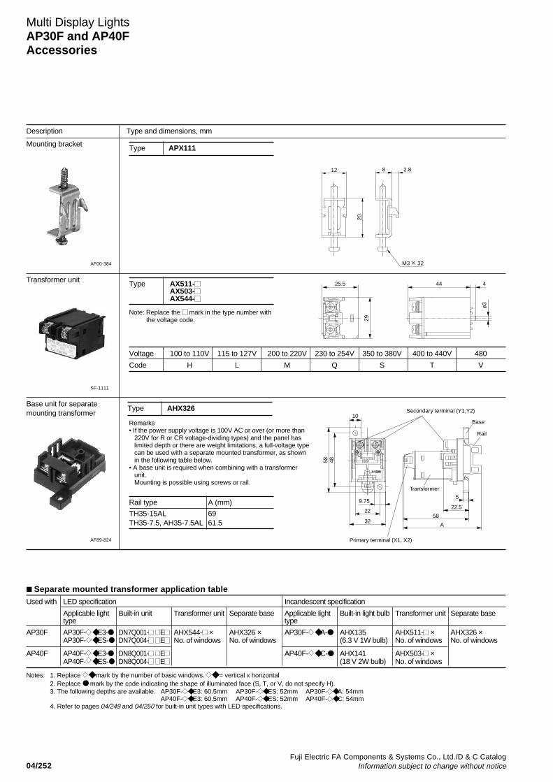
04/252Fuji Electric FA Components & Systems Co., Ltd./D & C Catalog
Information subject to change without notice
Description Type and dimensions, mm
Mounting bracket
Multi Display LightsAP30F and AP40FAccessories
Type APX111
AF00-384
12
20
8 2.8
M3 32
Transformer unit
Note: Replace the mark in the type number withthe voltage code.
Voltage 100 to 110V 115 to 127V 200 to 220V 230 to 254V 350 to 380V 400 to 440V 480
Code H L M Q S T V
4425.5
29
ø3
4
SF-1111
Base unit for separatemounting transformer
AF89-824
Type AHX326
Remarks• If the power supply voltage is 100V AC or over (or more than
220V for R or CR voltage-dividing types) and the panel haslimited depth or there are weight limitations, a full-voltage typecan be used with a separate mounted transformer, as shownin the following table below.
• A base unit is required when combining with a transformerunit.Mounting is possible using screws or rail.
58 48
22
9.75
32
10
58
22.5
5
A
Base
Rail
Transformer
Secondary terminal (Y1,Y2)
Primary terminal (X1, X2)
Type AX511-AX503-AX544-
Separate mounted transformer application tableUsed with LED specification Incandescent specification
Applicable light Built-in unit Transformer unit Separate base Applicable light Built-in light bulb Transformer unit Separate basetype type
AP30F AP30F- E3- DN7Q001- E AHX544- × AHX326 × AP30F- A- AHX135 AHX511- × AHX326 ×AP30F- ES- DN7Q004- E No. of windows No. of windows (6.3 V 1W bulb) No. of windows No. of windows
AP40F AP40F- E3- DN8Q001- E AP40F- C- AHX141 AHX503- ×AP40F- ES- DN8Q004- E (18 V 2W bulb) No. of windows
Notes: 1. Replace mark by the number of basic windows. = vertical x horizontal2. Replace mark by the code indicating the shape of illuminated face (S, T, or V, do not specify H).3. The following depths are available. AP30F- E3: 60.5mm AP30F- ES: 52mm AP30F- A: 54mm
AP40F- E3: 60.5mm AP40F- ES: 52mm AP40F- C: 54mm4. Refer to pages 04/249 and 04/250 for built-in unit types with LED specifications.
Rail type A (mm)
TH35-15AL 69TH35-7.5, AH35-7.5AL 61.5

04/253Fuji Electric FA Components & Systems Co., Ltd./D & C CatalogInformation subject to change without notice
04
Description Type and dimensions, mm
Terminal cover
Multi Display LightsAP30F and AP40F
Accessories
13
13
22.8sq.
ø6.5
15.7 1332.8sq.
13
ø6.5
15.7
12
1727sq.
ø7 3
2 17.8
1629
16.9
27
2 11.1
3.2
12.827sq.
8
2 11.5
3.2ø7
ø7
DN7Y002 DN8Y002 APCX055
APX131 APCX054
AF00-389
AF00-388
AF00-387
AF00-386
AF00-385
Series Description DN7Y002 APCX054 APX131 DN8Y002 APCX055
AP30F LED single-color, Full-voltage typefull-surface R, CR voltageillumination dividing type
Transformer type
Half-size, Full-voltage type2-colorilluminationLED short body Full-voltage typetype
Incandescent Full-voltage typelamp
Transformer type110V, 220V
Transformer typeover than 220V
AP40F LED single-color, Full-voltage typefull-surface R, CR voltageillumination dividing type
Transformer type
Half-size, 2-color Full-voltage typeillumination
LED short body Full-voltage typetype
Incandescent Full-voltage typelamp
Transformer type
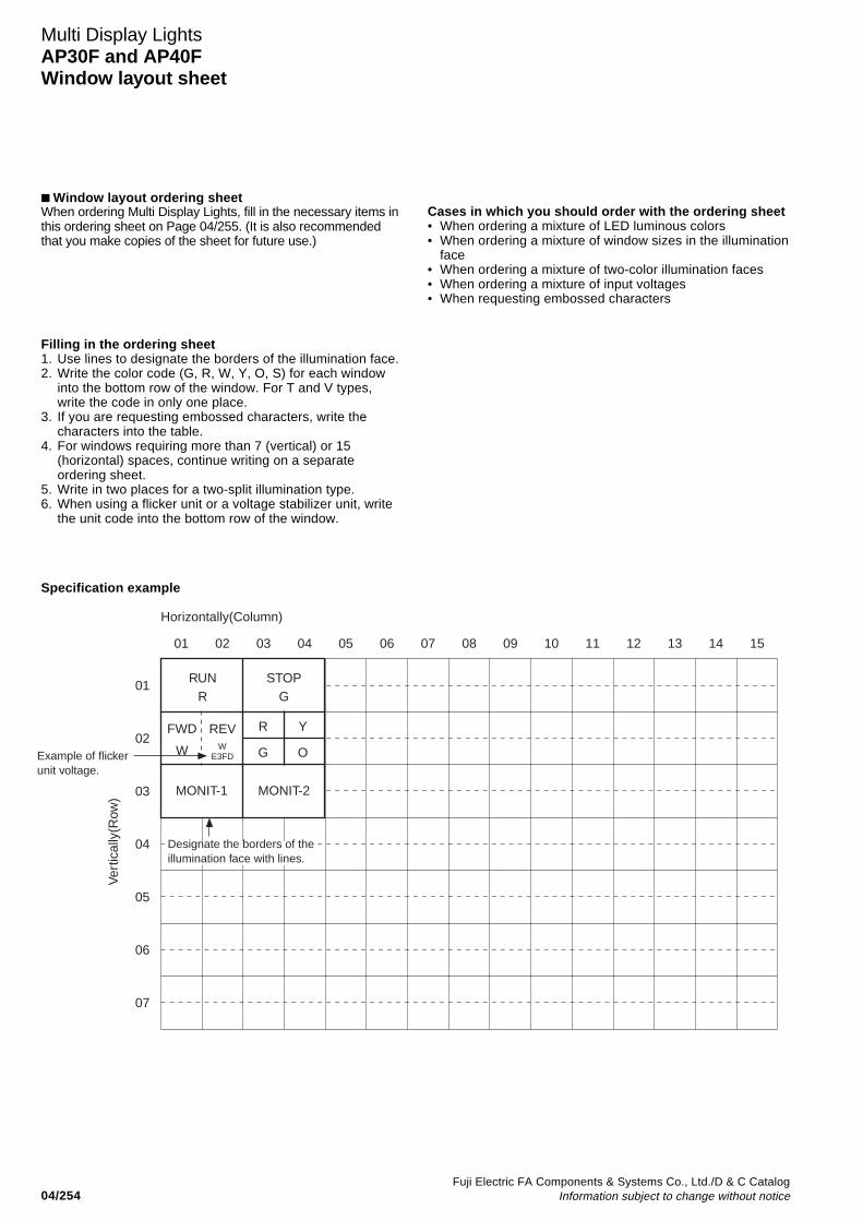
04/254Fuji Electric FA Components & Systems Co., Ltd./D & C Catalog
Information subject to change without notice
Window layout ordering sheet
Multi Display LightsAP30F and AP40FWindow layout sheet
Filling in the ordering sheet1. Use lines to designate the borders of the illumination face.2. Write the color code (G, R, W, Y, O, S) for each window
into the bottom row of the window. For T and V types,write the code in only one place.
3. If you are requesting embossed characters, write thecharacters into the table.
4. For windows requiring more than 7 (vertical) or 15(horizontal) spaces, continue writing on a separateordering sheet.
5. Write in two places for a two-split illumination type.6. When using a flicker unit or a voltage stabilizer unit, write
the unit code into the bottom row of the window.
01
01
02
03
04
05
06
07
02 03 04 05 06 07 08 09 10 11 12 13 14 15
Horizontally(Column)
Ver
tical
ly(R
ow)
RUNR
R Y
G O
FWD
W
REV
STOPG
MONIT-1 MONIT-2
W E3FD
Designate the borders of the illumination face with lines.
Example of flicker unit voltage.
When ordering Multi Display Lights, fill in the necessary items inthis ordering sheet on Page 04/255. (It is also recommendedthat you make copies of the sheet for future use.)
Cases in which you should order with the ordering sheet• When ordering a mixture of LED luminous colors• When ordering a mixture of window sizes in the illumination
face• When ordering a mixture of two-color illumination faces• When ordering a mixture of input voltages• When requesting embossed characters
Specification example
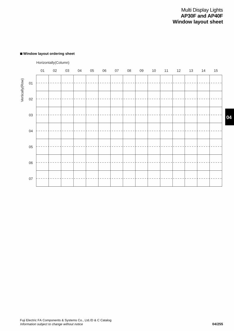
04/255Fuji Electric FA Components & Systems Co., Ltd./D & C CatalogInformation subject to change without notice
04
Multi Display LightsAP30F and AP40F
Window layout sheet
Window layout ordering sheet
01
01
02
03
04
05
06
07
02 03 04 05 06 07 08 09 10 11 12 13 14 15
Horizontally(Column)
Ver
tical
ly(R
ow)
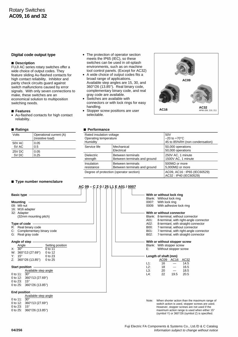
Fuji Electric FA Components & Systems Co., Ltd./D & C CatalogInformation subject to change without notice04/256
Rotary SwitchesAC09, 16 and 32
Digital code output type
DescriptionFUJI AC series rotary switches offer awide choice of output codes. Theyfeature sliding Au-flashed contacts forhigh contact reliability. Inhibitor andparity check circuits guard againstswitch malfunctions caused by errorsignals. With only seven connections tomake, these switches are aneconomical solution to multipositionswitching needs.
Features• Au-flashed contacts for high contact
reliability.
• The protection of operator sectionmeets the IP65 (IEC), so theseswitches can be used in oil-splashenvironments, such as on machinetool control panels. (Except for AC32)
• A wide choice of output codes fits abroad range of applications.Available step angles are 15, 30, and360°/26 (13.85°). Real binary code,complementary binary code, and realgray code are available.
• Switches are available withconnectors or with lock rings for easyhandling.
• Stopper screw positions are userselectable.
AF90-209, 210, 211AC16AC32
AC09
Ratings PerformanceVolts Operational current (A)
(resistive load)
50V AC 0.055V AC 0.5
25V DC 0.055V DC 0.25
Rated insulation voltage 50VOperating temperature –20 to +70°CHumidity 45 to 85%RH (non condensation)
Service life Mechanical 50,000 operationsElectrical 50,000 operations
Dielectric Between terminals 250V AC, 1 minutestrength Between terminals and ground 1500V AC, 1 minute
Insulation Between terminals 500MΩ or moreresistance Between terminals and ground 5,000MΩ or more
Degree of protection (operator section) AC09, AC16 : IP65 (IEC60529)AC32 : IP40 (IEC60529)
Type number nomenclature
Basic type
Mounting09: M9 nut16: M16 adapter32: Adapter
(32mm mounting pitch)
Type of codeR: Real binary codeC: Complementary binary codeG: Real gray code
Angle of stepAngle Setting position
X: 30° 0 to 11W: 360°/13 (27.69°) 0 to 12Y: 15° 0 to 23Z: 360°/26 (13.85°) 0 to 25
Start positionAvailable step angle
0 to 11: 30°0 to 12: 360°/13 (27.69°)0 to 23: 15°0 to 25: 360°/26 (13.85°)
End positionAvailable step angle
0 to 11: 30°0 to 12: 360°/13 (27.69°)0 to 23: 15°0 to 25: 360°/26 (13.85°)
With or without lock ringBlank: Without lock ring0007: With lock ring0009: With adhesive lock ring
With or without connectorBlank: 8-terminal, without connectorA01: 8-terminal, with right-angle connectorA02: 8-termianl, with straight connectorB00: 7-terminal, without connectorB01: 7-terminal, with right-angle connectorB02: 7-terminal, with straight connector
With or without stopper screwBlank: With stopper screwE: Without stopper screw
Length of shaft (mm)AC09 AC16 AC32
L1: 16 — 14.5L2: 18 — 16.5L3: 20 — 18.5L4: 22 19.5 20.5
Note: When shorter action than the maximum range ofswitch action is used, stopper screws are used.However, stopper screws are not used if themaximum action range is used when either 15°(symbol Y) or 360°/26 (symbol Z) is specified.
AC 09 – C Z 0 / 25 L1 E A01 / 0007

Fuji Electric FA Components & Systems Co., Ltd./D & C CatalogInformation subject to change without notice 04/257
04
• M9 nut mountingAngle of Connector Lock ring Typestep
Real binary code Complementary Real gray codebinary code
30° Without Without lock ring AC09-RX / ( ) AC09-CX / ( ) AC09-GX / ( )connector With lock ring AC09-RX / ( ) /0007 AC09-CX / ( ) /0007 AC09-GX / ( ) /0007
With adhesive lock ring AC09-RX / ( ) /0009 AC09-CX / ( ) /0009 AC09-GX / ( ) /0009
With right Without lock ring AC09-RX / ( ) 01 AC09-CX / ( ) 01 AC09-GX / ( ) 01angle With lock ring AC09-RX / ( ) 01/0007 AC09-CX / ( ) 01/0007 AC09-GX / ( ) 01/0007connector With adhesive lock ring AC09-RX / ( ) 01/0009 AC09-CX / ( ) 01/0009 AC09-GX / ( ) 01/0009
With Without lock ring AC09-RX / ( ) 02 AC09-CX / ( ) 02 AC09-GX / ( ) 02straight With lock ring AC09-RX / ( ) 02/0007 AC09-CX / ( ) 02/0007 AC09-GX / ( ) 02/0007connector With adhesive lock ring AC09-RX / ( ) 02/0009 AC09-CX / ( ) 02/0009 AC09-GX / ( ) 02/0009
360°/13 Without Without lock ring AC09-RW / ( ) AC09-CW / ( )(27.69°) connector With lock ring AC09-RW / ( ) /0007 AC09-CW / ( ) /0007
With adhesive lock ring AC09-RW / ( ) /0009 AC09-CW / ( ) /0009
With right Without lock ring AC09-RW / ( ) 01 AC09-CW / ( ) 01angle With lock ring AC09-RW / ( ) 01/0007 AC09-CW / ( ) 01/0007connector With adhesive lock ring AC09-RW / ( ) 01/0009 AC09-CW / ( ) 01/0009
With Without lock ring AC09-RW / ( ) 02 AC09-CW / ( ) 02straight With lock ring AC09-RW / ( ) 02/0007 AC09-CW / ( ) 02/0007connector With adhesive lock ring AC09-RW / ( ) 02/0009 AC09-CW / ( ) 02/0009
15° Without Without lock ring AC09-RY / ( ) AC09-CY / ( ) AC09-GY / ( )connector With lock ring AC09-RY / ( ) /0007 AC09-CY / ( ) /0007 AC09-GY / ( ) /0007
With adhesive lock ring AC09-RY / ( ) /0009 AC09-CY / ( ) /0009 AC09-GY / ( ) /0009
With right Without lock ring AC09-RY / ( ) 01 AC09-CY / ( ) 01 AC09-GY / ( ) 01angle With lock ring AC09-RY / ( ) 01/0007 AC09-CY / ( ) 01/0007 AC09-GY / ( ) 01/0007connector With adhesive lock ring AC09-RY / ( ) 01/0009 AC09-CY / ( ) 01/0009 AC09-GY / ( ) 01/0009
With Without lock ring AC09-RY / ( ) 02 AC09-CY / ( ) 02 AC09-GY / ( ) 02straight With lock ring AC09-RY / ( ) 02/0007 AC09-CY / ( ) 02/0007 AC09-GY / ( ) 02/0007connector With adhesive lock ring AC09-RY / ( ) 02/0009 AC09-CY / ( ) 02/0009 AC09-GY / ( ) 02/0009
360°/26 Without Without lock ring AC09-RZ / ( ) AC09-CZ / ( ) AC09-GZ / ( )(13.85°) connector With lock ring AC09-RZ / ( ) /0007 AC09-CZ / ( ) /0007 AC09-GZ / ( ) /0007
With adhesive lock ring AC09-RZ / ( ) /0009 AC09-CZ / ( ) /0009 AC09-GZ / ( ) /0009
With right Without lock ring AC09-RZ / ( ) 01 AC09-CZ / ( ) 01 AC09-GZ / ( ) 01angle With lock ring AC09-RZ / ( ) 01/0007 AC09-CZ / ( ) 01/0007 AC09-GZ / ( ) 01/0007connector With adhesive lock ring AC09-RZ / ( ) 01/0009 AC09-CZ / ( ) 01/0009 AC09-GZ / ( ) 01/0009
With Without lock ring AC09-RZ / ( ) 02 AC09-CZ / ( ) 02 AC09-GZ / ( ) 02straight With lock ring AC09-RZ / ( ) 02/0007 AC09-CZ / ( ) 02/0007 AC09-GZ / ( ) 02/0007connector With adhesive lock ring AC09-RZ / ( ) 02/0009 AC09-CZ / ( ) 02/0009 AC09-GZ / ( ) 02/0009
Rotary SwitchesAC09, 16 and 32
*1 *2 *3
Notes:*1 Replace the marks by the Start and End positions
Step angle 30° 360°/13 15° 360°/26
Start and End positions 0 to 11 0 to 12 0 to 23 0 to 25
*2 Replace the ( ) mark by the shaft length codeL1: 16mm L2: 18mm L3: 20mm L4: 22mm
*3 Replace the mark by the connectorBlank: 8-terminal, without connectorA01: 8-terminal, with right angle connectorA02: 8-terminal, with straight connectorB00: 7-terminal, without connectorB01: 7-terminal, with right angle connectorB02: 7-terminal, with straight connector

Fuji Electric FA Components & Systems Co., Ltd./D & C CatalogInformation subject to change without notice04/258
Rotary SwitchesAC09, 16 and 32
Notes:*1 Replace the marks by the Start and End positions
Step angle 30° 360°/13 15° 360°/26
Start and End positions 0 to 11 0 to 12 0 to 23 0 to 25
*2 Replace the mark by the connectorBlank: 8-terminal, without connectorA01: 8-terminal, with right angle connectorA02: 8-terminal, with straight connectorB00: 7-terminal, without connectorB01: 7-terminal, with right angle connectorB02: 7-terminal, with straight connector
• M16 adapter mountingAngle of Connector Type*1 *2
stepReal binary code Complementary Real gray code
binary code
30° Without connector AC16-RX / L4 AC16-CX / L4 AC16-GX / L4With right angle connector AC16-RX / L4 01 AC16-CX / L4 01 AC16-GX / L4 01With straight connector AC16-RX / L4 02 AC16-CX / L4 02 AC16-GX / L4 02
360°/13 Without connector AC16-RW / L4 AC16-CW / L4(27.69°) With right angle connector AC16-RW / L4 01 AC16-CW / L4 01
With straight connector AC16-RW / L4 02 AC16-CW / L4 02
15° Without connector AC16-RY / L4 AC16-CY / L4 AC16-GY / L4With right angle connector AC16-RY / L4 01 AC16-CY / L4 01 AC16-GY / L4 01With straight connector AC16-RY / L4 02 AC16-CY / L4 02 AC16-GY / L4 02
360°/26 Without connector AC16-RZ / L4 AC16-CZ / L4 AC16-GZ / L4(13.85°) With right angle connector AC16-RZ / L4 01 AC16-CZ / L4 01 AC16-GZ / L4 01
With straight connector AC16-RZ / L4 02 AC16-CZ / L4 02 AC16-GZ / L4 02
Notes:*1 Replace the marks by the Start and End positions
Step angle 30° 360°/13 15° 360°/26
Start and End positions 0 to 11 0 to 12 0 to 23 0 to 25
*3 Replace the mark by the connectorBlank: 8-terminal, without connectorA01: 8-terminal, with right angle connectorA02: 8-terminal, with straight connectorB00: 7-terminal, without connectorB01: 7-terminal, with right angle connectorB02: 7-terminal, with straight connector
• Adaptor mounting (32mm mounting pitch)Angle of Connector Type*1 *2 *3
stepReal binary code Complementary Real gray code
binary code
30° Without connector AC32-RX / ( ) AC32-CX / ( ) AC32-GX / ( )With right angle connector AC32-RX / ( ) 01 AC32-CX / ( ) 01 AC32-GX / ( ) 01With straight connector AC32-RX / ( ) 02 AC32-CX / ( ) 02 AC32-GX / ( ) 02
360°/13 Without connector AC32-RW / ( ) AC32-CW / ( )(27.69°) With right angle connector AC32-RW / ( ) 01 AC32-CW / ( ) 01
With straight connector AC32-RW / ( ) 02 AC32-CW / ( ) 02
15° Without connector AC32-RY / ( ) AC32-CY / ( ) AC32-GY / ( )With right angle connector AC32-RY / ( ) 01 AC32-CY / ( ) 01 AC32-GY / ( ) 01With straight connector AC32-RY / ( ) 02 AC32-CY / ( ) 02 AC32-GY / ( ) 02
360°/26 Without connector AC32-RZ / ( ) AC32-CZ / ( ) AC32-GZ / ( )(13.85°) With right angle connector AC32-RZ / ( ) 01 AC32-CZ / ( ) 01 AC32-GZ / ( ) 01
With straight connector AC32-RZ / ( ) 02 AC32-CZ / ( ) 02 AC32-GZ / ( ) 02
*2 Replace the ( ) mark by the shaft lengthL1: 14.5mm L2: 16.5mm L3: 18.5mm L4: 20.5mm

Fuji Electric FA Components & Systems Co., Ltd./D & C CatalogInformation subject to change without notice 04/259
04
Rotary SwitchesAC09, 16 and 32
24-positionR: Real binary code
C: Complementary binary code
12-positionR: Real binary code
G: Real gray code
C: Complementary binary code
G: Real gray code
Terminal Bit Setting position
No. No. 0 1 2 3 4 5 6 7 8 9 10 11 12 13 14 15 16 17 18 19 20 21 22 23
A 1
F 2
B 4
E 8
C 16
G INH
D C
26-positionR: Real binary code
Terminal Bit Setting position
No. No. 0 1 2 3 4 5 6 7 8 9 10 11 12 13 14 15 16 17 18 19 20 21 22 23
A 1
F 2
B 4
E 8
C 16
G INH
D C
Terminal Bit Setting position
No. No. 0 1 2 3 4 5 6 7 8 9 10 11 12 13 14 15 16 17 18 19 20 21 22 23
A a
F b
B c
E d
C e
G P
D C
Terminal Bit Setting position
No. No. 0 1 2 3 4 5 6 7 8 9 10 11 12 13 14 15 16 17 18 19 20 21 22 23 24 25
A a
F b
B c
E d
C e
G P
D C
Terminal Bit Setting position
No. No. 0 1 2 3 4 5 6 7 8 9 10 11 12 13 14 15 16 17 18 19 20 21 22 23 24 25
A 1
F 2
B 4
E 8
C 16
G INH
D C
Terminal Bit Setting position
No. No. 0 1 2 3 4 5 6 7 8 9 10 11 12 13 14 15 16 17 18 19 20 21 22 23 24 25
A 1
F 2
B 4
E 8
C 16
G INH
D C
Terminal Bit Setting position
No. No. 0 1 2 3 4 5 6 7 8 9 1011
A a
F b
B c
E d
C P
G
D C
C: Complementary binary code
G: Real gray code
Terminal Bit Setting position
No. No. 0 1 2 3 4 5 6 7 8 9 1011
A 1
F 2
B 4
E 8
C P
G INH
D C
Terminal Bit Setting position
No. No. 0 1 2 3 4 5 6 7 8 9 1011
A 1
F 2
B 4
E 8
C P
G INH
D C
INH : Inhibit terminalP : Parity check terminalC : Common terminal : Turned ON
13-positionR: Real binary code
C: Complementary binary code
Terminal Bit Setting position
No. No. 0 1 2 3 4 5 6 7 8 9 101112
A 1
F 2
B 4
E 8
C P
G INH
D C
Terminal Bit Setting position
No. No. 0 1 2 3 4 5 6 7 8 9 101112
A 1
F 2
B 4
E 8
C P
G INH
D C

Fuji Electric FA Components & Systems Co., Ltd./D & C CatalogInformation subject to change without notice04/260
Rotary SwitchesAC 09, 16 and 32
Dimensions, mmAC09 AC09 (with connector)
Mass: 47g
Panel cutting Panel cutting
AC16 AC32
Panel cuttingShaft length L1 L2 L3 L4* 14.5 16.5 18.5 20.5Mass (g) 47 48 49 50
Panel cutting
25.5 *L8
Panel thicknessMax. 4
M9 P=0.75
ø6
ø9.1
+0.3
–0
2.54
17.78
22
31
30
28
20 2215
.8
8-terminal
A B C D D E F G
Panel thicknessMax. 4
M9 P=0.75
ø6
40
25.5
8
*L
32
30.5 23
.4
Right-angle connector
Straight connector
ø9.1
+0.3
–0
17.78
22
2.54
31
30
28
2022
15.8
8-terminal
A BCDDE FG
ø9.1
ø2.7
+0.3
–0
In case of using lock ring(AC09- /0007)
Panel thickness1.2 to 3.2
M16 P=1
28 19.511
Panel thicknessMax. 4
ø6
ø20
ø16.1
+0.3
–0
2.54
17.78
22
31
30
28
20 2215
.8
8-terminal
A B CDD E F G
M9 P=0.75
27 *L6.4
Panel thicknessMax. 4
ø6
20
ø32±0.2
ø17
M2.3 (for flat head screw)
28
20 2215
.8
2.5417.78
223031
M2.3×6
38
32
8-terminal
A B CDD E F G
Shaft length L1 L2 L3 L4* 16 18 20 22Mass (g)Without connector 41 42 43 44With connector 42 43 44 45
Length of lead wire (m) Type Mass (g)
0.5 ACX011-805 11
1.0 (Standard) ACX011-810 19
2.0 ACX011-820 33
Type Mass (g)
Lock ring (inserted) ACX001 2
Lock ring (sealed) ACX001A 5
ACX001
AF91-675
AccessoriesLead wire with connector (8-terminal)
AF91-710
Lock ring
ø16
ø28
4.7
ø9.1 1 1.28
1.9
ø9.
1ø
10
1.5 1
ACX001A
20.5
6 14 L
L: 0.5, 1.0, 2.0m

Fuji Electric FA Components & Systems Co., Ltd./D & C CatalogInformation subject to change without notice 04/261
04
Notes on use1. Connecting wires
Note the following points when soldering:• The power of the soldering iron must not be over 30W.• Use solder with resin flux core.• Complete soldering within 5 seconds if using a 30W
soldering iron, or within 10 seconds if using a 20Wsoldering iron.
2. Note on the case linkage
Rotary SwitchesAC09, 16 and 32
3. Number of stopper screws shipped AC09 and AC32• Step angle: 30° (symbol X)
Positions 0/11 (0 to 11): one screw. User-selectable startand stop positions: two screws (one for start position, onefor end position).
• Step angle: 15° (symbol Y)Positions 0/22 (0 to 22): one screw. User-selectable startand stop positions: two screws (one for start position, onefor end position).
• Step angle: 360°/26 (symbol Z)Positions 0/24 (0 to 24): one screw. User-selectable startand stop positions: two screws (one for start position, onefor end position).
AC16Customers can specify the stopper screw positions. Theswitch is then shipped with stopper screws already in thespecified positions.
4. Stopper screw positionsInsert stopper screws into the switch body holes marked withletters, as shown in the insertion example on the right. Thesetables below show that the start position stopper screw isinserted in the hole on the left of the position setting and theend positions stopper screw is inserted in the hole on theright.
Do not disconnect this case linkage.
Switch body
Stopper screw holes (24)
Stopper screw holes (26)
If step angle X (30°) or Y (15°) is specified.
If step angle W (360°/13) or Z (360°/26) is specified.
G HI
JK
LM
N
O
PQRST
U
VW
XA
B
CD
E F G H IJ
KL
MN
OP
QRSTUV
W
XY
ZA
BC
DE F
5. Installing a stopper screwThe maximum tightening torque for a stopper screw is 0.1N·m.Screw the stopper screw into position until it hits the bodyframe rib. Do not overtighten the screw.
Stopper screw
Stopper screw
Frame rib
AC09Pass the switch body through the hole fromthe back of the panel, and secure it bytightening the hexagonal nut with a flat washerand a toothed lock washer.The recommended tightening torque for thehexagonal nut is 1.5 to 2N·m.Insert the lock ring (ACX001) between thepanel and the flat washer, and the adhesivelock ring (ACX001A) between the switch bodyand the panel.
Installation
AC16Pass the switch body with a bezel through thehole from the back of the panel, and secure itwith a φ16 mounting nut. The recommendedtightening torque for the nut is 0.6 to 1N·m.
AC32Pass the switch body through the hole fromthe back of the panel, and secure it with twoflat head screws from the face of the panel.The recommended tightening torque for theflat head screws is 0.3 to 0.5N·m.
Switch body
O ring
PanelFlat washer
Toothed look washerM9 hexagonal nut
Packing
Panel Panel
ø16 mounting nutM2.3 flat head screw
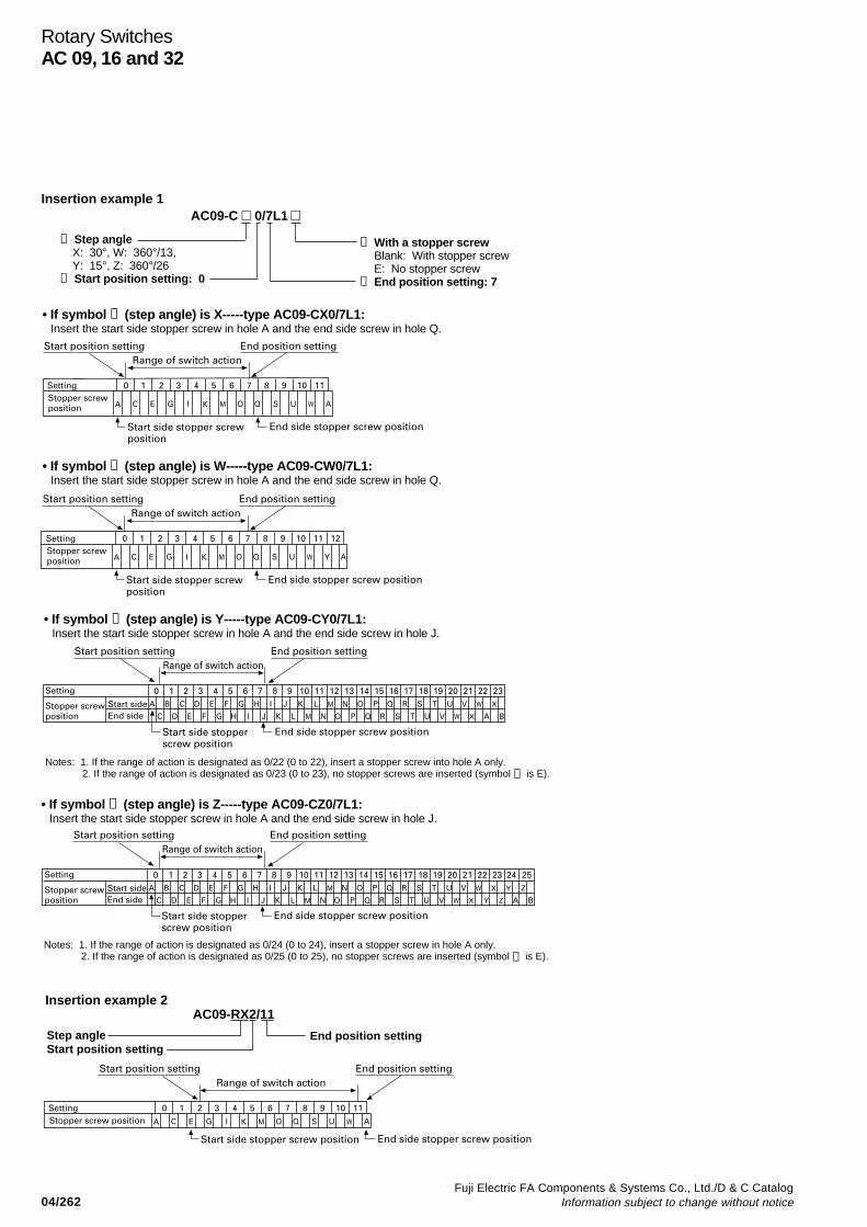
Fuji Electric FA Components & Systems Co., Ltd./D & C CatalogInformation subject to change without notice04/262
Rotary SwitchesAC 09, 16 and 32
SettingStopper screw position A C
0 1 2 3 4 5 6 7 8 9 10 11
E G I K OM Q US W A
Start position setting End position settingRange of switch action
Start side stopper screw position
End side stopper screw position
Notes: 1. If the range of action is designated as 0/24 (0 to 24), insert a stopper screw in hole A only.2. If the range of action is designated as 0/25 (0 to 25), no stopper screws are inserted (symbol ➃ is E).
• If symbol ➀ (step angle) is Z-----type AC09-CZ0/7L1:Insert the start side stopper screw in hole A and the end side screw in hole J.
• If symbol ➀ (step angle) is Y-----type AC09-CY0/7L1:Insert the start side stopper screw in hole A and the end side screw in hole J.
Start sideEnd side
Setting
Stopper screw position
A B
C
0 1 2 3 4 5 6 7 8 9 10 11 12 13 14 15 16 17 18 19 20 21 22 23C
D E
D
F
E F
G H
G
I
H
J
JI
K L
K L
ONM
M N PO
P
Q R
Q R
S T U V
S T U V
W X
XW A B
Start position setting End position settingRange of switch action
Start side stopper screw position
End side stopper screw position
Notes: 1. If the range of action is designated as 0/22 (0 to 22), insert a stopper screw into hole A only.2. If the range of action is designated as 0/23 (0 to 23), no stopper screws are inserted (symbol ➃ is E).
• If symbol ➀ (step angle) is X-----type AC09-CX0/7L1:Insert the start side stopper screw in hole A and the end side screw in hole Q.
Start sideEnd side
Setting
Stopper screw position
A B
C
0 1 2 3 4 5 6 7 8 9 10 11 12 13 14 15 16 17 18 19 20 21 22 23 24 25C
D E
D
F
E F
G H
G
I
H
J
JI
K L
K L
ONM
M N PO
P
Q R
Q R
S T U V
S T U V
W X Y Z
X Y ZW A B
Start position setting End position settingRange of switch action
Start side stopper screw position
End side stopper screw position
SettingStopper screw position A C
0 1 2 3 4 5 6 7 8 9 10 11
E G I K OM Q US W A
Start position setting End position settingRange of switch action
Start side stopper screw position End side stopper screw position
AC09-C 0/7L1 Insertion example 1
➀ Step angle X: 30°, W: 360°/13, Y: 15°, Z: 360°/26➁ Start position setting: 0
➃ With a stopper screwBlank: With stopper screwE: No stopper screw
➂ End position setting: 7
AC09-RX2/11
Step angleStart position setting
End position setting
Insertion example 2
• If symbol ➀ (step angle) is W-----type AC09-CW0/7L1:Insert the start side stopper screw in hole A and the end side screw in hole Q.
SettingStopper screw position A C
0 1 2 3 4 5 6 7 8 9 10 11 12
E G I K OM Q US W Y A
Start position setting End position settingRange of switch action
Start side stopper screw position
End side stopper screw position

04/263Fuji Electric FA Components & Systems Co., Ltd./D & C CatalogInformation subject to change without notice
04
Cam TypeRC310
Control selector switches
Cam-type control selectorswitches
DescriptionFUJI cam-type control switches arerecommended for use on switchboards,control panels and switchgear becauseof their reliability in service. The maintype is RC310 with operational currentratings of 10A.Simplified and economical circuits can bedesigned around the RC310, since it canhandle loads of up to 10A at 220VACwithout the need of contactors. Typicalexamples of complex circuits based onthe attractive features of theseeconomical cam-type selector switchesare given on pages 04/265 to 04/268.FUJI is prepared to manufacture otherversions to suit your particularapplications, and switches with up to 12selector positions can be made to order.RC310 switches are normally suppliedwith H-type handles. Alternative handleshapes available include the pistol-gripP-type, cane-handle shaped S-type androsette shaped R-type.Switches with a 2-12 position maintainedtype, 3-position center spring-return typeand center spring-return type with lockingdevice are also available.
Ordering informationSpecify the following (See page 04/264):
1. Type number2. Mounting method3. Operation4. Selector position and notch angles5. No. of contact blocks6. Contact arrangement7. Handle8. Handle colors
ExampleCam switch,rated current 10A .................. RC310-1Flush mounting ............................ xMaintained operation ......................... MContact arrangement ............................. 3201(3-position, 2 contact blocks,H type handle ................................................... HBlack color handle............................................... BType number RC310x-1M3201HB
Note: “C” in the type No. nomenclature must befilled with numbers appearing in the table of “TheContact Arrangement”. (page 04/265)When requiring special arrangements not appearingin the list clearly specify the arrangement required.Note that “C” in the type nomenclature must not beremoved in this case. RC310x-1MCHB
Type Flush mounting Semi-flush mounting Enclosedx-type g-type
RC310-1
SG-740 SG-743 AF-191
RC310x-1 RC310-1 RC310g-1
RatingsType Rated thermal Breaking capacity (A)
current Voltage AC DC DC(A) (V) Inductive Resistive Inductive
RC310-1 10 24 10 10 5110 7.5 3 1.3220 7.5 0.8 0.45440 2.5 0.4 0.2550 2 0.3 0.15
Life expectancy (operations)Type Mechanical Electrical
RC310-1 5 million 250,000 at 220VAC 7.5A500,000 at 220VAC 3A
Contact arrangement (typical)(Viewed from the direction of the handle)
Technical dataInsulation resistance: Over 100MΩ at 500VDCDielectric strength: 2,500VAC. 1 minuteAmbient temperature: –5° to +60°COperating cycle: 600 cycles/hour
Contact arrangement: See page 04/265.
Contactof upperside
Nos. of selectorpositions
Contact oflower side
Handle
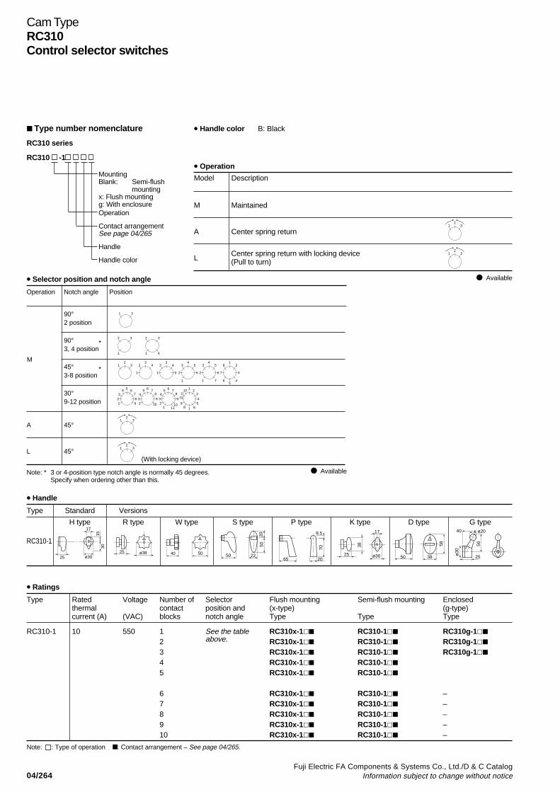
04/264Fuji Electric FA Components & Systems Co., Ltd./D & C Catalog
Information subject to change without notice
Cam TypeRC310Control selector switches
• Handle color B: Black
• Operation
Model Description
M Maintained
A Center spring return
L
Available
Type number nomenclature
RC310 series
RC310 -1
MountingBlank: Semi-flush
mountingx: Flush mountingg: With enclosureOperation
Contact arrangementSee page 04/265
Handle
Handle colorCenter spring return with locking device(Pull to turn)
• Selector position and notch angle
Operation Notch angle Position
90°2 position
90° *3, 4 position
45° *3-8 position
30°9-12 position
(With locking device)
Note: * 3 or 4-position type notch angle is normally 45 degrees.Specify when ordering other than this.
A 45°
L 45°
Available
M
• Handle
Type Standard Versions
H type R type W type S type P type K type D type G type
RC310-1
• Ratings
Type Rated Voltage Number of Selector Flush mounting Semi-flush mounting Enclosedthermal contact position and (x-type) (g-type)current (A) (VAC) blocks notch angle Type Type Type
RC310-1 10 550 1 See the table RC310x-1 RC310-1 RC310g-1
2 above. RC310x-1 RC310-1 RC310g-1
3 RC310x-1 RC310-1 RC310g-1
4 RC310x-1 RC310-1
5 RC310x-1 RC310-1
6 RC310x-1 RC310-1 –7 RC310x-1 RC310-1 –8 RC310x-1 RC310-1 –9 RC310x-1 RC310-1 –10 RC310x-1 RC310-1 –
Note: : Type of operation : Contact arrangement – See page 04/265.
231
231
231
231
231
34
1
23
4
51
24
5
62
3
1
45
62
3
71
1
5
2
37
8
46
5 6782
34
91
6 7893
45
102
6 7893
45
1110
12
1
7
23410
1112
65
89
21
32
1
32
41
25 ø38 40 50
2050
225065 20
70
9.5
25
38
17
ø30 50 38
58
40 ø20
50
ø30
25
1530
25 ø30
17
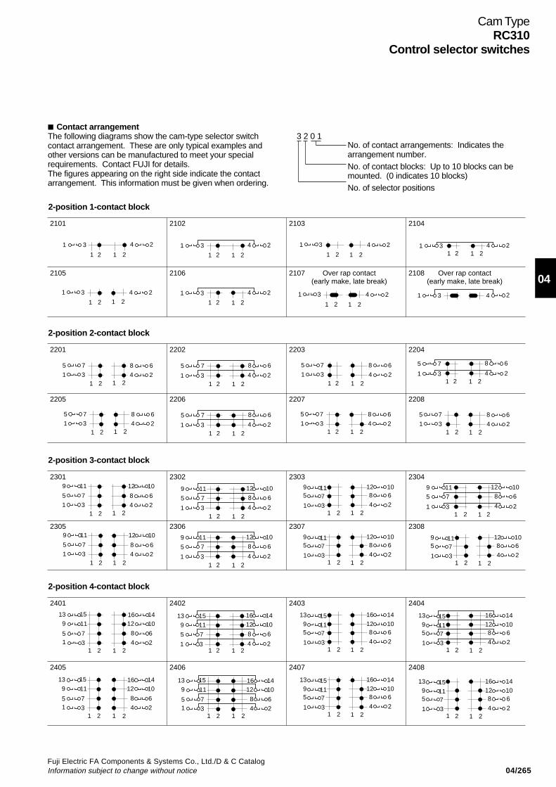
04/265Fuji Electric FA Components & Systems Co., Ltd./D & C CatalogInformation subject to change without notice
04
Cam TypeRC310
Control selector switches
Contact arrangementThe following diagrams show the cam-type selector switchcontact arrangement. These are only typical examples andother versions can be manufactured to meet your specialrequirements. Contact FUJI for details.The figures appearing on the right side indicate the contactarrangement. This information must be given when ordering.
3 2 0 1No. of contact arrangements: Indicates thearrangement number.No. of contact blocks: Up to 10 blocks can bemounted. (0 indicates 10 blocks)No. of selector positions
2-position 4-contact block
1 24 2
8 6
12 1016 1413 15
9 11
5 71 3
1 2
1 24 2
8 6
12 1016 1413 15
9 11
5 71 3
1 2
5 7
1 2 1 2
8 6
1 3 4 2
9 11 12 1013 15 16 14
1 24 2
8 6
12 1016 1413 15
9 11
5 71 3
1 2
1 24 2
8 65 7
12 109 11
16 1413 15
1 31 2
1 24 2
8 65 7
12 109 11
16 1413 15
1 31 2
1 24 2
8 65 7
12 109 11
16 1413 15
1 31 2
1 24 2
8 65 7
12 109 11
16 1413 15
1 31 2
2401
2405
2402
2406
2403
2407
2404
2408
2-position 3-contact block
1 31 2 1 2
4 2
5 7 8 6
12 109 11
1 31 2 1 2
4 2
5 7 8 6
12 109 11
5 7
1 2 1 2
8 6
1 3 4 2
9 11 12 10
5 7
1 2 1 2
8 6
1 3 4 2
9 11 12 10
1 24 2
8 65 7
12 109 11
1 3
1 24 2
8 65 7
12 109 11
1 3
1 2
1 2
1 31 2 1 2
4 2
5 7 8 69 11 12 10
1 24 2
8 65 7
12 109 11
1 31 2
2301
2305
2302
2306
2303
2307
2304
2308
2-position 2-contact block
1 31 2 1 2
4 2
5 7 8 6
1 31 2 1 2
4 2
5 7 8 6
5 7
1 2 1 2
8 6
1 3 4 2 1 31 2 1 2
4 2
5 7 8 6
1 31 2 1 2
4 2
5 7 8 6
1 31 2 1 2
4 2
5 7 8 6
1 31 2 1 2
4 2
5 7 8 65 7
1 2 1 2
8 6
1 3 4 2
2201
2205
2202
2206
2203
2207
2204
2208
2-position 1-contact block
1 3
1 2 1 2
4 2
1 3
1 2 1 2
4 2
1 3
1 2 1 2
4 2
1 3
1 2 1 2
4 2
1 3
1 2 1 2
4 2 1 31 2 1 2
4 2
1 3
1 2 1 2
4 2 1 3 4 2
2101
2105
2102
2106
2103
2107 Over rap contact(early make, late break)
Over rap contact(early make, late break)
2104
2108

04/266Fuji Electric FA Components & Systems Co., Ltd./D & C Catalog
Information subject to change without notice
Cam TypeRC310Control selector switches
Contact arrangement3-position 1-contact block
1 4 23
1 12 23 3
1 4 23
1 12 23 3
1 4 23
1 12 23 3
1 4 231 12 23 3
1 4 231 12 23 3
1 4 231 12 23 3
1 4 231 12 23 3
1 4 231 12 23 3
1 4 231 12 23 3
1 4 231 12 23 3
1 12 23 31 4 23
1 12 23 31 4 23
3101
3105
3102
3106
3103
3107
3104
3108 Notch angle : 90°
3109 3110 3111 3112
3-position 2-contact block
1 4 235 8 67
1 12 23 3
1 4 235 8 67
1 12 23 3
1 4 235 8 67
1 12 23 3
1 4 235 8 67
1 12 23 3
1 4 235 8 67
1 12 23 3
1 4 23
5 8 67
1 12 23 3
1 4 235 8 67
1 12 23 3
1 4 235 8 67
1 12 23 3
1 4 23
5 8 67
1 12 23 3
1 4 23
5 8 67
1 12 23 3
1 4 235 8 67
1 12 23 3
1 4 23
5 8 67
1 12 23 3
3201
3205
3202
3206
3203
3207
3204
3208
3209 3210 3211 3212
3-position 3-contact block
1
95 7 8 6
1011 12
3 4 21 2 3 1 2 3
1
95 7 8 6
1011 12
3 4 21 2 3 1 2 3
1
95 7 8 6
1011 12
3 4 21 2 3 1 2 3
1
95
1
95
7 8 61011 12
3 4 21 2 3 1 2 3
1
95 7 8 6
1011 12
3 4 21 2 3 1 2 3
8 61012
4 21
95 7
11
31 2 3 1 2 3
8 61012
4 21
95 7
11
31 2 3 1 2 3
8 61012
4 21
95 7
11
31 2 3 1 2 3
8 61012
4 21
95 7
11
31 2 3 1 2 3
8 61012
4 2
711
31 2 3 1 2 3
1
958 6
1012
4 2
711
31 2 3 1 2 3
1
95 8 6
1012
4 2
711
31 2 3 1 2 3
3301
3305
3302
3306
3303
3307
3304
3308
3309 3310 3311 3312
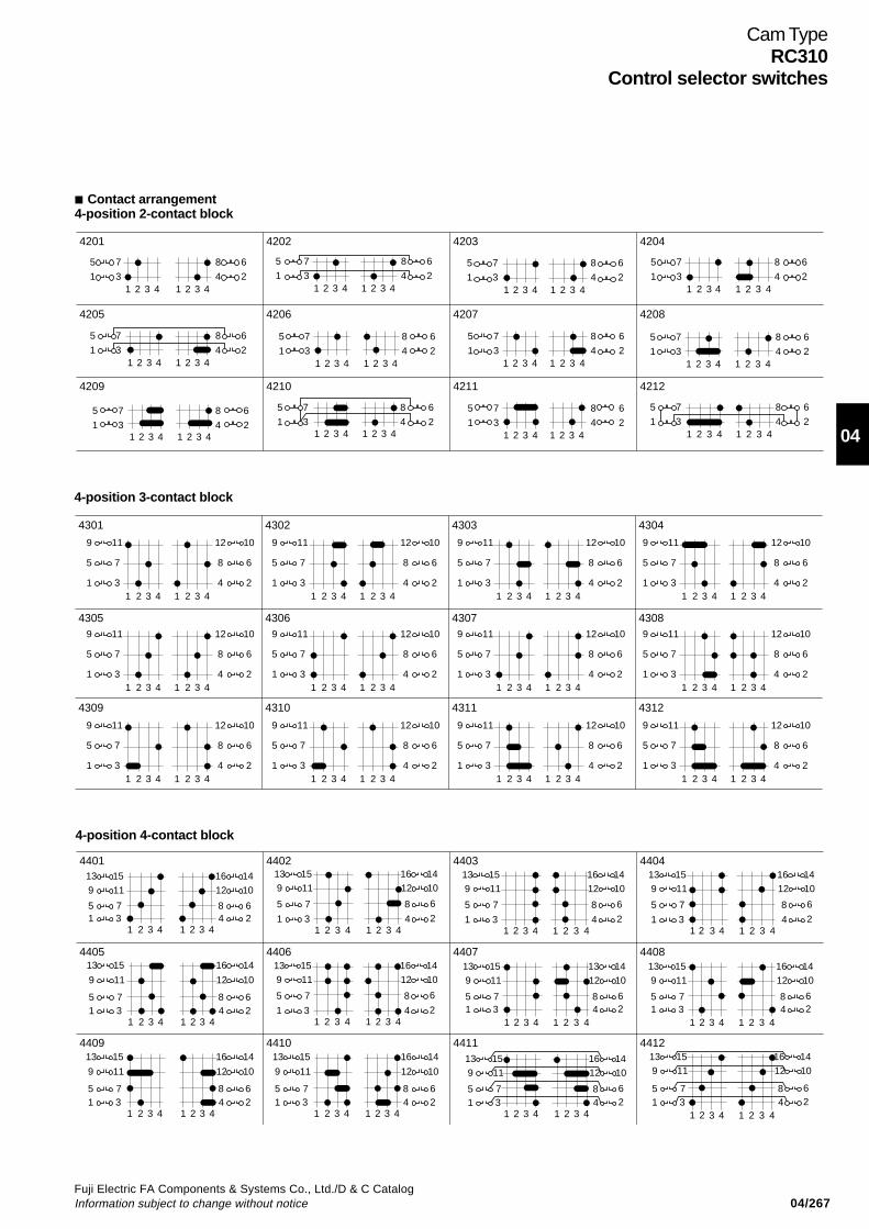
04/267Fuji Electric FA Components & Systems Co., Ltd./D & C CatalogInformation subject to change without notice
04
Cam TypeRC310
Control selector switches
4-position 3-contact block
9 11 12 10
1 3 4 2
5 7 8 6
1 2 3 4 1 2 3 4
9 11 12 10
1 3 4 2
5 7 8 6
1 2 3 4 1 2 3 4
9 11 12 10
1 3 4 2
5 7 8 6
1 2 3 4 1 2 3 4
9 11 12 10
1 3 4 2
5 7 8 6
1 2 3 4 1 2 3 4
9 11 12 10
1 3 4 2
5 7 8 6
1 2 3 4 1 2 3 4
9 11 12 10
1 3 4 2
5 7 8 6
1 2 3 4 1 2 3 4
9 11 12 10
1 3 4 2
5 7 8 6
1 2 3 4 1 2 3 4
9 11 12 10
1 3 4 2
5 7 8 6
1 2 3 4 1 2 3 4
9 11 12 10
1 3 4 2
5 7 8 6
1 2 3 4 1 2 3 4
9 11 12 10
1 3 4 2
5 7 8 6
1 2 3 4 1 2 3 4
9 11 12 10
1 3 4 2
5 7 8 6
1 2 3 4 1 2 3 4
9 11 12 10
1 3 4 2
5 7 8 6
1 2 3 4 1 2 3 4
4301
4305
4302
4306
4303
4307
4304
4308
4309 4310 4311 4312
Contact arrangement4-position 2-contact block
1 2 3 4 1 2 3 4
5
1
7
3
8
4
6
21 2 3 4 1 2 3 4
5
1
7
3
8
4
6
2
1 2 3 4 1 2 3 4
5
1
7
3
8
4
6
21 2 3 4 1 2 3 4
5
1
7
3
8
4
6
2
1 2 3 4 1 2 3 4
5
1
7
3
8
4
6
21 2 3 4 1 2 3 4
5
1
7
3
8
4
6
2
1 2 3 4 1 2 3 4
5
1
7
3
8
4
6
2
1 2 3 4 1 2 3 4
5
1
7
3
8
4
6
2
1 2 3 4 1 2 3 4
5
1
7
3
8
4
6
2
1 2 3 4 1 2 3 4
5
1
7
3
8
4
6
2
1 2 3 4 1 2 3 4
5
1
7
3
8
4
6
2
1 2 3 4 1 2 3 4
5
1
7
3
8
4
6
2
4201
4205
4202
4206
4203
4207
4204
4208
4209 4210 4211 4212
4-position 4-contact block
9
13 15 16 14
51 3 4 2
7 8 6
11 12 10
1 2 3 4 1 2 3 4
9
13 15 16 14
51 3 4 2
7 8 6
11 12 10
1 2 3 4 1 2 3 4
9
13 15 16 14
51 3 4 2
7 8 6
11 12 10
1 2 3 4 1 2 3 4
9
13 15 16 14
51 3 4 2
7 8 6
11 12 10
1 2 3 4 1 2 3 4
913 15 16 14
51 3 4 2
7 8 6
11 12 10
1 2 3 4 1 2 3 4
913 15 16 14
5
1 3 4 2
7 8 6
11 12 10
1 2 3 4 1 2 3 4
913 15 16 14
5
1 3 4 2
7 8 6
11 12 10
1 2 3 4 1 2 3 4
913 15 16 14
5
1 3 4 2
7 8 6
11 12 10
1 2 3 4 1 2 3 4
913 15 13 14
51 3 4 2
7 8 6
11 12 10
1 2 3 4 1 2 3 4
913 15 16 14
5
1 3 4 2
7 8 6
11 12 10
1 2 3 4 1 2 3 4
913 15 16 14
51 3 4 2
7 8 6
11 12 10
1 2 3 4 1 2 3 4
913 15 16 14
51 3 4 2
7 8 6
11 12 10
1 2 3 4 1 2 3 4
4401
4405
4402
4406
4403
4407
4404
4408
4409 4410 4411 4412
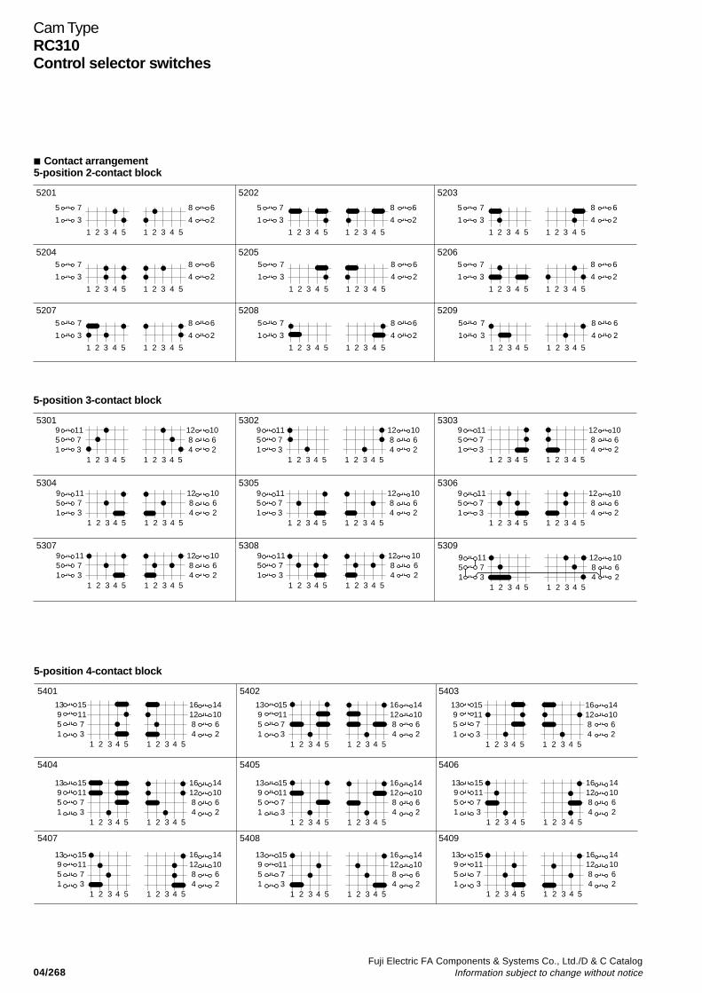
04/268Fuji Electric FA Components & Systems Co., Ltd./D & C Catalog
Information subject to change without notice
Cam TypeRC310Control selector switches
5-position 3-contact block
951
1173
1284
1062
1 2 3 4 5 1 2 3 4 5
951
1173
1284
1062
1 2 3 4 5 1 2 3 4 5
951
1173
1284
1062
1 2 3 4 5 1 2 3 4 5
951
1173
1284
1062
1 2 3 4 5 1 2 3 4 5
951
1173
1284
1062
1 2 3 4 5 1 2 3 4 5
951
1173
1284
1062
1 2 3 4 5 1 2 3 4 5
951
1173
1284
1062
1 2 3 4 5 1 2 3 4 5
951
1173
1284
1062
1 2 3 4 5 1 2 3 4 5
951
1173
1284
1062
1 2 3 4 5 1 2 3 4 5
5301
5304
5302
5305
5303
5306
5307 5308 5309
5-position 4-contact block
13951
151173
161284
141062
1 2 3 4 5 1 2 3 4 5
13951
151173
161284
141062
1 2 3 4 5 1 2 3 4 5
13951
151173
161284
141062
1 2 3 4 5 1 2 3 4 5
13951
151173
161284
141062
1 2 3 4 5 1 2 3 4 5
13951
151173
161284
141062
1 2 3 4 5 1 2 3 4 5
13951
151173
161284
141062
1 2 3 4 5 1 2 3 4 5
13951
151173
161284
141062
1 2 3 4 5 1 2 3 4 5
13951
151173
161284
141062
1 2 3 4 5 1 2 3 4 5
13951
151173
161284
141062
1 2 3 4 5 1 2 3 4 5
5401
5404
5402
5405
5403
5406
5407 5408 5409
Contact arrangement5-position 2-contact block
5
1
7
3
8
4
6
2
1 2 3 4 5 1 2 3 4 5
5
1
7
3
8
4
6
2
1 2 3 4 5 1 2 3 4 5
5
1
7
3
8
4
6
2
1 2 3 4 5 1 2 3 4 5
5
1
7
3
8
4
6
2
1 2 3 4 5 1 2 3 4 5
5
1
7
3
8
4
6
2
1 2 3 4 5 1 2 3 4 5
5
1
7
3
8
4
6
2
1 2 3 4 5 1 2 3 4 5
5
1
7
3
8
4
6
2
1 2 3 4 5 1 2 3 4 5
5
1
7
3
8
4
6
2
1 2 3 4 5 1 2 3 4 5
5
1
7
3
8
4
6
2
1 2 3 4 5 1 2 3 4 5
5201
5204
5202
5205
5203
5206
5207 5208 5209
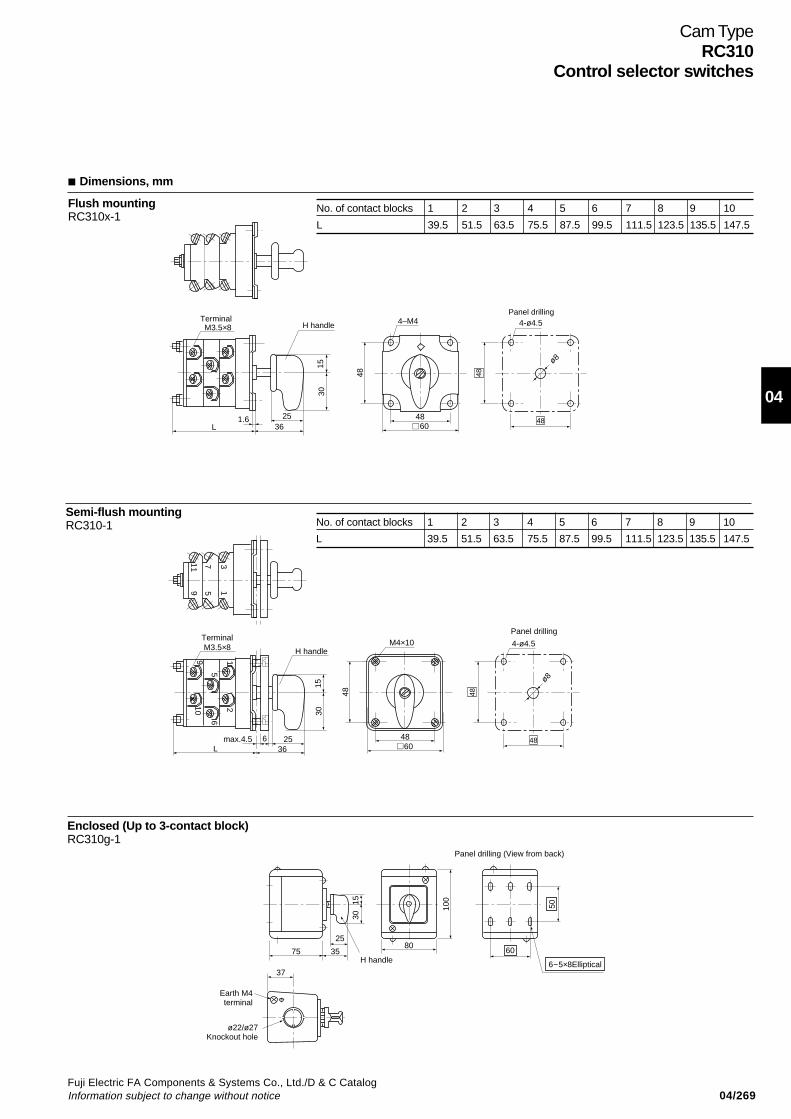
04/269Fuji Electric FA Components & Systems Co., Ltd./D & C CatalogInformation subject to change without notice
04
Cam TypeRC310
Control selector switches
Dimensions, mm
Flush mountingRC310x-1
Semi-flush mountingRC310-1
Enclosed (Up to 3-contact block)RC310g-1
No. of contact blocks 1 2 3 4 5 6 7 8 9 10
L 39.5 51.5 63.5 75.5 87.5 99.5 111.5 123.5 135.5 147.5
Terminal M3.5×8
L1.6 25
1530
48
36
4–M4
4860
4-ø4.5
ø8
Panel drilling
H handle
48
48
No. of contact blocks 1 2 3 4 5 6 7 8 9 10
L 39.5 51.5 63.5 75.5 87.5 99.5 111.5 123.5 135.5 147.5
11 7
9
3
5 1
TerminalM3.5×8 H handle
9
5
1
6
10
Lmax.4.5 6 25
36
1530
M4×10
4860
4-ø4.5
Panel drilling
ø8
2
48 48
48
Panel drilling (View from back)
1530
25
75 35
37
Earth M4terminal
ø22/ø27Knockout hole
100
80
H handle60
50
6-5×8Elliptical
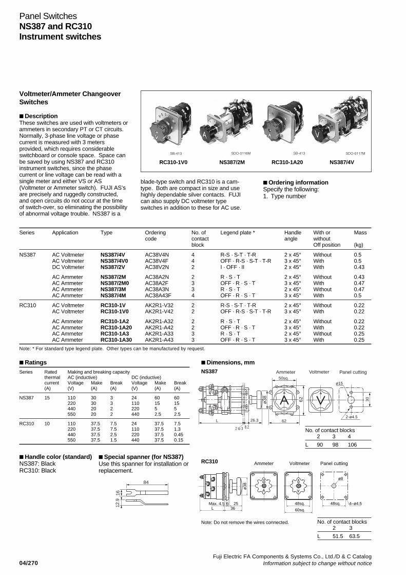
04/270Fuji Electric FA Components & Systems Co., Ltd./D & C Catalog
Information subject to change without notice
Panel SwitchesNS387 and RC310Instrument switches
Voltmeter/Ammeter ChangeoverSwitches
DescriptionThese switches are used with voltmeters orammeters in secondary PT or CT circuits.Normally, 3-phase line voltage or phasecurrent is measured with 3 metersprovided, which requires considerableswitchboard or console space. Space canbe saved by using NS387 and RC310instrument switches, since the phasecurrent or line voltage can be read with asingle meter and either VS or AS(Voltmeter or Ammeter switch). FUJI AS’sare precisely and ruggedly constructed,and open circuits do not occur at the timeof switch-over, so eliminating the possibilityof abnormal voltage trouble. NS387 is a
Series Application Type Ordering No. of Legend plate * Handle With or Masscode contact angle without
block Off position (kg)
NS387 AC Voltmeter NS387/4V AC38V4N 4 R-S · S-T · T-R 2 x 45° Without 0.5AC Voltmeter NS387/4V0 AC38V4F 4 OFF · R-S · S-T · T-R 3 x 45° With 0.5DC Voltmeter NS387/2V AC38V2N 2 I · OFF · II 2 x 45° With 0.43
AC Ammeter NS387/2M AC38A2N 2 R · S · T 2 x 45° Without 0.43AC Ammeter NS387/2M0 AC38A2F 3 OFF · R · S · T 3 x 45° With 0.47AC Ammeter NS387/3M AC38A3N 3 R · S · T 2 x 45° Without 0.47AC Ammeter NS387/4M AC38A43F 4 OFF · R · S · T 3 x 45° With 0.5
RC310 AC Voltmeter RC310-1V AK2R1-V32 2 R-S · S-T · T-R 2 x 45° Without 0.22AC Voltmeter RC310-1V0 AK2R1-V42 2 OFF · R-S · S-T · T-R 3 x 45° With 0.22
AC Ammeter RC310-1A2 AK2R1-A32 2 R · S · T 2 x 45° Without 0.22AC Ammeter RC310-1A20 AK2R1-A42 2 OFF · R · S · T 3 x 45° With 0.22AC Ammeter RC310-1A3 AK2R1-A33 3 R · S · T 2 x 45° Without 0.25AC Ammeter RC310-1A30 AK2R1-A43 3 OFF · R · S · T 3 x 45° With 0.25
Note: * For standard type legend plate. Other types can be manufactured by request.
RatingsSeries Rated Making and breaking capacity
thermal AC (inductive) DC (inductive)current Voltage Make Break Voltage Make Break(A) (V) (A) (A) (V) (A) (A)
NS387 15 110 30 3 24 60 60220 30 3 110 15 15440 20 2 220 5 5550 20 2 440 2.5 2.5
RC310 10 110 37.5 7.5 24 37.5 7.5220 37.5 7.5 110 37.5 1.3440 37.5 2.5 220 37.5 0.45550 37.5 1.5 440 37.5 0.15
Handle color (standard)NS387: BlackRC310: Black
Special spanner (for NS387)Use this spanner for installation orreplacement.
RC310-1V0 NS387/2M RC310-1A20 NS387/4V
SB-413 SDO-0116M SB-413 SDO-0117M
Ordering informationSpecify the following:1. Type number
84
12.9
16
Note: Do not remove the wires connected. No. of contact blocks2 3
L 51.5 63.5
A V
ø38
Max. 4.5 6 25L 36
48sq.
60sq.
ø8
4–ø4.5
Ammeter Voltmeter Panel cutting
48sq.
RC310
Dimensions, mmNS387
No. of contact blocks2 3 4
L 90 98 106
L
2 to 3 8.2
26.3
ø38
50sq.
62
Ammeter
62 30
2-ø4.5
ø15
Voltmeter Panel cutting
blade-type switch and RC310 is a cam-type. Both are compact in size and usehighly dependable silver contacts. FUJIcan also supply DC voltmeter typeswitches in addition to these for AC use.
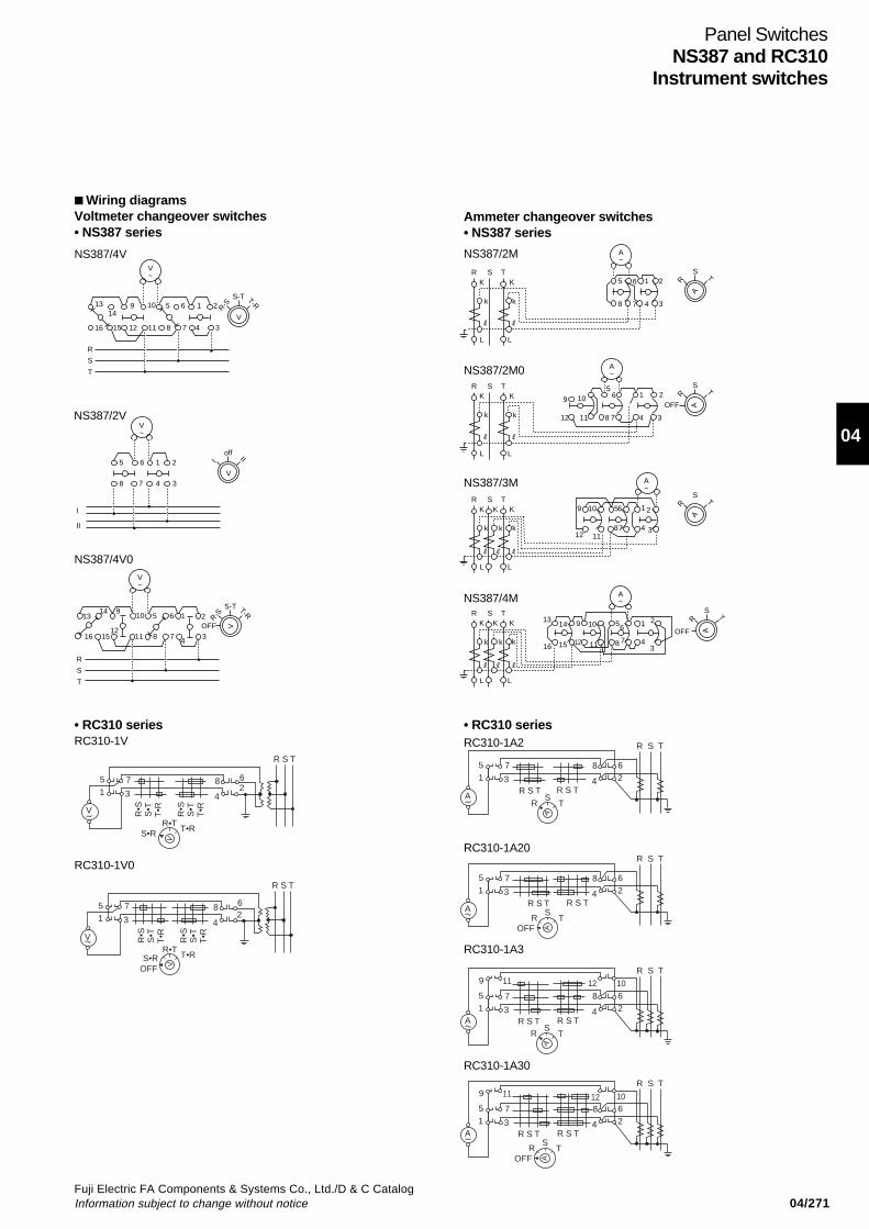
04/271Fuji Electric FA Components & Systems Co., Ltd./D & C CatalogInformation subject to change without notice
04
Panel SwitchesNS387 and RC310
Instrument switches
1314
9 5 6 1 210
16 15 12 11 8 7 4 3
V~
V
S-T T-R
R-S
R
S
T
V~
6 1 25
8 7 4 3V
off III
II
I
A~
A
S
T
R5 1 26
8 4 37
RK
L L
k k
KS T
V~
V
S-T T-R
R-S
R
S
T
10 5 6 11314 9
124
2
16 15 11 8 7 3OFF
A~
A
S
OFF
T
R
5
9 10
1112 8 7 4 3
1 26R
K
L L
k k
KS T
A~
A
S
T
R
RK K
L L
k k k
KS T
9 10
12 11
56
87
1 2
34
A~
A
S
T
R
RK K
L L
k k k
KS T
1314
16 15
9 10 56 1 2
34781112
OFF
R S T
62
8
415 7
3
T•R
V
V
S•RR•T
T•RS•T
R•S
T•RS•T
R•S
V
V
R S T
62
8
415 7
3
T•RS•RR•T
T•RS•T
R•S
T•RS•T
R•S
OFF
62
8
415 7
3
TA
A
RS
R S T R S T
R S T
62
8
415 7
3
TA
A
ROFF
SR S T R S T
R S T
T
A
RS
62
8
1012
415 7
9 11
3A R S T R S T
R S T
T
A
ROFF
S
62
81012
415 7
9 11
3A R S T R S T
R S T
Wiring diagramsVoltmeter changeover switches• NS387 series
NS387/4V
NS387/2V
NS387/4V0
RC310-1V
RC310-1V0
• RC310 series
Ammeter changeover switches• NS387 series
NS387/2M
NS387/2M0
NS387/3M
NS387/4M
• RC310 series
RC310-1A20
RC310-1A2
RC310-1A3
RC310-1A30
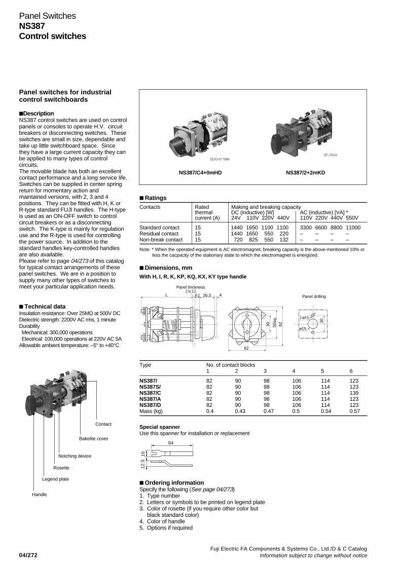
04/272Fuji Electric FA Components & Systems Co., Ltd./D & C Catalog
Information subject to change without notice
Panel SwitchesNS387Control switches
Panel switches for industrialcontrol switchboards
DescriptionNS387 control switches are used on controlpanels or consoles to operate H.V. circuitbreakers or disconnecting switches. Theseswitches are small in size, dependable andtake up little switchboard space. Sincethey have a large current capacity they canbe applied to many types of controlcircuits.The movable blade has both an excellentcontact performance and a long service life.Switches can be supplied in center springreturn for momentary action andmaintained versions, with 2, 3 and 4positions. They can be fitted with H, K orR-type standard FUJI handles. The H-typeis used as an ON-OFF switch to controlcircuit breakers or as a disconnectingswitch. The K-type is mainly for regulationuse and the R-type is used for controllingthe power source. In addition to thestandard handles key-controlled handlesare also available.Please refer to page 04/273 of this catalogfor typical contact arrangements of thesepanel switches. We are in a position tosupply many other types of switches tomeet your particular application needs.
Technical dataInsulation resistance: Over 25MΩ at 500V DCDielectric strength: 2200V AC rms, 1 minuteDurability Mechanical: 300,000 operations Electrical: 100,000 operations at 220V AC 5AAllowable ambient temperature: –5° to +40°C
RatingsContacts Rated Making and breaking capacity
thermal DC (inductive) [W] AC (inductive) [VA] *current (A) 24V 110V 220V 440V 110V 220V 440V 550V
Standard contact 15 1440 1650 1100 1100 3300 6600 8800 11000Residual contact 15 1440 1650 550 220 – – – –Non-break contact 15 720 825 550 132 – – – –
Note: * When the operated equipment is AC electromagnet, breaking capacity is the above-mentioned 10% or less the cacpacity of the stationary state to which the electromagnet is energized.
Dimensions, mmWith H, I, R, K, KP, KQ, KX, KY type handle
Type No. of contact blocks1 2 3 4 5 6
NS387/ 82 90 98 106 114 123NS387S/ 82 90 98 106 114 123NS387/C 82 90 98 106 114 139NS387/A 82 90 98 106 114 123NS387/D 82 90 98 106 114 123Mass (kg) 0.4 0.43 0.47 0.5 0.54 0.57
NS387/C4+0mHD NS387/2+2mKD
SDO-0118MSF-2024
Special spannerUse this spanner for installation or replacement
L
Panel thickness2 to 3.2
26.3 48.2
30
30
50sq
.62
62
2-ø4.5
ø15
Panel drilling
84
12.9
16
Handle
Legend plate
Rosette
Notching device
Bakelite cover
Contact
Ordering informationSpecify the following (See page 04/273)1. Type number2. Letters or symbols to be printed on legend plate3. Color of rosette (if you require other color but
black standard color)4. Color of handle5. Options if required
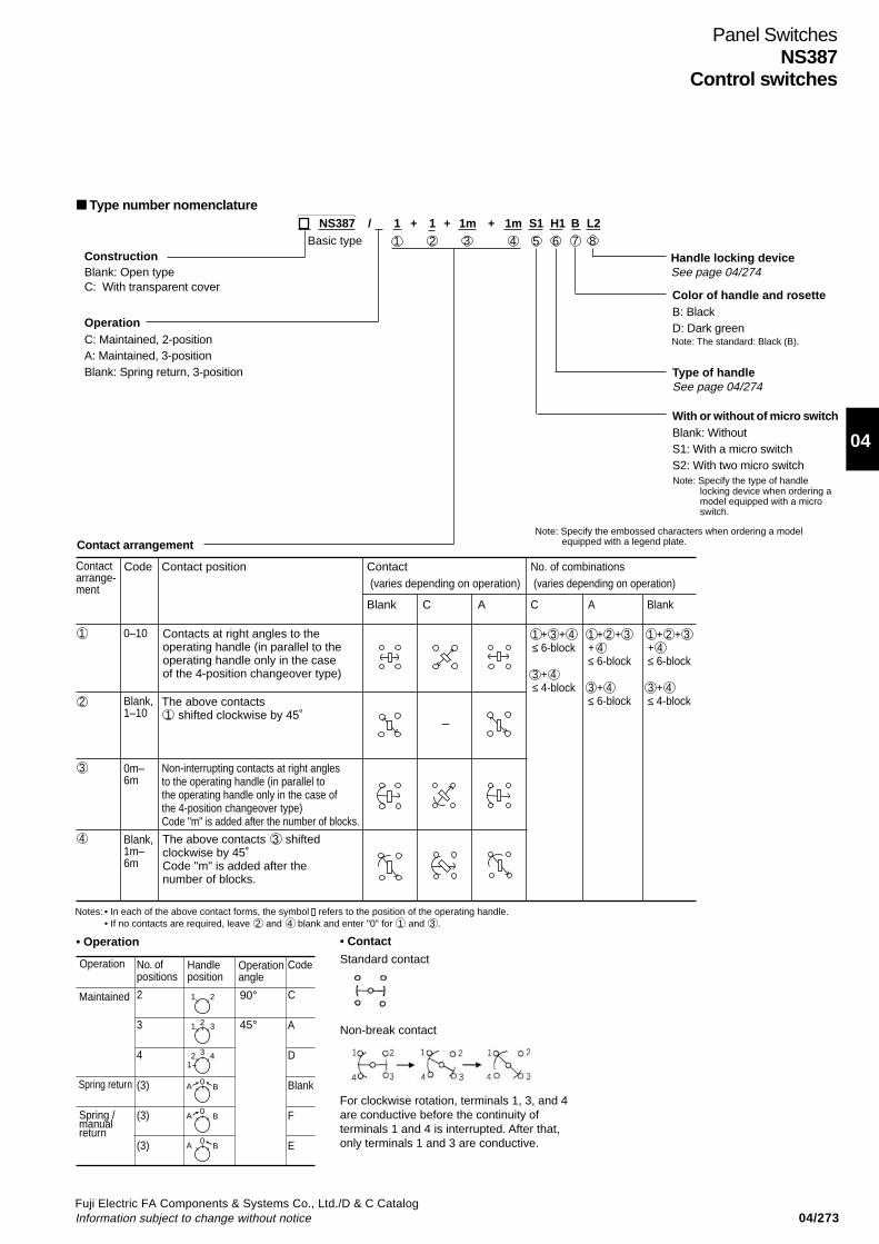
04/273Fuji Electric FA Components & Systems Co., Ltd./D & C CatalogInformation subject to change without notice
04
Panel SwitchesNS387
Control switches
Type number nomenclature
ConstructionBlank: Open typeC: With transparent cover
Basic type
OperationC: Maintained, 2-positionA: Maintained, 3-positionBlank: Spring return, 3-position
Contact arrangement
Handle locking deviceSee page 04/274
Color of handle and rosetteB: BlackD: Dark green
Type of handleSee page 04/274
With or without of micro switchBlank: WithoutS1: With a micro switchS2: With two micro switch
Note: The standard: Black (B).
Note: Specify the embossed characters when ordering a model equipped with a legend plate.
• Operation • Contact
Standard contact
Non-break contact
For clockwise rotation, terminals 1, 3, and 4are conductive before the continuity ofterminals 1 and 4 is interrupted. After that,only terminals 1 and 3 are conductive.
Note: Specify the type of handlelocking device when ordering amodel equipped with a microswitch.
No. of positions
2
3
4
(3)
(3)
(3)
Handle position
Operation angle
Code
C
A
D
Blank
F
E
1 2
1 32
21
43
A B0
A B0
A B0
Spring / manual return
90°
45°
Operation
Maintained
Spring return
NS387 / 1 + 1 + 1m + 1m S1 H1 B L2
Contact arrange-ment
Code Contact position Contact (varies depending on operation)
Blank C A
No. of combinations (varies depending on operation)
C A Blank
Contacts at right angles to theoperating handle (in parallel to theoperating handle only in the case of the 4-position changeover type)
The above contacts 1 shifted clockwise by 45˚
Non-interrupting contacts at right angles to the operating handle (in parallel to the operating handle only in the case of the 4-position changeover type)Code "m" is added after the number of blocks.
The above contacts 3 shifted clockwise by 45˚Code "m" is added after the number of blocks.
1 + 3 + 4≤ 6-block
3 + 4≤ 4-block
1 + 2 + 3+ 4≤ 6-block
3 + 4≤ 6-block
1 + 2 + 3+ 4≤ 6-block
3 + 4≤ 4-block
1 0–10
Blank,1–10
0m–6m
Blank,1m–6m
2
3
4
4321 5 6 7 8
Notes: • In each of the above contact forms, the symbol refers to the position of the operating handle.• If no contacts are required, leave 2 and 4 blank and enter "0" for 1 and 3 .

04/274Fuji Electric FA Components & Systems Co., Ltd./D & C Catalog
Information subject to change without notice
H type I type K type R type KP type KQ type KX type KY type
H type R type W type S type P type K type D type
Panel SwitchesNS387Control switches
Operating handle• Combination of rosette and handle
Rosette
For NS387
Handle
For NS387
For RC310
Type of handle (refer to 2. Shape of handle, table below)
Without micro switch:H, I, KKP1 – KP10KQ1 – KQ10KX1 – KX10KY1 – KY10R
Without micro switch:P, S, D, W
With micro switch:H, P, S, K, D, R, W
Notes:• With micro switch equipped, NS387 panel switch are provided with NS387-use rosette as standard, and with the handle for RC310-1 cam switch.• The large handle (P, S, D, or W) for the RC310-1 is not compatible with any other handle.
• Types of handle lockingCodeBlank
Center spring return type Maintained type
Note: If a micro switch is equipped, it will be activated when the handle is pulled.
KP
Key removable position
KP KP KP KP 10KPKPKPKPKP 1KQ KQ KQ1
11
22
22
33
33
4KQ KQKQ KQ KQ KQ KQKQ KQ 104
44
55
55
66
66
77
77
8
88
8 99
99
KX 10KXKXKXKXKXKXKXKXKXKY 10KYKYKYKYKYKYKYKYKY
• Shape of handle
ForNS387
ForRC310
8.2 26.3
1340
14 26.3 14
3013
26.3 14
38
26.3
ø38
41
38 38
45.5
38
48.5
2030
27.5 ø3525 ø38 40 50
2050
2250 65 20
70
9.5
25
38
17
ø3050 38
58
The handle can be turned without being locked.
The handle can be turned after being pulled, and the handlestops at each notch when it is released.
The handle can be turned after being pulled, and when it isreleased in any notch position, the handle will stop at thatnotch position. Moreover, when the handle is pulled in anynotch position, the micro switch will be activated, and boththe micro switch and handle will be reset when the handle isreleased. However, the handle cannot be switched to anyother notch while it is in the pulled condition.
In the case of the NS387, the handle can be turned after being pulled,and the handle then returns to the center position automatically when itis released. If the handle needs to be turned without being pulled, ordera model with "no handle lock".The RC310 handle can be turned without being locked.
With a handle for the RC310.The handle can be turned after being pulled, and the handle thenreturns to the center position automatically when it is released.
The handle can be turned without being pulled, and will return to thecenter position automatically when it is released. The micro switch isactivated while the handle is pulled in the center position, and theswitch is reset when the handle is released. The handle, however, doesnot turn left or right when it is pulled.
The handle can be turned without being pulled, and will return to thecenter position automatically when it is released. When the handle ispulled in the left position, the lock mechanism will activate and no othernotch can be selected. In that case, the handle will automatically returnto the center position when it is pressed in the shaft direction.
The handle can be turned without being pulled, and will return to thecenter position automatically when it is released. The micro switch willbe activated when the handle is pulled in the center position, and thehandle will return when the handle is pressed in the shaft direction.
L1
L2
L3
L4
L5
The handle can be turned after being pulled. When it is released, thehandle will automatically return to the center position in the pulledcondition. The handle will return when it is pressed in the shaftdirection.
–
–
–
38
45.5

04/275Fuji Electric FA Components & Systems Co., Ltd./D & C CatalogInformation subject to change without notice
04
Panel SwitchesNS387
Control switches
Assembled typical switches
For other than above, contact FUJI.
Operation Type(example) Contact arrangement Description
Centerspringreturn
NS387/2 + 0mHD • The handle can be turned after being pulled, and will return to thecenter position automatically when it is released.
NS387/2 + 2 + 0mHB • The handle can be turned after being pulled, and will return to thecenter position automatically when it is released.
NS387/1 + 1mHB • The handle can be turned after being pulled, and will return to thecenter position automatically when it is released.
NS387/2 + 0mS1B • RC310-1 handle, equipped with a rosette.• Add L1 for the pull-and-turn type.
NS387/1 + 0mS1HDL2 • Provided with a micro switch, RC310-1 handle, and a rosette for theNS387.• The handle can be turned without being pulled, and will return to thecenter position automatically when it is released. The micro switch willbe activated while the handle is pulled in the center position.
NS387/5 + 0mSBL3 • RC310-1 handle, equipped with the NS387 rosette.• When the handle is pulled in the left position, it will be locked, and thehandle will automatically return to the center position when it is pressedin the shaft direction.
NS387/1 + 0mS1H1BL4 • Equipped with a micro switch, RC310-1 handle, and a rosette for theNS387.• The handle can be turned after being pulled, and will return to thecenter position automatically when it is released, but the handleremains in the pulled condition. The handle will be reset when it ispressed.• The micro switch will be activated while the handle is pulled.
Maintained2-position
NS387/C3 + 1mKB
NS387/C6 + 0mW1D • RC310-1 cam switch handle, equipped with a rosette.
NS387/A6 + 0mRB
NS387/A2 + 0mH1B • RC310-1 cam switch handle, equipped with a rosette.
NS387/A3 + 3 + 0mS1KDL2 • RC310-1 cam switch handle, equipped with the NS387 rosette.• The handle can be turned left or right without being pulled. Themicro switch will be activated while the handle is pulled.
Maintained3-position
0
0
0
0
0
0
0
A B
A B
A B
A B
A B
A B
A B
1 2
1 2
21 3
21 3
21 3
1 2 5 6
4 3 8 7
1 2 5 6 9 10 13 14
4 3 8 7 12 11 16 15
1 2 5 6
4 3 8 7
1 2 5 6
4 3 8 7
1 2
4 3
1 2 5 6 9 10 13 14 17 18
4 3 8 7 12 11 16 15 20 19
1 2
4 3
1 2 5 6 9 10 13 14
4 3 8 7 12 11 16 15
1 2 5 6 9 10 13 1417 18 21 22
4 3 8 7 12 11 16 1520 19 24 23
1 2 5 6 9 10 13 14 17 18 21 22
4 3 8 7 12 11 16 15 20 19 24 23
1 2 5 6
4 3 8 7
1 2 5 6 9 10 13 1417 18 21 22
4 3 8 7 12 11 16 15 20 19 24 23
C
NO NC
C
NO NC
C
NO NC
–
–

04/276Fuji Electric FA Components & Systems Co., Ltd./D & C Catalog
Information subject to change without notice
Terminal BlocksGeneral Information
DescriptionFUJI can supply a variety of terminalblocks for switchboard or switchgear use.FUJI terminal blocks and end barriers arestrongly constructed from a phenol resinand have adequate creepage distanceand excellent insulation characteristics.Good connections are assured byconvenient screw terminals andsolderless box lugs. All terminal blocksare designed to carry their ratedamperage without danger of overheating.FUJI terminal blocks are available in avariety of types, some of which areillustrated on this page.AYBN type is simple to assemble and isdesigned to speed up installation. It isavailable in up to 12 poles and 600 Ampsversions.AYBS type terminal blocks are madefrom the highest quality phenol resin andresists tracking. Current ratings areavailable up to 115 Amps and 12 poles.The customer is required to assemblethe channel-mounted type himself. Themodular construction allows the numberof blocks in a channel to be increased ordecreased very easily.In addition we can also supply the LT4Dtype which is provided with an isolatingswitch, and SKT type power terminalblocks, which are used in motor circuits,power source and similar circuits.Testing terminals type LT5 for CT, VTsecondary circuits are also available.
Type LT2ERail mounted type terminal blocks600 volts 22 to 600 Amps Further information: See page 04/283.
Type AYBNGeneral purpose terminal blocks600 Volts 15 to 600 Amps
Further information: See page 04/228.
Type AYBSHigh quality terminal blocks600 Volts 49 to 115 Amps Further information: See page 04/279.
Type LT4DRail mounted terminal blocks with isolating switch660 Volts 20 Amps Further information: See page 04/280.
Type SKTTerminal block with pressure solderless box lug typeconnector on one side and screw type connector onthe other.600 Volts 50 to 200 Amps Further information: See page 04/281.
Type LT5Testing terminal and link for VT and CT circuit250 Volts AC/DC 30 Amps Further information: See page 04/288.
Wire gauge and squareThe following table shows the relationshipbetween B.W.G., A.W.G. wire gauge and mm2
cross-sections. In this catalog wire sizes arequoted in mm2. Please use this table forreference.
SB-232 SB-277
SB-279 SB-279
AF01-220
Gauge SquareB.W.G. A.W.G. mm2
4/0 107.24/0 104.23/0 91.6
3/0 85.22/0 73.2
2/0 67.50 58.6
0 53.51 45.6
1 42.42 40.93 34.0
2 33.64 28.7
3 26.75 24.5
4 21.26 20.9
5 16.87 16.48 13.8
6 13.39 11.1
7 10.510 9.1
8 8.311 7.3
Gauge SquareB.W.G. A.W.G. mm2
9 6.612 6.0
10 5.313 4.6
11 4.214 3.5
12 3.315 13 2.6316 2.14
14 2.0817 1.71
15 1.6516 1.32
18 1.2217 1.03
19 0.8918 0.8119 0.66
20 0.6221 20 0.52
21 0.4122 0.40
22 0.3223 0.32
23 0.2624 0.25
24 0.20
B.W.G. Birminghan Wire GaugeA.W.G. American Wire Gauge
Type AYBNGeneral purpose terminal blocks600 Volts 15 to 600 Amps Further information: See page 04/277.
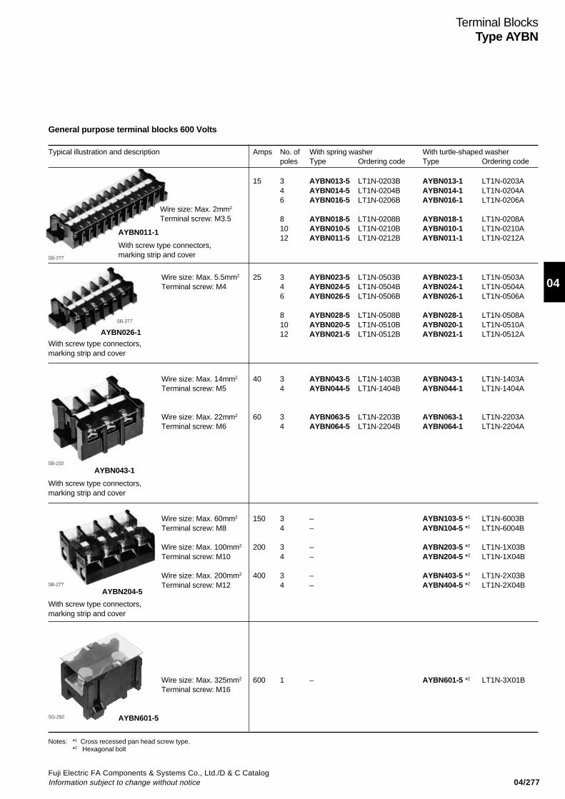
04/277Fuji Electric FA Components & Systems Co., Ltd./D & C CatalogInformation subject to change without notice
04
Terminal BlocksType AYBN
General purpose terminal blocks 600 Volts
Typical illustration and description Amps No. of With spring washer With turtle-shaped washerpoles Type Ordering code Type Ordering code
15 3 AYBN013-5 LT1N-0203B AYBN013-1 LT1N-0203A4 AYBN014-5 LT1N-0204B AYBN014-1 LT1N-0204A6 AYBN016-5 LT1N-0206B AYBN016-1 LT1N-0206A
8 AYBN018-5 LT1N-0208B AYBN018-1 LT1N-0208A10 AYBN010-5 LT1N-0210B AYBN010-1 LT1N-0210A12 AYBN011-5 LT1N-0212B AYBN011-1 LT1N-0212A
Wire size: Max. 5.5mm2 25 3 AYBN023-5 LT1N-0503B AYBN023-1 LT1N-0503ATerminal screw: M4 4 AYBN024-5 LT1N-0504B AYBN024-1 LT1N-0504A
6 AYBN026-5 LT1N-0506B AYBN026-1 LT1N-0506A
8 AYBN028-5 LT1N-0508B AYBN028-1 LT1N-0508A10 AYBN020-5 LT1N-0510B AYBN020-1 LT1N-0510A12 AYBN021-5 LT1N-0512B AYBN021-1 LT1N-0512A
With screw type connectors,marking strip and cover
Wire size: Max. 14mm2 40 3 AYBN043-5 LT1N-1403B AYBN043-1 LT1N-1403ATerminal screw: M5 4 AYBN044-5 LT1N-1404B AYBN044-1 LT1N-1404A
Wire size: Max. 22mm2 60 3 AYBN063-5 LT1N-2203B AYBN063-1 LT1N-2203ATerminal screw: M6 4 AYBN064-5 LT1N-2204B AYBN064-1 LT1N-2204A
With screw type connectors,marking strip and cover
Wire size: Max. 60mm2 150 3 – AYBN103-5 *1 LT1N-6003BTerminal screw: M8 4 – AYBN104-5 *1 LT1N-6004B
Wire size: Max. 100mm2 200 3 – AYBN203-5 *2 LT1N-1X03BTerminal screw: M10 4 – AYBN204-5 *2 LT1N-1X04B
Wire size: Max. 200mm2 400 3 – AYBN403-5 *2 LT1N-2X03BTerminal screw: M12 4 – AYBN404-5 *2 LT1N-2X04B
With screw type connectors,marking strip and cover
Wire size: Max. 325mm2 600 1 – AYBN601-5 *2 LT1N-3X01BTerminal screw: M16
Notes: *1 Cross recessed pan head screw type.*2 Hexagonal bolt
With screw type connectors,marking strip and cover
AYBN011-1
SB-277
AYBN026-1
SB-277
SB-232
SB-277
AYBN601-5SG-292
AYBN043-1
AYBN204-5
Wire size: Max. 2mm2
Terminal screw: M3.5
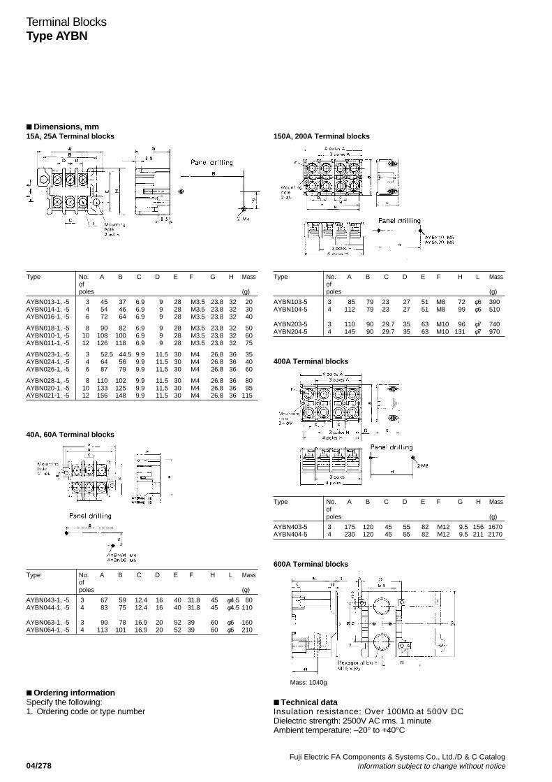
04/278Fuji Electric FA Components & Systems Co., Ltd./D & C Catalog
Information subject to change without notice
Terminal BlocksType AYBN
Dimensions, mm15A, 25A Terminal blocks
Type No. A B C D E F G H Massofpoles (g)
AYBN013-1, -5 3 45 37 6.9 9 28 M3.5 23.8 32 20AYBN014-1, -5 4 54 46 6.9 9 28 M3.5 23.8 32 30AYBN016-1, -5 6 72 64 6.9 9 28 M3.5 23.8 32 40
AYBN018-1, -5 8 90 82 6.9 9 28 M3.5 23.8 32 50AYBN010-1, -5 10 108 100 6.9 9 28 M3.5 23.8 32 60AYBN011-1, -5 12 126 118 6.9 9 28 M3.5 23.8 32 75
AYBN023-1, -5 3 52.5 44.5 9.9 11.5 30 M4 26.8 36 35AYBN024-1, -5 4 64 56 9.9 11.5 30 M4 26.8 36 40AYBN026-1, -5 6 87 79 9.9 11.5 30 M4 26.8 36 60
AYBN028-1, -5 8 110 102 9.9 11.5 30 M4 26.8 36 80AYBN020-1, -5 10 133 125 9.9 11.5 30 M4 26.8 36 95AYBN021-1, -5 12 156 148 9.9 11.5 30 M4 26.8 36 115
40A, 60A Terminal blocks
Type No. A B C D E F H L Massofpoles (g)
AYBN043-1, -5 3 67 59 12.4 16 40 31.8 45 φ4.5 80AYBN044-1, -5 4 83 75 12.4 16 40 31.8 45 φ4.5 110
AYBN063-1, -5 3 90 78 16.9 20 52 39 60 φ6 160AYBN064-1, -5 4 113 101 16.9 20 52 39 60 φ6 210
Ordering informationSpecify the following:1. Ordering code or type number
150A, 200A Terminal blocks
Type No. A B C D E F H L Massofpoles (g)
AYBN103-5 3 85 79 23 27 51 M8 72 φ6 390AYBN104-5 4 112 79 23 27 51 M8 99 φ6 510
AYBN203-5 3 110 90 29.7 35 63 M10 96 φ7 740AYBN204-5 4 145 90 29.7 35 63 M10 131 φ7 970
400A Terminal blocks
Type No. A B C D E F G H Massofpoles (g)
AYBN403-5 3 175 120 45 55 82 M12 9.5 156 1670AYBN404-5 4 230 120 45 55 82 M12 9.5 211 2170
600A Terminal blocks
Technical dataInsulation resistance: Over 1 0 0 M Ω at 500V DCDielectric strength: 2500V AC rms. 1 minuteAmbient temperature: –20° to +40°C
Mass: 1040g
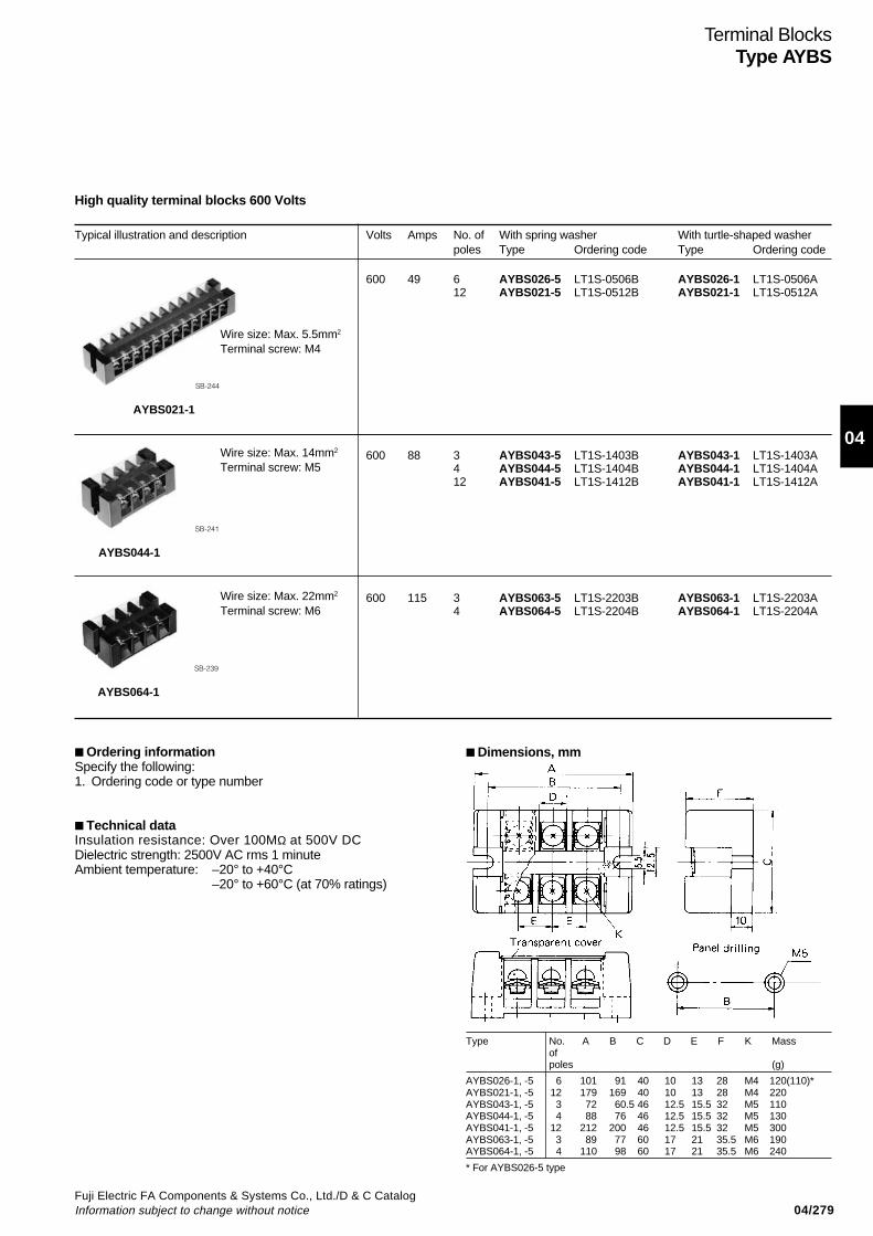
04/279Fuji Electric FA Components & Systems Co., Ltd./D & C CatalogInformation subject to change without notice
04
Terminal BlocksType AYBS
High quality terminal blocks 600 Volts
Typical illustration and description Volts Amps No. of With spring washer With turtle-shaped washerpoles Type Ordering code Type Ordering code
600 49 6 AYBS026-5 LT1S-0506B AYBS026-1 LT1S-0506A12 AYBS021-5 LT1S-0512B AYBS021-1 LT1S-0512A
600 88 3 AYBS043-5 LT1S-1403B AYBS043-1 LT1S-1403A4 AYBS044-5 LT1S-1404B AYBS044-1 LT1S-1404A12 AYBS041-5 LT1S-1412B AYBS041-1 LT1S-1412A
600 115 3 AYBS063-5 LT1S-2203B AYBS063-1 LT1S-2203A4 AYBS064-5 LT1S-2204B AYBS064-1 LT1S-2204A
Wire size: Max. 14mm2
Terminal screw: M5
Wire size: Max. 22mm2
Terminal screw: M6
Dimensions, mm
Type No. A B C D E F K Massofpoles (g)
AYBS026-1, -5 6 101 91 40 10 13 28 M4 120(110)*AYBS021-1, -5 12 179 169 40 10 13 28 M4 220AYBS043-1, -5 3 72 60.5 46 12.5 15.5 32 M5 110AYBS044-1, -5 4 88 76 46 12.5 15.5 32 M5 130AYBS041-1, -5 12 212 200 46 12.5 15.5 32 M5 300AYBS063-1, -5 3 89 77 60 17 21 35.5 M6 190AYBS064-1, -5 4 110 98 60 17 21 35.5 M6 240
* For AYBS026-5 type
Ordering informationSpecify the following:1. Ordering code or type number
Technical dataInsulation resistance: Over 1 0 0 M Ω at 500V DCDielectric strength: 2500V AC rms 1 minuteAmbient temperature: –20° to +40°C
–20° to +60°C (at 70% ratings)
Wire size: Max. 5.5mm2
Terminal screw: M4
AYBS021-1
SB-244
AYBS044-1
SB-241
AYBS064-1
SB-239
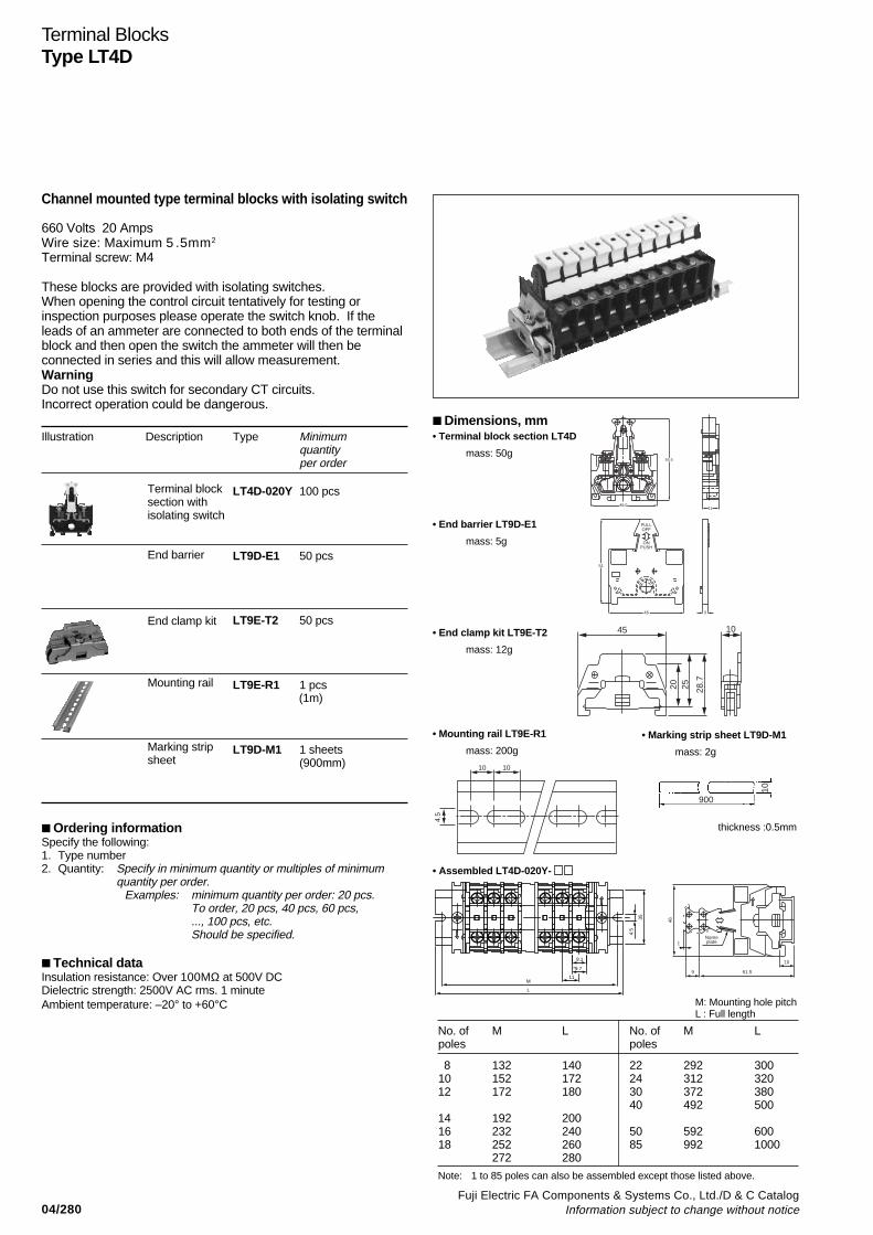
04/280Fuji Electric FA Components & Systems Co., Ltd./D & C Catalog
Information subject to change without notice
Terminal BlocksType LT4D
900
10
Channel mounted type terminal blocks with isolating switch
660 Volts 20 AmpsWire size: Maximum 5 . 5 m m 2Terminal screw: M4
These blocks are provided with isolating switches.When opening the control circuit tentatively for testing orinspection purposes please operate the switch knob. If theleads of an ammeter are connected to both ends of the terminalblock and then open the switch the ammeter will then beconnected in series and this will allow measurement.WarningDo not use this switch for secondary CT circuits.Incorrect operation could be dangerous.
Illustration Description Type Minimumquantityper order
LT4D-020Y 100 pcs
LT9D-E1 50 pcs
LT9E-T2 50 pcs
LT9E-R1 1 pcs
LT9D-M1 1 sheets(900mm)
Ordering informationSpecify the following:1. Type number2. Quantity: Specify in minimum quantity or multiples of minimum
quantity per order.Examples: minimum quantity per order: 20 pcs.
To order, 20 pcs, 40 pcs, 60 pcs,..., 100 pcs, etc.Should be specified.
Technical dataInsulation resistance: Over 1 0 0 M Ω at 500V DCDielectric strength: 2500V AC rms. 1 minuteAmbient temperature: –20° to +60°C
Terminal blocksection withisolating switch
End barrier
End clamp kit
Mounting rail
Marking stripsheet
1146.0
55.5
51
46 3
PULLOFF
ONPUSH
45
20 25 28.7
10
10 10
4.5
Dimensions, mm• Terminal block section LT4D
mass: 50g
• End clamp kit LT9E-T2
mass: 12g
• Assembled LT4D-020Y-
M: Mounting hole pitchL : Full length
• End barrier LT9D-E1
mass: 5g
No. of M L No. of M Lpoles poles
8 132 140 22 292 30010 152 172 24 312 32012 172 180 30 372 380
40 492 50014 192 20016 232 240 50 592 60018 252 260 85 992 1000
272 280
Note: 1 to 85 poles can also be assembled except those listed above.
• Mounting rail LT9E-R1
mass: 200g
• Marking strip sheet LT9D-M1
mass: 2g
35
L
9.1
11
4.5
M
*9.710
61.59
1Nameplate
46
thickness :0.5mm
(1m)

04/281Fuji Electric FA Components & Systems Co., Ltd./D & C CatalogInformation subject to change without notice
04
Terminal BlocksType SKT
With transparent cover power terminal blocks
600 Volts 50 to 200 AmpsWire size: 2 to 100 mm2
• Transparent terminal cover allows the wiring configuration tobe checked externally.
• Slotted hexagon head bolts that can be tightened withscrewdrivers or box wrenches are used for the terminals.
• The line side and load side are provided with hingedterminal covers to ensure safety and allow easiermaintenance and inspections.
• cUL approved, file No. E45457 SKT14A-3C to SKT100A-3C only.
SKT14A-3C
AF01-220
Types and ratings
Specifications Tightening torque
Type
SKT14A-3CSKT38A-3CSKT60A-3CSKT100A-3CSKT14A-3CGSKT38A-3CGSKT60A-3CGSKT100A-3CG
Wire size(mm2)2 to 142 to 3814 to 6030 to 1002 to 142 to 3814 to 6030 to 100
Mass(g) 300 310 450 730 440 450 6901120
Pole
3
3 + 1 (Earth terminal)
Rated insulationvoltage (V AC)
600
600
Rated continuouscurrent (A)
50100150200 50100150200
Insulation resistanceWithstand voltageAmbient temperatureHumidityFlammabilityTemperature rise
100MΩ or more (500V DC megger)2500V AC 1minute-20 to +55°C85%RH or lessUL94V-2 (Cover), UL94V-0 (Frame)45K or less (JIS C 2811)
Type
SKT14A-3CSKT14A-3CGSKT38A-3CSKT38A-3CGSKT60A-3CSKT60A-3CGSKT100A-3CSKT100A-3CG
Load side11.5–15.5
11.5–15.5
11.5–15.5
23–31
(M8)
(M8)
(M8)
(M10)
Cable pull-out (UL486A)min. force (N)
Min. cable222
222
311
311
(14AWG)
(14AWG)
(12AWG)
(12AWG)
Max. cable400
445
623
801
(8AWG)
(6AWG)
(4AWG)
(2AWG)
Line side5.1–6.5
5.1–6.5
11.5–15.5
23–31
Recommended tighteningtorque (N•m)
(M6)
(M6)
(M8)
(M10)
• Terminal blocks
• Connectors
Rated continuous current(A) 50100150200
Type
SKT14-SSKT38-SSKT60-SSKT100-S
Wire size(mm2 )2 to 142 to 3814 to 6030 to 100
Mass(g ) 52 55 80135
Rated voltage(V AC)
600
Ordering informationSpecify the following:1. Type number
Discontinued
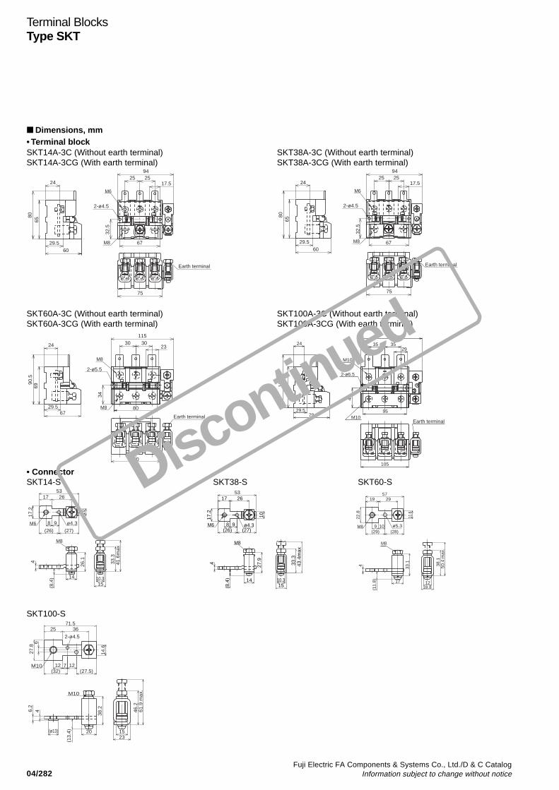
04/282Fuji Electric FA Components & Systems Co., Ltd./D & C Catalog
Information subject to change without notice
Terminal BlocksType SKT
Dimensions, mm• Terminal blockSKT14A-3C (Without earth terminal)SKT14A-3CG (With earth terminal)
SKT38A-3C (Without earth terminal)SKT38A-3CG (With earth terminal)
SKT60A-3C (Without earth terminal)SKT60A-3CG (With earth terminal)
SKT100A-3C (Without earth terminal)SKT100A-3CG (With earth terminal)
• ConnectorSKT14-S SKT38-S SKT60-S
65
24
29.560
252517.5
67
75
32.5
2-ø4.5
M8
M6
94
Earth terminal
80 80
Earth terminal
94
M6
M8
2-ø4.5
32.5
67
17.525 25
6029.5
24
6575
303023
80
90
24
69
6729.5
34
M8
M8
2-ø5.5
115
Earth terminal
90.5
89
24
29.579
3535
2-ø6.5
115.
5
29
105
43
M10
M10
Earth terminal
135
95
ø4.39M6
53
8
2617
17.2
10
(26) (27)
M8
41.6
max
33.3
1510.314
4
(8.4
)
26.1
53
ø4.39
M8
43.4
max
33.3
17.2
17 26
8M6
4
14 10.315
10
(26) (27)
(8.4
)
27.9
38.1
50.4
max
.
18.81217
M8
ø5.3M8 109
22.8
572919
11.6
(29) (28)
(11.
8)
33.14
SKT100-S
M10
61.9
max
.46
.2
2315
6.2
4
20
2-ø4.5
M10 1212
27.8
71.53625
6
14.6
(32) (27.5)
(ø13)
(13.
4)
38.2
7
Discontinued
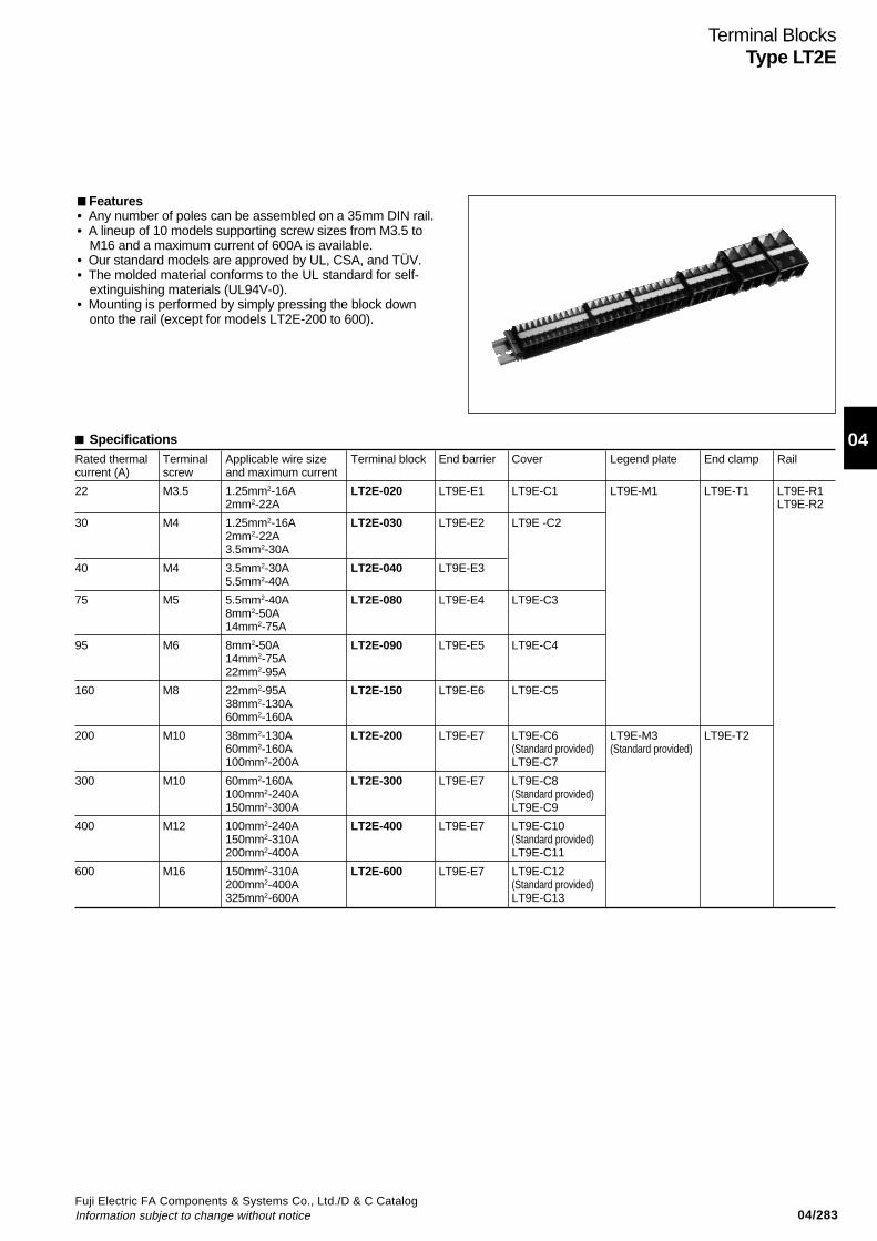
04/283Fuji Electric FA Components & Systems Co., Ltd./D & C CatalogInformation subject to change without notice
04
Terminal BlocksType LT2E
SpecificationsRated thermal Terminal Applicable wire size Terminal block End barrier Cover Legend plate End clamp Railcurrent (A) screw and maximum current
22 M3.5 1.25mm2-16A LT2E-020 LT9E-E1 LT9E-C1 LT9E-M1 LT9E-T1 LT9E-R12mm2-22A LT9E-R2
30 M4 1.25mm2-16A LT2E-030 LT9E-E2 LT9E -C22mm2-22A3.5mm2-30A
40 M4 3.5mm2-30A LT2E-040 LT9E-E35.5mm2-40A
75 M5 5.5mm2-40A LT2E-080 LT9E-E4 LT9E-C38mm2-50A14mm2-75A
95 M6 8mm2-50A LT2E-090 LT9E-E5 LT9E-C414mm2-75A22mm2-95A
160 M8 22mm2-95A LT2E-150 LT9E-E6 LT9E-C538mm2-130A60mm2-160A
200 M10 38mm2-130A LT2E-200 LT9E-E7 LT9E-C6 LT9E-M3 LT9E-T260mm2-160A (Standard provided) (Standard provided)100mm2-200A LT9E-C7
300 M10 60mm2-160A LT2E-300 LT9E-E7 LT9E-C8100mm2-240A (Standard provided)150mm2-300A LT9E-C9
400 M12 100mm2-240A LT2E-400 LT9E-E7 LT9E-C10150mm2-310A (Standard provided)200mm2-400A LT9E-C11
600 M16 150mm2-310A LT2E-600 LT9E-E7 LT9E-C12200mm2-400A (Standard provided)325mm2-600A LT9E-C13
Features• Any number of poles can be assembled on a 35mm DIN rail.• A lineup of 10 models supporting screw sizes from M3.5 to
M16 and a maximum current of 600A is available.• Our standard models are approved by UL, CSA, and TÜV.• The molded material conforms to the UL standard for self-
extinguishing materials (UL94V-0).• Mounting is performed by simply pressing the block down
onto the rail (except for models LT2E-200 to 600).
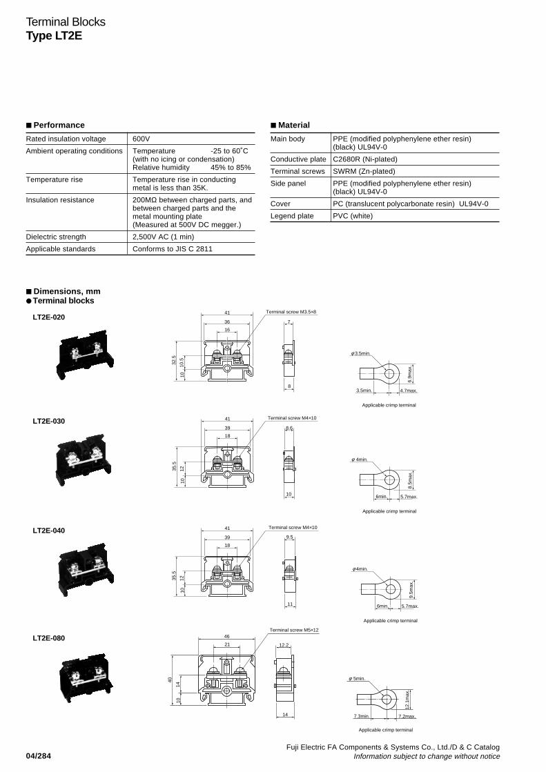
04/284Fuji Electric FA Components & Systems Co., Ltd./D & C Catalog
Information subject to change without notice
Terminal BlocksType LT2E
Performance
Rated insulation voltage 600V
Ambient operating conditions Temperature -25 to 60˚C(with no icing or condensation)Relative humidity 45% to 85%
Temperature rise Temperature rise in conductingmetal is less than 35K.
Insulation resistance 200MΩ between charged parts, andbetween charged parts and themetal mounting plate(Measured at 500V DC megger.)
Dielectric strength 2,500V AC (1 min)
Applicable standards Conforms to JIS C 2811
Material
Main body PPE (modified polyphenylene ether resin)(black) UL94V-0
Conductive plate C2680R (Ni-plated)
Terminal screws SWRM (Zn-plated)
Side panel PPE (modified polyphenylene ether resin)(black) UL94V-0
Cover PC (translucent polycarbonate resin) UL94V-0
Legend plate PVC (white)
Dimensions, mm Terminal blocks
LT2E-02041
8
7
Terminal screw M3.5×8
36
16
10.5
32.5
10
6.9m
ax.
4.7max.3.5min.
3.5min.
Applicable crimp terminal
φ
41
10
8.6
Terminal screw M4×10
39
18
1235.5
10
8.5m
ax.
5.7max.6min.
4min.
Applicable crimp terminal
φ
LT2E-030
41
11
9.539
18
1235.5
10
9.5m
ax.
5.7max.6min.
4min.
Terminal screw M4×10
Applicable crimp terminal
φ
LT2E-040
14
12.2
46
21
14
40
10
12.1
max
.
7.2max.7.3min.
5min.
Terminal screw M5×12
Applicable crimp terminal
φ
LT2E-080
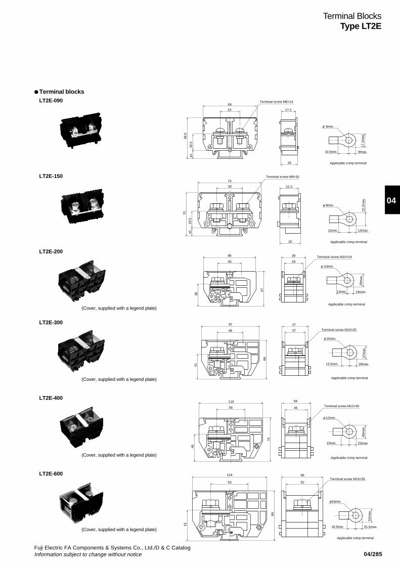
04/285Fuji Electric FA Components & Systems Co., Ltd./D & C CatalogInformation subject to change without notice
04
Terminal BlocksType LT2E
64
23
18.5
48.5
10
19
17.2
17.1
max
.
9max.10.5min.
6min.
Terminal screw M6×14
Applicable crimp terminal
φ
LT2E-090
74
3019
.5
51
10
25
22.3
22.2
max
.
12max.12min.
8min.
Terminal screw M8×16
Applicable crimp terminal
φ
LT2E-150
86
40
39
29
36
57
29m
ax.
14max.13min.
10min.
Terminal screw M10×24
Applicable crimp terminal
φ
LT2E-200
47
37
97
48
41
66
37m
ax.
18max.
10min.
13.5min.
Terminal screw M10×25
Applicable crimp terminal
φ
LT2E-300
110
56
46
74
46m
ax.
22max.
12min.
15min.
58
46 Terminal screw M12×30
Applicable crimp terminal
φ
LT2E-400
(Cover, supplied with a legend plate)
(Cover, supplied with a legend plate)
(Cover, supplied with a legend plate)
(Cover, supplied with a legend plate)
124
63
66
52
84
51
52m
ax.
25.5max.
16min.
18.5min.
Terminal screw M16×35
Applicable crimp terminal
φ
LT2E-600
Terminal blocks
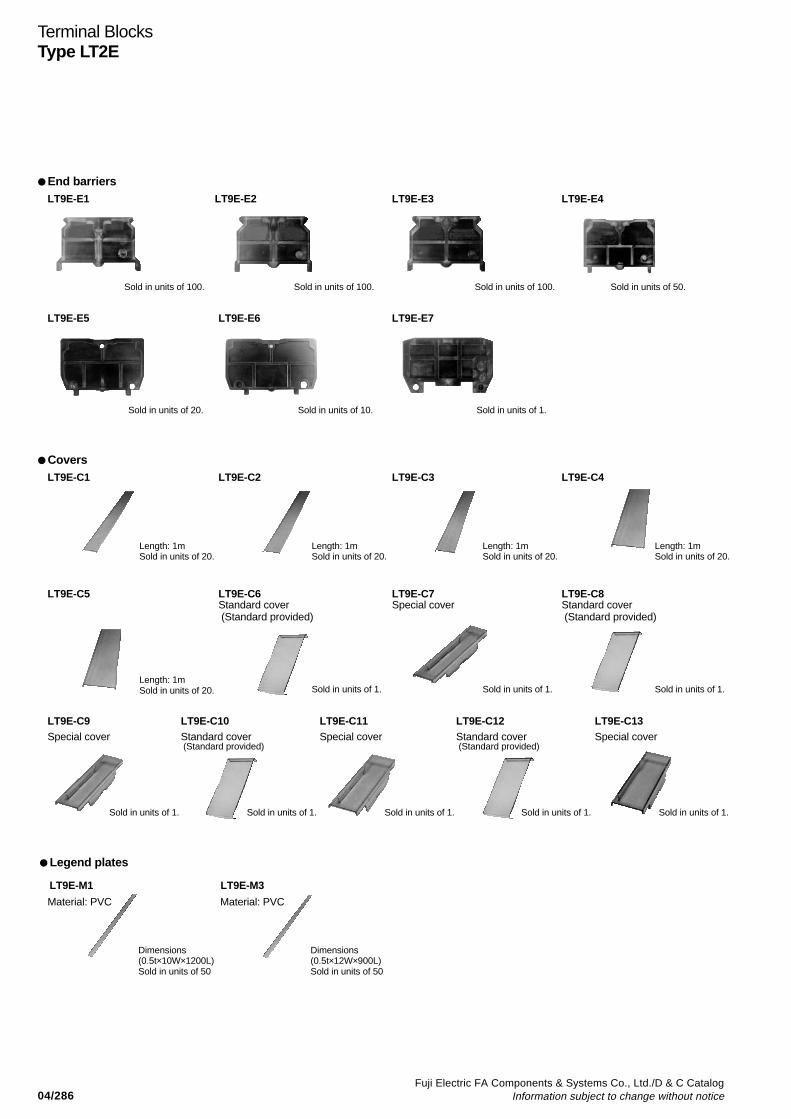
04/286Fuji Electric FA Components & Systems Co., Ltd./D & C Catalog
Information subject to change without notice
Terminal BlocksType LT2E
CoversLT9E-C1 LT9E-C2 LT9E-C3 LT9E-C4
LT9E-C5 LT9E-C6 LT9E-C7 LT9E-C8Standard cover Special cover Standard cover (Standard provided) (Standard provided)
LT9E-C9 LT9E-C10 LT9E-C11 LT9E-C12 LT9E-C13Special cover Standard cover Special cover Standard cover Special cover
(Standard provided) (Standard provided)
Length: 1mSold in units of 20.
Length: 1mSold in units of 20.
Length: 1mSold in units of 20.
Length: 1mSold in units of 20.
Length: 1mSold in units of 20. Sold in units of 1. Sold in units of 1. Sold in units of 1.
Sold in units of 1.Sold in units of 1.Sold in units of 1.Sold in units of 1.Sold in units of 1.
End barriersLT9E-E1 LT9E-E2 LT9E-E3 LT9E-E4
Sold in units of 100. Sold in units of 100. Sold in units of 100. Sold in units of 50.
LT9E-E5 LT9E-E6 LT9E-E7
Sold in units of 20. Sold in units of 10. Sold in units of 1.
Legend plates
LT9E-M1 LT9E-M3
Dimensions(0.5t×10W×1200L)Sold in units of 50
Dimensions(0.5t×12W×900L)Sold in units of 50
Material: PVC Material: PVC
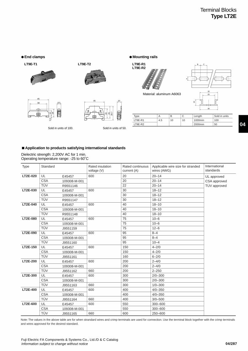
04/287Fuji Electric FA Components & Systems Co., Ltd./D & C CatalogInformation subject to change without notice
04
Terminal BlocksType LT2E
Application to products satisfying international standards
Dielectric strength: 2,200V AC for 1 min.Operating temperature range: -25 to 60˚C
LT2E-020
LT2E-030
LT2E-040
LT2E-080
LT2E-090
LT2E-150
LT2E-200
LT2E-300
LT2E-400
LT2E-600
ULCSATÜVULCSATÜVULCSATÜVULCSATÜVULCSATÜVULCSATÜVULCSATÜVULCSATÜVULCSATÜVULCSATÜV
600
600
600
600
600
600
600
660600
660600
660600
660
202022303030404040757575959595150150160200200200300300300400400400550550600
20–1420–1420–1418–1218–1218–1218–1018–1018–1010–610–612–68–48–410–44–2/04–2/06–2/02–4/02–4/02–2502/0–3002/0–3001/0–3004/0–3504/0–3503/0–500300–600300–600250–600
Note: The values in the above table are for when strandard wires and crimp terminals are used for connection. Use the terminal block together with the crimp terminals and wires approved for the desired standard.
UL approvedCSA approvedTUV approved
:
Type Standard Rated insulation voltage (V)
Rated continuous current (A)
Applicable wire size for stranded wires (AWG)
International standards
E45457109308-M-001R9551146E45457109308-M-001R9551147E45457109308-M-001R9551148E45457109308-M-001J9551159E45457109308-M-001J9551160E45457109308-M-001J9551161E45457109308-M-001J9551162E45457109308-M-001J9551163E45457109308-M-001J9551164E45457109308-M-001J9551165
End clamps Mounting rails
LT9E-T1 LT9E-T2 LT9E-R1LT9E-R2
Sold in units of 100. Sold in units of 50.
45
38 8.5
12 183.
5
1045
20 28.7
25
B C
A
35
25
30
10
Type
LT9E-R1
LT9E-R2
A
4.5
B
10
C
10
Length
1000mm
2000mm
Sold in units
100
50
Material: aluminum A6063
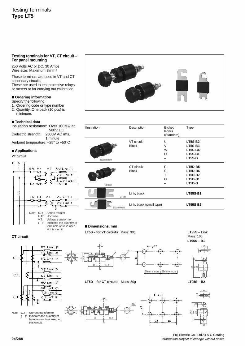
04/288Fuji Electric Co., Ltd./D & C Catalog
Information subject to change without notice
Testing TerminalsType LT5
V.
V.
Note: S.R.: Series resistorH.F.: H.V. fuseV.T.: Voltage transformer( ): Indicates the quantity of
terminals or links usedat this circuit.
12
50mm or more 50mm or more
12
21 Ø19
28 31.7
Ø12
21 Ø19
43 31.7
Ø12
5
20
1
9184056
5
20
16
12
184047.2
Testing terminals for VT, CT circuit –For panel mounting
250 Volts AC or DC, 30 AmpsWire size: Maximum 8 m m 2
These terminals are used in VT and CTsecondary circuits.These are used to test protective relaysor meters or for carrying out calibration.
Ordering informationSpecify the following:1. Ordering code or type number2. Quantity: One pack (10 pcs) is
minimum.
Technical dataInsulation resistance: Over 100MΩ at
500V DCDielectric strength: 2000V AC rms.
1 minuteAmbient temperature: –25° to +50°C
ApplicationsVT circuit
CT circuit
Note: C.T.: Current transformer( ): Indicates the quantity of
terminals or links used atthis circuit.
Illustration Description Etched Typeletters(Standard)
VT circuit U LT5S-B2Black V LT5S-B3
W LT5S-B4O LT5S-B1– LT5S-B
CT circuit R LT5D-B5Black S LT5D-B6
T LT5D-B7O LT5D-B1– LT5D-B
Link, black LT95S-B1
Link, black (small type) LT95S-B2
SDO-0095M
SB-260
Q-482
SDO-0099M
Dimensions, mm
LT5S – for VT circuits Mass: 30g
LT5D – for CT circuits Mass: 50g
LT95S – LinkMass: 10g
LT95S – B2
LT95S – B1
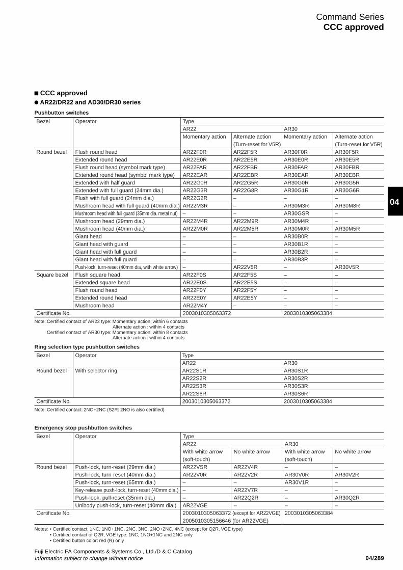
04/289Fuji Electric FA Components & Systems Co., Ltd./D & C CatalogInformation subject to change without notice
Command SeriesCCC approved
04
CCC approved AR22/DR22 and AD30/DR30 series
Bezel Operator TypeAR22 AR30Momentary action Alternate action Momentary action Alternate action
(Turn-reset for V5R) (Turn-reset for V5R)Round bezel Flush round head AR22F0R AR22F5R AR30F0R AR30F5R
Extended round head AR22E0R AR22E5R AR30E0R AR30E5RFlush round head (symbol mark type) AR22FAR AR22FBR AR30FAR AR30FBRExtended round head (symbol mark type) AR22EAR AR22EBR AR30EAR AR30EBRExtended with half guard AR22G0R AR22G5R AR30G0R AR30G5RExtended with full guard (24mm dia.) AR22G3R AR22G8R AR30G1R AR30G6RFlush with full guard (24mm dia.) AR22G2R – – –Mushroom head with full guard (40mm dia.) AR22M3R – AR30M3R AR30M8RMushroom head with full guard (35mm dia. metal nut) – – AR30GSR –Mushroom head (29mm dia.) AR22M4R AR22M9R AR30M4R –Mushroom head (40mm dia.) AR22M0R AR22M5R AR30M0R AR30M5RGiant head – – AR30B0R –Giant head with guard – – AR30B1R –Giant head with full guard – – AR30B2R –Giant head with full guard – – AR30B3R –Push-lock, turn-reset (40mm dia, with white arrow) – AR22V5R – AR30V5R
Square bezel Flush square head AR22F0S AR22F5S – –Extended square head AR22E0S AR22E5S – –Flush round head AR22F0Y AR22F5Y – –Extended round head AR22E0Y AR22E5Y – –Mushroom head AR22M4Y – – –
Certificate No. 2003010305063372 2003010305063384
Note: Certified contact of AR22 type: Momentary action: within 6 contacts Alternate action : within 4 contacts
Certified contact of AR30 type: Momentary action: within 8 contacts Alternate action : within 4 contacts
Pushbutton switches
Bezel Operator TypeAR22 AR30
Round bezel With selector ring AR22S1R AR30S1RAR22S2R AR30S2RAR22S3R AR30S3RAR22S6R AR30S6R
Certificate No. 2003010305063372 2003010305063384
Note: Certified contact: 2NO+2NC (S2R: 2NO is also certified)
Ring selection type pushbutton switches
Bezel Operator TypeAR22 AR30With white arrow No white arrow With white arrow No white arrow(soft-touch) (soft-touch)
Round bezel Push-lock, turn-reset (29mm dia.) AR22VSR AR22V4R – –Push-lock, turn-reset (40mm dia.) AR22V0R AR22V2R AR30V0R AR30V2RPush-lock, turn-reset (65mm dia.) – – AR30V1R –Key-release push-lock, turn-reset (40mm dia.) – AR22V7R – –Push-look, pull-reset (35mm dia.) – AR22Q2R – AR30Q2RUnibody push-lock, turn-reset (40mm dia.) AR22VGE – – –
Certificate No. 2003010305063372 (except for AR22VGE) 20030103050633842005010305156646 (for AR22VGE)
Notes: • Certified contact: 1NC, 1NO+1NC, 2NC, 3NC, 2NO+2NC, 4NC (except for Q2R, VGE type)• Certified contact of Q2R, VGE type: 1NC, 1NO+1NC and 2NC only• Certified button color: red (R) only
Emergency stop pushbutton switches

04/290Fuji Electric FA Components & Systems Co., Ltd./D & C Catalog
Information subject to change without notice
Command SeriesCCC approved
Bezel Operator TypeAR22 AR30Momentary Alternate Momentary Alternate
Round bezel Flush round head AR22F0L AR22F5L – –Extended round head AR22E0L AR22E5L AR30E0L AR30E5LMushroom head (29mm dia.) AR22M4L AR22M9L – –Mushroom head (40mm dia.) AR22M0L AR22M5L – –Extended with transparent full guard (24mm dia.) AR22G4L AR22G9L AR30G4L AR30G9LExtended with full guard (24mm dia. with openings) AR22G2L AR22G7L AR30G2L AR30G7LExtended with full guard (24mm dia.) AR22G1L AR22G6L AR30G3L AR30G8LPush-lock, turn-reset – – – AR30V5L(40mm dia. with white arrow)
Square bezel Flush square head AR22F0M AR22F5M – –Extended square head AR22E0M AR22E5M – –Flush round head AR22F0P AR22F5P – –Extended round head AR22E0P AR22E5P – –Mushroom head AR22M4P – – –
Certificate No. 2003010305063372 2003010305063384Specifications · Contact
Without transformerMomentary action: within 5 contactsAlternate action: within 3 contacts
With transformerMomentary action: within 3 contactsAlternate action: within 2 contacts
· Color of buttonGreen, red, white, yellow, orange, blue
· Light sourceLED lamp, incandescent lamp
· Operating voltage of lampWithout transformer
LED: 6V AC, 6V DC, 12V AC/DCIncandescent lamp: 5.5V AC/DC, 20V AC/DCLED, incandescent lamp: 15V AC/DC, 24V AC/DC
With transformerLED, incandescent lamp: 100-110V AC, 115-127V AC, 200-220V AC,
230-254V AC, 350-380V AC, 400-440V AC,480V AC, 500-550V AC
· Contact Without transformer
Momentary action: within 6 contactsAlternate action: within 3 contacts
With transformerMomentary action: within 4 contactsAlternate action: within 2 contacts
Illuminated pushbutton switches
Bezel Operator TypeAR22 AR30With white arrow No white arrow With white arrow No white arrow(soft-touch) (soft-touch)
Round bezel Push-lock, turn-reset (29mm dia.) AR22VSL – – –Push-lock, turn-reset (40mm dia.) AR22V0L AR22V2L AR30V0L AR30V2LPush-lock, turn-reset (40mm dia. transparent in all colors) AR22VDL AR22VAL – –Unibody push-lock, turn-reset (40mm dia.) AR22VGF – – –
Certificate No. 2003010305063372 (except for AR22VGF) 20030103050633842005010305156646 (for AR22VGF)
Notes: • Certified contact without transformer: 1NC, 1NO+1NC, 2NC, 3NC (except for VGF type)• Certified contact with transformer: 1NC, 1NO+1NC, 2NC (except for VGF type)• Certified contact of VGF type: 1NC, 1NO+1NC and 2NC only, • Certified lamp voltage of VGF type: LED lamp: 24V AC/DC, neon lamp: 110, 120, 220, 240V AC• Certified button color: red (R) only
Emergency stop illuminated pushbutton switches
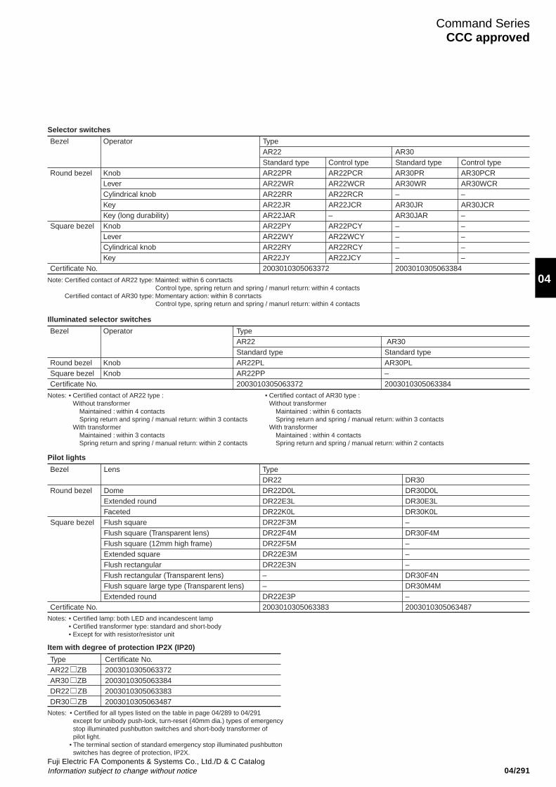
04/291Fuji Electric FA Components & Systems Co., Ltd./D & C CatalogInformation subject to change without notice
Command SeriesCCC approved
04
Bezel Operator TypeAR22 AR30Standard type Standard type
Round bezel Knob AR22PL AR30PLSquare bezel Knob AR22PP –Certificate No. 2003010305063372 2003010305063384
Notes: • Certified contact of AR22 type : Without transformer
Maintained : within 4 contactsSpring return and spring / manual return: within 3 contacts
With transformerMaintained : within 3 contactsSpring return and spring / manual return: within 2 contacts
• Certified contact of AR30 type : Without transformer
Maintained : within 6 contactsSpring return and spring / manual return: within 3 contacts
With transformerMaintained : within 4 contactsSpring return and spring / manual return: within 2 contacts
Illuminated selector switches
Bezel Lens TypeDR22 DR30
Round bezel Dome DR22D0L DR30D0LExtended round DR22E3L DR30E3LFaceted DR22K0L DR30K0L
Square bezel Flush square DR22F3M –Flush square (Transparent lens) DR22F4M DR30F4MFlush square (12mm high frame) DR22F5M –Extended square DR22E3M –Flush rectangular DR22E3N –Flush rectangular (Transparent lens) – DR30F4NFlush square large type (Transparent lens) – DR30M4MExtended round DR22E3P –
Certificate No. 2003010305063383 2003010305063487
Notes: • Certified lamp: both LED and incandescent lamp• Certified transformer type: standard and short-body• Except for with resistor/resistor unit
Pilot lights
Type Certificate No.AR22 ZB 2003010305063372AR30 ZB 2003010305063384DR22 ZB 2003010305063383DR30 ZB 2003010305063487
Notes: • Certified for all types listed on the table in page 04/289 to 04/291 except for unibody push-lock, turn-reset (40mm dia.) types of emergency stop illuminated pushbutton switches and short-body transformer of pilot light. • The terminal section of standard emergency stop illuminated pushbutton switches has degree of protection, IP2X.
Item with degree of protection IP2X (IP20)
Bezel Operator TypeAR22 AR30Standard type Control type Standard type Control type
Round bezel Knob AR22PR AR22PCR AR30PR AR30PCRLever AR22WR AR22WCR AR30WR AR30WCRCylindrical knob AR22RR AR22RCR – –Key AR22JR AR22JCR AR30JR AR30JCRKey (long durability) AR22JAR – AR30JAR –
Square bezel Knob AR22PY AR22PCY – –Lever AR22WY AR22WCY – –Cylindrical knob AR22RY AR22RCY – –Key AR22JY AR22JCY – –
Certificate No. 2003010305063372 2003010305063384
Note: Certified contact of AR22 type: Mainted: within 6 conrtactsControl type, spring return and spring / manurl return: within 4 contacts
Certified contact of AR30 type: Momentary action: within 8 conrtactsControl type, spring return and spring / manurl return: within 4 contacts
Selector switches
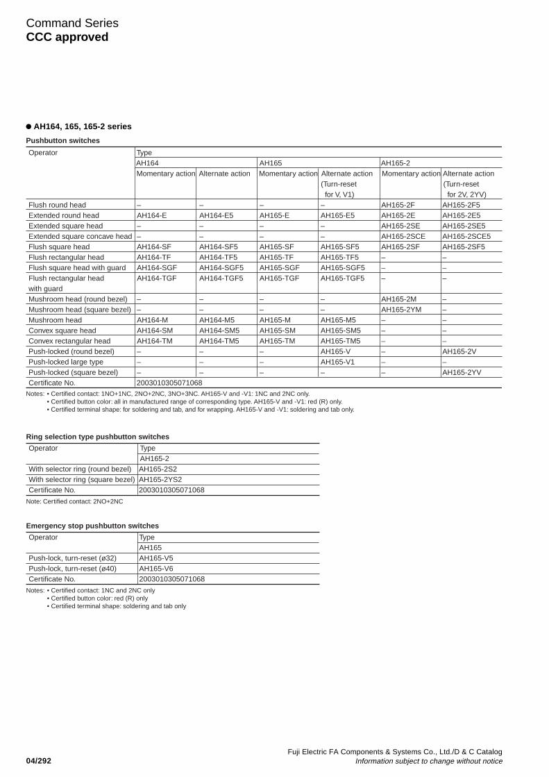
04/292Fuji Electric FA Components & Systems Co., Ltd./D & C Catalog
Information subject to change without notice
Command SeriesCCC approved
AH164, 165, 165-2 series
Operator TypeAH164 AH165 AH165-2Momentary action Alternate action Momentary action Alternate action Momentary action Alternate action
(Turn-reset (Turn-reset for V, V1) for 2V, 2YV)
Flush round head – – – – AH165-2F AH165-2F5Extended round head AH164-E AH164-E5 AH165-E AH165-E5 AH165-2E AH165-2E5Extended square head – – – – AH165-2SE AH165-2SE5Extended square concave head – – – – AH165-2SCE AH165-2SCE5Flush square head AH164-SF AH164-SF5 AH165-SF AH165-SF5 AH165-2SF AH165-2SF5Flush rectangular head AH164-TF AH164-TF5 AH165-TF AH165-TF5 – –Flush square head with guard AH164-SGF AH164-SGF5 AH165-SGF AH165-SGF5 – –Flush rectangular head AH164-TGF AH164-TGF5 AH165-TGF AH165-TGF5 – –with guard Mushroom head (round bezel) – – – – AH165-2M –Mushroom head (square bezel) – – – – AH165-2YM –Mushroom head AH164-M AH164-M5 AH165-M AH165-M5 – –Convex square head AH164-SM AH164-SM5 AH165-SM AH165-SM5 – –Convex rectangular head AH164-TM AH164-TM5 AH165-TM AH165-TM5 – –Push-locked (round bezel) – – – AH165-V – AH165-2VPush-locked large type – – – AH165-V1 – –Push-locked (square bezel) – – – – – AH165-2YVCertificate No. 2003010305071068
Notes: • Certified contact: 1NO+1NC, 2NO+2NC, 3NO+3NC. AH165-V and -V1: 1NC and 2NC only.• Certified button color: all in manufactured range of corresponding type. AH165-V and -V1: red (R) only.• Certified terminal shape: for soldering and tab, and for wrapping. AH165-V and -V1: soldering and tab only.
Pushbutton switches
Operator TypeAH165-2
With selector ring (round bezel) AH165-2S2With selector ring (square bezel) AH165-2YS2Certificate No. 2003010305071068
Note: Certified contact: 2NO+2NC
Ring selection type pushbutton switches
Notes: • Certified contact: 1NC and 2NC only• Certified button color: red (R) only• Certified terminal shape: soldering and tab only
Operator TypeAH165
Push-lock, turn-reset (ø32) AH165-V5Push-lock, turn-reset (ø40) AH165-V6Certificate No. 2003010305071068
Emergency stop pushbutton switches

04/293Fuji Electric FA Components & Systems Co., Ltd./D & C CatalogInformation subject to change without notice
Command SeriesCCC approved
04
Lens TypeAH164 AH165 AH165-2
Flush round – – AH165-2ZExtended round AH164-Z AH165-Z AH165-2ZEExtended square – – AH165-2SZEFlush square AH164-ZS AH165-ZS AH165-2SZFlush rectangular AH164-ZT AH165-ZT –Certificate No. 2003010305071044
Notes: • Certified lamp: LED, incandescent lamp and neon• Certified operating lamp voltage: 6, 12 and 24V DC (LED)/ 5, 12, 15 and 24V AC/DC (incandescent lamp)/ 110, 120, 220 and 240V AC (neon) /110, 220V AC (LED and incandesent lamps with transformer)• The spot LED type have not been approved.
Pilot lights
Operator Typeknob (round bezel) AH165-2PLCertificate No. 2003010305071068
Notes: • Certified contact: 1NO+1NC, 2NO+2NC• Certified operating lamp voltage: 6, 12 and 24V DC (LED)/ 5, 12, 15
and 24V AC/DC (incandescent lamp)
Illuminated selector switches
Operator TypeAH164 AH165 AH165-2Momentary action Alternate action Momentary action Alternate action Momentary action Alternate action
(Turn-reset for 2VL, 2YVL)
Flush round head – – – – AH165-2FL AH165-2FL5Extended round head AH164-L AH164-L5 AH165-L AH165-L5 AH165-2EL AH165-2EL5Extended square head – – – – AH165-2SEL AH165-2SEL5Concave square head – – – – AH165-2SCL AH165-2SCL5Flush square head AH164-SL AH164-SL5 AH165-SL AH165-SL5 AH165-2SFL AH165-2SFL5Flush rectangular head AH164-TL AH164-TL5 AH165-TL AH165-TL5 – –Flush square head with guard AH164-SGL AH164-SGL5 AH165-SGL AH165-SGL5 – –Flush rectangular head AH164-TGL AH164-TGL5 AH165-TGL AH165-TGL5 – –with guard Mushroom head (round bezel) – – – – AH165-2ML –Mushroom head (square bezel) – – – – AH165-2YML –Push-locked (round bezel) – – – – – AH165-2VLPush-locked (square bezel) – – – – – AH165-2YVLCertificate No. 2003010305071068
Notes: • Certified contact: 1NO+1NC, 2NO+2NC, 3NO+3NC• Certified terminal shape: for soldering and tab, and for wrapping.• Certified lamp: LED, incandescent lamp and neon
Illuminated pushbutton switches
• Certified operating lamp voltage: 6, 12 and 24V DC (LED)/ 5, 12, 15 and 24V AC/DC (incandescent lamp) / 110, 120, 220 and 240V AC (neon) /110, 220V AC (LED and incandesent lamps with transformer)• The spot LED type have not been approved.
Operator TypeAH164 AH165 AH165-2
Knob (round bezel) – – AH165-2PKnob (rectangular bezel) AH164-P AH165-P –Knob (square bezel) AH164-SP AH165-SP AH165-2YPKey (round bezel) – – AH165-2JKey (rectangular bezel) AH164-J AH165-J –Key (square bezel) AH164-SJ AH165-SJ AH165-2YJKey, 45-degree notch AH164-JK AH165-JK –(rectangular bezel)Certificate No. 2003010305071068
Notes: • Certified contact: 1NO+1NC, 2NO+2NC, 3NO+3NC• Certified terminal shape: for soldering and tab, and for wrapping
Selector switches (Standard)
Operator TypeKey (rectangular bezel) AH165-JM2Key (round bezel) AH165-RJM2Certificate No. 2003010305071068
Notes: • Certified contact: 1NO+1NC, 2NO+2NC• Certified position quantity: 2-position only.
Certified returning method: maintained only.
Selector switches (Direct opening action)
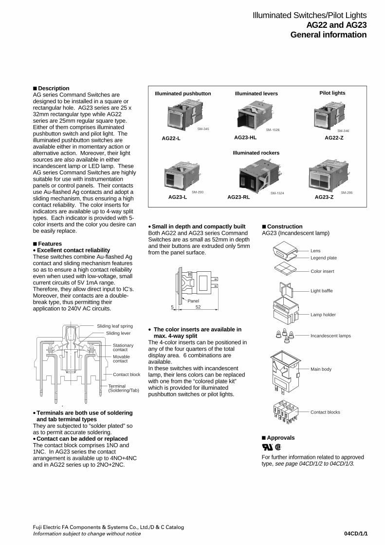
04CD/1/1Fuji Electric FA Components & Systems Co., Ltd./D & C CatalogInformation subject to change without notice
Illuminated Switches/Pilot LightsAG22 and AG23
General information
DescriptionAG series Command Switches aredesigned to be installed in a square orrectangular hole. AG23 series are 25 x32mm rectangular type while AG22series are 25mm regular square type.Either of them comprises illuminatedpushbutton switch and pilot light. Theilluminated pushbutton switches areavailable either in momentary action oralternative action. Moreover, their lightsources are also available in eitherincandescent lamp or LED lamp. TheseAG series Command Switches are highlysuitable for use with instrumentationpanels or control panels. Their contactsuse Au-flashed Ag contacts and adopt asliding mechanism, thus ensuring a highcontact reliability. The color inserts forindicators are available up to 4-way splittypes. Each indicator is provided with 5-color inserts and the color you desire canbe easily replace.
Features• Excellent contact reliabilityThese switches combine Au-flashed Agcontact and sliding mechanism featuresso as to ensure a high contact reliabilityeven when used with low-voltage, smallcurrent circuits of 5V 1mA range.Therefore, they allow direct input to IC’s.Moreover, their contacts are a double-break type, thus permitting theirapplication to 240V AC circuits.
•Small in depth and compactly builtBoth AG22 and AG23 series CommandSwitches are as small as 52mm in depthand their buttons are extruded only 5mmfrom the panel surface.
Pilot lights
SM-295
• The color inserts are available inmax. 4-way split
The 4-color inserts can be positioned inany of the four quarters of the totaldisplay area. 6 combinations areavailable.In these switches with incandescentlamp, their lens colors can be replacedwith one from the “colored plate kit”which is provided for illuminatedpushbutton switches or pilot lights.
•Terminals are both use of solderingand tab terminal types
They are subjected to “solder plated” soas to permit accurate soldering.•Contact can be added or replacedThe contact block comprises 1NO and1NC. In AG23 series the contactarrangement is available up to 4NO+4NCand in AG22 series up to 2NO+2NC.
SM-345
AG22-L
AG23-LSM-293
SM-1526 SM-346
AG22-Z
SM-1524AG23-Z
Sliding leaf spring
Sliding lever
Stationarycontact
Movablecontact
Contact block
Terminal(Soldering/Tab)
Panel525
Lens
Legend plate
Color insert
Light baffle
Lamp holder
Incandescent lamps
Main body
Contact blocks
Illuminated pushbutton Illuminated levers
Illuminated rockers
ConstructionAG23 (Incandescent lamp)
Approvals
For further information related to approvedtype, see page 04CD/1/2 to 04CD/1/3.
R
AG23-RL
AG23-HL
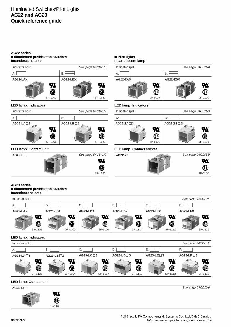
04CD/1/2Fuji Electric FA Components & Systems Co., Ltd./D & C Catalog
Information subject to change without notice
Indicator split See page 04CD/1/8
A: B:
AG22-LAX AG22-LBX
SP-1099 SP-1120
R R
Illuminated Switches/Pilot LightsAG22 and AG23Quick reference guide
AG22 series Illuminated pushbutton switchesIncandescent lamp
LED lamp: Indicators
Indicator split See page 04CD/1/9
A: B:
AG22-LA 3 AG22-LB 3
SP-1101 SP-1121
R R
See page 04CD/1/9AG22-L
SP-1100
R
LED lamp: Contact unit
Indicator split See page 04CD/1/8
A: B:
AG22-ZAX AG22-ZBX
SP-1099 SP-1120
R R
Pilot lightsIncandescent lamp
LED lamp: Indicators
Indicator split See page 04CD/1/9
A: B:
AG22-ZA 3 AG22-ZB 3
SP-1101 SP-1121
R R
See page 04CD/1/9AG22-Z6
SP-1100
R
LED lamp: Contact socket
AG23 series Illuminated pushbutton switchesIncandescent lamp
Indicator split See page 04CD/1/8
A:
AG23-LAX
SP-1102
B:
AG23-LBX
SP-1105
C:
AG23-LCX
SP-1116
D:
AG23-LDX
SP-1114
E:
AG23-LEX
SP-1112
F:
AG23-LFX
SP-1118
R R R R R R
LED lamp: Indicators
Indicator split See page 04CD/1/9
A:
AG23-LA 3
SP-1122
B:
AG23-LB 3
SP-1104
C:
AG23-LC 3
SP-1117
D:
AG23-LD 3
SP-1115
E:
AG23-LE 3
SP-1113
F:
AG23-LF 3
SP-1119
R R R R R R
LED lamp: Contact unit
See page 04CD/1/9AG23-L
SP-1103
R

04CD/1/3Fuji Electric FA Components & Systems Co., Ltd./D & C CatalogInformation subject to change without notice
Illuminated Switches/Pilot LightsAG22 and AG23
Quick reference guide
Pilot lightsIncandescent lamp
Indicator split See page 04CD/1/8
A:
AG23-ZAX
SP-1102
B:
AG23-ZBX
SP-1105
C:
AG23-ZCX
SP-1116
D:
AG23-ZDX
SP-1114
E:
AG23-ZEX
SP-1112
F:
AG23-ZFX
SP-1118
R R R R R R
LED lamp: Indicators
Indicator split See page 04CD/1/9
A:
AG23-ZA 3
SP-1112
B:
AG23-ZB 3
SP-1104
C:
AG23-ZC 3
SP-1117
D:
AG23-ZD 3
SP-1115
E:
AG23-ZE 3
SP-1113
F:
AG23-ZF 3
SP-1119
R R R R R R
Illuminated lever switches
See page 04CD/1/9AG23-Z6
SP-1103
R
LED lamp: Socket
2-position 3-position See page 04CD/1/10
Mainteined,Spring return
AG23-HL
SP-1108
Spring/manualreturn
AG23-HL
SP-1108
2-position 3-position See page 04CD/1/11
Mainteined,Spring return
AG23-RL
SP-1107
Spring/manualreturn
AG23-RL
SP-1107
Illuminated rocker switches
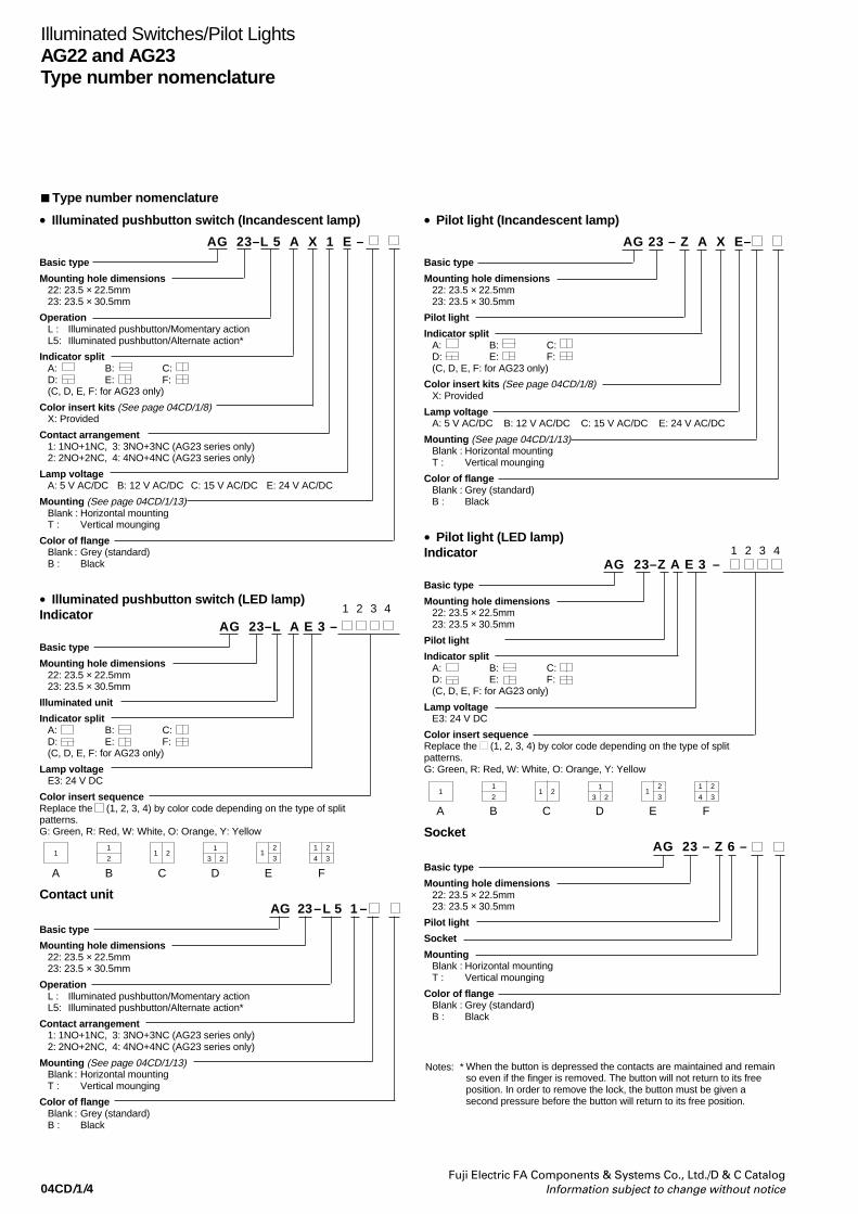
04CD/1/4Fuji Electric FA Components & Systems Co., Ltd./D & C Catalog
Information subject to change without notice
Illuminated Switches/Pilot LightsAG22 and AG23Type number nomenclature
• Illuminated pushbutton switch (Incandescent lamp)
AG 23–L 5 A X 1 E –
Basic type
Mounting hole dimensions22: 23.5 × 22.5mm23: 23.5 × 30.5mm
OperationL : Illuminated pushbutton/Momentary actionL5: Illuminated pushbutton/Alternate action*
Indicator splitA: B: C:D: E: F:(C, D, E, F: for AG23 only)
Color insert kits (See page 04CD/1/8)X: Provided
Contact arrangement1: 1NO+1NC, 3: 3NO+3NC (AG23 series only)2: 2NO+2NC, 4: 4NO+4NC (AG23 series only)
Lamp voltageA: 5 V AC/DC B: 12 V AC/DC C: 15 V AC/DC E: 24 V AC/DC
Mounting (See page 04CD/1/13)Blank : Horizontal mountingT : Vertical mounging
Color of flangeBlank : Grey (standard)B : Black
• Illuminated pushbutton switch (LED lamp)Indicator
AG 23–L A E 3 –
Basic type
Mounting hole dimensions22: 23.5 × 22.5mm23: 23.5 × 30.5mm
Illuminated unit
Indicator splitA: B: C:D: E: F:(C, D, E, F: for AG23 only)
Lamp voltageE3: 24 V DC
Color insert sequenceReplace the (1, 2, 3, 4) by color code depending on the type of splitpatterns.G: Green, R: Red, W: White, O: Orange, Y: Yellow
A B C D E F
Contact unitAG 23–L 5 1 –
Basic type
Mounting hole dimensions22: 23.5 × 22.5mm23: 23.5 × 30.5mm
OperationL : Illuminated pushbutton/Momentary actionL5: Illuminated pushbutton/Alternate action*
Contact arrangement1: 1NO+1NC, 3: 3NO+3NC (AG23 series only)2: 2NO+2NC, 4: 4NO+4NC (AG23 series only)
Mounting (See page 04CD/1/13)Blank : Horizontal mountingT : Vertical mounging
Color of flangeBlank : Grey (standard)B : Black
• Pilot light (Incandescent lamp)
AG 23 – Z A X E–
Basic type
Mounting hole dimensions22: 23.5 × 22.5mm23: 23.5 × 30.5mm
Pilot light
Indicator splitA: B: C:D: E: F:(C, D, E, F: for AG23 only)
Color insert kits (See page 04CD/1/8)X: Provided
Lamp voltageA: 5 V AC/DC B: 12 V AC/DC C: 15 V AC/DC E: 24 V AC/DC
Mounting (See page 04CD/1/13)Blank : Horizontal mountingT : Vertical mounging
Color of flangeBlank : Grey (standard)B : Black
• Pilot light (LED lamp)Indicator
AG 23–Z A E 3 –
Basic type
Mounting hole dimensions22: 23.5 × 22.5mm23: 23.5 × 30.5mm
Pilot light
Indicator splitA: B: C:D: E: F:(C, D, E, F: for AG23 only)
Lamp voltageE3: 24 V DC
Color insert sequenceReplace the (1, 2, 3, 4) by color code depending on the type of splitpatterns.G: Green, R: Red, W: White, O: Orange, Y: Yellow
A B C D E F
SocketAG 23 – Z 6 –
Basic type
Mounting hole dimensions22: 23.5 × 22.5mm23: 23.5 × 30.5mm
Pilot light
Socket
MountingBlank : Horizontal mountingT : Vertical mounging
Color of flangeBlank : Grey (standard)B : Black
1 2 3 4
1 2 3 4
1
21 1 2
1
3 21
2
3
1 2
4 3
1
21 1 2
1
3 21
2
3
1 2
4 3
When the button is depressed the contacts are maintained and remainso even if the finger is removed. The button will not return to its freeposition. In order to remove the lock, the button must be given asecond pressure before the button will return to its free position.
Type number nomenclature
Notes: *

04CD/1/5Fuji Electric FA Components & Systems Co., Ltd./D & C CatalogInformation subject to change without notice
Illuminated Switches/Pilot LightsAG22 and AG23
Type number nomenclature
• Illuminated lever switch and illuminated rocker switch
AG 23–RL 2 R 4 E 3–1 /
Basic type
Mounting hole dimensions
23: 23.5 30.5mm
Operator shapeHL: Lever typeRL: Rocker type
Operation2: 2-position, maintained0: 2-position, spring return (Upper to lower)3: 3-position, maintained1: 3-position, spring return (To center)6: 3-position, maintained and spring return
(Upper to center)
Operator colorG: GreenR: RedW: WhiteY: YellowO: OrangeS: Blue (For Incandescent lamp only)
Contact arrangement1: 1NO+1NC 3: 3NO+3NC2: 2NO+2NC 4: 4NO+4NC
(Also available with 2-colorindicators when requiring 2-lamptype, Example: AG23-RL2RG)
Color of lever (Lever type only)Blank: BlackH: GrayR: Red
Color of flangeBlank: Gray (Standard)B: Black
MountingBlank: Horizontal mountingT: Vertical mounting (Standard)
Number of lamps1: 1-lamp2: 2-lamp
Type of lampsBlank: Incandescent2: Spot LED3: Flat LED
Lamp voltageIncandescent LED
A: 5 V AC/DC AA: 5 V DCB: 12 V AC/DC A: 6 V DCC: 15 V AC/DC B: 12 V DCE: 24 V AC/DC E: 24 V DC
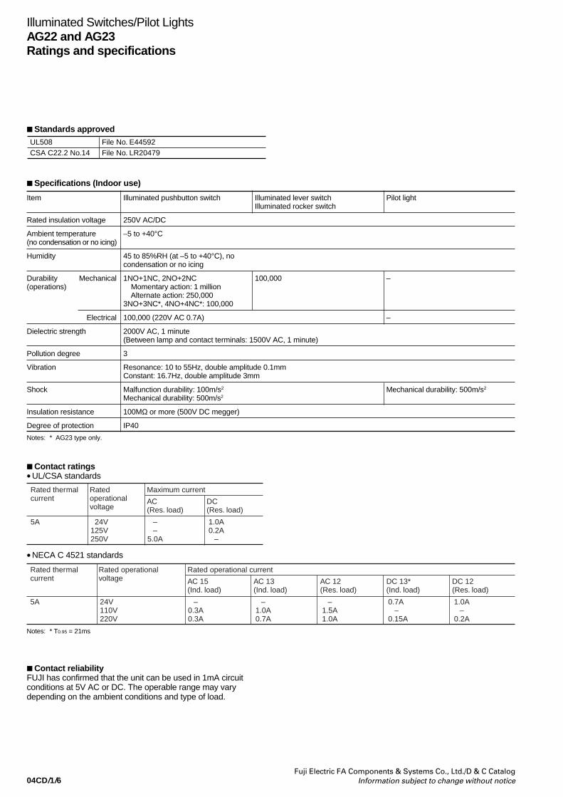
04CD/1/6Fuji Electric FA Components & Systems Co., Ltd./D & C Catalog
Information subject to change without notice
Item Illuminated pushbutton switch Illuminated lever switch Pilot lightIlluminated rocker switch
Rated insulation voltage 250V AC/DC
Ambient temperature –5 to +40°C(no condensation or no icing)
Humidity 45 to 85%RH (at –5 to +40°C), nocondensation or no icing
Durability Mechanical 1NO+1NC, 2NO+2NC 100,000 –(operations) Momentary action: 1 million
Alternate action: 250,0003NO+3NC*, 4NO+4NC*: 100,000
Electrical 100,000 (220V AC 0.7A) –
Dielectric strength 2000V AC, 1 minute(Between lamp and contact terminals: 1500V AC, 1 minute)
Pollution degree 3
Vibration Resonance: 10 to 55Hz, double amplitude 0.1mmConstant: 16.7Hz, double amplitude 3mm
Shock Malfunction durability: 100m/s2 Mechanical durability: 500m/s2
Mechanical durability: 500m/s2
Insulation resistance 100MΩ or more (500V DC megger)
Degree of protection IP40
Notes: * AG23 type only.
Specifications (Indoor use)
Standards approved
Illuminated Switches/Pilot LightsAG22 and AG23Ratings and specifications
UL508CSA C22.2 No.14
File No. E44592File No. LR20479
Contact ratings•UL/CSA standards
Rated thermalcurrent
Ratedoperationalvoltage
Maximum current
AC(Res. load)
DC(Res. load)
5A 24V125V250V
––
5.0A
1.0A0.2A
–
•NECA C 4521 standards
Rated thermalcurrent
Rated operationalvoltage
Rated operational current
AC 15(Ind. load)
AC 13(Ind. load)
5A 24V110V220V
–0.3A0.3A
–1.0A0.7A
AC 12(Res. load)
–1.5A1.0A
DC 13*(Ind. load)
0.7A –0.15A
DC 12(Res. load)
1.0A–
0.2A
Notes: * T0.95 = 21ms
Contact reliabilityFUJI has confirmed that the unit can be used in 1mA circuitconditions at 5V AC or DC. The operable range may varydepending on the ambient conditions and type of load.
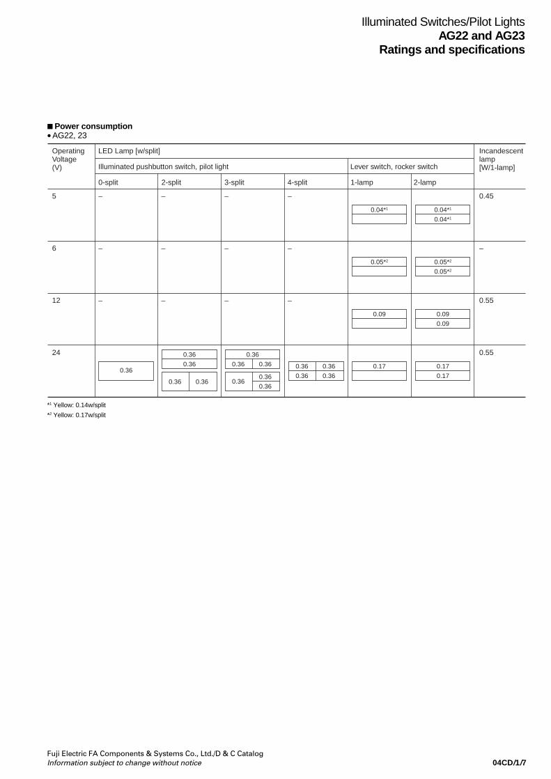
04CD/1/7Fuji Electric FA Components & Systems Co., Ltd./D & C CatalogInformation subject to change without notice
Illuminated Switches/Pilot LightsAG22 and AG23
Ratings and specifications
Power consumption•AG22, 23
0.04*1 0.04*1
0.04*1
0.05*2 0.05*2
0.05*2
0.09 0.09
0.09
0.36
0.360.36
0.360.36
0.36
0.360.36
0.360.36
0.170.36
0.17
0.17
0.36
0.36
0.360.36
Operating Voltage(V)
Incandescent lamp[W/1-lamp]
5 0.45
6 –
12 0.55
24 0.55
LED Lamp [w/split]
Illuminated pushbutton switch, pilot light Lever switch, rocker switch
0-split
–
–
–
–
–
–
–
–
–
–
–
–
2-split 3-split 4-split 1-lamp 2-lamp
*1 Yellow: 0.14w/split
*2 Yellow: 0.17w/split

04CD/1/8Fuji Electric FA Components & Systems Co., Ltd./D & C Catalog
Information subject to change without notice
Illuminated pushbutton switches (Incandescent lamp)Momentary action
Illuminated pushbutton Switches/Pilot LightsAG22 and AG23
Description Color 1NO+1NC 2NO+2NCinsert *1 *2 *3 *1 *2 *3
split Type Type
A AG22-LAX1 -( ) AG22-LAX2 -( )
B AG22-LBX1 -( ) AG22-LBX2 -( )
A AG23-LAX1 -( ) AG23-LAX2 -( )
B AG23-LBX1 -( ) AG23-LBX2 -( )
C AG23-LCX1 -( ) AG23-LCX2 -( )
D AG23-LDX1 -( ) AG23-LDX2 -( )
E AG23-LEX1 -( ) AG23-LEX2 -( )
F AG23-LFX1 -( ) AG23-LFX2 -( )
Alternate actionDescription Color 1NO+1NC 2NO+2NC
insert *1 *2 *3 *1 *2 *3
split Type Type
A AG22-L5AX1 -( ) AG22-L5AX2 -( )
B AG22-L5BX1 -( ) AG22-L5BX2 -( )
A AG23-L5AX1 -( ) AG23-L5AX2 -( )
B AG23-L5BX1 -( ) AG23-L5BX2 -( )
C AG23-L5CX1 -( ) AG23-L5CX2 -( )
D AG23-L5DX1 -( ) AG23-L5DX2 -( )
E AG23-L5EX1 -( ) AG23-L5EX2 -( )
F AG23-L5FX1 -( ) AG23-L5FX2 -( )
*1
Replace the mark by the lamp voltage codeA: 5V AC/DCB: 12V AC/DCC: 15V AC/DCE: 24V AC/DC
*2
Replace the ( ) mark by the mounting angle codeBlank:Horizontal mountingT: Vertical mounting
*3
Replace the mark by the flange color codeBlank: Gray (Standard)B: Black
For AG23 type illuminated pushbutton switch,3NO+3NC and 4NO+4NC are also available.
Pilot lights (Incandescent lamp)Description Color 1NO+1NC
insert *1 *2 *3
split Type
A AG22-ZAX -( )
B AG22-ZBX -( )
A AG23-ZAX -( )
B AG23-ZBX -( )
C AG23-ZCX -( )
D AG23-ZDX -( )
E AG23-ZEX -( )
F AG23-ZFX -( )
Color insert kitsIlluminated pushbutton switches and pilot lights with an incandescent lampcomprise the following number of green, red, white, orange and blue inserts,legend plates and light baffle plates.
Color insert Light baffleFull Half Quarter Half Quarter
A 5 – – – – – – – 1
B – 5 – – 1 – – – 1
C – – 5 – – 1 – – 1
D – 5 – 5 1 – – 1 1
E – – 5 5 – 1 1 – 1
F – – – 10 1 – – 2 1
Legendplate
Colorinsertsplit
Dimensions, mmAG22 AG23• Body • Body
• Barrier • Barrier Center barrier End barrier Long center barrier Long end barrier AGX008-C AGX008-E AGX003-LC AGX003-LE
AG23-LSM-293
AG22-LSM-346
AG23-L5SM-295
AG22-L5SM-345
AG23-ZSM-294
AG22-ZSM-346
Wiring diagramsAG22 (2NO+2NC) AG23 (4NO+4NC)• Terminal arrangement • Terminal arrangement
View from terminal side
Short center barrier Short end barrier AGX003-SC AGX003-SE
52 5 25 sq. 52 5 32
25
Notes:
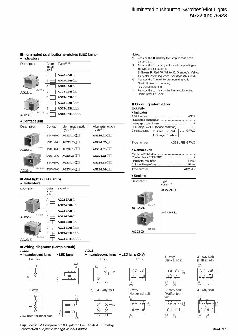
04CD/1/9Fuji Electric FA Components & Systems Co., Ltd./D & C CatalogInformation subject to change without notice
Illuminated pushbutton switches (LED lamp)• IndicatorsDescription Color Type*1 *2
insertsplit
A AG22-LA -
B AG22-LB -
A AG23-LA -
B AG23-LB -
C AG23-LC -
D AG23-LD -
E AG23-LE -
F AG23-LF -AG23-L
AG22-L
SM-348
SK-1016
•Contact unitDescription Contact Momentary action Alternate actionn
Type*3 *4 Type*3 *4
1NO+1NC AG22-L1-( ) AG22-L51-( )
2NO+2NC AG22-L2-( ) AG22-L52-( )
1NO+1NC AG23-L1-( ) AG23-L51-( )
2NO+2NC AG23-L2-( ) AG23-L52-( )
3NO+3NC AG23-L3-( ) AG23-L53-( )
4NO+4NC AG23-L4-( ) AG23-L54-( )
AG22-LSM-347
AG23-LSM-298
Pilot lights (LED lamp)• IndicatorsDescription Color Type*1 *2
insertsplit
A AG22-ZA -
B AG22-ZB -
A AG23-ZA -
B AG23-ZB -
C AG23-ZC -
D AG23-ZD -
E AG23-ZE -
F AG23-ZF -AG23-Z
AG22-Z
SM-304
SM-349
Wiring diagrams (Lamp circuit)AG22• Incandescent lamp • LED lamp
AG23• Incandescent lamp • LED lamp (24V)
Illuminated pushbutton Switches/Pilot LightsAG22 and AG23
Description Typecode*3 *4
AG22-Z6-( )
AG23-Z6-( )
AG23-Z6SM-298
AG22-Z6SM-347
• Sockets
Notes:*1 Replace the mark by the lamp voltage code.
E3: 24V DC*2 Replace the mark by color code depending on
the type of split patterns.G: Green, R: Red, W: White, O: Orange, Y: Yellow(For color insert sequence, see page 04CD/1/4)
*3 Replace the ( ) mark by the mounting code.Blank: Horizontal mountingT: Vertical mounting
*4 Replace the mark by the flange color code.Blank: Gray, B: Blank
Ordering informationExample• IndicatorAG23 series .................................................. AG23Illuminated pushbutton .......................................... L4-way split color insert .......................................... FLED lamp 24V DC (Anode common) .................. E3Color sequence ....... GRWO
Type number AG23-LFE3-GRWO
• Contact unitMomentary action .................................................. LContact block 2NO+2NC ....................................... 2Horizontal mounting ........................................ BlankColor of flange Gray ....................................... Blank
Type number AG23-L2
1: Green 2: Red 4: Orange 3: White
LC
LC
L1
L1
L2
L1 L3
L2 L4
LC
L1 L3
L2 L4
LC
LC(+)
( )L1
LC(+)
L2( )
( )L1
( )L1
LC(+)
L2( )
LC(+)
L2( )
( )L1
LC(+)
L2( )
L4( )
( )L1
( )L3
LC(+)
L2( )
L4( )
( )L1
LC(+)
L2( )
LC(+)
L2( )
L4( )
L4( )
Full face Full face Full face3 - way split (Half at left)
2 - wayVertical split
4 - way split3 - way split(Half at top)
2-wayHorizontal split
2, 3, 4 - way split2-way
View from terminal side
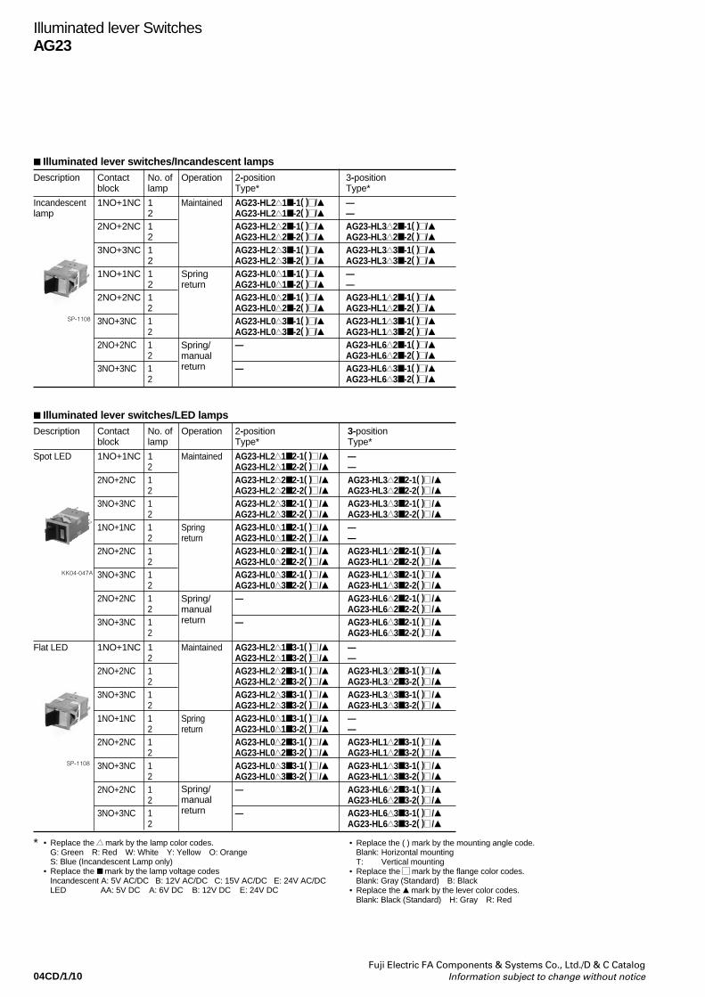
04CD/1/10Fuji Electric FA Components & Systems Co., Ltd./D & C Catalog
Information subject to change without notice
Illuminated lever switches/Incandescent lampsDescription Contact No. of Operation 2-position 3-position
block lamp Type* Type*
Incandescent 1NO+1NC 1 Maintained AG23-HL2 1 -1( ) / —lamp 2 AG23-HL2 1 -2( ) / —
2NO+2NC 1 AG23-HL2 2 -1( ) / AG23-HL3 2 -1( ) /2 AG23-HL2 2 -2( ) / AG23-HL3 2 -2( ) /
3NO+3NC 1 AG23-HL2 3 -1( ) / AG23-HL3 3 -1( ) /2 AG23-HL2 3 -2( ) / AG23-HL3 3 -2( ) /
1NO+1NC 1 Spring AG23-HL0 1 -1( ) / —2 return AG23-HL0 1 -2( ) / —
2NO+2NC 1 AG23-HL0 2 -1( ) / AG23-HL1 2 -1( ) /2 AG23-HL0 2 -2( ) / AG23-HL1 2 -2( ) /
3NO+3NC 1 AG23-HL0 3 -1( ) / AG23-HL1 3 -1( ) /2 AG23-HL0 3 -2( ) / AG23-HL1 3 -2( ) /
2NO+2NC 1 — AG23-HL6 2 -1( ) /2 AG23-HL6 2 -2( ) /
3NO+3NC 1 — AG23-HL6 3 -1( ) /2 AG23-HL6 3 -2( ) /
Spring/manualreturn
Illuminated lever SwitchesAG23
Illuminated lever switches/LED lampsDescription Contact No. of Operation 2-position 3-position
block lamp Type* Type*
Spot LED 1NO+1NC 1 Maintained AG23-HL2 1 2-1( ) / —2 AG23-HL2 1 2-2( ) / —
2NO+2NC 1 AG23-HL2 2 2-1( ) / AG23-HL3 2 2-1( ) /2 AG23-HL2 2 2-2( ) / AG23-HL3 2 2-2( ) /
3NO+3NC 1 AG23-HL2 3 2-1( ) / AG23-HL3 3 2-1( ) /2 AG23-HL2 3 2-2( ) / AG23-HL3 3 2-2( ) /
1NO+1NC 1 Spring AG23-HL0 1 2-1( ) / —2 return AG23-HL0 1 2-2( ) / —
2NO+2NC 1 AG23-HL0 2 2-1( ) / AG23-HL1 2 2-1( ) /2 AG23-HL0 2 2-2( ) / AG23-HL1 2 2-2( ) /
3NO+3NC 1 AG23-HL0 3 2-1( ) / AG23-HL1 3 2-1( ) /2 AG23-HL0 3 2-2( ) / AG23-HL1 3 2-2( ) /
2NO+2NC 1 — AG23-HL6 2 2-1( ) /2 AG23-HL6 2 2-2( ) /
3NO+3NC 1 — AG23-HL6 3 2-1( ) /2 AG23-HL6 3 2-2( ) /
Flat LED 1NO+1NC 1 Maintained AG23-HL2 1 3-1( ) / —2 AG23-HL2 1 3-2( ) / —
2NO+2NC 1 AG23-HL2 2 3-1( ) / AG23-HL3 2 3-1( ) /2 AG23-HL2 2 3-2( ) / AG23-HL3 2 3-2( ) /
3NO+3NC 1 AG23-HL2 3 3-1( ) / AG23-HL3 3 3-1( ) /2 AG23-HL2 3 3-2( ) / AG23-HL3 3 3-2( ) /
1NO+1NC 1 Spring AG23-HL0 1 3-1( ) / —2 return AG23-HL0 1 3-2( ) / —
2NO+2NC 1 AG23-HL0 2 3-1( ) / AG23-HL1 2 3-1( ) /2 AG23-HL0 2 3-2( ) / AG23-HL1 2 3-2( ) /
3NO+3NC 1 AG23-HL0 3 3-1( ) / AG23-HL1 3 3-1( ) /2 AG23-HL0 3 3-2( ) / AG23-HL1 3 3-2( ) /
2NO+2NC 1 — AG23-HL6 2 3-1( ) /2 AG23-HL6 2 3-2( ) /
3NO+3NC 1 — AG23-HL6 3 3-1( ) /2 AG23-HL6 3 3-2( ) /
Spring/manualreturn
* • Replace the mark by the lamp color codes.G: Green R: Red W: White Y: Yellow O: OrangeS: Blue (Incandescent Lamp only)
• Replace the mark by the lamp voltage codesIncandescent A: 5V AC/DC B: 12V AC/DC C: 15V AC/DC E: 24V AC/DCLED AA: 5V DC A: 6V DC B: 12V DC E: 24V DC
• Replace the ( ) mark by the mounting angle code.Blank: Horizontal mountingT: Vertical mounting
• Replace the mark by the flange color codes.Blank: Gray (Standard) B: Black
• Replace the mark by the lever color codes.Blank: Black (Standard) H: Gray R: Red
SP-1108
KK04-047A
Spring/manualreturn
SP-1108

04CD/1/11Fuji Electric FA Components & Systems Co., Ltd./D & C CatalogInformation subject to change without notice
Illuminated rocker switches/Incandescent lampsDescription Contact No. of Operation 2-position 3-position
block lamp Type* Type*
Incandescent 1NO+1NC 1 Maintained AG23-RL2 1 -1( ) —2 AG23-RL2 1 -2( ) —
2NO+2NC 1 AG23-RL2 2 -1( ) AG23-RL3 2 -1( )2 AG23-RL2 2 -2( ) AG23-RL3 2 -2( )
3NO+3NC 1 AG23-RL2 3 -1( ) AG23-RL3 3 -1( )2 AG23-RL2 3 -2( ) AG23-RL3 3 -2( )
1NO+1NC 1 Spring AG23-RL0 1 -1( ) —2 return AG23-RL0 1 -2( ) —
2NO+2NC 1 AG23-RL0 2 -1( ) AG23-RL1 2 -1( )2 AG23-RL0 2 -2( ) AG23-RL1 2 -2( )
3NO+3NC 1 AG23-RL0 3 -1( ) AG23-RL1 3 -1( )2 AG23-RL0 3 -2( ) AG23-RL1 3 -2( )
2NO+2NC 1 — AG23-RL6 2 -1( )2 AG23-RL6 2 -2( )
3NO+3NC 1 — AG23-RL6 3 -1( )2 AG23-RL6 3 -2( )
Spring/manualreturn
Illuminated rocker switches/LED lampsDescription Contact No. of Operation 2-position 3-position
block lamp Type* Type*
Spot LED 1NO+1NC 1 Maintained AG23-RL2 1 2-1( ) —2 AG23-RL2 1 2-2( ) —
2NO+2NC 1 AG23-RL2 2 2-1( ) AG23-RL3 2 2-1( )2 AG23-RL2 2 2-2( ) AG23-RL3 2 2-2( )
3NO+3NC 1 AG23-RL2 3 2-1( ) AG23-RL3 3 2-1( )2 AG23-RL2 3 2-2( ) AG23-RL3 3 2-2( )
1NO+1NC 1 Spring AG23-RL0 1 2-1( ) —2 return AG23-RL0 1 2-2( ) —
2NO+2NC 1 AG23-RL0 2 2-1( ) AG23-RL1 2 2-1( )2 AG23-RL0 2 2-2( ) AG23-RL1 2 2-2( )
3NO+3NC 1 AG23-RL0 3 2-1( ) AG23-RL1 3 2-1( )2 AG23-RL0 3 2-2( ) AG23-RL1 3 2-2( )
2NO+2NC 1 — AG23-RL6 2 2-1( )2 AG23-RL6 2 2-2( )
3NO+3NC 1 — AG23-RL6 3 2-1( )2 AG23-RL6 3 2-2( )
Flat LED 1NO+1NC 1 Maintained AG23-RL2 1 3-1( ) —2 AG23-RL2 1 3-2( ) —
2NO+2NC 1 AG23-RL2 2 3-1( ) AG23-RL3 2 3-1( )2 AG23-RL2 2 3-2( ) AG23-RL3 2 3-2( )
3NO+3NC 1 AG23-RL2 3 3-1( ) AG23-RL3 3 3-1( )2 AG23-RL2 3 3-2( ) AG23-RL3 3 3-2( )
1NO+1NC 1 Spring AG23-RL0 1 3-1( ) —2 return AG23-RL0 1 3-2( ) —
2NO+2NC 1 AG23-RL0 2 3-1( ) AG23-RL1 2 3-1( )2 AG23-RL0 2 3-2( ) AG23-RL1 2 3-2( )
3NO+3NC 1 AG23-RL0 3 3-1( ) AG23-RL1 3 3-1( )2 AG23-RL0 3 3-2( ) AG23-RL1 3 3-2( )
2NO+2NC 1 — AG23-RL6 2 3-1( )2 AG23-RL6 2 3-2( )
3NO+3NC 1 — AG23-RL6 3 3-1( )2 AG23-RL6 3 3-2( )
Spring/manualreturn
SP-1107
KK04-048A
Illuminated rocker SwitchesAG23
* • Replace the mark by the lamp color codesG: Green R: Red W: White Y: Yellow O: OrangeS: Blue (Incandescent Lamp only)
• Replace the mark by the lamp voltage codesIncandescent A: 5V AC/DC B: 12V AC/DC C: 15V AC/DC E: 24V AC/DCLED AA: 5V DC A: 6V DC B: 12V DC E: 24V DC
• Replace the ( ) mark by the mounting angle codeBlank: Horizontal mountingT: Vertical mounting
• Replace the mark by the flange color codesBlank: Gray (Standard) B: Black
Spring/manualreturn
SP-1107

04CD/1/12Fuji Electric FA Components & Systems Co., Ltd./D & C Catalog
Information subject to change without notice
L3
LC LC( )
LC
LB
L2
L3(+)
L3
LC( )
LB( )
L2(+)
L3(+)
1 - lamp
2 - lamp
1 - lamp
2 - lamp
Illuminated lever Switches/Illuminated rocker SwitchesAG23Dimensions
Dimensions, mmLever switches Rocker switches
NP
No. oflamp
1
2
16.5 25523230
° NP
52
9.5
3.5 25
32
No. oflamp
1
2
Contact arrangement
Wiring diagrams(AG23 4NO+4NC)• Terminal arrangement
L3
L2
41
4344
42
11
1314
12
21
2324
22
31
3334
32
LC
LB
Name plate
Wiring diagrams (Lamp circuit)
• Incandescent lamp • LED lamp
1 2
41 42
43 44
1
1
2
2
1
1
2
2
3
3
1 2
11 12
13 14
1 2 3
11 12
13 14
1 2 3
41 42
43 44
1 2 3
11 12
13 14
1 2 3
31 32
33 34
1 2 3
41 42
43 44
1 2 3
11 12
13 14
1 2 3
21 22
23 24
1 2 3
31 32
33 34
1 2 3
41 42
43 44
1 2
41 42
43 44
1 2
11 12
13 14
1 2
31 32
33 34
1 2
41 42
43 44
1 2
11 12
13 14
1 2
21 22
23 24
1 2
31 32
33 34
1 2
41 42
43 44
1NO+1NCOperator positon 2NO+2NC 3NO+3NC 4NO+4NC
2-position
3-position –
Note: The operator position shown is where the nameplate-stuck-surface is positioned toward you.

04CD/1/13Fuji Electric FA Components & Systems Co., Ltd./D & C CatalogInformation subject to change without notice
Illuminated Switches/Pilot LightsAG22 and AG23
Notes on use
Panel cutting• AG 22Description Mounting design Panel cutting Remarks
Flange Individual mountingmounting (Horizontal)
Manifold mounting(Horizontal)
Barrier Individual mountingmounting (Horizontal)
Manifold mounting(Horizontal)
Notes • n: Number of mounted unit Max 10 Panel thickness: 1 to 5 mm (with dust covers: 1 to 4 mm)• For vertical mounting, contact FUJI• The dimensions in parentheses are for tandem mounting of switches with dust covers.
Panel cutting space betweenrows of units
Panel cutting space betweenrows of unitsDotted line indicates the positionof each mounting barrier
• AG 23Description Mounting design Panel cutting Remarks
Flange Individual mountingmounting (Horizontal)
Manifold mounting(Horizontal)
Individual mounting(Vertical)
Manifold mounting(Vertical)
Barrier Individual mountingmounting (Horizontal)
Manifold mounting(Horizontal)
Individual mounting(Vertical)
Manifold mounting(Vertical)
Notes • n: Number of mounted unit Max10 Panel thickness: 1 to 5 mm (with dust covers: 1 to 4 mm)• The dimensions in parentheses are for tandem mounting of switches with dust covers.
Panel cutting space betweenrows of units
Panel cutting space betweenrows of unitsDotted line indicates the positionof each mounting barrier
25 ±
0.1
23.5
± 0
.323
.5 ±
0.3
23.5
± 0
.323
.5 ±
0.3
30.5
± 0
.330
.5 ±
0.3
30.5
± 0
.330
.5 ±
0.3
25 ± 0.1
25 ±
0.1
32 ± 0.1 30.5 ± 0.3
23.5 ± 0.3
32 ±
0.1
32 ±
0.1
32 ± 0.3
32n ± 0.5
25n ± 0.5
26n+6 ± 1
26.5
39
33.5
26.5
33n+6 ± 1
33.5
31.9n–1.5 ± 0.3
(39.5n–9 ± 0.3)
(32.5n–9 ± 0.3)
24.9n–1.5 ± 0.3
36.4 ± 0.3
32.8n+3.5 ± 0.3
25.8n+3.5 ± 0.3
29.4 ± 0.3
Over 3
Ove
r 6
Over 61.3
Ove
r 6
25 ±
0.1
25 ± 0.1
25 ±
0.1
25n ± 0.5
23.5
± 0
.3
22.5 ± 0.3
23.5
± 0
.3
24.9n–2.4 ± 0.3 (32.5n–10 ± 0.3)
Over 3
Ove
r 6
26.5
32
23.5
± 0
.3
27.8 ± 0.3
26.5
26n+6.5 ± 1
23.5
± 0
.3
25.9n+1.9 ± 0.3
Over 61.3
Ove
r 6
Mounting the Switches (Pilot lights)Mounting the switches by inserting them into place in the front of the mounting panel.The switches will be held in position by the mounting springs.
Notes on use
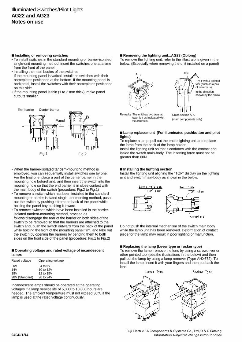
04CD/1/14Fuji Electric FA Components & Systems Co., Ltd./D & C Catalog
Information subject to change without notice
Illuminated Switches/Pilot LightsAG22 and AG23Notes on use
Installing or removing switches• To install switches in the standard mounting or barrier-isolated
single-unit mounting method, insert the switches one at a timefrom the front of the panel.
• Installing the main bodies of the switchesIf the mounting panel is vatical, install the switches with theirnameplates positioned at the bottom. If the mounting panel ishorizontal, install the switches with their nameplates positionedon this side.
• If the mounting panel is thin (1 to 2 mm thick), make panelcutouts smaller.
• When the barrier-isolated tandem-mounting method isemployed, you can sequentially install switches one by one.For the final one, place a part of the center barrier in themounting hole beforehand, and then insert the switch into themounting hole so that the end barrier is in close contact withthe main body of the switch (procedure: Fig.2 to Fig.1)
• To remove a switch which has been installed in the standardmounting or barrier-isolated single-uint monting method, pushout the switch by pushing it from the back of the panel whileholding the panel bay pushing it inward.
• To remove switches which have been installed in the barrier-isolated tandem-mounting method, proceed asfollows:disengage the rear of the barrier on both sides of theswitch to be removed so that the barriers are attached to theswitch and, push the switch outward from the back of the panelwhile holding the front of the mounting panel firm, and take outthe switch by opening the barriers by bending them to bothsides on the front side of the panel (procedure: Fig.1 to Fig.2)
Operating voltage and rated voltage of incandescentlamps
Rated voltage Operating voltage
6V 4 to 5V14V 10 to 12V18V 12 to 15V28V (Standard) 20 to 24V
Incandescent lamps should be operated at the operatingvoltages if a lamp service life of 5,000 to 10,000 hours areneeded. The ambient temperature must not exceed 30°C if thelamp is used at the rated voltage continuously.
Removing the lighting unit...AG23 (Oblong)To remove the lighting unit, refer to the illlustraions given in thebelow. (Especially when removing the unit installed on a panel)
Lamp replacement (For illuminated pushbutton and pilotlights)To replace a lamp, pull out the entire lighting unit and replacethe lamp from the back of the lamp holder.Install the lighting unit so that it conforms with the contact endinside the switch main-body. The inserting force must not begreater than 60N.
Installing the lighting sectionInstall the lighting unit aligning the "TOP" display on the lightinguint and switch main-body as shown in the below.
Do not push the internal mechanism of the switch main bodywhile the lamp unit has been removed. Deformation of contactpiece for the lamp may result in poor lighting or malfunction.
Replacing the lamp (Lever type or rocker type)To remove the lamp, remove the lens by using a screwdriver orother pointed tool (see.the illustrations in the below) and thenpull out the lamp by using a lamp remover (Type AHX672) .Toinstall the lamp, insert it with your fingers and then put back thelens.
End barrier Center barrier
Panel
Fig.1 Fig.2
A *
A
Remarks*The unit has two jaws at lower left as indicated with the asterisks
Cross section A-A
(main components only)
Jaw
Pry it with a pointedtool (such as a pairof tweerzers)
in the directionshown by the arrow

04CD/1/15Fuji Electric FA Components & Systems Co., Ltd./D & C CatalogInformation subject to change without notice
Removeing or installing the lensTo remove the lens, slide it horizontally. To install the lens, alignit with the lamp house and insert it from the top.
Installing the color plate and nameplateInstall the color plate and Nameplate in the lens section withtheir grained surfaces directed inward.
Removeing or installing the nameplate (Lever type)To remove the nameplate from the lens, press the studs of thelens against a flat plane so that the lens is widened slightly, andinsert a screwdriver or other pointed tool into the groove of thenameplate. (See the illustration in the below.)To install the nameplate into the cover, put the end ofthenameplate in the cover and then press the nameplate intothe cover by pinching them with your fingers. (See theillustration in the below.)
Contact blockTo replace a contact block, use removing tool AGX012. Ifexcessive force is applied when attempting to open the supportlegs for the contact block holder, deformation or damage mayoccur.
Illuminated Switches/Pilot LightsAG22 and AG23
Notes on use
Contacts configuration modificationsNote that there are certain restrictions on contact configureationmodifications.No modifications other than those below are available. Althoughit is not impossible to modify a switch with 3a3b or 4a4b into thatwith 2a2b, do not attempt this modification because the layout ofthe contacts of the former differs from that of the latter.Caution: never remove any of the contact units or dummy unitswhich are located at both ends. If you do, the main units of theswitches may be damaged, may become unable to be installed,or other troubles may result.
Wiring connections• Use a soldering iron with a wattage of not more than 30W and
a tip length of more than 20mm.Use a rosin-core solderWith a 30W iron complete soldering within 5 seconds, or 10seconds with a 20W iron. Do not apply external force to theterminals. Do not deform the terminals.Because lead-free solder's melting point is slightly high,soldering work may be difficult. Use a soldering iron whose tipis rather large or whose calorie is rather high.
• Wires that can be connectedTwo solid wires with a maximum diameter of 0.8mm (solder)One stranded wire with a maximum area of 0.75mm2 (solder)
• Using contact blocksWhen using NO and NC contacts in the same contact block,avoid connection that involves opposite polarity or wiring fromdifferent types of power supply.
• For wiring to adjacent terminals, use insulated tubing toprevent short-circuit and to assure isolation. For solderterminals, be careful when connecting thick wires. Do not usetoo much solder.
Installing lamps in close orderWhen continuously lighting pilot lights or pressing illuminatedpushbuttons installed in close order, care must be taken that theambient temperature does not exceed the rated value.
Alternate types
Do not open/close the switch with its leaf spring held pressed.Ifyou do, the alternate mechanism can be damaged.
AG23-L5 AG22-L5
Lens
Lamp house
Push
Name plate
Name plate
LensLens
Pull
Pull
Befor modification
After modification
With 1NO+1NC
With 2NO+2NC
With 3NO+3NC
With 4NO+4NC
With 2NO+2NC
With 1NO+1NC
With 4NO+4NC
With 3NO+3NC
Insert the contact unitin this hole
Insert the contact unitin this hole
Remove this contact unit.
Remove this contact unit.
Slide
SP-1122
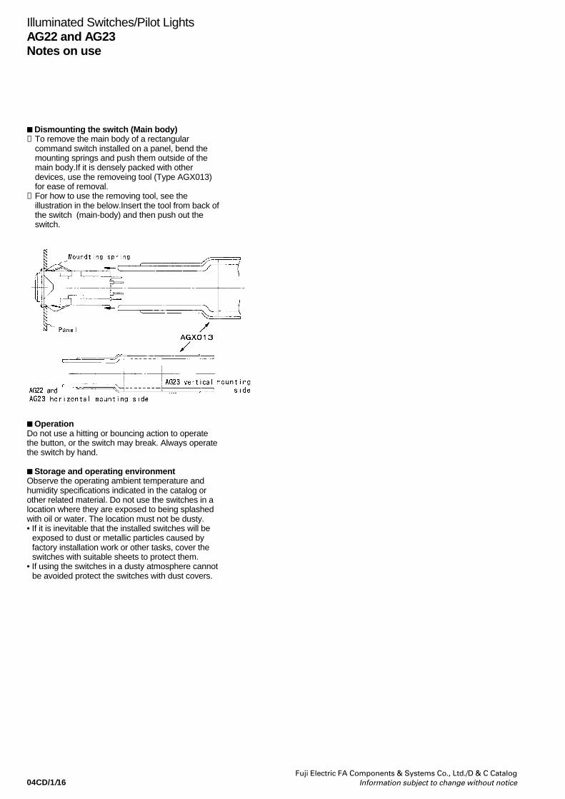
04CD/1/16Fuji Electric FA Components & Systems Co., Ltd./D & C Catalog
Information subject to change without notice
Dismounting the switch (Main body)➀ To remove the main body of a rectangular
command switch installed on a panel, bend themounting springs and push them outside of themain body.If it is densely packed with otherdevices, use the removeing tool (Type AGX013)for ease of removal.
➁ For how to use the removing tool, see theillustration in the below.Insert the tool from back ofthe switch (main-body) and then push out theswitch.
OperationDo not use a hitting or bouncing action to operatethe button, or the switch may break. Always operatethe switch by hand.
Storage and operating environmentObserve the operating ambient temperature andhumidity specifications indicated in the catalog orother related material. Do not use the switches in alocation where they are exposed to being splashedwith oil or water. The location must not be dusty.• If it is inevitable that the installed switches will be
exposed to dust or metallic particles caused byfactory installation work or other tasks, cover theswitches with suitable sheets to protect them.
• If using the switches in a dusty atmosphere cannotbe avoided protect the switches with dust covers.
Illuminated Switches/Pilot LightsAG22 and AG23Notes on use

04CD/1/17Fuji Electric FA Components & Systems Co., Ltd./D & C CatalogInformation subject to change without notice
SM-338
Illuminated Switches/Pilot LightsAG22 and AG23
Accessories
Type Used with
AGX011-3
AGX011-2
AG23-L
AG22-L
Description Type
Accessories
Barrier
SM-313
SM-337
For AG22Center-barrierEnd-barrier
For AG23Long center-barrierLong end-barrierShort center-barrierShort end-barrier
Color
BlackGrayBlackGray
BlackGrayBlackGrayBlackGrayBlackGray
Type
AGX008-CBAGX008-CHAGX008-EBAGX008-EH
AGX003-LCBAGX003-LCHAGX003-LEBAGX003-LEHAGX003-SCBAGX003-SCHAGX003-SEBAGX003-SEH
Bezel
SM-354
For AG22
For AG23
ColorBlackGrayBlackGray
TypeAGX010-2BAGX010-2HAGX010-3BAGX010-3H
Color insert kit
This kit contains green,red, white, orange andblue color-inserts,legend plates and lightbaffle plates.See page 04CD/1/8
For AG22-L, Z
For AG23-L, Z
SplitFull face2-way split
Full face2-way split
3-way split
4-way split
TypeAGX019-2AAGX019-2B
AGX019-3AAGX019-3BAGX019-3CAGX019-3DAGX019-3EAGX019-3F
Legend plateFor AG22-L, Z
For AG23-L, Z
ColorClear*WhiteClear*White
TypeAGX009-2CAGX009-2WAGX009-3CAGX009-3W
SM-355
Dimension (mm)• 15sq.×1 (AGX009-2)• 15×23×1 (AGX009-3)
Dust-tight cover
SM-1528
Description Type
Protection cover
For AG22-LFor AG23-L
TypeAGX007-2AGX007-3AGX007-3T
SM-375
(vertical mounting)The cover portects against accidentaloperation.The cover lid is returned home with a springforce.
AGX007-3
AGX007-2
AGX007-3T
24.5
12.5
12.5 21.5 2628.5
24.5
12.5
12.5 21.5 19
31.5
16
12.5 19
Panel plugFor AG22
For AG23
ColorBlackGrayBlackGray
TypeAGX006-2BAGX006-2HAGX006-3BAGX006-3H
Contact block AGX001
Soldering/Tab use
Dummy unit AGX002
*:Standard
Dimensions (mm)
The dummy unit installs in the part whichdoes not use the contact unit.
KKD06-305
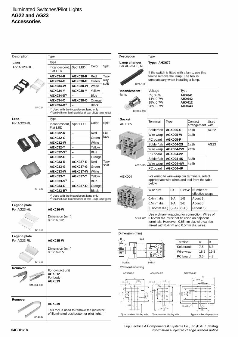
04CD/1/18Fuji Electric FA Components & Systems Co., Ltd./D & C Catalog
Information subject to change without notice
Illuminated Switches/Pilot LightsAG22 and AG23Accessories
Description Type Description Type
LensFor AG23-HL
Type
*1 Used with the incandecent lamp only*2 Used with non illuminated side of spot LED(1-lamp types)
*1 Used with the incandecent lamp only*2 Used with non illuminated side of spot LED(1-lamp types)
Incandescent, Flat LED
Spot LED Color Split
AGX034-R
AGX034-G
AGX034-W
AGX034-Y
AGX034-S*1
AGX034-O
AGX034-B*2
AGX038-R
AGX038-G
AGX038-W
AGX038-Y
–
AGX038-O
–
Red
Green
White
Yellow
Blue
Orange
Black
Two-waysplit
LensFor AG23-RL AGX005
Legend plateFor AG23-HL
SP-123
SP-124
SM-334, 335
SP-115
Type
Incandescent, Flat LED
Spot LED Color Split
AGX032-R
AGX032-G
AGX032-W
AGX032-Y
AGX032-S*1
AGX032-O
AGX033-R
AGX033-G
AGX033-W
AGX033-Y
AGX033-S*1
AGX033-O
AGX033-B*2
AGX036-W
RemoverFor contact unitAGX012For bodyAGX013
Legend plateFor AG23-RL
This tool is used to remove the indicatorof illuminated pushbutton or pilot light.
Dimension (mm)8.5×16.5×2
Voltage Type6V, 0.6W14V, 0.7W18V, 0.7W28V, 0.7W
AHX641AHX642AHX612AHX643
Dimension (mm)9.5×16×8.5
If the switch is fitted with a lamp, use this tool to remove the lamp. The tool is unnecessary when installing a lamp.
Type: AHX672
SP-116
AGX035-W
Remover
SP-1142
AF02-117
AGX039
Lamp changer For AG23-HL, RL
–
–
–
–
–
–
AGX037-R
AGX037-G
AGX037-W
AGX037-Y
–
AGX037-O
–
Red
Green
White
Yellow
Blue
Orange
Red
Green
White
Yellow
Blue
Orange
Black
Fullface
Two-split
Incandescent lamp
KKD06-333
Socket
AF02-129
AGX004
AF02-130
Terminal
For wiring to wire-wrap pin terminals, selectappropriate wire sizes and tool from the table below.
Use ordinary wrapping for connection. Wires of 0.65mm dia. must not be used on adjacent terminals. Howerver, 0.65mm dia. wire can be mixed with 0.4mm and 0.5mm dia. wires.
PC board mounting
Type Contactarrangement
Used with
Solder/tab
Wire wrap
PC board
Solder/tab
Wire wrap
PC board
Solder/tab
Wire wrap
PC board
AGX005-S
AGX005-W
AGX005-P
AGX004-2S
AGX004-2W
AGX004-2P
AGX004-4S
AGX004-4W
AGX004-4P
1a1b
2a2b
1a1b
2a2b
3a3b
4a4b
AG22
AG23
Wire size Bit Sleeve Number of effective wraps
0.4mm dia.
0.5mm dia.
(0.65mm dia.)
3-A
1-A
(2-A)
1-B
2-B
(2-B)
About 8
About 6
(About 6)
Terminal A B
Solder/tab
Wire wrap
PC board
7.5
18.5
3.5
8.8
19.8
4.8
Dimension (mm)
Type number display side Type number display side Type number display side
60.6BA
SwitchSocket
AGX005-P AGX004-2P AGX004-4P
12.813-ø1.3
21-ø1.36 6
11.7 11.713.45
13.45
31
18.4
20.3
54.6
4.6
6.3
14.3
20.3
5
256.3
14.3
9.15
25
12.811-ø1.3
44
0.55
6.3
14.324
20.3
54.
5
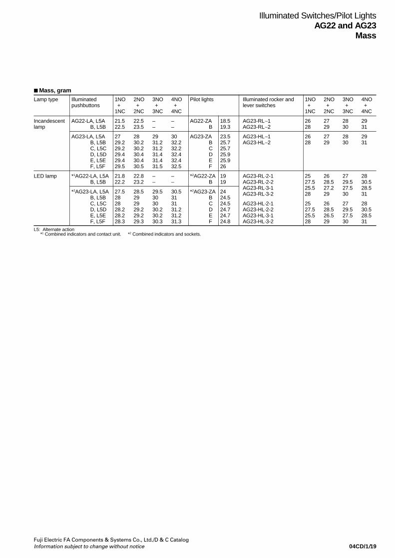
04CD/1/19Fuji Electric FA Components & Systems Co., Ltd./D & C CatalogInformation subject to change without notice
Lamp type Illuminated 1NO 2NO 3NO 4NO Pilot lightspushbuttons + + + +
1NC 2NC 3NC 4NC
Incandescent AG22-LA, L5A 21.5 22.5 – – AG22-ZA 18.5lamp B, L5B 22.5 23.5 – – B 19.3
AG23-LA, L5A 27 28 29 30 AG23-ZA 23.5B, L5B 29.2 30.2 31.2 32.2 B 25.7C, L5C 29.2 30.2 31.2 32.2 C 25.7D, L5D 29.4 30.4 31.4 32.4 D 25.9E, L5E 29.4 30.4 31.4 32.4 E 25.9F, L5F 29.5 30.5 31.5 32.5 F 26
LED lamp *1AG22-LA, L5A 21.8 22.8 – – *2AG22-ZA 19B, L5B 22.2 23.2 – – B 19
*2AG23-LA, L5A 27.5 28.5 29.5 30.5 *2AG23-ZA 24B, L5B 28 29 30 31 B 24.5C, L5C 28 29 30 31 C 24.5D, L5D 28.2 29.2 30.2 31.2 D 24.7E, L5E 28.2 29.2 30.2 31.2 E 24.7F, L5F 28.3 29.3 30.3 31.3 F 24.8
Illuminated rocker and 1NO 2NO 3NO 4NOlever switches + + + +
1NC 2NC 3NC 4NC
AG23-RL·-1 26 27 28 29AG23-RL·-2 28 29 30 31
AG23-HL·-1 26 27 28 29AG23-HL·-2 28 29 30 31
AG23-RL·2-1 25 26 27 28AG23-RL·2-2 27.5 28.5 29.5 30.5AG23-RL·3-1 25.5 27.2 27.5 28.5AG23-RL·3-2 28 29 30 31
AG23-HL·2-1 25 26 27 28AG23-HL·2-2 27.5 28.5 29.5 30.5AG23-HL·3-1 25.5 26.5 27.5 28.5AG23-HL·3-2 28 29 30 31
L5: Alternate action*1 Combined indicators and contact unit. *2 Combined indicators and sockets.
Mass, gram
Illuminated Switches/Pilot LightsAG22 and AG23
Mass

04CD/2/1Fuji Electric FA Components & Systems Co., Ltd./D & C CatalogInformation subject to change without notice
Pushbuttons/Selectors/Pilot LightsAM22 and DM22
General information
Illuminated pushbuttons Pushbuttons Pilot lights
AM22F0L AM22F0R DM22D0L
AM22E0L AM22E0R DM22E3L
AF99-70 AF99-68 AF99-83
AF99-63 AF99-64 KK02-246A
Selectors
AM22V0F AM22V0E AM22PR
KK02-240A KK02-236 AF99-82
Emergency stop pushbuttons
The full range of the contact blocks andtransformer units suitable for the AR22and DR22 series may also be fitted tothe AM22 and DM22 series.
FeaturesQuick-replacement contact blocksand transformer unitsThe snap-on construction makesreplacement and addition of contactblocks and transformer units very simpleand straightforward.
Oil-and dust-proof operator moduleconstructionThe protection level of the AM22/DM22operator modules conforms to IECStandard IP65. The special sealsprotect the operator modules and switchmechanisms against oil, dust, and grime,thus ensuring high performance in dustyand moist environments.
Miniaturization• Pushbutton and selector switches with
1NO+1NC: 40mm deepPilot lights: 35mm deep
• The transformer now occupies far lessspace.
Metal nutSafer model with metal nut is alsoavailable
Wiring• Wiring from two directions is possible.• Wiring in both vertical and lateral
directions facilitates wiring in narrowspaces.
• Color coding of contact blocksmakes wiring easy.1NO: Blue, 1NC: RedLamp terminal andtransformer unit: Black
Safety• A terminal cover is provided, assuring
safety and security.• FUJI’s original Trigger Action
mechanism is used in the emergencystop pushbuttons. They are suitablefor emergency stop and safety. Thismechanism prevents the contacts frommoving until the button is pushed andlocked.
Protection• Excellent oil-tight construction (IP65) of
the operator.• Closure of the contact block has been
improved.
Approvals
For further information related toapproved type, see page 04CD/2/2 to04CD/2/3.
40mm
PushbuttonSelector switch
Illuminatedpushbuttonswitch withtransformer
Pilot light/Standard
60mm*
35mm
transformer
* 230V and over: 64mm
Self-cleaning contactsAll the contacts are double break typeand feature self-cleaning action.Every time the switch is operated, thecontact surfaces are wiped with asliding movement, thus ensuring highcontact reliability even at low voltageand small current levels (5V, 5mA).
Stationarycontact
Returnspring
Movablecontact
S

04CD/2/2Fuji Electric FA Components & Systems Co., Ltd./D & C Catalog
Information subject to change without notice
Pushbuttons/Selectors/Pilot LightsAM22 and DM22Quick reference guide
Illuminated pushbutton switchesOperator Type Operator Type Operator Type
Pushbutton switchesOperator Type Operator Type Operator Type
Flush round head AM22F0L, F5L
S
Extended round head AM22E0L, E5L
S
Mushroom head(40mm dia.)
AM22M0L, M5L
Mushroom head(29mm dia.)
AM22M4L, M9L
S S
Extended withtransparent full guard
AM22G4L, G9L
S S
Extended with full guard (With openings)
AM22G2L, G7L
Flush round head AM22F0R, F5R
S
Extended with full guard(24mm dia.)
AM22G3R, G8R
S
Extended round head AM22E0R, E5R
S
Mushroom head withfull guard(40mm dia.)
AM22M3R, M8R
S
AF99-70
AF99-61AF99-63
AF99-66AF99-59
AF99-69
AF99-68 AF99-65
AF99-64 AF99-89
See page 04CD/2/13,04CD/2/29
See page 04CD/2/13,04CD/2/29
See page 04CD/2/13,04CD/2/29
See page 04CD/2/14,04CD/2/29
See page 04CD/2/13,04CD/2/29
See page 04CD/2/14,04CD/2/29
See page 04CD/2/15,04CD/2/30
See page 04CD/2/15,04CD/2/30
See page 04CD/2/15,04CD/2/30
See page 04CD/2/15,04CD/2/30
Note : See page 04CD/2/50S
Mushroom head(40mm dia.)
AM22M0R, M5R
S
Mushroom head(29mm dia.)
AM22M4R
S
AF99-58
AF99-67
See page 04CD/2/15,04CD/2/30
See page 04CD/2/15,04CD/2/30
Emergency stop pushbutton switches (conform to EN418)Operator Type Operator Type Operator Type
AM22V0E AM22VSE
KK02-236A KK02-237A
Push-lock, turn-reset(40mm dia. with whitearrow)
Push-lock, turn-reset(29mm dia. with whitearrow)
See page 04CD/2/16,04CD/2/31
See page 04CD/2/16,04CD/2/31
Push-lock, turn-reset(40mm dia. withmechanical indicator)
See page 04CD/2/16,04CD/2/31
AW22VME
KKD07-091S S
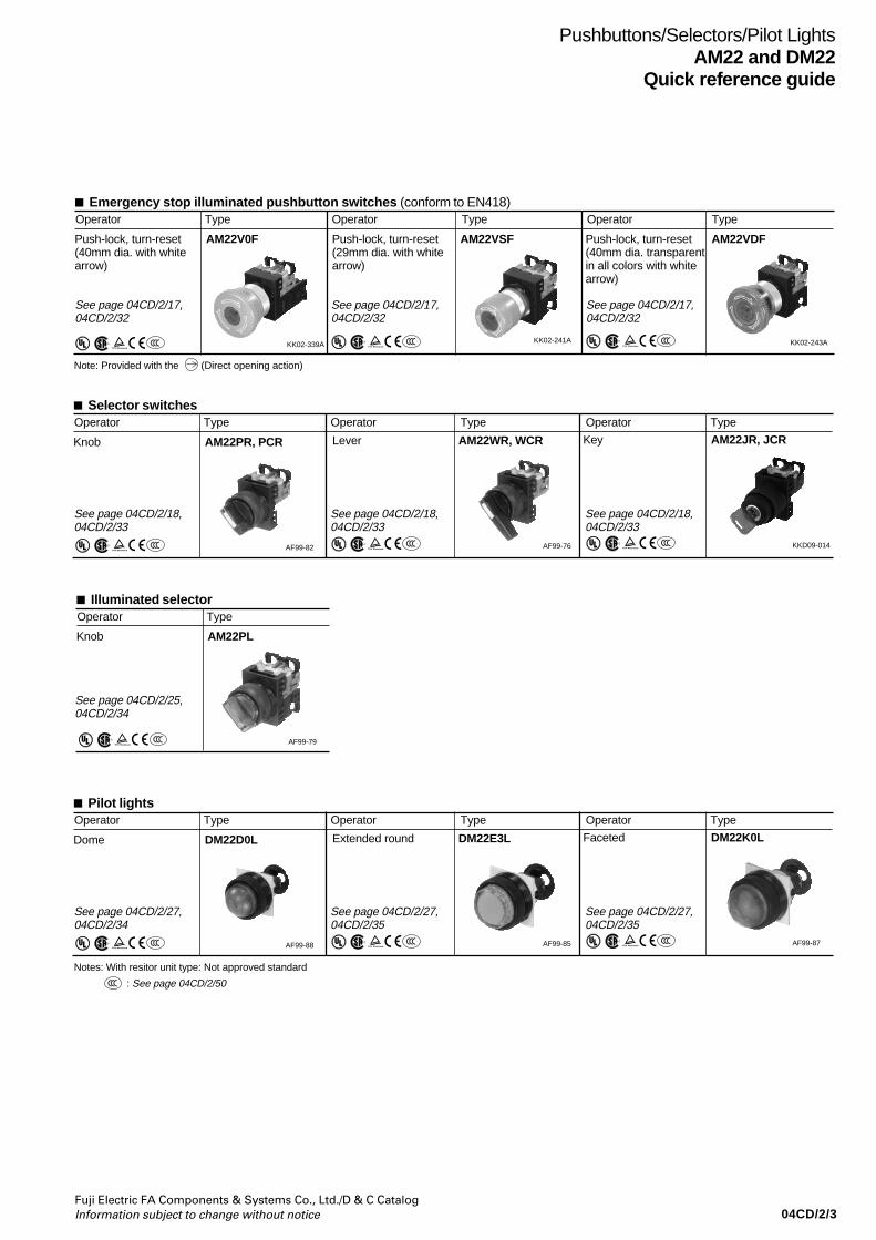
04CD/2/3Fuji Electric FA Components & Systems Co., Ltd./D & C CatalogInformation subject to change without notice
Key AM22JR, JCR
S
KKD09-014
Lever AM22WR, WCR
S
AF99-76
Pushbuttons/Selectors/Pilot LightsAM22 and DM22
Quick reference guide
Illuminated selectorOperator Type
Knob AM22PL
S
AF99-79
Emergency stop illuminated pushbutton switches (conform to EN418)Operator Type Operator Type Operator Type
Push-lock, turn-reset(40mm dia. with whitearrow)
AM22V0F Push-lock, turn-reset(29mm dia. with whitearrow)
AM22VSF Push-lock, turn-reset(40mm dia. transparentin all colors with whitearrow)
AM22VDF
KK02-339A KK02-243AKK02-241A
Selector switchesOperator Type Operator Type Operator Type
Knob AM22PR, PCR
S
AF99-82
See page 04CD/2/17,04CD/2/32
See page 04CD/2/17,04CD/2/32
See page 04CD/2/17,04CD/2/32
Note: Provided with the (Direct opening action)
: See page 04CD/2/50S
See page 04CD/2/18,04CD/2/33
See page 04CD/2/18,04CD/2/33
See page 04CD/2/18,04CD/2/33
See page 04CD/2/25,04CD/2/34
Faceted DM22K0L
S
AF99-87
Extended round DM22E3L
S
AF99-85
Pilot lightsOperator Type Operator Type Operator Type
Dome DM22D0L
S
AF99-88
See page 04CD/2/27,04CD/2/34
See page 04CD/2/27,04CD/2/35
See page 04CD/2/27,04CD/2/35
Notes: With resitor unit type: Not approved standard
SS
S
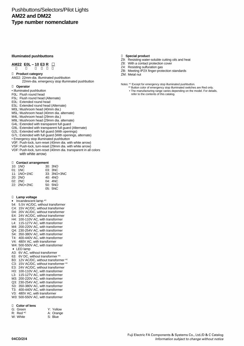
04CD/2/4Fuji Electric FA Components & Systems Co., Ltd./D & C Catalog
Information subject to change without notice
Pushbuttons/Selectors/Pilot LightsAM22 and DM22Type number nomenclature
Illuminated pushbuttons
AM22 E0L – 10 E3 R➀ ➁ ➂ ➃ ➄ ➅
➀ Product categoryAM22: 22mm-dia. illuminated pushbutton
22mm-dia. emergency stop illuminated pushbutton
➁ Operator• Illuminated pushbuttonF0L: Flush round headF5L: Flush round head (Alternate)E0L: Extended round headE5L: Extended round head (Alternate)M0L: Mushroom head (40mm dia.)M5L: Mushroom head (40mm dia. alternate)M4L: Mushroom head (29mm dia.)M9L: Mushroom head (29mm dia. alternate)G4L: Extended with transparent full guardG9L: Extended with transparent full guard (Alternate)G2L: Extended with full guard (With openings)G7L: Extended with full guard (With openings, alternate)• Emergency stop illuminated pushbuttonV0F: Push-lock, turn-reset (40mm dia. with white arrow)VSF: Push-lock, turn-reset (29mm dia. with white arrow)VDF: Push-lock, turn-reset (40mm dia. transparent in all colors
with white arrow)
➂ Contact arrangement10: 1NO 30: 3NO01: 1NC 03: 3NC11: 1NO+1NC 33: 3NO+3NC20: 2NO 40: 4NO02: 2NC 04: 4NC22: 2NO+2NC 50: 5NO
05: 5NC
➃ Lamp voltage• Incandescent lamp *1
54: 5.5V AC/DC, without transformerC4: 15V AC/DC, without transformerD4: 20V AC/DC, without transformerE4: 24V AC/DC, without transformerH4: 100-110V AC, with transformerL4: 115-127V AC, with transformerM4: 200-220V AC, with transformerQ4: 230-254V AC, with transformerS4: 350-380V AC, with transformerT4: 400-440V AC, with transformerV4: 480V AC, with transformerW4: 500-550V AC, with transformer • LED lampA3: 6V AC, without transformer63: 6V DC, without transformer *1
B3: 12V AC/DC, without transformer *1
C3: 15V AC/DC, without transformer *1
E3: 24V AC/DC, without transformerH3: 100-110V AC, with transformerL3: 115-127V AC, with transformerM3: 200-220V AC, with transformerQ3: 230-254V AC, with transformerS3: 350-380V AC, with transformerT3: 400-440V AC, with transformerV3: 480V AC, with transformerW3: 500-550V AC, with transformer
➄ Color of lensG: Green Y: YellowR: Red *2 A: OrangeW: White S: Blue
➅ Special productZ9: Resisting water-soluble cutting oils and heatZ8: With a contact protection coverZ4: Resisting sulfuration gasZB: Meeting IP2X finger-protection standardsZM: Metal nut
Notes: *1 Except for emergency stop illuminated pushbutton.*2 Button color of emergency stop illuminated switches are Red only. • The manufacturing range varies depending on the model. For details,
refer to the contents of this catalog.

04CD/2/5Fuji Electric FA Components & Systems Co., Ltd./D & C CatalogInformation subject to change without notice
Pushbuttons/Selectors/Pilot LightsAM22 and DM22
Type number nomenclature
Pushbuttons
AM22 E0R – 10 R➀ ➁ ➂ ➃ ➄
➀ Product categoryAM22: 22mm-dia. pushbutton
➁ Operator • Pushbutton switchF0R: Flush round headF5R: Flush round head (Alternate)E0R: Extended round headE5R: Extended round head (Alternate)M0R: Mushroom head (40mm dia.)M5R: Mushroom head (40mm dia. alternate)M4R: Mushroom head (29mm dia.)G3R:Extended with full guard (24mm dia.)G8R:Extended with full guard (24mm dia. alternate)M3R:Mushroom head with full guard (40mm dia.)M8R:Mushroom head with full guard (40mm dia. alternate) • Emergency stop pushbutton switchV0E: Push-lock, turn-reset (40mm dia. with white arrow)VSE: Push-lock, turn-reset (29mm dia. with white arrow)VME:Push-lock, turn-reset (40mm dia. with mechanical indicator)
➂ Contact arrangement10: 1NO 30: 3NO01: 1NC 03: 3NC11: 1NO+1NC 33: 3NO+3NC20: 2NO 40: 4NO02: 2NC 04: 4NC22: 2NO+2NC 44: 4NO+4NC
50: 5NO05: 5NC
➃ Color of buttonG: Green Y: YellowR: Red * A: OrangeB: Black S: BlueW: WhiteT: Green, Red, Black (For AM22F0R)
➄ Special productZ9: Resisting water-soluble cutting oils and heatZ8: With a contact protection coverZ4: Resisting sulfuration gasZB: Meeting IP2X finger-protection standardsZM: Metal nut
Notes: * Button color of emergency stop switches are Red only.• The manufacturing range varies depending on the model. For details, refer
to the contents of this catalog.
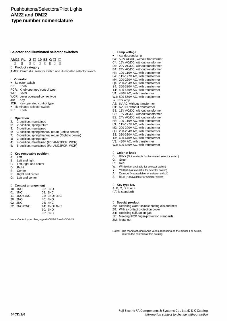
04CD/2/6Fuji Electric FA Components & Systems Co., Ltd./D & C Catalog
Information subject to change without notice
Pushbuttons/Selectors/Pilot LightsAM22 and DM22Type number nomenclature
Selector and illuminated selector switches
AM22 PL – 2 10 E3 G ➀ ➁ ➂ ➃ ➄ ➅ ➆ ➇ ➈
➀ Product categoryAM22: 22mm dia. selector switch and illuminated selector switch
➁ Operator• Selector switchPR: KnobPCR: Knob operated control typeWR: LeverWCR: Lever operated control typeJR: KeyJCR: Key operated control type• Illuminated selector switchPL: Knob
➂ Operation2: 2-position, maintained0: 2-position, spring return3: 3-position, maintained6: 3-position, spring/manual return (Left to center)7: 3-position, spring/manual return (Right to center)1: 3-position, spring return4: 4-position, maintained (For AM22PCR, WCR)5: 5-position, maintained (For AM22PCR, WCR)
➃ Key removable positionA: LeftB: Left and rightC: Left, right and centerD: RightE: CenterF: Right and centerG: Left and center
➄ Contact arrangement10: 1NO 30: 3NO01: 1NC 03: 3NC11: 1NO+1NC 33: 3NO+3NC20: 2NO 40: 4NO02: 2NC 04: 4NC22: 2NO+2NC 44: 4NO+4NC
50: 5NO05: 5NC
Note: Control type: See page 04CD/2/22 to 04CD/2/24
➅ Lamp voltage• Incandescent lamp54: 5.5V AC/DC, without transformerC4: 15V AC/DC, without transformerD4: 20V AC/DC, without transformerE4: 24V AC/DC, without transformerH4: 100-110V AC, with transformerL4: 115-127V AC, with transformerM4: 200-220V AC, with transformerQ4: 230-254V AC, with transformerS4: 350-380V AC, with transformerT4: 400-440V AC, with transformerV4: 480V AC, with transformerW4: 500-550V AC, with transformer • LED lampA3: 6V AC, without transformer63: 6V DC, without transformerB3: 12V AC/DC, without transformerC3: 15V AC/DC, without transformerE3: 24V AC/DC, without transformerH3: 100-110V AC, with transformerL3: 115-127V AC, with transformerM3: 200-220V AC, with transformerQ3: 230-254V AC, with transformerS3: 350-380V AC, with transformerT3: 400-440V AC, with transformerV3: 480V AC, with transformerW3: 500-550V AC, with transformer
➆ Color of knobB: Black (Not available for illuminated selector switch)G: GreenR: RedW: White (Not available for selector switch)Y: Yellow (Not available for selector switch)A: Orange (Not available for selector switch)S: Blue (Not available for selector switch)
➇ Key type No.A, B, C, D, E or F(“A” is standard)
➈ Special productZ9: Resisting water-soluble cutting oils and heatZ8: With a contact protection coverZ4: Resisting sulfuration gasZB: Meeting IP2X finger-protection standardsZM: Metal nut
Notes: •The manufacturing range varies depending on the model. For details,refer to the contents of this catalog.
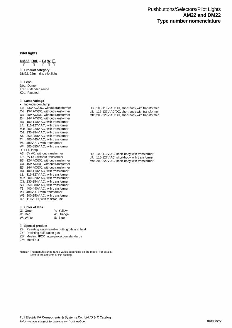
04CD/2/7Fuji Electric FA Components & Systems Co., Ltd./D & C CatalogInformation subject to change without notice
Pushbuttons/Selectors/Pilot LightsAM22 and DM22
Type number nomenclature
Pilot lights
DM22 D0L – E3 W➀ ➁ ➂ ➃ ➄
➀ Product categoryDM22: 22mm dia. pilot light
➁ LensD0L: DomeE3L: Extended roundK0L: Faceted
➂ Lamp voltage• Incandescent lamp54: 5.5V AC/DC, without transformerC4: 15V AC/DC, without transformerD4: 20V AC/DC, without transformerE4: 24V AC/DC, without transformerH4: 100-110V AC, with transformerL4: 115-127V AC, with transformerM4: 200-220V AC, with transformerQ4: 230-254V AC, with transformerS4: 350-380V AC, with transformerT4: 400-440V AC, with transformerV4: 480V AC, with transformerW4: 500-550V AC, with transformer • LED lampA3: 6V AC, without transformer63: 6V DC, without transformerB3: 12V AC/DC, without transformerC3: 15V AC/DC, without transformerE3: 24V AC/DC, without transformerH3: 100-110V AC, with transformerL3: 115-127V AC, with transformerM3: 200-220V AC, with transformerQ3: 230-254V AC, with transformerS3: 350-380V AC, with transformerT3: 400-440V AC, with transformerV3: 480V AC, with transformerW3: 500-550V AC, with transformerH7: 110V DC, with resistor unit
➃ Color of lensG: Green Y: YellowR: Red A: OrangeW: White S: Blue
➄ Special productZ9: Resisting water-soluble cutting oils and heatZ4: Resisting sulfuration gasZB: Meeting IP2X finger-protection standardsZM: Metal nut
Notes: • The manufacturing range varies depending on the model. For details, refer to the contents of this catalog.
H8: 100-110V AC/DC, short-body with transformerL8: 115-127V AC/DC, short-body with transformerM8: 200-220V AC/DC, short-body with transformer
H9: 100-110V AC, short-body with transformerL9: 115-127V AC, short-body with transformerM9: 200-220V AC, short-body with transformer
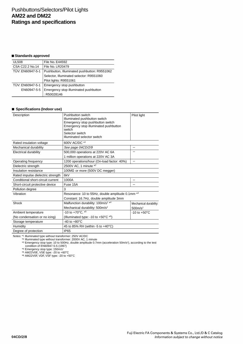
04CD/2/8Fuji Electric FA Components & Systems Co., Ltd./D & C Catalog
Information subject to change without notice
Pushbuttons/Selectors/Pilot LightsAM22 and DM22Ratings and specifications
Specifications (Indoor use)
Pilot lightDescription Pushbutton switch Illuminated pushbutton switchEmergency stop pushbutton switchEmergency stop illuminated pushbutton switchSelector switchIlluminated selector switch
Rated insulation voltageMechanical durability Electrical durability
Operating frequencyDielectric strengthInsulation resistanceRated impulse dielectric strengthConditional short-circuit currentShort-circuit protective devicePollution degreeVibration
Shock
Ambient temperature(No condensation or no icing)Storage temperatureHumidityDegree of protection
600V AC/DC *1
See page 04CD/2/9500,000 operations at 220V AC 6A1 million operations at 220V AC 3A1200 operations/hour (On-load factor: 40%)2500V AC, 1 minute *2
100MΩ or more (500V DC megger)6kV1000AFuse 15A3Resonance: 10 to 55Hz, double amplitude 0.1mm *3
Constant: 16.7Hz, double amplitude 3mmMalfunction durability: 100m/s2 *4
Mechanical durability: 500m/s2
-10 to +70°C, *5
(Illuminated type: -10 to +50°C *6)-40 to +80°C45 to 85% RH (within -5 to +40°C)IP65
Notes: *1 Illuminated type without transformer: 250V AC/DC *2 Illuminated type without transformer: 2000V AC, 1 minute *3 Emergency stop type: 10 to 500Hz, double amplitude 0.7mm (acceleration 50m/s2), according to the test
condition of EN60947-5-5 (1997) *4 Emergency stop type: 150m/s2
*5 AM22V0E, VSE type: -20 to +60°C *6 AM22V0F, VDF, VSF type: -20 to +50°C
Mechanical durability: 500m/s2
-10 to +50°C
Standards approved
UL508CSA C22.2 No.14TÜV: EN60947-5-1
TÜV: EN60947-5-1 EN60947-5-5
File No. E44592File No. LR20479Pushbutton, Illuminated pushbutton: R9551062 Selector, Illuminated selector: R9551060Pilot lights: R9551061Emergency stop pushbuttonEmergency stop illuminated pushbutton: R50028146
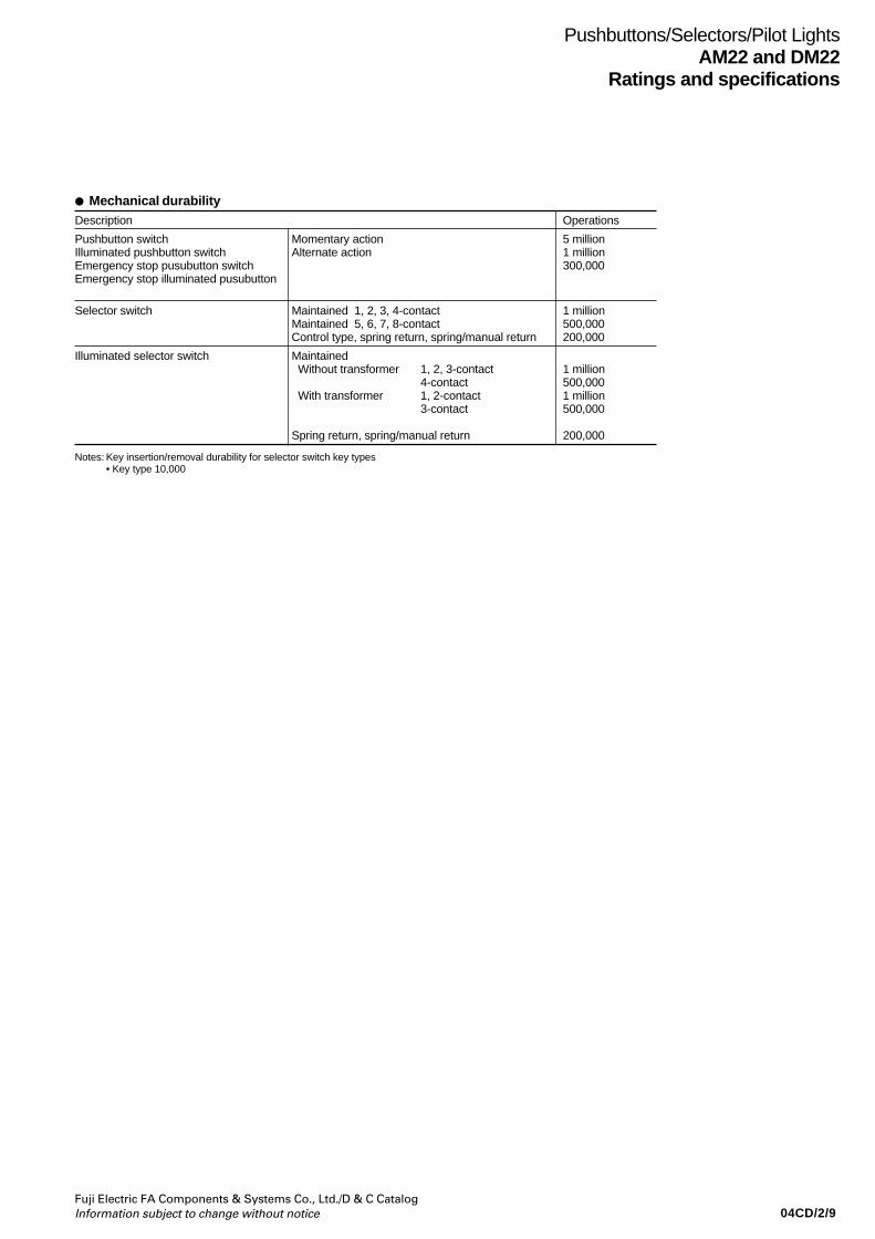
04CD/2/9Fuji Electric FA Components & Systems Co., Ltd./D & C CatalogInformation subject to change without notice
Pushbuttons/Selectors/Pilot LightsAM22 and DM22
Ratings and specifications
Mechanical durabilityDescription Operations
Pushbutton switch Momentary action 5 millionIlluminated pushbutton switch Alternate action 1 millionEmergency stop pusubutton switch 300,000Emergency stop illuminated pusubutton
Selector switch Maintained 1, 2, 3, 4-contact 1 millionMaintained 5, 6, 7, 8-contact 500,000Control type, spring return, spring/manual return 200,000
Illuminated selector switch Maintained Without transformer 1, 2, 3-contact 1 million
4-contact 500,000 With transformer 1, 2-contact 1 million
3-contact 500,000
Spring return, spring/manual return 200,000
Notes: Key insertion/removal durability for selector switch key types• Key type 10,000
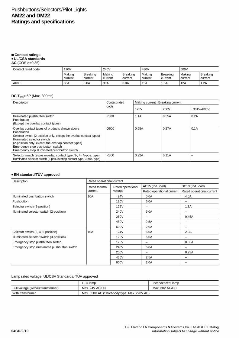
04CD/2/10Fuji Electric FA Components & Systems Co., Ltd./D & C Catalog
Information subject to change without notice
Pushbuttons/Selectors/Pilot LightsAM22 and DM22Ratings and specifications
• EN standard/TÜV approved
Rated operational currentDescripton
Rated thermal Rated operational AC15 (Ind. load) DC13 (Ind. load)current voltage Rated operational current Rated operational current
Illuminated pushbutton switch 10A 24V 6.0A 4.0A
Pushbutton 120V 6.0A –
Selector switch (2-position) 125V – 1.3A
Illuminated selector switch (2-position) 240V 6.0A –
250V – 0.45A
480V 2.5A –
600V 2.0A –
Selector switch (3, 4, 5-position) 10A 24V 6.0A 2.0A
Illuminated selector switch (3-position) 120V 6.0A –
Emergency stop pushbutton switch 125V – 0.65A
Emergency stop illuminated pushbutton switch 240V 6.0A –
250V – 0.23A
480V 2.5A –
600V 2.0A –
DC T0.95= 6P (Max. 300ms)
Descripton Contact rated Making current · Breaking currentcode
125V 250V 301V–600V
Illuminated pushbutton switch P600 1.1A 0.55A 0.2APushbutton(Except the overlap contact types)
Overlap contact types of products shown above Q600 0.55A 0.27A 0.1APushbuttonSelector switch (2-position only, except the overlap contact types)Illuminated selector switch(2-position only, except the overlap contact types)Emergency stop pushbutton switchEmergency stop illuminated pushbutton switch
Selector switch (2-pos./overlap contact type, 3-, 4-, 5-pos. type) R300 0.22A 0.11A –Illuminated selector switch (2-pos./overlap contact type, 3-pos. type)
Lamp rated voltage UL/CSA Standards, TÜV approved
LED lamp Incandescent lamp
Full-voltage (without transformer) Max. 24V AC/DC Max. 30V AC/DC
With transformer Max. 550V AC (Short-body type: Max. 220V AC)
Contact ratings• UL/CSA standardsAC (COS ø=0.35)
Contact rated code 120V 240V 480V 600V
Making Breaking Making Breaking Making Breaking Making Breakingcurrent current current current current current current current
A600 60A 6.0A 30A 3.0A 15A 1.5A 12A 1.2A

04CD/2/11Fuji Electric FA Components & Systems Co., Ltd./D & C CatalogInformation subject to change without notice
Pushbuttons/Selectors/Pilot LightsAM22 and DM22
Ratings and specifications
Operating characteristic (1NO+1NC)
Description
Note: * 4-position, 5-position : 2NO+2NC
PushbuttonIlluminated pushbutton
Ave. required operating forceOperating travel
Required return force
9N
Approx. 6mm
–
Emergency stop pushbutton Emergency stop illuminated pushbuttonPush-lock type
Selector *Illuminated selector Maintained Spring/manual return Spring return
22N
Approx. 9mm
( Operation angle: Approx. 60°)
0.25N•m
0.15N•m
2-position: Approx. 90°
3-position: Approx. 45°
4-position: Approx. 40°
5-position: Approx. 30°
0.15N•m
0.13N•m
3-position: Approx. 45°
0.13N•m
0.1N•m
2-position: Approx. 60°
3-position: Approx. 45°
–
Lamp ratings• Illuminated pushbuttons, illuminated selectors, pilot lights
Transformer
Without transformer
With transformer(Standard type: AR9T511)
With resistor unit(AR9T519-H)
Lamp voltege
5.5V AC/DC6V AC
6V DC
12V AC/DC
15V AC/DC
20V AC/DC24V AC/DC110V AC127V AC220V AC254V AC380V AC440V AC480V AC550V AC110V DC
LED (lamp base: BA9S/13) Type–APX510-6
APX510-D6
APX510-12
APX510-15
–APX510-24APX510-6
APX510-6
APX510-24
Rated voltage–6V AC
6V DC
12V AC/DC
15V AC/DC
–24V AC/DC6V AC
6V AC
24V AC/DC
Consumption–Green, red, orange, amber, blue: 7mA ACYellow: 50mA ACGreen, red, orange, amber, blue: 11mA DCYellow: 33mA DCGreen, red, orange, amber, blue: 14mA AC, 11mA DCYellow: 28mA AC, 22mA DCGreen, red, orange, amber, blue: 13mA AC, 11mA DCYellow: 26mA AC, 22mA DC–12mA AC, 11mA DC1.5VA
2.5VA
1.2W
Incandescent (lamp base: BA9S/13)TypeAHX135–
–
–
AHX279
AHX144AHX129AHX135
AHX135
–
Rated voltage6.3V AC/DC–
–
–
18V AC/DC
24V AC/DC30V AC/DC6.3V AC/DC
6.3V AC/DC
–
Consumption0.9W–
–
–
0.8W
0.9W0.8W2VA2VA2VA2.5VA2.5VA2.5VA2.5VA2.5VA–
Notes: • Short body pilot lights: 110V AC, 127V AC, 220V AC only• Replace the mark by the lamp luminous color code, see page 04CD/2/12• Except AM22V0F, VDF, VSF type
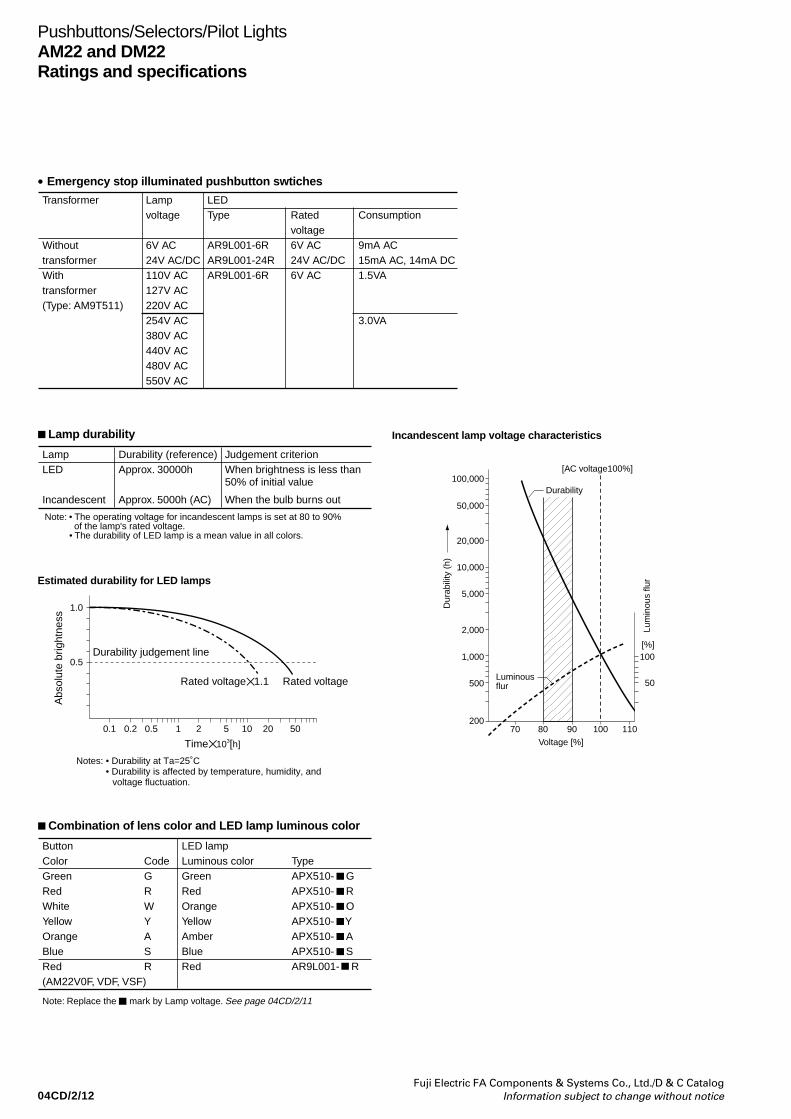
04CD/2/12Fuji Electric FA Components & Systems Co., Ltd./D & C Catalog
Information subject to change without notice
Pushbuttons/Selectors/Pilot LightsAM22 and DM22Ratings and specifications
Combination of lens color and LED lamp luminous color
LampLED
Incandescent
Durability (reference)Approx. 30000h
Approx. 5000h (AC)
Judgement criterionWhen brightness is less than 50% of initial value
When the bulb burns out
Note: • The operating voltage for incandescent lamps is set at 80 to 90% of the lamp's rated voltage.
• The durability of LED lamp is a mean value in all colors.
Estimated durability for LED lamps
1.0
0.5
0.1 0.2 0.5 1 2 5 10 20 50
Time 103[h]
Abs
olut
e br
ight
ness
Durability judgement line
Rated voltage1.1 Rated voltage
Notes: • Durability at Ta=25˚C• Durability is affected by temperature, humidity, and
voltage fluctuation.
• Emergency stop illuminated pushbutton swtiches
[AC voltage100%]100,000
50,000
20,000
10,000
5,000
2,000
1,000
500
20070 80
Voltage [%]
90 100 110
100
50
Durability
Luminous flur
Dur
abili
ty (
h)
Lum
inou
s flu
r[%]
Incandescent lamp voltage characteristics
Transformer
WithouttransformerWithtransformer(Type: AM9T511)
Lampvoltage
6V AC24V AC/DC110V AC127V AC220V AC254V AC380V AC440V AC480V AC550V AC
LEDType
AR9L001-6RAR9L001-24RAR9L001-6R
Ratedvoltage6V AC24V AC/DC6V AC
Consumption
9mA AC15mA AC, 14mA DC1.5VA
3.0VA
Lamp durability
ButtonColorGreenRedWhiteYellowOrangeBlueRed (AM22V0F, VDF, VSF)
Note: Replace the mark by Lamp voltage. See page 04CD/2/11
CodeGRWYASR
LED lampLuminous colorGreenRedOrangeYellowAmberBlueRed
TypeAPX510- GAPX510- RAPX510- OAPX510- YAPX510- AAPX510- SAR9L001- R
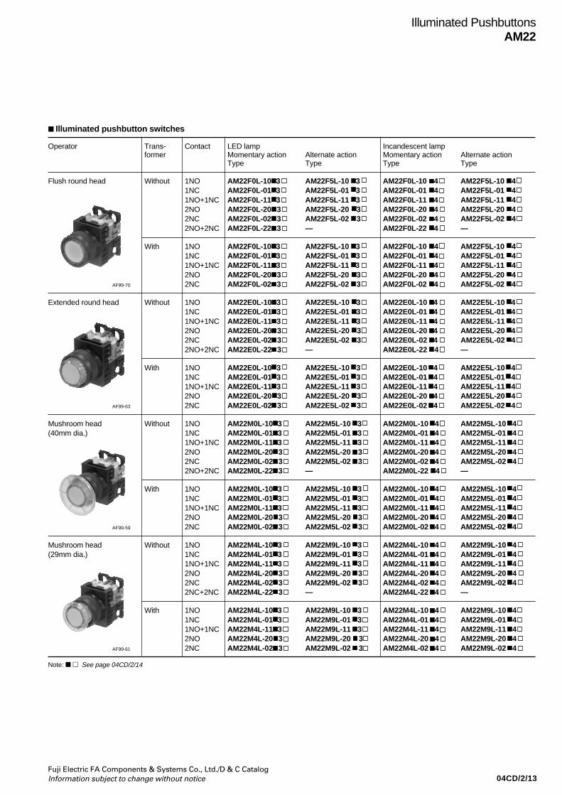
04CD/2/13Fuji Electric FA Components & Systems Co., Ltd./D & C CatalogInformation subject to change without notice
Operator Trans- Contact LED lamp Incandescent lampformer Momentary action Alternate action Momentary action Alternate action
Type Type Type Type
Flush round head Without 1NO AM22F0L-10 3 AM22F5L-10 3 AM22F0L-10 4 AM22F5L-10 41NC AM22F0L-01 3 AM22F5L-01 3 AM22F0L-01 4 AM22F5L-01 41NO+1NC AM22F0L-11 3 AM22F5L-11 3 AM22F0L-11 4 AM22F5L-11 42NO AM22F0L-20 3 AM22F5L-20 3 AM22F0L-20 4 AM22F5L-20 42NC AM22F0L-02 3 AM22F5L-02 3 AM22F0L-02 4 AM22F5L-02 42NO+2NC AM22F0L-22 3 — AM22F0L-22 4 —
With 1NO AM22F0L-10 3 AM22F5L-10 3 AM22F0L-10 4 AM22F5L-10 41NC AM22F0L-01 3 AM22F5L-01 3 AM22F0L-01 4 AM22F5L-01 41NO+1NC AM22F0L-11 3 AM22F5L-11 3 AM22F0L-11 4 AM22F5L-11 42NO AM22F0L-20 3 AM22F5L-20 3 AM22F0L-20 4 AM22F5L-20 4
AF99-70 2NC AM22F0L-02 3 AM22F5L-02 3 AM22F0L-02 4 AM22F5L-02 4
Extended round head Without 1NO AM22E0L-10 3 AM22E5L-10 3 AM22E0L-10 4 AM22E5L-10 41NC AM22E0L-01 3 AM22E5L-01 3 AM22E0L-01 4 AM22E5L-01 41NO+1NC AM22E0L-11 3 AM22E5L-11 3 AM22E0L-11 4 AM22E5L-11 42NO AM22E0L-20 3 AM22E5L-20 3 AM22E0L-20 4 AM22E5L-20 42NC AM22E0L-02 3 AM22E5L-02 3 AM22E0L-02 4 AM22E5L-02 42NO+2NC AM22E0L-22 3 — AM22E0L-22 4 —
With 1NO AM22E0L-10 3 AM22E5L-10 3 AM22E0L-10 4 AM22E5L-10 41NC AM22E0L-01 3 AM22E5L-01 3 AM22E0L-01 4 AM22E5L-01 41NO+1NC AM22E0L-11 3 AM22E5L-11 3 AM22E0L-11 4 AM22E5L-11 42NO AM22E0L-20 3 AM22E5L-20 3 AM22E0L-20 4 AM22E5L-20 4
AF99-63 2NC AM22E0L-02 3 AM22E5L-02 3 AM22E0L-02 4 AM22E5L-02 4
Mushroom head Without 1NO AM22M0L-10 3 AM22M5L-10 3 AM22M0L-10 4 AM22M5L-10 4(40mm dia.) 1NC AM22M0L-01 3 AM22M5L-01 3 AM22M0L-01 4 AM22M5L-01 4
1NO+1NC AM22M0L-11 3 AM22M5L-11 3 AM22M0L-11 4 AM22M5L-11 42NO AM22M0L-20 3 AM22M5L-20 3 AM22M0L-20 4 AM22M5L-20 42NC AM22M0L-02 3 AM22M5L-02 3 AM22M0L-02 4 AM22M5L-02 42NO+2NC AM22M0L-22 3 — AM22M0L-22 4 —
With 1NO AM22M0L-10 3 AM22M5L-10 3 AM22M0L-10 4 AM22M5L-10 41NC AM22M0L-01 3 AM22M5L-01 3 AM22M0L-01 4 AM22M5L-01 41NO+1NC AM22M0L-11 3 AM22M5L-11 3 AM22M0L-11 4 AM22M5L-11 42NO AM22M0L-20 3 AM22M5L-20 3 AM22M0L-20 4 AM22M5L-20 4
AF99-59 2NC AM22M0L-02 3 AM22M5L-02 3 AM22M0L-02 4 AM22M5L-02 4
Mushroom head Without 1NO AM22M4L-10 3 AM22M9L-10 3 AM22M4L-10 4 AM22M9L-10 4(29mm dia.) 1NC AM22M4L-01 3 AM22M9L-01 3 AM22M4L-01 4 AM22M9L-01 4
1NO+1NC AM22M4L-11 3 AM22M9L-11 3 AM22M4L-11 4 AM22M9L-11 42NO AM22M4L-20 3 AM22M9L-20 3 AM22M4L-20 4 AM22M9L-20 42NC AM22M4L-02 3 AM22M9L-02 3 AM22M4L-02 4 AM22M9L-02 42NC+2NC AM22M4L-22 3 — AM22M4L-22 4 —
With 1NO AM22M4L-10 3 AM22M9L-10 3 AM22M4L-10 4 AM22M9L-10 41NC AM22M4L-01 3 AM22M9L-01 3 AM22M4L-01 4 AM22M9L-01 41NO+1NC AM22M4L-11 3 AM22M9L-11 3 AM22M4L-11 4 AM22M9L-11 42NO AM22M4L-20 3 AM22M9L-20 3 AM22M4L-20 4 AM22M9L-20 4
AF99-61 2NC AM22M4L-02 3 AM22M9L-02 3 AM22M4L-02 4 AM22M9L-02 4
Illuminated PushbuttonsAM22
Illuminated pushbutton switches
Note: See page 04CD/2/14
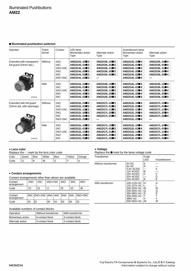
04CD/2/14Fuji Electric FA Components & Systems Co., Ltd./D & C Catalog
Information subject to change without notice
• Lens colorReplace the mark by the lens color codeColor Green Red White Blue Yellow Orange
Code G R W S Y A
• VoltageReplace the mark by the lamp voltage codeTransformer Code
LED Incandescent
Without transformer 6V DC 6 —6V AC A —5.5V AC/DC — 512V AC/DC B —15V AC/DC C C20V AC/DC — D24V AC/DC E E
With transformer 100-110V AC H H115-127V AC L L200-220V AC M M230-254V AC Q Q350-380V AC S S400-440V AC T T480V AC V V500-550V AC W W
• Contact arrangementsContact arrangements other than above are availableContact 1NO 1NC 1NO+1NC 2NO 2NC 3NOarrangement
Code 10 01 11 20 02 30
Contact 3NC 2NO+2NC 4NO 4NC 5NO 5NC 3NO+3NCarrangement
Code 03 22 40 04 50 05 33
Available numbers of contact blocks
Operation Without transformer With transformer
Momentary action 6-contact block 4-contact block
Alternate action 3-contact block 2-contact block
Illuminated PushbuttonsAM22
Operator Trans- Contact LED lamp Incandescent lampformer Momentary action Alternate action Momentary action Alternate action
Type Type Type Type
Extended with transparent Without 1NO AM22G4L-10 3 AM22G9L-10 3 AM22G4L-10 4 AM22G9L-10 4 full guard (24mm dia.) 1NC AM22G4L-01 3 AM22G9L-01 3 AM22G4L-01 4 AM22G9L-01 4
1NO+1NC AM22G4L-11 3 AM22G9L-11 3 AM22G4L-11 4 AM22G9L-11 4 2NO AM22G4L-20 3 AM22G9L-20 3 AM22G4L-20 4 AM22G9L-20 4 2NC AM22G4L-02 3 AM22G9L-02 3 AM22G4L-02 4 AM22G9L-02 4 2NO+2NC AM22G4L-22 3 — AM22G4L-22 4 —
With 1NO AM22G4L-10 3 AM22G9L-10 3 AM22G4L-10 4 AM22G9L-10 4 1NC AM22G4L-01 3 AM22G9L-01 3 AM22G4L-01 4 AM22G9L-01 4 1NO+1NC AM22G4L-11 3 AM22G9L-11 3 AM22G4L-11 4 AM22G9L-11 4 2NO AM22G4L-20 3 AM22G9L-20 3 AM22G4L-20 4 AM22G9L-20 4
AF99-66 2NC AM22G4L-02 3 AM22G9L-02 3 AM22G4L-02 4 AM22G9L-02 4
Extended with full guard Without 1NO AM22G2L-10 3 AM22G7L-10 3 AM22G2L-10 4 AM22G7L-10 4 (24mm dia. with openings) 1NC AM22G2L-01 3 AM22G7L-01 3 AM22G2L-01 4 AM22G7L-01 4
1NO+1NC AM22G2L-11 3 AM22G7L-11 3 AM22G2L-11 4 AM22G7L-11 4 2NO AM22G2L-20 3 AM22G7L-20 3 AM22G2L-20 4 AM22G7L-20 4 2NC AM22G2L-02 3 AM22G7L-02 3 AM22G2L-02 4 AM22G7L-02 4 2NO+2NC AM22G2L-22 3 — AM22G2L-22 4 —
With 1NO AM22G2L-10 3 AM22G7L-10 3 AM22G2L-10 4 AM22G7L-10 4 1NC AM22G2L-01 3 AM22G7L-01 3 AM22G2L-01 4 AM22G7L-01 4 1NO+1NC AM22G2L-11 3 AM22G7L-11 3 AM22G2L-11 4 AM22G7L-11 4 2NO AM22G2L-20 3 AM22G7L-20 3 AM22G2L-20 4 AM22G7L-20 4
AF99-69 2NC AM22G2L-02 3 AM22G7L-02 3 AM22G2L-02 4 AM22G7L-02 4
Illuminated pushbutton switches
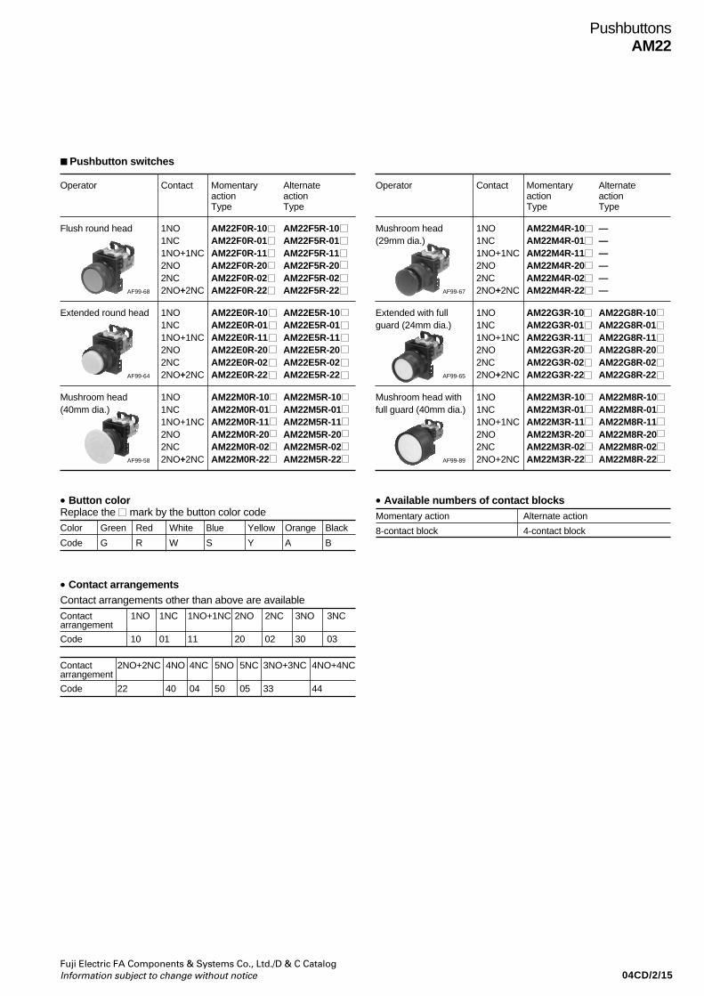
04CD/2/15Fuji Electric FA Components & Systems Co., Ltd./D & C CatalogInformation subject to change without notice
PushbuttonsAM22
Operator Contact Momentary Alternateaction actionType Type
Flush round head 1NO AM22F0R-10 AM22F5R-101NC AM22F0R-01 AM22F5R-011NO+1NC AM22F0R-11 AM22F5R-112NO AM22F0R-20 AM22F5R-202NC AM22F0R-02 AM22F5R-02
AF99-68 2NO+2NC AM22F0R-22 AM22F5R-22
Extended round head 1NO AM22E0R-10 AM22E5R-101NC AM22E0R-01 AM22E5R-011NO+1NC AM22E0R-11 AM22E5R-112NO AM22E0R-20 AM22E5R-202NC AM22E0R-02 AM22E5R-02
AF99-64 2NO+2NC AM22E0R-22 AM22E5R-22
Mushroom head 1NO AM22M0R-10 AM22M5R-10(40mm dia.) 1NC AM22M0R-01 AM22M5R-01
1NO+1NC AM22M0R-11 AM22M5R-112NO AM22M0R-20 AM22M5R-202NC AM22M0R-02 AM22M5R-02
AF99-58 2NO+2NC AM22M0R-22 AM22M5R-22
Pushbutton switches
Operator Contact Momentary Alternateaction actionType Type
Mushroom head 1NO AM22M4R-10 —(29mm dia.) 1NC AM22M4R-01 —
1NO+1NC AM22M4R-11 —2NO AM22M4R-20 —2NC AM22M4R-02 —
AF99-67 2NO+2NC AM22M4R-22 —
Extended with full 1NO AM22G3R-10 AM22G8R-10guard (24mm dia.) 1NC AM22G3R-01 AM22G8R-01
1NO+1NC AM22G3R-11 AM22G8R-112NO AM22G3R-20 AM22G8R-202NC AM22G3R-02 AM22G8R-02
AF99-65 2NO+2NC AM22G3R-22 AM22G8R-22
Mushroom head with 1NO AM22M3R-10 AM22M8R-10full guard (40mm dia.) 1NC AM22M3R-01 AM22M8R-01
1NO+1NC AM22M3R-11 AM22M8R-112NO AM22M3R-20 AM22M8R-202NC AM22M3R-02 AM22M8R-02
AF99-89 2NO+2NC AM22M3R-22 AM22M8R-22
• Available numbers of contact blocksMomentary action Alternate action
8-contact block 4-contact block
• Button colorReplace the mark by the button color codeColor Green Red White Blue Yellow Orange Black
Code G R W S Y A B
• Contact arrangementsContact arrangements other than above are available
Contact 1NO 1NC 1NO+1NC 2NO 2NC 3NO 3NCarrangement
Code 10 01 11 20 02 30 03
Contact 2NO+2NC 4NO 4NC 5NO 5NC 3NO+3NC 4NO+4NCarrangement
Code 22 40 04 50 05 33 44
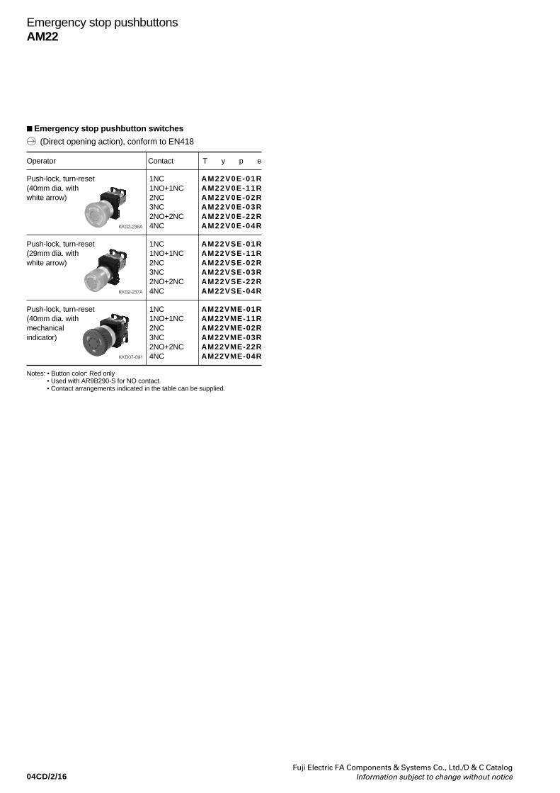
04CD/2/16Fuji Electric FA Components & Systems Co., Ltd./D & C Catalog
Information subject to change without notice
Operator Contact T y p e
Push-lock, turn-reset 1NC AM22V0E-01R(40mm dia. with 1NO+1NC AM22V0E-11Rwhite arrow) 2NC AM22V0E-02R
3NC AM22V0E-03R2NO+2NC AM22V0E-22R
KK02-236A 4NC AM22V0E-04R
Push-lock, turn-reset 1NC AM22VSE-01R(29mm dia. with 1NO+1NC AM22VSE-11Rwhite arrow) 2NC AM22VSE-02R
3NC AM22VSE-03R2NO+2NC AM22VSE-22R
KK02-237A 4NC AM22VSE-04R
Push-lock, turn-reset 1NC AM22VME-01R(40mm dia. with 1NO+1NC AM22VME-11Rmechanical 2NC AM22VME-02Rindicator) 3NC AM22VME-03R
2NO+2NC AM22VME-22RKKD07-091 4NC AM22VME-04R
Emergency stop pushbuttonsAM22
Emergency stop pushbutton switches
(Direct opening action), conform to EN418
Notes: • Button color: Red only• Used with AR9B290-S for NO contact.• Contact arrangements indicated in the table can be supplied.
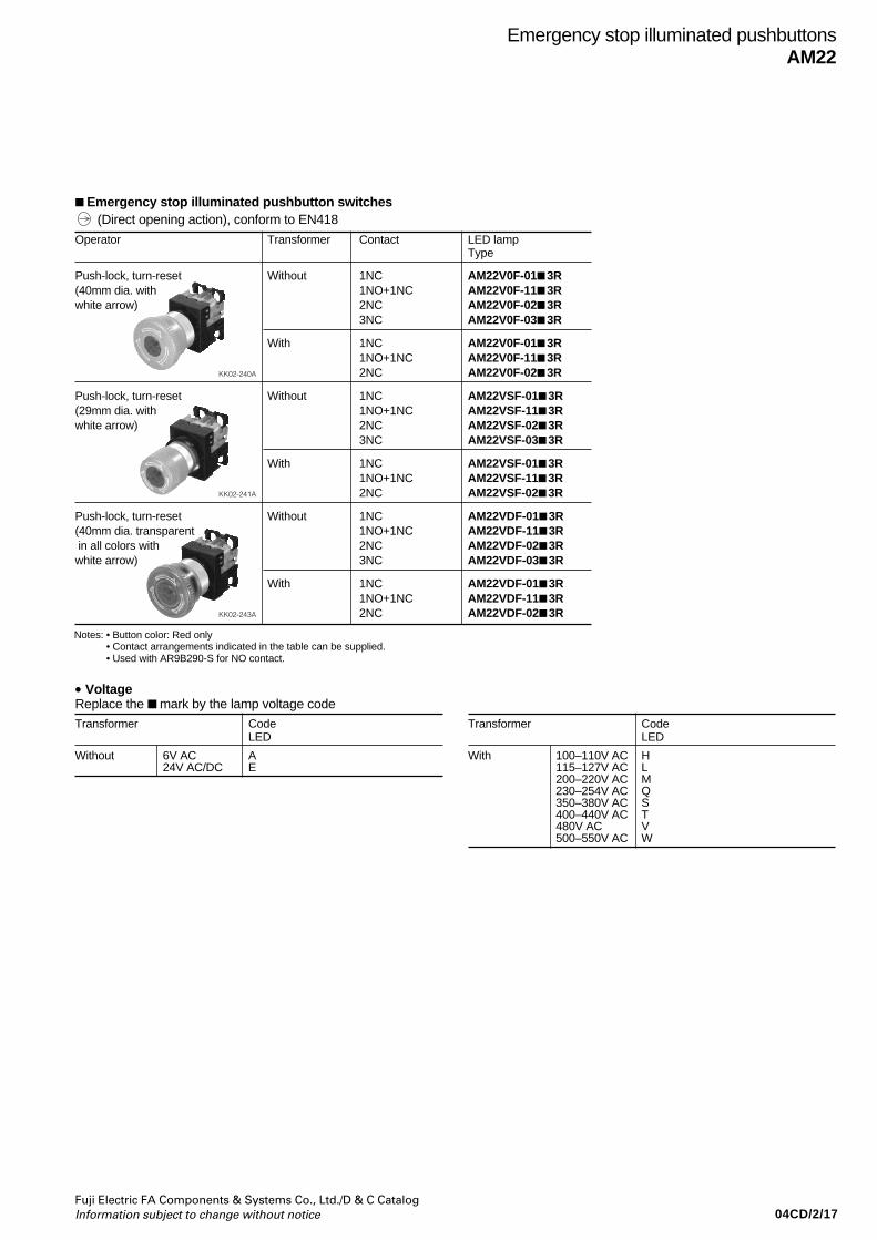
04CD/2/17Fuji Electric FA Components & Systems Co., Ltd./D & C CatalogInformation subject to change without notice
Emergency stop illuminated pushbuttonsAM22
Operator Transformer Contact LED lampType
Push-lock, turn-reset Without 1NC AM22V0F-01 3R(40mm dia. with 1NO+1NC AM22V0F-11 3Rwhite arrow) 2NC AM22V0F-02 3R
3NC AM22V0F-03 3R
With 1NC AM22V0F-01 3R1NO+1NC AM22V0F-11 3R
KK02-240A 2NC AM22V0F-02 3R
Push-lock, turn-reset Without 1NC AM22VSF-01 3R(29mm dia. with 1NO+1NC AM22VSF-11 3Rwhite arrow) 2NC AM22VSF-02 3R
3NC AM22VSF-03 3R
With 1NC AM22VSF-01 3R1NO+1NC AM22VSF-11 3R
KK02-241A 2NC AM22VSF-02 3R
Push-lock, turn-reset Without 1NC AM22VDF-01 3R(40mm dia. transparent 1NO+1NC AM22VDF-11 3R in all colors with 2NC AM22VDF-02 3Rwhite arrow) 3NC AM22VDF-03 3R
With 1NC AM22VDF-01 3R1NO+1NC AM22VDF-11 3R
KK02-243A 2NC AM22VDF-02 3R
Emergency stop illuminated pushbutton switches
• VoltageReplace the mark by the lamp voltage code
Transformer CodeLED
Without 6V AC A24V AC/DC E
Transformer CodeLED
With 100–110V AC H115–127V AC L200–220V AC M230–254V AC Q350–380V AC S400–440V AC T480V AC V500–550V AC W
(Direct opening action), conform to EN418
Notes: • Button color: Red only • Contact arrangements indicated in the table can be supplied. • Used with AR9B290-S for NO contact.
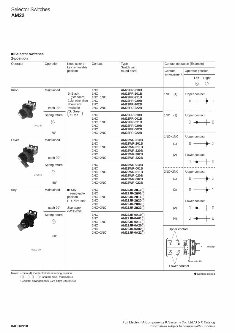
04CD/2/18Fuji Electric FA Components & Systems Co., Ltd./D & C Catalog
Information subject to change without notice
2-positionOperator Operation Knob color or Contact Type Contact operation (Example)
key removable Switch withposition round bezel Contact Operator position
arrangement Left Right
Knob Maintained 1NO AM22PR-210B1NC AM22PR-201B1NO+1NC AM22PR-211B2NO AM22PR-020B2NC AM22PR-202B
each 90° 2NO+2NC AM22PR-222B
Spring return 1NO AM22PR-010B1NC AM22PR-001B1NO+1NC AM22PR-011B2NO AM22PR-020B2NC AM22PR-002B
60° 2NO+2NC AM22PR-022B
Lever Maintained 1NO AM22WR-210B1NC AM22WR-201B1NO+1NC AM22WR-211B2NO AM22WR-220B2NC AM22WR-202B
each 90° 2NO+2NC AM22WR-222B
Spring return 1NO AM22WR-010B1NC AM22WR-001B1NO+1NC AM22WR-011B2NO AM22WR-020B2NC AM22WR-002B
60° 2NO+2NC AM22WR-022B
Key Maintained : Key 1NO AM22JR-2 10( ) removable 1NC AM22JR-2 01( )
position 1NO+1NC AM22JR-2 11( )( ): Key type 2NO AM22JR-2 20( )
2NC AM22JR-2 02( ) each 90° See page 2NO+2NC AM22JR-2 22( )
04CD/2/20Spring return 1NO AM22JR-0A10( )
1NC AM22JR-0A01( )1NO+1NC AM22JR-0A11( )2NO AM22JR-0A20( )2NC AM22JR-0A02( )2NO+2NC AM22JR-0A22( )
60°
Selector SwitchesAM22
Notes: • (1) to (4): Contact block mounting position• ➀ – ➁ , ➂ – ➃ : Contact block terminal No.• Contact arrangements: See page 04CD/2/20
Upper contact
Lower contact
Operator
Name plate side
(1)
(2)
(3)
(4)
Selector switches
Contact closed
➂ ➃
1NO (1) Upper contact
➀ ➁
1NC (1) Upper contact
➂ ➃
1NO+1NC Upper contact
(1)
➀ ➁
(2) Lower contact
➂ ➃
2NO+2NC Upper contact
(1)
Lower contact
➂ ➃ (3)
➀ ➁ (2)
➀ ➁ (4)
B: Black(Standard)
Color other thanabove areavailable G: Green R: Red
AF99-82
AF99-76
KKD09-014

04CD/2/19Fuji Electric FA Components & Systems Co., Ltd./D & C CatalogInformation subject to change without notice
Selector SwitchesAM22
3-positionOperator Operation Knob color Contact Type Contact operation (Example)
Switch withround bezel Contact Operation position
arrange-ment L C R L C R
Knob Maintained 1NO+1NC AM22PR-311B 1NO+1NC Upper contact Lower contact2NO AM22PR-320B ➂ ➀2NC AM22PR-302B 2NO+2NC AM22PR-322B ➃ ➁
Spring/manual 1NO+1NC AM22PR-611Breturn 2NO AM22PR-620B
2NC AM22PR-602B2NO+2NC AM22PR-622B
Spring/manual 1NO+1NC AM22PR-711B 1NO+1NC Upper contact Lower contactreturn 2NO AM22PR-720B ➂ ➀
2NC AM22PR-702B 2NO+2NC AM22PR-722B ➃ ➁
Spring return 2NO+2NC AM22PR-122B 2NO+2NC Upper contact Lower contact➀ ➀
➁ ➁
➂ ➂ ➃ ➃
Lever Maintained 1NO+1NC AM22WR-311B 1NO+1NC Upper contact Lower contact2NO AM22WR-320B ➂ ➀2NC AM22WR-302B 2NO+2NC AM22WR-322B ➃ ➁
Spring/manual 1NO+1NC AM22WR-611Breturn 2NO AM22WR-620B
2NC AM22WR-602B2NO+2NC AM22WR-622B
Spring/manual 1NO+1NC AM22WR-711B 1NO+1NC Upper contact Lower contactreturn 2NO AM22WR-720B ➂ ➀
2NC AM22WR-702B 2NO+2NC AM22WR-722B ➃ ➁
Spring return 2NO+2NC AM22WR-122B 2NO+2NC Upper contact Lower contact➀ ➀
➁ ➁
➂ ➂ ➃ ➃
(1) (2)
(1) (2)
(1) (2)
(1) (2)
(1) (2)
(3) (4)
(3) (4)
(1) (2)
Color code:B: Black
(Standard)Color other thanabove areavailable G: Green R: Red
each 45˚
each 45˚
each 45˚
each 45˚
each 45˚
each 45˚
each 45˚
each 45˚
AF99-82
AF99-76
Contact closedNote: • Contact arrangements: See page 04CD/2/20
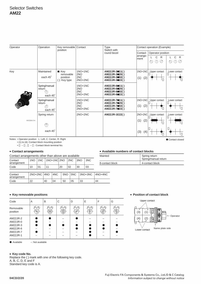
04CD/2/20Fuji Electric FA Components & Systems Co., Ltd./D & C Catalog
Information subject to change without notice
Selector SwitchesAM22
Operator Operation Key removable Contact Type Contact operation (Example)position Switch with
round bezel Contact Operator positionarrange-ment L C R L C R
Key Maintained : Key 1NO+1NC AM22JR-3 11( ) 1NO+1NC Upper contact Lower contact removable 2NO AM22JR-3 20( ) ➂ ➀ position 2NC AM22JR-3 02( )
( ): Key type 2NO+2NC AM22JR-3 22( ) ➃ ➁
Spring/manual 1NO+1NC AM22JR-6 11( )return 2NO AM22JR-6 20( )
2NC AM22JR-6 02( )2NO+2NC AM22JR-6 22( )
Spring/manual 1NO+1NC AM22JR-7 11( ) 1NO+1NC Upper contact Lower contactreturn 2NO AM22JR-7 20( ) ➂ ➀
2NC AM22JR-7 02( ) 2NO+2NC AM22JR-7 22( ) ➃ ➁
Spring return 2NO+2NC AM22JR-1E22( ) 2NO+2NC Upper contact Lower contact➀ ➀
➁ ➁
➂ ➂ ➃ ➃
Notes: • Operator position L: Left, C: Center, R: Right• (1) to (4): Contact block mounting position• ➀ – ➁ , ➂ – ➃ : Contact block terminal No.
• Key removable positions
Code A B C D E F G
Removableposition
AM22JR-2 – – – –AM22JR-0 – – – – – –AM22JR-3
AM22JR-6 – – – –AM22JR-7 – – – –
AM22JR-1 – – – – – –
: Available –: Not available
• Position of contact block
• Key code No.Replace the ( ) mark with one of the following key code.A, B, C, D, E and FStandard key code is A.
(3) (4)
(1) (2)
(1) (2)
(1) (2)
each 45˚
each 45˚
each 45˚
each 45˚
45° 45° 45° 45° 45° 45° 45° 45° 45° 45°45° 45° 45° 45°
KKD09-014
Contact closed
• Contact arrangementsContact arrangements other than above are availableContact 1NO 1NC 1NO+1NC 2NO 2NC 3NO 3NCarrangement
Code 10 01 11 20 02 30 03
Contact 2NO+2NC 4NO 4NC 5NO 5NC 3NO+3NC 4NO+4NCarrangement
Code 22 40 04 50 05 33 44
• Available numbers of contact blocksMainted Spring return
Spring/manual return
8-contact block 4-contact block
Name plate side
(1)
(2)
(3)
(4)Operator
Upper contact
Lower contact
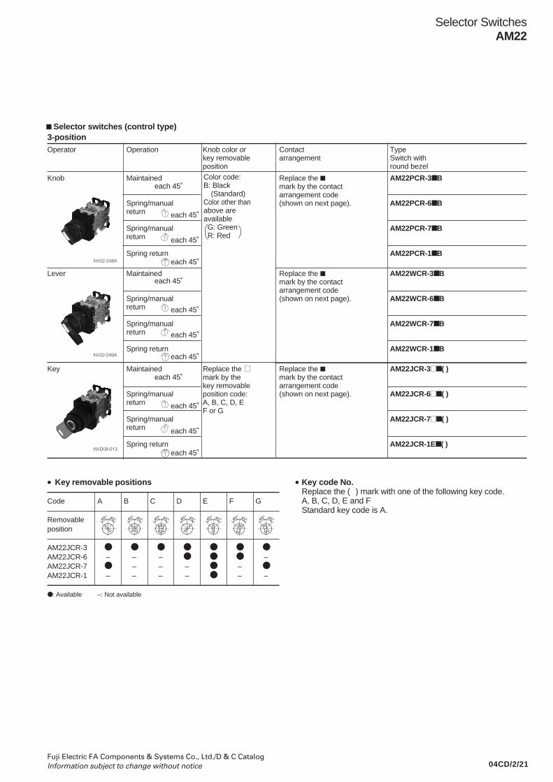
04CD/2/21Fuji Electric FA Components & Systems Co., Ltd./D & C CatalogInformation subject to change without notice
3-positionOperator Operation Knob color or Contact Type
key removable arrangement Switch withposition round bezel
Knob Maintained Replace the AM22PCR-3 Bmark by the contactarrangement code
Spring/manual (shown on next page). AM22PCR-6 Breturn
Spring/manual AM22PCR-7 Breturn
Spring return AM22PCR-1 B
Lever Maintained Replace the AM22WCR-3 Bmark by the contactarrangement code
Spring/manual (shown on next page). AM22WCR-6 Breturn
Spring/manual AM22WCR-7 Breturn
Spring return AM22WCR-1 B
Key Maintained Replace the Replace the AM22JCR-3 ( )mark by the mark by the contactkey removable arrangement code
Spring/manual position code: (shown on next page). AM22JCR-6 ( )return A, B, C, D, E
F or GSpring/manual AM22JCR-7 ( )return
Spring return AM22JCR-1E ( )
Selector SwitchesAM22
• Key removable positions
Code A B C D E F G
Removableposition
AM22JCR-3 AM22JCR-6 – – – –AM22JCR-7 – – – – AM22JCR-1 – – – – – –
: Available –: Not available
• Key code No.Replace the ( ) mark with one of the following key code.A, B, C, D, E and FStandard key code is A.
Color code:B: Black
(Standard)Color other thanabove areavailable G: Green R: Red
each 45˚
each 45˚
each 45˚
each 45˚
each 45˚
each 45˚
each 45˚
each 45˚
each 45˚
each 45˚
each 45˚
each 45˚
45° 45° 45° 45° 45° 45° 45° 45° 45° 45°45° 45° 45° 45°
Selector switches (control type)
KK02-248A
KK02-249A
KKD09-013

04CD/2/22Fuji Electric FA Components & Systems Co., Ltd./D & C Catalog
Information subject to change without notice
Selector SwitchesAM22
Contact Contact Contact operationarrange- arrange-ment ment Contact block Operator position
codeMounting Type Left Center Rightposition
2NO+2NC 064 (1) NC
(2) NC
(3) NO
(4) NO
1NO+1NC 07F (1) NC
(2) NO
– – – – –
– – – – –
2NO+2NC 07C* (1) NC
(2) NC
(3) NO
(4) NO
2NO+2NC 084 (1) NC
(2) NC
(3) NO
(4) NO
2NO+2NC 094* (1) NC
(2) NC
(3) NO
(4) NO
2NO+2NC 104 (1) NC
(2) NC
(3) NO
(4) NO
2NO+2NC 11C* (1) NC
(2) NC
(3) NO
(4) NO
Contact Contact Contact operationarrange- arrange-ment ment Contact block Operator position
codeMounting Type Left Center Rightposition
2NC 01F (1) NC
(2) NC
– – – – –
– – – – –
2NO+2NC 014 (1) NC
(2) NC
(3) NO
(4) NO
4NC 01J (1) NC
(2) NC
(3) NC
(4) NC
2NO+2NC 024 (1) NC
(2) NC
(3) NO
(4) NO
2NO+2NC 03C* (1) NC
(2) NC
(3) NO
(4) NO
2NO+2NC 044* (1) NC
(2) NC
(3) NO
(4) NO
2NO+2NC 054 (1) NC
(2) NC
(3) NO
(4) NO
Notes: : Contact closed Blank: Contact open* These may be some overlap in the contact when switching between
notches.
• Position of contact block
(Maintainedonly)
(Maintainedonly)
(Maintainedonly)
• Contact arrangement code (Typical example)
Operator
Name plate side
(1)
(2)
(3)
(4)
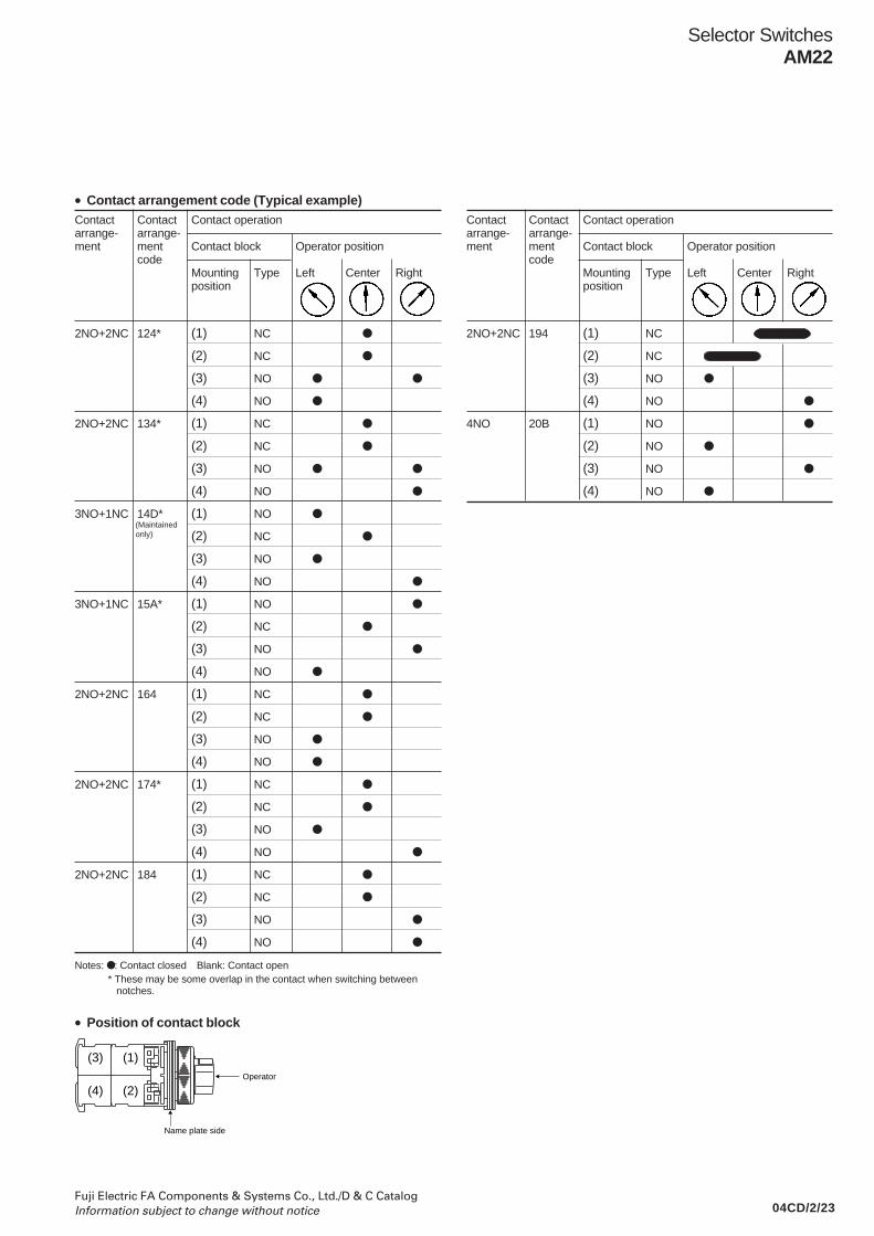
04CD/2/23Fuji Electric FA Components & Systems Co., Ltd./D & C CatalogInformation subject to change without notice
Selector SwitchesAM22
• Contact arrangement code (Typical example)Contact Contact Contact operationarrange- arrange-ment ment Contact block Operator position
codeMounting Type Left Center Rightposition
2NO+2NC 124* (1) NC
(2) NC
(3) NO
(4) NO
2NO+2NC 134* (1) NC
(2) NC
(3) NO
(4) NO
3NO+1NC 14D* (1) NO
(2) NC
(3) NO
(4) NO
3NO+1NC 15A* (1) NO
(2) NC
(3) NO
(4) NO
2NO+2NC 164 (1) NC
(2) NC
(3) NO
(4) NO
2NO+2NC 174* (1) NC
(2) NC
(3) NO
(4) NO
2NO+2NC 184 (1) NC
(2) NC
(3) NO
(4) NO
Notes: : Contact closed Blank: Contact open* These may be some overlap in the contact when switching between
notches.
• Position of contact block
Contact Contact Contact operationarrange- arrange-ment ment Contact block Operator position
codeMounting Type Left Center Rightposition
2NO+2NC 194 (1) NC
(2) NC
(3) NO
(4) NO
4NO 20B (1) NO
(2) NO
(3) NO
(4) NO
(Maintainedonly)
Operator
Name plate side
(1)
(2)
(3)
(4)
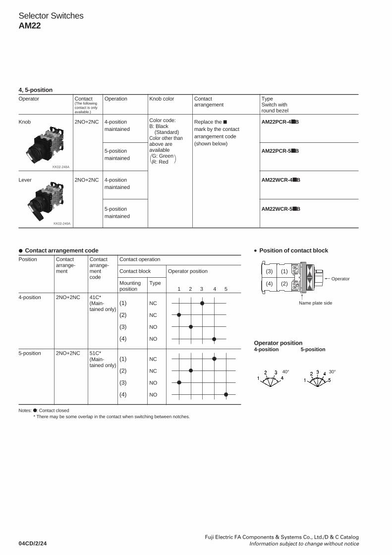
04CD/2/24Fuji Electric FA Components & Systems Co., Ltd./D & C Catalog
Information subject to change without notice
Contact arrangement codePosition Contact Contact Contact operation
arrange- arrange-ment ment Contact block Operator position
codeMounting Typeposition 1 2 3 4 5
4-position 2NO+2NC 41C*(1) NC
(2) NC
(3) NO
(4) NO
5-position 2NO+2NC 51C*(1) NC
(2) NC
(3) NO
(4) NO
Selector SwitchesAM22
4, 5-positionOperator Contact Operation Knob color Contact Type
arrangement Switch withround bezel
Knob 2NO+2NC 4-position Replace the AM22PCR-4 Bmaintained mark by the contact
arrangement code(shown below)
5-position AM22PCR-5 Bmaintained
Lever 2NO+2NC 4-position AM22WCR-4 Bmaintained
5-position AM22WCR-5 Bmaintained
• Position of contact block
Operator position4-position 5-position
Color code:B: Black
(Standard)Color other thanabove areavailable G: Green R: Red
(The followingcontact is onlyavailable.)
(Main-tained only)
(Main-tained only)
40° 30°
KK02-248A
KK02-249A
Notes: : Contact closed* There may be some overlap in the contact when switching between notches.
Name plate side
(1)
(2)
(3)
(4)Operator
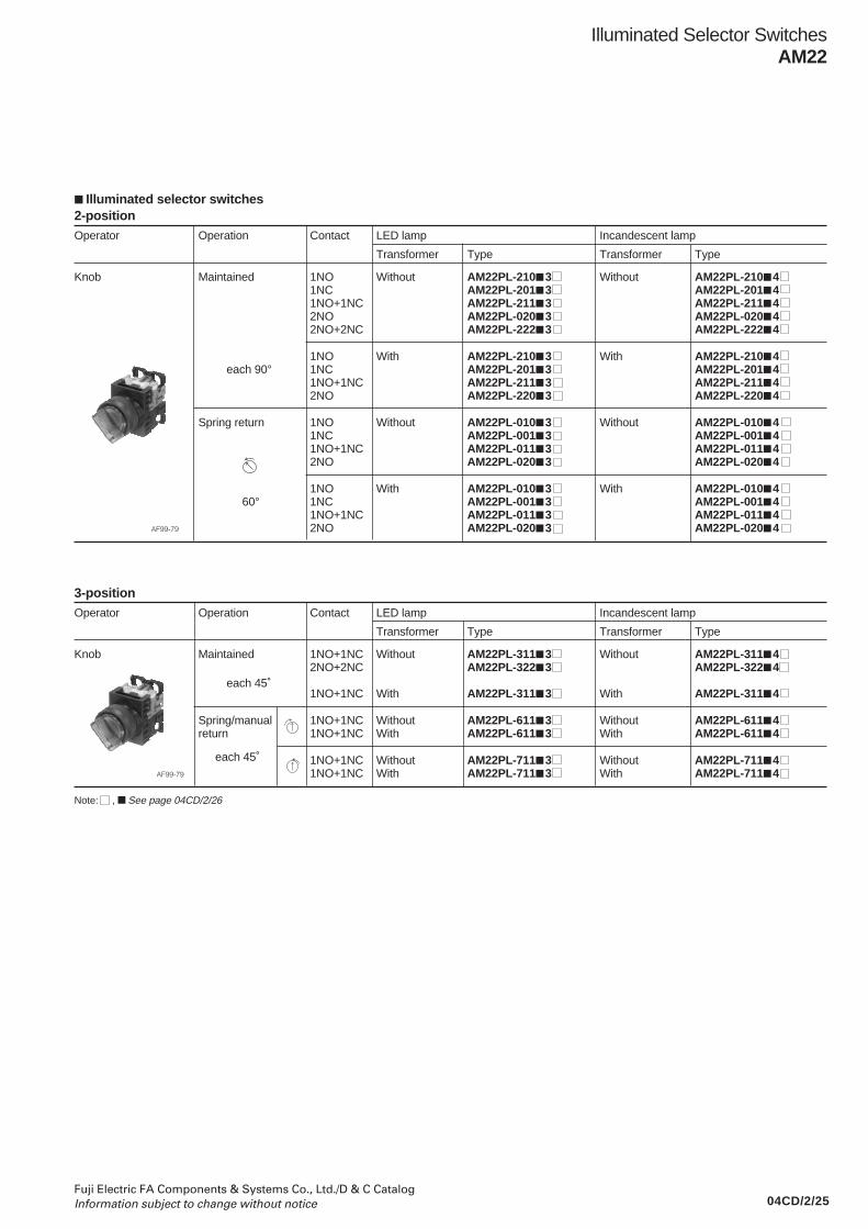
04CD/2/25Fuji Electric FA Components & Systems Co., Ltd./D & C CatalogInformation subject to change without notice
2-positionOperator Operation Contact LED lamp Incandescent lamp
Transformer Type Transformer Type
Knob Maintained 1NO Without AM22PL-210 3 Without AM22PL-210 41NC AM22PL-201 3 AM22PL-201 41NO+1NC AM22PL-211 3 AM22PL-211 42NO AM22PL-020 3 AM22PL-020 42NO+2NC AM22PL-222 3 AM22PL-222 4
1NO With AM22PL-210 3 With AM22PL-210 4 each 90° 1NC AM22PL-201 3 AM22PL-201 4
1NO+1NC AM22PL-211 3 AM22PL-211 42NO AM22PL-220 3 AM22PL-220 4
Spring return 1NO Without AM22PL-010 3 Without AM22PL-010 41NC AM22PL-001 3 AM22PL-001 41NO+1NC AM22PL-011 3 AM22PL-011 42NO AM22PL-020 3 AM22PL-020 4
1NO With AM22PL-010 3 With AM22PL-010 4 60° 1NC AM22PL-001 3 AM22PL-001 4
1NO+1NC AM22PL-011 3 AM22PL-011 42NO AM22PL-020 3 AM22PL-020 4
Illuminated Selector SwitchesAM22
Illuminated selector switches
AF99-79
3-positionOperator Operation Contact LED lamp Incandescent lamp
Transformer Type Transformer Type
Knob Maintained 1NO+1NC Without AM22PL-311 3 Without AM22PL-311 42NO+2NC AM22PL-322 3 AM22PL-322 4
1NO+1NC With AM22PL-311 3 With AM22PL-311 4
Spring/manual 1NO+1NC Without AM22PL-611 3 Without AM22PL-611 4return 1NO+1NC With AM22PL-611 3 With AM22PL-611 4
1NO+1NC Without AM22PL-711 3 Without AM22PL-711 41NO+1NC With AM22PL-711 3 With AM22PL-711 4
each 45˚
each 45˚AF99-79
Note: , See page 04CD/2/26

04CD/2/26Fuji Electric FA Components & Systems Co., Ltd./D & C Catalog
Information subject to change without notice
Illuminated Selector SwitchesAM22
• Replace the mark by the following lamp voltage code
Transformer Voltage CodeLED Incandescent
Without 5V AC/DC – 5 6V DC 6 – 6V AC A – 12V AC/DC B – 15V AC/DC C C 20V AC/DC – D 24V AC/DC E E
With 100-110V AC H H115-127V AC L L200-220V AC M M230-254V AC Q Q350-380V AC S S400-440V AC T T480V AC V V500-550V AC W W
• Replace the mark by the following knob color code
Color Green Red White Blue Yellow Orange
Code G R W S Y A
• Up to 4-contact of contact arrangement can be made.Available numbers of contacts are as follow.
No. of Operation Without Withposition transformer transformer
2-position Maintained 6-contact 4-contact
Spring return 3-contact 2-contact
3-position Maintained 6-contact 4-contact
Spring/manual return 3-contact 2-contact
Contact arrangement and operator position2-position
Transformer Contact Contact block Operator positionarrangement
Mounting Type Left Rightposition
With/without 1NO (1) NO –
With/without 1NC (1) NC –
Without 1NO+1NC (1) NO –
(2) NC –
With 1NO+1NC (1) NC –
(2) NO –
With/without 2NO (1) NO –
(2) NO –
Without 2NO+2NC (1) NO –
*1 (2) NC –
(3) NO –
(4) NC –
With 2NO+2NC (1) NC –
*1 (2) NC –
(3) NO –
(4) NO –
Notes: *1 : AM22PL-2 : Contact closed, – : Contact open
Position of contact block
Without transformer
3-position
Transformer Contact Contact block Operator positionarrangement
Mounting Type Left Center Rightposition
Without 1NO+1NC (1) NO – –
*1 (2) NC – –
1NO+1NC (1) NO – –
*2 (2) NC – –
2NO+2NC (1) NO – –
*3 (2) NC – –
(3) NO – –
(4) NC – –
With 1NO+1NC (1) NC – –
*1 (2) NO – –
1NO+1NC (1) NC – –
*2 (2) NO – –
2NO+2NC (1) NC – –
*3 (2) NC – –
(3) NO – –
(4) NO – –
Notes: *1 : AM22PL-3, 6 *3 : AM22PL-3*2 : AM22PL-7 : Contact closed, – : Contact open
With transformer
Lamp terminalName plate side
(1)(3)
(2)(4)
TransformerName plate side
(1)(2)(3)(4)
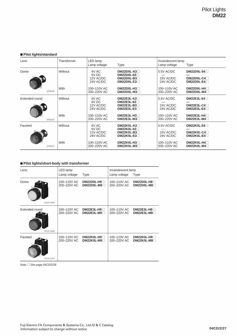
04CD/2/27Fuji Electric FA Components & Systems Co., Ltd./D & C CatalogInformation subject to change without notice
Lens Transformer LED lamp Incandescent lampLamp voltage Type Lamp voltage Type
Dome Without 6V AC DM22D0L-A3 5.5V AC/DC DM22D0L-54 6V DC DM22D0L-63 — — 12V AC/DC DM22D0L-B3 15V AC/DC DM22D0L-C4 24V AC/DC DM22D0L-E3 24V AC/DC DM22D0L-E4
With 100–110V AC DM22D0L-H3 100–110V AC DM22D0L-H4200–220V AC DM22D0L-M3 200–220V AC DM22D0L-M4
Extended round Without 6V AC DM22E3L-A3 5.5V AC/DC DM22E3L-54 6V DC DM22E3L-63 — — 12V AC/DC DM22E3L-B3 15V AC/DC DM22E3L-C4 24V AC/DC DM22E3L-E3 24V AC/DC DM22E3L-E4
With 100–110V AC DM22E3L-H3 100–110V AC DM22E3L-H4200–220V AC DM22E3L-M3 200–220V AC DM22E3L-M4
Faceted Without 6V AC DM22K0L-A3 5.5V AC/DC DM22K0L-54 6V DC DM22K0L-63 — — 12V AC/DC DM22K0L-B3 15V AC/DC DM22K0L-C4 24V AC/DC DM22K0L-E3 24V AC/DC DM22K0L-E4
With 100–110V AC DM22K0L-H3 100–110V AC DM22K0L-H4200–220V AC DM22K0L-M3 200–220V AC DM22K0L-M4
Pilot LightsDM22
Pilot lights/standard
AF99-88
AF99-85
AF99-87
Pilot lights/short-body with transformer
Lens LED lamp Incandescent lampLamp voltage Type Lamp voltage Type
Dome 100–110V AC DM22D0L-H9 100–110V AC DM22D0L-H8200–220V AC DM22D0L-M9 200–220V AC DM22D0L-M8
Extended round 100–110V AC DM22E3L-H9 100–110V AC DM22E3L-H8200–220V AC DM22E3L-M9 200–220V AC DM22E3L-M8
Faceted 100–110V AC DM22K0L-H9 100–110V AC DM22K0L-H8200–220V AC DM22K0L-M9 200–220V AC DM22K0L-M8
KK02-245A
KK02-246A
KK02-247A
Note: See page 04CD/2/28
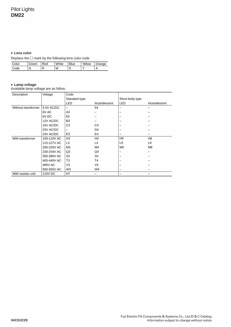
04CD/2/28Fuji Electric FA Components & Systems Co., Ltd./D & C Catalog
Information subject to change without notice
Pilot LightsDM22
ColorCode
GreenG
RedR
WhiteW
BlueS
YellowY
OrangeA
Replace the mark by the following lens color code• Lens color
• Lamp voltageAvailable lamp voltage are as follow.
Description
Without transformer
With transformer
With resistor unit
Voltage
5.5V AC/DC6V AC6V DC12V AC/DC15V AC/DC20V AC/DC24V AC/DC100-110V AC115-127V AC200-220V AC230-254V AC350-380V AC 400-440V AC480V AC 500-550V AC110V DC
CodeStandard typeLED–A363B3C3–E3H3L3M3Q3S3T3V3W3H7
Incandescent54–––C4D4E4H4L4M4Q4S4T4V4W4–
Short-body typeLED–––––––H9L9M9––––––
Incandescent–––––––H8L8M8––––––
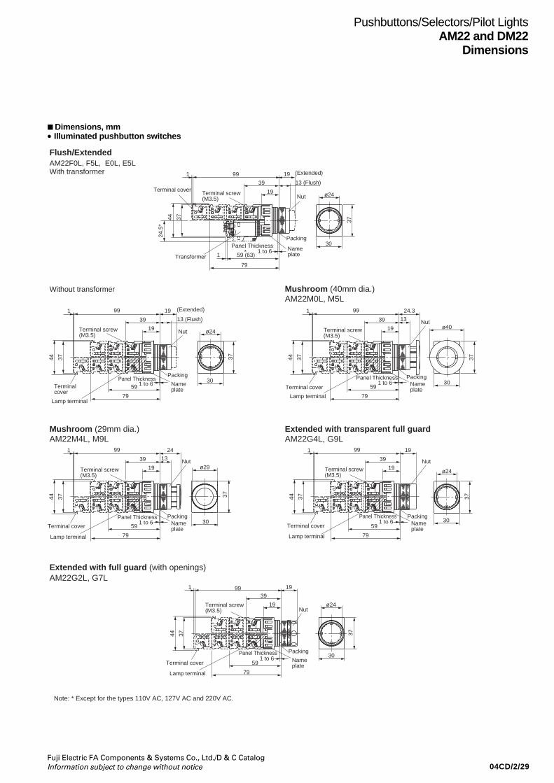
04CD/2/29Fuji Electric FA Components & Systems Co., Ltd./D & C CatalogInformation subject to change without notice
Pushbuttons/Selectors/Pilot LightsAM22 and DM22
Dimensions
Dimensions, mm• Illuminated pushbutton switches
19
19
39
991
1 to 659
79
3744
13 (Flush)
ø24
30
37
ø24
30
37
ø24
30
37
ø40
30
37ø29
30
37
Nut
PackingPanel Thickness
Name plate
Terminal screw(M3.5)
Terminal cover
13
24.3
19
39
991
1 to 659
79
3744
Nut
PackingPanel ThicknessName plate
Terminal screw(M3.5)
Terminal cover
13
24
19
39
991
1 to 659
79
3744
Nut
PackingPanel ThicknessName plate
Terminal screw(M3.5)
Terminal cover
19
19
39
991
1 to 659
79
3744
Nut
PackingPanel ThicknessName plate
Terminal screw(M3.5)
Terminal cover
19
19
39991
1 to 659
79
ø24
30
373744
Nut
PackingPanel ThicknessName plate
Terminal screw(M3.5)
Terminal cover
Note: * Except for the types 110V AC, 127V AC and 220V AC.
19
19
39
991
1 to 659 (63)1
79
3744
24.5
*
Nut
PackingPanel Thickness Name
plate
Terminal screw(M3.5)
Terminal cover
Transformer
(Extended)
13 (Flush)
(Extended)
*
Lamp terminalLamp terminal
Lamp terminal
Lamp terminalLamp terminal
AM22F0L, F5L, E0L, E5LWith transformer
Without transformer
Mushroom (29mm dia.)
Mushroom (40mm dia.)AM22M0L, M5L
Extended with transparent full guardAM22M4L, M9L AM22G4L, G9L
Extended with full guard (with openings)AM22G2L, G7L
Flush/Extended
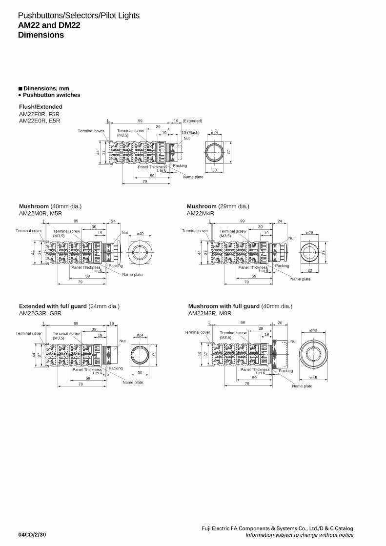
04CD/2/30Fuji Electric FA Components & Systems Co., Ltd./D & C Catalog
Information subject to change without notice
Pushbuttons/Selectors/Pilot LightsAM22 and DM22Dimensions
Dimensions, mm• Pushbutton switches
ø24
30
13 (Flush)19
39
191
1 to 6
3744
99
19
39
1 99
37
37
44
24
ø40
26
ø40
Nut
Terminal cover
(Extended)
Terminal screw(M3.5)
Terminal screw(M3.5)
Nut
Packing
Terminal cover Nut
Name plate
Name plate
Name plateName plate
Name plate
Packing
ø48
Panel Thickness
59
79
ø24
30
19
39
191
1 to 6
3744
99
37
Terminal cover Terminal screw(M3.5)
Nut
PackingPanel Thickness
59
79
1 to 6Panel Thickness
59
79
19
39
1 99
3744
ø29
24
Terminal screw(M3.5)
Terminal cover
Nut
Packing301 to 6
37
Panel Thickness
59
79
19
39
1 99
3744
Terminal screw(M3.5)
Terminal cover
Packing1 to 6Panel Thickness
59
79
Flush/ExtendedAM22F0R, F5RAM22E0R, E5R
Mushroom (40mm dia.)
Extended with full guard (24mm dia.) Mushroom with full guard (40mm dia.)
Mushroom (29mm dia.)AM22M0R, M5R
AM22G3R, G8R AM22M3R, M8R
AM22M4R
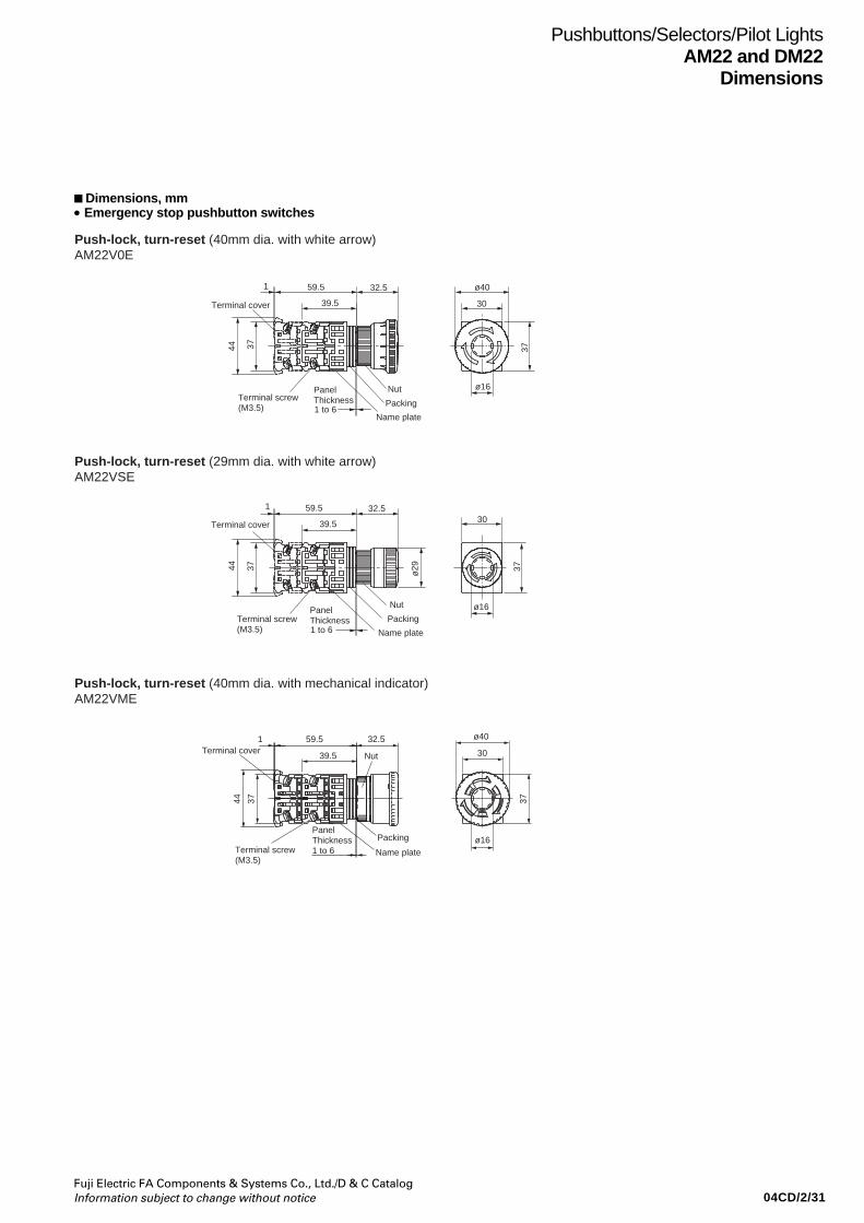
04CD/2/31Fuji Electric FA Components & Systems Co., Ltd./D & C CatalogInformation subject to change without notice
Pushbuttons/Selectors/Pilot LightsAM22 and DM22
Dimensions
Dimensions, mm• Emergency stop pushbutton switches
59.5
44
39.5
32.51
37
ø40
37
Terminal screw(M3.5)
Nut
Packing
Name plate
30
ø16
Terminal cover
59.5
39.5
32.51
44 37 37ø29
Terminal screw(M3.5)
Panel Thickness
Nut
Packing
Name plate
30
ø16
Terminal cover
Push-lock, turn-reset (40mm dia. with white arrow)
Push-lock, turn-reset (29mm dia. with white arrow)
AM22V0E
AM22VSE
1 to 6
Push-lock, turn-reset (40mm dia. with mechanical indicator)AM22VME
Panel Thickness1 to 6
32.5
39.5
59.51
3744
Terminal screw(M3.5)
Panel Thickness1 to 6 Name plate
Packing
Nut
ø16
ø40
30
37
Terminal cover
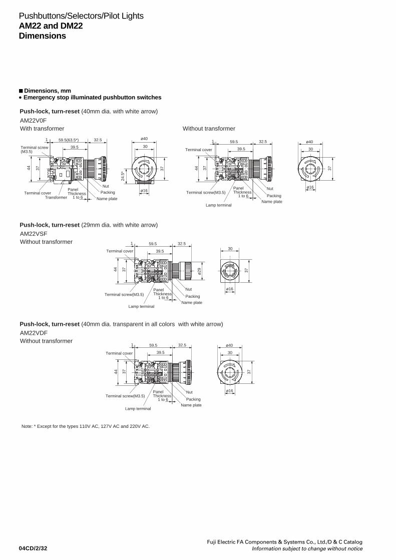
04CD/2/32Fuji Electric FA Components & Systems Co., Ltd./D & C Catalog
Information subject to change without notice
Pushbuttons/Selectors/Pilot LightsAM22 and DM22Dimensions
Dimensions, mm• Emergency stop illuminated pushbutton switches
59.5(63.5*)
39.5
32.51
44 37 37
24.5
*
Terminal screw(M3.5)
Panel Thickness
Nut
Packing
Name plate
ø16
30
ø40
Terminal coverTransformer
59.5
39.5
32.51
44 37 37
Terminal screw(M3.5)Nut
PackingName plate
30
ø40
ø16
Terminal cover
Lamp terminal
59.5
39.5
32.51
44 37 37ø29
Terminal screw(M3.5)Nut
Packing
Name plate
30
ø16
Terminal cover
Lamp terminal
59.5
39.5
32.51
44 37 37
Terminal screw(M3.5)Nut
PackingName plate
30
ø40
ø16
Terminal cover
Lamp terminal
1 to 6
Panel Thickness
1 to 6
Panel Thickness
1 to 6
Panel Thickness
1 to 6
Push-lock, turn-reset (40mm dia. with white arrow)
AM22V0F
Push-lock, turn-reset (29mm dia. with white arrow)
AM22VSF
Push-lock, turn-reset (40mm dia. transparent in all colors with white arrow)
AM22VDF
With transformer Without transformer
Without transformer
Without transformer
Note: * Except for the types 110V AC, 127V AC and 220V AC.

04CD/2/33Fuji Electric FA Components & Systems Co., Ltd./D & C CatalogInformation subject to change without notice
Dimensions, mm• Selector switches
Pushbuttons/Selectors/Pilot LightsAM22 and DM22
Dimensions
26
39
991
59
79
ø24
30
37
ø24
30
37
27
3744
Terminal coverTerminal screw(M3.5) Nut
ø24.5
30
37
Nut
PackingPanel Thickness
Name plate
19 13
39
99 261
59
79
3744
Terminal coverTerminal screw(M3.5)
PackingName plate
19 13
39
99 23 241
59
79
3744
Terminal cover Terminal screw(M3.5)
PackingName plate
19 13
1 to 6
Panel Thickness1 to 6
Panel Thickness1 to 6
Knob
Lever
Key
AM22PR, PCR
AM22WR, WCR
AM22JR, JCR
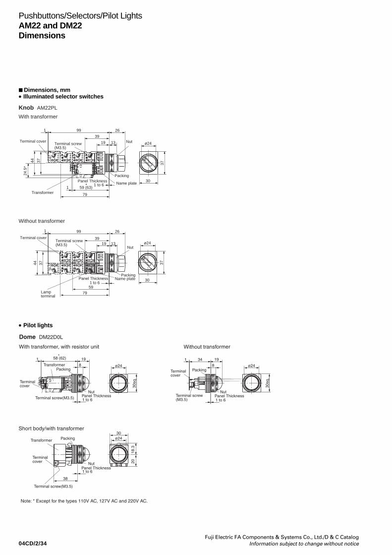
04CD/2/34Fuji Electric FA Components & Systems Co., Ltd./D & C Catalog
Information subject to change without notice
Dimensions, mm• Illuminated selector switches
Pushbuttons/Selectors/Pilot LightsAM22 and DM22Dimensions
• Pilot lights
30
ø24
37
ø24
30
37
26
39
991
59
79
3744
Terminal coverTerminal screw(M3.5)
Nut
Packing
Lamp terminal
Panel Thickness Name plate
19 13
26
19 13
39
991
1 to 659 (63)1
79
3744
24.5
*
Nut
PackingPanel Thickness Name plate
Terminal screw(M3.5)
Terminal cover
Transformer
1 to 6
With transformer
Knob AM22PL
Without transformer
*
*
8
19341
1 to 6Panel Thickness
Nut
PackingTerminal cover
Terminal screw(M3.5)
8
1958 (62)1
1 to 6Panel Thickness
Nut
Packing
Terminal cover
Terminal screw(M3.5)
Terminal screw(M3.5)
ø24
30sq
.
ø24
ø2430
30sq
.
Transformer
38
1 to 6Panel Thickness
Nut
Packing
Terminal cover
18.3
20
Transformer
With transformer, with resistor unit Without transformer
Short body/with transformer
Dome DM22D0L
Note: * Except for the types 110V AC, 127V AC and 220V AC.

04CD/2/35Fuji Electric FA Components & Systems Co., Ltd./D & C CatalogInformation subject to change without notice
Pushbuttons/Selectors/Pilot LightsAM22 and DM22
Dimensions
Dimensions, mm• Pilot lights
30sq
.
821341
1 to 6Panel Thickness
PackingTerminal cover
Terminal screw(M3.5)
ø24
30sq
.
ø24
ø24
8
34 141
1 to 6Panel Thickness
Nut
PackingTerminal cover
Terminal screw(M3.5)
ø24
30sq
.
ø24
ø24
30
30
30sq
.20
18.3
2018
.3
38
1 to 6Panel Thickness
Nut
1 to 6
Nut
Packing
Terminal cover
Transformer
38
Panel Thickness
Packing
Terminal cover
Transformer
8
20.61
1 to 6Panel Thickness
Nut
Packing
Terminal cover
Terminal screw(M3.5)
Transformer
148
1
1 to 6Panel Thickness
Packing
Terminal cover
Terminal screw (M3.5)
Terminal screw (M3.5)
Terminal screw (M3.5)
Transformer
Nut
58 (62)*
58 (62)*
Extended DM22E3LWith transformer, with resistor unit Without transformer
Faceted DM22K0LWith transformer, with resistor unit Without transformer
Short body/with transformer
Short body/with transformer
Note: * Except for the types 110V AC, 127V AC and 220V AC.

04CD/2/36Fuji Electric FA Components & Systems Co., Ltd./D & C Catalog
Information subject to change without notice
Pushbuttons/Selectors/Pilot LightsAM22 and DM22Notes on use
Panel cutout hole
Fig. 1 Panel cutout hole dimensions, mm
Note : If key-washer or legend plate are not used, 3.2mm-wide. location holesshown in Fig. 1 need not be cutout.
Mounting operator to panel1. Pushbutton with a round bezel (ordinary mounting)Insert the operator into the cutout hole from the back of thepanel, and tighten the nut with the AR9A006 wrench from thefront of the panel to secure the operator as shown in Fig.2.
Fig. 2 Pushbutton with a round bezel
AF95-465
Note : Recommended tightening torque is from 1.0 to 1.5N·m.
2. Mounting Procedure for the M3R and M8R• Insert the operator through the cutout hole from behind the
panel and secure it by the guard ring from the front of thepanel.
Note: The correct tightening torque is 1.0 to 1.5 N•m.• Use the wrench (AR9A001) to mount the button. Note:The correct tightening torque is 0.5 to 1.0 N•m.
Fig. 3
rmax=0.8mm
3.2+0.2mm
ø22.3+0.4mm0
0
24.1+0.4mm0
Notes on use
Wrench(AR9A006)
Nut
Panel
Packing
Operator
Button
Method for changing the button, lens, and nameplate AM22F0R, F5R, E0R, E5R, G3R, G8R• To remove the button, insert a small flat-tip screwdriver in the
groove around the periphery of the button, and gently pry it offworking the screwdriver around the entire periphery.
• To attach the button, align the I-shaped protrusion on the backside of the button with the cross-shaped groove on the plungerand push the button in.
Fig. 4a
Fig. 5
AM22M0R, M5R, M4R, M0L, M4L, M5L, M9L• The button is threaded. Attach it and remove it by hand. When
attaching the button, make sure that it is screwed incompletely.Note: The correct tightening torque is 0.5 to 1.0 N•m.
• For illuminated pushbutton switches, insert the groove of thenameplate onto the protrusion on the plunger and push in thenameplate.
Fig. 6
Wrench(AR9A001)
Button
Guard ring
Packing
Operator
Panel
Button
(Back side of the button)
*Small flat-tip screwdriver
I-shaped protrusion
Groove
Button
Nut
Pull
ButtonNameplate
Groove
Protrusion
Fig. 4b
• In case of G3R, G8R: Loosen and pull the nut, and the buttonwill come off.

04CD/2/37Fuji Electric FA Components & Systems Co., Ltd./D & C CatalogInformation subject to change without notice
Insert the operator into the cutout hole from the back of thepanel, and as shown in Fig.8, insert the pushbutton into theoperator cylinder while aligning the grooves inside thepushbutton with the protrusions on the operator.Note: The correct tightening torque is 0.5 to 1.0N•m.
Fig. 8 Setting pushbutton to operator cylinder
AM22PR, PCR, WR, WCR(1) As shown in the following figure, insert the tip of a small
flathead screwdriver into the selector tip groove. Rotate thescrewdriver in the direction indicated by the arrow until theselector tip rises, and draw out the knob.
(2) Attach the operator in the same manner as described in step 1.(3) Insert the knob, with the selector tip in the floated state, into
the original position of the rotation tube, and push theselector tip into place.
Fig. 11a
Center button Button
* Provide with products
Wrench *(AM9A008)
Pushbutton in side groove
Cylinder inside protrusion
Small flathead screwdriver*
Selector tip groove
Pushbuttons/Selectors/Pilot LightsAM22 and DM22
Notes on use
AM22V0E, VSE, VME, V0F, VDF, VSFAs shown in Fig.7, engage the tips of the AM9A008 wrenchinto the indentations around the pushbutton center button,and turn the wrench to loosen and remove the pushbuttoncenter button, then remove the pushbutton.Note: The correct tightening torque is 0.5 to 1.0N•m.
Fig. 7
AM22F0L, F5L, E0L, E5L, G4L, G9L, G2L, DM22E3L• Engage the protrusions on the front end of the wrench
(AR9A001) with the groove on the lens and screw on the lens. Note: The correct tightening torque is 0.5 to 1.0 N•m.• Attaching the nameplate
Insert the groove of the nameplate onto the protrusion on theplunger.
Fig. 9
Wrench(AR9A001)
Lens
Nameplate
Groove
Groove
Protrusion
DM22D0L, K0L• Push the end of the wrench (AHX702) onto the lens and turn
the wrench to attach or remove the lens. Note: The correct tightening torque is 0.5 to 1.0 N•m.
Fig. 10
Lens
Wrench
AM22PL• To remove an illuminated switch, insert a small flathead
screwdriver or the like into the groove around the periphery ofthe knob and pry it off.
Fig. 12a
Periphery of the knob
Knob
Cylinder
Small flathead screwdriver*
Selector tip
Cylinder
Knob
Fig. 11b
Fig. 12b
*Use a small flathead screwdriver with a head that is about 4 mm wide.

04CD/2/38Fuji Electric FA Components & Systems Co., Ltd./D & C Catalog
Information subject to change without notice
Using accessory ring-packingsUse the required number of ring-packings (1.3mm-thick, 5pieces, resin mold).Table below is a guideline for using the packings.If a locking nut or legend plate is used, the thickness must becounted as an additional panel thickness.
Panel thickness vs. number of packings (reference data)
Number of packings
1.0mm to less than 1.6mm
1.6mm to less than 2.8mm
2.8mm to less than 3.8mm
3.8mm to less than 4.8mm
4.8mm to less than 6.0mm
Minimum mounting space, mmThe minimum mounting spaces required for AM22•DM22command switches are given below. (Fig. 15)
Fig. 15
• Illuminated pushbutton and pushbutton• Emergency stop illuminated pushbutton and emergency stop pushbutton• Illuminated and non-illuminated selectors
Notes: *1 • AM22M0L, M5L, M0R, M5R, V0E, V0F, VDF: 42• AM22M3R, M8R: 49• AM22WR, WCR: 40
*2 When mounting contact blocks at 30mm pitch, use it circuit of 380V orless.
*3 Short body with transformer types: 50mm.*4 This dimension applies when transformer units or contact blocks face
each other.*5 This dimension applies when transformer unit or contact block is
mounted on only one side.
Other items are the same as for the AR22 and DR22 series,see page 04/53 to 04/57
Effective panel thicknessincluding lock-ring andlegend plate thicknesses
• Pilot light
30*2
50*4 37*1 *5
42*1 30
30*3
Water-proof and dust-proof capApplicable type: Water-proof cap AHX797
Dust-proof cap AM9D797
When attached to the panel in combination with a water-proof ordust-proof cap, the water-proof cap or dust-proof cap may sinkdownward and prevent the depressed button from returning toits original position.As shown in the following figure, cut an approximately 5-mm airoutlet in the portion of the ring packing touching the panelsurface. Also, reduce the number of packing rings by one belowthe standard number. The clamp ring tightening torque is 1 to1.5 N•m.
Fig. 14
Degree of protectionThe water-proof cap or dust-proof cap seals the panel surface toprovide IP65 protection.• AM9D797 : Air outlet groove packing provided.
5mm
Cap
Packing
AM22JR, JCR• For key type switches, the decorative cover and nut are
threaded. Removing the decorative cover enables the nut tobe removed. Make sure to tighten the decorative cover so thatthere is no play.
Note: The correct tightening torque is 0.3 to 0.5 N•m.
Fig. 13
Nut
Decorative cover
Pushbuttons/Selectors/Pilot LightsAM22 and DM22Notes on use
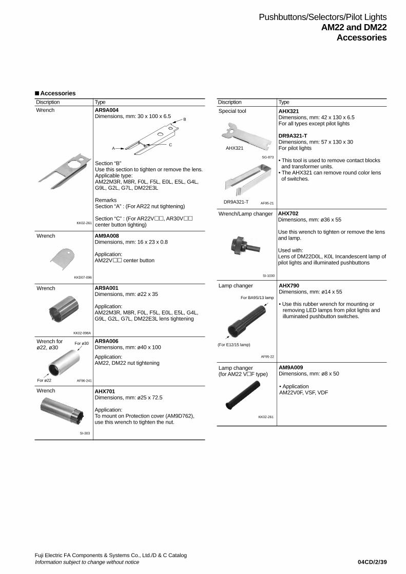
04CD/2/39Fuji Electric FA Components & Systems Co., Ltd./D & C CatalogInformation subject to change without notice
Pushbuttons/Selectors/Pilot LightsAM22 and DM22
Accessories
Discription
Wrench
KK02-261
Wrench AM9A008Dimensions, mm: 16 x 23 x 0.8
Application:AM22V center button
KKD07-096
Wrench
KK02-098A
AF96-241
SG-873
AF95-21
Wrench/Lamp changer
SI-1030
AF95-22
SI-303
Type
AR9A004Dimensions, mm: 30 x 100 x 6.5
B
CA
Section “B”Use this section to tighten or remove the lens.Applicable type:AM22M3R, M8R, F0L, F5L, E0L, E5L, G4L,G9L, G2L, G7L, DM22E3L
RemarksSection “A” : (For AR22 nut tightening)
Section “C” : (For AR22V, AR30Vcenter button tighting)
AR9A001Dimensions, mm: ø22 x 35
Application:AM22M3R, M8R, F0L, F5L, E0L, E5L, G4L,G9L, G2L, G7L, DM22E3L lens tightening
Wrench forø22, ø30
AR9A006Dimensions, mm: ø40 x 100
Application:AM22, DM22 nut tightening
Wrench AHX701Dimensions, mm: ø25 x 72.5
Application:To mount on Protection cover (AM9D762),use this wrench to tighten the nut.
Discription Type
AHX321Dimensions, mm: 42 x 130 x 6.5For all types except pilot lights
DR9A321-TDimensions, mm: 57 x 130 x 30For pilot lights
• This tool is used to remove contact blocks and transformer units.• The AHX321 can remove round color lens of switches.
Special tool
AHX702Dimensions, mm: ø36 x 55
Use this wrench to tighten or remove the lensand lamp.
Used with:Lens of DM22D0L, K0L Incandescent lamp ofpilot lights and illuminated pushbuttons
Lamp changer AHX790Dimensions, mm: ø14 x 55
• Use this rubber wrench for mounting orremoving LED lamps from pilot lights andilluminated pushbutton switches.
Accessories
AHX321
DR9A321-T
For BA9S/13 lamp
(For E12/15 lamp)
• ApplicationAM22V0F, VSF, VDF
Lamp changer(for AM22 VF type)
AM9A009Dimensions, mm: ø8 x 50
KK02-261
For ø30
For ø22
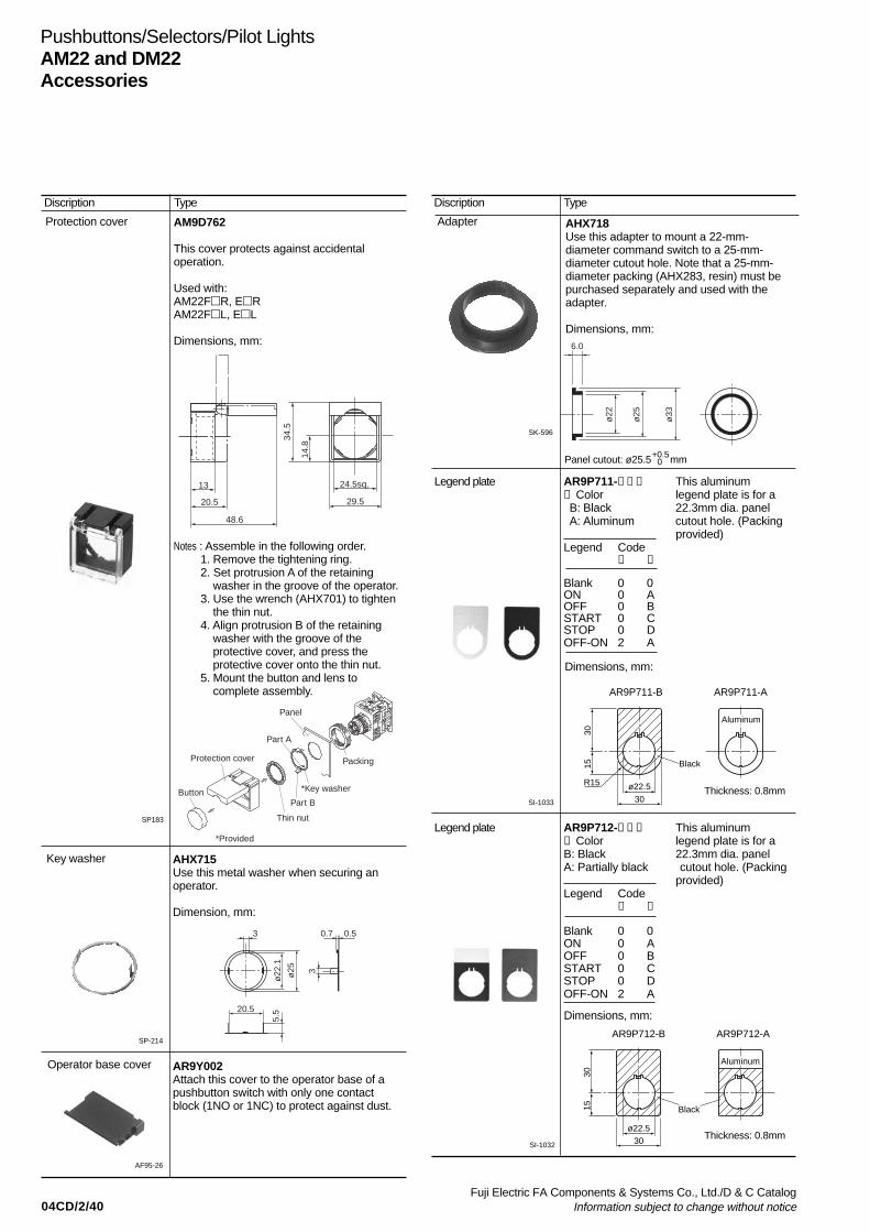
04CD/2/40Fuji Electric FA Components & Systems Co., Ltd./D & C Catalog
Information subject to change without notice
Pushbuttons/Selectors/Pilot LightsAM22 and DM22Accessories
Protection cover
SP183
Key washer AHX715Use this metal washer when securing anoperator.
Dimension, mm:
SP-214
Operator base cover
AF95-26
Discription Type
AM9D762
This cover protects against accidentaloperation.
Used with:AM22FR, ERAM22FL, EL
Dimensions, mm:
AR9Y002Attach this cover to the operator base of apushbutton switch with only one contactblock (1NO or 1NC) to protect against dust.
13
20.5
48.6
29.5
14.8
34.5
24.5sq.
0.73
20.5
3ø25
5.5
ø22
.1
0.5
Adapter
SK-596
AHX718Use this adapter to mount a 22-mm-diameter command switch to a 25-mm-diameter cutout hole. Note that a 25-mm-diameter packing (AHX283, resin) must bepurchased separately and used with theadapter.
Dimensions, mm:6.0
ø33
ø25
ø22
Thickness: 0.8mm
Discription Type
Legend plate AR9P711-➀➁➂ This aluminum➀ Color legend plate is for aB: Black 22.3mm dia. panelA: Aluminum cutout hole. (Packing
provided)Legend Code
➁ ➂
Blank 0 0ON 0 AOFF 0 BSTART 0 CSTOP 0 DOFF-ON 2 A
Legend plate AR9P712-➀➁➂ This aluminum➀ Color legend plate is for aB: Black 22.3mm dia. panelA: Partially black cutout hole. (Packing
provided)Legend Code
➁ ➂
Blank 0 0ON 0 AOFF 0 BSTART 0 CSTOP 0 DOFF-ON 2 A
SI-1033
ø22.5
Aluminum
Black
30
R15
1530
Dimensions, mm:
SI-1032Thickness: 0.8mm
Dimensions, mm:
ø22.5
Aluminum
Black
30
1530
AR9P711-B AR9P711-A
AR9P712-B AR9P712-A
Button
Protection cover Packing
*Key washer
Panel
Part A
Part B
Thin nut
*Provided
Notes : Assemble in the following order.1. Remove the tightening ring.2. Set protrusion A of the retaining
washer in the groove of the operator.3. Use the wrench (AHX701) to tighten
the thin nut.4. Align protrusion B of the retaining
washer with the groove of theprotective cover, and press theprotective cover onto the thin nut.
5. Mount the button and lens tocomplete assembly.
Panel cutout: ø25.5 mm+0.5 0
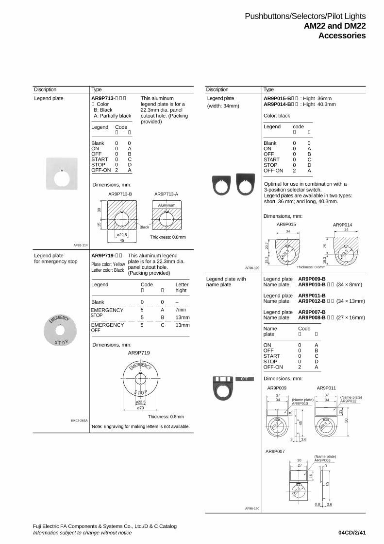
04CD/2/41Fuji Electric FA Components & Systems Co., Ltd./D & C CatalogInformation subject to change without notice
Pushbuttons/Selectors/Pilot LightsAM22 and DM22
Accessories
AR9P719
Legend plate AR9P713-➀➁➂ This aluminum➀ Color legend plate is for aB: Black 22.3mm dia. panelA: Partially black cutout hole. (Packing
provided)Legend Code
➁ ➂
Blank 0 0ON 0 AOFF 0 BSTART 0 CSTOP 0 DOFF-ON 2 A
AF95-114
Thickness: 0.8mm
Dimensions, mm:
ø22.5
Aluminum
Black
45
1530
Discription Type
Legend plate AR9P719-➀➁ This aluminum legend for emergency stop plate is for a 22.3mm dia.
panel cutout hole.(Packing provided)
Legend Code Letter➀ ➁ hight
Blank 0 0 –
5 A 7mm
5 B 13mm
5 C 13mm
Dimensions, mm:
Thickness: 0.8mm
AR9P713-B AR9P713-A
ø22.5
ø70
S T O P
EMERGENCY
KK02-265A
Legend plate
(width: 34mm)AR9P015-B➀➁ : Hight 36mmAR9P014-B➀➁ : Hight 40.3mm
Color: black
Legend code➀ ➁
Blank 0 0ON 0 AOFF 0 BSTART 0 CSTOP 0 DOFF-ON 2 A
.AF96-190
Optimal for use in combination with a3-position selector switch.Legend plates are available in two types:short, 36 mm; and long, 40.3mm.
AR9P015 AR9P014
AR9P009 AR9P011
AR9P007
34
ø22.5
ø22.5
Thickness: 0.6mm
34
2520.7
15.3
15.3
3734
3.63
45
50
(Name plate)AR9P010
(Name plate)AR9P012
138
3734
ø22.3
ø22.3
(Name plate)AR9P008
50
16
3
3.60.8
3027
ø22.3
Discription Type
Dimensions, mm:
Legend plate with Legend plate AR9P009-B name plate Name plate AR9P010-B ➀➁ (34 × 8mm)
Legend plate AR9P011-BName plate AR9P012-B ➀➁ (34 × 13mm)
Legend plate AR9P007-BName plate AR9P008-B ➀➁ (27 × 16mm)
Name Codeplate ➀ ➁
ON 0 AOFF 0 BSTART 0 CSTOP 0 DOFF-ON 2 A
Dimensions, mm:
.AF96-190
EMERGENCYSTOP
EMERGENCYOFF
Plate color: YellowLetter color: Black
Note: Engraving for making letters is not available.
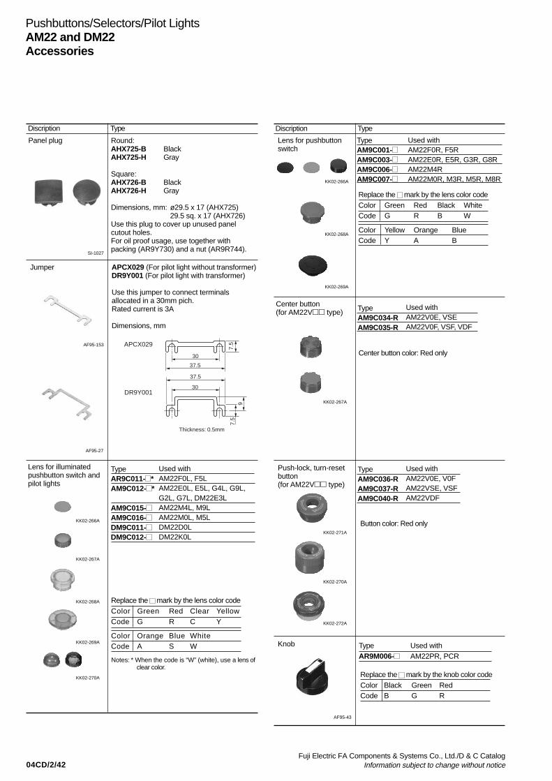
04CD/2/42Fuji Electric FA Components & Systems Co., Ltd./D & C Catalog
Information subject to change without notice
Pushbuttons/Selectors/Pilot LightsAM22 and DM22Accessories
Panel plug
SI-1027
AF95-153
Jumper
AF95-27
Discription Type
Round:AHX725-B BlackAHX725-H Gray
Square:AHX726-B BlackAHX726-H Gray
Dimensions, mm: ø29.5 x 17 (AHX725)29.5 sq. x 17 (AHX726)
Use this plug to cover up unused panelcutout holes.For oil proof usage, use together withpacking (AR9Y730) and a nut (AR9R744).
APCX029 (For pilot light without transformer)DR9Y001 (For pilot light with transformer)
Use this jumper to connect terminalsallocated in a 30mm pich.Rated current is 3A
Dimensions, mm
7.5
30
37.5
37.5
30
Thickness: 0.5mm
9
7.5APCX029
DR9Y001
Lens for pushbuttonswitch
TypeAM9C001-AM9C003-AM9C006-AM9C007-
Discription Type
Used withAM22F0R, F5RAM22E0R, E5R, G3R, G8RAM22M4RAM22M0R, M3R, M5R, M8R
Lens for illuminatedpushbutton switch andpilot lights
Notes: * When the code is “W” (white), use a lens of clear color.
TypeAR9C011- *AM9C012- *
AM9C015-AM9C016-DM9C011-DM9C012-
Used withAM22F0L, F5LAM22E0L, E5L, G4L, G9L,G2L, G7L, DM22E3LAM22M4L, M9LAM22M0L, M5LDM22D0LDM22K0L
Replace the mark by the lens color codeColor Green Red Clear YellowCode G R C Y
Color Orange Blue WhiteCode A S W
KK02-266A
KK02-267A
KK02-268A
KK02-269A
KK02-270A
KK02-266A
KK02-268A
KK02-269A
Push-lock, turn-resetbutton(for AM22V type)
Knob
AF95-43
Center button(for AM22V type)
Center button color: Red only
Replace the mark by the knob color codeColor Black Green RedCode B G R
TypeAR9M006-
Used withAM22PR, PCR
KK02-267A
TypeAM9C034-RAM9C035-R
Used withAM22V0E, VSEAM22V0F, VSF, VDF
TypeAM9C036-RAM9C037-RAM9C040-R
Used withAM22V0E, V0FAM22VSE, VSFAM22VDF
Button color: Red only
KK02-272A
KK02-271A
KK02-270A
Replace the mark by the lens color codeColor Green Red Black WhiteCode G R B W
Color Yellow Orange BlueCode Y A B
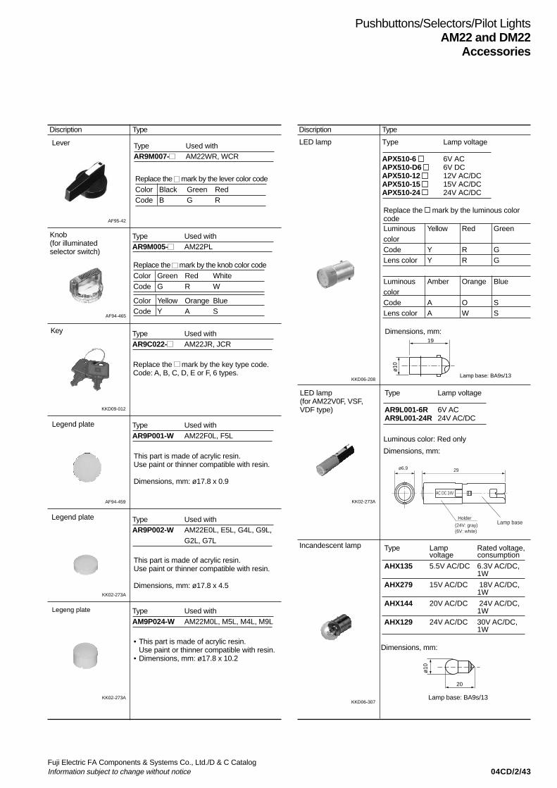
04CD/2/43Fuji Electric FA Components & Systems Co., Ltd./D & C CatalogInformation subject to change without notice
Pushbuttons/Selectors/Pilot LightsAM22 and DM22
Accessories
AF95-42
Lever
Replace the mark by the lever color codeColor Black Green RedCode B G R
TypeAR9M007-
Used withAM22WR, WCR
Discription Type
KK02-273A
AF94-465
Key
Legend plate
KK02-273A
Legeng plate
Knob(for illuminatedselector switch)
KKD09-012
AF94-459
Legend plate
TypeAR9M005-
Used withAM22PL
Replace the mark by the knob color codeColor Green Red WhiteCode G R W
Color Yellow Orange BlueCode Y A S
TypeAR9C022-
Used withAM22JR, JCR
Replace the mark by the key type code.Code: A, B, C, D, E or F, 6 types.
This part is made of acrylic resin.Use paint or thinner compatible with resin.
Dimensions, mm: ø17.8 x 0.9
This part is made of acrylic resin.Use paint or thinner compatible with resin.
Dimensions, mm: ø17.8 x 4.5
• This part is made of acrylic resin.Use paint or thinner compatible with resin.
• Dimensions, mm: ø17.8 x 10.2
KKD06-208
KK02-273A
LED lamp(for AM22V0F, VSF,VDF type)
Type Lamp voltage
AR9L001-6R 6V ACAR9L001-24R 24V AC/DC
Dimensions, mm:
Lamp base: BA9s/13
19
ø10
Discription Type
LED lamp Type Lamp voltage
APX510-6 6V ACAPX510-D6 6V DCAPX510-12 12V AC/DCAPX510-15 15V AC/DCAPX510-24 24V AC/DC
Dimensions, mm:
Replace the mark by the luminous colorcodeLuminous Yellow Red GreencolorCode Y R GLens color Y R G
Luminous Amber Orange BluecolorCode A O SLens color A W S
AC DC 24V
ø6.9 29
Holder
(24V: gray)(6V: white)
Lamp base
Incandescent lamp
KKD06-307
Type Lamp Rated voltage,voltage consumption
AHX135 5.5V AC/DC 6.3V AC/DC,1W
AHX279 15V AC/DC 18V AC/DC,1W
AHX144 20V AC/DC 24V AC/DC,1W
AHX129 24V AC/DC 30V AC/DC,1W
Dimensions, mm:
Lamp base: BA9s/13
20
ø10
TypeAR9P001-W
Used withAM22F0L, F5L
TypeAR9P002-W
Used withAM22E0L, E5L, G4L, G9L,G2L, G7L
TypeAM9P024-W
Used withAM22M0L, M5L, M4L, M9L
Luminous color: Red only
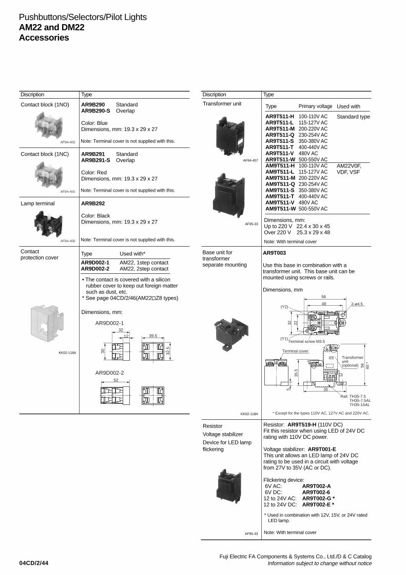
04CD/2/44Fuji Electric FA Components & Systems Co., Ltd./D & C Catalog
Information subject to change without notice
Pushbuttons/Selectors/Pilot LightsAM22 and DM22Accessories
Type
AR9T511-HAR9T511-LAR9T511-MAR9T511-QAR9T511-SAR9T511-TAR9T511-VAR9T511-WAM9T511-HAM9T511-LAM9T511-MAM9T511-QAM9T511-SAM9T511-TAM9T511-VAM9T511-W
Primary voltage
100-110V AC115-127V AC200-220V AC230-254V AC350-380V AC400-440V AC480V AC500-550V AC100-110V AC115-127V AC200-220V AC230-254V AC350-380V AC400-440V AC480V AC500-550V AC
Transformer unit
Dimensions, mm:Up to 220 V 22.4 x 30 x 45Over 220 V 25.3 x 29 x 48
AF94-457
AF95-33
Discription Type Discription Type
Contact block (1NO) AR9B290 StandardAR9B290-S Overlap
Color: BlueDimensions, mm: 19.3 x 29 x 27
AF94-455
Contact block (1NC) AR9B291 StandardAR9B291-S Overlap
Color: RedDimensions, mm: 19.3 x 29 x 27
AF94-455
Lamp terminal AR9B292
Color: BlackDimensions, mm: 19.3 x 29 x 27
AF94-456
Used with
Standard type
AM22V0F,VDF, VSF
• The contact is covered with a siliconrubber cover to keep out foreign mattersuch as dust, etc.
* See page 04CD/2/46(AM22 Z8 types)
KK02-118A
Contactprotection cover
Type Used with*
AR9D002-1 AM22, 1step contactAR9D002-2 AM22, 2step contact
Dimensions, mm:
32
12
52
39.5
32.5
30
AR9D002-1
AR9D002-2
Resistor
Voltage stabilizer
Device for LED lampflickering
AF95-33
KK02-118A
* Used in combination with 12V, 15V, or 24V rated LED lamp.
AR9T003
Use this base in combination with atransformer unit. This base unit can bemounted using screws or rails.
Dimensions, mm
Base unit fortransformerseparate mounting
5
58
48
32 22
2-ø4.5
35.5
56 60 *
35
Rail: TH35-7.5 TH35-7.5AL TH35-15AL
Terminal screw M3.5
Terminal cover
Transformer unit(optional)
X2
X1
(Y2)
(Y1)
* Except for the types 110V AC, 127V AC and 220V AC.
Resistor: AR9T519-H (110V DC)Fit this resistor when using LED of 24V DCrating with 110V DC power.
Voltage stabilizer: AR9T001-EThis unit allows an LED lamp of 24V DCrating to be used in a circuit with voltagefrom 27V to 35V (AC or DC).
Flickering device: 6V AC: AR9T002-A 6V DC: AR9T002-612 to 24V AC: AR9T002-G *12 to 24V DC: AR9T002-E *
Note: Terminal cover is not supplied with this.
Note: Terminal cover is not supplied with this.
Note: Terminal cover is not supplied with this. Note: With terminal cover
Note: With terminal cover

04CD/2/45Fuji Electric FA Components & Systems Co., Ltd./D & C CatalogInformation subject to change without notice
Pushbuttons/Selectors/Pilot LightsAM22 and DM22
Accessories
Nut
Discription Type
TypeAM9R744*1
DM9R744*1
AM9R057*3
AM9R057*2
AM9R058*3
DM9R057*2
Used withAM22F0R, F5R, E0R, E5R,M0R, M5R, M4R, F0L, F5L,E0L, E5L, M0L, M5L, M4L,M9L, PR, PCR, WR, WCR,JR, JCR, PL
DM22D0L, E3L, K0LAM22V0E, V0F, VDFAM22F0R, F5R, E0R, E5R,M4R, F0L, F5L, E0L, E5L,M4L, M9L, PR, PCR, WR,WCR, JR, JCR, PLAM22VSE, VSFDM22D0L, E3L, K0L
KK02-276A
KK02-275A
KK02-274A
Guard-ring TypeAM9R003*1
AM9R054*2
AM9R056*2
AM9R223*2
Used withAM22G4L, G9LAM22G3R, G8RAM22G2L, G7LAM22M3R, M8R
KK02-278A
KK02-277A
KK02-274A
AF94-462
Nut
Packing
KK02-279A
Dust-proof cap
AF94-462
Used for sealing the operator from foreigndebris such as dust in environments wherethe unit is in contact with such elements.
Discription Type
AM9D797-
Dimensions, mm:
AHX730:For all AM22 and DM22 (Resin)
AHX283:For AHX728 (Resin)
AR9Y730:For AHX725*, 726* (Rubber)
Replace the mark by the cap color codeColor Green Red BlackCode G R B
1.3 ø3421
ø30
ø24
.5
Packing
Air outlet groove
SF-1113
Terminal cover
AF94-466
TypeAR9Y305
DR9Y320
* Rated up to 220V.
The terminal cover is provided as standardwith the applicable types listed above.(Except for contact block alone and lampterminal alone)
Used withContact unitLamp terminalTransformer unit *Pilot lights(without transformer)
Dimensions, mm18.4 x 29 x 8.4
ø22 x 5.8
Terminal cover
* Use types that exceed the standard 220V ratingfor products with standard type transformer.
The terminal cover is provided as standardwith the applicable types listed above.
SG-5
TypeAHX376
Used with
With transformer *With short-bodytransformerWith resistor unit
Dimensions, mm13 x 29 x 6.5
*1 Resin types are black (standard)*2 Aluminum types are silver*3 Aluminum types are silver (standard)
AM9R003 AM9R054
AM9R056
AM9R223
*1 Resin types are transparent*2 Resin types are black
SK-594
Water-tight cap AHX797
This rubber cap protects the operator andswitch mechanism against dust and water.Use this cap in a dusty or moist environment.The only color available is transparent.
Used with:AM22E0R, E5R, E0L, E5L
Dimensions, mm: ø36 x 22.5
AHX283
AR9Y730
SI-299AHX730
AR9R744
For AHX725*, 726*
* When use the panel plug as IP65, then use with packing(AR9Y730)
* When use the panel plug as IP65, then use with nut (AR9R744)
Note: 5 pieces of packing per delivery
Note: 4 pieces of packing per delivery

04CD/2/46Fuji Electric FA Components & Systems Co., Ltd./D & C Catalog
Information subject to change without notice
Pushbuttons/Selectors/Pilot LightsAM22 and DM22Special products
Products equipped with contact protection cover
FeaturesA silicon rubber cover is provided for the contact block to keepout foreign matter such as dust, etc.Other ratings and specifications are the same as those of thestandard type.
TypeAM22 Z8Specify “Z8” at the end of the type number of the standard type.
DimensionsThe only thing different from the standard product is the additionof a 1-mm thick silicon rubber cover around the contact block.
Applicable types
Type• Pushbuttons• Emergency stop pushbuttons• Selectors
• Illuminated pushbuttons (without transformer)• Emergency stop illuminated pushbuttons (without transformer)• Illuminated selectors (without transformer)
Contact arrangement1NO+1NC,2NO*1, 2NC1NO+3NC, 2NO+2NC,3NO+1NC, 4NO*1, 4NC1NO*2, 1NC
1NO+2NC, 2NO+1NC,3NO*2, 3NC
RemarksFor use with a1-step contact
For use with a2-step contact
For use with a1-step contact
For use with a2-step contact
Notes: *1 Except for emergency stop pushbutton switch*2 Except for emergency stop illuminated pushbutton switch
Resisting water-soluble cutting oils and heat
FeaturesSafer operation in environments exposed to water-misciblecutting fluids, machining oils, lubricating oils, cleaning oils andhigh humidity (up to 95%) is made possible by using materialsthat protect against rust and corrosion of components.Other ratings and specifications are the same as those of thestandard type.
TypeAM22 Z9, DM22 Z9Specify “Z9” at the end of the type number of the standard type.
DimensionsSame as those of the standard type
Applicable types• AM22, DM22 seriesAM22 (Except for emergency stop pushbutton switch and
emergency stop illuminated pushbutton switch)DM22 (Except for pilot lights with resistor unit)

04CD/2/47Fuji Electric FA Components & Systems Co., Ltd./D & C CatalogInformation subject to change without notice
Pushbuttons/Selectors/Pilot LightsAM22 and DM22
Special products
Meeting IP2X finger protection standards
FeaturesConforms to EN standard EN60204-1 (protecting againstelectric shock). The terminal has IEC60529 degree ofprotection; IP2X finger protection secured (a mock human fingerused in testing did not come into contact with charged parts).The contact block and lamp terminal can be easily mounted orremoved with the terminal cover mounted.
TypeAM22 ZB, DM22 ZBSpecify “ZB” at the end of the type number of the standard type.
Accessories• Contact block (plus terminal cover)NO contact: AR9B290- DNC contact: AR9B291- D•Transformer unit (plus terminal cover)AR9T511- D
Ratings and specifications• Protection degree: IP2X• Terminal screw: M3.5
Wiring can be done with a solid wire or fork shaped crimpterminal.
Note: Ring-type crimp terminals cannot be used.
• Other ratings and specifications are the same as those of thestandard type.
Applicable typesAM22DM22: Without transformer, with transformer (except for short-body types)
Dimensions, mm
AM22/Pushbutton switches
DM22/Without transformer
DM22/With transformer
40
Terminal screw(M3.5) Panel thickness1 to 6
39
59
19
13(Extended)(Flush)
Nut
79
PackingNameplate
Terminal cover
36.5 19
Terminal cover
Terminal screw (M3.5)
8
1 to 6Panel thickness
Nut
Packing
19
Terminal cover
Terminal screw(M3.5)
60
62.5* 8
1 to 6Panel thickness
Nut
Packing
Note : * Except for the types 110V AC, 127V AC and 220V AC.
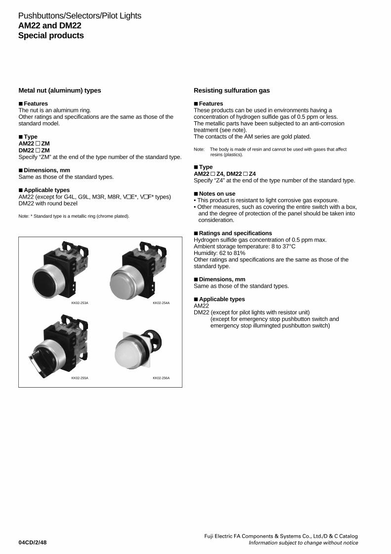
04CD/2/48Fuji Electric FA Components & Systems Co., Ltd./D & C Catalog
Information subject to change without notice
Pushbuttons/Selectors/Pilot LightsAM22 and DM22Special products
Metal nut (aluminum) types
FeaturesThe nut is an aluminum ring.Other ratings and specifications are the same as those of thestandard model.
TypeAM22 ZMDM22 ZMSpecify “ZM” at the end of the type number of the standard type.
Dimensions, mmSame as those of the standard types.
Applicable typesAM22 (except for G4L, G9L, M3R, M8R, V E*, V F* types)DM22 with round bezel
Note: * Standard type is a metallic ring (chrome plated).
Resisting sulfuration gas
FeaturesThese products can be used in environments having aconcentration of hydrogen sulfide gas of 0.5 ppm or less.The metallic parts have been subjected to an anti-corrosiontreatment (see note).The contacts of the AM series are gold plated.
Note: The body is made of resin and cannot be used with gases that affectresins (plastics).
TypeAM22 Z4, DM22 Z4Specify “Z4” at the end of the type number of the standard type.
Notes on use• This product is resistant to light corrosive gas exposure.• Other measures, such as covering the entire switch with a box,
and the degree of protection of the panel should be taken intoconsideration.
Ratings and specificationsHydrogen sulfide gas concentration of 0.5 ppm max.Ambient storage temperature: 8 to 37°CHumidity: 62 to 81%Other ratings and specifications are the same as those of thestandard type.
Dimensions, mmSame as those of the standard types.
Applicable typesAM22DM22 (except for pilot lights with resistor unit)
(except for emergency stop pushbutton switch andemergency stop illumingted pushbutton switch)
KK02-253A KK02-254A
KK02-255A KK02-256A
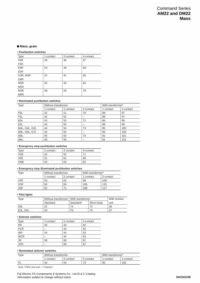
04CD/2/49Fuji Electric FA Components & Systems Co., Ltd./D & C CatalogInformation subject to change without notice
Mass, gram
Type 1-contactF0RF5RE0RE5RG3R, M4RG8RM0RM5RM3RM8R
28
29
31
33
49
2-contact38
39
41
43
59
4-contact57
58
60
62
78
• Pushbutton switches
Type Without transformer
F0LF5LE0LE5LM4L, G4L, G2LM9L, G9L, G7LM0LM5L
4242434344444545
5151535354545555
1-contact 2-contact 4-contact70–72–73–74–
With transformer*1-contact8888898990909191
2-contact97979999100100101101
• Illuminated pushbutton switches
Type 1-contactVSEV0EVME
425153
2-contact526163
4-contact718082
• Emergency stop pushbutton switches
Type Without transformer
VSFVDFV0F
536062
626971
1-contact 2-contactWith transformer*1-contact99106108
2-contact108115117
• Emergency stop illuminated pushbutton switches
Type Without transformer With transformer
D0LE3L, K0L
2223
7475
Standard Standard* Short body7273
With resistorunit3637
• Pilot lights
Type 1-contactPRPCRWRWCRJRJCR
33–34–58–
2-contact434344446868
4-contact626263638787
• Selector switches
Type
Note: *230V and over : +17grams
Without transformer
PL 44 541-contact 2-contact 4-contact
73
With transformer*1-contact90
2-contact100
• Illuminated selector switches
Command SeriesAM22 and DM22
Mass
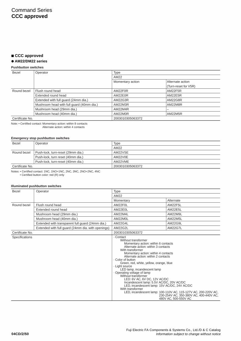
04CD/2/50Fuji Electric FA Components & Systems Co., Ltd./D & C Catalog
Information subject to change without notice
CCC approved AM22/DM22 series
Command SeriesCCC approved
· ContactWithout transformer
Momentary action: within 6 contactsAlternate action: within 3 contacts
With transformerMomentary action: within 4 contactsAlternate action: within 2 contacts
· Color of buttonGreen, red, white, yellow, orange, blue
· Light sourceLED lamp, incandescent lamp
· Operating voltage of lampWithout transformer
LED: 6V AC, 6V DC, 12V AC/DCIncandescent lamp: 5.5V AC/DC, 20V AC/DCLED, incandescent lamp: 15V AC/DC, 24V AC/DC
With transformerLED, incandescent lamp: 100-110V AC, 115-127V AC, 200-220V AC,
230-254V AC, 350-380V AC, 400-440V AC,480V AC, 500-550V AC
Bezel
Round bezel
Certificate No.Specifications
Operator
Flush round headExtended round headMushroom head (29mm dia.)Mushroom head (40mm dia.)Extended with transparent full guard (24mm dia.)Extended with full guard (24mm dia. with openings)
TypeAM22MomentaryAM22F0LAM22E0LAM22M4LAM22M0LAM22G4LAM22G2L2003010305063372
AlternateAM22F5LAM22E5LAM22M9LAM22M5LAM22G9LAM22G7L
Illuminated pushbutton switches
Bezel
Round bezel
Certificate No.
Operator
Flush round headExtended round headExtended with full guard (24mm dia.)Mushroom head with full guard (40mm dia.)Mushroom head (29mm dia.)Mushroom head (40mm dia.)
TypeAM22Momentary action
AM22F0RAM22E0RAM22G3RAM22M3RAM22M4RAM22M0R2003010305063372
Alternate action(Turn-reset for V5R)AM22F5RAM22E5RAM22G8RAM22M8R–AM22M5R
Note: • Certified contact: Momentary action: within 8 contactsAlternate action: within 4 contacts
Pushbutton switches
Bezel
Round bezel
Certificate No.
Operator
Push-lock, turn-reset (29mm dia.)Push-lock, turn reset (40mm dia.)Push-lock, turn-reset (40mm dia.)
TypeAM22AM22VSEAM22V0EAM22VME2003010305063372
Notes: • Certified contact: 1NC, 1NO+1NC, 2NC, 3NC, 2NO+2NC, 4NC• Certified button color: red (R) only
Emergency stop pushbutton switches
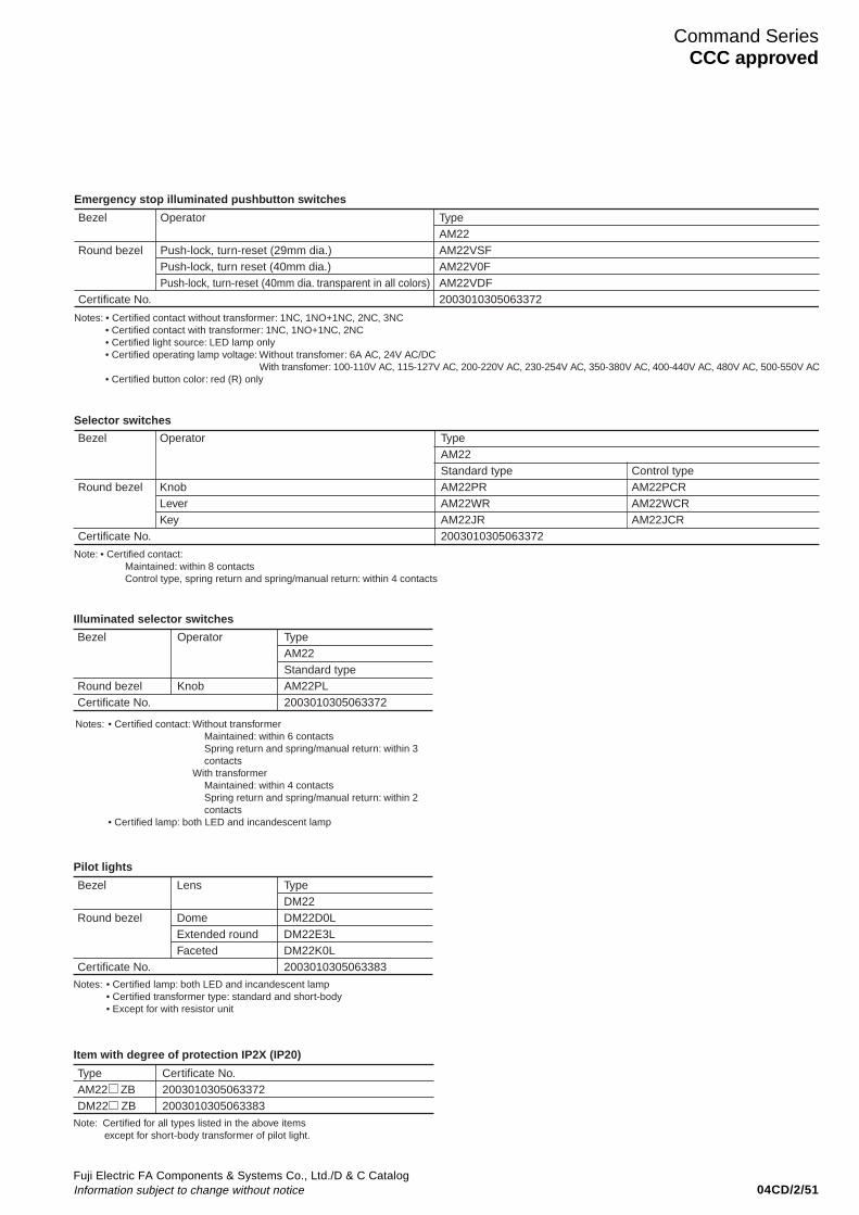
04CD/2/51Fuji Electric FA Components & Systems Co., Ltd./D & C CatalogInformation subject to change without notice
Bezel
Round bezelCertificate No.
Operator
Knob
TypeAM22Standard typeAM22PL2003010305063372
Illuminated selector switches
Notes: • Certified contact: Without transformerMaintained: within 6 contactsSpring return and spring/manual return: within 3 contacts
With transformerMaintained: within 4 contactsSpring return and spring/manual return: within 2 contacts
• Certified lamp: both LED and incandescent lamp
Bezel
Round bezel
Certificate No.
Lens
DomeExtended roundFaceted
TypeDM22DM22D0LDM22E3LDM22K0L2003010305063383
Notes: • Certified lamp: both LED and incandescent lamp• Certified transformer type: standard and short-body• Except for with resistor unit
Pilot lights
Type Certificate No.AM22 ZB 2003010305063372DM22 ZB 2003010305063383
Note: Certified for all types listed in the above items except for short-body transformer of pilot light.
Item with degree of protection IP2X (IP20)
Command SeriesCCC approved
Bezel
Round bezel
Certificate No.
Operator
Push-lock, turn-reset (29mm dia.)Push-lock, turn reset (40mm dia.)Push-lock, turn-reset (40mm dia. transparent in all colors)
TypeAM22AM22VSFAM22V0FAM22VDF2003010305063372
Notes: • Certified contact without transformer: 1NC, 1NO+1NC, 2NC, 3NC• Certified contact with transformer: 1NC, 1NO+1NC, 2NC• Certified light source: LED lamp only• Certified operating lamp voltage: Without transfomer: 6A AC, 24V AC/DC
With transfomer: 100-110V AC, 115-127V AC, 200-220V AC, 230-254V AC, 350-380V AC, 400-440V AC, 480V AC, 500-550V AC• Certified button color: red (R) only
Emergency stop illuminated pushbutton switches
Bezel
Round bezel
Certificate No.
Operator
KnobLeverKey
TypeAM22Standard typeAM22PRAM22WRAM22JR2003010305063372
Control typeAM22PCRAM22WCRAM22JCR
Note: • Certified contact:Maintained: within 8 contactsControl type, spring return and spring/manual return: within 4 contacts
Selector switches
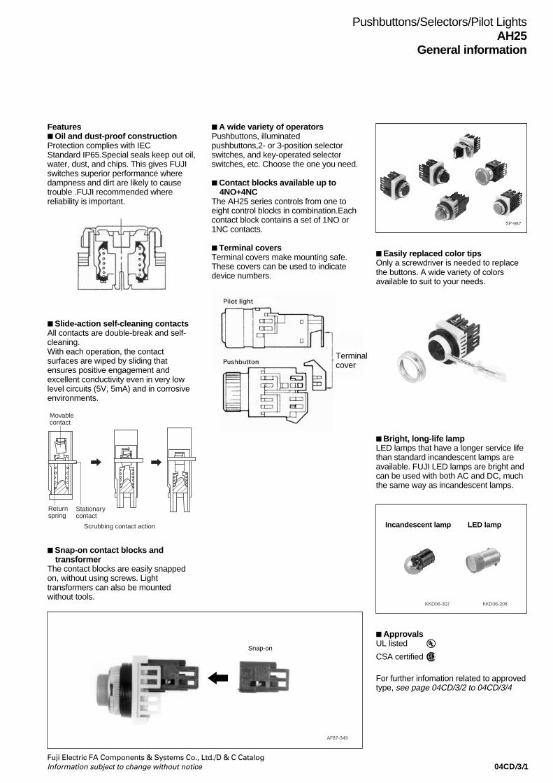
04CD/3/1Fuji Electric FA Components & Systems Co., Ltd./D & C CatalogInformation subject to change without notice
Pushbuttons/Selectors/Pilot LightsAH25
General information
Features Oil and dust-proof constructionProtection complies with IECStandard IP65.Special seals keep out oil,water, dust, and chips. This gives FUJIswitches superior performance wheredampness and dirt are likely to causetrouble .FUJI recommended wherereliability is important.
SP-987
Slide-action self-cleaning contactsAll contacts are double-break and self-cleaning.With each operation, the contactsurfaces are wiped by sliding thatensures positive engagement andexcellent conductivity even in very lowlevel circuits (5V, 5mA) and in corrosiveenvironments.
Stationarycontact
Scrubbing contact action
Returnspring
Movablecontact
A wide variety of operatorsPushbuttons, illuminatedpushbuttons,2- or 3-position selectorswitches, and key-operated selectorswitches, etc. Choose the one you need.
Contact blocks available up to4NO+4NC
The AH25 series controls from one toeight control blocks in combination.Eachcontact block contains a set of 1NO or1NC contacts.
Terminal coversTerminal covers make mounting safe.These covers can be used to indicatedevice numbers.
Snap-on contact blocks andtransformer
The contact blocks are easily snappedon, without using screws. Lighttransformers can also be mountedwithout tools.
Easily replaced color tipsOnly a screwdriver is needed to replacethe buttons. A wide variety of colorsavailable to suit to your needs.
Bright, long-life lampLED lamps that have a longer service lifethan standard incandescent lamps areavailable. FUJI LED lamps are bright andcan be used with both AC and DC, muchthe same way as incandescent lamps.
KKD06-208
ApprovalsUL listed
CSA certified
AF87-349
Snap-on
Incandescent lamp LED lamp
KKD06-307
For further infomation related to approvedtype, see page 04CD/3/2 to 04CD/3/4
Terminalcover
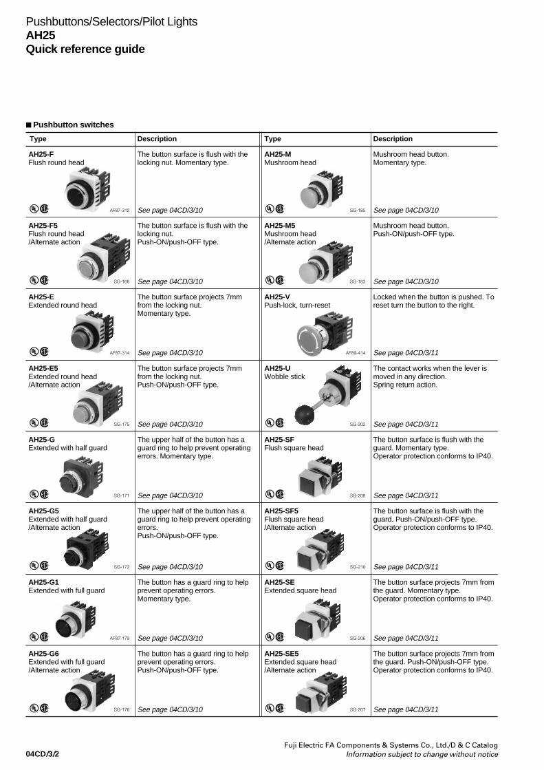
04CD/3/2Fuji Electric FA Components & Systems Co., Ltd./D & C Catalog
Information subject to change without notice
Pushbuttons/Selectors/Pilot LightsAH25Quick reference guide
Pushbutton switches
Type Description Type Description
AH25-FFlush round head
The button surface is flush with thelocking nut. Momentary type.
AF87-312
AH25-MMushroom head
Mushroom head button.Momentary type.
SG-185
AH25-F5Flush round head/Alternate action
The button surface is flush with thelocking nut.Push-ON/push-OFF type.
SG-166
AH25-M5Mushroom head/Alternate action
Mushroom head button.Push-ON/push-OFF type.
SG-183
AH25-EExtended round head
The button surface projects 7mmfrom the locking nut.Momentary type.
AF87-314
AH25-E5Extended round head/Alternate action
The button surface projects 7mmfrom the locking nut.Push-ON/push-OFF type.
SG-175
AH25-SFFlush square head
The button surface is flush with theguard. Momentary type.Operator protection conforms to IP40.
SG-208
AH25-GExtended with half guard
The upper half of the button has aguard ring to help prevent operatingerrors. Momentary type.
SG-171
AH25-SF5Flush square head/Alternate action
The button surface is flush with theguard. Push-ON/push-OFF type.Operator protection conforms to IP40.
SG-210
AH25-G5Extended with half guard/Alternate action
The upper half of the button has aguard ring to help prevent operatingerrors.Push-ON/push-OFF type.
SG-172
AH25-SEExtended square head
The button surface projects 7mm fromthe guard. Momentary type.Operator protection conforms to IP40.
SG-206
AH25-G1Extended with full guard
The button has a guard ring to helpprevent operating errors.Momentary type.
AF87-179
AH25-SE5Extended square head/Alternate action
The button surface projects 7mm fromthe guard. Push-ON/push-OFF type.Operator protection conforms to IP40.
SG-207
AH25-G6Extended with full guard/Alternate action
The button has a guard ring to helpprevent operating errors.Push-ON/push-OFF type.
SG-176
AH25-VPush-lock, turn-reset
Locked when the button is pushed. Toreset turn the button to the right.
AF89-414
AH25-UWobble stick
The contact works when the lever ismoved in any direction.Spring return action.
SG-202
See page 04CD/3/10 See page 04CD/3/10
See page 04CD/3/10 See page 04CD/3/10
See page 04CD/3/10 See page 04CD/3/11
See page 04CD/3/10 See page 04CD/3/11
See page 04CD/3/10 See page 04CD/3/11
See page 04CD/3/10 See page 04CD/3/11
See page 04CD/3/10 See page 04CD/3/11
See page 04CD/3/10 See page 04CD/3/11
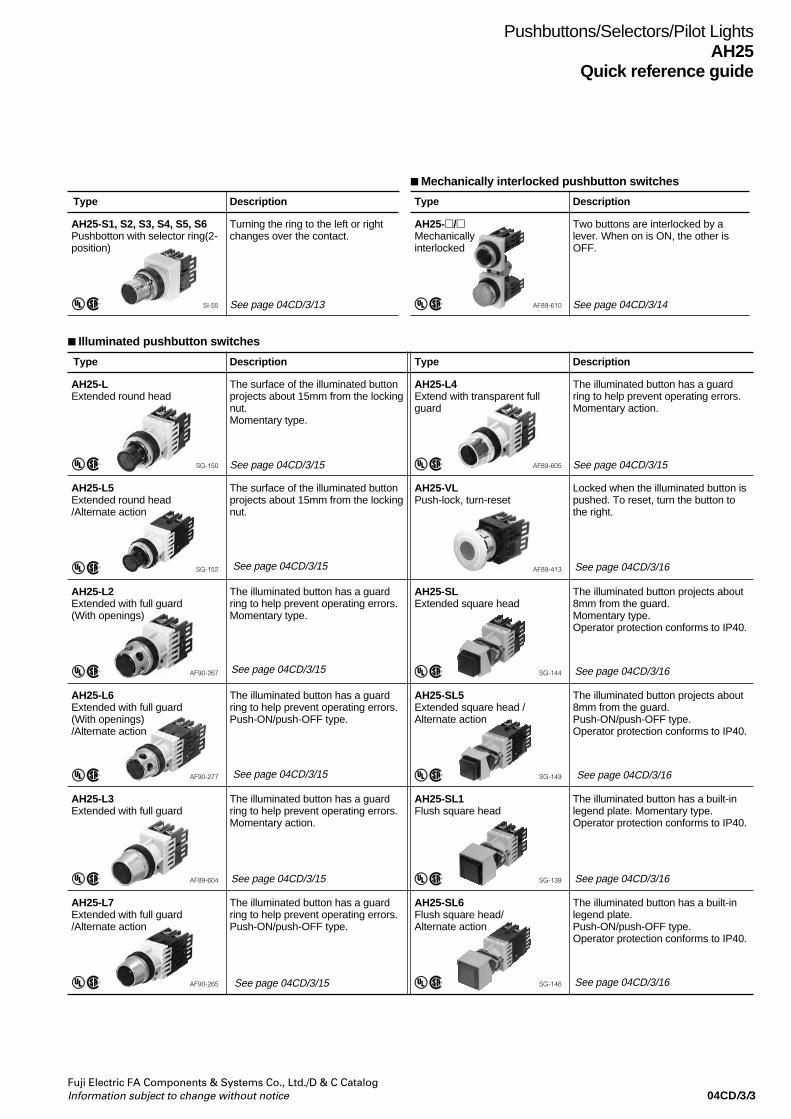
04CD/3/3Fuji Electric FA Components & Systems Co., Ltd./D & C CatalogInformation subject to change without notice
Pushbuttons/Selectors/Pilot LightsAH25
Quick reference guide
Illuminated pushbutton switches
Type Description Type Description
AH25-LExtended round head
The surface of the illuminated buttonprojects about 15mm from the lockingnut.Momentary type.
SG-150
AH25-L4Extend with transparent fullguard
The illuminated button has a guardring to help prevent operating errors.Momentary action.
AF89-605
AH25-L5Extended round head/Alternate action
The surface of the illuminated buttonprojects about 15mm from the lockingnut.
SG-152
AH25-VLPush-lock, turn-reset
Locked when the illuminated button ispushed. To reset, turn the button tothe right.
AF89-413
AH25-L2Extended with full guard(With openings)
The illuminated button has a guardring to help prevent operating errors.Momentary type.
AF90-267
AH25-SLExtended square head
The illuminated button projects about8mm from the guard.Momentary type.Operator protection conforms to IP40.
SG-144
AH25-L6Extended with full guard(With openings)/Alternate action
The illuminated button has a guardring to help prevent operating errors.Push-ON/push-OFF type.
AF90-277
AH25-SL5Extended square head /Alternate action
The illuminated button projects about8mm from the guard.Push-ON/push-OFF type.Operator protection conforms to IP40.
SG-149
AH25-L3Extended with full guard
The illuminated button has a guardring to help prevent operating errors.Momentary action.
AF89-604
AH25-SL1Flush square head
The illuminated button has a built-inlegend plate. Momentary type.Operator protection conforms to IP40.
SG-139
AH25-L7Extended with full guard/Alternate action
The illuminated button has a guardring to help prevent operating errors.Push-ON/push-OFF type.
AF90-265
AH25-SL6Flush square head/Alternate action
The illuminated button has a built-inlegend plate.Push-ON/push-OFF type.Operator protection conforms to IP40.
SG-146
See page 04CD/3/15 See page 04CD/3/15
Mechanically interlocked pushbutton switches
Type Description Type Description
AH25-S1, S2, S3, S4, S5, S6Pushbotton with selector ring(2-position)
Turning the ring to the left or rightchanges over the contact.
SI-55
AH25-/Mechanicallyinterlocked
Two buttons are interlocked by alever. When on is ON, the other isOFF.
AF89-610See page 04CD/3/13 See page 04CD/3/14
See page 04CD/3/15
See page 04CD/3/15
See page 04CD/3/15
See page 04CD/3/15
See page 04CD/3/15
See page 04CD/3/16
See page 04CD/3/16
See page 04CD/3/16
See page 04CD/3/16
See page 04CD/3/16

04CD/3/4Fuji Electric FA Components & Systems Co., Ltd./D & C Catalog
Information subject to change without notice
Selector switches
Type Description Type Description
AH25-PKnob
This switch works when the knob isturned.Operating positions : 2 or 3Operating : Maintained, spring return,
and spring/manual return.
SG-188
AH25-SJKey with square bezel
This switch works with a key inserted.Operator protection conforms to IP40.Operating positions : 2 or 3Operating : Maintained.
SG-226
AH25-PCKnob operated control type
21 types of operation are availableusing a cam for performing complexcontrols.
AF89-596
AH25-PWLever
The lever extends out 13mm from theknob.Operating positions : 2 or 3Operating : Maintained, spring return,
and spring/manual return.
SP-1007
AH25-JKey
This switch works when the key isinserted.Operating positions : 2 or 3Operating : Maintained, spring return,
and spring/manual return.
SG-233
AH25-PLIlluminated knob
Illuminated switch with a lamp builtinto the knob.Operating positions : 2 or 3Operating : Maintained.
AF89-622
AH25-SPKnob with square bezel
This switch works when the knob isturned.Operator protection conforms to IP40.Operating positions : 2 or 3Operating : Maintained.
SG-196
— —
Pushbuttons/Selectors/Pilot LightsAH25Quick reference guide
Pilot lights
Type Description Type Description
AH25-ZM*Dome
This pilot light uses a roundtransparent colored lens.
SF-1095
AH25-ZNFlush square with legend plate
This pilot light has a built-in squarelegend plate on which characters andsymbols can be marked.Operator protection conforms to IP40.
SF-1092
AH25-ZK*Faceted
This pilot light uses a facetedtransparent colored lens.
SF-1094
AH25-ZM8, 9Dome (Short-body withtransformer)
This pilot light has a short-bodytransformer.
SH-971
AH25-ZSExtended square
This pilot light uses a square lens.Operator protection conforms to IP40.
SF-1093
— —
See page 04CD/3/18 See page 04CD/3/18
Note: * With resistor unit types: Not approved standard
See page 04CD/3/22
See page 04CD/3/18
See page 04CD/3/18
See page 04CD/3/25
See page 04CD/3/25
See page 04CD/3/25
See page 04CD/3/25
See page 04CD/3/25
See page 04CD/3/23
See page 04CD/3/18

04CD/3/5Fuji Electric FA Components & Systems Co., Ltd./D & C CatalogInformation subject to change without notice
Pushbuttons/Selectors/Pilot LightsAH25
Type number nomenclature
Type number nomenclaturePushbuttons
AH25 - E R 11 ➀ ➁ ➂ ➃
➀ Product categoryAH25: 25mm-dia. pushbutton
➁ OperatorF: Flush round headF5: Flush round head(Alternate action)E: Extended round headE5: Extended round head(Alternate action)G: Extended with half guardG5: Extended with half guard (Alternate action)G1: Extended with full guardG6: Extended with full guard (Alternate action)M: Mushroom headM5: Mushroom head (Alternate action)V: Push-lock, turn-resetU: Wobble stickSF: Flush square headSF5: Flush square head (Alternate action)SE: Extended square headSE5: Extended square head (Alternate action)S1-S6:Pushbutton with selector ring (2-position)
➂ Color of buttonG: GreenR: RedW: WhiteS: Sky-blue*AH25-U type: ball color Black only.
➃ Contact arrangement10: 1NO01: 1NC11: 1NO+1NC20: 2NO02: 2NC22: 2NO+2NC
Mechanically interlocked pushbutton switches
➀ Product categoryAH25: 25mm-dia. interlocked pushbutton
➁ Combination of operator and operation mode• Latched/LatchedF5/F5: Flush (Push-locked)/Flush (Push-locked)F5/E5: Flush (Push-locked)/Extended (Push-locked)M5/M5: Mushroom (Push-locked)/Mushroom (Push-locked)• Latched/UnlatchedF5/F: Flush (Push-locked)/Flush (Momentary)E5/E: Extended (Push-locked)/Extended (Momentary)M5/M: Mushroom (Push-locked)/Mushroom (Momentary)
➂ Button colorG: GreenR: RedB: BlackD: Dark greenY: YellowW: WhiteS: Sky-blueO: Orange
30: 3NO03: 3NC33: 3NO+3NC40: 4NO04: 4NC44: 4NO+4NC
D: Dark greenY: YellowB: Black*O: Orange
Illuminated pushbuttons
AH25 - L5 G 11 H 3a ➀ ➁ ➂ ➃ ➄ ➅
➀ Product categoryAH25: 25mm-dia. illuminated pushbutton
➁ OperatorL: Extended round headL5: Extended round head (Alternate action)L2: Extended with full guard (With openings)L6: Extended with full guard (With openings alternate action)L3: Extended with full guardL7: Extended with full guard (Alternate action)L4: Extended with transparent full guardVL: Push-lock, turn-resetSL: Extended square headSL5: Extended square head (Alternate action)SL1: Flush square headSL6: Flush square head (Alternate action)
➂ Color of lensG: GreenR: RedW: White
* For LED lamp: Not available
➃ Contact arrangement10: 1NO01: 1NC11: 1NO+1NC20: 2NO02: 2NC22: 2NO+2NC
➄ Lamp voltage
• Without transformer:Incandescent LED
Blank 5.5V -A - 6V ACAD - 6V DCB - 12V AC/DCC 15V AC/DC 15V AC/DCD 20V AC/DC -E 24V AC/DC 24V AC/DC
• With transformer:Incandescent LED
H 100-110V AC 100-110V ACL 115-127V AC 115-127V ACM 200-220V AC 200-220V ACQ 230-254V AC 230-254V ACS 350-380V AC 350-380V ACT 400-440V AC 400-440V ACV 480V AC 480V ACW 500-550V AC 500-550V AC
➅ Type of lampBlank: Incandescent lamp3: LED lamp
30: 3NO03: 3NC33: 3NO+3NC40: 4NO04: 4NC44: 4NO+4NC
S: Sky-blue*Y: YellowO: Orange
AH25 - F5 B 10 /M5 R 10➀ ➃➁ ➂➂ ➁➃
➃ Contact arrangement10: 1NO01: 1NC11: 1NO+1NC20: 2NO02: 2NC
Note: • The manufacturing varies depending on the model. For details, refer to thecontents of this catalog
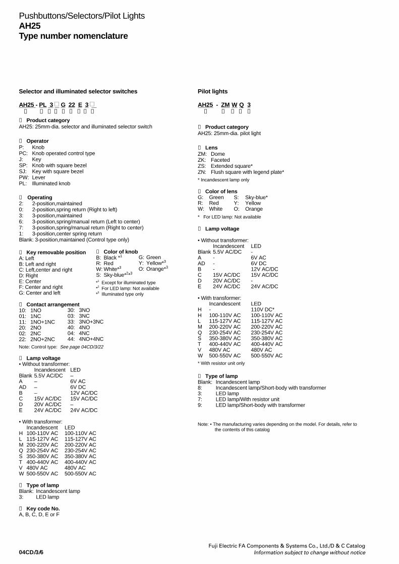
04CD/3/6Fuji Electric FA Components & Systems Co., Ltd./D & C Catalog
Information subject to change without notice
Pushbuttons/Selectors/Pilot LightsAH25Type number nomenclature
Selector and illuminated selector switches
AH25 - PL 3 G 22 E 3 a ➀ ➁ ➂ ➃ ➄ ➅ ➆ ➇ ➈
➀ Product categoryAH25: 25mm-dia. selector and illuminated selector switch
➁ OperatorP: KnobPC: Knob operated control typeJ: KeySP: Knob with square bezelSJ: Key with square bezelPW: LeverPL: Illuminated knob
➂ Operating2: 2-position,maintained0: 2-position,spring return (Right to left)3: 3-position,maintained6: 3-position,spring/manual return (Left to center)7: 3-position,spring/manual return (Right to center)1: 3-position,center spring returnBlank: 3-position,maintained (Control type only)
➃ Key removable positionA: LeftB: Left and rightC: Left,center and rightD: RightE: CenterF: Center and rightG: Center and left
➅ Contact arrangement10: 1NO01: 1NC11: 1NO+1NC20: 2NO02: 2NC22: 2NO+2NCNote: Control type: See page 04CD/3/22
➆ Lamp voltage• Without transformer:
Incandescent LEDBlank 5.5V AC/DC –A – 6V ACAD – 6V DCB – 12V AC/DCC 15V AC/DC 15V AC/DCD 20V AC/DC –E 24V AC/DC 24V AC/DC
• With transformer:Incandescent LED
H 100-110V AC 100-110V ACL 115-127V AC 115-127V ACM 200-220V AC 200-220V ACQ 230-254V AC 230-254V ACS 350-380V AC 350-380V ACT 400-440V AC 400-440V ACV 480V AC 480V ACW 500-550V AC 500-550V AC
➇ Type of lampBlank: Incandescent lamp3: LED lamp
➈ Key code No.A, B, C, D, E or F
30: 3NO03: 3NC33: 3NO+3NC40: 4NO04: 4NC44: 4NO+4NC
Pilot lights
AH25 - ZM W Q 3a ➀ ➁ ➂ ➃ ➄
➀ Product categoryAH25: 25mm-dia. pilot light
➁ LensZM: DomeZK: FacetedZS: Extended square*ZN: Flush square with legend plate** Incandescent lamp only
➂ Color of lensG: GreenR: RedW: White
* For LED lamp: Not available
➃ Lamp voltage
• Without transformer:Incandescent LED
Blank 5.5V AC/DC -A - 6V ACAD - 6V DCB - 12V AC/DCC 15V AC/DC 15V AC/DCD 20V AC/DC -E 24V AC/DC 24V AC/DC
• With transformer:Incandescent LED
H - 110V DC*H 100-110V AC 100-110V ACL 115-127V AC 115-127V ACM 200-220V AC 200-220V ACQ 230-254V AC 230-254V ACS 350-380V AC 350-380V ACT 400-440V AC 400-440V ACV 480V AC 480V ACW 500-550V AC 500-550V AC* With resistor unit only
➄ Type of lampBlank: Incandescent lamp8: Incandescent lamp/Short-body with transformer3: LED lamp7: LED lamp/With resistor unit9: LED lamp/Short-body with transformer
Note: • The manufacturing varies depending on the model. For details, refer tothe contents of this catalog
➄ Color of knobB: Black *1
R: RedW: White*3
S: Sky-blue*2*3
G: GreenY: Yellow*3
O: Orange*3
*1 Except for illuminated type*2 For LED lamp: Not available*3 Illuminated type only
S: Sky-blue*Y: YellowO: Orange

04CD/3/7Fuji Electric FA Components & Systems Co., Ltd./D & C CatalogInformation subject to change without notice
Pushbuttons/Selectors/Pilot LightsAH25
Ratings and specifications
Specifications (Indoor use)
Standards approved
UL508CSA C22.2 No.14
File No. E44592File No. LR20479
Description Pushbutton switch Illuminated pushbutton switchMechanically interlacked pushbutton switchSelector switchIlluminated selector switch
Pilot light
Rated insulation voltageMechanical durability Electrical durability
Operating frequencyDielectric strengthInsulation resistancePollution degreeVibration
Shock
Ambient temperature(No condensation or no icing)Storage temperatureHumidityDegree of protection
600V AC/DC *1
See the table below500,000 operations at 220V AC 6A1 million operations at 220V AC 3A1800 operations/hour (On-load factor: 40%)2500V AC, 1 minute *2
100MΩ or more (500V DC megger)3Resonance: 10 to 55Hz, double amplitude 0.1mmConstant: 16.7Hz, double amplitude 3mmMalfunction durability: 100m/s2
Mechanical durability: 500m/s2
-20 to +70°C(Illuminated type: -20 to +50°C)-40 to +80°C45 to 85% RH (within -5 to +40°C)IP65*3
––
–
Mechanical durability: 500m/s2
-20 to +50°C
Notes: *1 Illuminated type without transformer: 250V AC/DC *2 Illuminated type without transformer: 1500V AC, 1 minute *3 Square type : IP40
Mechanical durabilityDescription Operations
Pushbutton switch Momentary action 5 millionIlluminated pushbutton switch Alternate action 1 million
With selector ring 200,000Push-lock, turn-reset 100,000
Mechanically interlocked pushbutton Latched/Latched, Latched/Unlatched 100,000switch
Selector switch Maintained, spring return, spring/manual return 1 millionControl type 200,000
Illuminated selector switch Maintained, spring return, spring/manual return 1 million
Note: Key insertion/removal durability for selector switch key types
• Key type 10,000
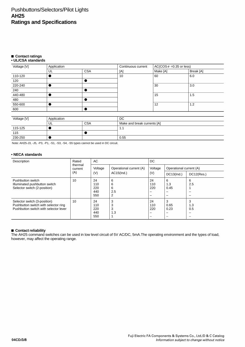
04CD/3/8Fuji Electric FA Components & Systems Co., Ltd./D & C Catalog
Information subject to change without notice
Pushbuttons/Selectors/Pilot LightsAH25Ratings and Specifications
Contact ratings• UL/CSA standards
Description Rated thermal current(A)
AC DC
Voltage(V)
Operational current (A) AC15(Ind.)
Voltage(V)
Operational current (A)
DC13(Ind.) DC12(Res.)
Pushbutton switchIlluminated pushbutton switchSelector switch (2-position)
10 24110220440550
6662.52
24110220––
61.30.45––
62.51––
Selector switch (3-position) Pushbutton switch with selector ring Pushbutton switch with selector lever
10 24110220440550
3331.31
24110220––
30.650.23––
31.30.5––
Voltage [V]
110-120120220-240240440-480480550-600600
ApplicationUL
CSA
AC(COS =0.35 or less)Make [A]60
30
15
12
Continuous current[A]10
Break [A]6.0
3.0
1.5
1.2
Voltage [V]
115-125115230-250
Note: AH25-J3, -J5, -P3, -P1, -S1, -S3, -S4, -S5 types cannot be used in DC circuit.
ApplicationUL
CSA
DCMake and break currents [A]1.1
0.55
• NECA standards
Contact reliabilityThe AH25 command switches can be used in low level circuit of 5V AC/DC, 5mA.The operating environment and the types of load,however, may affect the operating range.

04CD/3/9Fuji Electric FA Components & Systems Co., Ltd./D & C CatalogInformation subject to change without notice
Combination of lens color and LED luminous color
LampLED
Incandescent
Durability (reference)Approx. 30000h
Approx. 5000h (AC)
Judgement criterionWhen brightness is less than 50% of initial value
When the bulb burns out
Note: • The operating voltage for incandescent lamps is set at 80 to 90% of the lamp's rated voltage.
• The durability of LED lamp is a mean value in all colors.
Estimated durability for LED lamps
1.0
0.5
0.1 0.2 0.5 1 2 5 10 20 50
Time 103[h]
Abs
olut
e br
ight
ness
Durability judgement line
Rated voltage1.1 Rated voltage
Notes: • Durability at Ta=25˚C• Durability is affected by temperature, humidity, and
voltage fluctuation.
[AC voltage100%]100,000
50,000
20,000
10,000
5,000
2,000
1,000
500
20070 80
Voltage [%]
90 100 110
100
50
Durability
Luminous flux
Dur
abili
ty (
h)
Lum
inou
s flu
x
[%]
Incandescent lamp voltage characteristics Lamp durability
Lens color (lens or color plate)ColorGreenRedWhiteYellowOrange
LED lamp (high-brightness)Luminous colorGreenRedOrangeYellowAmber
TypeAPX510- GAPX510- RAPX510- OAPX510- YAPX510- A
Type *1
APX508- GAPX508- RAPX510- OAPX508- YAPX508- A
CodeGRWYA
Notes: *1 For pilot lights• Replace the mark by the lamp voltage code
Pushbuttons/Selectors/Pilot LightsAH25
Ratings and specifications
Lamp ratings• Illuminated pushbuttons, illuminated selectors, pilot lights
Transformer
Without transformer
With transformer
With resistor unit
Lamp voltage
5.5V AC/DC6V AC
6V DC
12V AC/DC
15V AC/DC
20V AC/DC24V AC/DC110V AC127V AC220V AC254V AC380V AC440V AC480V AC550V AC110V DC
LED (lamp base: BA9S/13)Type–APX508-6
APX508-D6
APX508-12
APX508-15
–APX508-24APX508-6
APX508-6
APX508-24
–APX510-6
APX510-D6
APX510-12
APX510-15
–APX510-24APX510-6
APX510-6
APX510-24
Rated voltage–6V AC
6V DC
12V AC/DC
15V AC/DC
–24V AC/DC6V AC
6V AC
24V AC/DC
Consumption–Green, red, orange, amber: 7mA ACYellow: 50mA ACGreen, red, orange, amber: 11mA DCYellow: 33mA DCGreen, red, orange, amber: 14mA AC, 11mA DCYellow: 28mA AC, 22mA DCGreen, red, orange, amber: 13mA AC, 11mA DC Yellow: 26mA AC, 22mA DC–12mA AC, 11mA DC1.5VA
2.5VA
1.2W
Incandescent (lamp base: BA9S/13)TypeAHX135–
–
–
AHX279
AHX144AHX129AHX135
AHX135
–
Rated voltage6.3V AC/DC–
–
–
18V AC/DC
24V AC/DC30V AC/DC6.3V AC/DC
6.3V AC/DC
–
Consumption0.9W–
–
–
0.8W
0.9W0.8W2VA2VA2VA2.5VA2.5VA2.5VA2.5VA2.5VA–
Note: Replace the mark by the lamp luminous color code.
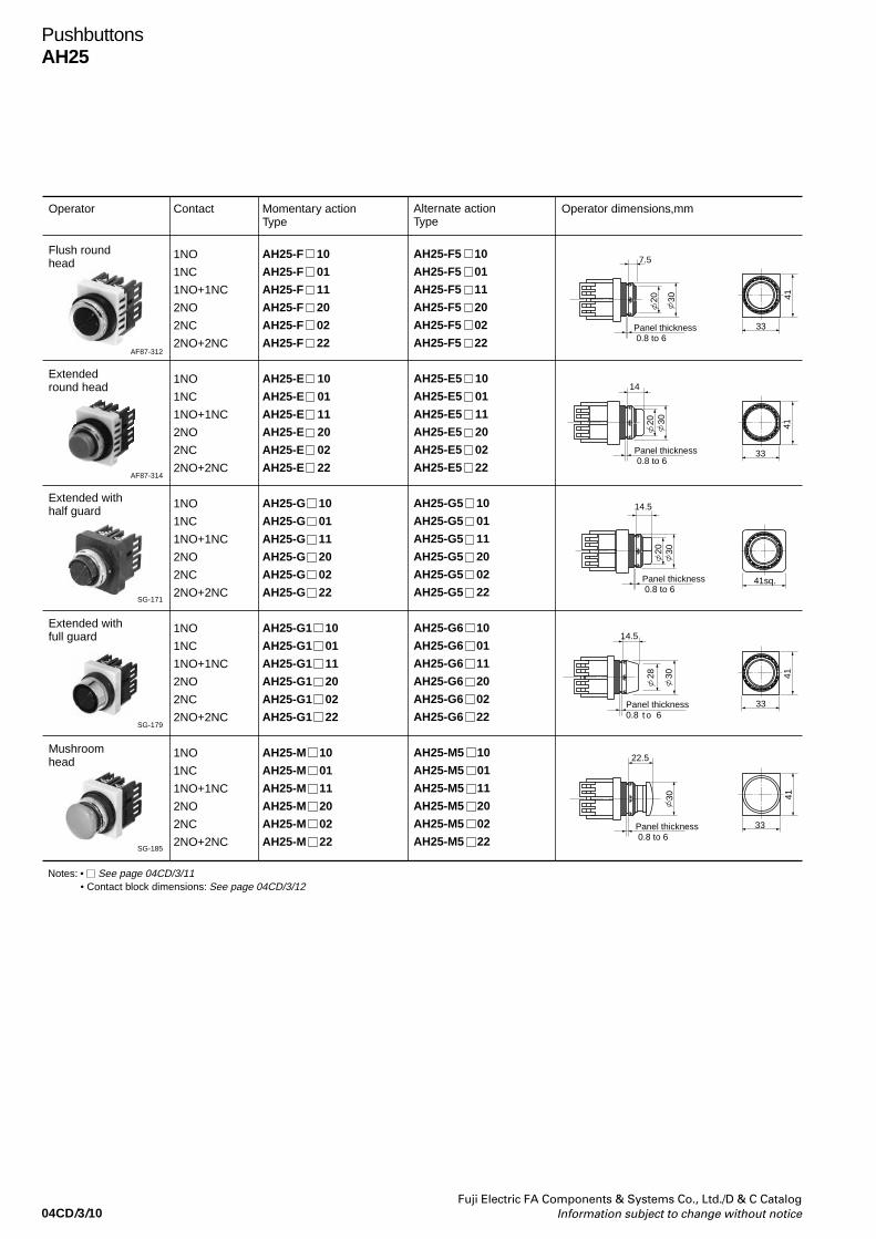
04CD/3/10Fuji Electric FA Components & Systems Co., Ltd./D & C Catalog
Information subject to change without notice
PushbuttonsAH25
Operator Contact Momentary actionType
Operator dimensions,mm
Flush roundhead
Notes: • See page 04CD/3/11• Contact block dimensions: See page 04CD/3/12
1NO
1NC
1NO+1NC
2NO
2NC
2NO+2NC
1NO
1NC
1NO+1NC
2NO
2NC
2NO+2NC
1NO
1NC
1NO+1NC
2NO
2NC
2NO+2NC
1NO
1NC
1NO+1NC
2NO
2NC
2NO+2NC
1NO
1NC
1NO+1NC
2NO
2NC
2NO+2NC
AH25-F 10
AH25-F 01
AH25-F 11
AH25-F 20
AH25-F 02
AH25-F 22
AH25-E 10
AH25-E 01
AH25-E 11
AH25-E 20
AH25-E 02
AH25-E 22
AH25-G 10
AH25-G 01
AH25-G 11
AH25-G 20
AH25-G 02
AH25-G 22
AH25-G1 10
AH25-G1 01
AH25-G1 11
AH25-G1 20
AH25-G1 02
AH25-G1 22
AH25-M 10
AH25-M 01
AH25-M 11
AH25-M 20
AH25-M 02
AH25-M 22
Alternate actionType
AH25-F5 10
AH25-F5 01
AH25-F5 11
AH25-F5 20
AH25-F5 02
AH25-F5 22
AH25-E5 10
AH25-E5 01
AH25-E5 11
AH25-E5 20
AH25-E5 02
AH25-E5 22
AH25-G5 10
AH25-G5 01
AH25-G5 11
AH25-G5 20
AH25-G5 02
AH25-G5 22
AH25-G6 10
AH25-G6 01
AH25-G6 11
AH25-G6 20
AH25-G6 02
AH25-G6 22
AH25-M5 10
AH25-M5 01
AH25-M5 11
AH25-M5 20
AH25-M5 02
AH25-M5 22
AF87-312
Extended round head
AF87-314
Extended with half guard
SG-171
Extended with full guard
SG-179
Mushroom head
SG-185
7.5
Panel thickness 0.8 to 6
33
4120 30
Panel thickness 0.8 to 6
20 30
33
41
14
Panel thickness 0.8 to 6
14.5
41sq.
20 30
Panel thickness0.8 t o 6
33
41
14.5
28 30
Panel thickness 0.8 to 6
33
41
22.5
30
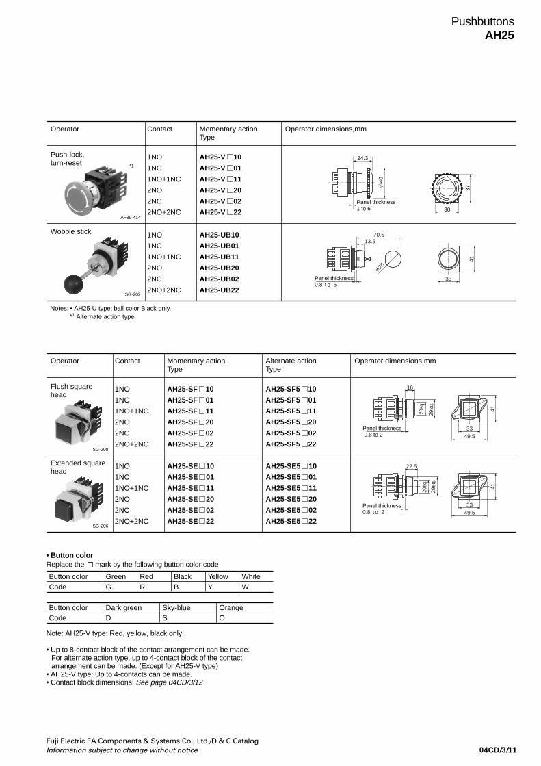
04CD/3/11Fuji Electric FA Components & Systems Co., Ltd./D & C CatalogInformation subject to change without notice
PushbuttonsAH25
Operator Contact Momentary actionType
Operator dimensions,mm
Flush squarehead
1NO
1NC
1NO+1NC
2NO
2NC
2NO+2NC
1NO
1NC
1NO+1NC
2NO
2NC
2NO+2NC
AH25-SF 10
AH25-SF 01
AH25-SF 11
AH25-SF 20
AH25-SF 02
AH25-SF 22
AH25-SE 10
AH25-SE 01
AH25-SE 11
AH25-SE 20
AH25-SE 02
AH25-SE 22
Alternate actionType
AH25-SF5 10
AH25-SF5 01
AH25-SF5 11
AH25-SF5 20
AH25-SF5 02
AH25-SF5 22
AH25-SE5 10
AH25-SE5 01
AH25-SE5 11
AH25-SE5 20
AH25-SE5 02
AH25-SE5 22
SG-208
Extended square head
SG-206
22.5
Panel thickness0.8 t o 2
33
41
49.5
20sq
.
29sq
.
16
Panel thickness 0.8 to 2
3320
sq.
29sq
.
41
49.5
• Button colorReplace the mark by the following button color code
Button color GreenCode G
RedR
BlackB
YellowY
WhiteW
Button color Dark greenCode D
Sky-blueS
OrangeO
Note: AH25-V type: Red, yellow, black only.
• Up to 8-contact block of the contact arrangement can be made.For alternate action type, up to 4-contact block of the contactarrangement can be made. (Except for AH25-V type)
• AH25-V type: Up to 4-contacts can be made.• Contact block dimensions: See page 04CD/3/12
Operator Contact Momentary actionType
Operator dimensions,mm
Push-lock,turn-reset
Notes: • AH25-U type: ball color Black only. *1 Alternate action type.
1NO
1NC
1NO+1NC
2NO
2NC
2NO+2NC
AH25-V 10
AH25-V 01
AH25-V 11
AH25-V 20
AH25-V 02
AH25-V 22
1NO
1NC
1NO+1NC
2NO
2NC
2NO+2NC
AH25-UB10
AH25-UB01
AH25-UB11
AH25-UB20
AH25-UB02
AH25-UB22
AF89-414
*1
Wobble stick
SG-202
Panel thickness1 to 6
24.3
37
30
40
13.570.5
25
Panel thickness0.8 t o 6
33
41
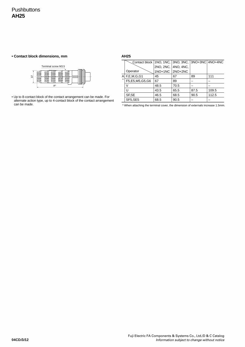
04CD/3/12Fuji Electric FA Components & Systems Co., Ltd./D & C Catalog
Information subject to change without notice
PushbuttonsAH25
• Up to 8-contact block of the contact arrangement can be made. Foralternate action type, up to 4-contact block of the contact arrangementcan be made.
AH25
Contact block
* When attaching the terminal cover, the dimension of externals increase 1.5mm.
Operator
1NO, 1NC,2NO, 2NC,1NO+1NC
3NO, 3NC,4NO, 4NC,2NO+2NC
F,E,M,G,G1F5,E5,M5,G5,G6VUSF,SESF5,SE5
A*
456748.543.546.568.5
678970.565.568.590.5
3NO+3NC
89––87.590.5–
4NO+4NC
111––109.5112.5–
• Contact block dimensions, mm
Terminal screw M3.5
37
A*

04CD/3/13Fuji Electric FA Components & Systems Co., Ltd./D & C CatalogInformation subject to change without notice
PushbuttonsAH25
Operator Type Contact operation
Type DepressedMountingposition
Free DepressedFree
Contact block Left Right
Pushbutton with selector ring 2-position 2NO+2NC
(1)
(2)
(3)
(4)
(1)
(2)
(3)
(4)
(1)
(2)
(3)
(4)
(1)
(2)
(3)
(4)
(1)
(2)
(3)
(4)
(1)
(2)
(3)
(4)
NC
NC
NO
NO
NC
NC
NO
NO
NC
NC
NO
NO
NC
NC
NO
NO
NC
NC
NO
NO
NC
NC
NO
NO
—
—
—
—
—
—
—
—
—
—
—
—
—
—
—
—
—
—
—
—
—
—
—
—
—
—
—
—
—
—
—
—
—
—
—
—
—
—
—
—
—
—
—
—
—
—
—
—
—
—
—
—
—
—
Note: (1) to (4) contact block mounting position Contact closed— Contact open
AH25-S1 22
AH25-S2 22
AH25-S3 22
AH25-S4 22
AH25-S5 22
AH25-S6 22
SI-55
Locked
• Button colorReplace the mark by the following button color code
• The contact arrangement is 2NO+2NC only.• The terminals are on the upper and lower positions.• To turn selector ring of the S3 type right/left,the contacts in the upper
and lower contact blocks overlap.
Button color GreenCode G
RedR
BlackB
YellowY
WhiteW
Button color Dark greenCode D
Sky-blueS
OrangeO
• Dimensions, mm
Panel thickness 0.8 t o 633
41
25.583*90
Name plate side
* When attaching the terminal cover, the dimension of externals increase 1.5mm.
(1)(3)
(2)(4)
Terminal screw M3.5
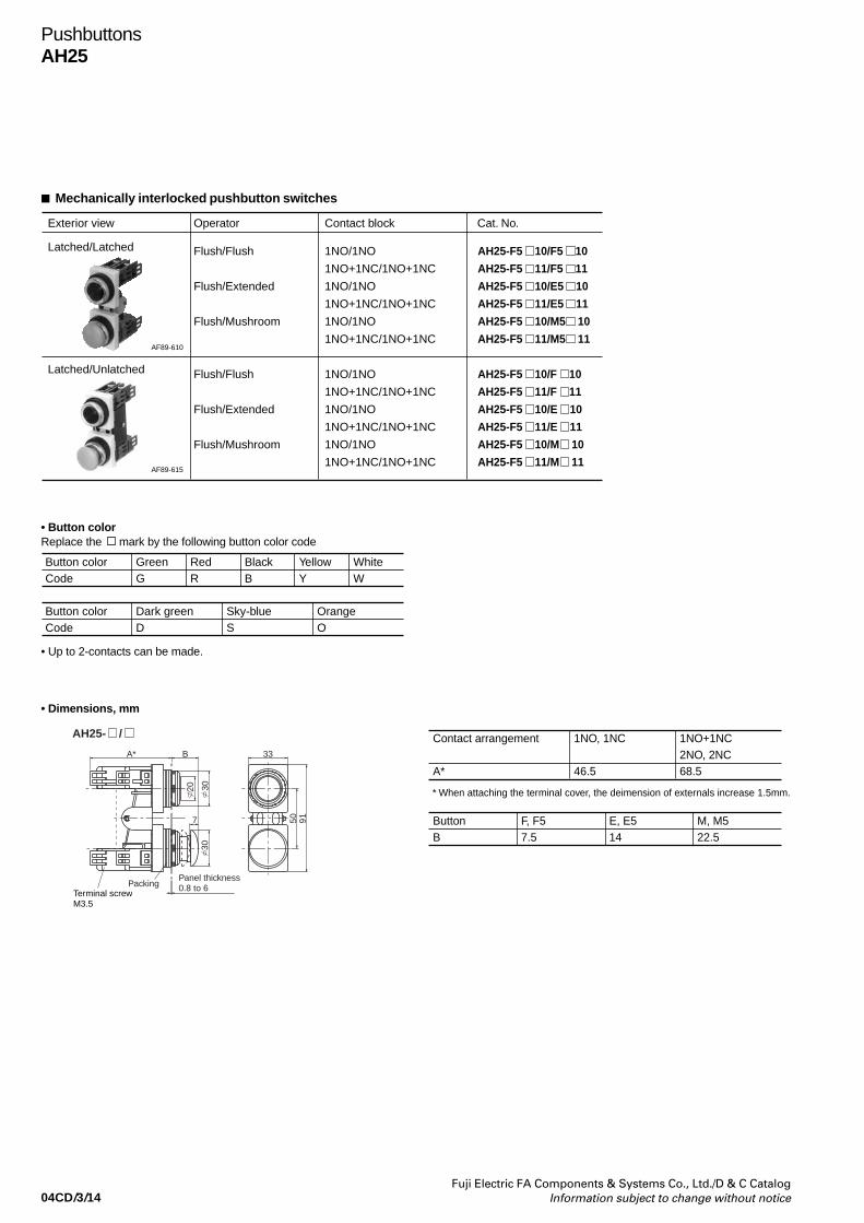
04CD/3/14Fuji Electric FA Components & Systems Co., Ltd./D & C Catalog
Information subject to change without notice
PushbuttonsAH25
Mechanically interlocked pushbutton switches
Exterior view Operator Cat. No.
Latched/Latched Flush/Flush
Flush/Extended
Flush/Mushroom
Flush/Flush
Flush/Extended
Flush/Mushroom
Contact block
1NO/1NO
1NO+1NC/1NO+1NC
1NO/1NO
1NO+1NC/1NO+1NC
1NO/1NO
1NO+1NC/1NO+1NC
1NO/1NO
1NO+1NC/1NO+1NC
1NO/1NO
1NO+1NC/1NO+1NC
1NO/1NO
1NO+1NC/1NO+1NC
AH25-F5 10/F5 10
AH25-F5 11/F5 11
AH25-F5 10/E5 10
AH25-F5 11/E5 11
AH25-F5 10/M5 10
AH25-F5 11/M5 11
AH25-F5 10/F 10
AH25-F5 11/F 11
AH25-F5 10/E 10
AH25-F5 11/E 11
AH25-F5 10/M 10
AH25-F5 11/M 11
AF89-610
Latched/Unlatched
AF89-615
• Button colorReplace the mark by the following button color code
• Up to 2-contacts can be made.
Button color GreenCode G
RedR
BlackB
YellowY
WhiteW
Button color Dark greenCode D
Sky-blueS
OrangeO
• Dimensions, mm
A*
AH25- /
B
20 3030
50 917
33
Terminal screwM3.5
Panel thickness 0.8 to 6Packing
Contact arrangement
A*
1NO, 1NC
46.5
1NO+1NC2NO, 2NC68.5
Button F, F5B 7.5
E, E514
M, M522.5
* When attaching the terminal cover, the deimension of externals increase 1.5mm.
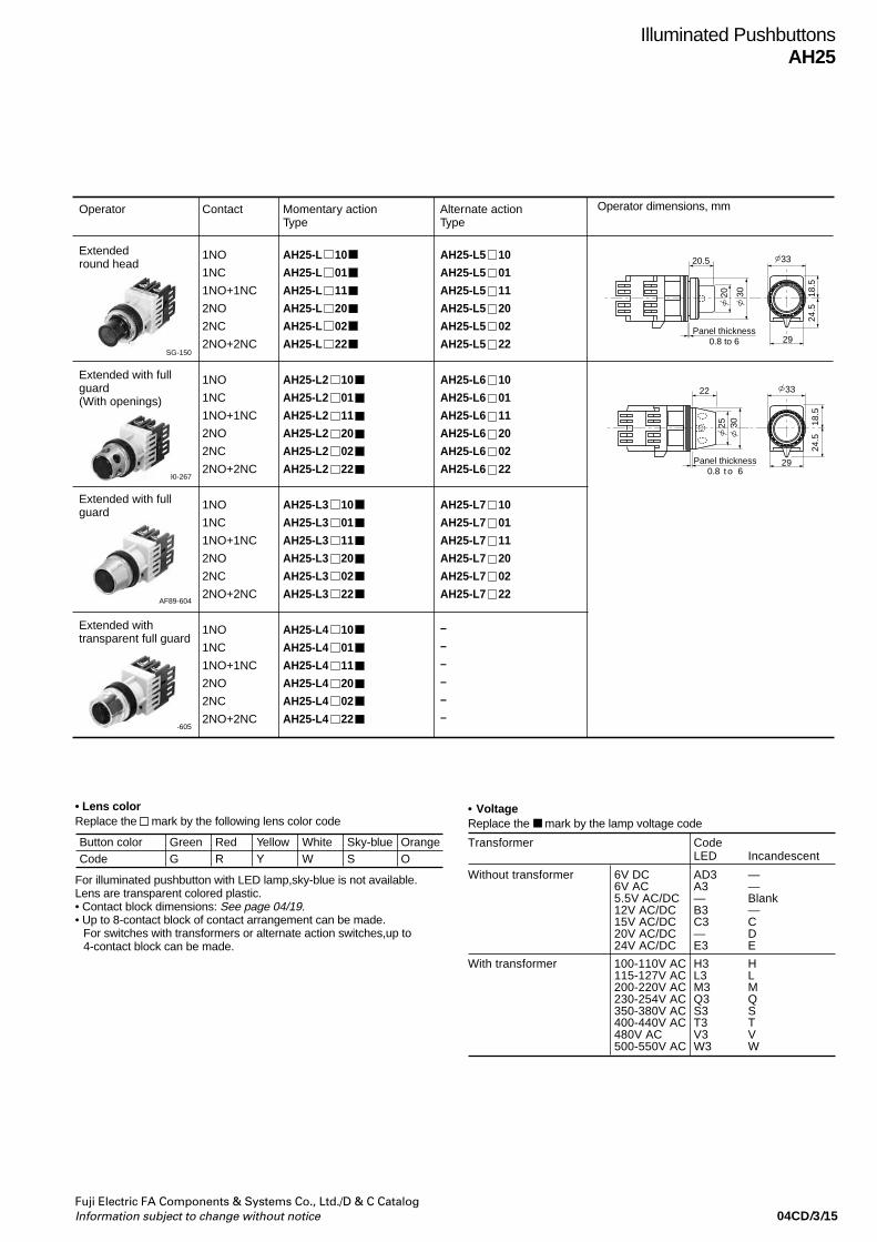
04CD/3/15Fuji Electric FA Components & Systems Co., Ltd./D & C CatalogInformation subject to change without notice
Operator Contact Momentary actionType
Extended round head
1NO
1NC
1NO+1NC
2NO
2NC
2NO+2NC
1NO
1NC
1NO+1NC
2NO
2NC
2NO+2NC
1NO
1NC
1NO+1NC
2NO
2NC
2NO+2NC
1NO
1NC
1NO+1NC
2NO
2NC
2NO+2NC
AH25-L 10
AH25-L 01
AH25-L 11
AH25-L 20
AH25-L 02
AH25-L 22
AH25-L2 10
AH25-L2 01
AH25-L2 11
AH25-L2 20
AH25-L2 02
AH25-L2 22
AH25-L3 10
AH25-L3 01
AH25-L3 11
AH25-L3 20
AH25-L3 02
AH25-L3 22
AH25-L4 10
AH25-L4 01
AH25-L4 11
AH25-L4 20
AH25-L4 02
AH25-L4 22
Alternate actionType
AH25-L5 10
AH25-L5 01
AH25-L5 11
AH25-L5 20
AH25-L5 02
AH25-L5 22
AH25-L6 10
AH25-L6 01
AH25-L6 11
AH25-L6 20
AH25-L6 02
AH25-L6 22
AH25-L7 10
AH25-L7 01
AH25-L7 11
AH25-L7 20
AH25-L7 02
AH25-L7 22
–
–
–
–
–
–
SG-150
Extended with full guard(With openings)
AF90-267
Extended with full guard
Extended with transparent full guard
AF89-604
AF89-605
Illuminated PushbuttonsAH25
Operator dimensions, mm
33
3020
Panel thickness0.8 to 6
18.5
24.5
20.5
29
22 33
29Panel thickness0.8 t o 6
18.5
24.5
25 30
• Lens colorReplace the mark by the following lens color code
For illuminated pushbutton with LED lamp,sky-blue is not available.Lens are transparent colored plastic.• Contact block dimensions: See page 04/19.• Up to 8-contact block of contact arrangement can be made.
For switches with transformers or alternate action switches,up to4-contact block can be made.
Button color GreenCode G
RedR
YellowY
OrangeO
Sky-blueS
WhiteW
• VoltageReplace the mark by the lamp voltage code
Transformer CodeLED Incandescent
Without transformer 6V DC AD3 —6V AC A3 —5.5V AC/DC — Blank12V AC/DC B3 —15V AC/DC C3 C20V AC/DC — D24V AC/DC E3 E
With transformer 100-110V AC H3 H115-127V AC L3 L200-220V AC M3 M230-254V AC Q3 Q350-380V AC S3 S400-440V AC T3 T480V AC V3 V500-550V AC W3 W
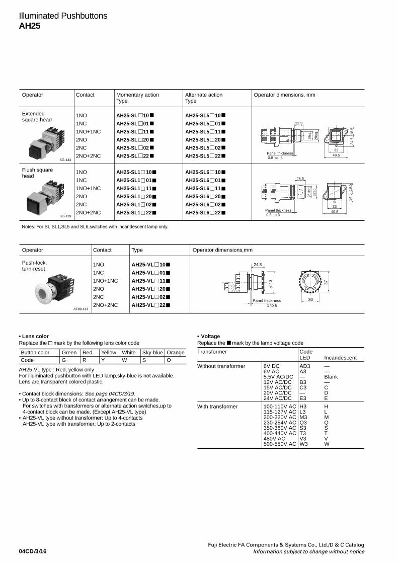
04CD/3/16Fuji Electric FA Components & Systems Co., Ltd./D & C Catalog
Information subject to change without notice
Illuminated PushbuttonsAH25
Operator Contact Momentary actionType
Extended square head
Notes: For SL,SL1,SL5 and SL6,switches with incandescent lamp only.
1NO
1NC
1NO+1NC
2NO
2NC
2NO+2NC
1NO
1NC
1NO+1NC
2NO
2NC
2NO+2NC
AH25-SL 10
AH25-SL 01
AH25-SL 11
AH25-SL 20
AH25-SL 02
AH25-SL 22
AH25-SL1 10
AH25-SL1 01
AH25-SL1 11
AH25-SL1 20
AH25-SL1 02
AH25-SL1 22
Alternate actionType
Operator dimensions, mm
AH25-SL5 10
AH25-SL5 01
AH25-SL5 11
AH25-SL5 20
AH25-SL5 02
AH25-SL5 22
AH25-SL6 10
AH25-SL6 01
AH25-SL6 11
AH25-SL6 20
AH25-SL6 02
AH25-SL6 22
SG-144
Flush square head
SG-139
22.3
Panel thickness 0.8 t o 3
33
29sq
.
29sq
. 18.5
24.5
49.5
26.5
Panel thickness 0.8 to 3
33
26.3
sq.
32sq
.
18.5
24.5
49.5
Operator Contact Type Operator dimensions,mm
Push-lock,turn-reset
1NO
1NC
1NO+1NC
2NO
2NC
2NO+2NC
AH25-VL 10
AH25-VL 01
AH25-VL 11
AH25-VL 20
AH25-VL 02
AH25-VL 22AF89-413
Panel thickness1 to 6
24.3
37
30
40
• Lens colorReplace the mark by the following lens color code
AH25-VL type : Red, yellow onlyFor illuminated pushbutton with LED lamp,sky-blue is not available.Lens are transparent colored plastic.
• Contact block dimensions: See page 04CD/3/19.• Up to 8-contact block of contact arrangement can be made.
For switches with transformers or alternate action switches,up to4-contact block can be made. (Except AH25-VL type)
• AH25-VL type without transformer: Up to 4-contactsAH25-VL type with transformer: Up to 2-contacts
Button color GreenCode G
RedR
YellowY
OrangeO
Sky-blueS
WhiteW
• VoltageReplace the mark by the lamp voltage code
Transformer CodeLED Incandescent
Without transformer 6V DC AD3 —6V AC A3 —5.5V AC/DC — Blank12V AC/DC B3 —15V AC/DC C3 C20V AC/DC — D24V AC/DC E3 E
With transformer 100-110V AC H3 H115-127V AC L3 L200-220V AC M3 M230-254V AC Q3 Q350-380V AC S3 S400-440V AC T3 T480V AC V3 V500-550V AC W3 W

04CD/3/17Fuji Electric FA Components & Systems Co., Ltd./D & C CatalogInformation subject to change without notice
Illuminated PushbuttonsAH25
Without transformer
Contact block
Operator
1NO, 1NC 2NO, 2NC,1NO+1NC
LL5L2,L3,L4L6,L7VLSL,SL1SL5,SL6
A*1
64.586.563.585.548.56688
70.5
3NO, 3NC
86.5108.585.5107.570.588110
4NO, 4NC,2NO+2NC
92.5
3NO+3NC
108.5–107.5––110–
4NO+4NC
130.5–129.5––132–
With transformer
Contact block
Operator
1NO, 1NC 2NO, 2NC1NO+1NC
LL5L2,L3,L4L6,L7VLSL,SL1SL5,SL6
A*2
81103801026283105
86.5108.585.5107.570.588110
3NO, 3NC
108.5130.5107.5129.5 –110132
4NO, 4NC2NO+2NC
130.5152.5129.5151.5 –132154
Notes: • Up to 8-contact block of contact arrangement can be made.For switches with transformers or alternate action switches, up to 4-
contact block of contact arrangement can be made. (Except AH25-VL)• Type AH25-VL without transformer: 4 contact Max.
with transformer: 2 contact Max. *1 When attaching the terminal cover, the dimension of externals
increase 1.5mm. *2 When attaching the terminal cover, the dimension of externals
increase 1.5mm. (Except for 1NO and 1NC)
• Contact block dimensions, mm
Terminal screw M3.5 Terminal screw M3.5
Terminal screw M3.5
Without transformer (Except VL type) With transformer Without transformer (For VL type)
37
18.5
24.5
Lamp terminal (AHX291L)Lamp terminal M3.5
A*1 A*1A*2
37
Transformer
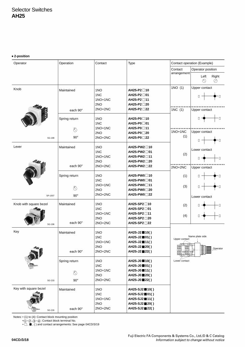
04CD/3/18Fuji Electric FA Components & Systems Co., Ltd./D & C Catalog
Information subject to change without notice
Selector SwitchesAH25
Operator Operation Type Contact operation (Example)
Contactarrangement
Operator position
1NO (1) Upper contact
Left Right
Knob
Notes: • (1) to (4): Contact block mounting position • 1 – 2 , 3 – 4 : Contact block terminal No. • , , ( ) and contact arrangements: See page 04CD/3/19
Maintained
Spring return
Maintained
Spring return
Maintained
Maintained
Spring return
Maintained
Contact
1NO1NC1NO+1NC2NO2NO+2NC
1NO1NC1NO+1NC2NO2NO+2NC
1NO1NC1NO+1NC2NO2NO+2NC
1NO1NC1NO+1NC2NO2NO+2NC
1NO1NC1NO+1NC2NO2NO+2NC
1NO1NC1NO+1NC2NO2NO+2NC
1NO1NC1NO+1NC2NO2NO+2NC
1NO1NC1NO+1NC2NO2NO+2NC
AH25-P2 10AH25-P2 01AH25-P2 11AH25-P2 20AH25-P2 22
AH25-P0 10AH25-P0 01AH25-P0 11AH25-P0 20AH25-P0 22
AH25-PW2 10AH25-PW2 01AH25-PW2 11AH25-PW2 20AH25-PW2 22
AH25-PW0 10AH25-PW0 01AH25-PW0 11AH25-PW0 20AH25-PW0 22
AH25-SP2 10AH25-SP2 01AH25-SP2 11AH25-SP2 20AH25-SP2 22
AH25-J2 10( )AH25-J2 01( )AH25-J2 11( )AH25-J2 20( )AH25-J2 22( )
AH25-J0 10( )AH25-J0 01( )AH25-J0 11( )AH25-J0 20( )AH25-J0 22( )
AH25-SJ2 10( )AH25-SJ2 01( )AH25-SJ2 11( )AH25-SJ2 20( )AH25-SJ2 22( )
SG-188
SP-1007
Lever
Knob with square bezel
SG-196
Key
Key with square bezel
SG-233
SG-226
➂ ➃
1NC (1) Upper contact
➀ ➁
1NO+1NC(1)
Upper contact
➂ ➃
(2)Lower contact
➀ ➁
2NO+2NC
(1)
Upper contact
➂ ➃
(3) ➂ ➃
(2)
Lower contact
➀ ➁
(4) ➀ ➁
Name plate sideUpper contact
Lower contact
(1)
(2)
(3)
(4)
Operator
each 90°
90°
each 90°
each 90°
each 90°
90°
each 90°
90°
• 2-position
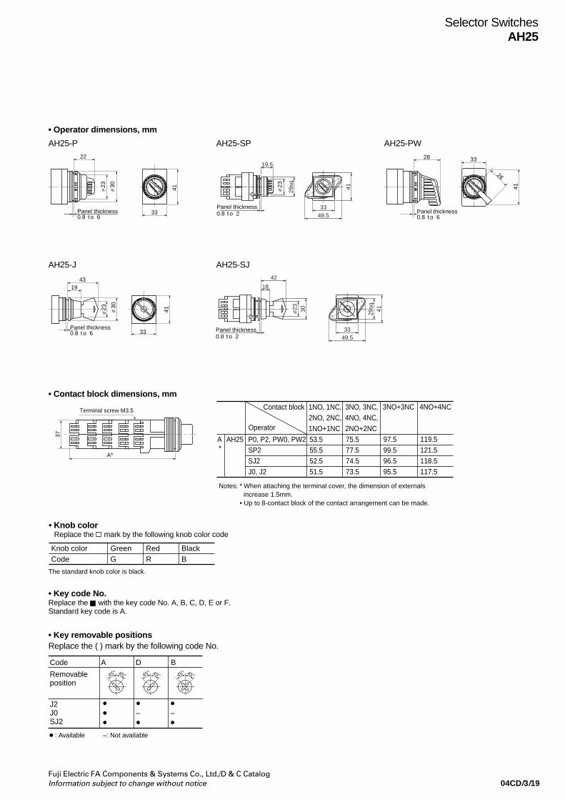
04CD/3/19Fuji Electric FA Components & Systems Co., Ltd./D & C CatalogInformation subject to change without notice
Selector SwitchesAH25
AH25-P
• Operator dimensions, mm
AH25-SP AH25-PW22
23 30
Panel thickness0.8 t o 6
33
41
19.5
Panel thickness0.8 t o 2
33
4129sq
.
49.5
23
28
Panel thickness0.8 t o 6
33
26
41
30
Panel thickness0.8 t o 6
41
33
4319
23
AH25-J AH25-SJ
18
Panel thickness0.8 t o 2
33
23
29sq
.41
42
30
49.5
• Contact block dimensions, mm
• Key removable positionsReplace the ( ) mark by the following code No.
Contact block
Operator
1NO, 1NC,2NO, 2NC,1NO+1NC
3NO, 3NC,4NO, 4NC,2NO+2NC
P0, P2, PW0, PW2SP2SJ2J0, J2
A*
AH25 53.555.552.551.5
75.577.574.573.5
3NO+3NC
97.599.596.595.5
4NO+4NC
119.5121.5118.5117.5
Notes: * When attaching the terminal cover, the dimension of externals increase 1.5mm.
• Up to 8-contact block of the contact arrangement can be made.
• Key code No.Replace the with the key code No. A, B, C, D, E or F.Standard key code is A.
Removable position
J2J0SJ2
: Available –: Not available
– –
Code A D B
45° 45°45° 45° 45° 45°
• Knob colorReplace the mark by the following knob color code
Knob color
The standard knob color is black.
GreenCode G
RedR
BlackB
Terminal screw M3.5
37
A*

04CD/3/20Fuji Electric FA Components & Systems Co., Ltd./D & C Catalog
Information subject to change without notice
Selector SwitchesAH25
• 3-position
Operator Operation AH25Type
Knob Maintained
Spring/manual return
Spring/manual return
Spring return
Maintained
Spring/manual return
Spring/manual return
Spring return
Maintained
Maintained
Spring/manual return
Spring/manual return
Maintained
Contact
1NO+1NC
2NO+2NC
1NO+1NC
2NO+2NC
1NO+1NC
2NO+2NC
2NO+2NC
1NO+1NC
2NO+2NC
1NO+1NC
2NO+2NC
1NO+1NC
2NO+2NC
2NO+2NC
1NO+1NC
2NO+2NC
1NO+1NC
2NO+2NC
1NO+1NC
2NO+2NC
1NO+1NC
2NO+2NC
1NO+1NC
2NC+2NC
AH25-P3 11
AH25-P3 22
AH25-P5 11
AH25-P5 22
AH25-P6 11
AH25-P6 22
AH25-P1 22
AH25-PW3 11
AH25-PW3 22
AH25-PW5 11
AH25-PW5 22
AH25-PW6 11
AH25-PW6 22
AH25-PW1 22
AH25-SP3 11
AH25-SP3 22
AH25-J3 11( )
AH25-J3 22( )
AH25-J5 11( )
AH25-J5 22( )
AH25-J6 11( )
AH25-J6 22( )
AH25-SJ3 11( )
AH25-SJ3 22( )
SG-193
AF89-602
Lever operated
Knob with square bezel
AF88-599
SG-364
Key
Key with square bezel
AF89-609
Notes: • , , ( ) and contact arrangements: See page 04CD/3/21 • Operator dimensions: See page 04CD/3/19
each 45°
each 45°
each 45°
each 45°
each 45°
each 45°
each 45°
each 45°
each 45°
each 45°
each 45°
each 60°
each 60°

04CD/3/21Fuji Electric FA Components & Systems Co., Ltd./D & C CatalogInformation subject to change without notice
Selector SwitchesAH25
Contactblock
Operator
Notes : * When attaching the terminal cover, the dimension of externals increase 1.5mm.• Up to 8-contact block of the contact arrangement can be made.
For spring return switches, up to 4-contact block can be made.
1NO, 1NC2NO, 2NC1NO+1NC
3NO, 3NC4NO, 4NC2NO+2NC
P3, P5, P6, PW3, PW5, PW6SP3SJ3J3, J5, J6P1, PW1J1
A*
AH25 53.555.552.551.5––
75.577.574.573.575.573.5
3NO+3NC
97.599.596.595.5––
4NO+4NC
119.5121.5118.5117.5––
• Contact block dimensions, mm
• Contact operation (Example)3-position
Terminal screw M3.5
37
A*
• Key removable positionsReplace the ( ) mark by the following code No.
Code A B C D E F G
Removableposition
J3, SJ3
J5 – – – – J6 – – – –
: Available –: Not available
45° 45° 45° 45° 45° 45° 45° 45° 45° 45°45° 45° 45° 45°
Type
P3, PW3, SP3, J3, SJ3, P5,PW5, J5
1NO+1NC
(1) (2)
Upper contact Lower contact
1NO+1NC
(1) (2)
Upper contact Lower contact
2NO+2NC
(1) (2)
(3) (4)
Upper contact Lower contact
Contact closedNote: ➀-➁,➂-➃ : Contact block terminal No.
• Up to 8-contact block of the contact arrangement can be made. For P1, PW1 types, up to 4-contact block can be made.
P6, PW6, J6
P1, PW1
Operator position
L C R L C R
Contactarrange-ment
➂
➃
➀
➁
➂
➃
➀
➁
➀
➁
➀
➁
➂
➃
➂
➃
• Position of contact block
Name plate sideUpper contact
Lower contact
(1)
(2)
(3)
(4)
Operator
• Key code No. Replace the with the key code No. A, B, C, D, E or F. Standard key code is A.
• Knob colorReplace the mark by the following knob color code
Knob color
The standard knob color is black.
GreenCode G
RedR
BlackB

04CD/3/22Fuji Electric FA Components & Systems Co., Ltd./D & C Catalog
Information subject to change without notice
Selector SwitchesAH25
3-positionOperator Operation Knob color or Contact Type
key removable arrangementposition (2NO+2NC only)
Knob Maintained Replace the AH25-PCBmark by typearrangement code(shown on under table). AH25-PCR
AH25-PCG
Color code:B: Black
(Standard)Color other thanabove areavailable G: Green R: Red
each 60˚
Selector switches (control type)
AF89-596
Contact operation
Upper contact Lower contact
Contact operation
Upper contact Lower contact
21 3
21 3
21 313
24
21 3 21 3 21 3
21 3 21 3 21 3 21 3
21 3 21 3 21 3 21 3
21 3 21 3 21 3 21 3
21 3 21 3 21 3 21 3
21 3 21 3 21 3 21 3
21 3 21 3 21 3 21 3
21 3 21 3 21 3 21 3
21 3 21 3 21 3 21 3
21 3 21 3 21 3 21 3
21 3 21 3
Code
012
032
052
072
092
112
132
152
172
192
212
022
042
062
082
102
122
142
162
182
202
Operation Code Operation
Maintained Maintained13
24
(1)(3)
(2)(4)
13
24
13
24
(1)(3)
(2)(4)
13
24
13
24
(1)(3)
(2)(4)
13
24
13
24
(1)(3)
(2)(4)
13
24
13
24
(1)(3)
(2)(4)
13
24
13
24
(1)(3)
(2)(4)
13
24
13
24
(1)(3)
(2)(4)
13
24
13
24
(1)(3)
(2)(4)
13
24
13
24
(1)(3)
(2)(4)
13
24
13
24
(1)(3)
(2)(4)
13
24
13
24
(1)(3)
(2)(4)
13
24
13
24
(1)(3)
(2)(4)
13
24
13
24
(1)(3)
(2)(4)
13
24
13
24
(1)(3)
(2)(4)
13
24
13
24
(1)(3)
(2)(4)
13
24
13
24
(1)(3)
(2)(4)
13
24
13
24
(1)(3)
(2)(4)
13
24
13
24
(1)(3)
(2)(4)
13
24
13
24
(1)(3)
(2)(4)
13
24
13
24
(1)(3)
(2)(4)
13
24
13
24
(1)(3)
(2)(4)
each 60˚each 60˚
Contact closed
Contact operation (2NO+2NC)
Name plate sideUpper contact
Lower contact
(1)
(2)
(3)
(4)
Operator
23 30
Panel thickness0.8 to 6
41
33
83* 22
Terminal screw M3.5
• Dimensions, mm
Notes : • (1) to (4) : Contact block mounting position
• 1 - 2 , 3 - 4 : Contact block terminal No.
* When attaching the terminal cover, the dimmension of externals increase1.5mm.
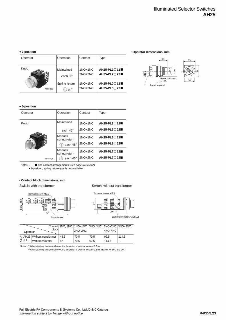
04CD/3/23Fuji Electric FA Components & Systems Co., Ltd./D & C CatalogInformation subject to change without notice
Illuminated Selector SwitchesAH25
Operator Contact Type
Knob 1NO+1NC
2NO+2NC
Operation
Maintained
each 90˚
90˚
AH25-PL2 11
AH25-PL2 22
1NO+1NC
2NO+2NC
Spring return AH25-PL0 11
AH25-PL0 22AF89-622
• 2-position
• 3-position
Operator Contact Type
Knob 1NO+1NC
2NO+2NC
Operation
Maintained
Notes: • , and contact arrangements: See page 04CD/3/24• 3-position, spring return type is not available.
AH25-PL3 11
AH25-PL3 22
1NO+1NC
2NO+2NC
Manual/spring return
AH25-PL6 11
AH25-PL6 22
1NO+1NC
2NO+2NC
Manual/spring return
AH25-PL7 11
AH25-PL7 22AF89-415
each 45°
each 45°
each 45°
Notes: • *1 When attaching the terminal cover, the dimension of external increase 1.5mm.
*2 When attaching the terminal cover, the dimension of external increase 1.5mm. (Except for 1NO and 1NC)
Contactblock
Operator
1NO, 1NC 1NO+1NC2NO, 2NC
Without transformerWith transformer
A*1
*2
AH25-PL
48.562
70.570.5
3NO, 3NC
70.592.5
2NO+2NC4NO, 4NC
92.5114.5
3NO+3NC
114.5–
• Contact block dimensions, mm
• Operator dimensions, mm
23.5
30
Panel thickness1 t o 6
25
30
37
Lamp terminal
33
Lamp terminal (AHX291L)
37
A*1
Terminal screw M3.5Terminal screw M3.5
18.5
24.5
A*2
Transformer
Switch: with transformer Switch: without transformer
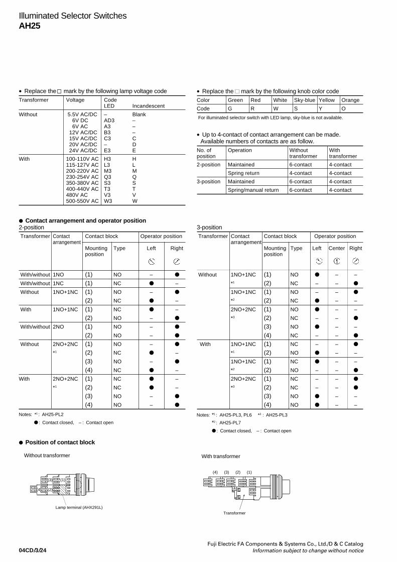
04CD/3/24Fuji Electric FA Components & Systems Co., Ltd./D & C Catalog
Information subject to change without notice
Illuminated Selector SwitchesAH25
• Replace the mark by the following lamp voltage codeTransformer Voltage Code
LED Incandescent
Without 5.5V AC/DC – Blank 6V DC AD3 – 6V AC A3 – 12V AC/DC B3 – 15V AC/DC C3 C 20V AC/DC – D 24V AC/DC E3 E
With 100-110V AC H3 H115-127V AC L3 L200-220V AC M3 M230-254V AC Q3 Q350-380V AC S3 S400-440V AC T3 T480V AC V3 V500-550V AC W3 W
• Replace the mark by the following knob color codeColor Green Red White Sky-blue Yellow Orange
Code G R W S Y O
• Up to 4-contact of contact arrangement can be made.Available numbers of contacts are as follow.
No. of Operation Without Withposition transformer transformer
2-position Maintained 6-contact 4-contact
Spring return 4-contact 4-contact
3-position Maintained 6-contact 4-contact
Spring/manual return 6-contact 4-contact
Contact arrangement and operator position2-position Transformer Contact Contact block Operator position
arrangementMounting Type Left Rightposition
With/without 1NO (1) NO –
With/without 1NC (1) NC –
Without 1NO+1NC (1) NO –
(2) NC –
With 1NO+1NC (1) NC –
(2) NO –
With/without 2NO (1) NO –
(2) NO –
Without 2NO+2NC (1) NO –
*1 (2) NC –
(3) NO –
(4) NC –
With 2NO+2NC (1) NC –
*1 (2) NC –
(3) NO –
(4) NO –
Notes: *1 : AH25-PL2
: Contact closed, – : Contact open
Position of contact block
Without transformer
3-position Transformer Contact Contact block Operator position
arrangementMounting Type Left Center Rightposition
Without 1NO+1NC (1) NO – –
*1 (2) NC – –
1NO+1NC (1) NO – –
*2 (2) NC – –
2NO+2NC (1) NO – –
*3 (2) NC – –
(3) NO – –
(4) NC – –
With 1NO+1NC (1) NC – –
*1 (2) NO – –
1NO+1NC (1) NC – –
*2 (2) NO – –
2NO+2NC (1) NC – –
*3 (2) NC – –
(3) NO – –
(4) NO – –
Notes: *1 : AH25-PL3, PL6 *3 : AH25-PL3
*2 : AH25-PL7
: Contact closed, – : Contact open
With transformer
For illuminated selector switch with LED lamp, sky-blue is not available.
Lamp terminal (AHX291L)
(1)(3)
(2)(4)
Transformer
(4) (3) (2) (1)
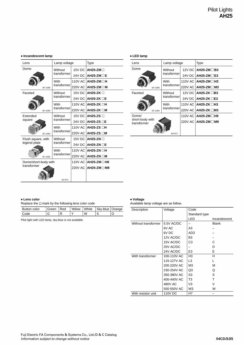
04CD/3/25Fuji Electric FA Components & Systems Co., Ltd./D & C CatalogInformation subject to change without notice
Pilot LightsAH25
• Incandescent lamp
Lens Type
Dome 15V DC
24V DC
110V AC
220V AC
15V DC
24V DC
110V AC
220V AC
15V DC
24V DC
110V AC
220V AC
15V DC
24V DC
110V AC
220V AC
110V AC
220V AC
Lamp voltage
Without transformer
With transformer
AH25-ZM
AH25-ZM E
AH25-ZM H
AH25-ZM M
AH25-ZK
AH25-ZK E
AH25-ZK H
AH25-ZK M
AH25-ZS
AH25-ZS E
AH25-ZS H
AH25-ZS M
AH25-ZN
AH25-ZN E
AH25-ZN H
AH25-ZN M
AH25-ZM H8
AH25-ZM M8
SF-1095
Faceted Without transformer
With transformer
SF-1094
Extendedsquare
Without transformer
With transformer
SF-1093
Flush square, with legend plate
Without transformer
With transformer
SF-1092
Dome/short-body with transformer
SH-971
• LED lamp
Lens Type
Dome 12V DC
24V DC
110V AC
220V AC
12V DC
24V DC
110V AC
220V AC
110V AC
220V AC
Lamp voltage
Without transformer
With transformer
AH25-ZM B3
AH25-ZM E3
AH25-ZM H3
AH25-ZM M3
AH25-ZK B3
AH25-ZK E3
AH25-ZK H3
AH25-ZK M3
AH25-ZM H9
AH25-ZM M9
SF-1095
Faceted Without transformer
With transformer
SF-1094
Dome/ short-body with transformer
SH-971
• Lens colorReplace the mark by the following lens color code
Pilot light with LED lamp, sky-blue is not available.
Button color GreenCode G
RedR
YellowY
OrangeO
Sky-blueS
WhiteW
• VoltageAvailable lamp voltage are as follow.
Description
Without transformer
With transformer
With resistor unit
Voltage
5.5V AC/DC6V AC6V DC12V AC/DC15V AC/DC20V AC/DC24V AC/DC100-110V AC115-127V AC200-220V AC230-254V AC350-380V AC 400-440V AC480V AC 500-550V AC110V DC
CodeStandard typeLED–A3AD3B3C3–E3H3L3M3Q3S3T3V3W3H7
IncandescentBlank–––CDEHLMQSTVW–

04CD/3/26Fuji Electric FA Components & Systems Co., Ltd./D & C Catalog
Information subject to change without notice
Pilot LightsAH25
Dimensions, mm
Type Without transformer With transformer
AH25-ZM
Terminal screw M3.5 Terminal screw M3.5
Panel thickness0.8 t o 6
Panel thickness0.8 t o 6
22.5*2 2222
20 2030 30
59*1
33
29
18.5
16.5
LampBA 9 S/13
Panel thickness0.8 t o 6
2250
29
18.5
16.5
33
20 30
Terminal screw M3.5
Terminal screw M3.5Terminal screw M3.5
Panel thickness0.8 t o 6Panel thickness
0.8 t o 6
22.5*2 22
29
18.5
16.5
2259*1
LampBA 9 S/13
33
20 3020 30
Terminal screw M3.5 Terminal screw M3.5
Panel thickness0.8 t o 6
Panel thickness0.8 t o 6
LampBA 9 S/13
11
31*2 69
11
18.5
16.5
49.5
29sq
.
Legend plate Legend plate
Terminal screw M3.5 Terminal screw M3.5
Panel thickness0.8 t o 6Panel thickness
0.8 t o 6
18.5
16.5
LampBA 9 S/13
15
31*2 69
15
49.5
29sq
.
AH25-ZM8
AH25-ZK
AH25-ZS
AH25-ZN
Note: *1 Same as the resistor unit type.
*2 When attaching the terminal cover, the dimension of externals increase 1.0mm.
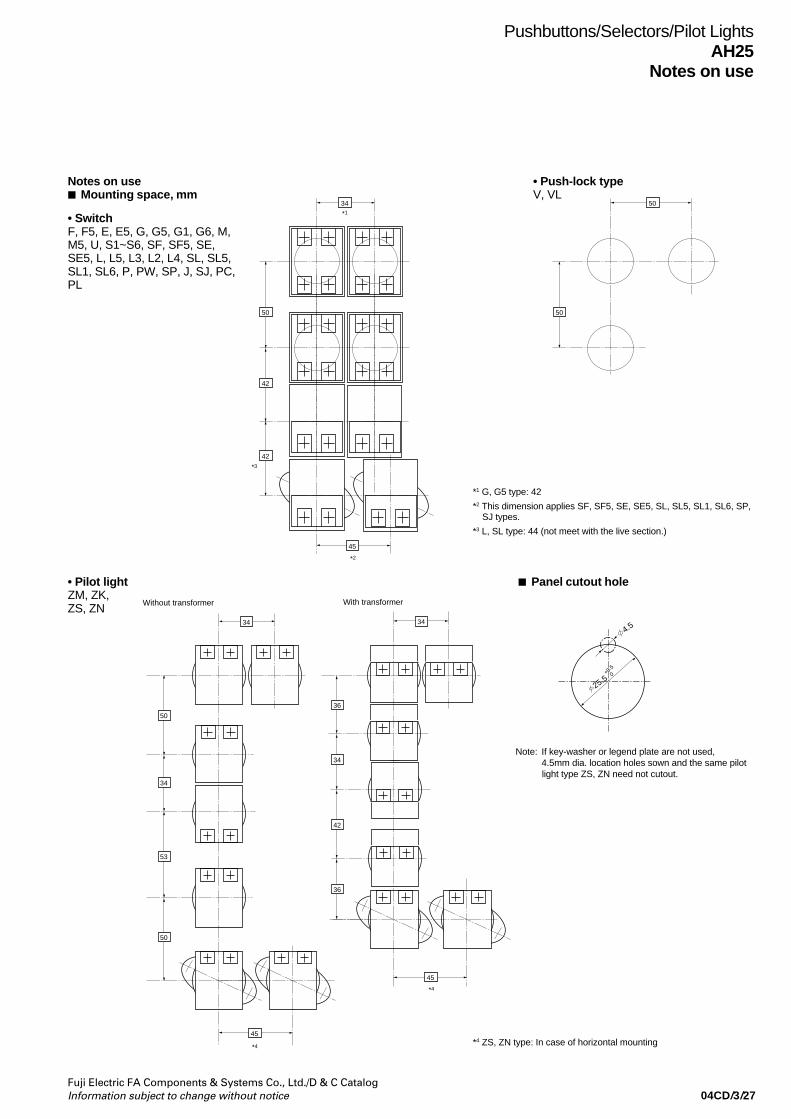
04CD/3/27Fuji Electric FA Components & Systems Co., Ltd./D & C CatalogInformation subject to change without notice
Pushbuttons/Selectors/Pilot LightsAH25
Notes on use
Notes on use Mounting space, mm
• SwitchF, F5, E, E5, G, G5, G1, G6, M,M5, U, S1~S6, SF, SF5, SE,SE5, L, L5, L3, L2, L4, SL, SL5,SL1, SL6, P, PW, SP, J, SJ, PC,PL
• Push-lock typeV, VL
• Pilot lightZM, ZK,ZS, ZN
Panel cutout hole
25.5
4.5
+0.5
0
34
50
*1
*3
50
50
*2
42
42
45
34
50
45
36
34
42
36
45
34
34
53
50
Without transformer With transformer
*4
*4
Note: If key-washer or legend plate are not used,4.5mm dia. location holes sown and the same pilotlight type ZS, ZN need not cutout.
*1 G, G5 type: 42
*2 This dimension applies SF, SF5, SE, SE5, SL, SL5, SL1, SL6, SP,SJ types.
*3 L, SL type: 44 (not meet with the live section.)
*4 ZS, ZN type: In case of horizontal mounting
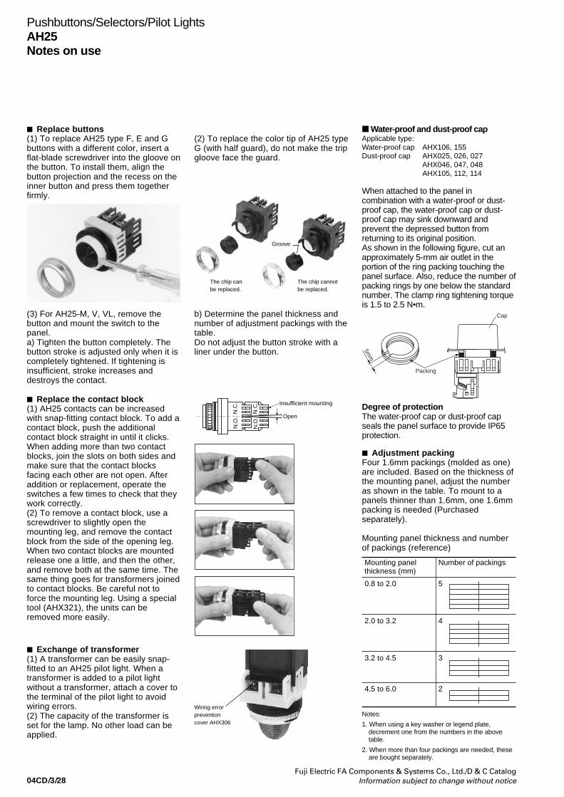
04CD/3/28Fuji Electric FA Components & Systems Co., Ltd./D & C Catalog
Information subject to change without notice
Pushbuttons/Selectors/Pilot LightsAH25Notes on use
Replace buttons(1) To replace AH25 type F, E and Gbuttons with a different color, insert aflat-blade screwdriver into the gloove onthe button. To install them, align thebutton projection and the recess on theinner button and press them togetherfirmly.
(2) To replace the color tip of AH25 typeG (with half guard), do not make the tripgloove face the guard.
(3) For AH25-M, V, VL, remove thebutton and mount the switch to thepanel.a) Tighten the button completely. Thebutton stroke is adjusted only when it iscompletely tightened. If tightening isinsufficient, stroke increases anddestroys the contact.
b) Determine the panel thickness andnumber of adjustment packings with thetable.Do not adjust the button stroke with aliner under the button.
Replace the contact block(1) AH25 contacts can be increasedwith snap-fitting contact block. To add acontact block, push the additionalcontact block straight in until it clicks.When adding more than two contactblocks, join the slots on both sides andmake sure that the contact blocksfacing each other are not open. Afteraddition or replacement, operate theswitches a few times to check that theywork correctly.(2) To remove a contact block, use ascrewdriver to slightly open themounting leg, and remove the contactblock from the side of the opening leg.When two contact blocks are mountedrelease one a little, and then the other,and remove both at the same time. Thesame thing goes for transformers joinedto contact blocks. Be careful not toforce the mounting leg. Using a specialtool (AHX321), the units can beremoved more easily.
The chip canbe replaced.
The chip cannotbe replaced.
Open
Insufficient mounting
N.C
.N
.O.
N.C
.N
.O.
Exchange of transformer(1) A transformer can be easily snap-fitted to an AH25 pilot light. When atransformer is added to a pilot lightwithout a transformer, attach a cover tothe terminal of the pilot light to avoidwiring errors.(2) The capacity of the transformer isset for the lamp. No other load can beapplied.
Adjustment packingFour 1.6mm packings (molded as one)are included. Based on the thickness ofthe mounting panel, adjust the numberas shown in the table. To mount to apanels thinner than 1.6mm, one 1.6mmpacking is needed (Purchasedseparately).
Mounting panel thickness and numberof packings (reference)
Wiring errorpreventioncover AHX306
Mounting panelthickness (mm)
Number of packings
0.8 to 2.0 5
2.0 to 3.2 4
3.2 to 4.5 3
4.5 to 6.0 2
Notes:
1. When using a key washer or legend plate,decrement one from the numbers in the abovetable.
2. When more than four packings are needed, theseare bought separately.
Groove
Water-proof and dust-proof capApplicable type:Water-proof cap AHX106, 155Dust-proof cap AHX025, 026, 027
AHX046, 047, 048AHX105, 112, 114
When attached to the panel incombination with a water-proof or dust-proof cap, the water-proof cap or dust-proof cap may sink downward andprevent the depressed button fromreturning to its original position.As shown in the following figure, cut anapproximately 5-mm air outlet in theportion of the ring packing touching thepanel surface. Also, reduce the number ofpacking rings by one below the standardnumber. The clamp ring tightening torqueis 1.5 to 2.5 N•m.
Degree of protectionThe water-proof cap or dust-proof capseals the panel surface to provide IP65protection.
Packing
5mm
Cap
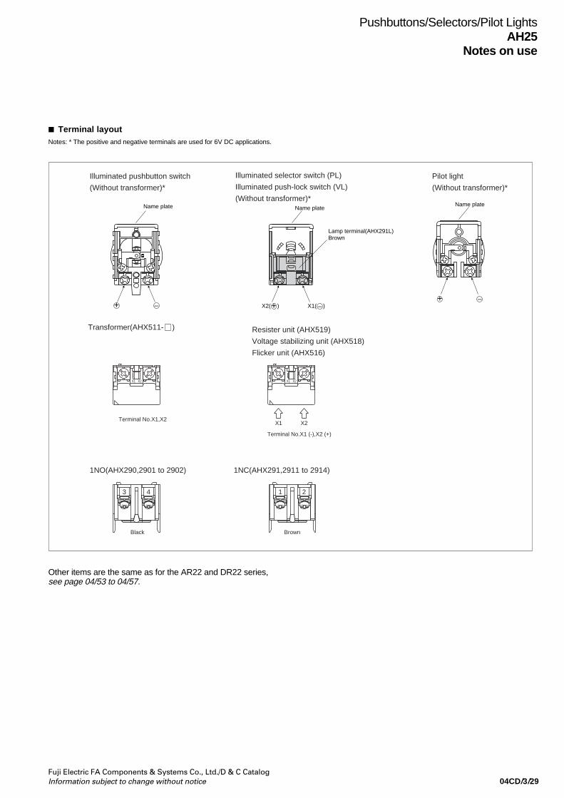
04CD/3/29Fuji Electric FA Components & Systems Co., Ltd./D & C CatalogInformation subject to change without notice
Pushbuttons/Selectors/Pilot LightsAH25
Notes on use
Terminal layout
X1 X2X2X1
X2X1Terminal No.X1,X2
Terminal No.X1 (-),X2 (+)
Black
43
Brown
1 2
Name plate Name plateName plate
Lamp terminal(AHX291L)Brown
X1( )+ – X2( )
Illuminated pushbutton switch
(Without transformer)*
1NO(AHX290,2901 to 2902) 1NC(AHX291,2911 to 2914)
Resister unit (AHX519)
Voltage stabilizing unit (AHX518)
Flicker unit (AHX516)
Pilot light
(Without transformer)*
Illuminated selector switch (PL)
Illuminated push-lock switch (VL)
(Without transformer)*
Transformer(AHX511- )
+ –+ –
Notes: * The positive and negative terminals are used for 6V DC applications.
Other items are the same as for the AR22 and DR22 series,see page 04/53 to 04/57.

04CD/3/30Fuji Electric FA Components & Systems Co., Ltd./D & C Catalog
Information subject to change without notice
AHX046AHX047AHX048AHX025AHX026AHX027AHX105-RAHX105-GAHX105-BAHX105-YAHX105-WAHX112-RAHX112-GAHX112-BAHX114-RAHX114-GAHX114-B
AHX001
AHX003
Wrench
Panel plug
Dust-tight cap(indoor use)
Dust-tight cap(outdoor use)
Water-tight cap
Lamp changer
F type
E type
M type
F type
E type
E typeL type
Color: Silver (metal)Dimensions, mm
Dimensions, mm 34×17.3
Dimensions, mm 34×17.3
Dimensions, mm 31×18Dimensions, mm 31×25.5
Dimensions, mm 45×25
Dimensions, mm 34×17.3
Dimensions, mm 34×17.3
RedGreenBlackRedGreenBlackRedGreenBlackYellowWhiteRedGreenBlackRedGreenBlack
Description Type
Button
Description Type
SC992
SC993
SC-993
Y-1559
AF95-22
Y-1990
Y-1541
Y-1542
SC-1094
SC-1012
AF87-522
T-1995
T-1993
AHX106AHX155
AHX029AHX790
Standard
Engraving
Mushroom head pushbutton
Symbol mark button
Push-lock, turn-reset pushbutton
M, M5 type AHX065-
F, F5, S1-S6 typeE, E5, G, G5, G1, G6 type
F, F5, S1-S6 typeE, E5, G, G5, G1, G6 type
AHX061-AHX062-
AHX063-AHX064-
For Incandescen lampFor LED lamp
AHX029
AHX790
Note: The only color available is transparent.
Button color GreenCode G
RedR
BlackB
Button colorCode
YellowY
Dark greenD
WhiteW
Button colorCode
OrangeO
Sky-blueS
Replace the mark by the following color code.
Button color GreenCode G
RedR
BlackB
Symbol mark
Symbol mark color
Button
Code
Red
White Black White
Green
Black
E F H J
Button colorCode
YellowY
Dark greenD
WhiteW
Button colorCode
OrangeO
Sky-blueS
Replace the mark by the following color code.
Type
V typeVL type
AHX769-AHX755-
Used with
AHX066- F, F5 type
AHX067- E, E5 type
Panel plug PackingNut
M5
2013
31 35
Note: Replace the mark by the following color code.
Symbol mark
Symbol mark color
Button
Code
Green
White Black
T U
Button colorCode
RedR
Black*B
YellowY
Replace the mark by the following color code.
* Except VL type.
Pushbuttons/Selectors/Pilot LightsAH25Accessories
Accessories
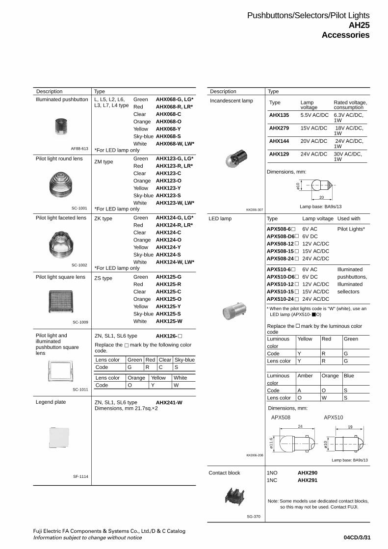
04CD/3/31Fuji Electric FA Components & Systems Co., Ltd./D & C CatalogInformation subject to change without notice
Pushbuttons/Selectors/Pilot LightsAH25
Accessories
Description Type Description Type
Illuminated pushbutton
Pilot light round lens
Pilot light faceted lens
Pilot light square lens
Pilot light and illuminated pushbutton square lens
Legend plate
L, L5, L2, L6, L3, L7, L4 type
*For LED lamp only
*For LED lamp only
*For LED lamp only
ZM type
ZK type
ZS type
GreenRed Clear Orange Yellow Sky-blue White
GreenRed Clear OrangeYellow Sky-blue White GreenRed Clear OrangeYellow Sky-blue White
GreenRed Clear OrangeYellow Sky-blue White
AHX068-G, LG*AHX068-R, LR*AHX068-CAHX068-OAHX068-YAHX068-SAHX068-W, LW*
AHX123-G, LG*AHX123-R, LR*AHX123-C AHX123-OAHX123-YAHX123-SAHX123-W, LW*
AHX124-G, LG*AHX124-R, LR*AHX124-CAHX124-OAHX124-YAHX124-SAHX124-W, LW*
AHX125-GAHX125-RAHX125-C AHX125-OAHX125-YAHX125-SAHX125-W
AHX126-
AHX241-W
ZN, SL1, SL6 type
ZN, SL1, SL6 typeDimensions, mm 21.7sq.×2
SC-1001
AF88-613
SC-1002
SC-1009
SC-1011
SF-1114
SG-370
APX508-6APX508-D6APX508-12APX508-15APX508-24
TypeLED lamp
1NO1NC
AHX290AHX291
Contact block
6V AC6V DC12V AC/DC15V AC/DC24V AC/DC
Lamp voltage
Pilot Lights*
APX510-6APX510-D6APX510-12APX510-15APX510-24
* When the pilot lights code is "W" (white), use anLED lamp (APX510- O)
6V AC6V DC12V AC/DC15V AC/DC24V AC/DC
Illuminatedpushbuttons, Illuminatedsellectors
Used with
Note: Some models use dedicated contact blocks, so this may not be used. Contact FUJI.
Lens color GreenCode G
RedR
ClearC
Sky-blueS
Lens colorCode
YellowY
OrangeO
WhiteW
Replace the mark by the following color code.
Incandescent lamp
KKD06-307
Type Lamp Rated voltage,voltage consumption
AHX135 5.5V AC/DC 6.3V AC/DC,1W
AHX279 15V AC/DC 18V AC/DC,1W
AHX144 20V AC/DC 24V AC/DC,1W
AHX129 24V AC/DC 30V AC/DC,1W
Dimensions, mm:
Lamp base: BA9s/13
20
ø10
Lamp base: BA9s/13
Dimensions, mm:
Replace the mark by the luminous colorcodeLuminous Yellow Red GreencolorCode Y R GLens color Y R G
Luminous Amber Orange BluecolorCode A O SLens color O W S
24
APX508 APX510
ø1
1.6
19
ø1
0
KKD06-208

04CD/3/32Fuji Electric FA Components & Systems Co., Ltd./D & C Catalog
Information subject to change without notice
Pushbuttons/Selectors/Pilot LightsAH25Accessories
Description Type Description Type
Note:The locking nut is made of aluminum
Lamp terminal unit
SG-370
Lamp terminal: for without transformer
AHX291L
Type
VL, PL
Used with
Transformer 100 to 110V AC115 to 127V AC200 to 220V AC230 to 254V AC350 to 380V AC400 to 440V AC480V AC500 to 550V AC
AHX511-HAHX511-LAHX511-MAHX511-QAHX511-SAHX511-TAHX511-VAHX511-W
100 to 110V AC115 to 127V AC200 to 220V AC230 to 254V AC350 to 380V AC400 to 440V AC480V AC500 to 550V AC
AHX513-HAHX513-LAHX513-MAHX513-QAHX513-SAHX513-TAHX513-VAHX513-W
SI-8
SH-183
AF89-824
SG-842
AHX305
AF92-339
AHX426
SG-5
AHX376
Short-body transformer for ZM 8 and ZM 9 type
Base unit for transformer separate mounting
* Not aproved
Secondary side terminal cover need to order.
AHX326Combining the base unit with a standard transformer makes a separate mounting type transformer. It can be mounted to thepanel with screw or rails.
AHX305
Type
The terminal cover is provided as standardwith the applicable types listed above.
Terminal cover
Contact block,lamp terminal unit
Used with
23.5×27.5×16
AHX426 Pilot lights(without transformer)
27.5×31×8
AHX376 Transformer
Short-bodytransformer
Resistor unit
13×29×6.5
Dimensions, mm
SG-842
AHX306
Type
For pilot lights and AH326 (base unit)
Dimensions, mm
Terminal cover
SC-1016
SF-1113
SC-1148
SC-1000
SC-998
SH-154
Key washer
Packing RubberResin (Standard)
AHX083
AHX151AHX283
Nut (Resin) For F, E, L, L5type
For ZM, ZK typeFor P, J, M, S1-S6, G, G5
RedBlackWhiteDark green
* Chrome-plateChrome-plateRedBlackWhiteDark green
* Chrome-plate
Nut (aluminum) For F, EFor M, P
AHX050AHX051
Full guard ring For G1, G6 typeFor L2, L6 typeFor L3, L7 typeFor L4 type
Dust-tight cap for knob operated selector switch
AHX323
Dust-tight case
AHX055AHX058AHX059AHX060
AHX094AHX095AHX096AHX097AHX098AHX098-1AHX099AHX100AHX101AHX102AHX103
Illuminated type
Used with
Use rubber packing for mounting on plastic panels or panels painted with natural dry paint.
Note: Chrome-plated products marked with asterisk (*) are made of metal.
In combination with this cap, the knob operated selector switch can be used as a dust-proof type.
Used with AHX315(1NO+1NC)AHX316(2NO+2NC)
AH25F, E, G1, M, U S1-S6, SF, SE, P, PW, J, PCSJ, SP
SG-1051SG-1050
25.5
8.5
Thickness: 0.5mmColor : Black
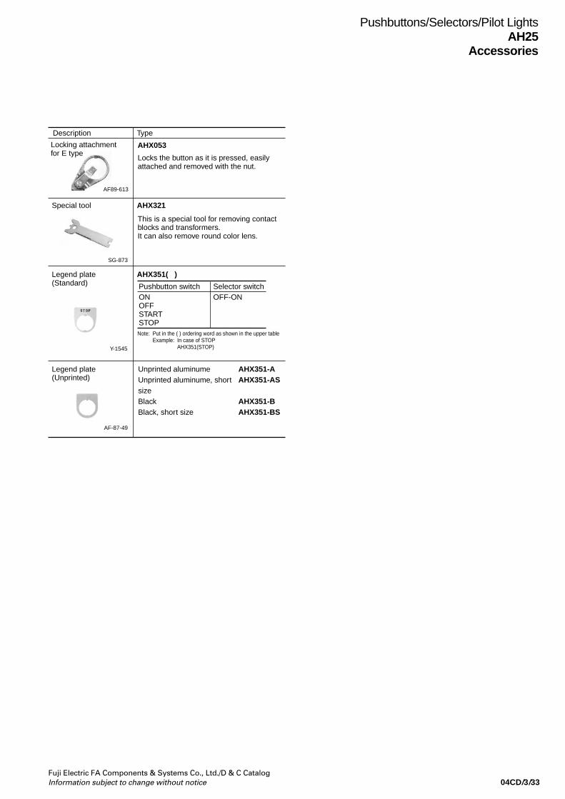
04CD/3/33Fuji Electric FA Components & Systems Co., Ltd./D & C CatalogInformation subject to change without notice
Pushbuttons/Selectors/Pilot LightsAH25
Accessories
Description Type
Locking attachmentfor E type
AF89-613
AHX053
This is a special tool for removing contact blocks and transformers.It can also remove round color lens.
Locks the button as it is pressed, easily attached and removed with the nut.
Special tool AHX321
AHX351( )
SG-873
Y-1545
AF-87-49
Legend plate (Standard)
Legend plate (Unprinted)
Unprinted aluminumeUnprinted aluminume, short sizeBlackBlack, short size
AHX351-AAHX351-AS
AHX351-BAHX351-BS
Note: Put in the ( ) ordering word as shown in the upper tableExample: In case of STOP
AHX351(STOP)
Pushbutton switch Selector switchONOFFSTARTSTOP
OFF-ON
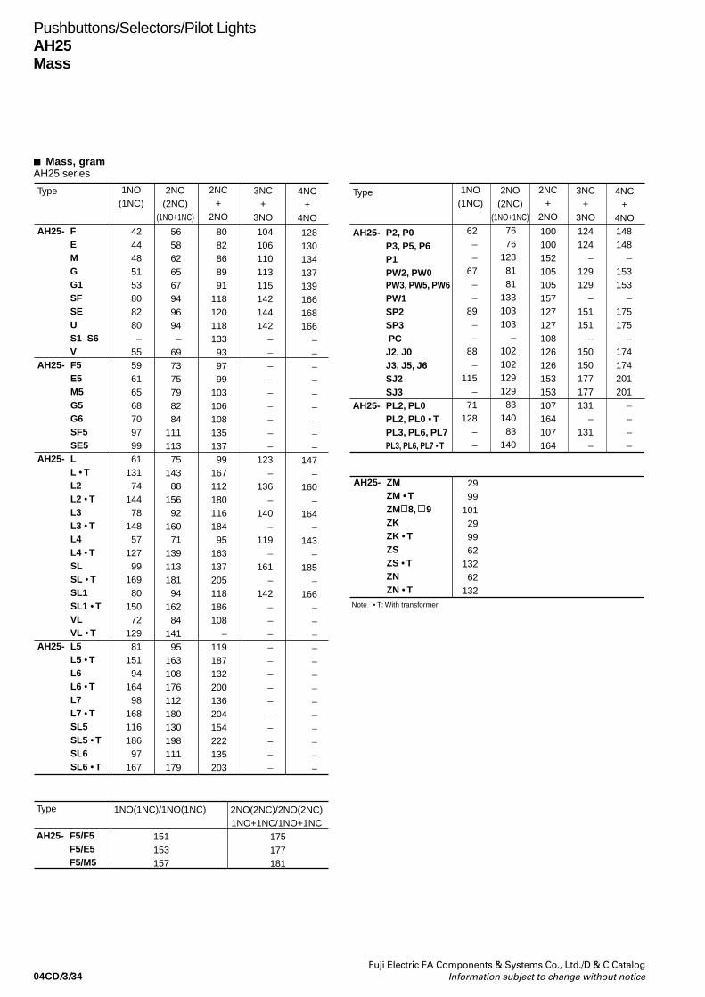
04CD/3/34Fuji Electric FA Components & Systems Co., Ltd./D & C Catalog
Information subject to change without notice
Pushbuttons/Selectors/Pilot LightsAH25Mass
Mass, gramAH25 series
Type
AH25- F E
MGG1SFSEUS1–S6V
AH25- F5 E5 M5 G5 G6 SF5 SE5AH25- L L • T L2 L2 • T L3 L3 • T L4 L4 • T SL SL • T SL1 SL1 • T VL VL • TAH25- L5 L5 • T L6 L6 • T L7 L7 • T SL5 SL5 • T SL6 SL6 • T
4244485153808280–
555961656870979961
13174
14478
14857
12799
16980
15072
12981
15194
16498
16811618697
167
5658626567949694–
697375798284
11111375
14388
15692
16071
13911318194
16284
14195
163108176112180130198111179
8082868991
118120118133939799
10310610813513799
16711218011618495
163137205118186108
–119187132200136204154222135203
104106110113115142144142
–––––––––
123–
136–
140–
119–
161–
142–––––––––––––
128130134137139166168166
–––––––––
147–
160–
164–
143–
185–
166–––––––––––––
Type
AH25- F5/F5 F5/E5 F5/M5
1NO(1NC)/1NO(1NC)
151 153 157
2NO(2NC)/2NO(2NC) 1NO+1NC/1NO+1NC
175 177 181
Type
AH25- P2, P0 P3, P5, P6 P1 PW2, PW0 PW3, PW5, PW6 PW1 SP2 SP3 PC J2, J0 J3, J5, J6 SJ2 SJ3AH25- PL2, PL0 PL2, PL0 • T PL3, PL6, PL7 PL3, PL6, PL7 • T
62––
67––
89––
88–
115–
71128
––
7676
1288181
133103103
–10210212912983
14083
140
100100152105105157127127108126126153153107164107164
124124
–129129
–151151
–150150177177131
–131
–
148148
–153153
–175175
–174174201201
––––
AH25- ZM ZM • T ZM 8, 9 ZK ZK • T ZS ZS • T ZN
ZN • T
2999
101299962
13262
132Note • T: With transformer
1NO(1NC)
2NO(2NC)
(1NO+1NC)
2NC+
2NO
3NC+
3NO
4NC+
4NO
1NO(1NC)
2NO(2NC)
(1NO+1NC)
2NC+
2NO
3NC+
3NO
4NC+
4NO

04CD/4/1Fuji Electric FA Components & Systems Co., Ltd./D & C CatalogInformation subject to change without notice
Command boxesAHX9
Description•Enclosed type
Enclosed type steel boxes finished respectivelywith one to five holes.Rounded, smooth design.
Selectable from the 22mm, 25mm, and 30mm dia.series command switches according to theapplication.
•Dust protected type, protected against water jetsMade of lightweight, strong aluminum die-casting.Rounded, smooth design.Series of models finished respectively with one to
four holes. (Note: Only 22 dia. series modelsincorporate four holes.)
AF92-388AF92-277
Type number nomenclature
AHX 9 0 1 A➀ ➁ ➂ ➃
➀ Product category AHX: Type
➁ Size of mounting hole2: 22mm dia. series1: 25mm dia. series0: 30mm dia. series9: without hole
➂ Number of mounting hole•Enclosed type
1: 1 hole*1
2: 2 holes3: 3 holes4: 4 holes5: 5 holes
•Dust protected type, protected against water jets1: 1 hole*2
2: 2 holes3: 3 holes4: 4 hole*3
9: 1 hole*1
Notes: *1 Dedicated box with one hole*2 Same as the box for two holes in external dimension*3 Only 22mm dia. series can be manufactured
➃ Degree of protectionA: Enclosed typeW: Dust protected type, protected against water jets
Dgree of ProtectionEnclosed-type
Dust protected type, protected against water jets
TypeAHX9 1AAHX9 2AAHX9 3AAHX9 4AAHX9 5AAHX929WAHX919WAHX909WAHX9 1WAHX9 2WAHX9 3WAHX924W
Dedicated box with one hole.
Replace the mark the Size of mounting hole code
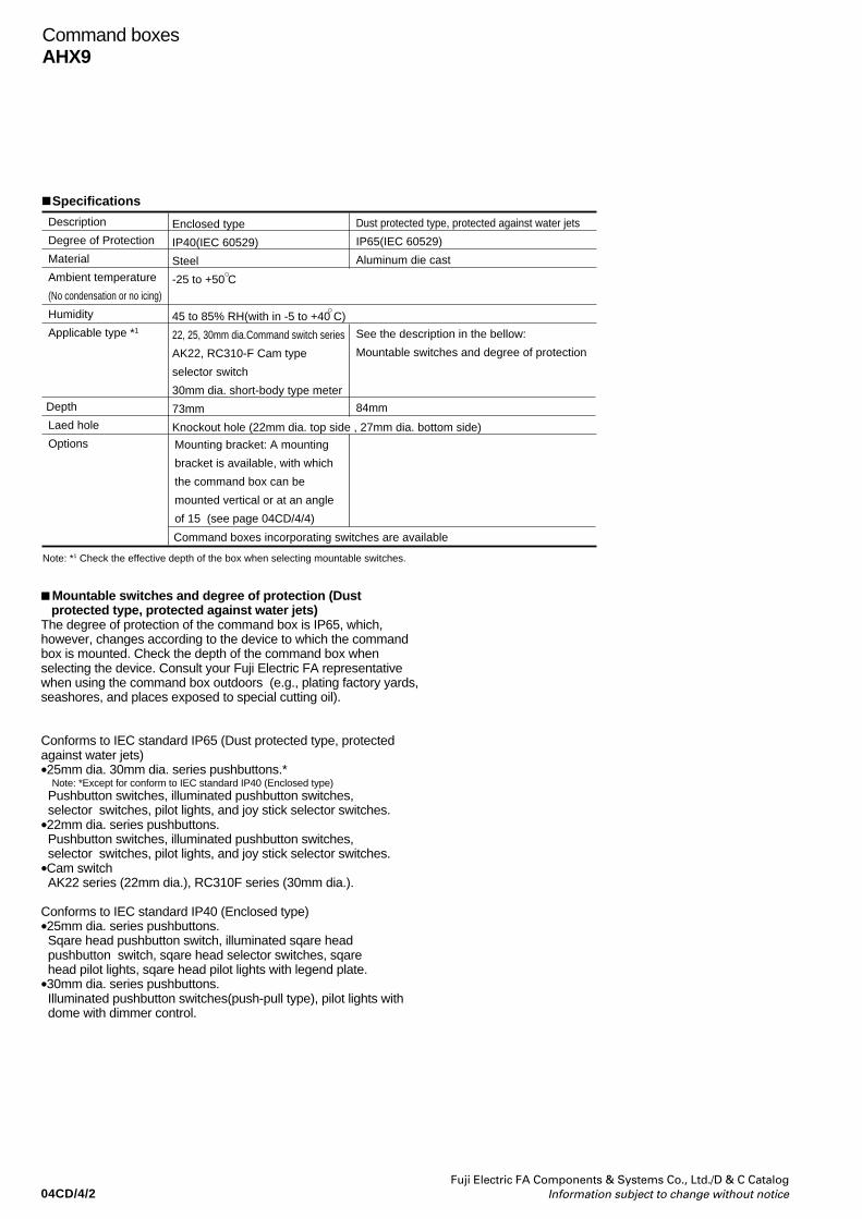
04CD/4/2Fuji Electric FA Components & Systems Co., Ltd./D & C Catalog
Information subject to change without notice
Mountable switches and degree of protection (Dust protected type, protected against water jets)The degree of protection of the command box is IP65, which,however, changes according to the device to which the commandbox is mounted. Check the depth of the command box whenselecting the device. Consult your Fuji Electric FA representativewhen using the command box outdoors (e.g., plating factory yards,seashores, and places exposed to special cutting oil).
Conforms to IEC standard IP65 (Dust protected type, protectedagainst water jets)•25mm dia. 30mm dia. series pushbuttons.* Note: *Except for conform to IEC standard IP40 (Enclosed type) Pushbutton switches, illuminated pushbutton switches, selector switches, pilot lights, and joy stick selector switches.•22mm dia. series pushbuttons. Pushbutton switches, illuminated pushbutton switches, selector switches, pilot lights, and joy stick selector switches.•Cam switch AK22 series (22mm dia.), RC310F series (30mm dia.).
Conforms to IEC standard IP40 (Enclosed type)•25mm dia. series pushbuttons. Sqare head pushbutton switch, illuminated sqare head pushbutton switch, sqare head selector switches, sqare head pilot lights, sqare head pilot lights with legend plate.•30mm dia. series pushbuttons. Illuminated pushbutton switches(push-pull type), pilot lights with dome with dimmer control.
Description
Degree of Protection
Material
Ambient temperature
(No condensation or no icing)
Humidity
Applicable type *1
Depth
Laed hole
Options
Enclosed type
IP40(IEC 60529)
Steel
-25 to +50 C
45 to 85% RH(with in -5 to +40 C)
22, 25, 30mm dia.Command switch series
AK22, RC310-F Cam type
selector switch
30mm dia. short-body type meter
73mm
Knockout hole (22mm dia. top side , 27mm dia. bottom side)
Dust protected type, protected against water jets
IP65(IEC 60529)
Aluminum die cast
See the description in the bellow:
Mountable switches and degree of protection
84mm
Note: *1 Check the effective depth of the box when selecting mountable switches.
Mounting bracket: A mounting
bracket is available, with which
the command box can be
mounted vertical or at an angle
of 15 (see page 04CD/4/4)
Command boxes incorporating switches are available
Specifications
Command boxesAHX9
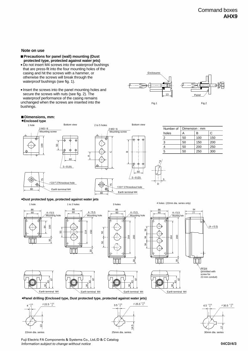
04CD/4/3Fuji Electric FA Components & Systems Co., Ltd./D & C CatalogInformation subject to change without notice
1 hole
8660 4- 5.5
Mounting hole Mounting hole Mounting hole Mounting hole
64 100
30
1 to 2 holes
8660 4- 5.5
50 114
150
30
3 holes
8660
5050
30
164
200
4- 5.5
(4- 5.5)
4 holes (22mm dia. series only)
8660 4- 5.5
164
200
30
3636
36
8477
PF3/4(provided withscrew for22-mm conduit)
3063
87
30 30 30
63 63 63
87 87 87
Earth terminal M4Earth terminal M4Earth terminal M4Earth terminal M4
2-M3 6
100
50
60
1 hole 2 to 5 holes
2-M3 6Mounting screwMounting screw
60
5 8 (D)
75
80
22/ 27Knockout hole
Earth terminal M4 Earth terminal M4
80
75
8
5
A
C B
22/ 27Knockout hole
5 8 (A)
D
Bottom viewBottom view
Number of holes2 345
Dimension : mmA50505050
B100150200250
C150200250300
Enclosures
13
Fig.1
Panel
Fig.2
Precautions for panel (wall) mounting (Dust protected type, protected against water jets)•Do not insert M4 screws into the waterproof bushings
that are press-fit into the four mounting holes of thecasing and hit the screws with a hammer, orotherwise the screws will break through thewaterproof bushings (see fig. 1).
• Insert the screws into the panel mounting holes andsecure the screws with nuts (see fig. 2). Thewaterproof performance of the casing remains
unchanged when the screws are inserted into thebushings.
•Enclosed type
•Dust protected type, protected against water jets
Dimensions, mm:
Command boxesAHX9
•Panel drilling (Enclosed type, Dust protected type, protected against water jets)
4 22.5 0.50
13
3.5 25.54.5 30.5
14.5
17
30mm dia. series 25mm dia. series 22mm dia. series
0.50 0.5
00.50
0.50
0.50
Note on use

04CD/4/4Fuji Electric FA Components & Systems Co., Ltd./D & C Catalog
Information subject to change without notice
Mounting bracket(Vertical type)
Mounting bracket(Angle type)
15
Number of holes1
2
3
4
5
Mounting method
Vertical typeAngle typeVertical typeAngle typeVertical typeAngle typeVertical typeAngle typeVertical typeAngle type
Type
AJ91SAJ91KAJ92SAJ92KAJ93SAJ93KAJ94SAJ94KAJ95SAJ95K
Type
AJ91S
AJ91K
AJ92S
AJ92K
AJ93S
AJ93K
AJ94S
AJ94K
AJ95S
AJ95K
Dimension:mm
A B C
90 50 90
90 50 105
140 100 90
140 100 105
190 150 90
190 150 105
240 200 90
240 200 105
290 250 90
290 250 105
C5
A
B 20
C5 23
4-M4
60
C
76
5
5.5
4360
4.5
Dimensions, mm:
• Mounting bracket Accessories (for Enclosed type)
Command boxesAHX9

04CD/4/5Fuji Electric FA Components & Systems Co., Ltd./D & C CatalogInformation subject to change without notice
TypeAHX901AAHX902AAHX903AAHX904AAHX905AAHX911AAHX912AAHX913AAHX914AAHX915AAHX921AAHX922A
Mass300410500650770300410510660770300410
TypeAHX923AAHX924AAHX925AAHX901WAHX902WAHX903WAHX911WAHX912WAHX913WAHX921WAHX922WAHX923W
Mass520660780480480600490490590490490610
TypeAHX924WAHX992WAHX993WAHX909WAHX919WAHX929WAHX999WAHX991AAHX992AAHX993AAHX994AAHX995A
Mass610490620390390390400310420520670790
Mass, gram
Command boxesAHX9

Catalog DisclaimerThe information contained in this catalog does not constitute an express or implied warranty of quality, any warranty of merchantability of fitness for a particular purpose is hereby disclaimed.
Since the user's product information, specific use application, and conditions of use are all outside of Fuji Electric FA Components & Systems'control, it shall be the responsibility of the user to determine the suitability of any of the products mentioned for the user's application.
One Year Limited WarrantyThe products identified in this catalog shall be sold pursuant to the terms and conditions identified in the"Conditions of Sale" issued by Fuji Electric FA with each order confirmation.
Except to the extent otherwise provided for in the Conditions of Sale issued by Fuji Electric FA, Fuji Electric FA warrants that the Fuji Electric FA products identified in this catalog shall be free from significant defects in materials and workmanship provided the product has not been: 1) repaired or altered by others than Fuji Electric FA; 2) subjected to negligence, accident, misuse, or damage by circumstances beyond Fuji Electric FA's control; 3) improperly operated, maintained or stored; or 4) used in other than normal use or service. This warranty shall apply only to defects appearing within one (1) year from the date of shipment by Fuji Electric FA, and in such case, only if such defects are reported to Fuji Electric FA within thirty (30) days of discovery by purchaser. Such notice should be submitted in writing to Fuji Electric FA at 5-7, Nihonbashi Odemma-cho, Chuo-ku, Tokyo, Japan. The sole and exclusive remedy with respected to the above warranty whether such claim is based on warranty, contract, negligence, strict liability or any other theory, is limited to the repair or replacement of such product or, at Fuji Electric FA's option reimbursement by Fuji Electric FA of the purchase price paid to Fuji Electric FA for the particular product. Fuji Electric FA does not make any other representations or warranties, whether oral or in writing, expressed or implied, including but not limited to any warranty regarding merchantability or fitness for a particular purpose. Except as provided in the Conditions of Sale, no agent or representative of Fuji Electric FA is authorized to modify the terms of this warranty in writing or orally. In no event shall Fuji Electric FA be liable for special, indirect or consequential damages, including but not limited to, loss of use of the product, other equipment, plant and power system which is installed with the product, loss of profits or revenues, cost of capital, or claims against the purchaser or user of the product by its customers resulting from the use of information, recommendations and descriptions contained herein. The purchaser agrees to pass on to its customers and users, in writing at the time inquiries and orders are received by buyer, Fuji Electric FA's warranty as set forth above.
Caution "Safety precautions"• Operate (keep) in the environment specified in the operating instructions and manual. High temperature, high
humidity, condensation, dust, corrosive gases, oil, organic solvents, excessive vibration or shock might cause electric shock, fire, erratic operation or failure.
• Follow the regulations of industrial wastes when the product is to be discarded.• The products covered in this catalogs have not been designed or manufactured for use in equipment or systems
which, in the event of failure, can lead to loss of human life.• If you intend to use the products covered in this catalog for special applications, such as for nuclear energy control,
aerospace, medical, or transportation, please consult tour Fuji Electric FA agent.• Be sure to provide protective measures when using the product covered in these catalogs in equipment which, in the
event of failure, may lead to loss of human life or other grave results.• Follow the directions of the operating instructions when mounting the product.
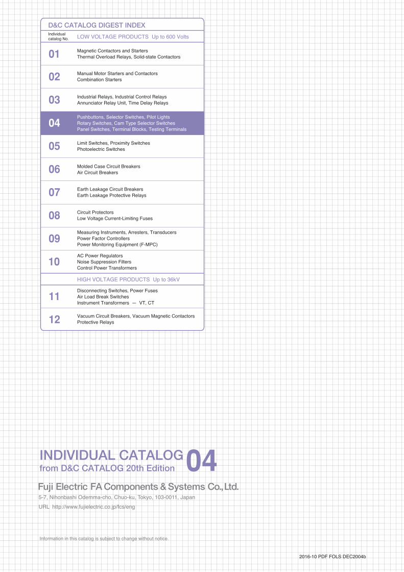
Information in this catalog is subject to change without notice.
5-7, Nihonbashi Odemma-cho, Chuo-ku, Tokyo, 103-0011, Japan URL http://www.fujielectric.co.jp/fcs/eng
IND
IVID
UA
L CA
TA
LOG
from
D&
C C
AT
ALO
G 20th E
ditio
n
04
PUSHBUTTON SWITCHESSELECTOR SWITCHESEMERGENCY STOP PUSHBUTTON SWITCHESPILOT LIGHTSMULTI DISPLAY LIGHTSTERMINAL BLOCKS
01 02 03 04 05 06 07 08 09 10 11 12
LOWVOLTAGE
EQUIPMENTUp to 600 Volts
INDIVIDUAL CATALOGfrom D&C CATALOG 20th Edition 04INDIVIDUAL CATALOG
from D&C CATALOG 20th Edition 04
LOW VOLTAGE PRODUCTS Up to 600 VoltsIndividualcatalog No.
01 Magnetic Contactors and StartersThermal Overload Relays, Solid-state Contactors
02
Industrial Relays, Industrial Control RelaysAnnunciator Relay Unit, Time Delay Relays
Manual Motor Starters and Contactors Combination Starters
Pushbuttons, Selector Switches, Pilot LightsRotary Switches, Cam Type Selector SwitchesPanel Switches, Terminal Blocks, Testing Terminals
Molded Case Circuit BreakersAir Circuit Breakers
Earth Leakage Circuit BreakersEarth Leakage Protective Relays
Measuring Instruments, Arresters, TransducersPower Factor ControllersPower Monitoring Equipment (F-MPC)
Circuit ProtectorsLow Voltage Current-Limiting Fuses
03
04
05
06
07
08
09
10
HIGH VOLTAGE PRODUCTS Up to 36kV
11Disconnecting Switches, Power FusesAir Load Break SwitchesInstrument Transformers — VT, CT
D&C CATALOG DIGEST INDEX
AC Power RegulatorsNoise Suppression FiltersControl Power Transformers
12 Vacuum Circuit Breakers, Vacuum Magnetic ContactorsProtective Relays
Limit Switches, Proximity SwitchesPhotoelectric Switches
AR22Pushbutton switches
Terminal blocks
AR22Emergency stop pushbutton
AR30Selector switches
DR30Pilot lights
Multi display lights
AH164, AH165Pushbutton switches
AR16Illuminated pushbutton
AR16Selector switches(Key)
2016-10 PDF FOLS DEC2004b
Related Documents


