1 Dealing with Routes within a Junos OS Based Router When migrating services from one network design to the next, it is highly likely that a non- negligible transition period is required. During this time, services may live in two worlds, in which some applications and network sites for those services are partially duplicated to allow the old and new designs to coexist. From the perspective of an IP network, a service is identified by different abstractions, and a valid concept for a service is a set of IP addresses that are reachable from different network sites. This reachability information, which is exchanged via routing protocols, is collected in routing tables, and the best routing information from routing tables is propagated to the forwarding engine. This chapter focuses primarily on routing and addressing for the Internet Protocol ver- sion 4 (IPv4) and illustrates Junos operating system (Junos OS) configuration options that can leverage and optimize route manipulation among different routing tables. The underlying concepts presented only for IPv4 here can be generalized to other address families. 1.1 Route Handling Features inside a Junos OS Based Router Transition scenarios should avoid non-standard routing-protocol behavior, unless a network designer is deliberately planning a migration considering this. The impact of a migration can be reduced by employing specific and often creative behaviors on the routers themselves, behaviors that do not change the expected routing-protocol behavior, or that change that behavior in an identified fashion. These behaviors may have only a local effect on the router, and do not require a redefinition of open standards or modification to routing protocols. In Junos OS routing architecture, the routing table is the central repository for routing information. Routes are imported into the routing table and exported from the routing table. This centralized approach avoids direct interaction among routing protocols; rather, protocols interact with the relevant routing table to exchange information outside their domain. Junos OS allows the use of more than one routing table to limit visibility of routing information Network Mergers and Migrations Gonzalo Gómez Herrero and Jan Antón Bernal van der Ven c 2010 John Wiley & Sons, Ltd COPYRIGHTED MATERIAL

Welcome message from author
This document is posted to help you gain knowledge. Please leave a comment to let me know what you think about it! Share it to your friends and learn new things together.
Transcript
1
Dealing with Routes within aJunos OS Based Router
When migrating services from one network design to the next, it is highly likely that a non-negligible transition period is required. During this time, services may live in two worlds, inwhich some applications and network sites for those services are partially duplicated to allowthe old and new designs to coexist.
From the perspective of an IP network, a service is identified by different abstractions, anda valid concept for a service is a set of IP addresses that are reachable from different networksites. This reachability information, which is exchanged via routing protocols, is collectedin routing tables, and the best routing information from routing tables is propagated to theforwarding engine.
This chapter focuses primarily on routing and addressing for the Internet Protocol ver-sion 4 (IPv4) and illustrates Junos� operating system (Junos OS) configuration options thatcan leverage and optimize route manipulation among different routing tables. The underlyingconcepts presented only for IPv4 here can be generalized to other address families.
1.1 Route Handling Features inside a Junos OS BasedRouter
Transition scenarios should avoid non-standard routing-protocol behavior, unless a networkdesigner is deliberately planning a migration considering this. The impact of a migration canbe reduced by employing specific and often creative behaviors on the routers themselves,behaviors that do not change the expected routing-protocol behavior, or that change thatbehavior in an identified fashion. These behaviors may have only a local effect on the router,and do not require a redefinition of open standards or modification to routing protocols.
In Junos OS routing architecture, the routing table is the central repository for routinginformation. Routes are imported into the routing table and exported from the routing table.This centralized approach avoids direct interaction among routing protocols; rather, protocolsinteract with the relevant routing table to exchange information outside their domain. JunosOS allows the use of more than one routing table to limit visibility of routing information
Network Mergers and Migrations Gonzalo Gómez Herrero and Jan Antón Bernal van der Venc© 2010 John Wiley & Sons, Ltd
COPYRIG
HTED M
ATERIAL
2 NETWORK MERGERS AND MIGRATIONS
to specific protocols only. Junos OS also allows the option for protocols to inject routinginformation into more than a single routing table.
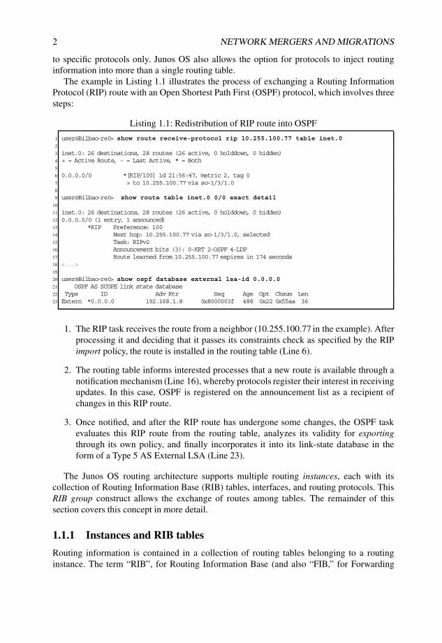
The example in Listing 1.1 illustrates the process of exchanging a Routing InformationProtocol (RIP) route with an Open Shortest Path First (OSPF) protocol, which involves threesteps:
Listing 1.1: Redistribution of RIP route into OSPF
1 user@Bilbao-re0> show route receive-protocol rip 10.255.100.77 table inet.02
3 inet.0: 26 destinations, 28 routes (26 active, 0 holddown, 0 hidden)4 + = Active Route, - = Last Active, * = Both5
6 0.0.0.0/0 *[RIP/100] 1d 21:56:47, metric 2, tag 07 > to 10.255.100.77 via so-1/3/1.08
9 user@Bilbao-re0> show route table inet.0 0/0 exact detail10
11 inet.0: 26 destinations, 28 routes (26 active, 0 holddown, 0 hidden)12 0.0.0.0/0 (1 entry, 1 announced)13 *RIP Preference: 10014 Next hop: 10.255.100.77 via so-1/3/1.0, selected15 Task: RIPv216 Announcement bits (3): 0-KRT 2-OSPF 4-LDP17 Route learned from 10.255.100.77 expires in 174 seconds18 <...>19
20 user@Bilbao-re0> show ospf database external lsa-id 0.0.0.021 OSPF AS SCOPE link state database22 Type ID Adv Rtr Seq Age Opt Cksum Len23 Extern *0.0.0.0 192.168.1.8 0x8000003f 488 0x22 0x55aa 36
1. The RIP task receives the route from a neighbor (10.255.100.77 in the example). Afterprocessing it and deciding that it passes its constraints check as specified by the RIPimport policy, the route is installed in the routing table (Line 6).
2. The routing table informs interested processes that a new route is available through anotification mechanism (Line 16), whereby protocols register their interest in receivingupdates. In this case, OSPF is registered on the announcement list as a recipient ofchanges in this RIP route.
3. Once notified, and after the RIP route has undergone some changes, the OSPF taskevaluates this RIP route from the routing table, analyzes its validity for exportingthrough its own policy, and finally incorporates it into its link-state database in theform of a Type 5 AS External LSA (Line 23).
The Junos OS routing architecture supports multiple routing instances, each with itscollection of Routing Information Base (RIB) tables, interfaces, and routing protocols. ThisRIB group construct allows the exchange of routes among tables. The remainder of thissection covers this concept in more detail.
1.1.1 Instances and RIB tables
Routing information is contained in a collection of routing tables belonging to a routinginstance. The term “RIB”, for Routing Information Base (and also “FIB,” for Forwarding

DEALING WITH ROUTES WITHIN A JUNOS OS BASED ROUTER 3
Information Base) is a tribute to the good old GateD origins of Junos OS and is the internalname for such a routing table.
The content of a RIB does not necessarily need to be a collection of IPv4 routes; in fact,RIBs can store routing information related to a variety of protocols. As an example, a basicconfiguration on a Service Provider core router with a single routing instance enabling IS–IS,MPLS, and IPv4 features at least three RIBs.
The default, or master, routing instance contains multiple RIBs, each with its specificpurposes. Table 1.1 lists some of these RIBs in the master instance and their intended uses.Besides traditional unicast RIBs for IPv4 and IPv6, Junos OS provides next-hop resolutionfor BGP using an auxiliary RIB, inet.3 (or inet6.3 for IPv6) that is generally populated withdestinations reachable over MPLS. In an MPLS transit node, the mpls.0 RIB holds the statefor exchanged MPLS labels, that are locally installed in the forwarding plane and used toswitch MPLS packets. For IS–IS enabled routes, the iso.0 table contains the NET Identifier(Net-ID) of the router. MPLS/VPN routes received from remote PEs for Layer 3 or Layer 2services are stored in the relevant VPN table, from which the real prefix (for IP or Layer 2connections) is derived. Similarly, multicast routing has its own set of dedicated RIBs, tostore (Source, Group) pairs (inet.1) or Reverse Path Forwarding (RPF) check information(inet.2).
Table 1.1 Default RIBs
RIB name Use Family
inet.0 Unicast routing IPv4inet6.0 Unicast routing IPv6inet.3 Next-hop resolution IPv4inet6.3 Next-hop resolution IPv6inet.1 Multicast routing IPv4inet.2 Multicast RPF IPv4mpls.0 MPLS labels MPLSiso.0 CLNS routing ISObgp.l3vpn.0 inet-vpn INET-VPNbgp.l2vpn.0 l2vpn L2VPN
Some RIB tables within the master instance.
Note that for optimization purposes, a RIB becomes visible only once it is populated. Ifno routes from a particular address family exist, the corresponding RIB is not instantiatedin Junos OS. This behavior means though that additional supporting RIBs are created forservices as needed.
By default, a collection of RIBs is present in the master instance. To provide uniqueforwarding contexts, additional instances can be created, each one with its own set of RIBs.A forwarding context is understood as the combination of a forwarding table with multipleRIBs feeding it with routing information.
Hence, an instance can contain multiple RIBs, but a RIB can have only one parentinstance. That is to say, the main routing instance may contain inet.0, inet6.0, iso.0, mpls.0,and others, but those RIBs are univocally related to the main routing instance only.

4 NETWORK MERGERS AND MIGRATIONS
RIBs within a routing instance on the control plane can create companion forwardinginstances, or can be used purely at the control plane for supporting activities, generally relatedto other RIBs.
Figure 1.1 depicts a router configured with three instances. For the associated collectionof RIBs, only some populate the forwarding table, and the remaining RIBs performsupporting functions. Instance A contains three RIBs, storing IPv4 unicast prefixes (A.inet.0),IPv4 multicast (Source, Group) pairs (A.inet.1), and the multicast RPF check supportRIB (A.inet.2). Instance B is likely a Carrier-supporting-Carrier (CsC) VPN Routing andForwarding (VRF) table implementing both IPv4 unicast prefixes (B.inet.0) and an instance-based MPLS table (B.mpls.0). Similarly, the global instance includes a set of helper RIBsfor the next-hop resolution (inet.3) and the helper RIBs to support received VPN prefixes(bgp.l3vpn.0 and bgp.l2vpn.0).
inet.3
inet.0
inet.2
inet.1
inet.3
bgp.l3vpn.0
A.inet.2
mpls.0
bgp.l2vpn.0
A.inet.0 B.inet.0
B.mpls.0
control plane
forwarding plane
inet.0 inet.1 mpls.0A.inet.0 B.inet.0
B.mpls.0
A B
helper RIB RIB FIB
legend:
instance
A.inet.1
A.inet.1
Figure 1.1: Sample distribution of RIBs and instances on a router.
The actual packet-by-packet forwarding of transit data occurs in the forwarding plane.In Junos OS-based architectures, the prefix lookup hardware makes decisions about how toswitch the packets based on tables that contain next-hop information. These FIB tables arethe forwarding instances and are populated with information derived from best-path selectionin the RIBs. The creation of a forwarding instance triggers instantiation in the hardware thatpopulates the forwarding plane with FIBs that are consulted by the lookup engine whenswitching packets.
The master routing instance is the only one available for administrators in the defaultconfiguration. Additional instances can be defined for interconnect or virtualization purposes,collapsing the functionality of multiple service delivery points into a single platform. Eachtype of instance has a specific behavior, as shown in Table 1.2.

DEALING WITH ROUTES WITHIN A JUNOS OS BASED ROUTER 5
Table 1.2 Instance types
Instance name Use Interfaces?
forwarding Filter-based forwarding nonon-forwarding Constrained route manipulation novrf L3VPN support yesvirtual-router Simplified VPN, VRF-lite yesl2vpn L2 VPN yesvpls VPLS yesvirtual-switch L2 switching yeslayer2-control L2 loop control support yes
Types of routing instance.
In Junos OS the default routing instance type, for instances different from the master, isnon-forwarding for historical reasons. The first customer requirement for virtualizationwas to support constrained route exchange between two separate OSPF routing tasks,but within the same forwarding instance. This default setting can be overridden with therouting-instances instance-type knob.
Listing 1.2 shows sample CLI output for a router with two L3VPN in addition to thedefault configuration.
Listing 1.2: Looking at available instances
1 user@Livorno> show route instance2 Instance Type3 Primary RIB Active/holddown/hidden4 master forwarding5 inet.0 23/0/16 mpls.0 3/0/07 inet6.0 3/0/08 l2circuit.0 0/0/09 CORP vrf
10 CORP.inet.0 2/0/011 CORP.iso.0 0/0/012 CORP.inet6.0 0/0/013 helper vrf14 helper.inet.0 1/0/015 helper.iso.0 0/0/016 helper.inet6.0 0/0/0
Armed with the knowledge that multiple RIBs and various instances hold routinginformation, we move to the next section to understand how to group RIBs together to allowrouting information insertion procedures to act simultaneously on all RIB members in thegroup.
1.1.2 Grouping RIBs together
Based on customer use cases, Junos OS was enhanced early on to add RIB groups, whichare a mechanism to provide route information to multiple RIBs. The primary purpose ofRIB groups is to allow independent protocol processes to exchange routing information in aconstrained fashion, using routing tables to scope route visibility.
6 NETWORK MERGERS AND MIGRATIONS
RIPBGPOSPFIS−ISES−ISDVRMPPIMMSDPStatic
Rib−Group
LocalDirect
A
inet.0
inet.0
inet.2
Pro
toco
l Ro
ute
sIn
terf
ace
Ro
ute
s
RIBRoute
imp
ort
po
licy
rib−group { import−rib [ inet.0 inet.2 A.inet.0 ]; import−policy select−route−to−leak;}
secondary
secondary
primary
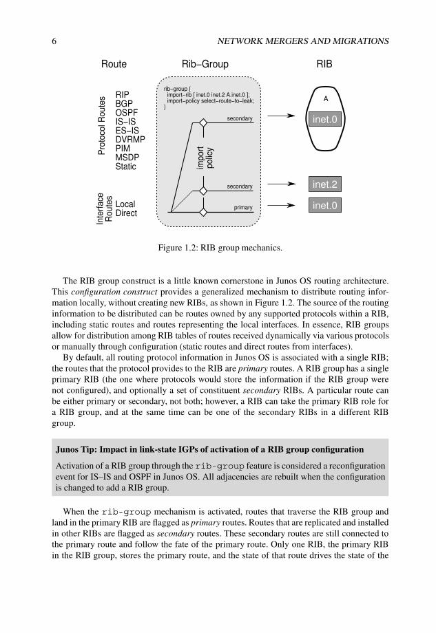
Figure 1.2: RIB group mechanics.
The RIB group construct is a little known cornerstone in Junos OS routing architecture.This configuration construct provides a generalized mechanism to distribute routing infor-mation locally, without creating new RIBs, as shown in Figure 1.2. The source of the routinginformation to be distributed can be routes owned by any supported protocols within a RIB,including static routes and routes representing the local interfaces. In essence, RIB groupsallow for distribution among RIB tables of routes received dynamically via various protocolsor manually through configuration (static routes and direct routes from interfaces).
By default, all routing protocol information in Junos OS is associated with a single RIB;the routes that the protocol provides to the RIB are primary routes. A RIB group has a singleprimary RIB (the one where protocols would store the information if the RIB group werenot configured), and optionally a set of constituent secondary RIBs. A particular route canbe either primary or secondary, not both; however, a RIB can take the primary RIB role fora RIB group, and at the same time can be one of the secondary RIBs in a different RIBgroup.
Junos Tip: Impact in link-state IGPs of activation of a RIB group configuration
Activation of a RIB group through the rib-group feature is considered a reconfigurationevent for IS–IS and OSPF in Junos OS. All adjacencies are rebuilt when the configurationis changed to add a RIB group.
When the rib-group mechanism is activated, routes that traverse the RIB group andland in the primary RIB are flagged as primary routes. Routes that are replicated and installedin other RIBs are flagged as secondary routes. These secondary routes are still connected tothe primary route and follow the fate of the primary route. Only one RIB, the primary RIBin the RIB group, stores the primary route, and the state of that route drives the state of the

DEALING WITH ROUTES WITHIN A JUNOS OS BASED ROUTER 7
set of replicated routes. If a primary route were to disappear or change, all secondary routesdependent on it would follow suit immediately. This dependency facilitates the existenceof a single resolution context for the entire set of prefixes. Route attributes for the secondaryroute, including the protocol from which the route was learned, are inherited from the primaryroute.
Junos Tip: Finding sibling tables for a prefix
The extensive output of show route operational command provides hints about theproperties for a particular prefix. Listing 1.3 helps to identify primary and secondary routes.For a primary route that is leaked using RIB groups, the list of secondary routes is shownin the secondary field on Line 16. For secondary routes, the state field includes a flag(Line 25), and an additional legend at the bottom of the output on Line 31 provides areference to the primary RIB for the prefix.
Listing 1.3: Verifying primary owner instance of routes
1 user@male-re0> show route 10.1.1.0/24 exact protocol rip detail2
3 inet.0: 21 destinations, 24 routes (21 active, 0 holddown, 0 hidden)4 10.1.1.0/24 (2 entries, 1 announced)5 RIP Preference: 1806 Next hop type: Router, Next hop index: 15387 Next-hop reference count: 108 Next hop: 10.255.100.78 via so-3/2/1.0, selected9 State: <Int>
10 Inactive reason: Route Preference11 Local AS: 6500012 Age: 3:54:26 Metric: 2 Tag: 100013 Task: RIPv214 AS path: I15 Route learned from 10.255.100.78 expires in 160 seconds16 Secondary Tables: inet.217
18 inet.2: 4 destinations, 4 routes (4 active, 0 holddown, 0 hidden)19
20 10.1.1.0/24 (1 entry, 0 announced)21 *RIP Preference: 18022 Next hop type: Router, Next hop index: 153823 Next-hop reference count: 1024 Next hop: 10.255.100.78 via so-3/2/1.0, selected25 State: <Secondary Active Int>26 Local AS: 6500027 Age: 1:51:30 Metric: 2 Tag: 100028 Task: RIPv229 AS path: I30 Route learned from 10.255.100.78 expires in 160 seconds31 Primary Routing Table inet.0
Although the RIB group is applied to all routes received by the protocol or interface, thepower of Junos OS policy language can be leveraged to restrict the distribution of specificprefixes to specific RIBs, based on a route filter, a route attribute, or some protocol attribute.Note that to maintain a single resolution context, any changes to the next hop that can bedefined as an action of a Junos OS policy are silently ignored.
8 NETWORK MERGERS AND MIGRATIONS
Junos Tip: Multi-Topology Routing
The Multi-Topology Routing (MTR) feature deviates from the philosophy of the rib-group construct providing an independent routing resolution context, in which thedependent routes of a primary route may have a different next hop.
This feature does not leverage the RIB group mechanism and is therefore not discussedfurther. The Junos OS feature guide provides additional information on multiple topologieswith independent routing resolution contexts in its Multi Topology Routing Section.
1.1.3 Instructing protocols to use different RIBs
Leaking routes between different RIBs provides a mechanism for populating the RIBs withthe desired routing information. This functionality is tremendously powerful for migrationscenarios.
In some cases, when the destination RIBs already exist and have a specific purpose, routeleaking among RIBs already suffices to achieve the final goal. For some protocols, however,an additional step is required to direct the routes to the proper RIB, the one that is used duringthe route-lookup process, and to make those routes eligible in that RIB for further populationto other systems.
Labeled BGP
[RFC3107] defines an implementation to have BGP carrying label information, thereforebinding routing information to a MPLS label. This implementation is widely used as acomprehensive MPLS label distribution protocol and is covered in Chapter 4.
By default, the received routing information with Labeled BGP, or L-BGP, is installedin the main IPv4 table, inet.0. Through configuration under protocols bgp familyinet labeled-unicast rib inet.3, it is possible to specify that these routes beinstalled only in the helper RIB table inet.3, used for route resolution. A direct advantageof this configuration is to allow MPLS VPNs, which perform route lookup using inet.3 bydefault, to access the labeled information straightaway. Hence, prefixes exchanged over alabeled BGP session can provide the transport label for VPN services. Section 4.4.4 providesadditional information on the various Junos OS resources available to handle these prefixes.
Protocol Independent Multicast
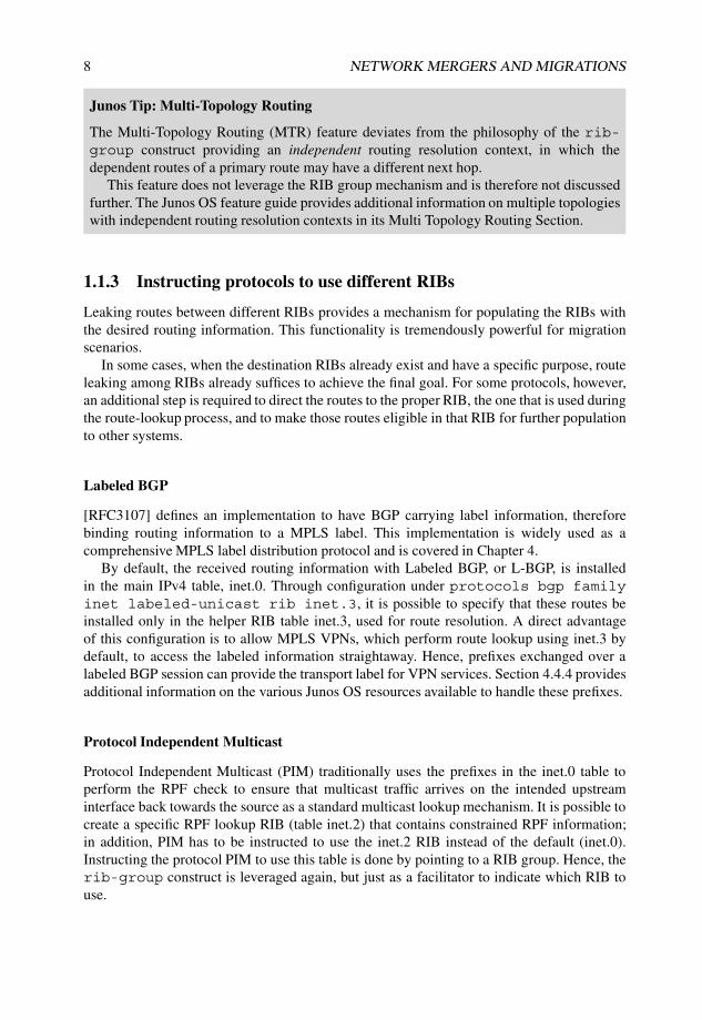
Protocol Independent Multicast (PIM) traditionally uses the prefixes in the inet.0 table toperform the RPF check to ensure that multicast traffic arrives on the intended upstreaminterface back towards the source as a standard multicast lookup mechanism. It is possible tocreate a specific RPF lookup RIB (table inet.2) that contains constrained RPF information;in addition, PIM has to be instructed to use the inet.2 RIB instead of the default (inet.0).Instructing the protocol PIM to use this table is done by pointing to a RIB group. Hence, therib-group construct is leveraged again, but just as a facilitator to indicate which RIB touse.
DEALING WITH ROUTES WITHIN A JUNOS OS BASED ROUTER 9
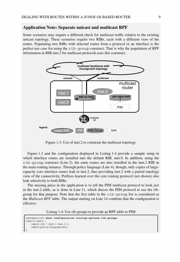
Application Note: Separate unicast and multicast RPF
Some scenarios may require a different check for multicast traffic relative to the existingunicast topology. These scenarios require two RIBs, each with a different view of theroutes. Populating two RIBs with selected routes from a protocol or an interface is theperfect use case for using the rib-group construct. That is why the population of RPFinformation in RIB inet.2 for multicast protocols uses this construct.
inet.0
inet.2leak−to−inet2
helper RIB RIB RIB Grouplegend:
multicastrouter
multicast
CE
multicastunicast
inet.1
PIM
task
multicast backbone with incongruent topology
pim−uses−inet2
Figure 1.3: Use of inet.2 to constrain the multicast topology.
Figure 1.3 and the configuration displayed in Listing 1.4 provide a sample setup inwhich interface routes are installed into the default RIB, inet.0. In addition, using therib-group construct (Line 2), the same routes are also installed in the inet.2 RIB inthe main routing instance. Through policy language (Line 4), though, only copies of large-capacity core interface routes leak to inet.2, thus providing inet.2 with a partial topologyview of the connectivity. Prefixes learned over the core routing protocol (not shown) alsoleak selectively to both RIBs.
The missing piece in the application is to tell the PIM multicast protocol to look justin the inet.2 table, as is done in Line 11, which directs the PIM protocol to use the rib-group for that purpose. Note that the first table in the rib-group list is considered asthe Multicast RPF table. The output starting on Line 14 confirms that the configuration iseffective.
Listing 1.4: Use rib-groups to provide an RPF table to PIM
1 user@male-re0> show configuration routing-options rib-groups2 leak-to-inet2 {3 import-rib [ inet.0 inet.2 ];4 import-policy big-pipe-only;5 }
10 NETWORK MERGERS AND MIGRATIONS
6 pim-uses-inet2 {7 import-rib [ inet.2 ];8 }9
10 user@male-re0> show configuration protocols pim rib-group11 inet pim-uses-inet2; # Only the first RIB taken into account12
13 user@male-re0> show multicast rpf summary inet14 Multicast RPF table: inet.2 , 3 entries
While it is possible to reuse the leak-to-inet2 RIB group definition on Line 2, whichincludes both RIBs, doing so would defeat the whole purpose of the exercise because sucha configuration instructs PIM to use the first RIB in the list, which is inet.0, when what iswanted is to use inet.2.
1.1.4 Automatic RIB groups and VPN routes
Although visible only indirectly, Junos OS VPN technology uses the RIB group constructinternally to build RIB groups dynamically to leak VPN routes received from a BGP peer.
The Junos OS import policy is generic enough in that it allows for matching on anyBGP attribute. Therefore, the RIB group concept is of direct applicability to MPLS VPNs.Configuration of the Junos OS vrf-import option is a one-stop shop that triggers theautomatic creation of internal rib-group elements to distribute prefixes. This option not onlyavoids the manual configuration of rib-groups but it also automates the addition of membersto the VPN. Section 1.1.5 elaborates further about this functionality.
The introduction of MPLS L3VPNs (first with [RFC2547], later with [RFC4364]) addeda new requirement to create prefix distribution trees based on extended Route Target (RT)BGP community membership. The Junos OS implementation inspects all policies associatedwith instance-type vrf routing instances when searching for RT communities, andinternally builds the associated RIB groups in advance. When routing information for MPLSVPNs arrives, it is funneled through these RIB groups to leak the prefix to all interested RIBsfrom the corresponding instances.
For MPLS VPNs, Junos OS installs all BGP prefixes received over the MPLS VPNbackbone into helper or supporting RIBs. Junos OS maintains one RIB for inet-vpn(bgp.l3vpn.0) and another RIB for l2vpn (bgp.l2vpn.0). These tables include the full NLRIinformation, including the Route Distinguisher (RD).
The BGP updates that contain VPN NLRIs have to get rid of the RD part of the NLRIinformation and become usable forwarding prefixes related to each internal instance. JunosOS performs the appropriate translation for the NLRIs based on the target RIB. No translationis needed to populate the BGP support tables. For customer RIBs, the translation is automatic.Junos OS currently provides no support for manual configuration of rib-groups in whichthe source NLRI and destination RIBs are of different families, except for leaking IPv4prefixes in IPv6 tables for next-hop resolution.
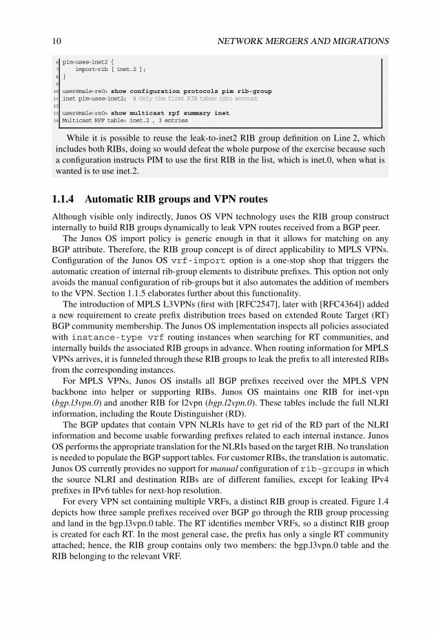
For every VPN set containing multiple VRFs, a distinct RIB group is created. Figure 1.4depicts how three sample prefixes received over BGP go through the RIB group processingand land in the bgp.l3vpn.0 table. The RT identifies member VRFs, so a distinct RIB groupis created for each RT. In the most general case, the prefix has only a single RT communityattached; hence, the RIB group contains only two members: the bgp.l3vpn.0 table and theRIB belonging to the relevant VRF.

DEALING WITH ROUTES WITHIN A JUNOS OS BASED ROUTER 11
A
a.inet.0
1:1:10.1.1.1/32 target:64500:9992:2:10.0.0.0/24 target:64500:13:3:10.0.0.1/32 target:64500:1 target:64500:23:3:10.0.1.0/24 target:64500:3
b.inet.0 c.inet.0
B C
10.0.0.0/2410.0.0.1/32
10.0.0.1/32 10.0.0.1/3210.0.1.0/24
2:2
:10
.0.0
.0/2
4 t
arg
et:
64
50
0:1
3:3
:10
.0.0
.1/3
2 t
arg
et:
64
50
0:1
targ
et:
64
50
0:2
3:3
:10
.0.1
.0/2
4 t
arg
et:
64
50
0:3
bgp.l3vpn.0
target:64500:1
target:64500:1 target:64500:2target:64500:2target:64500:3
target:64500:3target:64500:2
helper RIB RIB RIB Group
legend:
instance
Figure 1.4: Rib-groups to distribute VPN prefixes.
From a scalability perspective, a Provider Edge (PE) device in the MPLS VPN architectureshould not need to store route information for VPNs to which it does not belong. By default,Junos OS discards received BGP prefixes with a RT that does not match any of the locallyconfigured targets, when acting as a plain PE. With no matching target in that situation, theseprefixes are not installed in any VRF instance and are also not installed in the BGP supportingtable in Junos OS unless the keep-all feature is configured.
Router reconfiguration that might result in the creation of a new VRF or in the additionof new members to a VRF triggers a BGP route refresh message, which requests the peerto resend all VPN information. The router then re-evaluates this information to retrieve anyroutes that might have been filtered out earlier.
The primary RIB for these automatic RIB groups is the BGP VPN support table, namelybgp.l3vpn.0 in the case of MPLS L3VPNs. One exception to this rule, related to pathselection behaviors, occurs when the router acts as a Route Reflector or an AS BoundaryRouter (ASBR). This behavior is discussed in Section 1.2.2.
Listing 1.5 shows the output of the hidden Junos OS command show bgp targets,which contains information about the automatic RIB groups that are configured. Starting atLine 3 are details specific to a particular RT community. The example shows that prefixesreceived with route target target:64500:1 are imported into CORP VRF, and it shows thatdistribution of prefixes with target:64500:11 are distributed to two other VRFs besides thebgp.l3vpn.0 table.
Listing 1.5: Sample show BGP targets hidden command
1 user@Livorno>show bgp targets2 Target communities:3 64500:1 :4 Ribgroups:

12 NETWORK MERGERS AND MIGRATIONS
5 vpn-unicast target:64500:1 Family: l3vpn Refcount: 16 Export RIB: l3vpn.07 Import RIB: bgp.l3vpn.0 Secondary: CORP.inet.08 64500:11 :9 Ribgroups:
10 vpn-unicast target:64500:11 Family: l3vpn Refcount: 111 Export RIB: l3vpn.012 Import RIB: bgp.l3vpn.0 Secondary: CORP.inet.0 helper.inet.0
1.1.5 Local redistribution using the vrf-import option
Unlike other network operating systems, Junos OS performs route redistribution to and fromthe relevant routing table (RIB), not between routing protocols. Route exchange between twoprotocols is feasible only through an intermediate routing table that propagates only the bestroute information by default (as usual, some concrete exceptions exist to this general rule).
The discussion in Section 1.1.2 relied on manual configuration for each redistributioncombination. The configuration complexity increases as more RIBs are added to a RIB group,as illustrated in the sample management L3VPN scenario in Figure 1.5 because more VRFsneed to adjust their policies for route import and export actions.
c1
c1.inet.0 c2.inet.0 c3.inet.0
c2 c3
bg
p.l3
vp
n.0
noc+c1+c2+c3
noc+c2noc+c1
helper RIB RIB RIB Grouplegend:
instance
noc+c3
noc
noc.inet.0
NOC attachedProvider Edge
Cust CE
c1−lo0Cust2 CE
c2−loo
Cust3 CE
c3−lo0
NOC CE
noc−lo0
Figure 1.5: Reaching managed CPEs from the NOC.
In this example, a L3VPN extranet scenario is created, with multiple RIBs exchanginga subset of the same routes among themselves. Managed CPEs need to be reachable fromthe NOC VPN. Conversely, the NOC has to be reachable from each VRF. An additionalcustomer VRF (c3) requires the creation of a new RIB group (c3+noc) to install the CPEloopback address in the NOC VRF and to leak the NOC addressing space into the new VRFappropriately by adding this VRF to the NOC RIB group. This topology is representative
DEALING WITH ROUTES WITHIN A JUNOS OS BASED ROUTER 13
for a very common setup in MPLS L3VPN service providers that provide managed servicesfor CPEs in customer VPNs, in which management flows need to be intermingled amongthese VRFs.
Note that these RIB groups apply only to locally attached VRFs. For other VPNs, properRT tagging suffices, because an automatic RIB group is already in place for prefixes receivedinto the bgp.l3vpn.0 table. One obvious alternative to this design is to dedicate a small PEto attach to the Network Operations Center (NOC) and additional VRFs that home non-managed CPEs.
In light of this inherent complexity, Junos OS has been enhanced to introduce a moreintuitive construct that triggers the creation of RIB groups dynamically using the policylanguage, as is done for VRFs that are not on the same router. A pseudo-protocol namedrt-export allows RIBs on the same router to exchange information. This protocol handlesadvertisements and processes received routes, delegating all control to the policy language.
Existing customers are protected from this new functionality because it is disabled bydefault and must be activated through router configuration. Configuring this feature does notconflict with RIB groups and both options can be configured simultaneously, even in the sameVRF.
Configuring routing-options auto-export on a routing instance binds the rt-export protocol module to it. This module tracks changes in RIBs for routes that have tobe advertised and ensures that the advertised route is also imported in sibling RIBs on therouter if policy so dictates. Traditional vrf-import and vrf-export policies check forspecific matches on other VRFs on the router. These policies trigger local intra-router prefixredistribution based on the RT communities without the need for BGP. The resulting behavioris similar to what would be expected from a prefix received from a remote PE over BGP.
In some cases, routing information between VRFs and regular RIBs must be distributed,as happens when a VPN customer also has Internet access that is available from the mainrouting instance on the PE.
The same module can be leveraged for non-forwarding instances. The instance-import and instance-export configuration options mimic the intra-router behaviorof vrf-import and vrf-export for VRF for non-forwarding instances. Given that non-forwarding instances lack RT communities, the policy called as argument has to include afrom instance statement, to control the instances scope of the policy.
This section has focused on populating RIBs with route information. This informationis processed locally, and some of the routes become the best alternative within theirrespective RIB domains. The following section discusses how these behaviors interact withthe advertisement of the best selected routes.
1.2 RIB Route Advertisement at MPLS Layer 3 VPNs
For a PE router in the MPLS L3VPN architecture, the routing information that populates itslocal VRFs and which is learned from remote PE routers has to be advertised to the CEs.The advertisement can be achieved in Junos OS using a configuration similar to that for themain routing instance, but constrained to the specific VRF configuration block. Configuringprotocols within a routing-instance constrains the route advertisements to the VRF.

14 NETWORK MERGERS AND MIGRATIONS
Conversely, the routing information advertised by the CE must be propagated from thePE–CE connection to the MPLS L3VPN cloud by the PE router, which does so performingproper NLRI conversion to include the VPN Label and RD information, eventually taggingthe NLRI with RTs.
Figure 1.6 shows how a VRF named VRFA is populated with two prefixes coming fromtwo different sources, namely the loopback address from a remotely attached CE, CE2-lo0, and a prefix from the locally attached CE, CE1-lo0. CE2 of customer A advertisesits loopback address to PE2, which in turn propagates it to the Route Reflector. TheRoute Reflector performs regular route-processing with assistance from the helper table(bgp.l3vpn.0 for IPv4 prefixes), using the RD to disambiguate overlapping space for differentcustomers. The prefix is sent to PE1, which inspects its local list of RT matches in the importpolicy and redistributes the prefix to both the helper RIB and the relevant member VRFs.The advertisement by the local CE1 is received on the CE → PE connection at PE1, and theprefix is advertised directly from the VRF table, bypassing the helper RIB completely. Forcases where interprovider VPNs are used using VPN NLRI exchange at the border (optionB), the behavior of the ASBR is identical to the one performed by a Route Reflector, takingprefixes in and out of the BGP VPN table (bpg.l3vpn.0). More details on the interconnectoptions can be found in Section 5.2.6 on Page 391.
bgp.l3vpn.0
helper RIB RIB
legend:
instance
Cust A
CE1−lo0
MPLS L3VPN
vrf
RDvrfvrf.inet.0
vrf
PE1
RIB Group
bgp.l3vpn.0
RR
Cust A
CE2−lo0
bgp.l3vpn.0
ASBRPartnerMPLS L3VPN
ASBR
PE2
Figure 1.6: Receiving and advertising VPN prefixes.
1.2.1 Levels of advertisement policy – vpn-apply-export
By default, exporting routes from a VRF in Junos OS does not take into account the globalBGP export policy. In interprovider scenarios with combined PE and Inter-AS option BASBR functionality, blocking VPN advertisements only to certain peer groups may bedesired. Also, exposing all PE local VRFs across the partner MPLS L3VPN interconnect,may not be desired, but Junos OS does not allow the destination BGP groups from within
DEALING WITH ROUTES WITHIN A JUNOS OS BASED ROUTER 15
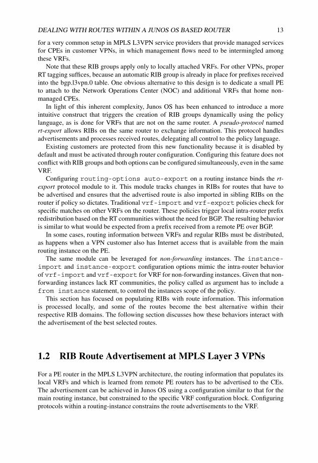
the vrf-export policy to be specified directly. Therefore, advertisement policy maydepend only on the VRF or can combine it with a global exporting policy for the coreBGP protocol. Figure 1.7 shows how the instance-level vrf-export and global bgp groupexport can be combined to modify attributes. This behavior, which is to be enabled with thevpn-apply-export configuration statement, splits the distribution of route informationbetween a VRF part and a global part.
bgp.l3vpn.0
RDb:CE2−lo0
helper RIB RIB
legend:
instance
Cust A
CE1−lo0
VRFA
RDaVRFA.inet.0
CE1−lo0CE2−lo0
VRFA rg
PE1
RIB Group
global bgp exportvrf export
global bgp importvrf import
RDb:CE2−lo0 from remote PE
Advertise RDa:CE1−lo0
export
import
Figure 1.7: Route policy points.
1.2.2 Path selection mode in Junos OS
When the router acts as a combined PE/Inter-AS option B ASBR or PE/Route Reflectordevice in MPLS VPN architectures, the routing information it propagates includes nativeVPN routes. As part of the propagation of the multiple routes, a path selection process needsto take place to select the best route among the set of comparable routes.
Generally, the RD acts as a differentiator for prefixes belonging to different VPNs thathave the same internal address allocation. The RD provides context separation when the sameprefix belongs to different VPNs, so the information about the prefix itself is not enough toallow a proper comparison.
Cases exist when a single prefix is available in the same VPN over different PE devices,such as with multihomed sites (see Figure 1.8). The RD may as well be unique for eachVRF within a VPN, to provide path diversity to the PEs in a Route Reflector environment.Conversely, when all copies of the same prefix within a VPN share the same RD, overallrouter memory consumption is reduced because identical VPN prefixes in the form RD:Prefixbecome comparable, and because only the best path is propagated.
Under this path selection mode, it is understood that a router can reflect VPN routes if itis acting as an Inter-AS option B boundary router (ASBR) or a Route Reflector, and if therouter is also a PE, the best-path comparison for reflected VPN routes also has to look at local

16 NETWORK MERGERS AND MIGRATIONS
bgp.l3vpn.0
RDa:CE1−lo0 NH:CE1RDa:CE1−lo0 NH:PE2
helper RIB RIB
legend:
instance
Cust A
CE1−lo0
VRFA
VRFA rg
PE1 + RR/ASBR
RIB Group
RDa:CE1−lo0 from PE2
CE1−lo0 from CE1
Advertise best
for CE1−lo0from
bgp.l3vpn.0
PE2
RDaVRFA.inet.0
CE1−lo0 CE1CE1−lo0 PE2
RDa
Figure 1.8: Advertisement of comparable NLRIs in PE acting as RR/ASBR.
prefixes to provide consistent routing information. In Junos OS, enabling this path selectionmode is automatic when the configuration parser detects a MP-BGP session configured thatrequires route reflection (either internally as a Route Reflector Server, or externally as anASBR), and triggers a process whereby all local prefixes and BGP paths learned from remoteroutes are copied to the bgp.l3vpn.0 table.
The example in Figure 1.8 depicts how the local routes are advertised from the helper tablebgp.l3vpn.0 instead of using the VRF table. Best-path selection for a reflected route versus alocally learned route is performed correctly, at the expense of duplicating local routes to thebgp.l3vpn.0 RIB. Without this duplication, every VRF would advertise its own version of thebest path, which could create non-deterministic inconsistency in the advertised state if, forinstance, the VRF advertised its prefix followed by a withdrawal from the bgp.l3vpn.0 table.
Listing 1.6 shows how to display the advertising state of a particular table. Output startingat Line 1 shows the regular PE case, in which prefixes are advertised directly from the VRF.By comparison, Line 7 shows a scenario in which path selection mode is enabled for a PEacting as Route Reflector, and prefixes are advertised from the bgp.l3vpn.0 table instead.
Listing 1.6: Advertising state for bgp.l3vpn.0
1 user@Havana> show bgp neighbor 192.168.1.1 | match "table|send"2 Table bgp.l3vpn.03 Send state: not advertising4 Table CORP.inet.0 Bit: 200005 Send state: in sync6
7 user@Nantes> show bgp neighbor | match "table|send"8 Table bgp.l3vpn.0 Bit: 100009 Send state: in sync
10 Table CORP.inet.011 Send state: not advertising

DEALING WITH ROUTES WITHIN A JUNOS OS BASED ROUTER 17
Junos Tip: Use of a table filter in path selection mode
With path selection mode, both local prefixes and BGP routes with paths from remote PEsare copied to the bgp.l3vpn.0 table and considered for export.
The table of the show route advertising-protocol bgp command filtersfor primary routes only. If a table qualifier is used and path selection mode is in force,the qualifier should refer to the helper table bgp.l3vpn.0 instead of the local VRF that isconfigured.
Listing 1.7 shows the sample output for router Nantes, a PE advertising 10.200.1.0/24on the CORP VRF, but also behaving as a Route Reflector (in path selection mode).
Listing 1.7: Correct table argument to show route in path-selection mode
1 user@Nantes> show route advertising-protocol bgp 192.168.1.6 table CORP2
3 user@Nantes> show route advertising-protocol bgp 192.168.1.6 table bgp.l3vpn.0 terse4
5 bgp.l3vpn.0: 7 destinations, 7 routes (7 active, 0 holddown, 0 hidden)6 Prefix Nexthop MED Lclpref AS path7 64500:1:10.200.1.0/248 * Self 2 100 I9 64500:1:10.200.1.9/32
10 * Self 2 100 I11 64500:2:0.0.0.0/012 * 192.168.1.4 100 65000 I
1.2.3 RIB group versus auto-exported routes
No specific constraints exist regarding advertisement of routes created by the RIB groupmechanism. The behavior is similar to any regular prefix. Therefore, if a prefix is receivedover a CE-PE connection and is leaked to various VRFs, each VRF advertises its own versionof the prefix, adding the instance’s RD and relevant topology extended communities asnecessary. One interesting corollary of this behavior is that, odd as it seems, a secondaryOSPF route can be further advertised into OSPF, because the information source is the RIB,not the task. Besides, two separate tasks are involved. An example of this behavior applied totwo OSPF tasks is discussed just before Section 1.4.8.
The export behavior differs slightly for auto-exported routes. These routes are handledby the rt-export module, which behaves like a regular protocol, requiring inclusion oflocal export and import RTs. Given the flexibility of this approach, to avoid the chance ofinconsistent advertisement, constraints are put in place to allow advertisement of only theprimary route. If advertisements for multiple VPNs are required, care has to be taken to tagthe primary route with the relevant RT communities for all participating VPNs, regardless ofwhether the actual homing of the member VRFs is on the same PE. This is consistent withthe typical route-tagging behavior when creating extranets in MPLS VPNs, in which routesare advertised with multiple RTs, one for each remote VRF that requires route import.
1.2.4 RIB selection – no-vrf-advertise
For a BGP route that is present in multiple tables, the primary route is the one that is selectedfor advertisement. However, for one special hub-and-spoke scenario, the desire is to advertise
18 NETWORK MERGERS AND MIGRATIONS
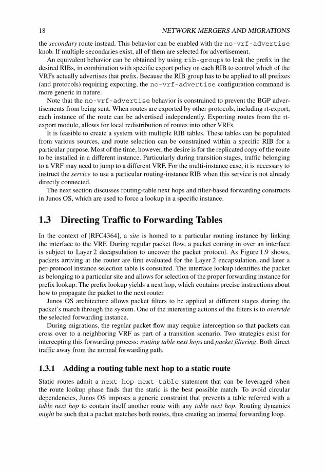
the secondary route instead. This behavior can be enabled with the no-vrf-advertiseknob. If multiple secondaries exist, all of them are selected for advertisement.
An equivalent behavior can be obtained by using rib-groups to leak the prefix in thedesired RIBs, in combination with specific export policy on each RIB to control which of theVRFs actually advertises that prefix. Because the RIB group has to be applied to all prefixes(and protocols) requiring exporting, the no-vrf-advertise configuration command ismore generic in nature.
Note that the no-vrf-advertise behavior is constrained to prevent the BGP adver-tisements from being sent. When routes are exported by other protocols, including rt-export,each instance of the route can be advertised independently. Exporting routes from the rt-export module, allows for local redistribution of routes into other VRFs.
It is feasible to create a system with multiple RIB tables. These tables can be populatedfrom various sources, and route selection can be constrained within a specific RIB for aparticular purpose. Most of the time, however, the desire is for the replicated copy of the routeto be installed in a different instance. Particularly during transition stages, traffic belongingto a VRF may need to jump to a different VRF. For the multi-instance case, it is necessary toinstruct the service to use a particular routing-instance RIB when this service is not alreadydirectly connected.
The next section discusses routing-table next hops and filter-based forwarding constructsin Junos OS, which are used to force a lookup in a specific instance.
1.3 Directing Traffic to Forwarding Tables
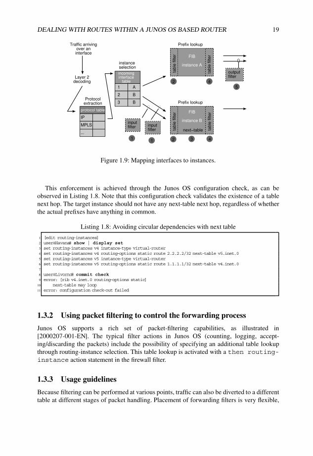
In the context of [RFC4364], a site is homed to a particular routing instance by linkingthe interface to the VRF. During regular packet flow, a packet coming in over an interfaceis subject to Layer 2 decapsulation to uncover the packet protocol. As Figure 1.9 shows,packets arriving at the router are first evaluated for the Layer 2 encapsulation, and later aper-protocol instance selection table is consulted. The interface lookup identifies the packetas belonging to a particular site and allows for selection of the proper forwarding instance forprefix lookup. The prefix lookup yields a next hop, which contains precise instructions abouthow to propagate the packet to the next router.
Junos OS architecture allows packet filters to be applied at different stages during thepacket’s march through the system. One of the interesting actions of the filters is to overridethe selected forwarding instance.
During migrations, the regular packet flow may require interception so that packets cancross over to a neighboring VRF as part of a transition scenario. Two strategies exist forintercepting this forwarding process: routing table next hops and packet filtering. Both directtraffic away from the normal forwarding path.
1.3.1 Adding a routing table next hop to a static route
Static routes admit a next-hop next-table statement that can be leveraged whenthe route lookup phase finds that the static is the best possible match. To avoid circulardependencies, Junos OS imposes a generic constraint that prevents a table referred with atable next hop to contain itself another route with any table next hop. Routing dynamicsmight be such that a packet matches both routes, thus creating an internal forwarding loop.
DEALING WITH ROUTES WITHIN A JUNOS OS BASED ROUTER 19
protocol table
incoming interface
table
FIB
instance B
FIB
instance A
inputfilter input
filter next−table
outputfilter
table
filt
er
table
filt
er
table
filt
er
table
filt
er
Traffic arrivingover aninterface
Layer 2decoding
Protocolextraction
instanceselection
Prefix lookup
Prefix lookup
IP
1 A
MPLS
2 B
...
3 B
11
2
3 4
4
5
2
Figure 1.9: Mapping interfaces to instances.
This enforcement is achieved through the Junos OS configuration check, as can beobserved in Listing 1.8. Note that this configuration check validates the existence of a tablenext hop. The target instance should not have any next-table next hop, regardless of whetherthe actual prefixes have anything in common.
Listing 1.8: Avoiding circular dependencies with next table
1 [edit routing-instances]2 user@Havana# show | display set3 set routing-instances v4 instance-type virtual-router4 set routing-instances v4 routing-options static route 2.2.2.2/32 next-table v5.inet.05 set routing-instances v5 instance-type virtual-router6 set routing-instances v5 routing-options static route 1.1.1.1/32 next-table v4.inet.07
8 user@Livorno# commit check9 error: [rib v4.inet.0 routing-options static]
10 next-table may loop11 error: configuration check-out failed
1.3.2 Using packet filtering to control the forwarding process
Junos OS supports a rich set of packet-filtering capabilities, as illustrated in[2000207-001-EN]. The typical filter actions in Junos OS (counting, logging, accept-ing/discarding the packets) include the possibility of specifying an additional table lookupthrough routing-instance selection. This table lookup is activated with a then routing-instance action statement in the firewall filter.
1.3.3 Usage guidelines
Because filtering can be performed at various points, traffic can also be diverted to a differenttable at different stages of packet handling. Placement of forwarding filters is very flexible,

20 NETWORK MERGERS AND MIGRATIONS
as depicted in Figure 1.9. Filters can be attached to the interface and to the instance, and inboth directions, on incoming and outgoing traffic.
Note that a prefix match in a table at one step is independent of another prefix match ina separate table in a later step. For instance, it is possible to match first on a host (IPv4 /32)route and then jump to another table that matches on a default route.
Using Figure 1.9 as guideline, both table next-hop and firewall strategies are described inthe packet-processing sequence as follows:
1. Input interface filters can be used when the interface remains homed to the existinginstance, but selected traffic needs to be processed first elsewhere. An example isdiverting selected source-destination pairs arriving on a specific input interface.
2. Input forwarding table filters generalize the previous case for any input interface. Notethat these filters take effect before route lookup, on both traffic directions. Use of theinterface, interface-group, and group qualifiers within the filter may helpwith scoping of the filter.
3. Static routes admit a next-table next-hop statement that can be leveraged whenthe route lookup phase identifies that the static route is the best possible match. Anyvalid route is allowed, be it a specific destination, a prefix, or a default route. Note thatthe next-table next hop cannot be applied to dynamic routes.
4. Output forwarding table filters work after a lookup is done, when the output interface isalready known, and is typically used in combination with the Destination Class Usage(DCU) feature in Junos OS. DCU marking allows the combination of route information(such as BGP communities) with forwarding.
5. Output interface filters constrain the above to a single output interface.
1.3.4 Risks of decoupling routing and forwarding
Using some of these resources allows a granular definition of multiple actions on the packetflow in terms of routing lookup and forwarding decisions. In fact, a subset of these featurescan be combined so that the final forwarding decision for a flow is completely different fromthe plain routing lookup.
The control plane can be considered to be the brain of the system, providing strategy anddirection. Standard routing decisions are made as a consequence of information distributedby protocols on the control plane. Tinkering with the forwarding plane could unwittinglyhave the following consequences on the control plane:
• Static configuration prevents any reaction to protocol dynamics, unless this configura-tion is carefully planned by having a less preferred static route in combination withdynamic routes. A forwarding loop may occur if adjacent routers have conflictingrouting information.
• No redundancy is available for failure conditions, introducing the possibility of trafficblackholes as routes jump to another VRF that has no good destination for the traffic.

DEALING WITH ROUTES WITHIN A JUNOS OS BASED ROUTER 21
1.4 Case Study
This section presents a migration case study that illustrates the different route-sharing andmodification technologies outlined in this chapter. Figure 1.10 shows the IP network of a bigenterprise that has grown over time connecting all routers in a full mesh. The data centerprovides access to critical applications, and the hub router connects the office headquarters.
OSPF
IP network
R1 R2 R99
RHub
RDCDataCenter
Headquarters
Router RDC connecting
the Data Center has also
locally connected sites
Enterprise headquarters
provides external access
Sites have any−to−any connectivity
and access Headquarters for corporate
applications
Figure 1.10: Overview of existing enterprise network.
The newly appointed network manager has a good understanding of the business andknows that the network infrastructure is critical. He is also very concerned about thecurrent traffic distribution and wants to maintain control of interoffice user traffic from theheadquarters. Therefore, he has set as main priority to rebuild the network to a headquarters-centric, compartmentalized collection of MPLS L3VPNs. The clearest advantage is theanalysis of traffic flows and the ability to isolate errors by identifying the VPN reportingapplications affected by issues. The migration project consists in moving traffic flows forservices for corporate users off the global routing table to a hub-and-spoke VPN, as shownin Figure 1.11.
Throughout this case study only a single VPN, the CORP VPN, is analyzed. It isunderstood that this VPN represents one of the many VPNs of this enterprise.
1.4.1 Original network
Currently, all corporate users, regardless of their department, leverage any-to-any connec-tivity provided by a flat IP OSPF network. Users have access to headquarters via a defaultroute, and they connect to data center servers located in a special hosting facility that includesbackup services for critical applications. The router connecting the data center to the networkhas additional interconnections to regular users over other router interfaces.
Figure 1.12 illustrates the detailed topology of the network. The most relevant elementsto consider in this migration are summarized below:

22 NETWORK MERGERS AND MIGRATIONS
CORP
MPLS VPN
PE1 PE2 PE99
PE Hub
PEDCDataCenter
Headquarters
PE Router RDC connecting
the Data Center has also
locally connected sites
Direct traffic from spoke site to
data center for best performance
is allowed only for well−identified
site addresses.
Multicast replication between
Headquarters and Data Center
has to stay on the global routing
table.
Enterprise headquarters
provides external access
Regular site to site traffic
has to cross the firewall at
headquarters because of
the hub−and−spoke setup
New access link
Spoke sites have no direct visibility between themselves.
Figure 1.11: Target network migrated to MPLS/VPN with direct flows to data center.
Male
Bilbao
Havana
Nantes
Skopie
Livorno
Barcelona
Honolulu
192.168.1.4
10.255.100.20
192.168.1.8
192.168.1.1
192.168.1.2
192.168.1.6
10.50.1.7
10.1.1.21
Torino
10.200.1.9InvernessBasel
192.168.1.3
10.100.1.10
Data center
User spoke site
User spoke site User spoke site
OSPF NSSA
area 1
RIPRIP
RIP RIP
Corporate
Headquarters
Hub
site
OSPF
backbone
area 0.0.0.0
.77
.86
.85
.78
172.16.1.96/30
.101
.5
.41
.42
.37 .38 .53.54
.89
.88
.34
.33
.6
10.100.1.82 10.200.1.66
10.200.1.6510.100.1.81
.102
.1
.2
Figure 1.12: Network topology used through the case study.
• Backbone infrastructure addressing is contained within prefix 172.16.1.0/24. PE–CEaddressing follows the addressing of the connected site. For instance, the data centerWAN address is 10.1.1.88/30.
• User locations connect to the backbone routers using RIP as the routing protocol toadvertise the location address space.
• At headquarters, represented by router Male, RIP is used to exchange a default routetowards remote locations over the link between router Male and router Bilbao to attractexternal traffic. In the reverse direction, the headquarters site receives all location
DEALING WITH ROUTES WITHIN A JUNOS OS BASED ROUTER 23
prefixes. A corporate firewall controls external access. Note that the link between routerMale and router Havana is added as part of the migration and is originally not carryingany traffic.
• Because of latency constraints, selected corporate applications hosted on the datacenter (represented by router Honolulu) are accessed directly without intervention fromheadquarters. This access is restricted to a few critical clients whose site-addressingspaces are known. Keeping critical traffic flows to the data center with minimumlatency is one of the key requirements for a successful migration.
• As part of the global OSPF domain, the data center is a member of OSPF NSSA Area 1.The data center address ranges are advertised as Type 7 LSAs, which are automaticallytranslated into Type 5 LSAs in the core by the Area Border Router (ABR) Livorno.From the core, routers in OSPF Area 1 receive a default route, which suffices for trafficto reach the data center core border router.
• The border router Havana towards Headquarters is configured with a set of filters thatcount traffic going to and from the Data Center for statistics purposes. This counter iscurrently on the global table and is implemented as an inbound and outbound firewallfilter.
• A multicast replication service between headquarters and the data center is independentof customer access. Headquarters uses PIM Sparse Mode dynamically to signalmulticast group availability. A PIM rendezvous point is sited at router Bilbao. No plansexist to migrate this service to an MPLS L3VPN at this stage. Any migration activitiesshould ensure that this application is not affected.
1.4.2 Target network
The OSPF backbone is extended with LDP as MPLS label distribution protocol, and borderrouters are promoted to PE devices. The final design calls for a hub-and-spoke VPNconfiguration, in which corporate users interconnect using the hub located at headquarters.The need for low-latency access to the applications hosted on the data center prompts theuse of a fully meshed topology for data center access. The existing any-to-any connectivity ismaintained only for data center access; remaining traffic is to reach the hub for accountabilityand security control. An increased latency in user-to-user traffic is deemed to be acceptable.
As part of the migration, services homed to the VPN at the hub location connect over anew access link, providing separation at the hub for traffic that has already been migrated.
The data center connectivity between router Livorno and router Honolulu involves acomplex Layer 2 infrastructure (not shown in Figure 1.12) that cannot support a new accessport at the border router Livorno. This restriction poses a challenge supporting a transientstate in the migration, in which some sites are connected to the VPN while others are stillconnected to the global routing table. Access to the data center from the global routing tableand to the VPN has to be provided over a single interface.
24 NETWORK MERGERS AND MIGRATIONS
1.4.3 Migration strategy
Two important requirements for the migration are that it be smooth and that it have only localimpact. During the migration, sites can be affected one at a time offering a way to back out ofchanges if any problems occur. The desire is to avoid changing many sites and components atthe same time, and especially to avoid an all or nothing approach in which the entire networkchanges in a single go. Some of the migration elements can be treated separately, while othersrequire a careful sequence of actions to minimize the impact.
During preparatory stages, proper migration planning is envisaged to maintain existingtraffic flows.
Maintain multicast on global routing table
Before it receives any routing information from the Hub PE (router Havana), router Malehas to ensure that multicast traffic uses only the existing access on the global routing tablefor the RPF check using the separation of unicast and multicast topology concept describedin Section 1.1.3.
Data center transition challenge
Because of the nature of the networking protocols being used on the end-user hosts, anyadditional latency in accessing the data center, even a small one, imposes huge penaltiesin service responsiveness. Relaying critical traffic over headquarters does introduce thisunwanted extra latency, which should be avoided in both directions of traffic flow duringthe migration, both for users moved to the CORP VPN and for users still attached to theglobal routing table. A means to keep direct data center access is needed to maintain servicelevels during the transition.
Note Some networking protocols defined for corporate environments correctly assume thatlatency is a negligible consideration for enterprise LANs and implement a retransmissionwindow of one. For every message sent, a confirmation message is expected to acknowledgecorrect reception. A complete traffic round trip is required for every block of data that needsconfirmation. When using the same protocols in the wide area, the user latency increasesproportionally to the additional latency experienced. Larger files imply longer latency,because the number of data blocks that need to be exchanged increases, thus introducinga negative impact in end-user experience.
Thus, the desire is to offer data center access both to the global table and to the CORP VPNdirectly, without visiting the hub site for critical applications. One possible approach is to usean additional data center interface during the migration, in the same way as is performed atthe hub. The result of this approach is that the data center devices continue to decide whichtraffic is sent over which interface.
In keeping with the spirit of this case study and showing route-leaking constructs, it isdecided for administrative reasons to leave the data center site untouched rather than to addanother interface and instead, to explore the possibility of solving the issue on the data centerPE router Livorno. Looking at the concepts discussed in this chapter, it is apparent that a setof tools can be leveraged to control the migration process from the PE instead of having toconfigure an additional port.
DEALING WITH ROUTES WITHIN A JUNOS OS BASED ROUTER 25
Using this second approach, the data center site CE is unaware that the site to which itbelongs is becoming a member of a VPN. Decisions are made by router Livorno, the datacenter PE. All traffic uses the global routing table to reach critical destinations for non-migrated sites and the CORP VPN for already migrated sites.
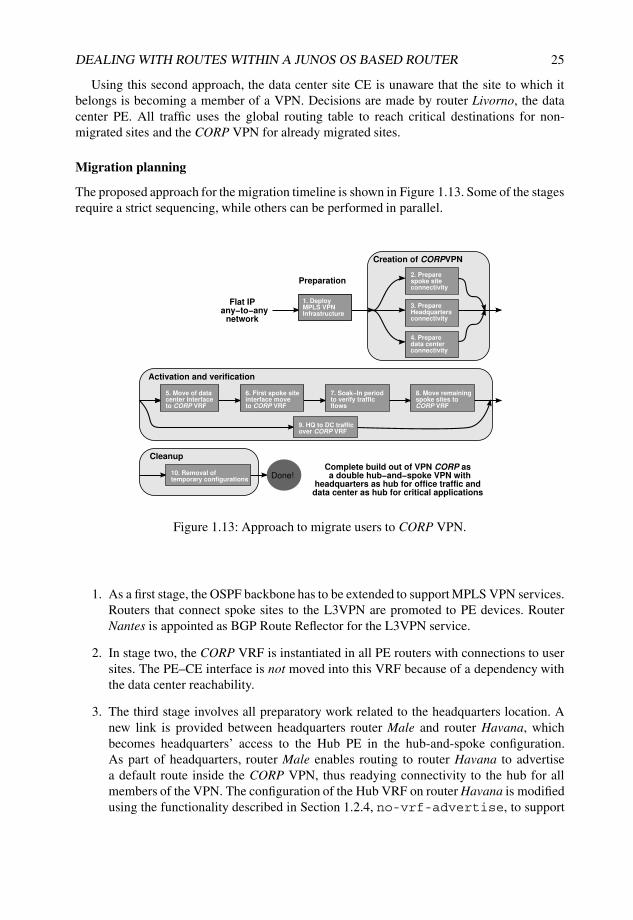
Migration planning
The proposed approach for the migration timeline is shown in Figure 1.13. Some of the stagesrequire a strict sequencing, while others can be performed in parallel.
Flat IP any−to−any
network
Complete build out of VPN CORP as a double hub−and−spoke VPN with
headquarters as hub for office traffic and data center as hub for critical applications
1. DeployMPLS VPNInfrastructure
Creation of CORPVPN
3. PrepareHeadquartersconnectivity
4. Preparedata centerconnectivity
2. Preparespoke siteconnectivity
5. Move of data center interfaceto CORP VRF
6. First spoke site interface move to CORP VRF
7. Soak−In periodto verify trafficflows
8. Move remainingspoke sites toCORP VRF
9. HQ to DC trafficover CORP VRF
10. Removal of temporary configurations
Activation and verification
Preparation
Cleanup
Done!
Figure 1.13: Approach to migrate users to CORP VPN.
1. As a first stage, the OSPF backbone has to be extended to support MPLS VPN services.Routers that connect spoke sites to the L3VPN are promoted to PE devices. RouterNantes is appointed as BGP Route Reflector for the L3VPN service.
2. In stage two, the CORP VRF is instantiated in all PE routers with connections to usersites. The PE–CE interface is not moved into this VRF because of a dependency withthe data center reachability.
3. The third stage involves all preparatory work related to the headquarters location. Anew link is provided between headquarters router Male and router Havana, whichbecomes headquarters’ access to the Hub PE in the hub-and-spoke configuration.As part of headquarters, router Male enables routing to router Havana to advertisea default route inside the CORP VPN, thus readying connectivity to the hub for allmembers of the VPN. The configuration of the Hub VRF on router Havana is modifiedusing the functionality described in Section 1.2.4, no-vrf-advertise, to support

26 NETWORK MERGERS AND MIGRATIONS
the egress IP functionality that already exists at router Bilbao for the global routingtable. Finally, preparatory work at headquarters finishes modifying the configurationon router Male to ensure that multicast traffic uses only the existing access on theglobal routing table for the RPF check using the incongruent unicast/multicast conceptsdescribed in Section 1.1.3.
4. The fourth stage covers preliminary work on the data center. Only one interfaceconnects router Livorno and the data center represented by router Honolulu. Accessover the single access at router Livorno presents a challenge in the transient state of themigration because traffic from both migrated and non-migrated sites must bypass thehub router Havana. An interim configuration construct using a helper VRF is presentedto allow data center traffic to reach the intended destination either over CORP VPN ifit is available, directly over global table in a meshed fashion, or using the hub as a lastresort. To meet this requirement, leaking routes and diverting traffic to the helper VRFas described in Section 1.3 is required.
5. In stage five, the PE–CE interface at the data center PE router Livorno is moved to theCORP VRF. Preparatory work in previous stages ensures that this step does not changetraffic flows. Traffic patterns still follow the original route over the global routing table.
6. A fundamental milestone is achieved in stage six. Router Inverness is chosen as the firstspoke site to migrate to the CORP VPN. Notice that this starts the transition stage, inwhich sites within the CORP VRF reach other sites that are not yet migrated followingthe default route within the CORP VRF advertised by hub router Havana.
7. In stage seven, a monitoring period is established to confirm traffic flows andapplications behave as expected. Two anomalies are detected and addressed.
8. Stage eight streamlines the migration of spoke sites to the CORP VRF. With both theheadquarters and the data center locations simultaneously present in both the globaltable and the CORP VPN, user sites can join the VPN one at a time by moving thespoke site access interface from the global routing table to the CORP VRF whilemaintaining the meshed connectivity requirement for critical services. Traffic impactis restricted to the site under migration, which allows for an incremental rollout.
9. Stage nine can take place anywhere after the preparatory stages up to stage four. Assoon as the new link to the CORP VRF is active at the headquarters and the datacenter prefix is received over the VPN, router Male can choose both the global routingtable and the CORP VRF for traffic to the data center. This stage moves traffic fromheadquarters to the data center over the VPN.
10. Stage ten involves cleanup of the old configuration and helper constructs. With theapproach presented in this case study, all configuration changes performed in thepreparatory stages become final as specified in the target design, except for the helperconstruct at the data center from stage four and the core protocol configuration thatcan be removed. Thus, the only cleanup required at the data center PE is to removethe helper VRF configuration, which, because it does not impact any service, canbe performed once all user sites have been migrated successfully and a prudentialmonitoring period has elapsed in which post-migration issues have been sorted out.

DEALING WITH ROUTES WITHIN A JUNOS OS BASED ROUTER 27
Notice that removing the helper VRF forces all data center traffic destined to the hubto flow over the CORP VRF.
Table 1.3 describes the connectivity matrix between the different locations in the currentnetwork. Notice that all traffic is traversing the global routing table.
Table 1.3 Traffic flow between site pairs in original network
HQ DC NMS
Headquarters (HQ) Global GlobalData Center (DC) Global GlobalNon-Migrated Spoke (NMS) Global Global Global
Rows indicate traffic sources. Columns indicate traffic destinations.
1.4.4 Stage one: Building an MPLS L3VPN
The original backbone protocol is OSPFv2, as defined in [RFC2328]. This IGP is reusedin the new MPLS VPN design. LDP, as per [RFC5036], is used for MPLS transport labelbinding between PE devices. Multi-Protocol BGP provides L3VPN prefix connectivity asper [RFC4364]. Router Skopie is the BGP Route Reflector and all PE routers establish aMP-BGP session with it including the inet-vpn address family.
For simplicity, connectivity between PE and CE routers leverages RIP version 2, asdefined in [RFC2453], except for the data center, which is in OSPF NSSA area 1, and theHub location, which uses EBGP.
MPLS L3VPN infrastructure
The CORP VPN is distributed across all access routers to which a site is connected. Thehub site router Male connects to the CORP VPN in PE router Havana using a newly createdconnection. The old connection remains only to simulate existing services that are alreadyusing the global table and are not to be migrated, such as multicast replication betweenheadquarters and the data center.
The target network scenario requires the creation of the CORP VRF at the PEs and movingthe PE–CE interface of spoke sites that is on the routing table to the CORP VRF. This movehas to be deferred to stage six, until both the headquarters and the data center have passed aset of preparatory steps.
A sample configuration for a PE router is shown in Listing 1.9. The MPLS configurationdefines the interfaces and enables special processing for ICMP messages coming in for VPNsthrough the icmp-tunneling configuration statement shown on Line 3 as per [RFC3032]Section 2.3.2. The BGP cluster configuration option shown on Line 18 enables routerNantes as a route reflector for the VPNs. The loopback range defined with the BGP allowknob shown on Line 19 facilitates the configuration. As a best practice, tracking of IGPmetrics for LDP is enabled on Line 36. RIP is used to exchange information with router
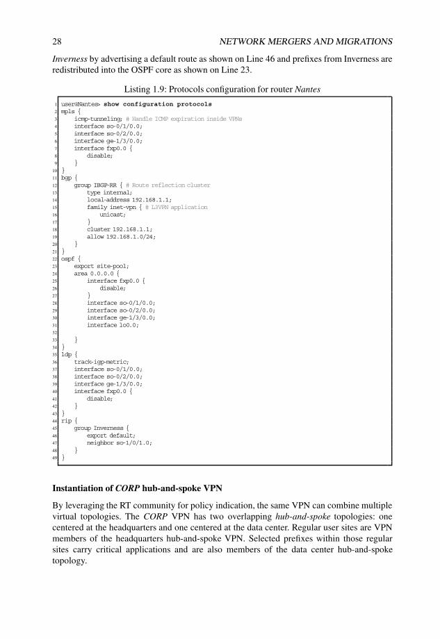
28 NETWORK MERGERS AND MIGRATIONS
Inverness by advertising a default route as shown on Line 46 and prefixes from Inverness areredistributed into the OSPF core as shown on Line 23.
Listing 1.9: Protocols configuration for router Nantes
1 user@Nantes> show configuration protocols2 mpls {3 icmp-tunneling; # Handle ICMP expiration inside VPNs4 interface so-0/1/0.0;5 interface so-0/2/0.0;6 interface ge-1/3/0.0;7 interface fxp0.0 {8 disable;9 }
10 }11 bgp {12 group IBGP-RR { # Route reflection cluster13 type internal;14 local-address 192.168.1.1;15 family inet-vpn { # L3VPN application16 unicast;17 }18 cluster 192.168.1.1;19 allow 192.168.1.0/24;20 }21 }22 ospf {23 export site-pool;24 area 0.0.0.0 {25 interface fxp0.0 {26 disable;27 }28 interface so-0/1/0.0;29 interface so-0/2/0.0;30 interface ge-1/3/0.0;31 interface lo0.0;32
33 }34 }35 ldp {36 track-igp-metric;37 interface so-0/1/0.0;38 interface so-0/2/0.0;39 interface ge-1/3/0.0;40 interface fxp0.0 {41 disable;42 }43 }44 rip {45 group Inverness {46 export default;47 neighbor so-1/0/1.0;48 }49 }
Instantiation of CORP hub-and-spoke VPN
By leveraging the RT community for policy indication, the same VPN can combine multiplevirtual topologies. The CORP VPN has two overlapping hub-and-spoke topologies: onecentered at the headquarters and one centered at the data center. Regular user sites are VPNmembers of the headquarters hub-and-spoke VPN. Selected prefixes within those regularsites carry critical applications and are also members of the data center hub-and-spoketopology.
DEALING WITH ROUTES WITHIN A JUNOS OS BASED ROUTER 29
For regular office work, the CORP VPN provides a default route from Headquartersthrough the hub site PE router Havana. Headquarters router Male receives all site prefixes toallow connectivity to the spoke sites.
For data center access, the data center router Honolulu provides the data center prefix, andit imports selected site prefixes.
Regular interoffice traffic at remote sites traverses the hub to reach headquarters. Criticalprefixes at the remote sites have direct access to the data center.
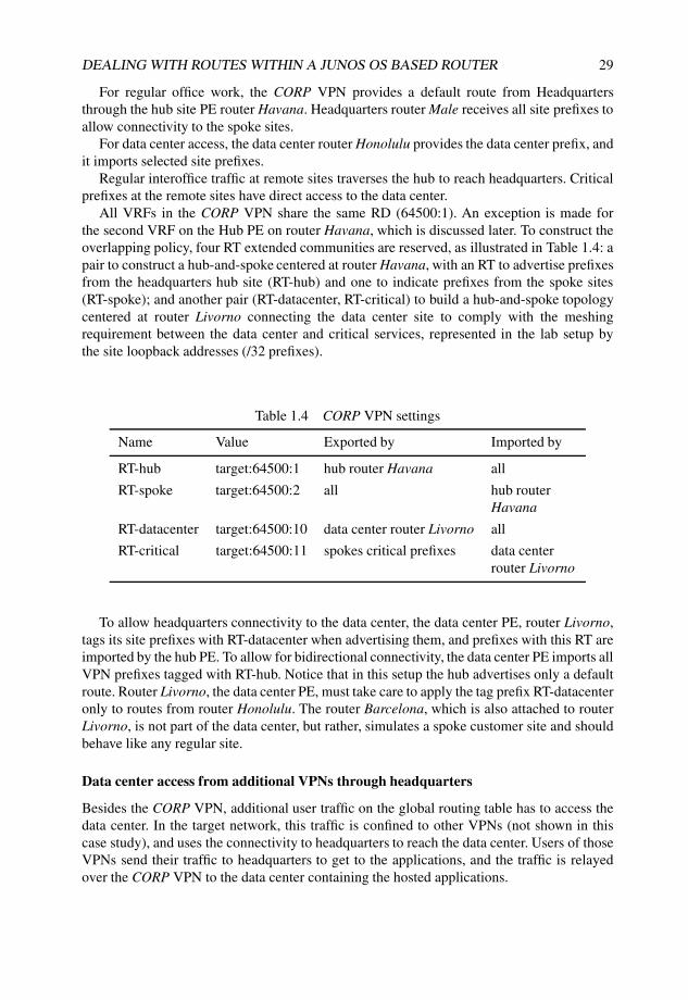
All VRFs in the CORP VPN share the same RD (64500:1). An exception is made forthe second VRF on the Hub PE on router Havana, which is discussed later. To construct theoverlapping policy, four RT extended communities are reserved, as illustrated in Table 1.4: apair to construct a hub-and-spoke centered at router Havana, with an RT to advertise prefixesfrom the headquarters hub site (RT-hub) and one to indicate prefixes from the spoke sites(RT-spoke); and another pair (RT-datacenter, RT-critical) to build a hub-and-spoke topologycentered at router Livorno connecting the data center site to comply with the meshingrequirement between the data center and critical services, represented in the lab setup bythe site loopback addresses (/32 prefixes).
Table 1.4 CORP VPN settings
Name Value Exported by Imported by
RT-hub target:64500:1 hub router Havana all
RT-spoke target:64500:2 all hub routerHavana
RT-datacenter target:64500:10 data center router Livorno all
RT-critical target:64500:11 spokes critical prefixes data centerrouter Livorno
To allow headquarters connectivity to the data center, the data center PE, router Livorno,tags its site prefixes with RT-datacenter when advertising them, and prefixes with this RT areimported by the hub PE. To allow for bidirectional connectivity, the data center PE imports allVPN prefixes tagged with RT-hub. Notice that in this setup the hub advertises only a defaultroute. Router Livorno, the data center PE, must take care to apply the tag prefix RT-datacenteronly to routes from router Honolulu. The router Barcelona, which is also attached to routerLivorno, is not part of the data center, but rather, simulates a spoke customer site and shouldbehave like any regular site.
Data center access from additional VPNs through headquarters
Besides the CORP VPN, additional user traffic on the global routing table has to access thedata center. In the target network, this traffic is confined to other VPNs (not shown in thiscase study), and uses the connectivity to headquarters to reach the data center. Users of thoseVPNs send their traffic to headquarters to get to the applications, and the traffic is relayedover the CORP VPN to the data center containing the hosted applications.
30 NETWORK MERGERS AND MIGRATIONS
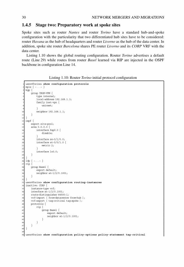
1.4.5 Stage two: Preparatory work at spoke sites
Spoke sites such as router Nantes and router Torino have a standard hub-and-spokeconfiguration with the particularity that two differentiated hub sites have to be considered:router Havana as the hub of headquarters and router Livorno as the hub of the data center. Inaddition, spoke site router Barcelona shares PE router Livorno and its CORP VRF with thedata center.
Listing 1.10 shows the global routing configuration. Router Torino advertises a defaultroute (Line 29) while routes from router Basel learned via RIP are injected in the OSPFbackbone in configuration Line 14.
Listing 1.10: Router Torino initial protocol configuration
1 user@Torino> show configuration protocols2 mpls { <...> }3 bgp {4 group IBGP-VPN {5 type internal;6 local-address 192.168.1.3;7 family inet-vpn {8 unicast;9 }
10 neighbor 192.168.1.1;11 }12 }13 ospf {14 export site-pool;15 area 0.0.0.0 {16 interface fxp0.0 {17 disable;18 }19 interface so-0/1/0.0;20 interface at-0/0/1.0 {21 metric 2;22 }23 interface lo0.0;24 }25 }26 ldp { <...> }27 rip {28 group Basel {29 export default;30 neighbor at-1/2/0.1001;31 }32 }33 user@Torino> show configuration routing-instances34 inactive: CORP {35 instance-type vrf;36 interface at-1/2/0.1001;37 route-distinguisher 64500:1;38 vrf-import [ from-datacenter from-hub ];39 vrf-export [ tag-critical tag-spoke ];40 protocols {41 rip {42 group Basel {43 export default;44 neighbor at-1/2/0.1001;45 }46 }47 }48 }49
50 user@Torino> show configuration policy-options policy-statement tag-critical

DEALING WITH ROUTES WITHIN A JUNOS OS BASED ROUTER 31
51 from {52 protocol rip;53 route-filter 0.0.0.0/0 prefix-length-range /32-/32;54 }55 then {56 community add RT-critical;57 }58
59 user@Torino> show configuration policy-options policy-statement tag-spoke60 from protocol rip;61 then {62 community add RT-spoke;63 accept;64 }
The CORP VRF configuration starting in Line 34 advertises a default route to router Basel.VRF policies tag the loopback address of router Basel as critical (Line 50) for the data centerhub-and-spoke VPN topology and everything (Line 59) as a spoke prefix for the headquartershub-and-spoke VPN topology.
Notice that the CORP VRF is prepared but left inactive at this stage, awaiting its turn forproper activation sequence.
1.4.6 Stage three: Preparatory work at headquarters
The headquarters use a new connection to reach the CORP VPN, which allows for work tobe performed incrementally. Care has to be taken by router Male not to prefer any routinginformation received from the CORP VPN at this preparatory stage. The configurationelements for this work involve mainly the hub PE router Havana and the headquarters CErouter Male as follows:
• Existing accounting functions performed at router Bilbao need to be mirrored to thePE router Havana. Accounting happens in both directions of traffic. This requirementforces a double VRF configuration to be created at PE router Havana to enable VPNegress IP functionality.
• A default route is advertised by router Male into the CORP VPN. This route attractstraffic to headquarters unless a more specific route exists in the VPN.
• Multicast traffic from router Male must be kept on the global table. The migrationshould maintain multicast on its existing connection to router Bilbao.
Details for each of the required configurations follow.
IP accounting on Havana
One requirement for the network migration is to retain the ability to count traffic that isexchanged between the data center and the hub site. In the original network, two countersapplied to the global routing table on router Bilbao collect packet and byte counts of trafficheaded towards and from the data center (see Listing 1.11). The filter shown in this listing isapplied both inbound and outbound on the interface that faces headquarters on router Bilbao(so-1/3/1.0).
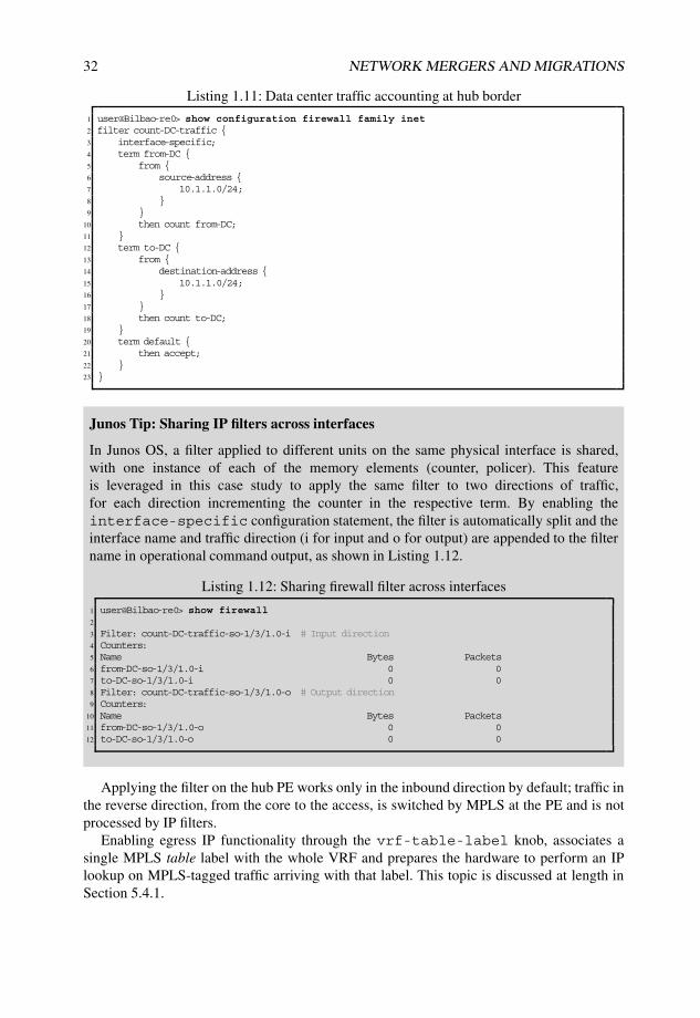
32 NETWORK MERGERS AND MIGRATIONS
Listing 1.11: Data center traffic accounting at hub border
1 user@Bilbao-re0> show configuration firewall family inet2 filter count-DC-traffic {3 interface-specific;4 term from-DC {5 from {6 source-address {7 10.1.1.0/24;8 }9 }
10 then count from-DC;11 }12 term to-DC {13 from {14 destination-address {15 10.1.1.0/24;16 }17 }18 then count to-DC;19 }20 term default {21 then accept;22 }23 }
Junos Tip: Sharing IP filters across interfaces
In Junos OS, a filter applied to different units on the same physical interface is shared,with one instance of each of the memory elements (counter, policer). This featureis leveraged in this case study to apply the same filter to two directions of traffic,for each direction incrementing the counter in the respective term. By enabling theinterface-specific configuration statement, the filter is automatically split and theinterface name and traffic direction (i for input and o for output) are appended to the filtername in operational command output, as shown in Listing 1.12.
Listing 1.12: Sharing firewall filter across interfaces
1 user@Bilbao-re0> show firewall2
3 Filter: count-DC-traffic-so-1/3/1.0-i # Input direction4 Counters:5 Name Bytes Packets6 from-DC-so-1/3/1.0-i 0 07 to-DC-so-1/3/1.0-i 0 08 Filter: count-DC-traffic-so-1/3/1.0-o # Output direction9 Counters:
10 Name Bytes Packets11 from-DC-so-1/3/1.0-o 0 012 to-DC-so-1/3/1.0-o 0 0
Applying the filter on the hub PE works only in the inbound direction by default; traffic inthe reverse direction, from the core to the access, is switched by MPLS at the PE and is notprocessed by IP filters.
Enabling egress IP functionality through the vrf-table-label knob, associates asingle MPLS table label with the whole VRF and prepares the hardware to perform an IPlookup on MPLS-tagged traffic arriving with that label. This topic is discussed at length inSection 5.4.1.
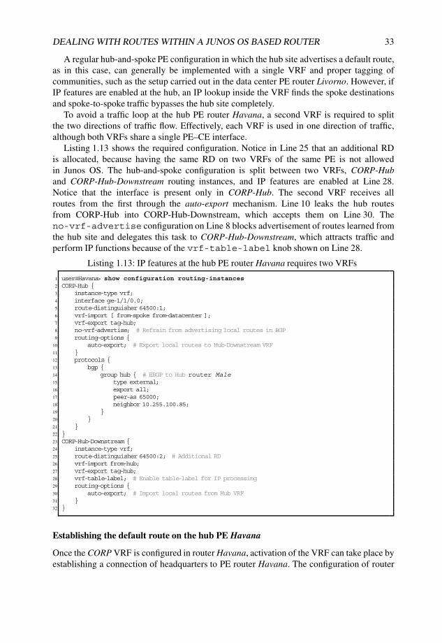
DEALING WITH ROUTES WITHIN A JUNOS OS BASED ROUTER 33
A regular hub-and-spoke PE configuration in which the hub site advertises a default route,as in this case, can generally be implemented with a single VRF and proper tagging ofcommunities, such as the setup carried out in the data center PE router Livorno. However, ifIP features are enabled at the hub, an IP lookup inside the VRF finds the spoke destinationsand spoke-to-spoke traffic bypasses the hub site completely.
To avoid a traffic loop at the hub PE router Havana, a second VRF is required to splitthe two directions of traffic flow. Effectively, each VRF is used in one direction of traffic,although both VRFs share a single PE–CE interface.
Listing 1.13 shows the required configuration. Notice in Line 25 that an additional RDis allocated, because having the same RD on two VRFs of the same PE is not allowedin Junos OS. The hub-and-spoke configuration is split between two VRFs, CORP-Huband CORP-Hub-Downstream routing instances, and IP features are enabled at Line 28.Notice that the interface is present only in CORP-Hub. The second VRF receives allroutes from the first through the auto-export mechanism. Line 10 leaks the hub routesfrom CORP-Hub into CORP-Hub-Downstream, which accepts them on Line 30. Theno-vrf-advertise configuration on Line 8 blocks advertisement of routes learned fromthe hub site and delegates this task to CORP-Hub-Downstream, which attracts traffic andperform IP functions because of the vrf-table-label knob shown on Line 28.
Listing 1.13: IP features at the hub PE router Havana requires two VRFs
1 user@Havana> show configuration routing-instances2 CORP-Hub {3 instance-type vrf;4 interface ge-1/1/0.0;5 route-distinguisher 64500:1;6 vrf-import [ from-spoke from-datacenter ];7 vrf-export tag-hub;8 no-vrf-advertise; # Refrain from advertising local routes in BGP9 routing-options {
10 auto-export; # Export local routes to Hub-Downstream VRF11 }12 protocols {13 bgp {14 group hub { # EBGP to Hub router Male15 type external;16 export all;17 peer-as 65000;18 neighbor 10.255.100.85;19 }20 }21 }22 }23 CORP-Hub-Downstream {24 instance-type vrf;25 route-distinguisher 64500:2; # Additional RD26 vrf-import from-hub;27 vrf-export tag-hub;28 vrf-table-label; # Enable table-label for IP processing29 routing-options {30 auto-export; # Import local routes from Hub VRF31 }32 }
Establishing the default route on the hub PE Havana
Once the CORP VRF is configured in router Havana, activation of the VRF can take place byestablishing a connection of headquarters to PE router Havana. The configuration of router
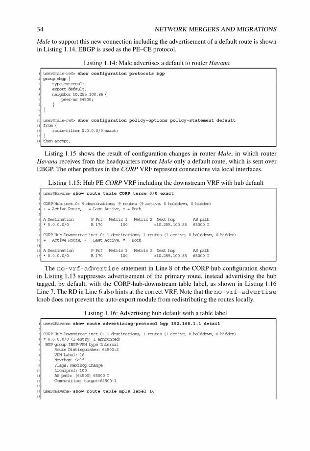
34 NETWORK MERGERS AND MIGRATIONS
Male to support this new connection including the advertisement of a default route is shownin Listing 1.14. EBGP is used as the PE–CE protocol.
Listing 1.14: Male advertises a default to router Havana
1 user@male-re0> show configuration protocols bgp2 group ebgp {3 type external;4 export default;5 neighbor 10.255.100.86 {6 peer-as 64500;7 }8 }9
10 user@male-re0> show configuration policy-options policy-statement default11 from {12 route-filter 0.0.0.0/0 exact;13 }14 then accept;
Listing 1.15 shows the result of configuration changes in router Male, in which routerHavana receives from the headquarters router Male only a default route, which is sent overEBGP. The other prefixes in the CORP VRF represent connections via local interfaces.
Listing 1.15: Hub PE CORP VRF including the downstream VRF with hub default
1 user@Havana> show route table CORP terse 0/0 exact2
3 CORP-Hub.inet.0: 9 destinations, 9 routes (9 active, 0 holddown, 0 hidden)4 + = Active Route, - = Last Active, * = Both5
6 A Destination P Prf Metric 1 Metric 2 Next hop AS path7 * 0.0.0.0/0 B 170 100 >10.255.100.85 65000 I8
9 CORP-Hub-Downstream.inet.0: 1 destinations, 1 routes (1 active, 0 holddown, 0 hidden)10 + = Active Route, - = Last Active, * = Both11
12 A Destination P Prf Metric 1 Metric 2 Next hop AS path13 * 0.0.0.0/0 B 170 100 >10.255.100.85 65000 I
The no-vrf-advertise statement in Line 8 of the CORP-hub configuration shownin Listing 1.13 suppresses advertisement of the primary route, instead advertising the hubtagged, by default, with the CORP-hub-downstream table label, as shown in Listing 1.16Line 7. The RD in Line 6 also hints at the correct VRF. Note that the no-vrf-advertiseknob does not prevent the auto-export module from redistributing the routes locally.
Listing 1.16: Advertising hub default with a table label
1 user@Havana> show route advertising-protocol bgp 192.168.1.1 detail2
3 CORP-Hub-Downstream.inet.0: 1 destinations, 1 routes (1 active, 0 holddown, 0 hidden)4 * 0.0.0.0/0 (1 entry, 1 announced)5 BGP group IBGP-VPN type Internal6 Route Distinguisher: 64500:27 VPN Label: 168 Nexthop: Self9 Flags: Nexthop Change
10 Localpref: 10011 AS path: [64500] 65000 I12 Communities: target:64500:113
14 user@Havana> show route table mpls label 1615
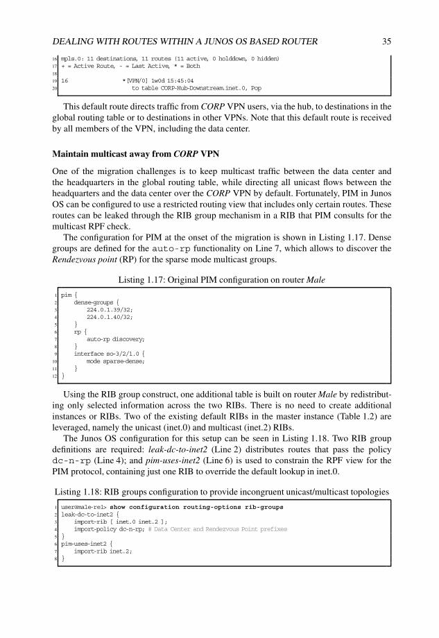
DEALING WITH ROUTES WITHIN A JUNOS OS BASED ROUTER 35
16 mpls.0: 11 destinations, 11 routes (11 active, 0 holddown, 0 hidden)17 + = Active Route, - = Last Active, * = Both18
19 16 *[VPN/0] 1w0d 15:45:0420 to table CORP-Hub-Downstream.inet.0, Pop
This default route directs traffic from CORP VPN users, via the hub, to destinations in theglobal routing table or to destinations in other VPNs. Note that this default route is receivedby all members of the VPN, including the data center.
Maintain multicast away from CORP VPN
One of the migration challenges is to keep multicast traffic between the data center andthe headquarters in the global routing table, while directing all unicast flows between theheadquarters and the data center over the CORP VPN by default. Fortunately, PIM in JunosOS can be configured to use a restricted routing view that includes only certain routes. Theseroutes can be leaked through the RIB group mechanism in a RIB that PIM consults for themulticast RPF check.
The configuration for PIM at the onset of the migration is shown in Listing 1.17. Densegroups are defined for the auto-rp functionality on Line 7, which allows to discover theRendezvous point (RP) for the sparse mode multicast groups.
Listing 1.17: Original PIM configuration on router Male
1 pim {2 dense-groups {3 224.0.1.39/32;4 224.0.1.40/32;5 }6 rp {7 auto-rp discovery;8 }9 interface so-3/2/1.0 {
10 mode sparse-dense;11 }12 }
Using the RIB group construct, one additional table is built on router Male by redistribut-ing only selected information across the two RIBs. There is no need to create additionalinstances or RIBs. Two of the existing default RIBs in the master instance (Table 1.2) areleveraged, namely the unicast (inet.0) and multicast (inet.2) RIBs.
The Junos OS configuration for this setup can be seen in Listing 1.18. Two RIB groupdefinitions are required: leak-dc-to-inet2 (Line 2) distributes routes that pass the policydc-n-rp (Line 4); and pim-uses-inet2 (Line 6) is used to constrain the RPF view for thePIM protocol, containing just one RIB to override the default lookup in inet.0.
Listing 1.18: RIB groups configuration to provide incongruent unicast/multicast topologies
1 user@male-re1> show configuration routing-options rib-groups2 leak-dc-to-inet2 {3 import-rib [ inet.0 inet.2 ];4 import-policy dc-n-rp; # Data Center and Rendezvous Point prefixes5 }6 pim-uses-inet2 {7 import-rib inet.2;8 }
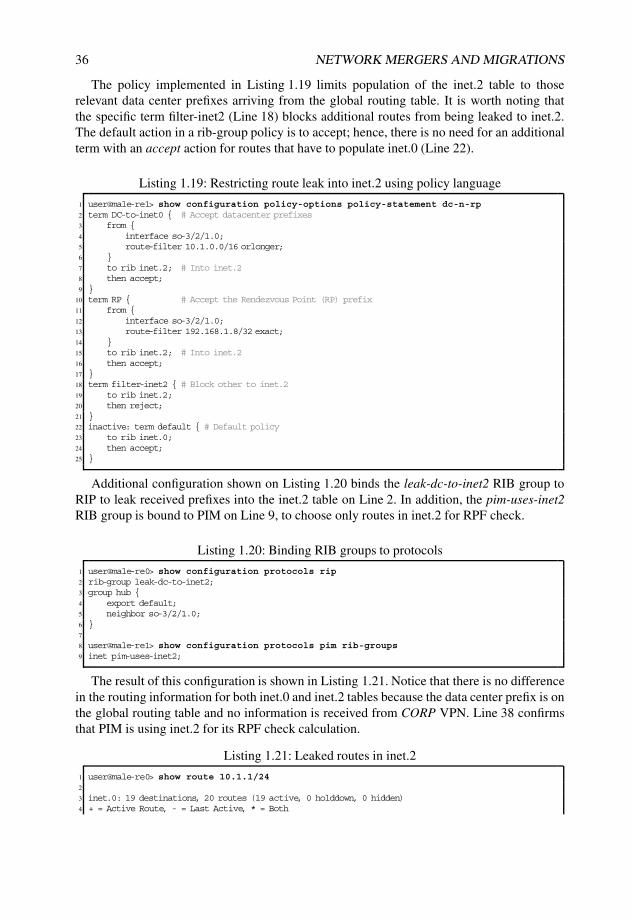
36 NETWORK MERGERS AND MIGRATIONS
The policy implemented in Listing 1.19 limits population of the inet.2 table to thoserelevant data center prefixes arriving from the global routing table. It is worth noting thatthe specific term filter-inet2 (Line 18) blocks additional routes from being leaked to inet.2.The default action in a rib-group policy is to accept; hence, there is no need for an additionalterm with an accept action for routes that have to populate inet.0 (Line 22).
Listing 1.19: Restricting route leak into inet.2 using policy language
1 user@male-re1> show configuration policy-options policy-statement dc-n-rp2 term DC-to-inet0 { # Accept datacenter prefixes3 from {4 interface so-3/2/1.0;5 route-filter 10.1.0.0/16 orlonger;6 }7 to rib inet.2; # Into inet.28 then accept;9 }
10 term RP { # Accept the Rendezvous Point (RP) prefix11 from {12 interface so-3/2/1.0;13 route-filter 192.168.1.8/32 exact;14 }15 to rib inet.2; # Into inet.216 then accept;17 }18 term filter-inet2 { # Block other to inet.219 to rib inet.2;20 then reject;21 }22 inactive: term default { # Default policy23 to rib inet.0;24 then accept;25 }
Additional configuration shown on Listing 1.20 binds the leak-dc-to-inet2 RIB group toRIP to leak received prefixes into the inet.2 table on Line 2. In addition, the pim-uses-inet2RIB group is bound to PIM on Line 9, to choose only routes in inet.2 for RPF check.
Listing 1.20: Binding RIB groups to protocols
1 user@male-re0> show configuration protocols rip2 rib-group leak-dc-to-inet2;3 group hub {4 export default;5 neighbor so-3/2/1.0;6 }7
8 user@male-re1> show configuration protocols pim rib-groups9 inet pim-uses-inet2;
The result of this configuration is shown in Listing 1.21. Notice that there is no differencein the routing information for both inet.0 and inet.2 tables because the data center prefix is onthe global routing table and no information is received from CORP VPN. Line 38 confirmsthat PIM is using inet.2 for its RPF check calculation.
Listing 1.21: Leaked routes in inet.2
1 user@male-re0> show route 10.1.1/242
3 inet.0: 19 destinations, 20 routes (19 active, 0 holddown, 0 hidden)4 + = Active Route, - = Last Active, * = Both

DEALING WITH ROUTES WITHIN A JUNOS OS BASED ROUTER 37
5
6 10.1.1.0/24 *[RIP/100] 01:05:32, metric 2, tag 17 > to 10.255.100.78 via so-3/2/1.08 10.1.1.21/32 *[RIP/100] 01:05:32, metric 2, tag 09 > to 10.255.100.78 via so-3/2/1.0
10 10.1.1.88/30 *[RIP/100] 01:05:32, metric 2, tag 011 > to 10.255.100.78 via so-3/2/1.012
13 inet.2: 4 destinations, 4 routes (4 active, 0 holddown, 0 hidden)14 + = Active Route, - = Last Active, * = Both15
16 10.1.1.0/24 *[RIP/100] 00:00:14, metric 2, tag 117 > to 10.255.100.78 via so-3/2/1.018 10.1.1.21/32 *[RIP/100] 00:00:14, metric 2, tag 019 > to 10.255.100.78 via so-3/2/1.020 10.1.1.88/30 *[RIP/100] 00:00:14, metric 2, tag 021 > to 10.255.100.78 via so-3/2/1.022
23 user@male-re0> show route 192.168.1.8/3224
25 inet.0: 19 destinations, 20 routes (19 active, 0 holddown, 0 hidden)26 + = Active Route, - = Last Active, * = Both27
28 192.168.1.8/32 *[RIP/100] 02:44:25, metric 2, tag 029 > to 10.255.100.78 via so-3/2/1.030
31 inet.2: 4 destinations, 4 routes (4 active, 0 holddown, 0 hidden)32 + = Active Route, - = Last Active, * = Both33
34 192.168.1.8/32 *[RIP/100] 00:00:22, metric 2, tag 035 > to 10.255.100.78 via so-3/2/1.036
37 user@male-re0> show multicast rpf38 Multicast RPF table: inet.2 , 4 entries39
40 10.1.1.0/2441 Protocol: RIP42 Interface: so-3/2/1.043 Neighbor: 10.255.100.7844
45 10.1.1.21/3246 Protocol: RIP47 Interface: so-3/2/1.048 Neighbor: 10.255.100.7849
50 10.1.1.88/3051 Protocol: RIP52 Interface: so-3/2/1.053 Neighbor: 10.255.100.7854
55 192.168.1.8/3256 Protocol: RIP57 Interface: so-3/2/1.058 Neighbor: 10.255.100.78
Verification of the implemented changes to separate multicast traffic from the CORP VRFis discussed in Section 1.4.8.
1.4.7 Stage four: Preparatory work at the data center
Lack of a separate interconnect from the data center to the CORP VPN introduces additionalcomplexity because a single access interface shares traffic for both the global routing tableand the VPN. During the migration process, the data center access interface has to be

38 NETWORK MERGERS AND MIGRATIONS
homed to both the global routing table and the CORP VRF to serve all spoke sites withno intervention from headquarters.
No changes are required in the configuration of the data denter router Honolulu becausethe data center is unaware of the changes to become part of a VPN. Preparatory steps at thedata center PE router Livorno follow:
• configuration for router Livorno as data center PE with single attachment;
• access from all user sites to the data center;
• access from the data center to reach both migrated and non-migrated user sites.
Data center PE configuration
The initial configuration on the PE router Livorno related to the protocols on the globalrouting table is shown in Listing 1.22. Besides the backbone OSPF area (Line 15), routerLivorno acts as ABR for the data center, sited in NSSA area 1 (Line 24). The access to routerBarcelona using RIP routing is configured in Line 34.
Listing 1.22: Router Livorno initial protocol configuration
1 user@Livorno> show configuration protocols2 mpls { # MPLS core interfaces3 <...>4 }5 bgp { # L3VPN BGP session to the reflector Nantes6 group IBGP-VPN {7 type internal;8 local-address 192.168.1.6;9 family inet-vpn {
10 unicast;11 }12 neighbor 192.168.1.1;13 }14 }15 ospf {16 area 0.0.0.0 { # Backbone OSPF17 interface fxp0.0 {18 disable;19 }20 interface so-0/0/0.0;21 interface so-0/0/1.0;22 interface lo0.0;23 }24 area 0.0.0.1 { # Data Center NSSA Area 125 nssa {26 default-lsa default-metric 1;27 no-summaries;28 }29 interface ge-1/3/0.0;30 }31 }32 ldp { # LDP for MPLS transport tunnels33 <...>34 rip { # RIP to site Barcelona35 group BCN {36 export default;37 neighbor ge-0/2/0.0;38 }39 }

DEALING WITH ROUTES WITHIN A JUNOS OS BASED ROUTER 39
Listing 1.23 provides the preliminary configuration of router Livorno with the globalrouting table protocols and a newly instantiated CORP VRF. The data center PE routerLivorno also homes regular spoke sites like router Barcelona, which is reflected in theconfiguration by having a mixed RT vrf-import (Line 9) and vrf-export (Line 10)policy and additional RIP protocol configuration for the spoke interface (Line 33).
Listing 1.23: Interim configuration for CORP VRF in data center PE router Livorno
1 user@Livorno# show routing-instances CORP2 ##3 ## inactive: routing-instances4 ##5 instance-type vrf;6 interface ge-1/3/0.0;7 interface ge-0/2/0.0;8 route-distinguisher 64500:1;9 vrf-import [ from-critical from-hub ];
10 vrf-export [ tag-datacenter tag-spoke ];11 routing-options {12 inactive: interface-routes {13 rib-group inet leak-to-inet0;14 }15 inactive: auto-export {16 family inet {17 unicast {18 inactive: rib-group leak-to-inet0;19 }20 }21 }22 }23 protocols {24 inactive: ospf {25 area 0.0.0.1 {26 nssa {27 default-lsa default-metric 1;28 no-summaries;29 }30 interface ge-1/3/0.0;31 }32 }33 inactive: rip {34 group BCN {35 export default;36 neighbor ge-0/2/0.0;37 }38 }39 }
Notice the inactive: statement for the VRF as a whole, as well as in Line 12, Line 15, andLine 18. These portions of the configuration will be activated in following stages to illustratethe impact in populating the routing table.
The RIB group reference in Line 18 of Listing 1.23 corresponds to the configurationin Listing 1.24 that includes a policy to leak only the data center interface, but not otherinterfaces belonging to spoke sites connected on the same PE. Note that the default action forthe RIB group policy is to accept all routes. Hence, the CORP VRF is populated correctlywithout requiring a specific term in the policy that accepts routes in order to leak them intoCORP.inet.0.
Listing 1.24: Interface leaking rib-group configuration
1 [edit]2 user@Livorno# show routing-options rib-groups
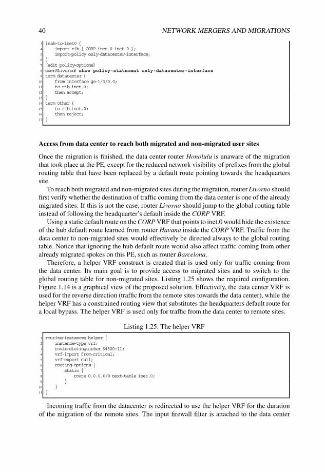
40 NETWORK MERGERS AND MIGRATIONS
3 leak-to-inet0 {4 import-rib [ CORP.inet.0 inet.0 ];5 import-policy only-datacenter-interface;6 }7 [edit policy-options]8 user@Livorno# show policy-statement only-datacenter-interface9 term datacenter {
10 from interface ge-1/3/0.0;11 to rib inet.0;12 then accept;13 }14 term other {15 to rib inet.0;16 then reject;17 }
Access from data center to reach both migrated and non-migrated user sites
Once the migration is finished, the data center router Honolulu is unaware of the migrationthat took place at the PE, except for the reduced network visibility of prefixes from the globalrouting table that have been replaced by a default route pointing towards the headquarterssite.
To reach both migrated and non-migrated sites during the migration, router Livorno shouldfirst verify whether the destination of traffic coming from the data center is one of the alreadymigrated sites. If this is not the case, router Livorno should jump to the global routing tableinstead of following the headquarter’s default inside the CORP VRF.
Using a static default route on the CORP VRF that points to inet.0 would hide the existenceof the hub default route learned from router Havana inside the CORP VRF. Traffic from thedata center to non-migrated sites would effectively be directed always to the global routingtable. Notice that ignoring the hub default route would also affect traffic coming from otheralready migrated spokes on this PE, such as router Barcelona.
Therefore, a helper VRF construct is created that is used only for traffic coming fromthe data center. Its main goal is to provide access to migrated sites and to switch to theglobal routing table for non-migrated sites. Listing 1.25 shows the required configuration.Figure 1.14 is a graphical view of the proposed solution. Effectively, the data center VRF isused for the reverse direction (traffic from the remote sites towards the data center), while thehelper VRF has a constrained routing view that substitutes the headquarters default route fora local bypass. The helper VRF is used only for traffic from the data center to remote sites.
Listing 1.25: The helper VRF
1 routing-instances helper {2 instance-type vrf;3 route-distinguisher 64500:11;4 vrf-import from-critical;5 vrf-export null;6 routing-options {7 static {8 route 0.0.0.0/0 next-table inet.0;9 }
10 }11 }
Incoming traffic from the datacenter is redirected to use the helper VRF for the durationof the migration of the remote sites. The input firewall filter is attached to the data center
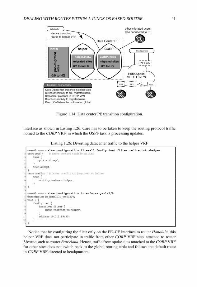
DEALING WITH ROUTES WITHIN A JUNOS OS BASED ROUTER 41
Hub&SpokeMPLS L3VPN
PE1 PE2 PE20
PEHub
Data Center PE
DataCenter
HeadQuarters
Keep Datacenter presence in global table
Direct connectivity to pre−migrated users
Datacenter presence in CORP VPN
Direct connectivity to migrated users
Keep HQ−Datacenter multicast on global
Transient connectivity
CORP.inet.0helper.inet.0
0/0 to inet.0 0/0 to HQ
0/0 to HQ
migrated sitesmigrated sites
pre
−m
igra
ted
sit
es
inet.0 CORPhelper
derive incoming
traffic to helper VRF
other migrated users
also connected to PE
Figure 1.14: Data center PE transition configuration.
interface as shown in Listing 1.26. Care has to be taken to keep the routing protocol traffichomed to the CORP VRF, in which the OSPF task is processing updates.
Listing 1.26: Diverting datacenter traffic to the helper VRF
1 user@Livorno> show configuration firewall family inet filter redirect-to-helper2 term ospf { # Leave control traffic on CORP3 from {4 protocol ospf;5 }6 then accept;7 }8 term traffic { # Other traffic to jump over to helper9 then {
10 routing-instance helper;11 }12 }13
14 user@Livorno> show configuration interfaces ge-1/3/015 description To_Honolulu_ge-5/2/0;16 unit 0 {17 family inet {18 inactive: filter {19 input redirect-to-helper;20 }21 address 10.1.1.89/30;22 }23 }
Notice that by configuring the filter only on the PE–CE interface to router Honolulu, thishelper VRF does not participate in traffic from other CORP VRF sites attached to routerLivorno such as router Barcelona. Hence, traffic from spoke sites attached to the CORP VRFfor other sites does not switch back to the global routing table and follows the default routein CORP VRF directed to headquarters.

42 NETWORK MERGERS AND MIGRATIONS
Maintaining access from all user sites to the data center
After the data center interface moves, data center visibility must be maintained simultane-ously on both the CORP VPN and the global table for the duration of the migration. Routinginformation that must be duplicated is both the local interface and the data center addressinglearned from OSPF.
Using RIB groups on the PE–CE side as configured in Listing 1.23 on Page 39 offers aperfect solution for this need. As seen in Line 12, it is ensured that the interface is visible inboth the CORP VRF and in the global routing table. The activation of the auto-export featurewith rib-groups (Line 15 and Line 18) triggers leaking of the data center prefixes towards themain table inet.0. More details of the activation are discussed in Section 1.4.8.
Redistribute OSPF area 1 into OSPF backbone
Although the leaking configuration effectively installs the data center OSPF routes intothe main table, the OSPF task running on the main instance considers these routes as notbelonging to its own task and does not incorporate them into its link-state database bydefault; that is, these routes are of protocol OSPF, but router Livorno is not an ABR afterthe interface move. The behavior differs from that of the old network, in which the Area 1NSSA Type 7 LSAs were automatically translated into Type 5 LSAs as part of the ABRfunction from [RFC2328].
Listing 1.27 shows the additional configuration required to export the data center routespresent in the main instance so as to propagate them into the OSPF core.
Listing 1.27: Exporting data center OSPF routes to backbone OSPF
1 user@Livorno> show configuration protocols ospf | compare rollback 12 + export datacenter; # Required to inject datacenter OSPF routes3 user@Livorno> show configuration policy-options policy-statement datacenter4 from {5 inactive: protocol ospf;6 interface ge-1/3/0.0;7 }8 then {9 tag 1000;
10 accept;11 }
1.4.8 Stage five: Move of data center site to CORP VRF
Moving the data center interface into the CORP VFR provides direct access from the datacenter to already migrated sites. The data center receives a default route from the hub,which is sufficient to reach the CORP VRF at router Livorno. The CORP VRF at routerLivorno contains more specific information that is learned from other PEs advertising routinginformation that belong to critical prefixes at spoke sites.
Note Before performing this step, to avoid breaking the multicast replication flows betweenthe hub and the data center, preparatory work at the hub CE router Male has separated theunicast and multicast RIBs, as discussed in Section 1.4.6.
The most critical stage in this migration is the move of the PE–CE interface of the datacenter. All destinations must keep connectivity to the data center in both directions (from
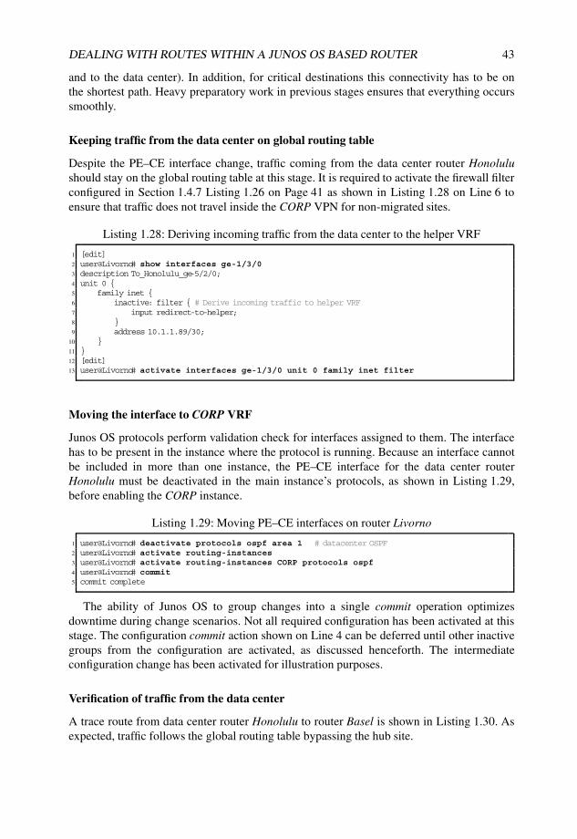
DEALING WITH ROUTES WITHIN A JUNOS OS BASED ROUTER 43
and to the data center). In addition, for critical destinations this connectivity has to be onthe shortest path. Heavy preparatory work in previous stages ensures that everything occurssmoothly.
Keeping traffic from the data center on global routing table
Despite the PE–CE interface change, traffic coming from the data center router Honolulushould stay on the global routing table at this stage. It is required to activate the firewall filterconfigured in Section 1.4.7 Listing 1.26 on Page 41 as shown in Listing 1.28 on Line 6 toensure that traffic does not travel inside the CORP VPN for non-migrated sites.
Listing 1.28: Deriving incoming traffic from the data center to the helper VRF
1 [edit]2 user@Livorno# show interfaces ge-1/3/03 description To_Honolulu_ge-5/2/0;4 unit 0 {5 family inet {6 inactive: filter { # Derive incoming traffic to helper VRF7 input redirect-to-helper;8 }9 address 10.1.1.89/30;
10 }11 }12 [edit]13 user@Livorno# activate interfaces ge-1/3/0 unit 0 family inet filter
Moving the interface to CORP VRF
Junos OS protocols perform validation check for interfaces assigned to them. The interfacehas to be present in the instance where the protocol is running. Because an interface cannotbe included in more than one instance, the PE–CE interface for the data center routerHonolulu must be deactivated in the main instance’s protocols, as shown in Listing 1.29,before enabling the CORP instance.
Listing 1.29: Moving PE–CE interfaces on router Livorno
1 user@Livorno# deactivate protocols ospf area 1 # datacenter OSPF2 user@Livorno# activate routing-instances3 user@Livorno# activate routing-instances CORP protocols ospf4 user@Livorno# commit5 commit complete
The ability of Junos OS to group changes into a single commit operation optimizesdowntime during change scenarios. Not all required configuration has been activated at thisstage. The configuration commit action shown on Line 4 can be deferred until other inactivegroups from the configuration are activated, as discussed henceforth. The intermediateconfiguration change has been activated for illustration purposes.
Verification of traffic from the data center
A trace route from data center router Honolulu to router Basel is shown in Listing 1.30. Asexpected, traffic follows the global routing table bypassing the hub site.

44 NETWORK MERGERS AND MIGRATIONS
Listing 1.30: Traffic from router Honolulu to router Basel
1 user@honolulu-re0> traceroute 10.100.1.10 source 10.1.1.212 traceroute to 10.100.1.10 (10.100.1.10) from 10.1.1.21, 30 hops max, 40 byte packets3 1 livorno-ge1300 (10.1.1.89) 0.499 ms 0.417 ms 0.402 ms4 2 skopie-so1000 (172.16.1.33) 0.511 ms 0.462 ms 0.472 ms5 3 nantes-so0100 (172.16.1.1) 0.521 ms 0.461 ms 0.469 ms6 4 torino-so0100 (172.16.1.97) 0.571 ms 0.488 ms 0.491 ms7 5 basel (10.100.1.10) 1.500 ms 1.383 ms 1.579 ms
What If... Data center traffic bypassing the helper table
Listing 1.31 illustrates how traffic entering the PE–CE interface from the data center that isnot derived to the helper VRF with a firewall filter (Line 1) follows the default route insidethe CORP VRF (Line 8). The trace route on Line 12 confirms that traffic is taking a detourover router Male, which is undesired.
Listing 1.31: Traffic from router Honolulu to router Basel
1 user@Livorno# deactivate interfaces ge-1/3/0 unit 0 family inet filter input2
3 user@Livorno> show route table CORP 10.100.1.104
5 CORP.inet.0: 11 destinations, 11 routes (11 active, 0 holddown, 0 hidden)6 + = Active Route, - = Last Active, * = Both7
8 0.0.0.0/0 *[BGP/170] 00:00:37, localpref 100, from 192.168.1.19 AS path: 65000 I
10 > via so-0/0/1.0, Push 30150411
12 user@honolulu-re0> traceroute 10.100.1.10 source 10.1.1.2113 traceroute to 10.100.1.10 (10.100.1.10) from 10.1.1.21, 30 hops max, 40 byte packets14 1 livorno-ge1300 (10.1.1.89) 0.496 ms 0.419 ms 0.399 ms15 2 havana-so1000 (172.16.1.37) 0.721 ms 0.594 ms 0.589 ms16 MPLS Label=301504 CoS=0 TTL=1 S=117 3 male-ge4240 (10.255.100.85) 0.369 ms 0.311 ms 0.311 ms18 4 bilbao-so1310 (10.255.100.78) 0.503 ms 0.519 ms 0.483 ms19 5 torino-at0010 (172.16.1.101) 0.649 ms 0.881 ms 1.004 ms20 6 basel (10.100.1.10) 1.770 ms 1.467 ms 1.493 ms
The current CORP VRF configuration (still containing inactive statements for the leakingconfiguration) yields a routing table with data center prefixes as shown in Listing 1.32. Noticethat by moving the PE–CE interface, the data center prefixes are not available on the globaltable anymore.
Listing 1.32: Data center address space after moving the PE–CE interface
1 user@Livorno> show route 10.1/16 terse2
3 CORP.inet.0: 12 destinations, 12 routes (12 active, 0 holddown, 0 hidden)4 + = Active Route, - = Last Active, * = Both5
6 A Destination P Prf Metric 1 Metric 2 Next hop AS path7 * 10.1.1.0/24 O 150 0 >10.1.1.908 * 10.1.1.21/32 O 150 0 >10.1.1.909 * 10.1.1.88/30 D 0 >ge-1/3/0.0
10 * 10.1.1.89/32 L 0 Local
Listing 1.33 shows the address space of the data center at the data center PE router Livornoafter enabling the RIB group configuration for the data center interface.
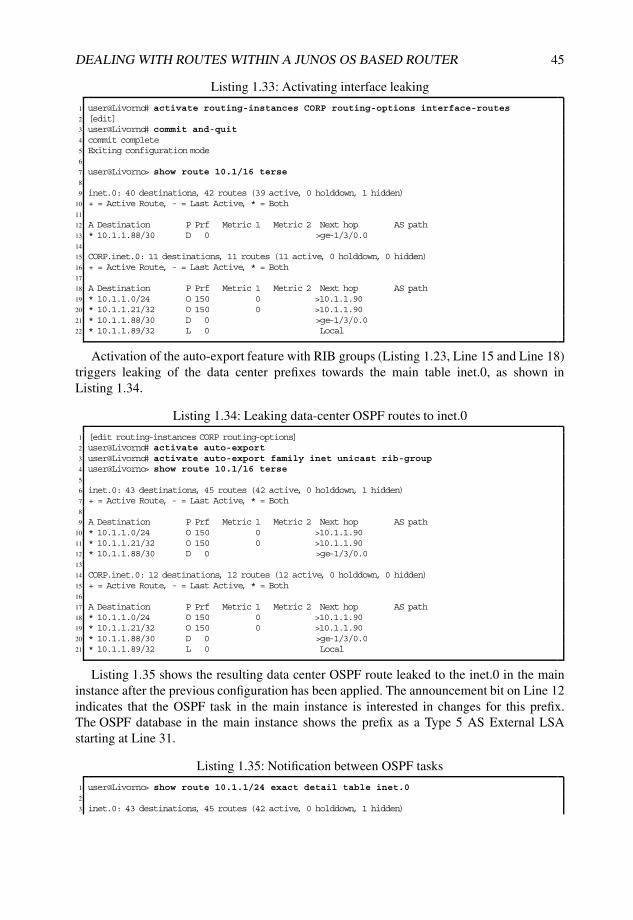
DEALING WITH ROUTES WITHIN A JUNOS OS BASED ROUTER 45
Listing 1.33: Activating interface leaking
1 user@Livorno# activate routing-instances CORP routing-options interface-routes2 [edit]3 user@Livorno# commit and-quit4 commit complete5 Exiting configuration mode6
7 user@Livorno> show route 10.1/16 terse8
9 inet.0: 40 destinations, 42 routes (39 active, 0 holddown, 1 hidden)10 + = Active Route, - = Last Active, * = Both11
12 A Destination P Prf Metric 1 Metric 2 Next hop AS path13 * 10.1.1.88/30 D 0 >ge-1/3/0.014
15 CORP.inet.0: 11 destinations, 11 routes (11 active, 0 holddown, 0 hidden)16 + = Active Route, - = Last Active, * = Both17
18 A Destination P Prf Metric 1 Metric 2 Next hop AS path19 * 10.1.1.0/24 O 150 0 >10.1.1.9020 * 10.1.1.21/32 O 150 0 >10.1.1.9021 * 10.1.1.88/30 D 0 >ge-1/3/0.022 * 10.1.1.89/32 L 0 Local
Activation of the auto-export feature with RIB groups (Listing 1.23, Line 15 and Line 18)triggers leaking of the data center prefixes towards the main table inet.0, as shown inListing 1.34.
Listing 1.34: Leaking data-center OSPF routes to inet.0
1 [edit routing-instances CORP routing-options]2 user@Livorno# activate auto-export3 user@Livorno# activate auto-export family inet unicast rib-group4 user@Livorno> show route 10.1/16 terse5
6 inet.0: 43 destinations, 45 routes (42 active, 0 holddown, 1 hidden)7 + = Active Route, - = Last Active, * = Both8
9 A Destination P Prf Metric 1 Metric 2 Next hop AS path10 * 10.1.1.0/24 O 150 0 >10.1.1.9011 * 10.1.1.21/32 O 150 0 >10.1.1.9012 * 10.1.1.88/30 D 0 >ge-1/3/0.013
14 CORP.inet.0: 12 destinations, 12 routes (12 active, 0 holddown, 0 hidden)15 + = Active Route, - = Last Active, * = Both16
17 A Destination P Prf Metric 1 Metric 2 Next hop AS path18 * 10.1.1.0/24 O 150 0 >10.1.1.9019 * 10.1.1.21/32 O 150 0 >10.1.1.9020 * 10.1.1.88/30 D 0 >ge-1/3/0.021 * 10.1.1.89/32 L 0 Local
Listing 1.35 shows the resulting data center OSPF route leaked to the inet.0 in the maininstance after the previous configuration has been applied. The announcement bit on Line 12indicates that the OSPF task in the main instance is interested in changes for this prefix.The OSPF database in the main instance shows the prefix as a Type 5 AS External LSAstarting at Line 31.
Listing 1.35: Notification between OSPF tasks
1 user@Livorno> show route 10.1.1/24 exact detail table inet.02
3 inet.0: 43 destinations, 45 routes (42 active, 0 holddown, 1 hidden)

46 NETWORK MERGERS AND MIGRATIONS
4 10.1.1.0/24 (1 entry, 1 announced)5 *OSPF Preference: 1506 Next hop type: Router, Next hop index: 6317 Next-hop reference count: 98 Next hop: 10.1.1.90 via ge-1/3/0.0, selected9 State: <Secondary Active Int Ext>
10 Age: 9:38 Metric: 0 Tag: 111 Task: CORP-OSPF12 Announcement bits (3): 0-KRT 2-OSPF 4-LDP13 AS path: I14 Communities: target:64500:2 target:64500:10 rte-type:0.0.0.1:5:115 Primary Routing Table CORP.inet.016
17 user@Livorno> show ospf database18
19 OSPF database, Area 0.0.0.020 Type ID Adv Rtr Seq Age Opt Cksum Len21 Router 192.168.1.1 192.168.1.1 0x80000010 2392 0x22 0xb9c0 9622 Router 192.168.1.2 192.168.1.2 0x80000205 1502 0x22 0x2345 9623 Router 192.168.1.3 192.168.1.3 0x8000000b 2316 0x22 0x72cf 8424 Router 192.168.1.4 192.168.1.4 0x8000000a 646 0x22 0x5bd2 8425 Router *192.168.1.6 192.168.1.6 0x80000283 4 0x22 0x586a 8426 Router 192.168.1.8 192.168.1.8 0x8000000b 744 0x22 0xe629 9627 Network 172.16.1.5 192.168.1.8 0x80000008 1537 0x22 0xa87a 3228 OSPF AS SCOPE link state database29 Type ID Adv Rtr Seq Age Opt Cksum Len30 Extern 0.0.0.0 192.168.1.8 0x80000007 2373 0x22 0xc572 3631 Extern *10.1.1.0 192.168.1.6 0x80000001 4 0x22 0xc386 3632 Extern *10.1.1.21 192.168.1.6 0x80000001 4 0x22 0xf044 3633 Extern *10.1.1.88 192.168.1.6 0x80000001 4 0x22 0x3eb6 3634 Extern 10.100.1.0 192.168.1.3 0x80000009 1550 0x22 0x526f 3635 Extern 10.100.1.10 192.168.1.3 0x80000008 712 0x22 0xefc8 3636 Extern 10.200.1.0 192.168.1.1 0x80000005 1598 0x22 0xb1b1 3637 Extern 10.200.1.9 192.168.1.1 0x80000005 824 0x22 0x5703 36
Connectivity verification towards the data center
Taking a not-yet migrated user site (router Basel), verification of direct communication to thedata center is confirmed on Listing 1.36. Traffic bypasses the hub completely.
Listing 1.36: Basel correctly reaches data center in CORP VPN over global table
1 user@Basel> traceroute honolulu source basel2 traceroute to honolulu (10.1.1.21) from basel, 30 hops max, 40 byte packets3 1 torino-at1201001 (10.100.1.81) 1.424 ms 0.892 ms 0.941 ms4 2 nantes-so0200 (172.16.1.98) 0.922 ms 1.143 ms 0.934 ms5 3 skopie-so0100 (172.16.1.2) 0.953 ms 1.147 ms 0.943 ms6 4 livorno-so0000 (172.16.1.34) 1.447 ms 1.708 ms 1.434 ms7 5 honolulu (10.1.1.21) 1.469 ms 1.686 ms 1.428 ms
What If... Data center not visible in global routing table
If the OSPF redistribution were not taking place at router Livorno, router Basel wouldfollow the default route coming from router Male over the global routing table, as shown inListing 1.37. This additional latency is undesired for site-critical prefixes. Note that thetrace route hop 4 on Line 13 is the hub CE router Male. The MPLS label on Line 16indicates that the data center prefix is being advertised correctly to the hub, which isforwarding traffic over the CORP VRF.

DEALING WITH ROUTES WITHIN A JUNOS OS BASED ROUTER 47
Listing 1.37: With no OSPF redistribution, Basel follows the corporate default route
1 user@Livorno# deactivate protocols ospf export2
3 [edit]4 user@Livorno# commit and-quit5 commit complete6 Exiting configuration mode7
8 user@Basel> traceroute honolulu source basel9 traceroute to honolulu (10.1.1.21) from basel, 30 hops max, 40 byte packets
10 1 torino-at1201001 (10.100.1.81) 1.305 ms 0.899 ms 0.926 ms11 2 nantes-so0200 (172.16.1.98) 0.933 ms 1.137 ms 0.929 ms12 3 bilbao-ge0100 (172.16.1.5) 1.439 ms 1.741 ms 1.436 ms13 4 male-so3210 (10.255.100.77) 0.944 ms 1.151 ms 0.936 ms14 5 havana-ge1100 (10.255.100.86) 1.449 ms 1.714 ms 1.439 ms15 6 livorno-so0010 (172.16.1.38) 1.288 ms 1.028 ms 1.428 ms16 MPLS Label=300640 CoS=0 TTL=1 S=117 7 honolulu (10.1.1.21) 1.702 ms 1.709 ms 1.436 ms
Confirming multicast stays on global routing table
A key requirement of the migration is to maintain multicast on the global routing table. Thedata center prefix is propagated within the CORP VPN and eventually reaches the hub CErouter Male in which the special preparatory work carried out for multicast in Section 1.4.5prevents the use of the CORP VRF.
The data center prefix on router Male as seen in Listing 1.38 shows that the multicast RPFRIB contains only one RIP route coming from neighbor router Bilbao, while the unicast RIBinet.0 holds both the BGP route from router Havana (over CORP VPN) and the RIP routefrom router Bilbao. The RIP route has been configured with a worse preference (180) inorder that unicast traffic flows over the CORP VPN, if the destination is available. Becausethe inet.2 table has no BGP route, the RIP route is used, regardless of its preference. Thisscheme allows migrated user sites to use the CORP VPN in both directions, while keepingmulticast traffic on the global table.
Listing 1.38: Incongruent routing tables for unicast/multicast
1 user@male-re0> show route 10.1.1.0/24 terse2
3 inet.0: 20 destinations, 23 routes (20 active, 0 holddown, 0 hidden)4 + = Active Route, - = Last Active, * = Both5
6 A Destination P Prf Metric 1 Metric 2 Next hop AS path7 * 10.1.1.0/24 B 170 100 >10.255.100.86 64500 I # BGP route8 R 180 2 >10.255.100.78 # RIP route9 * 10.1.1.21/32 B 170 100 >10.255.100.86 64500 I # BGP route
10 R 180 2 >10.255.100.78 # RIP route11
12 inet.2: 3 destinations, 3 routes (3 active, 0 holddown, 0 hidden)13 + = Active Route, - = Last Active, * = Both14
15 A Destination P Prf Metric 1 Metric 2 Next hop AS path16 * 10.1.1.0/24 R 180 2 >10.255.100.7817 * 10.1.1.21/32 R 180 2 >10.255.100.7818
19 user@male-re0> show multicast rpf | match inet.220 Multicast RPF table: inet.2 , 4 entries
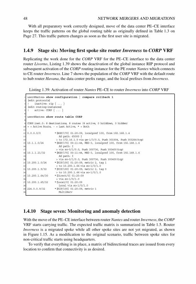
48 NETWORK MERGERS AND MIGRATIONS
With all preparatory work correctly designed, move of the data center PE–CE interfacekeeps the traffic patterns on the global routing table as originally defined in Table 1.3 onPage 27. This traffic pattern changes as soon as the first user site is migrated.
1.4.9 Stage six: Moving first spoke site router Inverness to CORP VRF
Replicating the work done for the CORP VRF for the PE–CE interface to the data centerrouter Livorno, Listing 1.39 shows the deactivation of the global instance RIP protocol andsubsequent activation of the CORP routing instance for the PE router Nantes which connectsto CE router Inverness. Line 7 shows the population of the CORP VRF with the default routeto hub router Havana, the data center prefix range, and the local prefixes from Inverness.
Listing 1.39: Activation of router Nantes PE–CE to router Inverness into CORP VRF
1 user@Nantes> show configuration | compare rollback 12 [edit protocols]3 ! inactive: rip { ... }4 [edit routing-instances]5 ! active: CORP { ... }6
7 user@Nantes> show route table CORP8
9 CORP.inet.0: 8 destinations, 8 routes (8 active, 0 holddown, 0 hidden)10 + = Active Route, - = Last Active, * = Both11
12 0.0.0.0/0 *[BGP/170] 01:20:09, localpref 100, from 192.168.1.413 AS path: 65000 I14 > to 172.16.1.5 via ge-1/3/0.0, Push 301504, Push 303264(top)15 10.1.1.0/24 *[BGP/170] 00:11:44, MED 0, localpref 100, from 192.168.1.616 AS path: I17 > via so-0/1/0.0, Push 300736, Push 300400(top)18 10.1.1.21/32 *[BGP/170] 00:11:44, MED 0, localpref 100, from 192.168.1.619 AS path: I20 > via so-0/1/0.0, Push 300736, Push 300400(top)21 10.200.1.0/24 *[RIP/100] 01:20:09, metric 2, tag 122 > to 10.200.1.66 via so-1/0/1.023 10.200.1.9/32 *[RIP/100] 01:20:09, metric 2, tag 024 > to 10.200.1.66 via so-1/0/1.025 10.200.1.64/30 *[Direct/0] 01:20:0926 > via so-1/0/1.027 10.200.1.65/32 *[Local/0] 01:20:0928 Local via so-1/0/1.029 224.0.0.9/32 *[RIP/100] 01:20:09, metric 130 MultiRecv
1.4.10 Stage seven: Monitoring and anomaly detection
With the move of the PE–CE interface between router Nantes and router Inverness, the CORPVRF starts carrying traffic. The expected traffic matrix is summarized in Table 1.5. RouterInverness is a migrated spoke while all other spoke sites are not yet migrated, as shownin Figure 1.15. As a modification to the original scenario, traffic between spoke sites fornon-critical traffic starts using headquarters.
To verify that everything is in place, a matrix of bidirectional traces are issued from everylocation to confirm that connectivity is as desired.

DEALING WITH ROUTES WITHIN A JUNOS OS BASED ROUTER 49
Table 1.5 Traffic flow matrix halfway through the migration
HQ DC NMS MS
Headquarters (HQ) Global Global CORPData Center (DC) Global Global CORPNon-Migrated Spoke (NMS) Global Global Global HubMigrated Spoke (MS) CORP CORP Hub CORP/hub
Connectivity between migrated spokes uses the CORP VRF via the hub.
Male
Bilbao
Havana
Nantes
Skopie
Livorno
Barcelona
Honolulu
192.168.1.4
10.255.100.20
192.168.1.8
192.168.1.1
192.168.1.2
192.168.1.6
10.50.1.7
10.1.1.21
Torino
10.200.1.9InvernessBasel
192.168.1.3
10.100.1.10
Data center
User spoke site
User spoke site User spoke site
OSPF NSSA
area 1
RIPRIP
RIP RIP
Corporate
Headquarters
Hub
site
MPLS
VPN.77
.86
.85
.78
172.16.1.96/30
.101
.5
.41
.42
.37 .38 .53.54
.89
.88
.34
.33
.6
10.100.1.82 10.200.1.66
10.200.1.6510.100.1.81
.102
.1
.2
Figure 1.15: Network topology after moving router Inverness.
Verification of hub-and-spoke behavior among spoke sites
Correct traffic distributions are verified between router Inverness and sample spoke site routerBasel in Listing 1.40. Because router Basel is not yet migrated, traffic from router Basel usesthe global routing table to reach the hub site router Male as shown starting at Line 1. Fromrouter Male, traffic is forwarded over the CORP VPN to the migrated router Inverness. Thereverse direction is shown starting at Line 14, in which traffic flows within the CORP VPNto reach the hub site router Male and continues its way over the global routing table to routerBasel.
Listing 1.40: Trace between router Inverness and router Basel relays over headquarters
1 user@Inverness> traceroute basel source inverness2 traceroute to basel (10.100.1.10) from inverness, 30 hops max, 40 byte packets3 1 nantes-so1010 (10.200.1.65) 0.819 ms 0.658 ms 0.590 ms4 2 bilbao-ge0100 (172.16.1.5) 1.077 ms 1.005 ms 0.961 ms5 MPLS Label=303264 CoS=0 TTL=1 S=06 MPLS Label=301504 CoS=0 TTL=1 S=17 3 havana-at1200 (172.16.1.41) 1.062 ms 0.935 ms 0.877 ms8 MPLS Label=301504 CoS=0 TTL=1 S=19 4 male-ge4240 (10.255.100.85) 0.614 ms 0.633 ms 0.590 ms

50 NETWORK MERGERS AND MIGRATIONS
10 5 bilbao-so1310 (10.255.100.78) 0.761 ms 0.786 ms 0.743 ms11 6 torino-at0010 (172.16.1.101) 1.173 ms 1.082 ms 0.935 ms12 7 basel (10.100.1.10) 2.092 ms 2.256 ms 2.446 ms13
14 user@Basel> traceroute inverness source basel15 traceroute to inverness (10.200.1.9) from basel, 30 hops max, 40 byte packets16 1 torino-at1201001 (10.100.1.81) 1.516 ms 1.204 ms 0.921 ms17 2 nantes-so0200 (172.16.1.98) 0.931 ms 0.942 ms 11.456 ms18 3 bilbao-ge0100 (172.16.1.5) 1.429 ms 1.715 ms 1.447 ms19 4 male-so3210 (10.255.100.77) 1.433 ms 1.470 ms 1.442 ms20 5 havana-ge1100 (10.255.100.86) 1.444 ms 1.674 ms 1.453 ms21 6 bilbao-at1210 (172.16.1.42) 1.297 ms 1.573 ms 1.426 ms22 MPLS Label=303312 CoS=0 TTL=1 S=023 MPLS Label=316224 CoS=0 TTL=1 S=124 7 nantes-ge1300 (172.16.1.6) 1.508 ms 1.302 ms 1.431 ms25 MPLS Label=316224 CoS=0 TTL=1 S=126 8 inverness (10.200.1.9) 2.253 ms 2.115 ms 1.450 ms
Verification of data center connectivity to router Basel
Tracing traffic between data center and non-migrated router Basel as shown in Listing 1.41yields the desired result: despite the fact that is not yet migrated, traffic is bypassing the hubsite router Male. Likewise, traffic from the data center to router Basel follows the shortestpath, as originally intended.
Listing 1.41: Non-migrated site on the shortest path
1 user@honolulu-re0> traceroute basel source honolulu2 traceroute to basel (10.100.1.10) from honolulu, 30 hops max, 40 byte packets3 1 livorno-ge1300 (10.1.1.89) 0.458 ms 0.418 ms 0.403 ms4 2 havana-so1000 (172.16.1.37) 0.508 ms 0.438 ms 0.438 ms5 3 bilbao-at1210 (172.16.1.42) 0.547 ms 0.506 ms 0.546 ms6 4 torino-at0010 (172.16.1.101) 25.191 ms 1.001 ms 0.970 ms7 5 basel (10.100.1.10) 2.026 ms 1.464 ms 1.498 ms8
9 user@Basel> traceroute honolulu source basel10 traceroute to honolulu (10.1.1.21) from basel, 30 hops max, 40 byte packets11 1 torino-at1201001 (10.100.1.81) 1.563 ms 1.224 ms 1.423 ms12 2 nantes-so0200 (172.16.1.98) 1.438 ms 1.441 ms 1.435 ms13 3 skopie-so0100 (172.16.1.2) 1.240 ms 1.446 ms 1.427 ms14 4 livorno-so0000 (172.16.1.34) 1.447 ms 1.116 ms 1.434 ms15 5 honolulu (10.1.1.21) 1.457 ms 1.131 ms 2.847 ms
Verification of data center connectivity to hub
Notice that the traffic between data center and hub is still flowing over the global routingtable. As Listing 1.42 shows, this is a direct consequence of the default static route presentin the helper VRF pointing to inet.0 as shown on Line 7. This traffic shall move to the CORPVRF automatically as part of the cleanup stage.
Listing 1.42: Data center follows the default route to reach the hub
1 user@Livorno> show route table helper2
3 helper.inet.0: 2 destinations, 2 routes (2 active, 0 holddown, 0 hidden)4 + = Active Route, - = Last Active, * = Both5
6 0.0.0.0/0 *[Static/5] 07:36:267 to table inet.08 10.200.1.9/32 *[BGP/170] 00:26:35, MED 2, localpref 100, from 192.168.1.1
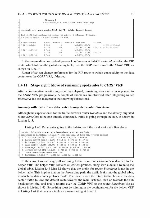
DEALING WITH ROUTES WITHIN A JUNOS OS BASED ROUTER 51
9 AS path: I10 > via so-0/0/0.0, Push 316224, Push 300432(top)11
12
13 user@male-re0> show route 10.1.1.0/24 table inet.0 terse14
15 inet.0: 21 destinations, 24 routes (21 active, 0 holddown, 0 hidden)16 + = Active Route, - = Last Active, * = Both17
18 A Destination P Prf Metric 1 Metric 2 Next hop AS path19 * 10.1.1.0/24 R 100 2 >10.255.100.78 # RIP to Global20 B 170 100 >10.255.100.86 64500 I # BGP to CORP21 * 10.1.1.21/32 R 100 2 >10.255.100.7822 B 170 100 >10.255.100.86 64500 I23 * 10.1.1.88/30 R 100 2 >10.255.100.78
In the reverse direction, default protocol preferences at hub CE router Male select the RIProute, which follows the global routing table, over the BGP route towards the CORP VRF, asshown on Line 13.
Router Male can change preferences for the RIP route to switch connectivity to the datacenter over the CORP VRF, if desired.
1.4.11 Stage eight: Move of remaining spoke sites to CORP VRF
After a conservative monitoring period has elapsed, remaining sites can be incorporated tothe CORP VPN progressively. A couple of anomalies are observed after integrating routerBarcelona and are analyzed in the following subsections.
Anomaly with traffic from data center to migrated router Barcelona
Although the expectation is for the traffic between router Honolulu and the already migratedrouter Barcelona to be one directly connected, traffic is going through the hub, as shown inListing 1.43.
Listing 1.43: Data center going to the hub to reach the local spoke site Barcelona
1 user@honolulu-re0> traceroute barcelona source honolulu2 traceroute to barcelona (10.50.1.7) from honolulu, 30 hops max, 40 byte packets3 1 livorno-ge1300 (10.1.1.89) 0.518 ms 0.422 ms 0.409 ms4 2 havana-so1000 (172.16.1.37) 0.544 ms 0.474 ms 0.437 ms5 3 bilbao-at1210 (172.16.1.42) 0.545 ms 0.521 ms 0.500 ms6 4 male-so3210 (10.255.100.77) 0.423 ms 0.399 ms 0.402 ms7 5 havana-ge1100 (10.255.100.86) 0.527 ms 0.502 ms 2.307 ms8 6 livorno-so0010 (172.16.1.38) 1.949 ms 1.952 ms 1.949 ms9 MPLS Label=300784 CoS=0 TTL=1 S=1
10 7 barcelona (10.50.1.7) 1.949 ms 1.951 ms 1.031 ms
In the current rollout stage, all incoming traffic from router Honolulu is diverted to thehelper VRF. The helper VRF contains all critical prefixes, along with a default route to theglobal table. Listing 1.44 Line 12 shows that the prefix for router Barcelona is not in thehelper table. This implies that on the forwarding path, the traffic leaks into the global table,in which the data center prefixes reside. The issue is with the return traffic, because the datacenter traffic follows the default route towards the main instance, then on towards the hubheadquarters site, and finally returns over the CORP VPN to the router Barcelona site asshown in Listing 1.43. Something must be missing in the configuration for the helper VRFin Listing 1.44 that creates a table as shown starting at Line 12.
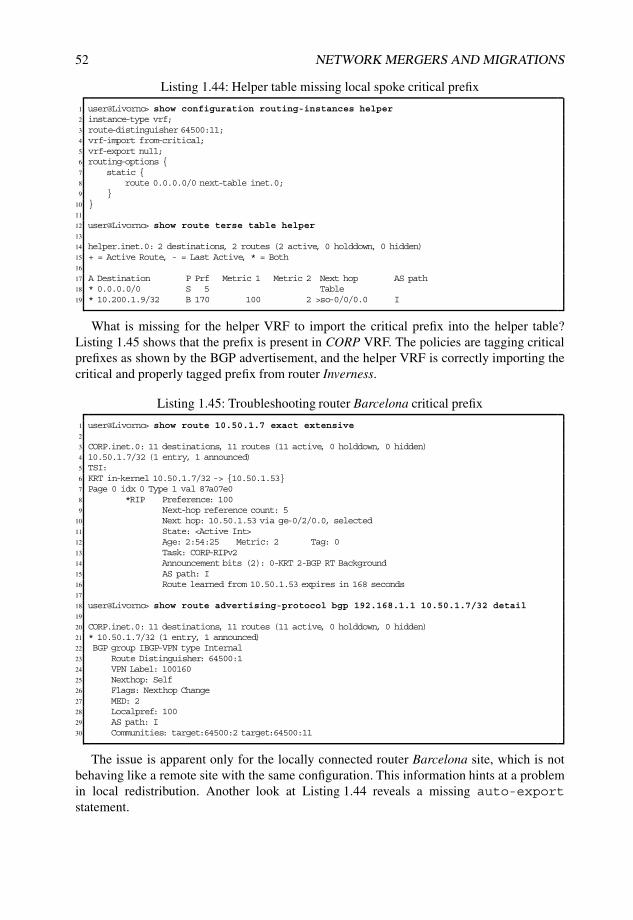
52 NETWORK MERGERS AND MIGRATIONS
Listing 1.44: Helper table missing local spoke critical prefix
1 user@Livorno> show configuration routing-instances helper2 instance-type vrf;3 route-distinguisher 64500:11;4 vrf-import from-critical;5 vrf-export null;6 routing-options {7 static {8 route 0.0.0.0/0 next-table inet.0;9 }
10 }11
12 user@Livorno> show route terse table helper13
14 helper.inet.0: 2 destinations, 2 routes (2 active, 0 holddown, 0 hidden)15 + = Active Route, - = Last Active, * = Both16
17 A Destination P Prf Metric 1 Metric 2 Next hop AS path18 * 0.0.0.0/0 S 5 Table19 * 10.200.1.9/32 B 170 100 2 >so-0/0/0.0 I
What is missing for the helper VRF to import the critical prefix into the helper table?Listing 1.45 shows that the prefix is present in CORP VRF. The policies are tagging criticalprefixes as shown by the BGP advertisement, and the helper VRF is correctly importing thecritical and properly tagged prefix from router Inverness.
Listing 1.45: Troubleshooting router Barcelona critical prefix
1 user@Livorno> show route 10.50.1.7 exact extensive2
3 CORP.inet.0: 11 destinations, 11 routes (11 active, 0 holddown, 0 hidden)4 10.50.1.7/32 (1 entry, 1 announced)5 TSI:6 KRT in-kernel 10.50.1.7/32 -> {10.50.1.53}7 Page 0 idx 0 Type 1 val 87a07e08 *RIP Preference: 1009 Next-hop reference count: 5
10 Next hop: 10.50.1.53 via ge-0/2/0.0, selected11 State: <Active Int>12 Age: 2:54:25 Metric: 2 Tag: 013 Task: CORP-RIPv214 Announcement bits (2): 0-KRT 2-BGP RT Background15 AS path: I16 Route learned from 10.50.1.53 expires in 168 seconds17
18 user@Livorno> show route advertising-protocol bgp 192.168.1.1 10.50.1.7/32 detail19
20 CORP.inet.0: 11 destinations, 11 routes (11 active, 0 holddown, 0 hidden)21 * 10.50.1.7/32 (1 entry, 1 announced)22 BGP group IBGP-VPN type Internal23 Route Distinguisher: 64500:124 VPN Label: 10016025 Nexthop: Self26 Flags: Nexthop Change27 MED: 228 Localpref: 10029 AS path: I30 Communities: target:64500:2 target:64500:11
The issue is apparent only for the locally connected router Barcelona site, which is notbehaving like a remote site with the same configuration. This information hints at a problemin local redistribution. Another look at Listing 1.44 reveals a missing auto-exportstatement.
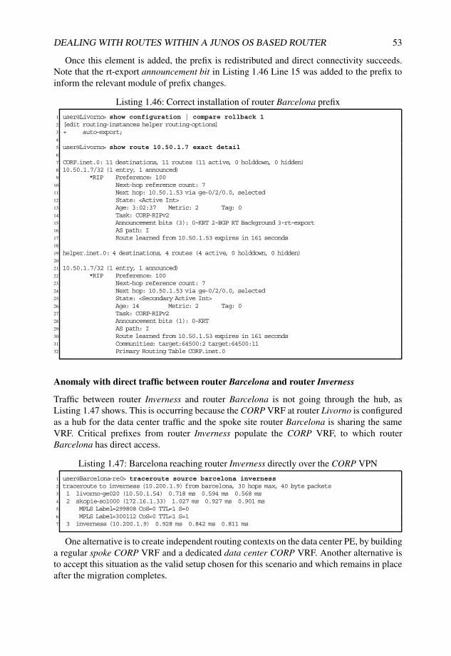
DEALING WITH ROUTES WITHIN A JUNOS OS BASED ROUTER 53
Once this element is added, the prefix is redistributed and direct connectivity succeeds.Note that the rt-export announcement bit in Listing 1.46 Line 15 was added to the prefix toinform the relevant module of prefix changes.
Listing 1.46: Correct installation of router Barcelona prefix
1 user@Livorno> show configuration | compare rollback 12 [edit routing-instances helper routing-options]3 + auto-export;4
5 user@Livorno> show route 10.50.1.7 exact detail6
7 CORP.inet.0: 11 destinations, 11 routes (11 active, 0 holddown, 0 hidden)8 10.50.1.7/32 (1 entry, 1 announced)9 *RIP Preference: 100
10 Next-hop reference count: 711 Next hop: 10.50.1.53 via ge-0/2/0.0, selected12 State: <Active Int>13 Age: 3:02:37 Metric: 2 Tag: 014 Task: CORP-RIPv215 Announcement bits (3): 0-KRT 2-BGP RT Background 3-rt-export16 AS path: I17 Route learned from 10.50.1.53 expires in 161 seconds18
19 helper.inet.0: 4 destinations, 4 routes (4 active, 0 holddown, 0 hidden)20
21 10.50.1.7/32 (1 entry, 1 announced)22 *RIP Preference: 10023 Next-hop reference count: 724 Next hop: 10.50.1.53 via ge-0/2/0.0, selected25 State: <Secondary Active Int>26 Age: 14 Metric: 2 Tag: 027 Task: CORP-RIPv228 Announcement bits (1): 0-KRT29 AS path: I30 Route learned from 10.50.1.53 expires in 161 seconds31 Communities: target:64500:2 target:64500:1132 Primary Routing Table CORP.inet.0
Anomaly with direct traffic between router Barcelona and router Inverness
Traffic between router Inverness and router Barcelona is not going through the hub, asListing 1.47 shows. This is occurring because the CORP VRF at router Livorno is configuredas a hub for the data center traffic and the spoke site router Barcelona is sharing the sameVRF. Critical prefixes from router Inverness populate the CORP VRF, to which routerBarcelona has direct access.
Listing 1.47: Barcelona reaching router Inverness directly over the CORP VPN
1 user@Barcelona-re0> traceroute source barcelona inverness2 traceroute to inverness (10.200.1.9) from barcelona, 30 hops max, 40 byte packets3 1 livorno-ge020 (10.50.1.54) 0.718 ms 0.594 ms 0.568 ms4 2 skopie-so1000 (172.16.1.33) 1.027 ms 0.927 ms 0.901 ms5 MPLS Label=299808 CoS=0 TTL=1 S=06 MPLS Label=300112 CoS=0 TTL=1 S=17 3 inverness (10.200.1.9) 0.928 ms 0.842 ms 0.811 ms
One alternative is to create independent routing contexts on the data center PE, by buildinga regular spoke CORP VRF and a dedicated data center CORP VRF. Another alternative isto accept this situation as the valid setup chosen for this scenario and which remains in placeafter the migration completes.

54 NETWORK MERGERS AND MIGRATIONS
Migrating remaining spoke sites
Additional spoke sites can be migrated, one at a time, in an incremental fashion. Listing 1.48shows the restricted view of the CORP VRF at each of the spoke sites PE. Notice that eachVRF does not have visibility of other spoke prefixes.
Listing 1.48: VRF contents for spoke-site PE at end of migration
1 user@Nantes> show route table CORP terse2
3 CORP.inet.0: 8 destinations, 8 routes (8 active, 0 holddown, 0 hidden)4 + = Active Route, - = Last Active, * = Both5
6 A Destination P Prf Metric 1 Metric 2 Next hop AS path7 * 0.0.0.0/0 B 170 100 >172.16.1.5 65000 I8 * 10.1.1.0/24 B 170 100 0 >so-0/1/0.0 I9 * 10.1.1.21/32 B 170 100 0 >so-0/1/0.0 I
10 * 10.200.1.0/24 R 100 2 >10.200.1.6611 * 10.200.1.9/32 R 100 2 >10.200.1.6612 * 10.200.1.64/30 D 0 >so-1/0/1.013 * 10.200.1.65/32 L 0 Local14 * 224.0.0.9/32 R 100 1 MultiRecv15
16 user@Torino> show route table CORP terse17
18 CORP.inet.0: 8 destinations, 8 routes (8 active, 0 holddown, 0 hidden)19 + = Active Route, - = Last Active, * = Both20
21 A Destination P Prf Metric 1 Metric 2 Next hop AS path22 * 0.0.0.0/0 B 170 100 >at-0/0/1.0 65000 I23 so-0/1/0.024 * 10.1.1.0/24 B 170 100 0 >so-0/1/0.0 I25 * 10.1.1.21/32 B 170 100 0 >so-0/1/0.0 I26 * 10.100.1.0/24 R 100 2 >10.100.1.8227 * 10.100.1.10/32 R 100 2 >10.100.1.8228 * 10.100.1.80/30 D 0 >at-1/2/0.100129 * 10.100.1.81/32 L 0 Local30 * 224.0.0.9/32 R 100 1 MultiRecv
Listing 1.49 shows the data-center view at the end of the migration, with all criticalprefixes imported from the spoke sites.
Listing 1.49: VRF contents for data-center PE at end of migration
1 user@Livorno> show route table CORP terse2
3 CORP.inet.0: 13 destinations, 13 routes (13 active, 0 holddown, 0 hidden)4 + = Active Route, - = Last Active, * = Both5
6 A Destination P Prf Metric 1 Metric 2 Next hop AS path7 * 0.0.0.0/0 B 170 100 >so-0/0/1.0 65000 I8 * 10.1.1.0/24 O 150 0 >10.1.1.909 * 10.1.1.21/32 O 150 0 >10.1.1.90
10 * 10.1.1.88/30 D 0 >ge-1/3/0.011 * 10.1.1.89/32 L 0 Local12 * 10.50.1.0/24 R 100 2 >10.50.1.5313 * 10.50.1.7/32 R 100 2 >10.50.1.5314 * 10.50.1.52/30 D 0 >ge-0/2/0.015 * 10.50.1.54/32 L 0 Local16 * 10.100.1.10/32 B 170 100 2 >so-0/0/0.0 I17 so-0/0/1.018 * 10.200.1.9/32 B 170 100 2 >so-0/0/0.0 I19 * 224.0.0.5/32 O 10 1 MultiRecv20 * 224.0.0.9/32 R 100 1 MultiRecv
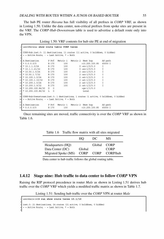
DEALING WITH ROUTES WITHIN A JUNOS OS BASED ROUTER 55
The hub PE router Havana has full visibility of all prefixes in CORP VRF, as shownin Listing 1.50. Unlike the data center, non-critical prefixes from spoke sites are present inthe VRF. The CORP-Hub-Downstream table is used to advertise a default route only intothe VPN.
Listing 1.50: VRF contents for hub site PE at end of migration
1 user@Havana> show route table CORP terse2
3 CORP-Hub.inet.0: 11 destinations, 11 routes (11 active, 0 holddown, 0 hidden)4 + = Active Route, - = Last Active, * = Both5
6 A Destination P Prf Metric 1 Metric 2 Next hop AS path7 * 0.0.0.0/0 B 170 100 >10.255.100.85 65000 I8 * 10.1.1.0/24 B 170 100 0 >so-1/0/0.0 I9 * 10.1.1.21/32 B 170 100 0 >so-1/0/0.0 I
10 * 10.50.1.0/24 B 170 100 2 >so-1/0/0.0 I11 * 10.50.1.7/32 B 170 100 2 >so-1/0/0.0 I12 * 10.100.1.0/24 B 170 100 2 >at-1/2/0.0 I13 * 10.100.1.10/32 B 170 100 2 >at-1/2/0.0 I14 * 10.200.1.0/24 B 170 100 2 >at-1/2/0.0 I15 * 10.200.1.9/32 B 170 100 2 >at-1/2/0.0 I16 * 10.255.100.84/30 D 0 >ge-1/1/0.017 * 10.255.100.86/32 L 0 Local18
19 CORP-Hub-Downstream.inet.0: 1 destinations, 1 routes (1 active, 0 holddown, 0 hidden)20 + = Active Route, - = Last Active, * = Both21
22 A Destination P Prf Metric 1 Metric 2 Next hop AS path23 * 0.0.0.0/0 B 170 100 >10.255.100.85 65000 I
Once remaining sites are moved, traffic connectivity is over the CORP VRF as shown inTable 1.6.
Table 1.6 Traffic flow matrix with all sites migrated
HQ DC MS
Headquarters (HQ) Global CORPData Center (DC) Global CORPMigrated Spoke (MS) CORP CORP CORP/hub
Data center to hub traffic follows the global routing table.
1.4.12 Stage nine: Hub traffic to data center to follow CORP VPN
Raising the RIP protocol precedence in router Male as shown in Listing 1.51 derives hubtraffic over the CORP VRF which yields a modified traffic matrix as shown in Table 1.7.
Listing 1.51: Sending hub traffic over the CORP VPN at router Male
1 user@male-re0# run show route terse 10.1/162
3 inet.0: 21 destinations, 24 routes (21 active, 0 holddown, 0 hidden)4 + = Active Route, - = Last Active, * = Both5
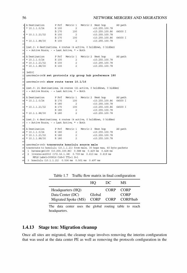
56 NETWORK MERGERS AND MIGRATIONS
6 A Destination P Prf Metric 1 Metric 2 Next hop AS path7 * 10.1.1.0/24 R 100 2 >10.255.100.788 B 170 100 >10.255.100.86 64500 I9 * 10.1.1.21/32 R 100 2 >10.255.100.78
10 B 170 100 >10.255.100.86 64500 I11 * 10.1.1.88/30 R 100 2 >10.255.100.7812
13 inet.2: 4 destinations, 4 routes (4 active, 0 holddown, 0 hidden)14 + = Active Route, - = Last Active, * = Both15
16 A Destination P Prf Metric 1 Metric 2 Next hop AS path17 * 10.1.1.0/24 R 100 2 >10.255.100.7818 * 10.1.1.21/32 R 100 2 >10.255.100.7819 * 10.1.1.88/30 R 100 2 >10.255.100.7820
21 [edit]22 user@male-re0# set protocols rip group hub preference 18023
24 user@male-re0> show route terse 10.1/1625
26 inet.0: 21 destinations, 24 routes (21 active, 0 holddown, 0 hidden)27 + = Active Route, - = Last Active, * = Both28
29 A Destination P Prf Metric 1 Metric 2 Next hop AS path30 * 10.1.1.0/24 B 170 100 >10.255.100.86 64500 I31 R 180 2 >10.255.100.7832 * 10.1.1.21/32 B 170 100 >10.255.100.86 64500 I33 R 180 2 >10.255.100.7834 * 10.1.1.88/30 R 180 2 >10.255.100.7835
36 inet.2: 4 destinations, 4 routes (4 active, 0 holddown, 0 hidden)37 + = Active Route, - = Last Active, * = Both38
39 A Destination P Prf Metric 1 Metric 2 Next hop AS path40 * 10.1.1.0/24 R 180 2 >10.255.100.7841 * 10.1.1.21/32 R 180 2 >10.255.100.7842 * 10.1.1.88/30 R 180 2 >10.255.100.7843
44 user@male-re0> traceroute honolulu source male45 traceroute to honolulu (10.1.1.21) from male, 30 hops max, 40 byte packets46 1 havana-ge1100 (10.255.100.86) 0.588 ms 0.429 ms 0.428 ms47 2 livorno-so0010 (172.16.1.38) 0.739 ms 0.613 ms 0.619 ms48 MPLS Label=300816 CoS=0 TTL=1 S=149 3 honolulu (10.1.1.21) 0.536 ms 0.501 ms 0.497 ms
Table 1.7 Traffic flow matrix in final configuration
HQ DC MS
Headquarters (HQ) CORP CORPData Center (DC) Global CORPMigrated Spoke (MS) CORP CORP CORP/hub
The data center uses the global routing table to reachheadquarters.
1.4.13 Stage ten: Migration cleanup
Once all sites are migrated, the cleanup stage involves removing the interim configurationthat was used at the data center PE as well as removing the protocols configuration in the
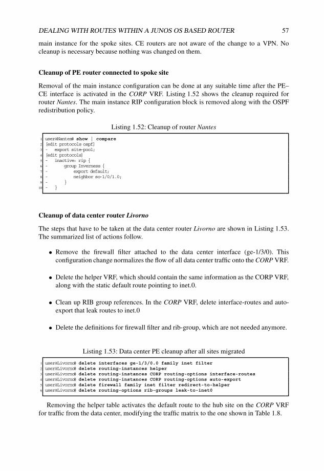
DEALING WITH ROUTES WITHIN A JUNOS OS BASED ROUTER 57
main instance for the spoke sites. CE routers are not aware of the change to a VPN. Nocleanup is necessary because nothing was changed on them.
Cleanup of PE router connected to spoke site
Removal of the main instance configuration can be done at any suitable time after the PE–CE interface is activated in the CORP VRF. Listing 1.52 shows the cleanup required forrouter Nantes. The main instance RIP configuration block is removed along with the OSPFredistribution policy.
Listing 1.52: Cleanup of router Nantes
1 user@Nantes# show | compare2 [edit protocols ospf]3 - export site-pool;4 [edit protocols]5 - inactive: rip {6 - group Inverness {7 - export default;8 - neighbor so-1/0/1.0;9 - }
10 - }
Cleanup of data center router Livorno
The steps that have to be taken at the data center router Livorno are shown in Listing 1.53.The summarized list of actions follow.
• Remove the firewall filter attached to the data center interface (ge-1/3/0). Thisconfiguration change normalizes the flow of all data center traffic onto the CORP VRF.
• Delete the helper VRF, which should contain the same information as the CORP VRF,along with the static default route pointing to inet.0.
• Clean up RIB group references. In the CORP VRF, delete interface-routes and auto-export that leak routes to inet.0
• Delete the definitions for firewall filter and rib-group, which are not needed anymore.
Listing 1.53: Data center PE cleanup after all sites migrated
1 user@Livorno# delete interfaces ge-1/3/0.0 family inet filter2 user@Livorno# delete routing-instances helper3 user@Livorno# delete routing-instances CORP routing-options interface-routes4 user@Livorno# delete routing-instances CORP routing-options auto-export5 user@Livorno# delete firewall family inet filter redirect-to-helper6 user@Livorno# delete routing-options rib-groups leak-to-inet0
Removing the helper table activates the default route to the hub site on the CORP VRFfor traffic from the data center, modifying the traffic matrix to the one shown in Table 1.8.
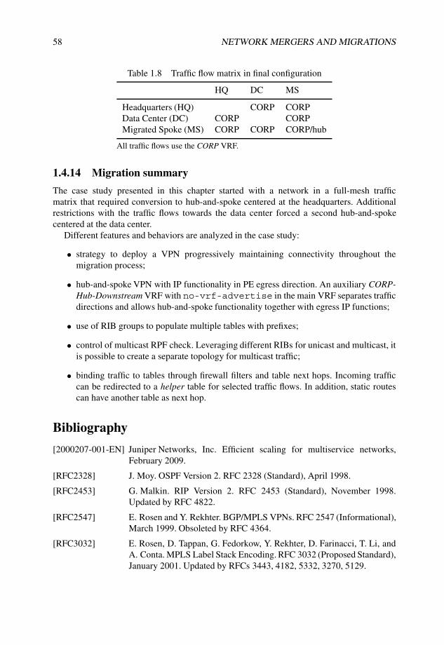
58 NETWORK MERGERS AND MIGRATIONS
Table 1.8 Traffic flow matrix in final configuration
HQ DC MS
Headquarters (HQ) CORP CORPData Center (DC) CORP CORPMigrated Spoke (MS) CORP CORP CORP/hub
All traffic flows use the CORP VRF.
1.4.14 Migration summary
The case study presented in this chapter started with a network in a full-mesh trafficmatrix that required conversion to hub-and-spoke centered at the headquarters. Additionalrestrictions with the traffic flows towards the data center forced a second hub-and-spokecentered at the data center.
Different features and behaviors are analyzed in the case study:
• strategy to deploy a VPN progressively maintaining connectivity throughout themigration process;
• hub-and-spoke VPN with IP functionality in PE egress direction. An auxiliary CORP-Hub-Downstream VRF with no-vrf-advertise in the main VRF separates trafficdirections and allows hub-and-spoke functionality together with egress IP functions;
• use of RIB groups to populate multiple tables with prefixes;
• control of multicast RPF check. Leveraging different RIBs for unicast and multicast, itis possible to create a separate topology for multicast traffic;
• binding traffic to tables through firewall filters and table next hops. Incoming trafficcan be redirected to a helper table for selected traffic flows. In addition, static routescan have another table as next hop.
Bibliography
[2000207-001-EN] Juniper Networks, Inc. Efficient scaling for multiservice networks,February 2009.
[RFC2328] J. Moy. OSPF Version 2. RFC 2328 (Standard), April 1998.
[RFC2453] G. Malkin. RIP Version 2. RFC 2453 (Standard), November 1998.Updated by RFC 4822.
[RFC2547] E. Rosen and Y. Rekhter. BGP/MPLS VPNs. RFC 2547 (Informational),March 1999. Obsoleted by RFC 4364.
[RFC3032] E. Rosen, D. Tappan, G. Fedorkow, Y. Rekhter, D. Farinacci, T. Li, andA. Conta. MPLS Label Stack Encoding. RFC 3032 (Proposed Standard),January 2001. Updated by RFCs 3443, 4182, 5332, 3270, 5129.

DEALING WITH ROUTES WITHIN A JUNOS OS BASED ROUTER 59
[RFC3107] Y. Rekhter and E. Rosen. Carrying Label Information in BGP-4. RFC3107 (Proposed Standard), May 2001.
[RFC4364] E. Rosen and Y. Rekhter. BGP/MPLS IP Virtual Private Networks(VPNs). RFC 4364 (Proposed Standard), February 2006. Updated byRFCs 4577, 4684.
[RFC5036] L. Andersson, I. Minei, and B. Thomas. LDP Specification. RFC 5036(Draft Standard), October 2007.
Further Reading
[1] Aviva Garrett. JUNOS Cookbook, April 2006. ISBN 0-596-10014-0.
[2] Matthew C. Kolon and Jeff Doyle. Juniper Networks Routers : The Complete Reference,February 2002. ISBN 0-07-219481-2.

Related Documents


