DE1600 DSA E-Series iSCSI Disk Arrays en Installation Manual

Welcome message from author
This document is posted to help you gain knowledge. Please leave a comment to let me know what you think about it! Share it to your friends and learn new things together.
Transcript

DE1600 DSA E-Series iSCSI Disk Arrays
en Installation Manual

DE1600 DSA E-Series iSCSI Disk Arrays Table of Contents | en 3
Bosch Security Systems Installation Manual - | V1 | 2012.07
Table of Contents
1 Safety Precautions 41.1 Warning Notices 41.2 Caution Notices 7
2 Device view 9
3 Replacing an Environmental Services Monitor Canister in a DE1600 Drive Tray 10
4 Replacing a Drive in a DE1600 Drive Tray 14
5 Replacing a Power-Fan Canister in the DE1600 Drive Tray 175.1 Replacing an AC Power-Fan Canister in the DE1600 Drive Tray 175.2 Replacing a DC Power-Fan Canister in the DE1600 Drive Tray 20
6 Additional documentation 25

4 en | Safety Precautions DE1600 DSA E-Series iSCSI Disk Arrays
- | V1 | 2012.07 Installation Manual Bosch Security Systems
1 Safety PrecautionsDefinitions of safety notices:– WARNING indicates a poptentially hazadous situation that could result in death or severe
personal injury.– CAUTION indicates a potentially hazardous situation that could result in moderate or
minor personal injury.
1.1 Warning Notices
WARNING! Risk of electrical shockIf there is evidence of fire, water, or structural damage, never turn on the power to the equipment.
WARNING! Risk of electrical shockBefore removing or installing a power supply, turn off the power switch, and unplug the power cord.
WARNING! Risk of exposure to laser radiationDo not disassemble or remove any part of a Small Form-factor Pluggable (SFP) transceiver because you might be exposed to laser radiation.
WARNING! Risk of bodily injuryThe battery can weigh up to 10.9 kg (24 lb). When you remove the battery, be prepared to support its weight. If the battery is dropped, the impact might cause bodily injury, including deep puncture wounds caused by the battery pins.
WARNING! Risk of bodily injuryIf the bottom half of the cabinet is empty, do not install components in the top half of the cabinet. If the top half of the cabinet is too heavy for the bottom half, the cabinet might fall and cause bodily injury. Always install a component in the lowest available position in the cabinet.
WARNING! Risk of bodily injuryAttach the stability foot before moving the cabinet. If you do not attach the stability foot, the cabinet might become unstable, or it might fall. This problem is most likely to occur when the cabinet is moved along inclined surfaces or over uneven surfaces.

DE1600 DSA E-Series iSCSI Disk Arrays Safety Precautions | en 5
Bosch Security Systems Installation Manual - | V1 | 2012.07
WARNING! Risk of bodily injuryOnly move a populated cabinet with a forklift or adequate help from other persons. Always push the cabinet from the front to prevent it from falling over.A fully populated cabinet can weigh more than 909 kg (2000 lb). The cabinet is difficult to move, even on a flat surface. If you must move the cabinet along an inclined surface, remove the components from the top half of the cabinet, and make sure that you have adequate help.
WARNING! Risk of bodily injury
Two persons are required to safely lift the component.
,
WARNING! Risk of bodily injury
Three persons are required to safely lift the component.
,
WARNING! Risk of bodily injury
Four or more persons are required to safely lift the component.
,
WARNING! Risk of fire or chemical burnBefore disposing of a used battery, review the battery warning label. The label reads: The battery used in this device may present a risk of fire or chemical burn if mistreated. DO NOT disassemble, heat above 60ºC (140ºF), crush or puncture, short circuit external contacts, or dispose of in fire or water. Use LSI recommended charger only. Replace only with original LSI batteries.

6 en | Safety Precautions DE1600 DSA E-Series iSCSI Disk Arrays
- | V1 | 2012.07 Installation Manual Bosch Security Systems
WARNING! Risk of electrical shock
1 - Supply (Negative), Brown Wire, -48 VDC2 - Return (Positive), Blue Wire3 - Ground, Green/Yellow Wire4 - DC Power ConnectorThis unit has more than one power source. To remove all power from the unit, all DC MAINS must be disconnected by removing all power connectors (item 4 below) from the power supplies.
WARNING! Risk of bodily injuryOnly move a populated cabinet with a forklift or adequate help from other persons. Attach the stability foot before moving the cabinet. If you do not attach the stability foot, the cabinet might become unstable, or it might fall. Always push the cabinet from the front to prevent it from falling over.A fully populated cabinet can weigh more than 636 kg (1420 lb). The cabinet is difficult to move, even on a flat surface. If you must move the cabinet along an inclined surface, remove the components from the top half of the cabinet, and make sure that you have adequate help.
WARNING! Risk of bodily injuryA qualified service person is required to make the DC power connection according to NEC and CEC guidelines.
WARNING! Risk of bodily injuryAn empty tray weighs approximately 56.7 kg (125 lb). Three persons are required to safely move an empty tray. If the tray is populated with components, a mechanized lift is required to safely move the tray.
DE1600 DSA E-Series iSCSI Disk Arrays Safety Precautions | en 7
Bosch Security Systems Installation Manual - | V1 | 2012.07
1.2 Caution Notices
WARNING! Risk of bodily injuryEach tray has more than one power cord. To remove all electrical current from the devices, make sure that all of the power cords are disconnected from the power source and that the two-pole 20-amp circuit breaker for the storage array has been disconnected.
WARNING! Risk of bodily injuryEach tray has more than one power cord. To remove all electrical current from the devices, make sure that all of the power cords are disconnected from the power source.
WARNING! Risk of bodily injuryDo not use equipment in the cabinet as a shelf or work space.
CAUTION! Potentially hazardous materialThe battery pack contains sealed lead acid batteries that might be considered hazardous material. If you recycle a used battery pack that is not damaged, use the proper facilities. Handle the battery pack according to all applicable regulations.
CAUTION! Potentially hazardous materialIf the used battery pack is physically damaged or is leaking, DO NOT ship the battery pack to a recycling center. Handling a damaged battery pack exposes you and others to potentially hazardous material. Dispose of the damaged battery pack according to all applicable regulations.
CAUTION! Pinching hazardAs you push the canister into the slot, ensure that your fingers are not pinched between the lever and the canister. The lever automatically moves toward the closed position as the canister is pushed into its slot.

8 en | Safety Precautions DE1600 DSA E-Series iSCSI Disk Arrays
- | V1 | 2012.07 Installation Manual Bosch Security Systems
CAUTION! Potentially hazardous materialThe battery pack contains sealed lithium ion batteries that might be considered hazardous material. If the used battery pack is physically damaged and is leaking, DO NOT ship the battery pack to a recycling center. Handling a damaged battery pack exposes you and others to potentially hazardous material. Dispose of the damaged battery pack according to all applicable regulations. If you recycle a used battery pack that is not damaged, use the proper facilities. Handle the battery pack according to all applicable regulations.
CAUTION! Electrical grounding hazardThis equipment is designed to permit the connection of the DC supply circuit to the earthing conductor at the equipment.
CAUTION! Possible hazard existsDo not remove more than one canister from the enclosure while power to the enclosure is turned on.

DE1600 DSA E-Series iSCSI Disk Arrays Device view | en 9
Bosch Security Systems Installation Manual - | V1 | 2012.07
2 Device viewDE1600 Drive Tray – Front View
Figure 2.1 DE1600 Front View
DE1600 Drive Tray – Rear View
Figure 2.2 DE1600 Rear View (AC version)
Figure 2.3 DE1600 Rear View (DC version)
1 Left End Cap (Has the Drive Tray LEDs)
2 Drives
3 Right End Cap
1 Environmental Services Monitor (ESM) Canister
2 Power-Fan Canister
3 AC Power Connectors
1 Environmental Services Monitor (ESM) Canister
2 Power-Fan Canister
3 DC Power Connectors
!
1 32
ACDC!
ACDC!
2
1
3
2 3
!
DCDC
!
DCDC
10 en | Replacing an Environmental Services Monitor Canister in a DE1600 Drive Tray DE1600 DSA E-Series iSCSI Disk Arrays
- | V1 | 2012.07 Installation Manual Bosch Security Systems
3 Replacing an Environmental Services Monitor Canister in a DE1600 Drive TrayIn this procedure, you will replace a failed environmental services monitor (ESM) canister with a new ESM canister.Before you start to replace the ESM canister in the drive tray, gather antistatic protection and a replacement ESM canister.
You can determine whether you have a failed ESM canister in two ways:– The Recovery Guru directs you to replace a failed ESM canister.– You locate the failed ESM canister by checking the ESM Service Action Required LED.
1. If possible, use the storage management software to create, save, and print a new storage array profile.
2. Did the Recovery Guru direct you to replace a failed ESM canister?– Yes
Go to step 3.
– NoRun the Recovery Guru to identify the failed component.
3. Put on antistatic protection.4. Unpack the new ESM canister.
– Set the new ESM canister on a dry, level surface near the drive tray.– Save all the packing materials in case you need to return the ESM canister.
5. Locate the failed ESM canister by checking the ESM Service Action Required LEDs (Figure 1).If a fault is detected, the amber ESM Service Action Required LED is on. If you can safely remove the ESM canister, the blue ESM Service Action Allowed LED is on.
Figure 3.1 LEDs on an ESM Canister
CAUTION! Possible equipment damageYou must replace the ESM canister within three minutes after removing the failed ESM canister to prevent the possibility of overheating the equipment.
NOTICE! Possible extended outageYou must replace the ESM with the power turned on to ensure auto-code synchronization of the native controller firmware to the new ESM canister, and to prevent the possibility of an extended outage.
CAUTION! Possible hardware damageTo prevent electrostatic discharge damage to the tray, use proper antistatic protection when handling tray components.
90001-02
1 2

DE1600 DSA E-Series iSCSI Disk Arrays Replacing an Environmental Services Monitor Canister in a DE1600 Drive Tray | en 11
Bosch Security Systems Installation Manual - | V1 | 2012.07
6. Label each interface cable that is attached to the ESM canister so that you can reconnect the cables correctly to the new ESM canister.
7. Disconnect all of the controller interface cables, and, if applicable, disconnect all of the interface cables to other ESM canisters from the failed ESM canister.
8. Remove the failed ESM canister from the drive tray:– Rotate the ESM latches to disengage the ESM canister.– Use the ESM latches as handles to pull the ESM canister out of the drive tray.
Figure 3.2 Removing and Replacing an ESM Canister
9. Slide the replacement ESM canister all the way into the drive tray. Rotate the ESM latches to lock the ESM canister into place.
10. Reconnect all of the controller interface cables, as well as reconnect the cables from the other ESM canisters to the replacement ESM canister.
11. Look at the LEDs on the ESM canister and the drives to make sure that the new ESM canister is rebooting correctly. The symbols next to the LEDs identify their purpose.
1 ESM Service Action Allowed LED (Blue)
2 ESM Service Action Required LED (Amber)
CAUTION! Possible damage to fiber-optic cablesFiber-optic cables are fragile. Bending, twisting, folding, or pinching fiber-optic cables can cause damage to the cables, degraded performance, or loss of data. To prevent damage, do not twist, fold, pinch, or step on the cables. Do not bend the cables in less than a 5-cm (2-in.) radius.
1 ESM Latches
2 ESM Canister
96008-012
1

12 en | Replacing an Environmental Services Monitor Canister in a DE1600 Drive Tray DE1600 DSA E-Series iSCSI Disk Arrays
- | V1 | 2012.07 Installation Manual Bosch Security Systems
Figure 3.3 Removing and Replacing an ESM Canister
12. Look at the ESM Link LEDs and the ESM Service Action Required LED on both ESM canisters. Based on the LED status, perform one of these actions:– On both ESM canisters, the ESM Link LEDs are on and the ESM Service Action
Required LEDs are offGo to step 14
– On both ESM canisters, either of the ESM Link LEDs is off or either of the ESM Service Action Required LEDs is onCheck that the ESM canister is installed correctly. Reinstall the ESM canister if nec-essary. Go to step 13
13. Did this action correct the problem?– Yes
Go to step 14.
– NoIf the problem has not been resolved, click the Recovery Guru toolbar button in the Array Management Window to see if any further issues are reported. After you attempt to correct any problems listed, contact a Customer and Technical Support representative.
14. Remove the antistatic protection.15. Check the status of all the trays in the storage array.
1 ESM Service Action Allowed LED (Blue)
2 ESM Service Action Required LED (Amber)
3 ESM Link Service Action Required LEDs (Amber)
4 ESM Link LEDs (Green)
Note: All four LEDs come on and go off intermittently for approximately 60 seconds (possibly longer). After this time, you are able to discover the new ESM canister by using the storage management software.
96002-01
ACDC!
ACDC!
4
Lnk!
21
LnkLnk!Lnk LnkLnk!
!
ID/Diag
Lnk!
21
Lnk LnkLnk!
!
ID/Diag
3
1
2

DE1600 DSA E-Series iSCSI Disk Arrays Replacing an Environmental Services Monitor Canister in a DE1600 Drive Tray | en 13
Bosch Security Systems Installation Manual - | V1 | 2012.07
16. Does any component have a Needs Attention status?– Yes
Go to step 17.
– NoClick the Recovery Guru toolbar button in the Array Management Window, and com-plete the recovery procedure. If the problem has not been resolved, contact a Cus-tomer and Technical Support representative.
17. Create, save, and print a new storage array profile.

14 en | Replacing a Drive in a DE1600 Drive Tray DE1600 DSA E-Series iSCSI Disk Arrays
- | V1 | 2012.07 Installation Manual Bosch Security Systems
4 Replacing a Drive in a DE1600 Drive TrayIn this procedure, you will replace a failed drive with a new drive.Before you start to replace a drive in the drive tray, gather antistatic protection and a replacement drive. You can determine whether you have a failed drive in two ways:– The Recovery Guru directs you to replace a failed drive.– You locate the failed drive by checking the LEDs on the drive (see Figure 4.1, Page 15).
1. If possible, use the storage management software to create, save, and print a new storage array profile.
2. Did the Recovery Guru direct you to replace a failed drive?– Yes
Go to step 3.
– NoRun the Recovery Guru to identify the failed component.
3. Put on antistatic protection.4. Unpack the new drive.
– Set the new drive on a dry, level surface near the drive tray.– Save all the packing materials in case you need to return the drive.
CAUTION! Possible equipment damageYou must replace the drive within three minutes after removing the failed drive to prevent the possibility of overheating the equipment.
CAUTION! Possible loss of data accessNever insert drives into the drive tray without first confirming that the drive firmware level is compatible with the other drives. Inserting a drive with an incorrect firmware level can cause loss of data access. For information about the supported drive firmware levels, contact a Customer and Technical Support representative.
CAUTION! Possible loss of data accessMagnetic fields can destroy all data on the drive and cause irreparable damage to the drive circuitry. To avoid the loss of data access and damage to the drives, always keep drives away from magnetic devices.
CAUTION! Possible hardware damageTo prevent electrostatic discharge damage to the tray, use proper antistatic protection when handling tray components.
NOTICE! Install only drives that are specifically designed for your drive tray and that have been tested and qualified by the factory.
DE1600 DSA E-Series iSCSI Disk Arrays Replacing a Drive in a DE1600 Drive Tray | en 15
Bosch Security Systems Installation Manual - | V1 | 2012.07
5. Locate the failed drive by checking the Drive Service Action Required LEDs on the front of the drive tray. If a fault is detected, the amber Drive Service Action Required LED is on. If you can safely remove the drive, the blue Service Action Allowed LED is on (see Figure 4.1, Page 15).
Figure 4.1 Drive Status LEDs
6. Remove the failed drive from the drive tray:– Pull the drive handle to the left.– Use the drive handle to pull the drive out of the slot.– Put the drive on an antistatic, cushioned surface away from magnetic fields.
Figure 4.2 Removing a Drive from and Replacing a Drive in a DE1600 Drive Tray
1 Drive Service Action Allowed LED (Blue)
2 rive Service Action Required LED (Amber)
3 Drive Power LED (Green)
77064-00
1 2 3
CAUTION! Potential damage to drivesBumping drives against another surface can damage the drive mechanism or connectors. To avoid damage when removing or installing a drive, always place your hand under the drive to support its weight.
1 Drive Handle
97006-01
1

16 en | Replacing a Drive in a DE1600 Drive Tray DE1600 DSA E-Series iSCSI Disk Arrays
- | V1 | 2012.07 Installation Manual Bosch Security Systems
7. Wait 30 seconds for the storage management software to recognize that the drive has been removed.– Place the replacement drive on the slot guides, and slide the drive all of the way into
the slot.– Push the drive handle to the right to lock the drive securely in place.As the drive spins up, the Drive Power LED might blink intermittently, which indicates that data is being restored to the new drive.
8. Look at the Drive Power LED and Drive Service Action Required LED (see Figure 4.1, Page 15). Based on the LED status, perform one of these actions:– The Drive Power LED is off
The drive might not be installed correctly. Remove the drive, wait 30 seconds, and then reinstall it. Go to step 9.
– The Drive Power LED is on and the Drive Service Action Required LED is offGo to step 10.
– The Drive Service Action Required LED is onThe new drive might be defective. Replace it with another new drive. Go to step 9.
9. Did this action correct the problem?– Yes
Go to step 10.
– NoIf the problem has not been resolved, contact a Customer and Technical Support representative.
10. Remove the antistatic protection.11. Bring the new drive back online by using the storage management software.12. Check the status of all the trays in the storage array.13. Does any component have a Needs Attention status?
– YesGo to step 14.
– NoClick the Recovery Guru toolbar button in the Array Management Window, and com-plete the recovery procedure. If the problem has not been resolved, contact a Cus-tomer and Technical Support representative.
14. Create, save, and print a new storage array profile.
NOTICE! If you accidentally remove an active drive, wait at least 30 seconds, and then reinstall it. For the recovery procedure, refer to your storage management software.
NOTICE! Depending on your configuration, the controller might automatically reconstruct data to the new drive. If the drive tray uses hot spares, the controller might need to perform a complete reconstruction on the hot spare before the controller copies the data to the replaced drive. This reconstruction process increases the time that is required to complete this procedure.

DE1600 DSA E-Series iSCSI Disk Arrays Replacing a Power-Fan Canister in the DE1600 Drive Tray | en 17
Bosch Security Systems Installation Manual - | V1 | 2012.07
5 Replacing a Power-Fan Canister in the DE1600 Drive TrayUse one of these procedures to replace a failed power-fan canister in the DE1600 drive tray.– If your storage array uses AC power, see Section 5.1 Replacing an AC Power-Fan Canister
in the DE1600 Drive Tray, page 17.– If your storage array uses DC power, see Section 5.2 Replacing a DC Power-Fan Canister in
the DE1600 Drive Tray, page 20.Before you start to replace the power-fan canister in the DE1600 drive tray, gather antistatic protection and the appropriate replacement power-fan canister (AC power or DC power)
5.1 Replacing an AC Power-Fan Canister in the DE1600 Drive TrayIn this procedure, you will replace a failed AC power-fan canister with a new AC power-fan canister.Before you start to replace the AC power-fan canister in the drive tray, gather antistatic protection and a replacement AC power-fan canister.
You can determine whether you have a failed power-fan canister in two ways:– The Recovery Guru directs you to replace a failed power-fan canister.– You locate the failed power-fan canister by checking the amber Power-Fan Service Action
Required LED.1. Gather support data through one of the following methods:
– Use the storage management software to collect and save a support bundle of your storage array. From the Array Management Window, select Advanced >>Troubleshooting >> Support Data >> Collect. Then name and specify a location on your system where you want to store the support bundle.
– Use the command line interface (CLI) to run the save storageArray supportData command to gather comprehensive support data about the storage array. For more information about this command, refer to Command Line Interface and Script Commands. Running this command can temporarily impact performance on your storage array.
2. Did the Recovery Guru direct you to replace a failed power-fan canister?– Yes
Go to step 3.
– NoRun the Recovery Guru to identify the failed component.
CAUTION! Possible equipment failureBefore starting this procedure, make sure that you have the correct power-fan canister for your particular hardware configuration. If you are performing a hardware reconfiguration, make sure you have the correct replacement power-fan canister to support the particular controller tray or controller-drive tray to which your DE1600 drive tray is to be attached. Using a power-fan canister with the wrong power supply can cause your storage array to power down and stop working because of the power supply mismatch.
CAUTION! Possible equipment failureIf you perform this procedure with the power turned on, you must complete it within three minutes to prevent the possibility of overheating the equipment.
18 en | Replacing a Power-Fan Canister in the DE1600 Drive Tray DE1600 DSA E-Series iSCSI Disk Arrays
- | V1 | 2012.07 Installation Manual Bosch Security Systems
3. If the Recovery Guru has directed you to replace the power-fan canister and the blue Power-Fan Service Action Allowed LED is not on, type this command on the command line, and press Enter:SMcli <ctrl_IP1> -c “Set tray [trayID] powerfanCanister [left|right]
service Allowed Indicator=on;”
In this command:
– <ctlr_IP1> is the identifier of the controller to which the drive tray is assigned.– [trayID] is the identifier of the drive tray that contains the power-fan canister that
you want to replace. Drive tray ID values are 0 to 99. Be sure to type the square brackets around the identifier.
– [left|right] is the identifier of the power-fan canister you want to replace. Valid values are left or right. Be sure to type the square brackets around the value.
4. Put on antistatic protection.5. Unpack the new AC power-fan canister.
– Set the new power-fan canister on a flat, static-free surface near the drive tray.– Save all packing materials in case you need to return the power-fan canister.
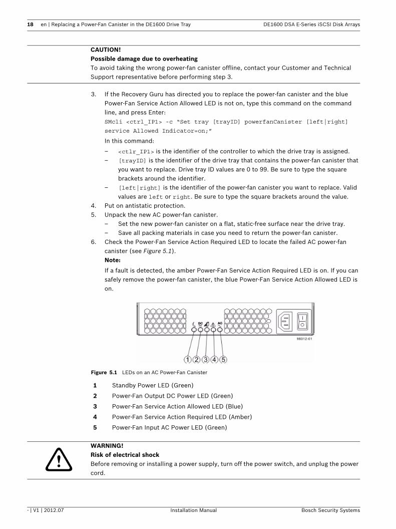
6. Check the Power-Fan Service Action Required LED to locate the failed AC power-fan canister (see Figure 5.1).Note:
If a fault is detected, the amber Power-Fan Service Action Required LED is on. If you can safely remove the power-fan canister, the blue Power-Fan Service Action Allowed LED is on.
Figure 5.1 LEDs on an AC Power-Fan Canister
CAUTION! Possible damage due to overheatingTo avoid taking the wrong power-fan canister offline, contact your Customer and Technical Support representative before performing step 3.
1 Standby Power LED (Green)
2 Power-Fan Output DC Power LED (Green)
3 Power-Fan Service Action Allowed LED (Blue)
4 Power-Fan Service Action Required LED (Amber)
5 Power-Fan Input AC Power LED (Green)
WARNING! Risk of electrical shockBefore removing or installing a power supply, turn off the power switch, and unplug the power cord.
DE1600 DSA E-Series iSCSI Disk Arrays Replacing a Power-Fan Canister in the DE1600 Drive Tray | en 19
Bosch Security Systems Installation Manual - | V1 | 2012.07
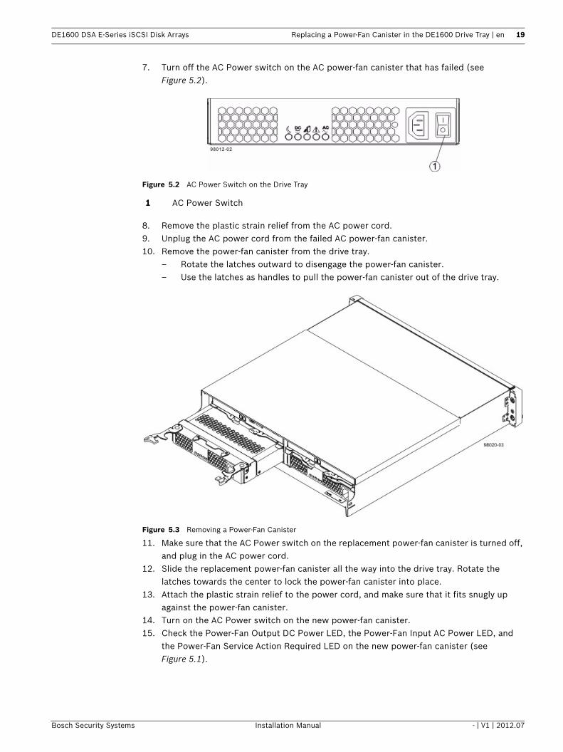
7. Turn off the AC Power switch on the AC power-fan canister that has failed (see Figure 5.2).
Figure 5.2 AC Power Switch on the Drive Tray
8. Remove the plastic strain relief from the AC power cord.9. Unplug the AC power cord from the failed AC power-fan canister.10. Remove the power-fan canister from the drive tray.
– Rotate the latches outward to disengage the power-fan canister.– Use the latches as handles to pull the power-fan canister out of the drive tray.
Figure 5.3 Removing a Power-Fan Canister
11. Make sure that the AC Power switch on the replacement power-fan canister is turned off, and plug in the AC power cord.
12. Slide the replacement power-fan canister all the way into the drive tray. Rotate the latches towards the center to lock the power-fan canister into place.
13. Attach the plastic strain relief to the power cord, and make sure that it fits snugly up against the power-fan canister.
14. Turn on the AC Power switch on the new power-fan canister.15. Check the Power-Fan Output DC Power LED, the Power-Fan Input AC Power LED, and
the Power-Fan Service Action Required LED on the new power-fan canister (see Figure 5.1).
1 AC Power Switch

20 en | Replacing a Power-Fan Canister in the DE1600 Drive Tray DE1600 DSA E-Series iSCSI Disk Arrays
- | V1 | 2012.07 Installation Manual Bosch Security Systems
16. Based on the LED status, perform one of these actions:– The Power-Fan Output DC Power LED and the Power-Fan Input AC Power LED are
on and the Power-Fan Service Action Required LED is offGo to step 18.
– The Power-Fan Output DC Power LED and the Power-Fan Input AC Power LED are off or the Power-Fan Service Action Required LED is onCheck that the power-fan canister is installed correctly. Reinstall the power-fan can-ister. Go to step 17.
17. Did this action correct the problem?– Yes
Go to step 18.
– NoIf the problem has not been resolved, contact your Customer and Technical Support representative.
18. Using the LEDs and the storage management software, check the status of all of the trays in the storage array.
19. Does any component have a Needs Attention status?– Yes
Click the Recovery Guru toolbar button in the Array Management Window, and com-plete the recovery procedure. If the problem has not been resolved, contact your Customer and Technical Support representative.
– NoGo to step 20.
20. Remove the antistatic protection.21. Gather support data on your updated storage array through one of the following
methods:– Use the storage management software to collect and save a support bundle of your
storage array. From the Array Management Window, select Advanced >Troubleshooting > Support Data > Collect. Then name and specify a location on your system where you want to store the support bundle.
– Use the CLI to run the save storageArray supportData command to gather comprehensive support data about the storage array. For more information about this command, refer to Command Line Interface and Script Commands. Running this command can temporarily impact performance on your storage array.
5.2 Replacing a DC Power-Fan Canister in the DE1600 Drive TrayIn this procedure, you will replace a failed DC power-fan canister with a new DC power-fan canister.Before you start to replace the power-fan canister in the drive tray, gather antistatic protection and a replacement DC power-fan canister.
You can determine whether you have a failed power-fan canister in two ways:The Recovery Guru directs you to replace a failed power-fan canister.
CAUTION! Possible equipment damageIf you perform this procedure with the power turned on, you must complete it within three minutes to prevent the possibility of overheating the equipment.

DE1600 DSA E-Series iSCSI Disk Arrays Replacing a Power-Fan Canister in the DE1600 Drive Tray | en 21
Bosch Security Systems Installation Manual - | V1 | 2012.07
You locate the failed power-fan canister by checking the Power-Fan Service Action Required LED.
1. Gather support data through one of these methods:– Use the storage management software to collect and save a support bundle of your
storage array. From the Array Management Window, select Advanced >>Troubleshooting >> Support Data >> Collect. Then name and specify a location on your system where you want to store the support bundle.
– Use the command line interface (CLI) to run the save storageArray supportData command to gather comprehensive support data about the storage array. For more information about this command, refer to Command Line Interface and Script Commands. Running this command can temporarily impact performance on your storage array.
2. Did the Recovery Guru direct you to replace a failed power-fan canister?– Yes
Go to step 3.
– NoRun the Recovery Guru to identify the failed component.
3. If the Recovery Guru has directed you to replace the power-fan canister and the blue Power-Fan Service Action Allowed LED is not on, type this command on the command line, and press Enter:SMcli <ctrl_IP1> -c “Set tray [trayID] powerfanCanister [left|right]
service Allowed Indicator=on;”
In this command:
– <ctlr_IP1> is the identifier of the controller to which the drive tray is assigned.– [trayID] is the identifier of the drive tray that contains the power-fan canister you
want to replace. Drive tray ID values are 0 to 99. Be sure to type the square brackets around the identifier.
– [left|right] is the identifier of the power-fan canister you want to replace. Valid values are left or right. Be sure to type the square brackets around the value.
4. Put on antistatic protection.5. Unpack the new power-fan canister.
– Set the new power-fan canister on a flat, static-free surface near the drive tray.– Save all packing materials in case you need to return the power-fan canister.
6. Check the Power-Fan Service Action Required LED to locate the failed DC power-fan canister (see Figure 5.4).Note:
If a fault is detected, the amber Fan Service Action Required LED is on. If you can safely remove the power-fan canister, the blue Fan Service Action Allowed LED is on.
CAUTION! Possible hardware damageTo prevent electrostatic discharge damage to the tray, use proper antistatic protection when handling tray components.
CAUTION! Possible damage due to overheatingTo avoid taking the wrong power-fan canister offline, contact your Customer and Technical Support representative before performing step 3.
22 en | Replacing a Power-Fan Canister in the DE1600 Drive Tray DE1600 DSA E-Series iSCSI Disk Arrays
- | V1 | 2012.07 Installation Manual Bosch Security Systems
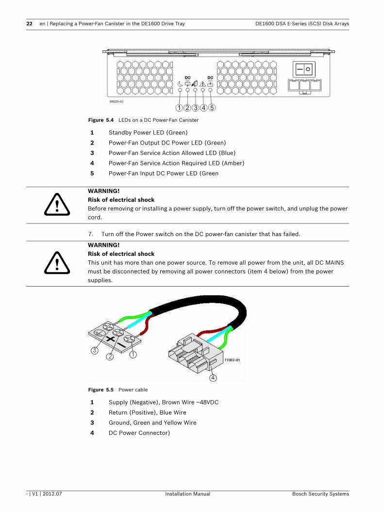
Figure 5.4 LEDs on a DC Power-Fan Canister
7. Turn off the Power switch on the DC power-fan canister that has failed.
Figure 5.5 Power cable
1 Standby Power LED (Green)
2 Power-Fan Output DC Power LED (Green)
3 Power-Fan Service Action Allowed LED (Blue)
4 Power-Fan Service Action Required LED (Amber)
5 Power-Fan Input DC Power LED (Green
WARNING! Risk of electrical shockBefore removing or installing a power supply, turn off the power switch, and unplug the power cord.
WARNING! Risk of electrical shockThis unit has more than one power source. To remove all power from the unit, all DC MAINS must be disconnected by removing all power connectors (item 4 below) from the power supplies.
1 Supply (Negative), Brown Wire –48VDC
2 Return (Positive), Blue Wire
3 Ground, Green and Yellow Wire
4 DC Power Connector)
DE1600 DSA E-Series iSCSI Disk Arrays Replacing a Power-Fan Canister in the DE1600 Drive Tray | en 23
Bosch Security Systems Installation Manual - | V1 | 2012.07
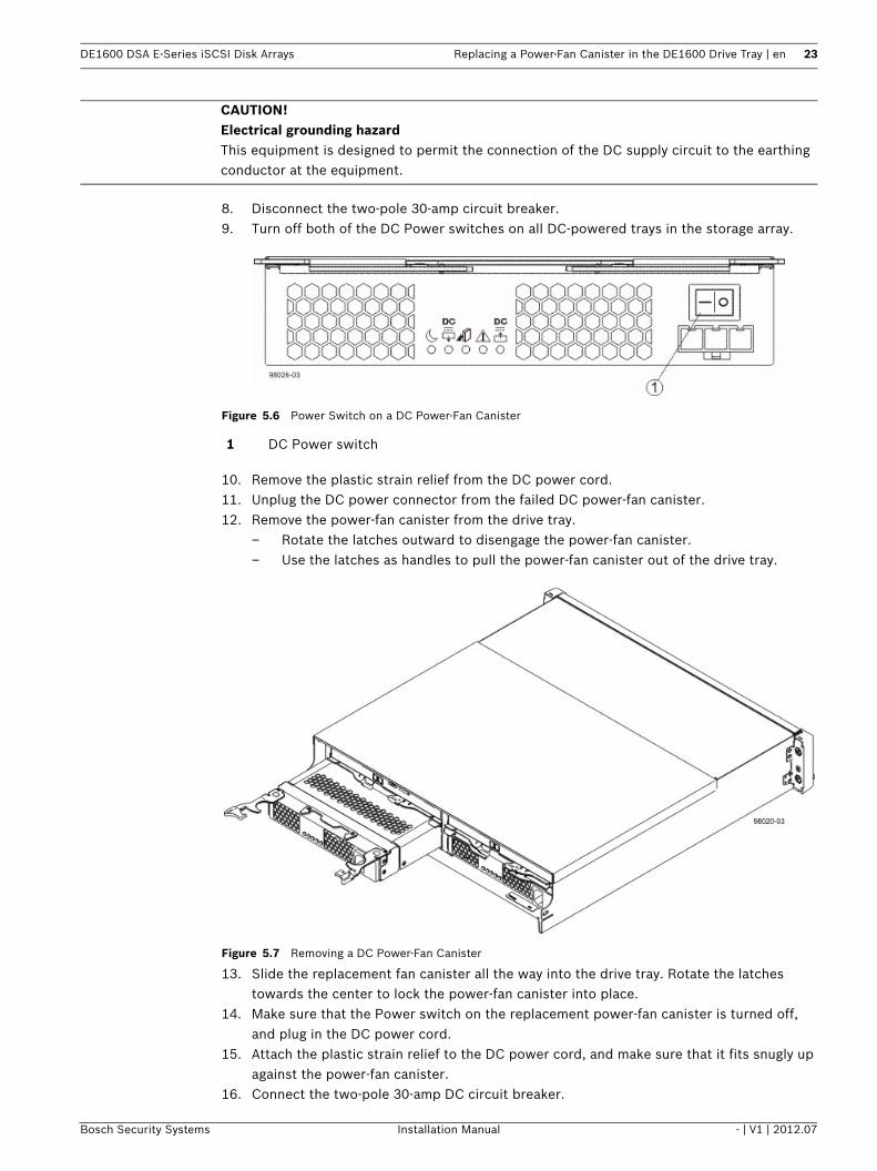
8. Disconnect the two-pole 30-amp circuit breaker.9. Turn off both of the DC Power switches on all DC-powered trays in the storage array.
Figure 5.6 Power Switch on a DC Power-Fan Canister
10. Remove the plastic strain relief from the DC power cord.11. Unplug the DC power connector from the failed DC power-fan canister.12. Remove the power-fan canister from the drive tray.
– Rotate the latches outward to disengage the power-fan canister. – Use the latches as handles to pull the power-fan canister out of the drive tray.
Figure 5.7 Removing a DC Power-Fan Canister
13. Slide the replacement fan canister all the way into the drive tray. Rotate the latches towards the center to lock the power-fan canister into place.
14. Make sure that the Power switch on the replacement power-fan canister is turned off, and plug in the DC power cord.
15. Attach the plastic strain relief to the DC power cord, and make sure that it fits snugly up against the power-fan canister.
16. Connect the two-pole 30-amp DC circuit breaker.
CAUTION! Electrical grounding hazardThis equipment is designed to permit the connection of the DC supply circuit to the earthing conductor at the equipment.
1 DC Power switch
24 en | Replacing a Power-Fan Canister in the DE1600 Drive Tray DE1600 DSA E-Series iSCSI Disk Arrays
- | V1 | 2012.07 Installation Manual Bosch Security Systems
17. Turn on both of the Power switches on all of the DC-powered drive trays and DC-powered controller-drive trays in the storage array.
18. Check the Power-Fan Output DC Power LED, the Power-Fan Input DC Power LED, and the Power-Fan Service Action Required LED on the new power-fan canister (see Figure 5.4) .
19. Based on the LED status, perform one of these actions:– The Power-Fan Output DC Power LED and the Power-Fan Input DC Power LED are
on and the Power-Fan Service Action Required LED is offGo to step 21.
– The Power-Fan Output DC Power LED or the Power-Fan Input DC Power LED is off or the Power-Fan Service Action Required LED is onCheck that the power-fan canister is installed correctly. Reinstall the fan canister. Go to step 20.
20. Did this action correct the problem?– Yes
Go to step 21.
– NoIf the problem has not been resolved, contact your Customer and Technical Support representative.
21. Using the LEDs and the storage management software, check the status of all of the trays in the storage array.
22. Does any component have a Needs Attention status?– Yes
Click the Recovery Guru toolbar button in the Array Management Window, and com-plete the recovery procedure. If the problem has not been resolved, contact your Customer and Technical Support representative.
– NoGo to step 23.
23. Remove the antistatic protection.24. Gather support data on your updated storage array through one of these methods:
– Use the storage management software to collect and save a support bundle of your storage array. From the Array Management Window, select Advanced >>Troubleshooting >> Support Data >> Collect. Then name and specify a location on your system where you want to store the support bundle.
– Use the CLI to run the save storageArray supportData command to gather comprehensive support data about the storage array. For more information about this command, refer to Command Line Interface and Script Commands. Running this command can temporarily impact performance on your storage array.
DE1600 DSA E-Series iSCSI Disk Arrays Additional documentation | en 25
Bosch Security Systems Installation Manual - | V1 | 2012.07
6 Additional documentationAdditional documentation for DSA E-Series can be found in the Online Product Catalog on;http://www.boschsecurity.com > Video > Digital Recording and Storage > Disk Arrays (NetworkAttached) > DSA – Disk Arrays > DSA E-Series iSCSI Disk Arrays.(The navigation path is subject to change).

26 en | Additional documentation DE1600 DSA E-Series iSCSI Disk Arrays
- | V1 | 2012.07 Installation Manual Bosch Security Systems

Bosch Security SystemsWerner-von-Siemens-Ring 1085630 GrasbrunnGermanywww.boschsecurity.com© Bosch Security Systems, 2011
Related Documents