• Introduction to Refinery operation • Overview Of Crude Distillation • Delayed Coking • History OF Delayed Coking • Overview of DCU • Process description • Operating modes • Chemistry of Delayed coking • Process variables BGR - IOCL

DCU Trainingfor New Engineers
Oct 26, 2014
Welcome message from author
This document is posted to help you gain knowledge. Please leave a comment to let me know what you think about it! Share it to your friends and learn new things together.
Transcript
• Introduction to Refinery operation• Overview Of Crude Distillation• Delayed Coking• History OF Delayed Coking• Overview of DCU• Process description• Operating modes• Chemistry of Delayed coking• Process variables
BGR - IOCL
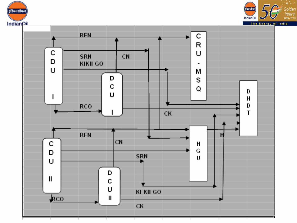
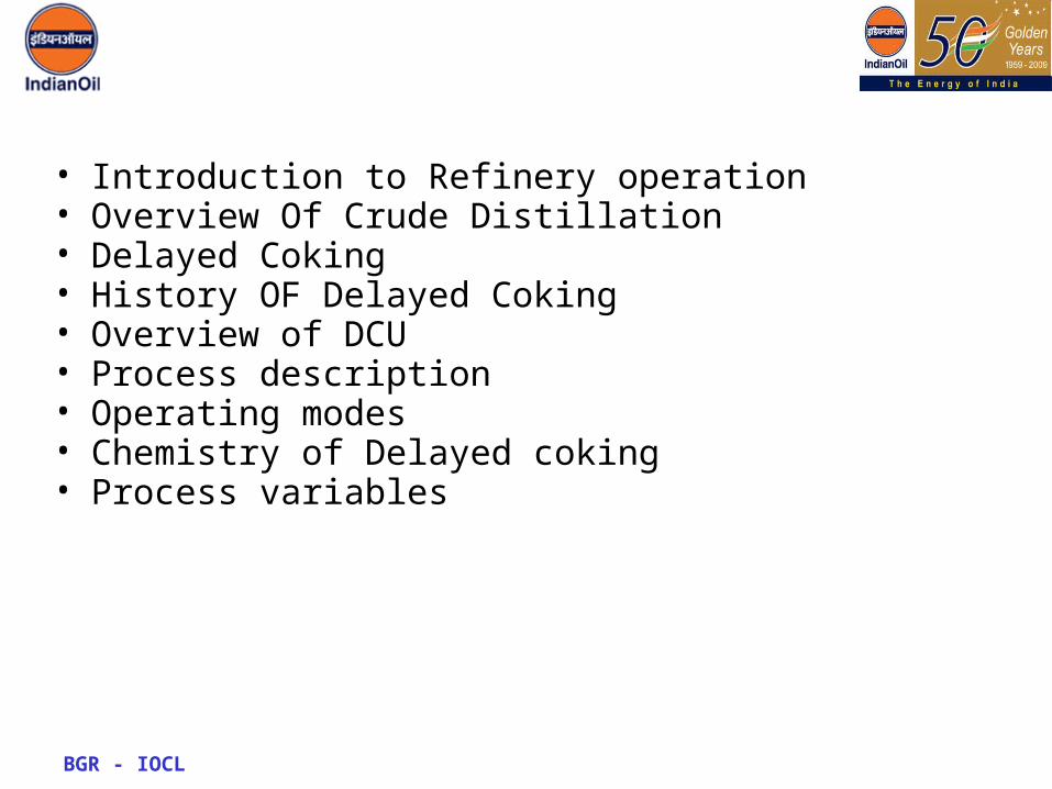
Following Units Come Under Refinery Operation:
Unit: Date Commissioned
CDU-I 6th Feb 1979
DCU-I 21st Sept 1981
CCU 29th Dec 1981
CDU-II May 1995
DCU-II May 1996
Delayed Coking
• It is a Thermal conversion process where Heavy residue from CDU or/else VDU bottoms are upgraded to more usable hydrocarbon products, such as Gas, LPG, Kerosene, Gas oil and Coke.

• Pet coke first made in 1860s in Pennsylvania.• Only one still was used.• Lighter components evaporated• Coke was scrapped out.• Cokers with horizontal stills and distillation column and tube furnace
developed after 1920’s• Decoking was still the crude manual process• First vertical delayed coker was built in 1929 by Standard Oil
Company.• The concept of recycle was developed subsequently• Hydraulic cutting system was first patented by Shell oil in 1930.
BGR - IOCL

• Cokers became popular after 2nd world war.
>> use in Diesel engine locomotives
>> Use of gasoline in planes
>> development in automobile industry.
• Catalytic processes developed during this period had problem of catalyst poisoning.
• Cokers helped removal of asphaltic content along with metals.
• From 1950 to 1970 coking capacity increased 5 folds
BGR - IOCL
BGR - IOCL
Worldwide crudes are becoming heavier, containing more bottom residues, high CCR, metals, etc.
Increasing thrust on residue upgradation - Zero residue refinery
Higher operating/capital cost of other residue upgradation technologies
Ability of Delayed Cokers to convert even heaviest residues to lighter distillates - Permits refiners to process wide variety of crudes, dispose low value byproducts
Improved profitability through integration with other secondary conversion units

Process Description
BGR - IOCL


BGR - IOCL

BGR - IOCL

BGR - IOCL
Continuous operation
Feed circuit till the feed furnace
Fractionator along with product strippers & associated equipment
Batch operationCoke drumCycle time
Coke drum feeding time durationTypical cycle time 24 hrs.
Process Description
Diagram

BGR - IOCL
Coker Cycle• Chamber Changeover : 0 hrs• Depressurisation : 0.25hrs• Steam Cooling : 2hrs• Low rage water : 3hrs• Deluge cooling : 2hrs• Draining : 1.5 hrs• Deheading : 2 hrs• Drilling / Decoking : 6 hrs• Heading : 2 hrs• Pressure testing :1 hr• Vapor heating/ changeover : 5 hrs• Idle time : 8hrs
Process Description
Diagram
• Decoking Operation
- Carried by high pressure water jet- J et pump with a Discharge pressure of 164kg/cm sq.- Coke handling equipment : Galick Crane- W ater reuse/ recirculation system
BGR - IOCL
Process Description
Diagram

Operating modes
BGR - IOCL

Operating Characteristics
• Two Modes– Needle coke mode– Pet coke mode
BGR - IOCL
Process Description

• Feed:Assam Crude Atm Residue (data IIP and R&D Faridabad)– W t % on crude : 40%– Sp Gravity : 0.9802– CCR : 5.99 - 6.8 wt%– Asphaltene : 1.81- 2.1 wt%– Aromatics : 51.6 wt%– Saturates : 48.4 wt %– W ax 43.4 : 43.4(24.5) wt%– Pour point : +48 OC– Sulphur : 0.49 wt %– Metals• V : 0.24 Ni : 1.78 Fe: 14.4• Cu : 0.13 Zn : 0.94BGR - IOCL
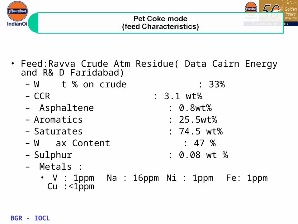
• Feed:Ravva Crude Atm Residue( Data Cairn Energy and R& D Faridabad)– W t % on crude : 33%– CCR : 3.1 wt%– Asphaltene : 0.8wt%– Aromatics : 25.5wt%– Saturates : 74.5 wt%– W ax Content : 47 %– Sulphur : 0.08 wt %– Metals :
• V : 1ppm Na : 16ppm Ni : 1ppm Fe: 1ppm Cu :<1ppm
BGR - IOCL
• Additional feedtypes
– Slop from unit– RFO and CFO recycle
BGR - IOCL
• Furnace- COT : 496-499 oC- BFW : 0.4 m3 /hr/pass for secondary flow of 40m3
/hr/pass or 1vol%- Recycle ratio : 0.8-0.9
• Coke Chamber- After quench Temperature 438 – 440 oC- Bottom Temperature 490-495 OC- Top Pressure 2.1-2.3 kg/cm2g- Bottom Pressure 4.5 – 5 kg/cm2g
BGR - IOCL
BGR - IOCL
• Quench Column
- Top Temperature 430-435 oC
• Fractionator
- Top Pressure 1.50 – 1.55 kg/cm2g
- Top Temperature 102-105OC
- Bottom Temperature 360-370 OC

BGR - IOCL
NB : Design fig is as per Assam crude RCO & Actual yield is as per mixed (Assam + Ravva) crude RCO.
Coke + Loss
CFO + RFO
Coker Kero + CGO
Coker Naphtha
Gas + LPG
PRODU CT S
13.513.0
29.024.2
43.143.0
6.8 7.5
7.612.3
ACT U AL ( W T % )
DE S IG N( W T % )

BGR - IOCL
Coker Naphtha MS Pool Coker Kero HSD
LGO
HGO LDO
CFO
RFO LSHS

BGR - IOCL
• Used in the manufacture of Graphite electrode.
• Must have low Low Coefficient of thermal expansion (CTE) i.e expansion between 0 oC and 50 oC
• Must be able to withstand a temperature of 2800 oC.
BGR - IOCL
•Feed Characteristics•Should have low Asphaltene content (below 1wt%)•Should be aromatic•Should have low sulphur content
Feeds used in DCU- RFO (DCU Product)
- CFO (DCU Product) - CLO ( Bottom product of FCCU) FBP 550 oC

BGR - IOCL
•Furnace•COT : 502-504 oC•BF W : 0.3m3 /Pass •Recycle ratio : 1.2-1.3
●Chamber - After quench Temperature 442 oC - Bottom Temperature 495 - 498 OC- Top Pressure 2.7-3 kg/cm2g- Bottom Pressure 5 - 5.5 kg/cm2g
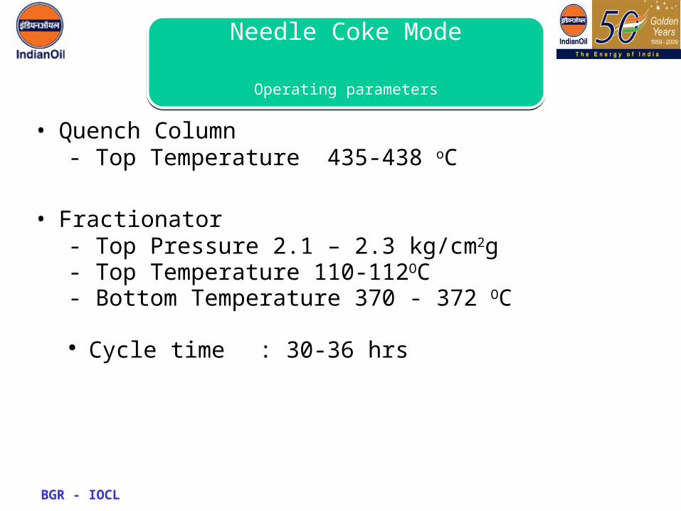
Needle Coke Mode
Operating parameters
BGR - IOCL
• Quench Column- Top Temperature 435-438 oC
• Fractionator- Top Pressure 2.1 – 2.3 kg/cm2g- Top Temperature 110-112OC- Bottom Temperature 370 - 372 OC
● Cycle time : 30-36 hrs
Needle Coke Mode
Operating parameters

BGR - IOCL 100%100%100%100%Total20%--- CLO70%80%85%85% RFO10%10%15%15% CFO
-10%-- RCO Feedstock comp
3631605658368167Feed Processed4000810084008200NCFS Prepared1.221.2 M/S GIL1.081.23, 1.221.411.41MS HEG
1.0351.1--IOC (R & D) CTE Value * 10‾6
551.55605414887Total CNC
149---Double Calcined402.55605414887Single Calcined
Calcined Needle Coke665.737349811290.4Green Needle Coke
Production of Needle Coke
4th3rd2nd1stPARTICULARS
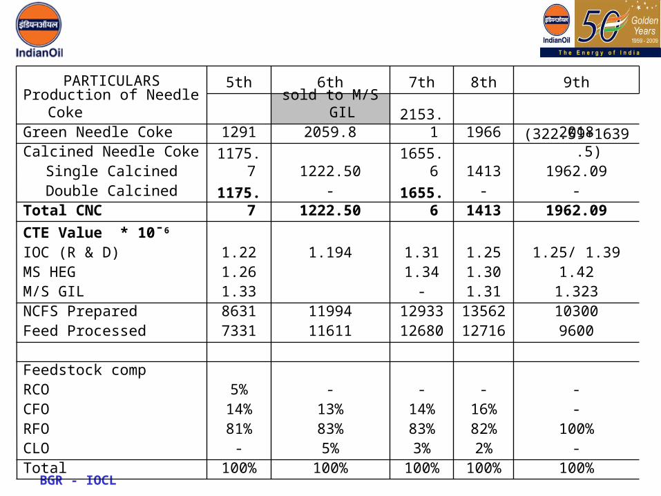
BGR - IOCL100%100%100%100%100%Total
-2%3%5%- CLO100%82%83%83%81% RFO
-16%14%13%14% CFO----5% RCO Feedstock comp
96001271612680116117331Feed Processed103001356212933119948631NCFS Prepared1.3231.31- 1.33M/S GIL1.421.301.34 1.26MS HEG
1.25/ 1.391.251.311.1941.22IOC (R & D) CTE Value * 10‾6
1962.0914131655.61222.501175.7Total CNC-----Double Calcined
1962.0914131655.61222.501175.7Single Calcined(322.59+1639.5) Calcined Needle Coke
201819662153.12059.81291Green Needle Coke sold to M/S GIL Production of Needle Coke
9th8th7th6th5thPARTICULARS
BGR - IOCL
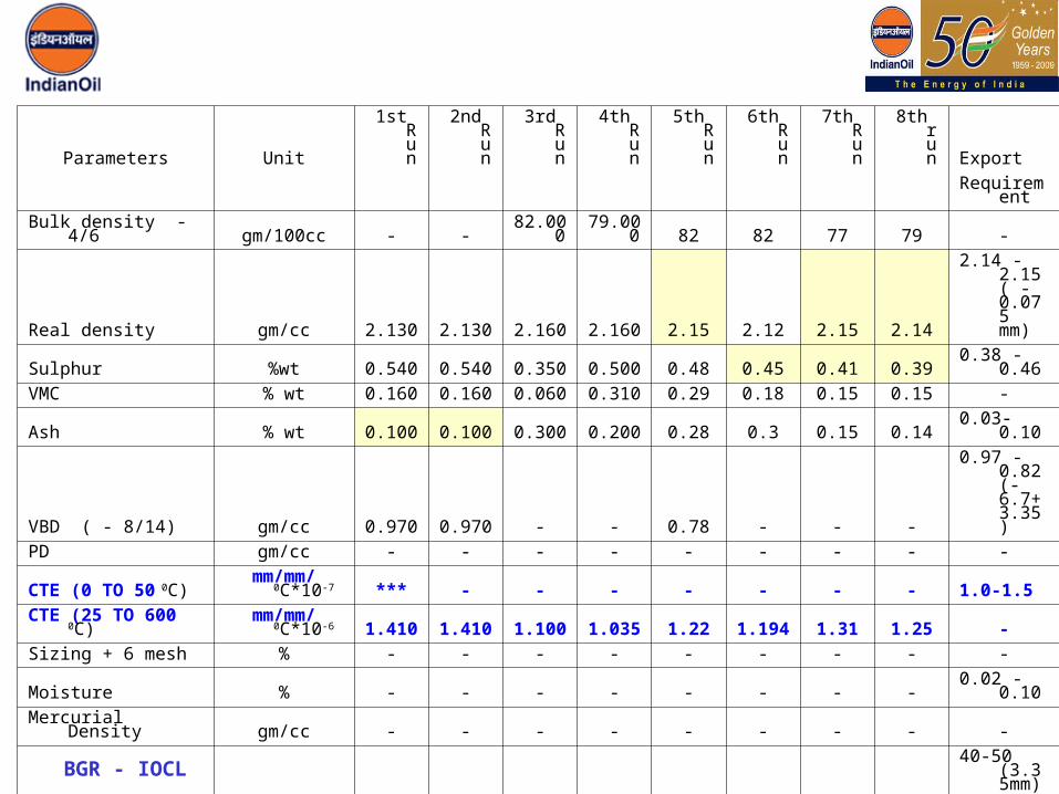
Parameters Unit
1st Run
2nd Run
3rd Run
4th Run
5th Run
6th Run
7th Run
8th run Export
Requireme
nt
Bulk density - 4/6 gm/100cc - -82.00
079.00
0 82 82 77 79 -
Real density gm/cc 2.130 2.130 2.160 2.160 2.15 2.12 2.15 2.14
2.14 - 2.15 ( - 0.075 mm)
Sulphur %wt 0.540 0.540 0.350 0.500 0.48 0.45 0.41 0.39 0.38 - 0.46
VMC % wt 0.160 0.160 0.060 0.310 0.29 0.18 0.15 0.15 -
Ash % wt 0.100 0.100 0.300 0.200 0.28 0.3 0.15 0.14 0.03-0.10
VBD ( - 8/14) gm/cc 0.970 0.970 - - 0.78 - - -
0.97 - 0.82 (-6.7+ 3.35)
PD gm/cc - - - - - - - - -
CTE (0 TO 50 0C)mm/mm/
0C*10-7 *** - - - - - - - 1.0-1.5
CTE (25 TO 600 0C)mm/mm/
0C*10-6 1.410 1.410 1.100 1.035 1.22 1.194 1.31 1.25 -
Sizing + 6 mesh % - - - - - - - - -
Moisture % - - - - - - - - 0.02 - 0.10
Mercurial Density gm/cc - - - - - - - - -
HGI 48 48 39 43 39 41 37 35
40-50 (3.35mm), 28-35 (-1mm)
Coking Chemistry
BGR - IOCL

Courtesy : The Chemistry and Technology of petroleum 2nd Ed
BGR - IOCL
Paraffins
Benzene ring Compounds
Polycondensed Aromatic Rings

• Feedstock can be divided into asphaltenes and maltenes.
• Alphaltenes are n-heptane insolubles and maltenes are n-heptane solubles.
• Maltenes include resins, aromatics and saturates.• Asphaltenes are high molecular weight polynuclear
aromatics having low H-C ratio• Resins are low molecular wt asphaltenes• Saturates include Naphthenes, Paraffins.• Higher the asphaltenes higher is the coke make.
BGR - IOCL
Coking Chemistry
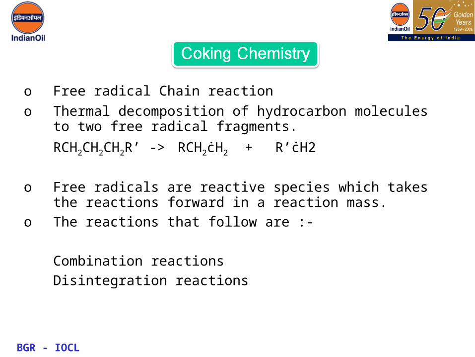
o Free radical Chain reaction
o Thermal decomposition of hydrocarbon molecules to two free radical fragments.
RCH2CH2CH2R’ -> RCH2ċH2 + R’ċH2
o Free radicals are reactive species which takes the reactions forward in a reaction mass.
o The reactions that follow are :-
Combination reactions
Disintegration reactions
BGR - IOCL
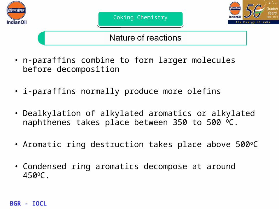
• n-paraffins combine to form larger molecules before decomposition
• i-paraffins normally produce more olefins
• Dealkylation of alkylated aromatics or alkylated naphthenes takes place between 350 to 500 OC.
• Aromatic ring destruction takes place above 500oC
• Condensed ring aromatics decompose at around 450OC.
BGR - IOCL
Coking Chemistry
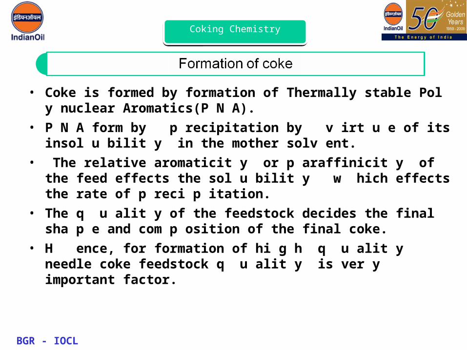
• Coke is formed by formation of Thermally stable Pol y nuclear Aromatics(P N A).
• P N A form by p recipitation by v irt u e of its insol u bilit y in the mother solv ent.
• The relative aromaticit y or p araffinicit y of the feed effects the sol u bilit y w hich effects the rate of p reci p itation.
• The q u alit y of the feedstock decides the final sha p e and com p osition of the final coke.
• H ence, for formation of hi g h q u alit y needle coke feedstock q u alit y is ver y important factor.
BGR - IOCL
Coking Chemistry

BGR - IOCL
Coking Chemistry

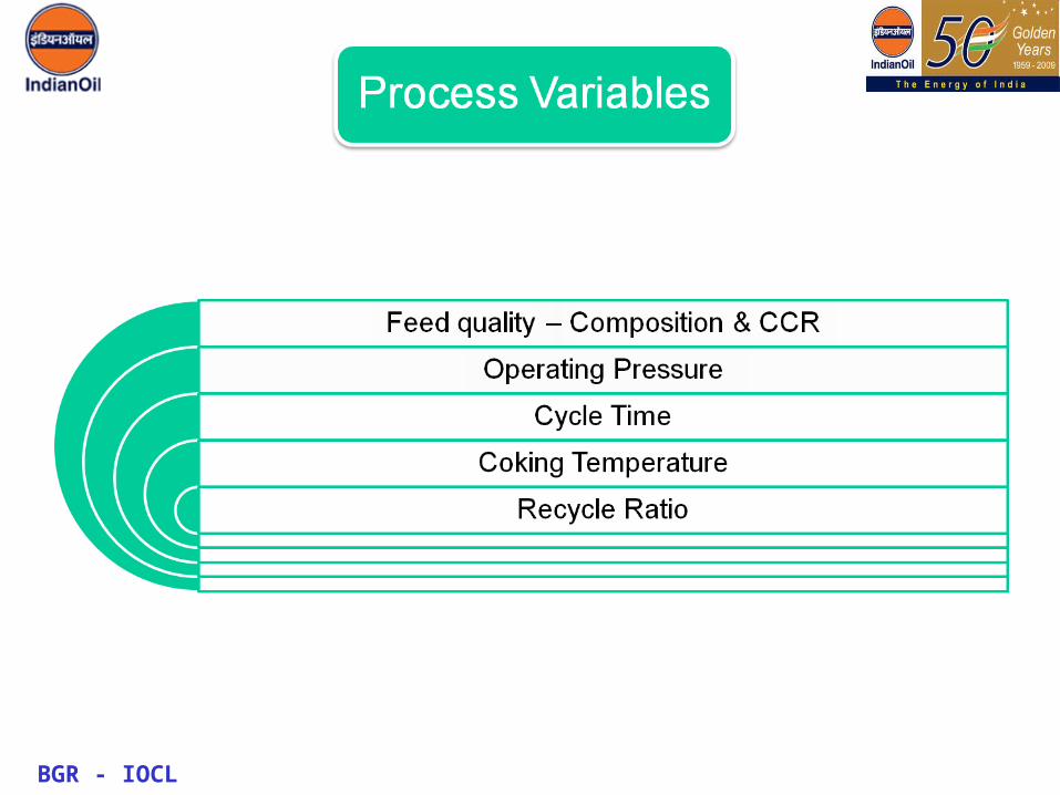
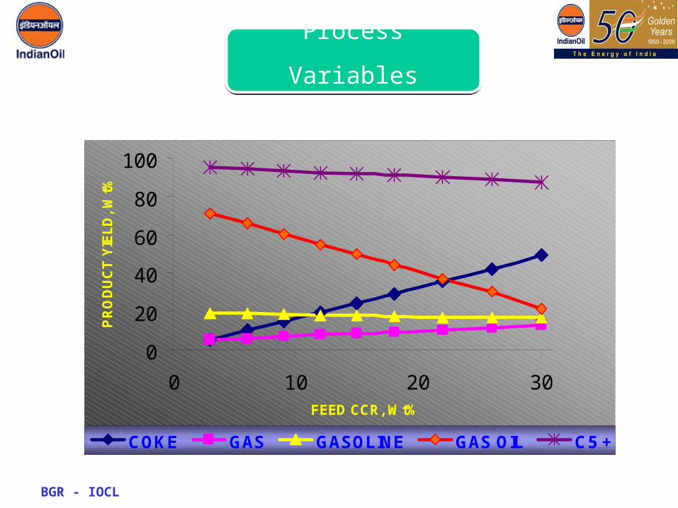
Process Variables
BGR - IOCL
BGR - IOCL
0
20
40
60
80
100
0 10 20 30FEED CCR, Wt%
PR
OD
UC
T Y
IEL
D,
Wt%
COKE GAS GASOLINE GAS OIL C5 +
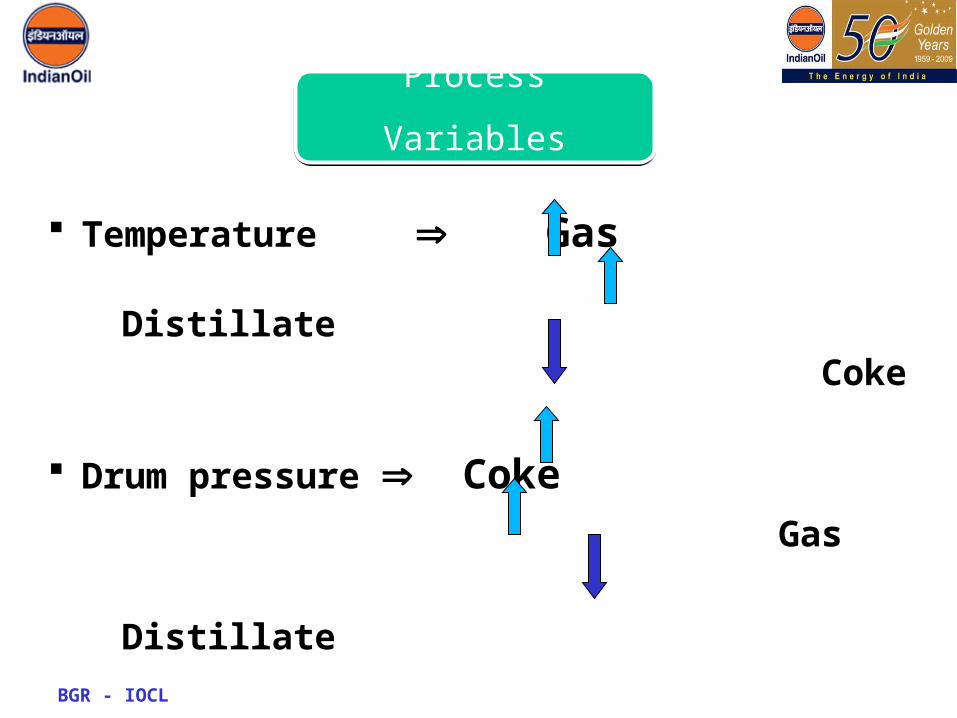
Process Variables
BGR - IOCL
Temperature Gas Distillate Coke
Drum pressure Coke
Gas
Distillate
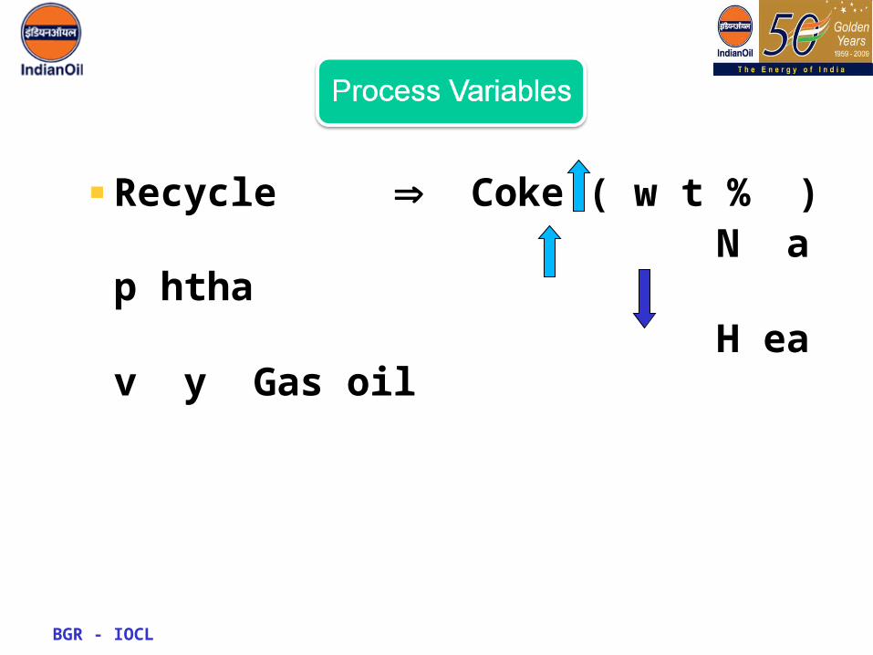
Process Variables
BGR - IOCL
Recycle Coke ( w t % ) N a p htha H ea v y Gas oil

BGR - IOCL
• Coke drums have restrictions in max size• Coke drum size bottleneck in increasing plant
t’put.• Multiple (<2) coker drums provides higher t’put
but more slop and loss• Shorter cycle time allows higher t’put to be
processed
Process Variables

Thank Y ou
BGR - IOCL
Related Documents
![Taller [DCU] 2012 › 2012 › 05 › definicic3b3n-… · Muéstrame / Dibújame / 5 Porqués Taller [DCU] INMERSIÓN EN SUS VIDAS. Taller [DCU] Taller [DCU] PERFIL DE USUARIO ...](https://static.cupdf.com/doc/110x72/5f289122455fd67b955d58d4/taller-dcu-2012-a-2012-a-05-a-definicic3b3n-mustrame-dibjame-.jpg)