This document and the information contained herein, is the exclusive property of Konecranes Plc and represents a non-public, confidential and proprietary trade secret that may not be reproduced, disclosed to third parties, altered or otherwise employed in any manner whatsoever without the express written consent of Konecranes Plc. Copyright © (2010) Konecranes Plc. All rights reserved. 7841360554-0 KS0361 PS01504 6.7.2010 Original instructions OWNER'S MANUAL FOR TRAVEL FREQUENCY CONTROL SYSTEM CXT20410020P15FAL0F English 784136-0.ORD 6.7.2010 - KS0361 O21272-178 KS0361

Welcome message from author
This document is posted to help you gain knowledge. Please leave a comment to let me know what you think about it! Share it to your friends and learn new things together.
Transcript
This document and the information contained herein, is the exclusive property of Konecranes Plc and represents a non-public, confidential and proprietary trade secret that may not be reproduced, disclosed to third parties, altered or otherwise employed in any manner whatsoever without the express written consent of Konecranes Plc.Copyright © (2010) Konecranes Plc. All rights reserved.
7841
3605
54-0
KS
0361
PS
0150
4 6.
7.20
10
Original instructions
OWNER'S MANUAL FOR TRAVEL FREQUENCY CONTROL SYSTEM CXT20410020P15FAL0F
English 784136-0.ORD 6.7.2010
- KS0361 O21272-178 KS0361

OWNER'S MANUAL FOR TRAVEL FREQUENCY CONTROL SYSTEM
This document and the information contained herein, is the exclusive property of Konecranes Plc and represents a non-public, confidential and proprietary trade secret that may not be reproduced, disclosed to third parties, altered or otherwise employed in any manner whatsoever without the express written consent of Konecranes Plc.Copyright © (2010) Konecranes Plc. All rights reserved.
2/22
Table of content
1 DESCRIPTION OF THE INVERTER .................................................................................................. 4
1.1 Connections ............................................................................................................................................ 4
1.2 Technical characteristics ......................................................................................................................... 4
1.3 Normal operation .................................................................................................................................... 5
1.4 Status indication leds (green and red) ..................................................................................................... 5
1.5 Compact brake motors ............................................................................................................................ 5
1.6 Programming switches ............................................................................................................................ 5
1.7 The EMC requirements ........................................................................................................................... 6
1.7.1 EMC filter connection to inverter for trolley travelling. ........................................................................... 6
1.7.2 EMC filter connection to inverter for bridge travelling. .......................................................................... 6
2 DESCRIPTION OF CONTROL MODES ............................................................................................. 7
2.1 MS2-control (S4-1=OFF) ......................................................................................................................... 7
2.2 EP2-control (S4-1=ON) ........................................................................................................................... 7
3 FAULT CODES, TROUBLESHOOTING ............................................................................................. 8
4 PROGRAMMING OF THE APPLICATION PARAMETERS ................................................................ 9
4.1 Minimum speed, maximum speed and ramp time .................................................................................... 9
4.1.1 Acceleration and deceleration ramp..................................................................................................... 9
4.2 Selection of the motor type .................................................................................................................... 10
5 DESCRIPTION OF THE INVERTER ................................................................................................ 11
5.1 Connections .......................................................................................................................................... 11
5.2 Technical characteristics ....................................................................................................................... 12
5.3 Normal operation .................................................................................................................................. 12
5.4 Status indication leds (green and red) ................................................................................................... 12
5.5 Programming switches .......................................................................................................................... 12
5.6 The EMC requirements (Not in use for deliveries in USA/Canada) ......................................................... 13
5.6.1 EMC filter connection to inverter for trolley travelling. ......................................................................... 13
5.6.2 EMC filter connection to inverter for bridge travelling. ........................................................................ 13
6 DESCRIPTION OF CONTROL MODES ........................................................................................... 15
6.1 MS2-control (S6-1=OFF & S6-2=OFF) .................................................................................................. 15
6.2 EP2-control (S6-1=ON & S6-2=OFF) .................................................................................................... 15
6.3 EP3-control (S6-1=OFF & S6-2=ON) .................................................................................................... 16
6.4 MS4-control (S6-1=ON & S6-2=ON) ...................................................................................................... 16
7 FAULT CODES, TROUBLESHOOTING ........................................................................................... 17
1 PROGRAMMING OF THE APPLICATION PARAMETERS .............................................................. 18
7.1 Minimum speed, maximum speed and ramp time .................................................................................. 18
7.1.1 Example of parameter setting ............................................................................................................ 18
7.1.2 Acceleration and deceleration ramp................................................................................................... 19
7.1.3 Example of parameter setting: ........................................................................................................... 19
7.2 Stopping method ................................................................................................................................... 19
7.3 Control mode ........................................................................................................................................ 19
7.4 Slowdown speed ................................................................................................................................... 20
7.5 Speed2 and Speed3 ............................................................................................................................. 20
2 PROGRAMMING OF THE MOTOR PARAMETERS ........................................................................ 21
7.6 Defining the motor parameters .............................................................................................................. 21
7.6.1 Motor nominal voltage and frequency ................................................................................................ 21
7.6.2 IR-compensation ............................................................................................................................... 21
7.6.3 Motor nominal current ....................................................................................................................... 22

OWNER'S MANUAL FOR TRAVEL FREQUENCY CONTROL SYSTEM
This document and the information contained herein, is the exclusive property of Konecranes Plc and represents a non-public, confidential and proprietary trade secret that may not be reproduced, disclosed to third parties, altered or otherwise employed in any manner whatsoever without the express written consent of Konecranes Plc.Copyright © (2010) Konecranes Plc. All rights reserved.
3/22
OWNER'S MANUAL FOR TRAVEL FREQUENCY CONTROL SYSTEM
This document and the information contained herein, is the exclusive property of Konecranes Plc and represents a non-public, confidential and proprietary trade secret that may not be reproduced, disclosed to third parties, altered or otherwise employed in any manner whatsoever without the express written consent of Konecranes Plc.Copyright © (2010) Konecranes Plc. All rights reserved.
4/22
1 DESCRIPTION OF THE INVERTER
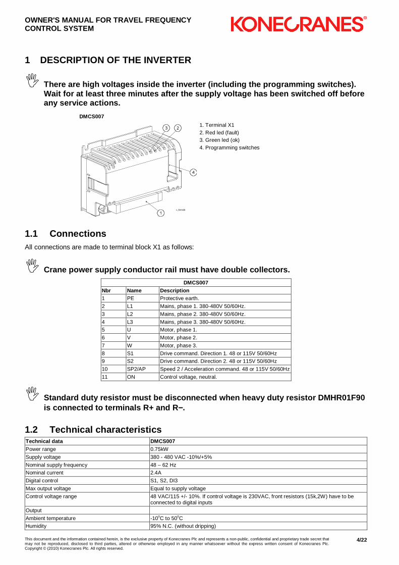
� There are high voltages inside the inverter (includ ing the programming switches). Wait for at least three minutes after the supply vo ltage has been switched off before any service actions.
DMCS007
c_fcmo1b
1. Terminal X1 2. Red led (fault) 3. Green led (ok) 4. Programming switches
1.1 Connections All connections are made to terminal block X1 as follows:
� Crane power supply conductor rail must have double collectors.
DMCS007 Nbr Name Description 1 PE Protective earth.
2 L1 Mains, phase 1. 380-480V 50/60Hz.
3 L2 Mains, phase 2. 380-480V 50/60Hz.
4 L3 Mains, phase 3. 380-480V 50/60Hz.
5 U Motor, phase 1.
6 V Motor, phase 2.
7 W Motor, phase 3.
8 S1 Drive command. Direction 1. 48 or 115V 50/60Hz
9 S2 Drive command. Direction 2. 48 or 115V 50/60Hz
10 SP2/AP Speed 2 / Acceleration command. 48 or 115V 50/60Hz
11 ON Control voltage, neutral.
� Standard duty resistor must be disconnected when he avy duty resistor DMHR01F90 is connected to terminals R+ and R −−−−.
1.2 Technical characteristics Technical data DMCS007 Power range 0.75kW
Supply voltage 380 - 480 VAC -10%/+5%
Nominal supply frequency 48 – 62 Hz
Nominal current 2.4A
Digital control S1, S2, DI3
Max output voltage Equal to supply voltage
Control voltage range 48 VAC/115 +/- 10%. If control voltage is 230VAC, front resistors (15k,2W) have to be connected to digital inputs
Output
Ambient temperature -10oC to 50oC
Humidity 95% N.C. (without dripping)

OWNER'S MANUAL FOR TRAVEL FREQUENCY CONTROL SYSTEM
This document and the information contained herein, is the exclusive property of Konecranes Plc and represents a non-public, confidential and proprietary trade secret that may not be reproduced, disclosed to third parties, altered or otherwise employed in any manner whatsoever without the express written consent of Konecranes Plc.Copyright © (2010) Konecranes Plc. All rights reserved.
5/22
Technical data DMCS007 Degree of protection Frequency converter + cover (IP20)
Dimensions (WxHxD) 133x92x60mm
Altitude Output current must be reduced 1 % for every 100 m over 1000 m. For altitudes over 3000 m, manufacturer must be consulted.
Pollution degree Pollution degree 2 according to NEMA ICS-1, IEC664 and UL840
Vibration IEC68-2-6
Shock IEC68-2-27
1.3 Normal operation The inverter goes into the ready-to-run state within one second after the power supply is connected. During running the inverter follows the operator’s speed reference according to the set acceleration/deceleration ramp. During direction change the brake is kept open all the time. When drive command is switched off the inverter decelerates to zero according to the set ramp and closes the mechanical brake.
1.4 Status indication leds (green and red) The inverter indicates its operating state by two leds. Red led indicates “fault state” (driving is inhibited). Green led indicates “ok-state”. Blinking of green led indicates that fault state has been active, but it has been recovered. Normal driving is however possible also when green led is blinking (in other words, blinking of green led does not indicate “warning-state”).
1.5 Compact brake motors This inverter is used with Compact brake motors, which have been especially designed for this use. The Compact brake motors have the following special features:
� Compact brake, which is opened by the magnetic force of the motor. When the magnetic force is removed (by cutting off the motor current) the brake is closed by spring force.
� High nominal frequency (80Hz…120Hz)
1.6 Programming switches
� WARNING!!! There are high voltages inside the inver ter (including the programming switches). Wait for at least three minutes after th e supply voltage has been switched off before any service actions.
The programming of the inverter is performed by dip-switches. The state of each switch is either OFF (0) or ON (1). There are five parameters that are possible to set by the switches S1-S4.
DMSC007
ON
DIP
12
34
ON
DIP
12
34
ON
DIP
12
34
ON DIP
1 2 3 4
S1
S2
S3
S4
S1 = Maximum speed S2 = Minimimum speed S3 = Acceleration / deceleration time S4 = Control mode and motor type
OWNER'S MANUAL FOR TRAVEL FREQUENCY CONTROL SYSTEM
This document and the information contained herein, is the exclusive property of Konecranes Plc and represents a non-public, confidential and proprietary trade secret that may not be reproduced, disclosed to third parties, altered or otherwise employed in any manner whatsoever without the express written consent of Konecranes Plc.Copyright © (2010) Konecranes Plc. All rights reserved.
6/22
1.7 The EMC requirements The device complies with the requirements of EN61800-3:2004 (IEC61800-3) for second environment, category C3, when a dedicated external EMC filter is applied.
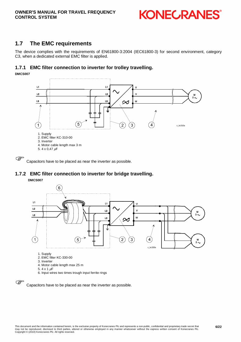
1.7.1 EMC filter connection to inverter for trolley travelling. DMCS007
c_kc310a
1. Supply 2. EMC filter KC-310-00 3. Inverter 4. Motor cable length max 3 m 5. 4 x 0,47 µF
� Capacitors have to be placed as near the inverter as possible.
1.7.2 EMC filter connection to inverter for bridge travelling. DMCS007
c_kc330a
1. Supply 2. EMC filter KC-330-00 3. Inverter 4. Motor cable length max 25 m 5. 4 x 1 µF 6. Input wires two times trough input ferrite rings
� Capacitors have to be placed as near the inverter as possible.
OWNER'S MANUAL FOR TRAVEL FREQUENCY CONTROL SYSTEM
This document and the information contained herein, is the exclusive property of Konecranes Plc and represents a non-public, confidential and proprietary trade secret that may not be reproduced, disclosed to third parties, altered or otherwise employed in any manner whatsoever without the express written consent of Konecranes Plc.Copyright © (2010) Konecranes Plc. All rights reserved.
7/22
2 DESCRIPTION OF CONTROL MODES
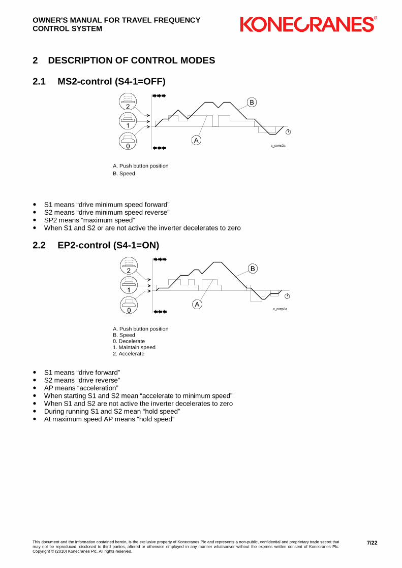
2.1 MS2-control (S4-1=OFF)
c_coms2a
A. Push button position B. Speed
� S1 means “drive minimum speed forward” � S2 means “drive minimum speed reverse” � SP2 means “maximum speed” � When S1 and S2 or are not active the inverter decelerates to zero
2.2 EP2-control (S4-1=ON)
c_coep2a
A. Push button position B. Speed 0. Decelerate 1. Maintain speed 2. Accelerate
� S1 means “drive forward” � S2 means “drive reverse” � AP means “acceleration” � When starting S1 and S2 mean “accelerate to minimum speed” � When S1 and S2 are not active the inverter decelerates to zero � During running S1 and S2 mean “hold speed” � At maximum speed AP means “hold speed”
OWNER'S MANUAL FOR TRAVEL FREQUENCY CONTROL SYSTEM
This document and the information contained herein, is the exclusive property of Konecranes Plc and represents a non-public, confidential and proprietary trade secret that may not be reproduced, disclosed to third parties, altered or otherwise employed in any manner whatsoever without the express written consent of Konecranes Plc.Copyright © (2010) Konecranes Plc. All rights reserved.
8/22
3 FAULT CODES, TROUBLESHOOTING
� There are high voltages inside the inverter (includ ing the programming switches). Wait for at least three minutes after the supply vo ltage has been switched off before any service actions.
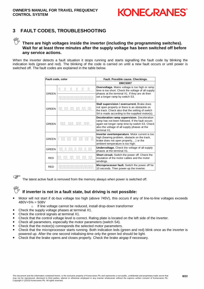
When the inverter detects a fault situation it stops running and starts signalling the fault code by blinking the indication leds (green and red). The blinking of the code is carried on until a new fault occurs or until power is switched off. The fault codes are explained in the table below.
Fault code, color Fault. Possible cause. Checkings.
DMCS007
GREEN
Overvoltage. Mains voltage is too high or ramp time is too short. Check the voltage of all supply phases at the terminal X1. If they are ok then set a longer ramp by switch S3.
GREEN
Stall supervision / overcurrent. Brake does not open properly or there is an obstackle on the track. Check also that the setting of switch S4 is made according to the supplied motor(s).
GREEN
Deceleration ramp supervision . Deceleration ramp has not been followed. If the fault occurs again set longer ramp time by switch S3. Check also the voltage of all supply phases at the terminal X1.
GREEN
Inverter overtemperature . Motor current is too high (bearing problem, obstacle on the track, brake does not open properly,…) or the ambient temperature is too high.
GREEN Undervoltage. Check the voltage of all supply phases at the terminal X1.
RED Short circuit. Switch the power off. Check the insulation of the motor cables and the motor windings.
RED Microprocessor fault. Switch the power off for 10 seconds. Then power-up the inverter.
� The latest active fault is removed from the memory always when power is switched off.
� If inverter is not in a fault state, but driving is not possible:
� Motor will not start if dc-bus voltage too high (above 745V), this occurs if any of line-to-line voltages exceeds 480V+5% = 508V
o If line voltage cannot be reduced, install drop-down transformer � Check the supply voltage phases at terminal X1. � Check the control signals at terminal X1. � Check that the control voltage level is correct. Rating plate is located on the left side of the inverter. � Check all parameters, especially the motor parameters (switch S4). � Check that the motor(s) corresponds the selected motor parameters. � Check that the microprocessor starts running. Both indication leds (green and red) blink once as the inverter is
powered up. After the one second initialising-time only the green led should be light. � Check that the brake opens and closes properly. Check the brake airgap if necessary.
OWNER'S MANUAL FOR TRAVEL FREQUENCY CONTROL SYSTEM
This document and the information contained herein, is the exclusive property of Konecranes Plc and represents a non-public, confidential and proprietary trade secret that may not be reproduced, disclosed to third parties, altered or otherwise employed in any manner whatsoever without the express written consent of Konecranes Plc.Copyright © (2010) Konecranes Plc. All rights reserved.
9/22
4 PROGRAMMING OF THE APPLICATION PARAMETERS
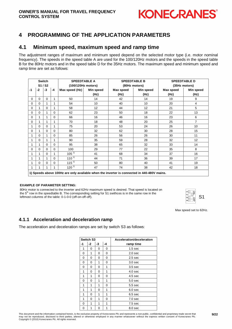
4.1 Minimum speed, maximum speed and ramp time The adjustment ranges of maximum and minimum speed depend on the selected motor type (i.e. motor nominal frequency). The speeds in the speed table A are used for the 100/120Hz motors and the speeds in the speed table B for the 80Hz motors and in the speed table D for the 35Hz motors. The maximum speed and minimum speed and ramp time are set as follows:
Switch S1 / S2
SPEEDTABLE A (100/120Hz motors)
SPEEDTABLE B (80Hz motors)
SPEEDTABLE D (35Hz motors)
-1 -2 -3 -4 Max speed (Hz) Min speed (Hz)
Max speed (Hz)
Min speed (Hz)
Max speed (Hz)
Min speed (Hz)
0 0 0 1 50 14 42 14 19 9
0 0 1 1 54 10 40 10 20 4
0 1 0 1 58 12 44 12 21 5
0 0 1 0 62 23 50 18 22 13
0 1 1 0 66 16 46 16 23 6
0 1 1 1 70 18 48 20 25 7
1 0 0 1 75 20 53 24 26 10
0 1 0 0 80 32 62 30 28 15
1 0 1 0 85 26 56 26 30 11
1 0 1 1 90 35 59 28 32 12
1 1 0 0 95 38 65 32 33 14
0 0 0 0 100 29 77 22 35 8
1 1 0 1 105 1) 41 68 34 37 16
1 1 1 0 110 1) 44 71 36 39 17
1 0 0 0 115 1) 50 80 40 41 19
1 1 1 1 120 1) 47 74 38 42 18
1) Speeds above 100Hz are only available when the i nverter is connected in 440-480V mains.
EXAMPLE OF PARAMETER SETTING: 80Hz motor is connected to the inverter and 62Hz maximum speed is desired. That speed is located on the 5th row in the speedtable B. The corresponding setting for S1 swithces is in the same row in the leftmost columns of the table: 0-1-0-0 (off-on-off-off).
ON
DIP
12
34 S1
Max speed set to 62Hz.
4.1.1 Acceleration and deceleration ramp
The acceleration and deceleration ramps are set by switch S3 as follows:
Switch S3 Acceleration/deceleration -1 -2 -3 -4 ramp time
1 0 0 0 1.5 sec
0 1 0 0 2.0 sec
0 0 0 0 2.5 sec
0 0 1 0 3.0 sec
0 0 0 1 3.5 sec
1 0 0 1 4.0 sec
1 1 0 0 4.5 sec
0 0 1 1 5.0 sec
1 1 1 0 5.5 sec
1 1 0 1 6.0 sec
1 0 1 1 6.5 sec
1 0 1 0 7.0 sec
0 1 1 1 7.5 sec
0 1 0 1 8.0 sec
OWNER'S MANUAL FOR TRAVEL FREQUENCY CONTROL SYSTEM
This document and the information contained herein, is the exclusive property of Konecranes Plc and represents a non-public, confidential and proprietary trade secret that may not be reproduced, disclosed to third parties, altered or otherwise employed in any manner whatsoever without the express written consent of Konecranes Plc.Copyright © (2010) Konecranes Plc. All rights reserved.
10/22
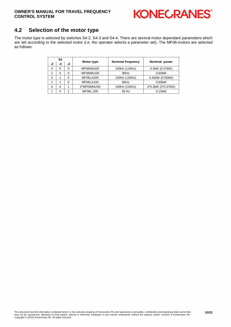
4.2 Selection of the motor type The motor type is selected by switches S4-2, S4-3 and S4-4. There are several motor dependant parameters which are set according to the selected motor (i.e. the operator selects a parameter set). The MF06-motors are selected as follows:
S4
Motor type Nominal frequency Nominal power -2 -3 -4 0 0 0 MF06MA200 100Hz (120Hz) 0.3kW (0.37kW)
1 0 0 MF06MA100 80Hz 0.65kW
0 1 0 MF06LA200 100Hz (120Hz) 0.45kW (0.55kW)
1 1 0 MF06LA100 80Hz 0.65kW
0 0 1 2*MF06MA200 100Hz (120Hz) 2*0.3kW (2*0.37kW)
1 0 1 MF06L-200 35 Hz 0.15kW

OWNER'S MANUAL FOR TRAVEL FREQUENCY CONTROL SYSTEM
This document and the information contained herein, is the exclusive property of Konecranes Plc and represents a non-public, confidential and proprietary trade secret that may not be reproduced, disclosed to third parties, altered or otherwise employed in any manner whatsoever without the express written consent of Konecranes Plc.Copyright © (2010) Konecranes Plc. All rights reserved.
11/22
5 DESCRIPTION OF THE INVERTER
� There are high voltages inside the inverter (includ ing the programming switches). Wait for at least three minutes after the supply vo ltage has been switched off before any service actions.
1.Control terminal X1 2.Power terminal X2 3.Programming switches 4.Leds
3 2
1 4
5.1 Connections Control signals are connected to terminal block X1 as follows:
Nbr Name Description 1 S1 Drive command. Direction 1. 48 or 115V 50/60Hz
2 S2 Drive command. Direction 2. 48 or 115V 50/60Hz
3 DI3 Digital input. 48 or 115V 50/60Hz.
4 DI4 Digital input. 48 or 115V 50/60Hz.
5 DI5 Digital input. 48 or 115V 50/60Hz.
6 ONE Control voltage, neutral.
7 R01 Relay output
8 R02 Relay output
9 Empty
10 T1 Motor thermistor
11 T2 Motor thermistor
Power cabling is connected to terminal block X2 as follows:
� Crane power supply conductor rail must have double collectors.
Nbr Name Description 1 L1 Mains, phase 1. 380-480V 50/60Hz.
2 L2 Mains, phase 2. 380-480V 50/60Hz.
3 L3 Mains, phase 3. 380-480V 50/60Hz.
4 U Motor, phase 1.
5 V Motor, phase 2.
6 W Motor, phase 3.
7 R+ Braking resistor, positive, see note
8 R- Braking resistor, negative, see note
9 PE Protective earth
OWNER'S MANUAL FOR TRAVEL FREQUENCY CONTROL SYSTEM
This document and the information contained herein, is the exclusive property of Konecranes Plc and represents a non-public, confidential and proprietary trade secret that may not be reproduced, disclosed to third parties, altered or otherwise employed in any manner whatsoever without the express written consent of Konecranes Plc.Copyright © (2010) Konecranes Plc. All rights reserved.
12/22
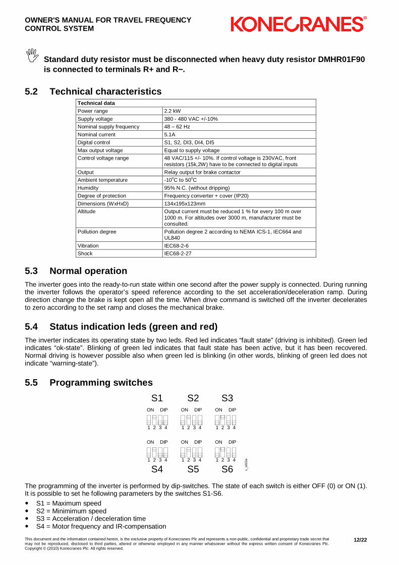
� Standard duty resistor must be disconnected when he avy duty resistor DMHR01F90 is connected to terminals R+ and R −−−−.
5.2 Technical characteristics Technical data Power range 2.2 kW
Supply voltage 380 - 480 VAC +/-10%
Nominal supply frequency 48 – 62 Hz
Nominal current 5.1A
Digital control S1, S2, DI3, DI4, DI5
Max output voltage Equal to supply voltage
Control voltage range 48 VAC/115 +/- 10%. If control voltage is 230VAC, front resistors (15k,2W) have to be connected to digital inputs
Output Relay output for brake contactor
Ambient temperature -10oC to 50oC
Humidity 95% N.C. (without dripping)
Degree of protection Frequency converter + cover (IP20)
Dimensions (WxHxD) 134x195x123mm
Altitude Output current must be reduced 1 % for every 100 m over 1000 m. For altitudes over 3000 m, manufacturer must be consulted.
Pollution degree Pollution degree 2 according to NEMA ICS-1, IEC664 and UL840
Vibration IEC68-2-6
Shock IEC68-2-27
5.3 Normal operation The inverter goes into the ready-to-run state within one second after the power supply is connected. During running the inverter follows the operator’s speed reference according to the set acceleration/deceleration ramp. During direction change the brake is kept open all the time. When drive command is switched off the inverter decelerates to zero according to the set ramp and closes the mechanical brake.
5.4 Status indication leds (green and red) The inverter indicates its operating state by two leds. Red led indicates “fault state” (driving is inhibited). Green led indicates “ok-state”. Blinking of green led indicates that fault state has been active, but it has been recovered. Normal driving is however possible also when green led is blinking (in other words, blinking of green led does not indicate “warning-state”).
5.5 Programming switches
ON DIP
1 2 3 4
ON DIP
1 2 3 4
ON DIP
1 2 3 4
ON DIP
1 2 3 4
ON DIP
1 2 3 4
ON DIP
1 2 3 4
S1 S2 S3
S4 S5 S6 c_s0
22a
The programming of the inverter is performed by dip-switches. The state of each switch is either OFF (0) or ON (1). It is possible to set he following parameters by the switches S1-S6.
� S1 = Maximum speed � S2 = Minimimum speed � S3 = Acceleration / deceleration time � S4 = Motor frequency and IR-compensation

OWNER'S MANUAL FOR TRAVEL FREQUENCY CONTROL SYSTEM
This document and the information contained herein, is the exclusive property of Konecranes Plc and represents a non-public, confidential and proprietary trade secret that may not be reproduced, disclosed to third parties, altered or otherwise employed in any manner whatsoever without the express written consent of Konecranes Plc.Copyright © (2010) Konecranes Plc. All rights reserved.
13/22
� S5 = Motor current, fast deceleration, stopping method � S6 = Control mode, slowdown speed, speed2, speed3
5.6 The EMC requirements (Not in use for deliveries in USA/Canada) The device complies with the requirements of EN61800-3:2004 (IEC61800-3) for second environment, category C3, when a dedicated external EMC filter is applied.
5.6.1 EMC filter connection to inverter for trolley travelling.
c_kc330ba 1. Supply 2. EMC filter KC-330-00 3. Inverter 4. Motor cable length max 3 m 5. 4 x 1 µF 6. Input wires two times through input ferrite rings.
KC-330-00 includes capacitors (4*1µF) and input ferrite rings (3 x EF 32008).
� Ferrite rings and capacitors must be placed as near the inverter as possible.
5.6.2 EMC filter connection to inverter for bridge travelling.
c_kc330ca
1. Supply 2. EMC filter KC-330-00 3. Inverter 4. Motor cable length max 1 m + 25 m 5. 4 x 1 µF 6. Input wires two times through input ferrite rings. 7. Output ferrite ring RH175285107
KC-330-00 includes capacitors (4*1µF) and input ferrite rings (3 x EF 32008).

OWNER'S MANUAL FOR TRAVEL FREQUENCY CONTROL SYSTEM
This document and the information contained herein, is the exclusive property of Konecranes Plc and represents a non-public, confidential and proprietary trade secret that may not be reproduced, disclosed to third parties, altered or otherwise employed in any manner whatsoever without the express written consent of Konecranes Plc.Copyright © (2010) Konecranes Plc. All rights reserved.
14/22
� Ferrite rings and capacitors must be placed as near the inverter as possible.

OWNER'S MANUAL FOR TRAVEL FREQUENCY CONTROL SYSTEM
This document and the information contained herein, is the exclusive property of Konecranes Plc and represents a non-public, confidential and proprietary trade secret that may not be reproduced, disclosed to third parties, altered or otherwise employed in any manner whatsoever without the express written consent of Konecranes Plc.Copyright © (2010) Konecranes Plc. All rights reserved.
15/22
6 DESCRIPTION OF CONTROL MODES
6.1 MS2-control (S6-1=OFF & S6-2=OFF)
c_coms2a
A. Pushbutton position B. Speed
� S1 means “drive minimum speed forward” � S2 means “drive minimum speed reverse” � HSP means “maximum speed” � When S1 and S2 or are not active the inverter decelerates to zero
6.2 EP2-control (S6-1=ON & S6-2=OFF)
c_coep2a
0. Decelerate 1. Maintain speed 2. Accelerate A. Pushbutton position B. Speed
� S1 means “drive forward” � S2 means “drive reverse” � AP means “accelerate” � When starting, S1 and S2 mean “accelerate to minimum speed” � When S1 and S2 are not active the inverter decelerates to zero � During running S1 and S2 mean “hold speed” � At maximum speed AP means “hold speed”

OWNER'S MANUAL FOR TRAVEL FREQUENCY CONTROL SYSTEM
This document and the information contained herein, is the exclusive property of Konecranes Plc and represents a non-public, confidential and proprietary trade secret that may not be reproduced, disclosed to third parties, altered or otherwise employed in any manner whatsoever without the express written consent of Konecranes Plc.Copyright © (2010) Konecranes Plc. All rights reserved.
16/22
6.3 EP3-control (S6-1=OFF & S6-2=ON)
c_coep3a
0. Decelerate 1. Minimum speed 2. Maintain speed 3. Accelerate A. Pushbutton position B. Speed
� S1 means “drive minimum speed forward” � S2 means “drive minimum speed reverse” � AP means “accelerate” � HOLD means “hold speed” � When S1 and S2 are not active the inverter decelerates to zero � At maximum speed AP means “hold speed”
6.4 MS4-control (S6-1=ON & S6-2=ON)
c_coms4a
A. Pushbutton position B. Speed
� S1 means “drive minimum speed forward” � S2 means “drive minimum speed reverse” � SP2 means “drive speed2” � SP3 means “drive speed3” � HSP means “drive maximum speed” � When S1 and S2 are not active the inverter decelerates to zero � The “highest” active input sets the speed reference (i.e. if HSP is active SP2 and SP3 are ignored. If SP3 is
active SP2 is ignored)

OWNER'S MANUAL FOR TRAVEL FREQUENCY CONTROL SYSTEM
This document and the information contained herein, is the exclusive property of Konecranes Plc and represents a non-public, confidential and proprietary trade secret that may not be reproduced, disclosed to third parties, altered or otherwise employed in any manner whatsoever without the express written consent of Konecranes Plc.Copyright © (2010) Konecranes Plc. All rights reserved.
17/22
7 FAULT CODES, TROUBLESHOOTING
� There are high voltages inside the inverter (includ ing the programming switches). Wait for at least three minutes after the supply vo ltage has been switched off before any service actions.
When the inverter detects a fault situation it stops running and starts signalling the fault code by blinking the indication leds (green and red). The blinking of the code is carried on until a new fault occurs or until power is switched off. The fault codes are explained in the table below.
Fault code, color Fault. Possible cause. Checkings.
Green Overvoltage. Mains voltage is too high or deceleration ramp time is too short. Check
the voltage of all supply phases at the terminal X2. If they are ok, set a longer ramp by switch S3 (and S5-3).
Green Stall supervision / overcurrent. Brake does not open properly or there is an obstackle on the track. Check also the motor dependent parameters.
Green Deceleration ramp supervision. Deceleration ramp has not been followed. If the fault occurs again set longer ramp time by switch S3. Check also the setting of the motor nominal current (switch S5).
Green
Motor overtemperature. Check the type and the loading of the motor. If there is no sensor in the motor the inverter terminals X1:10-11 must be short circuited.
Green Inverter overtemperature. Motor current is too high (bearing problem, obstacle on the track, brake does not open properly,…) or the ambient temperature is too high.
Green Undervoltage. Check the voltage of all supply phases at the terminal X2.
Red Short circuit. Switch the power off. Check the insulation of the motor cables and the motor windings.
Red Microprosessor fault. Switch the power off for 10 seconds. Then power-up the inverter.
� The latest active fault is removed from the memory always when power is switched off.
� If inverter is not in a fault state, but driving is not possible:
� Motor will not start if dc-bus voltage too high (above 745V), this occurs if any of line-to-line voltages exceeds 480V+10% = 528V
If line voltage cannot be reduced, install drop-down transformer � Check the supply voltage phases at terminal X2. � Check the drive command signal at terminal X1. � Check the limit-switch signals at terminal X1. � Check that the control voltage level is correct. Rating plate is located on the left side of the inverter. � Check all parameters, especially the motor dependent parameters. � Check that the motor(s) corresponds the selected motor parameters. � Check that the brake opens and closes properly. Check the brake airgap if necessary. Inverter starts and opens the brake, but motor does not rotate. Check motor current parameter.

OWNER'S MANUAL FOR TRAVEL FREQUENCY CONTROL SYSTEM
This document and the information contained herein, is the exclusive property of Konecranes Plc and represents a non-public, confidential and proprietary trade secret that may not be reproduced, disclosed to third parties, altered or otherwise employed in any manner whatsoever without the express written consent of Konecranes Plc.Copyright © (2010) Konecranes Plc. All rights reserved.
18/22
1 PROGRAMMING OF THE APPLICATION PARAMETERS
m Check that he wiring and the mechanical performance of the machinery is suitable for the selected application parameters.
7.1 Minimum speed, maximum speed and ramp time The adjustment ranges of maximum and minimum speed depend on the selected motor nominal frequency. Table A is for 100 and 120Hz motors, Table B for 80Hz motors and Table C for 50 and 60Hz motors. Maximum speed is set by the four switches of the switch-package S1 and minimum frequency by the four switches of the switch-package S2.
Switch S1 / S2
Table A (100/120Hz motors)
Table B (80Hz motors)
Table C (50/60Hz motors)
-1 -2 -3 -4 Max speed (Hz)
Min speed (Hz)
Max speed (Hz)
Min speed (Hz)
Max speed (Hz)
Min speed (Hz)
0 0 0 1 50 14 42 14 25 7
0 0 1 1 54 10 40 10 27 5
0 1 0 1 58 12 44 12 29 6
0 0 1 0 62 23 50 18 31 12
0 1 1 0 66 16 46 16 33 8
0 1 1 1 70 18 48 20 35 9
1 0 0 1 75 20 53 24 38 10
0 1 0 0 80 32 62 30 40 16
1 0 1 0 85 26 56 26 43 13
1 0 1 1 90 35 59 28 45 18
1 1 0 0 95 38 65 32 48 19
0 0 0 0 100 29 77 22 50 15
1 1 0 1 105 1) 41 68 34 53 2) 21
1 1 1 0 110 1) 44 71 36 55 2) 22
1 0 0 0 115 1) 50 80 40 58 2) 25
1 1 1 1 120 1) 47 74 38 60 2) 24
1) 100Hz may be exceeded only if line voltage is 44 0-480V mains. 2) 50Hz may be exceeded only if line voltage is 440 -480V mains.
7.1.1 Example of parameter setting 80Hz motor is connected to the inverter and 62Hz maximum speed is desired. That speed is located on the 5th row in the speed table B. The corresponding setting for S1 swithces is in the same row in the leftmost columns of the table: 0-1-0-0 (off-on-off-off).
ON
DIP
12
34
S1
OWNER'S MANUAL FOR TRAVEL FREQUENCY CONTROL SYSTEM
This document and the information contained herein, is the exclusive property of Konecranes Plc and represents a non-public, confidential and proprietary trade secret that may not be reproduced, disclosed to third parties, altered or otherwise employed in any manner whatsoever without the express written consent of Konecranes Plc.Copyright © (2010) Konecranes Plc. All rights reserved.
19/22
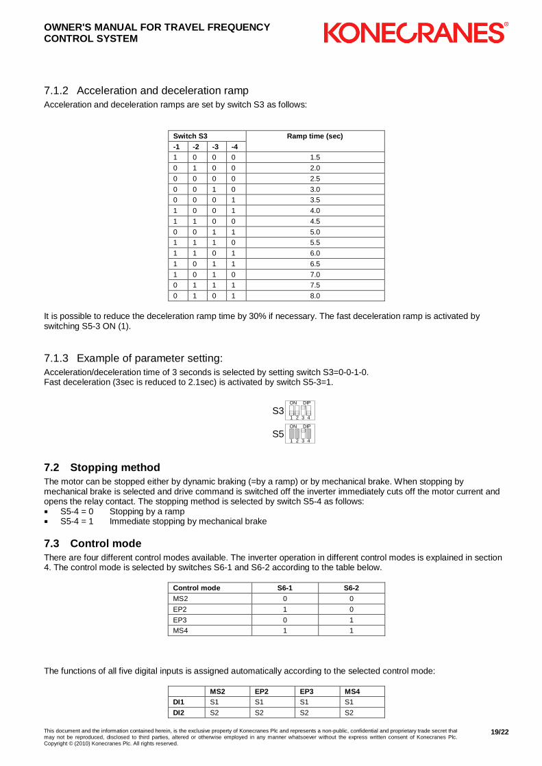
7.1.2 Acceleration and deceleration ramp Acceleration and deceleration ramps are set by switch S3 as follows:
Switch S3 Ramp time (sec) -1 -2 -3 -4 1 0 0 0 1.5
0 1 0 0 2.0
0 0 0 0 2.5
0 0 1 0 3.0
0 0 0 1 3.5
1 0 0 1 4.0
1 1 0 0 4.5
0 0 1 1 5.0
1 1 1 0 5.5
1 1 0 1 6.0
1 0 1 1 6.5
1 0 1 0 7.0
0 1 1 1 7.5
0 1 0 1 8.0
It is possible to reduce the deceleration ramp time by 30% if necessary. The fast deceleration ramp is activated by switching S5-3 ON (1).
7.1.3 Example of parameter setting: Acceleration/deceleration time of 3 seconds is selected by setting switch S3=0-0-1-0. Fast deceleration (3sec is reduced to 2.1sec) is activated by switch S5-3=1.
ON DIP
1 2 3 4S3
ON DIP
1 2 3 4S5
7.2 Stopping method The motor can be stopped either by dynamic braking (=by a ramp) or by mechanical brake. When stopping by mechanical brake is selected and drive command is switched off the inverter immediately cuts off the motor current and opens the relay contact. The stopping method is selected by switch S5-4 as follows: � S5-4 = 0 Stopping by a ramp � S5-4 = 1 Immediate stopping by mechanical brake
7.3 Control mode There are four different control modes available. The inverter operation in different control modes is explained in section 4. The control mode is selected by switches S6-1 and S6-2 according to the table below.
Control mode S6-1 S6-2 MS2 0 0
EP2 1 0
EP3 0 1
MS4 1 1
The functions of all five digital inputs is assigned automatically according to the selected control mode:
MS2 EP2 EP3 MS4 DI1 S1 S1 S1 S1
DI2 S2 S2 S2 S2

OWNER'S MANUAL FOR TRAVEL FREQUENCY CONTROL SYSTEM
This document and the information contained herein, is the exclusive property of Konecranes Plc and represents a non-public, confidential and proprietary trade secret that may not be reproduced, disclosed to third parties, altered or otherwise employed in any manner whatsoever without the express written consent of Konecranes Plc.Copyright © (2010) Konecranes Plc. All rights reserved.
20/22
MS2 EP2 EP3 MS4 DI3 HSP AP HOLD SP2
DI4 S12 S11 AP SP3
DI5 S22 S21 S11/S21 HSP
Description of the control signals:
S1 Drive command forward
AP Acceleration command
S11 Slowdown limit forward
S12 Stop-limit forward
SP2 Speed2
HSP High speed
S2 Drive command reverse
HOLD Hold speed command
S21 Slowdown limit reverse
S22 Stop-limit reverse
SP3 Speed3
7.4 Slowdown speed
S1
S21 S11
EP2 EP3
S2
Slowdown frequency is activated in EP2 and EP3 control modes when the slowdown limit circuit is opened. In EP2 there are separate inputs for both limit switch, therefore it is possible to drive high speed in the slowdown area in the safe direction. In EP3 there is only one input and therefore the speed is limited in both directions in the slowdown area. There are two alternatives for the level of slowdown speed which are selected by switch S6-3 as follows: � S6-3 = 0 Slowdown speed is 20% of the maximum speed (set by switch S1) � S6-3 = 1 Slowdown speed is 35% of the maximum speed (set by switch S1)
7.5 Speed2 and Speed3 In MS4-control mode the lowest speed level is set by switch S2 and the highest level by switch S1. There are two alternative settings for the speed2 and speed3, which are set as a percentage of the maximum speed by switch S6-3 as follows: � S6-3 = 0 Speed2 is 20% of maximum speed and speed3 is 40% of maximum � S6-3 = 1 Speed2 is 30% of maximum speed and speed3 is 50% of maximum

OWNER'S MANUAL FOR TRAVEL FREQUENCY CONTROL SYSTEM
This document and the information contained herein, is the exclusive property of Konecranes Plc and represents a non-public, confidential and proprietary trade secret that may not be reproduced, disclosed to third parties, altered or otherwise employed in any manner whatsoever without the express written consent of Konecranes Plc.Copyright © (2010) Konecranes Plc. All rights reserved.
21/22
2 PROGRAMMING OF THE MOTOR PARAMETERS The motor parameters are set by switches S4 and S5 according to the following table. Only the most common motor types are shown in the table. Settings for other motors can be defined when motor nominal frequency, voltage, current and the IR-rate are known.
S5 settings
Motor type Nominal voltage and frequency S4
settings Number of motors 1 2 4
MF06MA200 400V 100Hz 460V 120Hz 0 00xx 10xx 11xx
MF06MA100 400V 80Hz 1010 10xx 11xx -
MF06LA200 400V 100Hz 460V 120Hz 10 10xx 11xx -
MF06LA100 400V 80Hz 1001 10xx 11xx -
MF06LB200 400V 100Hz 460V 120Hz 10 01xx - -
MF06LB100 400V 80Hz 1011 01xx - -
MF07LA200 380-415V 50Hz 460-480V 60Hz 100 00xx 10xx 11xx
MF07LA100 380-415V 50Hz 460-480V 60Hz 101 00xx 10xx 11xx
MF07LB200 380-415V 50Hz 460-480V 60Hz 100 00xx 01xx -
MF07LB100 380-415V 50Hz 460-480V 60Hz 101 00xx 10xx 11xx
MF07ZC200 380-415V 50Hz 460-480V 60Hz 110 10xx 11xx -
MF07ZC100 380-415V 50Hz 460-480V 60Hz 111 10xx 11xx -
MF09LA200 380-415V 50Hz 460-480V 60Hz 110 11xx - -
MF09LA100 380-415V 50Hz 460-480V 60Hz 111 01xx 11xx -
MF09LB200 380-415V 50Hz 460-480V 60Hz 101 11xx - -
MF09LB100 380-415V 50Hz 460-480V 60Hz 111 11xx - -
7.6 Defining the motor parameters
7.6.1 Motor nominal voltage and frequency Motor nominal voltage and frequency are selected by switches S4-1 and S4-2 according to the following table:
Motor nominal S4-1 S4-2 Speedtable Voltage Frequency
400V 460V
100Hz 120Hz
0 0 A
400V 80Hz 1 0 B
380-415V 440-480V
50Hz 60Hz
0 1 C
7.6.2 IR-compensation By the IR-compensation the effect of the stator resistance at low frequencies is compensated by increasing the U/f-ratio. Typically the necessary amount of compensation (added voltage) is higher for small motors. The IR-compensation is set by switches S4-3 and S4-4. Estimation of the correct setting of IR-compensation is made by calculating the IR-rate of the motor.
U(V)
f (Hz)f middle0
ON DIP
1 2 3 4
S4 setting
ON DIP
1 2 3 4
ON DIP
1 2 3 4
ON DIP
1 2 3 4
Calculation of the IR-rate:
OWNER'S MANUAL FOR TRAVEL FREQUENCY CONTROL SYSTEM
This document and the information contained herein, is the exclusive property of Konecranes Plc and represents a non-public, confidential and proprietary trade secret that may not be reproduced, disclosed to third parties, altered or otherwise employed in any manner whatsoever without the express written consent of Konecranes Plc.Copyright © (2010) Konecranes Plc. All rights reserved.
22/22
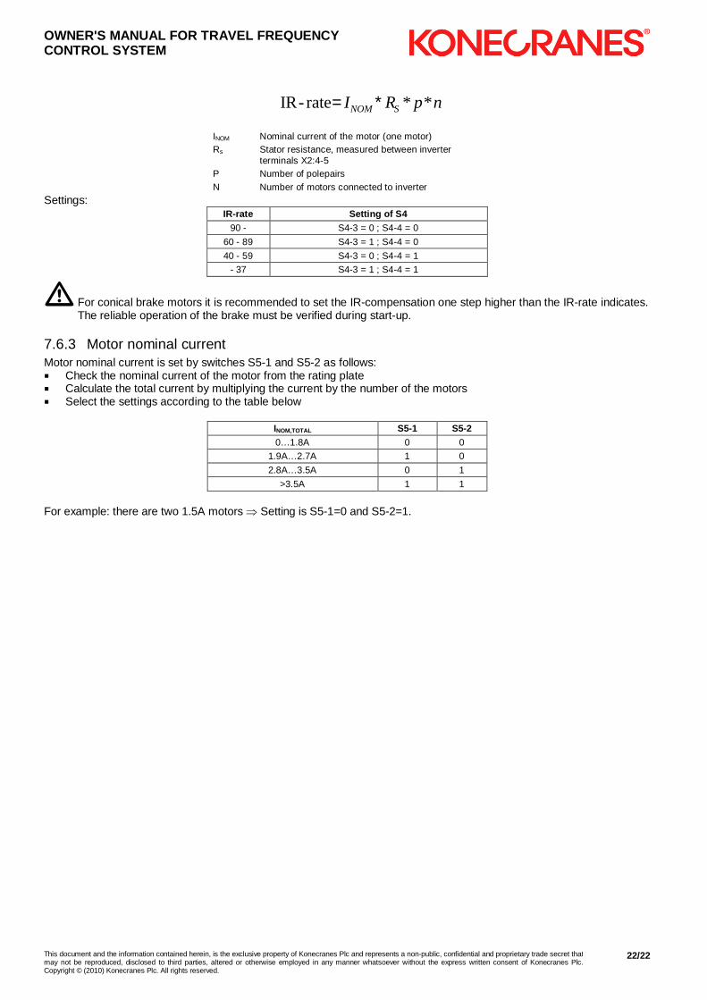
npRI SNOM **rate-IR ∗=
INOM Nominal current of the motor (one motor) Rs Stator resistance, measured between inverter
terminals X2:4-5 P Number of polepairs N Number of motors connected to inverter
Settings: IR-rate Setting of S4
90 - S4-3 = 0 ; S4-4 = 0
60 - 89 S4-3 = 1 ; S4-4 = 0
40 - 59 S4-3 = 0 ; S4-4 = 1
- 37 S4-3 = 1 ; S4-4 = 1
m For conical brake motors it is recommended to set the IR-compensation one step higher than the IR-rate indicates. The reliable operation of the brake must be verified during start-up.
7.6.3 Motor nominal current Motor nominal current is set by switches S5-1 and S5-2 as follows: � Check the nominal current of the motor from the rating plate � Calculate the total current by multiplying the current by the number of the motors � Select the settings according to the table below
INOM,TOTAL S5-1 S5-2 0…1.8A 0 0
1.9A…2.7A 1 0
2.8A…3.5A 0 1
>3.5A 1 1
For example: there are two 1.5A motors ⇒ Setting is S5-1=0 and S5-2=1.
Related Documents


