http://www.UandiStar.org http://www.UandiStar.org DC Machines Introduction D. C. machines are seldom used in ordinary applications because all electric supply companies furnish alternating current However, for special applications such as in steel mills, mines and electric trains, it is advantageous to convert alternating current into direct current in order to use D.C. motors. The reason is that speed/torque characteristics of D.C. motors are much more superior to that of a.c. motors. Therefore, it is not surprising to note that for industrial drives, D.C. motors are as popular as 3-phase induction motors. Like D.C. generators, D.C. motors are also of three types viz., series-wound, shunt-wound and compoundwound. The use of a particular motor depends upon the mechanical load it has to drive. In DC Machines the field poles are present on the stator called as YOKE. Armature windings and Commutator are on the Rotor. The Figure gives the cross-sectional view of a 4-pole DC machine. Brushes press on to the Commutator view for collecting the power from a dc generator or for feeding the DC Power to the armature of a DC Motor. DC Machines are of three types: 1. Series (A) 2. Shunt (B) 3. Compound (C) DC Series machines has the field winding in series with armature circuit, DC Shunt Machine has field winding across the armature circuit. Where as DC Compound machine has two Field Windings. One across the armature and the other in series with the armature. DC Machines has inter poles. Large DC machines have also compensating windings embedded in the pole faces of the main poles. DC Machine Posses very versatile characteristics. DC motor is easily adaptable for drives requiring wide range speed control and maintenance. It is highly versatile energy conservation device. It can meet the demand of loads requiring high starting torques, high accelerating and decelerating torques. In view of these outstanding features, DC Machines are widely used for the industrial purpose particularly for tough jobs as are in steel mills. There are two types of DC Machines depending on their field system employed, they are:

Welcome message from author
This document is posted to help you gain knowledge. Please leave a comment to let me know what you think about it! Share it to your friends and learn new things together.
Transcript
http://www.UandiStar.org
http://www.UandiStar.org
DC Machines
Introduction
D. C. machines are seldom used in ordinary applications because all electric supply
companies furnish alternating current However, for special applications such as in steel mills,
mines and electric trains, it is advantageous to convert alternating current into direct current in
order to use D.C. motors. The reason is that speed/torque characteristics of D.C. motors are much
more superior to that of a.c. motors. Therefore, it is not surprising to note that for industrial
drives, D.C. motors are as popular as 3-phase induction motors. Like D.C. generators, D.C. motors
are also of three types viz., series-wound, shunt-wound and compoundwound. The use of a
particular motor depends upon the mechanical load it has to drive.
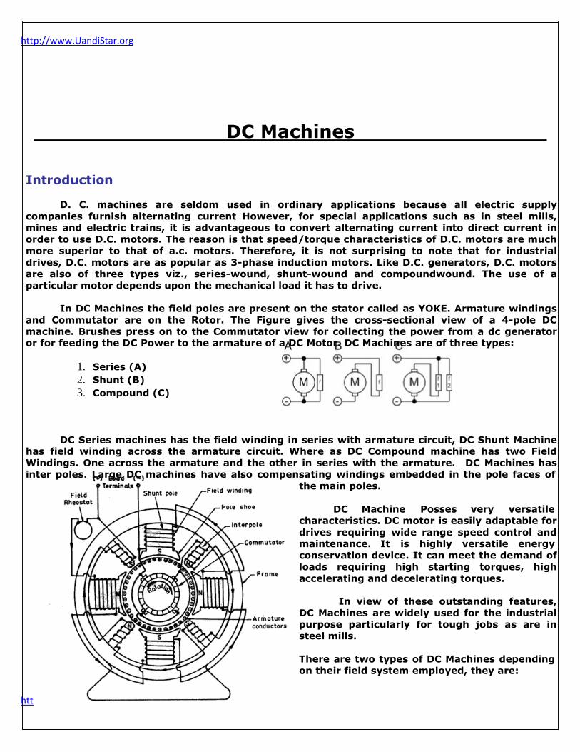
In DC Machines the field poles are present on the stator called as YOKE. Armature windings
and Commutator are on the Rotor. The Figure gives the cross-sectional view of a 4-pole DC
machine. Brushes press on to the Commutator view for collecting the power from a dc generator or for feeding the DC Power to the armature of a DC Motor. DC Machines are of three types:
1. Series (A)
2. Shunt (B)
3. Compound (C)
DC Series machines has the field winding in series with armature circuit, DC Shunt Machine has field winding across the armature circuit. Where as DC Compound machine has two Field
Windings. One across the armature and the other in series with the armature. DC Machines has
inter poles. Large DC machines have also compensating windings embedded in the pole faces of
the main poles.
DC Machine Posses very versatile
characteristics. DC motor is easily adaptable for
drives requiring wide range speed control and
maintenance. It is highly versatile energy
conservation device. It can meet the demand of
loads requiring high starting torques, high
accelerating and decelerating torques.
In view of these outstanding features,
DC Machines are widely used for the industrial
purpose particularly for tough jobs as are in
steel mills.
There are two types of DC Machines depending
on their field system employed, they are:
http://www.UandiStar.org
http://www.UandiStar.org
HOMO-POLAR Machines HETERO-POLAR Machines
1
http://www.UandiStar.org
http://www.UandiStar.org
HOMO-POLAR Machines
These types of machines are used where low Voltage and High Currents are required and
the fields system is unusual as in the Faraday Disc Dynamo, which is an example of this type of
machine.
HETERO-POLAR Machines
These types of machines are most commonly used in Practice. The magnetic poles are mounted
as shown in figure to form alternate south and north poles when traversed along the
circumference of an armature. These machines are used for moderate voltage and high output
power.
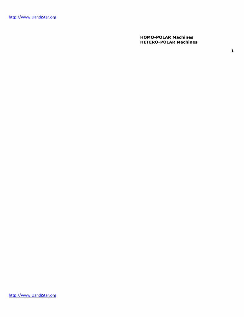
Construction of a DC machine Basically the construction of a DC machine includes mainly 7 parts. They are:
i. Magnetic Frame (or) Yoke
ii. Poles
a. Pole Face (or) Pole Core b. Pole Shoe
iii. Pole Windings (or) Field Windings
iv. Armature Core
v. Commutator
vi. Armature Windings
vii. Brushes and Bearings
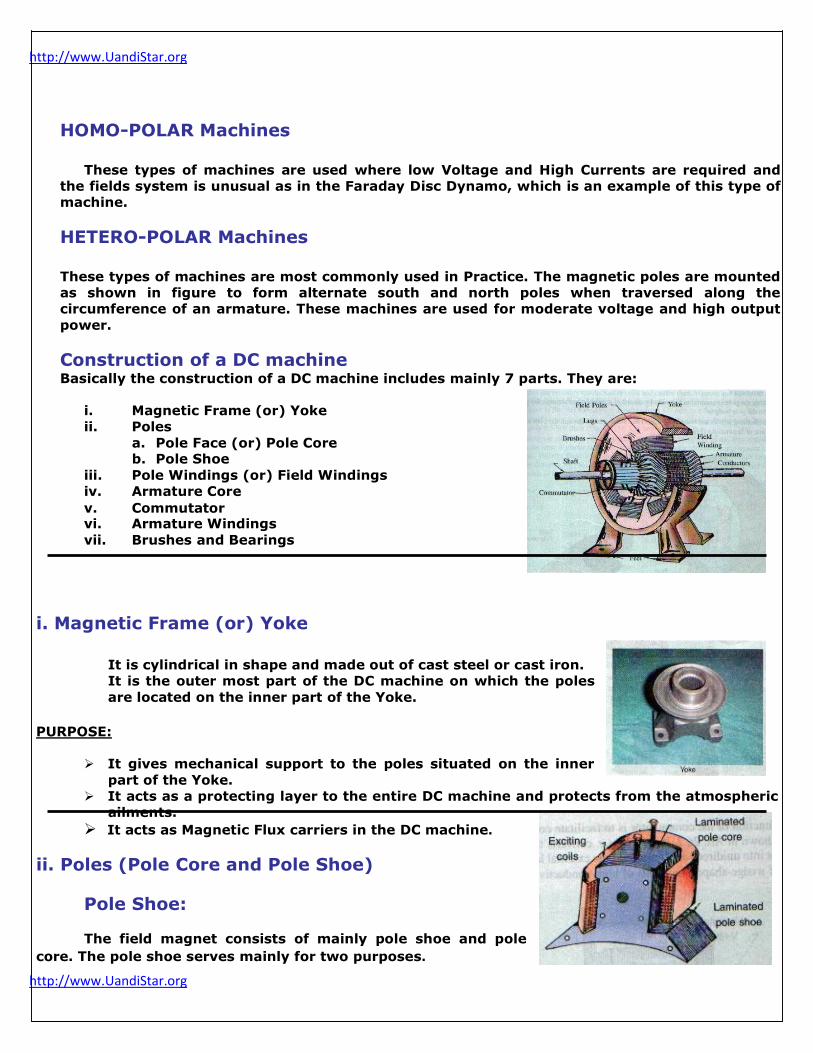
i. Magnetic Frame (or) Yoke
It is cylindrical in shape and made out of cast steel or cast iron.
It is the outer most part of the DC machine on which the poles
are located on the inner part of the Yoke.
PURPOSE:
It gives mechanical support to the poles situated on the inner
part of the Yoke.
It acts as a protecting layer to the entire DC machine and protects from the atmospheric
ailments.
It acts as Magnetic Flux carriers in the DC machine.
ii. Poles (Pole Core and Pole Shoe)
Pole Shoe:
The field magnet consists of mainly pole shoe and pole
core. The pole shoe serves mainly for two purposes.
http://www.UandiStar.org
http://www.UandiStar.org
2
http://www.UandiStar.org
http://www.UandiStar.org
In spreading the magnetic flux in the air gap and being of larger cross-section, reduce
the reluctance of the magnetic path.
It supports the exciting coils (or field coils) shown in figure.
Pole Core:
The pole core itself maybe a solid piece made up of either cast iron or cast steel. But
the pole shoe is laminated.
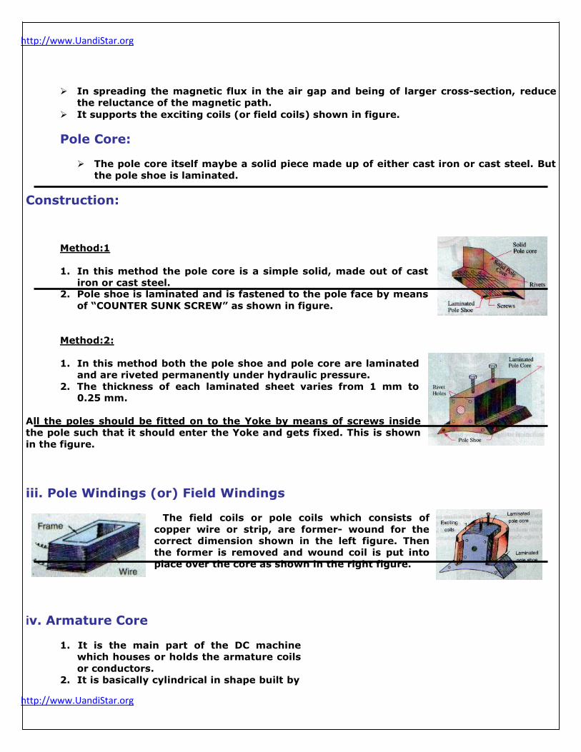
Construction:
Method: 1
1. In this method the pole core is a simple solid, made out of cast
iron or cast steel. 2. Pole shoe is laminated and is fastened to the pole face by means
of “COUNTER SUNK SCREW” as shown in figure.
Method: 2:
1. In this method both the pole shoe and pole core are laminated
and are riveted permanently under hydraulic pressure.
2. The thickness of each laminated sheet varies from 1 mm to
0.25 mm. All the poles should be fitted on to the Yoke by means of screws inside
the pole such that it should enter the Yoke and gets fixed. This is shown
in the figure.
iii. Pole Windings (or) Field Windings
The field coils or pole coils which consists of
copper wire or strip, are former- wound for the
correct dimension shown in the left figure. Then
the former is removed and wound coil is put into
place over the core as shown in the right figure.
iv. Armature Core
1. It is the main part of the DC machine
which houses or holds the armature coils
or conductors.
2. It is basically cylindrical in shape built by

http://www.UandiStar.org
http://www.UandiStar.org
several circular steel disks.
3. Every disk is punched, the punched
portion is called as “SLOTS” and the un-
punched portion is called as “TEETH”.
3
http://www.UandiStar.org
http://www.UandiStar.org
4. The slot must be covered with the insulating material MICA. 5. The laminations are perforated for air duct which permits the axial flow of air through
the armature for cooling purpose.
6. The inner peripheral consists of “KEYWAYS” where as the outer peripheral consists of
“SLOTS and TEETH”.
7. Keyways are used to fix the shaft, which appears as a “DOVE- Tailed” or “Wedge –
Shaped”.
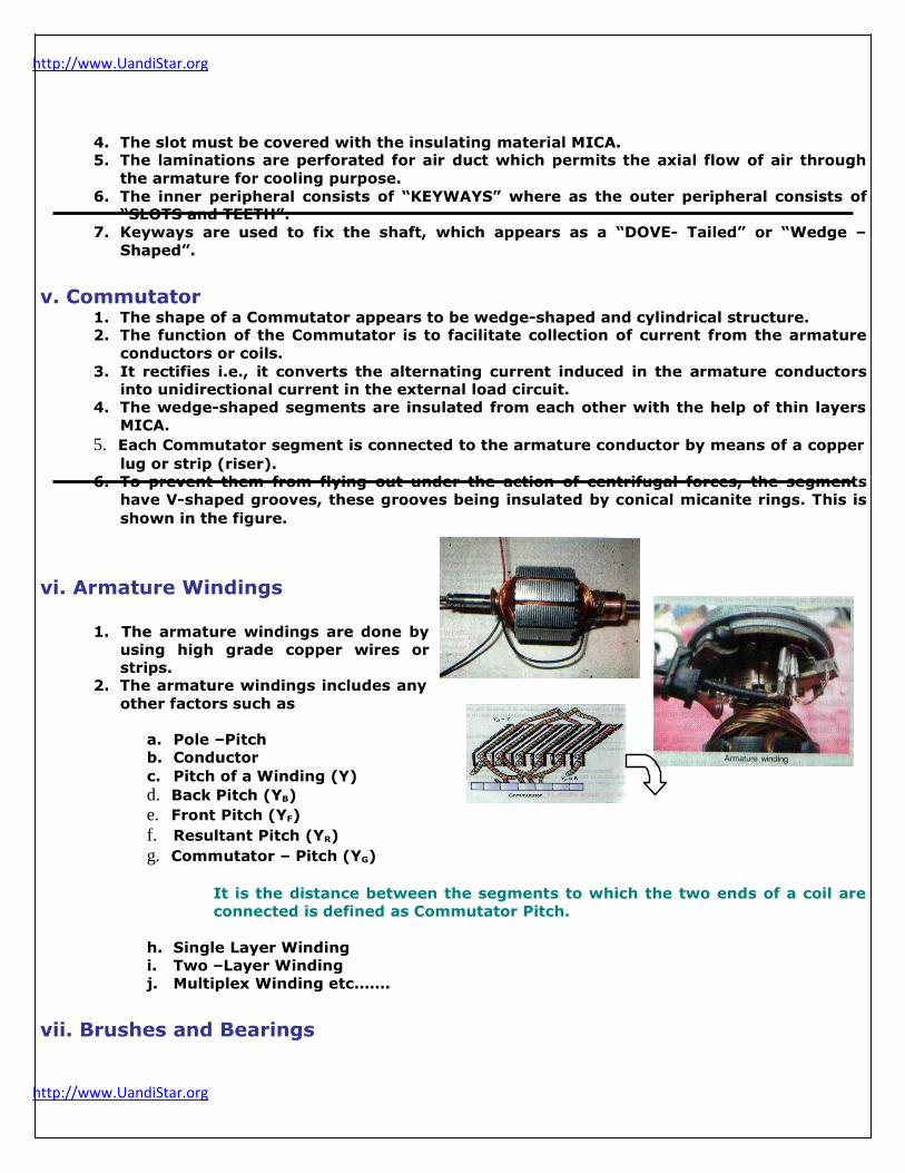
v. Commutator 1. The shape of a Commutator appears to be wedge-shaped and cylindrical structure. 2. The function of the Commutator is to facilitate collection of current from the armature
conductors or coils.
3. It rectifies i.e., it converts the alternating current induced in the armature conductors
into unidirectional current in the external load circuit.
4. The wedge-shaped segments are insulated from each other with the help of thin layers
MICA.
5. Each Commutator segment is connected to the armature conductor by means of a copper
lug or strip (riser).
6. To prevent them from flying out under the action of centrifugal forces, the segments
have V-shaped grooves, these grooves being insulated by conical micanite rings. This is
shown in the figure.
vi. Armature Windings
1. The armature windings are done by
using high grade copper wires or
strips. 2. The armature windings includes any
other factors such as
a. Pole –Pitch
b. Conductor
c. Pitch of a Winding (Y)
d. Back Pitch (YB)
e. Front Pitch (YF)
f. Resultant Pitch (YR)
g. Commutator – Pitch (YG)
It is the distance between the segments to which the two ends of a coil are
connected is defined as Commutator Pitch.
h. Single Layer Winding
i. Two –Layer Winding
j. Multiplex Winding etc…….
vii. Brushes and Bearings

http://www.UandiStar.org
http://www.UandiStar.org
1. The function of Brushes is to collect the current from the Commutator, is usually
made of carbon or graphite and is in the shape of a rectangular block. 2. These brushes are housed in brush-holders usually of the box-type variety.
4

http://www.UandiStar.org
http://www.UandiStar.org
3. The brushes are made to bear
down on the commutator by a
spring whose tension can be
adjusted by changing the position
of the lever in the notches. 4. A flexible copper wire is mounted
at the top of the brush conveys
current from the brushes to the
holder.
5. The number of brushes per spindle
depends on the magnitude of the
current to be collected from the Commutator.
6. Because of the reliability, ball-bearings are frequently employed, though for heavy
duties. Roller bearings are most preferred.
7. Sleeve bearings are used which are lubricated by ring oilers fed from oil reservoir
in the bearing bracket. This is shown in the figure.
Operation of a DC Machine as a Generator
Principle:
An Electric Generator is a machine which converts mechanical energy or Power in to
Electrical energy or power. The energy conversion is based on the principle of the production of
dynamically induced emf. Whenever a conductor cuts the magnetic flux dynamically, induced emf
is produced in it according to the Faraday‟s laws of Electromagnetic induction. This emf causes a
current to flow if the conductor circuit is closed.
Hence, two basic essential parts of an electrical generator are
Magnetic Field
Conductor or Conductors which can move
as to cut the flux
Construction of Generators
The generator mainly consists of magnetic
poles which are mounted on the stator and a
armature core in between the magnetic field. The armature conductors are placed within the slots in
the armature core. Initially the armature conductors
are wounded in rectangular shape flat coils. Let us
consider a single turn rectangular copper coil
rotating about its own axis in a magnetic field
provided by either permanent or electromagnets.
The two ends of the coil are joined to two slip rings which are insulated from each other and from the
central shaft as shown in the figure. The collecting
brushes are made up of copper or carbon and are pressed against the split rings. Their function is
to collect the current induced in the coil and to convey it to the external load resistance „R‟. The
rotating coil may be called as „Armature‟ and the magnets as „Field Magnets‟.

http://www.UandiStar.org
http://www.UandiStar.org
5
http://www.UandiStar.org
http://www.UandiStar.org
Working (Generator)
Assume the coil to be rotating in clock-wise direction as shown. As the coil assumes
successive position in the field, the flux linked wit it changes. Hence an emf is induces in it which
is proportional to the rate of change of flux linkage
E = NdФ
dt
When the plane coil is at right angle to the lines of flux. Then the flux linked with the coil is
maximum, but rate of change of flux linkage is minimum. As a result, the coil sides do not cut the
flux, rather they move along them parallel. Hence there is no emf induced in the coil. As a result
coil continues rotating further, rate of change of flux linkage increases when it makes an angle of 90°. Here, the coil will be in horizontal, the flux linked with the coil is minimum but rate of change
of flux is maximum. Hence maximum emf is induced in the coil at 90°.
In the next quarter revolution (i.e. from 90° to 180°), flux linked with the coil gradually
increases but the rate of change of flux linkages decreases. Hence the induced emf decreases
gradually till the position, it is reduced to zero. In the first half revolution, emf is induced at the
initial position, maximum when it is at 90° and no emf at 180°. The direction of this induced emf
can be found by applying Fleming‟s right-Hand Rule which gives its direction. Hence the current
flows.
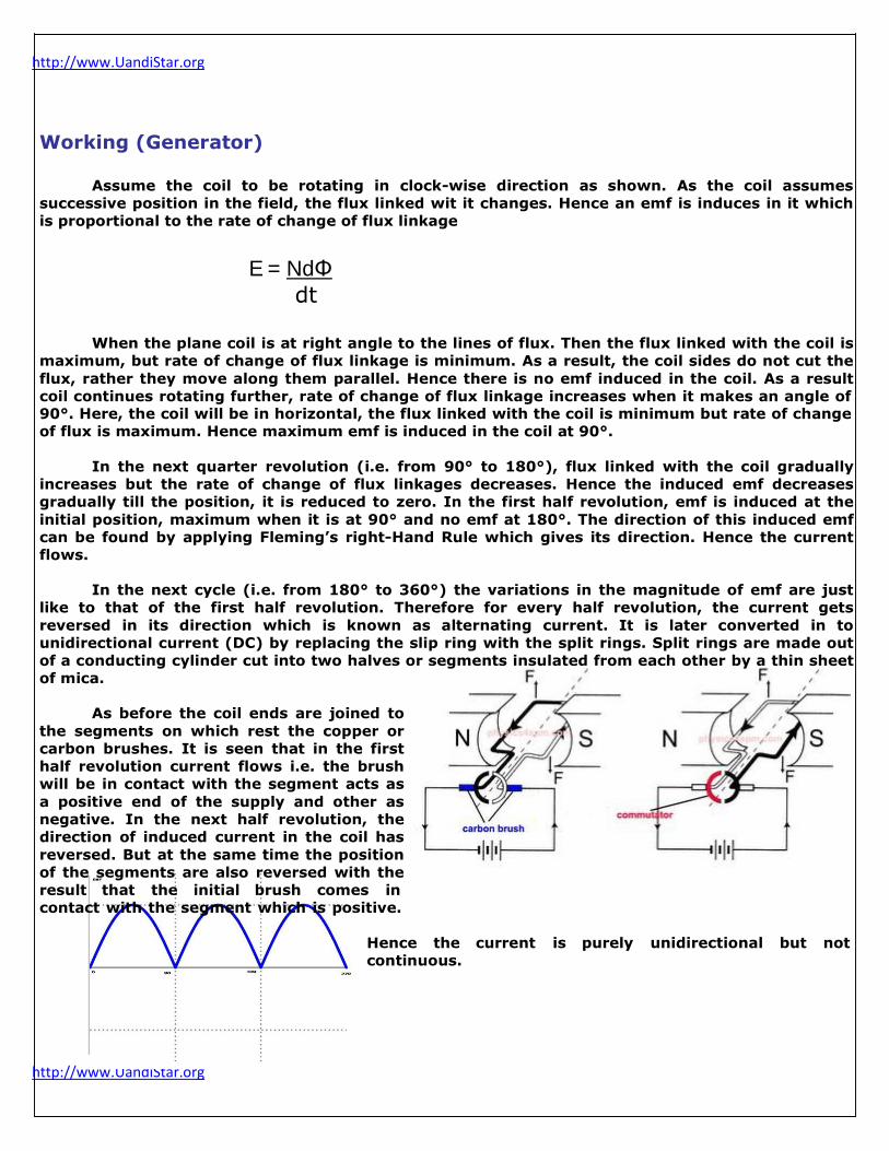
In the next cycle (i.e. from 180° to 360°) the variations in the magnitude of emf are just
like to that of the first half revolution. Therefore for every half revolution, the current gets
reversed in its direction which is known as alternating current. It is later converted in to
unidirectional current (DC) by replacing the slip ring with the split rings. Split rings are made out
of a conducting cylinder cut into two halves or segments insulated from each other by a thin sheet
of mica.
As before the coil ends are joined to
the segments on which rest the copper or
carbon brushes. It is seen that in the first
half revolution current flows i.e. the brush
will be in contact with the segment acts as
a positive end of the supply and other as
negative. In the next half revolution, the
direction of induced current in the coil has
reversed. But at the same time the position
of the segments are also reversed with the
result that the initial brush comes in
contact with the segment which is positive.
Hence the current is purely unidirectional but not
continuous.

http://www.UandiStar.org
http://www.UandiStar.org
6
http://www.UandiStar.org
http://www.UandiStar.org
Operation of a DC machine as a motor
Principle:
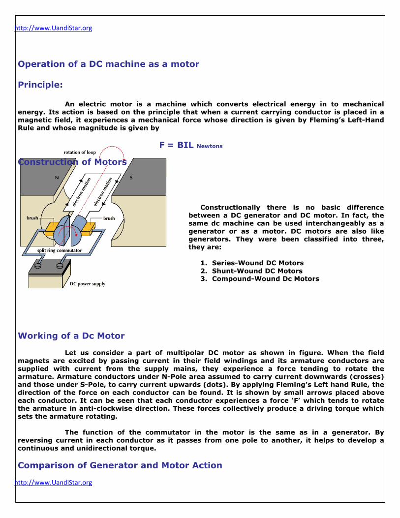
An electric motor is a machine which converts electrical energy in to mechanical
energy. Its action is based on the principle that when a current carrying conductor is placed in a
magnetic field, it experiences a mechanical force whose direction is given by Fleming‟s Left-Hand
Rule and whose magnitude is given by
Construction of Motors
F = BIL Newtons
Constructionally there is no basic difference
between a DC generator and DC motor. In fact, the
same dc machine can be used interchangeably as a
generator or as a motor. DC motors are also like generators. They were been classified into three,
they are:
1. Series-Wound DC Motors
2. Shunt-Wound DC Motors 3. Compound-Wound Dc Motors
Working of a Dc Motor
Let us consider a part of multipolar DC motor as shown in figure. When the field
magnets are excited by passing current in their field windings and its armature conductors are
supplied with current from the supply mains, they experience a force tending to rotate the
armature. Armature conductors under N-Pole area assumed to carry current downwards (crosses)
and those under S-Pole, to carry current upwards (dots). By applying Fleming‟s Left hand Rule, the
direction of the force on each conductor can be found. It is shown by small arrows placed above
each conductor. It can be seen that each conductor experiences a force „F‟ which tends to rotate
the armature in anti-clockwise direction. These forces collectively produce a driving torque which
sets the armature rotating.
The function of the commutator in the motor is the same as in a generator. By
reversing current in each conductor as it passes from one pole to another, it helps to develop a
continuous and unidirectional torque.
Comparison of Generator and Motor Action
http://www.UandiStar.org
http://www.UandiStar.org
The same DC Machine can be used interchangeably as a generator as well as motor. When
operating as a generator, it is driven by a mechanical machine and it develops voltage which I turn
produces a current flow in an electric circuit. When operating as a motor, it is supplied by electric
current and it acquires torque which in turn produces mechanical rotation.
7
http://www.UandiStar.org
http://www.UandiStar.org
Generator Action
Let us consider a part of a generator whose armature is being driven clockwise by its
prime mover as shown in figure. Fig.1 represents the field setup independently by the main poles
and the armature conductors like „A‟ in the shown figure. The resultant field or magnetic lines of
flux may be linked to the rubber bands under tension. Hence, the bet lines of flux set up a
mechanical force on „A‟ much, just like as the bent elastic rubber band of a catapult, Produces a
mechanical force on the piece of a stone. The direction of this force is opposite to that of armature
rotation. Hence, it is known as backward force or magnetic drag on the conductors.
Therefore, against this drag action on all the armature conductors that the prime
mover has to work. The work done in overcoming this opposition is converted into electrical
energy.
E.M.F Equation in a DC Machine
Generator Generated EMF or EMF Equation of a Generator
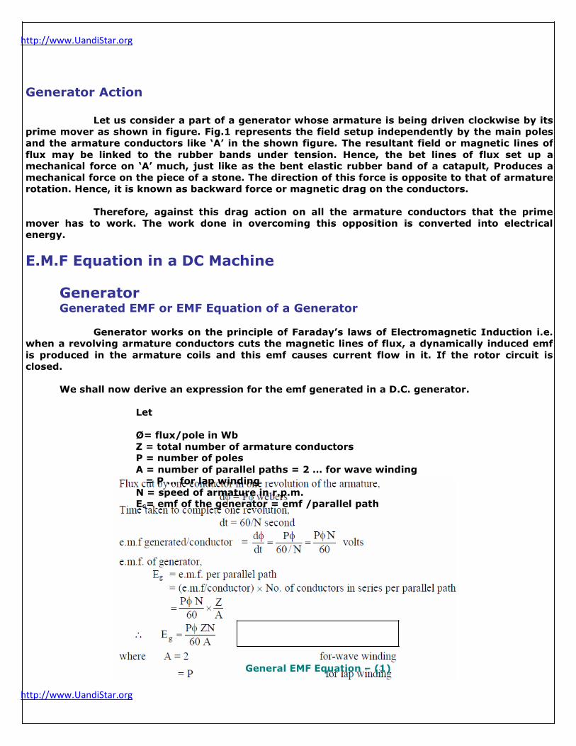
Generator works on the principle of Faraday‟s laws of Electromagnetic Induction i.e.
when a revolving armature conductors cuts the magnetic lines of flux, a dynamically induced emf
is produced in the armature coils and this emf causes current flow in it. If the rotor circuit is
closed.
We shall now derive an expression for the emf generated in a D.C. generator.
Let
Ø= flux/pole in Wb
Z = total number of armature conductors
P = number of poles
A = number of parallel paths = 2 … for wave winding
= P … for lap winding
N = speed of armature in r.p.m.
EG= emf of the generator = emf /parallel path
General EMF Equation – (1)
http://www.UandiStar.org
http://www.UandiStar.org
8

http://www.UandiStar.org
http://www.UandiStar.org
For a simple wave-wound generator
No. of parallel paths „A‟ =2
No. of conductors in one path = Z
2
EMF generated per path = ØPN X Z
60 2
= ØPNZ Volt
120
For a simple lap-wound generator
No. of parallel paths „A‟ = P
No. of conductors I one path = Z P
EMF generated per path = ØPN X Z
60 P
= ØNZ Volt
60
If we multiply and divide the above general equation of EG by
„2∏‟ EG = 2∏ X ØPN X Z
2∏ 60 A
By solving, we get
= ωØZ X P Volts ω-omega- in radians 2∏ A
But for a given DC machine Z,P and A are constants. Hence putting Ka = ZP in the general
EMF equation, we get A
EG = KaØN Volt
60
EG = KaØN Volts (where ‟N‟ is in r.p.s)
Motor
When the motor armature rotates, the conductors also rotate and hence cut the flux.
In accordance with the laws of electromagnetic induction, emf is induced in them whose direction,

http://www.UandiStar.org
http://www.UandiStar.org
as found by Fleming‟s right-Hand Rule, is in opposition to the applied voltage. Because of its
opposing direction. It is referred to as counter emf or back emf „Eb‟.
9

http://www.UandiStar.org
http://www.UandiStar.org
Eb= ØZN X P Volts
60 A
The equivalent circuit of a motor is as shown below. The rotating armature generates the back emf „Eb‟ is like a battery of emf „Eb‟ put across supply mains of „V‟ volts. This „V‟ has to drive
the current „Ia‟ against the opposition of „Eb‟. the power required to overcome this opposition is
EbIa
The back emf depends on other factors as the armature speed. If the speed of the armature
is high, Eb is large. Hence armature current Ia is small. If the speed is less, then „Eb‟ is less.
Hence more current flows which develops motor torque. So Eb acts like a governor.
Voltage Equation of a Motor
The voltage „V‟ is applied across the motor armature, has to
Overcome the back emf Eb
The armature ohmic drop IaRa
V = Eb + IaRa
This is known as voltage equation of a motor.
Multiplying ob both sides by Ia in the above equation, we get
VIa =EbIa + Ia²Ra
Where VIa – Electrical input to the armature
EbIa – Electrical equivalent of mechanical power developed in the armature
Ia²Ra - Cu Losses in the armature
Hence out of the armature input, some is wasted in I²R loss and rest is converted into
mechanical power within the armature. The motor efficiency is given by the ratio of power
developed by the armature to its input i.e
Eb
V Eb is higher as compared to V, there fore the motor efficiency is higher.
Production of Torque in a DC Machine
The term torque is meant the turning or twisting moment of
a force about an axis. It is measured by the product of the force
and the radius at which this force acts.
Consider a pulley of radius „r‟ meter acted upon by a
circumferential force of „F‟ Newtons which causes it to rotate at
„N‟ rpm as shown in figure.

http://www.UandiStar.org
http://www.UandiStar.org
Then torque τ = F X r (N-m) Work done by this force is one revolution = force X distance
10
http://www.UandiStar.org
http://www.UandiStar.org
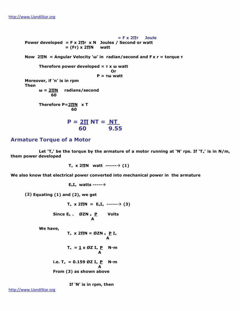
= F x 2∏r Joule
Power developed = F x 2∏r x N Joules / Second or watt
= (Fr) x 2∏N watt
Now 2∏N = Angular Velocity „ω‟ in radian/second and F x r = torque τ
Therefore power developed = τ x ω watt
Or
P = τω watt
Moreover, if „n‟ is in rpm
Then
ω = 2∏N radians/second
60
Therefore P=2∏N x T
60
P = 2∏ NT = NT 60 9.55
Armature Torque of a Motor
Let „Ta‟ be the torque by the armature of a motor running at „N‟ rps. If „Ta‟ is in N/m,
them power developed
Ta x 2∏N watt ------ (1) We also know that electrical power converted into mechanical power in the armature
EbIa watts -----
(2) Equating (1) and (2), we get
Ta x 2∏N = EbIa ------ (3)
Since Eb = ØZN X P Volts
A
We have, Ta x 2∏N = ØZN X P Ia
A Ta = 1 x ØZ Ia P N-m
A
i.e. Ta = 0.159 ØZ Ia P N-m A
From (3) as shown above
If „N‟ is in rpm, then

http://www.UandiStar.org
http://www.UandiStar.org
Ta =EbIa N-m were „N‟ is in rps 2∏N
Ta = 60 EbIa = 9.55 EbIa N-m
2∏N 2∏N
11
http://www.UandiStar.org
http://www.UandiStar.org
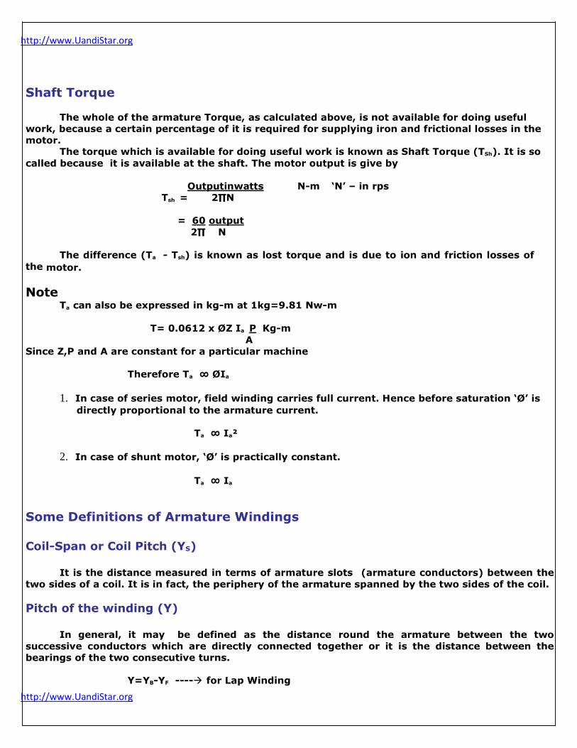
Shaft Torque
The whole of the armature Torque, as calculated above, is not available for doing useful
work, because a certain percentage of it is required for supplying iron and frictional losses in the
motor. The torque which is available for doing useful work is known as Shaft Torque (TSh). It is so
called because it is available at the shaft. The motor output is give by
Output in watts N-m „N‟ – in rps
Tsh = 2∏N
= 60 output
2∏ N
The difference (Ta - Tsh) is known as lost torque and is due to ion and friction losses of
the motor.
Note
Ta can also be expressed in kg-m at 1kg=9.81 Nw-m
T= 0.0612 x ØZ Ia P Kg-m A
Since Z,P and A are constant for a particular machine
Therefore Ta ∞ ØIa
1. In case of series motor, field winding carries full current. Hence before saturation „Ø‟ is
directly proportional to the armature current.
Ta ∞ Ia²
2. In case of shunt motor, „Ø‟ is practically constant.
Ta ∞ Ia
Some Definitions of Armature Windings
Coil-Span or Coil Pitch (YS)
It is the distance measured in terms of armature slots (armature conductors) between the
two sides of a coil. It is in fact, the periphery of the armature spanned by the two sides of the coil. Pitch of the winding (Y)
In general, it may be defined as the distance round the armature between the two
successive conductors which are directly connected together or it is the distance between the
bearings of the two consecutive turns.
Y=YB-YF ---- for Lap Winding
http://www.UandiStar.org
http://www.UandiStar.org
Y=YB+YF ---- for Wave winding
12
http://www.UandiStar.org
http://www.UandiStar.org
Back Pitch (YB)
The distance measured in terms of the armature conductors, which a coil advances on the
back of the armature is called back pitch and is denoted by YB.
Front Pitch (YF)
The number of armature conductors or elements spanned by a coil on the front
(commutator end of an armature) is called the front pitch and is denoted by YF.
Or
The front pitch may be defines as the distance (in terms of the armature conductors)
between the second conductor of one coil and the first conductor of the next coil which are
connected at the front i.e. commutator end of the armature. Resultant Pitch (YR)
It is defined between the beginning of one coil and the beginning of the next coil to which it
is connected. Commutator Pitch (YC)
It is the distance (measured in commutator bars or segments) between the segments to
which the two ends of a coil are connected.
YC =YB-YF ---- for Lap Winding YC =YB+YF ---- for Wave winding
Armature Windings
Two basic types of windings mostly employed for drum type armature are as follows
Wave-Winding
Lap –Winding
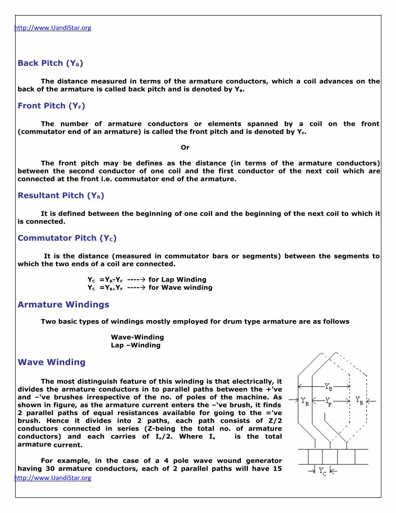
Wave Winding
The most distinguish feature of this winding is that electrically, it
divides the armature conductors in to parallel paths between the +‟ve
and –„ve brushes irrespective of the no. of poles of the machine. As
shown in figure, as the armature current enters the –„ve brush, it finds
2 parallel paths of equal resistances available for going to the =‟ve
brush. Hence it divides into 2 paths, each path consists of Z/2
conductors connected in series (Z-being the total no. of armature
conductors) and each carries of Ia/2. Where Ia is the total
armature current.
For example, in the case of a 4 pole wave wound generator
having 30 armature conductors, each of 2 parallel paths will have 15
http://www.UandiStar.org
http://www.UandiStar.org
conductors.
13

http://www.UandiStar.org
http://www.UandiStar.org
The wave winding is one in which the coil end, diverge and go to the segments widely
separated. This is called series winding.
Lap winding
Lap winding is one in which the adjacent ends of the coils are connected
together in closed to each other on the commutator segments. In the lap
windings the armature conductors are divided into many parallel paths as the
no. of poles of the generator. If there are „P‟ poles and „Z‟ armature
conductors, then there will be „P‟ parallel paths, each consisting of Z/P
conductors connected in series between the positive and negative set of
brushes.
From the figure, as the armature current enters the negative brush, it
has four parallel paths available for going to the positive brush. Each path has
Z/4 conductors and carries a current if Ia/4 amps. Advantages
1. The wave windings giving (gives) more emf than the lap winding for the
same no. of poles and armature conductors. 2. In a wave winding equalizing connections are not necessary which are
in lap windings.
3. Lap winding gives more parallel paths, hence its importance lies when large currents are
required.
Armature Windings
Types of DC Windings
Dc armature windings can be divided into two groups mainly depending upon the way in which the coil ends are connected to the commutator segments. They are
1. Lap Windings
2. Wave windings
In the lap windings, the two ends of any coil are taken to
the adjacent commutator segments and the coil ends are bent
inwards as shown below. Where as in the wave wingding, the coil
ends are bent in opposite directions and taken to the commutator
segments some distance apart as shown.
A Simplex lap winding can be progressive or retrogressive. In general, lap windings, the coil
ends are connected to the adjacent commutator segments. In progressive winding, the start and
finish of the coils ends are connected to the respective commutator segments in an ascending
order and in the retrogressive winding the ends are connected to the connected segments in the
descending order.
In a wave winding, the conductors in each parallel path are distributed symmetrically over
all the poles of the machine. They are used for high voltage and low current equipment.
http://www.UandiStar.org
http://www.UandiStar.org
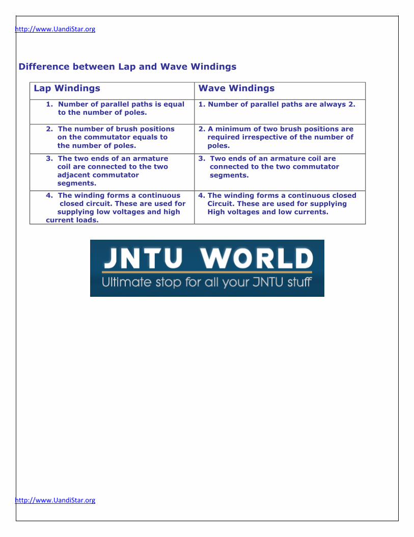
Difference between Lap and Wave Windings
Lap Windings Wave Windings
1. Number of parallel paths is equal
to the number of poles. 1. Number of parallel paths are always 2.
2. The number of brush positions on the commutator equals to
the number of poles.
2. A minimum of two brush positions are required irrespective of the number of
poles.
3. The two ends of an armature coil are connected to the two
adjacent commutator
segments.
3. Two ends of an armature coil are connected to the two commutator
segments.
4. The winding forms a continuous
closed circuit. These are used for
supplying low voltages and high
current loads.
4. The winding forms a continuous closed
Circuit. These are used for supplying
High voltages and low currents.
Related Documents