International Journal of Power Electronics and Drive System (IJPEDS) Vol. 9, No. 3, September 2018, pp. 1038~1050 ISSN: 2088-8694, DOI: 10.11591/ijpeds.v9.i3.pp1038-1050 1038 Journal homepage: http://iaescore.com/journals/index.php/IJPEDS DC-DC Boost Converter Design for Fast and Accurate MPPT Algorithms in Stand-Alone Photovoltaic System Norazlan Hashim 1 , Zainal Salam 2 , Dalina Johari 3 , Nik Fasdi Nik Ismail 4 1, 3, 4 Faculty of Electrical Engineering, Universiti Teknologi MARA, Malaysia 2 Center of Electrical Energy Systems, School of Electrical Engineering, Faculty of Engineering, Universiti Teknologi Malaysia, Malaysia Article Info ABSTRACT Article history: Received May 3, 2018 Revised Jul 12, 2018 Accepted Jul 22, 2018 The main components of a Stand-Alone Photovoltaic (SAPV) system consists of PV array, DC-DC converter, load and the maximum power point tracking (MPPT) control algorithm. MPPT algorithm was used for extracting maximum available power from PV module under a particular environmental condition by controlling the duty ratio of DC-DC converter. Based on maximum power transfer theorem, by changing the duty cycle, the load resistance as seen by the source is varied and matched with the internal resistance of PV module at maximum power point (MPP) so as to transfer the maximum power. Under sudden changes in solar irradiance, the selection of MPPT algorithm’s sampling time (TS_MPPT) is very much depends on two main components of the converter circuit namely; inductor and capacitor. As the value of these components increases, the settling time of the transient response for PV voltage and current will also increase linearly. Consequently, TS_MPPT needs to be increased for accurate MPPT and therefore reduce the tracking speed. This work presents a design considerations of DC-DC Boost Converter used in SAPV system for fast and accurate MPPT algorithm. The conventional Hill Climbing (HC) algorithm has been applied to track the MPP when subjected to sudden changes in solar irradiance. By selecting the optimum value of the converter circuit components, a fast and accurate MPPT especially during sudden changes in irradiance has been realized. Keyword: DC-DC boost converter Hill climbing MPPT Stand-alone PV system Copyright © 2018 Institute of Advanced Engineering and Science. All rights reserved. Corresponding Author: Norazlan Hashim, Faculty of Electrical Engineering, Universiti Teknologi MARA, 40000 Shah Alam, Malaysia Email: [email protected] 1. INTRODUCTION In recent years, due to the energy crisis and environment pollution, the direct solar electricity generation using PV system become more significant. The market for solar PV system has grown rapidly over the past decade, as local governments offered various incentives to expand the solar market as well as the declining PV cost. Generally, PV system can be classified into three major categories: Stand-Alone (SA), Grid-Connected (GC) and Hybrid (H) PV system. Stand-Alone PV system are designed to operate independent of the electric utility grid, and are generally designed and sized to supply certain DC and/or AC electrical loads. In the grid-connected PV system, electricity produced from PV array are either used directly, or fed into a large electricity grid. A hybrid PV system is essentially a system that employs at least one more source, other than the PV such as wind turbines or diesel generators, to meet the electrical power demand of the loads [1].

Welcome message from author
This document is posted to help you gain knowledge. Please leave a comment to let me know what you think about it! Share it to your friends and learn new things together.
Transcript

International Journal of Power Electronics and Drive System (IJPEDS)
Vol. 9, No. 3, September 2018, pp. 1038~1050
ISSN: 2088-8694, DOI: 10.11591/ijpeds.v9.i3.pp1038-1050 1038
Journal homepage: http://iaescore.com/journals/index.php/IJPEDS
DC-DC Boost Converter Design for Fast and Accurate MPPT
Algorithms in Stand-Alone Photovoltaic System
Norazlan Hashim1, Zainal Salam2, Dalina Johari3, Nik Fasdi Nik Ismail4
1, 3, 4Faculty of Electrical Engineering, Universiti Teknologi MARA, Malaysia 2Center of Electrical Energy Systems, School of Electrical Engineering, Faculty of Engineering, Universiti Teknologi
Malaysia, Malaysia
Article Info ABSTRACT
Article history:
Received May 3, 2018
Revised Jul 12, 2018
Accepted Jul 22, 2018
The main components of a Stand-Alone Photovoltaic (SAPV) system
consists of PV array, DC-DC converter, load and the maximum power point
tracking (MPPT) control algorithm. MPPT algorithm was used for extracting
maximum available power from PV module under a particular environmental
condition by controlling the duty ratio of DC-DC converter. Based on
maximum power transfer theorem, by changing the duty cycle, the load
resistance as seen by the source is varied and matched with the internal
resistance of PV module at maximum power point (MPP) so as to transfer the
maximum power. Under sudden changes in solar irradiance, the selection of
MPPT algorithm’s sampling time (TS_MPPT) is very much depends on two
main components of the converter circuit namely; inductor and capacitor. As
the value of these components increases, the settling time of the transient
response for PV voltage and current will also increase linearly.
Consequently, TS_MPPT needs to be increased for accurate MPPT and
therefore reduce the tracking speed. This work presents a design
considerations of DC-DC Boost Converter used in SAPV system for fast and
accurate MPPT algorithm. The conventional Hill Climbing (HC) algorithm
has been applied to track the MPP when subjected to sudden changes in solar
irradiance. By selecting the optimum value of the converter circuit
components, a fast and accurate MPPT especially during sudden changes in
irradiance has been realized.
Keyword:
DC-DC boost converter
Hill climbing
MPPT
Stand-alone PV system
Copyright © 2018 Institute of Advanced Engineering and Science.
All rights reserved.
Corresponding Author:
Norazlan Hashim,
Faculty of Electrical Engineering,
Universiti Teknologi MARA,
40000 Shah Alam, Malaysia
Email: [email protected]
1. INTRODUCTION
In recent years, due to the energy crisis and environment pollution, the direct solar electricity
generation using PV system become more significant. The market for solar PV system has grown rapidly
over the past decade, as local governments offered various incentives to expand the solar market as well as
the declining PV cost. Generally, PV system can be classified into three major categories: Stand-Alone (SA),
Grid-Connected (GC) and Hybrid (H) PV system. Stand-Alone PV system are designed to operate
independent of the electric utility grid, and are generally designed and sized to supply certain DC and/or AC
electrical loads. In the grid-connected PV system, electricity produced from PV array are either used directly,
or fed into a large electricity grid. A hybrid PV system is essentially a system that employs at least one more
source, other than the PV such as wind turbines or diesel generators, to meet the electrical power demand of
the loads [1].

Int J Pow Elec & Dri Syst ISSN: 2088-8694
DC-DC Boost Converter Design for Fast and Accurate MPPT Algorithms in Stand …(Norazlan Hashim)
1039
In this work, only Stand-Alone PV system that can be utilized for any heating, cooking and water
pumping applications is considered [2, 3]. In order to reduce the costs and environmental issues, the battery is
not applied in these applications. One major problem with any PV system is that, the amount of electric
power generated is constantly changing with weather conditions, especially solar irradiance. If the solar
irradiance changes, the operating point of the PV array will shift away from its maximum power point
(MPP). To overcome this problem, a Maximum Power Point Tracking (MPPT) algorithms incorporating with
DC-DC converter is implemented which has led to the increase in the operation efficiency of the PV array.
For SAPV system with fixed load resistance (without battery), maximum power is delivered to the load when
input resistance (Rin) of the converter matches with the internal resistance of PV array at (RMPP) based on
Maximum Power Transfer Theorem. To do so, MPPT regulates the input voltage of the PV array at MPP by
adjusting the duty cycle (D) of the converter.
The most popular MPPT algorithms in practice are perturb and observe (P&O), hill climbing (HC),
and the incremental conductance method (INC). These conventional algorithms are widely applied due to
their simplicity, ease of implementation and low cost [4]. The other conventional MPPT algorithms used in
PV system are presented in [5-12]. In literature [13-17], many new improved performance of MPPT
algorithms have been proposed. However, the components sizing of the different topologies of DC-DC
converters have not been studied widely although this sizing affects significantly the optimum operation of
the MPPT algorithms. For example, the poorly selection of the converter component sizing, especially
capacitor and inductor according to the load could make MPPT operate less optimally. Under sudden step
changes in irradiance, the selection of the MPPT sampling time (TS_MPPT) must consider the transient
response of the MPPT inputs such as PV’s voltage and current, in order to avoid the delay and failure in
tracking of maximum power. The three most commonly used DC-DC converters in PV system are: buck,
boost and buck-boost converters. The circuit parameters and mode of operation of each topology have been
discussed in [18, 19]. Boost converter has some advantages over the other converters as it is more stable and
efficient [20], and hence chosen in this work.
This work focuses on the sizing effect of two DC-DC boost converter components i.e capacitor and
inductor, on transient response and speed of the MPPT algorithm. Furthermore, hill climbing (HC) MPPT
algorithm has been chosen to track the MPP during suddenly changing solar irradiance. Only DC-DC boost
converter used in Stand-Alone PV system with fixed load resistor is considered here.
2. MPPT FOR STAND-ALONE PV SYSTEM WITH LOAD RESISTANCE
In SAPV system, the battery is crucial for power flow management if the load demands a constant
voltage. However, in some applications like heating, cooking and water pumping system where the change in
the load voltage will not affect the reliability of the system, the battery is not needed. In those applications,
the battery is not applied to reduce cost, frequent maintenance and environmental issues caused by battery
usages [2, 3]. The main objective of the system is to obtain power from the PV array as much as possible
without having to regulate the output voltage and current. As per maximum power transfer theorem,
maximum power is transferred to the load when equivalent load resistance referred to the input terminals of
the converter (Rin) is match to the internal resistance of PV array at MPP (RMPP). Figure 1 shows such a
system.
HC MPPT
PWM
GENERATORPV MODULE
RE
SIS
TO
R (R
L )
+
-
+
-
IPV
VPV
Duty CYcle
PWM Signal
DC-DC BOOST CONVERTER
Rin
Figure 1. Block diagram of MPPT stand-alone PV systems with load resistor
ISSN: 2088-8694
Int J Pow Elec & Dri Syst, Vol. 9, No. 3, September 2018 : 1038 – 1050
1040
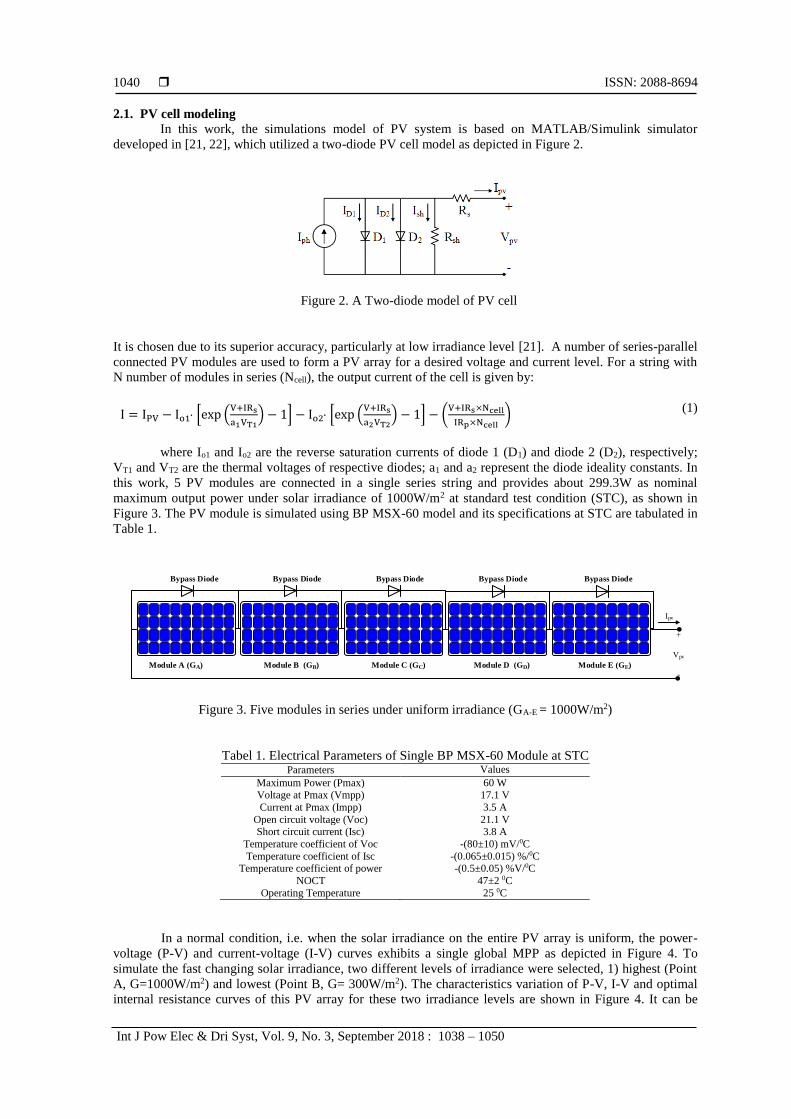
2.1. PV cell modeling
In this work, the simulations model of PV system is based on MATLAB/Simulink simulator
developed in [21, 22], which utilized a two-diode PV cell model as depicted in Figure 2.
Figure 2. A Two-diode model of PV cell
It is chosen due to its superior accuracy, particularly at low irradiance level [21]. A number of series-parallel
connected PV modules are used to form a PV array for a desired voltage and current level. For a string with
N number of modules in series (Ncell), the output current of the cell is given by:
I = IPV − Io1 [exp (V+IRs
a1VT1) − 1] − Io2 [exp (
V+IRs
a2VT2) − 1] − (
V+IRs×Ncell
IRp×Ncell)
(1)
where Io1 and Io2 are the reverse saturation currents of diode 1 (D1) and diode 2 (D2), respectively;
VT1 and VT2 are the thermal voltages of respective diodes; a1 and a2 represent the diode ideality constants. In
this work, 5 PV modules are connected in a single series string and provides about 299.3W as nominal
maximum output power under solar irradiance of 1000W/m2 at standard test condition (STC), as shown in
Figure 3. The PV module is simulated using BP MSX-60 model and its specifications at STC are tabulated in
Table 1.
Module A (GA) Module B (GB) Module C (GC) Module D (GD) Module E (GE)
Bypass Diode Bypass Diode Bypass Diode Bypass Diode Bypass Diode
Ipv
+
Vpv
-
Figure 3. Five modules in series under uniform irradiance (GA-E = 1000W/m2)
Tabel 1. Electrical Parameters of Single BP MSX-60 Module at STC Parameters Values
Maximum Power (Pmax) 60 W Voltage at Pmax (Vmpp) 17.1 V
Current at Pmax (Impp) 3.5 A
Open circuit voltage (Voc) 21.1 V Short circuit current (Isc) 3.8 A
Temperature coefficient of Voc -(80±10) mV/0C
Temperature coefficient of Isc -(0.065±0.015) %/0C Temperature coefficient of power -(0.5±0.05) %V/0C
NOCT 47±2 0C
Operating Temperature 25 0C
In a normal condition, i.e. when the solar irradiance on the entire PV array is uniform, the power-
voltage (P-V) and current-voltage (I-V) curves exhibits a single global MPP as depicted in Figure 4. To
simulate the fast changing solar irradiance, two different levels of irradiance were selected, 1) highest (Point
A, G=1000W/m2) and lowest (Point B, G= 300W/m2). The characteristics variation of P-V, I-V and optimal
internal resistance curves of this PV array for these two irradiance levels are shown in Figure 4. It can be

Int J Pow Elec & Dri Syst ISSN: 2088-8694
DC-DC Boost Converter Design for Fast and Accurate MPPT Algorithms in Stand …(Norazlan Hashim)
1041
seen that, the maximum power point (MPP) has changed from point A to B when the irradiance (G) level
decreases from 1000W/m2 to 300W/m2. As a result, RMPP increased from 24.6 to 84.4 which is calculated
using;
RMPP=VMPP
IMPP (2)
It is not practical to change the load resistance manually at any moment the solar irradiance changes
[23]. Therefore, MPPT algorithm has been designed to continuously adjusts the duty cycle of the converter,
in order to match the input resistance to the internal resistance of PV array at MPP (Rin=RMPP), and hence
extracts maximum available power. At MPP, the duty cycle of the converter is calculated as [3];
DMPP=1 −√RMPP
RL
(3)
By assuming a lossless converter (PPV=Pout), the output voltage (Vout) of the converter at MPP is
determined as;
Vout=Vmpp
1−Dmpp (4)
Point A
Point B
ISC
VOC
MPP Zone
MPP Zone
Dmpp= 0.34
Rmpp= 84.4
Dmpp= 0.64
Rmpp= 24.6
Figure 4. (a) I–V and P–V curves of PV array at two irradiance level at STC
2.2. Hill climbing (HC) MPPT algorithm
The goal of employing MPPT is to extract maximum power from PV Array at any varying
atmospheric conditions especially solar irradiance changes. To do so, MPPT algorithm perturbs the duty
cycle of the DC-DC converter to match the resistance of load as seen by the source (Rin) to the internal
optimal resistance of PV Array (RMPP). In this work, the conventional Hill Climbing algorithm as discussed
in [4, 24-28] has been applied to track the MPP when subjected to sudden changes in solar irradiance. HC
algorithm offers number of advantages: 1) it simplifies the tracking structure, 2) it reduces the computation
time, and 3) no tuning effort is needed for the PI gains [28]. Practically, it can replace the expensive MPPT
controller with lower cost controller while maintaining similar optimum results.
In HC, at each iteration i, the algorithm starts sensing the voltage, V(i) and current, I(i) of PV array
and the corresponding power, P(i)= V(i)×I(i) is then calculated. Next, the duty cycle (D) of the converter is
perturbed by an increment of duty cycle step size (Dstep), and the resulting change of power, P = P(i+1) -

ISSN: 2088-8694
Int J Pow Elec & Dri Syst, Vol. 9, No. 3, September 2018 : 1038 – 1050
1042
P(i) is obtained. If the P is positive, then perturbation is in the right direction, and more perturbation is
applied in the same direction to reach the MPP. The perturbation direction is reversed if P is negative, an
indication that the tracking is moved away from the MPP. The flowchart of the HC algorithm is shown in
Figure 5.
When solar irradiance changes, the tracking speed to reach new MPP using conventional HC
algorithm depends mainly on two variables, 1) the duty cycle step size (Dstep), and 2) the MPPT sampling
time (TS_MPPT) which is the time given to the MPPT to read all the inputs and solve all the calculations
involved in the algorithm at each applied duty cycle (D). Large Dstep will increase the MPP tracking speed but
the power losses also increases due to the large oscillation around MPP. Small Dstep will reduce power losses
oscillation around MPP but the tracking speed will be low. Hence, the trade-off have to be made to increase
the overall MPPT efficiency. In this study, Dstep is set at 10% during exploration process and is set at 0.5%
during exploitation process. Meanwhile, large TS_MPPT will reduce the MPP tracking speed and vice versa.
Due to the step change in irradiance, PV voltage and current will undergo a transient response
before shortly recovering to its new steady-state condition [17, 28, 29] . The settling time (TSettling) of voltage
and current depends muchly on the circuit components i.e capacitor and inductor, which will be discussed
further in the next section. For accurate MPPT, TS_MPPT must be designed to be greater than TSettling and all
readings and calculations involved in algorithm must be completed within this specified period. Otherwise,
the algorithm might fail to perform in the required manner.
YES
If P(i) > P(i-1)
Initialization Stage
Set i =1; Slope =1; Dref= 0.1
V(i-1) = I(i-1) = P(i-1) = 0;
i=i+1
Send D(i) = D(i-1) + Dstep × Slope
Sense V(i) & I(i)
Calculate P(i) = V(i)×I(i)
Complement
Slope sign
NO
Start
Update P(i-1) = P(i),
I(i-1) = I(i) & D(i-1) = D(i)
Send D(i) = Dref
Sense V(i) & I(i)
Calculate P(i) = V(i)×I(i)
Figure 5. Flow chart of conventional HC MPPT Algorithm.
3. DESIGN OF DC-DC BOOST CONVERTER
For Stand-Alone PV systems [30], a DC-DC boost converter is interfaced between the PV array and
the load resistance as shown in Figure 1. The maximum power generated from the PV array at standard test
condition (STC) is about 299.3W. The specifications of the PV module (BP-MSX60) are given in Table 1. In
DC-DC boost converter, five components needs to be chosen namely, switching device, diode, inductor,
capacitor and resistor. In the simulation, a standard power diode and the switching device of Power-
MOSFET are chosen since there are widely used for low to medium power applications. The switching
frequency is set at 20 kHz after a trade-off between the switching losses and size of inductor. Selection of
other components is done as the following.

Int J Pow Elec & Dri Syst ISSN: 2088-8694
DC-DC Boost Converter Design for Fast and Accurate MPPT Algorithms in Stand …(Norazlan Hashim)
1043
3.1. Selection of the resistor
The relationship between load resistance (RL) of boost converter and optimal internal resistance of
PV array at MPP (RMPP) can be expressed as [3];
RL=RMPP
(1-Dmpp)2
(5)
Where, Dmpp is the converter duty cycle at maximum power point (MPP). In order to track the maximum
power, the load resistance of boost converter must be greater than or equal to optimal internal resistance of
PV Array at MPP (RL ≥ RMPP), since the range of duty ratio (D) is between 0 to 1. The tracking of maximum
power will fails if the above condition is not met [3]. In this work, the value of load resistance is chosen as
RL=200Ω, which is greater than the internal resistance of PV array at MPP for lowest irradiance (300W/m2)
and temperature of 25°C (STC) as in Table 2. It is a real resistance measurement for 300W rated load bank
available at the lab for future hardware execution. This load bank acts as a dumping place for 299.3W power
generated from PV array used in this work.
3.2. Selection of the inductor
Boost inductor value is selected based on the maximum allowable current ripple which occurs at the
MPP under highest solar irradiance (1000W/m2). The higher the inductor value, the lower is the ripple output
current and vice versa. To realize a low cost converter, the lower inductor value is preferred, because
inductor is the most expensive component compared to the others. In this work, the switching frequency (s)
is set at 20 kHz and the permitted amount of ripple current (I) is selected as 40% of the input current [31].
Hence, the minimum value of inductor is determined as [19, 29];
Lmin=Vmpp×Dmpp
2×∆Iout×𝑓𝑠=0.948 mH (6)
Here, a commercially available of 1mH, 5mH and 10mH inductors are chosen for MPPT’s transient
response study. For example, 1mH boost converter choke (10A, 20 kHz) is available from SMP
(www.smp.de).
3.3. Selection of the capacitor
In this study, the input and output filter capacitor (Cin & Cout) are chosen to meet the voltage ripple
requirement of 0.2%. An approximate expression for the required capacitance is given as [19, 29];
Cmin=Vout×Dmpp
2×∆Vout×𝑅×𝑓𝑠 = 41.7 µF (7)
To study the effect of the capacitor value on the transient response of MPPT for step change in
irradiance, three (3) practical capacitor values available to support the voltage of 250V are selected i.e., 47
μF, 100 μF and 220 μF. Using all the equations above, sets of data used in this work are calculated and
tabulated in Table 2. PV array data under highest and lowest solar irradiance at the temperature of 250C
(STC) are generated from the MATLAB/Simulink PV simulator model as proposed in [21, 22].
Table 2. PV Array and Converter characteristics in lowest and highest irradiance
Irradiance
(W/m2)
PV Array Converter (fs = 20 kHz)
Vmpp
(V)
Impp
(A)
Pmpp
(W)
Rmpp
()
Dmpp Vout
(V)
Iout
(A)
RL
()
L
(mH)
C
(uH)
1000 (Highest) 85.7 3.49 299.3 24.6 0.64 238.1 1.26 200 1 47
300 (Lowest) 83.6 0.99 82.4 84.4 0.34 126.7 0.65
4. SIMULATION RESULTS
The simulation model of the Stand-Alone PV system with MPPT algorithm is carried out in
MATLAB/Simulink (2016a) environment as in Figure 6. The PV array model is based on the simulator
developed by [21, 22] and took place on 2.7GHz, 8GB RAM, Intel Core i7 laptop machine. The electrical
parameters at standard test conditions (STC) of PV solar module are taken from BP MSX-60 model as
tabulated in Table 1. HC algorithm has been coded in MATLAB's programming language and stored as
subroutine (M-file). The simulation is carried out for 3 seconds using the solver of ode23t

ISSN: 2088-8694
Int J Pow Elec & Dri Syst, Vol. 9, No. 3, September 2018 : 1038 – 1050
1044
(mod.stiff/Trapezoidal) with variable time step and relative tolerance of 1e-6. The MPPT sampling time
(TS_MPPT) is set at 0.2 second (200 ms). To study the effects of boost converter components towards MPPT
transient response during sudden changes in irradiance, the simulations are divided into two cases, 1)
Inductor value is fixed at 1 mH while different values of the capacitor are increased accordingly as (47F
100F 220), and 2) Capacitor value is fixed at 47F while different values of the inductor are increased
i.e (1mH 5mH 10mH). For both cases, sudden decrease in the irradiance is simulated from 1000W/m2
to 300W/m2. Meanwhile, sudden increase is simulated from 300W/m2 to 1000W/m2.
Figure 6. Simulation model of SAPV system with MPPT
4.1. Case 1 (L=1mH, C=47F 100F 220F)
Figure 7 (a) shows the tracking of duty cycle, voltage, current, and power of the PV array using the
conventional HC algorithm for a sudden decrease in the irradiance. Initially, the PV array is simulated at
irradiance of 1000W/m2. Hence, HC algorithm start the exploration process (Dstep=10%) to search the MPP at
point A (D=0.64, V=85.7V, I= 3.49A, P= 299.3W). When it enters the zone of MPP A, exploitation process
(Dstep=0.5%) is activated to reach the true MPP and oscillates around it as shown at 1s-2s interval in Figure 7
(a). At 2s instant, the irradiance is suddenly decreased from 1000W/m2 to 300W/m2. Therefore, HC starts
exploring the new MPP B by reducing the duty cycle from 0.64(MPP A) to 0.54 to 0.44 and to 0.34 (MPP
B). As the duty cycle decreases, the PV power will increase from 30W to 46.8W to 66.3W and to 82.3W.
Once it enters the zone of MPP B, the exploitation process is used to reach true MPP which is 82.5W. In this
case, the MPPT tracking speed is 800ms (TS_MPPT × 4 steps).
The tracking speed can be improved by reducing TS_MPPT but it depends on the transient response of
the PV voltage and current. To observe the details of transient response due to the sudden decrease in
irradiance, the voltage and current waveforms are zoomed in the interval of 2s–2.2s as shown in Figure 7(b).
During this interval, the duty cycle of the converter is still operated at 0.64. As seen, both voltage and current
are decreased due to the decrease in irradiance. Voltage drops almost exponentially from 87.5V and after a
while it stabilizes at 27.2V. Meanwhile, current undershoot from 3.49A to 0.94A before rising exponentially
and stabilizes at 1.11A. By using measurement tools provided in Matlab/Simulink Scope, the settling time
(Tsettling) and percentage of undershoot (US)/overshoot (OS) are calculated as tabulated in Table 3. When the
capacitor values increase, Tsettling also increases almost linearly from 100ms (47F) to 190ms (100F) and to
>200ms (220F). If 47F capacitor is chosen for the converter, the selectable optimum value of TS_MPPT is
100ms and the MPPT tracking speed will be 400ms (TS_MPPT × 4 steps). However, for 220F capacitor the
TS_MPPT must be increased to >200ms in order to realize an accurate MPPT and hence decreases the MPPT
tracking speed. Otherwise, the MPPT algorithm will measure the wrong values of voltage and current in
which will leading to incorrect MPP detection. As for undershoot problem, all three capacitors exhibits the
same condition, i.e almost 0% voltage undershoot and 15% of current undershoot. Next, the MPPT transient
response under sudden increase in irradiance is investigated as in Figure 8(a-b).
The PV array is simulated at irradiance, G=300W/m2 at the beginning of the simulation. At steady-
state condition, MPPT is oscillates around MPP at point B (D=0.34, V=83.6V, I= 0.99A, P= 82.5W). At 2s
instant, the irradiance is suddenly increased to 1000W/m2. HC algorithm start searching the new MPP A by
increasing the duty cycle from 0.34 to 0.64 with 0.1(10%) increment per step. Time taken to reach the zone
of MPP A is 800ms (4 steps including initialise step). Figure 8 (b) shows the zoomed voltage and current

Int J Pow Elec & Dri Syst ISSN: 2088-8694
DC-DC Boost Converter Design for Fast and Accurate MPPT Algorithms in Stand …(Norazlan Hashim)
1045
waveforms during 2s-2.2s interval. Due to sudden increase in irradiance, current overshoot to 195% (OS%)
from its steady-state value for all capacitors. No overshoot observed in voltage as seen in Figure 8 (b). Tsettling
for 47F, 100F and 220F capacitors are 5ms, 10ms and 24ms respectively.
TS_MPPT = 200ms
Dste p= 0.005
TS_MPPT =200ms
Zoom In
Zoom In
Steady State
D= 0.64D= 0.54
D= 0.44D= 0.34
P = 30W P = 46.8WP = 66.3W P = 82.3W
P = 299.3W
I = 3.49A
V = 85.7A
D= 0.64
Exploration Mode (Dstep= 0.1)
I = 1AI = 1.06AI = 1.09AI = 1.11A
V = 62.4V
V = 82.3V
V = 43.1V
V = 27.2V
(a)
(b)
(c )
(d)
MPP B
4 steps
Figure 7. (a) The tracking of D, VPV, IPV, and PPV during a sudden decrease in irradiance
Zoom In
(Fig. 7b)
(a) (b)
UnderShoot
(US)
Settling Time
(Tsettling)
Figure 7. (b) The zoomed image of VPV & IPV in the interval of 2s–2.2s

ISSN: 2088-8694
Int J Pow Elec & Dri Syst, Vol. 9, No. 3, September 2018 : 1038 – 1050
1046
Zoom In
Zoom In
Steady State
D= 0.34
D= 0.44D= 0.54
D= 0.64
Exploration Mode (Dstep= 0.1)
Initialise
Step
TS_MPPT = 200ms
V = 83.6V
I = 0.99A
P = 82.4W
D= 0.64
Dste p= 0.005
V = 96.3V
V = 86.4V
V = 99.6VV = 101.4V
I = 3.46A
I = 2.38A
I = 1.66A
I = 1.21A
P = 122.1W
P = 165.5W
P = 229.6WP = 299.1W
Figure 8. (a) The tracking of D, VPV, IPV, and PPV during a sudden increase in irradiance
Zoom In
(Fig. 8b)
Zoom In
(Fig. 8b)
(a) (b)
OverShoot
(OS)
Settling Time (Tsettling)
Figure 8. (b) The zoomed image of VPV & IPV in the interval of 2s–2.2s
4.2. Case 2 (C=47F, L=1mH 5mH 10mH)
In this case, the capacitor is fixed to its optimum value of 47F. At 2s instant, solar irradiance is
suddenly decreased/increased. The transient response of MPPT is observed by increasing the inductance
value from 1mH to 5mH and to 10mH. Figure 9 (a-b) shows the MPP tracking results for sudden decreases in
irradiance from 1000W/m2 to 300W/m2. As the inductance increase, the settling time of the waveforms will
also increase. Tsettling for 1mH inductor is 100ms, while Tsettling for both 5mH and 10mH inductors exceeds the
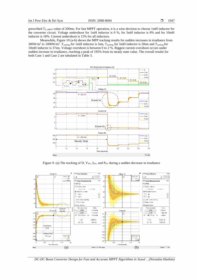
Int J Pow Elec & Dri Syst ISSN: 2088-8694
DC-DC Boost Converter Design for Fast and Accurate MPPT Algorithms in Stand …(Norazlan Hashim)
1047
prescribed TS_MPPT value of 200ms. For fast MPPT operation, it is a wise decision to choose 1mH inductor for
the converter circuit. Voltage undershoot for 1mH inductor is 0 %, for 5mH inductor is 8% and for 10mH
inductor is 18%. Current undershoot is 15% for all inductors.
Meanwhile, Figure 10 (a-b) shows the MPP tracking results for sudden increases in irradiance from
300W/m2 to 1000W/m2. Tsettling for 1mH inductor is 5ms, Tsettling for 5mH inductor is 20ms and Tsettling for
10mH inductor is 37ms. Voltage overshoot is between 0 to 2 %. Biggest current overshoot occurs under
sudden increase in irradiance, reaching a peak of 195% from its steady state value. The overall results for
both Case 1 and Case 2 are tabulated in Table 3.
Zoom In
Zoom In
Steady State
P = 299.3W
I = 3.49A
V = 85.7A
Dste p= 0.005
D= 0.64 TS_MPPT =0.2s
D= 0.64D= 0.54
D= 0.44
D= 0.34
Figure 9. (a) The tracking of D, VPV, IPV, and PPV during a sudden decrease in irradiance
Zoom In
(Fig.9b)
(a) (b)
UnderShoot
(US)
Settling Time
(Tsettling)

ISSN: 2088-8694
Int J Pow Elec & Dri Syst, Vol. 9, No. 3, September 2018 : 1038 – 1050
1048
Figure 9. (b) The zoomed image of VPV & IPV in the interval of 2s–2.2s
Zoom In
Zoom In
Dste p= 0.005
D= 0.64 TS_MPPT =0.2s
TS_MPPT =0.2sD= 0.34D= 0.44
D= 0.54
D= 0.64
Exploration Mode (Dstep= 0.1)
Initialise
Step
Steady State
V = 83.6V
I = 0.99A
P = 82.4W
Figure 10. (a) The tracking of D, VPV, IPV, and PPV during a sudden increase in irradiance
Zoom In
(Fig.10b)
Zoom In
(Fig.10b)
(a) (b)
OverShoot (OS)
Settling Time
(Tsettling)
UnderShoot (US)
OverShoot (OS)
Figure 10. (b) The zoomed image of VPV & IPV in the interval of 2s–2.2s

Int J Pow Elec & Dri Syst ISSN: 2088-8694
DC-DC Boost Converter Design for Fast and Accurate MPPT Algorithms in Stand …(Norazlan Hashim)
1049
Table 3. Overall Results for Varying C&L Under Sudden Changes in Solar Irradiance Parameters Sudden Decrease in Irradiance
( G=1 to G=0.3, D= 0.64 ) Sudden Increase in Irradiance
( G=0.3 to G=1, D= 0.34 )
C L V & I Settling Time
(mS)
Overshoot (OS) /
Undershoot (US) (%)
Settling Time (mS) Overshoot (OS) /
Undershoot (US) (%)
CA
SE
1
47 µF 1 mH V 100 0 5 0
I 15 (US) 195 (OS) 100 µF V 190 0 10 0
I 15 (US) 195 (OS)
220 µF V >200 0 24 0 I 15 (US) 195 (OS)
CA
SE
2
47 µF 1 mH V 100 0 5 0 I 15 (US) 195 (OS)
5 mH V >200 8 (US) 20 2 (OS)
I 15 (US) 195 (OS) 10 mH V >200 18 (US) 37 2 (OS)
I 15 (US) 195 (OS)
5. CONCLUSION
The effects of capacitance and inductance of DC-DC boost converter towards MPPT transient
response has been demonstrated in this work. The converter is designed for 299.3W Stand-Alone PV systems
connected to fixed 200 load resistor. As the value of capacitor and inductor increases, the settling time
(Tsettling) of voltage and current waveforms will also increase and vice versa. In order to improve the tracking
speed and the accuracy of the MPPT under suddenly (step) changes in irradiance, the value of capacitor and
inductor must be selected as low as possible while maintaining the permissible ripple limit. TS_MPPT must be
equal to or greater than the maximum Tsettling of the circuit. Otherwise, the wrong MPP might be tracked. In
this work, the optimum value of capacitor and inductor are chosen as 47µF and 1mH respectively. The
optimum value of TS_MPPT is found to be 100ms. Due to the sudden changes in irradiance, MPPT takes 400ms
to reach the new MPP zone. Meanwhile, the biggest current overshoot occurs during suddenly increase in
irradiance from 300W/m2 to 1000W/m2 i.e 195%. Although, overshoot/undershoot does not directly affects
the tracking speed, but it may increase the noise margin and damage the internal FET of the gate IC. By
selecting optimum circuit parameter values, a fast and accurate MPPT especially during sudden changes in
irradiance is realized.
ACKNOWLEDGEMENTS
This research was supported and funded by Institute of Research Management & Innovation (IRMI),
Universiti Teknologi MARA under Lestari (0103/2016) grant.
REFERENCES [1] C. S. Solanki, Solar photovoltaics: fundamentals, technologies and applications. PHI Learning Pvt. Ltd., 2015.
[2] A. Oi, M. Anwari, and M. Taufik, "Modeling and simulation of photovoltaic water pumping system," in Modelling
& Simulation, 2009. AMS'09. Third Asia International Conference on, 2009, pp. 497-502: IEEE.
[3] B. Nayak, A. Mohapatra, and K. B. Mohanty, "Selection criteria of dc-dc converter and control variable for MPPT
of PV system utilized in heating and cooking applications," Cogent Engineering, vol. 4, no. 1, p. 1363357, 2017.
[4] H. Rezk and A. M. Eltamaly, "A comprehensive comparison of different MPPT techniques for photovoltaic
systems," Solar energy, vol. 112, pp. 1-11, 2015.
[5] J. Ahmed and Z. Salam, "A critical evaluation on maximum power point tracking methods for partial shading in PV
systems," Renewable and Sustainable Energy Reviews, vol. 47, pp. 933-953, 2015.
[6] T. Esram and P. L. Chapman, "Comparison of Photovoltaic Array Maximum Power Point Tracking Techniques,"
Energy Conversion, IEEE Transactions on, vol. 22, no. 2, pp. 439-449, 2007.
[7] R. Faranda, S. Leva, and V. Maugeri, "MPPT techniques for PV Systems: Energetic and cost comparison," in
Power and Energy Society General Meeting - Conversion and Delivery of Electrical Energy in the 21st Century,
2008 IEEE, 2008, pp. 1-6.
[8] D. Hohm and M. E. Ropp, "Comparative study of maximum power point tracking algorithms," Progress in
photovoltaics: Research and Applications, vol. 11, no. 1, pp. 47-62, 2003.
[9] K. Ishaque and Z. Salam, "A review of maximum power point tracking techniques of PV system for uniform
insolation and partial shading condition," Renewable and Sustainable Energy Reviews, vol. 19, no. 0, pp. 475-488,
3// 2013.
[10] K. Ishaque, Z. Salam, and G. Lauss, "The performance of perturb and observe and incremental conductance
maximum power point tracking method under dynamic weather conditions," Applied Energy, vol. 119, pp. 228-236,
2014.

ISSN: 2088-8694
Int J Pow Elec & Dri Syst, Vol. 9, No. 3, September 2018 : 1038 – 1050
1050
[11] J. P. Ram, T. S. Babu, and N. Rajasekar, "A comprehensive review on solar PV maximum power point tracking
techniques," Renewable and Sustainable Energy Reviews, vol. 67, pp. 826-847, 2017.
[12] M. Tajuddin, M. Arif, S. Ayob, and Z. Salam, "Perturbative methods for maximum power point tracking (MPPT)
of photovoltaic (PV) systems: a review," International Journal of Energy Research, vol. 39, no. 9, pp. 1153-1178,
2015.
[13] J. Ahmed and Z. Salam, "An improved perturb and observe (P&O) maximum power point tracking (MPPT)
algorithm for higher efficiency," Applied Energy, vol. 150, pp. 97-108, 2015.
[14] J. Ahmed and Z. Salam, "A modified P&O maximum power point tracking method with reduced steady-state
oscillation and improved tracking efficiency," IEEE Transactions on Sustainable Energy, vol. 7, no. 4, pp. 1506-
1515, 2016.
[15] J. Ahmed and Z. Salam, "An Enhanced Adaptive P&O MPPT for Fast and Efficient Tracking Under Varying
Environmental Conditions," IEEE Transactions on Sustainable Energy, 2018.
[16] R. H. Ashique, Z. Salam, and J. Ahmed, "An adaptive P&O MPPT using a sectionalized piece-wise linear PV
curve," in Energy Conversion (CENCON), 2015 IEEE Conference on, 2015, pp. 474-479: IEEE.
[17] K. Ishaque and Z. Salam, "A deterministic particle swarm optimization maximum power point tracker for
photovoltaic system under partial shading condition," IEEE transactions on industrial electronics, vol. 60, no. 8,
pp. 3195-3206, 2013.
[18] S. Kolsi, H. Samet, and M. B. Amar, "Design Analysis of DC-DC converters connected to a photovoltaic generator
and controlled by MPPT for Optimal energy transfer throughout a clear day," Journal of Power and Energy
Engineering, vol. 2, no. 01, p. 27, 2014.
[19] D. W. Hart, Power Electronics. Tata McGraw-Hill, 2011.
[20] A. Hayat, A. Faisal, M. Y. Javed, M. Hasseb, and R. A. Rana, "Effects of input capacitor (cin) of boost converter
for photovoltaic system," in Computing, Electronic and Electrical Engineering (ICE Cube), 2016 International
Conference on, 2016, pp. 68-73: IEEE.
[21] K. Ishaque, Z. Salam, and Syafaruddin, "A comprehensive MATLAB Simulink PV system simulator with partial
shading capability based on two-diode model," Solar Energy, vol. 85, no. 9, pp. 2217-2227, 9// 2011.
[22] K. Ishaque, Z. Salam, and H. Taheri, "Simple, fast and accurate two-diode model for photovoltaic modules," Solar
Energy Materials and Solar Cells, vol. 95, no. 2, pp. 586-594, 2// 2011.
[23] S. S. Mohammed and D. Devaraj, "Fuzzy based maximum power point tracking controller for stand-alone
photovoltaic system using MATLAB/simulink," Int. J. of Appl. Eng. Research, vol. 10, no. 55, pp. 3101-3106,
2015.
[24] F. Liu, Y. Kang, Y. Zhang, and S. Duan, "Comparison of P&O and hill climbing MPPT methods for grid-
connected PV converter," in Industrial Electronics and Applications, 2008. ICIEA 2008. 3rd IEEE Conference on,
2008, pp. 804-807: IEEE.
[25] T. Esram and P. L. Chapman, "Comparison of photovoltaic array maximum power point tracking techniques,"
IEEE Transactions on energy conversion, vol. 22, no. 2, pp. 439-449, 2007.
[26] N. Femia, G. Petrone, G. Spagnuolo, and M. Vitelli, "Optimization of perturb and observe maximum power point
tracking method," IEEE transactions on power electronics, vol. 20, no. 4, pp. 963-973, 2005.
[27] N. Fermia, D. Granozio, G. Petrone, and M. Vitelli, "Predictive & adaptive MPPT perturb and observe method,"
IEEE Transactions on Aerospace and Electronic Systems, vol. 43, no. 3, 2007.
[28] K. Ishaque and Z. Salam, "A review of maximum power point tracking techniques of PV system for uniform
insolation and partial shading condition," Renewable and Sustainable Energy Reviews, vol. 19, pp. 475-488, 2013.
[29] S. K. Kollimalla and M. K. Mishra, "A novel adaptive P&O MPPT algorithm considering sudden changes in the
irradiance," IEEE Transactions on Energy conversion, vol. 29, no. 3, pp. 602-610, 2014.
[30] N. Hashim, Z. Salam, and S. Ayob, "Maximum power point tracking for stand-alone photovoltaic system using
evolutionary programming," in Power Engineering and Optimization Conference (PEOCO), 2014 IEEE 8th
International, 2014, pp. 7-12: IEEE.
[31] T. Instruments, "Basic calculation of a boost converter's Power Stage," Application Report SLVA327B, 2009.
Related Documents


![Vol. 2, Issue 9, September 2013 DESIGN OF DC-DC BOOST ... · DESIGN OF DC-DC BOOST CONVERTER WITH THERMOELECTRIC POWER SOURCE ... [2-4].In this research, DC-DC boost converter is](https://static.cupdf.com/doc/110x72/5aec36db7f8b9ae5318ea3af/vol-2-issue-9-september-2013-design-of-dc-dc-boost-of-dc-dc-boost-converter.jpg)