1 EEX 17215 : Elements of Electronics FY Diploma E&TC DC Circuits and Network Theorem

Welcome message from author
This document is posted to help you gain knowledge. Please leave a comment to let me know what you think about it! Share it to your friends and learn new things together.
Transcript

8/12/2019 DC Circuits and Network Theorems
http://slidepdf.com/reader/full/dc-circuits-and-network-theorems 1/74
1EEX 17215 : Elements of ElectronicsFY Diploma E&TC DC Circuits and Network Theorem
8/12/2019 DC Circuits and Network Theorems
http://slidepdf.com/reader/full/dc-circuits-and-network-theorems 2/74
1. Introduction :
Network is an electrical configuration in which various components such as resistors, capacitors,
inductors etc. and voltage sources or current sources are electrically connected to each other. A
network can also be called as a circuit.
The networks can be DC or AC depending on the type of source involved. For the DC circuits,the voltage and current sources are DC whereas AC sources are connected in the AC circuits.
Example of a DC source is a battery and that of an AC source is the AC mains supply.
2EEX 17215 : Elements of ElectronicsFY Diploma E&TC DC Circuits and Network Theorem
8/12/2019 DC Circuits and Network Theorems
http://slidepdf.com/reader/full/dc-circuits-and-network-theorems 3/74
2. Fundamentals of DC Circuit :
1. Review of Ohms Law :
Statement :
The Ohm’s law gives the relation between the voltage, current and resistance for good
conductors.
It states that the electric current (I) passing through a capacitor is directly proportional to the
potential difference (V) applied across the conductor. i.e. I ⍺ V.
Mathematically it is given by
I = V/R
Where R = constant of proportionality known as resistance of the conductor in ohm.
EEX 17215 : Elements of ElectronicsFY Diploma E&TC DC Circuits and Network Theorem 3
8/12/2019 DC Circuits and Network Theorems
http://slidepdf.com/reader/full/dc-circuits-and-network-theorems 4/74
.
Explanation :
The equation I = V/R may also be expressed as in the following ways
V =I.R
The meaning of Eq. is that whenever there is a current through the conductor, the potential
difference (or voltage drop) across its two ends is equal to the product of the current (I) passing
through it and the resistance (R) of the conductor.
Similarly, the Eq. I = V/R says that the ratio of potential difference (V) across the two ends of a
conductor to the current (I) passing through the conductor is constant and is equal to the
resistance (R) of the conductor.
EEX 17215 : Elements of ElectronicsFY Diploma E&TC DC Circuits and Network Theorem 4
8/12/2019 DC Circuits and Network Theorems
http://slidepdf.com/reader/full/dc-circuits-and-network-theorems 5/74
.
2. Electrical Circuits :
Introduction : In actual practice, a charge of many billions of electrons or protons is necessary for common
applications of electricity.
An electron charge has a potential to do some work by moving another charge either by
attraction or repulsion.
An electric charge is a result of work done in separating electrons and holes.
If one electric charge is different from the other, then there is a difference of potential between
them.
It means no work can be done in moving electrons between the two identical electrical charges.
The potential difference is generally called voltage and its unit is volt (V).
The potential difference is also called as electro motive force (e.m.f.).
Voltage is used to denote the voltage drop across the passive components (i.e. resistor,
capacitor, inductor).
EEX 17215 : Elements of ElectronicsFY Diploma E&TC DC Circuits and Network Theorem 5
8/12/2019 DC Circuits and Network Theorems
http://slidepdf.com/reader/full/dc-circuits-and-network-theorems 6/74
.
The e.m.f. is used to denote the potential difference of voltage source.
The unit of voltage or e.m.f. is volt (V).
The movement of the electric charge is called as an electric current.
The electric current is always produced due to the potential difference between the two charges.
EEX 17215 : Elements of ElectronicsFY Diploma E&TC DC Circuits and Network Theorem 6
8/12/2019 DC Circuits and Network Theorems
http://slidepdf.com/reader/full/dc-circuits-and-network-theorems 7/74
.
Concept :
The combination of electrical devices, voltage source and load connected together to form a
connecting path for the flow of electric current is called as an electric circuit. It is also known as
an electrical network.
The electric circuits fulfill a desired function, such as to light bulb, heat a toaster etc.
EEX 17215 : Elements of ElectronicsFY Diploma E&TC DC Circuits and Network Theorem 7
8/12/2019 DC Circuits and Network Theorems
http://slidepdf.com/reader/full/dc-circuits-and-network-theorems 8/74
.
Characteristics :
There must be a source of voltage. Without the applied voltage, the electric current cannot flow.
There must be a complete path for electric current to flow from one side of the applied voltage
source, through the external circuit and returning to the other side of the voltage source.
Usually, the current path has some value of resistance, whose purpose is either to generate the
current or limit the amount of current.
EEX 17215 : Elements of ElectronicsFY Diploma E&TC DC Circuits and Network Theorem 8
8/12/2019 DC Circuits and Network Theorems
http://slidepdf.com/reader/full/dc-circuits-and-network-theorems 9/74

8/12/2019 DC Circuits and Network Theorems
http://slidepdf.com/reader/full/dc-circuits-and-network-theorems 10/74
.
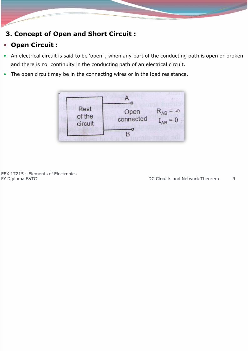
An open circuit gives rise to the following two effects ;
1. The resistance of the open circuit is infinitely high.
2. There is no flow of current in an open-circuit.
Fig. shows an open-circuit in a load resistance (i.e. load).
As a result the resistance between two points A and B is infinity (i.e. RAB =∞) and there is no
flow of electric current through the load resistance (i.e. IAB = 0).
If there is ‘open’ in a series d.c. circuit, then there is no voltage across the resistor.
The open in a parallel d.c. circuit may be of two types, namely an open in the main line and an
open in the branch line.
If there is an ‘open’ in any one of the main lines, then there is no flow of current in all the
branch lines but the voltage across that open line is equal to the applied source voltage.
If there is an ‘open’ in any one of the branch lines, then there is no flow of electric current in
that branch lines only.
EEX 17215 : Elements of ElectronicsFY Diploma E&TC DC Circuits and Network Theorem 10

8/12/2019 DC Circuits and Network Theorems
http://slidepdf.com/reader/full/dc-circuits-and-network-theorems 11/74
.
Short Circuit :
An electrical circuit is said to be ‘short’ when the voltage source has a closed path across its
terminals.
The short circuit results in too much flow of electric current in the electric circuit.
Usually, the short circuit is a bypass across the load resistance.
A short may occur due to a component failure or wiring error in the electrical circuit.
A short may cause some problem due to excessively high current in the electric circuit, even
may result burning out the circuit components.
EEX 17215 : Elements of ElectronicsFY Diploma E&TC DC Circuits and Network Theorem 11

8/12/2019 DC Circuits and Network Theorems
http://slidepdf.com/reader/full/dc-circuits-and-network-theorems 12/74
8/12/2019 DC Circuits and Network Theorems
http://slidepdf.com/reader/full/dc-circuits-and-network-theorems 13/74
.
4.Kirchhoff’s Current and Voltage Law :
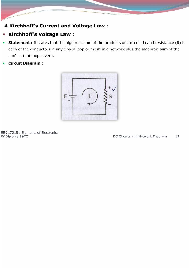
Kirchhoff’s Voltage Law :
Statement : It states that the algebraic sum of the products of current (I) and resistance (R) in
each of the conductors in any closed loop or mesh in a network plus the algebraic sum of the
emfs in that loop is zero.
Circuit Diagram :
EEX 17215 : Elements of ElectronicsFY Diploma E&TC DC Circuits and Network Theorem 13

8/12/2019 DC Circuits and Network Theorems
http://slidepdf.com/reader/full/dc-circuits-and-network-theorems 14/74
.
Consider the above circuit E is a voltage source across which a resistor connected.
There will be a flow of current I through the resistor R.
There will be a voltage drop across the resistor R due to the flow of current I from high potential
(+) to low potential (-).
This is termed as voltage drop and it is considered to be negative (i.e. –IR).
The same current I flows through the voltage source from low potential (-) to high potential (+)
and this is termed as voltage rise.
The voltage rise is considered to be positive (i.e. +E).
∑ Voltage rise = ∑ Voltage drop
E = IR
E –IR = 0
Thus in any closed loop circuit, the algebraic sum of voltage rise is equal to the algebraic sum of
voltage drop.
EEX 17215 : Elements of ElectronicsFY Diploma E&TC DC Circuits and Network Theorem 14
8/12/2019 DC Circuits and Network Theorems
http://slidepdf.com/reader/full/dc-circuits-and-network-theorems 15/74
.
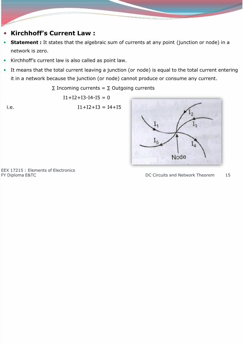
Kirchhoff’s Current Law :
Statement : It states that the algebraic sum of currents at any point (junction or node) in a
network is zero.
Kirchhoff’s current law is also called as point law.
It means that the total current leaving a junction (or node) is equal to the total current entering
it in a network because the junction (or node) cannot produce or consume any current.
∑ Incoming currents = ∑ Outgoing currents
I1+I2+I3-I4-I5 = 0
i.e. I1+I2+I3 = I4+I5
EEX 17215 : Elements of ElectronicsFY Diploma E&TC DC Circuits and Network Theorem 15
8/12/2019 DC Circuits and Network Theorems
http://slidepdf.com/reader/full/dc-circuits-and-network-theorems 16/74
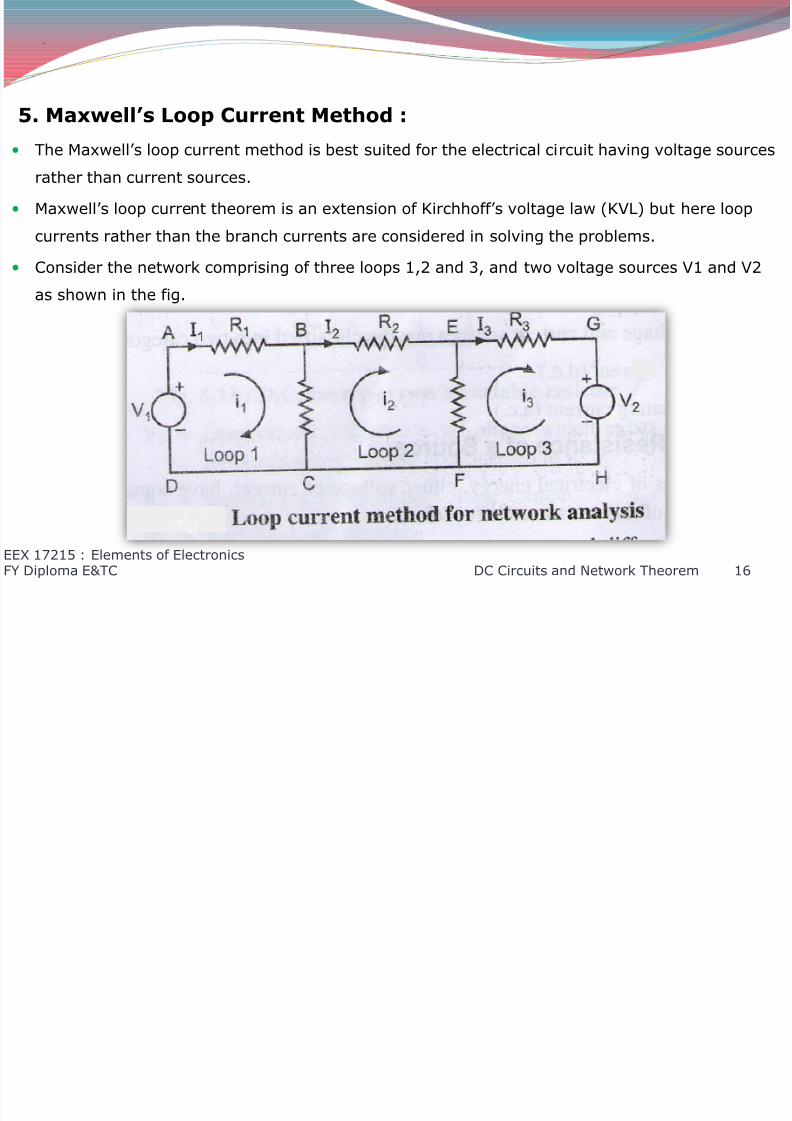
5. Maxwell’s Loop Current Method :
The Maxwell’s loop current method is best suited for the electrical circuit having voltage sources
rather than current sources.
Maxwell’s loop current theorem is an extension of Kirchhoff’s voltage law (KVL) but here loop
currents rather than the branch currents are considered in solving the problems.
Consider the network comprising of three loops 1,2 and 3, and two voltage sources V1 and V2
as shown in the fig.
EEX 17215 : Elements of ElectronicsFY Diploma E&TC DC Circuits and Network Theorem 16
.

8/12/2019 DC Circuits and Network Theorems
http://slidepdf.com/reader/full/dc-circuits-and-network-theorems 17/74
.
If we have to solve the network by KVL, we also have named different branch currents as I1, I2
and I3 as shown in Fig. The currents in different branches are as follows
Current in branch AB = I1
Current in branch BE = I2
Current in branch BC = I1-I2
Current in branch EG = I3
Current in branch EF = I2-I3
According to Maxwell’s loop current theorem, we would name the currents in different loops as
i1, i2 and i3.
The currents in different loops are as follows.
current in loop ABCD = i1
current in loop BEFC = i2
current in loop EGHF = i3
EEX 17215 : Elements of ElectronicsFY Diploma E&TC DC Circuits and Network Theorem 17

8/12/2019 DC Circuits and Network Theorems
http://slidepdf.com/reader/full/dc-circuits-and-network-theorems 18/74
.
From this, if we find the branch currents for BC and EF by inspection, it turns not to be (i1-i2)
and (i2-i3) respectively.
The KVL and Maxwell’s loop current methods for analysis of network are therefore similar and
may be used as required.
In this method, the loop voltage equation is to be written by using KVL.
EEX 17215 : Elements of ElectronicsFY Diploma E&TC DC Circuits and Network Theorem 18
8/12/2019 DC Circuits and Network Theorems
http://slidepdf.com/reader/full/dc-circuits-and-network-theorems 19/74
3. Node Analysis :
1. Sources for Electronic Circuit :
Introduction :
Every electronic circuit requires some source of energy for its operation.
The electrical energy may be supplied either in the form of a voltage or current.
The electrical device which supplies the electrical energy required for the operation of an
electronic circuit is called as a source.
EEX 17215 : Elements of ElectronicsFY Diploma E&TC DC Circuits and Network Theorem 19

8/12/2019 DC Circuits and Network Theorems
http://slidepdf.com/reader/full/dc-circuits-and-network-theorems 20/74
.
Types of Sources :
The sources required for the electronic circuits are of the following two types :
1. Voltage source.
2. Current source.
All the voltage and current sources may be classified into to categories as under :
1. Direct current(d.c.).
2. Alternating current( a.c.).
EEX 17215 : Elements of ElectronicsFY Diploma E&TC DC Circuits and Network Theorem 20

8/12/2019 DC Circuits and Network Theorems
http://slidepdf.com/reader/full/dc-circuits-and-network-theorems 21/74
.
Internal Resistance of a Source :
All sources of electrical energy, either voltage or current, have some internal resistance. Thevalue of this resistance is few ohms.
The internal resistance of a source may be due to the following reasons :
1. The resistance of an electrolyte between the electrodes in the case of dry cell.
2. The resistance of an armature winding in the case of d.c. generator or an alternator.
3. The output resistance of an active device like transistor in case of capacitor, signal generator
or regulated d.c. supply.
The d.c resistance offered by a source is called as an internal resistance.
The internal resistance of a voltage source and a current source should be very low and very
high respectively.
The internal resistance of a source (voltage or current), may be due to following reasons :
1. the resistance of an electrolyte between the electrodes in the case of dry cell.
2. The resistance of armature winding in the case of d.c. generator or an alternator.
EEX 17215 : Elements of ElectronicsFY Diploma E&TC DC Circuits and Network Theorem 21

8/12/2019 DC Circuits and Network Theorems
http://slidepdf.com/reader/full/dc-circuits-and-network-theorems 22/74
.
3. The output resistance of an active device like a transistor in case of oscillator, signal
generator or regulated d.c. supply.
EEX 17215 : Elements of ElectronicsFY Diploma E&TC DC Circuits and Network Theorem 22
8/12/2019 DC Circuits and Network Theorems
http://slidepdf.com/reader/full/dc-circuits-and-network-theorems 23/74
.
2. Voltage Source :
Introduction :
The source, which supplies electrical energy in the form of a voltage, is known as a voltage
source.
All voltage sources in practice must have very low internal resistance.
All voltage sources may be broadly classified as d.c. voltage source, a.c. voltage source,
depending upon whether a source supplies d.c. or a.c. to the load.
Some of the commonly used d.c. sources are batteries, d.c. generators and regulated d.c.
power supplies.
EEX 17215 : Elements of ElectronicsFY Diploma E&TC DC Circuits and Network Theorem 23

8/12/2019 DC Circuits and Network Theorems
http://slidepdf.com/reader/full/dc-circuits-and-network-theorems 24/74
8/12/2019 DC Circuits and Network Theorems
http://slidepdf.com/reader/full/dc-circuits-and-network-theorems 25/74
.
The total resistance inn the circuit is given by
RT = Rs + RL
The current through the variable load is given by,
I = Vs/RT = Vs/(Rs + RL)
Therefore, voltage across the terminals (which is also equal to the voltage across the load) is
given by,
EEX 17215 : Elements of ElectronicsFY Diploma E&TC DC Circuits and Network Theorem 25
VAB = VL = I.RL
= Vs
+ .
=Vs
1+Rs
RL
8/12/2019 DC Circuits and Network Theorems
http://slidepdf.com/reader/full/dc-circuits-and-network-theorems 26/74
.
It may be noted from the equation, that the ratio Rs/RL is small as compared to unity, then the
terminal voltage remains the same as that of the source voltage.
Under this condition, this source behaves as a good voltage source.
Thus even if the load resistance changes, the terminal voltage VAB of the voltage source
remains practically constant, provided the ratio Rs/RL is very much less than unity (i.e.
Rs/RL<<1).
EEX 17215 : Elements of ElectronicsFY Diploma E&TC DC Circuits and Network Theorem 26
8/12/2019 DC Circuits and Network Theorems
http://slidepdf.com/reader/full/dc-circuits-and-network-theorems 27/74
.
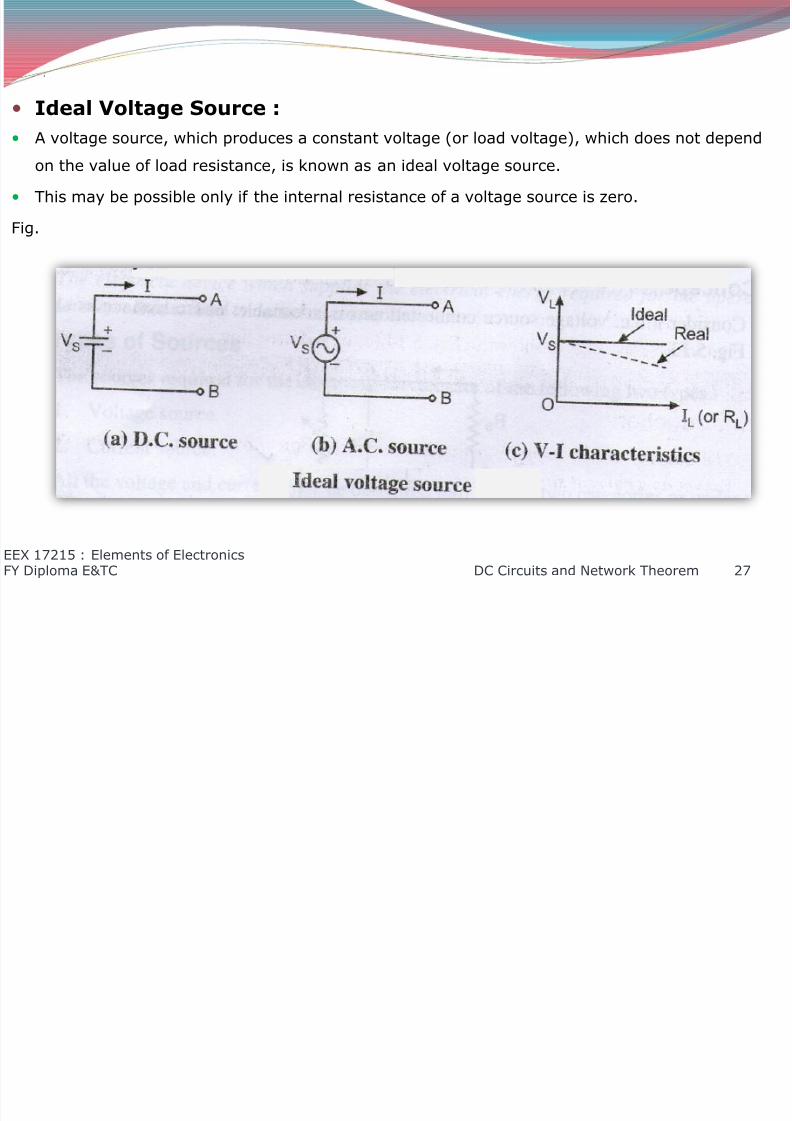
Ideal Voltage Source :
A voltage source, which produces a constant voltage (or load voltage), which does not dependon the value of load resistance, is known as an ideal voltage source.
This may be possible only if the internal resistance of a voltage source is zero.
Fig.
EEX 17215 : Elements of ElectronicsFY Diploma E&TC DC Circuits and Network Theorem 27
8/12/2019 DC Circuits and Network Theorems
http://slidepdf.com/reader/full/dc-circuits-and-network-theorems 28/74
.
Fig. a and b shows the circuit symbol and reference direction for currents of d.c. and a.c.
voltage sources.
It may be noted that the marking of positive and negative on the a.c. source does not mean the
same thing as that of a d.c. source.
In an a.c. source, it means that the upper terminal of the ideal voltage source is positive, with
respect to the lower terminal at that particular instant.
In the next half cycle of a.c. voltage, the marking will become opposite.
Fig. c shows the V-I characteristic of an ideal voltage source.
It may be noted that as the value of load resistance is reduced, the load current increases and
vice versa.
The open circuit voltage remains constant for the variation of either load resistance or current.
EEX 17215 : Elements of ElectronicsFY Diploma E&TC DC Circuits and Network Theorem 28
8/12/2019 DC Circuits and Network Theorems
http://slidepdf.com/reader/full/dc-circuits-and-network-theorems 29/74
.
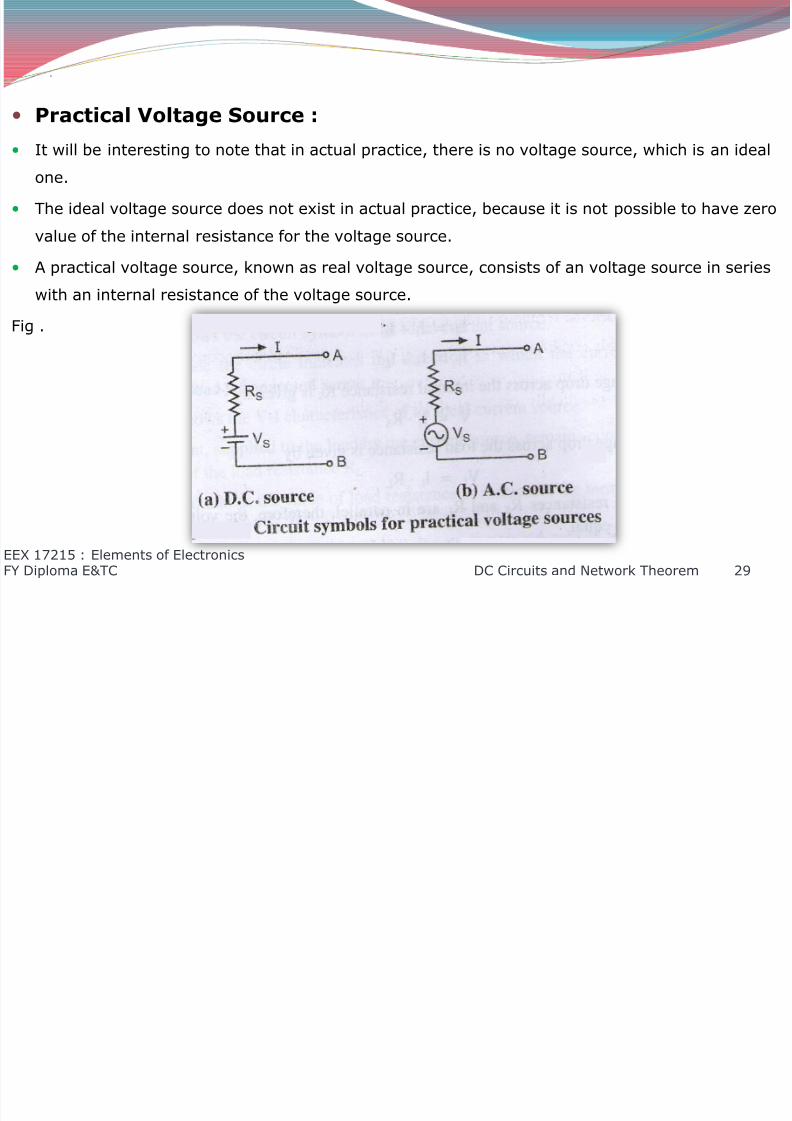
Practical Voltage Source :
It will be interesting to note that in actual practice, there is no voltage source, which is an ideal
one.
The ideal voltage source does not exist in actual practice, because it is not possible to have zero
value of the internal resistance for the voltage source.
A practical voltage source, known as real voltage source, consists of an voltage source in series
with an internal resistance of the voltage source.
Fig .
EEX 17215 : Elements of ElectronicsFY Diploma E&TC DC Circuits and Network Theorem 29
8/12/2019 DC Circuits and Network Theorems
http://slidepdf.com/reader/full/dc-circuits-and-network-theorems 30/74
.
Fig. a and b show the circuit symbols and the reference direction for current of the practical d.c.
and a.c. voltage sources.
The practical (i.e. real) voltage source has very small value of internal resistance.
It may be noted that the open circuit voltage (Vs) decreases as the load current increases and
vice-versa. This is shown in fig. c by the dotted line.
EEX 17215 : Elements of ElectronicsFY Diploma E&TC DC Circuits and Network Theorem 30
8/12/2019 DC Circuits and Network Theorems
http://slidepdf.com/reader/full/dc-circuits-and-network-theorems 31/74
.
3. Current Source :
Introduction : The source, which supplies electrical energy in the form of an electrical current, is known as a
current source.
All current sources, in practice, may be broadly classified as d.c. current source or a.c. current
source, depending upon whether a source supplies direct current (d.c.) or alternating
current(a.c.) to the load.
Some of the commonly used a.c. sources are alternators. oscillators or signal generators.
EEX 17215 : Elements of ElectronicsFY Diploma E&TC DC Circuits and Network Theorem 31

8/12/2019 DC Circuits and Network Theorems
http://slidepdf.com/reader/full/dc-circuits-and-network-theorems 32/74
.
Concept :
Consider the d.c. current source connected as a variable load resistance as shown in fig.
Let Is = Short circuit (i.e. a current through the source terminals when they are shorted)
RL = Variable load resistance connected across a current source.
Rs = Internal resistance of the source.
The current Is divides it into parts, namely IL and I1.
EEX 17215 : Elements of ElectronicsFY Diploma E&TC DC Circuits and Network Theorem 32

8/12/2019 DC Circuits and Network Theorems
http://slidepdf.com/reader/full/dc-circuits-and-network-theorems 33/74
..
The part IL flows through the load RL and I1 through the internal resistance Rs.
The source current is given byIs = I1 + IL
I1 = Is – IL
The voltage drop across the internal resistance Rs is given by
V = I1.Rs
The voltage drop across the load resistance is given by
VL = IL.RL
Since the resistance Rs and RL are in parallel, therefore, the voltage drop across them should be
equal.
so, Is . Rs = IL . RL(Is – IL).Rs = IL . RL
(Rs+RL).IL = Is . RS
Therefore, IL = Is/(1+[RL/Rs])
EEX 17215 : Elements of ElectronicsFY Diploma E&TC DC Circuits and Network Theorem 33
8/12/2019 DC Circuits and Network Theorems
http://slidepdf.com/reader/full/dc-circuits-and-network-theorems 34/74
.
The above equation indicates that the load current remain almost equal to the short circuit
current Is, provided the ratio RL/Rs is small as compared to unity.
In other words, large the value of internal resistance RS, as compared to the load resistance RL,
smaller is the ratio RL/Rs and hence better is the current source.
The condition for a good current source is given by,
RL/Rs <<1.
EEX 17215 : Elements of ElectronicsFY Diploma E&TC DC Circuits and Network Theorem 34
8/12/2019 DC Circuits and Network Theorems
http://slidepdf.com/reader/full/dc-circuits-and-network-theorems 35/74
.
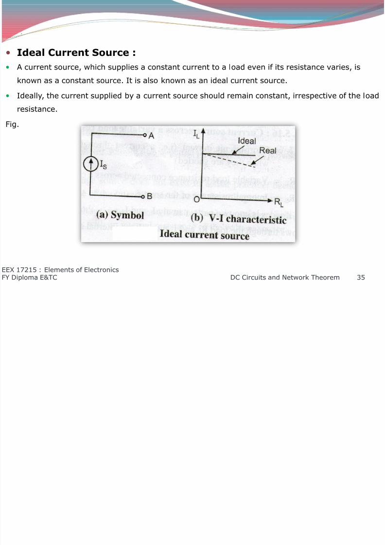
Ideal Current Source :
A current source, which supplies a constant current to a load even if its resistance varies, isknown as a constant source. It is also known as an ideal current source.
Ideally, the current supplied by a current source should remain constant, irrespective of the load
resistance.
Fig.
EEX 17215 : Elements of ElectronicsFY Diploma E&TC DC Circuits and Network Theorem 35
8/12/2019 DC Circuits and Network Theorems
http://slidepdf.com/reader/full/dc-circuits-and-network-theorems 36/74
.
This may be possible only if the internal resistance of a current source is infinite.
Fig. a shows the circuit symbol of an ideal current source. The arrow inside the circle indicates the direction in which the current flows in the circuit when a
load is connected across it.
Fig. b shows the V-I characteristics of an ideal current source.
The load current, supplied to the load by the current source, remains constant for all values of
the load resistance RL.
It may be noted that as the value of load resistance is increased, the terminal voltage VAB also
increases.
It is due to the fact, that the variation of terminal voltage is shown in the same direction as that
of the load resistance along the horizontal axis of the V –I characteristic.
EEX 17215 : Elements of ElectronicsFY Diploma E&TC DC Circuits and Network Theorem 36
8/12/2019 DC Circuits and Network Theorems
http://slidepdf.com/reader/full/dc-circuits-and-network-theorems 37/74
.
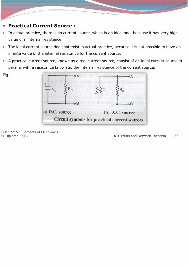
Practical Current Source :
In actual practice, there is no current source, which is an ideal one, because it has very highvalue of n internal resistance.
The ideal current source does not exist in actual practice, because it is not possible to have an
infinite value of the internal resistance for the current source.
A practical current source, known as a real current source, consist of an ideal current source in
parallel with a resistance known as the internal resistance of the current source.
Fig.
EEX 17215 : Elements of ElectronicsFY Diploma E&TC DC Circuits and Network Theorem 37
8/12/2019 DC Circuits and Network Theorems
http://slidepdf.com/reader/full/dc-circuits-and-network-theorems 38/74
.
Fig. a and b show the circuit symbols and reference direction for current of the practical d.c. and
a.c. current source.
The practical (i.e. real) current source has very high value of the internal resistance.
It may be noted that the load current Is decreases below the short circuit current, as the loas
resistance RL is increased. It is shown in Fig. b by dotted line.
EEX 17215 : Elements of ElectronicsFY Diploma E&TC DC Circuits and Network Theorem 38

8/12/2019 DC Circuits and Network Theorems
http://slidepdf.com/reader/full/dc-circuits-and-network-theorems 39/74
.
4. Equivalence Between Sources :
We know that the source may either work as a voltage source or a current source, depending
upon the working conditions.
As a matter of fact, a voltage source is not different from a current source.
If the value of load resistance RL is very high as compared to the internal resistance Rs, the
source is treated as a voltage source.
If the value of the load resistance RL, is very low as compared to the internal resistance RL, the
source is treated as a current source.
In order to establishment between a voltage source and a current source, consider an a.c.
source connected to the load resistance RL as shown in Fig.
The equivalent circuit of a practical voltage source is as shown in fig. a and it consist of an ideal
voltage source Vs in series with a source resistance Rs.
The equivalent circuit of a practical current source is as shown in fig. b and it consists of an ideal
current source Is in parallel with a source resistance Rs.
Since both equivalent circuits are of the same source, they give the same results.
EEX 17215 : Elements of ElectronicsFY Diploma E&TC DC Circuits and Network Theorem 39

8/12/2019 DC Circuits and Network Theorems
http://slidepdf.com/reader/full/dc-circuits-and-network-theorems 40/74
.
It may be noted that the source resistance in both the equivalent circuits are the same.
Rs1 = Rs2
Also indicates that whatever may be the value of load resistance RL, the current drawn by the
load resistance in either voltage source or current source, equivalent circuits will be the same.
IL1 = IL2
Thus the equivalence between a voltage source and current source is completely established.
EEX 17215 : Elements of ElectronicsFY Diploma E&TC DC Circuits and Network Theorem 40
8/12/2019 DC Circuits and Network Theorems
http://slidepdf.com/reader/full/dc-circuits-and-network-theorems 41/74
.
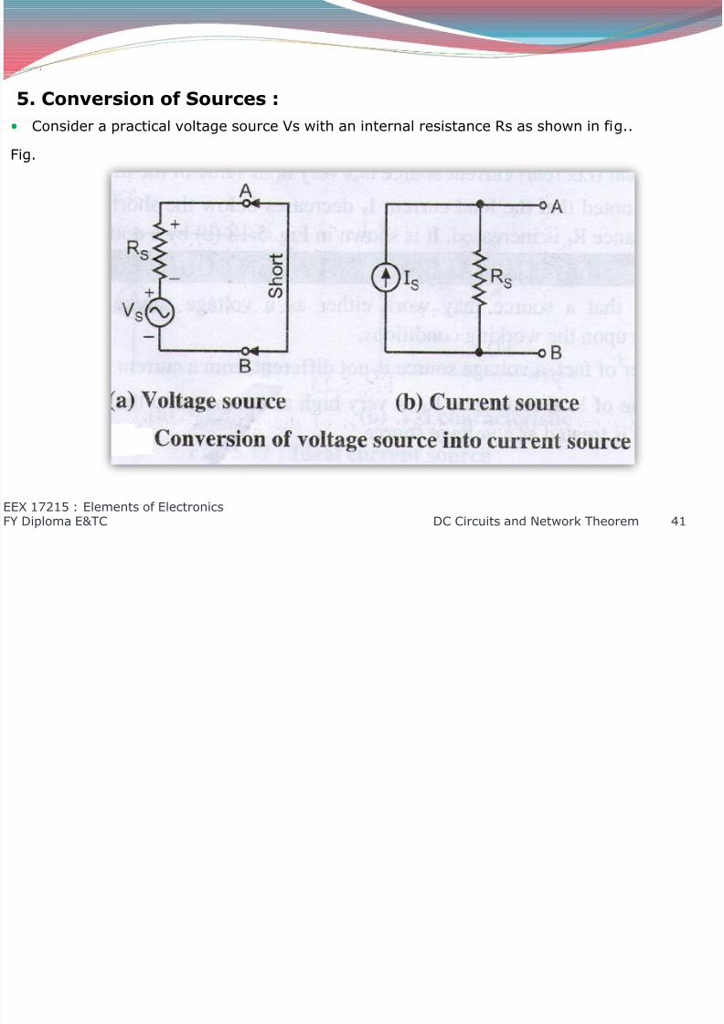
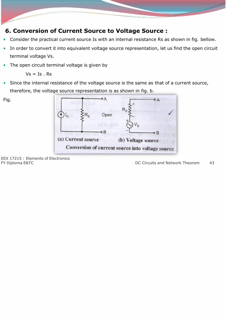
5. Conversion of Sources :
Consider a practical voltage source Vs with an internal resistance Rs as shown in fig..Fig.
EEX 17215 : Elements of ElectronicsFY Diploma E&TC DC Circuits and Network Theorem 41
8/12/2019 DC Circuits and Network Theorems
http://slidepdf.com/reader/full/dc-circuits-and-network-theorems 42/74
.
In order to convert it into its equivalent current source representation, let us short circuit the
terminals A and B and then determine the current through the short circuit. The short circuit current is given by
Is = Vs/Rs
We know that the source resistance in either voltage source representation or current
representation in the same.
Therefore, the current source has the same internal resistance at that a voltage source.
Thus the equivalent current source may be represented by a current source Is in parallel with a
source resistance Rs as shown in fig. b.
EEX 17215 : Elements of ElectronicsFY Diploma E&TC DC Circuits and Network Theorem 42
8/12/2019 DC Circuits and Network Theorems
http://slidepdf.com/reader/full/dc-circuits-and-network-theorems 43/74
8/12/2019 DC Circuits and Network Theorems
http://slidepdf.com/reader/full/dc-circuits-and-network-theorems 44/74
.
7. Delta to Star and Star to Delta Conversions :
Introduction : Kirchhoff’s laws or Maxwell’s loop current theorem is very useful in solving network problems.
But if a network with considerable number of branches is to be analyzed, then there are a large
number of simultaneous equations and a great difficulty may have to be forced in finding the
solution.
Such complicated networks may be simplified by successfully replacing delta or mesh circuit
with equivalent star circuit and vice versa.
EEX 17215 : Elements of ElectronicsFY Diploma E&TC DC Circuits and Network Theorem 44

8/12/2019 DC Circuits and Network Theorems
http://slidepdf.com/reader/full/dc-circuits-and-network-theorems 45/74
.
Delta to Star Conversion :
Delta to star conversion is useful for quick reduction of the given circuit. Consider the delta network as shown in fig. a below.
EEX 17215 : Elements of ElectronicsFY Diploma E&TC DC Circuits and Network Theorem 45
8/12/2019 DC Circuits and Network Theorems
http://slidepdf.com/reader/full/dc-circuits-and-network-theorems 46/74
.
It is connected between points 1,2 and 3, and the resistance are denoted as R12, R22 and R31.
This delta circuit can be transformed into a star circuit as shown in fig. b with the resistance R1,R2 and R3.
In order that the two networks be exactly equivalent, the resistance between any two terminals
of the network must be equal to the resistance between the corresponding pair of terminals of
the other network.
For delta to star conversion, we can find the values for R12, R21, R31 in terms of R1, R2 and
R3.
R12 = R1+R2+(R1R2)/R3
R23 = R2+R3+(R2R3)/R1
R31 = R3+R1+(R3R1)/R2
EEX 17215 : Elements of ElectronicsFY Diploma E&TC DC Circuits and Network Theorem 46

8/12/2019 DC Circuits and Network Theorems
http://slidepdf.com/reader/full/dc-circuits-and-network-theorems 47/74
.
Star to Delta Conversion :
Consider a star network as shown in the fig. b. It is connected between points 1, 2 and 3 and the resistances are denoted as R1, R2 and R3.
Fig.
EEX 17215 : Elements of ElectronicsFY Diploma E&TC DC Circuits and Network Theorem 47
8/12/2019 DC Circuits and Network Theorems
http://slidepdf.com/reader/full/dc-circuits-and-network-theorems 48/74
.
Conversion from star to delta can be easily obtained by use of the resistance R12, R23, R31 in
terms of R1, R2, R3.R12 = (R1.R2+R2.R3+R3.R1) / R3
R23 = (R1.R2+R2.R3+R3.R1) / R1
R31 = (R1.R2+R2.R3+R3.R1) / R2
The star network can be transformed into a delta network as shown in fig. a with the resistance
R12, R21 and R23.
EEX 17215 : Elements of ElectronicsFY Diploma E&TC DC Circuits and Network Theorem 48
8/12/2019 DC Circuits and Network Theorems
http://slidepdf.com/reader/full/dc-circuits-and-network-theorems 49/74
.
8. Network Terminology :
Any interconnection of electrical components like resistors, inductors, capacitors,semiconductor devices, transformers and sources of e.m.f. is known as a network. A network
may comprise of one or more circuit elements.
Types of network are as follows :
1. One port network.
2. Two port network.
A network having one pair of terminal is called one port network.
e.g. :- a series, parallel or series-parallel combination of resistors, capacitors etc.
A network having two pairs of terminals (i.e. four terminals) is called two port network.
e.g. :- an amplifier, attenuator, filter, transformer etc.
EEX 17215 : Elements of ElectronicsFY Diploma E&TC DC Circuits and Network Theorem 49
8/12/2019 DC Circuits and Network Theorems
http://slidepdf.com/reader/full/dc-circuits-and-network-theorems 50/74
.
8.1 Linear Network :
If the resistance, capacitance or inductance offered by the passive elements does not change
with a change in the applied e.m.f. or the circuit current , the element is called as a linear
element.
The linear element shows a linear relation between voltage and current.
The network comprising of one or more linear number of elements is known as a linear network.
EEX 17215 : Elements of ElectronicsFY Diploma E&TC DC Circuits and Network Theorem 50
8/12/2019 DC Circuits and Network Theorems
http://slidepdf.com/reader/full/dc-circuits-and-network-theorems 51/74
.
8.2 Non-linear Network :
A non-linear circuit element is one in which the current does not change linearly with a changein applied voltage at a given frequency.
The non-linear elements include components like VDR (voltage dependent resistor), varactor
(voltage dependent capacitor), LDR (light dependent resistor), thermistor (temperature
dependent resistor) etc.
A network comprising of one or more non-linear elements is known as a non-linear network.
EEX 17215 : Elements of ElectronicsFY Diploma E&TC DC Circuits and Network Theorem 51

8/12/2019 DC Circuits and Network Theorems
http://slidepdf.com/reader/full/dc-circuits-and-network-theorems 52/74
.
8.3 Passive Network :
An element that is not capable of amplifying or processing an electrical signal is known aspassive element.
Resistor, capacitors, inductors, transformers are few examples of passive elements.
A network comprising of one or more number of passive elements is known as a passive
network.
EEX 17215 : Elements of ElectronicsFY Diploma E&TC DC Circuits and Network Theorem 52

8/12/2019 DC Circuits and Network Theorems
http://slidepdf.com/reader/full/dc-circuits-and-network-theorems 53/74
.
8.4 Active Network:
An electronic element which itself is capable of amplifying (or processing) an electrical signal is
known as an active element.
The active element includes semiconductor devices such as diodes, BJTs, FETs etc.
A network comprising one or more number of active elements is known as an active network.
EEX 17215 : Elements of ElectronicsFY Diploma E&TC DC Circuits and Network Theorem 53
8/12/2019 DC Circuits and Network Theorems
http://slidepdf.com/reader/full/dc-circuits-and-network-theorems 54/74
.
8.5 Unilateral Network :
If the magnitude of the current flowing through a circuit element is affected when the polarity of
the applied e.m.f is changed, then the element is known as a unilateral element.
An example of the unilateral element is semiconductor diode.
The unilateral elements offer different resistance to the flow of current in different direction.
A network comprising of one or more number of unilateral elements is known as a unilateral
network.
EEX 17215 : Elements of ElectronicsFY Diploma E&TC DC Circuits and Network Theorem 54
8/12/2019 DC Circuits and Network Theorems
http://slidepdf.com/reader/full/dc-circuits-and-network-theorems 55/74
.
8.6 Bilateral Network :
If the magnitude of the current flowing through a circuit element is not affected when the
polarity of the applied voltage is changed, then the element is known as a bilateral element.
The bilateral elements offer the same impedance in both directions.
A resistor is a bilateral element.
A network comprising of one or more number of bilateral elements is known as a bilateral
network.
EEX 17215 : Elements of ElectronicsFY Diploma E&TC DC Circuits and Network Theorem 55
8/12/2019 DC Circuits and Network Theorems
http://slidepdf.com/reader/full/dc-circuits-and-network-theorems 56/74
4. Network Theorem :
1. Superposition Theorem :
Statement :
The superposition theorem states that in any linear network containing two or more
sources, the response (current) in any element is equal to the algebraic sum of the response(current) caused by individual sources acting alone, while the other sources are inoperative.
Or
The voltage or current, present in a component, is equal to the sum of voltages currents,
which exist independently.
EEX 17215 : Elements of ElectronicsFY Diploma E&TC DC Circuits and Network Theorem 56
8/12/2019 DC Circuits and Network Theorems
http://slidepdf.com/reader/full/dc-circuits-and-network-theorems 57/74
.
Diagram :
EEX 17215 : Elements of ElectronicsFY Diploma E&TC DC Circuits and Network Theorem 57

8/12/2019 DC Circuits and Network Theorems
http://slidepdf.com/reader/full/dc-circuits-and-network-theorems 58/74
.
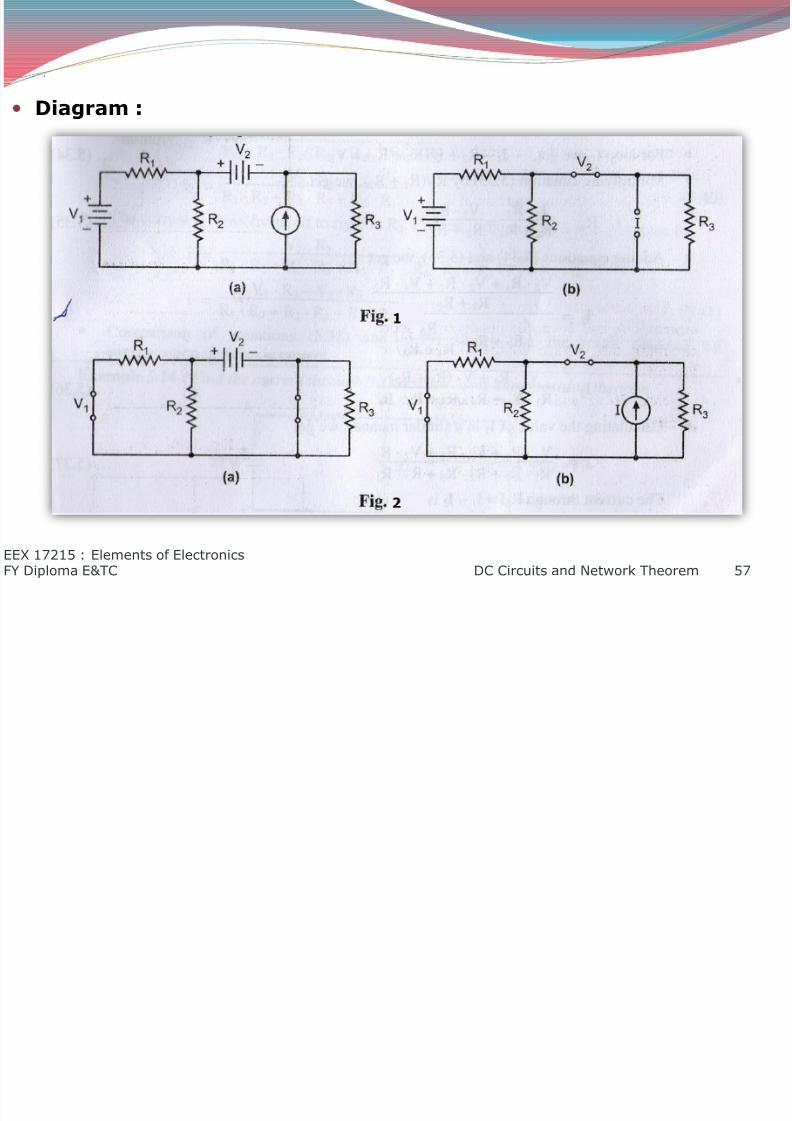
Explanation :
This theorem is useful where more than one voltage or current source is present. It may be
used to determine the current in a component, which exist as a result of each of the sources.
It is important to note that while calculating the results for each source, the other sources must
be set to zero and replaced by their internal resistances. In other words voltage sources are
replaced by a short circuit and current sources by an open circuit.
If there are any dependent sources, then leave them undisturbed in the circuit.
For example, let us consider the circuit as shown in fig. 1(b) . Now the first step is that we have
to draw the individual circuits for each source for calculation purposes.
Thus fig. 1(b) shows the circuit for source V1, fig. 2(a) for source V2 and fig. 2(b) for current
source I.
The next step is to calculate the effects of each source from the individual circuits.
Then they finally find the results caused by all the combined sources.
In using this theorem the polarity of each voltage and current is very important , because end
result is the algebraic sum of the individual results.
EEX 17215 : Elements of ElectronicsFY Diploma E&TC DC Circuits and Network Theorem 58

8/12/2019 DC Circuits and Network Theorems
http://slidepdf.com/reader/full/dc-circuits-and-network-theorems 59/74
.
Applications :
The superposition theorem is useful in circuit analysis, when the circuit has large number of
independent sources.
It helps up to determine the voltage across a component or current through branch by
calculating the effect of each source individually and determining the combined effect of these
sources.
The superposition theorem ca be used for a.c. as well as d.c. networks.
EEX 17215 : Elements of ElectronicsFY Diploma E&TC DC Circuits and Network Theorem 59

8/12/2019 DC Circuits and Network Theorems
http://slidepdf.com/reader/full/dc-circuits-and-network-theorems 60/74
.
Drawbacks :
The superposition theorem is not applicable to the circuits consisting of non-linear elements e.g.
diode, transistors.
The superposition theorem cannot be applied to circuits containing dependent sources only.
The superposition theorem is not useful for circuit analysis, for circuits containing less than two
independent sources.
Superposition theorem cannot be used for calculating power because power is proportional tosquare of voltage or current i.e. nonlinear.
EEX 17215 : Elements of ElectronicsFY Diploma E&TC DC Circuits and Network Theorem 60
8/12/2019 DC Circuits and Network Theorems
http://slidepdf.com/reader/full/dc-circuits-and-network-theorems 61/74
.
2. Thevenin’s Theorem :
Statement :
Thevenin’s theorem states that any two terminal linear(complex) network containing
energy sources and impedance can be replaced by an equivalent circuit consisting of an ideal
voltage source VTH in series with a resistance RTH.
EEX 17215 : Elements of ElectronicsFY Diploma E&TC DC Circuits and Network Theorem 61
8/12/2019 DC Circuits and Network Theorems
http://slidepdf.com/reader/full/dc-circuits-and-network-theorems 62/74
.
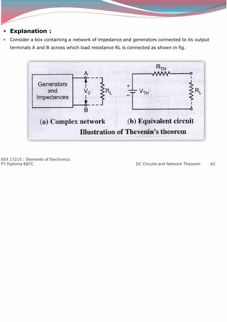
Explanation :
Consider a box containing a network of impedance and generators connected to its output
terminals A and B across which load resistance RL is connected as shown in fig.
EEX 17215 : Elements of ElectronicsFY Diploma E&TC DC Circuits and Network Theorem 62
8/12/2019 DC Circuits and Network Theorems
http://slidepdf.com/reader/full/dc-circuits-and-network-theorems 63/74
.
Let V0 be the open circuit voltage between terminals A and B of the network and Z is the
impedance measured between these two terminals when all energy sources are eliminated.
In any circuit, consider the load resistor R1 is removed and with ends kept open, calculate the
open circuit voltage Vx. This equals the Thevenin’s resistance RTH.
Next remove voltage source leaving only its internal resistance, calculate equivalent resistance
across the terminals. This equals the Thevenin’s resistance RTH.
According to Thevenin’s theorem, the entire network connected to A and B terminals can be
replaced by a single voltage source VTH in series with a single resistance RTH across the same
terminals as shown in fig. b.
EEX 17215 : Elements of ElectronicsFY Diploma E&TC DC Circuits and Network Theorem 63
8/12/2019 DC Circuits and Network Theorems
http://slidepdf.com/reader/full/dc-circuits-and-network-theorems 64/74
.
Applications :
The Thevenin’s theorem makes it possible to convert a complicated network to a simple
equivalent network. Using the simple network we can determine voltage, current, power
delivered to the load.
It can be used to justify the concept of input and output resistances of an amplifier.
EEX 17215 : Elements of ElectronicsFY Diploma E&TC DC Circuits and Network Theorem 64
8/12/2019 DC Circuits and Network Theorems
http://slidepdf.com/reader/full/dc-circuits-and-network-theorems 65/74
.
Drawbacks :
The Thevenin’s theorem is not applicable to the networks containing unilateral elements e.g.
diode.
The Thevenin’s theorem is not applicable to circuits consisting of load with dependent or
controlled sources.
The Thevenin’s theorem is not applicable to networks containing non linear elements e.g. diode,
transistors.
The Thevenin’s theorem is not applicable to the networks containing magnetic coupling between
load and any other circuit element.
EEX 17215 : Elements of ElectronicsFY Diploma E&TC DC Circuits and Network Theorem 65
8/12/2019 DC Circuits and Network Theorems
http://slidepdf.com/reader/full/dc-circuits-and-network-theorems 66/74
.
3. Norton’s Theorem :
Statement :Norton’s theorem states that any complex linear network can be replaced by a parallel
circuit consisting of an ideal current source and a resistance.
EEX 17215 : Elements of ElectronicsFY Diploma E&TC DC Circuits and Network Theorem 66
8/12/2019 DC Circuits and Network Theorems
http://slidepdf.com/reader/full/dc-circuits-and-network-theorems 67/74
.
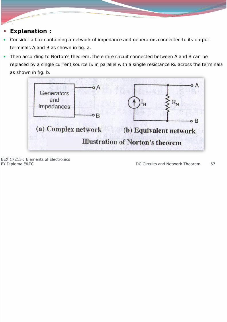
Explanation :
Consider a box containing a network of impedance and generators connected to its output
terminals A and B as shown in fig. a.
Then according to Norton’s theorem, the entire circuit connected between A and B can be
replaced by a single current source IN in parallel with a single resistance RN across the terminala
as shown in fig. b.
EEX 17215 : Elements of ElectronicsFY Diploma E&TC DC Circuits and Network Theorem 67
8/12/2019 DC Circuits and Network Theorems
http://slidepdf.com/reader/full/dc-circuits-and-network-theorems 68/74
.
As a matter of fact, IN is the current, that actually flows between the terminals A and B, when
they are short circuited.
Similarly, RN is the equivalent resistance between the terminal A and B of the original network
with the load resistance removed and all the sources replaced by their internal resistances.
EEX 17215 : Elements of ElectronicsFY Diploma E&TC DC Circuits and Network Theorem 68
8/12/2019 DC Circuits and Network Theorems
http://slidepdf.com/reader/full/dc-circuits-and-network-theorems 69/74
.
Applications :
The Norton’s theorem makes it possible to convert a complicated network to a simple equivalent
network. Using the network we can find voltage , current and power delivered to the load.
EEX 17215 : Elements of ElectronicsFY Diploma E&TC DC Circuits and Network Theorem 69

8/12/2019 DC Circuits and Network Theorems
http://slidepdf.com/reader/full/dc-circuits-and-network-theorems 70/74
.
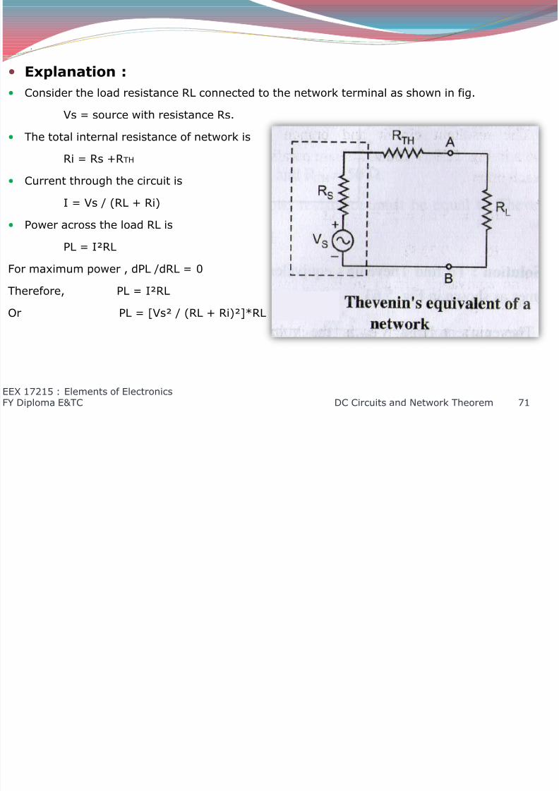
4. Maximum Power Transfer Theorem :
Statement :
The power transfer theorem states that for a given linear network represented by a
Thevenin’s equivalent circuit , the maximum power will be transferred by the network to the
resistive load, when the load resistance is equal to the Thevenin’s resistance.
EEX 17215 : Elements of ElectronicsFY Diploma E&TC DC Circuits and Network Theorem 70
8/12/2019 DC Circuits and Network Theorems
http://slidepdf.com/reader/full/dc-circuits-and-network-theorems 71/74

8/12/2019 DC Circuits and Network Theorems
http://slidepdf.com/reader/full/dc-circuits-and-network-theorems 72/74
.
EEX 17215 : Elements of ElectronicsFY Diploma E&TC DC Circuits and Network Theorem 72
∴ = ² 1
(+)²× 1 + [ −2+3]
∴ ² 1(+)² − 2+3 = 0
∴ 1
(+)² =2
+3
Or 2RL = RL + Ri
∴ RL = Ri
This is the condition for maximum power given by
P = ²
(2)²× =²4 ×
Pmax =²4
8/12/2019 DC Circuits and Network Theorems
http://slidepdf.com/reader/full/dc-circuits-and-network-theorems 73/74
.
Applications :
In the power amplifiers, we use this theorem in order to match the loud speaker impedance to
the output impedance of amplifier in order to ensure maximum power transfer.
For impedance matching in any electrical circuit.
EEX 17215 : Elements of ElectronicsFY Diploma E&TC DC Circuits and Network Theorem 73

8/12/2019 DC Circuits and Network Theorems
http://slidepdf.com/reader/full/dc-circuits-and-network-theorems 74/74
EEX 17215 El t f El t i
Related Documents