7/29/2019 DBS_EDW Migration - Technical Architecture Document v 1.3 http://slidepdf.com/reader/full/dbsedw-migration-technical-architecture-document-v-13 1/26 Controlledcopy Project ID: 07264 <SCI.ID. > / Ver: 1.0 Release ID: QTDW-TARCH.doc / 1.0 / 11.07.2003 C3: Protected C o n f i d e n t i a l D o c u m ent Fo r I n t e r n a l U s e O n l y P r o prieta r y o f C o g n i z a n t DBS EDW Migration Technical Architecture Version No. 1.2 Prepared By Reviewed by Approved By Name Cognizant DBS Role Signature Date

Welcome message from author
This document is posted to help you gain knowledge. Please leave a comment to let me know what you think about it! Share it to your friends and learn new things together.
Transcript

7/29/2019 DBS_EDW Migration - Technical Architecture Document v 1.3
http://slidepdf.com/reader/full/dbsedw-migration-technical-architecture-document-v-13 1/26
Controlledcopy
Project ID: 07264 <SCI.ID. > / Ver: 1.0
Release ID: QTDW-TARCH.doc / 1.0 / 11.07.2003 C3: Protected
C o n f i d e
n t i a l D o
c u m e n t
F o r I n
t e r n a l U
s e O n
l y
P r o p r i e t a
r y o f C o
g n i z a n
t
DBS
EDW Migration
Technical Architecture
Version No. 1.2
Prepared By Reviewed by Approved By
Name Cognizant DBS
Role
Signature
Date

7/29/2019 DBS_EDW Migration - Technical Architecture Document v 1.3
http://slidepdf.com/reader/full/dbsedw-migration-technical-architecture-document-v-13 2/26
Controlledcopy TechnicalArchitecture
Project ID: 07264 <SCI.ID. > / Ver:1.0
Release ID: QTDW-TARCH.doc / 1.0 / 11.07.2003 C3: Protected Page 2 of 26
C o n f i d e
n t i a l D o
c u m e n t
F o r I n
t e r n a l U
s e O n
l y
P r o p r i e t a
r y o f C o
g n i z a n
t
Table of Contents
1 Introduction 3
1.1 Purpose of this Document 3
2 Introduction to the project 3
2.1 Purpose of the project 3
2.2 Scope 3
2.3 Assumptions and Dependencies 4
2.4 Design Inputs and Constraints 5
3 Technical Architecture 5
3.1 Existing ETL Architecture 6
3.2 Proposed BDW ETL Architecture 8
3.3 Walkthrough of BDW ETL Architecture Diagram 8
3.4 Re-Extraction ETL Architecture 16
3.5 Process Control – Auditing Mechanism & Alert System 17
3.6 Re-start / Recovery 19
3.7 Error Handling 20
4 Appendix 24
5 Change Log 25
7/29/2019 DBS_EDW Migration - Technical Architecture Document v 1.3
http://slidepdf.com/reader/full/dbsedw-migration-technical-architecture-document-v-13 3/26
Controlledcopy TechnicalArchitecture
Project ID: 07264 <SCI.ID. > / Ver:1.0
Release ID: QTDW-TARCH.doc / 1.0 / 11.07.2003 C3: Protected Page 3 of 26
C o n f i d e
n t i a l D o
c u m e n t
F o r I n
t e r n a l U
s e O n
l y
P r o p r i e t a
r y o f C o
g n i z a n
t
1 Introduction
1.1 Purpose of this DocumentThe purpose of this document is to provide a high level approach of the ETL architecture and processdesign for the EDW Migration solution. This document is to be shared with other projects that arerelated to BDW as an understanding of the proposed architecture that would replace the existingEDW system. This document serves as the foundation for the detailed design activities of the EDWMigration.
This document is a working document and various sections in this document will be explored further during the design and construction stages and amended periodically to incorporate additional aspectsfound relevant during the stages of the project.
2 Introduction to the project
2.1 Purpose of the project
DBS has initiated the Business Data Warehouse (BDW) Program to implement a new Data
Warehouse that will enable DBS Bank to achieve its ambition to be a sound, well-managed
enterprise. The BDW will be designed to meet the group’s current analytical requirements and will
have the capability to scale up to meet the Bank’s future requirements.
The Enterprise Data Warehouse (EDW) Migration Project is part of this program and has the
objective of extracting and loading data into the Business Data Warehouse (BDW) from a specific
set of data sources in Singapore and creating downstream feeds from the BDW to the Data martsoperational in Singapore.
2.2 Scope
2.2.1 In Scope
1. The scope involves only moving the existing sources of EDW to BDW and existing re-extractionlogic which is operating from EDW to re-extract from the BDW.
2. The re-extraction components include extract files from BDW to the downstreamdatamart/systems - CPMS, RMG, IMINE, SAS and Others extracts.
3. The re-extraction files will have the same layout as the current files extracted out of EDW.4. All existing EDW Cobol extraction and transformation processes on mainframe would beconverted to equivalent ETL processes.
5. All existing UNIX script processes that are loading in to EDW will be converted to equivalent ETLprocess using Informatica and Teradata.

7/29/2019 DBS_EDW Migration - Technical Architecture Document v 1.3
http://slidepdf.com/reader/full/dbsedw-migration-technical-architecture-document-v-13 4/26
Controlledcopy TechnicalArchitecture
Project ID: 07264 <SCI.ID. > / Ver:1.0
Release ID: QTDW-TARCH.doc / 1.0 / 11.07.2003 C3: Protected Page 4 of 26
C o n f i d e
n t i a l D o
c u m e n t
F o r I n
t e r n a l U
s e O n
l y
P r o p r i e t a
r y o f C o
g n i z a n
t
2.3 Assumptions and Dependencies
2.3.1 General Assumptions
• The architectural designs discussed here are based on the ‘DBS EDW Migration’ Proposal
Document submitted by Cognizant, follow-up interviews with DBS and based on the analysis of
the code elements of the project.
• The specifications presented in this design document are subject to change, as and when any
changes are done to the Business Definition Layout.
• Architectural considerations are made based on the volume specifications, frequency & ETA of
files provided by DBS. (Files are attached for reference in the appendix section of this document.)
2.3.2 Technical Assumptions
• Technology Related
ETL tools: Informatica Power Center 7.1.3
Power Connect for Mainframe 4.2
Database: Teradata V2R5
• Hardware sizing will be done by DBS technical architecture team.
• Informatica ETCL server will be shared by the projects under BDW program.
• This document assumes multi-CPU server configuration to achieve the expected
performance level and optimal operating performance based on the documented and signed
off SLA with the downstream data marts.
• Informatica and Teradata will reside in separate servers.
• Capacity planning for the database and file system will be done by the DBS team.
• All data loading and extraction between the layers in the architecture will be batch processes.
•
The scope of the verification and validation rules are limited to the existing rules beinghandled in EDW processes.
• Staging / Work Tables of EDW Migration project will not be shared by any other projects
under BDW program.

7/29/2019 DBS_EDW Migration - Technical Architecture Document v 1.3
http://slidepdf.com/reader/full/dbsedw-migration-technical-architecture-document-v-13 5/26
Controlledcopy TechnicalArchitecture
Project ID: 07264 <SCI.ID. > / Ver:1.0
Release ID: QTDW-TARCH.doc / 1.0 / 11.07.2003 C3: Protected Page 5 of 26
C o n f i d e
n t i a l D o
c u m e n t
F o r I n
t e r n a l U
s e O n
l y
P r o p r i e t a
r y o f C o
g n i z a n
t
2.3.3 Dependencies
• Same database instance that will be shared by the projects under BDW program
• Surrogate key generation logic will have to be decided after consensus from other projects as
the same tables will be loaded.
• SLA for the load window will have to be decided after consensus from other projects as the
same tables will be loaded.
• Exception handling and Message escalation framework for exception scenarios will have to
be decided after consensus from other projects.
• Decision on the technical components between the layers in the architecture is based on
current information of volumetric available to the Cognizant team. Multiple options would be
explored to achieve the optimal performance based on the accurate information sourced from
DBS.
• Approval from DBS Data Modeling team to include in the FSLDM any adhoc code table that
is not part of the reference model but is required for processing.
• DBS to perform a POC using Informatica Power Exchange tool to check the performance of
reading the data from Tapes in Mainframes. This will be done on the completion of the
Informatica Upgrade.
2.4 Design Inputs and Constraints
The design approach is based on the following points.
1. Target BDW Data model.
2. Source (Mainframe Files), Staging (Informatica generated Files on UNIX) and Target(Teradata) Platform.
3. ETL Platform (Informatica).
4. Analysis of Mainframes EDW, EDW and Re-extraction Unix/C scripts for the data flow andETL transformations.
3 Technical Architecture
The scope of this project assumes that the downstream data marts meet the existing businessrequirements of the end users and hence there will not be any change in the feeds provided to thedownstream data marts. The focus is entirely on migrating the data assets that are already availablein the EDW into a more robust, scalable and efficient BDW environment and to create the data feedsthat are available to the downstream data marts in the same format as they are currently beingdelivered. At a high level the project includes the following:
• Data Integration

7/29/2019 DBS_EDW Migration - Technical Architecture Document v 1.3
http://slidepdf.com/reader/full/dbsedw-migration-technical-architecture-document-v-13 6/26
Controlledcopy TechnicalArchitecture
Project ID: 07264 <SCI.ID. > / Ver:1.0
Release ID: QTDW-TARCH.doc / 1.0 / 11.07.2003 C3: Protected Page 6 of 26
C o n f i d e
n t i a l D o
c u m e n t
F o r I n
t e r n a l U
s e O n
l y
P r o p r i e t a
r y o f C o
g n i z a n
t
a) FSLDM Design: Create a new FSLDM based Data model for DBS to meet all the datarequirements for the downstream data marts.
b) ETL Architecture Design: Create the metadata driven design for the ETL architecture toconduct a complete migration of the existing ETL processes into the BDW environment.
c) BDW ETL: Migrate the existing ETL processes that feed the current data warehouse (EDW)onto the Business Data Warehouse (BDW)
d) Re-extraction ETL: Migrate the existing re-extraction processes from the current datawarehouse (EDW) onto the Business Data warehouse (BDW) to feed the RMG, CPMS,iMINE and SAS Data marts.
3.1 Existing ETL Architecture
The DBS EDW is a DB2 on AIX warehouse that houses the Bank’s data encompassing all facets of
business. Currently there are 43 source feeds into the warehouse populated by a mix of mainframes and
open system processes. From EDW, a set of re-extraction processes extract the data from the
warehouse to the downstream marts. Data provided to these marts are by means of flat files.
There is a whole set of processes on the mainframes source layer that extract data from the
applications, transform the data and prepare intermediate files for the downstream processes. There is a
robust change detection layer that identifies the changes in the data and builds differential files to beloaded into the warehouse. Currently there is no direct pull from the mainframes layer to the warehouse
layer. Data files prepared by the processes on the mainframes layer are pushed to the designated AIX
box by ConnectDirect. Thereon the ETL processes in the warehouse layer stage the files, chop and
prune the data, transform as required and load the data into the EDW tables. The target load strategy
being followed – truncate and load insert and update.
The EDW load processes and the data mart re-extraction processes extract data from the original tables
and views built on top of the EDW tables, as well as some temporary work tables for standardization,

7/29/2019 DBS_EDW Migration - Technical Architecture Document v 1.3
http://slidepdf.com/reader/full/dbsedw-migration-technical-architecture-document-v-13 7/26
Controlledcopy TechnicalArchitecture
Project ID: 07264 <SCI.ID. > / Ver:1.0
Release ID: QTDW-TARCH.doc / 1.0 / 11.07.2003 C3: Protected Page 7 of 26
C o n f i d e
n t i a l D o
c u m e n t
F o r I n
t e r n a l U
s e O n
l y
P r o p r i e t a
r y o f C o
g n i z a n
t
summarization and reconciliation. Data files for the marts are built from these tables.

7/29/2019 DBS_EDW Migration - Technical Architecture Document v 1.3
http://slidepdf.com/reader/full/dbsedw-migration-technical-architecture-document-v-13 8/26
Controlledcopy TechnicalArchitecture
Project ID: 07264 <SCI.ID. > / Ver:1.0
Release ID: QTDW-TARCH.doc / 1.0 / 11.07.2003 C3: Protected Page 8 of 26
C o n f i d e
n t i a l D o
c u m e n t
F o r I n
t e r n a l U
s e O n
l y
P r o p r i e t a
r y o f C o
g n i z a n
t
3.2 Proposed BDW ETL Architecture
3.3 Walkthrough of BDW ETL Architecture Diagram
There are 4 major processes/layers involved with acquiring data into the BDW data warehouse inTeradata. A process can be a single session or a collection of sessions designed to accomplish aspecific task. The processes for the BDW data warehouse are broken up into the following areas andthey fall into four layers viz.
Source Layer - Mainframe Change Detection Process
ETCL Layer- Source Specific ETL Process
Target Layer- FTP & Mart Load Process
TDS Layer – TDS load process
The following sections describe each of these processes in detail.
3.3.1 Source Layer
The source layer includes the source feeds and processes that provide data for the warehouse. Source
for BDW will be mainframe and open system feeds. Informatica will extract data from these sources
through its PowerExchange interface.
Type of files:
Source system feeds consists of the following types of files:

7/29/2019 DBS_EDW Migration - Technical Architecture Document v 1.3
http://slidepdf.com/reader/full/dbsedw-migration-technical-architecture-document-v-13 9/26
Controlledcopy TechnicalArchitecture
Project ID: 07264 <SCI.ID. > / Ver:1.0
Release ID: QTDW-TARCH.doc / 1.0 / 11.07.2003 C3: Protected Page 9 of 26
C o n f i d e
n t i a l D o
c u m e n t
F o r I n
t e r n a l U
s e O n
l y
P r o p r i e t a
r y o f C o
g n i z a n
t
• VSAM Data sets\Sequential data Files
• Backup Tapes
• Open System Files (For CMSV2 and YIEIDCURVE source systems)
All the source system files are pushed into a pre-designated area on the mainframes. Currently the ZR
and RX systems process the files by performing minor transformations on the data as per the
warehouse requirements. That apart, the changes are detected and appropriately three files are built to
accommodate the inserts, updates and deletes from the original file.
In the proposed system, the data acquisition processes in Informatica will extract data from the files
provided by the source systems, perform all the processing currently done by ZR and RX systems and
prepare the source system extracts to be fed into the warehouse.
3.3.2 ETCL Layer
3.3.2.1 Source Specific ETL Process (INFA 1)Through the Power-Exchange interface, Informatica processes will extract data from the source files on
mainframes to a pre-designated area on the ETCL server.
The source files are physically of two types:
1.Source Delta Files – Will contain only the changed records, no Change detection is applied for thesefiles.
2. Full Files – These files will undergo change detection process and the resultant file with changeindicators is loaded to the staging area.
For Full Files, only the “current version” of file will be extracted from the source system as the Current
version of the previous batch run will become the “previous version” for the current batch run. Currentand Previous versions are compared in the change detection process to create the delta files.
All source files (Incremental & Full) will be extracted from mainframe source and stored in the staging
area in ETCL server for further processing. Before each batch run, all previous run’s files will be
archived to some designated area in the ETCL server itself
For the delta files (.ADD, .UPD and .DEL) sent by the source, the corresponding schedule in TWS will
be configured with a merge script that will merge the files and append the insert, update and delete flags
appropriately to the records.
3.3.2.2 Change Detection Process
Change detection will be done for those sources that provide only full files. Changes detected in this
layer will not necessarily translate into the transaction of the same kind hitting the target tables in BDW.
That will actually be determined by the load strategy defined for each BDW target table. The CD process
will create the delta files with appropriate flags to discern the New, Update and Delete records. These
flags will be carried forward until the stage area in Teradata. The final update strategy will be determined
in the BTEQ scripts that load into the BDW tables.
7/29/2019 DBS_EDW Migration - Technical Architecture Document v 1.3
http://slidepdf.com/reader/full/dbsedw-migration-technical-architecture-document-v-13 10/26
Controlledcopy TechnicalArchitecture
Project ID: 07264 <SCI.ID. > / Ver:1.0
Release ID: QTDW-TARCH.doc / 1.0 / 11.07.2003 C3: Protected Page 10 of 26
C o n f i d e
n t i a l D o
c u m e n t
F o r I n
t e r n a l U
s e O n
l y
P r o p r i e t a
r y o f C o
g n i z a n
t
The CD process will also take care of the BDW reference code lookups to avoid records from being
dropped off when the corresponding source codes remain the same for current and previous batches.
The codes will not actually be translated to the target BDW codes, but will only be looked up for any
change in the BDW codes. The history of changes maintained in the BDW reference code tables will be
used for this purpose.
The dependency here is that these code tables will have to be loaded prior to the loading of the actualdata tables.
There are three alternative approaches to carrying out the change detection process. The pros and cons
of these three approaches have been listed below.
1. Change detection in Informatica – Joiners will be used for detecting the changes between theprevious version and current version of the data file on the key fields.
Pros:
• With proper cache-sizing, the process will be faster.
• Change detection logic is captured in Informatica Metadata.
Cons:
• Data volumes have to be properly assessed for cache-sizing lest should disk swapping
happen and hence slow down the performance.
2. Change detection in UNIX – Using the scripting language that is defined as the standard for DBS projects, a generic CDC program will be built that will compare the time-stamped files andextract the delta data for the downstream load. The program will be generic as the layouts of thesource files will be maintained outside of the program and will be read at run-time.
Pros:
• Processing via scripts will be faster compared to a tool based approach.
• The program being generic with source feed layouts maintained outside of the program, this
solution allows for scalability in terms of adding new feeds in future.
Cons:
• Change Detection metadata is buried in the scripts
• Overhead in script maintenance as there are multiple files used in this option
• Changes/enhancement to the script is not an easy task.
• Efficient change control mechanism is required to be in place to keep track of proper version
running in production.
3. Change detection in Teradata Option A – After the source data is extracted using INFA1process, FULL files of the source system that required Change detection will be loaded into thestaging table in Teradata using Teradata Fastload. Every batch run will fetch only the currentversion of the Full File data into these staging table. Current version of the previous run will bemade as previous version for the current run. These previous and current versions of data instaging tables will undergo change detection logic implemented in Teradata BTEQ script. BTEQwill perform change detection and load the delta records (identifying the add/update/deleterecords) into the Delta table in Teradata. Delta records from the Delta table will then be exportedback to Files using Teradata Fastexport for further processing in INFA process.

7/29/2019 DBS_EDW Migration - Technical Architecture Document v 1.3
http://slidepdf.com/reader/full/dbsedw-migration-technical-architecture-document-v-13 11/26
Controlledcopy TechnicalArchitecture
Project ID: 07264 <SCI.ID. > / Ver:1.0
Release ID: QTDW-TARCH.doc / 1.0 / 11.07.2003 C3: Protected Page 11 of 26
C o n f i d e
n t i a l D o
c u m e n t
F o r I n
t e r n a l U
s e O n
l y
P r o p r i e t a
r y o f C o
g n i z a n
t
4. Change detection in Teradata Option B – In option B the following steps would be carried out
1. Extract data using the same PowerExchange process and fast load into current table (externalloader in Infa).2. Have a staging table.3. Use a Teradata script to extract data from the current table and perform Upsert on the stagetable using BTEQ. Flag the Inserts/Updates/Deletes in BTEQ.
Pros:
• Change detection logic implemented in BTEQ could be much faster for the change detection
process alone.
Cons:
• Going back and forth between Teradata and Informatica environments will have performance
impact on overall ETL process.
• Change Detection metadata is buried in the scripts
• Overhead in script maintenance• Changes/enhancement to the script is not an easy task.
Recommended ApproachBased on relevant experience in the past, Cognizant recommends Option 2 ( Change detectionin UNIX) for performing this Change Detection process due to the following reasons:
• The number of hops between Teradata and Informatica is lesser than in Option 3 and Option
4.
• The cache sizing required for Option 2 will be lower than that for Option 1
Cognizant proposes to perform a Proof-of-Concept (POC) to benchmark the performance of Option 1 as compared to Option 2 to do the change detection. POC will be performed for each
daily/weekly/Monthly load and accordingly it will be decided to go for either of the two approachesfor Change detection.
3.3.2.3 Target Transformation ETL process (INFA2)
In this process the source data elements will be transformed to BDW structures. This layer will be built
with processes to cater to each subject area. The components that will constitute the layer would be
made reusable so that they can be developed once and deployed across different mappings based on
the requirement.
Data elements from the delta files will be undergo all necessary source specific transformations, data
sanity checks and error flagging checks. For BDW load, after the source transformations, the data will
undergo BMAP conversions to convert the codes to BDW codes. Surrogate keys will be generated in
this process for the following subject –

7/29/2019 DBS_EDW Migration - Technical Architecture Document v 1.3
http://slidepdf.com/reader/full/dbsedw-migration-technical-architecture-document-v-13 12/26
Controlledcopy TechnicalArchitecture
Project ID: 07264 <SCI.ID. > / Ver:1.0
Release ID: QTDW-TARCH.doc / 1.0 / 11.07.2003 C3: Protected Page 12 of 26
C o n f i d e
n t i a l D o
c u m e n t
F o r I n
t e r n a l U
s e O n
l y
P r o p r i e t a
r y o f C o
g n i z a n
t
• Party
• Location
• Event
• Card
• Asset
Generated BKEYs will be stored in central tables one per subject area. These tables will be looked up
by the ETL processes to set the generated BKEYs wherever required.
Exceptions generated as part of the transformation process will be captured appropriately in relational
tables. The transformed data will be loaded into the staging tables in Teradata through Informatica
calling Teradata external loader (Multiload). Multiload is preferred to Fastload because when files are
loaded into the target tables they may have some data and Multiload is the preferred bulk loading utility
for non-empty tables.
A post dataload housekeeping process will cleanup (TRUNCATE) the data in the staging tables after the
load for the current cycle in BDW is over. Data from target files are brought to the staging area so that
the downstream BTEQ processes can further process and load into the final tables. A separate staging
area has many advantages like
• Ability to perform data reconciliation
• Perform checks and balances on the data
• Availability of a ready audit trail of the data etc
Administering the data validation across the source systems.
Collect Data metrics for the data load from different sources.
Place holder for the reject records from various sources that can be re-processed appropriately.
Gives the option to selectively move the data into the target database at will. Gives the option for easier recovery in case of data corruption or load failure in the target.
The staging area will also house the lookup tables that are used by the downstream data marts. Thesetables will only be refreshed on an ad-hoc basis.[Currently in EDW, these are available as work or maptables that are used by the re-extraction processes]
Note: The architectural change here has been done based on DBS’s decision to have the CIF removedfrom the architecture and have one component that will transform the Delta files to the BDW format.However Cognizant finds some risk in housing all the source and BDW transformations in one componentas it might turn out to be transformation intensive causing the performance to degrade. If at a later point intime if there is a decision taken to rollback this change to the previous design, it will be taken as a ChangeRequest.
3.3.3 Target Layer
3.3.3.1 BDW Target Table Load process
Target BDW tables will be loaded using Teradata BTEQ scripts, as transformations cannot be applied in
bulk load utilities and BTEQ would not be locking up the target tables in a multi project scenario.
Teradata BTEQ scripts will directly read the data from the staging tables and will house the logic to
generate the surrogate keys for the target tables. This script will also determine the update strategy by

7/29/2019 DBS_EDW Migration - Technical Architecture Document v 1.3
http://slidepdf.com/reader/full/dbsedw-migration-technical-architecture-document-v-13 13/26
Controlledcopy TechnicalArchitecture
Project ID: 07264 <SCI.ID. > / Ver:1.0
Release ID: QTDW-TARCH.doc / 1.0 / 11.07.2003 C3: Protected Page 13 of 26
C o n f i d e
n t i a l D o
c u m e n t
F o r I n
t e r n a l U
s e O n
l y
P r o p r i e t a
r y o f C o
g n i z a n
t
performing the necessary lookups on the target tables. Based on the update strategy these scripts will
directly insert or update records in to the target BDW tables.
The target table load plan will be designed taking into consideration the dependencies between the
different data sets and the sources. The dependencies will be handled in the scheduler that will ensure
the sequence of loading the Master data followed by the dependent Transaction loads. This way the RI
is maintained ensuring that all the ID generation for the master data is done so that there is a seamlessload of transaction data into the appropriate BDW tables. Parallelizing the BTEQ sessions will be
considered wherever the targets for each of the involved sessions are different. Different sessions
loading the same table will be handled serially and this will be taken care by the scheduling processes.
In the proposed architecture, there are different scenarios in which the data loads will take place in the
target BDW layer. The difference is due to the dependencies that exist among different source systems.
Primarily there are a few sources like Customer and RX sources whose data form the master for the
other systems. Hence it is mandatory that these sources be loaded into BDW for the dependent sources
to go into the BDW tables. For sources that have dependency constraints on the master sources, the
data will be processed up to the staging area and will be loaded in to BDW tables only after the
processing of the corresponding master data.
Given this situation, the factor of SLA will also be taken into consideration for processing data into BDW.
Assuming a hypothetical case when the master data don't come in time and that the SLA window is
exceeded, it is suggested that the data be processed using the previous version of the master data into
the warehouse. In this process, there might be certain fallouts like the addition and deletion of customers
to the source system. These cases will be processed and kept as exceptions with appropriate intimation
to all the stakeholders. Users of downstream data marts will also be aware of the exceptional cases
when they look at the dashboard.
Note: Implementation of the method of handling SLA issues with respect to late arrival of master sources
explained in the preceding paragraph is a suggestion which needs the approval of DBS team if that
would be suitable for their information processing needs.
3.3.3.2 Surrogate Key Generation
Surrogate keys will be generated by the Infa 3 process while creating the target table based files. The
primary key in FSLDM may be a single surrogate key or a combination of key columns from source.
Accordingly the lookup logic will be built to look for a single column or a specific combination of columns
to generate the keys.
This section will be updated upon the finalization of keys. The keys will be finalized during the design
stage of the project after identification of the source attributes that can uniquely create a record. .
3.3.3.3 BDW Table Load Strategy
Load Frequency Source Type Loading Process For Targetsin Data warehouse
Daily Incremental Tables APPEND the corresponding
Table if it is a new record.
UPDATE if the key exists.
Weekly Incremental Tables APPEND the corresponding
Table if it is a new record.
7/29/2019 DBS_EDW Migration - Technical Architecture Document v 1.3
http://slidepdf.com/reader/full/dbsedw-migration-technical-architecture-document-v-13 14/26
Controlledcopy TechnicalArchitecture
Project ID: 07264 <SCI.ID. > / Ver:1.0
Release ID: QTDW-TARCH.doc / 1.0 / 11.07.2003 C3: Protected Page 14 of 26
C o n f i d e
n t i a l D o
c u m e n t
F o r I n
t e r n a l U
s e O n
l y
P r o p r i e t a
r y o f C o
g n i z a n
t
UPDATE if the key exists.
Monthly Incremental Tables APPEND the corresponding
Table if it is a new record.
UPDATE if the key exists.
3.3.4 TDS Load (SAS Application)
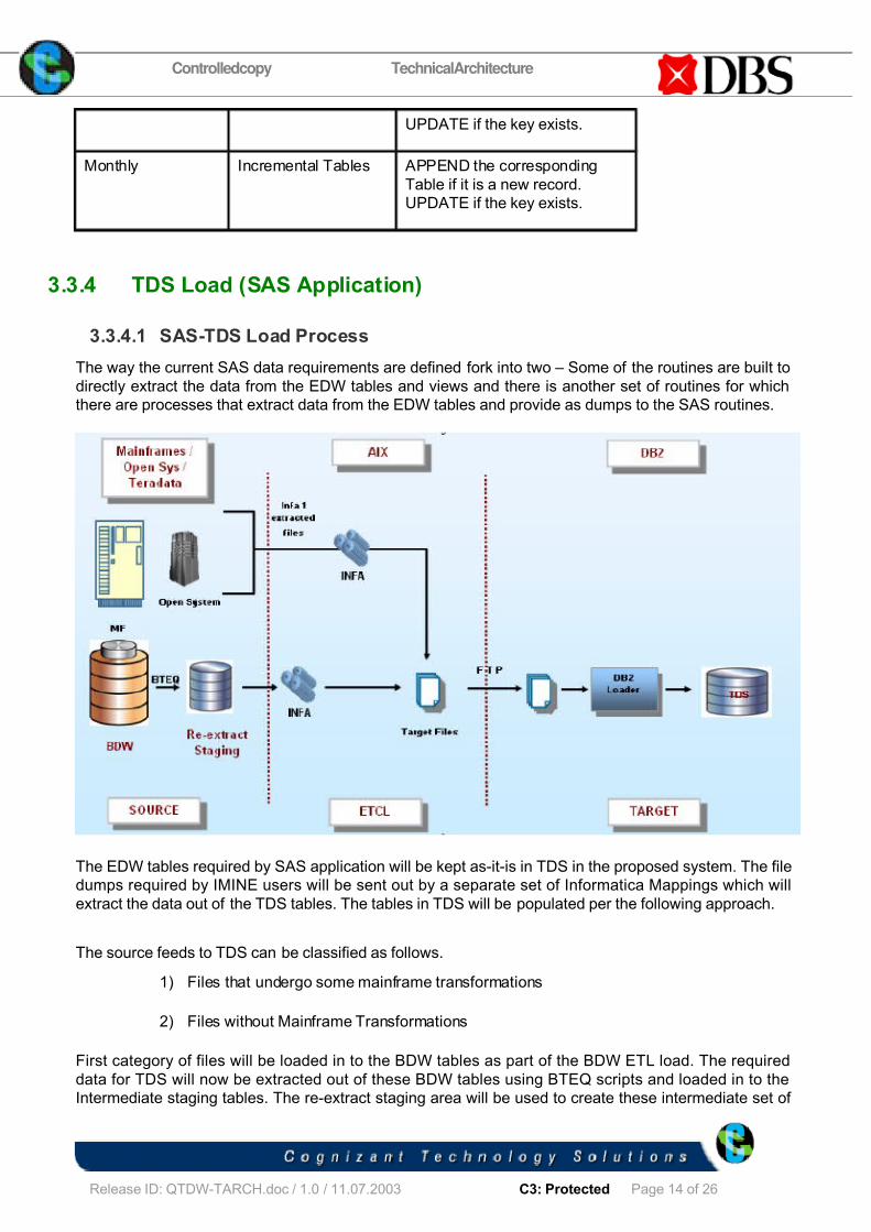
3.3.4.1 SAS-TDS Load Process
The way the current SAS data requirements are defined fork into two – Some of the routines are built to
directly extract the data from the EDW tables and views and there is another set of routines for which
there are processes that extract data from the EDW tables and provide as dumps to the SAS routines.
The EDW tables required by SAS application will be kept as-it-is in TDS in the proposed system. The file
dumps required by IMINE users will be sent out by a separate set of Informatica Mappings which will
extract the data out of the TDS tables. The tables in TDS will be populated per the following approach.
The source feeds to TDS can be classified as follows.
1) Files that undergo some mainframe transformations
2) Files without Mainframe Transformations
First category of files will be loaded in to the BDW tables as part of the BDW ETL load. The required
data for TDS will now be extracted out of these BDW tables using BTEQ scripts and loaded in to the
Intermediate staging tables. The re-extract staging area will be used to create these intermediate set of

7/29/2019 DBS_EDW Migration - Technical Architecture Document v 1.3
http://slidepdf.com/reader/full/dbsedw-migration-technical-architecture-document-v-13 15/26
Controlledcopy TechnicalArchitecture
Project ID: 07264 <SCI.ID. > / Ver:1.0
Release ID: QTDW-TARCH.doc / 1.0 / 11.07.2003 C3: Protected Page 15 of 26
C o n f i d e
n t i a l D o
c u m e n t
F o r I n
t e r n a l U
s e O n
l y
P r o p r i e t a
r y o f C o
g n i z a n
t
staging tables which are of the required TDS format. These tables will be read by Informatica and after
doing the transformations if any in the mappings, flat files will be created in the Informatica Server.
Second Category of files can be directly copied from the source layer in to the file staging area in the
Informatica Server. Wherever transformations are involved, Informatica will be used to read the source
files, perform the required transformations and to write to the file staging area.
These files will then be FTPed to the target TDS server using SSH. The DB2 loader scripts will pick up
these files and load into the corresponding DB2 tables.
Note: For Category 2, files of lesser volume can be directly read by Informatica from the source file
staging area. Transformations if any can be performed in this layer and the mapping can directly load
these files in to the TDS tables in DB2.
Pros for extracting the TDS data out of BDW:
This will use the data warehouse as the source of information.
Data in the warehouse is clean and hence need not undergo any quality checks
Cons:
Extraction from BDW will be complex and intermediate stage tables might be required as depicted in the
diagram

7/29/2019 DBS_EDW Migration - Technical Architecture Document v 1.3
http://slidepdf.com/reader/full/dbsedw-migration-technical-architecture-document-v-13 16/26
Controlledcopy TechnicalArchitecture
Project ID: 07264 <SCI.ID. > / Ver:1.0
Release ID: QTDW-TARCH.doc / 1.0 / 11.07.2003 C3: Protected Page 16 of 26
C o n f i d e
n t i a l D o
c u m e n t
F o r I n
t e r n a l U
s e O n
l y
P r o p r i e t a
r y o f C o
g n i z a n
t
3.4 Re-Extraction ETL Architecture
3.4.1 Re-extraction ETL Architecture Diagram
Re-extraction process involves creation of load ready files for the downstream data marts that includes
CPMS, RMG, iMINE and other extracts.
The re-extraction process will have two layers. The first layer will join the necessary BDW tables and
extract the data in an intermediate format and load in to the re-extraction stage tables.BTEQ scripts will
be used in this process to join, extract and load the stage tables. There will be minimal or no
transformations in this layer.
The second layer will be designed to read the stage table data and performing the necessary
transformations to arrive at the required target file format. This process will use Informatica to read thestage tables and to perform all the required transformations. This layer will also perform conversion of
BDW reference code back to EDW reference code as required by the existing downstream marts. The
target files will be in the same format as in the existing system.
Reusability of common logic will be considered wherever possible. For example, all similar extract files
[Instrument files for the same source system] can be vended out of the same Informatica process thus
reducing the total number of processes.

7/29/2019 DBS_EDW Migration - Technical Architecture Document v 1.3
http://slidepdf.com/reader/full/dbsedw-migration-technical-architecture-document-v-13 17/26
Controlledcopy TechnicalArchitecture
Project ID: 07264 <SCI.ID. > / Ver:1.0
Release ID: QTDW-TARCH.doc / 1.0 / 11.07.2003 C3: Protected Page 17 of 26
C o n f i d e
n t i a l D o
c u m e n t
F o r I n
t e r n a l U
s e O n
l y
P r o p r i e t a
r y o f C o
g n i z a n
t
This staging area will also include the temporary code tables which are not mapped in to the BDW
tables but are used only for re-extraction purposes.
3.5 Process Control – Auditing Mechanism & Alert System
Process Control & Statistics collection has become a mandatory part in any ETL system. This involvescapturing data on the different processes that get executed. The data gathered would be like the starting
time of the process, ending time, the initiator, the result of the process, counts like number of records
extracted/rejected, minimum/maximum values etc.
3.5.1 Benefits of process Control and statistics collection
Building a Process Control and Statistics collection process in an ETL environment gives us the ability to
build other applications on the collected data as listed below:
• Auditing Reports: To know which source/application has affected the data, when and how etc.
• Performance Reports: To know how long a process has taken to run, the number of records
processed, rejected records, peak load time etc.
• Validation Of Source feeds: The collected statistics on each source feed also enables us to
define a threshold for the validity of a feed. Also compare against any summary file thesource system sends along with the data file.
• Incremental Extract: Selective access of records from the tables based on timestamp. Usually
applicable in the staging area.
• Scheduling: To integrate with other applications with the help of the status/processed flags.
3.5.2 Suggested Data model Changes/Additions
A process control table will be maintained to capture the status and statistics of the all the processes
running in the system. This table helps to maintain the audit log all the processes running in the system
and will also help to raise alerts as appropriate for the failed processes.
The table for recording the process control related information would have the following structure.
BDW_ETL_CTRL
COLUMN DESCRIPTION
PROCESS_ID A unique sequence number assigned to each
and every load process
PROCESS_NAME The name of the Process.
PROCESS_START_TIME The time when the load started.

7/29/2019 DBS_EDW Migration - Technical Architecture Document v 1.3
http://slidepdf.com/reader/full/dbsedw-migration-technical-architecture-document-v-13 18/26
Controlledcopy TechnicalArchitecture
Project ID: 07264 <SCI.ID. > / Ver:1.0
Release ID: QTDW-TARCH.doc / 1.0 / 11.07.2003 C3: Protected Page 18 of 26
C o n f i d e
n t i a l D o
c u m e n t
F o r I n
t e r n a l U
s e O n
l y
P r o p r i e t a
r y o f C o
g n i z a n
t
PROCESS_END_TIME The time when the load ends.
SOURCE_NAME Name of the Incoming Source feed or the
source table being read by the process
SOURCE_SYSTEM_ID The identifier for the source systemcorresponding to the process
ROWS_READ The number of input rows.
TARGET_NAME Name of the target table or file for the
process
ROWS_INSERTED The number of rows inserted into the target
table or file.
ROWS_UPDATED The number of rows updated in the target.
ROWS_DELETED The number of rows deleted from the target.
PROCESS_STATUS_FLAG The flag identifying the status of the load at
various points during the load.
LAST UPDATE TIME The time when the row was last updated.
Exception Description This field will be updated only when aprocess is aborted. For eg., duplicate rows in
a file, file header containing invalid date,etc.
The Process Control table will be Inserted and Updated by the Teradata script with the below listed
status flags.
Flag Description
C Initial Process Control Inserted
I Data Insert/Load Success
U Data Update Success
D Data Delete Success
S Final Process Control Timestamp Update

7/29/2019 DBS_EDW Migration - Technical Architecture Document v 1.3
http://slidepdf.com/reader/full/dbsedw-migration-technical-architecture-document-v-13 19/26
Controlledcopy TechnicalArchitecture
Project ID: 07264 <SCI.ID. > / Ver:1.0
Release ID: QTDW-TARCH.doc / 1.0 / 11.07.2003 C3: Protected Page 19 of 26
C o n f i d e
n t i a l D o
c u m e n t
F o r I n
t e r n a l U
s e O n
l y
P r o p r i e t a
r y o f C o
g n i z a n
t
A Process Abort due to file related problems
3.5.3 Status Tracking
The start of each process will trigger an insert in to the process control table with a status ‘C’ and all
successful script should end with a status of ‘S’. The combination of table name and the max (Identifier)
will be used to locate the latest record and the status flag will be updated as appropriate.
3.5.4 Post-Process Validation
The counts captured in the process control table will be used for post-process record reconciliation
purposes wherever applicable. For example these fields can be used to tally the counts in the Change
Detection process. The reconciliation checks will be limited to what is currently being done in the EDW
processes.
3.5.5 Implementation
The process of gathering statistics and updating the same into the Process Control table will be
implemented inside the Informatica mappings. There will be separate flows in the mapping to insert a
record into the Process Control table and a separate flow to update the same record in the Process
Control table. The statistics will be gathered as part of the main flow in the mapping.
To capture the statistics for the BDW tables load, the BTEQ scripts will be built with the logic of
capturing the load volumetrics and updating the same in the Process Control table.
3.6 Re-start / Recovery
In the BDW ETL process, data movement from the source to the final target will happen using the
following steps:
1. INFA 1 & CD process - Creating delta files from mainframe flat file and performing Change detectionprocess for FULL files.
2. INFA 2 - Creating CIF files after performing Source based transformations on delta files.
3. INFA 3 - Transforming the CIF to Target table based files and loading into staging area in Teradatausing External loader in Informatica
4. Target BTEQ Layer - Loading the target tables in Teradata from staging tables using BTEQ
1. Extraction of files[INFA 1] and Change detection process
In these processes, since the target is a flat file, process of writing from the point of failure can’t be
implemented, as flat files cannot be appended. Hence any failure in this process will require
reprocessing of all input records.

7/29/2019 DBS_EDW Migration - Technical Architecture Document v 1.3
http://slidepdf.com/reader/full/dbsedw-migration-technical-architecture-document-v-13 20/26
Controlledcopy TechnicalArchitecture
Project ID: 07264 <SCI.ID. > / Ver:1.0
Release ID: QTDW-TARCH.doc / 1.0 / 11.07.2003 C3: Protected Page 20 of 26
C o n f i d e
n t i a l D o
c u m e n t
F o r I n
t e r n a l U
s e O n
l y
P r o p r i e t a
r y o f C o
g n i z a n
t
2. INFA 2 - Creating CIF Files
In this case also since the target is a flat file, process of writing from the point of failure can’t be
implemented. Hence any failure will warrant reprocessing of all the records..
3. INFA 3- Loading Staging/Target BDW tables in Teradata
Staging tables will be populated by Teradata Bulk loader utilities through Informatica. In case of failure,
Informatica job will be re-submitted after resolving the issue. Teradata Fastload will take care of re-start
activity. In case of Multiload script, when MultiLoad encounters an error in the job script, the job can be
resubmitted after rectifying the error. The utility resumes processing at the statement following the last
one that completed successfully. If there is any failure during application phase of Multiload, this will
require clean up action i.e. releasing lock on the target table and re-submitting the Multiload job again.
Teradata Multiload creates a restart log table that will be used to identify the re-start point once the job is
re-submitted. The utility automatically rolls back to the most recent checkpoint and resume processing
using restart log table.
4. Target Layer - Loading Target BDW tables in Teradata using BTEQ
In case of failure in any BTEQ scripts while loading the Target table from staging table, script will also be
re-submitted after resolving the error. Separate BTEQ script will be written for each Table load that will
perform Insert-update operation. Failures in the BTEQ script will completely rollback the data loaded and
hence any failure will require complete reprocessing.
3.7 Error Handling
Error handling involves applying pre defined business knowledge against the input records and marking
them classifying them as valid, invalid or warning records.
3.7.1 Classification of Validations
The types of validations or rules that are applied on the input read records can be classified into:
• Null validation
• Data type validation
• Format validation
• Code validation
• Business rule validation
Such classification and finding of such errors in the early stages of the process would provide an easy
interface for the end users to verify the validity of the data being processed and provides them an option
to correct and reprocess the data if necessary.
Note: The list of validations mentioned above may vary according to DBS requirements. The list of
validations that should be handled in the proposed architecture will be limited to what is currently being
handled in the EDW processes.
Following are some of the validations which are currently being done in the Mainframe processes.
These will be done as part of INFA 1 process in the current architecture.

7/29/2019 DBS_EDW Migration - Technical Architecture Document v 1.3
http://slidepdf.com/reader/full/dbsedw-migration-technical-architecture-document-v-13 21/26
Controlledcopy TechnicalArchitecture
Project ID: 07264 <SCI.ID. > / Ver:1.0
Release ID: QTDW-TARCH.doc / 1.0 / 11.07.2003 C3: Protected Page 21 of 26
C o n f i d e
n t i a l D o
c u m e n t
F o r I n
t e r n a l U
s e O n
l y
P r o p r i e t a
r y o f C o
g n i z a n
t
1. Check for fields - This is a proc inside the Cobol program which checks on the field for low valuehexadecimal which is X'00' or spaces and replaces the same with 'U' 2. Check bytes - This is a proc inside the Cobol program which checks for each and every bytefor hexadecimal values like X'4F' (that is ¦) or X'6A' (that is '|') or for special characters like '/'. If foundcorrespondingly 'U' will be set.
3. DataType checks -
a. For dates, if the incoming value is not numeric then 0 to be set.b. For all low value hexadecimals for indicator fields, replace with 'U'c. Alphanumeric check - If the amount field is ' ', it will be replaced with 0.d. If date contains spaces or low value hex, replace with '9999-01-01'.e. If date contains X'4F' (that is ¦) or X'6A' (that is '|') or '/', then replace with '-'
Reprocessing of exception records:
The exception records will be dropped off or will be loaded in to the BDW target tables based on the
criticality of the exceptions. When the exceptions are not critical they will be loaded with default values
as being currently done in the EDW processes. When the exceptions are because of the source system
errors, the exception report will be sent to the concerned source team. When the source system sends
back the corrected records in a separate file, these records will be reprocessed and loaded in to the
BDW table.
Note: This section will be updated after understanding the way in which the source system will send the
repaired files. This will also be determined based on the consensus arrived with the other project teams.
3.7.2 Suggested Data Model Changes/Additions
The following error table will be added to the data model to trap the error records and values for further
evaluation.
Error Log Table Columns Column Description
Error Id A running sequence number that will be
generated for each error logged in this
table
Process Id This column corresponds to the Id
generated for each ETL process and
references the Process ID of the
Process Control table
Source Table Name This is the name of the source table for
whose rows are being processed
Source Key Values The key columns in the source table
Error Code This is the code that corresponds to
each error in the error master

7/29/2019 DBS_EDW Migration - Technical Architecture Document v 1.3
http://slidepdf.com/reader/full/dbsedw-migration-technical-architecture-document-v-13 22/26
Controlledcopy TechnicalArchitecture
Project ID: 07264 <SCI.ID. > / Ver:1.0
Release ID: QTDW-TARCH.doc / 1.0 / 11.07.2003 C3: Protected Page 22 of 26
C o n f i d e
n t i a l D o
c u m e n t
F o r I n
t e r n a l U
s e O n
l y
P r o p r i e t a
r y o f C o
g n i z a n
t
Error Column Name Column name that is found to have
encountered the error
Error Column Value This is the erroneous data in the error
column
Error Timestamp Time when the error record is loggedinto this table
COB Close of Business date
With the help of the Key values column, the user will be able to identify the error record from the source
and handle it as appropriate.
3.7.3 Implementation
The exception process will be implemented as a reusable mapplet in Informatica and will be plugged
into the mappings.
If there are exceptions that need to be captured in the Teradata scripts, then a common routine will be
built to cater to such a need.
The details of the exceptions captured and their implementation will be discussed in detailed design.
3.7.4 Exception Scenarios
Apart from the usual validation and capture of errors falling out of such validation processes as classified
earlier in this section, there are certain typical scenarios in the current EDW production.
The following scenarios will be handled as part of INFA 1 process to detect the error and accordingly
raise email alert to the concerned and abort the process.
1) Header record does not exist in the file
2) Existence of System ID and Header Date in the header record
3) Check for the expected System ID and Header Date
4) Source file is empty.
Duplicate files with same header date : Critical measures like file size, record count etc. will bedetermined for the previous and current files in a pre-processing step to the CD process. If the measuresappear to be the same, escalation mails will be sent to the concerned source team and the file will berejected from further processing.
This pre-processing step will be implemented in a UNIX shell script.
Duplicate records within the same file: This check will be done as part of the Change Detectionprocess to stop the duplicate records from entering the BDW. The entire file will be rejected andescalation mails will be sent to all concerned personnel.
7/29/2019 DBS_EDW Migration - Technical Architecture Document v 1.3
http://slidepdf.com/reader/full/dbsedw-migration-technical-architecture-document-v-13 23/26
Controlledcopy TechnicalArchitecture
Project ID: 07264 <SCI.ID. > / Ver:1.0
Release ID: QTDW-TARCH.doc / 1.0 / 11.07.2003 C3: Protected Page 23 of 26
C o n f i d e
n t i a l D o
c u m e n t
F o r I n
t e r n a l U
s e O n
l y
P r o p r i e t a
r y o f C o
g n i z a n
t
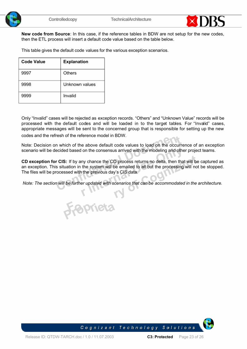
New code from Source: In this case, if the reference tables in BDW are not setup for the new codes,
then the ETL process will insert a default code value based on the table below.
This table gives the default code values for the various exception scenarios.
Code Value Explanation
9997 Others
9998 Unknown values
9999 Invalid
Only “Invalid” cases will be rejected as exception records. “Others” and “Unknown Value” records will be
processed with the default codes and will be loaded in to the target tables. For “Invalid” cases,
appropriate messages will be sent to the concerned group that is responsible for setting up the new
codes and the refresh of the reference model in BDW.
Note: Decision on which of the above default code values to load on the occurrence of an exception
scenario will be decided based on the consensus arrived with the modeling and other project teams.
CD exception for CIS: If by any chance the CD process returns no delta, then that will be captured as
an exception. This situation in the system will be emailed to all but the processing will not be stopped.
The files will be processed with the previous day’s CIS data.
Note: The section will be further updated with scenarios that can be accommodated in the architecture.

7/29/2019 DBS_EDW Migration - Technical Architecture Document v 1.3
http://slidepdf.com/reader/full/dbsedw-migration-technical-architecture-document-v-13 24/26
Controlledcopy TechnicalArchitecture
Project ID: 07264 <SCI.ID. > / Ver:1.0
Release ID: QTDW-TARCH.doc / 1.0 / 11.07.2003 C3: Protected Page 24 of 26
C o n f i d e
n t i a l D o
c u m e n t
F o r I n
t e r n a l U
s e O n
l y
P r o p r i e t a
r y o f C o
g n i z a n
t
4 Appendix
EDW Source System File Sizes
ZR Source FileSize.xls
Source feed arrival timings
EDW 2005 (SP)Monthend Status - 1s

7/29/2019 DBS_EDW Migration - Technical Architecture Document v 1.3
http://slidepdf.com/reader/full/dbsedw-migration-technical-architecture-document-v-13 25/26
Controlledcopy TechnicalArchitecture
Project ID: 07264 <SCI.ID. > / Ver:1.0
Release ID: QTDW-TARCH.doc / 1.0 / 11.07.2003 C3: Protected Page 25 of 26
C o n f i d e
n t i a l D o
c u m e n t
F o r I n
t e r n a l U
s e O n
l y
P r o p r i e t a
r y o f C o
g n i z a n
t
5 Change Log
Please note that this table needs to be maintained even if a Configuration Management tool
is used.
Version
Number
Changes made
V1.0 <First version>
V1.1 <If the change details are not explicitly documented in the table below,
reference should be provided here>
Page
no
Changed
by
Effective
date
Changes effected
15 CTS 23 Sep05
SAS-TDS section has been updatedafter decision on which of the options
to use for the process. Option 2 to
build views on Teradata tables is
dropped and the document is updated
to reflect this.
16 CTS 23 Sep
05
Re-extraction architecture diagram
has been updated to include the
staging layer and the explanation
updated accordingly.
V1.2 <If the change details are not explicitly documented in the table below,
reference should be provided here>
Page
no
Changed
by
Effective
date
Changes effected
6 CTS 17 Nov
05
Section 2.3.3 – Dependencies
updated for DB2 development
9 CTS 17 Nov
05
Section 3.2 – Architecture diagram
updated
12 CTS 17 Nov
05
Section 3.3.2.3 - CIF layer removed ;
INFA 3 changed to INFA 2 with
additional information

7/29/2019 DBS_EDW Migration - Technical Architecture Document v 1.3
http://slidepdf.com/reader/full/dbsedw-migration-technical-architecture-document-v-13 26/26
Controlledcopy TechnicalArchitecture
Project ID: 07264 <SCI ID > / Ver:1 0
C o n f i d e
n t i a l D o
c u m e n t
F o r I n
t e r n a l U
s e O n
l y
P r o p r i e t a
r y o f C o
g n i z a n
t
15 CTS 17 Nov
05
Section3.3.4 – SAS Load Section
updated with modified diagrams and
new options
V1.3 Section
3.3
CTS 05 Dec
05
1) Architectural Changes after removal
of CIF layer 2) TDS approach changes
Related Documents