© PHOENIX CONTACT - 10/2008 100240_en_05 INTERFACE MCR-f-UI-DC Data Sheet 1 Description MCR-f-UI-DC, the programmable MCR frequency transducer, is a module for displaying and converting frequencies up to120 kHz. On the input side, all common frequency generator signals in 2, 3 and 4-wire technology, and signals from incremental encoders can be collected. The input impulses are evaluated using period measurement and are then output by a processor as an analog voltage or current value to match the measuring range start and end value entered. In order to achieve as short as possible reaction times, the inputs of the frequency transducer have purposely been designed without a frequency input filter. An automatic measurement range selection function (autorange) ensures that the measured value is always displayed with the optimum resolution. Frequency interferences can, however, lead to too large a division factor being selected for low input frequencies. This in turn can result in an erratic output signal (see "Operation with Disturbed Frequency Input Signals" on page 6). In order to stabilize fluctuating input values, a filter function has been implemented for conversion into the analog output value. The depth of this filter can be set from 1 to 15 using the membrane keyboard. The optimum filter depth depends on the application. In addition to the analog output, there is also a PNP transistor switching output with a maximum carrying capacity of 100 mA, for monitoring functions, for example (not short-circuit proof). Specially for rotational speed measurement, it is possible to both enter the measuring range start and end value in revolutions per minute (RPM), and to observe the revolutions in RPM on the LCD (4-pos. + RPM as unit) during operation. Make sure you always use the latest documentation. It can be downloaded at www.download.phoenixcontact.com . A conversion table is available on the Internet at www.download.phoenixcontact.com/general/7000_en_00.pdf . This data sheet is valid for all products listed on the following page: Universal Frequency Transducer

Welcome message from author
This document is posted to help you gain knowledge. Please leave a comment to let me know what you think about it! Share it to your friends and learn new things together.
Transcript

© PHOENIX CONTACT - 10/2008100240_en_05
INTERFACE
MCR-f-UI-DC
Data Sheet
1 Description
MCR-f-UI-DC, the programmable MCR frequency
transducer, is a module for displaying and converting
frequencies up to120 kHz. On the input side, all common
frequency generator signals in 2, 3 and 4-wire technology,
and signals from incremental encoders can be collected.
The input impulses are evaluated using period
measurement and are then output by a processor as an
analog voltage or current value to match the measuring
range start and end value entered.
In order to achieve as short as possible reaction times, the
inputs of the frequency transducer have purposely been
designed without a frequency input filter. An automatic
measurement range selection function (autorange) ensures
that the measured value is always displayed with the
optimum resolution. Frequency interferences can, however,
lead to too large a division factor being selected for low input
frequencies. This in turn can result in an erratic output signal
(see "Operation with Disturbed Frequency Input Signals" on
page 6).
In order to stabilize fluctuating input values, a filter function
has been implemented for conversion into the analog output
value. The depth of this filter can be set from 1 to 15 using
the membrane keyboard. The optimum filter depth depends
on the application.
In addition to the analog output, there is also a PNP
transistor switching output with a maximum carrying
capacity of 100 mA, for monitoring functions, for example
(not short-circuit proof).
Specially for rotational speed measurement, it is possible to
both enter the measuring range start and end value in
revolutions per minute (RPM), and to observe the
revolutions in RPM on the LCD (4-pos. + RPM as unit) during
operation.
Make sure you always use the latest documentation.
It can be downloaded at www.download.phoenixcontact.com.
A conversion table is available on the Internet at
www.download.phoenixcontact.com/general/7000_en_00.pdf.
This data sheet is valid for all products listed on the following page:
Universal Frequency Transducer
MCR-f-UI-DC
100240_en_05 PHOENIX CONTACT 2
2 Table of Contents
1 Description.................................................................................................................................. 1
2 Table of Contents ....................................................................................................................... 2
3 Ordering Data ............................................................................................................................. 3
4 Technical Data............................................................................................................................ 3
4.1 Dimensions .................................................................................................................................................... 5
5 Features ..................................................................................................................................... 5
6 Block Diagram ............................................................................................................................ 6
7 Operation with Disturbed Frequency Input Signals ..................................................................... 6
7.1 Measures to Counter External Influences....................................................................................................... 6
7.2 If Signal Level > 20 V...................................................................................................................................... 6
7.3 If Signal Level > 10 V...................................................................................................................................... 6
8 Resetting to Delivery State ................................................................................................................................. 6
9 Connection Technology.............................................................................................................. 7
10 Functions of the Membrane Keypad ........................................................................................... 9
10.1 Special Function of the Keys in Edit Mode ..................................................................................................... 9
11 Display on LCD....................................................................................................................................................... 9
11.1 Display Within Setting Range ......................................................................................................................... 9
11.2 Displaying the Switching Output................................................................................................................... 10
11.3 Messages in Operating Mode ...................................................................................................................... 10
11.4 Menu Guidance............................................................................................................................................ 10
12 Menu Flowcharts .......................................................................................................................11
12.1 Configuration of the Frequency Input – Sequence of Menu .......................................................................... 11
12.2 Configuration of the Analog Input – Sequence of Menu................................................................................ 12
12.3 Configuration of the Extended Mode – Sequence of Menu .......................................................................... 13
13 Example: Configuration Based on a Frequency Input Signal .....................................................15
13.1 Continuation of the Configuration Example: ................................................................................................. 16
14 Configuration Software MCR/PI-CONF-WIN-... .........................................................................17
15 Application Example: Speed Measurement of a Drive ...............................................................17
MCR-f-UI-DC
100240_en_05 PHOENIX CONTACT 3
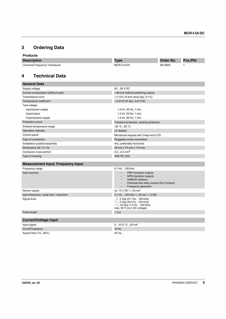
3 Ordering Data
4 Technical Data
Products
Description Type Order No. Pcs./Pkt
Universal Frequency Transducer MCR-f-UI-DC 2814605 1
General Data
Supply voltage 20…30 V DC
Current consumption (without load) < 60 mA (without switching output)
Transmission error < 0.15% of end value (typ. 0.1%)
Temperature coefficient < 0.015%/K (typ. 0,01%/K)
Test voltage:
Input/power supply
Input/output
Output/power supply
1.5 kV, 50 Hz, 1 min.
1.5 kV, 50 Hz, 1 min.
1.5 kV, 50 Hz, 1 min.
Protection circuit Transient protection, polarity protection
Ambient temperature range -20 °C...65 °C
Operation indicator LC display
Control panel Membrane keypad with 3 keys and LCD
Type of connection Pluggable screw connection
Installation position/assembly Any, preferably horizontal
Dimensions (W / H / D) 45 mm x 75 mm x 110 mm
Conductor cross section 0.2...2.5 mm2
Type of housing ASA-PC (V0)
Measurement Input, Frequency Input
Frequency range 0.1 Hz…120 kHz
Input sources – PNP transistor outputs
– NPN transistor outputs
– NAMUR initiators
– Potential-free relay contact (Dry Contact)
– Frequency generator
Sensor supply ca. 15 V DC / < 25 mA
Input frequency / peak time / resolution 0.1 Hz…120 kHz / ≤ 32 ms / ≥ 12 Bit
Signal level 2 Vpp (0.1 Hz…120 kHz)
2 Vpp (8.0 Hz…120 kHz)
18 Vpp (1.0 Hz…120 kHz)
max. 30 V (incl. DC voltage)
Pulse length ≥ 1μs
Current/Voltage Input
Input signal 0…10 V / 0…20 mA
Cut-off frequency 10 Hz
Ascent time (10...90%) 25 ms

MCR-f-UI-DC
100240_en_05 PHOENIX CONTACT 4
Output
Output signal 0…10 V / 10…0 V, 0…5 V / 5…0 V
or 0(4)…20 mA / 20…0(4) mA
Output signal
Current/voltage max. 25 mA / 12.5 V
Load
Current/voltage ≤ 500 Ω / ≥ 500 Ω
Alignment zero point / end value ± 25% / ± 25%
Switching output – PNP transistor output,
– switches the supply voltage to terminal SW,
– can carry a load of 100 mA,
– not short-circuit proof
Approval
U PROCESS CONTROL EQUIPMENT FOR
HAZARDOUS LOCATIONS 31ZN
Class I Div 2 Groups A, B, C, D
A) This equipment is suitable for use in Class I, Division 2, Groups A, B, C and
D or non-hazardous locations only.
B) Warning - explosion hazard - substitution of components may
impair suitability for Class 1, Division 2.
C) Warning - explosion hazard - do not disconnect equipment unless power
has been switched off or the area is known to be non-hazardous.
Conformance With EMC Guideline 89/336/EEC And Low Voltage Directive 73/23/EEC
Immunity to Interference According to EN 61000-6-21
Discharge of static electricity (ESD) EN 61000-4-2 Criterion B2
8 kV discharge in air
6 kV contact discharge
Electromagnetic HF fields EN 61000-4-3 Criterion A3
10 V/m
Fast transients (burst) EN 61000-4-4 Criterion B2
Input/output/supply: 2 kV / 5 kHz
Surge voltage capacities (Surge) EN 61000-4-5 Criterion B2
Input/output: 2 kV / 42 Ω Supply: 1 kV / 2 Ω
Conducted interference EN 61000-4-6 Criterion A3
Input/output/supply: 10 V
Noise Emission According to EN 61000-6-4
Noise emission of housing EN 550114
Criterion A5
1EN 61000 corresponds to IEC 61000
2Criterion B: Temporary impairment to operational behavior that is corrected by the device itself.
3Criterion A: Normal operating behavior within the defined limits.
4EN 55011 corresponds to CISPR11
5Criterion A: Area of application industry

MCR-f-UI-DC
100240_en_05 PHOENIX CONTACT 5
4.1 Dimensions
Figure 1 Dimensions
5 Features
Figure 2 Features of MCR-f-UI-DC
75 mm 45 mm
11
0 m
m
MC
R-f-U
I-D
C
Art.-N
r.:2814605
12
DC
DC
DC
mC
+24
V
9 GN
D
0
!
"
$
SW
GN
D
NC
IO
UT
UT
+8,2
V
Nam
ur
IN
ext.
Mode
Reset
Edit
Dis
pla
y
ZeroInput
Analog
Output
FullScale
Input
Digital
Output
High
Setpoint
LowSetpoint
MCR-f-U
I-DC
12
34
56
78
910
1112
13
14
15
16
Membrane keypad
Signal inputs
Supply
Signal outputs
Switching output
MCR-f-UI-DC
100240_en_05 PHOENIX CONTACT 6
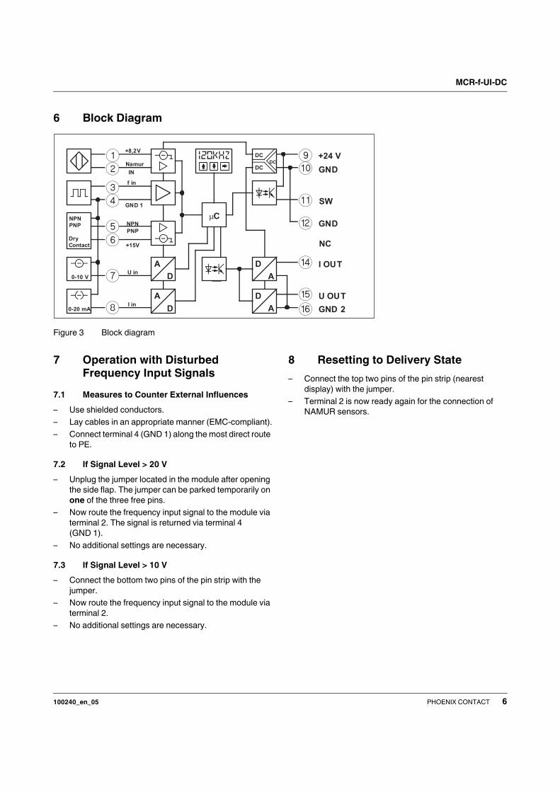
6 Block Diagram
Figure 3 Block diagram
7 Operation with Disturbed
Frequency Input Signals
7.1 Measures to Counter External Influences
– Use shielded conductors.
– Lay cables in an appropriate manner (EMC-compliant).
– Connect terminal 4 (GND 1) along the most direct route
to PE.
7.2 If Signal Level > 20 V
– Unplug the jumper located in the module after opening
the side flap. The jumper can be parked temporarily on
one of the three free pins.
– Now route the frequency input signal to the module via
terminal 2. The signal is returned via terminal 4
(GND 1).
– No additional settings are necessary.
7.3 If Signal Level > 10 V
– Connect the bottom two pins of the pin strip with the
jumper.
– Now route the frequency input signal to the module via
terminal 2.
– No additional settings are necessary.
8 Resetting to Delivery State
– Connect the top two pins of the pin strip (nearest
display) with the jumper.
– Terminal 2 is now ready again for the connection of
NAMUR sensors.
12
34
7
8D
A
DC
DC
DC
NPN
PNP
Dry
Contact
0-10 V
0-20 mA
A
D
A
D
�C
56
D
A
+24 V9GND0
!
"
%&
$
SW
GND
NC
I OUT
U OUT
GND 2
+8,2V
f in
Namur
IN
GND 1
NPN
PNP
+15V
U in
I in
MCR-f-UI-DC
100240_en_05 PHOENIX CONTACT 7
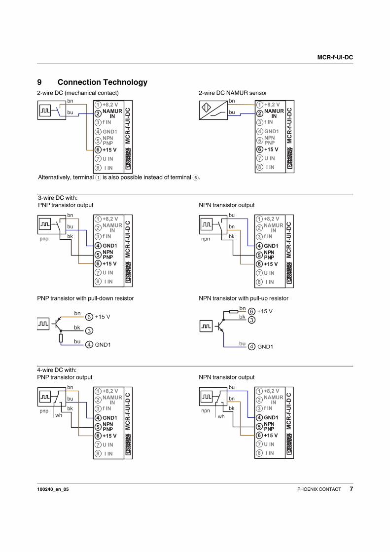
9 Connection Technology
1bn
2
3
4
5
6
7
8
bu
+8,2 V
NAMUR
IN
f IN
GND1
NPN
PNP
+15 V
U IN
I IN
MC
R-f
-UI-
DC
1bn
2
3
4
5
6
7
8
bu
+8,2 V
NAMUR
IN
f IN
GND1
NPN
PNP
+15 V
U IN
I IN
MC
R-f
-UI-
DC
2-wire DC NAMUR sensor2-wire DC (mechanical contact)
Alternatively, terminal 1 is also possible instead of terminal 6.
bn
buGND1
+15 Vbk
6
3
4
3-wire DC with:
PNP transistor output NPN transistor output
1bn
2
3
4
5
6
7
8
bu
+8,2 V
NAMUR
IN
f IN
GND1
NPN
PNP
+15 V
U IN
I IN
MC
R-f
-UI-
DC
bkpnp
1bu
2
3
4
5
6
7
8
bn
+8,2 V
NAMUR
IN
f IN
GND1
NPN
PNP
+15 V
U IN
I IN
MC
R-f
-UI-
DC
bknpn
bn
buGND1
+15 V
bk
6
3
4
PNP transistor with pull-down resistor NPN transistor with pull-up resistor
1bn
2
3
4
5
6
7
8
bu
+8,2 V
NAMUR
IN
f IN
GND1
NPN
PNP
+15 V
U IN
I IN
MC
R-f
-UI-
DC
bkpnpwh
1bu
2
3
4
5
6
7
8
bn
+8,2 V
NAMUR
IN
f IN
GND1
NPN
PNP
+15 V
U IN
I IN
MC
R-f
-UI-
DC
bknpnwh
4-wire DC with:
PNP transistor output NPN transistor output

MCR-f-UI-DC
100240_en_05 PHOENIX CONTACT 8
1
2
3
4
5
6
7
8
+8,2 V
NAMURIN
f IN
GND1
NPNPNP
+15 V
U IN
I IN
MC
R-f
-UI-
DC
15 V/25 mA1
2
3
4
5
6
7
8
+8,2 V
NAMURIN
f IN
GND1
NPNPNP
+15 V
U IN
I IN
MC
R-f
-UI-
DCUB = 5-30 V DC
UB = 0 V DC
The external supply can also be picked off from terminals
9 +24VDC and 0 GND.
3-way isolation is then no longer provided.
The connection from terminal block 4 GND1 to
terminal block 0 GND is essential!
– External supply of signal generator – Supply of signal generator from the module
Incremental encoder with push-pull:
1
2
3
4
5
6
7
8
+8,2 V
NAMURIN
f IN
GND1
NPNPNP
+15 V
U IN
I IN
MC
R-f
-UI-
DCUB = 24 V DC
K1, K2, K0
K1, K2, K0
UB = 0 V
1
2
3
4
5
6
7
8
+8,2 V
NAMURIN
f IN
GND1
NPNPNP
+15 V
U IN
I IN
MC
R-f
-UI-
DC
15 V/25 mA
K1, K2, K0
K1, K2, K0
– External supply of signal generator – Supply of signal generator from the module
Incremental encoder with HTL logic:
U input (direct current voltage) I input (direct current)
1
2
3
4
5
6
7
8
+8,2 V
NAMUR
IN
f IN
GND1
NPN
PNP
+15 V
U IN
I IN
MC
R-f
-UI-
DC
-
+
1
2
3
4
5
6
7
8
+8,2 V
NAMURIN
f IN
GND1
NPNPNP
+15 V
U IN
I IN
MC
R-f
-UI-
DC
-
+

MCR-f-UI-DC
100240_en_05 PHOENIX CONTACT 9
10 Functions of the Membrane
Keypad
Figure 4 Membrane keypad
Press the key briefly: The output value calcu-
lated is displayed.
By pressing the key again, you return to the cur-
rent input measured value.
Press the key briefly (< 0.sec.): Switches the
module to edit mode for frequency input sig-
nals.
Press the key for at least 2 seconds: Switches
the module to edit mode for analog input sig-
nals.
Press the keys briefly together (< 0.5 sec.):
Switches the module to extended edit mode
Press the keys briefly together: Ends edit
mode, without saving any settings that may
have been made.
Adopts the current setting in edit mode and
switches automatically to the next value.
10.1 Special Function of the Keys in Edit Mode
In edit mode for pulse input signals and for ana-
log input signals, pressing the enter key in
addition to the or key accelerates forward
or backward counting.
By releasing the key and then briefly pressing it
again, it is possible to carry out fine adjust-
ments.
11 Display on LCD
11.1 Display Within Setting Range
Frequency input for NAMUR, 2, 3 and 4-wire
sensors, incremental encoders with push-pull
and HTL output signal and dry contact. Settings
can be made in either Hz or RPM/kRPM [Dis-
play: kRM] / MRPM [Display: MRM].
Frequency input for NAMUR sensors with wire
break and short-circuit recognition. Settings
can be made in either Hz/kHz or RPM/kRPM
[Display: kRM] / MRPM [Display: MRM].
Current input 0…20 mA
Voltage input 0…10 V
ON delay of switching output.
(setting range 0…30 sec., default value = 0.00
sec.)
OFF delay of switching output.
(setting range 0…30 sec., default value = 0.00
sec.)
Setting POWER ON delay (switching output)
(setting range 0…30 sec., default value = 1.00
sec.) During this period, the switching output
does not react to events. This function is only of
effect directly after switching on the supply volt-
age.
Setting the wire-break detection time
(setting range 0.2…10.1 sec., default value =
10.1 sec.)
If no input signal is detected during this period,
"No Input" appears on the display and the out-
puts behave according to their settings
Setting the end value
(setting range 75…125%, default value =
100%)
Setting the zero point in relation to the previ-
ously set
output signal: (setting range -5…+5 mA / -
2.5…+2.5 V;
default value = 0 mA / 0 V)
Setting the division factor from 0.1 to 9999 (de-
fault value = 1.0). Slow positioning tasks require
holed coupling halves with multiple divisions
(factor > 1). Measuring the rotational speed of a
motor at the gearbox requires a small division
factor (factor < 1).
ext.
Mode
Reset
Edit
Dis
pla
y
ZeroInput
Analog
Output
FullScale
Input
Digital
Output
High
Setpoint
LowSetpoint
MCR-f-U
I-DC
23
45
67
8
10
1112
13
14
15
+
+
+
+

MCR-f-UI-DC
100240_en_05 PHOENIX CONTACT 10
Setting the filter depth of the analog output
when using frequencies as input value (setting
range 1...15).
This function can only be configured using
the membrane keyboard.
Setting the analog output value
if the measuring range is fallen below
(setting range 0.00…24.00 mA, or
0.00…12.00 V)
Setting the analog output value
if the measuring range is exceeded
(setting range 0.00…24.00 mA, or
0.00…12.00 V)
Setting the analog output value with wire break
or an input signal that is not available
(setting range 0.00…24.00 mA, or
0.00…12.00 V)
Saving. By pressing the key, the set
parameters are saved.
By pressing the key, the setting mode is in-
terrupted without saving the parameters set.
By pressing the -key, the current settings are
overwritten by the default values. The parame-
ters of the frequency input and analog input are
unaffected.
11.2 Displaying the Switching Output
If "High Setpoint" is exceeded, the transistor
switches to "High",
If "Low Setpoint" is fallen below, it switches to
"Low" (with hysteresis).
If"High Setpoint" is exceeded, the transistor
switches to "Low",
If "Low Setpoint" is fallen below, it switches to
"High" (with hysteresis)
If "High Setpoint" is fallen below, the transistor
switches to "High".
If "High Setpoint" is exceeded, the transistor
switches to "High".
Transistor is permanently switched (N/C).
Transistor is permanently switched off (N/O).
Between "Low Setpoint" and "High Setpoint",
the transistor switches to "High".
If "Low Setpoint" is fallen below, and
"High Setpoint" is exceeded, the transistor
switches to "High".
11.3 Messages in Operating Mode
Has fallen below the measuring range.
This message and the current frequency flash
alternately if the frequency falls below the bot-
tom measuring range set.
Measuring range exceeded.
This message and the current frequency flash
alternately if the frequency exceeds the top
measuring range set.
No input signal.
This message flashes for the following reasons:
1. No sensor connected!
2. For NAMUR: a) Short-circuit or b) Wire-
break!
3. Short-circuit frequency <-> GND!
4. No input signal found within the wire-break
detection time set (l.br.time).
11.4 Menu Guidance
In edit mode, the arrow points to the function to
be set.
ZeroInput
Full ScaleInput
AnalogOutput
DigitalOutput
HighSetpoint
LowSetpoint

MCR-f-UI-DC
100240_en_05 PHOENIX CONTACT 11
12 Menu Flowcharts
12.1 Configuration of the Frequency Input – Sequence of Menu
Figure 5 Configuration of the frequency input – sequence of menu
ZeroInput
+
ZeroInput
ZeroInput
ZeroInput
+
Full ScaleInput
Full ScaleInput
Full ScaleInput
Full ScaleInput
AnalogOutput
20 - 4 mA4 - 20 mA
20 - 0 mA0 - 20 mA5 - 0 V0 - 5 V
10 - 0 V
DigitalOutput
+
LowSetpoint
LowSetpoint
LowSetpoint
LowSetpoint
+
HighSetpoint
HighSetpoint
HighSetpoint
HighSetpoint
ON
Operating mode
Press briefly
all options
all options
Example ExampleExample
Example ExampleExample
Example ExampleExample
Example ExampleExample
f-input
Measuring
range start
Measuring
range end
Analog
output
Switching
output
Bottom
switching
point
Saving values
Top switching
point
Operating
mode

MCR-f-UI-DC
100240_en_05 PHOENIX CONTACT 12
12.2 Configuration of the Analog Input – Sequence of Menu
Figure 6 Configuration of the analog input – sequence of menu
ZeroInput
ZeroInput
Full ScaleInput
Full ScaleInput
AnalogOutput
20 - 4 mA4 - 20 mA
20 - 0 mA
5 - 0 V0 - 5 V
10 - 0 V0 - 10 V
DigitalOutput
ON
LowSetpoint
LowSetpoint
LowSetpoint
HighSetpoint
HighSetpoint
HighSetpoint
Operating modePress for at least 2 seconds
All options
All options
Example
Example Example
Example
Analog
input
Measuring
range start
Measuring
range end
Analog
output
Switching
output
Saving values
Top switching
point
Bottom
switching
point
Operating
mode
Example
Example

MCR-f-UI-DC
100240_en_05 PHOENIX CONTACT 13
12.3 Configuration of the Extended Mode – Sequence of Menu
Figure 7 Configuration of the extended mode – Sequence of menu (1)
+
Output filter
function
Division
factor
Zero point
End value
Wire break
detection
POWER ON
delay
OFF delay
ON delay
Press brieflyOperating mode
Example Example
Continued
Example Example
Example Example
Example Example
Example Example
Example Example
Example

MCR-f-UI-DC
100240_en_05 PHOENIX CONTACT 14
Continuation of the Sequence of Menu:
Figure 8 Configuration of the extended mode – sequence of menu (2)
Operating mode
Basic settings
Do not save
Save
No signal
Signal where
the measuring
range is
exceeded
Signal where
the measuring
range is fallen
below
MCR-f-UI-DC
100240_en_05 PHOENIX CONTACT 15
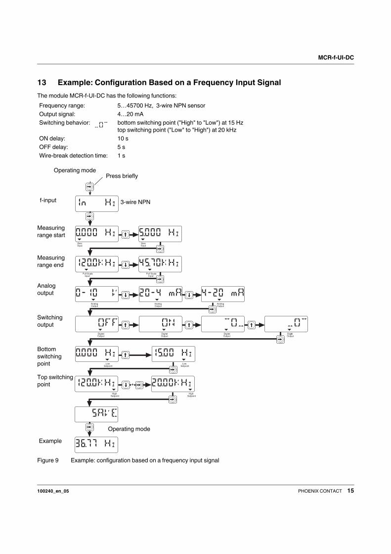
13 Example: Configuration Based on a Frequency Input Signal
The module MCR-f-UI-DC has the following functions:
Figure 9 Example: configuration based on a frequency input signal
Frequency range: 5…45700 Hz, 3-wire NPN sensor
Output signal: 4…20 mA
Switching behavior: bottom switching point ("High" to "Low") at 15 Hz
top switching point ("Low" to "High") at 20 kHz
ON delay: 10 s
OFF delay: 5 s
Wire-break detection time: 1 s
ZeroInput
ZeroInput
Full ScaleInput
Full ScaleInput
LowSetpoint
LowSetpoint
HighSetpoint
HighSetpoint
AnalogOutput
AnalogOutput
AnalogOutput
DigitalOutput
DigitalOutput
DigitalOutput
DigitalOutput
+
Operating mode
Press briefly
f-input 3-wire NPN
Operating mode
Example
Measuring
range start
Analog
output
Switching
output
Top switching
point
Bottom
switching
point
Measuring
range end

MCR-f-UI-DC
100240_en_05 PHOENIX CONTACT 16
13.1 Continuation of the Configuration Example:
Figure 10 Continuation of the configuration example
+
Operating modePress briefly -> extended operating mode
Operating mode
Wire break
detection time
OFF delay
ON delay
Example

MCR-f-UI-DC
100240_en_05 17PHOENIX CONTACT GmbH & Co. KG • 32823 Blomberg • Germany • Phone: +49-(0) 5235-3-00
PHOENIX CONTACT • P.O.Box 4100 • Harrisburg • PA 17111-0100 • USA • Phone: +717-944-1300
www.phoenixcontact.com
14 Configuration Software MCR/
PI-CONF-WIN-...
The MCR configuration software is available for the
configuration and visualization of all parameters for the
MCR-f-UI-DC frequency transducer.
The MCR-Software runs under Windows 95®,
Windows 98®, Windows NT®, Windows ME®,
Windows 2000® and under Windows XP®.
The modules are configured via a serial interface. A label is
also created by the software that can be placed on the
module.
15 Application Example: Speed Measurement of a Drive
Figure 11 Application example: speed measurement of a drive
Related Documents