cONFIDENTlAL ! COPY NO. : Adwtnced ship Data Bank DTWRDC, Bldg. 19, ~223 Bethesda, Maryland DAVIDSON LABORATORY F I NAL REPORT ON DESIGN GNP CONSTRUCTlON O F l/3-SCALE MANNED MODEL OF SKI -CAT HI GH-SPEED CATAMARAN W Daniel Savitsky John K. Roper &ohn A. Mew i er NATIONAL SECURITY INFORMATION UNAUTHORIZED DISCLOSURE SUBJECT TO CRIMINAL SANCTI ONS Classified by NAVSHIPSINST 5510.460 Exempt from GDS’of EO 11652 Exemption Category 3 Declassify on 31 December 1984 CONFIDENT1

Welcome message from author
This document is posted to help you gain knowledge. Please leave a comment to let me know what you think about it! Share it to your friends and learn new things together.
Transcript

cONFIDENTlAL !COPY NO. :
Adwtnced ship Data BankDTWRDC, Bldg. 19, ~223Bethesda, Maryland
DAVIDSONLABORATORY
F I NAL REPORTO N
DESIGN GNP CONSTRUCTlONO F
l/3-SCALE MANNED MODELOF
SKI -CAT HI GH-SPEED CATAMARANW
Daniel SavitskyJohn K. Roper
&ohn A. Mew i er
NATIONAL SECURITY INFORMATIONUNAUTHORIZED DISCLOSURE SUBJECT TO
CRIMINAL SANCTI ONS
C l a s s i f i e d b y NAVSHIPSINST 5510.460Exempt from GDS’of EO 11652Exemption Category 3Declassify on 31 December 1984
CONFIDENT1
Default
Declassify on 31 December 1984
Default
Default
Default
Default
Default

I
UNCLASS I FI ED:CURITY CLASSIFICATION OF THIS PAGE (When Data Enhcd)
REPORT DOCUMEMTATIOMREPORT NUMBER
SIT-DL-74-1699
FINAL REPORT ON DESIGN AND CONSTRUCTION OF
ONE-THIRD SCALE MA&NED MODEL OF SKICAT6. PERFORMING ORG. REPORT NUMBER
HICII-WEED CATAMARAh’*u THOR(s) 6. CONTRACT @R GRANT NlJMBERfr)
Daniel SavitskyJohn A. MercierJohn K. Roper - John K. Roucr Associates
Office of Naval ResearchNOOOlJ-67-A-0202-0031
. PERFORMING ORGANIZATION NAME AND ADDRESS 10. PROGRAM ELEMENT, PROJECT, TASKAREA 6 WORK UNIT NUMBERS
Stevens Institute of TechnologyDavidson I.aboratoryHoboken. New Jersey 0702
I. CONTROLLING OFFICE NAME AND ADDRESS 1 2 . REPORT DATE
Naval Sea Systems Command HeadquartersWashington, D. C. 20362
7413. NUMBER OF PAGES
1181
4 . MONITORING ‘AGENCY NAME h AODR&SS(tf dl!fsrenI fram tkn~rdfh# DtfiCS) 1% SECURITY CLASS. (or trtle rePor?)
Naval Ship Research& Development Center (114)Annapolis, Maryland
CONFIDENTIAL
15~. DECLASSIFICATIONiDOWNGRADINGSCHEOULEXGDS: 3 84
5. DISTRIBUTION STATEMENT (of lhle Rsporl)
7 . OiSTRl~UTlON STATEMENT <of the l brtrect entered In Btock 10, II dlliarmt from Report)
--.6. SUPI-LEMENTARY NOTES
9 . KEY WORDS (Canlfnue OR rev0144 *Ids If nsc~~suy md tdanttly by block number)
Marine CraftCatamaranHydrofoi 1Planing Surface
DD FoRM 14731 JAN 73 EDITION OF 1 NOV 68 IS OBSOLETE UNCLASSIFIEDS/N 0102-014-6601 I
Default

STEVENS INSTITUTE OF TECHNQL8GY CONFKIENTIALDAVIOSON LABORAT’GRYCASTLE PCINT STATIONHODOKEN. NEW JERSEY
Report SIT-DL-74-1699
March 1974
FINAL b%YvHT
ON
VESICN ANV CONSTRUCITION
OF
l/3-SCALE M4NNEV MODEL
OF
SKI-CAT HIGH-SPEEV CATAP&RAN (U)
byDaniel Sazdtsky
J o h n K. R o p e r
John A. Mercier
Prepared for
Naval Ship Systems CommandWashington, D.C. 20360
Under Contract NOOOl4-67-A-0202-0031, Mod. 3(DL Projects 4050/146 & 4051/!47)
NATIONAL SECURITY INFORMATIONUNAUTHORIZED DISCLOSURE SUBJECT 'i-0
CRIMINAL SANCTIONS
CONFKIE
Default
Default
Default
Default
Default

R-1699
T h i s p a g e u n c l a s s i f i e d
TABLE OF CONTENTS
iNTRODUCTlON . . . . . . . . . . . . . . . . . . . . . . . . . . . . . . . . . . . . . . . . . . . . . . . . . . . . . . . . 1
Background . . . . . . . . . . . . . . . . . . . . . . . . . . . . . . . . . . . . . . . . . . . . . . . . . . . . . . . 1
D e s i g n F e a t u r e s . . . . . . . . . . . . . . . . . . . . . . . . . . . . . . . . . . . . . . . . . . . . . . . . . . 2
PERFORMANCE . . . . . . . . . . . . . . . . . . . . . . . . . . . . . . . . . . . . . . . . . . . . . . . . . . . . . . . . . 7
E x t e n d e d B u i l d e r ’ s T r i a l s . . . . . . . . . . . . . . . . . . . . . . . . . . . . . . . . . . . . . . . . 7
S p e e d T r i a l s . . . . . . . . . . . . . . . . . . . . . . . . . . . . . . . . . . . . . . . . . . . . . . . . . . 7
E f f e c t o f D i s p l a c e m e n t . . . . . . . . . . . . . . . . . . . . . . . . . . . . . . . . . . . . . 7
E f f e c t o f L C G . . . . . . . . . . . . . . . . . . . . . . . . . . . . . . . . . . . . . . . . . . . . . . 9
E f f e c t o f S k i - H e i g h t ....................................... 10
EQUIPMENT DEFICIENCIES, ANALYSES AND CORRECTIVE ACTION..............1 2
P r o p e l l e r P i t c h . . . . . . . . . . . . . . . . . . . . . . . . . . . . . . . . . . . . . . . . . . . . . . . . . . 12
M a i n F o i l V e n t i l a t i o n . . . . . . . . . . . . . . . . . . . . . . . . . . . . . . . . . . . . . . . . . . . . 12
REFERENCE-; . . . . . . . . . . . . . . . . . . . . . . . . . . . . . . . . . . . . . . . . . . . . . . . . . . . . . . . . . . 14
TABLES 3 - 7 ..................................................... 1s - 2 2
FIGURES 1 - 7
APPENDIX, DESIGN NOTEBOOK
A .
8.
C.
D.
E.
F .
G.
H.
1.
V e h i c l e C h a r a c t e r i s t i c s . . . . . . . . . . . . . . . . . . . . . . . . . . . . . . . . . . . Al - A3
H u l l C h a r a c t e r i s t i c s . . . . . . . . . . . . . . . . . . . . . . . . . . . . . . . . . . . . . . 6 1 -B2
F o i l S y s t e m C h a r a c t e r i s t i c s . . . . . . . . . . . . . . . . . . . . . . . . . . . . . . . C l -c9
E q u i p m e n t L i s t . . . . . . . . . . . . . . . . . . . . . . . . . . . . . . . . . . . . . . . . . . . . 01 -Dl2
S t r u c t u r a l A n a l y s e s . . . . . . . . . . . . . . . . . . . . . . . . . . . . . . . . . . . . . . . E l - E26
Measured Weights . . . . . . . . . . . . . . . . . . . . . . . . . . . . . . . . . . . . . . . . . . F l -F3
H y d r o s t a t its . . . . . . . . . . . . . . . . . . . . . . . . . . . . . . . . . . . . . . . . . . . . . . Gl -Gg
E s t i m a t e d D r a g . . . . . . . . . . . . . . . . . . . . . . . . . . . . . . . . . . . . . . . . . . . . H l - H12
E s t i m a t e d T h r u s t a n d T o r q u e . . . . . . . . . . . . . . . . . . . . . . . . . . . . . . . II - 111
,, ”
i i T h i s p a g e u n c l a s s i f i e d

R-1699
This page unclassified
I NTRODUCT I ON
Background
tu) In past years there have been few significant hydrodynamic improve-
ments made in the design of planing or high-speed displacement hulls.
(uf Planing hulls have a basic conflict between efficiency and seakeep-
i n g a b i l i t y . The low loadings, high aspect ratio, low deadrise and high
trim desirable for maximum lift-drag ratio are in direct opposition to the
high loadings, low trim, low aspect ratio, and high deadrise required for
minimum accelerations and motion in rough water. From an arrangement
standpoint, usable hull volume is l imited by severe rotational accelera-
tions to those spaces near the longitudinal center of gravity and, thus,
result in crowded areas. F u r t h e r , t h e l i f t - d r a g r a t i o o f p l a n i n g h u l l s
with straight buttock lines in the planing area is not much greater than
6.0 for speeds in excess of 50 knots.
(u) High-speed displacement hull forms, governed by the trade-off between
wavemaking and frictional resistance, tend to have high length-beam ratios
and low beam-draft ratios and, for high-speed operation, become impractically
large when compared with normal small boat design practice. While these
characteristics result in smooth- and rough-water performance which are
better than that of planing hulls, they produce arrangement problems which
are compounded by precarious transverse stability and large overall lengths.
OJ) Under Contract NOOOl&67-A-0202-0031, the Davidson Laboratory,Stevens
lnsti tute of Technology, carried out a systematic series of model tests of
a unique hydrodynamic system composed of high length-beam ratio catamaran
hulls with a canard system of submerged main hydrofoil combined with either
small forward planing skis or surface-piercing ventilated hydrofoils. The
smooth- and rough-water characteristics of these configurations were found
to be superior to both the planing and high-speed displacement hulls at
speeds up to 60 knots.
UJ) On the basis of measurements and observations of these tests, a l/3-
1 This page unclassified

!I- 1699 CONFIDENTIAL
scale manned model was designed and built by John K. Roper Associates,
working under a subcontract from and in close coordination with Davidson
Labora tory.
Design Features
(u> The novel features of this hydrodynamic support system wiil be des-
cribed briefly here: a more complete exposition of principles and evolu-
tion of design details is given by Savitsky’ in the report on model tests
carried out.
03 The manned model represents a l/ j-scale model of the prototype.
Principal characteristics of both are tabulated below:
TABLE 1
PRINCIPAL CHARACTERISTICS OF SKI-CAT HIGH-SPEED CATAMARAN
Prototype Manned Model
Scale 3 1
Displacement, lb ‘35,000 5,040Length Overal 1 801 26 ’ -8”
Beam (Max imum) , f t 36 12
Burst Speed, kt 60 34.6Cruise Speed, kt 40 23Take-off Speed, kt 20 1r.5
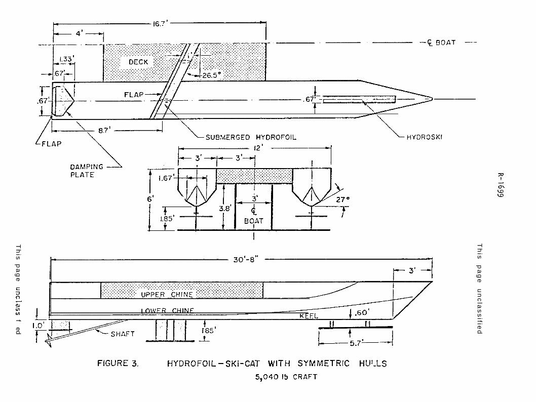
(u> Figure 1 shows the general arrangement, outboard profile, and deck
plan of the manned model. It is seen that the craft is composed of high
length-beam ratio twin hulls with a submerged high aspect ratio main hydro-
f o i l j u s t a f t o f the LCG, hydroskis which stand-off below the bow of each
hull, and submerged damping plates attached to the transom of each hull
which also serve as ventilation ;;lates over the propeller. At high speed,
with the hull unported, the load distribution is go”/, on the main foil , 6%
1Superior numbers in text matter refer to similarly numbered referenceslisted at the end of this report.
2
CONFIDENT1
Default
Default
Default

R-1699
This page unclassified
on the damping plates and 4% on the hydroskis (for the design LCG condi-
tion). The foil submergence subsequent to hull unporting is one chord.
An important feature is that there is no active control system in the
design, Flaps on the main foil and hydroskis are manually positioned for
l o a dV
(u)
as fo
(c* =
shown
llows: The high length-beam ratio hulls have a high beam loading
1 .5) and, at maximum speed, are designed to run at zero trim. As
in Reference 2, this combination of large cA and low trim angle
results in extremely low “g” loadings when running in waves. Thus, hul
clearance can be reduced (relative to conventional hydrofoil hulls) and
the resulting hull impact with waves are tolerably small. This leads t
reduced strut length with a considerable saving in structural weight,
hydrodynamic dra3, and simplicity in propulsive system.
ariations and for selected operating speeds.
The design philosophy embodied in the hydrodynamic configuration is
(u) The catamaran hulls and connecting bridge structure are fabricated
of j/*5-inch marine plywood on spruce framing. The connection between the
hulls and the center bridge is effected by sixteen l/4-inch diam tie-rods,
which affords convenient disassembly and transportability. A general ar-
rangement and inboard profi le, indicating some framing details of the hulls
and bridge is given in Figure 2.
(u) The forward 1 ifting surface, a low aspect ratio planing surface, was
selected because of reliability of flow separation at low speed and because
o f i t s l o w l i f t r a t e (dCL/da) c o m p a r e d t o s u r f a c e - p i e r c i n g f u l l y - v e n t i l a t e d
hydrofoi 1s. Early flow separation assures a stabilized flow over most of
the speed range while a low lift rate results in small inpact loads in waves,
The submerged aft plate has a lift rate approximately twice that of the
hydroski and thus provides the required pitch damping without being exposed
to wave impact loads. Pitch stability and control are provided by the com-
bined pitch restoring moment and damping action of the hydroskis and damping
plates. Heave stability is provided primarily by the natural reduction in
lift on the main hydrofoil as it approaches the fret surface and by the
natural increase in lift as its submergence increases. Because of the small
clearance between hull and foils, t h e h u l l i t s e l f w i l l p r o v i d e f o r p i t c h
and heave stability if the craft motions exceed the hull clearance, Thus,
3 This page unclassified
R-1699 CONFLDENTIAL
the proposed hydrofoi 1 sys tern s inherently self-stabilizing and does not
require any active control system. This was verified in the smooth- and.
rough-water model tests conducted at the Gavidson Laboratory.’
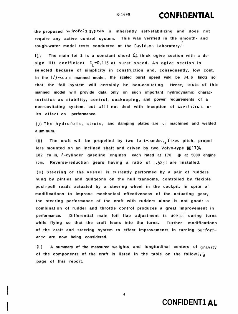
(cl The main foi 1 is a constant chord 6% thick ogive section with a de-
s i g n l i f t c o e f f i c i e n t CL=0.115 a t b u r s t s p e e d . A n o g i v e s e c t i o n i s
selected because of simplicity in construction and, consequently, low cost.
In the l/3-scale manned model, the scaled burst speed wikl be 34.6 knots so
that the foil system will certainly be non-cavitating. Hence, t e s t s o f t h i s
manned model will provide data only on such important hydrodynamic charac-
t e r i s t i c s a s s t a b i l i t y , c o n t r o l , s e a k e e p i n g , and power requirements of a
non-cavitating system, but wil’l not deal with inception of cavit..2tion, or
i t s e f f e c t on performance.
(u) T h e h y d r o f o i l s , s t r u t s , and damping plates are rji’ machined and welded
aluminum.
(a The craft wil l be propelled by two left-handed,&fixed pitch, propel-
lers mounted on an inclined shaft and driven by two Volvo-type BB170A
182 cu in, 6 -cylinder gasoline engines, each rated at 170 .HP at 5000 engine
rpm. Reverse-reduction gears having a ratio of l.52:1 are installed.
( U ) S t e e r i n g o f t h e v e s s e l is currently performed by a pair of rudders
hung by pintles and gudgeons on the hull transoms, controlled by flexible
push-pull roads actuated by a steering wheel in the cockpit. In spite of
modifications to improve mechanical effectiveness of the actuating gear,
the steering performance of the craft with rudders alone is not good: a
combination of rudder and throttle control produces a great improvement in
performance. Differential main foil flap adjustment is useful during turns
while flying so that the craft leans into the turns. Further modifications
of the craft and steering system to effect improvements in turning perform-
ante are now being considered.
(u) A summary of the measured we
of the components of the craft is
page of this report.
ights and longitudinal centers of
listed in the table on the follow
g r a v i t y
Ing
4
CONFIDENT1
Default
Default
Default

R-i699This page uncjassified
TABLE 2
WE 1 GHT SUMMARY
Component Weight
Port Huf 1 Assembly
Starboard Hul I Assembly
Center Section Assembly
Hydrofoi 1
Propel lers
Light Ship
Comp 1 emen t
Fire1
Wz!ter
Base
Bzil last (Nom.)
Full Load Displacement
1710/Y1710
660200
22
43 oz#
330
168
40
4848
200
5048
Forward LongitudinalTransom Moment
10.63'
IO.57
IO.57
9.70
0
10.5'
10.0
- 0.67
10.0- -10.07
8.67
10.02'
T$T77ft-lbs.
18075
6976
1940
0
45168
3300
- 111
400
48757
1734
50491 fr-lbs.
(u) The entire craft can be readily disassembled, mounted aboard a
specially-designed Transport and Launching Trailer which has been supplied
along with a small van suitable for towing the trailer and carrying support
equipment for the manned model.
(u) More complete information on arrangements, and structural and instal-
lation details, are contained in the drawings for the l/3-scale Manned Model
of Sk
Table
w
cha+:a
-Cat High-Speed Catamaran. A list of these drawings is
3 on the following page of this report.
given in
Further details, including vehicle characteristics, foi 1 system
ter is t ics , subsystem characteristics, equipment list, s tructural
analyses, measured weights, hydrostatics, estimated drag, estimated thrust,
an2.l performance summary are included in the Design Notebook appended to
th is report.
5 This page unclassified

R- 169Y
This page unclassified
TABLE 3- -
DRAUING LIST
Title of Drawing
General ArrangementOutboard Profile and Deck Plan
General Arrangement, I nboard Prof i le
Hull Lines
Structural Arrangement
Frames and Bulkheads
Machinery !nstal larion ar,d Detai Is
Piping Systems-Diagrammatic
Main Foi 1 and Controls
A f t F o i l and Controls
Ski Detai 1 s
Transport & Launching Trai ler
Prog re5s
Some key steps in the conduct of work on this project may be cited:
1) Initiation of design work on 1tract date for Modification 1
/3-scale manned model (also Con-o f C o n t r a c t NOOOl4-67-A-0202-0031
1 December 1973
Drawing No.
202-00.1 (Design Evaluation)
2 0 2 - 0 0 . 2 (Design Evaluatioil)
202-01.1 (Design Evaluation)
202-01-2 (Design Evaluation)(2 sheets)
202-01.3 (Design Evaluation)
202-02.1 ( i n s t a l l a t i o n )
202-05.1 (Maintenance)
202-08.1 (Design Evaluation)
202-08.2 (Design Evaluation)
202-08.3 (Design Evaluation)
202-09.1
2) Initiation of manned model construction16 March 1973
3) Launching of manned model, and first fl ight trials24 July 1973
Modification 24) Extended Builder’s Trials (carried out undero f con t rat t)
31 Ju ly to 3 August 1973
5) Del ivery of manned model to NSRDC, Annapolisa n d f l i g h t t r i a l s
, reassemb 1 y
September 1973
(IJ) Further evaluations of this manned model, including performance
trials, wi 11 be carried out by NSRDC. Davidson Laboratory will act in an
advisory capacity for these tests.
6 This page unclassified

R-1699
T h i s p a g e u n c l a s s i f i e d .
PERFORWNCE
Extended Bui ider’s Trials
w E x t e n d e d b u i i d e r ’ s t r i a l s , p r i o r t o f i n a l d e l i v e r y o f t h e m a n n e d
model to NSRDC at Annapolis, w e r e c a r r i e d o u t t o e v a l u a t e p r o p e r s k i a n d
f o i l - f l a p s e t t i n g s f o r o p e r a t i o n a t v a r i o u s s p e e d s , d i s p l a c e m e n t s a n d
LCG’s a n d p r o p e r r u d d e r a n d f o i l f l a p s e t t i n g s f o r t u r n i n g m a n e u v e r s .
The principal dimensions of the test craft are shown in Figure 3. Motion
picture records were also made of some aspects of the tests. These tests
w e r e a u t h o r i z e d a s a n e x t e n s i o n i n s c o p e o f c o n t r a c t u n d e r M o d 3 o f Con-
tract NOOOl4-67-A-0202-00~1.
S p e e d T r i a l s
(u> E f f e c t o f D i s p l a c e m e n t : T e s t s w e r e c a r r i e d o u t t o d e t e r m i n e t h e
e f f e c t o n s p e e d c a p a b i l i t y a s a f u n c t i o n o f i n c r e a s e d d i s p l a c e m e n t s . f o r
various main foil flap settings the speed and engine RPM’s were measured for
severai throttle settings. The Bliss (catalog Fig. 850) pitot-iog which
is mounted beneath the trailing edge of the starboard ski, and the readout
d i a l g a u g e w e r e c a l i b r a t e d b y c o m p a r i n g d i a i r e a d i n g s w i t h t i m e d s p e e d s
for traversing a distance between two buoys whose spacing was measured
w i t h s u r v e y i n g e q u i p m e n t . The timed speed was found to be about 0.98
t i m e s t h e p i t o t - i o g i n d i c a t e d s p e e d .
UJ) R e s u l t s f o r t h e d e s i g n d i s p l a c e m e n t , 5 0 4 0 i b s (139,600-lb f u l l s c a l e )
and, t w o g r e a t e r l o a d s , 5540 lbs (153,470-lb f u l l s c a l e ) a n d 6040 i b s
167,320-lb f u l l s c a l e ) a r e p r e s e n t e d i n T a b l e 3 a n d F i g u r e s 4 a n d 5 .
Propel ier RPl+‘s and hull trims are shown as a function of measured speed
i n F i g u r e 4 , w h i l e t h e e s t i m a t e d d r a g c u r v e ( c a l c u l a t i o n s a r e p r e s e n t e d i n
t h e “ E s t i m a t e d Drag” Section of the design notebook) is compared with the
e s t i m a t e d p r o p e l l e r t h r u s t ( f r o m t h e s e c t i o n , “ E s t i m a t e d T h r u s t a n d T o r q u e , ”
o f t h e d e s i g n n o t e b o o k ) i n F i g u r e 5. The thrust estimates are based on
measured speed and RPM and take into account in an approximate manner the
e f f e c t s o f c a v i t a t i o n a n d s h a f t i n c l i n a t i o n .
(u) T h e s c a t t e r o f t h e d e r i v e d t h r u s t e s t i m a t e s s h o w n i n F i g u r e 5 i s
excessive and clearly indicates that one or another of the measurements
are in error. By inspect ion of the propel ior thrust map, Figure l-2 of
7 This page unclassified
R- 1699
This page unclassified
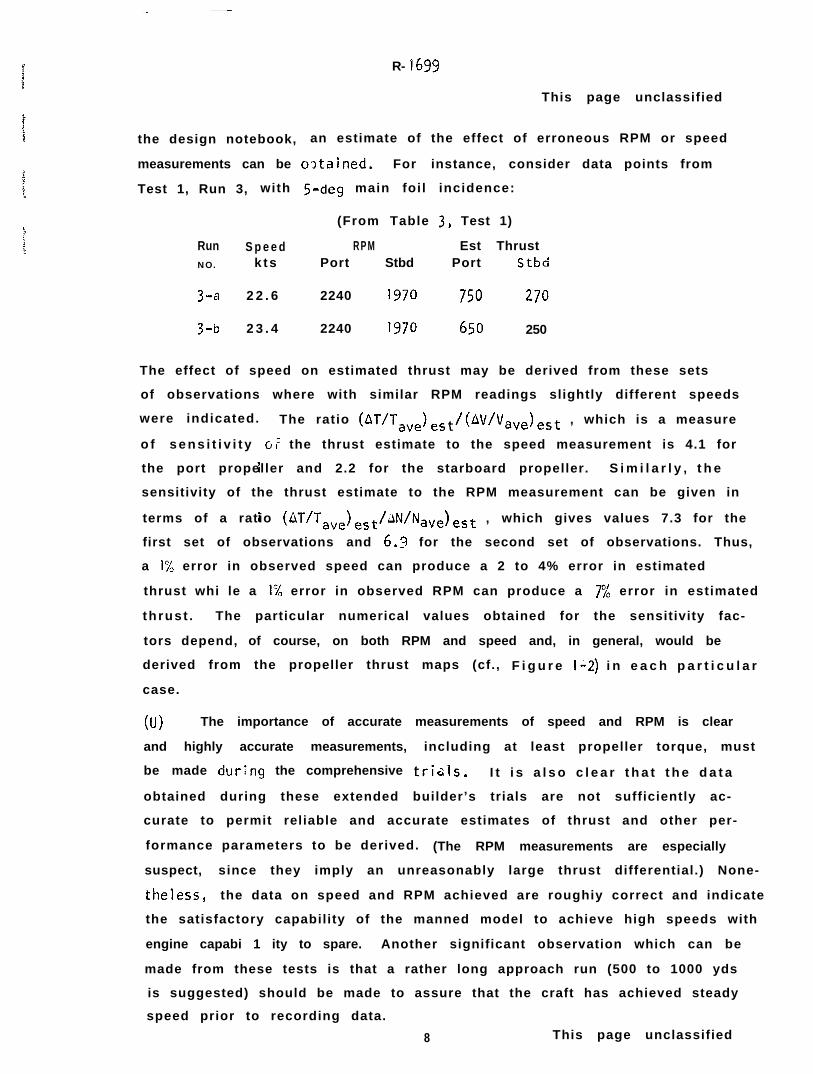
the design notebook, an estimate of the effect of erroneous RPM or speed
measurements can be oJtained. For instance, consider data points from
Test 1, Run 3, with 5-deg main foil incidence:
(From Table 3, Test 1)
Run S p e e d R P M Est ThrustNO. k ts Port Stbd Port Stbd
3-a 2 2 . 6 2240 1970 750 270
3-b 2 3 . 4 2240 1970 650 250
The effect of speed on estimated thrust may be derived from these sets
of observations where with similar RPM readings slightly different speeds
were indicated. The ratio (LYT/T,,,),~~/(~V/V,,,),,~ , which is a measure
o f s e n s i t i v i t y of the thrust estimate to the speed measurement is 4.1 for
the port propeller and 2.2 for the starboard propeller. S i m i l a r l y , t h e
sensitivity of the thrust estimate to the RPM measurement can be given in
terms of a ratio (~T/T,,,),,~/~N/N,,,),,~ , which gives values 7.3 for the
first set of observations and 6.9 for the second set of observations. Thus,
a 1% error in observed speed can produce a 2 to 4% error in estimated
thrust whi le a 1% error in observed RPM can produce a 7% error in estimated
thrust . The particular numerical values obtained for the sensitivity fac-
tors depend, of course, on both RPM and speed and, in general, would be
derived from the propeller thrust maps (cf., F i g u r e I-2) i n e a c h p a r t i c u l a r
case.
(u) The importance of accurate measurements of speed and RPM is clear
and highly accurate measurements, including at least propeller torque, must
be made during the comprehensive tric;ls. I t i s a l s o c l e a r t h a t t h e d a t a
obtained during these extended builder’s trials are not sufficiently ac-
curate to permit reliable and accurate estimates of thrust and other per-
formance parameters to be derived. (The RPM measurements are especially
suspect, since they imply an unreasonably large thrust differential.) None-
theless, the data on speed and RPM achieved are roughiy correct and indicate
the satisfactory capability of the manned model to achieve high speeds with
engine capabi 1 ity to spare. Another significant observation which can be
made from these tests is that a rather long approach run (500 to 1000 yds
is suggested) should be made to assure that the craft has achieved steady
speed prior to recording data.
8 This page unclassified

R-1699
This page unclassified
(U) T h e e f f e c t o f increasing displacement on performance is mainly a
consequence of increased lift coefficient on the foil while flying: 1)
The take-off speed is slightly increased, with some added wetness, 2) for
these preliminary tests, a somewhat greater tendency to intermittent loss
of lift, evidently due to ventilation of the main foil (this tendency has
been greatly reduced by blocking the air path down the strut fairing which
encases the flap push-rod, as described later under “corrective actions”),
3) f o r a f u l l - s c a l e c r a f t , cavitation inception might occur at a slightly
lower speed due to the high lift coefficient and, 4) in the absence of
cavitation or ventilation, the speed-power relation in the flying mode of
operation which, for ski-cat, is primarily a consequence of skin-friction,
is quite insensitive to changes in displacement. if the design displacement
were changed, the main foil design characteristics would, of course, be
adjusted and the relatively minor changes in performance mentioned
above would be appreciably ameliorated. A more definitive evaluation of
increased displacement will be made following the Annapolis tests.
(0) Effect of LCG: Additional tests were carried out at the medium dis-
placement of 5540 lb. to assess the effects of variations of LCG position
on speed performance. The ballast weights (five one-hundred-pound bags of
cement) were shifted, first aft by the greatest amount possible, producing
a 0.75-ft. change in LCG position, then forward by a similar amount. Again,
runs were made at various main foil flap settings and speed and engine RPM
indications recorded for several throttle settings. For the forward LCG
condition, it proved to be quite difficult to keep the ski-tips out of the
water with the standard ski incidence of 3.6-deg. relative to the hull and
the operation was, consequently, quite wet. In an attempt to remedy this,
it was decided to adjust the aft ski-control-rod, increasing the ski-incidence
to 7.6 degrees. There was little difficulty then in keeping the ski-tips
planing, but the spray generate0 was nonetheless much greater than for the
normal of aft LCG location.
(u> Results of these trials are presented in Table 4 and in Figure 6,
which is similar to Figure 4. Estimated thrust values are not tabulated
because of their relatively low accuracy.
9 This page unclassified
R-1699
This page unclassified
(u) E f f e c t o f S k i - H e i g h t : One group of tests were made at a displace-
ment of 5240 lb (l&,160-lb full scale) to evaluate the effect of increased
clearance between ski and hull. The skis were adjusted an additional 3.75”
downward with the standard 3.6-edcg incidence. in operation, the hull-
water clearance was favorably modified, b r i n g i n g tSe m a i n f o i l s s l i g h t l y
closer to the water surface. Flying performance was generally satisfactory
except that occasional intermittent loss of main foil lift occurred, per-
haps due to ai r-draw i ng down th P strut fa3ring encasing the flap push-rod,
and the craft would come down from flying to planing mode for a brief time
with attendant spray-generation from the ski-control-rods.
W) Trials results for this case are given in Table 5 and in Figure 7.
Turning Trials
(u) Turning trials were carried out at a displacement of 5240 lb
(145,160-lb f u l l s c a l e ) w i t h t h e d e s i g n LCG lccation, 10-mfI: f o r w a r d o f
the center of gravity.
w The measurements technique was admittedly crude: 1) the craft was
driven up to speed along a straight path and the steady speed recorded,
2) a turn was initiated by rudders and differential main foil flaps, 3)
the time for successive 30-deg heading changes (obtained from the compass)
to occur was measured with a stop-watch and recorded. The radius of the
turning circle was obtained from the relation:
2n x Radius x30 deg
360 deg= Speed x Time for 30-deg Heading Change
Results for turns executed with rudder and flaps only are recorded in
Table 6. Some additional trials were run in which differential engine
RPM was used: a) at low speed (estimated to he 6 MPH) with one engine
o f f , b ) f l y i n g , with 5-deg main foil f lap angle, at about 28 MPH with the
maximum differential engine thrust for which the pilot could maintain fly-
ing equilibrium together with maximum rudder action, and c) using ahead
thrust on one propeller and astern thrust on the other, the craft can be
turned quite expeditiously in its own length. Results for the additional
tests with differential thrust are tabulated in Table 7. At high speed
10 This page unclassified

R-1699 CONFIDENTIAL
the turning circle radius appears 90 be reduced by about 25% by using
differential propel ler thrust as we1 1 as rudder.
OJ) T h e l a r g e t u r n i n g c i r c l e s f o r t h i s 300ft LOA c r a f t a r e a s s o c i a t e d
with two factors: a ) t h e c r a f t h a s e x c e p t i o n a l d i r e c t i o n a l s t a b i l i t y ,
afforded by the large profile area of the aft strut, which acts JS pro-
peller shaft bearing support and cooling water intake, and b) the unbal-
anced rudder could not be turned through large angles at high speeds
because of inadequate mechanical advantage in the l inkage system. When
t h i s d i f f i c u l t y w a s f i r s t o b s e r v e d , the foot pedal l inkage system was
modified and the increased mechanical advantage afforded resulted in a
useful improvement in turning performance: this revised system was used
for the tests reported in Tables 6 and 7. The maximum rudder angle was
still limited by the pilot’s strength to about 5 to 10 degrees. The
rudder angle for th=? tests reported was not accurately measured, but
based on observed foot-pedal deflections, was in this range, i.e., 5 to
10 degrees.
w Published data on turning performance of high-speed craft is
sparse. Sugai2 has reported results of research on maneuverability of
a slender, twin-screw, twin-rudder, hard-chine boat model which show
that turning diameters are greater for high speeds (Froude Numbers based
on length up to 1.0). For rudder angles of 15-deg turning diameters in
excess of 10 times the length are found, even with quite large rudders.
The present craft, however, with Froude Number of 1.6 at 30 knots, re-
quires a turning diameter of 30 to 40 lengths with the (small) maximum
rudder angle. It is expected that a further rudder modification, pre-
ferably replacing the present unbalanced rudders with balanced ones, will
substantially improve the turning capability. Further, the prototype
design need not have the same profile characteristics as the manned model,
v i z . , the cooling water intakes,which make the aft strut large, could be
eliminated with air-cooled gas turbine engines.
Motion Pictures
OJ) During the course of the extended builderls tr
were taken of selected runs.
in the edited version of mot
15 J a n u a r y 1974.3
ia ls , motion p icturej
T a b
ion p
e 8 lists titles for the various scenes
cture which was submitted to NSRDC on
CONFIDENVI11
Default
Default
Default

Ii- 1699
Th i s page unclassified
EQUIPMENT DEFICIENCIES, AI?ALYSES AND CORRECTIVE ACTION
(u> During the bu ilder’s t r i a l s , a l o u d n o i se and service vibration
was observed to occur in the starboard engine compartment on at least
three o.,cas ions , which caused the pilot to immediately shut down opera-
t i o n . These occurrences were invariably associated with very high speeds,
i .e., engine rpm’s above about 4200.
Propel ler Pitch
OJ) The most l ikely explanation o f this behavior is considered to be
the existence of some form of critical {resonant) vibration of the engine
and shafting, most 1 ikely a lateral (whirling) mode . The noi se was so
intense that it was deemed to be excessively dangerous to risk extensive
exploratory operation in the vicinity of this speed which might lead to
a more conclusive diagnosis. instead, the propel ler’s were re-pi tched
(pitch increased) and a “full cup” blade modification incorporated, to
increase the propeller torque and thrust for a given rpm. In this way
the engine and propeller shaft rpm’s can be kept below the dangerous
initial speed while sti l l absorbing and delivering adequate power, eveI;
though the engine’s full power rating applies at the appreciably higher
value of 5000 rpm.
described
Notebook.
oJ> The details of the original and modified pitch propellers are
i gnin the ‘%stimated Thrust and Torque” Section of the Des
Main Foi 1 Venti lation
(u) Ouring the builder’s trials occasional instances of precipitous,
intermittent, loss of lift on either one side of the main foil or both
sides occurred, which resulted in the bow skis plowing in and substantial
spray and wetness on deck and in the cockpit. This behavior was generally
(but not always) quickly corrected by a slight change in speed, foil flap
setting, or engine rpm’s. it was diagnosed as pro&ably due to ventila-
tion over part of the main foil by air flowing down through the flap push-
rod enclosure of the inboard struts (see Figure 2).
12 This page unclassified

This page unclassified
(u) This air-drawing was corrected by blockirig rhe path of air with
a sponge-rubber pad inserted in the push-rod enclosure near the bottom
of the s t ru t . The flap adjustment push-rod slides easily in this pad
and the water-soaked sponge effectively prevents air-drawing.
13 This page unclassified

R-1699
REFERENCES
This page unclassified
1. S a v i t s k y , II. a n d R o p e r , J . K . , “Hydrodynamic Development of a High-SpeedHydrofoil C a t a m a r a n (u), ” 8 D a v i d s o n L a b o r a t o r y , Stevens i n s t i t u t eof Technology, Report SIT-K-73-1671, December 1973.
2. S u g a i , K . , “On the Maneuverability of the High-Speed Boat,ti JapaneseT r a n s p o r t a t i o n T e c h n i c a l R e s e a r c h I n s t i t u t e , T o k y o , Vo1.12, No.11,20 March 1963 (Bureau of Ships Translation ~0.868).
3. L e t t e r , dated 15 January 1974, J. Merrier (DL) to G. Springston (NSRDC)c o n v e y i n g o n e c o p y 16mm m o t i o n p i c t u r e s o f ‘A One-Th i rd Scale MannedM o d e l o f S k i - C a t , High-Speed Hydrofoi 1 Catamaran.”
14 This page unclassified

CONFIDENTIAL
RESULTS OF EXTENOED BUILDER’S TRIALSSPEED TRIALS AT TI!REE DISPLACEMENTS
M4iNR U N FOIL SPEED PROPELLCR RPM’S
;cTRIM ESTIMATED THRUST’
FLAP Port Stbd Ave. Port
deg k ts de9 lb
TES1” I: OisPl = 5 0 4 0 ?b5+, LCG = IO-Ft forward transom
1 15 13.9 1.5 1580 1710 1645 -1'1;
15.6 I.5 ,710 1840 ,775 _16.5 1.5 lS40 1840 ,840 700
2 10 19.1 1.0 1840 1840 ,840 470
3 5 22.6 1.0 2240 ,970 2105 7505 23.4 1.0 2240 1970 2105 650
; 25.2 24.3 1.0 1.0 2105 2105 2il?5 2105 2105 2105 276 263
4 0 26.9 2.0 2500 2105 2300 7550 31.3 1.5 2630 2630 2630 4800 33.0 1.0 2760 2700 2730 5300 33.0 1.0 2760 2760 2760 530
TEST 2: Displ = 551+0 l b s , L C G = 10 f t - f o r w a r d t r a n s o m
14 15 15.6 2.5 1645 1840 1740 500 7 5 0 125015 16.9 2 . 0 ,840 ,775 ,810 650 560 1210I5 20.8 1.0 1840 2105 1970 370 740 1110
10 10 16.5 3.0 1645 1775 1710 400 570 970
11 10 18.7 2.25 1775 1940 1860 420 6 4 0 ,06010 23.4 1.0 2040 2170 2105 390 570 960
9 5 21.7 2.0 2040 2170 2105 520 700 1220
8 5 23.9 1.5 2070 2240 2155 380 6 8 0 1060
15 5 23.5 2.0 ,975 2170 2070 280 5 3 0 8105 24.3 2.0 1975 2300 2140 250 700 9505 25..? 1 l 5 2170 2300 2235 350 590 920
7 5 28.2 1.0 2300 2470 2385 320 560 880
13 0 27.8 2.5 2370 2565 2470 460 780 124012 0 28.7 1 . 7 5 2 4 3 5 2 5 6 5 2500 470 700 1170
Stbd Totallb lb
700 1 4 0 0
470 940
270 ,020250 9 0 0276 552263 5 2 6
200 9 5 5480 960470 ,000530 I 060
I
[Cont’d)
+<Notes ; 1) Baso,d on measured rpm and speed and Design Notebook Fig.l-2.
2) The estimated thrusts are considered to be of questionablereliabil i ty and accy;racy, probably because measureme?ts ofrpm and speed are not sufficiently accurate.
15
Default
Default

R - 1 6 9 9 CONFIDENTIAL
TABLE 3 (Cont’d)‘I
.‘, t
M A I N ;:RUN FOIL SPEED TRIM PROPELLER RPM’S EST I MATED THRUST’
FLAP Fort Stbd Ave. Port Stbd
deg k ts deg lb lb
TEST 3: Displ = 6 0 4 0 1 bs, LCG = 1 O-f t forward transom
18 15 16.5 2.25 1840 1645 1740 670 4 3 0
1 6 10 22.1 2 . 0 2105 1975 2040 580 40010 24.3 2.0 2240 2105 2170 590 380
20 5 ?3.5 2.0 2240 2170 2205 650 540; 26.9 27 .‘+ 1.75 1.5 2370 2370 2105 2300 2235 2335 540 450 390 160
17 5 26.9 1.0 2435 2240 2335 660 3 5 0
1 9 0 26.5 2 . 5 243 5 2235 23?5 600 3000 27.8 2.0 2565 2300 2430 780 360, _
Totallb
1100
980970
1190
782
1010
9001 1 4 0
“Notes : 1) Based on measured rpm and speed and Design Notebook Fig..l-2.
2) The estimated thrusts are considered to be of questionablereliability and accuracy, probably because measurements ofrpm and speed are not sufficiently accurate.
1 6 CONFIDENTIAL
Default
Default
Default

CONFIDENflAt
TABLE 4
RESULTS OF EXTENDED BUILDER'S TRIALSSPEED TRIALS AT TWO ADDITIONAL LCG'S
RUNMAINFOILFLAPde9
SPEED TRIM
kts de9
PROPELLER RPM'SPort Stbd Ave.lb lb lb
TEST 4: Displ = 5540 lb, LCG = 9.25-ft forward transom
23 1515
21 10
22 :
:
25 5
24 0
19.520.4
21.7
21.323.526.126.5
26.527.428.2
28.229.5
1.51.5
1.75
2.02.0
1.75
1.5
2.0
lgra1975
2040
2040210522357300
230024352435
25002565
1840 18751840 1910
1840 1940
1875 19602105 21052105 21702170 2235
2170 22352235 23352235 2335
2370 24352435 2500
TEST 5: Displ = 5540 lb, LCG = 10.75-ft forward transom
25
26
10 24.3 2235 2105 217010 26.1 1.0 2300 2170 2235!O 27.8 2370 2300 2335
5 26.5 1.5 2300 2235 22705 27.8 2370 2270 23205 28.2 2500 2235 2370
TEST 6: Displ = 5540 Ib, LCG = 10.75-ft forward of transomSki Incidence = 7.64 degrees
29
27
15 13.015 16.515 17.415 18.2
10 21.710 23.9la 25.2
3.02.02.02.0
1.51.0
1710 1580 16451840 1775 18101975 - -1975 1710 1845
2040 1975 20102i7a 2105 21402300 2105 2205
[Cont'dJ
17
Default
Default

TABLE 4 (Cont'd)
RUNPii I NFOILFLAPdeg
TEST 6 Cont'd:
31 5 .4 2.0 2300 2040 21705 i.5 2.0 2435 2235 2335
28 5 ?5.6 1.5 2300 2235 22705 29.5 i .25 2500 2370 2435
30 0 28.2 2.0 2500 2370 24350 29.5 1.75 2630 2500 25650 30.0 1.75 2630 2570 2603
R-i699 CONFIDENTPAL
.‘(t
SPEED TRIM
kts dw
i8 CONFID
PROPELLER RPM'SPort Stbd Ave.lb. lb lb
Default
Default

R-1699 CONFIDENTIIAI,
TABLE 5
RESULTS OF EXTENDED BUILDER'S TRIALSSPEED TRIALS WITH MODlFiED SKI-ELEVATION
RUNMAINFOILFLAPde9
SPEED
krs
TRIM PROPELLER RPM'SPort Stbg Ave
de9 1 b, .lb ttr
TEST 9: Displ = 5240 lb, LCG = TO-ft forward transomSkis lowered 3.75 inches
43 1 0 20.0 1.75 1910 1840 1875
44 1 0 22.6 2.0 2040 1975 2010
4 1 5 26.9 2.0 2300 2170 2235
42 5 27.4 1 .s 2370 2300 2335
39 5 27.8 1.0 2370 2170 2270
40 5 27.8 1.5 2435 2105 2270
45 0 29.5 2630 2435 2535
19 CQNFIDENTIAL
Default
Default
Default

R- 1669 CONFIDENTIAL
RUN
32
33
34
35
36
MI\INFOILFLAP
de9
101010
z55
5
0000
TGBLE 6
RESULTS OF EXTENDED BUILDER’S TRIALSTURNING TRIALS WITH RUDDER AND DIFFERENTIAL FLAP ONLY
Table 7: Dispi = 5240 lb, LCG = 10 ft forward of transom
SPEED
kts
%5
19.519.520.4
25.225.225.225.2
25.2
26.926.926.926.9
PROPELLER RPM’S RUDDERPort Stbd Ave.lb lb lb
1120 1180 1150 max port1120 1180 1150 max stbd
1975 1775 1875 max stbd1975 1775 1875 rkx port2040 1840 1940 max port
2300 2105 2200 max port2300 2105 2200 max port2300 2105 2200 max port2300 2105 2200 max port
2300 2040 2170 max stbd
2500 2240 2370 max stbd2500 2240 2370 niax port2500 2240 2370 max port2500 2240 2370 max port
TIME FOR RADIUS OF30' CHANGE TURNINGIN HEADING CIRCLE
set ft
20.3 280:9.2 270
11.6 7309.4 5909.4 620
5.2
;:i6.2
420420470500
9.0 730
5.8 5006.8 5907.2 6207.0 610
20 CONFIDENTIAL
Default
Default

R-1699
TABLE 7
RTSULTS OF EXTENDED BUILDER'S TRIALSTURNING TRIALS WITH RUDDER DIFFERENTIAL FLAP
AND DIFFERENTIAL ENGINE RPM
Test 8: Displ = 5240 lb, LCG = IO-ft forward of transom
MA I N TIME FOR RADIUS OFRUN FOIL SPEED PROPELLER RPM'S RUDDER 30' CHANGE TURNING
FLAP PGi"t Stbd Ave. IN HEADING CiRCLEdeg kts lb lb lb set ft
37 - M 5 0 1640 820 Centered 10.6 180-0 1640 820 Centered 11.2 19e
0 1640 820 Max stbd 6.1 1000 1640 820 Max stbd 6.7 110
38 5 24.3 Not Recorded Max port 3.0 240Not Recorded Max port 5.4 420Not Recorded Max port 250Not Recorded Max stbd t:; 330Not Recorded Max stbd 5.8 460
21 CONFIDENTIAL
Default
Default

Fc- 1499
TABLE 8 This page unclassified
TITLES OF MOTlO:J PICTURE RECORDSOF A
ONE-THIRD SCALE MANNED MODELOF SKI CAT, HIGH-SPEED HYDROFOIL CATAMARAN
FORNAVAL SHIP SYSTEMS COMMAND
CONTRACT NOOOl4-67-A-0202-0032JULY-AUGUST 1973
BUILDER'S TRIALSAT LAKE NUBANUSITNEAR HANCOCK, N.H.
MANNED MODEL ON TRANSPORTAND LAUNCHING TRAILERPRIOR TO LAUNCHING
LAUNCHING OPE'RATIONS24 JULY 1973
MODEL THEN TOWED TO MOORINGFOR FURTHER OUTFITTING
LOW-SPEED TURNS AND TAKE-OFF
SPEEDS FROM 19 TO 35 MPHDISPL = 5540 L5S
TAKE-OFF AND FLY-BYDISPL = 6040 LBS
TURNING PERFORMANCEDISPL = 5240 LBS
BOW SKIS LOWERED 3.75-INTO INCREASE HULL-WATER CLEARANCE
DISPL = 5240 LBS
PILOT-INDUCED "GALLOPING"DEMONSTRATES CRAFT'S RUGGEDNESS
AND MiLD IMPACT BEHAVIOR
T H E E N D
DAVIDSON LABORATORY FILM NO.78This page unclassified
22

Gaso 1Tanks
-I3-.cn
i
/---
Center 1--.
Engine Blower Housing J)J=CK PIAN
neFlap Contr
S t r u t& F o i l
--_.
F o i lM a i nOUTBOARD PROF 1 LE
ine C r a f t
FI’X!RE t . GENERAL ARRANGEMENT,OUT?r)ARD PROFILE AYD DECK PLAN OF SKI-CAT HIGH-SPEED CATAMARAN
LP P
( 1/3-S;;Ae-M;;nez Mode 1)= 26’-8”, - ‘- Ii, Max Beam = 12’

Th
is
pa
ge
u
nc
las
sifie
dR-1699
-LY2T
his
p
ag
e
un
cla
ss
ified
R-1&99
Th
is p
ag
e
un
classifie
d
Th
is pa
ge
unclass
fed

R-1699CONFIDENTIAL
MAIN FOIL D I S P L A C E M E N TF L A P ANGLE, DEG 5 0 4 0 5 5 4 0 6 0 4 0
15 0 d dIO Cl Ef cl+
5 0 o/ (If0 n d A+
-
MAIN FOILFLAP ANGLE=
6040-LB DISPL
O/GI’0s RPM
00 5040-LB DISPL
I2 0 2 5
S P E E D , K N O T S
3 0 3 5
FIG.4. RPM AND TRIM VERSUS SPEED FOR VARIOUS DISPLACEMENTS,NORMAL LCG (IO.0 FT FORWARD OF TRANSOM
CONFIDENTIAL
Default
Default

p-1699CQNFIDENTIAI.
DISPLA.qEMENT T E S T5 0 4 0
II 0
5 5 4 0 2 06 0 4 0 3 V
1400
r0
THRUST ESTIMATESBASED ON MEASURED RPMAND SPEED-
0q cl
00
0
%00
Cl0 00 0 v.ga 0
/0
UYU
ESTIMATED DRAG( BY CALCULATION
FIGURE H-1)
STIMATED TAKE-OFF SPEED200 (504OLB. DISPLACEMENT)
0 I IIO I5 20 25 30 35
SPEED,KNOTS
FIG. 5. COMPARISON OF ESTIMATED DRAG (FROM DESIGN NQTEBOOK,FIG. A31 WITH ESTIMATED PROPELLER THRaJST BASED ONMEASURED SPEED AND RPM AND DESIGN NOTEBOOK FlG.I-2
Default
Default

AVER
AGE
PRO
P R
PM
(EN
GIN
E R
PM/l.
521
LCG
= 9
.25
FT. F
OR
WAR
D O
F TR
ANSO
M
AVER
AGE
PRO
P R
PM 1
ENG
iNE
RP
hA/l.
52)
LCG
=10
.75 F
T. F
OR
WAR
D O
F TR
ANSO
M
AVER
AGE
PRO
P R
PM (
ENG
INE
RPM
/l.52
1
n 0 z
Default
Default

R - 1 6 9 9 CONFIDENTIAL
MAIN FOILFLAP ANGLE DEG.
IO Cl5 00 n
aW>
a 1500 I I I I IIO 15 20 25 30 35
SPEED, KNOTS
FIG. 7. RPM VERSUS SPEED, NORMAL LCG, 5240 L8 DiSPLACEMERIT,SKIS LOWERED 3.75 IN.
Default
Default

R-1699
This page unclassified
APPENDIX
DESIGN NOTEBOOK
A . Vehicle C h a r a c t e r i s t i c s
B . Hul i C h a r a c t e r i s t i c sfLa. F o i l S y s t e m C h a r a c t e r i s t i c s
0. Eq\lipment L i s t
E . S t r u c t u r a l A n a l y s e s
F. Measured Weights
G. H y d r o s t a t i c s
H. Estimated Drag
1. Estimated Thrust and Torque
T h i s p a g e u n c l a s s i f i e d

VEHICLE CHARACTERISTICS
This page unclassified
This page unclassified

x-3
R-169911-2
55 = 4,s”
CONFIDE
&cJr;
Default
Default

R-1699n-3
l&-wP /I, 3, 2.,3,* 4, 5-, G
This page unclassified
This page unclassified

R- 16%B- 1
T h i s p a g e u n c l a s s i f i e d
HULL CHARACTERISTlCS
This page u n c l a s s i f i e d
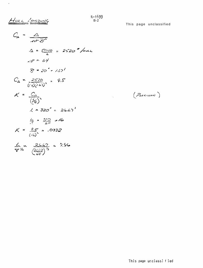
R-l699B-2
T h i s p a g e u n c l a s s i f i e d
This page ur:classi f ied

This page unclassified
FOIL SYSTEM CHARACTERISTICS
This page unclassified

CONFIDENTIAL
CONFIDENT1
Default
Default

This page unclassified
This page Linclassified

R-1699C-4 T h i s p a g e u n c l a s s i f i e d
T h i s paqe u n c l a s s i f i e d

1.
R-1699c-5 CONFIDENTIAL
CONFIDENTIAL
Default
Default

R- 16%c - 6
This page unclassified
This page unclassified

s-1699c-7
This page unclassified
This page unclassified

R-1 6%c-8
This page unclassified
,...I . . . . ~.“. -.... .._., ...
..’ a..-_.__,
,
This page unclassified

I\- 1699c-3 CONFIDENTI
Default
Default

R- 16%D - l
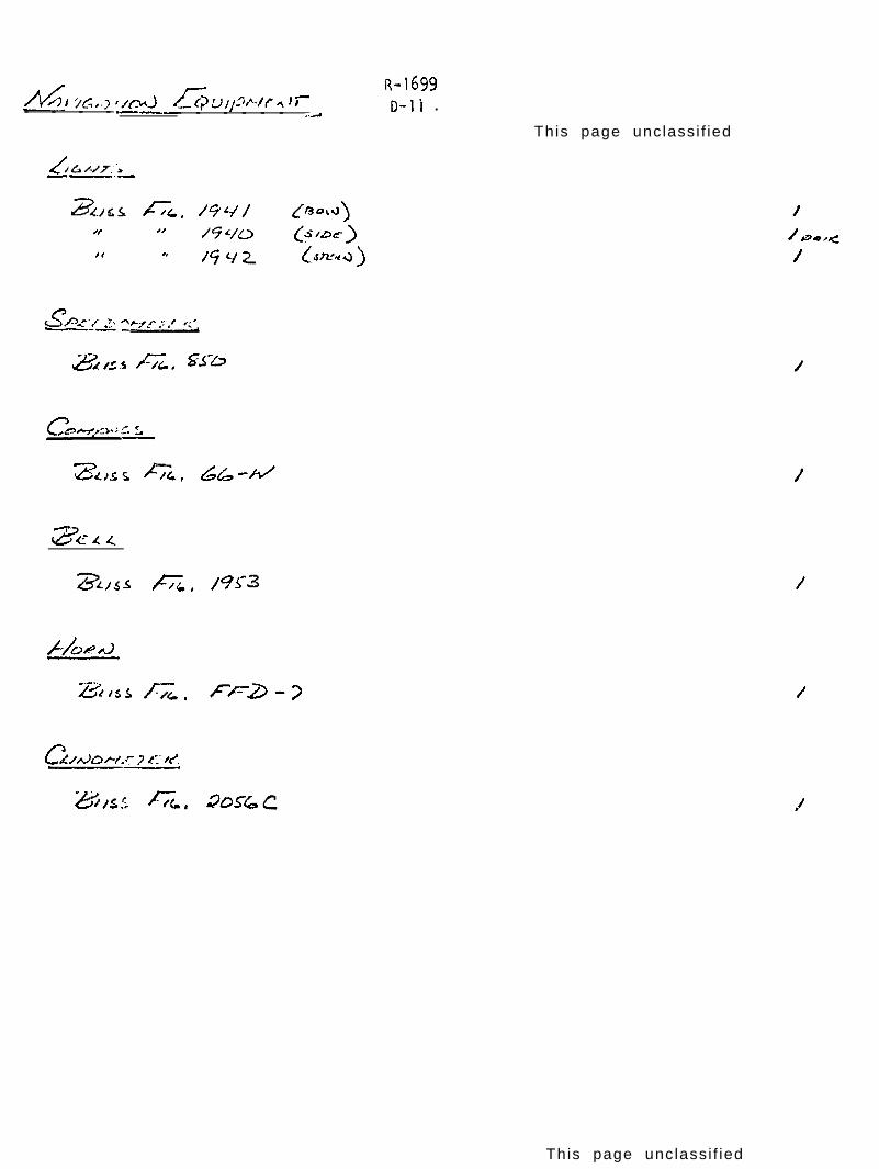
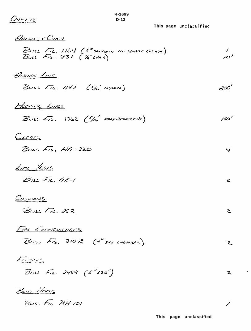
EQUtPMENT L I S T
T h i s p a g e u n c l a s s i f i e d
T h i s p a g e u n c l a s s i f i e d

This page unclassified
2
This page unclassified

R-l 699D-3
T h i s p a g e u n c l a s s i f i e d
T h i s p a g e u n c l a s s i f i e d

T h i s p a g e u n c l a s s i f i e d
T h i s p a g e u n c l a s s i f i e d

t
This page unclassi f ied

R-1699D-6 '
T h i s p a g e u n c l a s s i f i e d
T;.,s p a g e u n c l a s s i f i e d

s-1699D-7
T h i s p a g e u n c l a s s i f i e d
T h i s p a g e u n c l a s s i f i e d

R-1699D-8
‘illis page unclassified
/
This page unclassified

~-1699D-5
T h i s p a g e u n c l a s s i f i e d
T h i s p a g e u n c l a s s i f i e d

R- 16%D-10
This page unclassified
e
4
2
2
This page unclassified
(\/ /-- ~-1699e-7, ;/c:,.J.1/d ,QuIjlr-/r~ Ii- D-Ii .- - - - .A--- - - - - - ..C
This page unclassi f ied
This page unclassi f ied
R-1699D-12
This page unclassified
Y
2 ”
This page unclassified

R-l 699E - l
T h i s p a g e u n c l a s s i f i e d
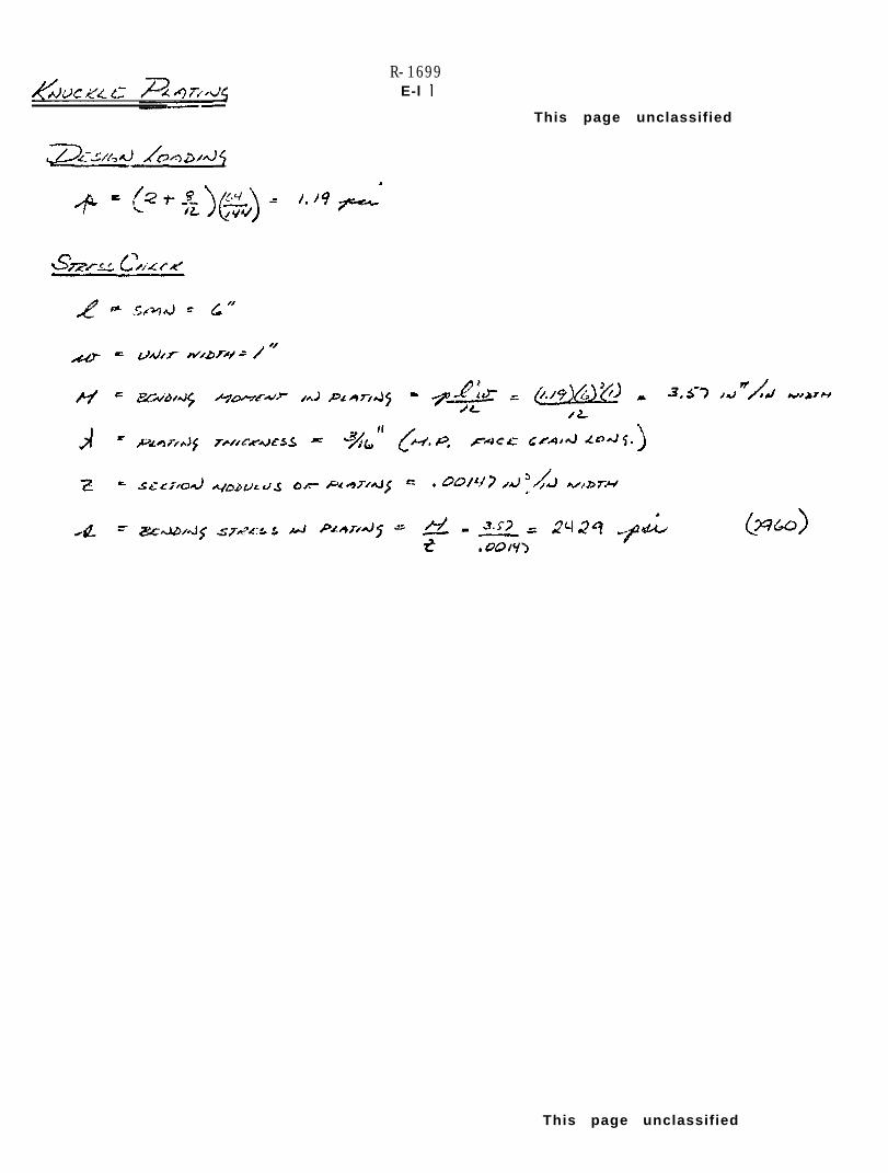
STRUCTURAL ANALYSES

R-1699E-Z-
This page unclassified
This page unclassified

Thi.s page unclassi f ied
- ’ i .

R- 1699E-4
This page unclassified
This page unclassified

R- 1699E - 5
This page unclassified
This page unclassified

R-1699E-6
This page unclassified
This page unclassified

R-1699
-_--_. --__ ___ . .--.--“I_This page unclassified
This page unclassified

T h i s page u n c l a s s i f i e d
This page unclassified

R-1699
E - 9This page unclassified
This page unclassified

R-1699E-10.
This page unclassified
This page unclassified
R-1699E-l I
This page unclassified
This page unclassified

R-1699E-12
T h i s p a g e u n c l a s s i f i e d
T h i s p a g e u n c l a s s i f i e d

R-1699E-13
This page unclassified
This page unclassified

R-1699E-14.
Thi,s page unclassi f ied
This page unclassi f ied

R - 1 6 9 9E-15
Tllis page unclassified
This page unclassified

R-1699E-16
This page unclassified
This page unclassified

tt.- lt?YYE-17
T h i s p a g e u n c l a s s i f i e d

T h i s page u n c l a s c i f ied
T h i s p a g e u n c l a s s i f i e d

is page unclassif ied
This page unclassified

R- 1099E-20
This page unclassified

il- 1699E-21
T h i s paye unciassified
This page unclassi f ied

R-1699E-22
T h i s p a g e u n c l a s s i f i e d
T h i s p a g e u n c l a s s i f i e d

u - 1 6 9 9E-23 .
This page unclassified
This page unclassified

q-1699E-24
T h i s p a g e u n c l a s s i f i e d
z-= ,007
T h i s p a g e u n c l a s s i f i e d

R- 1699E - 2 5
i% 71’-- T h i s p a g e u n c l a s s i f i e d
T h i s p a g e u n c l a s s i f i e d
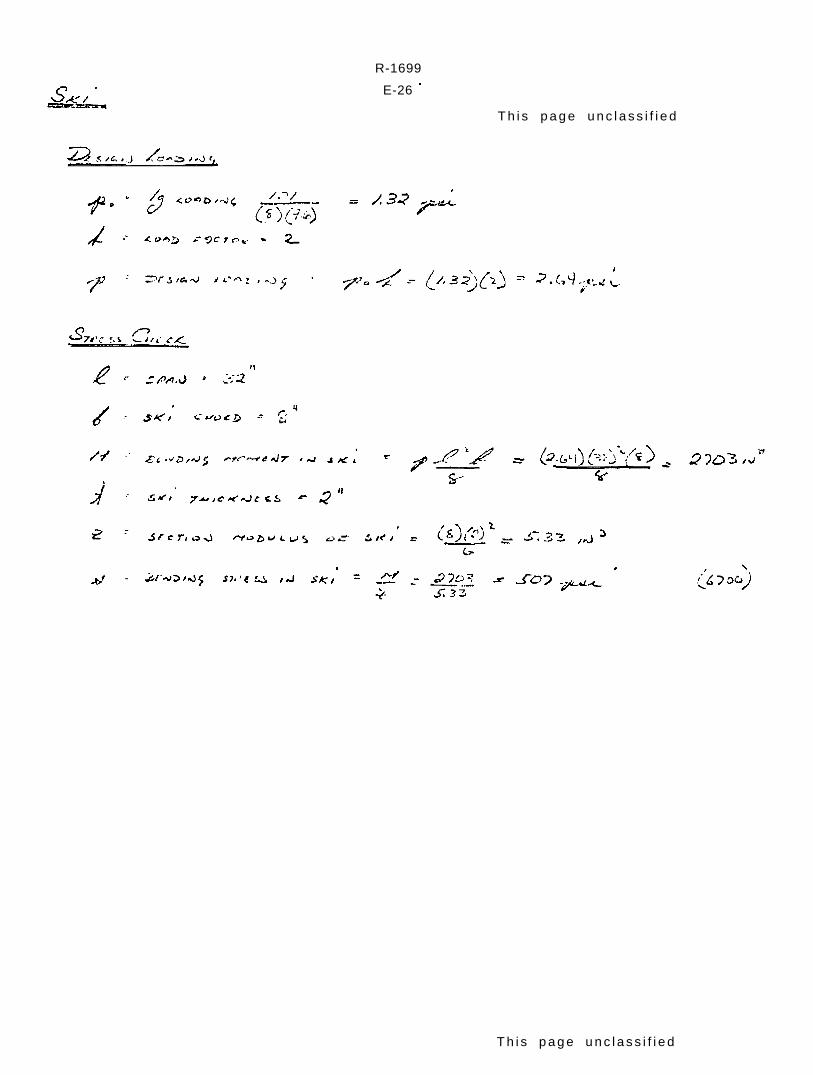
R-1699
E-26 -
T h i s p a g e u n c l a s s i f i e d
T h i s p a g e u n c l a s s i f i e d

R - l 699F - l
T h i s p a g e u n c l a s s i f i e d
MEASURED WE I GHTS
T h i s p a g e u n c l a s s i f i e d

R-1699F
-2
Th
is p
ag
e
un
classifie
d
Th
is p
ag
e
un
classifie
d

R-1699F-3
This page. unclassified
This page unclassified

R-1699G-l
T h i s p a g e u n c l a s s i f i e d
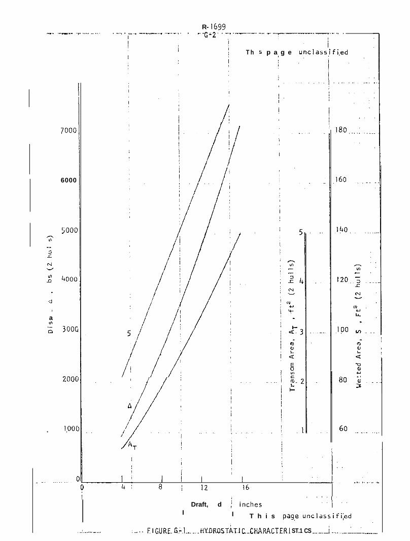
HYDROSTATICS
T h i s p a g e u n c l a s s i f i e d
I.. .--^-- .-,
1
/I
7000
6000
so00-
m--1tiV
_o” l+ooo
L
‘J,
a
*: 3ooc
zooc
. l,OO(
9
,I-2
R- 1699/ _/..” . .-.._.. -_---.-* .._..._,.” . “._ _ .-.. _______.. -r. _. _*.l_--.__r.-. -.G”2‘ / .
,
T h
i; ., Is p a g e unclassifi,ed :
160
60 ._._._ - . . . .
I 1 1 Ij 16
j, -- __. ,-_.- .-8 ; 12 I
I,i Draft, d : i riches
/ “::‘..I
/ I I T h i s pag,e unclassifi;ed! 4
- ___. -... i .- . . F: I CURE. I%-I__..___ HY.5RDST~T.l L-CkiARACTERI ST.1 CS ----.i ..__ -_.-X-..--_

R-16
99
3-3
Th
is pa
ge
unclass
ified
30wxz-&I-I,W
I
z,
aW10m
Th
is paqe
un
classif
ierj

T h i s p a g e u n c l a s s i f i e d
T h i s p a g e u n c l a s s i f i e d

T h i s p a g e u n c l a s s i f i e d

~-1699c-6
T h i s p a g e u n c l a s s i f i e d
Thi; page urxlassi f ied

R - 1 6 9 9G - 7
This page unclassif icd
T h i s p a g e u n c l a s s i f i e d

This page unclassi Fied
T h i s p a g e u n c l a s s i f i e d

T h i s p a g e u n c l a s s i f i e d

R - 1 6 3 9‘i- 1
T h i s page u n c l a s s i f i e d
ESTIMATED DRAG
T h i s p a g e u n c l a s s i f i e d

s-1699
__
___C
_.I.l
_.
_._-
_-.---
-.
-..------.--.
--..
-_
--H
e2---.‘~
-‘---
--I-
:-~
- :----
--
I/*I
!i
: e
ON
~i5EN
TIjU/
I1
I
. . ..
_.-. _... -..
Default
Default

R - 1 6 9 9H-3 CONFIDENTIAL
Y’l//
7
CONFIDENTIAL
Default
Default

CQNFLDEN
Default
Default

s.
R-1699
H-5
CO
NF
IDE
NT
IAL
Default
Default

R-1
69
9H
-4
Th
is
pa
ge
u
nc
las
sifie
d
Th
is
pa
ge
u
nc
las
sifie
d

R-16!%Ii- ‘/ CONF9DENWU
Default
Default

R-1699H-8 CONFIDENTIAL
CONFlDH’ULMm
Default
Default

RI,, ~,‘;‘/j;y-y, .-C7?,;,-----., ____&- -.A$
n-1699H-Y CQNFIDENTIAL
Default
Default

R-1639H-IO-
ONFIDENTI
Default
Default

R-1699H - i ; CONFdDENTIAL
Default
Default
Default

y-1699H-12. . CONFIDENTIIAL
Default
Default

R - 1 6 9 9l - l
This p a g e unclCassified
EST1 NATED THRIIST AND TORQUE
T h i s p a g e u n c l a s s i f i e d

R.-l 699l - 2
This page unclassified
PROPELLER CHARACTERISTICS
The propei lers were modif ied subsequent to completing the bui Ider’s
trials by increasing the pitch and bending the trailing edge dotin to form
a “Full cupIt blade contour. The characteristics of the original and modi-
f ied propel le t are 1 istcd in the following tabic:
Original(Columbian Bronze
“Make” Sty 1 e)
Modif ied
Diameter, in
P i t c h ( e f f e c t i v e )
P/D
B!ade Area Ratio
Rotation
Material
135 13s
16 18.9(estimated)
1.2 1 . 4
0.77 0.77
Left Hand Left Hand
Manganese Bronze Many. Bronze
THRUST AND TORQUE ESTIMATES
Axial Flow
Estimates of thrust and torque for the two alternative versions of
the propellers were made on the basis of data published by Gawn and
Burrill, “Effect of Cavitation on the Performance of a Series of 16-in
Model Propellers,” Transactions, I n s t i t u t i o n o f N a v a l A r c h i t e c t s , 1957.
“Maps’; of propeller thrust and torque, as ir function of propeller RPM
and vessel speed for axial flow conditions taking account of the develop-
ment of cavitation, are given in the accompanying Figures i-2 to l-5.
Lines of constant advance coefficient, J = speed of advance/ (Di am x rps) ,
are included in these figures.
.!nc!ined S h a f t E f f e c t s
Only a very few published investigations treat the effect of shaft
inclination on the complete system of forces acting on marine propellers
This page unclassified

Thii page unclassified
and even fewer include effects of cavitation, The only complete set of
er.pc r i mc:n t a 1 ins;c:stiqations of propeller performance characteristics
with incl incd shaft and cavitation wab recently reported by Peck and
Moore to the Spring Meeting of the Society of Na;.al Architects and Marine
Enginc,?rs i n A p r i l 1973. This refcrencc gives complete tabulated informa-
t i o n f o r four c~~mr:~~rcial-type p r o p e l l e r s , having four blades and differing
p i t c h r a t i o s . The force 3 i agram in the sketch below indicates the method
o f resolviny the f o r c e comporlcnts a n d o f p r e s e n t i n g r e s u l t s :
Sket .ch l - l , From Peck and Moore Paper
Comparable results for t hree-bladed propel lers (or, indeed, any
other propellers) are not yet avai iable. Consequent ly , for the purposes
of the present investigations an attempt wil l be made to general ize
these results as much as poss ble for purposes of analysis of results of
tests with the l/3-scale model of SKI-CAT. Two kinds of analysis problems
w i l l b e c o n s i d e r e d : ( 1 ) t h e case of the builder’s trials, where vessel
This page unclassified

This page unclassified
speed and propeller RPM are known and it is desired to estimate the pro-
peller thrust for preliminary comparison with the predicted drag, and (2)
the case of the comprehensive trials, where vessel speed, propeller RPM
and shaft torque are measured and it is desired to derive the propeller
thrust . These cases wili be considered separately.
(1) Known SF+ ed and RPM
In this case, one can obtain the evpected thrust developed by the
propel let-s, in axial flow, from the curves presented in the previous sec-
t i o n , which include a dependency on cavitation index, To estimate the
effects of shaft inclination on thrust developed, the data presented by
Peck and Moore have been plotted in Figure l-6 in the form of the ratio
of the horizontal component of thrust at 15-deg shaft inclination to that
at O-dcg inclination as a function of J/i (xl-‘$1 ip”) f o r o n e o f t h e
propellers tested. This generalized presentation shows that in the region
,,I = 0.85, which is approximately the operating point for the ski-cat
propel lers, the axial-flow thrust should be modified by a factor which de-
pends on the craft speed (cavitation index). Figure I-7 shows the multi-
plying factor as a function of craft speed corresponding to J/5= 0.85 for
three propel lers : there are differences among the rzsults, but the trends
are genera1 ly simi lar. The amount of scatter of the multiplying factor is
rather greater than hoped for, but it appears preferable to apply the cor-
rection, especially at higher speed, instead of ignoring the effect of
s h a f t i n c l i n a t i o n .
Other factors could affect the thrust developed by the propeller;
for instance, a possibility of air-drawing down the inclined propeller
shaf t . It is not possible to account for factors such as these for the
present analyses. However, the approximate analysis described above has
been used to analyze the extended builder’s trials results (presented in
t h e t e x t o f t h i s r e p o r t ) .
(2) Measured Torque, RPM and Speed
For the comprehensive trials, torsion meters will be fitted in the
propeller shaft, inboard of the stllffing box. With this measured data
improved estimates of thrust can be oht,Tined since both thrust and torque
This page unclassified

R - 1 6 8r -5
This page unclassified
are composed of suitably resolved components of the blade element lift
and drag.
The axial-flow thrust for a given torque, RPM and speed may be
estimated by correcting the thrust obtained from Figure l-5 for the meas-
ured speed and RPM by the ratio of measured torque to the torque obtained
from Figure i-I+ for the same speed and RPM. This value should then be cor-
rected further to approximately account for shaft inclination affects.
The final estimate would be expressed as
T(V,RP”) in=,T
corr, incl = T(V,R�M)a⌧ia, l )�{T(v RPM)
Q(V,RPM)axia,
, axiaQ(V,RPM) incl
or,Tcorr, incl
= T(V,RPM)axia,*
where
T(V,R’M)axial is found in Figure
Q(V,RPM) axial is found in Figure i-5 (modified prop)
and the ratio (To/Q) incl'(TD'Q)axiadata of Peck and Moore. Figure 1-8and advance coefficient on this rat
l-4 (modified prop)
must be estimated from the published
shows the effect of cavitation index
o f o r IS-deg s h a f t i n c l i n a t i o n f o r o n e
of the propellers tested, F i g u r e l-9 g i v e s v a l u e s o f t h i s r a t i o a s a
function of speed for three propellers, all at J/i= 0.85. It is suggested
that these results be applied for analyses of comprehensive trials results.
This page unclassified

1750 11505 -
1250 -
xl
I4.J*2g 1000
:lk
750 -500 -2.?0
R-1699i-6 CONFIDENTIAL
ORIGII\:AL PROPELLER(Builder's Trials)
AXIAL-FLOWCAVITATI,ON.TUNNEL~.TESTS
(Gawn-Burrill)Dim * 13.5”P/D t 1.20
AE/Ac = 0.80
0 0 ,L- lA.-dl-.--dJ I1600 2GOO r c .-- ' 3000 4000
Prcpeller RPM
FIGURE 1-2. ORIGINAL PROPELLER(BUILDER'S TRIALS) CONFIDENTIAL
Default
Default
400
350
300
250
9Ic-lcc-
2 200Lg
8lk
150
100
50
a
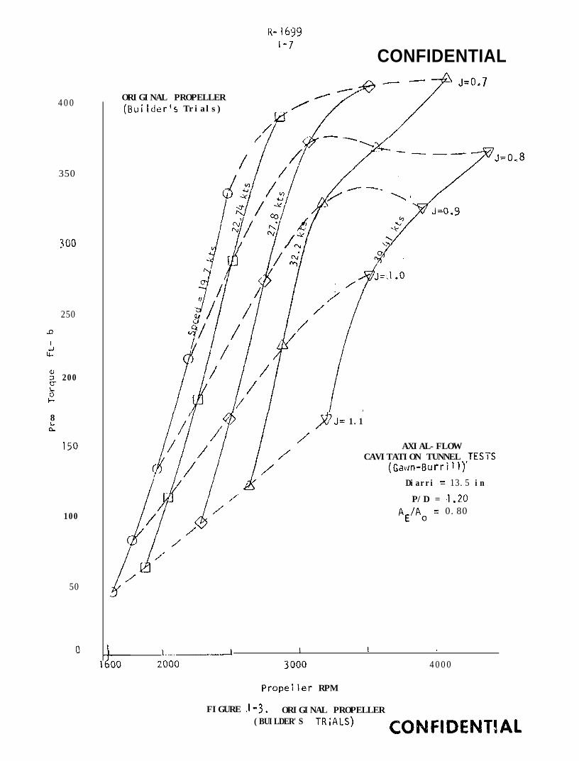
ii- 1699r-7
CONFIDENTIAL
ORIGINAL PROPELLER(Builder's Trials)
J=0.7
P J= 1.1
/ AXIAL-FLOWI CAVITATION TUNNEL ,TESTS
(Gawn-Burrill)
Diarri = 13.5 in
P/D = ,1.20
AE/Ao = 0.80
L-L I 1
2000 3000
Prqpe;ler RPM
FIGURE d-3. ORIGINAL PROPELLER
I
4000
(BUILDER'S TR;ALS) FIDENTSAL
Default
Default
250 _
i
R-1699i-8
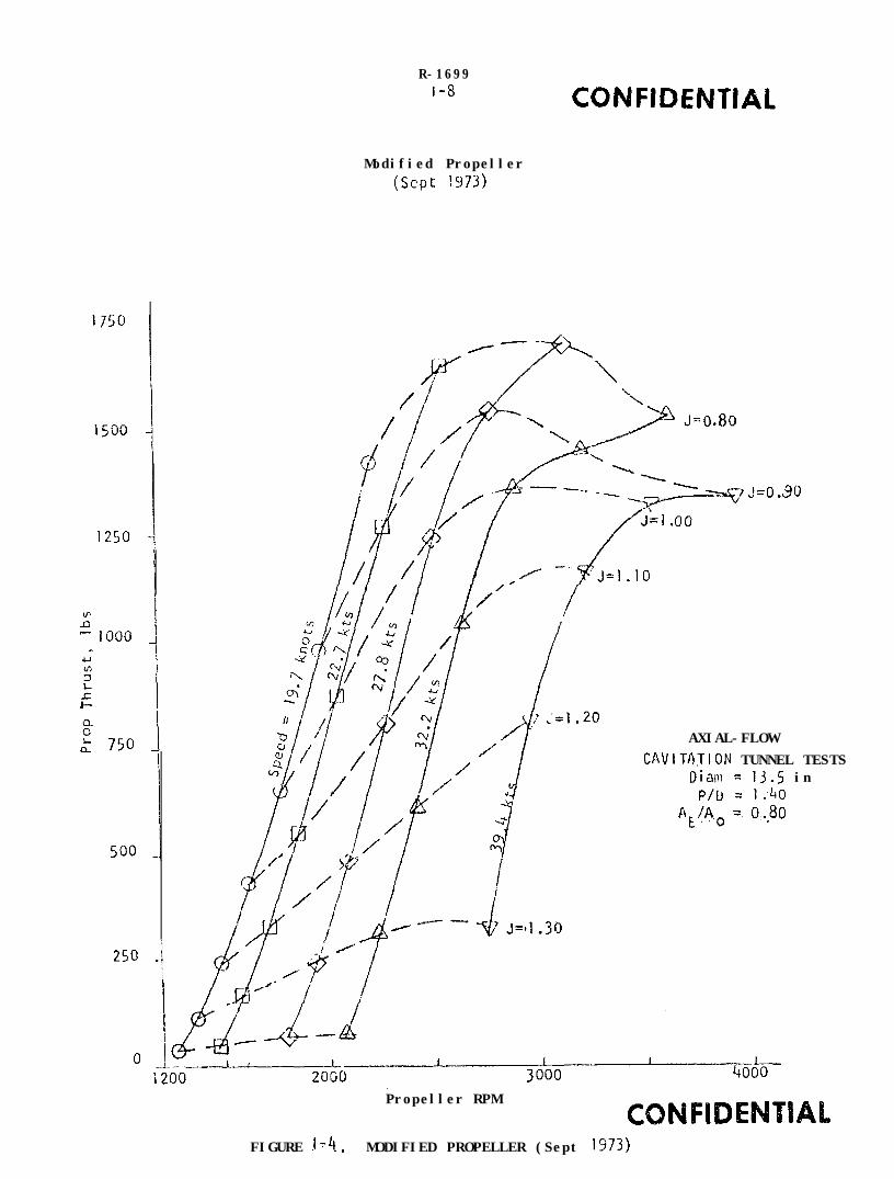
Modified Propeller(Scpt 1973)
AXIAL-FLOWCAVlTA,TlON TUNNEL TESTS
Diaw - 13.5 inP/b = li40"& =. 0.~80
Propeller RPMCQNFIDENTI
FIGURE 4-4. MODIFIED PROPELLER (Sept 1973)
Default
Default

Mocli firbcl Prnpcl lcrI^ ,,,-.?\
/ J=l.GO
,.
/' /- J=l.lOI
I
IJci
i
AXIAL-FLOWCA\/1 TATI nN TUNNEL TESTS
Burrill)Disw= 13~.5 inP/D:= I.!+0
AE/AO = 3.80
-..-1 0 2000
I J - I - - -3000 G&l-
Prop, RPMCONFIDENTI
FIGURE l-5. MOD1 FI FO PdOPELLER (Se@ 1973)
Default
Default

I .2
rg.- 1 .IX(0
z-u 1.0\
0Ln
2 0 . 9V
0 . 8n
R-1699I-IO C O N F I D E N T I A L ’
C a v . I ncleq,
L314.7 ' ; \ '
0 ::;
0 . 7 0 0 . 8 0 0 . 9 0
J/(P/D) (23 I-‘%1 ip")
1 . 0 0
FIGURE 16. EFFECT OF CAVITATION INDEX AND ADVANCE COEFF IC I ENTON RATIO OF THRUST FOR 15-DEG SHAFT INCLINATION TOT H R U S T I N A X IAL F L O W . R E F : P E C K A N D M O O R E , PRO-P E L L 4 5 3 0 , P / D = 1.19.
1 . 2
O 0 U s e f o r estimatinq S K I - C A T t h r u s t
d 10 2 0 3 0
S p e e d , k n o t s
F I G U R E i-.3. EFFECT OF SPEED ON RATIO OF THRUST FOR 15-DEG SHAFTI N C L I N A T I O N T O T H R U S T 1% A X I A L F L Q W , J/(P/D) = 0 . 8 5 .
CC)NFIDEMTIAL
Default
Default

Cav. lndey. b0 14.7 ’ .,
P 3aQ’
\
2 0.75 1>5 IL I0.5 I
o**----~~ 7m . o 8.J/(?/D) (=l~-~'slip") \
\
FIGURE l-.8.. EFFECT OF CAVITATION INDEX AND \b
ADVANCE COEFFICIENT ON THRUST-TO- \TORQUE RATIO IN INCLINED FLOW. mREF: PECK AND MOORE, PROPELLER 4531, P/D = 1.39
P/D
c-) 1.00r-J 1.19
0.8 .-0 10 20 30 40
Speed, knots
FIGURE ly-9. , EFFECT OF SPEED ON THRUST TO TORQUE RATIO ININCLINED FLOW, J/(P/D) = 0.85.
Default
Default

R- 1699
This page unclassified
Contract NOOO14-67-A-0202-0031
DISTRIBUTION LIST
1. Department of the NavyNaval Ship Systems CommandCode 03222Washington, D. C. 20360
2. Department of the NavyOffice of Naval ResearchScientific Officer (Code 438)Arlington, Virginia 22217
3. Department of the NavyOffice of Naval Research495 Summer StreetBoston, Massachusetts 02210
4. Di rectorDefense Documentation CenterCameron S t a t i o nAlexandria, Virginia 22314
5. Department of the NavyNaval Ship Research & Development CenterCode 114Bethesda, tiaryland 20034
(3)
(1)
(1)
(2)
(20)
This page unclassified
Related Documents