1 Description Power supply unit QUINT-PS/1AC/24DC/40 © PHOENIX CONTACT Data sheet QUINT POWER power supply units – Superior system avail- ability with SFB technology Compact power supply units of the new QUINT POWER generation maximize the availability of your system. With the SFB technology (Selective Fuse Breaking Technology), six times the nominal current for 12 ms, even the standard power circuit-breakers can now also be triggered reliably and quickly. Faulty current paths are switched off selec- tively, the fault is located and important system parts con- tinue to operate. Comprehensive diagnostics are provided through constant monitoring of output voltage and current. This preventive function monitoring visualizes critical oper- ating modes and reports them to the control unit before an error can occur. Features Superior system availability – Using SFB technology (6 times the nominal current for 12 ms), circuit breakers are tripped quickly and impor- tant system parts remain in operation – Through the preventive monitoring of output voltage and current and the transmission of critical operating states to the controller – Through reliable starting of difficult loads with POWER BOOST power reserve – Long mains buffering > 35 ms – high MTBF > 530,000 h (40 °C) Worldwide use – Input voltage from 85 V AC ... 264 V AC – Input voltage from 90 V DC ... 350 V DC Flexible use – Adjustable output voltage – Can be used in Class I, Division 2, Groups A, B, C, D (Hazardous Location) ANSI-ISA 12.12 Make sure you always use the latest documentation. It can be downloaded from the product at phoenixcontact.net/products . 104317_en_02 2015-09-11

Welcome message from author
This document is posted to help you gain knowledge. Please leave a comment to let me know what you think about it! Share it to your friends and learn new things together.
Transcript
1 Description
Power supply unit
QUINT-PS/1AC/24DC/40
© PHOENIX CONTACT
Data sheet
QUINT POWER power supply units – Superior system avail-
ability with SFB technology
Compact power supply units of the new QUINT POWER
generation maximize the availability of your system. With
the SFB technology (Selective Fuse Breaking Technology),
six times the nominal current for 12 ms, even the standard
power circuit-breakers can now also be triggered reliably
and quickly. Faulty current paths are switched off selec-
tively, the fault is located and important system parts con-
tinue to operate. Comprehensive diagnostics are provided
through constant monitoring of output voltage and current.
This preventive function monitoring visualizes critical oper-
ating modes and reports them to the control unit before an
error can occur.
Features
Superior system availability
– Using SFB technology (6 times the nominal current for
12 ms), circuit breakers are tripped quickly and impor-
tant system parts remain in operation
– Through the preventive monitoring of output voltage
and current and the transmission of critical operating
states to the controller
– Through reliable starting of difficult loads with POWER
BOOST power reserve
– Long mains buffering > 35 ms
– high MTBF > 530,000 h (40 °C)
Worldwide use
– Input voltage from 85 V AC ... 264 V AC
– Input voltage from 90 V DC ... 350 V DC
Flexible use
– Adjustable output voltage
– Can be used in Class I, Division 2, Groups A, B, C, D
(Hazardous Location) ANSI-ISA 12.12
Make sure you always use the latest documentation.
It can be downloaded from the product at phoenixcontact.net/products.
104317_en_02 2015-09-11

QUINT-PS/1AC/24DC/40
104317_en_02 PHOENIX CONTACT 2
2 Table of contents
1 Description .............................................................................................................................. 1
2 Table of contents ..................................................................................................................... 2
3 Ordering data .......................................................................................................................... 3
4 Technical data ......................................................................................................................... 4
5 Safety regulations and installation notes.................................................................................. 8
6 Structure.................................................................................................................................. 9
6.1 Block diagram..................................................................................................................... 9
6.2 Function elements ............................................................................................................... 9
6.3 Convection....................................................................................................................... 10
6.4 Mounting position .............................................................................................................. 11
7 Mounting/removal.................................................................................................................. 12
7.1 Normal mounting position .................................................................................................... 12
7.2 Mounting position rotated 90° ............................................................................................... 12
7.3 Mounting on a DIN rail ........................................................................................................ 12
7.4 Removal from the DIN rail .................................................................................................... 12
8 Device connection ................................................................................................................. 13
8.1 Network types................................................................................................................... 13
8.2 AC input .......................................................................................................................... 13
8.3 DC output ........................................................................................................................ 14
9 SFB technology ..................................................................................................................... 14
9.1 Circuit breaker tripping characteristics .................................................................................... 14
9.2 Installation notes ............................................................................................................... 14
9.3 SFB configuration .............................................................................................................. 15
10 Signaling................................................................................................................................ 17
10.1 Floating switch contact........................................................................................................ 17
10.2 Active signal outputs........................................................................................................... 17
10.3 Signal loop....................................................................................................................... 18
11 Derating................................................................................................................................. 18
11.1 Temperature response........................................................................................................ 18
12 Operating modes................................................................................................................... 18
12.1 Series operation ................................................................................................................ 18
12.2 Parallel operation............................................................................................................... 18
12.3 Redundant operation .......................................................................................................... 19
12.4 Increasing power ............................................................................................................... 19

QUINT-PS/1AC/24DC/40
104317_en_02 PHOENIX CONTACT 3
Description Type Order No. Pcs./Pkt.
Primary-switched QUINT POWER power supply for DIN rail mounting with
SFB (Selective Fuse Breaking) Technology, input: 1-phase, output: 24 V
DC/40 A
QUINT-PS/1AC/24DC/40 2866789 1
3 Ordering data
Accessories Type Order No. Pcs./Pkt.
Universal DIN rail adapter UTA 107 2853983 5
Universal wall adapter UWA 130 2901664 1
Universal wall adapter UWA 182/52 2938235 1
The fan for QUINT-PS/1AC and .../3AC can be mounted without the need
for tools or other accessories. By using the fan, optimum cooling is ensured
at high ambient temperatures or if the mounting position is rotated.
QUINT-PS/FAN/4 2320076 1
DIN rail diode module 12-24 V DC/2x20 A or 1x40 A. Uniform redundancy
up to the consumer.
QUINT-DIODE/12-24DC/2X20/1X40 2320157 1
Active QUINT redundancy module for DIN rail mounting with ACB technol-
ogy (Active Current Balancing) and monitoring functions, input: 24 V DC,
output: 24 V DC/2 x 20 A or 1 x 40 A, including mounted universal DIN rail
adapter UTA 107/30
QUINT-ORING/24DC/2X20/1X40 2320186 1
Thermomagnetic device circuit breaker, 1-pos., tripping characteristic
SFB, 1 PDT contact, plug for base element.
CB TM1 1A SFB P 2800836 1
Thermomagnetic device circuit breaker, 1-pos., tripping characteristic
SFB, 1 PDT contact, plug for base element.
CB TM1 2A SFB P 2800837 1
Thermomagnetic device circuit breaker, 1-pos., tripping characteristic
SFB, 1 PDT contact, plug for base element.
CB TM1 3A SFB P 2800838 1
Thermomagnetic device circuit breaker, 1-pos., tripping characteristic
SFB, 1 PDT contact, plug for base element.
CB TM1 4A SFB P 2800839 1
Thermomagnetic device circuit breaker, 1-pos., tripping characteristic
SFB, 1 PDT contact, plug for base element.
CB TM1 5A SFB P 2800840 1
Thermomagnetic device circuit breaker, 1-pos., tripping characteristic
SFB, 1 PDT contact, plug for base element.
CB TM1 6A SFB P 2800841 1
Thermomagnetic device circuit breaker, 1-pos., tripping characteristic
SFB, 1 PDT contact, plug for base element.
CB TM1 8A SFB P 2800842 1
Thermomagnetic device circuit breaker, 1-pos., tripping characteristic
SFB, 1 PDT contact, plug for base element.
CB TM1 10A SFB P 2800843 1
Thermomagnetic device circuit breaker, 1-pos., tripping characteristic
SFB, 1 PDT contact, plug for base element.
CB TM1 12A SFB P 2800844 1
Thermomagnetic device circuit breaker, 1-pos., tripping characteristic
SFB, 1 PDT contact, plug for base element.
CB TM1 16A SFB P 2800845 1
Our range of accessories is being continually extended, our current range can be found in the download area.
QUINT-PS/1AC/24DC/40
104317_en_02 PHOENIX CONTACT 4
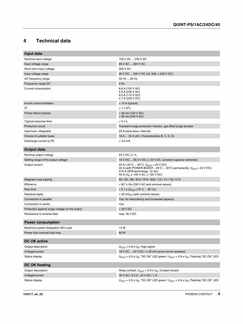
4 Technical data
Input data
Nominal input voltage 100 V AC ... 240 V AC
Input voltage range 85 V AC ... 264 V AC
Short-term input voltage 300 V AC
Input voltage range 90 V DC ... 300 V DC (UL 508: ≤ 250 V DC)
AC frequency range 45 Hz ... 65 Hz
Frequency range DC 0 Hz
Current consumption 8.8 A (120 V AC)
4.6 A (230 V AC)
9.5 A (110 V DC)
4.7 A (220 V DC)
Inrush current limitation < 15 A (typical)
I2t < 1.7 A
2s
Power failure bypass > 35 ms (120 V AC)
> 35 ms (230 V AC)
Typical response time < 0.7 s
Protective circuit Transient surge protection Varistor, gas-filled surge arrester
Input fuse, integrated 20 A (slow-blow, internal)
Choice of suitable fuses 16 A ... 20 A (AC: Characteristics B, C, D, K)
Discharge current to PE < 3.5 mA
Output data
Nominal output voltage 24 V DC ±1 %
Setting range of the output voltage 18 V DC ... 29.5 V DC (> 24 V DC, constant capacity restricted)
Output current 40 A (-25°C ... 60°C, UOUT = 24 V DC)
45 A (with POWER BOOST, -25°C ... 40°C permanently, UOUT = 24 V DC)
215 A (SFB technology, 12 ms)
45 A (UIn ≥ 100 V AC, ≥ 120 V DC)
Magnetic fuse tripping B2 / B4 / B6 / B10 / B16 / B25 / C2 / C4 / C6 / C13
Efficiency > 92 % (for 230 V AC and nominal values)
Rise time < 0.1 s (UOUT (10 % ... 90 %))
Residual ripple < 30 mVPP (with nominal values)
Connection in parallel Yes, for redundancy and increased capacity
Connection in series Yes
Protection against surge voltage on the output < 35 V DC
Resistance to reverse feed max. 35 V DC
Power consumption
Maximum power dissipation NO-Load 14 W
Power loss nominal load max. 80 W
DC OK active
Output description UOUT > 0.9 x UN: High signal
Voltage/current 18 V DC ... 24 V DC / ≤ 20 mA (short-circuit resistant)
Status display UOUT > 0.9 x UN: "DC OK" LED green / UOUT < 0.9 x UN: Flashing "DC OK" LED
DC OK floating
Output description Relay contact, UOUT > 0.9 x UN: Contact closed
Voltage/current 30 V AC / 0.5 A , 24 V DC / 1 A
Status display UOUT > 0.9 x UN: "DC OK" LED green / UOUT < 0.9 x UN: Flashing "DC OK" LED

QUINT-PS/1AC/24DC/40
104317_en_02 PHOENIX CONTACT 5
POWER BOOST, active
Output description IOUT < IN: High signal
Voltage/current 18 V DC ... 24 V DC / ≤ 20 mA (short-circuit resistant)
Status display IOUT > IN: LED "BOOST" yellow
General data
Insulation voltage input/output 4 kV AC (type test)
2 kV AC (routine test)
Insulation voltage input / PE 3.5 kV AC (type test)
2 kV AC (routine test)
Insulation voltage output / PE 500 V DC (routine test)
Degree of protection IP20
Protection class I
MTBF (IEC 61709, SN 29500) > 530000 h (40°C) / > 900000 h (25 °C)
Side element version Aluminum
Hood version Galvanized sheet steel, free from chrome (VI)
Dimensions W / H / D (state of delivery) 180 mm / 130 mm / 125 mm
Dimensions W / H / D (90° turned) 122 mm / 130 mm / 183 mm
Weight 3.3 kg
Ambient conditions
Ambient temperature (operation) -25 °C ... 70 °C (> 60 °C Derating: 2,5 %/K)
Ambient temperature (start-up type tested) -40 °C
Ambient temperature (storage/transport) -40 °C ... 85 °C
Max. permissible relative humidity (operation) ≤ 95 % (at 25 °C, non-condensing)
Maximum altitude 4000 m
Vibration (operation) < 15 Hz, amplitude ±2.5 mm (according to IEC 60068-2-6)
15 Hz ... 150 Hz, 2.3g, 90 min.
Shock 30g in each direction, according to IEC 60068-2-27
Pollution degree in acc. with EN 60950-1 2
Climatic class 3K3 (in acc. with EN 60721)
Standards
Electrical Equipment for Machinery EN 60204-1
Electrical safety (of information technology equipment) IEC 60950-1/VDE 0805 (SELV)
Electronic equipment for use in electrical power installations EN 50178/VDE 0160 (PELV) / Overvoltage category III
SELV IEC 60950-1 (SELV) and EN 60204-1 (PELV)
Safe isolation DIN VDE 0100-410
DIN VDE 0106-101
Protection against electric shock, basic requirements for safe isolation in
electrical equipment
EN 50178
Limitation of mains harmonic currents EN 61000-3-2
Medical standard IEC 60601-1, 2 x MOOP
Rail applications EN 50121-4
QUINT-PS/1AC/24DC/40
104317_en_02 PHOENIX CONTACT 6
Approvals
UL UL Listed UL 508
UL/C-UL Recognized UL 60950-1
UL ANSI/ISA-12.12.01 Class I, Division 2, Groups A, B, C, D (Hazardous Loca-
tion)
CSA CSA-C22.2 No. 107.1-01
SIQ CB Scheme
Shipbuilding Germanischer Lloyd (EMC 2), ABS, LR, RINA, NK, DNV, BV
BV-CPS
Current approvals/permissions for the product can be found in the download area under phoenixcontact.net/products.
QUINT-PS/1AC/24DC/40
104317_en_02 PHOENIX CONTACT 7
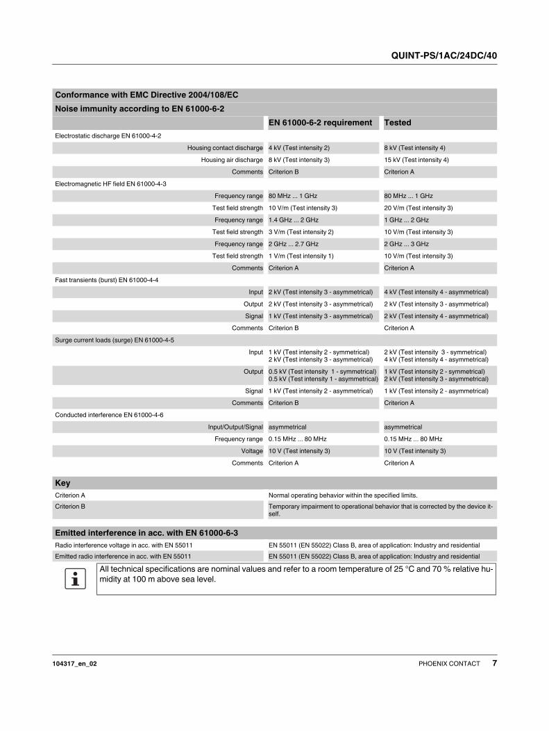
Conformance with EMC Directive 2004/108/EC
Noise immunity according to EN 61000-6-2
EN 61000-6-2 requirement Tested
Electrostatic discharge EN 61000-4-2
Housing contact discharge 4 kV (Test intensity 2) 8 kV (Test intensity 4)
Housing air discharge 8 kV (Test intensity 3) 15 kV (Test intensity 4)
Comments Criterion B Criterion A
Electromagnetic HF field EN 61000-4-3
Frequency range 80 MHz ... 1 GHz 80 MHz ... 1 GHz
Test field strength 10 V/m (Test intensity 3) 20 V/m (Test intensity 3)
Frequency range 1.4 GHz ... 2 GHz 1 GHz ... 2 GHz
Test field strength 3 V/m (Test intensity 2) 10 V/m (Test intensity 3)
Frequency range 2 GHz ... 2.7 GHz 2 GHz ... 3 GHz
Test field strength 1 V/m (Test intensity 1) 10 V/m (Test intensity 3)
Comments Criterion A Criterion A
Fast transients (burst) EN 61000-4-4
Input 2 kV (Test intensity 3 - asymmetrical) 4 kV (Test intensity 4 - asymmetrical)
Output 2 kV (Test intensity 3 - asymmetrical) 2 kV (Test intensity 3 - asymmetrical)
Signal 1 kV (Test intensity 3 - asymmetrical) 2 kV (Test intensity 4 - asymmetrical)
Comments Criterion B Criterion A
Surge current loads (surge) EN 61000-4-5
Input 1 kV (Test intensity 2 - symmetrical)
2 kV (Test intensity 3 - asymmetrical)
2 kV (Test intensity 3 - symmetrical)
4 kV (Test intensity 4 - asymmetrical)
Output 0.5 kV (Test intensity 1 - symmetrical)
0.5 kV (Test intensity 1 - asymmetrical)
1 kV (Test intensity 2 - symmetrical)
2 kV (Test intensity 3 - asymmetrical)
Signal 1 kV (Test intensity 2 - asymmetrical) 1 kV (Test intensity 2 - asymmetrical)
Comments Criterion B Criterion A
Conducted interference EN 61000-4-6
Input/Output/Signal asymmetrical asymmetrical
Frequency range 0.15 MHz ... 80 MHz 0.15 MHz ... 80 MHz
Voltage 10 V (Test intensity 3) 10 V (Test intensity 3)
Comments Criterion A Criterion A
Key
Criterion A Normal operating behavior within the specified limits.
Criterion B Temporary impairment to operational behavior that is corrected by the device it-
self.
Emitted interference in acc. with EN 61000-6-3
Radio interference voltage in acc. with EN 55011 EN 55011 (EN 55022) Class B, area of application: Industry and residential
Emitted radio interference in acc. with EN 55011 EN 55011 (EN 55022) Class B, area of application: Industry and residential
All technical specifications are nominal values and refer to a room temperature of 25 °C and 70 % relative hu-
midity at 100 m above sea level.
QUINT-PS/1AC/24DC/40
104317_en_02 PHOENIX CONTACT 8
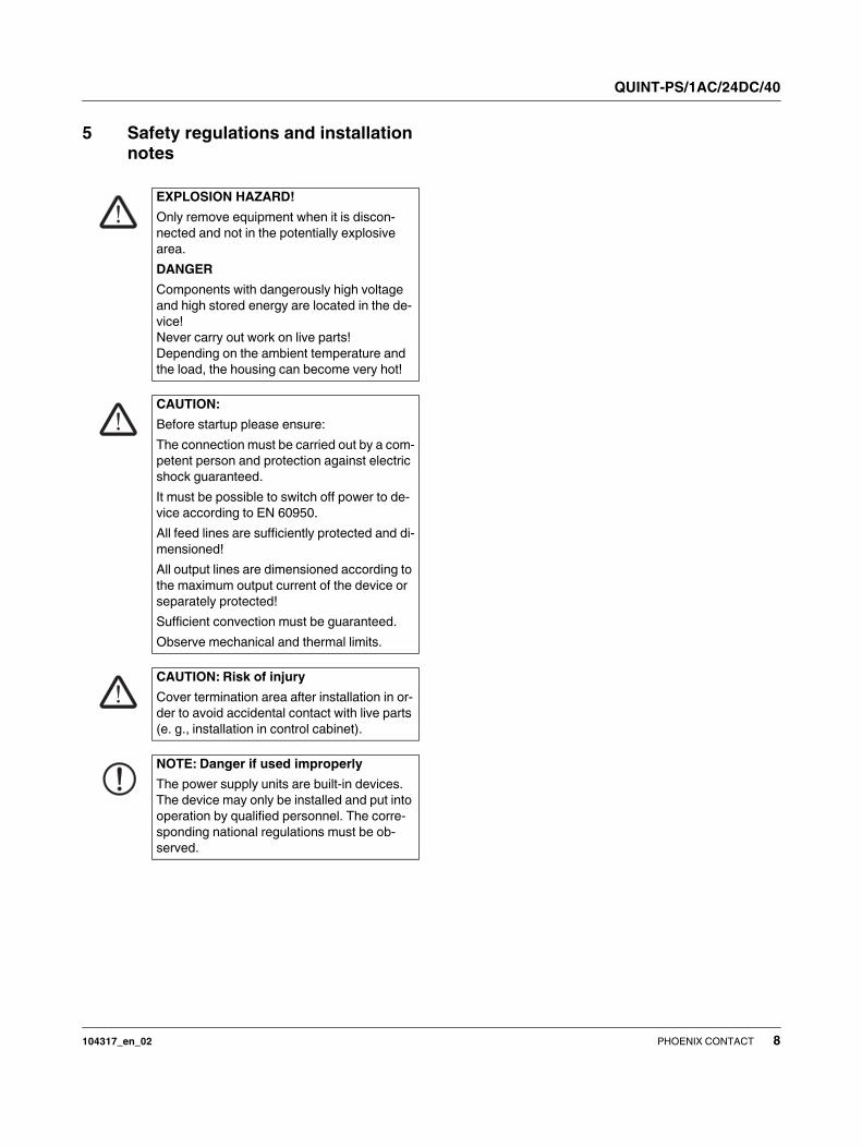
5 Safety regulations and installation
notes
EXPLOSION HAZARD!
Only remove equipment when it is discon-
nected and not in the potentially explosive
area.
DANGER
Components with dangerously high voltage
and high stored energy are located in the de-
vice!
Never carry out work on live parts!
Depending on the ambient temperature and
the load, the housing can become very hot!
CAUTION:
Before startup please ensure:
The connection must be carried out by a com-
petent person and protection against electric
shock guaranteed.
It must be possible to switch off power to de-
vice according to EN 60950.
All feed lines are sufficiently protected and di-
mensioned!
All output lines are dimensioned according to
the maximum output current of the device or
separately protected!
Sufficient convection must be guaranteed.
Observe mechanical and thermal limits.
CAUTION: Risk of injury
Cover termination area after installation in or-
der to avoid accidental contact with live parts
(e. g., installation in control cabinet).
NOTE: Danger if used improperly
The power supply units are built-in devices.
The device may only be installed and put into
operation by qualified personnel. The corre-
sponding national regulations must be ob-
served.

QUINT-PS/1AC/24DC/40
104317_en_02 PHOENIX CONTACT 9
6 Structure
6.1 Block diagram
6.2 Function elements
Figure 1 Position of the function elements
Element Meaning
Rectification
Power factor correction filter
Switch
Electrically isolated signal transmission
Regulation
Transformer
Output filter
Floating switching output
13
I < IN
DC OK
14
L (+)
N (-)
active
PFC
active
PFC
No. Connection terminal blocks and function ele-
ments
1 AC input
2 DC output
3 Active signal output I < IN (POWER BOOST)
4 Active DC OK signal output
5 Floating DC OK switching output
6 Potentiometer for setting the output voltage
7 DC OK signal LED, green
8 Signal LED boost, yellow
9 Universal DIN rail adapter
QU
INT
PO
WE
R
DC OK
Boost
18-29,5 V
LN
Input AC 100-240 V
Output DC 24 V 40 A
1314
SignalDCOK
Ι<Ι N
1
2
9
6
7
8
3
4
5

QUINT-PS/1AC/24DC/40
104317_en_02 PHOENIX CONTACT 10
6.3 Convection
Figure 2 Convection
NOTE: enable convection
The housing can become very hot, depending
on the ambient temperature and module load.
To enable sufficient convection, we recom-
mend a minimum vertical clearance of 50 mm
from other modules. In order to ensure proper
functioning of the module, it is necessary to
maintain a lateral distance of 5 mm and
15 mm for active components.
The device can be snapped onto all DIN rails
in accordance with EN 60715 and should be
mounted in the normal mounting position
(connection terminal blocks on top and bot-
tom).
1314
SignalDCOK
Ι<Ι N
LN
Input AC 100-240 V
Output DC 24 V 40 A
DC OK
Boost
18-29,5 V
QU
INT
PO
WE
R

QUINT-PS/1AC/24DC/40
104317_en_02 PHOENIX CONTACT 11
6.4 Mounting position
Figure 3 Locked areas
Possible mounting positions:
Normal mounting position, installation depth 125 mm (+ DIN rail) (delivery state)
Mounting position rotated at 90°, installation depth of 183 mm (+ DIN rail)
QU
INT
PO
WE
R
DC OK
Boost
18-29,5 V
Output DC 24 V 40 A
13 14
SignalDCOK
Ι<Ι N
L N
Input AC 100-240 V
13
0
12251805
50
11
5
23
0
QUINT-PS/1AC/24DC/40
104317_en_02 PHOENIX CONTACT 12
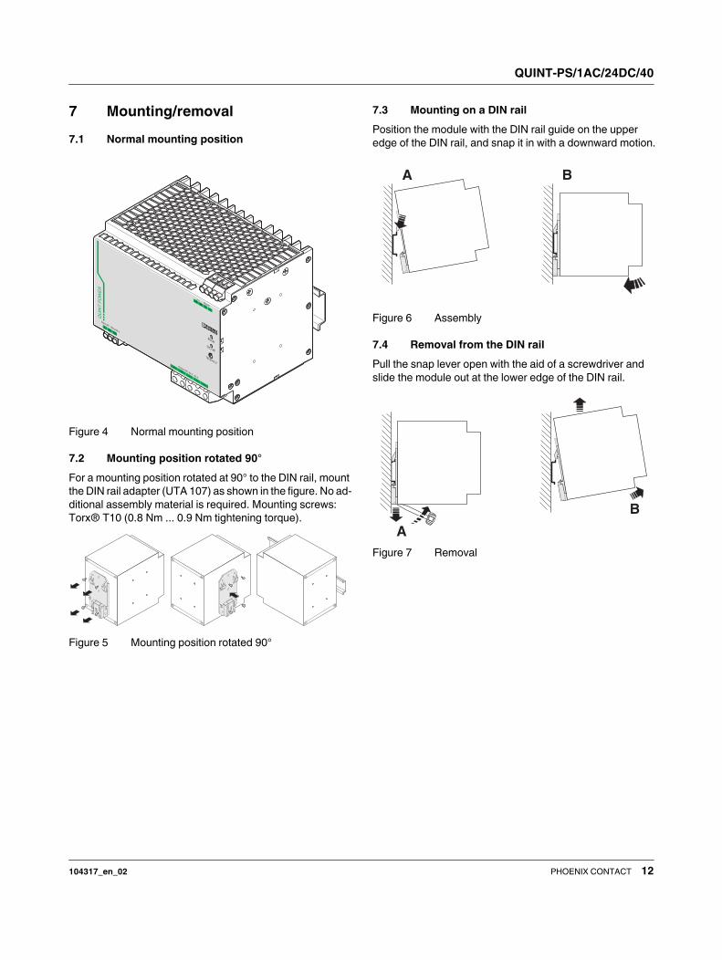
7 Mounting/removal
7.1 Normal mounting position
Figure 4 Normal mounting position
7.2 Mounting position rotated 90°
For a mounting position rotated at 90° to the DIN rail, mount
the DIN rail adapter (UTA 107) as shown in the figure. No ad-
ditional assembly material is required. Mounting screws:
Torx® T10 (0.8 Nm ... 0.9 Nm tightening torque).
Figure 5 Mounting position rotated 90°
7.3 Mounting on a DIN rail
Position the module with the DIN rail guide on the upper
edge of the DIN rail, and snap it in with a downward motion.
Figure 6 Assembly
7.4 Removal from the DIN rail
Pull the snap lever open with the aid of a screwdriver and
slide the module out at the lower edge of the DIN rail.
Figure 7 Removal
1314
SignalDCOK
Ι<Ι N
LN
Input AC 100-240 V
Output DC 24 V 40 A
DC OK
Boost
18-29,5 V
QU
INT
PO
WE
R
A B
B
A

QUINT-PS/1AC/24DC/40
104317_en_02 PHOENIX CONTACT 13
8 Device connection
8.1 Network types
The device can be connected to 1-phase AC networks or to
two of the phase conductors of 3-phase systems (TN, TT or
IT system according to VDE 0100-300/IEC 60364-3) with
nominal voltages of 100 V AC ... 240 V AC.
8.2 AC input
The supply voltage is connected via "Input AC 100 - 240 V"
connection terminal blocks.
8.2.1 Protection of the primary side
The device must be installed in acc. with the regulations as
in EN 60950. It must be possible to disconnect the device
using a suitable isolating facility outside the power supply.
Primary circuit mains protection, for example, is suitable for
this purpose.
An internal fuse is provided for device protection. Additional
device protection is not required.
8.2.2 Permissible backup fuse for mains protection
Power circuit-breaker 16 A or 20 A, characteristic B (or iden-
tical function).
Connect a suitable fuse upstream for DC applications!
For operation on two of the phase conductors
of a three-phase system, an isolating facility
for all poles must be provided.
iT
NL
+L N
−
L3L2L1
+L N
−
TN-C
PENL
+L N
−
PENL3L2L1
+L N
−
TT
PENL
+L N
−
NL3L2L1
+L N
−
PENL3L2L1
+L N
−
PENL
+L N
−
TN-S
CAUTION:
If an internal fuse is triggered, there is a device
malfunction. In this case, the device must be
inspected in the factory.
1314
SignalDCOK
Ι<Ι N
LN
Input AC 100-240 V
Output DC 24 V 40 A
DC OK
Boost
18-29,5 V
QU
INT
PO
WE
R

QUINT-PS/1AC/24DC/40
104317_en_02 PHOENIX CONTACT 14
8.3 DC output
The output voltage is connected via the “Output DC” con-
nection terminal blocks.
8.3.1 Protection of the secondary side
The device is electronically protected against short-circuit
and idling. In the event of a malfunction, the output voltage
is limited to 35 V DC.
8.3.2 Output characteristic curve
The module functions according to the U/I characteristic
curve with the static POWER BOOST power reserve. At a
constant output voltage UN, IBOOST is available. This IBOOST
current supplies up to 1.5 times the IN nominal output cur-
rent. High inrush currents are therefore absorbed without
voltage dips.
UN = 24 V
IN = 40 A
IBoost = 45 A
SFB technology = 215 A (12 ms)
PN = 960 W
PBOOST= 1080 W
9 SFB technology
SFB (Selective Fuse Breaking) technology reliably switches
off faulty current paths in the event of a short circuit. In this
case, it supplies up to six times the nominal current for 12
ms. SFB technology therefore reliably triggers standard cir-
cuit breakers. Faults are located reliably and important sys-
tem parts remain in operation.
9.1 Circuit breaker tripping characteristics
Typically, a circuit breaker trips within 3 ... 5 ms. Fast
enough to avoid voltage drops of parallel connected loads.
Tripping time of the circuit breaker = 3 - 5 ms, typically
9.2 Installation notes
To use the SFB technology of the QUINT power supply, you
must observe the following requirements:
– When designing the secondary side, consider the con-
figuration matrix that describes the maximum cable
lengths depending on the performance class of the de-
vices, cable cross section, and the circuit breaker.
– Ensure the lowest possible cable impedance at the in-
put of the power supply by using short cable lengths and
large cable cross sections.
QU
INT
PO
WE
R
DC OK
Boost
18-29,5 V
LN
Input AC 100-240 V
Output DC 24 V 40 A
1314
SignalDCOK
Ι<Ι N
Output DC 24 V 40 A
I [A]OUT
U[V
]O
UT
UN
IN
I < IN
U < 0,9 x UN
I > IN
IBOOST
The current configuration matrix can be found
in the product download area.
Note the maximum distance between the
power supply and load.
(see also SFB configuration)
t
I [A]
6x IN
IBOOST
IN
3-5 ms
QUINT-PS/1AC/24DC/40
104317_en_02 PHOENIX CONTACT 15
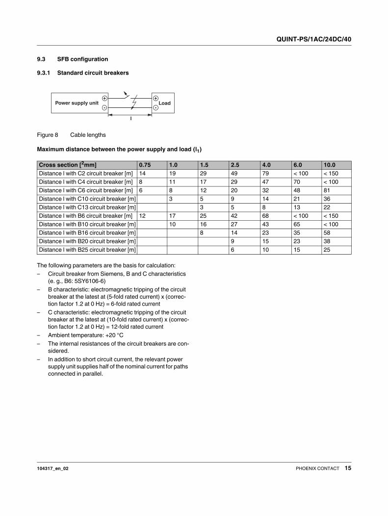
9.3 SFB configuration
9.3.1 Standard circuit breakers
Figure 8 Cable lengths
Maximum distance between the power supply and load (l1)
The following parameters are the basis for calculation:
– Circuit breaker from Siemens, B and C characteristics
(e. g., B6: 5SY6106-6)
– B characteristic: electromagnetic tripping of the circuit
breaker at the latest at (5-fold rated current) x (correc-
tion factor 1.2 at 0 Hz) = 6-fold rated current
– C characteristic: electromagnetic tripping of the circuit
breaker at the latest at (10-fold rated current) x (correc-
tion factor 1.2 at 0 Hz) = 12-fold rated current
– Ambient temperature: +20 °C
– The internal resistances of the circuit breakers are con-
sidered.
– In addition to short circuit current, the relevant power
supply unit supplies half of the nominal current for paths
connected in parallel.
-
+
-
+
l
LoadPower supply unit
Cross section [2mm] 0.75 1.0 1.5 2.5 4.0 6.0 10.0
Distance l with C2 circuit breaker [m] 14 19 29 49 79 < 100 < 150
Distance l with C4 circuit breaker [m] 8 11 17 29 47 70 < 100
Distance l with C6 circuit breaker [m] 6 8 12 20 32 48 81
Distance l with C10 circuit breaker [m] 3 5 9 14 21 36
Distance l with C13 circuit breaker [m] 3 5 8 13 22
Distance l with B6 circuit breaker [m] 12 17 25 42 68 < 100 < 150
Distance l with B10 circuit breaker [m] 10 16 27 43 65 < 100
Distance l with B16 circuit breaker [m] 8 14 23 35 58
Distance l with B20 circuit breaker [m] 9 15 23 38
Distance l with B25 circuit breaker [m] 6 10 15 25
QUINT-PS/1AC/24DC/40
104317_en_02 PHOENIX CONTACT 16
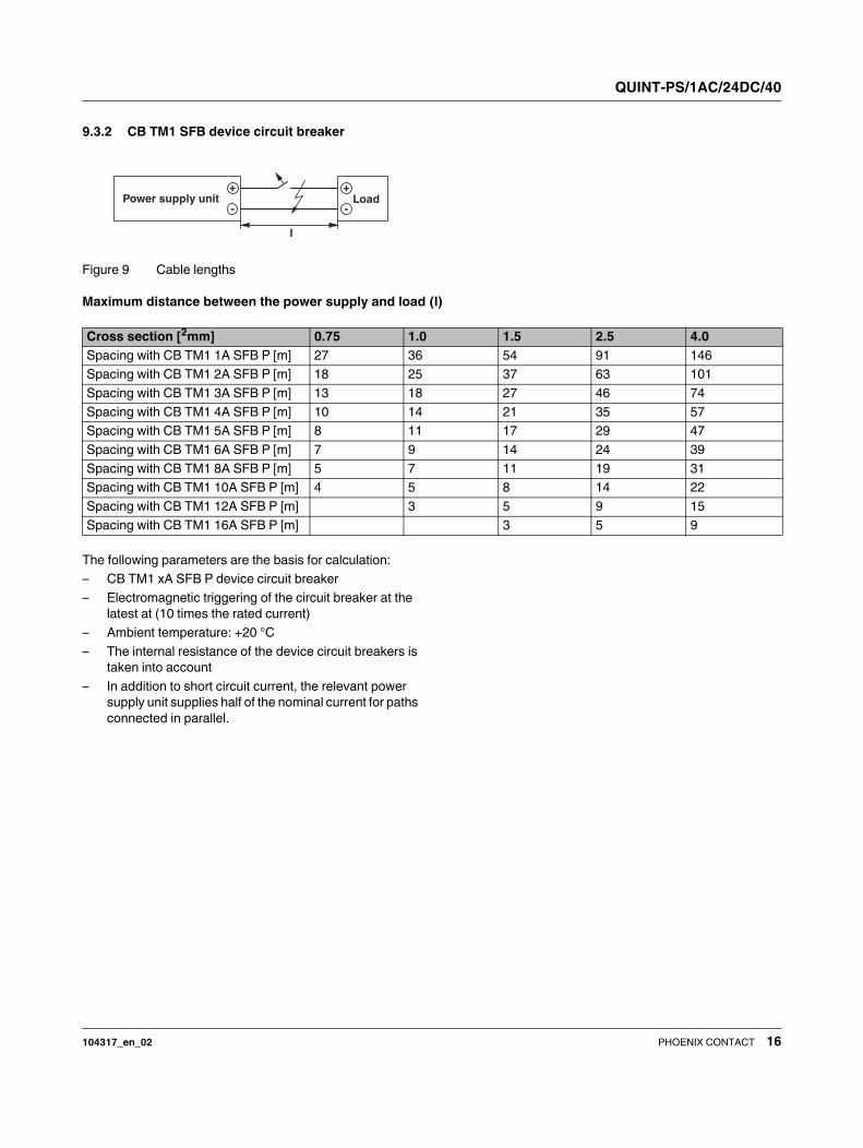
9.3.2 CB TM1 SFB device circuit breaker
Figure 9 Cable lengths
Maximum distance between the power supply and load (l)
The following parameters are the basis for calculation:
– CB TM1 xA SFB P device circuit breaker
– Electromagnetic triggering of the circuit breaker at the
latest at (10 times the rated current)
– Ambient temperature: +20 °C
– The internal resistance of the device circuit breakers is
taken into account
– In addition to short circuit current, the relevant power
supply unit supplies half of the nominal current for paths
connected in parallel.
-
+
-
+
l
LoadPower supply unit
Cross section [2mm] 0.75 1.0 1.5 2.5 4.0
Spacing with CB TM1 1A SFB P [m] 27 36 54 91 146
Spacing with CB TM1 2A SFB P [m] 18 25 37 63 101
Spacing with CB TM1 3A SFB P [m] 13 18 27 46 74
Spacing with CB TM1 4A SFB P [m] 10 14 21 35 57
Spacing with CB TM1 5A SFB P [m] 8 11 17 29 47
Spacing with CB TM1 6A SFB P [m] 7 9 14 24 39
Spacing with CB TM1 8A SFB P [m] 5 7 11 19 31
Spacing with CB TM1 10A SFB P [m] 4 5 8 14 22
Spacing with CB TM1 12A SFB P [m] 3 5 9 15
Spacing with CB TM1 16A SFB P [m] 3 5 9
QUINT-PS/1AC/24DC/40
104317_en_02 PHOENIX CONTACT 17
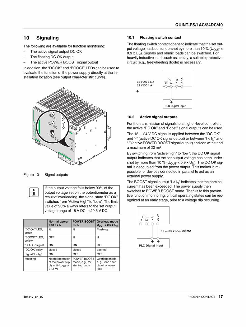
10 Signaling
The following are available for function monitoring:
– The active signal output DC OK
– The floating DC OK output
– The active POWER BOOST signal output
In addition, the “DC OK” and “BOOST” LEDs can be used to
evaluate the function of the power supply directly at the in-
stallation location (see output characteristic curve).
Figure 10 Signal outputs
10.1 Floating switch contact
The floating switch contact opens to indicate that the set out-
put voltage has been undershot by more than 10 % (UOUT <
0.9 x UN). Signals and ohmic loads can be switched. For
heavily inductive loads such as a relay, a suitable protective
circuit (e.g., freewheeling diode) is necessary.
10.2 Active signal outputs
For the transmission of signals to a higher-level controller,
the active “DC OK” and “Boost” signal outputs can be used.
The 18 ... 24 V DC signal is applied between the “DC OK”
and “-” (active DC OK signal output) or between “I < IN” and
“-” (active POWER BOOST signal output) and can withstand
a maximum of 20 mA.
By switching from “active high” to “low”, the DC OK signal
output indicates that the set output voltage has been under-
shot by more than 10 % (UOUT < 0.9 x UN). The DC OK sig-
nal is decoupled from the power output. This makes it im-
possible for devices connected in parallel to act as an
external power supply.
The BOOST signal output “I < IN” indicates that the nominal
current has been exceeded. The power supply then
switches to POWER BOOST mode. Thanks to this preven-
tive function monitoring, critical operating states can be rec-
ognized at an early stage, prior to a voltage dip occurring.
If the output voltage falls below 90% of the
output voltage set on the potentiometer as a
result of overloading, the signal state “DC OK”
switches from “Active High” to “Low”. The limit
value of 90% always refers to the set output
voltage range of 18 V DC to 29.5 V DC.
Normal opera-
tion I < IN
POWER BOOST
I > IN
Overload mode
UOUT < 0.9 x UN
“DC OK” LED,
green
lit lit Flashing
“BOOST” LED,
yellow
OFF lit lit
“DC OK” signal ON ON OFF
“DC OK” relay closed closed opened
Signal “I < IN” ON OFF OFF
Meaning Normal operation
of the power sup-
ply unit (UOUT >
21.5 V)
POWER BOOST
mode, e.g., for
starting loads
Overload mode,
e. g., load short
circuit or over-
load
1314
SignalDCOK
Ι<Ι N
LN
Input AC 100-240 V
Output DC 24 V 40 A
DC OK
Boost
18-29,5 V
QU
INT
PO
WE
R
30 V AC 0.5 A
24 V DC 1 A
+
DC
OK
13 14
PLC Digital Input
+
18 ... 24 V DC / 20 mA
DC
OK
13 14
PLC Digital Input
+ +
QUINT-PS/1AC/24DC/40
104317_en_02 PHOENIX CONTACT 18
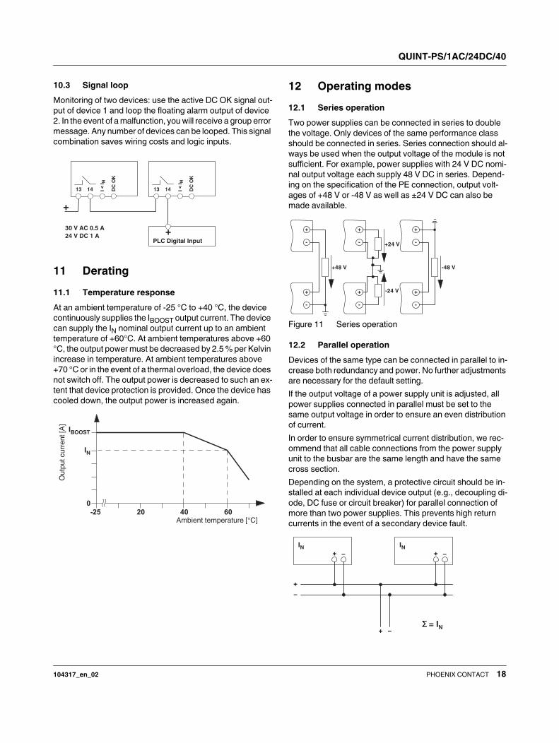
10.3 Signal loop
Monitoring of two devices: use the active DC OK signal out-
put of device 1 and loop the floating alarm output of device
2. In the event of a malfunction, you will receive a group error
message. Any number of devices can be looped. This signal
combination saves wiring costs and logic inputs.
11 Derating
11.1 Temperature response
At an ambient temperature of -25 °C to +40 °C, the device
continuously supplies the IBOOST output current. The device
can supply the IN nominal output current up to an ambient
temperature of +60°C. At ambient temperatures above +60
°C, the output power must be decreased by 2.5 % per Kelvin
increase in temperature. At ambient temperatures above
+70 °C or in the event of a thermal overload, the device does
not switch off. The output power is decreased to such an ex-
tent that device protection is provided. Once the device has
cooled down, the output power is increased again.
12 Operating modes
12.1 Series operation
Two power supplies can be connected in series to double
the voltage. Only devices of the same performance class
should be connected in series. Series connection should al-
ways be used when the output voltage of the module is not
sufficient. For example, power supplies with 24 V DC nomi-
nal output voltage each supply 48 V DC in series. Depend-
ing on the specification of the PE connection, output volt-
ages of +48 V or -48 V as well as ±24 V DC can also be
made available.
Figure 11 Series operation
12.2 Parallel operation
Devices of the same type can be connected in parallel to in-
crease both redundancy and power. No further adjustments
are necessary for the default setting.
If the output voltage of a power supply unit is adjusted, all
power supplies connected in parallel must be set to the
same output voltage in order to ensure an even distribution
of current.
In order to ensure symmetrical current distribution, we rec-
ommend that all cable connections from the power supply
unit to the busbar are the same length and have the same
cross section.
Depending on the system, a protective circuit should be in-
stalled at each individual device output (e.g., decoupling di-
ode, DC fuse or circuit breaker) for parallel connection of
more than two power supplies. This prevents high return
currents in the event of a secondary device fault.
DC
OK
13 14
30 V AC 0.5 A
24 V DC 1 A
+
DC
OK
13 14
PLC Digital Input
+
-25
0
40 6020
IBOOST
IN
Ambient temperature [°C]
Ou
tpu
tc
urr
en
t[A
]
+48 V -48 V
+24 V
-24 V+
-
+
-
+
-
+
-
+
-
+
-
+
IN− +
IN−
+
+
−
−Σ = IN
QUINT-PS/1AC/24DC/40
104317_en_02 19PHOENIX CONTACT GmbH & Co. KG • 32823 Blomberg • Germany
phoenixcontact.com
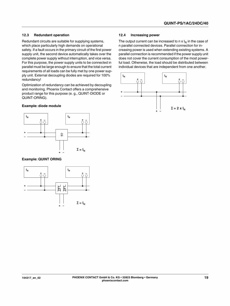
12.3 Redundant operation
Redundant circuits are suitable for supplying systems,
which place particularly high demands on operational
safety. If a fault occurs in the primary circuit of the first power
supply unit, the second device automatically takes over the
complete power supply without interruption, and vice versa.
For this purpose, the power supply units to be connected in
parallel must be large enough to ensure that the total current
requirements of all loads can be fully met by one power sup-
ply unit. External decoupling diodes are required for 100%
redundancy!
Optimization of redundancy can be achieved by decoupling
and monitoring. Phoenix Contact offers a comprehensive
product range for this purpose (e. g., QUINT-DIODE or
QUINT-ORING).
Example: diode module
Example: QUINT ORING
12.4 Increasing power
The output current can be increased to n x IN in the case of
n parallel connected devices. Parallel connection for in-
creasing power is used when extending existing systems. A
parallel connection is recommended if the power supply unit
does not cover the current consumption of the most power-
ful load. Otherwise, the load should be distributed between
individual devices that are independent from one another.
+
IN− +
IN−
+
+
−
−Σ = IN
+
IN− +
IN−
+
+
−
−Σ = IN
+
IN− +
IN−
+
+
−
−Σ = 2 x IN
Related Documents